Ref. 769401 - Televes
482
GPON OLT: 8xPON + 8xGbE + 2x10GbE EN Ref. 769401 User Manual www.televes.com
-
Upload
khangminh22 -
Category
Documents
-
view
0 -
download
0
Transcript of Ref. 769401 - Televes

GPON OLT: 8xPON + 8xGbE + 2x10GbEEN
Ref. 769401
User Manual
w w w . t e l e v e s . c o m

ENG
LISH
EN
Índice
1. Summary ................................................................................................................................................................................................... 102. Technical Description ........................................................................................................................................................................... 122.1 Services ...................................................................................................................................................................................................... 132.1.1 Usage Scenarios ...................................................................................................................................................................................... 132.1.2 GPON Service Scenarios ...................................................................................................................................................................... 142.1.2.1 N:1 Services .............................................................................................................................................................................................. 142.1.2.21 1 Services................................................................................................................................................................................................... 162.1.2.3 Transparent LAN Services (TLS) ......................................................................................................................................................... 162.20 LT System Features ................................................................................................................................................................................. 172.3 Services ...................................................................................................................................................................................................... 172.4 Interoperability ....................................................................................................................................................................................... 182.5 PLOAM ........................................................................................................................................................................................................ 182.6 OMCI ........................................................................................................................................................................................................... 182.6.1 ONU Related OLT OS Supported Features ..................................................................................................................................... 182.6.2 OMCI and ONU Software Upgrade .................................................................................................................................................. 192.7 FEC (Upstream/Downstream) Configuration and Monitoring............................................................................................... 192.8 Ethernet Features ................................................................................................................................................................................... 202.8.1 VLAN Provisioning ................................................................................................................................................................................. 202.8.2 Multicast .................................................................................................................................................................................................... 202.8.2.1 Supported Features ............................................................................................................................................................................... 202.8.2.2 IGMP Snooping/Proxy .......................................................................................................................................................................... 212.8.3 Authentication: DHCP Relay ............................................................................................................................................................... 222.8.3.1 DHCP Relay Agent Option 82............................................................................................................................................................. 222.8.3.2 Lightweith DHCPv6 Relay Agent ...................................................................................................................................................... 222.8.4 Security ...................................................................................................................................................................................................... 242.8.4.1 ACL - Access Control Lists Support .................................................................................................................................................. 242.8.4.2 White List for Multicast Group Addresses ..................................................................................................................................... 242.8.4.3 IP Source Guard....................................................................................................................................................................................... 242.8.4.4 MAC Duplication .................................................................................................................................................................................... 242.8.4.5 MAC/IP Spoofing .................................................................................................................................................................................... 252.8.4.6 Storm Attack Rate Limiters ................................................................................................................................................................. 252.8.4.7 User Isolation ........................................................................................................................................................................................... 252.8.5 QoS .............................................................................................................................................................................................................. 252.8.6 MTU ............................................................................................................................................................................................................. 262.8.7 OAM ............................................................................................................................................................................................................ 262.8.8 Ethernet Counters (RFC2819) ............................................................................................................................................................ 272.9 MAC ............................................................................................................................................................................................................. 272.9.1 Dynamic Bandwidth Allocation (DBA) ............................................................................................................................................ 272.9.2 MAC GPON DBA Algorithm ................................................................................................................................................................ 282.9.3 Overbooking ............................................................................................................................................................................................ 282.10 PON ............................................................................................................................................................................................................. 292.10.1 Splitting Ratio Options ......................................................................................................................................................................... 292.10.2 Supported PON Classes ....................................................................................................................................................................... 292.11 Protection.................................................................................................................................................................................................. 292.11.1 OLT Supported Protection Mechanisms ........................................................................................................................................ 292.11.1.1 Type B Redundancy for GPON Ports ................................................................................................................................................ 292.11.1.2 Ethernet Uplink Ports Protection ...................................................................................................................................................... 302.11.1.3 Link Aggregation Control Protocol (LACP) .................................................................................................................................... 302.11.1.4 Ethernet Ring Protection Switching ................................................................................................................................................ 302.12 Synchronization ...................................................................................................................................................................................... 322.12.1 Hybrid Synchronization with the OLT Equipment Family ....................................................................................................... 322.12.2 Ethernet Synchronization Messaging Channel (ESMC) ............................................................................................................ 32
Descripción del producto
4
2.12.3 Synchronous Ethernet (SyncE) .......................................................................................................................................................... 322.12.3.1 Ethernet without SyncE (e.g. 1000Base-T) .................................................................................................................................... 332.12.3.2 Ethernet with SyncE (e.g. 1000Base-T) ........................................................................................................................................... 332.12.4 IEEE 1588v2 .............................................................................................................................................................................................. 332.12.4.1 Client/Server model .............................................................................................................................................................................. 342.12.5 SYNC-E and IEEE 1588v2/PTP at the OLT equipment ................................................................................................................ 342.12.5.1 Clock configurations supported by the OLT: ................................................................................................................................ 342.12.5.2 Basic Operation of 1588V2 .................................................................................................................................................................. 352.13 Support Multiple Trap Destination Servers .................................................................................................................................. 372.14 External Alarm Conditions .................................................................................................................................................................. 372.15 Managers’ Configuration ..................................................................................................................................................................... 372.16 Connectivity Fault Management (CFM) ......................................................................................................................................... 372.17 Reboot Features ...................................................................................................................................................................................... 372.18 IP Features ................................................................................................................................................................................................. 382.19 Standards and Protocols ...................................................................................................................................................................... 383. System Specifications ........................................................................................................................................................................... 413.1 Configuring Dynamic Software UpgradeConfiguring Dynamic Software Upgrade OLT Equipment Chassis Features 413.2 ADC OverviewADC OverviewOLT Equipment Boards Features ............................................................................................ 413.3 Optical Interfaces ................................................................................................................................................................................... 413.3.1 10GE Interfaces ....................................................................................................................................................................................... 413.3.21 GbE Ethernet Interfaces ....................................................................................................................................................................... 423.3.3 GPON Interfaces ..................................................................................................................................................................................... 423.3.4 B+ Link Budget ........................................................................................................................................................................................ 433.3.5 C+ Link Budget ........................................................................................................................................................................................ 433.4 Power Supply Options .......................................................................................................................................................................... 433.5 Power Consumption ............................................................................................................................................................................. 433.6 System Heat Release ............................................................................................................................................................................. 443.7 Weight & Physical Dimensions .......................................................................................................................................................... 443.8 MTBF ........................................................................................................................................................................................................... 443.9 Environmental ConditionsLicense Requirements ...................................................................................................................... 453.10 Electromagnetic Compatibility ......................................................................................................................................................... 453.11 System Parts ............................................................................................................................................................................................. 453.11.1 OLT Ref.769401 single board .............................................................................................................................................................. 463.11.1.1 Interfaces ................................................................................................................................................................................................... 463.11.1.2 LED Indicators .......................................................................................................................................................................................... 463.11.1.3 Interface Interconnection Cables ..................................................................................................................................................... 464. Setup ........................................................................................................................................................................................................... 474.1 Configuring Dynamic Software UpgradeMechanical Packaging ......................................................................................... 474.2 ESD Precautions ...................................................................................................................................................................................... 474.3 OLT Ref.769401 System ........................................................................................................................................................................ 474.3.1 Restricted Access Location ................................................................................................................................................................. 484.4 Electrical Power Supply ........................................................................................................................................................................ 484.4.1 Disconnect Device ................................................................................................................................................................................. 484.4.2 Multiple Power Source ......................................................................................................................................................................... 484.4.3 Power Supply Connection Procedures ........................................................................................................................................... 484.4.4 Power Supply Cables Connection .................................................................................................................................................... 484.5 SFP/SFP+ Insertion and Removal ..................................................................................................................................................... 494.5.1 SFP/SFP+ Module Insertion Handling Procedures ..................................................................................................................... 494.5.2 SFP/SFP+ Module Removal Handling Procedures ..................................................................................................................... 494.6 Maintenance ............................................................................................................................................................................................ 504.6.1 Cooling System ....................................................................................................................................................................................... 504.6.1.1 FAN Module .............................................................................................................................................................................................. 504.6.1.2 Air Filter ...................................................................................................................................................................................................... 514.6.1.3 FAN Module Replacement Procedures ........................................................................................................................................... 514.6.1.4 Air Filter Replacement Procedures ................................................................................................................................................... 514.7 Cables ......................................................................................................................................................................................................... 524.7.1 Electrical Power Supply ........................................................................................................................................................................ 524.7.2 ETH 10/100/1000 BASE-T ..................................................................................................................................................................... 524.7.3 Alarms & Synchronism ......................................................................................................................................................................... 524.7.4 Optical ........................................................................................................................................................................................................ 534.8 Optical Interfaces ................................................................................................................................................................................... 544.8.1 Transceivers .............................................................................................................................................................................................. 544.8.1.1 SFP AND SFP+ Optical Transceivers ................................................................................................................................................. 544.9 Electrical Interfaces................................................................................................................................................................................ 554.9.1 Electrical Fast Ethernet ......................................................................................................................................................................... 555. Configuration ........................................................................................................................................................................................... 565.1 System Management ............................................................................................................................................................................ 56
EN
5
5.1.1 System Requirements ........................................................................................................................................................................... 575.1.2 Configuring the Web Browser............................................................................................................................................................ 575.1.3 Cleaning the Cookies and Temporary Files ................................................................................................................................... 575.1.4 Trusted Sites ............................................................................................................................................................................................. 585.2 WebTi .......................................................................................................................................................................................................... 585.2.1 Access to the Equipment ..................................................................................................................................................................... 585.2.2 Access Control ......................................................................................................................................................................................... 595.2.3 WebTi General Description ................................................................................................................................................................. 605.2.3.1 Heading ..................................................................................................................................................................................................... 615.2.3.2 Main Page.................................................................................................................................................................................................. 625.2.4 Invalid Operation error message ...................................................................................................................................................... 635.2.4.1 System Configuration ........................................................................................................................................................................... 645.2.4.2 Profiles Configuration ........................................................................................................................................................................... 655.2.4.3 Network Configurations ...................................................................................................................................................................... 705.2.4.4 Synchronism ............................................................................................................................................................................................ 725.2.4.5 Interfaces ................................................................................................................................................................................................... 785.2.4.6 LAG Interfaces ......................................................................................................................................................................................... 805.2.4.7 Services ...................................................................................................................................................................................................... 825.2.4.8 Classes of Service ................................................................................................................................................................................... 845.2.4.9 Multicast .................................................................................................................................................................................................... 855.2.4.10 MAC Tatble ::Switch ............................................................................................................................................................................... 885.2.4.11 DHCP ........................................................................................................................................................................................................... 895.2.4.12 IP Source Guard....................................................................................................................................................................................... 905.2.4.13 Access Lists ............................................................................................................................................................................................... 915.2.4.14 Protection Schemes .............................................................................................................................................................................. 965.2.4.15 Remote Equipment ............................................................................................................................................................................... 1035.2.4.16 System Services ...................................................................................................................................................................................... 1145.2.4.17 CFM probes............................................................................................................................................................................................... 1195.2.4.18 ONU Software Update .......................................................................................................................................................................... 1205.2.4.19 Backup Management ............................................................................................................................................................................ 1235.2.4.20 USERS .......................................................................................................................................................................................................... 1286. Operation .................................................................................................................................................................................................. 1296.1 Upgradingto a New OLT OS Software Release ............................................................................................................................ 1296.1.1 Determining the Software Version .................................................................................................................................................. 1296.1.2 Upgrading to a New Software Release .......................................................................................................................................... 1296.1.3 OLT OS Installation Procedure .......................................................................................................................................................... 1296.2 Status .......................................................................................................................................................................................................... 1306.2.1 System ........................................................................................................................................................................................................ 1326.2.2 Synchronism ............................................................................................................................................................................................ 1336.2.2.1 Global ......................................................................................................................................................................................................... 1336.2.2.2 PTP ............................................................................................................................................................................................................... 1356.2.3 Interfaces ................................................................................................................................................................................................... 1366.2.3.1 PON Interfaces ......................................................................................................................................................................................... 1366.2.3.2 Ethernet Interfaces Status ................................................................................................................................................................... 1436.2.4 LAG Interfaces ......................................................................................................................................................................................... 1466.2.5 Services ...................................................................................................................................................................................................... 1486.2.6 MAC Table ................................................................................................................................................................................................. 1526.2.6.1 GPON .......................................................................................................................................................................................................... 1526.2.6.2 Switch ......................................................................................................................................................................................................... 1536.2.7 DHCP ........................................................................................................................................................................................................... 1556.2.8 Multicast .................................................................................................................................................................................................... 1566.2.8.1 Active Groups .......................................................................................................................................................................................... 1566.2.8.2 Probes ......................................................................................................................................................................................................... 1586.2.9 Remote Equipment ............................................................................................................................................................................... 1596.2.10 Protection Schemes .............................................................................................................................................................................. 1676.2.10.1 ETH Ring/G.8032 ..................................................................................................................................................................................... 1676.2.10.2 GPON Type B Protection ...................................................................................................................................................................... 1696.2.11 OLT Ref.769401:: CFM Probes ............................................................................................................................................................. 1716.2.12 Users ............................................................................................................................................................................................................ 1726.3 Logs ............................................................................................................................................................................................................. 1726.3.1 Alarms......................................................................................................................................................................................................... 1726.3.1.1 Global ......................................................................................................................................................................................................... 1737. CLI ................................................................................................................................................................................................................ 1757.1 ystem Management .............................................................................................................................................................................. 1757.2 Access to the Equipment ..................................................................................................................................................................... 1757.2.1 System Access Control.......................................................................................................................................................................... 1767.3 CLI Overview ............................................................................................................................................................................................ 177
Descripción del producto
6
7.3.1 Features: .................................................................................................................................................................................................... 1777.3.2 Commands ............................................................................................................................................................................................... 1777.3.2.1 General Usage Commands ................................................................................................................................................................. 1777.3.2.2 Common Usage Commands .............................................................................................................................................................. 1797.3.2.3 Command Structure .............................................................................................................................................................................. 1797.4 CLI Navigation ......................................................................................................................................................................................... 1807.4.1 Help on Commands and Arguments Usage: ? ............................................................................................................................ 1827.4.2 Common Node Names ......................................................................................................................................................................... 1827.4.3 About the “showconfig” Command ................................................................................................................................................. 1847.4.4 Invalid Characters ................................................................................................................................................................................... 1847.4.5 Error Codes ............................................................................................................................................................................................... 1847.4.5.1 Syntax Errors ............................................................................................................................................................................................ 1847.4.5.2 Operational Errors .................................................................................................................................................................................. 1857.4.6 Writing CLI Scripts .................................................................................................................................................................................. 1857.4.7 Particular Argument Cases ................................................................................................................................................................ 1867.4.7.1 Arguments slot and port ..................................................................................................................................................................... 1867.4.7.2 Arguments ID and admin .................................................................................................................................................................... 1867.4.7.3 Remote equipment – connect ......................................................................................................................................................... 1867.5 CLI Tree ....................................................................................................................................................................................................... 1887.6 Nodes, Sub-Nodes and Commands................................................................................................................................................. 1907.6.1 “acl” node .................................................................................................................................................................................................. 1907.6.1.1 “config” command .................................................................................................................................................................................. 1907.6.1.2 “create” command ................................................................................................................................................................................. 1917.6.1.3 “remove” command ............................................................................................................................................................................... 1917.6.1.4 “show” command ................................................................................................................................................................................... 1927.6.1.5“ showconfig” command ........................................................................................................................................................................ 1937.6.1.6 “interface” sub-node.............................................................................................................................................................................. 1937.6.1.7 “network-service” sub-node ............................................................................................................................................................... 1957.6.1.8 “rule” sub-node........................................................................................................................................................................................ 1967.6.1.9 “rule-ipv4-ext” sub-node ..................................................................................................................................................................... 1977.6.1.10 “rule-ipv4-std” sub-node ..................................................................................................................................................................... 2007.6.1.11 “rule-ipv6-ext” sub-node ..................................................................................................................................................................... 2027.6.1.12 “rule-mac” sub-node ............................................................................................................................................................................. 2057.6.2 “applications” node ................................................................................................................................................................................ 2077.6.2.1 “firmware-upgrade” sub-node ........................................................................................................................................................... 2077.6.2.2 “manager” sub-node ............................................................................................................................................................................. 2147.6.2.3 “olt-upgrade” sub-node ........................................................................................................................................................................ 2157.6.2.4 “time” sub-node ...................................................................................................................................................................................... 2167.6.3 “backup-manager” node ..................................................................................................................................................................... 1087.6.3.1 “create” command .................................................................................................................................................................................. 1087.6.3.2 “del-serv-conf” command ................................................................................................................................................................... 2227.6.3.3 “export” command ................................................................................................................................................................................. 2237.6.3.4 “import” command ................................................................................................................................................................................ 2237.6.3.5 “remove” command ............................................................................................................................................................................... 2237.6.3.6 “restore” command ................................................................................................................................................................................ 2247.6.3.7 “show” command ................................................................................................................................................................................... 2247.6.4 “cfm-probe” node ................................................................................................................................................................................... 2257.6.4.1 “config” command .................................................................................................................................................................................. 2257.6.4.2 “create” command .................................................................................................................................................................................. 2267.6.4.3 “remove” command ............................................................................................................................................................................... 2277.6.4.4 “show” command ................................................................................................................................................................................... 2277.6.4.5 “showconfig” command ....................................................................................................................................................................... 2287.6.4.6 “status” command .................................................................................................................................................................................. 2297.6.4.7 “unx-ccm” sub-node .............................................................................................................................................................................. 2307.6.5 “dhcp” node .............................................................................................................................................................................................. 2317.6.5.1 Circuit ID template String Syntax ..................................................................................................................................................... 2327.6.5.2 “dhcp-services” sub-node .................................................................................................................................................................... 2327.6.5.3 “global” sub-node ................................................................................................................................................................................... 2347.6.5.4 “leases” sub-node ................................................................................................................................................................................... 2357.6.6“ equipment” node ................................................................................................................................................................................... 2367.6.6.1 “status” command .................................................................................................................................................................................. 2367.6.6.2 “boards” sub-node ................................................................................................................................................................................. 2377.6.6.3 “slot” sub-node ........................................................................................................................................................................................ 2397.6.6.4 “system” sub-node ................................................................................................................................................................................. 2417.6.7 “erp-ring” node ........................................................................................................................................................................................ 2447.6.7.1 “config” command .................................................................................................................................................................................. 2447.6.7.2 “create” command .................................................................................................................................................................................. 245

EN
7
7.6.7.3 “remove” command ............................................................................................................................................................................... 2467.6.7.4 “show” command ................................................................................................................................................................................... 2467.6.7.5 “showconfig” command ....................................................................................................................................................................... 2497.6.7.6 “status” sub-node ................................................................................................................................................................................... 2497.6.8 “eth-protection” node ........................................................................................................................................................................... 2517.6.8.1 “command” command .......................................................................................................................................................................... 2527.6.8.2 “config” command .................................................................................................................................................................................. 2527.6.8.3 “create” command .................................................................................................................................................................................. 2537.6.8.4 “remove” command ............................................................................................................................................................................... 2537.6.8.5 “show” command ................................................................................................................................................................................... 2547.6.8.6 “showconfig” command ....................................................................................................................................................................... 2547.6.8.7 “status” command .................................................................................................................................................................................. 2557.6.9 “gpon-protection” node ....................................................................................................................................................................... 2557.6.9.1 “command” command .......................................................................................................................................................................... 2567.6.9.2 “config” command .................................................................................................................................................................................. 2567.6.9.3 “create” command .................................................................................................................................................................................. 2577.6.9.4 “remove” command ............................................................................................................................................................................... 2577.6.9.5 “show” command ................................................................................................................................................................................... 2587.6.9.6 “showconfig” command ....................................................................................................................................................................... 2587.6.9.7 “status” command .................................................................................................................................................................................. 2597.6.10 “interfaces” node .................................................................................................................................................................................... 2607.6.10.1 “ethernet” sub-node .............................................................................................................................................................................. 2607.6.10.2 “gpon” sub-node ..................................................................................................................................................................................... 2827.6.10.3 “lag” sub-node ......................................................................................................................................................................................... 2967.6.11 “ip” node .................................................................................................................................................................................................... 3047.6.11.1 “apply” command ................................................................................................................................................................................... 3047.6.11.2 “save” command ..................................................................................................................................................................................... 3057.6.11.3 “interfaces” sub-node ............................................................................................................................................................................ 3057.6.11.4 “networking” sub-node ........................................................................................................................................................................ 3097.6.11.5 “route” sub-node..................................................................................................................................................................................... 3107.6.12 “ip-source-guard” node ........................................................................................................................................................................ 3127.6.12.1 “config” command .................................................................................................................................................................................. 3127.6.12.2 “create” command .................................................................................................................................................................................. 3137.6.12.3 “remove” command ............................................................................................................................................................................... 3137.6.12.4 “show” command ................................................................................................................................................................................... 3147.6.12.5 “showconfig” command ....................................................................................................................................................................... 3157.6.13 “logs” node ................................................................................................................................................................................................ 3157.6.13.1 “alarms” sub-node .................................................................................................................................................................................. 3157.6.14 “mac-table” node .................................................................................................................................................................................... 3177.6.14.1 ”config” command .................................................................................................................................................................................. 3177.6.14.2 “show” command ................................................................................................................................................................................... 3177.6.14.3 “showconfig” command ....................................................................................................................................................................... 3187.6.14.4 “status” sub-node ................................................................................................................................................................................... 3197.6.15 “multicast” node ..................................................................................................................................................................................... 3227.6.15.1 “active-groups” sub-node.................................................................................................................................................................... 3227.6.15.2 “group-list” sub-node ............................................................................................................................................................................ 3237.6.15.3 “igmp” sub-node ..................................................................................................................................................................................... 3267.6.15.4 “probes” sub-node ................................................................................................................................................................................. 3327.6.16 “profiles” node ......................................................................................................................................................................................... 3357.6.16.1 “dscp-to-pbits” sub-node .................................................................................................................................................................... 3367.6.16.2 “ethernet” sub-node .............................................................................................................................................................................. 3397.6.16.3 “ONUs” sub-node .................................................................................................................................................................................... 3427.6.16.4 “pbits-to pq” sub-node ......................................................................................................................................................................... 3447.6.16.5 “upstream-dba” sub-node ................................................................................................................................................................... 3477.6.16.6 “voip” sub-node ...................................................................................................................................................................................... 3507.6.17 “remote-eq” node ................................................................................................................................................................................... 3567.6.17.1 “config-onu-id” command ................................................................................................................................................................... 3577.6.17.2 “connect” command .............................................................................................................................................................................. 3577.6.17.3 “disconnect” command ........................................................................................................................................................................ 3587.6.17.4 “showconnected” command ............................................................................................................................................................. 3587.6.17.5 “discovery” sub-node ............................................................................................................................................................................ 3597.6.17.6 “ONUs” sub-node .................................................................................................................................................................................... 3657.6.17.7 “statistics” sub-node .............................................................................................................................................................................. 3977.6.17.8 “status” sub-node ................................................................................................................................................................................... 3977.6.18 “routing” node ......................................................................................................................................................................................... 4127.6.18.1 “arp-table” node ...................................................................................................................................................................................... 4127.6.18.2 “ipv4-interface” sub-node ................................................................................................................................................................... 412

Descripción del producto
8
7.6.18.3 “ping” sub-node ...................................................................................................................................................................................... 4157.6.18.4 “route-table” sub-node ......................................................................................................................................................................... 4187.6.18.5 “traceroute” sub-node .......................................................................................................................................................................... 4217.6.19 “services” node ........................................................................................................................................................................................ 4247.6.19.1 “availableValues” command ............................................................................................................................................................... 4257.6.19.2 “config” command .................................................................................................................................................................................. 4257.6.19.3 “create” command .................................................................................................................................................................................. 4267.6.19.4 “remove” command ............................................................................................................................................................................... 4277.6.19.5 “show” command ................................................................................................................................................................................... 4287.6.19.6 “showconfig” command ....................................................................................................................................................................... 4307.6.19.7 “rate-limiters” sub-node ....................................................................................................................................................................... 4307.6.19.8 “statistics” sub-node ............................................................................................................................................................................. 4327.6.20 “synchronism” node ............................................................................................................................................................................... 4407.6.20.1 “global” sub-node ................................................................................................................................................................................... 4407.6.20.2 “ptp” sub-node ........................................................................................................................................................................................ 4477.6.20.3 “status” sub-node ................................................................................................................................................................................... 4557.6.21 “users” node .............................................................................................................................................................................................. 4587.6.21.1 “config” command .................................................................................................................................................................................. 4587.6.21.2 “create” command .................................................................................................................................................................................. 4597.6.21.3 “remove” command ............................................................................................................................................................................... 4597.6.21.4 “show” command ................................................................................................................................................................................... 4607.6.21.5 “status” command .................................................................................................................................................................................. 4617.6.22 utils” node ................................................................................................................................................................................................. 4617.6.22.1 “ping” command ..................................................................................................................................................................................... 4617.6.22.2 “tcpdump” command ........................................................................................................................................................................... 4627.6.22.3 “telnet” command .................................................................................................................................................................................. 4637.6.22.4 “traceroute” command ......................................................................................................................................................................... 4638. Troubleshooting ..................................................................................................................................................................................... 4648.1 Common Problem Handling .............................................................................................................................................................. 4648.2 Equipment Error Codes ........................................................................................................................................................................ 4659. Glossary of Terms and Abbreviations .............................................................................................................................................. 469

EN
9
Descripción del producto
10
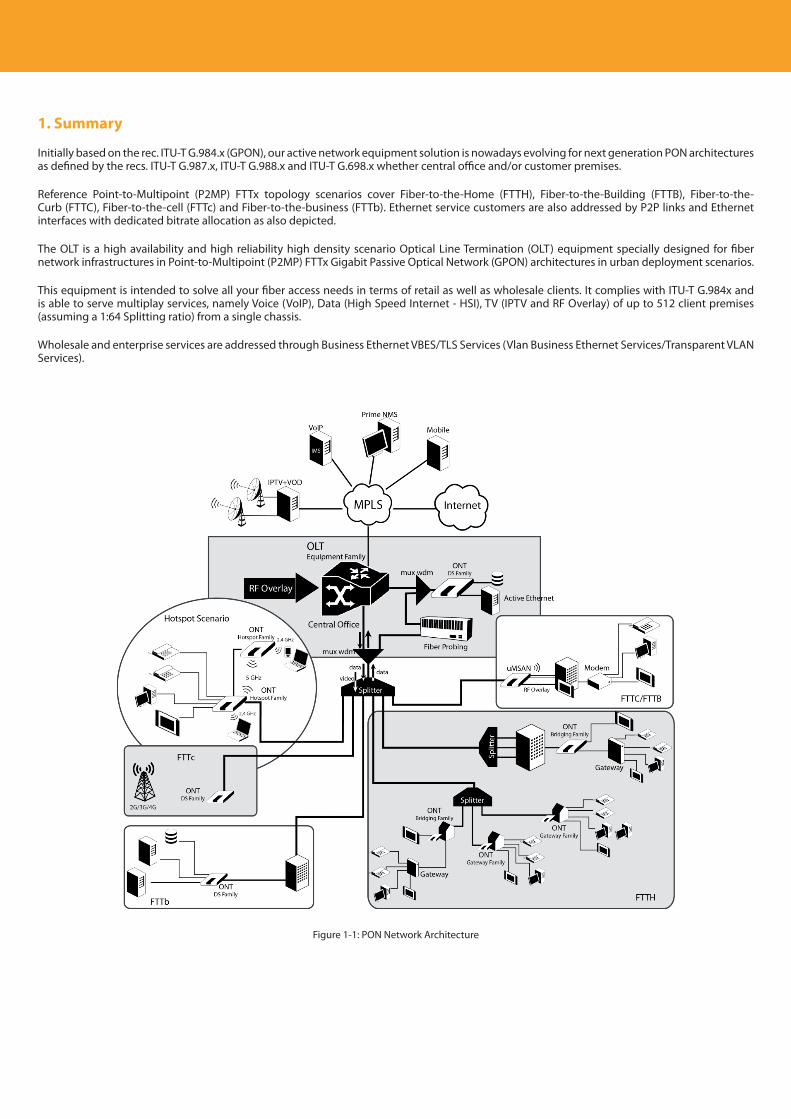
1. Summary
Initially based on the rec. ITU-T G.984.x (GPON), our active network equipment solution is nowadays evolving for next generation PON architectures as defined by the recs. ITU-T G.987.x, ITU-T G.988.x and ITU-T G.698.x whether central office and/or customer premises.
Reference Point-to-Multipoint (P2MP) FTTx topology scenarios cover Fiber-to-the-Home (FTTH), Fiber-to-the-Building (FTTB), Fiber-to-the-Curb (FTTC), Fiber-to-the-cell (FTTc) and Fiber-to-the-business (FTTb). Ethernet service customers are also addressed by P2P links and Ethernet interfaces with dedicated bitrate allocation as also depicted.
The OLT is a high availability and high reliability high density scenario Optical Line Termination (OLT) equipment specially designed for fiber network infrastructures in Point-to-Multipoint (P2MP) FTTx Gigabit Passive Optical Network (GPON) architectures in urban deployment scenarios.
This equipment is intended to solve all your fiber access needs in terms of retail as well as wholesale clients. It complies with ITU-T G.984x and is able to serve multiplay services, namely Voice (VoIP), Data (High Speed Internet - HSI), TV (IPTV and RF Overlay) of up to 512 client premises (assuming a 1:64 Splitting ratio) from a single chassis.
Wholesale and enterprise services are addressed through Business Ethernet VBES/TLS Services (Vlan Business Ethernet Services/Transparent VLAN Services).
Figure 1-1: PON Network Architecture

EN
11
Descripción del producto
12
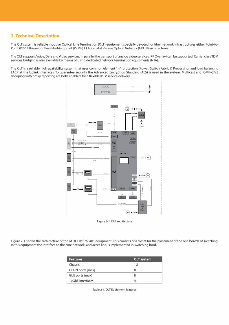
2. Technical Description
The OLT system is reliable modular Optical Line Termination (OLT) equipment specially devoted for fiber network infrastructures either Point-to-Point (P2P) Ethernet or Point-to-Multipoint (P2MP) FTTx Gigabit Passive Optical Network (GPON) architectures
The OLT supports Voice, Data and Video services. In parallel the transport of analog video services (RF Overlay) can be supported. Carrier class TDM services bridging is also available by means of using dedicated network termination equipments (NTA).
The OLT is a reliable high availability system that uses common element 1+1 protection (Power, Switch Fabric & Processing) and load balancing LACP at the Uplink interfaces. To guarantee security the Advanced Encryption Standard (AES) is used in the system. Multicast and IGMPv2/v3 snooping with proxy reporting are both enablers for a flexible IPTV service delivery.
Figure 2-1: OLT architecture
Figure 2-1 shows the architecture of the of OLT Ref.769401 equipment. This consists of a closet for the placement of the one boards of switching. In this equipment the interface to the core network, and acces line, is implemented in switching bord.
Features OLT system
Chassis 1U
GPON ports [max] 8
GbE ports (max) 8
10GbE interfaces 4
Table 2-1. OLT Equipment features
EN
13
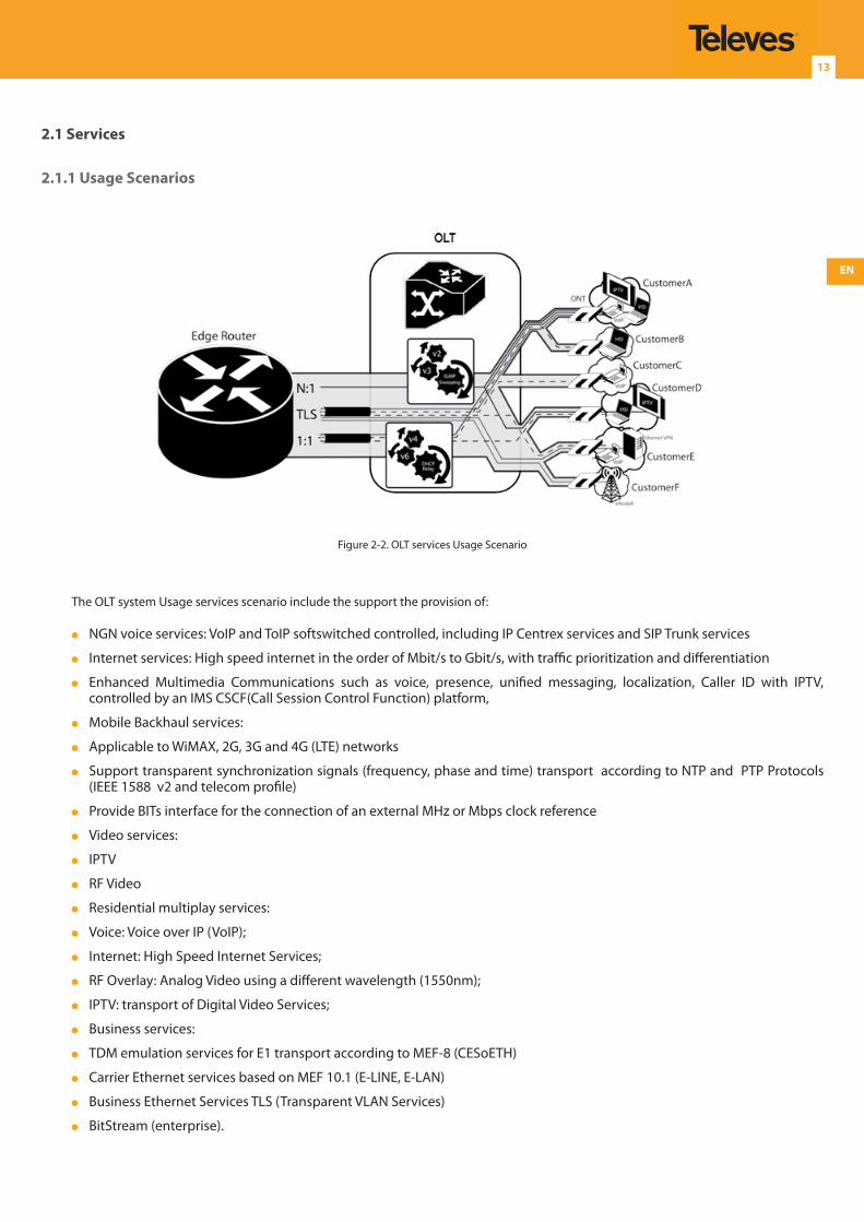
2.1 Services
2.1.1 Usage Scenarios
Figure 2-2. OLT services Usage Scenario
The OLT system Usage services scenario include the support the provision of:
NGN voice services: VoIP and ToIP softswitched controlled, including IP Centrex services and SIP Trunk services
Internet services: High speed internet in the order of Mbit/s to Gbit/s, with traffic prioritization and differentiation
Enhanced Multimedia Communications such as voice, presence, unified messaging, localization, Caller ID with IPTV, controlled by an IMS CSCF(Call Session Control Function) platform,
Mobile Backhaul services:
Applicable to WiMAX, 2G, 3G and 4G (LTE) networks
Support transparent synchronization signals (frequency, phase and time) transport according to NTP and PTP Protocols (IEEE 1588 v2 and telecom profile)
Provide BITs interface for the connection of an external MHz or Mbps clock reference
Video services:
IPTV
RF Video
Residential multiplay services:
Voice: Voice over IP (VoIP);
Internet: High Speed Internet Services;
RF Overlay: Analog Video using a different wavelength (1550nm);
IPTV: transport of Digital Video Services;
Business services:
TDM emulation services for E1 transport according to MEF-8 (CESoETH)
Carrier Ethernet services based on MEF 10.1 (E-LINE, E-LAN)
Business Ethernet Services TLS (Transparent VLAN Services)
BitStream (enterprise).
Descripción del producto
14
2.1.2 GPON Service Scenarios
The OLT system supports the following Ethernet services over GPON:
N:1
Multiple Clients using the same Service Tag
Traffic Forwarding based on the S-TAG+DMAC
1:1
Unique S-TAG or S-TAG+C-TAG per Client Service
Traffic switching based on S-TAG+C-TAG or S-TAG
Transparent LAN Services (TLS)
The traffic is not processed
The CPU is not part of the EVC
Can be use 1:1 and N:1 topology
2.1.2.1 N:1 Services
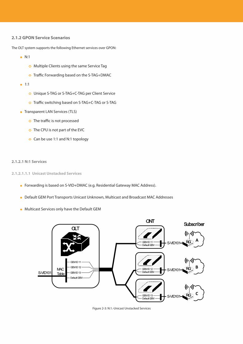
2.1.2.1.1.1 Unicast Unstacked Services
Forwarding is based on S-VID+DMAC (e.g. Residential Gateway MAC Address).
Default GEM Port Transports Unicast Unknown, Multicast and Broadcast MAC Addresses
Multicast Services only have the Default GEM
OLTONT
S-VID101MACTable
Subscriber
GEM ID 11Default GEM
S-VID101A
GEM ID 12Default GEM
S-VID101B
GEM ID 13Default GEM
S-VID101C
GEM ID 11
GEM ID 12
GEM ID 13
Default GEM
RG
RG
RG
Figure 2-3: N:1.-Unicast Unstacked Services
EN
15
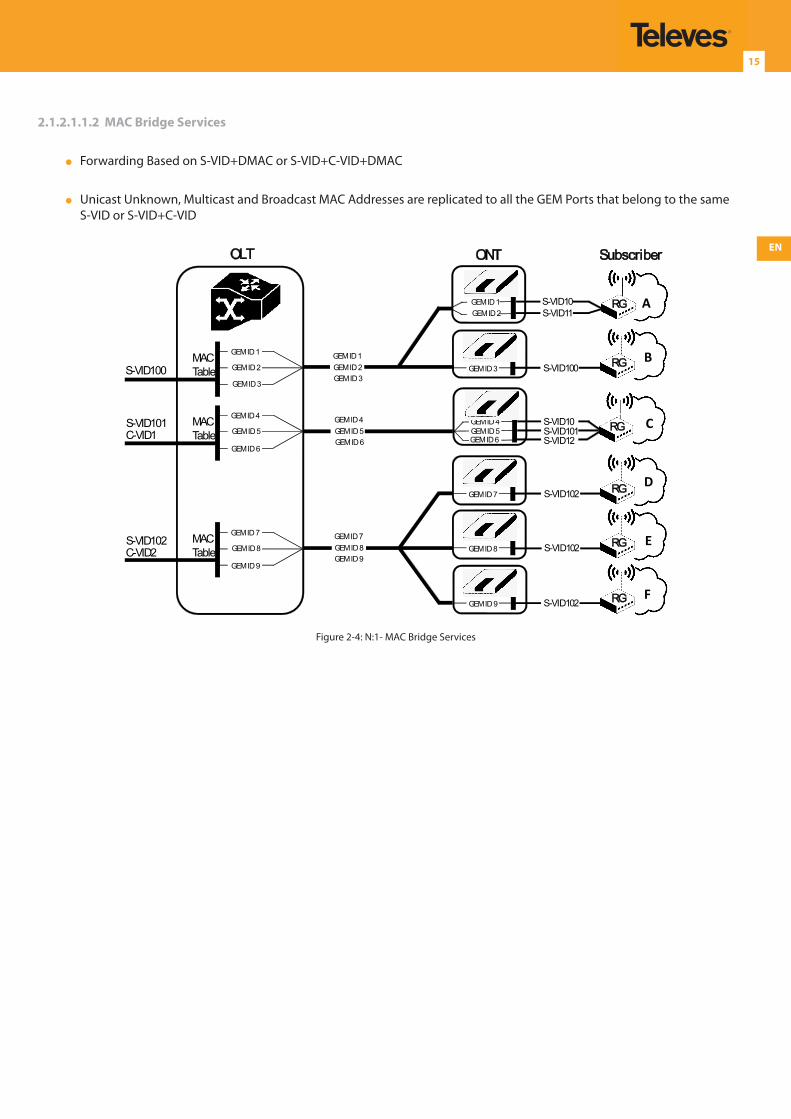
2.1.2.1.1.2 MAC Bridge Services
Forwarding Based on S-VID+DMAC or S-VID+C-VID+DMAC
Unicast Unknown, Multicast and Broadcast MAC Addresses are replicated to all the GEM Ports that belong to the same S-VID or S-VID+C-VID
GEM ID 1
OLT ONT
S-VID101 MACTable
Subscriber
GEM ID 4
GEM ID 3 S-VID100B
S-VID10 A
GEM ID 4 S-VID10 CGEM ID 5GEM ID 6
S-VID101S-VID12
GEM ID 7 S-VID102D
GEM ID 8 S-VID102 E
GEM ID 9 S-VID102F
GEM ID 5
GEM ID 6C-VID1
GEM ID 4GEM ID 5GEM ID 6
S-VID102 MACTable
GEM ID 7
GEM ID 8
GEM ID 9C-VID2
GEM ID 7GEM ID 8GEM ID 9
S-VID100MACTable
GEM ID 1
GEM ID 2
GEM ID 3
GEM ID 1GEM ID 2GEM ID 3
GEM ID 2 S-VID11RG
RG
RG
RG
RG
RG
Figure 2-4: N:1- MAC Bridge Services
Descripción del producto
16
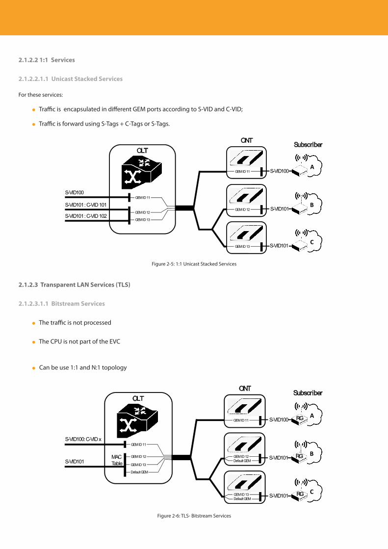
2.1.2.2 1:1 Services
2.1.2.2.1.1 Unicast Stacked Services
For these services:
Traffic is encapsulated in different GEM ports according to S-VID and C-VID;
Traffic is forward using S-Tags + C-Tags or S-Tags.
OLTONT
S-VID101 : C-VID 102
Subscriber
GEM ID 11 S-VID100A
GEM ID 12 S-VID101B
GEM ID 13 S-VID101 C
GEM ID 11
GEM ID 12
S-VID100
S-VID101 : C-VID 101
GEM ID 13
Figure 2-5: 1:1 Unicast Stacked Services
2.1.2.3 Transparent LAN Services (TLS)
2.1.2.3.1.1 Bitstream Services
The traffic is not processed
The CPU is not part of the EVC
Can be use 1:1 and N:1 topology
OLTONT
S-VID101MACTable
Subscriber
GEM ID 11 S-VID100A
GEM ID 12Default GEM
S-VID101B
GEM ID 13Default GEM
S-VID101C
GEM ID 11
GEM ID 12
GEM ID 13
Default GEM
S-VID100: C-VID x
RG
RG
RG
Figure 2-6: TLS- Bitstream Services
EN
17
2.2 OLT System Features
Ethernet features:
VLAN Switching;
Multicast – IGMP Snooping/Proxy;
Load Balancing and LACP;
DHCP Relay Agent;
QoS.
Interworking between the Ethernet and GPON packets ONT management via OMCI, the main features being:
Downstream/Upstream bit rate: 2.488/1.244 Gbps;
Advanced Encryption Standard (AES);
Forward Error Correction (FEC);
Up to 64 ONT per PON; (1:128 splitting ratio is hardware ready)
L2 Manipulation: Transparent, Add/change S-Tag e C-Tag;
Dynamic Bandwidth Allocation (DBA).
In parallel with the data services, the OLT System allows the transport of analog video services (RF Overlay).
2.3 Services
The following services’ related features are supported by the OLT:
Up to 255 network services
Up to 10 Client services per ONT.
Up to 447 Client services per PON in VLAN+P-bit mode (8GEM per service)
Up to 3582 Client services per PON in VLAN mode (1 GEM per service)
Up to 1K policers for:
Unicast an dor Bitstream Stacked
MAC Brigde Mac addresses
User isolation
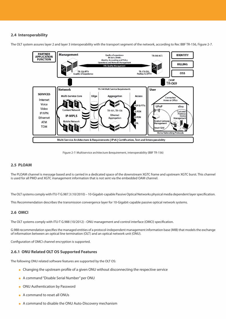
Descripción del producto
18
2.4 Interoperability
The OLT system assures layer 2 and layer 3 interoperability with the transport segment of the network, according to Rec BBF TR-156, Figure 2-7.
Figure 2-7: Multiservice architecture &requirement, interoperability (BBF TR-156)
2.5 PLOAM
The PLOAM channel is message based and is carried in a dedicated space of the downstream XGTC frame and upstream XGTC burst. This channel is used for all PMD and XGTC management information that is not sent via the embedded OAM channel.
The OLT systems comply with ITU-T G.987.3 (10/2010) – 10-Gigabit-capable Passive Optical Networks physical media dependent layer specification.
This Recommendation describes the transmission convergence layer for 10-Gigabit-capable passive optical network systems.
2.6 OMCI
The OLT systems comply with ITU-T G.988 (10/2012) - ONU management and control interface (OMCI) specification.
G.988 recommendation specifies the managed entities of a protocol-independent management information base (MIB) that models the exchange of information between an optical line termination (OLT) and an optical network unit (ONU).
Configuration of OMCI channel encryption is supported.
2.6.1 ONU Related OLT OS Supported Features
The following ONU related software features are supported by the OLT OS:
Changing the upstream profile of a given ONU without disconnecting the respective service
A command “Disable Serial Number” per ONU
ONU Authentication by Password
A command to reset all ONUs
A command to disable the ONU Auto-Discovery mechanism
EN
19
Allow disabling a PON interface with registered ONUs
ONU UPS alarms
ONU VEIP interfaces
Changing the ONU profile of a registered ONU
A notification when an ONU is detected as a “New equipment
Interoperability with Zhone and Huawei ONUs
ONU MIB synchronization
Provide the ONU ID related to the learned MAC Address in Switch MAC table
Display the ONU Equipment Model (in ‘new’ state)
Display the T-CONT IDs for each ONU service
Command to do ONU MIB (re)synchronization
Improvement of the ONU SW automatic upgrade policies
Refactoring of ONU Ethernet statistics - split TX and RX
Get the ONT Operational Status by SNMP
2.6.2 OMCI and ONU Software Upgrade
The OLT supports ONUs’ automatic software upgrade via OMCI according to standard G.984.4/G.988.
Following the control plane start software download order the downloading process is managed autonomously by the GPON MAC.
In order to inquire on the state of the operation queries are GPON MAC control plane enabled.
2.7 FEC (Upstream/Downstream) Configuration and Monitoring
FEC function applied to traffic GPON upstream/downstream can be set for a specified ONU at the time the ONU registration. When set this function is configured on a given ONU FEC statistics are available for the ONU upstream/downstream traffic indicating:
Number of bytes corrected with FEC
Number of words corrected with FEC
Number of words with unrecoverable errors
Total number of words processed
Descripción del producto
20
2.8 Ethernet Features
2.8.1 VLAN Provisioning
The following VLAN related software features are supported:
Full support of extended VLAN tagging operations (filter+treatment)
Support Default VLAN ID and Priority on Ethernet interfaces
The Range of VLAN ID per port – VLANs are configured individually; the limits are the following:
Switch Fabric where uplink ports are directly connected:
Just membership: up to 4k VLAN ID per port,
VLAN translation: up to 8k VLAN ID.
GPON ports:
Just membership: up to 4k VLAN ID per port,
VLAN translation: up to 8k VLAN ID.
2.8.2 Multicast
2.8.2.1 Supported Features
Support of IGMP v2
Support of IGMP v3 according to RFC3376
Multicast group features
Support configuring the end-point of the multicast static groups
Support bandwidth configuration of each multicast group
Display Client Service information in Multicast Active Groups list
IGMP features:
Improvement of IGMP control per interface, VLAN and client
Support IGMP control based on multicast bandwidth and number of groups
Allow disabling IGMP packet processing on client services
Support IGMPv3 on the scenario of merged UNI multicast VLANs
IGMP limits:
EN
21
Up to 4096 configured Groups (Group List)
Up to1024 pairs of simultaneous Active Groups and Sources.
Up to 40 different Multicast Services
Up to 128 ONUs.
Up to 512 IGMP Clients per GPON port.
Up to 8 devices (eg. Setop boxes) per port GPON port
Up to 8 devices (eg. Setop boxes) per port Gbe port
2.8.2.2 IGMP Snooping/Proxy
The OLT system provides IP Multicast features by implementing an IGMP Proxy mechanism. For each Multicast Service it is defined the VLAN of the client side and the VLAN that transports the IP Multicast Groups, so that all the IGMP packets with these VLANs are intercepted and delivered to the processor to perform the following actions:
The first Join for a certain Group received from the client side will be translated to a Join on the Network side, using the OLT Source MAC and Source IP;
The last Leave for a certain group received from the client side will be translated to a Leave on the Network side, using OLT Source MAC and Source IP;
The OLT transmits periodical IGMP General Queries to the client side using the Multicast VLAN;
The OLT answers to IGMP General Queries received from the Network with all Multicast Groups active in the system (requested by the clients and statically configured).
The OLT supports Static Multicast Groups, so that these groups are always present in the GPON interfaces even if no client demanded that Multicast group. The OLT answers to the upstream Queries as these Groups are always in the OLT.
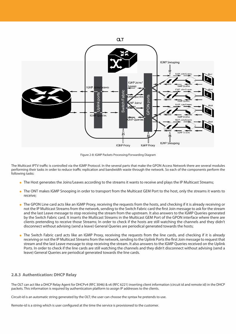
Descripción del producto
22
OLT
Upl
ink p
orts
Sw
itch
Fabr
ic
GP
ON
por
ts
Figure 2-8: IGMP Packets Processing/Forwarding Diagram
The Multicast IPTV traffic is controlled via the IGMP Protocol. In the several parts that make the GPON Access Network there are several modules performing their tasks in order to reduce traffic replication and bandwidth waste through the network. So each of the components perform the following tasks:
The Host generates the Joins/Leaves according to the streams it wants to receive and plays the IP Multicast Streams;
The ONT makes IGMP Snooping in order to transport from the Multicast GEM Port to the host, only the streams it wants to receive;
The GPON Line card acts like an IGMP Proxy, receiving the requests from the hosts, and checking if it is already receiving or not the IP Multicast Streams from the network, sending to the Switch Fabric card the first Join message to ask for the stream and the last Leave message to stop receiving the stream from the upstream. It also answers to the IGMP Queries generated by the Switch Fabric card. It inserts the Multicast Streams in the Multicast GEM Port of the GPON interface where there are clients pretending to receive those Streams; In order to check if the hosts are still watching the channels and they didn’t disconnect without advising (send a leave) General Queries are periodical generated towards the hosts;
The Switch Fabric card acts like an IGMP Proxy, receiving the requests from the line cards, and checking if it is already receiving or not the IP Multicast Streams from the network, sending to the Uplink Ports the first Join message to request that stream and the last Leave message to stop receiving the stream. It also answers to the IGMP Queries received on the Uplink Ports. In order to check if the line cards are still watching the channels and they didn’t disconnect without advising (send a leave) General Queries are periodical generated towards the line cards.
2.8.3 Authentication: DHCP Relay
The OLT can act like a DHCP Relay Agent for DHCPv4 (RFC 3046) & v6 (RFC 6221) inserting client information (circuit id and remote id) in the DHCP packets. This information is required by authentication platform to assign IP addresses to the clients.
Circuit-id is an automatic string generated by the OLT; the user can choose the syntax he pretends to use.
Remote-id is a string which is user configured at the time the service is provisioned to the customer.
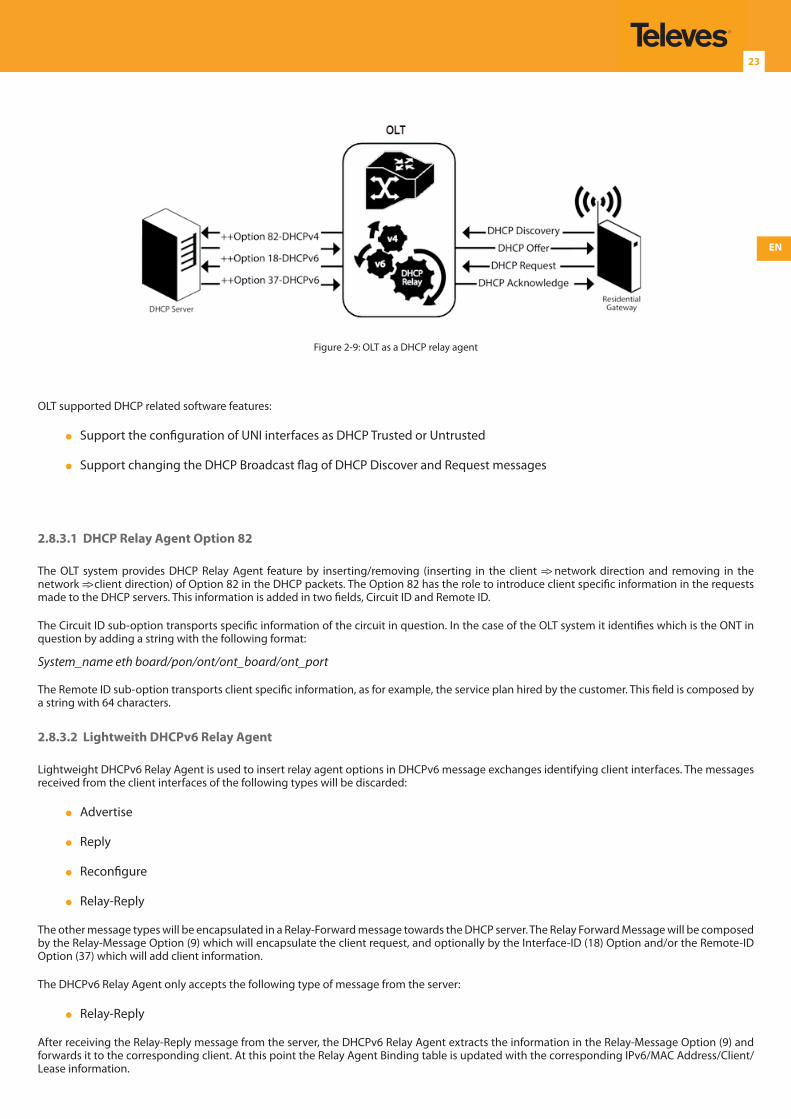
EN
23
Figure 2-9: OLT as a DHCP relay agent
OLT supported DHCP related software features:
Support the configuration of UNI interfaces as DHCP Trusted or Untrusted
Support changing the DHCP Broadcast flag of DHCP Discover and Request messages
2.8.3.1 DHCP Relay Agent Option 82
The OLT system provides DHCP Relay Agent feature by inserting/removing (inserting in the client => network direction and removing in the network => client direction) of Option 82 in the DHCP packets. The Option 82 has the role to introduce client specific information in the requests made to the DHCP servers. This information is added in two fields, Circuit ID and Remote ID.
The Circuit ID sub-option transports specific information of the circuit in question. In the case of the OLT system it identifies which is the ONT in question by adding a string with the following format:
System_name eth board/pon/ont/ont_board/ont_port
The Remote ID sub-option transports client specific information, as for example, the service plan hired by the customer. This field is composed by a string with 64 characters.
2.8.3.2 Lightweith DHCPv6 Relay Agent
Lightweight DHCPv6 Relay Agent is used to insert relay agent options in DHCPv6 message exchanges identifying client interfaces. The messages received from the client interfaces of the following types will be discarded:
Advertise
Reply
Reconfigure
Relay-Reply
The other message types will be encapsulated in a Relay-Forward message towards the DHCP server. The Relay Forward Message will be composed by the Relay-Message Option (9) which will encapsulate the client request, and optionally by the Interface-ID (18) Option and/or the Remote-ID Option (37) which will add client information.
The DHCPv6 Relay Agent only accepts the following type of message from the server:
Relay-Reply
After receiving the Relay-Reply message from the server, the DHCPv6 Relay Agent extracts the information in the Relay-Message Option (9) and forwards it to the corresponding client. At this point the Relay Agent Binding table is updated with the corresponding IPv6/MAC Address/Client/Lease information.
Descripción del producto
24
2.8.4 Security
The OLT equipment enables a group of features that avoid anti-DOS (Denial of Service) attacks and fake customer Trojan mechanisms, namely:
ACL’s
White list support
IP Source Guard
MAC duplication
MAC/IP spoofing
Broadcast rate control
User isolation
2.8.4.1 ACL - Access Control Lists Support
ACL’s (Access Control Lists) avoid the customers to use certain MAC or IP addresses in order to avoid them to reach certain networks MAC/IP groups. This feature is made by applying filters to source and/or destination MAC/IP addresses. These filters can be used to allow or drop the packets from a user attendance.
ACLs limits
Up to 99 supported ACLs
Up to 128 supported rules
Up to 128 supported ACL Service Apply
Up to 128 supported ACL Port Apply
2.8.4.2 White List for Multicast Group Addresses
The OLT supports white list for multicast group addresses.
This list is used to select the upstream multicast service (VLAN) when a particular client requests a group address.
The maximum number of groups is currently limited to 1024, but can go up to 4096 in the future;
2.8.4.3 IP Source Guard
IP Source Guard provides source IP address filtering on a Layer 2 port to prevent a malicious host from impersonating a legitimate host by assuming the legitimate host’s IP address. The feature uses dynamic DHCP snooping and static IP source binding to match IP addresses to hosts on untrusted Layer 2 access ports.
IP Source Guard Limits
Up to 1024 supported entries
2.8.4.4 MAC Duplication
MAC duplication is used to check and control if a specific customer is trying to use other MAC addresses different from its addressed one. This is a mechanism that detects duplicate MAC addresses. In order to avoid a copy of the BRAS, IPTV platform or other server MAC address, the system gives priority to the MAC address learnt in the uplink ports (network side). If the duplicate MAC addresses are both in the client side, the system forwards the traffic to the first customer that is using that MAC address.
EN
25
2.8.4.5 MAC/IP Spoofing
MAC/IP spoofing is used to allow only the authorized customers to access the network. This mechanism uses the DHCP Binding Table. The table with the client MAC address/IP address is built during the DHCP client IP attribution. The packet attributes from the client will only pass through the network in the case they have the same SMAC/SIP like those at the Binding Table.
2.8.4.6 Storm Attack Rate Limiters
The OLT allows the configuration of “Storm Attack” rate limiters in order to prevent malicious users that try to stress the network and the CPU of the network elements causing DoS on the system.
There are three types of configurable rate limiters:
Broadcast
Multicast
Unicast Unknown
Rate limiters parameter Maximum rate in bps (bits per second) is configurable between 0 and 1Mbps. Default configured value is of 1M bps
These limiters are applied to all services except:*
In-band traffic
Bitstream services
Multicast services (CPU trap active but MC flood is off)
2.8.4.7 User Isolation
User isolation is achieved by the topology of the EVC’s created in the system. The services are created in an EVP-TREE topology, the Root port is the uplink port and the Leaf ports are the client ports. Within this implementation, users can’t communicate between themselves and just flow transparently through the Access Node.
2.8.5 QoS
The OLT system provides several QoS mechanisms, that can be targeted to the flow characterized by one or two VLAN according with the type of service, or can be targeted to the packets priority, where each p-bit is mapped in one of eight queues of each port.
The following QoS features are supported on each one of the Ethernet OLT ports:
Classification : DSCP to P-bit mapping
Queuing,
Scheduling
Rate Limiting (Ethernet Profiles’ configurable parameters: CIR, CBS, EIR, EBS)
Forward PON traffic based on P-bits
For each of the OLT ports there are associated eight queues; for each of these queues is possible to configure the p-bit mapping in one of the queues, the scheduler type (Strict Priority or Weighted Fair Queuing) and the minimum and maximum bandwidth of each queue.
In the downstream direction the ingress traffic first passes by a policer configured to each ONT service, which is defined by one or two tags. After this the traffic is put in a queue according with the p-bit ->queue mapping. Each of these queues is associated with a scheduler and a policer. Then the traffic flows to the GPON interface and when it arrives to the ONT it will pass by a mapping block which will map the traffic in one of the eight queues according with the p-bits, these queues have a Strict Priority scheduler in order to guarantee that the most prioritized traffic passes first.
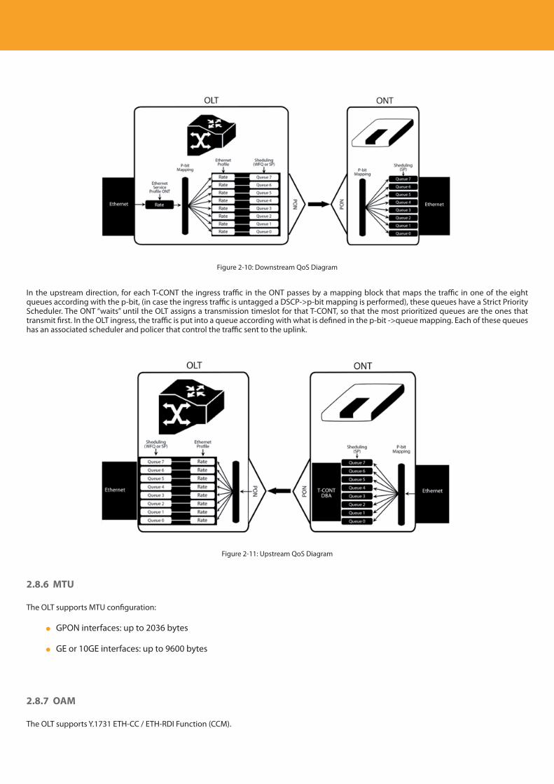
Descripción del producto
26
Figure 2-10: Downstream QoS Diagram
In the upstream direction, for each T-CONT the ingress traffic in the ONT passes by a mapping block that maps the traffic in one of the eight queues according with the p-bit, (in case the ingress traffic is untagged a DSCP->p-bit mapping is performed), these queues have a Strict Priority Scheduler. The ONT “waits” until the OLT assigns a transmission timeslot for that T-CONT, so that the most prioritized queues are the ones that transmit first. In the OLT ingress, the traffic is put into a queue according with what is defined in the p-bit ->queue mapping. Each of these queues has an associated scheduler and policer that control the traffic sent to the uplink.
Figure 2-11: Upstream QoS Diagram
2.8.6 MTU
The OLT supports MTU configuration:
GPON interfaces: up to 2036 bytes
GE or 10GE interfaces: up to 9600 bytes
2.8.7 OAM
The OLT supports Y.1731 ETH-CC / ETH-RDI Function (CCM).
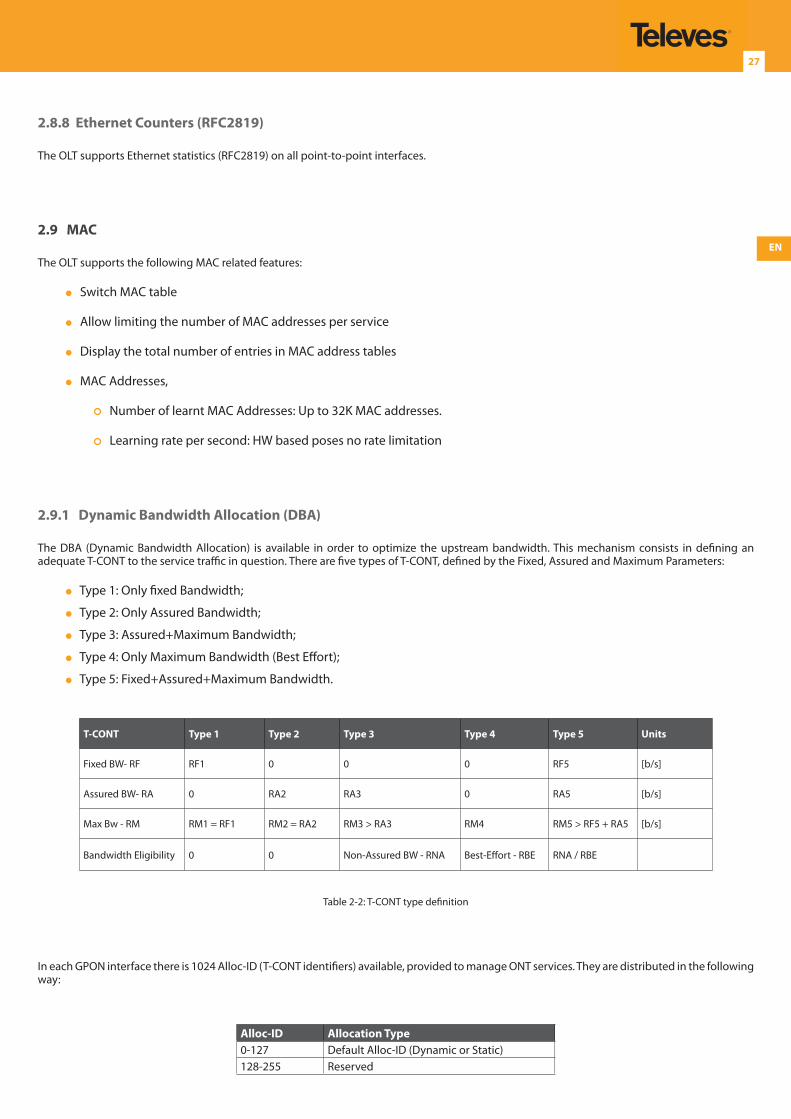
EN
27
2.8.8 Ethernet Counters (RFC2819)
The OLT supports Ethernet statistics (RFC2819) on all point-to-point interfaces.
2.9 MAC
The OLT supports the following MAC related features:
Switch MAC table
Allow limiting the number of MAC addresses per service
Display the total number of entries in MAC address tables
MAC Addresses,
Number of learnt MAC Addresses: Up to 32K MAC addresses.
Learning rate per second: HW based poses no rate limitation
2.9.1 Dynamic Bandwidth Allocation (DBA)
The DBA (Dynamic Bandwidth Allocation) is available in order to optimize the upstream bandwidth. This mechanism consists in defining an adequate T-CONT to the service traffic in question. There are five types of T-CONT, defined by the Fixed, Assured and Maximum Parameters:
Type 1: Only fixed Bandwidth;
Type 2: Only Assured Bandwidth;
Type 3: Assured+Maximum Bandwidth;
Type 4: Only Maximum Bandwidth (Best Effort);
Type 5: Fixed+Assured+Maximum Bandwidth.
T-CONT Type 1 Type 2 Type 3 Type 4 Type 5 Units
Fixed BW- RF RF1 0 0 0 RF5 [b/s]
Assured BW- RA 0 RA2 RA3 0 RA5 [b/s]
Max Bw - RM RM1 = RF1 RM2 = RA2 RM3 > RA3 RM4 RM5 > RF5 + RA5 [b/s]
Bandwidth Eligibility 0 0 Non-Assured BW - RNA Best-Effort - RBE RNA / RBE
Table 2-2: T-CONT type definition
In each GPON interface there is 1024 Alloc-ID (T-CONT identifiers) available, provided to manage ONT services. They are distributed in the following way:
Alloc-ID Allocation Type0-127 Default Alloc-ID (Dynamic or Static)128-255 Reserved
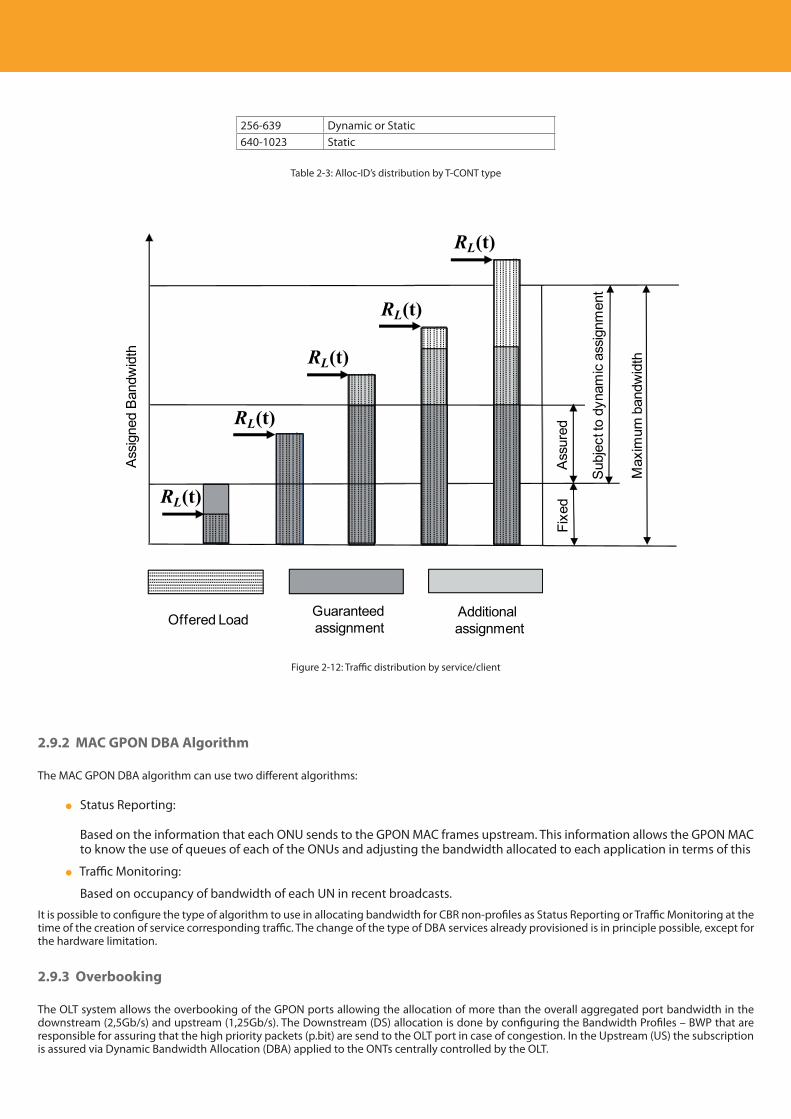
Descripción del producto
28
256-639 Dynamic or Static640-1023 Static
Table 2-3: Alloc-ID’s distribution by T-CONT type
Offered Load Guaranteed assignment
Additional assignment
Ass
igne
d B
andw
idth
Fixe
dA
ssur
ed
Sub
ject
to d
ynam
ic a
ssig
nmen
t
Max
imum
ban
dwid
th
RL(t)
RL(t)
RL(t)
RL(t)
RL(t)
Figure 2-12: Traffic distribution by service/client
2.9.2 MAC GPON DBA Algorithm
The MAC GPON DBA algorithm can use two different algorithms:
Status Reporting:
Based on the information that each ONU sends to the GPON MAC frames upstream. This information allows the GPON MAC to know the use of queues of each of the ONUs and adjusting the bandwidth allocated to each application in terms of this
Traffic Monitoring:
Based on occupancy of bandwidth of each UN in recent broadcasts.
It is possible to configure the type of algorithm to use in allocating bandwidth for CBR non-profiles as Status Reporting or Traffic Monitoring at the time of the creation of service corresponding traffic. The change of the type of DBA services already provisioned is in principle possible, except for the hardware limitation.
2.9.3 Overbooking
The OLT system allows the overbooking of the GPON ports allowing the allocation of more than the overall aggregated port bandwidth in the downstream (2,5Gb/s) and upstream (1,25Gb/s). The Downstream (DS) allocation is done by configuring the Bandwidth Profiles – BWP that are responsible for assuring that the high priority packets (p.bit) are send to the OLT port in case of congestion. In the Upstream (US) the subscription is assured via Dynamic Bandwidth Allocation (DBA) applied to the ONTs centrally controlled by the OLT.
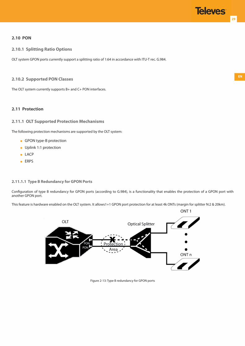
EN
29
2.10 PON
2.10.1 Splitting Ratio Options
OLT system GPON ports currently support a splitting ratio of 1:64 in accordance with ITU-T rec. G.984.
2.10.2 Supported PON Classes
The OLT system currently supports B+ and C+ PON interfaces.
2.11 Protection
2.11.1 OLT Supported Protection Mechanisms
The following protection mechanisms are supported by the OLT system:
GPON type-B protection
Uplink 1:1 protection
LACP
ERPS
2.11.1.1 Type B Redundancy for GPON Ports
Configuration of type B redundancy for GPON ports (according to G.984), is a functionality that enables the protection of a GPON port with another GPON port.
This feature is hardware enabled on the OLT system. It allows1+1 GPON port protection for at least 4k ONTs (margin for splitter N:2 & 20km).
Figure 2-13: Type B redundancy for GPON ports
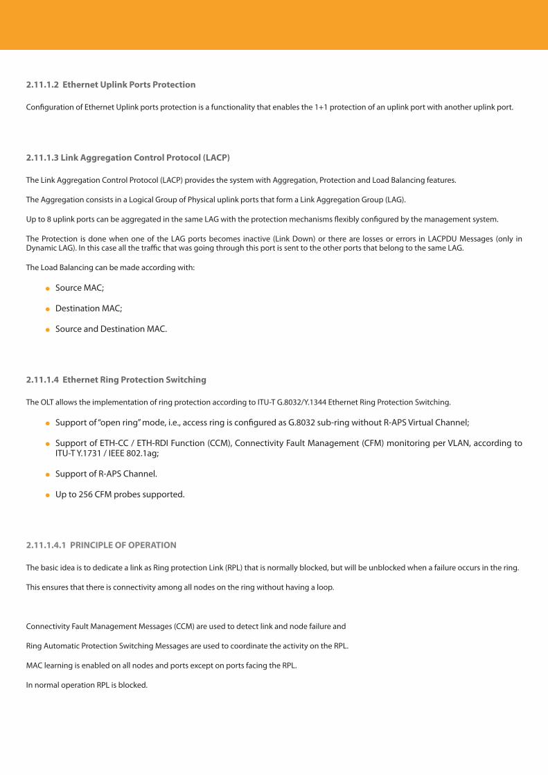
Descripción del producto
30
2.11.1.2 Ethernet Uplink Ports Protection
Configuration of Ethernet Uplink ports protection is a functionality that enables the 1+1 protection of an uplink port with another uplink port.
2.11.1.3 Link Aggregation Control Protocol (LACP)
The Link Aggregation Control Protocol (LACP) provides the system with Aggregation, Protection and Load Balancing features.
The Aggregation consists in a Logical Group of Physical uplink ports that form a Link Aggregation Group (LAG).
Up to 8 uplink ports can be aggregated in the same LAG with the protection mechanisms flexibly configured by the management system.
The Protection is done when one of the LAG ports becomes inactive (Link Down) or there are losses or errors in LACPDU Messages (only in Dynamic LAG). In this case all the traffic that was going through this port is sent to the other ports that belong to the same LAG.
The Load Balancing can be made according with:
Source MAC;
Destination MAC;
Source and Destination MAC.
2.11.1.4 Ethernet Ring Protection Switching
The OLT allows the implementation of ring protection according to ITU-T G.8032/Y.1344 Ethernet Ring Protection Switching.
Support of “open ring” mode, i.e., access ring is configured as G.8032 sub-ring without R-APS Virtual Channel;
Support of ETH-CC / ETH-RDI Function (CCM), Connectivity Fault Management (CFM) monitoring per VLAN, according to ITU-T Y.1731 / IEEE 802.1ag;
Support of R-APS Channel.
Up to 256 CFM probes supported.
2.11.1.4.1 PRINCIPLE OF OPERATION
The basic idea is to dedicate a link as Ring protection Link (RPL) that is normally blocked, but will be unblocked when a failure occurs in the ring.
This ensures that there is connectivity among all nodes on the ring without having a loop.
Connectivity Fault Management Messages (CCM) are used to detect link and node failure and
Ring Automatic Protection Switching Messages are used to coordinate the activity on the RPL.
MAC learning is enabled on all nodes and ports except on ports facing the RPL.
In normal operation RPL is blocked.
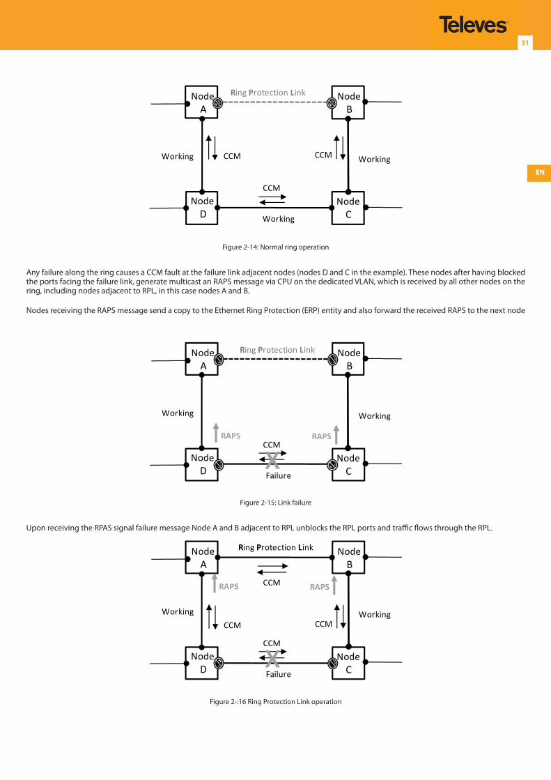
EN
31
NodeA
NodeB
NodeD
NodeCWorking
WorkingWorking
Ring Protection Link
CCM
CCM
CCM
Figure 2-14: Normal ring operation
Any failure along the ring causes a CCM fault at the failure link adjacent nodes (nodes D and C in the example). These nodes after having blocked the ports facing the failure link, generate multicast an RAPS message via CPU on the dedicated VLAN, which is received by all other nodes on the ring, including nodes adjacent to RPL, in this case nodes A and B.
Nodes receiving the RAPS message send a copy to the Ethernet Ring Protection (ERP) entity and also forward the received RAPS to the next node
NodeA
NodeB
NodeD
NodeCFailure
WorkingWorking
CCMxRAPS RAPS
Ring Protection Link
Figure 2-15: Link failure
Upon receiving the RPAS signal failure message Node A and B adjacent to RPL unblocks the RPL ports and traffic flows through the RPL.
NodeA
NodeB
NodeD
NodeCFailure
WorkingWorking
CCM
CCM
CCM
CCM
x
RAPS RAPS
Ring Protection Link
Figure 2-:16 Ring Protection Link operation
Descripción del producto
32
2.11.1.4.2 ERP TIMERS
WTR timer
May be configured by the operator in 1 minute steps between 1 and 12 minutes, the default value being 5 minutes.
WTB timer
Is defined to be 5 seconds longer than the guard timer.
Guard Timer
The period of the guard timer may be configured by the operator in 10 ms steps between 10 ms and 2 seconds, with a default value of 500 ms.
Hold off timer
The suggested range of the hold off timer is 0 to 10 seconds in steps of 100 ms with an accuracy of ±5 ms. the default value for hold off timer is 0 seconds.
2.12 Synchronization
The OLT equipment implements SyncE and IEEE 1588v2/PTP synchronization schemes. Timing over Packet (ToP) enables transfer of timing over an asynchronous network. The SyncE feature requires that each network element along the synchronization path need to support SyncE.
2.12.1 Hybrid Synchronization with the OLT Equipment Family
Within the OLT equipment, SyncE may co-exist with 1588 (PTP) in a hybrid configuration mode. The hybrid mode uses the clock derived from 1588 (PTP) to drive the system clock.
2.12.2 Ethernet Synchronization Messaging Channel (ESMC)
In order to maintain a logical communication channel in synchronous network connections, Ethernet relies on a channel called Ethernet Synchronization Messaging Channel (ESMC) based on IEEE 802.3 Organization Specific Slow Protocol standards. ESMC relays the SSM code that represents the quality level of the Ethernet Equipment Clock (EEC) in a physical layer.
To enable communications between various nodes, the OLT equipment (SyncE mode) provides an Ethernet Synchronization Status Messaging (ESMC, G.8264) channel, similar to SDH Synchronization Status Messaging (SSM) bytes that allow nodes to deliver their Synchronization Status to downstream nodes. The downstream nodes use this information to select between various references or possibly switch to their internal clock in case of failure on reference clocks.
2.12.3 Synchronous Ethernet (SyncE)
SyncE is defined by the ITU-T standards G.8261, G.8262, G.8264, and G.781. Frequency distribution protocol based Ethernet physical layer of Ethernet. The purpose of SyncE is to distribute frequency information through an Ethernet device. In this context “frequency” and “bit-rate” effectively have the same meaning, since SyncE attempts to determine frequency information from incoming bit streams. The basic operation of SyncE interfaces is deriving the frequency from the received bit stream and passing that information up to the system clock,
EN
33
2.12.3.1 Ethernet without SyncE (e.g. 1000Base-T)
Systems without SyncE have the following characteristics:
Rx clock extracted from line (line timed)
Tx clock generated from free-running XO
Clock within 100 ppm (125 MHz+/- 0.01 percent)
No relationship between Rx and Tx
Each Ethernet interface (uni-dir or bi-dir) has own independent timing
2.12.3.2 Ethernet with SyncE (e.g. 1000Base-T)
Systems with SyncE have the following characteristics:
Rx clock extracted from line & transferred to timing engine
Tx clock generated from the timing card
Clock within 4.6 ppm when free-running
Tx clock uses traceable to PRC/PRS
Note SyncE clock input may replace XO or may be in addition to normal XO input
2.12.4 IEEE 1588v2
IEEE1588v2 (also known as Precision Time Protocol, PTP) is a two-way precision protocol independent of the physical layer with time and frequency distribution protocol based on time-stamp information exchange to synchronize clocks over packet- based Ethernet networks. It synchronizes the local slave clock on each network device with a system Grandmaster clock and uses traffic time- stamping, with sub- nanoseconds granularity, to deliver the very high accuracies of synchronization needed to ensure the stability of base station frequency and handovers. Timestamps between master and slave devices are sent within specific PTP packets and in its basic form the protocol is administration- free.
The ITU-T defined profile of the IEEE 1588-2008 specification has been specifically optimized to support telecommunications applications such as wireless Mobile Backhaul, GPON and LTE.
The OLT Equipment supports IEEE 1588v2 as the following standard type devices:
Ordinary Clock (Can be a Master or Slave clock)
Boundary Clock (Acts as a Master and a Slave clock)
Transparent clock
Following elements are defined:
Grandmaster
A network device physically attached to the primary time source. All clocks are synchronized to the grandmaster clock.
Ordinary Clock
An ordinary clock is a 1588 clock with a single PTP port that can operate in one of the following modes:
PTP Master: Distributes timing information over the network to one or more slave clocks, thus allowing the slave to synchronize its clock to the master.
PTP Slave: Recovers the frequency and phase clock, from the timestamps sent by the Master.
Boundary Clock
The Boundary clock functions as both PTP master and slave. It acts as the slave to a Grand Master and derives the reference from the Grand Master. Boundary clock starts its own PTP session with a number of downstream slaves. The boundary clock mitigates the number of network hops and results in packet delay variations in the packet network between the Grand Master and Slave.
Descripción del producto
34
Transparent clock
A transparent clock is a device or a switch that calculates the time it requires to forward traffic and updates the PTP time correction field to account for the delay, making the device transparent in terms of time calculations.
2.12.4.1 Client/Server model
Master clock, slave clock (ordinary clock)
Intermediary nodes may or may not support IEEE1588 PTP (unlike SyncE)
On-path support mechanisms:
Boundary clock
t acts as a slave clock at port that connects to the grandmaster, and as a master to all other ports
t isolates the “downstream” clocks from any delays and jitter within the switch/routers
Transparent clock
It measures residence time of PTP events
2.12.5 SYNC-E and IEEE 1588v2/PTP at the OLT equipment
Network clocking is supported on the following ports:
1GbE,
10GbE.
2.12.5.1 Clock configurations supported by the OLT:
Different configurations are supported:
Clock Recovery: System clock is recovered from the clocking source (GbE, 10Gbe and 100Gbe).
Clock Recovery from External Interface: System clock is recovered from clocking source or a GPS interface.
Line to External: The clock received from an interface is forwarded to an external Synchronization Supply Unit (SSU).
The following sync. parameters are configurable in the OLT
Quality level Mode – Active or inactive
Reversibility level Mode– Active or inactive
Reversibility time – 0 to 3600 s
Holdover Message delay switching Message delay – 500 to 2000 ms
Switching Message delay – 180 to 500 s
Minimum Quality Before Squelch – Inactive, PRC G.811, SSU-A, SSU-B,SEC or DNU
Send value after Quality Unknown - PRC G.811, SSU-A, SSU-B,SEC or DNU
Number of external sync.- 2 IN and 2 OUT
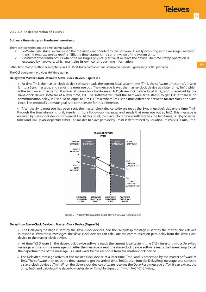
EN
35
2.12.5.2 Basic Operation of 1588V2
Software time-stamp vs. Hardware time-stamp
There are two techniques to time-stamp packets:1. Software time-stamp occurs when the messages are handled by the software. Usually occurring in the message’s receive/
transmit interrupt service routine (ISR), the time-stamp is the current value of the system time.2. Hardware time-stamp occurs when the messages physically arrive at or leave the device. The time-stamp operation is
executed by hardware, which maintains its own continuous time information.
Either time-stamp method is acceptable in IEEE 1588, but a hardware time-stamp can provide significantly better precision.
The OLT equipment provides HW time stamp.
Delay from Master-Clock Device to Slave-Clock Device, (Figure 2-)
At time Tm1, the master-clock device software reads the current local system time (Tm1, the software timestamp), inserts it into a Sync message, and sends the message out. The message leaves the master-clock device at a later time, Tm1’, which is the hardware time-stamp. It arrives at slave-clock hardware at Ts1’ (slave-clock device local time), and is received by the slave-clock device software at a later time, Ts1. The software will read the hardware time-stamp to get Ts1’. If there is no communication delay, Ts1’ should be equal to (Tm1’ + Tms), where Tms is the time difference between master clock and slave clock. The protocol’s ultimate goal is to compensate for this difference.
After the Sync message has been sent, the master-clock device software reads the Sync message’s departure time, Tm1’, through the time-stamping unit, inserts it into a Follow-up message, and sends that message out at Tm2. This message is received by slave clock device software at Ts2. At this point, the slave-clock device software has the two times, Ts1’ (Sync arrival time) and Tm1‘ (Sync departure time). The master-to-slave path delay, Tmsd, is determined by Equation Tmsd=(Ts1´+Tms)-Tm1´
Figure 2-17: Delay from Master-Clock Device to Slave-Clock Device
Delay from Slave-Clock Device to Master-Clock Device (Figure 2-)
The DelayReq message is sent by the slave-clock devices, and the DelayResp message is sent by the master-clock device in response. With these messages, the slave-clock devices can calculate the communication path delay from the slave-clock device to the master-clock device.
At time Ts3 (Figure 3), the slave-clock device software reads the current local system time (Ts3), inserts it into a DelayReq message, and sends the message out. After the message is sent, the slave-clock device software reads the time-stamp to get the departure time of the message, Ts3’, and waits for the response from the master-clock device.
The DelayReq message arrives at the master-clock device at a later time, Tm3’, and is processed by the master software at Tm3. The software then reads the time-stamp to get the arrival time, Tm3’, puts it into the DelayResp message, and sends to a slave-clock device at Tm4. When the slave-clock device software receives the DelayResp message at Ts4, it can extract the time, Tm3’, and calculate the slave-to-master delay, Tsmd, by Equation Tsmd=Tm3´-(Ts3´+Tms).
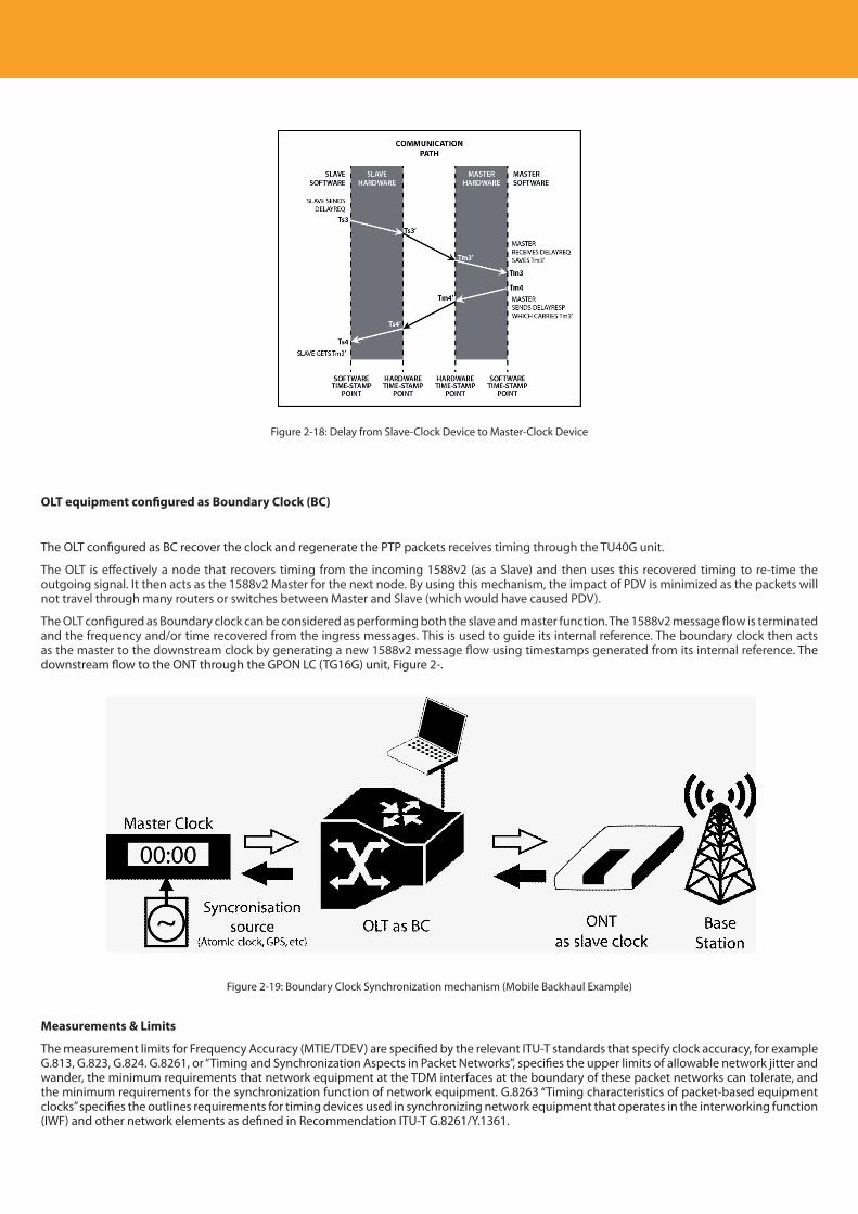
Descripción del producto
36
Figure 2-18: Delay from Slave-Clock Device to Master-Clock Device
OLT equipment configured as Boundary Clock (BC)
The OLT configured as BC recover the clock and regenerate the PTP packets receives timing through the TU40G unit.
The OLT is effectively a node that recovers timing from the incoming 1588v2 (as a Slave) and then uses this recovered timing to re-time the outgoing signal. It then acts as the 1588v2 Master for the next node. By using this mechanism, the impact of PDV is minimized as the packets will not travel through many routers or switches between Master and Slave (which would have caused PDV).
The OLT configured as Boundary clock can be considered as performing both the slave and master function. The 1588v2 message flow is terminated and the frequency and/or time recovered from the ingress messages. This is used to guide its internal reference. The boundary clock then acts as the master to the downstream clock by generating a new 1588v2 message flow using timestamps generated from its internal reference. The downstream flow to the ONT through the GPON LC (TG16G) unit, Figure 2-.
Figure 2-19: Boundary Clock Synchronization mechanism (Mobile Backhaul Example)
Measurements & Limits
The measurement limits for Frequency Accuracy (MTIE/TDEV) are specified by the relevant ITU-T standards that specify clock accuracy, for example G.813, G.823, G.824. G.8261, or “Timing and Synchronization Aspects in Packet Networks”, specifies the upper limits of allowable network jitter and wander, the minimum requirements that network equipment at the TDM interfaces at the boundary of these packet networks can tolerate, and the minimum requirements for the synchronization function of network equipment. G.8263 “Timing characteristics of packet-based equipment clocks” specifies the outlines requirements for timing devices used in synchronizing network equipment that operates in the interworking function (IWF) and other network elements as defined in Recommendation ITU-T G.8261/Y.1361.
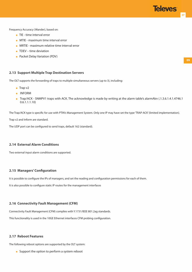
EN
37
Frequency Accuracy (Wander), based on:
TIE - time interval error
MTIE - maximum time interval error
MRTIE - maximum relative time interval error
TDEV – time deviation
Packet Delay Variation (PDV)
2.13 Support Multiple Trap Destination Servers
The OLT supports the forwarding of traps to multiple simultaneous servers (up to 3), including:
Trap v2
INFORM
Trap/ACK - SNMPV1 traps with ACK. The acknowledge is made by writing at the alarm table’s alarmAkn (.1.3.6.1.4.1.4746.10.6.1.1.1.10)
The Trap/ACK type is specific for use with PTIN’s Management System. Only one IP may have set the type ‘TRAP-ACK’ (limited implementation).
Trap v2 and Inform are standard.
The UDP port can be configured to send traps, default 162 (standard).
2.14 External Alarm Conditions
Two external input alarm conditions are supported.
2.15 Managers’ Configuration
It is possible to configure the IPs of managers, and set the reading and configuration permissions for each of them.
It is also possible to configure static IP routes for the management interfaces
2.16 Connectivity Fault Management (CFM)
Connectivity Fault Management (CFM) complies with Y.1731/IEEE 801.2ag standards.
This functionality is used in the 10GE Ethernet interfaces CFM probing configuration.
2.17 Reboot Features
The following reboot options are supported by the OLT system:
Support the option to perform a system reboot
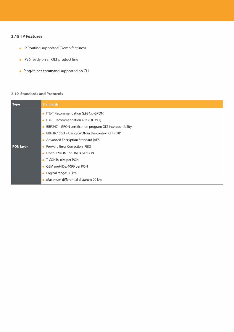
Descripción del producto
38
2.18 IP Features
IP Routing supported (Demo features)
IPv6 ready on all OLT product line
Ping/telnet command supported on CLI
2.19 Standards and Protocols
Type Standards
PON layer
ITU-T Recommendation G.984.x (GPON)
ITU-T Recommendation G.988 (OMCI)
BBF.247 – GPON certification program OLT interoperability
BBF TR.156i3 – Using GPON in the context of TR.101
Advanced Encryption Standard (AES)
Forward Error Correction (FEC)
Up to 128 ONT or ONUs per PON
T-CONTs: 896 per PON
GEM port-IDs: 4096 per PON
Logical range: 60 km
Maximum differential distance: 20 km
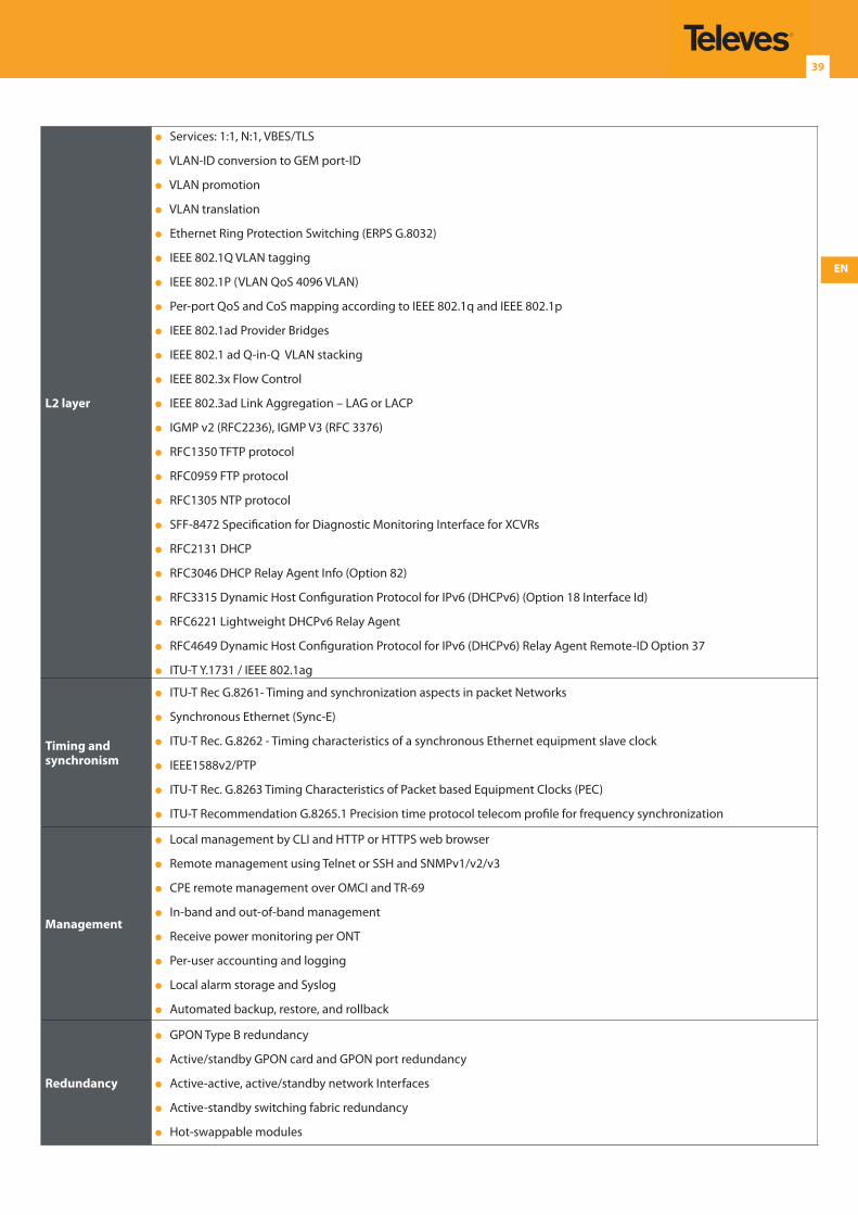
EN
39
L2 layer
Services: 1:1, N:1, VBES/TLS
VLAN-ID conversion to GEM port-ID
VLAN promotion
VLAN translation
Ethernet Ring Protection Switching (ERPS G.8032)
IEEE 802.1Q VLAN tagging
IEEE 802.1P (VLAN QoS 4096 VLAN)
Per-port QoS and CoS mapping according to IEEE 802.1q and IEEE 802.1p
IEEE 802.1ad Provider Bridges
IEEE 802.1 ad Q-in-Q VLAN stacking
IEEE 802.3x Flow Control
IEEE 802.3ad Link Aggregation – LAG or LACP
IGMP v2 (RFC2236), IGMP V3 (RFC 3376)
RFC1350 TFTP protocol
RFC0959 FTP protocol
RFC1305 NTP protocol
SFF-8472 Specification for Diagnostic Monitoring Interface for XCVRs
RFC2131 DHCP
RFC3046 DHCP Relay Agent Info (Option 82)
RFC3315 Dynamic Host Configuration Protocol for IPv6 (DHCPv6) (Option 18 Interface Id)
RFC6221 Lightweight DHCPv6 Relay Agent
RFC4649 Dynamic Host Configuration Protocol for IPv6 (DHCPv6) Relay Agent Remote-ID Option 37
ITU-T Y.1731 / IEEE 802.1ag
Timing and synchronism
ITU-T Rec G.8261- Timing and synchronization aspects in packet Networks
Synchronous Ethernet (Sync-E)
ITU-T Rec. G.8262 - Timing characteristics of a synchronous Ethernet equipment slave clock
IEEE1588v2/PTP
ITU-T Rec. G.8263 Timing Characteristics of Packet based Equipment Clocks (PEC)
ITU-T Recommendation G.8265.1 Precision time protocol telecom profile for frequency synchronization
Management
Local management by CLI and HTTP or HTTPS web browser
Remote management using Telnet or SSH and SNMPv1/v2/v3
CPE remote management over OMCI and TR-69
In-band and out-of-band management
Receive power monitoring per ONT
Per-user accounting and logging
Local alarm storage and Syslog
Automated backup, restore, and rollback
Redundancy
GPON Type B redundancy
Active/standby GPON card and GPON port redundancy
Active-active, active/standby network Interfaces
Active-standby switching fabric redundancy
Hot-swappable modules
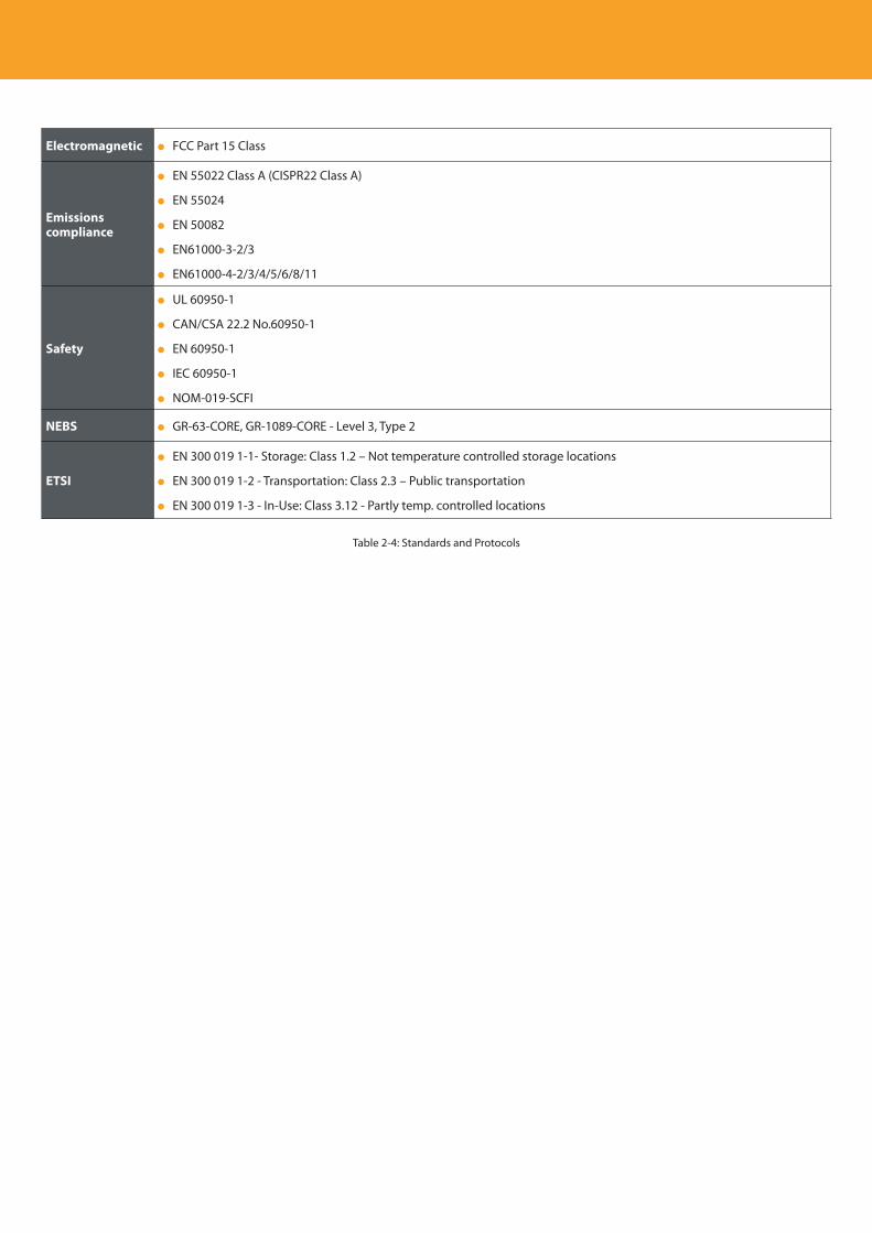
Descripción del producto
40
Electromagnetic FCC Part 15 Class
Emissions compliance
EN 55022 Class A (CISPR22 Class A)
EN 55024
EN 50082
EN61000-3-2/3
EN61000-4-2/3/4/5/6/8/11
Safety
UL 60950-1
CAN/CSA 22.2 No.60950-1
EN 60950-1
IEC 60950-1
NOM-019-SCFI
NEBS GR-63-CORE, GR-1089-CORE - Level 3, Type 2
ETSI
EN 300 019 1-1- Storage: Class 1.2 – Not temperature controlled storage locations
EN 300 019 1-2 - Transportation: Class 2.3 – Public transportation
EN 300 019 1-3 - In-Use: Class 3.12 - Partly temp. controlled locations
Table 2-4: Standards and Protocols
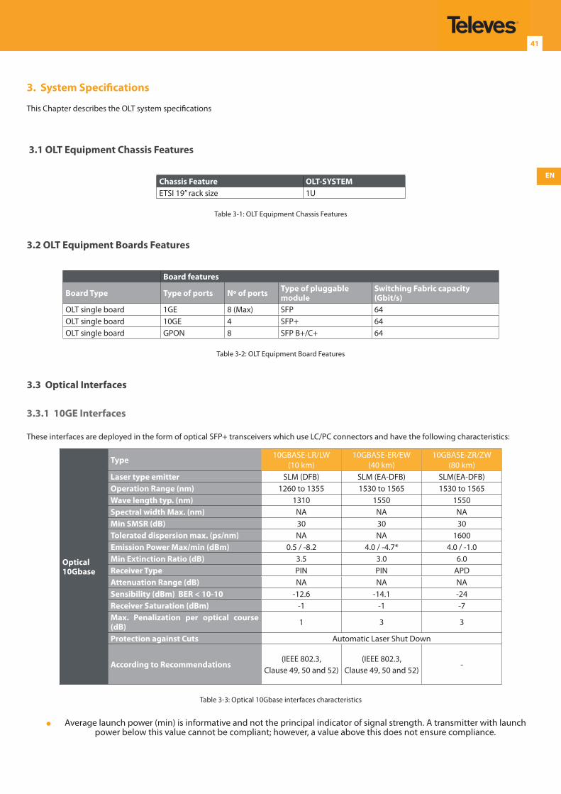
EN
41
3. System Specifications
This Chapter describes the OLT system specifications
3.1 OLT Equipment Chassis Features
Chassis Feature OLT-SYSTEMETSI 19’’ rack size 1U
Table 3-1: OLT Equipment Chassis Features
3.2 OLT Equipment Boards Features
Board features
Board Type Type of ports Nº of ports Type of pluggable module
Switching Fabric capacity (Gbit/s)
OLT single board 1GE 8 (Max) SFP 64OLT single board 10GE 4 SFP+ 64OLT single board GPON 8 SFP B+/C+ 64
Table 3-2: OLT Equipment Board Features
3.3 Optical Interfaces
3.3.1 10GE Interfaces
These interfaces are deployed in the form of optical SFP+ transceivers which use LC/PC connectors and have the following characteristics:
Optical 10Gbase
Type 10GBASE-LR/LW(10 km)
10GBASE-ER/EW(40 km)
10GBASE-ZR/ZW(80 km)
Laser type emitter SLM (DFB) SLM (EA-DFB) SLM(EA-DFB)Operation Range (nm) 1260 to 1355 1530 to 1565 1530 to 1565Wave length typ. (nm) 1310 1550 1550Spectral width Max. (nm) NA NA NAMin SMSR (dB) 30 30 30Tolerated dispersion max. (ps/nm) NA NA 1600Emission Power Max/min (dBm) 0.5 / -8.2 4.0 / -4.7* 4.0 / -1.0Min Extinction Ratio (dB) 3.5 3.0 6.0Receiver Type PIN PIN APDAttenuation Range (dB) NA NA NASensibility (dBm) BER < 10-10 -12.6 -14.1 -24Receiver Saturation (dBm) -1 -1 -7Max. Penalization per optical course (dB) 1 3 3
Protection against Cuts Automatic Laser Shut Down
According to Recommendations(IEEE 802.3,
Clause 49, 50 and 52)(IEEE 802.3,
Clause 49, 50 and 52)-
Table 3-3: Optical 10Gbase interfaces characteristics
Average launch power (min) is informative and not the principal indicator of signal strength. A transmitter with launch power below this value cannot be compliant; however, a value above this does not ensure compliance.
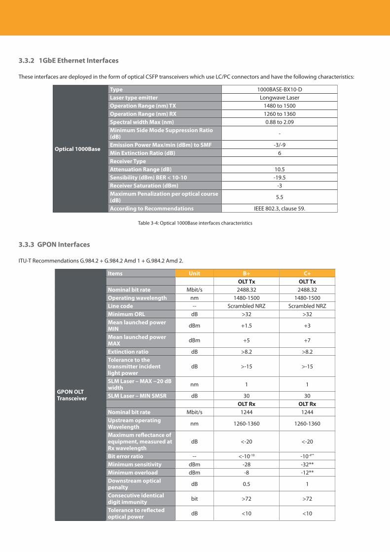
Descripción del producto
42
3.3.2 1GbE Ethernet Interfaces
These interfaces are deployed in the form of optical CSFP transceivers which use LC/PC connectors and have the following characteristics:
Optical 1000Base
Type 1000BASE-BX10-DLaser type emitter Longwave LaserOperation Range (nm) TX 1480 to 1500Operation Range (nm) RX 1260 to 1360Spectral width Max (nm) 0.88 to 2.09Minimum Side Mode Suppression Ratio (dB) -
Emission Power Max/min (dBm) to SMF -3/-9Min Extinction Ratio (dB) 6Receiver TypeAttenuation Range (dB) 10.5Sensibility (dBm) BER < 10-10 -19.5Receiver Saturation (dBm) -3Maximum Penalization per optical course (dB) 5.5
According to Recommendations IEEE 802.3, clause 59.
Table 3-4: Optical 1000Base interfaces characteristics
3.3.3 GPON Interfaces
ITU-T Recommendations G.984.2 + G.984.2 Amd 1 + G.984.2 Amd 2.
GPON OLT Transceiver
Items Unit B+ C+OLT Tx OLT Tx
Nominal bit rate Mbit/s 2488.32 2488.32Operating wavelength nm 1480-1500 1480-1500Line code -- Scrambled NRZ Scrambled NRZMinimum ORL dB >32 >32Mean launched power MIN dBm +1.5 +3
Mean launched power MAX dBm +5 +7
Extinction ratio dB >8.2 >8.2Tolerance to the transmitter incident light power
dB >-15 >-15
SLM Laser – MAX −20 dB width nm 1 1
SLM Laser – MIN SMSR dB 30 30OLT Rx OLT Rx
Nominal bit rate Mbit/s 1244 1244Upstream operating Wavelength nm 1260-1360 1260-1360
Maximum reflectance of equipment, measured at Rx wavelength
dB <-20 <-20
Bit error ratio -- <-10-10 -10-4**
Minimum sensitivity dBm -28 -32**Minimum overload dBm -8 -12**Downstream optical penalty dB 0.5 1
Consecutive identical digit immunity bit >72 >72
Tolerance to reflected optical power dB <10 <10
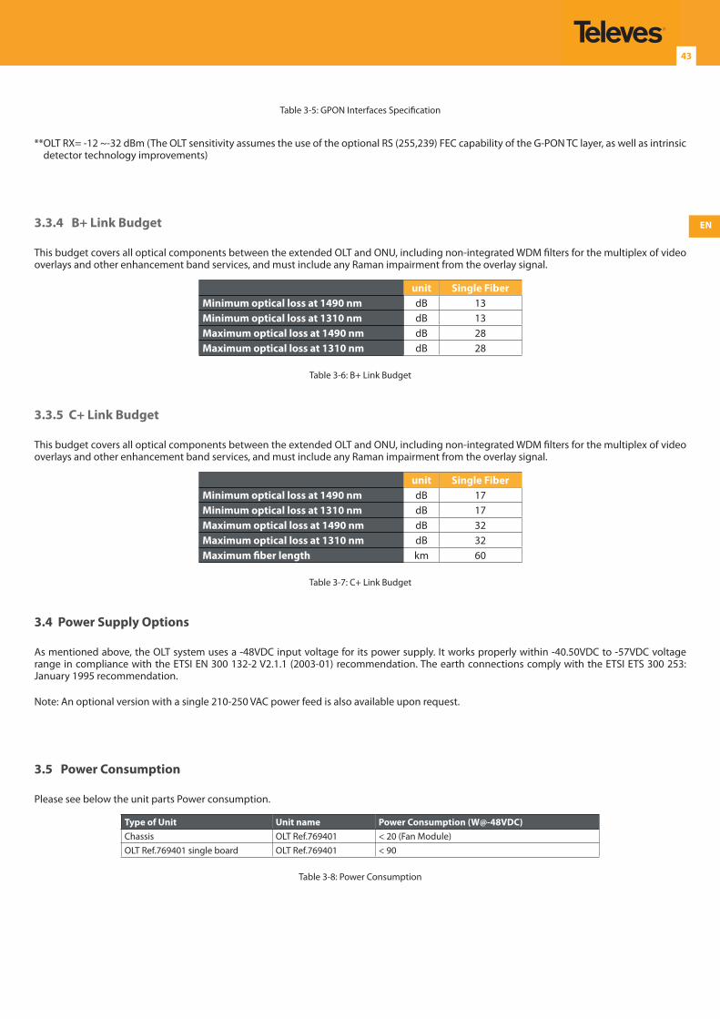
EN
43
Table 3-5: GPON Interfaces Specification
** OLT RX= -12 ~-32 dBm (The OLT sensitivity assumes the use of the optional RS (255,239) FEC capability of the G-PON TC layer, as well as intrinsic detector technology improvements)
3.3.4 B+ Link Budget
This budget covers all optical components between the extended OLT and ONU, including non-integrated WDM filters for the multiplex of video overlays and other enhancement band services, and must include any Raman impairment from the overlay signal.
unit Single FiberMinimum optical loss at 1490 nm dB 13Minimum optical loss at 1310 nm dB 13Maximum optical loss at 1490 nm dB 28Maximum optical loss at 1310 nm dB 28
Table 3-6: B+ Link Budget
3.3.5 C+ Link Budget
This budget covers all optical components between the extended OLT and ONU, including non-integrated WDM filters for the multiplex of video overlays and other enhancement band services, and must include any Raman impairment from the overlay signal.
unit Single FiberMinimum optical loss at 1490 nm dB 17Minimum optical loss at 1310 nm dB 17Maximum optical loss at 1490 nm dB 32Maximum optical loss at 1310 nm dB 32Maximum fiber length km 60
Table 3-7: C+ Link Budget
3.4 Power Supply Options
As mentioned above, the OLT system uses a -48VDC input voltage for its power supply. It works properly within -40.50VDC to -57VDC voltage range in compliance with the ETSI EN 300 132-2 V2.1.1 (2003-01) recommendation. The earth connections comply with the ETSI ETS 300 253: January 1995 recommendation.
Note: An optional version with a single 210-250 VAC power feed is also available upon request.
3.5 Power Consumption
Please see below the unit parts Power consumption.
Type of Unit Unit name Power Consumption (W@-48VDC)Chassis OLT Ref.769401 < 20 (Fan Module)OLT Ref.769401 single board OLT Ref.769401 < 90
Table 3-8: Power Consumption
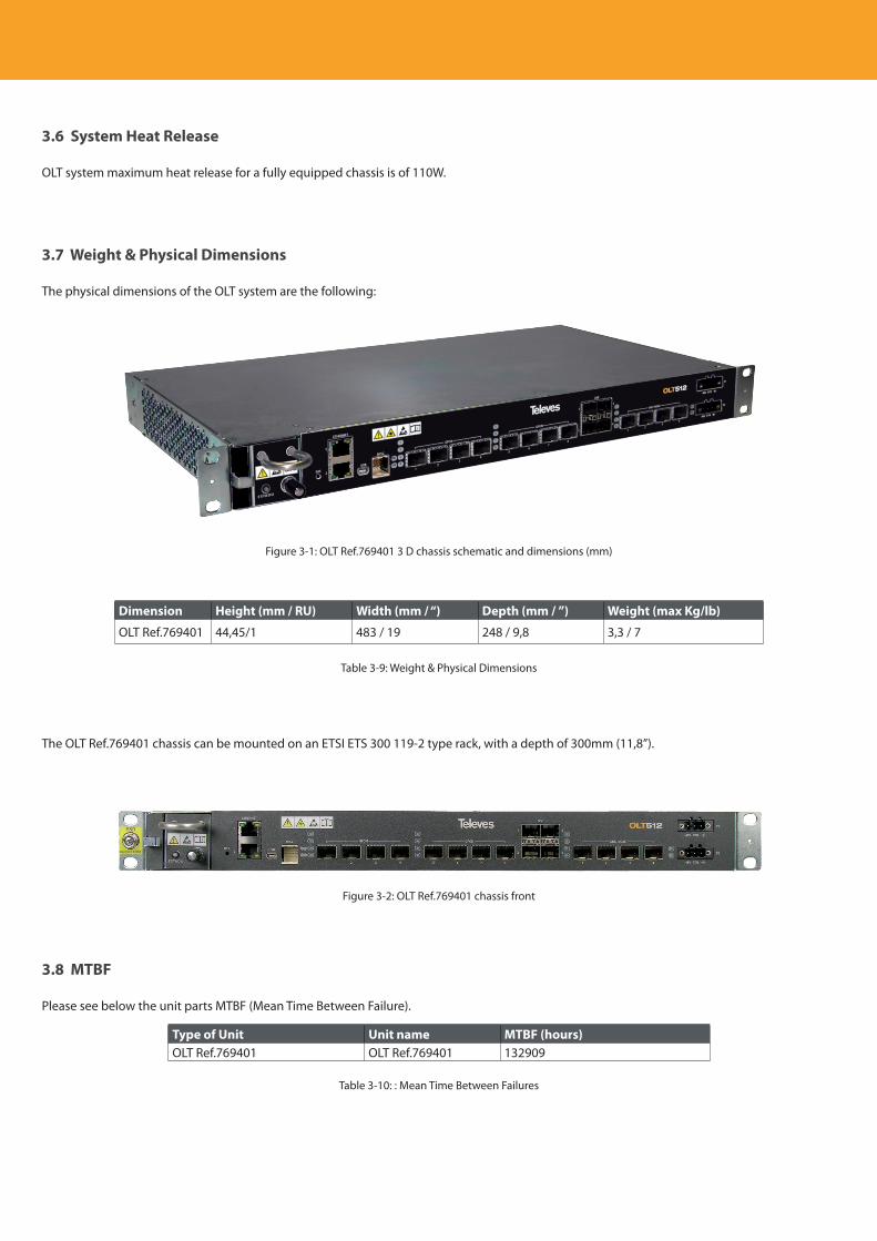
Descripción del producto
44
3.6 System Heat Release
OLT system maximum heat release for a fully equipped chassis is of 110W.
3.7 Weight & Physical Dimensions
The physical dimensions of the OLT system are the following:
Figure 3-1: OLT Ref.769401 3 D chassis schematic and dimensions (mm)
Dimension Height (mm / RU) Width (mm / “) Depth (mm / ”) Weight (max Kg/lb)
OLT Ref.769401 44,45/1 483 / 19 248 / 9,8 3,3 / 7
Table 3-9: Weight & Physical Dimensions
The OLT Ref.769401 chassis can be mounted on an ETSI ETS 300 119-2 type rack, with a depth of 300mm (11,8”).
Figure 3-2: OLT Ref.769401 chassis front
3.8 MTBF
Please see below the unit parts MTBF (Mean Time Between Failure).
Type of Unit Unit name MTBF (hours)OLT Ref.769401 OLT Ref.769401 132909
Table 3-10: : Mean Time Between Failures
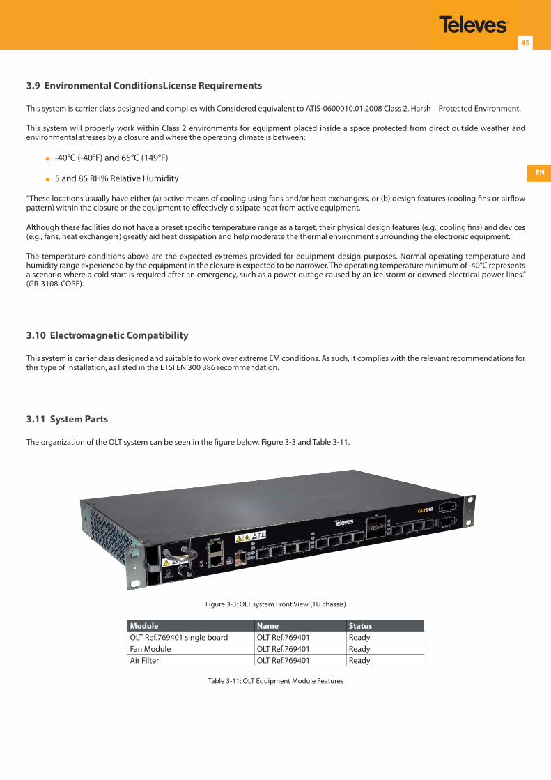
EN
45
3.9 Environmental ConditionsLicense Requirements
This system is carrier class designed and complies with Considered equivalent to ATIS-0600010.01.2008 Class 2, Harsh – Protected Environment.
This system will properly work within Class 2 environments for equipment placed inside a space protected from direct outside weather and environmental stresses by a closure and where the operating climate is between:
-40°C (-40°F) and 65°C (149°F)
5 and 85 RH% Relative Humidity
“These locations usually have either (a) active means of cooling using fans and/or heat exchangers, or (b) design features (cooling fins or airflow pattern) within the closure or the equipment to effectively dissipate heat from active equipment.
Although these facilities do not have a preset specific temperature range as a target, their physical design features (e.g., cooling fins) and devices (e.g., fans, heat exchangers) greatly aid heat dissipation and help moderate the thermal environment surrounding the electronic equipment.
The temperature conditions above are the expected extremes provided for equipment design purposes. Normal operating temperature and humidity range experienced by the equipment in the closure is expected to be narrower. The operating temperature minimum of -40°C represents a scenario where a cold start is required after an emergency, such as a power outage caused by an ice storm or downed electrical power lines.” (GR-3108-CORE).
3.10 Electromagnetic Compatibility
This system is carrier class designed and suitable to work over extreme EM conditions. As such, it complies with the relevant recommendations for this type of installation, as listed in the ETSI EN 300 386 recommendation.
3.11 System Parts
The organization of the OLT system can be seen in the figure below, Figure 3-3 and Table 3-11.
Figure 3-3: OLT system Front View (1U chassis)
Module Name StatusOLT Ref.769401 single board OLT Ref.769401 ReadyFan Module OLT Ref.769401 ReadyAir Filter OLT Ref.769401 Ready
Table 3-11: OLT Equipment Module Features
Descripción del producto
46
3.11.1 OLT Ref.769401 single board
This board integrates the OLT Ref.769401 switch fabric, uplink ports and GPON ports. It provides the Operation and Maintenance function of the system, and it also switches the client traffic between the client and the uplink interfaces.
OLT Ref.769401 single board has a 64 Gbps switching capacity and in addition has four 10GbE internal connections and one O&M for each of the uplink and client interfaces.
3.11.1.1 Interfaces
2x ETH management interfaces G1 and G2 (RJ45);
1xUSB debug port, exclusively for factory configuration
1x MISC (Alarms/conditions and ACK indicators) contacts
4 x 10GE uplink interfaces
SFP+ modules
4 x 1GbE uplink interfaces
SFP modules
8x GPON interfaces
SFP modules
3.11.1.2 LED Indicators
The board provides 2 LEDs, named PRC, ON, that must indicate
PRC: stands for the word «Processing» and defines the overall state of the board:
If Led is either OFF or steady GREEN the board has an internal hardware malfuction that does not allow the board to boot
If Led blinks GREEN 1 time per second the board is active;
If Led blinks GREEN 3 times per second the board is inactive;
ON: reflects the state of the -48VDC power supplies (A and B):
Steady green if rail A and B are OK;
Blinking GREEN/RED if rail A is NOT OK and rail B is OK;
Double GREEN/RED blinking if rail A is OK and rail B is NOT OK;
3.11.1.3 Interface Interconnection Cables
The equipment has two Ethernet (G1 and G2) management interfaces. For the G1 and G2 interfaces, UTP network cable category 5e or higher with RJ45 connectors should be used as interconnection cable. The expected range with this interconnection cable is 100m maximum.
For the MISC interface a coaxial Metral 2mm (FCI TM) plug is used.
The USB debug port is exclusively for factory configuration.

EN
47
4. Setup
This chapter describes the OLT system installation procedures.
4.1 Mechanical Packaging
Important!
When installing or servicing these GPON systems it is necessary to take into account the following aspects:
In a servicing system it is imperative that the access to any board or fan module, can be done without affecting the service supported by other units;
The grids that exist in the steel structures which are used for entry and exit of air, should not be clogged up with the penalty of affecting the correct functioning of the cooling system;
Once the connections and access to equipment interfaces are made, a distance of approximately 12cm in front of the structure must be reserved, to accommodate the wiring.
It is imperative to follow all ESD precautions described in ESD , when accessing to the OLT system or handling any system board or module.
It is imperative to disconnect all power source on the Disconnect Device before servicing the unit.
4.2 ESD Precautions
Important!When performing OLT system service actions, observe the following electrostatic discharge (ESD) precautions:
Wear an antistatic wrist strip at all times when handling any system part, board or module.
Before handling any system part, board or module, discharge any static electricity by touching a grounded surface.
Remove all plastic, vinyl, and foam material from the work area.
Do not remove a system board or module from its antistatic protective bag until you are ready to install it.
After removing a board or module from the system chassis, immediately place it in an antistatic bag or antistatic packaging.
Handle any system board only by its edges and avoid touching the components or circuitry.
Do not slide a system board or module over any surface.
Limit body movement (which builds up static electricity) during the removal and replacement of a system board or module.
4.3 OLT Ref.769401 System
The OLT Ref.769401 system uses 1U / 19” ETSI infrastructure. Please see Figure 4-1.
Figure 4-1: OLT Ref.769401 setup – Front view

Descripción del producto
48
4.3.1 Restricted Access Location
The OLT Ref.769401 unit is to be installed in a restricted access location.
4.4 Electrical Power Supply
The electrical connection for the OLT equipment is of redundant -48VDC.
4.4.1 Disconnect Device
A Disconnect Device must be installed close to unit chassis in order to allow disconnection of all power supply before servicing the unit.
In the case of installation in an ETSI rack, rack installed Power Box, provides disconnect device funcionality
Disconnect device circuit breaker should be rated 3A max.
4.4.2 Multiple Power Source
Power supply to the unit is provided by two 48 VN(egative) power supply source connection, source A and source B.
Important!All unit power supply must be disconnected at the disconnect device before servicing the unit.
4.4.3 Power Supply Connection Procedures
Important!When performing OLT system service actions, observe electrostatic discharge (ESD) precautions, ESDAll unit power supply must be disconnected at the disconnect device before servicing the unit.
4.4.4 Power Supply Cables Connection
In right side of the OLT front panel there are two tree input connectors for power supply connections P1 and P2, (see Figure 4-2):
Figure 4-2: OLT chassis redundant power supply input connectors
Step 1 Use the H03VV-F conducting electrical cables with eyelet terminals provided in the OLT mounting kit to connect the two redundant power supplies.
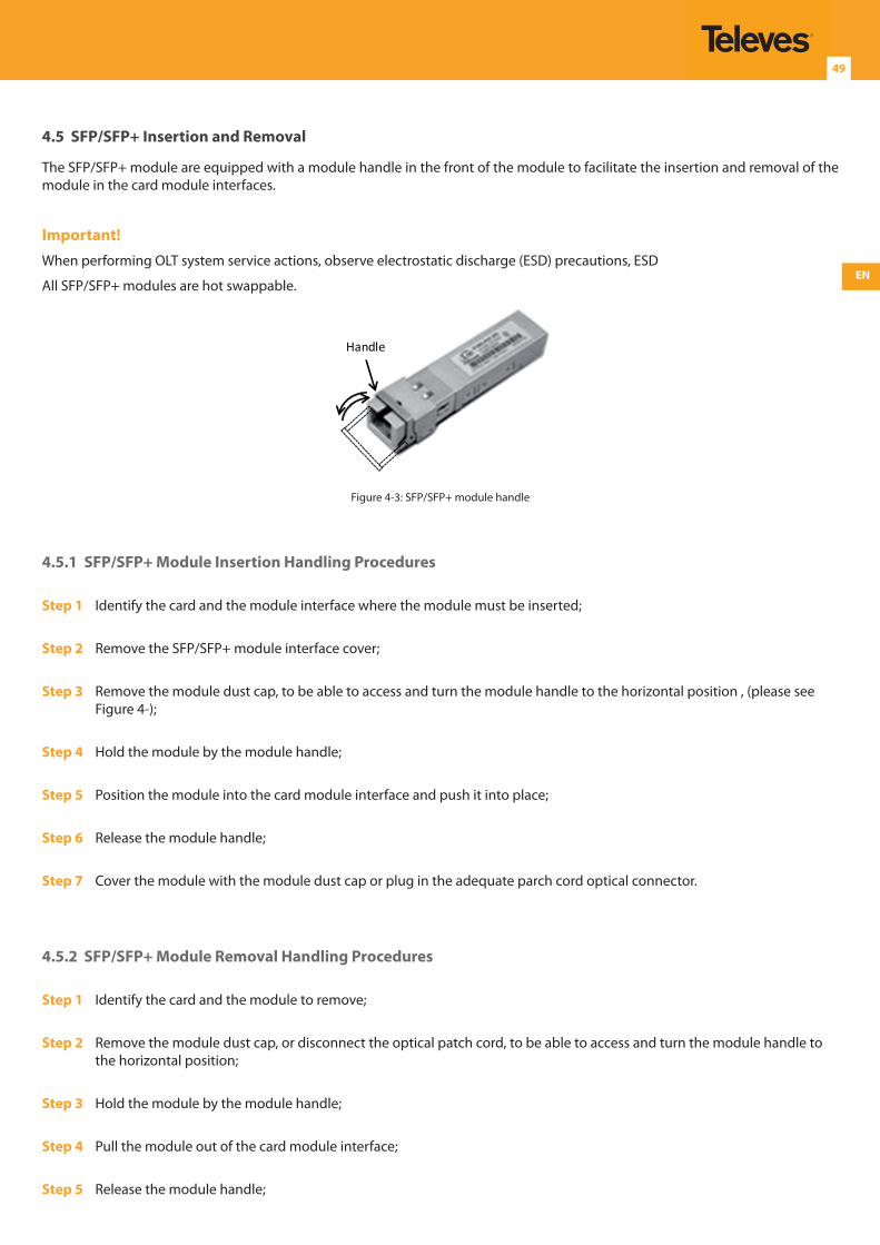
EN
49
4.5 SFP/SFP+ Insertion and Removal
The SFP/SFP+ module are equipped with a module handle in the front of the module to facilitate the insertion and removal of the module in the card module interfaces.
Important!When performing OLT system service actions, observe electrostatic discharge (ESD) precautions, ESD
All SFP/SFP+ modules are hot swappable.
Handle
Figure 4-3: SFP/SFP+ module handle
4.5.1 SFP/SFP+ Module Insertion Handling Procedures
Step 1 Identify the card and the module interface where the module must be inserted;
Step 2 Remove the SFP/SFP+ module interface cover;
Step 3 Remove the module dust cap, to be able to access and turn the module handle to the horizontal position , (please see Figure 4-);
Step 4 Hold the module by the module handle;
Step 5 Position the module into the card module interface and push it into place;
Step 6 Release the module handle;
Step 7 Cover the module with the module dust cap or plug in the adequate parch cord optical connector.
4.5.2 SFP/SFP+ Module Removal Handling Procedures
Step 1 Identify the card and the module to remove;
Step 2 Remove the module dust cap, or disconnect the optical patch cord, to be able to access and turn the module handle to the horizontal position;
Step 3 Hold the module by the module handle;
Step 4 Pull the module out of the card module interface;
Step 5 Release the module handle;
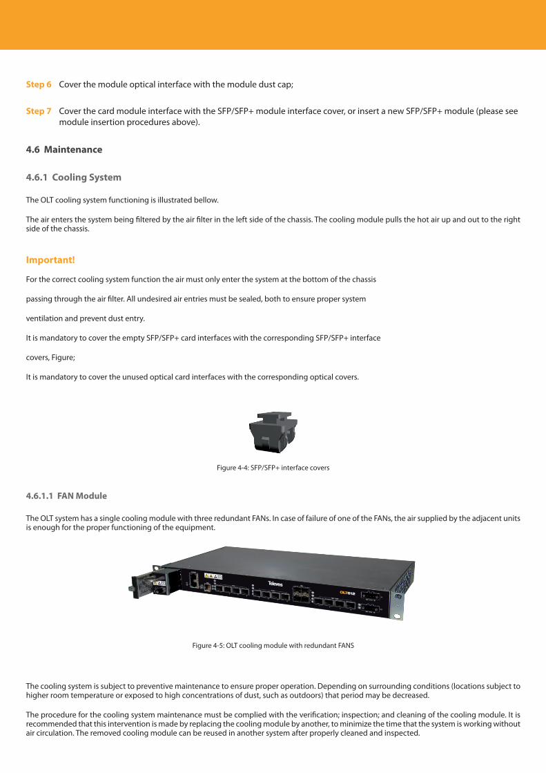
Descripción del producto
50
Step 6 Cover the module optical interface with the module dust cap;
Step 7 Cover the card module interface with the SFP/SFP+ module interface cover, or insert a new SFP/SFP+ module (please see module insertion procedures above).
4.6 Maintenance
4.6.1 Cooling System
The OLT cooling system functioning is illustrated bellow.
The air enters the system being filtered by the air filter in the left side of the chassis. The cooling module pulls the hot air up and out to the right side of the chassis.
Important!
For the correct cooling system function the air must only enter the system at the bottom of the chassis
passing through the air filter. All undesired air entries must be sealed, both to ensure proper system
ventilation and prevent dust entry.
It is mandatory to cover the empty SFP/SFP+ card interfaces with the corresponding SFP/SFP+ interface
covers, Figure;
It is mandatory to cover the unused optical card interfaces with the corresponding optical covers.
Figure 4-4: SFP/SFP+ interface covers
4.6.1.1 FAN Module
The OLT system has a single cooling module with three redundant FANs. In case of failure of one of the FANs, the air supplied by the adjacent units is enough for the proper functioning of the equipment.
Figure 4-5: OLT cooling module with redundant FANS
The cooling system is subject to preventive maintenance to ensure proper operation. Depending on surrounding conditions (locations subject to higher room temperature or exposed to high concentrations of dust, such as outdoors) that period may be decreased.
The procedure for the cooling system maintenance must be complied with the verification; inspection; and cleaning of the cooling module. It is recommended that this intervention is made by replacing the cooling module by another, to minimize the time that the system is working without air circulation. The removed cooling module can be reused in another system after properly cleaned and inspected.
EN
51
The FAN module can be replaced and is hot swappable. In order to replace the module, please refer to section FAN
4.6.1.1.1 LED Indicator
Each fan module has an LED, STATUS that must indicate the following states of the system:
•Without OLT Ref.769401 (switch fabric) on the chassis, the fan module blinks RED.
•The led remain to blink RED until the OLT Ref.769401 ( start (takes appx. 3 minutes).
• If no problem occur, the LED must blinks GREEN (normal state), unless the environmental temperature exceeds +45C.
4.6.1.2 Air Filter
The OLT system has a single air filter located at the left side of the chassis.
Filter maintenance is dependent on the environmental air quality in which the system is installed.
The filter should be checked, at a minimum, annually (8760 hours) and cleaned or replaced if there is evidence of airflow blockage.
In environments with high particulate matter, the filter should be checked, cleaned or replaced more often. Should the filter require cleaning, remove the filter from the server. See Removing the Air Filter. Take the filter to an open area and blow the particles from the filter using a can of compressed air. Do not use a coarse brush or anything abrasive since they may damage the filter.
4.6.1.3 FAN Module Replacement Procedures
Important!
When performing OLT system service actions, observe electrostatic discharge (ESD) precautions; please refer to section 4.2 ESD Precautions
4.6.1.4 Air Filter Replacement Procedures
Important!When performing OLT system service actions, observe electrostatic discharge (ESD) precaution; please referto section 4.2 ESD PrecautionsBe sure to have a spare cleaned Air Filter in order to minimize the time that the system is working without air filtering.
A trained technician should execute the task in a few seconds.
4.6.1.4.1 Air Filter Removal
Step 1 Locate the Air filter at the chassis
Step 2 Hold the Air filter with both hands, pull it towards you and slide it out of the chassis
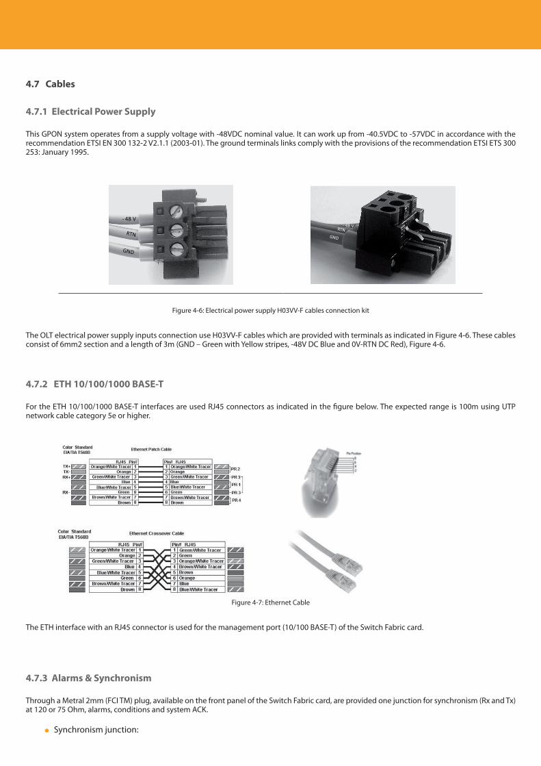
Descripción del producto
52
4.7 Cables
4.7.1 Electrical Power Supply
This GPON system operates from a supply voltage with -48VDC nominal value. It can work up from -40.5VDC to -57VDC in accordance with the recommendation ETSI EN 300 132-2 V2.1.1 (2003-01). The ground terminals links comply with the provisions of the recommendation ETSI ETS 300 253: January 1995.
- 48 V
Figure 4-6: Electrical power supply H03VV-F cables connection kit
The OLT electrical power supply inputs connection use H03VV-F cables which are provided with terminals as indicated in Figure 4-6. These cables consist of 6mm2 section and a length of 3m (GND – Green with Yellow stripes, -48V DC Blue and 0V-RTN DC Red), Figure 4-6.
4.7.2 ETH 10/100/1000 BASE-T
For the ETH 10/100/1000 BASE-T interfaces are used RJ45 connectors as indicated in the figure below. The expected range is 100m using UTP network cable category 5e or higher.
Figure 4-7: Ethernet Cable
The ETH interface with an RJ45 connector is used for the management port (10/100 BASE-T) of the Switch Fabric card.
4.7.3 Alarms & Synchronism
Through a Metral 2mm (FCI TM) plug, available on the front panel of the Switch Fabric card, are provided one junction for synchronism (Rx and Tx) at 120 or 75 Ohm, alarms, conditions and system ACK.
Synchronism junction:
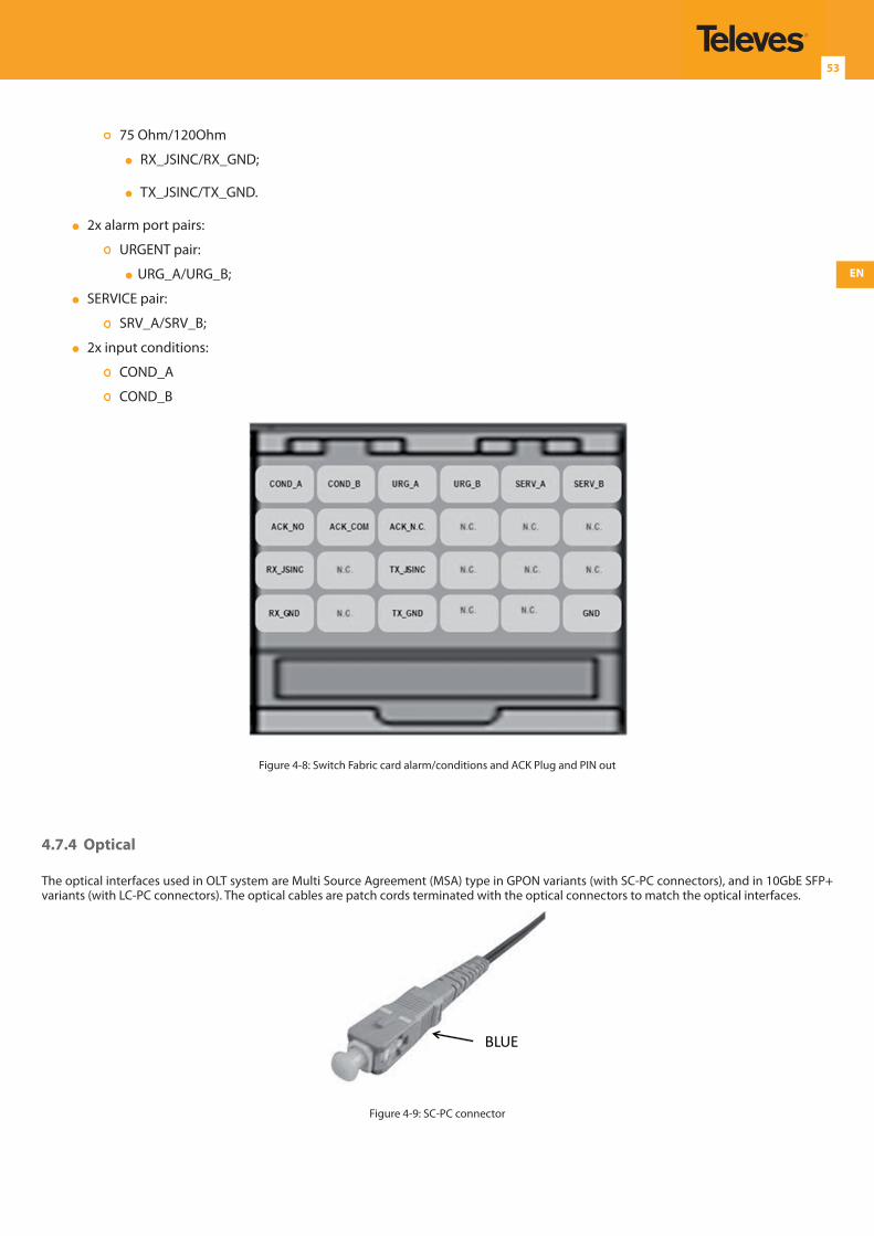
EN
53
75 Ohm/120Ohm
RX_JSINC/RX_GND;
TX_JSINC/TX_GND.
2x alarm port pairs:
URGENT pair:
URG_A/URG_B;
SERVICE pair:
SRV_A/SRV_B;
2x input conditions:
COND_A
COND_B
Figure 4-8: Switch Fabric card alarm/conditions and ACK Plug and PIN out
4.7.4 Optical
The optical interfaces used in OLT system are Multi Source Agreement (MSA) type in GPON variants (with SC-PC connectors), and in 10GbE SFP+ variants (with LC-PC connectors). The optical cables are patch cords terminated with the optical connectors to match the optical interfaces.
BLUE
Figure 4-9: SC-PC connector
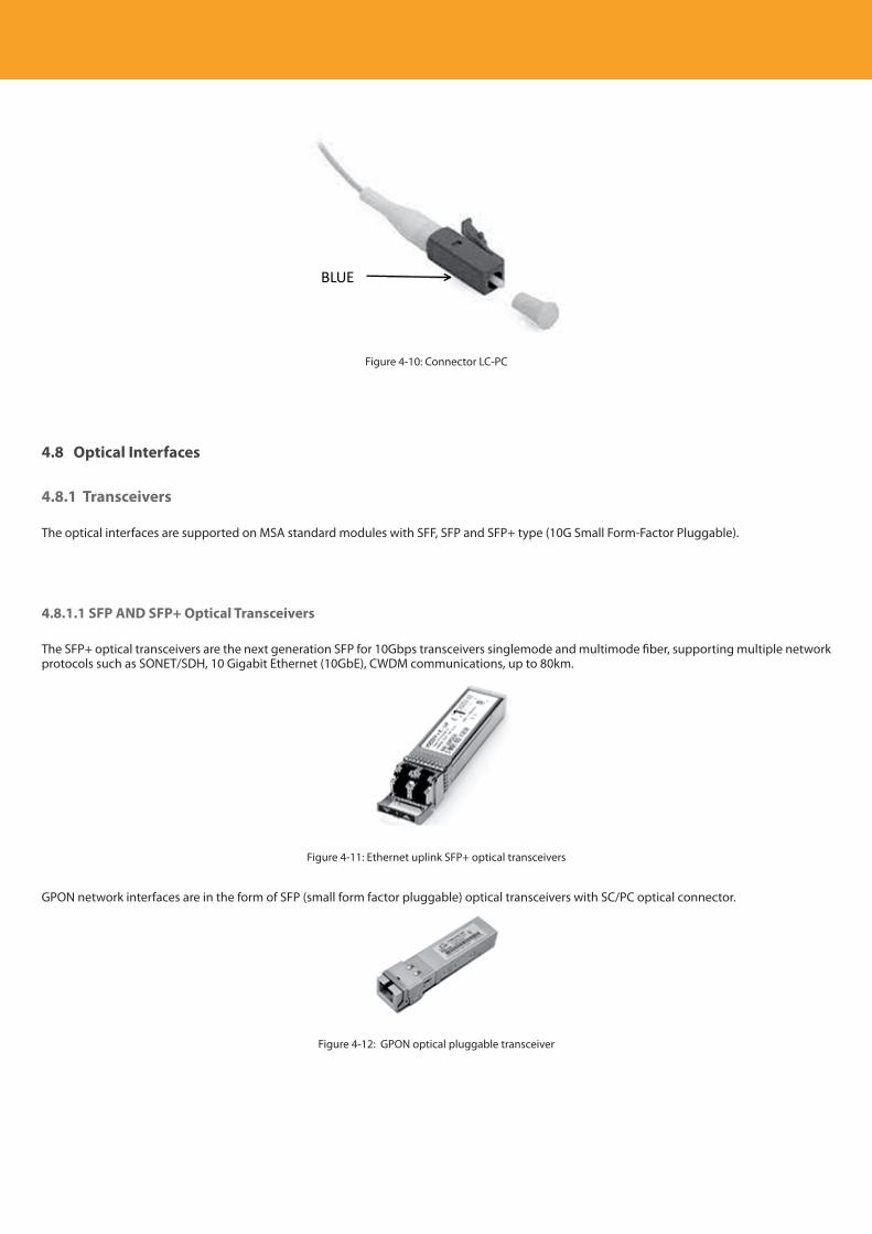
Descripción del producto
54
BLUE
Figure 4-10: Connector LC-PC
4.8 Optical Interfaces
4.8.1 Transceivers
The optical interfaces are supported on MSA standard modules with SFF, SFP and SFP+ type (10G Small Form-Factor Pluggable).
4.8.1.1 SFP AND SFP+ Optical Transceivers
The SFP+ optical transceivers are the next generation SFP for 10Gbps transceivers singlemode and multimode fiber, supporting multiple network protocols such as SONET/SDH, 10 Gigabit Ethernet (10GbE), CWDM communications, up to 80km.
Figure 4-11: Ethernet uplink SFP+ optical transceivers
GPON network interfaces are in the form of SFP (small form factor pluggable) optical transceivers with SC/PC optical connector.
Figure 4-12: GPON optical pluggable transceiver

EN
55
4.9 Electrical Interfaces
4.9.1 Electrical Fast Ethernet
RJ-45 connectors are used for Ethernet 10/100 BASE-T interfaces. The expected range is 100 meters using category 6 cable as described in the IEEE 802.3 recommendations.
Figure 4-13: RJ45 connector
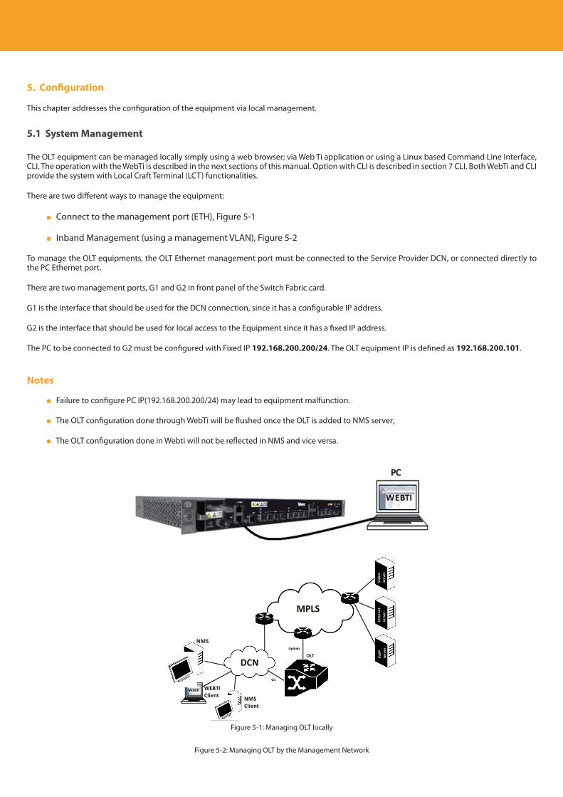
Descripción del producto
56
5. Configuration
This chapter addresses the configuration of the equipment via local management.
5.1 System Management
The OLT equipment can be managed locally simply using a web browser; via Web Ti application or using a Linux based Command Line Interface, CLI. The operation with the WebTi is described in the next sections of this manual. Option with CLI is described in section 7 CLI. Both WebTi and CLI provide the system with Local Craft Terminal (LCT) functionalities.
There are two different ways to manage the equipment:
Connect to the management port (ETH), Figure 5-1
Inband Management (using a management VLAN), Figure 5-2
To manage the OLT equipments, the OLT Ethernet management port must be connected to the Service Provider DCN, or connected directly to the PC Ethernet port.
There are two management ports, G1 and G2 in front panel of the Switch Fabric card.
G1 is the interface that should be used for the DCN connection, since it has a configurable IP address.
G2 is the interface that should be used for local access to the Equipment since it has a fixed IP address.
The PC to be connected to G2 must be configured with Fixed IP 192.168.200.200/24. The OLT equipment IP is defined as 192.168.200.101.
Notes
Failure to configure PC IP(192.168.200.200/24) may lead to equipment malfunction.
The OLT configuration done through WebTi will be flushed once the OLT is added to NMS server;
The OLT configuration done in Webti will not be reflected in NMS and vice versa.
Figure 5-1: Managing OLT locally
OLTUplinks
MPLS
DCNG1
NMS
WEBTI
VoIP
serv
erIn
tern
etse
rver
Vide
ose
rver
NMSClient
WEBTIClient
Figure 5-2: Managing OLT by the Management Network
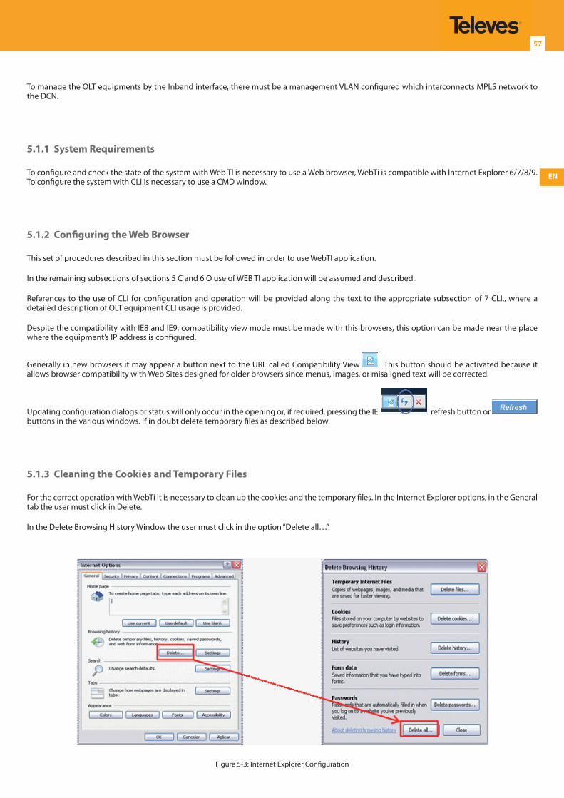
EN
57
To manage the OLT equipments by the Inband interface, there must be a management VLAN configured which interconnects MPLS network to the DCN.
5.1.1 System Requirements
To configure and check the state of the system with Web TI is necessary to use a Web browser, WebTi is compatible with Internet Explorer 6/7/8/9. To configure the system with CLI is necessary to use a CMD window.
5.1.2 Configuring the Web Browser
This set of procedures described in this section must be followed in order to use WebTI application.
In the remaining subsections of sections 5 C and 6 O use of WEB TI application will be assumed and described.
References to the use of CLI for configuration and operation will be provided along the text to the appropriate subsection of 7 CLI., where a detailed description of OLT equipment CLI usage is provided.
Despite the compatibility with IE8 and IE9, compatibility view mode must be made with this browsers, this option can be made near the place where the equipment’s IP address is configured.
Generally in new browsers it may appear a button next to the URL called Compatibility View . This button should be activated because it allows browser compatibility with Web Sites designed for older browsers since menus, images, or misaligned text will be corrected.
Updating configuration dialogs or status will only occur in the opening or, if required, pressing the IE refresh button or buttons in the various windows. If in doubt delete temporary files as described below.
5.1.3 Cleaning the Cookies and Temporary Files
For the correct operation with WebTi it is necessary to clean up the cookies and the temporary files. In the Internet Explorer options, in the General tab the user must click in Delete.
In the Delete Browsing History Window the user must click in the option “Delete all…”.
Figure 5-3: Internet Explorer Configuration
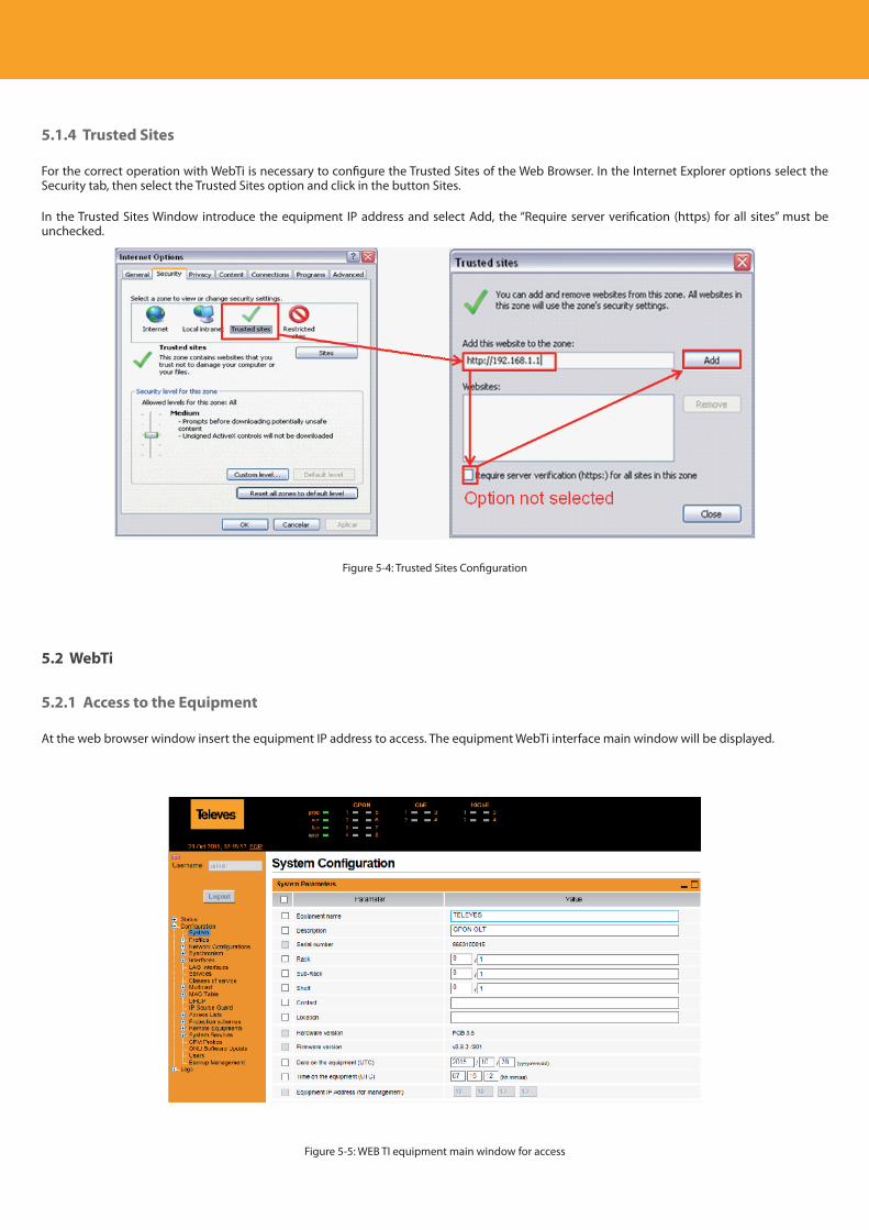
Descripción del producto
58
5.1.4 Trusted Sites
For the correct operation with WebTi is necessary to configure the Trusted Sites of the Web Browser. In the Internet Explorer options select the Security tab, then select the Trusted Sites option and click in the button Sites.
In the Trusted Sites Window introduce the equipment IP address and select Add, the “Require server verification (https) for all sites” must be unchecked.
Figure 5-4: Trusted Sites Configuration
5.2 WebTi
5.2.1 Access to the Equipment
At the web browser window insert the equipment IP address to access. The equipment WebTi interface main window will be displayed.
Figure 5-5: WEB TI equipment main window for access
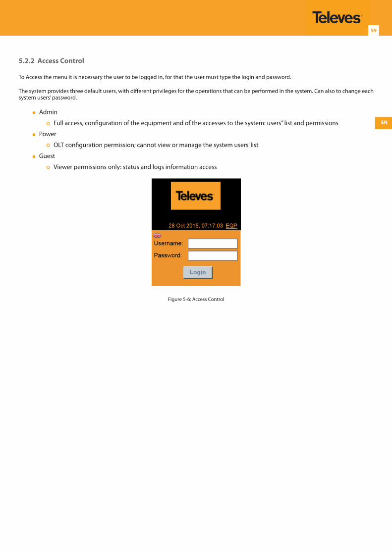
EN
59
5.2.2 Access Control
To Access the menu it is necessary the user to be logged in, for that the user must type the login and password.
The system provides three default users, with different privileges for the operations that can be performed in the system. Can also to change each system users’ password.
Admin
Full access, configuration of the equipment and of the accesses to the system: users’’ list and permissions
Power
OLT configuration permission; cannot view or manage the system users’ list
Guest
Viewer permissions only: status and logs information access
Figure 5-6: Access Control
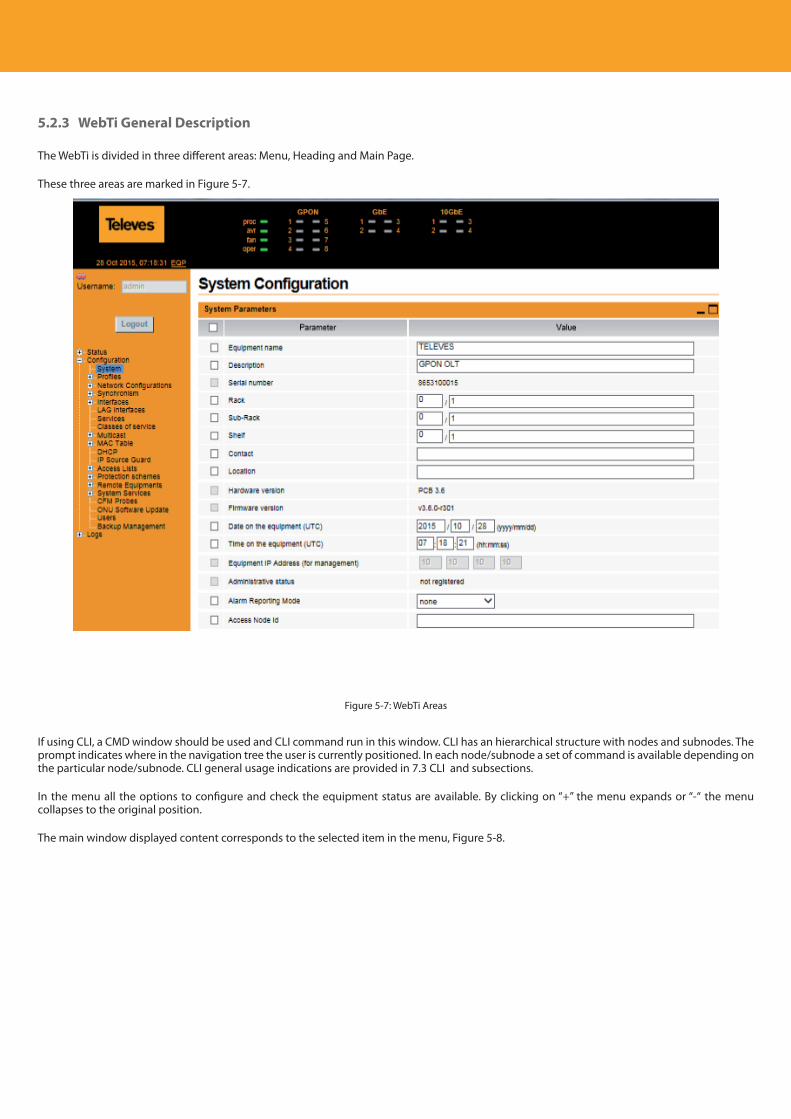
Descripción del producto
60
5.2.3 WebTi General Description
The WebTi is divided in three different areas: Menu, Heading and Main Page.
These three areas are marked in Figure 5-7.
Figure 5-7: WebTi Areas
If using CLI, a CMD window should be used and CLI command run in this window. CLI has an hierarchical structure with nodes and subnodes. The prompt indicates where in the navigation tree the user is currently positioned. In each node/subnode a set of command is available depending on the particular node/subnode. CLI general usage indications are provided in 7.3 CLI and subsections.
In the menu all the options to configure and check the equipment status are available. By clicking on “+” the menu expands or “-“ the menu collapses to the original position.
The main window displayed content corresponds to the selected item in the menu, Figure 5-8.
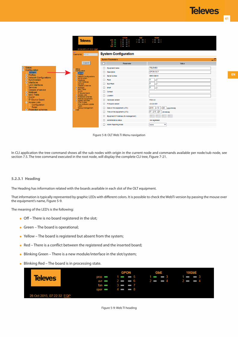
EN
61
Figure 5-8: OLT Web Ti Menu navigation
In CLI application the tree command shows all the sub nodes with origin in the current node and commands available per node/sub node, see section 7.5. The tree command executed in the root node, will display the complete CLI tree, Figure 7-21.
5.2.3.1 Heading
The Heading has information related with the boards available in each slot of the OLT equipment.
That information is typically represented by graphic LEDs with different colors. It is possible to check the WebTi version by passing the mouse over the equipment’s name, Figure 5-9.
The meaning of the LED’s is the following:
Off – There is no board registered in the slot;
Green – The board is operational;
Yellow – The board is registered but absent from the system;
Red – There is a conflict between the registered and the inserted board;
Blinking Green – There is a new module/interface in the slot/system;
Blinking Red – The board is in processing state.
Figure 5-9: Web TI heading
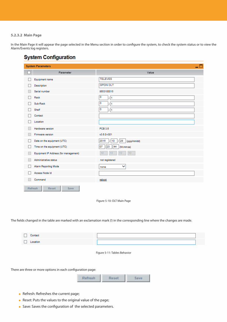
Descripción del producto
62
5.2.3.2 Main Page
In the Main Page it will appear the page selected in the Menu section in order to configure the system, to check the system status or to view the Alarm/Events log registers.
Figure 5-10: OLT Main Page
The fields changed in the table are marked with an exclamation mark (!) in the corresponding line where the changes are made.
Figure 5-11: Tables Behavior
There are three or more options in each configuration page:
Refresh: Refreshes the current page;
Reset: Puts the values to the original value of the page;
Save: Saves the configuration of the selected parameters.
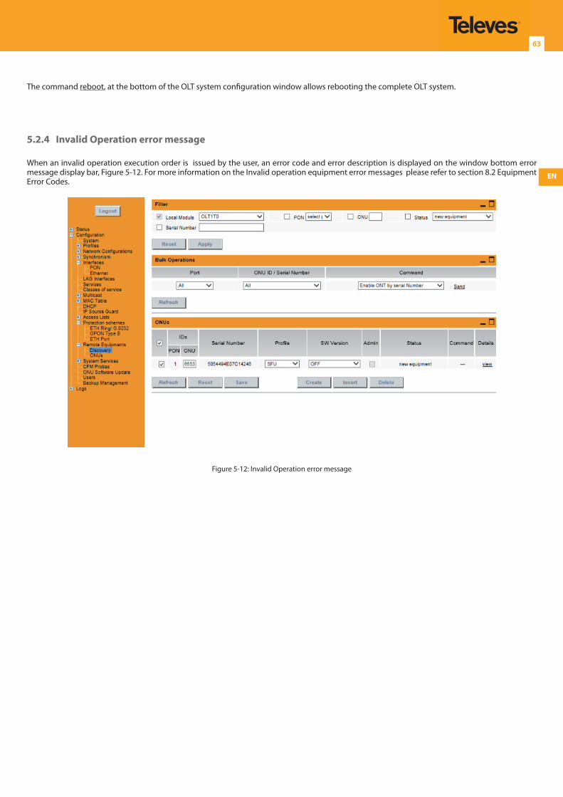
EN
63
The command reboot, at the bottom of the OLT system configuration window allows rebooting the complete OLT system.
5.2.4 Invalid Operation error message
When an invalid operation execution order is issued by the user, an error code and error description is displayed on the window bottom error message display bar, Figure 5-12. For more information on the Invalid operation equipment error messages please refer to section 8.2 Equipment Error Codes.
Figure 5-12: Invalid Operation error message
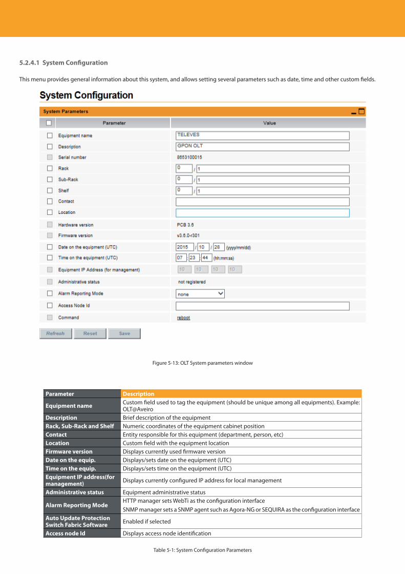
Descripción del producto
64
5.2.4.1 System Configuration
This menu provides general information about this system, and allows setting several parameters such as date, time and other custom fields.
Figure 5-13: OLT System parameters window
Parameter Description
Equipment name Custom field used to tag the equipment (should be unique among all equipments). Example: OLT@Aveiro
Description Brief description of the equipmentRack, Sub-Rack and Shelf Numeric coordinates of the equipment cabinet positionContact Entity responsible for this equipment (department, person, etc)Location Custom field with the equipment locationFirmware version Displays currently used firmware versionDate on the equip. Displays/sets date on the equipment (UTC)Time on the equip. Displays/sets time on the equipment (UTC)Equipment IP address(for management) Displays currently configured IP address for local management
Administrative status Equipment administrative status
Alarm Reporting ModeHTTP manager sets WebTi as the configuration interfaceSNMP manager sets a SNMP agent such as Agora-NG or SEQUIRA as the configuration interface
Auto Update Protection Switch Fabric Software Enabled if selected
Access node Id Displays access node identification
Table 5-1: System Configuration Parameters
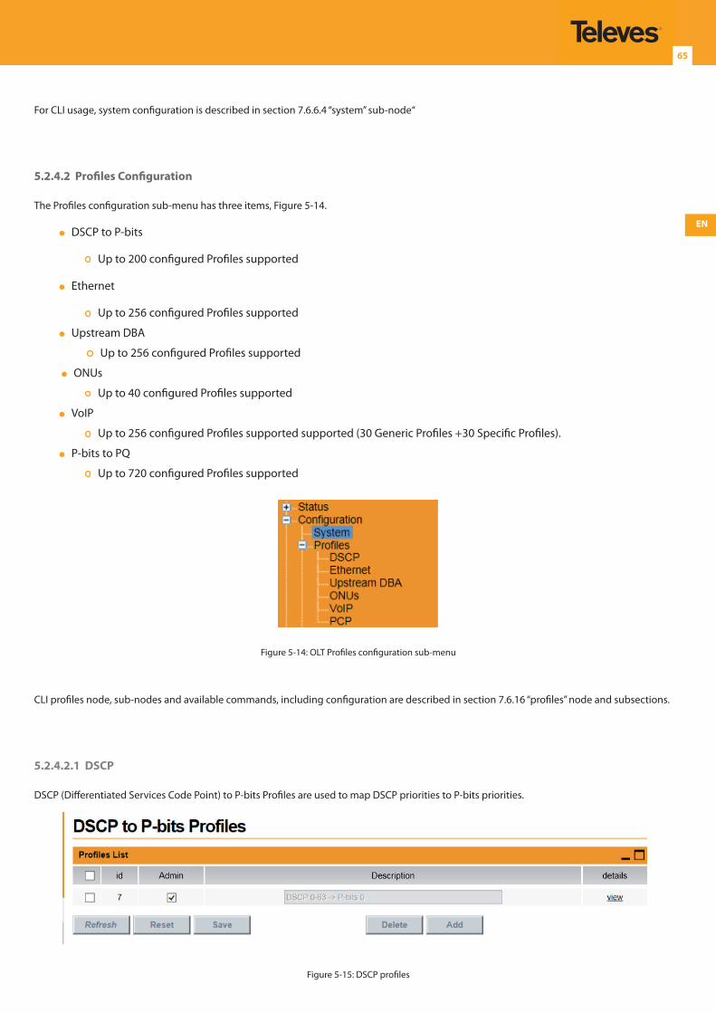
EN
65
For CLI usage, system configuration is described in section 7.6.6.4 “system” sub-node“
5.2.4.2 Profiles Configuration
The Profiles configuration sub-menu has three items, Figure 5-14.
DSCP to P-bits
Up to 200 configured Profiles supported
Ethernet
Up to 256 configured Profiles supported
Upstream DBA
Up to 256 configured Profiles supported
ONUs
Up to 40 configured Profiles supported
VoIP
Up to 256 configured Profiles supported supported (30 Generic Profiles +30 Specific Profiles).
P-bits to PQ
Up to 720 configured Profiles supported
Figure 5-14: OLT Profiles configuration sub-menu
CLI profiles node, sub-nodes and available commands, including configuration are described in section 7.6.16 “profiles” node and subsections.
5.2.4.2.1 DSCP
DSCP (Differentiated Services Code Point) to P-bits Profiles are used to map DSCP priorities to P-bits priorities.
Figure 5-15: DSCP profiles
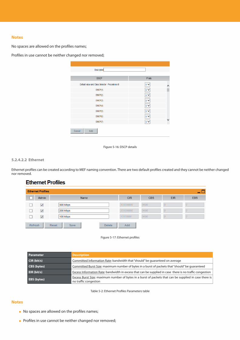
Descripción del producto
66
Notes
No spaces are allowed on the profiles names;
Profiles in use cannot be neither changed nor removed;
Figure 5-16: DSCP details
5.2.4.2.2 Ethernet
Ethernet profiles can be created according to MEF naming convention. There are two default profiles created and they cannot be neither changed nor removed.
Figure 5-17: Ethernet profiles
Parameter Description
CIR (bit/s) Committed Information Rate: bandwidth that “should” be guaranteed on average
CBS (bytes) Committed Burst Size: maximum number of bytes in a burst of packets that “should” be guaranteed
EIR (bit/s) Excess Information Rate: bandwidth in excess that can be supplied in case there is no traffic congestion
EBS (bytes)Excess Burst Size: maximum number of bytes in a burst of packets that can be supplied in case there is no traffic congestion
Table 5-2: Ethernet Profiles Parameters table
Notes
No spaces are allowed on the profiles names;
Profiles in use cannot be neither changed nor removed;
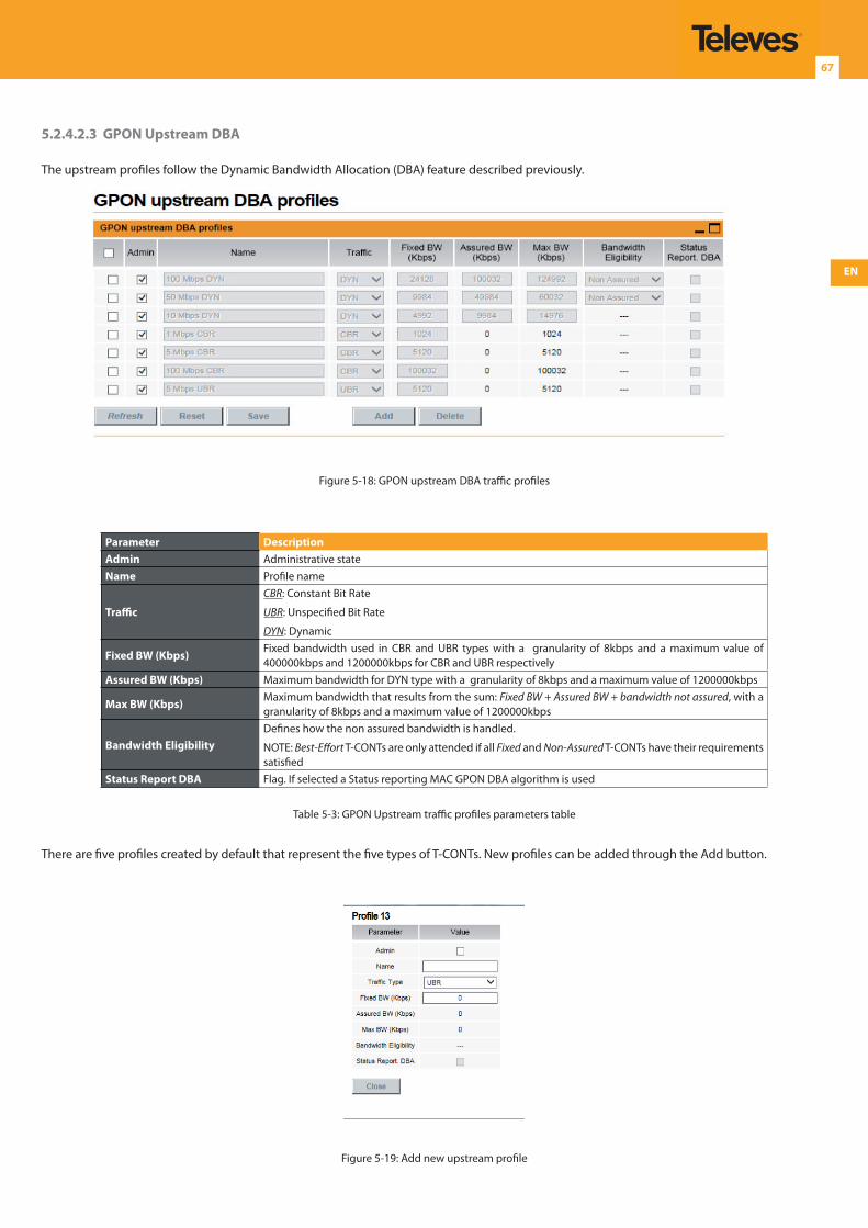
EN
67
5.2.4.2.3 GPON Upstream DBA
The upstream profiles follow the Dynamic Bandwidth Allocation (DBA) feature described previously.
Figure 5-18: GPON upstream DBA traffic profiles
Parameter DescriptionAdmin Administrative stateName Profile name
Traffic
CBR: Constant Bit Rate
UBR: Unspecified Bit Rate
DYN: Dynamic
Fixed BW (Kbps)Fixed bandwidth used in CBR and UBR types with a granularity of 8kbps and a maximum value of 400000kbps and 1200000kbps for CBR and UBR respectively
Assured BW (Kbps) Maximum bandwidth for DYN type with a granularity of 8kbps and a maximum value of 1200000kbps
Max BW (Kbps)Maximum bandwidth that results from the sum: Fixed BW + Assured BW + bandwidth not assured, with a granularity of 8kbps and a maximum value of 1200000kbps
Bandwidth EligibilityDefines how the non assured bandwidth is handled.
NOTE: Best-Effort T-CONTs are only attended if all Fixed and Non-Assured T-CONTs have their requirements satisfied
Status Report DBA Flag. If selected a Status reporting MAC GPON DBA algorithm is used
Table 5-3: GPON Upstream traffic profiles parameters table
There are five profiles created by default that represent the five types of T-CONTs. New profiles can be added through the Add button.
Figure 5-19: Add new upstream profile
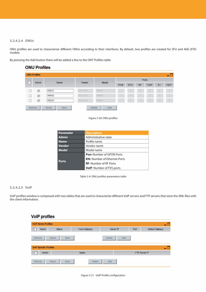
Descripción del producto
68
5.2.4.2.4 ONUs
ONU profiles are used to characterize different ONUs according to their interfaces. By default, two profiles are created for SFU and 4GE-2FXS models.
By pressing the Add button there will be added a line to the ONT Profiles table
Figure 5-20: ONU profiles
Parameter DescriptionAdmin Administrative stateName Profile nameVendor Vendor name Model Model name
Ports
Pon: Number of GPON PortsEth: Number of Ethernet PortsRF: Number of RF PortsVoIP: Number of FXS ports
Table 5-4: ONU profiles parameters table
5.2.4.2.5 VoIP
VoIP profiles window is composed with two tables that are used to characterize different VoIP servers and FTP servers that store the XML files with the client information.
Figure 5-21 - VoIP Profile configuration
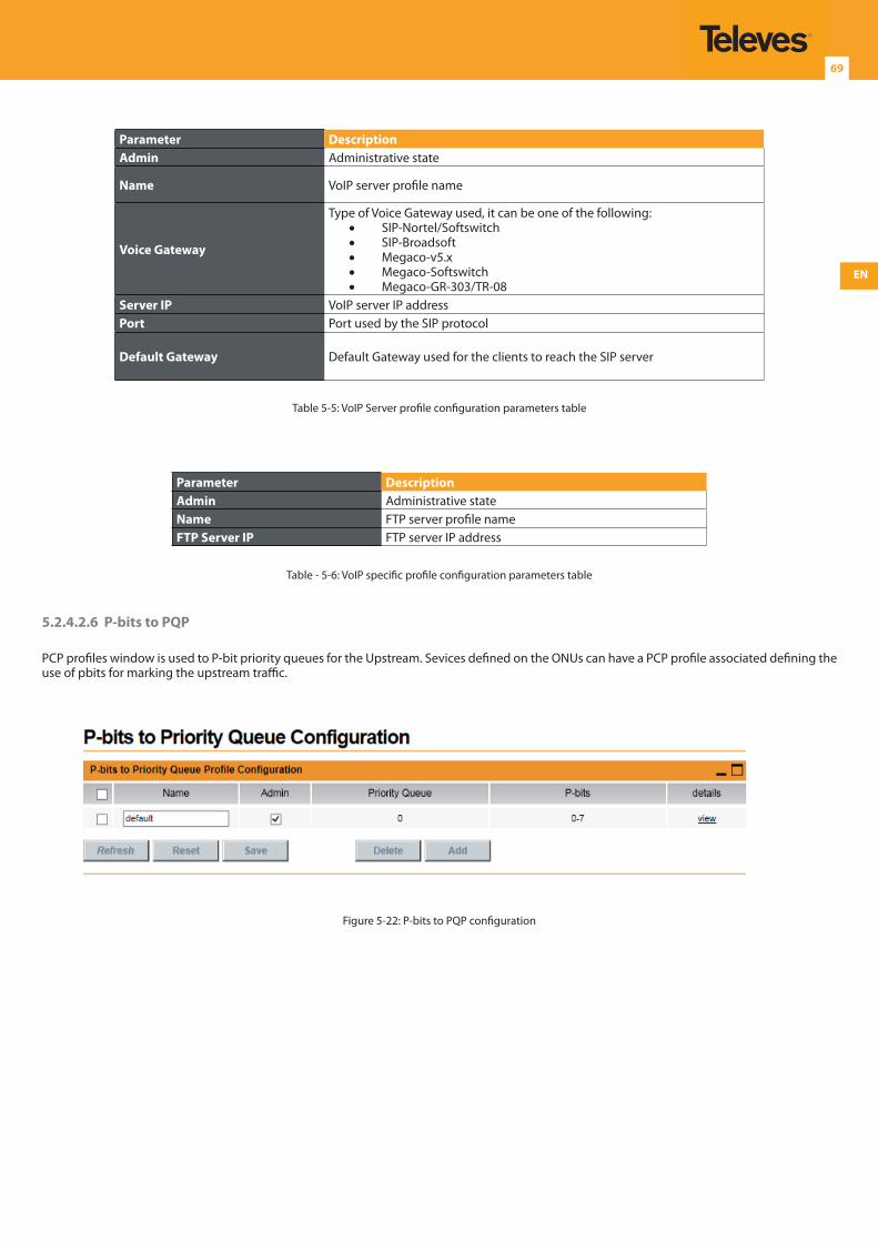
EN
69
Parameter DescriptionAdmin Administrative state
Name VoIP server profile name
Voice Gateway
Type of Voice Gateway used, it can be one of the following:• SIP-Nortel/Softswitch• SIP-Broadsoft• Megaco-v5.x• Megaco-Softswitch• Megaco-GR-303/TR-08
Server IP VoIP server IP addressPort Port used by the SIP protocol
Default Gateway Default Gateway used for the clients to reach the SIP server
Table 5-5: VoIP Server profile configuration parameters table
Parameter DescriptionAdmin Administrative stateName FTP server profile nameFTP Server IP FTP server IP address
Table - 5-6: VoIP specific profile configuration parameters table
5.2.4.2.6 P-bits to PQP
PCP profiles window is used to P-bit priority queues for the Upstream. Sevices defined on the ONUs can have a PCP profile associated defining the use of pbits for marking the upstream traffic.
Figure 5-22: P-bits to PQP configuration
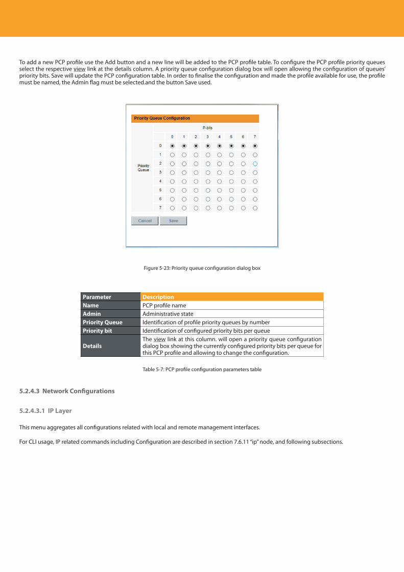
Descripción del producto
70
To add a new PCP profile use the Add button and a new line will be added to the PCP profile table. To configure the PCP profile priority queues select the respective view link at the details column. A priority queue configuration dialog box will open allowing the configuration of queues’ priority bits. Save will update the PCP configuration table. In order to finalise the configuration and made the profile available for use, the profile must be named, the Admin flag must be selected.and the button Save used.
Figure 5-23: Priority queue configuration dialog box
Parameter DescriptionName PCP profile name Admin Administrative statePriority Queue Identification of profile priority queues by numberPriority bit Identification of configured priority bits per queue
DetailsThe view link at this column. will open a priority queue configuration dialog box showing the currently configured priority bits per queue for this PCP profile and allowing to change the configuration.
Table 5-7: PCP profile configuration parameters table
5.2.4.3 Network Configurations
5.2.4.3.1 IP Layer
This menu aggregates all configurations related with local and remote management interfaces.
For CLI usage, IP related commands including Configuration are described in section 7.6.11 “ip” node, and following subsections.
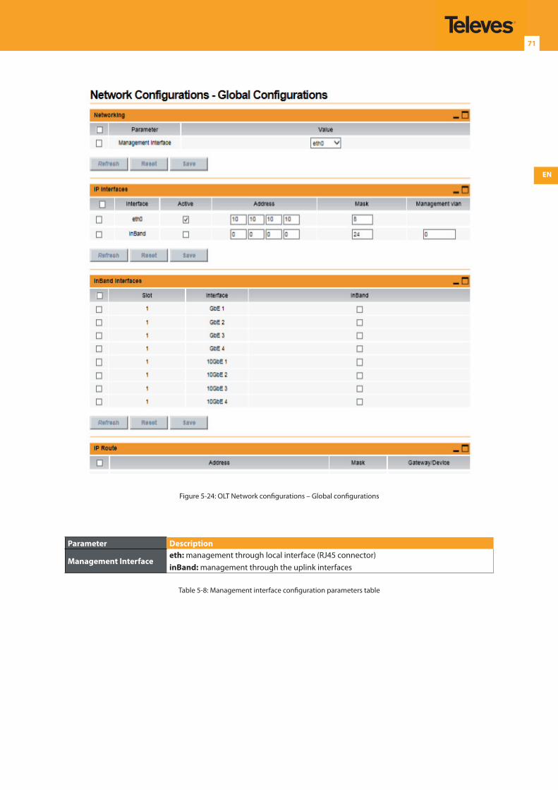
EN
71
Figure 5-24: OLT Network configurations – Global configurations
Parameter Description
Management Interfaceeth: management through local interface (RJ45 connector)inBand: management through the uplink interfaces
Table 5-8: Management interface configuration parameters table
Descripción del producto
72
For each interface, an IP address can be configured and the respective network mask. For InBand, a VLAN must be used since the management traffic is mixed with other flows.
Parameter Description
Interface Interface name
Active Administrative state of the interfaceAddress IP address of the interfaceMask Network mask of the InterfaceManagement VLAN VLAN identifier used in the inBand interface
Table 5-9: Interface Configuration parameters table
It is also possible to select among all uplink interfaces which ones are used for the in band management. By selecting multiple interfaces, it means they will be connected in an E-LAN topology for that management VLAN.
Parameter DescriptionSlot Slot number of the uplink interfaceInterface InterfaceInband If the interface is used or not to manage the system
Table 5-10: Uplink interface for InBand management configuration parameters table
Finally, a gateway may be configured on the system and it must belong to one of the networks configured previously through the IP + Netmask.
Parameter DescriptionAddress Destination IP NetworkMask Destination IP MaskGateway/Device Gateway to the configured network
Table 5-11: IP Route - Gateway Configuration parameters table
5.2.4.4 Synchronism
The synchronization block is physically located in the array units. It complies with G.781 and G.810 recommendations and is a category G.813 type I device.
Internal oscillator ±1.5 ppm;
Holdover deviation ±0.37 ppm per day;
Possible simultaneous sources: 1 Slot; 2 external junctions;
External sources: STM-N Ports, GbE and 10GbE NNI Ports, OTU Ports, 2Mbps Ports, 34Mbps Ports, 2MHz / 2Mbps input/output junctions;
Priority and Quality (SSM).
The Synchronism configuration sub-menu has two items, Figure 5-25:
Global
PTP
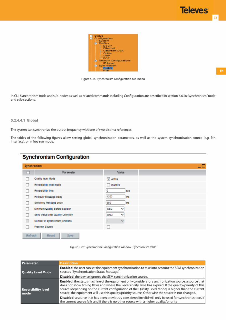
EN
73
Figure 5-25: Synchronism configuration sub-menu
In CLI, Synchronism node and sub-nodes as well as related commands including Configuration are described in section 7.6.20 “synchronism” node and sub-sections.
5.2.4.4.1 Global
The system can synchronize the output frequency with one of two distinct references.
The tables of the following figures allow setting global synchronization parameters, as well as the system synchronization source (e.g. Eth interface), or in free run mode.
Figure 5-26: Synchronism Configuration Window- Synchronism table
Parameter Description
Quality Level ModeEnabled: the user can set the equipment synchronization to take into account the SSM synchronization sources (Synchronization Status Message)Disabled: the device ignores the SSM synchronization source.
Reversibility level mode
Enabled: the status machine of the equipment only considers for synchronization source, a source that does not show timing flaws and where the Reversibility Time has expired. If the quality/priority of this source (depending on the current configuration of the Quality Level Mode) is higher than the current source, the equipment will use this quality/priority source. Otherwise the source is not changed.Disabled: a source that has been previously considered invalid will only be used for synchronization, if the current source fails and if there is no other source with a higher quality/priority
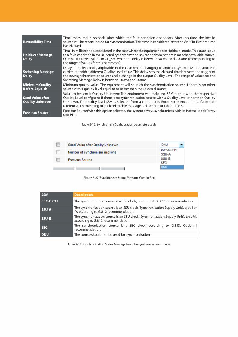
Descripción del producto
74
Reversibility TimeTime, measured in seconds, after which, the fault condition disappears. After this time, the invalid source will be reconsidered for synchronization. This time is considered after the Wait-To-Restore time has elapsed
Holdover Message Delay
Time, in milliseconds, considered in the case where the equipment is in Holdover mode. This state is due to a fault condition in the selected synchronization source and when there is no other available source. QL (Quality Level) will be in QL_SEC when the delay is between 300ms and 2000ms (corresponding to the range of values for this parameter);
Switching Message Delay
Delay, in milliseconds, applicable in the case where changing to another synchronization source is carried out with a different Quality Level value. This delay sets the elapsed time between the trigger of the new synchronization source and a change in the output Quality Level. The range of values for the Switching Message Delay is between 180ms and 500ms
Minimum Quality Before Squelch
Minimum quality value; The equipment will squelch the synchronization source if there is no other source with a quality level equal to or better than the selected source;
Send Value after Quality Unknown
Value to be sent if Quality Unknown; The equipment will make the SSM output with the respective Quality Level configured if there is no synchronization source with a Quality Level other than Quality Unknown. The quality level SSM is selected from a combo box, Error: No se encuentra la fuente de referencia. The meaning of each selectable message is described in table Table 5-.
Free-run Source Free-run Source; With this option selected, the system always synchronizes with its internal clock (array unit PLL).
Table 5-12: Synchronism Configuration parameters table
Figure 5-27: Synchronism Status Message Combo Box
SSM Description
PRC-G.811 The synchronization source is a PRC clock, according to G.811 recommendation
SSU-A The synchronization source is an SSU clock (Synchronization Supply Unit), type I or IV, according to G.812 recommendation.
SSU-B The synchronization source is an SSU clock (Synchronization Supply Unit), type VI, according to G.812 recommendation
SEC The synchronization source is a SEC clock, according to G.813, Option I recommendation.
DNU The source should not be used for synchronization.
Table 5-13: Synchronization Status Message from the synchronization sources
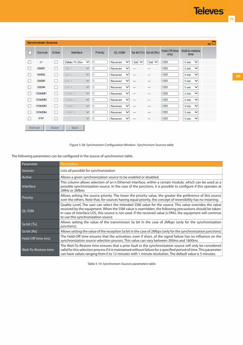
EN
75
Figure 5-28: Synchronism Configuration Window- Synchronism Sources table
The following parameters can be configured in the source of synchronism table.
Parameter Description
Sources Lists all possible for synchronization
Active Allows a given synchronization source to be enabled or disabled.
InterfaceThis column allows selection of an n Ethernet interface, within a certain module, which can be used as a possible synchronization source. In the case of the junctions, it is possible to configure if this operates at 2MHz or 2Mbits
Priority Allows setting the source priority. The lower the priority value, the greater the preference of this source over the others. Note that, for sources having equal priority, the concept of reversibility has no meaning.
QL-SSM
Quality Level; The user can select the intended SSM value for the source. This value overrides the value received by the equipment. When the SSM value is overridden, the following precautions should be taken: In case of interface LOS, this source is not used. If the received value is DNU, the equipment will continue to use this synchronization source.
Sa bit [Tx] Allows setting the value of the transmission Sa bit in the case of 2Mbps (only for the synchronization junctions);
Sa bit [Rx] Allows setting the value of the reception Sa bit in the case of 2Mbps (only for the synchronization junctions)
Hold-Off time (ms) The Hold-Off time ensures that the activation, even if short, of the signal failure has no influence on the synchronization source selection process. This value can vary between 300ms and 1800ms
Wait-To-Restore timeThe Wait-To-Restore time ensures that a prior fault in the synchronization source will only be considered valid for this selection process if it is maintained without failure for a specified period of time. This parameter can have values ranging from 0 to 12 minutes with 1 minute resolution. The default value is 5 minutes.
Table 5-14: Synchronism Sources parameters table
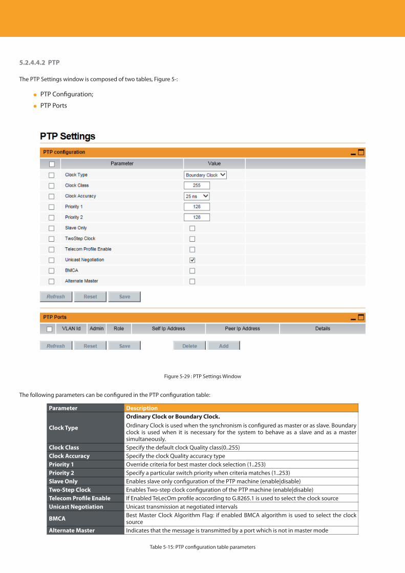
Descripción del producto
76
5.2.4.4.2 PTP
The PTP Settings window is composed of two tables, Figure 5-:
PTP Configuration;
PTP Ports
Figure 5-29 : PTP Settings Window
The following parameters can be configured in the PTP configuration table:
Parameter Description
Clock Type
Ordinary Clock or Boundary Clock. Ordinary Clock is used when the synchronism is configured as master or as slave. Boundary clock is used when it is necessary for the system to behave as a slave and as a master simultaneously.
Clock Class Specify the default clock Quality class(0..255)Clock Accuracy Specify the clock Quality accuracy typePriority 1 Override criteria for best master clock selection (1..253)Priority 2 Specify a particular switch priority when criteria matches (1..253)Slave Only Enables slave only configuration of the PTP machine (enable|disable) Two-Step Clock Enables Two-step clock configuration of the PTP machine (enable|disable)Telecom Profile Enable If Enabled TeLecOm profile acocording to G.8265.1 is used to select the clock sourceUnicast Negotiation Unicast transmission at negotiated intervals
BMCA Best Master Clock Algorithm Flag: if enabled BMCA algorithm is used to select the clock source
Alternate Master Indicates that the message is transmitted by a port which is not in master mode
Table 5-15: PTP configuration table parameters
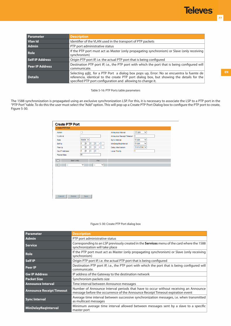
EN
77
Parameter DescriptionVlan Id Identifier of the VLAN used in the transport of PTP packetsAdmin PTP port administrative status
Role If the PTP port must act as Master (only propagating synchronism) or Slave (only receiving synchronism)
Self IP Address Origin PTP port IP, i.e. the actual PTP port that is being configured
Peer IP Address Destination PTP port IP, i.e., the PTP port with which the port that is being configured will communicate.
DetailsSelecting edit for a PTP Port a dialog box pops up, Error: No se encuentra la fuente de referencia, identical to the create PTP port dialog box, but showing the details for the specified PTP port configuration and allowing to change it.
Table 5-16: PTP Ports table parameters
The 1588 synchronization is propagated using an exclusive synchronization LSP. For this, it is necessary to associate the LSP to a PTP port in the “PTP Port” table. To do this the user must select the “Add” option. This will pop up a Create PTP Port Dialog box to configure the PTP port to create, Figure 5-30.
Figure 5-30: Create PTP Port dialog box
Parameter DescriptionAdmin PTP port administrative status
Service Corresponding to an LSP previously created in the Services menu of the card where the 1588 synchronization will take place
Role If the PTP port must act as Master (only propagating synchronism) or Slave (only receiving synchronism)
Self IP Origin PTP port IP, i.e. the actual PTP port that is being configured
Peer IP Destination PTP port IP, i.e., the PTP port with which the port that is being configured will communicate.
Gw IP Address IP address of the Gateway to the destination networkPacket Size Synchronism packets sizeAnnounce Interval Time interval between Announce messages
Announce Receipt Timeout Number of Announce Interval periods that have to occur without receiving an Announce message before the occurrence of the Announce Receipt Timeout expiration event
Sync Interval Average time interval between successive synchronization messages, i.e. when transmitted as multicast messages
MinDelayReqInterval Minimum average time interval allowed between messages sent by a slave to a specific master port
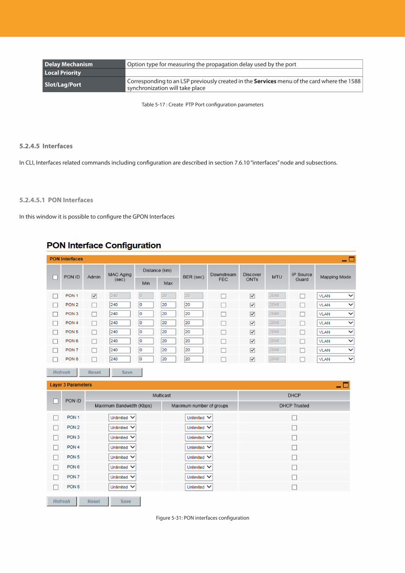
Descripción del producto
78
Delay Mechanism Option type for measuring the propagation delay used by the portLocal Priority
Slot/Lag/Port Corresponding to an LSP previously created in the Services menu of the card where the 1588 synchronization will take place
Table 5-17 : Create PTP Port configuration parameters
5.2.4.5 Interfaces
In CLI, Interfaces related commands including configuration are described in section 7.6.10 “interfaces” node and subsections.
5.2.4.5.1 PON Interfaces
In this window it is possible to configure the GPON Interfaces
Figure 5-31: PON interfaces configuration
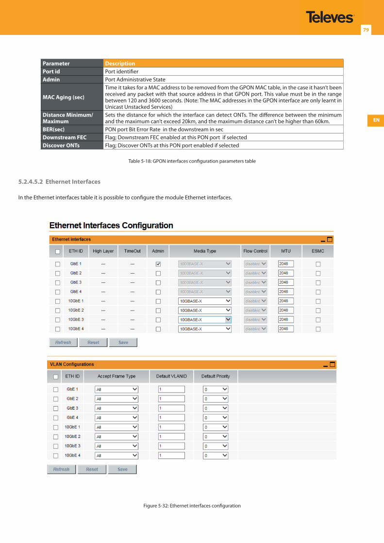
EN
79
Parameter DescriptionPort id Port identifierAdmin Port Administrative State
MAC Aging (sec)
Time it takes for a MAC address to be removed from the GPON MAC table, in the case it hasn’t been received any packet with that source address in that GPON port. This value must be in the range between 120 and 3600 seconds. (Note: The MAC addresses in the GPON interface are only learnt in Unicast Unstacked Services)
Distance Minimum/Maximum
Sets the distance for which the interface can detect ONTs. The difference between the minimum and the maximum can’t exceed 20km, and the maximum distance can’t be higher than 60km.
BER(sec) PON port Bit Error Rate in the downstream in secDownstream FEC Flag; Downstream FEC enabled at this PON port if selectedDiscover ONTs Flag; Discover ONTs at this PON port enabled if selected
Table 5-18: GPON interfaces configuration parameters table
5.2.4.5.2 Ethernet Interfaces
In the Ethernet interfaces table it is possible to configure the module Ethernet interfaces.
Figure 5-32: Ethernet interfaces configuration
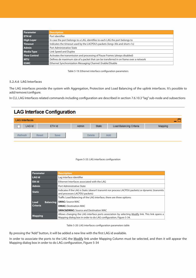
Descripción del producto
80
Parameter DescriptionETH id Port identifierHigh Layer In case the port belongs to a LAG, identifies to each LAG the port belongs toTimeout Indicates the timeout used by the LACPDU’s packets (long=30s and short=1s)Admin Port Administrative StateMedia Type Link Speed and DuplexFlow Control Activates the transmission and processing of Pause Frames (always disabled)MTU Defines de maximum size of a packet that can be transferred in on frame over a networkESMC Ethernet Synchronization Messaging Channel: Enable/Disable
Table 5-19: Ethernet interface configuration parameters
5.2.4.6 LAG Interfaces
The LAG interfaces provide the system with Aggregation, Protection and Load Balancing of the uplink interfaces. It’s possible to add/remove/configure.
In CLI, LAG Interfaces related commands including configuration are described in section 7.6.10.3 “lag” sub-node and subsections
Figure 5-33: LAG interfaces configuration
Parameter DescriptionLAG Id Lag interface identifier
Eth Id Ethernet Interfaces associated with the LAG
Admin Port Administrative State
StaticIndicates if the LAG is Static (doesn’t transmit nor process LACPDU packets) or dynamic (transmits and processes LACPDU packets)
Load Balancing Criteria
Traffic Load Balancing of the LAG interface, there are three options:
SMAC: Source MAC
DMAC: Destination MAC
SMAC&DMAC: Source and Destination MAC
MappingAllows changing the LAG interface ports association by selecting Modify link. This link opens a Mapping dialog box in order to do LAG configuration, Figure 5-34.
Table 5-20: LAG interfaces configuration parameters table
By pressing the “Add” button, it will be added a new line with the first LAG id available.
In order to associate the ports to the LAG the Modify link under Mapping Column must be selected, and then it will appear the Mapping dialog box in order to do LAG configuration, Figure 5-34
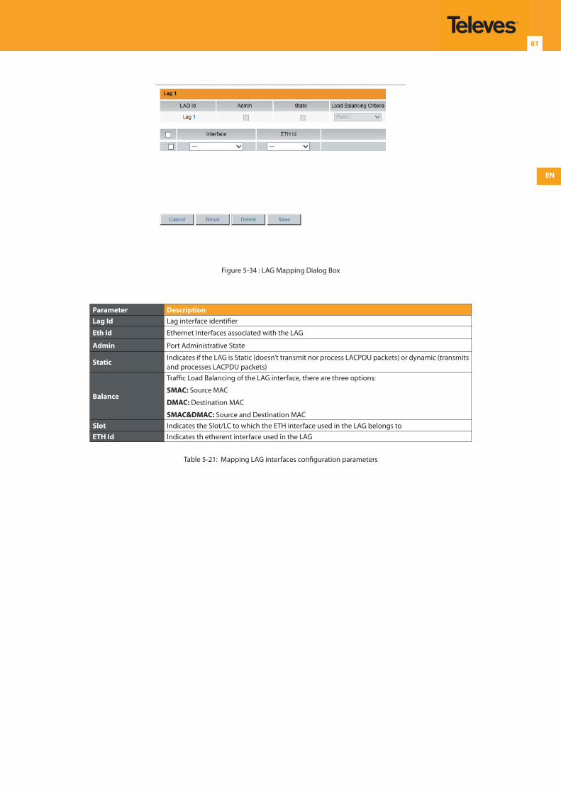
EN
81
Figure 5-34 : LAG Mapping Dialog Box
Parameter DescriptionLag Id Lag interface identifier
Eth Id Ethernet Interfaces associated with the LAG
Admin Port Administrative State
StaticIndicates if the LAG is Static (doesn’t transmit nor process LACPDU packets) or dynamic (transmits and processes LACPDU packets)
Balance
Traffic Load Balancing of the LAG interface, there are three options:
SMAC: Source MAC
DMAC: Destination MAC
SMAC&DMAC: Source and Destination MACSlot Indicates the Slot/LC to which the ETH interface used in the LAG belongs toETH Id Indicates th etherent interface used in the LAG
Table 5-21: Mapping LAG interfaces configuration parameters
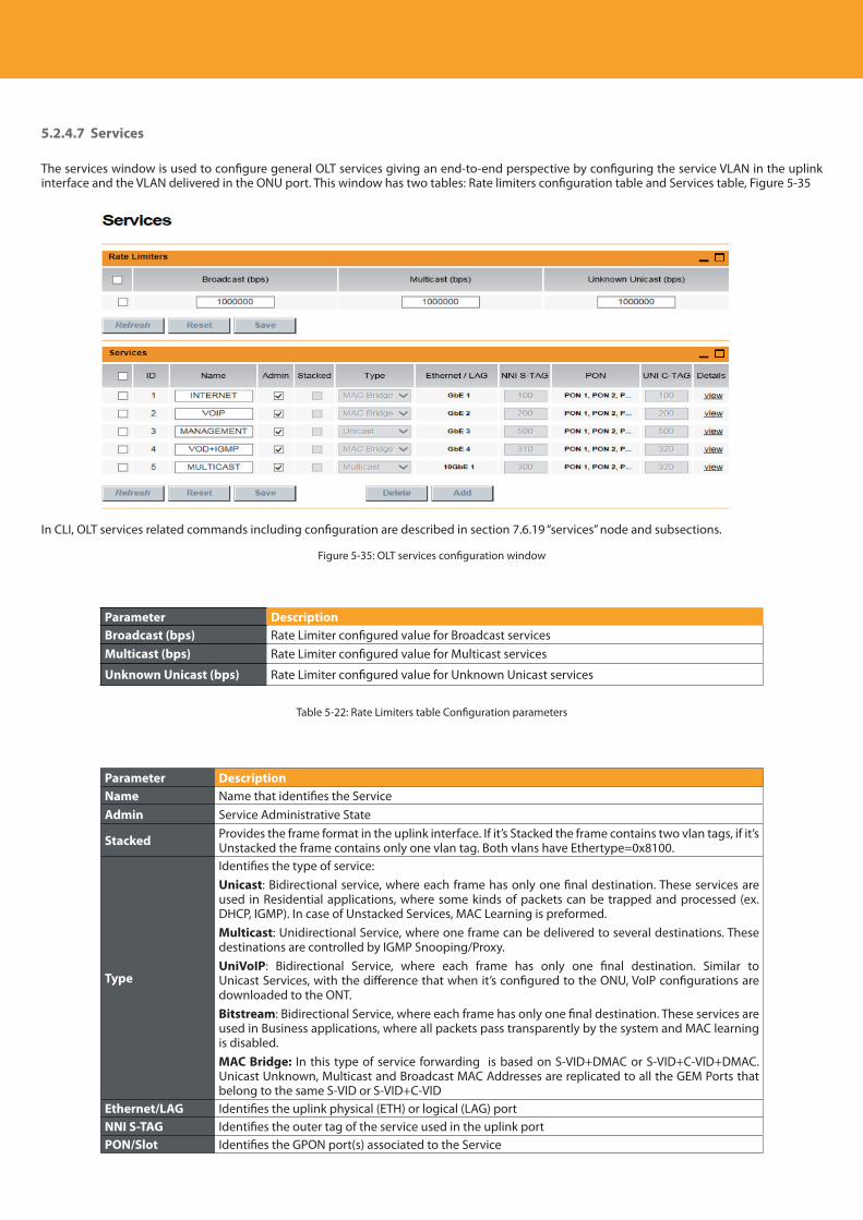
Descripción del producto
82
5.2.4.7 Services
The services window is used to configure general OLT services giving an end-to-end perspective by configuring the service VLAN in the uplink interface and the VLAN delivered in the ONU port. This window has two tables: Rate limiters configuration table and Services table, Figure 5-35
In CLI, OLT services related commands including configuration are described in section 7.6.19 “services” node and subsections.
Figure 5-35: OLT services configuration window
Parameter DescriptionBroadcast (bps) Rate Limiter configured value for Broadcast servicesMulticast (bps) Rate Limiter configured value for Multicast services
Unknown Unicast (bps) Rate Limiter configured value for Unknown Unicast services
Table 5-22: Rate Limiters table Configuration parameters
Parameter DescriptionName Name that identifies the ServiceAdmin Service Administrative State
Stacked Provides the frame format in the uplink interface. If it’s Stacked the frame contains two vlan tags, if it’s Unstacked the frame contains only one vlan tag. Both vlans have Ethertype=0x8100.
Type
Identifies the type of service:Unicast: Bidirectional service, where each frame has only one final destination. These services are used in Residential applications, where some kinds of packets can be trapped and processed (ex. DHCP, IGMP). In case of Unstacked Services, MAC Learning is preformed.Multicast: Unidirectional Service, where one frame can be delivered to several destinations. These destinations are controlled by IGMP Snooping/Proxy.UniVoIP: Bidirectional Service, where each frame has only one final destination. Similar to Unicast Services, with the difference that when it’s configured to the ONU, VoIP configurations are downloaded to the ONT.Bitstream: Bidirectional Service, where each frame has only one final destination. These services are used in Business applications, where all packets pass transparently by the system and MAC learning is disabled.MAC Bridge: In this type of service forwarding is based on S-VID+DMAC or S-VID+C-VID+DMAC.Unicast Unknown, Multicast and Broadcast MAC Addresses are replicated to all the GEM Ports that belong to the same S-VID or S-VID+C-VID
Ethernet/LAG Identifies the uplink physical (ETH) or logical (LAG) portNNI S-TAG Identifies the outer tag of the service used in the uplink portPON/Slot Identifies the GPON port(s) associated to the Service
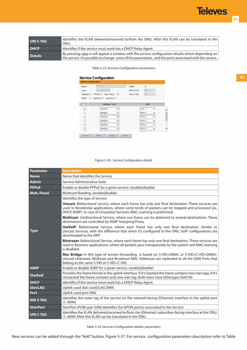
EN
83
UNI C-TAG Identifies the VLAN delivered/received to/from the ONU. After this VLAN can be translated in the ONU.
DHCP Identifies if the service must work has a DHCP Relay Agent.
Details By pressing view it will appear a window with the service configuration details where depending on the service it’s possible to change some of the parameters, and the ports associated with the service.
Table 5-23: Services Configuration parameters
Figure 5-36 : Service Configuration details
Parameter DescriptionName Name that identifies the Service
Admin Service Administrative StatePPPoE Enable or disable PPPoE for a given service. (enable|disable)Mult. Flood Multicast flooding. (enable|disable)
Type
Identifies the type of service:Unicast: Bidirectional service, where each frame has only one final destination. These services are used in Residential applications, where some kinds of packets can be trapped and processed (ex. DHCP, IGMP). In case of Unstacked Services, MAC Learning is preformed.Multicast: Unidirectional Service, where one frame can be delivered to several destinations. These destinations are controlled by IGMP Snooping/Proxy.UniVoIP: Bidirectional Service, where each frame has only one final destination. Similar to Unicast Services, with the difference that when it’s configured to the ONU, VoIP configurations are downloaded to the ONT.Bitstream: Bidirectional Service, where each frame has only one final destination. These services are used in Business applications, where all packets pass transparently by the system and MAC learning is disabled.Mac Bridge: In this type of service forwarding is based on S-VID+DMAC or S-VID+C-VID+DMAC.Unicast Unknown, Multicast and Broadcast MAC Addresses are replicated to all the GEM Ports that belong to the same S-VID or S-VID+C-VID.
IGMP Enable or disable IGMP for a given service. (enable|disable)
Stacked Provides the frame format in the uplink interface. If it’s Stacked the frame contains two vlan tags, if it’s Unstacked the frame contains only one vlan tag. Both vlans have Ethertype=0x8100.
DHCP Identifies if the service must work has a DHCP Relay Agent.Slot/LAG Uplink used Slot (card)/LAG (NNI)Port Uplink used port NNI)
NNI S-TAG Identifies the outer tag of the service on the network-facing (Ethernet) interface in the uplink port (1..4094)
Slot/Port Slot/Port (PON) pair (UNI).Identifies the GPON port(s) associated to the Service
UNI C-TAG Identifies the VLAN delivered/received to/from the (Ethernet) subscriber-facing interface at the ONU. (1..4094) After this VLAN can be translated in the ONU.
Table 5-24: Services Configuration details: parameters
New services can be added through the “Add” button, Figure 5-37. For service configuration parameters description refer to Table
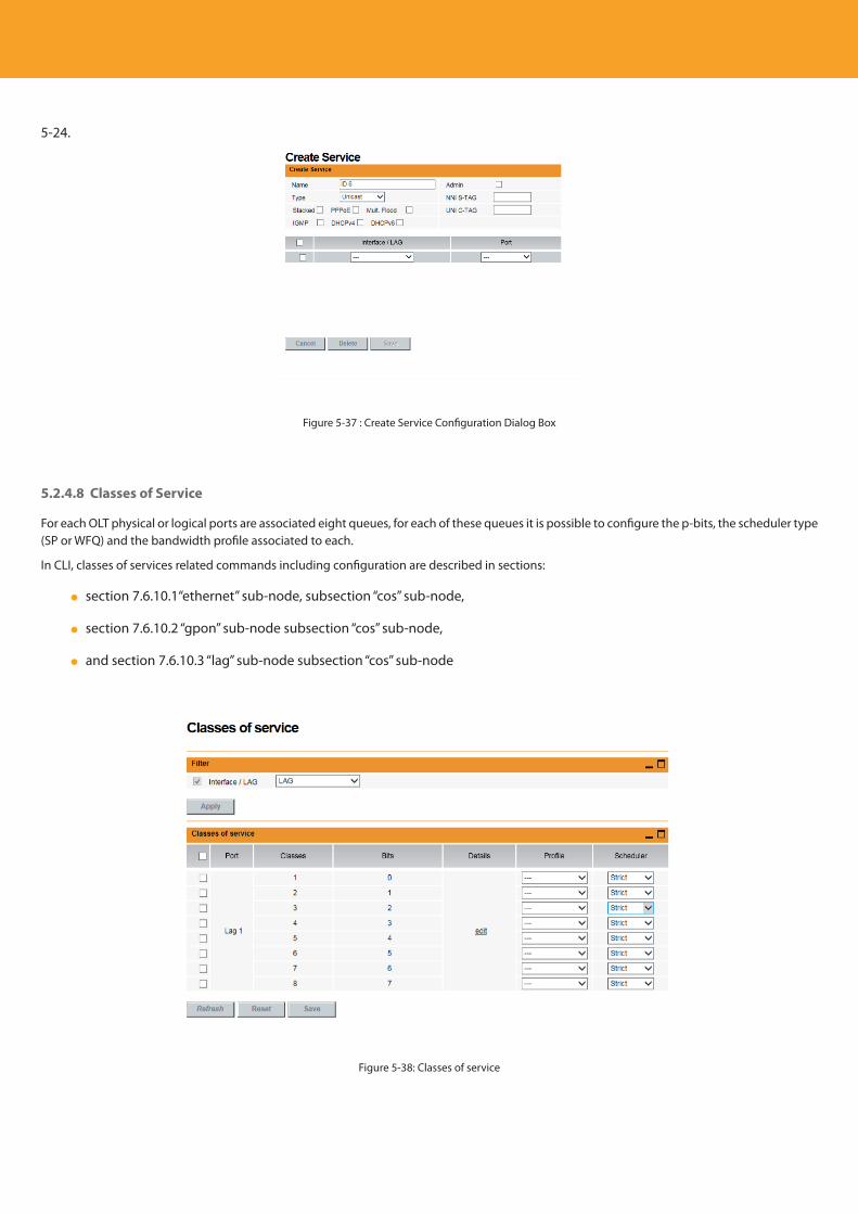
Descripción del producto
84
5-24.
Figure 5-37 : Create Service Configuration Dialog Box
5.2.4.8 Classes of Service
For each OLT physical or logical ports are associated eight queues, for each of these queues it is possible to configure the p-bits, the scheduler type (SP or WFQ) and the bandwidth profile associated to each.
In CLI, classes of services related commands including configuration are described in sections:
section 7.6.10.1“ethernet” sub-node, subsection “cos” sub-node,
section 7.6.10.2 “gpon” sub-node subsection “cos” sub-node,
and section 7.6.10.3 “lag” sub-node subsection “cos” sub-node
Figure 5-38: Classes of service
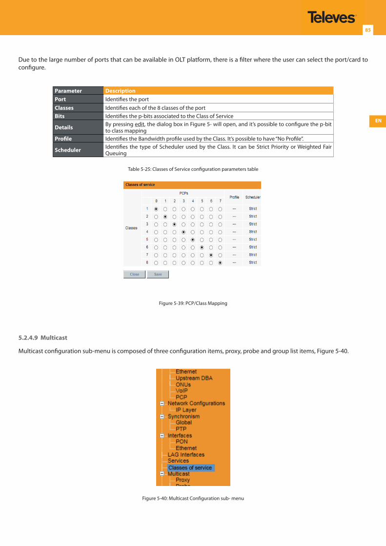
EN
85
Due to the large number of ports that can be available in OLT platform, there is a filter where the user can select the port/card to configure.
Parameter DescriptionPort Identifies the portClasses Identifies each of the 8 classes of the portBits Identifies the p-bits associated to the Class of Service
Details By pressing edit, the dialog box in Figure 5- will open, and it’s possible to configure the p-bit to class mapping
Profile Identifies the Bandwidth profile used by the Class. It’s possible to have “No Profile”.
Scheduler Identifies the type of Scheduler used by the Class. It can be Strict Priority or Weighted Fair Queuing
Table 5-25: Classes of Service configuration parameters table
Figure 5-39: PCP/Class Mapping
5.2.4.9 Multicast
Multicast configuration sub-menu is composed of three configuration items, proxy, probe and group list items, Figure 5-40.
Figure 5-40: Multicast Configuration sub- menu
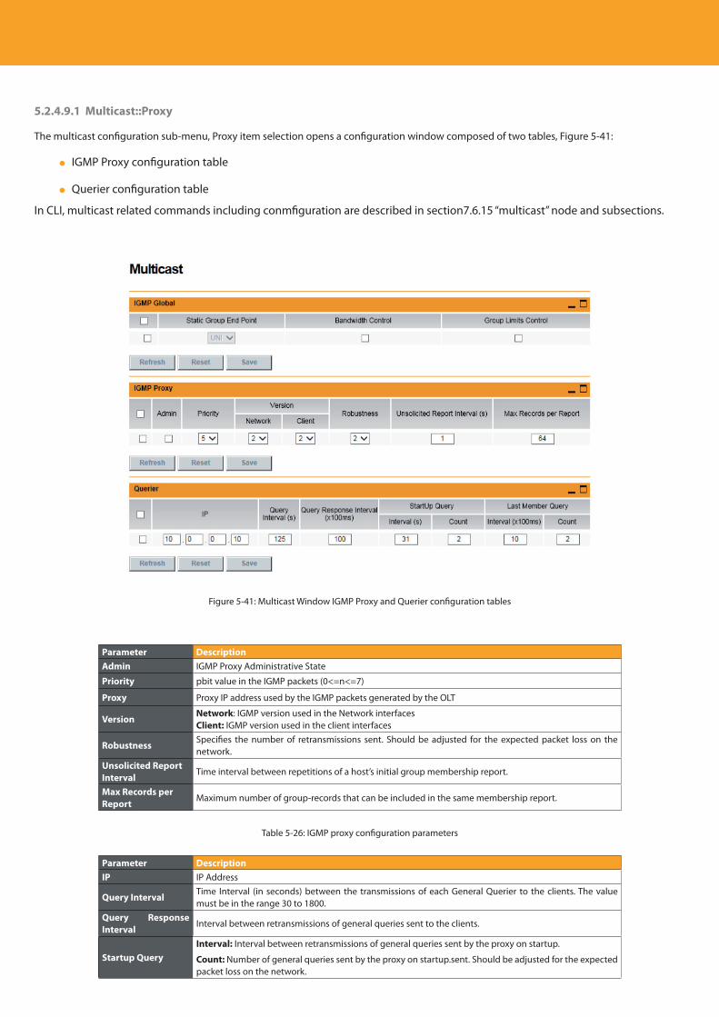
Descripción del producto
86
5.2.4.9.1 Multicast::Proxy
The multicast configuration sub-menu, Proxy item selection opens a configuration window composed of two tables, Figure 5-41:
IGMP Proxy configuration table
Querier configuration table
In CLI, multicast related commands including conmfiguration are described in section7.6.15 “multicast” node and subsections.
Figure 5-41: Multicast Window IGMP Proxy and Querier configuration tables
Parameter DescriptionAdmin IGMP Proxy Administrative State
Priority pbit value in the IGMP packets (0<=n<=7)
Proxy Proxy IP address used by the IGMP packets generated by the OLT
VersionNetwork: IGMP version used in the Network interfacesClient: IGMP version used in the client interfaces
RobustnessSpecifies the number of retransmissions sent. Should be adjusted for the expected packet loss on the network.
Unsolicited Report Interval
Time interval between repetitions of a host’s initial group membership report.
Max Records per Report
Maximum number of group-records that can be included in the same membership report.
Table 5-26: IGMP proxy configuration parameters
Parameter DescriptionIP IP Address
Query IntervalTime Interval (in seconds) between the transmissions of each General Querier to the clients. The value must be in the range 30 to 1800.
Query Response Interval
Interval between retransmissions of general queries sent to the clients.
Startup QueryInterval: Interval between retransmissions of general queries sent by the proxy on startup.
Count: Number of general queries sent by the proxy on startup.sent. Should be adjusted for the expected packet loss on the network.
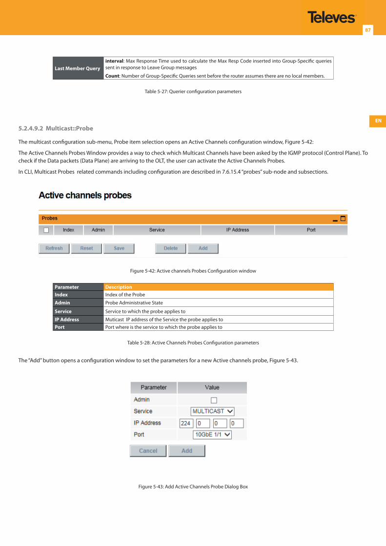
EN
87
Last Member Queryinterval: Max Response Time used to calculate the Max Resp Code inserted into Group-Specific queries sent in response to Leave Group messages
Count: Number of Group-Specific Queries sent before the router assumes there are no local members.
Table 5-27: Querier configuration parameters
5.2.4.9.2 Multicast::Probe
The multicast configuration sub-menu, Probe item selection opens an Active Channels configuration window, Figure 5-42:
The Active Channels Probes Window provides a way to check which Multicast Channels have been asked by the IGMP protocol (Control Plane). To check if the Data packets (Data Plane) are arriving to the OLT, the user can activate the Active Channels Probes.
In CLI, Multicast Probes related commands including configuration are described in 7.6.15.4 “probes” sub-node and subsections.
Figure 5-42: Active channels Probes Configuration window
Parameter DescriptionIndex Index of the Probe
Admin Probe Administrative State
Service Service to which the probe applies to
IP Address Muticast IP address of the Service the probe applies toPort Port where is the service to which the probe applies to
Table 5-28: Active Channels Probes Configuration parameters
The “Add” button opens a configuration window to set the parameters for a new Active channels probe, Figure 5-43.
Figure 5-43: Add Active Channels Probe Dialog Box
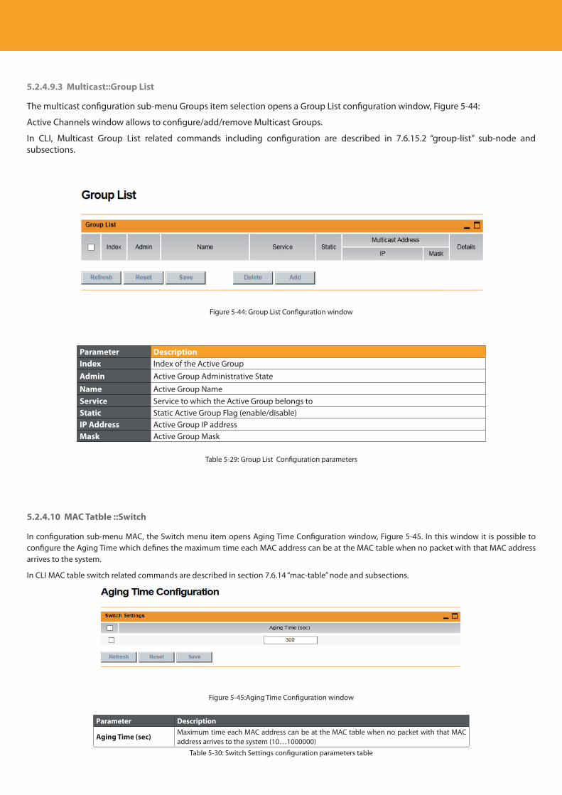
Descripción del producto
88
5.2.4.9.3 Multicast::Group List
The multicast configuration sub-menu Groups item selection opens a Group List configuration window, Figure 5-44:
Active Channels window allows to configure/add/remove Multicast Groups.
In CLI, Multicast Group List related commands including configuration are described in 7.6.15.2 “group-list” sub-node and subsections.
Figure 5-44: Group List Configuration window
Parameter DescriptionIndex Index of the Active GroupAdmin Active Group Administrative State
Name Active Group NameService Service to which the Active Group belongs toStatic Static Active Group Flag (enable/disable)IP Address Active Group IP address Mask Active Group Mask
Table 5-29: Group List Configuration parameters
5.2.4.10 MAC Tatble ::Switch
In configuration sub-menu MAC, the Switch menu item opens Aging Time Configuration window, Figure 5-45. In this window it is possible to configure the Aging Time which defines the maximum time each MAC address can be at the MAC table when no packet with that MAC address arrives to the system.
In CLI MAC table switch related commands are described in section 7.6.14 “mac-table” node and subsections.
Figure 5-45:Aging Time Configuration window
Parameter Description
Aging Time (sec)Maximum time each MAC address can be at the MAC table when no packet with that MAC address arrives to the system (10…1000000)
Table 5-30: Switch Settings configuration parameters table
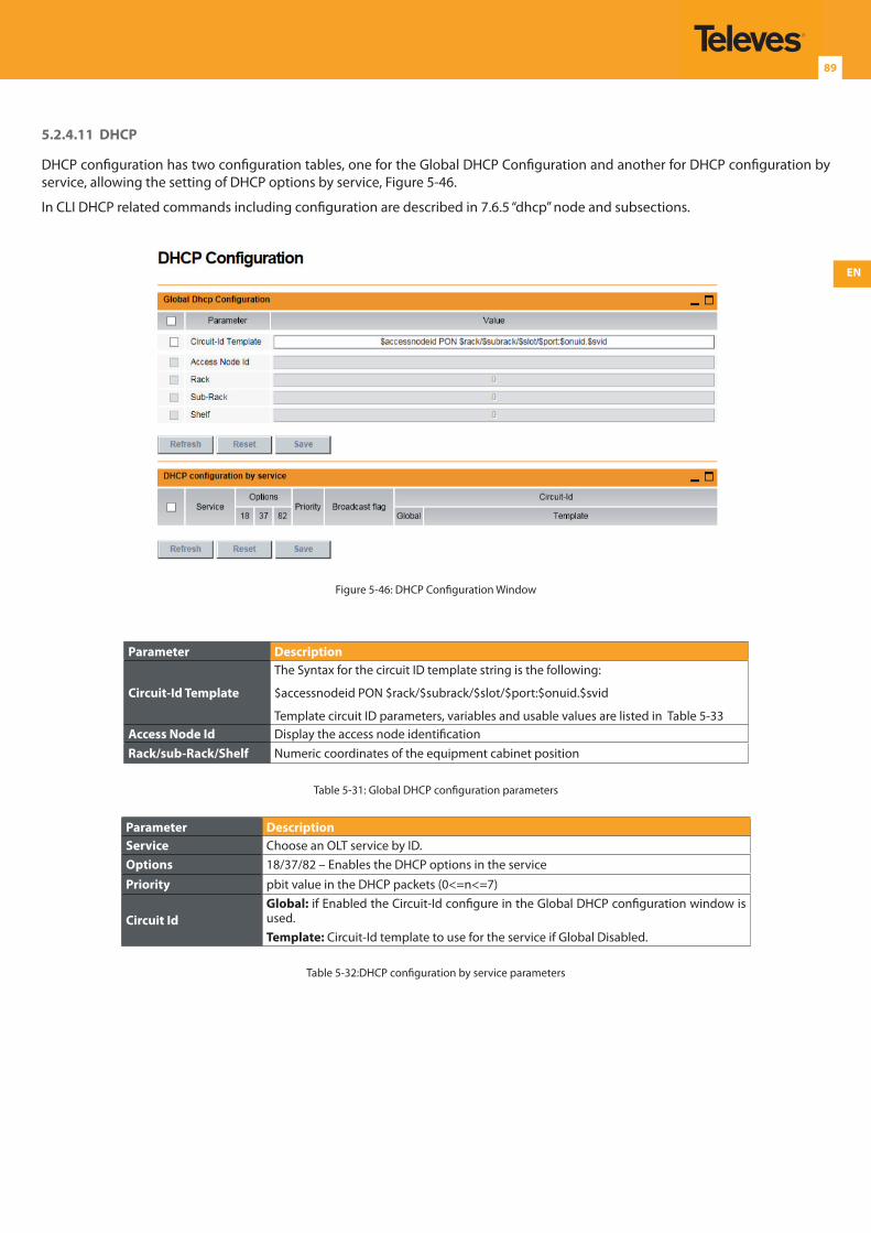
EN
89
5.2.4.11 DHCP
DHCP configuration has two configuration tables, one for the Global DHCP Configuration and another for DHCP configuration by service, allowing the setting of DHCP options by service, Figure 5-46.
In CLI DHCP related commands including configuration are described in 7.6.5 “dhcp” node and subsections.
Figure 5-46: DHCP Configuration Window
Parameter Description
Circuit-Id Template
The Syntax for the circuit ID template string is the following:
$accessnodeid PON $rack/$subrack/$slot/$port:$onuid.$svid
Template circuit ID parameters, variables and usable values are listed in Table 5-33Access Node Id Display the access node identificationRack/sub-Rack/Shelf Numeric coordinates of the equipment cabinet position
Table 5-31: Global DHCP configuration parameters
Parameter DescriptionService Choose an OLT service by ID.Options 18/37/82 – Enables the DHCP options in the service
Priority pbit value in the DHCP packets (0<=n<=7)
Circuit IdGlobal: if Enabled the Circuit-Id configure in the Global DHCP configuration window is used.Template: Circuit-Id template to use for the service if Global Disabled.
Table 5-32:DHCP configuration by service parameters
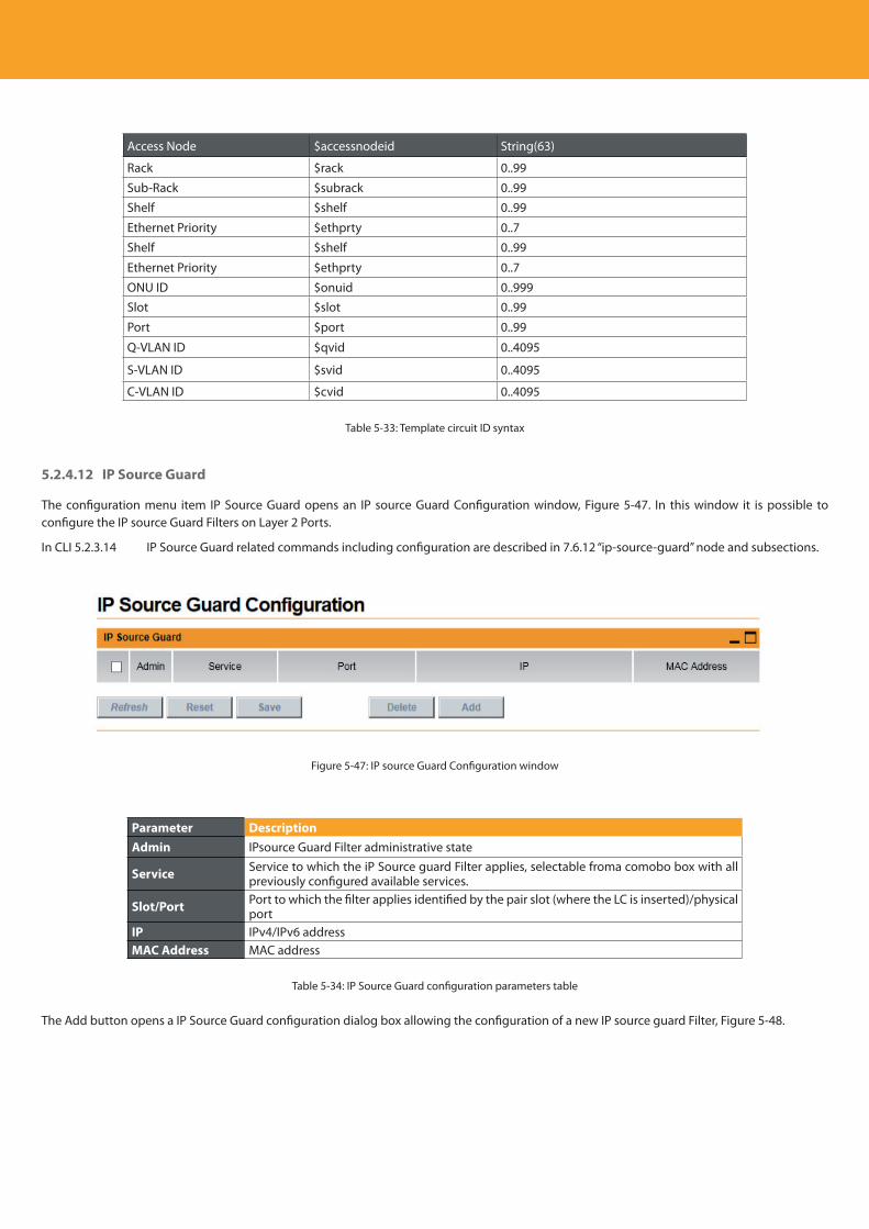
Descripción del producto
90
Access Node $accessnodeid String(63)
Rack $rack 0..99
Sub-Rack $subrack 0..99
Shelf $shelf 0..99
Ethernet Priority $ethprty 0..7
Shelf $shelf 0..99
Ethernet Priority $ethprty 0..7
ONU ID $onuid 0..999Slot $slot 0..99
Port $port 0..99
Q-VLAN ID $qvid 0..4095
S-VLAN ID $svid 0..4095
C-VLAN ID $cvid 0..4095
Table 5-33: Template circuit ID syntax
5.2.4.12 IP Source Guard
The configuration menu item IP Source Guard opens an IP source Guard Configuration window, Figure 5-47. In this window it is possible to configure the IP source Guard Filters on Layer 2 Ports.
In CLI 5.2.3.14 IP Source Guard related commands including configuration are described in 7.6.12 “ip-source-guard” node and subsections.
Figure 5-47: IP source Guard Configuration window
Parameter DescriptionAdmin IPsource Guard Filter administrative state
Service Service to which the iP Source guard Filter applies, selectable froma comobo box with all previously configured available services.
Slot/Port Port to which the filter applies identified by the pair slot (where the LC is inserted)/physical port
IP IPv4/IPv6 address MAC Address MAC address
Table 5-34: IP Source Guard configuration parameters table
The Add button opens a IP Source Guard configuration dialog box allowing the configuration of a new IP source guard Filter, Figure 5-48.
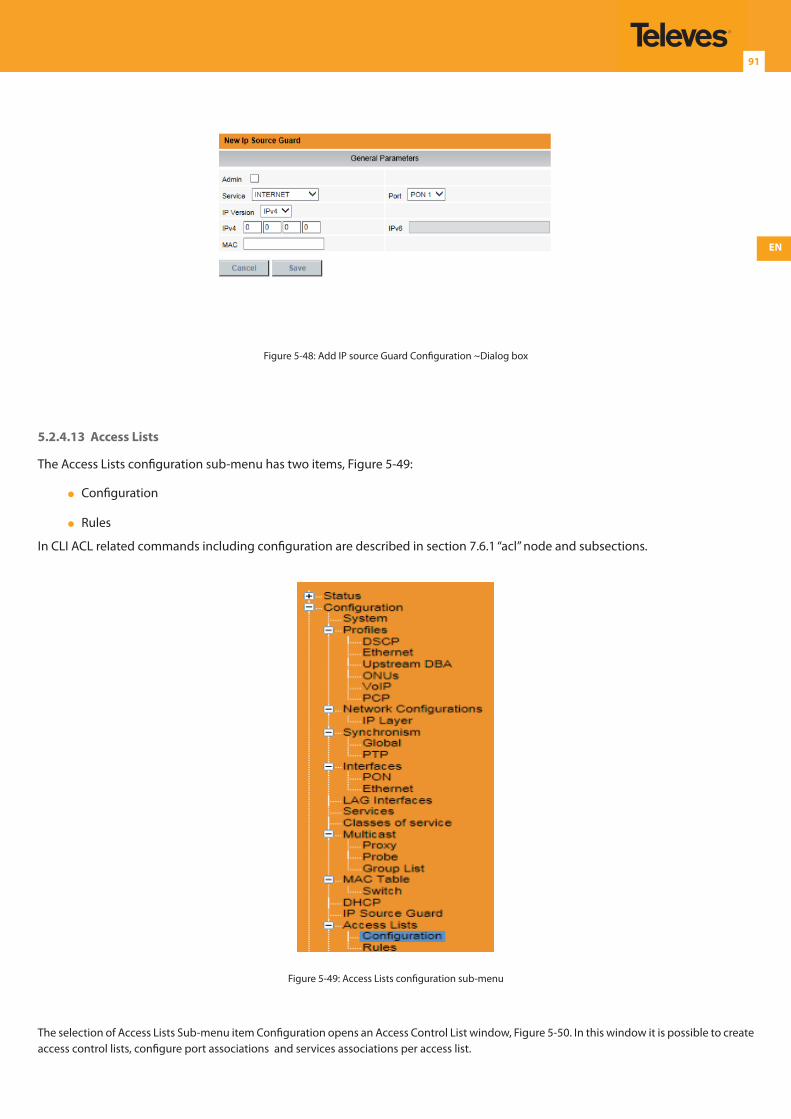
EN
91
Figure 5-48: Add IP source Guard Configuration ~Dialog box
5.2.4.13 Access Lists
The Access Lists configuration sub-menu has two items, Figure 5-49:
Configuration
Rules
In CLI ACL related commands including configuration are described in section 7.6.1 “acl” node and subsections.
Figure 5-49: Access Lists configuration sub-menu
The selection of Access Lists Sub-menu item Configuration opens an Access Control List window, Figure 5-50. In this window it is possible to create access control lists, configure port associations and services associations per access list.
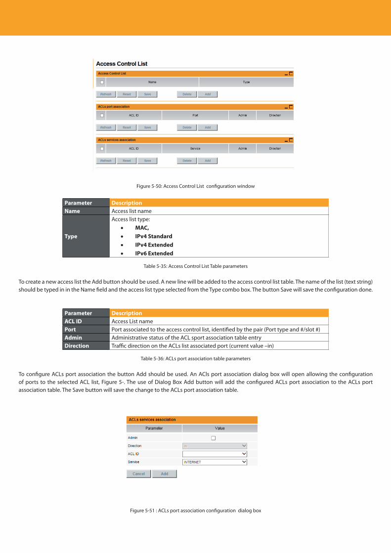
Descripción del producto
92
Figure 5-50: Access Control List configuration window
Parameter DescriptionName Access list name
Type
Access list type:• MAC,• IPv4 Standard• IPv4 Extended• IPv6 Extended
Table 5-35: Access Control List Table parameters
To create a new access list the Add button should be used. A new line will be added to the access control list table. The name of the list (text string)should be typed in in the Name field and the access list type selected from the Type combo box. The button Save will save the configuration done.
Parameter DescriptionACL ID Access List namePort Port associated to the access control list, identified by the pair (Port type and #/slot #)Admin Administrative status of the ACL sport association table entryDirection Traffic direction on the ACLs list associated port (current value –in)
Table 5-36: ACLs port association table parameters
To configure ACLs port association the button Add should be used. An ACls port association dialog box will open allowing the configuration of ports to the selected ACL list, Figure 5-. The use of Dialog Box Add button will add the configured ACLs port association to the ACLs port association table. The Save button will save the change to the ACLs port association table.
Figure 5-51 : ACLs port association configuration dialog box
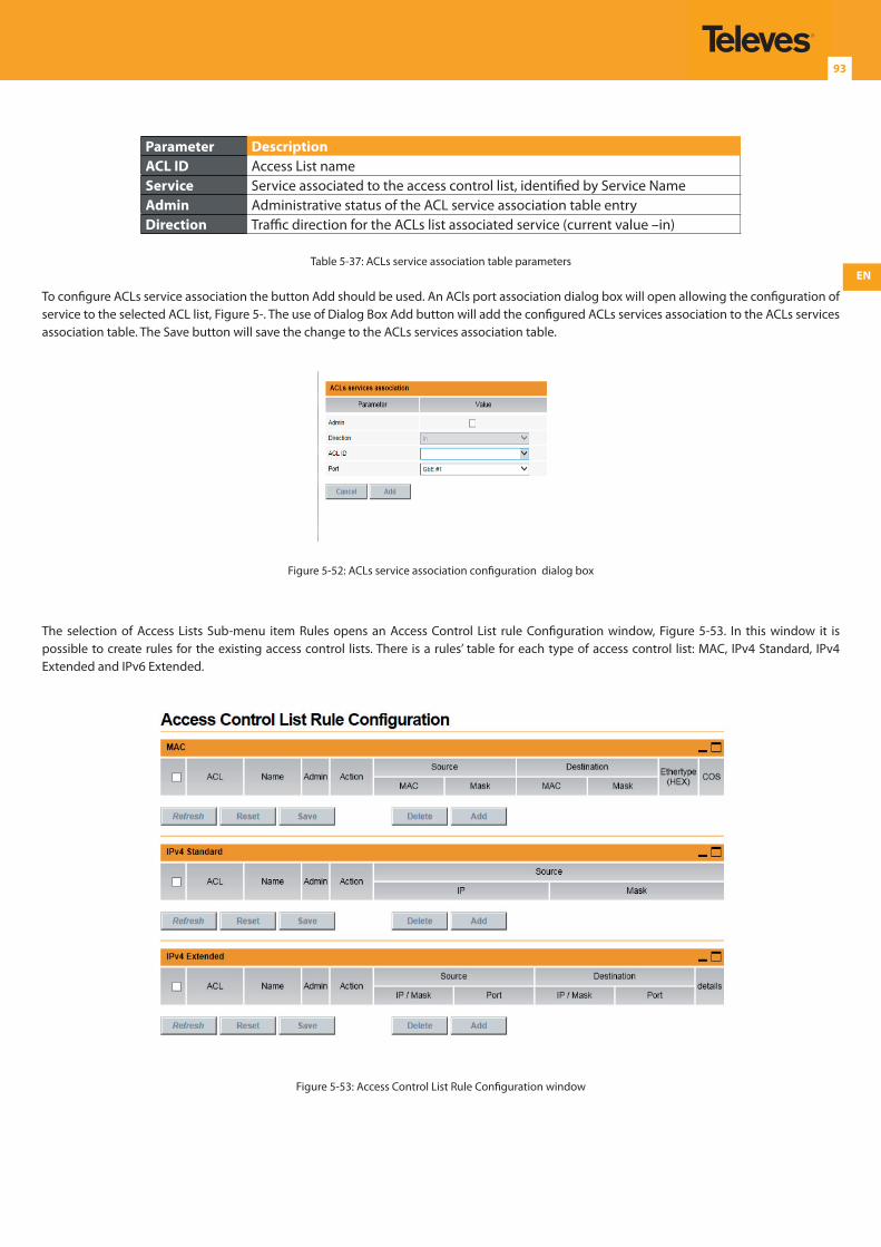
EN
93
Parameter DescriptionACL ID Access List nameService Service associated to the access control list, identified by Service NameAdmin Administrative status of the ACL service association table entryDirection Traffic direction for the ACLs list associated service (current value –in)
Table 5-37: ACLs service association table parameters
To configure ACLs service association the button Add should be used. An ACls port association dialog box will open allowing the configuration of service to the selected ACL list, Figure 5-. The use of Dialog Box Add button will add the configured ACLs services association to the ACLs services association table. The Save button will save the change to the ACLs services association table.
Figure 5-52: ACLs service association configuration dialog box
The selection of Access Lists Sub-menu item Rules opens an Access Control List rule Configuration window, Figure 5-53. In this window it is possible to create rules for the existing access control lists. There is a rules’ table for each type of access control list: MAC, IPv4 Standard, IPv4 Extended and IPv6 Extended.
Figure 5-53: Access Control List Rule Configuration window
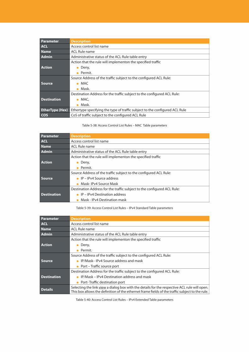
Descripción del producto
94
Parameter DescriptionACL Access control list nameName ACL Rule nameAdmin Administrative status of the ACL Rule table entry
ActionAction that the rule will implementon the specified traffic Deny, Permit.
SourceSource Address of the traffic subject to the configured ACL Rule: MAC Mask.
DestinationDestination Address for the traffic subject to the configured ACL Rule: MAC, Mask.
EtherType (Hex) Ethertype specifying the type of traffic subject to the configured ACL RuleCOS CoS of traffic subject to the configured ACL Rule
Table 5-38: Access Control List Rules – MAC Table parameters
Parameter DescriptionACL Access control list nameName ACL Rule nameAdmin Administrative status of the ACL Rule table entry
ActionAction that the rule will implementon the specified traffic Deny, Permit.
SourceSource Address of the traffic subject to the configured ACL Rule: IP – IPv4 Source address Mask- IPv4 Source Mask
DestinationDestination Address for the traffic subject to the configured ACL Rule: IP – IPv4 Destination address Mask - IPv4 Destination mask
Table 5-39: Access Control List Rules – IPv4 Standard Table parameters
Parameter DescriptionACL Access control list nameName ACL Rule nameAdmin Administrative status of the ACL Rule table entry
ActionAction that the rule will implementon the specified traffic Deny, Permit.
SourceSource Address of the traffic subject to the configured ACL Rule: IP/Mask– IPv4 Source address and mask Port – Traffic source port
DestinationDestination Address for the traffic subject to the configured ACL Rule: IP/Mask – IPv4 Destination address and mask Port- Traffic destination port
Details Selecting the link view a dialog box with the details for the respective ACL rule will open. This box allows the definition of the ethernet frame fields of the traffic subject to the rule.
Table 5-40: Access Control List Rules – IPv4 Extended Table parameters
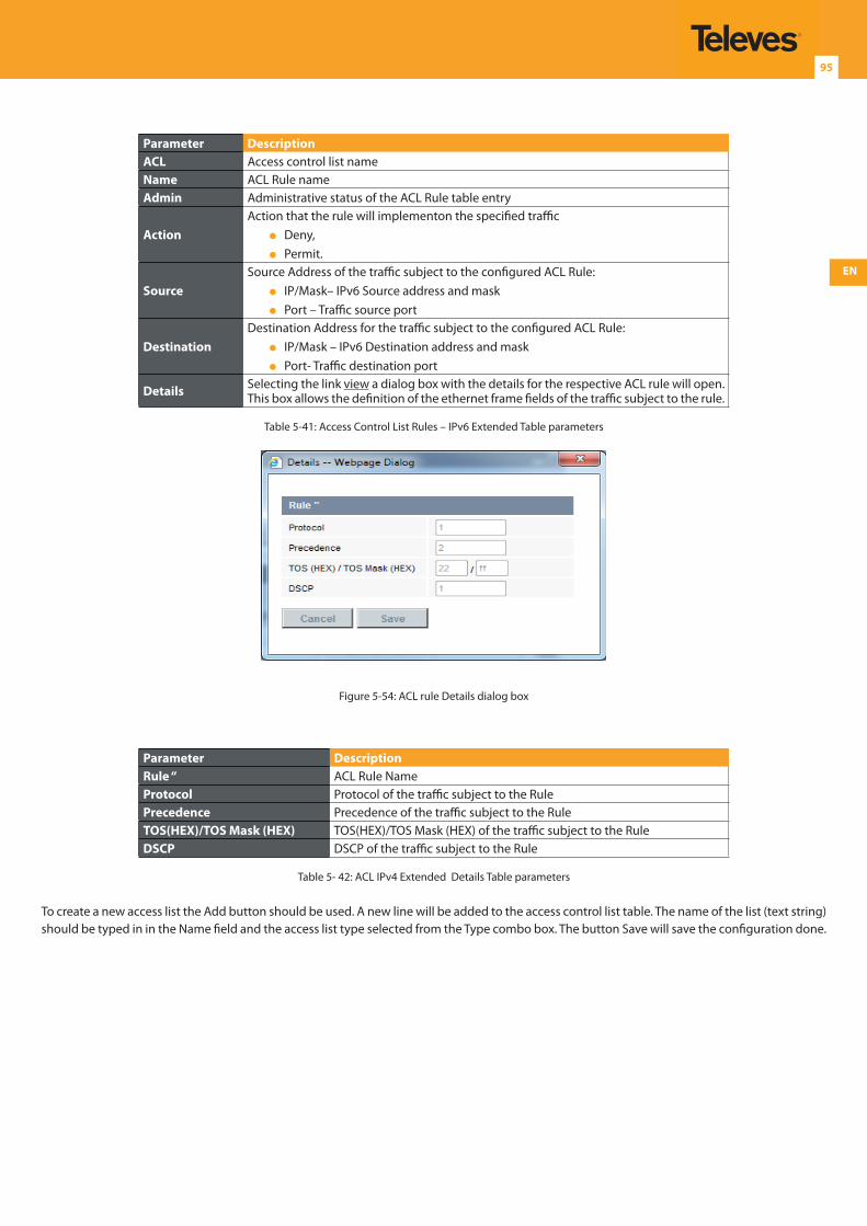
EN
95
Parameter DescriptionACL Access control list nameName ACL Rule nameAdmin Administrative status of the ACL Rule table entry
ActionAction that the rule will implementon the specified traffic Deny, Permit.
SourceSource Address of the traffic subject to the configured ACL Rule: IP/Mask– IPv6 Source address and mask Port – Traffic source port
DestinationDestination Address for the traffic subject to the configured ACL Rule: IP/Mask – IPv6 Destination address and mask Port- Traffic destination port
Details Selecting the link view a dialog box with the details for the respective ACL rule will open. This box allows the definition of the ethernet frame fields of the traffic subject to the rule.
Table 5-41: Access Control List Rules – IPv6 Extended Table parameters
Figure 5-54: ACL rule Details dialog box
Parameter DescriptionRule “ ACL Rule NameProtocol Protocol of the traffic subject to the RulePrecedence Precedence of the traffic subject to the RuleTOS(HEX)/TOS Mask (HEX) TOS(HEX)/TOS Mask (HEX) of the traffic subject to the Rule DSCP DSCP of the traffic subject to the Rule
Table 5- 42: ACL IPv4 Extended Details Table parameters
To create a new access list the Add button should be used. A new line will be added to the access control list table. The name of the list (text string)should be typed in in the Name field and the access list type selected from the Type combo box. The button Save will save the configuration done.
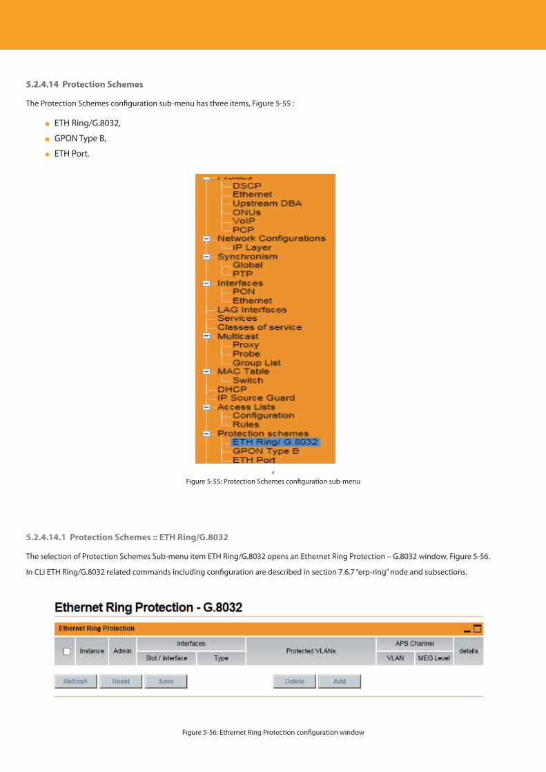
Descripción del producto
96
5.2.4.14 Protection Schemes
The Protection Schemes configuration sub-menu has three items, Figure 5-55 :
ETH Ring/G.8032,
GPON Type B,
ETH Port.
,Figure 5-55: Protection Schemes configuration sub-menu
5.2.4.14.1 Protection Schemes :: ETH Ring/G.8032
The selection of Protection Schemes Sub-menu item ETH Ring/G.8032 opens an Ethernet Ring Protection – G.8032 window, Figure 5-56.
In CLI ETH Ring/G.8032 related commands including configuration are described in section 7.6.7 “erp-ring” node and subsections.
Figure 5-56: Ethernet Ring Protection configuration window
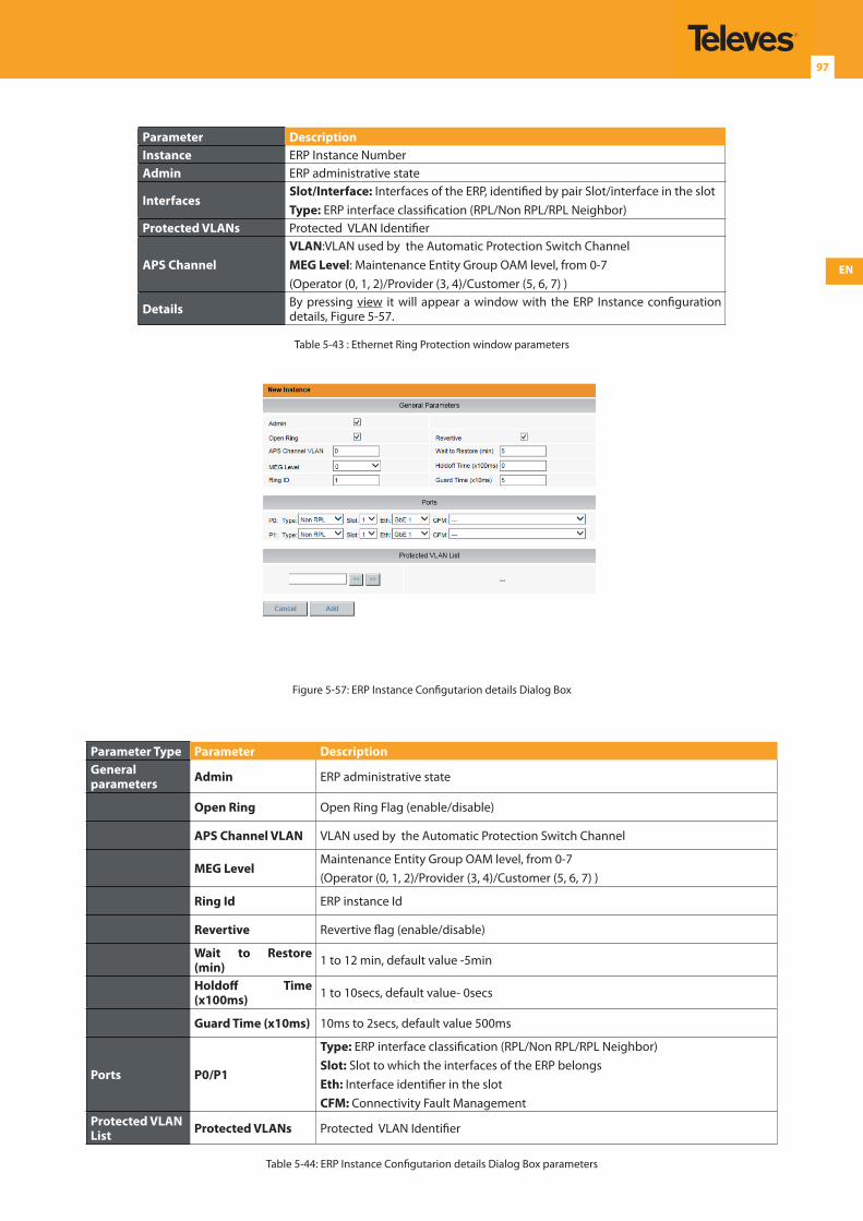
EN
97
Parameter DescriptionInstance ERP Instance NumberAdmin ERP administrative state
InterfacesSlot/Interface: Interfaces of the ERP, identified by pair Slot/interface in the slotType: ERP interface classification (RPL/Non RPL/RPL Neighbor)
Protected VLANs Protected VLAN Identifier
APS ChannelVLAN:VLAN used by the Automatic Protection Switch ChannelMEG Level: Maintenance Entity Group OAM level, from 0-7(Operator (0, 1, 2)/Provider (3, 4)/Customer (5, 6, 7) )
Details By pressing view it will appear a window with the ERP Instance configuration details, Figure 5-57.
Table 5-43 : Ethernet Ring Protection window parameters
Figure 5-57: ERP Instance Configutarion details Dialog Box
Parameter Type Parameter DescriptionGeneral parameters Admin ERP administrative state
Open Ring Open Ring Flag (enable/disable)
APS Channel VLAN VLAN used by the Automatic Protection Switch Channel
MEG LevelMaintenance Entity Group OAM level, from 0-7(Operator (0, 1, 2)/Provider (3, 4)/Customer (5, 6, 7) )
Ring Id ERP instance Id
Revertive Revertive flag (enable/disable)
Wait to Restore (min) 1 to 12 min, default value -5min
Holdoff Time (x100ms) 1 to 10secs, default value- 0secs
Guard Time (x10ms) 10ms to 2secs, default value 500ms
Ports P0/P1
Type: ERP interface classification (RPL/Non RPL/RPL Neighbor)Slot: Slot to which the interfaces of the ERP belongs Eth: Interface identifier in the slotCFM: Connectivity Fault Management
Protected VLAN List Protected VLANs Protected VLAN Identifier
Table 5-44: ERP Instance Configutarion details Dialog Box parameters
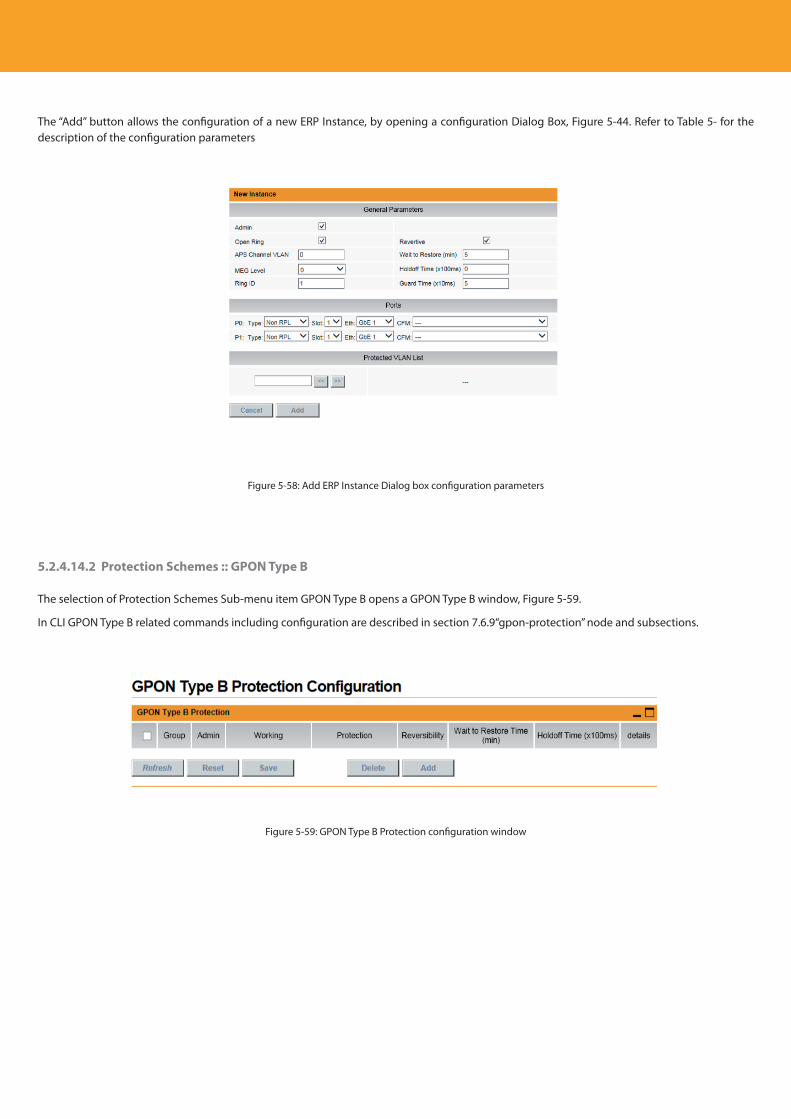
Descripción del producto
98
The “Add” button allows the configuration of a new ERP Instance, by opening a configuration Dialog Box, Figure 5-44. Refer to Table 5- for the description of the configuration parameters
Figure 5-58: Add ERP Instance Dialog box configuration parameters
5.2.4.14.2 Protection Schemes :: GPON Type B
The selection of Protection Schemes Sub-menu item GPON Type B opens a GPON Type B window, Figure 5-59.
In CLI GPON Type B related commands including configuration are described in section 7.6.9“gpon-protection” node and subsections.
Figure 5-59: GPON Type B Protection configuration window
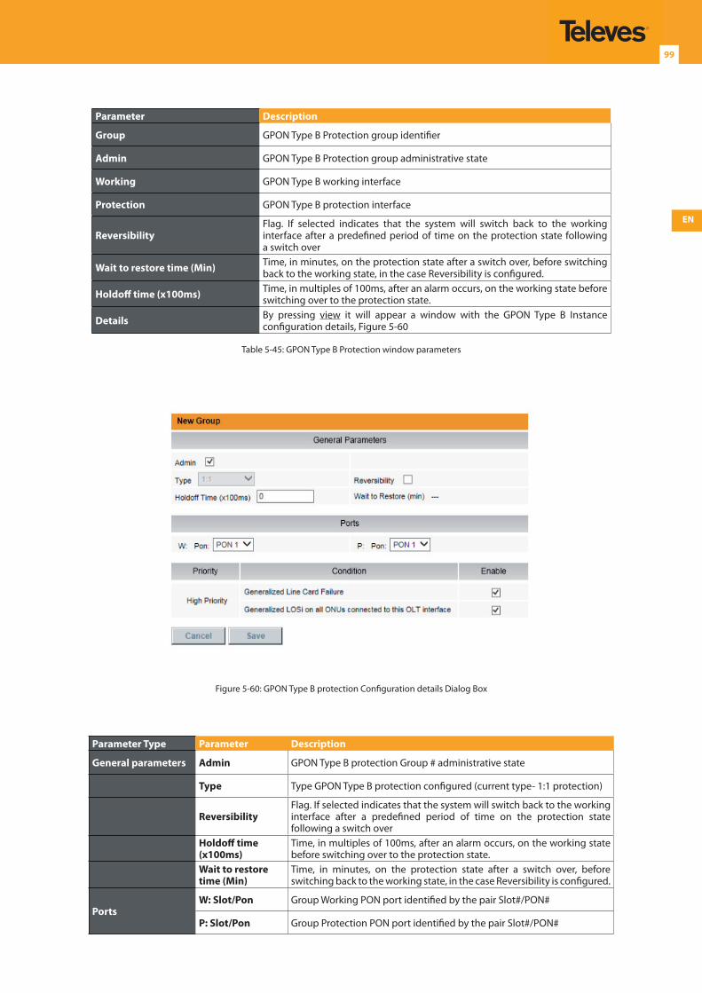
EN
99
Parameter Description
Group GPON Type B Protection group identifier
Admin GPON Type B Protection group administrative state
Working GPON Type B working interface
Protection GPON Type B protection interface
ReversibilityFlag. If selected indicates that the system will switch back to the working interface after a predefined period of time on the protection state following a switch over
Wait to restore time (Min) Time, in minutes, on the protection state after a switch over, before switching back to the working state, in the case Reversibility is configured.
Holdoff time (x100ms) Time, in multiples of 100ms, after an alarm occurs, on the working state before switching over to the protection state.
Details By pressing view it will appear a window with the GPON Type B Instance configuration details, Figure 5-60
Table 5-45: GPON Type B Protection window parameters
Figure 5-60: GPON Type B protection Configuration details Dialog Box
Parameter Type Parameter Description
General parameters Admin GPON Type B protection Group # administrative state
Type Type GPON Type B protection configured (current type- 1:1 protection)
ReversibilityFlag. If selected indicates that the system will switch back to the working interface after a predefined period of time on the protection state following a switch over
Holdoff time (x100ms)
Time, in multiples of 100ms, after an alarm occurs, on the working state before switching over to the protection state.
Wait to restore time (Min)
Time, in minutes, on the protection state after a switch over, before switching back to the working state, in the case Reversibility is configured.
PortsW: Slot/Pon Group Working PON port identified by the pair Slot#/PON#
P: Slot/Pon Group Protection PON port identified by the pair Slot#/PON#
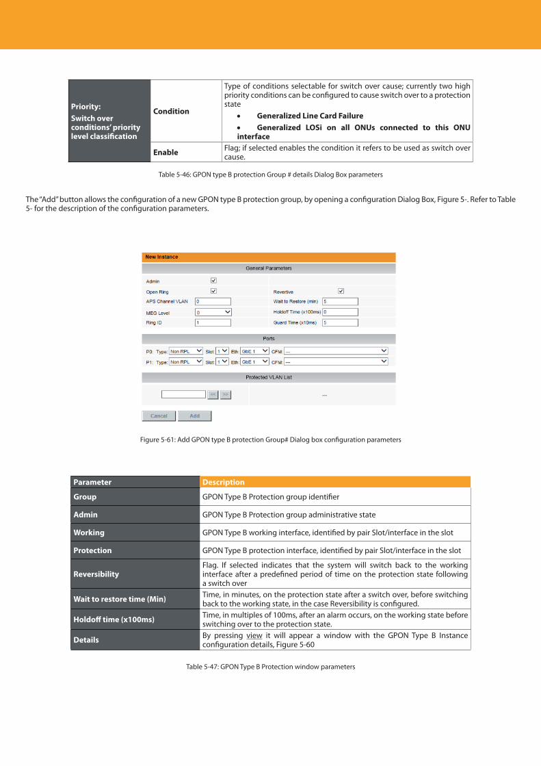
Descripción del producto
100
Priority: Switch over conditions’ priority level classification
Condition
Type of conditions selectable for switch over cause; currently two high priority conditions can be configured to cause switch over to a protection state
• Generalized Line Card Failure• Generalized LOSi on all ONUs connected to this ONU interface
Enable Flag; if selected enables the condition it refers to be used as switch over cause.
Table 5-46: GPON type B protection Group # details Dialog Box parameters
The “Add” button allows the configuration of a new GPON type B protection group, by opening a configuration Dialog Box, Figure 5-. Refer to Table 5- for the description of the configuration parameters.
Figure 5-61: Add GPON type B protection Group# Dialog box configuration parameters
Parameter Description
Group GPON Type B Protection group identifier
Admin GPON Type B Protection group administrative state
Working GPON Type B working interface, identified by pair Slot/interface in the slot
Protection GPON Type B protection interface, identified by pair Slot/interface in the slot
ReversibilityFlag. If selected indicates that the system will switch back to the working interface after a predefined period of time on the protection state following a switch over
Wait to restore time (Min) Time, in minutes, on the protection state after a switch over, before switching back to the working state, in the case Reversibility is configured.
Holdoff time (x100ms) Time, in multiples of 100ms, after an alarm occurs, on the working state before switching over to the protection state.
Details By pressing view it will appear a window with the GPON Type B Instance configuration details, Figure 5-60
Table 5-47: GPON Type B Protection window parameters
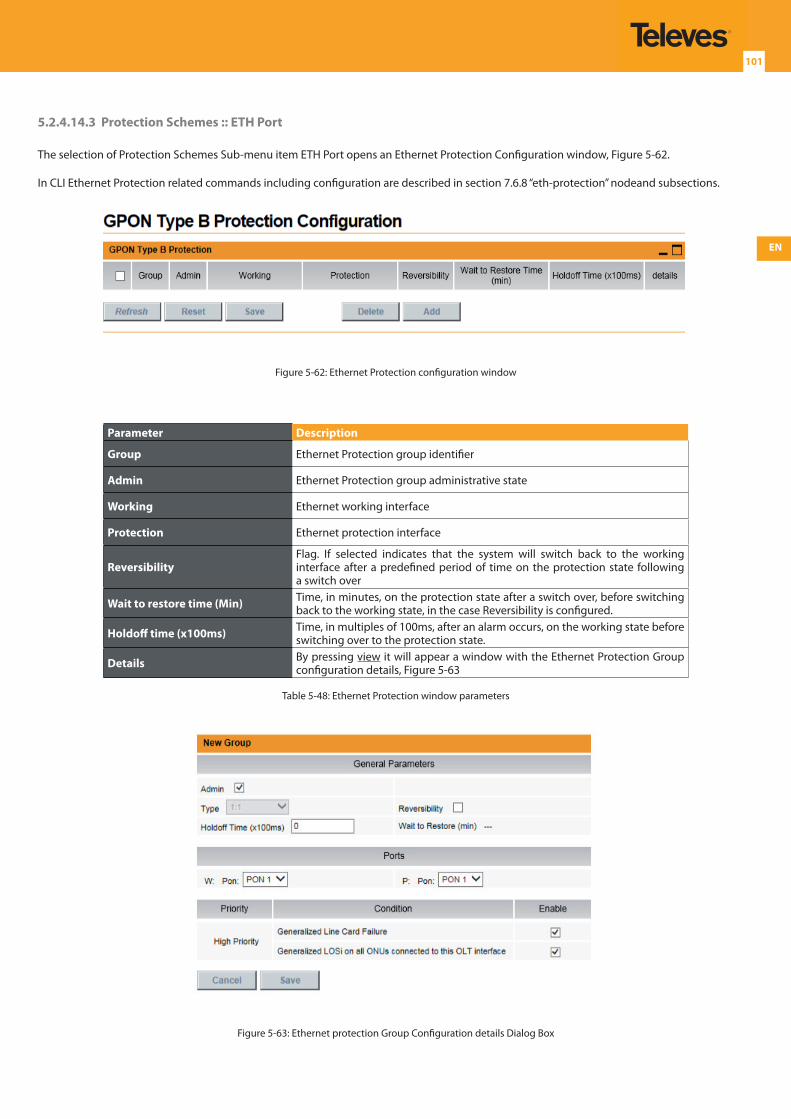
EN
101
5.2.4.14.3 Protection Schemes :: ETH Port
The selection of Protection Schemes Sub-menu item ETH Port opens an Ethernet Protection Configuration window, Figure 5-62.
In CLI Ethernet Protection related commands including configuration are described in section 7.6.8 “eth-protection” nodeand subsections.
Figure 5-62: Ethernet Protection configuration window
Parameter Description
Group Ethernet Protection group identifier
Admin Ethernet Protection group administrative state
Working Ethernet working interface
Protection Ethernet protection interface
ReversibilityFlag. If selected indicates that the system will switch back to the working interface after a predefined period of time on the protection state following a switch over
Wait to restore time (Min) Time, in minutes, on the protection state after a switch over, before switching back to the working state, in the case Reversibility is configured.
Holdoff time (x100ms) Time, in multiples of 100ms, after an alarm occurs, on the working state before switching over to the protection state.
Details By pressing view it will appear a window with the Ethernet Protection Group configuration details, Figure 5-63
Table 5-48: Ethernet Protection window parameters
Figure 5-63: Ethernet protection Group Configuration details Dialog Box
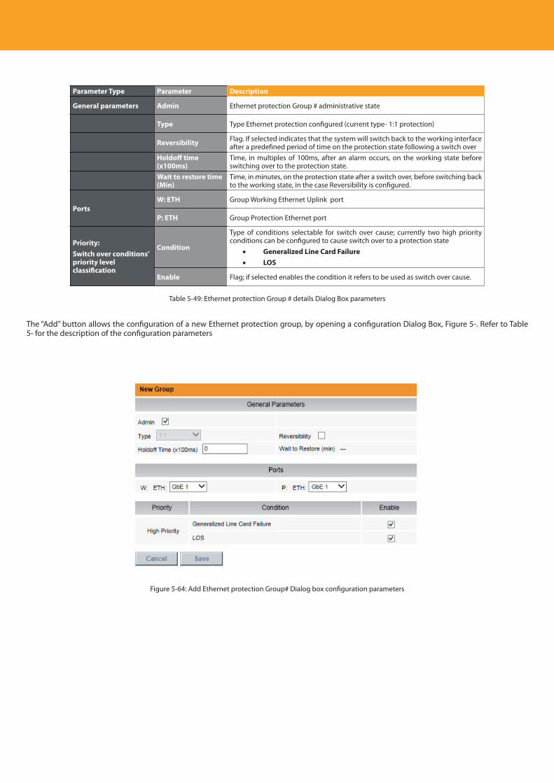
Descripción del producto
102
Parameter Type Parameter Description
General parameters Admin Ethernet protection Group # administrative state
Type Type Ethernet protection configured (current type- 1:1 protection)
Reversibility Flag. If selected indicates that the system will switch back to the working interface after a predefined period of time on the protection state following a switch over
Holdoff time (x100ms)
Time, in multiples of 100ms, after an alarm occurs, on the working state before switching over to the protection state.
Wait to restore time (Min)
Time, in minutes, on the protection state after a switch over, before switching back to the working state, in the case Reversibility is configured.
PortsW: ETH Group Working Ethernet Uplink port
P: ETH Group Protection Ethernet port
Priority: Switch over conditions’ priority level classification
Condition
Type of conditions selectable for switch over cause; currently two high priority conditions can be configured to cause switch over to a protection state
• Generalized Line Card Failure• LOS
Enable Flag; if selected enables the condition it refers to be used as switch over cause.
Table 5-49: Ethernet protection Group # details Dialog Box parameters
The “Add” button allows the configuration of a new Ethernet protection group, by opening a configuration Dialog Box, Figure 5-. Refer to Table 5- for the description of the configuration parameters
Figure 5-64: Add Ethernet protection Group# Dialog box configuration parameters
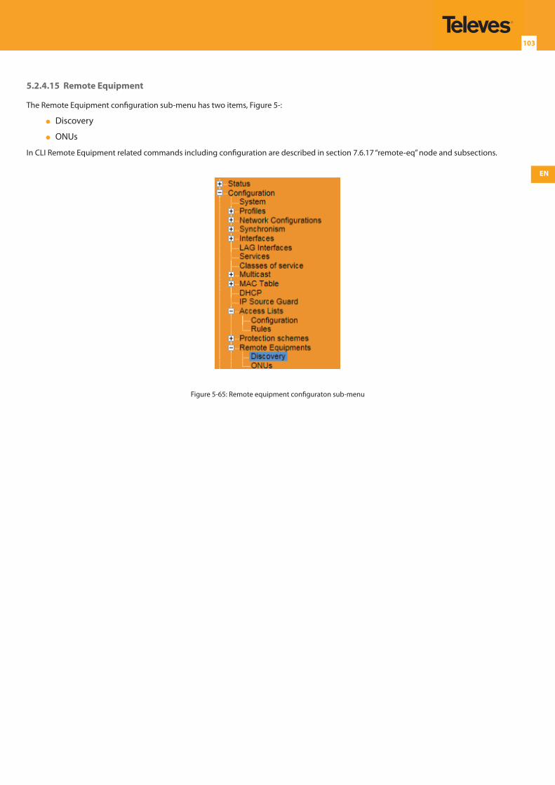
EN
103
5.2.4.15 Remote Equipment
The Remote Equipment configuration sub-menu has two items, Figure 5-:
Discovery
ONUs
In CLI Remote Equipment related commands including configuration are described in section 7.6.17 “remote-eq” node and subsections.
Figure 5-65: Remote equipment configuraton sub-menu
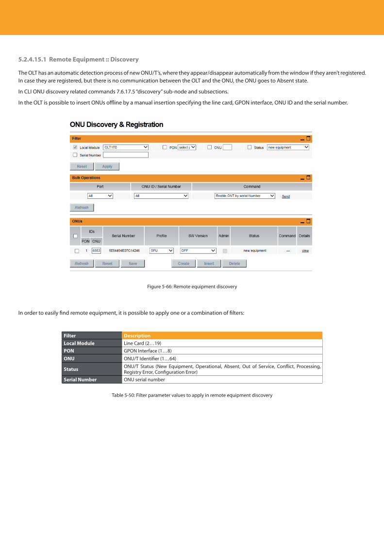
Descripción del producto
104
5.2.4.15.1 Remote Equipment :: Discovery
The OLT has an automatic detection process of new ONU/T’s, where they appear/disappear automatically from the window if they aren’t registered. In case they are registered, but there is no communication between the OLT and the ONU, the ONU goes to Absent state.
In CLI ONU discovery related commands 7.6.17.5 “discovery” sub-node and subsections.
In the OLT is possible to insert ONUs offline by a manual insertion specifying the line card, GPON interface, ONU ID and the serial number.
Figure 5-66: Remote equipment discovery
In order to easily find remote equipment, it is possible to apply one or a combination of filters:
Filter DescriptionLocal Module Line Card (2…19)PON GPON Interface (1…8)
ONU ONU/T Identifier (1…64)
Status ONU/T Status (New Equipment, Operational, Absent, Out of Service, Conflict, Processing, Registry Error, Configuration Error)
Serial Number ONU serial number
Table 5-50: Filter parameter values to apply in remote equipment discovery
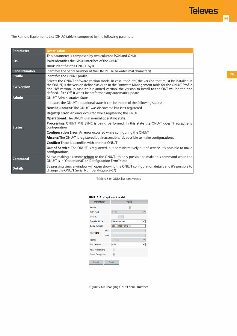
EN
105
The Remote Equipments List (ONUs) table is composed by the following parameter:
Parameter Description
IDsThis parameter is composed by two columns PON and ONU;PON: identifies the GPON interface of the ONU/TONU: identifies the ONU/T by ID
Serial Number Identifies the Serial Number of the ONU/T (16 hexadecimal characters)Profile Identifies the ONU/T profile
SW Version
Selects the ONU/T software version mode. In case it’s “Auto”, the version that must be installed in the ONU/T, is the version defined as Auto in the Firmware Management table for the ONU/T Profile and HW version. In case it’s a planned version, the version to install to the ONT will be the one defined. If it’s Off, it won’t be preformed any automatic update.
Admin ONU/T Administrative State
Status
Indicates the ONU/T operational state. It can be in one of the following states:New Equipment: The ONU/T was discovered but isn’t registeredRegistry Error: An error occurred while registering the ONU/TOperational: The ONU/T is in normal operating stateProcessing: ONU/T MIB SYNC is being performed, in this state the ONU/T doesn’t accept any configurationConfiguration Error: An error occurred while configuring the ONU/TAbsent: The ONU/T is registered but inaccessible. It’s possible to make configurations.Conflict: There is a conflict with another ONU/TOut of Service: The ONU/T is registered, but administratively out of service. It’s possible to make configurations.
Command Allows making a remote reboot to the ONU/T. It’s only possible to make this command when the ONU/T is in “Operational” or “Configuration Error” state
Details By pressing view, a window will open showing the ONU/T configuration details and it’s possible to change the ONU/T Serial Number (Figure 5-67)
Table 5-51: : ONUs list parameters
Figure 5-67: Changing ONU/T Serial Number
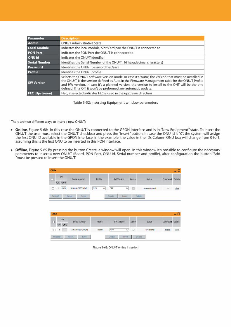
Descripción del producto
106
Parameter DescriptionAdmin ONU/T Administrative StateLocal Module Indicates the local module, Slot/Card pair the ONU/T is connected to PON Port Indicates the PON Port the ONU/T is connected toONU Id Indicates the ONU/T IdentifierSerial Number Identifies the Serial Number of the ONU/T (16 hexadecimal characters)Password Identifies the ONU/T password hex/asciiProfile Identifies the ONU/T profile
SW Version
Selects the ONU/T software version mode. In case it’s “Auto”, the version that must be installed in the ONU/T, is the version defined as Auto in the Firmware Management table for the ONU/T Profile and HW version. In case it’s a planned version, the version to install to the ONT will be the one defined. If it’s Off, it won’t be preformed any automatic update.
FEC (Upstream) Flag; if selected indicates FEC is used in the upstream direction
Table 5-52: Inserting Equipment window parameters
There are two different ways to insert a new ONU/T:
• Online, Figure 5-68: In this case the ONU/T is connected to the GPON Interface and is in “New Equipment” state. To insert the ONU/T the user must select the ONU/T checkbox and press the “Insert” button. In case the ONU id is “0”, the system will assign the first ONU ID available in the GPON Interface, in the example, the value in the IDs Column ONU box will change from 0 to 1, assuming this is the first ONU to be inserted in this PON interface.
• Offline, Figure 5-69.By pressing the button Create, a window will open. In this window it’s possible to configure the necessary parameters to insert a new ONU/T (Board, PON Port, ONU id, Serial number and profile), after configuration the button “Add “must be pressed to insert the ONU/T.
Figure 5-68: ONU/T online insertion
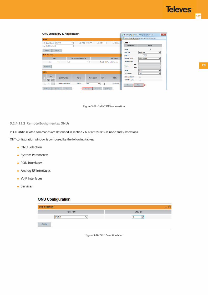
EN
107
1
2
Figure 5-69: ONU/T Offline insertion
5.2.4.15.2 Remote Equipments:: ONUs
In CLI ONUs related commands are described in section 7.6.17.6 “ONUs” sub-node and subsections.
ONT configuration window is composed by the following tables:
ONU Selection
System Parameters
PON Interfaces
Analog RF Interfaces
VoIP Interfaces
Services
Figure 5-70: ONU Selection filter
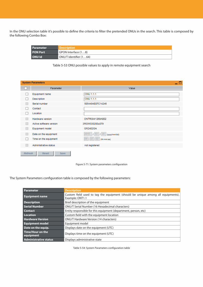
Descripción del producto
108
In the ONU selection table it’s possible to define the criteria to filter the pretended ONUs in the search. This table is composed by the following Combo Box:
Parameter DescriptionPON Port GPON Interface (1…8)
ONU Id ONU/T Identifier (1…64)
Table 5-53 ONU possible values to apply in remote equipment search
Figure 5-71: System parameters configuration
The System Parameters configuration table is composed by the following parameters:
Parameter Description
Equipment name Custom field used to tag the equipment (should be unique among all equipments). Example: ONT1.1
Description Brief description of the equipmentSerial Number ONU/T Serial Number (16 Hexadecimal characters)Contact Entity responsible for this equipment (department, person, etc)Location Custom field with the equipment locationHardware Version ONU/T Hardware Version (14 characters)Equipment model Equipment modelDate on the equip. Displays date on the equipment (UTC)Time/Hour on the equipment Displays time on the equipment (UTC)
Administrative status Displays administrative state
Table 5-54: System Parameters configuration table
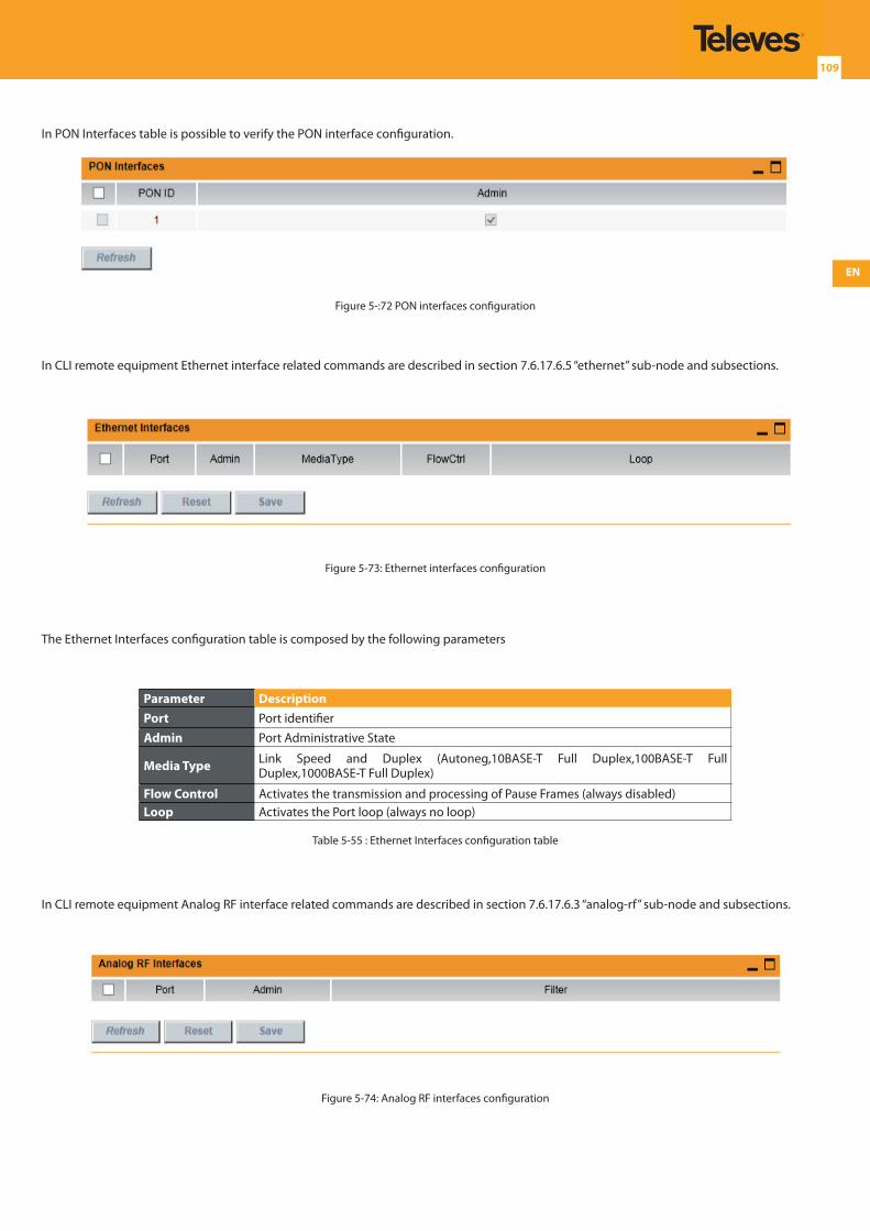
EN
109
In PON Interfaces table is possible to verify the PON interface configuration.
Figure 5-:72 PON interfaces configuration
In CLI remote equipment Ethernet interface related commands are described in section 7.6.17.6.5 “ethernet” sub-node and subsections.
Figure 5-73: Ethernet interfaces configuration
The Ethernet Interfaces configuration table is composed by the following parameters
Parameter DescriptionPort Port identifierAdmin Port Administrative State
Media Type Link Speed and Duplex (Autoneg,10BASE-T Full Duplex,100BASE-T Full Duplex,1000BASE-T Full Duplex)
Flow Control Activates the transmission and processing of Pause Frames (always disabled)Loop Activates the Port loop (always no loop)
Table 5-55 : Ethernet Interfaces configuration table
In CLI remote equipment Analog RF interface related commands are described in section 7.6.17.6.3 “analog-rf” sub-node and subsections.
Figure 5-74: Analog RF interfaces configuration
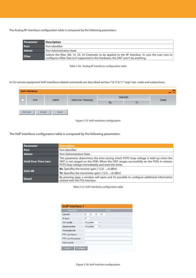
Descripción del producto
110
The Analog RF Interfaces configuration table is composed by the following parameters:
Parameter DescriptionPort Port identifierAdmin Port Administrative State
Filter Selects the filter (All, 15, 25, 35 Channels) to be applied to the RF Interface. In case the user tries to configure a filter that isn’t supported in the Hardware, the ONT won’t do anything.
Table 5-56 : Analog RF Interfaces configuration table
In CLI remote equipment VoIP interfaces related commands are described section 7.6.17.6.11 “voip” sub- node and subsections.
Figure 5-75: VoIP interfaces configuration
The VoIP Interfaces configuration table is composed by the following parameters:
Parameter DescriptionPort Port identifierAdmin Port Administrative State
Hold Over Time (sec)This parameter determines the time during which POTS loop voltage is held up when the ONT is not ranged on the PON. When the ONT ranges successfully on the PON, it restores POTS loop voltage immediately and reset the timer.
Gain dBRx: Specifies the receiver gain (-12.0…+6 dBm)Tx: Specifies the transmitter gain (-12.0…+6 dBm)
Detail By pressing view, a window will open and it’s possible to configure additional information related with the FXS interface
Table 5-57: VoIP Interfaces configuration table
Figure 5-76: VoIP interface configuration
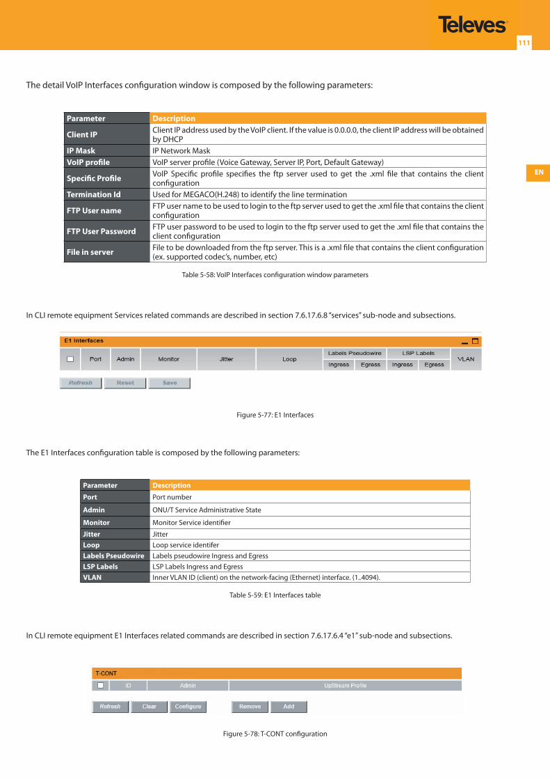
EN
111
The detail VoIP Interfaces configuration window is composed by the following parameters:
Parameter Description
Client IP Client IP address used by the VoIP client. If the value is 0.0.0.0, the client IP address will be obtained by DHCP
IP Mask IP Network MaskVoIP profile VoIP server profile (Voice Gateway, Server IP, Port, Default Gateway)
Specific Profile VoIP Specific profile specifies the ftp server used to get the .xml file that contains the client configuration
Termination Id Used for MEGACO(H.248) to identify the line termination
FTP User name FTP user name to be used to login to the ftp server used to get the .xml file that contains the client configuration
FTP User Password FTP user password to be used to login to the ftp server used to get the .xml file that contains the client configuration
File in server File to be downloaded from the ftp server. This is a .xml file that contains the client configuration (ex. supported codec’s, number, etc)
Table 5-58: VoIP Interfaces configuration window parameters
In CLI remote equipment Services related commands are described in section 7.6.17.6.8 “services” sub-node and subsections.
Figure 5-77: E1 Interfaces
The E1 Interfaces configuration table is composed by the following parameters:
Parameter Description
Port Port number
Admin ONU/T Service Administrative State
Monitor Monitor Service identifier
Jitter JitterLoop Loop service identiferLabels Pseudowire Labels pseudowire Ingress and EgressLSP Labels LSP Labels Ingress and EgressVLAN Inner VLAN ID (client) on the network-facing (Ethernet) interface. (1..4094).
Table 5-59: E1 Interfaces table
In CLI remote equipment E1 Interfaces related commands are described in section 7.6.17.6.4 “e1” sub-node and subsections.
Figure 5-78: T-CONT configuration
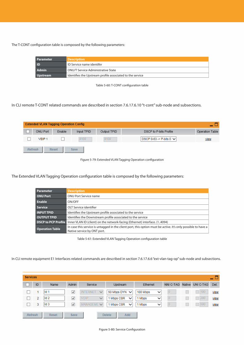
Descripción del producto
112
The T-CONT configuration table is composed by the following parameters:
Parameter Description
ID ID Service name identifer
Admin ONU/T Service Administrative State
Upstream Identifies the Upstream profile associated to the service
Table 5-60: T-CONT configuration table
In CLI remote T-CONT related commands are described in section 7.6.17.6.10 “t-cont” sub-node and subsections.
Figure 5-79: Extended VLAN Tagging Operation configuration
The Extended VLAN Tagging Operation configuration table is composed by the following parameters:
Parameter Description
ONU Port ONU Port Service name
Enable ON/OFF
Service OLT Service identifier
INPUT TPID Identifies the Upstream profile associated to the serviceOUTPUT TPID Identifies the Downstream profile associated to the serviceDSCP to PCP Profile Inner VLAN ID (client) on the network-facing (Ethernet) interface. (1..4094)
Operation TableIn case this service is untagged in the client port, this option must be active. It’s only possible to have a Native service by ONT port.
Table 5-61: Extended VLAN Tagging Operation configuration table
In CLI remote equipment E1 Interfaces related commands are described in section 7.6.17.6.6 “ext-vlan-tag-op” sub-node and subsections.
Figure 5-80: Service Configuration
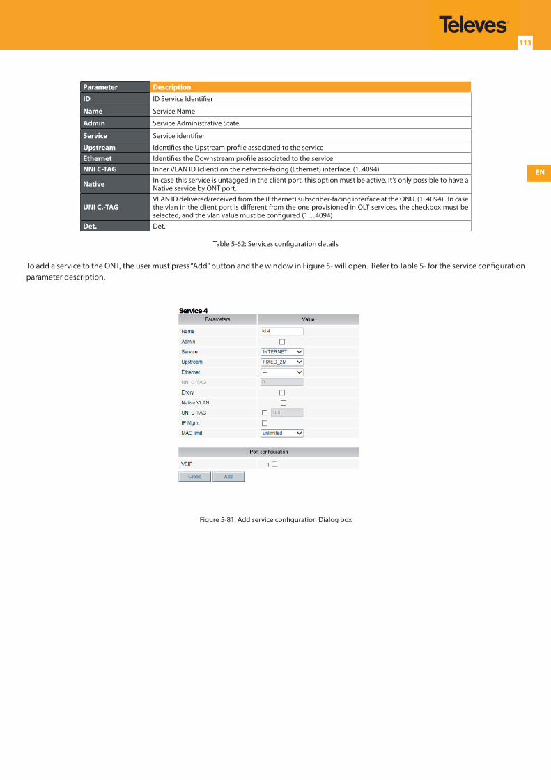
EN
113
Parameter Description
ID ID Service Identifier
Name Service Name
Admin Service Administrative State
Service Service identifier
Upstream Identifies the Upstream profile associated to the serviceEthernet Identifies the Downstream profile associated to the serviceNNI C-TAG Inner VLAN ID (client) on the network-facing (Ethernet) interface. (1..4094)
Native In case this service is untagged in the client port, this option must be active. It’s only possible to have a Native service by ONT port.
UNI C.-TAGVLAN ID delivered/received from the (Ethernet) subscriber-facing interface at the ONU. (1..4094) . In case the vlan in the client port is different from the one provisioned in OLT services, the checkbox must be selected, and the vlan value must be configured (1…4094)
Det. Det.
Table 5-62: Services configuration details
To add a service to the ONT, the user must press “Add” button and the window in Figure 5- will open. Refer to Table 5- for the service configuration parameter description.
Figure 5-81: Add service configuration Dialog box
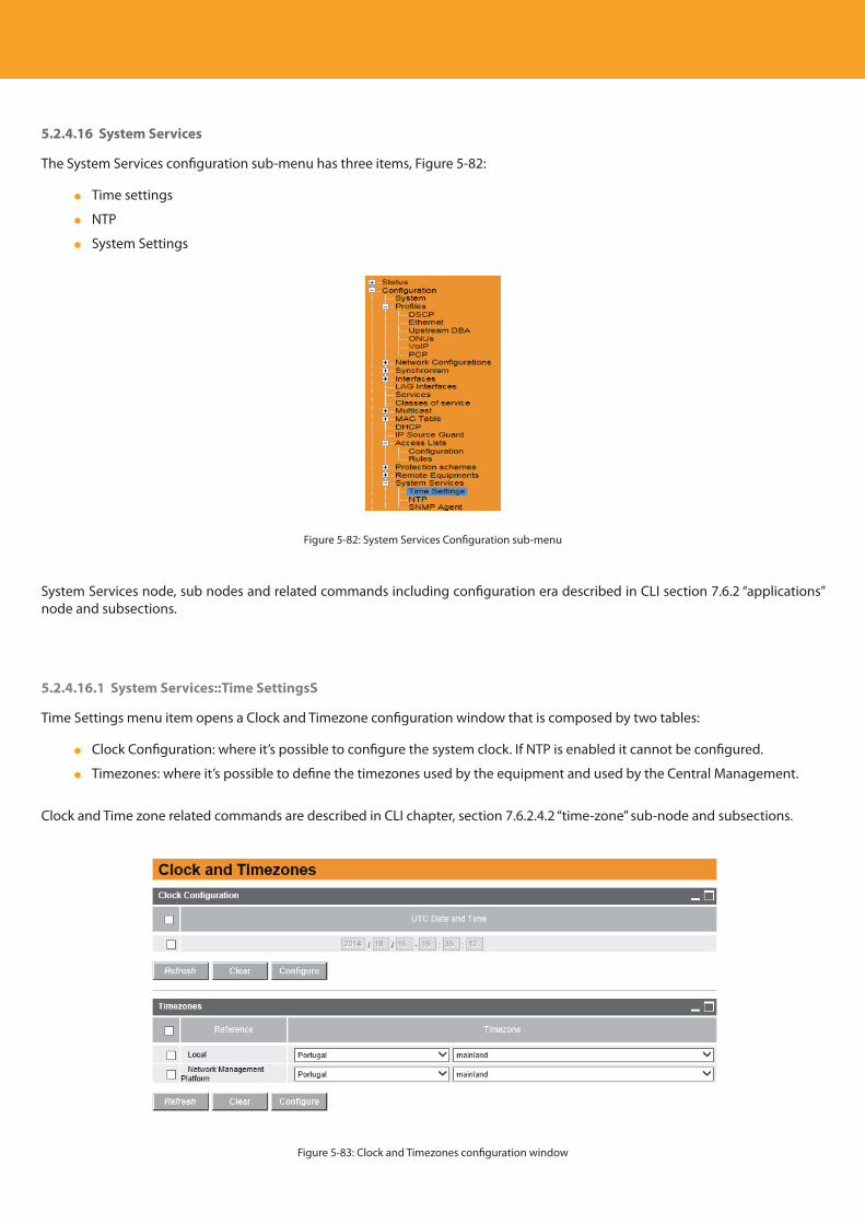
Descripción del producto
114
5.2.4.16 System Services
The System Services configuration sub-menu has three items, Figure 5-82:
Time settings
NTP
System Settings
Figure 5-82: System Services Configuration sub-menu
System Services node, sub nodes and related commands including configuration era described in CLI section 7.6.2 “applications” node and subsections.
5.2.4.16.1 System Services::Time SettingsS
Time Settings menu item opens a Clock and Timezone configuration window that is composed by two tables:
Clock Configuration: where it’s possible to configure the system clock. If NTP is enabled it cannot be configured.
Timezones: where it’s possible to define the timezones used by the equipment and used by the Central Management.
Clock and Time zone related commands are described in CLI chapter, section 7.6.2.4.2 “time-zone” sub-node and subsections.
Figure 5-83: Clock and Timezones configuration window
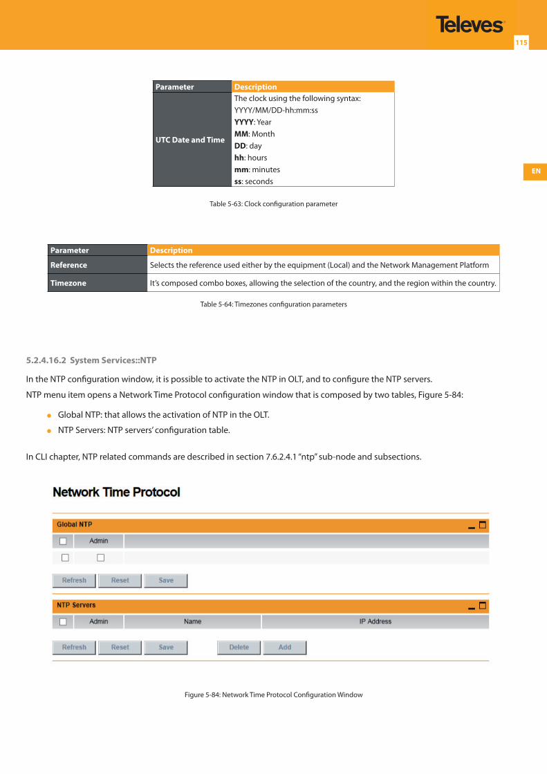
EN
115
Parameter Description
UTC Date and Time
The clock using the following syntax:YYYY/MM/DD-hh:mm:ssYYYY: YearMM: MonthDD: dayhh: hoursmm: minutesss: seconds
Table 5-63: Clock configuration parameter
Parameter Description
Reference Selects the reference used either by the equipment (Local) and the Network Management Platform
Timezone It’s composed combo boxes, allowing the selection of the country, and the region within the country.
Table 5-64: Timezones configuration parameters
5.2.4.16.2 System Services::NTP
In the NTP configuration window, it is possible to activate the NTP in OLT, and to configure the NTP servers.
NTP menu item opens a Network Time Protocol configuration window that is composed by two tables, Figure 5-84:
Global NTP: that allows the activation of NTP in the OLT.
NTP Servers: NTP servers’ configuration table.
In CLI chapter, NTP related commands are described in section 7.6.2.4.1 “ntp” sub-node and subsections.
Figure 5-84: Network Time Protocol Configuration Window
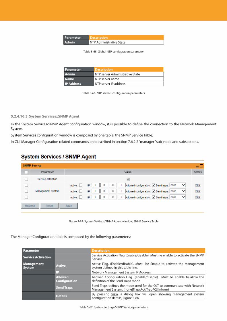
Descripción del producto
116
Parameter DescriptionAdmin NTP Administrative State
Table 5-65: Global NTP configuration parameter
Parameter DescriptionAdmin NTP server Administrative StateName NTP server nameIP Address NTP server IP address
Table 5-66: NTP servers’ configuration parameters
5.2.4.16.3 System Services::SNMP Agent
In the System Services/SNMP Agent configuration window, it is possible to define the connection to the Network Management System.
System Services configuration window is composed by one table, the SNMP Service Table.
In CLI, Manager Configuration related commands are described in section 7.6.2.2 “manager” sub-node and subsections.
Figure 5-85: System Settings/SNMP Agent window, SNMP Service Table
The Manager Configuration table is composed by the following parameters:
Parameter Description
Service Activation Service Activation Flag (Enable/disable). Must ne enable to activate the SNMP Service
Management System Active Active Flag. (Enable/disable). Must be Enable to activate the management
system defined in this table line.IP Network Management System IP AddressAllowed Configuration
Allowed Configuration Flag (enable/disable). Must be enable to allow the definition of the Send Traps mode
Send Traps Send Traps defines the mode used for the OLT to communicate with Network Management System. (none|Trap/Ack|Trap V2| Inform)
Details By pressing view, a dialog box will open showing management system configuration details, Figure 5-86.
Table 5-67: System Settings/SNMP Service parameters
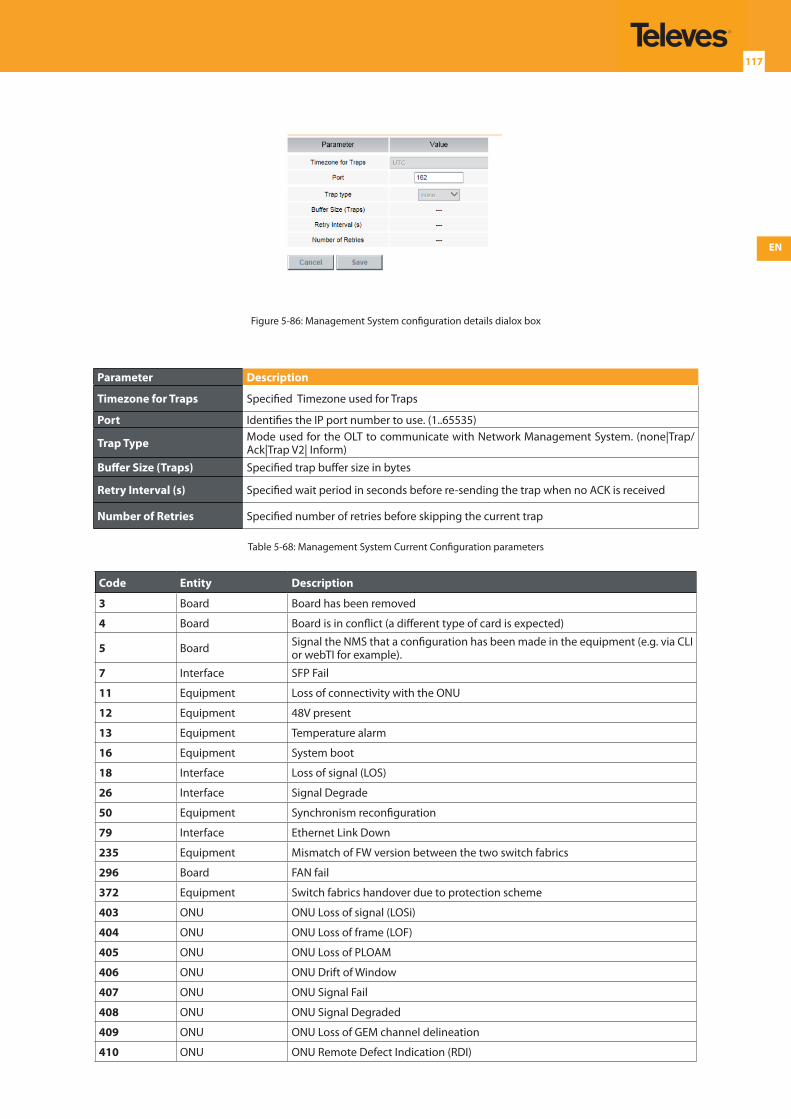
EN
117
Figure 5-86: Management System configuration details dialox box
Parameter Description
Timezone for Traps Specified Timezone used for Traps
Port Identifies the IP port number to use. (1..65535)
Trap Type Mode used for the OLT to communicate with Network Management System. (none|Trap/Ack|Trap V2| Inform)
Buffer Size (Traps) Specified trap buffer size in bytes
Retry Interval (s) Specified wait period in seconds before re-sending the trap when no ACK is received
Number of Retries Specified number of retries before skipping the current trap
Table 5-68: Management System Current Configuration parameters
Code Entity Description
3 Board Board has been removed
4 Board Board is in conflict (a different type of card is expected)
5 Board Signal the NMS that a configuration has been made in the equipment (e.g. via CLI or webTI for example).
7 Interface SFP Fail
11 Equipment Loss of connectivity with the ONU
12 Equipment 48V present
13 Equipment Temperature alarm
16 Equipment System boot
18 Interface Loss of signal (LOS)
26 Interface Signal Degrade
50 Equipment Synchronism reconfiguration
79 Interface Ethernet Link Down
235 Equipment Mismatch of FW version between the two switch fabrics
296 Board FAN fail
372 Equipment Switch fabrics handover due to protection scheme
403 ONU ONU Loss of signal (LOSi)
404 ONU ONU Loss of frame (LOF)
405 ONU ONU Loss of PLOAM
406 ONU ONU Drift of Window
407 ONU ONU Signal Fail
408 ONU ONU Signal Degraded
409 ONU ONU Loss of GEM channel delineation
410 ONU ONU Remote Defect Indication (RDI)
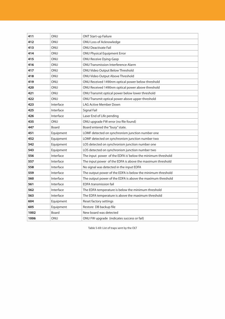
Descripción del producto
118
411 ONU ONT Start-up Failure
412 ONU ONU Loss of Acknowledge
413 ONU ONU Deactivate Fail
414 ONU ONU Physical Equipment Error
415 ONU ONU Receive Dying-Gasp
416 ONU ONU Transmission Interference Alarm
417 ONU ONU Video Output Below Threshold
418 ONU ONU Video Output Above Threshold
419 ONU ONU Received 1490nm optical power below threshold
420 ONU ONU Received 1490nm optical power above threshold
421 ONU ONU Transmit optical power below lower threshold
422 ONU ONU Transmit optical power above upper threshold
423 Interface LAG Active Member Down
425 Interface Signal Fail
426 Interface Laser End of Life pending
435 ONU ONU upgrade FW error (no file found)
447 Board Board entered the “busy” state.
451 Equipment LOMF detected on synchronism junction number one
452 Equipment LOMF detected on synchronism junction number two
542 Equipment LOS detected on synchronism junction number one
543 Equipment LOS detected on synchronism junction number two
556 Interface The input power of the EDFA is’ below the minimum threshold
557 Interface The input power of the EDFA is above the maximum threshold
558 Interface No signal was detected in the input EDFA
559 Interface The output power of the EDFA is below the minimum threshold
560 Interface The output power of the EDFA is above the maximum threshold
561 Interface EDFA transmission fail
562 Interface The EDFA temperature is below the minimum threshold
563 Interface The EDFA temperature is above the maximum threshold
604 Equipment Reset factory settings
605 Equipment Restore DB backup file
1002 Board New board was detected
1006 ONU ONU FW upgrade (indicates success or fail)
Table 5-69: List of traps sent by the OLT
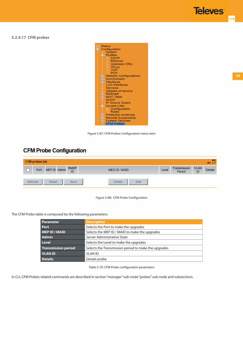
EN
119
5.2.4.17 CFM probes
Figure 5-87: CFM Probes Configuration menu item
Figure 5-88: CFM Probe Configuration
The CFM Probe table is composed by the following parameters:
Parameter DescriptionPort Selects the Port to make the upgradesMEP ID / MAID Selects the MEP ID / MAID to make the upgradesAdmin Server Administrative StateLevel Selects the Level to make the upgrades
Transmission period Selects the Transmission period to make the upgrades
VLAN ID VLAN IDDetails Details probe
Table 5-70: CFM Probe configuration parameters
In CLI, CFM Probes related commands are described in section “manager” sub-node “probes” sub-node and subsections.
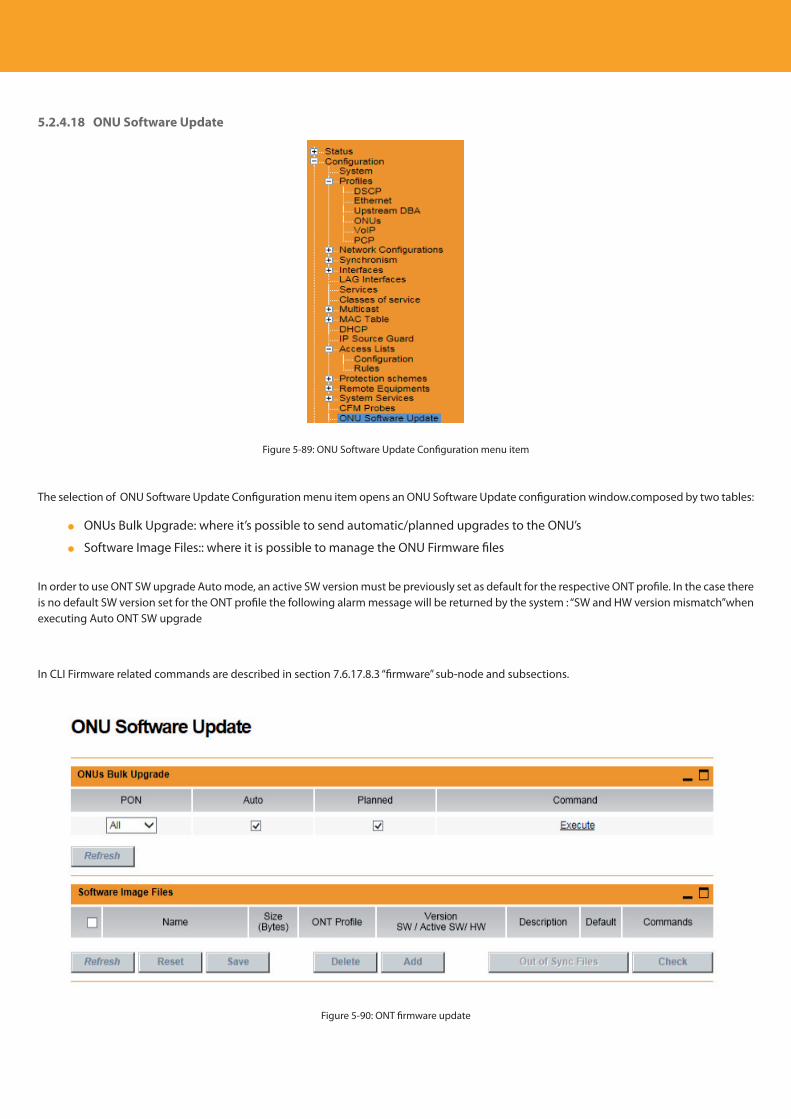
Descripción del producto
120
5.2.4.18 ONU Software Update
Figure 5-89: ONU Software Update Configuration menu item
The selection of ONU Software Update Configuration menu item opens an ONU Software Update configuration window.composed by two tables:
ONUs Bulk Upgrade: where it’s possible to send automatic/planned upgrades to the ONU’s
Software Image Files:: where it is possible to manage the ONU Firmware files
In order to use ONT SW upgrade Auto mode, an active SW version must be previously set as default for the respective ONT profile. In the case there is no default SW version set for the ONT profile the following alarm message will be returned by the system : “SW and HW version mismatch”when executing Auto ONT SW upgrade
In CLI Firmware related commands are described in section 7.6.17.8.3 “firmware” sub-node and subsections.
Figure 5-90: ONT firmware update
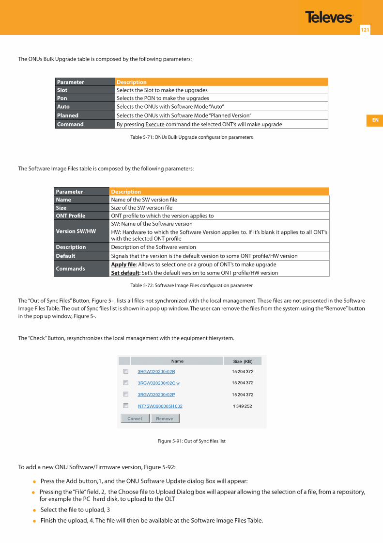
EN
121
The ONUs Bulk Upgrade table is composed by the following parameters:
Parameter DescriptionSlot Selects the Slot to make the upgradesPon Selects the PON to make the upgradesAuto Selects the ONUs with Software Mode “Auto”
Planned Selects the ONUs with Software Mode “Planned Version”
Command By pressing Execute command the selected ONT’s will make upgrade
Table 5-71: ONUs Bulk Upgrade configuration parameters
The Software Image Files table is composed by the following parameters:
Parameter DescriptionName Name of the SW version fileSize Size of the SW version fileONT Profile ONT profile to which the version applies to
Version SW/HWSW: Name of the Software versionHW: Hardware to which the Software Version applies to. If it’s blank it applies to all ONT’s with the selected ONT profile
Description Description of the Software version
Default Signals that the version is the default version to some ONT profile/HW version
CommandsApply file: Allows to select one or a group of ONT’s to make upgradeSet default: Set’s the default version to some ONT profile/HW version
Table 5-72: Software Image Files configuration parameter
The “Out of Sync Files” Button, Figure 5- , lists all files not synchronized with the local management. These files are not presented in the Software Image Files Table. The out of Sync files list is shown in a pop up window. The user can remove the files from the system using the “Remove” button in the pop up window, Figure 5-.
The “Check” Button, resynchronizes the local management with the equipment filesystem.
Remove
3RGW020200r02R
3RGW020200r02Q.w
3RGW020200r02P
NT7SW0000005H 002
15 204 372
15 204 372
15 204 372
1 349 252
Size (KB)Name
Cancel
Figure 5-91: Out of Sync files list
To add a new ONU Software/Firmware version, Figure 5-92:
Press the Add button,1, and the ONU Software Update dialog Box will appear:
Pressing the “File” field, 2, the Choose file to Upload Dialog box will appear allowing the selection of a file, from a repository, for example the PC hard disk, to upload to the OLT
Select the file to upload, 3
Finish the upload, 4. The file will then be available at the Software Image Files Table.
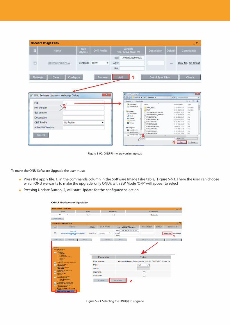
Descripción del producto
122
Figure 5-92: ONU Firmware version upload
To make the ONU Software Upgrade the user must:
Press the apply file, 1, in the commands column in the Software Image Files table, Figure 5-93. There the user can choose which ONU we wants to make the upgrade, only ONU’s with SW Mode “OFF” will appear to select
Pressing Update Button, 2, will start Update for the configured selection
2
1
Figure 5-93: Selecting the ONU(s) to upgrade
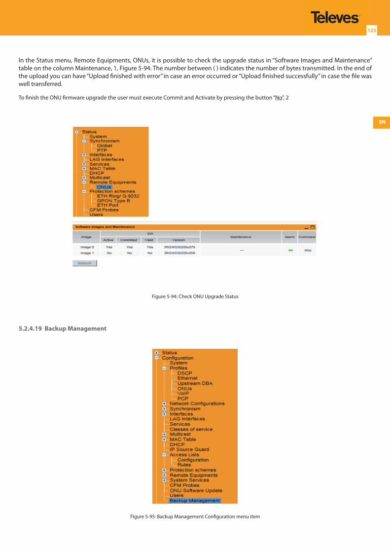
EN
123
In the Status menu, Remote Equipments, ONUs, it is possible to check the upgrade status in “Software Images and Maintenance” table on the column Maintenance, 1, Figure 5-94. The number between ( ) indicates the number of bytes transmitted. In the end of the upload you can have “Upload finished with error” in case an error occurred or “Upload finished successfully” in case the file was well transferred.
To finish the ONU firmware upgrade the user must execute Commit and Activate by pressing the button “No”, 2
Figure 5-94: Check ONU Upgrade Status
5.2.4.19 Backup Management
Figure 5-95: Backup Management Configuration menu item
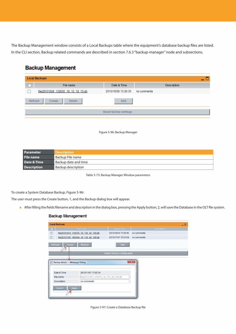
Descripción del producto
124
The Backup Management window consists of a Local Backups table where the equipment’s database backup files are listed.
In the CLI section, Backup related commands are described in section 7.6.3 “backup-manager” node and subsections.
Figure 5-96: Backup Manager
Parameter DescriptionFile name Backup File nameDate & Time Backup date and timeDescription Backup description
Table 5-73: Backup Manager Window parameters
To create a System Database Backup, Figure 5-96:
The user must press the Create button, 1, and the Backup dialog box will appear.
After filling the fields filename and description in the dialog box, pressing the Apply button, 2, will save the Database in the OLT file system.
Figure 5-97: Create a Database Backup file
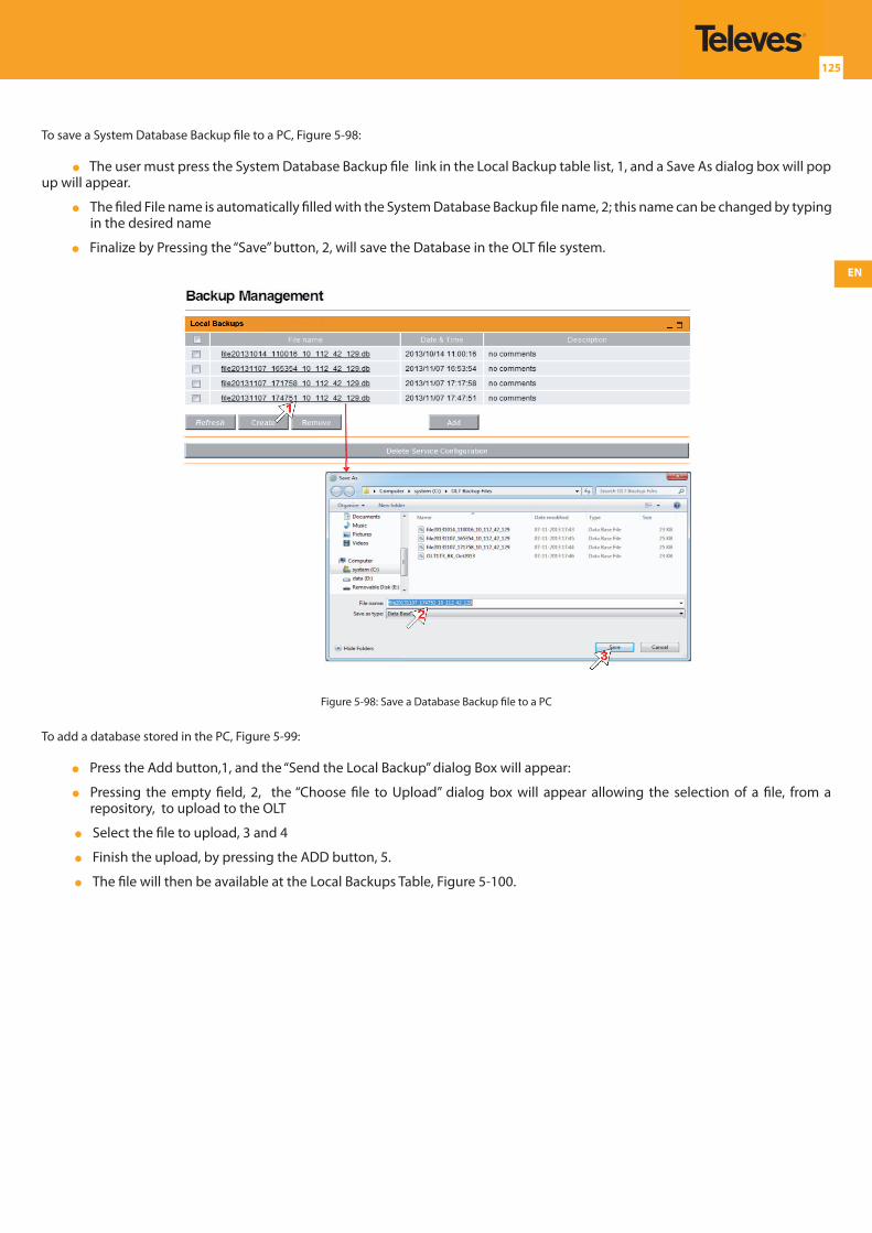
EN
125
To save a System Database Backup file to a PC, Figure 5-98:
The user must press the System Database Backup file link in the Local Backup table list, 1, and a Save As dialog box will pop up will appear.
The filed File name is automatically filled with the System Database Backup file name, 2; this name can be changed by typing in the desired name
Finalize by Pressing the “Save” button, 2, will save the Database in the OLT file system.
Figure 5-98: Save a Database Backup file to a PC
To add a database stored in the PC, Figure 5-99:
Press the Add button,1, and the “Send the Local Backup” dialog Box will appear:
Pressing the empty field, 2, the “Choose file to Upload” dialog box will appear allowing the selection of a file, from a repository, to upload to the OLT
Select the file to upload, 3 and 4
Finish the upload, by pressing the ADD button, 5.
The file will then be available at the Local Backups Table, Figure 5-100.
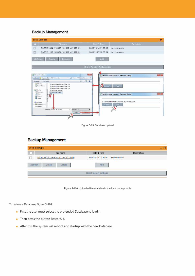
Descripción del producto
126
Figure 5-99: Database Upload
Figure 5-100: Uploaded file available in the local backup table
To restore a Database, Figure 5-101:
First the user must select the pretended Database to load, 1
Then press the button Restore, 3.
After this the system will reboot and startup with the new Database.
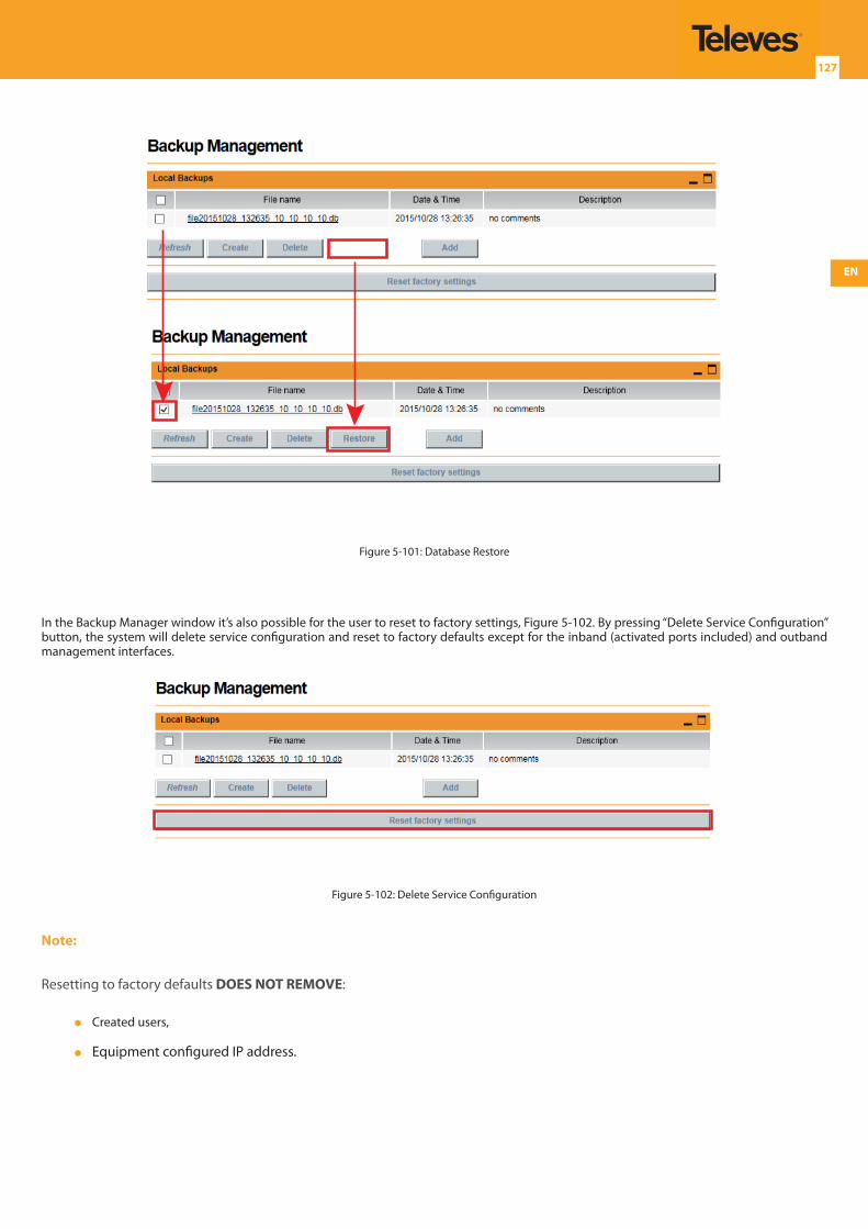
EN
127
Figure 5-101: Database Restore
In the Backup Manager window it’s also possible for the user to reset to factory settings, Figure 5-102. By pressing “Delete Service Configuration” button, the system will delete service configuration and reset to factory defaults except for the inband (activated ports included) and outband management interfaces.
Figure 5-102: Delete Service Configuration
Note:
Resetting to factory defaults DOES NOT REMOVE:
Created users,
Equipment configured IP address.
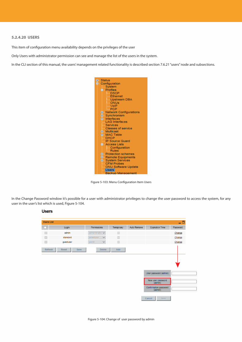
Descripción del producto
128
5.2.4.20 USERS
This item of configuration menu availability depends on the privileges of the user
Only Users with administrator permission can see and manage the list of the users in the system.
In the CLI section of this manual, the users’ management related functionality is described section 7.6.21 “users” node and subsections.
Figure 5-103: Menu Configuration Item Users
In the Change Password window it’s possible for a user with administrator privileges to change the user password to access the system, for any user in the user’s list which is used, Figure 5-104.
Figure 5-104: Change of user password by admin
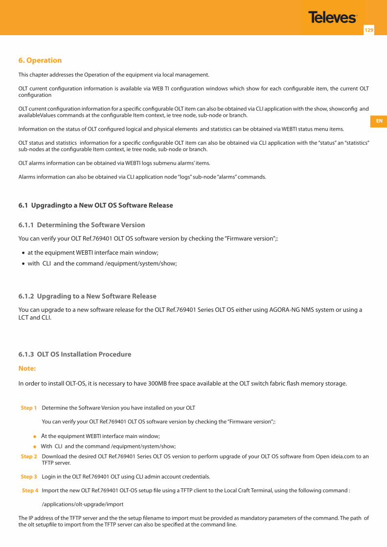
EN
129
6. Operation
This chapter addresses the Operation of the equipment via local management.
OLT current configuration information is available via WEB TI configuration windows which show for each configurable item, the current OLT configuration
OLT current configuration information for a specific configurable OLT item can also be obtained via CLI application with the show, showconfig and availableValues commands at the configurable Item context, ie tree node, sub-node or branch.
Information on the status of OLT configured logical and physical elements and statistics can be obtained via WEBTI status menu items.
OLT status and statistics information for a specific configurable OLT item can also be obtained via CLI application with the “status” an “statistics” sub-nodes at the configurable Item context, ie tree node, sub-node or branch.
OLT alarms information can be obtained via WEBTI logs submenu alarms’ items.
Alarms information can also be obtained via CLI application node “logs” sub-node “alarms” commands.
6.1 Upgradingto a New OLT OS Software Release
6.1.1 Determining the Software Version
You can verify your OLT Ref.769401 OLT OS software version by checking the “Firmware version”;:
•at the equipment WEBTI interface main window;
•with CLI and the command /equipment/system/show;
6.1.2 Upgrading to a New Software Release
You can upgrade to a new software release for the OLT Ref.769401 Series OLT OS either using AGORA-NG NMS system or using a LCT and CLI.
6.1.3 OLT OS Installation Procedure
Note:
In order to install OLT-OS, it is necessary to have 300MB free space available at the OLT switch fabric flash memory storage.
Step 1 Determine the Software Version you have installed on your OLT
You can verify your OLT Ref.769401 OLT OS software version by checking the “Firmware version”;:
At the equipment WEBTI interface main window;
With CLI and the command /equipment/system/show;
Step 2 Download the desired OLT Ref.769401 Series OLT OS version to perform upgrade of your OLT OS software from Open ideia.com to an TFTP server.
Step 3 Login in the OLT Ref.769401 OLT using CLI admin account credentials.
Step 4 Import the new OLT Ref.769401 OLT-OS setup file using a TFTP client to the Local Craft Terminal, using the following command :
/applications/olt-upgrade/import
The IP address of the TFTP server and the the setup filename to import must be provided as mandatory parameters of the command. The path of the olt setupfile to import from the TFTP server can also be specified at the command line.
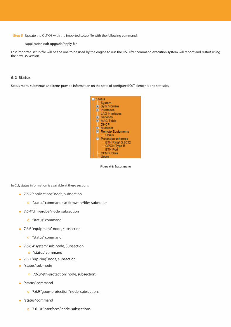
Descripción del producto
130
Step 5 Update the OLT OS with the imported setup file with the following command:
/applications/olt-upgrade/apply-file
Last imported setup file will be the one to be used by the engine to run the OS. After command execution system will reboot and restart using the new OS version.
6.2 Status
Status menu submenus and items provide information on the state of configured OLT elements and statistics.
Figure 6-1: Status menu
In CLI, status information is available at these sections
7.6.2“applications” node, subsection
“status” command ( at firmware/files subnode)
7.6.4“cfm-probe” node, subsection
“status” command
7.6.6 “equipment” node, subsection
“status” command
7.6.6.4“system” sub-node, Subsection
“status” command
7.6.7 “erp-ring” node, subsection:
“status” sub-node
7.6.8 “eth-protection” node, subsection:
“status” command
7.6.9 “gpon-protection” node, subsection:
“status” command
7.6.10 “interfaces” node, subsections:
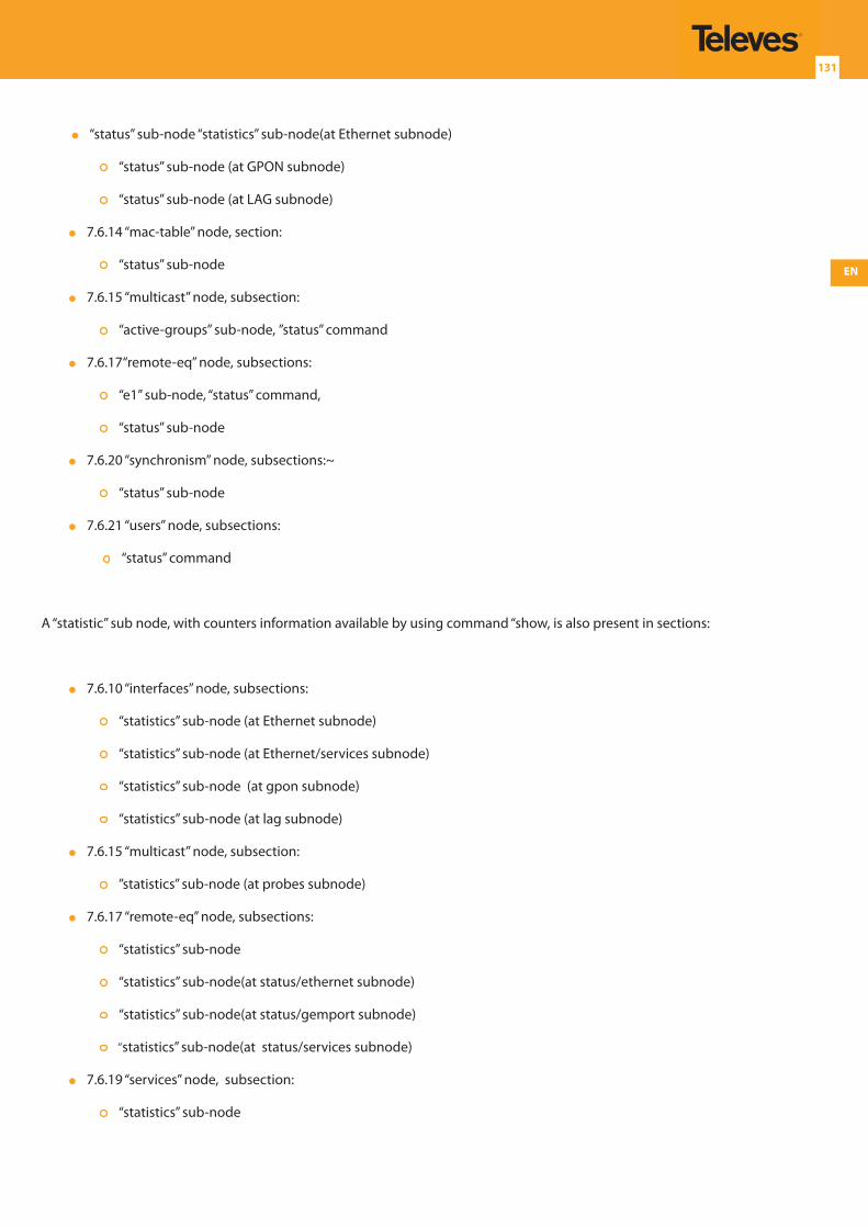
EN
131
“status” sub-node “statistics” sub-node(at Ethernet subnode)
“status” sub-node (at GPON subnode)
“status” sub-node (at LAG subnode)
7.6.14 “mac-table” node, section:
“status” sub-node
7.6.15 “multicast” node, subsection:
“active-groups” sub-node, ”status” command
7.6.17“remote-eq” node, subsections:
“e1” sub-node, “status” command,
“status” sub-node
7.6.20 “synchronism” node, subsections:~
“status” sub-node
7.6.21 “users” node, subsections:
“status” command
A “statistic” sub node, with counters information available by using command “show, is also present in sections:
7.6.10 “interfaces” node, subsections:
“statistics” sub-node (at Ethernet subnode)
“statistics” sub-node (at Ethernet/services subnode)
“statistics” sub-node (at gpon subnode)
“statistics” sub-node (at lag subnode)
7.6.15 “multicast” node, subsection:
”statistics” sub-node (at probes subnode)
7.6.17 “remote-eq” node, subsections:
“statistics” sub-node
“statistics” sub-node(at status/ethernet subnode)
“statistics” sub-node(at status/gemport subnode)
“statistics” sub-node(at status/services subnode)
7.6.19 “services” node, subsection:
“statistics” sub-node
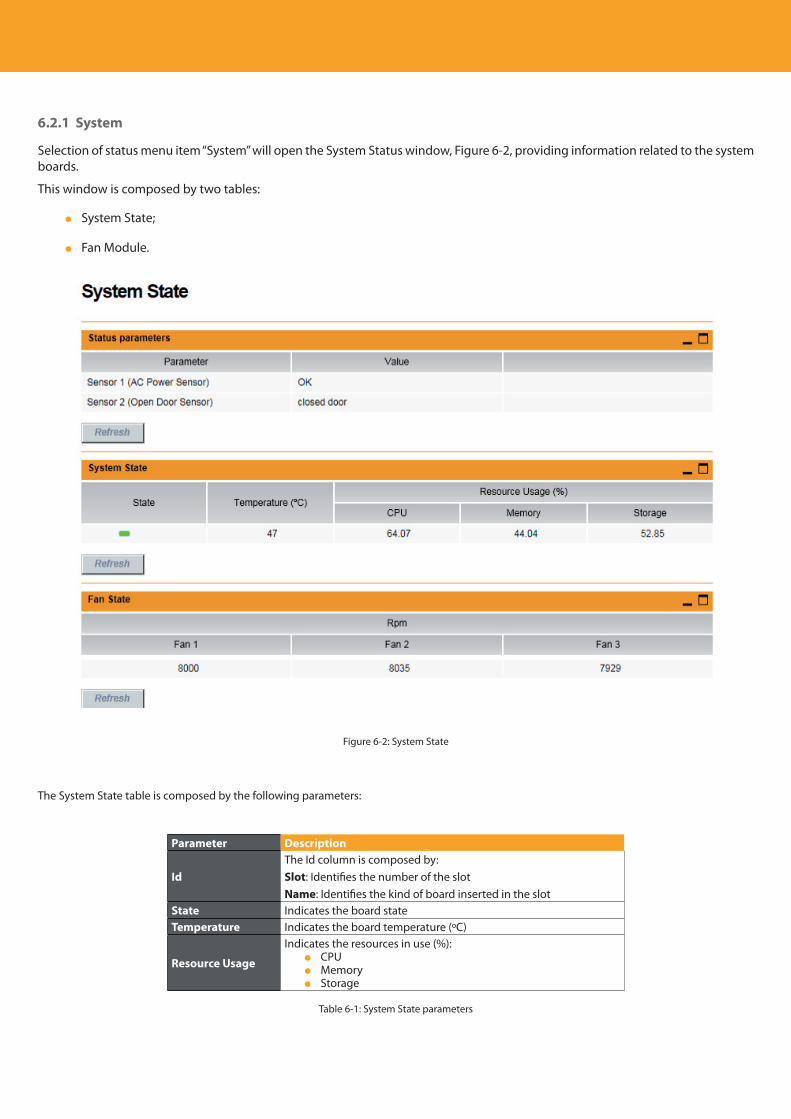
Descripción del producto
132
6.2.1 System
Selection of status menu item “System” will open the System Status window, Figure 6-2, providing information related to the system boards.
This window is composed by two tables:
System State;
Fan Module.
Figure 6-2: System State
The System State table is composed by the following parameters:
Parameter Description
IdThe Id column is composed by:Slot: Identifies the number of the slotName: Identifies the kind of board inserted in the slot
State Indicates the board stateTemperature Indicates the board temperature (ºC)
Resource Usage
Indicates the resources in use (%): CPU Memory Storage
Table 6-1: System State parameters
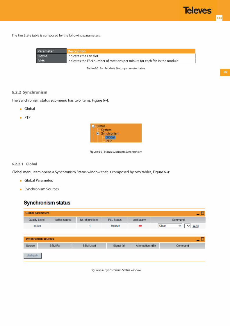
EN
133
The Fan State table is composed by the following parameters:
Parameter DescriptionSlot Id Indicates the Fan slotRPM Indicates the FAN number of rotations per minute for each fan in the module
Table 6-2: Fan Module Status parameter table
6.2.2 Synchronism
The Synchronism status sub-menu has two items, Figure 6-4:
Global
PTP
Figure 6-3: Status submenu Synchronism
6.2.2.1 Global
Global menu item opens a Synchronism Status window that is composed by two tables, Figure 6-4:
Global Parameter.
Synchronism Sources
Figure 6-4: Synchronism Status window
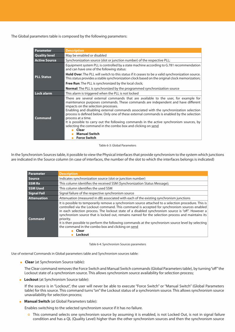
Descripción del producto
134
The Global parameters table is composed by the following parameters:
Parameter DescriptionQuality level May be enabled or disabled Active Source Synchronization source (slot or junction number) of the respective PLL;
PLL Status
Equipment system PLL is controlled by a state machine according to G.781 recommendation and can have one of the following status:Hold Over: The PLL will switch to this status if it ceases to be a valid synchronization source. This status provides a stable synchronization clock based on the original clock memorization;Free Run: The PLL is synchronized by the local clock;Normal: The PLL is synchronized by the programmed synchronization source
Lock alarm This alarm is triggered when the PLL is not locked
Command
There are several external commands that are available to the user, for example for maintenance purposes commands. These commands are independent and have different impacts on the selection processes.Enabling and disabling external commands associated with the synchronization selection process is defined below. Only one of these external commands is enabled by the selection process at a time.It is possible to carry out the following commands in the active synchronism sources, by selecting the command in the combo box and clicking on send Clear Manual Switch Force Switch
Table 6-3: Global Parameters
In the Synchronism Sources table, it possible to view the Physical interfaces that provide synchronism to the system which junctions are indicated in the Source column (in case of interfaces, the number of the slot to which the interfaces belongs is indicated)
Parameter DescriptionSource Indicates synchronization source (slot or junction number)SSM Rx This column identifies the received SSM (Synchronization Status Message);SSM Used This column identifies the used SSMSignal Fail Signal failure of the respective synchronism sourceAttenuation Attenuation (measured in dB) associated with each of the existing synchronism junctions
Command
It is possible to temporarily remove a synchronism source attached to a selection procedure. This is controlled via the Lockout command. This command is accepted for synchronism sources enabled in each selection process. The lockout state of a disabled synchronism source is “off”. However a synchronism source that is locked out, remains named for the selection process and maintains its priority.It is then possible to perform the following commands at the synchronism source level by selecting the command in the combo box and clicking on send Clear Lockout
Table 6-4: Synchronism Sources parameters
Use of external Commands in Global parameters table and Synchronism sources table:
Clear (at Synchronism Source table):
The Clear command removes the Force Switch and Manual Switch commands (Global Parameters table), by turning “off” the Lockout state of a synchronism source. This allows synchronism source availability for selection process;
Lockout (at Synchronism Source table):
If the source is in “Lockout”, the user will never be able to execute “Force Switch” or “Manual Switch” (Global Parameters table) for this source. This command turns “on” the Lockout status of a synchronism source. This allows synchronism source unavailability for selection process;
Manual Switch (at Global Parameters table):
Enables switching to the selected synchronism source if it has no failure.
This command selects one synchronism source by assuming it is enabled, is not Locked Out, is not in signal failure condition and has a QL (Quality Level) higher than the other synchronism sources and then the synchronism source
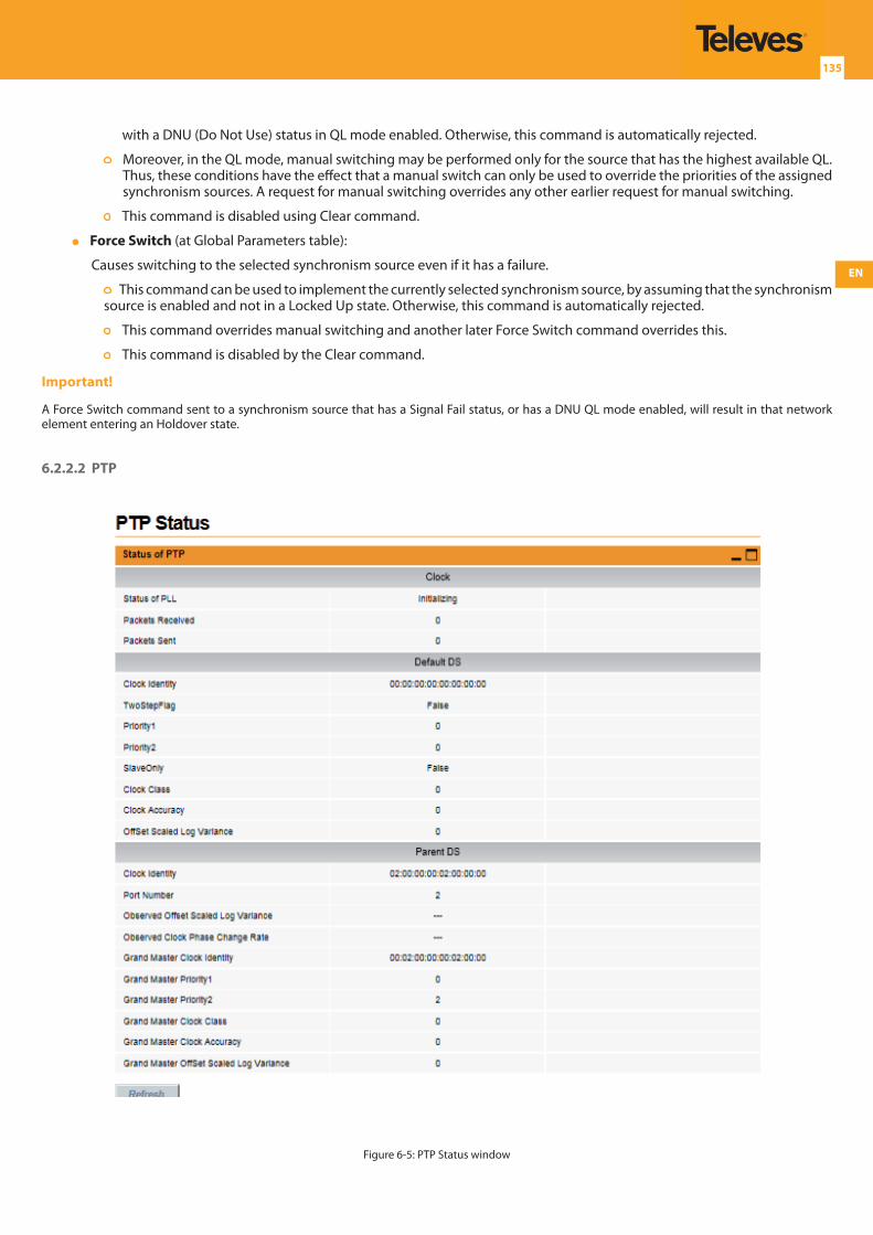
EN
135
with a DNU (Do Not Use) status in QL mode enabled. Otherwise, this command is automatically rejected.
Moreover, in the QL mode, manual switching may be performed only for the source that has the highest available QL. Thus, these conditions have the effect that a manual switch can only be used to override the priorities of the assigned synchronism sources. A request for manual switching overrides any other earlier request for manual switching.
This command is disabled using Clear command.
Force Switch (at Global Parameters table):
Causes switching to the selected synchronism source even if it has a failure.
This command can be used to implement the currently selected synchronism source, by assuming that the synchronism source is enabled and not in a Locked Up state. Otherwise, this command is automatically rejected.
This command overrides manual switching and another later Force Switch command overrides this.
This command is disabled by the Clear command.
Important!
A Force Switch command sent to a synchronism source that has a Signal Fail status, or has a DNU QL mode enabled, will result in that network element entering an Holdover state.
6.2.2.2 PTP
Figure 6-5: PTP Status window
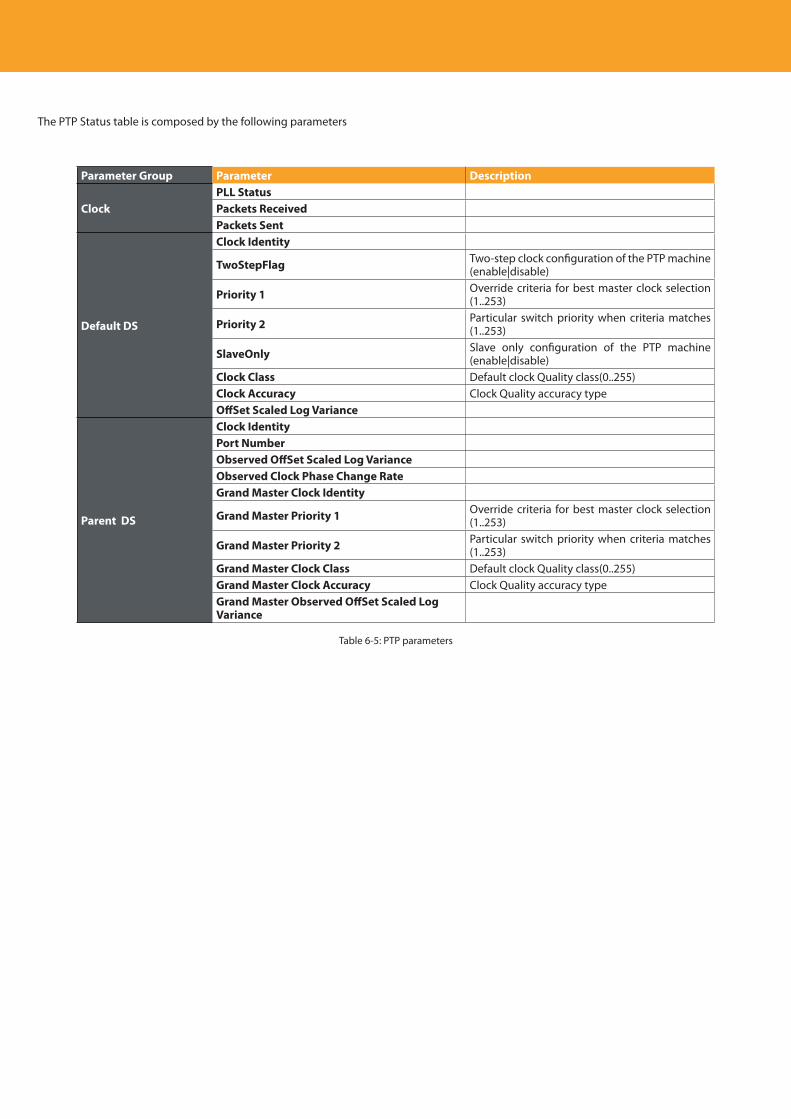
Descripción del producto
136
The PTP Status table is composed by the following parameters
Parameter Group Parameter Description
ClockPLL StatusPackets ReceivedPackets Sent
Default DS
Clock Identity
TwoStepFlag Two-step clock configuration of the PTP machine (enable|disable)
Priority 1 Override criteria for best master clock selection (1..253)
Priority 2 Particular switch priority when criteria matches (1..253)
SlaveOnly Slave only configuration of the PTP machine (enable|disable)
Clock Class Default clock Quality class(0..255)Clock Accuracy Clock Quality accuracy typeOffSet Scaled Log Variance
Parent DS
Clock IdentityPort NumberObserved OffSet Scaled Log VarianceObserved Clock Phase Change RateGrand Master Clock Identity
Grand Master Priority 1 Override criteria for best master clock selection (1..253)
Grand Master Priority 2 Particular switch priority when criteria matches (1..253)
Grand Master Clock Class Default clock Quality class(0..255)Grand Master Clock Accuracy Clock Quality accuracy typeGrand Master Observed OffSet Scaled Log Variance
Table 6-5: PTP parameters
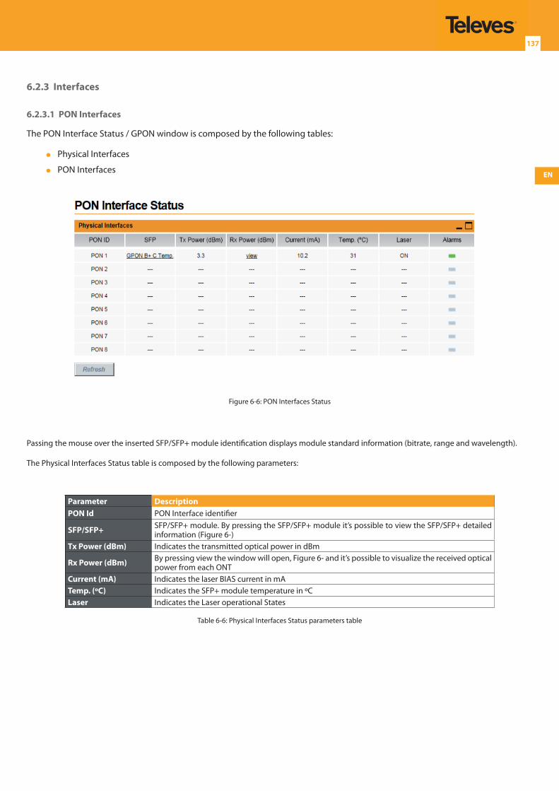
EN
137
6.2.3 Interfaces
6.2.3.1 PON Interfaces
The PON Interface Status / GPON window is composed by the following tables:
Physical Interfaces
PON Interfaces
Figure 6-6: PON Interfaces Status
Passing the mouse over the inserted SFP/SFP+ module identification displays module standard information (bitrate, range and wavelength).
The Physical Interfaces Status table is composed by the following parameters:
Parameter DescriptionPON Id PON Interface identifier
SFP/SFP+ SFP/SFP+ module. By pressing the SFP/SFP+ module it’s possible to view the SFP/SFP+ detailed information (Figure 6-)
Tx Power (dBm) Indicates the transmitted optical power in dBm
Rx Power (dBm) By pressing view the window will open, Figure 6- and it’s possible to visualize the received optical power from each ONT
Current (mA) Indicates the laser BIAS current in mATemp. (ºC) Indicates the SFP+ module temperature in ºCLaser Indicates the Laser operational States
Table 6-6: Physical Interfaces Status parameters table
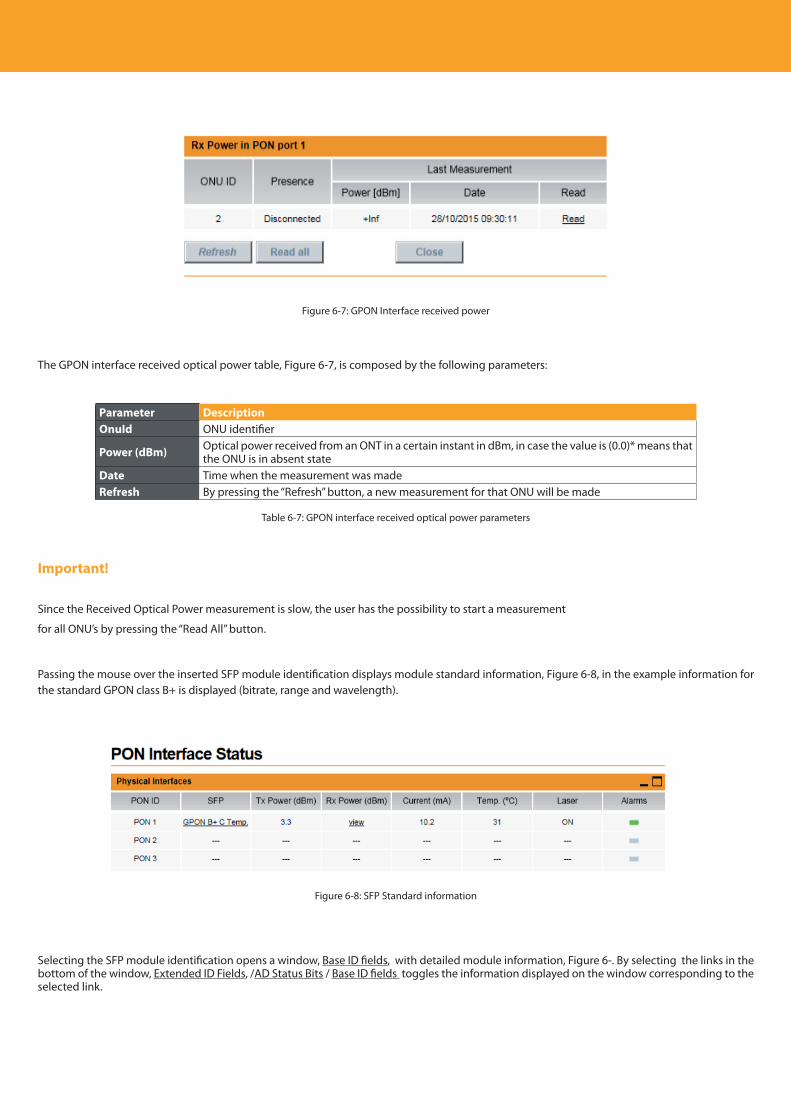
Descripción del producto
138
Figure 6-7: GPON Interface received power
The GPON interface received optical power table, Figure 6-7, is composed by the following parameters:
Parameter DescriptionOnuId ONU identifier
Power (dBm) Optical power received from an ONT in a certain instant in dBm, in case the value is (0.0)* means that the ONU is in absent state
Date Time when the measurement was madeRefresh By pressing the “Refresh” button, a new measurement for that ONU will be made
Table 6-7: GPON interface received optical power parameters
Important!
Since the Received Optical Power measurement is slow, the user has the possibility to start a measurement
for all ONU’s by pressing the “Read All” button.
Passing the mouse over the inserted SFP module identification displays module standard information, Figure 6-8, in the example information for the standard GPON class B+ is displayed (bitrate, range and wavelength).
Figure 6-8: SFP Standard information
Selecting the SFP module identification opens a window, Base ID fields, with detailed module information, Figure 6-. By selecting the links in the bottom of the window, Extended ID Fields, /AD Status Bits / Base ID fields toggles the information displayed on the window corresponding to the selected link.
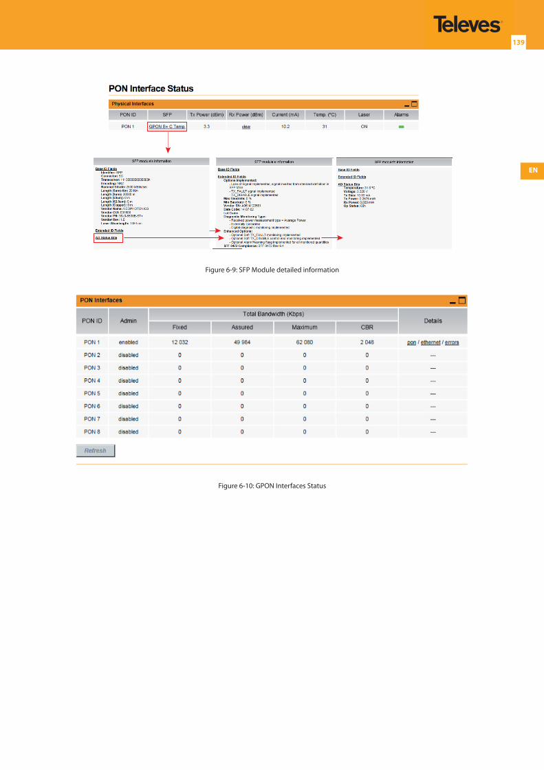
EN
139
Figure 6-9: SFP Module detailed information
Figure 6-10: GPON Interfaces Status
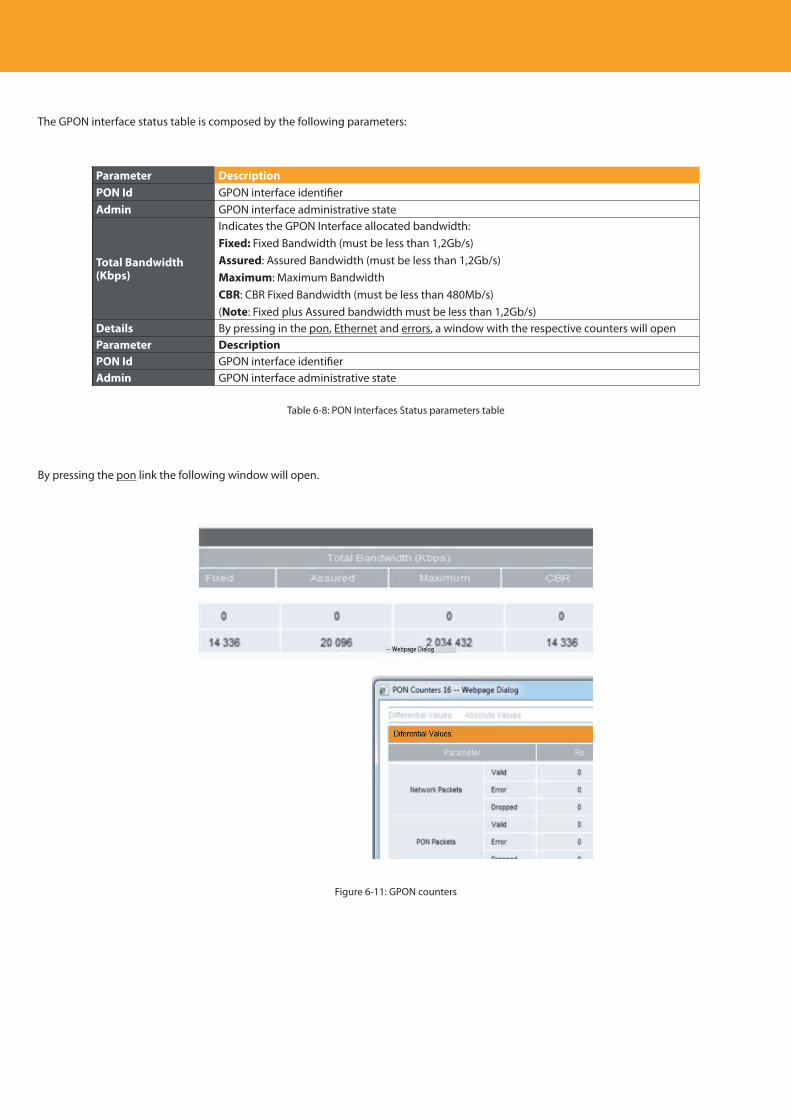
Descripción del producto
140
The GPON interface status table is composed by the following parameters:
Parameter DescriptionPON Id GPON interface identifierAdmin GPON interface administrative state
Total Bandwidth (Kbps)
Indicates the GPON Interface allocated bandwidth:Fixed: Fixed Bandwidth (must be less than 1,2Gb/s)Assured: Assured Bandwidth (must be less than 1,2Gb/s)Maximum: Maximum BandwidthCBR: CBR Fixed Bandwidth (must be less than 480Mb/s)(Note: Fixed plus Assured bandwidth must be less than 1,2Gb/s)
Details By pressing in the pon, Ethernet and errors, a window with the respective counters will openParameter DescriptionPON Id GPON interface identifierAdmin GPON interface administrative state
Table 6-8: PON Interfaces Status parameters table
By pressing the pon link the following window will open.
Figure 6-11: GPON counters
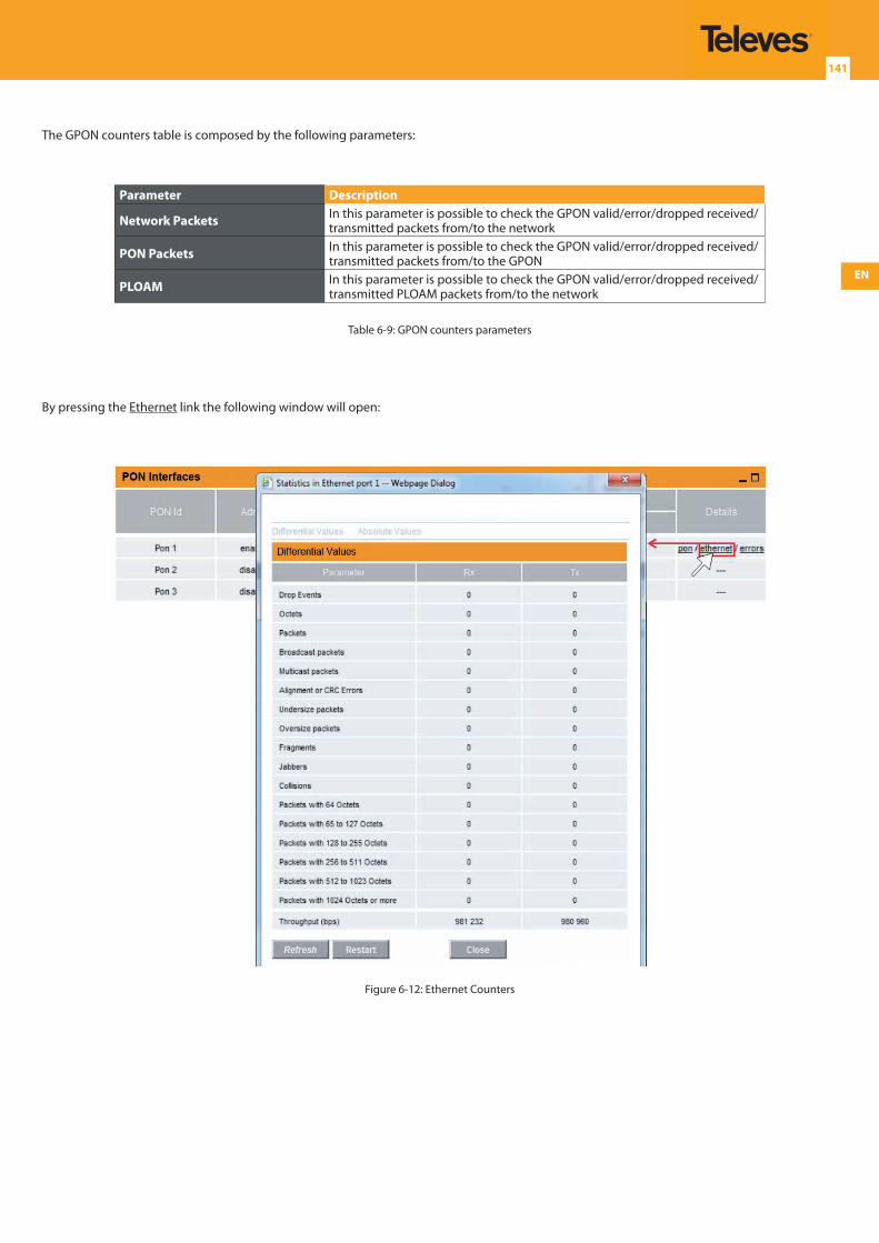
EN
141
The GPON counters table is composed by the following parameters:
Parameter Description
Network Packets In this parameter is possible to check the GPON valid/error/dropped received/transmitted packets from/to the network
PON Packets In this parameter is possible to check the GPON valid/error/dropped received/transmitted packets from/to the GPON
PLOAM In this parameter is possible to check the GPON valid/error/dropped received/transmitted PLOAM packets from/to the network
Table 6-9: GPON counters parameters
By pressing the Ethernet link the following window will open:
Figure 6-12: Ethernet Counters
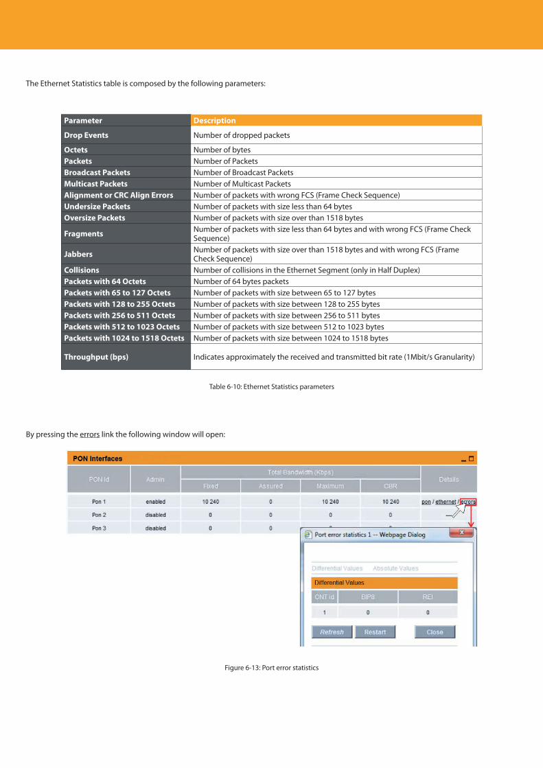
Descripción del producto
142
The Ethernet Statistics table is composed by the following parameters:
Parameter Description
Drop Events Number of dropped packets
Octets Number of bytesPackets Number of PacketsBroadcast Packets Number of Broadcast PacketsMulticast Packets Number of Multicast PacketsAlignment or CRC Align Errors Number of packets with wrong FCS (Frame Check Sequence)Undersize Packets Number of packets with size less than 64 bytesOversize Packets Number of packets with size over than 1518 bytes
Fragments Number of packets with size less than 64 bytes and with wrong FCS (Frame Check Sequence)
Jabbers Number of packets with size over than 1518 bytes and with wrong FCS (Frame Check Sequence)
Collisions Number of collisions in the Ethernet Segment (only in Half Duplex)Packets with 64 Octets Number of 64 bytes packetsPackets with 65 to 127 Octets Number of packets with size between 65 to 127 bytes Packets with 128 to 255 Octets Number of packets with size between 128 to 255 bytes Packets with 256 to 511 Octets Number of packets with size between 256 to 511 bytes Packets with 512 to 1023 Octets Number of packets with size between 512 to 1023 bytes Packets with 1024 to 1518 Octets Number of packets with size between 1024 to 1518 bytes
Throughput (bps) Indicates approximately the received and transmitted bit rate (1Mbit/s Granularity)
Table 6-10: Ethernet Statistics parameters
By pressing the errors link the following window will open:
Figure 6-13: Port error statistics
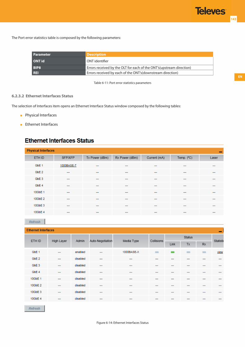
EN
143
The Port error statistics table is composed by the following parameters:
Parameter Description
ONT id ONT identifier
BIP8 Errors received by the OLT for each of the ONT’s(upstream direction)REI Errors received by each of the ONT’s(downstream direction)
Table 6-11: Port error statistics parameters
6.2.3.2 Ethernet Interfaces Status
The selection of Interfaces item opens an Ethernet Interface Status window composed by the following tables:
Physical Interfaces
Ethernet Interfaces
Figure 6-14: Ethernet Interfaces Status
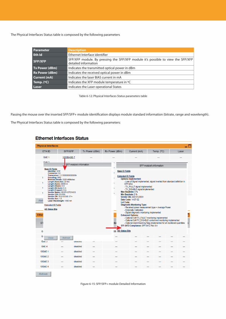
Descripción del producto
144
The Physical Interfaces Status table is composed by the following parameters
Parameter DescriptionEth Id Ethernet Interface identifier
SFP/XFP SFP/XFP module. By pressing the SFP/XFP module it’s possible to view the SFP/XFP detailed information
Tx Power (dBm) Indicates the transmitted optical power in dBmRx Power (dBm) Indicates the received optical power in dBmCurrent (mA) Indicates the laser BIAS current in mATemp. (ºC) Indicates the XFP module temperature in ºCLaser Indicates the Laser operational States
Table 6-12: Physical Interfaces Status parameters table
Passing the mouse over the inserted SFP/SFP+ module identification displays module standard information (bitrate, range and wavelength).
The Physical Interfaces Status table is composed by the following parameters:
Figure 6-15: SFP/SFP+ module Detailed Information
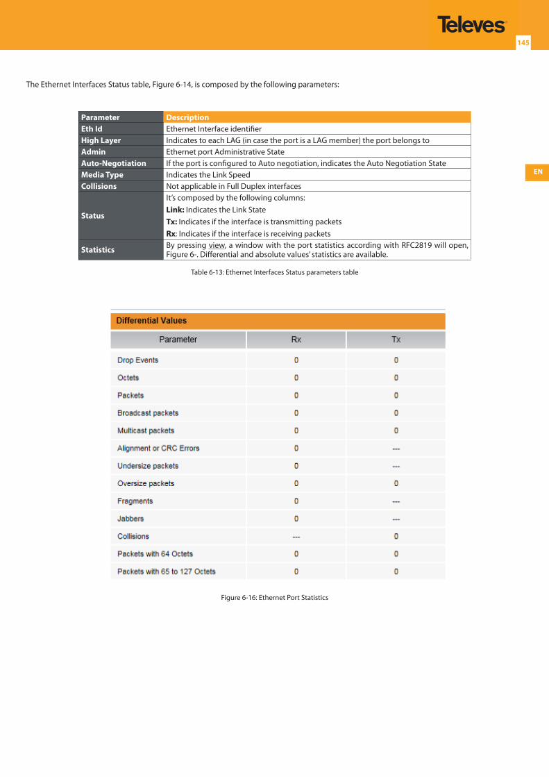
EN
145
The Ethernet Interfaces Status table, Figure 6-14, is composed by the following parameters:
Parameter DescriptionEth Id Ethernet Interface identifierHigh Layer Indicates to each LAG (in case the port is a LAG member) the port belongs toAdmin Ethernet port Administrative StateAuto-Negotiation If the port is configured to Auto negotiation, indicates the Auto Negotiation StateMedia Type Indicates the Link SpeedCollisions Not applicable in Full Duplex interfaces
Status
It’s composed by the following columns:Link: Indicates the Link StateTx: Indicates if the interface is transmitting packetsRx: Indicates if the interface is receiving packets
Statistics By pressing view, a window with the port statistics according with RFC2819 will open, Figure 6-. Differential and absolute values’ statistics are available.
Table 6-13: Ethernet Interfaces Status parameters table
Figure 6-16: Ethernet Port Statistics
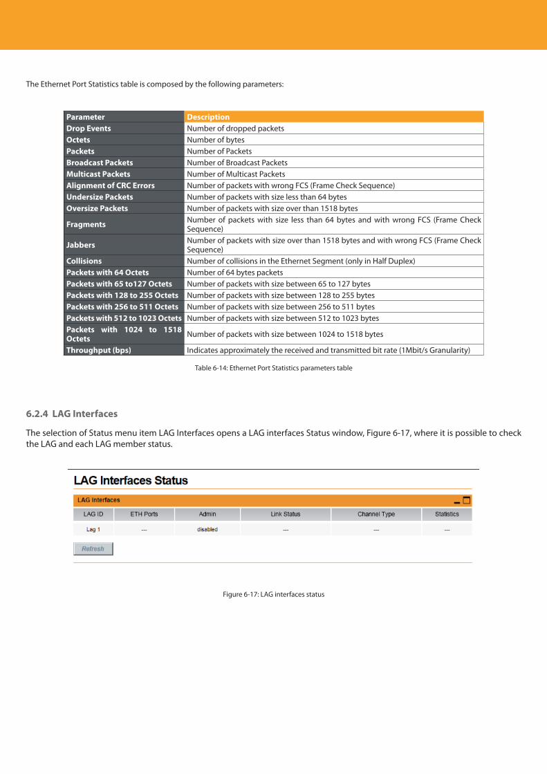
Descripción del producto
146
The Ethernet Port Statistics table is composed by the following parameters:
Parameter DescriptionDrop Events Number of dropped packetsOctets Number of bytesPackets Number of PacketsBroadcast Packets Number of Broadcast PacketsMulticast Packets Number of Multicast PacketsAlignment of CRC Errors Number of packets with wrong FCS (Frame Check Sequence)Undersize Packets Number of packets with size less than 64 bytesOversize Packets Number of packets with size over than 1518 bytes
Fragments Number of packets with size less than 64 bytes and with wrong FCS (Frame Check Sequence)
Jabbers Number of packets with size over than 1518 bytes and with wrong FCS (Frame Check Sequence)
Collisions Number of collisions in the Ethernet Segment (only in Half Duplex)Packets with 64 Octets Number of 64 bytes packetsPackets with 65 to127 Octets Number of packets with size between 65 to 127 bytes Packets with 128 to 255 Octets Number of packets with size between 128 to 255 bytes Packets with 256 to 511 Octets Number of packets with size between 256 to 511 bytes Packets with 512 to 1023 Octets Number of packets with size between 512 to 1023 bytes Packets with 1024 to 1518 Octets Number of packets with size between 1024 to 1518 bytes
Throughput (bps) Indicates approximately the received and transmitted bit rate (1Mbit/s Granularity)
Table 6-14: Ethernet Port Statistics parameters table
6.2.4 LAG Interfaces
The selection of Status menu item LAG Interfaces opens a LAG interfaces Status window, Figure 6-17, where it is possible to check the LAG and each LAG member status.
Figure 6-17: LAG interfaces status
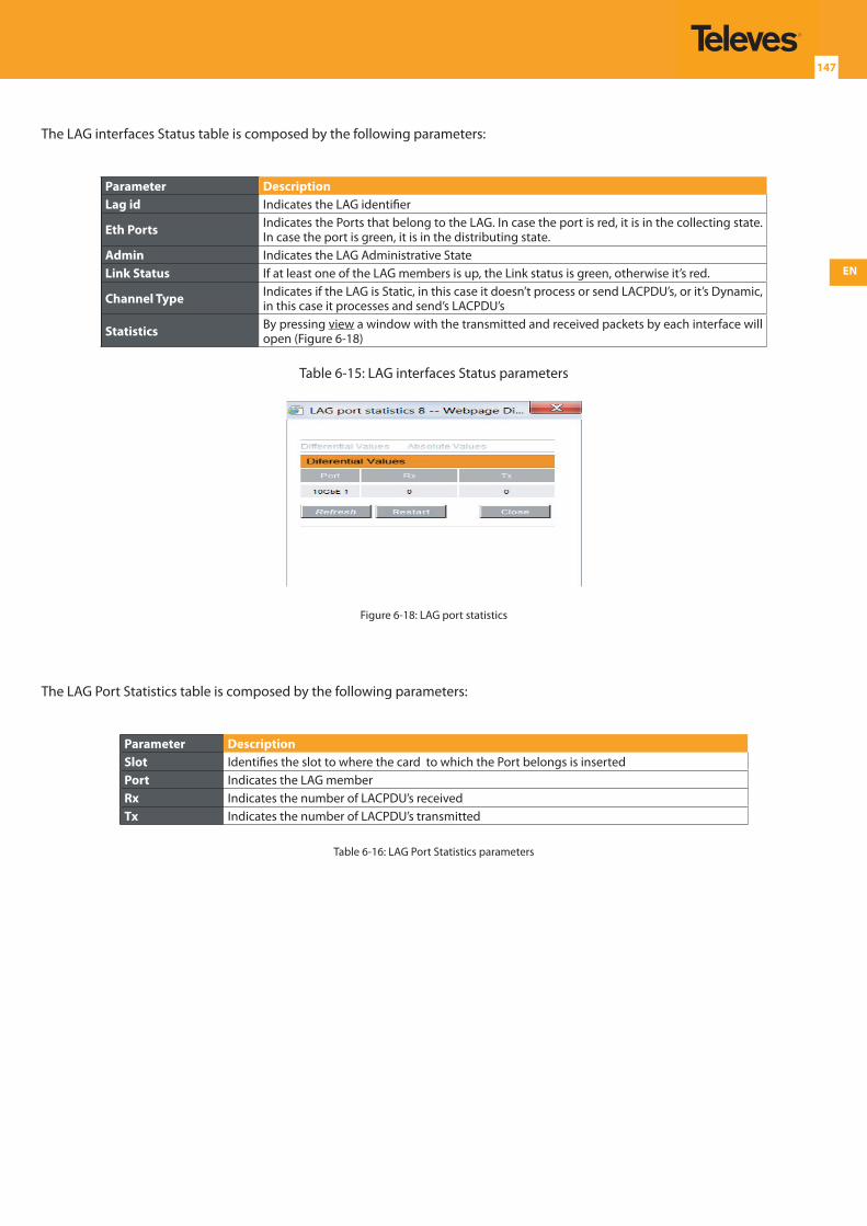
EN
147
The LAG interfaces Status table is composed by the following parameters:
Parameter DescriptionLag id Indicates the LAG identifier
Eth Ports Indicates the Ports that belong to the LAG. In case the port is red, it is in the collecting state. In case the port is green, it is in the distributing state.
Admin Indicates the LAG Administrative StateLink Status If at least one of the LAG members is up, the Link status is green, otherwise it’s red.
Channel Type Indicates if the LAG is Static, in this case it doesn’t process or send LACPDU’s, or it’s Dynamic, in this case it processes and send’s LACPDU’s
Statistics By pressing view a window with the transmitted and received packets by each interface will open (Figure 6-18)
Table 6-15: LAG interfaces Status parameters
Figure 6-18: LAG port statistics
The LAG Port Statistics table is composed by the following parameters:
Parameter DescriptionSlot Identifies the slot to where the card to which the Port belongs is insertedPort Indicates the LAG memberRx Indicates the number of LACPDU’s receivedTx Indicates the number of LACPDU’s transmitted
Table 6-16: LAG Port Statistics parameters
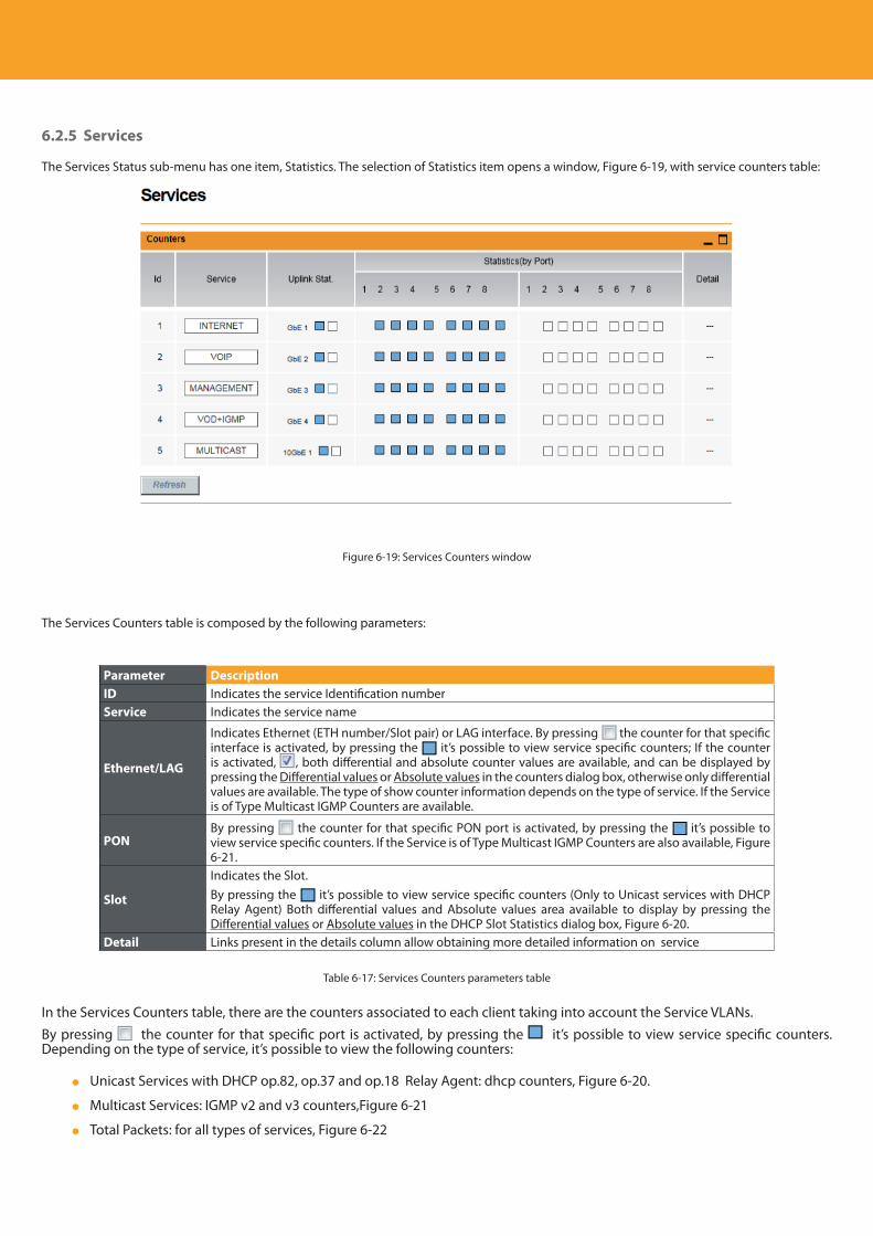
Descripción del producto
148
6.2.5 Services
The Services Status sub-menu has one item, Statistics. The selection of Statistics item opens a window, Figure 6-19, with service counters table:
Figure 6-19: Services Counters window
The Services Counters table is composed by the following parameters:
Parameter DescriptionID Indicates the service Identification numberService Indicates the service name
Ethernet/LAG
Indicates Ethernet (ETH number/Slot pair) or LAG interface. By pressing the counter for that specific interface is activated, by pressing the it’s possible to view service specific counters; If the counter is activated, , both differential and absolute counter values are available, and can be displayed by pressing the Differential values or Absolute values in the counters dialog box, otherwise only differential values are available. The type of show counter information depends on the type of service. If the Service is of Type Multicast IGMP Counters are available.
PONBy pressing the counter for that specific PON port is activated, by pressing the it’s possible to view service specific counters. If the Service is of Type Multicast IGMP Counters are also available, Figure 6-21.
Slot
Indicates the Slot. By pressing the it’s possible to view service specific counters (Only to Unicast services with DHCP Relay Agent) Both differential values and Absolute values area available to display by pressing the Differential values or Absolute values in the DHCP Slot Statistics dialog box, Figure 6-20.
Detail Links present in the details column allow obtaining more detailed information on service
Table 6-17: Services Counters parameters table
In the Services Counters table, there are the counters associated to each client taking into account the Service VLANs.By pressing the counter for that specific port is activated, by pressing the it’s possible to view service specific counters. Depending on the type of service, it’s possible to view the following counters:
Unicast Services with DHCP op.82, op.37 and op.18 Relay Agent: dhcp counters, Figure 6-20.
Multicast Services: IGMP v2 and v3 counters,Figure 6-21
Total Packets: for all types of services, Figure 6-22
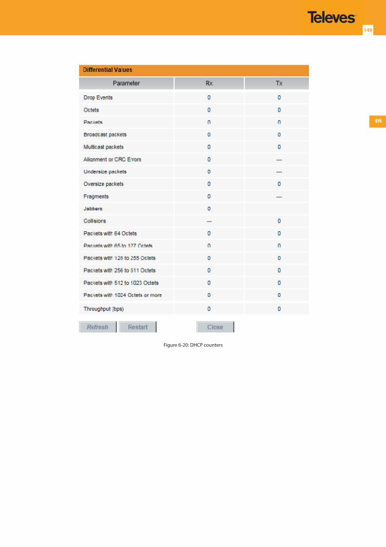
EN
149
Figure 6-20: DHCP counters
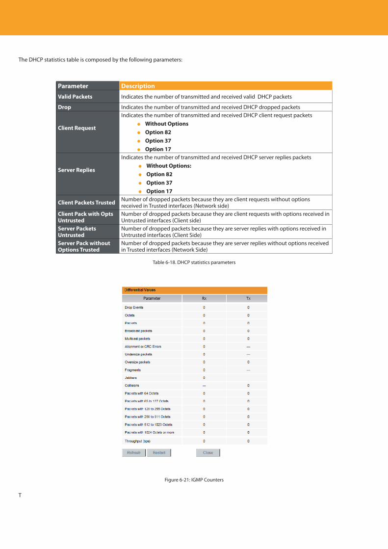
Descripción del producto
150
The DHCP statistics table is composed by the following parameters:
Parameter Description
Valid Packets Indicates the number of transmitted and received valid DHCP packets
Drop Indicates the number of transmitted and received DHCP dropped packets
Client Request
Indicates the number of transmitted and received DHCP client request packets Without Options Option 82 Option 37 Option 17
Server Replies
Indicates the number of transmitted and received DHCP server replies packets Without Options: Option 82 Option 37 Option 17
Client Packets Trusted Number of dropped packets because they are client requests without options received in Trusted interfaces (Network side)
Client Pack with Opts Untrusted
Number of dropped packets because they are client requests with options received in Untrusted interfaces (Client side)
Server Packets Untrusted
Number of dropped packets because they are server replies with options received in Untrusted interfaces (Client Side)
Server Pack without Options Trusted
Number of dropped packets because they are server replies without options received in Trusted interfaces (Network Side)
Table 6-18. DHCP statistics parameters
Figure 6-21: IGMP Counters
T
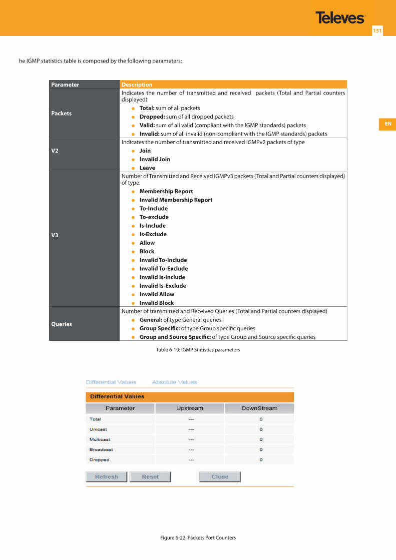
EN
151
he IGMP statistics table is composed by the following parameters:
Parameter Description
Packets
Indicates the number of transmitted and received packets (Total and Partial counters displayed): Total: sum of all packets Dropped: sum of all dropped packets Valid: sum of all valid (compliant with the IGMP standards) packets Invalid: sum of all invalid (non-compliant with the IGMP standards) packets
V2Indicates the number of transmitted and received IGMPv2 packets of type Join Invalid Join Leave
V3
Number of Transmitted and Received IGMPv3 packets (Total and Partial counters displayed) of type: Membership Report Invalid Membership Report To-Include To-exclude Is-Include Is-Exclude Allow Block Invalid To-Include Invalid To-Exclude Invalid Is-Include Invalid Is-Exclude Invalid Allow Invalid Block
Queries
Number of transmitted and Received Queries (Total and Partial counters displayed) General: of type General queries Group Specific: of type Group specific queries Group and Source Specific: of type Group and Source specific queries
Table 6-19: IGMP Statistics parameters
Figure 6-22: Packets Port Counters
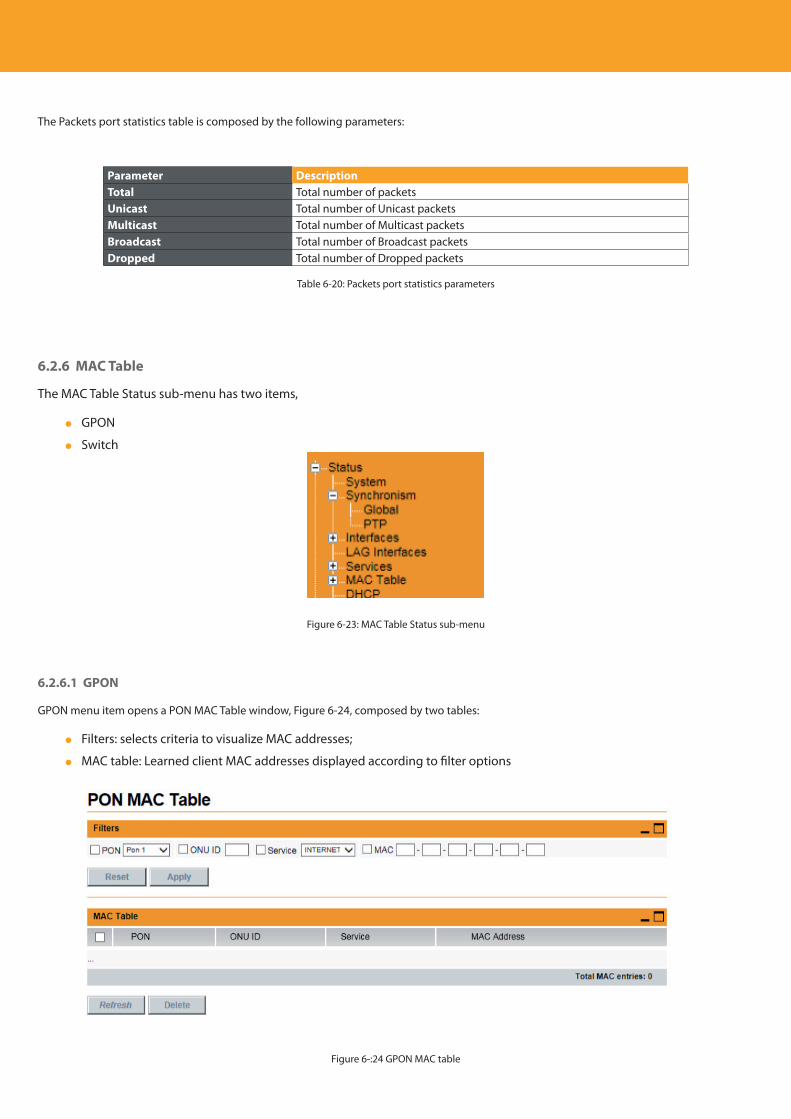
Descripción del producto
152
The Packets port statistics table is composed by the following parameters:
Parameter DescriptionTotal Total number of packetsUnicast Total number of Unicast packetsMulticast Total number of Multicast packetsBroadcast Total number of Broadcast packetsDropped Total number of Dropped packets
Table 6-20: Packets port statistics parameters
6.2.6 MAC Table
The MAC Table Status sub-menu has two items,
GPON
Switch
Figure 6-23: MAC Table Status sub-menu
6.2.6.1 GPON
GPON menu item opens a PON MAC Table window, Figure 6-24, composed by two tables:
Filters: selects criteria to visualize MAC addresses;
MAC table: Learned client MAC addresses displayed according to filter options
Figure 6-:24 GPON MAC table
EN
153
For the Unicast Unstacked Services, MAC learning is performed, learning the MAC addresses of the several clients. The MAC address table can be very large, in which case in order to facilitate analysis of the table, MAC address filtering must be used, to select and display only the desired MAC addresses.
The filter definition criteria parameters are the following:
Parameter DescriptionPON Selection of PON interface to filter from a list of available PON interfacesONU ID Selection of ONU# to filter from a list of available ONUsService Selection of service to filter from a combo box with the available servicesMAC Address Selection of MAC address to filter by introducing the desired MAC address
Table 6-21: Filter selection parameters
The MAC address table is composed by the following parameters:
Parameter DescriptionPON Indicates the PON interfaceONU ID Indicates the ONUMAC Address Indicates the learned MAC addressTotal MAC entries Indicates the total number of MAC entries in the table
Table 6-22: MAC address parameters
For each GPON interface it’s possible to learn up to 4096 MAC addresses. The MAC addresses are removed from the MAC table in the following situations:
Aging time has expired
ONT Eth port to which the service is connected is turned off
The service is removed from the ONT
By selecting the MAC address and press Delete.
6.2.6.2 Switch
Switch menu item opens a Switch MAC Table window,Figure 6-25, composed by two tables:
Filters: selects criteria to visualize MAC addresses;
MAC table: Learned client MAC addresses displayed according to filter options

Descripción del producto
154
Figure 6-25: Switch MAC table window
For the Unicast Unstacked Services and for the Management VLAN, MAC learning is performed, learning the MAC addresses of the several clients. The MAC address table can be very large, in which case in order to facilitate analysis of the table, MAC address filtering must be used, to select and display only the desired MAC addresses.
The filter definition criteria parameters are the following:
Parameter DescriptionPort Selection of PON interface to filter from a list of available Port interfacesONU ID Filtering by ONU ID: the desired ONU ID must be typed inService Selection of Service Id to filter from a list of available ServicesMAC Address Selection of MAC address to filter by introducing the desired MAC address
Table 6-23: Filters selection parameters
The MAC address table is composed by the following parameters:
Parameter DescriptionPort Indicates the PortONU ID Indicates the ONU
Service Indicates the Service. In case “--“the MAC learned isn’t associated to any service.
MAC Address Indicates the learned MAC addressTotal MAC entries Indicates the total number of MAC entries in the table
Table 6-24: MAC address parameters
The MAC addresses are removed from the MAC table in the following situations:
Aging time has expired
By selecting the MAC address and press Delete
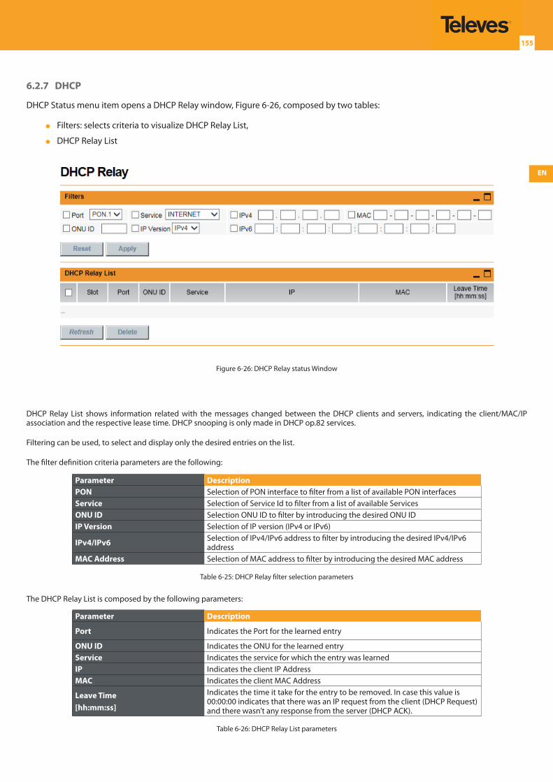
EN
155
6.2.7 DHCP
DHCP Status menu item opens a DHCP Relay window, Figure 6-26, composed by two tables:
Filters: selects criteria to visualize DHCP Relay List,
DHCP Relay List
Figure 6-26: DHCP Relay status Window
DHCP Relay List shows information related with the messages changed between the DHCP clients and servers, indicating the client/MAC/IP association and the respective lease time. DHCP snooping is only made in DHCP op.82 services.
Filtering can be used, to select and display only the desired entries on the list.
The filter definition criteria parameters are the following:
Parameter DescriptionPON Selection of PON interface to filter from a list of available PON interfacesService Selection of Service Id to filter from a list of available ServicesONU ID Selection ONU ID to filter by introducing the desired ONU IDIP Version Selection of IP version (IPv4 or IPv6)
IPv4/IPv6 Selection of IPv4/IPv6 address to filter by introducing the desired IPv4/IPv6 address
MAC Address Selection of MAC address to filter by introducing the desired MAC address
Table 6-25: DHCP Relay filter selection parameters
The DHCP Relay List is composed by the following parameters:
Parameter Description
Port Indicates the Port for the learned entry
ONU ID Indicates the ONU for the learned entryService Indicates the service for which the entry was learnedIP Indicates the client IP AddressMAC Indicates the client MAC Address
Leave Time[hh:mm:ss]
Indicates the time it take for the entry to be removed. In case this value is 00:00:00 indicates that there was an IP request from the client (DHCP Request) and there wasn’t any response from the server (DHCP ACK).
Table 6-26: DHCP Relay List parameters
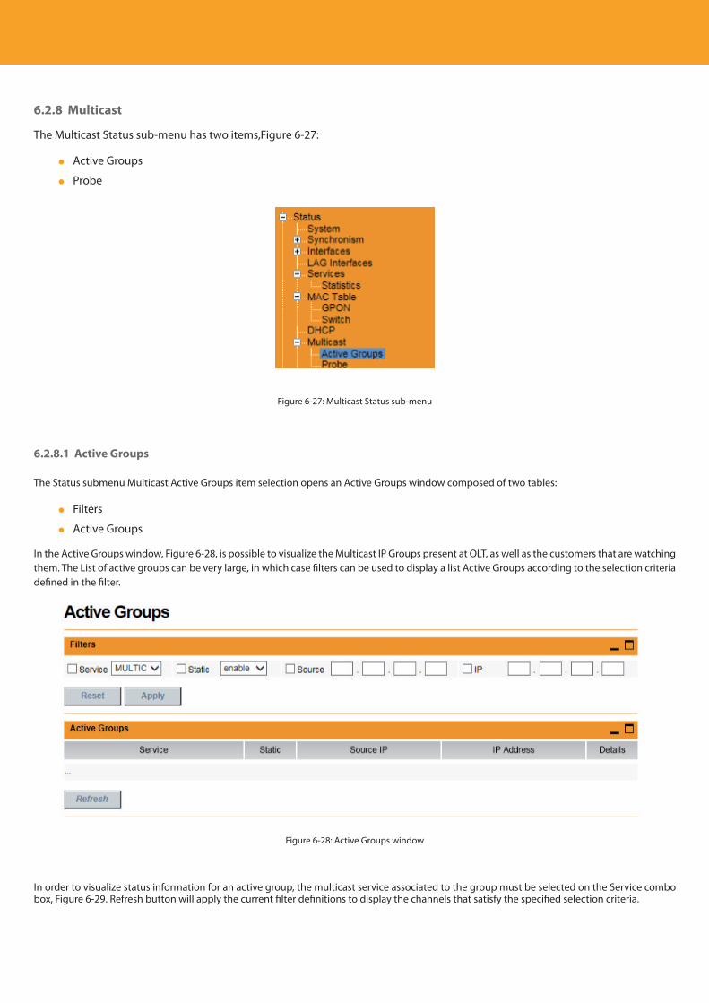
Descripción del producto
156
6.2.8 Multicast
The Multicast Status sub-menu has two items,Figure 6-27:
Active Groups
Probe
Figure 6-27: Multicast Status sub-menu
6.2.8.1 Active Groups
The Status submenu Multicast Active Groups item selection opens an Active Groups window composed of two tables:
Filters
Active Groups
In the Active Groups window, Figure 6-28, is possible to visualize the Multicast IP Groups present at OLT, as well as the customers that are watching them. The List of active groups can be very large, in which case filters can be used to display a list Active Groups according to the selection criteria defined in the filter.
Figure 6-28: Active Groups window
In order to visualize status information for an active group, the multicast service associated to the group must be selected on the Service combo box, Figure 6-29. Refresh button will apply the current filter definitions to display the channels that satisfy the specified selection criteria.
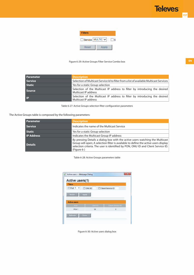
EN
157
Figure 6-29: Active Groups Filter Service Combo box
Parameter DescriptionService Selection of Multicast Service Id to filter from a list of available Multicast ServicesStatic Yes for a static Group selection
Source Selection of the Multicast IP address to filter by introducing the desired Multicast IP address
IP Selection of the Multicast IP address to filter by introducing the desired Multicast IP address
Table 6-27: Active Groups selection filter configuration parameters
The Active Groups table is composed by the following parameters:
Parameter Description
Service Indicates the name of the Multicast Service
Static Yes for a static Group selectionIP Address Indicates the Multicast Group IP address
Details
By pressing Details a dialog box with the active users watching the Multicast Group will open; A selection filter is available to define the active users display selection criteria. The user is identified by PON, ONU ID and Client Service ID. (Figure 6-)
Table 6-28: Active Groups parameters table
Figure 6-30: Active users dialog box
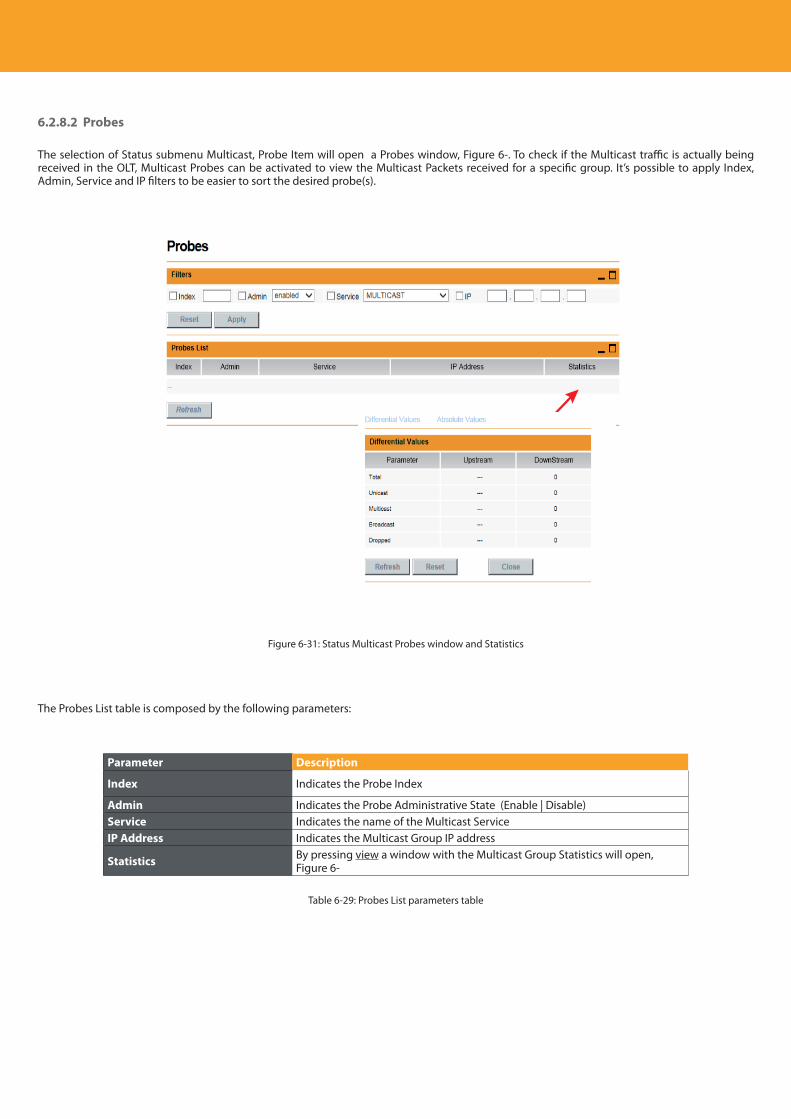
Descripción del producto
158
6.2.8.2 Probes
The selection of Status submenu Multicast, Probe Item will open a Probes window, Figure 6-. To check if the Multicast traffic is actually being received in the OLT, Multicast Probes can be activated to view the Multicast Packets received for a specific group. It’s possible to apply Index, Admin, Service and IP filters to be easier to sort the desired probe(s).
Figure 6-31: Status Multicast Probes window and Statistics
The Probes List table is composed by the following parameters:
Parameter Description
Index Indicates the Probe Index
Admin Indicates the Probe Administrative State (Enable | Disable)Service Indicates the name of the Multicast ServiceIP Address Indicates the Multicast Group IP address
Statistics By pressing view a window with the Multicast Group Statistics will open, Figure 6-
Table 6-29: Probes List parameters table
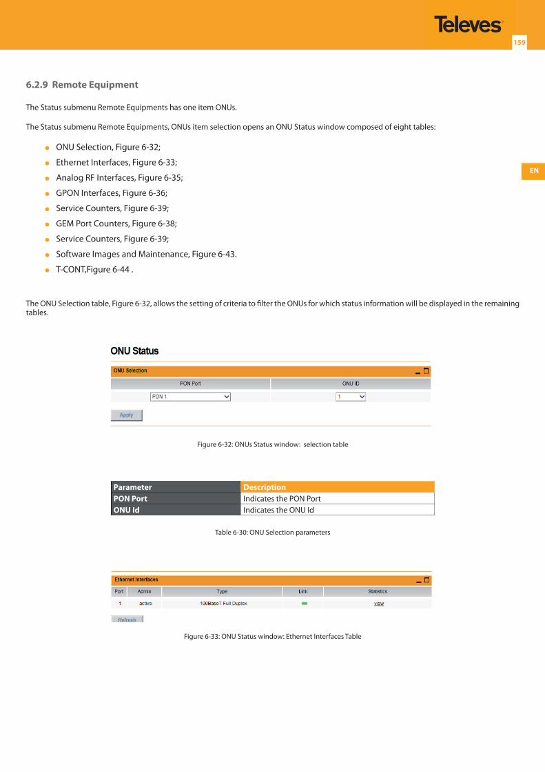
EN
159
6.2.9 Remote Equipment
The Status submenu Remote Equipments has one item ONUs.
The Status submenu Remote Equipments, ONUs item selection opens an ONU Status window composed of eight tables:
ONU Selection, Figure 6-32;
Ethernet Interfaces, Figure 6-33;
Analog RF Interfaces, Figure 6-35;
GPON Interfaces, Figure 6-36;
Service Counters, Figure 6-39;
GEM Port Counters, Figure 6-38;
Service Counters, Figure 6-39;
Software Images and Maintenance, Figure 6-43.
T-CONT,Figure 6-44 .
The ONU Selection table, Figure 6-32, allows the setting of criteria to filter the ONUs for which status information will be displayed in the remaining tables.
Figure 6-32: ONUs Status window: selection table
Parameter DescriptionPON Port Indicates the PON PortONU Id Indicates the ONU Id
Table 6-30: ONU Selection parameters
Figure 6-33: ONU Status window: Ethernet Interfaces Table
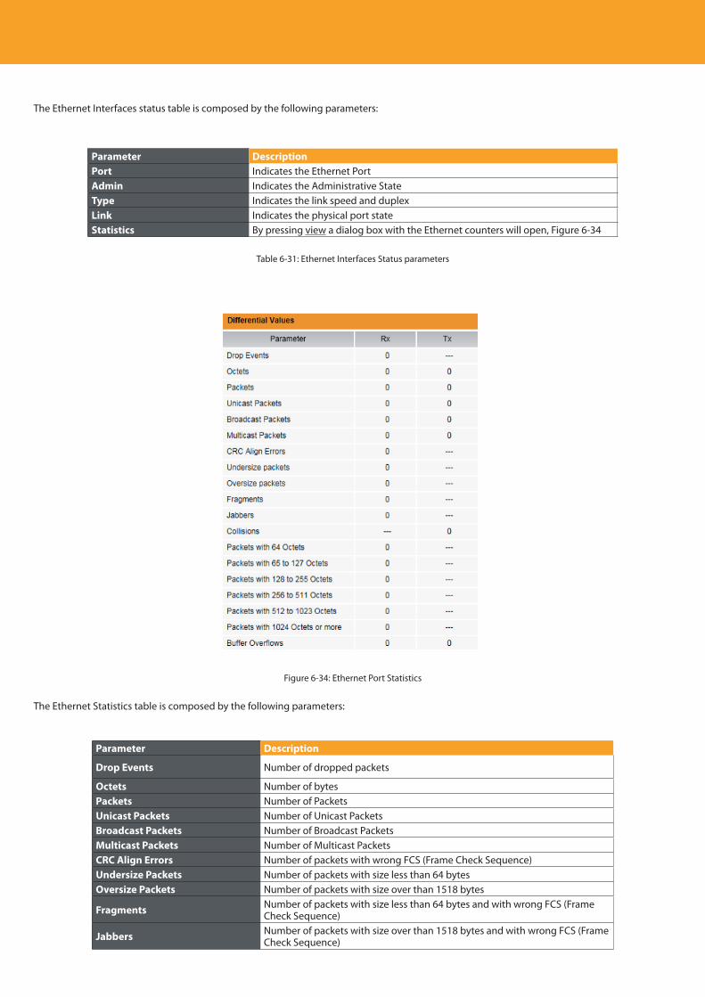
Descripción del producto
160
The Ethernet Interfaces status table is composed by the following parameters:
Parameter DescriptionPort Indicates the Ethernet PortAdmin Indicates the Administrative StateType Indicates the link speed and duplexLink Indicates the physical port stateStatistics By pressing view a dialog box with the Ethernet counters will open, Figure 6-34
Table 6-31: Ethernet Interfaces Status parameters
Figure 6-34: Ethernet Port Statistics
The Ethernet Statistics table is composed by the following parameters:
Parameter Description
Drop Events Number of dropped packets
Octets Number of bytesPackets Number of PacketsUnicast Packets Number of Unicast PacketsBroadcast Packets Number of Broadcast PacketsMulticast Packets Number of Multicast PacketsCRC Align Errors Number of packets with wrong FCS (Frame Check Sequence)Undersize Packets Number of packets with size less than 64 bytesOversize Packets Number of packets with size over than 1518 bytes
Fragments Number of packets with size less than 64 bytes and with wrong FCS (Frame Check Sequence)
Jabbers Number of packets with size over than 1518 bytes and with wrong FCS (Frame Check Sequence)
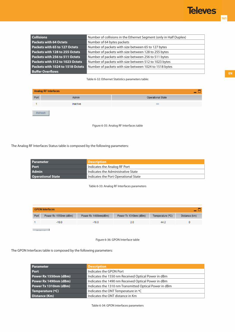
EN
161
Collisions Number of collisions in the Ethernet Segment (only in Half Duplex)Packets with 64 Octets Number of 64 bytes packetsPackets with 65 to 127 Octets Number of packets with size between 65 to 127 bytes Packets with 128 to 255 Octets Number of packets with size between 128 to 255 bytes Packets with 256 to 511 Octets Number of packets with size between 256 to 511 bytes Packets with 512 to 1023 Octets Number of packets with size between 512 to 1023 bytes Packets with 1024 to 1518 Octets Number of packets with size between 1024 to 1518 bytes Buffer Overflows
Table 6-32: Ethernet Statistics parameters table:
Figure 6-35: Analog RF Interfaces table
The Analog RF Interfaces Status table is composed by the following parameters:
Parameter DescriptionPort Indicates the Analog RF PortAdmin Indicates the Administrative StateOperational State Indicates the Port Operational State
Table 6-33: Analog RF Interfaces parameters
Figure 6-36: GPON Interface table
The GPON Interfaces table is composed by the following parameters:
Parameter DescriptionPort Indicates the GPON PortPower Rx 1550nm (dBm) Indicates the 1550 nm Received Optical Power in dBmPower Rx 1490nm (dBm) Indicates the 1490 nm Received Optical Power in dBmPower Tx 1310nm (dBm) Indicates the 1310 nm Transmitted Optical Power in dBmTemperature (ºC) Indicates the ONT Temperature in ºCDistance (Km) Indicates the ONT distance in Km
Table 6-34: GPON interfaces parameters
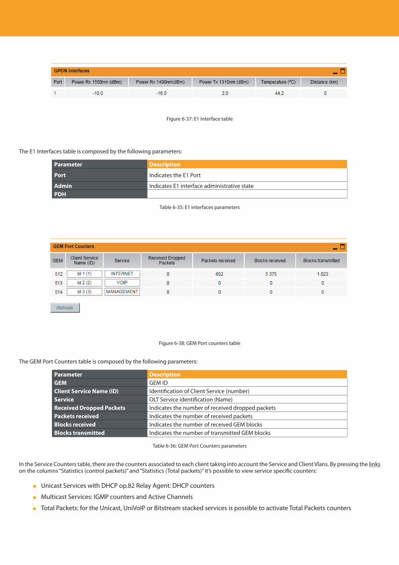
Descripción del producto
162
Figure 6-37: E1 Interface table
The E1 Interfaces table is composed by the following parameters:
Parameter Description
Port Indicates the E1 Port
Admin Indicates E1 interface administrative statePDH
Table 6-35: E1 interfaces parameters
Figure 6-38: GEM Port counters table
The GEM Port Counters table is composed by the following parameters:
Parameter DescriptionGEM GEM IDClient Service Name (ID) Identification of Client Service (number)Service OLT Service identification (Name)Received Dropped Packets Indicates the number of received dropped packetsPackets received Indicates the number of received packetsBlocks received Indicates the number of received GEM blocksBlocks transmitted Indicates the number of transmitted GEM blocks
Table 6-36: GEM Port Counters parameters
In the Service Counters table, there are the counters associated to each client taking into account the Service and Client Vlans. By pressing the links on the columns “Statistics (control packets)” and “Statistics (Total packets)” it’s possible to view service specific counters:
Unicast Services with DHCP op.82 Relay Agent: DHCP counters
Multicast Services: IGMP counters and Active Channels
Total Packets: for the Unicast, UniVoIP or Bitstream stacked services is possible to activate Total Packets counters
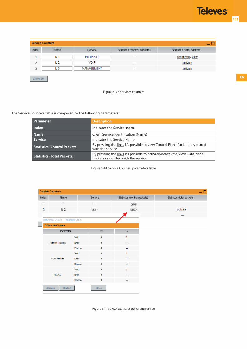
EN
163
Figure 6-39: Services counters
The Service Counters table is composed by the following parameters:
Parameter Description
Index Indicates the Service Index
Name Client Service Identification (Name)Service Indicates the Service Name
Statistics (Control Packets) By pressing the links it’s possible to view Control Plane Packets associated with the service
Statistics (Total Packets) By pressing the links it’s possible to activate/deactivate/view Data Plane Packets associated with the service
Figure 6-40: Service Counters parameters table
Figure 6-41: DHCP Statistics per client/service
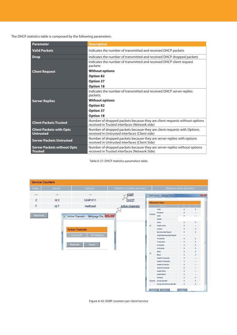
Descripción del producto
164
The DHCP statistics table is composed by the following parameters:
Parameter Description
Valid Packets Indicates the number of transmitted and received DHCP packets
Drop Indicates the number of transmitted and received DHCP dropped packets
Client Request
Indicates the number of transmitted and received DHCP client request packets:Without optionsOption 82Option 37Option 18
Server Replies
Indicates the number of transmitted and received DHCP server replies packets:Without optionsOption 82Option 37Option 18
Client Packets Trusted Number of dropped packets because they are client requests without options received in Trusted interfaces (Network side)
Client Packets with Opts Untrusted
Number of dropped packets because they are client requests with Options received in Untrusted interfaces (Client side)
Server Packets Untrusted Number of dropped packets because they are server replies with options received in Untrusted interfaces (Client Side)
Server Packets without Opts Trusted
Number of dropped packets because they are server replies without options received in Trusted interfaces (Network Side)
Table 6-37: DHCP statistics parameters table
Figure 6-42: IGMP counters per client/service
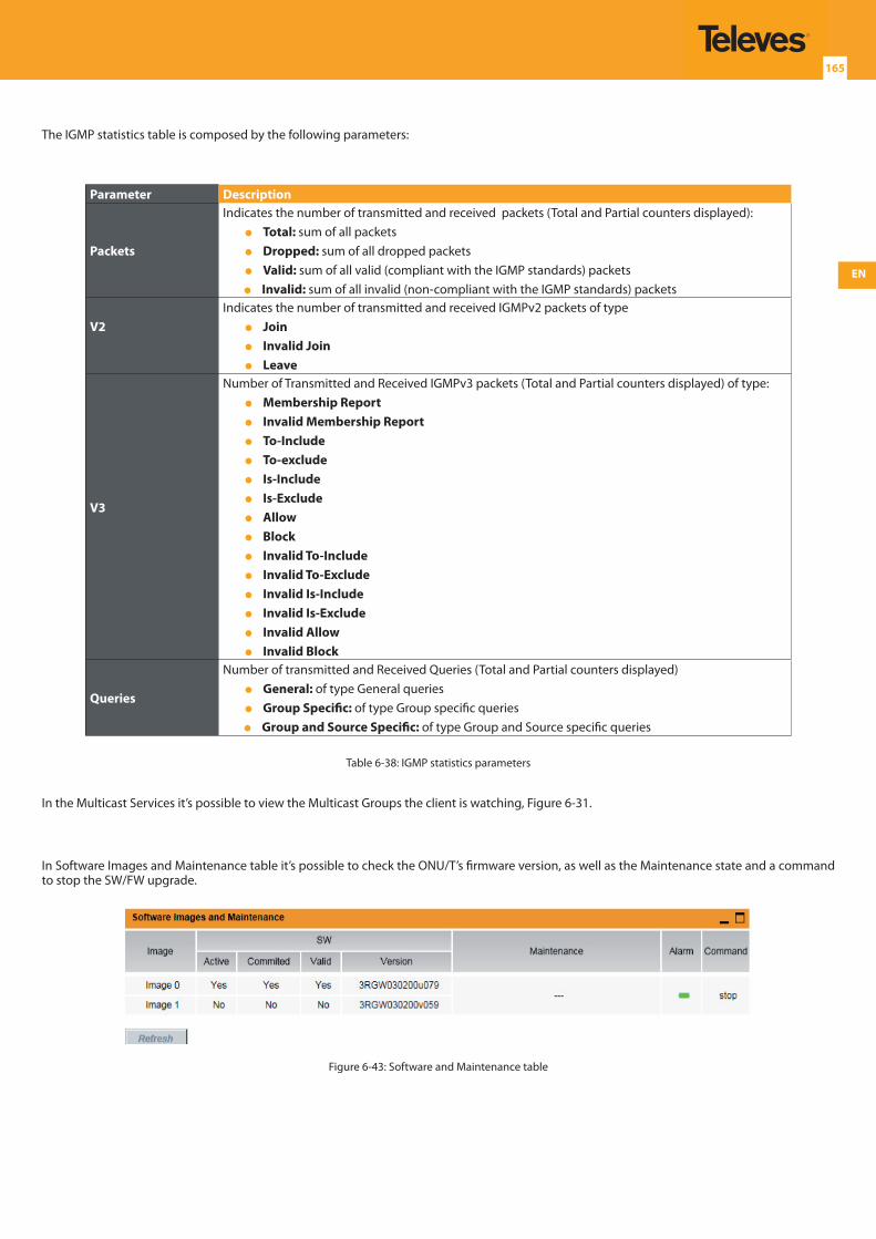
EN
165
The IGMP statistics table is composed by the following parameters:
Parameter Description
Packets
Indicates the number of transmitted and received packets (Total and Partial counters displayed): Total: sum of all packets Dropped: sum of all dropped packets Valid: sum of all valid (compliant with the IGMP standards) packets Invalid: sum of all invalid (non-compliant with the IGMP standards) packets
V2Indicates the number of transmitted and received IGMPv2 packets of type Join Invalid Join Leave
V3
Number of Transmitted and Received IGMPv3 packets (Total and Partial counters displayed) of type: Membership Report Invalid Membership Report To-Include To-exclude Is-Include Is-Exclude Allow Block Invalid To-Include Invalid To-Exclude Invalid Is-Include Invalid Is-Exclude Invalid Allow Invalid Block
Queries
Number of transmitted and Received Queries (Total and Partial counters displayed) General: of type General queries Group Specific: of type Group specific queries Group and Source Specific: of type Group and Source specific queries
Table 6-38: IGMP statistics parameters
In the Multicast Services it’s possible to view the Multicast Groups the client is watching, Figure 6-31.
In Software Images and Maintenance table it’s possible to check the ONU/T’s firmware version, as well as the Maintenance state and a command to stop the SW/FW upgrade.
Figure 6-43: Software and Maintenance table
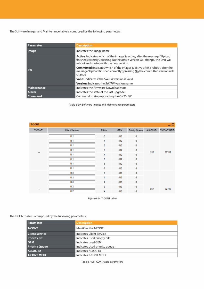
Descripción del producto
166
The Software Images and Maintenance table is composed by the following parameters:
Parameter Description
Image Indicates the Image name
SW
Active: Indicates which of the images is active, after the message “Upload finished correctly”, pressing No the active version will change, the ONT will reboot and startup with the new version.Committed: Indicates which of the images is active after a reboot, after the message “Upload finished correctly”, pressing No the committed version will changeValid: Indicates if the SW/FW version is ValidVersion: Indicates the SW/FW version name
Maintenance Indicates the Firmware Download stateAlarm Indicates the state of the last upgradeCommand Command to stop upgrading the ONT’s FW
Table 6-39: Software Images and Maintenance parameters
Figure 6-44: T-CONT table
The T-CONT table is composed by the following parameters:
Parameter Description
T-CONT Identifies the T-CONT
Client Service Indicates Client ServicePriority Bit Indicates used priority bitsGEM Indicates used GEMPriority Queue Indicates Used priority queueALLOC-ID Indicates ALLOC-IDT-CONT MEID Indicates T-CONT MEID
Table 6-40: T-CONT table parameters
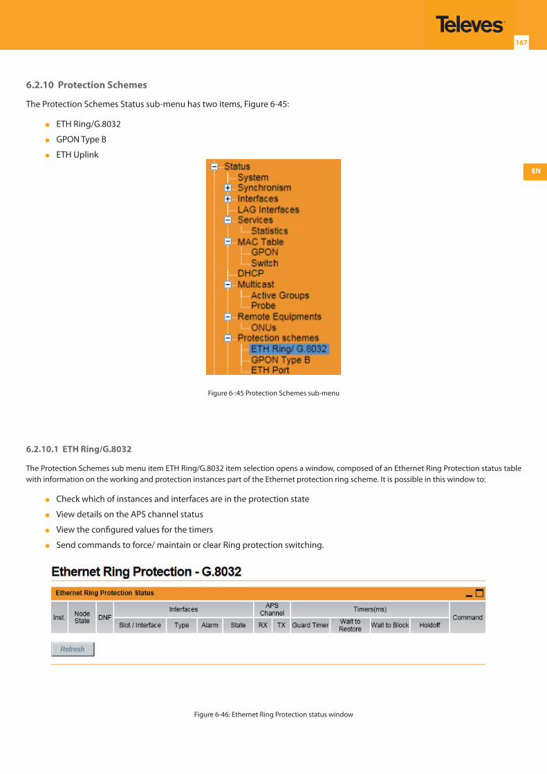
EN
167
6.2.10 Protection Schemes
The Protection Schemes Status sub-menu has two items, Figure 6-45:
ETH Ring/G.8032
GPON Type B
ETH Uplink
Figure 6-:45 Protection Schemes sub-menu
6.2.10.1 ETH Ring/G.8032
The Protection Schemes sub menu item ETH Ring/G.8032 item selection opens a window, composed of an Ethernet Ring Protection status table with information on the working and protection instances part of the Ethernet protection ring scheme. It is possible in this window to:
Check which of instances and interfaces are in the protection state
View details on the APS channel status
View the configured values for the timers
Send commands to force/ maintain or clear Ring protection switching.
Figure 6-46: Ethernet Ring Protection status window
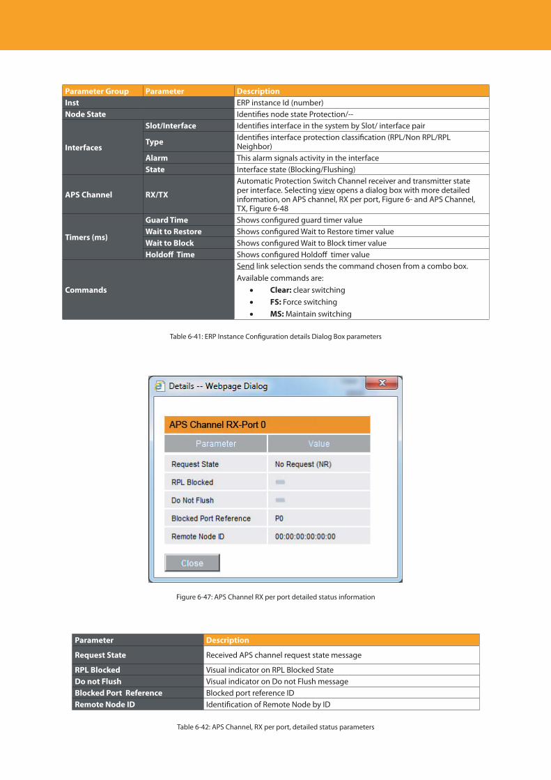
Descripción del producto
168
Parameter Group Parameter DescriptionInst ERP instance Id (number)Node State Identifies node state Protection/--
Interfaces
Slot/Interface Identifies interface in the system by Slot/ interface pair
Type Identifies interface protection classification (RPL/Non RPL/RPL Neighbor)
Alarm This alarm signals activity in the interfaceState Interface state (Blocking/Flushing)
APS Channel RX/TX
Automatic Protection Switch Channel receiver and transmitter state per interface. Selecting view opens a dialog box with more detailed information, on APS channel, RX per port, Figure 6- and APS Channel, TX, Figure 6-48
Timers (ms)
Guard Time Shows configured guard timer valueWait to Restore Shows configured Wait to Restore timer valueWait to Block Shows configured Wait to Block timer valueHoldoff Time Shows configured Holdoff timer value
Commands
Send link selection sends the command chosen from a combo box. Available commands are:
• Clear: clear switching• FS: Force switching• MS: Maintain switching
Table 6-41: ERP Instance Configuration details Dialog Box parameters
Figure 6-47: APS Channel RX per port detailed status information
Parameter Description
Request State Received APS channel request state message
RPL Blocked Visual indicator on RPL Blocked StateDo not Flush Visual indicator on Do not Flush messageBlocked Port Reference Blocked port reference IDRemote Node ID Identification of Remote Node by ID
Table 6-42: APS Channel, RX per port, detailed status parameters
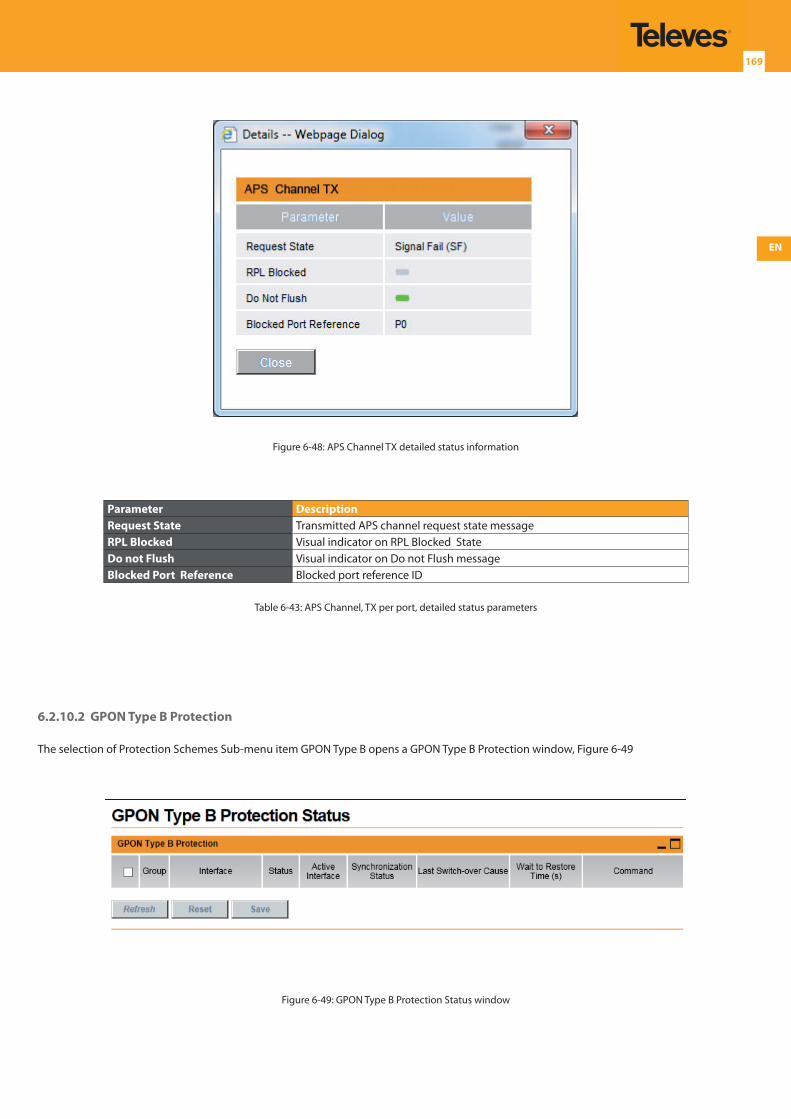
EN
169
Figure 6-48: APS Channel TX detailed status information
Parameter DescriptionRequest State Transmitted APS channel request state message RPL Blocked Visual indicator on RPL Blocked StateDo not Flush Visual indicator on Do not Flush messageBlocked Port Reference Blocked port reference ID
Table 6-43: APS Channel, TX per port, detailed status parameters
6.2.10.2 GPON Type B Protection
The selection of Protection Schemes Sub-menu item GPON Type B opens a GPON Type B Protection window, Figure 6-49
Figure 6-49: GPON Type B Protection Status window
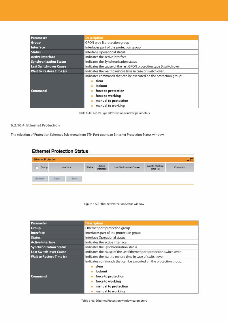
Descripción del producto
170
Parameter DescriptionGroup GPON type B protection groupInterface Interfaces part of the protection groupStatus Interface Operational statusActive Interface Indicates the active interfaceSynchronization Status Indicates the Synchronization statusLast Switch-over Cause Indicates the cause of the last GPON protection type B switch overWait to Restore Time (s) Indicates the wait to restore time in case of switch over.
Command
Indicates commands that can be executed on the protection group: clear lockout force to protection force to working manual to protection manual to working
Table 6-44: GPON Type B Protection window parameters
6.2.10.4 Ethernet Protection
The selection of Protection Schemes Sub-menu item ETH Port opens an Ethernet Protection Status window.
Figure 6-50: Ethernet Protection Status window
Parameter DescriptionGroup Ethernet port protection groupInterface Interfaces part of the protection groupStatus Interface Operational statusActive Interface Indicates the active interfaceSynchronization Status Indicates the Synchronization statusLast Switch-over Cause Indicates the cause of the last Ethernet port protection switch overWait to Restore Time (s) Indicates the wait to restore time in case of switch over.
Command
Indicates commands that can be executed on the protection group: clear lockout force to protection force to working manual to protection manual to working
Table 6-45: Ethernet Protection window parameters
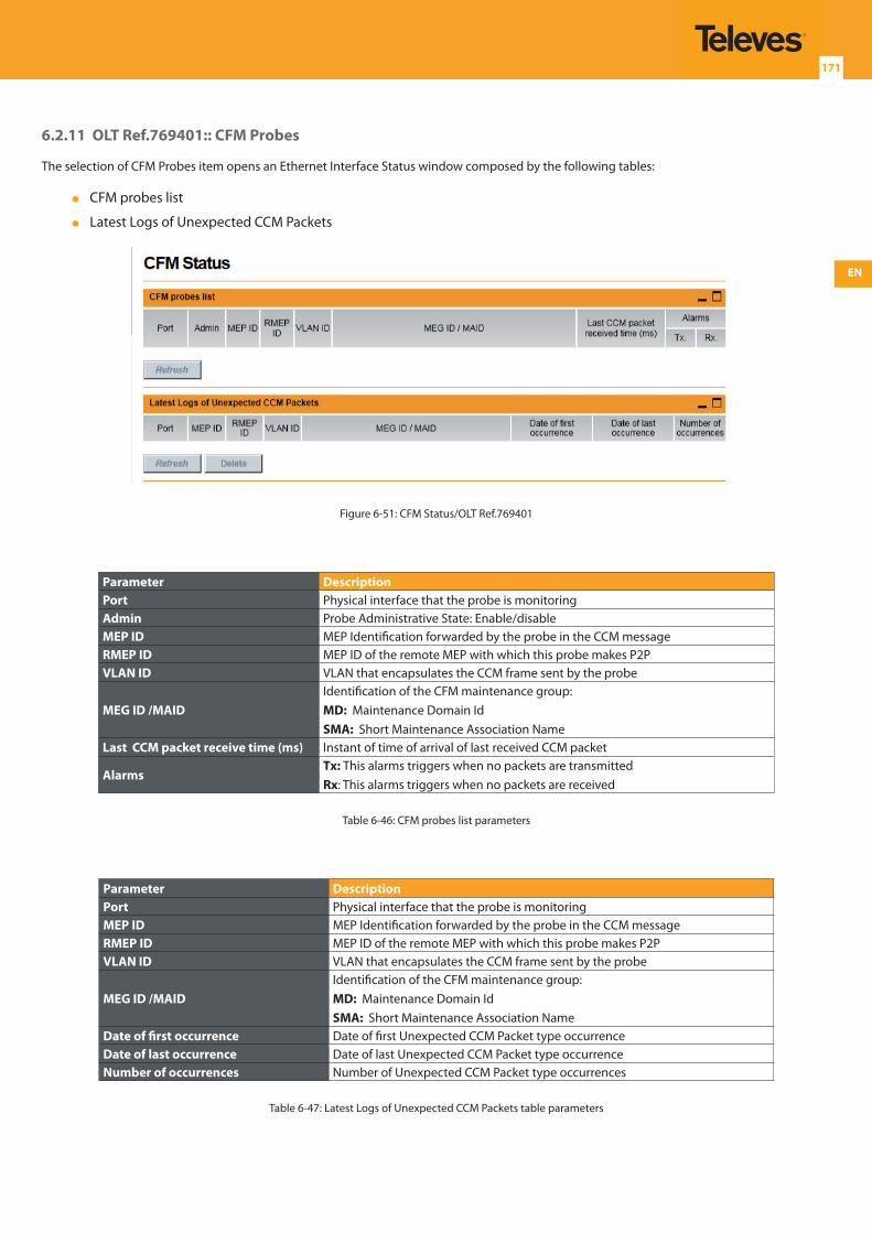
EN
171
6.2.11 OLT Ref.769401:: CFM Probes
The selection of CFM Probes item opens an Ethernet Interface Status window composed by the following tables:
CFM probes list
Latest Logs of Unexpected CCM Packets
Figure 6-51: CFM Status/OLT Ref.769401
Parameter DescriptionPort Physical interface that the probe is monitoringAdmin Probe Administrative State: Enable/disableMEP ID MEP Identification forwarded by the probe in the CCM messageRMEP ID MEP ID of the remote MEP with which this probe makes P2PVLAN ID VLAN that encapsulates the CCM frame sent by the probe
MEG ID /MAIDIdentification of the CFM maintenance group:MD: Maintenance Domain IdSMA: Short Maintenance Association Name
Last CCM packet receive time (ms) Instant of time of arrival of last received CCM packet
AlarmsTx: This alarms triggers when no packets are transmitted Rx: This alarms triggers when no packets are received
Table 6-46: CFM probes list parameters
Parameter DescriptionPort Physical interface that the probe is monitoringMEP ID MEP Identification forwarded by the probe in the CCM messageRMEP ID MEP ID of the remote MEP with which this probe makes P2PVLAN ID VLAN that encapsulates the CCM frame sent by the probe
MEG ID /MAIDIdentification of the CFM maintenance group:MD: Maintenance Domain IdSMA: Short Maintenance Association Name
Date of first occurrence Date of first Unexpected CCM Packet type occurrenceDate of last occurrence Date of last Unexpected CCM Packet type occurrenceNumber of occurrences Number of Unexpected CCM Packet type occurrences
Table 6-47: Latest Logs of Unexpected CCM Packets table parameters
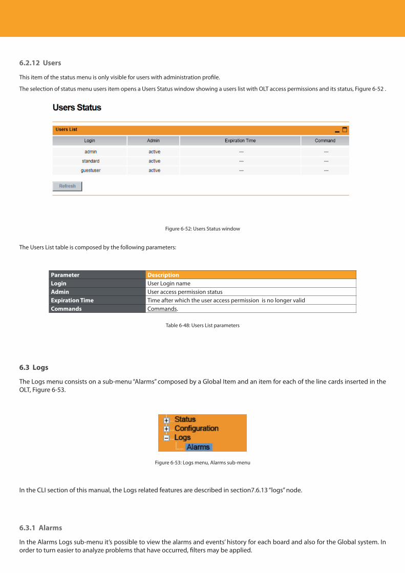
Descripción del producto
172
6.2.12 Users
This item of the status menu is only visible for users with administration profile.
The selection of status menu users item opens a Users Status window showing a users list with OLT access permissions and its status, Figure 6-52 .
Figure 6-52: Users Status window
The Users List table is composed by the following parameters:
Parameter DescriptionLogin User Login nameAdmin User access permission statusExpiration Time Time after which the user access permission is no longer validCommands Commands.
Table 6-48: Users List parameters
6.3 Logs
The Logs menu consists on a sub-menu “Alarms” composed by a Global Item and an item for each of the line cards inserted in the OLT, Figure 6-53.
Figure 6-53: Logs menu, Alarms sub-menu
In the CLI section of this manual, the Logs related features are described in section7.6.13 “logs” node.
6.3.1 Alarms
In the Alarms Logs sub-menu it’s possible to view the alarms and events’ history for each board and also for the Global system. In order to turn easier to analyze problems that have occurred, filters may be applied.
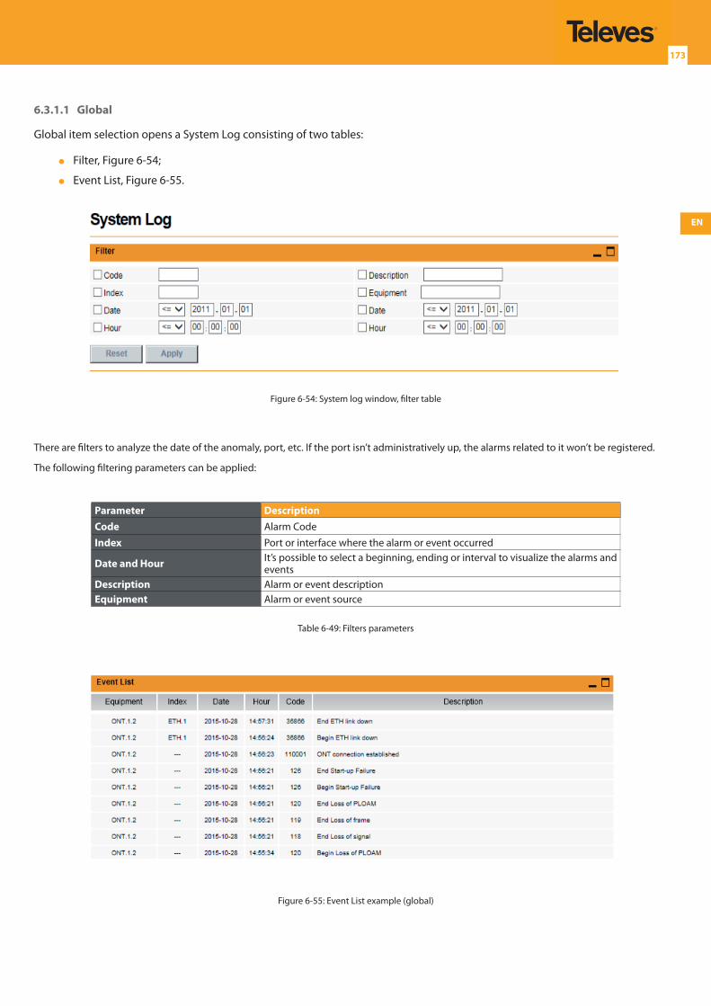
EN
173
6.3.1.1 Global
Global item selection opens a System Log consisting of two tables:
Filter, Figure 6-54;
Event List, Figure 6-55.
Figure 6-54: System log window, filter table
There are filters to analyze the date of the anomaly, port, etc. If the port isn’t administratively up, the alarms related to it won’t be registered.
The following filtering parameters can be applied:
Parameter DescriptionCode Alarm Code Index Port or interface where the alarm or event occurred
Date and Hour It’s possible to select a beginning, ending or interval to visualize the alarms and events
Description Alarm or event descriptionEquipment Alarm or event source
Table 6-49: Filters parameters
Figure 6-55: Event List example (global)

Descripción del producto
174
Parameter DescriptionEquipment Alarm or event sourceIndex Port or interface where the alarm or event occurredDate and Hour Date and hour when the alarm or event occurredCode Alarm CodeDescription Alarm or event description
Table 6-50: Event List parameters
In the end of the table there are two buttons:
Refresh: updates the table
Delete: Deletes all the alarms
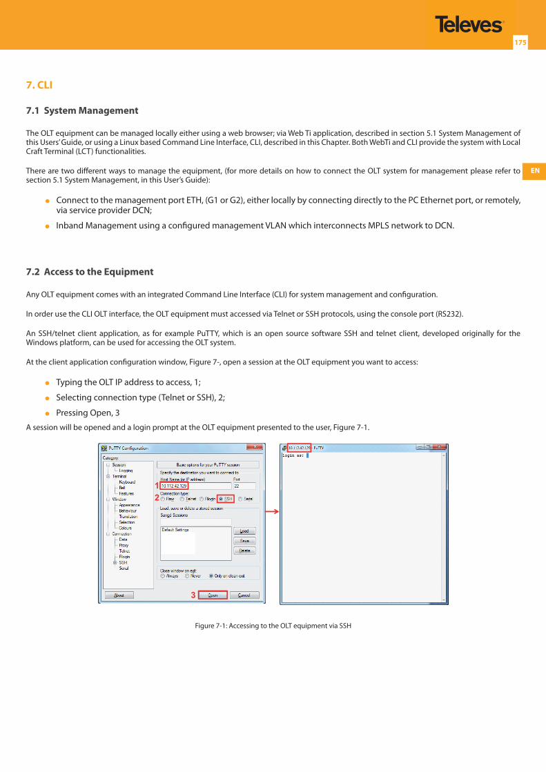
EN
175
7. CLI
7.1 System Management
The OLT equipment can be managed locally either using a web browser; via Web Ti application, described in section 5.1 System Management of this Users’ Guide, or using a Linux based Command Line Interface, CLI, described in this Chapter. Both WebTi and CLI provide the system with Local Craft Terminal (LCT) functionalities.
There are two different ways to manage the equipment, (for more details on how to connect the OLT system for management please refer to section 5.1 System Management, in this User’s Guide):
Connect to the management port ETH, (G1 or G2), either locally by connecting directly to the PC Ethernet port, or remotely, via service provider DCN;
Inband Management using a configured management VLAN which interconnects MPLS network to DCN.
7.2 Access to the Equipment
Any OLT equipment comes with an integrated Command Line Interface (CLI) for system management and configuration.
In order use the CLI OLT interface, the OLT equipment must accessed via Telnet or SSH protocols, using the console port (RS232).
An SSH/telnet client application, as for example PuTTY, which is an open source software SSH and telnet client, developed originally for the Windows platform, can be used for accessing the OLT system.
At the client application configuration window, Figure 7-, open a session at the OLT equipment you want to access:
Typing the OLT IP address to access, 1;
Selecting connection type (Telnet or SSH), 2;
Pressing Open, 3
A session will be opened and a login prompt at the OLT equipment presented to the user, Figure 7-1.
12
3
Figure 7-1: Accessing to the OLT equipment via SSH
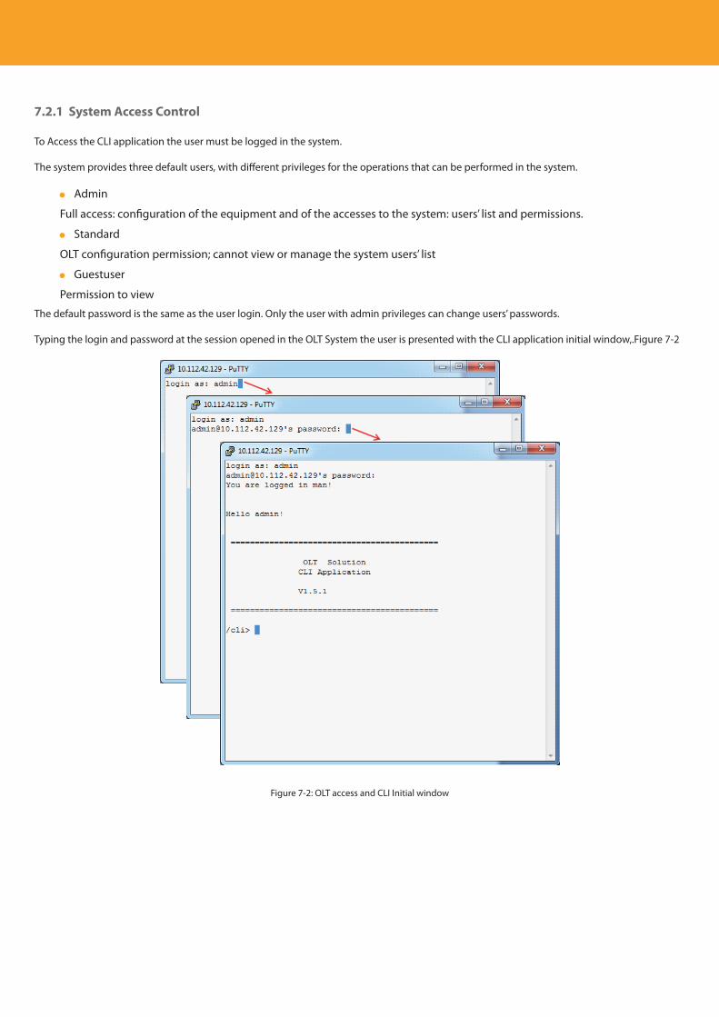
Descripción del producto
176
7.2.1 System Access Control
To Access the CLI application the user must be logged in the system.
The system provides three default users, with different privileges for the operations that can be performed in the system.
Admin
Full access: configuration of the equipment and of the accesses to the system: users’ list and permissions.
Standard
OLT configuration permission; cannot view or manage the system users’ list
Guestuser
Permission to view
The default password is the same as the user login. Only the user with admin privileges can change users’ passwords.
Typing the login and password at the session opened in the OLT System the user is presented with the CLI application initial window,.Figure 7-2
Figure 7-2: OLT access and CLI Initial window
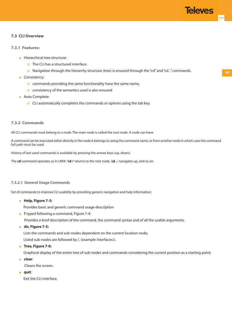
EN
177
7.3 CLI Overview
7.3.1 Features:
Hierarchical tree structure:
The CLI has a structured interface.
Navigation through the hierarchy structure (tree) is ensured through the “cd” and “cd ..” commands.
Consistency:
commands providing the same functionality have the same name,
consistency of the semantics used is also ensured
Auto Complete:
CLI automatically completes the commands or options using the tab key.
7.3.2 Commands
All CLI commands must belong to a node. The main node is called the root node. A node can have
A command can be executed either directly in the node it belongs to using the command name, or from another node in which case the command full path must be used.
History of last used commands is available by pressing the arrows keys (up, down).
The cd command operates as in UNIX: ‘cd /’ returns to the root node, ‘cd ..’ navigates up, and so on.
7.3.2.1 General Usage Commands
Set of commands to improve CLI usability by providing generic navigation and help information:
Help, Figure 7-3:
Provides basic and generic command usage description
? typed following a command, Figure 7-4:
Provides a brief description of the command, the command syntax and of all the usable arguments.
dir, Figure 7-5:
Lists the commands and sub-nodes dependent on the current location node;
Listed sub-nodes are followed by /, (example interfaces/).
Tree, Figure 7-6:
Graphical display of the entire tree of sub-nodes and commands considering the current position as a starting point;
clear:
Cleans the screen.
quit:
Exit the CLI interface.
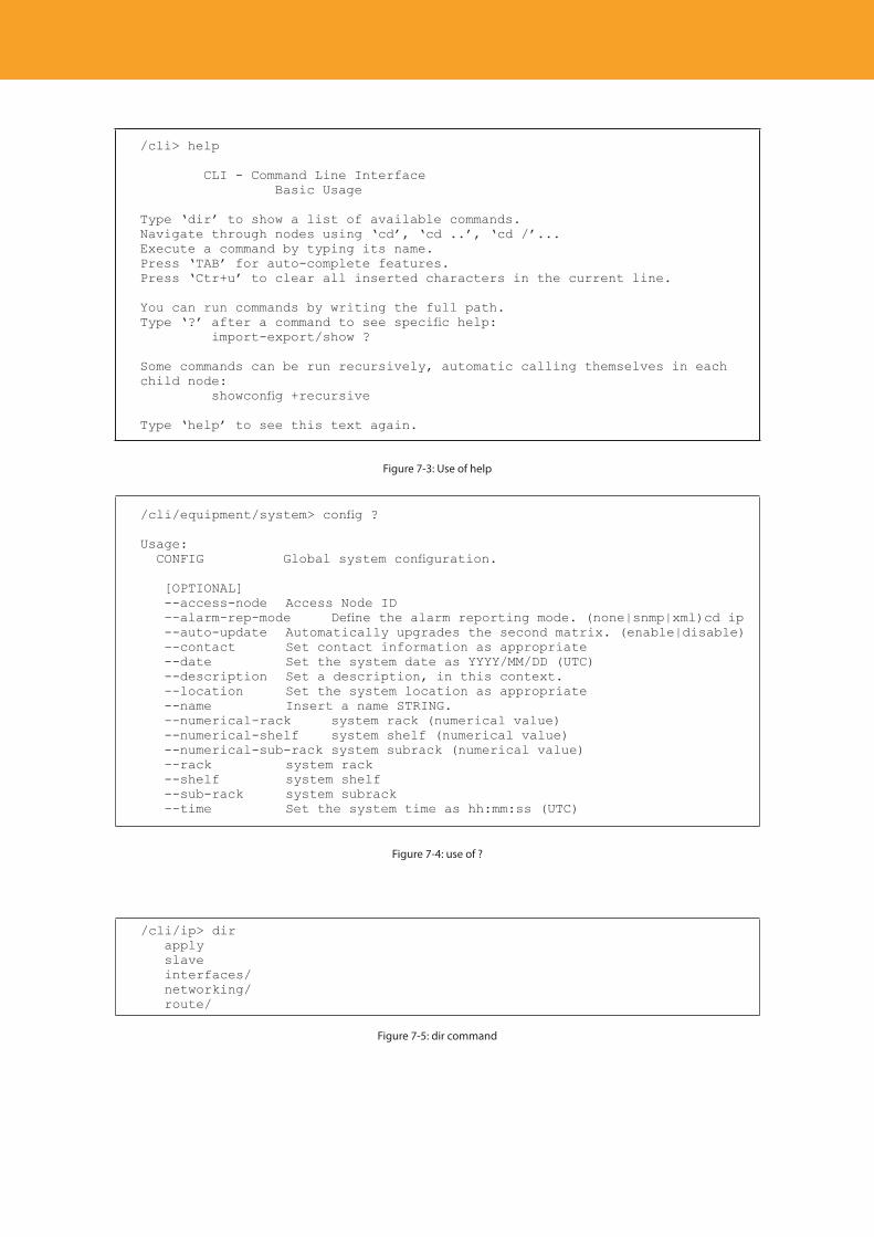
Descripción del producto
178
/cli> help
CLI - Command Line Interface Basic Usage
Type ‘dir’ to show a list of available commands.Navigate through nodes using ‘cd’, ‘cd ..’, ‘cd /’...Execute a command by typing its name.Press ‘TAB’ for auto-complete features.Press ‘Ctr+u’ to clear all inserted characters in the current line.
You can run commands by writing the full path.Type ‘?’ after a command to see specific help: import-export/show ?
Some commands can be run recursively, automatic calling themselves in eachchild node: showconfig +recursive
Type ‘help’ to see this text again.
Figure 7-3: Use of help
/cli/equipment/system> config ?
Usage: CONFIG Global system configuration.
[OPTIONAL] --access-node Access Node ID --alarm-rep-mode Define the alarm reporting mode. (none|snmp|xml)cd ip --auto-update Automatically upgrades the second matrix. (enable|disable) --contact Set contact information as appropriate --date Set the system date as YYYY/MM/DD (UTC) --description Set a description, in this context. --location Set the system location as appropriate --name Insert a name STRING. --numerical-rack system rack (numerical value) --numerical-shelf system shelf (numerical value) --numerical-sub-rack system subrack (numerical value) --rack system rack --shelf system shelf --sub-rack system subrack --time Set the system time as hh:mm:ss (UTC)
Figure 7-4: use of ?
/cli/ip> dir apply slave interfaces/ networking/ route/
Figure 7-5: dir command
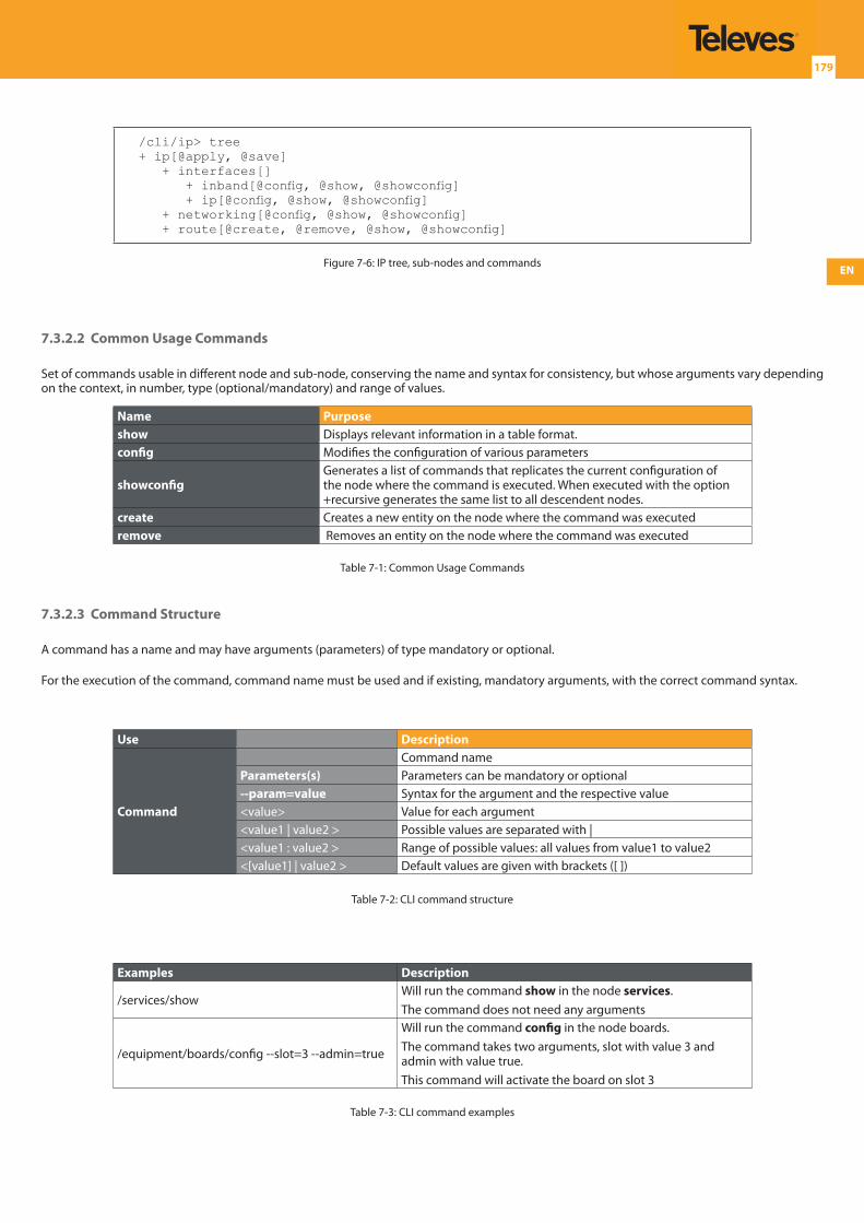
EN
179
/cli/ip> tree+ ip[@apply, @save] + interfaces[] + inband[@config, @show, @showconfig] + ip[@config, @show, @showconfig] + networking[@config, @show, @showconfig] + route[@create, @remove, @show, @showconfig]
Figure 7-6: IP tree, sub-nodes and commands
7.3.2.2 Common Usage Commands
Set of commands usable in different node and sub-node, conserving the name and syntax for consistency, but whose arguments vary depending on the context, in number, type (optional/mandatory) and range of values.
Name Purposeshow Displays relevant information in a table format.config Modifies the configuration of various parameters
showconfigGenerates a list of commands that replicates the current configuration of the node where the command is executed. When executed with the option +recursive generates the same list to all descendent nodes.
create Creates a new entity on the node where the command was executedremove Removes an entity on the node where the command was executed
Table 7-1: Common Usage Commands
7.3.2.3 Command Structure
A command has a name and may have arguments (parameters) of type mandatory or optional.
For the execution of the command, command name must be used and if existing, mandatory arguments, with the correct command syntax.
Use Description
Command
Command nameParameters(s) Parameters can be mandatory or optional--param=value Syntax for the argument and the respective value<value> Value for each argument<value1 | value2 > Possible values are separated with |<value1 : value2 > Range of possible values: all values from value1 to value2 <[value1] | value2 > Default values are given with brackets ([ ])
Table 7-2: CLI command structure
Examples Description
/services/showWill run the command show in the node services. The command does not need any arguments
/equipment/boards/config --slot=3 --admin=true
Will run the command config in the node boards.The command takes two arguments, slot with value 3 and admin with value true.This command will activate the board on slot 3
Table 7-3: CLI command examples
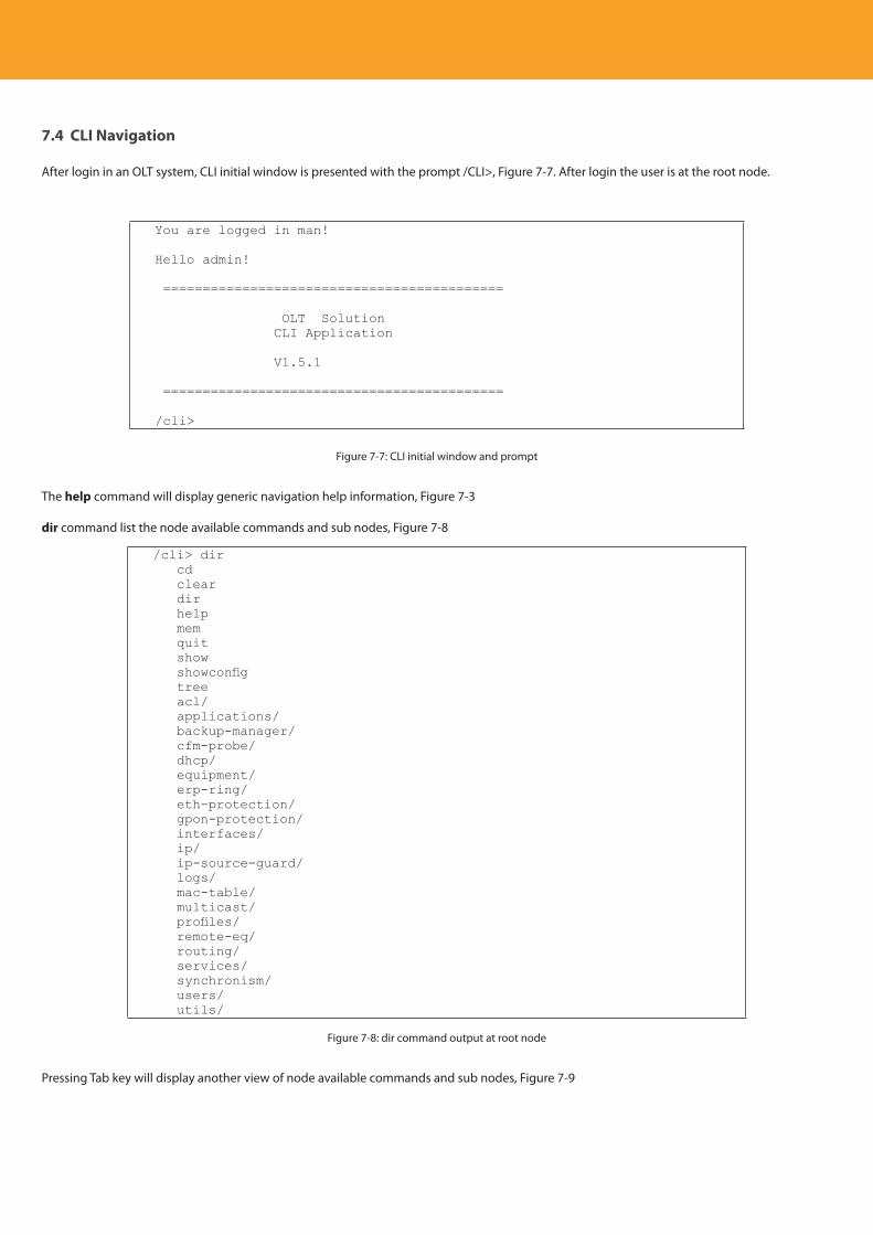
Descripción del producto
180
7.4 CLI Navigation
After login in an OLT system, CLI initial window is presented with the prompt /CLI>, Figure 7-7. After login the user is at the root node.
You are logged in man!
Hello admin!
===========================================
OLT Solution CLI Application
V1.5.1
===========================================
/cli>
Figure 7-7: CLI initial window and prompt
The help command will display generic navigation help information, Figure 7-3
dir command list the node available commands and sub nodes, Figure 7-8
/cli> dir cd clear dir help mem quit show showconfig tree acl/ applications/ backup-manager/ cfm-probe/ dhcp/ equipment/ erp-ring/ eth-protection/ gpon-protection/ interfaces/ ip/ ip-source-guard/ logs/ mac-table/ multicast/ profiles/ remote-eq/ routing/ services/ synchronism/ users/ utils/
Figure 7-8: dir command output at root node
Pressing Tab key will display another view of node available commands and sub nodes, Figure 7-9
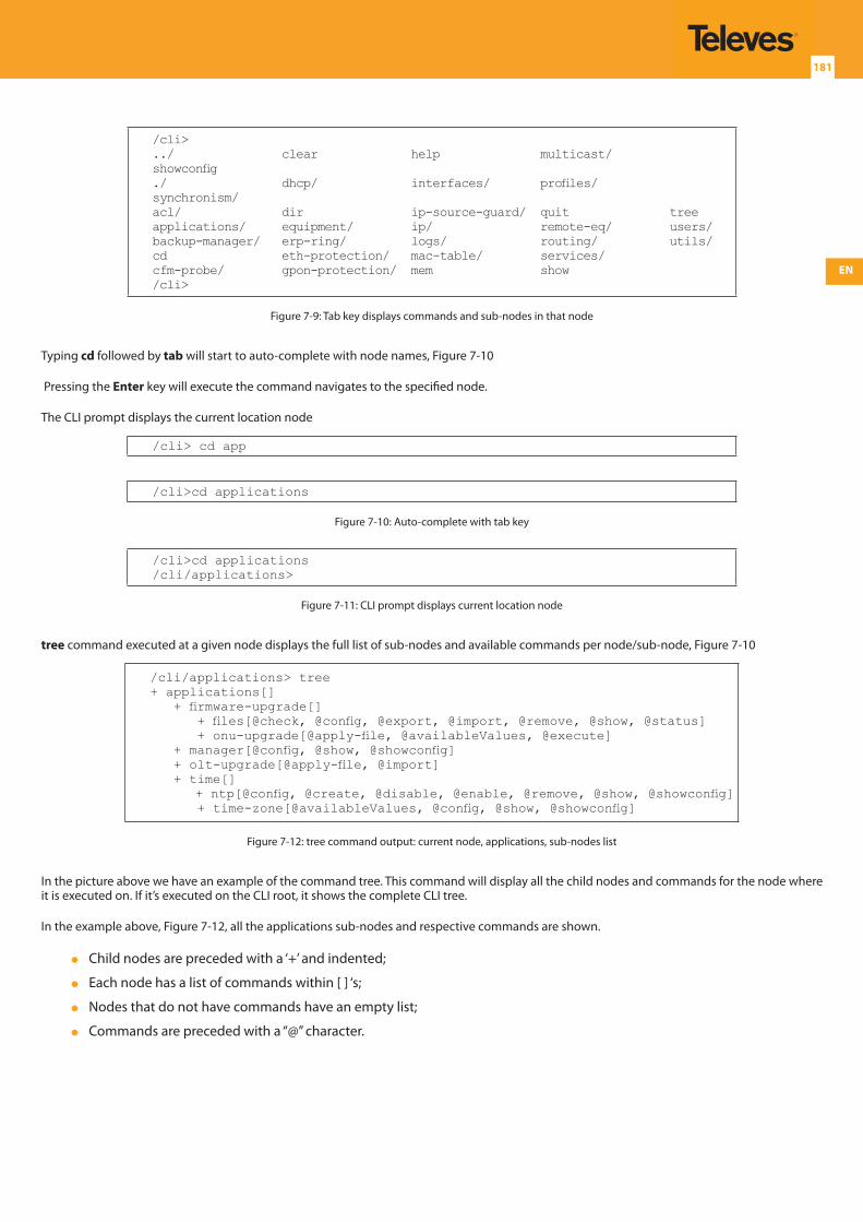
EN
181
/cli>../ clear help multicast/ showconfig./ dhcp/ interfaces/ profiles/ synchronism/acl/ dir ip-source-guard/ quit treeapplications/ equipment/ ip/ remote-eq/ users/backup-manager/ erp-ring/ logs/ routing/ utils/cd eth-protection/ mac-table/ services/cfm-probe/ gpon-protection/ mem show/cli>
Figure 7-9: Tab key displays commands and sub-nodes in that node
Typing cd followed by tab will start to auto-complete with node names, Figure 7-10
Pressing the Enter key will execute the command navigates to the specified node.
The CLI prompt displays the current location node
/cli> cd app
/cli>cd applications
Figure 7-10: Auto-complete with tab key
/cli>cd applications/cli/applications>
Figure 7-11: CLI prompt displays current location node
tree command executed at a given node displays the full list of sub-nodes and available commands per node/sub-node, Figure 7-10
/cli/applications> tree+ applications[] + firmware-upgrade[] + files[@check, @config, @export, @import, @remove, @show, @status] + onu-upgrade[@apply-file, @availableValues, @execute] + manager[@config, @show, @showconfig] + olt-upgrade[@apply-file, @import] + time[] + ntp[@config, @create, @disable, @enable, @remove, @show, @showconfig] + time-zone[@availableValues, @config, @show, @showconfig]
Figure 7-12: tree command output: current node, applications, sub-nodes list
In the picture above we have an example of the command tree. This command will display all the child nodes and commands for the node where it is executed on. If it’s executed on the CLI root, it shows the complete CLI tree.
In the example above, Figure 7-12, all the applications sub-nodes and respective commands are shown.
Child nodes are preceded with a ‘+’ and indented;
Each node has a list of commands within [ ] ‘s;
Nodes that do not have commands have an empty list;
Commands are preceded with a “@” character.
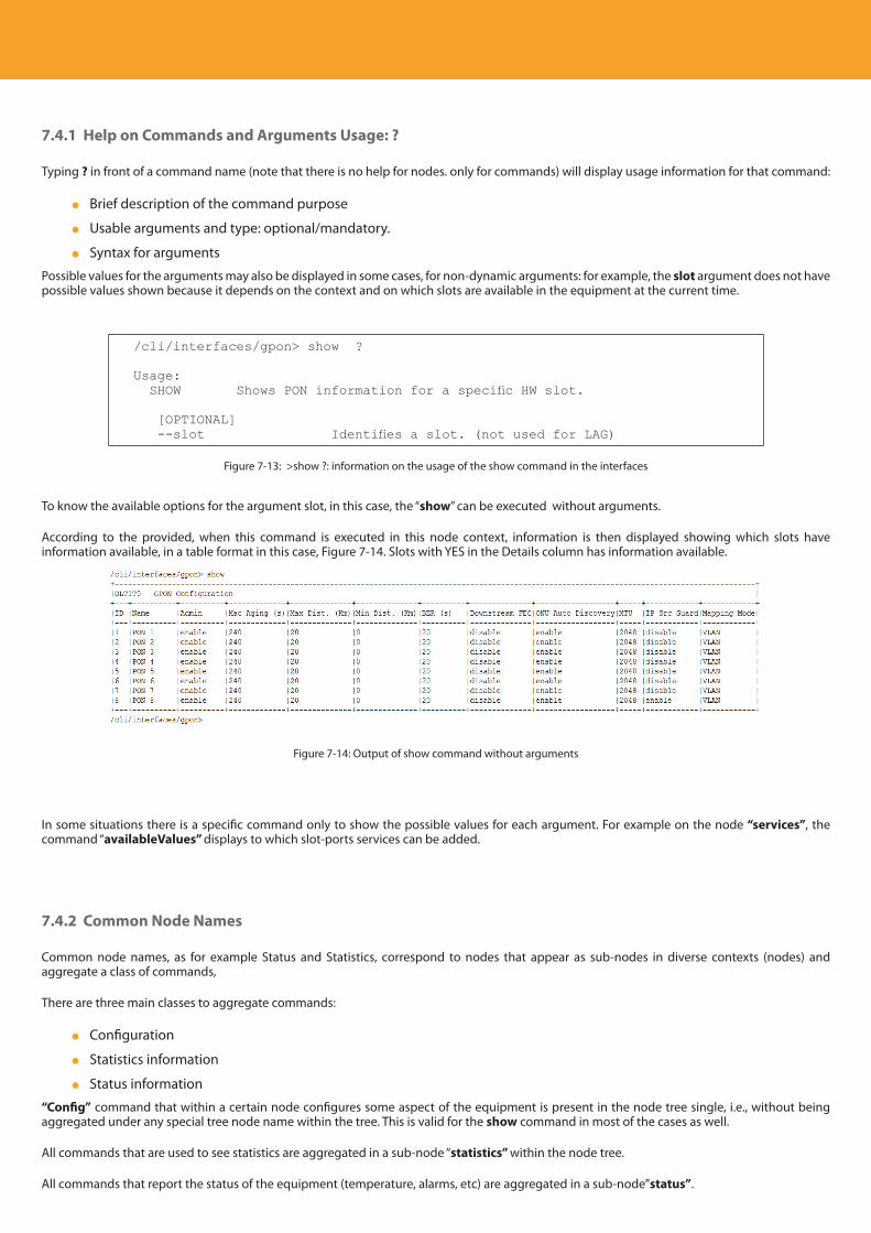
Descripción del producto
182
7.4.1 Help on Commands and Arguments Usage: ?
Typing ? in front of a command name (note that there is no help for nodes. only for commands) will display usage information for that command:
Brief description of the command purpose
Usable arguments and type: optional/mandatory.
Syntax for arguments
Possible values for the arguments may also be displayed in some cases, for non-dynamic arguments: for example, the slot argument does not have possible values shown because it depends on the context and on which slots are available in the equipment at the current time.
/cli/interfaces/gpon> show ?
Usage: SHOW Shows PON information for a specific HW slot.
[OPTIONAL] --slot Identifies a slot. (not used for LAG)
Figure 7-13: >show ?: information on the usage of the show command in the interfaces
To know the available options for the argument slot, in this case, the “show” can be executed without arguments.
According to the provided, when this command is executed in this node context, information is then displayed showing which slots have information available, in a table format in this case, Figure 7-14. Slots with YES in the Details column has information available.
Figure 7-14: Output of show command without arguments
In some situations there is a specific command only to show the possible values for each argument. For example on the node “services”, the command “availableValues” displays to which slot-ports services can be added.
7.4.2 Common Node Names
Common node names, as for example Status and Statistics, correspond to nodes that appear as sub-nodes in diverse contexts (nodes) and aggregate a class of commands,
There are three main classes to aggregate commands:
Configuration
Statistics information
Status information
“Config” command that within a certain node configures some aspect of the equipment is present in the node tree single, i.e., without being aggregated under any special tree node name within the tree. This is valid for the show command in most of the cases as well.
All commands that are used to see statistics are aggregated in a sub-node “statistics” within the node tree.
All commands that report the status of the equipment (temperature, alarms, etc) are aggregated in a sub-node”status”.
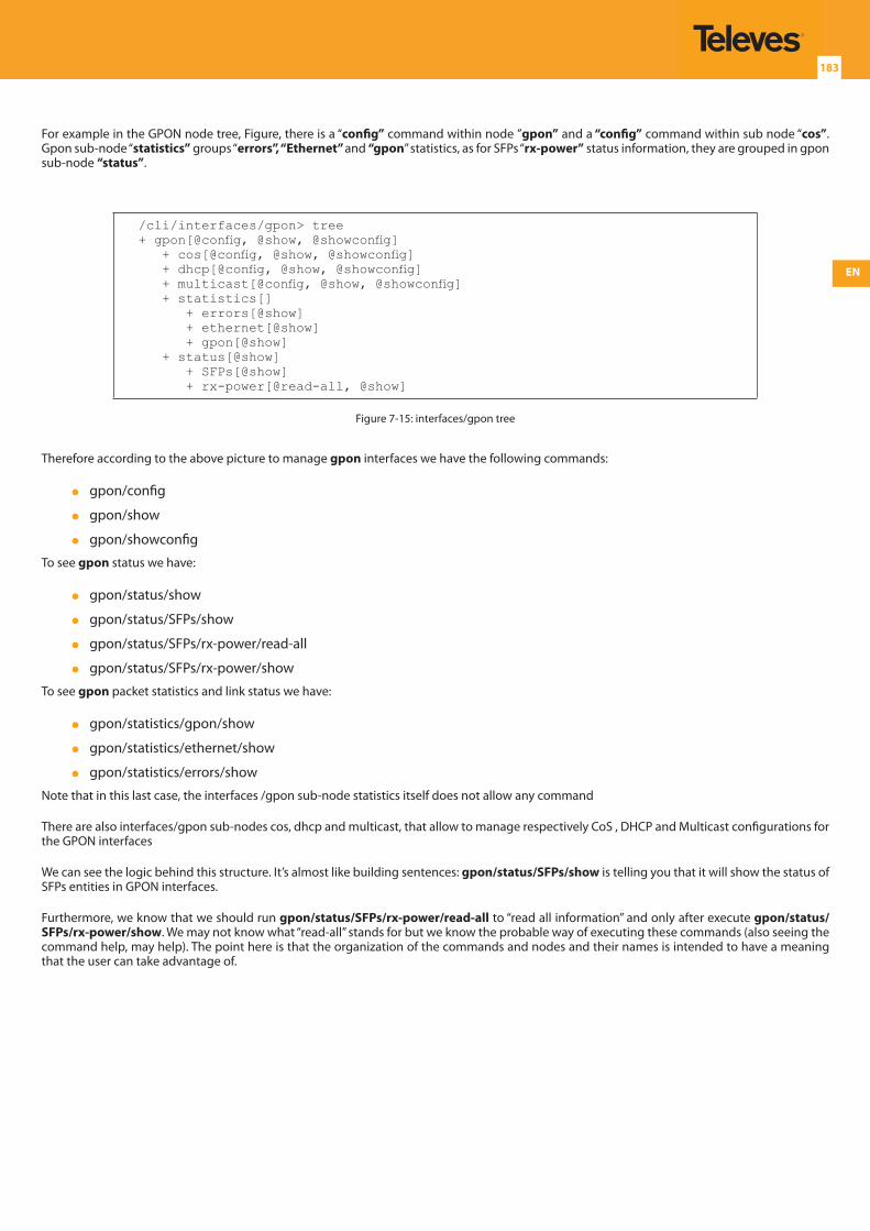
EN
183
For example in the GPON node tree, Figure, there is a “config” command within node ”gpon” and a “config” command within sub node “cos”. Gpon sub-node “statistics” groups “errors”, “Ethernet” and “gpon” statistics, as for SFPs “rx-power” status information, they are grouped in gpon sub-node “status”.
/cli/interfaces/gpon> tree+ gpon[@config, @show, @showconfig] + cos[@config, @show, @showconfig] + dhcp[@config, @show, @showconfig] + multicast[@config, @show, @showconfig] + statistics[] + errors[@show] + ethernet[@show] + gpon[@show] + status[@show] + SFPs[@show] + rx-power[@read-all, @show]
Figure 7-15: interfaces/gpon tree
Therefore according to the above picture to manage gpon interfaces we have the following commands:
gpon/config
gpon/show
gpon/showconfig
To see gpon status we have:
gpon/status/show
gpon/status/SFPs/show
gpon/status/SFPs/rx-power/read-all
gpon/status/SFPs/rx-power/show
To see gpon packet statistics and link status we have:
gpon/statistics/gpon/show
gpon/statistics/ethernet/show
gpon/statistics/errors/show
Note that in this last case, the interfaces /gpon sub-node statistics itself does not allow any command
There are also interfaces/gpon sub-nodes cos, dhcp and multicast, that allow to manage respectively CoS , DHCP and Multicast configurations for the GPON interfaces
We can see the logic behind this structure. It’s almost like building sentences: gpon/status/SFPs/show is telling you that it will show the status of SFPs entities in GPON interfaces.
Furthermore, we know that we should run gpon/status/SFPs/rx-power/read-all to “read all information” and only after execute gpon/status/SFPs/rx-power/show. We may not know what “read-all” stands for but we know the probable way of executing these commands (also seeing the command help, may help). The point here is that the organization of the commands and nodes and their names is intended to have a meaning that the user can take advantage of.
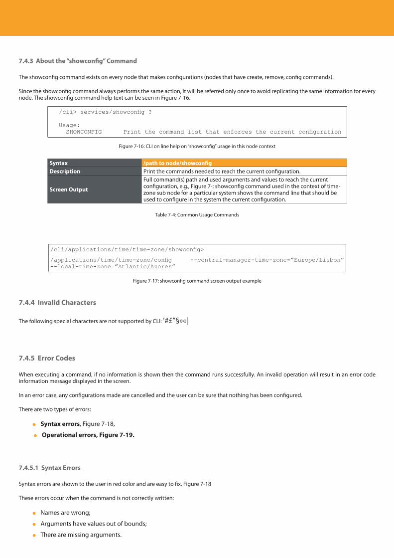
Descripción del producto
184
7.4.3 About the “showconfig” Command
The showconfig command exists on every node that makes configurations (nodes that have create, remove, config commands).
Since the showconfig command always performs the same action, it will be referred only once to avoid replicating the same information for every node. The showconfig command help text can be seen in Figure 7-16.
/cli> services/showconfig ?
Usage: SHOWCONFIG Print the command list that enforces the current configuration
Figure 7-16: CLI on line help on “showconfig” usage in this node context
Syntax /path to node/showconfigDescription Print the commands needed to reach the current configuration.
Screen Output
Full command(s) path and used arguments and values to reach the current configuration, e.g., Figure 7-; showconfig command used in the context of time-zone sub node for a particular system shows the command line that should be used to configure in the system the current configuration.
Table 7-4: Common Usage Commands
/cli/applications/time/time-zone/showconfig>
/applications/time/time-zone/config --central-manager-time-zone=”Europe/Lisbon” --local-time-zone=”Atlantic/Azores”
Figure 7-17: showconfig command screen output example
7.4.4 Invalid Characters
The following special characters are not supported by CLI: ’#£”§»«|
7.4.5 Error Codes
When executing a command, if no information is shown then the command runs successfully. An invalid operation will result in an error code information message displayed in the screen.
In an error case, any configurations made are cancelled and the user can be sure that nothing has been configured.
There are two types of errors:
Syntax errors, Figure 7-18,
Operational errors, Figure 7-19.
7.4.5.1 Syntax Errors
Syntax errors are shown to the user in red color and are easy to fix, Figure 7-18
These errors occur when the command is not correctly written:
Names are wrong;
Arguments have values out of bounds;
There are missing arguments.
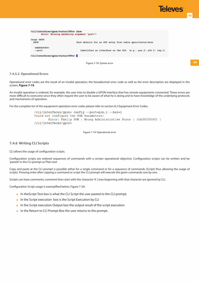
EN
185
Figure 7-18: Syntax error
7.4.5.2 Operational Errors
Operational error codes are the result of an invalid operation; the hexadecimal error code as well as the error description are displayed in the screen, Figure 7-19.
An invalid operation is ordered, for example, the user tries to disable a GPON interface that has remote equipments connected: These errors are more difficult to overcome since they often require the user to be aware of what he is doing and to have knowledge of the underlying protocols and mechanisms of operation.
For the complete list of the equipment operation error codes please refer to section 8.2 Equipment Error Codes.
Figure 7-19: Operational error
7.4.6 Writing CLI Scripts
CLI allows the usage of configuration scripts.
Configuration scripts are ordered sequences of commands with a certain operational objective. Configuration scripts can be written and be ‘pasted’ in the CLI prompt as Plain text
Copy and paste at the CLI prompt is possible either for a single command or for a sequence of commands (Script) thus allowing the usage of scripts. Pressing enter after copying a command or script the CLI prompt will execute the given commands one by one.
Scripts can have comments; comment lines start with the character ‘#’. Lines beginning with that character are ignored by CLI.
Configuration Script usage is exemplified below, Figure 7-20:
In theScript Text box is what the CLI Script the user pasted to the CLI prompt;
In the Script execution box is the Script Execution by CLI
In the Script execution Output box the output result of the script execution
In the Return to CLI Prompt Box the user returns to the prompt.
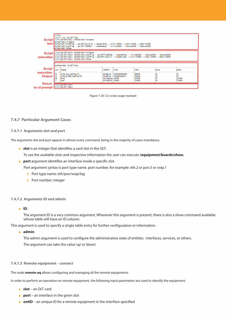
Descripción del producto
186
Scripttext
Script execution
Script execution
Output
Returnto cli prompt
Figure 7-20: CLI script usage example
7.4.7 Particular Argument Cases
7.4.7.1 Arguments slot and port
The arguments slot and port appear in almost every command, being in the majority of cases mandatory.
slot is an integer that identifies a card slot in the OLT.
To see the available slots and respective information the user can execute /equipment/boards/show.
port argument identifies an interface inside a specific slot.
Port argument syntax is port type name. port number, for example: eth.2 or pon.5 or voip.1
Port type name: eth/pon/voip/lag
Port number: integer
7.4.7.2 Arguments ID and admin
ID:
The argument ID is a very common argument. Whenever this argument is present, there is also a show command available whose table will have an ID column.
This argument is used to specify a single table entry for further configuration or information.
admin:
The admin argument is used to configure the administrative state of entities: interfaces, services, or others.
The argument can take the value ‘up’ or ‘down’.
7.4.7.3 Remote equipment – connect
The node remote-eq allows configuring and managing all the remote equipments.
In order to perform an operation on remote equipment, the following input parameters are used to identify the equipment:
slot – an OLT card
port – an interface in the given slot
ontID – an unique ID for a remote equipment in the interface specified

EN
187
Multiple configuration and management operations using the same set of values for this group may be required in the same remote equipment.
The connect command defines the three arguments (slot/port/ontID) and values in a single operation. A command in this node-sub-tree (remote equipment) uses this information as needed.
Configuration on a connected ONT with other different argument (Slot, Port, ontID) values than those defined in the initial connect command arguments, takes precedence over the information stored in the connect command.
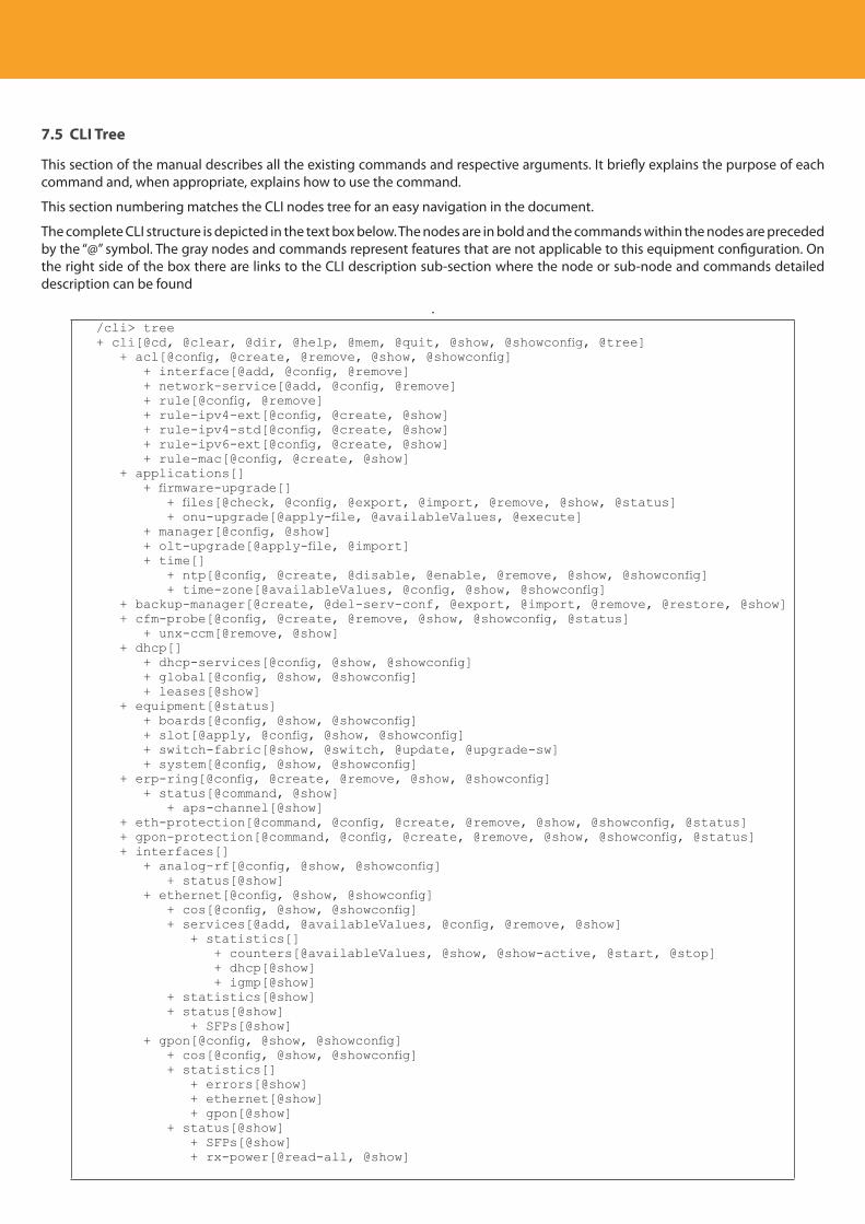
Descripción del producto
188
7.5 CLI Tree
This section of the manual describes all the existing commands and respective arguments. It briefly explains the purpose of each command and, when appropriate, explains how to use the command.
This section numbering matches the CLI nodes tree for an easy navigation in the document.
The complete CLI structure is depicted in the text box below. The nodes are in bold and the commands within the nodes are preceded by the “@” symbol. The gray nodes and commands represent features that are not applicable to this equipment configuration. On the right side of the box there are links to the CLI description sub-section where the node or sub-node and commands detailed description can be found
./cli> tree+ cli[@cd, @clear, @dir, @help, @mem, @quit, @show, @showconfig, @tree] + acl[@config, @create, @remove, @show, @showconfig] + interface[@add, @config, @remove] + network-service[@add, @config, @remove] + rule[@config, @remove] + rule-ipv4-ext[@config, @create, @show] + rule-ipv4-std[@config, @create, @show] + rule-ipv6-ext[@config, @create, @show] + rule-mac[@config, @create, @show] + applications[] + firmware-upgrade[] + files[@check, @config, @export, @import, @remove, @show, @status] + onu-upgrade[@apply-file, @availableValues, @execute] + manager[@config, @show] + olt-upgrade[@apply-file, @import] + time[] + ntp[@config, @create, @disable, @enable, @remove, @show, @showconfig] + time-zone[@availableValues, @config, @show, @showconfig] + backup-manager[@create, @del-serv-conf, @export, @import, @remove, @restore, @show] + cfm-probe[@config, @create, @remove, @show, @showconfig, @status] + unx-ccm[@remove, @show] + dhcp[] + dhcp-services[@config, @show, @showconfig] + global[@config, @show, @showconfig] + leases[@show] + equipment[@status] + boards[@config, @show, @showconfig] + slot[@apply, @config, @show, @showconfig] + switch-fabric[@show, @switch, @update, @upgrade-sw] + system[@config, @show, @showconfig] + erp-ring[@config, @create, @remove, @show, @showconfig] + status[@command, @show] + aps-channel[@show] + eth-protection[@command, @config, @create, @remove, @show, @showconfig, @status] + gpon-protection[@command, @config, @create, @remove, @show, @showconfig, @status] + interfaces[] + analog-rf[@config, @show, @showconfig] + status[@show] + ethernet[@config, @show, @showconfig] + cos[@config, @show, @showconfig] + services[@add, @availableValues, @config, @remove, @show] + statistics[] + counters[@availableValues, @show, @show-active, @start, @stop] + dhcp[@show] + igmp[@show] + statistics[@show] + status[@show] + SFPs[@show] + gpon[@config, @show, @showconfig] + cos[@config, @show, @showconfig] + statistics[] + errors[@show] + ethernet[@show] + gpon[@show] + status[@show] + SFPs[@show] + rx-power[@read-all, @show]
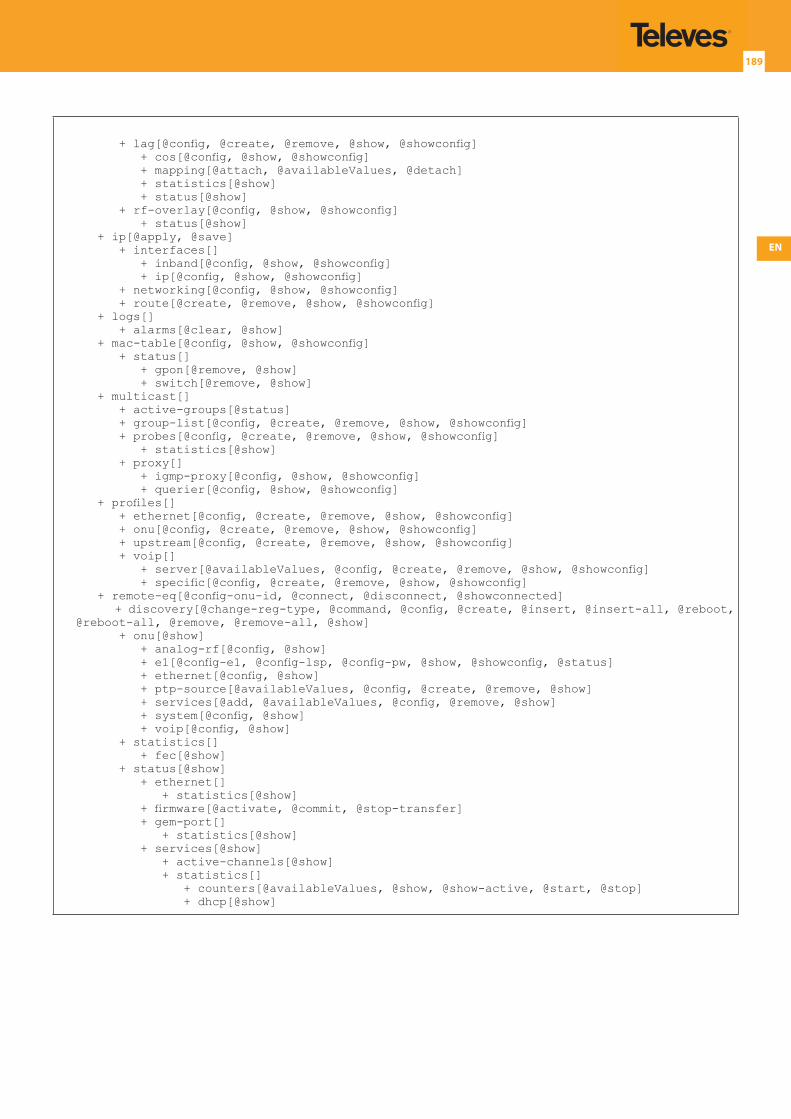
EN
189
+ lag[@config, @create, @remove, @show, @showconfig] + cos[@config, @show, @showconfig] + mapping[@attach, @availableValues, @detach] + statistics[@show] + status[@show] + rf-overlay[@config, @show, @showconfig] + status[@show] + ip[@apply, @save] + interfaces[] + inband[@config, @show, @showconfig] + ip[@config, @show, @showconfig] + networking[@config, @show, @showconfig] + route[@create, @remove, @show, @showconfig] + logs[] + alarms[@clear, @show] + mac-table[@config, @show, @showconfig] + status[] + gpon[@remove, @show] + switch[@remove, @show] + multicast[] + active-groups[@status] + group-list[@config, @create, @remove, @show, @showconfig] + probes[@config, @create, @remove, @show, @showconfig] + statistics[@show] + proxy[] + igmp-proxy[@config, @show, @showconfig] + querier[@config, @show, @showconfig] + profiles[] + ethernet[@config, @create, @remove, @show, @showconfig] + onu[@config, @create, @remove, @show, @showconfig] + upstream[@config, @create, @remove, @show, @showconfig] + voip[] + server[@availableValues, @config, @create, @remove, @show, @showconfig] + specific[@config, @create, @remove, @show, @showconfig] + remote-eq[@config-onu-id, @connect, @disconnect, @showconnected] + discovery[@change-reg-type, @command, @config, @create, @insert, @insert-all, @reboot, @reboot-all, @remove, @remove-all, @show] + onu[@show] + analog-rf[@config, @show] + e1[@config-e1, @config-lsp, @config-pw, @show, @showconfig, @status] + ethernet[@config, @show] + ptp-source[@availableValues, @config, @create, @remove, @show] + services[@add, @availableValues, @config, @remove, @show] + system[@config, @show] + voip[@config, @show] + statistics[] + fec[@show] + status[@show] + ethernet[] + statistics[@show] + firmware[@activate, @commit, @stop-transfer] + gem-port[] + statistics[@show] + services[@show] + active-channels[@show] + statistics[] + counters[@availableValues, @show, @show-active, @start, @stop] + dhcp[@show]
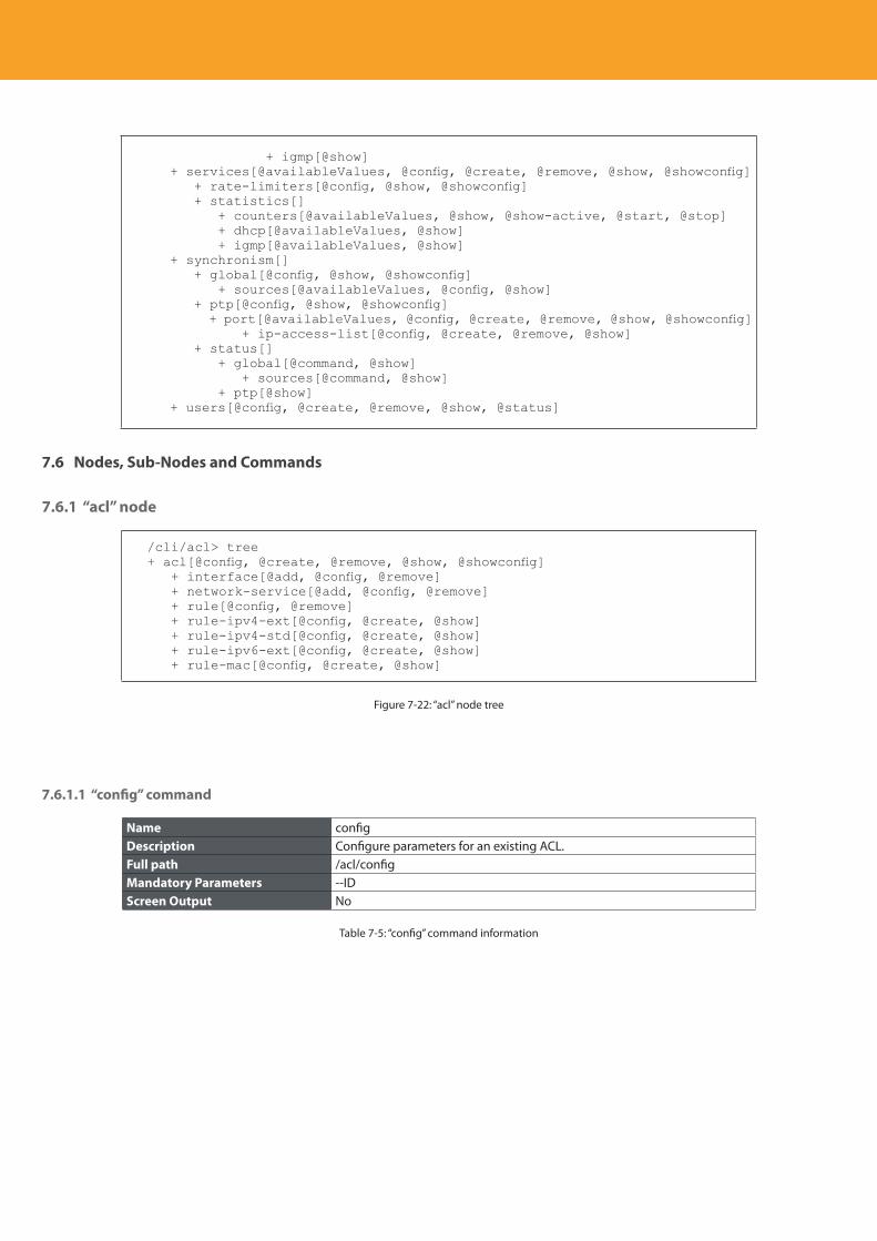
Descripción del producto
190
+ igmp[@show] + services[@availableValues, @config, @create, @remove, @show, @showconfig] + rate-limiters[@config, @show, @showconfig] + statistics[] + counters[@availableValues, @show, @show-active, @start, @stop] + dhcp[@availableValues, @show] + igmp[@availableValues, @show] + synchronism[] + global[@config, @show, @showconfig] + sources[@availableValues, @config, @show] + ptp[@config, @show, @showconfig] + port[@availableValues, @config, @create, @remove, @show, @showconfig] + ip-access-list[@config, @create, @remove, @show] + status[] + global[@command, @show] + sources[@command, @show] + ptp[@show] + users[@config, @create, @remove, @show, @status]
7.6 Nodes, Sub-Nodes and Commands
7.6.1 “acl” node
/cli/acl> tree+ acl[@config, @create, @remove, @show, @showconfig] + interface[@add, @config, @remove] + network-service[@add, @config, @remove] + rule[@config, @remove] + rule-ipv4-ext[@config, @create, @show] + rule-ipv4-std[@config, @create, @show] + rule-ipv6-ext[@config, @create, @show] + rule-mac[@config, @create, @show]
Figure 7-22: “acl” node tree
7.6.1.1 “config” command
Name configDescription Configure parameters for an existing ACL.Full path /acl/configMandatory Parameters --IDScreen Output No
Table 7-5: “config” command information
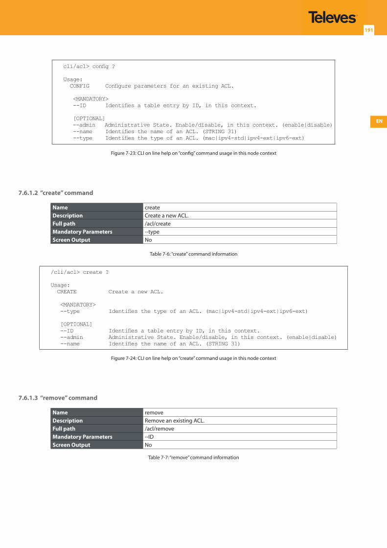
EN
191
cli/acl> config ?
Usage: CONFIG Configure parameters for an existing ACL.
<MANDATORY> --ID Identifies a table entry by ID, in this context.
[OPTIONAL] --admin Administrative State. Enable/disable, in this context. (enable|disable) --name Identifies the name of an ACL. (STRING 31) --type Identifies the type of an ACL. (mac|ipv4-std|ipv4-ext|ipv6-ext)
Figure 7-23: CLI on line help on “config” command usage in this node context
7.6.1.2 “create” command
Name createDescription Create a new ACL.Full path /acl/createMandatory Parameters --typeScreen Output No
Table 7-6: “create” command information
/cli/acl> create ?
Usage: CREATE Create a new ACL.
<MANDATORY> --type Identifies the type of an ACL. (mac|ipv4-std|ipv4-ext|ipv6-ext)
[OPTIONAL] --ID Identifies a table entry by ID, in this context. --admin Administrative State. Enable/disable, in this context. (enable|disable) --name Identifies the name of an ACL. (STRING 31)
Figure 7-24: CLI on line help on “create” command usage in this node context
7.6.1.3 “remove” command
Name removeDescription Remove an existing ACL.Full path /acl/removeMandatory Parameters --IDScreen Output No
Table 7-7: “remove” command information
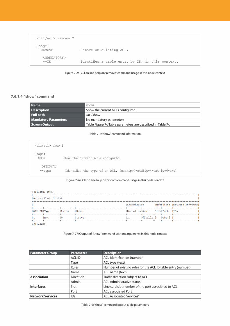
Descripción del producto
192
/cli/acl> remove ?
Usage: REMOVE Remove an existing ACL.
<MANDATORY> --ID Identifies a table entry by ID, in this context.
Figure 7-25: CLI on line help on “remove” command usage in this node context
7.6.1.4 “show” command
Name showDescription Show the current ACLs configured.Full path /acl/showMandatory Parameters No mandatory parametersScreen Output Table Figure 7-; Table parameters are described in Table 7-.
Table 7-8: “show” command information
/cli/acl> show ?
Usage: SHOW Show the current ACLs configured.
[OPTIONAL] --type Identifies the type of an ACL. (mac|ipv4-std|ipv4-ext|ipv6-ext)
Figure 7-26: CLI on line help on “show” command usage in this node context
Figure 7-27: Output of ”show” command without arguments in this node context
Parameter Group Parameter DescriptionACL ID ACL identification (number)Type ACL type (text)Rules Number of existing rules for the ACL ID table entry (number)Name ACL name (text)
Association Direction Traffic direction subject to ACLAdmin ACL Administrative status
Interfaces Slot Line card slot number of the port associated to ACL Port ACL associated Port
Network Services IDs ACL Associated Services’
Table 7-9: “show” command output table parameters
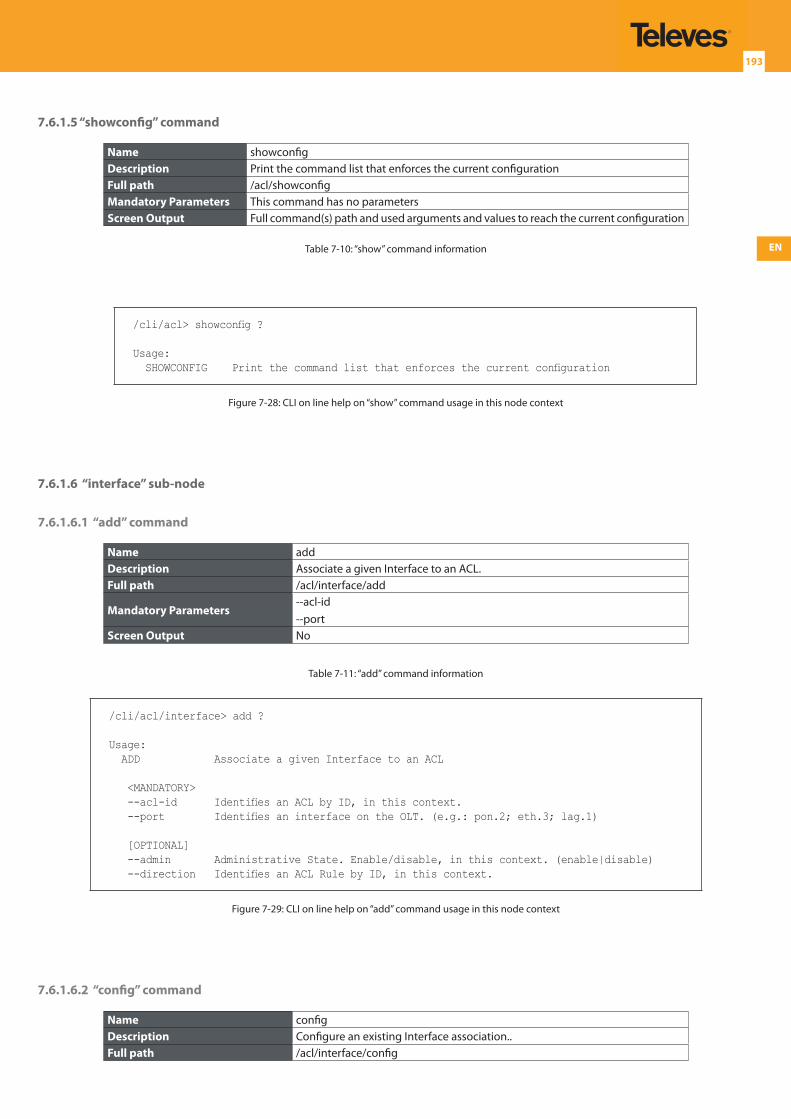
EN
193
7.6.1.5 “showconfig” command
Name showconfigDescription Print the command list that enforces the current configurationFull path /acl/showconfigMandatory Parameters This command has no parametersScreen Output Full command(s) path and used arguments and values to reach the current configuration
Table 7-10: “show” command information
/cli/acl> showconfig ?
Usage: SHOWCONFIG Print the command list that enforces the current configuration
Figure 7-28: CLI on line help on “show” command usage in this node context
7.6.1.6 “interface” sub-node
7.6.1.6.1 “add” command
Name addDescription Associate a given Interface to an ACL.Full path /acl/interface/add
Mandatory Parameters--acl-id--port
Screen Output No
Table 7-11: “add” command information
/cli/acl/interface> add ?
Usage: ADD Associate a given Interface to an ACL
<MANDATORY> --acl-id Identifies an ACL by ID, in this context. --port Identifies an interface on the OLT. (e.g.: pon.2; eth.3; lag.1)
[OPTIONAL] --admin Administrative State. Enable/disable, in this context. (enable|disable) --direction Identifies an ACL Rule by ID, in this context.
Figure 7-29: CLI on line help on “add” command usage in this node context
7.6.1.6.2 “config” command
Name configDescription Configure an existing Interface association..Full path /acl/interface/config
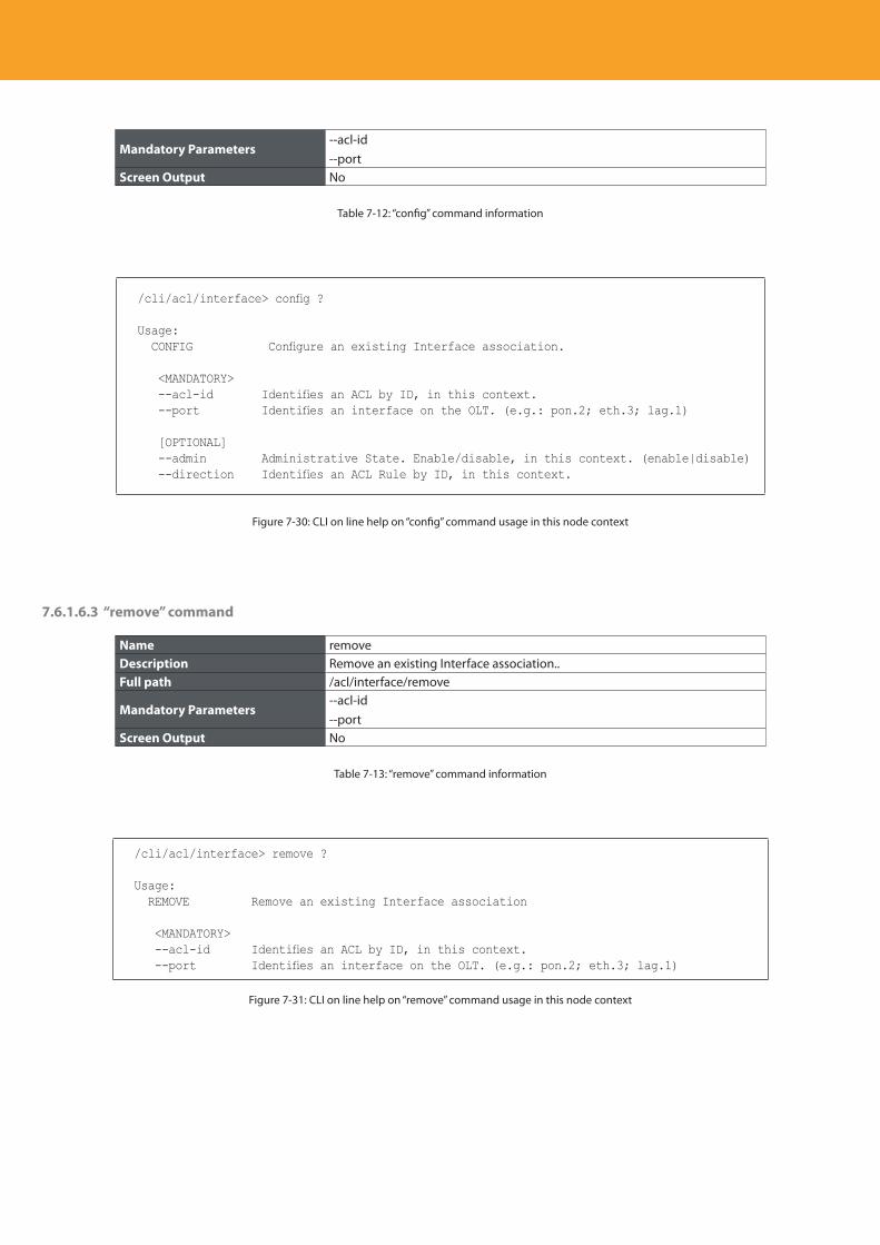
Descripción del producto
194
Mandatory Parameters--acl-id--port
Screen Output No
Table 7-12: “config” command information
/cli/acl/interface> config ?
Usage: CONFIG Configure an existing Interface association.
<MANDATORY> --acl-id Identifies an ACL by ID, in this context. --port Identifies an interface on the OLT. (e.g.: pon.2; eth.3; lag.1)
[OPTIONAL] --admin Administrative State. Enable/disable, in this context. (enable|disable) --direction Identifies an ACL Rule by ID, in this context.
Figure 7-30: CLI on line help on “config” command usage in this node context
7.6.1.6.3 “remove” command
Name removeDescription Remove an existing Interface association..Full path /acl/interface/remove
Mandatory Parameters--acl-id--port
Screen Output No
Table 7-13: “remove” command information
/cli/acl/interface> remove ?
Usage: REMOVE Remove an existing Interface association
<MANDATORY> --acl-id Identifies an ACL by ID, in this context. --port Identifies an interface on the OLT. (e.g.: pon.2; eth.3; lag.1)
Figure 7-31: CLI on line help on “remove” command usage in this node context
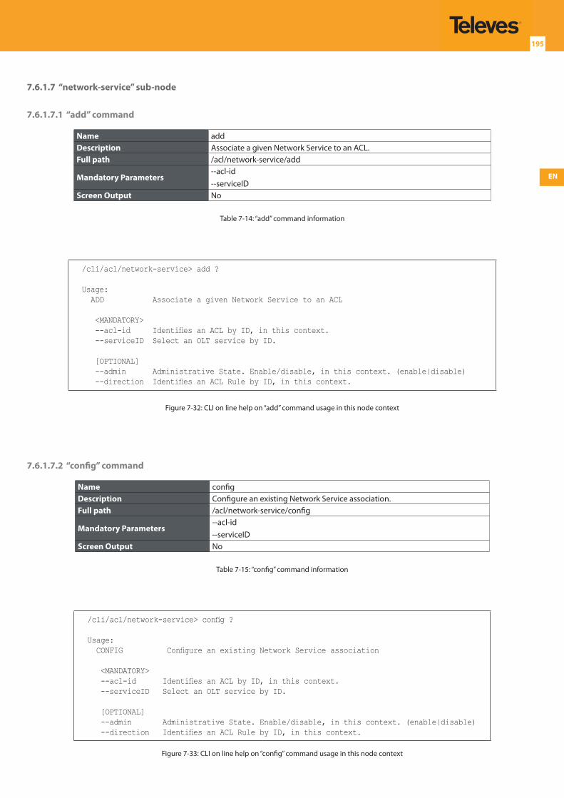
EN
195
7.6.1.7 “network-service” sub-node
7.6.1.7.1 “add” command
Name addDescription Associate a given Network Service to an ACL.Full path /acl/network-service/add
Mandatory Parameters--acl-id--serviceID
Screen Output No
Table 7-14: “add” command information
/cli/acl/network-service> add ?
Usage: ADD Associate a given Network Service to an ACL
<MANDATORY> --acl-id Identifies an ACL by ID, in this context. --serviceID Select an OLT service by ID.
[OPTIONAL] --admin Administrative State. Enable/disable, in this context. (enable|disable) --direction Identifies an ACL Rule by ID, in this context.
Figure 7-32: CLI on line help on “add” command usage in this node context
7.6.1.7.2 “config” command
Name configDescription Configure an existing Network Service association.Full path /acl/network-service/config
Mandatory Parameters--acl-id--serviceID
Screen Output No
Table 7-15: “config” command information
/cli/acl/network-service> config ?
Usage: CONFIG Configure an existing Network Service association
<MANDATORY> --acl-id Identifies an ACL by ID, in this context. --serviceID Select an OLT service by ID.
[OPTIONAL] --admin Administrative State. Enable/disable, in this context. (enable|disable) --direction Identifies an ACL Rule by ID, in this context.
Figure 7-33: CLI on line help on “config” command usage in this node context
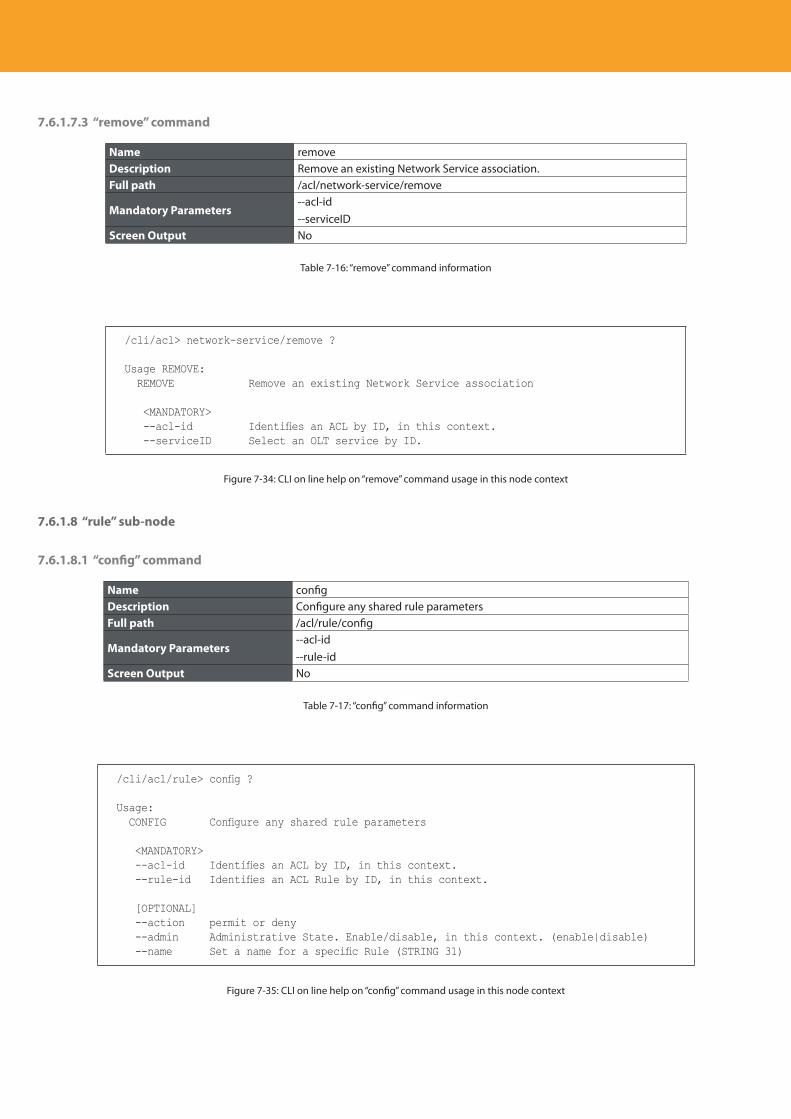
Descripción del producto
196
7.6.1.7.3 “remove” command
Name removeDescription Remove an existing Network Service association.Full path /acl/network-service/remove
Mandatory Parameters--acl-id--serviceID
Screen Output No
Table 7-16: “remove” command information
/cli/acl> network-service/remove ?
Usage REMOVE: REMOVE Remove an existing Network Service association
<MANDATORY> --acl-id Identifies an ACL by ID, in this context. --serviceID Select an OLT service by ID.
Figure 7-34: CLI on line help on “remove” command usage in this node context
7.6.1.8 “rule” sub-node
7.6.1.8.1 “config” command
Name configDescription Configure any shared rule parametersFull path /acl/rule/config
Mandatory Parameters--acl-id--rule-id
Screen Output No
Table 7-17: “config” command information
/cli/acl/rule> config ?
Usage: CONFIG Configure any shared rule parameters
<MANDATORY> --acl-id Identifies an ACL by ID, in this context. --rule-id Identifies an ACL Rule by ID, in this context.
[OPTIONAL] --action permit or deny --admin Administrative State. Enable/disable, in this context. (enable|disable) --name Set a name for a specific Rule (STRING 31)
Figure 7-35: CLI on line help on “config” command usage in this node context
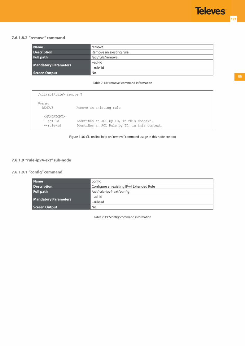
EN
197
7.6.1.8.2 “remove” command
Name removeDescription Remove an existing rule.Full path /acl/rule/remove
Mandatory Parameters--acl-id--rule-id
Screen Output No
Table 7-18: “remove” command information
/cli/acl/rule> remove ?
Usage: REMOVE Remove an existing rule
<MANDATORY> --acl-id Identifies an ACL by ID, in this context. --rule-id Identifies an ACL Rule by ID, in this context.
Figure 7-36: CLI on line help on “remove” command usage in this node context
7.6.1.9 “rule-ipv4-ext” sub-node
7.6.1.9.1 “config” command
Name configDescription Configure an existing IPv4 Extended RuleFull path /acl/rule-ipv4-ext/config
Mandatory Parameters--acl-id--rule-id
Screen Output No
Table 7-19: “config” command information
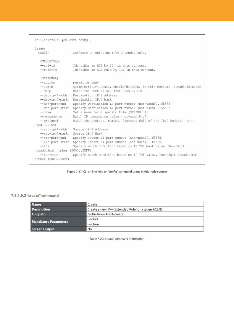
Descripción del producto
198
/cli/acl/rule-ipv4-ext> config ?
Usage: CONFIG Configure an existing IPv4 Extended Rule.
<MANDATORY> --acl-id Identifies an ACL by ID, in this context. --rule-id Identifies an ACL Rule by ID, in this context.
[OPTIONAL] --action permit or deny --admin Administrative State. Enable/disable, in this context. (enable|disable) --dscp Match the DSCP value. (not-used|0..63) --dst-ipv4-addr Destination IPv4 Address --dst-ipv4-mask Destination IPv4 Mask --dst-port-end Specify Destination L4 port number (not-used|0..65535) --dst-port-start Specify Destination L4 port number (not-used|0..65535) --name Set a name for a specific Rule (STRING 31) --precedence Match IP precedence value (not-used|0..7) --protocol Match the protocol number. Protocol field of the IPv4 header. (not-used|0..255) --src-ipv4-addr Source IPv4 Address --src-ipv4-mask Source IPv4 Mask --src-port-end Specify Source L4 port number (not-used|0..65535) --src-port-start Specify Source L4 port number (not-used|0..65535) --tos Specify match condition based on IP TOS Mask value. Two-digit hexadecimal number (0000..0XFF) --tos-mask Specify match condition based on IP TOS value. Two-digit hexadecimal number (0000..0XFF)
Figure 7-37: CLI on line help on “config” command usage in this node context
7.6.1.9.2 “create” command
Name CreateDescription Create a new IPv4 Extended Rule for a given ACL ID.Full path /acl/rule-ipv4-ext/create
Mandatory Parameters--acl-id--action
Screen Output No
Table 7-20: “create” command information
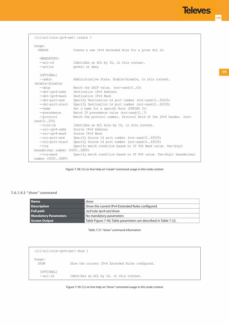
EN
199
/cli/acl/rule-ipv4-ext> create ?
Usage: CREATE Create a new IPv4 Extended Rule for a given ACL ID.
<MANDATORY> --acl-id Identifies an ACL by ID, in this context. --action permit or deny
[OPTIONAL] --admin Administrative State. Enable/disable, in this context. (enable|disable) --dscp Match the DSCP value. (not-used|0..63) --dst-ipv4-addr Destination IPv4 Address --dst-ipv4-mask Destination IPv4 Mask --dst-port-end Specify Destination L4 port number (not-used|0..65535) --dst-port-start Specify Destination L4 port number (not-used|0..65535) --name Set a name for a specific Rule (STRING 31) --precedence Match IP precedence value (not-used|0..7) --protocol Match the protocol number. Protocol field of the IPv4 header. (not-used|0..255) --rule-id Identifies an ACL Rule by ID, in this context. --src-ipv4-addr Source IPv4 Address --src-ipv4-mask Source IPv4 Mask --src-port-end Specify Source L4 port number (not-used|0..65535) --src-port-start Specify Source L4 port number (not-used|0..65535) --tos Specify match condition based on IP TOS Mask value. Two-digit hexadecimal number (0000..0XFF) --tos-mask Specify match condition based on IP TOS value. Two-digit hexadecimal number (0000..0XFF)
Figure 7-38: CLI on line help on “create” command usage in this node context
7.6.1.9.3 “show” command
Name showDescription Show the current IPv4 Extended Rules configured.Full path /acl/rule-ipv4-ext/showMandatory Parameters No mandatory parametersScreen Output Table Figure 7-40; Table parameters are described in Table 7-22.
Table 7-21: “show” command information
/cli/acl/rule-ipv4-ext> show ?
Usage: SHOW Show the current IPv4 Extended Rules configured.
[OPTIONAL] --acl-id Identifies an ACL by ID, in this context.
Figure 7-39: CLI on line help on “show” command usage in this node context
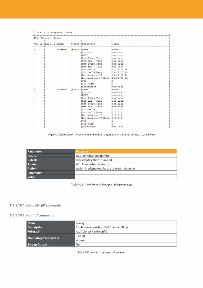
Descripción del producto
200
Figure 7-40: Output of ”show” command without arguments in this node context –partial view
Parameter DescriptionACL ID ACL identification (number)Rule ID Rule identification (number)Admin ACL Administrative statusAction Action implemented by the rule (permit|deny) ParameterValue
Table 7-22: “show” command output table parameters
7.6.1.10 “rule-ipv4-std” sub-node
7.6.1.10.1 “config” command
Name configDescription Configure an existing IPv4 Standard RuleFull path /acl/rule-ipv4-std/config
Mandatory Parameters--acl-id--rule-id
Screen Output No
Table 7-23: “config” command information
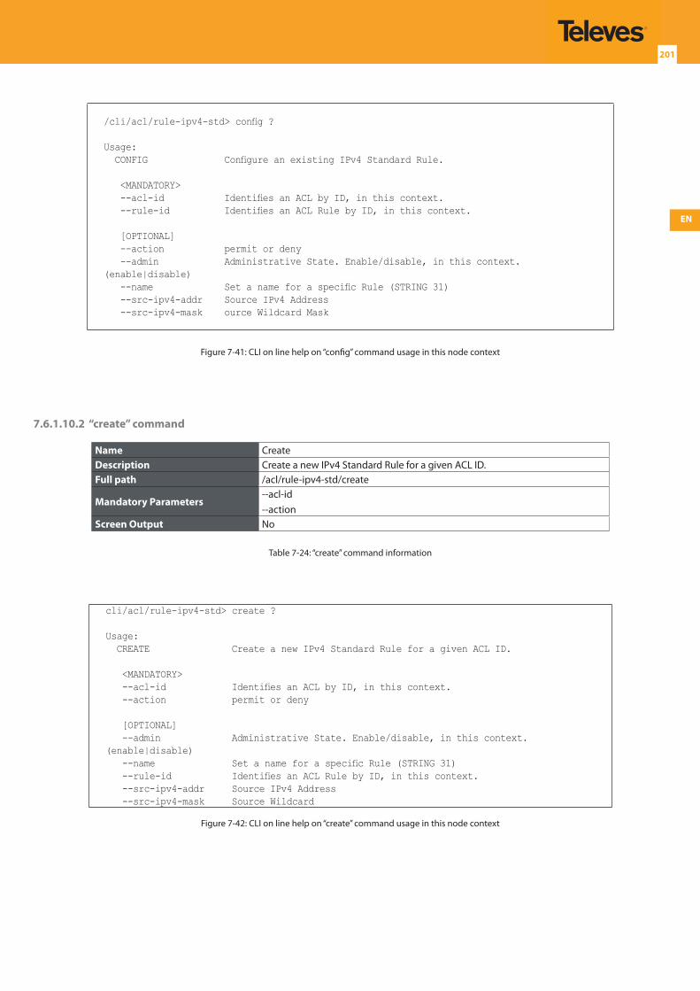
EN
201
/cli/acl/rule-ipv4-std> config ?
Usage: CONFIG Configure an existing IPv4 Standard Rule.
<MANDATORY> --acl-id Identifies an ACL by ID, in this context. --rule-id Identifies an ACL Rule by ID, in this context.
[OPTIONAL] --action permit or deny --admin Administrative State. Enable/disable, in this context. (enable|disable) --name Set a name for a specific Rule (STRING 31) --src-ipv4-addr Source IPv4 Address --src-ipv4-mask ource Wildcard Mask
Figure 7-41: CLI on line help on “config” command usage in this node context
7.6.1.10.2 “create” command
Name CreateDescription Create a new IPv4 Standard Rule for a given ACL ID.Full path /acl/rule-ipv4-std/create
Mandatory Parameters--acl-id--action
Screen Output No
Table 7-24: “create” command information
cli/acl/rule-ipv4-std> create ?
Usage: CREATE Create a new IPv4 Standard Rule for a given ACL ID.
<MANDATORY> --acl-id Identifies an ACL by ID, in this context. --action permit or deny
[OPTIONAL] --admin Administrative State. Enable/disable, in this context. (enable|disable) --name Set a name for a specific Rule (STRING 31) --rule-id Identifies an ACL Rule by ID, in this context. --src-ipv4-addr Source IPv4 Address --src-ipv4-mask Source Wildcard
Figure 7-42: CLI on line help on “create” command usage in this node context
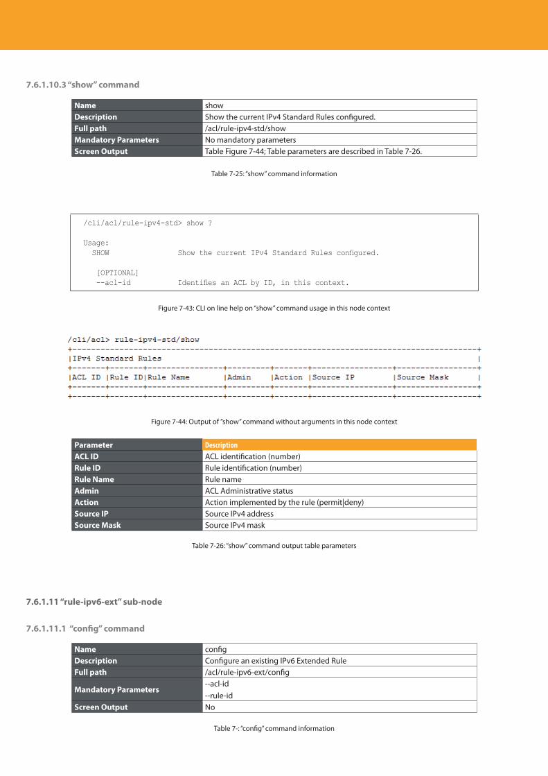
Descripción del producto
202
7.6.1.10.3 “show” command
Name showDescription Show the current IPv4 Standard Rules configured.Full path /acl/rule-ipv4-std/showMandatory Parameters No mandatory parametersScreen Output Table Figure 7-44; Table parameters are described in Table 7-26.
Table 7-25: “show” command information
/cli/acl/rule-ipv4-std> show ?
Usage: SHOW Show the current IPv4 Standard Rules configured.
[OPTIONAL] --acl-id Identifies an ACL by ID, in this context.
Figure 7-43: CLI on line help on “show” command usage in this node context
Figure 7-44: Output of ”show” command without arguments in this node context
Parameter DescriptionACL ID ACL identification (number)Rule ID Rule identification (number)Rule Name Rule nameAdmin ACL Administrative statusAction Action implemented by the rule (permit|deny) Source IP Source IPv4 addressSource Mask Source IPv4 mask
Table 7-26: “show” command output table parameters
7.6.1.11 “rule-ipv6-ext” sub-node
7.6.1.11.1 “config” command
Name configDescription Configure an existing IPv6 Extended RuleFull path /acl/rule-ipv6-ext/config
Mandatory Parameters--acl-id--rule-id
Screen Output No
Table 7-: “config” command information
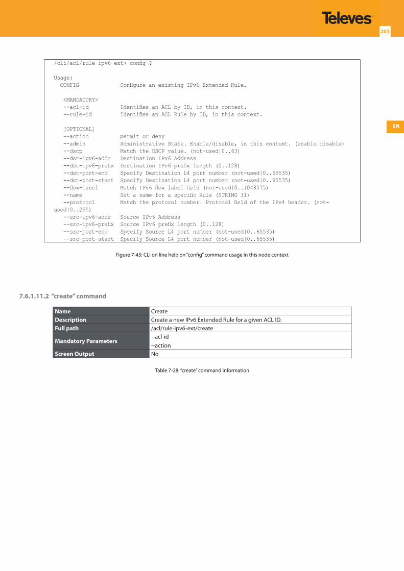
EN
203
/cli/acl/rule-ipv6-ext> config ?
Usage: CONFIG Configure an existing IPv6 Extended Rule.
<MANDATORY> --acl-id Identifies an ACL by ID, in this context. --rule-id Identifies an ACL Rule by ID, in this context.
[OPTIONAL] --action permit or deny --admin Administrative State. Enable/disable, in this context. (enable|disable) --dscp Match the DSCP value. (not-used|0..63) --dst-ipv6-addr Destination IPv6 Address --dst-ipv6-prefix Destination IPv6 prefix length (0..128) --dst-port-end Specify Destination L4 port number (not-used|0..65535) --dst-port-start Specify Destination L4 port number (not-used|0..65535) --flow-label Match IPv6 flow label field (not-used|0..1048575) --name Set a name for a specific Rule (STRING 31) --protocol Match the protocol number. Protocol field of the IPv4 header. (not-used|0..255) --src-ipv6-addr Source IPv6 Address --src-ipv6-prefix Source IPv6 prefix length (0..128) --src-port-end Specify Source L4 port number (not-used|0..65535) --src-port-start Specify Source L4 port number (not-used|0..65535)
Figure 7-45: CLI on line help on “config” command usage in this node context
7.6.1.11.2 “create” command
Name CreateDescription Create a new IPv6 Extended Rule for a given ACL ID.Full path /acl/rule-ipv6-ext/create
Mandatory Parameters--acl-id--action
Screen Output No
Table 7-28: “create” command information
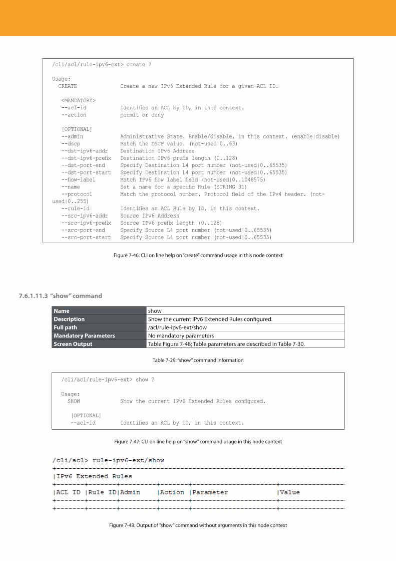
Descripción del producto
204
/cli/acl/rule-ipv6-ext> create ?
Usage: CREATE Create a new IPv6 Extended Rule for a given ACL ID.
<MANDATORY> --acl-id Identifies an ACL by ID, in this context. --action permit or deny
[OPTIONAL] --admin Administrative State. Enable/disable, in this context. (enable|disable) --dscp Match the DSCP value. (not-used|0..63) --dst-ipv6-addr Destination IPv6 Address --dst-ipv6-prefix Destination IPv6 prefix length (0..128) --dst-port-end Specify Destination L4 port number (not-used|0..65535) --dst-port-start Specify Destination L4 port number (not-used|0..65535) --flow-label Match IPv6 flow label field (not-used|0..1048575) --name Set a name for a specific Rule (STRING 31) --protocol Match the protocol number. Protocol field of the IPv4 header. (not-used|0..255) --rule-id Identifies an ACL Rule by ID, in this context. --src-ipv6-addr Source IPv6 Address --src-ipv6-prefix Source IPv6 prefix length (0..128) --src-port-end Specify Source L4 port number (not-used|0..65535) --src-port-start Specify Source L4 port number (not-used|0..65535)
Figure 7-46: CLI on line help on “create” command usage in this node context
7.6.1.11.3 “show” command
Name showDescription Show the current IPv6 Extended Rules configured.Full path /acl/rule-ipv6-ext/showMandatory Parameters No mandatory parametersScreen Output Table Figure 7-48; Table parameters are described in Table 7-30.
Table 7-29: “show” command information
/cli/acl/rule-ipv6-ext> show ?
Usage: SHOW Show the current IPv6 Extended Rules configured.
[OPTIONAL] --acl-id Identifies an ACL by ID, in this context.
Figure 7-47: CLI on line help on “show” command usage in this node context
Figure 7-48: Output of ”show” command without arguments in this node context
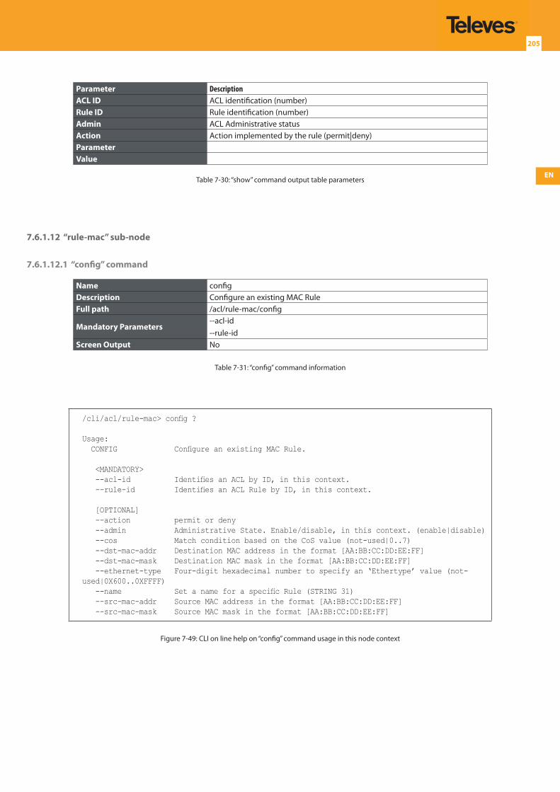
EN
205
Parameter DescriptionACL ID ACL identification (number)Rule ID Rule identification (number)Admin ACL Administrative statusAction Action implemented by the rule (permit|deny) ParameterValue
Table 7-30: “show” command output table parameters
7.6.1.12 “rule-mac” sub-node
7.6.1.12.1 “config” command
Name configDescription Configure an existing MAC RuleFull path /acl/rule-mac/config
Mandatory Parameters--acl-id--rule-id
Screen Output No
Table 7-31: “config” command information
/cli/acl/rule-mac> config ?
Usage: CONFIG Configure an existing MAC Rule.
<MANDATORY> --acl-id Identifies an ACL by ID, in this context. --rule-id Identifies an ACL Rule by ID, in this context.
[OPTIONAL] --action permit or deny --admin Administrative State. Enable/disable, in this context. (enable|disable) --cos Match condition based on the CoS value (not-used|0..7) --dst-mac-addr Destination MAC address in the format [AA:BB:CC:DD:EE:FF] --dst-mac-mask Destination MAC mask in the format [AA:BB:CC:DD:EE:FF] --ethernet-type Four-digit hexadecimal number to specify an ‘Ethertype’ value (not-used|0X600..0XFFFF) --name Set a name for a specific Rule (STRING 31) --src-mac-addr Source MAC address in the format [AA:BB:CC:DD:EE:FF] --src-mac-mask Source MAC mask in the format [AA:BB:CC:DD:EE:FF]
Figure 7-49: CLI on line help on “config” command usage in this node context
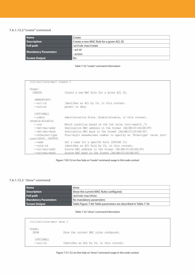
Descripción del producto
206
7.6.1.12.2 “create” command
Name CreateDescription Create a new MAC Rule for a given ACL ID.Full path /acl/rule-mac/create
Mandatory Parameters--acl-id--action
Screen Output No
Table 7-32: “create” command information
/cli/acl/rule-mac> create ?
Usage: CREATE Create a new MAC Rule for a given ACL ID.
<MANDATORY> --acl-id Identifies an ACL by ID, in this context. --action permit or deny
[OPTIONAL] --admin Administrative State. Enable/disable, in this context. (enable|disable) --cos Match condition based on the CoS value (not-used|0..7) --dst-mac-addr Destination MAC address in the format [AA:BB:CC:DD:EE:FF] --dst-mac-mask Destination MAC mask in the format [AA:BB:CC:DD:EE:FF] --ethernet-type Four-digit hexadecimal number to specify an ‘Ethertype’ value (not-used|0X600..0XFFFF) --name Set a name for a specific Rule (STRING 31) --rule-id Identifies an ACL Rule by ID, in this context. --src-mac-addr Source MAC address in the format [AA:BB:CC:DD:EE:FF] --src-mac-mask Source MAC mask in the format [AA:BB:CC:DD:EE:FF]
Figure 7-50: CLI on line help on “create” command usage in this node context
7.6.1.12.3 “show” command
Name showDescription Show the current MAC Rules configured.Full path /acl/rule-mac/showMandatory Parameters No mandatory parametersScreen Output Table Figure 7-60; Table parameters are described in Table 7-34.
Table 7-33: “show” command information
/cli/acl/rule-mac> show ?
Usage: SHOW Show the current MAC rules configured.
[OPTIONAL] --acl-id Identifies an ACL by ID, in this context.
Figure 7-51: CLI on line help on “show” command usage in this node context
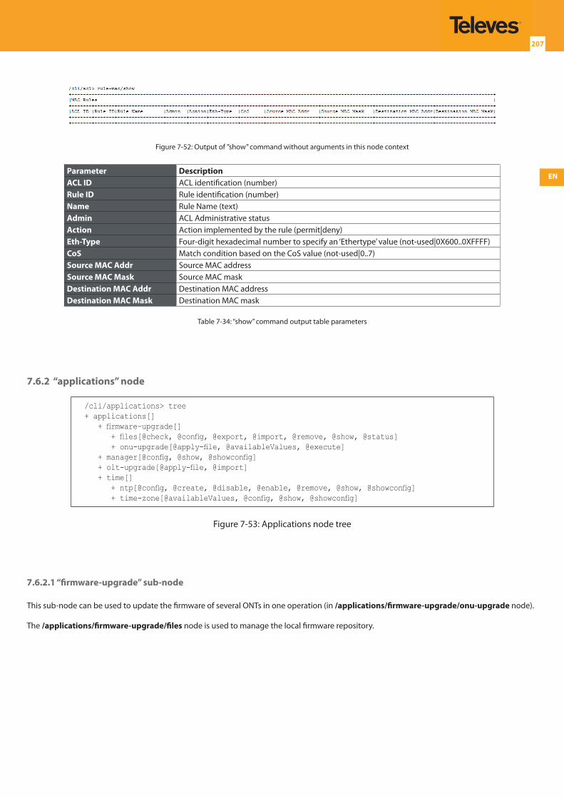
EN
207
Figure 7-52: Output of ”show” command without arguments in this node context
Parameter DescriptionACL ID ACL identification (number)Rule ID Rule identification (number)Name Rule Name (text)Admin ACL Administrative statusAction Action implemented by the rule (permit|deny) Eth-Type Four-digit hexadecimal number to specify an ‘Ethertype’ value (not-used|0X600..0XFFFF)CoS Match condition based on the CoS value (not-used|0..7)Source MAC Addr Source MAC address Source MAC Mask Source MAC maskDestination MAC Addr Destination MAC address Destination MAC Mask Destination MAC mask
Table 7-34: “show” command output table parameters
7.6.2 “applications” node
/cli/applications> tree+ applications[] + firmware-upgrade[] + files[@check, @config, @export, @import, @remove, @show, @status] + onu-upgrade[@apply-file, @availableValues, @execute] + manager[@config, @show, @showconfig] + olt-upgrade[@apply-file, @import] + time[] + ntp[@config, @create, @disable, @enable, @remove, @show, @showconfig] + time-zone[@availableValues, @config, @show, @showconfig]
Figure 7-53: Applications node tree
7.6.2.1 “firmware-upgrade” sub-node
This sub-node can be used to update the firmware of several ONTs in one operation (in /applications/firmware-upgrade/onu-upgrade node).
The /applications/firmware-upgrade/files node is used to manage the local firmware repository.
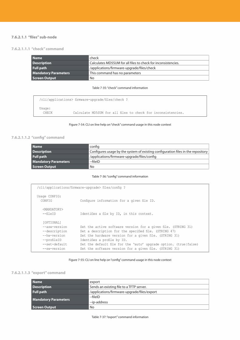
Descripción del producto
208
7.6.2.1.1 “files” sub-node
7.6.2.1.1.1 “check” command
Name checkDescription Calculates MD5SUM for all files to check for inconsistencies.Full path /applications/firmware-upgrade/files/checkMandatory Parameters This command has no parametersScreen Output No
Table 7-35: “check” command information
/cli/applications> firmware-upgrade/files/check ?
Usage: CHECK Calculate MD5SUM for all files to check for inconsistencies.
Figure 7-54: CLI on line help on “check” command usage in this node context
7.6.2.1.1.2 “config” command
Name configDescription Configures usage by the system of existing configuration files in the repositoryFull path /applications/firmware-upgrade/files/configMandatory Parameters --fileID Screen Output No
Table 7-36: “config” command information
/cli/applications/firmware-upgrade> files/config ?
Usage CONFIG: CONFIG Configure information for a given file ID.
<MANDATORY> --fileID Identifies a file by ID, in this context.
[OPTIONAL] --asw-version Set the active software version for a given file. (STRING 31) --description Set a description for the specified file. (STRING 47) --hw-version Set the hardware version for a given file. (STRING 31) --profileID Identifies a profile by ID. --set-default Set the default file for the ‘auto’ upgrade option. (true|false) --sw-version Set the software version for a given file. (STRING 31)
Figure 7-55: CLI on line help on “config” command usage in this node context
7.6.2.1.1.3 “export” command
Name exportDescription Sends an existing file to a TFTP server.Full path /applications/firmware-upgrade/files/export
Mandatory Parameters--fileID--ip-address
Screen Output No
Table 7-37: “export” command information
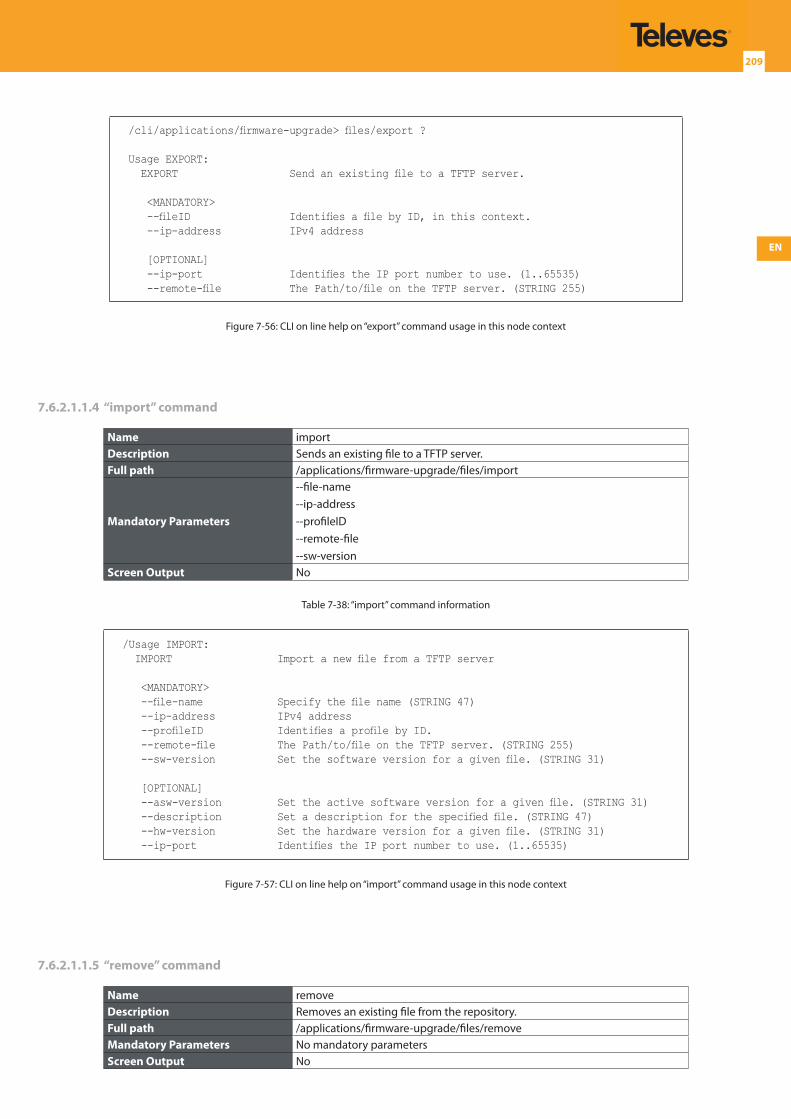
EN
209
/cli/applications/firmware-upgrade> files/export ?
Usage EXPORT: EXPORT Send an existing file to a TFTP server.
<MANDATORY> --fileID Identifies a file by ID, in this context. --ip-address IPv4 address
[OPTIONAL] --ip-port Identifies the IP port number to use. (1..65535) --remote-file The Path/to/file on the TFTP server. (STRING 255)
Figure 7-56: CLI on line help on “export” command usage in this node context
7.6.2.1.1.4 “import” command
Name importDescription Sends an existing file to a TFTP server.Full path /applications/firmware-upgrade/files/import
Mandatory Parameters
--file-name--ip-address--profileID--remote-file--sw-version
Screen Output No
Table 7-38: “import” command information
/Usage IMPORT: IMPORT Import a new file from a TFTP server
<MANDATORY> --file-name Specify the file name (STRING 47) --ip-address IPv4 address --profileID Identifies a profile by ID. --remote-file The Path/to/file on the TFTP server. (STRING 255) --sw-version Set the software version for a given file. (STRING 31)
[OPTIONAL] --asw-version Set the active software version for a given file. (STRING 31) --description Set a description for the specified file. (STRING 47) --hw-version Set the hardware version for a given file. (STRING 31) --ip-port Identifies the IP port number to use. (1..65535)
Figure 7-57: CLI on line help on “import” command usage in this node context
7.6.2.1.1.5 “remove” command
Name removeDescription Removes an existing file from the repository.Full path /applications/firmware-upgrade/files/removeMandatory Parameters No mandatory parametersScreen Output No
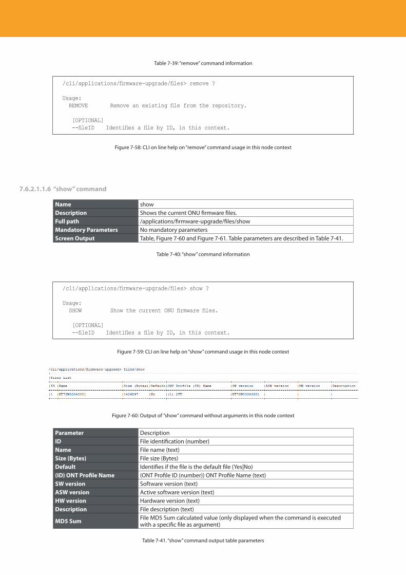
Descripción del producto
210
Table 7-39: “remove” command information
/cli/applications/firmware-upgrade/files> remove ?
Usage: REMOVE Remove an existing file from the repository.
[OPTIONAL] --fileID Identifies a file by ID, in this context.
Figure 7-58: CLI on line help on “remove” command usage in this node context
7.6.2.1.1.6 “show” command
Name showDescription Shows the current ONU firmware files.Full path /applications/firmware-upgrade/files/showMandatory Parameters No mandatory parametersScreen Output Table, Figure 7-60 and Figure 7-61. Table parameters are described in Table 7-41.
Table 7-40: “show” command information
/cli/applications/firmware-upgrade/files> show ?
Usage: SHOW Show the current ONU firmware files.
[OPTIONAL] --fileID Identifies a file by ID, in this context.
Figure 7-59: CLI on line help on “show” command usage in this node context
Figure 7-60: Output of ”show” command without arguments in this node context
Parameter DescriptionID File identification (number)Name File name (text)Size (Bytes) File size (Bytes)Default Identifies if the file is the default file (Yes|No)(ID) ONT Profile Name (ONT Profile ID (number)) ONT Profile Name (text)SW version Software version (text)ASW version Active software version (text)HW version Hardware version (text)Description File description (text)
MD5 Sum File MD5 Sum calculated value (only displayed when the command is executed with a specific file as argument)
Table 7-41. “show” command output table parameters
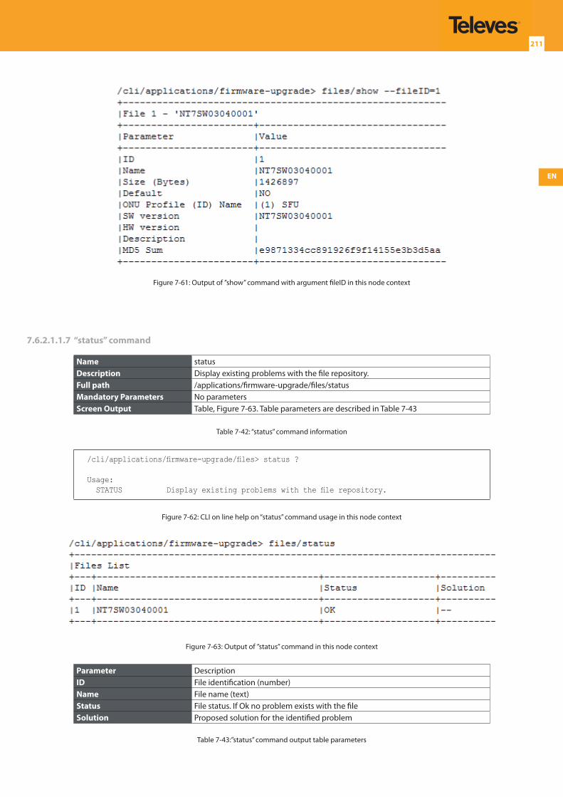
EN
211
Figure 7-61: Output of ”show” command with argument fileID in this node context
7.6.2.1.1.7 “status” command
Name statusDescription Display existing problems with the file repository.Full path /applications/firmware-upgrade/files/statusMandatory Parameters No parametersScreen Output Table, Figure 7-63. Table parameters are described in Table 7-43
Table 7-42: “status” command information
/cli/applications/firmware-upgrade/files> status ?
Usage: STATUS Display existing problems with the file repository.
Figure 7-62: CLI on line help on “status” command usage in this node context
Figure 7-63: Output of ”status” command in this node context
Parameter DescriptionID File identification (number)Name File name (text)Status File status. If Ok no problem exists with the fileSolution Proposed solution for the identified problem
Table 7-43:”status” command output table parameters
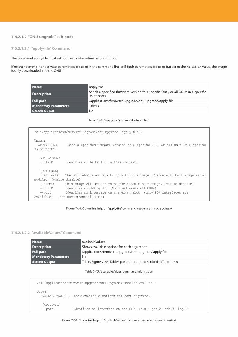
Descripción del producto
212
7.6.2.1.2 “ONU-upgrade” sub-node
7.6.2.1.2.1 “apply-file” Command
The command apply-file must ask for user confirmation before running.
If neither ‘commit’ nor ‘activate’ parameters are used in the command line or if both parameters are used but set to the <disable> value, the image is only downloaded into the ONU
Name apply-file
Description Sends a specified firmware version to a specific ONU, or all ONUs in a specific <slot-port>.
Full path /applications/firmware-upgrade/onu-upgrade/apply-fileMandatory Parameters --fileIDScreen Ouput No
Table 7-44: “ apply-file” command information
/cli/applications/firmware-upgrade/onu-upgrade> apply-file ?
Usage: APPLY-FILE Send a specified firmware version to a specific ONU, or all ONUs in a specific <slot-port>.
<MANDATORY> --fileID Identifies a file by ID, in this context.
[OPTIONAL] --activate The ONU reboots and starts up with this image. The default boot image is not modified. (enable|disable) --commit This image will be set to be the default boot image. (enable|disable) --onuID Identifies an ONU by ID. (Not used means all ONUs) --port Identifies an interface on the given slot. (only PON interfaces are available. Not used means all PONs)
Figure 7-64: CLI on line help on “apply-file” command usage in this node context
7.6.2.1.2.2 “availableValues” Command
Name availableValuesDescription Shows available options for each argument.Full path /applications/firmware-upgrade/onu-upgrade/ apply-fileMandatory Parameters NoScreen Output Table, Figure 7-66, Tables parameters are described in Table 7-46
Table 7-45: “availableValues” command information
/cli/applications/firmware-upgrade/onu-upgrade> availableValues ?
Usage: AVAILABLEVALUES Show available options for each argument.
[OPTIONAL] --port Identifies an interface on the OLT. (e.g.: pon.2; eth.3; lag.1)
Figure 7-65: CLI on line help on “availableValues” command usage in this node context
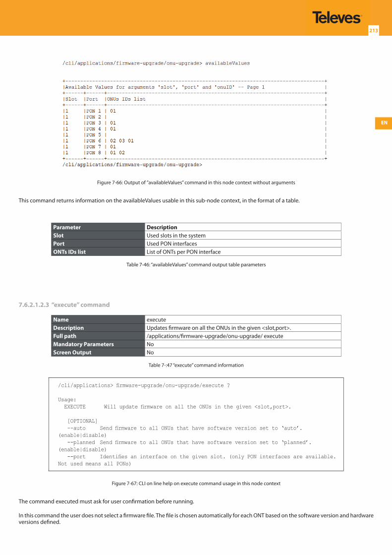
EN
213
Figure 7-66: Output of ”availableValues” command in this node context without arguments
This command returns information on the availableValues usable in this sub-node context, in the format of a table.
Parameter DescriptionSlot Used slots in the system Port Used PON interfacesONTs IDs list List of ONTs per PON interface
Table 7-46: “availableValues” command output table parameters
7.6.2.1.2.3 “execute” command
Name executeDescription Updates firmware on all the ONUs in the given <slot,port>.Full path /applications/firmware-upgrade/onu-upgrade/ executeMandatory Parameters NoScreen Output No
Table 7-:47 “execute” command information
/cli/applications> firmware-upgrade/onu-upgrade/execute ?
Usage: EXECUTE Will update firmware on all the ONUs in the given <slot,port>.
[OPTIONAL] --auto Send firmware to all ONUs that have software version set to ‘auto’. (enable|disable) --planned Send firmware to all ONUs that have software version set to ‘planned’. (enable|disable) --port Identifies an interface on the given slot. (only PON interfaces are available. Not used means all PONs)
Figure 7-67: CLI on line help on execute command usage in this node context
The command executed must ask for user confirmation before running.
In this command the user does not select a firmware file. The file is chosen automatically for each ONT based on the software version and hardware versions defined.
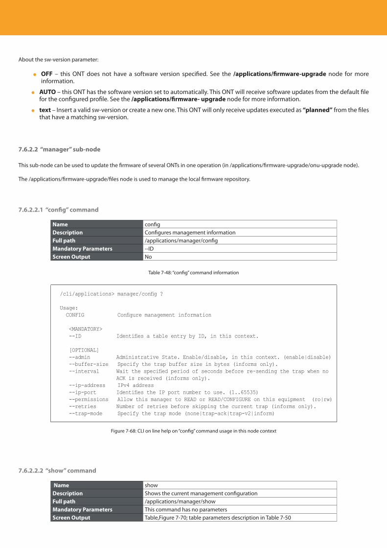
Descripción del producto
214
About the sw-version parameter:
OFF – this ONT does not have a software version specified. See the /applications/firmware-upgrade node for more information.
AUTO – this ONT has the software version set to automatically. This ONT will receive software updates from the default file for the configured profile. See the /applications/firmware- upgrade node for more information.
text – Insert a valid sw-version or create a new one. This ONT will only receive updates executed as “planned” from the files that have a matching sw-version.
7.6.2.2 “manager” sub-node
This sub-node can be used to update the firmware of several ONTs in one operation (in /applications/firmware-upgrade/onu-upgrade node).
The /applications/firmware-upgrade/files node is used to manage the local firmware repository.
7.6.2.2.1 “config” command
Name configDescription Configures management informationFull path /applications/manager/configMandatory Parameters --IDScreen Output No
Table 7-48: “config” command information
/cli/applications> manager/config ?
Usage: CONFIG Configure management information
<MANDATORY> --ID Identifies a table entry by ID, in this context.
[OPTIONAL] --admin Administrative State. Enable/disable, in this context. (enable|disable) --buffer-size Specify the trap buffer size in bytes (informs only). --interval Wait the specified period of seconds before re-sending the trap when no
ACK is received (informs only). --ip-address IPv4 address --ip-port Identifies the IP port number to use. (1..65535) --permissions Allow this manager to READ or READ/CONFIGURE on this equipment (ro|rw) --retries Number of retries before skipping the current trap (informs only). --trap-mode Specify the trap mode (none|trap-ack|trap-v2|inform)
Figure 7-68: CLI on line help on “config” command usage in this node context
7.6.2.2.2 “show” command
Name showDescription Shows the current management configurationFull path /applications/manager/showMandatory Parameters This command has no parametersScreen Output Table,Figure 7-70; table parameters description in Table 7-50
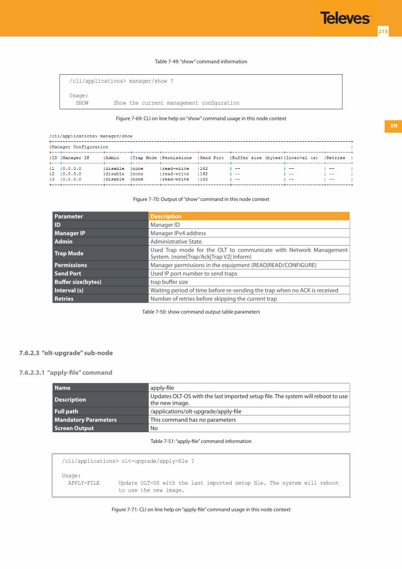
EN
215
Table 7-49: “show” command information
/cli/applications> manager/show ?
Usage: SHOW Show the current management configuration
Figure 7-69: CLI on line help on “show” command usage in this node context
Figure 7-70: Output of ”show” command in this node context
Parameter DescriptionID Manager IDManager IP Manager IPv4 addressAdmin Administrative State.
Trap Mode Used Trap mode for the OLT to communicate with Network Management System. (none|Trap/Ack|Trap V2| Inform)
Permissions Manager permissions in the equipment (READ|READ/CONFIGURE)Send Port Used IP port number to send trapsBuffer size(bytes) trap buffer sizeInterval (s) Waiting period of time before re-sending the trap when no ACK is receivedRetries Number of retries before skipping the current trap
Table 7-50: show command output table parameters
7.6.2.3 “olt-upgrade” sub-node
7.6.2.3.1 “apply-file” command
Name apply-file
Description Updates OLT-OS with the last imported setup file. The system will reboot to use the new image.
Full path /applications/olt-upgrade/apply-fileMandatory Parameters This command has no parametersScreen Output No
Table 7-51: “apply-file” command information
/cli/applications> olt-upgrade/apply-file ?
Usage: APPLY-FILE Update OLT-OS with the last imported setup file. The system will reboot
to use the new image.
Figure 7-71: CLI on line help on “apply-file” command usage in this node context
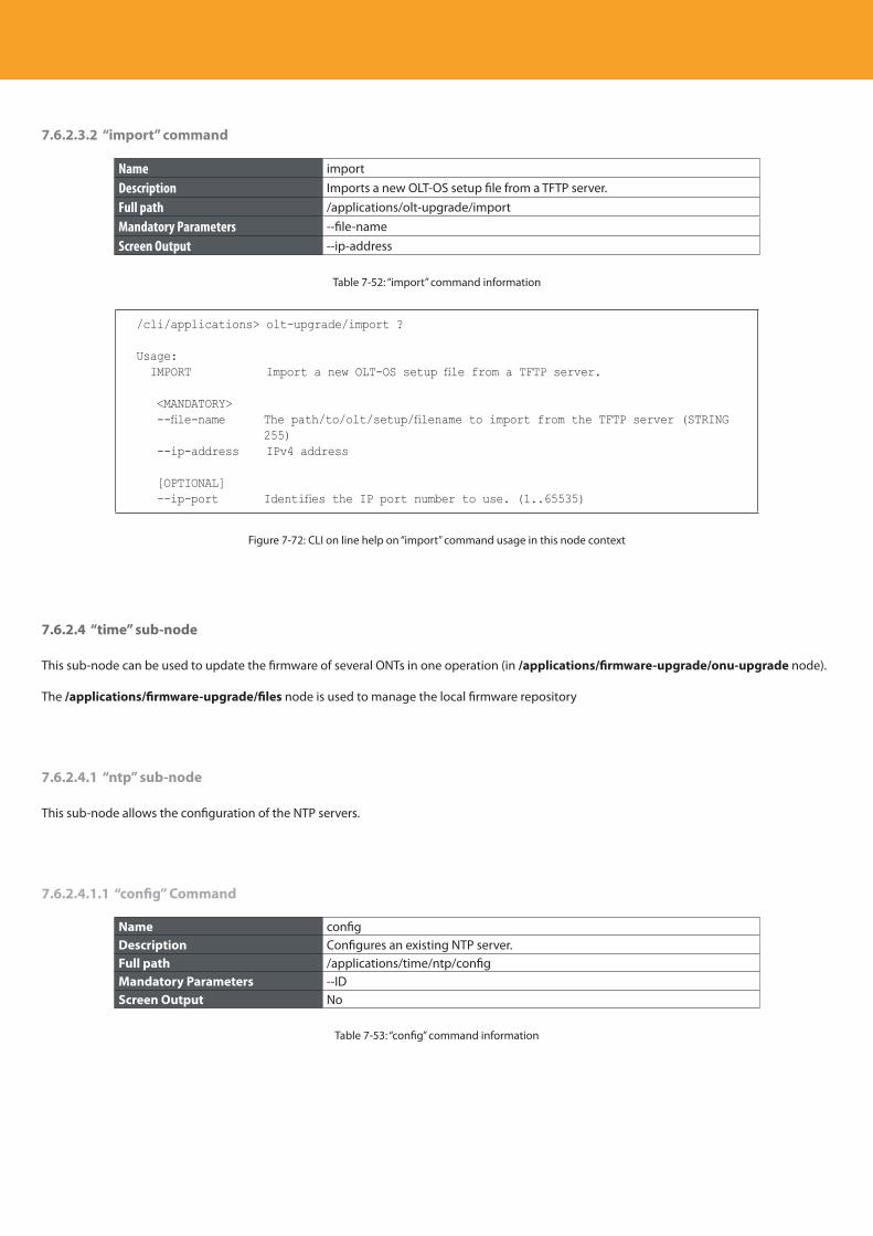
Descripción del producto
216
7.6.2.3.2 “import” command
Name import
Description Imports a new OLT-OS setup file from a TFTP server.
Full path /applications/olt-upgrade/import
Mandatory Parameters --file-name
Screen Output --ip-address
Table 7-52: “import” command information
/cli/applications> olt-upgrade/import ?
Usage: IMPORT Import a new OLT-OS setup file from a TFTP server.
<MANDATORY> --file-name The path/to/olt/setup/filename to import from the TFTP server (STRING
255) --ip-address IPv4 address
[OPTIONAL] --ip-port Identifies the IP port number to use. (1..65535)
Figure 7-72: CLI on line help on “import” command usage in this node context
7.6.2.4 “time” sub-node
This sub-node can be used to update the firmware of several ONTs in one operation (in /applications/firmware-upgrade/onu-upgrade node).
The /applications/firmware-upgrade/files node is used to manage the local firmware repository
7.6.2.4.1 “ntp” sub-node
This sub-node allows the configuration of the NTP servers.
7.6.2.4.1.1 “config” Command
Name configDescription Configures an existing NTP server.Full path /applications/time/ntp/configMandatory Parameters --IDScreen Output No
Table 7-53: “config” command information
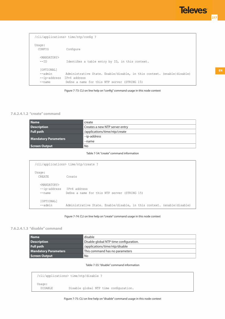
EN
217
/cli/applications> time/ntp/config ?
Usage: CONFIG Configure
<MANDATORY> --ID Identifies a table entry by ID, in this context.
[OPTIONAL] --admin Administrative State. Enable/disable, in this context. (enable|disable) --ip-address IPv4 address --name Define a name for this NTP server (STRING 15)
Figure 7-73: CLI on line help on “config” command usage in this node context
7.6.2.4.1.2 “create” command
Name createDescription Creates a new NTP server entryFull path /applications/time/ntp/create
Mandatory Parameters--ip-address--name
Screen Output No
Table 7-54: “create” command information
/cli/applications> time/ntp/create ?
Usage: CREATE Create
<MANDATORY> --ip-address IPv4 address --name Define a name for this NTP server (STRING 15)
[OPTIONAL] --admin Administrative State. Enable/disable, in this context. (enable|disable)
Figure 7-74: CLI on line help on “create” command usage in this node context
7.6.2.4.1.3 “disable” command
Name disableDescription Disable global NTP time configuration.Full path /applications/time/ntp/disableMandatory Parameters This command has no parametersScreen Output No
Table 7-55: “disable” command information
/cli/applications> time/ntp/disable ?
Usage: DISABLE Disable global NTP time configuration.
Figure 7-75: CLI on line help on “disable” command usage in this node context
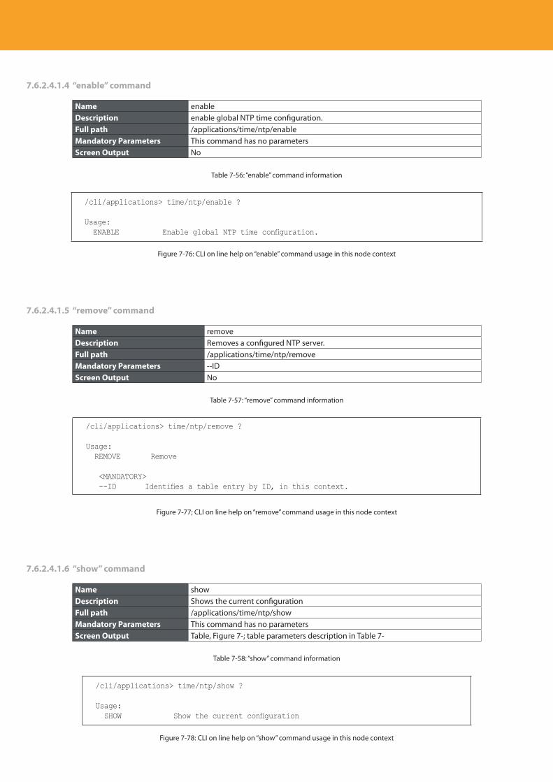
Descripción del producto
218
7.6.2.4.1.4 “enable” command
Name enableDescription enable global NTP time configuration.Full path /applications/time/ntp/enableMandatory Parameters This command has no parametersScreen Output No
Table 7-56: “enable” command information
/cli/applications> time/ntp/enable ?
Usage: ENABLE Enable global NTP time configuration.
Figure 7-76: CLI on line help on “enable” command usage in this node context
7.6.2.4.1.5 “remove” command
Name removeDescription Removes a configured NTP server.Full path /applications/time/ntp/removeMandatory Parameters --IDScreen Output No
Table 7-57: “remove” command information
/cli/applications> time/ntp/remove ?
Usage: REMOVE Remove
<MANDATORY> --ID Identifies a table entry by ID, in this context.
Figure 7-77; CLI on line help on “remove” command usage in this node context
7.6.2.4.1.6 “show” command
Name showDescription Shows the current configurationFull path /applications/time/ntp/showMandatory Parameters This command has no parametersScreen Output Table, Figure 7-; table parameters description in Table 7-
Table 7-58: “show” command information
/cli/applications> time/ntp/show ?
Usage: SHOW Show the current configuration
Figure 7-78: CLI on line help on “show” command usage in this node context
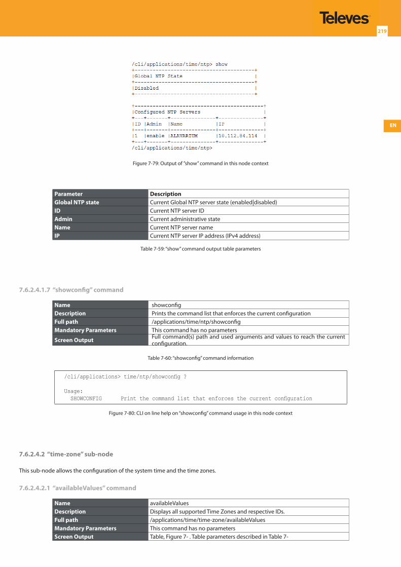
EN
219
Figure 7-79: Output of ”show” command in this node context
Parameter DescriptionGlobal NTP state Current Global NTP server state (enabled|disabled)ID Current NTP server ID Admin Current administrative stateName Current NTP server nameIP Current NTP server IP address (IPv4 address)
Table 7-59: “show” command output table parameters
7.6.2.4.1.7 “showconfig” command
Name showconfigDescription Prints the command list that enforces the current configurationFull path /applications/time/ntp/showconfigMandatory Parameters This command has no parameters
Screen Output Full command(s) path and used arguments and values to reach the current configuration.
Table 7-60: “showconfig” command information
/cli/applications> time/ntp/showconfig ?
Usage: SHOWCONFIG Print the command list that enforces the current configuration
Figure 7-80: CLI on line help on “showconfig” command usage in this node context
7.6.2.4.2 “time-zone” sub-node
This sub-node allows the configuration of the system time and the time zones.
7.6.2.4.2.1 “availableValues” command
Name availableValuesDescription Displays all supported Time Zones and respective IDs.Full path /applications/time/time-zone/availableValuesMandatory Parameters This command has no parametersScreen Output Table, Figure 7- . Table parameters described in Table 7-
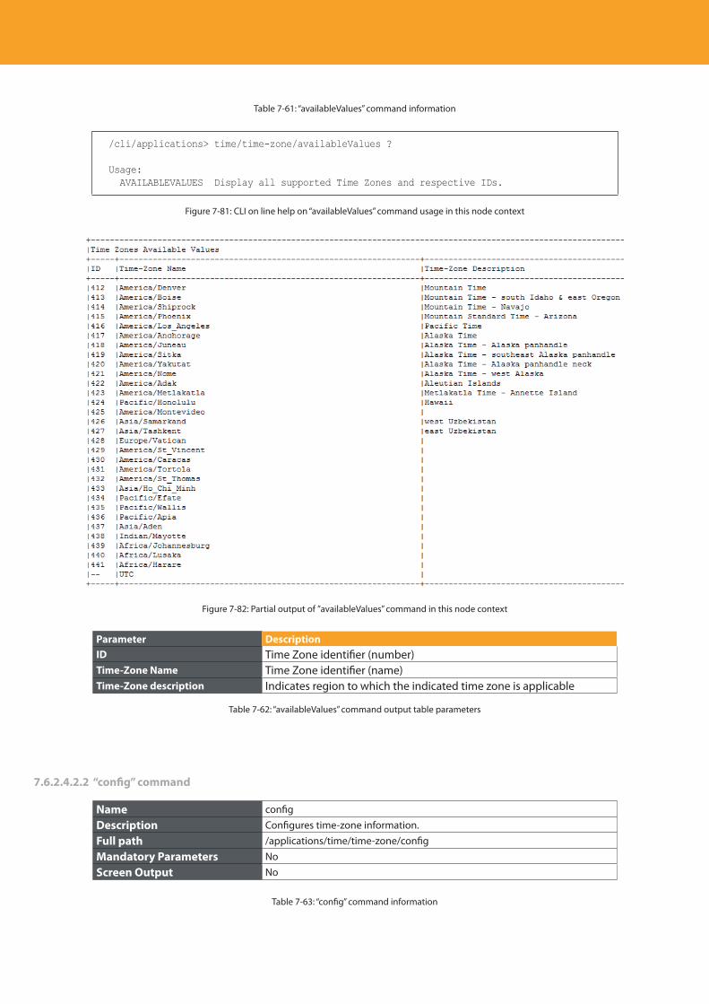
Descripción del producto
220
Table 7-61: “availableValues” command information
/cli/applications> time/time-zone/availableValues ?
Usage: AVAILABLEVALUES Display all supported Time Zones and respective IDs.
Figure 7-81: CLI on line help on “availableValues” command usage in this node context
Figure 7-82: Partial output of ”availableValues” command in this node context
Parameter DescriptionID Time Zone identifier (number)Time-Zone Name Time Zone identifier (name)Time-Zone description Indicates region to which the indicated time zone is applicable
Table 7-62: “availableValues” command output table parameters
7.6.2.4.2.2 “config” command
Name config
Description Configures time-zone information.
Full path /applications/time/time-zone/config
Mandatory Parameters No
Screen Output No
Table 7-63: “config” command information
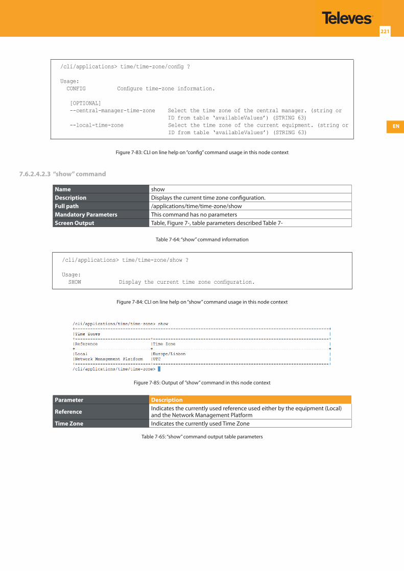
EN
221
/cli/applications> time/time-zone/config ?
Usage: CONFIG Configure time-zone information.
[OPTIONAL] --central-manager-time-zone Select the time zone of the central manager. (string or
ID from table ‘availableValues’) (STRING 63) --local-time-zone Select the time zone of the current equipment. (string or
ID from table ‘availableValues’) (STRING 63)
Figure 7-83: CLI on line help on “config” command usage in this node context
7.6.2.4.2.3 “show” command
Name showDescription Displays the current time zone configuration.Full path /applications/time/time-zone/showMandatory Parameters This command has no parametersScreen Output Table, Figure 7-, table parameters described Table 7-
Table 7-64: “show” command information
/cli/applications> time/time-zone/show ?
Usage: SHOW Display the current time zone configuration.
Figure 7-84: CLI on line help on “show” command usage in this node context
Figure 7-85: Output of ”show” command in this node context
Parameter Description
Reference Indicates the currently used reference used either by the equipment (Local) and the Network Management Platform
Time Zone Indicates the currently used Time Zone
Table 7-65: “show” command output table parameters
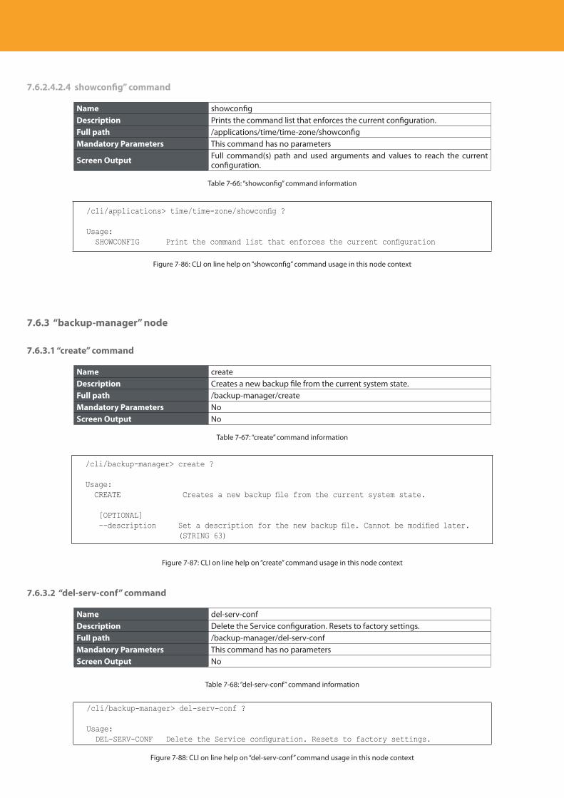
Descripción del producto
222
7.6.2.4.2.4 showconfig” command
Name showconfigDescription Prints the command list that enforces the current configuration.Full path /applications/time/time-zone/showconfigMandatory Parameters This command has no parameters
Screen Output Full command(s) path and used arguments and values to reach the current configuration.
Table 7-66: “showconfig” command information
/cli/applications> time/time-zone/showconfig ?
Usage: SHOWCONFIG Print the command list that enforces the current configuration
Figure 7-86: CLI on line help on “showconfig” command usage in this node context
7.6.3 “backup-manager” node
7.6.3.1 “create” command
Name createDescription Creates a new backup file from the current system state.Full path /backup-manager/createMandatory Parameters NoScreen Output No
Table 7-67: “create” command information
/cli/backup-manager> create ?
Usage: CREATE Creates a new backup file from the current system state.
[OPTIONAL] --description Set a description for the new backup file. Cannot be modified later.
(STRING 63)
Figure 7-87: CLI on line help on “create” command usage in this node context
7.6.3.2 “del-serv-conf” command
Name del-serv-confDescription Delete the Service configuration. Resets to factory settings.Full path /backup-manager/del-serv-confMandatory Parameters This command has no parametersScreen Output No
Table 7-68: “del-serv-conf” command information
/cli/backup-manager> del-serv-conf ?
Usage: DEL-SERV-CONF Delete the Service configuration. Resets to factory settings.
Figure 7-88: CLI on line help on “del-serv-conf” command usage in this node context
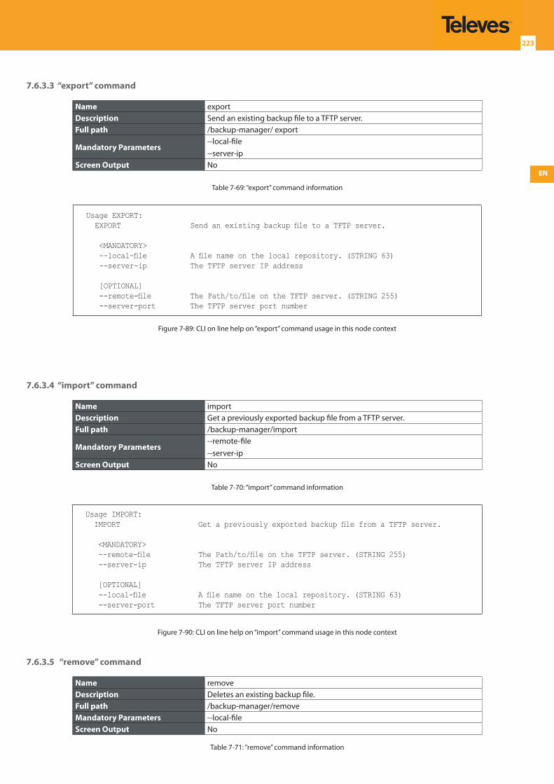
EN
223
7.6.3.3 “export” command
Name exportDescription Send an existing backup file to a TFTP server.Full path /backup-manager/ export
Mandatory Parameters--local-file--server-ip
Screen Output No
Table 7-69: “export” command information
Usage EXPORT: EXPORT Send an existing backup file to a TFTP server.
<MANDATORY> --local-file A file name on the local repository. (STRING 63) --server-ip The TFTP server IP address
[OPTIONAL] --remote-file The Path/to/file on the TFTP server. (STRING 255) --server-port The TFTP server port number
Figure 7-89: CLI on line help on “export” command usage in this node context
7.6.3.4 “import” command
Name importDescription Get a previously exported backup file from a TFTP server.Full path /backup-manager/import
Mandatory Parameters--remote-file--server-ip
Screen Output No
Table 7-70: “import” command information
Usage IMPORT: IMPORT Get a previously exported backup file from a TFTP server.
<MANDATORY> --remote-file The Path/to/file on the TFTP server. (STRING 255) --server-ip The TFTP server IP address
[OPTIONAL] --local-file A file name on the local repository. (STRING 63) --server-port The TFTP server port number
Figure 7-90: CLI on line help on “import” command usage in this node context
7.6.3.5 “remove” command
Name removeDescription Deletes an existing backup file.Full path /backup-manager/removeMandatory Parameters --local-fileScreen Output No
Table 7-71: “remove” command information
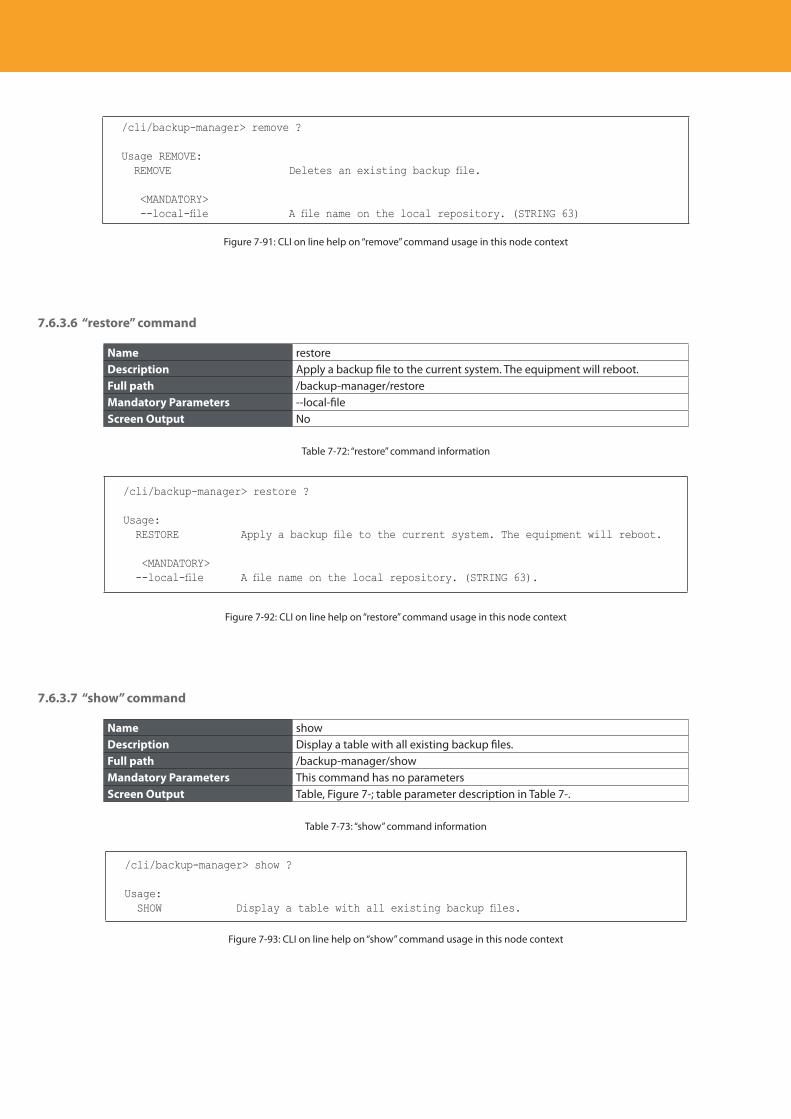
Descripción del producto
224
/cli/backup-manager> remove ?
Usage REMOVE: REMOVE Deletes an existing backup file.
<MANDATORY> --local-file A file name on the local repository. (STRING 63)
Figure 7-91: CLI on line help on “remove” command usage in this node context
7.6.3.6 “restore” command
Name restoreDescription Apply a backup file to the current system. The equipment will reboot.Full path /backup-manager/restoreMandatory Parameters --local-fileScreen Output No
Table 7-72: “restore” command information
/cli/backup-manager> restore ?
Usage: RESTORE Apply a backup file to the current system. The equipment will reboot.
<MANDATORY> --local-file A file name on the local repository. (STRING 63).
Figure 7-92: CLI on line help on “restore” command usage in this node context
7.6.3.7 “show” command
Name showDescription Display a table with all existing backup files.Full path /backup-manager/showMandatory Parameters This command has no parametersScreen Output Table, Figure 7-; table parameter description in Table 7-.
Table 7-73: “show” command information
/cli/backup-manager> show ?
Usage: SHOW Display a table with all existing backup files.
Figure 7-93: CLI on line help on “show” command usage in this node context
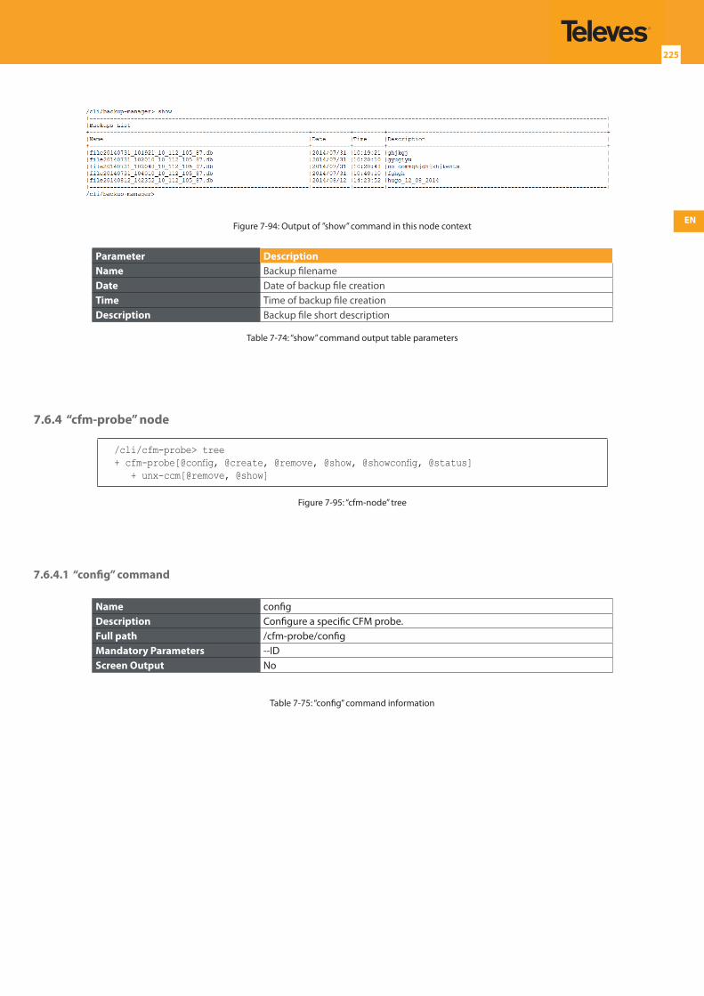
EN
225
Figure 7-94: Output of ”show” command in this node context
Parameter DescriptionName Backup filenameDate Date of backup file creationTime Time of backup file creationDescription Backup file short description
Table 7-74: “show” command output table parameters
7.6.4 “cfm-probe” node
/cli/cfm-probe> tree+ cfm-probe[@config, @create, @remove, @show, @showconfig, @status] + unx-ccm[@remove, @show]
Figure 7-95: “cfm-node” tree
7.6.4.1 “config” command
Name configDescription Configure a specific CFM probe.Full path /cfm-probe/configMandatory Parameters --IDScreen Output No
Table 7-75: “config” command information
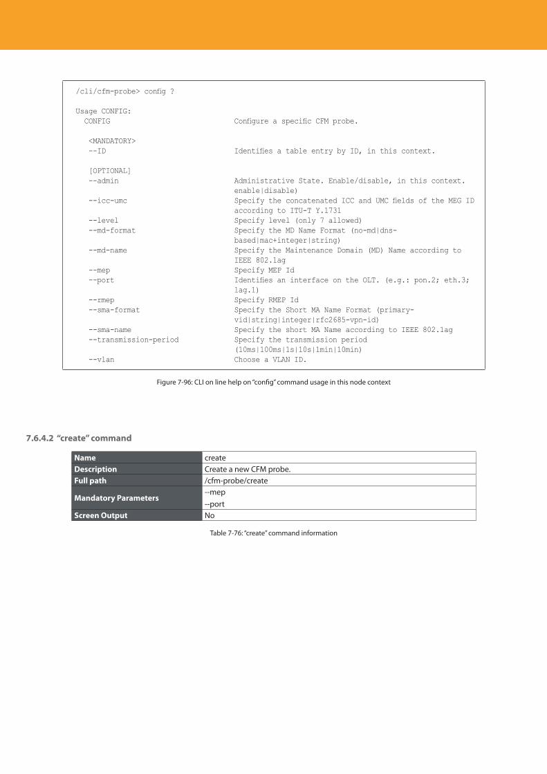
Descripción del producto
226
/cli/cfm-probe> config ?
Usage CONFIG: CONFIG Configure a specific CFM probe.
<MANDATORY> --ID Identifies a table entry by ID, in this context.
[OPTIONAL] --admin Administrative State. Enable/disable, in this context.
enable|disable) --icc-umc Specify the concatenated ICC and UMC fields of the MEG ID
according to ITU-T Y.1731 --level Specify level (only 7 allowed) --md-format Specify the MD Name Format (no-md|dns-
based|mac+integer|string) --md-name Specify the Maintenance Domain (MD) Name according to
IEEE 802.1ag --mep Specify MEP Id --port Identifies an interface on the OLT. (e.g.: pon.2; eth.3;
lag.1) --rmep Specify RMEP Id --sma-format Specify the Short MA Name Format (primary-
vid|string|integer|rfc2685-vpn-id) --sma-name Specify the short MA Name according to IEEE 802.1ag --transmission-period Specify the transmission period
(10ms|100ms|1s|10s|1min|10min) --vlan Choose a VLAN ID.
Figure 7-96: CLI on line help on “config” command usage in this node context
7.6.4.2 “create” command
Name createDescription Create a new CFM probe.Full path /cfm-probe/create
Mandatory Parameters--mep--port
Screen Output No
Table 7-76: “create” command information
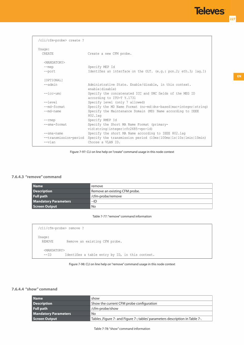
EN
227
/cli/cfm-probe> create ?
Usage: CREATE Create a new CFM probe.
<MANDATORY> --mep Specify MEP Id --port Identifies an interface on the OLT. (e.g.: pon.2; eth.3; lag.1)
[OPTIONAL] --admin Administrative State. Enable/disable, in this context.
enable|disable) --icc-umc Specify the concatenated ICC and UMC fields of the MEG ID
according to ITU-T Y.1731 --level Specify level (only 7 allowed) --md-format Specify the MD Name Format (no-md|dns-based|mac+integer|string) --md-name Specify the Maintenance Domain (MD) Name according to IEEE
802.1ag --rmep Specify RMEP Id --sma-format Specify the Short MA Name Format (primary-
vid|string|integer|rfc2685-vpn-id) --sma-name Specify the short MA Name according to IEEE 802.1ag --transmission-period Specify the transmission period (10ms|100ms|1s|10s|1min|10min) --vlan Choose a VLAN ID.
Figure 7-97: CLI on line help on “create” command usage in this node context
7.6.4.3 “remove” command
Name removeDescription Remove an existing CFM probe.Full path /cfm-probe/removeMandatory Parameters --IDScreen Output No
Table 7-77: “remove” command information
/cli/cfm-probe> remove ?
Usage: REMOVE Remove an existing CFM probe.
<MANDATORY> --ID Identifies a table entry by ID, in this context.
Figure 7-98: CLI on line help on “remove” command usage in this node context
7.6.4.4 “show” command
Name showDescription Show the current CFM probe configurationFull path /cfm-probe/showMandatory Parameters NoScreen Output Tables ,Figure 7- and Figure 7-; tables’ parameters description in Table 7-.
Table 7-78: “show” command information
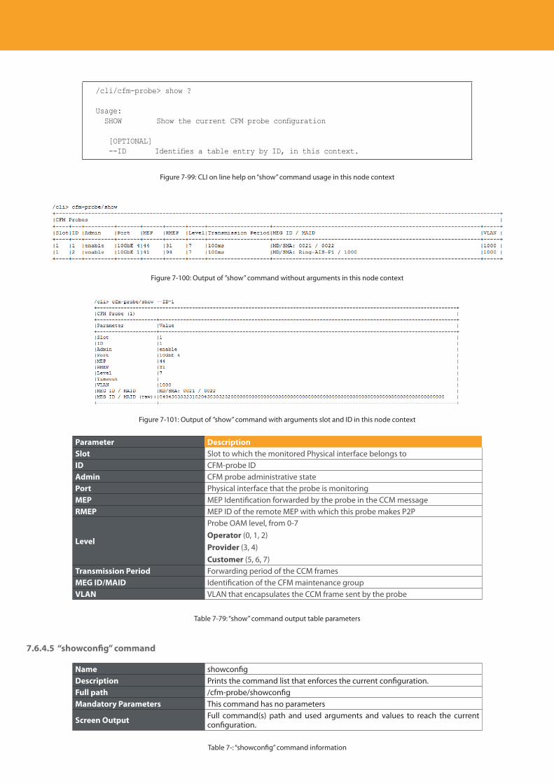
Descripción del producto
228
/cli/cfm-probe> show ?
Usage: SHOW Show the current CFM probe configuration
[OPTIONAL] --ID Identifies a table entry by ID, in this context.
Figure 7-99: CLI on line help on “show” command usage in this node context
Figure 7-100: Output of ”show” command without arguments in this node context
Figure 7-101: Output of ”show” command with arguments slot and ID in this node context
Parameter DescriptionSlot Slot to which the monitored Physical interface belongs toID CFM-probe IDAdmin CFM probe administrative statePort Physical interface that the probe is monitoringMEP MEP Identification forwarded by the probe in the CCM messageRMEP MEP ID of the remote MEP with which this probe makes P2P
Level
Probe OAM level, from 0-7 Operator (0, 1, 2)Provider (3, 4)Customer (5, 6, 7)
Transmission Period Forwarding period of the CCM framesMEG ID/MAID Identification of the CFM maintenance groupVLAN VLAN that encapsulates the CCM frame sent by the probe
Table 7-79: “show” command output table parameters
7.6.4.5 “showconfig” command
Name showconfigDescription Prints the command list that enforces the current configuration.Full path /cfm-probe/showconfigMandatory Parameters This command has no parameters
Screen Output Full command(s) path and used arguments and values to reach the current configuration.
Table 7-: “showconfig” command information
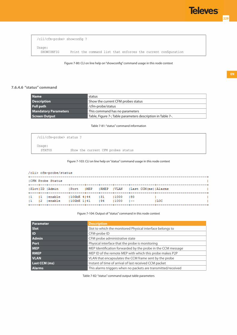
EN
229
/cli/cfm-probe> showconfig ?
Usage: SHOWCONFIG Print the command list that enforces the current configuration
Figure 7-80: CLI on line help on “showconfig” command usage in this node context
7.6.4.6 “status” command
Name statusDescription Show the current CFM probes statusFull path /cfm-probe/statusMandatory Parameters This command has no parametersScreen Output Table, Figure 7-; Table parameters description in Table 7-.
Table 7-81: “status” command information
/cli/cfm-probe> status ?
Usage: STATUS Show the current CFM probes status
Figure 7-103: CLI on line help on “status” command usage in this node context
Figure 7-104: Output of ”status” command in this node context
Parameter DescriptionSlot Slot to which the monitored Physical interface belongs toID CFM-probe IDAdmin CFM probe administrative statePort Physical interface that the probe is monitoringMEP MEP Identification forwarded by the probe in the CCM messageRMEP MEP ID of the remote MEP with which this probe makes P2PVLAN VLAN that encapsulates the CCM frame sent by the probeLast CCM (ms) Instant of time of arrival of last received CCM packetAlarms This alarms triggers when no packets are transmitted/received
Table 7-82: “status” command output table parameters
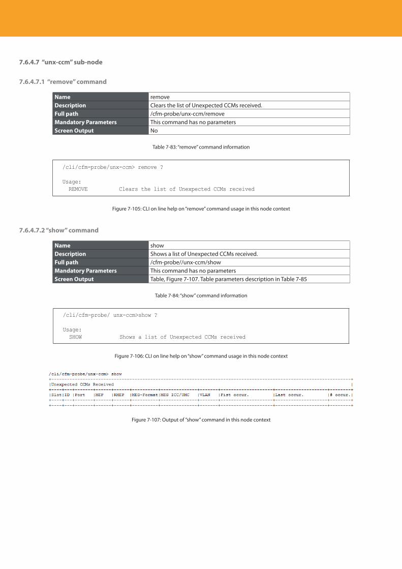
Descripción del producto
230
7.6.4.7 “unx-ccm” sub-node
7.6.4.7.1 “remove” command
Name removeDescription Clears the list of Unexpected CCMs received.Full path /cfm-probe/unx-ccm/removeMandatory Parameters This command has no parametersScreen Output No
Table 7-83: “remove” command information
/cli/cfm-probe/unx-ccm> remove ?
Usage: REMOVE Clears the list of Unexpected CCMs received
Figure 7-105: CLI on line help on “remove” command usage in this node context
7.6.4.7.2 “show” command
Name showDescription Shows a list of Unexpected CCMs received.Full path /cfm-probe//unx-ccm/showMandatory Parameters This command has no parametersScreen Output Table, Figure 7-107. Table parameters description in Table 7-85
Table 7-84: “show” command information
/cli/cfm-probe/ unx-ccm>show ?
Usage: SHOW Shows a list of Unexpected CCMs received
Figure 7-106: CLI on line help on “show” command usage in this node context
Figure 7-107: Output of ”show” command in this node context
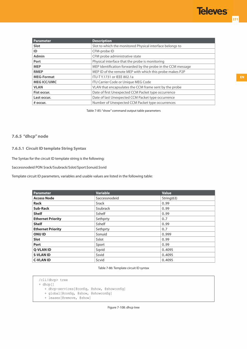
EN
231
Parameter DescriptionSlot Slot to which the monitored Physical interface belongs toID CFM-probe IDAdmin CFM probe administrative statePort Physical interface that the probe is monitoringMEP MEP Identification forwarded by the probe in the CCM messageRMEP MEP ID of the remote MEP with which this probe makes P2PMEG-Format ITU-T Y.1731 or IEEE 802.1aMEG ICC/UMC ITU Carrier Code or Unique MEG CodeVLAN VLAN that encapsulates the CCM frame sent by the probeFist occur. Date of first Unexpected CCM Packet type occurrenceLast occur. Date of last Unexpected CCM Packet type occurrence# occur. Number of Unexpected CCM Packet type occurrences
Table 7-85: “show” command output table parameters
7.6.5 “dhcp” node
7.6.5.1 Circuit ID template String Syntax
The Syntax for the circuit ID template string is the following:
$accessnodeid PON $rack/$subrack/$slot/$port:$onuid.$svid
Template circuit ID parameters, variables and usable values are listed in the following table:
Parameter Variable ValueAccess Node $accessnodeid String(63)Rack $rack 0..99Sub-Rack $subrack 0..99Shelf $shelf 0..99Ethernet Priority $ethprty 0..7Shelf $shelf 0..99Ethernet Priority $ethprty 0..7ONU ID $onuid 0..999Slot $slot 0..99Port $port 0..99Q-VLAN ID $qvid 0..4095S-VLAN ID $svid 0..4095C-VLAN ID $cvid 0..4095
Table 7-86: Template circuit ID syntax
/cli/dhcp> tree+ dhcp[] + dhcp-services[@config, @show, @showconfig] + global[@config, @show, @showconfig] + leases[@remove, @show]
Figure 7-108: dhcp tree
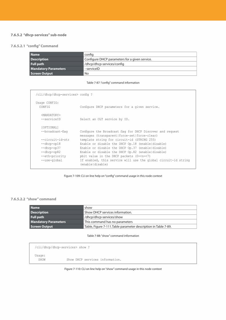
Descripción del producto
232
7.6.5.2 “dhcp-services” sub-node
7.6.5.2.1 “config” Command
Name configDescription Configure DHCP parameters for a given service.Full path /dhcp/dhcp-services/configMandatory Parameters --serviceIDScreen Output No
Table 7-87: “config” command information
/cli/dhcp/dhcp-services> config ?
Usage CONFIG: CONFIG Configure DHCP parameters for a given service.
<MANDATORY> --serviceID Select an OLT service by ID.
[OPTIONAL] --broadcast-flag Configure the Broadcast flag for DHCP Discover and request
messages (transparent|force-set|force-clear) --circuit-id-str template string for circuit-id (STRING 255) --dhcp-op18 Enable or disable the DHCP Op.18 (enable|disable) --dhcp-op37 Enable or disable the DHCP Op.37 (enable|disable) --dhcp-op82 Enable or disable the DHCP Op.82 (enable|disable) --eth-priority pbit value in the DHCP packets (0=<n=<7) --use-global If enabled, this service will use the global circuit-id string
(enable|disable)
Figure 7-109: CLI on line help on “config” command usage in this node context
7.6.5.2.2 “show” command
Name showDescription Show DHCP services information.Full path /dhcp/dhcp-services/showMandatory Parameters This command has no parametersScreen Output Table, Figure 7-111.Table parameter description in Table 7-89.
Table 7-88: “show” command information
/cli/dhcp/dhcp-services> show ?
Usage: SHOW Show DHCP services information.
Figure 7-110: CLI on line help on “show” command usage in this node context
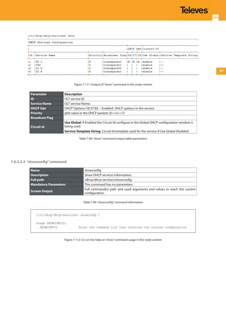
EN
233
Figure 7-111: Output of ”show” command in this node context
Parameter DescriptionID OLT service IDService Name OLT service Name.DHCP Opt DHCP Options:18/37/82 – Enabled DHCP options in the servicePriority pbit value in the DHCP packets (0<=n<=7)Broadcast Flag
Circuit IdUse Global: if Enabled the Circuit-Id configure in the Global DHCP configuration window is being used.Service Template String: Circuit-Id template used for the service if Use Global Disabled.
Table 7-89: “show” command output table parameters
7.6.5.2.3 “showconfig” command
Name showconfigDescription Show DHCP services information.Full path /dhcp/dhcp-services/showconfigMandatory Parameters This command has no parameters
Screen Output Full command(s) path and used arguments and values to reach the current configuration.
Table 7-90: “showconfig” command information
/cli/dhcp/dhcp-services> showconfig ?
Usage SHOWCONFIG: SHOWCONFIG Print the command list that enforces the current configuration
Figure 7-112: CLI on line help on “show” command usage in this node context
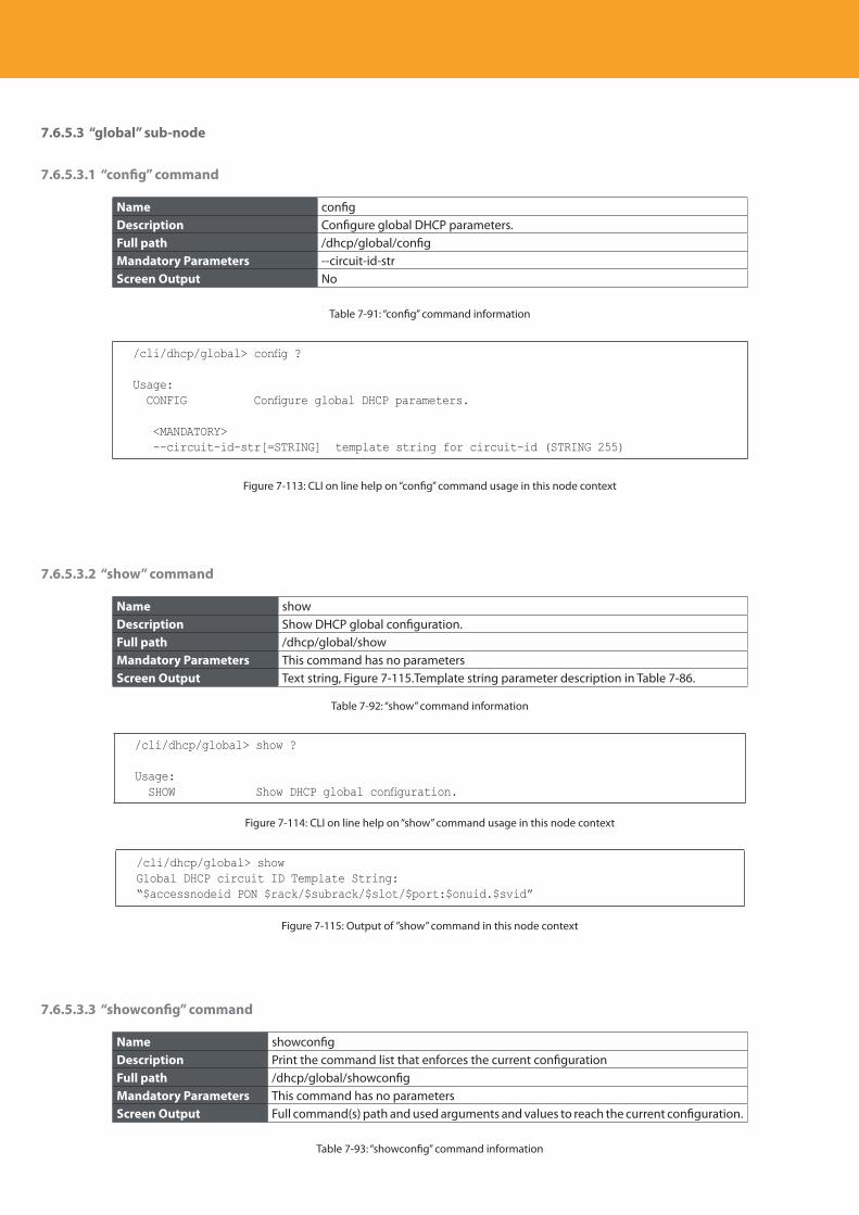
Descripción del producto
234
7.6.5.3 “global” sub-node
7.6.5.3.1 “config” command
Name configDescription Configure global DHCP parameters.Full path /dhcp/global/configMandatory Parameters --circuit-id-strScreen Output No
Table 7-91: “config” command information
/cli/dhcp/global> config ?
Usage: CONFIG Configure global DHCP parameters.
<MANDATORY> --circuit-id-str[=STRING] template string for circuit-id (STRING 255)
Figure 7-113: CLI on line help on “config” command usage in this node context
7.6.5.3.2 “show” command
Name showDescription Show DHCP global configuration.Full path /dhcp/global/showMandatory Parameters This command has no parametersScreen Output Text string, Figure 7-115.Template string parameter description in Table 7-86.
Table 7-92: “show” command information
/cli/dhcp/global> show ?
Usage: SHOW Show DHCP global configuration.
Figure 7-114: CLI on line help on “show” command usage in this node context
/cli/dhcp/global> showGlobal DHCP circuit ID Template String:“$accessnodeid PON $rack/$subrack/$slot/$port:$onuid.$svid”
Figure 7-115: Output of ”show” command in this node context
7.6.5.3.3 “showconfig” command
Name showconfigDescription Print the command list that enforces the current configurationFull path /dhcp/global/showconfigMandatory Parameters This command has no parametersScreen Output Full command(s) path and used arguments and values to reach the current configuration.
Table 7-93: “showconfig” command information
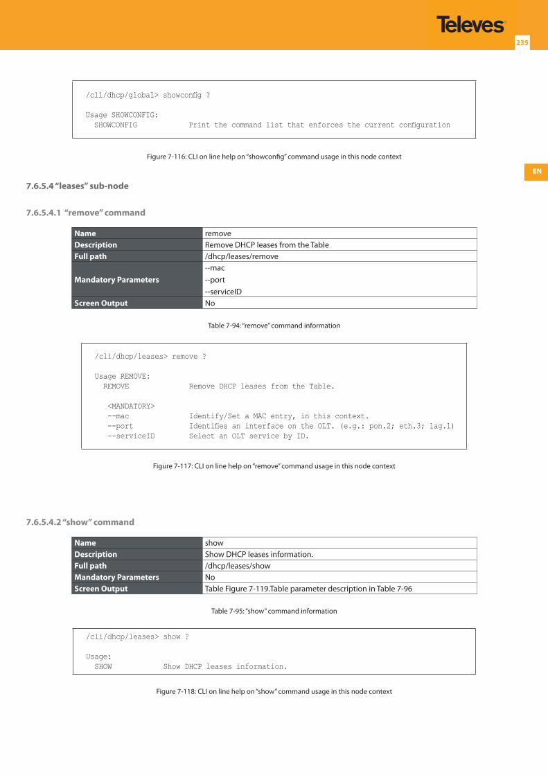
EN
235
/cli/dhcp/global> showconfig ?
Usage SHOWCONFIG: SHOWCONFIG Print the command list that enforces the current configuration
Figure 7-116: CLI on line help on “showconfig” command usage in this node context
7.6.5.4 “leases” sub-node
7.6.5.4.1 “remove” command
Name removeDescription Remove DHCP leases from the TableFull path /dhcp/leases/remove
Mandatory Parameters--mac--port--serviceID
Screen Output No
Table 7-94: “remove” command information
/cli/dhcp/leases> remove ?
Usage REMOVE: REMOVE Remove DHCP leases from the Table.
<MANDATORY> --mac Identify/Set a MAC entry, in this context. --port Identifies an interface on the OLT. (e.g.: pon.2; eth.3; lag.1) --serviceID Select an OLT service by ID.
Figure 7-117: CLI on line help on “remove” command usage in this node context
7.6.5.4.2 “show” command
Name showDescription Show DHCP leases information.Full path /dhcp/leases/showMandatory Parameters NoScreen Output Table Figure 7-119.Table parameter description in Table 7-96
Table 7-95: “show” command information
/cli/dhcp/leases> show ?
Usage: SHOW Show DHCP leases information.
Figure 7-118: CLI on line help on “show” command usage in this node context
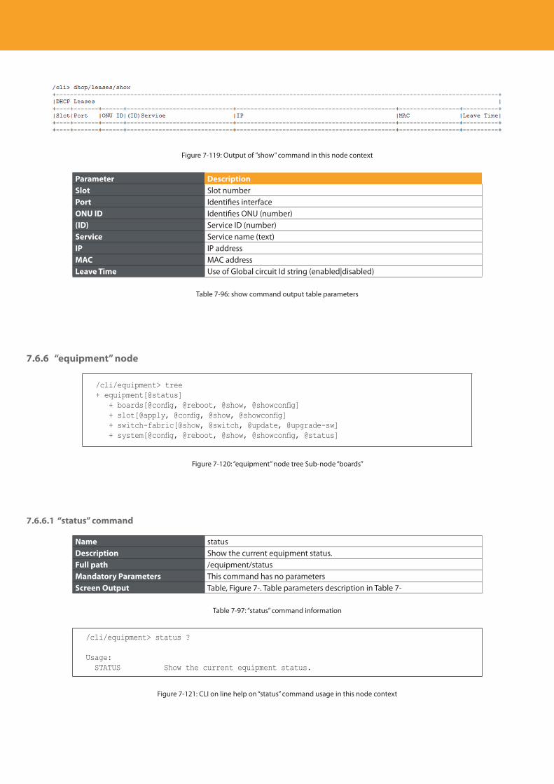
Descripción del producto
236
Figure 7-119: Output of ”show” command in this node context
Parameter DescriptionSlot Slot numberPort Identifies interface ONU ID Identifies ONU (number) (ID) Service ID (number)Service Service name (text)IP IP addressMAC MAC addressLeave Time Use of Global circuit Id string (enabled|disabled)
Table 7-96: show command output table parameters
7.6.6 “equipment” node
/cli/equipment> tree+ equipment[@status] + boards[@config, @reboot, @show, @showconfig] + slot[@apply, @config, @show, @showconfig] + switch-fabric[@show, @switch, @update, @upgrade-sw] + system[@config, @reboot, @show, @showconfig, @status]
Figure 7-120: “equipment” node tree Sub-node “boards”
7.6.6.1 “status” command
Name statusDescription Show the current equipment status.Full path /equipment/statusMandatory Parameters This command has no parametersScreen Output Table, Figure 7-. Table parameters description in Table 7-
Table 7-97: “status” command information
/cli/equipment> status ?
Usage: STATUS Show the current equipment status.
Figure 7-121: CLI on line help on “status” command usage in this node context
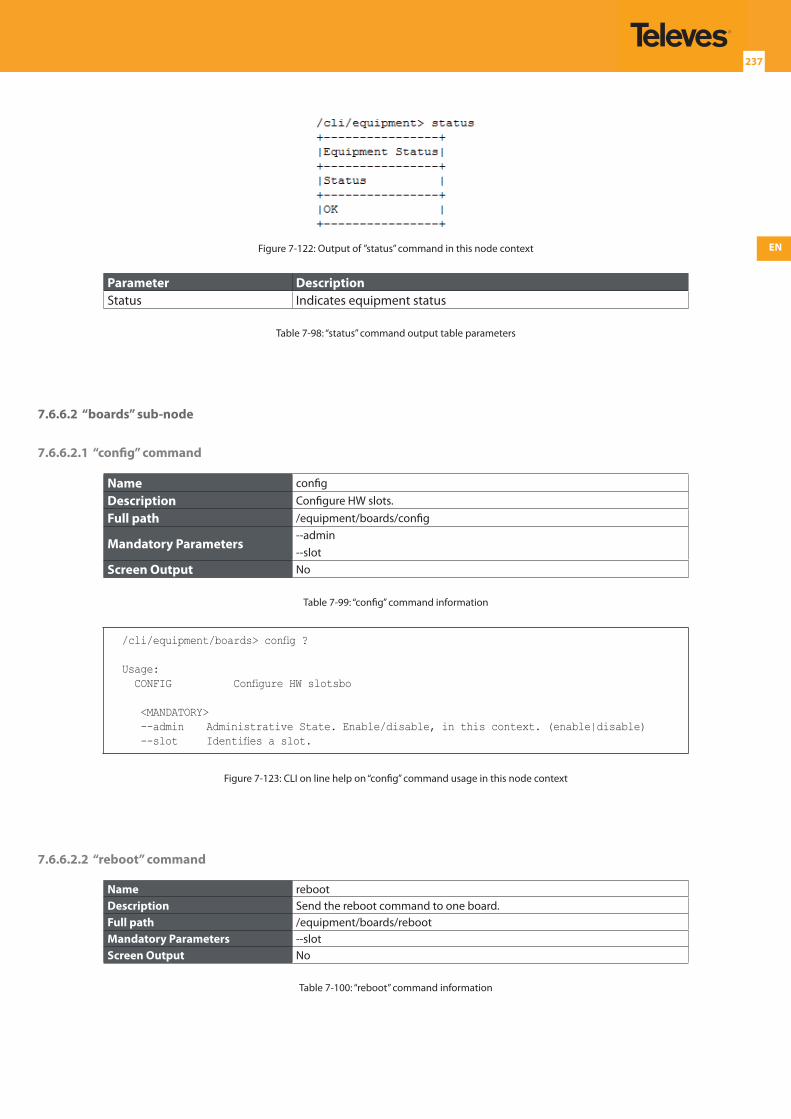
EN
237
Figure 7-122: Output of ”status” command in this node context
Parameter DescriptionStatus Indicates equipment status
Table 7-98: “status” command output table parameters
7.6.6.2 “boards” sub-node
7.6.6.2.1 “config” command
Name config
Description Configure HW slots.
Full path /equipment/boards/config
Mandatory Parameters--admin--slot
Screen Output No
Table 7-99: “config” command information
/cli/equipment/boards> config ?
Usage: CONFIG Configure HW slotsbo
<MANDATORY> --admin Administrative State. Enable/disable, in this context. (enable|disable) --slot Identifies a slot.
Figure 7-123: CLI on line help on “config” command usage in this node context
7.6.6.2.2 “reboot” command
Name rebootDescription Send the reboot command to one board.Full path /equipment/boards/rebootMandatory Parameters --slotScreen Output No
Table 7-100: “reboot” command information
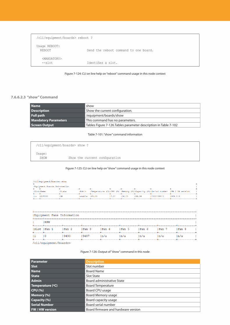
Descripción del producto
238
/cli/equipment/boards> reboot ?
Usage REBOOT: REBOOT Send the reboot command to one board.
<MANDATORY> --slot Identifies a slot.
Figure 7-124: CLI on line help on “reboot” command usage in this node context
7.6.6.2.3 “show” Command
Name showDescription Show the current configuration.Full path /equipment/boards/showMandatory Parameters This command has no parameters.Screen Output Tables Figure 7-126.Tables parameter description in Table 7-102
Table 7-101: “show” command information
/cli/equipment/boards> show ?
Usage: SHOW Show the current configuration
Figure 7-125: CLI on line help on “show” command usage in this node context
Figure 7-126: Output of ”show” command in this node
Parameter DescriptionSlot Slot numberName Board Name State Slot StateAdmin Board administrative StateTemperature (ºC) Board TemperatureCPU (%) Board CPU usageMemory (%) Board Memory usageCapacity (%) Board capacity usageSerial Number Board serial numberFW / HW version Board firmware and hardware version
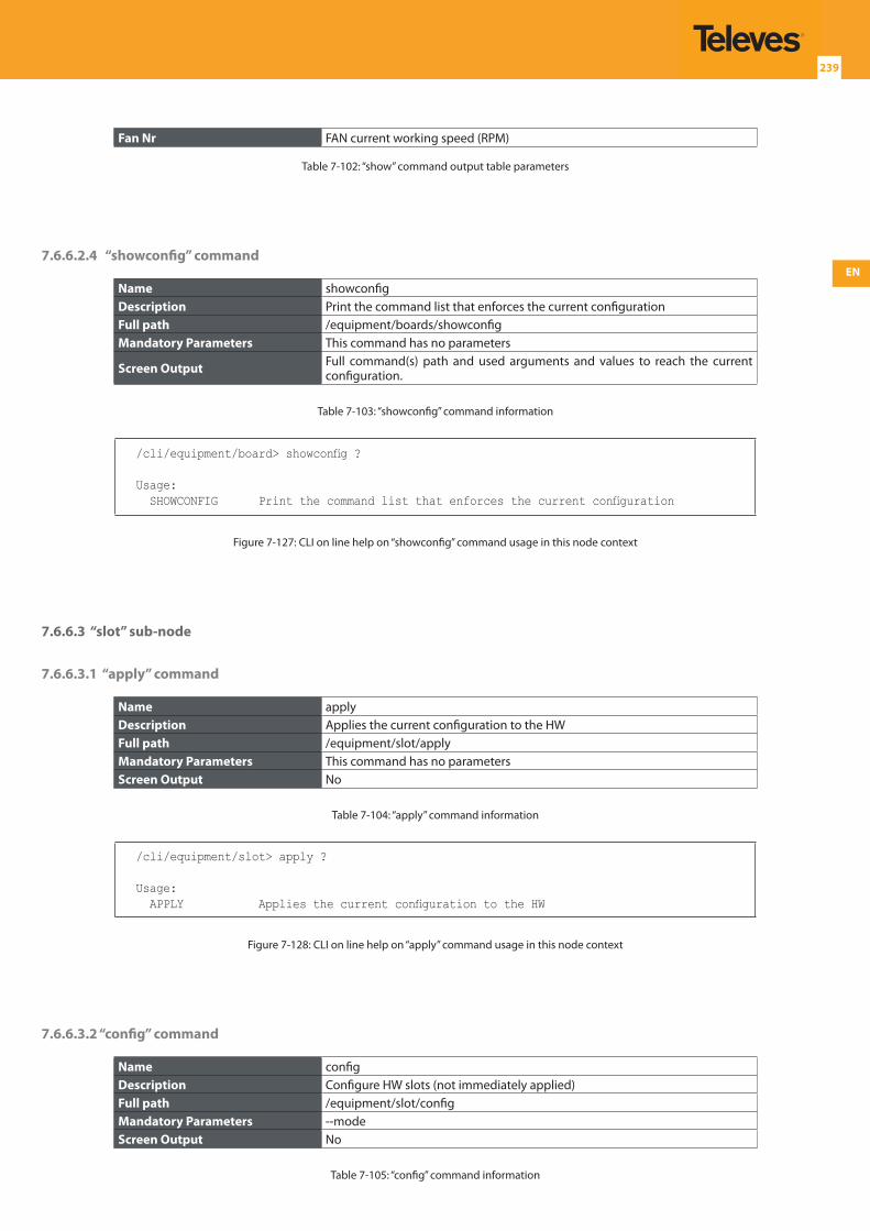
EN
239
Fan Nr FAN current working speed (RPM)
Table 7-102: “show” command output table parameters
7.6.6.2.4 “showconfig” command
Name showconfigDescription Print the command list that enforces the current configurationFull path /equipment/boards/showconfigMandatory Parameters This command has no parameters
Screen Output Full command(s) path and used arguments and values to reach the current configuration.
Table 7-103: “showconfig” command information
/cli/equipment/board> showconfig ?
Usage: SHOWCONFIG Print the command list that enforces the current configuration
Figure 7-127: CLI on line help on “showconfig” command usage in this node context
7.6.6.3 “slot” sub-node
7.6.6.3.1 “apply” command
Name applyDescription Applies the current configuration to the HWFull path /equipment/slot/applyMandatory Parameters This command has no parametersScreen Output No
Table 7-104: “apply” command information
/cli/equipment/slot> apply ?
Usage: APPLY Applies the current configuration to the HW
Figure 7-128: CLI on line help on “apply” command usage in this node context
7.6.6.3.2 “config” command
Name configDescription Configure HW slots (not immediately applied)Full path /equipment/slot/configMandatory Parameters --modeScreen Output No
Table 7-105: “config” command information
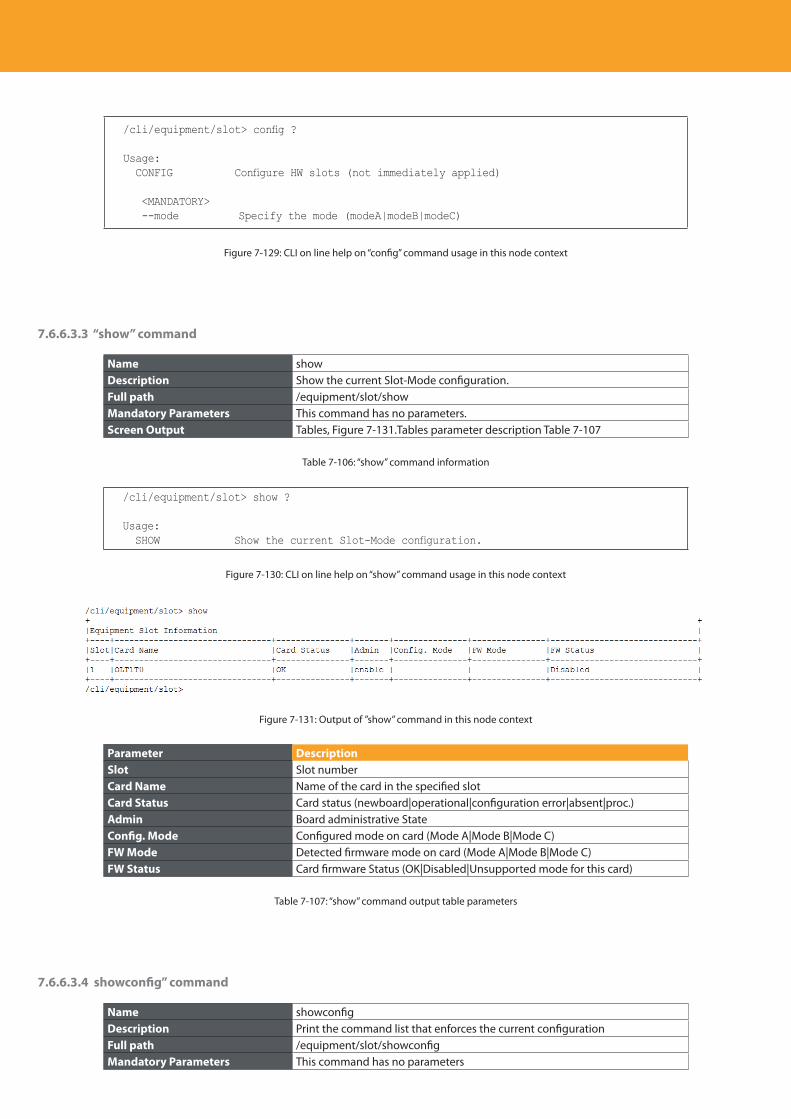
Descripción del producto
240
/cli/equipment/slot> config ?
Usage: CONFIG Configure HW slots (not immediately applied)
<MANDATORY> --mode Specify the mode (modeA|modeB|modeC)
Figure 7-129: CLI on line help on “config” command usage in this node context
7.6.6.3.3 “show” command
Name showDescription Show the current Slot-Mode configuration.Full path /equipment/slot/showMandatory Parameters This command has no parameters.Screen Output Tables, Figure 7-131.Tables parameter description Table 7-107
Table 7-106: “show” command information
/cli/equipment/slot> show ?
Usage: SHOW Show the current Slot-Mode configuration.
Figure 7-130: CLI on line help on “show” command usage in this node context
Figure 7-131: Output of ”show” command in this node context
Parameter DescriptionSlot Slot numberCard Name Name of the card in the specified slotCard Status Card status (newboard|operational|configuration error|absent|proc.)Admin Board administrative StateConfig. Mode Configured mode on card (Mode A|Mode B|Mode C)FW Mode Detected firmware mode on card (Mode A|Mode B|Mode C)FW Status Card firmware Status (OK|Disabled|Unsupported mode for this card)
Table 7-107: “show” command output table parameters
7.6.6.3.4 showconfig” command
Name showconfigDescription Print the command list that enforces the current configurationFull path /equipment/slot/showconfigMandatory Parameters This command has no parameters
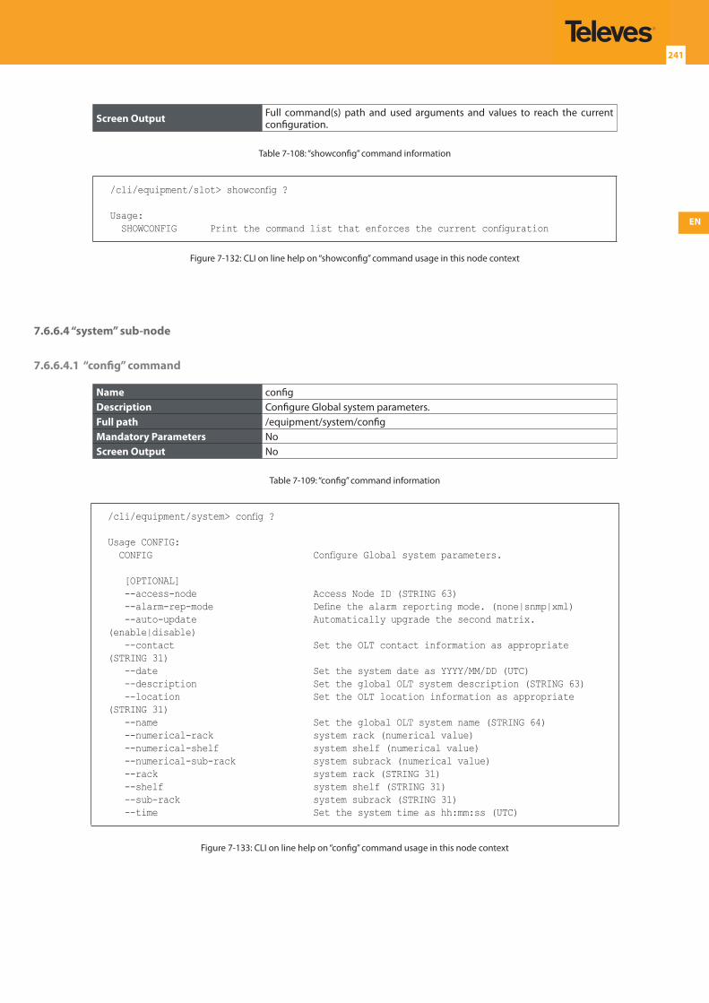
EN
241
Screen Output Full command(s) path and used arguments and values to reach the current configuration.
Table 7-108: “showconfig” command information
/cli/equipment/slot> showconfig ?
Usage: SHOWCONFIG Print the command list that enforces the current configuration
Figure 7-132: CLI on line help on “showconfig” command usage in this node context
7.6.6.4 “system” sub-node
7.6.6.4.1 “config” command
Name configDescription Configure Global system parameters.Full path /equipment/system/configMandatory Parameters NoScreen Output No
Table 7-109: “config” command information
/cli/equipment/system> config ?
Usage CONFIG: CONFIG Configure Global system parameters.
[OPTIONAL] --access-node Access Node ID (STRING 63) --alarm-rep-mode Define the alarm reporting mode. (none|snmp|xml) --auto-update Automatically upgrade the second matrix. (enable|disable) --contact Set the OLT contact information as appropriate (STRING 31) --date Set the system date as YYYY/MM/DD (UTC) --description Set the global OLT system description (STRING 63) --location Set the OLT location information as appropriate (STRING 31) --name Set the global OLT system name (STRING 64) --numerical-rack system rack (numerical value) --numerical-shelf system shelf (numerical value) --numerical-sub-rack system subrack (numerical value) --rack system rack (STRING 31) --shelf system shelf (STRING 31) --sub-rack system subrack (STRING 31) --time Set the system time as hh:mm:ss (UTC)
Figure 7-133: CLI on line help on “config” command usage in this node context
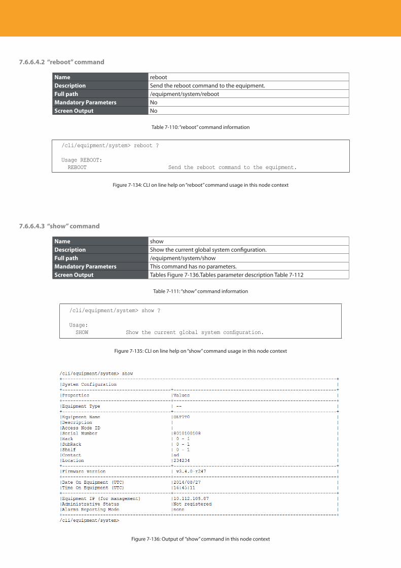
Descripción del producto
242
7.6.6.4.2 “reboot” command
Name rebootDescription Send the reboot command to the equipment.Full path /equipment/system/rebootMandatory Parameters NoScreen Output No
Table 7-110: “reboot” command information
/cli/equipment/system> reboot ?
Usage REBOOT: REBOOT Send the reboot command to the equipment.
Figure 7-134: CLI on line help on “reboot” command usage in this node context
7.6.6.4.3 “show” command
Name showDescription Show the current global system configuration.Full path /equipment/system/showMandatory Parameters This command has no parameters.Screen Output Tables Figure 7-136.Tables parameter description Table 7-112
Table 7-111: “show” command information
/cli/equipment/system> show ?
Usage: SHOW Show the current global system configuration.
Figure 7-135: CLI on line help on “show” command usage in this node context
Figure 7-136: Output of ”show” command in this node context
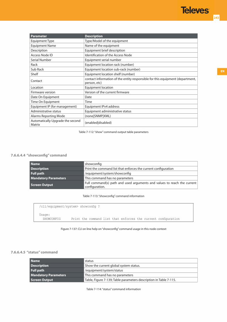
EN
243
Parameter DescriptionEquipment Type Type/Model of the equipment Equipment Name Name of the equipmentDescription Equipment brief descriptionAccess Node ID Identification of the Access NodeSerial Number Equipment serial numberRack Equipment location rack (number)Sub Rack Equipment location sub-rack (number)Shelf Equipment location shelf (number)
Contact contact information of the entity responsible for this equipment (department, person, etc)
Location Equipment locationFirmware version Version of the current firmwareDate On Equipment DateTime On Equipment TimeEquipment IP (for management) Equipment IPv4 addressAdministrative status Equipment administrative statusAlarms Reporting Mode (none|SNMP|XML)Automatically Upgrade the second Matrix (enabled|disabled)
Table 7-112: “show” command output table parameters
7.6.6.4.4 “showconfig” command
Name showconfigDescription Print the command list that enforces the current configurationFull path /equipment/system/showconfigMandatory Parameters This command has no parameters
Screen Output Full command(s) path and used arguments and values to reach the current configuration.
Table 7-113: “showconfig” command information
/cli/equipment/system> showconfig ?
Usage: SHOWCONFIG Print the command list that enforces the current configuration
Figure 7-137: CLI on line help on “showconfig” command usage in this node context
7.6.6.4.5 “status” command
Name statusDescription Show the current global system status.Full path /equipment/system/statusMandatory Parameters This command has no parametersScreen Output Table, Figure 7-139; Table parameters description in Table 7-115.
Table 7-114: “status” command information
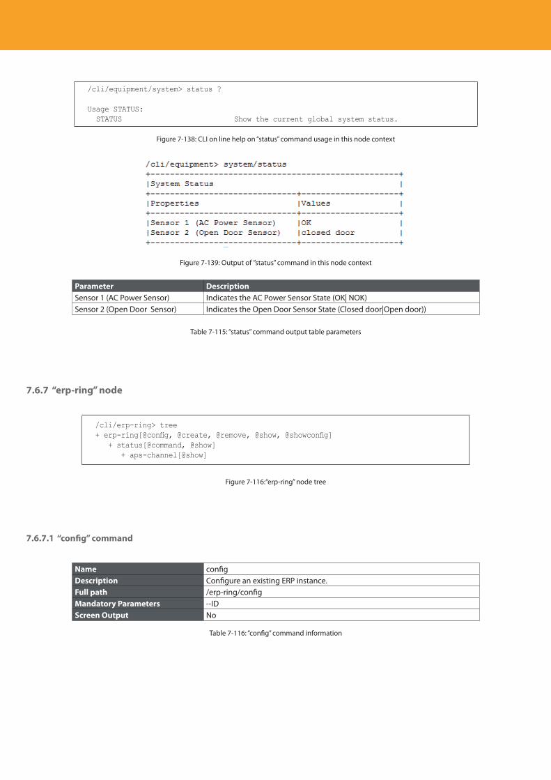
Descripción del producto
244
/cli/equipment/system> status ?
Usage STATUS: STATUS Show the current global system status.
Figure 7-138: CLI on line help on “status” command usage in this node context
Figure 7-139: Output of ”status” command in this node context
Parameter DescriptionSensor 1 (AC Power Sensor) Indicates the AC Power Sensor State (OK| NOK)Sensor 2 (Open Door Sensor) Indicates the Open Door Sensor State (Closed door|Open door))
Table 7-115: “status” command output table parameters
7.6.7 “erp-ring” node
/cli/erp-ring> tree+ erp-ring[@config, @create, @remove, @show, @showconfig] + status[@command, @show] + aps-channel[@show]
Figure 7-116:“erp-ring” node tree
7.6.7.1 “config” command
Name configDescription Configure an existing ERP instance.Full path /erp-ring/configMandatory Parameters --IDScreen Output No
Table 7-116: “config” command information
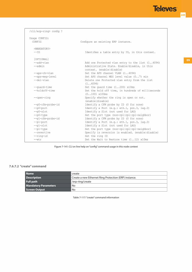
EN
245
/cli/erp-ring> config ?
Usage CONFIG: CONFIG Configure an existing ERP instance.
<MANDATORY> --ID Identifies a table entry by ID, in this context.
[OPTIONAL] --add-vlan Add one Protected vlan entry to the list (1..4094) --admin Administrative State. Enable/disable, in this
context. (enable|disable) --aps-ch-vlan Set the APS channel VLAN (1..4094) --aps-meg-level Set APS channel MEG level value (0..7) min --del-vlan Delete one Protected vlan entry from the list
(1..4094) --guard-time Set the guard time (1..200) x10ms --holdoff-time Set the hold off time, in hundreds of milliseconds
(0..100) x100ms --open-ring Specify whether the ring is open or not.
(enable|disable) --p0-cfm-probe-id Identify a CFM probe by ID (0 for none) --p0-port Identify a Port (e.g.: eth.1, pon.3, lag.2) --p0-slot Identify a Slot (not used for LAG) --p0-type Set the port type (non-rpl|rpl|rpl-neighbor) --p1-cfm-probe-id Identify a CFM probe by ID (0 for none) --p1-port Identify a Port (e.g.: eth.1, pon.3, lag.2) --p1-slot Identify a Slot (not used for LAG) --p1-type Set the port type (non-rpl|rpl|rpl-neighbor) --revertive Specify is reversion is enabled. (enable|disable) --ring-id Set the ring ID --wtr Set the Wait to Restore time (1..12) x10ms
Figure 7-141: CLI on line help on “config” command usage in this node context
7.6.7.2 “create” command
Name createDescription Create a new Ethernet Ring Protection (ERP) instance.Full path /erp-ring/createMandatory Parameters NoScreen Output No
Table 7-117: “create” command information
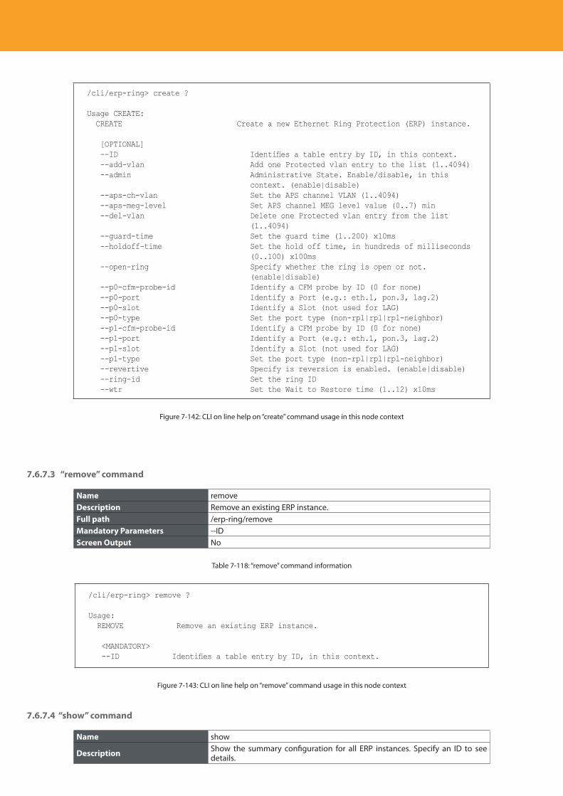
Descripción del producto
246
/cli/erp-ring> create ?
Usage CREATE: CREATE Create a new Ethernet Ring Protection (ERP) instance.
[OPTIONAL] --ID Identifies a table entry by ID, in this context. --add-vlan Add one Protected vlan entry to the list (1..4094) --admin Administrative State. Enable/disable, in this
context. (enable|disable) --aps-ch-vlan Set the APS channel VLAN (1..4094) --aps-meg-level Set APS channel MEG level value (0..7) min --del-vlan Delete one Protected vlan entry from the list
(1..4094) --guard-time Set the guard time (1..200) x10ms --holdoff-time Set the hold off time, in hundreds of milliseconds
(0..100) x100ms --open-ring Specify whether the ring is open or not.
(enable|disable) --p0-cfm-probe-id Identify a CFM probe by ID (0 for none) --p0-port Identify a Port (e.g.: eth.1, pon.3, lag.2) --p0-slot Identify a Slot (not used for LAG) --p0-type Set the port type (non-rpl|rpl|rpl-neighbor) --p1-cfm-probe-id Identify a CFM probe by ID (0 for none) --p1-port Identify a Port (e.g.: eth.1, pon.3, lag.2) --p1-slot Identify a Slot (not used for LAG) --p1-type Set the port type (non-rpl|rpl|rpl-neighbor) --revertive Specify is reversion is enabled. (enable|disable) --ring-id Set the ring ID --wtr Set the Wait to Restore time (1..12) x10ms
Figure 7-142: CLI on line help on “create” command usage in this node context
7.6.7.3 “remove” command
Name removeDescription Remove an existing ERP instance.Full path /erp-ring/removeMandatory Parameters --IDScreen Output No
Table 7-118: “remove” command information
/cli/erp-ring> remove ?
Usage: REMOVE Remove an existing ERP instance.
<MANDATORY> --ID Identifies a table entry by ID, in this context.
Figure 7-143: CLI on line help on “remove” command usage in this node context
7.6.7.4 “show” command
Name show
Description Show the summary configuration for all ERP instances. Specify an ID to see details.
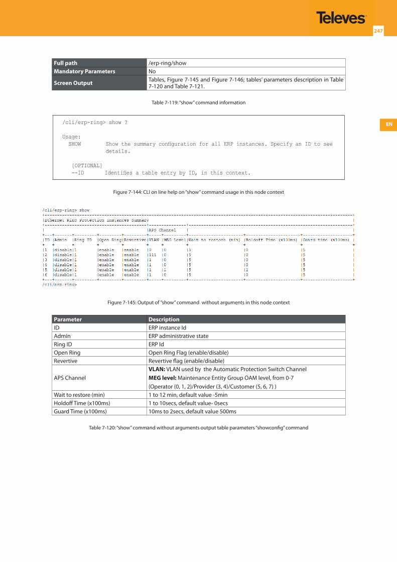
EN
247
Full path /erp-ring/showMandatory Parameters No
Screen Output Tables, Figure 7-145 and Figure 7-146; tables’ parameters description in Table 7-120 and Table 7-121.
Table 7-119: “show” command information
/cli/erp-ring> show ?
Usage: SHOW Show the summary configuration for all ERP instances. Specify an ID to see
details.
[OPTIONAL] --ID Identifies a table entry by ID, in this context.
Figure 7-144: CLI on line help on “show” command usage in this node context
Figure 7-145: Output of ”show” command without arguments in this node context
Parameter DescriptionID ERP instance IdAdmin ERP administrative stateRing ID ERP IdOpen Ring Open Ring Flag (enable/disable)Revertive Revertive flag (enable/disable)
APS ChannelVLAN: VLAN used by the Automatic Protection Switch ChannelMEG level: Maintenance Entity Group OAM level, from 0-7(Operator (0, 1, 2)/Provider (3, 4)/Customer (5, 6, 7) )
Wait to restore (min) 1 to 12 min, default value -5minHoldoff Time (x100ms) 1 to 10secs, default value- 0secsGuard Time (x100ms) 10ms to 2secs, default value 500ms
Table 7-120: “show” command without arguments output table parameters “showconfig” command
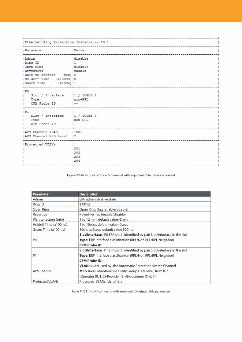
Descripción del producto
248
Figure 7-146: Output of ”show” command with argument ID in this node context
Parameter DescriptionAdmin ERP administrative stateRing ID ERP IdOpen Ring Open Ring Flag (enable/disable)Revertive Revertive flag (enable/disable)Wait to restore (min) 1 to 12 min, default value -5minHoldoff Time (x100ms) 1 to 10secs, default value- 0secsGuard Time (x100ms) 10ms to 2secs, default value 500ms
P0Slot/Interface : P0 ERP port , identified by pair Slot/interface in the slotType: ERP interface classification (RPL/Non RPL/RPL Neighbor)CFM Probe ID:
P1Slot/Interface : P1 ERP port , identified by pair Slot/interface in the slotType: ERP interface classification (RPL/Non RPL/RPL Neighbor)CFM Probe ID:
APS ChannelVLAN: VLAN used by the Automatic Protection Switch ChannelMEG level: Maintenance Entity Group OAM level, from 0-7(Operator (0, 1, 2)/Provider (3, 4)/Customer (5, 6, 7) )
Protected VLANs Protected VLANs’ Identifiers
Table 7-121: “show” command with argument ID output table parameters
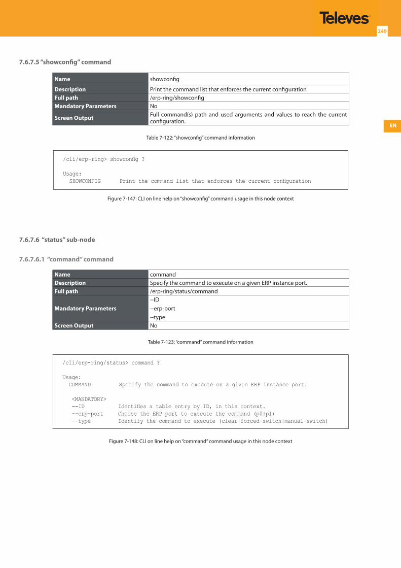
EN
249
7.6.7.5 “showconfig” command
Name showconfig
Description Print the command list that enforces the current configurationFull path /erp-ring/showconfigMandatory Parameters No
Screen Output Full command(s) path and used arguments and values to reach the current configuration.
Table 7-122: “showconfig” command information
/cli/erp-ring> showconfig ?
Usage: SHOWCONFIG Print the command list that enforces the current configuration
Figure 7-147: CLI on line help on “showconfig” command usage in this node context
7.6.7.6 “status” sub-node
7.6.7.6.1 “command” command
Name commandDescription Specify the command to execute on a given ERP instance port.Full path /erp-ring/status/command
Mandatory Parameters--ID--erp-port--type
Screen Output No
Table 7-123: “command” command information
/cli/erp-ring/status> command ?
Usage: COMMAND Specify the command to execute on a given ERP instance port.
<MANDATORY> --ID Identifies a table entry by ID, in this context. --erp-port Choose the ERP port to execute the command (p0|p1) --type Identify the command to execute (clear|forced-switch|manual-switch)
Figure 7-148: CLI on line help on “command” command usage in this node context
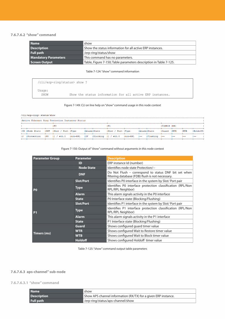
Descripción del producto
250
7.6.7.6.2 “show” command
Name showDescription Show the status information for all active ERP instances.Full path /erp-ring/status/showMandatory Parameters This command has no parameters.Screen Output Table, Figure 7-150; Table parameters description in Table 7-125.
Table 7-124: “show” command information
/cli/erp-ring/status> show ?
Usage: SHOW Show the status information for all active ERP instances.
Figure 7-149: CLI on line help on “show” command usage in this node context
Figure 7-150: Output of ”show” command without arguments in this node context
Parameter Group Parameter Description ID ERP instance Id (number) Node State Identifies node state Protection/--
DNF Do Not Flush – correspond to status DNF bit set when filtering database (FDB) flush is not necessary.
P0
Slot/Port Identifies P0 interface in the system by Slot/ Port pair
Type Identifies P0 interface protection classification (RPL/Non RPL/RPL Neighbor)
Alarm This alarm signals activity in the P0 interfaceState P0 Interface state (Blocking/Flushing)
P1
Slot/Port Identifies P1 interface in the system by Slot/ Port pair
Type Identifies P1 interface protection classification (RPL/Non RPL/RPL Neighbor)
Alarm This alarm signals activity in the P1 interfaceState P1 Interface state (Blocking/Flushing)
Timers (ms)
Guard Shows configured guard timer valueWTR Shows configured Wait to Restore timer valueWTB Shows configured Wait to Block timer valueHoldoff Shows configured Holdoff timer value
Table 7-125: “show” command output table parameters
7.6.7.6.3 aps-channel” sub-node
7.6.7.6.3.1 “show” command
Name showDescription Show APS channel information (RX/TX) for a given ERP instance.Full path /erp-ring/status/aps-channel/show
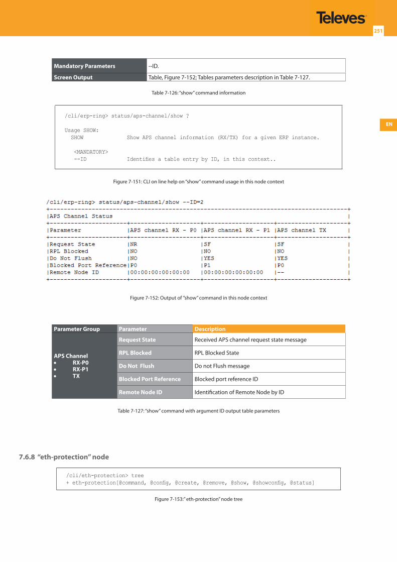
EN
251
Mandatory Parameters --ID.
Screen Output Table, Figure 7-152; Tables parameters description in Table 7-127.
Table 7-126: “show” command information
/cli/erp-ring> status/aps-channel/show ?
Usage SHOW: SHOW Show APS channel information (RX/TX) for a given ERP instance.
<MANDATORY> --ID Identifies a table entry by ID, in this context..
Figure 7-151: CLI on line help on “show” command usage in this node context
Figure 7-152: Output of ”show” command in this node context
Parameter Group Parameter Description
APS Channel• RX-P0• RX-P1• TX
Request State Received APS channel request state message
RPL Blocked RPL Blocked State
Do Not Flush Do not Flush message
Blocked Port Reference Blocked port reference ID
Remote Node ID Identification of Remote Node by ID
Table 7-127: “show” command with argument ID output table parameters
7.6.8 “eth-protection” node
/cli/eth-protection> tree+ eth-protection[@command, @config, @create, @remove, @show, @showconfig, @status]
Figure 7-153:” eth-protection” node tree
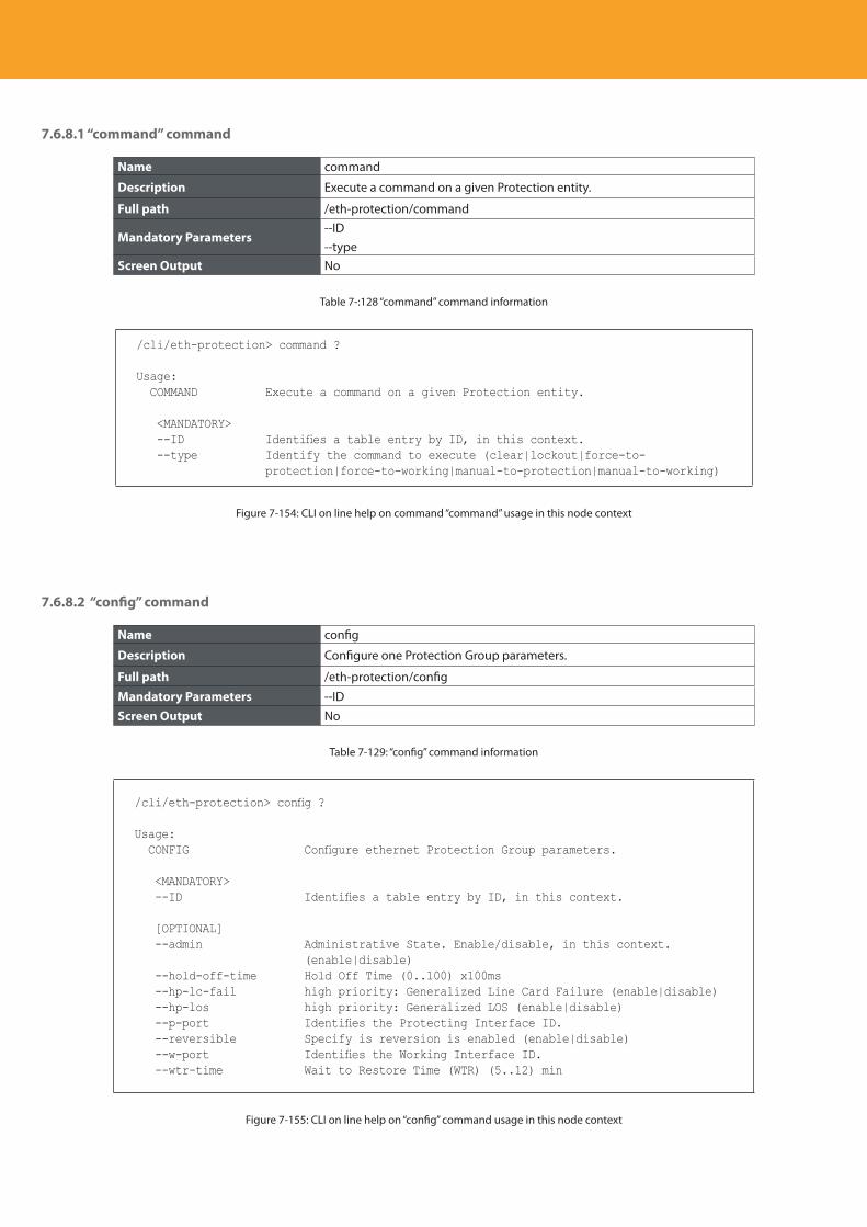
Descripción del producto
252
7.6.8.1 “command” command
Name command
Description Execute a command on a given Protection entity.
Full path /eth-protection/command
Mandatory Parameters--ID--type
Screen Output No
Table 7-:128 “command” command information
/cli/eth-protection> command ?
Usage: COMMAND Execute a command on a given Protection entity.
<MANDATORY> --ID Identifies a table entry by ID, in this context. --type Identify the command to execute (clear|lockout|force-to-
protection|force-to-working|manual-to-protection|manual-to-working)
Figure 7-154: CLI on line help on command “command” usage in this node context
7.6.8.2 “config” command
Name config
Description Configure one Protection Group parameters.
Full path /eth-protection/config
Mandatory Parameters --IDScreen Output No
Table 7-129: “config” command information
/cli/eth-protection> config ?
Usage: CONFIG Configure ethernet Protection Group parameters.
<MANDATORY> --ID Identifies a table entry by ID, in this context.
[OPTIONAL] --admin Administrative State. Enable/disable, in this context.
(enable|disable) --hold-off-time Hold Off Time (0..100) x100ms --hp-lc-fail high priority: Generalized Line Card Failure (enable|disable) --hp-los high priority: Generalized LOS (enable|disable) --p-port Identifies the Protecting Interface ID. --reversible Specify is reversion is enabled (enable|disable) --w-port Identifies the Working Interface ID. --wtr-time Wait to Restore Time (WTR) (5..12) min
Figure 7-155: CLI on line help on “config” command usage in this node context
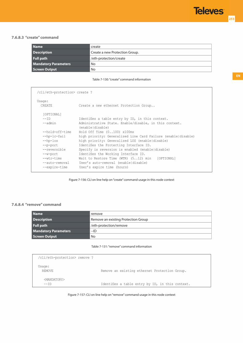
EN
253
7.6.8.3 “create” command
Name create
Description Create a new Protection Group.
Full path /eth-protection/create
Mandatory Parameters NoScreen Output No
Table 7-130: “create” command information
/cli/eth-protection> create ?
Usage: CREATE Create a new ethernet Protection Group..
[OPTIONAL] --ID Identifies a table entry by ID, in this context. --admin Administrative State. Enable/disable, in this context.
(enable|disable) --hold-off-time Hold Off Time (0..100) x100ms --hp-lc-fail high priority: Generalized Line Card Failure (enable|disable) --hp-los high priority: Generalized LOS (enable|disable) --p-port Identifies the Protecting Interface ID. --reversible Specify is reversion is enabled (enable|disable) --w-port Identifies the Working Interface ID. --wtr-time Wait to Restore Time (WTR) (5..12) min [OPTIONAL] --auto-removal User’s auto-removal (enable|disable) --expire-time User’s expire time (hours)
Figure 7-156: CLI on line help on “create” command usage in this node context
7.6.8.4 “remove” command
Name remove
Description Remove an existing Protection Group
Full path /eth-protection/remove
Mandatory Parameters --IDScreen Output No
Table 7-131: “remove” command information
/cli/eth-protection> remove ?
Usage: REMOVE Remove an existing ethernet Protection Group.
<MANDATORY> --ID Identifies a table entry by ID, in this context.
Figure 7-157: CLI on line help on “remove” command usage in this node context
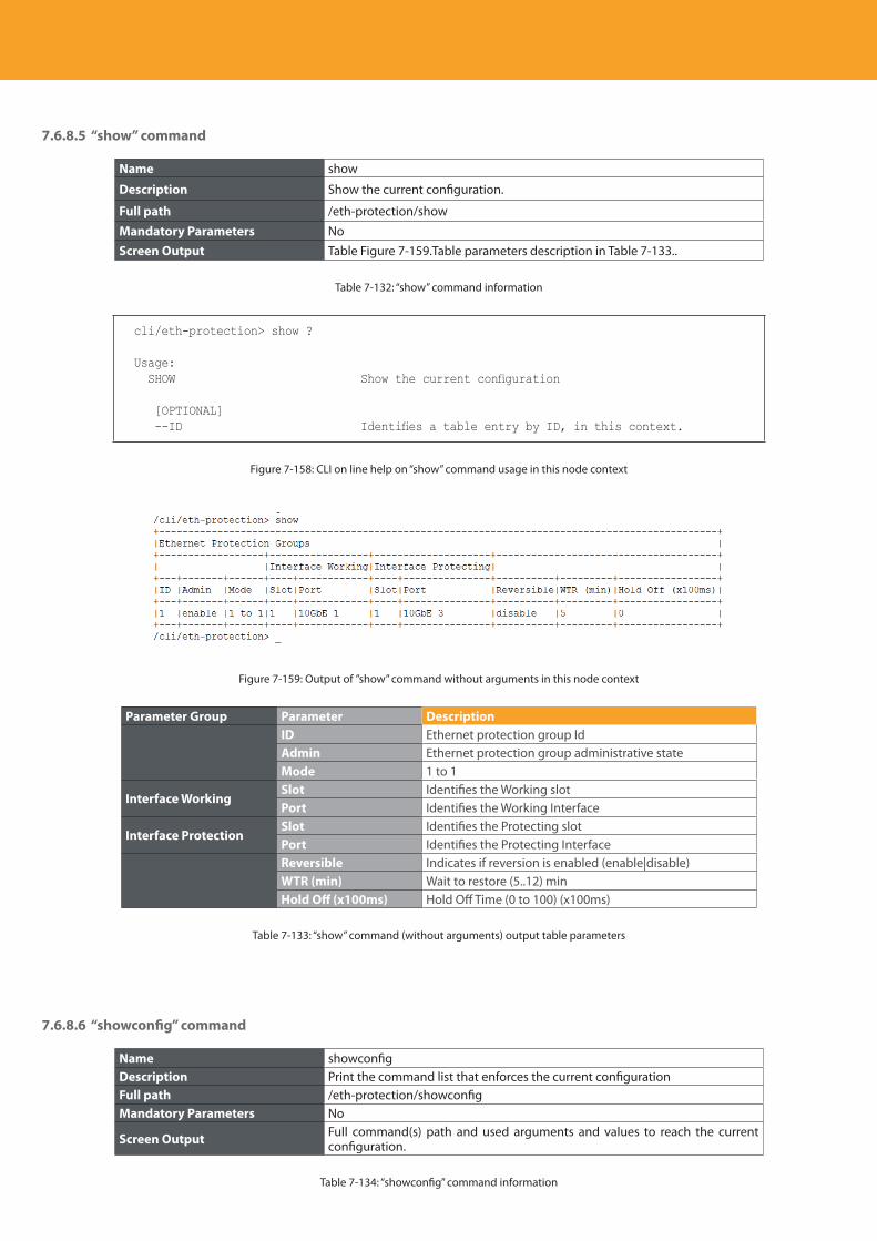
Descripción del producto
254
7.6.8.5 “show” command
Name show
Description Show the current configuration.
Full path /eth-protection/show
Mandatory Parameters NoScreen Output Table Figure 7-159.Table parameters description in Table 7-133..
Table 7-132: “show” command information
cli/eth-protection> show ?
Usage: SHOW Show the current configuration
[OPTIONAL] --ID Identifies a table entry by ID, in this context.
Figure 7-158: CLI on line help on “show” command usage in this node context
Figure 7-159: Output of ”show” command without arguments in this node context
Parameter Group Parameter DescriptionID Ethernet protection group IdAdmin Ethernet protection group administrative stateMode 1 to 1
Interface WorkingSlot Identifies the Working slotPort Identifies the Working Interface
Interface ProtectionSlot Identifies the Protecting slotPort Identifies the Protecting InterfaceReversible Indicates if reversion is enabled (enable|disable)WTR (min) Wait to restore (5..12) min Hold Off (x100ms) Hold Off Time (0 to 100) (x100ms)
Table 7-133: “show” command (without arguments) output table parameters
7.6.8.6 “showconfig” command
Name showconfigDescription Print the command list that enforces the current configurationFull path /eth-protection/showconfigMandatory Parameters No
Screen Output Full command(s) path and used arguments and values to reach the current configuration.
Table 7-134: “showconfig” command information
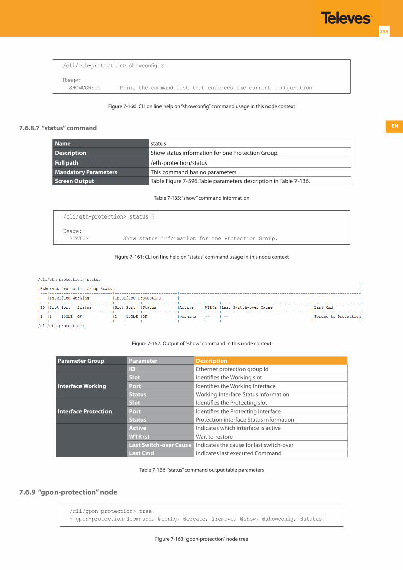
EN
255
/cli/eth-protection> showconfig ?
Usage: SHOWCONFIG Print the command list that enforces the current configuration
Figure 7-160: CLI on line help on “showconfig” command usage in this node context
7.6.8.7 “status” command
Name status
Description Show status information for one Protection Group.
Full path /eth-protection/status
Mandatory Parameters This command has no parametersScreen Output Table Figure 7-596.Table parameters description in Table 7-136.
Table 7-135: “show” command information
/cli/eth-protection> status ?
Usage: STATUS Show status information for one Protection Group.
Figure 7-161: CLI on line help on “status” command usage in this node context
Figure 7-162: Output of ”show” command in this node context
Parameter Group Parameter DescriptionID Ethernet protection group Id
Interface WorkingSlot Identifies the Working slotPort Identifies the Working InterfaceStatus Working interface Status information
Interface ProtectionSlot Identifies the Protecting slotPort Identifies the Protecting InterfaceStatus Protection interface Status informationActive Indicates which interface is activeWTR (s) Wait to restore Last Switch-over Cause Indicates the cause for last switch-overLast Cmd Indicates last executed Command
Table 7-136: “status” command output table parameters
7.6.9 “gpon-protection” node
/cli/gpon-protection> tree+ gpon-protection[@command, @config, @create, @remove, @show, @showconfig, @status]
Figure 7-163:“gpon-protection” node tree
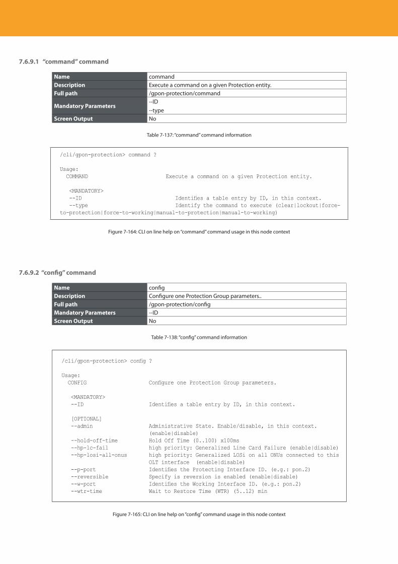
Descripción del producto
256
7.6.9.1 “command” command
Name commandDescription Execute a command on a given Protection entity.Full path /gpon-protection/command
Mandatory Parameters--ID--type
Screen Output No
Table 7-137: “command” command information
/cli/gpon-protection> command ?
Usage: COMMAND Execute a command on a given Protection entity.
<MANDATORY> --ID Identifies a table entry by ID, in this context. --type Identify the command to execute (clear|lockout|force-to-protection|force-to-working|manual-to-protection|manual-to-working)
Figure 7-164: CLI on line help on “command” command usage in this node context
7.6.9.2 “config” command
Name configDescription Configure one Protection Group parameters..Full path /gpon-protection/configMandatory Parameters --IDScreen Output No
Table 7-138: “config” command information
/cli/gpon-protection> config ?
Usage: CONFIG Configure one Protection Group parameters.
<MANDATORY> --ID Identifies a table entry by ID, in this context.
[OPTIONAL] --admin Administrative State. Enable/disable, in this context.
(enable|disable) --hold-off-time Hold Off Time (0..100) x100ms --hp-lc-fail high priority: Generalized Line Card Failure (enable|disable) --hp-losi-all-onus high priority: Generalized LOSi on all ONUs connected to this
OLT interface (enable|disable) --p-port Identifies the Protecting Interface ID. (e.g.: pon.2) --reversible Specify is reversion is enabled (enable|disable) --w-port Identifies the Working Interface ID. (e.g.: pon.2) --wtr-time Wait to Restore Time (WTR) (5..12) min
Figure 7-165: CLI on line help on “config” command usage in this node context
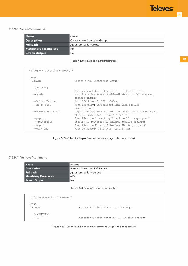
EN
257
7.6.9.3 “create” command
Name create
Description Create a new Protection Group.
Full path /gpon-protection/create
Mandatory Parameters No
Screen Output No
Table 7-139: “create” command information
/cli/gpon-protection> create ?
Usage: CREATE Create a new Protection Group.
[OPTIONAL] --ID Identifies a table entry by ID, in this context. --admin Administrative State. Enable/disable, in this context.
(enable|disable) --hold-off-time Hold Off Time (0..100) x100ms --hp-lc-fail high priority: Generalized Line Card Failure
enable|disable) --hp-losi-all-onus high priority: Generalized LOSi on all ONUs connected to
this OLT interface (enable|disable) --p-port Identifies the Protecting Interface ID. (e.g.: pon.2) --reversible Specify is reversion is enabled (enable|disable) --w-port Identifies the Working Interface ID. (e.g.: pon.2) --wtr-time Wait to Restore Time (WTR) (5..12) min
Figure 7-166: CLI on line help on “create” command usage in this node context
7.6.9.4 “remove” command
Name removeDescription Remove an existing ERP instance.Full path /gpon-protection/removeMandatory Parameters --IDScreen Output No
Table 7-140: “remove” command information
cli/gpon-protection> remove ?
Usage: REMOVE Remove an existing Protection Group.
<MANDATORY> --ID Identifies a table entry by ID, in this context.
Figure 7-167: CLI on line help on “remove” command usage in this node context
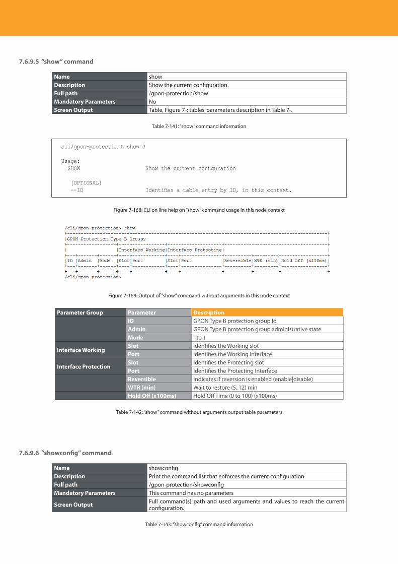
Descripción del producto
258
7.6.9.5 “show” command
Name showDescription Show the current configuration.Full path /gpon-protection/showMandatory Parameters NoScreen Output Table, Figure 7-; tables’ parameters description in Table 7-.
Table 7-141: “show” command information
cli/gpon-protection> show ?
Usage: SHOW Show the current configuration
[OPTIONAL] --ID Identifies a table entry by ID, in this context.
Figure 7-168: CLI on line help on “show” command usage in this node context
Figure 7-169: Output of ”show” command without arguments in this node context
Parameter Group Parameter DescriptionID GPON Type B protection group IdAdmin GPON Type B protection group administrative stateMode 1to 1
Interface WorkingSlot Identifies the Working slotPort Identifies the Working Interface
Interface ProtectionSlot Identifies the Protecting slotPort Identifies the Protecting InterfaceReversible Indicates if reversion is enabled (enable|disable)WTR (min) Wait to restore (5..12) min Hold Off (x100ms) Hold Off Time (0 to 100) (x100ms)
Table 7-142: “show” command without arguments output table parameters
7.6.9.6 “showconfig” command
Name showconfigDescription Print the command list that enforces the current configurationFull path /gpon-protection/showconfigMandatory Parameters This command has no parameters
Screen Output Full command(s) path and used arguments and values to reach the current configuration.
Table 7-143: “showconfig” command information
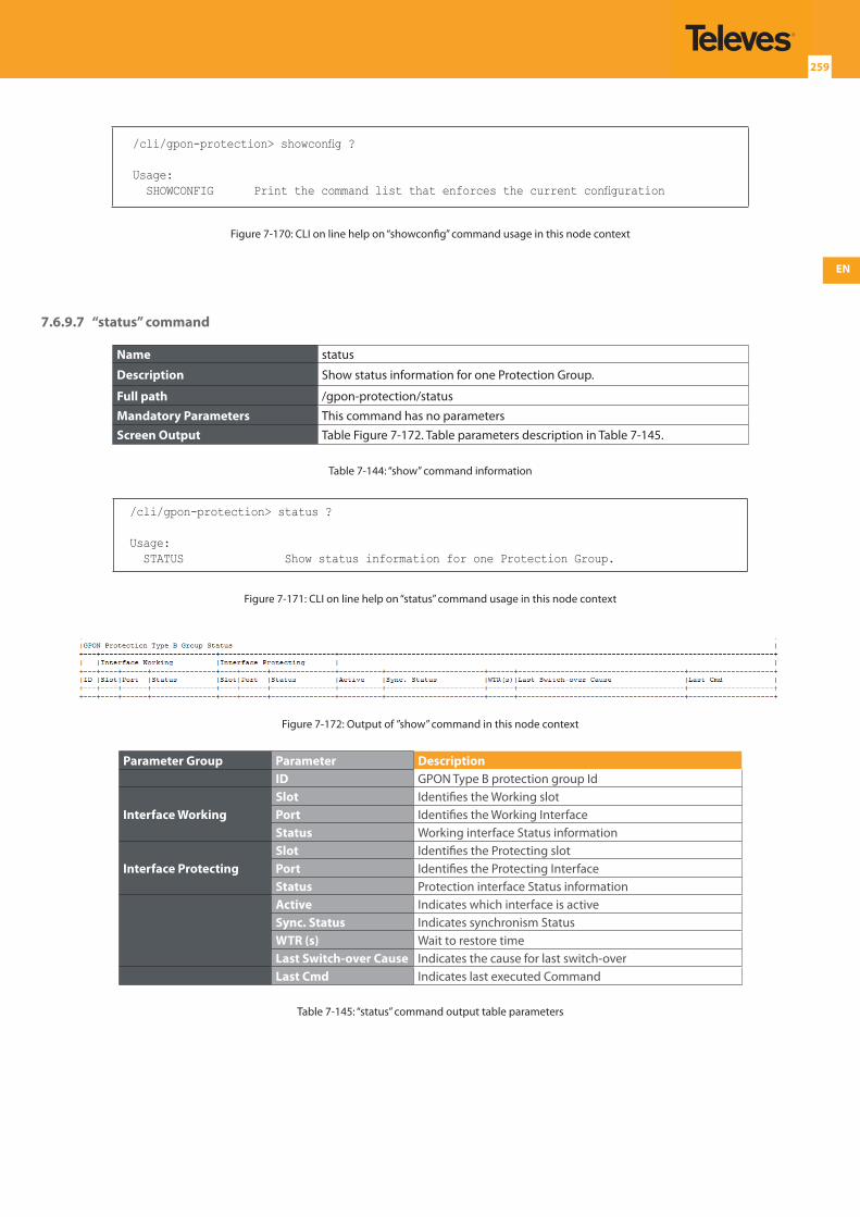
EN
259
/cli/gpon-protection> showconfig ?
Usage: SHOWCONFIG Print the command list that enforces the current configuration
Figure 7-170: CLI on line help on “showconfig” command usage in this node context
7.6.9.7 “status” command
Name status
Description Show status information for one Protection Group.
Full path /gpon-protection/status
Mandatory Parameters This command has no parametersScreen Output Table Figure 7-172. Table parameters description in Table 7-145.
Table 7-144: “show” command information
/cli/gpon-protection> status ?
Usage: STATUS Show status information for one Protection Group.
Figure 7-171: CLI on line help on “status” command usage in this node context
Figure 7-172: Output of ”show” command in this node context
Parameter Group Parameter DescriptionID GPON Type B protection group Id
Interface WorkingSlot Identifies the Working slotPort Identifies the Working InterfaceStatus Working interface Status information
Interface ProtectingSlot Identifies the Protecting slotPort Identifies the Protecting InterfaceStatus Protection interface Status informationActive Indicates which interface is activeSync. Status Indicates synchronism StatusWTR (s) Wait to restore time Last Switch-over Cause Indicates the cause for last switch-overLast Cmd Indicates last executed Command
Table 7-145: “status” command output table parameters
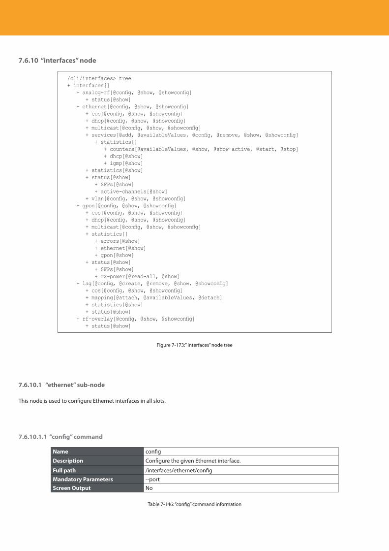
Descripción del producto
260
7.6.10 “interfaces” node
/cli/interfaces> tree+ interfaces[] + analog-rf[@config, @show, @showconfig] + status[@show] + ethernet[@config, @show, @showconfig] + cos[@config, @show, @showconfig] + dhcp[@config, @show, @showconfig] + multicast[@config, @show, @showconfig] + services[@add, @availableValues, @config, @remove, @show, @showconfig] + statistics[] + counters[@availableValues, @show, @show-active, @start, @stop] + dhcp[@show] + igmp[@show] + statistics[@show] + status[@show] + SFPs[@show] + active-channels[@show] + vlan[@config, @show, @showconfig] + gpon[@config, @show, @showconfig] + cos[@config, @show, @showconfig] + dhcp[@config, @show, @showconfig] + multicast[@config, @show, @showconfig] + statistics[] + errors[@show] + ethernet[@show] + gpon[@show] + status[@show] + SFPs[@show] + rx-power[@read-all, @show] + lag[@config, @create, @remove, @show, @showconfig] + cos[@config, @show, @showconfig] + mapping[@attach, @availableValues, @detach] + statistics[@show] + status[@show] + rf-overlay[@config, @show, @showconfig] + status[@show]
Figure 7-173:” Interfaces” node tree
7.6.10.1 “ethernet” sub-node
This node is used to configure Ethernet interfaces in all slots.
7.6.10.1.1 “config” command
Name config
Description Configure the given Ethernet interface.
Full path /interfaces/ethernet/config
Mandatory Parameters --portScreen Output No
Table 7-146: “config” command information
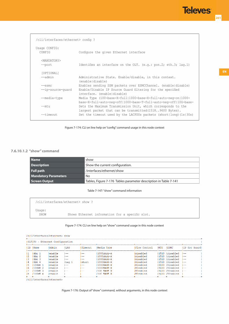
EN
261
/cli/interfaces/ethernet> config ?
Usage CONFIG: CONFIG Configure the given Ethernet interface
<MANDATORY> --port Identifies an interface on the OLT. (e.g.: pon.2; eth.3; lag.1)
[OPTIONAL] --admin Administrative State. Enable/disable, in this context.
(enable|disable) --esmc Enables sending SSM packets over ESMCChannel. (enable|disable) --ip-source-guard Enable/Disable IP Source Guard filtering for the specified
interface. (enable|disable) --media-type Media Type (100-base-X-full|1000-base-X-full-auto-neg-on|1000-
base-X-full-auto-neg-off|1000-base-T-full-auto-neg-off|10G-base- --mtu Sets the Maximum Transmission Unit, which corresponds to the
largest packet that can be transmitted(1518..9600 Bytes). --timeout Set the timeout used by the LACPDUs packets (short|long)(1s|30s)
Figure 7-174: CLI on line help on “config” command usage in this node context
7.6.10.1.2 “show” command
Name show
Description Show the current configuration.
Full path /interfaces/ethernet/show
Mandatory Parameters NoScreen Output Tables, Figure 7-176 Tables parameter description in Table 7-141
Table 7-147: “show” command information
/cli/interfaces/ethernet> show ?
Usage: SHOW Shows Ethernet information for a specific slot.
Figure 7-174: CLI on line help on “show” command usage in this node context
Figure 7-176: Output of “show” command, without arguments, in this node context
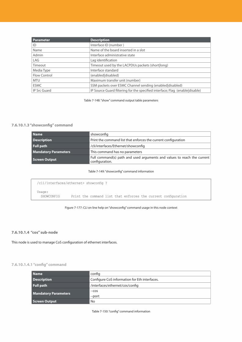
Descripción del producto
262
Parameter DescriptionID Interface ID (number )Name Name of the board inserted in a slotAdmin Interface administrative stateLAG Lag identificationTimeout Timeout used by the LACPDUs packets (short|long)Media Type Interface standardFlow Control (enabled|disabled)MTU Maximum transfer unit (number)ESMC SSM packets over ESMC Channel sending (enabled|disabled)IP Src Guard IP Source Guard filtering for the specified interface; Flag (enable|disable)
Table 7-148: “show” command output table parameters
7.6.10.1.3 “showconfig” command
Name showconfig
Description Print the command list that enforces the current configuration
Full path /cli/interfaces/Ethernet/showconfig
Mandatory Parameters This command has no parameters
Screen Output Full command(s) path and used arguments and values to reach the current configuration.
Table 7-149: “showconfig” command information
/cli/interfaces/ethernet> showconfig ?
Usage: SHOWCONFIG Print the command list that enforces the current configuration
Figure 7-177: CLI on line help on “showconfig” command usage in this node context
7.6.10.1.4 “cos” sub-node
This node is used to manage CoS configuration of ethernet interfaces.
7.6.10.1.4.1 “config” command
Name config
Description Configure CoS information for Eth interfaces.
Full path /interfaces/ethernet/cos/config
Mandatory Parameters--cos--port
Screen Output No
Table 7-150: “config” command information
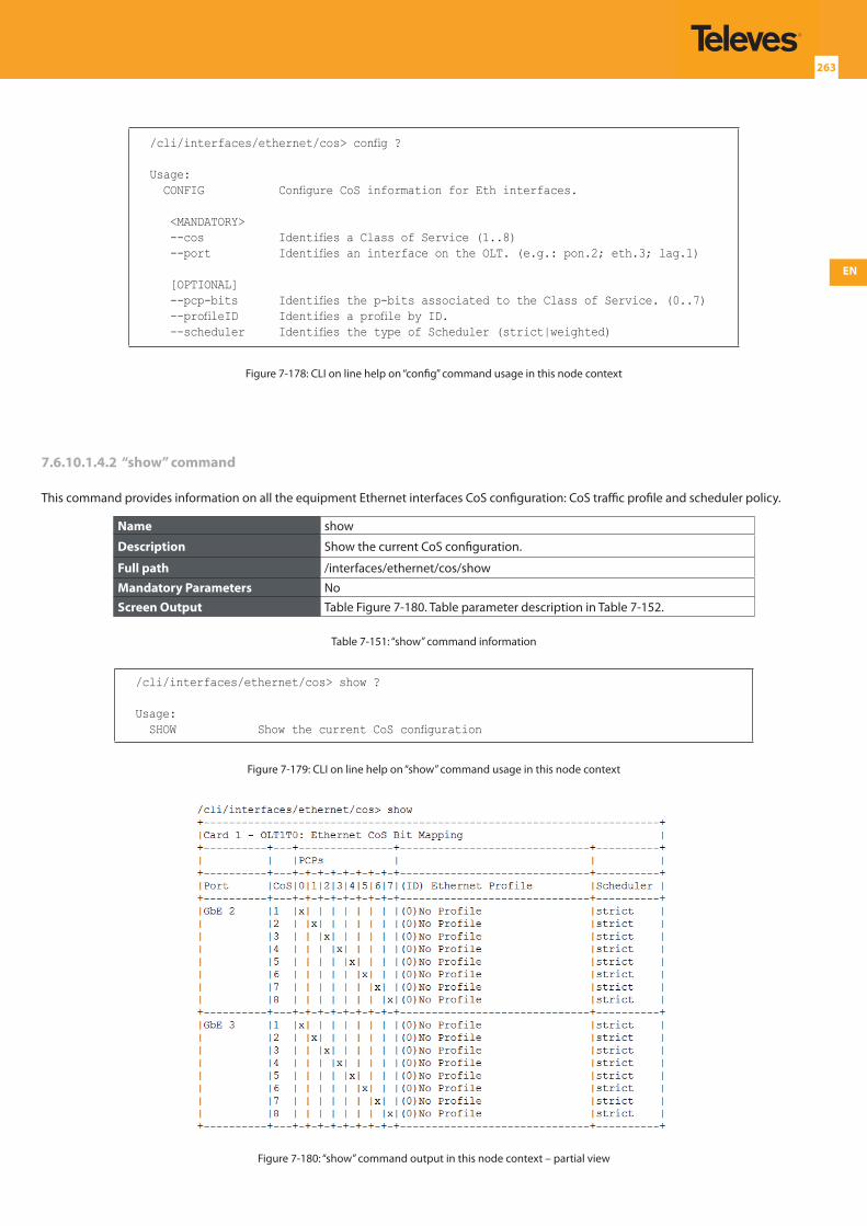
EN
263
/cli/interfaces/ethernet/cos> config ?
Usage: CONFIG Configure CoS information for Eth interfaces.
<MANDATORY> --cos Identifies a Class of Service (1..8) --port Identifies an interface on the OLT. (e.g.: pon.2; eth.3; lag.1)
[OPTIONAL] --pcp-bits Identifies the p-bits associated to the Class of Service. (0..7) --profileID Identifies a profile by ID. --scheduler Identifies the type of Scheduler (strict|weighted)
Figure 7-178: CLI on line help on “config” command usage in this node context
7.6.10.1.4.2 “show” command
This command provides information on all the equipment Ethernet interfaces CoS configuration: CoS traffic profile and scheduler policy.
Name show
Description Show the current CoS configuration.
Full path /interfaces/ethernet/cos/show
Mandatory Parameters NoScreen Output Table Figure 7-180. Table parameter description in Table 7-152.
Table 7-151: “show” command information
/cli/interfaces/ethernet/cos> show ?
Usage: SHOW Show the current CoS configuration
Figure 7-179: CLI on line help on “show” command usage in this node context
Figure 7-180: “show” command output in this node context – partial view
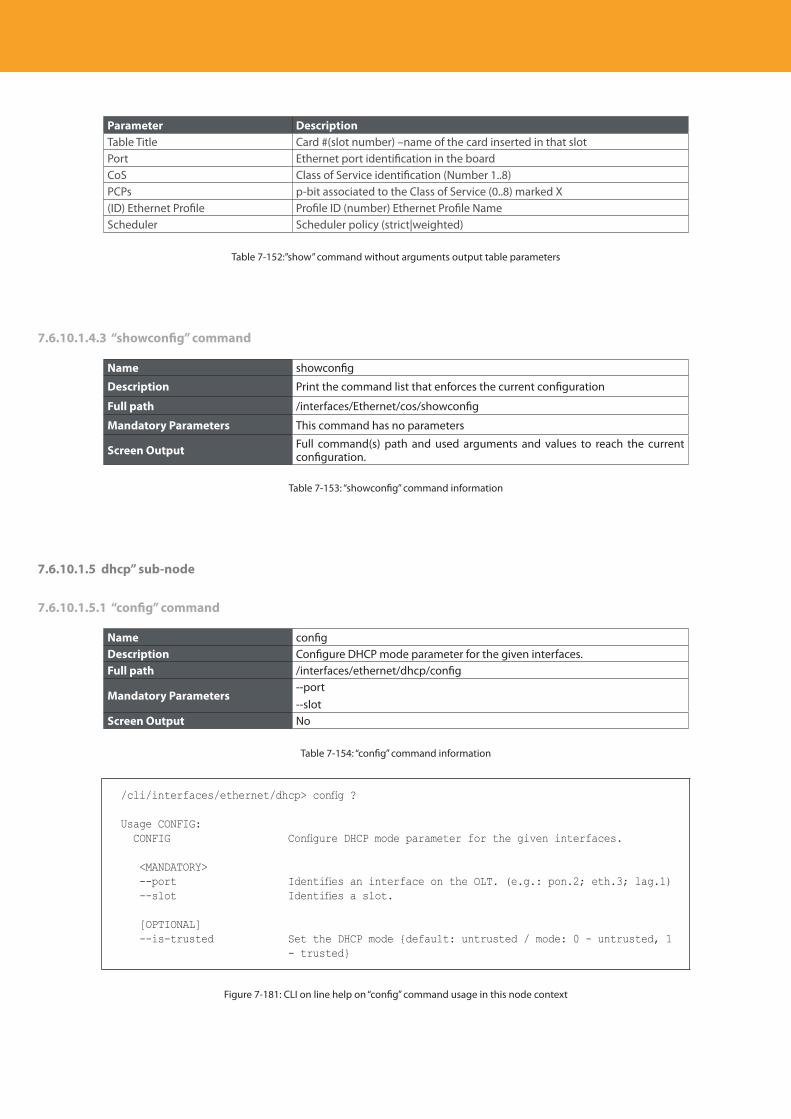
Descripción del producto
264
Parameter DescriptionTable Title Card #(slot number) –name of the card inserted in that slotPort Ethernet port identification in the boardCoS Class of Service identification (Number 1..8)PCPs p-bit associated to the Class of Service (0..8) marked X(ID) Ethernet Profile Profile ID (number) Ethernet Profile NameScheduler Scheduler policy (strict|weighted)
Table 7-152:”show” command without arguments output table parameters
7.6.10.1.4.3 “showconfig” command
Name showconfig
Description Print the command list that enforces the current configuration
Full path /interfaces/Ethernet/cos/showconfig
Mandatory Parameters This command has no parameters
Screen Output Full command(s) path and used arguments and values to reach the current configuration.
Table 7-153: “showconfig” command information
7.6.10.1.5 dhcp” sub-node
7.6.10.1.5.1 “config” command
Name configDescription Configure DHCP mode parameter for the given interfaces.Full path /interfaces/ethernet/dhcp/config
Mandatory Parameters--port--slot
Screen Output No
Table 7-154: “config” command information
/cli/interfaces/ethernet/dhcp> config ?
Usage CONFIG: CONFIG Configure DHCP mode parameter for the given interfaces.
<MANDATORY> --port Identifies an interface on the OLT. (e.g.: pon.2; eth.3; lag.1) --slot Identifies a slot.
[OPTIONAL] --is-trusted Set the DHCP mode {default: untrusted / mode: 0 - untrusted, 1
- trusted}
Figure 7-181: CLI on line help on “config” command usage in this node context
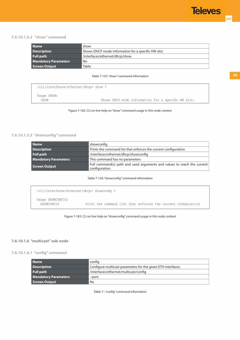
EN
265
7.6.10.1.5.2 “show” command
Name showDescription Shows DHCP mode information for a specific HW slot.Full path /interfaces/ethernet/dhcp/showMandatory Parameters NoScreen Output Table
Table 7-155: “show” command information
/cli/interfaces/ethernet/dhcp> show ?
Usage SHOW: SHOW Shows DHCP mode information for a specific HW slot.
Figure 7-182: CLI on line help on “show” command usage in this node context
7.6.10.1.5.3 “showconfig” command
Name showconfigDescription Prints the command list that enforces the current configurationFull path /interfaces/ethernet/dhcp/showconfigMandatory Parameters This command has no parameters
Screen Output Full command(s) path and used arguments and values to reach the current configuration.
Table 7-156: “showconfig” command information
/cli/interfaces/ethernet/dhcp> showconfig ?
Usage SHOWCONFIG: SHOWCONFIG Print the command list that enforces the current configuration
Figure 7-183: CLI on line help on “showconfig” command usage in this node context
7.6.10.1.6 “multicast” sub-node
7.6.10.1.6.1 “config” command
Name configDescription Configure multicast parameters for the given ETH interfaces.Full path /interfaces/ethernet/multicast/configMandatory Parameters --portScreen Output No
Table 7-: “config” command information
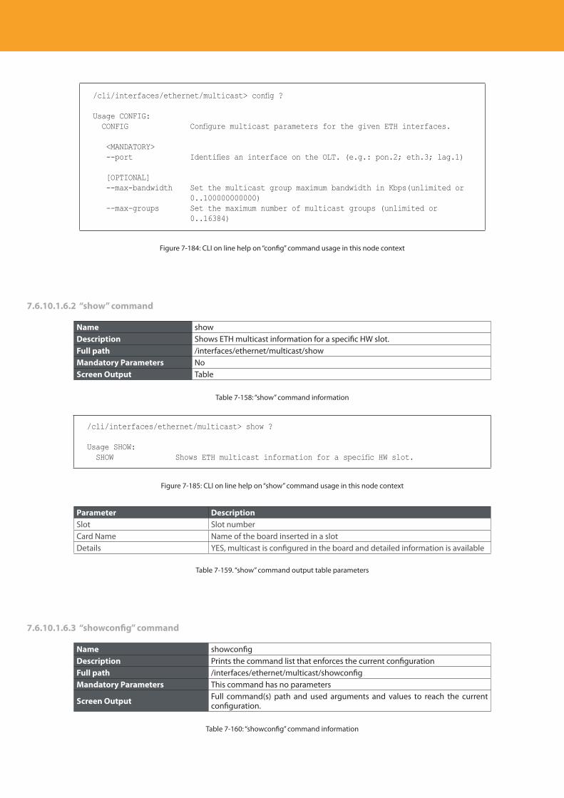
Descripción del producto
266
/cli/interfaces/ethernet/multicast> config ?
Usage CONFIG: CONFIG Configure multicast parameters for the given ETH interfaces.
<MANDATORY> --port Identifies an interface on the OLT. (e.g.: pon.2; eth.3; lag.1)
[OPTIONAL] --max-bandwidth Set the multicast group maximum bandwidth in Kbps(unlimited or
0..100000000000) --max-groups Set the maximum number of multicast groups (unlimited or
0..16384)
Figure 7-184: CLI on line help on “config” command usage in this node context
7.6.10.1.6.2 “show” command
Name showDescription Shows ETH multicast information for a specific HW slot.Full path /interfaces/ethernet/multicast/showMandatory Parameters NoScreen Output Table
Table 7-158: “show” command information
/cli/interfaces/ethernet/multicast> show ?
Usage SHOW: SHOW Shows ETH multicast information for a specific HW slot.
Figure 7-185: CLI on line help on “show” command usage in this node context
Parameter DescriptionSlot Slot numberCard Name Name of the board inserted in a slotDetails YES, multicast is configured in the board and detailed information is available
Table 7-159. “show” command output table parameters
7.6.10.1.6.3 “showconfig” command
Name showconfigDescription Prints the command list that enforces the current configurationFull path /interfaces/ethernet/multicast/showconfigMandatory Parameters This command has no parameters
Screen Output Full command(s) path and used arguments and values to reach the current configuration.
Table 7-160: “showconfig” command information
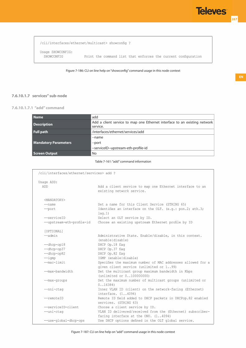
EN
267
/cli/interfaces/ethernet/multicast> showconfig ?
Usage SHOWCONFIG: SHOWCONFIG Print the command list that enforces the current configuration
Figure 7-186: CLI on line help on “showconfig” command usage in this node context
7.6.10.1.7 services” sub-node
7.6.10.1.7.1 “add” command
Name add
Description Add a client service to map one Ethernet interface to an existing network service.
Full path /interfaces/ethernet/services/add
Mandatory Parameters--name--port--serviceID--upstream-eth-profile-id
Screen Output No
Table 7-161: “add” command information
/cli/interfaces/ethernet/services> add ?
Usage ADD: ADD Add a client service to map one Ethernet interface to an
existing network service.
<MANDATORY> --name Set a name for this Client Service (STRING 65) --port Identifies an interface on the OLT. (e.g.: pon.2; eth.3;
lag.1) --serviceID Select an OLT service by ID. --upstream-eth-profile-id Choose an existing upstream Ethernet profile by ID
[OPTIONAL] --admin Administrative State. Enable/disable, in this context.
(enable|disable) --dhcp-op18 DHCP Op.18 flag --dhcp-op37 DHCP Op.37 flag --dhcp-op82 DHCP Op.82 flag --igmp IGMP (enable|disable) --mac-limit Specifies the maximum number of MAC addresses allowed for a
given client service (unlimited or 1..99) --max-bandwidth Set the multicast group maximum bandwidth in Kbps
(unlimited or 0..100000000) --max-groups Set the maximum number of multicast groups (unlimited or
0..16384) --nni-ctag Inner VLAN ID (client) on the network-facing (Ethernet)
interface. (1..4094) --remoteID Remote ID field added to DHCP packets in DHCPop.82 enabled
services. (STRING 63) --serviceID-client Choose a client service by ID. --uni-ctag VLAN ID delivered/received from the (Ethernet) subscriber-
facing interface at the ONU. (1..4094) --use-global-dhcp-ops Use DHCP options defined in the OLT global service.
Figure 7-187: CLI on line help on “add” command usage in this node context
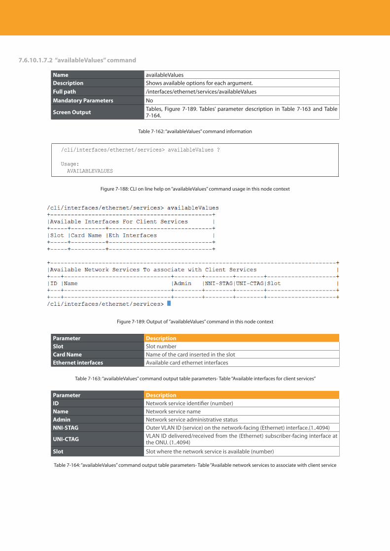
Descripción del producto
268
7.6.10.1.7.2 “availableValues” command
Name availableValuesDescription Shows available options for each argument.Full path /interfaces/ethernet/services/availableValues
Mandatory Parameters No
Screen Output Tables, Figure 7-189. Tables’ parameter description in Table 7-163 and Table 7-164.
Table 7-162: “availableValues” command information
/cli/interfaces/ethernet/services> availableValues ?
Usage: AVAILABLEVALUES
Figure 7-188: CLI on line help on “availableValues” command usage in this node context
Figure 7-189: Output of ”availableValues” command in this node context
Parameter DescriptionSlot Slot numberCard Name Name of the card inserted in the slotEthernet interfaces Available card ethernet interfaces
Table 7-163: “availableValues” command output table parameters- Table “Available interfaces for client services”
Parameter DescriptionID Network service identifier (number)Name Network service nameAdmin Network service administrative statusNNI-STAG Outer VLAN ID (service) on the network-facing (Ethernet) interface.(1..4094)
UNI-CTAG VLAN ID delivered/received from the (Ethernet) subscriber-facing interface at the ONU. (1..4094)
Slot Slot where the network service is available (number)
Table 7-164: “availableValues” command output table parameters- Table “Available network services to associate with client service
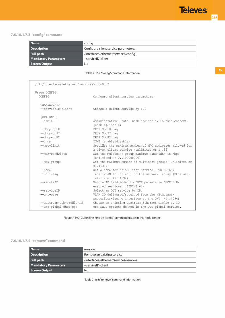
EN
269
7.6.10.1.7.3 “config” command
Name config
Description Configure client service parameters.
Full path /interfaces/ethernet/services/configMandatory Parameters --serviceID-clientScreen Output No
Table 7-165: “config” command information
/cli/interfaces/ethernet/services> config ?
Usage CONFIG: CONFIG Configure client service parameters.
<MANDATORY> --serviceID-client Choose a client service by ID.
[OPTIONAL] --admin Administrative State. Enable/disable, in this context.
(enable|disable) --dhcp-op18 DHCP Op.18 flag --dhcp-op37 DHCP Op.37 flag --dhcp-op82 DHCP Op.82 flag --igmp IGMP (enable|disable) --mac-limit Specifies the maximum number of MAC addresses allowed for
a given client service (unlimited or 1..99) --max-bandwidth Set the multicast group maximum bandwidth in Kbps
(unlimited or 0..100000000) --max-groups Set the maximum number of multicast groups (unlimited or
0..16384) --name Set a name for this Client Service (STRING 65) --nni-ctag Inner VLAN ID (client) on the network-facing (Ethernet)
interface. (1..4094) --remoteID Remote ID field added to DHCP packets in DHCPop.82
enabled services. (STRING 63) --serviceID Select an OLT service by ID. --uni-ctag VLAN ID delivered/received from the (Ethernet)
subscriber-facing interface at the ONU. (1..4094) --upstream-eth-profile-id Choose an existing upstream Ethernet profile by ID --use-global-dhcp-ops Use DHCP options defined in the OLT global service.
Figure 7-190: CLI on line help on “config” command usage in this node context
7.6.10.1.7.4 “remove” command
Name remove
Description Remove an existing service
Full path /interfaces/ethernet/services/remove
Mandatory Parameters --serviceID-clientScreen Output No
Table 7-166: “remove” command information
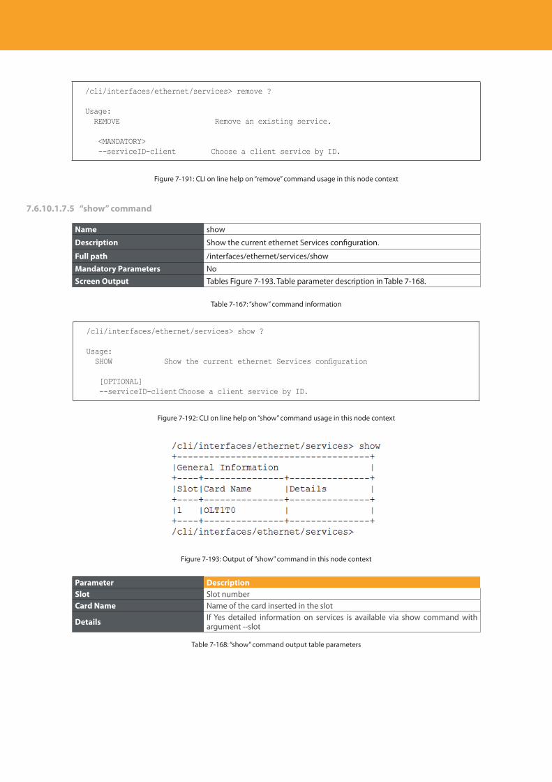
Descripción del producto
270
/cli/interfaces/ethernet/services> remove ?
Usage: REMOVE Remove an existing service.
<MANDATORY> --serviceID-client Choose a client service by ID.
Figure 7-191: CLI on line help on “remove” command usage in this node context
7.6.10.1.7.5 “show” command
Name show
Description Show the current ethernet Services configuration.
Full path /interfaces/ethernet/services/show
Mandatory Parameters NoScreen Output Tables Figure 7-193. Table parameter description in Table 7-168.
Table 7-167: “show” command information
/cli/interfaces/ethernet/services> show ?
Usage: SHOW Show the current ethernet Services configuration
[OPTIONAL] --serviceID-client Choose a client service by ID.
Figure 7-192: CLI on line help on “show” command usage in this node context
Figure 7-193: Output of ”show” command in this node context
Parameter DescriptionSlot Slot numberCard Name Name of the card inserted in the slot
Details If Yes detailed information on services is available via show command with argument --slot
Table 7-168: “show” command output table parameters
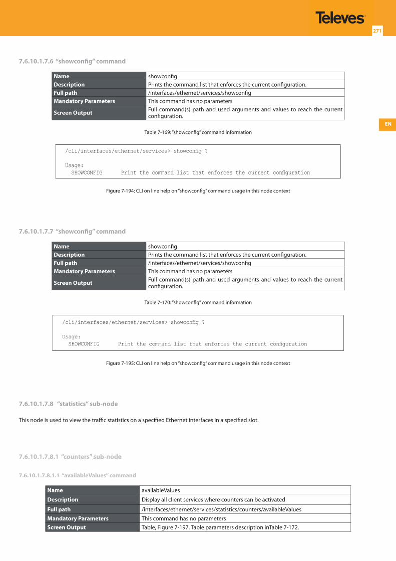
EN
271
7.6.10.1.7.6 “showconfig” command
Name showconfigDescription Prints the command list that enforces the current configuration.Full path /interfaces/ethernet/services/showconfigMandatory Parameters This command has no parameters
Screen Output Full command(s) path and used arguments and values to reach the current configuration.
Table 7-169: “showconfig” command information
/cli/interfaces/ethernet/services> showconfig ?
Usage: SHOWCONFIG Print the command list that enforces the current configuration
Figure 7-194: CLI on line help on “showconfig” command usage in this node context
7.6.10.1.7.7 “showconfig” command
Name showconfigDescription Prints the command list that enforces the current configuration.Full path /interfaces/ethernet/services/showconfigMandatory Parameters This command has no parameters
Screen Output Full command(s) path and used arguments and values to reach the current configuration.
Table 7-170: “showconfig” command information
/cli/interfaces/ethernet/services> showconfig ?
Usage: SHOWCONFIG Print the command list that enforces the current configuration
Figure 7-195: CLI on line help on “showconfig” command usage in this node context
7.6.10.1.7.8 “statistics” sub-node
This node is used to view the traffic statistics on a specified Ethernet interfaces in a specified slot.
7.6.10.1.7.8.1 “counters” sub-node
7.6.10.1.7.8.1.1 “availableValues” command
Name availableValues
Description Display all client services where counters can be activated
Full path /interfaces/ethernet/services/statistics/counters/availableValues
Mandatory Parameters This command has no parametersScreen Output Table, Figure 7-197. Table parameters description inTable 7-172.
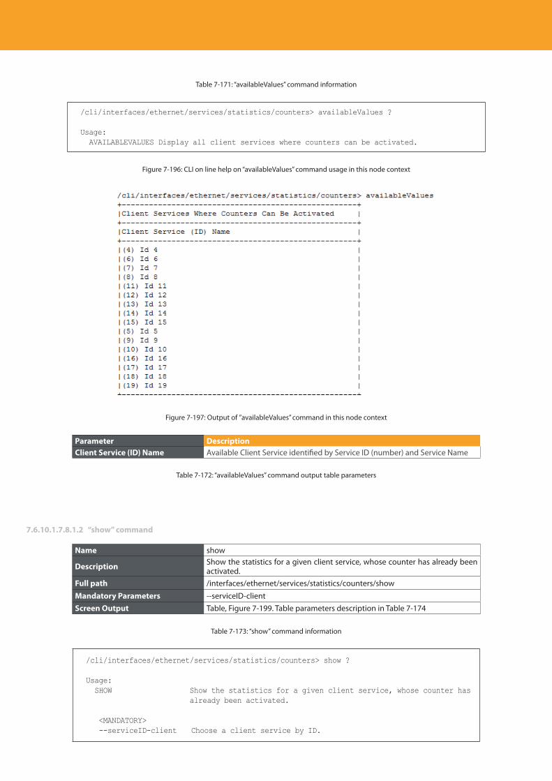
Descripción del producto
272
Table 7-171: “availableValues” command information
/cli/interfaces/ethernet/services/statistics/counters> availableValues ?
Usage: AVAILABLEVALUES Display all client services where counters can be activated.
Figure 7-196: CLI on line help on “availableValues” command usage in this node context
Figure 7-197: Output of ”availableValues” command in this node context
Parameter DescriptionClient Service (ID) Name Available Client Service identified by Service ID (number) and Service Name
Table 7-172: “availableValues” command output table parameters
7.6.10.1.7.8.1.2 “show” command
Name show
Description Show the statistics for a given client service, whose counter has already been activated.
Full path /interfaces/ethernet/services/statistics/counters/show
Mandatory Parameters --serviceID-clientScreen Output Table, Figure 7-199. Table parameters description in Table 7-174
Table 7-173: “show” command information
/cli/interfaces/ethernet/services/statistics/counters> show ?
Usage: SHOW Show the statistics for a given client service, whose counter has
already been activated.
<MANDATORY> --serviceID-client Choose a client service by ID.
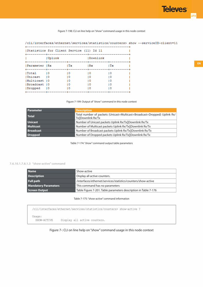
EN
273
Figure 7-198: CLI on line help on “show” command usage in this node context
Figure 7-199: Output of ”show” command in this node context
Parameter Description
Total Total number of packets (Unicast+Multicast+Broadcast+Dropped) Uplink Rx/Tx||Downlink Rx/Tx
Unicast Number of Unicast packets Uplink Rx/Tx||Downlink Rx/TxMulticast Number of Multicast packets Uplink Rx/Tx||Downlink Rx/TxBroadcast Number of Broadcast packets Uplink Rx/Tx||Downlink Rx/TxDropped Number of Dropped packets Uplink Rx/Tx||Downlink Rx/Tx
Table 7-174: “show” command output table parameters
7.6.10.1.7.8.1.3 “show-active” command
Name Show-active
Description Display all active counters.
Full path /interfaces/ethernet/services/statistics/counters/show-active
Mandatory Parameters This command has no parametersScreen Output Table Figure 7-201. Table parameters description in Table 7-176
Table 7-175: “show-active” command information
/cli/interfaces/ethernet/services/statistics/counters> show-active ?
Usage: SHOW-ACTIVE Display all active counters.
Figure 7-: CLI on line help on “show” command usage in this node context
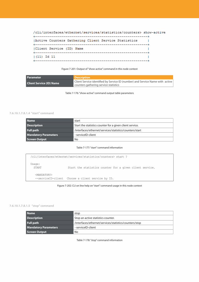
Descripción del producto
274
Figure 7-201: Output of ”show-active” command in this node context
Parameter Description
Client Service (ID) Name Client Service identified by Service ID (number) and Service Name with active counters gathering service statistics
Table 7-176: “show-active” command output table parameters
7.6.10.1.7.8.1.4 “start” command
Name start
Description Start the statistics counter for a given client service.
Full path /interfaces/ethernet/services/statistics/counters/start
Mandatory Parameters --serviceID-clientScreen Output No
Table 7-177: “start” command information
/cli/interfaces/ethernet/services/statistics/counters> start ?
Usage: START Start the statistics counter for a given client service.
<MANDATORY> --serviceID-client Choose a client service by ID.
Figure 7-202: CLI on line help on “start” command usage in this node context
7.6.10.1.7.8.1.5 “stop” command
Name stop
Description Stop an active statistics counter.
Full path /interfaces/ethernet/services/statistics/counters/stop
Mandatory Parameters --serviceID-clientScreen Output No
Table 7-178: “stop” command information
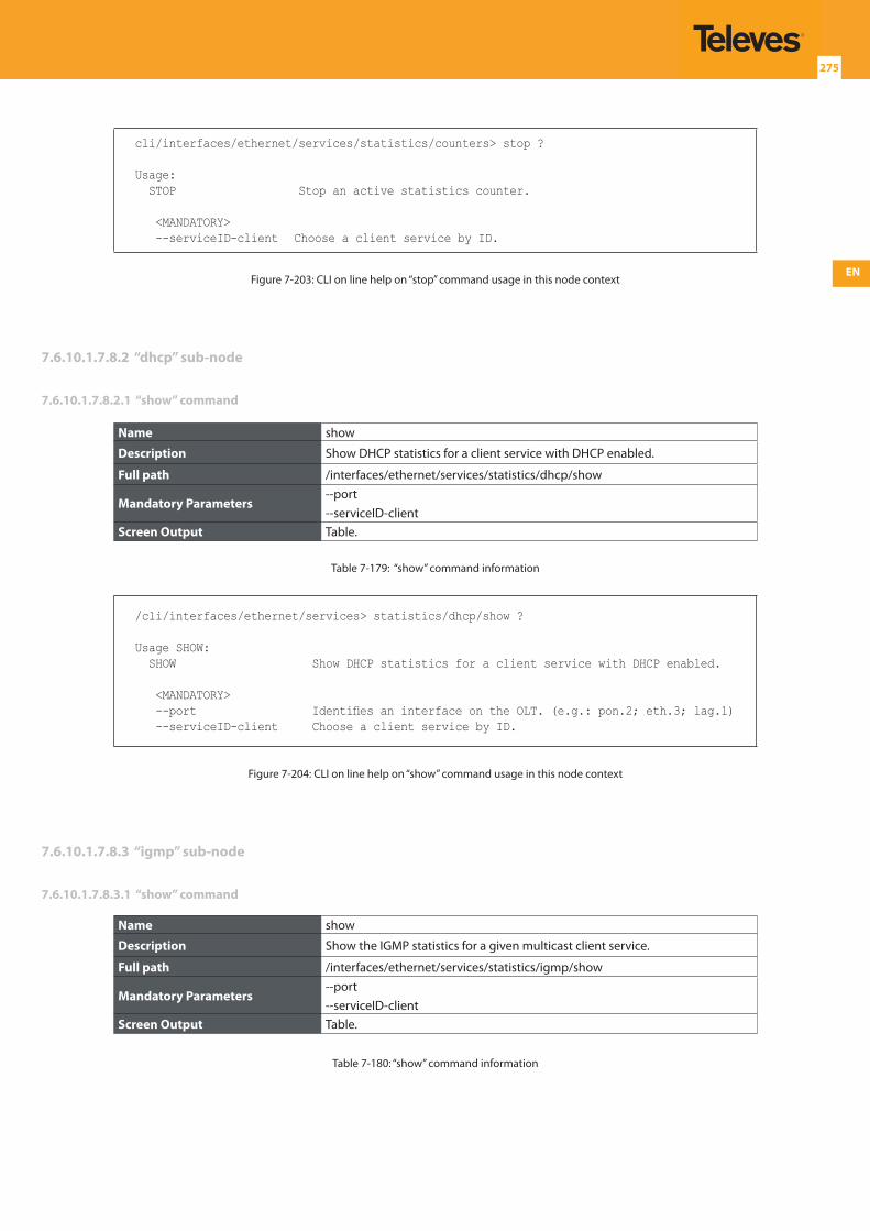
EN
275
cli/interfaces/ethernet/services/statistics/counters> stop ?
Usage: STOP Stop an active statistics counter.
<MANDATORY> --serviceID-client Choose a client service by ID.
Figure 7-203: CLI on line help on “stop” command usage in this node context
7.6.10.1.7.8.2 “dhcp” sub-node
7.6.10.1.7.8.2.1 “show” command
Name show
Description Show DHCP statistics for a client service with DHCP enabled.
Full path /interfaces/ethernet/services/statistics/dhcp/show
Mandatory Parameters--port--serviceID-client
Screen Output Table.
Table 7-179: “show” command information
/cli/interfaces/ethernet/services> statistics/dhcp/show ?
Usage SHOW: SHOW Show DHCP statistics for a client service with DHCP enabled.
<MANDATORY> --port Identifies an interface on the OLT. (e.g.: pon.2; eth.3; lag.1) --serviceID-client Choose a client service by ID.
Figure 7-204: CLI on line help on “show” command usage in this node context
7.6.10.1.7.8.3 “igmp” sub-node
7.6.10.1.7.8.3.1 “show” command
Name show
Description Show the IGMP statistics for a given multicast client service.
Full path /interfaces/ethernet/services/statistics/igmp/show
Mandatory Parameters--port--serviceID-client
Screen Output Table.
Table 7-180: “show” command information
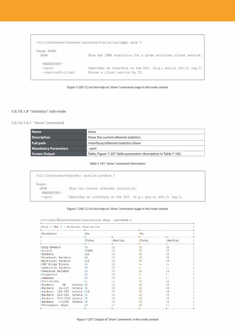
Descripción del producto
276
/cli/interfaces/ethernet/services/statistics/igmp> show ?
Usage SHOW: SHOW Show the IGMP statistics for a given multicast client service.
<MANDATORY> --port Identifies an interface on the OLT. (e.g.: pon.2; eth.3; lag.1) --serviceID-client Choose a client service by ID.
Figure 7-205: CLI on line help on “show” command usage in this node context
7.6.10.1.8 “statistics” sub-node
7.6.10.1.8.1 “show” command
Name show
Description Show the current ethernet statistics.
Full path /interfaces/ethernet/statistics/show
Mandatory Parameters --portScreen Output Table, Figure 7-207 Table parameters description in Table 7-182.
Table 7-181: “show” command information
/cli/interfaces/ethernet/ statistics>show ?
Usage: SHOW Show the current ethernet statistics. <MANDATORY> --port Identifies an interface on the OLT. (e.g.: pon.2; eth.3; lag.1)
Figure 7-206: CLI on line help on “show” command usage in this node context
Figure 7-207: Output of ”show” command in this node context
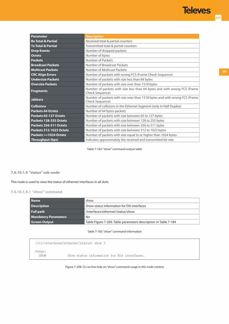
EN
277
Parameter DescriptionRx Total & Partial Received total & partial countersTx Total & Partial Transmitted total & partial countersDrop Events Number of dropped packetsOctets Number of bytesPackets Number of PacketsBroadcast Packets Number of Broadcast PacketsMulticast Packets Number of Multicast PacketsCRC Align Errors Number of packets with wrong FCS (Frame Check Sequence)Undersize Packets Number of packets with size less than 64 bytesOversize Packets Number of packets with size over than 1518 bytes
Fragments Number of packets with size less than 64 bytes and with wrong FCS (Frame Check Sequence)
Jabbers Number of packets with size over than 1518 bytes and with wrong FCS (Frame Check Sequence)
Collisions Number of collisions in the Ethernet Segment (only in Half Duplex)Packets 64 Octets Number of 64 bytes packetsPackets 65-127 Octets Number of packets with size between 65 to 127 bytesPackets 128-255 Octets Number of packets with size between 128 to 255 bytesPackets 256-511 Octets Number of packets with size between 256 to 511 bytesPackets 512-1023 Octets Number of packets with size between 512 to 1023 bytesPackets >=1024 Octets Number of packets with size equal to or higher than 1024 bytesThroughput (bps) Indicates approximately the received and transmitted bit rate
Table 7-182: “show” command output table
7.6.10.1.9 “status” sub-node
This node is used to view the status of ethernet interfaces in all slots.
7.6.10.1.9.1 “show” command
Name show
Description Show status information for Eth interfaces
Full path /interfaces/ethernet//status/show
Mandatory Parameters NoScreen Output Table Figure 7-209. Table parameters description in Table 7-184
Table 7-183: “show” command information
/cli/interfaces/ethernet/status> show ?
Usage: SHOW Show status information for Eth interfaces.
Figure 7-208: CLI on line help on “show” command usage in this node context
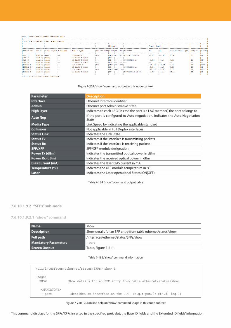
Descripción del producto
278
Figure 7-209:”show” command output in this node context
Parameter DescriptionInterface Ethernet Interface identifierAdmin Ethernet port Administrative StateHigh layer Indicates to each LAG (in case the port is a LAG member) the port belongs to
Auto Neg If the port is configured to Auto negotiation, indicates the Auto Negotiation State
Media Type Link Speed by indicating the applicable standardCollisions Not applicable in Full Duplex interfacesStatus Link Indicates the Link StateStatus Tx Indicates if the interface is transmitting packetsStatus Rx Indicates if the interface is receiving packets SFP/XFP SFP/XFP module designationPower Tx (dBm) Indicates the transmitted optical power in dBmPower Rx (dBm) Indicates the received optical power in dBmBias Current (mA) Indicates the laser BIAS current in mATemperature (ºC) Indicates the XFP module temperature in ºCLaser Indicates the Laser operational States (ON|OFF)
Table 7-184 “show” command output table
7.6.10.1.9.2 “SFPs” sub-node
7.6.10.1.9.2.1 “show” command
Name show
Description Show details for an SFP entry from table ethernet/status/show.
Full path /interfaces/ethernet/status/SFPs/show
Mandatory Parameters --portScreen Output Table, Figure 7-211.
Table 7-185: “show” command information
/cli/interfaces/ethernet/status/SFPs> show ?
Usage: SHOW Show details for an SFP entry from table ethernet/status/show
<MANDATORY> --port Identifies an interface on the OLT. (e.g.: pon.2; eth.3; lag.1)
Figure 7-210: CLI on line help on “show” command usage in this node context
This command displays for the SFPs/XFPs inserted in the specified port, slot, the Base ID fields and the Extended ID fields’ information
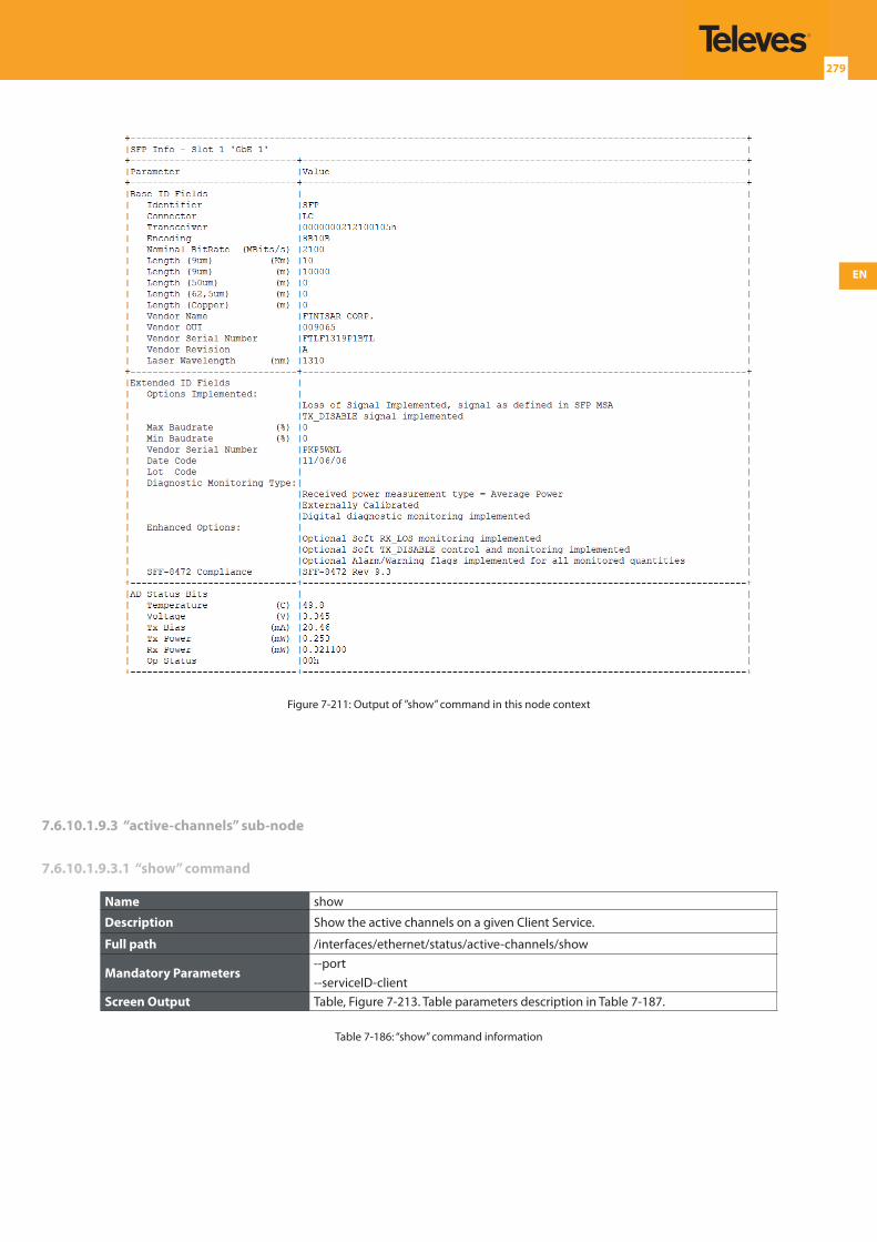
EN
279
Figure 7-211: Output of ”show” command in this node context
7.6.10.1.9.3 “active-channels” sub-node
7.6.10.1.9.3.1 “show” command
Name show
Description Show the active channels on a given Client Service.
Full path /interfaces/ethernet/status/active-channels/show
Mandatory Parameters--port--serviceID-client
Screen Output Table, Figure 7-213. Table parameters description in Table 7-187.
Table 7-186: “show” command information
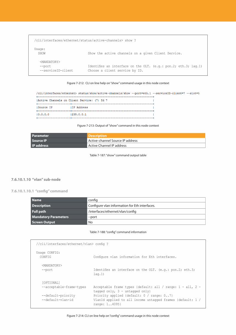
Descripción del producto
280
/cli/interfaces/ethernet/status/active-channels> show ?
Usage: SHOW Show the active channels on a given Client Service.
<MANDATORY> --port Identifies an interface on the OLT. (e.g.: pon.2; eth.3; lag.1) --serviceID-client Choose a client service by ID.
Figure 7-212: CLI on line help on “show” command usage in this node context
Figure 7-213: Output of ”show” command in this node context
Parameter DescriptionSource IP Active-channel Source IP addressIP address Active Channel IP address
Table 7-187: “show” command output table
7.6.10.1.10 “vlan” sub-node
7.6.10.1.10.1 “config” command
Name config
Description Configure vlan information for Eth interfaces.
Full path /interfaces/ethernet/vlan/config
Mandatory Parameters --portScreen Output No
Table 7-188: “config” command information
//cli/interfaces/ethernet/vlan> config ?
Usage CONFIG: CONFIG Configure vlan information for Eth interfaces.
<MANDATORY> --port Identifies an interface on the OLT. (e.g.: pon.2; eth.3;
lag.1)
[OPTIONAL] --acceptable-frame-types Acceptable frame types {default: all / range: 1 - all, 2 -
tagged only, 3 - untagged only} --default-priority Priority applied {default: 0 / range: 0..7} --default-vlan-id VlanId applied to all income untagged frames {default: 1 /
range: 1..4095}
Figure 7-214: CLI on line help on “config” command usage in this node context
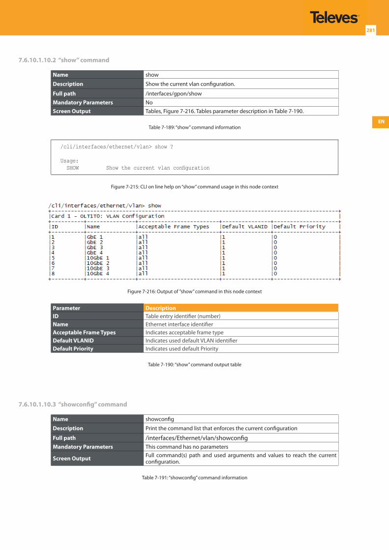
EN
281
7.6.10.1.10.2 “show” command
Name show
Description Show the current vlan configuration.
Full path /interfaces/gpon/show
Mandatory Parameters NoScreen Output Tables, Figure 7-216. Tables parameter description in Table 7-190.
Table 7-189: “show” command information
/cli/interfaces/ethernet/vlan> show ?
Usage: SHOW Show the current vlan configuration
Figure 7-215: CLI on line help on “show” command usage in this node context
Figure 7-216: Output of ”show” command in this node context
Parameter DescriptionID Table entry identifier (number)Name Ethernet interface identifierAcceptable Frame Types Indicates acceptable frame type Default VLANID Indicates used default VLAN identifierDefault Priority Indicates used default Priority
Table 7-190: “show” command output table
7.6.10.1.10.3 “showconfig” command
Name showconfig
Description Print the command list that enforces the current configuration
Full path /interfaces/Ethernet/vlan/showconfigMandatory Parameters This command has no parameters
Screen Output Full command(s) path and used arguments and values to reach the current configuration.
Table 7-191: “showconfig” command information
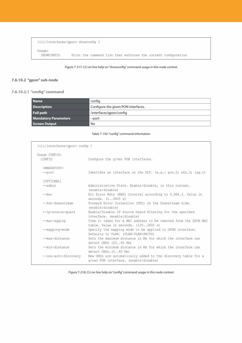
Descripción del producto
282
/cli/interfaces/gpon> showconfig ?
Usage: SHOWCONFIG Print the command list that enforces the current configuration
Figure 7-217: CLI on line help on “showconfig” command usage in this node context
7.6.10.2 “gpon” sub-node
7.6.10.2.1 “config” command
Name config
Description Configure the given PON interfaces.
Full path /interfaces/gpon/config
Mandatory Parameters --portScreen Output No
Table 7-192: “config” command information
/cli/interfaces/gpon> config ?
Usage CONFIG: CONFIG Configure the given PON interfaces.
<MANDATORY> --port Identifies an interface on the OLT. (e.g.: pon.2; eth.3; lag.1)
[OPTIONAL] --admin Administrative State. Enable/disable, in this context.
(enable|disable) --ber Bit Error Rate (BER) Interval according to G.984.3. Value in
seconds. (1..3600 s) --fec-downstream Forward Error Correction (FEC) on the Downstream side.
(enable|disable) --ip-source-guard Enable/Disable IP Source Guard filtering for the specified
interface. (enable|disable) --mac-agging Time it takes for a MAC address to be removed from the GPON MAC
table. Value in seconds. (120..3600 s) --mapping-mode Specify the mapping mode to be applied to GPON interface.
Defaults to VLAN. (VLAN|VLAN+PBITS) --max-distance Sets the maximum distance in Km for which the interface can
detect ONUs (20..60 Km) --min-distance Sets the minimum distance in Km for which the interface can
detect ONUs.(0..40 Km) --onu-auto-discovery New ONUs are automatically added to the discovery table for a
given PON interface. (enable|disable)
Figure 7-218: CLI on line help on “config” command usage in this node context
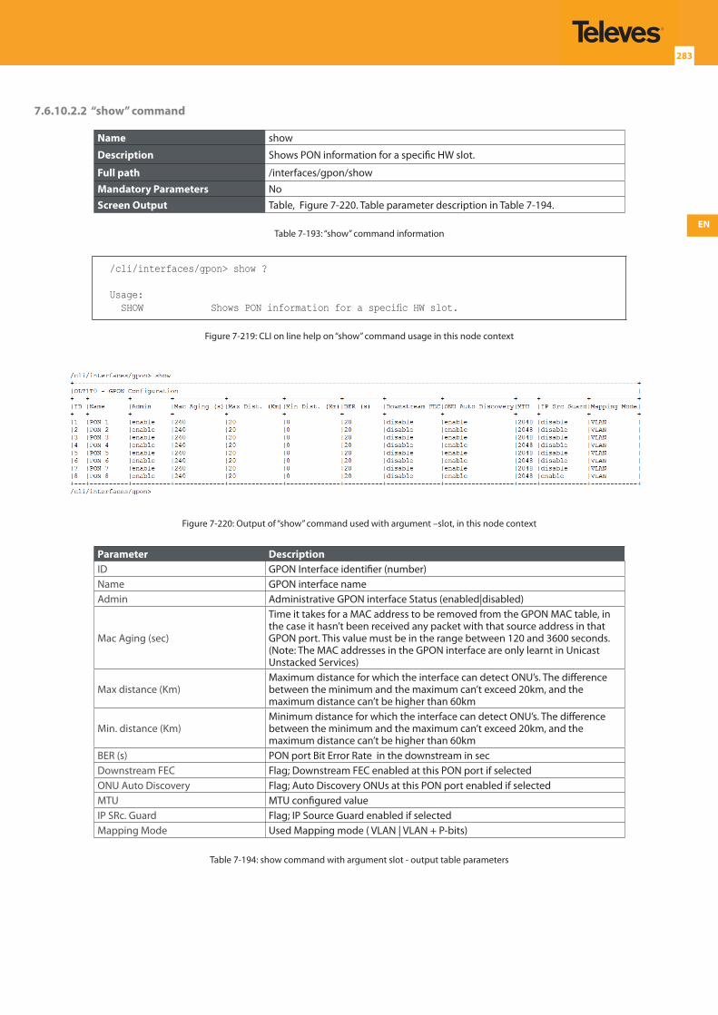
EN
283
7.6.10.2.2 “show” command
Name show
Description Shows PON information for a specific HW slot.
Full path /interfaces/gpon/show
Mandatory Parameters NoScreen Output Table, Figure 7-220. Table parameter description in Table 7-194.
Table 7-193: “show” command information
/cli/interfaces/gpon> show ?
Usage: SHOW Shows PON information for a specific HW slot.
Figure 7-219: CLI on line help on “show” command usage in this node context
Figure 7-220: Output of “show” command used with argument –slot, in this node context
Parameter DescriptionID GPON Interface identifier (number)Name GPON interface name Admin Administrative GPON interface Status (enabled|disabled)
Mac Aging (sec)
Time it takes for a MAC address to be removed from the GPON MAC table, in the case it hasn’t been received any packet with that source address in that GPON port. This value must be in the range between 120 and 3600 seconds. (Note: The MAC addresses in the GPON interface are only learnt in Unicast Unstacked Services)
Max distance (Km)Maximum distance for which the interface can detect ONU’s. The difference between the minimum and the maximum can’t exceed 20km, and the maximum distance can’t be higher than 60km
Min. distance (Km)Minimum distance for which the interface can detect ONU’s. The difference between the minimum and the maximum can’t exceed 20km, and the maximum distance can’t be higher than 60km
BER (s) PON port Bit Error Rate in the downstream in secDownstream FEC Flag; Downstream FEC enabled at this PON port if selectedONU Auto Discovery Flag; Auto Discovery ONUs at this PON port enabled if selectedMTU MTU configured valueIP SRc. Guard Flag; IP Source Guard enabled if selectedMapping Mode Used Mapping mode ( VLAN | VLAN + P-bits)
Table 7-194: show command with argument slot - output table parameters
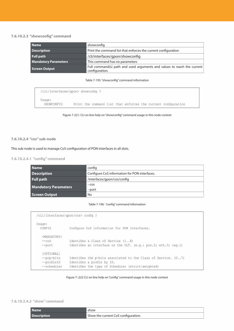
Descripción del producto
284
7.6.10.2.3 “showconfig” command
Name showconfig
Description Print the command list that enforces the current configuration
Full path /cli/interfaces/gpon/showconfigMandatory Parameters This command has no parameters
Screen Output Full command(s) path and used arguments and values to reach the current configuration.
Table 7-195: “showconfig” command information
/cli/interfaces/gpon> showconfig ?
Usage: SHOWCONFIG Print the command list that enforces the current configuration
Figure 7-221: CLI on line help on “showconfig” command usage in this node context
7.6.10.2.4 “cos” sub-node
This sub-node is used to manage CoS configuration of PON interfaces in all slots.
7.6.10.2.4.1 “config” command
Name config
Description Configure CoS information for PON interfaces.
Full path /interfaces/gpon/cos/config
Mandatory Parameters--cos--port
Screen Output No
Table 7-196: “config” command information
/cli/interfaces/gpon/cos> config ?
Usage: CONFIG Configure CoS information for PON interfaces.
<MANDATORY> --cos Identifies a Class of Service (1..8) --port Identifies an interface on the OLT. (e.g.: pon.2; eth.3; lag.1)
[OPTIONAL] --pcp-bits Identifies the p-bits associated to the Class of Service. (0..7) --profileID Identifies a profile by ID. --scheduler Identifies the type of Scheduler (strict|weighted)
Figure 7-:222 CLI on line help on “config” command usage in this node context
7.6.10.2.4.2 “show” command
Name show
Description Show the current CoS configuration.
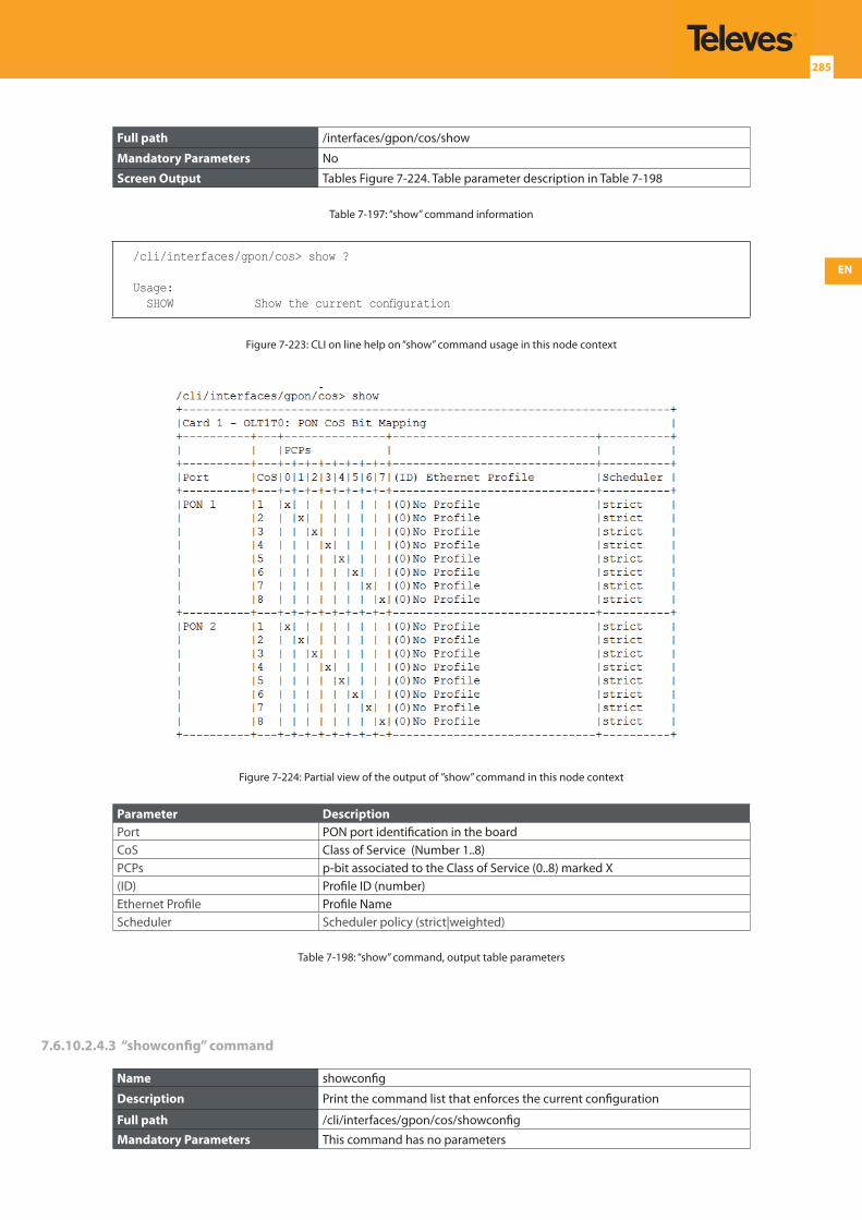
EN
285
Full path /interfaces/gpon/cos/show
Mandatory Parameters No
Screen Output Tables Figure 7-224. Table parameter description in Table 7-198
Table 7-197: “show” command information
/cli/interfaces/gpon/cos> show ?
Usage: SHOW Show the current configuration
Figure 7-223: CLI on line help on “show” command usage in this node context
Figure 7-224: Partial view of the output of ”show” command in this node context
Parameter DescriptionPort PON port identification in the board CoS Class of Service (Number 1..8)PCPs p-bit associated to the Class of Service (0..8) marked X(ID) Profile ID (number) Ethernet Profile Profile NameScheduler Scheduler policy (strict|weighted)
Table 7-198: “show” command, output table parameters
7.6.10.2.4.3 “showconfig” command
Name showconfig
Description Print the command list that enforces the current configuration
Full path /cli/interfaces/gpon/cos/showconfig
Mandatory Parameters This command has no parameters
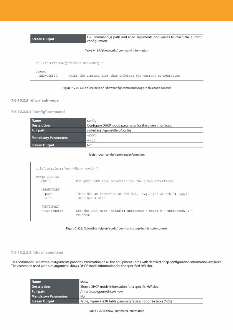
Descripción del producto
286
Screen Output Full command(s) path and used arguments and values to reach the current configuration.
Table 7-199: “showconfig” command information
/cli/interfaces/gpon/cos> showconfig ?
Usage: SHOWCONFIG Print the command list that enforces the current configuration
Figure 7-225: CLI on line help on “showconfig” command usage in this node context
7.6.10.2.5 “dhcp” sub-node
7.6.10.2.5.1 “config” command
Name configDescription Configure DHCP mode parameter for the given interfaces.Full path /interfaces/gpon/dhcp/config
Mandatory Parameters--port--slot
Screen Output No
Table 7-200: “config” command information
/cli/interfaces/gpon/dhcp> config ?
Usage CONFIG: CONFIG Configure DHCP mode parameter for the given interfaces.
<MANDATORY> --port Identifies an interface on the OLT. (e.g.: pon.2; eth.3; lag.1) --slot Identifies a slot.
[OPTIONAL] --is-trusted Set the DHCP mode {default: untrusted / mode: 0 - untrusted, 1 -
trusted}
Figure 7-226: CLI on line help on “config” command usage in this node context
7.6.10.2.5.2 “show” command
This command used without arguments provides information on all the equipment Cards with detailed dhcp configuration information available. The command used with slot argument shows DHCP mode information for the specified HW slot.
Name showDescription Shows DHCP mode information for a specific HW slot.Full path /interfaces/gpon/dhcp/showMandatory Parameters NoScreen Output Table, Figure 7-228.Table parameters description in Table 7-202
Table 7-201: “show” command information
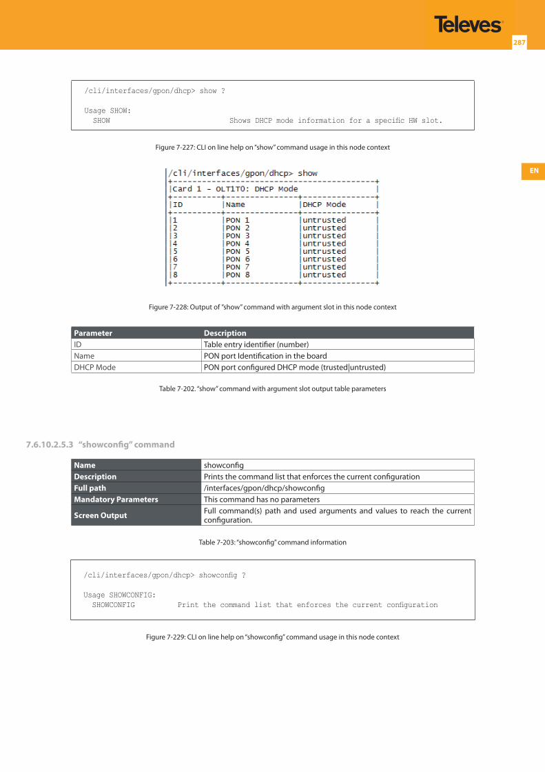
EN
287
/cli/interfaces/gpon/dhcp> show ?
Usage SHOW: SHOW Shows DHCP mode information for a specific HW slot.
Figure 7-227: CLI on line help on “show” command usage in this node context
Figure 7-228: Output of ”show” command with argument slot in this node context
Parameter DescriptionID Table entry identifier (number)Name PON port Identification in the boardDHCP Mode PON port configured DHCP mode (trusted|untrusted)
Table 7-202. “show” command with argument slot output table parameters
7.6.10.2.5.3 “showconfig” command
Name showconfigDescription Prints the command list that enforces the current configurationFull path /interfaces/gpon/dhcp/showconfigMandatory Parameters This command has no parameters
Screen Output Full command(s) path and used arguments and values to reach the current configuration.
Table 7-203: “showconfig” command information
/cli/interfaces/gpon/dhcp> showconfig ?
Usage SHOWCONFIG: SHOWCONFIG Print the command list that enforces the current configuration
Figure 7-229: CLI on line help on “showconfig” command usage in this node context
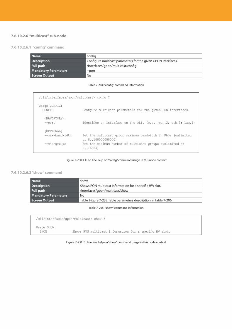
Descripción del producto
288
7.6.10.2.6 “multicast” sub-node
7.6.10.2.6.1 “config” command
Name configDescription Configure multicast parameters for the given GPON interfaces.Full path /interfaces/gpon/multicast/configMandatory Parameters --portScreen Output No
Table 7-204: “config” command information
/cli/interfaces/gpon/multicast> config ?
Usage CONFIG: CONFIG Configure multicast parameters for the given PON interfaces.
<MANDATORY> --port Identifies an interface on the OLT. (e.g.: pon.2; eth.3; lag.1)
[OPTIONAL] --max-bandwidth Set the multicast group maximum bandwidth in Kbps (unlimited
or 0..100000000000) --max-groups Set the maximum number of multicast groups (unlimited or
0..16384)
Figure 7-230: CLI on line help on “config” command usage in this node context
7.6.10.2.6.2 “show” command
Name showDescription Shows PON multicast information for a specific HW slot.Full path /interfaces/gpon/multicast/showMandatory Parameters NoScreen Output Table, Figure 7-232.Table parameters description in Table 7-206.
Table 7-205: “show” command information
/cli/interfaces/gpon/multicast> show ?
Usage SHOW: SHOW Shows PON multicast information for a specific HW slot.
Figure 7-231: CLI on line help on “show” command usage in this node context
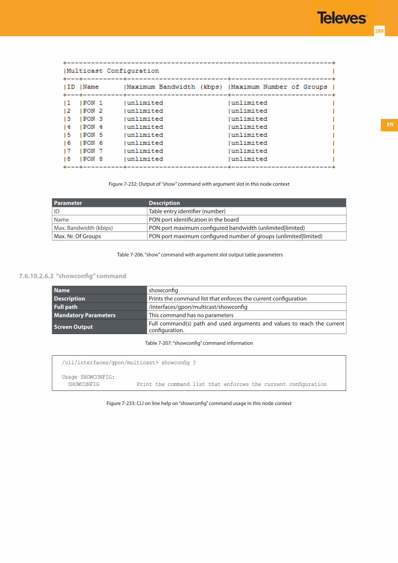
EN
289
Figure 7-232: Output of ”show” command with argument slot in this node context
Parameter DescriptionID Table entry identifier (number)Name PON port identification in the boardMax. Bandwidth (kbips) PON port maximum configured bandwidth (unlimited|limited)Max. Nr. Of Groups PON port maximum configured number of groups (unlimited|limited)
Table 7-206. “show” command with argument slot output table parameters
7.6.10.2.6.3 “showconfig” command
Name showconfigDescription Prints the command list that enforces the current configurationFull path /interfaces/gpon/multicast/showconfigMandatory Parameters This command has no parameters
Screen Output Full command(s) path and used arguments and values to reach the current configuration.
Table 7-207: “showconfig” command information
/cli/interfaces/gpon/multicast> showconfig ?
Usage SHOWCONFIG: SHOWCONFIG Print the command list that enforces the current configuration
Figure 7-233: CLI on line help on “showconfig” command usage in this node context
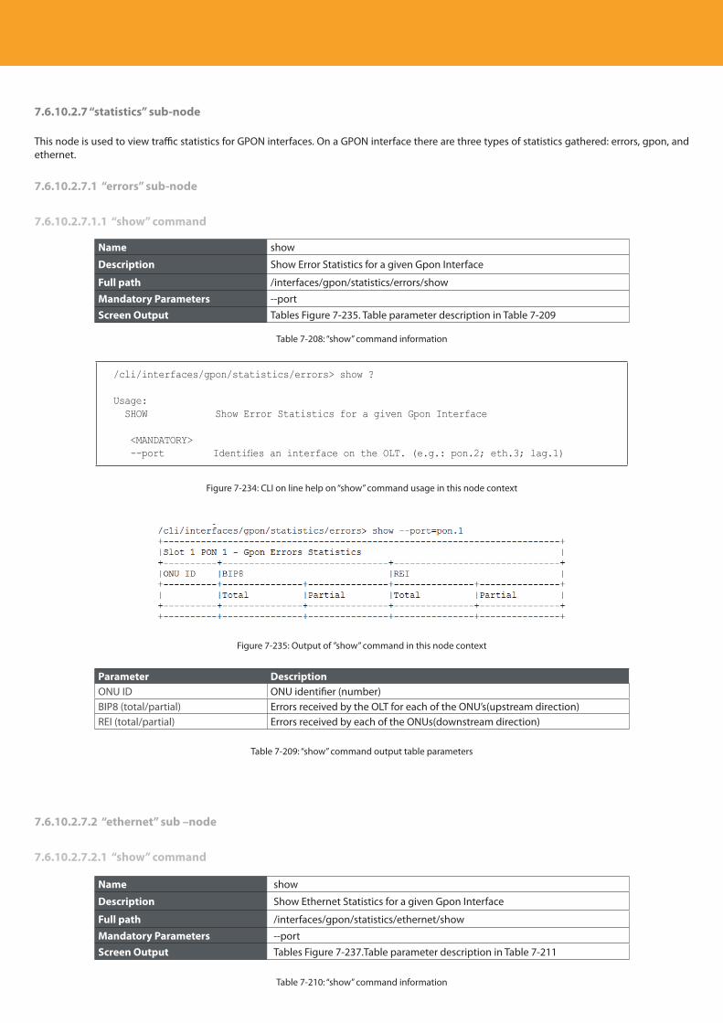
Descripción del producto
290
7.6.10.2.7 “statistics” sub-node
This node is used to view traffic statistics for GPON interfaces. On a GPON interface there are three types of statistics gathered: errors, gpon, and ethernet.
7.6.10.2.7.1 “errors” sub-node
7.6.10.2.7.1.1 “show” command
Name show
Description Show Error Statistics for a given Gpon Interface
Full path /interfaces/gpon/statistics/errors/show
Mandatory Parameters --portScreen Output Tables Figure 7-235. Table parameter description in Table 7-209
Table 7-208: “show” command information
/cli/interfaces/gpon/statistics/errors> show ?
Usage: SHOW Show Error Statistics for a given Gpon Interface
<MANDATORY> --port Identifies an interface on the OLT. (e.g.: pon.2; eth.3; lag.1)
Figure 7-234: CLI on line help on “show” command usage in this node context
Figure 7-235: Output of ”show” command in this node context
Parameter DescriptionONU ID ONU identifier (number)BIP8 (total/partial) Errors received by the OLT for each of the ONU’s(upstream direction)REI (total/partial) Errors received by each of the ONUs(downstream direction)
Table 7-209: “show” command output table parameters
7.6.10.2.7.2 “ethernet” sub –node
7.6.10.2.7.2.1 “show” command
Name show
Description Show Ethernet Statistics for a given Gpon Interface
Full path /interfaces/gpon/statistics/ethernet/show
Mandatory Parameters --portScreen Output Tables Figure 7-237.Table parameter description in Table 7-211
Table 7-210: “show” command information
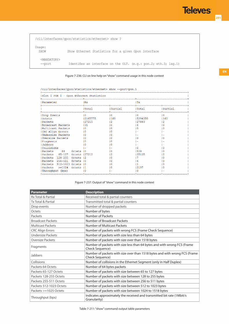
EN
291
/cli/interfaces/gpon/statistics/ethernet> show ?
Usage: SHOW Show Ethernet Statistics for a given Gpon Interface
<MANDATORY> --port Identifies an interface on the OLT. (e.g.: pon.2; eth.3; lag.1)
Figure 7-236: CLI on line help on “show” command usage in this node context
Figure 7-237: Output of ”show” command in this node context
Parameter DescriptionRx Total & Partial Received total & partial countersTx Total & Partial Transmitted total & partial countersDrop events Number of dropped packetsOctets Number of bytesPackets Number of PacketsBroadcast Packets Number of Broadcast PacketsMulticast Packets Number of Multicast PacketsCRC Align Errors Number of packets with wrong FCS (Frame Check Sequence)Undersize Packets Number of packets with size less than 64 bytesOversize Packets Number of packets with size over than 1518 bytes
Fragments Number of packets with size less than 64 bytes and with wrong FCS (Frame Check Sequence)
Jabbers Number of packets with size over than 1518 bytes and with wrong FCS (Frame Check Sequence)
Collisions Number of collisions in the Ethernet Segment (only in Half Duplex)Packets 64 Octets Number of 64 bytes packetsPackets 65-127 Octets Number of packets with size between 65 to 127 bytes Packets 128-255 Octets Number of packets with size between 128 to 255 bytesPackets 255-511 Octets Number of packets with size between 256 to 511 bytesPackets 512-1023 Octets Number of packets with size between 512 to 1023 bytesPackets >=1025 Octets Number of packets with size between 1024 to 1518 bytes
Throughput (bps) Indicates approximately the received and transmitted bit rate (1Mbit/s Granularity)
Table 7-211: “show” command output table parameters
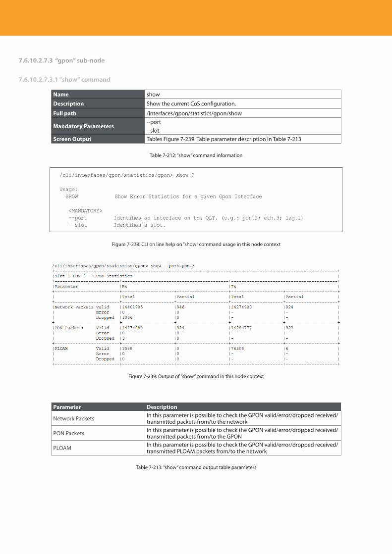
Descripción del producto
292
7.6.10.2.7.3 “gpon” sub-node
7.6.10.2.7.3.1 “show” command
Name show
Description Show the current CoS configuration.
Full path /interfaces/gpon/statistics/gpon/show
Mandatory Parameters--port--slot
Screen Output Tables Figure 7-239. Table parameter description in Table 7-213
Table 7-212: “show” command information
/cli/interfaces/gpon/statistics/gpon> show ?
Usage: SHOW Show Error Statistics for a given Gpon Interface
<MANDATORY> --port Identifies an interface on the OLT. (e.g.: pon.2; eth.3; lag.1) --slot Identifies a slot.
Figure 7-238: CLI on line help on “show” command usage in this node context
Figure 7-239: Output of ”show” command in this node context
Parameter Description
Network Packets In this parameter is possible to check the GPON valid/error/dropped received/transmitted packets from/to the network
PON Packets In this parameter is possible to check the GPON valid/error/dropped received/transmitted packets from/to the GPON
PLOAM In this parameter is possible to check the GPON valid/error/dropped received/transmitted PLOAM packets from/to the network
Table 7-213: “show” command output table parameters
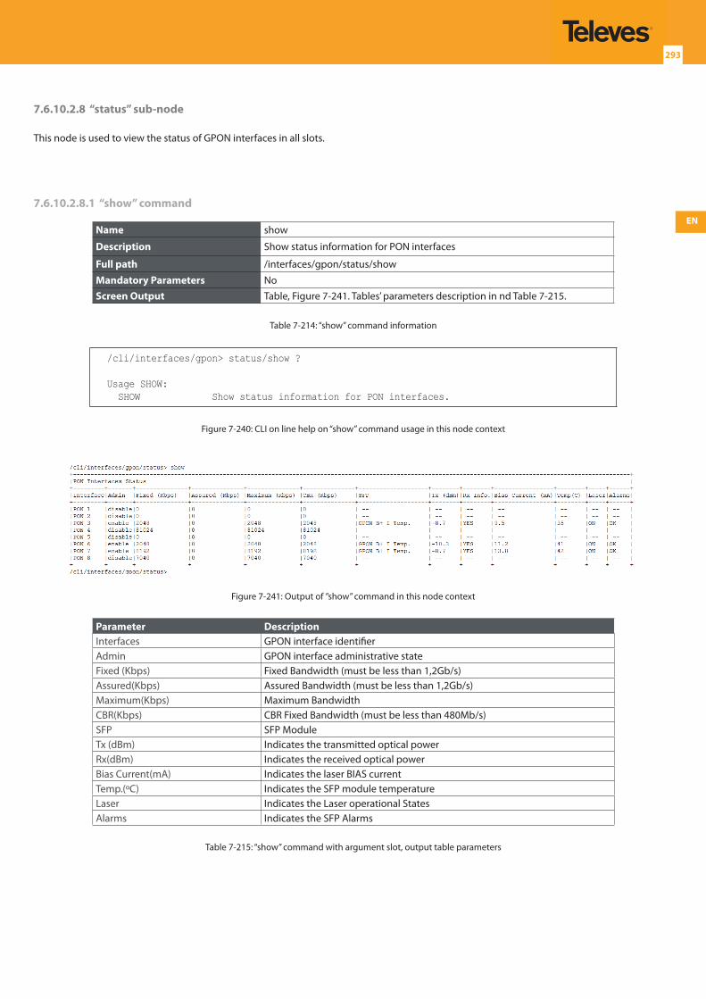
EN
293
7.6.10.2.8 “status” sub-node
This node is used to view the status of GPON interfaces in all slots.
7.6.10.2.8.1 “show” command
Name show
Description Show status information for PON interfaces
Full path /interfaces/gpon/status/show
Mandatory Parameters NoScreen Output Table, Figure 7-241. Tables’ parameters description in nd Table 7-215.
Table 7-214: “show” command information
/cli/interfaces/gpon> status/show ?
Usage SHOW: SHOW Show status information for PON interfaces.
Figure 7-240: CLI on line help on “show” command usage in this node context
Figure 7-241: Output of ”show” command in this node context
Parameter DescriptionInterfaces GPON interface identifierAdmin GPON interface administrative stateFixed (Kbps) Fixed Bandwidth (must be less than 1,2Gb/s)Assured(Kbps) Assured Bandwidth (must be less than 1,2Gb/s)Maximum(Kbps) Maximum BandwidthCBR(Kbps) CBR Fixed Bandwidth (must be less than 480Mb/s)SFP SFP ModuleTx (dBm) Indicates the transmitted optical powerRx(dBm) Indicates the received optical powerBias Current(mA) Indicates the laser BIAS currentTemp.(ºC) Indicates the SFP module temperatureLaser Indicates the Laser operational StatesAlarms Indicates the SFP Alarms
Table 7-215: “show” command with argument slot, output table parameters
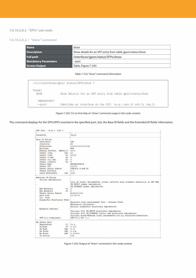
Descripción del producto
294
7.6.10.2.8.2 “SPFs” sub-node
7.6.10.2.8.2.1 “show” command
Name show
Description Show details for an SFP entry from table gpon/status/show
Full path /interfaces/gpon/status/SFPs/showMandatory Parameters --portScreen Output Table, Figure 7-243
Table 7-216: “show” command information
/cli/interfaces/gpon/ status/SFPs>show ?
Usage: SHOW Show details for an SFP entry from table gpon/status/show
<MANDATORY> --port Identifies an interface on the OLT. (e.g.: pon.2; eth.3; lag.1)
Figure 7-242: CLI on line help on “show” command usage in this node context
This command displays for the SFPs/XFPs inserted in the specified port, slot, the Base ID fields and the Extended ID fields’ information.
Figure 7-243: Output of ”show” command in this node context
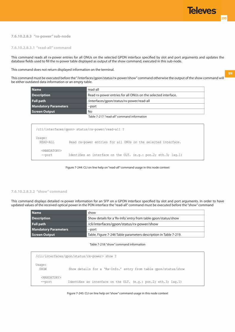
EN
295
7.6.10.2.8.3 “rx-power” sub-node
7.6.10.2.8.3.1 “read-all” command
This command reads all rx-power entries for all ONUs on the selected GPON interface specified by slot and port arguments and updates the database fields used to fill the rx-power table displayed as output of the show command, executed in this sub-node.
This command does not return displayed information on the terminal.
This command must be executed before the “/interfaces/gpon/status/rx-power/show” command otherwise the output of the show command will be either outdated data information or an empty table.
Name read-all
Description Read rx-power entries for all ONUs on the selected interface.
Full path /interfaces/gpon/status/rx-power/read-all
Mandatory Parameters --portScreen Output No
Table 7-217: “read-all” command information
/cli/interfaces/gpon> status/rx-power/read-all ?
Usage: READ-ALL Read rx-power entries for all ONUs on the selected interface.
<MANDATORY> --port Identifies an interface on the OLT. (e.g.: pon.2; eth.3; lag.1)
Figure 7-244: CLI on line help on “read-all” command usage in this node context
7.6.10.2.8.3.2 ”show” command
This command displays detailed rx-power information for an SFP on a GPON interface specified by slot and port arguments. In order to have updated values of the received optical power in the PON interface the “read-all” command must be executed before the “show” command
Name show
Description Show details for a ‘Rx-Info.’ entry from table gpon/status/show
Full path /cli/interfaces/gpon/status/rx-power/showMandatory Parameters --portScreen Output Table, Figure 7-246 Table parameters description in Table 7-219.
Table 7-218: “show” command information
/cli/interfaces/gpon/status/rx-power> show ?
Usage: SHOW Show details for a ‘Rx-Info.’ entry from table gpon/status/show
<MANDATORY> --port Identifies an interface on the OLT. (e.g.: pon.2; eth.3; lag.1)
Figure 7-245: CLI on line help on “show” command usage in this node context
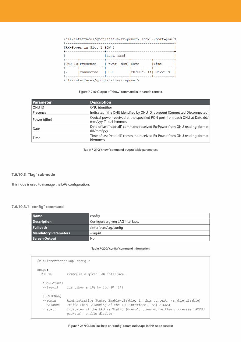
Descripción del producto
296
Figure 7-246: Output of ”show” command in this node context
Parameter DescriptionONU ID ONU identifierPresence Indicates if the ONU identified by ONU ID is present (Connected|Disconnected)
Power (dBm) Optical power received at the specified PON port from each ONU at Date dd/mm/yyy, Time hh:mm:ss
Date Date of last “read-all” command received Rx-Power from ONU reading; format dd/mm/yyy
Time Time of last “read-all” command received Rx-Power from ONU reading; format hh:mm:ss
Table 7-219: “show” command output table parameters
7.6.10.3 “lag” sub-node
This node is used to manage the LAG configuration.
7.6.10.3.1 “config” command
Name config
Description Configure a given LAG interface.
Full path /interfaces/lag/config
Mandatory Parameters --lag-idScreen Output No
Table 7-220: “config” command information
/cli/interfaces/lag> config ?
Usage: CONFIG Configure a given LAG interface.
<MANDATORY> --lag-id Identifies a LAG by ID. (0..14)
[OPTIONAL] --admin Administrative State. Enable/disable, in this context. (enable|disable) --balance Traffic Load Balancing of the LAG interface. (SA|DA|SDA) --static Indicates if the LAG is Static (doesn’t transmit neither processes LACPDU
packets) (enable|disable)
Figure 7-247: CLI on line help on “config” command usage in this node context
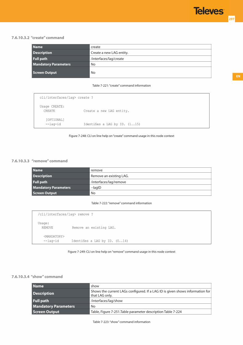
EN
297
7.6.10.3.2 “create” command
Name create
Description Create a new LAG entity.
Full path /interfaces/lag/create
Mandatory Parameters No
Screen Output No
Table 7-221: “create” command information
cli/interfaces/lag> create ?
Usage CREATE: CREATE Create a new LAG entity.
[OPTIONAL] --lag-id Identifies a LAG by ID. (1..15)
Figure 7-248: CLI on line help on “create” command usage in this node context
7.6.10.3.3 “remove” command
Name remove
Description Remove an existing LAG.
Full path /interfaces/lag/remove
Mandatory Parameters --lagIDScreen Output No
Table 7-222: “remove” command information
/cli/interfaces/lag> remove ?
Usage: REMOVE Remove an existing LAG.
<MANDATORY> --lag-id Identifies a LAG by ID. (0..14)
Figure 7-249: CLI on line help on “remove” command usage in this node context
7.6.10.3.4 “show” command
Name show
Description Shows the current LAGs configured. If a LAG ID is given shows information for that LAG only.
Full path /interfaces/lag/show
Mandatory Parameters No
Screen Output Table, Figure 7-251.Table parameter description Table 7-224
Table 7-223: “show” command information
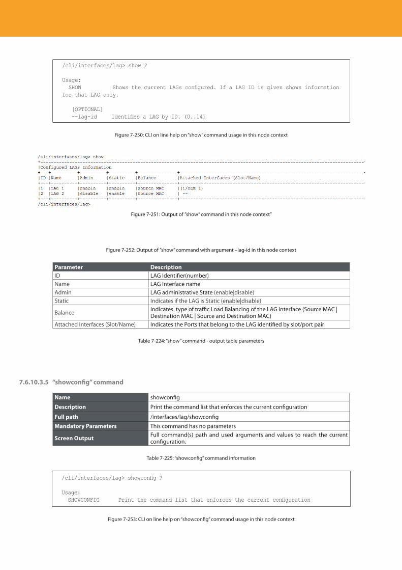
Descripción del producto
298
/cli/interfaces/lag> show ?
Usage: SHOW Shows the current LAGs configured. If a LAG ID is given shows information for that LAG only.
[OPTIONAL] --lag-id Identifies a LAG by ID. (0..14)
Figure 7-250: CLI on line help on “show” command usage in this node context
Figure 7-251: Output of ”show” command in this node context”
Figure 7-252: Output of ”show” command with argument –lag-id in this node context
Parameter DescriptionID LAG Identifier(number)Name LAG Interface nameAdmin LAG administrative State (enable|disable)Static Indicates if the LAG is Static (enable|disable)
Balance Indicates type of traffic Load Balancing of the LAG interface (Source MAC | Destination MAC | Source and Destination MAC)
Attached Interfaces (Slot/Name) Indicates the Ports that belong to the LAG identified by slot/port pair
Table 7-224: “show” command - output table parameters
7.6.10.3.5 “showconfig” command
Name showconfig
Description Print the command list that enforces the current configuration
Full path /interfaces/lag/showconfig
Mandatory Parameters This command has no parameters
Screen Output Full command(s) path and used arguments and values to reach the current configuration.
Table 7-225: “showconfig” command information
/cli/interfaces/lag> showconfig ?
Usage: SHOWCONFIG Print the command list that enforces the current configuration
Figure 7-253: CLI on line help on “showconfig” command usage in this node context
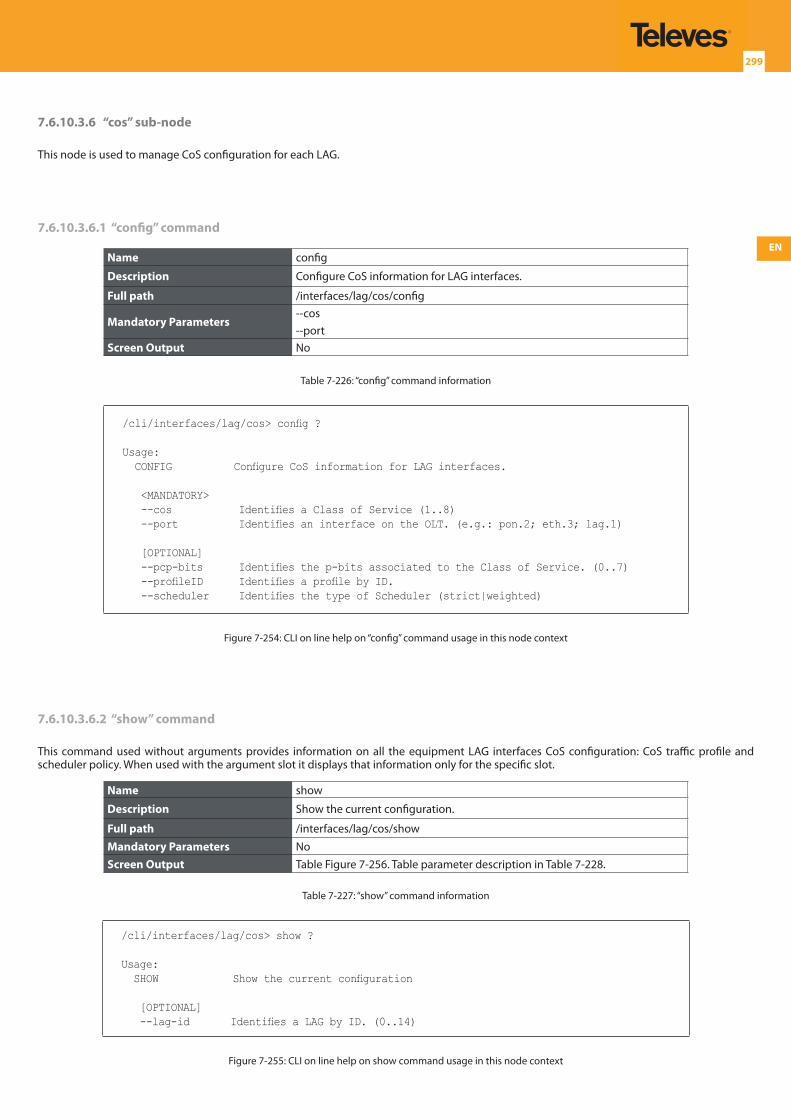
EN
299
7.6.10.3.6 “cos” sub-node
This node is used to manage CoS configuration for each LAG.
7.6.10.3.6.1 “config” command
Name config
Description Configure CoS information for LAG interfaces.
Full path /interfaces/lag/cos/config
Mandatory Parameters--cos--port
Screen Output No
Table 7-226: “config” command information
/cli/interfaces/lag/cos> config ?
Usage: CONFIG Configure CoS information for LAG interfaces.
<MANDATORY> --cos Identifies a Class of Service (1..8) --port Identifies an interface on the OLT. (e.g.: pon.2; eth.3; lag.1)
[OPTIONAL] --pcp-bits Identifies the p-bits associated to the Class of Service. (0..7) --profileID Identifies a profile by ID. --scheduler Identifies the type of Scheduler (strict|weighted)
Figure 7-254: CLI on line help on “config” command usage in this node context
7.6.10.3.6.2 “show” command
This command used without arguments provides information on all the equipment LAG interfaces CoS configuration: CoS traffic profile and scheduler policy. When used with the argument slot it displays that information only for the specific slot.
Name show
Description Show the current configuration.
Full path /interfaces/lag/cos/show
Mandatory Parameters NoScreen Output Table Figure 7-256. Table parameter description in Table 7-228.
Table 7-227: “show” command information
/cli/interfaces/lag/cos> show ?
Usage: SHOW Show the current configuration
[OPTIONAL] --lag-id Identifies a LAG by ID. (0..14)
Figure 7-255: CLI on line help on show command usage in this node context
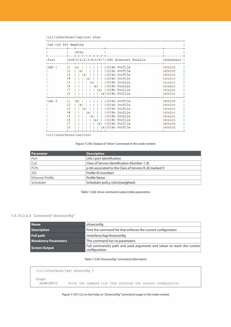
Descripción del producto
300
Figure 7-256: Output of ”show” command in this node context
Parameter DescriptionPort LAG I port identification CoS Class of Service identification (Number 1..8)PCPs p-bit associated to the Class of Service (0..8) marked X(ID) Profile ID (number)Ethernet Profile Profile Name Scheduler Scheduler policy (strict|weighted)
Table 7-228: show command output table parameters
7.6.10.3.6.3 Command “showconfig”
Name showconfig
Description Print the command list that enforces the current configuration
Full path /interfaces/lag/showconfig
Mandatory Parameters This command has no parameters
Screen Output Full command(s) path and used arguments and values to reach the current configuration.
Table 7-229:”showconfig” command information
/cli/interfaces/lag> showconfig ?
Usage: SHOWCONFIG Print the command list that enforces the current configuration
Figure 7-257: CLI on line help on “showconfig” command usage in this node context
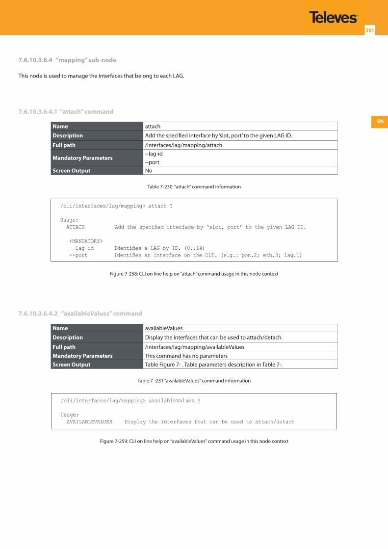
EN
301
7.6.10.3.6.4 “mapping” sub-node
This node is used to manage the interfaces that belong to each LAG.
7.6.10.3.6.4.1 “attach” command
Name attach
Description Add the specified interface by ‘slot, port’ to the given LAG ID.
Full path /interfaces/lag/mapping/attach
Mandatory Parameters--lag-id--port
Screen Output No
Table 7-230: “attach” command information
/cli/interfaces/lag/mapping> attach ?
Usage: ATTACH Add the specified interface by ‘slot, port’ to the given LAG ID.
<MANDATORY> --lag-id Identifies a LAG by ID. (0..14) --port Identifies an interface on the OLT. (e.g.: pon.2; eth.3; lag.1)
Figure 7-258: CLI on line help on “attach” command usage in this node context
7.6.10.3.6.4.2 “availableValues” command
Name availableValues
Description Display the interfaces that can be used to attach/detach.
Full path /interfaces/lag/mapping/availableValues
Mandatory Parameters This command has no parametersScreen Output Table Figure 7- . Table parameters description in Table 7-.
Table 7-:231 “availableValues” command information
/cli/interfaces/lag/mapping> availableValues ?
Usage: AVAILABLEVALUES Display the interfaces that can be used to attach/detach
Figure 7-259: CLI on line help on “availableValues” command usage in this node context
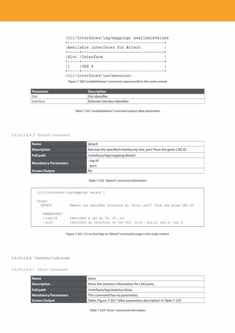
Descripción del producto
302
Figure 7-260:”availableValues” command output partial in this node context
Parameter DescriptionSlot Slot identifier Interface Ethernet interface Identifier
Table 7-232: “availableValues” command output table parameters
7.6.10.3.6.4.3 “detach” command
Name detach
Description Remove the specified interface by ‘slot, port’ from the given LAG ID.
Full path /interfaces/lag/mapping/detach
Mandatory Parameters--lag-id--port
Screen Output No
Table 7-233: “detach” command information
/cli/interfaces/lag/mapping> detach ?
Usage: DETACH Remove the specified interface by ‘slot, port’ from the given LAG ID.
<MANDATORY> --lag-id Identifies a LAG by ID. (0..14) --port Identifies an interface on the OLT. (e.g.: pon.2; eth.3; lag.1)
Figure 7-261: CLI on line help on “detach” command usage in this node context
7.6.10.3.6.5 “statistics” sub-node
7.6.10.3.6.5.1 ”show” command
Name show
Description Show the statistics information for LAG ports.
Full path /interfaces/lag/statistics/show
Mandatory Parameters This command has no parameters.Screen Output Table, Figure 7-263. Table parameters description in Table 7-235
Table 7-234: “show” command information
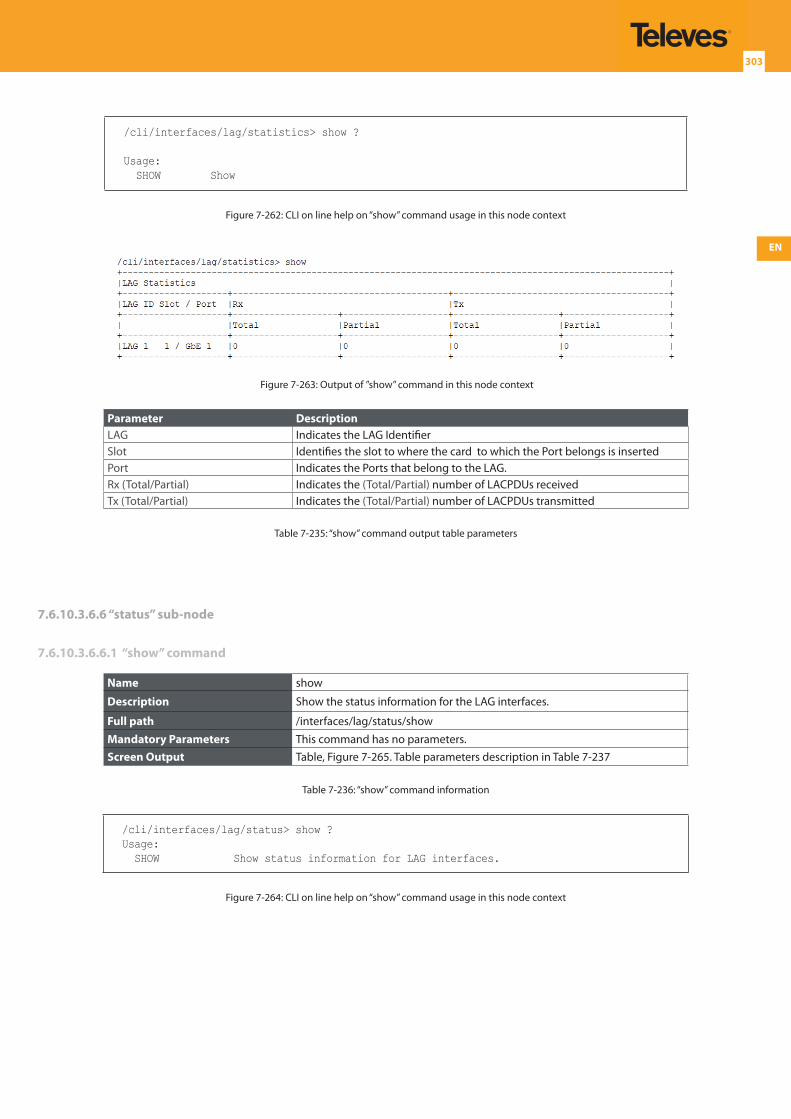
EN
303
/cli/interfaces/lag/statistics> show ?
Usage: SHOW Show
Figure 7-262: CLI on line help on “show” command usage in this node context
/cli/interfaces/lag/statistics> show ?
Usage: SHOW Show
Figure 7-: CLI on line help on “show” command usage in this node context
Figure 7-263: Output of ”show” command in this node context
Parameter DescriptionLAG Indicates the LAG IdentifierSlot Identifies the slot to where the card to which the Port belongs is insertedPort Indicates the Ports that belong to the LAG.Rx (Total/Partial) Indicates the (Total/Partial) number of LACPDUs receivedTx (Total/Partial) Indicates the (Total/Partial) number of LACPDUs transmitted
Table 7-235: “show” command output table parameters
7.6.10.3.6.6 “status” sub-node
7.6.10.3.6.6.1 “show” command
Name show
Description Show the status information for the LAG interfaces.
Full path /interfaces/lag/status/show
Mandatory Parameters This command has no parameters.Screen Output Table, Figure 7-265. Table parameters description in Table 7-237
Table 7-236: “show” command information
/cli/interfaces/lag/status> show ?Usage: SHOW Show status information for LAG interfaces.
Figure 7-264: CLI on line help on “show” command usage in this node context
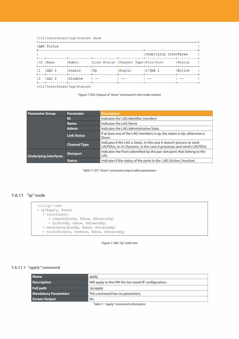
Descripción del producto
304
Figure 7-265: Output of ”show” command in this node context
Parameter Group Parameter DescriptionID Indicates the LAG Identifier (number)Name Indicates the LAG NameAdmin Indicates the LAG Administrative State.
Link Status If at least one of the LAG members is up, the status is Up, otherwise is Down
Channel Type Indicates if the LAG is Static, in this case it doesn’t process or send LACPDUs, or it’s Dynamic, in this case it processes and send’s LACPDUs
Underlying InterfacesSlot/port Indicates the Ports (identified by the pair slot/port) that belong to the
LAGStatus Indicates if the status of the ports in the LAG (Active | Inactive)
Table 7-237: “show” command output table parameters
7.6.11 “ip” node
/cli/ip> tree+ ip[@apply, @save] + interfaces[] + inband[@config, @show, @showconfig] + ip[@config, @show, @showconfig] + networking[@config, @show, @showconfig] + route[@create, @remove, @show, @showconfig]
Figure 7-266: “ip” node tree
7.6.11.1 “apply” command
Name apply
Description Will apply to the HW the last saved IP configuration..
Full path /ip/apply
Mandatory Parameters This command has no parameters.Screen Output No
Table 7-: “apply” command information
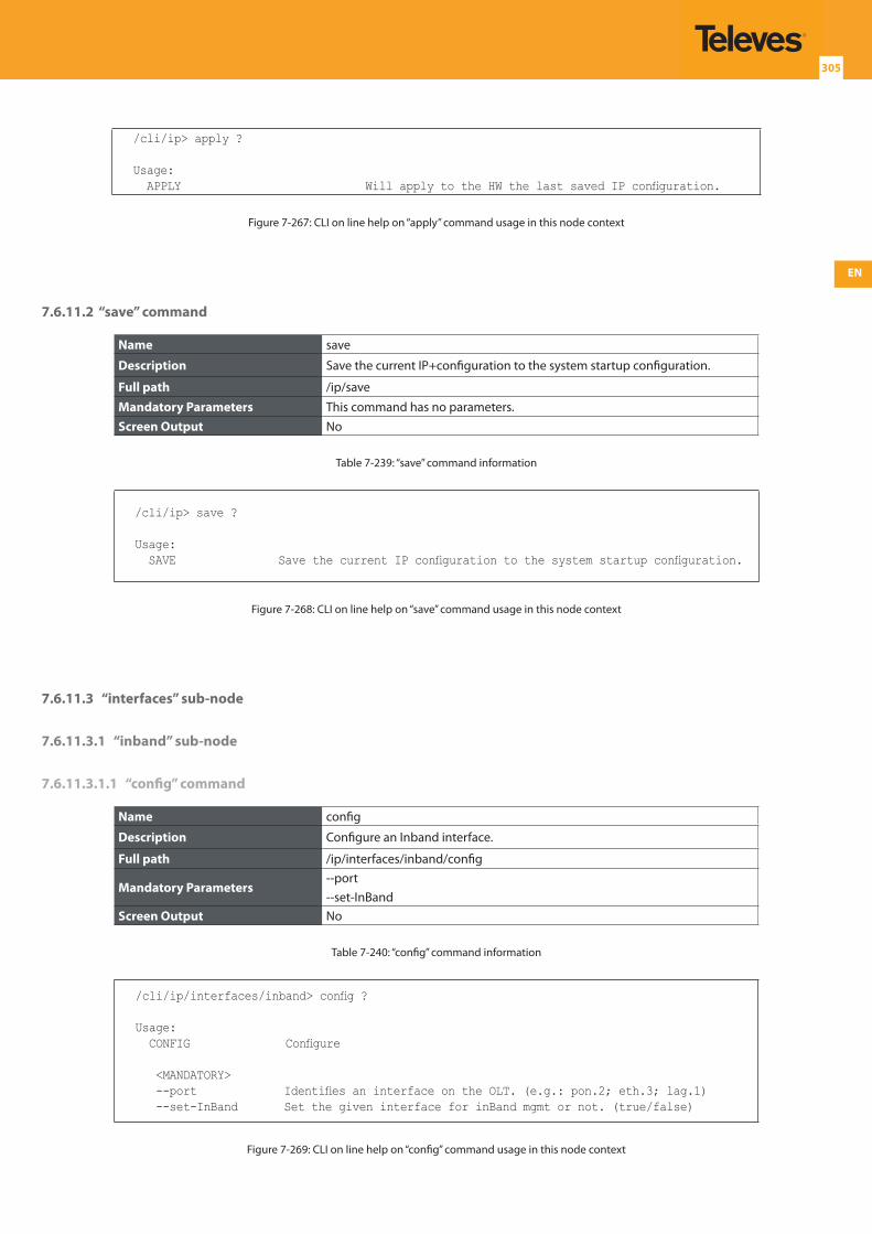
EN
305
/cli/ip> apply ?
Usage: APPLY Will apply to the HW the last saved IP configuration.
Figure 7-267: CLI on line help on “apply” command usage in this node context
7.6.11.2 “save” command
Name save
Description Save the current IP+configuration to the system startup configuration.
Full path /ip/save
Mandatory Parameters This command has no parameters.Screen Output No
Table 7-239: “save” command information
/cli/ip> save ?
Usage: SAVE Save the current IP configuration to the system startup configuration.
Figure 7-268: CLI on line help on “save” command usage in this node context
7.6.11.3 “interfaces” sub-node
7.6.11.3.1 “inband” sub-node
7.6.11.3.1.1 “config” command
Name config
Description Configure an Inband interface.
Full path /ip/interfaces/inband/config
Mandatory Parameters--port--set-InBand
Screen Output No
Table 7-240: “config” command information
/cli/ip/interfaces/inband> config ?
Usage: CONFIG Configure
<MANDATORY> --port Identifies an interface on the OLT. (e.g.: pon.2; eth.3; lag.1) --set-InBand Set the given interface for inBand mgmt or not. (true/false)
Figure 7-269: CLI on line help on “config” command usage in this node context
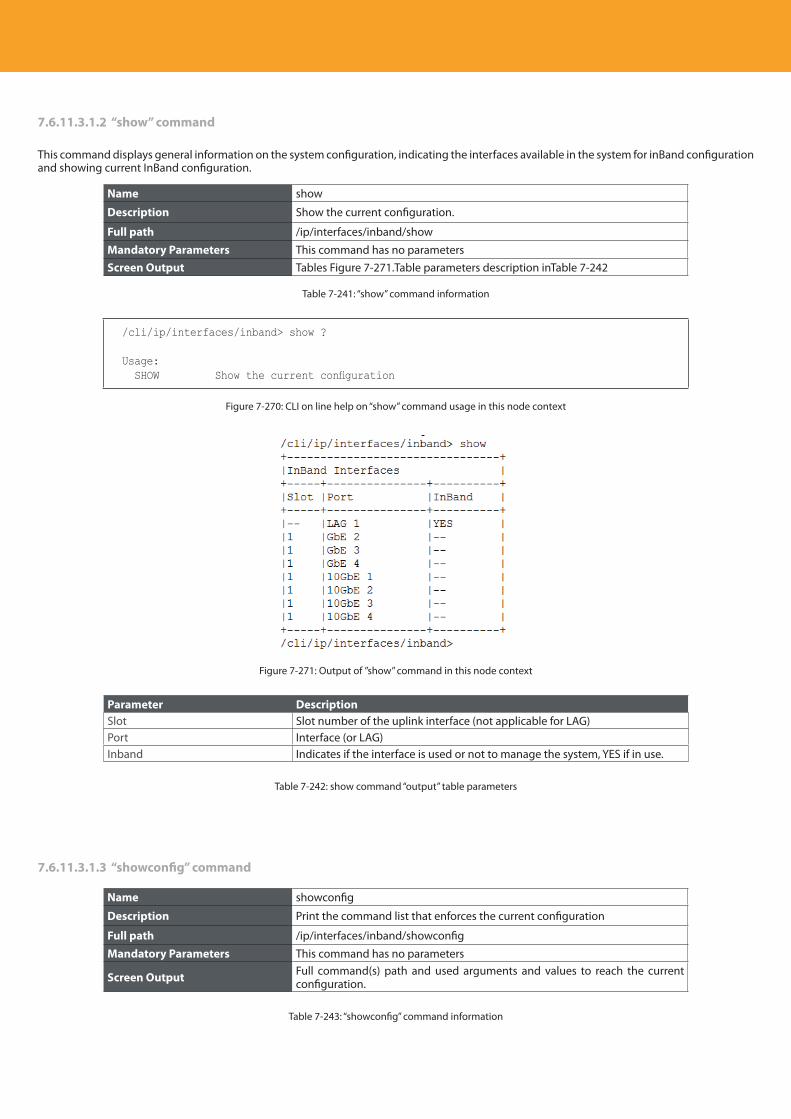
Descripción del producto
306
7.6.11.3.1.2 “show” command
This command displays general information on the system configuration, indicating the interfaces available in the system for inBand configuration and showing current InBand configuration.
Name show
Description Show the current configuration.
Full path /ip/interfaces/inband/show
Mandatory Parameters This command has no parametersScreen Output Tables Figure 7-271.Table parameters description inTable 7-242
Table 7-241: “show” command information
/cli/ip/interfaces/inband> show ?
Usage: SHOW Show the current configuration
Figure 7-270: CLI on line help on “show” command usage in this node context
Figure 7-271: Output of ”show” command in this node context
Parameter DescriptionSlot Slot number of the uplink interface (not applicable for LAG)Port Interface (or LAG)Inband Indicates if the interface is used or not to manage the system, YES if in use.
Table 7-242: show command “output” table parameters
7.6.11.3.1.3 “showconfig” command
Name showconfig
Description Print the command list that enforces the current configuration
Full path /ip/interfaces/inband/showconfig
Mandatory Parameters This command has no parameters
Screen Output Full command(s) path and used arguments and values to reach the current configuration.
Table 7-243: “showconfig” command information
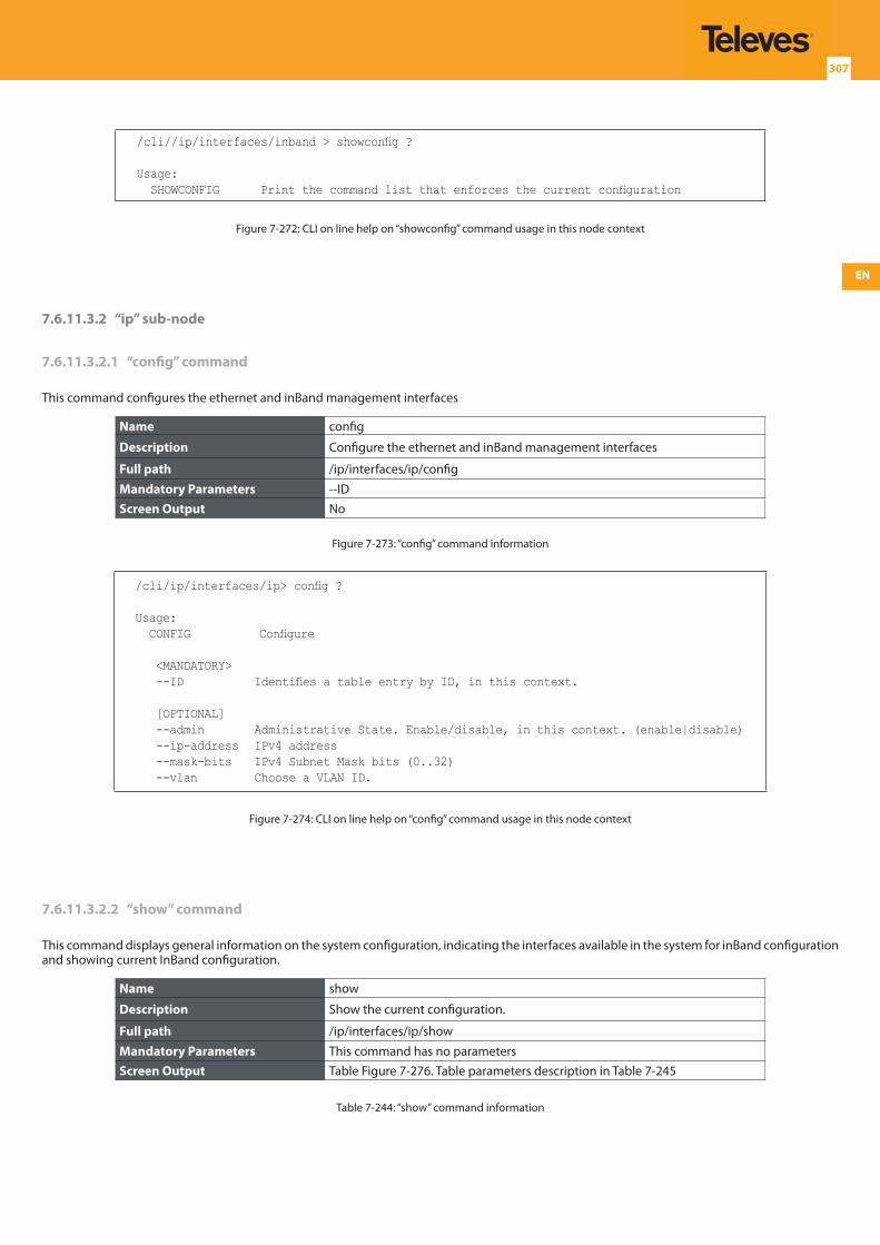
EN
307
/cli//ip/interfaces/inband > showconfig ?
Usage: SHOWCONFIG Print the command list that enforces the current configuration
Figure 7-272: CLI on line help on “showconfig” command usage in this node context
7.6.11.3.2 “ip” sub-node
7.6.11.3.2.1 “config” command
This command configures the ethernet and inBand management interfaces
Name config
Description Configure the ethernet and inBand management interfaces
Full path /ip/interfaces/ip/config
Mandatory Parameters --IDScreen Output No
Figure 7-273: “config” command information
/cli/ip/interfaces/ip> config ?
Usage: CONFIG Configure
<MANDATORY> --ID Identifies a table entry by ID, in this context.
[OPTIONAL] --admin Administrative State. Enable/disable, in this context. (enable|disable) --ip-address IPv4 address --mask-bits IPv4 Subnet Mask bits (0..32) --vlan Choose a VLAN ID.
Figure 7-274: CLI on line help on “config” command usage in this node context
7.6.11.3.2.2 “show” command
This command displays general information on the system configuration, indicating the interfaces available in the system for inBand configuration and showing current InBand configuration.
Name show
Description Show the current configuration.
Full path /ip/interfaces/ip/show
Mandatory Parameters This command has no parametersScreen Output Table Figure 7-276. Table parameters description in Table 7-245
Table 7-244: “show” command information
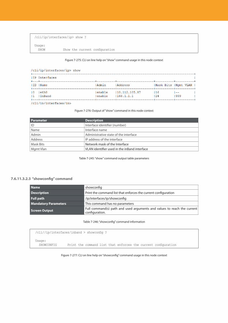
Descripción del producto
308
/cli/ip/interfaces/ip> show ?
Usage: SHOW Show the current configuration
Figure 7-275: CLI on line help on “show” command usage in this node context
Figure 7-276: Output of ”show” command in this node context
Parameter DescriptionID Interface identifier (number)Name Interface nameAdmin Administrative state of the interfaceAddress IP address of the interfaceMask Bits Network mask of the InterfaceMgmt Vlan VLAN identifier used in the inBand interface
Table 7-245: “show” command output table parameters
7.6.11.3.2.3 “showconfig” command
Name showconfig
Description Print the command list that enforces the current configuration
Full path /ip/interfaces/ip/showconfig
Mandatory Parameters This command has no parameters
Screen Output Full command(s) path and used arguments and values to reach the current configuration.
Table 7-246: “showconfig” command information
/cli//ip/interfaces/inband > showconfig ?
Usage: SHOWCONFIG Print the command list that enforces the current configuration
Figure 7-277: CLI on line help on “showconfig” command usage in this node context
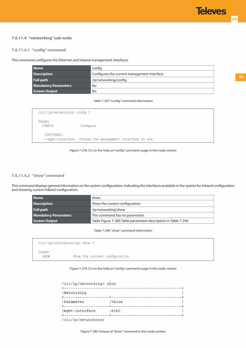
EN
309
7.6.11.4 “networking” sub-node
7.6.11.4.1 “config” command
This command configures the Ethernet and Inband management interfaces
Name config
Description Configures the current management interface.
Full path /ip/networking/config
Mandatory Parameters NoScreen Output No
Table 7-247: “config” command information
/cli/ip/networking> config ?
Usage: CONFIG Configure
[OPTIONAL] --mgmt-interface Choose the management interface to use.
Figure 7-278: CLI on line help on “config” command usage in this node context
7.6.11.4.2 “show” command
This command displays general information on the system configuration, indicating the interfaces available in the system for Inband configuration and showing current InBand configuration.
Name show
Description Show the current configuration.
Full path /ip/networking/show
Mandatory Parameters This command has no parametersScreen Output Table Figure 7-280 Table parameters description in Table 7-249
Table 7-248: “show” command information
/cli/ip/interfaces/ip> show ?
Usage: SHOW Show the current configuration
Figure 7-279: CLI on line help on “config” command usage in this node context
Figure 7-280: Output of ”show” command in this node context
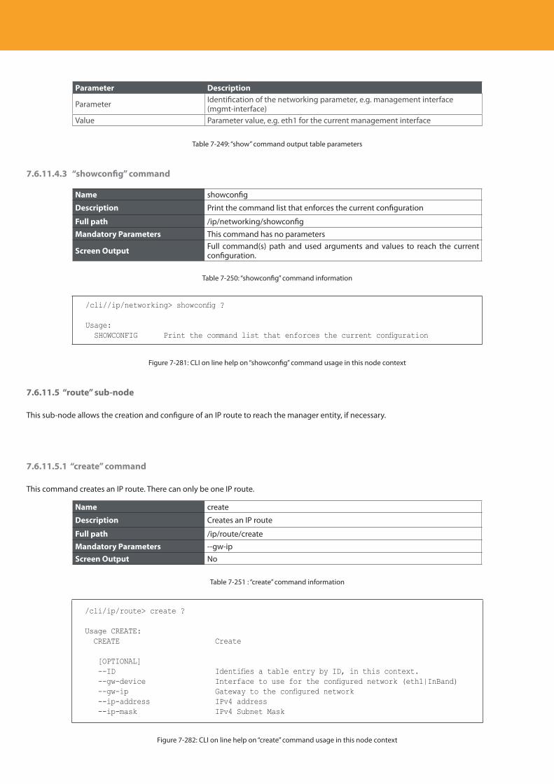
Descripción del producto
310
Parameter Description
Parameter Identification of the networking parameter, e.g. management interface (mgmt-interface)
Value Parameter value, e.g. eth1 for the current management interface
Table 7-249: “show” command output table parameters
7.6.11.4.3 “showconfig” command
Name showconfig
Description Print the command list that enforces the current configuration
Full path /ip/networking/showconfig
Mandatory Parameters This command has no parameters
Screen Output Full command(s) path and used arguments and values to reach the current configuration.
Table 7-250: “showconfig” command information
/cli//ip/networking> showconfig ?
Usage: SHOWCONFIG Print the command list that enforces the current configuration
Figure 7-281: CLI on line help on “showconfig” command usage in this node context
7.6.11.5 “route” sub-node
This sub-node allows the creation and configure of an IP route to reach the manager entity, if necessary.
7.6.11.5.1 “create” command
This command creates an IP route. There can only be one IP route.
Name create
Description Creates an IP route
Full path /ip/route/create
Mandatory Parameters --gw-ipScreen Output No
Table 7-251 : “create” command information
/cli/ip/route> create ?
Usage CREATE: CREATE Create
[OPTIONAL] --ID Identifies a table entry by ID, in this context. --gw-device Interface to use for the configured network (eth1|InBand) --gw-ip Gateway to the configured network --ip-address IPv4 address --ip-mask IPv4 Subnet Mask
Figure 7-282: CLI on line help on “create” command usage in this node context
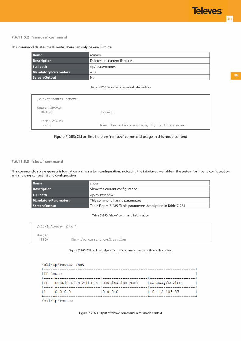
EN
311
7.6.11.5.2 “remove” command
This command deletes the IP route. There can only be one IP route.
Name remove
Description Deletes the current IP route.
Full path /ip/route/remove
Mandatory Parameters --IDScreen Output No
Table 7-252: “remove” command information
/cli/ip/route> remove ?
Usage REMOVE: REMOVE Remove
<MANDATORY> --ID Identifies a table entry by ID, in this context.
Figure 7-283: CLI on line help on “remove” command usage in this node context
7.6.11.5.3 “show” command
This command displays general information on the system configuration, indicating the interfaces available in the system for Inband configuration and showing current InBand configuration.
Name show
Description Show the current configuration.
Full path /ip/route/show
Mandatory Parameters This command has no parametersScreen Output Table Figure 7-285. Table parameters description in Table 7-254
Table 7-253: “show” command information
/cli/ip/route> show ?
Usage: SHOW Show the current configuration
Figure 7-285: CLI on line help on “show” command usage in this node context
Figure 7-286: Output of ”show” command in this node context
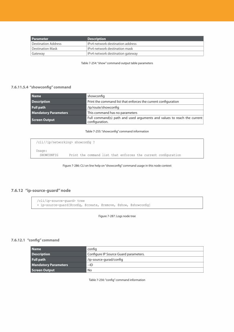
Descripción del producto
312
Parameter DescriptionDestination Address IPv4 network destination addressDestination Mask IPv4 network destination maskGateway IPv4 network destination gateway
Table 7-254: “show” command output table parameters
7.6.11.5.4 “showconfig” command
Name showconfig
Description Print the command list that enforces the current configuration
Full path /ip/route/showconfig
Mandatory Parameters This command has no parameters
Screen Output Full command(s) path and used arguments and values to reach the current configuration.
Table 7-255: “showconfig” command information
/cli//ip/networking> showconfig ?
Usage: SHOWCONFIG Print the command list that enforces the current configuration
Figure 7-286: CLI on line help on “showconfig” command usage in this node context
7.6.12 “ip-source-guard” node
/cli/ip-source-guard> tree+ ip-source-guard[@config, @create, @remove, @show, @showconfig]
Figure 7-287: Logs node tree
7.6.12.1 “config” command
Name configDescription Configure IP Source Guard parameters.
Full path /ip-source-gurad/config
Mandatory Parameters --IDScreen Output No
Table 7-256: “config” command information

EN
313
/cli/ip-source-guard> config ?
Usage CONFIG: CONFIG Configure IP Source Guard parameters.
<MANDATORY> --ID Identifies a table entry by ID, in this context.
[OPTIONAL] --admin Administrative State. Enable/disable, in this context.
(enable|disable) --ip-address IPv4/IPv6 address --mac Identify/Set a MAC entry, in this context. --port Identifies an interface on the OLT. (e.g.: pon.2; eth.3; lag.1) --serviceID Select an OLT service by ID.
Figure 7-288: CLI on line help on “config” command usage in this node context
7.6.12.2 “create” command
Name create
Description Create a new IP Source Guard entry.
Full path /ip-source-guard/create
Mandatory Parameters NoScreen Output No
Table 7-257: “create” command information
/cli/ip-source-guard> create ?
Usage CREATE: CREATE Create a new IP Source Guard entry.
[OPTIONAL] --ID Identifies a table entry by ID, in this context. --admin Administrative State. Enable/disable, in this context.
(enable|disable) --ip-address IPv4/IPv6 address --mac Identify/Set a MAC entry, in this context. --port Identifies an interface on the OLT. (e.g.: pon.2; eth.3; lag.1) --serviceID Select an OLT service by ID.
Figure 7-289: CLI on line help on “create” command usage in this node context
7.6.12.3 “remove” command
This command deletes the IP route. There can only be one IP route.
Name remove
Description Remove an existing IP Source Guard entry.
Full path /ip-source-guard/remove
Mandatory Parameters --IDScreen Output No
Table 7-258: “remove” command information
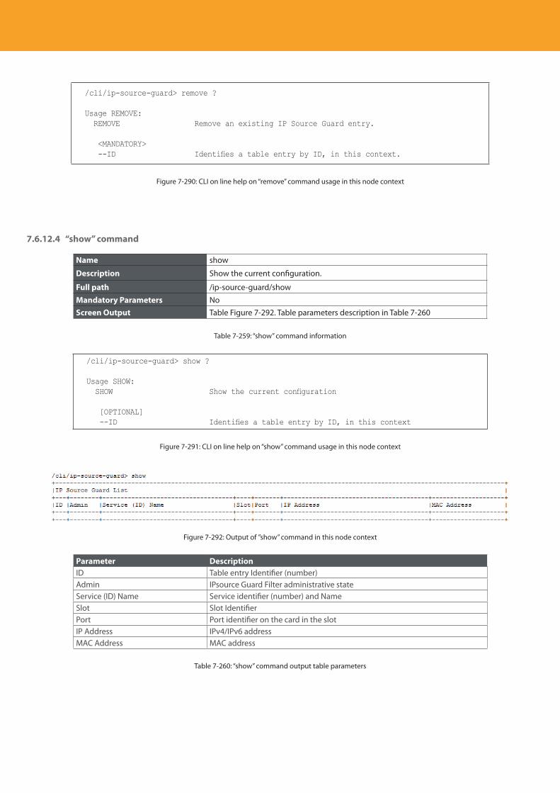
Descripción del producto
314
/cli/ip-source-guard> remove ?
Usage REMOVE: REMOVE Remove an existing IP Source Guard entry.
<MANDATORY> --ID Identifies a table entry by ID, in this context.
Figure 7-290: CLI on line help on “remove” command usage in this node context
7.6.12.4 “show” command
Name show
Description Show the current configuration.
Full path /ip-source-guard/show
Mandatory Parameters NoScreen Output Table Figure 7-292. Table parameters description in Table 7-260
Table 7-259: “show” command information
/cli/ip-source-guard> show ?
Usage SHOW: SHOW Show the current configuration
[OPTIONAL] --ID Identifies a table entry by ID, in this context
Figure 7-291: CLI on line help on “show” command usage in this node context
Figure 7-292: Output of ”show” command in this node context
Parameter DescriptionID Table entry Identifier (number)Admin IPsource Guard Filter administrative stateService (ID) Name Service identifier (number) and Name Slot Slot Identifier Port Port identifier on the card in the slotIP Address IPv4/IPv6 addressMAC Address MAC address
Table 7-260: “show” command output table parameters
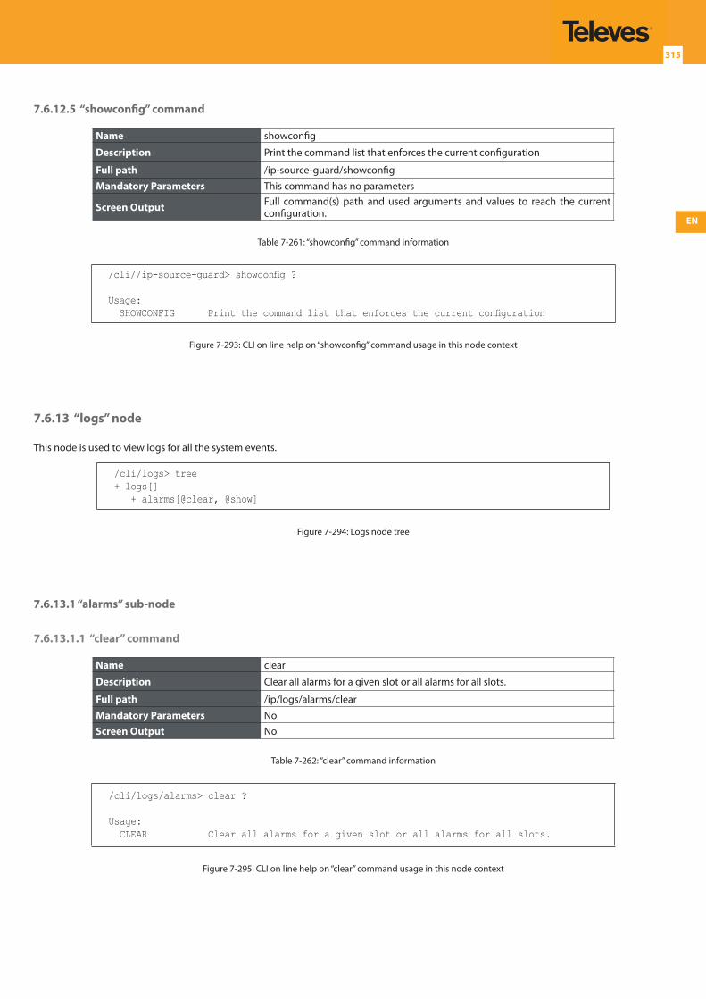
EN
315
7.6.12.5 “showconfig” command
Name showconfig
Description Print the command list that enforces the current configuration
Full path /ip-source-guard/showconfig
Mandatory Parameters This command has no parameters
Screen Output Full command(s) path and used arguments and values to reach the current configuration.
Table 7-261: “showconfig” command information
/cli//ip-source-guard> showconfig ?
Usage: SHOWCONFIG Print the command list that enforces the current configuration
Figure 7-293: CLI on line help on “showconfig” command usage in this node context
7.6.13 “logs” node
This node is used to view logs for all the system events.
/cli/logs> tree+ logs[] + alarms[@clear, @show]
Figure 7-294: Logs node tree
7.6.13.1 “alarms” sub-node
7.6.13.1.1 “clear” command
Name clear
Description Clear all alarms for a given slot or all alarms for all slots.
Full path /ip/logs/alarms/clear
Mandatory Parameters NoScreen Output No
Table 7-262: “clear” command information
/cli/logs/alarms> clear ?
Usage: CLEAR Clear all alarms for a given slot or all alarms for all slots.
Figure 7-295: CLI on line help on “clear” command usage in this node context
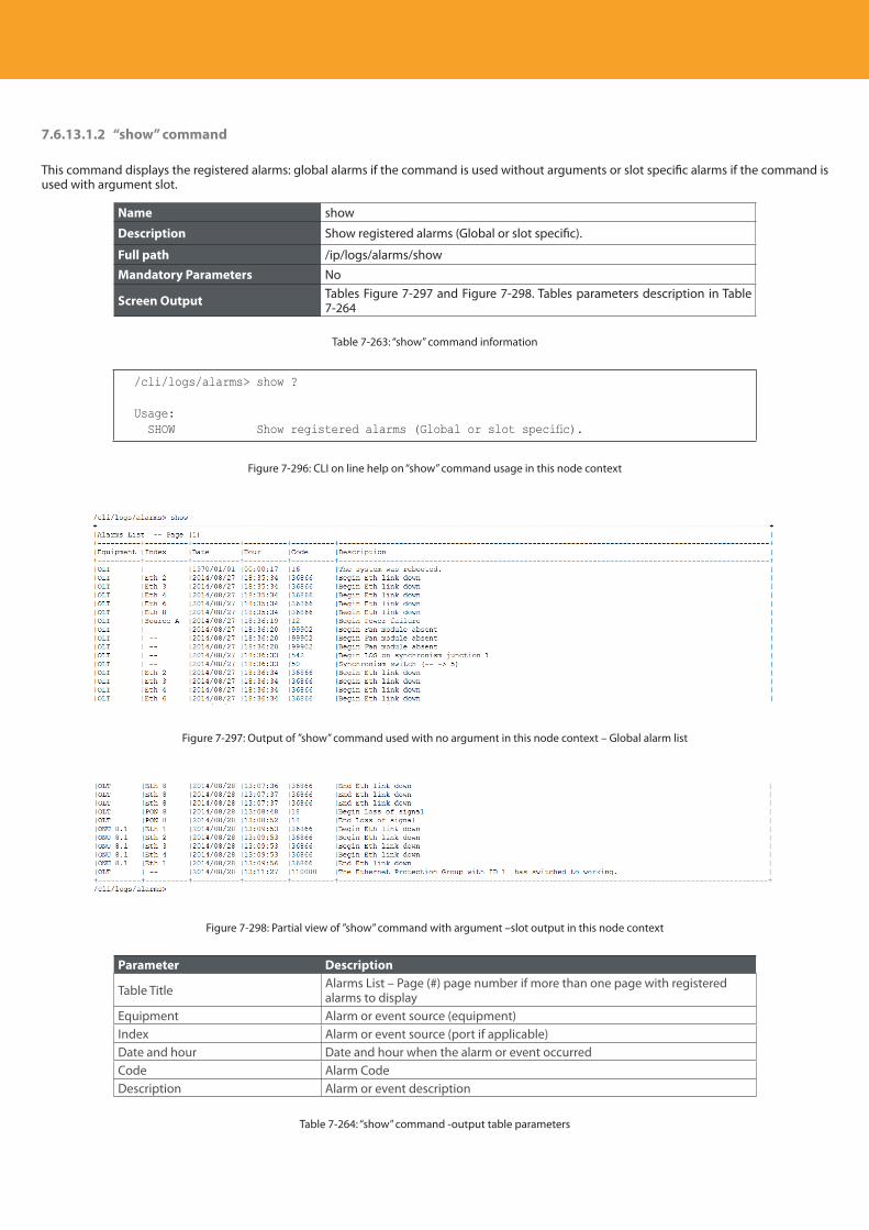
Descripción del producto
316
7.6.13.1.2 “show” command
This command displays the registered alarms: global alarms if the command is used without arguments or slot specific alarms if the command is used with argument slot.
Name show
Description Show registered alarms (Global or slot specific).
Full path /ip/logs/alarms/show
Mandatory Parameters No
Screen Output Tables Figure 7-297 and Figure 7-298. Tables parameters description in Table 7-264
Table 7-263: “show” command information
/cli/logs/alarms> show ?
Usage: SHOW Show registered alarms (Global or slot specific).
Figure 7-296: CLI on line help on “show” command usage in this node context
Figure 7-297: Output of ”show” command used with no argument in this node context – Global alarm list
Figure 7-298: Partial view of ”show” command with argument –slot output in this node context
Parameter Description
Table Title Alarms List – Page (#) page number if more than one page with registered alarms to display
Equipment Alarm or event source (equipment)Index Alarm or event source (port if applicable)Date and hour Date and hour when the alarm or event occurredCode Alarm CodeDescription Alarm or event description
Table 7-264: “show” command -output table parameters
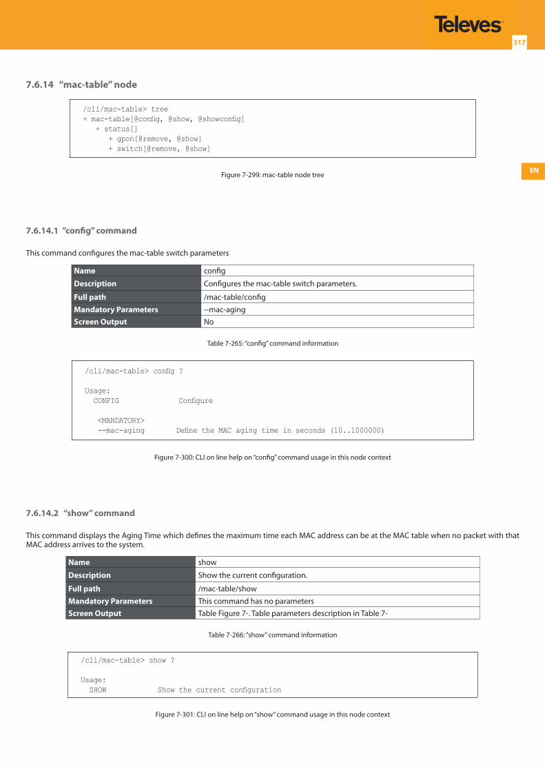
EN
317
7.6.14 “mac-table” node
/cli/mac-table> tree+ mac-table[@config, @show, @showconfig] + status[] + gpon[@remove, @show] + switch[@remove, @show]
Figure 7-299: mac-table node tree
7.6.14.1 ”config” command
This command configures the mac-table switch parameters
Name config
Description Configures the mac-table switch parameters.
Full path /mac-table/config
Mandatory Parameters --mac-agingScreen Output No
Table 7-265: “config” command information
/cli/mac-table> config ?
Usage: CONFIG Configure
<MANDATORY> --mac-aging Define the MAC aging time in seconds (10..1000000)
Figure 7-300: CLI on line help on “config” command usage in this node context
7.6.14.2 “show” command
This command displays the Aging Time which defines the maximum time each MAC address can be at the MAC table when no packet with that MAC address arrives to the system.
Name show
Description Show the current configuration.
Full path /mac-table/show
Mandatory Parameters This command has no parametersScreen Output Table Figure 7-. Table parameters description in Table 7-
Table 7-266: “show” command information
/cli/mac-table> show ?
Usage: SHOW Show the current configuration
Figure 7-301: CLI on line help on “show” command usage in this node context
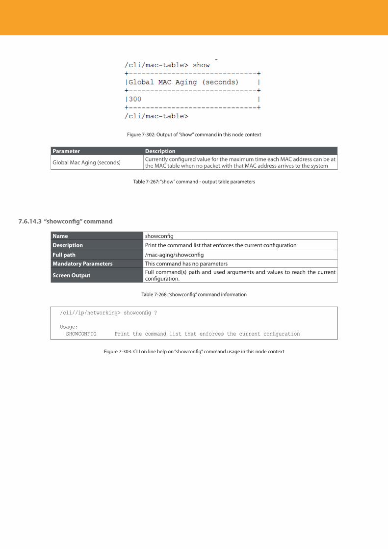
Descripción del producto
318
Figure 7-302: Output of ”show” command in this node context
Parameter Description
Global Mac Aging (seconds) Currently configured value for the maximum time each MAC address can be at the MAC table when no packet with that MAC address arrives to the system
Table 7-267: “show” command - output table parameters
7.6.14.3 “showconfig” command
Name showconfig
Description Print the command list that enforces the current configuration
Full path /mac-aging/showconfig
Mandatory Parameters This command has no parameters
Screen Output Full command(s) path and used arguments and values to reach the current configuration.
Table 7-268: “showconfig” command information
/cli//ip/networking> showconfig ?
Usage: SHOWCONFIG Print the command list that enforces the current configuration
Figure 7-303: CLI on line help on “showconfig” command usage in this node context
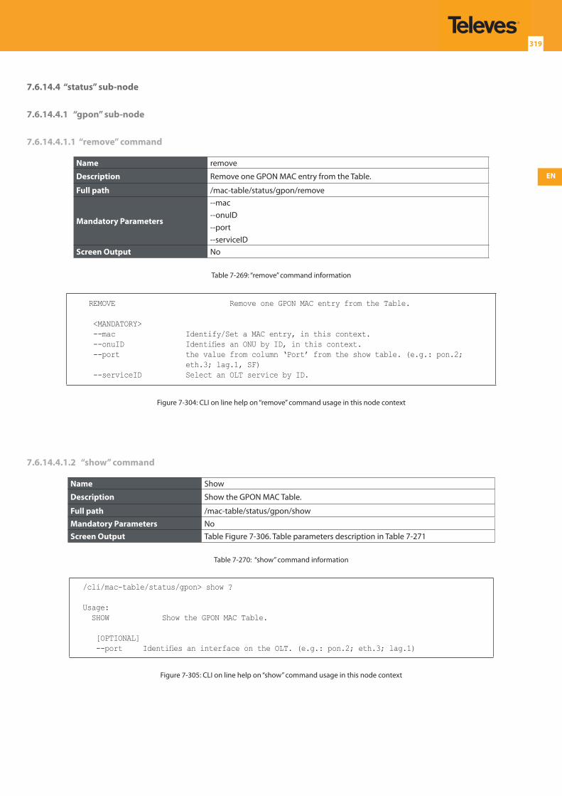
EN
319
7.6.14.4 “status” sub-node
7.6.14.4.1 “gpon” sub-node
7.6.14.4.1.1 “remove” command
Name remove
Description Remove one GPON MAC entry from the Table.
Full path /mac-table/status/gpon/remove
Mandatory Parameters
--mac--onuID--port--serviceID
Screen Output No
Table 7-269: “remove” command information
REMOVE Remove one GPON MAC entry from the Table.
<MANDATORY> --mac Identify/Set a MAC entry, in this context. --onuID Identifies an ONU by ID, in this context. --port the value from column ‘Port’ from the show table. (e.g.: pon.2;
eth.3; lag.1, SF) --serviceID Select an OLT service by ID.
Figure 7-304: CLI on line help on “remove” command usage in this node context
7.6.14.4.1.2 “show” command
Name Show
Description Show the GPON MAC Table.
Full path /mac-table/status/gpon/show
Mandatory Parameters NoScreen Output Table Figure 7-306. Table parameters description in Table 7-271
Table 7-270: “show” command information
/cli/mac-table/status/gpon> show ?
Usage: SHOW Show the GPON MAC Table.
[OPTIONAL] --port Identifies an interface on the OLT. (e.g.: pon.2; eth.3; lag.1)
Figure 7-305: CLI on line help on “show” command usage in this node context
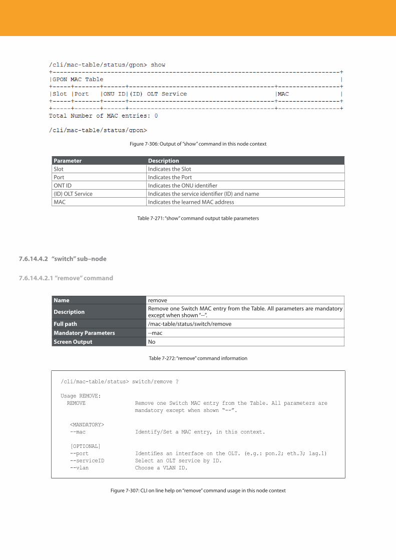
Descripción del producto
320
Figure 7-306: Output of ”show” command in this node context
Parameter DescriptionSlot Indicates the SlotPort Indicates the PortONT ID Indicates the ONU identifier(ID) OLT Service Indicates the service identifier (ID) and nameMAC Indicates the learned MAC address
Table 7-271: “show” command output table parameters
7.6.14.4.2 “switch” sub–node
7.6.14.4.2.1 ”remove” command
Name remove
Description Remove one Switch MAC entry from the Table. All parameters are mandatory except when shown “--”.
Full path /mac-table/status/switch/remove
Mandatory Parameters --macScreen Output No
Table 7-272: “remove” command information
/cli/mac-table/status> switch/remove ?
Usage REMOVE: REMOVE Remove one Switch MAC entry from the Table. All parameters are
mandatory except when shown “--”.
<MANDATORY> --mac Identify/Set a MAC entry, in this context.
[OPTIONAL] --port Identifies an interface on the OLT. (e.g.: pon.2; eth.3; lag.1) --serviceID Select an OLT service by ID. --vlan Choose a VLAN ID.
Figure 7-307: CLI on line help on “remove” command usage in this node context
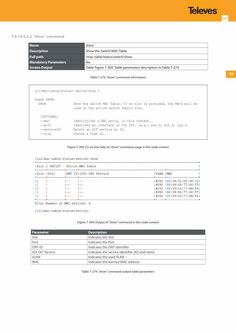
EN
321
7.6.14.4.2.2 ”show” command
Name show
Description Show the Switch MAC Table.
Full path /mac-table/status/switch/show
Mandatory Parameters NoScreen Output Table Figure 7-309. Table parameters description in Table 7-274
Table 7-273: “show” command information
cli/mac-table/status> switch/show ?
Usage SHOW: SHOW Show the Switch MAC Table. If no slot is provided, the MACs will be
read on the active switch fabric slot.
[OPTIONAL] --mac Identify/Set a MAC entry, in this context. --port Identifies an interface on the OLT. (e.g.: pon.2; eth.3; lag.1) --serviceID Select an OLT service by ID. --vlan Choose a VLAN ID.
Figure 7-308: CLI on line help on “show” command usage in this node context
Figure 7-309: Output of ”show” command in this node context
Parameter DescriptionSlot Indicates the SlotPort Indicates the PortONT ID Indicates the ONT identifier(ID) OLT Service Indicates the service identifier (ID) and nameVLAN Indicates the used VLANMAC Indicates the learned MAC address
Table 7-274: “show” command output table parameters
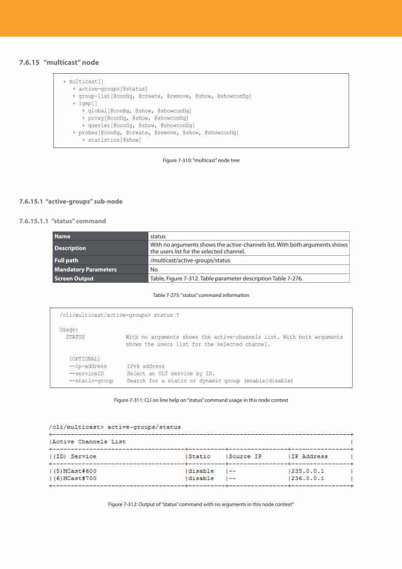
Descripción del producto
322
7.6.15 “multicast” node
+ multicast[] + active-groups[@status] + group-list[@config, @create, @remove, @show, @showconfig] + igmp[] + global[@config, @show, @showconfig] + proxy[@config, @show, @showconfig] + querier[@config, @show, @showconfig] + probes[@config, @create, @remove, @show, @showconfig] + statistics[@show]
Figure 7-310: “multicast” node tree
7.6.15.1 “active-groups” sub-node
7.6.15.1.1 ”status” command
Name status
Description With no arguments shows the active-channels list. With both arguments shows the users list for the selected channel.
Full path /multicast/active-groups/status
Mandatory Parameters NoScreen Output Table, Figure 7-312. Table parameter description Table 7-276.
Table 7-275: “status” command information
/cli/multicast/active-groups> status ?
Usage: STATUS With no arguments shows the active-channels list. With both arguments
shows the users list for the selected channel.
[OPTIONAL] --ip-address IPv4 address --serviceID Select an OLT service by ID. --static-group Search for a static or dynamic group (enable|disable)
Figure 7-311: CLI on line help on “status” command usage in this node context
Figure 7-312: Output of ”status” command with no arguments in this node context”
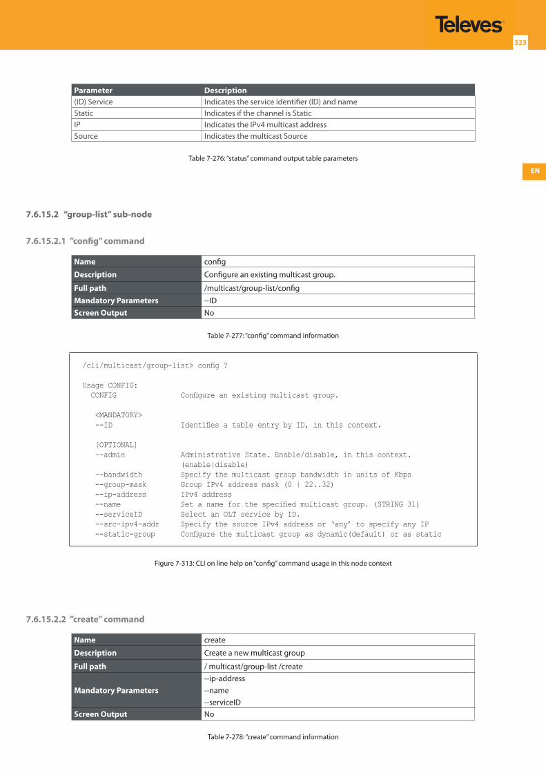
EN
323
Parameter Description(ID) Service Indicates the service identifier (ID) and nameStatic Indicates if the channel is Static IP Indicates the IPv4 multicast addressSource Indicates the multicast Source
Table 7-276: “status” command output table parameters
7.6.15.2 “group-list” sub-node
7.6.15.2.1 ”config” command
Name config
Description Configure an existing multicast group.
Full path /multicast/group-list/config
Mandatory Parameters --IDScreen Output No
Table 7-277: “config” command information
/cli/multicast/group-list> config ?
Usage CONFIG: CONFIG Configure an existing multicast group.
<MANDATORY> --ID Identifies a table entry by ID, in this context.
[OPTIONAL] --admin Administrative State. Enable/disable, in this context.
(enable|disable) --bandwidth Specify the multicast group bandwidth in units of Kbps --group-mask Group IPv4 address mask (0 | 22..32) --ip-address IPv4 address --name Set a name for the specified multicast group. (STRING 31) --serviceID Select an OLT service by ID. --src-ipv4-addr Specify the source IPv4 address or ‘any’ to specify any IP --static-group Configure the multicast group as dynamic(default) or as static
Figure 7-313: CLI on line help on “config” command usage in this node context
7.6.15.2.2 ”create” command
Name create
Description Create a new multicast group
Full path / multicast/group-list /create
Mandatory Parameters--ip-address--name--serviceID
Screen Output No
Table 7-278: “create” command information
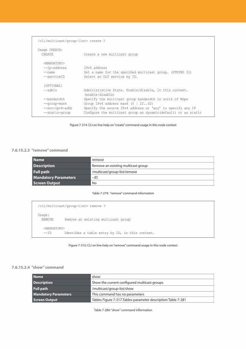
Descripción del producto
324
/cli/multicast/group-list> create ?
Usage CREATE: CREATE Create a new multicast group
<MANDATORY> --ip-address IPv4 address --name Set a name for the specified multicast group. (STRING 31) --serviceID Select an OLT service by ID.
[OPTIONAL] --admin Administrative State. Enable/disable, in this context.
(enable|disable) --bandwidth Specify the multicast group bandwidth in units of Kbps --group-mask Group IPv4 address mask (0 | 22..32) --src-ipv4-addr Specify the source IPv4 address or ‘any’ to specify any IP --static-group Configure the multicast group as dynamic(default) or as static
Figure 7-314: CLI on line help on “create” command usage in this node context
7.6.15.2.3 ”remove” command
Name remove
Description Remove an existing multicast group
Full path /multicast/group-list/remove
Mandatory Parameters --ID
Screen Output No
Table 7-279: “remove” command information
/cli/multicast/group-list> remove ?
Usage: REMOVE Remove an existing multicast group
<MANDATORY> --ID Identifies a table entry by ID, in this context.
Figure 7-315: CLI on line help on “remove” command usage in this node context
7.6.15.2.4 ”show” command
Name show
Description Show the current configured multicast groups
Full path /multicast/group-list/show
Mandatory Parameters This command has no parametersScreen Output Tables Figure 7-317.Tables parameter description Table 7-281
Table 7-280: “show” command information
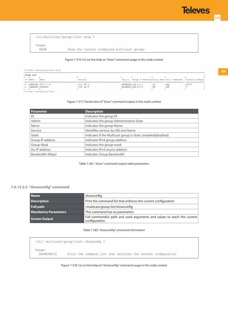
EN
325
/cli/multicast/group-list> show ?
Usage: SHOW Show the current configured multicast groups
Figure 7-316: CLI on line help on “show” command usage in this node context
Figure 7-317: Partial view of ”show” command output in this node context
Parameter DescriptionID Indicates the group IDAdmin Indicates the group Administrative StateName Indicates the group NameService Identifies service, by (ID) and NameStatic Indicates if the Multicast group is Static (enabled|disabled)Group IP address Indicates IPv4 group addressGroup Mask Indicates the group maskSrc IP address Indicates IPv4 source addressBandwidth (Kbps) Indicates Group Bandwidth
Table 7-281: “show” command output table parameters
7.6.15.2.5 ”showconfig” command
Name showconfig
Description Print the command list that enforces the current configuration
Full path /multicast/group-list/showconfig
Mandatory Parameters This command has no parameters
Screen Output Full command(s) path and used arguments and values to reach the current configuration.
Table 7-282: “showconfig” command information
/cli/ multicast/group-list> showconfig ?
Usage: SHOWCONFIG Print the command list that enforces the current configuration
Figure 7-318: CLI on line help on “showconfig” command usage in this node context
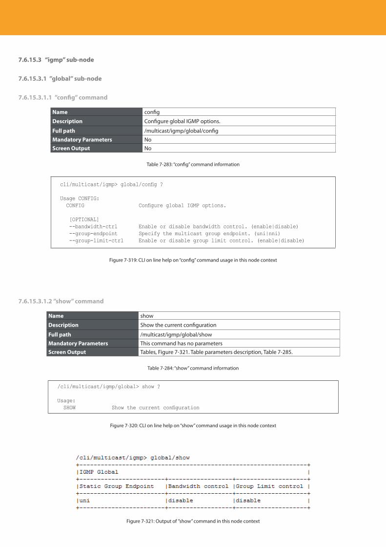
Descripción del producto
326
7.6.15.3 “igmp” sub-node
7.6.15.3.1 ”global” sub-node
7.6.15.3.1.1 ”config” command
Name config
Description Configure global IGMP options.
Full path /multicast/igmp/global/config
Mandatory Parameters NoScreen Output No
Table 7-283: “config” command information
cli/multicast/igmp> global/config ?
Usage CONFIG: CONFIG Configure global IGMP options.
[OPTIONAL] --bandwidth-ctrl Enable or disable bandwidth control. (enable|disable) --group-endpoint Specify the multicast group endpoint. (uni|nni) --group-limit-ctrl Enable or disable group limit control. (enable|disable)
Figure 7-319: CLI on line help on “config” command usage in this node context
7.6.15.3.1.2 ”show” command
Name show
Description Show the current configuration
Full path /multicast/igmp/global/show
Mandatory Parameters This command has no parametersScreen Output Tables, Figure 7-321. Table parameters description, Table 7-285.
Table 7-284: “show” command information
/cli/multicast/igmp/global> show ?
Usage: SHOW Show the current configuration
Figure 7-320: CLI on line help on “show” command usage in this node context
Figure 7-321: Output of ”show” command in this node context
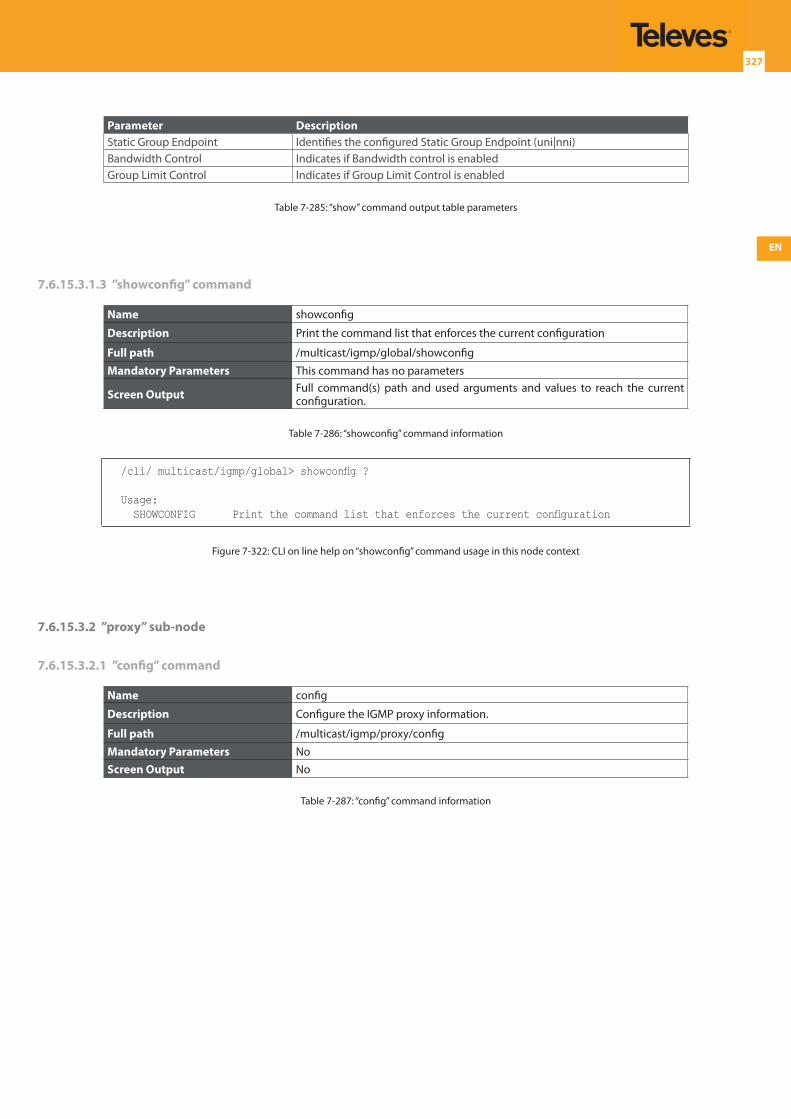
EN
327
Parameter DescriptionStatic Group Endpoint Identifies the configured Static Group Endpoint (uni|nni)Bandwidth Control Indicates if Bandwidth control is enabledGroup Limit Control Indicates if Group Limit Control is enabled
Table 7-285: “show” command output table parameters
7.6.15.3.1.3 ”showconfig” command
Name showconfig
Description Print the command list that enforces the current configuration
Full path /multicast/igmp/global/showconfig
Mandatory Parameters This command has no parameters
Screen Output Full command(s) path and used arguments and values to reach the current configuration.
Table 7-286: “showconfig” command information
/cli/ multicast/igmp/global> showconfig ?
Usage: SHOWCONFIG Print the command list that enforces the current configuration
Figure 7-322: CLI on line help on “showconfig” command usage in this node context
7.6.15.3.2 ”proxy” sub-node
7.6.15.3.2.1 ”config” command
Name config
Description Configure the IGMP proxy information.
Full path /multicast/igmp/proxy/config
Mandatory Parameters NoScreen Output No
Table 7-287: “config” command information
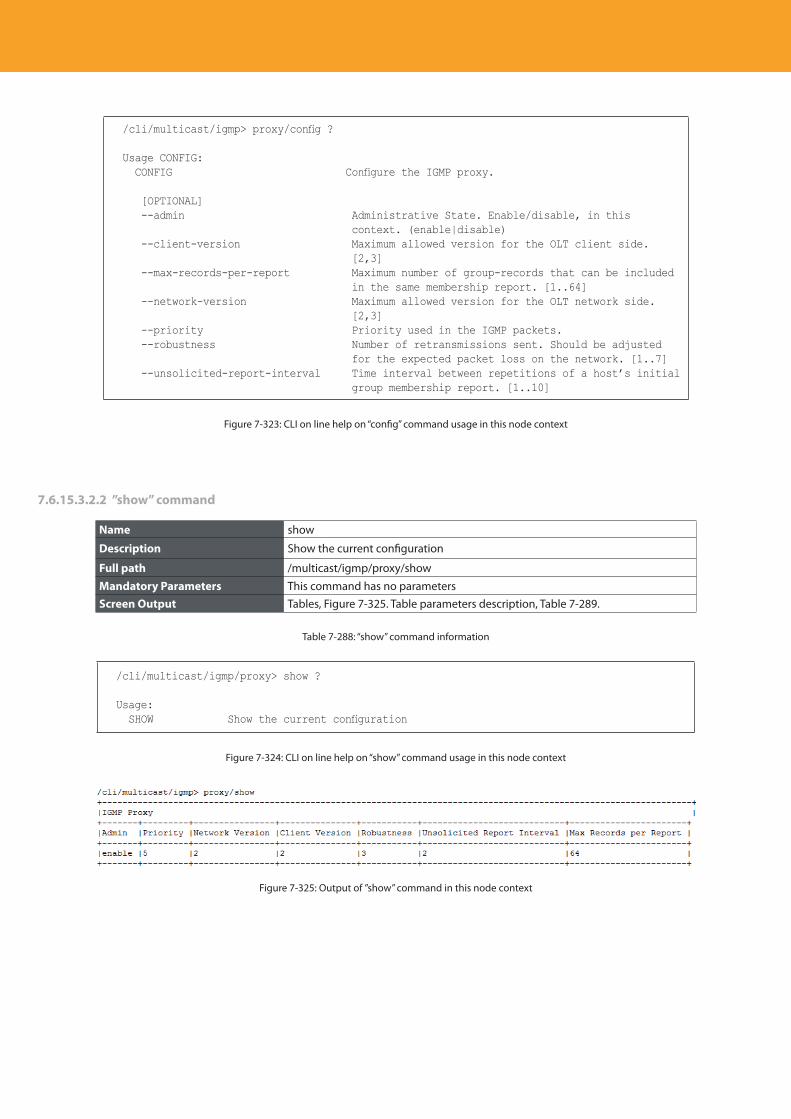
Descripción del producto
328
/cli/multicast/igmp> proxy/config ?
Usage CONFIG: CONFIG Configure the IGMP proxy.
[OPTIONAL] --admin Administrative State. Enable/disable, in this
context. (enable|disable) --client-version Maximum allowed version for the OLT client side.
[2,3] --max-records-per-report Maximum number of group-records that can be included
in the same membership report. [1..64] --network-version Maximum allowed version for the OLT network side.
[2,3] --priority Priority used in the IGMP packets. --robustness Number of retransmissions sent. Should be adjusted
for the expected packet loss on the network. [1..7] --unsolicited-report-interval Time interval between repetitions of a host’s initial
group membership report. [1..10]
Figure 7-323: CLI on line help on “config” command usage in this node context
7.6.15.3.2.2 ”show” command
Name show
Description Show the current configuration
Full path /multicast/igmp/proxy/show
Mandatory Parameters This command has no parametersScreen Output Tables, Figure 7-325. Table parameters description, Table 7-289.
Table 7-288: “show” command information
/cli/multicast/igmp/proxy> show ?
Usage: SHOW Show the current configuration
Figure 7-324: CLI on line help on “show” command usage in this node context
Figure 7-325: Output of ”show” command in this node context
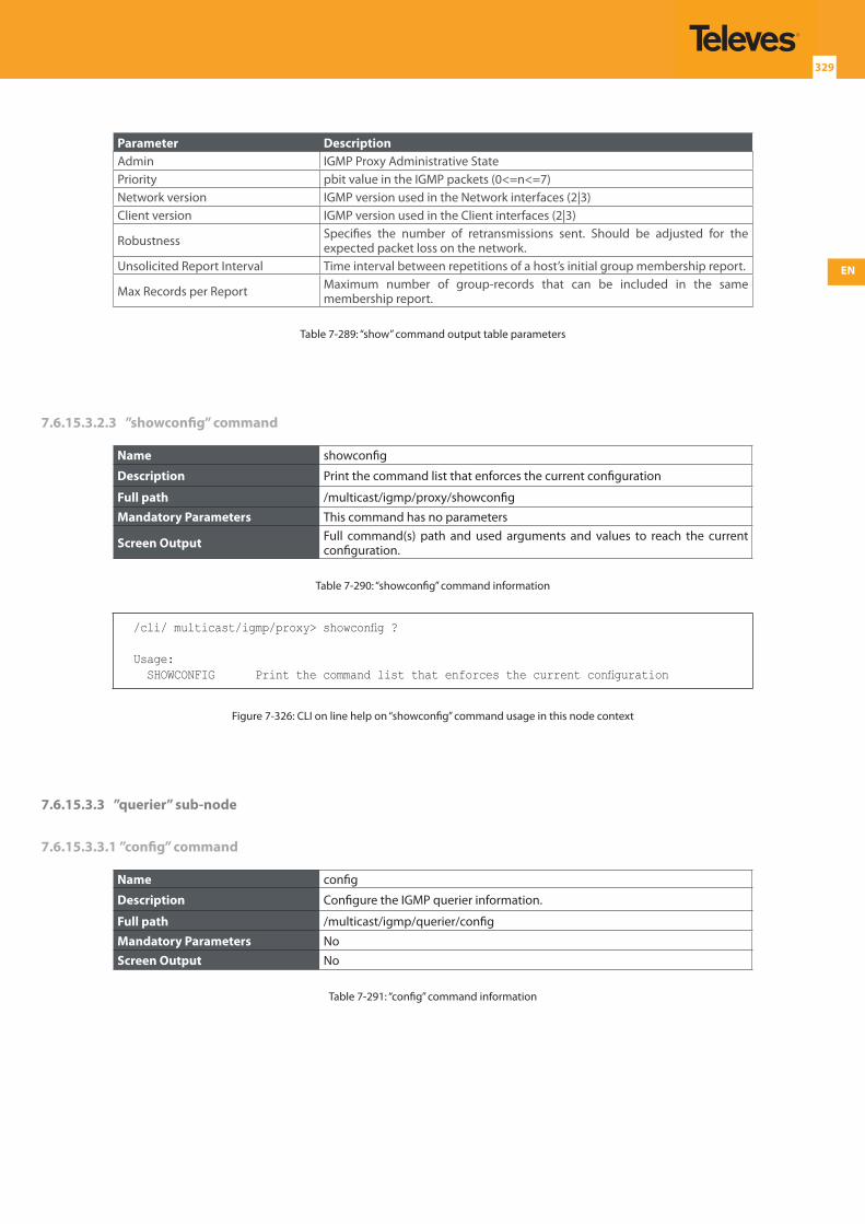
EN
329
Parameter DescriptionAdmin IGMP Proxy Administrative State Priority pbit value in the IGMP packets (0<=n<=7)Network version IGMP version used in the Network interfaces (2|3)Client version IGMP version used in the Client interfaces (2|3)
Robustness Specifies the number of retransmissions sent. Should be adjusted for the expected packet loss on the network.
Unsolicited Report Interval Time interval between repetitions of a host’s initial group membership report.
Max Records per Report Maximum number of group-records that can be included in the same membership report.
Table 7-289: “show” command output table parameters
7.6.15.3.2.3 ”showconfig” command
Name showconfig
Description Print the command list that enforces the current configuration
Full path /multicast/igmp/proxy/showconfig
Mandatory Parameters This command has no parameters
Screen Output Full command(s) path and used arguments and values to reach the current configuration.
Table 7-290: “showconfig” command information
/cli/ multicast/igmp/proxy> showconfig ?
Usage: SHOWCONFIG Print the command list that enforces the current configuration
Figure 7-326: CLI on line help on “showconfig” command usage in this node context
7.6.15.3.3 ”querier” sub-node
7.6.15.3.3.1 ”config” command
Name config
Description Configure the IGMP querier information.
Full path /multicast/igmp/querier/config
Mandatory Parameters NoScreen Output No
Table 7-291: “config” command information
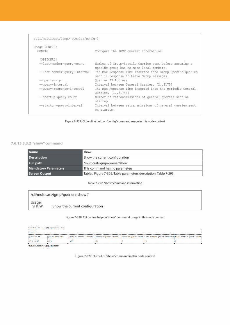
Descripción del producto
330
/cli/multicast/igmp> querier/config ?
Usage CONFIG: CONFIG Configure the IGMP querier information.
[OPTIONAL] --last-member-query-count Number of Group-Specific Queries sent before assuming a
specific group has no more local members. --last-member-query-interval The Max Response Time inserted into Group-Specific queries
sent in response to Leave Group messages. --querier-ip Querier IP Address --query-interval Interval between General Queries. [2..3175] --query-response-interval The Max Response Time inserted into the periodic General
Queries. [1..31744] --startup-query-count Number of retransmissions of general queries sent on
startup. --startup-query-interval Interval between retransmissions of general queries sent
on startup.
Figure 7-327: CLI on line help on “config” command usage in this node context
7.6.15.3.3.2 ”show” command
Name show
Description Show the current configuration
Full path /multicast/igmp/querier/show
Mandatory Parameters This command has no parametersScreen Output Tables, Figure 7-329. Table parameters description, Table 7-293.
Table 7-292: “show” command information
/cli/multicast/igmp/querier> show ?
Usage: SHOW Show the current configuration
Figure 7-328: CLI on line help on “show” command usage in this node context
Figure 7-329: Output of ”show” command in this node context
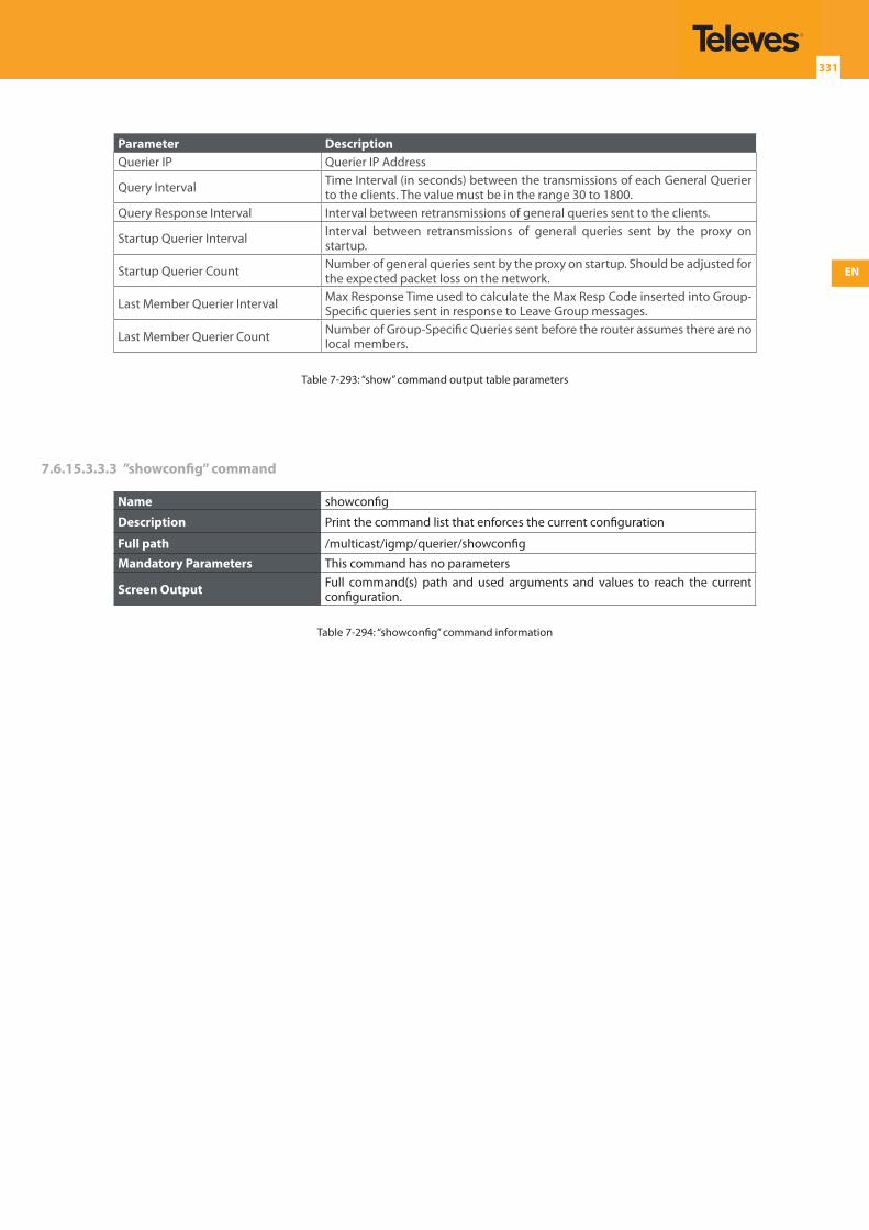
EN
331
Parameter DescriptionQuerier IP Querier IP Address
Query Interval Time Interval (in seconds) between the transmissions of each General Querier to the clients. The value must be in the range 30 to 1800.
Query Response Interval Interval between retransmissions of general queries sent to the clients.
Startup Querier Interval Interval between retransmissions of general queries sent by the proxy on startup.
Startup Querier Count Number of general queries sent by the proxy on startup. Should be adjusted for the expected packet loss on the network.
Last Member Querier Interval Max Response Time used to calculate the Max Resp Code inserted into Group-Specific queries sent in response to Leave Group messages.
Last Member Querier Count Number of Group-Specific Queries sent before the router assumes there are no local members.
Table 7-293: “show” command output table parameters
7.6.15.3.3.3 ”showconfig” command
Name showconfig
Description Print the command list that enforces the current configuration
Full path /multicast/igmp/querier/showconfig
Mandatory Parameters This command has no parameters
Screen Output Full command(s) path and used arguments and values to reach the current configuration.
Table 7-294: “showconfig” command information
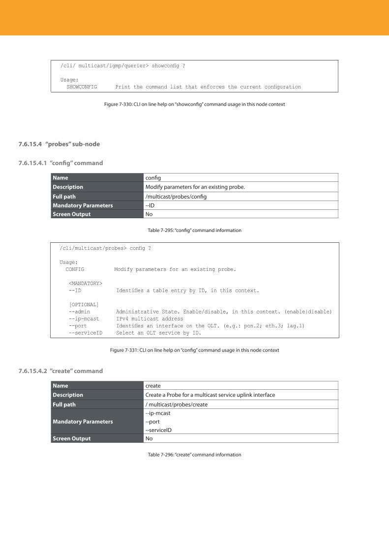
Descripción del producto
332
/cli/ multicast/igmp/querier> showconfig ?
Usage: SHOWCONFIG Print the command list that enforces the current configuration
Figure 7-330: CLI on line help on “showconfig” command usage in this node context
7.6.15.4 “probes” sub-node
7.6.15.4.1 ”config” command
Name config
Description Modify parameters for an existing probe.
Full path /multicast/probes/config
Mandatory Parameters --IDScreen Output No
Table 7-295: “config” command information
/cli/multicast/probes> config ?
Usage: CONFIG Modify parameters for an existing probe.
<MANDATORY> --ID Identifies a table entry by ID, in this context.
[OPTIONAL] --admin Administrative State. Enable/disable, in this context. (enable|disable) --ip-mcast IPv4 multicast address --port Identifies an interface on the OLT. (e.g.: pon.2; eth.3; lag.1) --serviceID Select an OLT service by ID.
Figure 7-331: CLI on line help on “config” command usage in this node context
7.6.15.4.2 ”create” command
Name create
Description Create a Probe for a multicast service uplink interface
Full path / multicast/probes/create
Mandatory Parameters--ip-mcast--port--serviceID
Screen Output No
Table 7-296: “create” command information
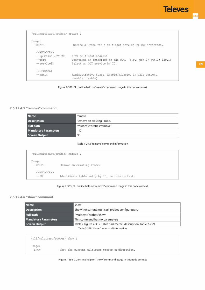
EN
333
/cli/multicast/probes> create ?
Usage: CREATE Create a Probe for a multicast service uplink interface.
<MANDATORY> --ip-mcast[=STRING] IPv4 multicast address --port Identifies an interface on the OLT. (e.g.: pon.2; eth.3; lag.1) --serviceID Select an OLT service by ID.
[OPTIONAL] --admin Administrative State. Enable/disable, in this context.
(enable|disable)
Figure 7-332: CLI on line help on “create” command usage in this node context
7.6.15.4.3 ”remove” command
Name remove
Description Remove an existing Probe.
Full path /multicast/probes/remove
Mandatory Parameters --IDScreen Output No
Table 7-297: “remove” command information
/cli/multicast/probes> remove ?
Usage: REMOVE Remove an existing Probe.
<MANDATORY> --ID Identifies a table entry by ID, in this context.
Figure 7-333: CLI on line help on “remove” command usage in this node context
7.6.15.4.4 ”show” command
Name show
Description Show the current multicast probes configuration.
Full path /multicast/probes/show
Mandatory Parameters This command has no parametersScreen Output Tables, Figure 7-335. Table parameters description, Table 7-299.
Table 7-298: “show” command information
/cli/multicast/probes> show ?
Usage: SHOW Show the current multicast probes configuration.
Figure 7-334: CLI on line help on “show” command usage in this node context
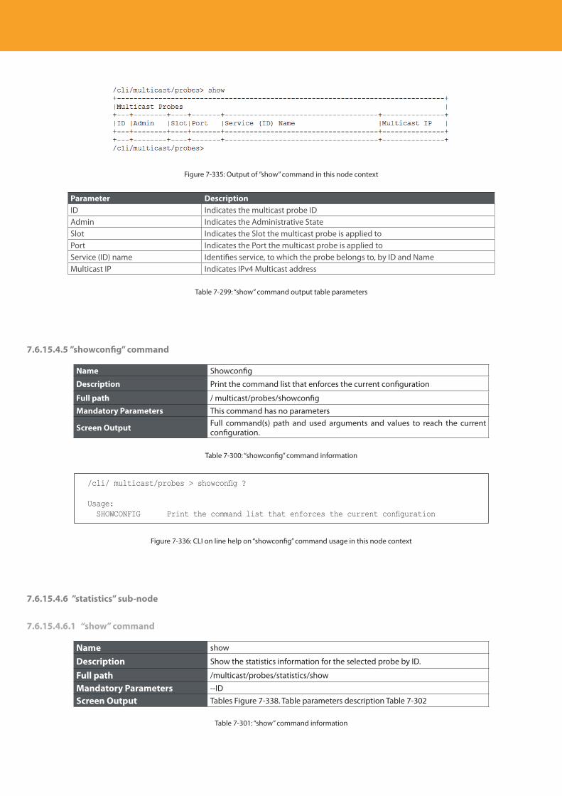
Descripción del producto
334
Figure 7-335: Output of ”show” command in this node context
Parameter DescriptionID Indicates the multicast probe IDAdmin Indicates the Administrative StateSlot Indicates the Slot the multicast probe is applied toPort Indicates the Port the multicast probe is applied toService (ID) name Identifies service, to which the probe belongs to, by ID and NameMulticast IP Indicates IPv4 Multicast address
Table 7-299: “show” command output table parameters
7.6.15.4.5 ”showconfig” command
Name Showconfig
Description Print the command list that enforces the current configuration
Full path / multicast/probes/showconfig
Mandatory Parameters This command has no parameters
Screen Output Full command(s) path and used arguments and values to reach the current configuration.
Table 7-300: “showconfig” command information
/cli/ multicast/probes > showconfig ?
Usage: SHOWCONFIG Print the command list that enforces the current configuration
Figure 7-336: CLI on line help on “showconfig” command usage in this node context
7.6.15.4.6 ”statistics” sub-node
7.6.15.4.6.1 “show” command
Name show
Description Show the statistics information for the selected probe by ID.
Full path /multicast/probes/statistics/show
Mandatory Parameters --ID
Screen Output Tables Figure 7-338. Table parameters description Table 7-302
Table 7-301: “show” command information
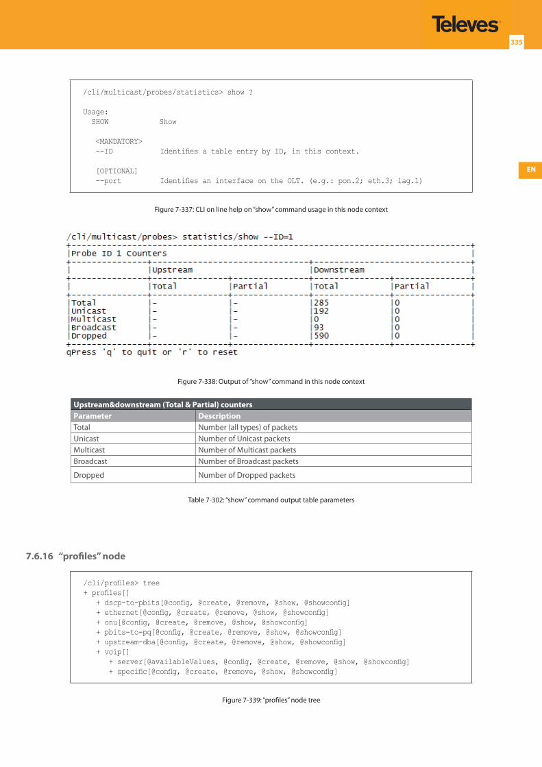
EN
335
/cli/multicast/probes/statistics> show ?
Usage: SHOW Show
<MANDATORY> --ID Identifies a table entry by ID, in this context.
[OPTIONAL] --port Identifies an interface on the OLT. (e.g.: pon.2; eth.3; lag.1)
Figure 7-337: CLI on line help on “show” command usage in this node context
Figure 7-338: Output of ”show” command in this node context
Upstream&downstream (Total & Partial) countersParameter DescriptionTotal Number (all types) of packetsUnicast Number of Unicast packetsMulticast Number of Multicast packetsBroadcast Number of Broadcast packets
Dropped Number of Dropped packets
Table 7-302: “show” command output table parameters
7.6.16 “profiles” node
/cli/profiles> tree+ profiles[] + dscp-to-pbits[@config, @create, @remove, @show, @showconfig] + ethernet[@config, @create, @remove, @show, @showconfig] + onu[@config, @create, @remove, @show, @showconfig] + pbits-to-pq[@config, @create, @remove, @show, @showconfig] + upstream-dba[@config, @create, @remove, @show, @showconfig] + voip[] + server[@availableValues, @config, @create, @remove, @show, @showconfig] + specific[@config, @create, @remove, @show, @showconfig]
Figure 7-339: “profiles” node tree
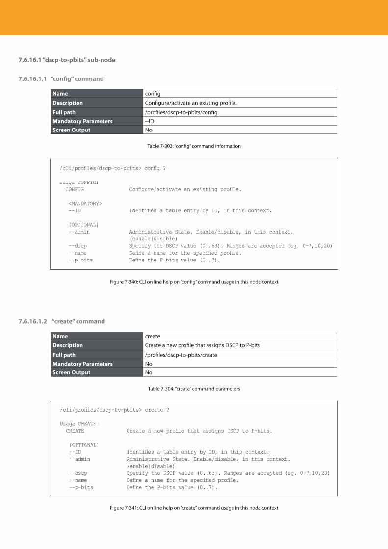
Descripción del producto
336
7.6.16.1 “dscp-to-pbits” sub-node
7.6.16.1.1 “config” command
Name config
Description Configure/activate an existing profile.
Full path /profiles/dscp-to-pbits/config
Mandatory Parameters --IDScreen Output No
Table 7-303: “config” command information
/cli/profiles/dscp-to-pbits> config ?
Usage CONFIG: CONFIG Configure/activate an existing profile.
<MANDATORY> --ID Identifies a table entry by ID, in this context.
[OPTIONAL] --admin Administrative State. Enable/disable, in this context.
(enable|disable) --dscp Specify the DSCP value (0..63). Ranges are accepted (eg. 0-7,10,20) --name Define a name for the specified profile. --p-bits Define the P-bits value (0..7).
Figure 7-340: CLI on line help on “config” command usage in this node context
7.6.16.1.2 “create” command
Name create
Description Create a new profile that assigns DSCP to P-bits
Full path /profiles/dscp-to-pbits/create
Mandatory Parameters NoScreen Output No
Table 7-304: “create” command parameters
/cli/profiles/dscp-to-pbits> create ?
Usage CREATE: CREATE Create a new profile that assigns DSCP to P-bits.
[OPTIONAL] --ID Identifies a table entry by ID, in this context. --admin Administrative State. Enable/disable, in this context.
(enable|disable) --dscp Specify the DSCP value (0..63). Ranges are accepted (eg. 0-7,10,20) --name Define a name for the specified profile. --p-bits Define the P-bits value (0..7).
Figure 7-341: CLI on line help on “create” command usage in this node context
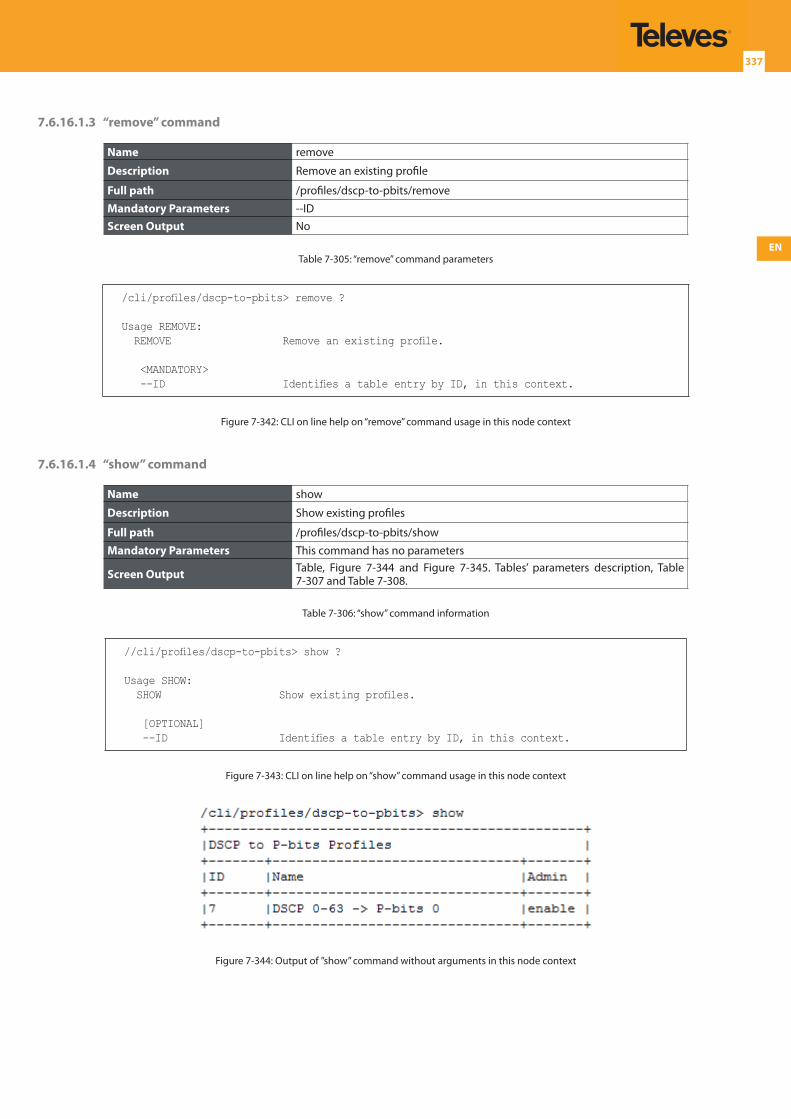
EN
337
7.6.16.1.3 “remove” command
Name remove
Description Remove an existing profile
Full path /profiles/dscp-to-pbits/remove
Mandatory Parameters --IDScreen Output No
Table 7-305: “remove” command parameters
/cli/profiles/dscp-to-pbits> remove ?
Usage REMOVE: REMOVE Remove an existing profile.
<MANDATORY> --ID Identifies a table entry by ID, in this context.
Figure 7-342: CLI on line help on “remove” command usage in this node context
7.6.16.1.4 “show” command
Name show
Description Show existing profiles
Full path /profiles/dscp-to-pbits/show
Mandatory Parameters This command has no parameters
Screen Output Table, Figure 7-344 and Figure 7-345. Tables’ parameters description, Table 7-307 and Table 7-308.
Table 7-306: “show” command information
//cli/profiles/dscp-to-pbits> show ?
Usage SHOW: SHOW Show existing profiles.
[OPTIONAL] --ID Identifies a table entry by ID, in this context.
Figure 7-343: CLI on line help on “show” command usage in this node context
Figure 7-344: Output of ”show” command without arguments in this node context
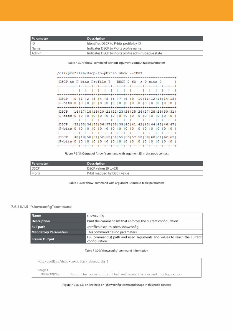
Descripción del producto
338
Parameter DescriptionID Identifies DSCP to P-bits profile by IDName Indicates DSCP to P-bits profile nameAdmin Indicates DSCP to P-bits profile administrative state
Table 7-307: “show” command without arguments output table parameters
Figure 7-345: Output of ”show” command with argument ID in this node context
Parameter DescriptionDSCP DSCP values (0 to 63)P-bits P-bit mapped by DSCP value
Table 7-308: “show” command with argument ID output table parameters
7.6.16.1.5 “showconfig” command
Name showconfig
Description Print the command list that enforces the current configuration
Full path /profiles/dscp-to-pbits/showconfig
Mandatory Parameters This command has no parameters
Screen Output Full command(s) path and used arguments and values to reach the current configuration.
Table 7-309: “showconfig” command information
/cli/profiles/dscp-to-pbits> showconfig ?
Usage: SHOWCONFIG Print the command list that enforces the current configuration
Figure 7-346: CLI on line help on “showconfig” command usage in this node context
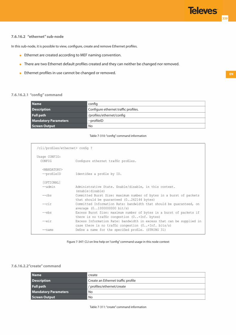
EN
339
7.6.16.2 “ethernet” sub-node
In this sub-node, it is possible to view, configure, create and remove Ethernet profiles.
Ethernet are created according to MEF naming convention.
There are two Ethernet default profiles created and they can neither be changed nor removed.
Ethernet profiles in use cannot be changed or removed.
7.6.16.2.1 “config” command
Name config
Description Configure ethernet traffic profiles.
Full path /profiles/ethernet/config
Mandatory Parameters --profileIDScreen Output No
Table 7-310: “config” command information
/cli/profiles/ethernet> config ?
Usage CONFIG: CONFIG Configure ethernet traffic profiles.
<MANDATORY> --profileID Identifies a profile by ID.
[OPTIONAL] --admin Administrative State. Enable/disable, in this context.
(enable|disable) --cbs Committed Burst Size: maximum number of bytes in a burst of packets
that should be guaranteed (0..262144 bytes) --cir Committed Information Rate: bandwidth that should be guaranteed, on
average (0..1000000000 bit/s) --ebs Excess Burst Size: maximum number of bytes in a burst of packets if
there is no traffic congestion (0..+Inf. bytes) --eir Excess Information Rate: bandwidth in excess that can be supplied in
case there is no traffic congestion (0..+Inf. bits/s) --name Define a name for the specified profile. (STRING 31)
Figure 7-347: CLI on line help on “config” command usage in this node context
7.6.16.2.2”create” command
Name create
Description Create an Ethernet traffic profile
Full path / profiles/ethernet/create
Mandatory Parameters NoScreen Output No
Table 7-311: “create” command information
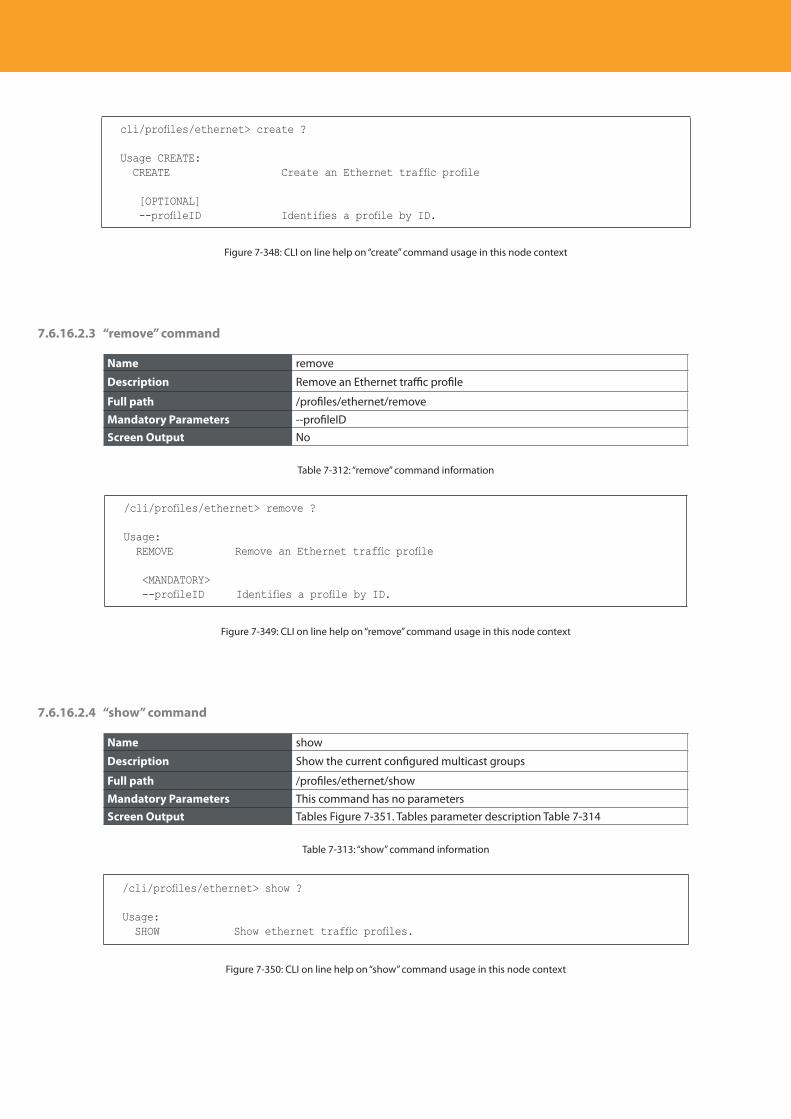
Descripción del producto
340
cli/profiles/ethernet> create ?
Usage CREATE: CREATE Create an Ethernet traffic profile
[OPTIONAL] --profileID Identifies a profile by ID.
Figure 7-348: CLI on line help on “create” command usage in this node context
7.6.16.2.3 “remove” command
Name remove
Description Remove an Ethernet traffic profile
Full path /profiles/ethernet/remove
Mandatory Parameters --profileIDScreen Output No
Table 7-312: “remove” command information
/cli/profiles/ethernet> remove ?
Usage: REMOVE Remove an Ethernet traffic profile
<MANDATORY> --profileID Identifies a profile by ID.
Figure 7-349: CLI on line help on “remove” command usage in this node context
7.6.16.2.4 “show” command
Name show
Description Show the current configured multicast groups
Full path /profiles/ethernet/show
Mandatory Parameters This command has no parametersScreen Output Tables Figure 7-351. Tables parameter description Table 7-314
Table 7-313: “show” command information
/cli/profiles/ethernet> show ?
Usage: SHOW Show ethernet traffic profiles.
Figure 7-350: CLI on line help on “show” command usage in this node context
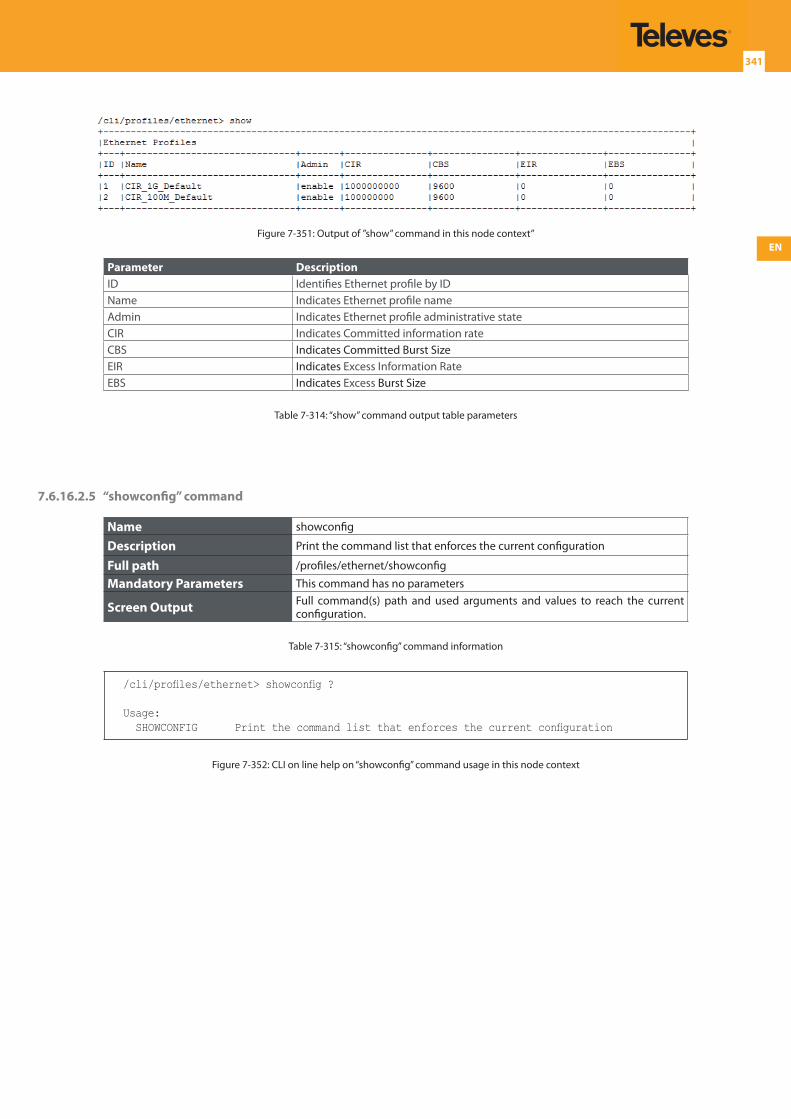
EN
341
Figure 7-351: Output of ”show” command in this node context”
Parameter DescriptionID Identifies Ethernet profile by IDName Indicates Ethernet profile nameAdmin Indicates Ethernet profile administrative stateCIR Indicates Committed information rateCBS Indicates Committed Burst SizeEIR Indicates Excess Information RateEBS Indicates Excess Burst Size
Table 7-314: “show” command output table parameters
7.6.16.2.5 “showconfig” command
Name showconfig
Description Print the command list that enforces the current configuration
Full path /profiles/ethernet/showconfig
Mandatory Parameters This command has no parameters
Screen Output Full command(s) path and used arguments and values to reach the current configuration.
Table 7-315: “showconfig” command information
/cli/profiles/ethernet> showconfig ?
Usage: SHOWCONFIG Print the command list that enforces the current configuration
Figure 7-352: CLI on line help on “showconfig” command usage in this node context
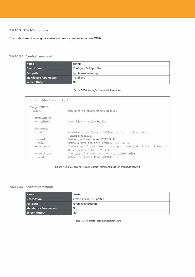
Descripción del producto
342
7.6.16.3 “ONUs” sub-node
This node is used to configure, create and remove profiles for remote ONUs.
7.6.16.3.1 “config” command
Name config
Description Configure ONU profiles.
Full path /profiles/onu/config
Mandatory Parameters --profileIDScreen Output No
Table 7-316: “config” command information
/cli/profiles/onu> config ?
Usage CONFIG: CONFIG Configure an existing ONU profile.
<MANDATORY> --profileID Identifies a profile by ID.
[OPTIONAL] --admin Administrative State. Enable/disable, in this context.
(enable|disable) --model Define the Model Name (STRING 47) --name Define a name for this profile. (STRING 47) --port-num The number of ports for a given port type (max: 4 ETH , 1 PON , 1
RF , 2 VoIP, 4 E1, 1 VEIP ) --port-type The type of a port (eth|pon|voip|rf|e1|veip) --vendor Define the Vendor Name (STRING 15)
Figure 7-353: CLI on line help on “config” command usage in this node context
7.6.16.3.2 “create” command
Name create
Description Create a new ONU profile
Full path /profiles/onu/create
Mandatory Parameters NoScreen Output No
Table 7-317: “create” command parameters
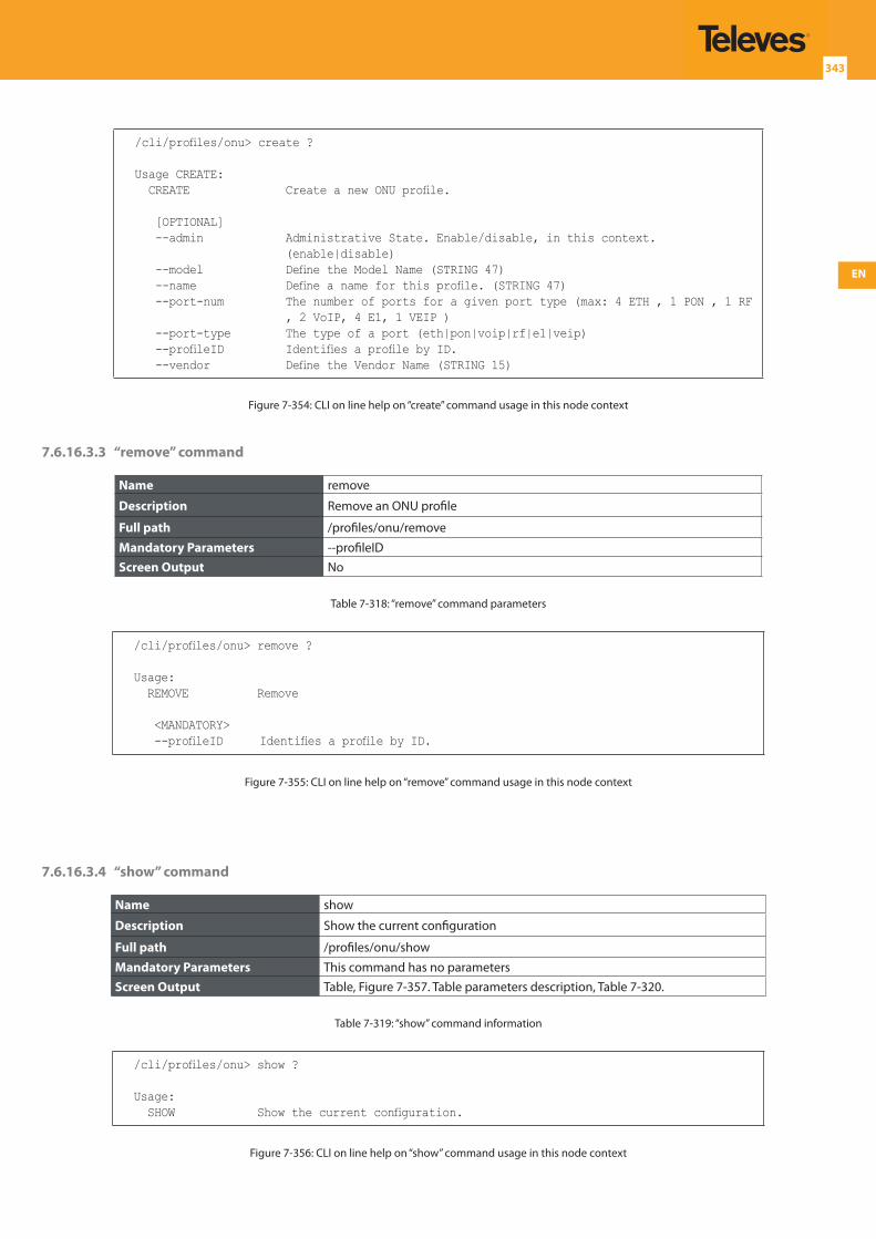
EN
343
/cli/profiles/onu> create ?
Usage CREATE: CREATE Create a new ONU profile.
[OPTIONAL] --admin Administrative State. Enable/disable, in this context.
(enable|disable) --model Define the Model Name (STRING 47) --name Define a name for this profile. (STRING 47) --port-num The number of ports for a given port type (max: 4 ETH , 1 PON , 1 RF
, 2 VoIP, 4 E1, 1 VEIP ) --port-type The type of a port (eth|pon|voip|rf|e1|veip) --profileID Identifies a profile by ID. --vendor Define the Vendor Name (STRING 15)
Figure 7-354: CLI on line help on “create” command usage in this node context
7.6.16.3.3 “remove” command
Name remove
Description Remove an ONU profile
Full path /profiles/onu/remove
Mandatory Parameters --profileIDScreen Output No
Table 7-318: “remove” command parameters
/cli/profiles/onu> remove ?
Usage: REMOVE Remove
<MANDATORY> --profileID Identifies a profile by ID.
Figure 7-355: CLI on line help on “remove” command usage in this node context
7.6.16.3.4 “show” command
Name show
Description Show the current configuration
Full path /profiles/onu/show
Mandatory Parameters This command has no parametersScreen Output Table, Figure 7-357. Table parameters description, Table 7-320.
Table 7-319: “show” command information
/cli/profiles/onu> show ?
Usage: SHOW Show the current configuration.
Figure 7-356: CLI on line help on “show” command usage in this node context
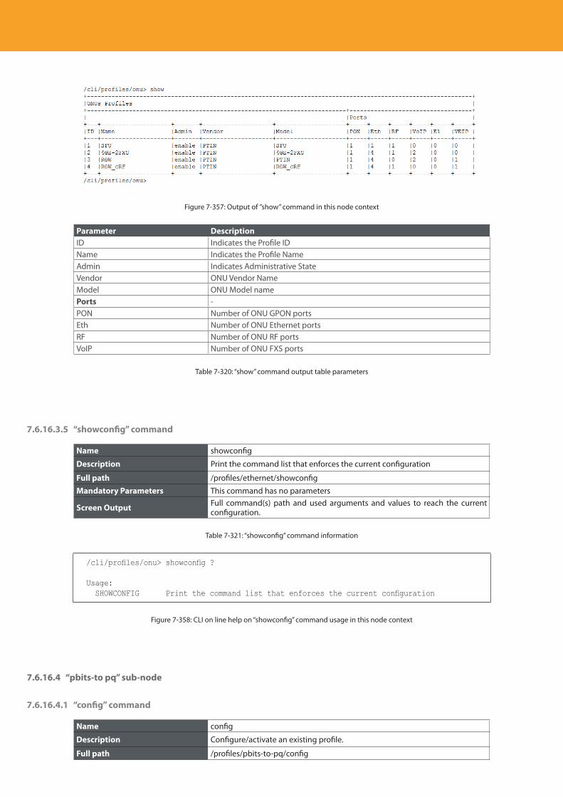
Descripción del producto
344
Figure 7-357: Output of ”show” command in this node context
Parameter DescriptionID Indicates the Profile IDName Indicates the Profile NameAdmin Indicates Administrative StateVendor ONU Vendor NameModel ONU Model namePorts -PON Number of ONU GPON portsEth Number of ONU Ethernet portsRF Number of ONU RF portsVoIP Number of ONU FXS ports
Table 7-320: “show” command output table parameters
7.6.16.3.5 “showconfig” command
Name showconfig
Description Print the command list that enforces the current configuration
Full path /profiles/ethernet/showconfig
Mandatory Parameters This command has no parameters
Screen Output Full command(s) path and used arguments and values to reach the current configuration.
Table 7-321: “showconfig” command information
/cli/profiles/onu> showconfig ?
Usage: SHOWCONFIG Print the command list that enforces the current configuration
Figure 7-358: CLI on line help on “showconfig” command usage in this node context
7.6.16.4 “pbits-to pq” sub-node
7.6.16.4.1 “config” command
Name config
Description Configure/activate an existing profile.
Full path /profiles/pbits-to-pq/config
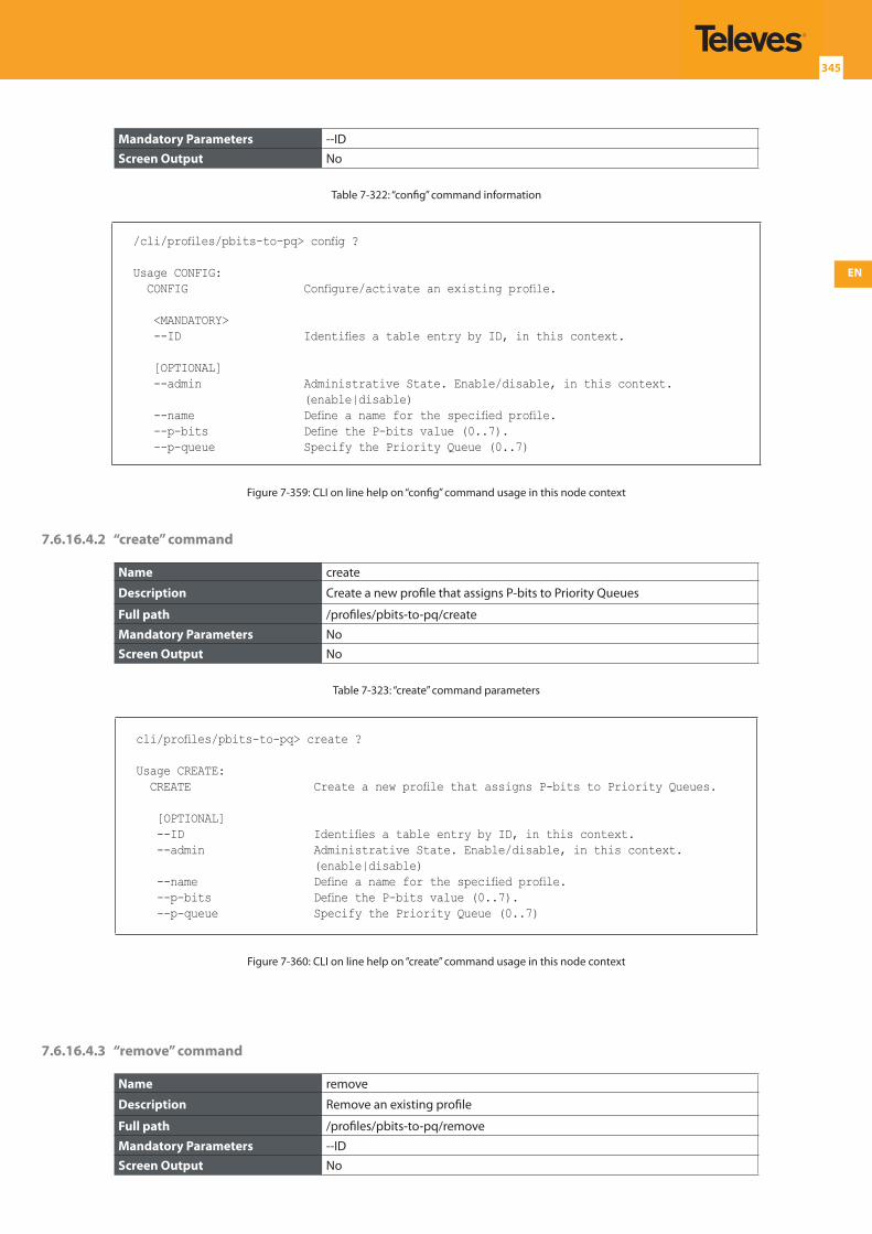
EN
345
Mandatory Parameters --IDScreen Output No
Table 7-322: “config” command information
/cli/profiles/pbits-to-pq> config ?
Usage CONFIG: CONFIG Configure/activate an existing profile.
<MANDATORY> --ID Identifies a table entry by ID, in this context.
[OPTIONAL] --admin Administrative State. Enable/disable, in this context.
(enable|disable) --name Define a name for the specified profile. --p-bits Define the P-bits value (0..7). --p-queue Specify the Priority Queue (0..7)
Figure 7-359: CLI on line help on “config” command usage in this node context
7.6.16.4.2 “create” command
Name create
Description Create a new profile that assigns P-bits to Priority Queues
Full path /profiles/pbits-to-pq/create
Mandatory Parameters NoScreen Output No
Table 7-323: “create” command parameters
cli/profiles/pbits-to-pq> create ?
Usage CREATE: CREATE Create a new profile that assigns P-bits to Priority Queues.
[OPTIONAL] --ID Identifies a table entry by ID, in this context. --admin Administrative State. Enable/disable, in this context.
(enable|disable) --name Define a name for the specified profile. --p-bits Define the P-bits value (0..7). --p-queue Specify the Priority Queue (0..7)
Figure 7-360: CLI on line help on “create” command usage in this node context
7.6.16.4.3 “remove” command
Name remove
Description Remove an existing profile
Full path /profiles/pbits-to-pq/remove
Mandatory Parameters --IDScreen Output No
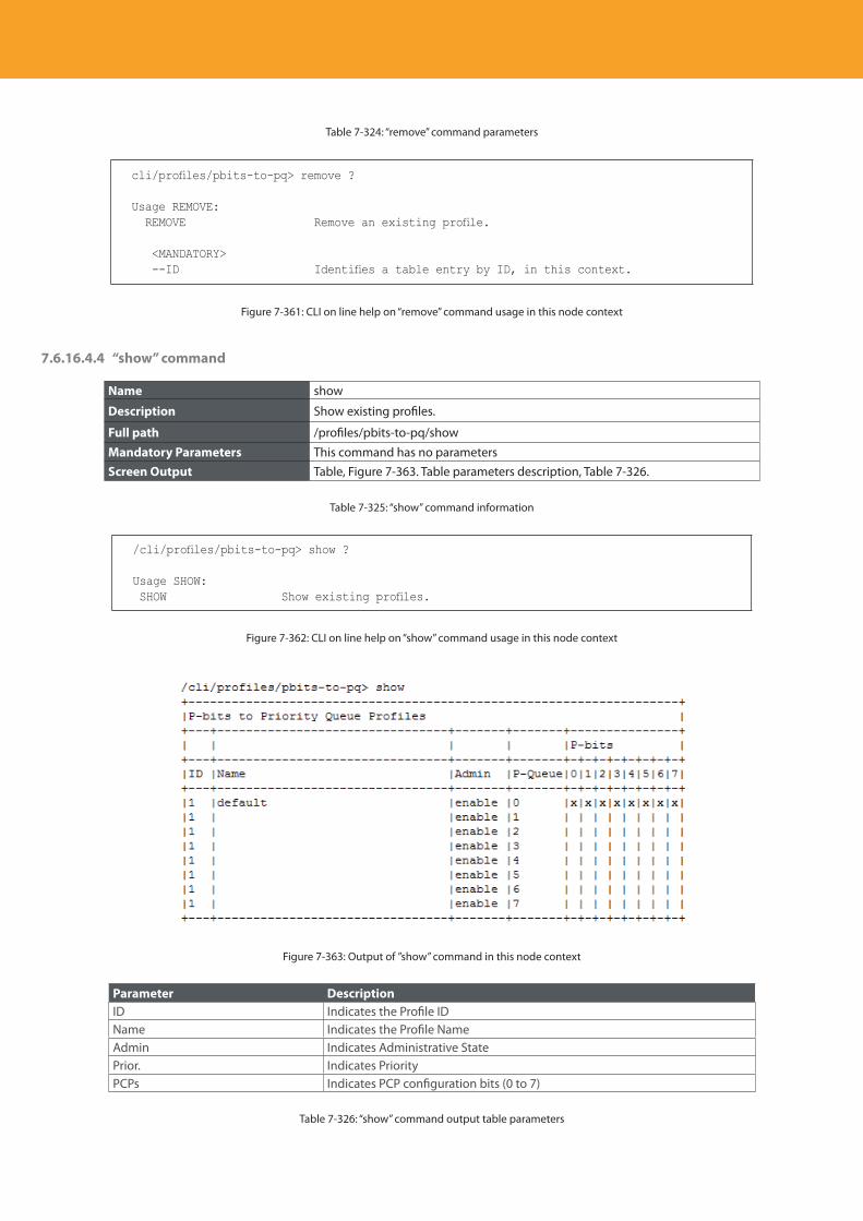
Descripción del producto
346
Table 7-324: “remove” command parameters
cli/profiles/pbits-to-pq> remove ?
Usage REMOVE: REMOVE Remove an existing profile.
<MANDATORY> --ID Identifies a table entry by ID, in this context.
Figure 7-361: CLI on line help on “remove” command usage in this node context
7.6.16.4.4 “show” command
Name show
Description Show existing profiles.
Full path /profiles/pbits-to-pq/show
Mandatory Parameters This command has no parametersScreen Output Table, Figure 7-363. Table parameters description, Table 7-326.
Table 7-325: “show” command information
/cli/profiles/pbits-to-pq> show ?
Usage SHOW: SHOW Show existing profiles.
Figure 7-362: CLI on line help on “show” command usage in this node context
Figure 7-363: Output of ”show” command in this node context
Parameter DescriptionID Indicates the Profile IDName Indicates the Profile NameAdmin Indicates Administrative StatePrior. Indicates PriorityPCPs Indicates PCP configuration bits (0 to 7)
Table 7-326: “show” command output table parameters
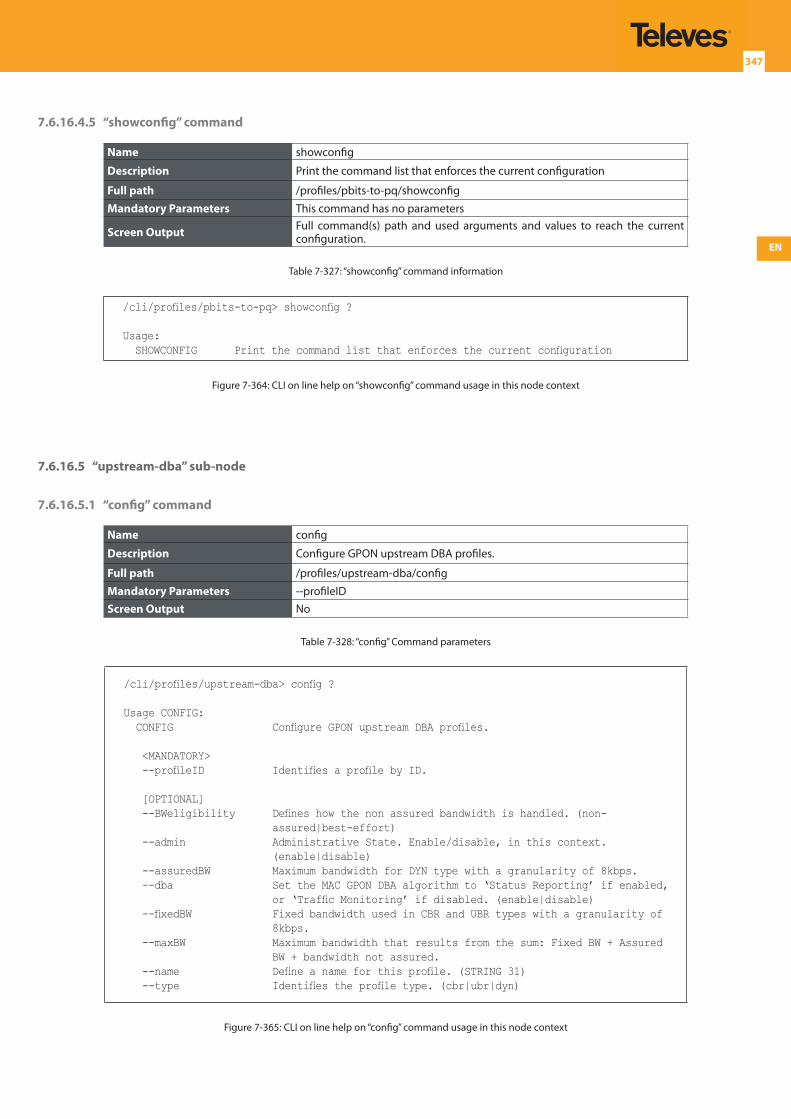
EN
347
7.6.16.4.5 “showconfig” command
Name showconfig
Description Print the command list that enforces the current configuration
Full path /profiles/pbits-to-pq/showconfig
Mandatory Parameters This command has no parameters
Screen Output Full command(s) path and used arguments and values to reach the current configuration.
Table 7-327: “showconfig” command information
/cli/profiles/pbits-to-pq> showconfig ?
Usage: SHOWCONFIG Print the command list that enforces the current configuration
Figure 7-364: CLI on line help on “showconfig” command usage in this node context
7.6.16.5 “upstream-dba” sub-node
7.6.16.5.1 “config” command
Name config
Description Configure GPON upstream DBA profiles.
Full path /profiles/upstream-dba/config
Mandatory Parameters --profileIDScreen Output No
Table 7-328: “config” Command parameters
/cli/profiles/upstream-dba> config ?
Usage CONFIG: CONFIG Configure GPON upstream DBA profiles.
<MANDATORY> --profileID Identifies a profile by ID.
[OPTIONAL] --BWeligibility Defines how the non assured bandwidth is handled. (non-
assured|best-effort) --admin Administrative State. Enable/disable, in this context.
(enable|disable) --assuredBW Maximum bandwidth for DYN type with a granularity of 8kbps. --dba Set the MAC GPON DBA algorithm to ‘Status Reporting’ if enabled,
or ‘Traffic Monitoring’ if disabled. (enable|disable) --fixedBW Fixed bandwidth used in CBR and UBR types with a granularity of
8kbps. --maxBW Maximum bandwidth that results from the sum: Fixed BW + Assured
BW + bandwidth not assured. --name Define a name for this profile. (STRING 31) --type Identifies the profile type. (cbr|ubr|dyn)
Figure 7-365: CLI on line help on “config” command usage in this node context
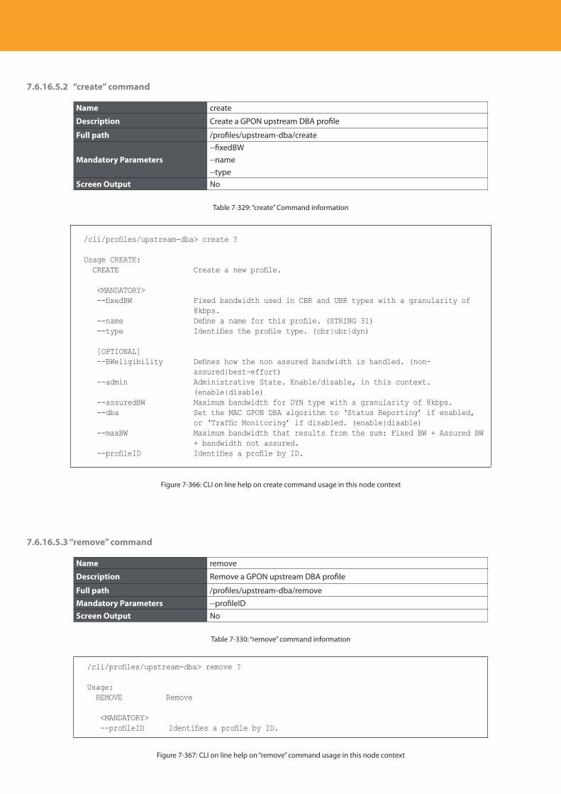
Descripción del producto
348
7.6.16.5.2 “create” command
Name create
Description Create a GPON upstream DBA profile
Full path /profiles/upstream-dba/create
Mandatory Parameters--fixedBW--name--type
Screen Output No
Table 7-329: “create” Command information
/cli/profiles/upstream-dba> create ?
Usage CREATE: CREATE Create a new profile.
<MANDATORY> --fixedBW Fixed bandwidth used in CBR and UBR types with a granularity of
8kbps. --name Define a name for this profile. (STRING 31) --type Identifies the profile type. (cbr|ubr|dyn)
[OPTIONAL] --BWeligibility Defines how the non assured bandwidth is handled. (non-
assured|best-effort) --admin Administrative State. Enable/disable, in this context.
(enable|disable) --assuredBW Maximum bandwidth for DYN type with a granularity of 8kbps. --dba Set the MAC GPON DBA algorithm to ‘Status Reporting’ if enabled,
or ‘Traffic Monitoring’ if disabled. (enable|disable) --maxBW Maximum bandwidth that results from the sum: Fixed BW + Assured BW
+ bandwidth not assured. --profileID Identifies a profile by ID.
Figure 7-366: CLI on line help on create command usage in this node context
7.6.16.5.3 “remove” command
Name remove
Description Remove a GPON upstream DBA profile
Full path /profiles/upstream-dba/remove
Mandatory Parameters --profileIDScreen Output No
Table 7-330: “remove” command information
/cli/profiles/upstream-dba> remove ?
Usage: REMOVE Remove
<MANDATORY> --profileID Identifies a profile by ID.
Figure 7-367: CLI on line help on “remove” command usage in this node context
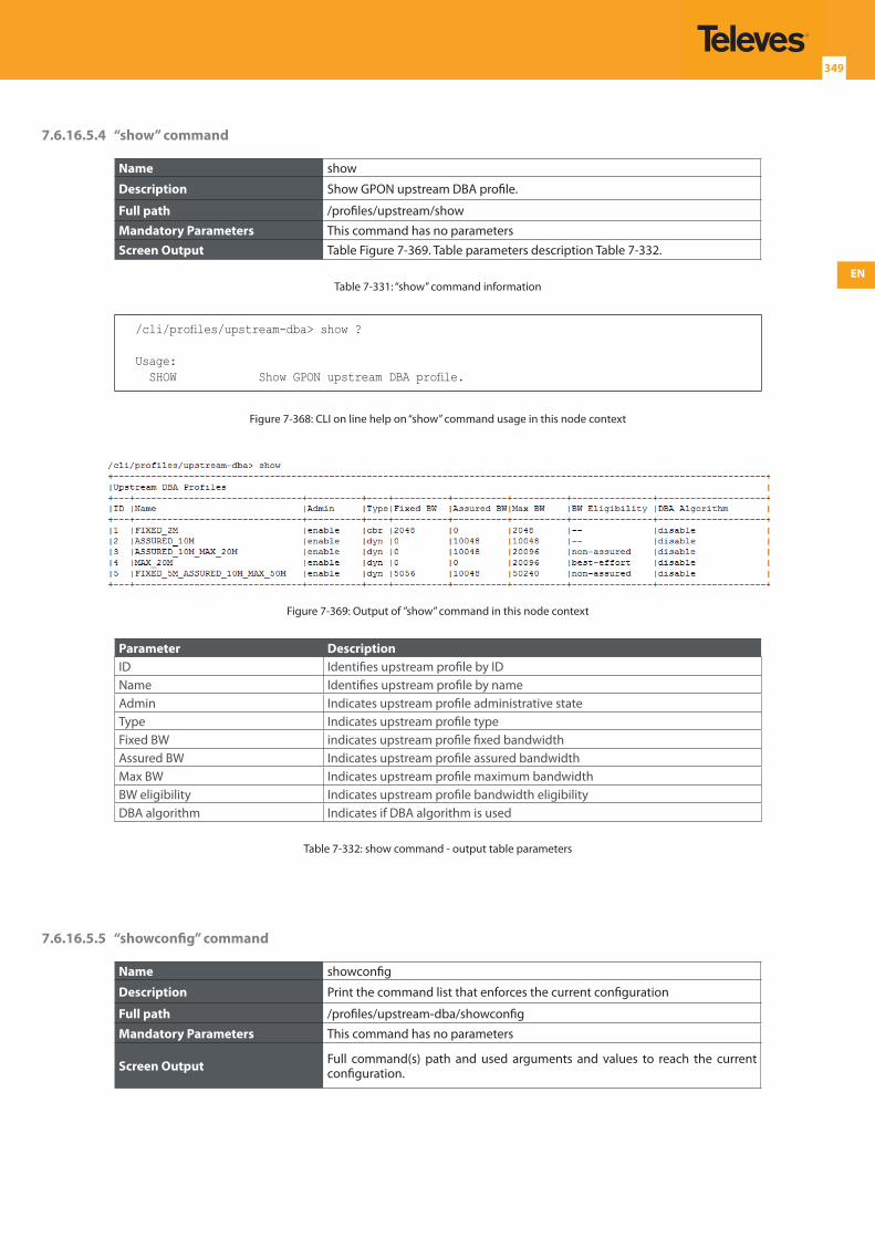
EN
349
7.6.16.5.4 “show” command
Name show
Description Show GPON upstream DBA profile.
Full path /profiles/upstream/show
Mandatory Parameters This command has no parametersScreen Output Table Figure 7-369. Table parameters description Table 7-332.
Table 7-331: “show” command information
/cli/profiles/upstream-dba> show ?
Usage: SHOW Show GPON upstream DBA profile.
Figure 7-368: CLI on line help on “show” command usage in this node context
Figure 7-369: Output of ”show” command in this node context
Parameter DescriptionID Identifies upstream profile by IDName Identifies upstream profile by nameAdmin Indicates upstream profile administrative stateType Indicates upstream profile typeFixed BW indicates upstream profile fixed bandwidthAssured BW Indicates upstream profile assured bandwidthMax BW Indicates upstream profile maximum bandwidthBW eligibility Indicates upstream profile bandwidth eligibilityDBA algorithm Indicates if DBA algorithm is used
Table 7-332: show command - output table parameters
7.6.16.5.5 “showconfig” command
Name showconfig
Description Print the command list that enforces the current configuration
Full path /profiles/upstream-dba/showconfig
Mandatory Parameters This command has no parameters
Screen Output Full command(s) path and used arguments and values to reach the current configuration.
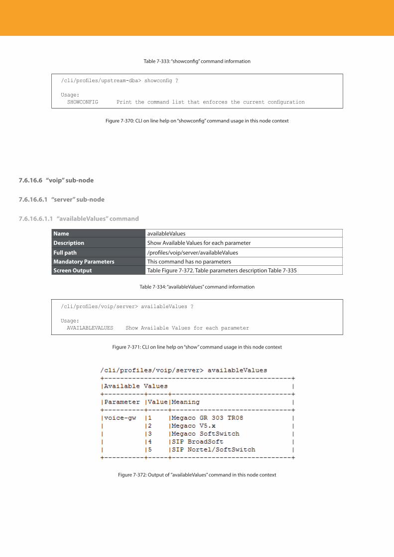
Descripción del producto
350
Table 7-333: “showconfig” command information
/cli/profiles/upstream-dba> showconfig ?
Usage: SHOWCONFIG Print the command list that enforces the current configuration
Figure 7-370: CLI on line help on “showconfig” command usage in this node context
7.6.16.6 “voip” sub-node
7.6.16.6.1 “server” sub-node
7.6.16.6.1.1 “availableValues” command
Name availableValues
Description Show Available Values for each parameter
Full path /profiles/voip/server/availableValues
Mandatory Parameters This command has no parametersScreen Output Table Figure 7-372. Table parameters description Table 7-335
Table 7-334: “availableValues” command information
/cli/profiles/voip/server> availableValues ?
Usage: AVAILABLEVALUES Show Available Values for each parameter
Figure 7-371: CLI on line help on “show” command usage in this node context
Figure 7-372: Output of ”availableValues” command in this node context
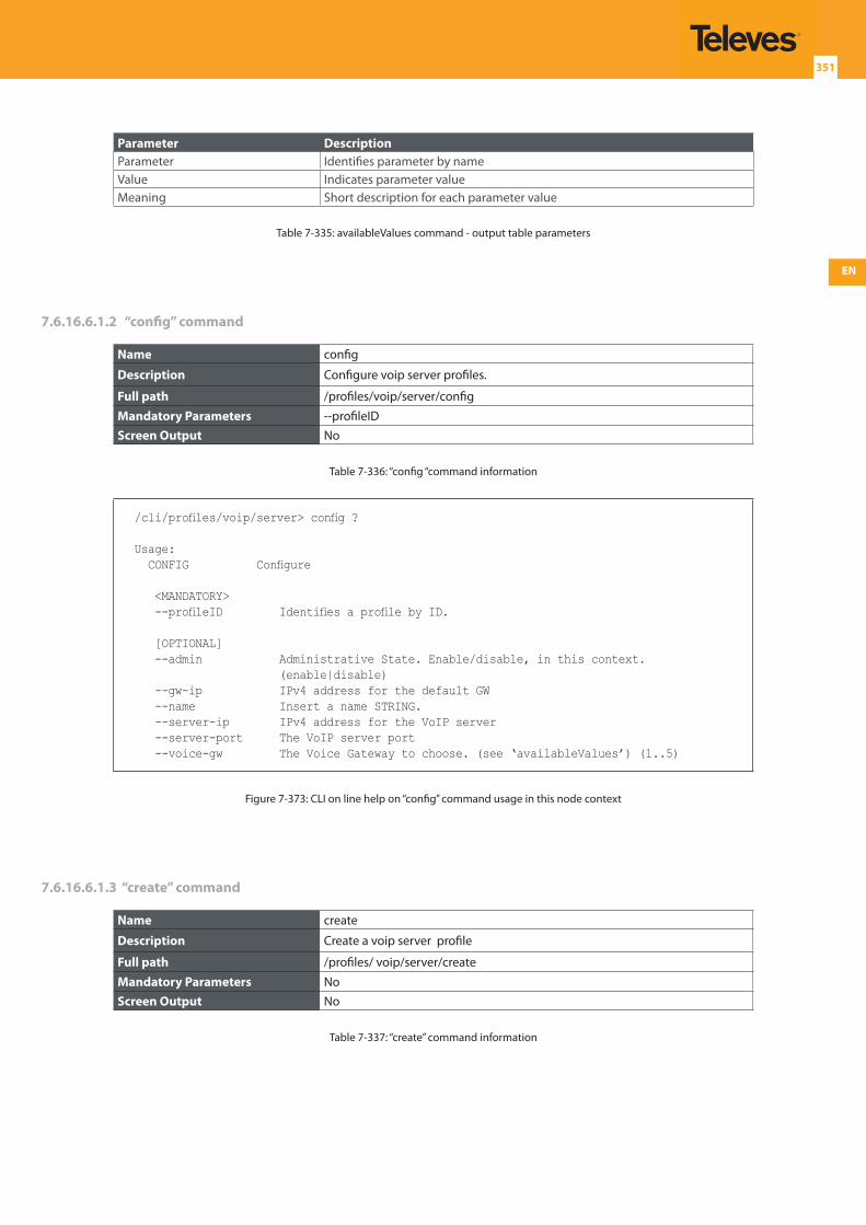
EN
351
Parameter DescriptionParameter Identifies parameter by nameValue Indicates parameter valueMeaning Short description for each parameter value
Table 7-335: availableValues command - output table parameters
7.6.16.6.1.2 “config” command
Name config
Description Configure voip server profiles.
Full path /profiles/voip/server/config
Mandatory Parameters --profileIDScreen Output No
Table 7-336: “config “command information
/cli/profiles/voip/server> config ?
Usage: CONFIG Configure
<MANDATORY> --profileID Identifies a profile by ID.
[OPTIONAL] --admin Administrative State. Enable/disable, in this context.
(enable|disable) --gw-ip IPv4 address for the default GW --name Insert a name STRING. --server-ip IPv4 address for the VoIP server --server-port The VoIP server port --voice-gw The Voice Gateway to choose. (see ‘availableValues’) (1..5)
Figure 7-373: CLI on line help on “config” command usage in this node context
7.6.16.6.1.3 “create” command
Name create
Description Create a voip server profile
Full path /profiles/ voip/server/create
Mandatory Parameters NoScreen Output No
Table 7-337: “create” command information
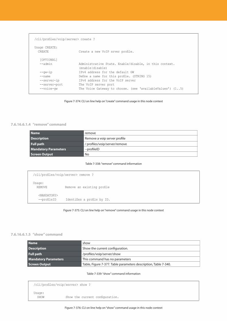
Descripción del producto
352
/cli/profiles/voip/server> create ?
Usage CREATE: CREATE Create a new VoIP srver profile.
[OPTIONAL] --admin Administrative State. Enable/disable, in this context.
(enable|disable) --gw-ip IPv4 address for the default GW --name Define a name for this profile. (STRING 15) --server-ip IPv4 address for the VoIP server --server-port The VoIP server port --voice-gw The Voice Gateway to choose. (see ‘availableValues’) (1..5)
Figure 7-374: CLI on line help on “create” command usage in this node context
7.6.16.6.1.4 “remove” command
Name remove
Description Remove a voip server profile
Full path / profiles/voip/server/remove
Mandatory Parameters --profileIDScreen Output No
Table 7-338: “remove” command information
/cli/profiles/voip/server> remove ?
Usage: REMOVE Remove an existing profile
<MANDATORY> --profileID Identifies a profile by ID.
Figure 7-375: CLI on line help on “remove” command usage in this node context
7.6.16.6.1.5 “show” command
Name show
Description Show the current configuration.
Full path /profiles/voip/server/show
Mandatory Parameters This command has no parametersScreen Output Table, Figure 7-377. Table parameters description, Table 7-340.
Table 7-339: “show” command information
/cli/profiles/voip/server> show ?
Usage: SHOW Show the current configuration.
Figure 7-376: CLI on line help on “show” command usage in this node context
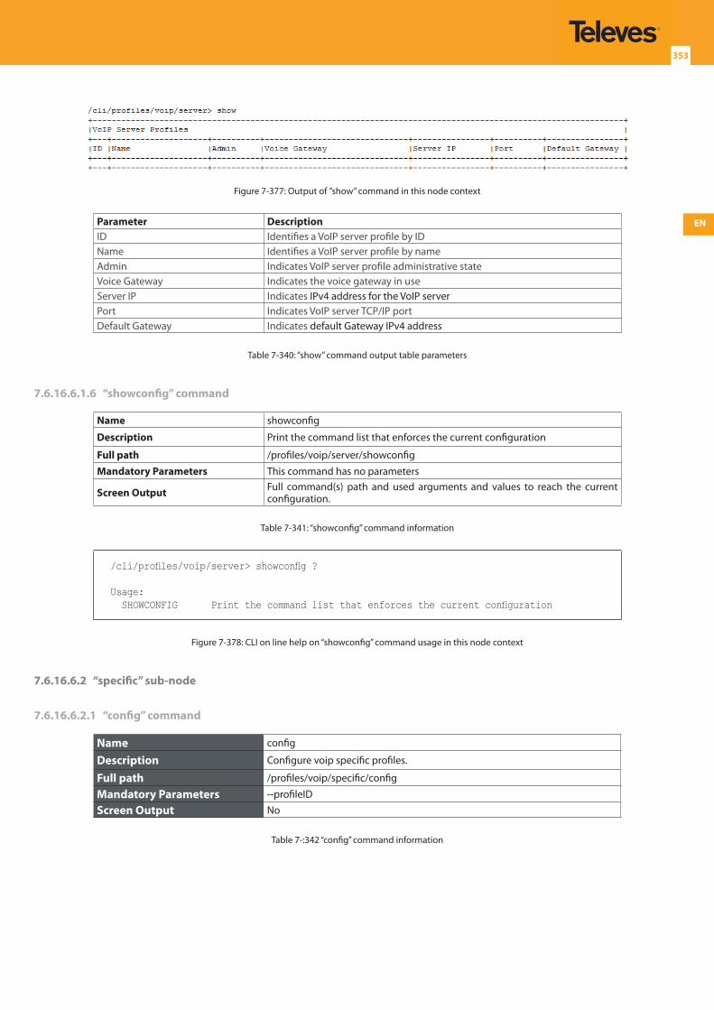
EN
353
Figure 7-377: Output of ”show” command in this node context
Parameter DescriptionID Identifies a VoIP server profile by IDName Identifies a VoIP server profile by nameAdmin Indicates VoIP server profile administrative stateVoice Gateway Indicates the voice gateway in useServer IP Indicates IPv4 address for the VoIP serverPort Indicates VoIP server TCP/IP portDefault Gateway Indicates default Gateway IPv4 address
Table 7-340: “show” command output table parameters
7.6.16.6.1.6 “showconfig” command
Name showconfig
Description Print the command list that enforces the current configuration
Full path /profiles/voip/server/showconfig
Mandatory Parameters This command has no parameters
Screen Output Full command(s) path and used arguments and values to reach the current configuration.
Table 7-341: “showconfig” command information
/cli/profiles/voip/server> showconfig ?
Usage: SHOWCONFIG Print the command list that enforces the current configuration
Figure 7-378: CLI on line help on “showconfig” command usage in this node context
7.6.16.6.2 “specific” sub-node
7.6.16.6.2.1 “config” command
Name config
Description Configure voip specific profiles.
Full path /profiles/voip/specific/config
Mandatory Parameters --profileID
Screen Output No
Table 7-:342 “config” command information
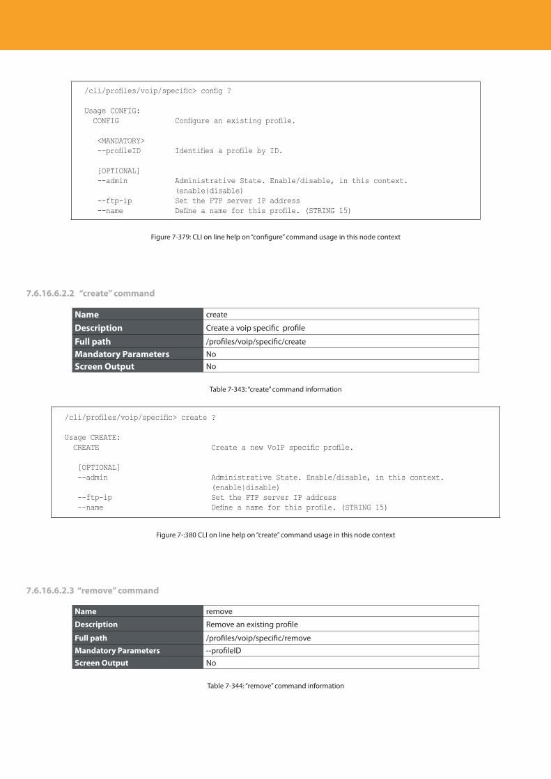
Descripción del producto
354
/cli/profiles/voip/specific> config ?
Usage CONFIG: CONFIG Configure an existing profile.
<MANDATORY> --profileID Identifies a profile by ID.
[OPTIONAL] --admin Administrative State. Enable/disable, in this context.
(enable|disable) --ftp-ip Set the FTP server IP address --name Define a name for this profile. (STRING 15)
Figure 7-379: CLI on line help on “configure” command usage in this node context
7.6.16.6.2.2 “create” command
Name create
Description Create a voip specific profile
Full path /profiles/voip/specific/create
Mandatory Parameters No
Screen Output No
Table 7-343: “create” command information
/cli/profiles/voip/specific> create ?
Usage CREATE: CREATE Create a new VoIP specific profile.
[OPTIONAL] --admin Administrative State. Enable/disable, in this context.
(enable|disable) --ftp-ip Set the FTP server IP address --name Define a name for this profile. (STRING 15)
Figure 7-:380 CLI on line help on “create” command usage in this node context
7.6.16.6.2.3 “remove” command
Name remove
Description Remove an existing profile
Full path /profiles/voip/specific/remove
Mandatory Parameters --profileIDScreen Output No
Table 7-344: “remove” command information
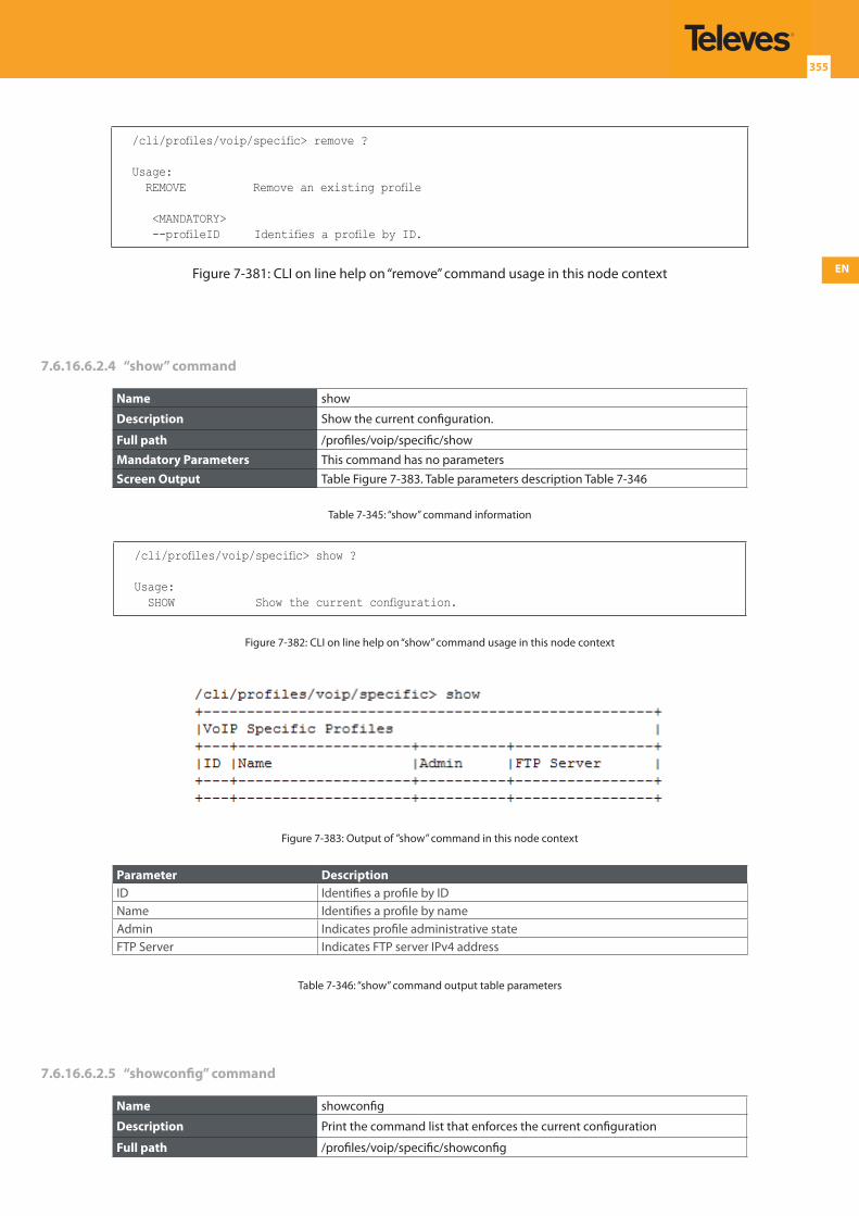
EN
355
/cli/profiles/voip/specific> remove ?
Usage: REMOVE Remove an existing profile
<MANDATORY> --profileID Identifies a profile by ID.
Figure 7-381: CLI on line help on “remove” command usage in this node context
7.6.16.6.2.4 “show” command
Name show
Description Show the current configuration.
Full path /profiles/voip/specific/show
Mandatory Parameters This command has no parametersScreen Output Table Figure 7-383. Table parameters description Table 7-346
Table 7-345: “show” command information
/cli/profiles/voip/specific> show ?
Usage: SHOW Show the current configuration.
Figure 7-382: CLI on line help on “show” command usage in this node context
Figure 7-383: Output of ”show” command in this node context
Parameter DescriptionID Identifies a profile by IDName Identifies a profile by nameAdmin Indicates profile administrative stateFTP Server Indicates FTP server IPv4 address
Table 7-346: “show” command output table parameters
7.6.16.6.2.5 “showconfig” command
Name showconfig
Description Print the command list that enforces the current configuration
Full path /profiles/voip/specific/showconfig
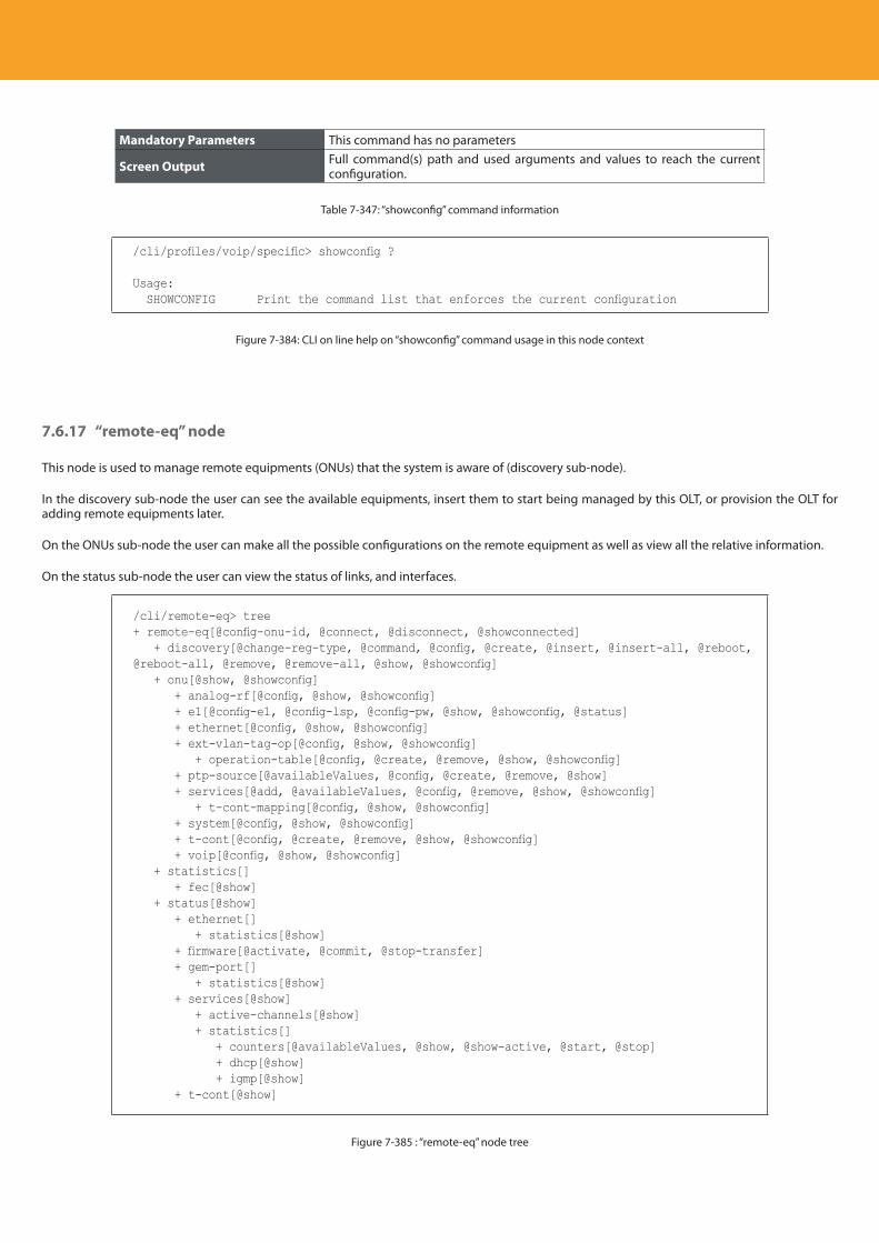
Descripción del producto
356
Mandatory Parameters This command has no parameters
Screen Output Full command(s) path and used arguments and values to reach the current configuration.
Table 7-347: “showconfig” command information
/cli/profiles/voip/specific> showconfig ?
Usage: SHOWCONFIG Print the command list that enforces the current configuration
Figure 7-384: CLI on line help on “showconfig” command usage in this node context
7.6.17 “remote-eq” node
This node is used to manage remote equipments (ONUs) that the system is aware of (discovery sub-node).
In the discovery sub-node the user can see the available equipments, insert them to start being managed by this OLT, or provision the OLT for adding remote equipments later.
On the ONUs sub-node the user can make all the possible configurations on the remote equipment as well as view all the relative information.
On the status sub-node the user can view the status of links, and interfaces.
/cli/remote-eq> tree+ remote-eq[@config-onu-id, @connect, @disconnect, @showconnected] + discovery[@change-reg-type, @command, @config, @create, @insert, @insert-all, @reboot, @reboot-all, @remove, @remove-all, @show, @showconfig] + onu[@show, @showconfig] + analog-rf[@config, @show, @showconfig] + e1[@config-e1, @config-lsp, @config-pw, @show, @showconfig, @status] + ethernet[@config, @show, @showconfig] + ext-vlan-tag-op[@config, @show, @showconfig] + operation-table[@config, @create, @remove, @show, @showconfig] + ptp-source[@availableValues, @config, @create, @remove, @show] + services[@add, @availableValues, @config, @remove, @show, @showconfig] + t-cont-mapping[@config, @show, @showconfig] + system[@config, @show, @showconfig] + t-cont[@config, @create, @remove, @show, @showconfig] + voip[@config, @show, @showconfig] + statistics[] + fec[@show] + status[@show] + ethernet[] + statistics[@show] + firmware[@activate, @commit, @stop-transfer] + gem-port[] + statistics[@show] + services[@show] + active-channels[@show] + statistics[] + counters[@availableValues, @show, @show-active, @start, @stop] + dhcp[@show] + igmp[@show] + t-cont[@show]
Figure 7-385 : “remote-eq” node tree
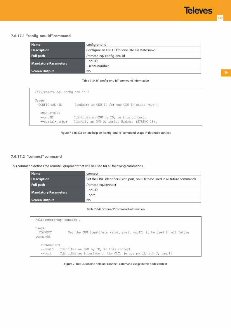
EN
357
7.6.17.1 “config-onu-id” command
Name config-onu-id
Description Configure an ONU ID for one ONU in state ‘new’.
Full path /remote-eq/ config-onu-id
Mandatory Parameters--onuID--serial-number
Screen Output No
Table 7-348: “ config-onu-id “ command information
/cli/remote-eq> config-onu-id ?
Usage: CONFIG-ONU-ID Configure an ONU ID for one ONU in state ‘new’.
<MANDATORY> --onuID Identifies an ONU by ID, in this context. --serial-number Identify an ONU by serial Number. (STRING 16).
Figure 7-386: CLI on line help on “config-onu-id” command usage in this node context
7.6.17.2 “connect” command
This command defines the remote Equipment that will be used for all following commands.
Name connect
Description Set the ONU identifiers (slot, port, onuID) to be used in all future commands.
Full path /remote-eq/connect
Mandatory Parameters--onuID--port
Screen Output No
Table 7-349: “connect” command information
/cli/remote-eq> connect ?
Usage: CONNECT Set the ONU identifiers (slot, port, onuID) to be used in all future commands.
<MANDATORY> --onuID Identifies an ONU by ID, in this context. --port Identifies an interface on the OLT. (e.g.: pon.2; eth.3; lag.1)
Figure 7-387: CLI on line help on “connect” command usage in this node context
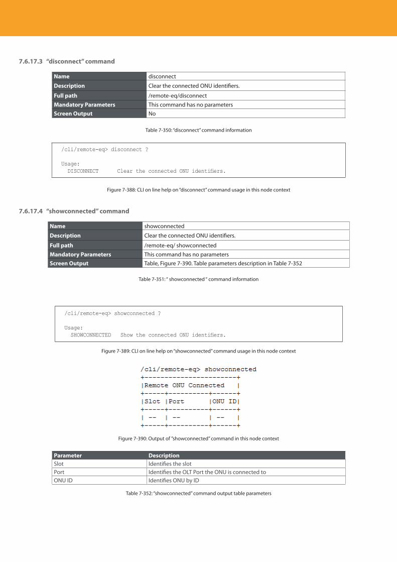
Descripción del producto
358
7.6.17.3 “disconnect” command
Name disconnect
Description Clear the connected ONU identifiers.
Full path /remote-eq/disconnect
Mandatory Parameters This command has no parametersScreen Output No
Table 7-350: “disconnect” command information
/cli/remote-eq> disconnect ?
Usage: DISCONNECT Clear the connected ONU identifiers.
Figure 7-388: CLI on line help on “disconnect” command usage in this node context
7.6.17.4 “showconnected” command
Name showconnected
Description Clear the connected ONU identifiers.
Full path /remote-eq/ showconnected
Mandatory Parameters This command has no parametersScreen Output Table, Figure 7-390. Table parameters description in Table 7-352
Table 7-351: “ showconnected “ command information
/cli/remote-eq> showconnected ?
Usage: SHOWCONNECTED Show the connected ONU identifiers.
Figure 7-389: CLI on line help on “showconnected” command usage in this node context
Figure 7-390: Output of ”showconnected” command in this node context
Parameter DescriptionSlot Identifies the slotPort Identifies the OLT Port the ONU is connected toONU ID Identifies ONU by ID
Table 7-352: “showconnected” command output table parameters
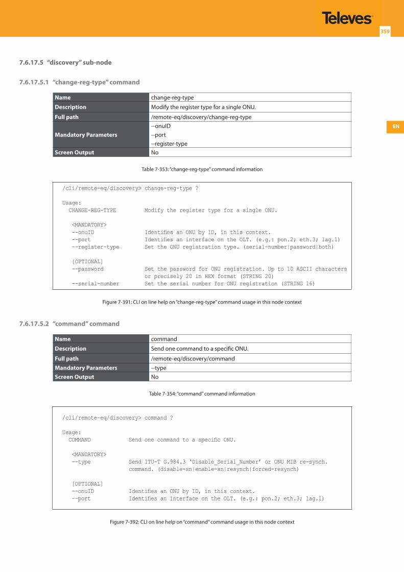
EN
359
7.6.17.5 “discovery” sub-node
7.6.17.5.1 “change-reg-type” command
Name change-reg-type
Description Modify the register type for a single ONU.
Full path /remote-eq/discovery/change-reg-type
Mandatory Parameters--onuID--port--register-type
Screen Output No
Table 7-353: “change-reg-type” command information
/cli/remote-eq/discovery> change-reg-type ?
Usage: CHANGE-REG-TYPE Modify the register type for a single ONU.
<MANDATORY> --onuID Identifies an ONU by ID, in this context. --port Identifies an interface on the OLT. (e.g.: pon.2; eth.3; lag.1) --register-type Set the ONU registration type. (serial-number|password|both)
[OPTIONAL] --password Set the password for ONU registration. Up to 10 ASCII characters
or precisely 20 in HEX format (STRING 20) --serial-number Set the serial number for ONU registration (STRING 16)
Figure 7-391: CLI on line help on “change-reg-type” command usage in this node context
7.6.17.5.2 “command” command
Name command
Description Send one command to a specific ONU.
Full path /remote-eq/discovery/command
Mandatory Parameters --typeScreen Output No
Table 7-354: “command” command information
/cli/remote-eq/discovery> command ?
Usage: COMMAND Send one command to a specific ONU.
<MANDATORY> --type Send ITU-T G.984.3 ‘Disable_Serial_Number’ or ONU MIB re-synch.
command. (disable-sn|enable-sn|resynch|forced-resynch)
[OPTIONAL] --onuID Identifies an ONU by ID, in this context. --port Identifies an interface on the OLT. (e.g.: pon.2; eth.3; lag.1)
Figure 7-392: CLI on line help on “command” command usage in this node context
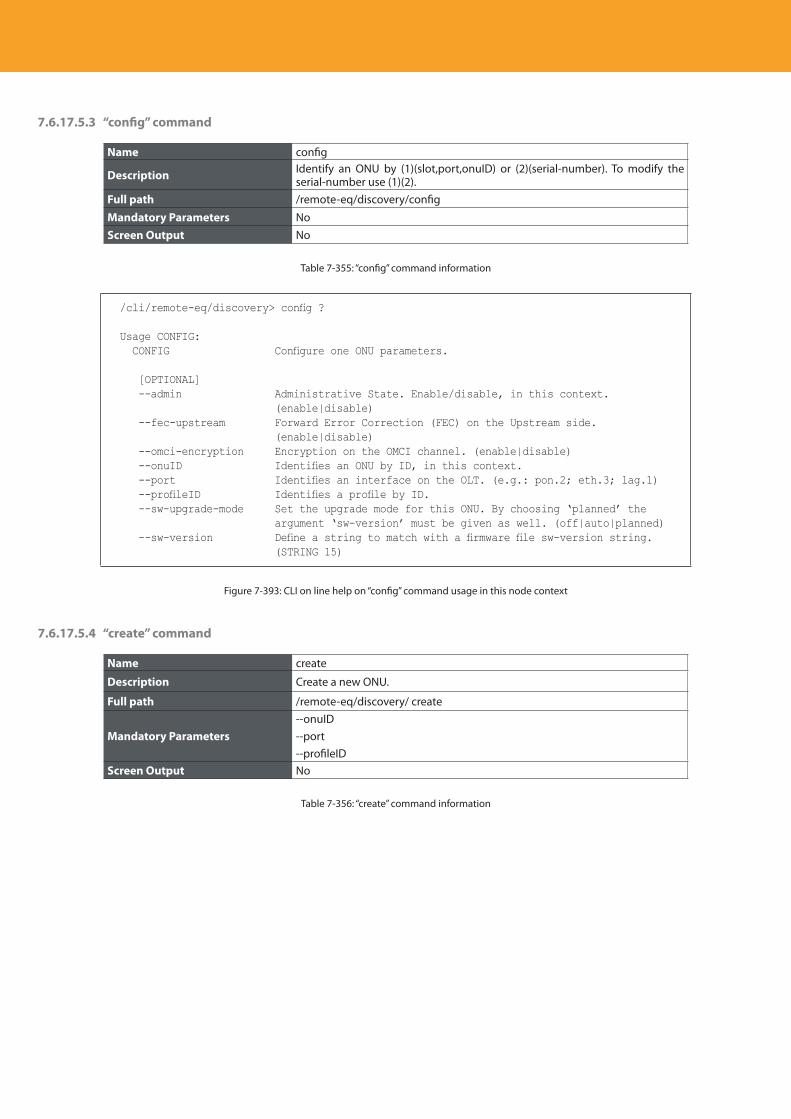
Descripción del producto
360
7.6.17.5.3 “config” command
Name config
Description Identify an ONU by (1)(slot,port,onuID) or (2)(serial-number). To modify the serial-number use (1)(2).
Full path /remote-eq/discovery/config
Mandatory Parameters NoScreen Output No
Table 7-355: “config” command information
/cli/remote-eq/discovery> config ?
Usage CONFIG: CONFIG Configure one ONU parameters.
[OPTIONAL] --admin Administrative State. Enable/disable, in this context.
(enable|disable) --fec-upstream Forward Error Correction (FEC) on the Upstream side.
(enable|disable) --omci-encryption Encryption on the OMCI channel. (enable|disable) --onuID Identifies an ONU by ID, in this context. --port Identifies an interface on the OLT. (e.g.: pon.2; eth.3; lag.1) --profileID Identifies a profile by ID. --sw-upgrade-mode Set the upgrade mode for this ONU. By choosing ‘planned’ the
argument ‘sw-version’ must be given as well. (off|auto|planned) --sw-version Define a string to match with a firmware file sw-version string.
(STRING 15)
Figure 7-393: CLI on line help on “config” command usage in this node context
7.6.17.5.4 “create” command
Name create
Description Create a new ONU.
Full path /remote-eq/discovery/ create
Mandatory Parameters--onuID--port--profileID
Screen Output No
Table 7-356: “create” command information
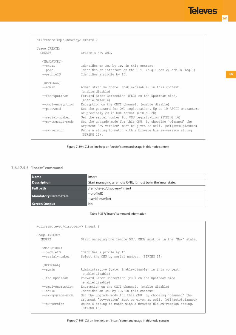
EN
361
cli/remote-eq/discovery> create ?
Usage CREATE: CREATE Create a new ONU.
<MANDATORY> --onuID Identifies an ONU by ID, in this context. --port Identifies an interface on the OLT. (e.g.: pon.2; eth.3; lag.1) --profileID Identifies a profile by ID.
[OPTIONAL] --admin Administrative State. Enable/disable, in this context.
(enable|disable) --fec-upstream Forward Error Correction (FEC) on the Upstream side.
(enable|disable) --omci-encryption Encryption on the OMCI channel. (enable|disable) --password Set the password for ONU registration. Up to 10 ASCII characters
or precisely 20 in HEX format (STRING 20) --serial-number Set the serial number for ONU registration (STRING 16) --sw-upgrade-mode Set the upgrade mode for this ONU. By choosing ‘planned’ the
argument ‘sw-version’ must be given as well. (off|auto|planned) --sw-version Define a string to match with a firmware file sw-version string.
(STRING 15).
Figure 7-394: CLI on line help on “create” command usage in this node context
7.6.17.5.5 “insert” command
Name insert
Description Start managing a remote ONU. It must be in the ‘new’ state.
Full path /remote-eq/discovery/ insert
Mandatory Parameters--profileID--serial-number
Screen Output No
Table 7-357: “insert” command information
/cli/remote-eq/discovery> insert ?
Usage INSERT: INSERT Start managing one remote ONU. ONUs must be in the ‘New’ state.
<MANDATORY> --profileID Identifies a profile by ID. --serial-number Select the ONU by serial number. (STRING 16)
[OPTIONAL] --admin Administrative State. Enable/disable, in this context.
(enable|disable) --fec-upstream Forward Error Correction (FEC) on the Upstream side.
(enable|disable) --omci-encryption Encryption on the OMCI channel. (enable|disable) --onuID Identifies an ONU by ID, in this context. --sw-upgrade-mode Set the upgrade mode for this ONU. By choosing ‘planned’ the
argument ‘sw-version’ must be given as well. (off|auto|planned) --sw-version Define a string to match with a firmware file sw-version string.
(STRING 15)
Figure 7-395: CLI on line help on “insert” command usage in this node context
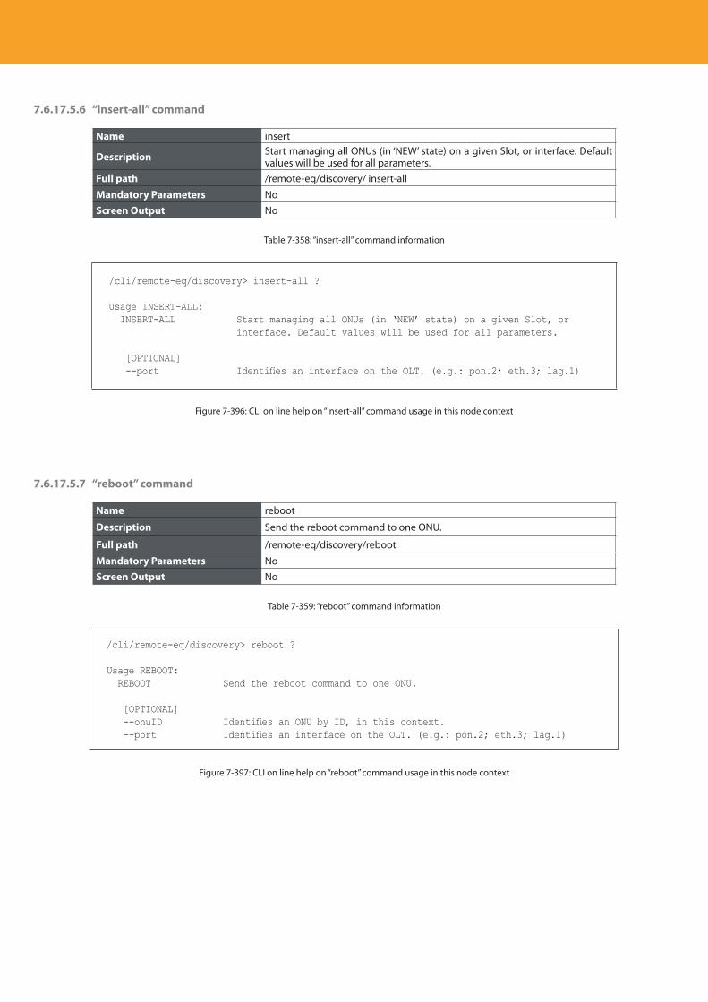
Descripción del producto
362
7.6.17.5.6 “insert-all” command
Name insert
Description Start managing all ONUs (in ‘NEW’ state) on a given Slot, or interface. Default values will be used for all parameters.
Full path /remote-eq/discovery/ insert-all
Mandatory Parameters NoScreen Output No
Table 7-358: “insert-all” command information
/cli/remote-eq/discovery> insert-all ?
Usage INSERT-ALL: INSERT-ALL Start managing all ONUs (in ‘NEW’ state) on a given Slot, or
interface. Default values will be used for all parameters.
[OPTIONAL] --port Identifies an interface on the OLT. (e.g.: pon.2; eth.3; lag.1)
Figure 7-396: CLI on line help on “insert-all” command usage in this node context
7.6.17.5.7 “reboot” command
Name reboot
Description Send the reboot command to one ONU.
Full path /remote-eq/discovery/reboot
Mandatory Parameters NoScreen Output No
Table 7-359: “reboot” command information
/cli/remote-eq/discovery> reboot ?
Usage REBOOT: REBOOT Send the reboot command to one ONU.
[OPTIONAL] --onuID Identifies an ONU by ID, in this context. --port Identifies an interface on the OLT. (e.g.: pon.2; eth.3; lag.1)
Figure 7-397: CLI on line help on “reboot” command usage in this node context
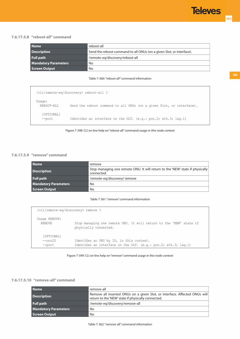
EN
363
7.6.17.5.8 “reboot-all” command
Name reboot-all
Description Send the reboot command to all ONUs (on a given Slot, or interface).
Full path /remote-eq/discovery/reboot-all
Mandatory Parameters NoScreen Output No
Table 7-360: “reboot-all” command information
/cli/remote-eq/discovery> reboot-all ?
Usage: REBOOT-ALL Send the reboot command to all ONUs (on a given Slot, or interface).
[OPTIONAL] --port Identifies an interface on the OLT. (e.g.: pon.2; eth.3; lag.1)
Figure 7-398: CLI on line help on “reboot-all” command usage in this node context
7.6.17.5.9 “remove” command
Name remove
Description Stop managing one remote ONU. It will return to the ‘NEW’ state if physically connected.
Full path /remote-eq/discovery/ remove
Mandatory Parameters NoScreen Output No
Table 7-361: “remove” command information
/cli/remote-eq/discovery> remove ?
Usage REMOVE: REMOVE Stop managing one remote ONU. It will return to the ‘NEW’ state if
physically connected.
[OPTIONAL] --onuID Identifies an ONU by ID, in this context. --port Identifies an interface on the OLT. (e.g.: pon.2; eth.3; lag.1)
Figure 7-399: CLI on line help on “remove” command usage in this node context
7.6.17.5.10 “remove-all” command
Name remove-all
Description Remove all inserted ONUs on a given Slot, or interface. Affected ONUs will return to the ‘NEW’ state if physically connected.
Full path /remote-eq/discovery/remove-all
Mandatory Parameters NoScreen Output No
Table 7-362: “remove-all” command information
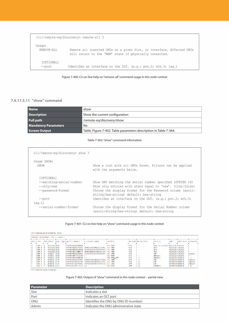
Descripción del producto
364
/cli/remote-eq/discovery> remove-all ?
Usage: REMOVE-ALL Remove all inserted ONUs on a given Slot, or interface. Affected ONUs
will return to the ‘NEW’ state if physically connected.
[OPTIONAL] --port Identifies an interface on the OLT. (e.g.: pon.2; eth.3; lag.1
Figure 7-400: CLI on line help on “remove-all” command usage in this node context
7.6.17.5.11 “show” command
Name show
Description Show the current configuration
Full path /remote-eq/discovery/show
Mandatory Parameters NoScreen Output Table, Figure 7-402. Table parameters description in Table 7-364.
Table 7-363: “show” command information
cli/remote-eq/discovery> show ?
Usage SHOW: SHOW Show a list with all ONUs known. Filters can be applied
with the arguments below.
[OPTIONAL] --matching-serial-number Show ONU matching the serial number specified (STRING 16) --only-new Show only entries with state equal to ‘new’. (true|false) --password-format Choose the display format for the Password column (ascii-
string|hex-string) default: hex-string --port Identifies an interface on the OLT. (e.g.: pon.2; eth.3; lag.1) --serial-number-format Choose the display format for the Serial Number column
(ascii-string|hex-string) default: hex-string
Figure 7-401: CLI on line help on “show” command usage in this node context
Figure 7-402: Output of ”show” command in this node context – partial view
Parameter DescriptionSlot Indicates a slotPort Indicates an OLT portONU Identifies the ONU by ONU ID (number)Admin Indicates the ONU administrative state
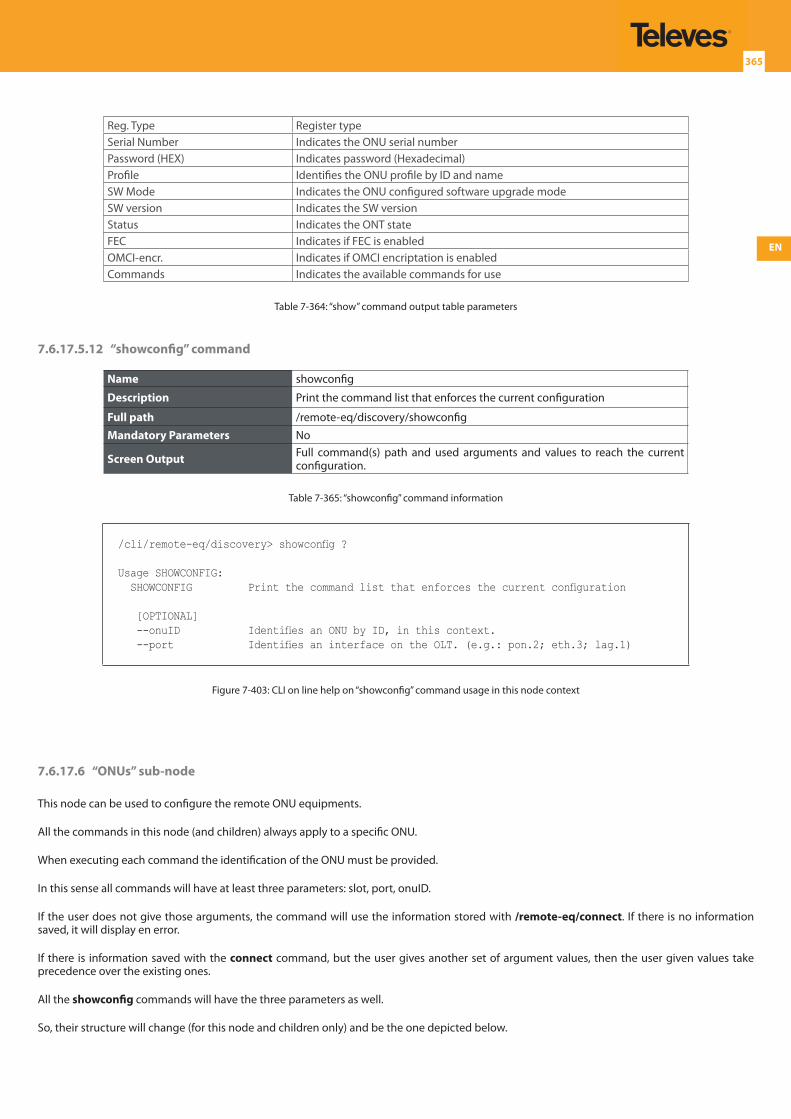
EN
365
Reg. Type Register typeSerial Number Indicates the ONU serial numberPassword (HEX) Indicates password (Hexadecimal)Profile Identifies the ONU profile by ID and nameSW Mode Indicates the ONU configured software upgrade modeSW version Indicates the SW versionStatus Indicates the ONT stateFEC Indicates if FEC is enabledOMCI-encr. Indicates if OMCI encriptation is enabledCommands Indicates the available commands for use
Table 7-364: “show” command output table parameters
7.6.17.5.12 “showconfig” command
Name showconfig
Description Print the command list that enforces the current configuration
Full path /remote-eq/discovery/showconfig
Mandatory Parameters No
Screen Output Full command(s) path and used arguments and values to reach the current configuration.
Table 7-365: “showconfig” command information
/cli/remote-eq/discovery> showconfig ?
Usage SHOWCONFIG: SHOWCONFIG Print the command list that enforces the current configuration
[OPTIONAL] --onuID Identifies an ONU by ID, in this context. --port Identifies an interface on the OLT. (e.g.: pon.2; eth.3; lag.1)
Figure 7-403: CLI on line help on “showconfig” command usage in this node context
7.6.17.6 “ONUs” sub-node
This node can be used to configure the remote ONU equipments.
All the commands in this node (and children) always apply to a specific ONU.
When executing each command the identification of the ONU must be provided.
In this sense all commands will have at least three parameters: slot, port, onuID.
If the user does not give those arguments, the command will use the information stored with /remote-eq/connect. If there is no information saved, it will display en error.
If there is information saved with the connect command, but the user gives another set of argument values, then the user given values take precedence over the existing ones.
All the showconfig commands will have the three parameters as well.
So, their structure will change (for this node and children only) and be the one depicted below.
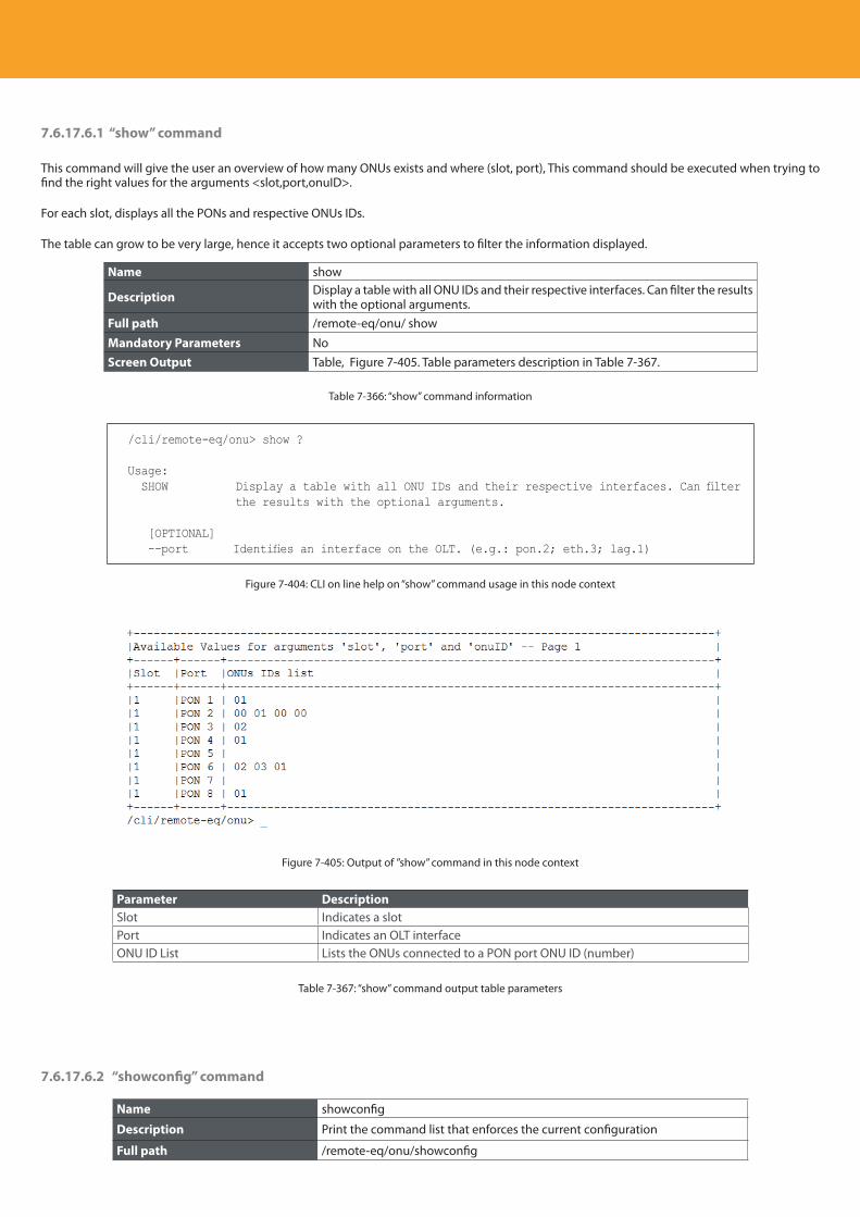
Descripción del producto
366
7.6.17.6.1 “show” command
This command will give the user an overview of how many ONUs exists and where (slot, port), This command should be executed when trying to find the right values for the arguments <slot,port,onuID>.
For each slot, displays all the PONs and respective ONUs IDs.
The table can grow to be very large, hence it accepts two optional parameters to filter the information displayed.
Name show
Description Display a table with all ONU IDs and their respective interfaces. Can filter the results with the optional arguments.
Full path /remote-eq/onu/ show
Mandatory Parameters NoScreen Output Table, Figure 7-405. Table parameters description in Table 7-367.
Table 7-366: “show” command information
/cli/remote-eq/onu> show ?
Usage: SHOW Display a table with all ONU IDs and their respective interfaces. Can filter
the results with the optional arguments.
[OPTIONAL] --port Identifies an interface on the OLT. (e.g.: pon.2; eth.3; lag.1)
Figure 7-404: CLI on line help on “show” command usage in this node context
Figure 7-405: Output of ”show” command in this node context
Parameter DescriptionSlot Indicates a slotPort Indicates an OLT interfaceONU ID List Lists the ONUs connected to a PON port ONU ID (number)
Table 7-367: “show” command output table parameters
7.6.17.6.2 “showconfig” command
Name showconfig
Description Print the command list that enforces the current configuration
Full path /remote-eq/onu/showconfig
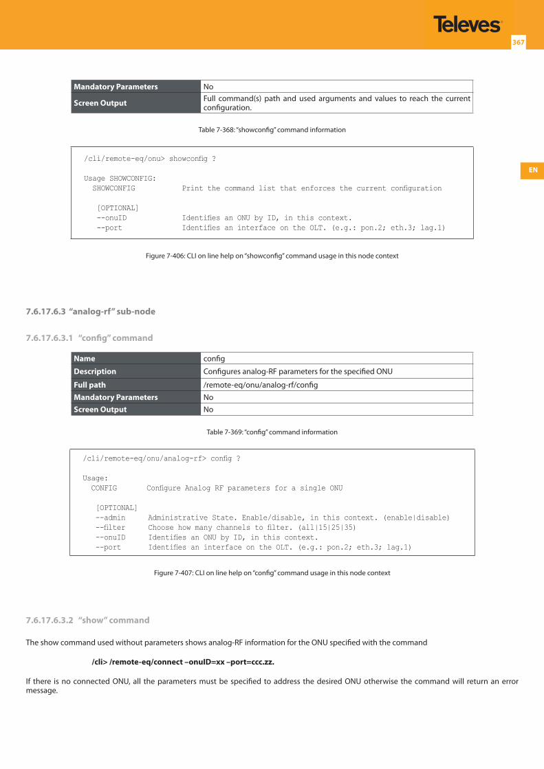
EN
367
Mandatory Parameters No
Screen Output Full command(s) path and used arguments and values to reach the current configuration.
Table 7-368: “showconfig” command information
/cli/remote-eq/onu> showconfig ?
Usage SHOWCONFIG: SHOWCONFIG Print the command list that enforces the current configuration
[OPTIONAL] --onuID Identifies an ONU by ID, in this context. --port Identifies an interface on the OLT. (e.g.: pon.2; eth.3; lag.1)
Figure 7-406: CLI on line help on “showconfig” command usage in this node context
7.6.17.6.3 “analog-rf” sub-node
7.6.17.6.3.1 “config” command
Name config
Description Configures analog-RF parameters for the specified ONU
Full path /remote-eq/onu/analog-rf/config
Mandatory Parameters NoScreen Output No
Table 7-369: “config” command information
/cli/remote-eq/onu/analog-rf> config ?
Usage: CONFIG Configure Analog RF parameters for a single ONU
[OPTIONAL] --admin Administrative State. Enable/disable, in this context. (enable|disable) --filter Choose how many channels to filter. (all|15|25|35) --onuID Identifies an ONU by ID, in this context. --port Identifies an interface on the OLT. (e.g.: pon.2; eth.3; lag.1)
Figure 7-407: CLI on line help on “config” command usage in this node context
7.6.17.6.3.2 “show” command
The show command used without parameters shows analog-RF information for the ONU specified with the command
/cli> /remote-eq/connect –onuID=xx –port=ccc.zz.
If there is no connected ONU, all the parameters must be specified to address the desired ONU otherwise the command will return an error message.
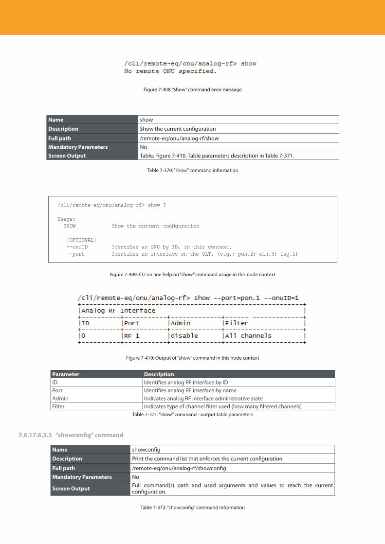
Descripción del producto
368
Figure 7-408: “show” command error message
Name show
Description Show the current configuration
Full path /remote-eq/onu/analog-rf/show
Mandatory Parameters NoScreen Output Table, Figure 7-410. Table parameters description in Table 7-371.
Table 7-370: “show” command information
/cli/remote-eq/onu/analog-rf> show ?
Usage: SHOW Show the current configuration
[OPTIONAL] --onuID Identifies an ONU by ID, in this context. --port Identifies an interface on the OLT. (e.g.: pon.2; eth.3; lag.1)
Figure 7-409: CLI on line help on “show” command usage in this node context
Figure 7-410: Output of ”show” command in this node context
Parameter DescriptionID Identifies analog RF interface by IDPort Identifies analog RF interface by nameAdmin Indicates analog RF interface administrative stateFilter Indicates type of channel filter used (how many filtered channels)
Table 7-371: “show” command - output table parameters
7.6.17.6.3.3 “showconfig” command
Name showconfig
Description Print the command list that enforces the current configuration
Full path /remote-eq/onu/analog-rf/showconfig
Mandatory Parameters No
Screen Output Full command(s) path and used arguments and values to reach the current configuration.
Table 7-372: “showconfig” command information
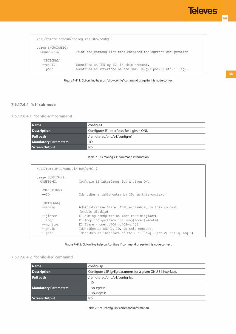
EN
369
/cli/remote-eq/onu/analog-rf> showconfig ?
Usage SHOWCONFIG: SHOWCONFIG Print the command list that enforces the current configuration
[OPTIONAL] --onuID Identifies an ONU by ID, in this context. --port Identifies an interface on the OLT. (e.g.: pon.2; eth.3; lag.1)
Figure 7-411: CLI on line help on “showconfig” command usage in this node contex
7.6.17.6.4 “e1” sub-node
7.6.17.6.4.1 “config-e1” command
Name config-e1
Description Configures E1 interfaces for a given ONU
Full path /remote-eq/onu/e1/config-e1
Mandatory Parameters -IDScreen Output No
Table 7-373: “config-e1” command information
/cli/remote-eq/onu/e1> config-e1 ?
Usage CONFIG-E1: CONFIG-E1 Configure E1 interfaces for a given ONU.
<MANDATORY> --ID Identifies a table entry by ID, in this context.
[OPTIONAL] --admin Administrative State. Enable/disable, in this context.
(enable|disable) --jitter E1 timing configuration (dcr|re-timing|acr) --loop E1 loop configuration (no-loop|local|remote) --monitor E1 Frame (none|g.704|g.704-g.706) --onuID Identifies an ONU by ID, in this context. --port Identifies an interface on the OLT. (e.g.: pon.2; eth.3; lag.1)
Figure 7-412: CLI on line help on “config-e1” command usage in this node context
7.6.17.6.4.2 “config-lsp” command
Name config-lsp
Description Configure LSP Ig/Eg paramters for a given ONU E1 interface.
Full path /remote-eq/onu/e1/config-lsp
Mandatory Parameters--ID--lsp-egress--lsp-ingress
Screen Output No
Table 7-374: “config-lsp” command information
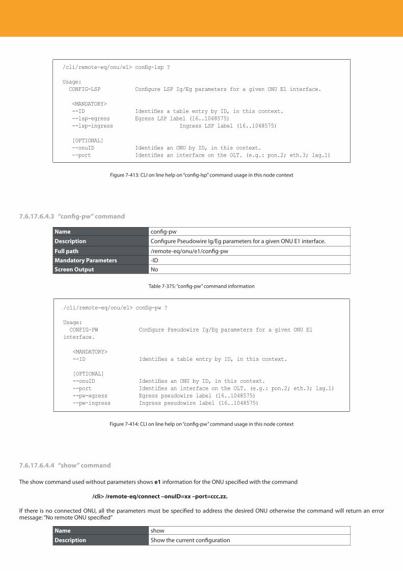
Descripción del producto
370
/cli/remote-eq/onu/e1> config-lsp ?
Usage: CONFIG-LSP Configure LSP Ig/Eg parameters for a given ONU E1 interface.
<MANDATORY> --ID Identifies a table entry by ID, in this context. --lsp-egress Egress LSP label (16..1048575) --lsp-ingress Ingress LSP label (16..1048575)
[OPTIONAL] --onuID Identifies an ONU by ID, in this context. --port Identifies an interface on the OLT. (e.g.: pon.2; eth.3; lag.1)
Figure 7-413: CLI on line help on “config-lsp” command usage in this node context
7.6.17.6.4.3 “config-pw” command
Name config-pw
Description Configure Pseudowire Ig/Eg parameters for a given ONU E1 interface.
Full path /remote-eq/onu/e1/config-pw
Mandatory Parameters -IDScreen Output No
Table 7-375: “config-pw” command information
/cli/remote-eq/onu/e1> config-pw ?
Usage: CONFIG-PW Configure Pseudowire Ig/Eg parameters for a given ONU E1 interface.
<MANDATORY> --ID Identifies a table entry by ID, in this context.
[OPTIONAL] --onuID Identifies an ONU by ID, in this context. --port Identifies an interface on the OLT. (e.g.: pon.2; eth.3; lag.1) --pw-egress Egress pseudowire label (16..1048575) --pw-ingress Ingress pseudowire label (16..1048575)
Figure 7-414: CLI on line help on “config-pw” command usage in this node context
7.6.17.6.4.4 “show” command
The show command used without parameters shows e1 information for the ONU specified with the command
/cli> /remote-eq/connect –onuID=xx –port=ccc.zz.
If there is no connected ONU, all the parameters must be specified to address the desired ONU otherwise the command will return an error message: “No remote ONU specified”
Name show
Description Show the current configuration
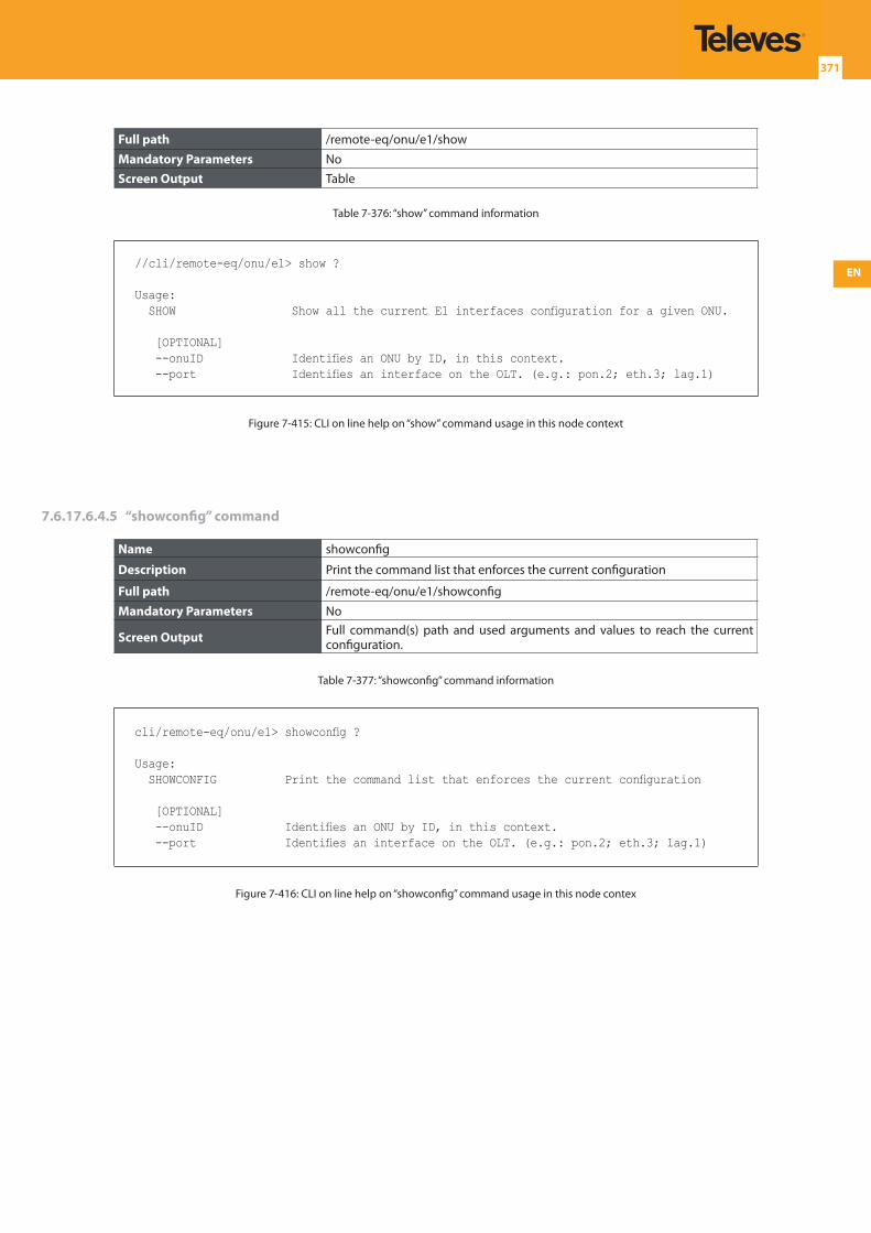
EN
371
Full path /remote-eq/onu/e1/show
Mandatory Parameters NoScreen Output Table
Table 7-376: “show” command information
//cli/remote-eq/onu/e1> show ?
Usage: SHOW Show all the current E1 interfaces configuration for a given ONU.
[OPTIONAL] --onuID Identifies an ONU by ID, in this context. --port Identifies an interface on the OLT. (e.g.: pon.2; eth.3; lag.1)
Figure 7-415: CLI on line help on “show” command usage in this node context
7.6.17.6.4.5 “showconfig” command
Name showconfig
Description Print the command list that enforces the current configuration
Full path /remote-eq/onu/e1/showconfig
Mandatory Parameters No
Screen Output Full command(s) path and used arguments and values to reach the current configuration.
Table 7-377: “showconfig” command information
cli/remote-eq/onu/e1> showconfig ?
Usage: SHOWCONFIG Print the command list that enforces the current configuration
[OPTIONAL] --onuID Identifies an ONU by ID, in this context. --port Identifies an interface on the OLT. (e.g.: pon.2; eth.3; lag.1)
Figure 7-416: CLI on line help on “showconfig” command usage in this node contex
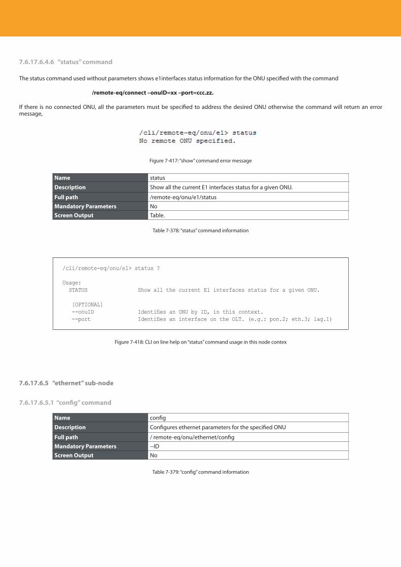
Descripción del producto
372
7.6.17.6.4.6 “status” command
The status command used without parameters shows e1interfaces status information for the ONU specified with the command
/remote-eq/connect –onuID=xx –port=ccc.zz.
If there is no connected ONU, all the parameters must be specified to address the desired ONU otherwise the command will return an error message,
Figure 7-417: “show” command error message
Name status
Description Show all the current E1 interfaces status for a given ONU.
Full path /remote-eq/onu/e1/status
Mandatory Parameters NoScreen Output Table.
Table 7-378: “status” command information
/cli/remote-eq/onu/e1> status ?
Usage: STATUS Show all the current E1 interfaces status for a given ONU.
[OPTIONAL] --onuID Identifies an ONU by ID, in this context. --port Identifies an interface on the OLT. (e.g.: pon.2; eth.3; lag.1)
Figure 7-418: CLI on line help on “status” command usage in this node contex
7.6.17.6.5 “ethernet” sub-node
7.6.17.6.5.1 “config” command
Name config
Description Configures ethernet parameters for the specified ONU
Full path / remote-eq/onu/ethernet/config
Mandatory Parameters --IDScreen Output No
Table 7-379: “config” command information
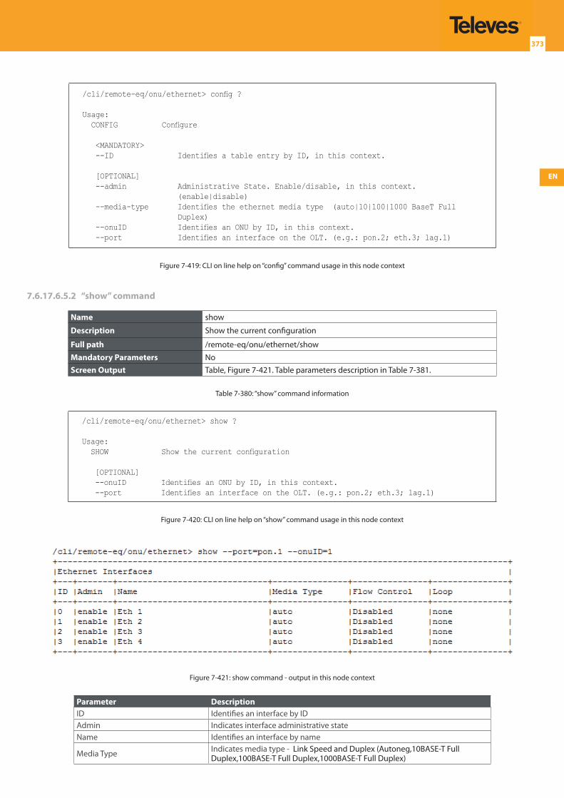
EN
373
/cli/remote-eq/onu/ethernet> config ?
Usage: CONFIG Configure
<MANDATORY> --ID Identifies a table entry by ID, in this context.
[OPTIONAL] --admin Administrative State. Enable/disable, in this context.
(enable|disable) --media-type Identifies the ethernet media type (auto|10|100|1000 BaseT Full
Duplex) --onuID Identifies an ONU by ID, in this context. --port Identifies an interface on the OLT. (e.g.: pon.2; eth.3; lag.1)
Figure 7-419: CLI on line help on “config” command usage in this node context
7.6.17.6.5.2 “show” command
Name show
Description Show the current configuration
Full path /remote-eq/onu/ethernet/show
Mandatory Parameters NoScreen Output Table, Figure 7-421. Table parameters description in Table 7-381.
Table 7-380: “show” command information
/cli/remote-eq/onu/ethernet> show ?
Usage: SHOW Show the current configuration
[OPTIONAL] --onuID Identifies an ONU by ID, in this context. --port Identifies an interface on the OLT. (e.g.: pon.2; eth.3; lag.1)
Figure 7-420: CLI on line help on “show” command usage in this node context
Figure 7-421: show command - output in this node context
Parameter DescriptionID Identifies an interface by IDAdmin Indicates interface administrative stateName Identifies an interface by name
Media Type Indicates media type - Link Speed and Duplex (Autoneg,10BASE-T Full Duplex,100BASE-T Full Duplex,1000BASE-T Full Duplex)
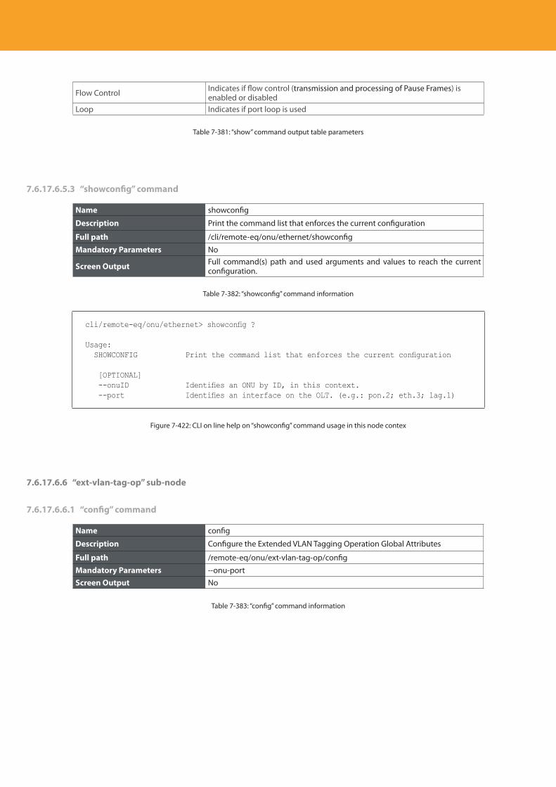
Descripción del producto
374
Flow Control Indicates if flow control (transmission and processing of Pause Frames) is enabled or disabled
Loop Indicates if port loop is used
Table 7-381: “show” command output table parameters
7.6.17.6.5.3 “showconfig” command
Name showconfig
Description Print the command list that enforces the current configuration
Full path /cli/remote-eq/onu/ethernet/showconfig
Mandatory Parameters No
Screen Output Full command(s) path and used arguments and values to reach the current configuration.
Table 7-382: “showconfig” command information
cli/remote-eq/onu/ethernet> showconfig ?
Usage: SHOWCONFIG Print the command list that enforces the current configuration
[OPTIONAL] --onuID Identifies an ONU by ID, in this context. --port Identifies an interface on the OLT. (e.g.: pon.2; eth.3; lag.1)
Figure 7-422: CLI on line help on “showconfig” command usage in this node contex
7.6.17.6.6 “ext-vlan-tag-op” sub-node
7.6.17.6.6.1 “config” command
Name config
Description Configure the Extended VLAN Tagging Operation Global Attributes
Full path /remote-eq/onu/ext-vlan-tag-op/config
Mandatory Parameters --onu-portScreen Output No
Table 7-383: “config” command information
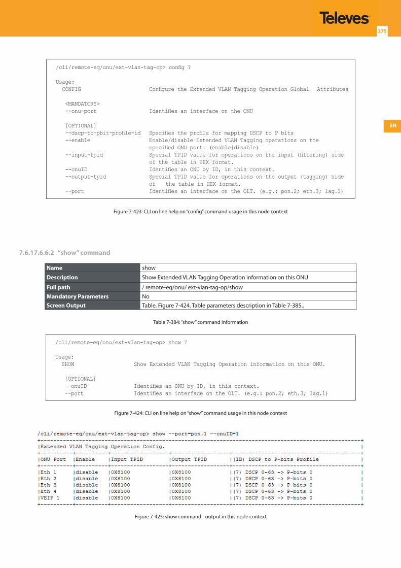
EN
375
/cli/remote-eq/onu/ext-vlan-tag-op> config ?
Usage: CONFIG Configure the Extended VLAN Tagging Operation Global Attributes
<MANDATORY> --onu-port Identifies an interface on the ONU
[OPTIONAL] --dscp-to-pbit-profile-id Specifies the profile for mapping DSCP to P bits --enable Enable/disable Extended VLAN Tagging operations on the
specified ONU port. (enable|disable) --input-tpid Special TPID value for operations on the input (filtering) side
of the table in HEX format. --onuID Identifies an ONU by ID, in this context. --output-tpid Special TPID value for operations on the output (tagging) side
of the table in HEX format. --port Identifies an interface on the OLT. (e.g.: pon.2; eth.3; lag.1)
Figure 7-423: CLI on line help on “config” command usage in this node context
7.6.17.6.6.2 “show” command
Name show
Description Show Extended VLAN Tagging Operation information on this ONU
Full path / remote-eq/onu/ ext-vlan-tag-op/show
Mandatory Parameters NoScreen Output Table, Figure 7-424. Table parameters description in Table 7-385..
Table 7-384: “show” command information
/cli/remote-eq/onu/ext-vlan-tag-op> show ?
Usage: SHOW Show Extended VLAN Tagging Operation information on this ONU.
[OPTIONAL] --onuID Identifies an ONU by ID, in this context. --port Identifies an interface on the OLT. (e.g.: pon.2; eth.3; lag.1)
Figure 7-424: CLI on line help on “show” command usage in this node context
Figure 7-425: show command - output in this node context
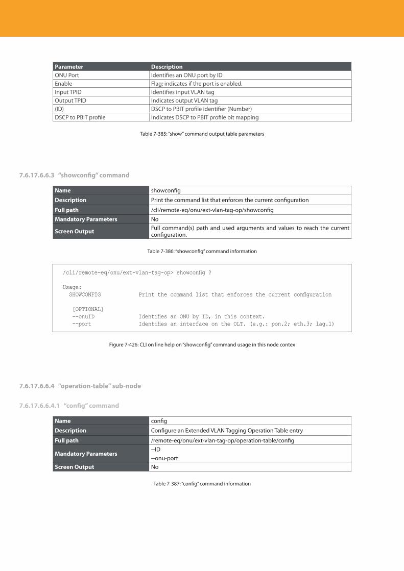
Descripción del producto
376
Parameter DescriptionONU Port Identifies an ONU port by IDEnable Flag; indicates if the port is enabled.Input TPID Identifies input VLAN tagOutput TPID Indicates output VLAN tag(ID) DSCP to PBIT profile identifier (Number)DSCP to PBIT profile Indicates DSCP to PBIT profile bit mapping
Table 7-385: “show” command output table parameters
7.6.17.6.6.3 “showconfig” command
Name showconfig
Description Print the command list that enforces the current configuration
Full path /cli/remote-eq/onu/ext-vlan-tag-op/showconfig
Mandatory Parameters No
Screen Output Full command(s) path and used arguments and values to reach the current configuration.
Table 7-386: “showconfig” command information
/cli/remote-eq/onu/ext-vlan-tag-op> showconfig ?
Usage: SHOWCONFIG Print the command list that enforces the current configuration
[OPTIONAL] --onuID Identifies an ONU by ID, in this context. --port Identifies an interface on the OLT. (e.g.: pon.2; eth.3; lag.1)
Figure 7-426: CLI on line help on “showconfig” command usage in this node contex
7.6.17.6.6.4 “operation-table” sub-node
7.6.17.6.6.4.1 “config” command
Name config
Description Configure an Extended VLAN Tagging Operation Table entry
Full path /remote-eq/onu/ext-vlan-tag-op/operation-table/config
Mandatory Parameters--ID--onu-port
Screen Output No
Table 7-387: “config” command information
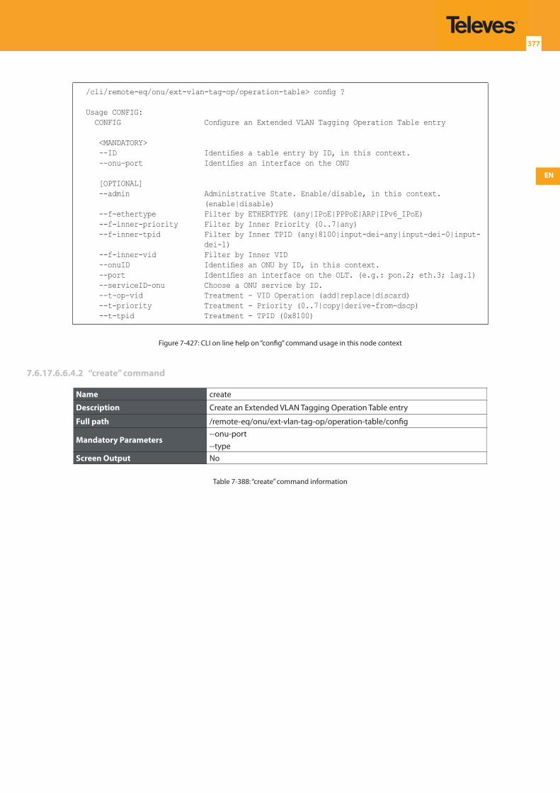
EN
377
/cli/remote-eq/onu/ext-vlan-tag-op/operation-table> config ?
Usage CONFIG: CONFIG Configure an Extended VLAN Tagging Operation Table entry
<MANDATORY> --ID Identifies a table entry by ID, in this context. --onu-port Identifies an interface on the ONU
[OPTIONAL] --admin Administrative State. Enable/disable, in this context.
(enable|disable) --f-ethertype Filter by ETHERTYPE (any|IPoE|PPPoE|ARP|IPv6_IPoE) --f-inner-priority Filter by Inner Priority (0..7|any) --f-inner-tpid Filter by Inner TPID (any|8100|input-dei-any|input-dei-0|input-
dei-1) --f-inner-vid Filter by Inner VID --onuID Identifies an ONU by ID, in this context. --port Identifies an interface on the OLT. (e.g.: pon.2; eth.3; lag.1) --serviceID-onu Choose a ONU service by ID. --t-op-vid Treatment - VID Operation (add|replace|discard) --t-priority Treatment - Priority (0..7|copy|derive-from-dscp) --t-tpid Treatment - TPID (0x8100)
Figure 7-427: CLI on line help on “config” command usage in this node context
7.6.17.6.6.4.2 “create” command
Name create
Description Create an Extended VLAN Tagging Operation Table entry
Full path /remote-eq/onu/ext-vlan-tag-op/operation-table/config
Mandatory Parameters--onu-port--type
Screen Output No
Table 7-388: “create” command information
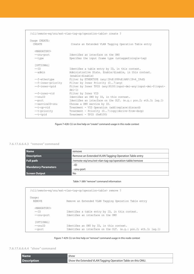
Descripción del producto
378
/cli/remote-eq/onu/ext-vlan-tag-op/operation-table> create ?
Usage CREATE: CREATE Create an Extended VLAN Tagging Operation Table entry
<MANDATORY> --onu-port Identifies an interface on the ONU --type Specifies the input frame type (untagged|single-tag)
[OPTIONAL] --ID Identifies a table entry by ID, in this context. --admin Administrative State. Enable/disable, in this context.
(enable|disable) --f-ethertype Filter by ETHERTYPE (any|IPoE|PPPoE|ARP|IPv6_IPoE) --f-inner-priority Filter by Inner Priority (0..7|any) --f-inner-tpid Filter by Inner TPID (any|8100|input-dei-any|input-dei-0|input-
dei-1) --f-inner-vid Filter by Inner VID --onuID Identifies an ONU by ID, in this context. --port Identifies an interface on the OLT. (e.g.: pon.2; eth.3; lag.1) --serviceID-onu Choose a ONU service by ID. --t-op-vid Treatment - VID Operation (add|replace|discard) --t-priority Treatment - Priority (0..7|copy|derive-from-dscp) --t-tpid Treatment - TPID (0x8100)
Figure 7-428: CLI on line help on “create” command usage in this node context
7.6.17.6.6.4.3 “remove” command
Name remove
Description Remove an Extended VLAN Tagging Operation Table entry
Full path /remote-eq/onu/ext-vlan-tag-op/operation-table/remove
Mandatory Parameters--ID--onu-port
Screen Output No
Table 7-389: “remove” command information
/cli/remote-eq/onu/ext-vlan-tag-op/operation-table> remove ?
Usage: REMOVE Remove an Extended VLAN Tagging Operation Table entry
<MANDATORY> --ID Identifies a table entry by ID, in this context. --onu-port Identifies an interface on the ONU
[OPTIONAL] --onuID Identifies an ONU by ID, in this context. --port Identifies an interface on the OLT. (e.g.: pon.2; eth.3; lag.1)
Figure 7-429: CLI on line help on “remove” command usage in this node context
7.6.17.6.6.4.4 “show” command
Name show
Description Show the Extended VLAN Tagging Operation Table on this ONU.
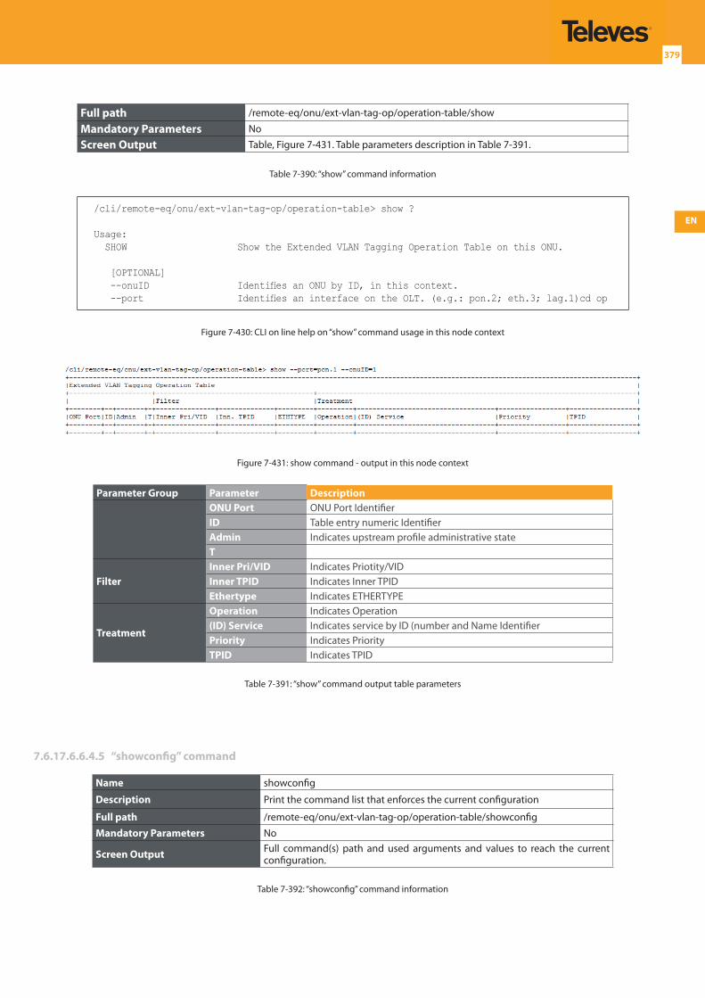
EN
379
Full path /remote-eq/onu/ext-vlan-tag-op/operation-table/show
Mandatory Parameters No
Screen Output Table, Figure 7-431. Table parameters description in Table 7-391.
Table 7-390: “show” command information
/cli/remote-eq/onu/ext-vlan-tag-op/operation-table> show ?
Usage: SHOW Show the Extended VLAN Tagging Operation Table on this ONU.
[OPTIONAL] --onuID Identifies an ONU by ID, in this context. --port Identifies an interface on the OLT. (e.g.: pon.2; eth.3; lag.1)cd op
Figure 7-430: CLI on line help on “show” command usage in this node context
Figure 7-431: show command - output in this node context
Parameter Group Parameter DescriptionONU Port ONU Port IdentifierID Table entry numeric IdentifierAdmin Indicates upstream profile administrative stateT
FilterInner Pri/VID Indicates Priotity/VIDInner TPID Indicates Inner TPIDEthertype Indicates ETHERTYPE
Treatment
Operation Indicates Operation(ID) Service Indicates service by ID (number and Name IdentifierPriority Indicates PriorityTPID Indicates TPID
Table 7-391: “show” command output table parameters
7.6.17.6.6.4.5 “showconfig” command
Name showconfig
Description Print the command list that enforces the current configuration
Full path /remote-eq/onu/ext-vlan-tag-op/operation-table/showconfig
Mandatory Parameters No
Screen Output Full command(s) path and used arguments and values to reach the current configuration.
Table 7-392: “showconfig” command information
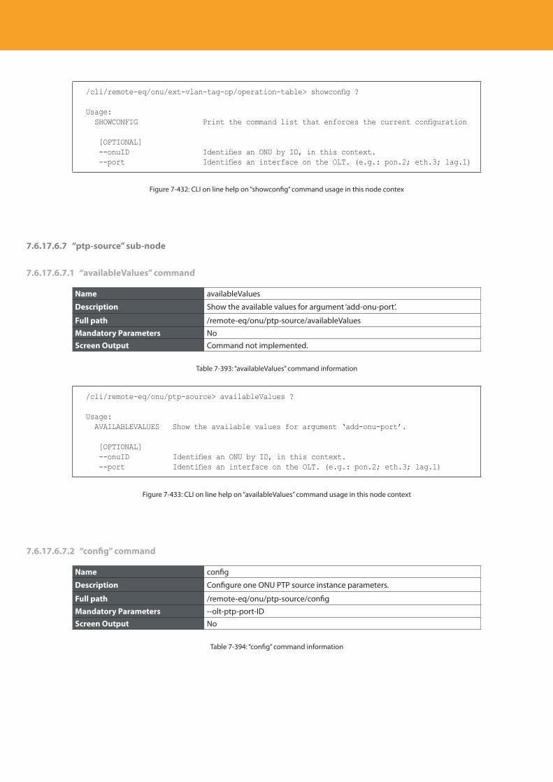
Descripción del producto
380
/cli/remote-eq/onu/ext-vlan-tag-op/operation-table> showconfig ?
Usage: SHOWCONFIG Print the command list that enforces the current configuration
[OPTIONAL] --onuID Identifies an ONU by ID, in this context. --port Identifies an interface on the OLT. (e.g.: pon.2; eth.3; lag.1)
Figure 7-432: CLI on line help on “showconfig” command usage in this node contex
7.6.17.6.7 “ptp-source” sub-node
7.6.17.6.7.1 “availableValues” command
Name availableValues
Description Show the available values for argument ‘add-onu-port’.
Full path /remote-eq/onu/ptp-source/availableValues
Mandatory Parameters NoScreen Output Command not implemented.
Table 7-393: “availableValues” command information
/cli/remote-eq/onu/ptp-source> availableValues ?
Usage: AVAILABLEVALUES Show the available values for argument ‘add-onu-port’.
[OPTIONAL] --onuID Identifies an ONU by ID, in this context. --port Identifies an interface on the OLT. (e.g.: pon.2; eth.3; lag.1)
Figure 7-433: CLI on line help on “availableValues” command usage in this node context
7.6.17.6.7.2 “config” command
Name config
Description Configure one ONU PTP source instance parameters.
Full path /remote-eq/onu/ptp-source/config
Mandatory Parameters --olt-ptp-port-IDScreen Output No
Table 7-394: “config” command information
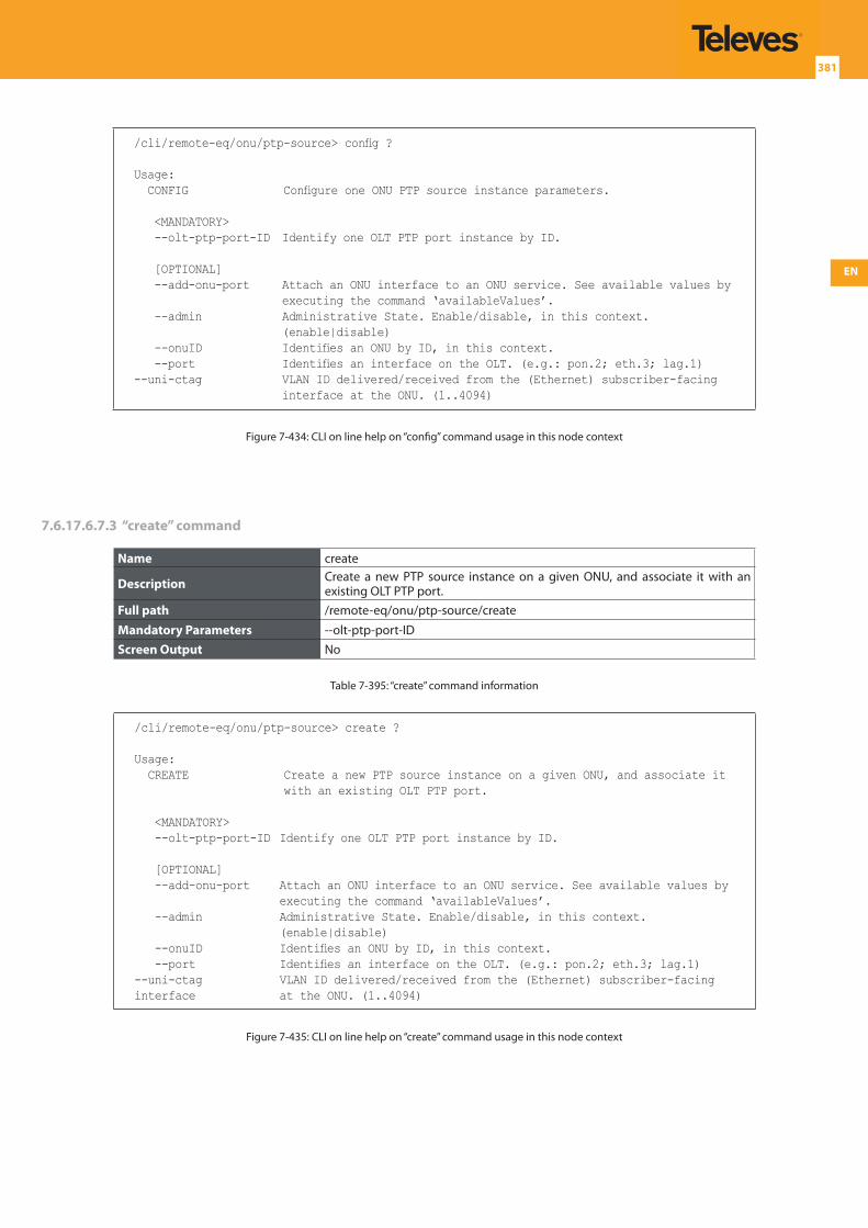
EN
381
/cli/remote-eq/onu/ptp-source> config ?
Usage: CONFIG Configure one ONU PTP source instance parameters.
<MANDATORY> --olt-ptp-port-ID Identify one OLT PTP port instance by ID.
[OPTIONAL] --add-onu-port Attach an ONU interface to an ONU service. See available values by
executing the command ‘availableValues’. --admin Administrative State. Enable/disable, in this context.
(enable|disable) --onuID Identifies an ONU by ID, in this context. --port Identifies an interface on the OLT. (e.g.: pon.2; eth.3; lag.1) --uni-ctag VLAN ID delivered/received from the (Ethernet) subscriber-facing
interface at the ONU. (1..4094)
Figure 7-434: CLI on line help on “config” command usage in this node context
7.6.17.6.7.3 “create” command
Name create
Description Create a new PTP source instance on a given ONU, and associate it with an existing OLT PTP port.
Full path /remote-eq/onu/ptp-source/create
Mandatory Parameters --olt-ptp-port-ID Screen Output No
Table 7-395: “create” command information
/cli/remote-eq/onu/ptp-source> create ?
Usage: CREATE Create a new PTP source instance on a given ONU, and associate it
with an existing OLT PTP port.
<MANDATORY> --olt-ptp-port-ID Identify one OLT PTP port instance by ID.
[OPTIONAL] --add-onu-port Attach an ONU interface to an ONU service. See available values by
executing the command ‘availableValues’. --admin Administrative State. Enable/disable, in this context.
(enable|disable) --onuID Identifies an ONU by ID, in this context. --port Identifies an interface on the OLT. (e.g.: pon.2; eth.3; lag.1) --uni-ctag VLAN ID delivered/received from the (Ethernet) subscriber-facing interface at the ONU. (1..4094)
Figure 7-435: CLI on line help on “create” command usage in this node context
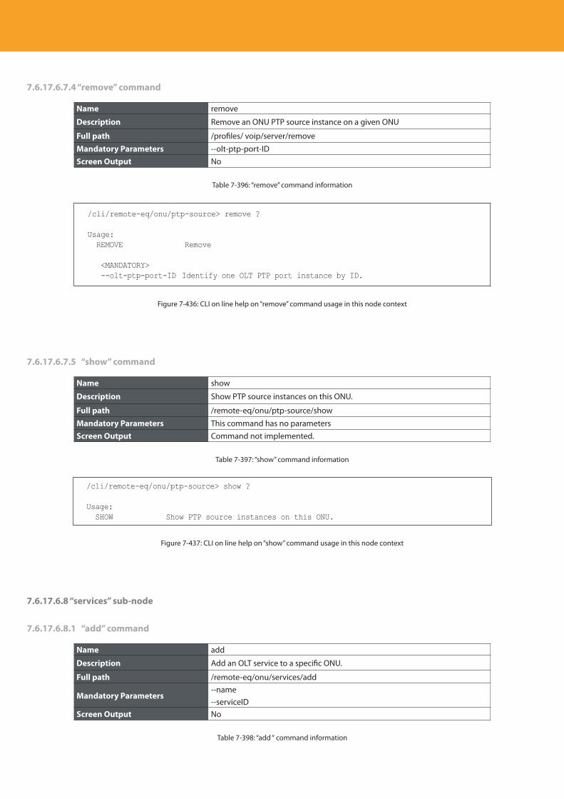
Descripción del producto
382
7.6.17.6.7.4 “remove” command
Name remove
Description Remove an ONU PTP source instance on a given ONU
Full path /profiles/ voip/server/remove
Mandatory Parameters --olt-ptp-port-IDScreen Output No
Table 7-396: “remove” command information
/cli/remote-eq/onu/ptp-source> remove ?
Usage: REMOVE Remove
<MANDATORY> --olt-ptp-port-ID Identify one OLT PTP port instance by ID.
Figure 7-436: CLI on line help on “remove” command usage in this node context
7.6.17.6.7.5 “show” command
Name show
Description Show PTP source instances on this ONU.
Full path /remote-eq/onu/ptp-source/show
Mandatory Parameters This command has no parametersScreen Output Command not implemented.
Table 7-397: “show” command information
/cli/remote-eq/onu/ptp-source> show ?
Usage: SHOW Show PTP source instances on this ONU.
Figure 7-437: CLI on line help on “show” command usage in this node context
7.6.17.6.8 “services” sub-node
7.6.17.6.8.1 “add” command
Name add
Description Add an OLT service to a specific ONU.
Full path /remote-eq/onu/services/add
Mandatory Parameters--name--serviceID
Screen Output No
Table 7-398: “add “ command information
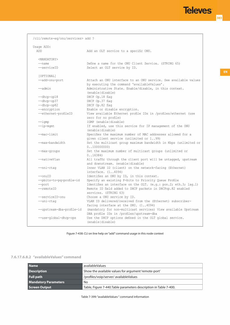
EN
383
/cli/remote-eq/onu/services> add ?
Usage ADD: ADD Add an OLT service to a specific ONU.
<MANDATORY> --name Define a name for the ONU Client Service. (STRING 65) --serviceID Select an OLT service by ID.
[OPTIONAL] --add-onu-port Attach an ONU interface to an ONU service. See available values
by executing the command ‘availableValues’. --admin Administrative State. Enable/disable, in this context.
(enable|disable) --dhcp-op18 DHCP Op.18 flag --dhcp-op37 DHCP Op.37 flag --dhcp-op82 DHCP Op.82 flag --encryption Enable or disable encryption. --ethernet-profileID View available Ethernet profile IDs in /profiles/ethernet (use
zero for no profile) --igmp IGMP (enable|disable) --ip-mgmt If enabled, use this service for IP management of the ONU
(enable|disable) --mac-limit Specifies the maximum number of MAC addresses allowed for a
given client service (unlimited or 1..99) --max-bandwidth Set the multicast group maximum bandwidth in Kbps (unlimited or
0..100000000) --max-groups Set the maximum number of multicast groups (unlimited or
0..16384) --nativeVlan All traffic through the client port will be untagged, upstream
and downstream. (enable|disable) --nni-ctag Inner VLAN ID (client) on the network-facing (Ethernet)
interface. (1..4094) --onuID Identifies an ONU by ID, in this context. --pbits-to-pq-profile-id Specify an existing P-bits to Priority Queue Profile --port Identifies an interface on the OLT. (e.g.: pon.2; eth.3; lag.1) --remoteID Remote ID field added to DHCP packets in DHCPop.82 enabled
services. (STRING 63) --serviceID-onu Choose a ONU service by ID. --uni-ctag VLAN ID delivered/received from the (Ethernet) subscriber-
facing interface at the ONU. (1..4094) --upstream-dba-profile-id (mandatory for non-multicast services) View available Upstream
DBA profile IDs in /profiles/upstream-dba --use-global-dhcp-ops Use the DHCP options defined in the OLT global service.
(enable|disable)
Figure 7-438: CLI on line help on “add” command usage in this node context
7.6.17.6.8.2 “availableValues” command
Name availableValues
Description Show the available values for argument ‘remote-port’
Full path /profiles/voip/server/ availableValues
Mandatory Parameters NoScreen Output Table, Figure 7-440.Table parameters description in Table 7-400.
Table 7-399: “availableValues “ command information
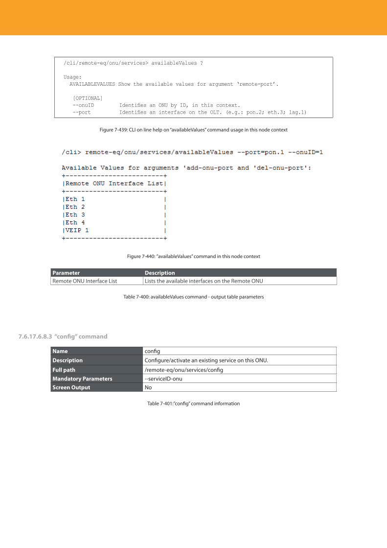
Descripción del producto
384
/cli/remote-eq/onu/services> availableValues ?
Usage: AVAILABLEVALUES Show the available values for argument ‘remote-port’.
[OPTIONAL] --onuID Identifies an ONU by ID, in this context. --port Identifies an interface on the OLT. (e.g.: pon.2; eth.3; lag.1)
Figure 7-439: CLI on line help on “availableValues” command usage in this node context
Figure 7-440: ”availableValues” command in this node context
Parameter DescriptionRemote ONU Interface List Lists the available interfaces on the Remote ONU
Table 7-400: availableValues command - output table parameters
7.6.17.6.8.3 “config” command
Name config
Description Configure/activate an existing service on this ONU.
Full path /remote-eq/onu/services/config
Mandatory Parameters --serviceID-onuScreen Output No
Table 7-401:”config” command information
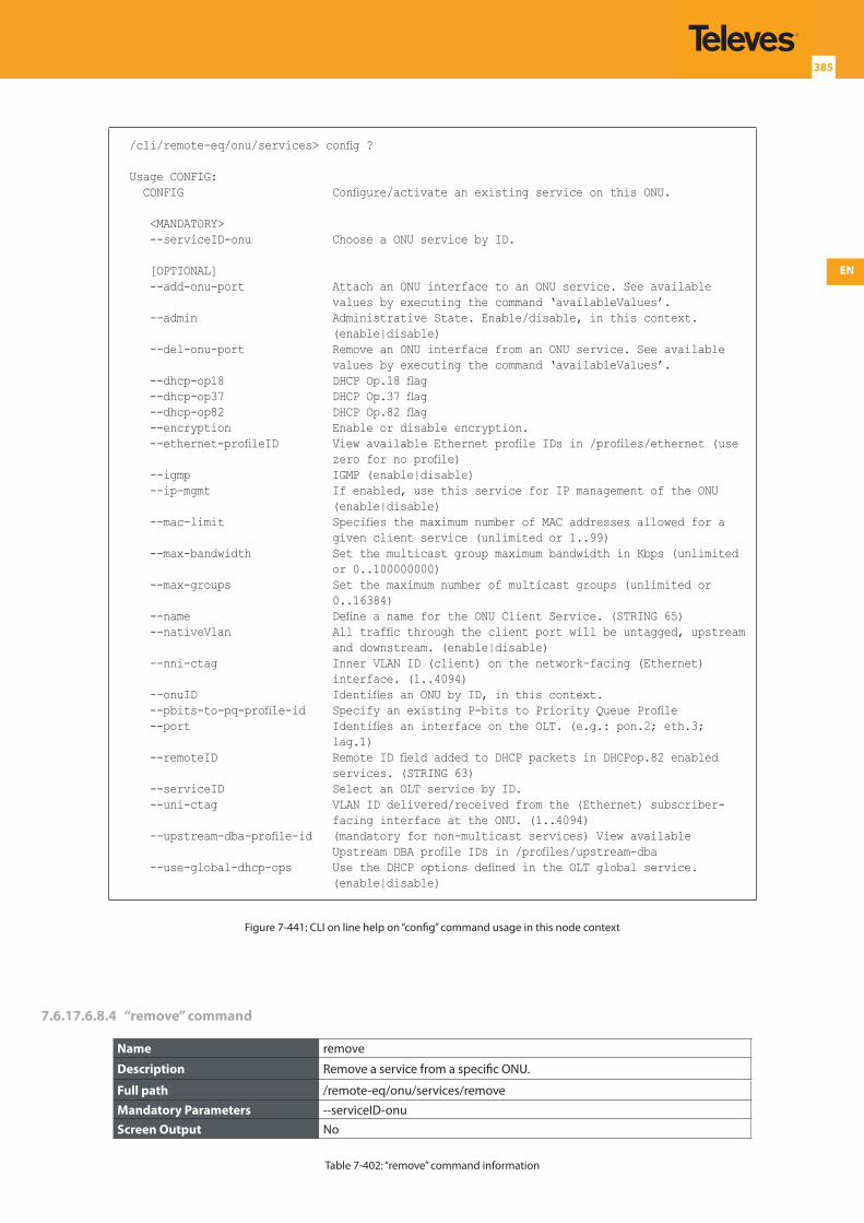
EN
385
/cli/remote-eq/onu/services> config ?
Usage CONFIG: CONFIG Configure/activate an existing service on this ONU.
<MANDATORY> --serviceID-onu Choose a ONU service by ID.
[OPTIONAL] --add-onu-port Attach an ONU interface to an ONU service. See available
values by executing the command ‘availableValues’. --admin Administrative State. Enable/disable, in this context.
(enable|disable) --del-onu-port Remove an ONU interface from an ONU service. See available
values by executing the command ‘availableValues’. --dhcp-op18 DHCP Op.18 flag --dhcp-op37 DHCP Op.37 flag --dhcp-op82 DHCP Op.82 flag --encryption Enable or disable encryption. --ethernet-profileID View available Ethernet profile IDs in /profiles/ethernet (use
zero for no profile) --igmp IGMP (enable|disable) --ip-mgmt If enabled, use this service for IP management of the ONU
(enable|disable) --mac-limit Specifies the maximum number of MAC addresses allowed for a
given client service (unlimited or 1..99) --max-bandwidth Set the multicast group maximum bandwidth in Kbps (unlimited
or 0..100000000) --max-groups Set the maximum number of multicast groups (unlimited or
0..16384) --name Define a name for the ONU Client Service. (STRING 65) --nativeVlan All traffic through the client port will be untagged, upstream
and downstream. (enable|disable) --nni-ctag Inner VLAN ID (client) on the network-facing (Ethernet)
interface. (1..4094) --onuID Identifies an ONU by ID, in this context. --pbits-to-pq-profile-id Specify an existing P-bits to Priority Queue Profile --port Identifies an interface on the OLT. (e.g.: pon.2; eth.3;
lag.1) --remoteID Remote ID field added to DHCP packets in DHCPop.82 enabled
services. (STRING 63) --serviceID Select an OLT service by ID. --uni-ctag VLAN ID delivered/received from the (Ethernet) subscriber-
facing interface at the ONU. (1..4094) --upstream-dba-profile-id (mandatory for non-multicast services) View available
Upstream DBA profile IDs in /profiles/upstream-dba --use-global-dhcp-ops Use the DHCP options defined in the OLT global service.
(enable|disable)
Figure 7-441: CLI on line help on “config” command usage in this node context
7.6.17.6.8.4 “remove” command
Name remove
Description Remove a service from a specific ONU.
Full path /remote-eq/onu/services/remove
Mandatory Parameters --serviceID-onuScreen Output No
Table 7-402: “remove” command information
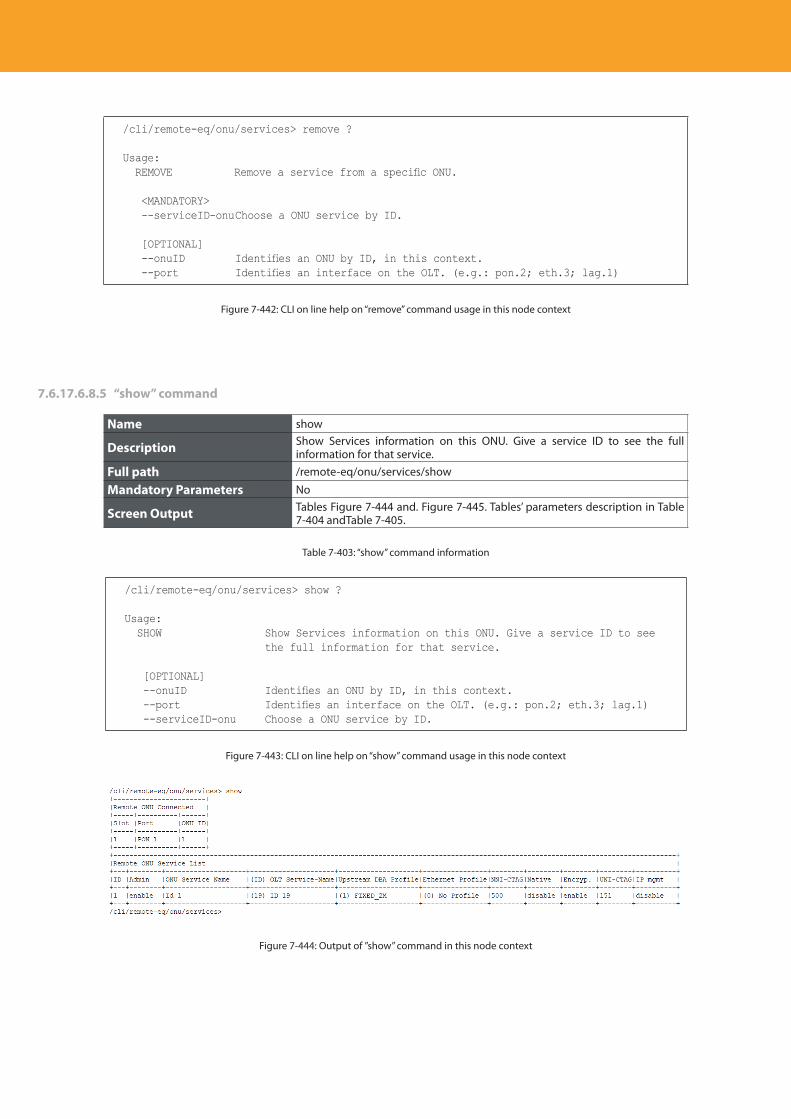
Descripción del producto
386
/cli/remote-eq/onu/services> remove ?
Usage: REMOVE Remove a service from a specific ONU.
<MANDATORY> --serviceID-onu Choose a ONU service by ID.
[OPTIONAL] --onuID Identifies an ONU by ID, in this context. --port Identifies an interface on the OLT. (e.g.: pon.2; eth.3; lag.1)
Figure 7-442: CLI on line help on “remove” command usage in this node context
7.6.17.6.8.5 “show” command
Name show
Description Show Services information on this ONU. Give a service ID to see the full information for that service.
Full path /remote-eq/onu/services/show
Mandatory Parameters No
Screen Output Tables Figure 7-444 and. Figure 7-445. Tables’ parameters description in Table 7-404 andTable 7-405.
Table 7-403: “show” command information
/cli/remote-eq/onu/services> show ?
Usage: SHOW Show Services information on this ONU. Give a service ID to see
the full information for that service.
[OPTIONAL] --onuID Identifies an ONU by ID, in this context. --port Identifies an interface on the OLT. (e.g.: pon.2; eth.3; lag.1) --serviceID-onu Choose a ONU service by ID.
Figure 7-443: CLI on line help on “show” command usage in this node context
Figure 7-444: Output of ”show” command in this node context
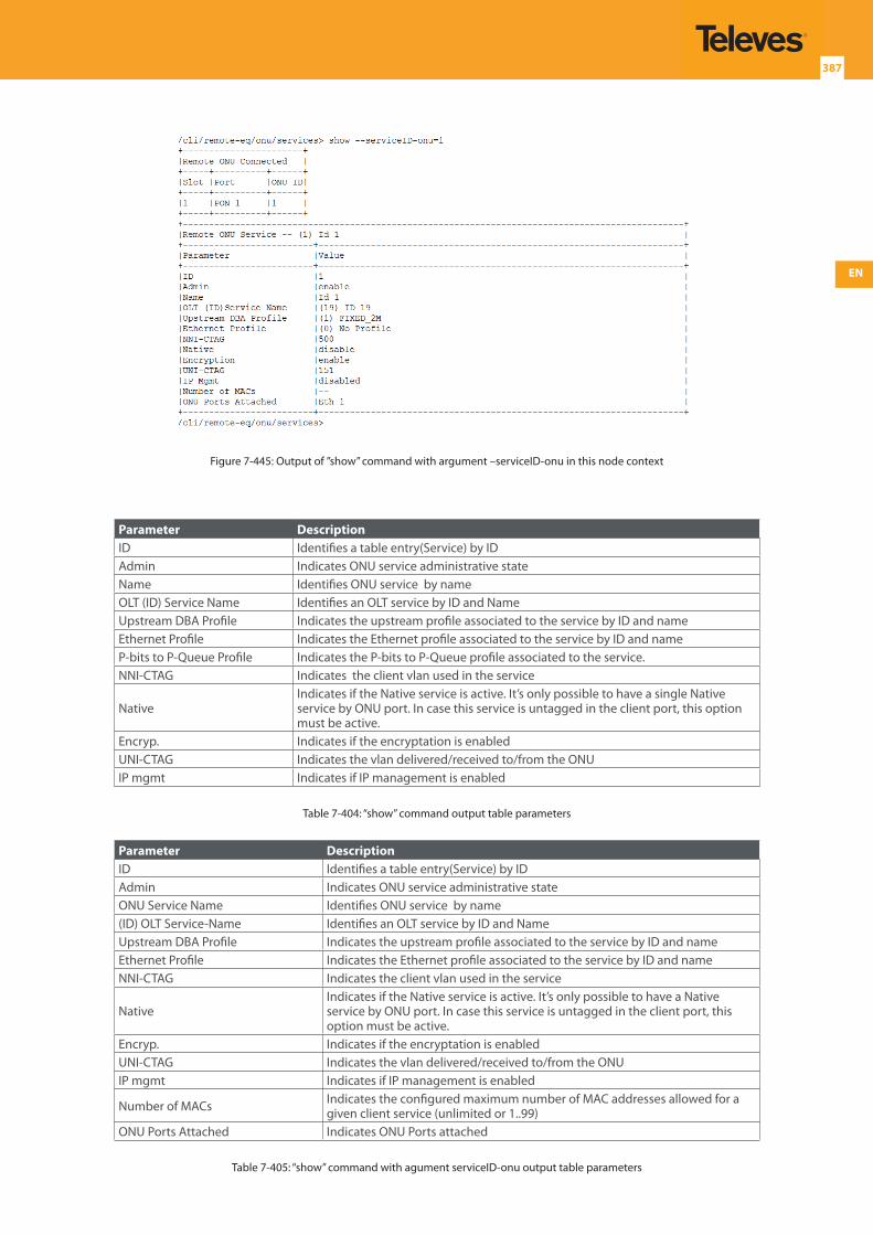
EN
387
Figure 7-445: Output of ”show” command with argument –serviceID-onu in this node context
Parameter DescriptionID Identifies a table entry(Service) by IDAdmin Indicates ONU service administrative stateName Identifies ONU service by nameOLT (ID) Service Name Identifies an OLT service by ID and NameUpstream DBA Profile Indicates the upstream profile associated to the service by ID and nameEthernet Profile Indicates the Ethernet profile associated to the service by ID and nameP-bits to P-Queue Profile Indicates the P-bits to P-Queue profile associated to the service.NNI-CTAG Indicates the client vlan used in the service
NativeIndicates if the Native service is active. It’s only possible to have a single Native service by ONU port. In case this service is untagged in the client port, this option must be active.
Encryp. Indicates if the encryptation is enabled UNI-CTAG Indicates the vlan delivered/received to/from the ONU IP mgmt Indicates if IP management is enabled
Table 7-404: “show” command output table parameters
Parameter DescriptionID Identifies a table entry(Service) by IDAdmin Indicates ONU service administrative stateONU Service Name Identifies ONU service by name(ID) OLT Service-Name Identifies an OLT service by ID and NameUpstream DBA Profile Indicates the upstream profile associated to the service by ID and nameEthernet Profile Indicates the Ethernet profile associated to the service by ID and nameNNI-CTAG Indicates the client vlan used in the service
NativeIndicates if the Native service is active. It’s only possible to have a Native service by ONU port. In case this service is untagged in the client port, this option must be active.
Encryp. Indicates if the encryptation is enabled UNI-CTAG Indicates the vlan delivered/received to/from the ONUIP mgmt Indicates if IP management is enabled
Number of MACs Indicates the configured maximum number of MAC addresses allowed for a given client service (unlimited or 1..99)
ONU Ports Attached Indicates ONU Ports attached
Table 7-405: “show” command with agument serviceID-onu output table parameters
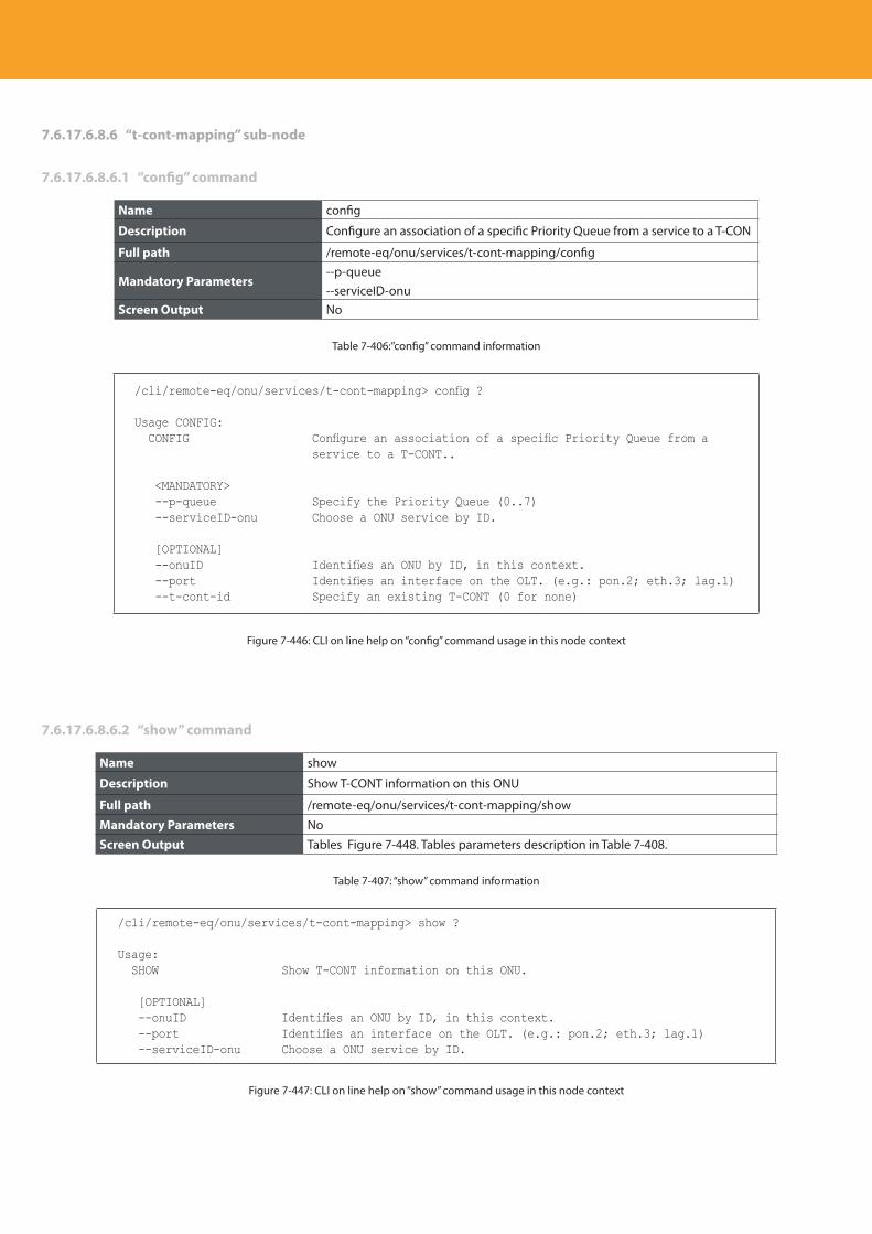
Descripción del producto
388
7.6.17.6.8.6 “t-cont-mapping” sub-node
7.6.17.6.8.6.1 “config” command
Name config
Description Configure an association of a specific Priority Queue from a service to a T-CON
Full path /remote-eq/onu/services/t-cont-mapping/config
Mandatory Parameters--p-queue--serviceID-onu
Screen Output No
Table 7-406:”config” command information
/cli/remote-eq/onu/services/t-cont-mapping> config ?
Usage CONFIG: CONFIG Configure an association of a specific Priority Queue from a
service to a T-CONT..
<MANDATORY> --p-queue Specify the Priority Queue (0..7) --serviceID-onu Choose a ONU service by ID.
[OPTIONAL] --onuID Identifies an ONU by ID, in this context. --port Identifies an interface on the OLT. (e.g.: pon.2; eth.3; lag.1) --t-cont-id Specify an existing T-CONT (0 for none)
Figure 7-446: CLI on line help on “config” command usage in this node context
7.6.17.6.8.6.2 “show” command
Name show
Description Show T-CONT information on this ONU
Full path /remote-eq/onu/services/t-cont-mapping/show
Mandatory Parameters NoScreen Output Tables Figure 7-448. Tables parameters description in Table 7-408.
Table 7-407: “show” command information
/cli/remote-eq/onu/services/t-cont-mapping> show ?
Usage: SHOW Show T-CONT information on this ONU.
[OPTIONAL] --onuID Identifies an ONU by ID, in this context. --port Identifies an interface on the OLT. (e.g.: pon.2; eth.3; lag.1) --serviceID-onu Choose a ONU service by ID.
Figure 7-447: CLI on line help on “show” command usage in this node context
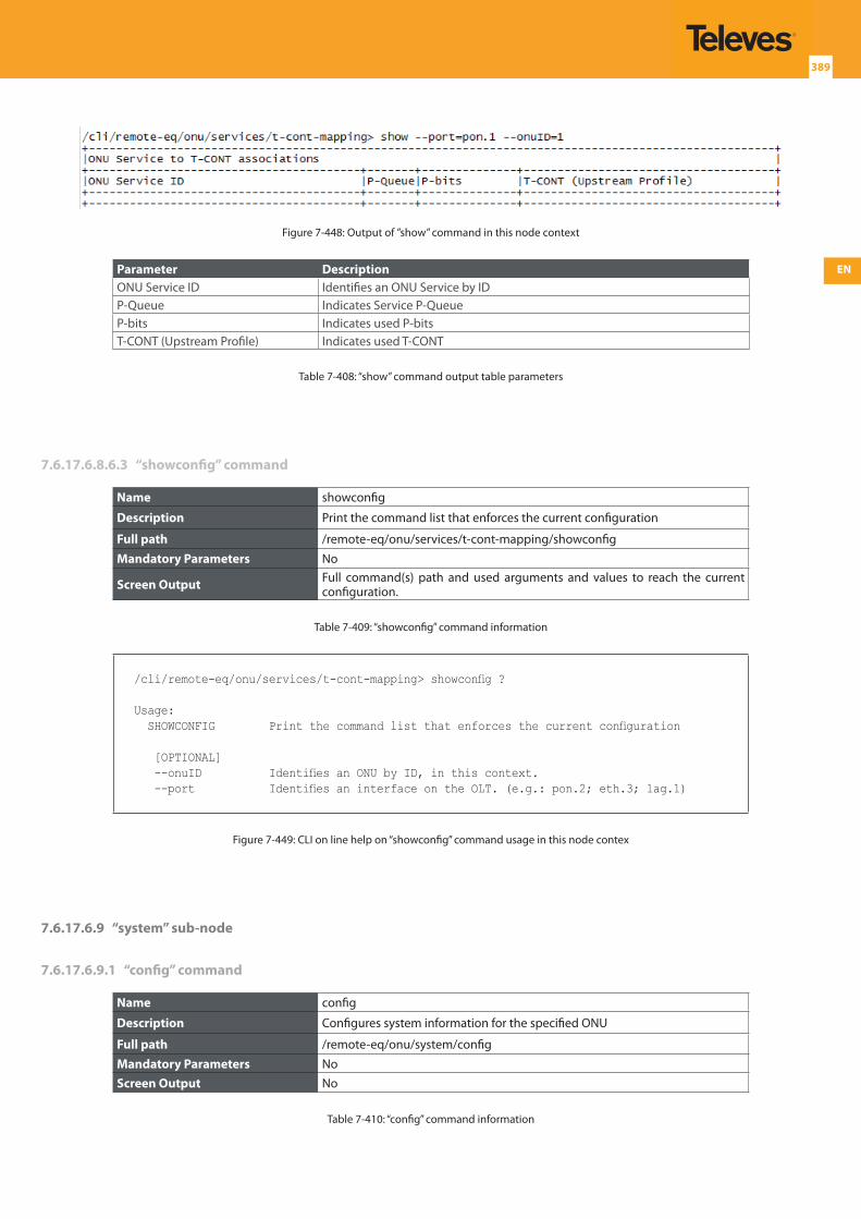
EN
389
Figure 7-448: Output of ”show” command in this node context
Parameter DescriptionONU Service ID Identifies an ONU Service by IDP-Queue Indicates Service P-QueueP-bits Indicates used P-bitsT-CONT (Upstream Profile) Indicates used T-CONT
Table 7-408: “show” command output table parameters
7.6.17.6.8.6.3 “showconfig” command
Name showconfig
Description Print the command list that enforces the current configuration
Full path /remote-eq/onu/services/t-cont-mapping/showconfig
Mandatory Parameters No
Screen Output Full command(s) path and used arguments and values to reach the current configuration.
Table 7-409: “showconfig” command information
/cli/remote-eq/onu/services/t-cont-mapping> showconfig ?
Usage: SHOWCONFIG Print the command list that enforces the current configuration
[OPTIONAL] --onuID Identifies an ONU by ID, in this context. --port Identifies an interface on the OLT. (e.g.: pon.2; eth.3; lag.1)
Figure 7-449: CLI on line help on “showconfig” command usage in this node contex
7.6.17.6.9 “system” sub-node
7.6.17.6.9.1 “config” command
Name config
Description Configures system information for the specified ONU
Full path /remote-eq/onu/system/config
Mandatory Parameters NoScreen Output No
Table 7-410: “config” command information
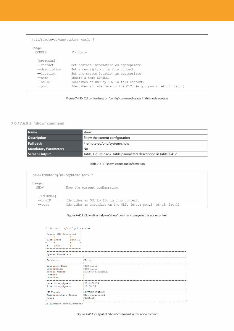
Descripción del producto
390
/cli/remote-eq/onu/system> config ?
Usage: CONFIG Configure
[OPTIONAL] --contact Set contact information as appropriate --description Set a description, in this context. --location Set the system location as appropriate --name Insert a name STRING. --onuID Identifies an ONU by ID, in this context. --port Identifies an interface on the OLT. (e.g.: pon.2; eth.3; lag.1)
Figure 7-450: CLI on line help on “config” command usage in this node context
7.6.17.6.9.2 “show” command
Name show
Description Show the current configuration
Full path / remote-eq/onu/system/show
Mandatory Parameters NoScreen Output Table, Figure 7-452. Table parameters description in Table 7-412.
Table 7-411: “show” command information
/cli/remote-eq/onu/system> show ?
Usage: SHOW Show the current configuration
[OPTIONAL] --onuID Identifies an ONU by ID, in this context. --port Identifies an interface on the OLT. (e.g.: pon.2; eth.3; lag.1)
Figure 7-451: CLI on line help on “show” command usage in this node context
Figure 7-452: Output of ”show” command in this node context
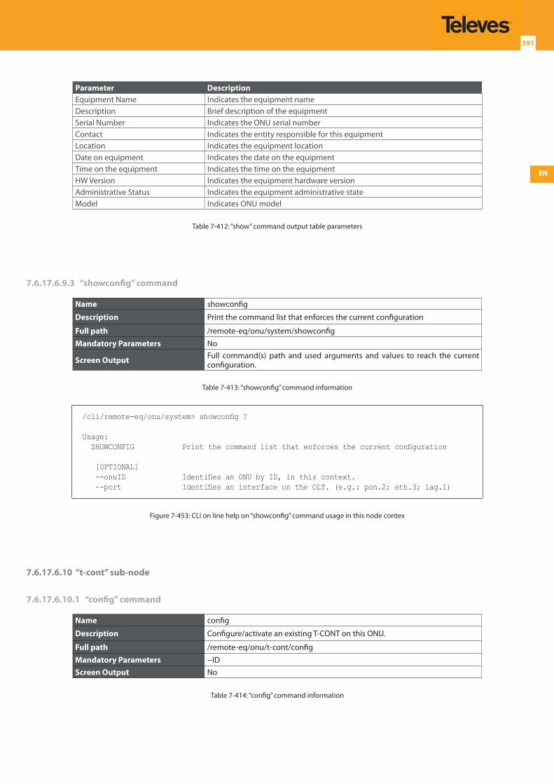
EN
391
Parameter DescriptionEquipment Name Indicates the equipment nameDescription Brief description of the equipmentSerial Number Indicates the ONU serial numberContact Indicates the entity responsible for this equipmentLocation Indicates the equipment locationDate on equipment Indicates the date on the equipmentTime on the equipment Indicates the time on the equipmentHW Version Indicates the equipment hardware version Administrative Status Indicates the equipment administrative state Model Indicates ONU model
Table 7-412: “show” command output table parameters
7.6.17.6.9.3 “showconfig” command
Name showconfig
Description Print the command list that enforces the current configuration
Full path /remote-eq/onu/system/showconfig
Mandatory Parameters No
Screen Output Full command(s) path and used arguments and values to reach the current configuration.
Table 7-413: “showconfig” command information
/cli/remote-eq/onu/system> showconfig ?
Usage: SHOWCONFIG Print the command list that enforces the current configuration
[OPTIONAL] --onuID Identifies an ONU by ID, in this context. --port Identifies an interface on the OLT. (e.g.: pon.2; eth.3; lag.1)
Figure 7-453: CLI on line help on “showconfig” command usage in this node contex
7.6.17.6.10 “t-cont” sub-node
7.6.17.6.10.1 “config” command
Name config
Description Configure/activate an existing T-CONT on this ONU.
Full path /remote-eq/onu/t-cont/config
Mandatory Parameters --IDScreen Output No
Table 7-414: “config” command information
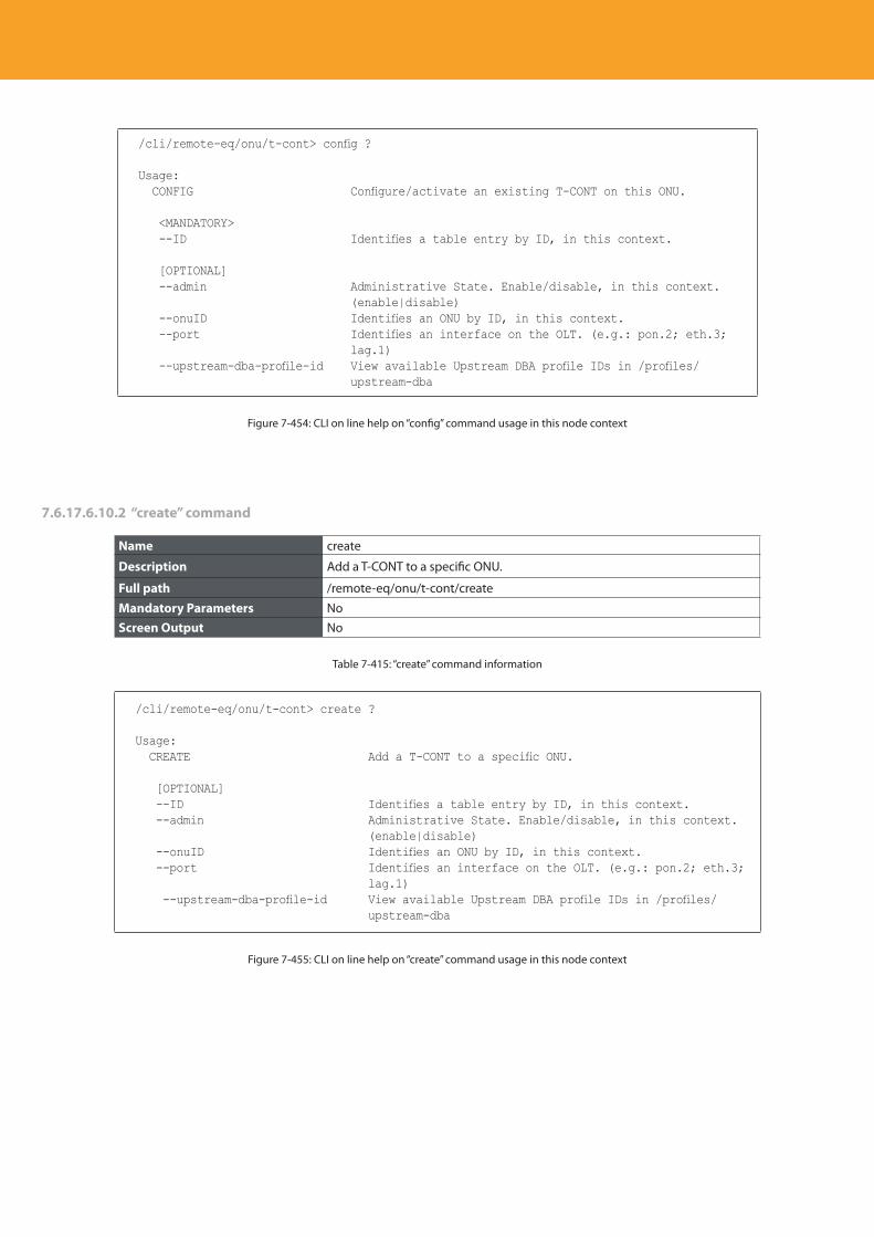
Descripción del producto
392
/cli/remote-eq/onu/t-cont> config ?
Usage: CONFIG Configure/activate an existing T-CONT on this ONU.
<MANDATORY> --ID Identifies a table entry by ID, in this context.
[OPTIONAL] --admin Administrative State. Enable/disable, in this context.
(enable|disable) --onuID Identifies an ONU by ID, in this context. --port Identifies an interface on the OLT. (e.g.: pon.2; eth.3;
lag.1) --upstream-dba-profile-id View available Upstream DBA profile IDs in /profiles/
upstream-dba
Figure 7-454: CLI on line help on “config” command usage in this node context
7.6.17.6.10.2 “create” command
Name create
Description Add a T-CONT to a specific ONU.
Full path /remote-eq/onu/t-cont/create
Mandatory Parameters NoScreen Output No
Table 7-415: “create” command information
/cli/remote-eq/onu/t-cont> create ?
Usage: CREATE Add a T-CONT to a specific ONU.
[OPTIONAL] --ID Identifies a table entry by ID, in this context. --admin Administrative State. Enable/disable, in this context.
(enable|disable) --onuID Identifies an ONU by ID, in this context. --port Identifies an interface on the OLT. (e.g.: pon.2; eth.3;
lag.1) --upstream-dba-profile-id View available Upstream DBA profile IDs in /profiles/
upstream-dba
Figure 7-455: CLI on line help on “create” command usage in this node context
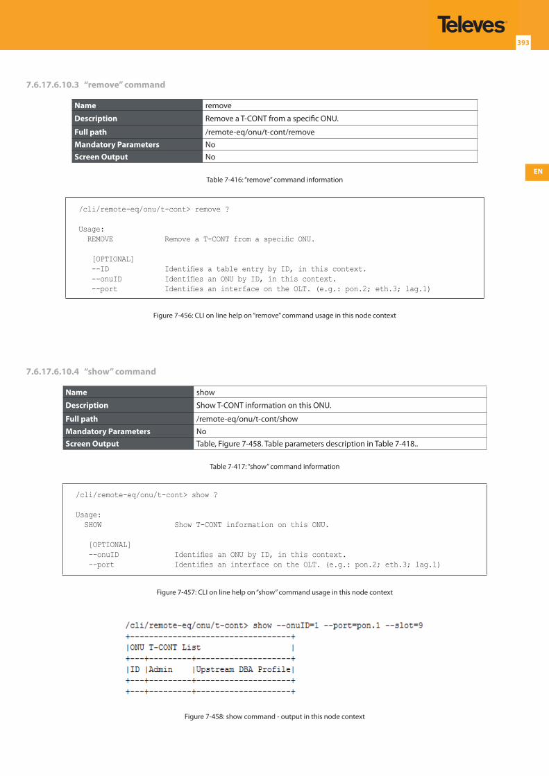
EN
393
7.6.17.6.10.3 “remove” command
Name remove
Description Remove a T-CONT from a specific ONU.
Full path /remote-eq/onu/t-cont/remove
Mandatory Parameters NoScreen Output No
Table 7-416: “remove” command information
/cli/remote-eq/onu/t-cont> remove ?
Usage: REMOVE Remove a T-CONT from a specific ONU.
[OPTIONAL] --ID Identifies a table entry by ID, in this context. --onuID Identifies an ONU by ID, in this context. --port Identifies an interface on the OLT. (e.g.: pon.2; eth.3; lag.1)
Figure 7-456: CLI on line help on “remove” command usage in this node context
7.6.17.6.10.4 “show” command
Name show
Description Show T-CONT information on this ONU.
Full path /remote-eq/onu/t-cont/show
Mandatory Parameters NoScreen Output Table, Figure 7-458. Table parameters description in Table 7-418..
Table 7-417: “show” command information
/cli/remote-eq/onu/t-cont> show ?
Usage: SHOW Show T-CONT information on this ONU.
[OPTIONAL] --onuID Identifies an ONU by ID, in this context. --port Identifies an interface on the OLT. (e.g.: pon.2; eth.3; lag.1)
Figure 7-457: CLI on line help on “show” command usage in this node context
Figure 7-458: show command - output in this node context
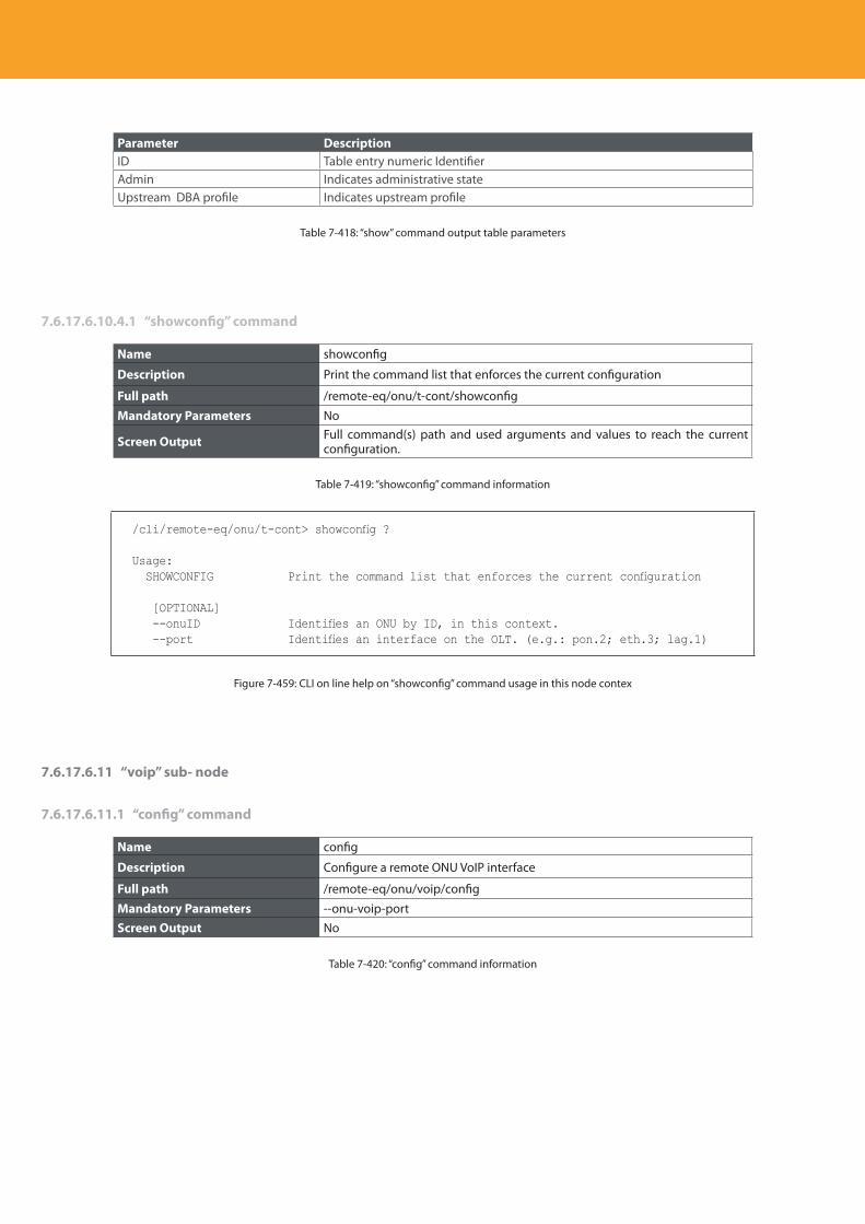
Descripción del producto
394
Parameter DescriptionID Table entry numeric IdentifierAdmin Indicates administrative stateUpstream DBA profile Indicates upstream profile
Table 7-418: “show” command output table parameters
7.6.17.6.10.4.1 “showconfig” command
Name showconfig
Description Print the command list that enforces the current configuration
Full path /remote-eq/onu/t-cont/showconfig
Mandatory Parameters No
Screen Output Full command(s) path and used arguments and values to reach the current configuration.
Table 7-419: “showconfig” command information
/cli/remote-eq/onu/t-cont> showconfig ?
Usage: SHOWCONFIG Print the command list that enforces the current configuration
[OPTIONAL] --onuID Identifies an ONU by ID, in this context. --port Identifies an interface on the OLT. (e.g.: pon.2; eth.3; lag.1)
Figure 7-459: CLI on line help on “showconfig” command usage in this node contex
7.6.17.6.11 “voip” sub- node
7.6.17.6.11.1 “config” command
Name config
Description Configure a remote ONU VoIP interface
Full path /remote-eq/onu/voip/config
Mandatory Parameters --onu-voip-portScreen Output No
Table 7-420: “config” command information
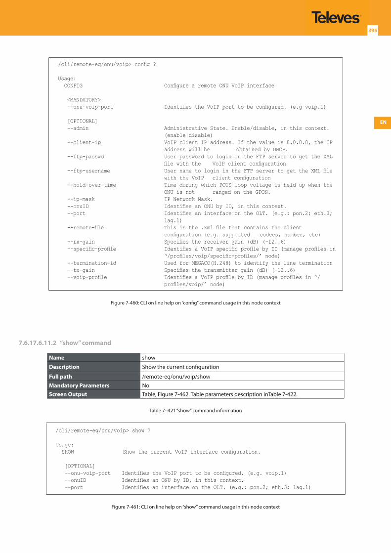
EN
395
/cli/remote-eq/onu/voip> config ?
Usage: CONFIG Configure a remote ONU VoIP interface
<MANDATORY> --onu-voip-port Identifies the VoIP port to be configured. (e.g voip.1)
[OPTIONAL] --admin Administrative State. Enable/disable, in this context.
(enable|disable) --client-ip VoIP client IP address. If the value is 0.0.0.0, the IP
address will be obtained by DHCP. --ftp-passwd User password to login in the FTP server to get the XML
file with the VoIP client configuration --ftp-username User name to login in the FTP server to get the XML file
with the VoIP client configuration --hold-over-time Time during which POTS loop voltage is held up when the
ONU is not ranged on the GPON. --ip-mask IP Network Mask. --onuID Identifies an ONU by ID, in this context. --port Identifies an interface on the OLT. (e.g.: pon.2; eth.3;
lag.1) --remote-file This is the .xml file that contains the client
configuration (e.g. supported codecs, number, etc) --rx-gain Specifies the receiver gain (dB) (-12..6) --specific-profile Identifies a VoIP specific profile by ID (manage profiles in
‘/profiles/voip/specific-profiles/’ node) --termination-id Used for MEGACO(H.248) to identify the line termination --tx-gain Specifies the transmitter gain (dB) (-12..6) --voip-profile Identifies a VoIP profile by ID (manage profiles in ‘/
profiles/voip/’ node)
Figure 7-460: CLI on line help on “config” command usage in this node context
7.6.17.6.11.2 “show” command
Name show
Description Show the current configuration
Full path /remote-eq/onu/voip/show
Mandatory Parameters NoScreen Output Table, Figure 7-462. Table parameters description inTable 7-422.
Table 7-:421 “show” command information
/cli/remote-eq/onu/voip> show ?
Usage: SHOW Show the current VoIP interface configuration.
[OPTIONAL] --onu-voip-port Identifies the VoIP port to be configured. (e.g. voip.1) --onuID Identifies an ONU by ID, in this context. --port Identifies an interface on the OLT. (e.g.: pon.2; eth.3; lag.1)
Figure 7-461: CLI on line help on “show” command usage in this node context
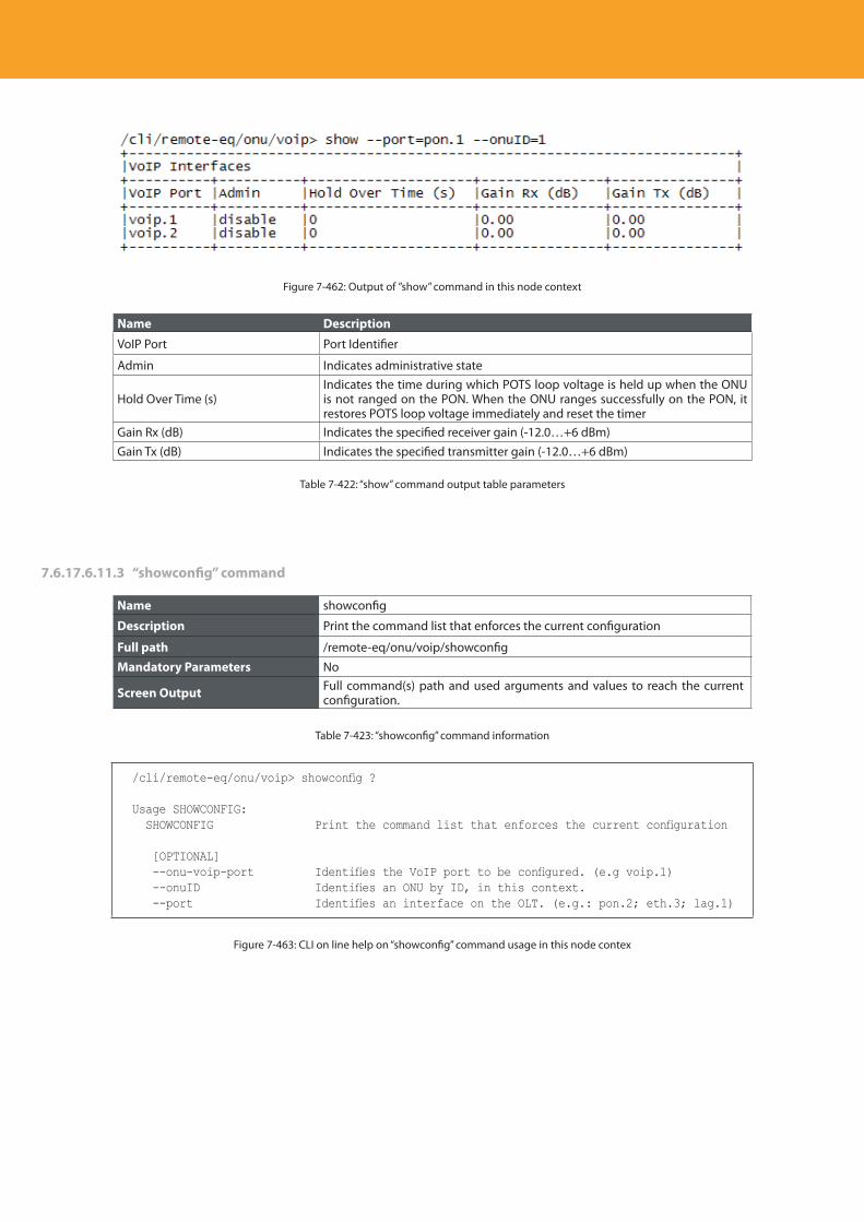
Descripción del producto
396
Figure 7-462: Output of ”show” command in this node context
Name Description
VoIP Port Port Identifier
Admin Indicates administrative state
Hold Over Time (s)Indicates the time during which POTS loop voltage is held up when the ONU is not ranged on the PON. When the ONU ranges successfully on the PON, it restores POTS loop voltage immediately and reset the timer
Gain Rx (dB) Indicates the specified receiver gain (-12.0…+6 dBm)Gain Tx (dB) Indicates the specified transmitter gain (-12.0…+6 dBm)
Table 7-422: “show” command output table parameters
7.6.17.6.11.3 “showconfig” command
Name showconfig
Description Print the command list that enforces the current configuration
Full path /remote-eq/onu/voip/showconfig
Mandatory Parameters No
Screen Output Full command(s) path and used arguments and values to reach the current configuration.
Table 7-423: “showconfig” command information
/cli/remote-eq/onu/voip> showconfig ?
Usage SHOWCONFIG: SHOWCONFIG Print the command list that enforces the current configuration
[OPTIONAL] --onu-voip-port Identifies the VoIP port to be configured. (e.g voip.1) --onuID Identifies an ONU by ID, in this context. --port Identifies an interface on the OLT. (e.g.: pon.2; eth.3; lag.1)
Figure 7-463: CLI on line help on “showconfig” command usage in this node contex
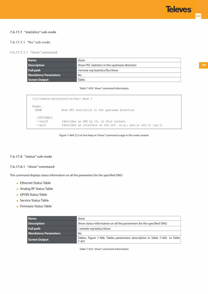
EN
397
7.6.17.7 “statistics” sub-node
7.6.17.7.1 “fec” sub-node
7.6.17.7.1.1 “show” command
Name show
Description Show FEC statistics in the upstream direction
Full path /remote-eq/statistics/fec/show
Mandatory Parameters NoScreen Output Table.
Table 7-424: “show” command information
/cli/remote-eq/statistics/fec> show ?
Usage: SHOW Show FEC statistics in the upstream direction
[OPTIONAL] --onuID Identifies an ONU by ID, in this context. --port Identifies an interface on the OLT. (e.g.: pon.2; eth.3; lag.1)
Figure 7-464: CLI on line help on “show” command usage in this node context
7.6.17.8 “status” sub-node
7.6.17.8.1 “show” command
This command displays status information on all the parameters for the specified ONU:
Ethernet Status Table
Analog RF Status Table
GPON Status Table
Service Status Table
Firmware Status Table
Name show
Description Show status information on all the parameters for the specified ONU
Full path / remote-eq/status/show
Mandatory Parameters No
Screen Output Tables, Figure 7-466. Tables parameters description in Table 7-426 to Table 7-431
Table 7-425: “show” command information
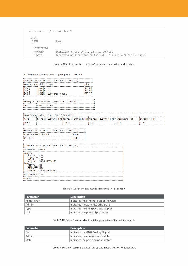
Descripción del producto
398
/cli/remote-eq/status> show ?
Usage: SHOW Show
[OPTIONAL] --onuID Identifies an ONU by ID, in this context. --port Identifies an interface on the OLT. (e.g.: pon.2; eth.3; lag.1)
Figure 7-465: CLI on line help on “show” command usage in this node context
Figure 7-466: “show” command output in this node context
Parameter DescriptionRemote Port Indicates the Ethernet port at the ONUAdmin Indicates the Administrative stateType Indicates the link speed and duplexLink Indicates the physical port state.
Table 7-426: “show” command output table parameters –Ethernet Status table
Parameter DescriptionPort Indicates the ONU Analog RF portAdmin Indicates the administrative stateState Indicates the port operational state
Table 7-427: “show” command output tables parameters –Analog RF Status table
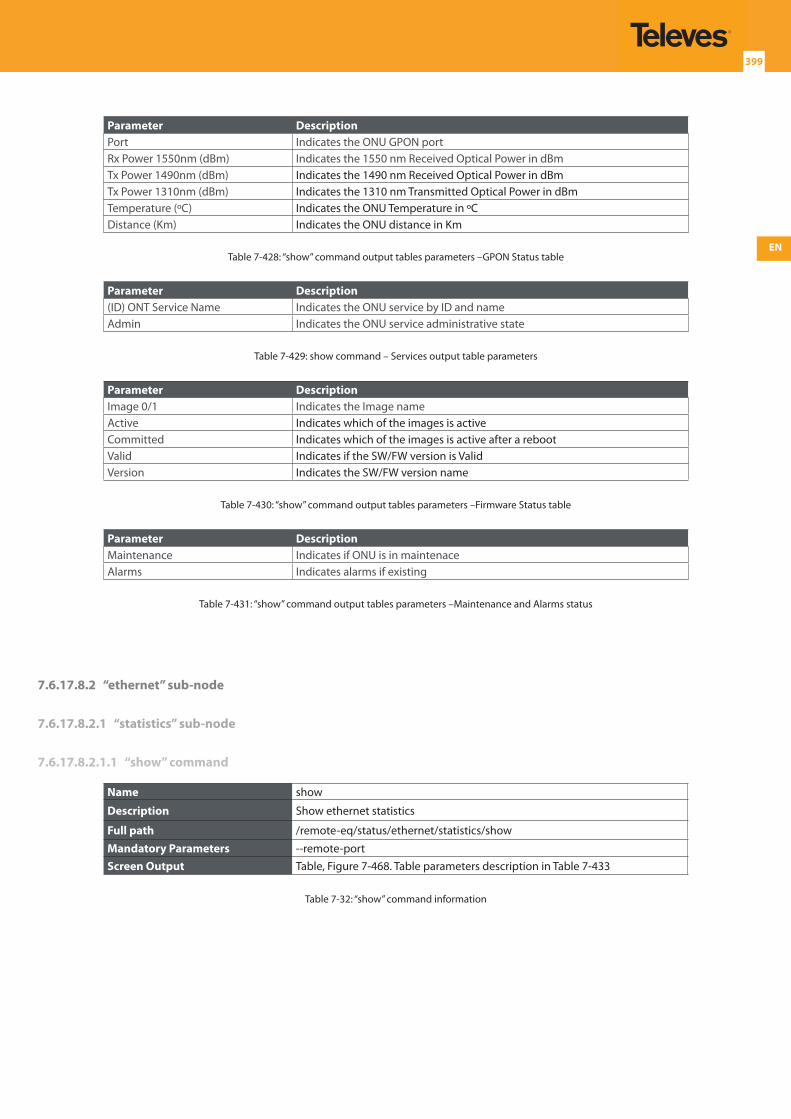
EN
399
Parameter DescriptionPort Indicates the ONU GPON portRx Power 1550nm (dBm) Indicates the 1550 nm Received Optical Power in dBmTx Power 1490nm (dBm) Indicates the 1490 nm Received Optical Power in dBmTx Power 1310nm (dBm) Indicates the 1310 nm Transmitted Optical Power in dBmTemperature (ºC) Indicates the ONU Temperature in ºCDistance (Km) Indicates the ONU distance in Km
Table 7-428: “show” command output tables parameters –GPON Status table
Parameter Description(ID) ONT Service Name Indicates the ONU service by ID and nameAdmin Indicates the ONU service administrative state
Table 7-429: show command – Services output table parameters
Parameter DescriptionImage 0/1 Indicates the Image nameActive Indicates which of the images is activeCommitted Indicates which of the images is active after a rebootValid Indicates if the SW/FW version is ValidVersion Indicates the SW/FW version name
Table 7-430: “show” command output tables parameters –Firmware Status table
Parameter DescriptionMaintenance Indicates if ONU is in maintenaceAlarms Indicates alarms if existing
Table 7-431: “show” command output tables parameters –Maintenance and Alarms status
7.6.17.8.2 “ethernet” sub-node
7.6.17.8.2.1 “statistics” sub-node
7.6.17.8.2.1.1 “show” command
Name show
Description Show ethernet statistics
Full path /remote-eq/status/ethernet/statistics/show
Mandatory Parameters --remote-portScreen Output Table, Figure 7-468. Table parameters description in Table 7-433
Table 7-32: “show” command information
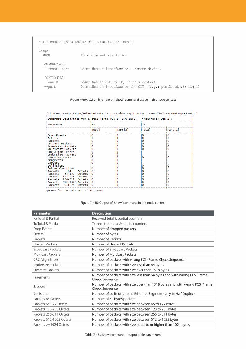
Descripción del producto
400
/cli/remote-eq/status/ethernet/statistics> show ?
Usage: SHOW Show ethernet statistics
<MANDATORY> --remote-port Identifies an interface on a remote device.
[OPTIONAL] --onuID Identifies an ONU by ID, in this context. --port Identifies an interface on the OLT. (e.g.: pon.2; eth.3; lag.1)
Figure 7-467: CLI on line help on “show” command usage in this node context
Figure 7-468: Output of ”show” command in this node context
Parameter DescriptionRx Total & Partial Received total & partial countersTx Total & Partial Transmitted total & partial countersDrop Events Number of dropped packetsOctets Number of bytesPackets Number of PacketsUnicast Packets Number of Unicast PacketsBroadcast Packets Number of Broadcast PacketsMulticast Packets Number of Multicast PacketsCRC Align Errors Number of packets with wrong FCS (Frame Check Sequence)Undersize Packets Number of packets with size less than 64 bytesOversize Packets Number of packets with size over than 1518 bytes
Fragments Number of packets with size less than 64 bytes and with wrong FCS (Frame Check Sequence)
Jabbers Number of packets with size over than 1518 bytes and with wrong FCS (Frame Check Sequence)
Collisions Number of collisions in the Ethernet Segment (only in Half Duplex)Packets 64 Octets Number of 64 bytes packetsPackets 65-127 Octets Number of packets with size between 65 to 127 bytesPackets 128-255 Octets Number of packets with size between 128 to 255 bytesPackets 256-511 Octets Number of packets with size between 256 to 511 bytesPackets 512-1023 Octets Number of packets with size between 512 to 1023 bytesPackets >=1024 Octets Number of packets with size equal to or higher than 1024 bytes
Table 7-433: show command – output table parameters
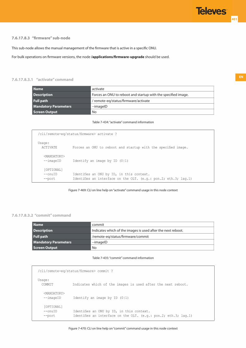
EN
401
7.6.17.8.3 “firmware” sub-node
This sub-node allows the manual management of the firmware that is active in a specific ONU.
For bulk operations on firmware versions, the node /applications/firmware-upgrade should be used.
7.6.17.8.3.1 “activate” command
Name activate
Description Forces an ONU to reboot and startup with the specified image.
Full path / remote-eq/status/firmware/activate
Mandatory Parameters --imageIDScreen Output No
Table 7-434: “activate” command information
/cli/remote-eq/status/firmware> activate ?
Usage: ACTIVATE Forces an ONU to reboot and startup with the specified image.
<MANDATORY> --imageID Identify an image by ID (0|1)
[OPTIONAL] --onuID Identifies an ONU by ID, in this context. --port Identifies an interface on the OLT. (e.g.: pon.2; eth.3; lag.1)
Figure 7-469: CLI on line help on “activate” command usage in this node context
7.6.17.8.3.2 “commit” command
Name commit
Description Indicates which of the images is used after the next reboot.
Full path /remote-eq/status/firmware/commit
Mandatory Parameters --imageIDScreen Output No
Table 7-435: “commit” command information
/cli/remote-eq/status/firmware> commit ?
Usage: COMMIT Indicates which of the images is used after the next reboot.
<MANDATORY> --imageID Identify an image by ID (0|1)
[OPTIONAL] --onuID Identifies an ONU by ID, in this context. --port Identifies an interface on the OLT. (e.g.: pon.2; eth.3; lag.1)
Figure 7-470: CLI on line help on “commit” command usage in this node context
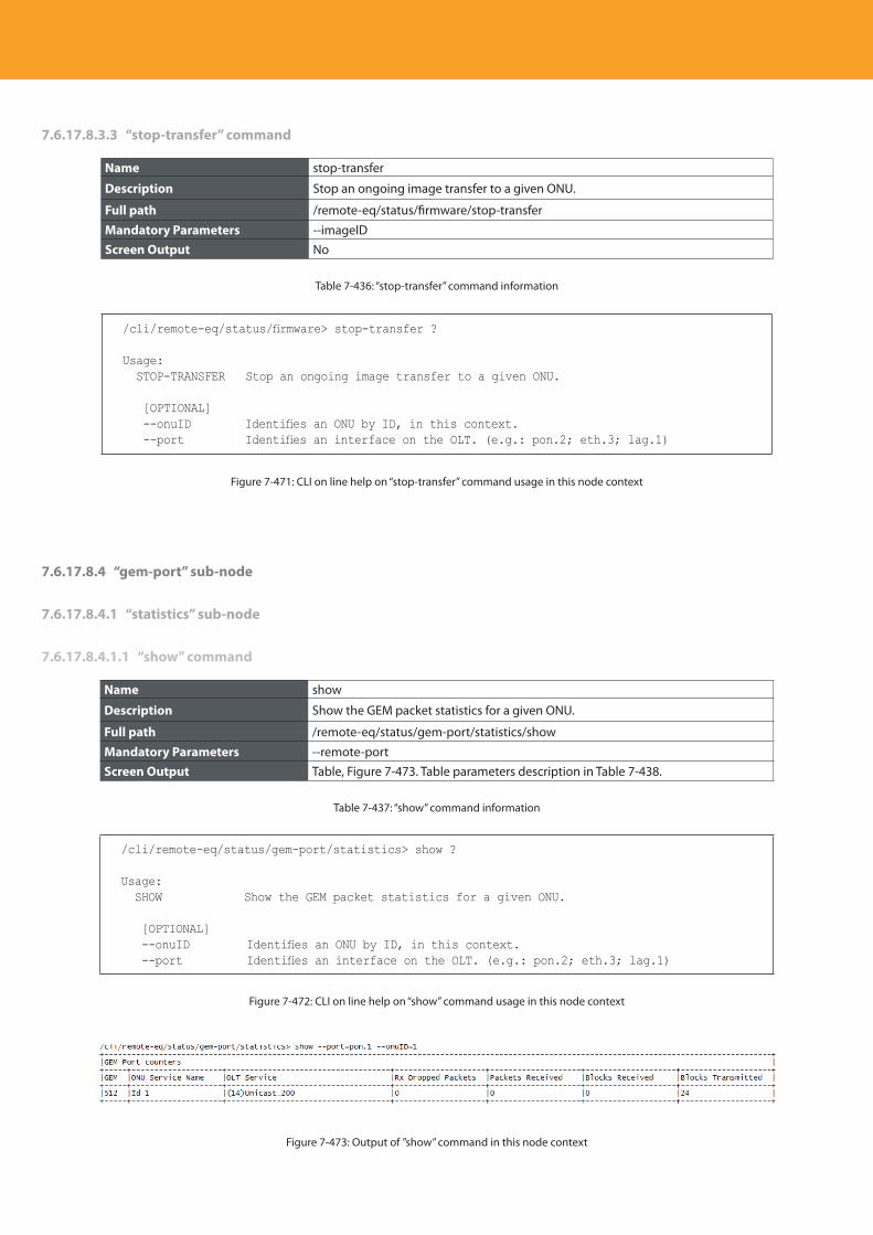
Descripción del producto
402
7.6.17.8.3.3 “stop-transfer” command
Name stop-transfer
Description Stop an ongoing image transfer to a given ONU.
Full path /remote-eq/status/firmware/stop-transfer
Mandatory Parameters --imageIDScreen Output No
Table 7-436: “stop-transfer” command information
/cli/remote-eq/status/firmware> stop-transfer ?
Usage: STOP-TRANSFER Stop an ongoing image transfer to a given ONU.
[OPTIONAL] --onuID Identifies an ONU by ID, in this context. --port Identifies an interface on the OLT. (e.g.: pon.2; eth.3; lag.1)
Figure 7-471: CLI on line help on “stop-transfer” command usage in this node context
7.6.17.8.4 “gem-port” sub-node
7.6.17.8.4.1 “statistics” sub-node
7.6.17.8.4.1.1 “show” command
Name show
Description Show the GEM packet statistics for a given ONU.
Full path /remote-eq/status/gem-port/statistics/show
Mandatory Parameters --remote-portScreen Output Table, Figure 7-473. Table parameters description in Table 7-438.
Table 7-437: “show” command information
/cli/remote-eq/status/gem-port/statistics> show ?
Usage: SHOW Show the GEM packet statistics for a given ONU.
[OPTIONAL] --onuID Identifies an ONU by ID, in this context. --port Identifies an interface on the OLT. (e.g.: pon.2; eth.3; lag.1)
Figure 7-472: CLI on line help on “show” command usage in this node context
Figure 7-473: Output of ”show” command in this node context
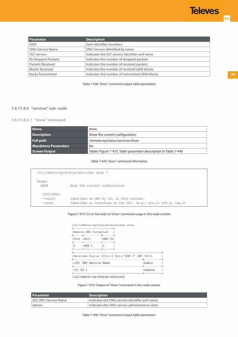
EN
403
Parameter DescriptionGEM Gem Identifier (number)ONU Service Name ONU Service identified by nameOLT service Indicates the OLT service identifier and nameRx Dropped Packets Indicates the number of dropped packetsPackets Received Indicates the number of received packetsBlocks Received Indicates the number of received GEM blocksBocks Transmitted Indicates the number of transmitted GEM blocks
Table 7-438: “show” command output table parameters
7.6.17.8.5 “services” sub- node
7.6.17.8.5.1 “show” command
Name show
Description Show the current configuration.
Full path /remote-eq/status/services/show
Mandatory Parameters NoScreen Output Tables Figure 7-475. Table parameter description in Table 7-440
Table 7-439: “show” command information
/cli/remote-eq/status/services> show ?
Usage: SHOW Show the current configuration
[OPTIONAL] --onuID Identifies an ONU by ID, in this context. --port Identifies an interface on the OLT. (e.g.: pon.2; eth.3; lag.1)
Figure 7-474: CLI on line help on “show” command usage in this node context
Figure 7-475: Output of ”show” command in this node context
Parameter Description(ID) ONU Service Name Indicates the ONU service identifier and nameAdmin Indicates the ONU service administrative state
Table 7-440: “show” command output table parameters
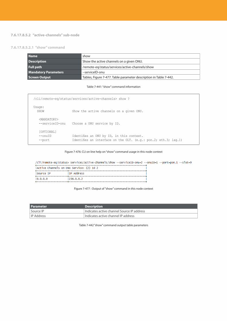
Descripción del producto
404
7.6.17.8.5.2 “active-channels” sub-node
7.6.17.8.5.2.1 ”show” command
Name show
Description Show the active channels on a given ONU.
Full path /remote-eq/status/services/active-channels/show
Mandatory Parameters --serviceID-onuScreen Output Tables, Figure 7-477. Table parameter description in Table 7-442.
Table 7-441: “show” command information
/cli/remote-eq/status/services/active-channels> show ?
Usage: SHOW Show the active channels on a given ONU.
<MANDATORY> --serviceID-onu Choose a ONU service by ID.
[OPTIONAL] --onuID Identifies an ONU by ID, in this context. --port Identifies an interface on the OLT. (e.g.: pon.2; eth.3; lag.1)
Figure 7-476: CLI on line help on “show” command usage in this node context
Figure 7-477 : Output of ”show” command in this node context
Parameter DescriptionSource IP Indicates active channel Source IP addressIP Address Indicates active channel IP address
Table 7-442 “show” command output table parameters
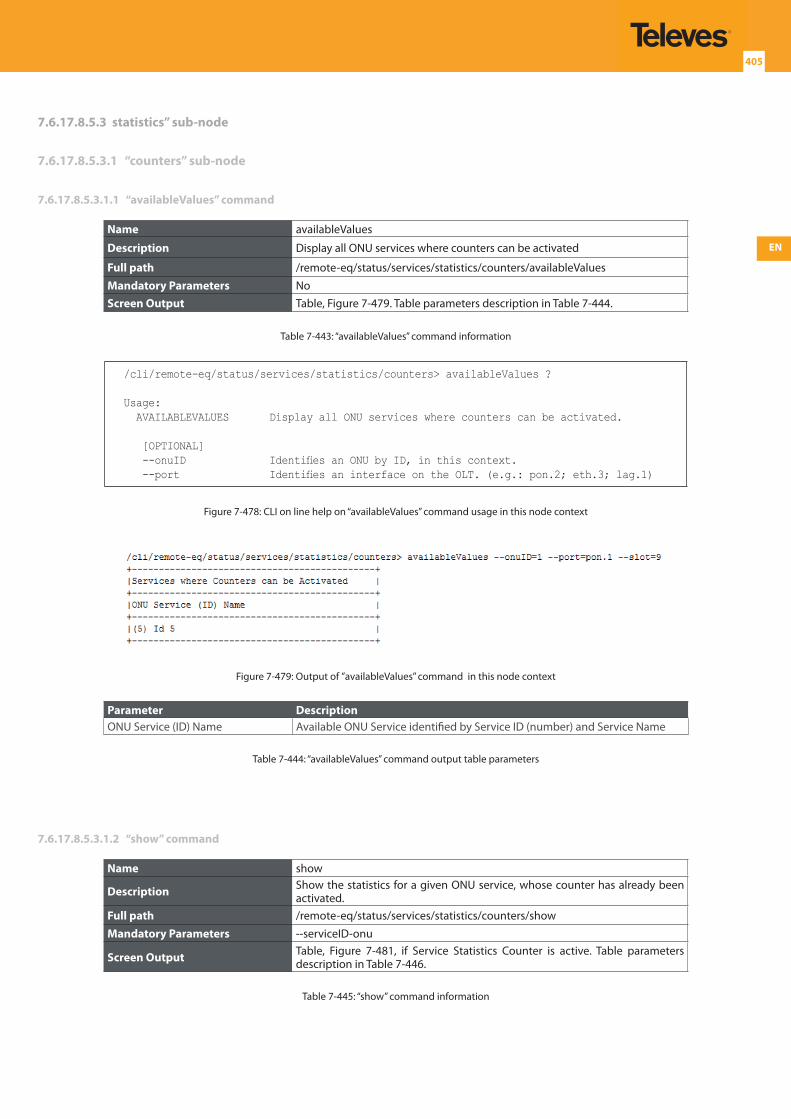
EN
405
7.6.17.8.5.3 statistics” sub-node
7.6.17.8.5.3.1 “counters” sub-node
7.6.17.8.5.3.1.1 “availableValues” command
Name availableValues
Description Display all ONU services where counters can be activated
Full path /remote-eq/status/services/statistics/counters/availableValues
Mandatory Parameters NoScreen Output Table, Figure 7-479. Table parameters description in Table 7-444.
Table 7-443: “availableValues” command information
/cli/remote-eq/status/services/statistics/counters> availableValues ?
Usage: AVAILABLEVALUES Display all ONU services where counters can be activated.
[OPTIONAL] --onuID Identifies an ONU by ID, in this context. --port Identifies an interface on the OLT. (e.g.: pon.2; eth.3; lag.1)
Figure 7-478: CLI on line help on “availableValues” command usage in this node context
Figure 7-479: Output of ”availableValues” command in this node context
Parameter DescriptionONU Service (ID) Name Available ONU Service identified by Service ID (number) and Service Name
Table 7-444: “availableValues” command output table parameters
7.6.17.8.5.3.1.2 “show” command
Name show
Description Show the statistics for a given ONU service, whose counter has already been activated.
Full path /remote-eq/status/services/statistics/counters/show
Mandatory Parameters --serviceID-onu
Screen Output Table, Figure 7-481, if Service Statistics Counter is active. Table parameters description in Table 7-446.
Table 7-445: “show” command information
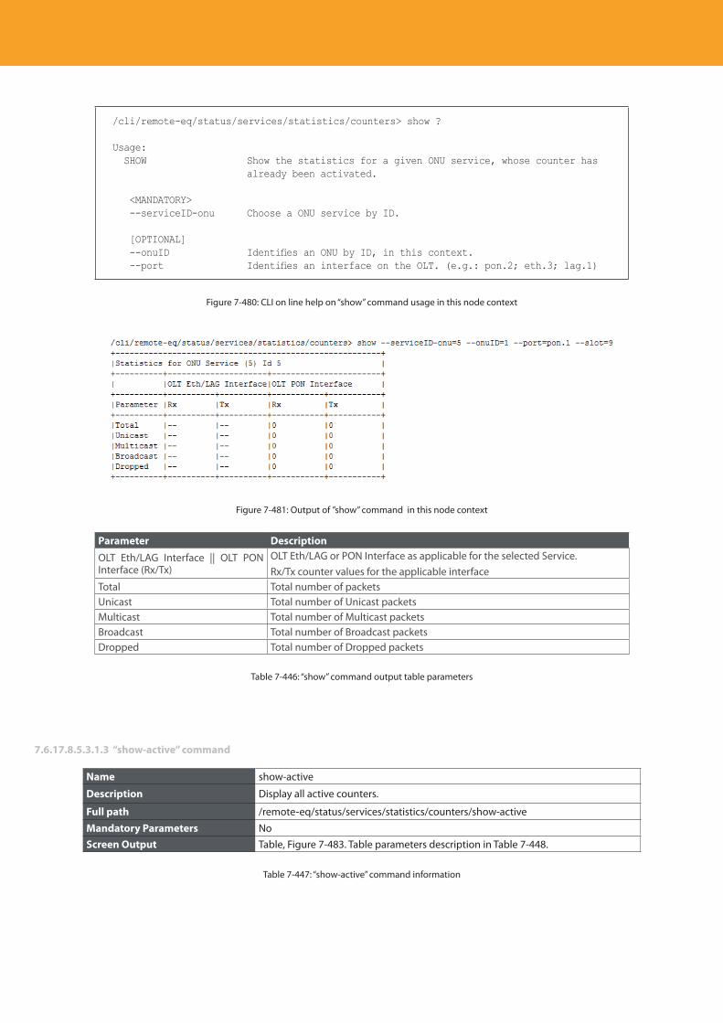
Descripción del producto
406
/cli/remote-eq/status/services/statistics/counters> show ?
Usage: SHOW Show the statistics for a given ONU service, whose counter has
already been activated.
<MANDATORY> --serviceID-onu Choose a ONU service by ID.
[OPTIONAL] --onuID Identifies an ONU by ID, in this context. --port Identifies an interface on the OLT. (e.g.: pon.2; eth.3; lag.1)
Figure 7-480: CLI on line help on “show” command usage in this node context
Figure 7-481: Output of ”show” command in this node context
Parameter DescriptionOLT Eth/LAG Interface || OLT PON Interface (Rx/Tx)
OLT Eth/LAG or PON Interface as applicable for the selected Service. Rx/Tx counter values for the applicable interface
Total Total number of packetsUnicast Total number of Unicast packetsMulticast Total number of Multicast packetsBroadcast Total number of Broadcast packetsDropped Total number of Dropped packets
Table 7-446: “show” command output table parameters
7.6.17.8.5.3.1.3 “show-active” command
Name show-active
Description Display all active counters.
Full path /remote-eq/status/services/statistics/counters/show-active
Mandatory Parameters NoScreen Output Table, Figure 7-483. Table parameters description in Table 7-448.
Table 7-447: “show-active” command information
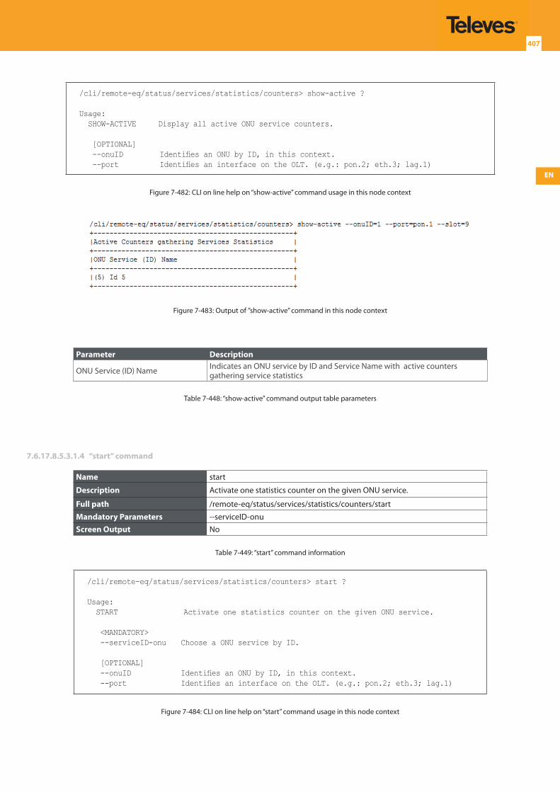
EN
407
/cli/remote-eq/status/services/statistics/counters> show-active ?
Usage: SHOW-ACTIVE Display all active ONU service counters.
[OPTIONAL] --onuID Identifies an ONU by ID, in this context. --port Identifies an interface on the OLT. (e.g.: pon.2; eth.3; lag.1)
Figure 7-482: CLI on line help on “show-active” command usage in this node context
Figure 7-483: Output of ”show-active” command in this node context
Parameter Description
ONU Service (ID) Name Indicates an ONU service by ID and Service Name with active counters gathering service statistics
Table 7-448: “show-active” command output table parameters
7.6.17.8.5.3.1.4 “start” command
Name start
Description Activate one statistics counter on the given ONU service.
Full path /remote-eq/status/services/statistics/counters/start
Mandatory Parameters --serviceID-onuScreen Output No
Table 7-449: “start” command information
/cli/remote-eq/status/services/statistics/counters> start ?
Usage: START Activate one statistics counter on the given ONU service.
<MANDATORY> --serviceID-onu Choose a ONU service by ID.
[OPTIONAL] --onuID Identifies an ONU by ID, in this context. --port Identifies an interface on the OLT. (e.g.: pon.2; eth.3; lag.1)
Figure 7-484: CLI on line help on “start” command usage in this node context
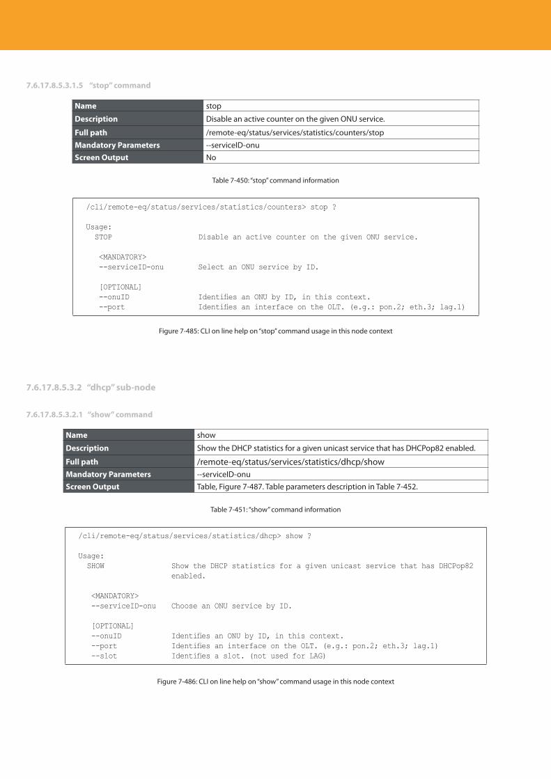
Descripción del producto
408
7.6.17.8.5.3.1.5 “stop” command
Name stop
Description Disable an active counter on the given ONU service.
Full path /remote-eq/status/services/statistics/counters/stop
Mandatory Parameters --serviceID-onuScreen Output No
Table 7-450: “stop” command information
/cli/remote-eq/status/services/statistics/counters> stop ?
Usage: STOP Disable an active counter on the given ONU service.
<MANDATORY> --serviceID-onu Select an ONU service by ID.
[OPTIONAL] --onuID Identifies an ONU by ID, in this context. --port Identifies an interface on the OLT. (e.g.: pon.2; eth.3; lag.1)
Figure 7-485: CLI on line help on “stop” command usage in this node context
7.6.17.8.5.3.2 “dhcp” sub-node
7.6.17.8.5.3.2.1 “show” command
Name show
Description Show the DHCP statistics for a given unicast service that has DHCPop82 enabled.
Full path /remote-eq/status/services/statistics/dhcp/showMandatory Parameters --serviceID-onuScreen Output Table, Figure 7-487. Table parameters description in Table 7-452.
Table 7-451: “show” command information
/cli/remote-eq/status/services/statistics/dhcp> show ?
Usage: SHOW Show the DHCP statistics for a given unicast service that has DHCPop82
enabled.
<MANDATORY> --serviceID-onu Choose an ONU service by ID.
[OPTIONAL] --onuID Identifies an ONU by ID, in this context. --port Identifies an interface on the OLT. (e.g.: pon.2; eth.3; lag.1) --slot Identifies a slot. (not used for LAG)
Figure 7-486: CLI on line help on “show” command usage in this node context
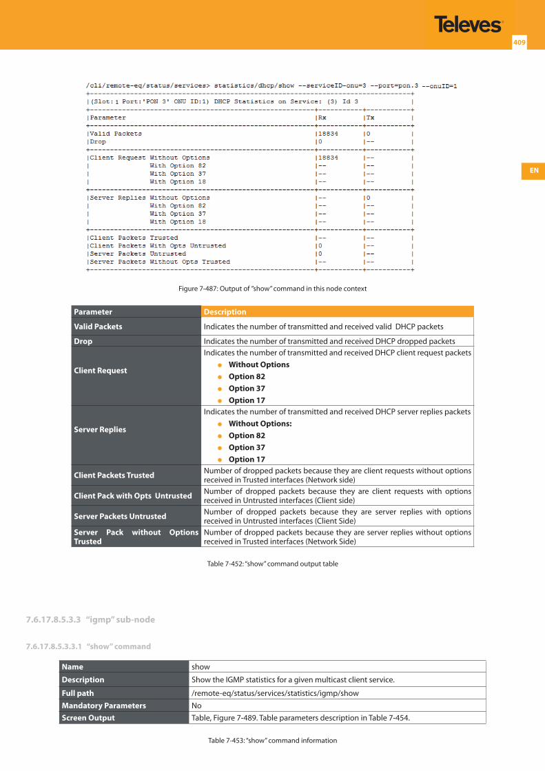
EN
409
1
Figure 7-487: Output of ”show” command in this node context
Parameter Description
Valid Packets Indicates the number of transmitted and received valid DHCP packets
Drop Indicates the number of transmitted and received DHCP dropped packets
Client Request
Indicates the number of transmitted and received DHCP client request packets Without Options Option 82 Option 37 Option 17
Server Replies
Indicates the number of transmitted and received DHCP server replies packets Without Options: Option 82 Option 37 Option 17
Client Packets Trusted Number of dropped packets because they are client requests without options received in Trusted interfaces (Network side)
Client Pack with Opts Untrusted Number of dropped packets because they are client requests with options received in Untrusted interfaces (Client side)
Server Packets Untrusted Number of dropped packets because they are server replies with options received in Untrusted interfaces (Client Side)
Server Pack without Options Trusted
Number of dropped packets because they are server replies without options received in Trusted interfaces (Network Side)
Table 7-452: “show” command output table
7.6.17.8.5.3.3 “igmp” sub-node
7.6.17.8.5.3.3.1 “show” command
Name show
Description Show the IGMP statistics for a given multicast client service.
Full path /remote-eq/status/services/statistics/igmp/show
Mandatory Parameters NoScreen Output Table, Figure 7-489. Table parameters description in Table 7-454.
Table 7-453: “show” command information
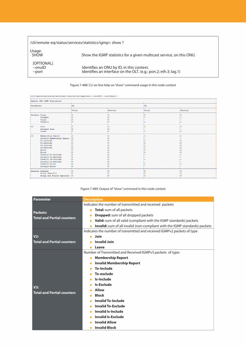
Descripción del producto
410
/cli/remote-eq/status/services/statistics/igmp> show ?
Usage: SHOW Show the IGMP statistics for a given multicast service, on this ONU.
[OPTIONAL] --onuID Identifies an ONU by ID, in this context. --port Identifies an interface on the OLT. (e.g.: pon.2; eth.3; lag.1)
Figure 7-488: CLI on line help on “show” command usage in this node context
Figure 7-489: Output of ”show” command in this node context
Parameter Description
Packets:Total and Partial counters
Indicates the number of transmitted and received packets Total: sum of all packets Dropped: sum of all dropped packets Valid: sum of all valid (compliant with the IGMP standards) packets Invalid: sum of all invalid (non-compliant with the IGMP standards) packets
V2:Total and Partial counters
Indicates the number of transmitted and received IGMPv2 packets of type Join Invalid Join Leave
V3:Total and Partial counters
Number of Transmitted and Received IGMPv3 packets of type: Membership Report Invalid Membership Report To-Include To-exclude Is-Include Is-Exclude Allow Block Invalid To-Include Invalid To-Exclude Invalid Is-Include Invalid Is-Exclude Invalid Allow Invalid Block
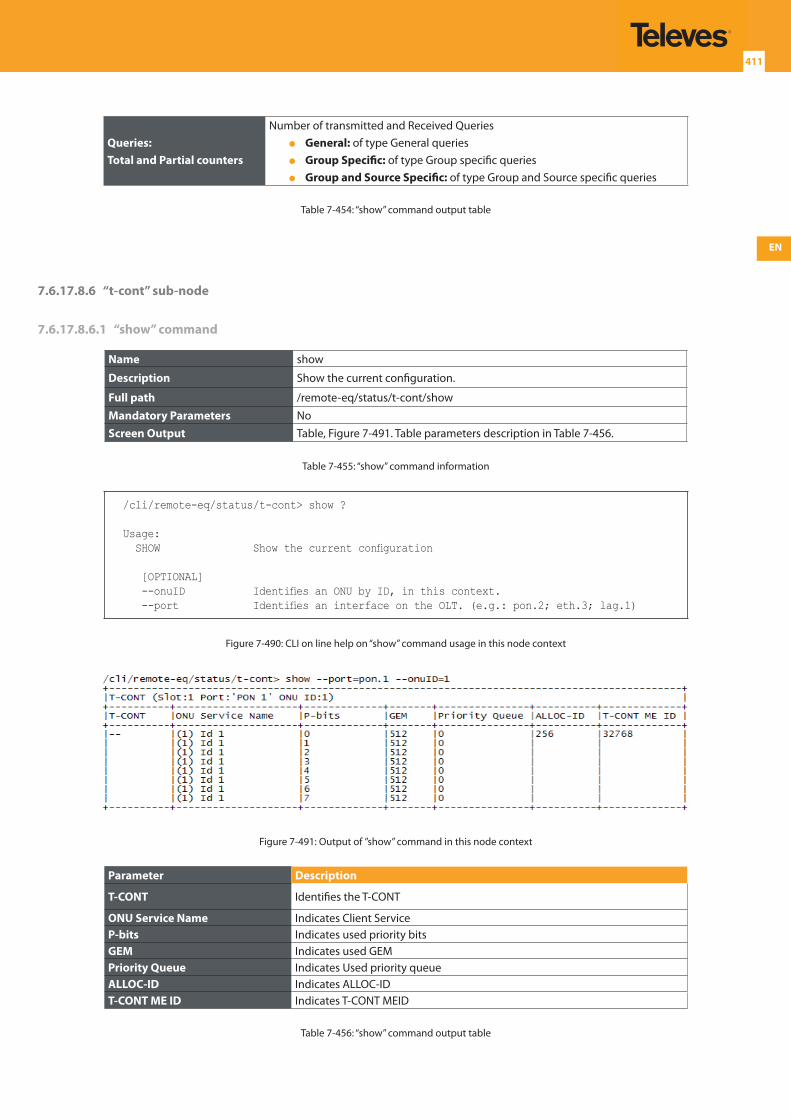
EN
411
Queries:Total and Partial counters
Number of transmitted and Received Queries General: of type General queries Group Specific: of type Group specific queries Group and Source Specific: of type Group and Source specific queries
Table 7-454: “show” command output table
7.6.17.8.6 “t-cont” sub-node
7.6.17.8.6.1 “show” command
Name show
Description Show the current configuration.
Full path /remote-eq/status/t-cont/show
Mandatory Parameters NoScreen Output Table, Figure 7-491. Table parameters description in Table 7-456.
Table 7-455: “show” command information
/cli/remote-eq/status/t-cont> show ?
Usage: SHOW Show the current configuration
[OPTIONAL] --onuID Identifies an ONU by ID, in this context. --port Identifies an interface on the OLT. (e.g.: pon.2; eth.3; lag.1)
Figure 7-490: CLI on line help on “show” command usage in this node context
Figure 7-491: Output of ”show” command in this node context
Parameter Description
T-CONT Identifies the T-CONT
ONU Service Name Indicates Client ServiceP-bits Indicates used priority bitsGEM Indicates used GEMPriority Queue Indicates Used priority queueALLOC-ID Indicates ALLOC-IDT-CONT ME ID Indicates T-CONT MEID
Table 7-456: “show” command output table
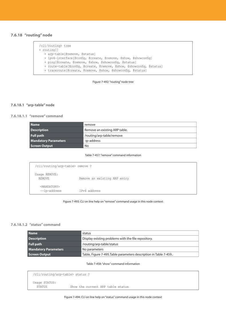
Descripción del producto
412
7.6.18 “routing” node
/cli/routing> tree+ routing[] + arp-table[@remove, @status] + ipv4-interface[@config, @create, @remove, @show, @showconfig] + ping[@create, @remove, @show, @showconfig, @status] + route-table[@config, @create, @remove, @show, @showconfig, @status] + traceroute[@create, @remove, @show, @showconfig, @status]
Figure 7-492: “routing” node tree
7.6.18.1 “arp-table” node
7.6.18.1.1 “remove” command
Name remove
Description Remove an existing ARP table.
Full path /routing/arp-table/remove
Mandatory Parameters -ip-addressScreen Output No
Table 7-457: “remove” command information
/cli/routing/arp-table> remove ?
Usage REMOVE: REMOVE Remove an existing ARP entry
<MANDATORY> --ip-address IPv4 address
Figure 7-493: CLI on line help on “remove” command usage in this node context
7.6.18.1.2 “status” command
Name status
Description Display existing problems with the file repository.
Full path /routing/arp-table/status
Mandatory Parameters No parametersScreen Output Table, Figure 7-495.Table parameters description in Table 7-459..
Table 7-458: “show” command information
/cli/routing/arp-table> status ?
Usage STATUS: STATUS Show the current ARP table status
Figure 7-494: CLI on line help on “status” command usage in this node context
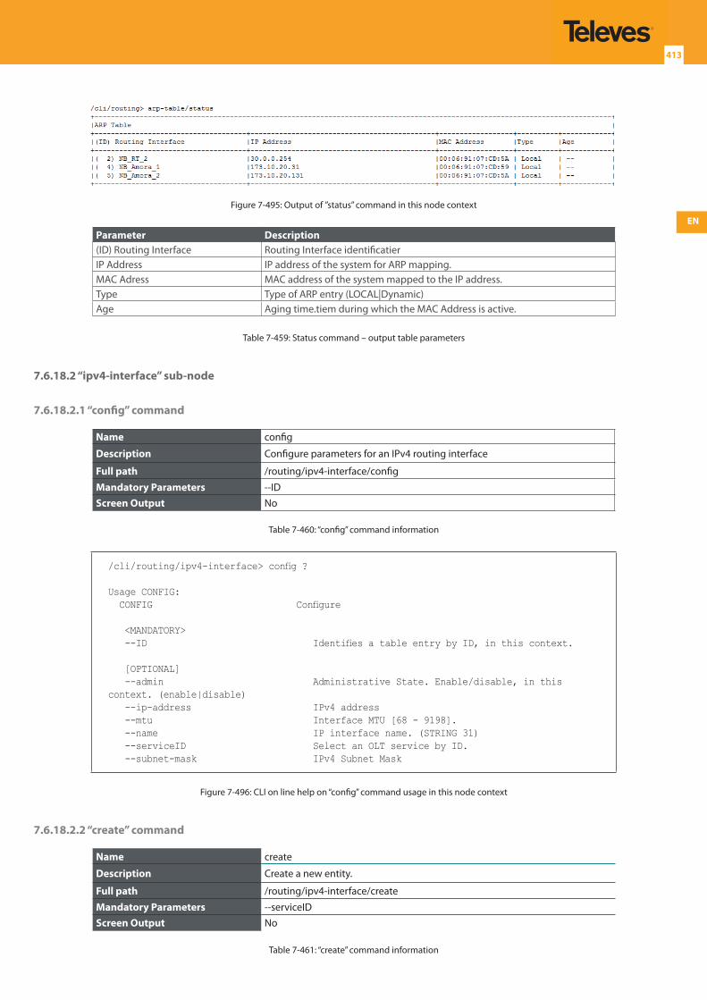
EN
413
Figure 7-495: Output of ”status” command in this node context
Parameter Description(ID) Routing Interface Routing Interface identificatierIP Address IP address of the system for ARP mapping.MAC Adress MAC address of the system mapped to the IP address.Type Type of ARP entry (LOCAL|Dynamic)Age Aging time.tiem during which the MAC Address is active.
Table 7-459: Status command – output table parameters
7.6.18.2 “ipv4-interface” sub-node
7.6.18.2.1 “config” command
Name config
Description Configure parameters for an IPv4 routing interface
Full path /routing/ipv4-interface/config
Mandatory Parameters --IDScreen Output No
Table 7-460: “config” command information
/cli/routing/ipv4-interface> config ?
Usage CONFIG: CONFIG Configure
<MANDATORY> --ID Identifies a table entry by ID, in this context.
[OPTIONAL] --admin Administrative State. Enable/disable, in this context. (enable|disable) --ip-address IPv4 address --mtu Interface MTU [68 - 9198]. --name IP interface name. (STRING 31) --serviceID Select an OLT service by ID. --subnet-mask IPv4 Subnet Mask
Figure 7-496: CLI on line help on “config” command usage in this node context
7.6.18.2.2 “create” command
Name create
Description Create a new entity.
Full path /routing/ipv4-interface/create
Mandatory Parameters --serviceIDScreen Output No
Table 7-461: “create” command information
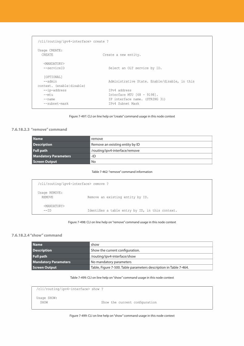
Descripción del producto
414
/cli/routing/ipv4-interface> create ?
Usage CREATE: CREATE Create a new entity.
<MANDATORY> --serviceID Select an OLT service by ID.
[OPTIONAL] --admin Administrative State. Enable/disable, in this context. (enable|disable) --ip-address IPv4 address --mtu Interface MTU [68 - 9198]. --name IP interface name. (STRING 31) --subnet-mask IPv4 Subnet Mask
Figure 7-497: CLI on line help on “create” command usage in this node context
7.6.18.2.3 “remove” command
Name remove
Description Remove an existing entity by ID
Full path /routing/ipv4-interface/remove
Mandatory Parameters -IDScreen Output No
Table 7-462: “remove” command information
/cli/routing/ipv4-interface> remove ?
Usage REMOVE: REMOVE Remove an existing entity by ID.
<MANDATORY> --ID Identifies a table entry by ID, in this context.
Figure 7-498: CLI on line help on “remove” command usage in this node context
7.6.18.2.4 “show” command
Name show
Description Show the current configuration.
Full path /routing/ipv4-interface/show
Mandatory Parameters No mandatory parametersScreen Output Table, Figure 7-500. Table parameters description in Table 7-464.
Table 7-499: CLI on line help on “show” command usage in this node context
/cli/routing/ipv4-interface> show ?
Usage SHOW: SHOW Show the current configuration
Figure 7-499: CLI on line help on “show” command usage in this node context
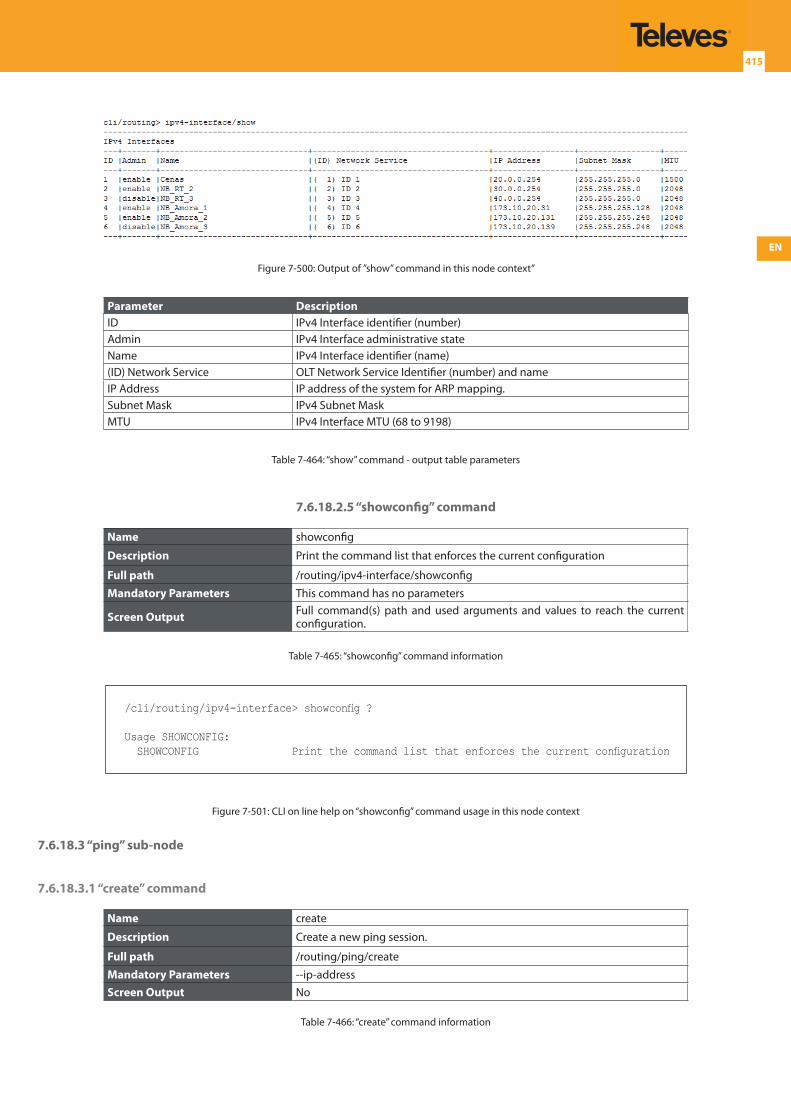
EN
415
Figure 7-500: Output of ”show” command in this node context”
Parameter DescriptionID IPv4 Interface identifier (number)Admin IPv4 Interface administrative stateName IPv4 Interface identifier (name)(ID) Network Service OLT Network Service Identifier (number) and nameIP Address IP address of the system for ARP mapping.Subnet Mask IPv4 Subnet MaskMTU IPv4 Interface MTU (68 to 9198)
Table 7-464: “show” command - output table parameters
7.6.18.2.5 “showconfig” command
Name showconfig
Description Print the command list that enforces the current configuration
Full path /routing/ipv4-interface/showconfig
Mandatory Parameters This command has no parameters
Screen Output Full command(s) path and used arguments and values to reach the current configuration.
Table 7-465: “showconfig” command information
/cli/routing/ipv4-interface> showconfig ?
Usage SHOWCONFIG: SHOWCONFIG Print the command list that enforces the current configuration
Figure 7-501: CLI on line help on “showconfig” command usage in this node context
7.6.18.3 “ping” sub-node
7.6.18.3.1 “create” command
Name create
Description Create a new ping session.
Full path /routing/ping/create
Mandatory Parameters --ip-addressScreen Output No
Table 7-466: “create” command information
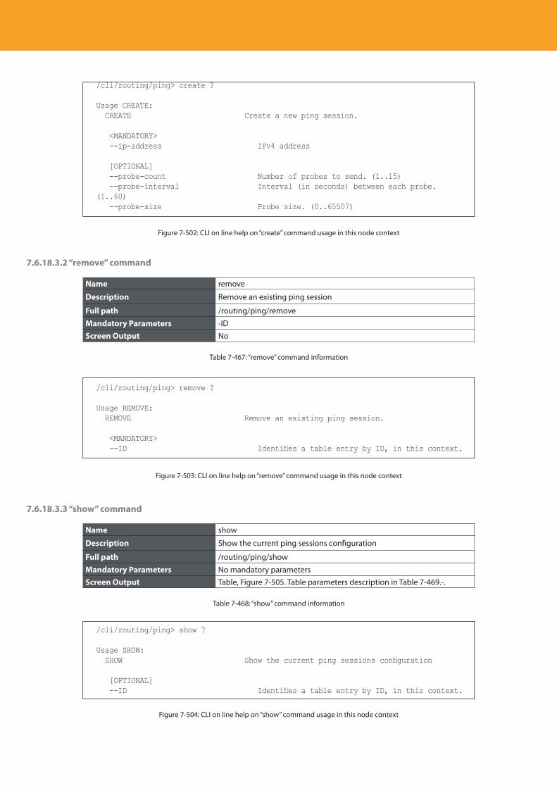
Descripción del producto
416
/cli/routing/ping> create ?
Usage CREATE: CREATE Create a new ping session.
<MANDATORY> --ip-address IPv4 address
[OPTIONAL] --probe-count Number of probes to send. (1..15) --probe-interval Interval (in seconds) between each probe. (1..60) --probe-size Probe size. (0..65507)
Figure 7-502: CLI on line help on “create” command usage in this node context
7.6.18.3.2 “remove” command
Name remove
Description Remove an existing ping session
Full path /routing/ping/remove
Mandatory Parameters -IDScreen Output No
Table 7-467: “remove” command information
/cli/routing/ping> remove ?
Usage REMOVE: REMOVE Remove an existing ping session.
<MANDATORY> --ID Identifies a table entry by ID, in this context.
Figure 7-503: CLI on line help on “remove” command usage in this node context
7.6.18.3.3 “show” command
Name show
Description Show the current ping sessions configuration
Full path /routing/ping/show
Mandatory Parameters No mandatory parametersScreen Output Table, Figure 7-505. Table parameters description in Table 7-469.-.
Table 7-468: “show” command information
/cli/routing/ping> show ?
Usage SHOW: SHOW Show the current ping sessions configuration
[OPTIONAL] --ID Identifies a table entry by ID, in this context.
Figure 7-504: CLI on line help on “show” command usage in this node context
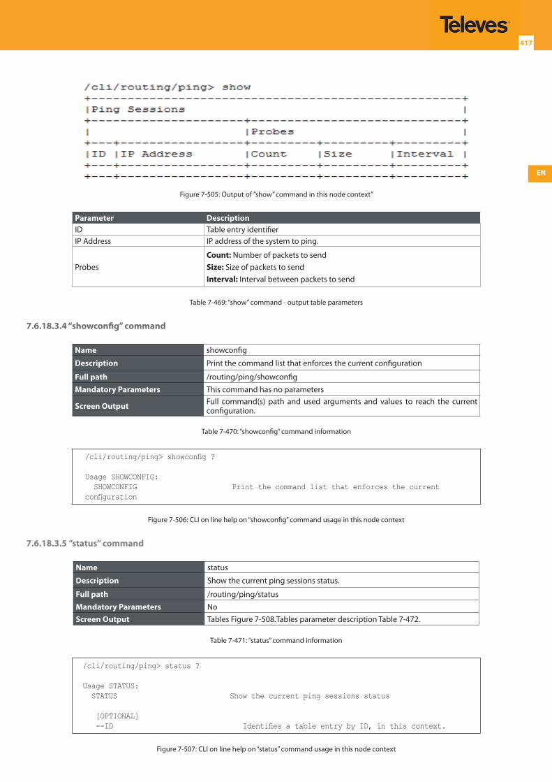
EN
417
Figure 7-505: Output of ”show” command in this node context”
Parameter DescriptionID Table entry identifierIP Address IP address of the system to ping.
ProbesCount: Number of packets to sendSize: Size of packets to sendInterval: Interval between packets to send
Table 7-469: “show” command - output table parameters
7.6.18.3.4 “showconfig” command
Name showconfig
Description Print the command list that enforces the current configuration
Full path /routing/ping/showconfig
Mandatory Parameters This command has no parameters
Screen Output Full command(s) path and used arguments and values to reach the current configuration.
Table 7-470: “showconfig” command information
/cli/routing/ping> showconfig ?
Usage SHOWCONFIG: SHOWCONFIG Print the command list that enforces the current configuration
Figure 7-506: CLI on line help on “showconfig” command usage in this node context
7.6.18.3.5 ”status” command
Name status
Description Show the current ping sessions status.
Full path /routing/ping/status
Mandatory Parameters NoScreen Output Tables Figure 7-508.Tables parameter description Table 7-472.
Table 7-471: “status” command information
/cli/routing/ping> status ?
Usage STATUS: STATUS Show the current ping sessions status
[OPTIONAL] --ID Identifies a table entry by ID, in this context.
Figure 7-507: CLI on line help on “status” command usage in this node context
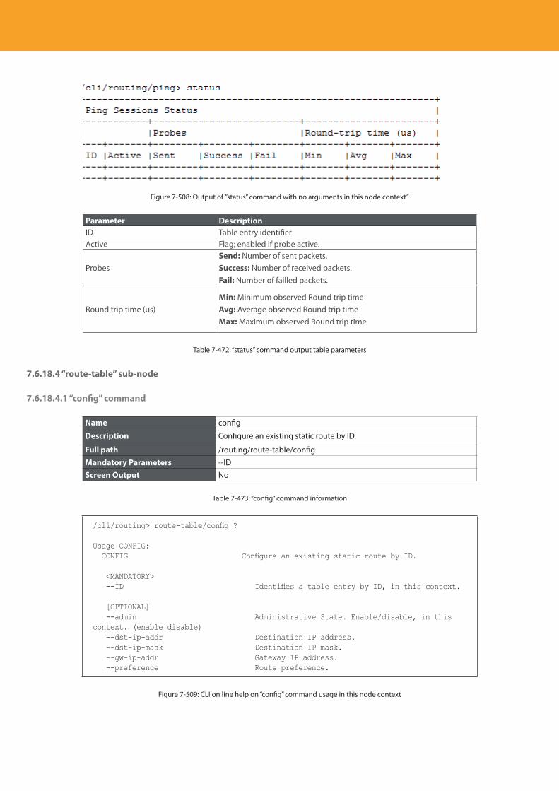
Descripción del producto
418
Figure 7-508: Output of ”status” command with no arguments in this node context”
Parameter DescriptionID Table entry identifierActive Flag; enabled if probe active.
ProbesSend: Number of sent packets.Success: Number of received packets.Fail: Number of failled packets.
Round trip time (us)Min: Minimum observed Round trip timeAvg: Average observed Round trip timeMax: Maximum observed Round trip time
Table 7-472: “status” command output table parameters
7.6.18.4 “route-table” sub-node
7.6.18.4.1 “config” command
Name config
Description Configure an existing static route by ID.
Full path /routing/route-table/config
Mandatory Parameters --IDScreen Output No
Table 7-473: “config” command information
/cli/routing> route-table/config ?
Usage CONFIG: CONFIG Configure an existing static route by ID.
<MANDATORY> --ID Identifies a table entry by ID, in this context.
[OPTIONAL] --admin Administrative State. Enable/disable, in this context. (enable|disable) --dst-ip-addr Destination IP address. --dst-ip-mask Destination IP mask. --gw-ip-addr Gateway IP address. --preference Route preference.
Figure 7-509: CLI on line help on “config” command usage in this node context
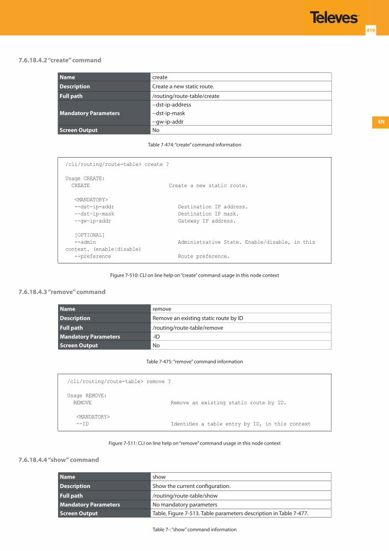
EN
419
7.6.18.4.2 “create” command
Name create
Description Create a new static route.
Full path /routing/route-table/create
Mandatory Parameters--dst-ip-address--dst-ip-mask--gw-ip-addr
Screen Output No
Table 7-474: “create” command information
/cli/routing/route-table> create ?
Usage CREATE: CREATE Create a new static route.
<MANDATORY> --dst-ip-addr Destination IP address. --dst-ip-mask Destination IP mask. --gw-ip-addr Gateway IP address.
[OPTIONAL] --admin Administrative State. Enable/disable, in this context. (enable|disable) --preference Route preference.
Figure 7-510: CLI on line help on “create” command usage in this node context
7.6.18.4.3 “remove” command
Name remove
Description Remove an existing static route by ID
Full path /routing/route-table/remove
Mandatory Parameters -IDScreen Output No
Table 7-475: “remove” command information
/cli/routing/route-table> remove ?
Usage REMOVE: REMOVE Remove an existing static route by ID.
<MANDATORY> --ID Identifies a table entry by ID, in this context
Figure 7-511: CLI on line help on “remove” command usage in this node context
7.6.18.4.4 “show” command
Name show
Description Show the current configuration.
Full path /routing/route-table/show
Mandatory Parameters No mandatory parametersScreen Output Table, Figure 7-513. Table parameters description in Table 7-477.
Table 7-: “show” command information
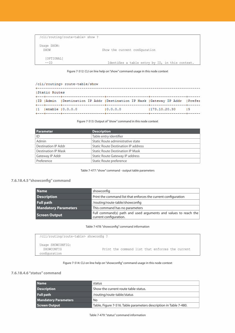
Descripción del producto
420
/cli/routing/route-table> show ?
Usage SHOW: SHOW Show the current configuration
[OPTIONAL] --ID Identifies a table entry by ID, in this context.
Figure 7-512: CLI on line help on “show” command usage in this node context
Figure 7-513: Output of ”show” command in this node context
Parameter DescriptionID Table entry identifierAdmin Static Route administrative stateDestination IP Addr Static Route Destination IP addressDestination IP Mask Static Route Destination IP MaskGateway IP Addr Static Route Gateway IP addressPreference Static Route preference
Table 7-477: “show” command - output table parameters
7.6.18.4.5 “showconfig” command
Name showconfig
Description Print the command list that enforces the current configuration
Full path /routing/route-table/showconfig
Mandatory Parameters This command has no parameters
Screen Output Full command(s) path and used arguments and values to reach the current configuration.
Table 7-478: “showconfig” command information
/cli/routing/route-table> showconfig ?
Usage SHOWCONFIG: SHOWCONFIG Print the command list that enforces the current configuration
Figure 7-514: CLI on line help on “showconfig” command usage in this node context
7.6.18.4.6 “status” command
Name status
Description Show the current route table status.
Full path /routing/route-table/status
Mandatory Parameters NoScreen Output Table, Figure 7-516. Table parameters description in Table 7-480.
Table 7-479: “status” command information
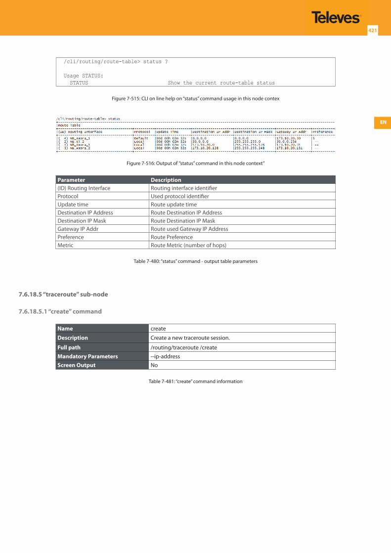
EN
421
/cli/routing/route-table> status ?
Usage STATUS: STATUS Show the current route-table status
Figure 7-515: CLI on line help on “status” command usage in this node contex
Figure 7-516: Output of ”status” command in this node context”
Parameter Description(ID) Routing Interface Routing interface identifierProtocol Used protocol identifierUpdate time Route update timeDestination IP Address Route Destination IP AddressDestination IP Mask Route Destination IP MaskGateway IP Addr Route used Gateway IP AddressPreference Route PreferenceMetric Route Metric (number of hops)
Table 7-480: “status” command - output table parameters
7.6.18.5 “traceroute” sub-node
7.6.18.5.1 “create” command
Name create
Description Create a new traceroute session.
Full path /routing/traceroute /create
Mandatory Parameters --ip-addressScreen Output No
Table 7-481: “create” command information
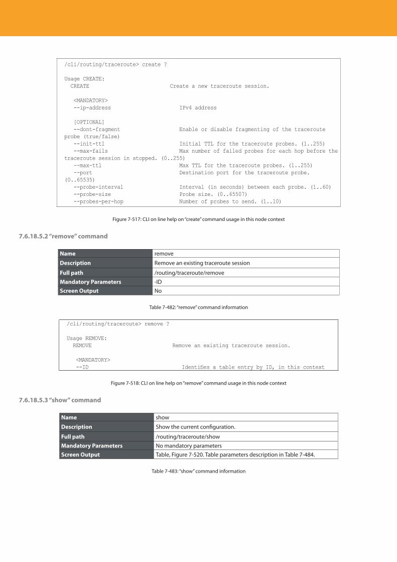
Descripción del producto
422
/cli/routing/traceroute> create ?
Usage CREATE: CREATE Create a new traceroute session.
<MANDATORY> --ip-address IPv4 address
[OPTIONAL] --dont-fragment Enable or disable fragmenting of the traceroute probe (true/false) --init-ttl Initial TTL for the traceroute probes. (1..255) --max-fails Max number of failed probes for each hop before the traceroute session in stopped. (0..255) --max-ttl Max TTL for the traceroute probes. (1..255) --port Destination port for the traceroute probe. (0..65535) --probe-interval Interval (in seconds) between each probe. (1..60) --probe-size Probe size. (0..65507) --probes-per-hop Number of probes to send. (1..10)
Figure 7-517: CLI on line help on “create” command usage in this node context
7.6.18.5.2 “remove” command
Name remove
Description Remove an existing traceroute session
Full path /routing/traceroute/remove
Mandatory Parameters -IDScreen Output No
Table 7-482: “remove” command information
/cli/routing/traceroute> remove ? Usage REMOVE: REMOVE Remove an existing traceroute session.
<MANDATORY> --ID Identifies a table entry by ID, in this context
Figure 7-518: CLI on line help on “remove” command usage in this node context
7.6.18.5.3 “show” command
Name show
Description Show the current configuration.
Full path /routing/traceroute/show
Mandatory Parameters No mandatory parametersScreen Output Table, Figure 7-520. Table parameters description in Table 7-484.
Table 7-483: “show” command information
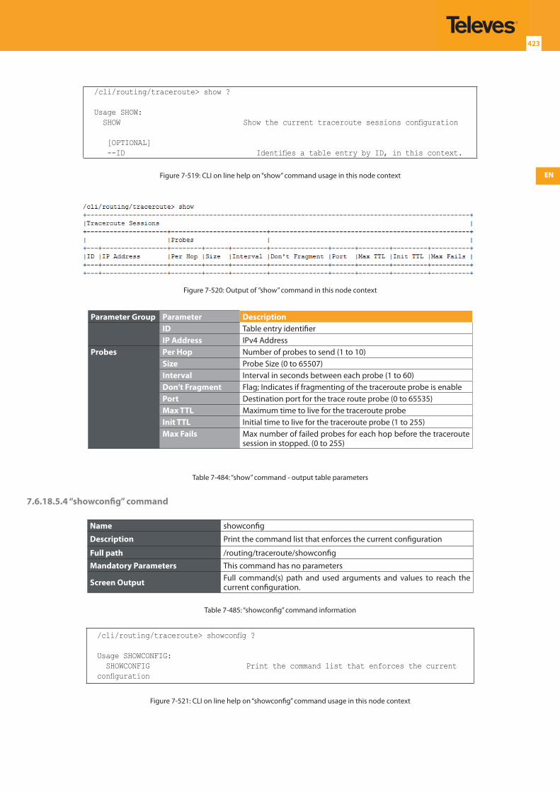
EN
423
/cli/routing/traceroute> show ?
Usage SHOW: SHOW Show the current traceroute sessions configuration
[OPTIONAL] --ID Identifies a table entry by ID, in this context.
Figure 7-519: CLI on line help on “show” command usage in this node context
Figure 7-520: Output of ”show” command in this node context
Parameter Group Parameter DescriptionID Table entry identifierIP Address IPv4 Address
Probes Per Hop Number of probes to send (1 to 10)Size Probe Size (0 to 65507)Interval Interval in seconds between each probe (1 to 60)Don’t Fragment Flag; Indicates if fragmenting of the traceroute probe is enablePort Destination port for the trace route probe (0 to 65535)Max TTL Maximum time to live for the traceroute probeInit TTL Initial time to live for the traceroute probe (1 to 255)Max Fails Max number of failed probes for each hop before the traceroute
session in stopped. (0 to 255)
Table 7-484: “show” command - output table parameters
7.6.18.5.4 “showconfig” command
Name showconfig
Description Print the command list that enforces the current configuration
Full path /routing/traceroute/showconfig
Mandatory Parameters This command has no parameters
Screen Output Full command(s) path and used arguments and values to reach the current configuration.
Table 7-485: “showconfig” command information
/cli/routing/traceroute> showconfig ?
Usage SHOWCONFIG: SHOWCONFIG Print the command list that enforces the current configuration
Figure 7-521: CLI on line help on “showconfig” command usage in this node context
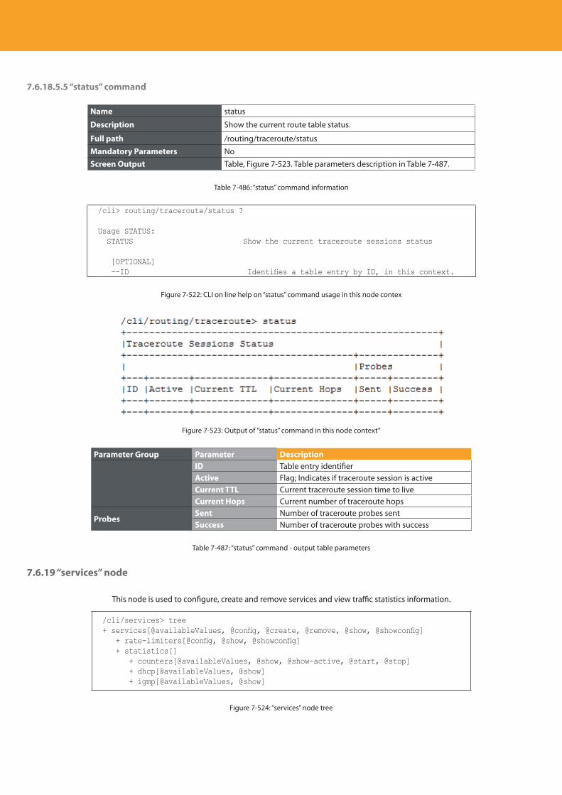
Descripción del producto
424
7.6.18.5.5 “status” command
Name status
Description Show the current route table status.
Full path /routing/traceroute/status
Mandatory Parameters NoScreen Output Table, Figure 7-523. Table parameters description in Table 7-487.
Table 7-486: “status” command information
/cli> routing/traceroute/status ?
Usage STATUS: STATUS Show the current traceroute sessions status
[OPTIONAL] --ID Identifies a table entry by ID, in this context.
Figure 7-522: CLI on line help on “status” command usage in this node contex
Figure 7-523: Output of ”status” command in this node context”
Parameter Group Parameter DescriptionID Table entry identifierActive Flag; Indicates if traceroute session is activeCurrent TTL Current traceroute session time to liveCurrent Hops Current number of traceroute hops
ProbesSent Number of traceroute probes sentSuccess Number of traceroute probes with success
Table 7-487: “status” command - output table parameters
7.6.19 “services” node
This node is used to configure, create and remove services and view traffic statistics information.
/cli/services> tree+ services[@availableValues, @config, @create, @remove, @show, @showconfig] + rate-limiters[@config, @show, @showconfig] + statistics[] + counters[@availableValues, @show, @show-active, @start, @stop] + dhcp[@availableValues, @show] + igmp[@availableValues, @show]
Figure 7-524: “services” node tree
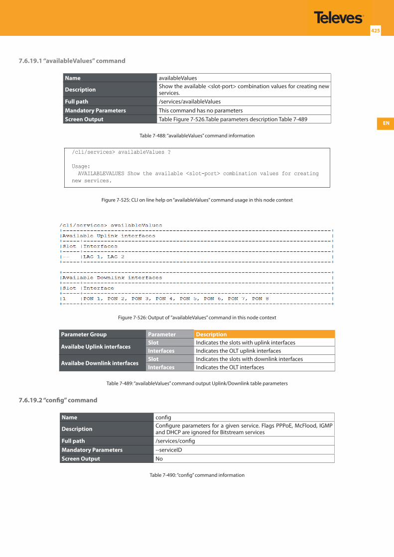
EN
425
7.6.19.1 “availableValues” command
Name availableValues
Description Show the available <slot-port> combination values for creating new services.
Full path /services/availableValuesMandatory Parameters This command has no parametersScreen Output Table Figure 7-526.Table parameters description Table 7-489
Table 7-488: “availableValues” command information
/cli/services> availableValues ?
Usage: AVAILABLEVALUES Show the available <slot-port> combination values for creating new services.
Figure 7-525: CLI on line help on “availableValues” command usage in this node context
Figure 7-526: Output of ”availableValues” command in this node context
Parameter Group Parameter Description
Availabe Uplink interfacesSlot Indicates the slots with uplink interfacesInterfaces Indicates the OLT uplink interfaces
Availabe Downlink interfacesSlot Indicates the slots with downlink interfacesInterfaces Indicates the OLT interfaces
Table 7-489: “availableValues” command output Uplink/Downlink table parameters
7.6.19.2 “config” command
Name config
Description Configure parameters for a given service. Flags PPPoE, McFlood, IGMP and DHCP are ignored for Bitstream services
Full path /services/config
Mandatory Parameters --serviceIDScreen Output No
Table 7-490: “config” command information
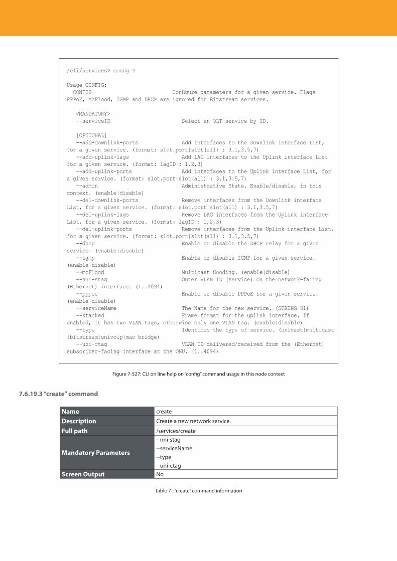
Descripción del producto
426
/cli/services> config ?
Usage CONFIG: CONFIG Configure parameters for a given service. Flags PPPoE, McFlood, IGMP and DHCP are ignored for Bitstream services.
<MANDATORY> --serviceID Select an OLT service by ID.
[OPTIONAL] --add-downlink-ports Add interfaces to the Downlink interface List, for a given service. (format: slot.port|slot(all) : 3.1,3.5,7) --add-uplink-lags Add LAG interfaces to the Uplink interface List for a given service. (format: lagID : 1,2,3) --add-uplink-ports Add interfaces to the Uplink interface List, for a given service. (format: slot.port|slot(all) : 3.1,3.5,7) --admin Administrative State. Enable/disable, in this context. (enable|disable) --del-downlink-ports Remove interfaces from the Downlink interface List, for a given service. (format: slot.port|slot(all) : 3.1,3.5,7) --del-uplink-lags Remove LAG interfaces from the Uplink interface List, for a given service. (format: lagID : 1,2,3) --del-uplink-ports Remove interfaces from the Uplink interface List, for a given service. (format: slot.port|slot(all) : 3.1,3.5,7) --dhcp Enable or disable the DHCP relay for a given service. (enable|disable) --igmp Enable or disable IGMP for a given service. (enable|disable) --mcFlood Multicast flooding. (enable|disable) --nni-stag Outer VLAN ID (service) on the network-facing (Ethernet) interface. (1..4094) --pppoe Enable or disable PPPoE for a given service. (enable|disable) --serviceName The Name for the new service. (STRING 31) --stacked Frame format for the uplink interface. If enabled, it has two VLAN tags, otherwise only one VLAN tag. (enable|disable) --type Identifies the type of service. (unicast|multicast|bitstream|univoip|mac bridge) --uni-ctag VLAN ID delivered/received from the (Ethernet) subscriber-facing interface at the ONU. (1..4094)
Figure 7-527: CLI on line help on “config” command usage in this node context
7.6.19.3 “create” command
Name create
Description Create a new network service.
Full path /services/create
Mandatory Parameters
--nni-stag--serviceName--type--uni-ctag
Screen Output No
Table 7-: “create” command information
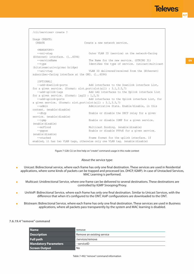
EN
427
/cli/services> create ?
Usage CREATE: CREATE Create a new network service.
<MANDATORY> --nni-stag Outer VLAN ID (service) on the network-facing (Ethernet) interface. (1..4094) --serviceName The Name for the new service. (STRING 31) --type Identifies the type of service. (unicast|multicast|bitstream|univoip|mac bridge) --uni-ctag VLAN ID delivered/received from the (Ethernet) subscriber-facing interface at the ONU. (1..4094)
[OPTIONAL] --add-downlink-ports Add interfaces to the Downlink interface List, for a given service. (format: slot.port|slot(all) : 3.1,3.5,7) --add-uplink-lags Add LAG interfaces to the Uplink interface List for a given service. (format: lagID : 1,2,3) --add-uplink-ports Add interfaces to the Uplink interface List, for a given service. (format: slot.port|slot(all) : 3.1,3.5,7) --admin Administrative State. Enable/disable, in this context. (enable|disable) --dhcp Enable or disable the DHCP relay for a given service. (enable|disable) --igmp Enable or disable IGMP for a given service. (enable|disable) --mcFlood Multicast flooding. (enable|disable) --pppoe Enable or disable PPPoE for a given service. (enable|disable) --stacked Frame format for the uplink interface. If enabled, it has two VLAN tags, otherwise only one VLAN tag. (enable|disable)
Figure 7-528: CLI on line help on “create” command usage in this node context
About the service type:
Unicast: Bidirectional service, where each frame has only one final destination. These services are used in Residential applications, where some kinds of packets can be trapped and processed (ex. DHCP, IGMP). In case of Unstacked Services,
MAC Learning is performed.
Multicast: Unidirectional Service, where one frame can be delivered to several destinations. These destinations are controlled by IGMP Snooping/Proxy.
UniVoIP: Bidirectional Service, where each frame has only one final destination. Similar to Unicast Services, with the difference that when it’s configured to the ONT, VoIP configurations are downloaded to the ONT.
Bitstream: Bidirectional Service, where each frame has only one final destination. These services are used in Business applications, where all packets pass transparently by the system and MAC learning is disabled.
7.6.19.4 “remove” command
Name remove
Description Remove an existing service
Full path /services/remove
Mandatory Parameters --serviceID
Screen Output No
Table 7-492: “remove” command information
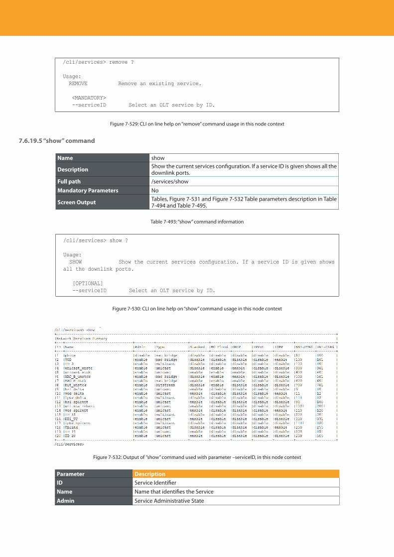
Descripción del producto
428
/cli/services> remove ?
Usage: REMOVE Remove an existing service.
<MANDATORY> --serviceID Select an OLT service by ID.
Figure 7-529: CLI on line help on “remove” command usage in this node context
7.6.19.5 “show” command
Name show
Description Show the current services configuration. If a service ID is given shows all the downlink ports.
Full path /services/show
Mandatory Parameters No
Screen Output Tables, Figure 7-531 and Figure 7-532 Table parameters description in Table 7-494 and Table 7-495.
Table 7-493: “show” command information
/cli/services> show ?
Usage: SHOW Show the current services configuration. If a service ID is given shows all the downlink ports.
[OPTIONAL] --serviceID Select an OLT service by ID.
Figure 7-530: CLI on line help on “show” command usage in this node context
Figure 7-532: Output of ”show” command used with parameter –serviceID, in this node context
Parameter DescriptionID Service Identifier
Name Name that identifies the Service
Admin Service Administrative State
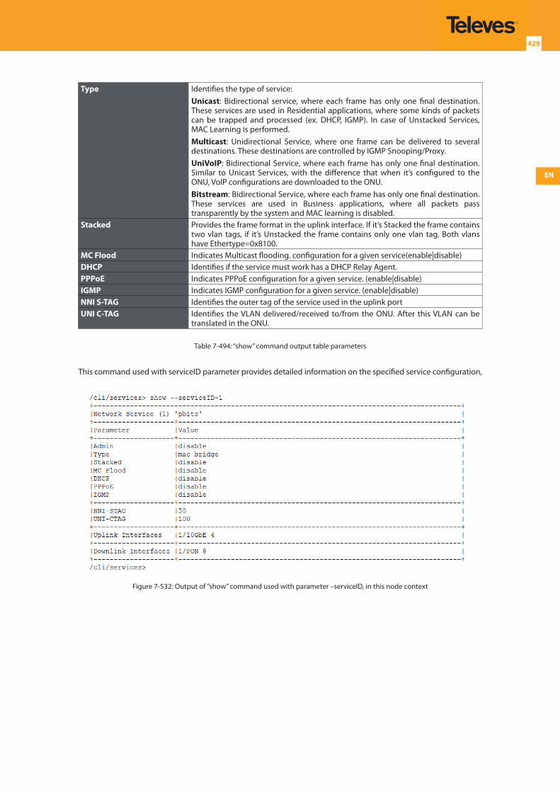
EN
429
Type Identifies the type of service:Unicast: Bidirectional service, where each frame has only one final destination. These services are used in Residential applications, where some kinds of packets can be trapped and processed (ex. DHCP, IGMP). In case of Unstacked Services, MAC Learning is performed.Multicast: Unidirectional Service, where one frame can be delivered to several destinations. These destinations are controlled by IGMP Snooping/Proxy.UniVoIP: Bidirectional Service, where each frame has only one final destination. Similar to Unicast Services, with the difference that when it’s configured to the ONU, VoIP configurations are downloaded to the ONU.Bitstream: Bidirectional Service, where each frame has only one final destination. These services are used in Business applications, where all packets pass transparently by the system and MAC learning is disabled.
Stacked Provides the frame format in the uplink interface. If it’s Stacked the frame contains two vlan tags, if it’s Unstacked the frame contains only one vlan tag. Both vlans have Ethertype=0x8100.
MC Flood Indicates Multicast flooding. configuration for a given service(enable|disable)DHCP Identifies if the service must work has a DHCP Relay Agent.PPPoE Indicates PPPoE configuration for a given service. (enable|disable)IGMP Indicates IGMP configuration for a given service. (enable|disable)NNI S-TAG Identifies the outer tag of the service used in the uplink portUNI C-TAG Identifies the VLAN delivered/received to/from the ONU. After this VLAN can be
translated in the ONU.
Table 7-494: “show” command output table parameters
This command used with serviceID parameter provides detailed information on the specified service configuration,
Figure 7-532: Output of ”show” command used with parameter –serviceID, in this node context
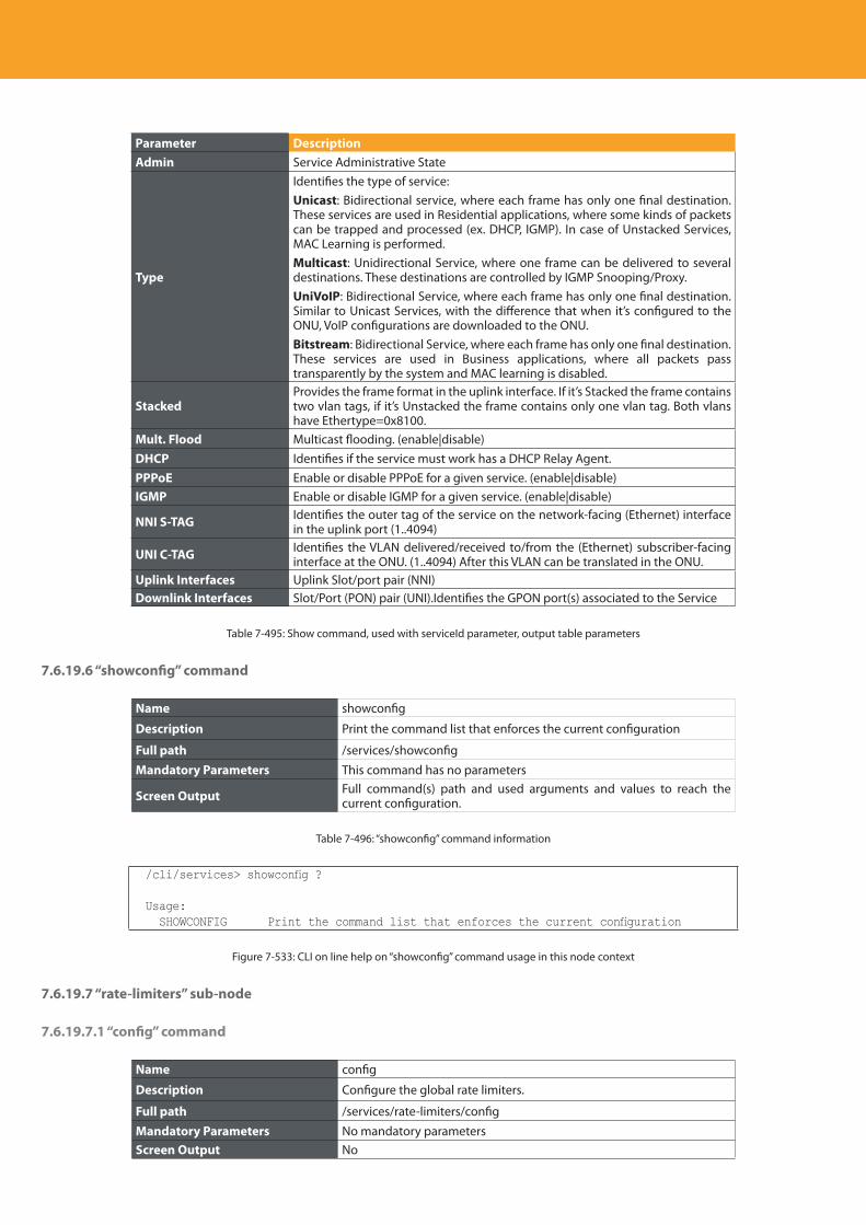
Descripción del producto
430
Parameter DescriptionAdmin Service Administrative State
Type
Identifies the type of service:Unicast: Bidirectional service, where each frame has only one final destination. These services are used in Residential applications, where some kinds of packets can be trapped and processed (ex. DHCP, IGMP). In case of Unstacked Services, MAC Learning is performed.Multicast: Unidirectional Service, where one frame can be delivered to several destinations. These destinations are controlled by IGMP Snooping/Proxy.UniVoIP: Bidirectional Service, where each frame has only one final destination. Similar to Unicast Services, with the difference that when it’s configured to the ONU, VoIP configurations are downloaded to the ONU.Bitstream: Bidirectional Service, where each frame has only one final destination. These services are used in Business applications, where all packets pass transparently by the system and MAC learning is disabled.
StackedProvides the frame format in the uplink interface. If it’s Stacked the frame contains two vlan tags, if it’s Unstacked the frame contains only one vlan tag. Both vlans have Ethertype=0x8100.
Mult. Flood Multicast flooding. (enable|disable)DHCP Identifies if the service must work has a DHCP Relay Agent.PPPoE Enable or disable PPPoE for a given service. (enable|disable)IGMP Enable or disable IGMP for a given service. (enable|disable)
NNI S-TAG Identifies the outer tag of the service on the network-facing (Ethernet) interface in the uplink port (1..4094)
UNI C-TAG Identifies the VLAN delivered/received to/from the (Ethernet) subscriber-facing interface at the ONU. (1..4094) After this VLAN can be translated in the ONU.
Uplink Interfaces Uplink Slot/port pair (NNI)Downlink Interfaces Slot/Port (PON) pair (UNI).Identifies the GPON port(s) associated to the Service
Table 7-495: Show command, used with serviceId parameter, output table parameters
7.6.19.6 “showconfig” command
Name showconfig
Description Print the command list that enforces the current configuration
Full path /services/showconfig
Mandatory Parameters This command has no parameters
Screen Output Full command(s) path and used arguments and values to reach the current configuration.
Table 7-496: “showconfig” command information
/cli/services> showconfig ?
Usage: SHOWCONFIG Print the command list that enforces the current configuration
Figure 7-533: CLI on line help on “showconfig” command usage in this node context
7.6.19.7 “rate-limiters” sub-node
7.6.19.7.1 “config” command
Name config
Description Configure the global rate limiters.
Full path /services/rate-limiters/config
Mandatory Parameters No mandatory parametersScreen Output No
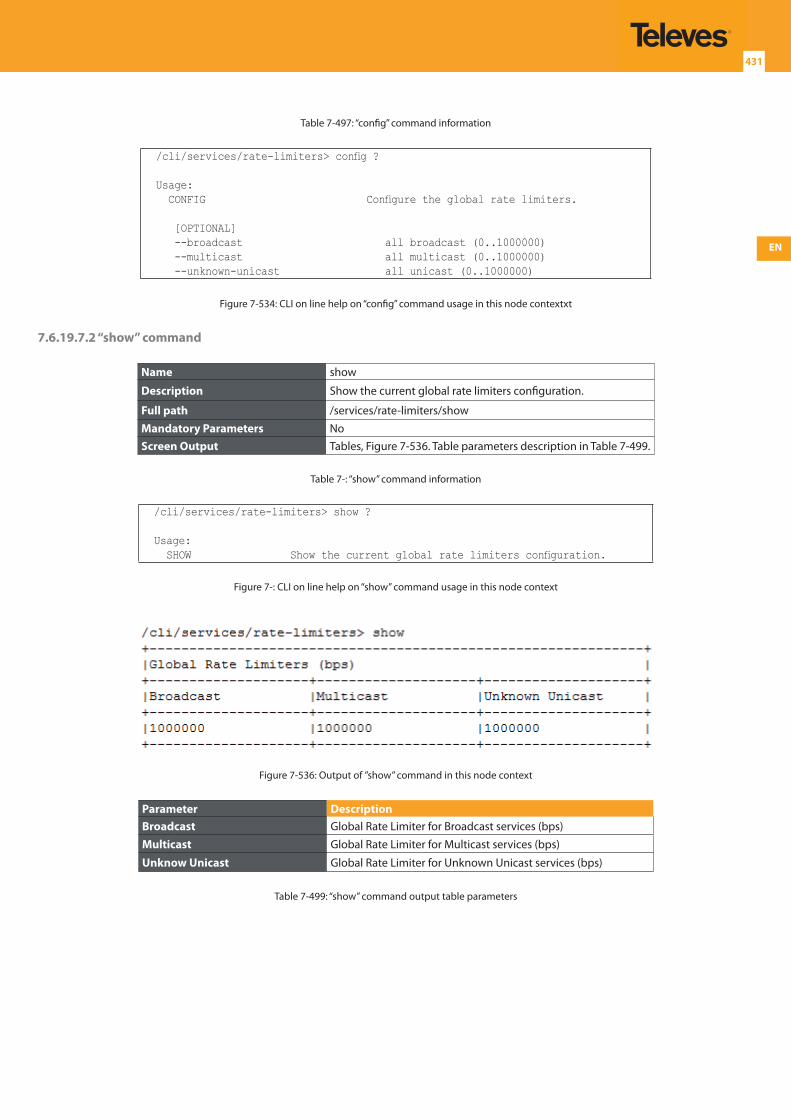
EN
431
Table 7-497: “config” command information
/cli/services/rate-limiters> config ?
Usage: CONFIG Configure the global rate limiters.
[OPTIONAL] --broadcast all broadcast (0..1000000) --multicast all multicast (0..1000000) --unknown-unicast all unicast (0..1000000)
Figure 7-534: CLI on line help on “config” command usage in this node contextxt
7.6.19.7.2 “show” command
Name show
Description Show the current global rate limiters configuration.
Full path /services/rate-limiters/show
Mandatory Parameters NoScreen Output Tables, Figure 7-536. Table parameters description in Table 7-499.
Table 7-: “show” command information
/cli/services/rate-limiters> show ?
Usage: SHOW Show the current global rate limiters configuration.
Figure 7-: CLI on line help on “show” command usage in this node context
Figure 7-536: Output of ”show” command in this node context
Parameter DescriptionBroadcast Global Rate Limiter for Broadcast services (bps)
Multicast Global Rate Limiter for Multicast services (bps)
Unknow Unicast Global Rate Limiter for Unknown Unicast services (bps)
Table 7-499: “show” command output table parameters
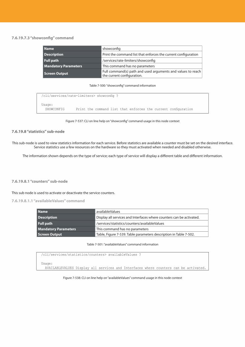
Descripción del producto
432
7.6.19.7.3 “showconfig” command
Name showconfig
Description Print the command list that enforces the current configuration
Full path /services/rate-limiters/showconfig
Mandatory Parameters This command has no parameters
Screen Output Full command(s) path and used arguments and values to reach the current configuration.
Table 7-500: “showconfig” command information
/cli/services/rate-limiters> showconfig ?
Usage: SHOWCONFIG Print the command list that enforces the current configuration
Figure 7-537: CLI on line help on “showconfig” command usage in this node context
7.6.19.8 “statistics” sub-node
This sub-node is used to view statistics information for each service. Before statistics are available a counter must be set on the desired interface. Service statistics use a few resources on the hardware so they must activated when needed and disabled otherwise.
The information shown depends on the type of service; each type of service will display a different table and different information.
7.6.19.8.1 “counters” sub-node
This sub node is used to activate or deactivate the service counters.
7.6.19.8.1.1 “availableValues” command
Name availableValues
Description Display all services and Interfaces where counters can be activated.
Full path /services/statistics/counters/availableValues
Mandatory Parameters This command has no parametersScreen Output Table, Figure 7-539. Table parameters description in Table 7-502.
Table 7-501: “availableValues” command information
/cli/services/statistics/counters> availableValues ?
Usage: AVAILABLEVALUES Display all services and Interfaces where counters can be activated.
Figure 7-538: CLI on line help on “availableValues” command usage in this node context
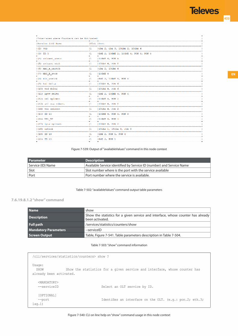
EN
433
Figure 7-539: Output of ”availableValues” command in this node context
Parameter DescriptionService (ID) Name Available Service identified by Service ID (number) and Service NameSlot Slot number where is the port with the service availablePort Port number where the service is available.
Table 7-502: “availableValues” command output table parameters
7.6.19.8.1.2 “show” command
Name show
Description Show the statistics for a given service and interface, whose counter has already been activated.
Full path /services/statistics/counters/show
Mandatory Parameters --serviceIDScreen Output Table, Figure 7-541. Table parameters description in Table 7-504.
Table 7-503: “show” command information
/cli/services/statistics/counters> show ?
Usage: SHOW Show the statistics for a given service and interface, whose counter has already been activated.
<MANDATORY> --serviceID Select an OLT service by ID.
[OPTIONAL] --port Identifies an interface on the OLT. (e.g.: pon.2; eth.3; lag.1)
Figure 7-540: CLI on line help on “show” command usage in this node context
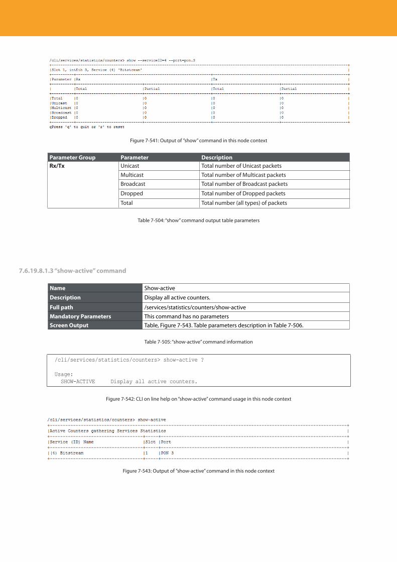
Descripción del producto
434
Figure 7-541: Output of ”show” command in this node context
Parameter Group Parameter DescriptionRx/Tx Unicast Total number of Unicast packets
Multicast Total number of Multicast packetsBroadcast Total number of Broadcast packets
Dropped Total number of Dropped packets
Total Total number (all types) of packets
Table 7-504: “show” command output table parameters
7.6.19.8.1.3 “show-active” command
Name Show-active
Description Display all active counters.
Full path /services/statistics/counters/show-active
Mandatory Parameters This command has no parametersScreen Output Table, Figure 7-543. Table parameters description in Table 7-506.
Table 7-505: “show-active” command information
/cli/services/statistics/counters> show-active ?
Usage: SHOW-ACTIVE Display all active counters.
Figure 7-542: CLI on line help on “show-active” command usage in this node context
Figure 7-543: Output of ”show-active” command in this node context
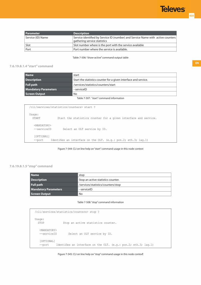
EN
435
Parameter DescriptionService (ID) Name Service identified by Service ID (number) and Service Name with active counters
gathering service statisticsSlot Slot number where is the port with the service availablePort Port number where the service is available.
Table 7-506: “show-active” command output table
7.6.19.8.1.4 “start” command
Name start
Description Start the statistics counter for a given interface and service.
Full path /services/statistics/counters/start
Mandatory Parameters --serviceIDScreen Output No
Table 7-507: “start” command information
/cli/services/statistics/counters> start ?
Usage: START Start the statistics counter for a given interface and service.
<MANDATORY> --serviceID Select an OLT service by ID.
[OPTIONAL] --port Identifies an interface on the OLT. (e.g.: pon.2; eth.3; lag.1)
Figure 7-544: CLI on line help on “start” command usage in this node context
7.6.19.8.1.5 “stop” command
Name stop
Description Stop an active statistics counter.
Full path /services/statistics/counters/stop
Mandatory Parameters --serviceIDScreen Output No
Table 7-508: “stop” command information
/cli/services/statistics/counters> stop ?
Usage: STOP Stop an active statistics counter.
<MANDATORY> --serviceID Select an OLT service by ID.
[OPTIONAL] --port Identifies an interface on the OLT. (e.g.: pon.2; eth.3; lag.1)
Figure 7-545: CLI on line help on “stop” command usage in this node context
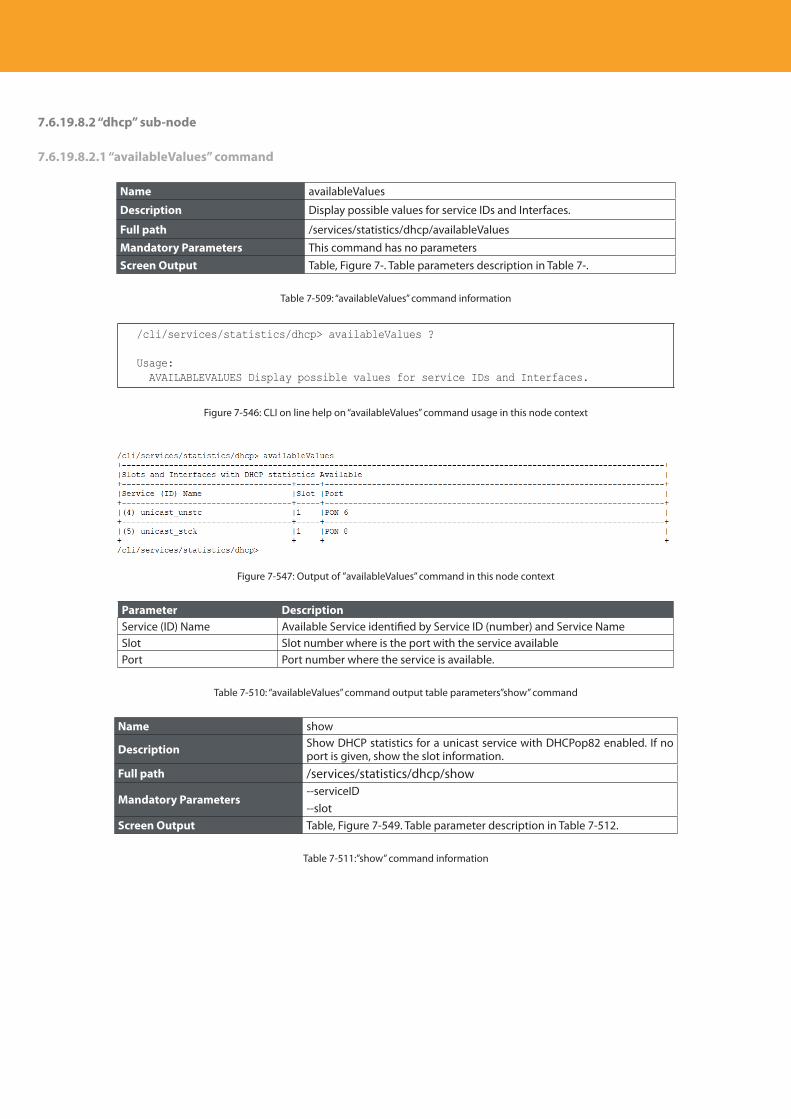
Descripción del producto
436
7.6.19.8.2 “dhcp” sub-node
7.6.19.8.2.1 “availableValues” command
Name availableValues
Description Display possible values for service IDs and Interfaces.
Full path /services/statistics/dhcp/availableValues
Mandatory Parameters This command has no parametersScreen Output Table, Figure 7-. Table parameters description in Table 7-.
Table 7-509: “availableValues” command information
/cli/services/statistics/dhcp> availableValues ?
Usage: AVAILABLEVALUES Display possible values for service IDs and Interfaces.
Figure 7-546: CLI on line help on “availableValues” command usage in this node context
Figure 7-547: Output of ”availableValues” command in this node context
Parameter DescriptionService (ID) Name Available Service identified by Service ID (number) and Service NameSlot Slot number where is the port with the service availablePort Port number where the service is available.
Table 7-510: “availableValues” command output table parameters”show” command
Name show
Description Show DHCP statistics for a unicast service with DHCPop82 enabled. If no port is given, show the slot information.
Full path /services/statistics/dhcp/show
Mandatory Parameters--serviceID--slot
Screen Output Table, Figure 7-549. Table parameter description in Table 7-512.
Table 7-511:”show” command information
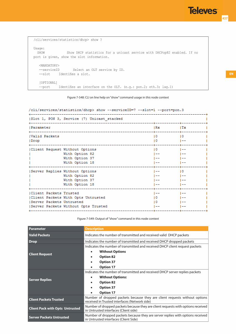
EN
437
/cli/services/statistics/dhcp> show ?
Usage: SHOW Show DHCP statistics for a unicast service with DHCPop82 enabled. If no port is given, show the slot information.
<MANDATORY> --serviceID Select an OLT service by ID. --slot Identifies a slot.
[OPTIONAL] --port Identifies an interface on the OLT. (e.g.: pon.2; eth.3; lag.1)
Figure 7-548: CLI on line help on “show” command usage in this node context
Figure 7-549: Output of ”show” command in this node context
Parameter Description
Valid Packets Indicates the number of transmitted and received valid DHCP packets
Drop Indicates the number of transmitted and received DHCP dropped packets
Client Request
Indicates the number of transmitted and received DHCP client request packets• Without Options• Option 82• Option 37• Option 17
Server Replies
Indicates the number of transmitted and received DHCP server replies packets• Without Options:• Option 82• Option 37• Option 17
Client Packets Trusted Number of dropped packets because they are client requests without options received in Trusted interfaces (Network side)
Client Pack with Opts Untrusted Number of dropped packets because they are client requests with options received in Untrusted interfaces (Client side)
Server Packets Untrusted Number of dropped packets because they are server replies with options received in Untrusted interfaces (Client Side)
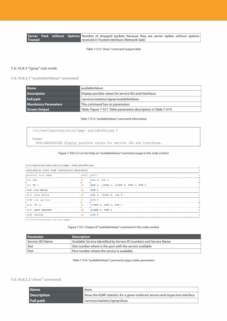
Descripción del producto
438
Server Pack without Options Trusted
Number of dropped packets because they are server replies without options received in Trusted interfaces (Network Side)
Table 7-512: “show” command output table
7.6.19.8.3 “igmp” sub-node
7.6.19.8.3.1 “availableValues” command
Name availableValues
Description Display possible values for service IDs and Interfaces.
Full path /services/statistics/igmp/availableValues
Mandatory Parameters This command has no parametersScreen Output Table, Figure 7-551. Table parameters description in Table 7-514.
Table 7-513: “availableValues” command information
/cli/services/statistics/igmp> availableValues ?
Usage: AVAILABLEVALUES Display possible values for service IDs and Interfaces.
Figure 7-550: CLI on line help on “availableValues” command usage in this node context
Figure 7-551: Output of ”availableValues” command in this node context
Parameter DescriptionService (ID) Name Available Service identified by Service ID (number) and Service NameSlot Slot number where is the port with the service availablePort Port number where the service is available.
Table 7-514: “availableValues” command output table parameters
7.6.19.8.3.2 “show” command
Name show
Description Show the IGMP statistics for a given multicast service and respective interface.
Full path /services/statistics/igmp/show
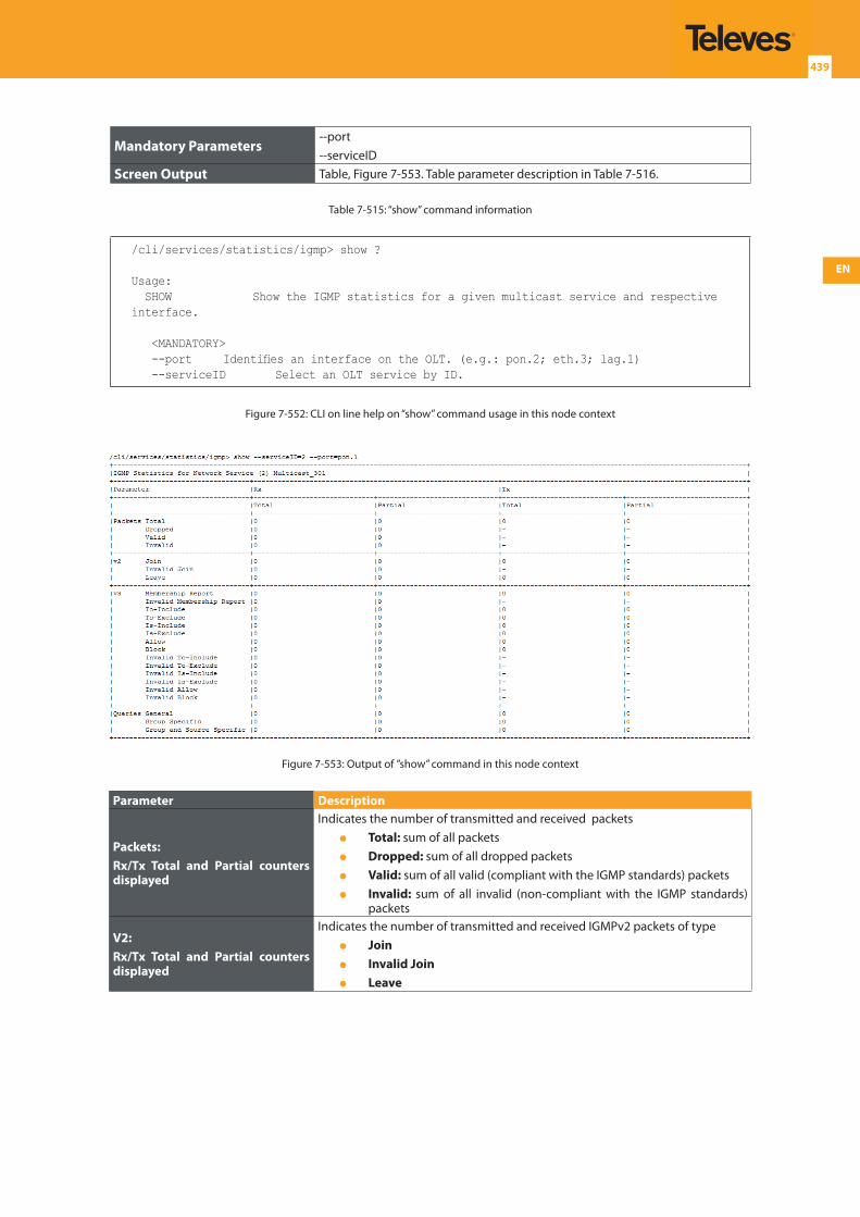
EN
439
Mandatory Parameters--port--serviceID
Screen Output Table, Figure 7-553. Table parameter description in Table 7-516.
Table 7-515: “show” command information
/cli/services/statistics/igmp> show ?
Usage: SHOW Show the IGMP statistics for a given multicast service and respective interface.
<MANDATORY> --port Identifies an interface on the OLT. (e.g.: pon.2; eth.3; lag.1) --serviceID Select an OLT service by ID.
Figure 7-552: CLI on line help on “show” command usage in this node context
Figure 7-553: Output of ”show” command in this node context
Parameter Description
Packets:Rx/Tx Total and Partial counters displayed
Indicates the number of transmitted and received packets Total: sum of all packets Dropped: sum of all dropped packets Valid: sum of all valid (compliant with the IGMP standards) packets Invalid: sum of all invalid (non-compliant with the IGMP standards)
packets
V2:Rx/Tx Total and Partial counters displayed
Indicates the number of transmitted and received IGMPv2 packets of type Join Invalid Join Leave
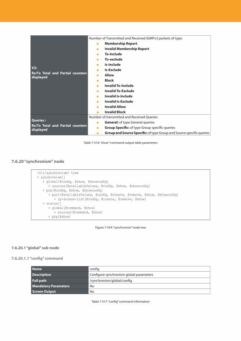
Descripción del producto
440
V3:Rx/Tx Total and Partial counters displayed
Number of Transmitted and Received IGMPv3 packets of type: Membership Report Invalid Membership Report To-Include To-exclude Is-Include Is-Exclude Allow Block Invalid To-Include Invalid To-Exclude Invalid Is-Include Invalid Is-Exclude Invalid Allow Invalid Block
Queries :Rx/Tx Total and Partial counters displayed
Number of transmitted and Received Queries General: of type General queries Group Specific: of type Group specific queries Group and Source Specific: of type Group and Source specific queries
Table 7-516: “show” command output table parameters
7.6.20 “synchronism” node
/cli/synchronism> tree+ synchronism[] + global[@config, @show, @showconfig] + sources[@availableValues, @config, @show, @showconfig] + ptp[@config, @show, @showconfig] + port[@availableValues, @config, @create, @remove, @show, @showconfig] + ip-access-list[@config, @create, @remove, @show] + status[] + global[@command, @show] + sources[@command, @show] + ptp[@show]
Figure 7-554: “synchronism” node tree
7.6.20.1 “global” sub-node
7.6.20.1.1 “config” command
Name config
Description Configure synchronism global parameters
Full path /synchronism/global/config
Mandatory Parameters NoScreen Output No
Table 7-517: “config” command information

EN
441
/cli/synchronism/global> config ?
Usage: CONFIG Configure synchronism global parameters
[OPTIONAL] --free-run-source Activate or deactivate the free-run source (enable|disable) --holdover-msg-delay Set the Holdover message delay (500..2000 ms) --min-quality-before-squelch Set the Minimum quality before squelch --quality-level-mode Enables synchronism quality level (enable|disable) --reversibility-level-mode Enables revertive switching mode when recovering from a failure (enable|disable) --reversibility-time Set the Reversibility time (0..3600 sec.) --send-val-after-quality-unknown Set the value to be sent in case Quality Unknown is received --switching-msg-delay Set the Switching message delay (180..500 ms)
Figure 7-: CLI on line help on “config” command usage in this node context
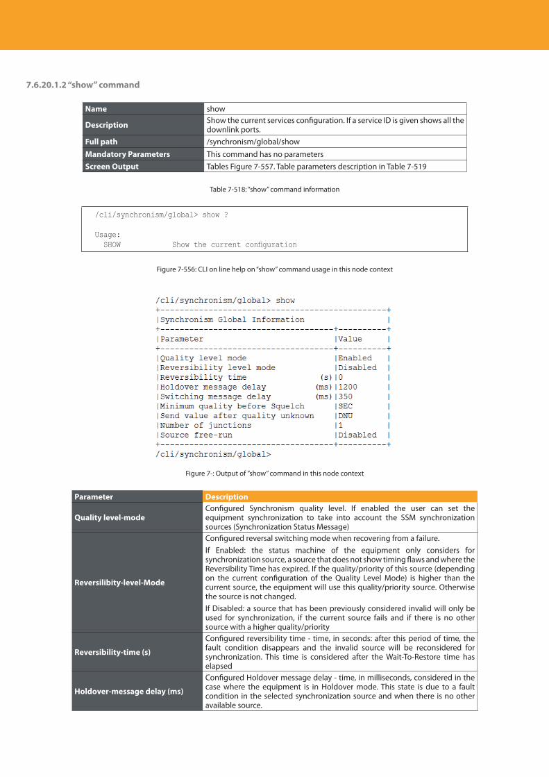
Descripción del producto
442
7.6.20.1.2 “show” command
Name show
Description Show the current services configuration. If a service ID is given shows all the downlink ports.
Full path /synchronism/global/show
Mandatory Parameters This command has no parametersScreen Output Tables Figure 7-557. Table parameters description in Table 7-519
Table 7-518: “show” command information
/cli/synchronism/global> show ?
Usage: SHOW Show the current configuration
Figure 7-556: CLI on line help on “show” command usage in this node context
Figure 7-: Output of ”show” command in this node context
Parameter Description
Quality level-modeConfigured Synchronism quality level. If enabled the user can set the equipment synchronization to take into account the SSM synchronization sources (Synchronization Status Message)
Reversilibity-level-Mode
Configured reversal switching mode when recovering from a failure.If Enabled: the status machine of the equipment only considers for synchronization source, a source that does not show timing flaws and where the Reversibility Time has expired. If the quality/priority of this source (depending on the current configuration of the Quality Level Mode) is higher than the current source, the equipment will use this quality/priority source. Otherwise the source is not changed.If Disabled: a source that has been previously considered invalid will only be used for synchronization, if the current source fails and if there is no other source with a higher quality/priority
Reversibility-time (s)
Configured reversibility time - time, in seconds: after this period of time, the fault condition disappears and the invalid source will be reconsidered for synchronization. This time is considered after the Wait-To-Restore time has elapsed
Holdover-message delay (ms)
Configured Holdover message delay - time, in milliseconds, considered in the case where the equipment is in Holdover mode. This state is due to a fault condition in the selected synchronization source and when there is no other available source.
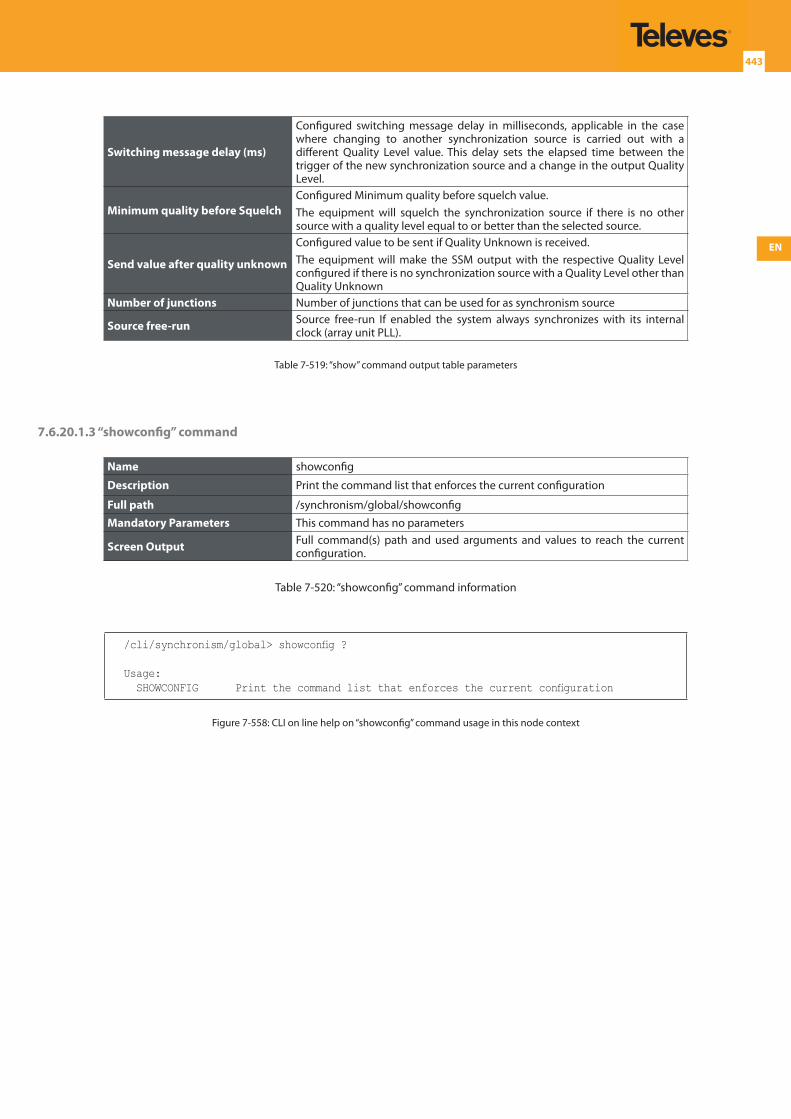
EN
443
Switching message delay (ms)
Configured switching message delay in milliseconds, applicable in the case where changing to another synchronization source is carried out with a different Quality Level value. This delay sets the elapsed time between the trigger of the new synchronization source and a change in the output Quality Level.
Minimum quality before SquelchConfigured Minimum quality before squelch value.The equipment will squelch the synchronization source if there is no other source with a quality level equal to or better than the selected source.
Send value after quality unknown
Configured value to be sent if Quality Unknown is received.The equipment will make the SSM output with the respective Quality Level configured if there is no synchronization source with a Quality Level other than Quality Unknown
Number of junctions Number of junctions that can be used for as synchronism source
Source free-run Source free-run If enabled the system always synchronizes with its internal clock (array unit PLL).
Table 7-519: “show” command output table parameters
7.6.20.1.3 “showconfig” command
Name showconfig
Description Print the command list that enforces the current configuration
Full path /synchronism/global/showconfig
Mandatory Parameters This command has no parameters
Screen Output Full command(s) path and used arguments and values to reach the current configuration.
Table 7-520: “showconfig” command information
/cli/synchronism/global> showconfig ?
Usage: SHOWCONFIG Print the command list that enforces the current configuration
Figure 7-558: CLI on line help on “showconfig” command usage in this node context
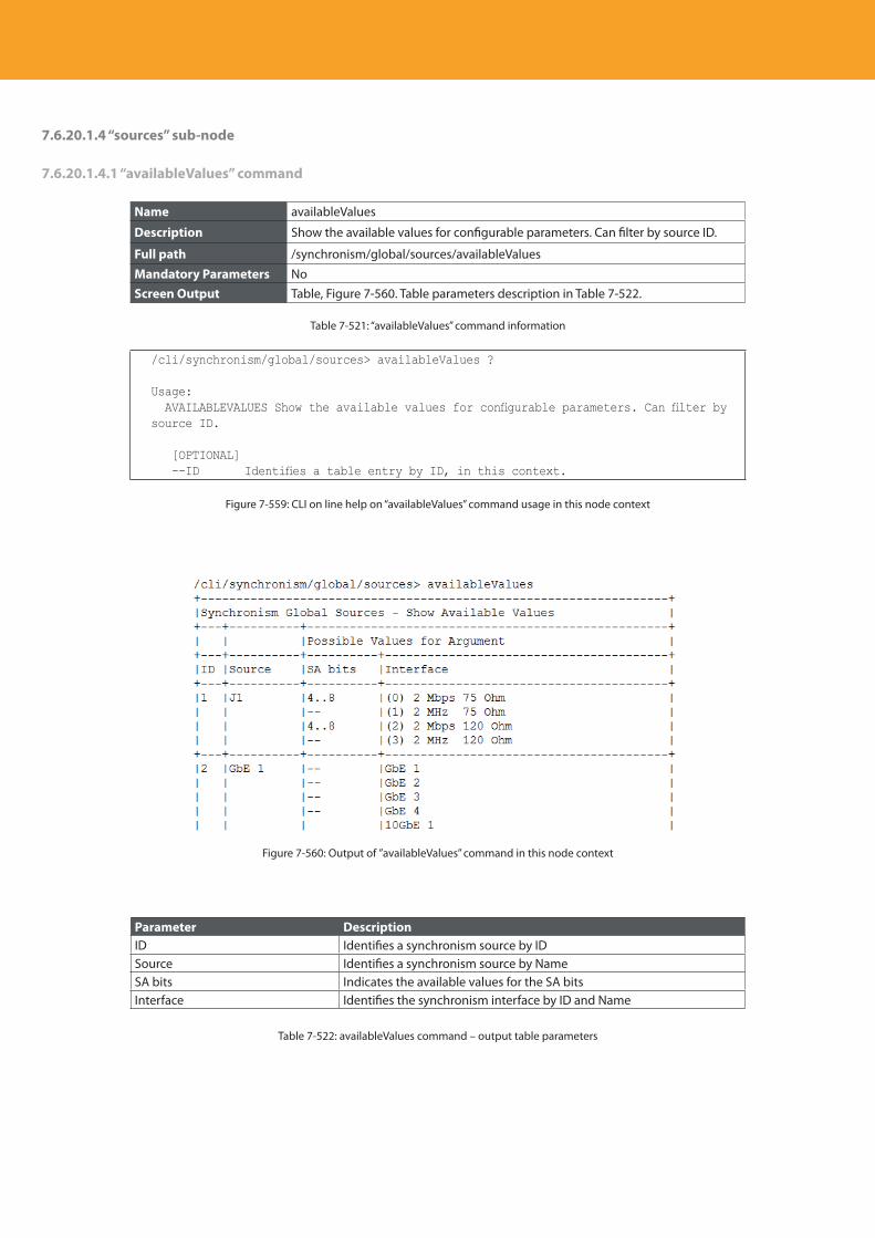
Descripción del producto
444
7.6.20.1.4 “sources” sub-node
7.6.20.1.4.1 “availableValues” command
Name availableValues
Description Show the available values for configurable parameters. Can filter by source ID.
Full path /synchronism/global/sources/availableValues
Mandatory Parameters NoScreen Output Table, Figure 7-560. Table parameters description in Table 7-522.
Table 7-521: “availableValues” command information
/cli/synchronism/global/sources> availableValues ?
Usage: AVAILABLEVALUES Show the available values for configurable parameters. Can filter by source ID.
[OPTIONAL] --ID Identifies a table entry by ID, in this context.
Figure 7-559: CLI on line help on “availableValues” command usage in this node context
Figure 7-560: Output of ”availableValues” command in this node context
Parameter DescriptionID Identifies a synchronism source by IDSource Identifies a synchronism source by NameSA bits Indicates the available values for the SA bitsInterface Identifies the synchronism interface by ID and Name
Table 7-522: availableValues command – output table parameters
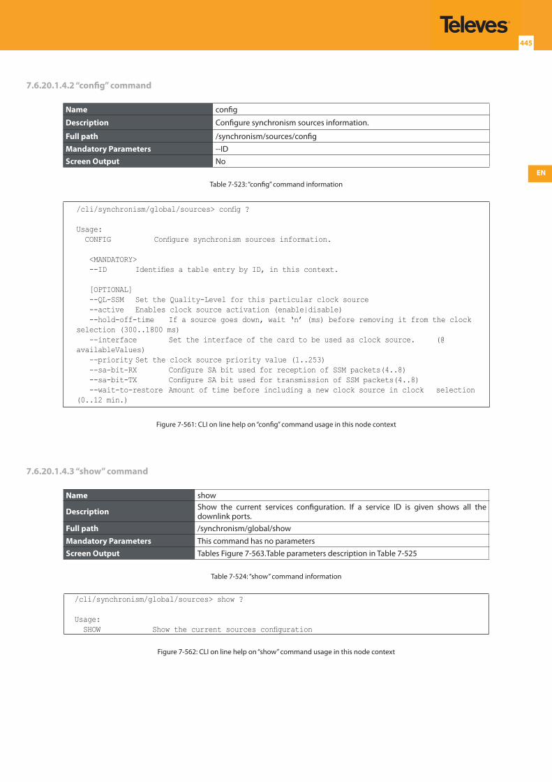
EN
445
7.6.20.1.4.2 “config” command
Name config
Description Configure synchronism sources information.
Full path /synchronism/sources/config
Mandatory Parameters --IDScreen Output No
Table 7-523: “config” command information
/cli/synchronism/global/sources> config ?
Usage: CONFIG Configure synchronism sources information.
<MANDATORY> --ID Identifies a table entry by ID, in this context.
[OPTIONAL] --QL-SSM Set the Quality-Level for this particular clock source --active Enables clock source activation (enable|disable) --hold-off-time If a source goes down, wait ‘n’ (ms) before removing it from the clock selection (300..1800 ms) --interface Set the interface of the card to be used as clock source. (@availableValues) --priority Set the clock source priority value (1..253) --sa-bit-RX Configure SA bit used for reception of SSM packets(4..8) --sa-bit-TX Configure SA bit used for transmission of SSM packets(4..8) --wait-to-restore Amount of time before including a new clock source in clock selection (0..12 min.)
Figure 7-561: CLI on line help on “config” command usage in this node context
7.6.20.1.4.3 “show” command
Name show
Description Show the current services configuration. If a service ID is given shows all the downlink ports.
Full path /synchronism/global/show
Mandatory Parameters This command has no parametersScreen Output Tables Figure 7-563.Table parameters description in Table 7-525
Table 7-524: “show” command information
/cli/synchronism/global/sources> show ?
Usage: SHOW Show the current sources configuration
Figure 7-562: CLI on line help on “show” command usage in this node context
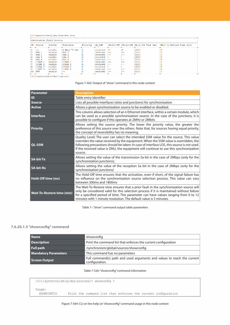
Descripción del producto
446
Figure 7-563: Output of ”show” command in this node context
Parameter DescriptionID Table entry IdentifierSource Lists all possible interfaces (slots and junctions) for synchronizationActive Allows a given synchronization source to be enabled or disabled.
InterfaceThis column allows selection of an n Ethernet interface, within a certain module, which can be used as a possible synchronization source. In the case of the junctions, it is possible to configure if this operates at 2MHz or 2Mbits
PriorityAllows setting the source priority. The lower the priority value, the greater the preference of this source over the others. Note that, for sources having equal priority, the concept of reversibility has no meaning.
QL-SSM
Quality Level; The user can select the intended SSM value for the source. This value overrides the value received by the equipment. When the SSM value is overridden, the following precautions should be taken: In case of interface LOS, this source is not used. If the received value is DNU, the equipment will continue to use this synchronization source.
SA-bit-Tx Allows setting the value of the transmission Sa bit in the case of 2Mbps (only for the synchronization junctions);
SA-bit-Rx Allows setting the value of the reception Sa bit in the case of 2Mbps (only for the synchronization junctions)
Hold-Off time (ms)The Hold-Off time ensures that the activation, even if short, of the signal failure has no influence on the synchronization source selection process. This value can vary between 300ms and 1800ms
Wait-To-Restore time (min)
The Wait-To-Restore time ensures that a prior fault in the synchronization source will only be considered valid for this selection process if it is maintained without failure for a specified period of time. This parameter can have values ranging from 0 to 12 minutes with 1 minute resolution. The default value is 5 minutes.
Table 7-: “show” command output table parameters
7.6.20.1.5 “showconfig” command
Name showconfig
Description Print the command list that enforces the current configuration
Full path /synchronism/global/sources/showconfig
Mandatory Parameters This command has no parameters
Screen Output Full command(s) path and used arguments and values to reach the current configuration.
Table 7-526: “showconfig” command information
/cli/synchronism/globa/sourcesl> showconfig ?
Usage: SHOWCONFIG Print the command list that enforces the current configuration
Figure 7-564: CLI on line help on “showconfig” command usage in this node context
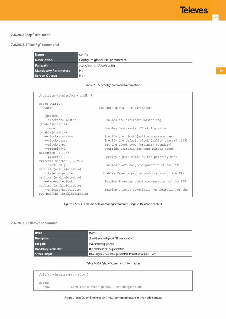
EN
447
7.6.20.2 “ptp” sub-node
7.6.20.2.1 “config” command
Name config
Description Configure global PTP parameters
Full path /synchronism/ptp/config
Mandatory Parameters NoScreen Output No
Table 7-527: “config” command information
//cli/synchronism/ptp> config ?
Usage CONFIG: CONFIG Configure global PTP parameters
[OPTIONAL] --alternate-master Enables the alternate master flag (enable|disable) --bmca Enables Best Master Clock Algorithm (enable|disable) --clock-accuracy Specify the clock Quality accuracy type --clock-class Specify the default clock Quality class(0..255) --clock-type Set the clock type (ordinary|boundary) --priority-1 Override criteria for best master clock selection (1..253) --priority-2 Specify a particular switch priority when criteria matches (1..253) --slave-only Enables slave only configuration of the PTP machine (enable|disable) --telecom-profile Enables Telecom profile configuration of the PTP machine (enable|disable) --two-step-clock Enables Two-step clock configuration of the PTP machine (enable|disable) --unicast-negotiation Enables Unicast negotiation configuration of the PTP machine (enable|disable)
Figure 7-565: CLI on line help on “config” command usage in this node context
7.6.20.2.2 “show” command
Name show
Description Show the current global PTP configuration
Full path /synchronism/ptp/show
Mandatory Parameters This command has no parametersScreen Output Tables Figure 7-567.Table parameters description in Table 7-529
Table 7-528: “show” command information
/cli/synchronism/ptp> show ?
Usage: SHOW Show the current global PTP configuration
Figure 7-566: CLI on line help on “show” command usage in this node context
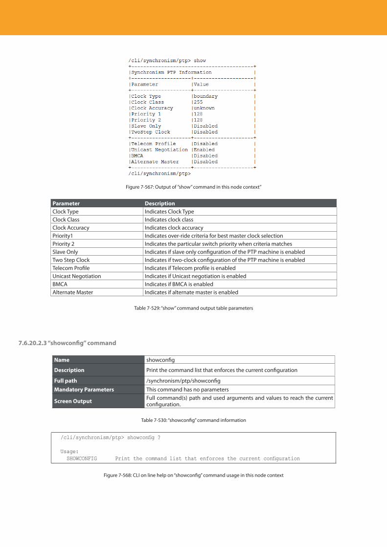
Descripción del producto
448
Figure 7-567: Output of ”show” command in this node context”
Parameter DescriptionClock Type Indicates Clock TypeClock Class Indicates clock classClock Accuracy Indicates clock accuracyPriority1 Indicates over-ride criteria for best master clock selectionPriority 2 Indicates the particular switch priority when criteria matchesSlave Only Indicates if slave only configuration of the PTP machine is enabledTwo Step Clock Indicates if two-clock configuration of the PTP machine is enabledTelecom Profile Indicates if Telecom profile is enabledUnicast Negotiation Indicates if Unicast negotiation is enabledBMCA Indicates if BMCA is enabledAlternate Master Indicates if alternate master is enabled
Table 7-529: “show” command output table parameters
7.6.20.2.3 “showconfig” command
Name showconfig
Description Print the command list that enforces the current configuration
Full path /synchronism/ptp/showconfig
Mandatory Parameters This command has no parameters
Screen Output Full command(s) path and used arguments and values to reach the current configuration.
Table 7-530: “showconfig” command information
/cli/synchronism/ptp> showconfig ?
Usage: SHOWCONFIG Print the command list that enforces the current configuration
Figure 7-568: CLI on line help on “showconfig” command usage in this node context
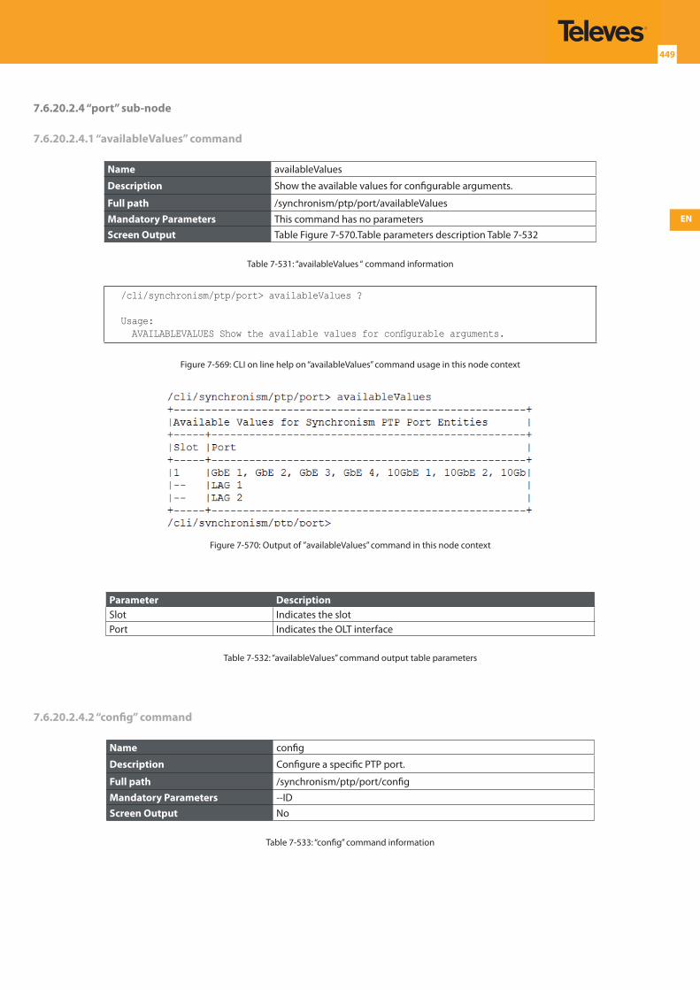
EN
449
7.6.20.2.4 “port” sub-node
7.6.20.2.4.1 “availableValues” command
Name availableValues
Description Show the available values for configurable arguments.
Full path /synchronism/ptp/port/availableValues
Mandatory Parameters This command has no parametersScreen Output Table Figure 7-570.Table parameters description Table 7-532
Table 7-531: “availableValues “ command information
/cli/synchronism/ptp/port> availableValues ?
Usage: AVAILABLEVALUES Show the available values for configurable arguments.
Figure 7-569: CLI on line help on “availableValues” command usage in this node context
Figure 7-570: Output of ”availableValues” command in this node context
Parameter DescriptionSlot Indicates the slotPort Indicates the OLT interface
Table 7-532: “availableValues” command output table parameters
7.6.20.2.4.2 “config” command
Name config
Description Configure a specific PTP port.
Full path /synchronism/ptp/port/config
Mandatory Parameters --IDScreen Output No
Table 7-533: “config” command information
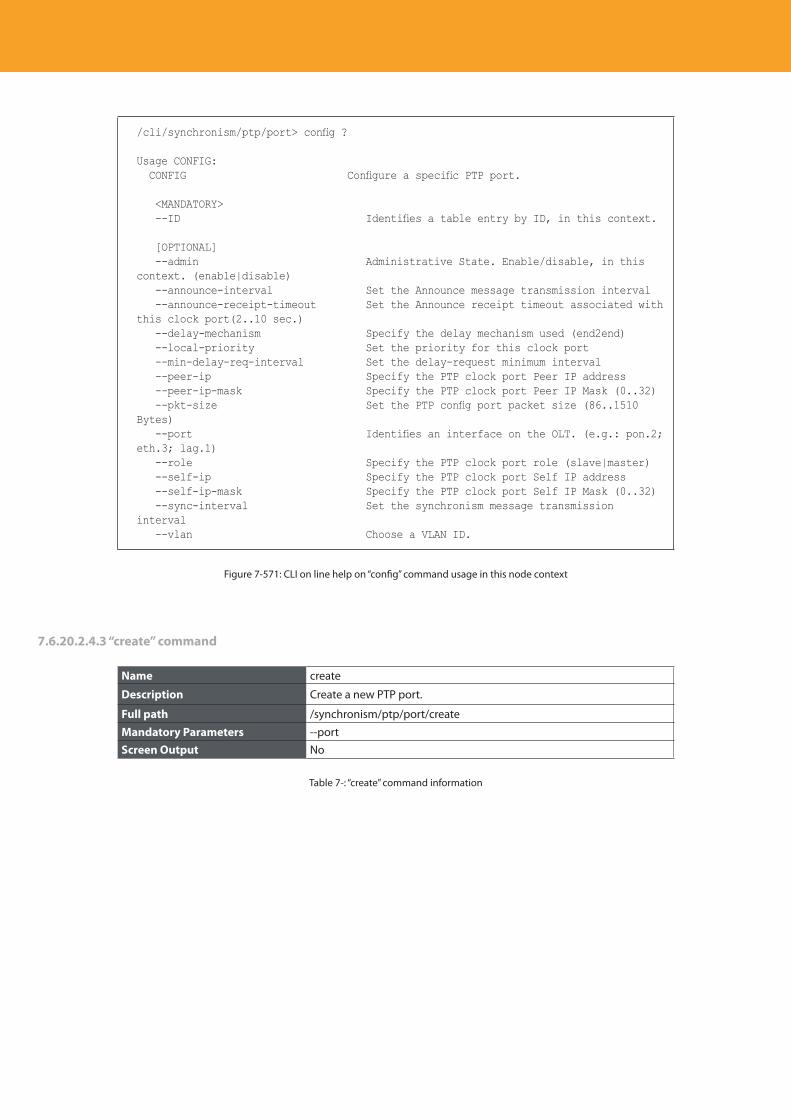
Descripción del producto
450
/cli/synchronism/ptp/port> config ?
Usage CONFIG: CONFIG Configure a specific PTP port.
<MANDATORY> --ID Identifies a table entry by ID, in this context.
[OPTIONAL] --admin Administrative State. Enable/disable, in this context. (enable|disable) --announce-interval Set the Announce message transmission interval --announce-receipt-timeout Set the Announce receipt timeout associated with this clock port(2..10 sec.) --delay-mechanism Specify the delay mechanism used (end2end) --local-priority Set the priority for this clock port --min-delay-req-interval Set the delay-request minimum interval --peer-ip Specify the PTP clock port Peer IP address --peer-ip-mask Specify the PTP clock port Peer IP Mask (0..32) --pkt-size Set the PTP config port packet size (86..1510 Bytes) --port Identifies an interface on the OLT. (e.g.: pon.2; eth.3; lag.1) --role Specify the PTP clock port role (slave|master) --self-ip Specify the PTP clock port Self IP address --self-ip-mask Specify the PTP clock port Self IP Mask (0..32) --sync-interval Set the synchronism message transmission interval --vlan Choose a VLAN ID.
Figure 7-571: CLI on line help on “config” command usage in this node context
7.6.20.2.4.3 “create” command
Name create
Description Create a new PTP port.
Full path /synchronism/ptp/port/create
Mandatory Parameters --portScreen Output No
Table 7-: “create” command information
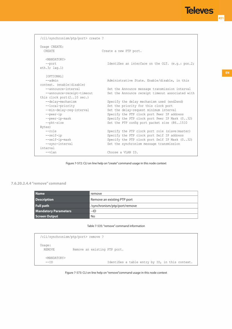
EN
451
/cli/synchronism/ptp/port> create ?
Usage CREATE: CREATE Create a new PTP port.
<MANDATORY> --port Identifies an interface on the OLT. (e.g.: pon.2; eth.3; lag.1)
[OPTIONAL] --admin Administrative State. Enable/disable, in this context. (enable|disable) --announce-interval Set the Announce message transmission interval --announce-receipt-timeout Set the Announce receipt timeout associated with this clock port(2..10 sec.) --delay-mechanism Specify the delay mechanism used (end2end) --local-priority Set the priority for this clock port --min-delay-req-interval Set the delay-request minimum interval --peer-ip Specify the PTP clock port Peer IP address --peer-ip-mask Specify the PTP clock port Peer IP Mask (0..32) --pkt-size Set the PTP config port packet size (86..1510 Bytes) --role Specify the PTP clock port role (slave|master) --self-ip Specify the PTP clock port Self IP address --self-ip-mask Specify the PTP clock port Self IP Mask (0..32) --sync-interval Set the synchronism message transmission interval --vlan Choose a VLAN ID.
Figure 7-572: CLI on line help on “create” command usage in this node context
7.6.20.2.4.4 “remove” command
Name remove
Description Remove an existing PTP port
Full path /synchronism/ptp/port/remove
Mandatory Parameters --IDScreen Output No
Table 7-535: “remove” command information
/cli/synchronism/ptp/port> remove ?
Usage: REMOVE Remove an existing PTP port.
<MANDATORY> --ID Identifies a table entry by ID, in this context.
Figure 7-573: CLI on line help on “remove”command usage in this node context
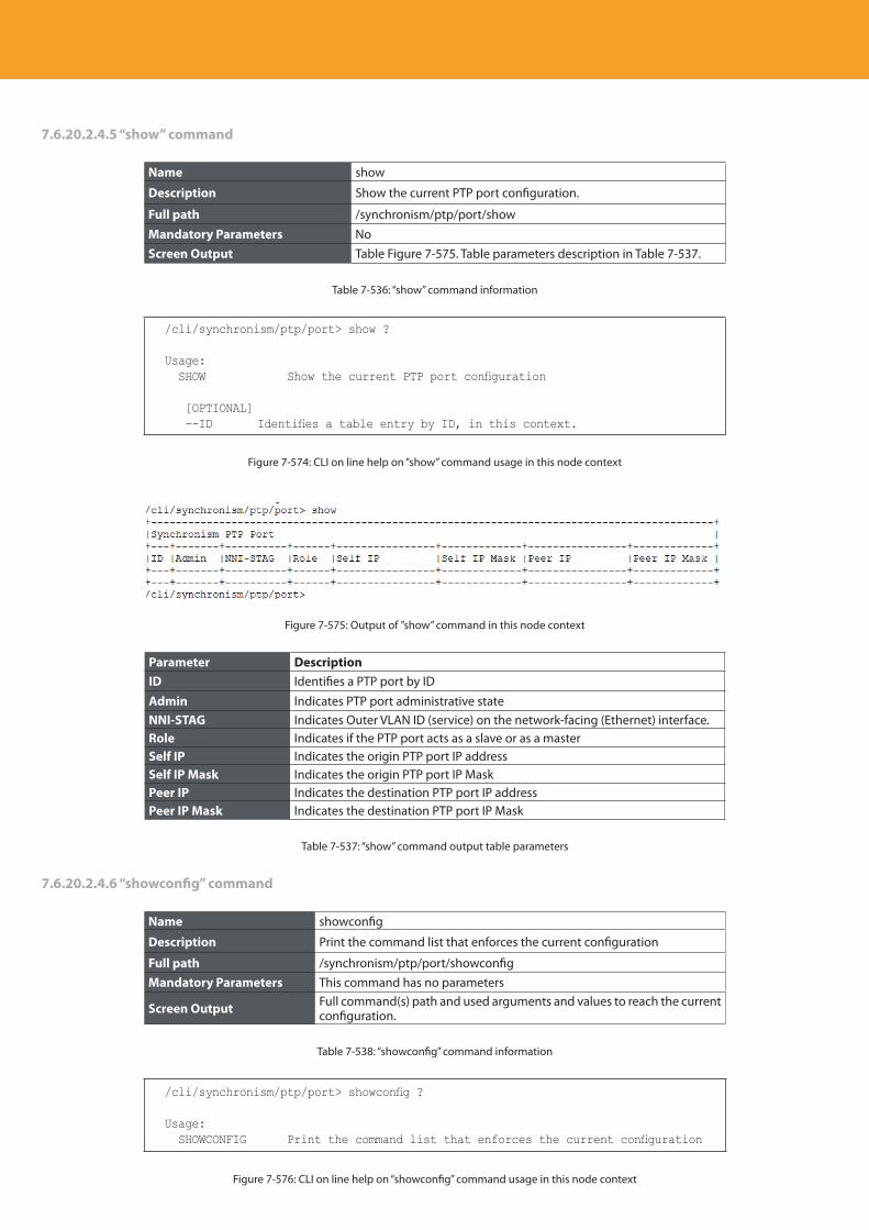
Descripción del producto
452
7.6.20.2.4.5 “show” command
Name show
Description Show the current PTP port configuration.
Full path /synchronism/ptp/port/show
Mandatory Parameters NoScreen Output Table Figure 7-575. Table parameters description in Table 7-537.
Table 7-536: “show” command information
/cli/synchronism/ptp/port> show ?
Usage: SHOW Show the current PTP port configuration
[OPTIONAL] --ID Identifies a table entry by ID, in this context.
Figure 7-574: CLI on line help on “show” command usage in this node context
Figure 7-575: Output of ”show” command in this node context
Parameter DescriptionID Identifies a PTP port by ID
Admin Indicates PTP port administrative stateNNI-STAG Indicates Outer VLAN ID (service) on the network-facing (Ethernet) interface.Role Indicates if the PTP port acts as a slave or as a masterSelf IP Indicates the origin PTP port IP addressSelf IP Mask Indicates the origin PTP port IP MaskPeer IP Indicates the destination PTP port IP addressPeer IP Mask Indicates the destination PTP port IP Mask
Table 7-537: “show” command output table parameters
7.6.20.2.4.6 “showconfig” command
Name showconfig
Description Print the command list that enforces the current configuration
Full path /synchronism/ptp/port/showconfigMandatory Parameters This command has no parameters
Screen Output Full command(s) path and used arguments and values to reach the current configuration.
Table 7-538: “showconfig” command information
/cli/synchronism/ptp/port> showconfig ?
Usage: SHOWCONFIG Print the command list that enforces the current configuration
Figure 7-576: CLI on line help on “showconfig” command usage in this node context
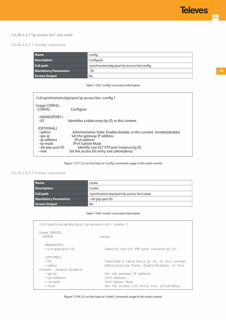
EN
453
7.6.20.2.4.7 “ip-access-list” sub-node
7.6.20.2.4.7.1 “config” command
Name config
Description Configure.
Full path /synchronism/ptp/port/ip-access-list/config
Mandatory Parameters --IDScreen Output No
Table 7-539: “config” command information
//cli/synchronism/ptp/port/ip-access-list> config ?
Usage CONFIG: CONFIG Configure
<MANDATORY> --ID Identifies a table entry by ID, in this context.
[OPTIONAL] --admin Administrative State. Enable/disable, in this context. (enable|disable) --gw-ip Set the gateway IP address --ip-address IPv4 address --ip-mask IPv4 Subnet Mask --olt-ptp-port-ID Identify one OLT PTP port instance by ID. --role Set the access list entry role (allow|deny)
Figure 7-577: CLI on line help on “config” command usage in this node context
7.6.20.2.4.7.2 “create” command
Name create
Description Create.
Full path /synchronism/ptp/port/ip-access-list/create
Mandatory Parameters --olt-ptp-port-IDScreen Output No
Table 7-540: “create” command information
/cli/synchronism/ptp/port/ip-access-list> create ?
Usage CREATE: CREATE Create
<MANDATORY> --olt-ptp-port-ID Identify one OLT PTP port instance by ID.
[OPTIONAL] --ID Identifies a table entry by ID, in this context. --admin Administrative State. Enable/disable, in this context. (enable|disable) --gw-ip Set the gateway IP address --ip-address IPv4 address --ip-mask IPv4 Subnet Mask --role Set the access list entry role (allow|deny)
Figure 7-578: CLI on line help on “create” command usage in this node context
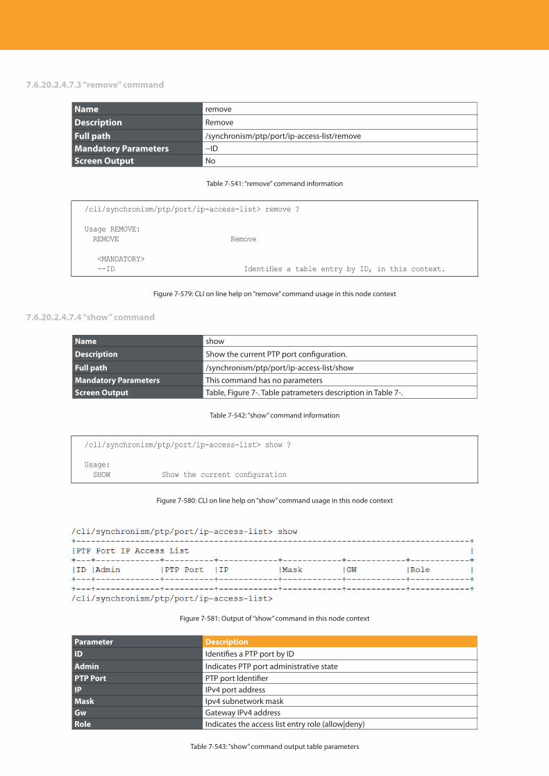
Descripción del producto
454
7.6.20.2.4.7.3 “remove” command
Name remove
Description Remove
Full path /synchronism/ptp/port/ip-access-list/remove
Mandatory Parameters --ID
Screen Output No
Table 7-541: “remove” command information
/cli/synchronism/ptp/port/ip-access-list> remove ?
Usage REMOVE: REMOVE Remove
<MANDATORY> --ID Identifies a table entry by ID, in this context.
Figure 7-579: CLI on line help on “remove” command usage in this node context
7.6.20.2.4.7.4 “show” command
Name show
Description Show the current PTP port configuration.
Full path /synchronism/ptp/port/ip-access-list/show
Mandatory Parameters This command has no parametersScreen Output Table, Figure 7-. Table patrameters description in Table 7-.
Table 7-542: “show” command information
/cli/synchronism/ptp/port/ip-access-list> show ?
Usage: SHOW Show the current configuration
Figure 7-580: CLI on line help on “show” command usage in this node context
Figure 7-581: Output of ”show” command in this node context
Parameter DescriptionID Identifies a PTP port by ID
Admin Indicates PTP port administrative statePTP Port PTP port IdentifierIP IPv4 port addressMask Ipv4 subnetwork maskGw Gateway IPv4 addressRole Indicates the access list entry role (allow|deny)
Table 7-543: “show” command output table parameters
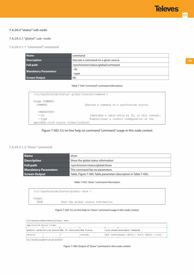
EN
455
7.6.20.3 “status” sub-node
7.6.20.3.1 “global” sub- node
7.6.20.3.1.1 “command” command
Name command
Description Execute a command on a given source.
Full path /synchronism/status/global/command
Mandatory Parameters--ID--type
Screen Output No
Table 7-544: “command” command information
/cli/synchronism/status> global/sources/command ?
Usage COMMAND: COMMAND Execute a command on a synchronism source.
<MANDATORY> --ID Identifies a table entry by ID, in this context. --type Enable/clear a lockout configuration on the specified clock source (clear|lockout)
Figure 7-582: CLI on line help on command “command” usage in this node context
7.6.20.3.1.2 ”show” command
Name show
Description Show the global status information
Full path /synchronism/status/global/show
Mandatory Parameters This command has no parameters.
Screen Output Table, Figure 7-584. Table parameters description in Table 7-456..
Table 7-545: “show” command information
/cli/synchronism/status/global> show ?
Usage: SHOW Show the global status information
Figure 7-583: CLI on line help on “show” command usage in this node context
Figure 7-584: Output of ”show” command in this node context
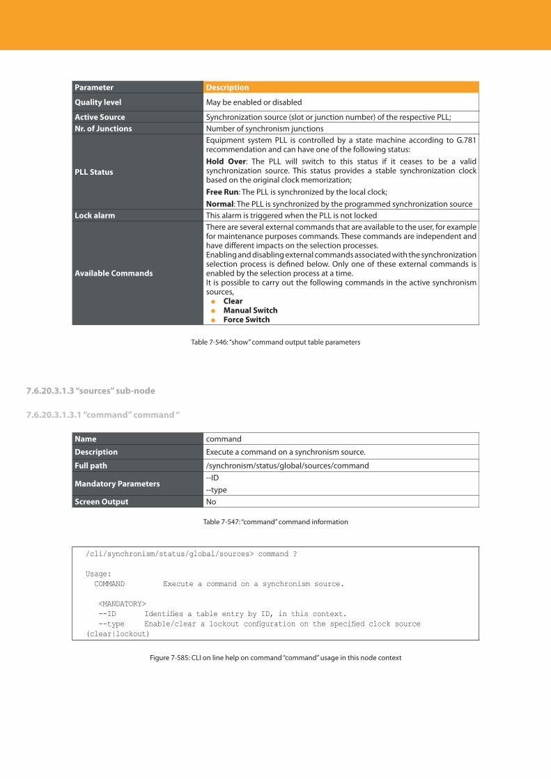
Descripción del producto
456
Parameter Description
Quality level May be enabled or disabled
Active Source Synchronization source (slot or junction number) of the respective PLL;Nr. of Junctions Number of synchronism junctions
PLL Status
Equipment system PLL is controlled by a state machine according to G.781 recommendation and can have one of the following status:Hold Over: The PLL will switch to this status if it ceases to be a valid synchronization source. This status provides a stable synchronization clock based on the original clock memorization;Free Run: The PLL is synchronized by the local clock;Normal: The PLL is synchronized by the programmed synchronization source
Lock alarm This alarm is triggered when the PLL is not locked
Available Commands
There are several external commands that are available to the user, for example for maintenance purposes commands. These commands are independent and have different impacts on the selection processes.Enabling and disabling external commands associated with the synchronization selection process is defined below. Only one of these external commands is enabled by the selection process at a time.It is possible to carry out the following commands in the active synchronism sources, Clear Manual Switch Force Switch
Table 7-546: “show” command output table parameters
7.6.20.3.1.3 “sources” sub-node
7.6.20.3.1.3.1 “command” command “
Name command
Description Execute a command on a synchronism source.
Full path /synchronism/status/global/sources/command
Mandatory Parameters--ID--type
Screen Output No
Table 7-547: “command” command information
/cli/synchronism/status/global/sources> command ?
Usage: COMMAND Execute a command on a synchronism source.
<MANDATORY> --ID Identifies a table entry by ID, in this context. --type Enable/clear a lockout configuration on the specified clock source (clear|lockout)
Figure 7-585: CLI on line help on command “command” usage in this node context
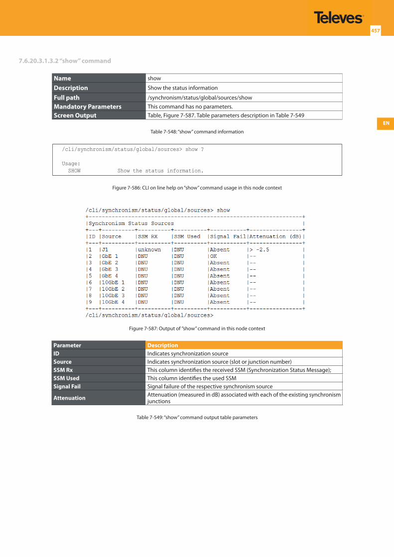
EN
457
7.6.20.3.1.3.2 “show” command
Name show
Description Show the status information
Full path /synchronism/status/global/sources/show
Mandatory Parameters This command has no parameters.
Screen Output Table, Figure 7-587. Table parameters description in Table 7-549
Table 7-548: “show” command information
/cli/synchronism/status/global/sources> show ?
Usage: SHOW Show the status information.
Figure 7-586: CLI on line help on “show” command usage in this node context
Figure 7-587: Output of ”show” command in this node context
Parameter DescriptionID Indicates synchronization sourceSource Indicates synchronization source (slot or junction number)SSM Rx This column identifies the received SSM (Synchronization Status Message);SSM Used This column identifies the used SSMSignal Fail Signal failure of the respective synchronism source
Attenuation Attenuation (measured in dB) associated with each of the existing synchronism junctions
Table 7-549: “show” command output table parameters
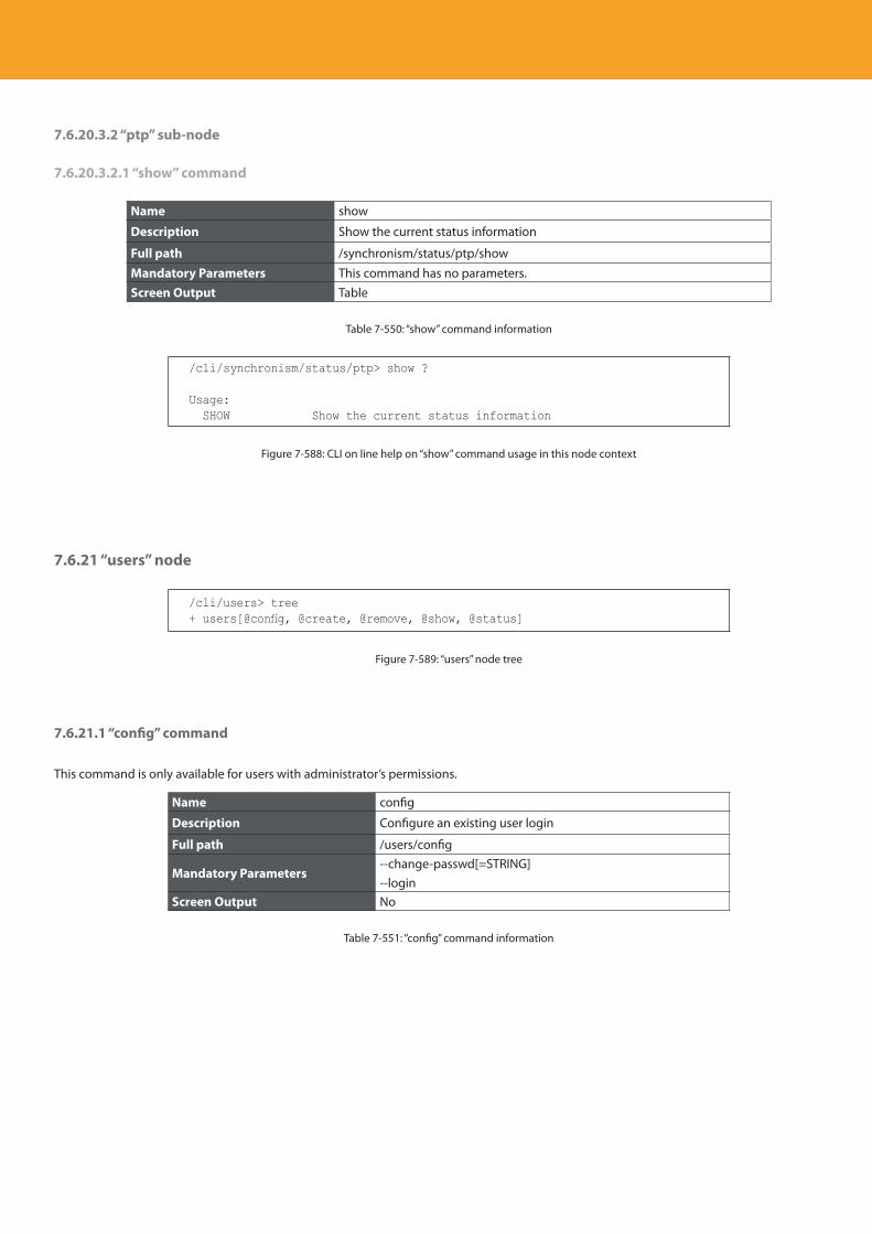
Descripción del producto
458
7.6.20.3.2 “ptp” sub-node
7.6.20.3.2.1 “show” command
Name show
Description Show the current status information
Full path /synchronism/status/ptp/show
Mandatory Parameters This command has no parameters.Screen Output Table
Table 7-550: “show” command information
/cli/synchronism/status/ptp> show ?
Usage: SHOW Show the current status information
Figure 7-588: CLI on line help on “show” command usage in this node context
7.6.21 “users” node
/cli/users> tree+ users[@config, @create, @remove, @show, @status]
Figure 7-589: “users” node tree
7.6.21.1 “config” command
This command is only available for users with administrator’s permissions.
Name config
Description Configure an existing user login
Full path /users/config
Mandatory Parameters--change-passwd[=STRING]--login
Screen Output No
Table 7-551: “config” command information
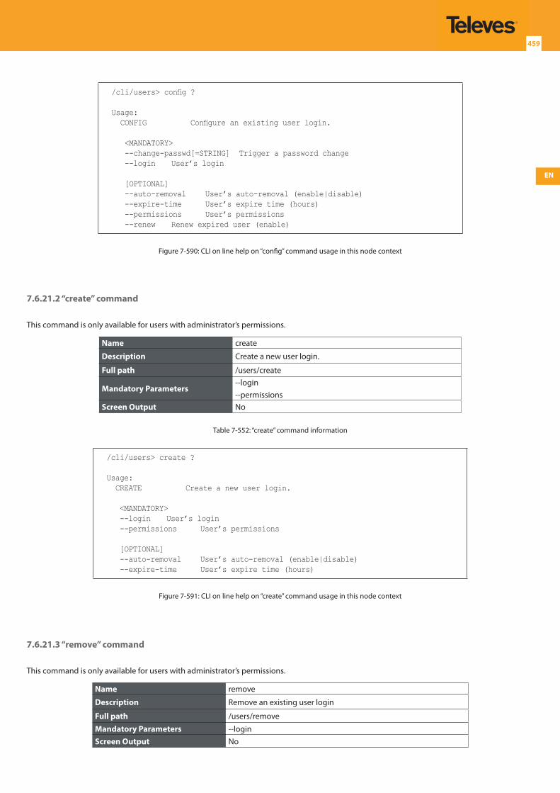
EN
459
/cli/users> config ?
Usage: CONFIG Configure an existing user login.
<MANDATORY> --change-passwd[=STRING] Trigger a password change --login User’s login
[OPTIONAL] --auto-removal User’s auto-removal (enable|disable) --expire-time User’s expire time (hours) --permissions User’s permissions --renew Renew expired user (enable)
Figure 7-590: CLI on line help on “config” command usage in this node context
7.6.21.2 “create” command
This command is only available for users with administrator’s permissions.
Name create
Description Create a new user login.
Full path /users/create
Mandatory Parameters--login--permissions
Screen Output No
Table 7-552: “create” command information
/cli/users> create ?
Usage: CREATE Create a new user login.
<MANDATORY> --login User’s login --permissions User’s permissions
[OPTIONAL] --auto-removal User’s auto-removal (enable|disable) --expire-time User’s expire time (hours)
Figure 7-591: CLI on line help on “create” command usage in this node context
7.6.21.3 “remove” command
This command is only available for users with administrator’s permissions.
Name remove
Description Remove an existing user login
Full path /users/remove
Mandatory Parameters --loginScreen Output No
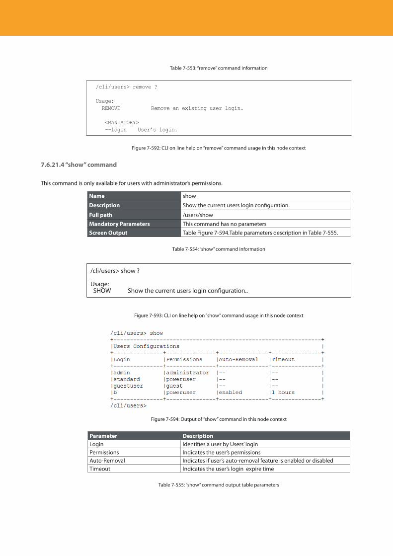
Descripción del producto
460
Table 7-553: “remove” command information
/cli/users> remove ?
Usage: REMOVE Remove an existing user login.
<MANDATORY> --login User’s login.
Figure 7-592: CLI on line help on “remove” command usage in this node context
7.6.21.4 “show” command
This command is only available for users with administrator’s permissions.
Name show
Description Show the current users login configuration.
Full path /users/show
Mandatory Parameters This command has no parametersScreen Output Table Figure 7-594.Table parameters description in Table 7-555.
Table 7-554: “show” command information
/cli/users> show ?
Usage: SHOW Show the current users login configuration..
Figure 7-593: CLI on line help on “show” command usage in this node context
Figure 7-594: Output of ”show” command in this node context
Parameter DescriptionLogin Identifies a user by Users’ loginPermissions Indicates the user’s permissionsAuto-Removal Indicates if user’s auto-removal feature is enabled or disabledTimeout Indicates the user’s login expire time
Table 7-555: “show” command output table parameters
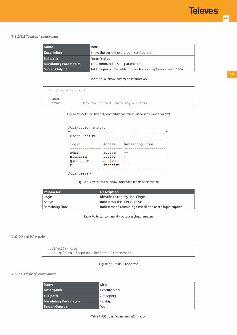
EN
461
Table 7-553: “remove” command information
/cli/users> remove ?
Usage: REMOVE Remove an existing user login.
<MANDATORY> --login User’s login.
Figure 7-592: CLI on line help on “remove” command usage in this node context
7.6.21.4 “show” command
This command is only available for users with administrator’s permissions.
Name show
Description Show the current users login configuration.
Full path /users/show
Mandatory Parameters This command has no parametersScreen Output Table Figure 7-594.Table parameters description in Table 7-555.
Table 7-554: “show” command information
/cli/users> show ?
Usage: SHOW Show the current users login configuration..
Figure 7-593: CLI on line help on “show” command usage in this node context
Figure 7-594: Output of ”show” command in this node context
Parameter DescriptionLogin Identifies a user by Users’ loginPermissions Indicates the user’s permissionsAuto-Removal Indicates if user’s auto-removal feature is enabled or disabledTimeout Indicates the user’s login expire time
Table 7-555: “show” command output table parameters
7.6.21.5 “status” command
Name status
Description Show the current users login configuration.
Full path /users/status
Mandatory Parameters This command has no parametersScreen Output Table Figure 7-596.Table parameters description in Table 7-557.
Table 7-556: “show” command information
/cli/users> status ?
Usage: STATUS Show the current users login status.
Figure 7-595: CLI on line help on “status” command usage in this node context
Figure 7-596: Output of ”show” command in this node context
Parameter DescriptionLogin Identifies a user by Users’ loginActive Indicates if the user is activeRemaining Time Indicates the remaining time till the user’s login expires
Table 7-: Status command – output table parameters
7.6.22 utils” node
/cli/utils> tree+ utils[@ping, @tcpdump, @telnet, @traceroute]
Figure 7-597: “utils” node tree
7.6.22.1 “ping” command
Name ping
Description Execute ping
Full path /utils/ping
Mandatory Parameters --dst-ipScreen Output Yes
Table 7-558: “ping” command information
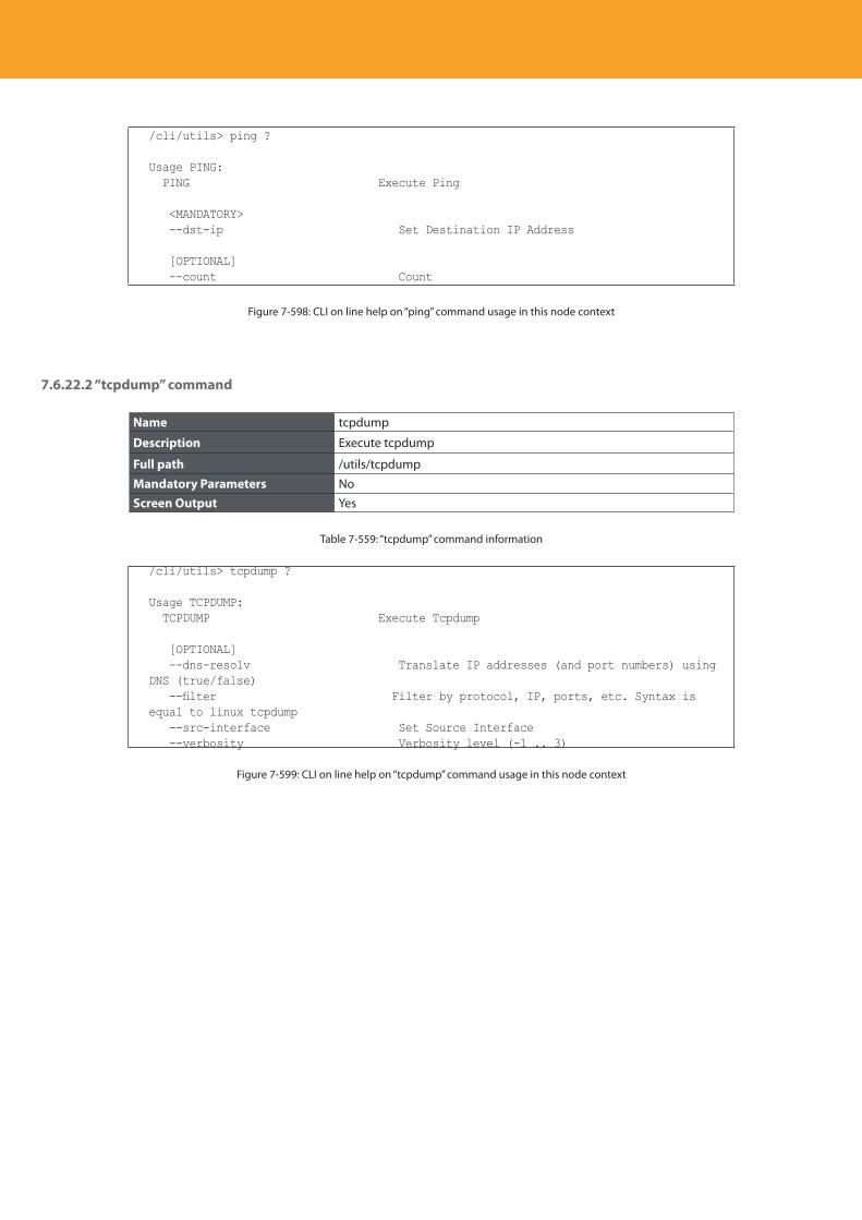
Descripción del producto
462
/cli/utils> ping ?
Usage PING: PING Execute Ping
<MANDATORY> --dst-ip Set Destination IP Address
[OPTIONAL] --count Count
Figure 7-598: CLI on line help on “ping” command usage in this node context
7.6.22.2 “tcpdump” command
Name tcpdump
Description Execute tcpdump
Full path /utils/tcpdump
Mandatory Parameters NoScreen Output Yes
Table 7-559: “tcpdump” command information
/cli/utils> tcpdump ?
Usage TCPDUMP: TCPDUMP Execute Tcpdump
[OPTIONAL] --dns-resolv Translate IP addresses (and port numbers) using DNS (true/false) --filter Filter by protocol, IP, ports, etc. Syntax is equal to linux tcpdump --src-interface Set Source Interface --verbosity Verbosity level (-1 .. 3)
Figure 7-599: CLI on line help on “tcpdump” command usage in this node context
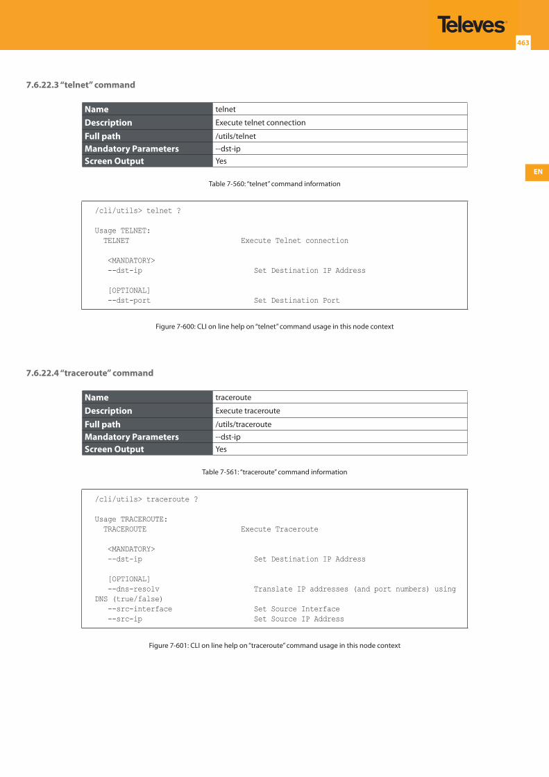
EN
463
7.6.22.3 “telnet” command
Name telnet
Description Execute telnet connection
Full path /utils/telnet
Mandatory Parameters --dst-ip
Screen Output Yes
Table 7-560: “telnet” command information
/cli/utils> telnet ?
Usage TELNET: TELNET Execute Telnet connection
<MANDATORY> --dst-ip Set Destination IP Address
[OPTIONAL] --dst-port Set Destination Port
Figure 7-600: CLI on line help on “telnet” command usage in this node context
7.6.22.4 “traceroute” command
Name traceroute
Description Execute traceroute
Full path /utils/traceroute
Mandatory Parameters --dst-ip
Screen Output Yes
Table 7-561: “traceroute” command information
/cli/utils> traceroute ?
Usage TRACEROUTE: TRACEROUTE Execute Traceroute
<MANDATORY> --dst-ip Set Destination IP Address
[OPTIONAL] --dns-resolv Translate IP addresses (and port numbers) using DNS (true/false) --src-interface Set Source Interface --src-ip Set Source IP Address
Figure 7-601: CLI on line help on “traceroute” command usage in this node context
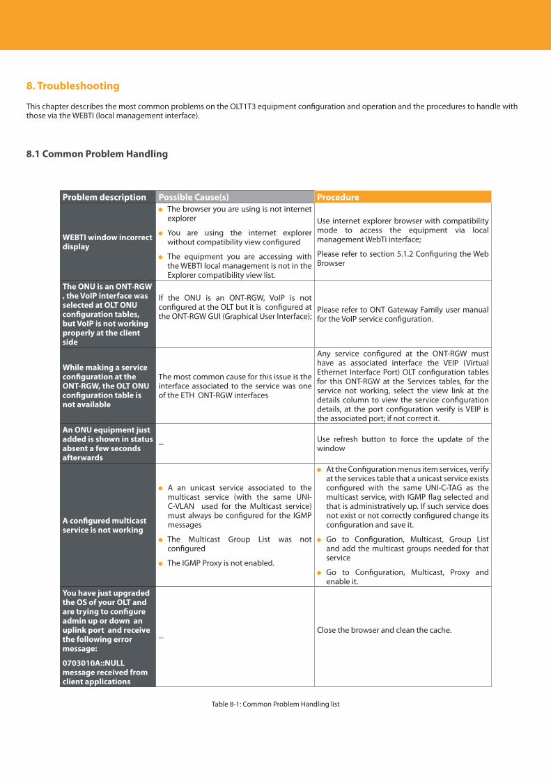
Descripción del producto
464
8. Troubleshooting
This chapter describes the most common problems on the OLT1T3 equipment configuration and operation and the procedures to handle with those via the WEBTI (local management interface).
8.1 Common Problem Handling
Problem description Possible Cause(s) Procedure
WEBTI window incorrect display
The browser you are using is not internet explorer
You are using the internet explorer without compatibility view configured
The equipment you are accessing with the WEBTI local management is not in the Explorer compatibility view list.
Use internet explorer browser with compatibility mode to access the equipment via local management WebTi interface;
Please refer to section 5.1.2 Configuring the Web Browser
The ONU is an ONT-RGW , the VoIP interface was selected at OLT ONU configuration tables, but VoIP is not working properly at the client side
If the ONU is an ONT-RGW, VoIP is not configured at the OLT but it is configured at the ONT-RGW GUI (Graphical User Interface);
Please refer to ONT Gateway Family user manual for the VoIP service configuration.
While making a service configuration at the ONT-RGW, the OLT ONU configuration table is not available
The most common cause for this issue is the interface associated to the service was one of the ETH ONT-RGW interfaces
Any service configured at the ONT-RGW must have as associated interface the VEIP (Virtual Ethernet Interface Port) OLT configuration tables for this ONT-RGW at the Services tables, for the service not working, select the view link at the details column to view the service configuration details, at the port configuration verify is VEIP is the associated port; if not correct it.
An ONU equipment just added is shown in status absent a few seconds afterwards
-- Use refresh button to force the update of the window
A configured multicast service is not working
A an unicast service associated to the multicast service (with the same UNI-C-VLAN used for the Multicast service) must always be configured for the IGMP messages
The Multicast Group List was not configured
The IGMP Proxy is not enabled.
At the Configuration menus item services, verify at the services table that a unicast service exists configured with the same UNI-C-TAG as the multicast service, with IGMP flag selected and that is administratively up. If such service does not exist or not correctly configured change its configuration and save it.
Go to Configuration, Multicast, Group List and add the multicast groups needed for that service
Go to Configuration, Multicast, Proxy and enable it.
You have just upgraded the OS of your OLT and are trying to configure admin up or down an uplink port and receive the following error message:
0703010A::NULL message received from client applications
--Close the browser and clean the cache.
Table 8-1: Common Problem Handling list
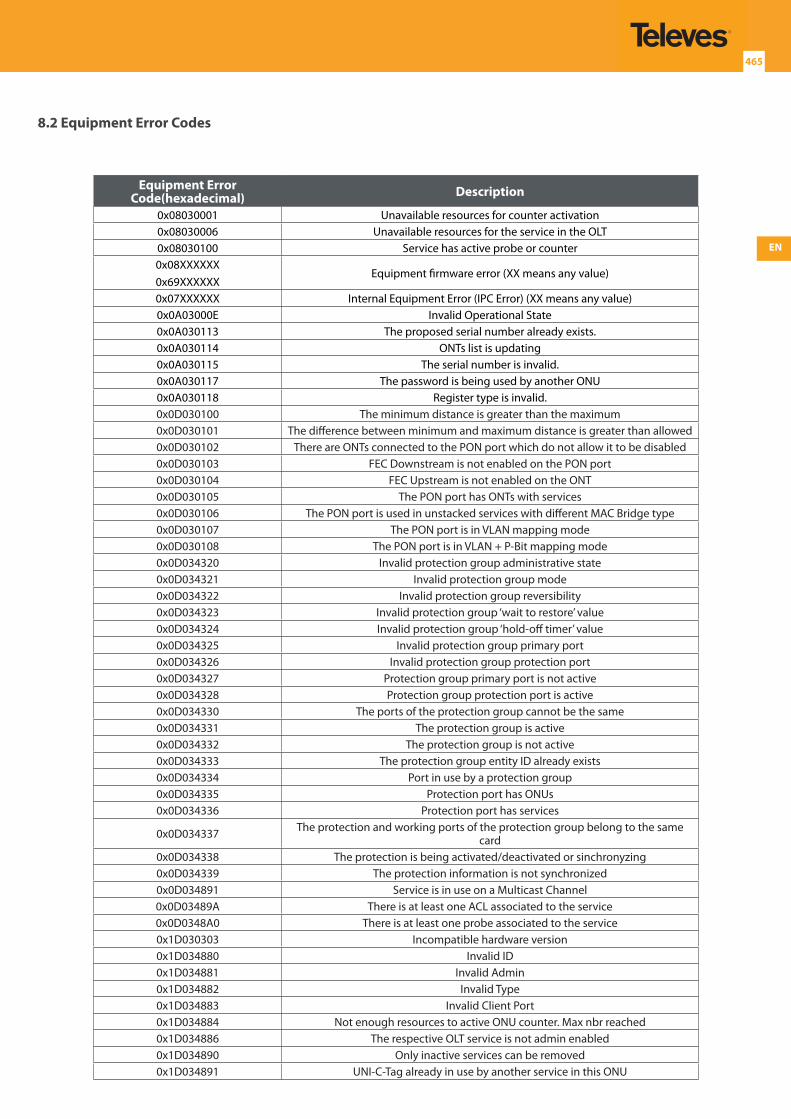
EN
465
8.2 Equipment Error Codes
Equipment Error Code(hexadecimal) Description
0x08030001 Unavailable resources for counter activation0x08030006 Unavailable resources for the service in the OLT0x08030100 Service has active probe or counter0x08XXXXXX0x69XXXXXX
Equipment firmware error (XX means any value)
0x07XXXXXX Internal Equipment Error (IPC Error) (XX means any value)0x0A03000E Invalid Operational State0x0A030113 The proposed serial number already exists.0x0A030114 ONTs list is updating0x0A030115 The serial number is invalid.0x0A030117 The password is being used by another ONU0x0A030118 Register type is invalid.0x0D030100 The minimum distance is greater than the maximum0x0D030101 The difference between minimum and maximum distance is greater than allowed0x0D030102 There are ONTs connected to the PON port which do not allow it to be disabled0x0D030103 FEC Downstream is not enabled on the PON port0x0D030104 FEC Upstream is not enabled on the ONT0x0D030105 The PON port has ONTs with services0x0D030106 The PON port is used in unstacked services with different MAC Bridge type0x0D030107 The PON port is in VLAN mapping mode0x0D030108 The PON port is in VLAN + P-Bit mapping mode0x0D034320 Invalid protection group administrative state0x0D034321 Invalid protection group mode0x0D034322 Invalid protection group reversibility0x0D034323 Invalid protection group ‘wait to restore’ value0x0D034324 Invalid protection group ‘hold-off timer’ value0x0D034325 Invalid protection group primary port0x0D034326 Invalid protection group protection port0x0D034327 Protection group primary port is not active0x0D034328 Protection group protection port is active0x0D034330 The ports of the protection group cannot be the same0x0D034331 The protection group is active0x0D034332 The protection group is not active0x0D034333 The protection group entity ID already exists0x0D034334 Port in use by a protection group0x0D034335 Protection port has ONUs0x0D034336 Protection port has services
0x0D034337 The protection and working ports of the protection group belong to the same card
0x0D034338 The protection is being activated/deactivated or sinchronyzing0x0D034339 The protection information is not synchronized0x0D034891 Service is in use on a Multicast Channel0x0D03489A There is at least one ACL associated to the service0x0D0348A0 There is at least one probe associated to the service0x1D030303 Incompatible hardware version0x1D034880 Invalid ID0x1D034881 Invalid Admin0x1D034882 Invalid Type0x1D034883 Invalid Client Port0x1D034884 Not enough resources to active ONU counter. Max nbr reached0x1D034886 The respective OLT service is not admin enabled0x1D034890 Only inactive services can be removed0x1D034891 UNI-C-Tag already in use by another service in this ONU
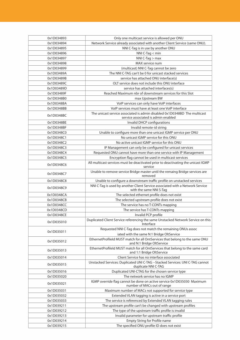
Descripción del producto
466
0x1D034893 Only one multicast service is allowed per ONU0x1D034894 Network Service already associated with another Client Service (same ONU).0x1D034895 NNI C-Tag is in use by another ONU0x1D034896 NNI C-Tag < min0x1D034897 NNI C-Tag > max0x1D034898 MAX service num0x1D034899 (multicast) NNI C-Tag cannot be zero0x1D03489A The NNI C-TAG can’t be 0 for unicast stacked services0x1D03489B service has attached ONU interface(s)0x1D03489C OLT service does not include this ONU interface0x1D03489D service has attached interfaces(s)0x1D03489F Reached Maximum nbr of downstream services for this Slot0x1D0348B0 max Upstream BW0x1D0348BA VoIP services can only have VoIP interfaces0x1D0348BB VoIP services must have at least one VoIP interface
0x1D0348BC The unicast service associated is admin disabled 0x1D0348BD The multicast service associated is admin enabled
0x1D0348BE Invalid DHCP configurations0x1D0348BF Invalid remote-id string0x1D0348C0 Unable to configure more than one unicast IGMP service per ONU0x1D0348C1 No unicast IGMP service for this ONU0x1D0348C2 No active unicast IGMP service for this ONU0x1D0348C3 IP Management can only be configured for unicast services0x1D0348C4 Requested ONU cannot have more than one service with IP Management0x1D0348C5 Encryption flag cannot be used in multicast services
0x1D0348C6 All multicast services must be deactivated prior to deactivating the unicast IGMP service
0x1D0348C7 Unable to remove service Bridge master until the remaing Bridge services are removed
0x1D0348C8 Unable to configure a downstream traffic profile on unstacked services
0x1D0348C9 NNI C-Tag is used by another Client Service associated with a Network Service with the same NNI S-Tag
0x1D0348CA The selected ethernet profile does not exist0x1D0348CB The selected upstream profile does not exist0x1D0348CC The service has no T-CONTs mapping0x1D0348CD The service has T-CONTs mapping0x1D0348CE Invalid PCP profile
0x1D035010 Duplicated Client Service referencing the same Unstacked Network Service on this Interface
0x1D035011Requested NNI C-Tag does not match the remaining ONUs assoc
iated with the same N:1 Bridge OltService
0x1D035012 EthernetProfileId MUST match for all OntServices that belong to the same ONU and N:1 Bridge OltService
0x1D035013 EthernetProfileId MUST match for all OntServices that belong to the same card and 1:1 Bridge OltService
0x1D035014 Client Service has no interface associated
0x1D035015 Unstacked Services: Duplicated UNI C-TAG --Stacked Services: UNI C-TAG cannot duplicate NNI C-TAG
0x1D035016 Duplicated UNI-CTAG for the chosen service type0x1D035020 The network service has no IGMP
0x1D035021 IGMP override flag cannot be done on active service 0x1D035030 Maximum number of MACs out of range
0x1D035031 Maximum number of MACs not supported for service type0x1D035032 Extended VLAN tagging is active in a service port0x1D035033 The service is referenced by Extended VLAN tagging rules0x1D039211 The upstream profile can’t be changed with upstream profiles0x1D039212 The type of the upstream traffic profile is invalid0x1D039213 Invalid parameter for upstream traffic profile0x1D039214 Empty String for Profile name0x1D039215 The specified ONU profile ID does not exist

EN
467
0x1D039216 The specified ONU profile ID is not ADMIN Enabled0x1D039230 Invalid T-CONT admin state0x1D039231 Invalid upstream profile0x1D039240 The T-CONT is active0x1D039241 The internal ALLOC ID pool is exhausted0x1D039242 The T-CONT is being used by a service0x1D039250 Invalid T-CONT ID0x1D039251 Invalid client service ID for T-CONT mapping0x1D039252 Invalid priority for T-CONT mapping0x1D039260 The specified priority does not exist on the P-Bit profile of the PON0x1D039261 The Service has an upstream profile0x1D039262 Invalid T-CONT admin state0x1D03A400 Invalid rule admin state0x1D03A401 Invalid outer priority filter0x1D03A402 Invalid inner priority filter0x1D03A403 Invalid inner VID filter0x1D03A404 Invalid outer VID filter0x1D03A405 Invalid inner TPID filter0x1D03A406 Invalid outer TPID filter0x1D03A407 Invalid ethertype filter0x1D03A408 Invalid number of tags to remove0x1D03A409 Invalid inner priority action0x1D03A40A Invalid outer priority action0x1D03A40B Invalid inner VID action0x1D03A40C Invalid outer VID action0x1D03A40D Invalid inner TPID action0x1D03A40E Invalid outer TPID action0x1D03A40F Invalid client service0x1D03A410 The rule is active0x1D03A411 Duplicate filter0x1D03A420 Invalid enable value0x1D03A421 Invalid association type0x1D03A422 Invalid associated entity ID0x1D03A423 Invalid input TPID0x1D03A424 Invalid output TPID0x1D03A425 Invalid DSCP to P-Bit mapping profile0x1D03A430 The port has services
0x1E034893 For unicast/multicat services the pair service type/uni-vlan has to be unique in the OLT
0x1E0348DD Stacked services can only have one uplink port0x1E034901 UNI C-Tag already in use in the NNI S-Tag of a non-multicast network service
0x1E034902 UNI C-Tag já em uso na NNI S-Tag dum serviço de rede multicastUNI C-Tag already in use in the NNI S-Tag of a multicast network service
0x1E039213 Invalid parameters in the configuration Upstream profile0x21030300 Static groups end point value not valid
0x21030301 Cannot change static group end point - there is at least one static active group list entry.
0x50034896 Only 32 bits mask is allowed in static groups0x5D030101 Invalid Downlink interface
0x5D030102 Multicast service interface is not mapped in any of the associated unicast services interfaces
0x5D030103 Unicast service interface is a member of a UC/MC association0x5D030104 Invalid interface Role0x5D030105 Invalid Admin State0x5D030106 Invalid uplink interface0x5D030107 Invalid downlink interface0x5D030108 Interface and NNI S-TAG already used in synchronism0x5D034850 The service must contain at least one uplink interface0x5D034850 The service must contain at least one uplink interface

Descripción del producto
468
0x5D034851 The service must contain at least two interfaces (uplink+downlink)0x5D034852 Stacked services cannot have multiple uplink interfaces
0x5D034853 Unable add this interface because an active PTP entry with the same NNI S-TAG already exists
0x5D034854 Selected port belongs to an invalid card for this service type0x5D034854 Selected port belongs to an invalid card for this service type0x5D034860 Stacked services for this service type, must contain only one uplink port0x5D034861 Selected port belongs to a Static Probe0x54030103 There is already an entry with the same service/mac0x5A030103 Invalid IP address for active probe0x60030104 Unknown parameter in the circuit ID string0x65030101 Invalid ACL id0x65030102 Invalid ACL administrative state0x65030103 Invalid ACL type0x65030104 ACL is used on a rule0x65030105 ACL is used on an interface0x65030106 ACL is used on a service0x65030107 Invalid ACL rule administrative state0x65030108 Invalid ACL rule action0x65030109 Invalid ACL rule ethernet type0x65030110 Invalid ACL rule CoS0x65030111 Invalid ACL rule IP protocol0x65030112 Invalid ACL rule port0x65030113 Invalid ACL rule DSCP0x65030114 Invalid ACL rule precedence0x65030115 Invalid ACL rule flow label0x65030116 Maximum number of rules per ACL reached0x65030117 Cannot remove/disable the last rule for an ACL with enabled associations0x65030118 ACL interface association: invalid administrative state0x65030119 ACL interface association: invalid direction0x65030120 ACL interface association: invalid interface id0x65030121 ACL interface association: invalid ACL id0x65030122 ACL interface association: invalid interface id0x65030123 ACL interface association: invalid ACL id0x65030124 ACL service association: invalid administrative state0x65030125 ACL service association: invalid direction0x65030126 ACL service association: invalid ACL id0x65030127 ACL service association: invalid network service id0x65030128 ACL service association: service is not active0x66030101 Invalid Interface for IP Source Guard0x66030102 Invalid Admin State0x66030103 Invalid IP Version0x66030104 The associated Network Service must be enabled0x66030105 Unknown Network Service.0x66030106 Cannot change admin enabled entities0x66030107 Interface must be active0x66030108 Interface must be IP Source Guard Enabled (interface configuration)0x66030109 Interface must belong the NS downlink port list0x6603010A Interface must belong the NS downlink card list.0x6603010B MAC cannot be full zeros
Table 8-2: Equipment Error Codes List
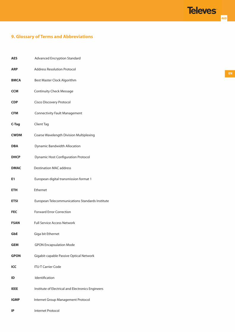
EN
469
9. Glossary of Terms and Abbreviations
AES Advanced Encryption Standard
ARP Address Resolution Protocol
BMCA Best Master Clock Algorithm
CCM Continuity Check Message
CDP Cisco Discovery Protocol
CFM Connectivity Fault Management
C-Tag Client Tag
CWDM Coarse Wavelength Division Multiplexing
DBA Dynamic Bandwidth Allocation
DHCP Dynamic Host Configuration Protocol
DMAC Destination MAC address
E1 European digital transmission format 1
ETH Ethernet
ETSI European Telecommunications Standards Institute
FEC Forward Error Correction
FSAN Full Service Access Network
GbE Giga bit Ethernet
GEM GPON Encapsulation Mode
GPON Gigabit-capable Passive Optical Network
ICC ITU-T Carrier Code
ID Identification
IEEE Institute of Electrical and Electronics Engineers
IGMP Internet Group Management Protocol
IP Internet Protocol

Descripción del producto
470
IPTV Internet Protocol Television
L2 Layer 2 - Data Link Layer
LACP Link Aggregation Control Protocol
LACPDU Link Aggregation Control Protocol Data Unit
LAG Link Aggregation Group
LC/PC LC/PC Fiber Optic Connector
MAC Media Access Control
MAID Maintenance Association Identifier. An identifier for a Maintenance Association, unique over the OAM domain. The MAID has two parts: the MD Name and the Short MA Name. A MAID is equivalent to the ITUs term MEG ID.
MD Maintenance Domain. The part of a network for which faults in connectivity can be managed.
ME Maintenance Entity. A point-to-point relationship between two MEPs within a single MEG.
MEG Maintenance Entity Group. Equivalent to a Maintenance Association (MA). A set of MEs that exist in the same administrative boundary, with the same MEG Level and MEG ID.
MEG ID Maintenance Entity Group Identifier. Equivalent to the IEEE term Maintenance Association Identifier (MAID). An identifier for a MEG, unique over the domain that SOAM is to protect against the accidental concatenation of service instances.
MEP Maintenance association End Point [IEEE 802.1ag], or equivalently MEG End Point [ITU-T Y.1731]. An actively managed SOAM entity associated with a specific service instance that can generate and receive SOAM PDUs and track any responses. It is an end point of a single MEG, and is an endpoint of a separate Maintenance Entity for each of the other MEPs in the same MEG.
MSA Multi Source Agreement
MTU Maximum Transmission Unit
ODN Optical Distribution Network
OLT Optical Line Terminal
OMCI ONT Management Control Interface
ONT Optical Network Terminal
ONU Optical Network Unit
OSPF Open Shortest Path First adaptive routing protocol
PON Passive Optical Network
PDU Protocol Data Unit
PDV Packet Delay Variation

EN
471
QoS Quality of Service
RF Radio Frequency
RG Residential Gateway
RIP Routing Information Protocol
RMEP Remote MEP
NG-PON Next Generation Passive Optical Network
SC/APC SC/APC Fiber Optic Connector
SC/PC SC/PC Fiber Optic Connector
SDH Synchronous Digital Hierarchy
SFP Small Form-factor Pluggable transceiver
PDU PDU Protocol Data Unit
PDV Packet Delay Variation
QoS Quality of Service
RF Radio Frequency
RG Residential Gateway
RIP Routing Information Protocol
RMEP Remote MEP
NG-PON Next Generation Passive Optical Network
SC/APC SC/APC Fiber Optic Connector
SC/PC SC/PC Fiber Optic Connector
SDH Synchronous Digital Hierarchy
SFP Small Form-factor Pluggable transceiver
SONET Synchronous Optical Networking
S-Tag Service Tag
STP Spanning Tree Protocol
TLS Transparent LAN Services

Descripción del producto
472
T-CONT Traffic Container
TWDM Time domain and Wavelength Division Multiplexing
UMC Unique MEG-ID code
USB Universal Serial Bus
UTP Unshielded Twisted Pair
VLAN Virtual Local Area Network
VoIP Voice over Internet Protocol
SFP+ 10 Gigabit Small Form Factor Pluggable transceiver
XGPON Extra Large Gigabit Passive Optical Network

EN
473


EN
477

Descripción del producto
478

EN
479

Descripción del producto
480

EN
481

Descripción del producto
482