RECHERCHE RESEARCH 2009 / 2011 - CiteSeerX
130
RECHERCHE RESEARCH 2009 / 2011
-
Upload
khangminh22 -
Category
Documents
-
view
1 -
download
0
Transcript of RECHERCHE RESEARCH 2009 / 2011 - CiteSeerX

RECHERCHERESEARCH2009 / 2011
Rech
erch
e R
esea
rch
200
9/20
11Fi
de
lis
Campus de Gif-sur-YvettePlateau de Moulon3 rue Joliot-CurieTél. : + 33 (0)1 69 85 12 12Fax : + 33 (0)1 69 85 12 34
Campus de MetzMetz Technopôle2 rue Edouard Belin57070 MetzTél. : + 33 (0)3 87 76 47 47Fax : + 33 (0)3 87 76 47 00
Campus de RennesAvenue de la BoulaieCS 4760135576 Cesson Sévigné CedexTél. : + 33 (0)2 99 84 45 00Fax : + 33 (0)2 99 84 45 99
Fid
elis
01
69
41 4
1 41
Une seule école sur trois campus organisés en réseau
Créée en 1894, Supélec se développe aujourd’hui dans la région parisienne à Gif-sur-Yvette (depuis 1975), en Lorraine à Metz (depuis 1985), en Bretagne à Rennes (depuis 1972).
Supélec participe aux pôles de compétitivité System@tic, Mov’eo et AsTech en Île-de-France, Images & Réseaux en Bretagne, Matéralia en Lorraine. Supélec est membre de deux réseaux Thématiques de Recherche Avancée (RTRA) : Digiteo et Triangle de la Physique.
En 2007, Supélec et Centrale Paris ont créé l’Institut Carnot C3S “Centrale-Supélec Sciences des Systèmes” (voir la présentation). Leur parte-nariat s’est transformé en novembre 2008 en une alliance stratégique. Désormais tous les grands projets sont examinés ensemble et chaque projet commun est l’occasion d’un rapprochement des deux structures.
A single institution located on three networked campuses
Founded in 1894, Supélec today operates on three campuses: the Paris region in Gif-sur-Yvette (since 1975), Lorraine in Metz (since 1985), Brittany in Rennes (since 1972).
Supélec participates in the following competiti-veness clusters: System@tic, Mov’eo and AsTech in the Ile-de-France region, Media & Networks in Brittany, Materalia in Lorraine. Supélec is a mem-ber of two Thematic Advanced Networks (RTRA): Digiteo and Triangle de la Physique.
In 2007, Supélec and Centrale Paris have created the “Carnot Institute” C3S “Centrale-Supélec Sciences des Systèmes” (see inside). They extended their partnership to a strategic alliance in November 2008. The schools work jointly on major projects, each serving to bring the two schools closer together.
www.supelec.fr

1
RECHERCHERESEARCH
2009-2011
Numéro 6
P1 à 15:P1 à 15.qxd 26/10/09 14:09 Page2

2
P1 à 15:P1 à 15.qxd 26/10/09 14:09 Page3

3Recherche Research 2009 / 2011
De plus en plus l’information, l’énergie et les systèmes sont au cœur desavancées de la connaissance et sont essentiels à la diffusion du progrès.
Dans un contexte scientifique et technologique qui évolue significative-ment, ne serait-ce que sous l’effet de la mondialisation, Supélec veut affir-mer sa volonté d’être au rendez-vous d’un triple défi :
• d’abord le défi d’une relation de plus en plus féconde entre enseigne-ment, recherche et innovation ;
• ensuite le défi d’une capacité toujours plus grande de création etd’échange de connaissances avec les groupes industriels, les sociétés desservices et les PME ;
• enfin le défi d’une science des systèmes de plus en plus avancée en termed’analyse, de modélisation et de simulation du risque et de l’incertain.
Tous ces défis, Supélec ne compte pas les relever seule :
• l’Institut Carnot C3S (Centrale Supélec Sciences des Systèmes) est en lamatière le vecteur stratégique de l’Alliance Centrale Paris – Supélec ;
• le développement de coopérations fortes avec nos partenaires acadé-miques et industriels sur les trois campus de Gif-sur-Yvette, de Metz et deRennes est également un élément clé des années à venir : coopérationsmultilatérales au sein des pôles de compétitivité et des réseaux théma-tiques de recherche avancée, coopérations bilatérales notamment vianotre Partenariat pour l’Enseignement et la Recherche en Coopérationavec l’Industrie et les Services (PERCI&S).
Puisse cette édition 2009-2011 de notre Revue Recherche illustrer cettedémarche et convaincre de sa pertinence !
Information, energy and systems lie at the heart of recent advancements inhuman knowledge. They are also essential for promoting and spreadingprogress.
Today’s scientific and technological world is changing at an extraordinari-ly fast pace, thanks to the impetus of globalization. In this respect, Supélecwishes to express its firm commitment to meeting a triple challenge:
• first, the challenge of managing a very rich relationship between highereducation, research and innovation;
• second, the challenge of finding creative ways to exchange this wealth ofknowledge with industrial groups, service companies and SMEs;
• third, the challenge of fostering an increasingly advanced science of systems in terms of analysis, modeling and simulation of risk and uncer-tainty.
Yet Supélec does not intend to face up to these challenges alone:
• the Institut Carnot C3S (Centrale Supélec Sciences des Systèmes), forexample, remains the strategic vector of the Centrale-Paris / SupélecAlliance;
• the development of strong ties with our academic and industrial partnersat the three main campuses of Gif-sur-Yvette, Metz and Rennes will also bea key factor in the coming years, namely thanks to: multilateral cooperationwithin the competitive clusters and thematic networks of advanced research; as well as bilateral cooperation via our well-known Partnershipfor Teaching and Research in Cooperation with Industry and Services(PERCI&S).
May this edition of our Research Review 2009-2011 continue to illustratethe unique features of our strategy and convince everyone of its relevance!
.....................................................................................................................................................................................................................................
ÉditorialEditorial
.....................................................................................................................................................................................................................................
Alain BravoDirecteur Général de Supélec
Alain BravoDirecteur Général de Supélec
Alain BravoDirector General
P1 à 15:P1 à 15.qxd 29/10/09 11:57 Page4

4
P1 à 15:P1 à 15.qxd 26/10/09 14:09 Page5

5Recherche Research 2009 / 2011
.....................................................................................................................................................................................................................................
La recherche à SupélecResearch at Supélec
.....................................................................................................................................................................................................................................
Jacques OksmanDirecteur de la Rechercheet des Relations Industriellesde Supélec
Supélec est une institution de statut privé (association) mais négocie avecl’État un Contrat Quadriennal. À ce titre, elle doit non seulement se com-parer à la recherche publique, dont la priorité est la production acadé-mique et qui est évaluée par l’AERES (Agence d’Évaluation de laRecherche et de l’Enseignement Supérieur) mais aussi à la recherche enentreprise, puisque son Contrat Quadriennal lui demande de se procurer50% de son budget (réel, donc incluant les salaires) sous forme de res-sources propres (les revenus de la recherche forment la moitié de celles-ci). Il s’agit là d’un double défi que Supélec relève par sa volonté d’accroîtreson ancrage dans le système français d’enseignement supérieur et derecherche tout en assurant la croissance durable de son modèle d’écono-mie mixte. La recherche a donc des positionnements sociétaux et scienti-fiques correspondant à ces défis et cohérents avec la formation des ingé-nieurs Supélec.
Positionnement sociétalSupélec veut assurer une continuité totale entre recherches amont etrecherches partenariales (qui interagissent avec le monde socio-économique). En effet, les recherches amont seules ne servent pas directe-ment la société, les recherches partenariales seules ne permettent pas depréparer l’avenir. Pour générer des idées nouvelles, le chercheur d’uneécole d’ingénieurs doit connaître les tendances et les besoins de la société.Afin d’assurer cette continuité, Supélec (avec Centrale Paris), bénéficie dudispositif Carnot, au sein de l’Institut C3S « Centrale-Supélec Sciences desSystèmes » qui permet d’aider la recherche amont grâce à l’abondementpar l’État du volume des contrats de recherche partenariale.
Supélec is an institution having a private (or association) status. However,it is entitled to negotiate a 4-year contract with the French government.Consequently, Supélec must live up to the high standards of State-fundedresearch, whose priority is academics and thus routinely evaluated byAERES (Agence d’Evaluation de la Recherche et de l’EnseignementSuperieur – Higher Education Research Evaluation Board). It must alsopromote company-sponsored research, since one of the terms of this 4-yearcontract requires that Supélec self-finance 50% of its budget (current bud-get, that is including salaries - revenues generated from research cover upto half of these funds). Indeed, this represents a double challenge thatSupélec intends to meet thanks to a firm desire to deepen its roots withinthe French higher learning system while ensuring the sustainable growthof a mixed economy model.Therefore, to meet these challenges and remain consistent with the educa-tion and training of Supélec engineers, research has to play a societal aswell as scientific role.
Societal roleSupélec wishes to assure optimal continuity between long-term researchand ensuing research partnerships (which interact with the socio-economicworld). In fact, long-term research alone does not directly serve society, justas research partnerships alone do not enable us to prepare well for the futu-re. To promote new ideas, researchers of Engineering Schools must be fami-liar with both the needs and trends of society. To ensure continuity, Supélec(together with Centrale Paris) is supported by the Carnot system, otherwi-se known as Institut C3S or « Centrale-Supélec Sciences des Systèmes »,whereby long-term research is funded thanks to State contributions intoresearch partnerships.
P1 à 15:P1 à 15.qxd 26/10/09 14:09 Page6

6
Positionnement scientifiqueLa recherche pratiquée dans une École d’ingénieurs se doit de mettre l’ac-cent sur les couplages forts entre enseignement et recherche d’une part,disciplines abstraites et applications d’autre part.Ce sont ces disciplines abstraites (les « sciences des systèmes ») qui sontau cœur de la stratégie scientifique de Supélec. On considère ici lessciences des systèmes comme l’ensemble des disciplines qui permettentd’analyser, concevoir et donc modéliser des systèmes multi-technologiques,multi-physiques, multi-échelles,… s’appuyant sur le socle des technologiesde l’information et de l’énergie (figure).
Scientific roleResearch conducted in an Engineering School strives to place the accent onstrong ties between education and research, on one hand, and the link bet-ween abstract fields and applications on the other.
These abstract fields (for ex. Systems Sciences) lie at the very heart ofSupélec’s scientific strategy.
In fact, Systems Sciences are considered the body of knowledge that allowsanyone to analyze, design and even carry out modeling of multi-technolo-gical, multi-physical, and multi-scale systems using information- andenergy-based technologies (see figure below).
Les « grands domaines » Comme souvent, la présentation des activités de recherche se heurte audilemme suivant : comment présenter à la fois une volonté de transdisci-plinarité (les Sciences des Systèmes) sans trahir les spécialistes et leursdisciplines propres ? Supélec n’échappe pas à ce dilemme. Aussi, cetteRevue sera organisée selon les sept grands domaines de la figure suivan-te. Ces domaines sont fortement reliés, les Sciences des Systèmes étant aucœur de leurs interactions.
Major fields of studyVery often the presentation of research activities is stifled by the followingdilemma: how does one present at the same time a cross-disciplinaryapproach (ex. Systems Sciences) without betraying the specialists and theirspecific fields of activity? Supélec cannot really circumvent this dilemmaeither. Nevertheless, this Review will try to organize things into seven majorfields of study (see figure below) closely linked to Systems Sciences sincethey are at the center of all interactions.
P1 à 15:P1 à 15.qxd 26/10/09 14:09 Page7

7Recherche Research 2009 / 2011
465 personnels de recherche• 215 personnels permanents de recherche
- 130 enseignants-chercheurs de Supélec- 30 chercheurs CNRS - 55 universitaires
• 250 doctorants
Production scientifique et technologique(par an)• 725 publications ou communications majeures• 17 brevets
Partenariats entreprises et organismes (par an)• 320 actions actives• 122 entreprises ou organismes partenaires • 8,6 M € de revenus de la Recherche
Pour toute question à caractère généralDirection de la Rechercheet des Relations Industrielles (D2RI)http://www.supelec.fr/d2ri Tél : +33 (01) 69 85 12 52
.....................................................................................................................................................................................................................................
Chiffres clésKey figures
.....................................................................................................................................................................................................................................
.....................................................................................................................................................................................................................................
A qui s’adresser ?Who to contact?
.....................................................................................................................................................................................................................................
For further information, please contact:Research and Industry Partnerships
465 Research staff• 215 Permanent research staff
- 130 Supélec faculty members- 30 CNRS researchers- 55 University faculty members
• 250 Ph.D. students
Scientific and technological output (per year)• 725 journal papers or major publications• 17 patents
Partnerships with companies or organizations(per year)• 320 ongoing projects• 122 partner companies or organizations• 8.6 M€ research income
Jacques OKSMAN, Directeur de la Recherche et des Relations IndustriellesTél. : +33 (0) 1 69 85 12 51 E-mail : [email protected]
Jean-Michel LE ROUX, Adjoint au Directeur de la Recherche et des Relations Industrielles,chargé de la valorisation et de l’innovation, Directeur Exécutif de l’Institut Carnot C3STél. : +33 (0) 1 69 85 12 55 E-mail : [email protected]
Bich-Liên DOAN, Adjointe au Directeur de la Recherche et des Relations IndustriellesTél. : +33 (0) 1 69 85 12 56 E-mail : [email protected]
Joël JACQUET, Délégué à la Recherche et aux Relations Industrielles, Campus de MetzTél. : +33 (0) 3 87 76 47 68 E-mail : [email protected]
Bernard JOUGA, Délégué à la Recherche et aux Relations Industrielles, Campus de RennesTél. : +33 (0) 2 99 84 45 28 E-mail : [email protected]
Pour toute information sur un thème s’adresser aux correspondants désignés sur chaque fiche thématique
For information on research,topics or examples, please contact:The main authors specified in each report.
P1 à 15:P1 à 15.qxd 26/10/09 14:09 Page8

8
P1 à 15:P1 à 15.qxd 26/10/09 14:09 Page9

9Recherche Research 2009 / 2011
SOMMAIRE GÉNÉRALGENERAL CONTENTS
Institut Carnot C3S « Centrale Supélec Sciences des Systèmes »......................10Carnot Institute C3S « Centrale Supelec Systems Sciences »
Études doctorales......................11PhD program
Domaines......................12Areas
1. Automatique.....15Control
2. Signaux et Statistiques.....29Signals and Statistics
3. Informatique et Réseaux.....41Computer Science and Networks
4. Télécommunications.....57Telecommunications
5. Électromagnétisme.....73Electromagnetics
6. Microélectronique et Photonique.....89Microelectronics and Photonics
7. Énergie.....107Energy
Mots-clés......................122Keywords
P1 à 15:P1 à 15.qxd 29/10/09 11:58 Page10

Les recherches scientifiques et techniques de Centrale Paris et de Supélecsont intégrées et bénéficient du label « Institut Carnot ». Rappelons qu’unInstitut Carnot a pour vocation de proposer à la société, en particulier auxentreprises, des compétences de recherche pérennes. Pour cela, il prend undouble engagement : celui de la qualité de la recherche « partenariale »(recherche effectuée en relation avec les entreprises, dans un cadrecontractuel) et celui de préparer aujourd’hui les compétences scientifiquesqui seront dans quelques années utiles à la société (« ressourcement scien-tifique »). L’État crée un cercle vertueux en abondant le volume descontrats de recherche partenariale des Instituts Carnot afin de leur per-mettre de financer ce ressourcement. Il s’agit donc pour Supélec, commepour Centrale, d’un outil idéal pour assurer le « continuum entrerecherche amont et recherche partenariale » déjà évoqué.
L'Institut C3S est l’un des acteurs majeurs de la Science des Systèmess'appuyant sur le socle technologique : Information, Communications,Énergie, Procédés. L'activité de C3S se place à la convergence des techno-logies dans un but d'innovation et de partenariat de recherche avec lemonde socio-économique.Ses compétences assurent à l'Institut une présence sur de nombreux mar-chés : du spatial aux services, en passant par les transports, les télécom-munications, la santé, l'économie et les finances.
Scientific and technical research is carried out jointly between CentraleParis and Supélec, which allows both institutions to benefit from the« Institut Carnot » label. Let us recall that the vocation of an InstitutCarnot is to generate know-how, in particular for companies but also forsociety, based on sustainable research. To this end, its commitment is two-fold: first, forging high-quality research partnerships (i.e joint researchprojects with companies based on special contracts); second, focusing todayon preparing the scientific know-how that will be useful to society in thefuture (scientific renewal). The French government creates a virtuous cycleby contributing funds to the research contracts of Institut Carnot, thusenabling them to finance their sourcing needs. For Supélec as well asCentrale Paris, this is the ideal way to ensure continuity between long-termresearch and ensuing research partnerships.
The C3S Institute is one of the major players in the field of SystemsSciences (i.e. multi-application sciences) and it is closely interconnectedwith such technologies as Information, Communications, Energy andProcesses. The aim of C3S is to provide industry and service companiesalike with highly accurate and innovative solutions. Thanks to its vastknow-how, the Institute’s presence covers a wide range of markets, namelyspace, transportation, telecommunications, services, healthcare, economyand finance.
Technologies de baseCommunications : communications mobiles : théorie, traitements, tech-niques d’accès multiples (MCCDMA, OFDMA), modulation et codageadaptatifs, MIMO, estimation de canal…, radio logicielle/cognitive, codageconjoint source/canal ; composants et systèmes optoélectroniques et micro-ondes; CEM, mesures de rayonnement, matériaux innovants, systèmesrayonnants complexes, dosimétrie électromagnétique, inversion des ondes ; antennes et traitements associés ; méthodes de conception de cir-cuits mixtes et de microsystèmes ; circuits de numérisation ; systèmesenfouis.Énergie : optimisation de moteurs, combustion, actionneurs électriques ;réseaux électriques, modélisation électromagnétique, couplages multiphy-siques ; fiabilité des dispositifs et composants ; matériaux pour les éner-gies nouvelles ; maîtrise environnementale et sanitaire par procédés élec-trochimiques.Information : maîtrise de l’hétérogénéité des systèmes et de l’informa-tion ; sécurité informatique, grilles de calcul, calcul intensif ; traitementmultimodaux ; middlewares ; data mining. Procédés : matériaux carbonés ; revêtements métalliques ; matériauxpour l’énergie et les actionneurs ; modélisation des matériaux d’intérêtpharmaceutique ; traitement des effluents industriels ; bio-procédés.
TechnologiesCommunications: mobile wireless communications: theory, signal proces-sing, multiple access techniques (MC-CDMA, OFDMA), adaptive modula-tion and coding, MIMO, channel estimation, software-defined radio andcognitive radio; channel/source coding; optoelectronic and microwavedevices/systems; EMC, microwave sensors and probes, electromagneticcomplex structures, electromagnetic dosimetry, inverse problem of waves;antennas and signal processing; architecture of mixed-signal circuits andmicrosystems, next-generation digitizing systems; embedded systems.Energy: electrical and mechanical systems optimization, electricalmachines, power networks, power electronics; combustion; devices and com-ponents reliability; materials for renewable energy; environmental andmedical control by means of electrochemical processes.Information: heterogeneous information and systems; distributed sys-tems, networks and information systems, security; grid computing; HPC;image processing, multimodal information processing; embedded software;data mining.Processes: carbonaceous materials; metal coatings; energy materials;material modeling for pharmaceutical application; industrial liquid wasteprocessing; bioprocesses.
Sciences des systèmes : principales compétencesSystèmes hybrides, non linéaires, com-plexes ; commande robuste, prédictive ;traitement statistique des signaux, àtemps continu ou à échantillonnage irré-gulier ; apprentissage, caractérisation del’incertitude ; méthodes multi-échelle etmulti-physique ; optimisation ; ingénie-rie scientifique ; management de laconnaissance
The Science of SystemsModeling, analysis and control of
complex, non-linear or hybrid systems;robust/predictive control; statisticalsignal processing; non-uniform sam-
pling and singular signal processing;learning; uncertainty characterization;
multi-physics/multi-scale methods;optimization; scientific engineering;
knowledge management
.....................................................................................................................................................................................................................................
Institut Carnot C3S« Centrale Supélec
Sciences des Systèmes ».....................................................................................................................................................................................................................................
10
P1 à 15:P1 à 15.qxd 29/10/09 13:14 Page11

Supélec est un important centre de formation de docteurs dans lesdomaines des sciences de l’information, de l’énergie et des systèmes, enaccueillant plus de 250 doctorants dans ses équipes propres et dans leslaboratoires dont elle est tutelle. Depuis sa création, le statut privé deSupélec ne lui permettait pas de délivrer le doctorat. En 2006, un arrêtédéfinissant les Études Doctorales a levé cette impossibilité de principe.L’École a alors décidé de poursuivre ses relations avec les ÉcolesDoctorales partenaires, dans le cadre de co-accréditations qui lui permet-tent d’inscrire ses propres doctorants. Avec trois Écoles Doctorales (EDs)partenaires (STITS - Sciences et Technologies de l'Information desTélécommunications et des Systèmes à Gif, MATISSE - Mathématiques,Informatique, Signal, Électronique et Télécommunications à Rennes,EMMA - Énergie, Mécanique et Matériaux à Metz) Supélec désire d’unepart appliquer les meilleures exigences de qualité (taux d’encadrement,production scientifique, etc.), d’autre part apporter sa marque propre(relations industrielles fortes, professionnalisation de la formation, etc.).
Début 2009, 269 doctorants étaient présents dans les unités de recherchede Supélec, 59 étant inscrits à l’École (les premières inscriptions en pre-mière année de thèse ont été effectuées en 2007 dans l’ED STITS et en2008 dans les EDs MATISSE et EMMA). A terme, la quasi-totalité desdoctorants présents dans les équipes propres devraient être inscrits àSupélec (éventuellement en cotutelle avec des institutions partenaires).Les deux graphiques qui suivent illustrent l’état actuel des doctorantsprésents à Supélec : les ingénieurs y sont majoritaires et les relations avecles entreprises très importantes.
Supélec is an important training center for Ph.D students in the field ofinformation, energy and systems sciences, and it welcomes more than250 Ph.D students into its research programs and laboratory facilities. Atthe beginning, on account of its private status, Supélec was not allowed tohold Ph.D programs. In 2006, however, a State order defining DoctoralStudies removed this impediment and paved the way for authorizing itsPh.D program. Supélec then chose to continue relations with other Ph.Dpartner schools, within the framework of a co-accreditation system permit-ting enrollment of its Ph.D students. Today, there are three Ph.D partnerschools (Ecoles Doctorales – EDs), namely STITS – Sciences et Technologies;MATISSE – Mathématiques, Informatique, Signal, Electronique etTélécommunications at Rennes; and EMMA- Energie, Mécanique etMatériaux at Metz. As a result, Supélec wishes to apply the best qualitystandards to its own programs (i.e. optimal faculty/student ratio, scienti-fic publications, etc.) while offering a unique style (thanks to strong indus-trial relations, highly qualifying and professional environment, etc.).
In early 2009, 269 Ph.D students were actively involved in research labs atSupélec. Out of these, 59 students were directly enrolled in Supélec’s pro-gram (initial enrollments into first-year thesis studies started in 2007 atSTITS and in 2008 at MATISSE and EMMA). In the end, virtually allPh.D students taking part in its programs will be enrolled at Supélec (pos-sibly in cooperation with other institution advisor). The two graphs below illustrate the current status of Ph.D students atSupélec: engineers hold the biggest share and the number of relations withindustry is quite impressive.
Le doctorat peut être préparé à Supélec dans toutes ses équipes derecherches et dans tous les domaines qui sont décrits dans cette Revue.
Nb. Toutes les informations particulières peuvent être trouvées sur lessites des Écoles Doctorales.
Ph.D studies may be conducted at Supélec during any of the research pro-grams mentioned above and in any of the fields described in this ResearchReview.
N.B. For further information, please check the websites of each Ph.D School.
.....................................................................................................................................................................................................................................
Études DoctoralesPh.D Program
.....................................................................................................................................................................................................................................
Etudes précédentes Financement
Privé : 45%Ingénieurs : 52%Supélec
UniversitaireEtranger
MasterFrançais
IngénieurFrançais
CIFRE
Entreprise
SupélecMESR
Public
Etranger
Divers
IngénieurEtranger
13% 18%
5%
12%12%
8%
9%
19%
20%
39%
23%22%
11Recherche Research 2009 / 2011
STITS : http://h0.web.u-psud.fr/stits/
MATISSE : http://matisse.univ-rennes1.fr/
EMMA : http://www.emma.uhp-nancy.fr/
P1 à 15:P1 à 15.qxd 29/10/09 12:03 Page12

12
152941
57
73
89
107
DOMAINES ET THÈMES
1. AUTOMATIQUE1.1 Systèmes non linéaires1.2 Automatique des systèmes hybrides1.3 Robustification et retouche de lois de commande1.4 Commande sous contraintes1.5 Approche système et procédés industriels1.6 Estimation et modélisation
............................................................................................................................................................................
2. SIGNAUX ET STATISTIQUES2.1 Modélisation statistique du signal2.2 Traitement statistique de l'information2.3 Traitement multimodal de l'information2.4 Traitement multidimensionnel pour le radar2.5 Signaux et échantillonnage singuliers
............................................................................................................................................................................
3. INFORMATIQUE ET RÉSEAUX3.1 Modélisation hétérogène et logiciel enfoui3.2 Détection d'intrusions3.3 Sécurité des réseaux auto-organisés3.4 Systèmes d'informations hétérogènes et adaptatifs3.5 Systèmes situés3.6 Systèmes distribués et grilles de calcul3.7 Performances de systèmes
............................................................................................................................................................................
4. TÉLÉCOMMUNICATIONS4.1 Communications numériques4.2 Systèmes de radiocommunications4.3 Réseaux sans fils distribués et coopératifs4.4 Radio logicielle / Radio intelligente4.5 Traitement du signal pour le multimédia4.6 Systèmes de numérisation4.7 Outils méthodologiques
............................................................................................................................................................................
5. ÉLECTROMAGNÉTISME5.1 Techniques de champs proches5.2 Senseurs et capteurs micro-ondes5.3 Compatibilité électromagnétique5.4 Dosimétrie électromagnétique5.5 Problèmes inverses des ondes5.6 Électromagnétisme des milieux complexes5.7 Nouveaux concepts d'antennes réseau
............................................................................................................................................................................
6. MICROÉLECTRONIQUE ET PHOTONIQUE6.1 Architectures de circuits mixtes et microsystèmes6.2 Intégration d'algorithmes et systèmes électroniques6.3 Semi-conducteurs en couches minces pour le photovoltaïque et l'optoélectronique6.4 Réseaux de détecteurs pour imagerie terahertz6.5 Transmissions optiques et micro-ondes6.6 Photonique non linéaire6.7 Matériaux pour l'UV et composants optoélectroniques6.8 Contrôle optique des microstructures et capteurs optiques
............................................................................................................................................................................
7. ÉNERGIE7.1 Systèmes électriques et réseaux d'énergie7.2 Électronique de puissance7.3 Machines électriques et systèmes de conversion7.4 Décharges électriques à pression atmosphériques et environnement7.5 Matériaux isolants et décharges partielles7.6 Modélisation de systèmes électromagnétiques : matériaux, CEM, CAO et CND7.7 Contacts électriques
P1 à 15:P1 à 15.qxd 26/10/09 14:09 Page13

13Recherche Research 2009 / 2011
107
152941
57
73
89
107
AREAS AND TOPICS
1. CONTROL1.1 Nonlinear systems1.2 Hybrid systems control1.3 Robustification and retuning of control laws1.4 Constrained control laws1.5 System approach and industrial processes1.6 Estimation and modeling
............................................................................................................................................................................
2. SIGNALS AND STATISTICS2.1 Statistical signal modelling2.2 Statistical information processing2.3 Multimodal information processing2.4 Multidimensional processing for radar applications2.5 Singular sampling and signal processing
............................................................................................................................................................................
3. COMPUTER SCIENCE AND NETWORKS3.1 Heterogeneous modeling and embedded software3.2 Intrusion detection 3.3 Self-organized networks security3.4 Heterogeneous and adaptive information systems3.5 Situated systems3.6 Distributed systems and computing grids3.7 System performance
............................................................................................................................................................................
4. TELECOMMUNICATIONS4.1 Digital communications4.2 Wireless communications systems4.3 Distributed and cooperative wireless networks4.4 Software radio and Cognitive radio4.5 Signal processing for multimedia4.6 Digitization systems4.7 Methodological tools
............................................................................................................................................................................
5. ELECTROMAGNETICS5.1 Near-field techniques5.2 Microwave sensors and probes5.3 Electromagnetic compatibility5.4 Electromagnetic dosimetry5.5 Inverse wave problems5.6 Electromagnetics of complex media5.7 New concepts of phased array antenna
............................................................................................................................................................................
6. MICROELECTRONICS AND PHOTONICS6.1 Architectures of mixed-signal integrated circuits and microsystems6.2 Algorithm integration and electronic systems6.3 Thin film semiconductors for photovoltaics and optoelectronics6.4 Detector arrays for terahertz imaging6.5 Optical and microwave transmissions6.6 Non linear photonics6.7 UV materials and optoelectronics devices6.8 Optical control of microstructures and optical sensors
............................................................................................................................................................................
7. ENERGY7.1 Power systems7.2 Power electronics7.3 Electrical machines and drives7.4 Atmospheric pressure electrical discharges and environment7.5 Insulating materials and partial discharges7.6 Modeling of electromagnetic systems: materials, EMC, CAD and NDT7.7 Electrical contacts
P1 à 15:P1 à 15.qxd 26/10/09 14:09 Page14

14
Chapitre 1:Chapitre 1.qxd 26/10/09 14:03 Page1

15
1. AUTOMATIQUECONTROL
1Chapitre 1:Chapitre 1.qxd 26/10/09 14:03 Page2

Systèmes non linéairesNonlinear systems
Antoine CHAILLET,Francoise LAMNABHI-LAGARRIGUE, Antonio LORIA, Elena PANTELEY,William PASILLAS-LEPINESujets 1, 2 / Topics 1, 2L2S - Division Systèmes Tél. : 33 (0) 1 69 85 12 [email protected]
Romeo ORTEGASujet 5 / Topic 5L2S - Division SystèmesCampus de GifTél. : 33 (0) 1 69 85 17 [email protected]
Silviu NICULESCUSujet 3 / Topic 3L2S - Division SystèmesCampus de GifTél. : 33 (0) 1 69 85 17 [email protected]
Dorothée NORMAND-CYROTSujet 4 / Topic 4L2S - Division SystèmesCampus de GifTél. : 33 (0) 1 69 85 17 [email protected]
1.1
16
Pour tout renseignement s'adresser à : For further information, please contact:
1. AUTOMATIQUE CONTROL
L'exigence croissante des secteurs applicatifs en termes d'objectifs et deperformances, liée aux possibilités accrues des moyens de calcul, stimu-lent la recherche fondamentale vers les cas difficiles. Prendre en compteles aspects non linéaires et autres complexités du comportement dyna-mique devient incontournable pour le succès du contrôle. De telles problé-matiques sont étudiées au sein de la Division « Systèmes » du L2S.Quelques aspects sont indiqués ci-dessous.
. . . . . . . . . . . . . . . . . . . . . . . . . . . . . . . . . . . . . . . . . . . . . . . . . . . . . . . . . . . . . . . . . . . . . . . . . . .
The increasing request of the applicative sector regarding goals and per-formances linked to new computing facilities stimulates fundamentalresearch oriented to challenging cases. As a consequence, nonlinear andmany other complexities of the dynamical behaviour have to be taken intoaccount for a successful control. Such problems are studied by the team“Systems” at the L2S. Some aspects are described below.
. . . . . . . . . . . . . . . . . . . . . . . . . . . . . . . . . . . . . . . . . . . . . . . . . . . . . . . . . . . . . . . . . . . . . . . . . . .
Sujets1. Systèmes embarqués et en réseau
Prise en compte de la topologie du réseau (plusieurs niveaux, de diffé-rentes tailles et échelles de temps) et des contraintes de communica-tion. Développement de nouvelles méthodologies (modélisation, contrô-le, commande, estimation d'états) afin d'assurer de bonnes perfor-mances, être robuste aux perturbations et fiable.
2. Synchronisation dynamique Il s'agit de faire en sorte que deux ou plusieurs systèmes dynamiquesse comportent de façon coordonnée, que les trajectoires de l'un suiventasymptotiquement celles de l'autre. On s'intéresse à la synchronisationde systèmes mécaniques ou de systèmes en formation (vaisseauxmarins, automobiles).
3. Systèmes à retards Parmi les objectifs scientifiques, on cite une meilleure compréhensiondes effets induits par les retards sur les dynamiques des systèmesinterconnectés afin d'améliorer les comportements dynamiques avecdes stratégies adaptées aux cas. Les « stratégies » peuvent être des loisde commande locales (réseaux de distribution), des traitements (leucé-mies) ou des algorithmes (synchronisation des mouvements à traversdes réseaux).
4. Systèmes discrets et échantillonnésComprendre la transposition sous échantillonnage des propriétés struc-turelles et de commande d'un système dynamique continu est fonda-mental au développement de stratégies échantillonnées maintenant ouaméliorant les objectifs et performances d'un schéma continu en termesde stabilité interne, robustesse, ….
5. Contrôle robuste via la passivité, l'immersion, l'invarianceLa « commande via la passivité », introduite par Ortega et Spong il y a20 ans, est devenue une méthode standard exploitant la propriété phy-sique fondamentale de passivité. Combinée aux techniques d'immersionet d'invariance, elle a récemment suscité plusieurs avancées intéres-santes.
Topics1. Embedded and networked systemsTaking into account the network topology (multiple levels, different sizesand time scales) and constraints of communication. Development of newmethodologies (modeling, control, state estimation of parameters) toensure good performances, be robust to disturbances and reliable.
2. Dynamical synchronizationSynchronisation of dynamical systems consists in making two or moredynamical systems to behave in a coordinated way and, in particular,making the trajectories of one system follow asymptotically, the trajecto-ries of another system. We are interested in the synchronisation ofmechanical systems and formation of physical systems (marine, auto-motive).
3. Time-delay systemsAmong the scientific objectives we cite a better comprehension of theeffects induced by the delays on the dynamics of interconnected systemsfor improving the dynamical behaviors by using appropriate strategies.The "strategies" can be local control laws (supply networks), treatmentmethods (leukemia) or algorithms (motion synchronization over net-works.
4. Discrete-time and sampled-data systemsTo understand the preservation of structural and control properties of agiven continuous-time control system is basic to provide digital controlstrategies maintaining, even improving, the objectives and performancesof a continuous design in terms of internal stability or robustness,….
5. Robust control via passivity, immersion, invariance« Passivity-based control », introduced by Ortega and Spong, 20 yearsago, is now a standard technique for controller design, that effectivelyexploits the fundamental physical property of passivity. Combining thiswith the classical techniques of system immersion and manifold inva-riance has given rise to a series of interesting results in the last fewyears.
Chapitre 1:Chapitre 1.qxd 26/10/09 14:03 Page3

1. AUTOMATIQUE CONTROL
1.1 Systèmes non linéaires Nonlinear systems
.....................................................................................................................................................................................................................................
Contrôle intégré d'un système PAC et ses auxiliaires par une approche dynamiqueA dynamic approach for energy management of a fuel cell-based system
.....................................................................................................................................................................................................................................
Abstract Efficient transfer of electric energy between various generating sources, storing devices and loads is a problem that arises inmany practical applications, including electric cars and isolated generating utilities. Energy transfer is currently achievedtranslating the power demand of the components into current (or voltage) references that are, subsequently, tracked with stan-dard controllers - usually proportional plus integral. According to the physical characteristics of the components, in particular,their time responses, linear (low or high-pass) filters are then introduced to discriminate fast and low changing power demandprofiles. This ``steady-state'' approach will clearly behave below par during the transients, or when fast responses are required.In this research a new approach to dynamically control energy flow is proposed. The main ingredient is the inclusion of a dyna-mic energy router, which is a nonlinear device that instantaneously transfers the energy among the units. The flow directionand the rate of change of the energy transfer are regulated with a single scalar parameter. A power electronic implementationof the device, and its corresponding nonlinear controller, for application in a fuel cell-based system are then proposed.
Romeo OrtegaFrançoise Lamnabhi-Lagarrigue
Recherche Research 2009 / 2011 17
Enjeux économiquesLa pile à combustible (PAC) à membrane polymère est une solution extrê-mement prometteuse pour un véhicule tout électrique. Cette technologieoffre plusieurs avantages, dont une excellente efficacité énergétique, unedensité de puissance élevée, un fonctionnement silencieux et l'absenced'émissions d'échappement nocives. Les piles à combustible convertissenten électricité un mélange d'oxygène et de gaz riche en hydrogène; cette élec-tricité est transmise à des moteurs électriques pour propulser le véhicule.Dans un système optimal, fonctionnant à l'hydrogène pur, la vapeur d'eauest le seul sous-produit de la pile à combustible. Il n'y a aucune pollutionatmosphérique. Toutefois, de nombreuses questions techniques restent ensuspend, au niveau de la durée de vie des systèmes à pile à combustible, deleur autonomie (problème du stockage de l'hydrogène) et aussi du coût, pourl'instant prohibitif. Il est à ce jour bien connu que ces verrous technolo-giques ne trouveront pas de solutions plausibles sans l'appui d'unerecherche fondamentale forte et multidisciplinaire. C'est dans cet esprit ques'inscrit notre collaboration SUPELEC-LGEP-L2S, en partant d'une modé-lisation du système complet pile et auxiliaires et en développant des com-mandes basées sur une approche structurée et formalisée s'appuyant sur desolides méthodologies qui répondront aux exigences d'un cahier des charges.
Objectifs de recherchei) Développement d'une base théorique pour la modélisation, l'analyse, la
conception et le diagnostic de contrôles intégrés pour une gestion opti-male de la production et du stockage de l'énergie d'une pile à combustibleet
ii) Validation des résultats sur un banc d'essais récemment mis en place auLGEP grâce à des fonds notamment de la communauté européenne (parle Réseau d'Excellence HYCON), du RTRA DIGITEO et du CNRS.
Spécificités de notre approcheLes principales spécificités de notre approche, qui la distingue des tech-niques existantes, sont : i) L'incorporation explicite, dans le modèle, des dynamiques (non-linéaires
et commutées) des divers composants du système de génération de puis-sance.
ii) La formulation de l'objectif de contrôle comme un problème intégré qui,tenant compte des couplages entre les différents composants du système,vise à l'établissement des interconnexions exigées qui réalisent les trans-ferts d'énergie/masse désirés.
Les commandes ainsi développées visent à assurer des performances impor-tantes en termes de fiabilité et de robustesse, permettant ainsi, une meilleu-re optimisation de la production d'énergie et une plus grande durée de viede la pile. La technique utilisée se base sur le développement d'un disposi-tif qui peut transmettre l'énergie dans les deux sens une fois placé entredeux composants du système. Son intérêt majeur est le fait qu'il permet untransfert instantané d'énergie sans dissiper de l'énergie. Ce dispositif,comme un convertisseur ordinaire, est constitué des composants d'électro-nique de puissance. Le schéma ci-contre représente deux composants inter-connectés par le dispositif proposé
sont des systèmes vérifiant la balance d'énergie,
où Hi est la fonction d'énergie (électrique + magnétique). D'autre part, ER(Energy Router) est un dispositif d'électronique de puissance qui intercon-necte deux systèmes électriques et assure le transfert d'énergie entre eux.Ceci est réalisé en imposant au dispositif le comportement suivant,
Par suite,
Selon le signe de , l'énergie est transmise d'un système à l'autre. De plus,le taux de transfert peut aussi être choisi en sélectionnant l'amplitude de .Dans notre application, les systèmes vont être des composants dusystème en étude (pile à combustible, super-condensateurs, batteries,charges, etc…), et le ER est le convertisseur à développer et à commanderpour assurer le bon transfert d'énergie.
Cette approche permet également une utilisation rationnelle et limitée dunombre de capteurs du système pile et, lorsque c'est nécessaire, la concep-tion d'observateurs [3].
Références
[1] R. Ortega, A. van der Schaft, F. Castaños et A. Astolfi, Control bystate-modulated interconnection of port-hamiltonian systems, IEEETransactions on Automatic Control (Regular Paper), Vol. 53, No. 11,pp. 2527-2542, 2008.
[2] M. Hernandez-Gomez, R. Ortega, F. Lamnabhi-Lagarrigue et G. Escobar, Adaptive PI Stabilization of Switched Power Converters,IEEE Transactions on Control System Technology, 2009 (à paraître).
[3] T. Ahmed-Ali, G. Kenne et F. Lamnabhi-Lagarrigue, Identificationof nonlinear systems with time-varying parameters using a sliding-neural network observer, Neurocomputing, Vol. 72 , No. 7-9, pp. 1611-1620, 2009.
Chapitre 1:Chapitre 1.qxd 26/10/09 14:03 Page4

Automatique des systèmes hybrides Hybrid systems control
Hervé GUÉGUENÉquipe ASH - IETRCampus de RennesTél. : 33 (0) 2 99 84 45 04E-mail : [email protected]
1.2
18
Pour tout renseignement s'adresser à : For further information, please contact:
Les contraintes économiques et environnementales induisent des exi-gences de plus en plus importantes sur la maîtrise du comportement dessystèmes. Alors même que ces systèmes sont de plus en plus complexes, lasatisfaction de ces exigences demande de prendre en compte globalementleur comportement. D'autre part, cette complexité favorise le développe-ment de systèmes de commande distribués en réseaux qui, d'un point devue pratique, permettent de la maîtriser.Il est donc nécessaire d'intégrer dans la conception de la commande lesévolutions de modèles (en fonction des modes de fonctionnement et deschangements d'objectif), les incertitudes de modélisation et les limitationsd'échange d'information entre les composants de commande. Les modèleset les approches hybrides intégrant les dynamiques continues et événe-mentielles des systèmes sont des outils puissants pour permettre cetteprise en compte.Nos objectifs sont d'étudier et de développer un ensemble de formalismeset de méthodes prenant en compte la spécificité des systèmes hybridespour permettre leur modélisation, l'analyse et la vérification de leur com-portement, ainsi que la synthèse de leur commande (dans ses composantesalgorithmiques et méthodologiques). Ces travaux contribuent aux avancées dans différents domaines tels quel'automobile, le contrôle industriel, l'énergie… mais aussi le bio-médical.Ils s'intègrent dans diverses actions européennes telles que le réseauHYCON, ou les projets HDMPC et ISiPADAS.
. . . . . . . . . . . . . . . . . . . . . . . . . . . . . . . . . . . . . . . . . . . . . . . . . . . . . . . . . . . . . . . . . . . . . . . . . . .
Economic and environmental constraints lead to increasing requirementsfor controlling the behavior of systems. While systems are more and morecomplex, it is necessary to fulfill these requirements to consider their globalbehavior. Moreover this complexity often leads to use distributed controlthat makes it possible to control bigger systems. It is then mandatory to take into account in the control design the mode-ling uncertainties, the changes in models (with modes and objectives swit-ching) and the communication limitations. The hybrid models andapproaches that take into account continuous and discrete dynamics arepowerful tools that allow this integration.The aim of this research is to develop a set of formalisms and methods thatcould take into account the specificity of hybrid systems, enabling theirmodeling, analysis and behavior checking, as well as the synthesis of theircontrol (taking into account algorithmic and methodological aspects). This work can be successfully applied to various application domains suchas automotive, industrial control, energy management… but also bio-medi-cal systems. It is partly integrated within various European frameworkssuch as the HYCON network or the HDMPCand ISiPADAS projects.
. . . . . . . . . . . . . . . . . . . . . . . . . . . . . . . . . . . . . . . . . . . . . . . . . . . . . . . . . . . . . . . . . . . . . . . . . . .
1. AUTOMATIQUE CONTROL
Sujets1. Systèmes physiques en commutations
Modélisation et analyse en électronique de puissance.Commande stabilisante des systèmes physiques en commutation.
2. Commande distribuée et hiérarchisée Commande prédictive distribuée des systèmes hybrides incertains.Application à l'efficacité énergétique des bâtiments et des installationsindustrielles.
3. Sûreté fonctionnelleVérifications de propriétés.Calculs sûrs d'atteignabilité et abstraction.
4. Système bio-médicauxRégulation de la glycémie pour les patients atteint de diabète.
Topics1. Switching physical systemsModeling and analysis in power electronics.Stabilizing control of switching physical systems.
2. Distributed and hierachical controlPredictive distributed control of uncertain hybrid systems. Distributed optimization.Energetic efficiency of buildings and industrial plants.
3. Functional safetySafety verification.Reachability computations.Abstractions of dynamical systems.
4. Bio-medical systemsGlycaemia control for diabetic patients.
Chapitre 1:Chapitre 1.qxd 26/10/09 14:03 Page5

.....................................................................................................................................................................................................................................
Distributed predictive control of a Supermarket Refrigeration SystemCommande prédictive distribuée d'un système de réfrigération de supermarché
.....................................................................................................................................................................................................................................
Résumé Nous appliquons une commande prédictive distribuée au cas test de système de réfrigération de supermarchés défini dans lecadre du réseau HYCON. Ce système est en effet un exemple de système non-linéaire commandé par des variables tout ou rienpour lequel des objectifs d'optimisation dans le respect de contraintes de fonctionnement ont été définis. L'objectif de notreapproche est de dépasser les limitations liées à la complexité de calcul des précédentes propositions de commande prédictive endistribuant la commande. Pour ce faire nous utilisons un mécanisme de prix afin de permettre la synchronisation des différentscontrôleurs.
Hervé GuéguenRomain Bourdais
Recherche Research 2009 / 2011 19
1. AUTOMATIQUE CONTROL
1.2 Automatique des systèmes hybrides Hybrid systems control
References
[1] D. Sarabia, F. Capraro, L.F. Larsen and C. de Prada, (2009),“Hybrid NMPC of supermarket display cases”, Control EngineeringPractice, 17(4), 428 - 441.
[2] C. Sonntag, A. Devanathan and S. Engell (2008), “Hybrid NMPCof a supermarket refrigeration system using sequential optimiza-tion”, in IFAC World Congress, 13901-13906.
[3] A. Rantzer (2009). “Dynamic dual decomposition for distributedcontrol”, in American Control Conference 09.
IntroductionSupermarket Refrigeration Systems are an example of non-linear hybridsystems where components that are controlled by logical switched inputsinteract by means of continuous variables. Within the HYCON network abenchmark based on these systems has been specified by an industrial part-ner. The system considered in this study is made of three display cases andthree compressors and the aim is to control the inlet valves of the displaycases and the switch on and off of the compressors in order to fulfil theconstraints on the temperature inside the cases and on the pressure of thesuction manifold. The classical control of these systems is a distributedcontrol where each display case is locally controlled according to its tempe-rature. This non-coordinated control leads to the synchronization of the dis-play cases and frequent switch on and off of the compressors. In order toovercome these drawbacks different Model Predictive Control scheme havebeen proposed [1, 2]. However they are based on a global view of the systemthat leads to an exponential complexity when the number of display casesincreases. We have proposed a decentralised model predictive control of thissystem in order to make it possible to efficiently control the system whiledealing with this complexity.
Control structureThe control structure is given in figure 1. One controller is associated witheach display case and one with the rack of compressors. These controllersinteract by means of the value of the pressure predicted by the controller ofthe compressors and a so-called price mechanism for the consumption ofrefrigerant flow.
Figure 1: Distributed control structure
The global aim of the predictive control is to determine, on the predictionhorizon, the control that minimizes the following criteria:
where Jd(i) is a criterion for a display case and Jc is a criterion for the com-pressors. In order to solve this problem in a distributed way auxiliaryvariables are introduced [3] and the following local criteria are consideredfor each display case:
where Pf is an auxiliary price variable and Fi the predicted consumption ofrefrigerant flow and for the compressor rack:
where F is the optimum value of the flow from the point of view of the com-pressors according to the value of the price.The global optimization is performed by a first step where the local criterionof the compressors rack is minimized. Then in a second step the criteria forall display cases are minimized and in a third one the new value of the priceis computed according to:
These steps are iterated until the various components agree on the value ofthe flow and the price does not evolve any more. At each sampling time theprice is initialized with its final value at the previous time in order to favorthe convergence of the iteration. However the aim is to implement thecontroller in a real-time framework, so we have limited the number of ite-rations to reach the agreement and assessed the performances of the controlwith these limitations.
Table 1: Performance measure variables
Results and open pointsThe performances are considered according to three variables expressed asmean on the experiment time, the first one (Dcst) measures the constraintsviolation, the second one (Dsw) the number of switching and the last (Dpw)the power consumption. The results for controllers with 1 iteration(DMPC1), 2 iterations (DMPC2) and 8 iterations (DMPC8) are summed upin table 3. It can be noticed that the results are better with the predictiveapproach but that there are no significant differences between the 3 limita-tions of iteration. A precise analysis of the number of iterations at each step(when the maximum number is 8) shows that the average number of itera-tions for the experiment is 2.2, and that in most cases the value is 1. This work achieves interesting results as for example it has been easilyextended to the case with ten display cases but it also opens very importantquestions about the approach. The main one is that, as hybrid systems areconsidered, it is possible that the agreement phase does not converge. It isthen important to characterize these cases in order to specify strategies toavoid them.
Chapitre 1:Chapitre 1.qxd 26/10/09 14:03 Page6

Robustification et retouche de lois de commande Robustification and retuning of control laws
Gilles DUCDépartement AutomatiqueCampus de GifTél. : 33 (0) 1 69 85 13 88E-mail : [email protected]
Pedro RODRIGUEZDépartement AutomatiqueCampus de GifTél. : 33 (0) 1 69 85 13 74E-mail : [email protected]
1.3
20
Pour tout renseignement s'adresser à : For further information, please contact:
Pour résoudre les problèmes de plus en plus complexes qui relèvent del'Automatique, les modèles mis en œuvre sont suffisamment simples pourêtre utilisables mais dès lors sujets à des incertitudes. On est donc conduità exiger la robustesse de la commande, de sorte que les propriétés de l'as-servissement puissent être garanties en dépit des différentes sources d'in-certitudes de modèle.La puissance accrue des moyens de calcul permet désormais d'envisagersoit la robustification de lois de commande existantes, soit la synthèse dela commande sous l'angle d'un problème d'optimisation, en général multi-critères. Parallèlement se fait sentir le besoin de méthodes d'analyse puis-santes et précises des performances et de la robustesse, et d'une évalua-tion du potentiel de ces approches dans le cadre non-linéaire. Dès lors, ils'avère important de développer des approches globales et systématiquespour poser les divers problèmes d'analyse, de robustification et deretouche de correcteurs, et de mettre en place dans tous les cas des procé-dures pratiques, simples et efficaces.
. . . . . . . . . . . . . . . . . . . . . . . . . . . . . . . . . . . . . . . . . . . . . . . . . . . . . . . . . . . . . . . . . . . . . . . . . . .
To solve increasingly complex control problems, models considered duringthe design of control laws must be simple enough for use but are unavoi-dably subject to uncertainties. Robustness of the control law is thereforerequired in order to guarantee the properties of the controlled system des-pite different modelling uncertainties.Recent improvement in computer capabilities allows us to considerer eitherrobustification of existing control structures, either the design of a controllaw as an optimisation problem, which in general is more precisely a multi-objective one. Meanwhile, new requirements are emerging concerningpowerful and efficient analysis methods, capable of providing usefulinsight on performance and robustness, and evaluating the possibilities ofsuch strategies in a non-linear context. Therefore, global and systematicapproaches are to be developped for expressing different control problems,such as analysis, robustification and retuning of control laws.
. . . . . . . . . . . . . . . . . . . . . . . . . . . . . . . . . . . . . . . . . . . . . . . . . . . . . . . . . . . . . . . . . . . . . . . . . . .
1. AUTOMATIQUE CONTROL
Sujets1. Analyse de robustesse
Développement d'outils méthodologiques pour les systèmes non-linéaires et les systèmes linéaires à paramètres variants.Développement de procédures par inégalités matricielles pour l'étudedes performances et de la robustesse d'une commande.Recherche de propriétés caractérisant la robustesse d'un système dyna-mique non-linéaire.
2. Robustification hors-ligne de lois de commande sans contraintePrise en compte d'incertitudes de modèles.Robustification par la paramétrisation de Youla, afin de définir la clas-se de régulateurs garantissant stabilité et performances pour un niveaud'incertitudes donné.Application à la commande d'axes de machine-outil et en mécatronique.Extension aux systèmes multivariables.
3. Retouche de lois de commande en temps réelRetouche de correcteurs par optimisation en ligne via des techniquesd'apprentissage locales, combinées avec un réseau de neurones RBF(Radial Basis Function).Mise à jour de lois de commande par des techniques d'identification enligne, application dans le domaine sidérurgique à la régulation deniveau en coulée continue.
Topics1. Robustness analysisMethodology for the development of design tools for nonlinear systemsand linear parameter varying systems.Development of matrix inequality based procedure for performance androbustness analysis. Properties investigations for characterization of the robustness of dyna-mic nonlinear systems.
2. Off-line robustification of unconstrained control lawsInclusion of model uncertainties.Robustification via Youla parametrization, in order to define a completeset of controllers ensuring stability and performance for a given level ofuncertainties (e.g. model uncertainties).Application to axis control of machine tools and mechatronics.Extension to multivariable systems.
3. On-line retuning of control lawsRetuning of control laws by means of on-line optimization techniques,based on local learning techniques, combined with RBF neural network(Radial Basis Function).Update of control laws by means of on-line identification techniques,application in the iron and steel industry to the level control in conti-nuous casting.
Chapitre 1:Chapitre 1.qxd 26/10/09 14:03 Page7
.....................................................................................................................................................................................................................................
Retuning control for a thermal power plantRetouche de régulateur pour une centrale thermique
.....................................................................................................................................................................................................................................
Résumé Deux approches ont été mises en œuvre pour retoucher les lois de commande avancées développées par EDF pour une centralethermique, processus complexe où plusieurs sorties doivent être contrôlées pour faire face à différentes demandes et perturba-tions. Dans la première, le régulateur est restructuré et complété de façon à améliorer le comportement en poursuite et en régu-lation. Dans la seconde des commandes additionnelles sont générées en utilisant un modèle inverse du processus.
Pedro RodriguezSihem Tebbani, Gilles Duc
En collaboration avec EDF R&D
Recherche Research 2009 / 2011 21
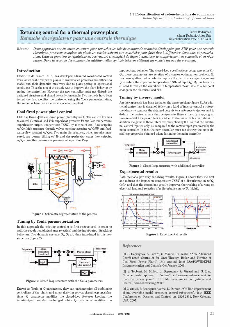
IntroductionElectricité de France (EDF) has developed advanced coordinated controllaws for its coal-fired power plants. However such processes are difficult tomodel and their dynamics may vary due to plant ageing or operationalconditions. Thus the aim of this study was to improve the plant behavior bytuning the control law. However the new controller must not disturb thedesigned structure and should be easily removable. Two methods have beentested: the first modifies the controller using the Youla parameterization,the second is based on an inverse model of the plant.
Coal fired power plant controlEDF has three Q600 coal-fired power plant (figure 1). The control law hasto control electrical load Peb, superheat pressure Ps and low temperaturesuperheater output temperature TSBT, by means of coal flow setpoint ref Qc, high pressure throttle valves opening setpoint ref OHP and feed-water flow setpoint ref Qea. Two main disturbances, which are also mea-sured, are burner tilting ref Ib and desuperheater water flow setpoint ref Qis. Another measure is pressure at separator Psep.
Figure 1: Schematic representation of the process.
Tuning by Youla parameterizationIn this approach the existing controller is first restructured in order tosplit the regulation (disturbance rejection) and the input/output (tracking)behaviors. Two dynamic systems Q1, Q2 are then introduced in this newstructure (figure 2).
Figure 2: Closed loop structure with the Youla parameters
Known as Youla or Q-parameters, they can parameterize all stabilizingcontrollers of the plant, and allow deriving convex closed-loop specifica-tions. Q1-parameter modifies the closed-loop features keeping theinput/output transfer unchanged while Q2-parameter modifies the
input/output behavior. The closed-loop specifications being convex in Q1-Q2, these parameters are solution of a convex optimization problem. Q1has been synthesized in order to improve the disturbance rejection, name-ly to reduce the impact on temperature TSBT of input Qc. Q2 has been cal-culated to reduce the overshoot in temperature TSBT due to a set pointchange in the electrical load Peb.
Tuning by inverse model Another approach has been tested on the same problem (figure 3). An addi-tional control law is designed following a kind of inverse control strategy:the idea is to compare the obtained outputs to a reference trajectory and todeduce the control inputs that compensate these errors, by applying aninverse model. Low-pass filters are added to eliminate too fast variations. Inaddition the gains of these filters are multiplied by 0.01 so that the additio-nal control input is only 1% compared to the control input generated by themain controller. In fact, the new controller must not destroy the main clo-sed-loop properties obtained when designing the main controller.
Figure 3: Closed-loop structure with additional controller
Experimental resultsBoth methods give very satisfying results. Figure 4 shows that the firstone reduces the impact on temperature TSBT of a disturbance on ref Qc(left); and that the second one greatly improves the tracking of a ramp onelectrical load and rejection of a disturbance on ref Qc (right).
Figure 4: Experimental results
1. AUTOMATIQUE CONTROL
1.3 Robustification et retouche de lois de commande Robustification and retuning of control laws
References
[1] L. Deprugney, A. Girard, S. Maurin, H. Jestin, “New AdvancedCoordi-nated Controller for Once-Through Boiler and Turbine ofCoal-Fired Power Plant”, 16th Annual Joint ISA/POWID/EPRIInstrumentation and Controls Conference, 2006.
[2] S. Tebbani, M. Midou, L. Deprugney, A. Girard and G. Duc,“Inverse model approach to “online” performance enhancement forcoal-fired power plant”. IEEE Multi-conference on Systems andControl, Saint-Petersburg, 2009.
[3] C. Stoica, P. Rodriguez-Ayerbe, D. Dumur , “Off-line improvementof multivariable model predictive control robustness”, 46th IEEEConference on Decision and Control, pp. 2826-2831, New Orleans,USA, 2007.
Chapitre 1:Chapitre 1.qxd 26/10/09 14:03 Page8

Commande sous contraintesConstrained control laws
Didier DUMURDépartement AutomatiqueCampus de GifTél. : 33 (0) 1 69 85 13 75E-mail : [email protected]
Guillaume SANDOUDépartement AutomatiqueCampus de GifTél. : 33 (0) 1 69 85 13 86E-mail: [email protected]
Sorin OLARUDépartement AutomatiqueCampus de GifTél. : 33 (0) 1 69 85 13 86E-mail: [email protected]
Houria SIGUERDIDJANEDépartement AutomatiqueCampus de GifTél. : 33 (0) 1 69 85 13 77E-mail: [email protected]
1.4
22
Pour tout renseignement s'adresser à : For further information, please contact:
Les méthodes classiques de synthèse de lois de commande entraînent biensouvent une alternance de phases de synthèse et d'analyse permettant devérifier a posteriori que les contraintes non prises en compte a priori sonteffectivement satisfaites. Face au besoin toujours plus pressant d'optimi-ser le fonctionnement des systèmes, la prise en compte de toutes lescontraintes apparaît comme un enjeu fondamental de la théorie des sys-tèmes.Dans ce contexte, ce thème de recherche s'attache à prendre en compte descontraintes intervenant sur le système dès la phase de synthèse des loisde commande. A cette fin, différentes approches sont développées : d'unepart l'élaboration hors-ligne de solutions explicites, permettant ainsi deréduire le temps de calcul dans la phase temps réel pour des systèmesrapides ; d'autre part des approches basées sur des stratégies d'optimisa-tion sous contraintes ; enfin des structures de commande non-linéairespermettant notamment une planification de la trajectoire à suivre.
. . . . . . . . . . . . . . . . . . . . . . . . . . . . . . . . . . . . . . . . . . . . . . . . . . . . . . . . . . . . . . . . . . . . . . . . . . .
Classical methods for the design of control laws lead most often to a com-bination of design and analysis phases, enabling to check a posteriori thatthe constraints which are not a priori considered are effectively fulfilled.Being faced to a more and more important need for optimization of the sys-tem behaviour, taking into account constraints appears to be a challengingissue for the system theory.In this framework, this research theme aims at considering constraintsappearing on the system at an early stage during the design of the controllaws. For that purpose, several different approaches are developed: off-lineelaboration of explicit solutions, which provide a significant reduction ofthe calculation time during the real-time phase, being of most interest forfast systems; approaches based on optimization strategies underconstraints; finally nonlinear control structures which allows in particulartrajectory planning.
. . . . . . . . . . . . . . . . . . . . . . . . . . . . . . . . . . . . . . . . . . . . . . . . . . . . . . . . . . . . . . . . . . . . . . . . . . .
1. AUTOMATIQUE CONTROL
Sujets1. Recherche de solutions explicites
Développement d'outils méthodologiques basés sur les théories des sys-tèmes incertains et de la commande robuste, permettant la prise encompte de contraintes en temps réel par détermination de solutionsexplicites.
2. Optimisation sous contraintesRéduction du modèle du système à optimiser afin d'obtenir des pro-blèmes d'optimisation approchés mais solvables. Utilisation d'algorithmes approchés tels que les métaheuristiques pourla résolution générique de problèmes d'Automatique présentant descontraintes non différentiables ou non analytiques.Prise en compte des contraintes de structure de la loi de commandedans la phase de synthèse.
3. Approche par la théorie de la viabilitéConstruction d'ensembles invariants pour l'analyse de la viabilité dessystèmes affectés par des incertitudes paramétriques, définition de tra-jectoires viables.Etude des liens entre faisabilité et robustesse dans le cas de la com-mande prédictive.
4. Lois de commande non-linéaires et génération de trajectoires Planification de trajectoires, conception de lois de commande prédictivenon-linéaires à horizon fini et implantation temps réel.Synthèse de commandes non-linéaires (par retour d'état statique oudynamique, par backstepping ou par modes glissants) sur des systèmesdynamiques non-linéaires.Stabilisation de systèmes dynamiques non-linéaires autour de trajec-toires de référence.
Topics1. Elaboration of explicit solutions Development of methodologies combining theories that stem from sys-tems subject to uncertainty and robust control, taking into account real-time constraints, followed by determination of explicit solutions.
2. Constrained optimizationModel reduction of the system that has to be optimized in order to obtainsub-optimal but feasible optimization problems.Development of approximated algorithms, such as metaheuristics, for ageneric resolution of problems with non differentiable and non analytic constraints.Consideration of structural constraints of the control law during thedesign phase.
3. Approach based on the viability theoryElaboration of invariant sets in order to perform a viability analysis ofsystems subject to parametric uncertainties, coupled with the definitionof viable trajectories.Study of the existing links between feasibility and robustness in the par-ticular case of predictive control.
4. Design of nonlinear control laws and trajectory generation Trajectory planning, design of nonlinear finite horizon predictive controllaws and real-time implementation architecture.Synthesis of non-linear control laws (by static or dynamic state feed-back, by backstepping or sliding modes) for dynamic nonlinear systems.Stabilization of nonlinear dynamic systems along reference trajectories.
Chapitre 1:Chapitre 1.qxd 26/10/09 14:03 Page9

.....................................................................................................................................................................................................................................
Particle Swarm Optimization for controller designOptimisation par essaim particulaire pour la synthèse de correcteurs
.....................................................................................................................................................................................................................................
Résumé L'optimisation est au cœur des méthodes de synthèse de correcteurs (commande LQG, commande Hx,…). La démarche classiqueconsiste à utiliser un modèle simplifié (modèle linéaire avec des dynamiques négligées par exemple) et à utiliser des reformu-lations afin d'obtenir des problèmes d'optimisation résolubles de manière exacte. Cependant, les systèmes industriels devenantde plus en plus complexes, la détermination de modèles simplifiés devient difficile. En outre, il devient primordial de prendreen compte toutes les contraintes lors de la phase de synthèse. Enfin, il ne s'agit plus seulement pour les industriels de satisfai-re un cahier des charges, mais plutôt d'optimiser le fonctionnement de leurs systèmes. Pour toutes ces raisons, les problèmesd'optimisation à résoudre deviennent éminemment complexes. Nous proposons ici d'utiliser l'optimisation par essaim particu-laire pour la synthèse de correcteurs. La méthode est appliquée avec succès pour la synthèse de PID, pour l'optimisation desfiltres de pondération de la synthèse Hx, pour la synthèse d'ordre réduit, ou encore dans le cadre de la commande prédictivenon linéaire.
Commande sous contraintesConstrained control laws
Houria SIGUERDIDJANEDépartement AutomatiqueCampus de GifTél. : 33 (0) 1 69 85 13 77E-mail: [email protected]
Guillaume Sandou
Recherche Research 2009 / 2011 23
1. AUTOMATIQUE CONTROL
1.4 Commande sous contraintes Constrained control laws
References
[1] R. C. Eberhart, and J. Kennedy. “A new optimizer using particleswarm theory”. In: Proc. of the 6th Int. Symposium on Micromachineand Human Science, Nagoya, Japan. pp. 39-43, 1995.
[2] G. Sandou and G. Duc, “Using Particle Swarm Optimization forReduced Order Hoo Synthesis”, 14th IFAC workshop on ControlApplications of Optimisation, Finland, 2009.
[3] G. Sandou and B. Lassami, “Optimisation par essaim particulairepour la synthèse ou la retouche de correcteurs”, MOSIM, France,2008.
[4] G. Sandou, G. Duc and D. Beauvois, “Optimisation par essaim par-ticulaire du réglage d'un correcteur Hoo”, Conférence InternationaleFrancophone d'Automatique, Romania, 2008.
[5] G. Sandou and S. Olaru, “Particle Swarm Optimization basedNMPC: An Application to District Heating Networks”, Lecture Notesin Control and Information Sciences, Vol. 384, pp. 551-559, 2009.
IntroductionOptimization is widely used in Automatic Control for the design of controllaws (LQG, Hoo, predictive control…). However, the traditional approach isbased on simplified and highly tractable models and constraints, allowingthe use of exact optimization solvers (LMIs, SQP, Riccati solvers…). This effi-cient approach may fail for complex systems. Further, many constraints can-not be tractably expressed and have to be a posteriori checked.The idea of the proposed approach is to consider all the constraints duringthe synthesis procedure. In other words, a difficult optimization problem hasto be solved, encompassing some non linear, non convex and non analyticalconstraints and cost functions. For that purpose, a particle swarm optimiza-tion algorithm, belonging to the class of metaheuristic methods, has beenchosen for the solution to those problems. The algorithm has been introdu-ced by Kennedy and Eberhart in the mid 90s and is inspired by the socialbehavior of bird flocking or fish schooling [1]. Much than satisfactory resultshave been achieved, proving the viability and the versatility of the approach.
An example: reduced order Hoo synthesisThe method has been tested for a well known problem: the reduced order Hoo synthesis. Consider the closed loop of figure 1.
Figure 1: Classical closed loop structure
The problem refers to the solution to:
(1)
where K(s) denotes the order of K(s). In the traditional approach, specifications have to be reformulated as tem-plates on the transfers of the closed loop system, leading to the definition offictive filters in the synthesis procedure. This has not to be done in ourapproach. Indeed, any performance criterion (frequency or temporal tem-plates on any transfer of the loop) is a function of the controller parameterand thus can be written as a constraint for the optimization problem (1).Note that these constraints have non differentiable or even non analyticexpressions. Thus, the optimization problem will be solved by a ParticleSwarm Optimization algorithm. The method has been tested for a pendu-lum in the cart depicted in figure 2.
Figure 2: Case study - Pendulum in the cart
For that example, the full order Hoo synthesis leads to a controller of order 6with a Hoo norm of the closed loop system 1.06; a classical Hankel singularvalues reduction of the controller to the order 2 leads to a Hoo norm of 56.7.The results of the Particle Swarm Optimization are given in table 1 for thesynthesis of an order 2 controller.
Table 1: Results of the Particle Swarm Optimization algorithm
As the algorithm is a stochastic one, the validation can only be made by sta-tistical data. That is why the algorithm has been performed 100 times lea-ding to the results of table 1. Results show that the Particle SwarmOptimization algorithm outperforms the traditional a posteriori Hankelreduction. From a performance point of view, controllers that are computedby the PSO algorithm have quite similar performances than the Hankelreduction controller but are more robust especially against measurementnoises, due to a decrease in controller high frequency gains. For more detailson the method and the results, see [2].
Concluding remarks and related works Some results on the use of Particle Swarm Optimization have been presen-ted. The main advantage of the method is that it can take into account allconstraints of the problem, whatever its mathematical structure (non diffe-rentiable, non analytical…). This is particularly interesting in an industrialcontext, as it avoids reformulating the constraints in a tractable way andperforming several synthesis/analysis phases in the design process. Themain drawback is that no guarantee can be given on the actual optimalityof the solution. However, in a synthesis procedure, the goal is mainly to finda controller which satisfies the specifications, and so a satisfying near opti-mal solution is sufficient for that purpose.
The method is quite versatile and can be applied to many Automatic Controlproblems: synthesis and optimization of PID controllers [3], optimization ofHoo controllers [4], non linear predictive control [5].
Chapitre 1:Chapitre 1.qxd 26/10/09 14:03 Page10

Approche système et procédés industrielsSystem approach and industrial processes
Patrick BOUCHERDépartement AutomatiqueCampus de GifTél. : 33 (0) 1 69 85 13 71E-mail : [email protected]
Emmanuel GODOY Département AutomatiqueCampus de GifTél. : 33 (0) 1 69 85 13 73E-mail : [email protected]
Dominique BEAUVOIS Département AutomatiqueCampus de GifTél. : 33 (0) 1 69 85 13 87E-mail : [email protected]
1.5
24
Pour tout renseignement s'adresser à : For further information, please contact:
Les sujets présentés dans cette thématique, organisés par domaines d'ap-plication, relèvent de l'application des travaux méthodologiques développéspar l'équipe et essentiellement de la mise en œuvre des différents domainesde l'automatique nécessaire pour aborder les problématiques issues dumonde industriel. Ces sujets impliquent formalisation des problèmes industriels posés selonune approche fonctionnelle, développement et validation de modèles analy-tiques permettant la simulation d'un système, détermination, identificationet validation de modèles simplifiés de commande, choix, sans a priori, syn-thèse et validation d'une loi de commande propre à remplir les objectifs fixésdans le cahier des charges.
. . . . . . . . . . . . . . . . . . . . . . . . . . . . . . . . . . . . . . . . . . . . . . . . . . . . . . . . . . . . . . . . . . . . . . . . . . .
The topics presented in this thematic, organized owing to applicationdomains, are characterized by application of methodological works studiedby the team, and essentially the use of the various methods of AutomaticControl necessary to deal with problems from the industrial world.
These topics involve formalization of industrial problems, according to afunctional approach, development and validation of analytical models forsimulation, determination, identification and validation of simplifiedcontrol models, choice, without a priori, of a methodology to design andvalidate a control law in order to meet desired specifications.
. . . . . . . . . . . . . . . . . . . . . . . . . . . . . . . . . . . . . . . . . . . . . . . . . . . . . . . . . . . . . . . . . . . . . . . . . . .
1. AUTOMATIQUE CONTROL
Sujets1. Domaine automobile
Pilotage en glissement d'un organe de friction pour le filtrage des acy-clismes d'un groupe motopropulseur.Estimation temps réel non-linéaire pour le contrôle de systèmes de sus-pensions pilotées.Commande de véhicule à direction et freinage découplés.Stratégie de commande d'un groupe motopropulseur hybride.Gestion de l'énergie dans un véhicule électrique.
2. Systèmes d'énergieModélisation générique et optimisation de lois de commande pourconvertisseurs de puissance.Modélisation et optimisation robuste de réseaux d'énergie.Manœuvre contrôlée de transformateurs HT avec flux rémanent.Commande non-linéaire d'éolienne à vitesse variable équipée de géné-ratrice double alimentation.Commande non-linéaire et stabilisation de systèmes de transmissionVSC HVDC.
3. Systèmes mécatroniquesModélisation et commande de robots à architecture parallèle.Conception d'un robot multiaxes pour le positionnement d'un appareilde radiographie cardiovasculaire.Modèle ARMARKOV et algorithmes adaptatifs de commande d'action-neurs antivibratoires.
4. Systèmes biotechnologiquesProposition de stratégies de commande pour la culture de microalguesdans un photo-bioréacteur continu.Commande prédictive non-linéaire de culture de bactéries en mode fed-batch.Estimation et commande robuste de la culture de microalgues pour lavalorisation biologique du CO2.
5. Domaine aéronautique et aérospatialGuidage et pilotage robuste d'aéronefs autonomes en milieu turbulent.Optimisation de trajectoires et analyse de mission pour voyages inter-planétaires.
Topics1. Automotive industryControl of the slip of a friction process in order to filter the acyclisms ofa vehicle power-train.Real Time nonlinear state estimation of a vehicle in order to control itwith active suspension.Control of a vehicle with non interacting steering and braking systemsStrategy for the control law of an hybrid power-train.Power management in an electrical vehicle.
2. Power systemsGeneric modeling and optimization of control laws for power converters.Modeling and robust optimization of energy networks.Controlled switching of HT transformers with residual flux.Nonlinear control of variable speed wind turbine equipped with doublyfed induction generators.Nonlinear control and stabilization of VSC HVDC transmission lines.
3. MechatronicsModeling and control of robots with parallel architecture.Modeling and control of a multi-axis actuator in a cardiovascular radio-graphy system.ARMARKOV model and adaptive algorithms for active vibration rejec-tion.
4. Biotechnological systemsPropositions for control strategies of microalgae culture in a continuousphoto-bioreactor.Nonlinear predictive control of bacteria culture in a fed-batch mode bio-reactor.Estimation and robust control of microalgae culture for biologic valori-zation of CO2.
5. Human-Machine InteractionGuidance and control of autonomous aircrafts in a turbulent medium.Trajectory Optimization and mission analysis for interplanetary travel.
Chapitre 1:Chapitre 1.qxd 26/10/09 14:03 Page11

.....................................................................................................................................................................................................................................
Control of microalgae cultivation in a continuous photobioreactorCommande de la culture de microalgues dans un photobioréacteur continu
.....................................................................................................................................................................................................................................
Résumé La production de microalgues s'avère fondamentale pour de nombreuses applications industrielles et environnementales. De façon générale, afin d'obtenir un niveau élevé de production de microalgues, la stratégie de commande consiste à régulerla concentration en biomasse à une valeur donnée au sein d'un photobioréacteur continu, de façon à maintenir la culture àune densité de population optimale. Pour cela, la loi de commande proposée inclut au sein d'une structure cascade une boucleinterne basée sur une stratégie de linéarisation entrée-sortie, et une boucle externe avec un régulateur de type P.I.D. et un dispositif d'anti-saturation afin d'annuler toute erreur statique. De plus, dès lors que la concentration en biomasse n'est pasdisponible en temps réel, un filtre de Kalman étendu permet d'estimer cette concentration, à partir de la mesure du carboneinorganique total et des états physiques classiques (pH, intensité lumineuse, concentration en oxygène dissous…). Cette struc-ture de commande validée en temps réel sur un photobioréacteur instrumenté montre l'efficacité et la robustesse de la struc-ture par rapport à d'autres stratégies plus classiques.
Dominique BEAUVOIS Département AutomatiqueCampus de GifTél. : 33 (0) 1 69 85 13 87E-mail : [email protected]
Sihem TebbaniDidier Dumur
Arsène Isambert
Recherche Research 2009 / 2011 25
IntroductionMicroalgal biomass has many applications such as the production of highvalue compounds. This biomass is an excellent source of long-chain polyun-saturated fatty acids (PUFAs), polysaccharides, vitamins and pigments.Large-scale cultures also find applications in energy production (e.g. photo-biological hydrogen, biofuel, methane) and environmental remediation (e.g.wastewater treatment, carbon dioxide fixation and greenhouse gas emis-sions reduction). Microalgae can also absorb heavy metals and sequester ordegrade many different classes of toxic compounds. The microalgae cultureis classically carried out in open ponds mode leading to several problems.Closed photobioreactor culture seems to be more efficient than the last one,especially when applying real-time control laws for microalgal culture. Ageneral objective of process control is to guarantee that the process will ope-rate in a constant biomass density mode, in order to maintain the culture atthe optimal population density and sustain high biomass production levels.
Proposed control strategyThe biomass control is carried out in three steps. First, mathematical mode-ling and model parameters identification are assessed by fitting the experi-mental data acquired along the exponential phase of batch cultivation [1].Since biomass concentration is one of the most valuable variables to control,but remains quite difficult to measure on-line, a software sensor for its esti-mation has to be elaborated. That is the reason why, in a second step, anextended Kalman filter (E.K.F.) is developed, based on total inorganic car-bon (TIC) and physical states (pH, temperature, dissolved oxygen, lightintensity) measurements [2]. Finally, the biomass concentration control isrealized by appropriately changing the culture medium flow-rate to the pho-tobioreactor.Several control strategies have been successively investigated (linearizedmodel based control, P.I.D., Generic Model Control, Nonlinear control,Nonlinear Model Predictive Control). Among them, the following designedcontrol strategy consists of a linearizing state-feedback algorithm imple-mented in an inner loop [3]. A Proportional Integral Derivative (P.I.D.)controller with an anti-windup compensator in the outer loop offers the pos-sibility to correct the deviations due to system disturbances and slightmodel/process mismatches.
Figure 1: Control system architecture
Experimental resultsThe proposed control strategy is validated on the culture of red microalgaePorphyridium purpureum in an instrumented bubble column photobioreac-tor (figure 2), in collaboration with the “Laboratoire de Génie de Procédés etMatériaux” of Ecole Centrale Paris. Experiments in case of setpoint changes(figure 3) and significant disturbances acting on the system (figure 4) areconsidered, showing good performances in terms of accuracy, overshoot androbustness.
Figure 2: Schematic representation of the photobioreactor
Figure 3: Experimental biomass step response.
Figure 4: Experimental evolution of biomass under disturbances
1. AUTOMATIQUE CONTROL
1.5 Approche système et procédés industriels System approach and industrial processes
References
[1] D. Baquerisse, S. Nouals, A. Isambert, P. Ferreira dos Santos and G. Durand, “Modelling of a continuous pilot photobioreactor for microal-gae production”. Journal of Biotechnology, 70, 335-342, 1999.
[2] G. Becerra-Celis, S. Tebbani, C. Joannis-Cassan, A. Isambert, P. Boucher, “Estimation of microalgal photobioreactor production basedon total inorganic carbon in the medium”. 17th IFAC World Congress,Seoul, 2008.
[3] A. Isidori, “Nonlinear control systems”. Berlin, Springer-Verlag, 1989.
Chapitre 1:Chapitre 1.qxd 26/10/09 14:04 Page12

Estimation et modélisationEstimation and modeling
Sette DIOPL2S - Division SystèmesCampus de GifTél. : 33 (0) 1 69 85 17 30E-mail : [email protected]
Béatrice LAROCHEL2S - Division SystèmesCampus de GifTél. : 33 (0) 1 69 85 17 22E-mail : [email protected]
Éric WALTERL2S - Division SystèmesCampus de GifTél. : 33 (0) 1 69 85 17 11E-mail : [email protected]
1.6
26
Pour tout renseignement s'adresser à : For further information, please contact:
Pour comprendre ou commander un système il est souvent très utile de lemodéliser puis d'identifier les paramètres inconnus éventuels du modèlesur la base de mesures effectuées sur le système. Le modèle ainsi obtenusert, pendant l'exploitation du système, à prévoir ou surveiller son com-portement, voire à modifier ce dernier, auquel cas il faut souvent faireappel de nouveau à des techniques d'estimation. La complexité desmodèles utilisés n'est pas en rapport nécessairement avec celle de la phy-sique du système mais plutôt avec le degré de précision souhaité. Quantaux algorithmes d'estimation, parfois appelés capteurs logiciels, ce sontbien des compagnons des capteurs physiques, qu'ils peuvent d'ailleursparfois remplacer de façon avantageuse du point de vue coût, encombre-ment, ou fiabilité.
. . . . . . . . . . . . . . . . . . . . . . . . . . . . . . . . . . . . . . . . . . . . . . . . . . . . . . . . . . . . . . . . . . . . . . . . . . .
To understand or control a system it is often extremely useful to model it,and then to identify the unknown parameters of this model, if any, basedon measurements carried out on the system. The model thus obtained maybe used, during the operation of the system, to predict or monitor its beha-viour, or to modify it. In the latter case, estimation techniques often need tobe invoked again. The model complexity is not necessarily comparable tothat of the knowledge-based description of the system; it is rather related tothe degree of accuracy that is required. Estimation algorithms, sometimescalled software sensors, are companions of physical sensors. They may evenbe used in lieu of some sensors for their lower price, smaller size, and dura-bility.
. . . . . . . . . . . . . . . . . . . . . . . . . . . . . . . . . . . . . . . . . . . . . . . . . . . . . . . . . . . . . . . . . . . . . . . . . . . .
1. AUTOMATIQUE CONTROL
Sujets1. Modélisation de systèmes biologiques
Le domaine de la biologie est extrêmement actif, et présente de réelsbesoins d'organisation et de représentation des connaissances. Nousavons développé une activité de modélisation à base de connaissance,simplification de modèles et estimation sur données en épidémiologie etmicrobiologie, en collaboration avec l'INRA.
2. Modélisation boîte noire (ou grise) à l'aide du krigeageLe krigeage est une méthodologie issue des géostatistiques, où elle s'estdéveloppée dans le contexte de l'exploration minière. Cette méthodolo-gie est maintenant utilisée de plus en plus pour des applications eningénierie. Elle permet de construire des modèles de prédiction simplessoit à partir de données uniquement, soit en intégrant des connais-sances a priori pour transformer le modèle boîte noire en un modèleboîte grise. Cette activité est conduite en collaboration avec leDépartement Signaux et Systèmes Electroniques.
3. Estimation par analyse par intervalleL'analyse par intervalles permet d'effectuer d'une façon globale etgarantie les tâches de base en estimation non linéaire de paramètres oude variables d'état que sont la minimisation d'une fonction coût ou lacaractérisation de l'ensemble des vecteurs de paramètres ou d'état quisont compatibles avec des erreurs acceptables. Les résultats peuventêtre rendus remarquablement robustes à des données aberrantes.
4. Techniques algébriques différentielles et numériques pourl'estimationNombre de questions rencontrées dans le domaine de l'estimation desystèmes dynamiques sont de nature structurelle et algébrique diffé-rentielle. Il en est ainsi des questions d'identifiabilité, d'observabilité,etc. Les algorithmes d'estimation eux relèvent plutôt de l'analyse numé-rique et font appel aux notions d'approximation de solutions de pro-blèmes souvent mal conditionnés voire mal posés.
Topics1. Modeling of biological systemsBiology is a very active area, with acute needs in knowledge structura-tion and modeling. Our activity has been focused on knowledge-basedmodeling, model simplification and estimation from experimental datain the field of epidemics and microbiology in collaboration with partnersfrom INRA (National Institute for Agronomic Research).
2. Black (ou grey) box modeling via KrigingKriging, a methodologogy initially developed by geostatiticians in thecontext of mining, is increasingly used in engineering applications. Itmakes it possible to build simple prediction models either uniquely fromdata (or simulations of complex knowledge-based models) or whileincorporating some degree of prior knowledge, which transforms theblack-box model into a grey box model. This activity is carried out inconnection with the Signal and Electronic Systems Department.
3. Estimation via interval analysisInterval analysis makes it possible to achieve, in a global and guaran-teed way, basic tasks in nonlinear parameter or state estimation such asminimizing a cost function or characterizing the set of all parameter orstate vectors that are consistent with acceptable errors. The results canbe made remarkably robust to outliers.
4. Differential algebraic and numerical techniques for estimationMany questions which are encountered in system estimation bear somestructural and differential algebraic nature. That is the case of identi-fiability, observability, etc. Estimation algorithms rather stem fromnumerical analysis, and they appeal on notions of approximation ofsolutions of problems which are often ill-conditionned, or even ill-posed.
Chapitre 1:Chapitre 1.qxd 26/10/09 14:04 Page13

.....................................................................................................................................................................................................................................
Une nouvelle structure d'observateurA new observer structure
.....................................................................................................................................................................................................................................
Abstract An observer structure has been proposed with features such as ``nonpeaking'', ``bounded'' and with quasi explicit algorithmsfor its design. These new potentialities are attribuable to both the structure of the data feedback and the introduction of regu-larized numerical differentiation schemes of sampled data.
Sette Diop
Recherche Research 2009 / 2011 27
La question de l'estimation en temps réel d'une variable x(t) d'un systèmedynamique est essentielle en automatique. En effet, les bonnes réponses à cette question rendent possibles l'implantation de com-mandes par retour d'état, le diagnostic et la surveillance d'unsystème en exploitation, et parfois, un gain économique substantiel en rem-plaçant un capteur trop encombrant, trop cher, ou peu fiable par un simplealgorithme programmé dans un processeur de calcul. D'ailleurs, n'est-ce pasle filtre de Kalman qui, par son succès dans l'aérospatial depuis les années1960, a permis l'émergence de notre discipline, l'automatique. La preuveque le filtre de Kalman est une solution au problème de l'estimation suppo-se que le modèle est linéaire . L'immense succès résulte de ce que cet estimateur temps réel a d'excel-lentes propriétés de convergence tout en tolérant quelques inévitablesimprécisions à la fois du modèle lui-même et des mesures
délivrées par les capteurs. Appliqué aux modèlesnon linéaires la validité du filtre de Kalman devient locale en ce que laconvergence de l'estimateur n'est garantie que si ce dernier a été ini-tialisé suffisamment près de . De combien doit être près de
? Il est souvent difficile d'en donner une bonne estimation. De plus, lefiltre de Kalman étendu n'a pas cette propriété essentielle d'un estimateur,à savoir la bornitude vis-à-vis des incertitudes de mesure. Une faiblessenotoire du filtre c'est la difficulté à vérifier a priori les hypothèses qui auto-risent son utilisation. Enfin rappelons que la complexité en charge de calculdu filtre de Kalman peut également le rendre inutilisable dans certainesapplications.
C'est ainsi que la recherche sur l'estimation temps réel non linéaire a conti-nué d'occuper de très nombreux collègues dans le monde. Une nouvelleapproche est explorée depuis le début des années 1990. Elle repose sur uneanalyse algébrique différentielle du problème d'estimation qui nous aconduit à une notion d'identifiabilité ou d'observabilité qui est explicit (etdont on peut confier la vérification à des systèmes de calcul symboliques)ainsi qu'à une nouvelle structure d'observateur dans laquelle la complexitédu calcul du gain du filtre de Kalman étendu disparaît, mais apparaît lanécessité d'utiliser la différentiation numérique régularisée. De ce fait lecaractère de problème inverse mal posé de la question de l'estimation faitsurface à travers la différentiation numérique qui en est l'exemple type bienconnu en analyse numérique. Le caractère de problème inverse de l'estima-tion est intuitivement clair puisqu'il s'agit d'extraire une informationconnue à travers un modèle qui se présente sous la forme d'une cause pro-duisant un effet et où l'effet, y(t) est connu ainsi qu'une partie de la cause,u(t) l'autre partie de la cause x(t), étant précisément l'inconnu à détermi-ner. Est-ce que ce problème inverse est mal posé au sens d'Hadamard ?Formellement cela reste à être prouvé. Le génie du filtre de Kalman linéai-re est sans doute d'en avoir trouvé une solution dynamique qui ne consistepas en une inversion algébrique du problème mais en la construction d'unsystème dynamique qui se contente de produire une sortie qui convergeasymptotiquement vers x(t) . La structure proposée, elle, inverse différen-tiellement algébriquement le problème. C'est là toute sa faiblesse, maisaussi sa force car elle a le mérite de produire une solution explicite contrai-rement au filtre de Kalman étendu.
La nouvelle structure d'observateurLe schéma fonctionnel suivant montre les deux composantes de l'observa-teur ainsi que leur interaction.
Les données disponibles à l'utilisateur en temps réel, u(t), y(t), sont traitéesd'abord dans un bloc notée NDO pour numerical differentiation observer ; cebloc fournit une estimation retardée, de l'état. Le retard
est en général connu de l'utilisateur ; il est directementlié à la longueur de la fenêtre de données utilisée pour estimer les dérivées,et son choix résulte d'un compromis entre la précision de l'estimation desdérivées et la nécessité de filtrer le bruit sur ces données. Le symbole
représente l'erreur d'estimation de . Des exemples de diffé-rentiateurs numériques sont montrés dans les références ci-dessous. Leretard est alors compensé à l'aide du modèle du système dans le bloc notéPrediction dans le schéma précédent. La prédiction est décrite par les équa-tions suivantes.
Le symbole K représente un gain. A l'inverse du filtre de Kalman où il seraitcalculé à travers la résolution en ligne d'une équation de Riccati, K est unematrice constante très facile à calculer. Le contenu du bloc NDO n'est pasexplicité ici. Outre la différentiation numérique, il contient l'expression del'état du système en fonction des données. Cette expression est donnée defaçon explicite par l'approche algébrique de l'observabilité. La convergencede cet observateur est exponentielle sous des hypothèses mineures.
Pour plus de détails sur cette approche des observateurs non linéaires le lec-teur pourra consulter les quelques publications ci-dessous ainsi que les réfé-rences qu'elles contiennent.
1. AUTOMATIQUE CONTROL
1.6 Estimation et modélisation Estimation and modeling
Références
[1] S. Diop, “Observers for sampled data nonlinear systems via numericaldifferentiation”, Proceedings of the European Control Conference, Kos,Greece, 2007.
[2] S. Diop, V. Fromion, J. W. Grizzle, “A global exponential observer basedon numerical differentiation,” Proceedings of the IEEE Conference onDecision and Control, 2001.
[3] S. Diop, J. W. Grizzle, P. E. Moraal, A. G. Stefanopoulou, “Interpolationand numerical differentiation for observer design,” Proceedings of theAmerican Control Conference, 1994.
Chapitre 1:Chapitre 1.qxd 26/10/09 14:04 Page14

28
Chapitre 2:Chapitre 2.qxd 26/10/09 14:04 Page1

29
2. SIGNAUX ET STATISTIQUESSIGNALS AND STATISTICS
2Chapitre 2:Chapitre 2.qxd 26/10/09 14:04 Page2

Modélisation statistique du signalStatistical signal modelling
Pascal BONDONL2S - Division SignauxCampus de GifTél. : 33 (0) 1 69 85 17 31E-mail : [email protected]
2.1
30
Pour tout renseignement s'adresser à : For further information, please contact:
2. SIGNAUX ET STATISTIQUES SIGNALS AND STATISTICS
Les principaux axes de recherche de l'équipe « modélisation statistique dusignal » sont l'étude de processus ponctuels, la séparation de sources, lessignaux multi-capteurs et les séries chronologiques.
. . . . . . . . . . . . . . . . . . . . . . . . . . . . . . . . . . . . . . . . . . . . . . . . . . . . . . . . . . . . . . . . . . . . . . . . . . .
The main interests of the “Statistical signal modelling” group are the studyof random point processes, sources separation, multi-sensors systems andtime series analysis.
. . . . . . . . . . . . . . . . . . . . . . . . . . . . . . . . . . . . . . . . . . . . . . . . . . . . . . . . . . . . . . . . . . . . . . . . . . .
Sujets1. Processus ponctuels et optique statistiqueLa plupart des travaux consacrés à l'étude des processus ponctuels sontessentiellement théoriques. Aussi lorsque la théorie est difficile à éla-borer, une simulation sur ordinateur semble être une approche satisfai-sante du processus ponctuel. Ainsi, nous nous intéressons à la simula-tion d'intervalles entre les points successifs d'un processus ponctuelparticulier défini comme une suite de variables aléatoires positives.Celles-ci sont générées soit à partir de processus auto-régressifs, soit àpartir de processus physiques mettant en évidence des propriétés nonclassiques des champs optiques.
2. Séparation de sourcesLes méthodes de séparation aveugle de sources ne permettent pas detraiter le cas sous-déterminé (nombre de sources supérieur au nombrede capteurs) et sont peu utilisables dans le cas d'un rapport signal àbruit faible. La propriété de parcimonie des signaux, largement utiliséedans les années 90 en compression, commence à être utilisée en sépa-ration de sources et elle a conduit à un algorithme connu sous la déno-mination Analyse en Composantes Parcimonieuses. Cet algorithmesemble être en mesure de lever les limitations mentionnées ci-dessus etnous étudions son application au cas d'un mélange de signaux à phasepolynomiale.
3. Signaux multi-capteursLe concept de systèmes multi-capteurs tend à se développer afin d'uti-liser judicieusement les degrés de liberté supplémentaires apportés pardes informations multiples dans le but de réduire l'incertitude sur l'in-formation résultante. Déjà utilisés dans les domaines de la téléphoniemobile, de l'internet (réseaux WiFi) et de la localisation (GPS), les sys-tèmes multi-capteurs s'ouvrent à d'autres domaines tels que l'imageriemédicale, l'aéronautique et le nucléaire. Notre activité de recherche seconcentre sur l'amélioration de l'estimation de paramètres d'intérêts (laposition d'un objet par exemple) en étudiant la géométrie des telsréseaux ainsi qu'en optimisant les formes d'ondes émises.
4. Séries chronologiquesNos travaux portent principalement sur l'estimation et la prédiction deprocessus à longue mémoire avec données manquantes, l'étude de pro-cessus à mémoire intermédiaire, le développement de méthodes de filtra-ge particulaire pour des systèmes dynamiques non linéaires, l'estimationrobuste de modèles de consommation d'électricité pour la prévision àcourt terme, et l'analyse et la prédiction du trafic dans des réseaux aumoyen de processus localement stationnaires à longue dépendance.
Topics1. Point processes and statistical opticsMost of the work dedicated to point processes are mainly theoretical.When it is hard to elaborate the theory, a computer simulation is some-time satisfactory for the point process. We are interested in the simula-tion of intervals between successive points of a particular point processdefined as a sequence of positive random variables which are generatedfrom particular autoregressive models or from physical processes yiel-ding non classical properties of light fields.
2. Sources separationThe Blind Source Separation methods don't solve properly the under-determined case (more sources than sensors) and are of little use in poorsignal-to-noise ratio. The property of signals's sparsity, widely studied inthe 90’s in signals compression, begin to be used in sources separationand gives an algorithm known as Sparse Component Analysis. Thisalgorithm seems to be able to solve the abovementioned limitations andwe study its applications to the case of a mixture of polynomial phasesignals.
3. Multi-sensors systems The concept of multi-sensors systems has quickly grows during pastdecades. The multiplicity of the information given by such systems is use-ful to reduce the uncertainties on the resulting information. Alreadyused in the field of digital communication and source localization, thesesystems are now present in other domains such as medical imaging andnuclear system. Our research activities are focused on the increase ofperformance in terms of parameter estimation of these systems. Our ana-lysis combines both the study of the network geometry and the design ofoptimal emitted waveforms.
4. Time series analysis Our interests are the estimation and the prediction of a long memoryprocess with missing data, the study of processes with intermediatememory, the development of particular filtering methods for dynamicalnonlinear systems, the robust estimation of statistical models for theFrench daily electricity consumption for the short-term forecasting, and the analysis and the prediction of traffic data using piecewise stationary long-memory processes.
Chapitre 2:Chapitre 2.qxd 26/10/09 14:04 Page3

2.1 Modélisation statistique du signal Statistical signal modelling
.....................................................................................................................................................................................................................................
Bornes de Cramér-Rao pour la localisation de sources en champ procheCramér-Rao bounds for near-field localization parameters
.....................................................................................................................................................................................................................................
Abstract Near-field source localization problem by a passive antenna array makes the assumption that the time-varying sources arelocated near the antenna. In this situation, one has to consider a more complicated observation model parameterized by thebearing (as in the far-field case) and by the distance, named range, between the source and a reference sensor. We can find aplethora of estimation schemes in the literature but the ultimate performance has not been fully investigated. Here, we deriveand analyze the Cramér-Rao Bound (CRB) for a single time-varying source. In this case, one obtains nonmatrix closed-formexpressions. This approach has two advantages: (i) the computational cost for a large number of snapshots of a matrix-basedCRB can be high while the proposed approach is cheap and (ii) some useful information can be deduced from the behavior ofthe bound.
Mohammed El KorsoRémy Boyer
Alexandre RenauxSylvie Marcos
Recherche Research 2009 / 2011 31
Références
[1] Y. D. Huang and M. Barkat, "Near-field multiple source localiza-tion by passive sensor array", IEEE Transactions on AntennasPropagation, vol. 39, no. 7, pp. 968-975, Jul. 1991.
[2] S.F. Yau, Y. Bresler, "A compact Cramér-Rao bound expression forparametric estimation of superimposed signals," IEEE Transactionson Signal Processing, vol. 40, no. 5, pp. 1226-1230, May 1992.
[3] P. Stoica and A. Nehorai, "MUSIC, maximum likelihood, andCramér-Rao bound", IEEE Transactions on Signal Processing, vol.37, no. 5, pp.720-741, May. 1989.
IntroductionLors d'une localisation de sources à l'aide d'un réseau de capteurs passifs,on fait généralement l'hypothèse simplificatrice de sources situées loin del'antenne. Cependant, dans le cas de sources proches de l'antenne, les frontsd'ondes ne sont plus plans et il faut prendre en compte un modèle d'obser-vation paramétré, non seulement par l'azimut et l'élévation de chaque sour-ce, mais aussi par la distance entre les sources et un référentiel vis-à-vis del'antenne. Bien qu'une pléthore de méthodes d'estimation concernant cesparamètres soit disponible dans la littérature, les performances ultimes detels estimateurs n'ont pas tout à fait été traitées en détail. Dans cet article,nous calculons et analysons les bornes de Cramér-Rao déterministes dansle cas d'une source située en champs proche. Dans cette situation, le nombrede paramètres d'intérêt augmente avec le nombre d'observations. Celasignifie que l'inversion numérique de la matrice d'information de Fisher estdifficile. C'est pourquoi, nous proposons des expressions analytiques non-matricielles de la borne de Cramér-Rao.
Modèle d'observationConsidérons une antenne linéaire uniforme composée de N capteurs avecune distance inter-capteurs notée d. L'antenne reçoit un signal émispar une source, supposée à bande étroite, située dans le champ proche(région de Fresnel) de l'antenne. Par conséquent, le modèle d'observationau niveau de l'antenne s'écrit comme : avec et où T est le nombre d'oservations et N le nombre de capteurs. Le retard inter-capteur peut être approximé par [1]
, où est la longueur d'onde et r et représentent, respectivement, la distance et l'azimut de la source. On
admet que le bruit est un processus complexe circulaire blancgaussien de moyenne nulle et de variance inconnue .
Bornes de Cramér-RaoLes paramètres d'intérêts sont la distance, l'azimut, l'amplitude et laphase du signal à chaque instant (la fréquence porteuse est supposéeconnue) ainsi que la puissance du bruit. La matrice d'information deFisher est donc de taille (2T+3)x(2T+3). Puisqu'il s'agit ici d'un modèled'observation gaussien à moyenne et covariance paramétrées, cette matri-ce est obtenue classiquement à l'aide de la formule de Slepian-Bang com-plexe circulaire [2]. Néanmoins, c'est l'inversion de cette matrice qui nousintéresse et cette opération devient très coûteuse lorsque T devient grand.C'est l'une des raisons pour laquelle nous proposons l'inversion analy-tique. En utilisant une partition appropriée de la matrice d'information deFisher et après le calcul explicite de l'inverse du complément de Schur,nous obtenons les expressions non-matricielles de la borne de Cramér-Raorelative à la distance et à l'azimut :
avec
et
Analyse- Pour un grand nombre de capteurs et une distance inter-capteurs fixée,
exprimée dans le champ proche tend vers la borne de Cramér-Rao en champ lointain [3]. Ceci correspond bien à l'intuition générale, c'est-à-dire que, la région de Fresnel dépend du nombre de capteurs et un grand nombre de capteurs implique une grande distance pour la source, ce qui correspond au champ lointain.- Les bornes de Cramér-Rao sont invariantes par rapport à la phase dusignal source. De plus, comme dans le cas du champ lointain,
ne dépend que de l'azimut en selon . De ce fait, l'antennelinéaire uniforme en champ proche n'est pas une antenne isotrope.- dépend à la fois de l'azimut et de la distance. Pour r et , la dépendance par rapport à la distance est de . Ce qui signifie queles performances d'estimation s'améliorent quand la source se rapprochede l'antenne (dans la limite de la région de Fresnel).- La dépendance de par rapport à l'azimut est en . Si est proche de , tend vers l'infini et cette divergence est plus rapide que celle de .- Pour un nombre suffisant de capteurs, et sont en .- Pour , est indépendante de la fréquence porteuse. Cependant, ce n'est pas le cas de qui décroit lorsque la fréquence augmente.
Chapitre 2:Chapitre 2.qxd 26/10/09 14:04 Page4

Traitement statistique de l'informationStatistical information processing
Gilles FLEURYDépartement Signaux et Systèmes ÉlectroniquesCampus de GifTél. : 33 (0) 1 69 85 13 91E-mail : [email protected]
Laurent LE BRUSQUETDépartement Signaux et Systèmes ÉlectroniquesCampus de GifTél. : 33 (0) 1 69 85 14 23E-mail : [email protected]
2.2
32
Pour tout renseignement s'adresser à : For further information, please contact:
La valorisation des données, qu'elles soient issues de connaissances a prio-ri, de mesures, ou bien de résultats de simulation est un souci récurrenttant dans le monde industriel qu'académique. Le contexte général del'augmentation de la qualité des produits, de la réduction des coûts defabrication, du respect des normes environnementales, ne fait que renfor-cer cette préoccupation. Il s'agit d'extraire l'information contenue dans cesdonnées afin de concevoir des systèmes permettant par exemple d'estimerune grandeur, d'attribuer une classe, de prendre une décision. Le traite-ment statistique de l'information intervient à toutes les étapes de cetteconception, dès la phase de recueil d'information et jusqu'à l'évaluationdes performances des systèmes conçus.L'alliance de modélisations dédiées à un objectif spécifique, de méthodesd'estimation, de prise en compte de caractère abondant ou lacunaire desdonnées, de leur éventuelle hétérogénéité, de critères traduisant la robus-tesse, permet de construire des systèmes performants. Inscrire cetteconstruction dans un cadre probabiliste permet de traiter le caractèreincertain à la fois des données et des modèles. La mise en œuvre de cetteapproche dans différents domaines (thermophysique, biologie, génie élec-trique, finance) a permis de valider son caractère générique.
. . . . . . . . . . . . . . . . . . . . . . . . . . . . . . . . . . . . . . . . . . . . . . . . . . . . . . . . . . . . . . . . . . . . . . . . . . .
Exploiting data, whatever is its source (prior, expertises, measurement,simulated result) is a very basic requirement in industry as well as research. Owing to increased production quality levels, lower manufactu-ring costs and tighter environmental controls, today this requirement is allthe more important. The issue is the extraction of information from thesedata in order to develop systems able to estimate an unknown quantity,choose a class or take a decision. Statistical processing is present in allsteps, from the collection of the data to the evaluation of the performance ofthe designed systems. The joint use of modelling approaches dedicated to a specific measurement,of estimation methods, both designed by considering robustness require-ment and with a particular care when the data set is small or/andincludes heterogeneous variables is a key-point to design efficient systems.This approach has been widely used in a number of applications and pro-ved generic (thermophysics, biology, electrical engineering, finance).
. . . . . . . . . . . . . . . . . . . . . . . . . . . . . . . . . . . . . . . . . . . . . . . . . . . . . . . . . . . . . . . . . . . . . . . . . . .
Emmanuel VAZQUEZDépartement Signaux et Systèmes ÉlectroniquesCampus de GifTél. : 33 (0) 1 69 85 14 16E-mail : [email protected]
Sujets1. Propagation d'incertitudesModélisation des incertitudes dans un cadre non-linéaire et dynamique.Modélisation par équations différentielles stochastiques.Généralisation de l'équation de Fokker-Planck aux processus stochas-tiques hybrides.
2. Inférence à partir d'un faible nombre de donnéesChoix de l'ordre d'un modèle par la divergence symétrique de Kullback. Optimisation globale de fonctions coûteuses à évaluer (approche bayé-sienne). Intégration de données biologiques hétérogènes (exemple : réseau,transcriptome).Construction de réseaux d'interaction génétique à partir de donnéesissues de puces à ADN.
3. Modélisation de systèmes complexesModélisation comportementale par des méthodes à noyaux (krigeage,SVR, processus gaussiens, etc.).Planification d'expériences tenant compte de l'erreur de modélisation.
4. Statistiques extrêmesModélisation des comportements extrêmes d'un système pour uneconception robuste.Estimation de la probabilité de défaillance d'un système.
Topics1. Statistical characterizationStatistical characterization for a non-linear dynamic indirect measure-ment.Models based on stochastic differential equations. Generalized Fokker-Planck equation for stochastic hybrid processes.
2. Inference from small datasetsModel order selection criterion for incomplete data based on Kullback'ssymmetric divergence.Global optimization of expensive-to-evaluate functions (Bayesianapproach). Integration of heterogeneous biological data (e.g. gene network, trans-criptomic data).Inference of gene interaction networks from microarray data.
3. Modeling complex systems Kernel-based black-box modeling (kriging, SVR, Gaussian processes,etc.).Design of experiments for misspecified models.
4. Modeling of extreme values in systems Extreme value modeling for robust system design.Estimation of the probability of a failure for an uncertain system.
2. SIGNAUX ET STATISTIQUES SIGNALS AND STATISTICS
Chapitre 2:Chapitre 2.qxd 26/10/09 14:04 Page5

.....................................................................................................................................................................................................................................
Optimization of expensive-to-evaluate functionsOptimisation de fonctions coûteuses
.....................................................................................................................................................................................................................................
Résumé Comment optimiser une fonction dont l'évaluation est très coûteuse en ressources informatiques ? Cette question apparaîtde manière récurrente dans le domaine de la conception de système reposant sur la simulation de phénomènes physiques.Par exemple, la simulation du comportement d'un véhicule en cas de choc peut nécessiter jusqu'à 24h sur des systèmes decalcul avancés. Dans ce type de problème, il est essentiel d'utiliser des algorithmes qui permettent d'approcher lesperformances optimales en utilisant un nombre très réduit de simulations. Les algorithmes d'optimisation les plus efficacesaujourd'hui sont des algorithmes itératifs qui construisent à chaque itération une approximation de la fonction à optimiser, souvent appelée métamodèle, à partir des évaluations de la fonction à optimiser réalisées précédemment. Ces approximationssont utilisées pour choisir les points de l'espace de recherche où seront effectuées les évaluations suivantes. Nous proposons unnouvel algorithme, appelé IAGO, qui fait appel à l'entropie de Shannon comme critère d'information pour effectuer ce choixde nouveaux points.
Emmanuel Vazquez,Julien Villemonteix,
Eric Walter.
Recherche Research 2009 / 2011 33
Optimization of expensive-to-evaluate functionsHow to optimize a function when the budget for its evaluation is severelylimited by either time or cost? For example, when optimization relies oncomputer simulations, each taking several hours, the dimension and com-plexity of the optimization problem may seem incompatible with the eva-luation budget (for instance, thirty parameters to be optimized with lessthan one hundred evaluations). Such a problem is frequently encounteredin the industrial world. For example, in the automotive industry, optimalcombustion-related parameters are obtained using time-consuming compu-ter simulations. A single simulation of the airflow in an intake port (seeFigure 1) may take up several hours on high-end servers. It then becomesessential to favor optimization methods that use the dramatically scarceinformation as efficiently as possible.
This work is devoted to optimization algorithms to be used in this context,which is out of range for most classical methods. The common principle ofthe methods studied is to build a cheap approximation of the function to beoptimized. This approximation is then used iteratively to choose the eva-luation points. This choice is guided by a sampling criterion which combineslocal search, near promising evaluation results, and global search, in unex-plored areas. Most of the criteria proposed over the years, such as the oneunderlying the classical Efficient Global Optimization (EGO) algorithm [1],sample where the optimum is most likely to appear. By contrast, we propo-se a new algorithm that samples where the information gain on the optimi-zer location is deemed to be the highest.
Informational Approach to Global OptimizationOur objective is to find an approximation of a global maximizer x* of a real-valued function f defined on X , a compact subset of Rd , using a very limitednumber of evaluations of f . To make up for the lack of knowledge on the func-tion, surrogate (also called meta or approximate) models are used to obtaincheap approximations [2]. They turn out to be convenient tools for visuali-zing the function behavior or suggesting the location of an additional pointat which f should be evaluated in the search for x* . Yet, given existing eva-luation results, the most likely location of a global maximizer is not necessa-rily a good evaluation point to improve our knowledge on x*.
By using Gaussian process models and Kriging, it is possible explicitly toestimate the probability distribution of the optimum location given pastevaluations (see Figure 2). This probability distribution represents whathas been learned (through evaluations) and assumed (through theGaussian model) about x*. The progress made in finding a solution to theglobal optimization problem can be assessed by looking at how the proba-bility distribution of x* is spread over X . In particular, the support of thedistribution narrows as progress is being made towards reducing theuncertainty left on x*. The main idea is then to adopt an information-basedsearch strategy, by sampling f where the largest uncertainty reduction isexpected. To quantify uncertainty, we use the conditional Shannon entro-py of the global maximizer. This criterion is then inserted in an algorithmsimilar to the EGO algorithm. We call the resulting algorithm IAGO, forInformational Approach to Global Optimization [3, 4].
Figure 1 : Airflow simulation in a simplified intake port of a car engine (cour-tesy of Renault S.A.). The intake port brings the mixture of air and fuel intothe combustion chamber. This Navier-Stokes problem is solved iteratively by afinite-element method. Left: 3D representation of an intake port. Right: valueof the swirl, which quantifies the level of turbulence in the combustion cham-ber, as a function of the number of iterations of the solving procedure. Theswirl has to be optimized in order to maximize the performance of the enginewhile keeping the emissions of pollutants sufficiently low
Figure 2 : Six iterations of IAGO on a 1D function. Top: prediction byKriging of the unknown function (solid line) based on six evaluationresults (squares) and confidence intervals for this prediction (dashed line).Bottom: conditional distribution of the global maximizer after six itera-tions of IAGO.
2.2 Traitement statistique de l’informationStatistical information processing
References
[1] Jones D.R., Schonlau M., and William J., Efficient global optimi-zation of expensive black-box functions. J. Global Optim., 13:455_492,1998.
[2] Jones D.R., A taxonomy of global optimization methods based onresponse surfaces. J. Global Optim., 21:345-383, 2001.
[3] Villemonteix J., Vazquez E., Walter E., An informational approachto the global optimization of expensive-to-evaluate functions. J. Global Optim., doi:10.1007/s10898-008-9354-2, published online:26 September 2008.
[4] Villemonteix J., Vazquez E., M. Sidorkiewicz, Walter E. Globaloptimization of expensive-to-evaluate functions: an empirical compa-rison of two sampling criteria. J. Global Optim. 43(2-3):373-389, 2009.
Chapitre 2:Chapitre 2.qxd 26/10/09 14:04 Page6

Traitement multimodal de l'informationMultimodal Information Processing
Olivier PIETQUINÉquipe IMSCampus de MetzTél. : 33 (0) 3 87 76 47 70 E-mail : [email protected]
Hervé FREZZA-BUET Équipe IMSCampus de MetzTél. : 33 (0) 3 87 76 47 35 E-mail : [email protected]
2.3
34
Pour tout renseignement s'adresser à : For further information, please contact:
Dans de nombreux domaines de l'ingénieur, les phénomènes faisant l'ob-jet d'une analyse ou d'un traitement se manifestent par le biais de diffé-rents supports d'information. Ces différents supports sont parfois porteursd'informations complémentaires et indépendantes auquel cas, la prise encompte simultanée des différentes observations est nécessaire à la com-préhension totale du processus générateur. Dans d'autres cas les diffé-rents supports portent des informations redondantes à des degrés diverset leur étude globale permet, outre une compréhension complète, d'assu-rer une plus grande robustesse de l'analyse. L'extraction de paramètresprovenant de flux dissociés d'informations complémentaires et/ou redon-dantes de natures hétérogènes peut-être vue comme l'utilisation de plu-sieurs modalités dans un processus d'analyse, ce qui justifie l'appellationd'analyse multimodale ou de traitement multimodal de l'information. Toutl'art de l'ingénieur consiste alors à extraire les informations pertinentesde ces données hétérogènes pour créer des modèles capables de reprodui-re (simulation), classifier (détection, reconnaissance de formes) ou contrô-ler (automatique, robotique, interfaces homme-machine) le comportementdes systèmes qui ont généré les informations ou même d'en améliorer laqualité (filtrage, restauration) ou de les compresser.
. . . . . . . . . . . . . . . . . . . . . . . . . . . . . . . . . . . . . . . . . . . . . . . . . . . . . . . . . . . . . . . . . . . . . . . . . . .
In many engineering domains, phenomena to be analysed or processed areobserved through different information supports. These supports sometimescarry complementary and independent information. In this case, takinginto account simultaneously the different observations is necessary for acomplete understanding of the generative process. In other cases, the diffe-rent supports carry redundant information at diverse levels and studyingthem as a whole allows, besides a complete understanding, a greaterrobustness of the analysis. Extracting parameters from complementaryand/or redundant information flows of heterogeneous natures can beregarded as using different modalities in the analysis process which justifies the naming of multimodal analysis or multimodal informationprocessing. With regard to this description, the problem we are dealing with is to extract meaningful information from these heterogeneous data and to buildmodels able to reproduce (simulation), classify (detection, pattern recogni-tion) or control (automation, robotics, human-computer interfaces) thebehaviour of the systems that generated the observed information or evento enhance their quality (filtering, restoring) or to compress them.
. . . . . . . . . . . . . . . . . . . . . . . . . . . . . . . . . . . . . . . . . . . . . . . . . . . . . . . . . . . . . . . . . . . . . . . . . . .
Renaud SEGUIERÉquipe SCEE - IETRCampus de RennesTél. : 33 (0) 2 99 84 45 35 E-mail : [email protected]
Sujets1. Identification biométriqueDétection et reconnaissance de visages.Reconnaissance de locuteur sur base de signaux acoustiques.Identification et vérification de locuteurs par fusion de données audio-visuelles.
2. Interfaces Homme-MachineReconnaissance vocale sur base de propriétés articulatoires.Modélisation probabiliste de l'interaction homme-machine.Optimisation de stratégies d'interaction par apprentissage non-supervisé.Reconnaissance d’émotions et animation d’avatar.
3. Environnement intelligents et vidéosurveillanceLocalisation de sources sonores.Détection de fond.Suivi et reconnaissance d'objets.
Topics1. Biometric IdentificationFace detection and recognition.Speaker recognition based on acoustic signal. Speaker identification and verification using audiovisual data fusion.
2. Human-Computer InteractionAutomatic Speech Recognition based on articulatory features.Probabilistic description of human-computer interaction.Interaction optimization by means of unsupervised learning.Emotion recognition and avatar animation.
3. Smart Environments and videosurveillanceAudio source localization.Background/foreground segmentation.Tracking and recognition of objects.
2. SIGNAUX ET STATISTIQUES SIGNALS AND STATISTICS
Chapitre 2:Chapitre 2.qxd 26/10/09 14:04 Page7

.....................................................................................................................................................................................................................................
Adapted Active Appearance Models for robust face analysisModèles Actifs d'Apparence adaptés pour l'analyse robuste de visage
.....................................................................................................................................................................................................................................
Résumé Les Modèles Actifs d'Apparence (AAM) sont très efficaces lorsqu'il s'agit d'aligner des visages connus dans des poses etilluminations contraintes. Malheureusement, ils sont beaucoup moins performants lorsque l'identité, la pose et l'illuminationdes visages ne sont pas connues. Nous proposons dans ce papier des Modèles Actifs d'Apparence robustes permettant uneimplémentation temps réel. Pour améliorer la robustesse des AAM aux changements d'illumination, nous proposons demodifier les textures prises en compte dans les AAM par des cartes orientés. Les Modèles Actifs d'Apparence Adaptés serontensuite présentés pour améliorer la robustesse des AAM aux autres types de variabilité (en identité, pose, expression etc...).
Renaud SéguierSylvain Le Gallou
Recherche Research 2009 / 2011 35
References
[1] R. Séguier, S. Le Gallou, G. Breton et C. Garcia, "Modèles actifsd'apparence adaptés", Traitement du Signal, volume 25, numéro 5,février 2009.
[2] A. Sattar, Y. Aïdarous and R. Séguier, "GAGM-AAM: A GeneticOptimization with Gaussian Mixtures for Active AppearanceModels", International Conference on Image Processing (ICIP 2008),October 2008.
[3] A. Sattar and R. Séguier, "MVAAM (Multi-View ActiveAppearance Model) Optimized by Multi-Objective GeneticAlgorithm", International Conference on Automatic Face andGesture Recognition (FG 2008), September 2008.
[4] N. Stoiber, R. Séguier and G. Breton, "Automatic design of acontrol interface for a synthetic face", International Conference onIntelligent User Interfaces (IUI 2009), February 2009.
Scientific ContextOur team has worked for ten years on face analysis and synthesis. Ourskills are focused on the Active Appearance Models (AAM) which gives usthe ability to localise in real time a hundred points to characterize the eyes,nose, mouth and outline of the face. Some work was done on the robustnessof the AAM [1] to face unspecified illuminations, poses and face expressions.We have proposed new fast optimisation algorithms [2] and 2.5D AAMwhich gives us the possibility to identify the face pose starting from severaldifferent cameras [3]. We approached the field of the 3D synthesis for facecompression in video-communication and actually we are interested in rea-listic animation of synthetic faces expressions [4]. Our actual work concernsemotional analysis and avatar cloning. This research direction is impossibleto circumvent taking into account the evolution of the research topics inInterface Man Machine and of the pressure of the industrial market. A tech-nological bottleneck difficult to rise in IHM relates to the robust analysis ofthe faces under unknown conditions of illumination, poses and expression ofthe analyzed faces. It is the object of this article.
BottleneckActive Appearance Models (AAM) are able to efficiently align known facesunder duress, when face pose and illumination are controlled. We proposeAdapted Active Appearance Models to align unknown faces in unknownposes and illuminations. Our proposal is based on the one hand on a spe-cific transformation of the active model texture in an oriented map, whichchanges the AAM normalization process; and on the other hand on theresearch made in a set of different pre-computed models related to themost adapted AAM for an unknown face.
Active Appearance Models and Oriented MapIn order to increase the AAM's robustness to illumination variation, wepropose a new representation of the texture used in the model. The inputimage is first enhanced by a Contrast Limited Adaptive HistogramEqualization (CLAHE) and then transformed in an oriented map which,in our case, gives the edge orientation in a range of value 0 and . Thistransformation leads to a specific evaluation of the shape angle related tothe AAM pose parameters during the convergence process.We have tested this proposition in a generalization context: the faces usedto construct the model (public database M2VTS) and the ones used for thetests are different. The results show that OM-AAM outperform the pre-vious approaches which are based on normalized grey level when appliedto the CMU-PIE and BioId public data sets. Respectively, the faces are bet-ter aligned in 15% and 27% if we take into account the percentage of cor-rect alignment on the whole database. A face is considered as corrected ali-gned if the localisation error of the gravity centre of the eyes, nose andmouth is less than 15% of the real distance between the eyes.
Figure 1: Face examples in BioId and CMU-PIE databases
Adapted Active Appearance ModelsIn order to align unknown faces moving in different poses and expres-sions, we suggest a system witch adapt the model to the analysed face.This adaptation is made by choosing, in a set of pre-computed models, thebest suited model to the unknown face.If a video stream related to one person needs to be analyzed, we use thefirst second of the stream in order to perform a more robust selection ofthe adapted model. On the first images, we align the face with a genericinitial model made up from different faces in frontal view and neutralexpressions from a general database. We evaluate the pixel error on eachimage and compare it to a threshold, in order to decide if the model hasconverged. We then evaluate, from the correctly aligned faces, the k-nea-rest identities which must be taken into account in the general database,in order to construct the adapted model. This model is then used on thefollowing images in the video stream to align the faces. Adapted ActiveAppearance Models were tested in a generalization context on 560 imagesof 28 faces with 4 expressions in 5 different poses. At equal complexity,they outperform classical AAM in 55% of the cases (94% of the faces arecorrectly aligned) and can be implemented in real time.
Technology TransferThis work is protected by one patent with Orange Labs and was rewardedby a price in 2008 from the Métivier Foundation. The startup DynamiXyz(http://www.dynamixyz.com/), integrated in the Brittany incubator Emergysin 2009, is currently working at optimizing some parts of this work.
Renaud SEGUIERÉquipe SCEE - IETRCampus de RennesTél. : 33 (0) 2 99 84 45 35 E-mail : [email protected]
2.3 Traitement multimodal de l'information Multimodal information processing
Chapitre 2:Chapitre 2.qxd 26/10/09 14:04 Page8

Traitement multidimensionnel pour le RADARMultidimensional processing for radar applications
Frédéric PASCALSONDRACampus de GifTél. : 33 (0) 1 69 85 18 03E-mail : [email protected]
Jean-Philippe OVARLEZSONDRA / ONERACampus de GifTél. : 33 (0) 1 69 93 63 13E-mail : [email protected]
2.4
36
Pour tout renseignement s'adresser à : For further information, please contact:
Les avancées récentes des technologies dans le domaine du RADAR ontconduit à la dégradation significative des outils de traitement classique-ment utilisés. Ainsi, l'amélioration de la résolution permet une meilleuredétection ainsi qu'une meilleure classification des cibles, mais dans desconditions de fouillis qui ne respectait plus l'hypothèse conventionnelle degaussianité. Depuis plusieurs années, les traitements multidimensionnels ont connu unessor important dans le domaine du RADAR : le traitement spatio-temporeladaptatif (STAP), le radar à ouverture de synthèse (SAR), les radars MIMO,…Les travaux menés exploitent la nature hétérogène, non stationnaire etnon gaussienne du fouillis pour développer des outils robustes à ces diversscenarii. Grâce à l'utilisation des modèles SIRP (processus aléatoiressphériquement invariants), validés par de nombreuses campagnes demesures, nous avons mis en œuvre des algorithmes d'estimation (estima-teur du Point Fixe) et de détection qui ont démontré leur supériorité parrapport aux techniques classiques.
. . . . . . . . . . . . . . . . . . . . . . . . . . . . . . . . . . . . . . . . . . . . . . . . . . . . . . . . . . . . . . . . . . . . . . . . . . .
Recent advances of technology in the field of RADAR led to significant dete-rioration in the use of classical processing tools. Thus, one of the maincontributions is to improve the resolution, which allows a better detectionand improve classification of targets. But in this context, the clutter cannotassumed anymore to be Gaussian. For example, the assumptions of CentralLimit Theorem are not repected anymore.For several years, multidimensional processing has increased importancein the field of RADAR: spatio-temporal adaptive processing (STAP), syn-thetic aperture radar (SAR), multiple input multiple output radar(MIMO),...This work exploits the heterogeneous nature, non-stationarity and non-gaussiannity of the clutter in order to develop robust tools to these variousscenarios. Using SIRP (spherically invariant random process) model, vali-dated by several measurements, we have implemented algorithms for esti-mation problems (Fixed Point estimate) and for detection problems thathave demonstrated their superiority over classical techniques.
. . . . . . . . . . . . . . . . . . . . . . . . . . . . . . . . . . . . . . . . . . . . . . . . . . . . . . . . . . . . . . . . . . . . . . . . . . .
Sujets1. Traitements Spatio-Temporels Adaptatifs (STAP)Modélisation par des processus aléatoires sphériquement invariants(SIRP).Exploitation de la structure de la matrice de covariance du clutter(Persymétrie, Toeplitz). Mise en place de détecteurs STAP.Amélioration des performances de détection grâce à des techniques àrang réduit.Application sur des données réelles fournies par le CELAR, laboratoirede la DGA.
2. Radar MIMO (Multiple Input Multiple Output)Modélisation par des processus aléatoires sphériquement invariants(SIRP).Mise en place d'outils adaptés au fouillis non gaussien.Régulation théorique de la fausse alarme.Détection de cibles fluctuantes.Expérimentations en chambre anéchoïque (ONERA).
3. Classification polarimétrique dans des images SARExploitation de l'information polarimétrique dans des images SARhétérogènes et à très haute résolution.Classification sur les estimateurs de la matrice de cohérence des pixels. Mise en place de nouvelles méthodes (estimateur FP, distance SIRV,algorithme de classification,...).
3. Techniques robustes pour le traitement RadarEstimation robuste de la matrice de covariance du clutter : méthode dupoint fixe. Analyse des performances statistiques des nouveaux outils mis enœuvre (détecteur, estimateur, algorithme,…). Robustesse aux données aberrantes et/ou à la contamination par des cibles.Détection à Taux de Fausse Alarme Constant (TFAC).Validation sur données réelles (Thales).
Topics1. Space-Time Adaptive Processing (STAP) Spherically Invariant Random Process (SIRP) modeling.Exploitation of the structure of the clutter covariance matrix(Persymmetry, Toeplitz,...).Derivation of STAP detector.Improvment of détection performance by low ranh techniques.Application on real STAP data provided by the CELAR, the French DGA lab.
2. Multiple Input Multiple Output RadarSpherically Invariant Random Process (SIRP) modeling. Derivation of tools (detector, estimator) for non Gaussian clutter.Theoretical false alarm regulation.Detection of fluctuating targets (Swerling).Experimentations in anechoic chamber (ONERA).
3. Polarimetric Classification in SAR ImagesExploitation of polarimetric information in heterogeneous and veryhighly resoluted SAR images.Classification on the coherency matrix estimate of each pixel.Derivation of improved methods (FP estimate, SIRV distance, classifica-tion algorithm,…).
3. Robust techniques for radar applicationsRobust estimation of the clutter covariance matrix: Fixed Point algorithm.Statistical performance analysis of the proposed tools (detector, estima-tor, algorithm).Analysis of robustness to outliers and/or target contamination.Constant False Alarm Rate (CFAR) detection.Validation on real data (Thales).
2. SIGNAUX ET STATISTIQUES SIGNALS AND STATISTICS
Chapitre 2:Chapitre 2.qxd 26/10/09 14:04 Page9

.....................................................................................................................................................................................................................................
Détection et estimation en environnement non gaussien - Application sur des données réelles STAPDetection and estimation in non Gaussian environment - Application to STAP data
.....................................................................................................................................................................................................................................
Traitement multidimensionnel pour le RADARMultidimensional processing for radar applications
Frédéric PascalJean-Philippe Ovarlez
Recherche Research 2009 / 2011 37
References
[1] F. Pascal, Y. Chitour, J-P. Ovarlez, P. Forster and P. Larzabal."Covariance structure maximum likelihood stimates in compoundgaussian noise : Existence and algorithm analysis." IEEE Trans.-SP,56(1):34-48, January 2008.
[2] F. Pascal, P. Forster, J-P. Ovarlez and P. Larzabal. "Performanceanalysis of covariance matrix estimates in impulsive noise." IEEETrans.-SP, 56(6):2206-2217, June 2008.
[3] F. Pascal, J.-P. Ovarlez, P. Forster, and P. Larzabal, “On a sirv-cfardetector with radar experimentations in impulsive noise” in Proc. ofthe European Signal Processing Conf., EUSIPCO-06, Florence, Italy,September, 2006.
Background and notationsLet us consider here an airborne Uniform Linear Array with L antennasspaced at d and flying with constant velocity v. This array emits to theground, in the direction orthogonal to the flying path (azimuth angle equalto zero), a known signal s(t) characterized by a constant Pulse RepetitionFrequency 1/T_r and by the wavelength . The Lx1 vector signal x(tj) is collected by the array at time tj . The concatenation vector of all the collec-ted pulses returns leads to define a MLx1 vector Xj as:
The exploitation of the path difference on the array allows to model thesignal received by the array from a source with amplitude A located at theazimuth angle and at the range c tj/2. Finally, the Doppler effect allowsto rewrite the signal as:
where is the Kronecker product, fd is the Doppler frequency of the source.In the following, the Kronecker product between bM(fd) and aL( ) will be denoted by p (fd ).
STAP detection problem formulationLet us now consider a source with amplitude A0, located at azimuth angle
0 and in a range gate j with Doppler fd,0, the detection problem addres-sed here consists in deciding between the two following hypothesis:
where i = j and where the Xc,i are the N signal-free secondary data contai-ning the interferences (noise and clutter). When the secondary data arenot Gaussian distributed, one can define the covariance matrix of theinterferences by the solution of the following implicit equation (see [1,2]):
and the resulting adaptive detector becomes [3]:
This detector has been used on STAP data provided by the CELAR insti-tute (DGA). The STAP clutter is built by CELAR from real SAR data. Thefirst investigations provided improved results in terms of detection and
classification of the target (with the Doppler and the azimuth). The radarparameters are the following: X band, aircraft speed 100m/s, distance bet-ween aircraft and target 30km, grazing angle 5°, 1kHz of Pulse RepetitionFrequency, 4 antennas with antenna interleaving 0.3m, 512 range binsand 64 pulses.
The proposed detection scheme improves the noise cancellation in compa-rison to the classical techniques. The outlooks are to work on the signal ofinterest and not only on the clutter parameters estimation.
Figure (a): Classical techniques for range bin 256 with a target withspeed 4m/s located at the azimuth 0°
Figure (b): Improved detector for range bin 256 with a target withspeed 4m/s located at the azimuth 0°
2.4 Traitement multidimensionnel pour le radar Multidimensional processing for radar applications
Résumé Le traitement adaptatif spatio-temporel (STAP) est une technique récente utilisée dans les radars aéroportés pour détecterdes cibles mobiles noyées dans des interférences, telles que des brouilleurs et/ou du fouillis. Tandis que les radarstraditionnels sont capables de détecter des cibles dans le domaine temporel relié à la position de la cible (en terme de case distance, "temps long") ainsi que dans le domaine fréquentiel lié à la vitesse de la cible ("temps court"), le STAP utilise une dimension supplémentaire dépendant de la localisation angulaire de la cible ("domaine spatial"). Le STAP est donc unfiltrage adapté bidimensionne qui nécessite conjointement le domaine temporel et le domaine spatial pour supprimer lesinterférences ainsi que pour améliorer la détection. Dans le cas d'un bruit gaussien, la matrice de covariance (du bruit) est souvent estimée par la SampleCovariance Matrix, à partir de données secondaires collectées dans les cases adjacentes à cellesous test. Quand le bruit est non gaussien ou hétérogène, les performances de détection sont dégradées significativement. Nousproposons ici l'amélioration de ces performances en environnement non-gaussien.
Chapitre 2:Chapitre 2.qxd 26/10/09 14:04 Page10

Signaux et échantillonnage singuliersSingular sampling and signal processing
Gilles FLEURYDépartement Signaux et Systèmes ÉlectroniquesCampus de GifTél. : 33 (0) 1 69 85 13 91E-mail : [email protected]
Elisabeth LAHALLEDépartement Signaux et Systèmes ÉlectroniquesCampus de GifTél. : 33 (0) 1 69 85 14 27E-mail : [email protected]
2.5
38
Pour tout renseignement s'adresser à : For further information, please contact:
Disposer périodiquement des échantillons d'un signal n'est ni toujourspossible, ni toujours utile. Par exemple, certains échantillons peuvent êtreperdus par suite d'erreurs de transmission, certaines mesures sont intrin-sèquement asynchrones (c'est le cas de leur transmission sur certainstypes de réseaux - à accès aléatoire ou à commutation de paquets, parexemple -, des mesures Doppler, des mesures par comptage de particulesou encore de la vélocimétrie laser). De plus, acquérir ou émettre un échan-tillon quand il n'est pas porteur d'information est inutile : on utilise alorsen pure perte de l'énergie électrique (systèmes à alimentation sur piles,par exemple). Dans le contexte général de l'utilisation optimale des res-sources de transmission des données, sont étudiées en conséquence dessolutions fondées sur ce type d'échantillonnage, qui aboutissent à des pro-cédés de compression de données. Le traitement d'antennes lacunaires estun axe de développement des méthodes d'analyse des signaux à échan-tillonnage non uniforme (SENU).
. . . . . . . . . . . . . . . . . . . . . . . . . . . . . . . . . . . . . . . . . . . . . . . . . . . . . . . . . . . . . . . . . . . . . . . . . . .
Periodic sampling is not always feasible, nor is it useful. For instance, somesamples may be lost due to transmission errors, or some observation pro-cesses may be intrinsically asynchronous. This is the case with certaintransmissions over a given network, such as multi-access or packet swit-ching networks, or other types of measurements (e.g. Doppler, particlescounting, and laser velocimetry). Moreover, a sample that does not carryany information does not need to be acquired or even transmitted. This mayhappen, for instance, when the signal is totally predictable, even if thisvalue is missing. In this case, electric power or transfer throughput may beutilized. In this context of an optimal use of data transmission resources,several methods based on this new sampling concept have been developed.As a result, the proposed processes show natural compression properties.Lacunar antenna analysis has also been developed recently within the fra-mework of non-uniform sampling signals (NUSS).
. . . . . . . . . . . . . . . . . . . . . . . . . . . . . . . . . . . . . . . . . . . . . . . . . . . . . . . . . . . . . . . . . . . . . . . . . . .
José PICHERALDépartement Signaux et Systèmes ÉlectroniquesCampus de GifTél. : 33 (0) 1 69 85 14 10E-mail : [email protected]
Sujets1. Méthodes générales de traitementIdentification adaptative stable et reconstruction robuste de signauxAR 1D et 2D à échantillons manquants (algorithme en treillis associé àfiltre de Kalman pour la prédiction).Modélisation de signaux échantillonnés irrégulièrement (application àla modélisation du logarithme du prix d'actif par une équation diffé-rentielle stochastique).Estimation en ligne de paramètres à partir de données échantillonnéesirrégulièrement (application à l'estimation de la volatilité instantanéepar un algorithme LMS).
2. Estimation spectrale et traitement d'antennes Analyse spectrale non paramétrique par un estimateur consistant(IRINCORREL).Analyse spectrale paramétrique (fondée sur un modèle CARMA et surle concept de pseudo-corrélogramme). Analyse spectrale par uneapproche projectionniste qui généralise la classique Slotting technique.Méthodes à haute résolution : estimation conjointe angle/retard pourl'estimation de canal de télécommunication, estimation conjointe vites-se/polarisation pour la séparation d'onde sismique. Construction et ana-lyse DOA pour les antennes lacunaires.Estimation récursive de paramètres ARMA pour les signaux à échan-tillons manquants.
3. Compression de donnéesCodeur de parole de type ADPCM à transmission non uniforme.Compression d'images, avec ou sans pertes, par échantillonnage adap-tatif (application aux images médicales 3D, meilleures performances entermes de compromis taux de compression/ erreur de reconstruction,comparées aux normes JPEG2000 ou JPEG-LS).
Topics1. General processing methodsAdaptive and stable identification of irregular sampled 1D and 2D ARsignals for reconstruction purposes (lattice filter based algorithm jointlyused with Kalman filter for the prediction step).Irregular sampled signals modeling (application to asset price modelingthanks to a stochastic differential equation).Recursive estimation of parameters based on irregular sampled data(application to volatility estimation based on LMS algorithm).
2. Spectral analysis and antennas processingA new, non-parametric, consistent spectral estimator called IRINCORREL.Parametric spectral analysis (based on CARMA modeling and a newpseudo-correlogram concept). Projection-based spectral analysis whichgeneralizes well-known Slotting techniques.High-resolution methods: joint angle/delay estimation for telecommuni-cation channel identification, and joint velocity/polarization estimationfor seismic wave separation. Optimum design and DOA analyses forlacunar antennas.Real-time ARMA identification in the case of missing observations.
3. Signal compressionADPCM-like speech coder based on non-uniform transmission.Images compression, with or without loss, based on adaptive sampling(application for 3D medical imaging, better trade-off between compres-sion rate and quantification error compared to JPEG2000 or JPEG-LSstandards).
2. SIGNAUX ET STATISTIQUES SIGNALS AND STATISTICS
Chapitre 2:Chapitre 2.qxd 26/10/09 14:04 Page11

.....................................................................................................................................................................................................................................
Advantages of nonuniform arrays using root-MUSICAvantages des antennes lacunaires en utilisant root-MUSIC
.....................................................................................................................................................................................................................................
Résumé Nous considérons le problème d'estimation des directions d'arrivée dans le cas des réseaux d'antennes lacunaires. Nousmontrons que l'algorithme root-MUSIC peut directement être appliqué aux antennes lacunaires et exploite les avantages des réseaux nonuniformes en s'affranchissant des problèmes liés aux lobes secondaires. Nous montrons, par une analyse théorique, que pourun même nombre de capteurs, un réseau non uniforme présente de meilleures performances qu'un réseau uniforme. De plus, si nous réduisonsle nombre de capteurs en maintenant la même ouverture, les performances du réseau ne sont que très légèrement affectées.
Carine El KassisJosé Picheral
Recherche Research 2009 / 2011 39
References
[1] B. Friedlander, “The root-MUSIC algorithm for direction findingwith interpolated arrays,” Signal Processing, vol. 30, no. 1, 1993.
[2] A. J. Weiss, A. S. Willsky and B. C. Levy, “Nonuniform array pro-cessing via the polynomial approach”, IEEE Transactions onAerospace and Electronic Systems, vol. 25, no. 1, 1989.
[3] C. El Kassis, J. Picheral and C. Mokbel, “Advantages of nonuni-form arrays using root-MUSIC”, Signal Processing (2009), doc :10.1016/j. sigpro. 2009.07.014.
IntroductionWe are interested in the Direction Of Arrival (DOA) estimation problem, inthe case of Nonuniform Linear Arrays (NLA). In particular, we use the caseof uniform grid arrays with missing sensors. In practice, some of the sensorsin a uniform array may stop functioning, which yields an NLA. Anotherapplication of NLA is the design of high performance and low cost arrayswith reduced number of sensors. Reducing the number of sensors decreasesthe production cost as well as the computational time. Thanks to its gene-rality, spectral MUSIC is applicable to any type of array geometry.Friedlander [1] proposes a sector dependant interpolation to obtain a vir-tual Uniform Linear Array (ULA). In [2], the authors propose theExpectation-Maximization (EM) algorithm in order to interpolate the obser-ved data. In this paper, we use the simple root-MUSIC [3] algorithm direct-ly applied to the NLA case. It does not require any additional data trans-formation and can be considered as one of the simplest methods to deal withthe NLA case. Furthermore, it is known that nonuniform spacing may leadto improved DOA estimation performance in terms of minimum variance[2]. In this paper, we achieve an analytical and simulation performancestudy in order to show the advantages of using an NLA instead of a ULA forDOA estimation. Results show that using an NLA having the same apertu-re as a ULA but with significantly less number of sensors maintain goodperformance. In addition, we show that the performance of an NLA is bet-ter than the equivalent ULA with the same number of sensors, i.e. with asmaller aperture.
Figure 1: centro-symetric NLA, : existing sensor, : missing sensor
Theoretical analysisN far-field narrowband sources are incident on an M-element lineararray from directions The sensors, assumed to be omnidirectional, are situated at positions dm (m = 1,…,M) where dm = , being an integer and is the intersensor separation. The signal received by the M array elements and sampled by L samples canbe written as: where is the stee-ring matrix of the NLA and a( ) =S is the complex amplitude of the signals and V is an additive whiteGaussian noise with zero mean and covariance . The covariance matrixis given by: where Rss is the source covariancematrix. Let EN denote a basis of the noise subspace formed by the (M - N)unitnorm eigenvectors associated with the (M - N) smallest eigenvalues. It is straightforward that the noise subspace is orthogonal to thesteering matrix and thus:
, we can define the vector Define the polynomial Exploiting the proper-ty of orthogonality, it is easy to show that when ÊN = EN and Rank (ARss) = N,the only 2N roots of G(z) of unitary modulus have the form
and and . The expres-sion of the Cramer-Rao Bound (CRB) in the case of NLA with N=1 sourceand L = 1 observation is given by:
where SNR is the Signal to Noise Ratio, and is the variance of the sensors positions dm . Consider the case of NLA with centro-symetric geo-metry as shown in Fig. 1. This structure maximizes the for a given num-ber of sensors M and aperture M’. The ratio of the NLA CRB to the ULA CRB having the same aperture M’ is is the number of missing sensors. That means if the number of missing sen-sors is small enough with respect to M’, the last term is negligible. Thus,the NLA performance is almost the same as the ULA having the same aper-ture. If we consider a ULA and an NLA having the same number of sensorsM, the ration becomes: Thus, the ULA per-formance degrades rapidly in comparison to the NLA when the aperture M' increases.
ResultsIn this experiment, we chose nine NLAs having an aperture of 10 as theULA with 10 sensors, and the number of sensors vary from M = 9 toM = 3. We fix the SNR at 10 dB, the DOAs are located at [-5°;10°] and weplot the Root Mean Square (RMS) error for the source at -5° versus thenumber of sensors (Fig. 2). For each value of M, we compare the performan-ce of the NLA with M sensors to the ULA with M sensors. We see that NLAprovides better performance than the ULA with the same number of sensors. Furthermore, if we focus on the NLA curve, we can see that goingfrom M = 9 to , M = 4 slightly changes the performance. This means that instead of using 10 sensors, similar RMS error can be achieved using onlyhalf of the number of sensors, thanks to Root-MUSIC.
Figure 2: RMS error for the source at -5°
2.5 Signaux et échantillonnage singuliersSingular sampling and signal processing
where
Chapitre 2:Chapitre 2.qxd 26/10/09 14:04 Page12

40
Chapitre 3:Chapitre 3.qxd 26/10/09 14:05 Page1

41
3. INFORMATIQUE ET RÉSEAUXCOMPUTER SCIENCE AND NETWORKS
3Chapitre 3:Chapitre 3.qxd 26/10/09 14:05 Page2

Modélisation hétérogène et logiciel enfouiHeterogeneous modeling and embedded software
Sujets1. Modélisation et validation des systèmesConception de modèles d'exécution pour les systèmes hétérogènes.Conception séparée du contrôle et des traitements pour faciliter lespreuves. Adaptation de la sémantique d'un modèle de calcul à son environne-ment d'exécution. Conception de composants adaptatifs, réutilisables selon plusieursmodèles de calcul. Modélisation des liens entre différentes vues d'un même système, véri-fication de la cohérence entre ces vues. Génération de scénarios de test pour valider le comportement de sys-tèmes hétérogènes.Dans le cadre d'UML, formalisation de la sémantique des modèles decalcul ou d'exécution. Définition de méta-modèles et de profils, approchepar transformation de modèles.
2. Validation formelleModularité des preuves et formalisation des mécanismes de sûreté pourpermettre de composer des modules en conservant les propriétés desûreté de chacun d'entre eux. Utilisation en particulier de l'approcheréactive synchrone, de la méthode B et des réseaux de Petri.
Topics1. Modeling and Validation of SystemsDesign of execution models for heterogeneous systems. Separate design of control and processing to make formal proofs easier. Adapting the semantics of a model of computation to its runtime envi-ronment. Design of adaptive components, reusable in different models of compu-tation. Modeling of the links between several views of a given system, consis-tency checking of these views. Generation of test cases for validating the behavior of heterogeneous sys-tems.In the context of UML, formal definition of the semantics of models ofcomputation. Definition of meta-models and profiles, transformations ofmodels.
2. Formal proofsModular proofs and formal description of safety mechanisms to allowthe composition of modules while preserving their individual safety pro-perties. Use of the synchronous reactive approach, of the B method, andof Petri nets.
Frédéric BOULANGERSujet 1 / Topic 1Département InformatiqueCampus de GifTél. : 33 (0) 1 69 85 14 84E-mail : [email protected]
Guy VIDAL-NAQUETSujet 2 / Topic 2Département InformatiqueCampus de GifTél. : 33 (0) 1 69 85 14 75E-mail : [email protected]
Dominique MARCADETSujet 1 / Topic 1Département InformatiqueCampus de GifTél. : 33 (0) 1 69 85 14 73E-mail : [email protected]
3.1
42
Pour tout renseignement s'adresser à : For further information, please contact:
3. INFORMATIQUE ET RÉSEAUX COMPUTER SCIENCE AND NETWORKS
La conception d'un système fait appel à différents métiers qui utilisentchacun des concepts et des outils de modélisation spécifiques adaptés àl'aspect ou la partie du système qu'ils traitent, ainsi qu'à la phase deconception et au niveau d'abstraction auquel ils le traitent. La nécessitéde modéliser la totalité du système de façon cohérente - afin de simulerson comportement, valider formellement certaines propriétés ou générerune implémentation pour une architecture cible - implique donc de rai-sonner sur un modèle hétérogène du système, ce qui oblige à définir pré-cisément la sémantique des modèles métier et de leur combinaison.La modélisation hétérogène permet donc de construire un modèle globald'un système (sujet 1) qui permet de le concevoir tout en prenant en comp-te des contraintes non fonctionnelles, et de le valider en raisonnant for-mellement sur ses propriétés (sujet 2).Ces travaux s'inscrivent dans le cadre de l'ingénierie dirigée par lesmodèles et des recommandations de l'Object Management Group (OMG).
. . . . . . . . . . . . . . . . . . . . . . . . . . . . . . . . . . . . . . . . . . . . . . . . . . . . . . . . . . . . . . . . . . . . . . . . . . .
The design of a system involves several technical specialties that each havetheir own mindset and modeling tools. These tools suit the needs for a spe-cific abstraction level, a particular aspect and a given part of the system,as well as a design phase. The need for a global and consistent model of thesystem - for simulation, formal proof of properties or code generation for atarget platform - requires the ability to work on the system using a globalheterogeneous model. Such a model is useful only if we are able to precise-ly define the semantics of each domain-specific model and of their combi-nation in an heterogeneous model.Heterogeneous modeling allows the construction of global models of a sys-tem (topic 1) which allows a designer to take non-functional constraintsinto account while building a system, and to validate the system using for-mal techniques (topic 2).This work is done in the context of Model Driven Engineering and followsthe recommendations of the OMG (Object Management Group).
. . . . . . . . . . . . . . . . . . . . . . . . . . . . . . . . . . . . . . . . . . . . . . . . . . . . . . . . . . . . . . . . . . . . . . . . . . .
Chapitre 3:Chapitre 3.qxd 26/10/09 14:05 Page3

3. INFORMATIQUE ET RÉSEAUX COMPUTER SCIENCE AND NETWORKS
3.1 Modélisation hétérogène et logiciel enfoui Heterogeneous modeling and embedded software
.....................................................................................................................................................................................................................................
Verification of safety properties on heterogeneous systemsVérification de propriétés de sûreté sur des sytèmes hétérogènes
.....................................................................................................................................................................................................................................
Résumé Les systèmes industriels complexes sont en général composés de sous-systèmes décrits à l'aide de différentes méthodes demodélisation. Nos travaux visent à permettre aux concepteurs d'utiliser le formalisme de description le plus adapté à chaquesous-système, tout en étant capable d'exprimer le recollement entre les différents sous-systèmes. Dans cet exemple, nousmontrons comment cette approche permet de valider les aspects critiques d'un système doté d'un contrôleur synchrone. Despropriétés de sûreté, exprimées par le concepteur sur les signaux du système, sont traduites automatiquement en observateursdu comportement du contrôleur. Les outils de model-checking permettent alors de vérifier formellement la conformité dusystème aux propriétés de sûreté spécifiées.
Christophe JacquetFrédéric Boulanger
Dominique Marcadet
Recherche Research 2009 / 2011 43
IntroductionWe describe a method for the design and code generation of heterogeneoussoftware systems, which allows the specification of safety properties on thesystem and their formal verification. We distinguish two aspects in the desi-gn of a heterogeneous system: data processing, which produces the outputsfrom the inputs, and control, which determines the schedule and parame-ters of the operations. Data processing is described by data-flow models,whereas control is described by state machines or synchronous languages.Designing control independently from data processing allows the formalverification, re-use and independent modification of the parts of the system.We propose a modular approach, in which data processing is modeled by adata-flow network of processing components, and control is modeled by aunique control component whose inputs and outputs are pure events. Sucha description of an application can be used both for deployment [1] and forvalidation [2]. System designers can express safety properties, which applyglobally to the inputs and outputs of the application. Our main contributionis the automatic translation of these properties into local properties of thecontrol component. The latter properties are transformed into observers inthe formalism used for the controller. In this way, classical formal methodsand tools can be used to check the control component directly: what is pro-ved is what gets executed.
Application Description Language for VerificationThe ADLV language allows one to describe an application based on com-ponents connected through events ( event source, event sink) anddata flows ( data flow out, data flow in). Figure 1 is an ADLV des-cription of a cruise control system.
Components can be of three types:- the controller of the application, written in Esterel or Lustre,- external components modeled using various methods, for instanceSimulink components or C code. They are viewed as black boxes,- internal components, which translate between events and data flows andare described in ADLV. Figure 2 shows the description of the SpeedCheckinternal component in ADLV's textual syntax.
internal component SpeedCheck {sink FloatFlow current_speed;
publishes PureEvent speed_ok { publishes PureEventspeed_nok {when current_speed >= 40 when current_speed < 40&& current_speed <= 130; || current_speed > 130;
} } };
Figure 2: Internal component SpeedCheck.
Verification of Safety PropertiesWe allow the designer to express safety properties (LTL formulae of theform f where is the “always” temporal operator, and f contains pastoperators only) that involve any of the application's signals. For instance,the following formula expresses the fact that the cruise control should notset the target speed when the current speed is off-limits:
¬( (speed < 40 v speed > 130) set_speed )From that, we automatically create an intermediate formula which refers tocontroller events only. Therefore, we translate data flow signals or otherevents into intervals between two events. For instance, from the definitionof the SpeedCheck component, one sees that the sub-formula speed < 40 v speed > 130 starts to be true when event speed_nok is emit-ted, and ceases to be true when speed_ok is emitted. This means that thissub-formula corresponds to the interval [speed_nok, speed_ok[. The safe-ty formula above yields the following that involves only controller eventsand can be translated into a Lustre or Esterel observer:
¬( [speed_nok, speed_ok[ [set_speed, !set_speed[ )
Approximate ObserversIt may not be possible to find exact matches between safety properties and the ADLV description. For instance, if we replace speed > 130 by speed > 140 in the safety formula above, it is no longer pos-sible to generate an observer with the same method. However, we can gene-rate an approximate observer since (speed > 140) = (speed > 130). This means that the event which corresponds to speed > 130 happens before that triggering speed > 140. Therefore the interval [speed_nok,speed_ok[ is an approximation of the interval corresponding to the newformula, but it is too narrow. When we use it to generate an observer, ifmodel-checking detects a failure, this will be a real failure of the system, butthe check may miss some misbehaviors. Conversely, with too large an inter-val, an observer that passes would guarantee that the system conforms tothe safety property, however, that observer might detect some false posi-tives.
ConclusionsThanks to the method presented above, the designer of a system may expresssafety properties in the global context of the system, and yet can use model-chec-king tools to get an exhaustive diagnosis on the system controller. In cases whenan exact observer cannot be generated, the method provides a clear indication ofwhether a sub- or over-verification is performed, allowing the designer to getuseful results even in this case. The method has been implemented in an exten-sible tool chain that currently targets Esterel and Lustre.This work has been performed in the context of the Usine Logicielle project (www.usine-logicielle.org) and is partially financed by the System@tic Paris-Région CompetitivenessCluster (www.systematic-paris-region.org).
Figure 1: Cruise control in ADLV.
References
[1] A. Bouzoualegh, D. Marcadet, F. Boulanger and C. Jacquet, “AnArchitecture Description Language for Verification in Component-Based Software”, Proceedings of the 32nd Annual IEEEInternational Computer Software and Applications Conference,COMPSAC 2008, Jul 2008. pp. 365-368.
[2] C. Jacquet, F. Boulanger and D. Marcadet. “From Data to Events:Checking Properties on the Control of a System”, Memocode 2008,the sixth ACM/IEEE International Conference on Formal Methodsand Models for Co-Design, Jun 2008. pp. 17-26.
v
v
Chapitre 3:Chapitre 3.qxd 26/10/09 14:05 Page4

Détection d'intrusions Intrusion Detection
Ludovic MÉÉquipe SSIRCampus de RennesTél. : 33 (0) 2 99 84 45 00E-mail : [email protected]
3.2
44
Pour tout renseignement s'adresser à : For further information, please contact:
Les organisations humaines de toutes tailles dépendant aujourd'hui trèsfortement de leurs systèmes informatiques, si bien que leur sécurité estdevenue un enjeu crucial. Il convient donc, préventivement, de définir etde mettre en œuvre des politiques de sécurité. En outre, en tenant comp-te de failles toujours possibles, il convient également, en seconde ligne dedéfense, de contrôler le respect de la dite politique. En d'autres termes, oncherchera à détecter toute action non conforme à la politique. C'est ladétection d'intrusions. Les principaux outils de détection d'intrusions cou-ramment utilisés de nos jours ne permettent de détecter que des attaquesdéjà répertoriées (approche dite par signature). Ils se heurtent donc auproblème quotidien des nouvelles formes d'attaques. Pour contourner ceproblème, la « détection d'anomalies » consiste à confronter le comporte-ment courant de l'entité surveillée à un modèle de comportement de réfé-rence construit préalablement. Classiquement, le modèle de référence estconstruit par apprentissage. Par exemple, le comportement d'un processusapplicatif est observé pendant le temps nécessaire à la découverte detoutes les suites d'une longueur donnée d'appels systèmes émis par ce pro-cessus. En phase de détection, toute suite de cette longueur qui ne se trou-vent pas dans le modèle donne lieu à alarme. En effet, une attaque parinjection de code, par exemple peut expliquer cette situation.
. . . . . . . . . . . . . . . . . . . . . . . . . . . . . . . . . . . . . . . . . . . . . . . . . . . . . . . . . . . . . . . . . . . . . . . . . . .
Computer and network security is nowadays a major concern, as humanorganizations of any kind and any size depend on its information system.The answer essentially lies in the capacity to define and enforce securitypolicies; subsequently it is important to consider that flaws are always pos-sible and to monitor systems in order to detect possible exploitation of theseflaws. This is intrusion detection. Intrusion detection systems currentlyused can only detect already known attacks (misuse detection). Thus, theyface the problem of daily appearing new form of attacks. To avoid this pro-blem, “anomaly detection” aims at comparing a current observed behaviourof the monitored entity, to a reference model previously built. Generally thereference model is built through a learning process. For example, an appli-cative process is, in an initial learning phase, observed during the period oftime needed to identify all the possible system call sequences of a givenlength. Then, in a detection phase, sequences occurring but not present inthe identified possible sequences lead to the emission of an alert. Indeed,such a situation may be the result of a code injection attack.
. . . . . . . . . . . . . . . . . . . . . . . . . . . . . . . . . . . . . . . . . . . . . . . . . . . . . . . . . . . . . . . . . . . . . . . . . . .
SujetsNotre contribution au domaine de la détection d'intrusions s'inscrit dansle cadre de la détection d'anomalies. Cependant, nous cherchons àconstruire des modèles de référence en évitant toute forme d'apprentisa-ge. En effet, un modèle appris peut être incorrect (la phase d'apprentissa-ge peut inclure des attaques) ou incomplet (il est difficile voire impossiblede savoir si toute les situations possibles ont été rencontrées pendant l'apprentissage). Pour éviter l'apprentissage, nous avons exploré diversespistes. Par exemple, dans l'exemple présenté ci-contre, le modèle de référence est implicite, chaque version constituant un modèle pour lesautres. Une autre approche qui nous semble particulièrement intéressan-te, consiste à faire de la politique de sécurité la référence. Nous avons proposé un mécanisme de surveillance des flux d'information paramétrépar la politique, qui permet de détecter tout accès à l'information illégalau regard de la dite politique, et ce même lorsque l'information n'est plusdans son conteneur d'origine. Ce mécanisme de détection de flux illégauxpeut être implanté à divers niveaux. Nous disposons d'une implantationau niveau système d'exploitation et au niveau langage (java/JVM).
TopicsOur contributions to the intrusion detection field are mainly related to ano-maly detection. Nevertheless, we avoid, as far as possible, relying on a lear-ning mechanism. Indeed, learning may lead to incorrect (attacks mayoccurs during the learning phase) or incomplete (it is difficult if not impos-sible to know if all the possible behaviours have been seen during the lear-ning phase) models. To avoid learning, we have explored several researchtracks. For example, the work presented here after proposes to consider animplicit reference model. Here, the user requests are forwarded to differentmodules that implements the same functionality but through diverse desi-gns. Any difference between responses that are returned by these modulescan be interpreted as a possible corruption of one or several modules. Thisprovides a way to detect intrusions in the diversified system. Anotherappealing approach lies for us in policy-based intrusion detection. Here, thedetection system is aware of the security policy that constitutes actually thereference model. We have proposed an approach to monitor informationflows allowing detecting violation of a security policy even if the informa-tion is no more in its original container. Such an approach can be imple-mented at various levels. We have an implementation for a Linux operatingsystem and another one for the Java Virtual Machine.
3. INFORMATIQUE ET RÉSEAUX COMPUTER SCIENCE AND NETWORKS
Chapitre 3:Chapitre 3.qxd 26/10/09 14:05 Page5

.....................................................................................................................................................................................................................................
Anomaly detection through design diversityDétection d’anomalies par diversité fonctionnelle
.....................................................................................................................................................................................................................................
Résumé Les approches de détection d'intrusions dites « comportementales » (« anomaly detection », en anglais) demandent qu'un modèle de comportement de l'entité surveillée soit explicitement défini. Nous proposons ici une nouvelle approche, basée surla diversification fonctionnelle, qui permet de contourner cette contrainte en proposant un modèle de référence implicite. Nousavons expérimenté, sur une architecture à trois serveurs, deux algorithmes de détection. Le premier (boîte blanche) compareles sorties des serveurs, tandis que le second (boîte grise) compare les flux d'information internes aux serveurs. Ces deux algo-rithmes donnent des résultats expérimentaux intéressants. Le second offre cependant un taux de couverture plus large et, desurcroit, permet une forme de diagnostic de l'anomalie détecter.
Ludovic MéEric Totel
Recherche Research 2009 / 2011 45
Design diversity aims at fault tolerance by performing a function in two ormore versions and then by executing a comparison algorithm (differencedetection) on the different results. To greatly reduce the probability of com-mon-mode failure in the different versions, they are independently designedand produced, by different teams using different tools. Design diversity is ofcourse a very expensive approach, as the same software has to be developedseveral times. However, many of the services available via the Internet arealready implemented as Components-Off-The-Shelf (COTS) on a wide rangeof operating systems. We have here a “natural” diversity of these services, asthey offer the same functionalities. That is why we proposed to build onCOTS diversity.
Albeit two COTS implementing the same service should theoretically followthe same specification, there is unfortunately no proof that it is the case.Actually, it is only true for the COTS user interfaces, that are explicitly pro-vided, for instance by some international standard. The comparison algo-rithm can obviously only be applied on the outputs that are defined by thecommon specification, and not on other outputs that may be defined by aCOTS specific specification part.
Figure 1: General architecture
The architecture we proposed (Fig. 1) is composed of three components: aproxy, an IDS (Intrusion Detection System), and a set of servers. The role ofthe proxy is to handle the client requests. It forwards the request from theclient to the COTS servers and then forwards the response from the IDS tothe client. It is the sole part of the architecture accessible directly to theclients but it is simple enough to be considered as secure. The IDS is in char-ge of comparing the responses from the COTS servers. If it detects some dif-ferences, it raises an alarm and it informs the proxy of the response that hasbeen elected by a voting algorithm. This algorithm is in charge of choosingwhich response must be sent back to the client. A set of COTS servers pro-vides the service requested by the client. These servers offer the same ser-vices but they are diverse in terms of application software, operating sys-tems and hardware. This aims to reduce the probability of a common-modefailure: in the context of our studies, it aims at ensuring the vulnerabilitiesof the different servers are not correlated and thus that an intrusion occursin only one COTS server at a time. Because the other COTS servers are notaffected by the same vulnerability, the architecture allows to detect theintrusion and even to tolerate it (1).
The output differences that can be detected are due to design differenceseither in the specific parts of the specifications, or in the part of the programcovered by the common specification. We intend to detect differences thatare the consequences of the exploit of vulnerabilities (these vulnerabilitiesare design faults and can be part of any of the two classes that have beenlisted above). The output differences detected that are due to classical design faults or specification differences would actually lead to false alarmsand must be eliminated. In order to avoid known difference of servers' beha-vior, masking functions are applied to modify the request before it is pro-cessed or the response after processing. In both cases, these differences areexperimentally identified.
In order to compare the responses from the COTS servers, we have propo-sed and evaluated two mechanisms: a black box approach that consist incomparing the outputs of the diversified services (http responses) withoutany knowledge of the internals of the servers [1], and a grey box approachthat relies on an intrusive observation of the activities that occur on thediversified servers (information flow graphs generated by the activities onthe servers) [2].
Our experiments have shown that both approaches can provide a high cove-rage of detection and a low level of false positives. However, the black-boxapproach cannot obviously detect intrusions that have no impact on the net-work outputs. The grey-box approach increases thus the detection coverage.Moreover, it adds an interesting diagnosis capability to the IDS, as the ana-lysis of the differences between the information flow graphs enlightens theeffects of the intrusions at the OS level. The advantage here is thus to pro-pose to the administrator more than a simple intrusion detection mecha-nism: it brings him an evidence of the intrusion and its causes. As far as weknow, this is the first anomaly detector that offers such a capability.
(1) A study of the vulnerabilities of IIS and Apache proves that there are very few com-mon mode failures between them.
3. INFORMATIQUE ET RÉSEAUX COMPUTER SCIENCE AND NETWORKS
3.2 Détection d'intrusions Intrusion Detection
References
[1] F. Majorczyk, E. Totel, and L. Mé. “COTS Diversity BasedIntrusion Detection and Application to Web Servers”. In proceedingsof the 8th RAID Symposium. Springer Verlag, LNCS 3858,September 2005.
[2] F. Majorczyk, E. Totel, L. Mé, and A. Saidane. “Anomaly Detectionwith Diagnosis in Diversified Systems using Information FlowGraphs”. In proceedings of the 23rd IFIP SEC Conference. September2008.
Chapitre 3:Chapitre 3.qxd 26/10/09 14:05 Page6

Sécurité des réseaux auto-organisés Self-organized Networks Security
Christophe BIDANÉquipe SSIRCampus de RennesTél. : 33 (0) 2 99 84 45 00E-mail : [email protected]
3.3
46
Pour tout renseignement s'adresser à : For further information, please contact:
Nous regroupons sous la dénomination « réseaux auto-organisés » toutréseau se caractérisant par l'absence d'une autorité globale en charge dedéfinir et maintenir d'une part son infrastructure, d'autre part la politiquede sécurité qui s'y applique. Cette absence d'autorité se traduit pas lanécessité d'intégrer, au niveau de chaque nœud, des mécanismes permet-tant de constituer et de gérer le dit réseau. La notion de réseaux auto-organisés est naturellement présente dans l'informatique ambiante (ubi-quitous computing) avec les réseaux ad hoc (ou MANET pour Mobile Adhoc NETwork), mais également dans les systèmes distribués avec lesréseaux pair-à-pair (P2P). Dans le cas des réseaux ad hoc, la probléma-tique est la mise en place des mécanismes de routage nécessaires à l'in-terconnexion des nœuds. Dans le cas des réseaux P2P, les problèmes relè-vent davantage du partage et de la distribution de l'information. Du pointde vue de la sécurité, les réseaux auto-organisés n'introduisent pas réelle-ment de nouveaux problèmes. En revanche, l'absence d'autorité centraleen charge de gérer les infrastructures et les usages a des conséquencesimportantes. En particulier, chaque nœud doit considérer qu'il évolue dansun environnement « à risque » et donc mettre en place les mécanismes luipermettant de se protéger contre les nœuds malveillants, éventuellementen collaborant avec les nœuds qu'il sait être bienveillants.
. . . . . . . . . . . . . . . . . . . . . . . . . . . . . . . . . . . . . . . . . . . . . . . . . . . . . . . . . . . . . . . . . . . . . . . . . . .
We call « Self-Organized Networks » any network that has no global autho-rity in charge of defining and managing its infrastructure as well as itssecurity policy. The absence of such an authority leads to the necessity tointegrate, on each node of the network, the mechanisms and services thatare mandatory to build and manage the network. The notion of self-orga-nized networks is present in the ubiquitous computing with the ad hoc net-work or MANET (Mobile Ad Hoc NETwork) and in the distributed systemswith the P2P networks. In the case of ad hoc networks, the main problem isto establish the routing infrastructure that allows interconnecting thenodes. In the context of the P2P networks, the challenge is to propose a dis-tributed mechanism to share and manage the information of the nodes.From the security point of view, the self-organized networks do not reallyintroduce new problems. However, the absence of a central authority incharge of managing the infrastructures and the services has serious conse-quences. In particular, each node have to consider that it evolves in an inse-cure environment, and so has to implement its own mechanisms to enforceits security against malicious nodes, eventually by collaborating with sometrusted nodes.
. . . . . . . . . . . . . . . . . . . . . . . . . . . . . . . . . . . . . . . . . . . . . . . . . . . . . . . . . . . . . . . . . . . . . . . . . . .
Sujets1. Sécurité des réseaux ad hocExpression formelle des règles de confiance implicite.Détection des incohérences entre les informations de routage.Détection des nœuds ayant un comportement malicieux.
2. Sécurité des réseaux P2PSystème de contrôle d'accès distribué à base de cryptographie à seuiladaptatif.Protection contre les attaques de type Sybil.Détection et révocation de nœuds ayant un comportement malicieux.
Topics1. Security of ad hoc networksFormal specification of the implicit trust relations.Detection of inconsistencies of the routing information.Detection of nodes having malicious behavior.
2. Security of P2P networksDistributed access control based on a adaptive threshold cryptographyscheme.Protection against Sybil attacks.Detection and revocation of nodes having malicious behavior.
3. INFORMATIQUE ET RÉSEAUX COMPUTER SCIENCE AND NETWORKS
Chapitre 3:Chapitre 3.qxd 26/10/09 14:05 Page7

.....................................................................................................................................................................................................................................
Trust management as a security solution for OLSR protocol Gestion de la confiance au service de la sécurité du protocole OLSR
.....................................................................................................................................................................................................................................
Résumé La notion de confiance, quoique implicite, est toujours présente dans le fonctionnement des protocoles, en particulier, entre lesentités qui participent aux opérations de routage. Dans ce travail, nous nous sommes intéressés à la gestion de la confiance(trust management) comme une solution de sécurité pour le protocole OLSR (Optimized Link State Routing Protocol). Cetteapproche s'adapte particulièrement à la nature mobile, distribuée et auto-organisée des réseaux ad-hoc. De plus, la gestion explicite de la confiance permet aux entités de raisonner avec et à propos de la confiance, les rendant ainsi plus robustes pourla prise de décisions concernant les autres entités.
Christophe Bidan
Recherche Research 2009 / 2011 47
ContextSeveral research studies were conducted during the last few years aimingat developing protocols for networks whose nodes communicate directlywith each other to relay messages without the support of a central entity.This operating mode characterizes the ad hoc networks, for which theInternet Engineering Task Force (IETF) standardized some routing proto-cols such as the Optimized Link State Routing Protocol (OLSR, RFC3626).
Due to the absence of a fixed network infrastructure as well as a centralentity, traditional security solutions are not adapted to the ad hoc networks.Especially, since all nodes are involved in the routing protocol, each nodeshould consider other nodes as potential attackers. Thus, new security solu-tions have been proposed to secure the routing protocol in ad hoc networks.These solutions are often focused on the security of the routing information(in terms of confidentiality and integrity), and are based on either a centralauthority, or the cooperation between the nodes. However, they do not takeinto account the nodes that exploit vulnerabilities in the routing protocol.
The basic idea of our work is that the notion of trust, although almost impli-citly, is always present in network protocols. Thus, it can be regarded as anunreasonable behavior that protocol entities do not explicitly take trust intoaccount. Conversely, managing trust explicitly allows the entities to reasonwith and based on trust, which in turn helps these entities to take decisionsregarding the other entities. Such an approach fits particularly with thecharacteristics of ad-hoc networks, since each node can individually takedecisions about its neighbor nodes.
ContributionWe have focused on the OLSR (Optimized Link State Routing) protocol.First, we have analyzed the OLSR protocol to demonstrate that, accordingto its specifications, the establishment of the routing structure is associa-ted to a process based on trust rules through cooperation among nodes fordiscovering neighbors, selecting routers and announcing topology infor-mation. We have formalized these implicit trust rules, and shown that formany attacks against the OLSR protocol, the attacker generally misbe-haves with respect to these trust rules.
Based on these trust rules, we have proposed for OLSR the integration ofsemantics checking and trust reasoning into each node, so as to allow aself-organized control to help nodes to detect attacks. The solution consistsin verifying the consistency between the information received by a node.By using this reasoning, and without modifying the bare OLSR protocole,each node can evaluate the behavior of its neighbor nodes, and detect mis-behavior nodes, and so decided whether it can trust or not these nodes.
We have used the GlomoSim Simulator and the OLSR patch developed bythe Niigata University to simulate the attacks and the mistrust-baseddetection process. We have added to this patch a module implementingmistrust rules, so as to allow the simulations to be carried out for the casesof the bare OLSR protocol and the OLSR with trust reasoning. Simulationresults have demonstrated the effectiveness of the verification based ontrust reasoning in the attack detection. The results allow setting up veri-fications that each node can perform to assess the correct behavior of theother nodes and detect attacks against OLSR. It is important to mentionthat the OLSR protocol (messages) is unchanged, and the detection isbased on local observation of each node.
Finally, we have proposed two kinds of counter-measure. Some of the vul-nerabilities of the OLSR protocol are due to the easy usurpation of node'sidentity or to the lack of links verification during the neighborhood disco-very step. They can be solved by a preventive solution based on messagesignature. Other vulnerabilities cannot be mitigated by preventive mea-sures. We have then proposed a corrective misbehavior and inconsistencydetection solution that permits to isolate the malicious nodes and to shareinformation about detected attacks so as to make the malicious nodesknown of all the nodes of the network.
ConclusionIn this work, we have demonstrated that trust based reasoning can beused to enforce the security of the OLSR protocol. This result has motiva-ted us to apply the same approach on other ad hoc routing protocols. Wehave begun to study the implicit trust rules of the AODV protocol.Moreover, we also plan to use the cooperation for the propagation of mis-trust, in order to enforce a reputation system by verifying trust relation-ships before cooperating with the other nodes.
3. INFORMATIQUE ET RÉSEAUX COMPUTER SCIENCE AND NETWORKS
3.3 Sécurité des réseaux auto-organisés Self-organized Networks Security
References
[1] F. Majorczyk, E. Totel, and L. Mé. “COTS Diversity BasedIntrusion Detection and Application to Web Servers”. In proceedingsof the 8th RAID Symposium. Springer Verlag, LNCS 3858,September 2005.
[2] F. Majorczyk, E. Totel, L. Mé, and A. Saidane. “Anomaly Detectionwith Diagnosis in Diversified Systems using Information FlowGraphs”. In proceedings of the 23rd IFIP SEC Conference. September2008.
Chapitre 3:Chapitre 3.qxd 26/10/09 14:05 Page8

Systèmes d'informations hétérogènes et adaptatifsHeterogeneous and Adaptive Information Systems
Géraldine POLAILLONNacéra BENNACERSujets 1, 4 / Topics 1, 4Département InformatiqueCampus de GifTél. : 33 (0) 1 69 85 14 78/14 71E-mail : [email protected]
Yolaine BOURDASujet 2 / Topic 2Département InformatiqueCampus de GifTél. : 33 (0) 1 69 85 14 80E-mail : [email protected]
Bich-Liên DOANSujet 3 / Topic 3Département InformatiqueCampus de GifTél. : 33 (0) 1 69 85 12 56E-mail : [email protected]
3.4
48
Pour tout renseignement s'adresser à : For further information, please contact:
Les systèmes d'informations actuels sont caractérisés par leur volumecroissant et leur hétérogénéité en termes de domaines, de sources, dereprésentation et de structuration des informations. L'accès à une infor-mation pertinente et adaptée aux utilisateurs dans ces systèmes est unvrai challenge. Les besoins des utilisateurs sont difficiles à traiter, d'unepart, parce qu'ils ne sont pas toujours formulés explicitement, et d'autrepart, parce qu'ils sont évolutifs.Les systèmes visés sont les systèmes de recommandation, les hypermédiasadaptatifs et les systèmes de recherche d'informations adaptatifs.Nos travaux portent sur la définition des modèles des utilisateurs, descontextes, des services et des ressources, ainsi que sur l'exploitation de cesmodèles pour adapter le fonctionnement des systèmes d'informations auxutilisateurs.
. . . . . . . . . . . . . . . . . . . . . . . . . . . . . . . . . . . . . . . . . . . . . . . . . . . . . . . . . . . . . . . . . . . . . . . . . . .
The current information systems are characterized by the increasing num-ber and the heterogeneity of available resources. These resources are hete-rogeneous on different points of view: domains, sources, representation andstructure. The access to a relevant and adapted information for each userin these systems is a challenge. The user needs are difficult to deal, on onehand, because they are not formulated explicitly and, on the other hand,because they are evolutive.The aimed systems are recommendation systems, adaptive hypermedia andmore generally adaptive information systems.Our aim is to define models of the users, models of the contexts, models ofthe services and models of the resources and to exploit these models in orderto adapt information systems to the user needs.
. . . . . . . . . . . . . . . . . . . . . . . . . . . . . . . . . . . . . . . . . . . . . . . . . . . . . . . . . . . . . . . . . . . . . . . . . . .
Sujets1. Systèmes de recommandation
Conception de systèmes basés sur : - des modèles utilisateurs hybrides intégrant différentes sources d'in-formations (numériques ou symboliques) ;
- des méthodes d'apprentissage pour déterminer les recommandationsadaptées à l'utilisateur.
2. Web adaptatifModèles, méthodes et architectures permettant, l'adaptation d'hyper-médias à l'utilisateur (profil et objectif) ainsi qu'au contexte d'utilisa-tion. Construction d'une plateforme générique pour le développementd'applications adaptables. La généricité est réalisée grâce à l'utilisationde la logique pour la partie moteur d'exécution, et des langages du WebSémantique pour la représentation des connaissances.
3. Recherche d'information adaptativeModélisation et conception de systèmes prenant en compte le profil, lespréférences les interactions et l'environnement de l'utilisateur. Spécification de modèles de fonction de correspondance utilisant desmodèles utilisateurs et les caractéristiques des corpus de documentstraités.
4. Extraction de connaissances Classification Conceptuelle de données hétérogènes basée sur lestreillis de Galois. Développement d'un système d'intégration et de recherche d'informa-tions dans des ressources semi-structurées, guidé par les connaissancesdu domaine (ontologie). Apprentissage de documents multimédia annotés pour l'adaptation àl'utilisateur.
Topics1. Recommendation Systems Conception of systems based on: - hybrid user models which take into account different informationsources (numeric and symbolic data);
- learning methods for adapting recommendations according to userneeds.
2. Adaptive WebModels, methods and architectures allowing, on the fly, the adaptation ofhypermedia systems to the user (profile and aims) and to the context.Creation of a generic platform for the development of adaptive applica-tions. The genericity is achieved through the use of logic for the executionmachine and the use of the Semantic Web languages for knowledgerepresentation.
3. Adaptive Information RetrievalModelling and conception of systems considering the profile, preferences,interactions and environment of the user in order to personalize the ans-wers. Specification of models of matching functions using user models andfeatures of corpora of documents.
4. Knowledge Extraction Conceptual clustering of heterogeneous data by Galois lattices. Ontology-based system for integration of semi-structured resources. Thepurpose is to allow users to access directly relevant parts of documentsas answers to their queries. Learning methods on annotated multimedia documents for user adap-tation.
3. INFORMATIQUE ET RÉSEAUX COMPUTER SCIENCE AND NETWORKS
Chapitre 3:Chapitre 3.qxd 28/10/09 15:23 Page9
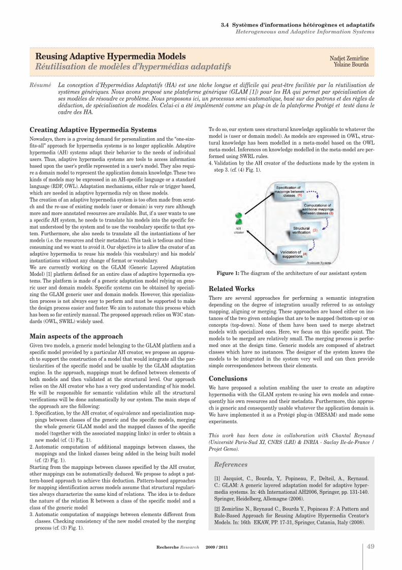
.....................................................................................................................................................................................................................................
Reusing Adaptive Hypermedia ModelsRéutilisation de modèles d’hypermédias adaptatifs
.....................................................................................................................................................................................................................................
Résumé La conception d'Hypermédias Adaptatifs (HA) est une tâche longue et difficile qui peut-être facilitée par la réutilisation desystèmes génériques. Nous avons proposé une plateforme générique (GLAM [1]) pour les HA qui permet par spécialisation deses modèles de résoudre ce problème. Nous proposons ici, un processus semi-automatique, basé sur des patrons et des règles dedéduction, de spécialisation de modèles. Celui-ci a été implémenté comme un plug-in de la plateforme Protégé et testé dans lecadre des HA.
Systèmes d'informations hétérogènes et adaptatifsHeterogeneous and Adaptive Information Systems
Nadjet ZemirlineYolaine Bourda
Creating Adaptive Hypermedia SystemsNowadays, there is a growing demand for personalization and the “one-size-fits-all” approach for hypermedia systems is no longer applicable. Adaptivehypermedia (AH) systems adapt their behavior to the needs of individualusers. Thus, adaptive hypermedia systems are tools to access informationbased upon the user's profile represented in a user's model. They also requi-re a domain model to represent the application domain knowledge. These twokinds of models may be expressed in an AH-specific language or a standardlanguage (RDF, OWL). Adaptation mechanisms, either rule or trigger based,which are needed in adaptive hypermedia rely on these models. The creation of an adaptive hypermedia system is too often made from scrat-ch and the re-use of existing models (user or domain) is very rare althoughmore and more annotated resources are available. But, if a user wants to usea specific AH system, he needs to translate his models into the specific for-mat understood by the system and to use the vocabulary specific to that sys-tem. Furthermore, she also needs to translate all the instantiations of hermodels (i.e. the resources and their metadata). This task is tedious and time-consuming and we want to avoid it. Our objective is to allow the creator of anadaptive hypermedia to reuse his models (his vocabulary) and his models'instantiations without any change of format or vocabulary.We are currently working on the GLAM (Generic Layered AdaptationModel) [1] platform defined for an entire class of adaptive hypermedia sys-tems. The platform is made of a generic adaptation model relying on gene-ric user and domain models. Specific systems can be obtained by speciali-zing the GLAM generic user and domain models. However, this specializa-tion process is not always easy to perform and must be supported to makethe design process easier and faster. We aim to automate this process whichhas been so far entirely manual. The proposed approach relies on W3C stan-dards (OWL, SWRL) widely used.
Main aspects of the approachGiven two models, a generic model belonging to the GLAM platform and aspecific model provided by a particular AH creator, we propose an approa-ch to support the construction of a model that would integrate all the par-ticularities of the specific model and be usable by the GLAM adaptationengine. In the approach, mappings must be defined between elements ofboth models and then validated at the structural level. Our approachrelies on the AH creator who has a very good understanding of his model.He will be responsible for semantic validation while all the structuralverifications will be done automatically by our system. The main steps ofthe approach are the following:1. Specification, by the AH creator, of equivalence and specialization map-pings between classes of the generic and the specific models, mergingthe whole generic GLAM model and the mapped classes of the specificmodel (together with the associated mapping links) in order to obtain anew model (cf. (1) Fig. 1).
2. Automatic computation of additional mappings between classes, themappings and the linked classes being added in the being built model(cf. (2) Fig. 1).
Starting from the mappings between classes specified by the AH creator,other mappings can be automatically deduced. We propose to adopt a pat-tern-based approach to achieve this deduction. Pattern-based approachesfor mapping identification across models assume that structural regulari-ties always characterize the same kind of relations. The idea is to deducethe nature of the relation R between a class of the specific model and aclass of the generic model3. Automatic computation of mappings between elements different fromclasses. Checking consistency of the new model created by the mergingprocess (cf. (3) Fig. 1).
To do so, our system uses structural knowledge applicable to whatever themodel is (user or domain model). As models are expressed in OWL, struc-tural knowledge has been modelled in a meta-model based on the OWLmeta-model. Inferences on knowledge modelled in the meta-model are per-formed using SWRL rules. 4. Validation by the AH creator of the deductions made by the system instep 3. (cf. (4) Fig. 1).
Figure 1: The diagram of the architecture of our assistant system
Related WorksThere are several approaches for performing a semantic integrationdepending on the degree of integration usually referred to as ontologymapping, aligning or merging. These approaches are based either on ins-tances of the two given ontologies that are to be mapped (bottom-up) or onconcepts (top-down). None of them have been used to merge abstractmodels with specialized ones. Here, we focus on this specific point. Themodels to be merged are relatively small. The merging process is perfor-med once at the design time. Generic models are composed of abstractclasses which have no instances. The designer of the system knows themodels to be integrated in the system very well and can then providesimple correspondences between their elements.
ConclusionsWe have proposed a solution enabling the user to create an adaptivehypermedia with the GLAM system re-using his own models and conse-quently his own resources and their metadata. Furthermore, this approa-ch is generic and consequently usable whatever the application domain is.We have implemented it as a Protégé plug-in (MESAM) and made someexperiments.
This work has been done in collaboration with Chantal Reynaud(Université Paris-Sud XI, CNRS (LRI) & INRIA - Saclay Ile-de-France /Projet Gemo).
Recherche Research 2009 / 2011 49
3. INFORMATIQUE ET RÉSEAUX COMPUTER SCIENCE AND NETWORKS
3.4 Systèmes d'informations hétérogènes et adaptatifs Heterogeneous and Adaptive Information Systems
References
[1] Jacquiot, C., Bourda, Y,. Popineau, F., Delteil, A., Reynaud. C.: GLAM: A generic layered adaptation model for adaptive hyper-media systems. In: 4th International AH2006, Springer, pp. 131-140.Springer, Heidelberg, Allemagne (2006).
[2] Zemirline N., Reynaud C., Bourda Y., Popineau F.: A Pattern andRule-Based Approach for Reusing Adaptive Hypermedia Creator'sModels. In: 16th EKAW, PP. 17-31, Springer, Catania, Italy (2008).
Chapitre 3:Chapitre 3.qxd 26/10/09 14:05 Page10

Systèmes situésSituated Systems
Sujets1. Environnements intelligentsLes moyens de captation et de traitement d'information peuvent main-tenant être enfouis dans les objets du quotidien et dans nos environne-ments (domicile, bureau, voiture). Ces moyens peuvent être utiliséspour améliorer la qualité de vie de tout un chacun mais peuvent aussipermettre le maintien à domicile de personnes dépendantes ou ensituation de handicap. Néanmoins, c'est l'humain qui doit être au centredes développements technologiques et c'est pour cette raison que l'adap-tation doit être intrinsèque aux méthodes développées dans ce cadre.
2. Robotique cognitiveL'approche située ne peut se concevoir que s'il y a interaction physiqueentre les machines et le monde. La robotique est un des meilleursmoyens d'ancrer l'intelligence dans le monde réel et en devient uneapplication privilégiée de l'approche située.
3. Interfaces homme-machineL'interaction est au cœur de l'approche présentée et la nécessité d'adap-tation autonome qui est recherchée est souvent créée par la présenced'humains dans l'environnement des machines. Les interfaces entremachines et humains peuvent prendre plusieurs formes comme lesinterfaces vocales, multimodales ou cerveau-machine.
4. Modèles d'inspiration biologiqueDes méthodes d'apprentissage d'inspiration biologique sont mises aupoint comme la modélisation corticale ou l'apprentissage par renforce-ment.
Topics1. Smart EnvironmentsSensors and information processing units can now be embedded intoday-to-day life objects as well as in our environments (home, office, cars).Those means can be used to enhance the quality of life for each of us butcan also enable elderly, impaired or dependent persons to stay longer athome. However, the human has to be at the centre technological develop-ments. This is why adaptation should be at the heart of the methodsdeveloped in this framework.
2. Cognitive RoboticsThe situated approach can only be envisioned if physical interactionsbetween machines and the real world happen. Robotics is one of the bestmeans to anchor intelligence in the real world. It therefore becomes aprivileged application of the situated approach.
3. Human-Machine InteractionInteraction is at the heart of the situated approach and the necessity ofautonomous adaptation is often created because of the presence ofhumans in the machines environment. Interfaces between man andmachines can be of several types such as voice-based, multimodal orbrain-machine interfaces.
4. Bio-inspired modelsArtificial learning methods inspired from biology are under focus suchas cortical modeling and reinforcement learning.
Olivier PIETQUINÉquipe IMSCampus de MetzTél. : 33 (0) 3 87 76 47 70 E-mail : [email protected]
Hervé FREZZA-BUET Équipe IMSCampus de MetzTél. : 33 (0) 3 87 76 47 35 E-mail : [email protected]
3.5
50
Pour tout renseignement s'adresser à : For further information, please contact:
L'approche située du traitement de l'information vise à développer desmachines autonomes capables d'évoluer dans des environnements naturelset donc hautement non-stationnaires (du fait de la présence d'humains parexemple) et possédant des facultés d'adaptation. En particulier, l'approchesituée de la perception considère la captation (ou la perception), l'analyse(ou le raisonnement) et la décision (ou l'action, le comportement) comme dif-férentes modalités d'un même processus visant à l'accomplissement d'unetâche dans un environnement. La perception n'est alors plus considéréecomme passive comme dans les approches ascendantes classiques ou lesinformations sont traitées de manière hiérarchisée, mais plutôt comme fai-sant partie d'une démarche active, par interaction, visant la découverte d'in-formations pertinentes pour la tâche à laquelle le système est dévolu. C'estdonc la tâche et l'interaction avec l'environnement qui pilotent l'extractiond'information et pas uniquement une connaissance a priori du concepteur,ce qui confère aux machines adaptabilité et autonomie.
. . . . . . . . . . . . . . . . . . . . . . . . . . . . . . . . . . . . . . . . . . . . . . . . . . . . . . . . . . . . . . . . . . . . . . . . . . .
The situated approach to information processing aims at developing auto-nomous machines able to evolve in natural environments and so highlynon-stationary (because of the presence of humans, for instance) and sho-wing adaptation capabilities. Especially, the situated approach to percep-tion considers sensing (or perception), analysis (or reasoning)and decision(or action, behavior) as different modalities of a same process which goal isthe achievement of a task in a given environment. Perception is not consi-dered anymore as passive as in standard approaches where information is processed in a hierarchical manner. It is regarded as being an active process happening through interaction with the environment so as to collect relevant information regarding the application at seek. Informationextraction is therefore driven by the task and interactions with the envi-ronment and not only according to designer's knowledge and expertise.This makes machines adaptive and more autonomous.
. . . . . . . . . . . . . . . . . . . . . . . . . . . . . . . . . . . . . . . . . . . . . . . . . . . . . . . . . . . . . . . . . . . . . . . . . . .
3. INFORMATIQUE ET RÉSEAUX COMPUTER SCIENCE AND NETWORKS
Chapitre 3:Chapitre 3.qxd 26/10/09 14:05 Page11

.....................................................................................................................................................................................................................................
Dynamic neural fieldsChamps neuronaux dynamiques
.....................................................................................................................................................................................................................................
Résumé Les champs neuronaux dynamiques sont une population d'unités de calcul qui modélisent la surface corticale. Les connexionsforment une topologie 2D qui sert de base aux compétitions au sein de cette population. Les calculs unitaires sont décrits parune équation différentielle en espace et en temps, faisant de l'ensemble de la population un système dynamique complexe.La population répond à un profile de stimulation en contrastant ce profil, le ramenant à quelques activités isolées. Cette opération est utilisée comme processus de décision dans nos systèmes situés, pouvant réduire l'information tout en restantfortement lié à l'évolution des entrées.
Hervé Frezza - Buet
Recherche Research 2009 / 2011 51
An equation for competitionDynamic neural fields are defined by a population of computation al units,referenced in a continuous space X of positions (usually 1D or 2D). At eachposition x in X, a unit is fed with an input i(x) and computes u(x) as an out-put. This output is driven by a differential equation, as the one presentedhereafter, proposed by Amari [1]. Lateral coupling weigh tkernel w is usual-ly a difference of Gaussians.
Once discretized according to both space and time, the equation is the acti-vation rule of a cellular automata, which is a discrete dynamical system.This system continuously evolves toward some equilibrium configuration. Ifparameters are chosen in a suitable way, the u(x) distribution at equilibriumis made of sparse bumps of activity, placed where the input distribution i(x)is the most compact. If i(x) represents the result of some filtering processcentered at x, the field activity consists of selecting over the field X the fewplaces where the filtering process is the mostly responding (cf. figure 1).
Figure 1: Neural field (here a disk). The light surface represents i(x) andthe darker one represents u(x), that is the distributed decision computed bythe field. Such a decision process is the basis for the situated decisionmechanisms investigated in our team.
This selection can be viewed as a robust reduction mechanism, reducinginformation according to a population compromise rather than an arbitrarythreshold. This allows us to consider decisions, that usually belong to thesymbolic domain due to their binary nature, as processes that are keptgrounded in the analogical real world. This grounding ensures that the deci-sion is permanently recomputed as input profile changes.
Multimodal self organizationOn the basis of such a decision process, we have set up an unsupervisedlearning technique, close to Kohonen’s Self-Organizing Maps (SOM). Asopposed to SOMs, one advantage here is that the learning process can beparallelized since competition is distributed. This has allowed the imple-mentation on our PC cluster (InterCell project [2]). From this learningmodule, a multimodal adaptive architecture as been defined [3] allowing tobuilt controllers. It is made of initially undifferentiated elements (thefields), that become more and more specialized as the system interacts withits environment to actually achieve the control. Handling such complexdynamical systems requires analysis and visualizing tools, that are provi-
ded for cluster simulation in the framework of InterCell, allowing us toaddress large scale problems. Moreover, as reinforcement learning is alsoinvestigated, new equations for dynamic neural fields have also been pro-posed [4].
Figure 2:Multimodal architecture based on 4 neural fields. Each field dealswith a specific modality, or is at the intersection of some other fields, tohandle multimodal computation. Each field is also performing competition,and all competitive processes are coupled through inter-field connections.Once learning is achieved, filters are tuned so that related ones standactually connected places.
ConclusionDynamic neural fields can be used to set up a decision process withoutrequiring the designer to make any rule explicit. This is coherent with ourmain goal to propose new algorithms for situated perception. Such mecha-nisms are inspired from the dynamics of cortical computation, as describedin biology. Indeed, the cortex in mammals is one of the major adaptive struc-tures for setting up multimodal behaviors.
3. INFORMATIQUE ET RÉSEAUX COMPUTER SCIENCE AND NETWORKS
3.5 Systèmes situésSituated Systems
References
[1] S-I Amari, Biological Cybernetics, 27:77–87, 1977
[2] http://intercell.metz.supelec.fr
[3] O. Ménard, H. Frezza-Buet, "Model of multi-modal cortical processing:Coherent learning in self-organizing modules". In Neural Networks, 18(5-6):646-655, 2005
[4] L. Alecu, H. Frezza-Buet, "Reconciling neural fields to selforganiza-tion". In ESANN’09, 2009.
Chapitre 3:Chapitre 3.qxd 26/10/09 14:05 Page12

Systèmes distribués et grilles de calculsDistributed Systems and Computing grids
Stéphane VIALLEÉquipe IMSCampus de MetzTél. : 33 (0) 3 87 76 47 20E-mail : [email protected]
Virginie GALTIER Équipe IMSCampus de Metz Tél. : 33 (0) 3 87 76 47 36E-mail : [email protected]
3.6
52
Pour tout renseignement s'adresser à : For further information, please contact:
Les architectures multi-cœurs sont devenues courantes et progressentrapidement, les clusters sont également devenus des moyens de calcul trèsrépandus. D'autre part, la France a récemment intensifié sa stratégied'équipement en supercalculateurs et l'Europe dispose maintenant degrilles de calculs scientifiques opérationnelles. Toutes ces architecturesparallèles et distribuées requièrent des algorithmes et des paradigmes deprogrammation différents, mais se retrouvent aujourd'hui combinées dansdes « machines hétérogènes », comme des clusters de machines multi-cœurs, ou des supercalculateurs équipés d'accélérateurs matériels. Nosrecherches visent à concevoir des algorithmes et des environnements dedéveloppements pour des architectures hétérogènes à large échelle. Cettedémarche inclut la conception de mécanismes de tolérance aux pannes,problème incontournable dans les systèmes parallèles à large échelle. Nous concevons également des architectures de services distribués per-mettant de profiter pleinement et facilement de ressources informatiquesréparties sur plusieurs sites. Enfin, nous analysons autant les perfor-mances calculatoires qu'énergétiques de nos systèmes distribués.
. . . . . . . . . . . . . . . . . . . . . . . . . . . . . . . . . . . . . . . . . . . . . . . . . . . . . . . . . . . . . . . . . . . . . . . . . . .
Multi-core architectures are available and improving, and clusters are nowwell known architectures installed in many laboratories and companies.Moreover, today France purchases more supercomputers and Europe hasoperational scientific computing Grids. These architectures requires diffe-rent parallel programming strategies, and are now mixed in “heteroge-neous machines”, like clusters of multi-core nodes, or supercomputers withhardware accelerators. We aim to design algorithms and development envi-ronments for large scale heterogeneous architectures. This approachincludes the design of fault tolerance mechanisms, as failures are unavoi-dable on large scale systems. We also design service oriented architectures, in order to easily use compu-ting resources distributed on different sites. Finally, we study both compu-ting and energetic performances of all our parallel and distributed systems.
. . . . . . . . . . . . . . . . . . . . . . . . . . . . . . . . . . . . . . . . . . . . . . . . . . . . . . . . . . . . . . . . . . . . . . . . . . . .
Sujets1. Distribution de calculs de contrôle stochastique en grandedimensionNous avons distribué sur clusters de PCs et sur supercalculateurs IBMBlue Gene (32000 cœurs) des calculs de contrôle stochastique en gran-de dimension, appliqués à l'optimisation de problèmes de gestion deproduction d'énergie.
2. Distribution de calculs financiers sur clusters de GPUsLes clusters de PC équipés d'accélérateurs matériels, comme les GPUs,permettent d'atteindre de hautes performances avec une faible consom-mation énergétique, mais nécessitent de concevoir des algorithmesparallèles complexes. Nous l'avons fait avec succès pour des pricingsd'options européennes exotiques.
3. Mécanisme de tolérance aux pannes pour des applications surcluster de PCsConception d'un modèle et d'un mécanisme de tolérance aux pannes auniveau applicatif, suivant des patrons de conception simples à utiliseret limitant les surcoûts d'exécution.
Topics1. Parallelization and distribution of large scale stochasticcontrol computationsWe have distributed large scale stochastic control computations on largePC clusters and IBM Blue Gene supercomputers (32000 cores), to solvesome optimisation problems of energy production management.
2. Distribution of financial computations on GPU clustersPC clusters with GPU (on each node) achieve high performances withlow energy consumption, but they require very complex parallel algo-rithms. We succeeded to do it for some exotic european option pricing.
3. Fault tolerance mechanisms for applications running on PCclustersDesign fault tolerance model and mechanisms, to use at application levelaccordingly to design patterns, and exhibiting very limited overheads.
3. INFORMATIQUE ET RÉSEAUX COMPUTER SCIENCE AND NETWORKS
Chapitre 3:Chapitre 3.qxd 26/10/09 14:05 Page13

.....................................................................................................................................................................................................................................
Algorithmes multi-paradigmes pour des clusters de CPU et GPU multi-coeursMulti-paradigm algorithms for multi-core CPU and GPU clusters
.....................................................................................................................................................................................................................................
Résumé Les architectures parallèles modernes sont hétérogènes, comme des clusters de CPUs multicoeurs ou de GPUs. Ce type d'architecture peut atteindre des performances très élevées, mais nécessite des parallélisations complexes multi-grains et multiparadigmes. Les principaux défis à relever consistent à concevoir des algorithmes multi-paradigmes efficaces et desenvironnements de développement de haut niveau, et à maîtriser la consommation énergétique de ces architectures.
Stéphane Vialle
Recherche Research 2009 / 2011 53
Multi-paradigm programming of heterogeneousarchitecturesPC cluster are cheap to purchase, and today they are automatically multi-core PC clusters. Moreover it is easy to add a GPU card in each PC to get aGPU cluster, i.e: a PC cluster with “hardware accelerator” inside each node.However, this kind of heterogeneous architectures remain difficult to pro-gram. Their programming includes two level of parallelism, with differentgrains.
The first level is “coarse grained” and aims to distribute computations acrossthe nodes, while minimizing inter-node communications and achieving thesecommunications in parallel of the computations (overlapping computationsand communications). The programming paradigm of this parallelism levelis message passing, and the MPI library is the most common developmenttool for this paradigm. The second level of parallelism is “medium grained”and exploits the cores of a node. Its natural programming paradigm is memo-ry sharing, and the most common associated programming tools are multi-thread libraries. They can be explicit multithread libraries, like POSIXthreads, or they can supply a higher level of multithreading, like OpenMPbased on pre-processing directives, or like Intel-TBB based on C++ tem-plates. Finally, a third level of parallelism is “fine grained” and exploitsSIMD computing units of GPUs, or SSE units of CPUs. Its programmingparadigm is data parallelism, running a same operation flow on a vector ofdata. Standard are emerging, but currently programs for hardware accelera-tors are not portable. Beyond these three levels of parallelism it exist a “verycoarse grained” level when using a multisite Grid of computing resources,interconnected through Wide Area Networks. The associated programmingparadigm remains the Remote Procedure Call or the message passing, withasynchronous calls in order to hide the long communication times.
For heterogeneous architectures, we need to exploit simultaneously diffe-rent grains of parallelism: to design multi-grain parallel algorithms and touse different parallel programming paradigms. From a pure technical pointof view, it is possible to use both message passing with MPI, and multi-threading with OpenMP or data-parallelism of GPUs with CUDA. But thedesign of efficient multi-paradigm algorithms remains complex. We lack ofalgorithmic knowledge, and we lack of adapted high level development envi-ronment to reduce development times.
Algorithmic development examplesRecently we have designed two multi-paradigm parallel applications: anoptimization of energy management, designed with EDF company on amulti-core CPU cluster and on a supercomputer, and exotic european optionpricing, designed with ENPC and CERMICS laboratories on a GPU cluster.
The application of the optimization of the energy management uses complexstochastic control algorithms. Their distribution on coarse grained architec-tures requires redistributing data and computations at each iteration.Moreover, the communication scheme depends on previous computed valuesand computing nodes have to compute and to establish their routage planat each iteration before to execute it. On each node, a second and mediumgrained parallelization allows to easily spread the local computations on thedifferent cores of each CPU. Finally, despite many parallelism managementoperations and their associated overheads, our parallel algorithm andimplementation (using MPI and OpenMP) have been efficient on a 256 dual-core PC cluster and on an IBM BlueGene/P with up to 8192 quad-core nodes(more than 32000 cores) [1]. An implementation on a GPU cluster isongoing.
The parallelization of an exotic european option pricer on a GPU clusterappeared to be symmetric to the previously described parallelization ofenergy management optimizations. The coarse grained parallelization on aPC cluster has been straightforward to develop, leading to an embarrassin-gly parallel implementation. It does not require inter-node communications,excepted at the beginning and at the end of the application, in order to dis-tribute data and to collect results. But the fine grained parallelization onGPU has required strong development efforts to be efficient. When callingGPU routines from a CPU routine, the most time consuming operations canbe the data transfers between CPU and GPU memories. It is advised totransfer data onto the GPU card and to run the maximum number of ope-rations before to transfer back results onto the CPU. In the case of the exo-tic european option pricing we have implemented several random numbergenerators on the GPU, in order to run all computations on the GPU and toget uncorrelated random number suites. Finally, the parallelization on a 16GPU cluster appeared 2.8 times faster than the parallelization on a 256dual-core CPU cluster, and has consumed 28 times less energy! The productof the speedup and the energy saving showed it was 80 times more interes-ting to use our 16 GPU cluster instead of our 256 dual-core CPU cluster [2].
PerspectivesWe are currently designing an algorithmic and a programming knowledgeon heterogeneous architectures. However, we consider it is mandatory todesign some modern development environments, adapted to these architec-tures and hiding the exact node features. Some of our research works, achie-ved in collaboration with INRIA and with EDF R&D, address this issue.
AcknowledgmentThe author wants to thank EDF for supporting this research.
3. INFORMATIQUE ET RÉSEAUX COMPUTER SCIENCE AND NETWORKS
3.6 Systèmes distribués et grilles de calculs Distributed Systems and computing grids
References
[1] S-P. Vezolle, S.Vialle and X. Warin. Large Scale Experiment andOptimization of a Distributed Stochastic Control Algorithm. Applicationto Energy Management Problems. Workshop on Large-Scale ParallelProcessing (LSPP 2009). 2009.
[2] L.A. Abbas-Turki, S. Vialle, B. Lapeyre and P. Mercier. HighDimensional Pricing of Exotic European Contracts on a GPU Cluster, andComparison to a CPU Cluster. Second Workshop on Parallel andDistributed Computing in Finance (PDCoF 2009). 2009.
Chapitre 3:Chapitre 3.qxd 26/10/09 14:05 Page14

Performance de systèmes System performance
Joanna TOMASIKSujets 1 à 3 / Topics 1 to 3Département InformatiqueCampus de GifTél. : 33 (0) 1 69 85 14 79E-mail : [email protected]
Mohamad ASSAADSujet 4 / Topic 4Département TélécommunicationsCampus de GifTél. : 33 (0) 1 69 85 14 43E-mail : [email protected]
3.7
54
Pour tout renseignement s'adresser à : For further information, please contact:
Notre objectif consiste à étudier un système de sa définition fonctionnelleà la proposition de solutions validées avec des performances évaluées.Nous nous intéressons donc : 1) au choix et à la validation de modèles cal-culables qui tiennent compte de tous les éléments pertinents du système,2) à la définition formelle du problème étudié dans ce modèle et au calculde sa complexité algorithmique, 3) à la proposition de solutions algorith-miques, centralisées ou distribuées selon les cas, notamment des solutionsheuristiques dans le cas où le problème s'avère NP-complet, 4) à la vali-dation de l'efficacité de ces algorithmes en termes de temps d'exécution etde qualité par leur introduction dans le modèle déjà construit et 5) à larésolution ce modèle modifié afin de décider si les heuristiques proposéesont un impact positif sur l'efficacité du système.Pour pouvoir valider l'efficacité de nos solutions heuristiques, nous utili-sons différents concepts et outils comme la théorie des files d'attente. Ilexiste un éventail de méthodes analytiques et empiriques (simulations)qui, en trouvant la solution du modèle, donnent des informations sur l'ef-ficacité du système.
. . . . . . . . . . . . . . . . . . . . . . . . . . . . . . . . . . . . . . . . . . . . . . . . . . . . . . . . . . . . . . . . . . . . . . . . . . .
We study a system starting from its functional definition up to proposedsolutions which are validated by evaluation of the system performance. Weare interested in: 1) choice and validation of calculable models taking intoaccount pertinent elements of the system, 2) formal definition of a studiedsystem within the given model with its complexity computation, 3) propo-sition of algorithmic solutions (centralised or distributed), notably heuris-tic ones in the case of the NP-complete problem treatment, 4) validation ofperformance of these algorithms in terms of execution time and quality bytheir introduction into models which have been already constructed, and 5)resolution of the modified model in order to decide whether the proposedheuristic algorithms have a positive impact upon the system performance.To answer these questions, we use different concepts and tools such as thequeueing theory. There is a wide range of analytic methods (Markov chains)and empirical ones (simulations) which, by finding the solution to themodel, offer information about the system performance.
. . . . . . . . . . . . . . . . . . . . . . . . . . . . . . . . . . . . . . . . . . . . . . . . . . . . . . . . . . . . . . . . . . . . . . . . . . .
3. INFORMATIQUE ET RÉSEAUX COMPUTER SCIENCE AND NETWORKS
Sujets1. Algorithmes distribués pour le routage multi-contraint satis-faisant la qualité de service dans un réseau inter-domaineAlgorithmes de réservation multi-contraintes dans un environnementBGP. Algorithmes de détection de congestion dans ce réseau. Validationpar simulation.
2. Méthodes décompositionnelles pour les files d'attenteMatrices de Markov. Réseaux d'automates stochastiques. Algèbre deprocessus pour l'évaluation de performances.
3. Complexité et approximabilité de problèmes Traitement de problèmes NP-complets. Problèmes de Steiner. Preuvesd'inapproximabilité.
4. Performance et QoS des services IP multimedia dans lesréseaux sans filUMTS, HSDPA, WiMAX, interaction entre TCP et lien sans fil, algo-rithmes d'ordonnancement, analyse du trafic dans des réseaux wireless(QoS, délai, gigue).
Topics1. Distributed algorithms for multi-constraint routing satisfying Quality of Service in an inter-domain networkAlgorithms for multi-constraint reservation in a BGP environment.Algorithms for congestion detection in the same environment.Validation by simulation.
2. Decompositional methods for queueing modelsConstruction of Markov matrices. Stochastic automata networks.Performance evaluation process algebra.
3. Problems complexity and approximabilityTreatement of NP-complete problems. Steiner problems.Inapproximability proofs.
4. Performance and QoS of IP multimedia services in wireless networksUMTS, HSDPA, WiMAX, interaction between TCP and wireless link,scheduling study, streaming traffic analysis in wireless systems(QoS, delay, jitter).
Chapitre 3:Chapitre 3.qxd 26/10/09 14:05 Page15

.....................................................................................................................................................................................................................................
Exploiting the inter-domain hierarchy for the QoS routingExploitation de la hiérarchie inter-domaine pour le routage avec QoS
.....................................................................................................................................................................................................................................
Résumé Le routage inter-domaine dans l'Internet est assuré par le protocole BGP qui garantit à chaque domaine l'indépendance deschoix et des annonces des routes. Ce mécanisme seul ne permet pas la satisfaction de QoS et l'ingénierie de trafic. Pour pallier ces manques, nos travaux dans le réseau inter-domaine nous ont amené à exploiter la hiérarchie introduite par les relations commerciales existantes entre les domaines. Nous proposons un mécanisme envoyant des messages d'alerte pour communiquer l'état de congestion d'un domaine uniquement à chaque domaine concerné. Notre solution limite le nombred'alertes envoyées grâce à la structure hiérarchique de l'Internet. Notre heuristique est distribuée et traite un problème NP-complet et inapproximable. Pour pouvoir valider notre mécanisme d'envoi d'alertes pour signaler la congestion possible,nous avons proposé un générateur de topologies aléatoires avec hiérarchie SHIIP (Supélec Hierarchy Inter-domain InductingProgram).
Joanna TomasikMarc-Antoine Weisser
Recherche Research 2009 / 2011 55
Hierarchy of inter-domain networkAn inter-domain network is composed of independent domains administra-ted by operators. Links connecting domains are characterized by two typesof relationships: P2C and P2P.A P2C relationship links providers which sellconnectivity to their customers. A P2P relationship exists between twodomains which share connectivity. The inter-domain hierarchy has animpact on the current inter-domain routing because routes are establishedaccording to commercial relationships. The only routes present in an inter-domain network are composed of an uphill and a downhill component. Adownhill component is a list of consecutive links labeled with a P2C rela-tionship. An uphill component is a list of consecutive links labeled with aC2P relationship which is dual to a P2C. The uphill and downhill compo-nents are connected either by zero or by one P2P relationship. Such routesare called valley-free.
Problem modelingGiven a network, a traffic matrix and a routing matrix, we say that a nodeis perturbed if the total amount of traffic transiting through it, emitted byit, and sending to it is greater than its capacity. A perturbed path is a pathcontaining at least one perturbed node. Given a network and a trafficmatrix, our problem is to find a valley-free routing matrix which minimizes1) the number of perturbed nodes (network approach); 2) the volume of thetraffic passing along perturbed paths (traffic approach). We focus on the net-work approach only because we assume that minimizing the number of per-turbed nodes may be a good heuristic approach to minimize the number ofperturbed paths as well as the volume of perturbed traffic. In [2] we haveproved that this problem is NP-complete and inapproximable. The proofconsists to reduce the directed Steiner tree problem to our problem.
Alert sending algorithmOur distributed algorithm is based upon the principle of sending alert mes-sages which carry information about the domain congestion state. Eachnode informs its clients when it becomes perturbed in order to allow themto change their routing. Each node also keeps its neighbors informed whenit returns to an operational state. We limit the range of their diffusion bytaking advantage of the inter-domain hierarchy. Each node contains a list ofpossible next hops towards every destination. These lists are constructedwith routes announced by BGP. Their construction guarantees that all nexthops satisfy the valley-free property of routes. Each node can be in either oftwo distinct states: green or red. A node state is red if at least one of the twofollowing conditions is satisfied: 1) the amount of traffic transiting throughthe node, sending from it and sending to it, is greater than its capacity; 2)at least one of its next hops which is a provider is in red state. A node can-not become red because of its customer and peer congestion. Because of thisfact, our algorithm avoids the spreading of red nodes in the entire networkwhen a single node becomes red. We use the hierarchy to limit the numberof nodes in red state as well as the messages sent: a node which has a cus-tomer or a peer in red state as a next hop should not be in red state itself.The node which is not in red state is in green state. The green state is adomain stable state.
Performance evaluationWe used our generator of hierarchical topologies SHIIP (SupélecHierarchical Inter-domain Inferring Program) [1], available athttp://wwwsi.supelec.fr/~weisser/fr/shiip.html) to obtain network for expe-riences. We also choose the capacities in generated topologies to study net-works which are not over-dimensioned. On the Internet, the largestdomains with the largest capacities are at the top of the hierarchy. Domainswith smaller capacities are at the bottom of the hierarchy. We suppose thatthe domains in the core are never perturbed. The first performance measu-re is obviously the number of perturbed nodes because it is also the optimi-zation criterion for our algorithm. The second one is the number of pertur-bed paths and the third one is the amount of perturbed traffic. These threemeasures are essential for the comparison of performance results of our dis-tributed algorithm with the results of BGP and the lowest theoreticalbound. In Figure 1 we present the gain in perturbed node/path numberobtained with our algorithm comparing to BGP routing [2].
Figure 1: The number of perturbed nodes and paths averaged for a simulation run series, network of 100 nodes and heavy traffic.
3. INFORMATIQUE ET RÉSEAUX COMPUTER SCIENCE AND NETWORKS
3.7 Performance de systèmes System performance
References
[1] M.-A. Weisser, J. Tomasik, “Automatic Induction of Inter-DomainHierarchy in Randomly Generated Network Topologies”, 10th ACM/SIG-SIM CNS'07, pp. 77-84, Norfolk, VA, USA, 26-28 March 2007.
[2] M.-A. Weisser, J. Tomasik, D. Barth, “Congestion avoiding mechanismbased on inter-domain hierarchy”, IFIP Networking 2008, LNCS 4982,pp. 470-481, Singapore, 5-9 May 2008.
Chapitre 3:Chapitre 3.qxd 26/10/09 14:05 Page16

56
Chapitre 4:Chapitre 4.qxd 26/10/09 14:06 Page1

57
4. TÉLÉCOMMUNICATIONSTELECOMMUNICATIONS
4Chapitre 4:Chapitre 4.qxd 26/10/09 14:06 Page2

4.1 Communications numériques Digital communications
Communications numériquesDigital Communications
Pierre DUHAMELL2S - Division SignauxCampus de GifTél. : 33 (0) 1 69 85 17 16E-mail : [email protected]
Hikmet SARIDépartement TélécommunicationsCampus de GifTél. : 33 (0) 1 69 85 14 31E-mail : [email protected]
Daniel LE GUENNECÉquipe SCEE - IETRCampus de RennesTél. : 33 (0) 2 99 84 45 45E-mail : [email protected]
4.1
58
Pour tout renseignement s'adresser à : For further information, please contact:
4. TÉLÉCOMMUNICATIONS TELECOMMUNICATIONS
Dans les systèmes de communications numériques actuels, un problèmeimportant est de pouvoir transmettre un message sans erreur et sécuriséavec des ressources limitées. En raison de variations des caractéristiquestemporelles/fréquentielles/spatiales des utilisateurs, le medium sans filsoffre divers degrés de liberté à exploiter bien que cela puisse induire deserreurs et une connaissance imparfaite du canal à l’émetteur et/ou aurécepteur. De plus, dans les futurs réseaux sans fils, la qualité de service(en termes de sécurité, taux d'erreur) doit être assurée. Dans cetteoptique, deux approches se présentent : La première consiste à améliorer la qualité de la transmission point àpoint en offrant de la diversité et en ajustant correctement les paramètresdu récepteur. Le développement de codes espace-temps permet d'améliorerla diversité tandis que l'égalisation, l'estimation, le traitement non-linéai-re permettent d'optimiser le récepteur.La seconde approche consiste à exploiter de manière opportuniste lesdegrés de liberté du canal, en fonction de la connaissance à l'émission. Lesexemples pratiques concernent le canal à interférence, le network MIMOainsi que les canaux broadcast avec des messages confidentiels.
. . . . . . . . . . . . . . . . . . . . . . . . . . . . . . . . . . . . . . . . . . . . . . . . . . . . . . . . . . . . . . . . . . . . . . . . . . .
In practical digital communication systems, a major challenge consists indealing with the underlying wireless medium under a limited resource.Due to its variation in time/frequency/spatial/user domains, the wirelessmedium potentially offers various degrees of freedom to exploit, although itmight induce errors, imperfect knowledge at transmitter or/and receiver.Moreover, in future secured wireless communication systems, one needs toensure reliable transmission while satisfying an additional secrecyconstraint. To handle these situations, there are roughly two approaches: A classical approach aims to either improve the reliability of a point-to-point wireless link by offering some diversity or to detect unknown para-meters by appropriately designing receivers. A design of practical space-time code focuses on the former aspect, while the channel equalization, esti-mation, non-linearity processing, fall into the latter aspect. A more opportunistic approach consists of exploiting available degrees offreedom of the channel together with some side information. The examplesof such approach include interference channels, capacity with side infor-mation, network multiple-input multiple-output (MIMO), and broadcastchannels with confidential messages.
. . . . . . . . . . . . . . . . . . . . . . . . . . . . . . . . . . . . . . . . . . . . . . . . . . . . . . . . . . . . . . . . . . . . . . . . . . .
Sujets1. Techniques de réceptionEgalisation (méthode aveugle pour les systèmes IFDMA).Estimation du canal en présence de forte mobilité.Détection multiutilisateurs.
2. Diversité et codage canalCodes espace-temps à décodage rapide.Optimisation de la redondance en codage canal.Codage canal pour réseaux coopératifs.
3. Communications sécurisées Canaux broadcast avec messages confidentiels.Connaissance du canal imparfaite à l'émission.Codage structuré pour communications sécurisées.
4. Applications de la théorie de l'informationCanaux à interférence.Réseaux MIMO.Interprétation des algorithmes itératifs.Capacité avec information adjacente.
5. Traitement des nonlinéaritésRéduction de la puissance crête des signaux OFDM(A).Réduction des non linéarités par turbo annulation.Applications dans des contextes variés (DVB-T2, SWR, DRM, WLAN).
Topics1. Receiver TechniquesChannel equalization (e.g. blind equalization for IFDMA systems). Channel estimation in the presence of high mobility. Multiuser detection.
2. Diversity and Channel CodingSpace-time codes with fast maximum-likelihood decoding.Redundancy optimization in channel coding.Channel coding for cooperative networks.
3. Physical Layer SecurityBroadcast channels with confidential messages. Imperfect channel state information at transmitter.Structured coding for secured communications.
4. Applications of Information TheoryInterference channels.Network MIMO.Interpretation of iterative algorithms.Capacity with side information.
5. Processing of NonlinearitiesPeak-to-average power ratio (PAPR) reduction of OFDM(A) signals.Non linearity mitigation with turbo cancellation.Applied to DVB-T2, SWR, DRM, WLAN contexts.
Chapitre 4:Chapitre 4.qxd 26/10/09 14:06 Page3

Recherche Research 2009 / 2011
4.1 Communications numériques Digital communications
.....................................................................................................................................................................................................................................
Communications sécurisées sur les canaux sélectifs en fréquence Secured communications over frequency selective fading channels
.....................................................................................................................................................................................................................................
Abstract We consider the secured communication over frequency-selective fading channels. In particular, we focus on the broadcastchannel where a transmitter sends a confidential message to its receiver which must be kept secret to the eavesdropper.For the case of a block transmission followed by a cyclic prefix, the model at hand reduces to a special case of multiple-inputmultiple-output (MIMO) wiretap channel whose secrecy capacity has been proved in [3,4.]. We propose a practical yetorder-optimal Vandermonde precoder that consists of projecting the confidential messages in the null space of the channel seenby the eavesdropper. The proposed scheme can be applied to other multiuser communication scenarios.
Communications numériquesDigital Communications
4. TÉLÉCOMMUNICATIONS TELECOMMUNICATIONS
Mari KobayashiMérouane Debbah
Position du problèmeNous considérons la communication sécurisée où un émetteur transmet unmessage confidentiel destiné à son récepteur tout en le gardant secret vis àvis d'un écouteur. Wyner a introduit ''wiretap channel'' pour modéliser uncanal broadcast dégradé où l'écouteur observe une version dégradée d'unsignal reçu au récepteur [1]. Csiszár et Körner ont ensuite généralisé cemodèle pour le cas non-dégradé avec un message commun [2]. Du faitqu'une capacité secrète positive est atteignable si, et seulement si, la quali-té du récepteur est meilleure que celle de l'écouteur, ces travaux n'avaientpas attiré beaucoup d'attention. Récemment, un nombre significatif de tra-vaux ont été consacrés à ce problème afin d'exploiter les degrés de libertédans le domaine spatial/fréquentiel/temporel. L'idée principale consiste àcacher l'information confidentielle d'une manière opportuniste. En particu-lier, la capacité secrète du multiple-input multiple-output (MIMO) wiretapchannel a été complètement caractérisée par [3] puis son expression analy-tique a été trouvée par [4].
ContributionsPour un canal avec L+1 trajets, nous avons considéré la transmission parbloc (N symboles) sur les canaux sélectifs en fréquence suivi d'un inter-valle de garde (L symboles) pour éviter l'interférence entre les blocs. Cetype de transmission est typiquement utilisé dans les standards tels queIEEE802.11a ou WiMax. Supposant que les deux récepteurs ont la mêmestructure qui est non-modifiable, le canal en question devient un cas spé-cial du MIMO wiretap channel où la matrice MIMO a une structure deToeplitz. Sous ces hypothèses, nous avons proposé un schéma de précoda-ge dénommé ''Vandermonde precoder''. Notre schéma proposé s'inspire dela stratégie optimale pour le MIMO wiretap channel qui projette le mes-sage confidentiel dans un noyau du canal de l'écouteur dans le cas d'unfort rapport signal au bruit (SNR). Pour le cas spécial d'une matrice deToeplitz de taille N * (N+L) avec N lignes indépendantes, il existe unematrice de Vandermonde de taille (N+L) * L, composée des L zéros ducanal, qui permet de cacher l'information confidentielle. Pour ce schémaproposé, nous avons caractérisé :• la région de taux atteignables (R_0, R_c) où R_0, R_c représentent res-pectivement le taux de message commun et message confidentiel ;
• les covariances optimales qui atteignent la région pour certains cas spé-ciaux ;
• le comportement de la région à fort SNR.
L'intérêt majeur de ce schéma réside dans les aspects suivants :• il permet de transmettre L symboles confidentiels sans interférer avecles N symboles simultanément sur un bloc de N+L symboles ;
• il est applicable à n'importe quelle technique de codage de canal clas-sique et garantit la sécurité parfaite. Ce dernier comporte un avantagepar rapport à la méthode conventionnelle nécessitant un codage trèscomplexe (random binning) ;
• il est également applicable aux autres scénarios de communicationsecrète (voir plus de détails [5]).
Pour des raisons évidentes de manque d'espace, nous ne donnons ici qu'unseul exemple de résultat.
Un exemple de résultats (5)La figure 1 représente le taux secret atteignable par Vandermonde preco-ding avec et sans contrôle de puissance en fonction du SNR pour N=64,L=16. Comme référence, nous montrons aussi la performance du « gene-ralized SVD » proposé dans [1]. Nous voyons, par exemple, que les deux
schémas permettent d'augmenter le taux secret à l'ordre de 1/5 log(SNR)en envoyant le message confidentiel sur 16 canaux.
Figure 1 : Taux secret de Vandermonde precodin
Figure 1: Taux secret de Vandermonde precoding
59
Références
[1] A. D Wyner, “The Wiretap Channel,” Bell. Syst. Tech. J., vol. 54,1975.
[2] I. Csiszár and J. Körner, “Broadcast Channels with ConfidentialMessages,” IEEE Trans. Inform. Theory, vol. 24, 1978.
[3] A. Khisti, G. Wornell, A. Wiesel, and Y. Eldar, “On the GaussianMIMO wiretap channel,” Proc. ISIT'07, Nice, France.
[4] R. Bustin, R.Liu, H. Vincent Poor, and S. Shamai (Shitz), “AnMMSE Approach to the Secrecy Capacity of the MIMO GaussianWiretap Channel,” to appear in EURASIP, special issue on WirelessPhysical Security, 2009.
[5] M. Kobayashi, M. Debbah and Shlomo Shamai (Shitz), “On thesecrecy capacity of frequency-selective fading channels : A practicalVandermonde precoding,” to appear in EURASIP, special issue onWireless Physical Security, 2009.
Chapitre 4:Chapitre 4.qxd 26/10/09 14:06 Page4

Systèmes de radiocommunicationsWireless Communications Systems
Pierre DUHAMELL2S – Division SignauxCampus de GifTél. : 33 (0) 1 69 85 17 16E-mail : [email protected]
Mohamad ASSAADDépartement TélécommunicationsCampus de GifTél. : 33 (0) 1 69 85 14 43E-mail : [email protected]
Christophe MOYÉquipe SCEE - IETRCampus de RennesTél. : 33 (0) 2 99 84 45 84E-mail : [email protected]
4.2
60
Pour tout renseignement s'adresser à : For further information, please contact:
Les systèmes de radiocommunications connaissent une évolution extrê-mement rapide depuis le début des années 1990. Les réseaux de troisièmegénération sont maintenant en place, les systèmes WiMAX mobile ontrécemment fait leur apparition et les systèmes de quatrième génération(IEEE 802.16m et LTE Advanced) sont dans une phase de spécification. Les systèmes de quatrième génération font face à des défis technologiquesconsidérables : non seulement, il faut augmenter la capacité des cellulespar des techniques MIMO et d’autres fonctions sophistiquées, mais il fautaussi fournir un service à des utilisateurs avec une forte mobilité.Les travaux de recherche abordent l’optimisation de la couche physique,mais aussi l’allocation des ressources radio par une optimisation inter-couches.
. . . . . . . . . . . . . . . . . . . . . . . . . . . . . . . . . . . . . . . . . . . . . . . . . . . . . . . . . . . . . . . . . . . . . . . . . . .
Wireless Communications Systems are an area, which has been experien-cing an extremely rapid development since the beginning of the 1990s.Third generation networks are now well in place, mobile WiMAX systemshave been recently developed and deployed, and forth-generation networks(WiMAX evolutions based on IEEE 802.16m as well as LTE Advanced) arein the specification phase.Fourth-generation systems are facing considerable technological chal-lenges: Not only the cell capacity and performance must be substantiallyincreased by sophisticated MIMO techniques and other physical layer func-tions, but also service must be provided to users with very high mobility.Research topics in wireless communications systems include optimizationof physical layer functions, adaptive radio resource allocation, and cross-layer design.
. . . . . . . . . . . . . . . . . . . . . . . . . . . . . . . . . . . . . . . . . . . . . . . . . . . . . . . . . . . . . . . . . . . . . . . . . . .
Sujets1. Fonctionnement et surveillance des réseaux électriquesTechniques de transmission et d’accès multiple pour la voie montantedu système LTE.Multiplexage spatial de signaux MIMO en polarisation croisée pourapplications WiMAX mobile et LTE Advanced.Optimisation des ressources radio dans les systèmes WiMAX/LTEpour différents types de trafic.Conception de la couche MAC en présence d’une connaissance impar-faite du canal radio.Optimisation conjointe des ressources radio et des algorithmes derelayage dans un contexte de coopération entre stations de base et uti-lisateurs.Diffusion multiutilisateur (« Multicast ») et optimisations associées
1. Systèmes multistandards et hétérogènesOptimisation des ressources radio dans un environnement hétérogène.Architectures d’équipements radio multi-standards.Gestionnaire de reconfiguration et de radio intelligente d’un équipe-ment.Capteurs pour la radio intelligente.Prise de décision pour la radio intelligente.Traitements du PAPR des signaux multi-standards.Conception d’équipements multi-standards à base d’opérateurs com-muns.Conception de haut-niveau, méta-modélisation.
.
Topics1. Fourth-Generation SystemsTransmission and multiple access for the uplink of LTE systems.Spatial multiplexing of orthogonally polarized MIMO signals for mobile WiMAX and LTE Advanced.Radio resource optimization in WiMAX/LTE systems for various types of traffic.MAC design in the presence of imperfect channel knowledge.Joint optimization of resource allocation and relaying in the context of cooperation between base stations and users.Multicast in wireless networks, and corresponding optimizations.
2. Multistandard and Heterogeneous SystemsRadio resource allocation in a heterogeneous network environment. Multi-standard equipments architecture.Reconfiguration and cognitive radio management for equipments.Cognitive radio sensors.Decision making for cognitive radio.Multi-standards signals’PAPR processing.Multi-standards equipments design based on common operators.High-level design, meta-modeling.
4. TÉLÉCOMMUNICATIONS TELECOMMUNICATIONS
4.2 Systèmes de radiocommunications Wireless communications systems
Chapitre 4:Chapitre 4.qxd 26/10/09 14:06 Page5

.....................................................................................................................................................................................................................................
Optimisation des ressources dans les réseaux hétérogènes Resource Optimization in heterogeneous networks
.....................................................................................................................................................................................................................................
Abstract We develop a discrete optimization framework in order to deal with Radio Resource Management (RRM) in heterogeneous wireless systems. An efficient resource management solution, requiring low computation and signalling overhead, is proposed.This solution consists in splitting the resource allocation problem into two parts. First, Users and Base Stations negotiate amean allocation using a Rate Scheduling algorithm issued from a discrete optimization problem. Then, Base Stations allocate power independently and instantaneously in order to cope with changing radio conditions. Simulation resultsshow that the proposed M3RS converges quickly to an efficient allocation. Indeed, it reduces power usage in all systems and increases the number of satisfied Users compared to a mono-system RRM algorithm.
Christophe MOYÉquipe SCEE - IETRCampus de RennesTél. : 33 (0) 2 99 84 45 84E-mail : [email protected]
Christophe Gaie,Mohamad Assaad Pierre Duhamel
Recherche Research 2009 / 2011 61
Références
[1] S. Boyd and L. Vandenberghe, “Convex Optimization,” New York :Cambridge University Press, 2004.
[2] W. Yu,W. Rhee, S. Boyd, and J. Cioffi, “IterativeWater-filling forGaussian Vector Multiple-access Channels,” IEEE Trans. on InformationTheory, vol. 50, no. 1, pp. 145-152, Jan. 2004.
[3] W. Rhee and J. Cioffi, “Increase in Capacity of Multiuser OFDMSystem using Dynamic Subchannel Allocation,” Proceedings of the IEEEVehicular Technology Conference, pp. 1085-1089, May 2000.
[4] C. Saraydar, N.Mandayam, and D. Goodman, “Efficient Power Controlvia Pricing in Wireless Data Networks,” IEEE Trans. onCommunications, vol. 50, no. 2, pp. 291-303, 2002.
[5] Z. Han and K. Liu, “Noncooperative Power-control Game andThroughput Game over Wireless Networks,” IEEE Trans. OnCommunications, vol. 53, no. 10, pp. 1625-1629, 2005.
[6] H. J.M. Peters, “Axiomatic Bargaining Game Theory,” KluwerAcademic Publishers, 1992.
[7] L. Zhou, “The Nash Bargaining Theory with Non-convex Problems,”Econometrica, vol. 65, pp. 681-685, May 1997.
[8] Z. Han, Z. Ji, and K. Liu, “Fair Multiuser Channel Allocation forOFDMA Networks using Nash Bargaining Solutions and Coalitions,”IEEE Trans. on Communications, vol. 53, no. 8, pp. 1366-1376, 2005.
[9] C. Gaie, M. Assaad, M. Muck and Pierre Duhamel, “Discrete ResourceOptimization in Heterogeneous Networks”, In proceedings of IEEESPAWC 2008.
Position du problème De nos jours, l'émergence de nombreuses technologies de radiocommunica-tions a accru l'intérêt envers les méthodes de Gestion des RessourcesRadios, en particulier dans des systèmes hétérogènes. Les études déjà existantes dans l'état de l'art sur l'allocation des ressourcesdans des contextes mono et multi-technologies utilisent souvent uneapproche centralisée fondée sur l'optimisation convexe de fonctions conti-nues. Le problème est donc résolu en introduisant des multiplicateurs deLagrange et l'allocation est faite via des algorithmes de type « montée deseaux, Waterfilling » [1-3]. Ainsi, ces algorithmes nécessitent une signalisa-tion importante et une complexité élevée, ce qui les rend peu efficaces enpratique. Pour surmonter ces problèmes, la théorie des jeux sans coopéra-tion entre les différentes entités a été envisagée [4-5]. Cependant, ce typed'approche aboutit à une solution sous-optimale du problème d'optimisationenvisagé. Par conséquent, des modèles fondés sur la coopération des entitésont été proposés [6-8]. Cependant, ces solutions requièrent une signalisationélevée de manière à assurer la coordination entre les différentes entités. Dans cette étude [9], nous nous proposons de rechercher une méthode dis-tribuée permettant de réaliser l'allocation de ressources prenant desvaleurs discrètes. La solution proposée doit permettre de réduire la com-plexité et la signalisation, comparé à une optimisation centralisée ou àd'autres solutions distribuées basées sur la Théorie des Jeux.
ContributionsL'idée principale de l'algorithme proposé consiste à utiliser le fait quechaque utilisateur connait ses propres conditions radios sur chacun desréseaux auquel il a accès. Ainsi, il est possible de procéder à des négociationssuccessives entre les utilisateurs et les stations de base afin de déterminerle débit moyen minimum alloué par chaque station de base à chaque utili-sateur.La proposition est fondée sur un découpage du problème initial en deuxsous-problèmes. Tout d'abord, les utilisateurs cherchent à obtenir des sta-tions de base leur débit minimal par des négociations successives. Ce pro-cessus repose sur la décomposition du problème initial en Ns sous-pro-blèmes d'optimisation (Ns est le nombre de réseaux considérés), en utilisantla théorie de la décomposition et résoudre chaque sous-problème par uneméthode issue de l'optimisation discrète non linéaire permettant d'atteindrele point optimal sur l'enveloppe convexe avec convergence rapide. Une foisl'allocation moyenne obtenue, chaque station peut allouer de manière indé-pendante les ressources radios de manière à respecter les contraintes desutilisateurs et la contrainte de puissance de la-dite station. Ce deuxièmeproblème est aussi formulé sous la forme d'un problème d'optimisation dis-crète et résolu par un algorithme simple et efficace.
Pour des raisons évidentes de manque d'espace nous ne donnons ici qu'unseul exemple de résultat.
Un exemple de résultats [9]La Figure 1 montre que les utilisateurs utilisant l'ODC convergent vers lasolution optimale en moins de 3 itérations. Les utilisateurs effectuant leursrequêtes à l'aide du “Best SNR” n'améliorent pas leur configuration au coursdu temps. Ainsi, notre algorithme converge rapidement vers une solutionqui permet de diminuer la puissance consommée au niveau des stations debase.
Figure 1
4. TÉLÉCOMMUNICATIONS TELECOMMUNICATIONS
4.2 Systèmes de radiocommunications Wireless communications systems
Chapitre 4:Chapitre 4.qxd 26/10/09 14:06 Page6

Réseaux sans fils distribués et coopératifsDistributed and cooperative wireless networks
Samson LASAULCEL2S - Division SignauxCampus de GifTél. : 33 (0) 1 69 85 17 34E-mail : [email protected]
Mérouane DEBBAHChaire Alcatel-LucentCampus de GifTél. : 33 (0) 1 69 85 14 47E-mail : [email protected]
Mohamad ASSAAD - Sheng YANG Département TélécommunicationsCampus de GifTél. : 33 (0) 1 69 85 14 43 / 50E-mail : [email protected],[email protected]
4.3
62
Pour tout renseignement s'adresser à : For further information, please contact:
Traditionnellement, les réseaux de communications sans fils étaient cen-tralisés, et donc sans coopération entre utilisateurs. Or, la mise en place decoopérations et de décisions décentralisées apparaît de plus en pluscomme la voie principale d'amélioration de ces réseaux dans un futurproche. Il existe de nombreuses raisons pour cela, et nous ne donneronsque deux de ces raisons ici. La première est que certains réseaux sans filssont naturellement décentralisés. C'est le cas des réseaux WiFi et plusgénéralement de tous les réseaux de terminaux opérant dans les bandessans licence. La seconde est que le fait de distribuer certaines tâches entreles terminaux du réseau et de les autoriser à coopérer a de nombreuxavantages tels que : la diminution du coût de déploiement d'un réseausans fils, la diminution voire l'annulation du coût de signalisation pourcontrôler le réseau, la suppression des mécanismes de retour d'informa-tion, la possibilité d'avoir un réseau plus flexible, la répartition des coûtsde calculs, etc. En particulier, l'allocation de ressources distribuée estreconnue comme un problème fondamental dans les réseaux sans fils.Savoir bien concevoir et implanter des mécanismes d'allocation de res-sources distribuée s'avère donc déterminant pour obtenir un réseau per-formant mais aussi pour déployer, avec un coût faible, des réseaux tels quedes réseaux ad-hoc, cognitifs, mesh, à relais ou bien encore MIMO virtuels.
. . . . . . . . . . . . . . . . . . . . . . . . . . . . . . . . . . . . . . . . . . . . . . . . . . . . . . . . . . . . . . . . . . . . . . . . . . .
Traditionally, wireless communication networks were centralized, hencewithout cooperation between the various users. However, allowing decen-tralized decisions and cooperation between various users appears to be oneof the main ingredients for improving the next generation networks. Thereare many reasons for this, and we will just mention two of them. Somewireless networks are decentralized by conception. For example, this is thecase for WiFi networks and more generally for wireless systems operatingin unlicensed bands. Distributing some tasks between wireless devices hasmany desirable features: decreasing network deployment costs, decreasingthe amount of signalling needed to control the network, avoiding feedbackmechanisms, making the network more flexible, sharing computationaltasks, etc. In particular, the problem of distributed resource allocation isrecognized as being crucial in wireless networks. Being able to design andimplement smart resources allocation policies not only allows one to achie-ve good performance but also to deploy in a cost-effective manner importanttypes of wireless networks such as ad-hoc networks, cognitive networks,mesh networks, network MIMO with limited capacity backbone, relay net-works and virtual MIMO systems.
. . . . . . . . . . . . . . . . . . . . . . . . . . . . . . . . . . . . . . . . . . . . . . . . . . . . . . . . . . . . . . . . . . . . . . . . . . .
Sujets1. ApplicationsRéseaux ad-hoc, radio cognitive, réseaux coopératifs, réseaux hétéro-gènes, réseaux mesh, bandes libres, réseaux de capteurs.
2. TechnologiesCoopération entre stations de bases ou points d'accès, systèmes à relais,optimisation inter-couches, systèmes d'antennes distribuées, systèmesMIMO distribués, management de ressources et ordonnancement dis-tribués, apprentissage, codage réseau, codage distribué, sondage duspectre, répartition du spectre.
3. ThéoriesRéseaux bayésiens, optimisation convexe, théorie des jeux, théorie desgraphes, théorie de l'information pour les réseaux.
Topics1. ApplicationsAd-hoc networks, cognitive radio, cooperative networks, heterogeneousnetworks, mesh networks, open spectrum access, sensor networks.
2. TechnologyBS or AP cooperation, relay strategies, cross layer optimization, distri-buted antenna systems, distributed MIMO, distributed RRM or schedu-ling, learning, network coding, distributed coding, radio spectrum sen-sing, spatial spectrum sharing.
3. TheoryBayesian networks, convex optimization, game theory, graph theory, net-work information theory.
4. TÉLÉCOMMUNICATIONS TELECOMMUNICATIONS
4.3 Réseaux sans fils distribués et coopératifs Distributed and cooperative wireless networks
Chapitre 4:Chapitre 4.qxd 26/10/09 14:06 Page7

.....................................................................................................................................................................................................................................
Contrôle de puissance distribué pour les communications efficaces énergétiquementDistributed power control for energy-efficient communications
.....................................................................................................................................................................................................................................
Abstract The problem of power control in wireless multiuser channels where terminals can selfishly maximize their performance is consi-dered. The performance metric under consideration is energy-efficiency that is, the number of bits successfully transmitted perJoule burnt at the terminal. The non-cooperative nature of the type of networks under investigation generally results in an inef-ficient Nash equilibrium (when it exists). We have shown to what extent hierarchy, repetition and multiple antennas can helpto not only improve the performance of the overall network but also the individual performance for every user.
Mohamad ASSAAD - Sheng YANG Département TélécommunicationsCampus de GifTél. : 33 (0) 1 69 85 14 43 / 50E-mail : [email protected],[email protected]
Samson LasaulceMérouane Debbah
Recherche Research 2009 / 2011 63
Références
[1] S. Lasaulce, Y. Hayel, R. El Azouzi and M. Debbah, “Introducing hie-rarchy in energy games”, IEEE Trans. on Wireless Comm., Vol. 8, No.7,July 2009.
[2] M. Le Treust and S. Lasaulce, “Contrôle de puissance distribué effica-ce énergétiquement et jeux répétés”, Proc. of the Gresti Conference, 2009.
[3] V. Belmega, S. Lasaulce, M. Debbah and A. Hjorungnes, “A new ener-gy-efficiency measure for quasi-static MIMO channels”, IEEE ICWMC,June 2009, invited paper.
[4] V. Belmega and S. Lasaulce, “How useful are multiple antennas inenergy-efficient power control games? An information-theoretic answer”,2009, ACM Proc. of the International Conference on PerformanceEvaluation Methodologies and tools (Valuetools).
Position du problèmeLe contrôle de puissance (CP) est un problème crucial dans certains réseauxtels que les réseaux sans fils où la technique d'accès multiple est le CDMA.Dans les réseaux sans fils distribués ou décentralisés (CDMA ou non), le casdes bandes sans licences en est un exemple, il n'y a pas d'entité centrale quirégule le CP des émetteurs (supposés autonomes) ce qui rend ce problèmeencore plus délicat. Nous nous intéressons ici au CP dans de tels réseauxlorsque chaque terminal veut maximiser de manière égoïste l'efficacité énergétique de sa communication au sens de la mesure de performance suivante :
où pi est le niveau de puissance instantanée de l'émetteur i, Ri est son débitmoyen de communication, p-i correspond à l'ensemble des puissances desautres émetteurs et fi est une fonction d'efficacité de la communication (parexemple le taux d'erreur paquet moyen). La maximisation égoïste par chaqueémetteur du nombre de bits transmis correctement par Joule consomméconduit à un équilibre du réseau, dit équilibre de Nash, qui est inefficace.
ContributionsA ce jour, nous avons contribué à l'analyse et la résolution du problème décritsur essentiellement quatre aspects :
• Nous avons montré comment l'introduction d'un degré de hiérarchie dansle réseau permet d'obtenir un équilibre (de Stackelberg) plus efficace etd'avoir un curseur permettant de régler le compromis entre signalisation etperformances énergétiques [1].
• En analysant l'aspect dynamique du jeu de contrôle de puissance nousavons montré comment la répétition d'une situation d'interaction entre lesjoueurs, interaction due à l'interférence d'accès multiple, change le compor-tement de ceux-ci : la meilleure chose à faire pour maximiser son propre pro-fit est de coopérer. L'équilibre résultant est Pareto-optimal [2].
• Alors que la multiplication d'antennes au niveau des terminaux est connuecomme un moyen de diminuer la puissance émise pour un débit et une qua-lité de communication donnés, cette possibilité n'avait pas été explorée jus-qu'ici en ce qui concerne la métrique ui. Nous avons étudié cet aspect dans[3].
• Enfin, jusqu'à présent, la seule fonction d'efficacité fi qui avait été considé-rée était une expression empirique du taux d'erreur paquet. Récemment [4]nous avons donné une interprétation plus fondamentale (via la notion deprobabilité de coupure issue de la théorie de l'information) à cette quantité,permettant ainsi d'évaluer, pour les canaux quasi-statiques, la limite ultimedu nombre net de bits transférable par Joule consommé.
Pour des raisons évidentes de manque d'espace nous ne donnons ici qu'unseul exemple de résultat qui concerne le quatrième aspect uniquement.
Un exemple de résultats [4]La figure 1 représente l'efficacité énergétique en bit par Joule en fonction dela puissance d'émission [W] pour différents nombres d'antennes (unique-ment des systèmes MIMO carrés sont considérés) et pour une efficacité spec-trale de 1 bit par symbole. Nous voyons, par exemple, qu'un terminal mono-antenne (cas n=1) ayant 1 W de puissance disponible qui émet à pleine puis-sance voit son efficacité énergétique divisée par huit par rapport à la situa-
tion optimale où il émet à p* = 96 mW. Nous voyons aussi qu'un systèmeMIMO 4x4 (n=4) permet d'atteindre une efficacité énergétique environ deuxfois supérieure au système SISO (7 ,77/3,71) et de plus avec une puissancequatre fois plus faible (96/26).
Figure 1 : Influence du nb. d'antennes sur l'efficacité énergétique [4]
4. TÉLÉCOMMUNICATIONS TELECOMMUNICATIONS
4.3 Réseaux sans fils distribués et coopératifs Distributed and cooperative wireless networks
Chapitre 4:Chapitre 4.qxd 26/10/09 14:06 Page8

Radio logicielle/ Radio intelligenteSoftware Radio and Cognitive Radio
Jacques PALICOTÉquipe SCEE - IETRCampus de RennesTél. : 33 (0) 2 99 84 45 41E-mail : [email protected]
Christophe MOYÉquipe SCEE - IETRCampus de RennesTél. : 33 (0) 2 99 84 45 33E-mail : [email protected]
Mérouane DEBBAHChaire Alcatel-LucentCampus de GifTél. : 33 (0) 1 69 85 14 47E-mail : [email protected]
4.4
64
Pour tout renseignement s'adresser à : For further information, please contact:
La Radio Logicielle fait référence à un ensemble de techniques qui per-mettent la reconfiguration d'une chaîne de communication sans modifierun quelconque élément matériel. Cette idée très simple fait appel à ungrand nombre de domaines d'études et de technologies qui vont desaspects économiques et de régulation, aux aspects matériels et microélec-troniques en passant par les problèmes de téléchargement et d'intergiciel,etc… Parmi tous ces domaines le Traitement du Signal est particulière-ment important car c'est grâce aux progrès en Traitement du Signal quele véritable concept de Radio Logicielle verra le jour.Nos études concernent les architectures de plate forme reconfigurables,ainsi que les architectures du Front End.Un autre thème de recherche concerne le concept de Radio Intelligente,avec ses différentes implications dans l'adaptation des liaisons radio, de lagestion des réseaux, de la santé, du développement durable.
. . . . . . . . . . . . . . . . . . . . . . . . . . . . . . . . . . . . . . . . . . . . . . . . . . . . . . . . . . . . . . . . . . . . . . . . . . .
Software Radio refers basically to an ensemble of techniques that permitthe reconfiguration of a communication system without the need to changeany hardware system element. This basic idea of Software Radio involvesa large spectrum of areas going from economical aspects to hardware andmicroelectronics problems trough software architecture and middlewareconsiderations. Among all these topics, Signal Processing is one of the most importantbecause SP tools are used by all the others domains and because all the SPadvances offer the possibility to reach the true Software Radio concept.Our activities concern mainly the execution hardware platform architectu-re and mainly the real time reconfiguration on heterogeneous platforms.Another topic concerns the problems of the Analog Front End architecture.The most long term item is, without any doubt, the “Cognitive Radio”concept. Within this very attractive concept, we study the architecture offuture smart terminals, the link adaptation, the connection with the“context aware” concept, and the relations between cognitive radio, healthand Green communications.
. . . . . . . . . . . . . . . . . . . . . . . . . . . . . . . . . . . . . . . . . . . . . . . . . . . . . . . . . . . . . . . . . . . . . . . . . . .
Sujets1. Architectures matériellesEtude des architectures radio pour terminaux multistandard ; architec-tures parallèles ; architectures matérielles reconfigurables favorisant laconception des systèmes mobiles embarqués ; architectures matérielleshétérogènes à hautes performances (DSP, FPGA, SoC, SoPC) ; reconfi-guration dynamique ; reconfiguration partielle ; techniques de paramé-trisation. Architecture de récepteurs multiservices simultanés.
1. Front-endAnalyse de la découpe AFE/DFE. Etude des « front-end » large bandedans le récepteur. Modélisation des non linéarités. Définition de nou-velles fonctions, suite à la numérisation à haute fréquence.
3. Radio IntelligenteTerminaux intelligents ; étude des capteurs matériels; capteurs IHM ;contexte aware ; Terminal universel ; reconnaissance autodidacte desstandards ; reconnaissance de la ressource spectrale disponible, auto-adaptation du lien physique ; radio intelligente et santé, radio intelli-gente et développement durable.
Topics1. Hardware platform architecture Study of multistandards, mutibands receivers for real time mobile hand-set. Real time reconfiguration of heterogeneous platforms( DSP FPGA,SOC,…). Partial reconfiguration of FPGA. Parameterization techniques.Simultaneous multiservices receiver architecture.
2. Front EndAnalysis of the sharing between AFE/DFE. Study of the wide-bandFront End. Non-linearity modelisation. Definition of new functions inthe receiver. New design of Carrier and clock recoveries.
3. Cognitive RadioSmart Terminal. Study of sensors. IHM sensors. Context aware.Universal receiver. Blind recognition of the standard. Blind detection ofthe available resources. Link adaptation. Cognitive Radio and Health.Cognitive radio and green communication.
4. TÉLÉCOMMUNICATIONS TELECOMMUNICATIONS
4.4 Radio logicielle - Radio intelligente Software radio - Cognitive radio
Chapitre 4:Chapitre 4.qxd 26/10/09 14:06 Page9

.....................................................................................................................................................................................................................................
HDCRAM : un gestionnaire pour la conception d'architectures d'équipements de radio intelligente HDCRAM: a management architecture for the design of cognitive radioequipment
.....................................................................................................................................................................................................................................
Résumé Afin de concevoir un équipement de radio intelligente, il ne sera plus uniquement suffisant de programmer des opérations detraitement du signal (radio). Un tel équipement devra intégrer également une architecture de gestion dite intelligente. Elle com-prend notamment des fonctions de gestion de reconfiguration (que nous prônions déjà pour la conception radio logicielle), ainsique de prise en compte du reste du cycle cognitif (capteurs et prise de décision). Nous proposons pour cela aux concepteurs deradio intelligente une architecture appelée HDCRAM (pour Hierarchical and Distributed Cognitive Radio ArchitectureManagement) qui intègre les éléments nécessaires à une gestion efficace de ces fonctionnalités (reconfiguration, prise dedécision, capteurs, traitement du signal) à l'intérieur d'un équipement. Afin de faciliter la conception de tels équipements, unmétamodèle a été dérivé du HDCRAM pour une première approche de conception de haut-niveau.
Radio logicielle/ Radio intelligenteSoftware Radio and Cognitive Radio
Christophe MOYJacques PALICOT
Recherche Research 2009 / 2011 65
IntroductionFuture cognitive radio (CR) equipments will have to be able to sense theirenvironment, learn and make decisions in order to reconfigure the radiophysical layer (but we consider the entire protocol stack indeed) so as toadapt their operation to their environment. Sensing, decision making andreconfiguring are the major 3 steps of the cognitive cycle defined by JoeMitola [1] to characterize cognitive radio.It derives that the design of CR equipments does not consist anymore indesigning a set of radio operations. A CR equipment should be then com-posed of:• a flexible hardware platform,• radio processing functions (in software, firmware or wired),• sensing processing functions or devices,• decision making algorithms,• an infrastructure to support both reconfiguration and cognitive manage- ment.
This last point is often neglected if not forgotten.
A cognitive management architectureThis is what HDCRAM provides to a cognitive radio equipment, whateverthe hardware composition of the platform. HDCRAM stands forHierarchical and Distributed Cognitive Radio Architecture Management.HDCRAM has been thought to support the management of multi-proces-sing heterogeneous platforms composed for instance of DSPs, GPPs,FPGAs, ASICs, etc. It has been first introduced in [2] and is detailed in [3].In order to support the reactivity necessary for a real-time cognitive beha-vior in an heterogeneous hardware platform, HDCRAM is composed of 3levels of hierarchy as we can see in Figure 1. These 3 levels offer a mana-gement framework (or architecture) on top of processing operators consi-dered here at its largest sense, e.g. any processing function from radio toapplication layer, but also processing functions for sensing purposes, hard-wired devices, etc.. We are clearly addressing a cross-layer view of thecognitive management as any information from any OSI layer can provi-de useful information to adapt the protocol stack in the whole. Each of theHDCRAM 3 levels is made of both a cognitive (CRM) and a reconfigura-tion (ReM) management sub-part.
HDCRAM metamodelA cognitive radio equipment is becoming a complex system combininghardware-software co-design, mixing processing and management (somecontrol indeed), so that solutions foreseen for complex system design arein the scope of cognitive radio design. Trends in complex systems designare clearly moving towards high level design solutions (Model DrivenEngineering). A metamodeling design approach of HDCRAM is conse-quently also proposed. The HDCRAM metamodel is shown in Figure 1. Ametamodel is a way to set design rules, e.g. to orient/adapt UML semanticfor a specific domain, here cognitive radio domain.
Cognitive radio equipment design simulationHowever, meta-languages only support structural specifications and donot support operational semantic. We also consider the use of an execu-table language in order to specify actions in the meta-model structure. TheKermeta language is developed by the INRIA in order to support a beha-vioral definition and provide an action language, which enables to specifythe body of operations in meta-models.
Figure1: HDCRAM metamodel
With the help of the Kermeta language, the HDCRAM can be describedwith both structural and behavioral definitions with the creation of a DSLfor the CR. This offers the opportunity to refine the meta-model with sce-narios that ensure that the system conforms to specifications, while kee-ping a high level of abstraction.
Future workA key point is that this meta-model is defined at a very high level of abs-traction, meaning that it does not tackle physical constraints such as timeconstraint, physical interface, resource limitation, etc. The purpose of thisexecutable meta-model is to validate CR equipment APIs and its functio-nalities at a high level of abstraction. This is a necessary first step in themodeling process, which helps to refine the CR specifications. As a perspective, in a future step of our research, thanks to specific rules, thedesigner could use model transformations in order to specify the physicalconstraints. This means that appropriate abstraction levels have to bedefined (there may be several of them), as well as a pertinent representa-tion format (UML or SystemC).
4. TÉLÉCOMMUNICATIONS TELECOMMUNICATIONS
4.4 Radio logicielle - Radio intelligente Software radio - Cognitive radio
References
[1] J. Mitola, G. Maguire, “Cognitive radio: making software radiosmore personal, Personal Communications”, IEEE WirelessCommunications, Vol. 6, No. 4. (1999), pp. 13-18.
[2] L. Godard, C. Moy, J. Palicot, “From a Configuration Managementto a Cognitive Radio Management of SDR Systems”, CrownCom'06,8-10 June 2006, Mykonos, Greece, pp. 11-15.
[3] L. Godard, C. Moy, J. Palicot,"An Executable Meta-Model of aHierarchical and Distributed Architecture Management for theDesign of Cognitive Radio Equipments", Annals ofTelecommunications Journal, Special issue on Cognitive Radio,vol. 64, number 7-8, Aug. 2009, pp. 463-482.
Chapitre 4:Chapitre 4.qxd 26/10/09 14:06 Page10

Traitement du signal pour le multimédiaSignal Processing for Multimedia
Michel KIEFFERSujets 1, 2, 3 / Topics 1, 2, 3L2S - Division Signaux Campus de GifTél. : 33 (0) 1 69 85 17 32E-mail : [email protected]
Claude DELPHASujet 4 / Topic 4L2S - Division SignauxCampus de GifTél. : 33 (0) 1 69 85 17 64E-mail : [email protected]
4.5
66
Pour tout renseignement s'adresser à : For further information, please contact:
L'essor des communications modernes et des nouveaux services qui s'yrattachent introduisent un grand nombre de problématiques nouvellespour les chercheurs en traitement du signal. En particulier, la mise en place de transmission numérique de signauxaudio-visuels pose de manière aigue deux problèmes : (i) lors de cette transmission, des erreurs peuvent intervenir. Si l'on faitabstraction de toute contrainte (délai de transmission, réutilisation deréseaux existants), une optimisation séparée du codeur de source et ducodeur canal est optimale. Cependant, dans de nombreux cas concrets, uneoptimisation conjointe est plus efficace, car la moindre erreur de trans-mission engendre un comportement catastrophique du décodeur source.De plus, la transmission à travers l'ensemble des couches réseau ajoute dela structure au flux binaire. Exploiter cette structure permet une meilleu-re réception;(ii) dans un système bien conçu au niveau « transmission » on peut dupli-quer et diffuser à l'infini de tels signaux. Il est alors nécessaire de contrô-ler cette diffusion à l'aide d'outils spécifiques, comme le tatouage (water-marking).
. . . . . . . . . . . . . . . . . . . . . . . . . . . . . . . . . . . . . . . . . . . . . . . . . . . . . . . . . . . . . . . . . . . . . . . . . . .
The expansion of modern communication systems as well as the emergenceof new services state many interesting problems for signal processingresearch. For example, the digital transmission of audio-visual signals states in avery accurate manner two problems: (i) during this process, transmission errors may occur. If there is no exter-nal constraint (such as transmission delay, re-use of existing networks forother signals than those initially planned) such errors should not happen,since a separate optimization of the source encoder and the channel coderis optimal. However, in numerous cases, and due to practical constraints, ajoint optimization is more efficient, since transmission errors generate acatastrophic behaviour of the source decoder. Moreover, the transmissionacross the various network layers adds some structure and redundancy tothe bitstream. This can be used for a better reception;(ii) as a result, in a well designed system, one can duplicate and indefini-tely forward such signals. Thus, it is necessary to control this disseminationthrough the use of specific tools such as watermarking.
. . . . . . . . . . . . . . . . . . . . . . . . . . . . . . . . . . . . . . . . . . . . . . . . . . . . . . . . . . . . . . . . . . . . . . . . . . .
Sujets1. Décodage source-canal-protocole conjointDécodage itératif source/canal, analyse de la structure du train binai-re issu du codeur source, analyse de la structure du train binaire intro-duite par les différentes couches réseau.
2. Réception robuste d'entêtesCalcul optimal et approché de métriques prenant en compte les CRC,optimisation inter couches (allocation de redondance).
3. Codage source-canal conjointIntroduction délibérée de redondance dans le flux issu du codeur desource pour une meilleure robustesse : Codage entropique correcteurd'erreur (VLC, arithmétique), codes source-canal conjoints.
4. Tatouage et sécurité des transactionsTechniques de tatouage de signaux audiovisuels, théorie des jeux,tatouage robuste et fragile, analyse système de situations pratiques,tatouage indécelable (stéganographie).
Topics1. Joint source-channel-protocol decoding Iterative source/channel decoding, Analysis of the structure of the bits-tream issued by the source coder, Analysis of the structure of the bits-tream issued by the various protocol layers.
2. Robust Header ReceptionOptimal and approximate metric computation making use of the CRC,cross-layer optimization (redundancy allocation).
3. Joint Source and Channel Coding Introducing redundancy in the bitstream issued by the source coder foran improved robustness: error correcting entropy codes (VLC, arithme-tic), joint source-channel encoders.
4. Watermarking and securityTools for watermarking audiovisual signals, game theory, robust andfragile watermarking, analysis of practical situations, transparentwatermarking (steganography).
4. TÉLÉCOMMUNICATIONS TELECOMMUNICATIONS
4.5 Traitement du signal pour le multimédia Signal processing for multimedia
Chapitre 4:Chapitre 4.qxd 26/10/09 14:06 Page11
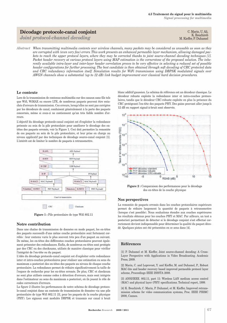
.....................................................................................................................................................................................................................................
Décodage protocole-canal conjointJoint protocol-channel decoding
.....................................................................................................................................................................................................................................
Abstract When transmitting multimedia contents over wireless channels, many packets may be considered as unusable as soon as theyare corrupted with (even very few) errors. This work presents an enhanced permeable layer mechanism, allowing damaged pac-kets to reach the upper protocol layers, where they may be corrected thanks to joint source-channel decoding techniques [1].Packet header recovery at various protocol layers using MAP estimation is the cornerstone of the proposed solution. The inhe-rently available intra-layer and inter-layer header correlation proves to be very effective in selecting a reduced set of possibleheader configurations for further processing. The best candidate is then obtained through soft decoding of CRC protected dataand CRC redundancy information itself. Simulation results for WiFi transmission using DBPSK modulated signals overAWGN channels show a substantial (up to 12 dB) link budget improvement over classical hard decision procedures.
C. Marin, U. Ali, K. Bouchireb
M. Kieffer, P. Duhamel
Recherche Research 2009 / 2011 67
Références
[1] P. Duhamel et M. Kieffer, Joint source-channel decoding: A Cross-Layer Perspective with Applications in Video Broadcasting. AcademicPress, 2009.
[2] Marin, C. and Leprovost, Y. and Kieffer, M. and Duhamel, P., RobustMAC-lite and header recovery based improved permeable protocol layerscheme, Proceedings IEEE ISSSTA 2008.
[3] ANSI/IEEE. 802.11, part 11: Wireless LAN medium access control(MAC) and physical layer (PHY) specifications. Technical report, 1999.
[4] K. Bouchireb, C. Marin, P. Duhamel, et M. Kieffer, Improved retrans-mission scheme for video communication systems, Proc. IEEE PIRMC2008, Cannes.
Le contexteLors de la transmission de contenus multimédia sur des canaux sans fils telsque Wifi, WiMAX ou encore LTE, de nombreux paquets peuvent être enta-chés d'erreurs de transmission. Ces erreurs, lorsqu'elles ne sont pas corrigéespar les décodeurs de canal, conduisent généralement à la perte des paquetsconcernés, même si ceux-ci ne contiennent qu'un très faible nombre d'er-reurs.
L'objectif du décodage protocole-canal conjoint est d'exploiter la redondanceprésente au sein de la pile protocolaire pour améliorer le décodage des en-têtes des paquets erronés, voir la Figure 1. Ceci doit permettre la remontéede ces paquets au sein de la pile protocolaire, et leur prise en charge auniveau applicatif par des techniques de décodage source-canal conjoint [1].L'intérêt est de limiter le nombre de paquets à retransmettre.
Figure 1 : Pile protocolaire de type Wifi 802.11
Notre contribution Dans une chaîne de transmission de données en mode paquet, les en-têtesdes paquets successifs d'une même couche protocolaire sont fortement cor-rélés : leur contenu varie le plus souvent très peu d'un paquet au suivant.De même, les en-têtes des différentes couches protocolaires peuvent égale-ment présenter des redondances. Enfin, de nombreux en-têtes sont protégéspar des CRC ou des checksums, utilisés de manière classique pour vérifierl'intégrité de l'en-tête ou du paquet. L'idée du décodage protocole-canal conjoint est d'exploiter cette redondanceinter et intra-couches protocolaires pour réaliser une estimation eu sens dumaximum a posteriori des en-têtes des paquets au niveau de chaque coucheprotocolaire. La redondance permet de réduire significativement la taille del'espace de recherche pour les en-têtes erronés. De plus, CRC et checksumne sont plus utilisés comme codes à détection d'erreurs, mais sont intégrésdans l'estimateur au sens du maximum a posteriori, où ils jouent le rôle decodes correcteurs d'erreurs. La figure 2 illustre les performances de notre schéma de décodage protoco-le-canal conjoint dans un contexte de transmission de données via une pileprotocolaire de type Wifi 802.11 [3], pour les paquets de la couche physique(PHY). Les signaux sont modulés DBPSK et transmis sur canal à bruit
blanc additif gaussien. Le schéma de référence est un décodeur classique. Ledécodeur robuste exploite la redondance inter et intra-couches protoco-laires, tandis que le décodeur CRC-robuste exploite en plus la présence duCRC protégeant l'en-tête des paquets PHY. Des gains pouvant aller jusqu'à12 dB en rapport signal-à-bruit sont observés.
Figure 2 : Comparaison des performances pour le décodage des en-têtes de la couche physique
Nos perspectivesLa remontée de paquets erronés dans les couches protocolaires supérieurspermet de réduire largement la quantité de paquets à retransmettre(lorsque c'est possible). Nous souhaitons étendre aux couches supérieuresles résultats obtenus pour les couches PHY et MAC. Par ailleurs, un test aposteriori permettant de détecter si le décodage conjoint s'est effectué cor-rectement devient indispensable pour déterminer la qualité du paquet déco-dé. Quelques pistes ont été présentées en ce sens dans [4].
4. TÉLÉCOMMUNICATIONS TELECOMMUNICATIONS
4.5 Traitement du signal pour le multimédia Signal processing for multimedia
Chapitre 4:Chapitre 4.qxd 26/10/09 14:06 Page12

Systèmes de numérisation Digitization systems
Richard KIELBASADépartement Signaux et Systèmes ÉlectroniquesCampus de GifTél. : 33 (0) 1 69 85 14 03E-mail : [email protected]
Philippe BENABESDépartement Signaux et Systèmes ÉlectroniquesCampus de GifTél. : 33 (0) 1 69 85 14 19E-mail : [email protected]
Caroline LELANDAIS-PERRAULTDépartement Signaux et Systèmes ÉlectroniquesCampus de GifTél. : 33 (0) 1 69 85 14 20E-mail : [email protected]
4.6
68
Pour tout renseignement s'adresser à : For further information, please contact:
C'est une évidence de constater tout à la fois la dissémination et l'évolu-tion des performances des systèmes numériques mobiles et communicants(téléphones portables, PDA, GPS, etc.). L'augmentation des débits, l'opti-misation des ressources radio, la versatilité et l'interopérabilité des maté-riels mobiles (« radio logicielle ») nécessitent de résoudre de nombreux pro-blèmes. L'un d'entre eux est incontournable : celui du passage entre lemonde radio et le monde numérique. Les changements de fréquence et laconversion analogique-numérique classique ne permettent pas de s'adap-ter par logiciel à différents standards dont certains requièrent une largebande à faible résolution et d'autres une bande étroite mais avec une réso-lution élevée. Les systèmes de numérisation du futur devront, dans une technologie don-née, présenter ces caractéristiques afin de rendre réalisable le concept de« radio logicielle ». De tels systèmes feraient également jouer les écono-mies d'échelle, même si leur complexité intrinsèque est plus élevée.
. . . . . . . . . . . . . . . . . . . . . . . . . . . . . . . . . . . . . . . . . . . . . . . . . . . . . . . . . . . . . . . . . . . . . . . . . . .
The general domain of mobile communications (cellular phones, PDAs,GPS) is always increasing. Higher data rates, optimization of the use of RFresources, versatility and interoperability of mobile terminals (e.g. “softwa-re radio”) need to solve a number of problems. One of them appears to becrucial: the necessary interface between the radio and digital worlds. IFstages and classical analog-to-digital conversion cannot fit to differentstandards requirements i.e. a wide bandwidth with a high resolution or anarrow bandwidth with a higher resolution.Tomorrow's digitization systems should offer, for a given process technolo-gy, the above characteristics in order to enable software radio applications.Defined to be versatile, such systems would lead to low costs of productionbecause of scaling effects, even though they would be certainly more com-plex than conventional ones.
. . . . . . . . . . . . . . . . . . . . . . . . . . . . . . . . . . . . . . . . . . . . . . . . . . . . . . . . . . . . . . . . . . . . . . . . . . .
Sujets1. Bancs de Filtres Hybrides (BFH) Les BFH permettent d'effectuer une conversion passe-bande large-bande. On peut de plus améliorer dynamiquement leur résolution dansune sous-bande. Ils se synthétisent à partir de filtres analogiques d'en-trée quelconques, mais leur sensibilité aux imperfections des dispositifsanalogiques exige l'emploi de techniques de compensation spécifiques(sujet 3).
2. Bancs de modulateurs sigma-deltaÀ l'origine, la mise en parallèle de modulateurs sigma-delta dérive duprincipe des BFH, mais du fait du suréchantillonnage, chaque sous-bande n'est convertie que par un seul modulateur, ce qui élimine lesproblèmes de repliement de spectre des BFH.
3. Compensation des défauts de l'analogique par adaptation dutraitement numériqueLes composants analogiques, indispensables dans les étages d'entrée,sont sources d'incertitudes (dérives, imprécision de fabrication…). Desméthodes numériques spécifiques permettent de les identifier, puis lescorriger. Il est cependant préférable d'adapter directement le traite-ment numérique sans identifier les imperfections. Dans le cas des BFH,l'égalisation adaptative permet d'effectuer une calibration du systèmeafin d'obtenir la résolution voulue dans la bande à convertir souhaitée.
Topics1. Hybrid Filter Banks (HFB)HFB allow band-pass and wide band conversion. Moreover, the resolu-tion may be dynamically improved in a narrower bandwidth. Some syn-thesis methods make it possible to design HFB from any analog inputfilters. But the HFB sensitivity to analog errors requires specific correc-tion techniques (topic 3).
2. Sigma delta modulators banksThis parallel delta-sigma modulators architecture relies upon frequencyband decomposition as HFB do, but due to oversampling, each subbandis converted by a single modulator, which removes the aliasing termsinherent in HFB.
3. Compensation of inaccuracy and drift in analog part of circuitsAnalog components must be present in the front-end, even if they aresubject to a number of uncertainties due to drifts, inaccuracy of the pro-cess… Relevant digital methods permit to identify and then compensatethese problems. It is however preferable to adapt directly the digital pro-cessing without identifying the imperfections. In the case of HFB, anadaptive equalization can calibrate the digital filtering in order to getthe good resolution in the signal band.
4. TÉLÉCOMMUNICATIONS TELECOMMUNICATIONS
4.6 Systèmes de numérisation Digitization systems
Chapitre 4:Chapitre 4.qxd 26/10/09 14:06 Page13

.....................................................................................................................................................................................................................................
Band-Pass Continuous-Time Delta-Sigma Modulators employing acoustic waves filters resonators Modulateurs sigma delta passe-bande à temps continu à base de filtres à ondes acoustiques
.....................................................................................................................................................................................................................................
Philippe BénabèsRichard Kielbasa
Recherche Research 2009 / 2011 69
4. TÉLÉCOMMUNICATIONS TELECOMMUNICATIONS
4.6 Systèmes de numérisation Digitization systems
References
[1] R. Yu, Y.P. Xu, “Band-pass Sigma-Delta Modulator Employing SAWResonator as Loop Filter”, IEEE Transactions on Circuits and Systems,Regular Papers, Vol. 54, No. 4, April 2007.
[2] P. Benabes, A. Beydoun, J. Oksman, “Extended Frequency-Band-Decompostion sigma-delta A/D converter”, Analog Integrated Circuitsand Signal Processing, January 2009.
[3] M. Javidan, P. Benabes, “Band-Pass Continuous-Time Delta-SigmaModulators Employing LWR Resonators”, IEEE InternationalConference on Electronics, Circuits, and Systems (ICECS'08), ISBN: 978-1-4244-2181-7, pp. 1119-1122, St Julians, Malta, August 31 - September3, 2008.
IntroductionContinuous-time Sigma-Delta modulators are an attractive way to buildband pass A to D converters. They are composed with an analog modulatorthat oversamples the input signal and a digital filter that reduces the sam-pling frequency and removes the out-of-band quantization noise. The modu-lator consists in an analog filter, a fast A-to-D converter, and a feedback D-to-A converter. The filter is the critical part of the modulator as it must havepoles with high quality factor and precise resonance frequency. Among alltechnologies to build the filters, acoustic wave filters are a promising tech-nology, especially Lamb Waves Resonators [1].
Lamb Wave Resonator (LWR)The structure of Lamb Wave Resonators (LWR) which is similar to AcousticWave resonator (SAW) and Film Bulk Acoustic Resonator (FBAR), is compo-sed of a piezoelectric layer sandwiched between two thin electrodes and pla-ced on a membrane (Fig. 1). The LWR employs lateral wave propagation.
Figure 1: Lamb wave resonator working on (a) fundamental (b)third harmonic
The advantages of LWR are:- accurate central frequency without the need for tuning,- wide available resonant frequency range up to Gigahertz,- high stability versus temperature.
A LWR resonator can be modeled by a RLC serial filter in parallel with a capa-citance C0. C0 is the inherent static capacitance between the two terminals.The presence of the static capacitance leads us to use a differential resona-tor structure with anti-resonance cancelation (Fig. 2). Two capacitive paths(Cc) are added. These paths act effectively as a negative capacitance. If Cc ismade equal to C0, the effect of C0 can be cancelled.
Figure 2: Proposed resonator topologyto anti-resonance cancelation
New continuous-time modulator topologyIn the context of parallel converters banks [2], sigma delta modulators mustbe able to work in a wide range of central frequencies. The topology presen-ted in Fig.3 [3] can work at a central frequency between 0.2fs and 0.3fs wherefs is the sampling frequency.
The Gm elements are voltage to differential current converters, the Z aredual current to voltage converters, and the M element are true differentialcurrent to current converters (current mirrors). The signal transfer functionwill be controlled by the gains of Gm1, Gm2 & Gm3
Figure 3: Innovative modulator filter topology
There are two major advantages for this structure:
- the filter transfer function of this structure is compatible with a wide rangeof central frequencies,
- this topology employs a single feedback DAC.
The NTF can be controlled by the gains of the current mirrors and the DACdelay. The optimal DAC delay will be equal to 1:95Ts for a central frequencyequal to 0:2Fs. It should be 1:08Ts for a central frequency equal to 0:3Fs.
Fig.4 shows the Noise Transfer Function (NTF) of the topology obtained forthree central frequencies.(fc= 0.22fs , fc=0.25fs , fc=0.28fs).
Figure 4: Noise Transfer Function for three central frequencies (fc).
Résumé La conversion analogique-numérique très large-bande peut se réaliser par une mise en parallèle de modulateurs sigma-delta àcondition de savoir réaliser des modulateurs capables de travailler dans une large gamme de fréquences centrales. Afin degarantir une performance minimale, les filtres utilisés dans ces modulateurs doivent présenter des facteurs de qualité suffi-sants. Les filtres à ondes de Lamb, dont les fréquences de résonance peuvent être définies à la conception en fonction de para-mètres géométriques simples sont une solution prometteuse. Mais il est nécessaire de concevoir de nouvelles topologies de modu-lateurs compatibles avec ces filtres.
Chapitre 4:Chapitre 4.qxd 26/10/09 14:06 Page14

Outils méthodologiquesMethodological tools
Mérouane DEBBAHChaire Alcatel LucentCampus de GifTél. : 33 (0) 1 69 85 14 47E-mail : [email protected]
Samson LASAULCEL2S - Division Signaux Campus de GifTél. : 33 (0) 1 69 85 17 34E-mail : [email protected]
Antoine BERTHETDépartement TélécommunicationsCampus de GifTél. : 33 (0) 1 69 85 14 62E-mail : [email protected]
4.7
70
Pour tout renseignement s'adresser à : For further information, please contact:
Dans ses premiers travaux, Shannon a étudié les transmissions point-à-point et a développé une théorie complète connue sous le nom de théoriede l'information. Aujourd'hui, les réseaux doivent faire face à des problèmes plus larges et plus complexes et ceci, pour trois raisons princi-pales : les réseaux sont hétérogènes en puissance de transmission, fré-quence, portée, efficacité spectrales et standards. Les communicationssont souvent limitées entre les systèmes et les décisions doivent se fairede manière décentralisée. Enfin, les systèmes sont souvent complexes etdenses et il est assez difficile de prendre en compte tous les paramètresd'intérêt. Un des problèmes les plus importants est de gérer la complexitéde ces systèmes et de développer les outils adéquats pour étudier les dyna-miques et les performances spatiales et temporelles des systèmes com-plexes. Afin de proposer une théorie fructueuse, la recherche dans cedomaine est interdisciplinaire et résulte d'un mélange de plusieurs théo-ries et domaines : théories des matrices aléatoires, théories des probabili-tés libres, inférence bayésienne, théorie des jeux, modèles graphiques et lagéométrie de l’information
. . . . . . . . . . . . . . . . . . . . . . . . . . . . . . . . . . . . . . . . . . . . . . . . . . . . . . . . . . . . . . . . . . . . . . . . . . .
In his early papers, Shannon studied the point-to-point channel and deve-loped a full theory known as information theory. Nowadays, wireless net-works face much broader and complex problems due to three facts: the sys-tems are heterogeneous in transmit power, frequencies, range, QoS require-ments, spectral efficiency and standards. Very often, no communication bet-ween the different systems is allowed and decisions have to be taken in adecentralized or distributed manner. Finally, systems are often dense andit is quite hard to capture all the parameters of interest. One of the mostchallenging problems is to manage complexity and develop the adequatetools to reason about the spatial and temporal dynamics of complex sys-tems. In order to provide a fruitful new theory, the research in this field isinter-disciplinary and is a blend of several important theories and fields,namely random matrix theory, free probability theory, Bayesian inference,game theory, graphical models and information geometry.
. . . . . . . . . . . . . . . . . . . . . . . . . . . . . . . . . . . . . . . . . . . . . . . . . . . . . . . . . . . . . . . . . . . . . . . . . . .
Sujets1. Matrices aléatoiresThéorèmes centraux limites, comportement de la plus grande/petitevaleur propres, modèles spiked, matrices aléatoires non centrées,matrices aléatoires avec un profil de variances.
2. Théorie des probabilités libresDéconvolution libre, partitions non-croisées, transformées en R, trans-formées en S, méthodes des moments, cumulants libres, variables aléa-toires non-commutatives, produits libres, algèbres de Von-Neumann.
3. Inférences bayésiennesMéthodes Maxent, procédures de marginalisation, théorème de Bayes,comparaison de modèles bayésiens, description minimale, maximisationd'entropie.
4. Théorie des jeuxThéorie des jeux algorithmique, jeux coopératifs/non-coopératifs, équi-libres, jeux avec information complète/incomplète, théorie de la connais-sance, apprentissage, rationalité, jeux statiques/dyamiques.
5. Modèles graphiquesGraphes factoriels, réseaux bayésiens, champs de Markov, approxima-tion normale pour les champs de Markov et pour les graphes de dépen-dance, propagation de croyance, algorithme somme-produit, analyse enconvergence, évolution de densité, méthodes issues de la physique sta-tistique.
6. Géométrie de l'informationEtude des algorithmes itératifs, accélération de convergence, caractéri-sation des points d'équilibre.
Topics1. Random MatricesCentral limit theorems, behavior of the maximum/minimum eigenvalueof Random matrices, spiked models, non-central random matrices, ran-dom matrices with a profile of variance.
2. Free ProbabilityFree deconvolution, non-crossing partitions, R-transform, S-transform,moments method, free cumulant, non-commutative random variables,free products, Von-Neumann algebras.
3. Bayesian InferenceMaxent Method, marginalization procedure, Bayes theorem, Bayesian modelcomparison, Minimum description length, Occam's razor, entropy maximi-zation.
4. Game theoryAlgorithmic game theory, cooperative/non-cooperative games, equili-bria, games with complete/incomplete information, knowledge theory,learning, rationality, static/dynamic games.
5. Graphical modelsFactors graphs, Bayesian networks, Markov random fields, normalapproximation for MRF and for dependency graphs, belief propagation,sum-product algorithm, convergence analysis, density evolution, statisti-cal physics methods.
6. Information geometryIterative algorithms, accelerating their convergence, characterization of theirequilibrium points.
4. TÉLÉCOMMUNICATIONS TELECOMMUNICATIONS
4.7 Outils Méthodologiques Methodological tools
Chapitre 4:Chapitre 4.qxd 26/10/09 14:06 Page15

.....................................................................................................................................................................................................................................
Matrices Aléatoires pour les Systèmes MIMO Broadcast et à Accès MultiplesRandom Matrices for Broadcast and Multiple Access MIMO Systems
.....................................................................................................................................................................................................................................
Abstract Multi-antenna (MIMO) systems have the potentiality to significantly increase channel capacity as has been theoreticallydemonstrated in the last decade. However, practical applications prove more challenging due to signal correlation at trans-mit/receive antenna arrays, which is rarely accounted for in theoretical studies. We propose here a methodology, based on arecent paper [1], to enable correlation parameters in multi-antenna systems. The rate regions of multiple access and broadcastMIMO channels are presented here as an introductory example.
Outils méthodologiquesMethodological tools
Antoine BERTHETDépartement TélécommunicationsCampus de GifTél. : 33 (0) 1 69 85 14 62E-mail : [email protected]
Romain CouilletMérouane Debbah
Recherche Research 2009 / 2011 71
Position du problèmeLes systèmes de communication à N antennes de transmission et nantennes de réceptions (MIMO) promettent en théorie un gain multiplicatifd'ordre min(n,N) comparé aux systèmes mono-antenne. Cependant, en pra-tique, la corrélation due à la proximité des antennes et aux directions detransmission porteuses d'énergie utile (celle qui sera effectivement reçue)réduit largement ce gain attendu. Nous proposons ici une méthode permet-tant d'intégrer ce paramètre de corrélation dans les calculs de capacité théo-rique. L'ingrédient essentiel de cette méthode repose sur un théorèmerécent dû à Silverstein [1]. Une application de nos résultats au cas decanaux MIMO broadcast et à accès multiples est également présentée.
ContributionsLe résultat clé de notre étude est un théorème liant des modèles de corréla-tion spatiale, exprimés sous forme matricielle T, NxN, et R, nxn, représen-tant respectivement la corrélation croisée entre antennes de transmissionet de réception d'un système MIMO, à la transformée de Stieltjes de lamatrice A=R1/2XTXHR1/2 où X est une matrice aléatoire gaussienne. Cette der-nière matrice caractérise la réalisation spécifique du canal à corrélationséparée R1/2XT1/2. La capacité d'un tel système est alors liée à la transforméede Shannon de A, i.e. une forme intégrale de la transformée de Stieltjes deA. La méthode en question se généralise alors à des systèmes à plusieursémetteurs et/ou plusieurs récepteurs.
L'intérêt majeur de cette méthode réside dans le fait que l'expression théo-rique de la capacité est indépendante de la réalisation spécifique du canal(donnée par la matrice X) et n'est alors qu'une fonction déterministe desmatrices de corrélation T et R.
Parmi les systèmes étudiés à ce jour à l'aide de cette méthode, nous comp-tons :
• les systèmes multi-cellulaires, de type téléphonie mobile, avec interféren-ce entre cellules. La capacité de transmission de tels systèmes lorsque lessources d'interférence sont décodées par chaque récepteur ou considéréescomme du bruit additif est déterminée [1,2] ;
• les systèmes à accès multiples où plusieurs émetteurs partagent les mêmeressources fréquentielles et temporelles et les systèmes « broadcast » danslesquels une source accède à plusieurs récepteurs sur une même ressour-ce [1,3].
A l'aide de cette nouvelle approche théorique, nous apportons pour tous sessystèmes des algorithmes d'optimisation convexe [2,3] (ou des heuristiques[1,3]) d'allocation de puissance par antenne de transmission lorsque l'émet-teur a connaissance parfaite du canal de transmission. Nous montrons que,via ces algorithmes, un gain potentiellement large en capacité peut êtreatteint.
Il est important de souligner que cette méthode n'est en théorie valide quepour de larges valeurs pour n,N. Il est cependant montré en simulations quede faibles valeurs pour n,N donnent lieu à une quasi-coïncidence entre théo-rie et simulations, dès lors que le rapport signal sur bruit (SNR) n'est pastrop large.
Un exemple de résultatsEn Figure 1 est présentée la région de capacité de deux utilisateurs, munischacun de 4 antennes proches, dans un canal « broadcast ». L'émetteur estlui muni de 8 antennes à distance modérée l'une de l'autre. La valeur duSNR est de -5 dB. Un algorithme d'allocation sous-optimal de puissance estappliqué. Nous observons en particulier le gain large en capacité pour letransmetteur à mettre en place une allocation efficace de puissance sur sesantennes.
Figure 1 : Région de capacité d'un canal broadcast à 2 utilisateurs, n=4,N=8, SNR=-5 dB. En ligne pleine, uniforme allocation de puissance parantenne de transmission.
4. TÉLÉCOMMUNICATIONS TELECOMMUNICATIONS
4.7 Outils Méthodologiques Methodological tools
Références
[1] R. Couillet, M. Debbah and J. Silverstein, “A deterministic equivalentapproach for the capacity analysis of multi-user MIMO channels”,Submitted to IEEE Trans. on Information Theory.
[2] R. Couillet, M. Debbah and J. Silverstein, “Asymptotic Capacity ofMulti-User MIMO Communications”, IEEE ITW 2009 Conference,October 2009, Italy.
[3] R. Couillet, M. Debbah and J. Silverstein, “Rate Region of CorrelatedMIMO Multiple Access Channels and Broadcast Channels”, IEEE SSP2009 Conference, Cardiff, UK.
Chapitre 4:Chapitre 4.qxd 26/10/09 14:06 Page16

72
Chapitre 5:Chapitre 5.qxd 26/10/09 14:06 Page1

73
5. ÉLECTROMAGNÉTISMEELECTROMAGNETICS
5Chapitre 5:Chapitre 5.qxd 26/10/09 14:06 Page2
5.1 Techniques de champs proches Near-field techniques
Techniques de champs prochesNear-field techniques
Dominique PICARDDépartement de Recherche en ÉlectromagnétismeCampus de GifTél. : 33 (0) 1 69 85 15 55E-mail : [email protected]
Nicolas RIBIÈRE-THARAUDDépartement de Recherche en ÉlectromagnétismeCampus de GifTél. : 33 (0) 1 69 85 15 72E-mail : [email protected]
5.1
74
Pour tout renseignement s'adresser à : For further information, please contact:
5. ÉLECTROMAGNÉTISME ELECTROMAGNETICS
Les techniques de champs proches constituent une approche efficace à lacaractérisation de systèmes rayonnants complexes. Leur efficacité résulteprincipalement d'une combinaison optimale de mesures et de traitementsnumériques dont la transformation « champ proche / champ lointain »constitue maintenant un exemple bien connu. Plus généralement, unnombre minimal de mesures sur une surface entourant le système soustest permet d'accéder au champ, pratiquement partout à l'extérieur dusystème. Ces techniques peuvent être mises en œuvre pour les rayonne-ments tant intentionnels que non intentionnels. Cette dernière possibilitéexplique leur utilisation croissante dans le domaine de la «compatibilitéélectromagnétique» (CEM). De surcroît, l'utilisation de réseaux de sondes,au lieu d'une sonde déplacée mécaniquement, procure une rapidité inéga-lée, si on la compare à celle des mesures effectuées plus classiquement enchambres longues ou compactes.
. . . . . . . . . . . . . . . . . . . . . . . . . . . . . . . . . . . . . . . . . . . . . . . . . . . . . . . . . . . . . . . . . . . . . . . . . . .
Near-field techniques constitute an efficient approach for characterizingcomplex radiating systems. Their efficiency mainly stems from optimalhybridization between measurements and numerical processing. « Near-field to far-field » transformations are the most popular example of thisprocessing. Generally however, a minimum number of measurements on aclosed surface surrounding the system under test makes it possible toretrieve the field virtually anywhere outside this system. Near-field tech-niques can be used for both intentional and non-intentional radiating sys-tems. This last capability explains the growing use of these techniques for « electromagnetic compatibility » (EMC) applications. The use of probearrays (instead of a mechanically scanned probe) provides unrivaled rapi-dity, even by comparison with more traditional measurements conductedover long or compact ranges.
. . . . . . . . . . . . . . . . . . . . . . . . . . . . . . . . . . . . . . . . . . . . . . . . . . . . . . . . . . . . . . . . . . . . . . . . . . .
Sujets1. Méthodes de mesure « sans phase »Corrélation temporelle et problème de source inverse pour émissionsmodulées.Caractérisation de sources MFP à partir de thermogrammes infra-rouges.
2. Mesures dans le domaine temporel Mise au point d'une plate-forme expérimentale et adaptation des tech-niques numériques dont la transformation « champ proche / champ loin-tain ».
3. Caractérisation des antennes de stations de baseCaractérisation des antennes BTS en coordonnées cylindriques :- diagrammes de rayonnement ;- périmètre de sécurité ;- DAS.Compensation des effets de troncature au moyen de techniques de pro-longement analytique.Conversions modales et algorithmes de rétro-propagation.Études statistiques du rayonnement des antennes relais.
Topics1. Phaseless measurementsTime domain correlation and inverse source techniques for non CWemissions.Characterization of HPM primary sources from infrared thermograms.
2. Time domain measurementsDevelopment of measurement facilities and adaptation of numericaltechniques such as “near field to far field” transformation.
3. Characterization of base station antennasNear-field measurements in cylindrical coordinates:- far-field radiation pattern;- safety perimeters;- SAR.Compensation for truncation effects via analytical prolongation tech-niques.Modal conversion and back-propagation algorithms.Statistical survey of radiation properties for base station antennas.
Chapitre 5:Chapitre 5.qxd 26/10/09 14:06 Page3

IntroductionThis work is carried out in the framework of a collaboration between DRÉand the Composite Materials and Structures Department (DMSC) / ONERA(F/3007/DAL.JCAP). We are concerned with the antenna radiation patterncharacterization in a wide frequency range (0.5-20 GHz) with a specificinfrared measurement technique (EMIR®). Such a method allows to get veryrapidly a planar cartography of the amplitude of the electric field in the vici-nity of the antenna under test (AUT) without any electromagnetic distur-bance of the latter [1][2]. Unfortunately both magnitude and phase of theelectric field are needed to reconstruct the far field by means of a near-field/far-field transformation. The development and the validation of a“phase retrieval” algorithm are then required.
FeaturesAmong the different methods of optimization used in this domain [3], aniterative technique allowing the reconstruction of the unknown phasefrom the knowledge of the field amplitude measured on two differentplanes parallel to the aperture of the AUT (Figure 1) has been applied. Thedeveloped algorithm has been validated at 8 GHZ using three kinds ofdata obtained from the same existing pyramidal horn antenna:
1. Simulated data obtained from a commercial code using a momentmethod (FEKO®). Such an approach allows a large parametric study(size of and distance between the planes, measurement samplingstep, dynamic range (sensitivity) of the measurements) and permitsto exhibit the optimal measurement configuration which has beenthen applied to the experimental acquisitions.
2. Experimental data (magnitude and phase) measured using a planarnear-field test facility at DRÉ (dipole probe and network analyzer).
3. Experimental data (magnitude only) measured by ONERA using theEMIR® method.
ResultsThree different computed far fields are compared: the far field obtained byconsidering the numerical computed near field amplitude and the recons-tructed phase, the far field obtained using the near field amplitude mea-sured by means of a classical probe and the reconstructed phase, and thefar field obtained from the near field amplitude measured by means of aninfrared technique and the reconstructed phase. Figure 2 shows a goodagreement between the three far fields obtained from the “phaselessreconstruction” algorithm and the exact solution. Others results withsimilar features [3] have been obtained at different frequencies.
Conclusion and future workAn iterative error reduction algorithm has been tested and validated onnumerical and experimental data. Both reconstructed phases and deducedfar fields show good agreements with exact results. A future field of inves-tigations consists in adding a priori information in the reconstruction pro-cess such as antenna aperture dimensions for example.
Figure 1: Measurement configuration
Figure 2: Comparison of the normalized far field components(top: E-polarization, bottom: H-polarization); exact (blue), “phaselessreconstruction” algorithm applied to synthetic data (red), experimentaldata measured with the planar near-field test facility at DRÉ (black) andwith the infrared method (green)
5.1 Techniques de champs proches Near-field techniques
.....................................................................................................................................................................................................................................
Antenna characterization from phaseless Near-Field dataCaractérisation d'antennes et mesures sans phases en champ proche
.....................................................................................................................................................................................................................................
Résumé L'utilisation des techniques de champs proches pour la caractérisation du diagramme de rayonnement d'une antenne nécessite la connaissance du champ près de l'antenne en module et en phase. L'accès à cette dernière n'est pas toujourspossible et une solution bien connue consiste à utiliser une technique algorithmique de reconstruction de phase.
5. ÉLECTROMAGNÉTISME ELECTROMAGNETICS
Nicolas Ribière-TharaudMarc LambertFrançois Jouvie
References
[1] J. Norgard et al., “Quantitative images of antenna patterns usinginfrared thermography and microwave holography”, InternationalJournal of Imaging Systems and Technology, vol. 11, pp. 210-218,2000.
[2] P. Levesque, L. Leylekian, A. Déom and D. Balageas, “Latest deve-lopments in the EMIR technique of infrared imaging electromagneticfields”, Proc. of SPIE, Vol. 4360, pp. 48-59, 2001.
[3] N. Ribière-Tharaud et al., “Numerical and experimental assess-ment of a phase retrieval technique applied to planar near-field distributions for wide band applications”, 3rd InternationalConference on Electromagnetic Near-Field Characterization andImaging (ICONIC), pp. 194-199, St. Louis, Missouri, 2007.
75Recherche Research 2009 / 2011
Chapitre 5:Chapitre 5.qxd 26/10/09 14:06 Page4

Senseurs et capteurs micro-ondesMicrowave sensors and probes
Antoine DIETDépartement de Recherche en ÉlectromagnétismeCampus de GifTél. : 33 (0) 1 69 85 17 64E-mail : [email protected]
Nadine JOACHIMOWICZDépartement de Recherche en ÉlectromagnétismeCampus de GifTél. : 33 (0) 1 57 27 79 75E-mail : [email protected]
5.2
76
Pour tout renseignement s'adresser à : For further information, please contact:
Les micro-ondes permettent la caractérisation diélectrique (permittivitéet conductivité) des matériaux non conducteurs et leur analyse tomogra-phique (imagerie micro-onde) fournissant ainsi des données complémen-taires de celles obtenues par d'autres méthodes de contrôle non destructif(CND) et d'analyse tomographique telles que rayons X, ultrasons, IRM,PET... L'estimation des paramètres électromagnétiques donne accès à desfacteurs physiques et/ou physiologiques dont ils dépendent : composition,température, teneur en eau… Nombre d'applications potentielles desmicro-ondes ont ainsi été répertoriées dans le domaine des applicationsIndustrielles Scientifiques et Médicales (ISM) : identification radiofré-quence (sujet 1), détection d'objets enfouis ou immergés (sujet 2), détectionde défauts ou de tumeurs (sujet 3), contrôle de l'humidité, contrôle de trai-tements par hyperthermie… Les techniques micro-ondes ont pour pointsforts : sensibilité, rapidité, innocuité. Les capteurs micro-ondes peuventprendre des formes variées, depuis la simple sonde de contact équipant unbanc de mesure réflectométrique, jusqu'aux caméras et scanners micro-ondes. Lorsque les phénomènes observés sont dynamiques ou lorsque l'oncherche à réduire le temps d'acquisition, des réseaux de capteurs sont uti-lisés. Chaque capteur du réseau peut être interrogé séquentiellementgrâce à un multiplexeur micro-onde ou en ayant recours à la méthode dela diffusion modulée. Cette technique a démontré sa capacité à analysertrès rapidement de grands réseaux (sujet 4).
. . . . . . . . . . . . . . . . . . . . . . . . . . . . . . . . . . . . . . . . . . . . . . . . . . . . . . . . . . . . . . . . . . . . . . . . . . .
Microwaves make it possible to carry out the dielectric characterization(permittivity and conductivity) of non-conducting materials and theirtomographic analysis (microwave imaging), which yield data that are com-plementary to those obtained by other non-destructive testing (NDT) andtomographic analysis techniques, such as X-rays, ultrasounds, MRI, PET,etc. An estimation of electromagnetic parameters provides the physicaland/or physiological factors they depend upon, namely composition, tem-perature, water content, etc. Therefore, a number of potential applicationsfor microwaves have been identified in the field of Industry, Science andMedicine (ISM): radio-frequency identification (topic 1), embedded orimmersed object detection (topic 2), deficiencies or tumor detection (topic 3),testing of moisture content, hyperthermia treatment control, etc. The strongpoint of microwave techniques is their sensitivity, speed, and harmlessness.Microwave sensors can take on various shapes: from the simple contactprobe equipping reflectometry measuring apparatus, to microwave camerasand scanners. When observed phenomena are time-varying, or when tryingto reduce acquisition time, sensor arrays may be used. Each sensor can besequentially interrogated by means of a microwave multiplexor or viamodulated scattering technique. This technique has been shown to be veryeffective in scanning very rapidly large arrays (Topic 4).
. . . . . . . . . . . . . . . . . . . . . . . . . . . . . . . . . . . . . . . . . . . . . . . . . . . . . . . . . . . . . . . . . . . . . . . . . . .
Christophe CONESSADépartement de Recherche en ÉlectromagnétismeCampus de GifTél. : 33 (0) 1 69 85 15 75E-mail : [email protected]
Sujets1. Antennes large bande pour les systèmes de communication sansfil et impulsionnels Etude et réalisation d'antennes ultra-large bande appliquées à la multi-radio et aux réseaux de capteurs d'identification radiofréquence ultra-large bande (RFID-UWB). La caractéristique de rayonnement de cesantennes est un avantage dans un environnement multi-trajet.
2. Antennes actives pour la mesure de champs en immersion Mise au point d'une antenne active compacte pour des mesures largebande en immersion.
3. Imagerie micro-onde appliquée au domaine médicalEtude de faisabilité de la détection de tumeurs du sein. Traitement spa-tial itératif appliqué à des données réelles obtenues sur un fantômeinhomogène. Coopération avec l'Université de Mälardalen (Suède).
4. Imagerie micro-onde temps réel pour processus dynamiquesPerfectionnement d'une caméra micro-onde à 2,45 GHz utilisant unerétine de 32 x 32 = 1024 sondes modulées. Ses données complexes sonttraitées en temps réel jusqu'à 25 images/seconde.
Topics1. Wideband antennas for wireless and pulsed communication systemsStudy and realization of ultra-wideband antennas dedicated to multi-radio and ultra-wideband radio-frequency identification sensor net-works (RFID-UWB). The radiation characteristics of these antennas arean advantage in multi-path environments.
2. Active antennas for underwater field measurementsDevelopment of a compact active antenna dedicated to wideband under-water field measurements.
3. Medical applications of quantitative microwave imagingFeasibility study of breast tumor detection. Spatial iterative algorithmapplied to real data collected from an inhomogeneous phantom.Cooperation with Mälardalen University (Sweden).
4. Real-time microwave imaging for time-varying processImprovement of a microwave camera operating at a 2.45 GHz frequencywith an array made of 32 x 32 = 1024 modulated probes. Complex dataare processed in real time up to 25 images/second.
5. ÉLECTROMAGNÉTISME ELECTROMAGNETICS
5.2 Senseurs et capteurs micro-ondes Microwave sensors and probes
Chapitre 5:Chapitre 5.qxd 26/10/09 14:06 Page5

.....................................................................................................................................................................................................................................
Wideband antennas for wireless communications Antennes large bandes pour les systèmes de communication sans fil
.....................................................................................................................................................................................................................................
Antoine DietNicolas Ribière-Tharaud
Jocelyn Fiorina
Recherche Research 2009 / 2011 77
References
[1] A. Diet, A. Azoulay, A. Joisel and B. Duchêne, “A UWB micro-stripantenna design and simulation”, European Microwave Week & EuropeanConference on Wireless Technology (EuMW/ECWT), pp. 1694-1697,Manchester, UK, 2006.
[2] D. Panaitopol, J. Fiorina, A. Diet and N. Ribière-Tharaud, “A new cri-terion to jointly design the antenna and optimize the communicationcapacity in IR-UWB”, IEEE Wireless Communications and NetworkingConference (WCNC), Budapest, Hungary, 2009.
[3] A. Diet et al., “Flexibility of class E HPA for cognitive radio”, IEEE19th Symposium on Personal Indoor and Mobile Radio Communications,(PIMRC), Cannes, France, 2008.
[4] A. Diet et al., “Front end accordability for cognitive multi-radio, usinga class E HPA and a multi-band antenna”, Asia Pacific MicrowaveConference (APMC), Hong Kong, China, 2008.
[5] A. Diet et al., “RUWBI: Radio Frequency - Ultra Wide Band -Identification”, submitted in the Projet ANR Jeunes Chercheurs frame-work, 2009.
Wideband antenna designThe interest in wireless and wideband communication systems has beendiscussed in [1]. This constitutes a multi-disciplinary research subject andleads to consider, as a first step, the wideband antenna design. Designingsuch an antenna is an interesting task involving an important state of theart and a careful analysis of previous studies (Scholtz, Schekulnikoff,Rumsey, Schantz,…) about pulsed communication and frequency indepen-dent antennas [1]. This first step has taken shape with the realization oflow-cost printed antennas displayed in Figure 1.
Figure 1:Wideband bended (left) and monopole with and without rejection (right) antennas
Measurements on these antennas give some interesting opportunities totest omnidirectionnal profiles and rejection profiles for different types ofapplications in the 1 - 6 GHz band. More recently, the impact of the fre-quency transfer function between two wideband printed antennas was usedto complete an analysis about multi-user interference in IR-TR-UWB sys-tems [2]. “CST microwaves” is a particularly well suited tool for widebandantenna design, as the latter requires a time domain analysis.
Multi-radio using wideband antennasWideband antennas are also interesting in the context of multi-radio frontend design (Figure 2). This is the subject of a scientific collaboration between DRÉ/L2S and ESYCOM (EA 2452). The idea is to provide a flexiblefront end in a wireless transceiver to adapt multiple standards specifica-tions: bandwidth, frequency, averaged power and modulation schemes [3].
Figure 2: Front end idea for multi-radio
This points out the interest in designing a multi-band antenna to relax theconstraints on power amplifier circuit design. Our recent works lead toconsider a Vivaldi printed antenna (Figure 3) with a parametric rejectionslot [4].
Figure 3: Vivaldi antennas and parametric rejection slot
RFID-UWB systemsHerein, the main idea is to consider “true” wideband systems such as thoseinvolved in UWB. Figure 4 displayed an interesting application of UWBtransmissions which interests a lot of research fields and is the subject ofthe RUWBI project [5]. The idea is to identify and localize a tagged targetby means of a pulsed based communication system involving signal proces-sing techniques (Figure 4). Pulse generation and wideband antenna emis-sion and reception are considered. Antenna diversity, which consists in com-bining different types of wideband antennas in the receiver for example, willbe also investigated.
Figure 4: The RUWBI project
5. ÉLECTROMAGNÉTISME ELECTROMAGNETICS
5.2 Senseurs et capteurs micro-ondes Microwave sensors and probes
Résumé Les systèmes de communications sans fil en bande S et C sont nombreux et présentent des caractéristiques variées en termesde fréquence, débit, contrôle de puissance et schéma de modulation. L'étude des antennes à très large bande est une opportu-nité de relier plusieurs applications de télécommunication en considérant les interactions et la coexistence des différentescouches physiques. Cette thématique de recherche permet de relier les aspects électromagnétiques (antennes et propagation)aux aspects circuits et traitement du signal. Le problème central est ici l'amélioration des performances et l'adaptation auxsystèmes multi-bandes (UMTS, LTE, Wifi, WiMAX) et à large bande (IR-UWB) du « front-end » radio, composé de l'amplifi-cateur forte puissance chargé par une antenne.
Chapitre 5:Chapitre 5.qxd 26/10/09 14:06 Page6

Compatibilité électromagnétique Electromagnetic compatibility
Lionel PICHONLGEP - Équipe ICHAMSCampus de GifTél. : 33 (0) 1 69 85 16 58E-mail : [email protected]
Alain AZOULAYDépartement de Recherche en ÉlectromagnétismeCampus de Gif Tél. : 33 (0) 1 69 85 15 63E-mail : [email protected]
Andréa COZZADépartement de Recherche en ÉlectromagnétismeCampus de GifTél. : 33 (0) 1 69 85 15 77E-mail : [email protected]
5.3
78
Pour tout renseignement s'adresser à : For further information, please contact:
Ces dix dernières années, un développement technologique sans précédents'est produit dans l'électronique en général et plus particulièrement dansle domaine de la radio aussi bien vis à vis du grand public que dans ledomaine professionnel.L'environnement électromagnétique a donc fortement évolué et a modifiéle traitement des questions de compatibilité électromagnétique (CEM),mettant assez fortement l'accent sur la compatibilité des systèmes radio-électriques.Cette pollution électromagnétique accroît les risques de perturbationsentre systèmes et donc les risques de dysfonctionnements. Pour remédierà cette situation, satisfaire aux normes en vigueur et réduire les coûts desproduits, il est impératif de prendre en considération l'aspect « compatibi-lité électromagnétique » dès la phase de conception d'un système. Ceciimplique la mise en place de méthodologies d'analyse, de prédiction desniveaux de perturbation et de développement de spécifications de CEMadaptées à l'évolution de l'environnement électromagnétique.
. . . . . . . . . . . . . . . . . . . . . . . . . . . . . . . . . . . . . . . . . . . . . . . . . . . . . . . . . . . . . . . . . . . . . . . . . . .
These last few years, a very important development of electronic systemsand more specifically of RF devices occurred in the general public as wellas in the professional area. The EM environment is still evolving and modi-fies the handling of EMC issues with a certain impact on the compatibili-ty of the radio frequency devices. This form of pollution increases the inter-ference probability between electronic or RF systems as well as their per-formance degradation.To overcome such difficulties and to comply with the standards and redu-ce production costs, “electromagnetic compatibility” problems must be tack-led at the system design stage. This means developing a method for analy-zing and predicting the level of induced interference, as well as finding sui-table techniques in order to reduce the effects of the latter and to define newspecifications compatible with the evolution of the EM environment.
. . . . . . . . . . . . . . . . . . . . . . . . . . . . . . . . . . . . . . . . . . . . . . . . . . . . . . . . . . . . . . . . . . . . . . . . . . .
Sujets1. Interactions entre champs électromagnétiques et structurescomplexesModélisation 3D des couplages. Simulation hybride champ-circuit pourles études d'immunité électromagnétique. Caractérisation du rayonne-ment des circuits imprimés de puissance.
2. Chambres réverbérantesModélisation des chambres réverbérantes. Caractérisation des champsdans les chambres réverbérantes à brassage de modes. Estimation de lapuissance totale rayonnée par différentes sources rayonnantes.Utilisation des chambres réverbérantes pour les études MIMO en pré-sence de trajets multiples.
3. Dispositifs de mesureTechniques de champs proches et dosimétrie.Mesures en très basse fréquence (50Hz à 100 kHz). Développement deméthodes de mesure du champ magnétique et électrique. Dispositifsd'étalonnage des appareils de mesure de champ à TBF.
4. Compatibilité radioélectriqueEtudes de compatibilité de systèmes aéronautiques en bande L. Etudede la dégradation des performances en fonction des types et des para-mètres des brouilleurs co-site ou entre avions.
Topics1. Coupling between electromagnetic fields and complex structures3D modeling of electromagnetic coupling. Field - circuit hybrid simula-tion for electromagnetic susceptibility computations. Characterization offields radiated by power printed circuit boards.
2. Reverberating chambersReverberation chambers modeling. Characterization of the fields inmode-stirred reverberation chambers. Study of the total radiated powerof RF radiating devices in various transmission scenarii by means ofreverberation chambers.. Study of MIMO antennas in strong multipathenvironments by means of reverberation chambers.
3. Measurement setupsNear-field techniques and dosimetry.ELF field strength measurement. Assessment of measurement methodsof magnetic and electric fields. Development of calibration setups forELF measurement devices.
4. Radiofrequency compatibility (RFC)Study of aeronautical systems compatibility in L band. Study of the per-formance degradation related to the type and the parameters of the inter-fering sources in a co-site scenario or between airplanes.
5. ÉLECTROMAGNÉTISME ELECTROMAGNETICS
5.3 Compatibilité électromagnétique Electromagnetic compatibility
Chapitre 5:Chapitre 5.qxd 26/10/09 14:06 Page7

.....................................................................................................................................................................................................................................
Generating coherent wavefronts within a reverberation chamber Génération de fronts d'onde cohérents en chambre réverbérante
....................................................................................................................................................................................................................................
Résumé Actuellement, les tests de compatibilité électromagnétique en chambre réverbérante permettent de savoir si un équipementsous test (EST) résiste à une agression électromagnétique de niveau fixé ; en cas de défaillance, il est très difficile d'identifierles points faibles de l'EST car les caractéristiques de l'onde agressive ne sont pas connues et maîtrisées. Pour répondre à ce manque, les propriétés du retournement temporel sont ici exploitées pour générer dans la chambre réverbérante des frontsd'ondes cohérents, similaires à ceux utilisés en chambre anéchoïque. Ce nouveau système, appelé TREC, permet de créer uneagression électromagnétique de forme et de niveau souhaités afin de tester la résistance des équipements électroniques. La possibilité de maîtriser la direction d'arrivée, la directivité et la polarisation du front d'onde, ainsi que la forme de l'im-pulsion, de façon instantanée devrait permettre de définir de nouvelles procédures de test d'immunité rayonnée.
Houmam MoussaAndrea Cozza
Michel Cauterman
Recherche Research 2009 / 2011 79
References
[1] “Procédé de contrôle de la directivité et la polarisation de distributionscohérentes de champ dans un milieu réverbérant”, Patent pending, filedon 30 March 2009 , INPI no. 0951995.
[2] H. Moussa, A. Cozza and M. Cauterman, “Directive wavefronts insidea time reversal electromagnetic chamber”, IEEE EMC SocietySymposium on Electromagnetic Compatibility, Austin, USA, 2009.
[3] G. Lerosey, J. de Rosny, A. Tourin, A. Derode, G. Montaldo and M. Fink,“Time reversal of electromagnetic waves”, Physical Review Letters, vol. 92, n° 19, 2004.
The state of the artElectromagnetic compatibility standards establish how equipments undertest (EUTs) should be tested for radiated immunity/susceptibility. This taskis currently accomplished by means of basically two main facilities, namelyanechoic chambers (ACs) and reverberation chambers (RCs). Although theformers allow the generation of plane wavefronts easily controllable, obtai-ning high-intensity fields requires the use of high-end power generators thatare not widely available; at the same time, in order to test the EUT underseveral directions of aggression, it is necessary to mechanically rotate theEUT, which introduces non-negligible delays. On the other hand, RCs gene-rate a field distribution equivalent to a superposition of a great number ofplane waves with random directions of arrival. This means that all the weak-nesses of the EUT can be highlighted at the same time, which reduces thetest duration and the probability of missing an entrance point for EM aggres-sions. Unfortunately, these advantages are jeopardized by the fact that theonly way of knowing which part of the EUT is the cause of the weakness isto come back to ACs. The same reasoning holds for polarization issues.
Figure 1: A schematic representation of the TREC system
Coherent wavefronts using a TRECDuring this Ph.D. thesis, supported by DGA and CNRS, we have develo-ped an alternative use of RCs, which brings together the advantages ofRCs and ACs [1]. This system, dubbed time-reversal electromagneticchamber (TREC), is depicted in Figure 1. It is based on a classical RC,where a limited number of antennas (the time-reversal mirror or TRM)have been installed. A group of locations are shown around the EUT as theequivalent array; attention should be paid to the fact that these points donot stand for antennas, but just represent sampling locations for theimplementation of the TREC technique [2]. The propagation inside theTREC system is characterized through measurements of transfer func-tions Hij, and thanks to the time-reversal technique [3], a coherent wave-front can be generated. This operation is carried out by feeding the TRMantennas with specific signals yi which are directly synthesized thanks tothe following formula:
where the quantities aj stand for complex weights allowing the definitionof any wavefront topography impinging on the EUT. The signal repre-sents the time-dependence of the excitation. It can be set to any type ofpulse-like sequences, or to pseudo-CW ones, independently from the wave-front topography.
ResultsThe feasibility of this technique has been demonstrated by means of nume-rical simulations of a quasi-2D metallic cavity. Results are displayed inFigure 2, for two different sets of weights aj corresponding to two directionsof arrival of a wavefront converging on the EUT. It is important to note thatthe two configurations were obtained just by feeding the TRM antennas withdifferent signals and not, as usually done, by means of mechanical or elec-tronic switching. Thus, the modification of the aggression scenario can bespeeded up as it is based on simple signal theory techniques. Any modifica-tion, from the direction of arrival to the directivity of the wavefront (spatialsupport) and the type of associated pulse, can be changed with no modifica-tion of the TREC.
Figure 2: Two examples of directive coherent wavefronts impinging on the EUT; neither mechanical nor electronic switching is used
PerspectivesThe validation of the TREC technique is currently being extended to a full3D configuration in order to assess its ability to span all the directions ofarrival over a spherical reference system. Much importance will be given tothe possibility of controlling also the polarization of the wavefront; up to now,this task has just undergone a partial validation. Experimental validationswill be carried out too in the near future.
5. ÉLECTROMAGNÉTISME ELECTROMAGNETICS
5.3 Compatibilité électromagnétique Electromagnetic compatibility
Chapitre 5:Chapitre 5.qxd 26/10/09 14:06 Page8

Dosimétrie électromagnétiqueElectromagnetic dosimetry
Vikass MONEBHURRUNDépartement de Recherche en ÉlectromagnétismeCampus de GifTél. : 33 (0) 1 69 85 15 44E-mail : [email protected]
Dominique PICARDDépartement de Recherche en ÉlectromagnétismeCampus de GifTél. : 33 (0) 1 69 85 15 55E mail : [email protected]
5.4
80
Pour tout renseignement s'adresser à : For further information, please contact:
Le développement rapide des communications cellulaires et des réseauxlocaux sans fil ne manque pas de soulever des questions sur de possibleseffets des ondes électromagnétiques sur la santé. Des recommandations etdes normes limitent le niveau maximum d'exposition. La dosimétrieconstitue un point de passage obligé pour s'assurer du respect de cesnormes. En partenariat avec un industriel du domaine, le Département deRecherche en Électromagnétisme s'est équipé d'une base dosimétriquecommerciale, destinée à la mesure du DAS des téléphones portables, et amis au point, par ailleurs, une base dosimétrique spécifique dotée de capa-cités d'évolution importantes. Cette base dosimétrique spécifique disposede performances fortement améliorées, notamment en termes de sensibi-lité et de rapidité. Elle permet de réaliser la dosimétrie d'objets rayon-nants de faible puissance grâce à sa sensibilité. Sa rapidité et ses dimen-sions lui permettent d'effectuer de la dosimétrie à l'échelle du corps entier.L'adaptation aux cas des rayonnements irréguliers et à sources multiplesliés aux nouvelles technologies est en cours.
. . . . . . . . . . . . . . . . . . . . . . . . . . . . . . . . . . . . . . . . . . . . . . . . . . . . . . . . . . . . . . . . . . . . . . . . . . .
The rapid development of cellular communications and wireless local areanetwork has raised many questions about the possible effects of electroma-gnetic waves on health. Recommendations and standards are expected tolimit the maximum exposure level. Electromagnetic dosimetry constitutes anecessary step towards ensuring compliance with current technical stan-dards. Within the framework of a partnership, the Département deRecherche en Électromagnétisme was equipped with a dosimetric facilitythat, more specifically, is intended for measuring the SAR of mobile phonesand developed, in addition, a specific dosimetric facility having importantcapacities of evolution. This specific dosimetric facility has strongly impro-ved performances, in particular in term of sensitivity and speed. It makesit possible to carry out the dosimetry of radiating objects of low powerthanks to its sensitivity. Its speed and its dimensions enable it to carry outthe whole body dosimetry. The adaptation to the cases of irregular and mul-tiple sources emissions is in progress.
. . . . . . . . . . . . . . . . . . . . . . . . . . . . . . . . . . . . . . . . . . . . . . . . . . . . . . . . . . . . . . . . . . . . . . . . . . .
Sujets1. Mesure de DAS d'objets rayonnants portés près du corpsCas des téléphones portables. Cas des kits mains libres filaires : défini-tion d'un protocole de mesure. Cas des oreillettes Bluetooth : instru-mentation haute sensibilité. Modélisation numérique.
2. Mesure de DAS d'antennes de station de baseCas des grandes antennes extérieures. Cas des petites antennes inté-rieures. Accélération des mesures.
3. Mesure de DAS de rayonnements complexesCas des rayonnements irréguliers. Cas des rayonnements à sourcesmultiples.
4. Etude de dosimètres radiofréquence et de leur usageCaractérisation expérimentale de dosimètres radiofréquence. Influencede l'usager sur la mesure réalisée par un dosimètre. Modélisationnumérique.
5. Contrôle de vêtements de protection Mesure de l'efficacité de blindage de combinaisons « étanches » auxondes électromagnétiques.
6. Mesures sur siteSystème de mesure portable de champs électromagnétiques pourmesures sur site. Logiciel d'analyse spectrale d'environnements électro-magnétiques pollués.
7. DASmètre individuelMesure sur site de la puissance rayonnée par un téléphone cellulaire.Evaluation de l'exposition réelle de la tête de l'usager en présence d'untéléphone portable sur le réseau.
Topics1. SAR measurement of handheld and body-mounted wireless com-munication devices Case of mobile phones. Case of hands free kits: definition of a measure-ment protocol. Case of Bluetooth earphone: high sensitivity instrumen-tation. Numerical modeling.
2. SAR measurement of base station antennasCase of the large outdoor antennas. Case of the small indoor antennas.Measurement duration decreasing.
3. SAR measurement of complex emissionsCase of the irregular emissions. Case of the multiple sources emissions.
4. Study of radiofrequency dosimeters and their use Experimental characterization of radiofrequency dosimeters. Influenceof the user on the measurement carried out by a dosimeter. Numericalmodeling.
5. Testing protective clothingMeasuring the shielding efficiency of “ wave-proof ” textiles and workoutfits.
6. On-site measurementsPortable equipment for broadband measurement of electro-magneticwaves. Software for spectral analysis of polluted electromagnetic envi-ronments.
7. Individual SARmeter In situ measurements of the power radiated by a mobile phone.Evaluation of the real exposure of the user head in the presence of amobile phone connected to the network.
5. ÉLECTROMAGNÉTISME ELECTROMAGNETICS
5.4 Dosimétrie électromagnétique Electromagnetic dosimetry
Chapitre 5:Chapitre 5.qxd 26/10/09 14:06 Page9
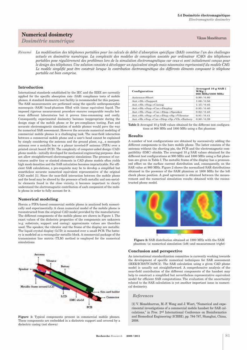
.....................................................................................................................................................................................................................................
Numerical dosimetry Dosimétrie numérique
.....................................................................................................................................................................................................................................
Résumé La modélisation des téléphones portables pour les calculs de débit d'absorption spécifique (DAS) constitue l'un des challengesactuels en dosimétrie numérique. La complexité des modèles de conception assistée par ordinateur (CAO) des téléphonesportables pose régulièrement des problèmes lors de la simulation électromagnétique car ceux-ci sont initialement conçus pourle design des téléphones. Une solution consiste à développer un équivalent simple mais néanmoins représentatif du modèle CAO.Le modèle simplifié peut être construit lorsque la contribution électromagnétique des différents éléments composant le téléphoneportable est bien comprise.
Vikass Monebhurrun
Recherche Research 2009 / 2011 81
IntroductionInternational standards established by the IEC and the IEEE are currentlyapplied for the specific absorption rate (SAR) compliance tests of mobilephones. A standard dosimetric test facility is recommended for this purpose.The SAR measurements are performed using the specific anthropomorphicmannequin (SAM) head-phantom filled with tissue equivalent liquid. Theimposed rigorous measurement procedure ensures comparable results bet-ween different laboratories but it proves time-consuming and costly.Consequently, experimental dosimetry becomes inappropriate during thedesign stage of the mobile phone or for pre-compliance testing. Fast andaccurate electromagnetic simulation of mobile phones would pave the wayfor numerical SAR assessment. However the accurate numerical modeling ofcommercial mobile phones is a challenging task. The near-field interactionbetween a commercial mobile phone and a user's head cannot be explainedby simply considering the antenna and the ground plane, e.g., a monopoleantenna over a metallic box or a planar inverted-F antenna (PIFA) over aprinted circuit board (PCB). The complexity of computer-aided design (CAD)phone models - initially developed for mechanical engineering purposes- doesnot allow straightforward electromagnetic simulations. The presence of cur-vatures and/or tiny or slanted elements in CAD phone models often yieldshigh mesh densities and the SAR calculation becomes impracticable. For effi-cient SAR calculations, a pre-requisite may be to develop a simplified butnonetheless accurate numerical equivalent representative of the originalCAD model [1]. Since the near-field interaction between the mobile phoneand the head may be altered by the presence of both metallic and non-metal-lic elements found in the close vicinity, it becomes important to clearlyunderstand the electromagnetic contribution of each component of the mobi-le phone in order to fully account for it.
Numerical modelingHerein a PIFA-based commercial mobile phone is analyzed both numeri-cally and experimentally. A clean numerical model of the mobile phone isreconstructed from the original CAD model provided by the manufacturer.The different components of the mobile phone are shown in Figure 1. Theexact values of the dielectric properties of the components are unknown(e.g. substrate, support and casing): approximate values are thereforeused. The speaker, the vibrator and the frame of the display are metallic.The liquid crystal display (LCD) is mounted over a small PCB. The batte-ry is modeled as a rectangular metallic block. A commercial package of thetransmission line matrix (TLM) method is employed for the numericalsimulations.
Figure 1: Typical components present in commercial mobile phones.These components are embedded in a dielectric support and covered by adielectric casing (not shown)
Table I: Averaged 10 g SAR values obtained for the different test configura-tions at 900 MHz and 1800 MHz using a flat phantom
ResultsA number of test configurations are obtained by successively adding thedifferent components to the bare mobile phone. The latter consists of theantenna without the shorting pin, the PCB and the electromagnetic com-patibility (EMC) shields. The averaged 10 g SAR values obtained for thedifferent test configurations at 900 MHz and 1800 MHz using a flat phan-tom are given in Table I. The metallic frame of the display has a pronoun-ced effect on the surface current distribution and, consequently, on theSAR value at 900 MHz. Figure 2 shows the normalized SAR distributionsobtained in the presence of the SAM phantom at 1800 MHz for the leftcheek phone position. A good agreement is obtained between the measu-rement and the numerical simulation results obtained with the recons-tructed phone model.
Figure 2: SAR distribution obtained at 1800 MHz with the SAM phantom: (a) numerical simulation (left) and measurement (right)
Conclusion and perspectiveAn international standardization committee is currently working towardsthe development of specific numerical techniques for SAR assessment(IEEE/ICES/TC34/SC2). The SAR calculation using a given CAD phonemodel is usually not straightforward. A comprehensive analysis of thenear-field contribution of the different components of the handset mayhelp to construct a simplified but nevertheless representative equivalentmodel for efficient SAR computations. The evaluation of the uncertaintyrelated to the SAR calculation is yet another important issue in numeri-cal dosimetry.
Averaged 10 g SAR [ Configuration W/Kg ]
900 MHz/1800 MHzAntenna+Short 0.90 / 0.80Ant.+Sh.+Support 1.06 / 0.56Ant.+Sh.+Sup.+Casing 1.15 / 0.45Ant.+Sh.+Sup.+Cas.+Display 0.85 / 0.40Ant.+Sh.+Sup.+Cas.+Disp.+Speaker 0.82 / 0.43Ant.+Sh.+Sup.+Cas.+Disp.+Sp.+Vibrator 0.81 / 0.41Ant.+Sh.+Sup.+Cas.+Disp.+Sp.+Vib.+Battery 0.80 / 0.39
5.4 Dosimétrie électromagnétique Electromagnetic dosimetry
References
[1] V. Monebhurrun, M.-F. Wong and J. Wiart, “Numerical and expe-rimental investigations of a commercial mobile handset for SAR cal-culations,” in Proc. 2nd International Conference on Bioinformaticsand Biomedical Engineering (ICBBE), pp. 784-787, Shanghai, China,2008.
Chapitre 5:Chapitre 5.qxd 28/10/09 15:25 Page10

Problèmes inverses des ondesInverse wave problems
Bernard DUCHÊNEDépartement de Recherche en ÉlectromagnétismeCampus de GifTél. : 33 (0) 1 69 85 15 57 E-mail : [email protected]
Dominique LESSELIER Département de Recherche en ÉlectromagnétismeCampus de GifTél. : 33 (0) 1 69 85 15 61E-mail : [email protected]
Marc LAMBERT Département de Recherche en ÉlectromagnétismeCampus de GifTél. : 33 (0) 1 69 85 15 67 E-mail : [email protected]
5.5
82
Pour tout renseignement s'adresser à : For further information, please contact:
La détection et le dimensionnement d'un endommagement d'un élémentd'une centrale électrique, la localisation de structures au sein d'un sous-sol urbain, la recherche de mines antipersonnelles, la cartographied'aciers dans un béton d'ouvrage d'art, la caractérisation de milieux natu-rels tels que la forêt, ou artificiels tels des panneaux composites, l'image-rie d'un corps humain, la prospection géophysique à partir de la surface oude puits de forage sont de bons exemples de "problèmes inverses desondes". Il s'agit d'identifier les propriétés physiques d'objets placés dansdes environnements réalistes (une pièce de machine, un sol, un corpshumain) à partir de l'observation de leur interaction avec une onde élec-tromagnétique ou acoustique interrogatrice. Ces problèmes inverses sontcritiques à nombre de situations en ingénierie médicale, civile et militai-re, sûreté nucléaire et des transports, où les enjeux de "sécurité" sontessentiels.
. . . . . . . . . . . . . . . . . . . . . . . . . . . . . . . . . . . . . . . . . . . . . . . . . . . . . . . . . . . . . . . . . . . . . . . . . . .
Detection and sizing of a defect affecting an element in a power plant, loca-lization of an underground pipe in an urban environment, detection ofantipersonnel land mines, mapping of metal bars in the reinforced concre-te of civil engineering works, characterization of natural media such as aforest, or artificial ones such as composite panels, human body imaging,geophysical prospecting from the surface or from boreholes, are all verygood examples of "inverse wave problems". The goal is to identify the phy-sical properties of objects located in real-life environments (i.e. a machinepart, the ground, the human body, etc.) by observing their interaction withprimary electromagnetic or acoustic radiation. These inverse problems arecritical in many situations, for example, in the field of biomedical, civil andmilitary engineering, as well as nuclear and transport safety, where "secu-rity" is at stake.
. . . . . . . . . . . . . . . . . . . . . . . . . . . . . . . . . . . . . . . . . . . . . . . . . . . . . . . . . . . . . . . . . . . . . . . . . . .
Sujets1. Evaluation de structures artificiellesEvaluation de pièces complexes, isotropes ou composites, en contexteindustriel et aéronautique, modèles et algorithmes d'inversion.
2. Caractérisation d'obstacles conducteurs en sous-solsModélisation basse fréquence d'obstacles conducteurs et leurs outils decaractérisation.
3. Imageries rapides MUSIC Méthodologies d'inversion rapide MUSIC, asymptotiques associées, etapplications.
4. Imagerie micro-onde du vivantIngénierie de la santé, imagerie du sein par caméras micro-ondes.
5. Approches bayésiennes en régime micro-ondeImagerie d'objets hétérogènes en micro-onde faisant appel à deschamps de Markov.
6. Détection radar en forêt Caractérisation et inversion du signal radar rétrodiffusé par des ciblesen forêt, impliquant des méthodes DORT.
Topics1. Evaluation of man-made structuresEvaluation of complex parts, isotropic or composite, within an industrialor aeronautical context, models and inversion algorithms.
2. Characterization of conductive obstacles in subsoilsLow-frequency modeling of conductive obstacles and their characteriza-tion tools.
3. Fast MUSIC imagingFast inversion methodologies of MUSIC type, companion asymptotics,and applications.
4. Microwave imaging in life sciencesHealth engineering, microwave breast imaging.
5. Bayesian approaches in the microwave regimeImaging of heterogeneous objects in the microwave regime using Markovfields.
6. Radar detection in forestsCharacterization and inversion of radar signals backscattered by targetsin forests, involving DORT methods.
5. ÉLECTROMAGNÉTISME ELECTROMAGNETICS
5.5 Problèmes inverses des ondes Inverse wave problems
Chapitre 5:Chapitre 5.qxd 26/10/09 14:06 Page11

.....................................................................................................................................................................................................................................
Bayesian approach in microwave imagingApproche bayésienne en imagerie micro-onde
.....................................................................................................................................................................................................................................
Résumé Nous abordons ici un problème inverse de diffraction électromagnétique où le but est de caractériser un objet inconnu à partir de la mesure du champ qui résulte de son interaction avec une onde interrogatrice connue dans le domaine des micro-ondes.La modélisation de cette interaction est menée à l'aide d'une représentation intégrale des champs dans une configuration2D-TM. Le problème inverse, non linéaire et mal posé, est abordé à l'aide d'un algorithme itératif dédié aux objets composésd'un nombre fini de matériaux homogènes ; ceci signifie que nous introduisons, dans l'algorithme d'inversion, l'informationa priori que l'image de contraste à reconstruire est constituée d'un nombre fini de régions homogènes et compactes. Cette information a priori est introduite, dans un cadre d'estimation bayésien, via un champ de Gauss - Markov pour la distribu-tion du contraste et un champ de Potts - Markov caché pour les classes de matériaux. Nous exprimons les distributionsaposteriori de toutes les inconnues et, ensuite, nous utilisons un algorithme d'échantillonnage de Gibbs pour tirer deséchantillons et estimer la moyenne a posteriori des grandeurs inconnues.
Olivier FéronBernard Duchêne
Ali Mohammad-Djafari
Recherche Research 2009 / 2011 83
References
[1] O. Féron, B. Duchêne and A. Mohammad-Djafari, “Microwave imagingof inhomogeneous objects made of a finite number of dielectric andconductive materials from experimental data”, Inverse Problems, vol. 21,n°6, pp. S95-S115, 2005.
[2] O. Féron, B. Duchêne and A. Mohammad-Djafari, “Approche bayésien-ne en imagerie micro-onde”, in Problèmes inverses en imagerie et envision, A. Mohammad-Djafari Ed., Hermes Science Publishing, Paris, tobe published 2009.
IntroductionWe consider, herein, the resolution, in the Bayesian estimation framework, ofan electromagnetic inverse scattering problem where the goal is to characte-rize an unknown object from measurements of the scattered field thatresults from its interaction with a known interrogating (or incident) wave.This kind of problem can be encountered in many applications where thequestion is to detect, to localize, to control, to characterize or to image anobject or a structure whose physical parameters are more or less known, andeven not at all, this being usually made by means of a radiation whose wave-length is of the same order of magnitude that the characteristic dimensionsof the object or of the structure inhomogeneities. In these conditions, thewave-object interaction gives rise to diffraction phenomena whose ratherinvolved modeling cannot be dealt with by means of high or low frequencyapproximations and usually leads to non-linear problems due to multiplescattering. It can be noted that, depending upon the frequency of the inter-rogating wave, the applications lie in very different domains such as civilengineering, geophysical prospecting, medical imaging, target detection orradar imaging. As for us, we are interested in microwave imaging whosemost usual applications are non-destructive testing and dielectric or compo-site material characterization, civil engineering work control, ground pene-trating radar for the near underground exploration (depth of about 1 meter)and biomedical imaging. In this last domain, particularly, microwaves giverise to a great interest from the international community for the breast can-cer detection as, in this frequency band, tumors have a strong dielectriccontrast with respect to sound tissues, which bodes better detection capabi-lities for the microwaves than for the usual imaging means such as X rays.
Gauss-Markov-Potts prior for Bayesian inversion Solving an inverse problem means obviously that the associated direct pro-blem has been previously modeled. In the latter, the incident wave and theobject are known and the goal is to compute the scattered field which resultsfrom their interaction. This modeling is based, herein, upon an integralrepresentation of the fields where the scattered fields appear to be radiatedby fictitious Huygens-type sources induced within the object by the incidentwave. These sources are equal to the total field times a contrast function (orobject function) representative of the electromagnetic parameters of theobject. The problem then consists in retrieving this contrast function fromthe measured scattered fields through the inversion of two coupled integralequations. This problem is nonlinear and is also well-known to be ill-posed.
This inherent ill-posedness of the inverse problem requires a regularizationof the latter prior to its resolution, which consists generally in introducingany a priori information available on the object. The Bayesian estimationframework allows to take easily into account such an information. It can benoted that, in this framework, several approaches can be adopted, depen-ding upon the choice of the a priori model and of the estimator. Herein, wechoose a compound Markov model with hidden variables as a priori modeland the so-called posterior mean, which is the expectation of the posteriordistribution, as estimator.
As underlined above, the inverse scattering problem considered herein isnonlinear. It is dealt with through two coupled integral equations expressedin terms of the contrast sources in a way similar to that of the contrast sour-ce inversion method (CSI), an iterative technique developed in a determi-
nistic framework which consists in minimizing a two-term cost functional byalternately updating the contrast sources and the contrast with a gradient-based method. The deterministic framework does not prevent to introduce a priori information; for example, when the objects are known to be homoge-neous, this a priori information can be accounted for by means of a multipli-cative constraint or directly in the expression of the sought contrast. However,when the object is made of a finite number of different materials, as conside-red herein, this a priori information is much more easily introduced in the sta-tistical framework of the Bayesian estimation [1, 2]. The contrast distributioncan then be modeled as a Gaussian mixture where each Gaussian law repre-sents a class of materials and the compactness of the regions can be accountedfor by means of a hidden Markov model. A Gibbs sampling algorithm can thenbe used to estimate the posterior means of the unknown variables. The inter-est of this method lies in the fact that we estimate not only the contrast dis-tribution but also its segmentation in regions and the parameters (means andvariances) of the contrast in each of the latter.
ResultsThis algorithm has been applied to data (courtesy of K. Belkebir and M. Saillard) coming from a laboratory controlled experiment led at theInstitut Fresnel (Marseille). They concern two objects, a dielectric one madeof two different dielectric materials and an hybrid one made of a dielectricand a metallic part. Although the latter represents a challenging case forinversion algorithms, both of them are well retrieved with good values of thecontrast. The algorithm also succeeds in retrieving homogeneous regions(the classes) corresponding to the different parts.
Figure 1: Reconstructions of a dielectric (top) and an hybrid object (down);the real object (left column), the class (2nd column), the real part (3rdcolumn) and the imaginary part (right column) of the contrast
5. ÉLECTROMAGNÉTISME ELECTROMAGNETICS
5.5 Problèmes inverses des ondes Inverse wave problems
Chapitre 5:Chapitre 5.qxd 26/10/09 14:06 Page12

Électromagnétisme des milieux complexes Electromagnetics of complex media
Saïd ZOUHDI Sujet 1 / Topic 1LGEP - Équipe ICHAMSCampus de GifTél. : 33 (0) 1 69 85 16 60E-mail: [email protected]
Olivier DUBRUNFAUTSujet 2 - 5 / Topics 2 - 5LGEP - Équipe MDMICampus de GifTél. : 33 (0) 1 69 85 16 75E-mail : [email protected]
Olivier MEYER Sujets 3, 4 / Topics 3, 4LGEP - Équipe MDMICampus de GifTél. : 33 (0) 1 69 85 16 75E-mail : [email protected]
Laetitia THIRION-LEFEVRESujet 6 / Topic 6SONDRACampus de GifTél. : 33 (0) 1 69 85 18 12E-mail : [email protected]
5.6
84
Pour tout renseignement s'adresser à : For further information, please contact:
Les milieux complexes, dont en premier lieu les matériaux composites,jouent un rôle important dans l'élaboration de nouveaux dispositifs etcomposants. L'étude du comportement du champ électromagnétique dansles milieux complexes est aujourd'hui un domaine de recherche technolo-gique prometteur, avec un éventail d'applications allant des dispositifsmicro-ondes aux systèmes optiques. Des méthodes numériques sont déve-loppées pour traiter les problèmes de propagation dans ces milieux ainsiqu'un banc expérimental (sujet 1).Pour la caractérisation de ces milieux, des méthodes originales de mesurelarge bande (5 Hz - 57 GHz) des paramètres constitutifs (permittivité, per-méabilité, conductivité) ont été développées. Les applications sont nom-breuses : l'étude de films (électrode pour batterie - sujet 2), le traitementthermique micro-onde (chimie, systèmes biologiques - sujet 3), l'étude dematériaux actifs (furtivité - sujet 4), l'étude in situ de liquides pétroliers(capteur - sujet 5), la diffusion par les forêts (sujet 6).
. . . . . . . . . . . . . . . . . . . . . . . . . . . . . . . . . . . . . . . . . . . . . . . . . . . . . . . . . . . . . . . . . . . . . . . . . . .
Electromagnetic complex materials will play a key role in providing newfunctionalities and enhancements to the future electronic devices and com-ponents. We develop various numerical methods for modeling the problemsof wave propagation in these complex media. Free space characterizationmethods are also developed (topic 1).Original methods for measuring the constitutive parameters (i.e. permitti-vity tensor, permeability, and conductivity) in a broad-band frequency (ran-ging from 5 Hz to 57 GHz) have been developed. They are applied to varioussubjects: study of films (electrode of battery - topic 2), behavior undermicrowave thermal processing (i.e. sintering, behavior of biological tissues- topic 3), active materials (anti-radar applications - topic 4), study on phy-sical phenomena in material, in situ control of petroleum (sensor - topic 5),forest scattering modeling (topic 6).
. . . . . . . . . . . . . . . . . . . . . . . . . . . . . . . . . . . . . . . . . . . . . . . . . . . . . . . . . . . . . . . . . . . . . . . . . . .
Sujets1. Modélisation et caractérisation de métamatériaux L'objectif est d'élaborer de nouveaux outils de modélisation dédiés auxmatériaux complexes (e.g. métamatériaux, matériaux chiraux, cristauxphotoniques…). Un banc de caractérisation en espace libre a été récem-ment implémenté.
2. Films minces et matériaux massifsCaractérisations de matériaux en couches minces ou épaisses pour lamicroélectronique, la CEM, les électrodes de batteries.
3. Contrôle de processus sous micro-ondes, traitement thermi-que micro-ondesInstrumentation pour l'étude du couplage entre le champ électroma-gnétique et les systèmes moléculaires et ioniques, biologiques et chi-miques. Traitement thermique micro-ondes.
4. Matériaux actifs Contrôle électrique ou thermique de la réponse électromagnétique dematériaux.
5. Capteur micro-ondesDéveloppement d'un capteur pour le contrôle de fluides en écoulement.
6. Diffusion par les forêts Un code EM asymptotique a été développé qui permet de simuler la dif-fusion multistatique par des forêts en bande P et L (entre 300 MHz et2 GHz). Ce code a fait l'objet de nombreuses validations avec des don-nées réelles « indoor » et « outdoor ».Un nouveau processeur SAR a été mis au point pour détecter des ciblescachées dans les milieux forestiers. Il s'appuie sur les différences carac-téristiques existant entre la diffusion par un tronc et par une plaquemétallique, élément canonique d'une cible manufacturée.La prise en compte de la polarisation est actuellement implémentéepour améliorer encore les performances de détection.
Topics1. Electromagnetic modeling of metamaterials
Development and test novel generation of tools for modeling complexelectromagnetic materials (e.g. Metamaterials, chiral materials, photoniccrystals…). A free space characterization bench is also implemented.
2. Thin films or massive materials characterizationDevelopment of broad-band measurement methods to study thin films ormassive materials for microelectronics, EMC, batteries.
3. Process control under microwaves and microwave thermal pro-cessingInstrumentation for studying the coupling between electromagnetic fieldand molecular / ionic systems / chemical and biological systems.Thermal processing using microwaves.
4. Active materialsApplication to the electric control of electromagnetic responses of mate-rials.
5. Microwave sensorStudy and development of a sensor to check the flowing of fluids.
6. Forest scattering modelingAn asymptotic EM code has been developed to simulate the multistaticscattering by forests at P and L bands (from 300 MHz to 2 GHz). Thiscode has been widely validated using indoor and outdoor radar data.A new SAR processor has been developed to detect a Man-Made-Target(MMT) hidden beneath foliage. This tool relies on the differences betweenthe scattering by a trunk and a metallic plate, seen as a canonical ele-ment for the MMT.The polarization properties are now studied to further improve the detec-tion performance.
5. ÉLECTROMAGNÉTISME ELECTROMAGNETICS
5.6 Électromagnétisme des milieux complexes Electromagnetics of complex media
Chapitre 5:Chapitre 5.qxd 26/10/09 14:06 Page13

.....................................................................................................................................................................................................................................
Electromagnetic characterization of complex structuresCaractérisation électromagnétique de structures complexes
.....................................................................................................................................................................................................................................
Abstract Une méthodologie pour la caractérisation électromagnétique de structures complexes basée sur la combinaison des réseauxde neurones (RN) et de la méthode des éléments finis (MEF) est présentée. La MEF est utilisée pour créer les bases de données nécessaires aux RN. L'exemple d'une cellule permettant de déterminer la permittivité d'un matériau illustre cette méthode.Des procédures ont été développées pour optimiser les bases de données nécessaires à l'apprentissage des RN et s'assurer dela bonne capacité de généralisation de ceux-ci.
Hulusi AcikgozLionel PichonOlivier MeyerYann Le Bihan
IntroductionThe in situ (e.g. sensor applications) or ex situ (e.g. material characterisa-tion) determination of permittivity of dielectric materials can be a difficultproblem depending on the complexity of the structure and the measurementfrequency. The direct problem, i.e. the expression of the observation (e.g.sensor admittance) versus the measurand (e.g. permittivity), is then oftensolved with numerical methods. The inverse problem (e.g. permittivity ver-sus the admittance) can be solved with iterative methods but they are com-putationally expensive. We propose then a method using numerical methodsassociated with an inversion procedure based on neural networks (NN).
MethodThe approach proposed is based on the combination of NN and finite ele-ment method (FEM). The FEM is a robust and versatile computationalmethod that can simulate the physical behaviour of complex structures. Itis used to provide for example the equivalent admittance of the structure bycarrying out the direct problem. Thus, the FEM permits to be unrestrictedon specific materials and structures. The FEM provides the training dataset required for the NN internal parameter adjustment. The data set isconstituted of input (e.g. complex admittance, frequency) and output (e.g.both real and imaginary parts of the complex permittivity) pairs. Multi-Layers Perceptron NN are used for the inverse problem. When designingNN, there are two important steps. The first is related to the building of thetraining data set which must allows representing at the best the physicalbehaviour of the system. A method for designing optimal data bases thanksto a meshing refinement of the measurand space was elaborated [1]. Thesecond problem is related to the training of the NN. Indeed, the NN mustnot only “learn” correctly the training data but most of all be able to esti-mate new data not included in the training set (generalisation capability).A regularization method based on a Bayesian rule was implemented inorder to enhance the generalisation capability of the designed NN [2].
ExampleThe validity of the proposed NN-based inversion method is assessed byusing different characterisation protocols developed in the laboratoryhaving no or restricted analytic solution. We present as an example a cha-racterisation cell consisting in a junction between a coaxial waveguide anda circular waveguide which is filled in an inhomogeneous way. This meansthat the material under test is located at the continuity of the inner conduc-tor and that it is held up by a Teflon crown (permittivity = 2.1) (figure. 1).
Figure 1: Measuring cell
Various impedance and network analysers (Agilent 4294A, 4291A,HP8510B, and E8364B) are available at LGEP in a broadband frequency.In this example, the whole device is connected to an impedance analyser4291 measuring the admittance of the cell. Inversion results obtained withNN (from 1 MHz to 1.8 GHz) are presented and compared with other resultsobtained using an iterative inversion procedure (figure 2).
Figure 2: Permittivity of ethanol computed from admittance with iterative method and with FEM/NN method
Figure 2 shows the good agreement between NN and reference iterativeinversion results.
ConclusionThe interest of NN inversion associated to numerical simulations in micro-wave dielectric characterization has been shown. NN are good candidates tosolve complex inverse problems for structures having no analytical solu-tions. This methodology has already been applied to a multiphase flow sen-sor [3].
Tools have been developed allowing to simplify the elaboration of the NNinversion procedure and to improve its performances. The first one allows tocreate optimized data base for the NN training. The second one consists ina Bayesian regularisation during the NN training process allowing to makefor the good generalisation of the designed NN.
Recherche Research 2009 / 2011 85
5. ÉLECTROMAGNÉTISME ELECTROMAGNETICS
5.6 Électromagnétisme des milieux complexes Electromagnetics of complex media
References
[1] H. Acikgoz, L. Santandrea, Y. Le Bihan, S. Gyimothy, J. Pavo, O. Meyer,L. Pichon, “Generation and use of optimized databases in microwave cha-racterization”, in IET Science, Measurement & Technology, vol. 2, pp. 467-473, 2008.
[2] H. Acikgoz, Y. Le Bihan, O. Meyer, L. Pichon, “MicrowaveCharacterization of Dielectric Materials using Bayesian NeuralNetworks”, in Progress In Electromagnetics Research C, vol. 3, pp. 169-182, 2008.
[3] H. Acikgoz, B. Jannier, Y. Le Bihan, O. Dubrunfaut, O. Meyer, L. Pichon, “Direct and inverse modeling of a microwave sensor determi-ning the proportion of fluids in a pipeline”, in IEEE trans. on Magnetics,vol.45, pp. 1510-1513, 2009.
Chapitre 5:Chapitre 5.qxd 26/10/09 14:06 Page14

Nouveaux concepts d'antennes réseauNew concepts of phased array antenna
Régis GUINVARC'H SONDRACampus de GifTél. : 33 (0) 1 69 85 18 11E-mail : [email protected]
5.7
86
Pour tout renseignement s'adresser à : For further information, please contact:
L'objectif premier des études d'antennes porte sur l'amélioration des per-formances des radars. Pour ce faire, deux thématiques sont abordées. Lapremière vise à étudier de nouvelles plateformes d'accueil pour accueillirdes antennes réseaux les plus grandes possibles. En effet, la résolutionazimutale d'un radar est directement proportionnelle à la taille de l'an-tenne. Ces grandes plateformes présentent la plupart du temps des géo-métries non linéaires, qui peuvent de surcroît varier avec le temps. Ellespeuvent de plus requérir des antennes spécifiques (antenne et alimenta-tion coplanaires, pas de possibilité d'installer un plan de masse,…). Lesecond axe traite des techniques de mises en réseau. L'objectif est icid'améliorer les performances d'une antenne réseau, en terme de pureté depolarisation, de largeur de bande etc., sans modifier l'antenne de base (etdonc de préférence en utilisant des antennes simples et de faible coût).
. . . . . . . . . . . . . . . . . . . . . . . . . . . . . . . . . . . . . . . . . . . . . . . . . . . . . . . . . . . . . . . . . . . . . . . . . . .
This theme covers two research axes, which both aims at enhancing theradar capabilities. The first consists in studying new platforms to receivevery large antenna arrays. As the radar azimuthal resolution is directlyrelated to the antenna size, identifying large receiving platforms is of agreat interest. These platforms are usually non linear, with a shape thatcan change with time. They can also implies some strong additional requi-rements, such as a coplanar feeding, the impossibility to have a groundplane and so on. The second axis aims at developing new techniques to putantennas in arrays in order to get arrays with dual polarization capabili-ties. This is done without any modification of the elementary antenna (andas such, using simple and low cost antennas).
. . . . . . . . . . . . . . . . . . . . . . . . . . . . . . . . . . . . . . . . . . . . . . . . . . . . . . . . . . . . . . . . . . . . . . . . . . .
Sujets1. Grands dirigeables en tant que grande antenne conformeLes dirigeables à hautes altitudes sont en développement dans plu-sieurs pays. Evoluant dans la stratosphère, à 20 km du sol, ils présen-tent une grande surface d'accueil (environ 150m de long), permettantdonc d'accueillir de grands réseaux. De plus, grâce à leur altitude, ilspermettent de couvrir de grandes zones, à un coût bien moindre quecelui d'un satellite. Par contre, leur capacité d'emport est limité et lesantennes doivent être extrêmement fines tout en se conformant à lasurface du dirigeable.
2. Antennes flottantes pour radar à onde de surfaceRemarquable en termes de détection longue portée et basse altitude,médiocre en termes de résolution, le radar à onde de surface est l'objetici de travaux concernant le déploiement de son réseau d'antennes surdes bouées, ce qui permettrait d'accroitre sa résolution en azimut. Auxproblèmes de modélisation (couplage avec la mer, mouvements d'anten-ne) se rajoute un problème de calibration de l'antenne, continûmentaffectée de déformations (déformations spatio-temporelles).
3. Développement d'antennes réseaux large bande à double pola-risationL'antenne spirale d'Archimède est une antenne très large bande pré-sentant une bonne pureté de polarisation. Cependant, sa mise enréseau pose des problèmes ardus. En effet, dans un réseau classique, safréquence de fonctionnement basse est directement proportionnelle à sataille alors la distance entre deux antennes fixe la fréquence de fonc-tionnement haute du réseau. Si l'on souhaite les deux polarisations, labande passante est alors nulle. Des techniques pour permettre la réali-sation de ces antennes réseaux avec les deux polarisations sont déve-loppées, le réseau fonctionnant sur deux octaves complètes (dépointablesur 60°).
Topics1. Large airships as a large conformal antenna arrayHigh Altitude Airships are in development in various countries. At analtitude of 20km, they offer a wide platform (about 150m long) to putlarge antenna arrays. Furthermore, thanks to this altitude, they cancover large area, at a cost much lower than that of a satellite. However,their payload is limited and the antennas have to be extremely thin andconformed to the skin of the airship.
2. Sea floating antenna for HFSWR Efficient in terms of long range and low altitude coverage, although poorin terms of resolution, a new concept of surface waves radar is studied,based on sea floating array of antennas. The concept allows for a betterazimuth resolution. Two main problems are on study: first, modeling ofthe antenna (including its interaction with the sea surface); second, thearray calibration must be achieved, with consideration of the space-timedeformations of the array.
3. New techniques to put antennas in arraysThe Archimedean spiral antenna is a very wide band antenna with a goodpolarization. However, its use in array raises some hard issues. In a standardarray, its low frequency limit is directly proportional to its size whereas thedistance between two antennas fixes the upper frequency of the array. If onewants to design a dual polarization array, then the bandwidth is zero. Newtechniques have been introduced to enhance both the lower and the upperlimits of the bandwidth. This leads to phased arrays with a two octave band-width, steerable over 60°.
5. ÉLECTROMAGNÉTISME ELECTROMAGNETICS
5.7 Nouveaux concepts d'antennes réseau New concepts of phased array antenna
Chapitre 5:Chapitre 5.qxd 26/10/09 14:06 Page15

.....................................................................................................................................................................................................................................
Coplanar feeding solutions for spiral antennaSolution d'alimentation coplanaire pour antenne spirale
.....................................................................................................................................................................................................................................
Résumé L'antenne spirale d'Archimède est un excellent élément rayonnant pour des applications nécessitant une large bande defréquences ainsi qu'une polarisation circulaire. Dans la plupart des cas, l'alimentation se fait au centre de l'antenne spirale.Cependant, certains environnements interdisent un accès au centre de l'antenne. Cela est notamment le cas des plateformesaéroportée tel que les dirigeables. Une antenne spirale alimentée par l'extérieur est présentée, son rayonnement est similaire àcelui de la spirale classique.
Nouveaux concepts d'antennes réseauNew concepts of phased array antenna
Karim LouertaniMarc Hélier
Régis Guinvarc'hNicolas Ribière-Tharaud
Recherche Research 2009 / 2011 87
IntroductionSpiral antenna [1] [2] is well known to be suitable for many applicationsrequiring a large bandwidth and circular polarization (Right Hand CircularPolarization and/or Left Hand Circular Polarization). In most cases, the spi-ral antenna is fed at the center. However, it is not always possible for thefeed to reach the center of the antenna. Thus, it could be interesting to feedthe device in another way. One possibility is to design an external feed.Studies have been done in this direction in order to control the polarizationat the cost of the quality of the far field pattern. Some designs require theuse of resistive loads [3] which affects the efficiency. For the classical case ofthe center-fed spiral antenna, each arm is fed out-of-phase. As a result, thecurrent distribution is symmetric about the center on the antenna. In orderto keep the characteristics of the Archimedean spiral antenna, the new design must have a symmetrical current distribution. This condition hasbeen applied to the geometry and to the feeding in order to design the newantenna. The antenna is studied without a ground plane.
Figure 1: Example of an airship with a spiral antenna array [4]
Antenna designThe new design is presented in Figure 2. This spiral antenna is composed offour arms winded two by two around the center and ending by a shortstraight line to reach one of the feed points. Each arm has three turns andhas a width w = 3.4 mm. The space s between two arms is equal to 1/3 of thewidth of an arm, hence s = 1.13 mm. This results in an antenna diameter Dof 12.5 cm. This design is chosen to be geometrically symmetric about itscenter as for the classical spiral antenna.
Figure 2: Design of the 2x2 spiral antenna and repartition of the currents
Two sources are used to feed the spiral antenna. Each source is connectedto two arms and provides a balanced signal (i.e. the two arms are fed out-of-phase). Moreover the two sources are out-of-phase. Hence the current dis-tribution is symmetric on the entire surface of the antenna.
ResultsThis antenna is studied using the software Feko based on the method ofmoments (MoM). For all simulation results, the 2x2 arms spiral antenna iscompared to the classical two arms center-fed Archimedean spiral antennawith the same diameter. The reflection coefficients (S11) are computed for areference impedance of 200 ohms for both antennas.
Figure 3: Total gain in dBi of the 2x2 antenna
For the 2x2 spiral antenna, since the sources are symmetric in position andin feeding, the reflection coefficient is the same for the two ports. With anidentical diameter, the 2x2 arms spiral antenna exhibits a reflection coeffi-cient lower than -10 dB from 650 MHz (except from 770 MHz to 830 MHzwhere the S11 is lower than -8 dB) while the Archimedean spiral antennaradiates above 800 MHz. Thus, we obtain an extension of around 150 MHzon the functional bandwidth. This extension is particularly interestingwhen the antenna is used in an array. For a half wavelength spaced array,this antenna improves the bandwidth by around 37.5%. Figure 3 shows thetotal gain in dBi of the 2x2 arms spiral antenna at 800 MHz, 900 MHz and1 GHz for 0 = [0° , 360°[.. As for the classical center-fed antenna, the radia-tion pattern is symmetric about the antenna plane and remains constantover the frequency range. However, the 2x2 arms spiral antenna radiates acircular polarization only for a narrow band. This is partly due to the shortlengths of the arms that creates reflection in the center of the spiral. Thisin turn gives rise to a cross-polarization that diminishes the Axial Ratio(AR). Optimization of the center of the antenna could reduce these reflec-tions. This can be done by adding resistive loads.
5. ÉLECTROMAGNÉTISME ELECTROMAGNETICS
5.7 Nouveaux concepts d'antennes réseau New concepts of phased array antenna
References
[1] J. D. Kraus and R. J Marhefka. Antennas for all applications. Mc GrawHill Third Edition, 2002.
[2] R. G. Corzine and J. A. Mosko. Four-Arm Spiral Antennas. ArtechHouse. 1990.
[3] K. Louertani, R. Guinvarc'h, N. Ribière-Tharaud and M. Darces,Design of a spiral antenna with coplanar feeding solution, IEEE antennaand Propagation Society International Symposium, July 2008.
[4] F. Chauvet, R. Guinvarc'h, and M. Hélier, “Approximated methodneglecting coupling for conformal array,” Applied ComputationalElectromagnetics Society Journal, Special Issue on ACES 2006Conference, no. 1, pp. 105-11, March 2007.
Chapitre 5:Chapitre 5.qxd 26/10/09 14:06 Page16

88
Chapitre 6:Chapitre 6.qxd 26/10/09 14:07 Page1

89
6. MICROÉLECTRONIQUE ET PHOTONIQUE
MICROELECTRONICS AND PHOTONICS
6Chapitre 6:Chapitre 6.qxd 26/10/09 14:07 Page2

Architectures de circuits mixtes et de microsystèmesArchitectures of mixed-signal integrated circuits andmicrosystems
Sujets1. Numérisation de signaux rapides Conception d'architectures de CAN Sigma-Delta passe bande, rapides,à filtres continus, pour des applications radiofréquences en téléphonie,radar ou instrumentation. Recherche de solutions utilisant des filtresGmC, LC ou RC intégrés, et à ondes de surface (S.A.W, B.A.W, Ondes deLamb).Études d'architectures originales de numérisation pour la radio logi-cielle (voir 4.6 « Systèmes de numérisation »).
2. Conception des MEMS et NEMS Méthodes d'estimation de paramètres à partir d'observations binaires :applications au test bas-coût des MEMS et des convertisseurs Sigma-Delta.Conception d'outils d'analyse des MEMS résonants non-linéaires.Conception d'architectures robustes intégrables pour l'actionnement etla détection des structures nano-mécaniques résonantes.
3. Conception et réalisation de circuits intégrés spécifiques Conception de circuits mixtes en technologie AsGa ou CMOS.
Topics1. Analog to Digital Conversion of HF signalsDesign of fast continuous bandpass Sigma-Delta ADCs for radiofre-quency applications (telephony, radar, instrumentation).Research of solutions involving Gm-C filters, integrated LC or RC filters,SAW, BAW, Lamb Waves Filters.Original ADC architectures design for radio software applications (see4.6 “Digitization systems”).
2. MEMS and NEMS designParameter estimation methods based on binary observations: applica-tion to low-cost BIST of MEMS and Sigma-Delta converters.Development of analysis tools for nonlinear resonant MEMS.Design of robust integration-oriented architectures for sensing andactuating resonant nano-mechanical structures.
3. Design and implementation of specific integrated circuitsDesign of mixed signal integrated circuits in GaAs or CMOS technology.
Richard KIELBASA Département Signauxet Systèmes ÉlectroniquesCampus de GifTél. : 33 (0) 1 69 85 14 03E-mail : [email protected]
Jérôme JUILLARDDépartement Signauxet Systèmes ÉlectroniquesCampus de GifTél. : 33 (0) 1 69 85 14 08E-mail : [email protected]
Philippe BENABES Département Signauxet Systèmes ÉlectroniquesCampus de GifTél. : 33 (0) 1 69 85 14 19E-mail : [email protected]
6.1
90
Pour tout renseignement s'adresser à : For further information, please contact:
6. MICROÉLECTRONIQUE ET PHOTONIQUE MICROELECTRONICS AND PHOTONICS
La réduction des coûts, stratégie fondamentale de la compétitivité, se tra-duit dans le secteur de l'électronique par une pression considérable tantsur les technologies que sur les systèmes. Dans le même temps, la mise enœuvre de nouvelles technologies devient de plus en plus risquée en raisondu niveau d'investissements requis, tandis que la complexification inexo-rable des systèmes conduit à une exigence de plus en plus forte sur lesméthodes de conception. Dès lors, les questions suivantes se posent à l'in-dustriel : comment tirer le meilleur parti des technologies ? Comment s'ou-vrir à de nouvelles applications ? Comment concevoir des produits tou-jours plus performants et innovants notamment sur le plan de la rapidité,de l'encombrement, de la robustesse vis-à-vis de perturbations, de laconsommation électrique…?
. . . . . . . . . . . . . . . . . . . . . . . . . . . . . . . . . . . . . . . . . . . . . . . . . . . . . . . . . . . . . . . . . . . . . . . . . . .
In the field of electronics, reduction of the costs, fundamental strategy ofcompetitiveness, leads to a considerable pressure on technologies as well ason systems. Moreover, the implementation of new technologies becomesincreasingly risky because of the required amount of investments, while theinevitable complexification of systems leads to increasingly strong require-ments on design methods. Consequently, the following questions arise: howto take the best advantage from existing technologies? How to get implica-ted in new applications? How to design new, more efficient products, whichare innovative with respect to speed, bulk, robustness towards perturba-tions, power requirements… ?
. . . . . . . . . . . . . . . . . . . . . . . . . . . . . . . . . . . . . . . . . . . . . . . . . . . . . . . . . . . . . . . . . . . . . . . . . . .
Chapitre 6:Chapitre 6.qxd 26/10/09 14:07 Page3

6.1 Architextures de circuits mixtes et de microsystèmesArchitectures of mixed-signal integrated circuits and microsystems
.....................................................................................................................................................................................................................................
Phase stability enhancement of a NEMS oscillator with electrostatic and mechanical nonlinearitiesAmélioration de la stabilité en phase d'un oscillateur NEMS à l'aide de non-linéarités mécaniques et électrostatiques
.....................................................................................................................................................................................................................................
Résumé On montre qu'en utilisant deux non-linéarités de comportements opposés (adoucissant et durcissant), il est possible d'action-ner un oscillateur NEMS à une grande amplitude tout en préservant une bonne stabilité en phase. On étudie le cas d'un systè-me bouclé consistant en une structure capacitive actionnée par impulsions, où le durcissement dû au phénomène de Duffing estcompensé localement par la polarisation électrostatique. Cette analyse est validée par la simulation transitoire du système non-linéaire.
Architectures de circuits mixtes et de microsystèmesArchitectures of mixed-signal integrated circuits andmicrosystems
6. MICROÉLECTRONIQUE ET PHOTONIQUE MICROELECTRONICS AND PHOTONICS
Jérôme Juillard
Recherche Research 2009 / 2011
IntroductionIt is a challenge to achieve large-amplitude motion of NEMS oscillatorswithout increasing their phase noise [1]. On one hand, achieving large oscil-lation amplitude leads to better SNR and, thus, simplifies the design of theelectronic feedback loop. On the other hand, it results in a nonlinear frequency-amplitude relationship: for example, the frequency instability ofa Duffing oscillator is proportional to its oscillation amplitude. In this paper,we show how to achieve large-amplitude oscillation and good frequency sta-bility in a NEMS oscillator: the governing idea is to use a softening nonli-nearity to locally balance the hardening behaviour of the Duffing nonlinea-rity for a given motion amplitude. This design approach is relevant for mostNEMS frequency-reference applications.
AnalysisWe study the case when the softening behaviour is obtained via electro-static biasing. The capacitive detection and actuation scheme is similar tothe one in [2] (Fig. 1).
Figure 1: The moving structure (in green) is the midpoint of a biasedcapacitive half-bridge. The amplifier's output voltage is proportional to thecharge of the moving electrode. Positive or negative pulses are delivered tothe central electrode when Vout crosses zero [2-3]. Measurement noise isresponsible for short-term frequency instability.
This feedback scheme ensures that the system oscillates and is stable, evenbeyond the critical Duffing amplitude [3-4]. Considering the simpler case ofparallel-plate actuation, we use describing function analysis to show that theself-oscillation pulsation of the closed-loop system is given by
, (1)
where is the natural pulsation of the resonant structure, A is the oscil-lation amplitude, normalized with respect to the electrostatic gap, and
and are positive design-dependent coefficients respectively repre-senting the strength of the Duffing hardening and that of the electrosta-tic softening. From (1), we establish that the quantity whenA equals:
Thus, provided the structure is designed so that , there exists an optimal oscillation amplitude around which amplitude perturbationshave little impact on the value of . In order to ensure a large SNR, Aoptshould be as large as possible, but safely maintained below Api , for whichelectrostatic pull-in [5] occurs.
ResultsSimilar analyses can be made in the case of flexible structures; althoughthey are not tractable analytically, they lead to results that are qualitati-vely similar to (1-2).
Figure 2: Simulated frequency stability of the M&NEMS structureunder a 12V bias.
These theoretical results are compared with simulations, in the case of theresonant structure developed in the ANR-funded M&NEMS project (Fig. 2). The measurement noise is white and has a uniform distribution.Each point of the curve corresponds to one nonlinear transient simulationof the closed-loop system, with a pulse amplitude varying between 10mVand 290mV. The relative error is defined as the ratio of the estimated stan-dard deviation of the pulsation to its estimated mean. It is minimal closeto the optimal oscillation amplitude predicted by our work, . For small pulse amplitudes (and, thus, small oscillation amplitudes), thedetected signal is drowned in the measurement noise, resulting in poorfrequency stability.
91
References
[1] Feng X.L., “Phase noise and frequency stability of very-high fre-quency silicon nanowire nanomechanical resonators”, 14thInternational Conference on Solid-State Sensors, Actuators andMicrosystems, pp. 327-30, 2007.
[2] Colinet E. et al., “Actuation of resonant MEMS using short pulsedforces”, Sensors and Actuators A, vol. 115 (2004), pp. 118-125.
[3] Juillard J. et al., “From MEMS to NEMS: closed-loop actuation ofresonant beams beyond the critical Duffing amplitude”, 7th IEEEConference on Sensors, 2008, pp 510-513.
[4] Kaajakari V. et al., “Nonlinear limits for single-crystal siliconmicroresonators”, J. MEMS, vol. 13 (2004), pp. 715-724.
[5] Elata D., “On the static and dynamic response of electrostaticactuators”, Bulletin of the Polish Academy of Sciences, TechnicalSciences, vol. 53, p 373-84.
, (2)
Frequency stability vs. amplitude
Oscillation amplitude A
Chapitre 6:Chapitre 6.qxd 26/10/09 14:07 Page4

Intégration d'algorithmes et systèmes électroniquesAlgorithm integration and electronic systems
Pierre LERAYÉquipe SCEE - IETRCampus de RennesTél. : 33 (0) 2 99 84 45 00E-mail : [email protected]
Jacques WEISSÉquipe SCEE - IETRCampus de RennesTél. : 33 (0) 2 99 84 45 00E-mail : [email protected]
Amor NAFKHAÉquipe SCEE - IETRCampus de RennesTél. : 33 (0) 2 99 84 45 00E-mail : [email protected]
6.2
92
Pour tout renseignement s'adresser à : For further information, please contact:
L'évolution tout à fait considérable des technologies de l'électroniquemoderne (circuits intégrés silicium notamment) permet la réalisation desystèmes électroniques d'une très grande complexité satisfaisant de mul-tiples critères : grande vitesse d'exécution, encombrement réduit, faibleconsommation, coûts acceptables, fiabilité accrue...Les problèmes rencontrés au niveau de la conception d'un équipementsont liés : - à la nécessaire adaptation des différents algorithmes devant être inté-grés sur des architectures novatrices qu'il faut imaginer en respectantdes contraintes hiérarchisées (coût, rapidité, encombrement, consomma-tion, robustesse à l'environnement,...) ;- au choix optimum des composants les plus adaptés en fonction descontraintes imposées (Processeurs, DSP, SOC, ASIC, FPGA).
. . . . . . . . . . . . . . . . . . . . . . . . . . . . . . . . . . . . . . . . . . . . . . . . . . . . . . . . . . . . . . . . . . . . . . . . . . .
Considerable advances in modern electronic technology (in particular, inte-grated circuits on silicon) have made it possible to develop complex elec-tronic systems capable of meeting multiple requirements: high speed of exe-cution, small overall dimensions, low power consumption, acceptable costs,increased reliability, etc.Problems encountered with equipment design are mostly related to:- Need for adapting various algorithms requiring integration on innovati-ve architectures, which may be envisaged while maintaining hierarchicalconstraints (i.e. cost, speed, obstruction, consumption, robustness with theenvironment, etc.);- Optimum choice of the most suitable components according to the impo-sed constraints (Processors, DSP, SOC, ASIC, FPGA).
. . . . . . . . . . . . . . . . . . . . . . . . . . . . . . . . . . . . . . . . . . . . . . . . . . . . . . . . . . . . . . . . . . . . . . . . . . .
Sujets1. Opérateurs numériques rapides Conception et intégration d'opérateurs arithmétiques dans les réels etdans les corps de Galois.Conception et intégration d'opérateurs pour le traitement du signal :transformateurs de Fourier et corrélateurs, opérateurs CORDIC.
2. Plateforme matérielle reconfigurable Etude de nouvelles architectures matérielles pour le traitement dusignal basées notamment sur l'utilisation des technologies FPGA recon-figurables partiellement et dynamiquement.Applications à la « radio logicielle » et à la conception des nouveaux ter-minaux multi-standards dynamiquement reconfigurables.
3. Electronique pour les communications numériquesDéveloppement de plateformes hétérogènes adaptées aux communica-tions haut débit.Étude et conception d'architectures reconfigurables pour les systèmesMIMO.Étude et conception d'IP paramétrables pour les communicationsnumériques : codec de de Reed Solomon, décodeur de Viterbi à décisionspondérées, turbo codec de codes produits.
4. Conception et réalisation de systèmes de diffusion multimédiaAlgorithmes et architectures pour la compression du son, des images etdes données.Conception et réalisation d'un système de multiplexage audio-vidéo surFPGA.
Topics1. Fast numerical operatorsDesign and integration of arithmetic operators in real and Galois fields.Design and integration of operators for digital signal processing: fastFourier transformers and fast correlation function, CORDIC operators.
2. Hardware reconfigurable platformDesign of new Digital Signal Processing architectures based on the useof FPGA enabling partial and dynamical hardware reconfiguration.Applications to “Software Radio” and to designing a new multimodehandset with dynamic reconfigurability.
3. Electronic for Digital CommunicationsDesign of heterogeneous systems dedicated to high data rate communi-cation.Design of reconfigurables architectures of MIMO systems.Design of parameterizable IP cores for digital communication: Reed-Solomon decoder, Viterbi decoder with soft decision, turbo encoder-decoder of product codes.
4. Design and development of multimedia streaming systemsAlgorithms and architectures for the compression of sound, images anddata.Design of an audio-video multiplexing system on FPGA component.
6. MICROÉLECTRONIQUE ET PHOTONIQUE MICROELECTRONICS AND PHOTONICS
Chapitre 6:Chapitre 6.qxd 26/10/09 14:07 Page5

6.2 Intégration d'algorithmes et systèmes électroniquesAlgorithm integration and electronic systems
.....................................................................................................................................................................................................................................
Reconfigurable architectures based on CORDIC operator for digital processing: MIMO decoder applicationsArchitectures reconfigurables à base d'opérateurs CORDICpour le traitement du signal : applications aux récepteurs MIMO
.....................................................................................................................................................................................................................................
Résumé Cet article propose une architecture reconfigurable dynamiquement pour l'implémentation d'algorithmes de traitement dusignal. L'architecture est basée sur l'utilisation d'opérateurs CORDIC (COordinate Rotation DIgital Computer) et s'appuie surla technologie de reconfiguration partielle des FPGAs. Cette architecture est mise en œuvre dans l'implémentation d'un déco-deur MIMO V-Blast Square Root dans un FPGA Xilinx Virtex4.
Amor NAFKHAÉquipe SCEE - IETRCampus de RennesTél. : 33 (0) 2 99 84 45 00E-mail : [email protected]
Hongzhi WangPierre Leray
Jacques Palicot
Recherche Research 2009 / 2011 93
References
[1] H. Wang, J.-P. Delahaye, P. Leray, and J. Palicot, « Managing dynamicreconfiguration on mimo decoder », in IPDPS. IEEE, 2007, pp. 1-8.
[2] H. Wang, P. Leray, J. Palicot, « Reconfigurable architecture forMIMO systems based on CORDIC operators », Comptes RendusPhysique, Elsevier, volume 7 septembre 2006, pp 735-750.
[3] H Wang, P Leray and J Palicot, «An efficient MIMO V-BLASTdecoder based on a dynamically reconfigurable FPGA including itsreconfiguration management », ICC08, Beijng, China.
IntroductionThis paper introduces a reconfigurable MIMO V-BLAST (Vertical BellLaboratories Layered Space-Time) square root decoder that is CORDIC ope-rators based, allows for dynamically changing the interconnections betweenthe CORDIC (COordinate Rotation DIgital Computer) operators. Theseinterconnections of CORDIC operators are implemented in a partial recon-figurable part of FPGA using the dynamic reconfiguration method whichimproves both the reconfiguration time and the area efficiency. Moreover,this reconfiguration time improvement is increased thanks to theMicroBlaze (within the FPGA) in which is included the reconfigurationmanagement. This MIMO square root decoder is mapped on a Xilinx Virtex-4, showing the configuration time improvement, area efficiency and flexibi-lity of the decoder by using the dynamic partial reconfiguration method.
Cordic Based Dynamically ReconfigurableArchitecture (CBDRA)We propose a processing structure where the number of CORDIC operatorsadapts itself to the data rate and number of antennas characteristics for opti-mal implementation (figure 1). A fully parallel architecture of course offerssignificant calculation capacity, but at the expense of very great complexity.On the other hand, an iterative structure constructed around a single opera-tor greatly reduces the complexity, but limits processing speed. It is by com-bining both these approaches that it will be possible to obtain an optimalarchitecture, being guided by the relationships that must link the characte-ristics of the communication chain (data rate, number of antennas) and thedecoder architecture (number of CORDIC operators and the way they areorganized). In the MIMO SRA application, the dynamic reconfiguration isused to change the interconnections of CORDIC in stead of a static imple-mentation of the interconnections frameworks which uses a great number ofmultiplexers to switch from one interconnection context to the next one.
Figure 1: Parallel Architecture versus CBDRA
Configuration managementIn the dynamic reconfigurable architecture, shown in figure 2, an embeddedprocessor (like Xilinx MicroBlaze) is used as configuration manager andICAP as configuration interface. The logic resources are divided into twoparts: the fixed area and the dynamically reconfigurable area. Each of thesetwo areas can contain several modules. The fixed area contains modulesthat remains the same. The physical separation between reconfigurablemodule with fixed module an other reconfigurable one have to be realizedby a special communication interface called Bus Macro. These Bus Macroprovided by Xilinx are used to ensure the right place and routing of signalcrossing over PR area.
Figure 2: Partially reconfigurable platform
Experimental resultsThe MIMO decoder for 2 antennas system with QPSK signal constellationis designed in VHDL, simulated with Modelsim. The decoder is implemen-ted and tested on a Virtex-4 xc4lx-160 from Xilinx. Table I shows some syn-thesis results of decoder implemented which uses the dynamic reconfigura-tion to change the interconnections between the processing elements. Thereconfiguration times are calculated with the Bitstreams size and ICAP fre-quency. As it could be seen in Table I, the reconfiguration of Virtex-4 isindeed more efficient than the Virtex-II, thanks to the new features ofVirtex-4. The reconfiguration time of dynamical reconfigurable part is equalto 50us which is very close to real-time reconfiguration.
Table IParallel structure (29 CORDIC)�
P1/2 et Qa
θ1
Ø1
0 0 0 0
P01/2 et Q0
0
θ2
Ø1 Ø1 Ø1
θ3
Ø2 Ø2 Ø2
0 0 0
Ø2
Ø3 Ø3 Ø3 Ø3 Ø3
Ø4 Ø4 Ø4 Ø4 Ø4
θ3 θ4 θ4 θ3
Ø2
0-1
0
Ø3
0
Ø4
0
Ø4
0-10 0 0 0 0 0
sscchheedduulleerr
CORDIC CORDIC CORDIC
Interconnection
I/O Data memory
Reconfigurable structureParallel structure (29 CORDIC)�P1/2 et Qa
θ1
Ø1
0 0 0 0
P01/2 et Q0
0
θ2
Ø1 Ø1 Ø1
θ3
Ø2 Ø2 Ø2
0 0 0
Ø2
Ø3 Ø3 Ø3 Ø3 Ø3
Ø4 Ø4 Ø4 Ø4 Ø4
θ3 θ4 θ4 θ3
Ø2
0-1
0
Ø3
0
Ø4
0
Ø4
0-10 0 0 0 0 0
sscchheedduulleerr
CORDIC CORDIC CORDIC
Interconnection
I/O Data memory
P1/2 et Qa
θ1
Ø1
0 0 0 0
P01/2 et Q0
0
θ2
Ø1 Ø1 Ø1
θ3
Ø2 Ø2 Ø2
0 0 0
Ø2
Ø3 Ø3 Ø3 Ø3 Ø3
Ø4 Ø4 Ø4 Ø4 Ø4
θ3 θ4 θ4 θ3
Ø2
0-1
0
Ø3
0
Ø4
0
Ø4
0-10 0 0 0 0 0
P1/2 et Qa
θ1
Ø1
0 0 0 0
P01/2 et Q0
0
θ2
Ø1 Ø1 Ø1
θ3
Ø2 Ø2 Ø2
0 0 0
Ø2
Ø3 Ø3 Ø3 Ø3 Ø3
Ø4 Ø4 Ø4 Ø4 Ø4
θ3 θ4 θ4 θ3
Ø2
0-1
0
Ø3
0
Ø4
0
Ø4
0-10 0 0 0 0 0
sscchheedduulleerr
CORDIC CORDIC CORDIC
Interconnection
I/O Data memory
sscchheedduulleerr
CORDIC CORDIC CORDIC
Interconnection
I/O Data memory
Reconfigurable structure
6. MICROÉLECTRONIQUE ET PHOTONIQUE MICROELECTRONICS AND PHOTONICS
Chapitre 6:Chapitre 6.qxd 26/10/09 14:07 Page6

Semiconducteurs en couches minces pour le photovoltaïque et l'optoélectronique Thin film semiconductors for photovoltaics and optoelectronics
Jean-Paul KLEIDERLGEP - Équipe SCMCampus de GifTél. : 33 (0) 1 69 85 16 45E-mail : [email protected]
6.3
94
Pour tout renseignement s'adresser à : For further information, please contact:
La recherche dans le domaine des semiconducteurs en couches mincess'est fortement développée au cours des dernières années. Ces matériauxpeuvent entrer dans différentes applications industrielles, du fait de deuxcaractéristiques principales. La première est la possibilité de déposer cer-tains matériaux par des procédés dits "basse température" (T < 250°C) surde grandes surfaces et sur des substrats bon marché tels que du verre ; ilsont alors une structure désordonnée, amorphe, polymorphe ou polycristal-line. Ces matériaux sont particulièrement intéressants pour les applica-tions électroniques nécessitant de grandes surfaces à des coûts abordablestelles que la conversion photovoltaïque de l'énergie solaire ou la visualisa-tion par écran plat à matrice active. La deuxième caractéristique est laparfaite maîtrise de leur croissance sur des épaisseurs extrêmementfaibles, de l'ordre de quelques couches atomiques, et avec une excellentequalité électronique, ce qui permet alors la réalisation de dispositifs nou-veaux basés sur des phénomènes quantiques ou sur des propriétés résul-tant de la juxtaposition de matériaux différents tels que des effets d'hété-rojonctions.
Nos travaux portent sur le développement de techniques de caractérisa-tion électrique et d'analyses spécifiques à ce type de semiconducteurs pour :- contribuer à l'optimisation des matériaux et des dispositifs,- comprendre et modéliser les phénomènes de transport électronique :effets liés à la structure désordonnée, aux très faibles épaisseurs ou auxhétérointerfaces.
. . . . . . . . . . . . . . . . . . . . . . . . . . . . . . . . . . . . . . . . . . . . . . . . . . . . . . . . . . . . . . . . . . . . . . . . . . .
Over the past few years, increasing attention has been given to thin filmsemiconductors. Indeed, these materials can be utilized in a wide range ofindustrial applications thanks to two main characteristics. Firstly, some of them can be produced at low temperatures (T < 250°C) onlow-cost and large-area substrates, such as glass. Having a disordered,amorphous, polymorphous or polycrystalline structure, these materials arewell suited for low-cost, large-area electronic applications, such as solarenergy photovoltaics or flat-screen display, active matrix addressing. Secondly, it is possible to control their growth quite effectively with electro-nic grade quality over a few interatomic distances, which ensures develop-ment of advanced electronic equipment based on quantum or multi-layerheterostructural effects.
Our studies are mainly focused on the development and use of electricalcharacterization techniques and theoretical modelling specific to thinfilms, primarily for:- diagnostics and optimization of materials and devices,- understanding of electronic transport properties in relation to their disor-dered structure as well as hetero-interface effects.
. . . . . . . . . . . . . . . . . . . . . . . . . . . . . . . . . . . . . . . . . . . . . . . . . . . . . . . . . . . . . . . . . . . . . . . . . . .
6. MICROÉLECTRONIQUE ET PHOTONIQUE MICROELECTRONICS AND PHOTONICS
Sujets1. Développement de techniques de caractérisation, plate-formeCAMADISC, et modélisationTechniques de photocourant dans divers régimes : stationnaire, modu-lé, transitoire, sous interférences.Photoréponse spectrale. Spectroscopie d'admittance de jonctions. Techniques sans contact : photoconductance, photoluminescence.
2. Semiconducteurs en couches minces pour le photovoltaïqueFilières silicium : silicium amorphe et polymorphe, microcristallin, cel-lules tandem, cellules à hétérojonctions.Filière des composés Cu(In, Ga)Se2.Filière des semiconducteurs organiques.
3. Semiconducteurs à large bande interdite pour l'optoélectro-niqueDiamant CVD : propriétés électroniques et applications à la détectiondans l'ultra-violet. Nitrures d'alliages III-V.
Topics1. Development of characterization techniques, CAMADISC plat-form, and modellingPhotocurrent based techniques in various regimes (steady-state, modu-lated, transient, photograting). Spectral photoresponse. Admittance spectroscopy. Contactless techniques: photoconductance, photoluminescence.
2. Thin film semiconductors for photovoltaicsSilicon solar cells (amorphous, polymorphous, microcrystalline, tandem,heterojunctions). CIGS compounds and solar cells.Organic semiconductors and solar cells.
3. Wide bandgap semiconductors for optoelectronicsSynthetic CVD diamond: electronic properties and application to UVand XUV radiation detectors.III-V nitrides.
Chapitre 6:Chapitre 6.qxd 26/10/09 14:07 Page7

.....................................................................................................................................................................................................................................
Organic solar cells: State-of-the-art and future challengesCellules solaires organiques : état de l'art et futurs challenges
.....................................................................................................................................................................................................................................
Résumé Sous forme cristalline, le silicium ou certains composés III-V à base de GaAs sont très bien adaptés à la conversion photovol-taïque pour l'alimentation des satellites qui requiert rendement élevé et grande fiabilité. Le coût élevé de production de telssemiconducteurs est cependant un frein pour les autres applications. La prise en considération des problèmes d'environnementaccroit cependant la demande d'énergie photovoltaïque. En effet, une surface équivalente à la France recouverte de panneauxsolaires à 10% de rendement (inférieur à celui des panneaux de satellites) produirait en un jour l'équivalent de trois jours deconsommation mondiale en électricité ! Les recherches concernent les couches minces minérales désordonnées, moins coûteusesque les cristallines, obtenues d'abord par voie sèche et, depuis une dizaine d'années, à partir de solutions liquides (voie humi-de). Ces derniers procédés n'ont pas encore réussi à percer dans le domaine des semiconducteurs minéraux à l'exception d'unevoie par électrodépôt pour le composé chalcopyrite CuInGa(S,Se), mais les techniques de dépôt en solution s'avèrent très bienadaptées à la synthèse de polymères semiconducteurs et devraient permettre la production de cellules organiques à des coûtstrès compétitifs. Cela passe encore par l'amélioration des rendements et de la stabilité de tels dispositifs. La filière organiquepourrait alors devenir une réelle solution alternative aux filières en couches minces minérales.
Denis MencaragliaPeiqing Yu
Recherche Research 2009 / 2011 95
References
[1] G. Yu, J. Gao, J.C. Hummelen, F. Wudl, A.J. Heeger, Polymer photovol-taic cell enhanced efficiencies via a network of internal donor-acceptorheterojunctions, Science 270 (1995) 1789-1791.
[2] M. A. Green, K. Emery, Y. Hishikawa and W. Warta, Solar CellEfficiency Tables (Version 33), Prog. Photovolt: Res. Appl. 2009; 17:85-94.
[3] B. Zimmermann, U.Wurfel, M.Niggemann, Longterm stability ofefficient inverted P3HT:PCBM solar cells, Solar EnergyMaterials &Solar Cells 93 (2009) 491-496.
[4] G. Dennler, M. C. Scharber, and C. J. Brabec, Polymer-FullereneBulk-Heterojunction Solar Cells, Adv. Mater. 2009, 21, 1-16.
[5] F.T. Reis, F. Santos, R.M. Faria and D. Mencaraglia, Temperaturedependent impedance spectroscopy on poly-aniline based devices,IEEE Trans. Dielectr. Electr. Ins. 13 (5) (2006) 1074-1081.
IntroductionDespite the successful use of solar cells for space power generation, thedevelopment of photovoltaic (PV) solar energy conversion on a significantscale for terrestrial applications suffers from the relatively high productioncost of crystalline semiconductors when large area electronic devices areneeded. Amorphous or polycrystalline mineral thin film technologies usingvacuum deposition reactors have begun to bridge the gap but they are stillconsidered too expensive to produce PV modules that can compete signifi-cantly with conventional energy sources. On the contrary solution-processedtechnologies suitable for organic solar cells are unrivalled in terms of lowcost production [1]. Further progress however is still needed to increase thephotovoltaic conversion efficiency and the stability of this challenging tech-nology but recent advances on solution-processed polymer-fullerene bulkheterojunction solar cells show great promise for future low cost mass pro-duction of PV systems (Fig. 1).
Figure 1: Photograph of reel-to-reel processed organic solar cell, the activelayer being a P3HT :PCBM blend (Source: C.J. Brabec and J.R. Durrant,MRS Bulletin 33 (2008) 671)
State-of-the-artWhile pioneering work on organic solar cells began thirty years ago, theappropriate concepts taking full advantage of the functionalisation possi-bilities permitted by organic chemistry only appeared in the mid-1990s.Indeed, whereas mineral solar cells are still based today on the bilayerconcept of a planar pn -junction, a major breakthrough was achieved whenit was realized that an interpenetrated network of donor and acceptorcould lead to dispersed bulk heterojunctions compensating the low valuesof excitons diffusion lengths typical of organic semiconductors [1]. Thisconcept led to enhanced conversion efficiencies from values lower than0,1% to more than 2%. It is then easily understood why solution-processedtechniques are well adapted to the synthesis optimisation of intimatedonor-acceptor blends using different weight ratios of each constituentalong with best-suited solvents and annealing procedures that can effi-ciently control the blend morphology which is critical to optimize charge-carrier creation and extraction. The material system that has proven to bethe more efficient is a polymer-fullerene blend where the polymer (donor)is poly-3-hexylthiophene (P3HT) and phenyl-C61-butyric acid methylesther (PCBM) is a soluble fullerene derivative (acceptor). This systemexhibits self-organization properties that can be tuned through solution-processing optimization. The application of the above mentioned conceptsled to a today confirmed efficiency slightly above 5% under the globalAM1.5 spectrum [2].
Future challengesFuture challenges are now to increase further this efficiency and the ope-rational device stability which is characterized today by 15% loss of initialefficiency after 1.5 years of sunlight illumination [3]. Chemistry routes areexplored to tune the bandgap of the donor and acceptor molecules as wellas the HOMO (Highest Occupied Molecular Orbitals) and LUMO (LowestUnoccupied Molecular Orbitals) offsets between the donor and acceptor[4]. For the long term stability, important issues have already been identi-fied as the choice of the metal electrodes as well as the use of thin inter-facial layers between the active layer and the metallic contacts. In ourgroup we investigate also a complementary approach using carbon nano-tubes embedded in the active P3HT :PCBM blend synthesized by a Frenchconsortium in the framework of an ANR contract [Fig. 2] and we developspecific electrical characterization techniques to determine the electrical-ly active defects in the active layer or at the interfaces of the solar cell [5].
Figure 2: Current density versus bias under AM 1.5 (1000 W.m-2) illumi-nation of a P3HT :PCBM based solar cell without and with carbon nano-tubes. The conversion efficiency of 5.74% in this last case is at the bestlevel of the international state-of-the-art.(Courtesy of B. Ratier, R. Radbeh, A. Moliton, Minacom Dpt, XLIM, Limoges)
6. MICROÉLECTRONIQUE ET PHOTONIQUE MICROELECTRONICS AND PHOTONICS
6.3 Semiconducteurs en couches minces pour le photovoltaïque et l'optoélectronique Thin film semiconductors for photovoltaics and optoelectronics
Chapitre 6:Chapitre 6.qxd 26/10/09 14:07 Page8

Réseaux de détecteurs pour imagerie terahertzDetector arrays for terahertz imaging
Annick DÉGARDINSujets 1, 2 / Topics 1, 2LGEP - Équipe MDMICampus de GifTél. : 33 (0) 1 69 85 16 53E-mail : [email protected]
Aurélie GENSBITTELSujet 3 / Topic 3LGEP - Équipe MDMICampus de GifTél. : 33 (0) 1 69 85 16 54E-mail : [email protected]
Alain KREISLERSujets 2, 3, 4 / Topics 2, 3, 4LGEP - Équipe MDMICampus de GifTél. : 33 (0) 1 69 85 16 51E-mail : [email protected]
6.4
96
Pour tout renseignement s'adresser à : For further information, please contact:
Le domaine terahertz (THz), qui s'étend typiquement de 500 GHz à 10 THz (longueurs d'onde comprises entre 30 et 600 micromètres), estpotentiellement très riche car il concerne un grand nombre de domainesapplicatifs : l'astronomie (atmosphères planétaires ou matière interstel-laire), l'environnement aussi bien pour le climat que la pollution, l'énergiepour les sources renouvelables (diagnostic des plasmas de fusion), lestransports (aériens, terrestres et maritimes), la sécurité des civils (armescachées, produits frauduleux, incendies), les diagnostics non invasifs pourle vivant : végétal (dégradation des feuillages), animal (qualité des ali-ments) ou maladie humaine (carie dentaire), etc.Ainsi, le domaine de recherche ciblé « imagerie THz » a été ces dernièresannées un sujet brûlant dans la recherche et les activités de développe-ment. Par ailleurs, l'imagerie THz implique des recherches multidiscipli-naires : science des matériaux, micro et nanotechnologies, électromagné-tisme, optique, conception des circuits électroniques, etc.Nos activités sont en fait largement orientées vers les réseaux de détec-teurs, qui ont posé et soulèvent encore bien des problèmes en termes dedisponibilité et de performances, depuis au moins quatre décennies.
. . . . . . . . . . . . . . . . . . . . . . . . . . . . . . . . . . . . . . . . . . . . . . . . . . . . . . . . . . . . . . . . . . . . . . . . . . .
The terahertz (THz) frequency range which typically extends from 500 GHzto 10 THz (or from 600 down to 30 wavelengths), is potentially veryrich insofar as a large number of applicative areas are concerned: astrono-my (in the planet atmosphere or interstellar matter areas), environment onboth pollution and climate contexts, energy for renewable sources (plasmadiagnoses for atomic fusion), transportation (air and marine navigation),security of the civilians (in the concealed weapons or fraud products or firealarm areas), vegetal (leaf degradation) or animal (food quality) or humandisease (tooth decay) diagnoses, etc. Thus the research field targeted “THz imaging” has been these very lastyears a hot topic in research and development activities. Besides, THz ima-ging also involves multidisciplinary issues, which address: materialssciences, micro and nanotechnologies, electromagnetism, optics, electroniccircuit design, etc. Our activities do in fact mainly focus on arrays of detectors, which haveposed many problems in terms of availability and performance, since atleast four decades. In fact, these problems address all the above mentionedmultidisciplinary activities.
. . . . . . . . . . . . . . . . . . . . . . . . . . . . . . . . . . . . . . . . . . . . . . . . . . . . . . . . . . . . . . . . . . . . . . . . . . .
Sujets1. Matériaux pour détecteursÉlaboration de films minces d'oxydes supraconducteurs (YBaCuO, àhaute Tc) et semiconducteurs par pulvérisation cathodique DC.Optimisation du dépôt et de la mise en forme des films en fonction desdispositifs envisagés (détecteur direct, mélangeur), et de leur environ-nement (refroidis ou non refroidis, par exemple).Étude de la microstructure (rayons X, AFM), de la composition (Auger /XPS et ICP) et des propriétés optiques des films (FTIR).Caractérisations électriques des films : R(T), I(V).
2. DispositifsConception et fabrication de dispositifs de détection bolométrique parmicro et nano technologies en salles blanches.Mise au point de tests électriques et optiques par sources continues, enimpulsions fs ou corps noir (IR proche et lointain), de 30 K à 300 K.
3. Interfaces des dispositifsEn amont : formation de faisceaux THz (techniques quasi optiques etréseaux de Fourier), couplage e.m. par antennes ultra large bande.En aval : conception de l'électronique de lecture (amplificateurs à faiblebruit) en détection directe et de circuits microondes en mélange THz.
4. Systèmes d'imagerie THz Imagerie THz passive : conception de réseaux linéaires de mélangeursà haute sensibilité à base de bolomètres à électrons chauds haute Tc.Imagerie THz active à température ambiante : conception de réseaux2D de bolomètres semiconducteurs en détection directe.
Topics1. Materials for detectors Elaboration of superconducting (YBaCuO high Tc) and semiconductingthin film oxides by DC sputtering technique.Optimization of film processing on various substrate materials accor-ding to the device specification (e.g. direct detector or mixer) or environ-mental conditions (e.g. cooled or uncooled).Microstructural, compositional and optical studies of the thin films: X-ray diffraction, near-field microscopy, Auger/XPS or ICP, FTIR, etc.Electrical characterizations of the films: R(T), I(V).
2. DevicesDesign and fabrication of bolometric detection devices by micro andnanotechnologies in clean rooms.Setting up of electrical and optical test benches with CW, pulsed (fs) orblackbody sources, from near to far infrared, from 30 K to 300 K.
3. Device interfacingFront end interfaces: beam forming (quasi-optical or Fourier gratings),electromagnetic coupling to the device by ultra wideband antennas.Back end interfaces: design of readout circuitry (low noise amplifiers)for direct detectors, and microwave circuitry for THz mixers.
4. THz imaging systems Passive THz imaging: design of high sensitivity heterodyne detector 1Dpixel arrays of high-Tc hot electron nanobolometers.Active THz room temperature imaging: design of semiconducting directdetector 2D arrays of bolometric pixels.
6. MICROÉLECTRONIQUE ET PHOTONIQUE MICROELECTRONICS AND PHOTONICS
Chapitre 6:Chapitre 6.qxd 26/10/09 14:07 Page9

.....................................................................................................................................................................................................................................
Superconducting vs. semiconducting YBCO bolometer arraysRéseaux de bolomètres supraconducteurs et semiconducteurs comparés
.....................................................................................................................................................................................................................................
Résumé Les oxydes YBa2Cu3O6+x (YBCO) sont bien connus pour leurs propriétés supraconductrices à haute température critique (x > 0.5) et leurspropriétés semiconductrices lorsqu'ils sont appauvris en oxygène. Dans les deux cas, YBCO peut être utilisé comme matériau sensible endétection bolométrique. On peut alors penser à exploiter l'YBCO supraconducteur en imagerie passive à haute sensibilité, alors que l'YBCOsemiconducteur, de sensibilité plus réduite, serait dédié à l'imagerie active. Afin d'examiner la faisabilité de tels bolomètres, nous avons effec-tué une étude comparative sur des pixels en forme de méandres en modélisant et mesurant (à 850 nm de longueur d'onde) leur sensibilitéthermique d'une part, et le couplage thermique (diaphotie) entre pixels d'autre part, pour des fréquences de modulation comprises entre 1 Hz et 100 kHz, afin d'évaluer une cadence adéquate de rafraichissement de l'image.
Réseaux de détecteurs pour imagerie terahertzDetector arrays for terahertz imaging
Vishal JagtapAlain Kreisler
Annick Dégardin
Recherche Research 2009 / 2011 97
IntroductionThe choice between an uncooled and cooled thermal imaging systemis driven by tradeoffs between system sensitivity and manufacturingcosts. A most straightforward application of the high-Tc superconduc-tors (HTSC) is the resistive-transition-edge bolometer, i.e. workingwithin the vicinity of the superconducting transition. Obviously, thesuperconducting bolometer exhibits a temperature coefficient resis-tance TCR = (1/R)(dR/dT) much larger (about 100 %K-1) than the TCR(a few %K-1) of any semiconducting material at room temperature(RT). This is why in the THz region, the antenna-coupled supercon-ducting hot electron bolometer remains the emergent high perfor-mance detector due to the progress in superconducting nanotechnolo-gies [1].Originally developed as a HTSC, YBa2Cu3O6+x (YBCO) shows semi-conductor-like behavior when 0.3 < x < 0.5, with a larger TCR (3 - 4 %K-1) [2] at RT, however, than currently used semiconductors forIR detection: VOx (2 %K-1) or amorphous SiH (2.5 %K-1). Moreover, itcan be produced on silicon substrates at RT, which allows envisagingthe single chip temperature sensors including the CMOS readoutelectronics.In this study, we have considered 2x2 pixel arrays elaborated usingstandard photolithography and chemical etching on both YBCO types.
ExperimentalSuperconducting YBCO (#Super) thin film (300 nm) prepared bythermal co-evaporation on (001) MgO substrate was obtained com-mercially; the semiconducting YBCO (#Semi) thin film (900 nm)was deposited by sputtering at 100°C on (001) MgO substrate. Thebolometer pixels were in the shape of meanders, embedded in anarea of about 1 mm2. Pixel responsivity and thermal crosstalk wereinvestigated in the 1 to 105 Hz frequency range using electronical-ly modulated 850 nm solid state VCSEL laser source. The dynamicoptical response measurements were carried out with a lock-inamplifier. The use of optical density filters allowed incident poweron the device in the 7.4µW to 74 µW range. The laser beam diame-ter was 500 µm. The samples were fastened to the cold finger of acryostat (temperature stability: 5 mK). The #Super (resp. #Semi)pixel array was current (resp. voltage) DC biased. The four pixels ofeach sample were tested and exhibited the same behavior, so attes-ting YBCO film homogeneity and process quality.
ResultsPixel #Super showed a transition temperature Tc = 92 K, with transitionmid-point resistance of 490 . The TCR value in the transition region washigh (176 %·K-1), as expected. For pixel #Semi, the resistance at 300 K wasvery high (1.3 M ). The TCR was 3.2 %·K-1 at 300 K.A 3D thermal model has been implemented which involved solving thecoupled second order heat diffusion differential equations taking intoaccount such additional parameters as film/substrate interface andfilm thickness, as described in [3].Fig. 1 shows the typical optical response versus frequency in a Bodeplot. In the 1 to 105 Hz range, the optical response exhibits four diffe-rent corner frequencies for sample #Semi; only three are visible forpixel #Super. Each frequency interval corresponds to a different heatflow process inside the film and the substrate, as detailed in [3]. From Fig. 2, we observe that the thermal crosstalk decreases withincreasing frequency, until fopt is reached, in line with the model.
We notice that it decreases more quickly for sample #Semi: at1 kHz, the measured crosstalk magnitude was -30 dB against -19dB for sample #Super. However the optimal frequency limitremains higher for sample #Super (10 kHz, with a magnitude of -45dB) than for sample #Semi (2 kHz, with a magnitude of -35 dB).
Figure 1: Optical response versus modulation frequency for super-conducting YBCO bolometer (top) and semiconducting YBCO bolome-ter (bottom). Experimental values for slopes and corner frequenciesare indicated.
Figure 2: For both technologies, thermal crosstalk between adja-cent pixels as a function of modulation frequency.
6. MICROÉLECTRONIQUE ET PHOTONIQUE MICROELECTRONICS AND PHOTONICS
6.4 Réseaux de détecteurs pour imagerie terahertz Detector arrays for terahertz imaging
References
[1] A. J. Kreisler, A. F. Dégardin, M. Aurino et al., “New trend in terahertzdetection: high Tc superconducting hot electron bolometer technologymay exhibit advantages vs. low Tc devices,” in Proc. IEEE InternationalMicrowave Symposium, Hawaii, June 2007, pp. 345-348.
[2] M. Longhin, A.J. Kreisler, and A. F. Dégardin, “SemiconductingYBCO thin films for uncooled terahertz imagers,” Materials ScienceForum, vol. 587-588, pp. 273-277, 2008.
[3] V. S. Jagtap, A. Scheuring, M. Longhin, A. F. Dégardin and A. J.Kreisler, “From superconducting to semiconducting YBCO thin filmbolometers: Sensitivity and crosstalk investigations for future THzimagers,” IEEE Trans. AS, vol. 19(3), pp. 287-292, 2009.
This work has been supported by a Marie Curie Early Stage TrainingFellowship of the European Community's Sixth FrameworkProgramme under contract number MEST-CT-2005-020692; NANOTIME project.
Chapitre 6:Chapitre 6.qxd 26/10/09 14:07 Page10
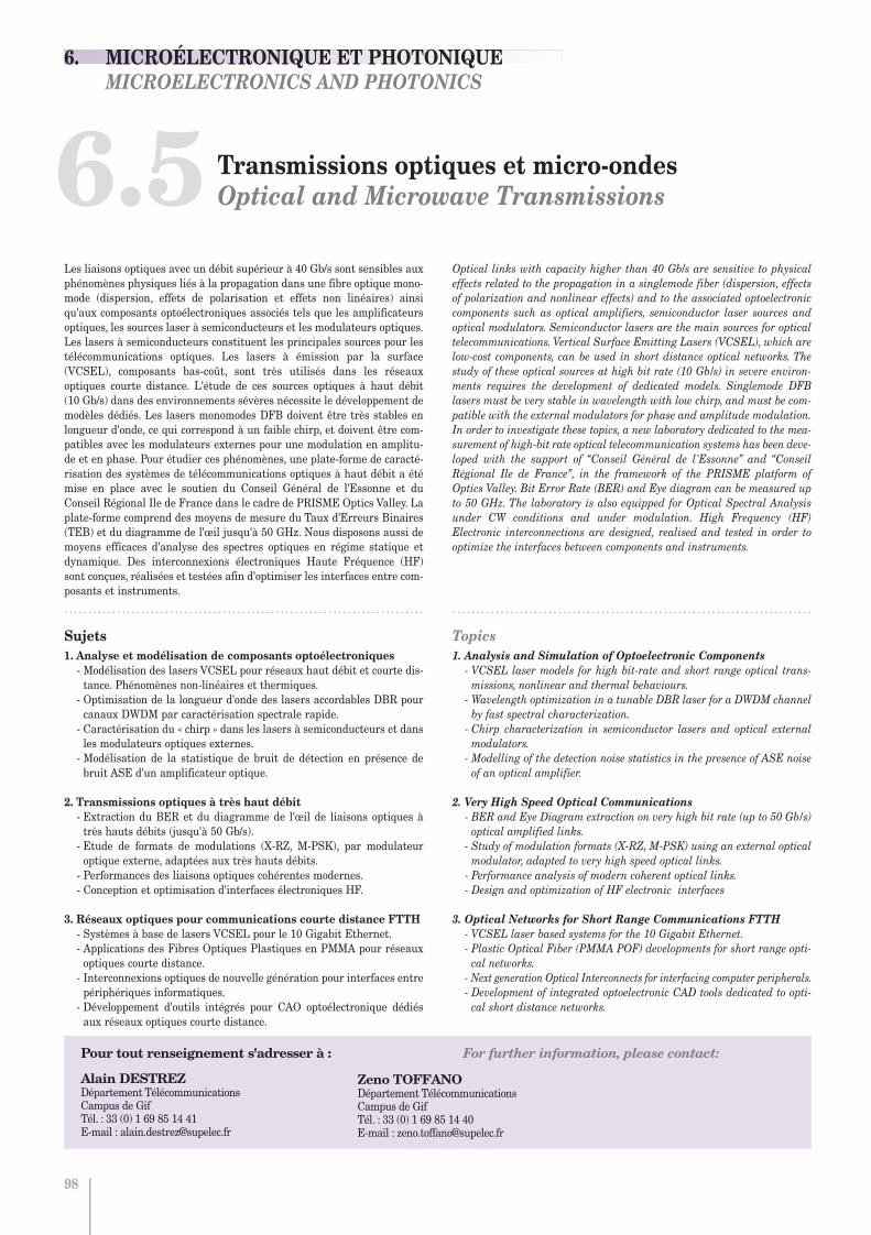
Transmissions optiques et micro-ondesOptical and Microwave Transmissions
Alain DESTREZDépartement TélécommunicationsCampus de GifTél. : 33 (0) 1 69 85 14 41E-mail : [email protected]
Zeno TOFFANODépartement TélécommunicationsCampus de GifTél. : 33 (0) 1 69 85 14 40E-mail : [email protected]
6.5
98
Pour tout renseignement s'adresser à : For further information, please contact:
Les liaisons optiques avec un débit supérieur à 40 Gb/s sont sensibles auxphénomènes physiques liés à la propagation dans une fibre optique mono-mode (dispersion, effets de polarisation et effets non linéaires) ainsiqu'aux composants optoélectroniques associés tels que les amplificateursoptiques, les sources laser à semiconducteurs et les modulateurs optiques.Les lasers à semiconducteurs constituent les principales sources pour lestélécommunications optiques. Les lasers à émission par la surface(VCSEL), composants bas-coût, sont très utilisés dans les réseauxoptiques courte distance. L'étude de ces sources optiques à haut débit (10 Gb/s) dans des environnements sévères nécessite le développement demodèles dédiés. Les lasers monomodes DFB doivent être très stables enlongueur d'onde, ce qui correspond à un faible chirp, et doivent être com-patibles avec les modulateurs externes pour une modulation en amplitu-de et en phase. Pour étudier ces phénomènes, une plate-forme de caracté-risation des systèmes de télécommunications optiques à haut débit a étémise en place avec le soutien du Conseil Général de l'Essonne et duConseil Régional Ile de France dans le cadre de PRISME Optics Valley. Laplate-forme comprend des moyens de mesure du Taux d'Erreurs Binaires(TEB) et du diagramme de l'œil jusqu'à 50 GHz. Nous disposons aussi demoyens efficaces d'analyse des spectres optiques en régime statique etdynamique. Des interconnexions électroniques Haute Fréquence (HF)sont conçues, réalisées et testées afin d'optimiser les interfaces entre com-posants et instruments.
. . . . . . . . . . . . . . . . . . . . . . . . . . . . . . . . . . . . . . . . . . . . . . . . . . . . . . . . . . . . . . . . . . . . . . . . . . .
Optical links with capacity higher than 40 Gb/s are sensitive to physicaleffects related to the propagation in a singlemode fiber (dispersion, effectsof polarization and nonlinear effects) and to the associated optoelectroniccomponents such as optical amplifiers, semiconductor laser sources andoptical modulators. Semiconductor lasers are the main sources for opticaltelecommunications. Vertical Surface Emitting Lasers (VCSEL), which arelow-cost components, can be used in short distance optical networks. Thestudy of these optical sources at high bit rate (10 Gb/s) in severe environ-ments requires the development of dedicated models. Singlemode DFBlasers must be very stable in wavelength with low chirp, and must be com-patible with the external modulators for phase and amplitude modulation.In order to investigate these topics, a new laboratory dedicated to the mea-surement of high-bit rate optical telecommunication systems has been deve-loped with the support of “Conseil Général de l'Essonne” and “ConseilRégional Ile de France”, in the framework of the PRISME platform ofOptics Valley. Bit Error Rate (BER) and Eye diagram can be measured upto 50 GHz. The laboratory is also equipped for Optical Spectral Analysisunder CW conditions and under modulation. High Frequency (HF)Electronic interconnections are designed, realised and tested in order tooptimize the interfaces between components and instruments.
. . . . . . . . . . . . . . . . . . . . . . . . . . . . . . . . . . . . . . . . . . . . . . . . . . . . . . . . . . . . . . . . . . . . . . . . . . .
Sujets1. Analyse et modélisation de composants optoélectroniques- Modélisation des lasers VCSEL pour réseaux haut débit et courte dis-tance. Phénomènes non-linéaires et thermiques.- Optimisation de la longueur d'onde des lasers accordables DBR pourcanaux DWDM par caractérisation spectrale rapide. - Caractérisation du « chirp » dans les lasers à semiconducteurs et dansles modulateurs optiques externes. - Modélisation de la statistique de bruit de détection en présence debruit ASE d'un amplificateur optique.
2. Transmissions optiques à très haut débit- Extraction du BER et du diagramme de l'œil de liaisons optiques àtrès hauts débits (jusqu'à 50 Gb/s).- Etude de formats de modulations (X-RZ, M-PSK), par modulateuroptique externe, adaptées aux très hauts débits.- Performances des liaisons optiques cohérentes modernes.- Conception et optimisation d'interfaces électroniques HF.
3. Réseaux optiques pour communications courte distance FTTH- Systèmes à base de lasers VCSEL pour le 10 Gigabit Ethernet.- Applications des Fibres Optiques Plastiques en PMMA pour réseauxoptiques courte distance.- Interconnexions optiques de nouvelle génération pour interfaces entrepériphériques informatiques.- Développement d'outils intégrés pour CAO optoélectronique dédiésaux réseaux optiques courte distance.
Topics1. Analysis and Simulation of Optoelectronic Components- VCSEL laser models for high bit-rate and short range optical trans-missions, nonlinear and thermal behaviours.- Wavelength optimization in a tunable DBR laser for a DWDM channelby fast spectral characterization.- Chirp characterization in semiconductor lasers and optical externalmodulators.- Modelling of the detection noise statistics in the presence of ASE noiseof an optical amplifier.
2. Very High Speed Optical Communications- BER and Eye Diagram extraction on very high bit rate (up to 50 Gb/s)optical amplified links.- Study of modulation formats (X-RZ, M-PSK) using an external opticalmodulator, adapted to very high speed optical links.- Performance analysis of modern coherent optical links.- Design and optimization of HF electronic interfaces
3. Optical Networks for Short Range Communications FTTH- VCSEL laser based systems for the 10 Gigabit Ethernet.- Plastic Optical Fiber (PMMA POF) developments for short range opti-cal networks.- Next generation Optical Interconnects for interfacing computer peripherals.- Development of integrated optoelectronic CAD tools dedicated to opti-cal short distance networks.
6. MICROÉLECTRONIQUE ET PHOTONIQUE MICROELECTRONICS AND PHOTONICS
Chapitre 6:Chapitre 6.qxd 26/10/09 14:07 Page11

.....................................................................................................................................................................................................................................
Bit Error Rate Extraction Method for High Speed Optical LinksMéthode d'extraction du TEB pour liaisons optiques rapides
.....................................................................................................................................................................................................................................
Résumé Une nouvelle méthode expérimentale d'extraction de Taux d'Erreur Binaire (BER), applicable jusqu'à 100 Gb/s, est développéepour des télécommunications optiques à très fort débit amplifiées. La méthode est basée sur l'analyse statistique des signauxprenant en considération le bruit d'émission spontanée ASE, le bruit du détecteur optique, la gigue et l'Interférence InterSymbole (ISI). Les paramètres statistiques sont extraits à partir du signal électrique détecté à l'aide d'un oscilloscope en tempséquivalent de très grande bande passante. Notre méthode est plus rapide et plus sensible que la méthode de mesure directe decomptage des erreurs. La bonne concordance entre les résultats de notre méthode et la méthode directe est vérifiée expérimen-talement. Notre méthode a été validée dans le cadre du projet CARRIOCAS du Pôle de Compétitivité Mondial SYSTEM@TIC.
Alain DestrezSébastien Pellevrault
Zeno Toffano
Recherche Research 2009 / 2011 99
References
[1] C.R. Giles, E. Desurvire, “Propagation of Signal and Noise in Erbium-Doped Fiber Optical Amplifiers”, J. Lightwave Technol., vol. 9, no. 2, pp. 147-154, Fev. 1991.
[2] A. Gholami, Z. Toffano, A. Destrez, S. Pellevrault, Mathias Pez, F. Quentel., “Optimization of VCSEL Spatiotemporal Operation in MMFLinks for 10-Gigabit Ethernet”, IEEE Journal of Selected Topics inQuantum Electronics, vol. 12, July/Aug. 2006, pp. 767-775.
IntroductionPerformance measurement and simulation to achieve a desired Bit-ErrorRate (BER) are fundamental for developing optical communication systems.Reliability and efficiency in terms of time consuming BER measurementshave become a more and more critical issue because of high quality linksassociated to ultra high speed transmission (40 Gb/s commercially availableand 100 Gb/s under development). For low BER, direct measurements arenot so widely used due to long acquisition times and also to the expensiveequipment. The Q factor, derived from the eye signal to noise ratio, is wide-ly used. It leads to BER using simple expressions. The limiting assumptionof this method is that the receiver signal statistics is considered Gaussian.This assumption fails generally when EDFA optical amplifiers are usedbecause the Amplified Spontaneous Emission (ASE) noise added inline or bythe preamplifier becomes the prevalent noise source [1]. ASE noise contri-bution is non Gaussian because of quadratic detection and also because ofnarrow optical filters widely used in optical wavelength multiplex.
Principle of the ETO Extraction MethodWe have developed a new BER extraction method, the Equivalent TimeOscilloscope (ETO) method, including ASE noise, post-detection noise, jitterand ISI.After optical conversion, the photoreceiver electrical signal is sampled usingan ETO which generates a waveform that is transferred to a computer. Thestatistical parameters are extracted from the signal moments. These para-meters are specific to the statistical laws associated to the detected signal.Here we consider three different statistical laws: 1) the Gaussian law, 2) TheNon-Central Chi-Square (NCX2) and 3) A specifically developed statisticsnamed Gaussian Convolved Non-central Chi-square statistic (GCNCX2).The resulting BER(td,s) at the user defined decision time td and thresholdvoltage s for a N = 2n-1 Pseudo Random Bit Sequence (PRBS) is obtained bythe averaged BER values of each bit of the PRBS, leading to:
It has been shown [2] that, because of the influence of the preceding bit(trailing bit) and of the following bit, that ISI effects can be taken intoaccount by using the averaged value of BER for three bit patterns. When considering jitter, we have to distinguish between timing random jit-ter and deterministic jitter. This last is included in the ISI processing.
ResultsAn optical link was set up to test the ETO BER extraction method (see fig. 1) using a Mach-Zehnder modulator connected to a NRZ 43 Gb/s PRBSgenerator and a 1550 nm DFB laser. The output of the modulator is connec-ted to an optical link. The receiver includes a low-noise EDFA pre-amplifier,an optical filter and a 40 GHz PIN diode followed by a Trans ImpedanceAmplifier (TIA) with linear characteristics.The experiments were undertaken in the framework of the French CARRIOCAS SYSTEM@TIC project. The equipment is part of the Optics-Valley PRISME platform at SUPELEC with the support of “Conseil Généralde l'Essonne” and “Région Ile de France” and feedback from AgilentTechnologies.
Figure 1: Experimental setup for the 43 Gb/s optical link
Figure 2: BER as a function of threshold voltage measured with BERTand ETO for different statistics.
We observe on fig. 2 that the tail of the extracted BER curve function ofthreshold voltage using the Gaussian statistics is less steep than the oneusing the NCX2 statistics. Better with the GCNCX2 statistics, we find thatthe BER follows closely the reference BER measured directly with a BitError Tester (BERT). GCNCX2 statistics takes into account both ASE andpost-detection noise.We have also shown that the ETO method permits to measure very lowvalues of BER (10-15) which are inaccessible by direct measurements. Themethod is also faster for low BER measurements making it a competitivetool for validation of very high quality optical links.
6. MICROÉLECTRONIQUE ET PHOTONIQUE MICROELECTRONICS AND PHOTONICS
6.5 Transmissions optiques et micro-ondes Optical and Micro-Wave Transmissions
Chapitre 6:Chapitre 6.qxd 26/10/09 14:07 Page12

Photonique non linéaireNon Linear Photonics
Marc SCIAMANNA Équipe OPTEL - LMOPSCampus de MetzTél. : +33 (0) 3 87 76 47 05 E-mail: [email protected]
Delphine WOLFERSBERGER Équipe OPTEL - LMOPS Campus de MetzTél. : +33 (0) 3 87 76 47 04 E-mail: [email protected]
6.6
100
Pour tout renseignement s'adresser à : For further information, please contact:
Les composants photoniques couramment utilisés dans de nombreux sys-tèmes (lasers, guides d'onde, amplificateurs) présentent des comporte-ments dynamiques non-linéaires : émission spontanée de cycles réguliersd'impulsions, chaos, soliton temporel/spatial, auto-organisation de lalumière (pattern optique). Ces dynamiques non-linéaires sont générale-ment considérées comme des inconvénients qu'il est nécessaire d'étudierphysiquement pour mieux les contrôler et les éviter. Cependant leur com-préhension permet également d'envisager de nombreuses applications :guidage de la lumière par elle-même, mémoire optique, routage toutoptique reconfigurable, basculement tout optique rapide, cryptographiepar chaos.
. . . . . . . . . . . . . . . . . . . . . . . . . . . . . . . . . . . . . . . . . . . . . . . . . . . . . . . . . . . . . . . . . . . . . . . . . . .
Photonic components typically used in several systems (lasers, waveguides,amplifiers) exhibit nonlinear dynamical behaviors: spontaneous emissionof regular pulses, chaos, temporal/spatial soliton, self-organization of lightinto optical patterns. These nonlinear dynamics are usually considered asdrawbacks whose physical understanding would finally help their controland avoidance. However insight into these nonlinear dynamics would alsobring interesting innovative applications: self-guiding of light, optical buf-fering, all-optical reconfigurable routing, all-optical fast switching, chaos-based cryptography.
. . . . . . . . . . . . . . . . . . . . . . . . . . . . . . . . . . . . . . . . . . . . . . . . . . . . . . . . . . . . . . . . . . . . . . . . . . .
Sujets1. Autofocalisation photoréfractiveModélisation théorique, simulation numérique et validation expéri-mentale des régimes temporels, dans le domaine visible et infrarouge(longueurs d'onde télécom). Etude de matériaux isolants et semi-conducteurs.
2. Interactions de solitons photoréfractifs - Routage et intercon-nexion optique Modélisation des systèmes. Etudes des propriétés temporelles d'ins-cription et de guidage. Autoalignement laser- fibre. Routage optique parinteraction de solitons.
3. Dynamique non linéaire de lasers à semi-conducteursModélisation, simulation et étude expérimentale des comportementsdynamiques non-linéaires de lasers à semi-conducteurs (dont lesVCSELs) soumis à une rétroaction ou une injection optique. Analysedes dynamiques auto-pulsées et de leur transition vers le chaos optique.
4. Transmission sécurisée de données encryptées dans du chaosoptiqueModélisation, simulation, et étude expérimentale de la synchronisationde chaos entre lasers couplés. Encryption de données dans du chaosoptique, communication sécurisée à haut débit et décodage des données.
5. Instabilités spatio-temporelles en cavité non-linéaire Etude théorique et expérimentale des formes d'auto-organisation de lalumière (patterns optiques, solitons de cavité, chaos).
Topics1. Photorefractive self-focusingTheoretical modelling, numerical simulations and experimental valida-tions of temporal evolution, under visible and infrared wavelength (tele-com windows). Insulator and semiconductor materials.
2. Photorefractive solitons interactions - Routing and optical inter-connectsSystem modelling. Studies on temporal properties of writing and gui-ding. Self-alignement laser diode-fiber. Optical routing via solitonsinteraction.
3. Nonlinear dynamics of semiconductor lasers Modelling, simulation, and experimental study of nonlinear dynamicalbehaviours of semiconductor lasers (including VCSELs) subject to opti-cal feedback or optical injection. Analysis of self-pulsating dynamics andtheir transition to optical chaos.
4. Secure transmission of data encrypted within optical chaosModelling, simulation, and experimental study of synchronisation ofchaos between coupled lasers. Encryption of data embedded into opticalchaos, secure communication at high bit rates and data recovery.
5. Spatio-temporal instabilities in nonlinear cavitiesTheoretical and experimental study of light self-organization (opticalpatterns, cavity solitons, chaos).
6. MICROÉLECTRONIQUE ET PHOTONIQUE MICROELECTRONICS AND PHOTONICS
Chapitre 6:Chapitre 6.qxd 26/10/09 14:07 Page13

.....................................................................................................................................................................................................................................
Control of nonlinear cavity modes by photonic latticesContrôle de modes de cavités non-linéaires par un réseau photonique
.....................................................................................................................................................................................................................................
Résumé Nous étudions le contrôle de la formation de patterns (motifs lumineux auto-organisés) dans un système non linéairedissipatif à rétroaction optique, composé d'un cristal photorefractif possédant une modulation périodique de son indice deréfraction. Nous identifions trois mécanismes pour le contrôle de patterns : la suppression des modes du pattern par effet bandeinterdite, la création de nouveaux modes dépendants de la périodicité de l'indice, le contrôle de la position transverse dupattern.
Nicolas Marsal
Recherche Research 2009 / 2011 101
References
[1] D. Gomila, et al, Phys. Rev. Lett. 92, 253904 (2004).
[2] T. Honda, Opt. Lett. 18, 598 (1993).
[3] N. Marsal, D. Wolfersberger, M. Sciamanna, G. Montemezzani, D. Neshev, Opt. Lett. 33, 2509 (2008).
Experimental SetupPeriodic photonic structures have proven to enable manipulation of the fun-damental aspects of wave propagation. The implementation of such struc-tures inside a cavity can lead to novel nonlinear phenomena, including dis-crete cavity modulational instability and discrete cavity soliton [1]. In thisstudy, we present the manipulation of modulational instability in a nonli-near dissipative cavity by a periodic photonic lattice. We use a photorefrac-tive system made of a baryum titanate crystal in a single feedback mirrorconfiguration (Figure 1) exhibiting hexagonal patterns formation.Additionally, we impose an optical lattice to induce one or two-dimensionalphotonic band-gap structures with variable parameters.
Figure 1: Photorefractive crystal in a single feedback configuration. M: mirror, L: distance between mirror and crystal, F and B correspond to theforward and backward beams at the origin of the pattern formation. kP isthe wave vector selected by the system, associated to the wavevector of thereflection grating (vertical green lines).
In our experiments we employ the setup shown in Fig. 1. It contains a pho-torefractive two-wave mixing in a reflection grating geometry and a tunablesingle feedback. In this counterpropagating configuration, the laser beambecomes unstable against modulational instability and sidebands arrangedin hexagonal patterns grow from scattered light appearing from this geo-metry [Fig 2(a)]. Their directions are determined by both the phase mat-ching in the nonlinear gain medium and the effect of diffraction introducedby the feedback. A lot of transverse k-vectors can appear but only the onewith the lowest gain threshold will grow [2].To create a periodic optical lattice, a Gaussian beam is sent through a 1Dtransmission grating with variable periodicity. The first diffraction ordersare then selected and recombined in the crystal to create a periodic modu-lation of the material refractive index, thanks to the photorefractive effect.
Results
Figure 2: Far-field patterns. (a) hexagonal pattern without lattice, (b)linear diffraction on the lattice, (c) co-existence between nonlinear patternand linear diffraction for kL=2.2kP.
Figure 2(a) shows the typical far-field hexagonal pattern formed in theabsence of the lattice. To test the strength of the optical lattice, we tempo-rarily remove the feedback mirror and monitor the far-field of the patternbeam diffracted on the optical lattice created inside the crystal [3]. The pat-tern beam diffraction gives rise to the two outer spots appearing along thediagonal, corresponding to the 45° lattice orientation, as seen in Fig. 2(b).The arrows in fig. 2(a,b) represent the transverse wavevectors associatedwith the hexagonal pattern (kP) and the optical lattice (kL). The dashed lines
in figs. 2,3 represent the position of the bandgap of the photonic lattice, situa-ted at kL/2 and corresponding to the edges of the first Brillouin zone [3].
An important configuration for bandgap control of the optical patterns isthe one where the periodicity of the optical lattice is such that kL=√3kP. Inthis case, some spots of the hexagonal pattern are situated exactly in thebandgap region of the optical lattice [Fig. 3(a)], pattern and lattice beamsintensities being comparable. By increasing the lattice beam intensity,IL=5IP [as seen by the two brighter outer spots in Fig. 3(b) compared to Fig. 3(a)], the modulational instability can be suppressed in the bandgapregion [Fig. 3(b)] , [3].
Figure 3: Bandgap inhibition of instability modes. (a) Co-existence betweennonlinear pattern and linear diffraction for kL=√3kP and IL=IP. (b)Suppression of instability modes for kL=√3kP and IL=5IP.
The results above are obtained in a range of parameters for which the pat-tern beam dominates the dynamics. This situation can be changed if wedecrease the pattern beam intensity below the threshold (Ith) for the hexa-gon formation. In this case, we have found (Fig 4) that the presence of thelattice periodicity can induce a new optical pattern solution that reflects thelattice geometry [3].
Figure 4: Seeding of instability modes. Diagonal pattern obtained at inten-sity below the hexagon formation threshold with (a) kL=1.3kP(hexagons) and (b)kL=2.2kP(hexagons). kP is the new wavevector associated with the new diagonalpattern.
Finally, a control of the hexagon orientation in its transverse plane can beachieved when the lattice and pattern wavevectors have the same magni-tude [3].
In conclusion, we have demonstrated a new method for controlling the pat-tern formation in a single feedback system that takes advantage of the pre-sence of an optically induced photonic lattice.
6. MICROÉLECTRONIQUE ET PHOTONIQUE MICROELECTRONICS AND PHOTONICS
6.6 Photonique non linéaire Non Linear Photonics
Chapitre 6:Chapitre 6.qxd 26/10/09 14:07 Page14

Matériaux pour l'UV et composants optoélectroniquesUV materials and Optoelectronics devices
Frédéric GENTY Équipe OPTEL - LMOPSCampus de MetzTél. : +33 (0) 3 87 76 47 19 E-mail : [email protected]
Joël JACQUET Équipe OPTEL - LMOPSCampus de MetzTél. : +33 (0) 3 87 76 47 68 E-mail : [email protected]
6.7
102
Pour tout renseignement s'adresser à : For further information, please contact:
Les composants à semi-conducteurs à base d'alliages nitrurés fonction-nant dans le lointain et le proche UV (250 nm < < 500 nm) connaissentactuellement un intérêt croissant. Les détecteurs ou émetteurs de lumiè-re de ce type permettent en effet d'envisager de nombreuses applicationsdans le domaine du photovoltaïque, de la médecine, de la protection del'environnement ou encore de la détection de substances explosives. Lespropriétés électro-optiques des alliages de base pour la fabrication de cescomposants restent néanmoins mal connues et de nombreuses études sontnécessaires pour une optimisation de leurs performances.
Les autres gammes de longueurs d'onde, telles que le proche et le moyenIR, ne sont cependant pas délaissées car elles restent idéales pour d'autresapplications spécifiques comme la détection de gaz polluants ou les télé-communications optiques à condition de disposer de sources lumineusesaux propriétés adaptées.
. . . . . . . . . . . . . . . . . . . . . . . . . . . . . . . . . . . . . . . . . . . . . . . . . . . . . . . . . . . . . . . . . . . . . . . . . . .
III-N based semiconductor devices operating in the near- and far-UV (250 nm < < 500 nm) are currently of great scientific interest. Indeed,such light emitters or detectors can be involved in numerous applicationsas photovoltaic cells, medicine, environment monitoring or detection ofexplosive matters. However, the knowledge concerning the electro-opticalproperties of the key alloys which constitute these devices still remainsimperfect and numerous studies continues to be necessary in order toimprove the performances of devices.
Nevertheless, other wavelength ranges, such as near- and mid-IR, are notforsaken since they appear as ideal for gas detection or optical telecommu-nications for example, on the condition of having light sources with theadapted properties.
. . . . . . . . . . . . . . . . . . . . . . . . . . . . . . . . . . . . . . . . . . . . . . . . . . . . . . . . . . . . . . . . . . . . . . . . . . .
Sujets1. Conception de miroirs de Bragg à haut pouvoir réflecteurdans l'UV ( < 400 nm)Modélisation des propriétés électro-optiques des alliages du systèmeAlGaInN pour la conception et l'optimisation de miroirs de Bragg àcouches quart d'onde. Ces miroirs sont destinés à être insérés dans des structures à cavitéverticale type RC-LED ou VCSEL fonctionnant dans l'UV.
2. Modélisation des propriétés électriques thermiques et optiquesdes composantsDéveloppement d'outils de calcul de la conduction électrique dans lescomposants. Injection de porteurs dans les jonctions tunnel, structurede bandes… Modélisation de la dissipation thermique dans les lasers.Recherche de la consommation minimale. Application aux lasers à 2.3 µm pour la spectroscopie et la détection de gaz et à 1.55µm pour lestélécommunications optiques.
3. Composants à cavité continuum Conception et caractérisation de laser en cavité externe avec miroir deBragg à réseau chirpé en régime dit continuum. Application aux ampli-ficateurs optiques résonants, aux filtres passe bande et aux LEDs fonc-tionnant en régime laser.
4. Miroirs de Bragg innovantsConception et développement de miroirs de Bragg sub-longueur d'ondeà réseau gravé de surface permettant le contrôle de la polarisation etdestinés à être insérés dans des VCSELs émettant à > 2.6 µm.
Topics1. Design of high reflective Bragg mirror in the UV wavelenghrange ( < 400 nm)Modelling of the electro-optical properties of AlGaInN alloys for the desi-gn and the optimization of quarterwavelength layers Bragg mirrors. These mirrors are intended to be inserted in vertical cavity structures,RC-LED or VCSEL, operating in the UV range.
2. Modelling of thermal, electrical and optical properties of devicesDevelopment of modelling tools for electrical conduction in devices: bandstructures, current injection in tunnel junction. Thermal dissipation incomponents. Investigation of power consumption minimization.Application to 2.3µm laser for spectroscopy or gas sensors and 1.55µmfor optical telecommunication.
3. Continuum cavity devicesDesign and characterisation of external cavity laser including chirped Braggreflectors in a continuum cavity. Application to resonant optical amplifiers,narrow band passive filters and LEDs operating in laser regime.
4. Innovative Bragg mirrorsDesign, modelling and development of sub-wavelength Bragg mirrorsallowing the control of light polarization and intended to be inserted inIII-Sb semiconductor VCSELs emitting at > 2.6 µm .
6. MICROÉLECTRONIQUE ET PHOTONIQUE MICROELECTRONICS AND PHOTONICS
Chapitre 6:Chapitre 6.qxd 26/10/09 14:07 Page15
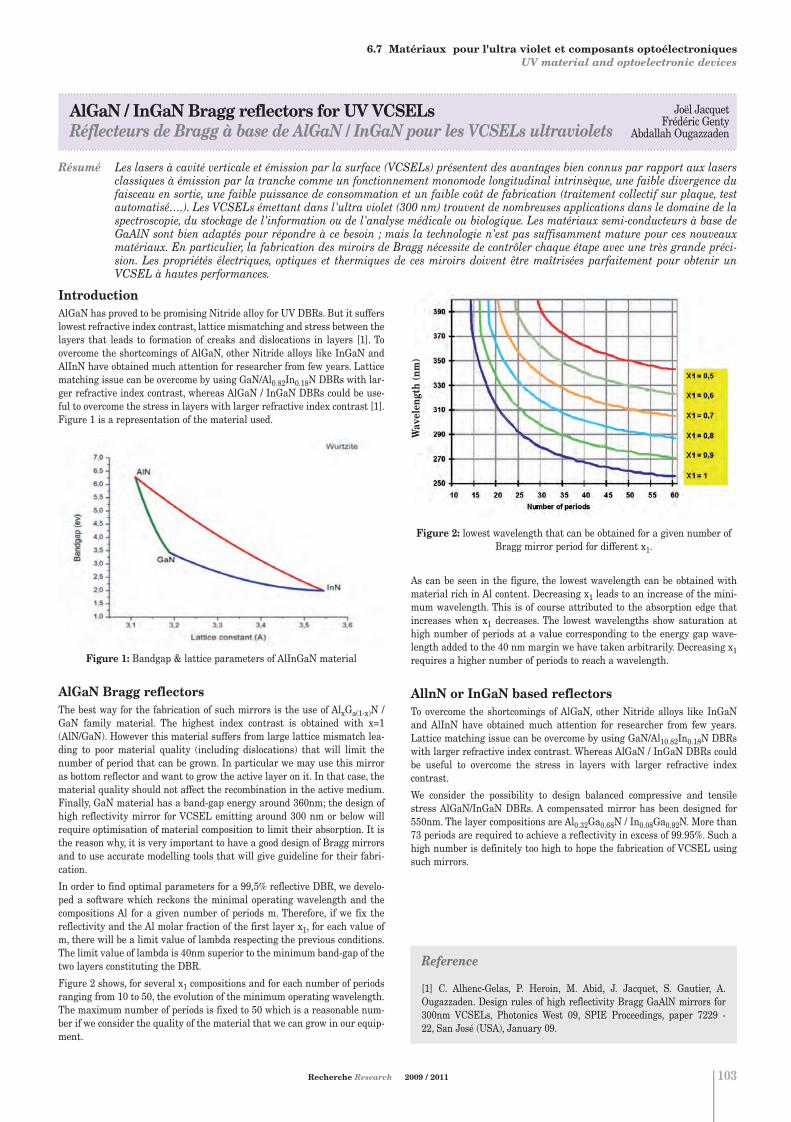
.....................................................................................................................................................................................................................................
AlGaN / InGaN Bragg reflectors for UV VCSELsRéflecteurs de Bragg à base de AlGaN / InGaN pour les VCSELs ultraviolets
.....................................................................................................................................................................................................................................
Résumé Les lasers à cavité verticale et émission par la surface (VCSELs) présentent des avantages bien connus par rapport aux lasersclassiques à émission par la tranche comme un fonctionnement monomode longitudinal intrinsèque, une faible divergence dufaisceau en sortie, une faible puissance de consommation et un faible coût de fabrication (traitement collectif sur plaque, testautomatisé….). Les VCSELs émettant dans l'ultra violet (300 nm) trouvent de nombreuses applications dans le domaine de laspectroscopie, du stockage de l'information ou de l'analyse médicale ou biologique. Les matériaux semi-conducteurs à base deGaAlN sont bien adaptés pour répondre à ce besoin ; mais la technologie n'est pas suffisamment mature pour ces nouveauxmatériaux. En particulier, la fabrication des miroirs de Bragg nécessite de contrôler chaque étape avec une très grande préci-sion. Les propriétés électriques, optiques et thermiques de ces miroirs doivent être maîtrisées parfaitement pour obtenir unVCSEL à hautes performances.
Matériaux pour l'UV et composants optoélectroniquesUV materials and Optoelectronics devices
Joël JacquetFrédéric Genty
Abdallah Ougazzaden
Recherche Research 2009 / 2011 103
IntroductionAlGaN has proved to be promising Nitride alloy for UV DBRs. But it sufferslowest refractive index contrast, lattice mismatching and stress between thelayers that leads to formation of creaks and dislocations in layers [1]. Toovercome the shortcomings of AlGaN, other Nitride alloys like InGaN andAlInN have obtained much attention for researcher from few years. Latticematching issue can be overcome by using GaN/Al0.82In0.18N DBRs with lar-ger refractive index contrast, whereas AlGaN / InGaN DBRs could be use-ful to overcome the stress in layers with larger refractive index contrast [1].Figure 1 is a representation of the material used.
Figure 1: Bandgap & lattice parameters of AlInGaN material
AlGaN Bragg reflectorsThe best way for the fabrication of such mirrors is the use of AlxGa(1-x)N /GaN family material. The highest index contrast is obtained with x=1(AlN/GaN). However this material suffers from large lattice mismatch lea-ding to poor material quality (including dislocations) that will limit thenumber of period that can be grown. In particular we may use this mirroras bottom reflector and want to grow the active layer on it. In that case, thematerial quality should not affect the recombination in the active medium.Finally, GaN material has a band-gap energy around 360nm; the design ofhigh reflectivity mirror for VCSEL emitting around 300 nm or below willrequire optimisation of material composition to limit their absorption. It isthe reason why, it is very important to have a good design of Bragg mirrorsand to use accurate modelling tools that will give guideline for their fabri-cation.
In order to find optimal parameters for a 99,5% reflective DBR, we develo-ped a software which reckons the minimal operating wavelength and thecompositions Al for a given number of periods m. Therefore, if we fix thereflectivity and the Al molar fraction of the first layer x1, for each value ofm, there will be a limit value of lambda respecting the previous conditions.The limit value of lambda is 40nm superior to the minimum band-gap of thetwo layers constituting the DBR.
Figure 2 shows, for several x1 compositions and for each number of periodsranging from 10 to 50, the evolution of the minimum operating wavelength.The maximum number of periods is fixed to 50 which is a reasonable num-ber if we consider the quality of the material that we can grow in our equip-ment.
Figure 2: lowest wavelength that can be obtained for a given number ofBragg mirror period for different x1.
As can be seen in the figure, the lowest wavelength can be obtained withmaterial rich in Al content. Decreasing x1 leads to an increase of the mini-mum wavelength. This is of course attributed to the absorption edge thatincreases when x1 decreases. The lowest wavelengths show saturation athigh number of periods at a value corresponding to the energy gap wave-length added to the 40 nm margin we have taken arbitrarily. Decreasing x1requires a higher number of periods to reach a wavelength.
AllnN or InGaN based reflectorsTo overcome the shortcomings of AlGaN, other Nitride alloys like InGaNand AlInN have obtained much attention for researcher from few years.Lattice matching issue can be overcome by using GaN/Al10.82In0.18N DBRswith larger refractive index contrast. Whereas AlGaN / InGaN DBRs couldbe useful to overcome the stress in layers with larger refractive indexcontrast.
We consider the possibility to design balanced compressive and tensilestress AlGaN/InGaN DBRs. A compensated mirror has been designed for550nm. The layer compositions are Al0.32Ga0.68N / In0.08Ga0.92N. More than73 periods are required to achieve a reflectivity in excess of 99.95%. Such ahigh number is definitely too high to hope the fabrication of VCSEL usingsuch mirrors.
6. MICROÉLECTRONIQUE ET PHOTONIQUE MICROELECTRONICS AND PHOTONICS
6.7 Matériaux pour l'ultra violet et composants optoélectroniques UV material and optoelectronic devices
Wavelength (nm)
Reference
[1] C. Alhenc-Gelas, P. Heroin, M. Abid, J. Jacquet, S. Gautier, A.Ougazzaden. Design rules of high reflectivity Bragg GaAlN mirrors for300nm VCSELs, Photonics West 09, SPIE Proceedings, paper 7229 - 22, San José (USA), January 09.
Chapitre 6:Chapitre 6.qxd 26/10/09 14:07 Page16

Contrôle optique des microstructureset capteurs optiques Optical control of microstructuresand optical sensors
Patrice BOURSONLMOPSCampus de Metz Tél. : (0) 3 87 37 85 64E-mail : [email protected]
Marc FONTANALMOPSCampus de Metz Tél. : (0) 3 87 37 85 72E-mail : [email protected]
6.8
104
Pour tout renseignement s'adresser à : For further information, please contact:
Cette activité du LMOPS répond à deux objectifs différents.
Le premier concerne le contrôle optique des microstructures, pour l'opti-misation des propriétés fonctionnelles de matériaux diélectriques à pro-priétés optiques linéaires ou non linéaires, et retour éventuel aux para-mètres de préparation.
Le but du second thème, « Capteurs optiques », est d'élaborer différentscapteurs utilisant les principes optiques (la spectrométrie en particulier).Ces capteurs permettent à la fois d'identifier les constituants d'un produit,ses défauts, de suivre un process en temps réel (transformations, cristalli-nité, phase...) et aussi de mesurer des grandeurs métrologiques telles quela concentration d'une solution, des distorsions mécaniques, une variation de température...
. . . . . . . . . . . . . . . . . . . . . . . . . . . . . . . . . . . . . . . . . . . . . . . . . . . . . . . . . . . . . . . . . . . . . . . . . . .
This activity of the LMOPS aims at two different objectives.
The first one concerns the optical control of microstructures, in order tooptimize the functional properties of dielectric materials with linear ornonlinear optical properties, possibly with feedback on the preparationparameters.
The purpose of the second, "Optical sensors", is to elaborate various sensorsusing optical principles (spectrometry in particular). These sensors allow atfirst to identify products and defects as well as to follow a real-time process(product transformations, crystallinity, phase...), but also to monitor metro-logical parameters such as the concentration of a mixture, mechanical dis-tortion, temperature variation...
. . . . . . . . . . . . . . . . . . . . . . . . . . . . . . . . . . . . . . . . . . . . . . . . . . . . . . . . . . . . . . . . . . . . . . . . . . .
Sujets1. Contrôle optique des microstructuresa. Guides d'onde de niobate de lithiumEtude de la structure modifiée par le dopage et les traitements. Défautsintrinsèques et extrinsèques. Polarons. Profil de diffusion. Lien avec lespropriétés optiques linéaires et non linéaires, en particulier photoré-fractives.b. Micro-nanostructures du PPLNEtude des domaines ferroélectriques antiparallèles. Murs de domaines.Influence des techniques de préparation, de la composition et du dopa-ge. Imagerie Raman.c. Couches minces diélectriques (SiO2...)Etude de la structure de couches de silice, selon les paramètres d'élabo-ration et les post-traitements. Caractérisation optique et spectrosco-pique : luminescence, absorption, FTIR, Raman… Effet du vieillisse-ment et l'illumination UV sur la structure et les propriétés optiques.
2. Capteurs optiquesa. Sels en solutions aqueusesIdentification de la nature du sel en solution. Etude de la transforma-tion de phase liquide/solide. Détermination de la concentration de sel.b. Polymères : contrôle et suivi de processEtude de l'orientation, du degré de cristallinité et de la déformation d'unpolymère. Suivi de process d'élaboration. Etudes on line, at line, off line.c. Applications médicalesEtude in situ de la composition de milieux biologiques.
Topics1. Optical control of the microstructuresa. Waveguides in lithium niobateStudy of the structure modified by doping and treatments. Intrinsic andextrinsic defects. Polarons. Diffusion profile. Link with linear and nonli-near optical properties, photorefraction in particular.b. Micro-nanostructures of PPLNStudy of antiparallel ferroelectric domains. Domain walls. Influence ofpreparation techniques, composition and doping. Raman imaging.c. Dielectric thin films (Si02...)Study of silica layers structure, in relation with preparation parametersand post-treatments. Optical and spectroscopic characterization: lumi-nescence, absorption, FTIR, Raman… Effects of aging and UV illumi-nation on structure and optical properties.
2. Optical sensorsa. Salts in aqueous solutionsCompound identification in solution. Study of the liquid/solid phasetransition. Measurement of the salt concentration.b. Polymers: control and monitoring processStudy of the orientation, the cristallinity and the deformation of a poly-mer. Monitoring of the elaboration process. On line, at line and off linestudies.c. Medical applicationsIn situ study of the composition of biological media.
6. MICROÉLECTRONIQUE ET PHOTONIQUE MICROELECTRONICS AND PHOTONICS
Chapitre 6:Chapitre 6.qxd 26/10/09 14:07 Page17
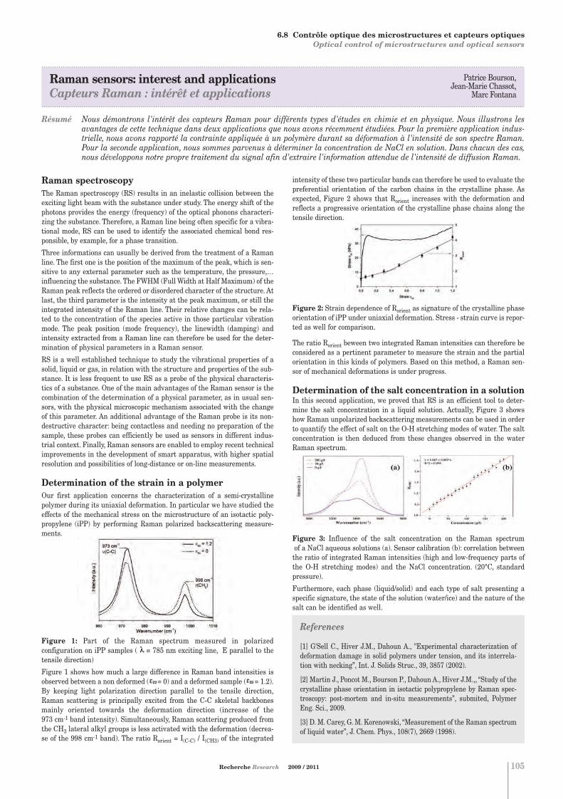
6.8 Contrôle optique des microstructures et capteurs optiques Optical control of microstructures and optical sensors
.....................................................................................................................................................................................................................................
Raman sensors: interest and applicationsCapteurs Raman : intérêt et applications
.....................................................................................................................................................................................................................................
Résumé Nous démontrons l'intérêt des capteurs Raman pour différents types d'études en chimie et en physique. Nous illustrons lesavantages de cette technique dans deux applications que nous avons récemment étudiées. Pour la première application indus-trielle, nous avons rapporté la contrainte appliquée à un polymère durant sa déformation à l'intensité de son spectre Raman.Pour la seconde application, nous sommes parvenus à déterminer la concentration de NaCl en solution. Dans chacun des cas,nous développons notre propre traitement du signal afin d'extraire l'information attendue de l'intensité de diffusion Raman.
Contrôle optique des microstructureset capteurs optiques Optical control of microstructuresand optical sensors
Patrice Bourson,Jean-Marie Chassot,
Marc Fontana
Recherche Research 2009 / 2011 105
References
[1] G'Sell C., Hiver J.M., Dahoun A., "Experimental characterization ofdeformation damage in solid polymers under tension, and its interrela-tion with necking”, Int. J. Solids Struc., 39, 3857 (2002).
[2] Martin J., Poncot M., Bourson P., Dahoun A., Hiver J.M.,, “Study of thecrystalline phase orientation in isotactic polypropylene by Raman spec-troscopy: post-mortem and in-situ measurements”, submited, PolymerEng. Sci., 2009.
[3] D. M. Carey, G. M. Korenowski, “Measurement of the Raman spectrumof liquid water”, J. Chem. Phys., 108(7), 2669 (1998).
Raman spectroscopyThe Raman spectroscopy (RS) results in an inelastic collision between theexciting light beam with the substance under study. The energy shift of thephotons provides the energy (frequency) of the optical phonons characteri-zing the substance. Therefore, a Raman line being often specific for a vibra-tional mode, RS can be used to identify the associated chemical bond res-ponsible, by example, for a phase transition.
Three informations can usually be derived from the treatment of a Ramanline. The first one is the position of the maximum of the peak, which is sen-sitive to any external parameter such as the temperature, the pressure,…influencing the substance. The FWHM (Full Width at Half Maximum) of theRaman peak reflects the ordered or disordered character of the structure. Atlast, the third parameter is the intensity at the peak maximum, or still theintegrated intensity of the Raman line. Their relative changes can be rela-ted to the concentration of the species active in those particular vibrationmode. The peak position (mode frequency), the linewidth (damping) andintensity extracted from a Raman line can therefore be used for the deter-mination of physical parameters in a Raman sensor.
RS is a well established technique to study the vibrational properties of asolid, liquid or gas, in relation with the structure and properties of the sub-stance. It is less frequent to use RS as a probe of the physical characteris-tics of a substance. One of the main advantages of the Raman sensor is thecombination of the determination of a physical parameter, as in usual sen-sors, with the physical microscopic mechanism associated with the changeof this parameter. An additional advantage of the Raman probe is its non-destructive character: being contactless and needing no preparation of thesample, these probes can efficiently be used as sensors in different indus-trial context. Finally, Raman sensors are enabled to employ recent technicalimprovements in the development of smart apparatus, with higher spatialresolution and possibilities of long-distance or on-line measurements.
Determination of the strain in a polymerOur first application concerns the characterization of a semi-crystallinepolymer during its uniaxial deformation. In particular we have studied theeffects of the mechanical stress on the microstructure of an isotactic poly-propylene (iPP) by performing Raman polarized backscattering measure-ments.
Figure 1: Part of the Raman spectrum measured in polarized configuration on iPP samples ( = 785 nm exciting line, E parallel to thetensile direction)
Figure 1 shows how much a large difference in Raman band intensities isobserved between a non deformed ( = 0) and a deformed sample ( = 1.2).By keeping light polarization direction parallel to the tensile direction,Raman scattering is principally excited from the C-C skeletal backbonesmainly oriented towards the deformation direction (increase of the 973 cm-1 band intensity). Simultaneously, Raman scattering produced fromthe CH3 lateral alkyl groups is less activated with the deformation (decrea-se of the 998 cm-1 band). The ratio Rorient = I(C-C) / I(CH3) of the integrated
intensity of these two particular bands can therefore be used to evaluate thepreferential orientation of the carbon chains in the crystalline phase. Asexpected, Figure 2 shows that Rorient increases with the deformation andreflects a progressive orientation of the crystalline phase chains along thetensile direction.
Figure 2: Strain dependence of Rorient as signature of the crystalline phaseorientation of iPP under uniaxial deformation. Stress - strain curve is repor-ted as well for comparison.
The ratio Rorient beween two integrated Raman intensities can therefore beconsidered as a pertinent parameter to measure the strain and the partialorientation in this kinds of polymers. Based on this method, a Raman sen-sor of mechanical deformations is under progress.
Determination of the salt concentration in a solutionIn this second application, we proved that RS is an efficient tool to deter-mine the salt concentration in a liquid solution. Actually, Figure 3 showshow Raman unpolarized backscattering measurements can be used in orderto quantify the effect of salt on the O-H stretching modes of water. The saltconcentration is then deduced from these changes observed in the waterRaman spectrum.
Figure 3: Influence of the salt concentration on the Raman spectrumof a NaCl aqueous solutions (a). Sensor calibration (b): correlation betweenthe ratio of integrated Raman intensities (high and low-frequency parts ofthe O-H stretching modes) and the NaCl concentration. (20°C, standardpressure).
Furthermore, each phase (liquid/solid) and each type of salt presenting aspecific signature, the state of the solution (water/ice) and the nature of thesalt can be identified as well.
6. MICROÉLECTRONIQUE ET PHOTONIQUE MICROELECTRONICS AND PHOTONICS
Chapitre 6:Chapitre 6.qxd 26/10/09 14:07 Page18

106
Chapitre 7:Chapitre 7.qxd 26/10/09 14:08 Page1

107
7. ÉNERGIEENERGY
7Chapitre 7:Chapitre 7.qxd 26/10/09 14:08 Page2

Systèmes électriques et réseaux d'énergiePower Systems
Marc PETIT Sujets 1 - 4 / Topics 1 - 4Département Électrotechniqueet Systèmes d'Énergie Campus de GifTél. : 33 (0) 1 69 85 15 33E-mail : [email protected]
Gérard BERGERSujet 5 / Topic 5LPGP - Équipe DEACampus de GifTél. : 33 (0) 1 69 15 36 73E-mail : [email protected]
7.1
108
Pour tout renseignement s'adresser à : For further information, please contact:
7. ÉNERGIE ENERGY
Le système électrique est en pleine évolution : insertion des énergiesrenouvelables, de dispositifs d’électronique de puissance (FACTS) et destockage, réseaux intelligents, ouverture des marchés, gestion de lademande, mais aussi l’impact des futurs véhicules électriques. Parailleurs, les réseaux électriques ont dépassé le seul cadre du transport etde la distribution publique ou industrielle. Désormais ils ont un rôlemajeur dans les systèmes embarqués où les générateurs, moteurs etactionneurs électriques sont de plus en plus utilisés.Actuellement les « smart grids » sont au cœur des thèmes de recherche.L’utilisation des TIC doit permettre d’améliorer la gestion de la charge(avec une demande élastique aux prix), d’optimiser le fonctionnement desréseaux (réseaux de distribution reconfigurables) afin d’accroitre la dispo-nibilité et la qualité tout en favorisant le développement des énergiesrenouvelables. Le contexte concurrentiel des marchés de l’électricité, l’optimisation tech-nico-économique des grands systèmes électriques avec les nouvelles règleséconomiques et les opportunités technologiques en matière de productiondélocalisée ou de stockage d’énergie constituent un réel enjeu, dans un sec-teur où les critères environnementaux ne peuvent plus être négligés
. . . . . . . . . . . . . . . . . . . . . . . . . . . . . . . . . . . . . . . . . . . . . . . . . . . . . . . . . . . . . . . . . . . . . . . . . . .
Power systems are evolving: renewable energy sources - RES - and storagedevices integration, FACTS, smart grids, electricity markets, demand res-ponse, and increasing demand from electric vehicles. At a smaller scale,embedded electrical systems are also subjected to new challenges with anincrease of electrical generators, motors, and actuators.'Smart grids' appear as one of the most challenging actual issues. Makingthe best use of ICT to improve demand side management, and optimize thepower system operation (reconfiguration of distribution networks, RESintegration …) could enhance both reliability and quality of service.Optimisation of large power systems taking into account new economicrules and environmental criteria, along with the new opportunities whichhave opened up in the field of distributed power source, energy storage anddemand response, is undoubtedly a real challenge for the next years.
. . . . . . . . . . . . . . . . . . . . . . . . . . . . . . . . . . . . . . . . . . . . . . . . . . . . . . . . . . . . . . . . . . . . . . . . . . .
Sujets1. Fonctionnement et surveillance des réseaux électriques
Gestion du plan de tension et de la puissance réactive.Commande de disjoncteurs pour l’enclenchement optimal d’ouvrages.Modélisation, contrôle et impact sur la stabilité de liaisons HVDC.Conception d’algorithmes de protection, localisation de défauts.Qualité de l’énergie : impact des harmoniques, classification des perturbations. Estimation d’état.
2. Intégration des énergies renouvelablesModélisation probabiliste des moyens de production renouvelables.Insertion des bâtiments à énergie positive. Stockage.
3. Optimisation technico-économique des grands réseauxProjet fédérateur €nergie (http://www.supelec.fr/deptenergie/)Tarification du transport d’énergie, conception et analyse de règles demarché. Calcul des capacités aux interconnexions. Valorisation desservices « systèmes ». Gestion des congestions.
4. Systèmes embarquésModélisation et simulation d’un réseau de bord automobile 14 V.Modélisation et optimisation des lois de gestion d’un véhiculeélectrique.Impact de la filière « véhicule électrique » sur le système électrique.
5. FoudreProtection des structures par paratonnerres.Phénoménologie de la foudre et ses aspects climatiques.Analyse de l'efficacité des réseaux de détection et localisation deséclairs.
Topics1. Control and supervision of power networksReactive power and voltage control.Switchgear command for optimal energizing.Modelling and control of HVDC links. Impact on stability.Design of digital relaying and fault location.Power quality: harmonics, events classification.State estimators.
2. Renewable sources integrationProbabilistic modelling.Integration of positive energy buildings. Storage.
3. Technical and economic optimization of large power networkshttp://www.supelec.fr/deptenergie/Energie/ Welcome.htmlElectricity transmission pricing. Market design.Management of congestions (market splitting, spot pricing, etc.).Cross-border lines available capacity.Economic analysis of ancillary services.
4. Embedded systemsModelling and simulation of a 14V automotive network.Modelling and optimization of an electric vehicle.Interaction between power network and electric vehicles.
5. LightningProtection of structures with lightning rods.Lightning phenomenology and its climatic aspects.Efficiency of lightning detection network.
Chapitre 7:Chapitre 7.qxd 26/10/09 14:08 Page3

7.1 Systèmes électriques et réseaux d'énergie Power systems
.....................................................................................................................................................................................................................................
Decentralized optimization of multi-area power systemsOptimisation décentralisée des grands systèmes électriques
.....................................................................................................................................................................................................................................
Résumé Cette recherche vise à développer des méthodes de coordination du réglage de tension pour les systèmes électriques contrôlés parplusieurs gestionnaires de réseau. Le problème est formalisé comme une optimisation successive des consignes données auxgroupes de production et de compensation en fonction d'une prévision d'état statique du système. Il s'agit alors de définir uneprocédure type pour les gestionnaires de réseau de sorte à obtenir un point de fonctionnement satisfaisant chaque partie touten minimisant les besoins d'échanges d'information. L'approche proposée consiste à laisser chaque gestionnaire de réseau opti-miser son propre système en représentant ses voisins avec des équivalents simples dont les paramètres sont estimés à partird'observations internes seulement. Les résultats obtenus montrent que des performances quasi-optimales peuvent être atteintesavec certains équivalents.
Yannick Phulpin
Recherche Research 2009 / 2011
IntroductionControl and optimization of multi-area power systems often rely on deci-sions made by local utilities regardless of their impact on the other areas ofthe interconnected systems. This type of non-coordinated operation maylead to suboptimal system operation and induce significant errors in powerflow prediction, which might cause severe disturbances. Consequent to suchevents, a better coordination among system operators has been advocated.Hence, different centralized control schemes have been proposed to coordi-nate power markets or reactive power dispatch [1]. They are usually inten-ded for a centralized control center, which gathers information from the dif-ferent utilities, makes decision for the entire system, and advises systemoperators with respect to control actions. To avoid information exchange andreduce computation complexity, decentralized approaches have also beenproposed. In [2], a decentralized scheme is proposed where the different sys-tem operators concurrently schedule reactive power dispatch within theirown control area while representing the neighboring areas with externalnetwork equivalents whose parameters are fitted based on local measure-ments only.
Proposed approachTo address the coordination problem in time-varying systems, an advan-ced decentralized control scheme was proposed in [3]. The coordinationrelies on guidelines for every system operator to optimize the control set-tings located in its control area as shown in Figure 1. In practice, at everyinstant k, each system operator TSOi models the external system with aset of parametric equality constraints, which correspond to a simple exter-nal network model whose parameters are denoted by zi*(k). Then, it solvesthe optimization problem in its own control area, applies locally optimizedcontrol actions ui*(k) to the interconnected power systems, and makesmeasurements zis(k) that will serve later to update zi*(k+1).
Figure 1: The role of TSOi in the decentralized optimization scheme.
The scheme is obviously simple since it involves no need for communica-tion between the different system operators or for a centralized authorityto coordinate their actions. While different external network models couldbe advocated (e.g., PQ, PV, REI, Thévenin, Non-reduced power system), itis demonstrated in [2] that constant PQ equivalents lead to the best per-formance. In addition, adaptive parameter tracking strategies have beenproposed to derive zi*(k) from the record of local measurements by consi-dering changes in the system configuration, or prediction errors at theprevious instants. As emphasized in [3], better performance is obtainedwith tracking strategies whose dynamics are fast after significant varia-tions (loss of a line, for example) and slow when the system is subjected tosmall variations of operation conditions.
ResultsSimulation results have shown that, whereas the coordination does notrely on any explicit information exchange, nearly optimal performance canbe achieved with relatively simple equivalents in the context of single-objective time-invariant and time-varying power systems.In addition, further research has also investigated the performance of thescheme when the system operators have individual objectives of differenttypes (e.g., some focus on active power losses while others on reactivepower support), as it usually occurs in real systems. Such a study hasrequired the definition of a quantitative index D(k) that reflects the fair-ness of multi-party resource allocations, which is introduced in [4]. Figure2 depicts the evolution of D(k), when the decentralized scheme is appliedto a UCTE-like 4141 bus system with seven system operators. It can beobserved that PQ equivalents lead to nearly optimal performance,although system operators have no information on the configuration out-side of their own control area.
Figure 2: Suboptimality index D(k) as a function of discrete time k in aUCTE-like system with 4141 bus and seven system operators with PQequivalents, PV equivalents, and the centralized minimization of D(k)
109
References
[1] Y. Phulpin, M. Begovic, M. Petit, D. Ernst, “A fair method for cen-tralized optimization of multi-TSO power systems,” Int Journal ofElectrical Power and Energy Systems, pp. 1-7, 2009.
[2] Y. Phulpin, M. Begovic, M. Petit, J. Heyberger, D. Ernst,“Evaluation of network equivalents for voltage optimization in multi-area power systems,” IEEE Transactions on Power Systems, Vol. 24,pp. 729-743, May 2009.
[3] Y. Phulpin, M. Begovic, M. Petit, D. Ernst, “Decentralized reactivepower dispatch for a time-varying multi-TSO power systems,” Proc ofthe HICSS-42, pp. 1-8, Jan 2009.
[4] Y. Phulpin, M. Begovic, M. Petit, D. Ernst, “On the fairness of cen-tralized decision-making strategies in multi-TSO power systems,”Proc of the PSCC, pp. 1-7, July 2008.
Chapitre 7:Chapitre 7.qxd 26/10/09 14:33 Page4

Électronique de puissancePower Electronics
Daniel SADARNACDépartement Électrotechnique et Systèmes d'ÉnergieCampus de GifTél. : 33 (0) 1 69 85 15 07E-mail : [email protected]
Charif KARIMIDépartement Électrotechnique et Systèmes d'ÉnergieCampus de GifTél. : 33 (0) 1 69 85 15 19E-mail : [email protected]
Pierre LEFRANCDépartement Électrotechnique et Systèmes d'ÉnergieCampus de GifTél. : 33 (0) 1 69 85 15 08E-mail : [email protected]
7.2
110
Pour tout renseignement s'adresser à : For further information, please contact:
L'électronique de puissance constitue un moyen et non une fin. Un conver-tisseur doit s'adapter à un système et non l'inverse. Il doit être fiable, faci-le à industrialiser au moindre coût et conforme aux normes en vigueur,notamment en matière de compatibilité électromagnétique.Dès lors, il nous a semblé opportun de rechercher des principes de conver-sion, des topologies et des technologies aptes à minimiser le nombre decomposants, les contraintes qui leur sont appliquées et les perturbationsélectromagnétiques.En outre, le choix d'une fréquence de découpage élevée, rendu possible pardiverses techniques de commutation douce, nous paraît propice à la réali-sation de convertisseurs compacts et rapides.
. . . . . . . . . . . . . . . . . . . . . . . . . . . . . . . . . . . . . . . . . . . . . . . . . . . . . . . . . . . . . . . . . . . . . . . . . . .
Power electronics are a means, not an end. Thus a converter must be adap-ted to a system and not the other way around. It must be reliable, easy toindustrialize at the lowest cost, and it must comply with current standards,especially those regarding electromagnetic compatibility.Therefore, in our study, we found it suitable to look for conversion prin-ciples, topologies and technologies capable of minimizing the number ofcomponents, any constraints applied to them as well as electromagneticdisturbances.In addition, the choice of a high switching frequency, made possible byusing various soft switching techniques, was found to be the most appro-priate for producing fast, compact power supplies at low cost.
. . . . . . . . . . . . . . . . . . . . . . . . . . . . . . . . . . . . . . . . . . . . . . . . . . . . . . . . . . . . . . . . . . . . . . . . . . .
Sujets1. Conception de convertisseurs à commutation douce
Alimentations en courant continu fonctionnant au delà de 1MHz pourles télécommunications (exemples : forward 100 W, demi-pont 500 W,pont 2000 W).Alimentations en courant continu de très faible puissance (exemple :alimentation 1 W avec correction du facteur de puissance).Alimentations en courant continu sous faible tension, à rendementélevé, dont certaines fiabilisées pour l'aéronautique.Alimentations en courant alternatif sous tension élevée pour tubes fluo-rescents et pour tubes à rayons X.Onduleur BF à transformateur HF (exemple : 50 Hz, 500 kHz, 500 W).
2. Conception de convertisseurs à absorption sinusoïdaleCorrecteurs de facteur de puissance monophasés et triphasés pour leréseau public et pour l'aéronautique.Structures assurant les fonctions de correction et d'alimentation conti-nue en un seul étage avec un unique transistor.Structure assurant les fonctions de filtre actif, de chargeur de batterieet d'onduleur de secours en un seul étage
3. Modélisation de convertisseursModélisation en régime de variations lentes et de faible amplitude desconvertisseurs continu / continu en vue de les intégrer dans une bouclede régulation (de la tension de sortie, du courant débité, du courantconsommé…).Prise en compte de l'environnement des convertisseurs (filtre d'entrée,nature de la charge…) en vue de proposer des règles de stabilité utilesau dimensionnement des convertisseurs.
Topics1. Design of soft switching convertersDC power supplies working beyond 1MHz for telecommunications(examples : forward 100 W, half bridge 500 W, bridge 2000 W).Very low power DC supplies (example: a very small 1 W converter withpower factor correction).High efficiency low voltage DC power supplies among which some veryreliable converters for aeronautics.High voltage AC power supplies for fluorescent lamps and for X-raystubes.Low frequency inverter with high frequency transformer (example: 50 Hz, 500 kHz, 500 W).
2. Design of converters with sinusoidal absorptionSingle-phase and three-phase power factor correctors for the public net-work and the aeronautics industry.Single-stage topologies ensuring the functions of a power factor correc-tor and DC power supply with only one transistor.Single stage topology ensuring the functions of an active filter, batterycharger and AC uninterruptible power supply.
3. Converters modelingSlow variations and low signal DC/DC converters modeling in order tointegrate them in a control loop (control of the output voltage, output cur-rent, input current...).Modeling of the converter environment (input filter, load...) in order topropose stability rules useful for dimensioning the converters.
7. ÉNERGIE ENERGY
Chapitre 7:Chapitre 7.qxd 26/10/09 14:08 Page5

7.2 Électronique de puissance Power electronics
.....................................................................................................................................................................................................................................
DC-DC converters modeling and controlModélisation des convertisseurs continu/continu à fin de régulation
.....................................................................................................................................................................................................................................
Résumé La modélisation et la commande des convertisseurs de type continu/continu occupent une place importante en électronique depuissance. La « modélisation moyenne » est la plus courante. Plusieurs variantes sont connues. Nous les avons évaluées et adap-tées de manière à prendre en compte les principaux éléments « parasites » d'un circuit électronique, notamment pour le modede conduction discontinu (DCM). Un des problèmes essentiels à résoudre pour réguler le débit d'un convertisseur est l'insta-bilité provoquée par l'inévitable filtre d'entrée. La modélisation des convertisseurs nous a permis de dégager des règles précisesde dimensionnement des filtres dans le but de stabiliser l'ensemble. Un amortissement passif du filtre d'entrée, par résistan-ce, est utilisable à cette fin mais des pertes énergétiques non négligeables peuvent apparaitre. Nous avons donc recherché unecommande capable d'assurer la stabilité.
Pierre LEFRANCDépartement Électrotechnique et Systèmes d'ÉnergieCampus de GifTél. : 33 (0) 1 69 85 15 08E-mail : [email protected]
Daniel SadarnacMuhammad Usman
Recherche Research 2009 / 2011 111
Reference
[1] Muhammad Usman Iftikhar, “Investigation of DC-DC ConverterModeling from the Perspective of Control and Input-Filter Influence”,Doctoral Supélec Thesis, Defended on 15 December 2008.
ModelingModeling and control of switched-mode dc-dc converters has occupied a cen-ter stage in the field of modern power electronics due to their widespreadmilitary and industrial applications. Averaged modeling is most commonlyapplied as an effective tool to analyze dynamic behavior of a converter andto get physical insights into various dynamical phenomena. State-spaceaveraged models are widely accepted in practice mainly because of theirsimplicity, generality and demonstrated practical utility. Various averagedmodels have been presented in literature; however, some fundamental ques-tions regarding averaging methodologies still lack satisfactory answers.These unresolved modeling issues are primarily related to their practicalvalidation, inclusion of circuit parasitics and their application to thecontrol-loop design. One of the primary concerns of this research is to studyand evaluate the performance of averaged modeling of dc-dc converters fromcontrol perspective. In particular, the main emphasis is placed on the theo-retical and experimental investigation of averaged modeling in disconti-nuous conduction mode (DCM). Various analytical averaged models of diffe-rent orders, presented in literature, are reformulated by including all appro-priate parasitic (Figure 1). Parasitics are introduced to take into accountthose phenomena which can possibly induce instability. Then, the validitiesof these averaged models are experimentally examined by comparing ana-lytical results with experimental results measured from a hardware proto-type.
Input-filter influenceAs far as control is concerned, stability is of prime importance in any dc vol-tage regulation system. However, closed-loop stability is not guaranteed if alow-pass filter is present at converter-input. The origin of this problem liesin the filter interactions with the negative dynamic resistance behavior ofthe dc-dc converter input port. Literature provides a gateway to solve thisissue and proposes a “passive” solution to damp the input-filter oscillations.Although exact values of the required damping resistance can be determi-ned using an ideal converter model, this value is not systematically confir-med through experiments. In this work, small-signal control-to-outputtransfer functions are used to systematically formulate some design rules toavoid instability. Safe operating regions are identified in terms of damping-circuit parameters and this approach is subsequently extended to the caseof cascade converters. Throughout this study, the small-signal averagedmodeling is used for the stability analysis.
Input-filter dampingAlthough adding adequate resistance to the filter can solve instability pro-blem, one drawback for which passive damping is commonly criticized is theundesirable power dissipation in the damping resistors. To properly inves-tigate its adverse impact on conversion efficiency, these damping losses arequantified in this work. A detailed theoretical power-loss analysis is pre-sented under varying operating conditions followed by its experimentalverification. Obtained results are generalized for all fundamental topolo-gies.
Active dampingOne of the main themes of this dissertation is the development of a controlsolution for the stability of dc-dc converter in presence of input filter, henceavoiding the use of dissipative damping. To achieve this objective, thisresearch suggests the use of full state-feedback control with pole-placement
technique. An augmented state-space averaged model is used to design thecontroller which combines state-feedback with PI-control loop. First of all atheoretical approach is presented. Then the effectiveness of the proposedcontrol algorithm is demonstrated with simulation studies. It appears thatan adequate level of dynamic performance under large perturbations can beachieved by using a varying gain state-feedback. A pseudo large-signal sta-bility analysis is also performed with the help of this technique.Importantly, this control strategy assures stability of the system withoutusing any passive components in the filter circuit and thus avoiding unde-sirable losses. An alternate control scheme, chosen from the literature, isalso discussed for filter-converter system stability. This scheme is basedupon sliding-mode control and Lyapunov function approach. Its dynamicperformance is compared with that of the full state-feedback controller pro-posed in this thesis while explaining pros and cons of both control strate-gies.
Figure 1: Control to output transfer function magnitude and phase plotcomparison; (a): reduced-order model for ideal converter, (b): reduced ordermodel with parasitics included, (c): full-order models for ideal converter, (d):full-order models with parasitics included, (e): corrected full-order model forideal converter, (f): corrected full-order model with parasitics included.
7. ÉNERGIE ENERGY
Chapitre 7:Chapitre 7.qxd 26/10/09 14:08 Page6

Machines électriques et systèmes de conversionElectrical machines and drives
Jean-Claude VANNIERSujets 1, 2 / Topics 1, 2Département Électrotechniqueet Systèmes d'ÉnergieCampus de GifTél. : 33 (0) 1 69 85 15 01E-mail : [email protected]
Claude MARCHANDSujets 2, 3, 4 / Topics 2, 3, 4LGEP - Équipe COCODICampus de GifTél. : 33 (0) 1 69 85 15 05E-mail : [email protected]
7.3
112
Pour tout renseignement s'adresser à : For further information, please contact:
La souplesse de l'énergie électrique et la qualité de son traitement par lesdispositifs convertisseurs font que les actionneurs électriques sont de plusen plus utilisés dans des applications performantes. Des appareils spéci-fiques sont conçus pour répondre au mieux à de nouvelles applications etdes innovations engendrent les évolutions nécessaires pour s'adapter auxnouvelles contraintes.Parallèlement, les outils d'analyse des phénomènes régissant le comporte-ment des appareils procurent une meilleure précision pour la définitiondes dimensions et des caractéristiques des appareils.Le matériel peut donc évoluer en vue d’une amélioration de ses perfor-mances tout en réduisant ses dimensions et son coût par une conceptionajustée aux spécifications.La conception spécifique permet de répondre au mieux à un cahier descharges directement défini par l'application et dépendant du secteur envi-sagé : Production - transports - usage industriel ou domestique. Desméthodes d'optimisation basées sur le développement de modèles de diffé-rents niveaux sont mises en œuvre dans ce contexte.
. . . . . . . . . . . . . . . . . . . . . . . . . . . . . . . . . . . . . . . . . . . . . . . . . . . . . . . . . . . . . . . . . . . . . . . . . . .
Thanks to the flexibility of the electric energy and to the quality of powerconverters, the applications using electrical machines perform evermoreeffectively. Some specific systems can be designed for new applicationswhile some evolution make the adaptation to new constraints possible.At the same time, the tools available for the analysing system performancesincrease the accuracy of physical dimensions and characteristics.As a consequence of a more well-balanced design, the equipment can bemodified to improve its intrinsic performances and can be of reduceddimensions.For all these reasons, the use of the electrical machines (rotation or linear)is increasing in number and often involves a specific design in order to fitas well as possible the specifications which directly depend on the applica-tion and on concerned domains : Energy production, transport, industrialor house appliances.Specific optimisation method involving different modelling levels havebeen developed and tested for these applications.
. . . . . . . . . . . . . . . . . . . . . . . . . . . . . . . . . . . . . . . . . . . . . . . . . . . . . . . . . . . . . . . . . . . . . . . . . . .
7. ÉNERGIE ENERGY
Sujets1. Conception et optimisation d'actionneurs
Conception d'actionneurs à circuit magnétique tridimensionnel.Optimisation d'actionneurs à déplacement rectiligne pour forte charge.Comparaison de solutions de motorisation : Moteurs à aimants, asyn-chrone, synchrone à rotor bobiné, à réluctance variable ou à courantcontinu. Intégration des contraintes convertisseur et réseau.
2. Conception et réalisation de systèmes de conversionMéthodes de synthèse, de simulation et d'analyse pour la conception desystèmes de motorisation. Utilisation des outils numériques 2D ou 3Dpour réaliser des modèles de conception et les valider.Optimisation globale de la chaine de conversion d'énergie.Exemple : conception et réalisation d'une électro-pompe de satellite.
3. Modélisation fine et outils d'aide à la conception de machinesDéveloppement de modèles multiphysiques analytique et numérique(éléments finis) de systèmes électromagnétiques.Outils de CAO de machines à aimants ou machine à réluctancevariable.
4. Amélioration des performances dynamiques et énergétiques etde la sureté de fonctionnementDéveloppement de lois de commande non-linéaires et robustes Réduction du nombre de capteurs par observateurs et estimateurs.Commande en mode dégradé et reconfiguration de loi de commande.Gestion de l'énergie dans les systèmes embarqués.
Topics1. Design and optimisation of actuatorsDesign of electrical machines with tridimensional armature.Linear movement actuators optimisation for heavy loads.Different drive proposal assessment and comparison: Permanent magnetstructures, induction machines, wound rotor synchronous machines,Switch reluctance machines, DC motors.Power quality constraints. Motor and electronic converter matching.
2. Drive system designAnalysis, synthesis and simulation methods to design embedded electri-cal drive applications. Use of 3D and 2D digital analysis tools for design model synthesis and model performances assessment.Global optimisation of the electrical energy conversion chain.Example: Design and realisation of an electro-pump for satellite.
3. Accurate modelling of electrical machines and CAD toolsFinite element-type or circuit-type models development of synchronous,induction and VR machines accounting the non linear phenomena.CAD tools for PM machines or switched reluctance machine.
4. Improvement of dynamic and energetic performances and relibilityDesign of robust and non linear control laws of static converters andelectrical machines. Number of sensors reduction by using state obser-vers or estimators. Fault tolerant control architecture.Energy management in embedded systems.
Chapitre 7:Chapitre 7.qxd 26/10/09 14:08 Page7

.....................................................................................................................................................................................................................................
Optimization of a drive system and its epicycloidal gear setOptimisation d’un système d’entraînement et de son train épicycloïdal
.....................................................................................................................................................................................................................................
Résumé Cette étude décrit le dimensionnement d’un système d’entraînement constitué d’un moteur à courant continu, d’un réducteurde vitesse et d’une vis sans fin. Ce système est alimenté par un convertisseur de puissance associé à sa source d’alimentation.L’objectif est de réduire la masse du système car les réductions de volume et de poids sont primordiales pour les systèmes embar-qués. Nous présentons un modèle analytique du système pour une application donnée puis une optimisation des dimensions dumoteur et du réducteur de vitesse ainsi que de la tension de la source d’alimentation avec pour objectif la diminution du poids.
Philippe DessantePierre Vidal
Recherche Research 2009 / 2011 113
References
[1] Macua E., Ripoll C., Vannier J-C, Optimization of a Brushless DCMotor Load Association, EPE2003, Sept 02-04, 2003, Toulouse (France).
[2] Ph. Dessante, J-C Vannier, Ch. Ripoll, Optimisation of a LinearBrushless DC Motor Drive, ICEM 2004, September 2004.
[3] Ph. Dessante, J-C Vannier, P. Vidal, Optimisation of a LinearBrushless DC Motor Drive and the Associated Power Supply, AES 2005Civil or Military All-Electric Ship Conference, 13 – 14 October 2005Paris-Versailles, France.
IntroductionThe studied system is a linear electrical drive realized with a Ni-MH batte-ry bank, a DC/DC converter, a DC motor, a speed reducer and a lead-screwdevice. The aim of the system is to move a load along a linear displacement.Regarding the load, we can define mainly two specifications. Firstly, it hasto apply a rather high static force to overcome some static friction force. Thishas to be done at constant speed or at standstill. Secondly, it has to be dri-ven from one point to another in a given time. This specification implies adynamic force, an acceleration and a maximum speed depending on the kindof displacement. In order to optimize the weight of the system, and mainlythe battery, DC motor and speed reducer weights, geometrical and physicalrelations have to be written for each component. These relations are thenlinked with the others to make a global optimization of the system. Theconstraints are based upon the load specifications. The mathematical opti-mization is performed with the help of various numerical methods likeGenetic Algorithm, Random Search, Differential Evolution and NelderMead.
System model
Figure 1: Power conversion system.
Concerning the mechanical part, the lead-screw is represented by itstransformation ratio deduced from the screw pitch while the speed reduc-tion system introduces a speed transformation ratio. The speed reducer isconstitued by two epicyclic gears (characterized by R1, R2) and one cylin-drical gear with straight outer teeth (characterized by R3, R4). All loadspecifications are expressed on the motor shaft. In the considered applica-tion, the motor has to generate two sorts of torques, imposed by the load.A static torque which is necessary to reach the breakaway force on theload just before it starts to move or to maintain the speed at a constantvalue. The motor must also generate a dynamic torque which is requiredwhen the different resistive forces are at their maximum values. All thesetorques can be expressed with the three main dimensions parametersused for the design: the rotor radius R, the rotor length L and the perma-nent magnet thickness E. The established relationships are used to define the constraints duringthe optimisation procedure. Two types of constraints are considered: thephysical constraints which permit to ensure that the motor can supplyload requirements and the geometrical constraints which permit to definea feasible motor and speed reducer. Concerning the physical constraints,the motor peak torque has to be greater than the static and dynamictorques. The nominal torque has also to be greater than the required rmstorque.
The total weight can be expressed by the following expression:
Before optimization, the battery voltage is 14 V and the weight M is equalto 1180 g. The optimization procedures uses the constraints and searchesa set of values for R, L, E, R1, R2, R3, R4 R, and Ubat which minimizes thetotal mass of the system.
ResultsThe initial total weight was 1180g and the total weight after optimizationis equal to 830g. We can note that the weight is reduced by 30%. The vol-tage of the chosen battery is now 12V.Figure 2 shows the motor and speed reducer weights of the system in function of the constraint max.
Figure 2: Motor and speed reducer weights versus max .
The system mass decreases until max= 95rad /mm , where it remains
constant. Consequently, there is no need for a transformation ratio grea-ter than 95 rad/mm. At this point, the motor mass decrease compensatesthe speed reducer mass increase.
ConclusionThe weight of an electromechanical conversion system has been optimized.Firstly, a model of the motor and the speed reducer has been done. Thismodel links the motor and speed reducer main dimensions to their perfor-mances. Then, the battery bank, motor and speed reducer weights havebeen expressed as function of the optimization parameters.Secondly, a procedure was executed in order to minimize the objective func-tion which is the weight of the previous components. The results illustrateshow important it is to consider all criteria at a same time. The optimizationcannot be carried out considering the parameters one after each other.
7. ÉNERGIE ENERGY
7.3 Machines électriques et systèmes de conversionElectrical machines and drives
Chapitre 7:Chapitre 7.qxd 26/10/09 14:08 Page8

Décharges électriques à pression atmosphérique et environnementAtmospheric pressure electrical discharges and environment
Jean-Pascal BORRALPGP - Équipe DéchargesElectriques et AérosolsCampus de GifTél. : 33 (0) 1 69 15 36 74E-mail : [email protected]
Emmanuel ODICDépartement Électrotechniqueet Systèmes d'ÉnergieCampus de GifTél. : 33 (0) 1 69 85 15 26E-mail : [email protected]
7.4
114
Pour tout renseignement s'adresser à : For further information, please contact:
Cette activité sur les plasmas froids à pression atmosphérique (PA) estbasée sur une approche de type « génie des procédés » et repose sur unebatterie de mesures électriques, thermiques et chimiques. Un thème émer-ge sur la production et le conditionnement d'aérosols par décharge, encomplétant ces méthodes « classiques » de diagnostics par des outils decaractérisation de ces particules solides et/ou liquides en suspension dansles gaz. Cette démarche pluridisciplinaire implique des chercheurs dudépartement Electrotechnique et Systèmes d'Énergie (ESE) de Supélec etde l'équipe Décharges Electriques et Aérosols (DEA) du LPGP, pour carac-tériser et maîtriser les processus physico-chimiques afin de proposer desprocédés plasmas à pression atmosphérique induits par décharges élec-triques.Les principaux champs d'applications sont l'énergétique, l'environnement(dépollution, diagnostique et production d'aérosols calibrés, filtration), lesmatériaux par procédés propres (traitement de surface, production depoudres) et les biotechnologies.
. . . . . . . . . . . . . . . . . . . . . . . . . . . . . . . . . . . . . . . . . . . . . . . . . . . . . . . . . . . . . . . . . . . . . . . . . . .
This work on atmospheric pressure (AP) non-thermal plasmas is based ona “Process Engineering” approach implying the production of controlledelectrical discharges by monitoring the related electrical, thermal and che-mical properties. An emerging research topic is the production and condi-tioning of aerosols (solid and/or liquid particles suspended in gas) withthe implementation of associated diagnostic tools. Researchers from theSupélec department of Power and Energy Systems are cooperating with theLPGP Electrical Discharges and Aerosols group to characterize and moni-tor physical and chemical mechanisms to propose plasma processes indu-ced by atmospheric pressure electrical discharges. The main fields of application are: energy and environment (pollutiontreatment, diagnostic and production of calibrated standard aerosol, fil-tration), materials processing by clean processes (surface treatment powderproduction), and biotechnologies.
. . . . . . . . . . . . . . . . . . . . . . . . . . . . . . . . . . . . . . . . . . . . . . . . . . . . . . . . . . . . . . . . . . . . . . . . . . .
7. ÉNERGIE ENERGY
Sujets1. Activation des gaz par plasma
Modélisation électrique, thermique et physico-chimique. Traitement d'effluents gazeux de type composés organiques volatils(COV : méthane, isopropanol, acétone, toluène, naphtalène,…).
2. Biotechnologies plasmaDécontamination de surface par procédé plasma froid à pression atmosphérique. Production de poudres et films fonctionnalisés biocompatibles et enro-bage de particules par procédés aérosols.
3. Procédés aérosol et plasma pour les matériaux Interaction plasma-surface : analyse non-destructive et production denanopoudres.Interaction plasma-précurseurs gazeux et liquide : production depoudres et de films de nature (polymère, oxydes métalliques) de tailleet structure contrôlées.Générateur d'aérosols nanométriques calibrés par nucléations en post-décharge.
4. Procédés aérosol et plasma pour l'environnement Lois de charge, chargeurs et diagnostique d'aérosols (taille, concentra-tion).Electro-filtration (précipitation par Décharges -Corona et à BarrièreDiélectrique- et coagulation sur gouttes produites par électro-spray -Pulvérisation EHD).
Topics1. Plasma induced gas phase activation Electrical, physical and chemical numerical modeling.Gas treatment (Volatile Organic Compounds VOC: methane, isopropyl-alcohol, acetone, toluene, naphthalene,…).
2. BiotechnologiesSurface bio-decontamination by atmospheric pressure non-thermal plas-ma.Production of functionalized powders/films and powder coating byaerosol processes.
3. Aerosol and Plasma Processes for MaterialsPlasma-surface interaction for nano-powder production.Plasma-gas or liquid precursor interaction for powder and film produc-tion with controlled size and structure of polymers and metal oxides.Standard nano-sized aerosol generator by nucleation in discharges.
4. Aerosol and Plasma Processes for Environment Particle charging laws, aerosol chargers and diagnostic (size andconcentration). Electro-filtration: Precipitation (in Corona and DBD) and wet scrubber-by coagulation on charged water droplets produced by electro-spray.
Chapitre 7:Chapitre 7.qxd 26/10/09 14:08 Page9

.....................................................................................................................................................................................................................................
Dilute methane treatment by atmospheric pressure electrical dischargeTraitement d'un effluent chargé en méthane par décharge électrique à pression atmosphérique
.....................................................................................................................................................................................................................................
Résumé L'oxydation par plasma froid à pression atmosphérique de faibles quantités de méthane (0,1%Vol.) diluées dans un effluent detype combustion (azote/oxygène - 90/10) a été étudiée en regard de la teneur en vapeur d'eau du mélange. La puissance dissi-pée dans la décharge à barrière diélectrique générant le plasma a été maintenue constante (50 W) et la température du mélan-ge gazeux inférieure à 150°C. L'addition de vapeur d'eau dans le mélange réactionnel conduit à l'augmentation de taux deconversion du méthane, à une oxydation plus avancée et à la formation d'hydrogène.
Décharges électriques à pression atmosphérique et environnementAtmospheric pressure electrical discharges and environment
Emmanuel OdicMichael J. Kirkpatrick
Recherche Research 2009 / 2011 115
References
[1] Li X-S, Zhu A-M, Wang K-J, Xu Y, Song Z-M (2004) Catal Today98:617.
[2] Nair SA, Nozaki T, Okazaki K (2007) Ind Eng Chem Res 46:3486.
[3] Pringle KJ, Whitehead JC, Wilman JJ, Wu J (2004) Plasma ChemPlasma P 24:421.
[4] Da Costa P, Marques R, Da Costa S (2008) Appl Catal B: Environ84:214.
[5] A. Mfopara, M.J. Kirkpatrick, E. Odic (2009) Plasma ChemPlasma Process 29:91-102.
IntroductionMethane, the major component of natural gas, is the third most importantglobal fuel after oil and coal. After water and carbon dioxide, methane is themost abundant greenhouse gas, trapping about 21 times more heat per mole-cule than CO2 and so it plays a significant role in climate warming. Althoughatmospheric methane emissions due to transportation are relatively small,European regulations classify it as an unburned hydrocarbon and thereforelimits on methane emission are becoming restrictive. Electrical dischargesare being investigated more and more for chemical process applications.These processes include the treatment of waste gases with the interest ofdestroying unwanted compounds such as for example nitrogen oxides,unburned hydrocarbons and carbon monoxide found in diesel exhaust gases.Another research pathway concerning atmospheric pressure electricaldischarges involves the goal of plasma 'assisted' reforming of methane. Forthis application, spark-like discharges such as gliding arcs are sometimesused [1]. These studies differ from the present one in that large concentra-tions of methane are used even when similar discharge technology is consi-dered [2]. The presented work specifically focuses on the influence of watervapor on methane oxidation by means of an atmospheric pressure dielectricbarrier discharge (DBD). Previous studies on dilute methane treatment bynon-thermal plasma at atmospheric pressure alone [3] and in combinationwith catalysts [4] have been done. The present work expands on these stu-dies and will be discussed in light of them.
ExperimentalThe experimental system was comprised of a dielectric barrier dischargereactor, a high voltage power supply and electrical measurement equipment(digital oscilloscope with 500MHz band pass and a maximum sampling rateof 2 GS/s), a gas supply controlled by rotameters and/or mass flow control-lers, and online gas-phase chemical analysis devices (FTIR for methanedegradation by-products, and TCD gas chromatography for H2). All experi-ments were carried out at atmospheric pressure. The experimental set-up ispresented in Fig.1.
Figure 1: a) overall gas flow set-up (CEM = Controlled Evaporator Mixer),b) DBD reactor and electrical set-up.
ResultsFor the advanced oxidation of organic compounds by means of atmosphericpressure non-thermal plasma in air-like mixtures, two main sources of oxi-dative species can be considered: molecular oxygen and water vapor. Oxygendissociation by direct electron impact or reaction with excited species leadsto the formation of oxygen atoms:
When water vapor is added to the gas mixture, a new source of reactive spe-cies arises through water dissociation via a direct electron mechanism or byexcited species as illustrated by reactions:
As has been previously demonstrated in the literature [3], oxygen acts as ascavenger for excited nitrogen molecules (or nitrogen atoms) in much theway that water has been shown to do in this work. This is the reason whymethane conversion is only around 15% in the beginning (20-30 min) of theexperiment depicted in Fig. 2.
Figure 2: Methane, carbon monoxide, carbon dioxide, and hydrogen concen-tration evolution in nitrogen with 10% oxygen and different water vaporconcentrations (P=50W) [5].
When water is added to the oxygen-containing mixture, two effects are obser-ved: the conversion of methane increases and reaction products are shiftedtoward total oxidation i.e., toward CO2 over CO. These two effects bothincrease with increasing water content. Molecular hydrogen is also produced.The hydrogen and nitrogen oxides concentration measurements (not shownin Figure 2) can provide information on what chemical mechanisms occur foreach particular case. In the presence of oxygen, once methane reacts to formCH3 radical, subsequent reactions with molecular oxygen, which is of coursein large excess, can lead to CO and CO2 formation via formic acid interme-diate. The effect of increasing water concentration shifting reaction productstoward complete oxidation (i.e., toward CO2 over CO) is likely due to reac-tions of hydroxyl radicals with methane decomposition intermediates.
7. ÉNERGIE ENERGY
7.4 Décharges électriques à pression atmosphérique et environnement Atmospheric pressure electrical discharges and environment
Chapitre 7:Chapitre 7.qxd 26/10/09 14:08 Page10

Matériaux isolants et décharges partiellesInsulating materials and partial discharges
Philippe MOLINIÉDépartement Électrotechnique et Systèmes d'ÉnergieCampus de GifTél. : 33 (0) 1 69 85 15 25E-mail : [email protected]
Emmanuel ODIC Département Électrotechnique et Systèmes d'ÉnergieCampus de GifTél. : 33 (0) 1 69 85 15 26E-mail : [email protected]
7.5
116
Pour tout renseignement s'adresser à : For further information, please contact:
La caractérisation du vieillissement des isolants et la maîtrise du risqueque représente leur claquage, comme celle du risque électrostatique, sontaujourd'hui des enjeux industriels importants.L'objectif est pour nous dans ce domaine d'acquérir une meilleure com-préhension des mécanismes intervenant dans un diélectrique pouvantcomporter des cavités ou des microvides, et soumis à une contrainte élec-trique. Cette compréhension passe par l'étude des décharges partielles etde l'injection de charge aux interfaces gaz-isolant et métal-isolant. Unautre aspect de cette démarche est la maîtrise des mécanismes de géné-ration et de dissipation de l'électricité statique dans divers environne-ments.
. . . . . . . . . . . . . . . . . . . . . . . . . . . . . . . . . . . . . . . . . . . . . . . . . . . . . . . . . . . . . . . . . . . . . . . . . . .
Polymer ageing characterization and electrostatic risk control are some ofthe challenges facing industry today.Our goal in this field is to obtain a better understanding of the mechanismsin a dielectric - including possible voids - submitted to an electricalconstraint. This involves the study of partial discharges, charge injection atthe gas-insulator and metal-insulator interfaces. Furthermore, we alsoconsider the control of static charge generation mechanisms in variousenvironmental situations.
. . . . . . . . . . . . . . . . . . . . . . . . . . . . . . . . . . . . . . . . . . . . . . . . . . . . . . . . . . . . . . . . . . . . . . . . . . .
Sujets1. Caractérisation des diélectriques
Etude de la corrosion souterraine d'un support métallique protégé parune peinture par mesures de potentiel de surface. Détection des défauts sur des films pour condensateurs.
2. Etude fondamentale des processus de polarisation et d'injectionde charge aux interfacesLa première étape conduisant au défaut d'isolement est le phénomèned'injection de charge. Celui-ci est étudié par méthodes de mesure dedéclin et retour de potentiel de surface après dépôt de charge (déchargeélectrique ou contact) sur un isolant solide. L'analyse du signal permetla différenciation entre polarisation et injection de charge. Etudes del'injection de charge à partir de cavités dans des résines époxy.
3. Etude et détection de décharges partiellesLes propriétés électriques et physicochimiques des décharges élec-triques sont étudiées et utilisées pour la détection de décharges par-tielles (décharges couronne, de surface et dans vacuoles) intervenantlors de défauts isolement sous moyenne et haute tension.
4. Mesures électrostatiquesOn peut citer parmi les études menées : étude de la génération de char-ge par frottement fluide (exemple : tubulure d'essence), par roulement(exemple : charge d'une bille métallique sur surface isolante) ou parfrottement solide (exemple : passager sur un siège de voiture). Etude de la formation de la charge d'espace et de sa dissipation sur unestructure isolante soumise à un faisceau de particules énergétiques(applications spatiales).
Topics1. Dielectrics characterizationStudy of underground corrosion on a painted metal substrate by meansof potential measurements.Defect detection on capacitance films.
2. Fundamental study of polarization processes and interfacecharge injection mechanismsThe first step leading to insulation default is charge injection. This phe-nomenon is studied using surface potential decay and return methods.Signal analysis allows discrimination between polarization and chargeinjection. Measurements of charge injection from micro-voids in epoxy resin.
3. Partial discharge study and detectionElectrical, physical and chemical properties of electrical discharges areused for the detection of partial discharges (corona discharges, surfacedischarges and voids discharges) occurring with insulation defaultsunder medium and high voltage conditions.
4. Electrostatic riskElectrostatic measurements, charge generation being either by fluid fric-tion. (example: oil pipe), by rotating movement (example: metal ballcharged by rolling on an insulating surface) or by solid friction(example: car passenger rubbing on seat).Study of the space charge buildup and decay in an insulating materialsubjected to an energetic particle beam (space environment).
7. ÉNERGIE ENERGY
Chapitre 7:Chapitre 7.qxd 26/10/09 14:08 Page11

.....................................................................................................................................................................................................................................
Etude de la dynamique de l'injection de charge dans un film isolantCharge injection dynamics in insulating films
.....................................................................................................................................................................................................................................
Abstract Although the 1990s marked the development of more sophisticated techniques for investigating space charge in insulating mate-rials (such as LIPP, PEA, or the mirror method), surface potential measurement obtained by means of electrostatic probesremains a convenient tool that is used in many laboratories. In the field of materials characterization, there is a strong needfor such basic laboratory techniques. However, some theoretical and practical issues concerning the interpretation of results stillneed to be resolved. Discrimination between injection of the deposited charge and polarization phenomena in the bulk is oftendifficult to fathom. The measurements presented here on polypropylene films show that this is possible since each phenomenonhas its own specific signature.
Philippe Molinié
Recherche Research 2009 / 2011 117
References
[1] P. Molinié, “Measuring and Modeling Transient Insulator Response toCharging: the Contribution of Surface Potential Studies”, IEEETransactions on Dielectrics and Electrical Insulation vol.12, pp. 939-950,2005.
[2] P. Molinié, “Charge injection in corona-charged polymeric films: poten-tial decay and current measurements”, Journal of Electrostatics, vol. 45,pp 265-273, 1999.
[3] P. Llovera, P. Molinié, “New methodology for surface potential decaymeasurements applications to the study of charge injection dynamics onpolypropylene films”, IEEE Transactions on Dielectrics and ElectricalInsulation, vol.11, pp 1049-1056, 2004.
7. ÉNERGIE ENERGY
7.5 Matériaux isolants et décharges partielles Insulating materials and partial discharges
Maîtriser l'injection de charge : un enjeu décisifL'injection de charge à partir du milieu environnant (électrodes, gaz) estclairement identifiée aujourd'hui comme le phénomène initiateur essentieldu claquage des isolations, à la fois parce qu'elle crée une distorsion localedu champ qui rend caducs les calculs de champ effectués sur l'hypothèsed'une isolation homogène, et parce qu'elle est accompagnée de phénomènesexoénergétiques, liés à la recombinaison et au piégeage dans le matériaudes porteurs de charge injectés. Ces phénomènes mettant en jeu des éner-gies de quelques eV peuvent dégrader localement irréversiblement le maté-riau.
Des techniques ont été développées ces dernières années, mettant en jeuune onde de pression traversant le diélectrique, qui permettent en théoriela mesure de la répartition de la charge dans le volume du solide.Cependant, elles ne sont pas toujours applicables, et il reste une fortedemande de techniques de caractérisation des matériaux plus simples etmoins chères. La mesure du potentiel de surface au moyen de sondes élec-trostatiques classiques en est une [1].
Une étude sur des films de polypropylène Sur des films isolants épais de quelques microns, tels ceux utilisés pour lafabrication des condensateurs, les techniques d'onde de pression sont inap-plicables dans l'état actuel de la technique, et des méthodes plus tradition-nelles s'imposent [2].
Nous avons réalisé une étude sur des films de polypropylène d'une épais-seur de 6µ, métallisés industriellement sur une seule face. Après charge dufilm à un potentiel connu par une décharge électrique, ou par contact avecun rouleau semi-conducteur, le suivi de l'évolution naturelle du potentiel dela surface a permis de reconstituer certains des mécanismes d'injectionayant eu lieu pendant la charge, et se poursuivant ensuite [3].
Mise en évidence de l'injectionLorsqu'on charge un isolant à un potentiel élevé, des phénomènes physiquesde nature différente se superposent généralement : si on exclut les phéno-mènes de conduction ou de décharge de surface et la neutralisation par le gazenvironnant pour ne retenir que les phénomènes internes, restent la polari-sation du matériau sous l'influence du champ appliqué, et l'injection de lacharge déposée dans le film. La signature spécifique de l'injection est la dis-symétrie (entre charge positive et négative) de la réponse du matériau.Un exemple de réponse caractéristique de l'injection de charge est donné surla figure 1 : pour des films de polypropylène chargés par décharge corona surleur face libre, on observe le croisement des courbes V(t), et les profils decharge font apparaître des « points faibles », où l'injection a été maximale.
Un traitement mathématique simple des enregistrements de l'évolution depotentiel permet de mettre en évidence des « pics » qui sont caractéristiquesde la dynamique dans le temps de l'injection de charge dans le film : en pola-rité positive, seul le pic B est visible (pour des temps de l'ordre de l'heure),qui est attribué à l'injection, activée par la température, des ions déposéspar la décharge couronne. En polarité négative, s'y ajoute un phénomèneplus rapide (réponse de l'ordre de la seconde) d'injection électronique, quiest surtout activé par le champ électrique, et par l'énergie apportée par ladécharge (pic A).
Figure 1 : Déclin de potentiel et exemple de profil latéral (films PP)
Figure 2 : Données traitées, en polarité positive et négative
Chapitre 7:Chapitre 7.qxd 26/10/09 14:08 Page12

Modélisation de systèmes électromagnétiques : matériaux, CEM, CAO et CNDModeling of electromagnetic systems: materials, EMC, CAD and NDT
Claude MARCHAND LGEP - Équipe COCODICampus de GifTél. : 33 (0) 1 69 85 16 58E-mail : [email protected]
Lionel PICHONLGEP - Équipe ICHAMSCampus de GifTél. : 33 (0) 1 69 85 16 58E-mail : [email protected]
Adel RAZEKLGEP - Département MOCOSEMCampus de GifTél. : 33 (0) 1 69 85 16 55E-mail : [email protected]
7.6
118
Pour tout renseignement s'adresser à : For further information, please contact:
Les études effectuées dans le domaine de la modélisation électromagné-tique visent à rendre compte de phénomènes physiques complexes enminimisant le recours à l'expérimentation et la multiplication des proto-types. Les modèles physiques simulés sur ordinateur peuvent fournir desinformations, soit sur des grandeurs que l'on ne peut mesurer lors desexpériences, soit sur les résultats que l'on pourrait obtenir si l'on réalisaitl'expérience représentée par le modèle correspondant. La modélisation de systèmes électromagnétiques contribue ainsi àrépondre à un besoin industriel relatif à de nombreux problèmes : réduc-tion du coût et de la consommation d'énergie, optimisation de la perfor-mance et de la robustesse, respect de contraintes électriques, mécaniques,thermiques, acoustiques... Les domaines d'applications sont variés : CAO,CEM, CND de structures critiques... Les travaux de recherche ont pourobjectifs :• l'élaboration des formulations et des méthodes les mieux adaptées au
calcul numérique des champs électromagnétiques ; • la modélisation de phénomènes régis par des systèmes d'équations cou-
plées ;• l'application à des problèmes concrets ;• le développement de recherches permettant une prise en compte plus
fine de lois de comportement de matériaux en génie électrique ;• la modélisation des actionneurs électriques.
. . . . . . . . . . . . . . . . . . . . . . . . . . . . . . . . . . . . . . . . . . . . . . . . . . . . . . . . . . . . . . . . . . . . . . . . . . .
The studies realized in the field of the modeling of electromagnetic systemsaim to take into account complex physical phenomena while minimizingthe use of experimentation and the realization of prototypes. The simulatedphysical models can provide information dealing with non-measurablequantities or with some results that can be obtained if the experimentwould be performed.The modeling of electromagnetic systems contributes to satisfy industrialrequirements relative to different problems: reduction of cost and of energyconsumption, optimization of performance and robustness, respect ofconstraints of different origins: electrical, mechanical, thermal, acoustic…The fields of application are various: CAD, EMC, NDT of critical struc-tures… The research works have as general goals:• elaboration of numerical formulations and methods to be well adaptedfor electromagnetic field computation; • modeling of phenomena governed by coupled equations;• study of practical examples;• development of researches dealing with the modeling of constitutive lawof materials used in electrical engineering; • modeling of electrical actuators.
. . . . . . . . . . . . . . . . . . . . . . . . . . . . . . . . . . . . . . . . . . . . . . . . . . . . . . . . . . . . . . . . . . . . . . . . . . .
Sujets1. Modélisation de matériaux
Lois de comportement de matériaux : « micro-ondes », supraconduc-teurs, matériaux actifs.Homogénéisation de matériaux hétérogènes.
2. Compatibilité électro-magnétique Modélisation 3D des couplages électromagnétiques. Simulation hybridechamp-circuit pour les études de susceptibilité électromagnétique.Caractérisation du rayonnement des circuits imprimés de puissance.
3. Conception assistée par ordinateur de systèmes Développement d'outils logiciels d'aide à la conception de machines parune approche multi physique. Deux plateformes :• Machine à Réluctance Variable ;• Machine Synchrone à Aimants Permanents.
4. Diagnostic et contrôle non destructifModélisation, conception et caractérisation de capteurs. Contrôle nondestructif de matériaux : reconstruction de paramètres physiques etgéométriques ou de défauts.Applications au domaine de l'aéronautique.
Topics1. Material Modeling Constitutive laws of materials: "microwaves", superconductors, smartmaterials.Homogenization of heterogeneous materials.
2. Electromagnetic compatibility 3D Modeling of coupling between electromagnetic fields and structures.Coupled field-circuit simulation for electromagnetic susceptibility.Radiation from power PCB.
3. Computer aided design of systemsDevelopment of CAD tools for electric machine design by a multiphysicapproach. Two platforms:• Switched Reluctance Machine;• Permanent Magnet Synchronous Machine.
4. Diagnosis and non destructive testingModeling, design and characterization of sensors. Non destructive tes-ting of materials: reconstruction of physical and geometrical parametersor flaws. Applications in the aircraft industry.
7. ÉNERGIE ENERGY
Chapitre 7:Chapitre 7.qxd 26/10/09 14:08 Page13

.....................................................................................................................................................................................................................................
Modélisation de l'effet magnétoélectriqueModelling of the magnetoelectric effect
.....................................................................................................................................................................................................................................
Résumé Les couplages multiphysiques sont aujourd'hui à l'origine de nombreuses applications. Des outils de modélisation pertinentssont nécessaires afin de concevoir des dispositifs optimisant le couplage des différentes grandeurs physiques. Cet article pré-sente succinctement deux approches de modélisation complémentaires appliquées à l'effet magnétoélectrique. Une par homogé-néisation, basée sur des informations statistiques des matériaux, permet d'estimer le comportement macroscopique (calcul ana-lytique : temps de calcul minime). La seconde approche basée sur la méthode des éléments finis présente l'avantage de fournirune description complète des différents champs.
Laurent Daniel, Xavier Mininger, Frédéric Bouillault et Romain Corcolle
Recherche Research 2009 / 2011 119
References
[1] R. Corcolle, L. Daniel, and F. Bouillault, “Generic formalism for homo-genization of coupled behavior: Application to magnetoelectroelasticbehavior”, PHYSICAL REVIEW B, 78, 214110, 2008.
[2] N. Galopin, X. Mininger, F. Bouillault et L. Daniel, “Finite elementmodelling of magneto-electric sensors,” IEEE Transactions on Mag., vol.44, n°6, 2008.
IntroductionCoupled behavior is a long-standing domain of interest in physics. The pos-sibility of applications such as sensors or actuators, relying on these multi-physics coupling effects have made these materials receive more and moreattention in the past years. In order to design properly these different appli-cations, advanced modelling tools are needed. Phenomenological macrosco-pic approaches can give a first description. These approaches proved to bevery efficient in the case of homogeneous materials. But a promising issueis the development of sensors and actuators made of composite materials.The properties of each constituent can then be combined to obtain optimalmacroscopic properties. In those cases, all the more if the composition of thecomposite material has to be optimized, a phenomenological macroscopicapproach is not suitable anymore. This is particularly true when the obser-ved macroscopic coupling effect is not observed in any of the constituent ofthe composite. It is the case of composites made of piezomagnetic and pie-zoelectric phases: these composites exhibit a macroscopic magnetoelectric(ME) effect, whereas none of the phases exhibit such an effect (Fig. 1).
Figure 1 : Magnetoelectric coupling
In order to study this magnetoelectric effect, two approaches are here pre-sented: analytical homogenization and finite element modelling.
HomogenizationWe consider a heterogeneous material constituted of n phases. The consti-tutive law for each phase i is known. The objective is to deduce the consti-tutive law of the equivalent homogeneous medium (EHM). This EHM exhi-bits, for a given loading, the same macroscopic response than the real hete-rogeneous medium (RHM). This process relies on the definition of localiza-tion operators, defining the local fields in phase I from the knowledge of themacroscopic loading. In order to build these localization operators, a homo-genization model based on inclusion problems is used [1]. This methoddivides the problem of a n-phasic material into n-independent basic inclu-sion problems (Fig. 2). Indeed the mean response of the phase i is supposedto be the same as the response of an inclusion of phase i embedded in aninfinite-loaded medium.
Figure 2: Homogenization based on inclusion problems
Fig. 3 gives the resulting magnetoelectric moduli considering a compositemade of a piezomagnetic matrix (CoFe2O4) reinforced with cylindrical pie-zoelectric fibers (BaTiO3).
Figure 3: Effective magnetoelectric moduli depending on thevolumetric fraction f of the piezoelectric phase.
Finite element approachThe thermodynamical model is based on the association of a magneto-elastic nonlinear model and a piezoelectricity linear one. From the minimi-zation of functional energy, finite element (FE) formulations of themagneto-elastic and electro-elastic problems are established. The FE dis-cretization leads to an algebraic equation system with magnetic, mechani-cal and electric equations, linked by coupling terms. The resolution of thisnon-linear system is obtained with an iterative fixed-point method. Figure4 presents the magnetic induction obtained from this resolution, conside-ring a representative material sample, with Terfenol-D (magnetostrictivematerial) inclusions in a piezoelectric matrix.
Figure 4: Magnetic induction for inclusion problem
Coefficients of the coupling magnetoelectric matrix are then obtained withan averaging of the different physical quantities.
7. ÉNERGIE ENERGY
7.6 Modélisation de systèmes électromagnétiques Modeling of electromagnetic systems
Chapitre 7:Chapitre 7.qxd 26/10/09 14:08 Page14

Contacts électriquesElectrical contacts
Frédéric HOUZÉ LGEP - Équipe CECampus de GifTél. : 33 (0) 1 69 85 16 74E-mail : [email protected]
Sophie NOËLLGEP - Équipe CECampus de GifTél. : 33 (0) 1 69 85 16 43E-mail : [email protected]
Philippe TESTÉLGEP - Équipe CECampus de GifTél. : 33 (0) 1 69 85 16 52E-mail : [email protected]
7.7
120
Pour tout renseignement s'adresser à : For further information, please contact:
Le domaine des contacts électriques se situe à la frontière de plusieursdisciplines : il met en jeu des phénomènes électriques, mécaniques, ther-miques - éventuellement couplés, auxquels s'ajoutent la topographie et laphysico-chimie des surfaces.Sur cette base, l'objectif général des travaux de notre équipe est de faireprogresser les connaissances scientifiques attachées à ces différentsaspects, tout en répondant à l'évolution des problématiques industrielles. Pour y parvenir, nos activités se partagent entre d'une part, la conception,la réalisation et l'exploitation de nombreux bancs de mesures et moyensde caractérisation, et d'autre part le développement de modèles phénomé-nologiques, analytiques et numériques. Nous nous appuyons pour cela à lafois sur une forte activité contractuelle et sur de nombreux partenariatsacadémiques.
. . . . . . . . . . . . . . . . . . . . . . . . . . . . . . . . . . . . . . . . . . . . . . . . . . . . . . . . . . . . . . . . . . . . . . . . . . .
The field of electrical contacts addresses several scopes of physics, sinceelectrical, mechanical and thermal phenomena -sometimes coupled - areinvolved, to which must be added topography and physico-chemical pro-perties of surfaces.In this context, our research activities aim to improve the scientific know-ledge regarding each physical angle, as well as to bring concrete answers toindustrial problems.To reach this purpose both experimental and theoretical approaches areconsidered, with on one hand the design and running of several home-made test benches and characterization equipments, and on the other handphenomenological, analytical and numerical modelling. These activitiesare strongly linked to academic collaborations and largely funded byindustrial partnerships.
. . . . . . . . . . . . . . . . . . . . . . . . . . . . . . . . . . . . . . . . . . . . . . . . . . . . . . . . . . . . . . . . . . . . . . . . . . .
7. ÉNERGIE ENERGY
Sujets1. Contacts bas niveau : fiabilité et revêtements innovants
Nous nous intéressons aux propriétés électriques, mécaniques (frotte-ment, adhésion) et de surface des contacts bas-niveau, afin de com-prendre leurs mécanismes de dégradation et d'améliorer leur fiabilitépar la mise au point de revêtements innovants. On recherche ainsi lesconditions d'élaboration des meilleures couches de protection des sur-faces métalliques vis-à-vis de l'usure et de la corrosion. On étudie éga-lement différents types de films composites ultraminces plus ou moinsfortement ancrés sur les substrats.
2. Microscopies en champ proche et nanocontactsNous développons des techniques originales de mesures électriqueslocales dérivées de la microscopie AFM. Le "Résiscope" permet de réali-ser, à la surface de nombreux matériaux, des cartographies simultanéesde la topographie et de la résistance électrique. Son extension, le"Capascope", ajoute l'accès à la capacité pointe/surface locale. Outre lespossibilités de caractérisation à l'échelle microscopique des revête-ments de contacts, ces outils permettent d'aborder la physique du nano-contact.
3. Contacts de puissance Un premier axe des travaux porte sur l'étude des phénomènes élec-triques, mécaniques et thermiques liés au passage du courant et leurmodélisation rendue complexe par les couplages ; les applicationsconcernent dans ce cas les contacts fermés (échauffement, soudure sta-tique, soudage par résistance…). D'autre part nous nous intéressonsaux phénomènes liés aux interactions arc-électrodes : érosion, mesurede température d'électrode, transition glow-arc.
Topics1. Low-level contacts: reliability and innovative coatingsElectrical, mechanical (friction, adhesion) and surface properties of low-level contacts are studied in order to understand their degradationmechanisms and improve their reliability by the elaboration of innova-tive coatings. In this way, layers insuring a better protection of metal sur-faces (Au, Ni, Ag, Sn, Cu) against wear and corrosion are investigated.We are also studying various types of ultrathin composite coatings moreor less strongly bounded to the substrate.
2. Scanning probe microscopies and nanocontactsOur main activity concerns the development of additional capabilitiesfor atomic force microscopy, in order to get local electrical measurements.The “Resiscope” add-on device allows simultaneous maps of topographyand electrical resistance on all kinds of material. Its extended version“Capascope” gives a third information regarding local capacitance.Beyond the characterization of contact coatings at a microscopic scale,these devices open the way to the nanocontact physics.
3. Power contactsA main axis of our work is devoted to the study of the electrical, mechanicaland thermal phenomena occurring in a contact submitted to a high currentand their modelling - complicated by coupling effects. Applications are hea-ting and/or welding in closed power contacts and “resistance welding”. Another axis of investigation concerns arc-electrode interactions phenomenasuch as metal erosion, measurement electrode temperature measurement,glow-arc transition.
Chapitre 7:Chapitre 7.qxd 26/10/09 14:08 Page15

.....................................................................................................................................................................................................................................
Mechanical and Electrical study of Fluorinated Diazonium Filmsfrom a Nanocontact viewpointEtude mécanique et électrique d'un nanocontact mettant en œuvre des films de diazonium fluorés
.....................................................................................................................................................................................................................................
Résumé L'utilisation des contacts électriques bas-niveau dans des conditions environnementales de plus en plus extrêmes (ultravide,haute température…) et la miniaturisation des systèmes électromécaniques (MEMS) impliquent l'étude de nouveaux matériauxpermettant une meilleure fiabilité de ces contacts. Les revêtements présentés ici sont des films organiques nanométriques gref-fés par voie électrochimique sur des revêtements d'or afin de limiter la migration des molécules. Les propriétés électriques etmécaniques de ces films ont été étudiées simultanément à l'aide d'un microscope à force atomique disposant d'une pointeconductrice.
Contacts électriquesElectrical contacts
Philippe TESTÉLGEP - Équipe CECampus de GifTél. : 33 (0) 1 69 85 16 52E-mail : [email protected]
David AlamarguySophie Noël
Frédéric Houzé
Recherche Research 2009 / 2011 121
IntroductionThin organic films are required in many applications where friction and wearare cause of degradation of the electrical properties. When these films areliquid, depletion phenomena occur: liquid lubricants are thus not suitable inextreme conditions such as ultra high vacuum, high temperature, or for microelectromechanical systems. For several years, we have been studying SelfAssembled Monolayers as coatings for low level electrical contacts [1]. The aimof the study presented here is to investigate molecular species yielding a morestable covalent bond with gold. Aryl diazonium salt thin films could be one ofthese species and thus their mechanical and electrical properties are investi-gated here. The organic film grafting was obtained by electrochemical reduc-tion of the diazonium salts presented in Figure 1.The Atomic Force Microscope (AFM) allows to investigate atomic scale phe-nomena. In the present paper, AFM was combined with a homemade wide-range current measurement system to investigate simultaneously themechanical and electrical microscopic interactions between the conductivetips (doped diamond coated) and the diazonium salts thin films electrograf-ted on gold surfaces, as a function of the applied force during tip/sampleapproach and withdrawal. This study has been performed in collaboration with the Chemistry ofSurfaces and Interfaces Laboratory (CEA Saclay DSM-DRECAM-SPCSI)and the “Chimie, Ingénierie Moléculaire d'Angers” Laboratory (Universityof Angers), in the framework of the ANR program “NanoConnect”.
Figure 1: Chemical structure and abbreviation used throughout the article for the diazonium salts used as starting molecules for the graf-ting of the organic films.
ResultsThe AFM lever deflection D and the "apparent contact resistance" R, defi-ned as the bias voltage U (1 Volt) divided by the tip/sample current measu-red i, are simultaneously acquired at a fixed location of the sample surfaceduring approach/withdrawal cycles, as a function of the sample displace-ment d.Typical examples of D-R curves representative of many measurementsacquired at several locations of the surface are presented in Figure 2 and 3.More details about the description of such curves have been reported in pre-vious works [2, 3].Figure 2 refers to an experiment performed on H8 diazonium salt modifiedgold electrode. During the approach phase, after the mechanical contact bet-ween the tip and the film surface called jump-to-contact labelled on the figu-re as A, the repulsive forces immediately dominate and the sample must bedisplaced to the point B to measure an electrical current. The sample mustbe displaced further to see the resistance value dropping down rapidly to alow and stable level at point C corresponding to the true tip/gold surface electrical contact. The load necessary to go through the diazoniumfilm (from A to C) is about 200nN. This value shows that the film is verycompact, confirmed by the observation of the repulsive forces just after thejump-to-contact.
The H2F6 fluorinated diazonium salt modified gold electrode presented avery different behaviour. In Figure 3, during the approach phase, just afterthe jump-to contact (position A), a slow increase of the attractive force takesplace (to point B), showing that the film is bonded to gold surfaces but thetop is not compact enough and not very well organised to push the tip back.Then the repulsive forces dominate and the electrical current is detected aftera further displacement (to point C), showing that the film is more compact atthis depth. Then the resistance value drops down quickly and steadily to thevalue corresponding to the tip/gold electrical contact (point D). The load neces-sary to go through the film (point A to point D) is about 140nN.
Figure 2: D-R curves acquired with a conducting tip on H8 diazonium saltmodified gold electrode (inset: deflection around the jump-to-contact). Thesecurves display the deflection D at the top and the resistance R at the bot-tom during the approach of the sample in grey, and during the withdrawalin black.
Figure 3: D-R curves acquired with a conducting tip on H2F6 fluorinated diazonium salt modified gold electrode.
7. ÉNERGIE ENERGY
7.7 Contacts électriques Electrical contacts
References
[1] S. Noël, N. Lécaudé, D. Alamarguy, "Grafting of bifunctional fluorina-ted polyether molecules on metallic surfaces: application to the protectionof electrical contacts", Surf. Interface Anal. (2006) 38, 4, 326.
[2] D. Alamarguy, O. Schneegans, S. Noël, L. Boyer, "Correlation betweenthe electrical and mechanical behaviours of a nanocontact with an alka-nethiol monolayer", Appl. Surf. Sci. (2004) 225, 1-4, 309.
[3] D. Alamarguy, A. Benedetto, M. Balog, P. Viel, F. Le Derf, F. Houzé, M. Sallé, S. Noël, S. Palacin, "Tribological and electrical study ofFluorinated Diazonium Films as dry lubricants for electrical contacts",Surf. Interface Anal. (2008) 40, 3-4, 802-805.
Chapitre 7:Chapitre 7.qxd 26/10/09 14:08 Page16

.....................................................................................................................................................................................................................................
Mots clésKeywords
.....................................................................................................................................................................................................................................
122
10 Gigabit Ethernet 10 Gigabit Ethernet 6.540 Gb/s 40 Gb/s 6.5Actionneurs électriques Electrical drives 7.3 Actionneurs Actuators 7.3Aéronautique Aeronautics 1.5Aérosols Aerosols 7.4Aérospatial Aerospace 1.5Algorithmes de transformation d’ondes Wave transformation algorithms 5.1Algorithmique Algorithms 3.7Analyse de surface Surface analysis 7.7Antennes actives Active antennas 5.2Antennes lacunaires Lacunar Antennas 2.5Antennes spirales Spiral antennas 5.7Antennes ultra-large bande Ultra-wide band antennas 5.2Applications des plasmas Plasma applications 7.4Apprentissage non supervisé Unsupervised learning 2.3Apprentissage par renforcement Machine Learning 3.5Architecture distribuée Distributed architecture 3.6Architecture reconfigurable Reconfigurable architecture 6.2Arcs électriques Arc discharges 7.7Automobile Automotive 1.5Auto-test Self-testing 6.1Biomedical Biomedical 1.2Biotechnologie Biotechnology 1.5Bolomètres Bolometers 6.4Calculs distribués Distributed computing 3.6Capteurs biologiques et médicaux Medical, biological sensors 6.8Capteurs de champ Field sensors 5.1Capteurs de gaz Gas sensors 6.7Capteurs intelligents Smart sensors 3.5Capteurs optiques Optical sensors 6.8Caractérisation micro-ondes Microwave measurements 5.6Cavité continuum Continuum cavity 6.7Cellules photovoltaïques Photovoltaic cells 6.3Chambres réverbérantes Reverberating chambers 5.3Champs électromagnétiques Electromagnetic fields 7.3 Chaos Chaos 6.6Circuits analogiques Analog circuits 6.1Circuits intégrés Integrated circuit 6.2Clusters de CPU / GPU CPU / GPU clusters 3.6Codage canal Channel coding 4.1Codage conjoint source-canal Joint source-channel coding 4.5Commande distribuée Distributed control 1.2Commande prédictive non-linéaire Nonlinear predictive control 1.4Commande prédictive Predictive control 1.2Commande sous contraintes Constrained control laws 1.4Communications numériques Digital communication 6.2Communications sécurisées PHY layer security 4.1Compatibilité électromagnétique Electromagnetic compatibility 5.3Compatibilité radio-électrique Radio-frequency compatibilitydes systèmes aéronautiques of aeronautic systems 5.3Composants en couches minces Thin film devices 6.3Composants optiques Optical devices 6.7Composants optoélectroniques Optoelectronic devices 6.5Compression Compression 2.5Conception de circuits intégrés Integrated circuit design 6.1Conception Design 7.3 Contacts Contacts 7.7Contrôle de la sécurité Site security monitoring 3.2 ; 3.3Contrôle de polarisation Polarisation control 6.7Contrôle non destructif Nondestructive testing 5.5Contrôles des systèmes passifs Passivity-based control 1.1Conversion analogique-numérique Analog-digital conversion 4.6Convertisseurs Converters 7.2 Cryptographie Cryptography 6.6DAS des antennes relais SAR of base station antennas 5.4Dasmètre individuel Individual SARmeter 5.4Débit d’Absorption Spécifique Specific Absorption Rate 5.4Décharge luminescente Glow discharges 7.7Décharges dans les gaz Gas discharges 7.4Décharges partielles Partial discharges 7.5Décodage itératif source-canal Iterative source-channel decoding 4.5Défauts dans les semiconducteurs Semiconductor defects 6.3Défauts Faults 7.1 Détecteurs en ondes submillimétriques Submillimeter wave detectors 6.4
Détection d’intrusions Intrusion detection 3.2 ; 3.3Détection d’objets enfouis Buried object detection 5.5Détection et reconnaissance de visage Face detection and recognition 2.3Détection foudre Lightning detection 7.1Détection multiutilisateurs Multiuser detection 4.1Diffusion électromagnétique Electromagnetic scattering 5.6Diffusion multistatique Multistatic scattering 5.6Distorsions non linéaires Nonlinear distortion 4.1Distribution électrique Electrical distribution 7.1 Dosimétrie électromagnétique Electromagnetic dosimetry 5.4Dynamique non linéaire Non linear Dynamics 6.6Echantillonnage adaptatif Adaptive Sampling 2.5Echantillonnage aléatoire Irregular Sampling 2.5Echantillonnage avec pertes Missing Observations 2.5Electricité Electricity 7.1 Electronique de puissance Power electronics 7.2 Emission électronique Electron emission 7.7Energie Energy 1.5 ; 7.1Environnement intelligents Smart environments 3.5Equations différentielles stochastiques Stochastic Differential Equations 2.2Erosion Erosion 7.7Estimateur Estimators 7.3 Estimation de matrice de covariance Covariance matrix estimation 2.4Estimation Estimation 1.6Evaluation de performance Performance evaluation 3.7Evaluation géophysique Geophysical inverse problems 5.5Extraction de la connaissance Knowledge discovery 3.4Fiabilité Reliability 7.7Film diélectrique fin Dielectric Thin film 6.8Films minces Thin films 6.4Filtres à résonateur piézoélectrique Piezoelectric resonator filters 4.6Filtres actifs Active filters 7.2 Filtres passe-bande Bandpass filters 4.6Foudre Lightning 7.1 Fouille de données Dataminig 3.4Fouillis non gaussien Non Gaussian clutter 2.4Génie biomédical Biomedical Engineering 7.4Géométrie de l’information Information geometry 4.7Harmoniques Harmonics 7.1 Hétérojonctions à semiconducteurs Semiconductor heterojunctions 6.3Homogénéisation Homogenization 5.6Identification biométrique Biometric identification 2.3Identification radio-fréquence Radio-frequency identification 5.2Identification Identification 1.6Imagerie électromagnétique et acoustique Electromagnetic and acoustical imaging 5.5Imagerie micro-onde pour Microwave imaging forapplications biomédicales biomedical applications 5.2Imagerie temps réel Real time imaging 5.2Imagerie Imaging 6.4Incertitude Uncertain systems 1.3Inférence bayesienne Bayesian inference 4.7Ingénierie de la connaissance Knowledge engineering 3.4Ingénierie dirigée par les modèles Model driven engineering 3.1Injection de charge Charge injection 7.5Interaction homme machine Human Computer Interaction 2.3Interface homme machine Human machine Interface 3.5Inversion Inverse Problems 2.2Lasers à émission par la surface Surface emitting lasers 6.7Lasers à semiconducteurs Semiconductor lasers 6.5 ; 6.6LED à cavité résonante Resonant cavity LED 6.7Localisation de défauts Fault localization 7.1 Localisation de source sonore Audio source localisation 2.3LTE LTE 4.2Lubrification Lubrication 7.7Machines à courant alternatif ou à courant continu AC and DC Machines 7.3Marché de l’électricité Electricity market 7.1 Matériau Niobate de Lithium Lithium Niobate material 6.8Matériaux actifs Smart materials 7.6Matériaux anisotropes Anisotropic materials 5.6Matériaux chiraux Chiral materials 5.6Matériaux diélectriques Dielectric materials 5.6Matériaux nitrures Nitride materials 6.7Matériaux photoréfractifs Photorefractive materials 6.6Matrices aléatoires Random matrices 4.7
P122 à 128:p122 à 125 26/10/09 14:10 Page2

.....................................................................................................................................................................................................................................
Mots clésKeywords
.....................................................................................................................................................................................................................................
123Recherche Research 2009 / 2011
Mécatronique Mechatronics 1.5Mélangeurs de fréquences Mixers 6.4MEMS Microelectromechanical devices 6.1Mesure de champ sur site On-site field measurements 5.4Mesure de champs à très basse fréquence ELF field measurements 5.3Mesures dans le domaine temporel Time domain measurements 5.1Mesures sur les matériaux semiconducteurs Semiconductor materials measurements 6.3Métamatériaux Metamaterials 5.6Méthode de diffusion modulée Modulated scattering technique 5.2Méthodes à haute résolution High resolution method 2.5Méthodes à noyaux reproduisants Kernel-based Regularized Regression 2.2Méthodes de mesure sans phase Phaseless measurements 5.1Microscopie Microscopy 7.7Milieux composites Composite media 5.6MIMO MIMO 2.4 ; 4.2Modèles bio inspirés Bio inspired models 3.5Modèles de calcul Model of computation 3.1Modèles graphiques Graphical models 4.7Modélisation à base de composants Component-based modeling 3.1Modélisation de composants à semiconducteurs Semiconductor device modelling 6.3Modélisation de systèmes System modelling 3.7Modélisation électromagnétique Electromagnetic modeling 7.3 ; 7.6Modélisation hétérogène Heterogeneous modeling 3.1Modélisation multi-paradigme Multi-paradigm modeling 3.1Modélisation Modeling 1.6Modification de surface Surface modification 7.7Modulation Sigma-Delta Sigma-delta modulation 4.6Multiplexage en longueur d’onde Wavelength Division Multiplexing 6.5Nanotechnologies Nanotechnology 7.7Observateurs Observers 1.6 ; 6.4 ; 7.3Optimisation intercouches Cross-layer optimization 4.2Optimisation LMI LMI optimization 1.3Optimisation sous contraintes Constrained optimization 1.4Optique non linéaire Nonlinear optics 6.6Ordre optimal d’un modèle Reduced Order Systems 2.2Oscillateurs non-linéaires Nonlinear oscillators 6.1Parallélisation de calculs Parallel programming 3.6Paramétrisation de Youla Youla parametrization 1.3Performance de réseaux de télécommunication Computer network performance 3.7Perturbations électromagnétiques Induced and radiated induites et rayonnées electromagnetic perturbations 5.3
Phénomènes couplés Coupled phenomena 7.6 ; 7.7Phénomènes d’interface Interface phenomena 6.3Photoconductivité Photoconductivity 6.3Planification d’expériences Optimum Design 2.2Polarimétrie radar Radar polarimetry 5.6Polarisation diélectrique Dielectric polarization 7.5Polarisation Polarization 5.7Pollution électromagnétique conduite Electromagnetic interference 7.3 Polymères Polymer 6.8Probabilités libres Free probability 4.7Problèmes inverses Inverse problems 5.5Problèmes NP-complets NP-complete problems 3.7Procédés industriels Industrial processes 1.5Processeurs multi-cœurs Multi-coeur processors 3.6Processus diffusifs par morceaux Piecewise-Diffusion Processes 2.2Processus et chaines de Markov Markov processes and chains 3.7Processus ponctuels Random point processes 2.1Propagation d’incertitudes Error analysis 2.2Protection foudre Lightning protection 7.1 Qualité de l’énergie Power quality 7.1 Qualité de service Quality of Service 3.7Radar à synthèse d’ouverture SAR 2.4Radio cognitive Cognitive radio 4.3 ; 4.4Radio logicielle Software Defined Radio 4.4 ; 4.6 ; 6.2Récepteurs Receivers 4.1Réception robuste d’entêtes Robust header reception 4.5Reconfiguration dynamique Dynamic reconfiguration 4.4Reconnaissance de la parole Speech recognition 2.3Réduction PAPR PAPR reduction 4.1Réflecteurs de Bragg Bragg mirror 6,7Relais Relaying 7.1 Représentation des connaissances Knowledge representation 3.4
Réseau de neurones Neural networks 5.6Réseaux ad-hoc Ad-hoc networks 4.3Réseaux coopératifs Cooperative networks 4.3Réseaux d’antennes Antenna arrays 6.4Réseaux d’énergie Power systems 7.1 Réseaux de capteurs Sensor networks 4.3Réseaux de sondes Probe arrays 5.1Réseaux hétérogènes Heterogeneous networks 4.2 ; 4.3Réseaux phasés Phased arrays 5.7Réseaux sans fils maillés Mesh networks 4.3Résistance de contact Contact resistance 7.7Retouche de lois de commande Controller retuning 1.3Revêtements innovants New Coatings 7.7Robotique cognitive Cognitive Robotics 3.5Robustesse Robustness 1.3Robustification Robustification 1.3Science des matériaux Materials science 6.4Sécurité des réseaux informatique Computer network security 3.2 ; 3.3Sécurité informatique Computer security 3.2 ; 3.3Sécurité Security 4.5Segmentation de signal Signal segmentation 2.3Séparation de sources Source separation 2.1Séries chronologiques Time series 2.1Simulation Simulation 3.7Solitons de cavité Soliton cavity 6.6Solitons optiques Optical Solitons 6.6Solutions explicites Explicit solutions 1.4Soudage Welding 7.7Sources optiques ultra violet Ultra violet optical source 6.7Spectroscopie Raman Raman spectroscopy 6.8STAP STAP 2.4Sûreté Safety 1.2Systèmes 4G 4G systems 4.2Systèmes à base de connaissances Knowledge based systems 3.4Systèmes à commutation Switching system 1.2Systèmes à retards Systems with delays 1.1Systèmes adaptatifs Adaptive Systems 3.4Systèmes de motorisation Motor drives 7.3 Systèmes de puissance Power systems 7.3 Systèmes dynamiques hybrides Hybrid dynamical systems 1.2Systèmes échantillonnés Sampled-data systems 1.1Systèmes hétérogènes Heterogeneous systems 3.1Systèmes interconnectés Interconnected systems 1.1Systèmes LPV LPV systems 1.3Systèmes multi-capteurs Multi-sensors systems 2.1Systèmes multistandards Multi-standard systems 4.2Systèmes non linéaires Nonlinear systems 1.1 ; 1.6Tatouage Watermarking 4.5Taux d’Erreurs Binaires Bit Error Rate 6.5Télédétection Remote sensing 5.5 ; 5.6Téléphones portables Mobile phones 5.4Temps de calcul Computation time 3.6Terahertz et quasi-optique Terahertz optics 6.4Test intégré Built-in testing 6.1Tests électrostatiques Electrostatic measurements 7.5Théorie des jeux Game theory 4.7Tolérance aux fautes Fault tolerance 3.6Traitement de signaux financiers Financial data processing 2.1 ; 2.5 ; 3.6Traitement du signal Signal processing 2.3 ; 6.2Transformateurs Transformers 7.2 Transmissions optiques Optical transmission 6.5Tribologie Tribology 7.7VCSEL VCSEL 6.5Viabilité Viability theory 1.4Vidéosurveillance Vidéo surveillance 2.3Vulnérabilité des systèmes complexes Vulnerability of complex systems 5.3Web sémantique Semantic Web 3.4WiMAX WiMAX 4.2
P122 à 128:p122 à 125 26/10/09 14:10 Page3

124
.....................................................................................................................................................................................................................................
KeywordsMots clés
.....................................................................................................................................................................................................................................
10 Gigabit Ethernet 10 Gigabit Ethernet 6.540 Gb/s 40 Gb/s 6.54G systems Systèmes 4G 4.2AC and DC Machines Machines à courant alternatif ou à courant continu 7.3 Active antennas Antennes actives 5.2Active filters Filtres actifs 7.2 Actuators Actionneurs 7.3Adaptive Sampling Echantillonnage adaptatif 2.5Adaptive Systems Systèmes adaptatifs 3.4Ad-hoc networks Réseaux ad-hoc 4.3Aeronautics Aéronautique 1.5Aerosols Aérosols 7.4Aerospace Aérospatial 1.5Algorithms Algorithmique 3.7Analog circuits Circuits analogiques 6.1Analog-digital conversion Conversion analogique-numérique 4.6Anisotropic materials Matériaux anisotropes 5.6Antenna arrays Réseaux d’antennes 6.4Arc discharges Arcs électriques 7.7Audio source localisation Localisation de source sonore 2.3Automotive Automobile 1.5Bandpass filters Filtres passe-bande 4.6Bayesian inference Inférence bayesienne 4.7Bio inspired models Modèles bio inspirés 3.5Biomedical Engineering Génie biomédical 7.4Biomedical Biomedical 1.2Biometric identification Identification biométrique 2.3Biotechnology Biotechnologie 1.5Bit Error Rate Taux d’Erreurs Binaires 6.5Bolometers Bolomètres 6.4Bragg mirrors reflectors Réflecteurs de Bragg 6.7Built-in testing Test intégré 6.1Buried object detection Détection d’objets enfouis 5.5Channel coding Codage canal 4.1Chaos Chaos 6.6Charge injection Injection de charge 7.5Chiral materials Matériaux chiraux 5.6Cognitive radio Radio cognitive 4.3 ; 4.4Cognitive Robotics Robotique cognitive 3.5Component-based modeling Modélisation à base de composants 3.1Composite media Milieux composites 5.6Compression Compression 2.5Computation time Temps de calcul 3.6Computer network performance Performance de réseaux de télécommunication 3.7Computer network security Sécurité des réseaux informatique 3.2 ; 3.3Computer security Sécurité informatique 3.2 ; 3.3Constrained control laws Commande sous contraintes 1.4Constrained optimization Optimisation sous contraintes 1.4Contact resistance Résistance de contact 7.7Contacts Contacts 7.7Continuum cavity Cavité continuum 6.7Controller retuning Retouche de lois de commande 1.3Converters Convertisseurs 7.2 Cooperative networks Réseaux coopératifs 4.3Coupled phenomena Phénomènes couplés 7.6 ; 7.7Covariance matrix estimation Estimation de matrice de covariance 2.4CPU / GPU clusters Clusters de CPU / GPU 3.6Cross-layer optimization Optimisation intercouches 4.2Cryptography Cryptographie 6.6Dataminig Fouille de données 3.4Design Conception 7.3 Dielectric materials Matériaux diélectriques 5.6Dielectric polarization Polarisation diélectrique 7.5Dielectric Thin film Film diélectrique fin 6.8Digital communication Communications numériques 6.2Distributed architecture Architecture distribuée 3.6Distributed computing Calculs distribués 3.6Distributed control Commande distribuée 1.2Dynamic reconfiguration Reconfiguration dynamique 4.4Electrical distribution Distribution électrique 7.1 Electrical drives Actionneurs électriques 7.3 Electricity market Marché de l’électricité 7.1 Electricity Electricité 7.1
Electromagnetic and Imagerie électromagnétiqueacoustical imaging et acoustique 5.5Electromagnetic compatibility Compatibilité électromagnétique 5.3Electromagnetic dosimetry Dosimétrie électromagnétique 5.4Electromagnetic fields Champs électromagnétiques 7.3 Electromagnetic interference Pollution électromagnétique conduite 7.3 Electromagnetic modeling Modélisation électromagnétique 7.3 ; 7.6Electromagnetic scattering Diffusion électromagnétique 5.6Electron emission Emission électronique 7.7Electrostatic measurements Tests électrostatiques 7.5ELF field measurements Mesure de champs à très basse fréquence 5.3Energy Energie 1.5 ; 7.1Erosion Erosion 7.7Error analysis Propagation d’incertitudes 2.2Estimation Estimation 1.6Estimators Estimateur 7.3 Explicit solutions Solutions explicites 1.4Face detection and recognition Détection et reconnaissance de visage 2.3Fault localization Localisation de défauts 7.1 Fault tolerance Tolérance aux fautes 3.6Faults Défauts 7.1 Field sensors Capteurs de champ 5.1Financial data processing Traitement de signaux financiers 2.1 ; 2.5 ; 3.6Free probability Probabilités libres 4.7Game theory Théorie des jeux 4.7Gas discharges Décharges dans les gaz 7.4Gas sensors Capteurs de gaz 6.7Geophysical inverse problems Evaluation géophysique 5.5Glow discharges Décharge luminescente 7.7Graphical models Modèles graphiques 4.7Harmonics Harmoniques 7.1 Heterogeneous modeling Modélisation hétérogène 3.1Heterogeneous networks Réseaux hétérogènes 4.2 ; 4.3Heterogeneous systems Systèmes hétérogènes 3.1High resolution method Méthodes à haute résolution 2.5Homogenization Homogénéisation 5.6Human Computer Interaction Interaction homme machine 2.3Human machine Interface Interface homme machine 3.5Hybrid dynamical systems Systèmes dynamiques hybrides 1.2Identification Identification 1.6Imaging Imagerie 6.4Individual SARmeter Dasmètre individuel 5.4Induced and radiated Perturbations électromagnétiqueselectromagnetic perturbations induites et rayonnées 5.3Industrial processes Procédés industriels 1.5Information geometry Géométrie de l’information 4.7Integrated circuit design Conception de circuits intégrés 6.1Integrated circuit Circuits intégrés 6.2Interconnected systems Systèmes interconnectés 1.1Interface phenomena Phénomènes d’interface 6.3Intrusion detection Détection d’intrusions 3.2 ; 3.3Inverse Problems Inversion 2.2Inverse problems Problèmes inverses 5.5Irregular Sampling Echantillonnage aléatoire 2.5Iterative source-channel decoding Décodage itératif source-canal 4.5Joint source-channel coding Codage conjoint source-canal 4.5Kernel-based Regularized Regression Méthodes à noyaux reproduisants 2.2Knowledge based systems Systèmes à base de connaissances 3.4Knowledge discovery Extraction de la connaissance 3.4Knowledge engineering Ingénierie de la connaissance 3.4Knowledge representation Représentation des connaissances 3.4Lacunar Antennas Antennes lacunaires 2.5Lightning detection Détection foudre 7.1Lightning protection Protection foudre 7.1 Lightning Foudre 7.1 Lithium Niobate material Matériau Niobate de Lithium 6.8LMI optimization Optimisation LMI 1.3LPV systems Systèmes LPV 1.3LTE LTE 4.2Lubrication Lubrification 7.7Machine Learning Apprentissage par renforcement 3.5Markov processes and chains Processus et chaines de Markov 3.7Materials science Science des matériaux 6.4Mechatronics Mécatronique 1.5
P122 à 128:p122 à 125 26/10/09 14:10 Page4
125
Medical, biological sensors Capteurs biologiques et médicaux 6.8Mesh networks Réseaux sans fils maillés 4.3Metamaterials Métamatériaux 5.6Microelectromechanical devices MEMS 6.1Microscopy Microscopie 7.7Microwave imaging for Imagerie micro-onde pour biomedical applications applications biomédicales 5.2Microwave measurements Caractérisation micro-ondes 5.6MIMO MIMO 2.4 ; 4.2Missing Observations Echantillonnage avec pertes 2.5Mixers Mélangeurs de fréquences 6.4Mobile phones Téléphones portables 5.4Model driven engineering Ingénierie dirigée par les modèles 3.1Model of computation Modèles de calcul 3.1Modeling Modélisation 1.6Modulated scattering technique Méthode de diffusion modulée 5.2Motor drives Systèmes de motorisation 7.3 Multi-coeur processors Processeurs multi-cœurs 3.6Multi-paradigm modeling Modélisation multi-paradigme 3.1Multi-sensors systems Systèmes multi-capteurs 2.1Multi-standard systems Systèmes multistandards 4.2Multistatic scattering Diffusion multistatique 5.6Multiuser detection Détection multiutilisateurs 4.1Nanotechnology Nanotechnologies 7.7Neural networks Réseau de neurones 5.6New Coatings Revêtements innovants 7.7Nitride materials Matériaux nitrures 6.7Non Gaussian clutter Fouillis non gaussien 2.4Non linear Dynamics Dynamique non linéaire 6.6Nondestructive testing Contrôle non destructif 5.5Nonlinear distortion Distorsions non linéaires 4.1Nonlinear optics Optique non linéaire 6.6Nonlinear oscillators Oscillateurs non-linéaires 6.1Nonlinear predictive control Commande prédictive non-linéaire 1.4Nonlinear systems Systèmes non linéaires 1.1 ; 1.6NP-complete problems Problèmes NP-complets 3.7Observers Observateurs 1.6 ; 6.4 ; 7.3On-site field measurements Mesure de champ sur site 5.4Optical devices Composants optiques 6.7Optical sensors Capteurs optiques 6.8Optical Solitons Solitons optiques 6.6Optical transmission Transmissions optiques 6.5Optimum Design Planification d’expériences 2.2Optoelectronic devices Composants optoélectroniques 6.5PAPR reduction Réduction PAPR 4.1Parallel programming Parallélisation de calculs 3.6Partial discharges Décharges partielles 7.5Passivity-based control Contrôles des systèmes passifs 1.1Performance evaluation Evaluation de performance 3.7Phased arrays Réseaux phasés 5.7Phaseless measurements Méthodes de mesure sans phase 5.1Photoconductivity Photoconductivité 6.3Photorefractive materials Matériaux photoréfractifs 6.6Photovoltaic cells Cellules photovoltaïques 6.3PHY layer security Communications sécurisées 4.1Piecewise-Diffusion Processes Processus diffusifs par morceaux 2.2Piezoelectric resonator filters Filtres à résonateur piézoélectrique 4.6Plasma applications Applications des plasmas 7.4Polarisation control Contrôle de polarisation 6.7Polarization Polarisation 5.7Polymer Polymères 6.8Power electronics Electronique de puissance 7.2 Power quality Qualité de l’énergie 7.1 Power systems Réseaux d’énergie 7.1 Power systems Systèmes de puissance 7.3 Predictive control Commande prédictive 1.2Probe arrays Réseaux de sondes 5.1Quality of Service Qualité de service 3.7Radar polarimetry Polarimétrie radar 5.6Radio-frequency compatibility Compatibilité radio-électrique of aeronautic systems des systèmes aéronautiques 5.3Radio-frequency identification Identification radio-fréquence 5.2Raman spectroscopy Spectroscopie Raman 6.8Random matrices Matrices aléatoires 4.7Random point processes Processus ponctuels 2.1
Real time imaging Imagerie temps réel 5.2Receivers Récepteurs 4.1Reconfigurable architecture Architecture reconfigurable 6.2Reduced Order Systems Ordre optimal d’un modèle 2.2Relaying Relais 7.1 Reliability Fiabilité 7.7Remote sensing Télédétection 5.5 ; 5.6Resonant cavity LED LED à cavité résonante 6.7Reverberating chambers Chambres réverbérantes 5.3Robust header reception Réception robuste d’entêtes 4.5Robustification Robustification 1.3Robustness Robustesse 1.3Safety Sûreté 1.2Sampled-data systems Systèmes échantillonnés 1.1SAR of base station antennas DAS des antennes relais 5.4SAR Radar à synthèse d’ouverture 2.4Security Sécurité 4.5Self-testing Auto-test 6.1Semantic Web Web sémantique 3.4Semiconductor defects Défauts dans les semiconducteurs 6.3Semiconductor device modelling Modélisation de composants à semiconducteurs 6.3Semiconductor heterojunctions Hétérojonctions à semiconducteurs 6.3Semiconductor lasers Lasers à semiconducteurs 6.5 ; 6.6Semiconductor Mesures sur les matériauxmaterials measurements semiconducteurs 6.3Sensor networks Réseaux de capteurs 4.3Sigma-delta modulation Modulation Sigma-Delta 4.6Signal processing Traitement du signal 2.3 ; 6.2Signal segmentation Segmentation de signal 2.3Simulation Simulation 3.7Site security monitoring Contrôle de la sécurité 3.2 ; 3.3Smart environments Environnement intelligents 3.5Smart materials Matériaux actifs 7.6Smart sensors Capteurs intelligents 3.5Software Defined Radio Radio logicielle 4.4 ; 4.6 ; 6.2Soliton cavity Solitons de cavité 6.6Source separation Séparation de sources 2.1Specific Absorption Rate Débit d’Absorption Spécifique 5.4Speech recognition Reconnaissance de la parole 2.3Spiral antennas Antennes spirales 5.7STAP STAP 2.4Stochastic Differential Equations Equations différentielles stochastiques 2.2Submillimeter wave detectors Détecteurs en ondes submillimétriques 6.4Surface analysis Analyse de surface 7.7Surface emitting lasers Lasers à émission par la surface 6.7Surface modification Modification de surface 7.7Switching system Systèmes à commutation 1.2System modelling Modélisation de systèmes 3.7Systems with delays Systèmes à retards 1.1Terahertz optics Terahertz et quasi-optique 6.4Thin film devices Composants en couches minces 6.3Thin films Films minces 6.4Time domain measurements Mesures dans le domaine temporel 5.1Time series Séries chronologiques 2.1Transformers Transformateurs 7.2 Tribology Tribologie 7.7Ultra violet optical source Sources optiques ultra violet 6.7Ultra-wide band antennas Antennes ultra-large bande 5.2Uncertain systems Incertitude 1.3Unsupervised learning Apprentissage non supervisé 2.3VCSEL VCSEL 6.5Viability theory Viabilité 1.4Vidéo surveillance Vidéosurveillance 2.3Vulnerability of complex systems Vulnérabilité des systèmes complexes 5.3Watermarking Tatouage 4.5Wave transformation algorithms Algorithmes de transformation d’ondes 5.1Wavelength Division Multiplexing Multiplexage en longueur d’onde 6.5Welding Soudage 7.7WiMAX WiMAX 4.2Youla parametrization Paramétrisation de Youla 1.3
.....................................................................................................................................................................................................................................
KeywordsMots clés
.....................................................................................................................................................................................................................................
Recherche Research 2009 / 2011
P122 à 128:p122 à 125 29/10/09 12:28 Page7

126
P122 à 128:p122 à 125 26/10/09 14:10 Page6

127
P122 à 128:p122 à 125 26/10/09 14:10 Page7

Conception/Réalisation : Fidelis 01 69 41 41 41Crédits photos : Shutterstock® couv.1, Jupiter images couv.4.
P122 à 128:p122 à 125 29/10/09 12:10 Page8

RECHERCHERESEARCH2009 / 2011
Rech
erch
e R
esea
rch
200
9/20
11Fi
de
lis
Campus de Gif-sur-YvettePlateau de Moulon3 rue Joliot-CurieTél. : + 33 (0)1 69 85 12 12Fax : + 33 (0)1 69 85 12 34
Campus de MetzMetz Technopôle2 rue Edouard Belin57070 MetzTél. : + 33 (0)3 87 76 47 47Fax : + 33 (0)3 87 76 47 00
Campus de RennesAvenue de la BoulaieCS 4760135576 Cesson Sévigné CedexTél. : + 33 (0)2 99 84 45 00Fax : + 33 (0)2 99 84 45 99
Fid
elis
01
69
41 4
1 41
Une seule école sur trois campus organisés en réseau
Créée en 1894, Supélec se développe aujourd’hui dans la région parisienne à Gif-sur-Yvette (depuis 1975), en Lorraine à Metz (depuis 1985), en Bretagne à Rennes (depuis 1972).
Supélec participe aux pôles de compétitivité System@tic, Mov’eo et AsTech en Île-de-France, Images & Réseaux en Bretagne, Matéralia en Lorraine. Supélec est membre de deux réseaux Thématiques de Recherche Avancée (RTRA) : Digiteo et Triangle de la Physique.
En 2007, Supélec et Centrale Paris ont créé l’Institut Carnot C3S “Centrale-Supélec Sciences des Systèmes” (voir la présentation). Leur parte-nariat s’est transformé en novembre 2008 en une alliance stratégique. Désormais tous les grands projets sont examinés ensemble et chaque projet commun est l’occasion d’un rapprochement des deux structures.
A single institution located on three networked campuses
Founded in 1894, Supélec today operates on three campuses: the Paris region in Gif-sur-Yvette (since 1975), Lorraine in Metz (since 1985), Brittany in Rennes (since 1972).
Supélec participates in the following competiti-veness clusters: System@tic, Mov’eo and AsTech in the Ile-de-France region, Media & Networks in Brittany, Materalia in Lorraine. Supélec is a mem-ber of two Thematic Advanced Networks (RTRA): Digiteo and Triangle de la Physique.
In 2007, Supélec and Centrale Paris have created the “Carnot Institute” C3S “Centrale-Supélec Sciences des Systèmes” (see inside). They extended their partnership to a strategic alliance in November 2008. The schools work jointly on major projects, each serving to bring the two schools closer together.
www.supelec.fr