Real-Time Least-Square Fitting of Ellipses Applied to the RobotCub Platform
13
Real-Time Least-Square Fitting of Ellipses Applied to the RobotCub Platform Nicola Greggio 1 , Luigi Manfredi 1 , Cecilia Laschi 2 , Paolo Dario 1 , and Maria Chiara Carrozza 1 1 ARTS Lab - Scuola Superiore S.Anna, Polo S.Anna Valdera Viale R. Piaggio, 34 - 56025 Pontedera, Italy 2 IMT Institute of Advanced Study Via San Micheletto, 3, 55100 Lucca, Italy [email protected] Abstract. This paper presents the first implementation of a new algo- rithm for pattern recognition in machine vision developed in our labo- ratory. This algorithm has been previously presented only theoretically, without practical use. In this work we applied it to the RobotCub hu- manoid robotics platform simulator. We used it as a base for a circular object localization within the 3D surrounding space. The algorithm is a robust and direct method for the least-square fitting of ellipses to scat- tered data. RobotCub is an open source platform, born to study the development of neuro-scientific and cognitive skills in human beings, es- pecially in children. Visual pattern recognition is a basic capability of many species in nature. The skill of visually recognizing and distinguish- ing different objects in the surrounding environment gives rise to the development of sensory-motor maps in the brain, with the consequent capability of object manipulation. In this work we present an improve- ment of the RobotCub project in terms of machine vision software, by implementing the method of the least-square fitting of ellipses of Maini (EDFE), previous developed in our laboratory, in a robotics context. Moreover, we compared its performance with the Hough Tranform, and others least-square ellipse fittings techniques. We used our system to detect spherical objects by applying it to the simulated RobotCub plat- form. We performed several tests to prove the robustness of the algorithm within the overall system. Finally we present our results. 1 Introduction The impressive advance of research and development in robotics and autonomous systems over the past few years has led to the development of robotic platforms of increasing motor, perceptual, and cognitive capabilities. These achievements are opening the way for new application opportunities that will require these systems to interact with other robots or nontechnical users during extended periods of time. The final goal is creating autonomous machines that learn how to execute complex tasks and improve their performance throughout their lifetime. Motivated by this objective the RobotCub (ROBotic Open-Architecture Tech- nology for Cognition, Understanding and Behavior) project has been developed.
-
Upload
independent -
Category
Documents
-
view
0 -
download
0
Transcript of Real-Time Least-Square Fitting of Ellipses Applied to the RobotCub Platform

Real-Time Least-Square Fitting of EllipsesApplied to the RobotCub Platform
Nicola Greggio1, Luigi Manfredi1, Cecilia Laschi2, Paolo Dario1, and MariaChiara Carrozza1
1 ARTS Lab - Scuola Superiore S.Anna, Polo S.Anna ValderaViale R. Piaggio, 34 - 56025 Pontedera, Italy
2 IMT Institute of Advanced Study Via San Micheletto, 3, 55100 Lucca, Italy
Abstract. This paper presents the first implementation of a new algo-rithm for pattern recognition in machine vision developed in our labo-ratory. This algorithm has been previously presented only theoretically,without practical use. In this work we applied it to the RobotCub hu-manoid robotics platform simulator. We used it as a base for a circularobject localization within the 3D surrounding space. The algorithm is arobust and direct method for the least-square fitting of ellipses to scat-tered data. RobotCub is an open source platform, born to study thedevelopment of neuro-scientific and cognitive skills in human beings, es-pecially in children. Visual pattern recognition is a basic capability ofmany species in nature. The skill of visually recognizing and distinguish-ing different objects in the surrounding environment gives rise to thedevelopment of sensory-motor maps in the brain, with the consequentcapability of object manipulation. In this work we present an improve-ment of the RobotCub project in terms of machine vision software, byimplementing the method of the least-square fitting of ellipses of Maini(EDFE), previous developed in our laboratory, in a robotics context.Moreover, we compared its performance with the Hough Tranform, andothers least-square ellipse fittings techniques. We used our system todetect spherical objects by applying it to the simulated RobotCub plat-form. We performed several tests to prove the robustness of the algorithmwithin the overall system. Finally we present our results.
1 Introduction
The impressive advance of research and development in robotics and autonomoussystems over the past few years has led to the development of robotic platforms ofincreasing motor, perceptual, and cognitive capabilities. These achievements areopening the way for new application opportunities that will require these systemsto interact with other robots or nontechnical users during extended periods oftime. The final goal is creating autonomous machines that learn how to executecomplex tasks and improve their performance throughout their lifetime.
Motivated by this objective the RobotCub (ROBotic Open-Architecture Tech-nology for Cognition, Understanding and Behavior) project has been developed.

2
This is a research initiative dedicated to the realization of embodied cognitivesystems [1], [2].
One of the basic assumptions of this project is that manipulation plays akey role in the development of cognitive capability. A ball is a perfect exampleof a very common and simple to manipulate toy every children uses. Fitting aball may be very problematic in image processing because of the light, likelycurvatures of the camera’s lens, etc. These phenomena cause a deformation onthe ball, making it look more like an ellipse. In addition, a ball is a particularcase of an ellipse, i.e. when the ellipse has its axes of the same length.
Two main approaches can be considered for circle detection.The first one is to use the Hough Transform [3], [4]. This approach can be
divided into several steps. Since spatial perspective alters the perceived objects,the first step is calibrating the camera (in terms of reconstructing the originalimage proportions by computing the inverse perspective and the camera’s lensdistortion). By doing this, a ball previously mapped to an ellipse returns to bedrawn as a circle. Subsequently, a pattern recognition algorithm, such as a sim-ple color detection, can be applied and then the Hough circle transform can beapplied in order to estimate all the ball’s characteristics (e.g. center of gravityposition - COG - within the 2D space and dimension). However, this approachcan be complex to be implemented, and even elevate resource consumption.First, it requires the camera calibration. Moreover, the Hugh transform needsto be set well, in terms of the accumulator threshold at the center detectionstage parameter. We will give a full explanation of our experiments later, in sec-tion 5. Finally, all these mathematical procedures require the implementation ofcomplex and therefore error-prone functions, likely also resulting in an excessivecomputational burden.
The second one is to use ellipse pattern recognition algorithms. We preferprocessing a ball thinking of it as it were an ellipse, in order to overcome thesedistortion problems. Circles in man-made scenes are almost always distortedwhen projected onto the camera image plane, therefore generating ellipses. Thelatter provide a useful representation of parts of the image since 1) they aremore convenient to manipulate than the corresponding sequences of straightlines needed to represent the curve, and 2) their detection is reasonably simpleand reliable. Thus they are often used by computer vision systems for modelmatching [5], [6]. There are many techniques for ellipse detection. Most of thewwork in real-time (even if depending on the image size) [7], [8].
In this paper we implemented for the first time in a real context the EnhanceDirect Fitting of Ellipses (EDFE) technique [8] for the least-square fitting of el-lipses, previously developed by our group. We implemented this as a continuationof a work started as a pure mathematical context in our team by Maini et Al [8].In their first version, the authors implemented and tested their work only withtheoretical simulations, in Matlab. We implemented and tested these techniquesunder a robotics context for the first time. We tested our new algorithm and theprevious related existing techniques ([4], [7]) under the same experimental con-ditions. First, we would check the performance differences among these methods,
3
intended as produced error. It is worth note we are not interested in the abso-lute error of each procedure (yet evaluated for each method in [4], [7], and [8]);nonetheless we are interested in verifying the systems’ execution dissimilaritiesunder the same situation. Moreover, we are not interested in analyzing thesedissimilarities in terms of mathematical performance, as done by the authors in[4], [7], and [8], but their usage in practical applications and scenarios instead,such as finding the position of a target object within the 3D surrounding space.We used the simulation of a state of art robotics platform, the RobotCub, inorder to test it at best before doing this with the real platform. So far, we notonly improved a growing open project by adding new capabilities to the robot,but also made our program open-sorce, available to whose need it as tool fortheir personal research or for improving our work as well. In fact, RobotCub is acompletely open project, and by adhering to it we made our work fully availableto everybody [9].
This paper is organized as follows. In section 2 we will describe the RobotCubrobotics platform, in terms of its mechanics and the simulator we used. Then, insection 3 we will discuss the state of the art problem of the least-square fitting ofellipses. Furthermore, in section 4 we will briefly explore our vision algorithms.In sec. 5 we will describe our experimental set-up. In section 6 we will discuss ourresults. Finally, in section 7 we will conclude our work and explain our projectsas future research.
2 The iCub Robotics Platform
In this section the iCub robotics platforms is described. It is one of the mostadvanced state of the art robots. It is dimensionally inspired to be a two-year-oldhuman being.
2.1 The iCub Mechanics
The robot is composed of 53 degrees of freedom (DOFs). Most of them aredirectly actuated, such as the shoulders [10], others are under-actuated, such asthe hands [2]. This has been decided according to the placement of the actuatorswhich is heavily constrained by the shape of the body. Of course, the shape isnot the only important factor in the robot’s realization.
In Fig. 1 is shown the iCub in its final configuration [9].In vision the head is of particular interests. The iCub’s head is completely
based on the Faulhaber motors. These are driven by DC micromotors (Faul-haber) with planetary gearheads. The neck consists of a serial chain of rotationsand it has three DOF, which have been placed in a configuration that best re-sembles human movements. The mechanism of the eyes has been developed inorder to achieve three degrees of freedom too. Both eyes can tilt (i.e. to movesimultaneously up and down), pan (i.e. to move simultaneously left and rigth),and verge (i.e. to converge or diverge, with respect to the vision axes). The panmovement is driven by a belt system, with the motor behind the eye ball. The

4
eyes’ tilt movement is actuated by a belt system placed in the middle of the twoeyes [10].
(a) The whole robot (b) The iCub’s headwithout cover
(c) The complete iCub’s head
Fig. 1. The RobotCub. On the left image the whole robot is depicted (a); on the centralimage the head without the cover is shown (b) while in the right image the cover isshown.
An exaustive explanation about a kinematic and a dynamic analysis for theupper body structure can be found in [11].
2.2 The ODE iCub Simulator
There are many reasons for which it is important to test new algorithms withina simulator in order to debug them safely [12]. Since there have been build onlya few prototypes (less than ten), it is not easy to access the robot. One of theseprototype is in the Italian Institute of Technology, in Genoa, Italy (this is thecenter the robot has been developed in). Clearly, this can be very expensive,especially when more people have to stay abroad for many days in order toperform their experiments. A simulator solves these problems. Scientists canperform their experiments without being close and compare the results finally.Moreover, the iCub platform can be extremely dangerous if not used properly.The motors torque and power can injury a human being seriously.
Tikhanoff et al. developed a completely open source simulator for the iCub[13], [14], based entirely on the ODE (Open Dynamic Engine).
We use this simulator in order to test our algorithms.
3 Least Square of Ellipses: The State of the Art
A new interesting LS technique, the Enhanced Least-Square Fitting of Ellipses(EDFE), has been developed recently by our work team by Maini et Al, and itwas proposed in [15], [8]. This is a LS procedure that improves the work described
5
in [7]. In this work, Fitzgibbon et al. developed a direct computational method(i.e. B2AC) based on the algebraic distance with a quadratic constrain. Our newapproach overcomes the state of the art by solving the problems of numericalinstability that can produce completely wrong results, such as infinite or complexsolutions, not reported in the original work [7].
Essentially, it is a upgrade of the Fitzgibbon’s original work, aimed by theidea of making it 1. faster (in order to use it in real-timeapplications) and 2. moreprecise (it works better on noisy data, loosing precision with better data). Thefirst result has been obtained by using an affine transformation, that recenters allthe points belonging to the ellipse to be fitted within a square of side length equalto 2 and centered at the origin of the referring cartesian plane. This representsan ellipse similar to the original but normalized within this square. Clearly,the ellipses parameters have to be denormalized after having solved the fittingproblem. This overcomes the problem of having huge numbers representing theellipse’s points coordinates, due to the fact the frame grabbers and cameras haveever bigger resolution, therefore making the fitting faster. The second result hasbeen solved by resampling the ellipse data with perturbations. Specifically, if thedata points lie exactly on the ellipse the eigenvalue corresponding to the optimalsolution is zero thus the original Fitzgibbon’s algorithm [7] does not lead to anysolution. Moreover, this happens even if the data points are close to the idealellipse therefore B2AC performs poorly both when noise is absent and low [15].The problem has been solved by slightly perturbing the original data by addinga known Gaussian noise. Therefore, the fitting is performed.
For a more precise analysis of the method one can refer to [15], and [8].However, the author describes his technique only as a mathematical proce-
dure, without inserting it within an actual robotics context. In fact, the authorstested its characteristics only in Matlab simulation [15], [8].
We implemented this state-of-the-art pattern recognition algorithm and wetested it in a real robotics project for the firs time.
4 ExPerCub: The Robot Controlling Tool
We implemented this algorithm as a tool for our research objective. It is com-prehensive of a more complete project. We have to fulfill the deliverable 3.5 ofthe RobotCub project [9], relative to the implementation of the sensorimotorcoordination for reaching and grasping.
4.1 Our Vision Algorithm
The vision module receives the images from the two cameras mounted on theiCub head. It is responsible for processing these images in order to obtain the rel-evant information about the object to be grasped. These are: shape, dimension,orientation, and position within the 3D surrounding environment (this is accom-plished by triangulating the information received from the binocular vision, the

6
head and the neck encoders). In our particular case we made our experimentsby using a ball of different colors as test object.
In order to detect the ball, and all its features, we implemented a simple butefficient image processing algorithm. We identify the ball by means of a colorfilter. The object detection is performed by using of a sample color recognitionprocedure.
(a) The left camera output. (b) The object recognizedwithin the left camera.
Fig. 2. The input image, as seen by the robot with the egocentric view (a) and thesame image with the superimposition of an ellipse, drawn by using the characteristicparameters obtained by computing the EDFE (b).
For the identification of the blob corresponding to the ball, we use a connectedcomponents labeling algorithm. We assume the largest blob is the ball, so welook for the blob with the largest area. Subsequently, we proceeded by applyingour LS technique [8] to the found blob, in order to detect all the parametersof the curve that describes the boundary of the blob. We used the iCub ODEsimulator present in the iCub repository. Moreover, we slightly modified thesimulator in order to create different scenarios for our experiments (such asby changing the color of the ball, by removing the table, etc.). In Fig. 5 anexample of the ball detection algorithm output is shown. In Fig. 2(a) the inputto the left camera is presented, i.e. the experimental scenario, while in Fig. 2(b)output of the algorithm is presented. These images are the input image as seenby the robot with the egocentric view (Fig. 2(a)) and the same image withthe superimposition of an ellipse, drawn by using the characteristic parametersobtained by computing the EDFE (Fig. 2(b)).
In addition, we implemented a tracking algorithm that directly commandsthe head of the robot, in order to be able to reconstruct the target object position(in terms of its centroid) by triangulating the information of the neck and headencoders.
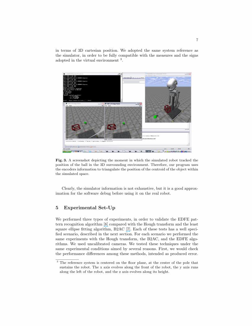
In Fig. 3 a screenshot is depicted, that shows an operative situation in whichthe simulator tracked the ball. The iCub program we implemented is able tolocalize the position of the ball (which is the target to be grasped in this case),
7
in terms of 3D cartesian position. We adopted the same system reference asthe simulator, in order to be fully compatible with the measures and the signsadopted in the virtual environment 3.
Fig. 3. A screenshot depicting the moment in which the simulated robot tracked theposition of the ball in the 3D surrounding environment. Therefore, our program usesthe encoders information to triangulate the position of the centroid of the object withinthe simulated space.
Clearly, the simulator information is not exhaustive, but it is a good approx-imation for the software debug before using it on the real robot.
5 Experimental Set-Up
We performed three types of experiments, in order to validate the EDFE pat-tern recognition algorithm [8] compared with the Hough transform and the leastsquare ellipse fitting algorithm, B2AC [7]. Each of these tests has a well speci-fied scenario, described in the next section. For each scenario we performed thesame experiments with the Hough transform, the B2AC, and the EDFE algo-rithms. We used uncalibrated cameras. We tested these techniques under thesame experimental conditions aimed by several reasons. First, we would checkthe performance differences among these methods, intended as produced error.
3 The reference system is centered on the floor plane, at the center of the pole thatsustains the robot. The x axis evolves along the front of the robot, the y axis runsalong the left of the robot, and the z axis evolves along its height.

8
It is worth noticing we are not interested in the absolute error of each pro-cedure (yet evaluated for each method in [4], [7], and [8]); nonetheless we areinterested in verifying the systems’ execution dissimilarities under the same situ-ation. Moreover, we are not interested in analyzing these dissimilarities in termsof mathematical performance, as already done by the authors, but their usagein practical applications and scenarios instead. The final error is a combinationof all the previous imprecisions. In the next section we will analyze the errorpropagation process, and we will quantize it in our specific case.
5.1 Scenarios
At each trial the Hough transform, the B2AC, and the EDFE algorithms are usedin order to evaluate the ball’s center of gravity (COG) within the 2D cameraimages. Therefore this information is triangulated with the encoders’ values inorder to determine the ball spatial position. For each scenario we performed atleast 30 trials.
Since there is a prospective error, introduced by the spatial perspective, theball is not seen as a 2D circle by the two camera.
We made the experiment in the scenario no. 1 by using a cylinder consideredhaving a a null depth. (hence reducing the prospective effect). In this way we cantest the algorithms by isolating the perspective error, while exploiting them ina real situation at the same time. The experiment in the scenario no. 2 is quitesimilar, but made using a ball instead of the cylinder, and letting it varying itsposition not only in the x-axis direction.
1 The robot has to localize a green cylinder in front of it, in terms of 3Dcartesian coordinates. The robot stands up and remains in the same position,while the cylinder goes away along the x-axis direction at each trial. The errorbetween the cylinder real coordinates and the evaluated ones is plotted asfunction of the distance between the middle point of the eyes-axes and thecylinder center. In the next section we will reconsider it for a more completeexplanation.
2 The robot has to localize a green ball in front of it, in terms of 3D cartesiancoordinates. The robot stands up and remains in the same position, whilethe ball changes its coordinates at each trial. The error between the ball’sreal coordinates and the evaluated ones is plotted as function of the distancebetween the middle point of the eyes-axes and the ball’s center. In the nextsection we will reconsider it for a more complete explanation.
3 The robot has to evaluate the ball’s radius while an occlusion hides theobject. The robot stands up in front of the ball, which remains in the sameposition during all the trials. The ball is occluded by a cube placed in frontof it more and more at each trial. Both the ball and the cube have beenplaced over a table, in front of the robot.

9
6 Results and Discussion
In the scenario 1 and 2 the error between the real and the evaluated cylinder’sand ball’s position is determined, while in the scenario 3 the error between thereal and evaluated ball’s radius is calculated. The position error is evaluated asfollows:
rmserr =3∑
i=1
√(preali − pevali)2 =√
(xreal − xeval)2 + (yreal − yeval)2 + (zreal − zeval)2
(1)
where the (xreal, yreal, zreal) and the (xeval, yeval, zeval) are the real and eval-uated 3D coordinates of the ball’s center, respectively. Indeed, this can be con-sidered as the root-mean square error. These values are relative to the simulator’sreference system, which has the origin in the center of the robot’s floor base islocated where. The reference system’s is orthonormal, and its orientation is asfollows:
– the x axis is parallel to the floor plane, and increases with direction orthog-onal to the eyes’ axis and going away in front of the robot;
– the y axis is parallel to the floor plane, and increases with direction parallelto the eyes’ axis and going away to the left of the robot;
– the z axis is orthogonal to the floor plane, and increases going away alongthe height.
6.1 Error Propagation Evaluation
We evaluated the error propagation for the position detection as follows.The absolute errors have been evaluated as:
erri−th−axis =√
err2pixel + err2
encoders + err2misure−iCub
err =√
err2x−axis + err2
y−axis + err2z−axis
(2)
each of them measured in simulator measure unit (we use the abbreviationSMU). The errpixel is the absolute error relative to the value of one square pixel.In order to evaluate it we referred to the known ball’s radius. By knowing it (as afixed value, i.e. 0.17 SMU) and by evaluating it at each measure we can estimatethe value of a square pixel in SMU (this is the image resolution at the objectdistance) as the ratio between the known radius and the one estimated with eachof the three algorithms considered (i.e. Hough transform, B2AC, and EDFE):
10
errpixel−x = errpixel−y = 0.17/radiuseval (3)
Therefore, according with the error propagation theory, the error of a squarepixel is:
errpixel =√
err2pixel−x + err2
pixel−y =√
2 · errpixel−x (4)
The errors of the encoders can be considered negligible within the simulator.Since there is no documentation on the encoders’ resolution within the simula-tor, we considered the accuracy of their information approximated to their lastdigit, wihch is the forth one (therefore negligible). Finally the errors due robot’slengths need to be considered. Again, there is no information about the errorthe lengths of the robot’s parts have been expressed with. Therefore, in orderto fix their accuracy we analyzed the simulator’s source code. So far, we foundthat the lengths of the robot’s parts were expressed with the second digit ofapproximation. Hence, we approximated them as 0.01 SMU.
6.2 Scenarios’ Evaluation
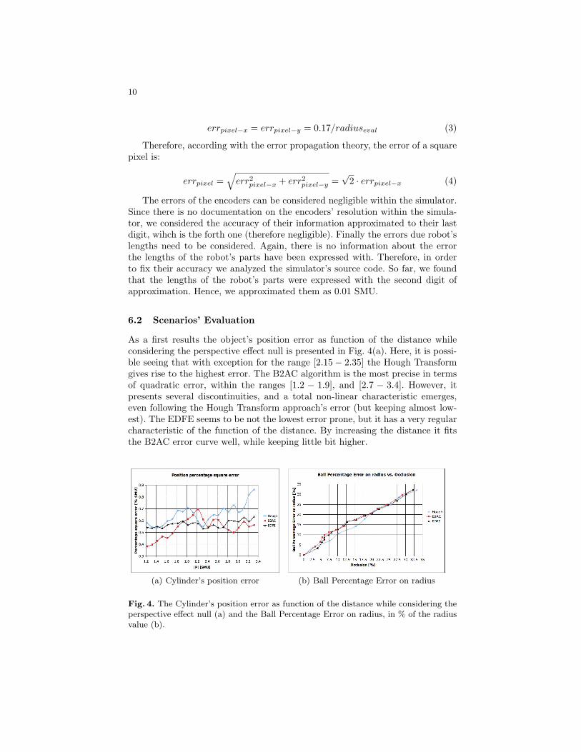
As a first results the object’s position error as function of the distance whileconsidering the perspective effect null is presented in Fig. 4(a). Here, it is possi-ble seeing that with exception for the range [2.15− 2.35] the Hough Transformgives rise to the highest error. The B2AC algorithm is the most precise in termsof quadratic error, within the ranges [1.2 − 1.9], and [2.7 − 3.4]. However, itpresents several discontinuities, and a total non-linear characteristic emerges,even following the Hough Transform approach’s error (but keeping almost low-est). The EDFE seems to be not the lowest error prone, but it has a very regularcharacteristic of the function of the distance. By increasing the distance it fitsthe B2AC error curve well, while keeping little bit higher.
(a) Cylinder’s position error (b) Ball Percentage Error on radius
Fig. 4. The Cylinder’s position error as function of the distance while considering theperspective effect null (a) and the Ball Percentage Error on radius, in % of the radiusvalue (b).

11
The experiment of the scenario no. 3 shows a great linearity between theocclusion of the ball and the error on its radius evaluation. Fig. 4(b) illustratesthe results of this experiment.
Here, the Hough Transform gets better results within the range [5 % - 20%] of occlusion (defined as in equation 5, where Pr is the residual number ofpixels, and Pt is the total number of target object pixels, determined with noocclusion), then almost superimposing with the other two approaches after he 20% of occlusion. The characteristic is quite linear for all the techniques adopted,with the exception of the cited range, in terms of a slight decrease from thelinear ideal line for the Hough Transform and a slight increment for both ellipsedetection approaches. Fig. 5(a) shows the target object partially hided by theoccluding object.
occlusion[%] = (Pt − Pr) · 100/Pt (5)
Subsequently, the error introduced by spatial perspective is mapped as afunction of the object’s distance from the eyes axis midpoint. We isolate theperspective error by comparing the absolute error obtained within the tests in thescenario no. 1 and in the scenario no. 2, as absolute errors. It is worth noting thatin order to compare these errors, the cylinder and and the ball we used have thesame radius (0.17 SMU) within the trials. Therefore the percentage perspectiveerror has been evaluated as the ratio between the absolute perspective error andthe module of the distance between the eyes axis midpoint and the object.
Here, it is possible to see that the two ellipse recognition techniques are moresensitive than the Hough Transform to the spatial perspective. This seems quiteobvious, due to the fact that the latter looks for circles, and the first two for yetdeformed circles, i.e. ellipses. Nevertheless, the Hough Transform smoothes thisartifact by bringing it back as a circle, before evaluating the centroid and radiusparameters. The B2AC and the EDFE algorithms do not.
Finally, the scenario no. 2 is discussed. We keep this as the last discussionin order to show that, in spite of the fact that the ellipse detection approachesgive rise to a bigger spatial perspective error than the Hough Transform, theprecision given within the overall system is superior than the one obtained withthe Hough Transform. In fact, despite the amount of the perspective error value,the major precision guaranteed by an ellipse detection rather than a circle onebrings about to a more exact final result in determining the spatial position ofthe ball. In Fig. 5(b) this is showed. We did not filter the results, in order tokeep them as natural as possible. By acting in this way, the noise affects thetrend of the curves most. Therefore, we inserted three trend lines (one for eachtechnique, each of them with exponential characteristic) in order to evidence themost fruiting approach. Here, the B2AC’s and the EDFE’s trend lines appearsuperimpose, so that it is not possible distinguishing them from each other.However, the Hough Transform’s trend line shows of this technique is the mosterror prone for balls’ spatial position detection in image processing. In fact, it isalways higher than the other two.

12
(a) The target object partiallyhidden by the occluding object.
(b) Percentage square error.
Fig. 5. The target object partially hidden by the occluding object (a) and the Percent-age square error, measured in % of the simulator measure unit (b).
7 Conclusions
In this work we presented the first implementation of the EDFE ellipse squarefitting algorithm, a technique developed by our team by Maini et Al, and weapplied it to a humanoid robotics platform. The task we planned is the spatiallocalization of a circular object (i.e. a ball) placed within the surrounding en-vironment. Therefore, we developed a computer vision algorithms in order toimplement the EDFE technique for the firs time. Moreover, we implementeda tracking algorithm to localize the object with the Robot’s binocular vision,and subsequently we triangulated these information in conjunction with thoseof the robot’s head encoders to determine the position of the object’s centroid inthe environment, in terms of 3D coordinates with the reference system locatedat the base of the robot. Therefore, we performed some experiments in orderto validate the precision of the overall system in presence of induced artifacts(such as the ball occlusion by another object) and as function of the distance ofthe target. We made the same experiments by using the Hough Transform, theB2AC, and the EDFE under the same assumption, in order to have the fairestexamination as possible. We found that the B2AC and EDFE give rise to a moreprecise results in terms of the overall system than the Hough Transform.
7.1 Future Work
In the near future we plan to apply our techniques to the real RobotCub roboticsplatform, in order to compare and validate our results with the real robot, andnot only with the ODE simulator.

13
Acknowledgements
This work has been partially supported by the EU Project RobotCub (EuropeanCommission FP6 Project IST-004370).
References
1. Sandini, G., Metta, G., Vernon, D.: Robotcub: An open research initiative inembodied cognition. Proceedings of the Third International Conference on Devel-opment and Learning (ICDL ’04) (2004)
2. Stellin, G., Cappiello, G., Roccella, S., Carrozza, M.C., Dario, P., Metta, G., San-dini, G., Becchi, F.: Preliminary design of an anthropomorphic dexterous hand fora 2-years-old humanoid: towards cognition. IEEE BioRob, Pisa February (2006)20–22
3. Yuen, H.K., Illingworth, J., Kittler, J.: Detecting partially occluded ellipses usingthe hough transform. Image Vision and Computing 7(1) (1989) 31–37
4. Leavers, V.F.: Shape detection in computer vision using the hough transform.Springer-Verlag (1992)
5. Dhome, M., Lapreste, J.T., Rives, G., Richetin, M.: Spatial localisation of modelledobjects of revolution in monocular perspective vision. (1990) 475–485
6. Forsyth, D., Mundy, J., Zisserman, A., Coelho, C., Heller, A., Rothwell, C.: In-variant descriptors for 3-d object recognition and pose. IEEE Trans. PAMI 13(10)(1991) 971–991
7. Fitzgibbon, A., Pilu, M., Fisher, R.: Direct least square fitting of ellipses. IEEETrans. PAMI 21 (1999) 476–480
8. Maini, E.S.: Enhanced direct least square fitting of ellipses. IJPRAI 20(6) (2006)939–954
9. RobotCub: Url: http://www.robotcub.org/10. Metta, G., Sandini, G., Vernon, D., Caldwell, D., Tsagarakis, N., Beira, R., Santos-
Victor, J., Ijspeert, A., Righetti, L., Cappiello, G., Stellin, G., Becchi, F.: Therobotcub project - an open framework for research in embodied cognition. Hu-manoids Workshop, IEEE –RAS International Conference on Humanoid Robots(December 2005)
11. Nava, N., Tikhanoff, V., Metta, G., Sandini, G.: Kinematic and dynamic simula-tions for the design of robocub upper-body structure. ESDA (2008)
12. Greggio, N., Silvestri, G., Antonello, S., Menegatti, E., Pagello, E.: A 3d modelof a humanoid robot for the usarsim simulator. In: First Workshop on HumanoidSoccer Robots. Number ISBN 88-900426-2-1 (December 2006) 17–24
13. Tikhanoff, V., Fitzpatrick, P., Metta, G., Nori, F., Natale, L., Cangelosi, A.: Anopen-source simulator for cognitive robotics research: The prototype of the icubhumanoid robot simulator. Performance Metrics for Intelligent Systems Workshop,PerMIS ’08, National Institute of Standards and Technology (NIST) (Gaithersburg,MD, 20899 August 19-21, 2008 2008)
14. Tikhanoff, V., Fitzpatrick, P., Nori, F., Natale, L., Metta, G., Cangelosi, A.: Theicub humanoid robot simulator. International Conference on Intelligent RObotsand Systems IROS Nice, France (2008)
15. Maini, E.S.: Robust ellipse-specific fitting for real-time machine vision. BVAI(2005) 318–327