Real-time interception systems for the GSM protocol
11
904 IEEE TRANSACTIONS ON VEHICULAR TECHNOLOGY, VOL. 51, NO. 5, SEPTEMBER 2002 Real-Time Interception Systems for the GSM Protocol Francisco J. González-Castaño, Javier Vales-Alonso, José M. Pousada-Carballo, Fernando Isasi de Vicente, and Manuel J. Fernández-Iglesias Abstract—A GSM protocol interceptor is a device located in a (possibly) closed area that listens to information exchanged between base stations (BSs) and mobile stations (MSs). This paper presents three new interception systems for security purposes. The first one (detector) forces all idle MSs nearby to generate activity, which can be used to activate an alarm of MS presence. The second one (selective interceptor) monitors information exchange between MS and BS and, in case of MS activity, 1) extracts messages containing MS identifiers and 2) checks identifiers in a local cache to decide if an external jamming unit should block individual calls (either incoming or outgoing). The third system (enhanced selective interceptor) combines the previous two sys- tems to improve blocking performance. We analyze transactions of the GSM protocol that are relevant to interception system operation. Those transactions impose real-time constraints that we quantify. We present real tests and simulations that address the feasibility of the systems. Index Terms—Electronic surveillance, GSM. I. INTRODUCTION A GSM protocol interceptor is a device located in a (pos- sibly) closed area that listens to information exchanged between base stations (BSs) and mobile stations (MSs). In this paper, we propose the following interception systems. 1) A detector forces all idle MSs nearby to initiate informa- tion exchange with the BS, including messages with their identifiers. 2) A selective interceptor monitors the information ex- change and extracts messages containing MS identifiers. Depending on MS identity, a jamming unit may block individual calls. 3) An enhanced selective interceptor is a combination of the previous two. Since a detector forces all idle MS nearby to emit, their trans- missions can be captured. Basically, the detector jams downlink active carriers and offers a signaling pseudocarrier, as explained in Section II-A. As we will see in Section IV-E, this is possible without increasing background radioelectric activity in a dan- gerous way. Manuscript received April 20, 2000; revised February 5, 2002. This work was supported by FEDER, European Union, under Grant 1FD97–1485-C02–02 TIC, by the Xunta de Galicia, Spain, under Grant XUGA32204B95, by CICYT, Spain, under Grant TIC 97–0669-C03–03, and by a NATO Scientific Committee grant. F. J. González-Castaño, J. Vales-Alonso, J. M. Pousada-Carballo, and M. J. Fernández-Iglesias are with the Departamento de Ingeniería Telemática, Uni- versidad de Vigo, 36200 Vigo, Spain (e-mail: [email protected]). F. I. de Vicente is with the Departamento de Teoría de laSeñal y Comunica- ciones, Universidad de Vigo, 36200 Vigo, Spain. Digital Object Identifier 10.1109/TVT.2002.801547 In other situations, MSs are allowed, but it would be desir- able to control user access. The identifiers obtained by a selec- tive interceptor can be used to decide if a particular MS should be blocked or not. Selective blocking of MS has obvious ad- vantages in security areas, where hidden data transmission is forbidden. One of our main motivations has been the search of solutions to this particular problem. During the late 1990s, indiscriminate frequency jamming has been a successful secu- rity measure in Spain, since malicious transmissions used gen- eral-purpose bands (like 27 or 433 MHz). Temporal jamming in those bands, when required by law-enforcement agencies, only affected nonessential domestic appliances (like cordless phones) or devices that admit with manual operation (like car locks, garage doors, and construction cranes). Unfortunately, in- discriminate jamming in those frequencies is no longer safe. 1 Mobile communications hide malicious transmission easily, and indiscriminate jamming of GSM networks is not a solution, be- cause it may cause severe problems in urban areas. As in the de- tector’s case, the interceptor only jams downlink active carriers, as described in Section III-B. Thus, the same considerations on the absence of adverse effects hold. This paper is organized as follows. In Section II, we describe three possible interception systems. In Section III, we analyze GSM protocol transactions that are relevant to obtain MS iden- tifiers. Those transactions impose real-time constraints that we quantify, to propose a blocking method. Section IV presents re- alistic tests and simulation results to address the feasibility of the interception systems described in Section II. Section V con- cludes this paper. 2 II. INTERCEPTION SYSTEMS A. Detector In [1], the authors described the theoretical foundation of a real-time detector of idle GSM MS, based on an analysis of the GSM specifications. Briefly, its operation can be described as follows. 1) A jamming device such as [2] blocks all downlink sig- naling carriers at the detection area (the authors have in- stalled one of these systems at the parliament of Galicia, Spain). 2) The detector offers a signaling pseudocarrier, whose broadcast control channel (BCCH) carries a location area identifier (LAI) different from those in the jammed signaling carriers. 1 http://www.el-mundo.es/1998/03/23/espana/23N0040.html. 2 In this paper, we refer to GSM signaling carriers as active carriers, signaling carriers or channels, depending on the context. 0018-9545/02$17.00 © 2002 IEEE
Transcript of Real-time interception systems for the GSM protocol
904 IEEE TRANSACTIONS ON VEHICULAR TECHNOLOGY, VOL. 51, NO. 5, SEPTEMBER 2002
Real-Time Interception Systems for theGSM Protocol
Francisco J. González-Castaño, Javier Vales-Alonso, José M. Pousada-Carballo, Fernando Isasi de Vicente, andManuel J. Fernández-Iglesias
Abstract—A GSM protocol interceptor is a device located ina (possibly) closed area that listens to information exchangedbetween base stations (BSs) and mobile stations (MSs). This paperpresents three new interception systems for security purposes. Thefirst one (detector) forces all idle MSs nearby to generate activity,which can be used to activate an alarm of MS presence. Thesecond one (selective interceptor) monitors information exchangebetween MS and BS and, in case of MS activity, 1) extractsmessages containing MS identifiers and 2) checks identifiers ina local cache to decide if an external jamming unit should blockindividual calls (either incoming or outgoing). The third system(enhanced selective interceptor) combines the previous two sys-tems to improve blocking performance. We analyze transactionsof the GSM protocol that are relevant to interception systemoperation. Those transactions impose real-time constraints thatwe quantify. We present real tests and simulations that addressthe feasibility of the systems.
Index Terms—Electronic surveillance, GSM.
I. INTRODUCTION
A GSM protocol interceptor is a device located in a (pos-sibly) closed area that listens to information exchanged
between base stations (BSs) and mobile stations (MSs). In thispaper, we propose the following interception systems.
1) A detectorforces all idle MSs nearby to initiate informa-tion exchange with the BS, including messages with theiridentifiers.
2) A selective interceptormonitors the information ex-change and extracts messages containing MS identifiers.Depending on MS identity, a jamming unit may blockindividual calls.
3) An enhanced selective interceptoris a combination of theprevious two.
Since a detector forces all idle MS nearby to emit, their trans-missions can be captured. Basically, the detector jams downlinkactive carriers and offers a signaling pseudocarrier, as explainedin Section II-A. As we will see in Section IV-E, this is possiblewithout increasing background radioelectric activity in a dan-gerous way.
Manuscript received April 20, 2000; revised February 5, 2002. This workwas supported by FEDER, European Union, under Grant 1FD97–1485-C02–02TIC, by the Xunta de Galicia, Spain, under Grant XUGA32204B95, by CICYT,Spain, under Grant TIC 97–0669-C03–03, and by a NATO Scientific Committeegrant.
F. J. González-Castaño, J. Vales-Alonso, J. M. Pousada-Carballo, and M. J.Fernández-Iglesias are with the Departamento de Ingeniería Telemática, Uni-versidad de Vigo, 36200 Vigo, Spain (e-mail: [email protected]).
F. I. de Vicente is with the Departamento de Teoría de la Señal y Comunica-ciones, Universidad de Vigo, 36200 Vigo, Spain.
Digital Object Identifier 10.1109/TVT.2002.801547
In other situations, MSs are allowed, but it would be desir-able to control user access. The identifiers obtained by a selec-tive interceptor can be used to decide if a particular MS shouldbe blocked or not. Selective blocking of MS has obvious ad-vantages in security areas, where hidden data transmission isforbidden. One of our main motivations has been the searchof solutions to this particular problem. During the late 1990s,indiscriminate frequency jamming has been a successful secu-rity measure in Spain, since malicious transmissions used gen-eral-purpose bands (like 27 or 433 MHz). Temporal jammingin those bands, when required by law-enforcement agencies,only affected nonessential domestic appliances (like cordlessphones) or devices that admit with manual operation (like carlocks, garage doors, and construction cranes). Unfortunately, in-discriminate jamming in those frequencies is no longer safe.1
Mobile communications hide malicious transmission easily, andindiscriminate jamming of GSM networks is not a solution, be-cause it may cause severe problems in urban areas. As in the de-tector’s case, the interceptor only jams downlink active carriers,as described in Section III-B. Thus, the same considerations onthe absence of adverse effects hold.
This paper is organized as follows. In Section II, we describethree possible interception systems. In Section III, we analyzeGSM protocol transactions that are relevant to obtain MS iden-tifiers. Those transactions impose real-time constraints that wequantify, to propose a blocking method. Section IV presents re-alistic tests and simulation results to address the feasibility ofthe interception systems described in Section II. Section V con-cludes this paper.2
II. I NTERCEPTIONSYSTEMS
A. Detector
In [1], the authors described the theoretical foundation of areal-time detector of idle GSM MS, based on an analysis of theGSM specifications. Briefly, its operation can be described asfollows.
1) A jamming device such as [2] blocks all downlink sig-naling carriers at the detection area (the authors have in-stalled one of these systems at the parliament of Galicia,Spain).
2) The detector offers a signaling pseudocarrier, whosebroadcast control channel (BCCH) carries a locationarea identifier (LAI) different from those in the jammedsignaling carriers.
1http://www.el-mundo.es/1998/03/23/espana/23N0040.html.2In this paper, we refer to GSM signaling carriers asactive carriers, signaling
carriers or channels,depending on the context.
0018-9545/02$17.00 © 2002 IEEE

GONZÁLEZ-CASTAÑOet al.: REAL-TIME INTERCEPTION SYSTEMS FOR GSM PROTOCOL 905
3) Ideally (but not necessarily), the jammed signaling car-riers include the pseudocarrier in their BCCH allocationlists.
4) When an idle MS enters the influence area of the jam-ming unit (the entrance of a hospital, or an airport accessbridge), it loses contact with the active carrier of its BS.After MS downlink signaling failure counter (DSC) ex-pires, which takes a time , the MS considers a failurehas taken place.
5) Then, it searches for an alternative carrier. Obviously, theonly possibilitymustbe the pseudocarrier. If we assumethat detection is a service offered by existing operators,the pseudocarriers can be present in the BCCH allocationlists of the jammed active carriers (with the lowest pri-ority, since they cannot be used for full GSM signaling,in a low-cost implementation). In this case, search time isalmost null.
6) Finally, the MS synchronizes with the pseudocarrier andreads its BCCH data. These two processes take an aggre-gated time . Since the new LAI differs from the pre-vious one, the MS is forced to perform self-identification.This implies MS RF transmission—and, therefore, MSdetection—by an auxiliary receiver.
According to the theoretical study in [1], for the GSM pro-tocol, s and s. In Section IV, we verifythese estimations by means of realistic tests.
B. Selective Interceptor
The selective interceptor monitors GSM protocol exchangebetween BS and MS. Once the interceptor has obtained MSidentifiers, and depending on the way these identifiers are pro-cessed, two different scenarios may result.
1) Remote Identity Check and Blocking:Identifiers aretransmitted to the corresponding mobile switching center(MSC). It is assumed that the MSC and the interceptor arelinked in a metropolitan-area network. It is possible to choosea particular MSC from a group of different service providers,since the interceptor knows the carrier in which the identifiermessage was embedded. Once the MSC knows that a particularMS is present in the monitored target area, it may block itsactivity during a period of time. Fig. 1 shows a representationof this scenario.
This approach requires a permanent communication betweenthe MSC and the interceptor, which may not be available. Toimplement real-time blocking, the connection must also be fastand reliable. For those reasons, we believe that this scenario isnot realistic.
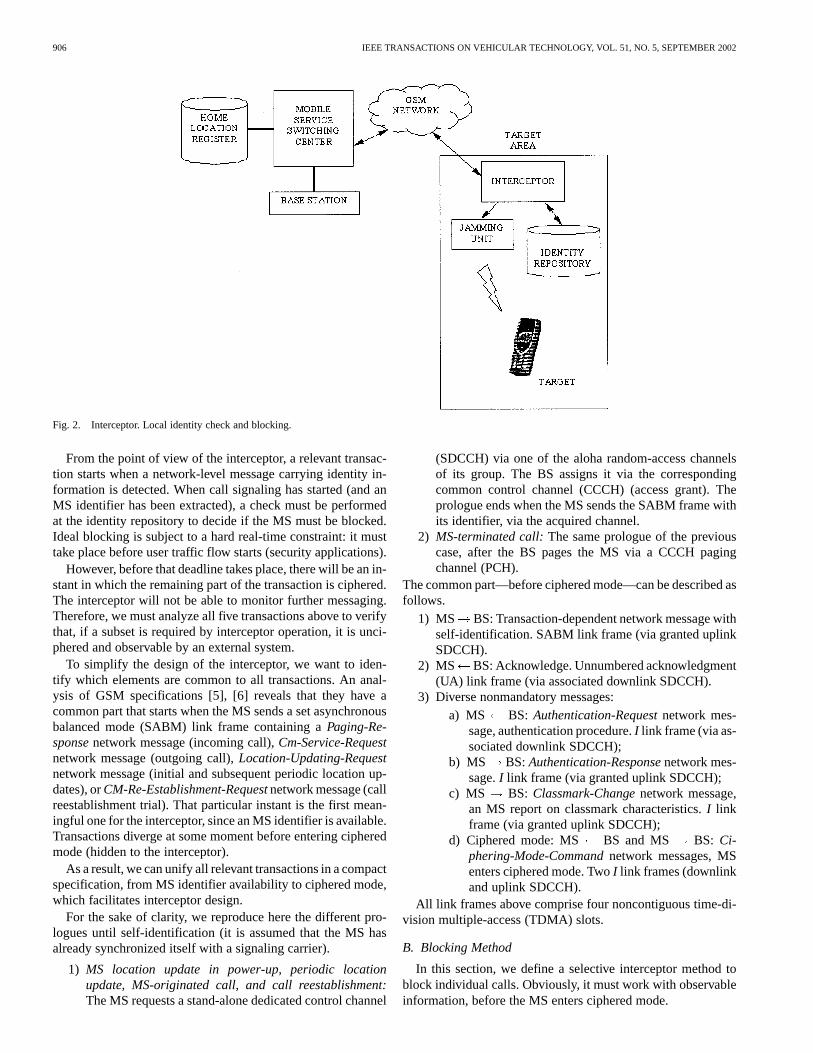
2) Local Identity Check and Blocking:In this scenario, alocal jamming device is required. This device generates inter-ferences that affect active carriers. Hence, it blocks MS activity.Fig. 2 describes the whole system. The interceptor obtainsidentifiers and checks them in a local identity repository. Ifthey are not listed there, or are not privileged, the interceptortriggers the jammer at convenient slots, blocking specific MScommunications.
In this case, the selective interceptor may include an RF unitthat decides if an MS is located inside a target area [3]. ExternalMSs are ignored.
Fig. 1. Interceptor. Remote identity check and blocking.
This approach also requires communication between theMSC and the interceptor. However, it only takes place fromtime to time, in order to reload the identity repository. Connec-tion speed does not compromise real-time blocking. The GSMnetwork seems an adequate choice to implement a link betweenthe interceptor and the MSC, since it is already present. For thisreason, in this paper, we consider a scenario with local identitycheck and blocking.
As we will see in Section III-B, interception jamming only af-fects downlink active carriers. In other words, as in the examplein Section IV-E, we do not have to transmit at MS uplink levels( 30 dBm) but at BS downlink levels ( 70 dBm).
Also, note that an interface with the MSC is required, inorder to get information to update the local identity repository.The Special Mobile Group (SMG) of the European Telecom-munications Standards Institute (ETSI) has generated TechnicalReport ETR 363 [4] to describe an interception interface withMSCs. The development of that interface was due to the needsof law-enforcement agencies to request target MS speech anddata from an MSC.
C. Enhanced Selective Interceptor
The enhanced selective interceptor combines the detector inSection II-A with the selective interceptor in Section II-B. Thedetector forces the MS to transmit self-identification informa-tion. Then, the selective interceptor captures MS identity and,if necessary, initiates the process to update the identity repos-itory. According to the simulation results in Section IV-F, theenhanced selective interceptor improves identity repository hitprobability in a dramatic way.
III. PROTOCOLANALYSIS
A. Relevant Transactions
Basically, there are five relevant transactions that lead to MSself-identification:
1) MS location update at power up;2) periodic MS location update when indicated by a local
counter (set by the BS);3) MS-terminated call;4) MS-originated call;5) call reestablishment trial, in case of abrupt fading.
906 IEEE TRANSACTIONS ON VEHICULAR TECHNOLOGY, VOL. 51, NO. 5, SEPTEMBER 2002
Fig. 2. Interceptor. Local identity check and blocking.
From the point of view of the interceptor, a relevant transac-tion starts when a network-level message carrying identity in-formation is detected. When call signaling has started (and anMS identifier has been extracted), a check must be performedat the identity repository to decide if the MS must be blocked.Ideal blocking is subject to a hard real-time constraint: it musttake place before user traffic flow starts (security applications).
However, before that deadline takes place, there will be an in-stant in which the remaining part of the transaction is ciphered.The interceptor will not be able to monitor further messaging.Therefore, we must analyze all five transactions above to verifythat, if a subset is required by interceptor operation, it is unci-phered and observable by an external system.
To simplify the design of the interceptor, we want to iden-tify which elements are common to all transactions. An anal-ysis of GSM specifications [5], [6] reveals that they have acommon part that starts when the MS sends a set asynchronousbalanced mode (SABM) link frame containing aPaging-Re-sponsenetwork message (incoming call),Cm-Service-Requestnetwork message (outgoing call),Location-Updating-Requestnetwork message (initial and subsequent periodic location up-dates), orCM-Re-Establishment-Requestnetwork message (callreestablishment trial). That particular instant is the first mean-ingful one for the interceptor, since an MS identifier is available.Transactions diverge at some moment before entering cipheredmode (hidden to the interceptor).
As a result, we can unify all relevant transactions in a compactspecification, from MS identifier availability to ciphered mode,which facilitates interceptor design.
For the sake of clarity, we reproduce here the different pro-logues until self-identification (it is assumed that the MS hasalready synchronized itself with a signaling carrier).
1) MS location update in power-up, periodic locationupdate, MS-originated call, and call reestablishment:The MS requests a stand-alone dedicated control channel
(SDCCH) via one of the aloha random-access channelsof its group. The BS assigns it via the correspondingcommon control channel (CCCH) (access grant). Theprologue ends when the MS sends the SABM frame withits identifier, via the acquired channel.
2) MS-terminated call:The same prologue of the previouscase, after the BS pages the MS via a CCCH pagingchannel (PCH).
The common part—before ciphered mode—can be described asfollows.
1) MS BS: Transaction-dependent network message withself-identification. SABM link frame (via granted uplinkSDCCH).
2) MS BS: Acknowledge. Unnumbered acknowledgment(UA) link frame (via associated downlink SDCCH).
3) Diverse nonmandatory messages:a) MS BS: Authentication-Requestnetwork mes-
sage, authentication procedure.I link frame (via as-sociated downlink SDCCH);
b) MS BS:Authentication-Responsenetwork mes-sage.I link frame (via granted uplink SDCCH);
c) MS BS: Classmark-Changenetwork message,an MS report on classmark characteristics.I linkframe (via granted uplink SDCCH);
d) Ciphered mode: MS BS and MS BS: Ci-phering-Mode-Commandnetwork messages, MSenters ciphered mode. TwoI link frames (downlinkand uplink SDCCH).
All link frames above comprise four noncontiguous time-di-vision multiple-access (TDMA) slots.
B. Blocking Method
In this section, we define a selective interceptor method toblock individual calls. Obviously, it must work with observableinformation, before the MS enters ciphered mode.
GONZÁLEZ-CASTAÑOet al.: REAL-TIME INTERCEPTION SYSTEMS FOR GSM PROTOCOL 907
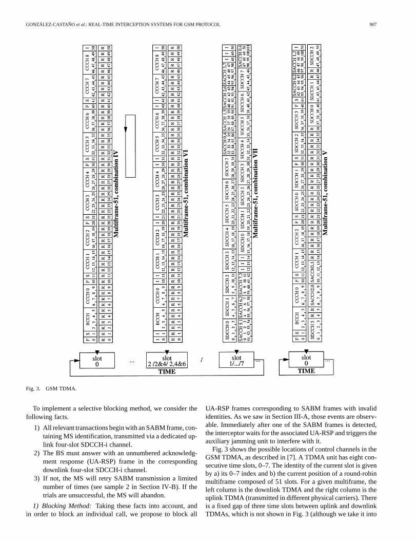
Fig. 3. GSM TDMA.
To implement a selective blocking method, we consider thefollowing facts.
1) All relevant transactions begin with an SABM frame, con-taining MS identification, transmitted via a dedicated up-link four-slot SDCCH-i channel.
2) The BS must answer with an unnumbered acknowledg-ment response (UA-RSP) frame in the correspondingdownlink four-slot SDCCH-i channel.
3) If not, the MS will retry SABM transmission a limitednumber of times (see sample 2 in Section IV-B). If thetrials are unsuccessful, the MS will abandon.
1) Blocking Method:Taking these facts into account, andin order to block an individual call, we propose to block all
UA-RSP frames corresponding to SABM frames with invalididentities. As we saw in Section III-A, those events are observ-able. Immediately after one of the SABM frames is detected,the interceptor waits for the associated UA-RSP and triggers theauxiliary jamming unit to interfere with it.
Fig. 3 shows the possible locations of control channels in theGSM TDMA, as described in [7]. A TDMA unit has eight con-secutive time slots, 0–7. The identity of the current slot is givenby a) its 0–7 index and b) the current position of a round-robinmultiframe composed of 51 slots. For a given multiframe, theleft column is the downlink TDMA and the right column is theuplink TDMA (transmitted in different physical carriers). Thereis a fixed gap of three time slots between uplink and downlinkTDMAs, which is not shown in Fig. 3 (although we take it into

908 IEEE TRANSACTIONS ON VEHICULAR TECHNOLOGY, VOL. 51, NO. 5, SEPTEMBER 2002
account in our analysis). There are three different possibilitiesto assign control multiframes to a time slot index:
1) combination IV for slot 0 and VI for slots 2, 4, and 6;2) combination V for slot 0;3) combination IV for slot 0 and VII for other slots.Let us suppose the third case (the combination that carries
more dedicated SDCCH channels). Let us assume that the cur-rent state is the one depicted in Fig. 3 and that slot 1 carries acombination VII. In the notation ( ), let be a TDMAslot, a channel identifier, and a multiframe slot. Then, thedownlink TDMA would evolve as follows:
SDCCH
SDCCH BCCH
SDCCH
Note that (0, [SDCCH0-1]) and (1, [SDCCH0-1]) are notcontiguous in time (although they arelogically contiguous inthe same VII-type multiframe). There are seven TDMA slotsin between, including (1, [ 0]). Thus, after (0, [SDCCH0-1])is transmitted, it takes eight TDMA slots tocomplete (1,[SDCCH0-1]) transmission.
In TDMA combinations V and VII in Fig. 3, the distancebetween the end of uplink channel SDCCH-i and the beginningof downlink channel SDCCH-i is 32 TDMA slots. Since TDMAslot length is 577 seg, this is equivalent to an elapsed timeof slots ms.
Consequently, once the interceptor uplink filter detects anSABM frame, there exists a blocking window of maximumlength ms to check SABM identities in the identityrepository, before triggering the jamming unit if required.The interceptor must trigger the jamming unit in the fourindependent slots (separated by seven-slot intervals) requiredfor UA-RSP transmission.
Remark 1: Note that the selective interceptor only jamsdownlink active carriers.
Remark 2: Note that, as an interesting by-product, the selec-tive interceptor eliminates incoming call alarms, since it abortsthe signaling procedure at an early stage. However, for socialapplications, a simpler system like [2] may be preferable. Webelieve that the selective interceptor is more oriented toward se-curity needs.
IV. I NTERCEPTIONSYSTEMS’ FEASIBILITY
All realistic tests were performed in the Main Hall of theEscuela Técnica Superior de Ingenieros de Telecomunicación,Universidad de Vigo, Spain (Fig. 11). We used two SpanishGSM networks, MoviStar (dual) and Airtel (900 MHz) and aPortuguese network, Optimus (dual).
A. Detector
We evaluated detector feasibility by means of two realistictests.
1) Link failure time evaluation : In this series of tests, wejammed a dominant active carrier (channel #61 MoviStar)with a Rohde Schwarz SMY-01 generator. In the absenceof the interference signal, an Ericsson SH888 TEMS unit
Fig. 4. SMY-01 interference signal, channel #61.
(software version TMS600/4R1E, monitored with soft-ware TEMS GSM 900 1900/98.0.3.2) received the ac-tive carrier with a power level in the range (81.96 dBm,
62.65 dBm), and an average value of69.71 dBm.Fig. 4 shows the spectrum of the interference signal atthe output of the SMY-01 unit.
In each test, we measured . Fig. 5 shows a sample. Init, s. The local counter DSC had a high initialvalue (this could be expected, since all MSs were workingnormally before activating the interfering signal). The av-erage value of across all tests was 5.25 s. All measureswere lower than the theoretical limit of 5.296 s.
2) Carrier detection and synchronization time evaluation: In this series of tests, we forced all MSs in the
detector neighborhood to resynchronize with channel#682 Optimus, which carried a different LAI. To achievethis goal, we jammed all target carriers with a G-MóvilDAM-01 unit (Fig. 6) with two omnidirectional antennas(one per GSM band). As expected, all MSs nearbyperformed self-identification.
In each test, we measured until transmission of theself-identification SABM frame. In the sample in Fig. 7,
s. The average value of across all testswas 2.13 s. All measures were lower than the theoreticallimit of 2.4 s.
B. MS-Originated/Terminated Calls
To validate the assumptions in Section III-A, we analyzed thebehavior of the TEMS unit. We captured a significant number oftraces for incoming/outgoing calls. Each line in the samples thatfollow shows elapsed time, link frames, and network messages,from left to right.
1) MS-Terminated Call:Sample #1:
0.00 UL: SABM-CMD (PAGING RESPONSE)0.21 DL: UA-RSP0.45 DL: I-CMD (CIPHERING MODE COMMAND)0.47 UL: I-CMD (CLASSMARK CHANGE)0.68 DL: RR-RSP0.71 UL: I-CMD (CIPHERING MODE COMPLETE)

GONZÁLEZ-CASTAÑOet al.: REAL-TIME INTERCEPTION SYSTEMS FOR GSM PROTOCOL 909
Fig. 5. TEMST sample.
Fig. 6. DAM-01 unit.
Note 1: There is an elapsed time of 0.21 s between the be-ginning of Paging-Response SABM frame transmission and theend of UA-RSP reception. This is plus the time to transmitSABM and UA-RSP frames, 179 ms in total. There is a smalldifference in the report, due to TEMS combined processing/re-porting delay. A similar behavior was observed in all experi-ments.
2) MS-Originated Call:Sample #2:
0.00 UL: SABM-CMD (CM SERVICE REQUEST)0.23 UL: SABM-CMD (CM SERVICE REQUEST)0.45 DL: UA-RSP0.68 DL: I-CMD (CIPHERING MODE COMMAND)0.71 UL: I-CMD (CLASSMARK CHANGE)0.92 DL: RR-RSP0.94 UL: I-CMD (CIPHERING MODE COMPLETE)
Note 2: The MS retried SABM transmission (the BS did notacknowledge the first SABM frame). TheClassmark-changemessage submits TEMS technical capabilities to the BS (the MSis jumping from the 900- to the 1800-MHz band).
Sample #3:
0.00 UL: SABM-CMD (CM SERVICE REQUEST)0.22 DL: UA-RSP0.46 DL: I-CMD (AUTHENTICATION REQUEST)0.48 UL: I-CMD (CLASSMARK CHANGE)0.69 DL: RR-RSP0.95 UL: I-CMD (AUTHENTICATION RESPONSE)1.16 DL: RR-RSP1.40 DL: I-CMD (CIPHERING MODE COMMAND)1.42 UL: I-CMD (CIPHERING MODE COMPLETE)
Note 3: This transaction included an authentication proce-dure.
C. Ongoing Calls
In security applications, the interception system must blockhidden ongoing calls. This goal can be achieved by means ofan enhanced selective interceptor (detector plus selective inter-ceptor). Let us suppose that an MS has an ongoing call andenters the influence area of the detector. Letbe the initialvalue of MS counter . As indicated in [8] [Fig. 4(1a)], after anMS has been unable to decode SACCH messages for min(,RADIO_LINK_TIMEOUT) times [9], it will either initiate a callreestablishment procedure or enter an idle state. This will cer-tainly be the case, since we are blocking all active carriers.
The BS transmits SACCH messages in traffic chan-nels. A given MS receives an SACCH message each 480ms [10]. In the three operators above, we observed that
, equivalent to 7.68 s, is areasonable setting. We entered the DAM-01 influence area withongoing calls several times, and average expiration time was
s s. Fig. 8 shows the TEMS trace of one of the tests,just before the MS issued aCM-Re-Establishment-Request(notshown).
Obviously, theCM-Re-Establishment-Requestis captured bythe selective interceptor, which blocks it. Eventually, the MSswitches to idle state, where it is forced to perform self-identi-fication in the pseudocarrier, as explained in Section II-A.
When studying this case, we observed a very interesting fea-ture. During an ongoing call, the MS transmits SACCH reportscontinuously (one slot each 120 ms) [9]. Therefore, the RF re-ceptor of the detector can easily signal the presence of a hiddenMS with an ongoing call. We checked that the TEMS kept trans-mitting SACCH reports until expiration of the counter.
D. Selective Interceptor
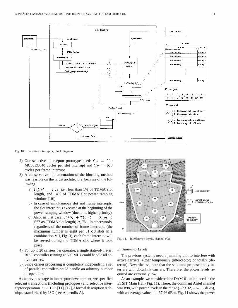
We implemented a selective interceptor prototype on anArnewsh Inc. SBC360 MC68EC040 board3 running at 25MHz (Fig. 9). The prototype analyzes a single active downlinkcarrier and jams specific slots in it, if necessary. Fig. 10 showsthe block diagram of interceptor operation.
A link layer SABM filter detects SABM frames carrying MSidentities. All messages are extracted, and, within them, all iden-tifiers (TMSI, IMSI, IMEI, or IMEISV). The controller checksthe status of MS identities in the repository. For incoming oroutgoing calls, or call reestablishment attempts, if an identity isnot included in the repository, the controller issues an updatingrequest via the MSC interface. Either in this case or in case theidentity is not authorized, the controller sets a UA-RSP blockingrequest. A blocking request is defined by a series of slot indexes
3Arnewsh Inc.: http://www.arnewsh.com/flyers/sbc360.html.

910 IEEE TRANSACTIONS ON VEHICULAR TECHNOLOGY, VOL. 51, NO. 5, SEPTEMBER 2002
Fig. 7. TEMST sample and forced identification sample.
Fig. 8. TEMS ongoing call sample.
Fig. 9. Selective interceptor, main board.
and an interference level. For this, the detector module pro-vides a synchronization reference and a level reference, so thatthe jamming module can match the level of the correspondingdownlink active carrier.
Note that the prototype only considers one active carrier. Typ-ically, at a given location, there are less than 20 active GSMcarriers per operator. A fully operational selective interceptorwould require as many detector units and jamming units as ac-tive carriers, although many components could be shared. Tostudy the feasibility of such system, we must consider the fol-lowing.
1) The operating system of the controller is interrupt-driven.There is aframe interrupt (each time a new frame isavailable for analysis) and adownlink slot interrupt,withhigher priority, to extract slot contents and decide if thatparticular slot must be jammed or not.
GONZÁLEZ-CASTAÑOet al.: REAL-TIME INTERCEPTION SYSTEMS FOR GSM PROTOCOL 911
Fig. 10. Selective interceptor, block diagram.
2) Our selective interceptor prototype needsMC68EC040 cycles per slot interrupt andcycles per frame interrupt.
3) A conservative implementation of the blocking methodwas feasible on the target architecture, because of the fol-lowing.
a) s (i.e., less than 1% of TDMA slotlength, and 14% of TDMA slot power rampingwindow [10]).
b) In case of simultaneous slot and frame interrupts,the slot interrupt is executed at the beginning of thepower ramping window (due to its higher priority).
c) Also, in that case, ss (TDMA slot length) . In other words,
regardless of the number of frame interrupts (themaximum number is eight per 518 slots in acombination VII, Fig. 3), each frame interrupt willbe served during the TDMA slot where it tookplace.
4) For up to 20 carriers per operator, a single state-of-the-artRISC controller running at 500 MHz could handle all ac-tive carriers.
5) Since carrier processing is completely independent, a setof parallel controllers could handle an arbitrary numberof operators.
As a previous stage in interceptor development, we specifiedrelevant transactions (including prologues) and selective inter-ceptor operation in LOTOS [11], [12], a formal description tech-nique standarized by ISO (see Appendix A).
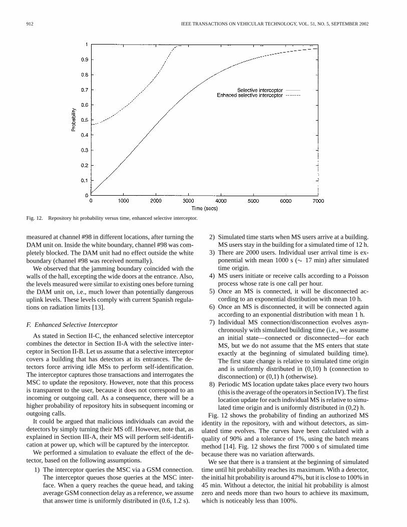
Fig. 11. Interference levels, channel #98.
E. Jamming Levels
The previous systems need a jamming unit to interfere withactive carriers, either temporarily (interceptor) or totally (de-tector). Nevertheless, note that the solutions proposed only in-terfere with downlink carriers. Therefore, the power levels re-quired are extremely low.
As an example, we considered the DAM-01 unit placed in theETSIT Main Hall (Fig. 11). There, the dominant Airtel channelwas #98, with power levels in the range (73.32, 62.32 dBm),with an average value of67.96 dBm. Fig. 11 shows the power
912 IEEE TRANSACTIONS ON VEHICULAR TECHNOLOGY, VOL. 51, NO. 5, SEPTEMBER 2002
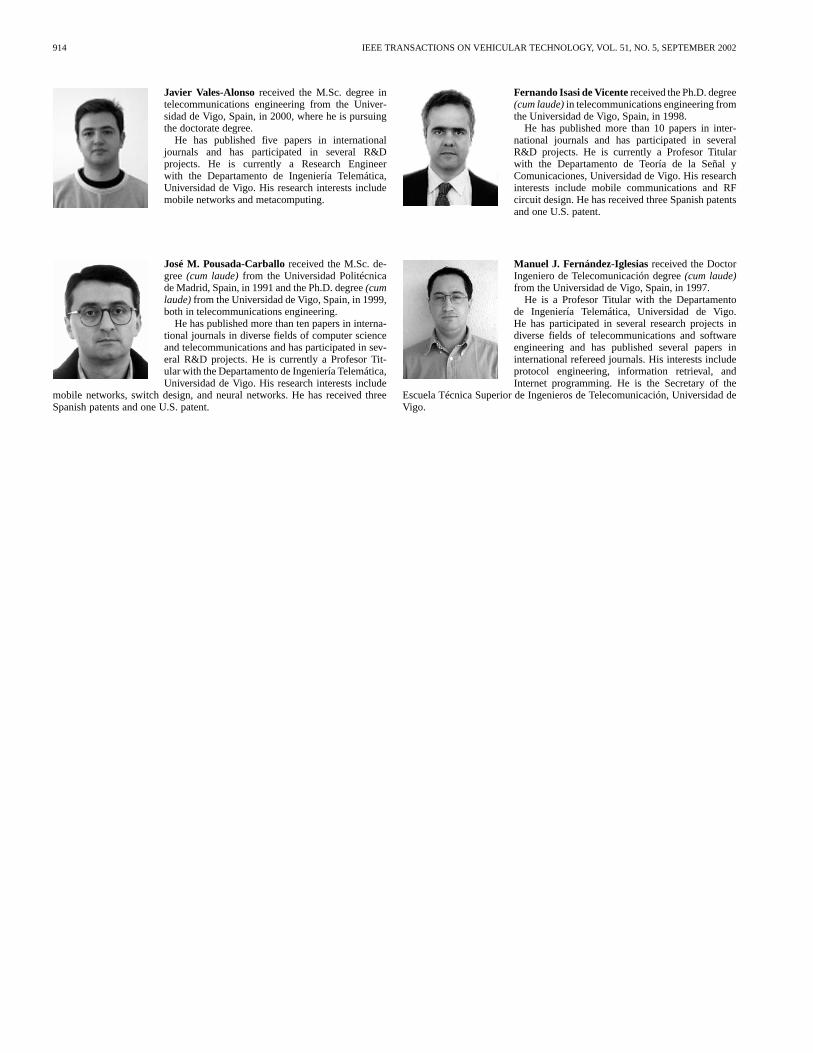
Fig. 12. Repository hit probability versus time, enhanced selective interceptor.
measured at channel #98 in different locations, after turning theDAM unit on. Inside the white boundary, channel #98 was com-pletely blocked. The DAM unit had no effect outside the whiteboundary (channel #98 was received normally).
We observed that the jamming boundary coincided with thewalls of the hall, excepting the wide doors at the entrance. Also,the levels measured were similar to existing ones before turningthe DAM unit on, i.e., much lower than potentially dangerousuplink levels. These levels comply with current Spanish regula-tions on radiation limits [13].
F. Enhanced Selective Interceptor
As stated in Section II-C, the enhanced selective interceptorcombines the detector in Section II-A with the selective inter-ceptor in Section II-B. Let us assume that a selective interceptorcovers a building that has detectors at its entrances. The de-tectors force arriving idle MSs to perform self-identification.The interceptor captures those transactions and interrogates theMSC to update the repository. However, note that this processis transparent to the user, because it does not correspond to anincoming or outgoing call. As a consequence, there will be ahigher probability of repository hits in subsequent incoming oroutgoing calls.
It could be argued that malicious individuals can avoid thedetectors by simply turning their MS off. However, note that, asexplained in Section III-A, their MS will perform self-identifi-cation at power up, which will be captured by the interceptor.
We performed a simulation to evaluate the effect of the de-tector, based on the following assumptions.
1) The interceptor queries the MSC via a GSM connection.The interceptor queues those queries at the MSC inter-face. When a query reaches the queue head, and takingaverage GSM connection delay as a reference, we assumethat answer time is uniformly distributed in (0.6, 1.2 s).
2) Simulated time starts when MS users arrive at a building.MS users stay in the building for a simulated time of 12 h.
3) There are 2000 users. Individual user arrival time is ex-ponential with mean 1000 s ( 17 min) after simulatedtime origin.
4) MS users initiate or receive calls according to a Poissonprocess whose rate is one call per hour.
5) Once an MS is connected, it will be disconnected ac-cording to an exponential distribution with mean 10 h.
6) Once an MS is disconnected, it will be connected againaccording to an exponential distribution with mean 1 h.
7) Individual MS connection/disconnection evolves asyn-chronously with simulated building time (i.e., we assumean initial state—connected or disconnected—for eachMS, but we do not assume that the MS enters that stateexactly at the beginning of simulated building time).The first state change is relative to simulated time originand is uniformly distributed in (0,10) h (connection todisconnection) or (0,1) h (otherwise).
8) Periodic MS location update takes place every two hours(this is the average of the operators in Section IV). The firstlocation update for each individual MS is relative to simu-lated time origin and is uniformly distributed in (0,2) h.
Fig. 12 shows the probability of finding an authorized MSidentity in the repository, with and without detectors, as sim-ulated time evolves. The curves have been calculated with aquality of 90% and a tolerance of 1%, using the batch meansmethod [14]. Fig. 12 shows the first 7000 s of simulated timebecause there was no variation afterwards.
We see that there is a transient at the beginning of simulatedtime until hit probability reaches its maximum. With a detector,the initial hit probability is around 47%, but it is close to 100% in45 min. Without a detector, the initial hit probability is almostzero and needs more than two hours to achieve its maximum,which is noticeably less than 100%.

GONZÁLEZ-CASTAÑOet al.: REAL-TIME INTERCEPTION SYSTEMS FOR GSM PROTOCOL 913
V. CONCLUSIONS
In this paper, we have presented a real-time selectiveinterceptor for the GSM protocol, with an improved variant(enhanced selective interceptor). These interceptors monitorGSM transactions and, if necessary, block nonprivileged callsby means of the method in Section III-B. We have analyzedthe feasibility of these systems and the auxiliary detectorwe proposed in [1]. The basic principles of all systems havebeen illustrated with the laboratory tests, implementations,and simulations in Section IV. We have described possibleimplementations that only jam downlink active carriers and,as a consequence, require low interference levels that complywith the regulations in [13].
Future research is oriented toward the following.
1) Interception planning. The proposals in this paper havebeen evaluated in the real scenario in Fig. 11. Forth-coming work seeks to define planning procedures forgeneral scenarios.
2) Porting the interception concepts to third-generation mo-bile communication systems.
APPENDIX
LOTOS SPECIFICATION OF THESELECTIVE INTERCEPTOR
LOTOS is a formal description technique that allows repre-sentation of concurrency, indeterminism, and synchronization.Our LOTOS specifications include network layer, link layer,physical layer, and TDMA evolution. To validate them, we haveused LOLA (LOTOS Laboratory) [15]. Validation is done bymeans of tests (small LOTOS specifications). A test describesa potential system behavior. The LOLAtextexpandcommandcomposes the specification and a test and analyzes if they inter-sect or not.
Once we validated the specification, a simulator was auto-matically generated by means of TOPO. TOPO is a LOLA toolthat translates LOTOS specifications into C code. In our case, Cfunctions to handle input trace files were included in the orig-inal specification asannotations.
The following advantages of formal description have beenobserved.
1) LOTOS forces the programmer to follow a methodicalanalysis of the target protocol. This made us betterunderstand the GSM specifications, which are scatteredthrough more than 5000 pages written in natural lan-guage.
2) The same specifications may be the basis for both an au-tomatically generated simulator (by using C-language an-notations) and a hardware implementation.4
A detailed description of our specifications can be found in[16].
4A package containing the full specification, LOLA tests, thesimulator, and a tool to generate GSM trace files can be down-loaded from ftp://helia.ait.uvigo.es/pub/interceptor/interceptor.tar.gz orhttp://alen.ait.uvigo.es/interceptor/interceptor.tar.gz for academic purposes.The package also includes an E-LOTOS specification (E-LOTOS is a newformal description standard, with enhanced data management and quantitativetiming).
ACKNOWLEDGMENT
The authors wish to thank A. Feijóo for his help. Also,they wish to thank G-Móvil Ingenieros SL (Spain) And In-foGLOBAL SA (Spain) for their support. Two anonymousreferees made relevant comments that improved this paper.
REFERENCES
[1] J. Vales-Alonso, F. I. de Vicente, F. J. González-Castaño, and J. M. Pou-sada-Carballo, “Real-time detector of GSM terminals,”IEEE Commun.Lett., vol. 5, pp. 275–276, 2001.
[2] J. M. Pousada-Carballo, F. J. González-Castaño, F. I. de Vicente, and M.J. Fernández-Iglesias, “Jamming system for mobile communications,”Electron. Lett., vol. 34, pp. 2166–2167, 1998.
[3] Telefonaktiebolaget LM Ericsson, “A Method of locating a mo-bile station in a mobile telephone system,” International PatentPCT/SE93/00 203.
[4] “Digital Cellular Telecommunications System: Lawful interception re-quirements for GSM (GSM 10.20 version 5.0.1),” ETSI, ETSI Tech.Rep. ETR 363, 1997.
[5] “Digital Cellular Telecommunications System (Phase 2+): Mobile radiointerface signaling layer 3; General aspects,” ETSI, ETSI Tech. Rep.ETR 300 939, 1997.
[6] “Digital Cellular Telecommunications System (Phase 2+): Functions re-lated to mobile station (MS) in idle mode and group receive mode (GSM03.22 version 5.2.1),” ETSI, ETSI Tech. Rep. ETR 300 930, 1997.
[7] “Digital Cellular Telecommunications System (Phase 2+): Multiplexingand multiple access on the radio path (GSM 05.02 version 5.4.1),” ETSI,ETSI Tech. Rep. ETR 300 908, 1997.
[8] “Digital Cellular Telecommunications System (Phase 2): Mobile radiointerface layer 3 specification (GSM 04.08),” ETSI, ETSI Doc. ETS 300557, 1997.
[9] “Digital Cellular Telecommunications System (Phase 2): Radio sub-system link control (GSM 05.08 v. 8.5.0 release 1999),” ETSI, ETSIDoc. ETS 100 911 v. 8.5.0 (2000–10), 1999.
[10] S. M. Redl, M. K. Weber, and M. W. Oliphant,An Introduction toGSM. Reading, MA: Artech House, 1995.
[11] J. Quemada, A. Azcorra, and S. Pavón, “Design with LOTOS,” Depar-tamento de Ingeniería de Sistemas Telemáticos, Universidad Politécnicade Madrid, 1993.
[12] P. H. J. van Eijk, C. A. Vissers, and M. Díaz, Eds.,The Formal Descrip-tion Technique LOTOS. Amsterdam, B.V., the Netherlands: ElsevierScience, 1989.
[13] “Reglamento que establece condiciones de protección del dominiopúblico radioeléctrico, restricciones a las emisiones radioeléctricas ymedidas de protección sanitaria frente a emisiones radioeléctricas,”Secretaría de Estado de Telecomunicaciones y para la Sociedad de laInformación de España, Real Decreto 1066/2001, 2001.
[14] A. M. Law and J. S. Carson, “A sequential procedure for determining thelength of a stady-state simulation,”Oper. Res., vol. 27, pp. 1011–1025,1979.
[15] J. A. Mañas and T. de Miguelet al., “TOPO: Quick reference,” Depar-tamento de Ingeniería de Sistemas Telemáticos, Universidad Politécnicade Madrid, 1995.
[16] M. J. Fernández-Iglesias, F. J. González-Castaño, M. Llamas-Nistal,J. M. Pousada-Carballo, and J. Vales-Alonso, “On the application offormal description techniques to the design of interception systems forGSM mobile terminals,”J. Syst. Software, vol. 60, no. 1, pp. 49–56,2002.
Francisco J. González-Castaño received theM.Sc. degree(cum laude)from the Universidad deSantiago, Spain, in 1990 and the Ph.D. degree(cumlaude)from the Universidad de Vigo, Spain, in 1998,both in telecommunications engineering.
He has published more than 20 papers in interna-tional journals in diverse fields of computer scienceand telecommunications and has participated in sev-eral R&D projects. He is currently a Profesor Tit-ular with the Departamento de Ingeniería Telemática,Universidad de Vigo, and has been a Visiting Assis-
tant Professor with the Computer Science Department, University of Wisconsin-Madison. He is Head of the TC-1 Information Technology Group, Universidadde Vigo. His research interests include mobile networks, switch design, meta-computing, and data mining. He has received three Spanish patents and one U.S.patent.
914 IEEE TRANSACTIONS ON VEHICULAR TECHNOLOGY, VOL. 51, NO. 5, SEPTEMBER 2002
Javier Vales-Alonso received the M.Sc. degree intelecommunications engineering from the Univer-sidad de Vigo, Spain, in 2000, where he is pursuingthe doctorate degree.
He has published five papers in internationaljournals and has participated in several R&Dprojects. He is currently a Research Engineerwith the Departamento de Ingeniería Telemática,Universidad de Vigo. His research interests includemobile networks and metacomputing.
José M. Pousada-Carballoreceived the M.Sc. de-gree(cum laude)from the Universidad Politécnicade Madrid, Spain, in 1991 and the Ph.D. degree(cumlaude)from the Universidad de Vigo, Spain, in 1999,both in telecommunications engineering.
He has published more than ten papers in interna-tional journals in diverse fields of computer scienceand telecommunications and has participated in sev-eral R&D projects. He is currently a Profesor Tit-ular with the Departamento de Ingeniería Telemática,Universidad de Vigo. His research interests include
mobile networks, switch design, and neural networks. He has received threeSpanish patents and one U.S. patent.
Fernando Isasi de Vicentereceived the Ph.D. degree(cum laude)in telecommunications engineering fromthe Universidad de Vigo, Spain, in 1998.
He has published more than 10 papers in inter-national journals and has participated in severalR&D projects. He is currently a Profesor Titularwith the Departamento de Teoría de la Señal yComunicaciones, Universidad de Vigo. His researchinterests include mobile communications and RFcircuit design. He has received three Spanish patentsand one U.S. patent.
Manuel J. Fernández-Iglesiasreceived the DoctorIngeniero de Telecomunicación degree(cum laude)from the Universidad de Vigo, Spain, in 1997.
He is a Profesor Titular with the Departamentode Ingeniería Telemática, Universidad de Vigo.He has participated in several research projects indiverse fields of telecommunications and softwareengineering and has published several papers ininternational refereed journals. His interests includeprotocol engineering, information retrieval, andInternet programming. He is the Secretary of the
Escuela Técnica Superior de Ingenieros de Telecomunicación, Universidad deVigo.