
Real-time face detection and lip feature extraction using field-programmable gate arrays
11
902 IEEE TRANSACTIONS ON SYSTEMS, MAN, AND CYBERNETICS—PART B: CYBERNETICS, VOL. 36, NO. 4, AUGUST 2006 Real-Time Face Detection and Lip Feature Extraction Using Field-Programmable Gate Arrays Duy Nguyen, David Halupka, Student Member, IEEE, Parham Aarabi, Member, IEEE, and Ali Sheikholeslami, Senior Member, IEEE Abstract—This paper proposes a new technique for face detec- tion and lip feature extraction. A real-time field-programmable gate array (FPGA) implementation of the two proposed techniques is also presented. Face detection is based on a naive Bayes classifier that classifies an edge-extracted representation of an image. Using edge representation significantly reduces the model’s size to only 5184 B, which is 2417 times smaller than a comparable statistical modeling technique, while achieving an 86.6% correct detection rate under various lighting conditions. Lip feature extraction uses the contrast around the lip contour to extract the height and width of the mouth, metrics that are useful for speech filtering. The proposed FPGA system occupies only 15 050 logic cells, or about six times less than a current comparable FPGA face detection system. Index Terms—Edge information, face detection, field- programmable gate array (FPGA), lip feature extraction, lip tracking, naive Bayes classifier, Sobel. I. I NTRODUCTION S TATE-OF-THE-ART speech recognition systems, in a noise-free environment, can achieve word error rates as low as 5% [1]. In noisy environments, such as an office, the word error rate jumps to 58% or higher. Noise, due to reverberations or other speakers, causes mismatches in the models initially trained on clean speech. Clearly, noise suppression is needed to improve the performance of speech recognition systems in practical environments. Motivated by the fact that humans can use lip motion to comprehend a speaker in a noisy environment, researchers have tried to use lip motion to improve the accuracy of speech recog- nition systems. Lip motion can be used by speech enhancement systems [3] to remove noise and enhance the speech signal of interest, or by speech recognition systems directly as extra information for recognition [2]. Several audio–visual automatic speech recognition (AV-ASR) systems have been proposed [3]–[5], [7], [25]. These systems can decrease the word er- ror rate significantly over purely acoustic speech recognition [4]–[6]. In addition to audio information, an audio–visual speech processing system also needs to extract visual information, such as lip motion, gestures, or facial expressions, to name a few. We will restrict the focus of this paper to lip motion analysis. For lip Manuscript received February 3, 2005; revised August 12, 2005. This paper was recommended by Associate Editor S. Sarkar. The authors are with the Department of Electrical and Computer Engineer- ing, University of Toronto, Toronto, ON M5S 2E4, Canada (e-mail: halupka@ eecg.toronto.edu). Digital Object Identifier 10.1109/TSMCB.2005.862728 motion analysis, the system first needs to locate the speaker’s face. The process of locating faces in an image is called face detection. Once the face is found, the lips can be located and their visual features can be extracted. This stage is called lip feature extraction. Visual information can be helpful for speech processing applications, but such information comes at increased system and computational complexity. In fact, most state-of-the-art face detection systems are computationally complex and cannot run in real time. Moreover, for lip feature extraction, we need to capture the motion of the lips in real time. That is, we need to process sets of images at a rate of 30 frames per second (fps). Given the processing requirements and the processing capa- bilities of today’s computers, a custom hardware implementa- tion is necessary to be able to localize faces and to detect lip motion in real time. Moreover, a hardware implementation can be integrated directly onto the charge-coupled device (CCD) substrate, which is the heart of digital image acquisition de- vices. As such, the focus of this paper is on hardware-based lip motion analysis. Specifically, the hardware optimized algo- rithms proposed for face detection and lip feature extraction, and the hardware implementations thereof. II. BACKGROUND AND PRIOR WORK A. Face Detection Face detection by itself is useful not only for AV-ASR systems but also for such varied applications such as facial expression recognition, teleconferencing, security, and robotics. Indeed, humans can find and identify a face in an image effortlessly. Extenuating circumstances, such as poor lighting conditions, partially obstructed faces, or side profiles of faces, do not seem to hinder our ability to find faces in an image. For machines, the task of face detection is very difficult, since faces exhibit facial feature variations from person to person and for a single person over time. Lighting conditions and the presence or absence of facial hair also compound the detection task. The face detection techniques proposed in the literature can be divided into two broad categories: facial feature based or machine learning based techniques. Facial feature based techniques use prior knowledge about the face’s features, such as its shape or skin color [10]–[14]. These systems are often simple, but do not work well in practice. On the other hand, machine-learned techniques require no prior, or rela- tively minimal, knowledge of what constitutes a face. Indeed, the system itself learns to detect faces. This is accomplished 1083-4419/$20.00 © 2006 IEEE Authorized licensed use limited to: The University of Toronto. Downloaded on January 2, 2010 at 11:33 from IEEE Xplore. Restrictions apply.
-
Upload
rewrwerwrw -
Category
Documents
-
view
1 -
download
0
Transcript of Real-time face detection and lip feature extraction using field-programmable gate arrays

902 IEEE TRANSACTIONS ON SYSTEMS, MAN, AND CYBERNETICS—PART B: CYBERNETICS, VOL. 36, NO. 4, AUGUST 2006
Real-Time Face Detection and Lip Feature ExtractionUsing Field-Programmable Gate Arrays
Duy Nguyen, David Halupka, Student Member, IEEE,Parham Aarabi, Member, IEEE, and Ali Sheikholeslami, Senior Member, IEEE
Abstract—This paper proposes a new technique for face detec-tion and lip feature extraction. A real-time field-programmablegate array (FPGA) implementation of the two proposed techniquesis also presented. Face detection is based on a naive Bayes classifierthat classifies an edge-extracted representation of an image. Usingedge representation significantly reduces the model’s size to only5184 B, which is 2417 times smaller than a comparable statisticalmodeling technique, while achieving an 86.6% correct detectionrate under various lighting conditions. Lip feature extraction usesthe contrast around the lip contour to extract the height and widthof the mouth, metrics that are useful for speech filtering. Theproposed FPGA system occupies only 15 050 logic cells, or aboutsix times less than a current comparable FPGA face detectionsystem.
Index Terms—Edge information, face detection, field-programmable gate array (FPGA), lip feature extraction, liptracking, naive Bayes classifier, Sobel.
I. INTRODUCTION
S TATE-OF-THE-ART speech recognition systems, in anoise-free environment, can achieve word error rates as low
as 5% [1]. In noisy environments, such as an office, the worderror rate jumps to 58% or higher. Noise, due to reverberationsor other speakers, causes mismatches in the models initiallytrained on clean speech. Clearly, noise suppression is neededto improve the performance of speech recognition systems inpractical environments.
Motivated by the fact that humans can use lip motion tocomprehend a speaker in a noisy environment, researchers havetried to use lip motion to improve the accuracy of speech recog-nition systems. Lip motion can be used by speech enhancementsystems [3] to remove noise and enhance the speech signalof interest, or by speech recognition systems directly as extrainformation for recognition [2]. Several audio–visual automaticspeech recognition (AV-ASR) systems have been proposed[3]–[5], [7], [25]. These systems can decrease the word er-ror rate significantly over purely acoustic speech recognition[4]–[6].
In addition to audio information, an audio–visual speechprocessing system also needs to extract visual information, suchas lip motion, gestures, or facial expressions, to name a few. Wewill restrict the focus of this paper to lip motion analysis. For lip
Manuscript received February 3, 2005; revised August 12, 2005. This paperwas recommended by Associate Editor S. Sarkar.
The authors are with the Department of Electrical and Computer Engineer-ing, University of Toronto, Toronto, ON M5S 2E4, Canada (e-mail: [email protected]).
Digital Object Identifier 10.1109/TSMCB.2005.862728
motion analysis, the system first needs to locate the speaker’sface. The process of locating faces in an image is called facedetection. Once the face is found, the lips can be located andtheir visual features can be extracted. This stage is called lipfeature extraction.
Visual information can be helpful for speech processingapplications, but such information comes at increased systemand computational complexity. In fact, most state-of-the-artface detection systems are computationally complex and cannotrun in real time. Moreover, for lip feature extraction, we need tocapture the motion of the lips in real time. That is, we need toprocess sets of images at a rate of 30 frames per second (fps).
Given the processing requirements and the processing capa-bilities of today’s computers, a custom hardware implementa-tion is necessary to be able to localize faces and to detect lipmotion in real time. Moreover, a hardware implementation canbe integrated directly onto the charge-coupled device (CCD)substrate, which is the heart of digital image acquisition de-vices. As such, the focus of this paper is on hardware-basedlip motion analysis. Specifically, the hardware optimized algo-rithms proposed for face detection and lip feature extraction,and the hardware implementations thereof.
II. BACKGROUND AND PRIOR WORK
A. Face Detection
Face detection by itself is useful not only for AV-ASRsystems but also for such varied applications such as facialexpression recognition, teleconferencing, security, and robotics.Indeed, humans can find and identify a face in an imageeffortlessly. Extenuating circumstances, such as poor lightingconditions, partially obstructed faces, or side profiles of faces,do not seem to hinder our ability to find faces in an image. Formachines, the task of face detection is very difficult, since facesexhibit facial feature variations from person to person and fora single person over time. Lighting conditions and the presenceor absence of facial hair also compound the detection task.
The face detection techniques proposed in the literaturecan be divided into two broad categories: facial feature basedor machine learning based techniques. Facial feature basedtechniques use prior knowledge about the face’s features,such as its shape or skin color [10]–[14]. These systems areoften simple, but do not work well in practice. On the otherhand, machine-learned techniques require no prior, or rela-tively minimal, knowledge of what constitutes a face. Indeed,the system itself learns to detect faces. This is accomplished
1083-4419/$20.00 © 2006 IEEE
Authorized licensed use limited to: The University of Toronto. Downloaded on January 2, 2010 at 11:33 from IEEE Xplore. Restrictions apply.

NGUYEN et al.: REAL-TIME FACE DETECTION AND LIP FEATURE EXTRACTION USING FPGAs 903
by training the system with a large database of preclassifiedface samples and nonface samples. Several successful learningsystems have been reported, which use support vector ma-chines [15], [16], neural networks [17]–[19], and statisticalmodeling [20]–[22].
Machine learning techniques, in particular, can achieve highdetection accuracies since they can adaptively change theirunderstanding of what constitutes a face during training (learn-ing). For example, the system in [20] achieves a detectionrate of over 90%. However, most machine learning techniquesare complex and computationally expensive. That is, real-timeface detection on a video stream is infeasible. For example,the neural network based system reported in [18] takes 140 sto process a 320 × 240 image on a 175-MHz R10000 SGIO2 workstation, equivalent to more than 20 s on a 3-GHzPentium IV. The statistical modeling approach in [21] takes90 s on a 420-MHz Pentium II, equivalent to more than 13 son a 3-GHz Pentium IV.
For a 30-fps video stream, face detection needs to be per-formed in approximately 33 ms for each frame. Clearly, a hard-ware implementation is necessary, where the speed-up can beachieved by parallelizing the algorithm, rather than increasingthe system’s clock frequency. However, most face detectiontechniques proposed have focused on improving face detectionaccuracy. As such, these implementations often do not have anefficient hardware implementation. For example, the hardwaresystem proposed by [26]—implementing the neural networkbased technique proposed by [18]—takes more than 30 mm2
of silicon area in a 160-nm technology and consumes morethan 7 W of power. In Section III, we propose a hardware-efficient statistical modeling technique that uses image gradi-ent information and a naive Bayes classifier to perform facedetection.
B. Lip Feature Extraction
Lip feature extraction, or lip tracking, is complicated by thesame problems that are encountered with face detection, suchas variation among persons, lighting variations, etc. However,lip feature extraction tends to be more sensitive to adverseconditions. A moustache, for example, can be easily confusedto be an upper lip. The teeth, tongue, and lack of a sharp contrastbetween the lips and face can further complicate lip featureextraction.
Recent techniques use knowledge about the lip’s color orshape to identify and track the lips. Indeed, color differentiationis an effective technique for locating the lips. A study by [5]showed that, in the hue saturation value color space, the huecomponent provides a high degree of discrimination. Thus, thelips can be found by isolating the connected area with the samelip color. Obviously, color discriminating techniques will notwork for grayscale images. Techniques that use informationabout the lip’s shape include active contour models [23], shapemodels [24], and active appearance models [25]. Unfortunately,these techniques also require a large amount of storage, whichis unattractive from a hardware perspective. In Section IV, wepropose a lip feature extraction technique, which makes use ofthe contrast at the contour of the lips. This technique works
well on grayscale images and can be easily implemented onhardware.
III. FACE DETECTION
Our proposed algorithm for hardware-based face detectionis described below. The basis for this algorithm is a simplenaive Bayes classifier. We do not claim that this classifier isoptimal in terms of hardware complexity and performance. Wechose this classifier in order to reduce the number of modelparameters that would need to be stored in memory. A classifiercomparison would be a fruitful research endeavor, and we arecurrently investigating this matter.
Given an input image, an exhaustive search is performedusing a window scanning technique. Each 20 × 20 searchwindow is preprocessed and then classified as a face (F) ornonface (Fc). In order to cope with faces occupying differentfractions of the given image, we also classify down-sampledversions of the given image: we use a recursive scaling factor(β) of 4
√2, or 1.189 as follows:
Algorithm 1 Proposed face detection algorithmRequire: I, an image of a scene
repeatfor all Ψ(20×20) ⊆ I do
Equalize grayscale histogram of Ψ
Compute ∇Ψ, magnitude, and direction of edgesClassify Ψ ∈ {F ,Fc} based on ∇Ψ
end forDown-sample I by β
until size of I is < 20 × 20
return position of face in I, if exists, determined by wherecluster of Ψ ∈ F exceeds a threshold
A. Preprocessing
In our proposed technique, images are classified based onthe amplitude and direction of edges in the image (gradientof the image) because of several intrinsic advantages of anedge-based algorithm. First, an image of a face usually hasdiscernable patterns of strong edges around the facial features,such as the mouth and eyes, whereas images of nonfacialobjects usually do not have such strong edges or are in randomlocations. Secondly, the image gradient can be quantized moreaggressively, without much loss in image information, espe-cially if the image’s contrast is maximized first. Third, usingedge representation allows us to concentrate on the shape of theobject instead of its appearance. This minimizes the effect ofdifferent lighting conditions.
The employed naive Bayes classifier is greatly simplifiedsince we classify images based on the gradient of the image.However, in order for such a technique to be robust in variouslighting conditions, we need to ensure that any image edgecan be successfully identified. That is, we need to maximizethe contrast for each 20 × 20 pixel search window. This isaccomplished by using histogram equalization.
Many simple edge extraction techniques exist, such as theSobel [27] filter or Roberts cross. These techniques are much
Authorized licensed use limited to: The University of Toronto. Downloaded on January 2, 2010 at 11:33 from IEEE Xplore. Restrictions apply.

904 IEEE TRANSACTIONS ON SYSTEMS, MAN, AND CYBERNETICS—PART B: CYBERNETICS, VOL. 36, NO. 4, AUGUST 2006
Fig. 1. A face has strong edges around facial features. These edges can beextracted using a Sobel filter [brighter pixels in (b) indicate strong edges].(a) Original image. (b) Edge magnitudes.
simpler than principal component analysis (PCA) in terms ofthe calculations required. We chose the Sobel filter because ofits proven performance and because of its ease of hardwareimplementation.
The Sobel filter uses two convolution kernels to compute themagnitude and direction of an edge at each pixel, i.e.,
Sx =
1 2 1
0 0 0−1 −2 −1
Sy =
−1 0 1−2 0 2−1 0 1
. (1)
Each 3 × 3 piece of the 20 × 20 search window is convolvedwith Sx and Sy to give the magnitude of the edges in thehorizontal and vertical directions, Ex and Ey, respectively.Given Ex and Ey, the magnitude and direction of an edge ateach pixel can be computed by using
|ei,j | =√e2xi,j
+ e2yi,j∠ei,j = arctan
(eyi,j
exi,j
)(2)
where Ex and Ey are obtained by filtering the 20 × 20 searchwindow using Sx and Sy. That is, given ψi,j , 3 × 3 submatrixof Ψ centered on the (i, j)th entry
exi,j= Tr
(Sxψ
Ti,j
)eyi,j
= Tr(Syψ
Ti,j
)(3)
where Tr indicates the matrix trace. Edge extraction reduces thedimensions of the search window from 20 × 20 to 18 × 18.
Fig. 1 shows an example image before and after beingprocessed by the Sobel filter. All edges with amplitudes below acertain threshold are eliminated; this threshold was chosen to bethe mean edge magnitude as computed over all training images.The direction of each edge is quantized to seven directions;weak edges are denoted as a special eighth direction. Weform an edge vector ξ = [∠e2,2,∠e2,3, . . . ,∠e19,19] for each20 × 20 search window, which is then classified.
B. Naive Bayes Classifier
Given the edge vector ξ, the naive Bayes classifier evaluatesthe likelihood that ξ is representative of a face. Let F indicatethe occurrence of a face and Fc be the converse. To classifywhether ξ is a face, we need to evaluate whether P (F|ξ) or
P (Fc|ξ) is more likely. Clearly, P (F|ξ) > P (Fc|ξ) for ξ tobe a face. This classification rule can be rewritten as
P (ξ|F)P (ξ|Fc)
> λ (4)
where λ = P (Fc)/P (F). The bias (sensitivity) of the classifiercan be controlled by varying λ. Without prior information, thenaive choice for λ would be 1/2.
If it is naively assumed that there is no relationship betweenneighboring image pixels, then the edge directions are indepen-dent. Hence
P (ξ|F) =∏
i
∏j
P (∠ei,j |F) (5a)
P (ξ|Fc) =∏
i
∏j
P (∠ei,j |Fc). (5b)
In the log-likelihood domain, the classification criteria of (4),taking into account the independence of pixels, can be calcu-lated as∑
i
∑j
[logP (∠ei,j |F) − logP (∠ei,j |Fc)] > log λ. (6)
Using a large database of preclassified images (faces andnonfaces) allows the naive Bayes classifier to train itselfwithin the probabilistic framework described above. That is,by analyzing training data, the model estimates the values ofP (∠ei,j |F) and P (∠ei,j |Fc), which will be used to classifyimages during normal operation.
C. Training
The edge vector ξ represents 324 image edges, quantizedto eight levels: seven of which represent direction and oneto denote a weak edge. Each edge needs to be assigned aprobability value for P (∠ei,j |F) and P (∠ei,j |Fc), which arecalculated, based on the training data {D} = {F} ∪ {Fc}, as
P (∠ei,j |F) ≈ f(∠ei,j ∧ F) =∑{F}
[∠ei,j = ∠e′i,j
]|{F}|
P (∠ei,j |Fc) ≈ f(∠ei,j ∧ Fc) =∑{Fc}
[∠ei,j = ∠e′i,j
]|{Fc}|
where ∠e′i,j is the measured and quantized edge angle atposition (i, j) in the training data image. The square bracketoperator is a counting operator, that is,
[a = b] ={
1, if a = b0, otherwise.
The training set is supplied by MIT’s Center for Biolog-ical and Computation Learning [30]. This set consists of a6977-image training set (2429 faces and 4548 nonfaces) anda 24 045-image test set (472 faces and 23 573 nonfaces). Thetraining set we utilized consists of 2400 faces and 15 000nonfaces all from the training set. To further enrich this set, wealso used the horizontally flipped versions of these 2400 faces.
Authorized licensed use limited to: The University of Toronto. Downloaded on January 2, 2010 at 11:33 from IEEE Xplore. Restrictions apply.

NGUYEN et al.: REAL-TIME FACE DETECTION AND LIP FEATURE EXTRACTION USING FPGAs 905
Fig. 2. Multiple face detections are used to remove false positives. High concentrations of detected faces are used to indicate the region where actual face exits.(a) Original. (b) Classifier results. (c) No false positives.
Hence, there are a total of 4800 faces and 15 000 nonfaces.These images are histogram equalized and converted into edgevectors in order to train the naive Bayes classifier.
To reduce the training time, we use bootstrapping [28]: thesystem is trained on a subset of the training set and thenretraining it incrementally on the rest of the set. The modelparameters P (∠ei,j |F) and P (∠ei,j |Fc) are initially set bycounting the number of times a specific edge appears at everylocation in the first 2000 faces and 5000 nonfaces. The systemis then retrained on the entire training set as follows.
Algorithm 2 Training via bootstrappingwhile false detection on training set > tolerance level do
for all misclassified faces doincrement P (∠ei,j |F) ∀ei,j in misclassified image
end forfor all misclassified nonfaces do
increment P (∠ei,j |Fc) ∀ei,j in misclassified imageend for
end while
By increasing P (∠ei,j |F) or P (∠ei,j |Fc) for the misclas-sified images, we effectively increase the likelihood that thesefaces will be classified correctly by the new model. The mag-nitude of the increment can be varied to train the system faster.Initially, a high increment is used so that the desired perfor-mance (high detection rate and low number of false positives)is reached quickly. Once close to the desired performance, themagnitude of the increment is decreased to avoid overshootingour performance goal.
Fifteen thousand nonface sample images are just a smallsubset of an image space consisting of 256(20×20) ≈ 10960
elements, and they are clearly not enough to achieve a low false-positive rate. Therefore, the system is further trained on about500 large nonface images collected from the Internet usingthe same bootstrapping approach. The images are pictures ofbuildings, clothes, scenery, etc.
D. Issues With Overlapping Search Windows
In this work, a large image is raster scanned for faces using a20 × 20 search window. Hence, there is a possibility that a facecan be detected at multiple locations in an image and possiblyat different scalings of the original image. This side effect canactually be exploited to reduce the number of false positives.
Fig. 2 shows an example of how this can be done. The inputimage to the system is shown in Fig. 2(a). Detected faces fordifferent search windows and scaling levels are indicated inFig. 2(b) as white squares. Note that in this example the falsepositive is detected only once. Thus, clusters of detected facesin one region can be used to indicate where a face exists in theoverall image.
Using clusters of detected faces was first proposed in [17]. Inthis work, a cluster is defined as a collection of detected faceswith more than 70% overlap. The weight of a cluster is definedas the number of members in the cluster, but can also be definedas the sum of classification scores for each search window in thecluster. The representative for a cluster is defined as the searchwindow with the largest classification score, but can also bedefined as the search window with the largest area.
Two or more clusters can also overlap. In this case, it is likelythat only one of the groups is a true face while the other is a falsepositive. In this case, the cluster with a higher total classificationscore is chosen and the other clusters are discarded.
Once all overlapping and false clusters are removed, thepositions of all remaining cluster representatives are reported.Our lip feature extraction assumes that only one face willever be present in a given scene; in this case, only the clusterrepresentative with the highest classification score is reported.
IV. LIP FEATURE EXTRACTION
The proposed lip feature extraction technique uses the con-trast between the lips and the face to locate the four cornersof the mouth. The position of the four corners in turn gives anestimate of the mouth’s height and width. The operation of theproposed technique is shown in Fig. 3. Contrast, in the contextof our lip feature extraction scheme, is defined as the averagedifference between pixels in a 2 × 2 pixel region.
Given the location of the face, the proposed techniquesearches for the mouth in the lower half of the face, Fig. 3(a).Fig. 3(b) and (c) shows the contrast and negative contrasts thatexist in this image. In Fig. 3(c), a higher contrast is representedby white. Notice that the left and right corners of the mouthare where the contrast is highest. The left corner of the mouthis located by searching from the leftmost column of the searcharea toward the middle. In each column, we take the pixel withthe highest contrast and compare its contrast with a threshold.If the contrast is greater than the threshold, that pixel is con-sidered the left corner and we stop the search. If it is not, we
Authorized licensed use limited to: The University of Toronto. Downloaded on January 2, 2010 at 11:33 from IEEE Xplore. Restrictions apply.

906 IEEE TRANSACTIONS ON SYSTEMS, MAN, AND CYBERNETICS—PART B: CYBERNETICS, VOL. 36, NO. 4, AUGUST 2006
Fig. 3. Example of lip detection scheme. A contrast image (b) is constructed from the original image (a). Once the corners of the mouth are found (d), thecontrast level is followed (e) to maximal top/bottom locations (f). (a) Lip search area. (b) Contrast. (c) Negated contrast. (d) Mouth corners. (e) Top/bottom searchpath. (f) Height/width points.
Fig. 4. Overall architecture of the system.
continue to the next column. The threshold can be made a tun-able parameter to compensate for different lighting conditions.The right corner is located in a similar way, resulting in the twopoints shown in Fig. 3(d).
To locate the top of the lips, the proposed technique tracesalong the edge of the mouth by, starting at the left corner of themouth, following neighboring points with the highest contrast.The search is terminated midway between the left and rightcorners of the mouth. The bottom of the lips can be found in asimilar manner. An example of the search paths traced is shownin Fig. 3(d), the resulting points denoting the width and heightof the lips are shown in Fig. 3(e). Note that the top of the lipsindicated falls on the outside of the upper lip and the bottom ofthe lips indicated falls on the inside of the lower lip. This doesin no way affect the ability for other systems to make use of thelip motion information provided as only the motion of the lipsis important and not the lips’ absolute position.
We found that this technique works better on faces that arelarger than 20 × 20 pixels. We found that the face must be atleast 80 × 80 pixels for this technique to work well. As such, thehardware implementation detects faces using a 20 × 20 searchwindow, but performs lip motion extraction on faces that are atleast 80 × 80 pixels.
TABLE IIMAGE DOWN-SAMPLING FACTORS
V. FIELD-PROGRAMMABLE GATE ARRAY
(FPGA) IMPLEMENTATION
Fig. 4 shows the block diagram of the proposed hardwaresystem. Video input is captured by a camera and stored in oneof the two input buffer memories, each of which is 128 kB andcan hold one 320 × 240 frame of video. Two input buffers areneeded in order to be able to process a frame, while another isbeing buffered.
To detect faces in a frame of video, the original imageis down-sampled by the scaling unit and stored in internalmemory. Each down-sampled image is raster scanned using a20 × 20 pixel search window. Each search window is histogram
Authorized licensed use limited to: The University of Toronto. Downloaded on January 2, 2010 at 11:33 from IEEE Xplore. Restrictions apply.

NGUYEN et al.: REAL-TIME FACE DETECTION AND LIP FEATURE EXTRACTION USING FPGAs 907
Fig. 5. Histogram equalization. Hardware to build pixel intensity histogram.
Fig. 6. Histogram equalization. Parts 2 and 3.
equalized and classified. If a search window’s likelihood (score)is greater than a threshold, then the search window’s informa-tion (its location, scale, and score) is stored in a resulting FIFO,to be processed by the overlap elimination (OE) block.
The OE block organizes overlapped faces into clusters andstores the locations of the detected faces into the resultingmemory block. Since the OE block has to scan through eachface cluster in the resulting memory block and the number ofgroups can vary during operation, the processing time of the OEblock can vary. Hence, the resulting FIFO is needed to ensurethat the main computing block does not have to wait for theOE block. The lip extraction block picks the face, from theresulting memory block, that has the highest score and searchesfor the four lip parameters. Finally, the display unit takes theoutput from the lip extraction block and displays the results ona monitor. To achieve real-time operation, all processing unitswere designed to process one column of data (20 pixels) inparallel per cycle. Let us now look at each processing blockin more detail.
A. Scaling Unit
The scaling unit takes a 320 × 240 pixel input video framefrom one of the two input buffers and produces a selectivelydown-sampled image. There are seven down-sampling factorsthat are used (shown in Table I). This scaled image is then storedin the internal memory block.
Image down-sampling is performed using the simple nearestneighbor technique. That is, pixel (i′, j′) in the scaled image isassigned the value of the pixel closes to β(i, j) in the originalimage, where β is the scale factor used. Scaling is performedby simply coping the corresponding image pixels from theinput buffer into the internal memory block. The scaling factorsand the corresponding image sizes are fixed parameters in thisimplementation and are stored in a read-only memory (ROM).
B. Organization of the Internal Memory Unit
Memory access proved to be a substantial bottleneck, asreading a 20 × 20 search window would take 400 clock cyclesfrom a single ported memory. Hence, to reduce access time,we use 20 smaller memories that are accessed in parallel. Eachmemory block is 256 B and stores a single row of the scaledimage such that one column of the search window can be readfrom the memory subsystem in parallel.
C. Histogram Equalization Unit
Histogram equalization allows the system to work well indifferent lighting conditions. This is the most complex block inthe system because it has to perform three operations. First, ithas to build the intensity histogram of the input window. Next,it has to build the cumulative density function (CDF) of thepixels. Finally, it has to build the new image based on the inputand the scaled CDF.
Authorized licensed use limited to: The University of Toronto. Downloaded on January 2, 2010 at 11:33 from IEEE Xplore. Restrictions apply.
908 IEEE TRANSACTIONS ON SYSTEMS, MAN, AND CYBERNETICS—PART B: CYBERNETICS, VOL. 36, NO. 4, AUGUST 2006
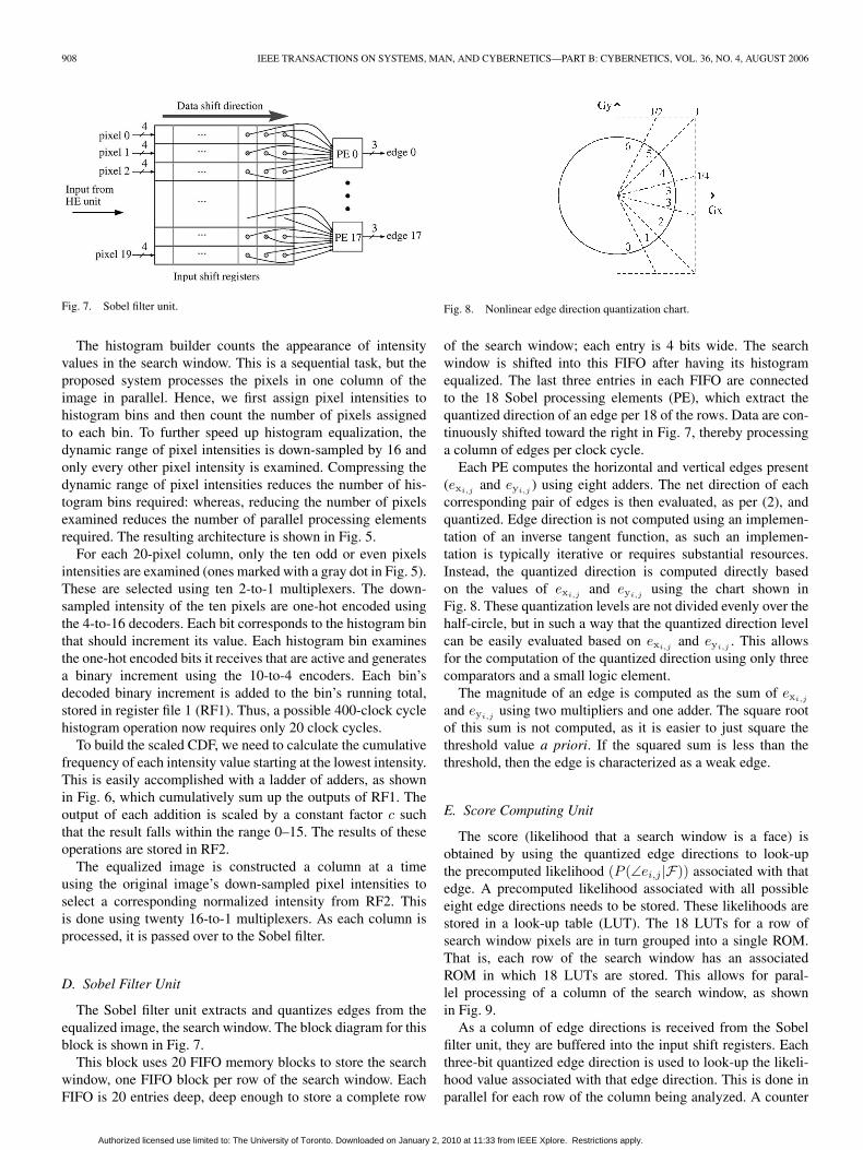
Fig. 7. Sobel filter unit.
The histogram builder counts the appearance of intensityvalues in the search window. This is a sequential task, but theproposed system processes the pixels in one column of theimage in parallel. Hence, we first assign pixel intensities tohistogram bins and then count the number of pixels assignedto each bin. To further speed up histogram equalization, thedynamic range of pixel intensities is down-sampled by 16 andonly every other pixel intensity is examined. Compressing thedynamic range of pixel intensities reduces the number of his-togram bins required: whereas, reducing the number of pixelsexamined reduces the number of parallel processing elementsrequired. The resulting architecture is shown in Fig. 5.
For each 20-pixel column, only the ten odd or even pixelsintensities are examined (ones marked with a gray dot in Fig. 5).These are selected using ten 2-to-1 multiplexers. The down-sampled intensity of the ten pixels are one-hot encoded usingthe 4-to-16 decoders. Each bit corresponds to the histogram binthat should increment its value. Each histogram bin examinesthe one-hot encoded bits it receives that are active and generatesa binary increment using the 10-to-4 encoders. Each bin’sdecoded binary increment is added to the bin’s running total,stored in register file 1 (RF1). Thus, a possible 400-clock cyclehistogram operation now requires only 20 clock cycles.
To build the scaled CDF, we need to calculate the cumulativefrequency of each intensity value starting at the lowest intensity.This is easily accomplished with a ladder of adders, as shownin Fig. 6, which cumulatively sum up the outputs of RF1. Theoutput of each addition is scaled by a constant factor c suchthat the result falls within the range 0–15. The results of theseoperations are stored in RF2.
The equalized image is constructed a column at a timeusing the original image’s down-sampled pixel intensities toselect a corresponding normalized intensity from RF2. Thisis done using twenty 16-to-1 multiplexers. As each column isprocessed, it is passed over to the Sobel filter.
D. Sobel Filter Unit
The Sobel filter unit extracts and quantizes edges from theequalized image, the search window. The block diagram for thisblock is shown in Fig. 7.
This block uses 20 FIFO memory blocks to store the searchwindow, one FIFO block per row of the search window. EachFIFO is 20 entries deep, deep enough to store a complete row
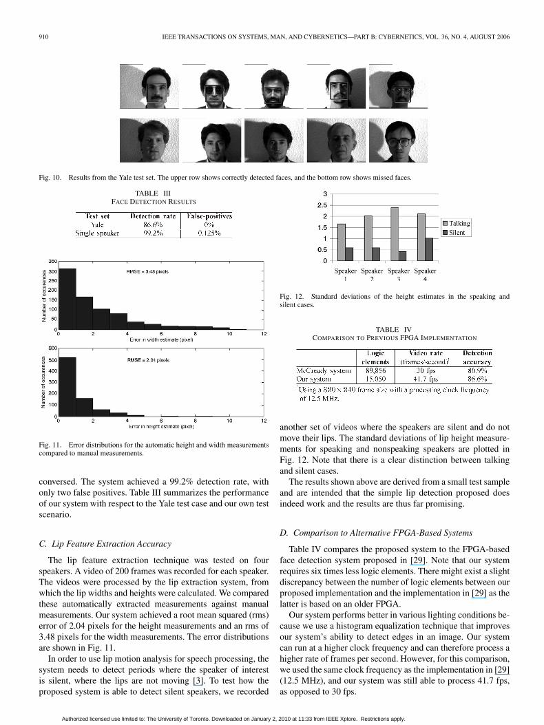
Fig. 8. Nonlinear edge direction quantization chart.
of the search window; each entry is 4 bits wide. The searchwindow is shifted into this FIFO after having its histogramequalized. The last three entries in each FIFO are connectedto the 18 Sobel processing elements (PE), which extract thequantized direction of an edge per 18 of the rows. Data are con-tinuously shifted toward the right in Fig. 7, thereby processinga column of edges per clock cycle.
Each PE computes the horizontal and vertical edges present(exi,j
and eyi,j) using eight adders. The net direction of each
corresponding pair of edges is then evaluated, as per (2), andquantized. Edge direction is not computed using an implemen-tation of an inverse tangent function, as such an implemen-tation is typically iterative or requires substantial resources.Instead, the quantized direction is computed directly basedon the values of exi,j
and eyi,jusing the chart shown in
Fig. 8. These quantization levels are not divided evenly over thehalf-circle, but in such a way that the quantized direction levelcan be easily evaluated based on exi,j
and eyi,j. This allows
for the computation of the quantized direction using only threecomparators and a small logic element.
The magnitude of an edge is computed as the sum of exi,j
and eyi,jusing two multipliers and one adder. The square root
of this sum is not computed, as it is easier to just square thethreshold value a priori. If the squared sum is less than thethreshold, then the edge is characterized as a weak edge.
E. Score Computing Unit
The score (likelihood that a search window is a face) isobtained by using the quantized edge directions to look-upthe precomputed likelihood (P (∠ei,j |F)) associated with thatedge. A precomputed likelihood associated with all possibleeight edge directions needs to be stored. These likelihoods arestored in a look-up table (LUT). The 18 LUTs for a row ofsearch window pixels are in turn grouped into a single ROM.That is, each row of the search window has an associatedROM in which 18 LUTs are stored. This allows for paral-lel processing of a column of the search window, as shownin Fig. 9.
As a column of edge directions is received from the Sobelfilter unit, they are buffered into the input shift registers. Eachthree-bit quantized edge direction is used to look-up the likeli-hood value associated with that edge direction. This is done inparallel for each row of the column being analyzed. A counter
Authorized licensed use limited to: The University of Toronto. Downloaded on January 2, 2010 at 11:33 from IEEE Xplore. Restrictions apply.

NGUYEN et al.: REAL-TIME FACE DETECTION AND LIP FEATURE EXTRACTION USING FPGAs 909
Fig. 9. Score (face likelihood) computing unit.
is used to offset each column to point to its respective LUT inthe ROM in order to obtain the correct likelihoods for each ofthe 18 × 18 pixels in the search window. Hence, the counterpoints to an LUT in the ROM and the edge direction indexes asingle entry in the LUT. The outputs of each row of ROMs aresummed for all search window columns processed.
Each edge direction likelihood (LUT entry) is represented bya 16-bit fixed-point number. One bit is reserved for the signof the number and the decimal point is to the right of thefirst mantissa bit, representing values in the range [−2, 2). Theprecision of this representation is 2−14.
F. Overlap Elimination Unit
This block organizes detected faces into clusters. The loca-tions and scores of detected faces, if any, are read from theresulting FIFO. For each detected face in the resulting FIFO,we search the resulting memory for a cluster that the detectedface belongs to. If a corresponding cluster exists, informationabout that cluster is updated to include the current detectedface. Otherwise, a new group is created. This unit is the mainperformance bottleneck in this system.
G. Lip Tracking Unit
The face that has the highest score from the resulting memoryis used for lip feature extraction. The video frame is read fromthe active input buffer and the left and right corners of the mouthare located using the contrast information for the lower half ofthe face. The top and bottom of the mouth are found by tracingalong the lip border.
The design can be broken into two main blocks: one to searchfor the left and right corners of the mouth and the other one tosearch for the top and bottom of the mouth. Both blocks usea common block to compute the contrast of the image, whichuses several adders. The left–right search block accepts thestarting point and search direction as its input. The top–bottomsearch block takes the search direction (up or down) and thestarting and ending points, which were found previously usingthe left–right search block. The result from the lip trackingblock can be either displayed on a monitor or sent to a hostcomputer.
TABLE IIIMPLEMENTATION CHARACTERISTICS
VI. RESULTS
A. Implementation Characteristics
The system was implemented on a Microtronix StratixDevelopment Kit that houses an Altera Stratix 40 000 logicelement FPGA. The characteristics of this implementation aresummarized in Table II.
The design uses 268 kB of memory, most of which (256 kB)is devoted to the two input buffers. The design takes up 15 050(38%) logic elements. Approximately 300 000 clock cyclesare required to process each frame through the face detectionsubsystem. Lip feature extraction takes only a few thousandclock cycles. Synthesis results indicated that the design canoperate at a maximum clock frequency of 41 MHz. Hence,this implementation can potentially process 136.6 fps, 30 fpsoperation can be achieved using a 9-MHz clock frequency.
B. Face Detection Accuracy
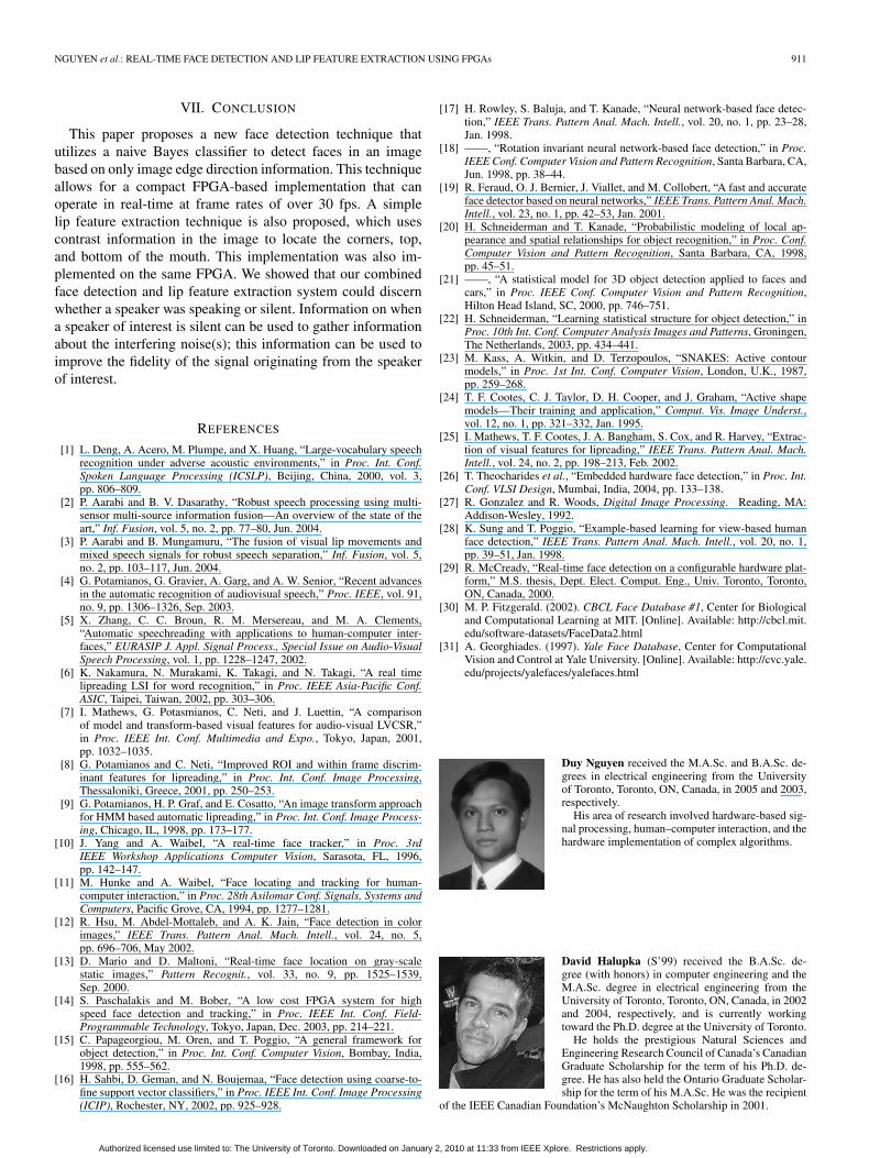
The proposed face detection was tested on the Yale test set[31] to measure the effectiveness of the system under variouslighting conditions. The test set consists of 164 images, eachface with different expressions (angry, surprised, etc.) underdifferent lighting conditions. The proposed system achieved adetection rate of 86.6%, with no false positives. A sample of im-ages from this test case is shown in Fig. 10. This demonstratesthat our system is able to detect faces over a wide range of light-ing conditions and only fails under extreme lighting conditions.
The targeted application of our proposed system is audio–visual speech processing, specifically for teleconference ap-plications. To gauge the performance our system with respectto the intended target application, we collected approximately1600 images of different speakers sitting in front of a cameraand talking. That is, each image only has one face in the frame.The speakers were free to move their head naturally while they
Authorized licensed use limited to: The University of Toronto. Downloaded on January 2, 2010 at 11:33 from IEEE Xplore. Restrictions apply.
910 IEEE TRANSACTIONS ON SYSTEMS, MAN, AND CYBERNETICS—PART B: CYBERNETICS, VOL. 36, NO. 4, AUGUST 2006
Fig. 10. Results from the Yale test set. The upper row shows correctly detected faces, and the bottom row shows missed faces.
TABLE IIIFACE DETECTION RESULTS
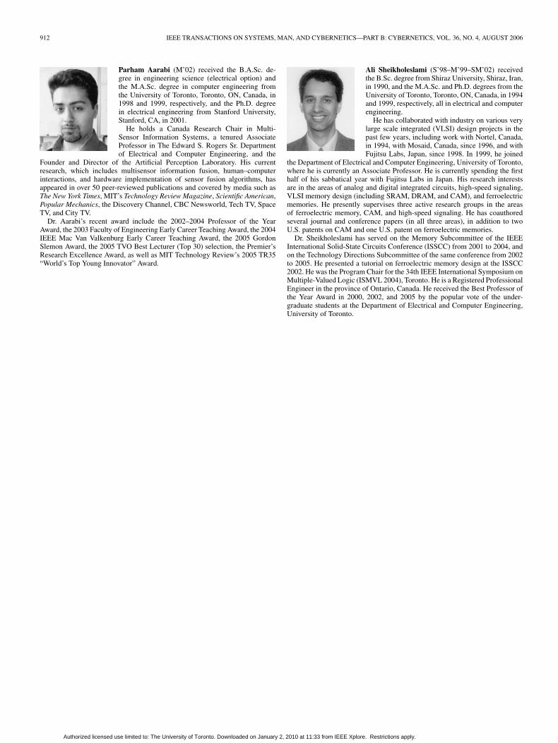
Fig. 11. Error distributions for the automatic height and width measurementscompared to manual measurements.
conversed. The system achieved a 99.2% detection rate, withonly two false positives. Table III summarizes the performanceof our system with respect to the Yale test case and our own testscenario.
C. Lip Feature Extraction Accuracy
The lip feature extraction technique was tested on fourspeakers. A video of 200 frames was recorded for each speaker.The videos were processed by the lip extraction system, fromwhich the lip widths and heights were calculated. We comparedthese automatically extracted measurements against manualmeasurements. Our system achieved a root mean squared (rms)error of 2.04 pixels for the height measurements and an rms of3.48 pixels for the width measurements. The error distributionsare shown in Fig. 11.
In order to use lip motion analysis for speech processing, thesystem needs to detect periods where the speaker of interestis silent, where the lips are not moving [3]. To test how theproposed system is able to detect silent speakers, we recorded
Fig. 12. Standard deviations of the height estimates in the speaking andsilent cases.
TABLE IVCOMPARISON TO PREVIOUS FPGA IMPLEMENTATION
another set of videos where the speakers are silent and do notmove their lips. The standard deviations of lip height measure-ments for speaking and nonspeaking speakers are plotted inFig. 12. Note that there is a clear distinction between talkingand silent cases.
The results shown above are derived from a small test sampleand are intended that the simple lip detection proposed doesindeed work and the results are thus far promising.
D. Comparison to Alternative FPGA-Based Systems
Table IV compares the proposed system to the FPGA-basedface detection system proposed in [29]. Note that our systemrequires six times less logic elements. There might exist a slightdiscrepancy between the number of logic elements between ourproposed implementation and the implementation in [29] as thelatter is based on an older FPGA.
Our system performs better in various lighting conditions be-cause we use a histogram equalization technique that improvesour system’s ability to detect edges in an image. Our systemcan run at a higher clock frequency and can therefore process ahigher rate of frames per second. However, for this comparison,we used the same clock frequency as the implementation in [29](12.5 MHz), and our system was still able to process 41.7 fps,as opposed to 30 fps.
Authorized licensed use limited to: The University of Toronto. Downloaded on January 2, 2010 at 11:33 from IEEE Xplore. Restrictions apply.
NGUYEN et al.: REAL-TIME FACE DETECTION AND LIP FEATURE EXTRACTION USING FPGAs 911
VII. CONCLUSION
This paper proposes a new face detection technique thatutilizes a naive Bayes classifier to detect faces in an imagebased on only image edge direction information. This techniqueallows for a compact FPGA-based implementation that canoperate in real-time at frame rates of over 30 fps. A simplelip feature extraction technique is also proposed, which usescontrast information in the image to locate the corners, top,and bottom of the mouth. This implementation was also im-plemented on the same FPGA. We showed that our combinedface detection and lip feature extraction system could discernwhether a speaker was speaking or silent. Information on whena speaker of interest is silent can be used to gather informationabout the interfering noise(s); this information can be used toimprove the fidelity of the signal originating from the speakerof interest.
REFERENCES
[1] L. Deng, A. Acero, M. Plumpe, and X. Huang, “Large-vocabulary speechrecognition under adverse acoustic environments,” in Proc. Int. Conf.Spoken Language Processing (ICSLP), Beijing, China, 2000, vol. 3,pp. 806–809.
[2] P. Aarabi and B. V. Dasarathy, “Robust speech processing using multi-sensor multi-source information fusion—An overview of the state of theart,” Inf. Fusion, vol. 5, no. 2, pp. 77–80, Jun. 2004.
[3] P. Aarabi and B. Mungamuru, “The fusion of visual lip movements andmixed speech signals for robust speech separation,” Inf. Fusion, vol. 5,no. 2, pp. 103–117, Jun. 2004.
[4] G. Potamianos, G. Gravier, A. Garg, and A. W. Senior, “Recent advancesin the automatic recognition of audiovisual speech,” Proc. IEEE, vol. 91,no. 9, pp. 1306–1326, Sep. 2003.
[5] X. Zhang, C. C. Broun, R. M. Mersereau, and M. A. Clements,“Automatic speechreading with applications to human-computer inter-faces,” EURASIP J. Appl. Signal Process., Special Issue on Audio-VisualSpeech Processing, vol. 1, pp. 1228–1247, 2002.
[6] K. Nakamura, N. Murakami, K. Takagi, and N. Takagi, “A real timelipreading LSI for word recognition,” in Proc. IEEE Asia-Pacific Conf.ASIC, Taipei, Taiwan, 2002, pp. 303–306.
[7] I. Mathews, G. Potasmianos, C. Neti, and J. Luettin, “A comparisonof model and transform-based visual features for audio-visual LVCSR,”in Proc. IEEE Int. Conf. Multimedia and Expo., Tokyo, Japan, 2001,pp. 1032–1035.
[8] G. Potamianos and C. Neti, “Improved ROI and within frame discrim-inant features for lipreading,” in Proc. Int. Conf. Image Processing,Thessaloniki, Greece, 2001, pp. 250–253.
[9] G. Potamianos, H. P. Graf, and E. Cosatto, “An image transform approachfor HMM based automatic lipreading,” in Proc. Int. Conf. Image Process-ing, Chicago, IL, 1998, pp. 173–177.
[10] J. Yang and A. Waibel, “A real-time face tracker,” in Proc. 3rdIEEE Workshop Applications Computer Vision, Sarasota, FL, 1996,pp. 142–147.
[11] M. Hunke and A. Waibel, “Face locating and tracking for human-computer interaction,” in Proc. 28th Asilomar Conf. Signals, Systems andComputers, Pacific Grove, CA, 1994, pp. 1277–1281.
[12] R. Hsu, M. Abdel-Mottaleb, and A. K. Jain, “Face detection in colorimages,” IEEE Trans. Pattern Anal. Mach. Intell., vol. 24, no. 5,pp. 696–706, May 2002.
[13] D. Mario and D. Maltoni, “Real-time face location on gray-scalestatic images,” Pattern Recognit., vol. 33, no. 9, pp. 1525–1539,Sep. 2000.
[14] S. Paschalakis and M. Bober, “A low cost FPGA system for highspeed face detection and tracking,” in Proc. IEEE Int. Conf. Field-Programmable Technology, Tokyo, Japan, Dec. 2003, pp. 214–221.
[15] C. Papageorgiou, M. Oren, and T. Poggio, “A general framework forobject detection,” in Proc. Int. Conf. Computer Vision, Bombay, India,1998, pp. 555–562.
[16] H. Sahbi, D. Geman, and N. Boujemaa, “Face detection using coarse-to-fine support vector classifiers,” in Proc. IEEE Int. Conf. Image Processing(ICIP), Rochester, NY, 2002, pp. 925–928.
[17] H. Rowley, S. Baluja, and T. Kanade, “Neural network-based face detec-tion,” IEEE Trans. Pattern Anal. Mach. Intell., vol. 20, no. 1, pp. 23–28,Jan. 1998.
[18] ——, “Rotation invariant neural network-based face detection,” in Proc.IEEE Conf. Computer Vision and Pattern Recognition, Santa Barbara, CA,Jun. 1998, pp. 38–44.
[19] R. Feraud, O. J. Bernier, J. Viallet, and M. Collobert, “A fast and accurateface detector based on neural networks,” IEEE Trans. Pattern Anal. Mach.Intell., vol. 23, no. 1, pp. 42–53, Jan. 2001.
[20] H. Schneiderman and T. Kanade, “Probabilistic modeling of local ap-pearance and spatial relationships for object recognition,” in Proc. Conf.Computer Vision and Pattern Recognition, Santa Barbara, CA, 1998,pp. 45–51.
[21] ——, “A statistical model for 3D object detection applied to faces andcars,” in Proc. IEEE Conf. Computer Vision and Pattern Recognition,Hilton Head Island, SC, 2000, pp. 746–751.
[22] H. Schneiderman, “Learning statistical structure for object detection,” inProc. 10th Int. Conf. Computer Analysis Images and Patterns, Groningen,The Netherlands, 2003, pp. 434–441.
[23] M. Kass, A. Witkin, and D. Terzopoulos, “SNAKES: Active contourmodels,” in Proc. 1st Int. Conf. Computer Vision, London, U.K., 1987,pp. 259–268.
[24] T. F. Cootes, C. J. Taylor, D. H. Cooper, and J. Graham, “Active shapemodels—Their training and application,” Comput. Vis. Image Underst.,vol. 12, no. 1, pp. 321–332, Jan. 1995.
[25] I. Mathews, T. F. Cootes, J. A. Bangham, S. Cox, and R. Harvey, “Extrac-tion of visual features for lipreading,” IEEE Trans. Pattern Anal. Mach.Intell., vol. 24, no. 2, pp. 198–213, Feb. 2002.
[26] T. Theocharides et al., “Embedded hardware face detection,” in Proc. Int.Conf. VLSI Design, Mumbai, India, 2004, pp. 133–138.
[27] R. Gonzalez and R. Woods, Digital Image Processing. Reading, MA:Addison-Wesley, 1992.
[28] K. Sung and T. Poggio, “Example-based learning for view-based humanface detection,” IEEE Trans. Pattern Anal. Mach. Intell., vol. 20, no. 1,pp. 39–51, Jan. 1998.
[29] R. McCready, “Real-time face detection on a configurable hardware plat-form,” M.S. thesis, Dept. Elect. Comput. Eng., Univ. Toronto, Toronto,ON, Canada, 2000.
[30] M. P. Fitzgerald. (2002). CBCL Face Database #1, Center for Biologicaland Computational Learning at MIT. [Online]. Available: http://cbcl.mit.edu/software-datasets/FaceData2.html
[31] A. Georghiades. (1997). Yale Face Database, Center for ComputationalVision and Control at Yale University. [Online]. Available: http://cvc.yale.edu/projects/yalefaces/yalefaces.html
Duy Nguyen received the M.A.Sc. and B.A.Sc. de-grees in electrical engineering from the Universityof Toronto, Toronto, ON, Canada, in 2005 and 2003,respectively.
His area of research involved hardware-based sig-nal processing, human–computer interaction, and thehardware implementation of complex algorithms.
David Halupka (S’99) received the B.A.Sc. de-gree (with honors) in computer engineering and theM.A.Sc. degree in electrical engineering from theUniversity of Toronto, Toronto, ON, Canada, in 2002and 2004, respectively, and is currently workingtoward the Ph.D. degree at the University of Toronto.
He holds the prestigious Natural Sciences andEngineering Research Council of Canada’s CanadianGraduate Scholarship for the term of his Ph.D. de-gree. He has also held the Ontario Graduate Scholar-ship for the term of his M.A.Sc. He was the recipient
of the IEEE Canadian Foundation’s McNaughton Scholarship in 2001.
Authorized licensed use limited to: The University of Toronto. Downloaded on January 2, 2010 at 11:33 from IEEE Xplore. Restrictions apply.
912 IEEE TRANSACTIONS ON SYSTEMS, MAN, AND CYBERNETICS—PART B: CYBERNETICS, VOL. 36, NO. 4, AUGUST 2006
Parham Aarabi (M’02) received the B.A.Sc. de-gree in engineering science (electrical option) andthe M.A.Sc. degree in computer engineering fromthe University of Toronto, Toronto, ON, Canada, in1998 and 1999, respectively, and the Ph.D. degreein electrical engineering from Stanford University,Stanford, CA, in 2001.
He holds a Canada Research Chair in Multi-Sensor Information Systems, a tenured AssociateProfessor in The Edward S. Rogers Sr. Departmentof Electrical and Computer Engineering, and the
Founder and Director of the Artificial Perception Laboratory. His currentresearch, which includes multisensor information fusion, human–computerinteractions, and hardware implementation of sensor fusion algorithms, hasappeared in over 50 peer-reviewed publications and covered by media such asThe New York Times, MIT’s Technology Review Magazine, Scientific American,Popular Mechanics, the Discovery Channel, CBC Newsworld, Tech TV, SpaceTV, and City TV.
Dr. Aarabi’s recent award include the 2002–2004 Professor of the YearAward, the 2003 Faculty of Engineering Early Career Teaching Award, the 2004IEEE Mac Van Valkenburg Early Career Teaching Award, the 2005 GordonSlemon Award, the 2005 TVO Best Lecturer (Top 30) selection, the Premier’sResearch Excellence Award, as well as MIT Technology Review’s 2005 TR35“World’s Top Young Innovator” Award.
Ali Sheikholeslami (S’98–M’99–SM’02) receivedthe B.Sc. degree from Shiraz University, Shiraz, Iran,in 1990, and the M.A.Sc. and Ph.D. degrees from theUniversity of Toronto, Toronto, ON, Canada, in 1994and 1999, respectively, all in electrical and computerengineering.
He has collaborated with industry on various verylarge scale integrated (VLSI) design projects in thepast few years, including work with Nortel, Canada,in 1994, with Mosaid, Canada, since 1996, and withFujitsu Labs, Japan, since 1998. In 1999, he joined
the Department of Electrical and Computer Engineering, University of Toronto,where he is currently an Associate Professor. He is currently spending the firsthalf of his sabbatical year with Fujitsu Labs in Japan. His research interestsare in the areas of analog and digital integrated circuits, high-speed signaling,VLSI memory design (including SRAM, DRAM, and CAM), and ferroelectricmemories. He presently supervises three active research groups in the areasof ferroelectric memory, CAM, and high-speed signaling. He has coauthoredseveral journal and conference papers (in all three areas), in addition to twoU.S. patents on CAM and one U.S. patent on ferroelectric memories.
Dr. Sheikholeslami has served on the Memory Subcommittee of the IEEEInternational Solid-State Circuits Conference (ISSCC) from 2001 to 2004, andon the Technology Directions Subcommittee of the same conference from 2002to 2005. He presented a tutorial on ferroelectric memory design at the ISSCC2002. He was the Program Chair for the 34th IEEE International Symposium onMultiple-Valued Logic (ISMVL 2004), Toronto. He is a Registered ProfessionalEngineer in the province of Ontario, Canada. He received the Best Professor ofthe Year Award in 2000, 2002, and 2005 by the popular vote of the under-graduate students at the Department of Electrical and Computer Engineering,University of Toronto.
Authorized licensed use limited to: The University of Toronto. Downloaded on January 2, 2010 at 11:33 from IEEE Xplore. Restrictions apply.