RDR-VX511/VX515 - Welcome to Sony Support
125
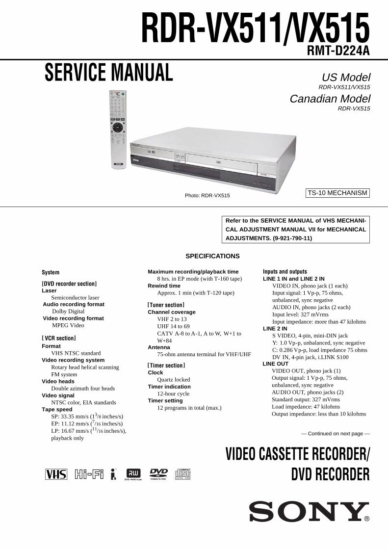
SERVICE MANUAL VIDEO CASSETTE RECORDER/ DVD RECORDER SPECIFICATIONS RMT-D224A TS-10 MECHANISM Refer to the SERVICE MANUAL of VHS MECHANI- CAL ADJUSTMENT MANUAL VII for MECHANICAL ADJUSTMENTS. (9-921-790-11) — Continued on next page — RDR-VX511/VX515 Laser Semiconductor laser Format VHS NTSC standard Video recording system tary head helical scanning FM system Video heads Double azimuth four heads Video signal NTSC color, EIA standards Tape speed SP: 33.35 mm/s (1 3 /8 inches/s) EP: 11.12 mm/s ( 7 /16 inches/s) LP: 16.67 mm/s ( 11 /16 inches/s), Ro Maximum recording/playback time 8 hrs. in EP mode (with T-160 tape) Rewind time Approx. 1 min (with T-120 tape) playback only Tuner section Channel coverage VHF 2 to 13 UHF 14 to 69 CATV A-8 to A-1, A to W, W+1 to System Antenna 75-ohm antenna terminal for VHF/UHF Inputs and outputs LINE 1 IN and LINE 2 IN VIDEO IN, phono jack (1 each) Input signal: 1 Vp-p, 75 ohms, unbalanced, sync negative AUDIO IN, phono jacks (2 each) Input level: 327 mVrms Input impedance: more than 47 kilohms LINE 2 IN S VIDEO, 4-pin, mini-DIN jack Y: 1.0 Vp-p, unbalanced, sync negative C: 0.286 Vp-p, load impedance 75 ohms DV IN, 4-pin jack, i.LINK S100 W+84 LINE OUT VIDEO OUT, phono jack (1) Output signal: 1 Vp-p, 75 ohms, unbalanced, sync negative AUDIO OUT, phono jacks (2) Standard output: 327 mVrms Load impedance: 47 kilohms Output impedance: less than 10 kilohms DVD recorder section] [ ] [ Audio recording format Dolby Digital Video recording format MPEG Video VCR section Timer section Clock Quartz locked Timer indication 12-hour cycle Timer setting 12 programs in total (max.) ] [ ] [ US Model RDR-VX511/VX515 Canadian Model RDR-VX515 Photo: RDR-VX515
-
Upload
khangminh22 -
Category
Documents
-
view
0 -
download
0
Transcript of RDR-VX511/VX515 - Welcome to Sony Support
SERVICE MANUAL
VIDEO CASSETTE RECORDER/DVD RECORDER
SPECIFICATIONS
RMT-D224A
TS-10 MECHANISM
Refer to the SERVICE MANUAL of VHS MECHANI-
CAL ADJUSTMENT MANUAL VII for MECHANICAL
ADJUSTMENTS. (9-921-790-11)
— Continued on next page —
RDR-VX511/VX515
LaserSemiconductor laser
FormatVHS NTSC standard
Video recording systemtary head helical scanning
FM systemVideo heads
Double azimuth four headsVideo signal
NTSC color, EIA standardsTape speed
SP: 33.35 mm/s (13/8 inches/s)EP: 11.12 mm/s (7/16 inches/s)LP: 16.67 mm/s (11/16 inches/s),
Ro
Maximum recording/playback time8 hrs. in EP mode (with T-160 tape)
Rewind timeApprox. 1 min (with T-120 tape)
playback only
Tuner sectionChannel coverage
VHF 2 to 13UHF 14 to 69CATV A-8 to A-1, A to W, W+1 to
System
Antenna75-ohm antenna terminal for VHF/UHF
Inputs and outputsLINE 1 IN and LINE 2 IN
VIDEO IN, phono jack (1 each)Input signal: 1 Vp-p, 75 ohms, unbalanced, sync negativeAUDIO IN, phono jacks (2 each)Input level: 327 mVrmsInput impedance: more than 47 kilohms
LINE 2 INS VIDEO, 4-pin, mini-DIN jackY: 1.0 Vp-p, unbalanced, sync negativeC: 0.286 Vp-p, load impedance 75 ohmsDV IN, 4-pin jack, i.LINK S100
W+84
LINE OUTVIDEO OUT, phono jack (1)Output signal: 1 Vp-p, 75 ohms, unbalanced, sync negativeAUDIO OUT, phono jacks (2)Standard output: 327 mVrmsLoad impedance: 47 kilohmsOutput impedance: less than 10 kilohms
DVD recorder section][
][
Audio recording formatDolby Digital
Video recording formatMPEG Video
VCR section
Timer sectionClock
Quartz lockedTimer indication
12-hour cycleTimer setting
12 programs in total (max.)
][
][
US ModelRDR-VX511/VX515
Canadian ModelRDR-VX515
Photo: RDR-VX515
— 2 —
Power back-upBack-up duration: 0 min
5°C to 35°C (41°F to 95°F)Storage temperature
−20°C to 60°C (−4°F to 140°F)Operating humidity
25% to 80%
Dimensions including projecting parts and controls (w/h/d)
Approx. 430 × 85 × 334 mm(Approx. 17 × 3 × 131/4 inches)
Supplied accessoriesRemote commander (remote) (1)Size AA (R6) batteries (2)Antenna cable (1)Audio/video cord (1)
Design and specifications are subject to change without notice.
GeneralPower requirements
120 V AC, 60 HzPower consumption
40 W MassApprox. 4.9 kg (Approx. 10.8 lbs)
Operating temperature
DIGITAL AUDIO OUTOPTICAL, Optical output jack
COAXIAL, phono jackOutput signal: 0.5 Vp-p, 75 ohms
COMPONENT VIDEO OUT (Y, PB, PR)Phono jackY: 1.0 Vp-p/PB, PR: 0.7 Vp-p, 75 ohms
S VIDEO OUT4-pin, mini-DIN jackY: 1.0 Vp-p, unbalanced, sync negativeC: 0.286 Vp-p, load impedance 75 ohms
−18 dBm (wave length: 660 nm)3/8
— 3 —
WARNING!!
WHEN SERVICING, DO NOT APPROACH THE LASEREXIT WITH THE EYE TOO CLOSELY. IN CASE IT ISNECESSARY TO CONFIRM LASER BEAM EMISSION,BE SURE TO OBSERVE FROM A DISTANCE OF MORETHAN 25 cm FROM THE SURFACE OF THEOBJECTIVE LENS ON THE OPTICAL PICK-UP BLOCK.
CAUTIONUse of controls or adjustments or performance of proceduresother than those specified herein may result in hazardousradiation exposure.
SAFETY-RELATED COMPONENT WARNING!!
COMPONENTS IDENTIFIED BY MARK 0 OR DOTTEDLINE WITH MARK 0 ON THE SCHEMATIC DIAGRAMSAND IN THE PARTS LIST ARE CRITICAL TO SAFEOPERATION. REPLACE THESE COMPONENTS WITHSONY PARTS WHOSE PART NUMBERS APPEAR ASSHOWN IN THIS MANUAL OR IN SUPPLEMENTSPUBLISHED BY SONY.
CAUTION:The use of optical instrument with this product will increase eyehazard.
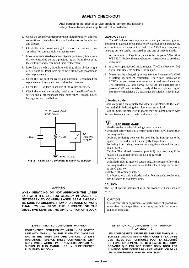
Fig. A. Using an AC voltmeter to check AC leakage.
1.5 kΩ0.15 µFACvoltmeter(0.75 V)
To Exposed MetalParts on Set
Earth Ground
LEAKAGE TESTThe AC leakage from any exposed metal part to earth ground
and from all exposed metal parts to any exposed metal part havinga return to chassis, must not exceed 0.5 mA (500 microamperes).Leakage current can be measured by any one of three methods.
1. A commercial leakage tester, such as the Simpson 229 or RCAWT-540A. Follow the manufacturers' instructions to use theseinstruments.
2. A battery-operated AC milliammeter. The Data Precision 245digital multimeter is suitable for this job.
3. Measuring the voltage drop across a resistor by means of a VOMor battery-operated AC voltmeter. The “limit” indication is0.75V, so analog meters must have an accurate low-voltage scale.The Simpson 250 and Sanwa SH-63Trd are examples of apassive VOM that is suitable. Nearly all battery operated digitalmultimeters that have a 2V AC range are suitable. (See Fig. A)
1. Check the area of your repair for unsoldered or poorly-solderedconnections. Check the entire board surface for solder splashesand bridges.
2. Check the interboard wiring to ensure that no wires are“pinched” or contact high-wattage resistors.
3. Look for unauthorized replacement parts, particularly transistors,that were installed during a previous repair. Point them out tothe customer and recommend their replacement.
4. Look for parts which, though functioning, show obvious signsof deterioration. Point them out to the customer and recommendtheir replacement.
5. Check the line cord for cracks and abrasion. Recommend thereplacement of any such line cord to the customer.
6. Check the B+ voltage to see it is at the values specified.
7. Check the antenna terminals, metal trim, “metallized” knobs,screws, and all other exposed metal parts for AC leakage. Checkleakage as described below.
SAFETY CHECK-OUT
After correcting the original service problem, perform the followingsafety checks before releasing the set to the customer:
Unleaded solderBoards requiring use of unleaded solder are printed with the lead-free mark (LF) indicating the solder contains no lead.(Caution: Some printed circuit boards may not come printed withthe lead free mark due to their particular size.)
: LEAD FREE MARKUnleaded solder has the following characteristics.• Unleaded solder melts at a temperature about 40°C higher than
ordinary solder.Ordinary soldering irons can be used but the iron tip has to beapplied to the solder joint for a slightly longer time.Soldering irons using a temperature regulator should be set toabout 350°C.Caution: The printed pattern (copper foil) may peel away if theheated tip is applied for too long, so be careful!
• Strong viscosityUnleaded solder is more viscous (sticky, less prone to flow) thanordinary solder so use caution not to let solder bridges occur suchas on IC pins, etc.
• Usable with ordinary solderIt is best to use only unleaded solder but unleaded solder mayalso be added to ordinary solder.
ATTENTION AU COMPOSANT AYANT RAPPORTÀ LA SÉCURITÉ!
LES COMPOSANTS IDENTIFIÉS PAR UNE MARQUE 0SUR LES DIAGRAMMES SCHÉMATIQUES ET LA LISTEDES PIÈCES SONT CRITIQUES POUR LA SÉCURITÉDE FONCTIONNEMENT. NE REMPLACER CES COM-POSANTS QUE PAR DES PIÈCES SONY DONT LESNUMÉROS SONT DONNÉS DANS CE MANUEL OU DANSLES SUPPLÉMENTS PUBLIÉS PAR SONY.
— 4 —
TABLE OF CONTENTS
Precautions1 Safety Precautions ······························································ 52 Servicing Precautions ························································ 73 ESD Precautions ································································· 84 Handling the Optical Pick-up ············································· 9
1. GeneralHookups and Settings ······················································ 1-2Quick Guide to Disc Types ·············································· 1-6DVD Playback ································································· 1-7DVD Recording ····························································· 1-10DVD Editing ·································································· 1-13VCR Playback ······························································· 1-16VCR Recording ····························································· 1-17Dubbing (TAPA y DVD) ··········································· 1-19DV/D8 Dubbing (DV/D8 y DVD) ····························· 1-21Settings and Adjustments ·············································· 1-22Additional Information ·················································· 1-25
2. Disassembly and Reassembly2-1 Cabinet and PCB ···························································· 2-12-1-1 Cabinet Top Removal ····················································· 2-12-1-2 Botton Cover Removal ··················································· 2-12-1-3 Ass’y Front Panel Removal ············································ 2-12-1-4 Function Timer PCB Removal ······································· 2-12-1-5 Chassis Removal ···························································· 2-22-1-6 VCR Main PCB Removal ·············································· 2-22-2 Circuit Board Locations ················································· 2-32-3 VCR Deck Parts Locations ············································ 2-42-3-1 Top View ········································································ 2-42-3-2 Bottom View ··································································· 2-62-4 VCR DECK ···································································· 2-72-4-1 Holder FL Cassette Ass’y Removal ······························· 2-72-4-2 Lever FL Arm Ass’y Removal ······································· 2-72-4-3 Lever FL Door Removal ················································ 2-82-4-4 Slider FL Drive, Gear FL Cam Removal ······················· 2-82-4-5 Gear Worm Wheel Removal ··········································· 2-92-4-6 Cable Flat Removal ························································ 2-92-4-7 Motor Loading Ass’y Removal ···································· 2-102-4-8 Bracket Gear, Gear Joint 2, 1 Removal ························ 2-102-4-9 Gear Loading Drive, Slider Cam,
Lever Load S, T Ass’y Removal ·································· 2-112-4-10 Gear Loading Drive, Slider Cam,
Lever Load S, T Ass’y Assembly ································· 2-112-4-11 Lever Pinch Drive, Lever Tension Drive Removal ······· 2-122-4-12 Lever Tension Ass’y, Band Brake Ass’y Removal ······· 2-122-4-13 Lever Brake S, T Ass’y Removal ································· 2-132-4-14 Gear Idle Ass’y Removal ············································· 2-132-4-15 Disk S, T Reel Removal ··············································· 2-142-4-16 Holder Clutch Ass’y Removal ······································ 2-142-4-17 Lever Up Down Ass’y, Gear Center Ass’y Removal ··· 2-152-4-18 Guide Cassette Door Removal ····································· 2-152-4-19 Lever Unit Pinch Ass’y, Plate Joint,
Spring Pinch Drive Removal ········································ 2-162-4-20 Lever #9 Guide Ass’y Removal ··································· 2-162-4-21 FE Head Removal ························································ 2-172-4-22 ACE Head Removal ····················································· 2-172-4-23 Slider S, T Ass’y Removal ··········································· 2-182-4-24 Plate Ground Deck, Cylinder Ass’y Removal ·············· 2-182-4-25 Hook Capstan, Belt Pulley Removal ···························· 2-192-4-26 Motor Capstan Ass’y Removal ···································· 2-192-4-27 Post #8 Guide Ass’y Removal ······································ 2-202-4-28 Level Head Cleaner Ass’y Removal ···························· 2-202-4-29 How to Eject the Cassette Tape ···································· 2-202-5 The Table of Cleaning, Lubrication and
Replacement Time about Principal Parts ····················· 2-21
3. Block Diagram .......................................................... 3-1
4. PCB Diagrams4-1 VCR Main PCB ······························································· 4-34-2 DVD Main PCB ······························································ 4-74-3 Jack PCB ······································································· 4-114-4 DV Jack PCB ·································································4-154-5 Function Timer PCB ······················································ 4-15
5. Schematic Diagrams Block Identification of Main PCB ········································· 5-35-1 S.M.P.S (VCR Main PCB) ·············································· 5-55-2 Power (VCR Main PCB) ················································· 5-75-3 Logic (VCR Main PCB) ·················································· 5-95-4 A/V (VCR Main PCB) ·················································· 5-115-5 Hi-Fi (VCR Main PCB) ················································ 5-135-6 Function Timer (Function Timer PCB) ·························5-155-7 Encoder (DVD Main PCB) ··········································· 5-175-8 Decoder (DVD Main PCB) ··········································· 5-195-9 Video Decoder and Connector (DVD Main PCB) ········ 5-215-10 DV Interface and 1394 Connector (DVD Main PCB) ··· 5-235-11 Connectors and Power (DVD Main PCB) ·····················5-255-12 Mts/Tuner (JACK PCB) ················································ 5-275-13 AV IN/OUT (JACK PCB) ·············································5-295-14 Component/Super Out (JACK PCB) ·····························5-31
6. Alignment and Adjustments6-1 VCR Adjustment ····························································· 6-16-1-1 Reference ········································································· 6-16-1-2 Head Switching Point Adjustment ·································· 6-36-2 VCR Mechanical Adjustment ·········································· 6-46-2-1 Tape Transport System and Adjustment Locations ········· 6-46-2-2 Tape Transport System Adjustment ································· 6-56-2-3 Reel Torque ··································································· 6-10
7. Troubleshooting ················································· 7-1
8. Repair Parts List8-1 Exploded Views ······························································· 8-28-1-1 Cabinet Assembly ···························································· 8-28-1-2 VCR Mechanical Parts (Top Side) ·································· 8-38-1-3 VCR Mechanical Parts (Bottom Side) ···························· 8-48-2 Electrical Parts List ························································· 8-5
5 Reset operation after IC203 or IC205 was replaced ..........10
— 5 —
PRECAUTIONS
1 SAFETY PRECAUTIONS
1) Before returning an instrument to the customer, always make asafety check of the entire instrument, including, but not limitedto, the following items:
(1) Be sure that no built-in protective devices are defective or havebeen defeated during servicing.(1)Protective shields are provided to protect both the technicianand the customer. Correctly replace all missing protectiveshields, including any removed for servicing convenience.(2)When reinstalling the chassis and/or other assembly in thecabinet, be sure to put back in place all protective devices,including, but not limited to, nonmetallic control knobs,insulating fish papers, adjustment and compartment covers/shields, and isolation resistor/capacitor networks. Do not operatethis instrument or permit it to be operated without all protectivedevices correctly installed and functioning.
(2) Be sure that there are no cabinet openings through which adultsor children might be able to insert their fingers and contact ahazardous voltage. Such openings include, but are not limitedto, excessively wide cabinet ventilation slots, and an improperlyfitted and/or incorrectly secured cabinet back cover.
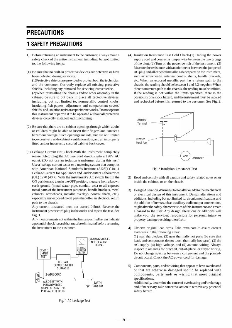
(3) Leakage Current Hot Check-With the instrument completelyreassembled, plug the AC line cord directly into a 120V ACoutlet. (Do not use an isolation transformer during this test.)Use a leakage current tester or a metering system that complieswith American National Standards institute (ANSI) C101.1Leakage Current for Appliances and Underwriters Laboratories(UL) 1270 (40.7). With the instrument’s AC switch first in theON position and then in the OFF position, measure from a knownearth ground (metal water pipe, conduit, etc.) to all exposedmetal parts of the instrument (antennas, handle brackets, metalcabinets, screwheads, metallic overlays, control shafts, etc.),especially any exposed metal parts that offer an electrical returnpath to the chassis.Any current measured must not exceed 0.5mA. Reverse theinstrument power cord plug in the outlet and repeat the test. SeeFig. 1.Any measurements not within the limits specified herein indicatea potential shock hazard that must be eliminated before returningthe instrument to the customer.
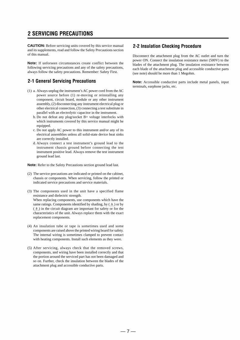
(4) Insulation Resistance Test Cold Check-(1) Unplug the powersupply cord and connect a jumper wire between the two prongsof the plug. (2) Turn on the power switch of the instrument. (3)Measure the resistance with an ohmmeter between the jumperedAC plug and all exposed metallic cabinet parts on the instrument,such as screwheads, antenna, control shafts, handle brackets,etc. When an exposed metallic part has a return path to thechassis, the reading should be between 1 and 5.2 megohm. Whenthere is no return path to the chassis, the reading must be infinite.If the reading is not within the limits specified, there is thepossibility of a shock hazard, and the instrument must be reparedand rechecked before it is returned to the customer. See Fig. 2.
DEVICEUNDERTEST
(READING SHOULDNOT BE ABOVE
0.5mA)LEAKAGECURRENTTESTER
EARTHGROUND
TEST ALLEXPOSED METER
SURFACES
ALSO TEST WITHPLUG REVERSED
(USING AC ADAPTERPLUG AS REQUIRED)
2-WIRE CORD
Fig. 1 AC Leakage Test
Fig. 2 Insulation Resistance Test
2) Read and comply with all caution and safety related notes on orinside the cabinet, or on the chassis.
3) Design Alteration Warning-Do not alter or add to the mechanicalor electrical design of this instrument. Design alterations andadditions, including but not limited to, circuit modifications andthe addition of items such as auxiliary audio output connections,might alter the safety characteristics of this instrument and createa hazard to the user. Any design alterations or additions willmake you, the servicer, responsible for personal injury orproperty damage resulting therefrom.
4) Observe original lead dress. Take extra care to assure correctlead dress in the following areas:(1) near sharp edges, (2) near thermally hot parts (be sure thatleads and components do not touch thermally hot parts), (3) theAC supply, (4) high voltage, and (5) antenna wiring. Alwaysinspect in all areas for pinched, out-of-place, or frayed wiring,Do not change spacing between a component and the printed-circuit board. Check the AC power cord for damage.
5) Components, parts, and/or wiring that appear to have overheatedor that are otherwise damaged should be replaced withcomponents, parts and/ or wiring that meet originalspecifications.Additionally, determine the cause of overheating and/or damageand, if necessary, take corrective action to remove any potentialsafety hazard.
AntennaTerminal
ExposedMetal Part
ohmohmmeter
— 6 —
6) Product Safety Notice-Some electrical and mechanical partshave special safety-related characteristics which are often notevident from visual inspection, nor can the protection they givenecessarily be obtained by replacing them with components ratedfor higher voltage, wattage, etc. Parts that have special safetycharacteristics are identified by shading, an ( ) or a ( ) onschematics and parts lists. Use of a substitute replacement thatdoes not have the same safety characteristics as therecommended replacement part might create shock, fire and/orother hazards. Product safety is under review continuously andnew instructions are issued whenever appropriate.
— 7 —
2 SERVICING PRECAUTIONS
CAUTION: Before servicing units covered by this service manualand its supplements, read and follow the Safety Precautions sectionof this manual.
Note: If unforseen circumstances create conflict between thefollowing servicing precautions and any of the safety precautions,always follow the safety precautions. Remember: Safety First.
2-1 General Servicing Precautions
(1) a. Always unplug the instrument’s AC power cord from the ACpower source before (1) re-moving or reinstalling anycomponent, circuit board, module or any other instrumentassembly, (2) disconnecting any instrument electrical plug orother electrical connection, (3) connecting a test substitute inparallel with an electrolytic capacitor in the instrument.
b. Do not defeat any plug/socket B+ voltage interlocks withwhich instruments covered by this service manual might beequipped.
c. Do not apply AC power to this instrument and/or any of itselectrical assemblies unless all solid-state device heat sinksare correctly installed.
d. Always connect a test instrument’s ground lead to theinstrument chassis ground before connecting the testinstrument positive lead. Always remove the test instrumentground lead last.
Note: Refer to the Safety Precautions section ground lead last.
(2) The service precautions are indicated or printed on the cabinet,chassis or components. When servicing, follow the printed orindicated service precautions and service materials.
(3) The components used in the unit have a specified flameresistance and dielectric strength.When replacing components, use components which have thesame ratings. Components identified by shading, by ( ) or by( ) in the circuit diagram are important for safety or for thecharacteristics of the unit. Always replace them with the exactreplacement components.
(4) An insulation tube or tape is sometimes used and somecomponents are raised above the printed wiring board for safety.The internal wiring is sometimes clamped to prevent contactwith heating components. Install such elements as they were.
(5) After servicing, always check that the removed screws,components, and wiring have been installed correctly and thatthe portion around the serviced part has not been damaged andso on. Further, check the insulation between the blades of theattachment plug and accessible conductive parts.
2-2 Insulation Checking Procedure
Disconnect the attachment plug from the AC outlet and turn thepower ON. Connect the insulation resistance meter (500V) to theblades of the attachment plug. The insulation resistance betweeneach blade of the attachment plug and accessible conductive parts(see note) should be more than 1 Megohm.
Note: Accessible conductive parts include metal panels, inputterminals, earphone jacks, etc.
— 8 —
3 ESD PRECAUTIONS
Electrostatically Sensitive Devices (ESD)
Some semiconductor (solid state) devices can be damaged easilyby static electricity.Such components commonly are called Electrostatically SensitiveDevices (ESD). Examples of typical ESD devices are integratedcircuits and some field-effect transistors and semiconductor chipcomponents. The following techniques should be used to help reducethe incidence of component damage caused by static electricity.
(1) Immediately before handling any semiconductor component orsemiconductor-equipped assembly, drain off any electrostaticcharge on your body by touching a known earth ground.Alternatively, obtain and wear a commercially availabledischarging wrist strap device, which should be removed forpotential shock reasons prior to applying power to the unit undertest.
(2) After removing an electrical assembly equipped with ESDdevices, place the assembly on a conductive surface such asaluminum foil, to prevent electrostatic charge buildup orexposure of the assembly.
(3) Use only a grounded-tip soldering iron to solder or unsolderESD devices.
(4) Use only an anti-static solder removal devices. Some solderremoval devices not classified as “anti-static” can generateelectrical charges sufficient to damage ESD devices.
(5) Do not use freon-propelled chemicals. These can generateelectrical charges sufficient to damage ESD devices.
(6) Do not remove a replacement ESD device from its protectivepackage until immediately before your are ready to install it.(Most replacement ESD devices are packaged with leadselectrically shorted together by conductive foam, aluminum foilor comparable conductive materials).
(7) Immediately before removing the protective materials from theleads of a replacement ESD device, touch the protective materialto the chassis or circuit assembly into which the device will beinstalled.
CAUTION: Be sure no power is applied to the chassis or circuit,and observe all other safety precautions.
(8) Minimize bodily motions when handling unpackagedreplacement ESD devices. (Otherwise harmless motion such asthe brushing together of your clothes fabric or the lifting ofyour foot from a carpeted floor can generate static electricitysufficient to damage an ESD device).
— 9 —
4 HANDLING THE OPTICAL PICK-UP
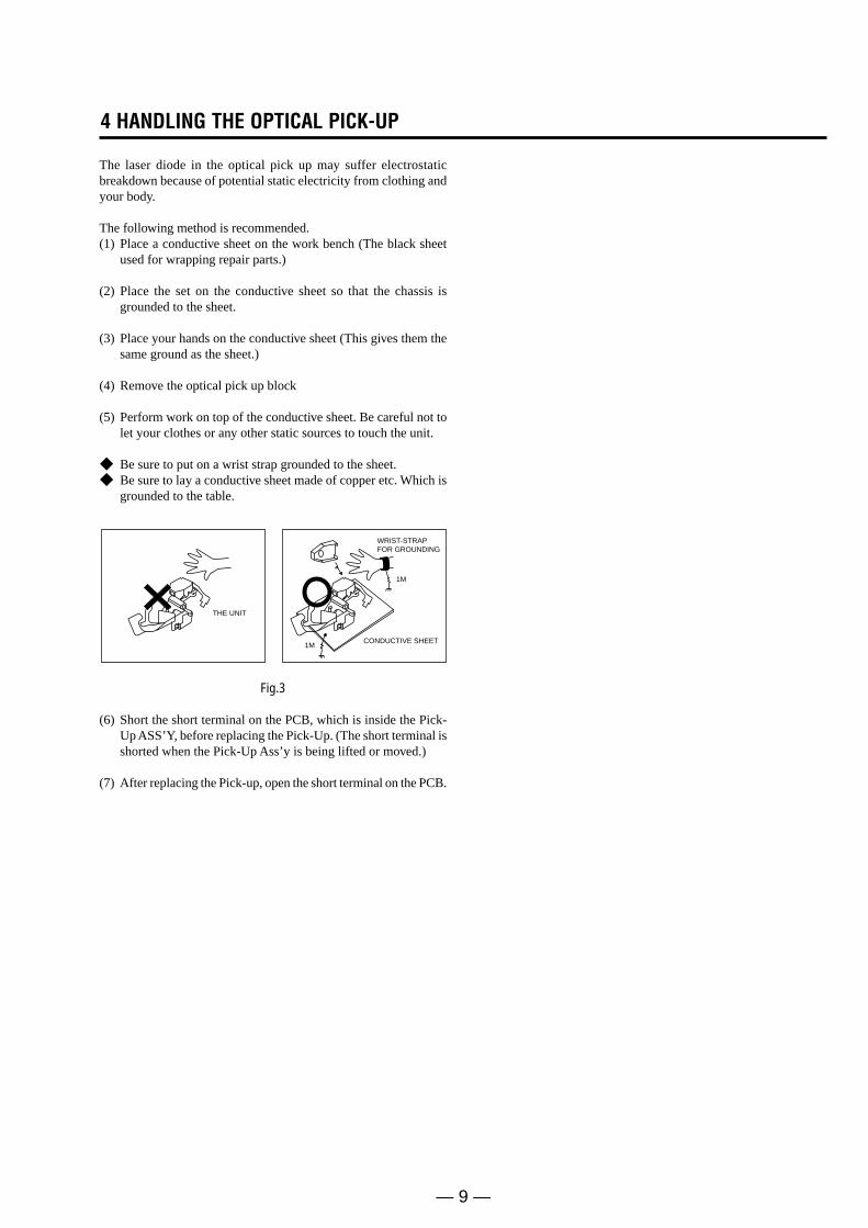
The laser diode in the optical pick up may suffer electrostaticbreakdown because of potential static electricity from clothing andyour body.
The following method is recommended.(1) Place a conductive sheet on the work bench (The black sheet
used for wrapping repair parts.)
(2) Place the set on the conductive sheet so that the chassis isgrounded to the sheet.
(3) Place your hands on the conductive sheet (This gives them thesame ground as the sheet.)
(4) Remove the optical pick up block
(5) Perform work on top of the conductive sheet. Be careful not tolet your clothes or any other static sources to touch the unit.
Be sure to put on a wrist strap grounded to the sheet. Be sure to lay a conductive sheet made of copper etc. Which is
grounded to the table.
Fig.3
(6) Short the short terminal on the PCB, which is inside the Pick-Up ASS’Y, before replacing the Pick-Up. (The short terminal isshorted when the Pick-Up Ass’y is being lifted or moved.)
(7) After replacing the Pick-up, open the short terminal on the PCB.
THE UNIT
WRIST-STRAPFOR GROUNDING
1M
1MCONDUCTIVE SHEET
— 10 —
5 Reset operation after IC203 or IC205 was replaced
Be sure to perform the reset by the method described below, if theIC203(IC FLASH MEMORY) or IC205(IC EEPROM) used on the DVD Main board was replaced.
Resetting method1. Enter the Adjustment mode, and press two times the “1” button
on the remote commander.(For an entering method of Adjustment mode, see 6-1. VCRAdjustment.)The tray will automatically open and the version informationwill be displayed on the TV screen.
2. Turn the power off.
1-1
1. GENERAL This section is extracted from RDR-VX515 instruc-tion manual. (2-636-467-11)
RDR-VX511/VX515
4
About this manual• Instructions in this manual describe the controls on the
remote. You can also use the controls on the recorder if they have the same or similar names as those on the remote.
• The on-screen display illustrations used in this manual may not match the graphics displayed on your TV screen.
• The explanations regarding discs in this manual refer to discs created on this recorder. The explanations do not apply to discs that are created on other recorders and played back on this recorder.
* MP3 (MPEG1 Audio Layer 3) is a standard format defined by ISO/MPEG which compresses audio data.
Icon Meaning
Functions available for DVD+RWs
Functions available for DVD-RWs in VR (Video Recording) mode
Functions available for DVD-RWs in video mode
Functions available for DVD+Rs
Functions available for DVD-Rs
Functions available for DVD VIDEOs
Functions available for VIDEO CDs or CD-Rs/CD-RWs in video CD format
Functions available for music CDs or CD-Rs/CD-RWs in music CD format
Functions available for DATA CDs (CD-Rs/CD-RWs containing MP3* audio tracks or JPEG files)
Functions available for DATA DVDs (DVD+RWs/DVD-RWs/DVD+Rs/DVD-Rs containing MP3* audio tracks or JPEG files)
Functions available for VHS VIDEOs
+RW
-RWVR
-RWVideo
+R
-R
DVD
VCD
CD
DATA CD
DATA DVD
8
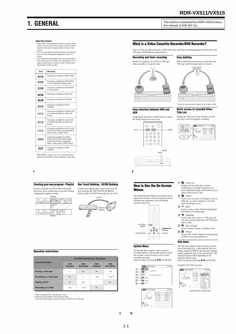
What is a Video Cassette Recorder/DVD Recorder?This is a DVD recorder with built-in VHS video deck, and allows recording/playback of DVD discs and VHS tapes. DVD editing is also possible.
Recording and timer recordingRecord TV programs on a DVD or VHS tape, either manually or using the timer.
Easy selection between DVD and VCRSimply press the DVD or VIDEO button to select the media format you want to use.
Easy dubbingDub in either direction between a DVD disc and VHS tape with the simple press of a button.
* Note that copy-protected signals will not be recorded.
Quick access to recorded titles - Title ListDisplay the Title List to view all titles on a disc and select a title for playback or editing.
DVD VIDEO
DVDVIDEO
VIDEODVD
10:10 AM
>
>
>
>
CH 23
08:00 PMMay/02/2005
T
No.1/4
01
02
03
04
Title Length Edit
CH 23 01:29:03
CH 66 00:31:23
CH 95 01:59:00
CH 97 00:58:56
Title List (Original)
9
Creating your own program - PlaylistRecord a program on a DVD-RW (VR mode), then erase, move or add scenes as you like without changing the original contents.
One Touch Dubbing - DV/D8 DubbingConnect your digital video camera to the DV IN jack and press the ONE TOUCH DUBBING button to dub a DV/D8 format tape over to a disc.
Operation restrictions
*1 When pressing DVD, VCR playback stops.*2 When pressing VIDEO, DVD playback stops.*3 Only the same program can be recorded on a DVD and a VHS tape.
Original
Playlist
control
dubbing
Current Operation
Possible Simultaneous Operations
VCR Playback
VCR Recording
DVD Playback
DVD Recording
Playing a VHS tape*1 — No No Yes
Recording on a VHS tape No — Yes Yes*3
Playing a DVD*2 No Yes — No
Recording on a DVD Yes Yes*3 No —
10
How to Use the On-Screen MenusThe following three displays are mainly used to operate this recorder. Once you become familiar with the basic operations, you will find the recorder easy to use.
System MenuThe System Menu appears when you press SYSTEM MENU, and provides entries to all of the recorder’s main functions, such as timer recording and setup.Select an option by pressing M/m and ENTER.
A “Title List”Displays the list of the disc contents, including the recording information and movie thumbnail image, which allows you to select a title to play or edit.
B “Timer”Used to set a new timer recording for a disc or VHS tape, as well as change or cancel the timer recordings you set.
C “Edit”Used to create or edit a Playlist (unfinalized DVD-RWs (VR mode) only).
D “Dubbing”Used to dub from a disc to a VHS tape and vice versa, and also dub from a DV/D8 format tape to a disc.
E “Disc Setting”Used to rename, format, or finalize a disc.
F “Setup”Displays the “Setup” display for setting up the recorder to suit your preferences.
Sub-menuThe sub-menu appears when you select an item from a list menu (e.g., a title from the Title List menu), and press ENTER. The sub-menu displays options applicable only to the selected item. The displayed options differ depending on the situation and disc type.Select an option by pressing M/m and ENTER.
Example: The Title List menu
M/m/</,, ENTER
SYSTEMMENU
TOOLSO RETURN
Title List (Original) 10:10 AM
Press ENTER :
Title Menu for DVD Title List.
Setup
Disc Setting
Edit
Title List
Timer
Dubbing
6
10:10 AM
01 CH 23 >01:29:03
02 CH 66 >00:31:23
03 CH 95 >01:59:00
04 CH 97 >00:58:56
CH 23
08:00 PMMay/02/2005
T
No. Title Length Edit
Title List (Original)
1/4
Title List (Original) 10:10 AM
No. Title Length Edit
01 CH 23 >01:29:03
02 CH 66 >00:31:23
03 CH 95 >01:59:00
04 CH 97 >00:58:56
CH 23
May/02/200508:00 PM
T
1/4
Play
Title Erase
Chapter Erase
Protect
Title Name
A·B Erase
Divide Title
Options for the selected item
1-2
11
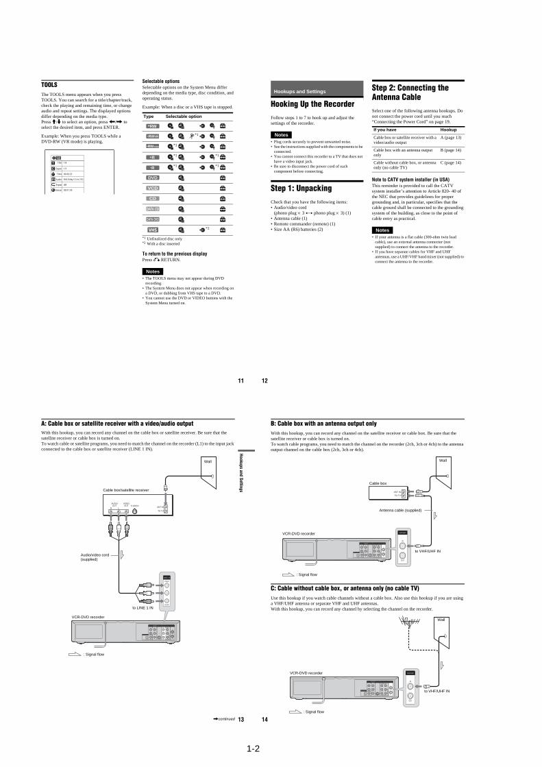
TOOLSThe TOOLS menu appears when you press TOOLS. You can search for a title/chapter/track, check the playing and remaining time, or change audio and repeat settings. The displayed options differ depending on the media type.Press M/m to select an option, press </, to select the desired item, and press ENTER.
Example: When you press TOOLS while a DVD-RW (VR mode) is playing.
Selectable optionsSelectable options on the System Menu differ depending on the media type, disc condition, and operating status.
Example: When a disc or a VHS tape is stopped.
*1 Unfinalized disc only*2 With a disc inserted
To return to the previous displayPress O RETURN.
Notes• The TOOLS menu may not appear during DVD
recording.• The System Menu does not appear when recording on
a DVD, or dubbing from VHS tape to a DVD.• You cannot use the DVD or VIDEO buttons with the
System Menu turned on.
1/4
1/1
00:00:25
T
C
Title
Chapter
Time
Repeat
Remain
Audio
Off
00:01:30
ENG Dolby 5.1ch (1/3)
Type Selectable option
+RW
-RWVR *1
-RWVideo *1
+R *1 *1
-R *1 *1
DVD
VCD
CD
DATA CD
DATA DVD
*2
12
Hookups and Settings
Hooking Up the RecorderFollow steps 1 to 7 to hook up and adjust the settings of the recorder.
Notes• Plug cords securely to prevent unwanted noise.• See the instructions supplied with the components to be
connected.• You cannot connect this recorder to a TV that does not
have a video input jack.• Be sure to disconnect the power cord of each
component before connecting.
Step 1: UnpackingCheck that you have the following items:• Audio/video cord
(phono plug × 3 y phono plug × 3) (1)• Antenna cable (1)• Remote commander (remote) (1)• Size AA (R6) batteries (2)
Step 2: Connecting the Antenna CableSelect one of the following antenna hookups. Do not connect the power cord until you reach “Connecting the Power Cord” on page 19.
Note to CATV system installer (in USA)This reminder is provided to call the CATV system installer’s attention to Article 820- 40 of the NEC that provides guidelines for proper grounding and, in particular, specifies that the cable ground shall be connected to the grounding system of the building, as close to the point of cable entry as practical.
Notes• If your antenna is a flat cable (300-ohm twin lead
cable), use an external antenna connector (not supplied) to connect the antenna to the recorder.
• If you have separate cables for VHF and UHF antennas, use a UHF/VHF band mixer (not supplied) to connect the antenna to the recorder.
If you have Hookup
Cable box or satellite receiver with a video/audio output
A (page 13)
Cable box with an antenna output only
B (page 14)
Cable without cable box, or antenna only (no cable TV)
C (page 14)
13
Hookups and Settings
A: Cable box or satellite receiver with a video/audio outputWith this hookup, you can record any channel on the cable box or satellite receiver. Be sure that the satellite receiver or cable box is turned on.To watch cable or satellite programs, you need to match the channel on the recorder (L1) to the input jack connected to the cable box or satellite receiver (LINE 1 IN).
IN
L
R
VIDEO
AUDIOOUT
VHF/UHFLINE OUT
VIDEO
YL
PBR
PR
AUDIO
LINE 1 INAUDIO OUT S VIDEO OUTCOMPONENTVIDEO OUT
DIGITAL AUDIO OUT
OPTICAL COAXIAL
ANT INR LS VIDEO
AUDIOOUT
VIDEOOUT
TO TV
VIDEO
LINE 1 IN
AUDIO
to LINE 1 IN
VCR-DVD recorder
Audio/video cord (supplied)
: Signal flow
Cable box/satellite receiver
Wall
,continued 14
B: Cable box with an antenna output onlyWith this hookup, you can record any channel on the satellite receiver or cable box. Be sure that the satellite receiver or cable box is turned on.To watch cable programs, you need to match the channel on the recorder (2ch, 3ch or 4ch) to the antenna output channel on the cable box (2ch, 3ch or 4ch).
C: Cable without cable box, or antenna only (no cable TV)Use this hookup if you watch cable channels without a cable box. Also use this hookup if you are using a VHF/UHF antenna or separate VHF and UHF antennas.With this hookup, you can record any channel by selecting the channel on the recorder.
IN
L
R
VIDEO
AUDIOOUT
VHF/UHFLINE OUT
VIDEO
YL
PBR
PR
AUDIO
LINE 1 INAUDIO OUT S VIDEO OUTCOMPONENTVIDEO OUT
DIGITAL AUDIO OUT
OPTICAL COAXIAL
IN
OUT
VHF/UHF
ANT IN
TO TV
to VHF/UHF IN
Wall
VCR-DVD recorder
Antenna cable (supplied)
: Signal flow
Cable box
IN
L
R
VIDEO
AUDIOOUT
VHF/UHFLINE OUT
VIDEO
YL
PBR
PR
AUDIO
LINE 1 INAUDIO OUT S VIDEO OUTCOMPONENTVIDEO OUT
DIGITAL AUDIO OUT
OPTICAL COAXIAL
IN
OUT
VHF/UHFVCR-DVD recorder
to VHF/UHF IN
: Signal flow
Wall
1-3
15
Hookups and Settings
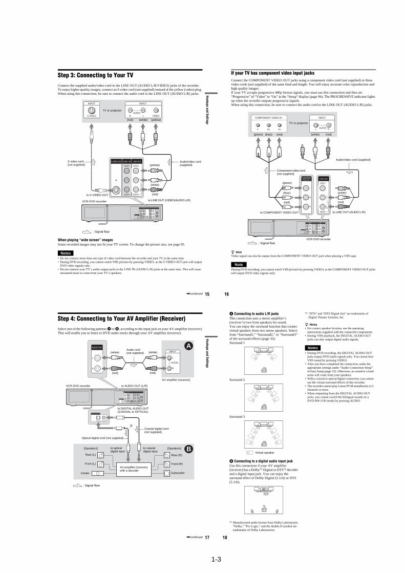
Step 3: Connecting to Your TVConnect the supplied audio/video cord to the LINE OUT (AUDIO L/R/VIDEO) jacks of the recorder.To enjoy higher quality images, connect an S video cord (not supplied) instead of the yellow (video) plug. When using this connection, be sure to connect the audio cord to the LINE OUT (AUDIO L/R) jacks.
When playing “wide screen” imagesSome recorded images may not fit your TV screen. To change the picture size, see page 95.
Notes• Do not connect more than one type of video cord between the recorder and your TV at the same time.• During DVD recording, you cannot watch VHS pictures by pressing VIDEO, as the S VIDEO OUT jack will output
DVD video signals only.• Do not connect your TV’s audio output jacks to the LINE IN (AUDIO L/R) jacks at the same time. This will cause
unwanted noise to come from your TV’s speakers.
IN
L
R
VIDEO
AUDIOOUT
VHF/UHFLINE OUT
VIDEO
YL
PBR
PR
AUDIO
LINE 1 INAUDIO OUT S VIDEO OUTCOMPONENTVIDEO OUT
DIGITAL AUDIO OUT
OPTICAL COAXIAL
L
R
VIDEO
AUDIO
LINE OUT
VIDEO
AUDIO
LINE 1 INS VIDEO OUT
AUDIO
INPUT
R L VIDEO
INPUT
S VIDEO
: Signal flow
VCR-DVD recorder
TV or projector
(red)
Audio/video cord (supplied)
to LINE OUT (VIDEO/AUDIO L/R)
(white) (yellow)
(yellow)
(white)
(red)to S VIDEO OUT
S video cord (not supplied)
,continued 16
If your TV has component video input jacksConnect the COMPONENT VIDEO OUT jacks using a component video cord (not supplied) or three video cords (not supplied) of the same kind and length. You will enjoy accurate color reproduction and high quality images.If your TV accepts progressive 480p format signals, you must use this connection and then set “Progressive” of “Video” to “On” in the “Setup” display (page 96). The PROGRESSIVE indicator lights up when the recorder outputs progressive signals.When using this connection, be sure to connect the audio cord to the LINE OUT (AUDIO L/R) jacks.
z HintVideo signal can also be output from the COMPONENT VIDEO OUT jack when playing a VHS tape.
NoteDuring DVD recording, you cannot watch VHS pictures by pressing VIDEO, as the COMPONENT VIDEO OUT jacks will output DVD video signals only.
IN
L
R
VIDEO
AUDIOOUT
VHF/UHFLINE OUT
VIDEO
YL
PBR
PR
AUDIO
LINE 1 INAUDIO OUT S VIDEO OUTCOMPONENTVIDEO OUT
DIGITAL AUDIO OUT
OPTICAL COAXIAL
Y
PB
PR
COMPONENTVIDEO OUT
COMPONENT VIDEO IN
PB PRYAUDIOL R
INPUT
L
R
VIDEO
AUDIO
LINE OUT
(red)
(blue)
(green)
(green) (blue) (red)
Component video cord (not supplied)
: Signal flow
TV or projector
Audio/video cord (supplied)
(white) (red)
(white)
(red)
to LINE OUT (AUDIO L/R)to COMPONENT VIDEO OUT
VCR-DVD recorder
17
Hookups and Settings
Step 4: Connecting to Your AV Amplifier (Receiver)Select one of the following patterns A or B, according to the input jack on your AV amplifier (receiver).This will enable you to listen to DVD audio tracks through your AV amplifier (receiver).
IN
L
R
VIDEO
AUDIOOUT
VHF/UHFLINE OUT
VIDEO
YL
PBR
PR
AUDIO
LINE 1 INAUDIO OUT S VIDEO OUTCOMPONENTVIDEO OUT
DIGITAL AUDIO OUT
OPTICAL COAXIAL
AUDIO
INPUT
L
R
L
R
AUDIO OUT
B
A
DIGITAL AUDIO OUT
OPTICAL COAXIAL
AV amplifier (receiver) with a decoder
(red)
Audio cord (not supplied)
: Signal flow
Coaxial digital cord (not supplied)
to DIGITAL AUDIO OUT (COAXIAL or OPTICAL)
to AUDIO OUT (L/R)
Optical digital cord (not supplied)
Rear (L)
VCR-DVD recorder
(white) (white)
(red)
[Speakers]
Front (L)
[Speakers]
Rear (R)
Front (R)
Subwoofer
or
Center
to optical digital input
to coaxial digital input
AV amplifier (receiver)
,continued 18
A Connecting to audio L/R jacksThis connection uses a stereo amplifier’s (receiver’s) two front speakers for sound.You can enjoy the surround function that creates virtual speakers from two stereo speakers. Select from “Surround1,” “Surround2,” or “Surround3” of the surround effects (page 33).Surround 1
Surround 2
Surround 3
B Connecting to a digital audio input jackUse this connection if your AV amplifier (receiver) has a Dolby*1 Digital or DTS*2 decoder and a digital input jack. You can enjoy the surround effect of Dolby Digital (5.1ch) or DTS (5.1ch).
*1 Manufactured under license from Dolby Laboratories.“Dolby,” “Pro Logic,” and the double-D symbol are trademarks of Dolby Laboratories.
*2 “DTS” and “DTS Digital Out” are trademarks of Digital Theater Systems, Inc.
z Hints• For correct speaker location, see the operating
instructions supplied with the connected components.• During VHS playback, the DIGITAL AUDIO OUT
jacks can also output digital audio signals.
Notes• During DVD recording, the DIGITAL AUDIO OUT
jacks output DVD audio signals only. You cannot hear VHS sound by pressing VIDEO.
• After you have completed the connection, make the appropriate settings under “Audio Connection Setup” in Easy Setup (page 22). Otherwise, no sound or a loud noise will come from your speakers.
• With a coaxial or optical digital connection, you cannot use the virtual surround effects of this recorder.
• The recorder cannot play Linear PCM soundtracks of 2 channels or more.
• When outputting from the DIGITAL AUDIO OUT jacks, you cannot switch the bilingual sounds on a DVD-RW (VR mode) by pressing AUDIO.
Virtual speaker
1-4
19
Hookups and Settings
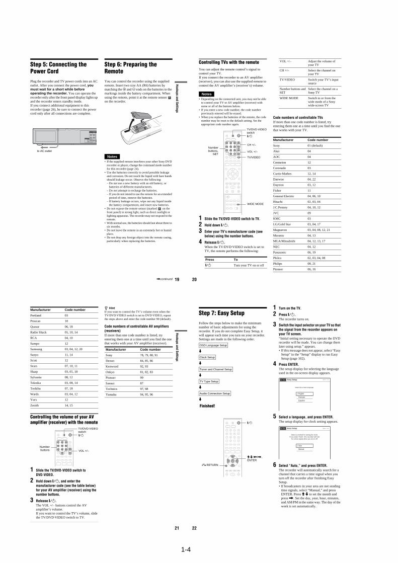
Step 5: Connecting the Power CordPlug the recorder and TV power cords into an AC outlet. After you connect the power cord, you must wait for a short while before operating the recorder. You can operate the recorder only after the front panel display lights up and the recorder enters standby mode.If you connect additional equipment to this recorder (page 26), be sure to connect the power cord only after all connections are complete.
Step 6: Preparing the RemoteYou can control the recorder using the supplied remote. Insert two size AA (R6) batteries by matching the 3 and # ends on the batteries to the markings inside the battery compartment. When using the remote, point it at the remote sensor on the recorder.
Notes• If the supplied remote interferes your other Sony DVD
recorder or player, change the command mode number for this recorder (page 24).
• Use the batteries correctly to avoid possible leakage and corrosion. Do not touch the liquid with bare hands should leakage occur. Observe the following:– Do not use a new battery with an old battery, or
batteries of different manufacturers.– Do not attempt to recharge the batteries.– If you do not intend to use the remote for an extended
period of time, remove the batteries.– If battery leakage occurs, wipe out any liquid inside
the battery compartment, and insert new batteries.• Do not expose the remote sensor (marked on the
front panel) to strong light, such as direct sunlight or lighting apparatus. The recorder may not respond to the remote.
• With normal use, the batteries should last about three to six months.
• Do not leave the remote in an extremely hot or humid place.
• Do not drop any foreign object into the remote casing, particularly when replacing the batteries.
YL
PBR
PR
AUDIO OUT S VIDCOMPONENTVIDEO OUT
DIGITAL AUDIO OUT
OPTICAL COAXIAL
to AC outlet
,continued 20
Controlling TVs with the remoteYou can adjust the remote control’s signal to control your TV.If you connect the recorder to an AV amplifier (receiver), you can also use the supplied remote to control the AV amplifier’s (receiver’s) volume.
Notes• Depending on the connected unit, you may not be able
to control your TV or AV amplifier (receiver) with some or all of the buttons below.
• If you enter a new code number, the code number previously entered will be erased.
• When you replace the batteries of the remote, the code number may be reset to the default setting. Set the appropriate code number again.
1 Slide the TV/DVD·VIDEO switch to TV.
2 Hold down "/1.
3 Enter your TV’s manufacturer code (see below) using the number buttons.
4 Release "/1.When the TV/DVD·VIDEO switch is set to TV, the remote performs the following:
Code numbers of controllable TVsIf more than one code number is listed, try entering them one at a time until you find the one that works with your TV.
Press To
"/1 Turn your TV on or off
TV/DVD·VIDEO switch"/1
VOL +/–Numberbuttons,
SETTV/VIDEO
CH +/–
WIDE MODE
VOL +/– Adjust the volume of your TV
CH +/– Select the channel on your TV
TV/VIDEO Switch your TV’s input source
Number buttons and SET
Select the channel on a Sony TV
WIDE MODE Switch to or from the wide mode of a Sony wide-screen TV
Manufacturer Code number
Sony 01 (default)
Akai 04
AOC 04
Centurion 12
Coronado 03
Curtis-Mathes 12, 14
Daewoo 04, 22
Daytron 03, 12
Fisher 11
General Electric 04, 06, 10
Hitachi 02, 03, 04
J.C.Penney 04, 10, 12
JVC 09
KMC 03
LG/Gold Star 03, 04, 17
Magnavox 03, 04, 08, 12, 21
Marantz 04, 13
MGA/Mitsubishi 04, 12, 13, 17
NEC 04, 12
Panasonic 06, 19
Philco 02, 03, 04, 08
Philips 08, 21
Pioneer 06, 16
21
Hookups and Settings
Controlling the volume of your AV amplifier (receiver) with the remote
1 Slide the TV/DVD·VIDEO switch to DVD·VIDEO.
2 Hold down "/1, and enter the manufacturer code (see the table below) for your AV amplifier (receiver) using the number buttons.
3 Release "/1.The VOL +/– buttons control the AV amplifier’s volume.If you want to control the TV’s volume, slide the TV/DVD·VIDEO switch to TV.
z HintIf you want to control the TV’s volume even when the TV/DVD·VIDEO switch is set to DVD·VIDEO, repeat the steps above and enter the code number 90 (default).
Code numbers of controllable AV amplifiers (receivers)If more than one code number is listed, try entering them one at a time until you find the one that works with your AV amplifier (receiver).
Portland 03
Proscan 10
Quasar 06, 18
Radio Shack 05, 10, 14
RCA 04, 10
Sampo 12
Samsung 03, 04, 12, 20
Sanyo 11, 14
Scott 12
Sears 07, 10, 11
Sharp 03, 05, 18
Sylvania 08, 12
Teknika 03, 08, 14
Toshiba 07, 18
Wards 03, 04, 12
Yorx 12
Zenith 14, 15
Manufacturer Code number
TV/DVD·VIDEO switch"/1
VOL +/–Numberbuttons
Manufacturer Code number
Sony 78, 79, 80, 91
Denon 84, 85, 86
Kenwood 92, 93
Onkyo 81, 82, 83
Pioneer 99
Sansui 87
Technics 97, 98
Yamaha 94, 95, 96
22
Step 7: Easy SetupFollow the steps below to make the minimum number of basic adjustments for using the recorder. If you do not complete Easy Setup, it will appear each time you turn on your recorder.Settings are made in the following order.
m
m
m
m
m
1 Turn on the TV.
2 Press "/1.The recorder turns on.
3 Switch the input selector on your TV so that the signal from the recorder appears on your TV screen.“Initial setting necessary to operate the DVD recorder will be made. You can change them later using setup.” appears. • If this message does not appear, select “Easy
Setup” in the “Setup” display to run Easy Setup (page 102).
4 Press ENTER.The setup display for selecting the language used in the on-screen display appears.
5 Select a language, and press ENTER.The setup display for clock setting appears.
6 Select “Auto,” and press ENTER.The recorder will automatically search for a channel that carries a time signal when you turn off the recorder after finishing Easy Setup. • If broadcasters in your area are not sending
time signals, select “Manual,” and press ENTER. Press M/m to set the month and press ,. Set the day, year, hour, minutes, and AM/PM in the same way. The day of the week is set automatically.
OSD Language Setup
Clock Setup
Tuner and Channel Setup
TV Type Setup
Audio Connection Setup
Finished!
M/m/</,, ENTER
O RETURN
"/1
English
Français
Español
Easy Setup
Select the screen language.
No Disc
Select a method for setting the clock.If you select "Auto", this recorder will look
for a time signal when you turn it off.
Auto
Manual
Easy SetupNo Disc
1-5
23
Hookups and Settings
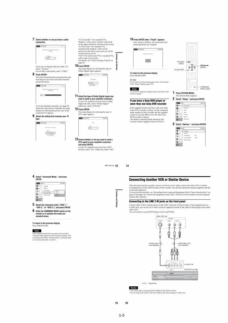
7 Select whether or not you have a cable connection.
If you use an antenna only (no cable TV), select “Antenna.”For all other connections, select “Cable.”
8 Press ENTER.The Tuner Preset function automatically starts searching for all of the receivable channels and presets them.
To set the channels manually, see page 94.After the Tuner Preset is finished, the setup display for selecting the picture size of the connected TV appears.
9 Select the setting that matches your TV type.
“4:3 Letter Box”: For standard TVs.Displays “wide screen” pictures with bands on the upper and lower sections of the screen.“4:3 Pan Scan”: For standard TVs.Automatically displays “wide screen” pictures on the entire screen and cuts off the sections that do not fit.“16:9”: For wide-screen TVs or standard TVs with a wide screen mode.For details, see “Video Settings (Video)” on page 95.
10 Press ENTER.The setup display for selecting the type of Dolby Digital signal appears.
11 Select the type of Dolby Digital signal you want to send to your amplifier (receiver).If your AV amplifier (receiver) has a Dolby Digital decoder, select “Dolby Digital.” Otherwise, select “D-PCM.”
12 Press ENTER.The setup display for selecting the type of DTS signal appears.
13 Select whether or not you want to send a DTS signal to your amplifier (receiver), and press ENTER.If your AV amplifier (receiver) has a DTS decoder, select “On.” Otherwise, select “Off.”
Select the way in which you will receivechannels.
Antenna
Cable
Easy SetupNo Disc
Searching for receivable channels. 25Please wait.
Easy SetupNo Disc
16 : 9
4 : 3 Letter Box
4 : 3 Pan Scan
Easy Setup
Select your TV screen type.
10:10 AMNo Disc
D-PCM
Dolby Digital
Easy Setup
Dolby Digital
10:10 AMNo Disc
On
Off
Easy Setup
DTS
10:10 AMNo Disc
,continued 24
14 Press ENTER when “Finish” appears.Easy Setup is finished. All connections and setup operations are complete.
To return to the previous displayPress O RETURN.
z HintIf you want to run Easy Setup again, select “Easy Setup” in the “Setup” display (page 102).
NoteTo record TV programs using the timer, you must set the clock accurately.
If you have a Sony DVD player or more than one Sony DVD recorderIf the supplied remote interferes with your other Sony DVD recorder or player, set the command mode number for this recorder and the supplied remote to one that differs from the other Sony DVD recorder or player.The default command mode setting for this recorder and the supplied remote is DVD 3.
1 Press SYSTEM MENU.The System Menu appears.
2 Select “Setup,” and press ENTER.
3 Select “Options,” and press ENTER.
Finish
Easy Setup
Easy Setup is finished.
10:10 AMNo Disc
SYSTEMMENU
M/m/</,, ENTER
COMMAND MODE switch
O RETURN
10:10 AM
Tuner Preset
Clock Set
Video
Audio
Features
Options
Easy SetupSetup
Disc Setting
Edit
Title List
Timer
Dubbing
SetupNo Disc
Options
Language
Parental
Front Display
Command Mode
Factory Setting
: Auto
: DVD 3
10:10 AM
Setup
Disc Setting
Edit
Title List
Timer
Dubbing
No Disc
25
Hookups and Settings
4 Select “Command Mode,” and press ENTER.
5 Select the command mode (“DVD 1,” “DVD 2,” or “DVD 3”), and press ENTER.
6 Slide the COMMAND MODE switch on the remote so it matches the mode you selected above.
To return to the previous displayPress O RETURN.
NoteIf the command mode does not match, the recorder’s command mode appears on the front panel display when you operate the remote. Set the remote’s command mode to one that matches the recorder’s.
Options
Language
Parental
Front Display
Command Mode
Factory Setting
: Auto
: DVD1 No
10:10 AM
Setup
Disc Setting
Edit
Title List
Timer
Dubbing
No Disc
DVD 1
DVD 2
DVD 3
26
Connecting Another VCR or Similar DeviceAfter disconnecting the recorder’s power cord from an AC outlet, connect the other VCR or similar recording device to the LINE IN jacks of this recorder. See also the instruction manual supplied with the connected equipment.To record on this recorder, see “Recording From Connected Equipment With a Timer (Synchro Rec)” on page 50 and page 78. Connect the equipment to the LINE 1 IN jacks of the recorder to record using the Synchro Rec function.
Connecting to the LINE 2 IN jacks on the front panelConnect other VCR or similar device to the LINE 2 IN jacks of this recorder. If the equipment has an S video jack, you can use an S video cord (not supplied) instead of the yellow (video) plug of the audio/video cord.You can connect a second DVD player and record DVDs.
Notes• You cannot dub a copy guard DVD VIDEO to this DVD recorder.• Do not connect the yellow LINE IN (VIDEO) jack when using an S video cord.
S VIDEO AUDIO
L R
VIDEO
(MONO)DV INS VIDEO VIDEO
LINE 2 INL AUDIO R
OUTPUT
Other VCR, etc.
Audio/video cord (not supplied)
S video cord (not supplied)
to LINE 2 IN
VCR-DVD recorder
: Signal flow
1-6
27
Hookups and Settings
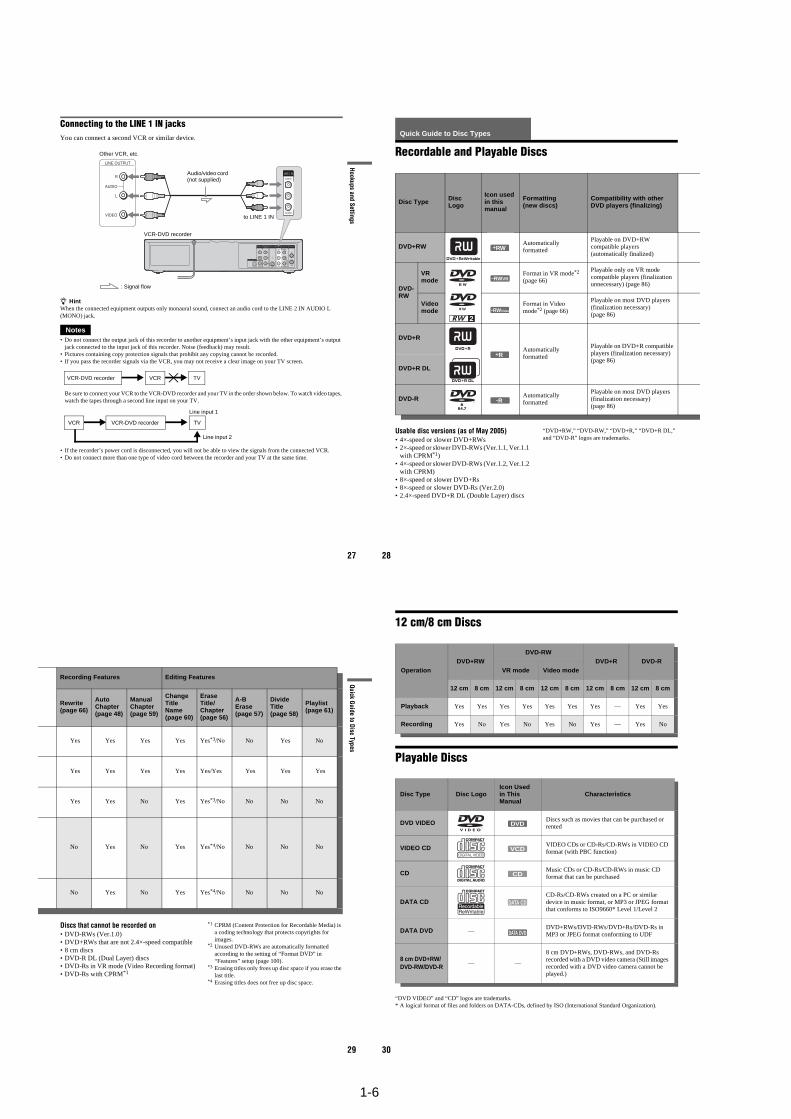
Connecting to the LINE 1 IN jacksYou can connect a second VCR or similar device.
z HintWhen the connected equipment outputs only monaural sound, connect an audio cord to the LINE 2 IN AUDIO L (MONO) jack.
Notes• Do not connect the output jack of this recorder to another equipment’s input jack with the other equipment’s output
jack connected to the input jack of this recorder. Noise (feedback) may result.• Pictures containing copy protection signals that prohibit any copying cannot be recorded.• If you pass the recorder signals via the VCR, you may not receive a clear image on your TV screen.
Be sure to connect your VCR to the VCR-DVD recorder and your TV in the order shown below. To watch video tapes, watch the tapes through a second line input on your TV.
• If the recorder’s power cord is disconnected, you will not be able to view the signals from the connected VCR.• Do not connect more than one type of video cord between the recorder and your TV at the same time.
LINE OUTPUT
AUDIO
R
L
VIDEO
IN
L
R
VIDEO
AUDIOOUT
VHF/UHFLINE OUT
VIDEO
YL
PBR
PR
AUDIO
LINE 1 INAUDIO OUT S VIDEO OUTCOMPONENTVIDEO OUT
DIGITAL AUDIO OUT
OPTICAL COAXIAL
VIDEO
AUDIO
LINE 1 IN
Other VCR, etc.
VCR-DVD recorder
Audio/video cord (not supplied)
: Signal flow
to LINE 1 IN
VCRVCR-DVD recorder TV
VCR VCR-DVD recorder TV
Line input 1
Line input 2
28
Quick Guide to Disc Types
Recordable and Playable Discs
Usable disc versions (as of May 2005)• 4×-speed or slower DVD+RWs• 2×-speed or slower DVD-RWs (Ver.1.1, Ver.1.1
with CPRM*1)• 4×-speed or slower DVD-RWs (Ver.1.2, Ver.1.2
with CPRM)• 8×-speed or slower DVD+Rs• 8×-speed or slower DVD-Rs (Ver.2.0)• 2.4×-speed DVD+R DL (Double Layer) discs
“DVD+RW,” “DVD-RW,” “DVD+R,” “DVD+R DL,” and “DVD-R” logos are trademarks.
Disc Type Disc Logo
Icon used in this manual
Formatting (new discs)
Compatibility with other DVD players (finalizing)
DVD+RW Automatically formatted
Playable on DVD+RW compatible players (automatically finalized)
DVD-RW
VR mode
Format in VR mode*2 (page 66)
Playable only on VR mode compatible players (finalization unnecessary) (page 86)
Video mode
Format in Video mode*2 (page 66)
Playable on most DVD players (finalization necessary) (page 86)
DVD+R
Automatically formatted
Playable on DVD+R compatible players (finalization necessary) (page 86)
DVD+R DL
DVD-R Automatically formatted
Playable on most DVD players (finalization necessary) (page 86)
+RW
-RWVR
-RWVideo
+R
-R
29
Quick Guide to D
isc Types
Discs that cannot be recorded on• DVD-RWs (Ver.1.0)• DVD+RWs that are not 2.4×-speed compatible• 8 cm discs• DVD-R DL (Dual Layer) discs• DVD-Rs in VR mode (Video Recording format)• DVD-Rs with CPRM*1
*1 CPRM (Content Protection for Recordable Media) is a coding technology that protects copyrights for images.
*2 Unused DVD-RWs are automatically formatted according to the setting of “Format DVD” in “Features” setup (page 100).
*3 Erasing titles only frees up disc space if you erase the last title.
*4 Erasing titles does not free up disc space.
Recording Features Editing Features
Rewrite (page 66)
Auto Chapter (page 48)
Manual Chapter (page 59)
Change Title Name (page 60)
Erase Title/Chapter (page 56)
A-B Erase (page 57)
Divide Title (page 58)
Playlist (page 61)
Yes Yes Yes Yes Yes*3/No No Yes No
Yes Yes Yes Yes Yes/Yes Yes Yes Yes
Yes Yes No Yes Yes*3/No No No No
No Yes No Yes Yes*4/No No No No
No Yes No Yes Yes*4/No No No No
30
12 cm/8 cm Discs
Playable Discs
“DVD VIDEO” and “CD” logos are trademarks.* A logical format of files and folders on DATA-CDs, defined by ISO (International Standard Organization).
OperationDVD+RW
DVD-RWDVD+R DVD-R
VR mode Video mode
12 cm 8 cm 12 cm 8 cm 12 cm 8 cm 12 cm 8 cm 12 cm 8 cm
Playback Yes Yes Yes Yes Yes Yes Yes — Yes Yes
Recording Yes No Yes No Yes No Yes — Yes No
Disc Type Disc LogoIcon Used in This Manual
Characteristics
DVD VIDEO Discs such as movies that can be purchased or rented
VIDEO CD VIDEO CDs or CD-Rs/CD-RWs in VIDEO CD format (with PBC function)
CD Music CDs or CD-Rs/CD-RWs in music CD format that can be purchased
DATA CDCD-Rs/CD-RWs created on a PC or similar device in music format, or MP3 or JPEG format that conforms to ISO9660* Level 1/Level 2
DATA DVD —DVD+RWs/DVD-RWs/DVD+Rs/DVD-Rs in MP3 or JPEG format conforming to UDF
8 cm DVD+RW/DVD-RW/DVD-R
— —
8 cm DVD+RWs, DVD-RWs, and DVD-Rs recorded with a DVD video camera (Still images recorded with a DVD video camera cannot be played.)
DVD
VCD
CD
DATA CD
DATA DVD
1-7
31
Quick Guide to D
isc Types
Discs that cannot be played• CD-Rs/CD-RWs, other than those recorded in
music CD format, MP3 or JPEG format, or Video CD format
• Data part of CD-Extras• DVD-ROMs• CD-ROMs• DVD Audio discs• DVD-R DL (Dual Layer) discs• DVD-Rs recorded in VR mode (Video
Recording format)• DVD-Rs with CPRM• DVD-RAMs• HD layer on Super Audio CDs• DVD VIDEOs with a different region code
(see page 31)• A disc recorded in a color system other than
NTSC, such as PAL or SECAM
Note on playback operations of DVD VIDEOs/VIDEO CDsSome playback operations of DVD VIDEOs/VIDEO CDs may be intentionally set by software producers. Since this recorder plays DVD VIDEOs/VIDEO CDs according to the disc contents the software producers designed, some playback features may not be available. Also, see the instructions supplied with the DVD VIDEOs/VIDEO CDs.
Note on DualDiscsA DualDisc is a two sided disc product which mates DVD recorded material on one side with digital audio material on the other side.However, since the audio material side does not conform to the Compact Disc (CD) standard, playback on this product is not guaranteed.
Region code (DVD VIDEO only)Your recorder has a region code printed on the rear of the unit and will only play DVD VIDEOs (playback only) labeled with identical region codes. This system is used to protect copyrights.DVD VIDEOs labeled will also play on this recorder.
If you try to play any other DVD VIDEO, a message will appear on the TV screen to indicate that the disc is not playable. Depending on the DVD VIDEO, no region code indication may be labeled even though playing the DVD VIDEO is prohibited by area restrictions.
Music discs encoded with copyright protection technologiesThis product is designed to playback discs that conform to the Compact Disc (CD) standard.Recently, various music discs encoded with copyright protection technologies are being marketed by some record companies. Please be aware that among those discs, there are some that do not conform to the CD standard and may not be playable by this product.
Notes• Some DVD+RWs/DVD+Rs, DVD-RWs/DVD-Rs, or
CD-RWs/CD-Rs cannot be played on this recorder due to the recording quality or physical condition of the disc, or the characteristics of the recording device and authoring software. The disc will not play if it has not been correctly finalized. For more information, see the operating instructions for the recording device.
• You cannot mix VR mode and Video mode on the same DVD-RW. To change the disc’s format, reformat the disc (page 66). Note that the disc’s contents will be erased after reformatting.
• You cannot shorten the time required for recording even with high-speed discs. Also, you cannot record on the disc if the disc is not 1x speed compatible.
• It is recommended that you use discs with “For Video” printed on their packaging.
• You cannot add new recordings to DVD-RWs (Video mode) or DVD-Rs that contain recordings made on other DVD equipment.
• You may not be able to further record on a DVD+RW recorded on other equipment. Note that recording on such discs may cause the recorder to rewrite the DVD menu.
• If the disc contains PC data unrecognizable by this recorder, the data may be erased.
ALL
NO.
RDR-VX515
X
Region code
32
DVD Playback
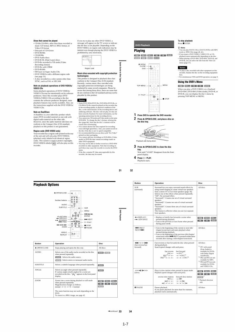
Playing
1 Press DVD to operate the DVD recorder.
2 Press Z OPEN/CLOSE, and place a disc on the disc tray.
3 Press Z OPEN/CLOSE to close the disc tray.Wait until “LOAD” disappears from the front panel display.
4 Press H PLAY.Playback starts.
To stop playbackPress x STOP.
z Hints• You can play DATA CDs or DATA DVDs with MP3
tracks or JPEG files (page 40, 41).• If you insert a DVD VIDEO, VIDEO CD, or CD,
playback starts automatically depending on the disc.• When playing a DVD+RW, DVD-RW, DVD+R, and
DVD-R, you can select the title from the Title List menu (page 37).
Notes• To play a disc recorded with other equipment on this
recorder, finalize the disc on the recording equipment first.
• For simultaneous VHS and DVD operation, see page 9.
Using the DVD’s Menu
When you play a DVD VIDEO, or a finalized DVD+RW, DVD-RW (Video mode), DVD+R, or DVD-R, you can display the disc’s menu by pressing TOP MENU or MENU.
+RW +R DVD
VCD CD
-RWVR -RWVideo -R
DATA DVDDATA CD
x STOP
Z OPEN/CLOSE
MENU
H PLAY
DVD
TOP MENU
Playback side facing down
+RW +R DVD-RWVideo -R+R -R
33
DVD Playback
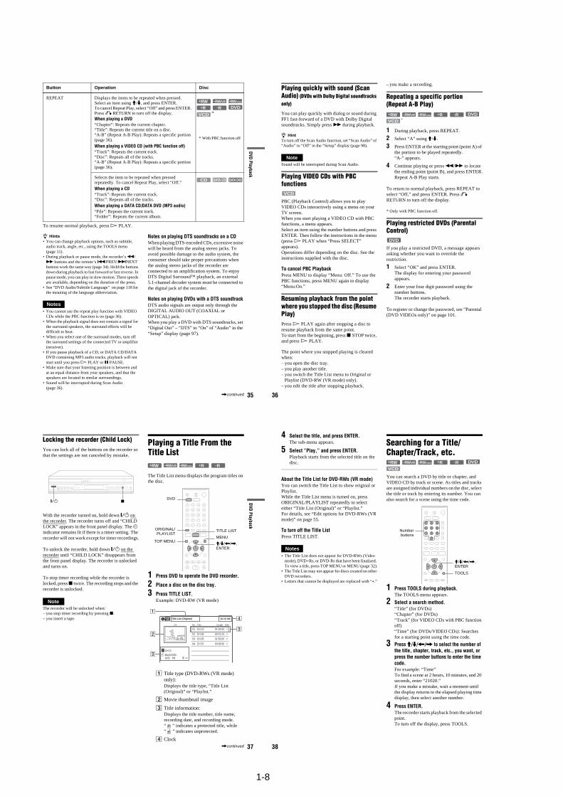
Playback Options
Button Operation Disc
Z OPEN/CLOSE Stops playing and opens the disc tray. All discs
AUDIO Selects one of the audio tracks recorded on the disc when pressed repeatedly.
: Selects the audio source.
: Selects stereo or monaural audio tracks.
SUBTITLE Selects a subtitle language when pressed repeatedly. .
ANGLE Selects an angle when pressed repeatedly.If various angles (multi-angles) for a scene are recorded on the disc, “ ” appears in the front panel display.
ZOOM Zooms into a scene during playback or still mode when pressed repeatedly.Magnification changes as follows: normal t ×2 t ×4 t normal
The zoom function may not work depending on the DVD.To zoom in a JPEG image, see page 42.
Z OPEN/CLOSE
X PAUSE
AUDIO
. PREV
REPLAY/ADVANCE
x STOP
SUBTITLE SUR
ZOOM
REPEAT
MENU
H PLAY
M/m/</,,ENTER
Number buttons
O RETURN
> NEXT
ANGLE
DVD
VCD
DVD VCD
DVD
DVD
DVDVCD
+RW -RWVR -RWVideo
+R -R
,continued 34
SUR(surround)
Surround lets you enjoy surround sound effects by using sound imaging to create virtual rear speakers from a stereo TV or two front speakers (page 18).Selects one of the effects when pressed repeatedly.“Off”: No surround effect.“Surround1”: Creates one set of virtual surround speakers.“Surround2”: Creates two sets of virtual surround speakers.“Surround3”: Creates three sets of virtual surround speakers. This feature is effective when you use two separate front speakers.
All discs
REPLAY/ ADVANCE
• Replays or briefly fast forwards a scene when pressed during playback.
• Goes to the previous or next frame when pressed during pause mode.
. PREV/ NEXT >
• Goes to the beginning of the current or next title/chapter/scene/track and starts playback when pressed during playback.
• Goes to the beginning of the previous title/chapter/scene/track when .PREV is pressed within three seconds after starting a title/chapter/scene/track.
All discs
(fast reverse/fast forward)
Fast reverses or fast forwards the disc when pressed during playback.Search speed changes with each press:
fast reverse fast forwardFR1 T t FF1*1
FR2*2 T T t t FF2*2
FR3*3 T T T t t t FF3*3
All discs
*1 FF1 with sound (Scan Audio) is available for DVDs with Dolby Digital soundtracks.
*2 FR2 and FF2 are not available for MP3.
*3 FR3 and FF3 are only available for DVDs and VIDEO CDs.
(slow)
Plays in slow motion when pressed in pause mode. Playback speed changes with each press:
reverse slow motion forward slow motion T t
T T t t T T T t t t
* Playback direction only
X PAUSE Pauses playback.If you pause playback for more than five minutes, playback starts automatically.
All discs
Button Operation Disc
+RW -RWVR -RWVideo
+R DVD-R
VCD *
+RW+R
-RWVR -RWVideo
DVD-R
1-8
35
DVD Playback
To resume normal playback, press H PLAY.
z Hints• You can change playback options, such as subtitle,
audio track, angle, etc., using the TOOLS menu (page 11).
• During playback or pause mode, the recorder’s m/M buttons and the remote’s .PREV/>NEXT buttons work the same way (page 34). Hold the buttons down during playback to fast forward or fast reverse. In pause mode, you can play in slow motion. Three speeds are available, depending on the duration of the press.
• See “DVD Audio/Subtitle Language” on page 118 for the meaning of the language abbreviation.
Notes• You cannot use the repeat play function with VIDEO
CDs while the PBC function is on (page 36).• When the playback signal does not contain a signal for
the surround speakers, the surround effects will be difficult to hear.
• When you select one of the surround modes, turn off the surround settings of the connected TV or amplifier (receiver).
• If you pause playback of a CD, or DATA CD/DATA DVD containing MP3 audio tracks, playback will not start until you press H PLAY or X PAUSE.
• Make sure that your listening position is between and at an equal distance from your speakers, and that the speakers are located in similar surroundings.
• Sound will be interrupted during Scan Audio (page 36).
Notes on playing DTS soundtracks on a CDWhen playing DTS-encoded CDs, excessive noise will be heard from the analog stereo jacks. To avoid possible damage to the audio system, the consumer should take proper precautions when the analog stereo jacks of the recorder are connected to an amplification system. To enjoy DTS Digital Surround™ playback, an external 5.1-channel decoder system must be connected to the digital jack of the recorder.
Notes on playing DVDs with a DTS soundtrackDTS audio signals are output only through the DIGITAL AUDIO OUT (COAXIAL or OPTICAL) jack.When you play a DVD with DTS soundtracks, set “Digital Out” – “DTS” to “On” of “Audio” in the “Setup” display (page 97).
REPEAT Displays the items to be repeated when pressed.Select an item using M/m, and press ENTER.To cancel Repeat Play, select “Off” and press ENTER. Press O RETURN to turn off the display.When playing a DVD“Chapter”: Repeats the current chapter.“Title”: Repeats the current title on a disc.“A-B” (Repeat A-B Play): Repeats a specific portion (page 36).When playing a VIDEO CD (with PBC function off)“Track”: Repeats the current track.“Disc”: Repeats all of the tracks.“A-B” (Repeat A-B Play): Repeats a specific portion (page 36).
* With PBC function off
Selects the item to be repeated when pressed repeatedly. To cancel Repeat Play, select “Off.”When playing a CD“Track”: Repeats the current track.“Disc”: Repeats all of the tracks.When playing a DATA CD/DATA DVD (MP3 audio)“File”: Repeats the current track.“Folder”: Repeats the current album.
Button Operation Disc
VCD
+RW -RWVR -RWVideo
+R DVD*
-R
DATA CDCD DATA DVD
,continued 36
Playing quickly with sound (Scan Audio) (DVDs with Dolby Digital soundtracks only)
You can play quickly with dialog or sound during FF1 fast-forward of a DVD with Dolby Digital soundtracks. Simply press M during playback.
z HintTo turn off the Scan Audio function, set “Scan Audio” of “Audio” to “Off” in the “Setup” display (page 98).
NoteSound will be interrupted during Scan Audio.
Playing VIDEO CDs with PBC functions
PBC (Playback Control) allows you to play VIDEO CDs interactively using a menu on your TV screen.When you start playing a VIDEO CD with PBC functions, a menu appears.Select an item using the number buttons and press ENTER. Then follow the instructions in the menu (press H PLAY when “Press SELECT” appears). Operations differ depending on the disc. See the instructions supplied with the disc.
To cancel PBC PlaybackPress MENU to display “Menu: Off.” To use the PBC functions, press MENU again to display “Menu:On.”
Resuming playback from the point where you stopped the disc (Resume Play)Press H PLAY again after stopping a disc to resume playback from the same point.To start from the beginning, press x STOP twice, and press H PLAY.
The point where you stopped playing is cleared when:– you open the disc tray.– you play another title.– you switch the Title List menu to Original or
Playlist (DVD-RW (VR mode) only).– you edit the title after stopping playback.
– you make a recording.
Repeating a specific portion (Repeat A-B Play)
1 During playback, press REPEAT.
2 Select “A” using M/m.
3 Press ENTER at the starting point (point A) of the portion to be played repeatedly.“A-” appears.
4 Continue playing or press m/M to locate the ending point (point B), and press ENTER.Repeat A-B Play starts.
To return to normal playback, press REPEAT to select “Off,” and press ENTER. Press O RETURN to turn off the display.
* Only with PBC function off.
Playing restricted DVDs (Parental Control)
If you play a restricted DVD, a message appears asking whether you want to override the restriction.
1 Select “OK” and press ENTER.The display for entering your password appears.
2 Enter your four digit password using the number buttons.The recorder starts playback.
To register or change the password, see “Parental (DVD VIDEOs only)” on page 101.
VCD
+RW +RVCD
-RWVR -RWVideo
*
DVD-R
DVD
37
DVD Playback
Locking the recorder (Child Lock)You can lock all of the buttons on the recorder so that the settings are not canceled by mistake.
With the recorder turned on, hold down "/1 on the recorder. The recorder turns off and “CHILD LOCK” appears in the front panel display. The indicator remains lit if there is a timer setting. The recorder will not work except for timer recordings.
To unlock the recorder, hold down "/1 on the recorder until “CHILD LOCK” disappears from the front panel display. The recorder is unlocked and turns on.
To stop timer recording while the recorder is locked, press x twice. The recording stops and the recorder is unlocked.
NoteThe recorder will be unlocked when:– you stop timer recording by pressing x.– you insert a tape.
Playing a Title From the Title List
The Title List menu displays the program titles on the disc.
1 Press DVD to operate the DVD recorder.
2 Place a disc on the disc tray.
3 Press TITLE LIST.Example: DVD-RW (VR mode)
A Title type (DVD-RWs (VR mode) only):Displays the title type, “Title List (Original)” or “Playlist.”
B Movie thumbnail image
C Title information:Displays the title number, title name, recording date, and recording mode.“ ” indicates a protected title, while “ ” indicates unprotected.
D Clock
"/1 x
+RW -RWVR -RWVideo +R -R
TITLE LIST
MENUTOP MENU
ORIGINAL/PLAYLIST
DVD
M/m/</,,ENTER
10:10 AM
01 CH 23 >01:29:03
02 CH 66 >00:31:23
03 CH 95 >01:59:00
04 CH 97 >00:58:56
CH 23
08:00 PMMay/02/2005
T
No. Title Length Edit
Title List (Original)
1/4
1
2
3
4
3
,continued 38
4 Select the title, and press ENTER.The sub-menu appears.
5 Select “Play,” and press ENTER.Playback starts from the selected title on the disc.
About the Title List for DVD-RWs (VR mode)You can switch the Title List to show original or Playlist.While the Title List menu is turned on, press ORIGINAL/PLAYLIST repeatedly to select either “Title List (Original)” or “Playlist.”For details, see “Edit options for DVD-RWs (VR mode)” on page 55.
To turn off the Title ListPress TITLE LIST.
Notes• The Title List does not appear for DVD-RWs (Video
mode), DVD+Rs, or DVD-Rs that have been finalized. To view a title, press TOP MENU or MENU (page 32).
• The Title List may not appear for discs created on other DVD recorders.
• Letters that cannot be displayed are replaced with “*.”
Searching for a Title/Chapter/Track, etc.
You can search a DVD by title or chapter, and VIDEO CD by track or scene. As titles and tracks are assigned individual numbers on the disc, select the title or track by entering its number. You can also search for a scene using the time code.
1 Press TOOLS during playback.The TOOLS menu appears.
2 Select a search method.“Title” (for DVDs)“Chapter” (for DVDs)“Track” (for VIDEO CDs with PBC function off)“Time” (for DVDs/VIDEO CDs): Searches for a starting point using the time code.
3 Press M/m/</, to select the number of the title, chapter, track, etc., you want, or press the number buttons to enter the time code.For example: “Time”To find a scene at 2 hours, 10 minutes, and 20 seconds, enter “21020.”If you make a mistake, wait a moment until the display returns to the elapsed playing time display, then select another number.
4 Press ENTER.The recorder starts playback from the selected point.To turn off the display, press TOOLS.
+RW +R DVD
VCD
-RWVR -RWVideo -R
TOOLS
M/m/</,, ENTER
Numberbuttons
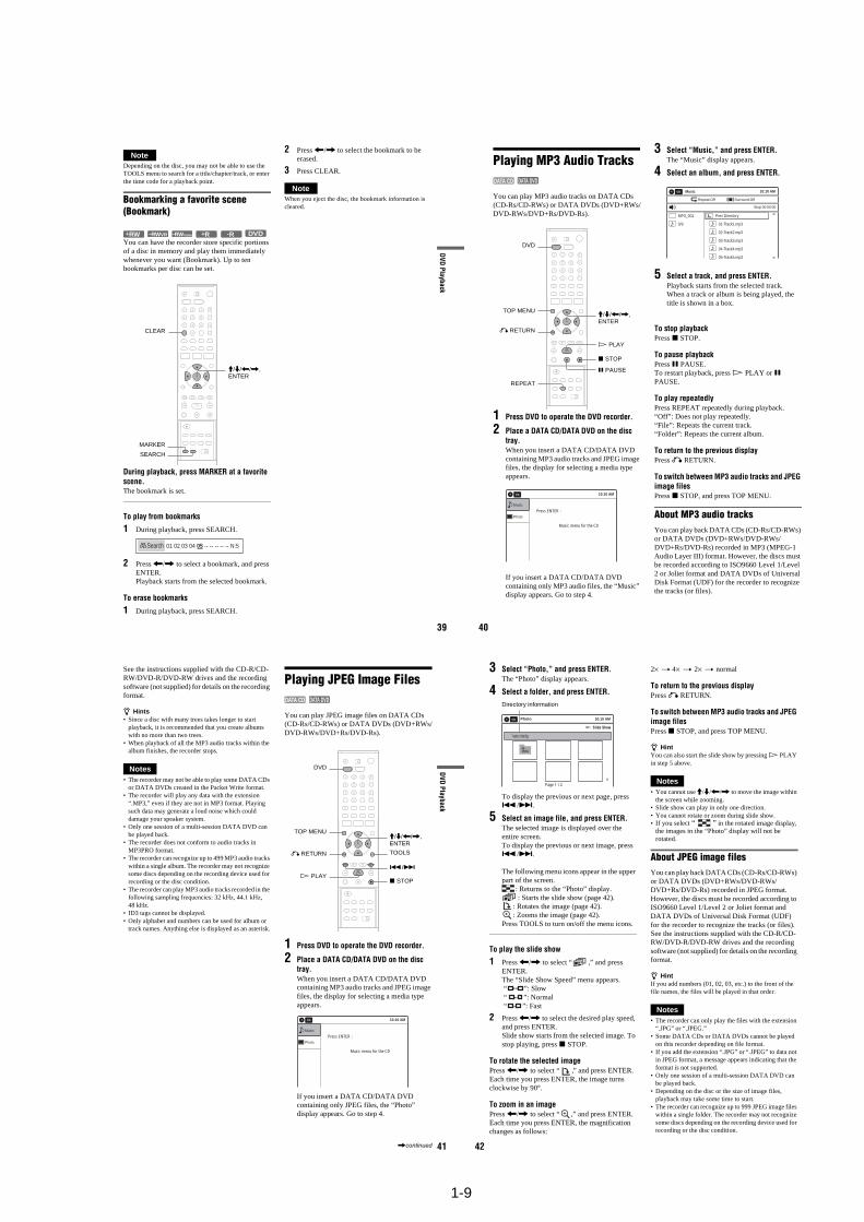
1-9
39
DVD Playback
NoteDepending on the disc, you may not be able to use the TOOLS menu to search for a title/chapter/track, or enter the time code for a playback point.
Bookmarking a favorite scene (Bookmark)
You can have the recorder store specific portions of a disc in memory and play them immediately whenever you want (Bookmark). Up to ten bookmarks per disc can be set.
During playback, press MARKER at a favorite scene.The bookmark is set.
To play from bookmarks
1 During playback, press SEARCH.
2 Press </, to select a bookmark, and press ENTER.Playback starts from the selected bookmark.
To erase bookmarks
1 During playback, press SEARCH.
2 Press </, to select the bookmark to be erased.
3 Press CLEAR.
NoteWhen you eject the disc, the bookmark information is cleared.
+RW +R DVD-RWVR -RWVideo -R
SEARCH
CLEAR
MARKER
M/m/</,,ENTER
01 02 03 04 05 -- -- -- -- -- N:5Search
40
Playing MP3 Audio Tracks
You can play MP3 audio tracks on DATA CDs (CD-Rs/CD-RWs) or DATA DVDs (DVD+RWs/DVD-RWs/DVD+Rs/DVD-Rs).
1 Press DVD to operate the DVD recorder.
2 Place a DATA CD/DATA DVD on the disc tray.When you insert a DATA CD/DATA DVD containing MP3 audio tracks and JPEG image files, the display for selecting a media type appears.
If you insert a DATA CD/DATA DVD containing only MP3 audio files, the “Music” display appears. Go to step 4.
3 Select “Music,” and press ENTER.The “Music” display appears.
4 Select an album, and press ENTER.
5 Select a track, and press ENTER.Playback starts from the selected track.When a track or album is being played, the title is shown in a box.
To stop playbackPress x STOP.
To pause playbackPress X PAUSE.To restart playback, press H PLAY or X PAUSE.
To play repeatedlyPress REPEAT repeatedly during playback.“Off”: Does not play repeatedly.“File”: Repeats the current track.“Folder”: Repeats the current album.
To return to the previous displayPress O RETURN.
To switch between MP3 audio tracks and JPEG image filesPress x STOP, and press TOP MENU.
About MP3 audio tracksYou can play back DATA CDs (CD-Rs/CD-RWs) or DATA DVDs (DVD+RWs/DVD-RWs/DVD+Rs/DVD-Rs) recorded in MP3 (MPEG-1 Audio Layer III) format. However, the discs must be recorded according to ISO9660 Level 1/Level 2 or Joliet format and DATA DVDs of Universal Disk Format (UDF) for the recorder to recognize the tracks (or files).
DATA CD DATA DVD
REPEAT
M/m/</,,ENTER
x STOP
O RETURN
DVD
TOP MENU
X PAUSE
H PLAY
10:10 AM
Photo
Music
Press ENTER :
Music menu for the CD
Stop 00:00:00
Prev Directory
01-Track1.mp3
02-Track2.mp3
03-Track3.mp3
04-Track4.mp3
05-Track5.mp3
MP3_001
0/9
10:10 AMMusic
Repeat:Off Surround:Off
41
DVD Playback
See the instructions supplied with the CD-R/CD-RW/DVD-R/DVD-RW drives and the recording software (not supplied) for details on the recording format.
z Hints• Since a disc with many trees takes longer to start
playback, it is recommended that you create albums with no more than two trees.
• When playback of all the MP3 audio tracks within the album finishes, the recorder stops.
Notes• The recorder may not be able to play some DATA CDs
or DATA DVDs created in the Packet Write format.• The recorder will play any data with the extension
“.MP3,” even if they are not in MP3 format. Playing such data may generate a loud noise which could damage your speaker system.
• Only one session of a multi-session DATA DVD can be played back.
• The recorder does not conform to audio tracks in MP3PRO format.
• The recorder can recognize up to 499 MP3 audio tracks within a single album. The recorder may not recognize some discs depending on the recording device used for recording or the disc condition.
• The recorder can play MP3 audio tracks recorded in the following sampling frequencies: 32 kHz, 44.1 kHz, 48 kHz.
• ID3 tags cannot be displayed.• Only alphabet and numbers can be used for album or
track names. Anything else is displayed as an asterisk.
Playing JPEG Image Files
You can play JPEG image files on DATA CDs (CD-Rs/CD-RWs) or DATA DVDs (DVD+RWs/DVD-RWs/DVD+Rs/DVD-Rs).
1 Press DVD to operate the DVD recorder.
2 Place a DATA CD/DATA DVD on the disc tray.When you insert a DATA CD/DATA DVD containing MP3 audio tracks and JPEG image files, the display for selecting a media type appears.
If you insert a DATA CD/DATA DVD containing only JPEG files, the “Photo” display appears. Go to step 4.
DATA CD DATA DVD
H PLAY
O RETURN
M/m/</,, ENTER
./>
DVD
TOP MENU
x STOP
TOOLS
10:10 AM
Photo
Music
Press ENTER :
Music menu for the CD
,continued 42
3 Select “Photo,” and press ENTER.The “Photo” display appears.
4 Select a folder, and press ENTER.
To display the previous or next page, press ./>.
5 Select an image file, and press ENTER.The selected image is displayed over the entire screen. To display the previous or next image, press ./>.
The following menu icons appear in the upper part of the screen.
: Returns to the “Photo” display.: Starts the slide show (page 42).
: Rotates the image (page 42).: Zooms the image (page 42).
Press TOOLS to turn on/off the menu icons.
To play the slide show
1 Press </, to select “ ,” and press ENTER.The “Slide Show Speed” menu appears. “ ”: Slow “ ”: Normal “ ”: Fast
2 Press </, to select the desired play speed, and press ENTER.Slide show starts from the selected image. To stop playing, press x STOP.
To rotate the selected imagePress </, to select “ ,” and press ENTER.Each time you press ENTER, the image turns clockwise by 90°.
To zoom in an imagePress </, to select “ ,” and press ENTER.Each time you press ENTER, the magnification changes as follows:
2× t 4× t 2× t normal
To return to the previous displayPress O RETURN.
To switch between MP3 audio tracks and JPEG image filesPress x STOP, and press TOP MENU.
z HintYou can also start the slide show by pressing H PLAY in step 5 above.
Notes• You cannot use M/m/</, to move the image within
the screen while zooming.• Slide show can play in only one direction.• You cannot rotate or zoom during slide show.• If you select “ ” in the rotated image display,
the images in the “Photo” display will not be rotated.
About JPEG image filesYou can play back DATA CDs (CD-Rs/CD-RWs) or DATA DVDs (DVD+RWs/DVD-RWs/DVD+Rs/DVD-Rs) recorded in JPEG format. However, the discs must be recorded according to ISO9660 Level 1/Level 2 or Joliet format and DATA DVDs of Universal Disk Format (UDF) for the recorder to recognize the tracks (or files).See the instructions supplied with the CD-R/CD-RW/DVD-R/DVD-RW drives and the recording software (not supplied) for details on the recording format.
z HintIf you add numbers (01, 02, 03, etc.) to the front of the file names, the files will be played in that order.
Notes• The recorder can only play the files with the extension
“.JPG” or “.JPEG.”• Some DATA CDs or DATA DVDs cannot be played
on this recorder depending on file format.• If you add the extension “.JPG” or “.JPEG” to data not
in JPEG format, a message appears indicating that the format is not supported.
• Only one session of a multi-session DATA DVD can be played back.
• Depending on the disc or the size of image files, playback may take some time to start.
• The recorder can recognize up to 999 JPEG image files within a single folder. The recorder may not recognize some discs depending on the recording device used for recording or the disc condition.
Slide Show
\\abc\defg
Page 1 / 2
10:10 AMPhoto
Directory information
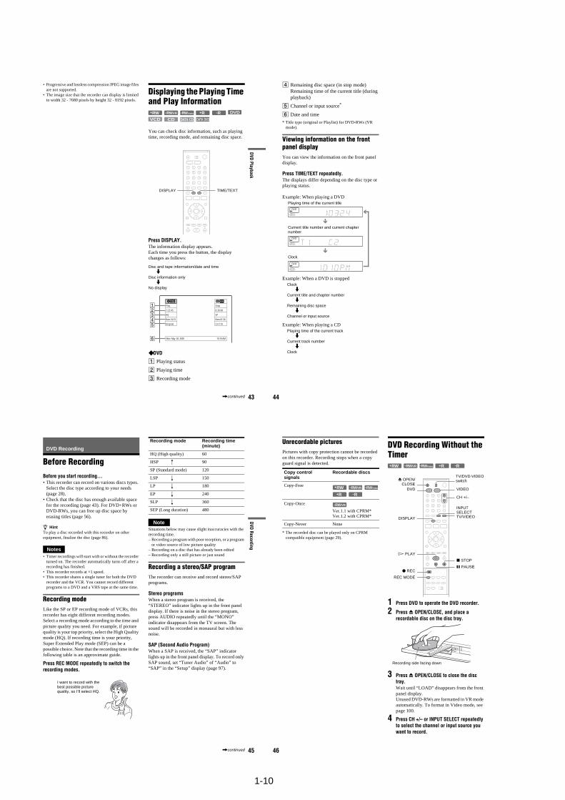
1-10
43
DVD Playback
• Progressive and lossless compression JPEG image files are not supported.
• The image size that the recorder can display is limited to width 32 - 7680 pixels by height 32 - 8192 pixels.
Displaying the Playing Time and Play Information
You can check disc information, such as playing time, recording mode, and remaining disc space.
Press DISPLAY.The information display appears.Each time you press the button, the display changes as follows:
Disc and tape information/date and timem
Disc information onlym
No display
DVD
A Playing status
B Playing time
C Recording mode
+R DVD
VCD CD
-RWVR -RWVideo+RW -R
DATA CD DATA DVD
TIME/TEXTDISPLAY
Stop
0:30:00
SP
Rem 01:30
CH 110
Mon May 02. 2005 10:10 AM
Play
1:23:45
HQ
Rem 16:15
Original
,continued 44
D Remaining disc space (in stop mode)Remaining time of the current title (during playback)
E Channel or input source*
F Date and time
* Title type (original or Playlist) for DVD-RWs (VR mode).
Viewing information on the front panel displayYou can view the information on the front panel display.
Press TIME/TEXT repeatedly.The displays differ depending on the disc type or playing status.
Example: When playing a DVD
Example: When a DVD is stopped
Example: When playing a CD
Playing time of the current title
Current title number and current chapter number
Clock
Clockm
Current title and chapter numberm
Remaining disc spacem
Channel or input source
Playing time of the current trackm
Current track numberm
Clock
45
DVD
Recording
DVD Recording
Before RecordingBefore you start recording…• This recorder can record on various discs types.
Select the disc type according to your needs (page 28).
• Check that the disc has enough available space for the recording (page 43). For DVD+RWs or DVD-RWs, you can free up disc space by erasing titles (page 56).
z HintTo play a disc recorded with this recorder on other equipment, finalize the disc (page 86).
Notes• Timer recordings will start with or without the recorder
turned on. The recorder automatically turns off after a recording has finished.
• This recorder records at ×1 speed.• This recorder shares a single tuner for both the DVD
recorder and the VCR. You cannot record different programs to a DVD and a VHS tape at the same time.
Recording modeLike the SP or EP recording mode of VCRs, this recorder has eight different recording modes.Select a recording mode according to the time and picture quality you need. For example, if picture quality is your top priority, select the High Quality mode (HQ). If recording time is your priority, Super Extended Play mode (SEP) can be a possible choice. Note that the recording time in the following table is an approximate guide.
Press REC MODE repeatedly to switch the recording modes.
NoteSituations below may cause slight inaccuracies with the recording time.– Recording a program with poor reception, or a program
or video source of low picture quality– Recording on a disc that has already been edited– Recording only a still picture or just sound
Recording a stereo/SAP programThe recorder can receive and record stereo/SAP programs.
Stereo programsWhen a stereo program is received, the “STEREO” indicator lights up in the front panel display. If there is noise in the stereo program, press AUDIO repeatedly until the “MONO” indicator disappears from the TV screen. The sound will be recorded in monaural but with less noise.
SAP (Second Audio Program)When a SAP is received, the “SAP” indicator lights up in the front panel display. To record only SAP sound, set “Tuner Audio” of “Audio” to “SAP” in the “Setup” display (page 97).
I want to record with the best possible picture quality, so I’ll select HQ.
Recording mode Recording time (minute)
HQ (High quality) 60
HSP R 90
SP (Standard mode) 120
LSP r 150
LP r 180
EP r 240
SLP r 360
SEP (Long duration) 480
,continued 46
Unrecordable picturesPictures with copy protection cannot be recorded on this recorder. Recording stops when a copy guard signal is detected.
* The recorded disc can be played only on CPRM compatible equipment (page 29).
DVD Recording Without the Timer
1 Press DVD to operate the DVD recorder.
2 Press Z OPEN/CLOSE, and place a recordable disc on the disc tray.
3 Press Z OPEN/CLOSE to close the disc tray.Wait until “LOAD” disappears from the front panel display.Unused DVD-RWs are formatted in VR mode automatically. To format in Video mode, see page 100.
4 Press CH +/– or INPUT SELECT repeatedly to select the channel or input source you want to record.
Copy control signals
Recordable discs
Copy-Free
Copy-Once
Ver.1.1 with CPRM*Ver.1.2 with CPRM*
Copy-Never None
+RW -RWVR -RWVideo
+R -R
-RWVR
+RW +R-RWVR -RWVideo -R
REC MODE
X PAUSE
x STOP
CH +/–
TV/VIDEO
z REC
Z OPEN/CLOSE
H PLAY
VIDEODVD
DISPLAY
INPUT SELECT
TV/DVD·VIDEO switch
Recording side facing down
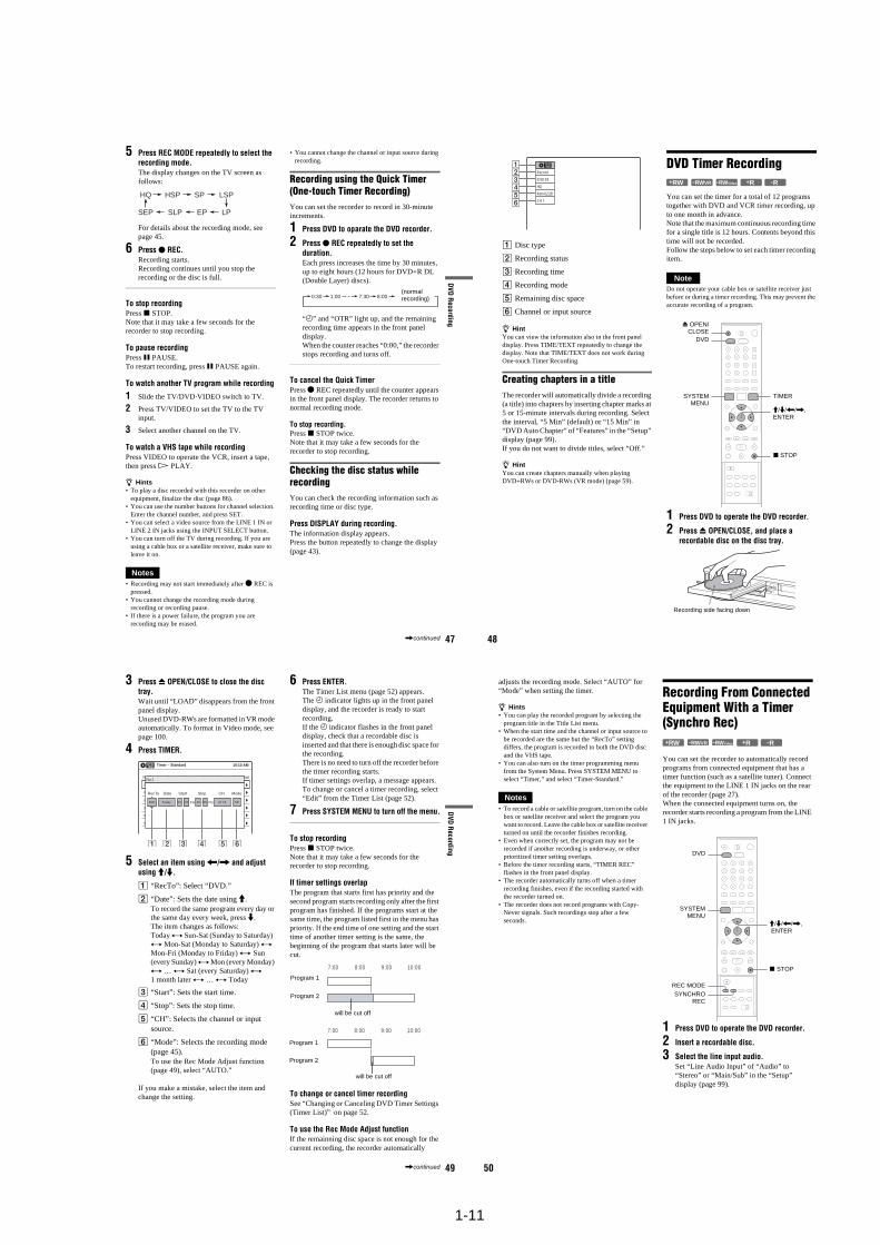
1-11
47
DVD
Recording
5 Press REC MODE repeatedly to select the recording mode.The display changes on the TV screen as follows:
For details about the recording mode, see page 45.
6 Press z REC.Recording starts.Recording continues until you stop the recording or the disc is full.
To stop recordingPress x STOP. Note that it may take a few seconds for the recorder to stop recording.
To pause recordingPress X PAUSE. To restart recording, press X PAUSE again.
To watch another TV program while recording
1 Slide the TV/DVD·VIDEO switch to TV.
2 Press TV/VIDEO to set the TV to the TV input.
3 Select another channel on the TV.
To watch a VHS tape while recordingPress VIDEO to operate the VCR, insert a tape, then press H PLAY.
z Hints• To play a disc recorded with this recorder on other
equipment, finalize the disc (page 86).• You can use the number buttons for channel selection.
Enter the channel number, and press SET.• You can select a video source from the LINE 1 IN or
LINE 2 IN jacks using the INPUT SELECT button.• You can turn off the TV during recording. If you are
using a cable box or a satellite receiver, make sure to leave it on.
Notes• Recording may not start immediately after z REC is
pressed.• You cannot change the recording mode during
recording or recording pause.• If there is a power failure, the program you are
recording may be erased.
• You cannot change the channel or input source during recording.
Recording using the Quick Timer(One-touch Timer Recording)You can set the recorder to record in 30-minute increments.
1 Press DVD to oparate the DVD recorder.
2 Press z REC repeatedly to set the duration.Each press increases the time by 30 minutes, up to eight hours (12 hours for DVD+R DL (Double Layer) discs).
“c” and “OTR” light up, and the remaining recording time appears in the front panel display.When the counter reaches “0:00,” the recorder stops recording and turns off.
To cancel the Quick TimerPress z REC repeatedly until the counter appears in the front panel display. The recorder returns to normal recording mode.
To stop recording. Press x STOP twice. Note that it may take a few seconds for the recorder to stop recording.
Checking the disc status while recordingYou can check the recording information such as recording time or disc type.
Press DISPLAY during recording.The information display appears.Press the button repeatedly to change the display (page 43).
HQ SPHSP LSP
SEP EPSLP LP
0:30 1:00 7:30 8:00(normal recording)
,continued 48
A Disc type
B Recording status
C Recording time
D Recording mode
E Remaining disc space
F Channel or input source
z HintYou can view the information also in the front panel display. Press TIME/TEXT repeatedly to change the display. Note that TIME/TEXT does not work during One-touch Timer Recording.
Creating chapters in a titleThe recorder will automatically divide a recording (a title) into chapters by inserting chapter marks at 5 or 15-minute intervals during recording. Select the interval, “5 Min” (default) or “15 Min” in “DVD Auto Chapter” of “Features” in the “Setup” display (page 99).If you do not want to divide titles, select “Off.”
z HintYou can create chapters manually when playing DVD+RWs or DVD-RWs (VR mode) (page 59).
DVD Timer Recording
You can set the timer for a total of 12 programs together with DVD and VCR timer recording, up to one month in advance.Note that the maximum continuous recording time for a single title is 12 hours. Contents beyond this time will not be recorded.Follow the steps below to set each timer recording item.
NoteDo not operate your cable box or satellite receiver just before or during a timer recording. This may prevent the accurate recording of a program.
1 Press DVD to operate the DVD recorder.
2 Press Z OPEN/CLOSE, and place a recordable disc on the disc tray.
Record
0:00:03
HQ
Rem 02:28
CH 1
+RW +R-RWVR -RWVideo -R
M/m/</,, ENTER
Z OPEN/CLOSE
x STOP
SYSTEMMENU
DVD
TIMER
Recording side facing down
49
DVD
Recording
3 Press Z OPEN/CLOSE to close the disc tray.Wait until “LOAD” disappears from the front panel display.Unused DVD-RWs are formatted in VR mode automatically. To format in Video mode, see page 100.
4 Press TIMER.
5 Select an item using </, and adjust using M/m.
A “RecTo”: Select “DVD.”
B “Date”: Sets the date using M.To record the same program every day or the same day every week, press m.The item changes as follows:Today y Sun-Sat (Sunday to Saturday) y Mon-Sat (Monday to Saturday) y Mon-Fri (Monday to Friday) y Sun (every Sunday) y Mon (every Monday) y … y Sat (every Saturday) y 1 month later y … y Today
C “Start”: Sets the start time.
D “Stop”: Sets the stop time.
E “CH”: Selects the channel or input source.
F “Mode”: Selects the recording mode (page 45).To use the Rec Mode Adjust function (page 49), select “AUTO.”
If you make a mistake, select the item and change the setting.
6 Press ENTER.The Timer List menu (page 52) appears.The c indicator lights up in the front panel display, and the recorder is ready to start recording.If the c indicator flashes in the front panel display, check that a recordable disc is inserted and that there is enough disc space for the recording.There is no need to turn off the recorder before the timer recording starts.If timer settings overlap, a message appears. To change or cancel a timer recording, select “Edit” from the Timer List (page 52).
7 Press SYSTEM MENU to turn off the menu.
To stop recordingPress x STOP twice. Note that it may take a few seconds for the recorder to stop recording.
If timer settings overlapThe program that starts first has priority and the second program starts recording only after the first program has finished. If the programs start at the same time, the program listed first in the menu has priority. If the end time of one setting and the start time of another timer setting is the same, the beginning of the program that starts later will be cut.
To change or cancel timer recording See “Changing or Canceling DVD Timer Settings (Timer List)” on page 52.
To use the Rec Mode Adjust functionIf the remainning disc space is not enough for the current recording, the recorder automatically
01 DVD 04/15 09:00PM 10:00PM CH8
--- --/-- --:-- --:-- ---- ---04
--- --/-- --:-- --:-- ---- ---05
--- --/-- --:-- --:-- ---- ---06
03 --- --/-- --:-- --:-- ---- ---
02 DVD 04/30 09:15PM 09:45PM CH11
10:10 AM
No Rec To Date Start End Source Mode Edit
Timer – Standard
No.1
: PMDVD PM:Today 09 00 10 00 CH 8 SP
1 2 3 4 5 6
RecTo Date Start Stop CH Mode
7:00 8:00 9:00 10:00
7:00 8:00 9:00 10:00
Program 1
Program 2
will be cut off
Program 1
Program 2
will be cut off
,continued 50
adjusts the recording mode. Select “AUTO” for “Mode” when setting the timer.
z Hints• You can play the recorded program by selecting the
program title in the Title List menu.• When the start time and the channel or input source to
be recorded are the same but the “RecTo” setting differs, the program is recorded to both the DVD disc and the VHS tape.
• You can also turn on the timer programming menu from the System Menu. Press SYSTEM MENU to select “Timer,” and select “Timer-Standard.”
Notes• To record a cable or satellite program, turn on the cable
box or satellite receiver and select the program you want to record. Leave the cable box or satellite receiver turned on until the recorder finishes recording.
• Even when correctly set, the program may not be recorded if another recording is underway, or other prioritized timer setting overlaps.
• Before the timer recording starts, “TIMER REC” flashes in the front panel display.
• The recorder automatically turns off when a timer recording finishes, even if the recording started with the recorder turned on.
• The recorder does not record programs with Copy-Never signals. Such recordings stop after a few seconds.
Recording From Connected Equipment With a Timer (Synchro Rec)
You can set the recorder to automatically record programs from connected equipment that has a timer function (such as a satellite tuner). Connect the equipment to the LINE 1 IN jacks on the rear of the recorder (page 27).When the connected equipment turns on, the recorder starts recording a program from the LINE 1 IN jacks.
1 Press DVD to operate the DVD recorder.
2 Insert a recordable disc.
3 Select the line input audio.Set “Line Audio Input” of “Audio” to “Stereo” or “Main/Sub” in the “Setup” display (page 99).
+RW +R-RWVR -RWVideo -R
M/m/</,, ENTER
SYNCHROREC
x STOP
REC MODE
SYSTEMMENU
DVD
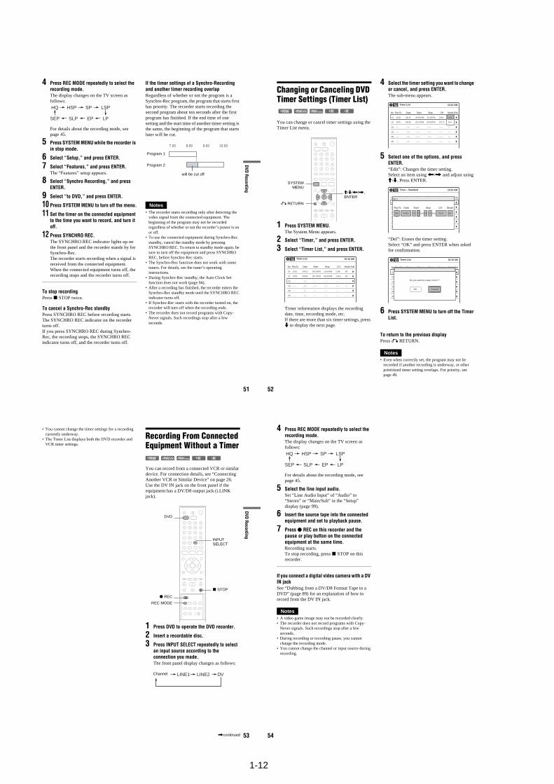
1-12
51
DVD
Recording
4 Press REC MODE repeatedly to select the recording mode.The display changes on the TV screen as follows:
For details about the recording mode, see page 45.
5 Press SYSTEM MENU while the recorder is in stop mode.
6 Select “Setup,” and press ENTER.
7 Select “Features,” and press ENTER.The “Features” setup appears.
8 Select “Synchro Recording,” and press ENTER.
9 Select “to DVD,” and press ENTER.
10 Press SYSTEM MENU to turn off the menu.
11 Set the timer on the connected equipment to the time you want to record, and turn it off.
12 Press SYNCHRO REC.The SYNCHRO REC indicator lights up on the front panel and the recorder stands by for Synchro-Rec.The recorder starts recording when a signal is received from the connected equipment. When the connected equipment turns off, the recording stops and the recorder turns off.
To stop recordingPress x STOP twice.
To cancel a Synchro-Rec standbyPress SYNCHRO REC before recording starts. The SYNCHRO REC indicator on the recorder turns off.If you press SYNCHRO REC during Synchro-Rec, the recording stops, the SYNCHRO REC indicator turns off, and the recorder turns off.
If the timer settings of a Synchro-Recording and another timer recording overlapRegardless of whether or not the program is a Synchro-Rec program, the program that starts first has priority. The recorder starts recording the second program about ten seconds after the first program has finished. If the end time of one setting and the start time of another timer setting is the same, the beginning of the program that starts later will be cut.
Notes• The recorder starts recording only after detecting the
video signal from the connected equipment. The beginning of the program may not be recorded regardless of whether or not the recorder’s power is on or off.
• To use the connected equipment during Synchro-Rec standby, cancel the standby mode by pressing SYNCHRO REC. To return to standby mode again, be sure to turn off the equipment and press SYNCHRO REC, before Synchro-Rec starts.
• The Synchro-Rec function does not work with some tuners. For details, see the tuner’s operating instructions.
• During Synchro-Rec standby, the Auto Clock Set function does not work (page 94).
• After a recording has finished, the recorder enters the Synchro-Rec standby mode until the SYNCHRO REC indicator turns off.
• If Synchro-Rec starts with the recorder turned on, the recorder will turn off when the recording ends.
• The recorder does not record programs with Copy-Never signals. Such recordings stop after a few seconds.
HQ SPHSP LSP
SEP EPSLP LP
7:00 8:00 9:00 10:00
Program 1
Program 2
will be cut off
52
Changing or Canceling DVD Timer Settings (Timer List)
You can change or cancel timer settings using the Timer List menu.
1 Press SYSTEM MENU.The System Menu appears.
2 Select “Timer,” and press ENTER.
3 Select “Timer List,” and press ENTER.
Timer information displays the recording date, time, recording mode, etc.If there are more than six timer settings, press m to display the next page.
4 Select the timer setting you want to change or cancel, and press ENTER.The sub-menu appears.
5 Select one of the options, and press ENTER.“Edit”: Changes the timer setting.Select an item using </, and adjust using M/m. Press ENTER.
“Del”: Erases the timer setting.Select “OK” and press ENTER when asked for confirmation.
6 Press SYSTEM MENU to turn off the Timer List.
To return to the previous displayPress O RETURN.
Notes• Even when correctly set, the program may not be
recorded if another recording is underway, or other prioritized timer setting overlaps. For priority, see page 49.
+RW +R-RWVR -RWVideo -R
SYSTEMMENU
M/m/</,, ENTER
O RETURN
01 DVD 04/15 09:00PM 10:00PM CH8
--- --/-- --:-- --:-- ---- ---04
--- --/-- --:-- --:-- ---- ---05
--- --/-- --:-- --:-- ---- ---06
03 --- --/-- --:-- --:-- ---- ---
02 DVD 04/30 09:15PM 09:45PM CH11
10:10 AM
SP
SP
Timer List
No RecTo Date Start Stop CH Mode Edit
01 DVD 04/15 09:00PM 10:00PM CH8
--- --/-- --:-- --:-- ---- ---04
--- --/-- --:-- --:-- ---- ---05
--- --/-- --:-- --:-- ---- ---06
03 --- --/-- --:-- --:-- ---- ---
02 DVD 04/30 09:15PM 09:45PM CH11
10:10 AMTimer List
No RecTo Date Start Stop CH Mode Edit
Edit
Del
01 DVD 04/15 09:00PM 10:00PM CH8
--- --/-- --:-- --:-- ---- ---04
--- --/-- --:-- --:-- ---- ---05
--- --/-- --:-- --:-- ---- ---06
03 --- --/-- --:-- --:-- ---- ---
02 DVD 04/30 09:15PM 09:45PM CH11
10:10 AM
No Rec To Date Start End Source Mode Edit
Timer – Standard
No.1
: PMDVD PM:04/15 09 00 10 00 CH 8 SP
RecTo Date Start Stop CH Mode
01 DVD 04/15 09:00PM 10:00PM CH8
--- --/-- --:-- --:-- ---- ---04
--- --/-- --:-- --:-- ---- ---05
--- --/-- --:-- --:-- ---- ---06
03 --- --/-- --:-- --:-- ---- ---
02 DVD 04/30 09:15PM 09:45PM CH11
10:10 AM
No Rec To Date Start End Source Mode Edit
Timer List
Do you want to erase ‘No.01’?
OK Cancel
53
DVD
Recording
• You cannot change the timer settings for a recording currently underway.
• The Timer List displays both the DVD recorder and VCR timer settings.
Recording From Connected Equipment Without a Timer
You can record from a connected VCR or similar device. For connection details, see “Connecting Another VCR or Similar Device” on page 26.Use the DV IN jack on the front panel if the equipment has a DV/D8 output jack (i.LINK jack).
1 Press DVD to operate the DVD recorder.
2 Insert a recordable disc.
3 Press INPUT SELECT repeatedly to select an input source according to the connection you made.The front panel display changes as follows:
+RW +R-RWVR -RWVideo -R
INPUT SELECT
x STOP
REC MODE
DVD
z REC
LINE2 DVLINE1Channel
,continued 54
4 Press REC MODE repeatedly to select the recording mode.The display changes on the TV screen as follows:
For details about the recording mode, see page 45.
5 Select the line input audio.Set “Line Audio Input” of “Audio” to “Stereo” or “Main/Sub” in the “Setup” display (page 99).
6 Insert the source tape into the connected equipment and set to playback pause.
7 Press z REC on this recorder and the pause or play button on the connected equipment at the same time.Recording starts.To stop recording, press x STOP on this recorder.
If you connect a digital video camera with a DV IN jackSee “Dubbing from a DV/D8 Format Tape to a DVD” (page 89) for an explanation of how to record from the DV IN jack.
Notes• A video game image may not be recorded clearly.• The recorder does not record programs with Copy-
Never signals. Such recordings stop after a few seconds.
• During recording or recording pause, you cannot change the recording mode.
• You cannot change the channel or input source during recording.
HQ SPHSP LSP
SEP EPSLP LP
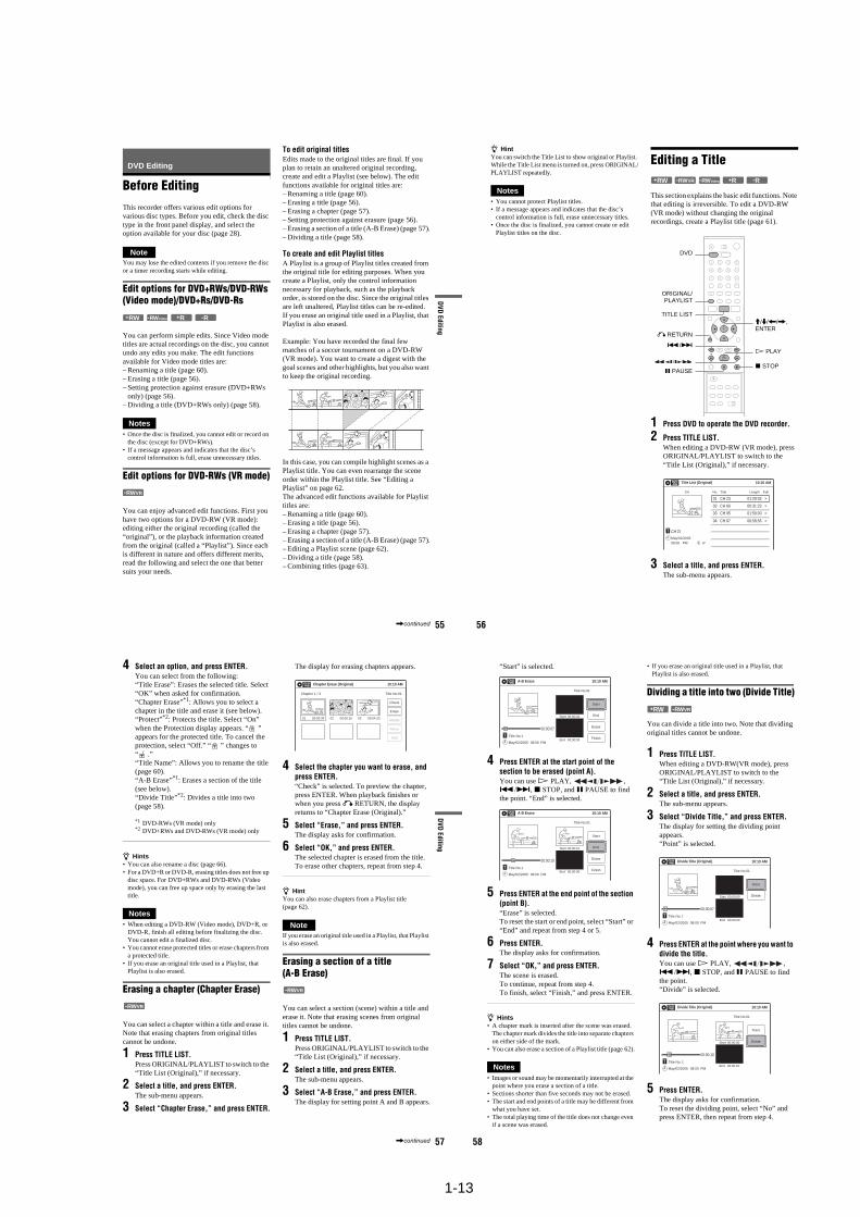
1-13
55
DVD
Editing
DVD Editing
Before EditingThis recorder offers various edit options for various disc types. Before you edit, check the disc type in the front panel display, and select the option available for your disc (page 28).
NoteYou may lose the edited contents if you remove the disc or a timer recording starts while editing.
Edit options for DVD+RWs/DVD-RWs (Video mode)/DVD+Rs/DVD-Rs
You can perform simple edits. Since Video mode titles are actual recordings on the disc, you cannot undo any edits you make. The edit functions available for Video mode titles are:– Renaming a title (page 60).– Erasing a title (page 56).– Setting protection against erasure (DVD+RWs
only) (page 56).– Dividing a title (DVD+RWs only) (page 58).
Notes• Once the disc is finalized, you cannot edit or record on
the disc (except for DVD+RWs).• If a message appears and indicates that the disc’s
control information is full, erase unnecessary titles.
Edit options for DVD-RWs (VR mode)
You can enjoy advanced edit functions. First you have two options for a DVD-RW (VR mode): editing either the original recording (called the “original”), or the playback information created from the original (called a “Playlist”). Since each is different in nature and offers different merits, read the following and select the one that better suits your needs.
To edit original titlesEdits made to the original titles are final. If you plan to retain an unaltered original recording, create and edit a Playlist (see below). The edit functions available for original titles are:– Renaming a title (page 60).– Erasing a title (page 56).– Erasing a chapter (page 57).– Setting protection against erasure (page 56).– Erasing a section of a title (A-B Erase) (page 57).– Dividing a title (page 58).
To create and edit Playlist titlesA Playlist is a group of Playlist titles created from the original title for editing purposes. When you create a Playlist, only the control information necessary for playback, such as the playback order, is stored on the disc. Since the original titles are left unaltered, Playlist titles can be re-edited.If you erase an original title used in a Playlist, that Playlist is also erased.
Example: You have recorded the final few matches of a soccer tournament on a DVD-RW(VR mode). You want to create a digest with the goal scenes and other highlights, but you also want to keep the original recording.
In this case, you can compile highlight scenes as a Playlist title. You can even rearrange the scene order within the Playlist title. See “Editing a Playlist” on page 62.The advanced edit functions available for Playlist titles are:– Renaming a title (page 60).– Erasing a title (page 56).– Erasing a chapter (page 57).– Erasing a section of a title (A-B Erase) (page 57).– Editing a Playlist scene (page 62).– Dividing a title (page 58).– Combining titles (page 63).
-RWVideo+RW +R -R
-RWVR
,continued 56
z HintYou can switch the Title List to show original or Playlist. While the Title List menu is turned on, press ORIGINAL/PLAYLIST repeatedly.
Notes• You cannot protect Playlist titles.• If a message appears and indicates that the disc’s
control information is full, erase unnecessary titles.• Once the disc is finalized, you cannot create or edit
Playlist titles on the disc.
Editing a Title
This section explains the basic edit functions. Note that editing is irreversible. To edit a DVD-RW (VR mode) without changing the original recordings, create a Playlist title (page 61).
1 Press DVD to operate the DVD recorder.
2 Press TITLE LIST.When editing a DVD-RW (VR mode), press ORIGINAL/PLAYLIST to switch to the “Title List (Original),” if necessary.
3 Select a title, and press ENTER.The sub-menu appears.
-RWVR -RWVideo+RW +R -R
M/m/</,,ENTER
TITLE LIST
H PLAY
x STOPX PAUSE
DVD
ORIGINAL/PLAYLIST
./>
O RETURN
Title List (Original) 10:10 AM
>
>
CH 23
08:00 PMMay/02/2005
T
No. Title Length Edit
01 CH 23 01:29:03
02 CH 66 00:31:23
03 CH 95 >01:59:00
04 CH 97 >00:58:56
1/4
57
DVD
Editing
4 Select an option, and press ENTER.You can select from the following:“Title Erase”: Erases the selected title. Select “OK” when asked for confirmation.“Chapter Erase”*1: Allows you to select a chapter in the title and erase it (see below).“Protect”*2: Protects the title. Select “On” when the Protection display appears. “ ” appears for the protected title. To cancel the protection, select “Off.” “ ” changes to “ .”“Title Name”: Allows you to rename the title (page 60).“A-B Erase”*1: Erases a section of the title (see below).“Divide Title”*2: Divides a title into two (page 58).
*1 DVD-RWs (VR mode) only*2 DVD+RWs and DVD-RWs (VR mode) only
z Hints• You can also rename a disc (page 66).• For a DVD+R or DVD-R, erasing titles does not free up
disc space. For DVD+RWs and DVD-RWs (Video mode), you can free up space only by erasing the last title.
Notes• When editing a DVD-RW (Video mode), DVD+R, or
DVD-R, finish all editing before finalizing the disc. You cannot edit a finalized disc.
• You cannot erase protected titles or erase chapters from a protected title.
• If you erase an original title used in a Playlist, that Playlist is also erased.
Erasing a chapter (Chapter Erase)
You can select a chapter within a title and erase it. Note that erasing chapters from original titles cannot be undone.
1 Press TITLE LIST.Press ORIGINAL/PLAYLIST to switch to the “Title List (Original),” if necessary.
2 Select a title, and press ENTER.The sub-menu appears.
3 Select “Chapter Erase,” and press ENTER.
The display for erasing chapters appears.
4 Select the chapter you want to erase, and press ENTER.“Check” is selected. To preview the chapter, press ENTER. When playback finishes or when you press O RETURN, the display returns to “Chapter Erase (Original).”
5 Select “Erase,” and press ENTER.The display asks for confirmation.
6 Select “OK,” and press ENTER.The selected chapter is erased from the title.To erase other chapters, repeat from step 4.
z HintYou can also erase chapters from a Playlist title (page 62).
NoteIf you erase an original title used in a Playlist, that Playlist is also erased.
Erasing a section of a title (A-B Erase)
You can select a section (scene) within a title and erase it. Note that erasing scenes from original titles cannot be undone.
1 Press TITLE LIST.Press ORIGINAL/PLAYLIST to switch to the “Title List (Original),” if necessary.
2 Select a title, and press ENTER.The sub-menu appears.
3 Select “A-B Erase,” and press ENTER.The display for setting point A and B appears.
-RWVR
Chapter Erase (Original) 10:10 AM
Chapter 1 / 3 Title No.01
Check
Erase
03 00:04:2002 00:00:1001 00:00:34Modify
Move
Add
-RWVR
,continued 58
“Start” is selected.
4 Press ENTER at the start point of the section to be erased (point A).You can use H PLAY, , ./>, x STOP, and X PAUSE to find the point. “End” is selected.
5 Press ENTER at the end point of the section (point B).“Erase” is selected.To reset the start or end point, select “Start” or “End” and repeat from step 4 or 5.
6 Press ENTER.The display asks for confirmation.
7 Select “OK,” and press ENTER.The scene is erased. To continue, repeat from step 4. To finish, select “Finish,” and press ENTER.
z Hints• A chapter mark is inserted after the scene was erased.
The chapter mark divides the title into separate chapters on either side of the mark.
• You can also erase a section of a Playlist title (page 62).
Notes• Images or sound may be momentarily interrupted at the
point where you erase a section of a title.• Sections shorter than five seconds may not be erased.• The start and end points of a title may be different from
what you have set.• The total playing time of the title does not change even
if a scene was erased.
• If you erase an original title used in a Playlist, that Playlist is also erased.
Dividing a title into two (Divide Title)
You can divide a title into two. Note that dividing original titles cannot be undone.
1 Press TITLE LIST.When editing a DVD-RW(VR mode), press ORIGINAL/PLAYLIST to switch to the “Title List (Original),” if necessary.
2 Select a title, and press ENTER.The sub-menu appears.
3 Select “Divide Title,” and press ENTER.The display for setting the dividing point appears.“Point” is selected.
4 Press ENTER at the point where you want to divide the title.You can use H PLAY, , ./>, x STOP, and X PAUSE to find the point.“Divide” is selected.
5 Press ENTER.The display asks for confirmation.To reset the dividing point, select “No” and press ENTER, then repeat from step 4.
A-B Erase 10:10 AM
Title No.01
End 00:00:00
Start 00:00:00
Start
End
Erase
Finish
00:00:07
T Title No.1
May/02/2005 08:00 PM
A-B Erase 10:10 AM
Title No.01
End 00:00:00
Start 00:00:10
Start
End
Erase
Finish
00:00:10
T Title No.1
May/02/2005 08:00 PM
-RWVR+RW
Divide Title (Original) 10:10 AM
Title No.01
T
Point
Divide
00:00:07
Title No. 1
Start 00:00:00
End 00:00:00May/02/2005 08:00 PM
10:10 AM
Title No.01
T00:00:10
Divide Title (Original)
Title No. 1End 00:00:10
Start 00:00:00
Point
Divide
May/02/2005 08:00 PM
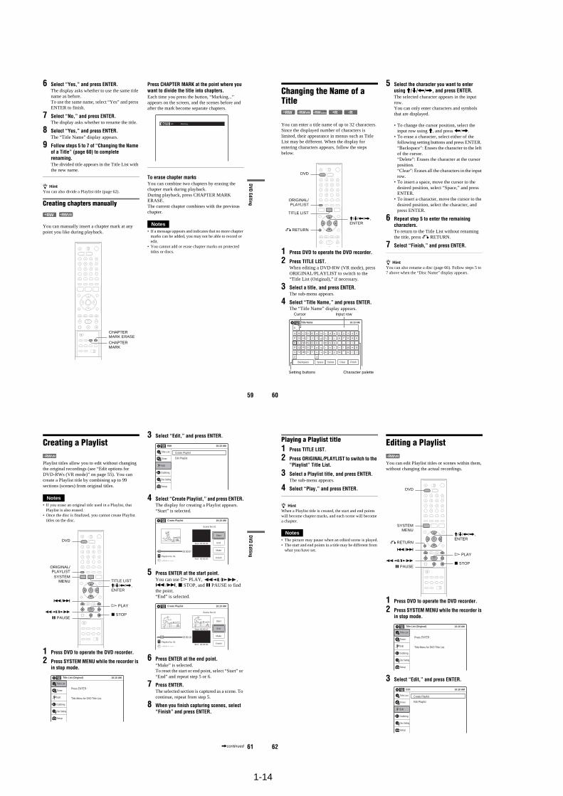
1-14
59
DVD
Editing
6 Select “Yes,” and press ENTER.The display asks whether to use the same title name as before.To use the same name, select “Yes” and press ENTER to finish.
7 Select “No,” and press ENTER.The display asks whether to rename the title.
8 Select “Yes,” and press ENTER.The “Title Name” display appears.
9 Follow steps 5 to 7 of “Changing the Name of a Title” (page 60) to complete renaming.The divided title appears in the Title List with the new name.
z HintYou can also divide a Playlist title (page 62).
Creating chapters manually
You can manually insert a chapter mark at any point you like during playback.
Press CHAPTER MARK at the point where you want to divide the title into chapters.Each time you press the button, “Marking...” appears on the screen, and the scenes before and after the mark become separate chapters.
To erase chapter marksYou can combine two chapters by erasing the chapter mark during playback.During playback, press CHAPTER MARK ERASE.The current chapter combines with the previous chapter.
Notes• If a message appears and indicates that no more chapter
marks can be added, you may not be able to record or edit.
• You cannot add or erase chapter marks on protected titles or discs.
-RWVR+RW
CHAPTER MARK
CHAPTER MARK ERASE
Marking...VR
60
Changing the Name of a Title
You can enter a title name of up to 32 characters. Since the displayed number of characters is limited, their appearance in menus such as Title List may be different. When the display for entering characters appears, follow the steps below.
1 Press DVD to operate the DVD recorder.
2 Press TITLE LIST.When editing a DVD-RW (VR mode), press ORIGINAL/PLAYLIST to switch to the “Title List (Original),” if necessary.
3 Select a title, and press ENTER.The sub-menu appears.
4 Select “Title Name,” and press ENTER.The “Title Name” display appears.
5 Select the character you want to enter using M/m/</,, and press ENTER.The selected character appears in the input row.You can only enter characters and symbols that are displayed.
• To change the cursor position, select the input row using M, and press </,.
• To erase a character, select either of the following setting buttons and press ENTER. “Backspace”: Erases the character to the left of the cursor. “Delete”: Erases the character at the cursor position. “Clear”: Erases all the characters in the input row.
• To insert a space, move the cursor to the desired position, select “Space,” and press ENTER.
• To insert a character, move the cursor to the desired position, select the character, and press ENTER.
6 Repeat step 5 to enter the remaining characters.To return to the Title List without renaming the title, press O RETURN.
7 Select “Finish,” and press ENTER.
z HintYou can also rename a disc (page 66). Follow steps 5 to 7 above when the “Disc Name” display appears.
+R-RWVR -RWVideo+RW -R
M/m/</,, ENTER
O RETURN
TITLE LIST
DVD
ORIGINAL/PLAYLIST
Title Name
K _
A B C D E
F G H I J
K L M N O
P Q R S T
U V W X Y
Z
a b c d e
f g h i j
k l m n o
p q r s t
u v w x y
z
1 2 3 4 5
6 7 8 9 0
- _ + = .
~ ! @ # $
% ^ & ( )
Backspace Space Delete Clear Finish
10:10 AM
Input row
Character paletteSetting buttons
Cursor
61
DVD
Editing
Creating a Playlist
Playlist titles allow you to edit without changing the original recordings (see “Edit options for DVD-RWs (VR mode)” on page 55). You can create a Playlist title by combining up to 99 sections (scenes) from original titles.
Notes• If you erase an original title used in a Playlist, that
Playlist is also erased.• Once the disc is finalized, you cannot create Playlist
titles on the disc.
1 Press DVD to operate the DVD recorder.
2 Press SYSTEM MENU while the recorder is in stop mode.
3 Select “Edit,” and press ENTER.
4 Select “Create Playlist,” and press ENTER.The display for creating a Playlist appears.“Start” is selected.
5 Press ENTER at the start point.You can use H PLAY, , ./>, x STOP, and X PAUSE to find the point.“End” is selected.
6 Press ENTER at the end point.“Make” is selected.To reset the start or end point, select “Start” or “End” and repeat step 5 or 6.
7 Press ENTER.The selected section is captured as a scene. To continue, repeat from step 5.
8 When you finish capturing scenes, select “Finish” and press ENTER.
-RWVR
M/m/</,,ENTER
SYSTEMMENU
H PLAY
TITLE LIST
x STOPX PAUSE
DVD
ORIGINAL/PLAYLIST
./>
Press ENTER :
Title Menu for DVD Title List.
10:10 AMTitle List (Original)
Setup
Disc Setting
Edit
Title List
Timer
Dubbing
10:10 AM
Create Playlist
Edit Playlist
Edit
Setup
Disc Setting
Edit
Title List
Timer
Dubbing
Create Playlist 10:10 AM
Scene No.01
End 00:00:00
Start 00:00:00
T
Start
End
Make
Finish
00:00:07
---/--/---- --:--
Playlist No. 01
10:10 AM
Scene No.01
TFinish
00:00:10
Create Playlist
Playlist No. 01End 00:00:00
Start 00:00:10
Start
End
Make
---/--/---- --:--
,continued 62
Playing a Playlist title1 Press TITLE LIST.
2 Press ORIGINAL/PLAYLIST to switch to the “Playlist” Title List.
3 Select a Playlist title, and press ENTER.The sub-menu appears.
4 Select “Play,” and press ENTER.
z HintWhen a Playlist title is created, the start and end points will become chapter marks, and each scene will become a chapter.
Notes• The picture may pause when an edited scene is played.• The start and end points in a title may be different from
what you have set.
Editing a Playlist
You can edit Playlist titles or scenes within them, without changing the actual recordings.
1 Press DVD to operate the DVD recorder.
2 Press SYSTEM MENU while the recorder is in stop mode.
3 Select “Edit,” and press ENTER.
-RWVR
SYSTEMMENU
DVD
M/m/</,, ENTER
H PLAY
x STOPX PAUSE
O RETURN
./>
Press ENTER :
Title Menu for DVD Title List.
10:10 AMTitle List (Original)
Setup
Disc Setting
Edit
Title List
Timer
Dubbing
10:10 AM
Create Playlist
Edit Playlist
Edit
Setup
Disc Setting
Edit
Title List
Timer
Dubbing
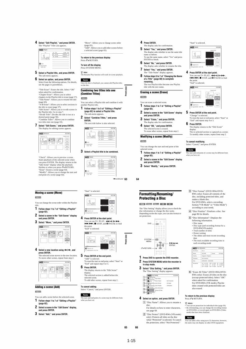
1-15
63
DVD
Editing
4 Select “Edit Playlist,” and press ENTER.The “Playlist” Title List appears.
5 Select a Playlist title, and press ENTER.The sub-menu appears.
6 Select an option, and press ENTER.Select from the following options. For details, see the pages in parentheses.
“Title Erase”: Erases the title. Select “OK” when asked for confirmation.“Chapter Erase”: Allows you to select chapters in the Playlist title to erase (page 57).“Title Name”: Allows you to rename the title (page 60).“A-B Erase”: Allows you to select sections in the title to erase (page 57).“Edit Scene”: Allows you to re-edit scenes in the Playlist title. Go to step 7.“Divide Title”: Divides the title in two at a desired point (page 58).“Combine Titles”: Allows you to combine two titles into one (page 63).
7 Select “Edit Scene,” and press ENTER.The display for editing scenes appears.
“Check”: Allows you to preview a scene. Starts playback of the selected scene when you press ENTER. The display returns to the “Edit Scene” display when the playback finishes or when you press O RETURN.“Erase”: Erases a scene (page 64).“Modify”: Allows you to change the start and end point of a scene (page 64).
“Move”: Allows you to change scene order (page 65).“Add”: Allows you to add other scenes before a selected scene (page 65).
To return to the previous displayPress O RETURN.
To turn off the displayPress SYSTEM MENU.
z HintThe Resume Play function will work for scene playback.
NoteOnce the disc is finalized, you cannot edit Playlist titles on the disc.
Combining two titles into one (Combine Titles)
You can select a Playlist title and combine it with another Playlist title.
1 Follow steps 1 to 5 of “Editing a Playlist” (page 62) to select a Playlist title.The sub-menu appears.
2 Select “Combine Titles,” and press ENTER.The next title below is also selected.
3 Select a Playlist title to be combined.
Playlist 10:10 AM
01 CH 32 >00:05:04
02 CH 96 >00:00:51
CH 32
03:25 PMMay/02/2005
T
No. Title Length Edit1/2
Edit Scene 10:10 AM
Scene No.1 / 3 Playlist No.01
Check
Erase
Modify
Move
Add
03 00:04:2002 00:00:1001 00:00:34
-RWVR
Playlist 10:10 AM
>
>
CH 32
03:25 PMMay/02/2005
T
No. Title Length Edit
01 CH 32 00:05:04
02 CH 96 00:00:51
03 CH 95 >01:59:00
04 CH 97 >00:58:56
1/4
Playlist 10:10 AM
>
>
CH 95
11:30 PMMay/15/2005
T
No. Title Length Edit
01 CH 32 00:05:04
02 CH 96 00:00:51
03 CH 95 >01:59:00
04 CH 97 >00:58:56
3/4
,continued 64
4 Press ENTER.The display asks for confirmation.
5 Select “Yes,” and press ENTER.The display asks whether to use the same title name as before.To use the same name, select “Yes” and press ENTER to finish.
6 Select “No,” and press ENTER.The display asks whether to rename the title.
7 Select “Yes,” and press ENTER.The “Title Name” display appears.
8 Follow steps 5 to 7 of “Changing the Name of a Title” (page 60) to complete renaming.The two Playlist titles become one Playlist title with the new name.
Erasing a scene (Erase)
You can erase a selected scene.
1 Follow steps 1 to 7 of “Editing a Playlist” (page 62).
2 Select a scene in the “Edit Scene” display and press ENTER.
3 Select “Erase,” and press ENTER.The display asks for confirmation.
4 Select “OK,” and press ENTER.The selected scene is erased.To erase other scenes, repeat from step 2.
Modifying a scene (Modify)
You can change the start and end point of the selected scene.
1 Follow steps 1 to 7 of “Editing a Playlist” (page 62).
2 Select a scene in the “Edit Scene” display and press ENTER.
3 Select “Modify,” and press ENTER.
“Start” is selected.
4 Press ENTER at the start point.You can use H PLAY, , ./>, x STOP, and X PAUSE to find the point.“End” is selected.
5 Press ENTER at the end point.“Change” is selected.To reset the start or end point, select “Start” or “End” and repeat step 4 or 5.
6 Press ENTER.The display returns to the “Edit Scene” display.The re-selected section is captured as a scene.To modify other scenes, repeat from step 2.
To cancel modifyingSelect “Cancel,” and press ENTER.
NoteThe start and end point of a scene may be different from what you have set.
-RWVR
-RWVR
Modify 10:10 AM
T
Change
Cancel
00:00:07
Playlist No. 01
Scene No.01
End 00:00:00
Start 00:00:00
Start
End
May/02/2005 03:25 PM
Modify 10:10 AM
Scene No.01
T00:00:10
May/02/2005 03:25 PM
Playlist No. 01
Change
CancelEnd 00:00:00
Start 00:00:10
Start
End
65
DVD
Editing
Moving a scene (Move)
You can change the scene order within the Playlist title.
1 Follow steps 1 to 7 of “Editing a Playlist” (page 62).
2 Select a scene in the “Edit Scene” display and press ENTER.
3 Select “Move,” and press ENTER.
4 Select a new location using </,, and press ENTER.The selected scene moves to the new location.To move other scenes, repeat from step 2.
Adding a scene (Add)
You can add a scene before the selected scene.
1 Follow steps 1 to 7 of “Editing a Playlist” (page 62).
2 Select a scene in the “Edit Scene” display, and press ENTER.
3 Select “Add,” and press ENTER.
“Start” is selected.
4 Press ENTER at the start point.You can use H PLAY, , ./>, x STOP, and X PAUSE to find the point.“End” is selected.
5 Press ENTER at the end point.“Add” is selected.To reset the start or end point, select “Start” or “End” and repeat step 4 or 5.
6 Press ENTER.The display returns to the “Edit Scene” display.The selected section is added before the selected scene.To add other scenes, repeat from step 2.
To cancel addingSelect “Cancel,” and press ENTER.
NoteThe start and end point of a scene may be different from what you have set.
-RWVR
Edit Scene 10:10 AM
Scene No. 2 / 3
Check
Erase
Modify
Move
Add
03 00:04:2002 00:00:1001 00:00:34
Playlist No.01
Edit Scene 10:10 AM
Scene No. 3 / 3
Check
Modify
Add
Erase
02 00:04:20 03 00:00:1001 00:00:34
Playlist No.01
Move
-RWVR
Add 10:10 AM
T00:00:07
Playlist No. 01
Scene No.01
Add
CancelEnd 00:00:00
Start 00:00:00
Start
End
May/02/2005 03:25 PM
Add 10:10 AM
Scene No.01
T00:00:10
Playlist No. 01
Add
CancelEnd 00:00:00
Start 00:00:10
Start
End
May/02/2005 03:25 PM
66
Formatting/Renaming/Protecting a Disc
The “Disc Setting” display allows you to check the disc information or change the disc name. Depending on the disc type, you can also format or set protection.
1 Press DVD to operate the DVD recorder.
2 Press SYSTEM MENU while the recorder is in stop mode.
3 Select “Disc Setting,” and press ENTER.The “Disc Setting” display appears.
4 Select an option, and press ENTER.
A “Disc Name”: Allows you to rename a disc.For details on how to enter characters, see page 60.
B “Disc Protect” (DVD-RWs (VR mode) only): Protects all titles on the disc when “Protected” is selected. To cancel the protection, select “Not Protected.”
C “Disc Format” (DVD+RWs/DVD-RWs only): Erases all contents of the disc, including protected titles, and makes a blank disc.For DVD-RWs, select a recording format (“VR Mode” or “Video Mode”) according to your needs.
D “Disc Finalize”: Finalizes a disc. See page 86 for details.
E “Disc Information”: Displays the following information.• Disc name• Disc type (and recording format for a
DVD-RW(VR mode))• Total number of titles• Protect setting• The oldest and most recent recording
date• The total available recording time in
each recording mode
F “Erase All Titles” (DVD+RWs/DVD-RWs only): Erases all titles on the disc (except protected titles). Select “OK” when asked for confirmation. For DVD-RWs (VR mode), Playlist titles created with protected titles are also erased.
To return to the previous displayPress O RETURN.
z Hints• You can set protection for individual titles (page 56).• By reformatting, you can change the recording format
on DVD-RWs, or record again on DVD-RWs (Video mode) that have been finalized.
NoteYou can label a disc using up to 32 characters; however, the name may not display on other DVD equipment.
+RW -RWVR -RWVideo +R -R
SYSTEMMENU
DVD
M/m/</,, ENTER
O RETURN
Disc Setting 10:10 AM
Disc Name :
Disc Protect : Not Protected
Disc Format : VR Mode
Disc Finalize : Unfinalized
Disc Information
Erase All Titles
Setup
Disc Setting
Edit
Title List
Timer
Dubbing
2
3
4
5
1
6
10:10 AMDisc Information
Disc Name
Media
Title No.
Protected
Date
Remainder
Disc 1
DVD-RW VR ModeFormat
Original 6 / Playlist 1
Not Protected
04/05/2005 ~ 04/30/2005
HQ : 0H 57MLSP : 2H 23MSLP : 5H 46M
HSP : 1H 26MLP : 2H 52MSEP : 7H 40M
SP : 1H 55MEP : 3H 50M4.4/4.7GB
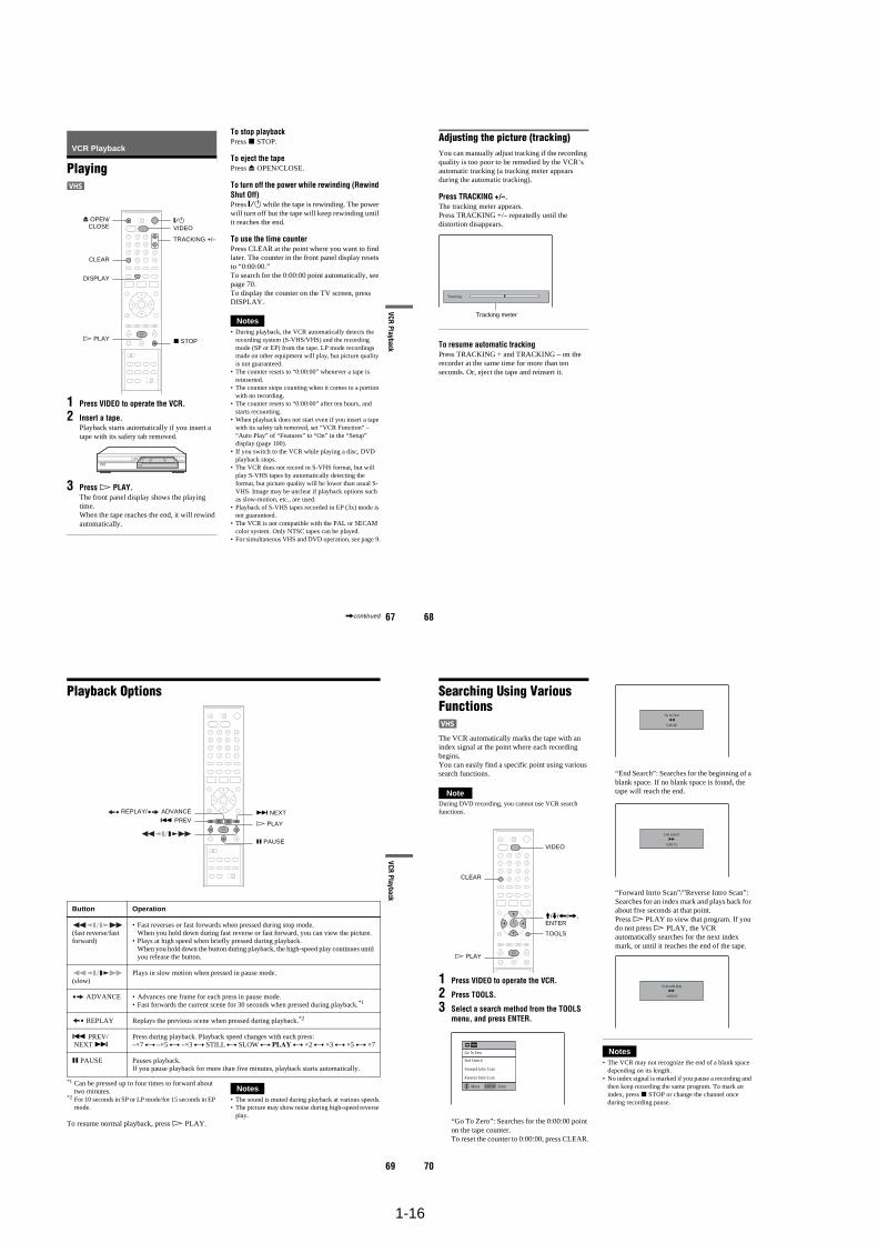
1-16
67
VCR Playback
VCR Playback
Playing
1 Press VIDEO to operate the VCR.
2 Insert a tape.Playback starts automatically if you insert a tape with its safety tab removed.
3 Press H PLAY.The front panel display shows the playing time.When the tape reaches the end, it will rewind automatically.
To stop playbackPress x STOP.
To eject the tapePress Z OPEN/CLOSE.
To turn off the power while rewinding (Rewind Shut Off)Press "/1 while the tape is rewinding. The power will turn off but the tape will keep rewinding until it reaches the end.
To use the time counterPress CLEAR at the point where you want to find later. The counter in the front panel display resets to “0:00:00.”To search for the 0:00:00 point automatically, see page 70. To display the counter on the TV screen, press DISPLAY.
Notes• During playback, the VCR automatically detects the
recording system (S-VHS/VHS) and the recording mode (SP or EP) from the tape. LP mode recordings made on other equipment will play, but picture quality is not guaranteed.
• The counter resets to “0:00:00” whenever a tape is reinserted.
• The counter stops counting when it comes to a portion with no recording.
• The counter resets to “0:00:00” after ten hours, and starts recounting.
• When playback does not start even if you insert a tape with its safety tab removed, set “VCR Function” – “Auto Play” of “Features” to “On” in the “Setup” display (page 100).
• If you switch to the VCR while playing a disc, DVD playback stops.
• The VCR does not record in S-VHS format, but will play S-VHS tapes by automatically detecting the format, but picture quality will be lower than usual S-VHS. Image may be unclear if playback options such as slow-motion, etc., are used.
• Playback of S-VHS tapes recorded in EP (3x) mode is not guaranteed.
• The VCR is not compatible with the PAL or SECAM color system. Only NTSC tapes can be played.
• For simultaneous VHS and DVD operation, see page 9.
x STOP
"/1
DISPLAY
CLEAR
H PLAY
Z OPEN/CLOSE VIDEO
TRACKING +/–
,continued 68
Adjusting the picture (tracking) You can manually adjust tracking if the recording quality is too poor to be remedied by the VCR’s automatic tracking (a tracking meter appears during the automatic tracking).
Press TRACKING +/–.The tracking meter appears. Press TRACKING +/– repeatedly until the distortion disappears.
To resume automatic trackingPress TRACKING + and TRACKING – on the recorder at the same time for more than ten seconds. Or, eject the tape and reinsert it.
Tracking
Tracking meter
69
VCR Playback
Playback Options
*1 Can be pressed up to four times to forward about two minutes.
*2 For 10 seconds in SP or LP mode/for 15 seconds in EP mode.
To resume normal playback, press H PLAY.
Notes• The sound is muted during playback at various speeds.• The picture may show noise during high-speed reverse
play.
Button Operation
(fast reverse/fast forward)
• Fast reverses or fast forwards when pressed during stop mode.When you hold down during fast reverse or fast forward, you can view the picture.
• Plays at high speed when briefly pressed during playback. When you hold down the button during playback, the high-speed play continues until you release the button.
(slow)Plays in slow motion when pressed in pause mode.
ADVANCE • Advances one frame for each press in pause mode.• Fast forwards the current scene for 30 seconds when pressed during playback.*1
REPLAY Replays the previous scene when pressed during playback.*2
. PREV/ NEXT >
Press during playback. Playback speed changes with each press:–×7 y –×5 y –×3 y STILL y SLOW y PLAY y ×2 y ×3 y ×5 y ×7
X PAUSE Pauses playback.If you pause playback for more than five minutes, playback starts automatically.
X PAUSE
> NEXT REPLAY/ ADVANCE. PREV
H PLAY
70
Searching Using Various Functions
The VCR automatically marks the tape with an index signal at the point where each recording begins.You can easily find a specific point using various search functions.
NoteDuring DVD recording, you cannot use VCR search functions.
1 Press VIDEO to operate the VCR.
2 Press TOOLS.
3 Select a search method from the TOOLS menu, and press ENTER.
“Go To Zero”: Searches for the 0:00:00 point on the tape counter. To reset the counter to 0:00:00, press CLEAR.
“End Search”: Searches for the beginning of a blank space. If no blank space is found, the tape will reach the end.
“Forward Inrto Scan”/”Reverse Intro Scan”: Searches for an index mark and plays back for about five seconds at that point. Press H PLAY to view that program. If you do not press H PLAY, the VCR automatically searches for the next index mark, or until it reaches the end of the tape.
Notes• The VCR may not recognize the end of a blank space
depending on its length.• No index signal is marked if you pause a recording and
then keep recording the same program. To mark an index, press x STOP or change the channel once during recording pause.
M/m/</,,ENTER
H PLAY
VIDEO
TOOLS
CLEAR
ENTER Enter
Go To Zero
End Search
Forward Intro Scan
Reverse Intro Scan
Move
0:00:00
Go to Zero
0:00:13
End search
–0:00:01
Scan and play
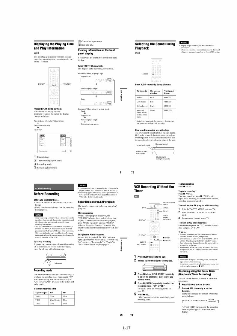
1-17
71
VCR Playback
Displaying the Playing Time and Play Information
You can check playback information, such as elapsed or remaining time, recording mode, etc., on the TV screen.
Press DISPLAY during playback.The information display appears.Each time you press the button, the display changes as follows:
Tape and disc information/date and timem
Tape information onlym
No display
A Playing status
B Time counter (elapsed time)
C Recording mode
D Remaining tape length
E Channel or input source
F Date and time
Viewing information on the front panel displayYou can view the information on the front panel display.
Press TIME/TEXT repeatedly.The displays differ depending on the status.
Example: When playing a tape
Example: When a tape is in stop modeClock
m
Elapsed timem
Remaining tape lengthm
Channel or input source
DISPLAY TIME/TEXT
Stop
1:23:45
HQ
Rem 16:15
Original
Play
0:30:00
SP
Rem 01:30
CH 110
Mon May 02. 2005 10:10 AM
Elapsed time
Remaining tape length
Clock
72
Selecting the Sound During Playback
Press AUDIO repeatedly during playback.
* No indicator appears in the front panel display when you play a tape without Hi-fi recording.
How sound is recorded on a video tapeThe VCR records sound onto two separate tracks. Hi-fi audio is recorded onto the main track along with the picture. Monaural sound is recorded onto the normal audio track along the edge of the tape.
Notes• To play a tape in stereo, you must use the A/V
connections.• When you play a tape recorded in monaural, the sound
is heard in monaural regardless of the AUDIO setting.
To listen to On-screen display
Front panel display
Stereo Hi-Fi STEREO
Left channel Left STEREO
Right channel Right STEREO
Monaural sound on the normal audio track
Mono STEREO*
AUDIO
Normal audio track
Hi-fi audio track (main track)
Monaural sound
Stereo sound(left/right channels)
73
VCR R
ecording
VCR Recording
Before RecordingBefore you start recording…• This VCR records in VHS format, not S-VHS
format.• Check that the tape is longer than the recording
time (page 71).
Notes• Timer recordings will start with or without the recorder
turned on. Once started, the recorder cannot be turned off. The recorder automatically turns off after a recording has finished.
• This recorder shares a single tuner for both the DVD recorder and the VCR. You cannot record different programs to a DVD and a VHS tape at the same time.
• This recorder has the copy guard function. Programs that contain a Copy-Never copy guard signal cannot be correctly recorded on the VCR.
To save a recordingTo prevent accidental erasure, break off the safety tab as illustrated. To record on the tape again, cover the tab hole with adhesive tape.
Recording mode“EP” (Extended Play) and “SP” (Standard Play) is available for recording mode (tape speed). “EP” provides recording time three times as long as “SP.” However, “SP” produces better picture and audio quality.
Maximum recording time
Notes• Tapes recorded in EP (×3) mode by this VCR cannot be
played back on VHS video decks with SP mode only.• Noise may appear in the image when tapes recorded in
EP (×3) mode by this VCR are played back on other VHS video decks with EP mode.
Recording a stereo/SAP programThe recorder can receive and record stereo/SAP programs.
Stereo programsWhen a stereo program is received, the “STEREO” indicator lights up in the front panel display. If there is noise in the stereo program, press AUDIO repeatedly until the “MONO” indicator disappears from the TV screen. The sound will be recorded in monaural but with less noise.
SAP (Second Audio Program)When a SAP is received, the “SAP” indicator lights up in the front panel display. To record only SAP sound, set “Tuner Audio” of “Audio” to “SAP” in the “Setup” display (page 97).
Tape Length SP EP
T-120 2 hrs 6 hrs
T-160 2 hrs 40 mins 8 hrs
T-180 3 hrs 9 hrs
Safety tab
74
VCR Recording Without the Timer
1 Press VIDEO to operate the VCR.
2 Insert a tape with its safety tab in place.
3 Press CH +/– or INPUT SELECT repeatedly to select the channel or input source you want to record.
4 Press REC MODE repeatedly to select the recording mode, “SP” or “EP.”For details about the recording mode, see page 73.
5 Press z REC.“REC” appears in the front panel display, and recording starts.
To stop recordingPress x STOP.
To pause recordingPress X PAUSE. To restart recording, press X PAUSE again.If you pause recording for more than five minutes, recording stops automatically.
To watch another TV program while recording
1 Slide the TV/DVD·VIDEO switch to TV.
2 Press TV/VIDEO to set the TV to the TV input.
3 Select another channel on the TV.
To watch a DVD while recordingPress DVD to operate the DVD recorder, insert a disc, and press H PLAY.
z Hints• To select a channel, you can use the number buttons.
Enter the channel number, and press SET.• You can select a video source from the LINE 1 IN or
LINE 2 IN jacks using the INPUT SELECT button.• Tape information displayed on the TV screen will not
be recorded on the tape.• You can turn off the TV during recording. If you are
using a cable box or a satellite receiver, make sure to leave it on.
Notes• You cannot change the recording mode, channel, or
input source while recording.• If you insert a tape with its safety tab removed, the tape
is ejected when you press z REC.
Recording using the Quick Timer(One-touch Timer Recording)You can set the recorder to record in 30-minute increments.
1 Press VIDEO to operate the VCR.
2 Press z REC repeatedly to set the duration.Each press increases the time by 30 minutes, up to six hours.
“c” and “OTR” light up, and the remaining recording time appears in the front panel display.
REC MODE
H PLAY
X PAUSE
x STOP
z REC
VIDEO
TV/VIDEO
CH +/–
DVD
INPUT SELECT
TV/DVD·VIDEO switch
DISPLAY
0:30 1:00 5:30 6:00(normal recording)
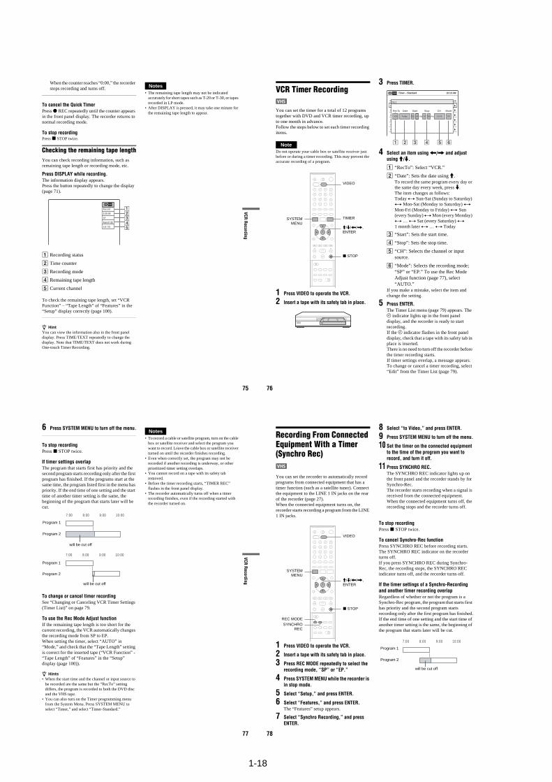
1-18
75
VCR R
ecording
When the counter reaches “0:00,” the recorder stops recording and turns off.
To cancel the Quick TimerPress z REC repeatedly until the counter appears in the front panel display. The recorder returns to normal recording mode.
To stop recordingPress x STOP twice.
Checking the remaining tape lengthYou can check recording information, such as remaining tape length or recording mode, etc.
Press DISPLAY while recording.The information display appears.Press the button repeatedly to change the display (page 71).
A Recording status
B Time counter
C Recording mode
D Remaining tape length
E Current channel
To check the remaining tape length, set “VCR Function” – “Tape Length” of “Features” in the “Setup” display correctly (page 100).
z HintYou can view the information also in the front panel display. Press TIME/TEXT repeatedly to change the display. Note that TIME/TEXT does not work during One-touch Timer Recording.
Notes• The remaining tape length may not be indicated
accurately for short tapes such as T-20 or T-30, or tapes recorded in LP mode.
• After DISPLAY is pressed, it may take one minute for the remaining tape length to appear.
Record
0:30:00
SP
Rem 01:30
CH 110
76
VCR Timer Recording
You can set the timer for a total of 12 programs together with DVD and VCR timer recording, up to one month in advance. Follow the steps below to set each timer recording items.
NoteDo not operate your cable box or satellite receiver just before or during a timer recording. This may prevent the accurate recording of a program.
1 Press VIDEO to operate the VCR.
2 Insert a tape with its safety tab in place.
3 Press TIMER.
4 Select an item using </, and adjust using M/m.
A “RecTo”: Select “VCR.”
B “Date”: Sets the date using M.To record the same program every day or the same day every week, press m.The item changes as follows:Today y Sun-Sat (Sunday to Saturday) y Mon-Sat (Monday to Saturday) y Mon-Fri (Monday to Friday) y Sun (every Sunday) y Mon (every Monday) y … y Sat (every Saturday) y 1 month later y … y Today
C “Start”: Sets the start time.
D “Stop”: Sets the stop time.
E “CH”: Selects the channel or input source.
F “Mode”: Selects the recording mode; “SP” or “EP.” To use the Rec Mode Adjust function (page 77), select “AUTO.”
If you make a mistake, select the item and change the setting.
5 Press ENTER.The Timer List menu (page 79) appears. The c indicator lights up in the front panel display, and the recorder is ready to start recording.If the c indicator flashes in the front panel display, check that a tape with its safety tab in place is inserted.There is no need to turn off the recorder before the timer recording starts.If timer settings overlap, a message appears. To change or cancel a timer recording, select “Edit” from the Timer List (page 79).
M/m/</,, ENTER
SYSTEMMENU
TIMER
x STOP
VIDEO
01 VHS 4/15 09:00PM 10:00PM CH8
--- --/-- --:-- --:-- ---- ---04
--- --/-- --:-- --:-- ---- ---05
--- --/-- --:-- --:-- ---- ---06
03 --- --/-- --:-- --:-- ---- ---
02 VHS 4/30 09:15PM 09:45PM CH11
10:10 AM
No Rec To Date Start End Source Mode EditNo.1
: PMVCR PM:Today 09 00 10 00 CH 8 SP
1 2 3 4 5 6
Timer – Standard
RecTo Date Start Stop CH Mode
77
VCR R
ecording
6 Press SYSTEM MENU to turn off the menu.
To stop recordingPress x STOP twice.
If timer settings overlapThe program that starts first has priority and the second program starts recording only after the first program has finished. If the programs start at the same time, the program listed first in the menu has priority. If the end time of one setting and the start time of another timer setting is the same, the beginning of the program that starts later will be cut.
To change or cancel timer recording See “Changing or Canceling VCR Timer Settings (Timer List)” on page 79.
To use the Rec Mode Adjust functionIf the remaining tape length is too short for the current recording, the VCR automatically changes the recording mode from SP to EP. When setting the timer, select “AUTO” in “Mode,” and check that the “Tape Length” setting is correct for the inserted tape (“VCR Function” - “Tape Length” of “Features” in the “Setup” display (page 100)).
z Hints• When the start time and the channel or input source to
be recorded are the same but the “RecTo” setting differs, the program is recorded to both the DVD disc and the VHS tape.
• You can also turn on the Timer programming menu from the System Menu. Press SYSTEM MENU to select “Timer,” and select “Timer-Standard.”
Notes• To record a cable or satellite program, turn on the cable
box or satellite receiver and select the program you want to record. Leave the cable box or satellite receiver turned on until the recorder finishes recording.
• Even when correctly set, the program may not be recorded if another recording is underway, or other prioritized timer setting overlaps.
• You cannot record on a tape with its safety tab removed.
• Before the timer recording starts, “TIMER REC” flashes in the front panel display.
• The recorder automatically turns off when a timer recording finishes, even if the recording started with the recorder turned on.
7:00 8:00 9:00 10:00
7:00 8:00 9:00 10:00
Program 1
Program 2
Program 1
will be cut off
will be cut off
Program 2
78
Recording From Connected Equipment With a Timer (Synchro Rec)
You can set the recorder to automatically record programs from connected equipment that has a timer function (such as a satellite tuner). Connect the equipment to the LINE 1 IN jacks on the rear of the recorder (page 27).When the connected equipment turns on, the recorder starts recording a program from the LINE 1 IN jacks.
1 Press VIDEO to operate the VCR.
2 Insert a tape with its safety tab in place.
3 Press REC MODE repeatedly to select the recording mode, “SP” or “EP.”
4 Press SYSTEM MENU while the recorder is in stop mode.
5 Select “Setup,” and press ENTER.
6 Select “Features,” and press ENTER.The “Features” setup appears.
7 Select “Synchro Recording,” and press ENTER.
8 Select “to Video,” and press ENTER.
9 Press SYSTEM MENU to turn off the menu.
10 Set the timer on the connected equipment to the time of the program you want to record, and turn it off.
11 Press SYNCHRO REC.The SYNCHRO REC indicator lights up on the front panel and the recorder stands by for Synchro-Rec.The recorder starts recording when a signal is received from the connected equipment. When the connected equipment turns off, the recording stops and the recorder turns off.
To stop recordingPress x STOP twice.
To cancel Synchro-Rec functionPress SYNCHRO REC before recording starts. The SYNCHRO REC indicator on the recorder turns off.If you press SYNCHRO REC during Synchro-Rec, the recording stops, the SYNCHRO REC indicator turns off, and the recorder turns off.
If the timer settings of a Synchro-Recording and another timer recording overlapRegardless of whether or not the program is a Synchro-Rec program, the program that starts first has priority and the second program starts recording only after the first program has finished.If the end time of one setting and the start time of another timer setting is the same, the beginning of the program that starts later will be cut.
SYNCHROREC
x STOP
REC MODE
SYSTEMMENU
M/m/</,, ENTER
VIDEO
7:00 8:00 9:00 10:00
Program 1
Program 2
will be cut off
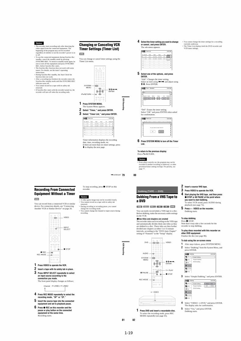
1-19
79
VCR R
ecording
Notes• The recorder starts recording only after detecting the
video signal from the connected equipment. The beginning of the program may not be recorded regardless of whether or not the recorder’s power is on or off.
• To use the connected equipment during Synchro-Rec standby, cancel the standby mode by pressing SYNCHRO REC. To return to standby mode again, be sure to turn off the equipment and press SYNCHRO REC, before Synchro-Rec starts.
• The Synchro-Rec function does not work with some tuners. For details, see the tuner’s operating instructions.
• During Synchro-Rec standby, the Auto Clock Set function does not work.
• After a recording has finished, the recorder enters the Synchro-Rec standby mode until the SYNCHRO REC indicator turns off.
• You cannot record on a tape with its safety tab removed.
• If Synchro-Rec starts with the recorder turned on, the recorder will turn off when the recording ends.
Changing or Canceling VCR Timer Settings (Timer List)
You can change or cancel timer settings using the Timer List menu.
1 Press SYSTEM MENU.The System Menu appears.
2 Select “Timer,” and press ENTER.
3 Select “Timer List,” and press ENTER.
Timer information displays the recording date, time, recording mode, etc.If there are more than six timer settings, press m to display the next page.
SYSTEMMENU
M/m/</,, ENTER
O RETURN
01 VCR 04/15 09:00PM 10:00PM CH8
--- --/-- --:-- --:-- ---- ---04
--- --/-- --:-- --:-- ---- ---05
--- --/-- --:-- --:-- ---- ---06
03 --- --/-- --:-- --:-- ---- ---
02 VCR 04/30 09:15PM 09:45PM CH11
10:10 AM
SP
SP
Timer List
No RecTo Date Start Stop CH Mode Edit
,continued 80
4 Select the timer setting you want to change or cancel, and press ENTER.The sub-menu appears.
5 Select one of the options, and press ENTER.“Edit”: Changes the timer setting.Select an item using </, and adjust using M/m. Press ENTER.
“Del”: Erases the timer setting.Select “OK” and press ENTER when asked for confirmation.
6 Press SYSTEM MENU to turn off the Timer List.
To return to the previous displayPress O RETURN.
Notes• Even when correctly set, the program may not be
recorded if another recording is underway, or other prioritized timer setting overlaps. For priority, see page 77.
• You cannot change the timer settings for a recording currently underway.
• The Timer List displays both the DVD recorder and VCR timer settings.
Del
Edit01 VCR 04/15 09:00PM 10:00PM CH8
--- --/-- --:-- --:-- ---- ---04
--- --/-- --:-- --:-- ---- ---05
--- --/-- --:-- --:-- ---- ---06
03 --- --/-- --:-- --:-- ---- ---
02 VCR 04/30 09:15PM 09:45PM CH11
10:10 AMTimer List
No RecTo Date Start Stop CH Mode Edit
01 DVD 04/15 09:00PM 10:00PM CH8
--- --/-- --:-- --:-- ---- ---04
--- --/-- --:-- --:-- ---- ---05
--- --/-- --:-- --:-- ---- ---06
03 --- --/-- --:-- --:-- ---- ---
02 DVD 04/30 09:15PM 09:45PM CH11
10:10 AMTimer – Standard
No Rec To Date Start End Source Mode EditNo.1
: PMVCR PM:04/15 09 00 10 00 CH 8 SP
RecTo Date Start Stop CH Mode
01 VHS 4/15 09:00PM 10:00PM CH8
--- --/-- --:-- --:-- ---- ---04
--- --/-- --:-- --:-- ---- ---05
--- --/-- --:-- --:-- ---- ---06
03 --- --/-- --:-- --:-- ---- ---
02 VHS 4/30 09:15PM 09:45PM CH11
10:10 AMTimer List
No Rec To Date Start End Source Mode Edit
Do you want to erase “No.01”?
OK Cancel
81
VCR R
ecording
Recording From Connected Equipment Without a Timer
You can record from a connected VCR or similar device. For connection details, see “Connecting Another VCR or Similar Device” on page 26.
1 Press VIDEO to operate the VCR.
2 Insert a tape with its safety tab in place.
3 Press INPUT SELECT repeatedly to select an input source according to the connection you made.The front panel display changes as follows:
4 Press REC MODE repeatedly to select the recording mode, “SP” or “EP.”
5 Insert the source tape into the connected equipment and set to playback pause.
6 Press z REC on this recorder and the pause or play button on the connected equipment at the same time.Recording starts.
To stop recording, press x STOP on this recorder.
Notes• A video game image may not be recorded clearly.• You cannot record on a tape with its safety tab
removed.• During recording or recording pause, you cannot
change the recording mode.• You cannot change the channel or input source during
recording.
INPUT SELECT
VIDEO
z REC
x STOP
REC MODE
LINE2LINE1Channel
82
Dubbing (TAPE y DVD)
Dubbing From a VHS Tape to a DVD
You can easily record (dub) a VHS tape to a disc. Before dubbing, make the necessary audio settings on the VCR.
How titles and chapters are createdThe recorder takes each recording on the VHS tape and automatically divides them into titles as they are dubbed to a disc. These titles are then further divided into chapters at either 5 or 15-minute intervals, according to the “DVD Auto Chapter” setting of “Features” in the “Setup” display.
1 Press DVD and insert a recordable disc.To select the recording mode, press REC MODE repeatedly (see page 45).
2 Insert a source VHS tape.
3 Press VIDEO to operate the VCR.
4 Start playing the VHS tape, and then press x STOP or X PAUSE at the point where you want to start dubbing.To select VCR sound, press AUDIO during playback (see page 72).
5 Press T VIDEO on the recorder.Dubbing starts.
To stop dubbingPress x STOP.Note that it may take a few seconds for the recorder to stop dubbing.
To play discs recorded with this recorder on other DVD equipmentFinalize the disc (see page 86).
To dub using the on-screen menu
1 After step 4 above, press SYSTEM MENU.
2 Select “Dubbing” from the System Menu, and press ENTER.
3 Select “Simple Dubbing,” and press ENTER.
4 Select “VIDEO t DVD,” and press ENTER.The display asks for confirmation.
5 Select “Yes,” and press ENTER.Dubbing starts.
-RWVR -RWVideo+RW +R -R
M/m/</,, ENTER
REC MODE
x STOP
SYSTEMMENU
DVD
AUDIO
VIDEO
X PAUSEH PLAY
T VIDEO
Dubbing 10:10 AM
Simple Dubbing
Program Dubbing
DV/D8 Dubbing
Setup
Disc Setting
Edit
Title List
Timer
Dubbing
Dubbing 10:10 AM
Simple Dubbing
Program Dubbing
DV/D8 Dubbing
Setup
Disc Setting
Edit
Title List
Timer
Dubbing
VIDEO --> DVD
DVD --> VIDEO
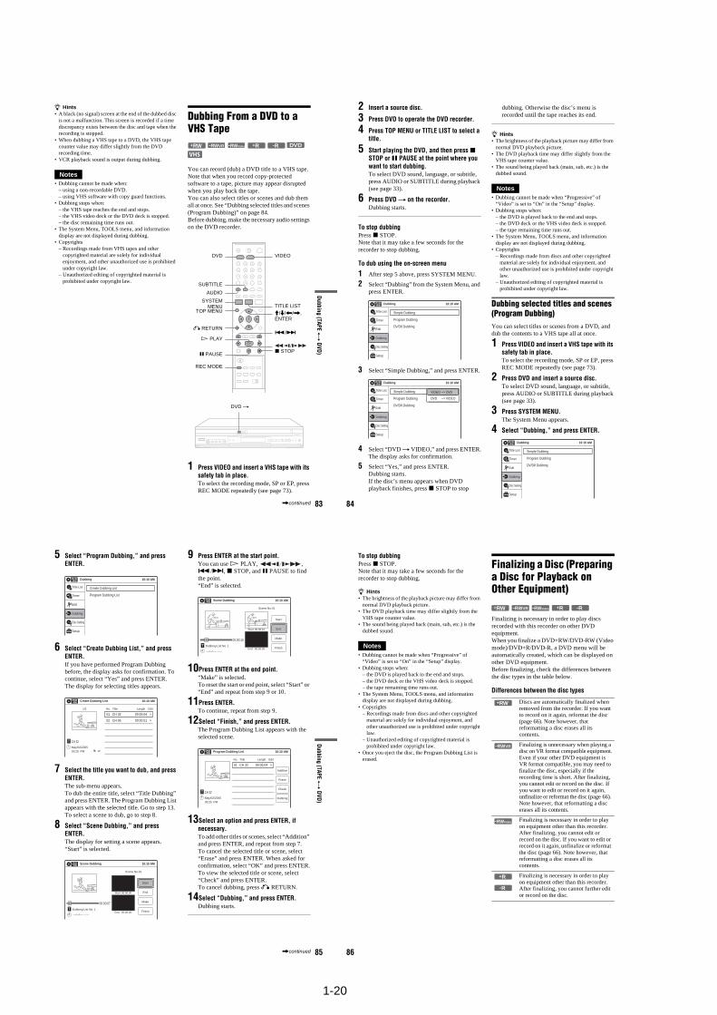
1-20
83
Dubbing (TAPE
y D
VD)
z Hints• A black (no signal) screen at the end of the dubbed disc
is not a malfunction. This screen is recorded if a time discrepancy exists between the disc and tape when the recording is stopped.
• When dubbing a VHS tape to a DVD, the VHS tape counter value may differ slightly from the DVD recording time.
• VCR playback sound is output during dubbing.
Notes• Dubbing cannot be made when:
– using a non-recordable DVD.– using VHS software with copy guard functions.
• Dubbing stops when:– the VHS tape reaches the end and stops.– the VHS video deck or the DVD deck is stopped.– the disc remaining time runs out.
• The System Menu, TOOLS menu, and information display are not displayed during dubbing.
• Copyrights– Recordings made from VHS tapes and other
copyrighted material are solely for individual enjoyment, and other unauthorized use is prohibited under copyright law.
– Unauthorized editing of copyrighted material is prohibited under copyright law.
Dubbing From a DVD to a VHS Tape
You can record (dub) a DVD title to a VHS tape. Note that when you record copy-protected software to a tape, picture may appear disrupted when you play back the tape.You can also select titles or scenes and dub them all at once. See “Dubbing selected titles and scenes (Program Dubbing)” on page 84.Before dubbing, make the necessary audio settings on the DVD recorder.
1 Press VIDEO and insert a VHS tape with its safety tab in place.To select the recording mode, SP or EP, press REC MODE repeatedly (see page 73).
-RWVR -RWVideo+RW +R DVD-R
M/m/</,,ENTER
x STOP
REC MODE
SYSTEMMENU
VIDEO
AUDIO
SUBTITLE
TOP MENU
DVD
TITLE LIST
H PLAY
X PAUSE
./>O RETURN
DVD t
,continued 84
2 Insert a source disc.
3 Press DVD to operate the DVD recorder.
4 Press TOP MENU or TITLE LIST to select a title.
5 Start playing the DVD, and then press x STOP or X PAUSE at the point where you want to start dubbing.To select DVD sound, language, or subtitle, press AUDIO or SUBTITLE during playback (see page 33).
6 Press DVD t on the recorder.Dubbing starts.
To stop dubbingPress x STOP.Note that it may take a few seconds for the recorder to stop dubbing.
To dub using the on-screen menu
1 After step 5 above, press SYSTEM MENU.
2 Select “Dubbing” from the System Menu, and press ENTER.
3 Select “Simple Dubbing,” and press ENTER.
4 Select “DVD t VIDEO,” and press ENTER.The display asks for confirmation.
5 Select “Yes,” and press ENTER.Dubbing starts.If the disc’s menu appears when DVD playback finishes, press x STOP to stop
dubbing. Otherwise the disc’s menu is recorded until the tape reaches its end.
z Hints• The brightness of the playback picture may differ from
normal DVD playback picture.• The DVD playback time may differ slightly from the
VHS tape counter value.• The sound being played back (main, sub, etc.) is the
dubbed sound.
Notes• Dubbing cannot be made when “Progressive” of
“Video” is set to “On” in the “Setup” display.• Dubbing stops when:
– the DVD is played back to the end and stops.– the DVD deck or the VHS video deck is stopped.– the tape remaining time runs out.
• The System Menu, TOOLS menu, and information display are not displayed during dubbing.
• Copyrights– Recordings made from discs and other copyrighted
material are solely for individual enjoyment, and other unauthorized use is prohibited under copyright law.
– Unauthorized editing of copyrighted material is prohibited under copyright law.
Dubbing selected titles and scenes (Program Dubbing)You can select titles or scenes from a DVD, and dub the contents to a VHS tape all at once.
1 Press VIDEO and insert a VHS tape with its safety tab in place.To select the recording mode, SP or EP, press REC MODE repeatedly (see page 73).
2 Press DVD and insert a source disc.To select DVD sound, language, or subtitle, press AUDIO or SUBTITLE during playback (see page 33).
3 Press SYSTEM MENU.The System Menu appears.
4 Select “Dubbing,” and press ENTER.
Dubbing 10:10 AM
Simple Dubbing
Program Dubbing
DV/D8 Dubbing
Setup
Disc Setting
Edit
Title List
Timer
Dubbing
Dubbing 10:10 AM
Simple Dubbing
Program Dubbing
DV/D8 Dubbing
Setup
Disc Setting
Edit
Title List
Timer
Dubbing
VIDEO --> DVD
DVD --> VIDEO
Dubbing 10:10 AM
Simple Dubbing
Program Dubbing
DV/D8 Dubbing
Setup
Disc Setting
Edit
Title List
Timer
Dubbing
85
Dubbing (TAPE
y D
VD)
5 Select “Program Dubbing,” and press ENTER.
6 Select “Create Dubbing List,” and press ENTER.If you have performed Program Dubbing before, the display asks for confirmation. To continue, select “Yes” and press ENTER.The display for selecting titles appears.
7 Select the title you want to dub, and press ENTER.The sub-menu appears.To dub the entire title, select “Title Dubbing” and press ENTER. The Program Dubbing List appears with the selected title. Go to step 13.To select a scene to dub, go to step 8.
8 Select “Scene Dubbing,” and press ENTER.The display for setting a scene appears.“Start” is selected.
9 Press ENTER at the start point.You can use H PLAY, , ./>, x STOP, and X PAUSE to find the point.“End” is selected.
10Press ENTER at the end point.“Make” is selected.To reset the start or end point, select “Start” or “End” and repeat from step 9 or 10.
11Press ENTER.To continue, repeat from step 9.
12Select “Finish,” and press ENTER.The Program Dubbing List appears with the selected scene.
13Select an option and press ENTER, if necessary.To add other titles or scenes, select “Addition” and press ENTER, and repeat from step 7.To cancel the selected title or scene, select “Erase” and press ENTER. When asked for confirmation, select “OK” and press ENTER.To view the selected title or scene, select “Check” and press ENTER.To cancel dubbing, press O RETURN.
14Select “Dubbing,” and press ENTER.Dubbing starts.
Dubbing 10:10 AM
Create Dubbing List
Program Dubbing List
Setup
Disc Setting
Edit
Title List
Timer
Dubbing
Create Dubbing List 10:10 AM
>
>
CH 32T
No. Title Length Edit
01 CH 32 00:05:04
02 CH 96 00:00:51
May/02/200503:25 PM
1/2
Scene Dubbing 10:10 AM
Scene No.01
T---/--/---- --:--
Dubbing List No. 1
Make
Finish
Start
EndStart 00:00:00
End 00:00:00
00:00:07
10:10 AM
Scene No.01
T00:00:10
---/--/---- --:--
Dubbing List No. 1
Make
Finish
Start
End
Scene Dubbing
Start 00:00:10
End 00:00:00
Program Dubbing List 10:10 AM
>
CH 32T
No. Title Length Edit
01 CH 32 00:05:04
May/02/200503:25 PM
Addition
Check
Dubbing
Erase
,continued 86
To stop dubbingPress x STOP.Note that it may take a few seconds for the recorder to stop dubbing.
z Hints• The brightness of the playback picture may differ from
normal DVD playback picture.• The DVD playback time may differ slightly from the
VHS tape counter value.• The sound being played back (main, sub, etc.) is the
dubbed sound.
Notes• Dubbing cannot be made when “Progressive” of
“Video” is set to “On” in the “Setup” display.• Dubbing stops when:
– the DVD is played back to the end and stops.– the DVD deck or the VHS video deck is stopped.– the tape remaining time runs out.
• The System Menu, TOOLS menu, and information display are not displayed during dubbing.
• Copyrights– Recordings made from discs and other copyrighted
material are solely for individual enjoyment, and other unauthorized use is prohibited under copyright law.
– Unauthorized editing of copyrighted material is prohibited under copyright law.
• Once you eject the disc, the Program Dubbing List is erased.
Finalizing a Disc (Preparing a Disc for Playback on Other Equipment)
Finalizing is necessary in order to play discs recorded with this recorder on other DVD equipment.When you finalize a DVD+RW/DVD-RW (Video mode)/DVD+R/DVD-R, a DVD menu will be automatically created, which can be displayed on other DVD equipment.Before finalizing, check the differences between the disc types in the table below.
Differences between the disc types
Discs are automatically finalized when removed from the recorder. If you want to record on it again, reformat the disc (page 66). Note however, that reformatting a disc erases all its contents.
Finalizing is unnecessary when playing a disc on VR format compatible equipment.Even if your other DVD equipment is VR format compatible, you may need to finalize the disc, especially if the recording time is short. After finalizing, you cannot edit or record on the disc. If you want to edit or record on it again, unfinalize or reformat the disc (page 66). Note however, that reformatting a disc erases all its contents.
Finalizing is necessary in order to play on equipment other than this recorder. After finalizing, you cannot edit or record on the disc. If you want to edit or record on it again, unfinalize or reformat the disc (page 66). Note however, that reformatting a disc erases all its contents.
Finalizing is necessary in order to play on equipment other than this recorder. After finalizing, you cannot further edit or record on the disc.
-RWVR -RWVideo+RW +R -R
+RW
-RWVR
-RWVideo
+R
-R
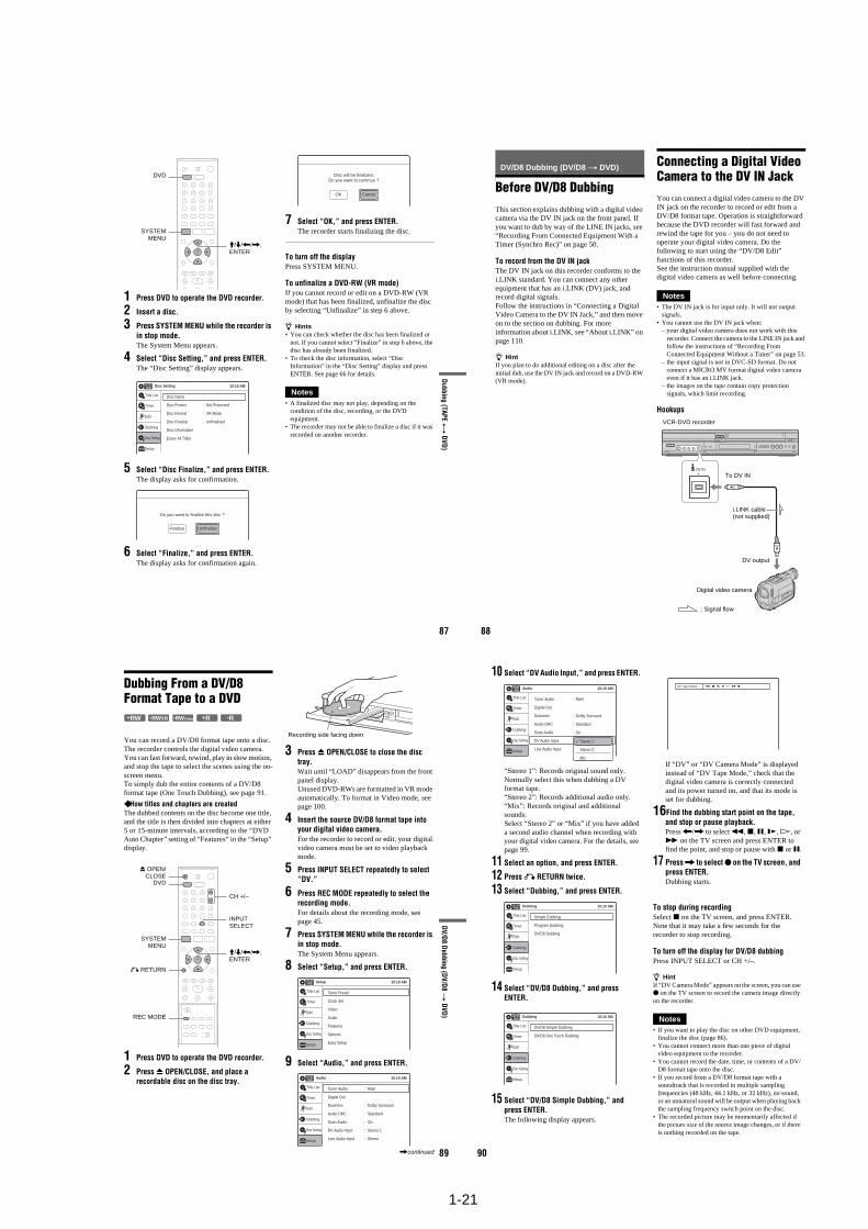
1-21
87
Dubbing (TAPE
y D
VD)
1 Press DVD to operate the DVD recorder.
2 Insert a disc.
3 Press SYSTEM MENU while the recorder is in stop mode.The System Menu appears.
4 Select “Disc Setting,” and press ENTER.The “Disc Setting” display appears.
5 Select “Disc Finalize,” and press ENTER.The display asks for confirmation.
6 Select “Finalize,” and press ENTER.The display asks for confirmation again.
7 Select “OK,” and press ENTER.The recorder starts finalizing the disc.
To turn off the displayPress SYSTEM MENU.
To unfinalize a DVD-RW (VR mode)If you cannot record or edit on a DVD-RW (VR mode) that has been finalized, unfinalize the disc by selecting “Unfinalize” in step 6 above.
z Hints• You can check whether the disc has been finalized or
not. If you cannot select “Finalize” in step 6 above, the disc has already been finalized.
• To check the disc information, select “Disc Information” in the “Disc Setting” display and press ENTER. See page 66 for details.
Notes• A finalized disc may not play, depending on the
condition of the disc, recording, or the DVD equipment.
• The recorder may not be able to finalize a disc if it was recorded on another recorder.
SYSTEMMENU
DVD
M/m/</,, ENTER
Disc Setting 10:10 AM
Disc Name :
Disc Protect : Not Protected
Disc Format : VR Mode
Disc Finalize : Unfinalized
Disc Information
Erase All Titles
Setup
Disc Setting
Edit
Title List
Timer
Dubbing
Do you want to finalize this disc ?
UnfinalizeFinalize
Disc will be finalized.Do you want to continue ?
CancelOK
88
DV/D8 Dubbing (DV/D8 t DVD)
Before DV/D8 DubbingThis section explains dubbing with a digital video camera via the DV IN jack on the front panel. If you want to dub by way of the LINE IN jacks, see “Recording From Connected Equipment With a Timer (Synchro Rec)” on page 50.
To record from the DV IN jackThe DV IN jack on this recorder conforms to the i.LINK standard. You can connect any other equipment that has an i.LINK (DV) jack, and record digital signals.Follow the instructions in “Connecting a Digital Video Camera to the DV IN Jack,” and then move on to the section on dubbing. For more information about i.LINK, see “About i.LINK” on page 110.
z HintIf you plan to do additional editing on a disc after the initial dub, use the DV IN jack and record on a DVD-RW (VR mode).
Connecting a Digital Video Camera to the DV IN JackYou can connect a digital video camera to the DV IN jack on the recorder to record or edit from a DV/D8 format tape. Operation is straightforward because the DVD recorder will fast forward and rewind the tape for you – you do not need to operate your digital video camera. Do the following to start using the “DV/D8 Edit” functions of this recorder.See the instruction manual supplied with the digital video camera as well before connecting.
Notes• The DV IN jack is for input only. It will not output
signals.• You cannot use the DV IN jack when:
– your digital video camera does not work with this recorder. Connect the camera to the LINE IN jack and follow the instructions of “Recording From Connected Equipment Without a Timer” on page 53.
– the input signal is not in DVC-SD format. Do not connect a MICRO MV format digital video camera even if it has an i.LINK jack.
– the images on the tape contain copy protection signals, which limit recording.
Hookups
DV IN
i.LINK cable (not supplied)
To DV IN
VCR-DVD recorder
DV output
Digital video camera
: Signal flow
89
DV/D8 D
ubbing (DV/D
8 t
DVD)
Dubbing From a DV/D8 Format Tape to a DVD
You can record a DV/D8 format tape onto a disc. The recorder controls the digital video camera. You can fast forward, rewind, play in slow motion, and stop the tape to select the scenes using the on-screen menu.To simply dub the entire contents of a DV/D8 format tape (One Touch Dubbing), see page 91.
How titles and chapters are createdThe dubbed contents on the disc become one title, and the title is then divided into chapters at either 5 or 15-minute intervals, according to the “DVD Auto Chapter” setting of “Features” in the “Setup” display.
1 Press DVD to operate the DVD recorder.
2 Press Z OPEN/CLOSE, and place a recordable disc on the disc tray.
3 Press Z OPEN/CLOSE to close the disc tray.Wait until “LOAD” disappears from the front panel display.Unused DVD-RWs are formatted in VR mode automatically. To format in Video mode, see page 100.
4 Insert the source DV/D8 format tape into your digital video camera.For the recorder to record or edit, your digital video camera must be set to video playback mode.
5 Press INPUT SELECT repeatedly to select “DV.”
6 Press REC MODE repeatedly to select the recording mode.For details about the recording mode, see page 45.
7 Press SYSTEM MENU while the recorder is in stop mode.The System Menu appears.
8 Select “Setup,” and press ENTER.
9 Select “Audio,” and press ENTER.
-RWVR -RWVideo+RW +R -R
REC MODE
INPUT SELECT
Z OPEN/CLOSE
SYSTEMMENU
M/m/</,, ENTER
O RETURN
DVD
CH +/–
Recording side facing down
Setup
Tuner Preset
Clock Set
Video
Audio
Features
Options
Easy Setup
10:10 AM
Setup
Disc Setting
Edit
Title List
Timer
Dubbing
Audio 10:10 AM
Tuner Audio
Digital Out
Downmix
Audio DRC
Scan Audio
DV Audio Input
Line Audio Input
: Main
: Dolby Surround
: Standard
: On
: Stereo 1
: StereoSetup
Disc Setting
Edit
Title List
Timer
Dubbing
,continued 90
10 Select “DV Audio Input,” and press ENTER.
“Stereo 1”: Records original sound only. Normally select this when dubbing a DV format tape.“Stereo 2”: Records additional audio only.“Mix”: Records original and additional sounds.Select “Stereo 2” or “Mix” if you have added a second audio channel when recording with your digital video camera. For the details, see page 99.
11 Select an option, and press ENTER.
12 Press O RETURN twice.
13 Select “Dubbing,” and press ENTER.
14 Select “DV/D8 Dubbing,” and press ENTER.
15 Select “DV/D8 Simple Dubbing,” and press ENTER.The following display appears.
If “DV” or “DV Camera Mode” is displayed instead of “DV Tape Mode,” check that the digital video camera is correctly connected and its power turned on, and that its mode is set for dubbing.
16Find the dubbing start point on the tape, and stop or pause playback.Press </, to select m, x, X, y, H, or M on the TV screen and press ENTER to find the point, and stop or pause with x or X.
17 Press , to select z on the TV screen, and press ENTER.Dubbing starts.
To stop during recordingSelect x on the TV screen, and press ENTER. Note that it may take a few seconds for the recorder to stop recording.
To turn off the display for DV/D8 dubbingPress INPUT SELECT or CH +/–.
z HintIf “DV Camera Mode” appears on the screen, you can use z on the TV screen to record the camera image directly on the recorder.
Notes• If you want to play the disc on other DVD equipment,
finalize the disc (page 86).• You cannot connect more than one piece of digital
video equipment to the recorder.• You cannot record the date, time, or contents of a DV/
D8 format tape onto the disc.• If you record from a DV/D8 format tape with a
soundtrack that is recorded in multiple sampling frequencies (48 kHz, 44.1 kHz, or 32 kHz), no sound, or an unnatural sound will be output when playing back the sampling frequency switch point on the disc.
• The recorded picture may be momentarily affected if the picture size of the source image changes, or if there is nothing recorded on the tape.
Audio 10:10 AM
Tuner Audio
Digital Out
Downmix
Audio DRC
Scan Audio
DV Audio Input
Line Audio Input
: Dolby Surround
: Standard
: On
:
:
: Main
Setup
Disc Setting
Edit
Title List
Timer
Dubbing
Stereo 1
Stereo 2
Mix
Dubbing 10:10 AM
Simple Dubbing
Program Dubbing
DV/D8 Dubbing
Setup
Disc Setting
Edit
Title List
Timer
Dubbing
Dubbing 10:10 AM
DV/D8 Simple Dubbing
DV/D8 One Touch Dubbing
Setup
Disc Setting
Edit
Title List
Timer
Dubbing
DV Tape Mode
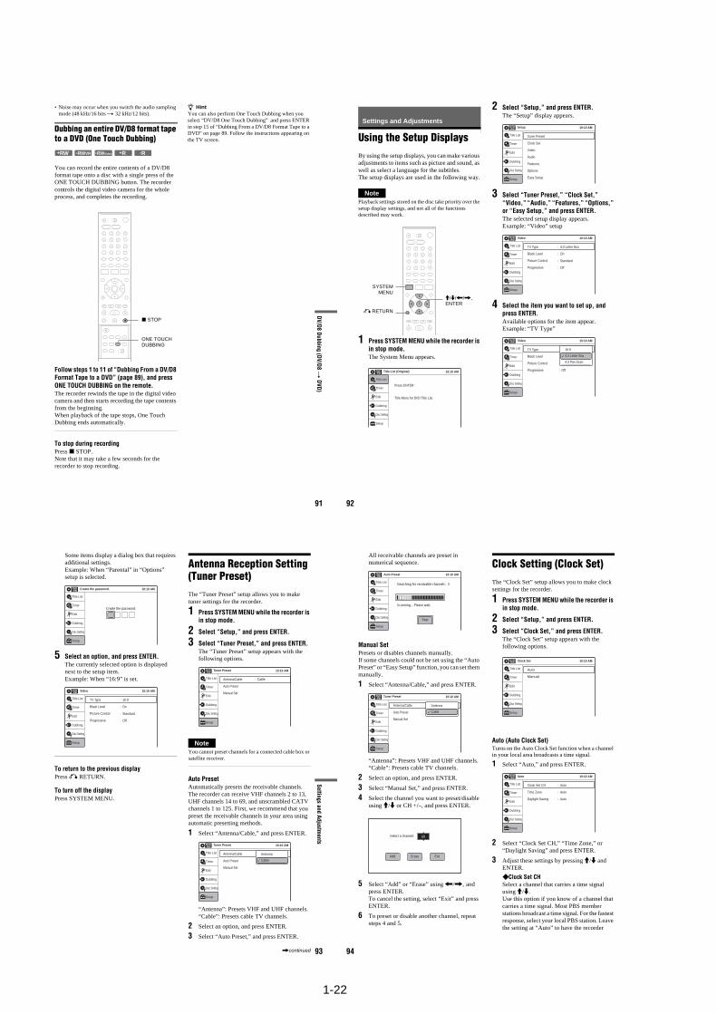
1-22
91
DV/D8 D
ubbing (DV/D
8 t
DVD)
• Noise may occur when you switch the audio sampling mode (48 kHz/16 bits t 32 kHz/12 bits).
Dubbing an entire DV/D8 format tape to a DVD (One Touch Dubbing)
You can record the entire contents of a DV/D8 format tape onto a disc with a single press of the ONE TOUCH DUBBING button. The recorder controls the digital video camera for the whole process, and completes the recording.
Follow steps 1 to 11 of “Dubbing From a DV/D8 Format Tape to a DVD” (page 89), and press ONE TOUCH DUBBING on the remote.The recorder rewinds the tape in the digital video camera and then starts recording the tape contents from the beginning.When playback of the tape stops, One Touch Dubbing ends automatically.
To stop during recordingPress x STOP.Note that it may take a few seconds for the recorder to stop recording.
z HintYou can also perform One Touch Dubbing when you select “DV/D8 One Touch Dubbing” and press ENTER in step 15 of “Dubbing From a DV/D8 Format Tape to a DVD” on page 89. Follow the instructions appearing on the TV screen.
-RWVR -RWVideo+RW +R -R
ONE TOUCH DUBBING
x STOP
92
Settings and Adjustments
Using the Setup DisplaysBy using the setup displays, you can make various adjustments to items such as picture and sound, as well as select a language for the subtitles.The setup displays are used in the following way.
NotePlayback settings stored on the disc take priority over the setup display settings, and not all of the functions described may work.
1 Press SYSTEM MENU while the recorder is in stop mode.The System Menu appears.
2 Select “Setup,” and press ENTER.The “Setup” display appears.
3 Select “Tuner Preset,” “Clock Set,” “Video,” “Audio,” “Features,” “Options,” or “Easy Setup,” and press ENTER.The selected setup display appears.Example: “Video” setup
4 Select the item you want to set up, and press ENTER.Available options for the item appear.Example: “TV Type”
M/m/</,, ENTER
SYSTEMMENU
O RETURN
10:10 AMTitle List (Original)
Press ENTER :
Title Menu for DVD Title List.
Setup
Disc Setting
Edit
Title List
Timer
Dubbing
10:10 AMSetup
Tuner Preset
Clock Set
Video
Audio
Features
Options
Easy SetupSetup
Disc Setting
Edit
Title List
Timer
Dubbing
Video 10:10 AM
TV Type
Black Level
Picture Control
Progressive
: Standard
: Off
: 4:3 Letter Box
: On
Setup
Disc Setting
Edit
Title List
Timer
Dubbing
10:10 AM
TV Type
Black Level
Picture Control
Progressive
Video
: Composite
: Off
: 4:3 Letter Box
: On
Setup
Disc Setting
Edit
Title List
Timer
Dubbing
16:9
4:3 Letter Box
4:3 Pan Scan
93
Settings and Adjustments
Some items display a dialog box that requires additional settings.Example: When “Parental” in “Options” setup is selected.
5 Select an option, and press ENTER.The currently selected option is displayed next to the setup item.Example: When “16:9” is set.
To return to the previous displayPress O RETURN.
To turn off the displayPress SYSTEM MENU.
Antenna Reception Setting (Tuner Preset)The “Tuner Preset” setup allows you to make tuner settings for the recorder.
1 Press SYSTEM MENU while the recorder is in stop mode.
2 Select “Setup,” and press ENTER.
3 Select “Tuner Preset,” and press ENTER.The “Tuner Preset” setup appears with the following options.
NoteYou cannot preset channels for a connected cable box or satellite receiver.
Auto PresetAutomatically presets the receivable channels.The recorder can receive VHF channels 2 to 13, UHF channels 14 to 69, and unscrambled CATV channels 1 to 125. First, we recommend that you preset the receivable channels in your area using automatic presetting methods.
1 Select “Antenna/Cable,” and press ENTER.
“Antenna”: Presets VHF and UHF channels.“Cable”: Presets cable TV channels.
2 Select an option, and press ENTER.
3 Select “Auto Preset,” and press ENTER.
10:10 AM
Create the password.
Create the password.
Setup
Disc Setting
Edit
Title List
Timer
Dubbing
Video 10:10 AM
TV Type
Black Level
Picture Control
Progressive
: Standard
: Off
: 16:9
: On
Setup
Disc Setting
Edit
Title List
Timer
Dubbing
10:10 AM
Setup
Disc Setting
Edit
Title List
Timer
Dubbing
Antenna/Cable
Auto Preset
Manual Set
: Cable
Tuner Preset
10:10 AM
Setup
Disc Setting
Edit
Title List
Timer
Dubbing
Antenna/Cable
Auto Preset
Manual Set
: Antenna
Tuner Preset
Antenna
Cable
,continued 94
All receivable channels are preset in numerical sequence.
Manual SetPresets or disables channels manually.If some channels could not be set using the “Auto Preset” or “Easy Setup” function, you can set them manually.
1 Select “Antenna/Cable,” and press ENTER.
“Antenna”: Presets VHF and UHF channels.“Cable”: Presets cable TV channels.
2 Select an option, and press ENTER.
3 Select “Manual Set,” and press ENTER.
4 Select the channel you want to preset/disable using M/m or CH +/–, and press ENTER.
5 Select “Add” or “Erase” using </,, and press ENTER.To cancel the setting, select “Exit” and press ENTER.
6 To preset or disable another channel, repeat steps 4 and 5.
Clock Setting (Clock Set)The “Clock Set” setup allows you to make clock settings for the recorder.
1 Press SYSTEM MENU while the recorder is in stop mode.
2 Select “Setup,” and press ENTER.
3 Select “Clock Set,” and press ENTER.The “Clock Set” setup appears with the following options.
Auto (Auto Clock Set)Turns on the Auto Clock Set function when a channel in your local area broadcasts a time signal.
1 Select “Auto,” and press ENTER.
2 Select “Clock Set CH,” “Time Zone,” or “Daylight Saving” and press ENTER.
3 Adjust these settings by pressing M/m and ENTER.
Clock Set CHSelect a channel that carries a time signal using M/m. Use this option if you know of a channel that carries a time signal. Most PBS member stations broadcast a time signal. For the fastest response, select your local PBS station. Leave the setting at “Auto” to have the recorder
10:10 AMAuto Preset
Searching for receivable channels: 3
Scanning... Please wait.
Setup
Disc Setting
Edit
Title List
Timer
Dubbing
Stop
10:10 AM
Setup
Disc Setting
Edit
Title List
Timer
Dubbing
Antenna/Cable
Auto Preset
Manual Set
: Antenna
Tuner Preset
Antenna
Cable
Select a channel: 69
EraseAdd Exit
Clock Set 10:10 AM
Auto
Manual
Setup
Disc Setting
Edit
Title List
Timer
Dubbing
Auto 10:10 AM
Clock Set CH
Time Zone
Daylight Saving
: Auto
: Auto
: Auto
Setup
Disc Setting
Edit
Title List
Timer
Dubbing
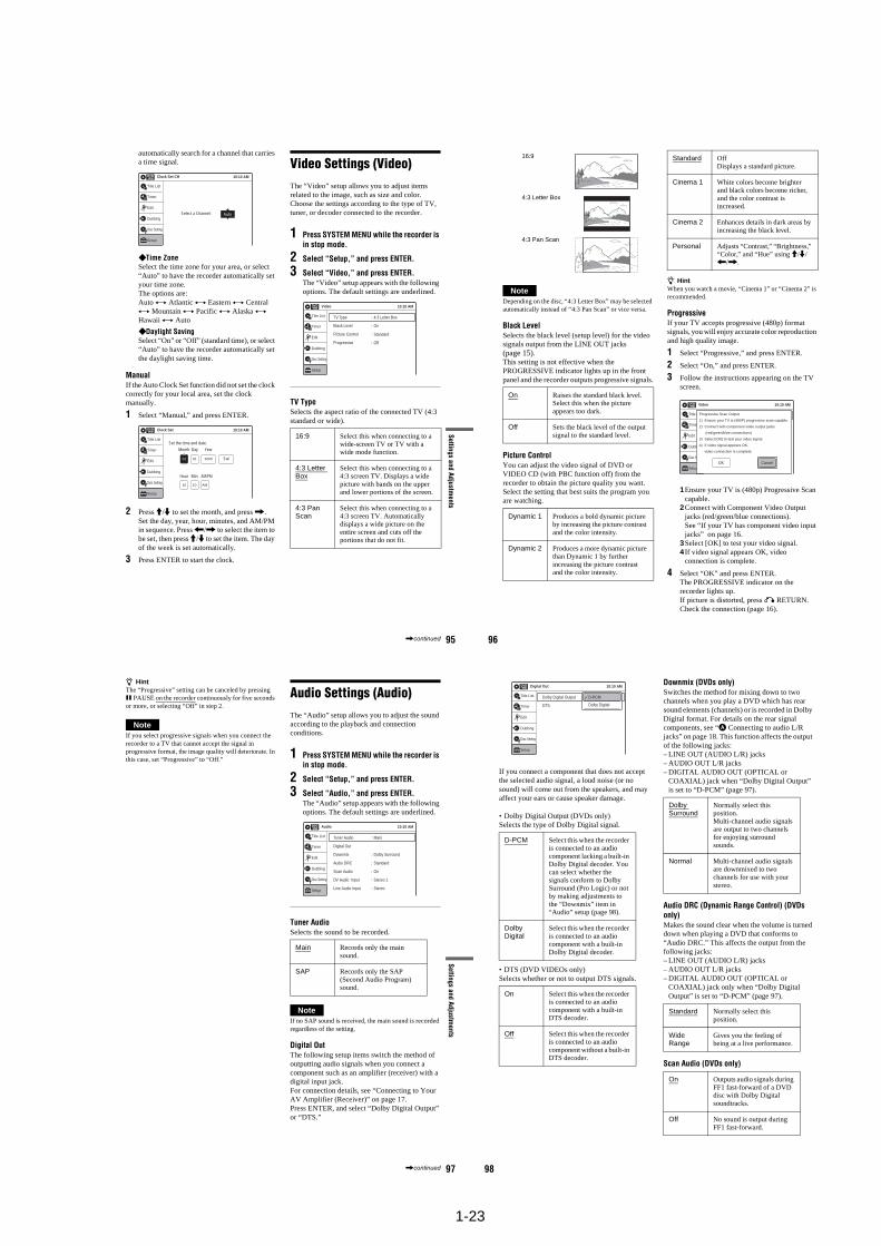
1-23
95
Settings and Adjustments
automatically search for a channel that carries a time signal.
Time ZoneSelect the time zone for your area, or select “Auto” to have the recorder automatically set your time zone.The options are:Auto y Atlantic y Eastern y Central y Mountain y Pacific y Alaska y Hawaii y Auto
Daylight Saving Select “On” or “Off” (standard time), or select “Auto” to have the recorder automatically set the daylight saving time.
ManualIf the Auto Clock Set function did not set the clock correctly for your local area, set the clock manually.
1 Select “Manual,” and press ENTER.
2 Press M/m to set the month, and press ,.Set the day, year, hour, minutes, and AM/PM in sequence. Press </, to select the item to be set, then press M/m to set the item. The day of the week is set automatically.
3 Press ENTER to start the clock.
Video Settings (Video)The “Video” setup allows you to adjust items related to the image, such as size and color.Choose the settings according to the type of TV, tuner, or decoder connected to the recorder.
1 Press SYSTEM MENU while the recorder is in stop mode.
2 Select “Setup,” and press ENTER.
3 Select “Video,” and press ENTER.The “Video” setup appears with the following options. The default settings are underlined.
TV TypeSelects the aspect ratio of the connected TV (4:3 standard or wide).
Clock Set CH 10:10 AM
Select a Channel: Auto
Setup
Disc Setting
Edit
Title List
Timer
Dubbing
2005 Sat01 01
10 : 10 AM
10:10 AMClock Set
Set the time and date.
Hour Min AM/PM
Month Day Year
Setup
Disc Setting
Edit
Title List
Timer
Dubbing
16:9 Select this when connecting to a wide-screen TV or TV with a wide mode function.
4:3 Letter Box
Select this when connecting to a 4:3 screen TV. Displays a wide picture with bands on the upper and lower portions of the screen.
4:3 Pan Scan
Select this when connecting to a 4:3 screen TV. Automatically displays a wide picture on the entire screen and cuts off the portions that do not fit.
Video 10:10 AM
TV Type
Black Level
Picture Control
Progressive
: Standard
: Off
: 4:3 Letter Box
: On
Setup
Disc Setting
Edit
Title List
Timer
Dubbing
,continued 96
NoteDepending on the disc, “4:3 Letter Box” may be selected automatically instead of “4:3 Pan Scan” or vice versa.
Black LevelSelects the black level (setup level) for the video signals output from the LINE OUT jacks (page 15).This setting is not effective when the PROGRESSIVE indicator lights up in the front panel and the recorder outputs progressive signals.
Picture ControlYou can adjust the video signal of DVD or VIDEO CD (with PBC function off) from the recorder to obtain the picture quality you want. Select the setting that best suits the program you are watching.
z HintWhen you watch a movie, “Cinema 1” or “Cinema 2” is recommended.
ProgressiveIf your TV accepts progressive (480p) format signals, you will enjoy accurate color reproduction and high quality image.
1 Select “Progressive,” and press ENTER.
2 Select “On,” and press ENTER.
3 Follow the instructions appearing on the TV screen.
1Ensure your TV is (480p) Progressive Scan capable.
2Connect with Component Video Output jacks (red/green/blue connections). See “If your TV has component video input jacks” on page 16.
3Select [OK] to test your video signal.4 If video signal appears OK, video
connection is complete.
4 Select “OK” and press ENTER.The PROGRESSIVE indicator on the recorder lights up.If picture is distorted, press O RETURN.Check the connection (page 16).
On Raises the standard black level. Select this when the picture appears too dark.
Off Sets the black level of the output signal to the standard level.
Dynamic 1 Produces a bold dynamic picture by increasing the picture contrast and the color intensity.
Dynamic 2 Produces a more dynamic picture than Dynamic 1 by further increasing the picture contrast and the color intensity.
16:9
4:3 Letter Box
4:3 Pan Scan
Standard OffDisplays a standard picture.
Cinema 1 White colors become brighter and black colors become richer, and the color contrast is increased.
Cinema 2 Enhances details in dark areas by increasing the black level.
Personal Adjusts “Contrast,” “Brightness,” “Color,” and “Hue” using M/m/</,.
Video 10:10 AM
TV Type
Black Level
Picture Control
Progressive
: Standard
: Off
: 4:3 Pan Scan
: On
Setup
Disc Setting
Edit
Title List
Timer
Dubbing
OK Cancel
Progressive Scan Output
1) Ensure your TV is (480P) progressive scan capable.
2) Connect with component video output jacks.
(red/green/blue connections)
3) Select [OK] to test your video signal.
4) If video signal appears OK,
video connection is complete.
97
Settings and Adjustments
z HintThe “Progressive” setting can be canceled by pressing X PAUSE on the recorder continuously for five seconds or more, or selecting “Off” in step 2.
NoteIf you select progressive signals when you connect the recorder to a TV that cannot accept the signal in progressive format, the image quality will deteriorate. In this case, set “Progressive” to “Off.”
Audio Settings (Audio)The “Audio” setup allows you to adjust the sound according to the playback and connection conditions.
1 Press SYSTEM MENU while the recorder is in stop mode.
2 Select “Setup,” and press ENTER.
3 Select “Audio,” and press ENTER.The “Audio” setup appears with the following options. The default settings are underlined.
Tuner AudioSelects the sound to be recorded.
NoteIf no SAP sound is received, the main sound is recorded regardless of the setting.
Digital OutThe following setup items switch the method of outputting audio signals when you connect a component such as an amplifier (receiver) with a digital input jack.For connection details, see “Connecting to Your AV Amplifier (Receiver)” on page 17.Press ENTER, and select “Dolby Digital Output” or “DTS.”
Main Records only the main sound.
SAP Records only the SAP (Second Audio Program) sound.
10:10 AM
Tuner Audio
Digital Out
Downmix
Audio DRC
Scan Audio
DV Audio Input
Line Audio Input
: Main
: Dolby Surround
: Standard
: On
: Stereo 1
: Stereo
Audio
Setup
Disc Setting
Edit
Title List
Timer
Dubbing
,continued 98
If you connect a component that does not accept the selected audio signal, a loud noise (or no sound) will come out from the speakers, and may affect your ears or cause speaker damage.
• Dolby Digital Output (DVDs only)Selects the type of Dolby Digital signal.
• DTS (DVD VIDEOs only)Selects whether or not to output DTS signals.
Downmix (DVDs only)Switches the method for mixing down to two channels when you play a DVD which has rear sound elements (channels) or is recorded in Dolby Digital format. For details on the rear signal components, see “A Connecting to audio L/R jacks” on page 18. This function affects the output of the following jacks:– LINE OUT (AUDIO L/R) jacks– AUDIO OUT L/R jacks– DIGITAL AUDIO OUT (OPTICAL or
COAXIAL) jack when “Dolby Digital Output” is set to “D-PCM” (page 97).
Audio DRC (Dynamic Range Control) (DVDs only)Makes the sound clear when the volume is turned down when playing a DVD that conforms to “Audio DRC.” This affects the output from the following jacks:– LINE OUT (AUDIO L/R) jacks– AUDIO OUT L/R jacks– DIGITAL AUDIO OUT (OPTICAL or
COAXIAL) jack only when “Dolby Digital Output” is set to “D-PCM” (page 97).
Scan Audio (DVDs only)
D-PCM Select this when the recorder is connected to an audio component lacking a built-in Dolby Digital decoder. You can select whether the signals conform to Dolby Surround (Pro Logic) or not by making adjustments to the “Downmix” item in “Audio” setup (page 98).
Dolby Digital
Select this when the recorder is connected to an audio component with a built-in Dolby Digital decoder.
On Select this when the recorder is connected to an audio component with a built-in DTS decoder.
Off Select this when the recorder is connected to an audio component without a built-in DTS decoder.
10:10 AM
Dolby Digital Output
DTS
Digital Out
: 4:3 Letter Box
On
Setup
Disc Setting
Edit
Title List
Timer
Dubbing
D-PCM
Dolby Digital
Dolby Surround
Normally select this position.Multi-channel audio signals are output to two channels for enjoying surround sounds.
Normal Multi-channel audio signals are downmixed to two channels for use with your stereo.
Standard Normally select this position.
Wide Range
Gives you the feeling of being at a live performance.
On Outputs audio signals during FF1 fast-forward of a DVD disc with Dolby Digital soundtracks.
Off No sound is output during FF1 fast-forward.
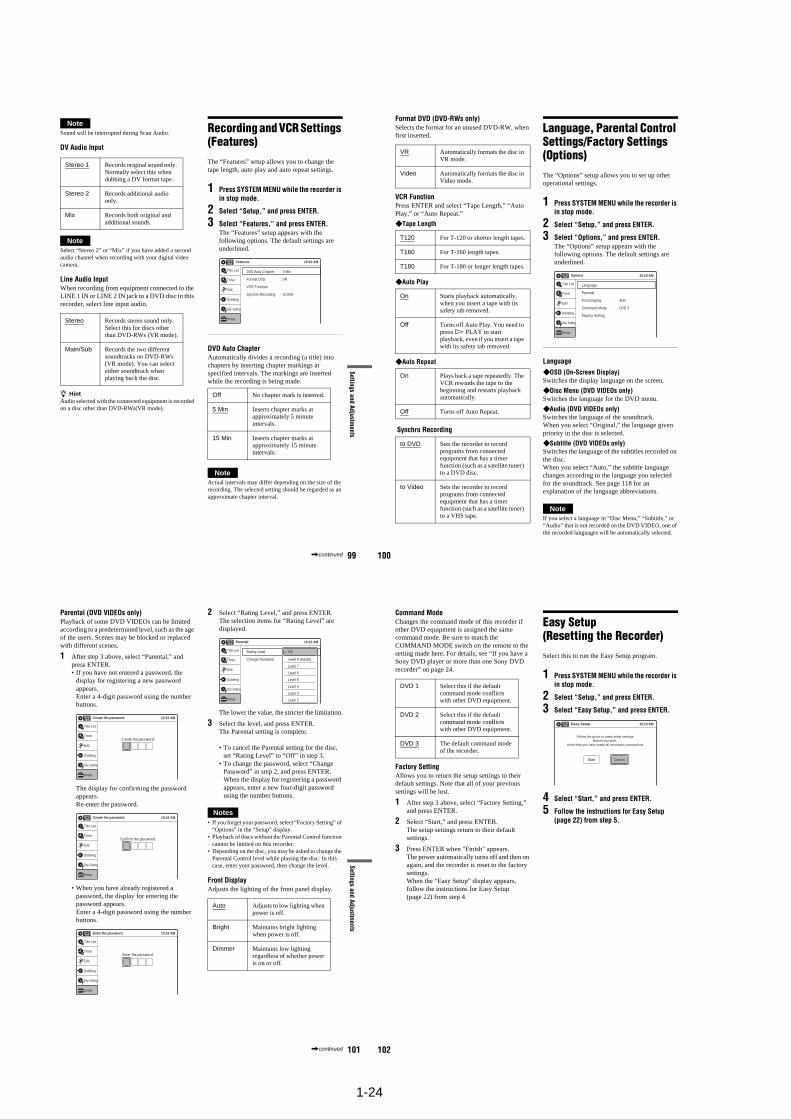
1-24
99
Settings and Adjustments
NoteSound will be interrupted during Scan Audio.
DV Audio Input
NoteSelect “Stereo 2” or “Mix” if you have added a second audio channel when recording with your digital video camera.
Line Audio InputWhen recording from equipment connected to the LINE 1 IN or LINE 2 IN jack to a DVD disc in this recorder, select line input audio.
z HintAudio selected with the connected equipment is recorded on a disc other than DVD-RWs(VR mode).
Recording and VCR Settings (Features)The “Features” setup allows you to change the tape length, auto play and auto repeat settings.
1 Press SYSTEM MENU while the recorder is in stop mode.
2 Select “Setup,” and press ENTER.
3 Select “Features,” and press ENTER.The “Features” setup appears with the following options. The default settings are underlined.
DVD Auto ChapterAutomatically divides a recording (a title) into chapters by inserting chapter markings at specified intervals. The markings are inserted while the recording is being made.
NoteActual intervals may differ depending on the size of the recording. The selected setting should be regarded as an approximate chapter interval.
Stereo 1 Records original sound only. Normally select this when dubbing a DV format tape.
Stereo 2 Records additional audio only.
Mix Records both original and additional sounds.
Stereo Records stereo sound only. Select this for discs other than DVD-RWs (VR mode).
Main/Sub Records the two different soundtracks on DVD-RWs (VR mode). You can select either soundtrack when playing back the disc.
Off No chapter mark is inserted.
5 Min Inserts chapter marks at approximately 5 minute intervals.
15 Min Inserts chapter marks at approximately 15 minute intervals.
Setup
Disc Setting
Edit
Title List
Timer
Dubbing
10:10 AM
DVD Auto Chapter
Format DVD
VCR Function
Synchro Recording
Features
: 5 Min
: VR
: to DVD
,continued 100
Format DVD (DVD-RWs only)Selects the format for an unused DVD-RW, when first inserted.
VCR FunctionPress ENTER and select “Tape Length,” “Auto Play,” or “Auto Repeat.”
Tape Length
Auto Play
Auto Repeat
Synchro Recording
Language, Parental Control Settings/Factory Settings (Options)The “Options” setup allows you to set up other operational settings.
1 Press SYSTEM MENU while the recorder is in stop mode.
2 Select “Setup,” and press ENTER.
3 Select “Options,” and press ENTER.The “Options” setup appears with the following options. The default settings are underlined.
Language OSD (On-Screen Display)Switches the display language on the screen.
Disc Menu (DVD VIDEOs only)Switches the language for the DVD menu.
Audio (DVD VIDEOs only)Switches the language of the soundtrack.When you select “Original,” the language given priority in the disc is selected.
Subtitle (DVD VIDEOs only)Switches the language of the subtitles recorded on the disc.When you select “Auto,” the subtitle language changes according to the language you selected for the soundtrack. See page 118 for an explanation of the language abbreviations.
NoteIf you select a language in “Disc Menu,” “Subtitle,” or “Audio” that is not recorded on the DVD VIDEO, one of the recorded languages will be automatically selected.
VR Automatically formats the disc in VR mode.
Video Automatically formats the disc in Video mode.
T120 For T-120 or shorter length tapes.
T160 For T-160 length tapes.
T180 For T-180 or longer length tapes.
On Starts playback automatically, when you insert a tape with its safety tab removed.
Off Turns off Auto Play. You need to press H PLAY to start playback, even if you insert a tape with its safety tab removed.
On Plays back a tape repeatedly. The VCR rewinds the tape to the beginning and restarts playback automatically.
Off Turns off Auto Repeat.
to DVD Sets the recorder to record programs from connected equipment that has a timer function (such as a satellite tuner) to a DVD disc.
to Video Sets the recorder to record programs from connected equipment that has a timer function (such as a satellite tuner) to a VHS tape.
Language
Parental
Front Display
Command Mode
Factory Setting
: Auto
: DVD 3
10:10 AMOptions
Setup
Disc Setting
Edit
Title List
Timer
Dubbing
101
Settings and Adjustments
Parental (DVD VIDEOs only)Playback of some DVD VIDEOs can be limited according to a predetermined level, such as the age of the users. Scenes may be blocked or replaced with different scenes.
1 After step 3 above, select “Parental,” and press ENTER.• If you have not entered a password, the
display for registering a new password appears. Enter a 4-digit password using the number buttons.
The display for confirming the password appears.Re-enter the password.
• When you have already registered a password, the display for entering the password appears. Enter a 4-digit password using the number buttons.
2 Select “Rating Level,” and press ENTER.The selection items for “Rating Level” are displayed.
The lower the value, the stricter the limitation.
3 Select the level, and press ENTER.The Parental setting is complete.
• To cancel the Parental setting for the disc, set “Rating Level” to “Off” in step 3.
• To change the password, select “Change Password” in step 2, and press ENTER. When the display for registering a password appears, enter a new four-digit password using the number buttons.
Notes• If you forget your password, select “Factory Setting” of
“Options” in the “Setup” display.• Playback of discs without the Parental Control function
cannot be limited on this recorder.• Depending on the disc, you may be asked to change the
Parental Control level while playing the disc. In this case, enter your password, then change the level.
Front DisplayAdjusts the lighting of the front panel display.
10:10 AM
Create the password.
Create the password.
Setup
Disc Setting
Edit
Title List
Timer
Dubbing
10:10 AM
Confirm the password.
Create the password.
Setup
Disc Setting
Edit
Title List
Timer
Dubbing
10:10 AM
Enter the password.
Enter the password.
Setup
Disc Setting
Edit
Title List
Timer
Dubbing
Auto Adjusts to low lighting when power is off.
Bright Maintains bright lighting when power is off.
Dimmer Maintains low lighting regardless of whether power is on or off.
Rating Level
Change Password
: On: Level 8 (Adults)
10:10 AMParental
Setup
Disc Setting
Edit
Title List
Timer
Dubbing
Off
Level 8 (Adults)
Level 7
Level 6
Level 5
Level 4
Level 3
Level 2
,continued 102
Command ModeChanges the command mode of this recorder if other DVD equipment is assigned the same command mode. Be sure to match the COMMAND MODE switch on the remote to the setting made here. For details, see “If you have a Sony DVD player or more than one Sony DVD recorder” on page 24.
Factory SettingAllows you to return the setup settings to their default settings. Note that all of your previous settings will be lost.
1 After step 3 above, select “Factory Setting,” and press ENTER.
2 Select “Start,” and press ENTER.The setup settings return to their default settings.
3 Press ENTER when "Finish" appears.The power automatically turns off and then on again, and the recorder is reset to the factory settings.When the “Easy Setup” display appears, follow the instructions for Easy Setup (page 22) from step 4.
Easy Setup (Resetting the Recorder)Select this to run the Easy Setup program.
1 Press SYSTEM MENU while the recorder is in stop mode.
2 Select “Setup,” and press ENTER.
3 Select “Easy Setup,” and press ENTER.
4 Select “Start,” and press ENTER.
5 Follow the instructions for Easy Setup (page 22) from step 5.
DVD 1 Select this if the default command mode conflicts with other DVD equipment.
DVD 2 Select this if the default command mode conflicts with other DVD equipment.
DVD 3 The default command mode of the recorder.
10:10 AMEasy Setup
Follow the guide to make initial settings.Before you start,
check that you have made all necessary connections.
Start Cancel
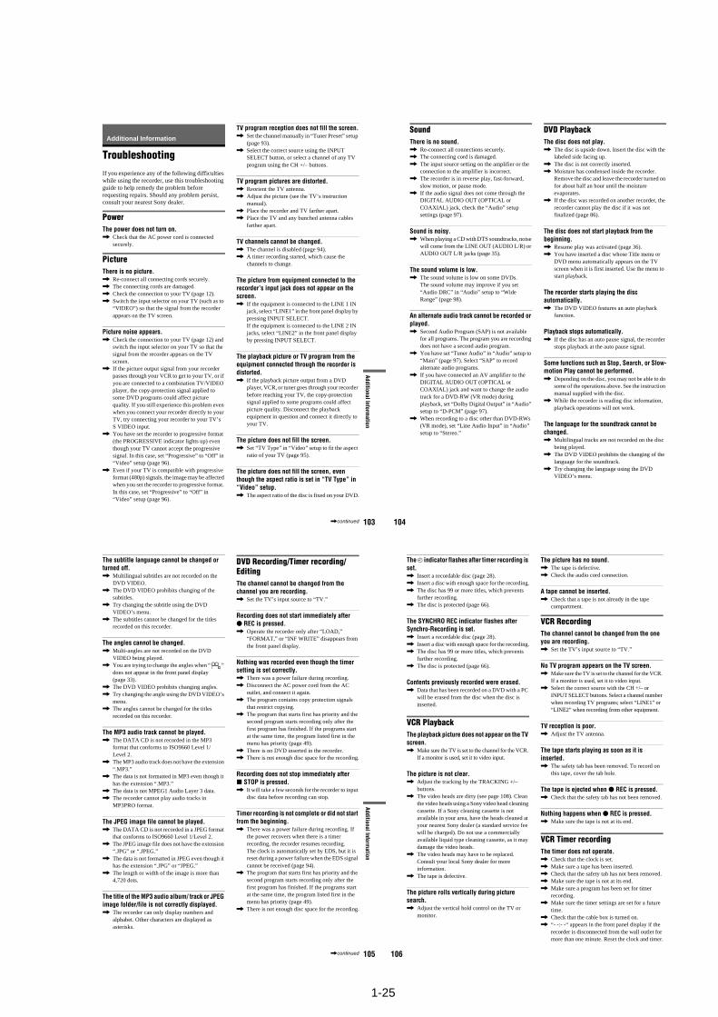
1-25
103
Additional Information
Additional Information
TroubleshootingIf you experience any of the following difficulties while using the recorder, use this troubleshooting guide to help remedy the problem before requesting repairs. Should any problem persist, consult your nearest Sony dealer.
PowerThe power does not turn on., Check that the AC power cord is connected
securely.
PictureThere is no picture., Re-connect all connecting cords securely., The connecting cords are damaged., Check the connection to your TV (page 12)., Switch the input selector on your TV (such as to
“VIDEO”) so that the signal from the recorder appears on the TV screen.
Picture noise appears., Check the connection to your TV (page 12) and
switch the input selector on your TV so that the signal from the recorder appears on the TV screen.
, If the picture output signal from your recorder passes through your VCR to get to your TV, or if you are connected to a combination TV/VIDEO player, the copy-protection signal applied to some DVD programs could affect picture quality. If you still experience this problem even when you connect your recorder directly to your TV, try connecting your recorder to your TV’s S VIDEO input.
, You have set the recorder to progressive format (the PROGRESSIVE indicator lights up) even though your TV cannot accept the progressive signal. In this case, set “Progressive” to “Off” in “Video” setup (page 96).
, Even if your TV is compatible with progressive format (480p) signals, the image may be affected when you set the recorder to progressive format. In this case, set “Progressive” to “Off” in “Video” setup (page 96).
TV program reception does not fill the screen., Set the channel manually in “Tuner Preset” setup
(page 93)., Select the correct source using the INPUT
SELECT button, or select a channel of any TV program using the CH +/– buttons.
TV program pictures are distorted., Reorient the TV antenna., Adjust the picture (see the TV’s instruction
manual)., Place the recorder and TV farther apart., Place the TV and any bunched antenna cables
farther apart.
TV channels cannot be changed., The channel is disabled (page 94)., A timer recording started, which cause the
channels to change.
The picture from equipment connected to the recorder’s input jack does not appear on the screen., If the equipment is connected to the LINE 1 IN
jack, select “LINE1” in the front panel display by pressing INPUT SELECT. If the equipment is connected to the LINE 2 IN jacks, select “LINE2” in the front panel display by pressing INPUT SELECT.
The playback picture or TV program from the equipment connected through the recorder is distorted., If the playback picture output from a DVD
player, VCR, or tuner goes through your recorder before reaching your TV, the copy-protection signal applied to some programs could affect picture quality. Disconnect the playback equipment in question and connect it directly to your TV.
The picture does not fill the screen., Set “TV Type” in “Video” setup to fit the aspect
ratio of your TV (page 95).
The picture does not fill the screen, even though the aspect ratio is set in “TV Type” in “Video” setup., The aspect ratio of the disc is fixed on your DVD.
,continued 104
SoundThere is no sound., Re-connect all connections securely., The connecting cord is damaged., The input source setting on the amplifier or the
connection to the amplifier is incorrect., The recorder is in reverse play, fast-forward,
slow motion, or pause mode., If the audio signal does not come through the
DIGITAL AUDIO OUT (OPTICAL or COAXIAL) jack, check the “Audio” setup settings (page 97).
Sound is noisy., When playing a CD with DTS soundtracks, noise
will come from the LINE OUT (AUDIO L/R) or AUDIO OUT L/R jacks (page 35).
The sound volume is low., The sound volume is low on some DVDs.
The sound volume may improve if you set “Audio DRC” in “Audio” setup to “Wide Range” (page 98).
An alternate audio track cannot be recorded or played., Second Audio Program (SAP) is not available
for all programs. The program you are recording does not have a second audio program.
, You have set “Tuner Audio” in “Audio” setup to “Main” (page 97). Select “SAP” to record alternate audio programs.
, If you have connected an AV amplifier to the DIGITAL AUDIO OUT (OPTICAL or COAXIAL) jack and want to change the audio track for a DVD-RW (VR mode) during playback, set “Dolby Digital Output” in “Audio” setup to “D-PCM” (page 97).
, When recording to a disc other than DVD-RWs (VR mode), set “Line Audio Input” in “Audio” setup to “Stereo.”
DVD PlaybackThe disc does not play., The disc is upside down. Insert the disc with the
labeled side facing up., The disc is not correctly inserted., Moisture has condensed inside the recorder.
Remove the disc and leave the recorder turned on for about half an hour until the moisture evaporates.
, If the disc was recorded on another recorder, the recorder cannot play the disc if it was not finalized (page 86).
The disc does not start playback from the beginning., Resume play was activated (page 36)., You have inserted a disc whose Title menu or
DVD menu automatically appears on the TV screen when it is first inserted. Use the menu to start playback.
The recorder starts playing the disc automatically., The DVD VIDEO features an auto playback
function.
Playback stops automatically., If the disc has an auto pause signal, the recorder
stops playback at the auto pause signal.
Some functions such as Stop, Search, or Slow-motion Play cannot be performed., Depending on the disc, you may not be able to do
some of the operations above. See the instruction manual supplied with the disc.
, While the recorder is reading disc information, playback operations will not work.
The language for the soundtrack cannot be changed., Multilingual tracks are not recorded on the disc
being played., The DVD VIDEO prohibits the changing of the
language for the soundtrack., Try changing the language using the DVD
VIDEO’s menu.
105
Additional Information
The subtitle language cannot be changed or turned off., Multilingual subtitles are not recorded on the
DVD VIDEO., The DVD VIDEO prohibits changing of the
subtitles., Try changing the subtitle using the DVD
VIDEO’s menu., The subtitles cannot be changed for the titles
recorded on this recorder.
The angles cannot be changed., Multi-angles are not recorded on the DVD
VIDEO being played., You are trying to change the angles when “ ”
does not appear in the front panel display (page 33).
, The DVD VIDEO prohibits changing angles., Try changing the angle using the DVD VIDEO’s
menu., The angles cannot be changed for the titles
recorded on this recorder.
The MP3 audio track cannot be played., The DATA CD is not recorded in the MP3
format that conforms to ISO9660 Level 1/Level 2.
, The MP3 audio track does not have the extension “.MP3.”
, The data is not formatted in MP3 even though it has the extension “.MP3.”
, The data is not MPEG1 Audio Layer 3 data., The recorder cannot play audio tracks in
MP3PRO format.
The JPEG image file cannot be played., The DATA CD is not recorded in a JPEG format
that conforms to ISO9660 Level 1/Level 2., The JPEG image file does not have the extension
“.JPG” or “.JPEG.”, The data is not formatted in JPEG even though it
has the extension “.JPG” or “JPEG.”, The length or width of the image is more than
4,720 dots.
The title of the MP3 audio album/ track or JPEG image folder/file is not correctly displayed., The recorder can only display numbers and
alphabet. Other characters are displayed as asterisks.
DVD Recording/Timer recording/EditingThe channel cannot be changed from the channel you are recording., Set the TV’s input source to “TV.”
Recording does not start immediately after z REC is pressed., Operate the recorder only after “LOAD,”
“FORMAT,” or “INF WRITE” disappears from the front panel display.
Nothing was recorded even though the timer setting is set correctly., There was a power failure during recording., Disconnect the AC power cord from the AC
outlet, and connect it again., The program contains copy protection signals
that restrict copying., The program that starts first has priority and the
second program starts recording only after the first program has finished. If the programs start at the same time, the program listed first in the menu has priority (page 49).
, There is no DVD inserted in the recorder., There is not enough disc space for the recording.
Recording does not stop immediately after x STOP is pressed., It will take a few seconds for the recorder to input
disc data before recording can stop.
Timer recording is not complete or did not start from the beginning., There was a power failure during recording. If
the power recovers when there is a timer recording, the recorder resumes recording.The clock is automatically set by EDS, but it is reset during a power failure when the EDS signal cannot be received (page 94).
, The program that starts first has priority and the second program starts recording only after the first program has finished. If the programs start at the same time, the program listed first in the menu has priority (page 49).
, There is not enough disc space for the recording.
,continued 106
The c indicator flashes after timer recording is set., Insert a recordable disc (page 28)., Insert a disc with enough space for the recording., The disc has 99 or more titles, which prevents
further recording., The disc is protected (page 66).
The SYNCHRO REC indicator flashes after Synchro-Recording is set., Insert a recordable disc (page 28)., Insert a disc with enough space for the recording., The disc has 99 or more titles, which prevents
further recording., The disc is protected (page 66).
Contents previously recorded were erased., Data that has been recorded on a DVD with a PC
will be erased from the disc when the disc is inserted.
VCR PlaybackThe playback picture does not appear on the TV screen., Make sure the TV is set to the channel for the VCR.
If a monitor is used, set it to video input.
The picture is not clear., Adjust the tracking by the TRACKING +/–
buttons., The video heads are dirty (see page 108). Clean
the video heads using a Sony video head cleaning cassette. If a Sony cleaning cassette is not available in your area, have the heads cleaned at your nearest Sony dealer (a standard service fee will be charged). Do not use a commercially available liquid type cleaning cassette, as it may damage the video heads.
, The video heads may have to be replaced. Consult your local Sony dealer for more information.
, The tape is defective.
The picture rolls vertically during picture search., Adjust the vertical hold control on the TV or
monitor.
The picture has no sound., The tape is defective., Check the audio cord connection.
A tape cannot be inserted., Check that a tape is not already in the tape
compartment.
VCR RecordingThe channel cannot be changed from the one you are recording., Set the TV’s input source to “TV.”
No TV program appears on the TV screen., Make sure the TV is set to the channel for the VCR.
If a monitor is used, set it to video input., Select the correct source with the CH +/– or
INPUT SELECT buttons. Select a channel number when recording TV programs; select “LINE1” or “LINE2” when recording from other equipment.
TV reception is poor., Adjust the TV antenna.
The tape starts playing as soon as it is inserted., The safety tab has been removed. To record on
this tape, cover the tab hole.
The tape is ejected when z REC is pressed., Check that the safety tab has not been removed.
Nothing happens when z REC is pressed., Make sure the tape is not at its end.
VCR Timer recordingThe timer does not operate., Check that the clock is set., Make sure a tape has been inserted., Check that the safety tab has not been removed., Make sure the tape is not at its end., Make sure a program has been set for timer
recording., Make sure the timer settings are set for a future
time., Check that the cable box is turned on., “- -:- -“ appears in the front panel display if the
recorder is disconnected from the wall outlet for more than one minute. Reset the clock and timer.
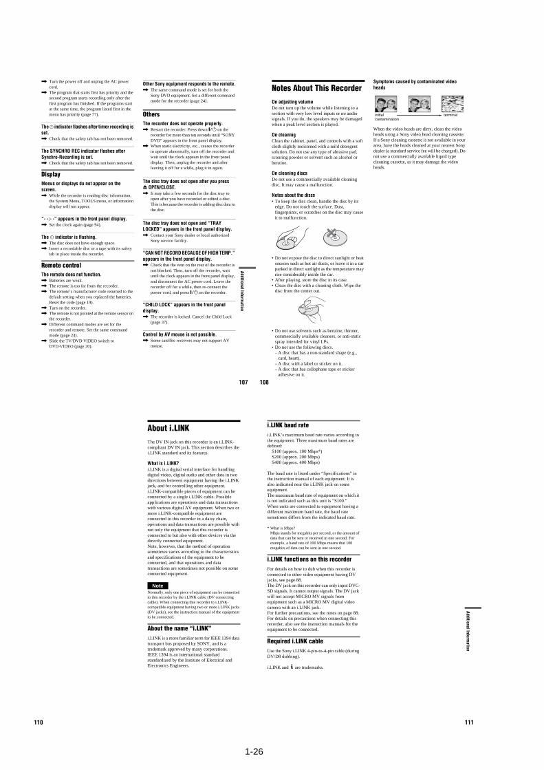
1-26
107
Additional Information
, Turn the power off and unplug the AC power cord.
, The program that starts first has priority and the second program starts recording only after the first program has finished. If the programs start at the same time, the program listed first in the menu has priority (page 77).
The c indicator flashes after timer recording is set., Check that the safety tab has not been removed.
The SYNCHRO REC indicator flashes after Synchro-Recording is set., Check that the safety tab has not been removed.
DisplayMenus or displays do not appear on the screen., While the recorder is reading disc information,
the System Menu, TOOLS menu, or information display will not appear.
“- -:- -” appears in the front panel display., Set the clock again (page 94).
The c indicator is flashing., The disc does not have enough space., Insert a recordable disc or a tape with its safety
tab in place inside the recorder.
Remote controlThe remote does not function., Batteries are weak., The remote is too far from the recorder., The remote’s manufacturer code returned to the
default setting when you replaced the batteries. Reset the code (page 19).
, Turn on the recorder., The remote is not pointed at the remote sensor on
the recorder., Different command modes are set for the
recorder and remote. Set the same command mode (page 24).
, Slide the TV/DVD·VIDEO switch to DVD·VIDEO (page 20).
Other Sony equipment responds to the remote., The same command mode is set for both the
Sony DVD equipment. Set a different command mode for the recorder (page 24).
OthersThe recorder does not operate properly., Restart the recorder. Press down "/1 on the
recorder for more than ten seconds until “SONY DVD” appears in the front panel display.
, When static electricity, etc., causes the recorder to operate abnormally, turn off the recorder and wait until the clock appears in the front panel display. Then, unplug the recorder and after leaving it off for a while, plug it in again.
The disc tray does not open after you press Z OPEN/CLOSE., It may take a few seconds for the disc tray to
open after you have recorded or edited a disc. This is because the recorder is adding disc data to the disc.
The disc tray does not open and “TRAY LOCKED” appears in the front panel display., Contact your Sony dealer or local authorized
Sony service facility.
“CAN NOT RECORD BECAUSE OF HIGH TEMP.” appears in the front panel display., Check that the vent on the rear of the recorder is
not blocked. Then, turn off the recorder, wait until the clock appears in the front panel display, and disconnect the AC power cord. Leave the recorder off for a while, then re-connect the power cord, and press "/1 on the recorder.
“CHILD LOCK” appears in the front panel display., The recorder is locked. Cancel the Child Lock
(page 37).
Control by AV mouse is not possible., Some satellite receivers may not support AV
mouse.
108
Notes About This RecorderOn adjusting volumeDo not turn up the volume while listening to a section with very low level inputs or no audio signals. If you do, the speakers may be damaged when a peak level section is played.
On cleaningClean the cabinet, panel, and controls with a soft cloth slightly moistened with a mild detergent solution. Do not use any type of abrasive pad, scouring powder or solvent such as alcohol or benzine.
On cleaning discsDo not use a commercially available cleaning disc. It may cause a malfunction.
Notes about the discs• To keep the disc clean, handle the disc by its
edge. Do not touch the surface. Dust, fingerprints, or scratches on the disc may cause it to malfunction.
• Do not expose the disc to direct sunlight or heat sources such as hot air ducts, or leave it in a car parked in direct sunlight as the temperature may rise considerably inside the car.
• After playing, store the disc in its case.• Clean the disc with a cleaning cloth. Wipe the
disc from the center out.
• Do not use solvents such as benzine, thinner, commercially available cleaners, or anti-static spray intended for vinyl LPs.
• Do not use the following discs.– A disc that has a non-standard shape (e.g.,
card, heart).– A disc with a label or sticker on it.– A disc that has cellophane tape or sticker
adhesive on it.
Symptoms caused by contaminated video heads
When the video heads are dirty, clean the video heads using a Sony video head cleaning cassette. If a Sony cleaning cassette is not available in your area, have the heads cleaned at your nearest Sony dealer (a standard service fee will be charged). Do not use a commercially available liquid type cleaning cassette, as it may damage the video heads.
initial contamination
terminal
110
About i.LINKThe DV IN jack on this recorder is an i.LINK-compliant DV IN jack. This section describes the i.LINK standard and its features.
What is i.LINK?i.LINK is a digital serial interface for handling digital video, digital audio and other data in two directions between equipment having the i.LINK jack, and for controlling other equipment.i.LINK-compatible pieces of equipment can be connected by a single i.LINK cable. Possible applications are operations and data transactions with various digital AV equipment. When two or more i.LINK-compatible equipment are connected to this recorder in a daisy chain, operations and data transactions are possible with not only the equipment that this recorder is connected to but also with other devices via the directly connected equipment.Note, however, that the method of operation sometimes varies according to the characteristics and specifications of the equipment to be connected, and that operations and data transactions are sometimes not possible on some connected equipment.
NoteNormally, only one piece of equipment can be connected to this recorder by the i.LINK cable (DV connecting cable). When connecting this recorder to i.LINK-compatible equipment having two or more i.LINK jacks (DV jacks), see the instruction manual of the equipment to be connected.
About the name “i.LINK”i.LINK is a more familiar term for IEEE 1394 data transport bus proposed by SONY, and is a trademark approved by many corporations.IEEE 1394 is an international standard standardized by the Institute of Electrical and Electronics Engineers.
111
Additional Information
i.LINK baud ratei.LINK’s maximum baud rate varies according to the equipment. Three maximum baud rates are defined:
S100 (approx. 100 Mbps*) S200 (approx. 200 Mbps) S400 (approx. 400 Mbps)
The baud rate is listed under “Specifications” in the instruction manual of each equipment. It is also indicated near the i.LINK jack on some equipment.The maximum baud rate of equipment on which it is not indicated such as this unit is “S100.” When units are connected to equipment having a different maximum baud rate, the baud rate sometimes differs from the indicated baud rate.
* What is Mbps? Mbps stands for megabits per second, or the amount of data that can be sent or received in one second. For example, a baud rate of 100 Mbps means that 100 megabits of data can be sent in one second.
i.LINK functions on this recorderFor details on how to dub when this recorder is connected to other video equipment having DV jacks, see page 88.The DV jack on this recorder can only input DVC-SD signals. It cannot output signals. The DV jack will not accept MICRO MV signals from equipment such as a MICRO MV digital video camera with an i.LINK jack.For further precautions, see the notes on page 88.For details on precautions when connecting this recorder, also see the instruction manuals for the equipment to be connected.
Required i.LINK cableUse the Sony i.LINK 4-pin-to-4-pin cable (during DV/D8 dubbing).
i.LINK and are trademarks.
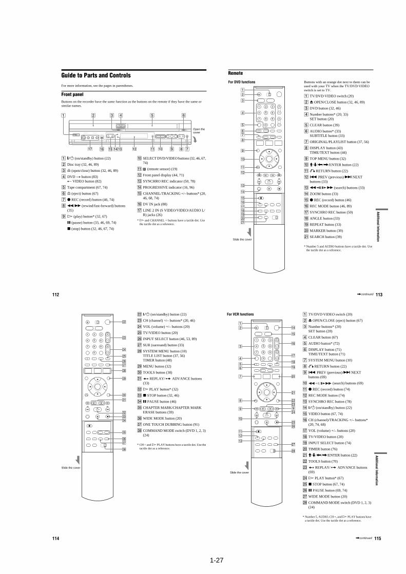
1-27
112
Guide to Parts and ControlsFor more information, see the pages in parentheses.
Front panelButtons on the recorder have the same function as the buttons on the remote if they have the same or similar names.
A "/1 (on/standby) button (22)
B Disc tray (32, 46, 89)
C A (open/close) button (32, 46, 89)
D DVD t button (83)T VIDEO button (82)
E Tape compartment (67, 74)
F A (eject) button (67)
G z REC (record) button (46, 74)
H m/M (rewind/fast-forward) buttons (35)
I H (play) button* (32, 67)
X (pause) button (33, 46, 69, 74)
x (stop) button (32, 46, 67, 74)
J SELECT DVD/VIDEO buttons (32, 46, 67, 74)
K (remote sensor) (19)
L Front panel display (44, 71)
M SYNCHRO REC indicator (50, 78)
N PROGRESSIVE indicator (16, 96)
O CHANNEL/TRACKING +/– buttons* (20, 46, 68, 74)
P DV IN jack (88)
Q LINE 2 IN (S VIDEO/VIDEO/AUDIO L/R) jacks (26)
* H and CHANNEL + buttons have a tactile dot. Use the tactile dot as a reference.
Open the cover
113
Additional Information
Remote
For DVD functions Buttons with an orange dot next to them can be used with your TV when the TV/DVD·VIDEO switch is set to TV.
A TV/DVD·VIDEO switch (20)
B Z OPEN/CLOSE button (32, 46, 89)
C DVD button (32, 46)
D Number buttons* (20, 33)SET button (20)
E CLEAR button (39)
F AUDIO button* (33)SUBTITLE button (33)
G ORIGINAL/PLAYLIST button (37, 56)
H DISPLAY button (43)TIME/TEXT button (44)
I TOP MENU button (32)
J M/m/</,/ENTER button (22)
K O RETURN button (22)
L . PREV (previous)/> NEXTbuttons (33)
M m / M (search) buttons (33)
N ZOOM button (33)
O z REC (record) button (46)
P REC MODE button (46, 89)
Q SYNCHRO REC button (50)
R ANGLE button (33)
S REPEAT button (33)
T MARKER button (39)
U SEARCH button (39)
* Number 5 and AUDIO buttons have a tactile dot. Use the tactile dot as a reference.
Slide the cover
,continued
114
V ?/1 (on/standby) button (22)
W CH (channel) +/– buttons* (20, 46)
X VOL (volume) +/– buttons (20)
Y TV/VIDEO button (20)
Z INPUT SELECT button (46, 53, 89)
wj SUR (surround) button (33)
wk SYSTEM MENU button (10)TITLE LIST button (37, 56)TIMER button (48)
wl MENU button (32)
e; TOOLS button (38)
ea REPLAY/ ADVANCE buttons (33)
es H PLAY button* (32)
ed x STOP button (32, 46)
ef X PAUSE button (46)
eg CHAPTER MARK/CHAPTER MARK ERASE buttons (59)
eh WIDE MODE button (20)
ej ONE TOUCH DUBBING button (91)
ek COMMAND MODE switch (DVD 1, 2, 3) (24)
* CH + and H PLAY buttons have a tactile dot. Use the tactile dot as a reference.
Slide the cover
115
Additional Information
For VCR functions A TV/DVD·VIDEO switch (20)
B Z OPEN/CLOSE (eject) button (67)
C Number buttons* (20)SET button (20)
D CLEAR button (67)
E AUDIO button* (72)
F DISPLAY button (71)TIME/TEXT button (71)
G SYSTEM MENU button (10)
H O RETURN button (22)
I . PREV (previous)/> NEXT buttons (69)
J (search) buttons (69)
K z REC (record) button (74)
L REC MODE button (74)
M SYNCHRO REC button (78)
N ?/1 (on/standby) button (22)
O VIDEO button (67, 74)
P CH (channel)/TRACKING +/– buttons* (20, 74, 68)
Q VOL (volume) +/– buttons (20)
R TV/VIDEO button (20)
S INPUT SELECT button (74)
T TIMER button (76)
U M/m/</,/ENTER button (22)
V TOOLS button (70)
W REPLAY/ ADVANCE buttons (69)
X H PLAY button* (67)
Y x STOP button (67, 74)
Z X PAUSE button (69, 74)
wj WIDE MODE button (20)
wk COMMAND MODE switch (DVD 1, 2, 3) (24)
* Number 5, AUDIO, CH +, and H PLAY buttons have a tactile dot. Use the tactile dot as a reference.
Slide the cover
,continued
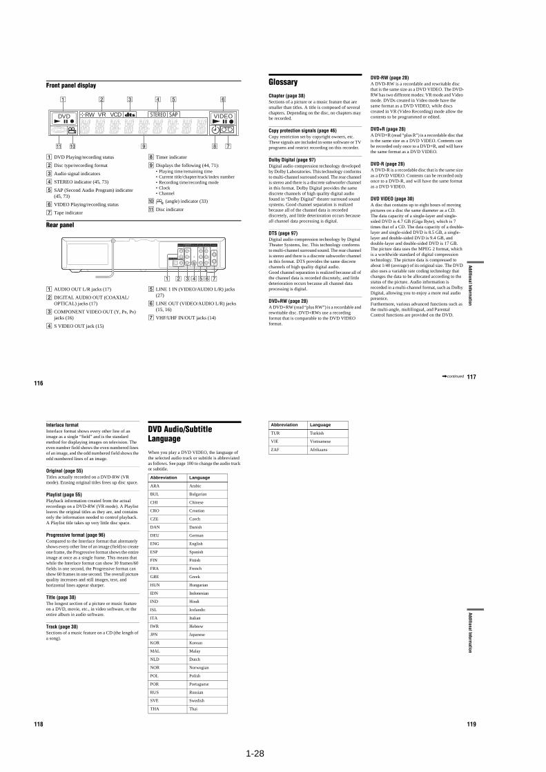
1-28
116
Front panel display
A DVD Playing/recording status
B Disc type/recording format
C Audio signal indicators
D STEREO indicator (45, 73)
E SAP (Second Audio Program) indicator (45, 73)
F VIDEO Playing/recording status
G Tape indicator
H Timer indicator
I Displays the following (44, 71):• Playing time/remaining time • Current title/chapter/track/index number• Recording time/recording mode• Clock• Channel
J (angle) indicator (33)
K Disc indicator
Rear panel
A AUDIO OUT L/R jacks (17)
B DIGITAL AUDIO OUT (COAXIAL/OPTICAL) jacks (17)
C COMPONENT VIDEO OUT (Y, PB, PR) jacks (16)
D S VIDEO OUT jack (15)
E LINE 1 IN (VIDEO/AUDIO L/R) jacks (27)
F LINE OUT (VIDEO/AUDIO L/R) jacks (15, 16)
G VHF/UHF IN/OUT jacks (14)
DVD RW VR VCD SAP VIDEOSTEREO
IN
L
R
VIDEO
AUDIOOUT
VHF/UHFLINE OUT
VIDEO
YL
PBR
PR
AUDIO
LINE 1 INAUDIO OUT S VIDEO OUTCOMPONENTVIDEO OUT
DIGITAL AUDIO OUT
OPTICAL COAXIAL
117
Additional Information
GlossaryChapter (page 38)Sections of a picture or a music feature that are smaller than titles. A title is composed of several chapters. Depending on the disc, no chapters may be recorded.
Copy protection signals (page 46)Copy restriction set by copyright owners, etc. These signals are included in some software or TV programs and restrict recording on this recorder.
Dolby Digital (page 97)Digital audio compression technology developed by Dolby Laboratories. This technology conforms to multi-channel surround sound. The rear channel is stereo and there is a discrete subwoofer channel in this format. Dolby Digital provides the same discrete channels of high quality digital audio found in “Dolby Digital” theater surround sound systems. Good channel separation is realized because all of the channel data is recorded discretely, and little deterioration occurs because all channel data processing is digital.
DTS (page 97)Digital audio compression technology by Digital Theater Systems, Inc. This technology conforms to multi-channel surround sound. The rear channel is stereo and there is a discrete subwoofer channel in this format. DTS provides the same discrete channels of high quality digital audio.Good channel separation is realized because all of the channel data is recorded discretely, and little deterioration occurs because all channel data processing is digital.
DVD+RW (page 28)A DVD+RW (read “plus RW”) is a recordable and rewritable disc. DVD+RWs use a recording format that is comparable to the DVD VIDEO format.
DVD-RW (page 28)A DVD-RW is a recordable and rewritable disc that is the same size as a DVD VIDEO. The DVD-RW has two different modes: VR mode and Video mode. DVDs created in Video mode have the same format as a DVD VIDEO, while discs created in VR (Video Recording) mode allow the contents to be programmed or edited.
DVD+R (page 28)A DVD+R (read “plus R”) is a recordable disc that is the same size as a DVD VIDEO. Contents can be recorded only once to a DVD+R, and will have the same format as a DVD VIDEO.
DVD-R (page 28)A DVD-R is a recordable disc that is the same size as a DVD VIDEO. Contents can be recorded only once to a DVD-R, and will have the same format as a DVD VIDEO.
DVD VIDEO (page 30)A disc that contains up to eight hours of moving pictures on a disc the same diameter as a CD.The data capacity of a single-layer and single-sided DVD is 4.7 GB (Giga Byte), which is 7 times that of a CD. The data capacity of a double-layer and single-sided DVD is 8.5 GB, a single-layer and double-sided DVD is 9.4 GB, and double-layer and double-sided DVD is 17 GB.The picture data uses the MPEG 2 format, which is a worldwide standard of digital compression technology. The picture data is compressed to about 1/40 (average) of its original size. The DVD also uses a variable rate coding technology that changes the data to be allocated according to the status of the picture. Audio information is recorded in a multi-channel format, such as Dolby Digital, allowing you to enjoy a more real audio presence.Furthermore, various advanced functions such as the multi-angle, multilingual, and Parental Control functions are provided on the DVD.
,continued
118
Interlace formatInterlace format shows every other line of an image as a single “field” and is the standard method for displaying images on television. The even number field shows the even numbered lines of an image, and the odd numbered field shows the odd numbered lines of an image.
Original (page 55)Titles actually recorded on a DVD-RW (VR mode). Erasing original titles frees up disc space.
Playlist (page 55)Playback information created from the actual recordings on a DVD-RW (VR mode). A Playlist leaves the original titles as they are, and contains only the information needed to control playback. A Playlist title takes up very little disc space.
Progressive format (page 96)Compared to the Interlace format that alternately shows every other line of an image (field) to create one frame, the Progressive format shows the entire image at once as a single frame. This means that while the Interlace format can show 30 frames/60 fields in one second, the Progressive format can show 60 frames in one second. The overall picture quality increases and still images, text, and horizontal lines appear sharper.
Title (page 38)The longest section of a picture or music feature on a DVD, movie, etc., in video software, or the entire album in audio software.
Track (page 38)Sections of a music feature on a CD (the length of a song).
DVD Audio/Subtitle LanguageWhen you play a DVD VIDEO, the language of the selected audio track or subtitle is abbreviated as follows. See page 100 to change the audio track or subtitle.
Abbreviation Language
ARA Arabic
BUL Bulgarian
CHI Chinese
CRO Croatian
CZE Czech
DAN Danish
DEU German
ENG English
ESP Spanish
FIN Finish
FRA French
GRE Greek
HUN Hungarian
IDN Indonesian
IND Hindi
ISL Icelandic
ITA Italian
IWR Hebrew
JPN Japanese
KOR Korean
MAL Malay
NLD Dutch
NOR Norwegian
POL Polish
POR Portuguese
RUS Russian
SVE Swedish
THA Thai
119
Additional Information
TUR Turkish
VIE Vietnamese
ZAF Afrikaans
Abbreviation Language
1-29
120
IndexWords in quotations appear in the on-screen displays.
Numerics16:9 23, 954:3 Letter Box 23, 954:3 Pan Scan 23, 95
A“A-B Erase” 57“Add” 63, 65ADVANCE 34, 69ANGLE 33Antenna 14AUDIO 33, 72“Audio” 100Audio cords 17“Audio DRC” 98Audio settings 97Auto Clock Set 94“Auto Play” 100“Auto Preset” 93“Auto Repeat” 100
BBatteries 19“Black Level” 96Bookmark 39
CCable box 13, 14Changing or Canceling Timer Settings (Timer List) 52, 79Chapter 117“Chapter Erase” 57CHAPTER MARK 59CHAPTER MARK ERASE 59“Check” 63Child Lock 37Cleaning discs 108Cleaning the video heads 106CLEAR 67“Clock Set CH” 94Clock Set settings 94
“Combine Titles” 63“Command Mode” 25, 102COMPONENT VIDEO OUT 16Connecting
the antenna cable 12to your AV/amplifier
(receiver) 17to your TV 15
Controlling TVs with the remote 20Copy protection 46, 117Copy-Free 46Copy-Never 46Copy-Once 46Counter 67CPRM 28“Create Dubbing List” 85“Create Playlist” 61Creating chapters 48, 59
D“Daylight Saving” 95“Del” 52, 80“Digital Out” 97“Disc Finalize” 66, 87“Disc Format” 66“Disc Information” 66“Disc Menu” 100“Disc Name” 66“Disc Protect” 66“Disc Setting” 66, 87Disc types 28Display
front panel display 116Setup Display 92
“Divide Title” 58, 63Dolby Digital 23, 98, 117“Downmix” 98DTS 23, 35, 98, 117“Dubbing” 82, 84“DV Audio Input” 90, 99“DV/D8 Dubbing” 90“DV/D8 One Touch Dubbing” 91“DV/D8 Simple Dubbing” 90“DVD Auto Chapter” 99DVD Editing 55DVD VIDEO 30, 117
DVD+R 28, 117DVD+R DL 28DVD+RW 28, 117DVD-R 28, 117DVD-RW 28, 117
EEasy Setup 102“Edit” 52, 80“Edit Playlist” 63“Edit Scene” 63Enter characters 60EP mode 74“Erase” 57“Erase All Titles” 66
F“Factory Setting” 102Fast forward 34, 69Fast reverse 34, 69Feature settings 99Finalizing 86“Format DVD” 100“Front Display” 101Front panel 112Front panel display 116
HHandling discs 108
Ii.LINK 88, 110INPUT SELECT 46, 74, 89Interlace format 118
JJPEG image files 41
L“Language” 100Language Abbreviation 118LINE 1 IN 27LINE 2 IN 26“Line Audio Input” 50, 54, 99
MManual Clock Set 95
121
“Manual Set” 94MARKER 39MENU 32Menu
Top menu 32“Modify” 63“Move” 63MP3 audio tracks 40
NNEXT 34, 69Number buttons 20, 38
OOne Touch Dubbing 91On-screen display
Setup Display 92Sub-menu 10System Menu 10TOOLS menu 11
Options settings 100Original 38, 118ORIGINAL/PLAYLIST 38, 56“OSD” language 22, 100
P“Parental” 101Parental Control 36Parts and controls 112PAUSE 34, 47, 69, 74PBC 36“Picture control” 96PLAY 32, 67Playable discs 30Playback 32, 67
MP3 audio tracks 40Repeat Play 35Resume Play 36Slow-motion play 33
Playlist 38, 61, 118Power cord 19PREV 34, 69Program Dubbing 84“Progressive” 96Progressive format 118“Protect” 57
QQuick Timer 47, 74
RRear panel 116REC 47, 74REC MODE 47, 74Recording 45, 73
recordable discs 28recording format 28recording mode 45tape speed 73while watching another
program 47, 74
Recording mode 45Recording time 45, 48Region code 31Remaining time 75Remote 19, 113REPEAT 35Repeat A-B Play 36REPLAY 34, 69Resetting 102Resume Play 36Rotate 42
SSafety tab 73SAP (Second Audio Program) 45, 73Satellite receiver 13“Scan Audio” 36, 98“Scene Dubbing” 85Searching
for “Chapter” 38for “Title” 38for “Track” 38Time Search 38
Settings 92Setup Display 92“Simple Dubbing” 84SP mode 74Stereo programs 45, 73STOP 32, 47, 67, 74Sub-menu 10SUBTITLE 33“Subtitle” 100SURROUND 34
SYNCHRO REC 51, 78“Synchro Recording” 51, 78, 100System Menu 10
T“Tape Length” 100Tape speed 73“Time Zone” 95TIME/TEXT 44, 71TIMER 49, 76Timer List 52, 79Timer recording 48, 76
change or cancel 52, 79Title 118“Title Dubbing” 85“Title Erase” 57, 63TITLE LIST 37, 56Title List 37“Title Name” 57, 63TOOLS 11TOP MENU 32Track 118TRACKING 68Tracking adjustment 68Troubleshooting 103“Tuner Audio” 97Tuner Preset 23Tuner Preset settings 93“TV Type” 95TV/DVD·VIDEO 20TV/VIDEO 47, 74
U“Unfinalize” 87Unrecordable pictures 46
V“VCR Function” 100VIDEO CD 30Video mode 28Video settings 95VR mode 28
ZZOOM 33Zoom 42

1-30E
MEMO
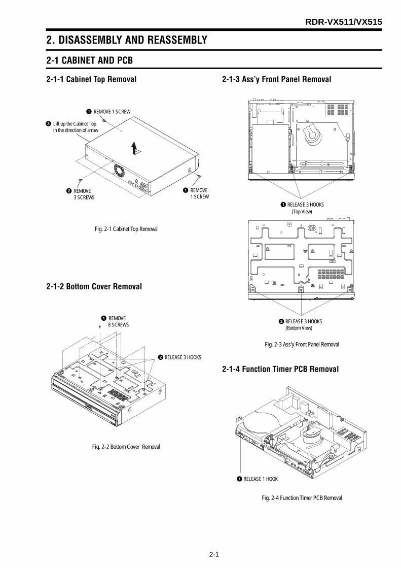
2-1
RDR-VX511/VX515
2. DISASSEMBLY AND REASSEMBLY
2-1 CABINET AND PCB
Fig. 2-1 Cabinet Top Removal
Fig. 2-2 Bottom Cover Removal
2-1-1 Cabinet Top Removal
2-1-2 Bottom Cover Removal
2-1-3 Ass’y Front Panel Removal
Fig. 2-3 Ass’y Front Panel Removal
2-1-4 Function Timer PCB Removal
Fig. 2-4 Function Timer PCB Removal
1 REMOVE 1 SCREW
3 Lift up the Cabinet Top in the direction of arrow
2 REMOVE3 SCREWS
1 REMOVE1 SCREW
2 RELEASE 3 HOOKS
1 REMOVE 8 SCREWS
1 RELEASE 3 HOOKS
2 RELEASE 3 HOOKS
(Top View)
(Bottom View)
1 RELEASE 1 HOOK
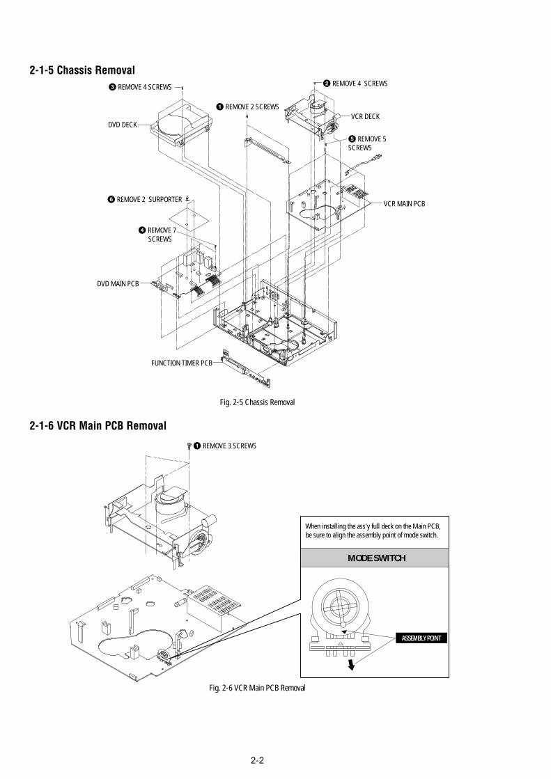
2-2
Fig. 2-5 Chassis Removal
2-1-5 Chassis Removal
2-1-6 VCR Main PCB Removal
Fig. 2-6 VCR Main PCB Removal
1 REMOVE 2 SCREWS
2 REMOVE 4 SCREWS
VCR MAIN PCB
DVD MAIN PCB
FUNCTION TIMER PCB
VCR DECK
3 REMOVE 4 SCREWS
5 REMOVE 5 SCREWS
4 REMOVE 7 SCREWS
6 REMOVE 2 SURPORTER
DVD DECK
1 REMOVE 3 SCREWS
MODE SWITCH
When installing the ass'y full deck on the Main PCB, be sure to align the assembly point of mode switch.
ASSEMBLY POINT
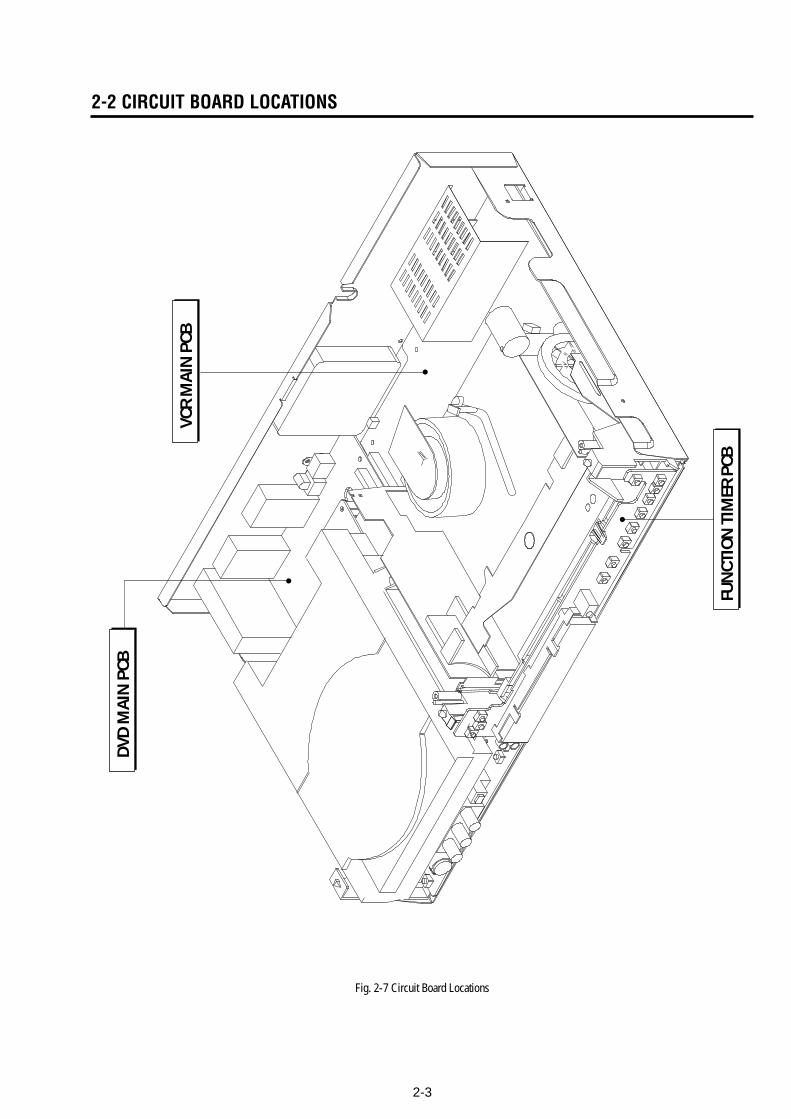
2-3
Fig. 2-7 Circuit Board Locations
2-2 CIRCUIT BOARD LOCATIONSD
VD M
AIN
PCB
FUN
CTIO
N T
IMER
PCB
VCR
MA
IN P
CB
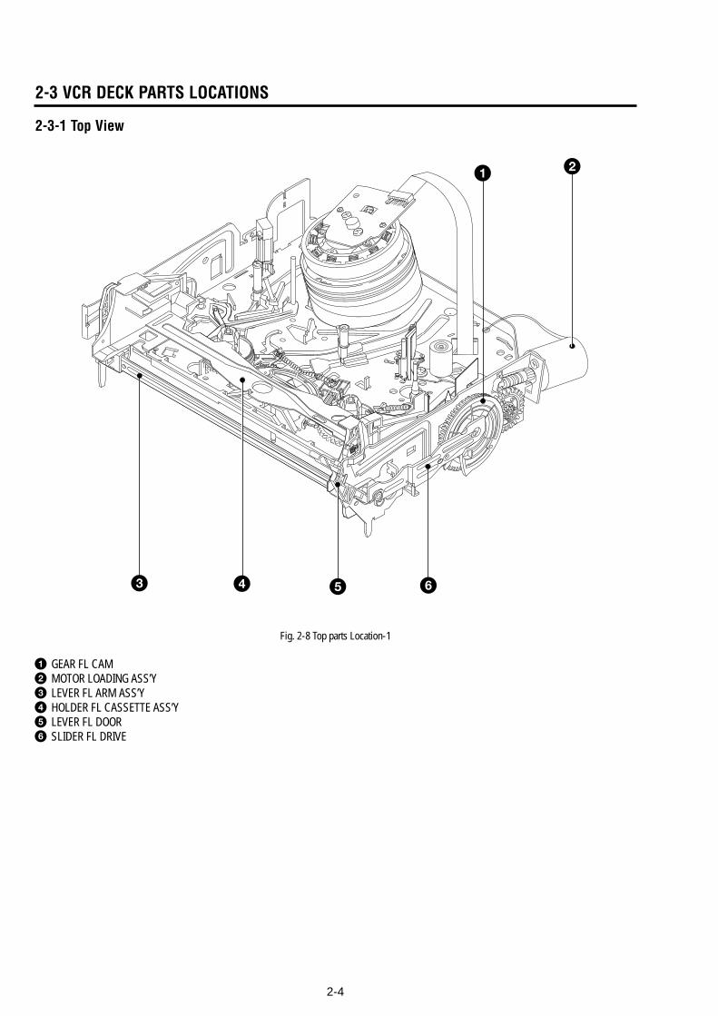
2-4
2-3 VCR DECK PARTS LOCATIONS
2-3-1 Top View
1 2
5 63 4
Fig. 2-8 Top parts Location-1
1 GEAR FL CAM2 MOTOR LOADING ASS’Y3 LEVER FL ARM ASS’Y4 HOLDER FL CASSETTE ASS’Y5 LEVER FL DOOR6 SLIDER FL DRIVE
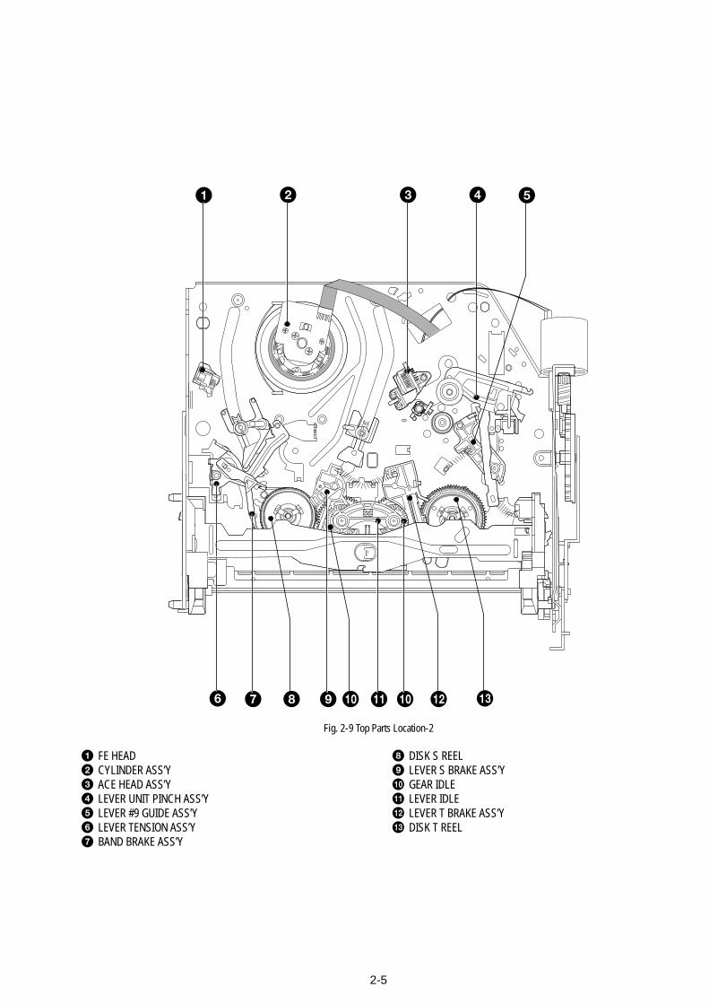
2-5
1 2
6 7 8 9 qa 0 qs qd0
3 4 5
Fig. 2-9 Top Parts Location-2
1 FE HEAD2 CYLINDER ASS’Y3 ACE HEAD ASS’Y4 LEVER UNIT PINCH ASS’Y5 LEVER #9 GUIDE ASS’Y6 LEVER TENSION ASS’Y7 BAND BRAKE ASS’Y
8 DISK S REEL9 LEVER S BRAKE ASS’Y0 GEAR IDLEqa LEVER IDLEqs LEVER T BRAKE ASS’Yqd DISK T REEL
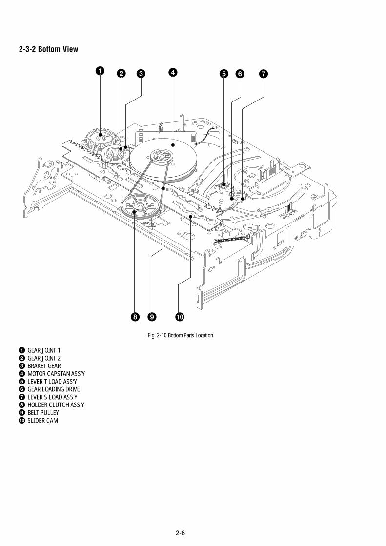
2-6
2-3-2 Bottom View
1 2 3 4 5 6 7
8 9 0
Fig. 2-10 Bottom Parts Location
1 GEAR JOINT 12 GEAR JOINT 23 BRAKET GEAR4 MOTOR CAPSTAN ASS’Y5 LEVER T LOAD ASS’Y6 GEAR LOADING DRIVE7 LEVER S LOAD ASS’Y8 HOLDER CLUTCH ASS’Y9 BELT PULLEY0 SLIDER CAM
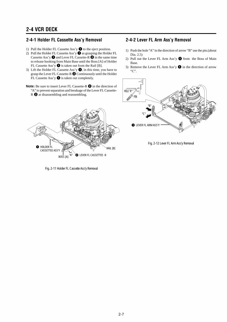
2-7
1 LEVER FL ARM ASS'Y
"C"
"B"
PIN
HOLE "A"
2-4 VCR DECK
2-4-1 Holder FL Cassette Ass’y Removal
1) Pull the Holder FL Cassette Ass’y 1 to the eject position.2) Pull the Holder FL Cassette Ass’y 1 as grasping the Holder FL
Cassette Ass’y 1 and Lever FL Cassette-R 2 in the same timeto release hooking from Main Base until the Boss [A] of HolderFL Cassette Ass’y 1 is taken out from the Rail [B].
3) Lift the Holder FL Cassette Ass’y 1, in this time, you have tograsp the Lever FL Cassette-R 2 Continuously until the HolderFL Cassette Ass’y 1 is taken out completely.
Note: Be sure to insert Lever FL Cassette-R 2 in the direction of“A” to prevent separation and breakage of the Lever FL Cassette-R 2 at disassembling and reassembling.
Fig. 2-11 Holder FL Cassette Ass’y Removal
RAIL [B]
BOSS [A] 2 LEVER FL CASSETTEE -R"A"
1 HOLDER FLCASSETTEE ASS'Y
2-4-2 Lever FL Arm Ass’y Removal
1) Push the hole “A” in the direction of arrow “B” use the pin.(aboutDia. 2.5)
2) Pull out the Lever FL Arm Ass’y 1 from the Boss of MainBase.
3) Remove the Lever FL Arm Ass’y 1 in the direction of arrow“C”.
Fig. 2-12 Lever FL Arm Ass’y Removal
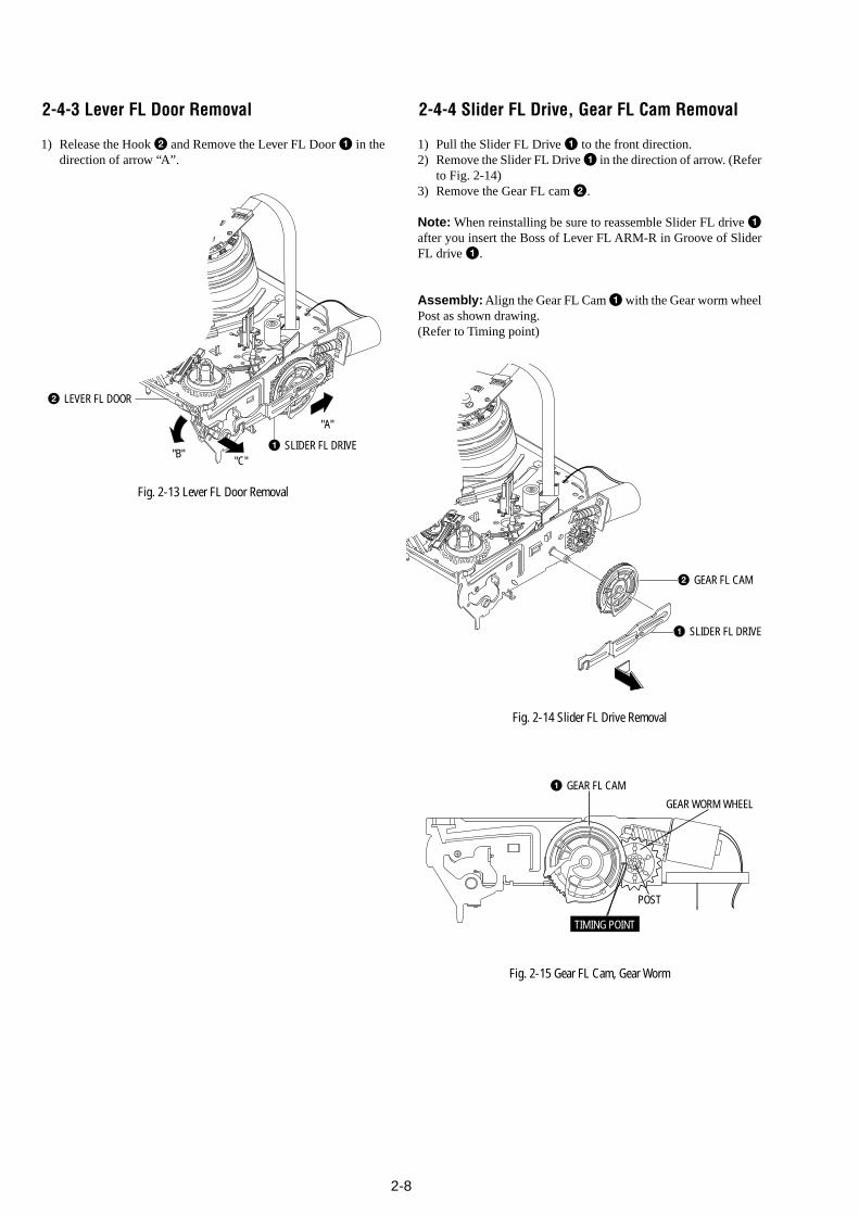
2-8
2-4-4 Slider FL Drive, Gear FL Cam Removal
1) Pull the Slider FL Drive 1 to the front direction.2) Remove the Slider FL Drive 1 in the direction of arrow. (Refer
to Fig. 2-14)3) Remove the Gear FL cam 2.
Note: When reinstalling be sure to reassemble Slider FL drive 1after you insert the Boss of Lever FL ARM-R in Groove of SliderFL drive 1.
Assembly: Align the Gear FL Cam 1 with the Gear worm wheelPost as shown drawing.(Refer to Timing point)
Fig. 2-14 Slider FL Drive Removal
Fig. 2-15 Gear FL Cam, Gear Worm
1 GEAR FL CAM
GEAR WORM WHEEL
POST
TIMING POINT
2-4-3 Lever FL Door Removal
1) Release the Hook 2 and Remove the Lever FL Door 1 in thedirection of arrow “A”.
Fig. 2-13 Lever FL Door Removal
"B""C"
"A"
2 LEVER FL DOOR
1 SLIDER FL DRIVE
1 SLIDER FL DRIVE
2 GEAR FL CAM
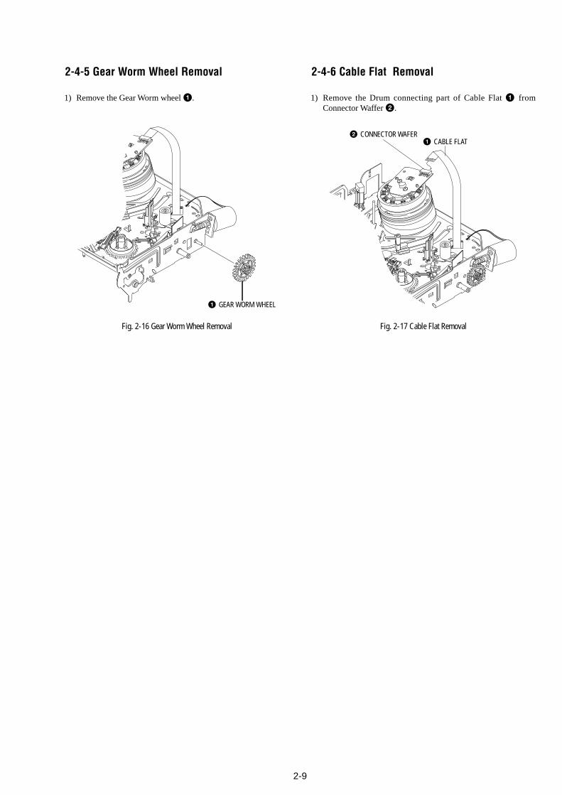
2-9
2 CONNECTOR WAFER1 CABLE FLAT
2-4-5 Gear Worm Wheel Removal
1) Remove the Gear Worm wheel 1.
Fig. 2-16 Gear Worm Wheel Removal
2-4-6 Cable Flat Removal
1) Remove the Drum connecting part of Cable Flat 1 fromConnector Waffer 2.
Fig. 2-17 Cable Flat Removal
1 GEAR WORM WHEEL
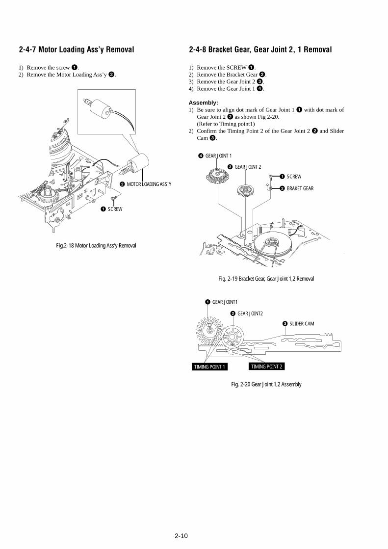
2-10
1 SCREW
2 BRAKET GEAR
4 GEAR JOINT 1
3 GEAR JOINT 2
2 MOTOR LOADING ASS`Y
1 SCREW
2-4-7 Motor Loading Ass’y Removal
1) Remove the screw 1.2) Remove the Motor Loading Ass’y 2.
Fig.2-18 Motor Loading Ass’y Removal
2-4-8 Bracket Gear, Gear Joint 2, 1 Removal
1) Remove the SCREW 1.2) Remove the Bracket Gear 2.3) Remove the Gear Joint 2 3.4) Remove the Gear Joint 1 4.
Assembly:1) Be sure to align dot mark of Gear Joint 1 1 with dot mark of
Gear Joint 2 2 as shown Fig 2-20.(Refer to Timing point1)
2) Confirm the Timing Point 2 of the Gear Joint 2 2 and SliderCam 3.
Fig. 2-19 Bracket Gear, Gear Joint 1,2 Removal
Fig. 2-20 Gear Joint 1,2 Assembly
1 GEAR JOINT1
2 GEAR JOINT2
3 SLIDER CAM
TIMING POINT 1 TIMING POINT 2
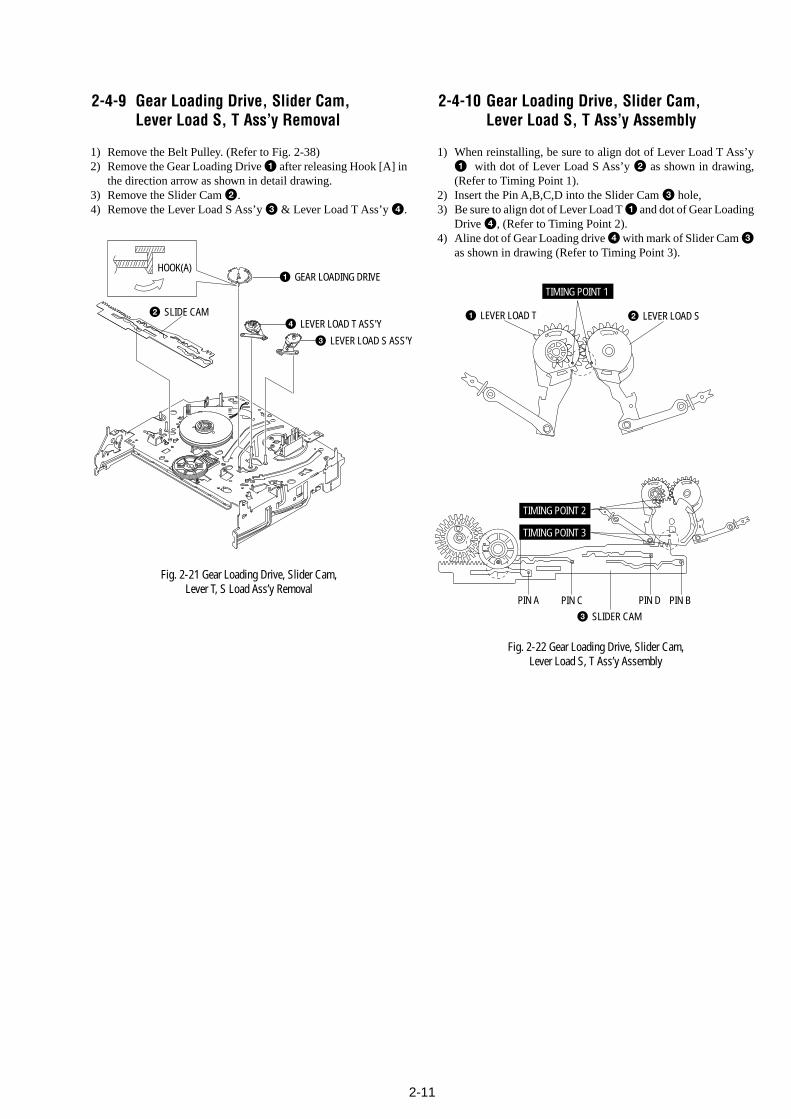
2-11
2-4-9 Gear Loading Drive, Slider Cam,Lever Load S, T Ass’y Removal
1) Remove the Belt Pulley. (Refer to Fig. 2-38)2) Remove the Gear Loading Drive 1 after releasing Hook [A] in
the direction arrow as shown in detail drawing.3) Remove the Slider Cam 2.4) Remove the Lever Load S Ass’y 3 & Lever Load T Ass’y 4.
Fig. 2-21 Gear Loading Drive, Slider Cam,Lever T, S Load Ass’y Removal
2-4-10 Gear Loading Drive, Slider Cam,Lever Load S, T Ass’y Assembly
1) When reinstalling, be sure to align dot of Lever Load T Ass’y1 with dot of Lever Load S Ass’y 2 as shown in drawing,(Refer to Timing Point 1).
2) Insert the Pin A,B,C,D into the Slider Cam 3 hole,3) Be sure to align dot of Lever Load T 1 and dot of Gear Loading
Drive 4, (Refer to Timing Point 2).4) Aline dot of Gear Loading drive 4 with mark of Slider Cam 3
as shown in drawing (Refer to Timing Point 3).
Fig. 2-22 Gear Loading Drive, Slider Cam,Lever Load S, T Ass’y Assembly
1 GEAR LOADING DRIVE
3 LEVER LOAD S ASS'Y
4 LEVER LOAD T ASS'Y2 SLIDE CAM
HOOK(A)
2 LEVER LOAD S 1 LEVER LOAD T
PIN A PIN C PIN BPIN D3 SLIDER CAM
TIMING POINT 2
TIMING POINT 1
TIMING POINT 3
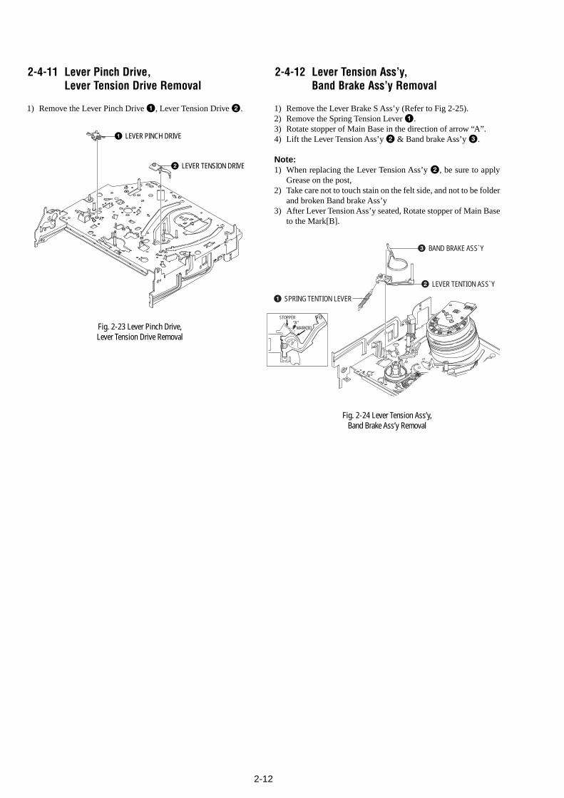
2-12
1 SPRING TENTION LEVER
2 LEVER TENTION ASS`Y
3 BAND BRAKE ASS`Y
STOPPER
MARK[B]"A"
2-4-11 Lever Pinch Drive,Lever Tension Drive Removal
1) Remove the Lever Pinch Drive 1, Lever Tension Drive 2.
Fig. 2-23 Lever Pinch Drive,Lever Tension Drive Removal
2-4-12 Lever Tension Ass’y,Band Brake Ass’y Removal
1) Remove the Lever Brake S Ass’y (Refer to Fig 2-25).2) Remove the Spring Tension Lever 1.3) Rotate stopper of Main Base in the direction of arrow “A”.4) Lift the Lever Tension Ass’y 2 & Band brake Ass’y 3.
Note:1) When replacing the Lever Tension Ass’y 2, be sure to apply
Grease on the post,2) Take care not to touch stain on the felt side, and not to be folder
and broken Band brake Ass’y3) After Lever Tension Ass’y seated, Rotate stopper of Main Base
to the Mark[B].
Fig. 2-24 Lever Tension Ass’y,Band Brake Ass’y Removal
1 LEVER PINCH DRIVE
2 LEVER TENSION DRIVE
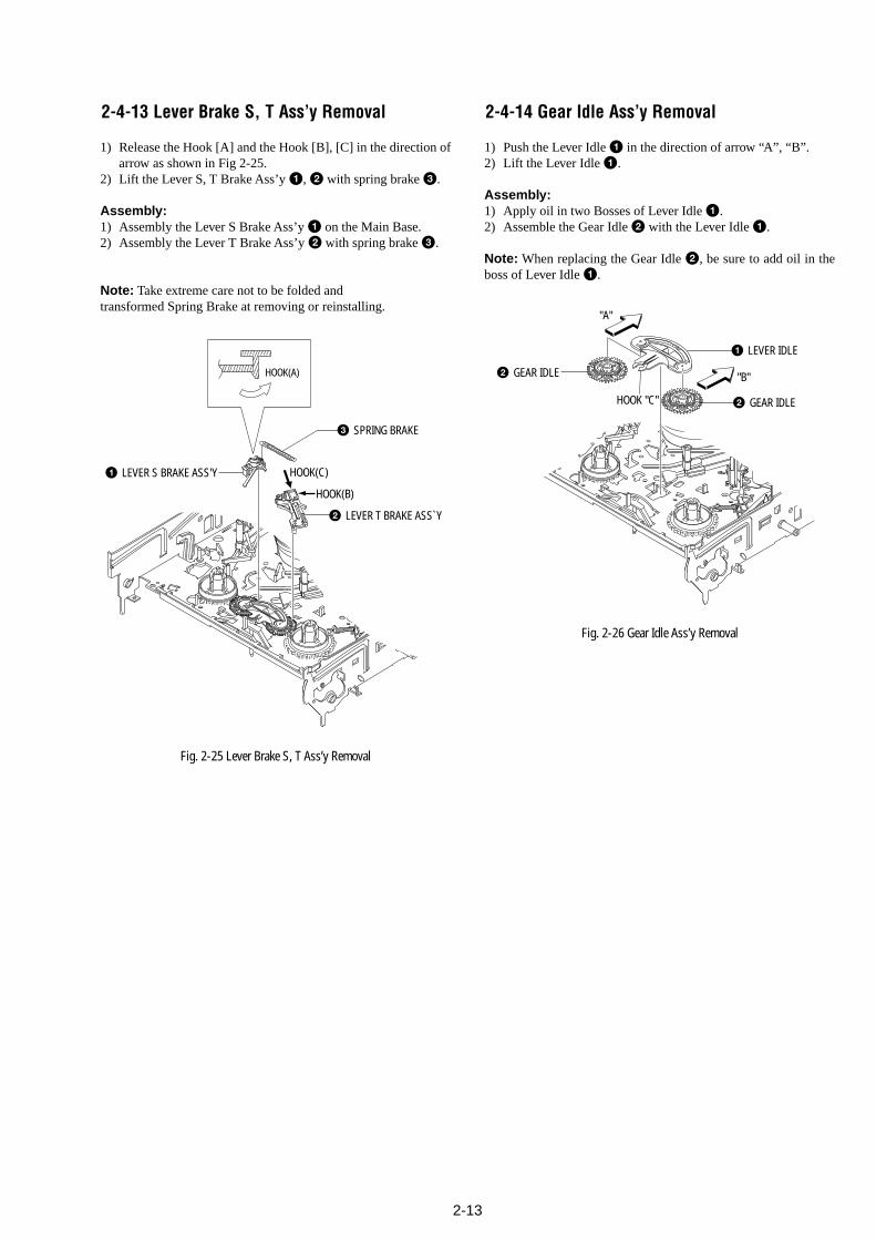
2-13
2-4-13 Lever Brake S, T Ass’y Removal
1) Release the Hook [A] and the Hook [B], [C] in the direction ofarrow as shown in Fig 2-25.
2) Lift the Lever S, T Brake Ass’y 1, 2 with spring brake 3.
Assembly:1) Assembly the Lever S Brake Ass’y 1 on the Main Base.2) Assembly the Lever T Brake Ass’y 2 with spring brake 3.
Note: Take extreme care not to be folded andtransformed Spring Brake at removing or reinstalling.
Fig. 2-25 Lever Brake S, T Ass’y Removal
2-4-14 Gear Idle Ass’y Removal
1) Push the Lever Idle 1 in the direction of arrow “A”, “B”.2) Lift the Lever Idle 1.
Assembly:1) Apply oil in two Bosses of Lever Idle 1.2) Assemble the Gear Idle 2 with the Lever Idle 1.
Note: When replacing the Gear Idle 2, be sure to add oil in theboss of Lever Idle 1.
Fig. 2-26 Gear Idle Ass’y Removal
HOOK(A)
2 LEVER T BRAKE ASS`Y
1 LEVER S BRAKE ASS'Y
HOOK(B)
HOOK(C)
3 SPRING BRAKE
2 GEAR IDLE
"B"
1 LEVER IDLE
2 GEAR IDLE
"A"
HOOK "C"
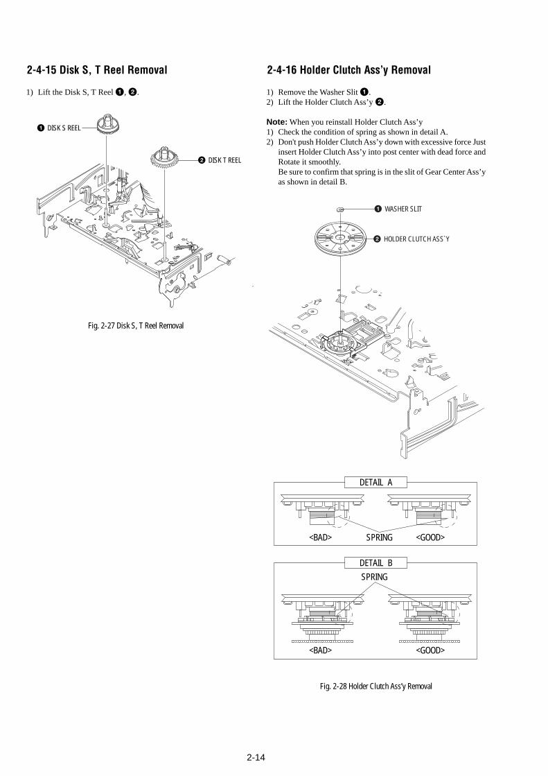
2-14
2-4-15 Disk S, T Reel Removal
1) Lift the Disk S, T Reel 1, 2.
Fig. 2-27 Disk S, T Reel Removal
2-4-16 Holder Clutch Ass’y Removal
1) Remove the Washer Slit 1.2) Lift the Holder Clutch Ass’y 2.
Note: When you reinstall Holder Clutch Ass’y1) Check the condition of spring as shown in detail A.2) Don't push Holder Clutch Ass’y down with excessive force Just
insert Holder Clutch Ass’y into post center with dead force andRotate it smoothly.Be sure to confirm that spring is in the slit of Gear Center Ass’yas shown in detail B.
Fig. 2-28 Holder Clutch Ass’y Removal
1 WASHER SLIT
2 HOLDER CLUTCH ASS`Y
DETAIL A
<BAD> SPRING <GOOD>
<BAD>
SPRING
<GOOD>
DETAIL B
1 DISK S REEL
2 DISK T REEL
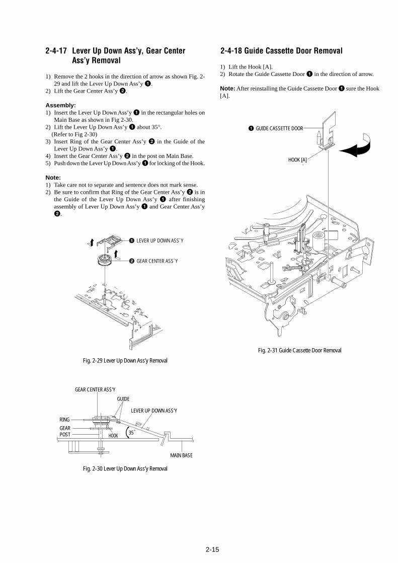
2-15
1 GUIDE CASSETTE DOOR
HOOK [A]
2-4-17 Lever Up Down Ass’y, Gear CenterAss’y Removal
1) Remove the 2 hooks in the direction of arrow as shown Fig. 2-29 and lift the Lever Up Down Ass’y 1.
2) Lift the Gear Center Ass’y 2.
Assembly:1) Insert the Lever Up Down Ass’y 1 in the rectangular holes on
Main Base as shown in Fig 2-30.2) Lift the Lever Up Down Ass’y 1 about 35°. (Refer to Fig 2-30)3) Insert Ring of the Gear Center Ass’y 2 in the Guide of the
Lever Up Down Ass’y 1.4) Insert the Gear Center Ass’y 2 in the post on Main Base.5) Push down the Lever Up Down Ass’y 1 for locking of the Hook.
Note:1) Take care not to separate and sentence does not mark sense.2) Be sure to confirm that Ring of the Gear Center Ass’y 2 is in
the Guide of the Lever Up Down Ass’y 1 after finishingassembly of Lever Up Down Ass’y 1 and Gear Center Ass’y2.
Fig. 2-29 Lever Up Down Ass’y Removal
Fig. 2-30 Lever Up Down Ass’y Removal
2-4-18 Guide Cassette Door Removal
1) Lift the Hook [A].2) Rotate the Guide Cassette Door 1 in the direction of arrow.
Note: After reinstalling the Guide Cassette Door 1 sure the Hook[A].
Fig. 2-31 Guide Cassette Door Removal
1 LEVER UP DOWN ASS`Y
2 GEAR CENTER ASS`Y
MAIN BASE
LEVER UP DOWN ASS'Y
GUIDE
GEAR CENTER ASS'Y
RING
GEARPOST HOOK 35
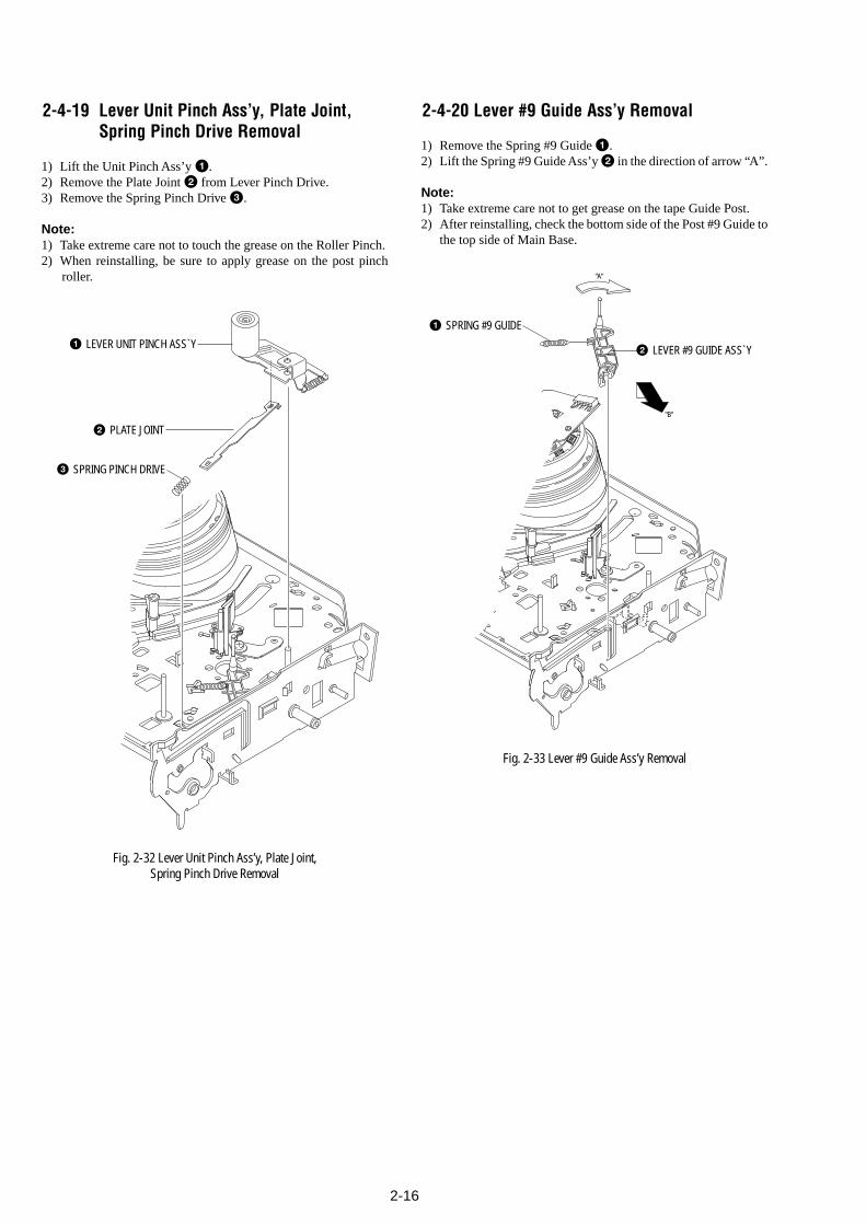
2-16
"A"
"B"
1 SPRING #9 GUIDE
2 LEVER #9 GUIDE ASS`Y
3 SPRING PINCH DRIVE
1 LEVER UNIT PINCH ASS`Y
2 PLATE JOINT
2-4-19 Lever Unit Pinch Ass’y, Plate Joint,Spring Pinch Drive Removal
1) Lift the Unit Pinch Ass’y 1.2) Remove the Plate Joint 2 from Lever Pinch Drive.3) Remove the Spring Pinch Drive 3.
Note:1) Take extreme care not to touch the grease on the Roller Pinch.2) When reinstalling, be sure to apply grease on the post pinch
roller.
Fig. 2-32 Lever Unit Pinch Ass’y, Plate Joint,Spring Pinch Drive Removal
2-4-20 Lever #9 Guide Ass’y Removal
1) Remove the Spring #9 Guide 1.2) Lift the Spring #9 Guide Ass’y 2 in the direction of arrow “A”.
Note:1) Take extreme care not to get grease on the tape Guide Post.2) After reinstalling, check the bottom side of the Post #9 Guide to
the top side of Main Base.
Fig. 2-33 Lever #9 Guide Ass’y Removal
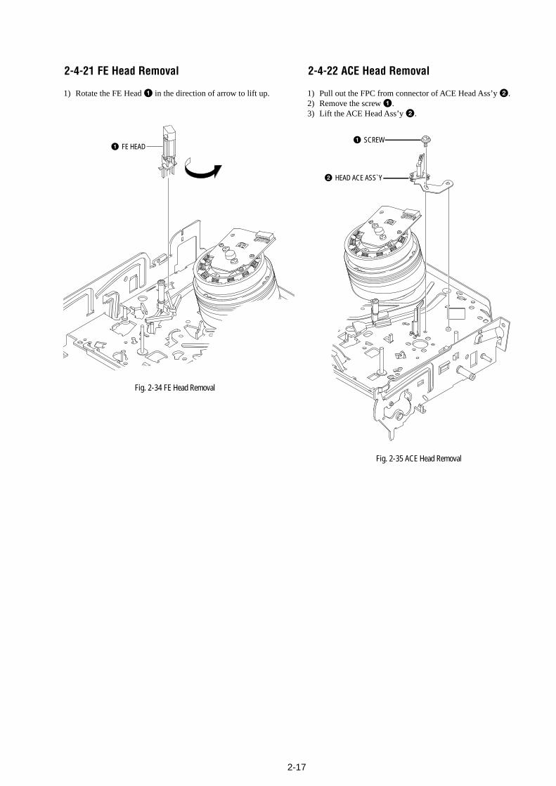
2-17
1 SCREW
2 HEAD ACE ASS`Y
1 FE HEAD
2-4-21 FE Head Removal
1) Rotate the FE Head 1 in the direction of arrow to lift up.
Fig. 2-34 FE Head Removal
2-4-22 ACE Head Removal
1) Pull out the FPC from connector of ACE Head Ass’y 2.2) Remove the screw 1.3) Lift the ACE Head Ass’y 2.
Fig. 2-35 ACE Head Removal
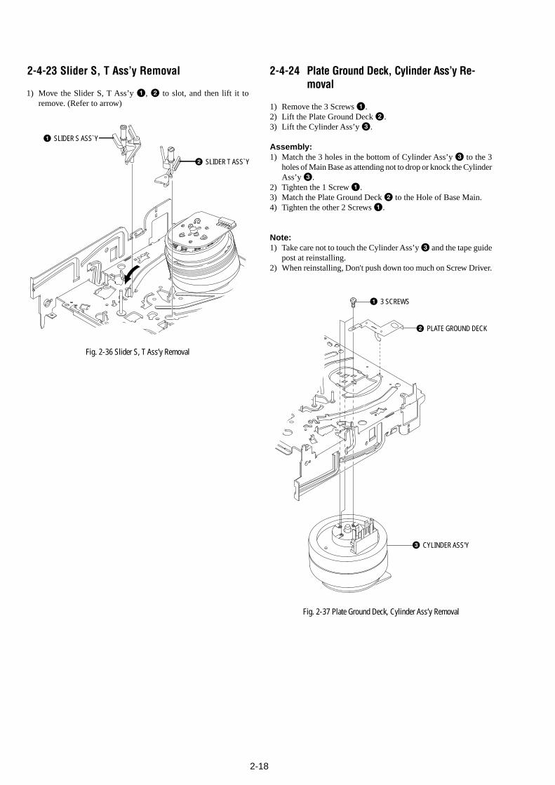
2-18
1 SLIDER S ASS`Y
2 SLIDER T ASS`Y
1 3 SCREWS
2 PLATE GROUND DECK
3 CYLINDER ASS'Y
2-4-23 Slider S, T Ass’y Removal
1) Move the Slider S, T Ass’y 1, 2 to slot, and then lift it toremove. (Refer to arrow)
Fig. 2-36 Slider S, T Ass’y Removal
2-4-24 Plate Ground Deck, Cylinder Ass’y Re-moval
1) Remove the 3 Screws 1.2) Lift the Plate Ground Deck 2.3) Lift the Cylinder Ass’y 3.
Assembly:1) Match the 3 holes in the bottom of Cylinder Ass’y 3 to the 3
holes of Main Base as attending not to drop or knock the CylinderAss’y 3.
2) Tighten the 1 Screw 1.3) Match the Plate Ground Deck 2 to the Hole of Base Main.4) Tighten the other 2 Screws 1.
Note:1) Take care not to touch the Cylinder Ass’y 3 and the tape guide
post at reinstalling.2) When reinstalling, Don't push down too much on Screw Driver.
Fig. 2-37 Plate Ground Deck, Cylinder Ass’y Removal
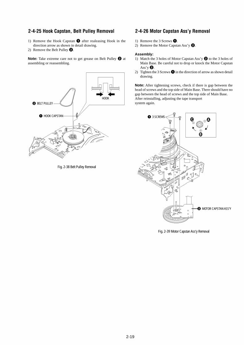
2-19
1 3 SCREWSA
B
C
2 MOTOR CAPSTAN ASS'Y
2 BELT PULLEY
1 HOOK CAPSTAN
HOOK
2-4-25 Hook Capstan, Belt Pulley Removal
1) Remove the Hook Capstan 1 after realeasing Hook in thedirection arrow as shown in detail drawing.
2) Remove the Belt Pulley 2.
Note: Take extreme care not to get grease on Belt Pulley 2 atassembling or reassembling.
Fig. 2-38 Belt Pulley Removal
2-4-26 Motor Capstan Ass’y Removal
1) Remove the 3 Screws 1.2) Remove the Motor Capstan Ass’y 2.
Assembly:1) Match the 3 holes of Motor Capstan Ass’y 2 to the 3 holes of
Main Base. Be careful not to drop or knock the Motor CapstanAss’y 2.
2) Tighten the 3 Screws 1 in the direction of arrow as shown detaildrawing.
Note: After tightening screws, check if there is gap between thehead of screws and the top side of Main Base. There should have nogap between the head of screws and the top side of Main Base.After reinstalling, adjusting the tape transportsystem again.
Fig. 2-39 Motor Capstan Ass’y Removal
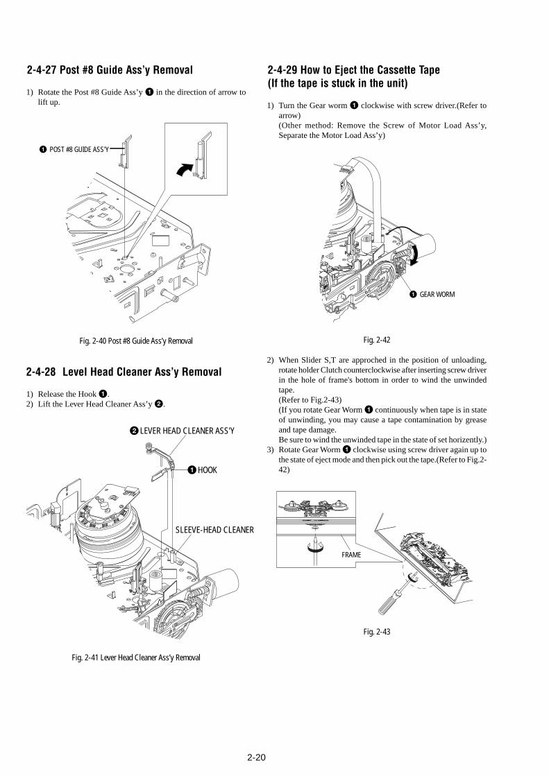
2-20
1 GEAR WORM
1 POST #8 GUIDE ASS'Y
Fig. 2-40 Post #8 Guide Ass’y Removal
1HOOK
2LEVER HEAD CLEANER ASS'Y
SLEEVE-HEAD CLEANER
2-4-27 Post #8 Guide Ass’y Removal
1) Rotate the Post #8 Guide Ass’y 1 in the direction of arrow tolift up.
2-4-28 Level Head Cleaner Ass’y Removal
1) Release the Hook 1.2) Lift the Lever Head Cleaner Ass’y 2.
Fig. 2-41 Lever Head Cleaner Ass’y Removal
2-4-29 How to Eject the Cassette Tape(If the tape is stuck in the unit)
1) Turn the Gear worm 1 clockwise with screw driver.(Refer toarrow)(Other method: Remove the Screw of Motor Load Ass’y,Separate the Motor Load Ass’y)
Fig. 2-42
2) When Slider S,T are approched in the position of unloading,rotate holder Clutch counterclockwise after inserting screw driverin the hole of frame's bottom in order to wind the unwindedtape.(Refer to Fig.2-43)(If you rotate Gear Worm 1 continuously when tape is in stateof unwinding, you may cause a tape contamination by greaseand tape damage.Be sure to wind the unwinded tape in the state of set horizently.)
3) Rotate Gear Worm 1 clockwise using screw driver again up tothe state of eject mode and then pick out the tape.(Refer to Fig.2-42)
Fig. 2-43
FRAME
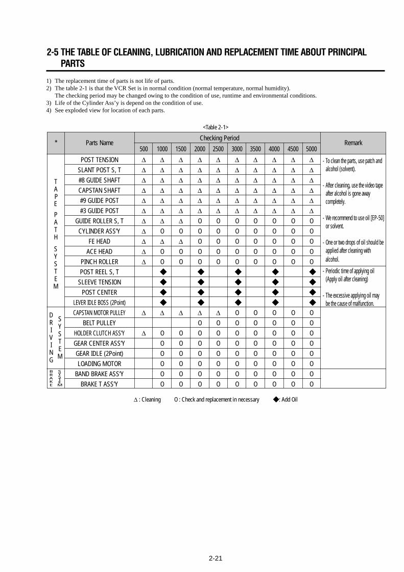
2-21
1) The replacement time of parts is not life of parts.2) The table 2-1 is that the VCR Set is in normal condition (normal temperature, normal humidity).
The checking period may be changed owing to the condition of use, runtime and environmental conditions.3) Life of the Cylinder Ass’y is depend on the condition of use.4) See exploded view for location of each parts.
<Table 2-1>
∆ : Cleaning O : Check and replacement in necessary : Add Oil
TAP E
PATH
SYSTEM
DRIVING
* Parts NameChecking Period
Remark500 1000 1500 2000 2500 3000 3500 4000 4500 5000
POST TENSION ∆ ∆ ∆ ∆ ∆ ∆ ∆ ∆ ∆ ∆SLANT POST S, T ∆ ∆ ∆ ∆ ∆ ∆ ∆ ∆ ∆ ∆#8 GUIDE SHAFT ∆ ∆ ∆ ∆ ∆ ∆ ∆ ∆ ∆ ∆CAPSTAN SHAFT ∆ ∆ ∆ ∆ ∆ ∆ ∆ ∆ ∆ ∆#9 GUIDE POST ∆ ∆ ∆ ∆ ∆ ∆ ∆ ∆ ∆ ∆#3 GUIDE POST ∆ ∆ ∆ ∆ ∆ ∆ ∆ ∆ ∆ ∆
GUIDE ROLLER S, T ∆ ∆ ∆ O O O O O O OCYLINDER ASS’Y ∆ O O O O O O O O O
FE HEAD ∆ ∆ ∆ O O O O O O OACE HEAD ∆ O O O O O O O O O
PINCH ROLLER ∆ O O O O O O O O OPOST REEL S, T
SLEEVE TENSION
POST CENTER
LEVER IDLE BOSS (2Point)
CAPSTAN MOTOR PULLEY ∆ ∆ ∆ ∆ ∆ O O O O OBELT PULLEY O O O O O O O
HOLDER CLUTCH ASS’Y ∆ O O O O O O O O OGEAR CENTER ASS’Y O O O O O O O O OGEAR IDLE (2Point) O O O O O O O O OLOADING MOTOR O O O O O O O O O
BAND BRAKE ASS’Y O O O O O O O O OBRAKE T ASS’Y O O O O O O O O O
SYSTEM
- Periodic time of applying oil (Apply oil after cleaning)
- The excessive applying oil may be the cause of malfunction.
- To clean the parts, use patch andalcohol (solvent).
- After cleaning, use the video tapeafter alcohol is gone away completely.
- We recommend to use oil [EP-50] or solvent.
- One or two drops of oil should beapplied after cleaning with alcohol.
BRAKE
SYSTEM
2-5 THE TABLE OF CLEANING, LUBRICATION AND REPLACEMENT TIME ABOUT PRINCIPALPARTS

2-222-22E
MEMO
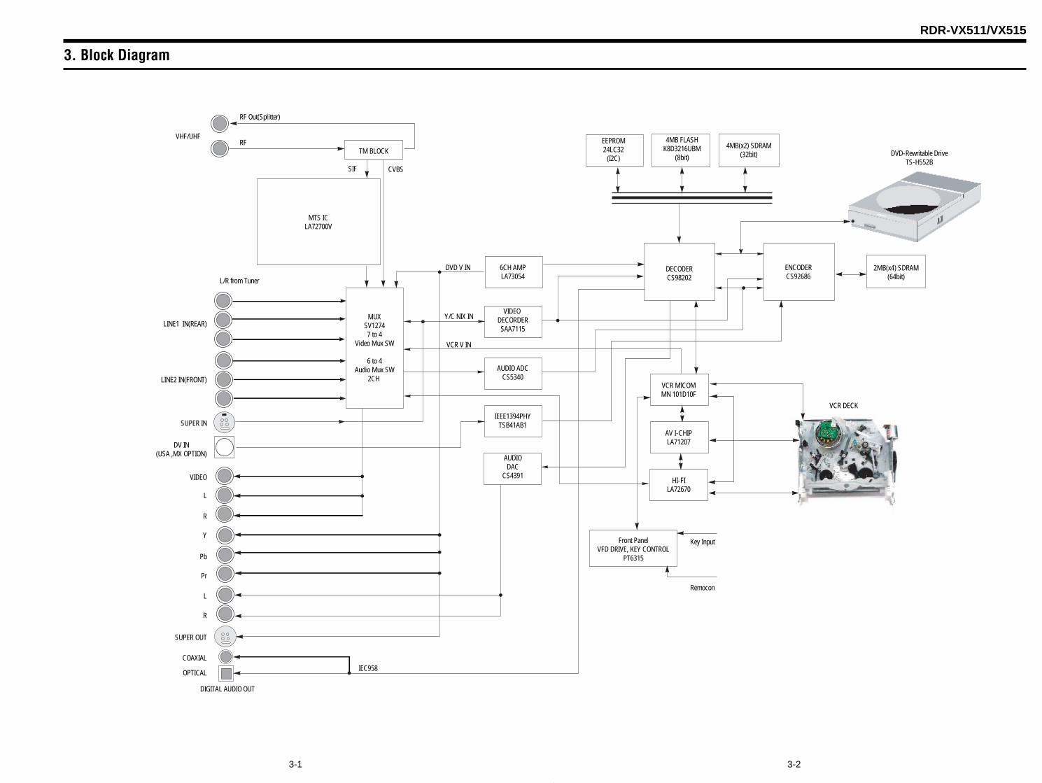
RDR-VX511/VX515
3. Block Diagram
3-23-1
4MB FLASHK8D3216UBM
(8bit)
4MB(x2) SDRAM(32bit) DVD-Rewritable Drive
TS-H552B
VCR DECK
SUPER IN
LINE1 IN(REAR)
LINE2 IN(FRONT)
DV IN(USA ,MX OPTION)
EEPROM24LC32
(I2C)TM BLOCK
RF
RF Out(Splitter)
VHF/UHF
CVBS
L/R from Tuner
MTS ICLA72700V
MUXSV12747 to 4
Video Mux SW
6 to 4Audio Mux SW
2CH
DECODERCS98202
ENCODERCS92686
6CH AMPLA73054
VIDEO DECORDERSAA7115
AUDIO ADCCS5340
AUDIODAC
CS4391
IEEE1394PHYTSB41AB1
VCR MICOMMN 101D10F
AV I-CHIPLA71207
HI-FILA72670
2MB(x4) SDRAM(64bit)
Front PanelVFD DRIVE, KEY CONTROL
PT6315
Key Input
Remocon
COAXIAL
OPTICAL
SIF
SUPER OUT
DIGITAL AUDIO OUT
VCR V IN
DVD V IN
Y/C NIX IN
Y
Pb
Pr
VIDEO
L
R
L
R
IEC958

3-4E
MEMO
4. PCB Diagrams
4-24-1
4-1 VCR Main PCB - - - - - - - - - - - - - - - - - - - - - - - - - - - - - - - - - - - - - - - - 4-3
4-2 DVD Main PCB - - - - - - - - - - - - - - - - - - - - - - - - - - - - - - - - - - - - - - - - 4-7
4-3 Jack PCB - - - - - - - - - - - - - - - - - - - - - - - - - - - - - - - - - - - - - - - - - - - - 4-11
4-4 DV Jack PCB - - - - - - - - - - - - - - - - - - - - - - - - - - - - - - - - - - - - - - - - - - 4-15
4-5 Function Timer PCB - - - - - - - - - - - - - - - - - - - - - - - - - - - - - - - - - - - - - 4-15
RDR-VX511/VX515
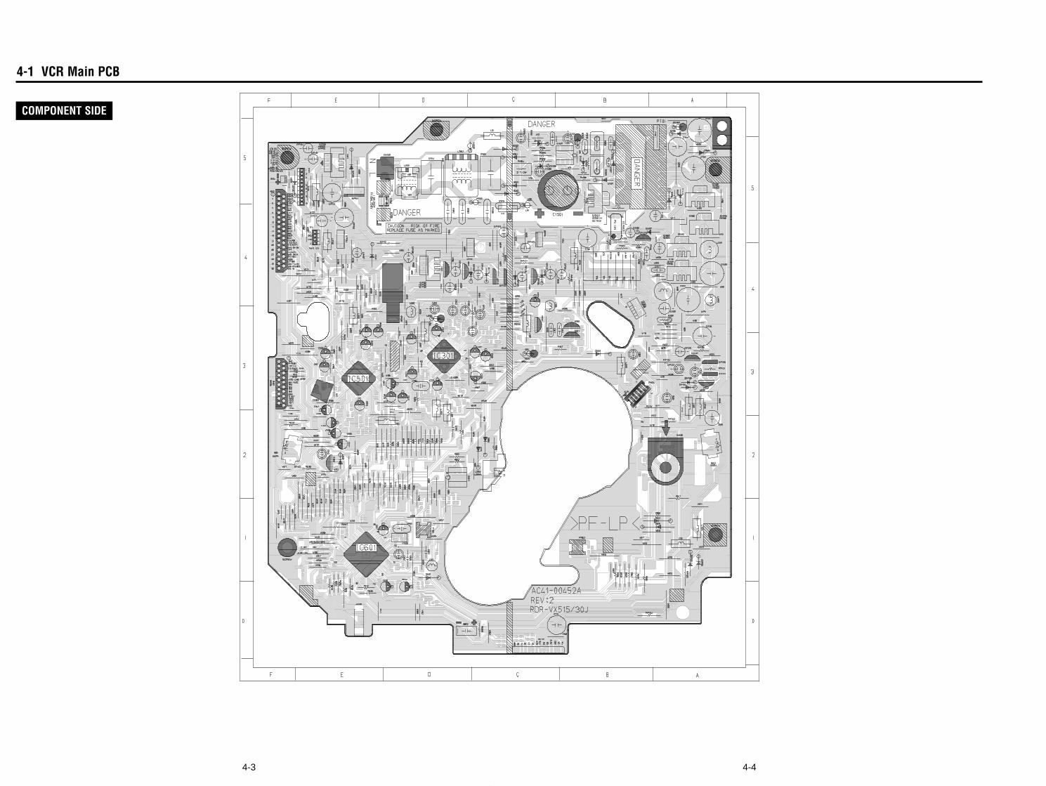
4-1 VCR Main PCB
4-44-3
COMPONENT SIDE
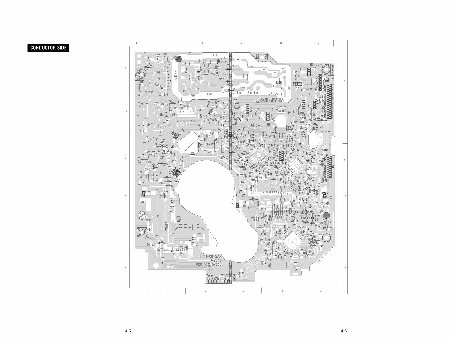
4-64-5
CONDUCTOR SIDE
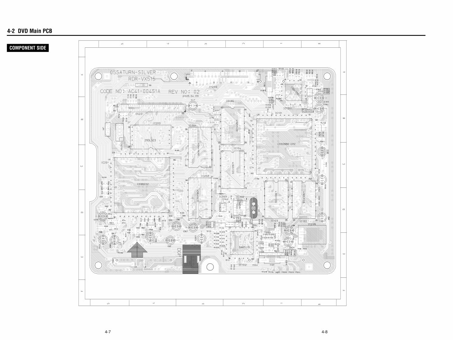
4-84-7
4-2 DVD Main PCB
COMPONENT SIDE
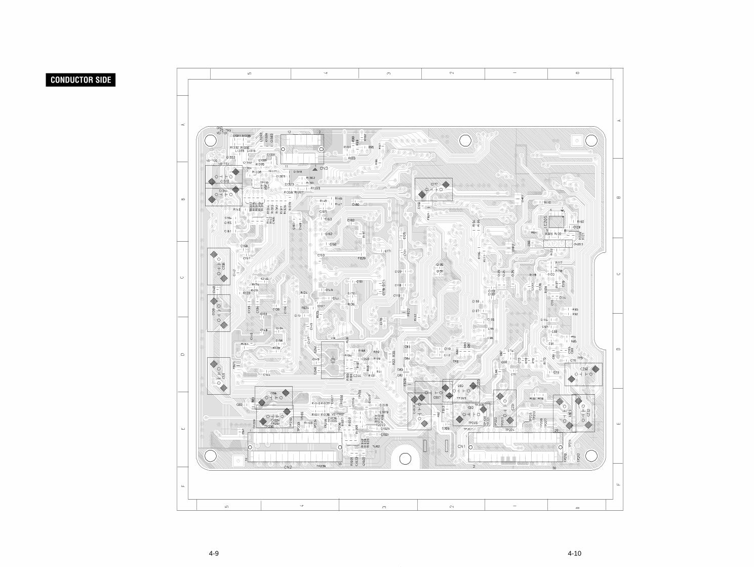
4-104-9
CONDUCTOR SIDE
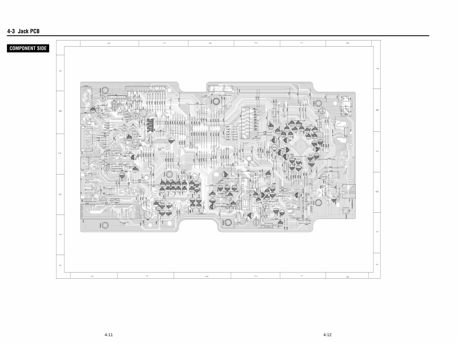
4-124-11
4-3 Jack PCB
COMPONENT SIDE
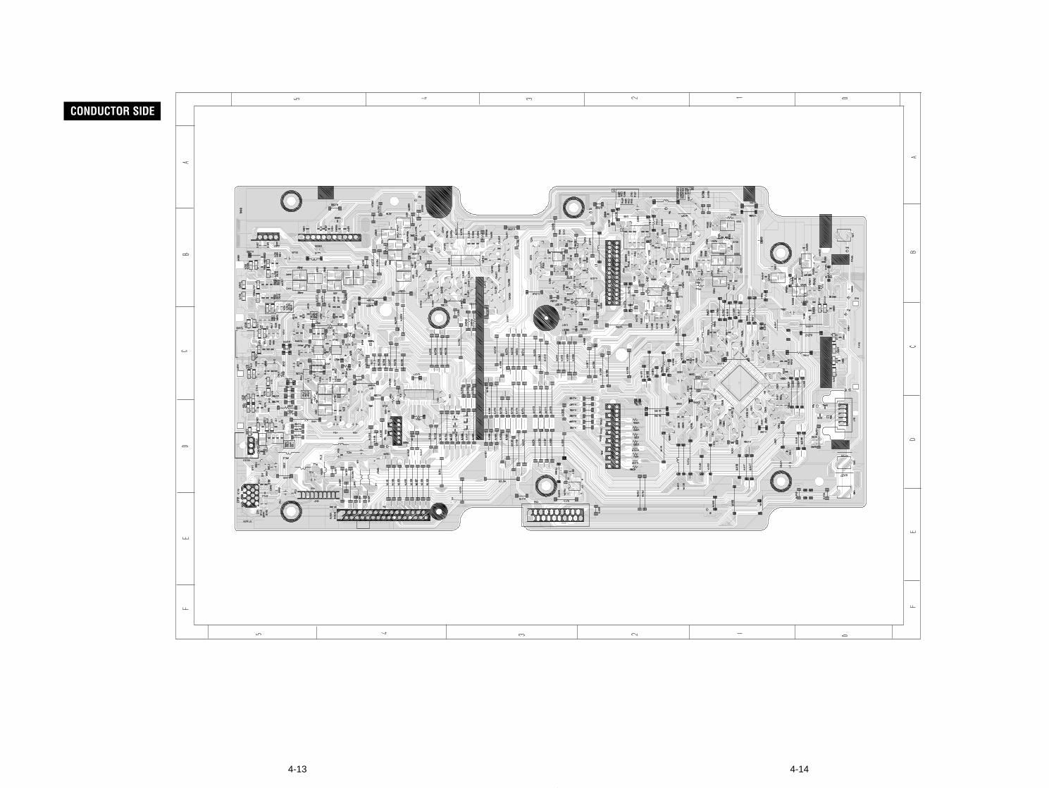
4-144-13
CONDUCTOR SIDE
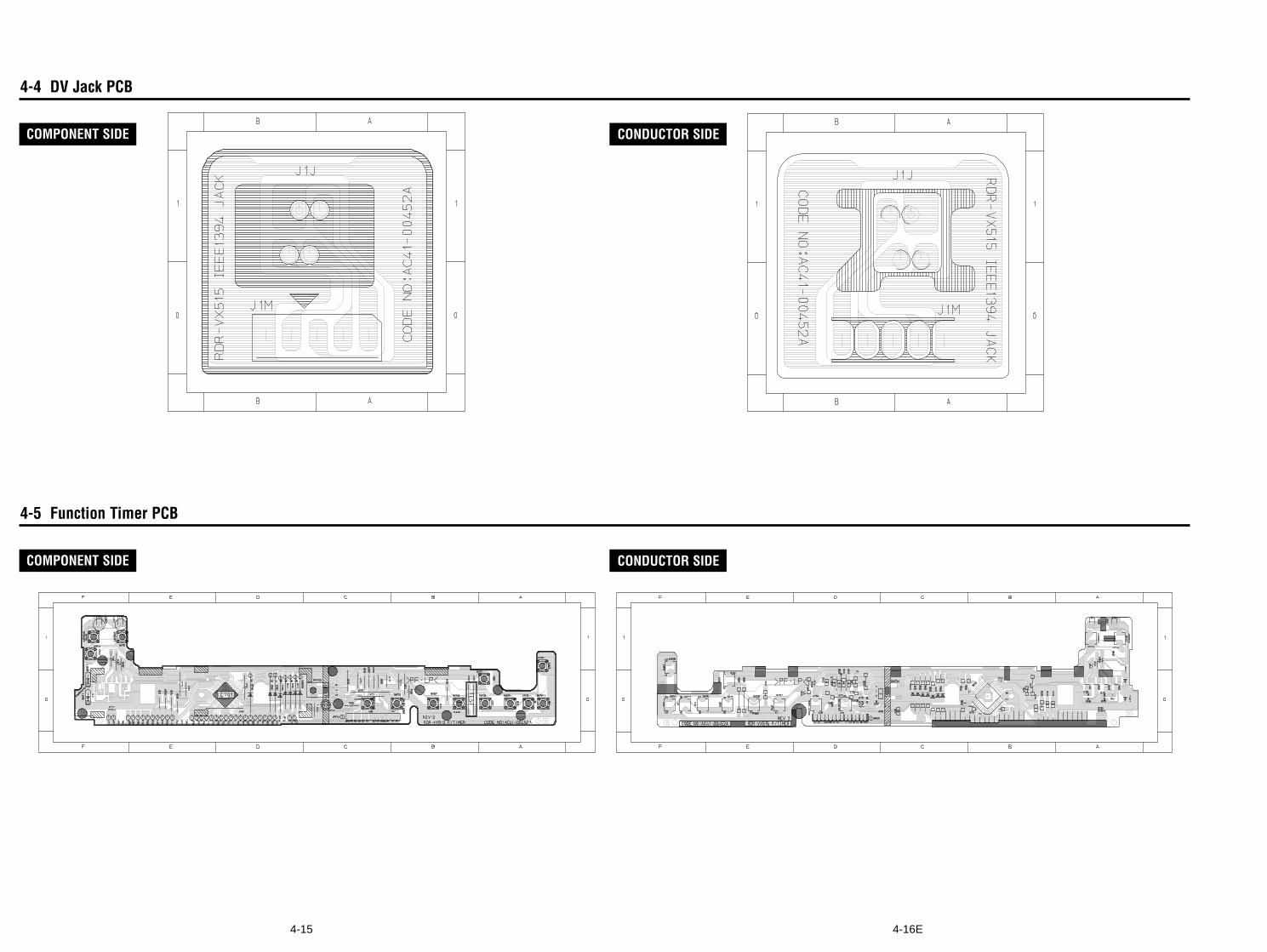
4-16E4-15
4-5 Function Timer PCB
4-4 DV Jack PCB
COMPONENT SIDE CONDUCTOR SIDE
COMPONENT SIDE CONDUCTOR SIDE
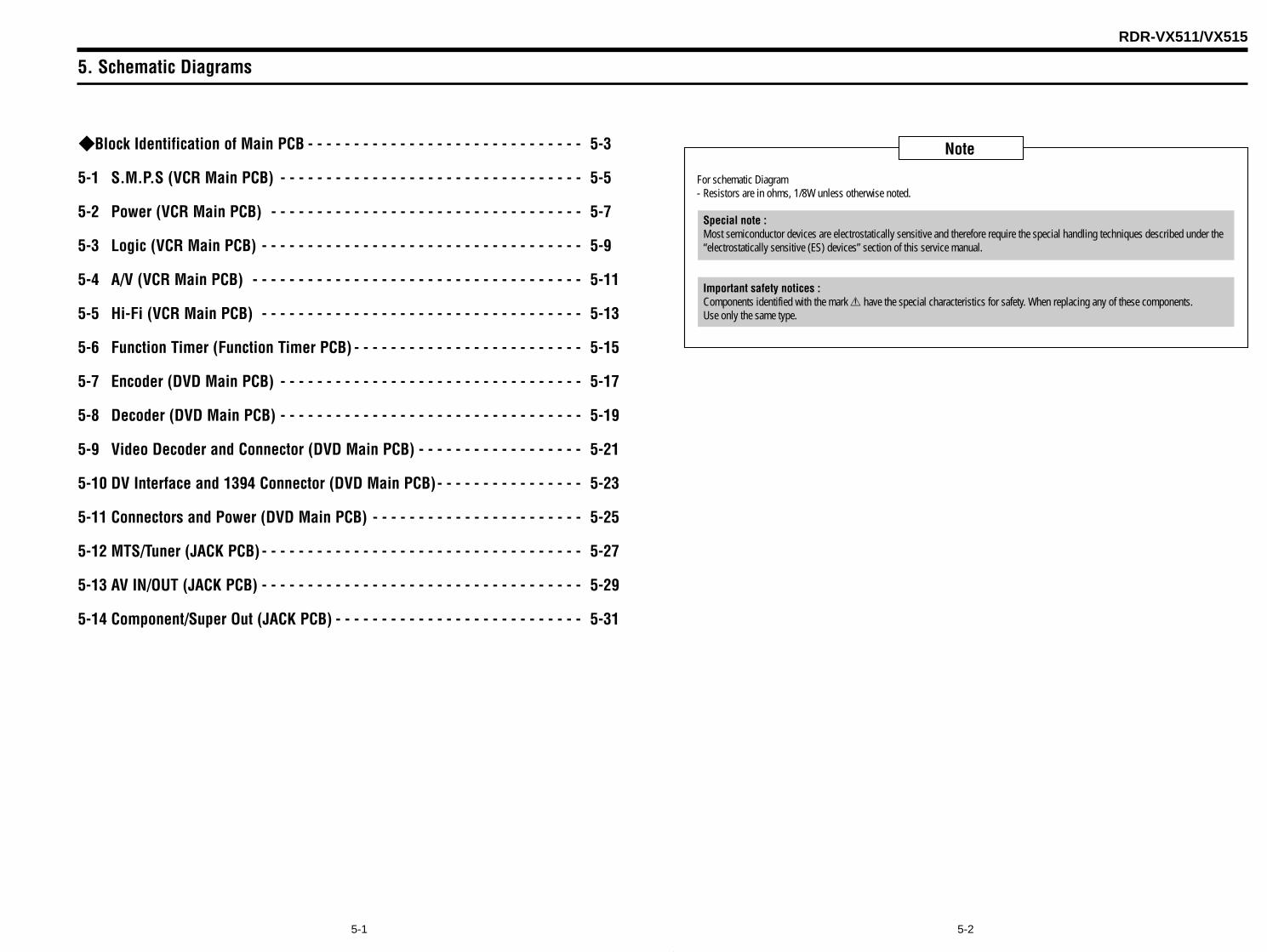
5. Schematic Diagrams
5-25-1
Block Identification of Main PCB - - - - - - - - - - - - - - - - - - - - - - - - - - - - - - 5-3
5-1 S.M.P.S (VCR Main PCB) - - - - - - - - - - - - - - - - - - - - - - - - - - - - - - - - - 5-5
5-2 Power (VCR Main PCB) - - - - - - - - - - - - - - - - - - - - - - - - - - - - - - - - - - 5-7
5-3 Logic (VCR Main PCB) - - - - - - - - - - - - - - - - - - - - - - - - - - - - - - - - - - - 5-9
5-4 A/V (VCR Main PCB) - - - - - - - - - - - - - - - - - - - - - - - - - - - - - - - - - - - - 5-11
5-5 Hi-Fi (VCR Main PCB) - - - - - - - - - - - - - - - - - - - - - - - - - - - - - - - - - - - 5-13
5-6 Function Timer (Function Timer PCB) - - - - - - - - - - - - - - - - - - - - - - - - - 5-15
5-7 Encoder (DVD Main PCB) - - - - - - - - - - - - - - - - - - - - - - - - - - - - - - - - - 5-17
5-8 Decoder (DVD Main PCB) - - - - - - - - - - - - - - - - - - - - - - - - - - - - - - - - - 5-19
5-9 Video Decoder and Connector (DVD Main PCB) - - - - - - - - - - - - - - - - - - 5-21
5-10 DV Interface and 1394 Connector (DVD Main PCB)- - - - - - - - - - - - - - - - 5-23
5-11 Connectors and Power (DVD Main PCB) - - - - - - - - - - - - - - - - - - - - - - - 5-25
5-12 MTS/Tuner (JACK PCB) - - - - - - - - - - - - - - - - - - - - - - - - - - - - - - - - - - - 5-27
5-13 AV IN/OUT (JACK PCB) - - - - - - - - - - - - - - - - - - - - - - - - - - - - - - - - - - - 5-29
5-14 Component/Super Out (JACK PCB) - - - - - - - - - - - - - - - - - - - - - - - - - - - 5-31
RDR-VX511/VX515
Note
For schematic Diagram- Resistors are in ohms, 1/8W unless otherwise noted.
Special note :Most semiconductor devices are electrostatically sensitive and therefore require the special handling techniques described under the“electrostatically sensitive (ES) devices” section of this service manual.
Important safety notices :Components identified with the mark 0 have the special characteristics for safety. When replacing any of these components.Use only the same type.
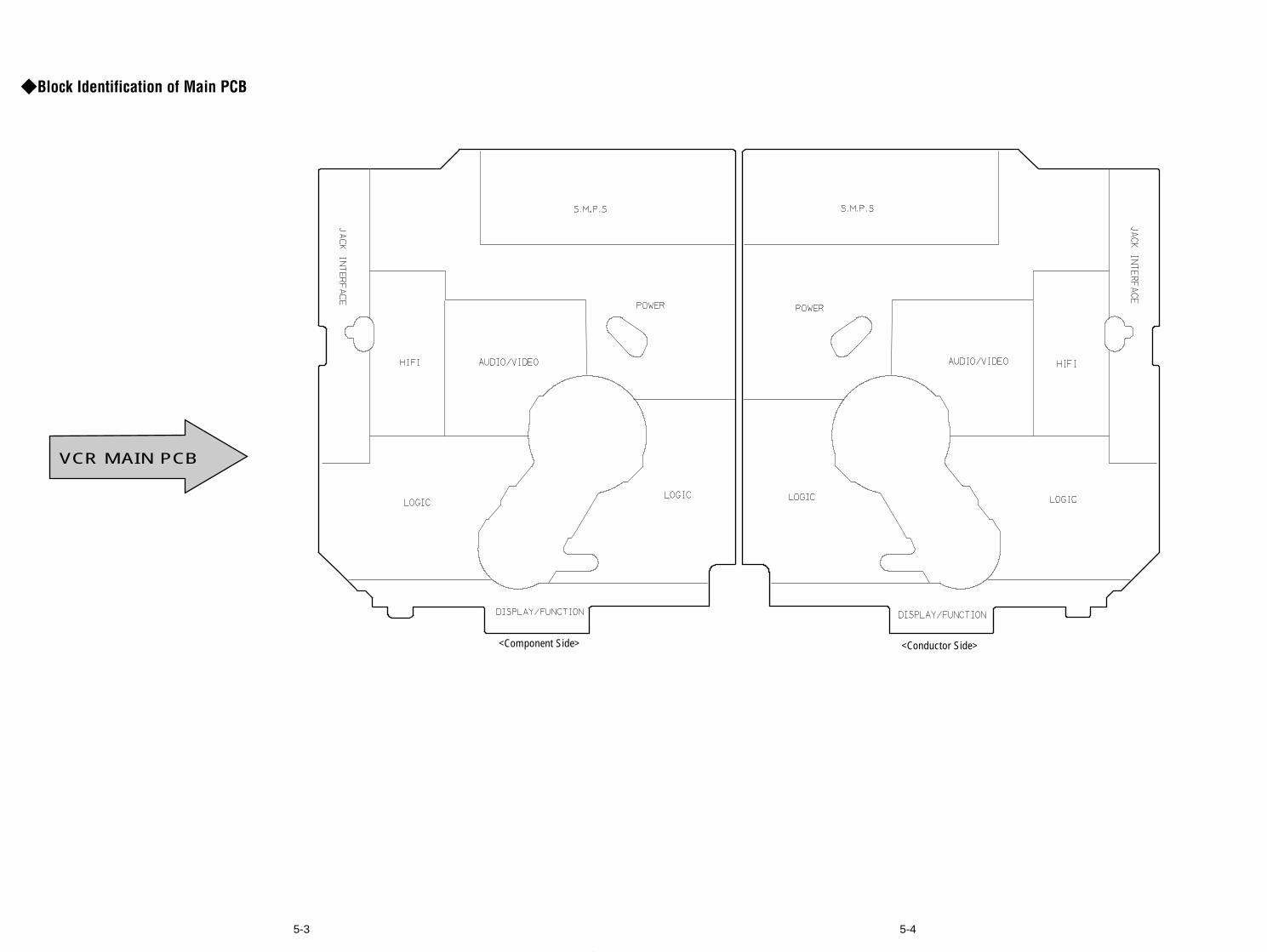
Block Identification of Main PCB
5-45-3
VCR MAIN PCB
<Component Side> <Conductor Side>
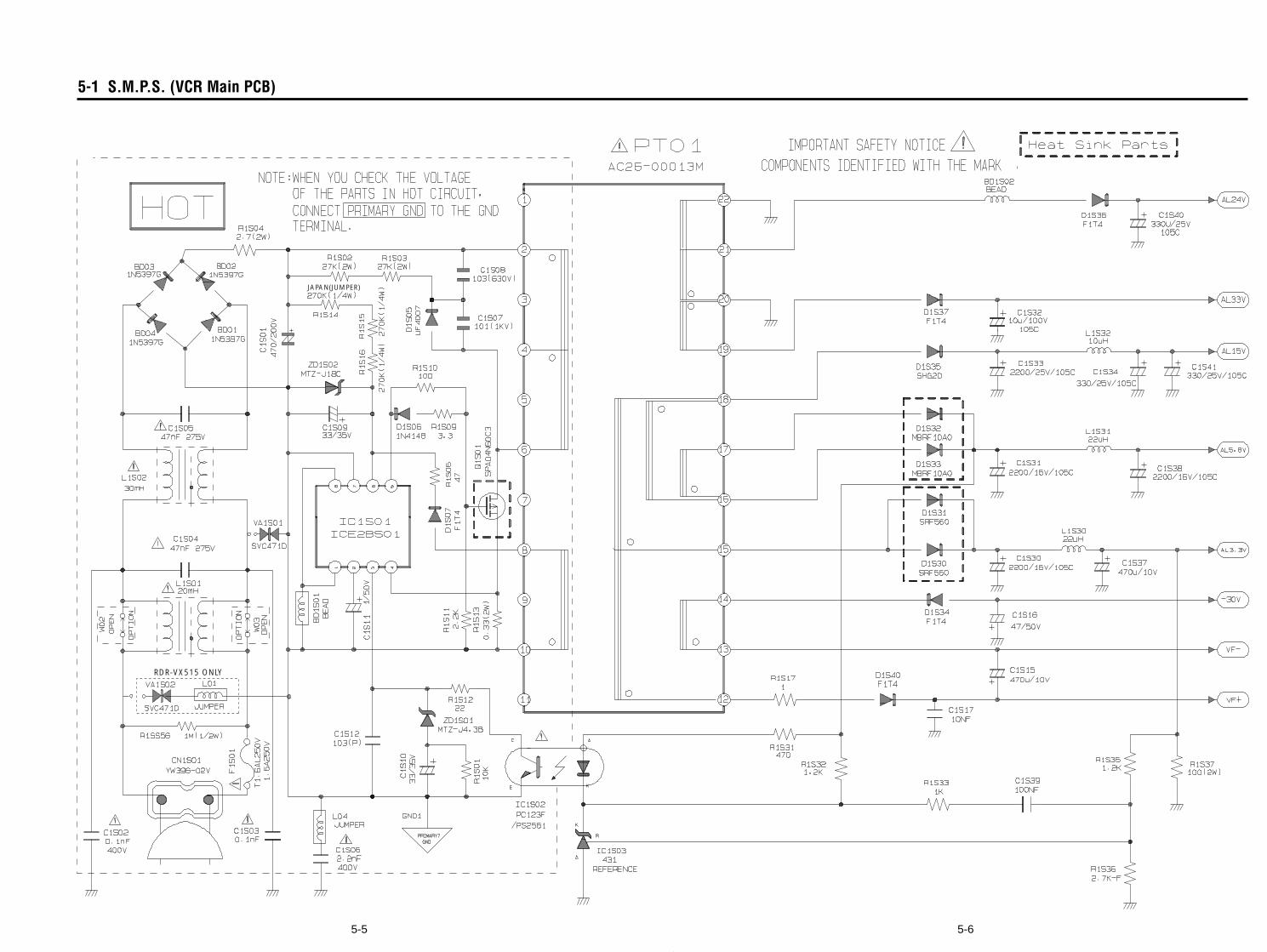
5-65-5
5-1 S.M.P.S. (VCR Main PCB)
JAPAN(JUMPER)
RDR-VX515 ONLY
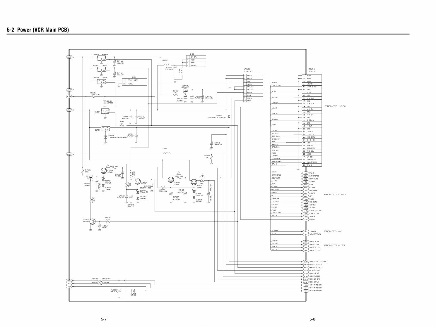
5-85-7
5-2 Power (VCR Main PCB)
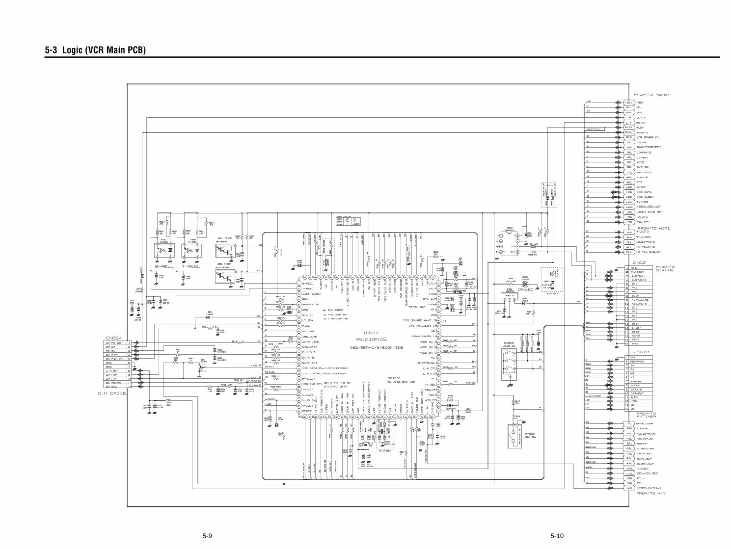
5-105-9
5-3 Logic (VCR Main PCB)
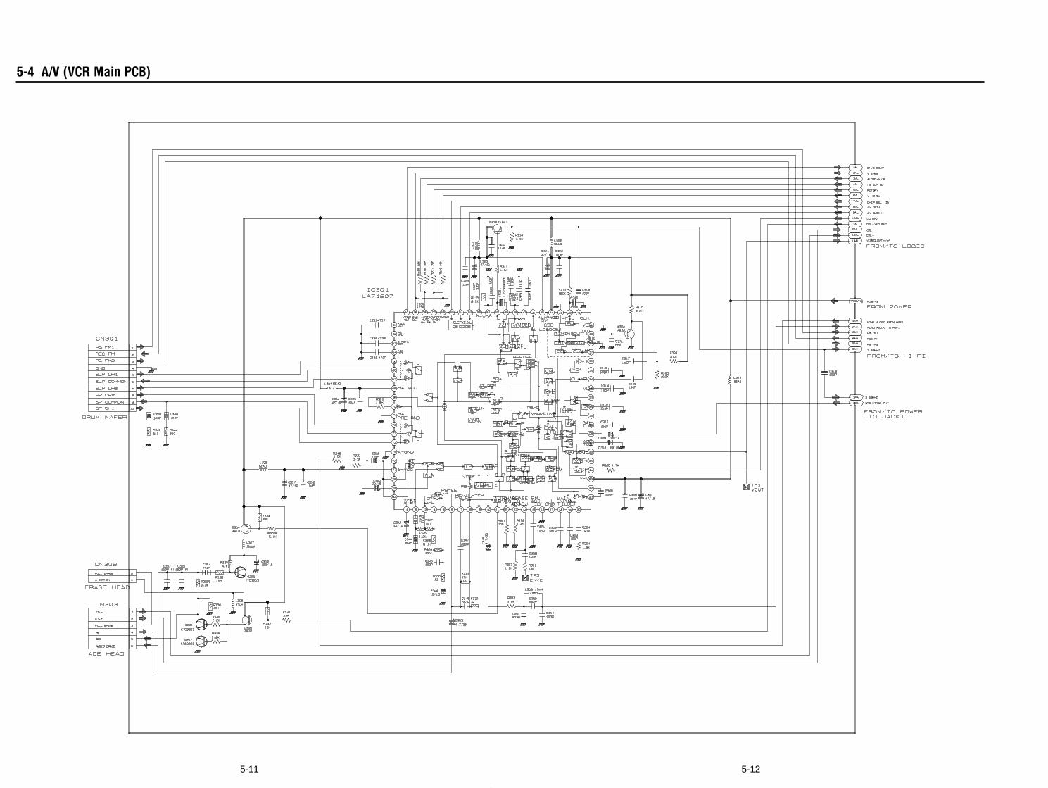
5-125-11
5-4 A/V (VCR Main PCB)
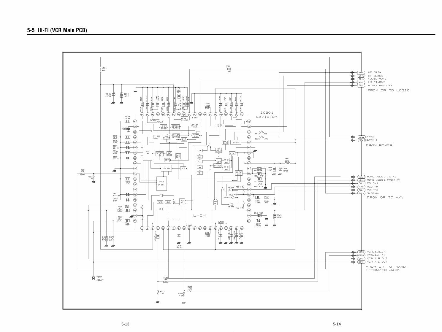
5-145-13
5-5 Hi-Fi (VCR Main PCB)
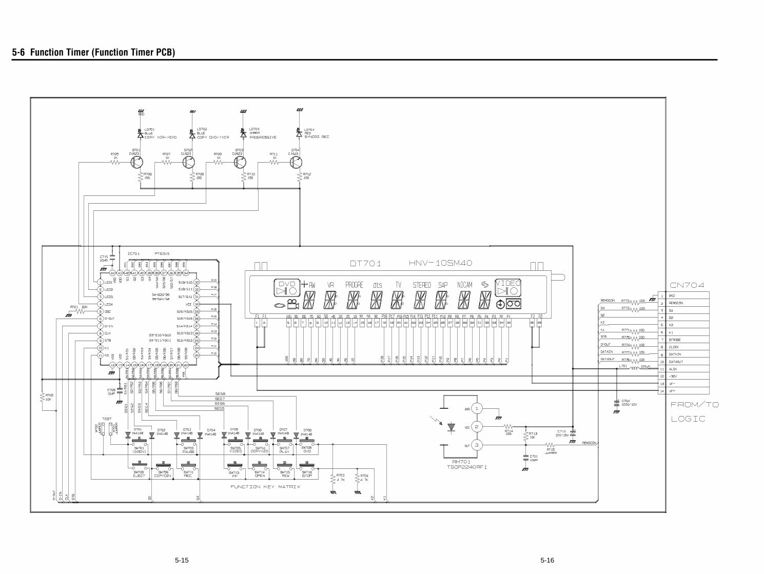
5-165-15
5-6 Function Timer (Function Timer PCB)
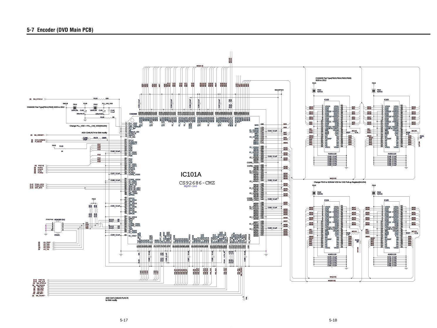
5-185-17
5-7 Encoder (DVD Main PCB)
HM
_R
DY
MCLK2
MCLK3
WE~CAS~RAS~
WE~CAS~RAS~
MBA0 MBA0
WE~CAS~RAS~
MBA0
WE~CAS~RAS~
MBA0
MD39
MA3
MA1
MD32
MA9
MA10
MD53
MA2 MA2
YIN
3Y
IN4
HM
_C
S3
MD62
MD48
MA10
MA
0
MA7
PD4
YIN
0
HM
_W
R~
MD49
MD32
MD33
MA2
PD5
HM
_D
5H
M_
D6
MD41
MA5
MD45
MA0
MD62
MA6Y
IN1
HM
_D
0
HM
_R
D~
MD33
RA
S~
MA8
MA
4
MA1MA5
MD36
MA8
MA6
MD58
MD53
MA7
MA8
PD6
HM
_A
LE
MD34
MA[10:0]
MD43
MD63
MD35
PD3
HM
_D
13
SM
_H
IUIN
T~
MD36
MA9
MA
1
HM
_D
9
MD39
MA3
MD47
MD51
MA7
MD42
MA6
YIN
2
HM
_D
11
MD43
WE
~
MD[63:32]
MA[10:0]
MD48
MD50
MA4
MA7
MA2
PD1
HM
_D
14
MD55
MD52
MD42
MD38
MA3 MA4
MD52
MA10
MD46
HM
_D
3
HM
_D
12
MD63
MD57
MD47
MD55
MA4
MA5
MD54MD56
MA10MA0
HM
_D
2
MD60
MD37
CA
S~
MA7
MD38
MA3
MD34
MA9
MA0
MD60
MD37
PD0
HM
_D
4
HM
_D
8
MA1
MA0
YIN
6Y
IN7
HM
_D
7
HM
_D
15
MD54
MD51MD50
MD44
MD59
MA1MA5
MD61
MA9
PD2
MD61
MD35
MA5
MA
3M
A2
MD40
MA4
MD41
MD49
MA9MA8
MD58MD56
MD46
MBA0
MA6
MD44
MD57
MA10MA8
MA6
PD7
HM
_D
10
MD59
MD45
MD40
HM
_D
1
YIN
5
MD
25
MD2
MD5
MD16
MD9
MD
8
MD24
MD
15
MD29
MD
14
MD
24
MD
31
MD21
MD
12
MD
9
MD
17
MD27
MD14
MD6
MD
29
MD15
MD20
MD
21
MD
28
MD30
MD8
MD19
MD
26
MD
16
MD
20
MD
18
MD
22
MD
30
MD3
MD4
MD
7
MD31
MD
0
MD
2
MD
4
MD
27
MD25
MD13MD28
MD23
MD
23
MD
5
MD17MD1
MD
13
MD
19
MD
3
MD
1
MD
6
MD7MD22
MD0
MD[31:0]
MD18
MD
10
MD10
MD
11
MD11MD26
MD12
MC
LK0
TDITDO
TMSTCK
MC
LK1
MCLK0
MCLK1
P1V8
SM1V8P3V3
P3V3
P3V3
P3V3 P3V3
P3V3P3V3
PLL_1V8_VDDSM1V8
HM_WR~[3]HM_RD~[3]HM_CS3[3]HM_RDY[3]
YIN[7:0][3,4]
HM_D[15:0][3]
PCNT0[5]PCNT1[5]
VIN_CLK[3,4]
PD[7:0][5]
PLREQ[5]
SM_HRESET~[3]
PLPS[5]
PCMI_LRCK[3,4]PCMI_DATA[3,4]
HM_ALE[3]
SM_HIUINT~[3]
SM_SYSCLK[4]
ADC_BCK[3,6]
SM_SYSCLK[4]
DVCLK49MHZ[5]PLINKON[5]
VD_TRST[4]
VD_TCK[4]VD_TMS[4]
VD_TDI[4]VD_TDO[4]
JTAG Port
Change PLL_VDD -> PLL_1V8_VDD(041204)
Change P3V3 to SDRAM VDD for CKE Pull-up Registor(041204)
CHANGE Part Type(FB14,FB15) 3225 to 2012
ADD C246,R174 for EMI modify
CHANGE Part Type(FB23,FB24,FB25,FB26)3225 to 2012
ADD C247,C248,R175,R176for EMI modify
MC
LK2
MC
LK3
C156 0.1uFC
16
60
.1u
F
R1
35
10K
R126 0R
RJ116 0R
R1364.7K
R1
33
10K
C174 0.1uF
C149 0.1uF
FB14
100XL/3A
330uF/6.3V
R1
32
10K
R174 330R
C147 0.1uF
C172 0.1uF
C159 0.1uF
R123 22R
R1
41
47K
R1
34
10K
C154 0.1uFR
14
22
2R
C180 0.1uF
R1
25
75
R
C143 0.1uF
C24620pF
C1
67
0.1
uF
C179 0.1uF
C148 0.1uF
C145 0.1uF
C153 0.1uF
C144 0.1uFC146 0.1uF
FB240(2012)
R129
1K C142 0.1uF
C177 0.1uFC176 0.1uF
C161 0.1uF
C150 0.1uF
RJ117 0R
+C138
C173 0.1uF
FB250(3216)
FB15
100XL/3A
C1
65
0.1
uF
C1400.1uF
C182 0.1uF
C175 0.1uF
C162 0.1uF
C170 0.1uF
R1
24
75
R
C171 0.1uF
IC105
416S1120
VDD01DQ02DQ13VSSQ04DQ25DQ36VDDQ07DQ48DQ59VSSQ110DQ611DQ712VDDQ113LDQM14WE15CAS16RAS17CS18BA19A10/AP20A021A122A223A324VDD125 VSS0 26A4 27A5 28A6 29A7 30A8 31A9 32N.C 33CKE 34CLK 35UDQM 36N.C/RFU 37VDDQ2 38DQ8 39DQ9 40VSSQ2 41DQ10 42DQ11 43VDDQ3 44DQ12 45DQ13 46VSSQ3 47DQ14 48DQ15 49VSS1 50
C1
36
0.1
uF
RJ118 OR
C1
37
0.1
uF
R1510R
R1
45
4.7
K
CS92686-CMZMQFP-240
IC101A
CS92688
PLL_VDD1PLL_VSS2
CORE_VDD030
CORE_VDD155
CO
RE
_V
DD
27
8
CO
RE
_V
DD
31
06
CORE_VDD4 141
CORE_VDD5 160
CO
RE
_V
DD
62
13
CORE_VSS029
CORE_VSS154
CO
RE
_V
SS
27
7
CO
RE
_V
SS
31
05
CORE_VSS4 140
CORE_VSS5 159
CO
RE
_V
SS
62
12
IO_VDD018
IO_VDD124
IO_VDD232
IO_VDD343
IO_VDD450
IO_VDD558IO_VDD659
IO_
VD
D7
69
IO_
VD
D8
80
IO_
VD
D9
90
IO_
VD
D10
96
IO_
VD
D11
10
2
IO_
VD
D12
11
4
IO_
VD
D13
12
0
IO_VDD14 128
IO_VDD15 137
IO_VDD16 147
IO_VDD17 156
IO_VDD18 166
IO_VDD19 178
IO_
VD
D2
01
89
IO_
VD
D2
11
98
IO_
VD
D2
22
09
IO_
VD
D2
32
19
IO_
VD
D2
42
28
IO_
VD
D2
52
34
IO_
VD
D2
62
39
IO_VSS017
IO_VSS123
IO_VSS231
IO_VSS337
IO_VSS441
IO_VSS545
IO_VSS648
IO_VSS760
IO_
VS
S8
68
IO_
VS
S1
07
9
IO_
VS
S1
18
9
IO_
VS
S1
29
5
IO_
VS
S1
31
01
IO_
VS
S1
41
07
IO_
VS
S1
51
13
IO_
VS
S1
61
19
IO_VSS17 125
IO_VSS18 131
IO_VSS19 136
IO_VSS20 144
IO_VSS21 150
IO_VSS22 155
IO_VSS23 163
IO_VSS24 169
IO_VSS25 174
IO_VSS26 177
IO_
VS
S2
81
97
IO_
VS
S2
92
03
IO_
VS
S3
02
08
IO_
VS
S3
12
16
IO_
VS
S3
22
22
IO_
VS
S3
32
27
IO_
VS
S3
42
33
IO_
VS
S3
52
40
MA
01
85
MA
11
84
MA
21
83
MA
31
82
MA
41
81
MA5 180
MA6 179
MA7 176MA8 175
MA9 173MA10 172
MD
02
38
MD
12
37
MD
22
36
MD
32
35
MD
42
32
MD
52
31
MD
62
30
MD
72
29
MD
82
26
MD
92
25
MD
10
22
4M
D1
12
23
MD
12
22
1M
D1
32
20
MD
14
21
8M
D1
52
17
MD
16
21
5M
D1
72
14
MD
18
21
1M
D1
92
10
MD
20
20
7M
D2
12
06
MD
22
20
5M
D2
32
04
MD
24
20
2M
D2
52
01
MD
26
20
0
MD
27
19
9
MD
28
19
6M
D2
91
95
MD
30
19
4M
D3
11
93
TCK53
TDI56TMS57
TDO52
MC
KO
UT
11
90
MC
KO
UT
01
91
MC
AS
18
8M
RA
S1
87
MW
E1
86
MBA0 170MBA1 171
MD32 168MD33 167
MD34 165MD35 164
MD36 162MD37 161
MD38 158MD39 157
MD40 154MD41 153MD42 152MD43 151
MD44 149MD45 148
MD46 146MD47 145
MD48 143MD49 142
MD50 139MD51 138
MD52 135MD53 134MD54 133MD55 132
MD56 130
MD57 129
MD58 127MD59 126
MD60 124MD61 123MD62 122MD63 121
GBL_PWRDN3PLL_BP4SE5DEBUG_EN6
TS
T_M
OD
E6
1M
BIS
T_
MS
Z6
2
ND_TREE38
IO_
VS
S2
71
92
IO_
VS
S9
76
CS_INn9 HRSTn8
HS
EL
n1
09
LD
S_R
DN
11
5U
DS
_W
RN
11
6
RW
N_
SB
HE
11
2
AS
_A
LE
10
3D
MA
_RE
Q1
04
DT
AC
K_
RD
Y1
08
INT
X1
61
10
INT
_MO
Tn
11
1
HU
I_IN
Tn
11
7S
YS
_R
DY
11
8
SYSCLK7
HA
D1
51
00
HA
D1
49
9H
AD
13
98
HA
D1
29
7
HA
D1
19
4H
AD
10
93
HA
D9
92
HA
D8
91
HA
D7
88
HA
D6
87
HA
D5
86
HA
D4
85
HA
D3
84
HA
D2
83
HA
D1
82
HA
D0
81
GPIO751
GPIO649GPIO547 GPIO446GPIO344GPIO242GPIO140GPIO039
YD
77
2Y
D6
71
YD
57
0
YD
46
7Y
D3
66
YD
26
5Y
D1
64
YD
06
3
HR
74
CL
K2
7_
MO
D7
5C
LK
27
_D
EM
73
LRCK_IO33
BCK_IN_ENC36SDA_IO34BCK_IN_DEC35
PD713PD614PD515PD416
PD319
PD220PD121PD022
PCNT125PCNT026
PLREQ28 PLPS27
PDIRECT12 PLINKON11 PCLK10
R1
46
4.7
KR
14
74
.7K
C1
34
0.1
uF
R127 4.7K
C151 0.1uF
C141 0.1uF
R137 4.7K
C160 0.1uF
C1
35
0.1
uF
R1
40
10K
RJ120 OR
C155 0.1uF
C1
33
0.1
uF
+C139
100uF/16V
IC104
416S1120
VDD01DQ02DQ13VSSQ04DQ25DQ36VDDQ07DQ48DQ59VSSQ110DQ611DQ712VDDQ113LDQM14WE15CAS16RAS17CS18BA19A10/AP20A021A122A223A324VDD125 VSS0 26A4 27A5 28A6 29A7 30A8 31A9 32N.C 33CKE 34CLK 35UDQM 36N.C/RFU 37VDDQ2 38DQ8 39DQ9 40VSSQ2 41DQ10 42DQ11 43VDDQ3 44DQ12 45DQ13 46VSSQ3 47DQ14 48DQ15 49VSS1 50
R1500R
IC102
416S1120
VDD01DQ02DQ13VSSQ04DQ25DQ36VDDQ07DQ48DQ59VSSQ110DQ611DQ712VDDQ113LDQM14WE15CAS16RAS17CS18BA19A10/AP20A021A122A223A324VDD125 VSS0 26A4 27A5 28A6 29A7 30A8 31A9 32N.C 33CKE 34CLK 35UDQM 36N.C/RFU 37VDDQ2 38DQ8 39DQ9 40VSSQ2 41DQ10 42DQ11 43VDDQ3 44DQ12 45DQ13 46VSSQ3 47DQ14 48DQ15 49VSS1 50
FB230(2012)
C1
69
0.1
uF
TP
81
C164 0.1uF
C181 0.1uF
C158 0.1uF
R1
44
4.7
K_
NC
C163 0.1uF
CN101
HEADER 5X2
2468
10
13579
IC103
416S1120
VDD01DQ02DQ13VSSQ04DQ25DQ36VDDQ07DQ48DQ59VSSQ110DQ611DQ712VDDQ113LDQM14WE15CAS16RAS17CS18BA19A10/AP20A021A122A223A324VDD125 VSS0 26A4 27A5 28A6 29A7 30A8 31A9 32N.C 33CKE 34CLK 35UDQM 36N.C/RFU 37VDDQ2 38DQ8 39DQ9 40VSSQ2 41DQ10 42DQ11 43VDDQ3 44DQ12 45DQ13 46VSSQ3 47DQ14 48DQ15 49VSS1 50
FB260(2012)
R1284.7K
C1
68
0.1
uF
C157 0.1uF
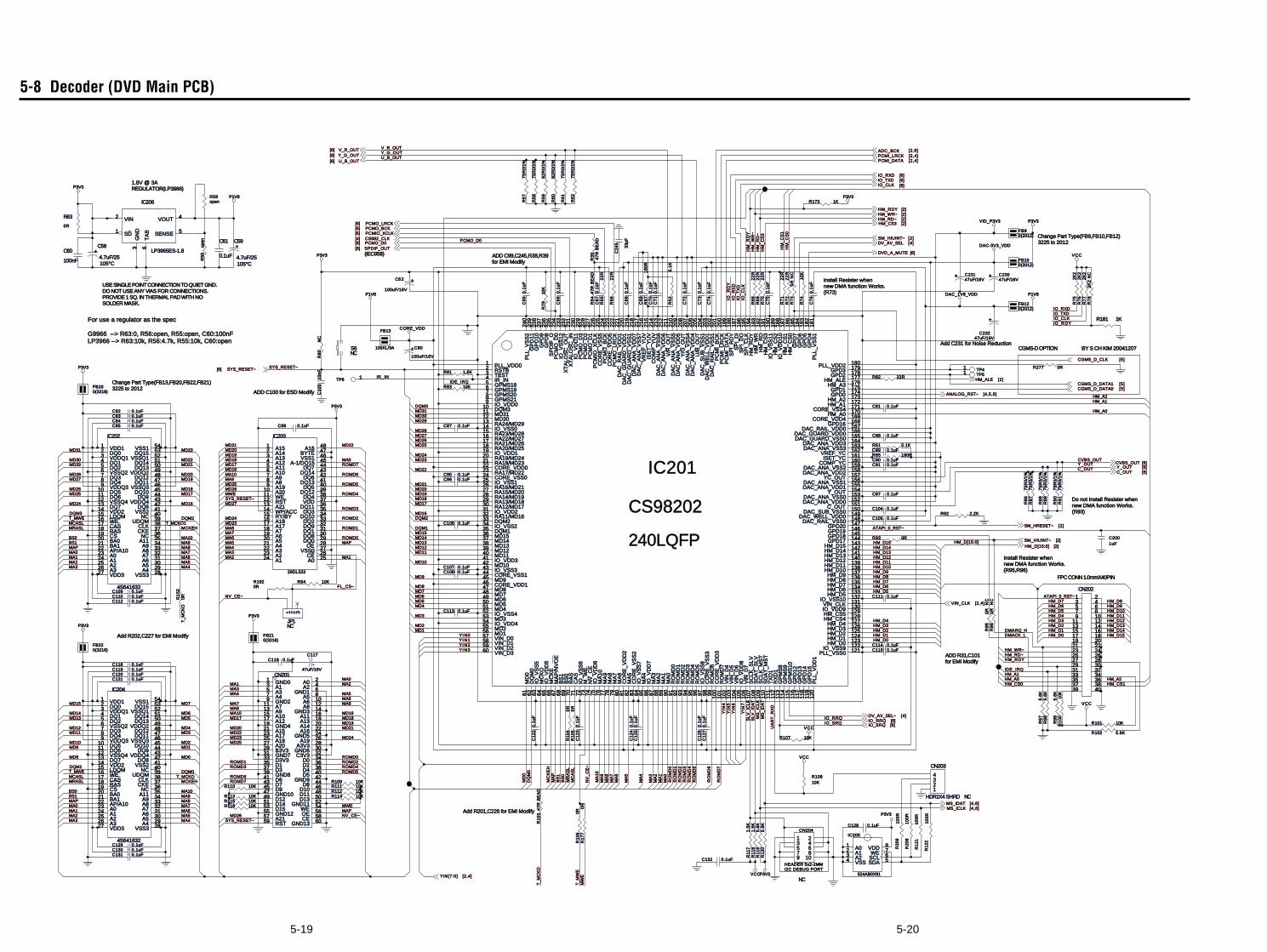
5-205-19
5-8 Decoder (DVD Main PCB)
YIN
7
Y I N3
YIN
5
Y I N2YI N1
YIN
4
HM
_R
DY
YIN
6
Y I N0
SL
V_
ICL
KS
LV
_ID
AT
HM
_C
S3
HM_D[15:0]
MD29
DQM2DQM2
MD19
DQM3
MD30
MD28
MD31
MD27
MD18
MD20
DQM3
MD27
FL_CS~
MD27
MD22
MD22
MD24
ROMD4
MD19
MD25
ROMD5
MD23
MD24
MD21
RO
MD
5
RO
MD
1
MD21MD31
ROMD7
MD20MD22
MD28
ROMD3
RO
MD
3
ROMD4
MD25
ROMD5
RO
MD
0
ROMD0
RO
MD
4
MD23
RO
MD
6
MD18R
OM
D7
MD30
MD23
MD21
MD20
MD18
RO
MD
2
MD21
ROMD2
ROMD6
ROMD2
ROMD7
MD24
MD24
ROMD1
ROMD0
MD20
MD18
MD25
ROMD6
MD23
MD22
ROMD1
MD19MD26
ROMD3
MD25
MD19
MA2
MA
6
BS1
MD7
MA
9
MA8
MA
2
MCASL
MD3
MA9
MC
AS
L
MA6
DQM1
MCASL
MAP
MD4
MD14
MD12
MA3
MD15
MAP
MD9
BS
0
MA0
MD8
MD4
MD6
MA
7
MD13
MA5
MD3
MA
P
MA6
MA4
MA8
MA2
MAP
MA10
BS
1
MD2
MA1
MRASL
MD7
MD2
MA0
MD13
MA0
MCKEH
MA9
MD12
MA7
MA1
MA2
MA9BS1
MA5
MA5
MCKEH
MA
10MD5
MA1
MRASL
MA3
MA3
MA10
MD1
MA4
MA1
MA4
MD9
MA5
MA
5
MA10
MD10
MA7
MA7 MD11
MD5
BS0
T_MWE
MA10
MD6
MA6
MD1
MD8 MD0
MA
3
MA8
MD14
T_MWE
MA8
MA4
MC
KE
H
BS0
MA
0M
A1
MD10
MD15
MA9
MA2
MAP
MA0MA6
MD11
T_MCKO
MA3
MA7
MR
AS
L
MA
4
MA
8
MD
0DQM1
V_R_OUT
PCMO_D0
DQ
M0DQM0
IR_IN
HMHM_CS1
HM
_C
S0
HM_CS0
HM
_C
S1
IDE_IRQ
HM
_R
D~
HM_RDYHM_RD~
Y_OUTC_OUT
SYS_RESET~
MD29
SYS_RESET~
MD26
MD26
SYS_RESET~
MD26
IO_RRQ
IO_
CL
KIO
_TX
DIO
_R
XD
IO_
RD
Y
IO_RXDIO_TXDIO_CLKIO_R DY
HM
_W
R~
HM_WR~
HM_A0
HM_A0HM_A1
HM_A1
DMARQ_H
IO_SRQ
U_B_OUTY_G_OUT
CVBS_OUT
NV_CE~
NV_CE~
MWE
NV
_C
E~
MWE
T_M
WE
MW
E
MS
_IC
LK
MS
_ID
AT
UA
RT
_R
XD
HM_D1HM_D0
HM_D6
HM_D6
HM_D4
HM_D3HM_D12HM_D4
HM_D0 HM_D15
HM_D15
HM_D3
HM_D9
HM_D14
HM_D11
HM_D11
HM_D2
HM_D8
HM_D1HM_D2
HM_D13
HM_D7
HM_D10
HM_D14
HM_D8
HM_D9HM_D10HM_D5
HM_D13
HM_D7
HM_D5
HM_D12
IDE_IRQ
DMACK_L
HM_A2
HM_A2
T_M
CK
O
MD17
MD16
MD16
MD16
MD17
MD17
MD17MD16
ATAPI_0_RST~
ATAPI_0_RST~
P1V8DAC_1V8_VDD
P3V3
P1V8
P3V3
CORE_VDD
VID_P3V3
DAC-3V3_VDD
P3V3
P3V3
P3V3
P3V3
VCC
VCC
P3V3
P1V8 P3V3
VCC
P3V3
P3V3
VCC
VCC
YIN[7:0] [2,4]
HM_ALE [2]
PCMIO_XCLK[6]
ANALOG_RST~ [4,5,6]
SM_HRESET~ [2]
HM_WR~ [2]
SPDIF_OUT[6]
HM_RD~ [2]
CS982_CLK[4]
HM_CS3 [2]
SYS_RESET~[6]
PCMO_D0[6]
SM_HIUINT~ [2]
PCMI_DATA [2,4]
CVBS_OUT [6]Y_OUT [6]C_OUT [6]
V_R_OUT[6]
HM_D[15:0] [2]
VIN_CLK [2,4]
PCMO_BCK[6]PCMO_LRCK[6]
U_B_OUT[6]
DVD_A_MUTE [6]
PCMI_LRCK [2,4]
HM_RDY [2]
DV_AV_SEL~ [4]
IO_TXD [6]IO_RXD [6]
SM_HIUINT~ [2]
ADC_BCK [2,6]
IO_CLK [6]
IO_RRQ [6]IO_SRQ [6]
DV_AV_SEL [4]
Y_G_OUT[6]
MS_ICLK [4,6]MS_IDAT [4,6]
CGMS_D_DATA0 [5]CGMS_D_DATA1 [5]
CGMS_D_CLK [5]
I2C DEBUG PORT
Install Resister when new DMA function Works.(R73)
Do not Install Resister when new DMA function Works.(R93)
Install Resister when new DMA function Works.(R95,R96)
USE SINGLE POINT CONNECTION TO QUIET GND.DO NOT USE ANY VIAS FOR CONNECTIONS.PROVIDE 1 SQ. IN THERMAL PAD WITH NOSOLDER MASK.
1.8V @ 3AREGULATOR(LP3966)
Add R202,C227 for EMI Modify
Add R201,C226 for EMI Modify
Add C231 for Noise Reduction
ADD C99,C245,R38,R39for EMI Modify
ADD C100 for ESD Modify
ADD R31,C101for EMI Modify
Change Part Type(FB13,FB20,FB22,FB21)3225 to 2012
Change Part Type(FB9,FB10,FB12)3225 to 2012
NC
NC
NC
NC
(IEC958)
FPC CONN 1.0mmX40PIN
CGMS-D OPTION BY S CH KIM 20041207
For use a regulator as the spec
G9966 --> R63:0, R56:open, R55:open, C60:100nFLP3966 --> R63:10k, R56:4.7k, R55:10k, C60:open
T_MCKO1
T_M
CK
O
R6
08
2R
0/1
%
R1
21
10
0R
+
C117
47uF/16V
R7
52K
2
R1
20
5.6
K
R7
410
K
R1
03
47
R B
EA
D
+C62
100uF/16V
100uF/16V
R5
87
5R
0/1
%
+C59
R7
62K
2
C60
100nF
R1
22
10
0R
R7
72K
2
R1
19
5.6
K
R1
05
0R
R93 0R
R6
17
5R
0/1
%
R7
82
K2
NC
R2
09
10
0R
R1
06
0R
C128 0.1uF
C90 0.1uF
+
C23247uF/16V
R83 10K
C114 0.1uF
R173 1K
C61
0.1uF
R109 10K
FB200(3216)
C81 0.1uF
R1
04
0R
C108 0.1uF
C6
90
.1u
F
R111 10K
C6
70
.1u
FC109 0.1uF
R112 10K
C1
23
0.1
uF
FB210(3216)
C1
00
10
nF
+C58
105°C 4.7uF/25
105°C 4.7uF/25
FB13
100XL/3A
C87 0.1uF
R114 10K
R1
52
0R
C95 0.1uF
JP1
1 2 3
C7
60
.1u
F
R2
08
10
0R
C116 0.1uF
+C80
FB120(2012)
R110 10K
R94 10K
C2
45
33
pF
R7
910
K
R113 10K
C96 0.1uF
IC203
29DL323
A0 25A124 A223 A322 A421 A520 A619 A718
A88 A97 A106 A115 A124 A133 A142 A151 A16 48
A1717 A1816
A199A2010
A2113
DQ0 29DQ1 31DQ2 33DQ3 35
DQ4 38DQ5 40DQ6 42DQ7 44
DQ8 30DQ9 32
DQ10 34DQ11 36
DQ12 39DQ13 41DQ14 43
A-1/DQ15 45
VDD 37
VSS0 27
VSS1 46
CE 26OE 28
BYTE 47
WE11
WP/ACC14RST12
RY/BY15
R6
27
5R
0/1
%
R51 5.1K
C6
60
.1u
F
R115 10K
R63
0R
TP6 1
C6
50
.1u
F
R116 10K
CN203
HDR1X4 SHRD1234
R181 1K
+ C23047uF/16V
C106 0.1uF
C1
27
0.1
uF
S6
C111 0.1uF
R1
77
0R
C88 0.1uF
C1
24
0.1
uF
C1
25
0.1
uF
R82 22R
C115 0.1uFFB220(3216)
R5
25
.1K
C6
80
.1u
F
FB90(2012)
R9
75
.6K
R8
0N
C
R5
77
5R
0/1
%
C121 0.1uF
CN202
13579
1113151719212325272931
2468101214161820222426283032
3335
3436
37 3839 40
R5
5op
en
R6
44
7R
BE
AD
C7
40
.1u
F
TP41
R8
67
5R
0/1
%
TP51
C107 0.1uF
R7
12
2R
C120 0.1uF
R6
62
2R
R7
22
2R
R9
85
.6K
C89 0.1uF
C119 0.1uF
R6
52
2R
R9
95
.6K
R6
71
80
R
R85 180R
R5
98
2R
0/1
%
C118 0.1uF
R8
77
5R
0/1
%
C85 0.1uF
R1
00
10K
R56open
R8
87
5R
0/1
%
C7
00
.1u
F
C130 0.1uF
R101 10K
R8
97
5R
0/1
%
C84 0.1uF
R92 2.2K
C97 0.1uF
R9
07
5R
0/1
%
C131 0.1uF
R9
17
5R
0/1
%
C83 0.1uF
R102 5.6K
C113 0.1uF
FB100(2012)
C91 0.1uF
R81 1.5K
R1920R
R7
30
R N
C
C1
26
0.1
uF
C105 0.1uF
C129 0.1uF
CN204
HEADER 5x2-2MM
1 23 45 67 89 10
CN201
GND01A13A35A47GND29A711A913A1015A1217GND419A1521A1723A1825A2027B3V329GND731D3V333D135D337GND839
A0 2A2 4
GND1 6A5 8A6 10A8 12
GND3 14A11 16A13 18A14 20A16 22
GND5 24A19 26
A3V3 28GND6 30C3V3 32
D0 34D2 36D4 38D5 40
D1451D1553 WE 54GND1255 OE 56
GND11 52
A2157 CE 58RST59 GND13 60
D641D743D945GND1047D1249
D8 44D10 46D11 48D13 50
GND9 42
C82 0.1uF
C104 0.1uF
R10810K
IC202
4S641632
VDD11DQ02
DQ14
VSSQ26 DQ25
DQ37
VDDQ13
DQ48
DQ510
VSSQ412 DQ611
DQ713
VDDQ2 49
LDQM15WE16CAS17RAS18CS19
A11 35
AP/A1022A023A124A225A326VDD327 VSS3 28A4 29A5 30A6 31A7 32A8 33A9 34
NC 36CKE 37CLK 38UDQM 39NC 40
VDDQ39
DQ8 42DQ9 44
VSSQ1 52
DQ10 45DQ11 47
VDDQ4 43
DQ12 48DQ13 50
VSSQ3 46
DQ14 51DQ15 53VSS1 54
VDD214 VSS2 41
BA020BA121
C7
30
.1u
F
R6
82
2R
C7
20
.1u
FIC204
4S641632
VDD11DQ02
DQ14
VSSQ26 DQ25
DQ37
VDDQ13
DQ48
DQ510
VSSQ412 DQ611
DQ713
VDDQ2 49
LDQM15WE16CAS17RAS18CS19
A11 35
AP/A1022A023A124A225A326VDD327 VSS3 28A4 29A5 30A6 31A7 32A8 33A9 34
NC 36CKE 37CLK 38UDQM 39NC 40
VDDQ39
DQ8 42DQ9 44
VSSQ1 52
DQ10 45DQ11 47
VDDQ4 43
DQ12 48DQ13 50
VSSQ3 46
DQ14 51DQ15 53VSS1 54
VDD214 VSS2 41
BA020BA121
C110 0.1uF
R107 10K
C7
50
.1u
F
R3
94
7R
BE
AD
C7
10
.1u
F
C112 0.1uF
R6
92
2R
R9
60
R
NC
R1
17
1.5
K
+ C23147uF/16V
IC201
CS98202
240LQFP
SD
AT
_S
LV
10
8S
CL
K_
SL
V1
07
SD
AT
_M
ST
11
0S
CL
K_
MS
T1
09
XT
AL
OS
C_
IN2
31
XT
AL
OS
C_
OU
T2
32
RSTB2TEST3
PLL_VSS0 121
PL
L_
VS
S1
18
1
PL
L_
VS
S2
24
0
CORE_VSS024
CORE_VSS144
CO
RE
_V
SS
28
3
CO
RE
_V
SS
39
8
CORE_VSS4 171
CO
RE
_V
SS
52
25
IO_VSS014
IO_VSS125
IO_VSS234
IO_VSS343
IO_VSS452
IO_
VS
S5
63
IO_
VS
S6
72
IO_
VS
S7
84
IO_
VS
S8
97
IO_VSS9 122
IO_VSS10 132
IO_
VS
S1
11
90
IO_
VS
S1
22
33
GP
MS
81
13
GP
MS
91
14
TX
D1
11
1R
XD
11
12
SP
I_D
O1
96
SP
I_D
I1
97
SP
I_R
DY
19
8
SP
I_C
LK
19
5
GP
MS
10
11
5
PLL_VDD01
PL
L_
VD
D1
12
0
PLL_VDD2 180
CORE_VDD022
CORE_VDD146
CO
RE
_V
DD
28
1
CO
RE
_V
DD
31
00
CORE_VDD4 169
CO
RE
_V
DD
52
23
IO_VDD09
IO_VDD119
IO_VDD231
IO_VDD341
IO_VDD454
IO_
VD
D5
65
IO_
VD
D6
75
IO_
VD
D7
86
IO_
VD
D8
10
5
IO_VDD9 130
IO_
VD
D1
01
88
IO_
VD
D1
12
30
BS
16
8B
S0
69
MA
P/N
VO
E6
7
MA
10
76
MA
97
7M
A8
78
MA
77
9M
A6
80
MA
58
2
MA
48
5
MA
38
7M
A2
88
MA
18
9M
A0
90
MC
KE
66
MC
KO
64
RA
S7
0C
AS
71
M_
WE
73
NV
_C
E7
4
RO
MD
71
01
RO
MD
69
9
RO
MD
59
6R
OM
D4
95
RO
MD
39
4R
OM
D2
93
RO
MD
19
2R
OM
D0
91
MD3111MD3012RA24/MD2913
RA23/MD2815RA22/MD2716RA21/MD2617RA20/MD2518
RA19/MD2420RA18/MD2321
RA17/MD2223
RA16/MD2126RA15/MD2027RA14/MD1928RA13/MD1829RA12/MD1730
RA11/MD1632
MD1536MD1437MD1338MD1239MD1140
MD1042
MD945
MD847MD748MD649MD550MD451
MD353
MD255MD156
MD
06
1
DQM310
DQM233
DQM135D
QM
06
2
GPMS218 GPMS207 GPMS196 GPMS185
GPD20 147GPD19 146GPD18 145GPD17 144
GP
D7
18
5G
PD
61
84
GP
D5
18
3G
PD
41
82
GPD3 179GPD2 178
GPD1 175GPD0 174
GPD16 168
GP
D1
51
19
GP
D1
41
18
GP
D1
31
17
GP
D1
21
16
GP
D1
12
39
GP
D1
02
38
GP
D9
23
7G
PD
82
36
PC
MI_
DA
TA
19
9P
CM
I_LR
CK
20
0P
CM
I_B
CK
20
1
HM
_RD
Y1
94
HM
_W
R1
93
HM
_C
S3
19
1
HM
_C
S2
18
9
HM
_C
S1
18
7H
M_
CS
01
86
SP
DIF
_O
23
5
PC
MO
_D
32
29
PC
MO
_D
22
28
PC
MO
_D
12
27
PC
MO
_D
02
34
PC
MO
_LR
CK
22
2P
CM
O_
BC
K2
24
PC
MIO
_X
CL
K2
26
HM_D15 143HM_D14 142HM_D13 141HM_D12 140HM_D11 139HM_D10 138HM_D9 137HM_D8 136HM_D7 135HM_D6 134HM_D5 133
HM_D4 127HM_D3 126HM_D2 125HM_D1 124HM_D0 123
HM_A3 176
HM_A2 173HM_A1 172
HM_A0 170
HM
_R
D1
92
HM_ALE 177
DAC_WELL_VDD0 149
DA
C_
WE
LL
_V
DD
12
03
DAC_GUARD_VDD0 166
DA
C_
GU
AR
D_V
DD
12
20
DAC_RAIL_VDD0 167
DA
C_
RA
IL_
VD
D1
22
1
DAC_ANA_VDD0 152
DAC_ANA_VDD1 155
DAC_ANA_VDD2 158
DAC_ANA_VDD3 164
DA
C_
AN
A_V
DD
42
06
DA
C_
AN
A_V
DD
52
09
DA
C_
AN
A_V
DD
62
12
DA
C_
AN
A_V
DD
72
18
YC_OUT 157
Y_OUT 154
C_OUT 151
COMP_YC 160ISET_YC 161VREF_YC 162
Y/G
_OU
T2
08
U/B
_O
UT
20
5
V/R
_OU
T2
11
CO
MP
_Y
UV
21
4IS
ET
_Y
UV
21
5V
RE
F_
YU
V2
16
DAC_SUB_VSS0 150
DA
C_
SU
B_
VS
S1
20
4
DAC_GUARD_VSS0 165
DA
C_
GU
AR
D_V
SS
12
19
DAC_RAIL_VSS0 148
DA
C_
RA
IL_
VS
S1
20
2
DAC_ANA_VSS0 153
DAC_ANA_VSS1 156
DAC_ANA_VSS2 159
DAC_ANA_VSS3 163
DA
C_
AN
A_
VS
S4
20
7
DA
C_
AN
A_
VS
S5
21
0
DA
C_
AN
A_
VS
S6
21
3
DA
C_
AN
A_
VS
S7
21
7
IR_IN4
VIN
_D7
10
6V
IN_D
61
04
VIN
_D5
10
3V
IN_D
41
02
VIN_D360 VIN_D259 VIN_D158 VIN_D057
HM_CS4 128HM_CS5 129VIN_CLK 131
C86 0.1uF
R9
50
R
NC
C2001uF
IC205
524AB0X91
SDA 5SCL 6A12A23A01
WE 7VDD 8
VSS4
R277 0R
R7
02
2R
C132 0.1uF
IC206
LP3965ES-1.8
VIN2
SD1 SENSE 5
VOUT 4
GN
D3
TA
B6
C1
22
0.1
uF
R1
18
1.5
K

5-225-21
5-9 Video Decoder and Connector (DVD Main PCB)
CS982_CLK
VIP_FRONT_C
VIP_FRONT_Y
VIP_A_Y_CVBS
VIP_FRONT_CVBS
VIP_TUN_CVBS
VIP_A_C_CVBS
PNX ITU IN1PNX ITU IN2PNX ITU IN3PNX ITU IN4PNX ITU IN5PNX ITU IN6PNX ITU IN7
PNX ITPNX ITU IN CLK
YIN2YIN1
YIN5
YIN7
YIN4
PNX ITU IN0 YIN0
YIN3
YIN6
PNX ITU IN VAL
PNX ITU IN FIDVIP IGP1PNX HS INPNX VS IN
P3V3
P3V3
VDDA_7115
P3V3
P3V3
VDD_7115
VDD_7115
VDD_7115
P3V3
YIN[7:0] [2,3]
ADC_SDA [6]
ADC_LRCK [6]PCMI_DATA [2,3]
PCMI_LRCK [2,3]
VIN_CLK[2,3]
DV_AV_SEL~[3]
DV_AV_SEL [3]
SM_SYSCLK [2]
CVBS_IN[6]
C_IN[6]
Y_IN[6]
CS982_CLK[3]
MS_ICLK[3,6]
MS_IDAT[3,6]
VIN_CLK [2,3]
ANALOG_RST~[3,5,6]
VD_TRST[2]
VD_TDO[2]
VD_TCK[2]VD_TMS[2]VD_TDI[2]
LINE2_VIN[6]
LINE1_VIN[6]
GND_A
GND_A
Change Part Type(FB19)3225 to 2012
Add
R10
35,C
1012
for E
MI M
odify
0R(3216)
10ppm
R188 100R
AM
AMC
I
I PORT
PORT
H
H PORT
PORT
X
X PORT
PORT
RT
RT
CL
CLOCK
OCK
I2
I2C
JTAG
TAG
TEST
EST
ANALOG
ANALOG INTERFACE
INTERFACE IC1001
SAA7115
AOUT22
AI1120
AI1218
AI1D19
AI2116
AI2214
AI2312
AI2410
AI2D13
TEST044TEST173TEST274TEST377TEST478TEST579
TRSTN97TCK98TMS99TDI3TDO2
SCL31
SDA32
RESON30CE27XTOUT4
XTAL6
XTALI7
VS
SA
02
4V
SS
A1
15
VS
SA
29
AG
ND
21
VS
SE
02
6V
SS
E1
50
VS
SE
27
6V
SS
E3
10
0
VX
SS
5
VS
S1
03
8V
SS
11
63
VS
S1
28
8
AMXCLK 41ALRCLK 40ASCLK 39AMCLK 37
IPD7 54IPD6 55IPD5 56IPD4 57IPD3 59
IPD0 62IPD1 61IPD2 60
IGPV 52IGPH 53IGP1 49IGP0 48ICLK 45IDQ 46ITRDY 42ITRI 47
HPD7 64HPD6 65HPD5 66HPD4 67HPD3 69HPD2 70HPD1 71HPD0 72
XPD7 81XPD6 82XPD5 84XPD4 85XPD3 86XPD2 87XPD1 89XPD0 90
XRV 91XRH 92XCLK 94XDQ 95XRDY 96XTRI 80
RTCO 36RTS1 35RTS0 34LLC2 29LLC 28
AD
DA
02
3A
DD
A1
17
AD
DA
21
1
AD
DE
01
AD
DE
12
5A
DD
E2
51
AD
DE
37
5
VX
DD
8
VD
DI0
33
VD
DI4
83
VD
DI1
43
VD
DI2
58
VD
DI3
68
VD
DI5
93
TP105 1
C240 30pF
TP113 1
R1031 10K
R131 22R
C1006 47nF
C1
02
51
00
nF
R1
00
55
60
R
C241 30pF
TP108 1
R1009 NC/0R
R1831M
R139 22R
R1012 100R
R1018 0R
FB5
100XL/3A
C1
02
21
00
nF
R1014 0R
R1028 0R
R1840R
C42 100nF
IC302
74HCU04
1
2
3
4
5
6
7 8
9
10
11
12
13
14
TP106 1
C1
01
71
00
nF
R185 220R
R1034 22R
R1105 180R
C100918pF
R4
00R
R1
00
35
60
R
TP116 1
X1001 24.576MHz
TP107 1
R1023 0R
C239 0.1uF
R1024 0R
C101018pF
TP1211R1008 NC/0R
R1
03
910
K
R1017 0R
R30 100R
C1
02
31
00
nF
R1033 0R
R48
100R
R1013 100R
R41 0R_NC
R1101 180R
TP109 1
R1026 0R
C1002 47nF
C1008 100nF
C2222100nF
TP1221
R1022 0R
R1
03
710
K
C1
01
81
00
nF
R1029 0R
R1016 NC
R1102 180R
R1106 180R
R1007 NC/0R
R1
04
010
K
R1015 10R
R1
00
65
60
R
C1
02
61
00
nF
R1
03
610
K
TP1231
R1030 10K
R5
04
.7K
C1004 47nF
C1007 100nF
TP126
R46 100R
R187 1M
R1
00
15
60
R
R1021 0R
C1
01
91
00
nF
C243 15pF
TP110 1
TP127
C1005 47nF
C1
01
41
00
nF
R1
00
4op
en
R1
03
810
K
TP1241
+
C10244.7uF/25V105°C
IC303
74VHC125
G11A12Y13G24A25Y26GND7 Y3 8A3 9G3 10Y4 11A4 12G4 13VCC 14
TP114 1
C1
02
71
00
nF
R1103 NC/180R_1%
+
C10134.7uF/50V
X327MHz
R1011 NC/0R
FB19
100XL/3A
TP104 1
TP111 1
FB2
100XL/3A
R1027 0R
R1020 0R
C244 15pF
C1
02
01
00
nF
R1
00
25
60
R
C1003 open
R1035 75R
TP115 1
C1
01
51
00
nF
C1011NC
C1001 47nF
C1
02
81
00
nF
TP112 1
R32 0R
TUB2
R1010 NC/0R TP1201
R1019 0R
R1104 180R
C1
02
11
00
nF
R1025 0R
R1032 0R
C1
01
61
00
nF
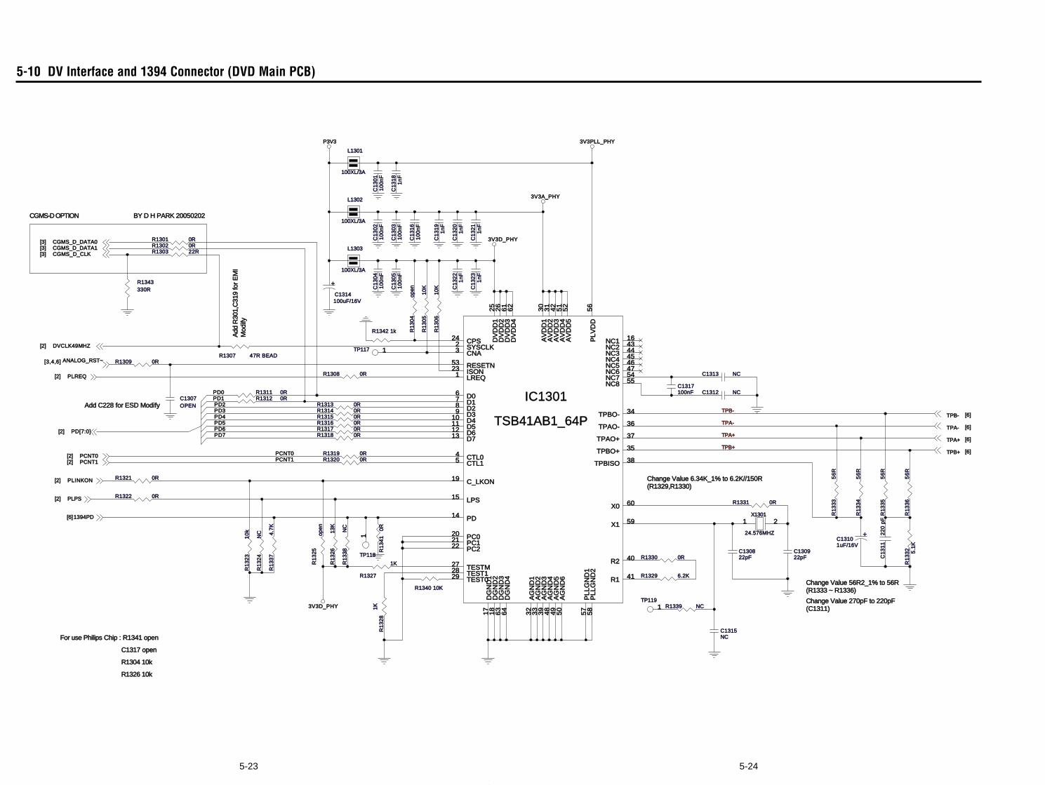
5-245-23
5-10 DV Interface and 1394 Connector (DVD Main PCB)
TPB+PCNT0
TPB-
TPA-
PCNT1
PD7
PD3
PD1
PD4PD5PD6
PD2
PD0
TPA+
P3V3 3V3PLL_PHY
3V3D_PHY
3V3D_PHY
3V3A_PHY
TPB+ [6]
TPB- [6]
ANALOG_RST~[3,4,6]
CGMS_D_CLK[3]
PLPS[2]
TPA- [6]
DVCLK49MHZ[2]
CGMS_D_DATA0[3]
PCNT0[2]PCNT1[2]
TPA+ [6]
CGMS_D_DATA1[3]
PD[7:0][2]
1394PD[6]
PLREQ[2]
PLINKON[2]
Change Value 56R2_1% to 56R(R1333 ~ R1336)
For use Philips Chip : R1341 open
CGMS-D OPTION BY D H PARK 20050202
C1317 open
Add
R30
1,C
319
for
EM
IM
odify
R1304 10k
Change Value 270pF to 220pF(C1311)
Add C228 for ESD Modify
Change Value 6.34K_1% to 6.2K//150R(R1329,R1330)
R1326 10k
R1
32
5op
en
C1313 NC
R1315 0R
C1
31
12
20
pF
R1343330R
R1
33
35
6R
TP1191
C1307OPEN
R1309 0R
R1
32
31
0k
C1
31
61
00
nF
R1
33
2 5.1
K
L1302
100XL/3A
R1321 0R
L1301
100XL/3A
C1
30
51
00
nF
R1
30
610
K
R1327
1K
C130822pF
R1320 0R
R1329 6.2K
R1
33
65
6R
C1
30
11
00
nF
C1
32
21
nF
+
C1314100uF/16V
R1319 0R
R1
32
613
K
R1302 0R
R1
33
8N
C
IC1301
TSB41AB1_64P
NC1 16NC2 43NC3 44NC4 45NC5 46NC6 47
TPBO- 34
TPAO- 36
TPAO+ 37
TPBO+ 35
TPBISO 38
X0 60
X1 59
R2 40
R1 41
PL
LG
ND
25
8P
LL
GN
D1
57
AG
ND
65
0A
GN
D5
49
AG
ND
44
8A
GN
D3
39
AG
ND
23
3A
GN
D1
32
DG
ND
46
4D
GN
D3
63
DG
ND
21
8D
GN
D1
17
PLV
DD
56
AV
DD
55
2A
VD
D4
51
AV
DD
34
2A
VD
D2
31
AV
DD
13
0
DV
DD
46
2D
VD
D3
61
DV
DD
22
6D
VD
D1
25
TEST029 TEST128 TESTM27
PC222 PC121 PC020
PD14
LPS15
C_LKON19
CTL15 CTL04
D713 D612 D511 D410 D39 D28 D17 D06
LREQ1 ISON23 RESETN53CNA3 SYSCLK2 CPS24
NC7 54NC8 55
C1317100nF
R1322 0R
C1
30
31
00
nF
C1
32
31
nF
R1342 1k
C130922pF
R1308 0R
R1
32
4N
C
R1313 0R
L1303
100XL/3A
R1316 0R
R1
33
55
6R
C1315NC
R1340 10K
R1
34
10R
C1
30
41
00
nF
C1
31
91
nF
R1307 47R BEAD
C1312 NCR1311 0R
R1301 0R C1
30
21
00
nF
TP118
1
C1
32
01
nF
R1
33
74
.7K
R1
30
510
K
R1331 0R
R1314 0R
R1
33
45
6R
R1
32
81K R1339 NC
TP117 1
R1303 22R
R1317 0R
C1
31
81
nF
C1
32
11
nF
R1
30
4op
en
X1301
24.576MHZ
1 2
R1330 0R
R1312 0R
+C13101uF/16V
R1318 0R
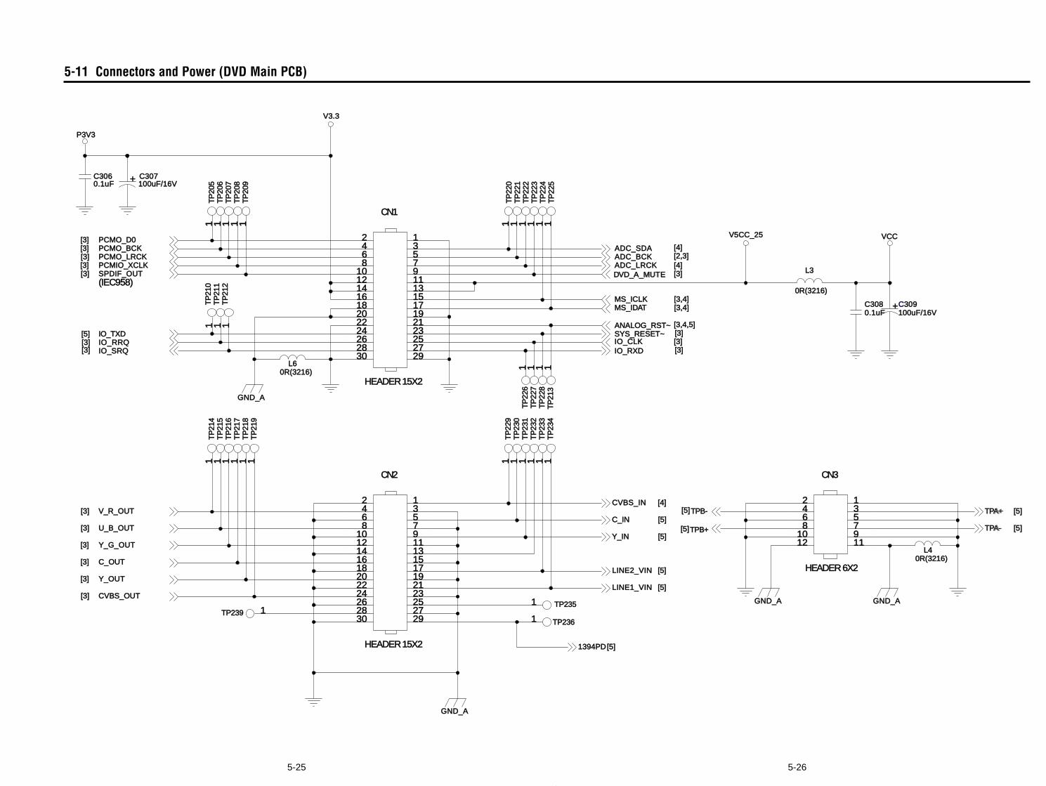
5-265-25
5-11 Connectors and Power (DVD Main PCB)
VCC
P3V3
V3.33.3
V5CC_25V5CC_25
SPSPDIF_OUTIF_OUT[3]
MS_ICLKMS_ICLK [3,4][3,4]
ADC_SDADC_SDA [4]ADC_BCADC_BCK [2,3]ADC_LRCKADC_LRCK [4]
TPA+TPA+ [5]
TPA-TPA- [5]TPB+PB+[5]
V_R_OUTV_R_OUT[3]
U_B_OUTU_B_OUT[3]
Y_G_OUY_G_OUT[3]
C_OUC_OUT[3]
Y_OUY_OUT[3]
CVBS_OUTCVBS_OUT[3]
C_IN [5]
Y_IN [5]
IOIO_RX_RXD [3]
CVBS_INCVBS_IN [4]TPB-PB-[5]
DVD_A_MUTDVD_A_MUTE [3]
IO_IO_RRQRRQ[3]SYS_RESETSYS_RESET~ [3]
PCMO_BCPCMO_BCK[3]
PCMIO_XCLK[3]
IOIO_SR_SRQ[3]
PCMO_LRCKPCMO_LRCK[3]
PCPCMO_D0[3]
MS_IDAT [3,4]
ANALOG_RST~ [3,4,5]
IOIO_CLK_CLK [3]IO_TIO_TXD[5]
1394PD394PD[5][5]
LINE2_VINLINE2_VIN [5]
LINE1_VINLINE1_VIN [5]
GND_GND_A
GND_GND_A
GND_GND_A
(IEC(IEC958)958)
GND_GND_A
TP
TP
211
211
1
TP
TP
217
217
1
TP
TP
226
226
1
C3063060.1uF0.1uF
CN3CN3
HEHEADER 6XADER 6X2
2468
1012
1357911
TP
TP
224
224
1
+ C307307100uF100uF/1616V
TP23TP2351
TP
TP
232
232
1
TP
TP
212
212
1
TP
TP
205
205
1
TP
TP
225
225
1
TP
TP
231
231
1
L40R(3216)0R(3216)
CN1CN1
HEADERHEADER 15X15X2
2468
1012141618202224262830
1357911131517192123252729
TP
TP
213
213
1
TP
TP
218
218
1
TP
TP
206
206
1
TP
TP
233
233
1
TP23TP2361
TP
TP
219
219
1
TP
TP
207
207
1
TP
TP
234
234
1
TP
TP
208
208
1T
PT
P20
920
91
TP
TP
220
220
1
+C309309100uF/16V100uF/16V
TP
TP
214
214
1
C3083080.1uF0.1uF
TP
TP
221
221
1
TP
TP
215
215
1
TP
TP
228
228
1
TP
TP
222
222
1
TP
TP
229
229
1
L3
0R(3216)0R(3216)
TP
TP
210
210
1
TP
TP
216
216
1
L60R(3216)0R(3216)
TP
TP
227
227
1
CN2CN2
HEADERHEADER 15X15X2
2468
1012141618202224262830
1357911131517192123252729
TP23TP239 1
TP
TP
223
223
1
TP
TP
230
230
1
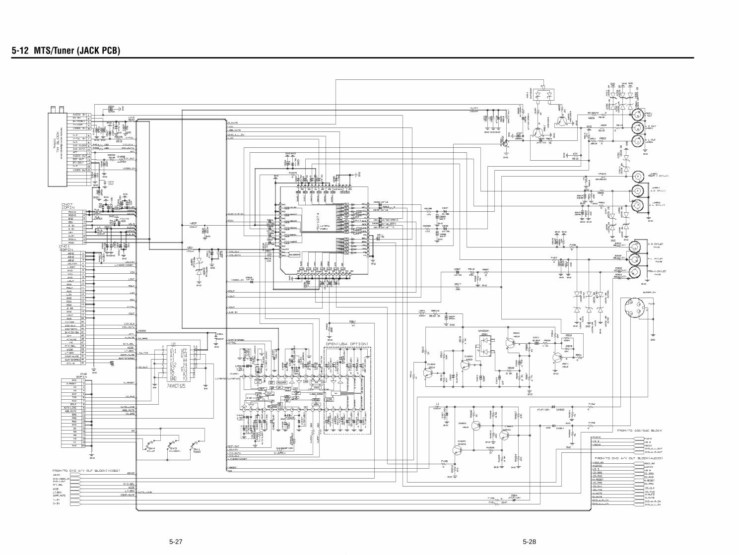
5-285-27
5-12 MTS/Tuner (JACK PCB)
100uF
470uF/10V
C405A
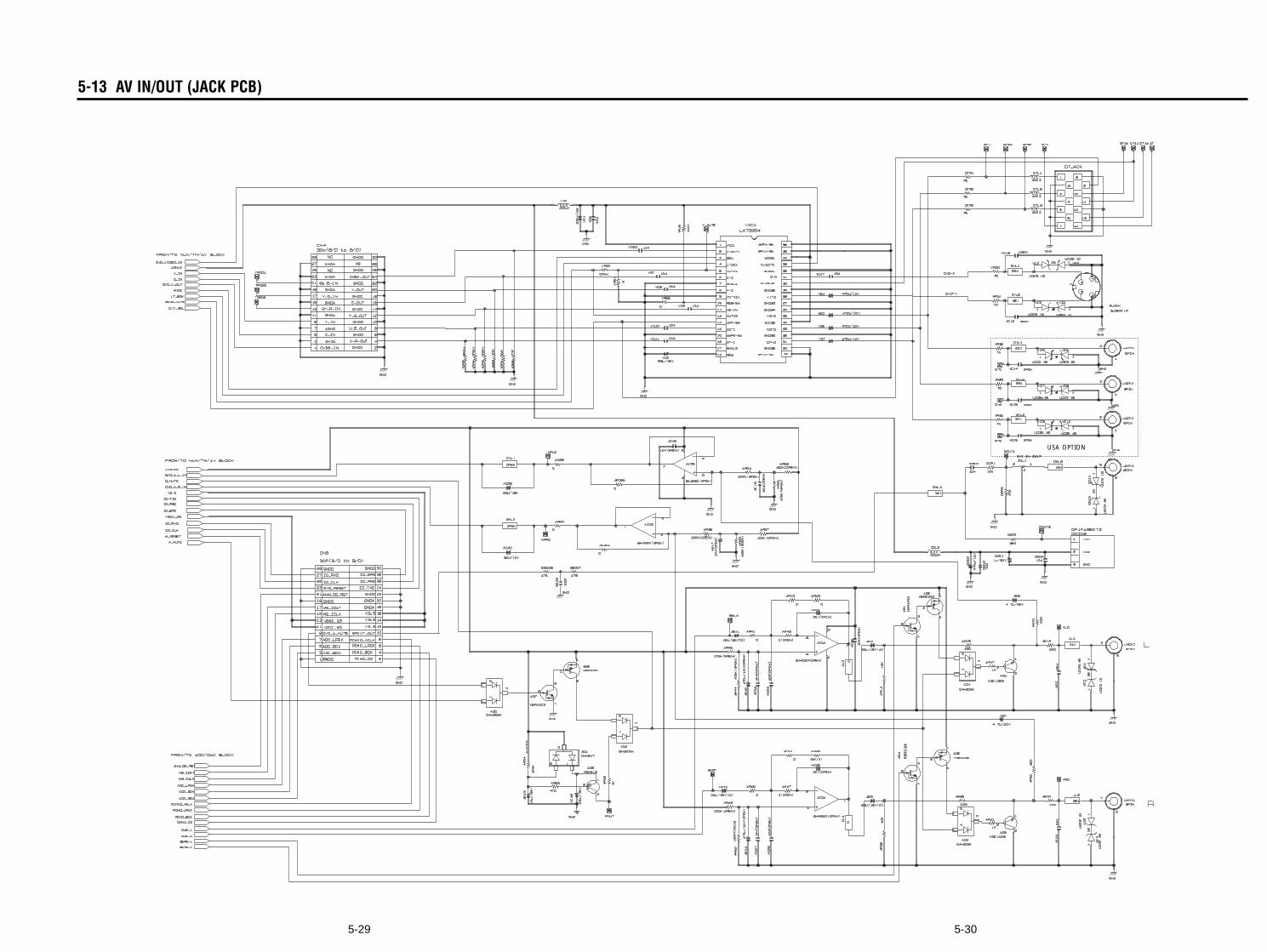
5-305-29
5-13 AV IN/OUT (JACK PCB)
USA OPTION
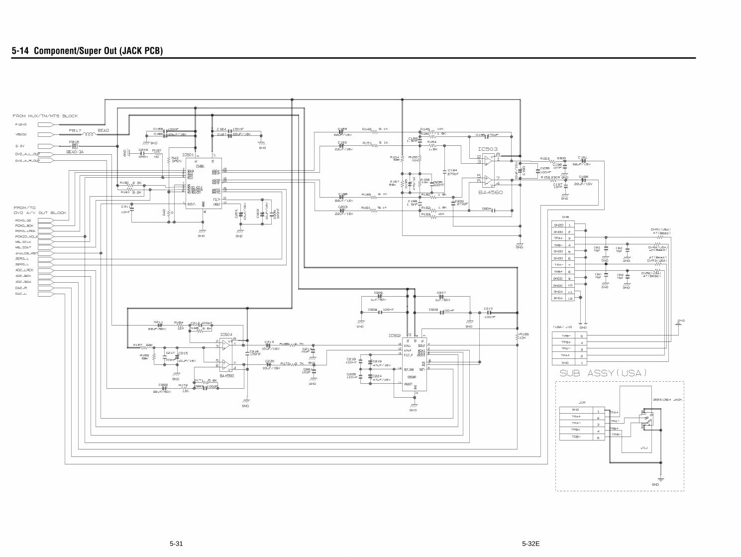
5-32E5-31
5-14 Component/Super Out (JACK PCB)
10pFC862
10pFC863
10pFC860
10pFC861
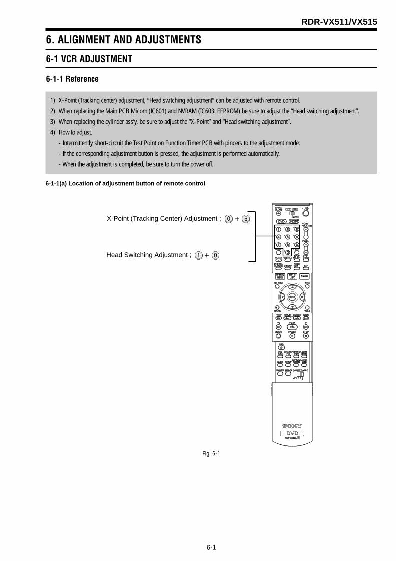
6-1
RDR-VX511/VX515
6. ALIGNMENT AND ADJUSTMENTS
6-1 VCR ADJUSTMENT
6-1-1 Reference
1) X-Point (Tracking center) adjustment, “Head switching adjustment” can be adjusted with remote control.
2) When replacing the Main PCB Micom (IC601) and NVRAM (IC603: EEPROM) be sure to adjust the “Head switching adjustment”.
3) When replacing the cylinder ass’y, be sure to adjust the “X-Point” and “Head switching adjustment”.
4) How to adjust.
- Intermittently short-circuit the Test Point on Function Timer PCB with pincers to the adjustment mode.
- If the corresponding adjustment button is pressed, the adjustment is performed automatically.
- When the adjustment is completed, be sure to turn the power off.
6-1-1(a) Location of adjustment button of remote control
Fig. 6-1
X-Point (Tracking Center) Adjustment ;
Head Switching Adjustment ;
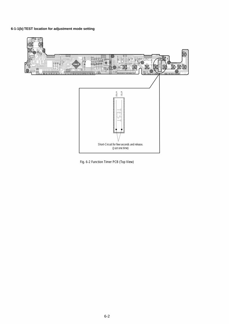
6-2
6-1-1(b) TEST location for adjustment mode setting
Fig. 6-2 Function Timer PCB (Top View)
Short-Circuit for few seconds and release.(Just one time)
6-3
6-1-2 Head Switching Point Adjustment
1) Playback the alignment tape.2) Intermittently short-circuit the two Test Points on Function Timer PCB while setting the adjustment mode. (See Fig. 6-2)3) Press the “1, 0” buttons ; remote control adjustment operates automatically. (See Fig. 6-1)
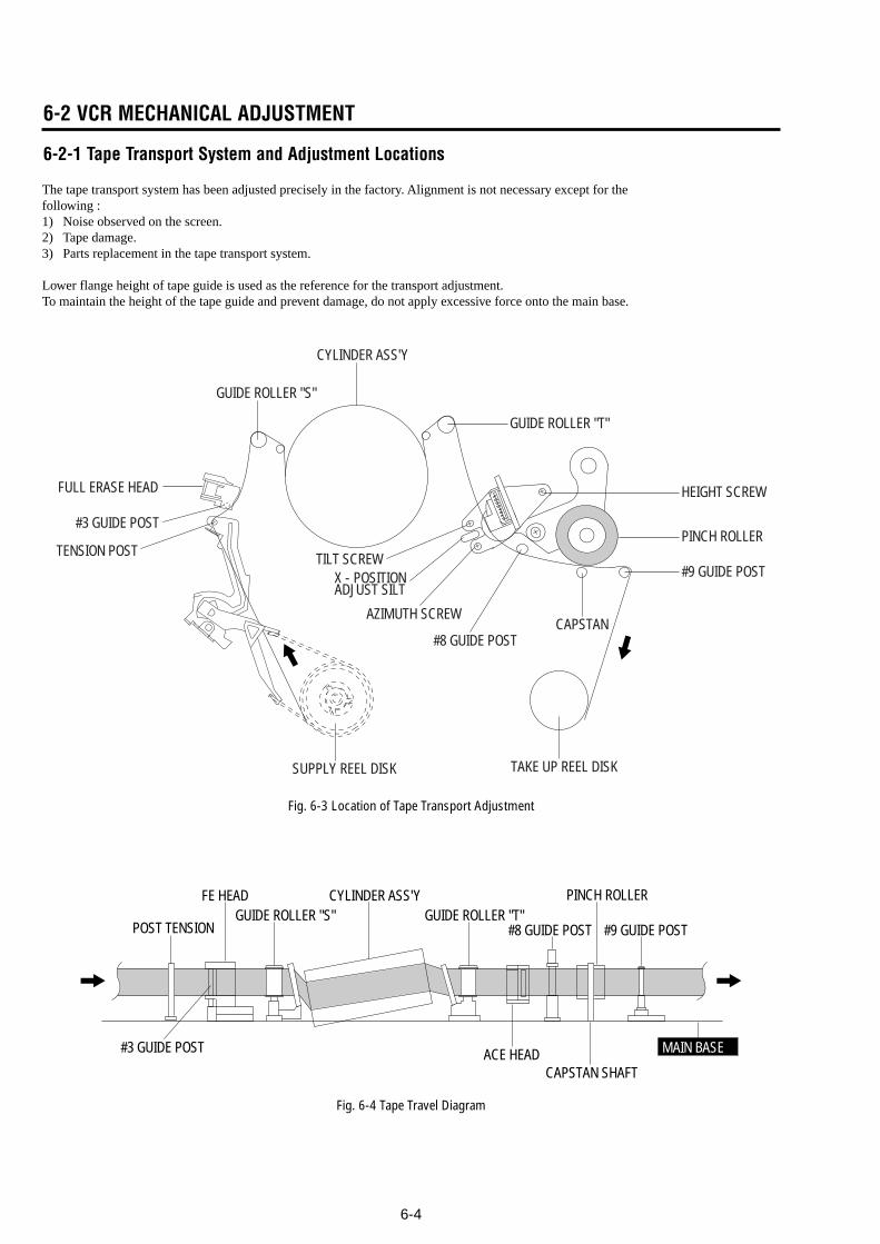
6-4
6-2 VCR MECHANICAL ADJUSTMENT
6-2-1 Tape Transport System and Adjustment Locations
The tape transport system has been adjusted precisely in the factory. Alignment is not necessary except for thefollowing :1) Noise observed on the screen.2) Tape damage.3) Parts replacement in the tape transport system.
Lower flange height of tape guide is used as the reference for the transport adjustment.To maintain the height of the tape guide and prevent damage, do not apply excessive force onto the main base.
Fig. 6-4 Tape Travel Diagram
CYLINDER ASS'Y
TAKE UP REEL DISK
#8 GUIDE POST
#9 GUIDE POST
SUPPLY REEL DISK
CAPSTAN
PINCH ROLLER
GUIDE ROLLER "T"
GUIDE ROLLER "S"
FULL ERASE HEAD
#3 GUIDE POST
TENSION POST
HEIGHT SCREW
TILT SCREWX - POSITIONADJUST SILT
AZIMUTH SCREW
POST TENSION
MAIN BASE
FE HEAD CYLINDER ASS'Y PINCH ROLLERGUIDE ROLLER "S" GUIDE ROLLER "T"
#8 GUIDE POST #9 GUIDE POST
CAPSTAN SHAFTACE HEAD#3 GUIDE POST
Fig. 6-3 Location of Tape Transport Adjustment
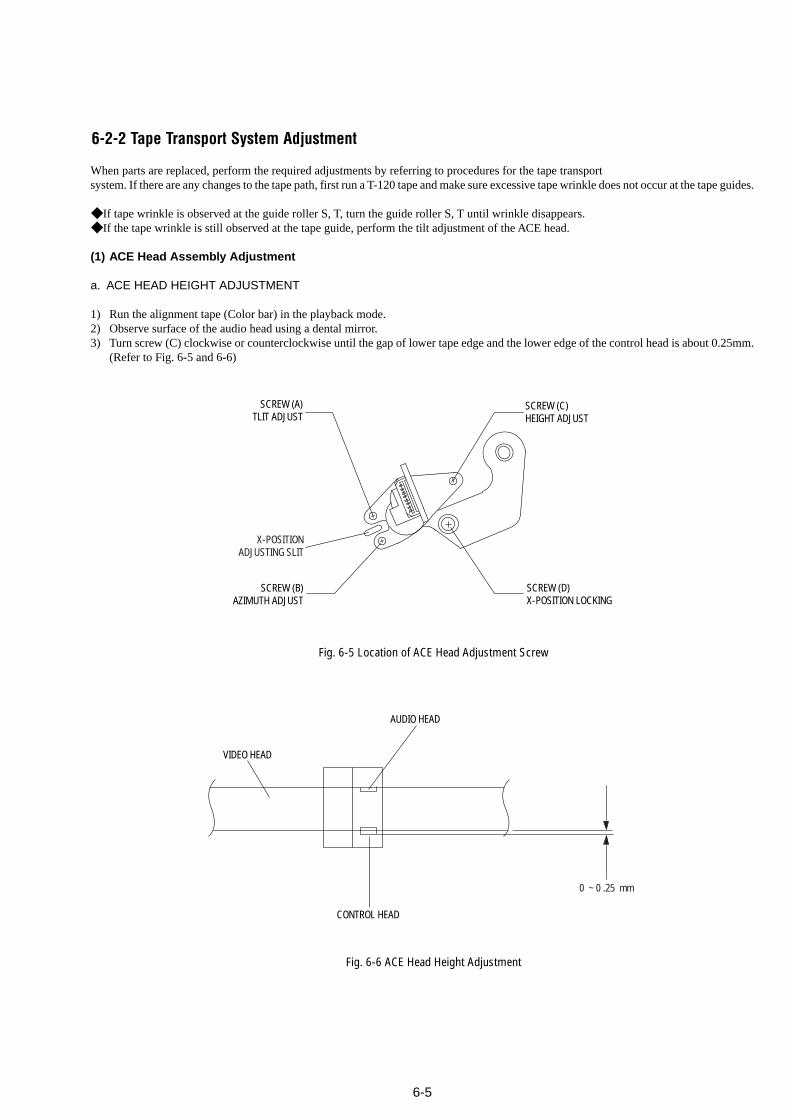
6-5
6-2-2 Tape Transport System Adjustment
When parts are replaced, perform the required adjustments by referring to procedures for the tape transportsystem. If there are any changes to the tape path, first run a T-120 tape and make sure excessive tape wrinkle does not occur at the tape guides.
If tape wrinkle is observed at the guide roller S, T, turn the guide roller S, T until wrinkle disappears. If the tape wrinkle is still observed at the tape guide, perform the tilt adjustment of the ACE head.
(1) ACE Head Assembly Adjustment
a. ACE HEAD HEIGHT ADJUSTMENT
1) Run the alignment tape (Color bar) in the playback mode.2) Observe surface of the audio head using a dental mirror.3) Turn screw (C) clockwise or counterclockwise until the gap of lower tape edge and the lower edge of the control head is about 0.25mm.
(Refer to Fig. 6-5 and 6-6)
Fig. 6-5 Location of ACE Head Adjustment Screw
SCREW (A)TLIT ADJUST
X-POSITIONADJUSTING SLIT
SCREW (C)HEIGHT ADJUST
SCREW (D)X-POSITION LOCKING
SCREW (B)AZIMUTH ADJUST
0 ~ 0 .25 mm
AUDIO HEAD
VIDEO HEAD
CONTROL HEAD
Fig. 6-6 ACE Head Height Adjustment
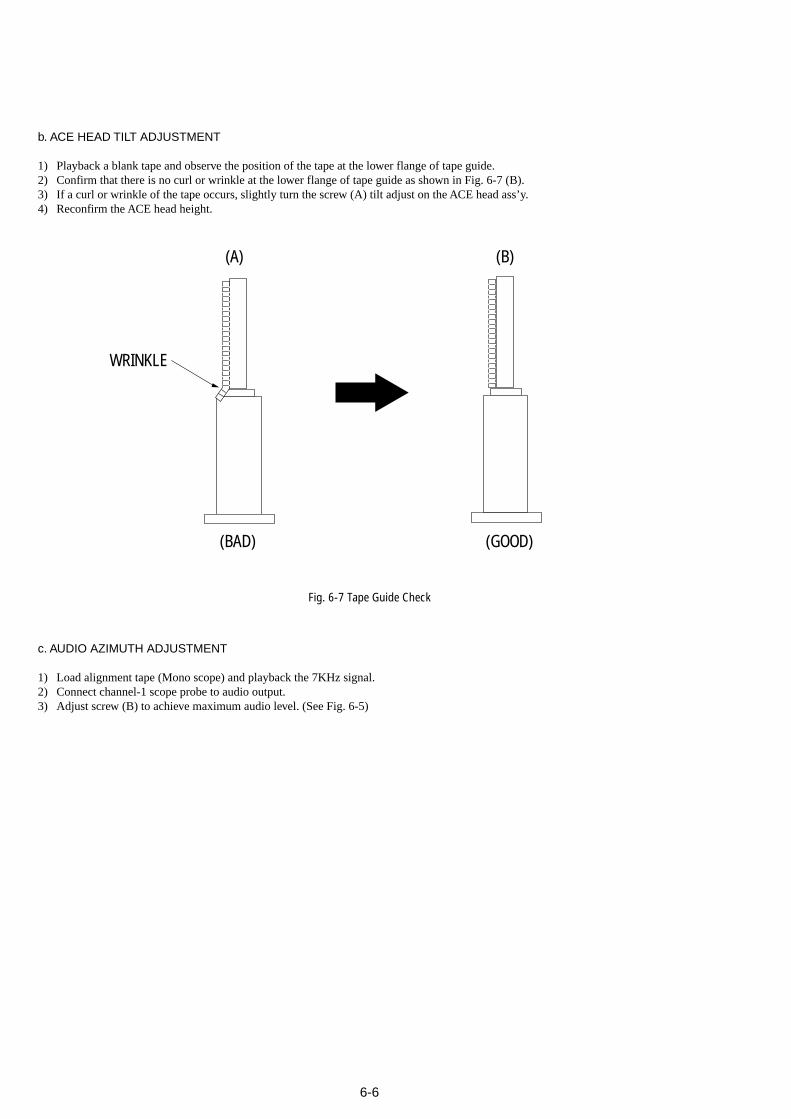
6-6
b. ACE HEAD TILT ADJUSTMENT
1) Playback a blank tape and observe the position of the tape at the lower flange of tape guide.2) Confirm that there is no curl or wrinkle at the lower flange of tape guide as shown in Fig. 6-7 (B).3) If a curl or wrinkle of the tape occurs, slightly turn the screw (A) tilt adjust on the ACE head ass’y.4) Reconfirm the ACE head height.
(A) (B)
(BAD)
WRINKLE
(GOOD)
Fig. 6-7 Tape Guide Check
c. AUDIO AZIMUTH ADJUSTMENT
1) Load alignment tape (Mono scope) and playback the 7KHz signal.2) Connect channel-1 scope probe to audio output.3) Adjust screw (B) to achieve maximum audio level. (See Fig. 6-5)
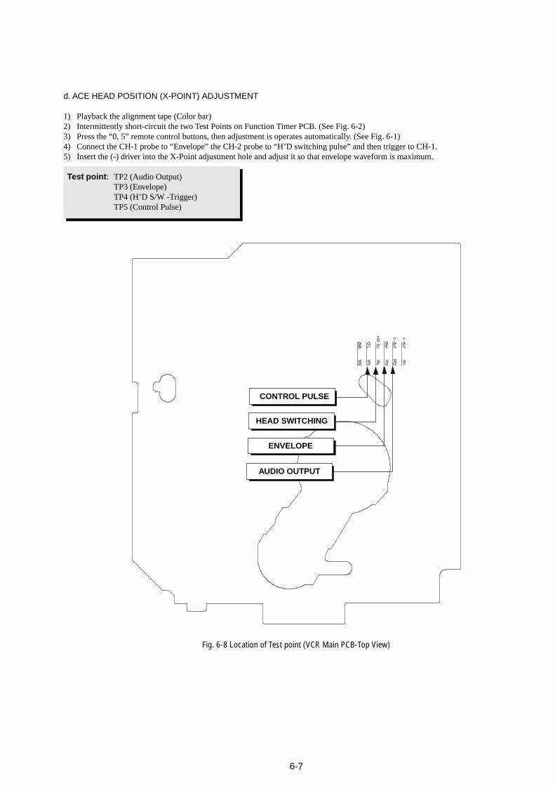
6-7
d. ACE HEAD POSITION (X-POINT) ADJUSTMENT
1) Playback the alignment tape (Color bar)2) Intermittently short-circuit the two Test Points on Function Timer PCB. (See Fig. 6-2)3) Press the “0, 5” remote control buttons, then adjustment is operates automatically. (See Fig. 6-1)4) Connect the CH-1 probe to “Envelope” the CH-2 probe to “H’D switching pulse” and then trigger to CH-1.5) Insert the (-) driver into the X-Point adjustment hole and adjust it so that envelope waveform is maximum.
Test point: TP2 (Audio Output)TP3 (Envelope)TP4 (H’D S/W -Trigger)TP5 (Control Pulse)
Fig. 6-8 Location of Test point (VCR Main PCB-Top View)
iew)
AUDIO OUTPUT
CONTROL PULSE
HEAD SWITCHING
ENVELOPE
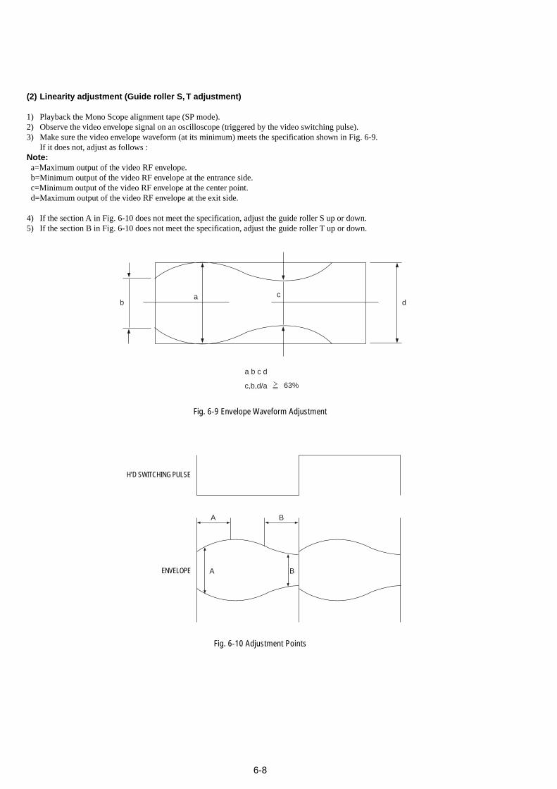
6-8
(2) Linearity adjustment (Guide roller S, T adjustment)
1) Playback the Mono Scope alignment tape (SP mode).2) Observe the video envelope signal on an oscilloscope (triggered by the video switching pulse).3) Make sure the video envelope waveform (at its minimum) meets the specification shown in Fig. 6-9.
If it does not, adjust as follows :Note:a=Maximum output of the video RF envelope.b=Minimum output of the video RF envelope at the entrance side.c=Minimum output of the video RF envelope at the center point.d=Maximum output of the video RF envelope at the exit side.
4) If the section A in Fig. 6-10 does not meet the specification, adjust the guide roller S up or down.5) If the section B in Fig. 6-10 does not meet the specification, adjust the guide roller T up or down.
a
a b c d
c,b,d/a 63%
bc
d
Fig. 6-9 Envelope Waveform Adjustment
A B
A B
H'D SWITCHING PULSE
ENVELOPE
Fig. 6-10 Adjustment Points
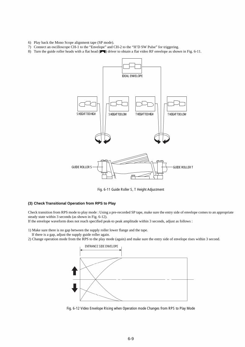
6-9
6) Play back the Mono Scope alignment tape (SP mode).7) Connect an oscilloscope CH-1 to the “Envelope” and CH-2 to the “H’D SW Pulse” for triggering.8) Turn the guide roller heads with a flat head ( ) driver to obtain a flat video RF envelope as shown in Fig. 6-11.
Fig. 6-11 Guide Roller S, T Height Adjustment
IDEAL ENVELOPE
S HEIGHT TOO HIGH S HEIGHT TOO LOW T HEIGHT TOO HIGH T HEIGHT TOO LOW
GUIDE ROLLER S GUIDE ROLLER T
Fig. 6-12 Video Envelope Rising when Operation mode Changes from RPS to Play Mode
ENTRANCE SIDE ENVELOPE
(3) Check Transitional Operation from RPS to Play
Check transition from RPS mode to play mode : Using a pre-recorded SP tape, make sure the entry side of envelope comes to an appropriatesteady state within 3 seconds (as shown in Fig. 6-12).If the envelope waveform does not reach specified peak-to peak amplitude within 3 seconds, adjust as follows :
1) Make sure there is no gap between the supply roller lower flange and the tape. If there is a gap, adjust the supply guide roller again.2) Change operation mode from the RPS to the play mode (again) and make sure the entry side of envelope rises within 3 second.
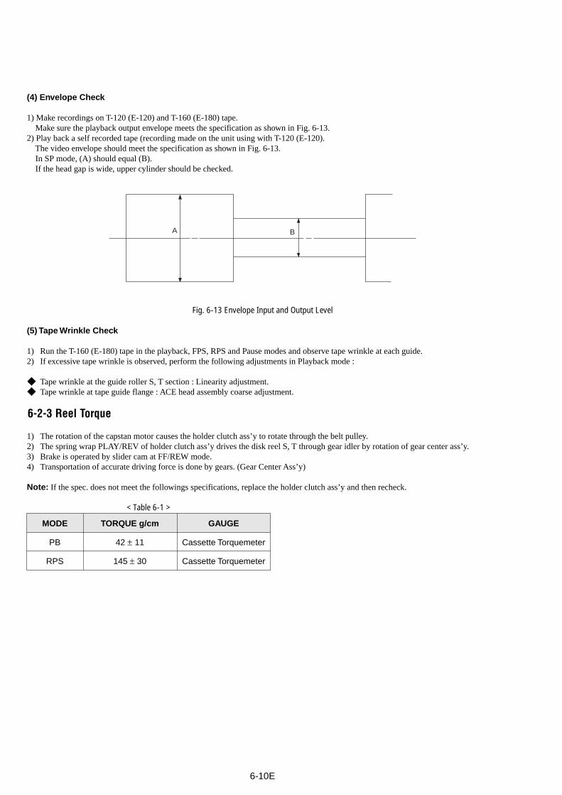
6-10E
(4) Envelope Check
1) Make recordings on T-120 (E-120) and T-160 (E-180) tape. Make sure the playback output envelope meets the specification as shown in Fig. 6-13.2) Play back a self recorded tape (recording made on the unit using with T-120 (E-120). The video envelope should meet the specification as shown in Fig. 6-13. In SP mode, (A) should equal (B). If the head gap is wide, upper cylinder should be checked.
Fig. 6-13 Envelope Input and Output Level
(5) Tape Wrinkle Check
1) Run the T-160 (E-180) tape in the playback, FPS, RPS and Pause modes and observe tape wrinkle at each guide.2) If excessive tape wrinkle is observed, perform the following adjustments in Playback mode :
Tape wrinkle at the guide roller S, T section : Linearity adjustment. Tape wrinkle at tape guide flange : ACE head assembly coarse adjustment.
6-2-3 Reel Torque
1) The rotation of the capstan motor causes the holder clutch ass’y to rotate through the belt pulley.2) The spring wrap PLAY/REV of holder clutch ass’y drives the disk reel S, T through gear idler by rotation of gear center ass’y.3) Brake is operated by slider cam at FF/REW mode.4) Transportation of accurate driving force is done by gears. (Gear Center Ass’y)
Note: If the spec. does not meet the followings specifications, replace the holder clutch ass’y and then recheck.
< Table 6-1 >
MODE TORQUE g/cm GAUGE
PB 42 ± 11 Cassette Torquemeter
RPS 145 ± 30 Cassette Torquemeter
A B
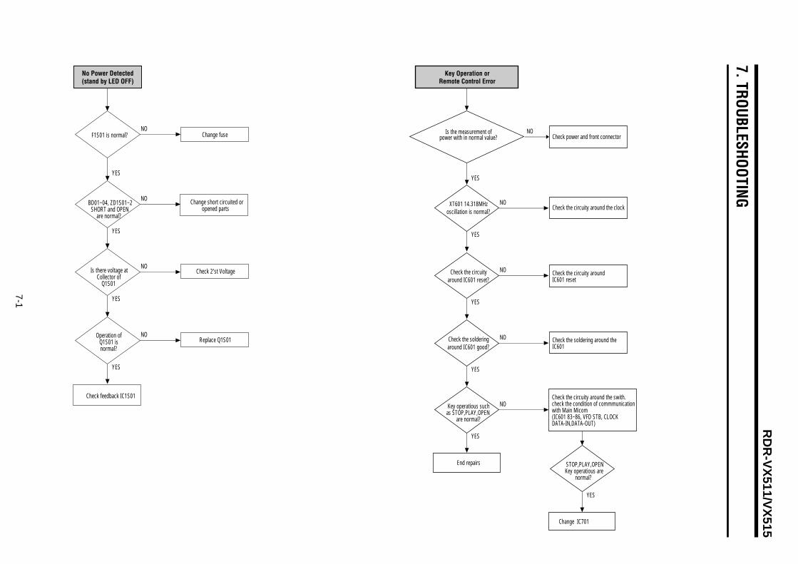
7-1
RD
R-V
X511/V
X515
7. TROUBLESHOOTING
Check power and front connector
Check the circuity around the clock
Check the circuity around IC601 reset
Check the soldering around theIC601
Change IC701
NO
NO
Check the circuity around the swith.check the condition of commmunicationwith Main Micom(IC601 83~86, VFD STB, CLOCKDATA-IN,DATA-OUT)
NO
YES
YES
NO
YES
NO
YES
YES
STOP,PLAY,OPENKey operatious are
normal?
YES
Key Operation orRemote Control Error
Is the measurement ofpower with in normal value?
End repairs
Key operatious suchas STOP,PLAY,OPEN
are normal?
Check the circuityaround IC601 reset?
Check the solderingaround IC601 good?
XT601 14.318MHzoscillation is normal?
F1S01 is normal?
BD01~04, ZD1S01~2SHORT and OPEN
are normal?
Check feedback IC1S01
Change short circuited oropened parts
Change fuse
Check 2'st Voltage
Replace Q1S01
NO
NO
Is there voltage atCollector of
Q1S01
NO
YES
YES
YES
Operation ofQ1S01 isnormal?
NO
YES
No Power Detected(stand by LED OFF)
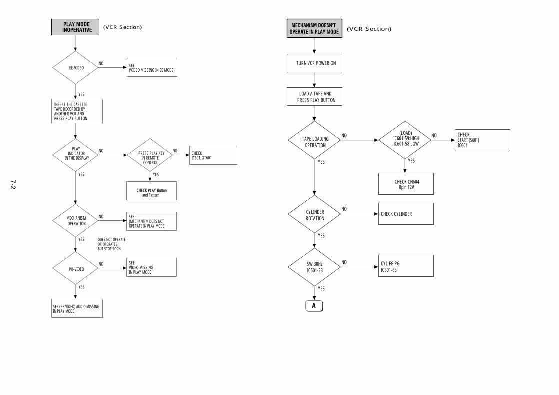
7-2
LOAD A TAPE ANDPRESS PLAY BUTTON
TURN VCR POWER ON
MECHANISM DOESN'TOPERATE IN PLAY MODE
TAPE LOADINGOPERATION
(LOAD)IC601-59:HIGHIC601-58:LOW
CYLINDERROTATION
SW 30HzIC601-23
CYL FG.PGIC601-65
CHECK CYLINDER
CHECKSTART (S601)IC601
NO NO
NO
NO
YESYES
YES
YES
CHECK CN6048pin 12V
(VCR Section)
A
PLAY MODE INOPERATIVE
EE-VIDEO
INSERT THE CASETTETAPE RECORDED BYANOTHER VCR ANDPRESS PLAY BUTTON
PLAYINDICATOR
IN THE DISPLAYPRESS PLAY KEY
IN REMOTE CONTROL
MECHANISMOPERATION
SEE (PB VIDEO) AUDIO MISSINGIN PLAY MODE
SEE(MECHANISM DOES NOTOPERATE IN PLAY MODE)
CHECK PLAY Buttonand Pattern
CHECK IC601, XT601
SEE(VIDEO MISSING IN EE MODE)
NO
NO NO
YES
NO
PB-VIDEOSEEVIDEO MISSINGIN PLAY MODE
NO
YES
YES
YES DOES NOT OPERATEOR OPERATESBUT STOP SOON
YES
(VCR Section)
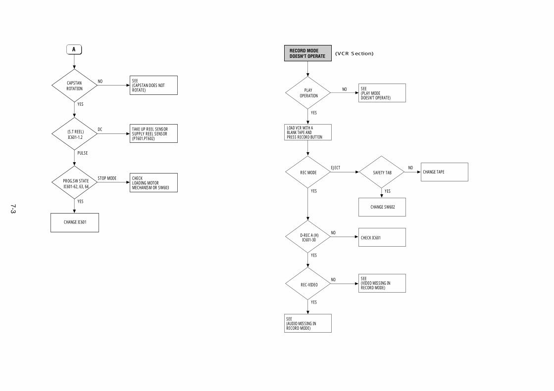
7-3
RECORD MODE DOESN'T OPERATE
PLAYOPERATION
LOAD VCR WITH ABLANK TAPE ANDPRESS RECORD BUTTON
REC MODE SAFETY TAB
D-REC A (H)IC601-30
SEE (AUDIO MISSING IN RECORD MODE)
CHANGE SW602
CHECK IC601
CHANGE TAPE
SEE(PLAY MODEDOESN'T OPERATE)
EJECT NO
NO
YES
NO
REC-VIDEOSEE (VIDEO MISSING IN RECORD MODE)
NO
YES
YES
YES
YES
(VCR Section)
CAPSTANROTATION
(S.T REEL)IC601-1.2
PROG.SW STATEIC601-62, 63, 64
CHANGE IC601
CHECK LOADING MOTOR MECHANISM OR SW603
TAKE UP REEL SENSORSUPPLY REEL SENSOR(PT601.PT602)
SEE(CAPSTAN DOES NOTROTATE)
NO
DC
STOP MODE
YES
PULSE
YES
A
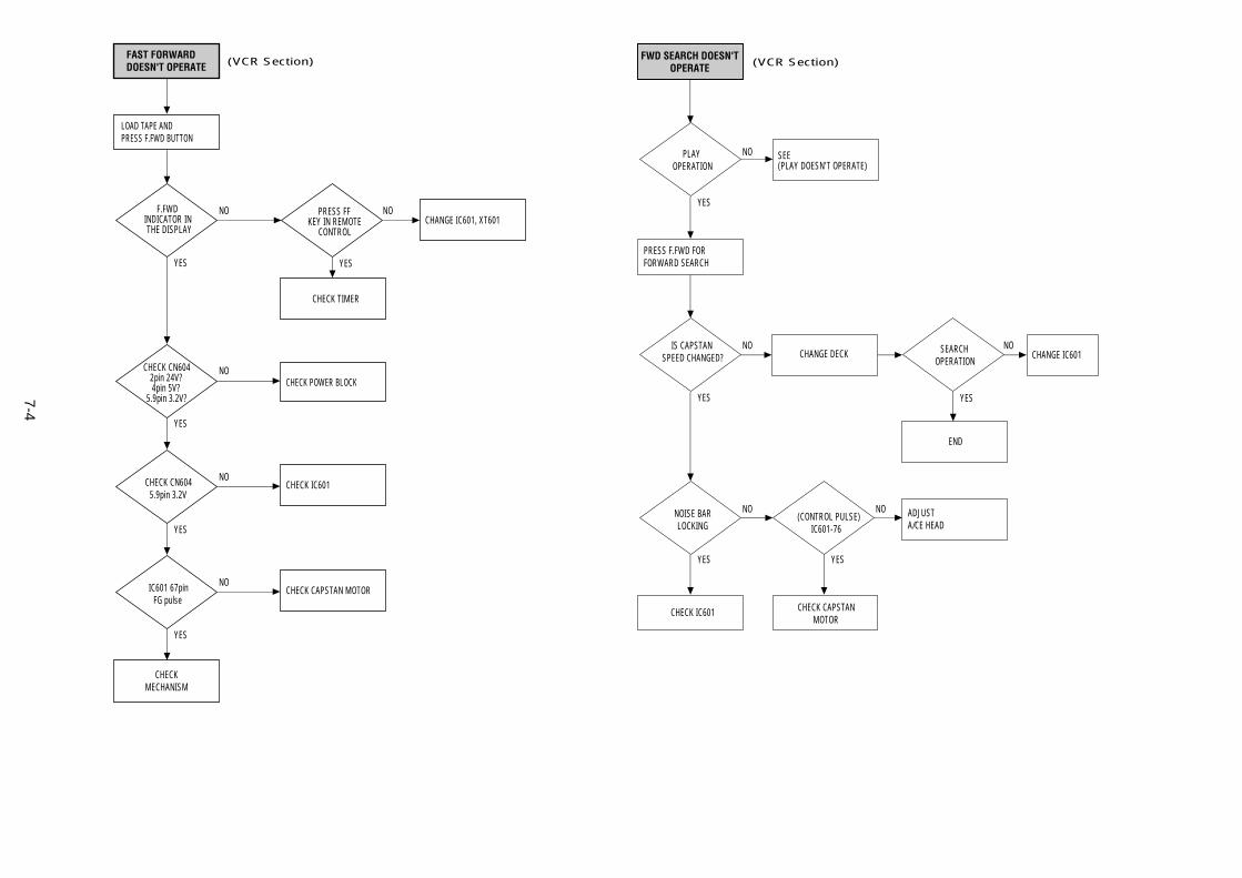
7-4
FWD SEARCH DOESN'TOPERATE
PLAYOPERATION
PRESS F.FWD FORFORWARD SEARCH
CHECK IC601 CHECK CAPSTAN MOTOR
IS CAPSTANSPEED CHANGED?
SEARCHOPERATION
NOISE BARLOCKING
END
ADJUSTA/CE HEAD
CHANGE DECK CHANGE IC601
SEE(PLAY DOESN'T OPERATE)
NO
NO
NO
YES
NO(CONTROL PULSE)
IC601-76
NO
YES
YES
YES YES
(VCR Section)
LOAD TAPE ANDPRESS F.FWD BUTTON
FAST FORWARDDOESN'T OPERATE
F.FWDINDICATOR IN THE DISPLAY
PRESS FF KEY IN REMOTE
CONTROL
CHECK CN6042pin 24V?4pin 5V?
5.9pin 3.2V?
CHECK TIMER
CHANGE IC601, XT601NO
NO
NO
NO
YES
CHECK CN6045.9pin 3.2V
CHECK IC601
CHECK POWER BLOCK
YES
YES
YES
CHECKMECHANISM
NOIC601 67pinFG pulse
CHECK CAPSTAN MOTOR
YES
(VCR Section)
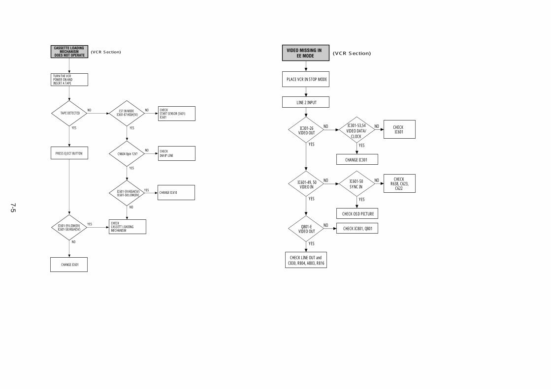
7-5
PLACE VCR IN STOP MODE
LINE 2 INPUT
VIDEO MISSING IN EE MODE
IC301-26VIDEO OUT
NO
NO
NO
IC601-49, 50VIDEO IN
YES
YES
Q801-EVIDEO OUT
YES
NO
YES
CHECK LINE OUT andC830, R804, AB03, R816
NO
YES
(VCR Section)
CHANGE IC301
IC301-53,54VIDEO DATA/
CLOCK
CHECK OSD PICTURE
CHECK IC801, Q801
IC601-50SYNC IN
CHECKIC601
CHECKR638, C623,
C622
TURN THE VCRPOWER ON ANDINSERT A TAPE
PRESS EJECT BUTTON
CASSETTE LOADING MECHANISM
DOES NOT OPERATE
TAPE DETECTED
CHANGE IC601
CHECK START SENSOR (S601)IC601
CHECK DM B+ LINE
CHANGE IC610
NO NO
NO
YES
IC601-59:HIGH(5V)IC601-58:LOW(0V)
CHECKCASSETT LOADINGMECHANISM
YES
YES
NO
CN604 8pin 12V?
YES
NO
YES
(VCR Section)
CST IN MODEIC601-87:HIGH(5V)
IC601-59:LOW(0V)IC601-58:HIGH(5V)
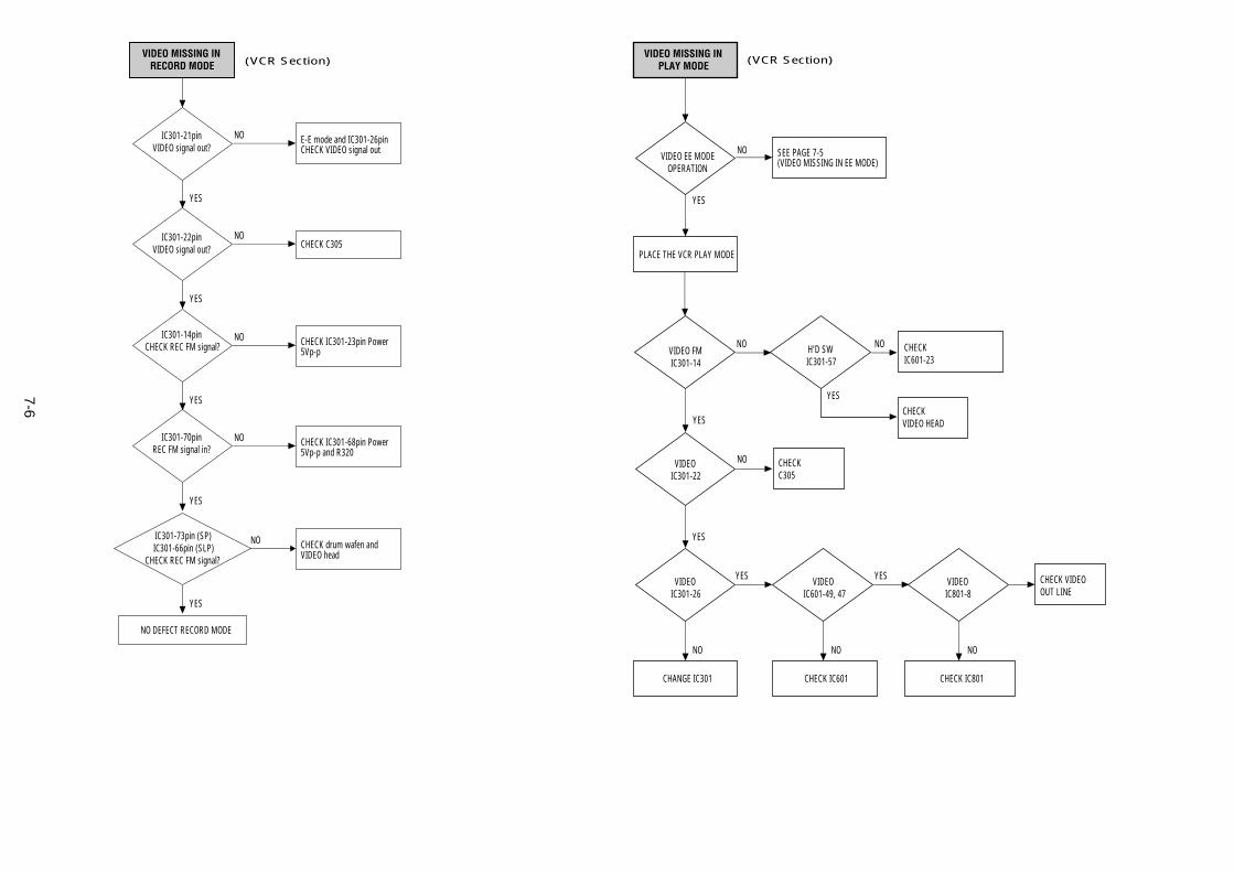
7-6
VIDEO MISSING INPLAY MODE
VIDEO EE MODEOPERATION
PLACE THE VCR PLAY MODE
CHANGE IC301 CHECK IC601
CHECKVIDEO HEAD
CHECKC305
CHECKIC601-23
CHECK VIDEOOUT LINE
SEE PAGE 7-5(VIDEO MISSING IN EE MODE)
NO
YES
YES
NO
YESYES
VIDEO FMIC301-14
VIDEOIC301-22
VIDEOIC301-26
VIDEOIC601-49, 47
VIDEOIC801-8
NO H'D SWIC301-57
NO
YES
YES
NO NO NO
CHECK IC801
(VCR Section)VIDEO MISSING IN
RECORD MODE
NO DEFECT RECORD MODE
E-E mode and IC301-26pinCHECK VIDEO signal out
NO
YES
CHECK C305NO
YES
CHECK IC301-23pin Power 5Vp-p
NO
YES
CHECK IC301-68pin Power5Vp-p and R320
NO
YES
CHECK drum wafen andVIDEO head
NO
YES
(VCR Section)
IC301-21pinVIDEO signal out?
IC301-22pinVIDEO signal out?
IC301-14pinCHECK REC FM signal?
IC301-70pinREC FM signal in?
IC301-73pin (SP)IC301-66pin (SLP)
CHECK REC FM signal?
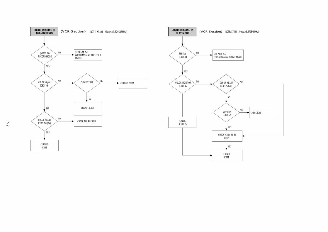
7-7
COLOR MISSING INPLAY MODE
FM-ENVIC301-14
COLOR-MONITORIC301-46
COLOR-KILLERIC301-"6"(2V)
SW 30HZIC301-57
CHANGEIC301
CHECK IC301-48, 51XT301
CHECK IC601
SEE PAGE 7-6(VIDEO MISSING IN PLAY MODE)
NO
NO
NO
NO
YES
YES
YES
YES
NOTE: XT301 - Always (3.579545MHz)(VCR Section)
CHECKIC301-26
COLOR MISSING INRECORD MODE
(VIDEO IN)RECORD MODE
(VCR Section) NOTE: XT301 - Always (3.579545MHz)
COLOR signalIC301-46
COLOR KILLERIC301 "60"(2V)
CHANGEIC301
CHECK THE REC LINE
SEE PAGE 7-6(VIDEO MISSING IN RECORDMODE)
NO
NO
NO
YES
NO
YES
CHECK XT301 CHANGE XT301NO
NO
CHANGE IC301
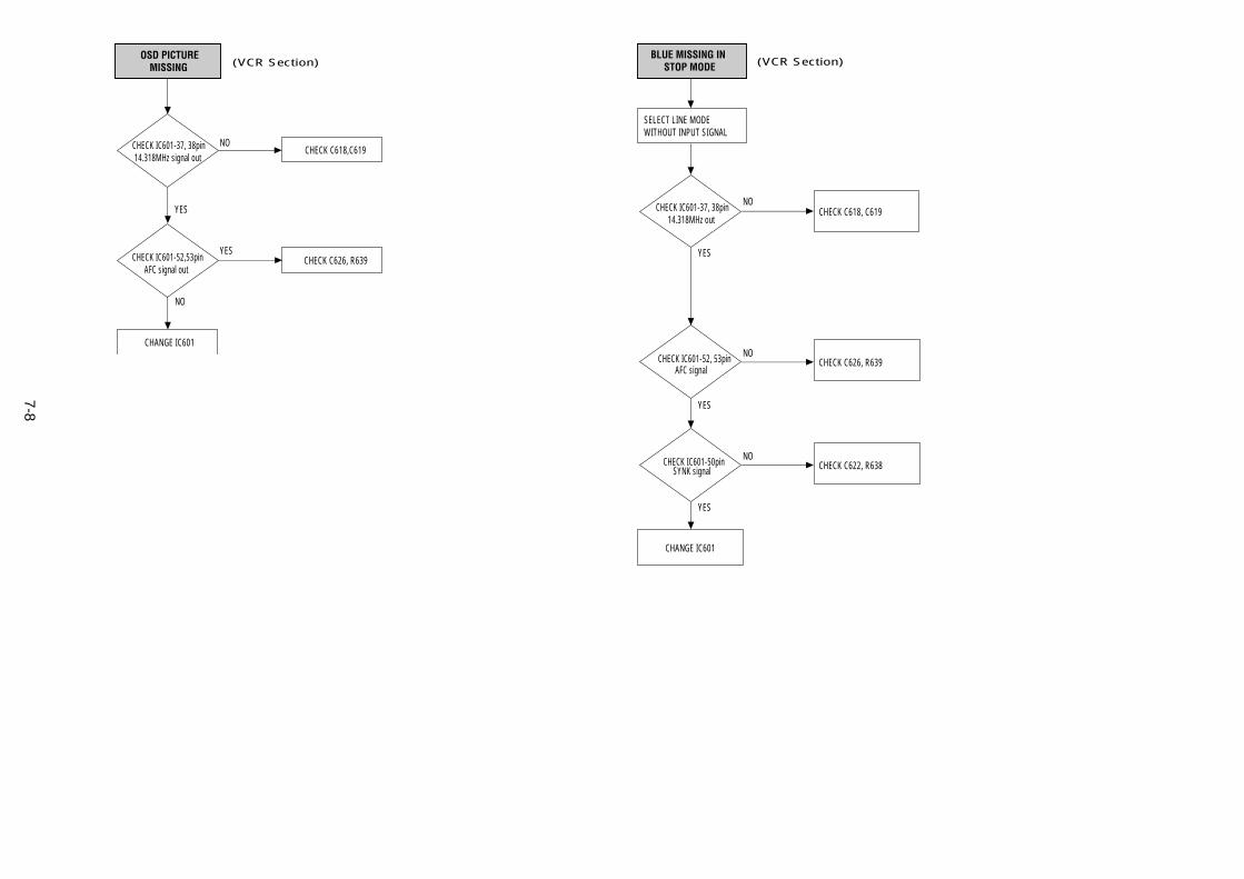
7-8
SELECT LINE MODEWITHOUT INPUT SIGNAL
BLUE MISSING IN STOP MODE
CHANGE IC601
CHECK C626, R639
CHECK C618, C619NO
NO
YES
YES
CHECK C622, R638NO
YES
(VCR Section)
CHECK IC601-37, 38pin14.318MHz out
CHECK IC601-52, 53pinAFC signal
CHECK IC601-50pinSYNK signal
OSD PICTUREMISSING
CHECK IC601-37, 38pin14.318MHz signal out
CHECK IC601-52,53pinAFC signal out
CHANGE IC601
CHECK C618,C619
CHECK C626, R639YES
NO
YES
NO
(VCR Section)
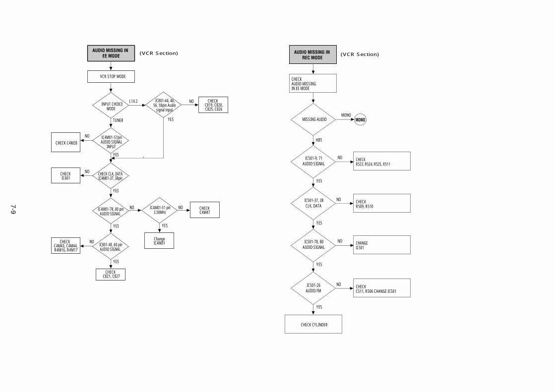
7-9
MISSING AUDIO
IC501-78, 80AUDIO SIGNAL
IC501-26AUDIO FM
CHECK CYLINDER
CHANGEIC501
CHECKC511, R506 CHANGE IC501
CHECKAUDIO MISSINGIN EE MODE
AUDIO MISSING INREC MODE
MONO
HIFI
MONO
NO
NO
YES
YES
IC501-9, 71AUDIO SIGNAL
IC501-37, 38CLK, DATA
CHECKR523, R524, R525, R511
CHECKR509, R510
NO
NO
YES
YES
(VCR Section)(VCR Section)
VCR STOP MODE
AUDIO MISSING IN EE MODE
IC801-44, 46,56, 58pin Audio
signal inputINPUT CHOICE
MODE
CHECK C4M28
CHECK IC601
CHECK C4M43, C4M44,R4M16, R4M17
CHECK C821, C827
CHECK C819, C820,C825, C826
L1/L2
NO
NO
NO NO
TUNER
YES
YES
YES
YES
IC4M01-78, 80 pinAUDIO SIGNAL
NO
YES
IC801-48, 60 pinAUDIO SIGNAL
ChangeIC4M01
CHECK C4M47
YES
IC4M01-51 pin3.58MHz
CHECK CLK, DATAIC4M01-37, 38pin
IC4M01-57pinAUDIO SIGNAL
INPUT
NO
(VCR Section)
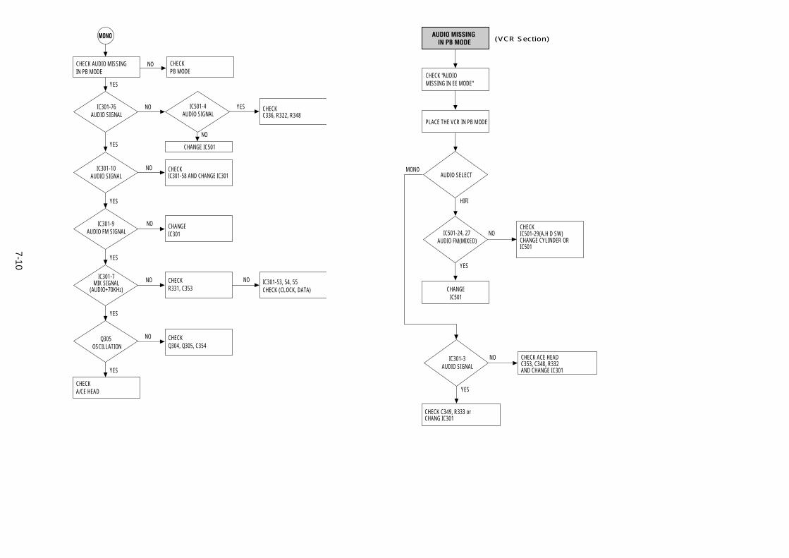
7-10
CHECK "AUDIO MISSING IN EE MODE"
PLACE THE VCR IN PB MODE
CHANGEIC501
AUDIO MISSING IN PB MODE
CHECK C349, R333 orCHANG IC301
CHECK ACE HEADC353, C348, R332AND CHANGE IC301
AUDIO SELECT
IC501-24, 27AUDIO FM(MIXED)
CHECK IC501-29(A.H D SW)CHANGE CYLINDER ORIC501
NO
HIFI
MONO
YES
IC301-3AUDIO SIGNAL
NO
YES
(VCR Section)
CHECK Q304, Q305, C354
CHECK R331, C353
CHANGEIC301
IC301-76AUDIO SIGNAL
IC501-4AUDIO SIGNAL
NO
NO
NO
IC301-53, 54, 55CHECK (CLOCK, DATA)
CHECK C336, R322, R348
YESNO
NO
NO
YES
YES
YES
YES
YES
YES
CHECK IC301-58 AND CHANGE IC301
CHANGE IC501
IC301-10AUDIO SIGNAL
IC301-9AUDIO FM SIGNAL
IC301-7MIX SIGNAL
(AUDIO+70KHz)
Q305OSCILLATION
NOCHECK AUDIO MISSINGIN PB MODE
CHECKPB MODE
CHECKA/CE HEAD
MONO
NO
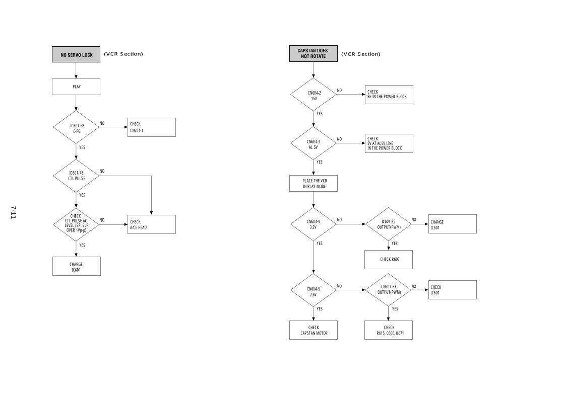
7-11
CAPSTAN DOES NOT ROTATE
PLACE THE VCRIN PLAY MODE
CN604-215V
CN604-3AL 5V
CN604-93.2V
CN604-52.6V
CN601-33OUTPUT(PWM)
IC601-35OUTPUT(PWM)
CHECKCAPSTAN MOTOR
CHECKR615, C606, R671
CHECK R607
CHANGEIC601
CHECK IC601
CHECKB+ IN THE POWER BLOCK
CHECK5V AT AL5V LINEIN THE POWER BLOCK
NO
NO NO
NO
YES
NO
YES
NO
YES
YES
YES YES
(VCR Section)
PLAY
NO SERVO LOCK
IC601-68C-FG
IC601-76CTL PULSE
CHECKCTL PULSE AC LEVEL (SP. SLP:OVER 1Vp-p)
CHANGEIC601
CHECK A/CE HEAD
CHECKCN604-1
NO
NO
NO
YES
YES
YES
(VCR Section)
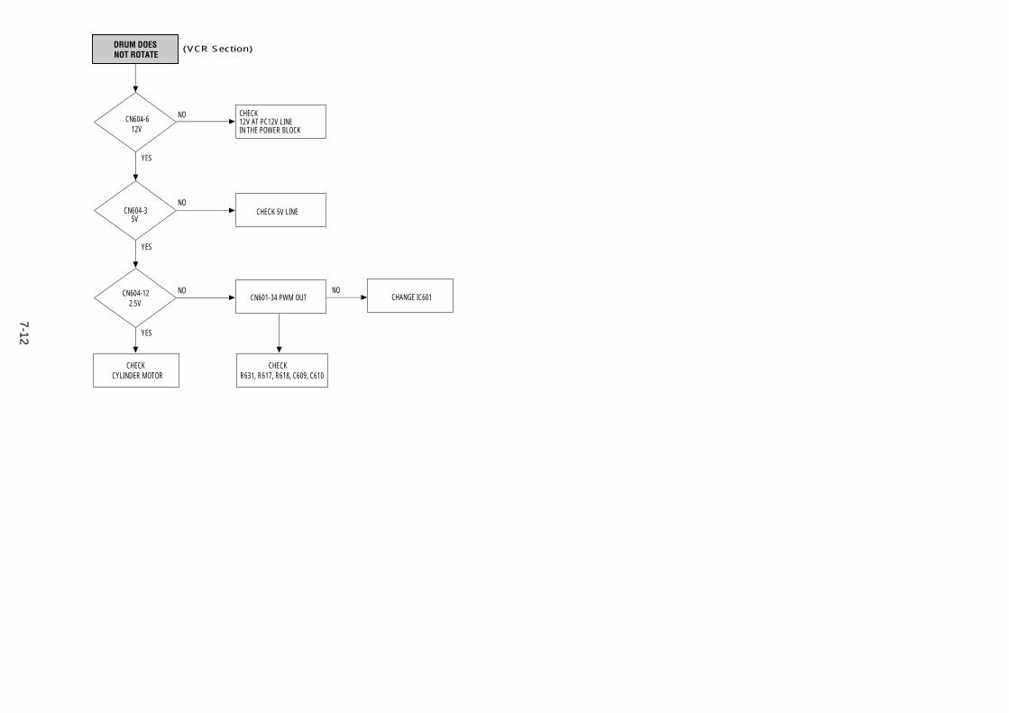
7-12
DRUM DOES NOT ROTATE
CN604-612V
CN604-35V
CN604-122.5V
CHECKCYLINDER MOTOR
CN601-34 PWM OUT
CHECK 5V LINE
CHECK12V AT PC12V LINEIN THE POWER BLOCK
NO
NO
NO
YES
YES
YES
CHANGE IC601NO
CHECKR631, R617, R618, C609, C610
(VCR Section)
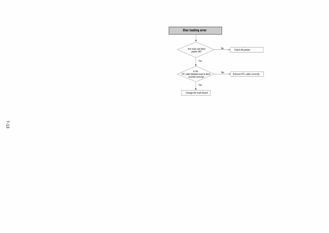
7-13
Are main and deck power OK?
Is the FFC cable (between main & deck)
inserted correctly?
Change the main board
Check the power
No
No
Reinsert FFC cable correctly
Yes
Yes
Disc loading error
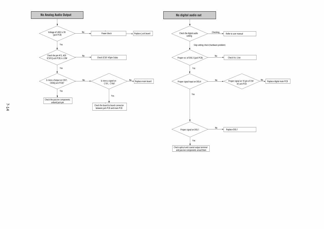
7-14
Check the digital audio setting
Proper vcc of DOL3 (jack PCB)
Check optical and coaxial output terminal and passive components aroud them
Refer to user manual
No
Checking
Check Vcc Line
Proper signal input on DOL4No
NoProper signal on DOL1 Replace DOL1
Yes
Yes
Yes
Skip setting check (hardware problem)
No digital audio out
Proper signal on 10 pin of CN1 of Jack PCB
NoReplace digital main PCB
Voltage of L802 is 9V(jack PCB)
Check the pin #13, #20IC501(Jack PCB) is LOW
Check the passive componentsardund jack pin
Power block
No
No
Check IC501 #3pin Sdata
Is trere a Output on C837,C836(Jack PCB)?
No No
Check the board to board connectorbetween jack PCB and main PCB
Yes
Yes
Yes
No Analog Audio Output
Is trere a signel onC191, C196?
Replace main board
Yes
Replace Jack board
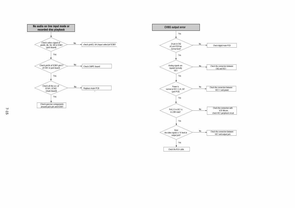
7-15
24 pin in CN2of Jack PCB has
normal level?
Check the RCA cable
NoCheck digital main PCB
Analog signals areinputed normally
VIC1
No
No
No
Check the connection betweenCN2 and VIC1
Power isnormal at VIC1-1,24, 34?
(jack PCB)
Pin5,12 in VIC1 isin LOW state?
Check the connection betweenVIC1-1 and power
Check the connection withVCR Micom.
check VIC1 peripheral circuit
Yes
NoDoosthe video signals is 1V level at
output jack?
Check the connection betweenVIC1 and output jack
CVBS output error
Yes
Yes
Yes
Yes
Yes
Check select signal of pin44, 46, 56, 58 in IC801
(jack board)
Check pin56 of IC801,pin17of CN1 in jack board
Check passive componentsaround jack-pin and IC801
check pin63, 64 (input select)of IC801
No
No
Check SMPS board
Check all the vcc of IC501, IC502 (main board)
NoReplace main PCB
Yes
Yes
Yes
No audio on line input mode or recorded disc playback
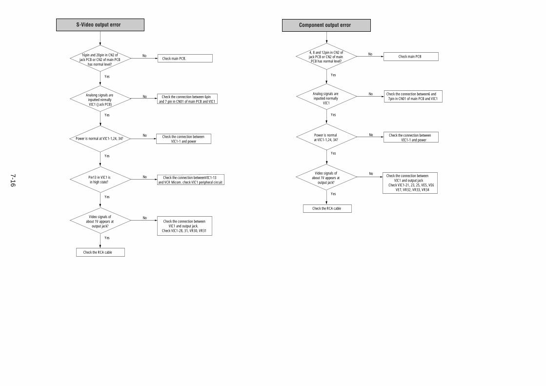
7-16
4, 8 and 12pin in CN2 ofjack PCB or CN2 of main
PCB has normal level?
Analog signals areinputted normally
VIC1
Check the RCA cable
Check main PCB
No
No
Check the connection between6 and 7pin in CN01 of main PCB and VIC1
Power is normal at VIC1-1,24, 34?
No
No
Check the connection betweenVIC1-1 and power
Video signals ofabout 1V appears at
output jack?
Check the connection betweenVIC1 and output jack
Check VIC1-21, 23, 25, VE5, VE6VE7, VR32, VR33, VR34
Yes
Yes
Component output error
Yes
Yes
16pin and 20pin in CN2 ofjack PCB or CN2 of main PCB
has normal level?
Check the RCA cable
NoCheck main PCB.
Analong signals areinputted nirmallyVIC1 (Jack PCB)
No
No
No
Check the connection between 6pin and 7 pin in CN01 of main PCB and VIC1
Power is normal at VIC1-1,24, 34?
Pin13 in VIC1 isin high state?
Check the connection betweenVIC1-1 and power
Check the connection betweenVIC1-13 and VCR Micom. check VIC1 peripheral circuit
Yes
Yes
Yes
Yes
NoVideo signals ofabout 1V appears at
output jack?Check the connection between
VIC1 and output jack.Check VIC1-28, 31, VR30, VR31
Yes
S-Video output error
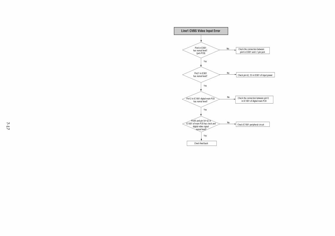
7-17
Pin4 in IC801has nomal level?
(jack PCB)
Pin21 in IC801has nomal level?
Check feed back
Check the connection between pin4 in IC801 and L1 pin-jack
No
No
Check pin 62, 55 in IC801 of input power
No
No
Pin12 in IC1001 digital main PCBhas nomal level?
Pin45 and pin 54~62 inIC1001 of main PCB has clock and
digital video signal nomal level?
Check the connection between pin12in IC1001 of digital main PCB
Check IC1001 peripheral circuit
Yes
Yes
Yes
Yes
Line1 CVBS Video Input Error
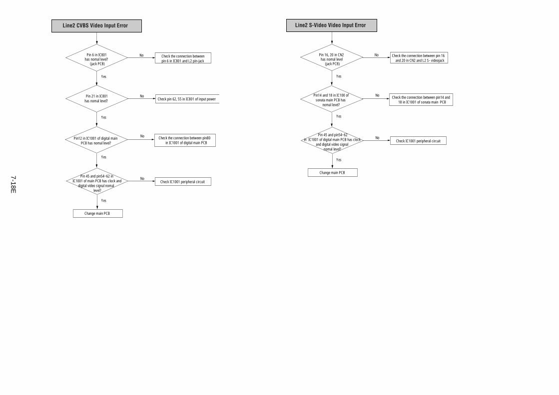
7-18E
Pin 16, 20 in CN2 has nomal level
(jack PCB)
Change main PCB
Check the connection between pin 16 and 20 in CN2 and L2 S- videojack
No
No
No
Pin14 and 18 in IC100 of sonata main PCB has
nomal level?
Pin 45 and pin54~62 in IC1001 of digital main PCB has clock
and digital video signalnomal level?
Check the connection between pin14 and18 in IC1001 of sonata main PCB
Check IC1001 peripheral circuit
Yes
Yes
Yes
Line2 S-Video Video Input Error
Pin 6 in IC801 has nomal level?
(jack PCB)
Pin 21 in IC801has nomal level?
Change main PCB
Check the connection betweenpin 6 in IC801 and L2 pin-jack
No
No
Check pin 62, 55 in IC801 of input power
No
No
Pin12 in IC1001 of digital main PCB has nomal level?
Pin 45 and pin54~62 in IC1001 of main PCB has clock and
digital video signal nomal level?
Check the connection between pin80in IC1001 of digital main PCB
Check IC1001 peripheral circuit
Yes
Yes
Yes
Yes
Line2 CVBS Video Input Error
8-1
RDR-VX511/VX515
8. REPAIR PARTS LIST
8-1 Exploded Views ----------------------------------------------------------------------8-2
8-1-1 Cabinet Assembly ---------------------------------------------------------------------------------- 8-2
8-1-2 VCR Mechanical Parts (Top Side) --------------------------------------------------------------- 8-3
8-1-3 VCR Mechanical Parts (Bottom Side) ----------------------------------------------------------- 8-4
8-2 Electrical Parts List ------------------------------------------------------------------8-5
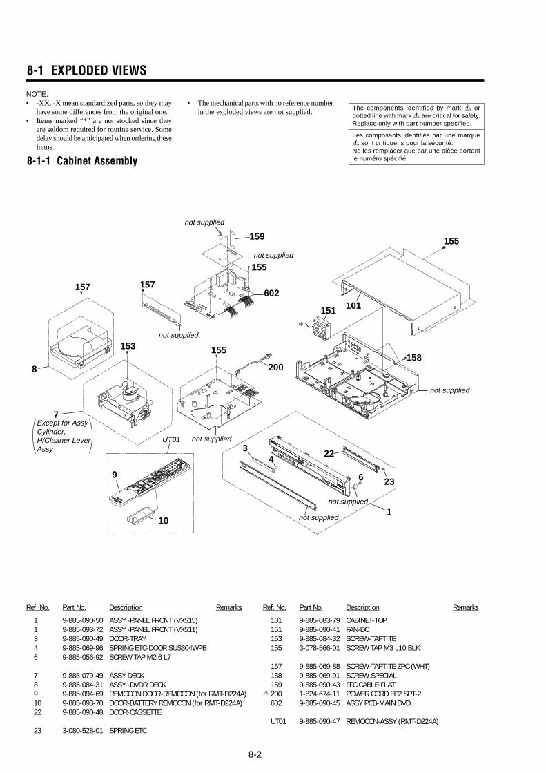
8-2
8-1-1 Cabinet Assembly
8-1 EXPLODED VIEWS
NOTE:• -XX, -X mean standardized parts, so they may
have some differences from the original one.• Items marked “*” are not stocked since they
are seldom required for routine service. Somedelay should be anticipated when ordering theseitems.
• The mechanical parts with no reference numberin the exploded views are not supplied.
Ref. No. Part No. Description Remarks Ref. No. Part No. Description Remarks
1 9-885-090-50 ASSY -PANEL FRONT (VX515)1 9-885-093-72 ASSY -PANEL FRONT (VX511)3 9-885-090-49 DOOR-TRAY4 9-885-069-96 SPRING ETC-DOOR SUS304WPB6 9-885-056-92 SCREW TAP M2.6 L7
7 9-885-079-49 ASSY DECK8 9-885-084-31 ASSY -DVDR DECK9 9-885-094-69 REMOCON DOOR-REMOCON (for RMT-D224A)10 9-885-093-70 DOOR-BATTERY REMOCON (for RMT-D224A)22 9-885-090-48 DOOR-CASSETTE
23 3-080-528-01 SPRING ETC
101 9-885-083-79 CABINET-TOP151 9-885-090-41 FAN-DC153 9-885-084-32 SCREW-TAPTITE155 3-078-566-01 SCREW TAP M3 L10 BLK
157 9-885-069-88 SCREW-TAPTITE ZPC (WHT)158 9-885-069-91 SCREW-SPECIAL159 9-885-090-43 FFC CABLE-FLAT
0200 1-824-674-11 POWER CORD EP2 SPT-2602 9-885-090-45 ASSY PCB-MAIN DVD
UT01 9-885-090-47 REMOCON-ASSY (RMT-D224A)
22
23
1
101
157
153
155
155
151
602
200
155
not supplied
not supplied
not supplied
not supplied
not supplied
157
159
9
34
6
8
7Except for Assy Cylinder,H/Cleaner LeverAssy
158
UT01
10 not supplied
not supplied
The components identified by mark 0 ordotted line with mark 0 are critical for safety.Replace only with part number specified.
Les composants identifiés par une marque0 sont critiquens pour la sécurité.Ne les remplacer que par une pièce portantle numéro spécifié.
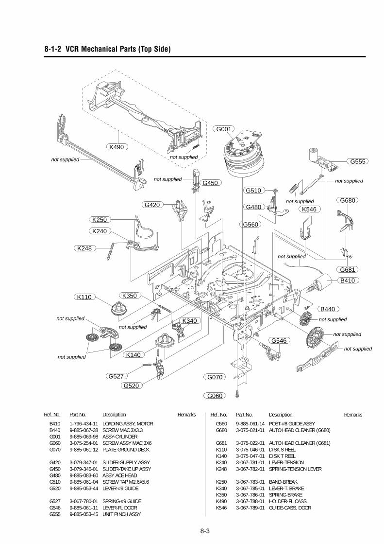
8-3
Ref. No. Part No. Description Remarks Ref. No. Part No. Description Remarks
B410 1-796-434-11 LOADING ASSY, MOTORB440 9-885-067-38 SCREW MAC 3X3.3G001 9-885-069-98 ASSY-CYLINDERG060 3-075-254-01 SCREW ASSY MAC 3X6G070 9-885-061-12 PLATE-GROUND DECK
G420 3-079-347-01 SLIDER-SUPPLY ASSYG450 3-079-346-01 SLIDER-TAKE UP ASSYG480 9-885-083-60 ASSY ACE HEADG510 9-885-061-04 SCREW TAP M2.6X5.6G520 9-885-053-44 LEVER-#9 GUIDE
G527 3-067-780-01 SPRING-#9 GUIDEG546 9-885-061-11 LEVER-FL DOORG555 9-885-053-45 UNIT PINCH ASSY
8-1-2 VCR Mechanical Parts (Top Side)
G560
G001
G555
G510
G480 K546
B410
B440
G546
G060
G520
G527
K110
K240
K248
K350
K140
K340
G070
K250
K490
G420
G450
G681
G680
not supplied not supplied
not supplied
not supplied
not supplied
not supplied
not supplied
not supplied
not supplied
not supplied
not supplied
not supplied
G560 9-885-061-14 POST-#8 GUIDE ASSYG680 3-075-021-01 AUTO HEAD CLEANER (G680)
G681 3-075-022-01 AUTO HEAD CLEANER (G681)K110 3-075-046-01 DISK S REELK140 3-075-047-01 DISK T REELK240 3-067-781-01 LEVER-TENSIONK248 3-067-782-01 SPRING-TENSION LEVER
K250 3-067-783-01 BAND-BREAKK340 3-067-785-01 LEVER-T. BRAKEK350 3-067-786-01 SPRING-BRAKEK490 3-067-788-01 HOLDER-FL CASS.K546 3-067-789-01 GUIDE-CASS. DOOR
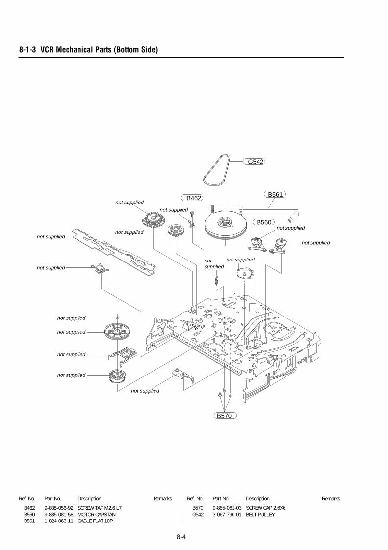
8-4
8-1-3 VCR Mechanical Parts (Bottom Side)
B462 9-885-056-92 SCREW TAP M2.6 L7B560 9-885-081-58 MOTOR CAPSTANB561 1-824-063-11 CABLE FLAT 10P
Ref. No. Part No. Description Remarks Ref. No. Part No. Description Remarks
G542
B462
B560
B570
not supplied
not supplied
not supplied
not supplied
not supplied
not supplied
not suppliednot supplied
not suppliednot supplied
not supplied
not supplied
not supplied
not supplied
B561
B570 9-885-061-03 SCREW CAP 2.6X6G542 3-067-790-01 BELT-PULLEY
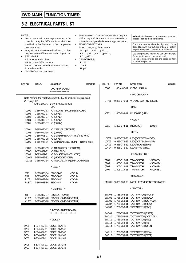
8-5
NOTE:• Due to standardization, replacements in the
parts list may be different from the partsspecified in the diagrams or the componentsused on the set.
• -XX, and -X mean standardized parts, so theymay have some difference from the original one.
• RESISTORSAll resistors are in ohms.METAL: metal-film resistorMETAL OXIDE: Metal Oxide-film resistorF: nonflammable
• Not all of the parts are listed.
• Items marked “*” are not stocked since they areseldom required for routine service. Some delayshould be anticipated when ordering these items.
• SEMICONDUCTORSIn each case, u: µ, for example:uA...: µA... , uPA... , µPA... ,uPB... , µPB... , uPC... , µPC... ,uPD..., µPD...
• CAPACITORS:uF: µF
• COILSuH: µH
8-2 ELECTRICAL PARTS LIST
Ref. No. Part No. Description Remarks Ref. No. Part No. Description Remarks
When indicating parts by reference number,please include the board name.
DVD MAIN
The components identified by mark 0 ordotted line with mark 0 are critical for safety.Replace only with part number specified.
Les composants identifiés par une marque0 sont critiquens pour la sécurité.Ne les remplacer que par une pièce portantle numéro spécifié.
DVD MAIN BOARD
IC101 9-885-070-63 IC CS92686 (ENCODER/DECODER)IC102 9-885-090-37 IC (DRAM)IC103 9-885-090-37 IC (DRAM)IC104 9-885-090-37 IC (DRAM)IC105 9-885-090-37 IC (DRAM)
IC201 9-885-070-62 IC CS98201 (DECODER)IC202 9-885-090-38 IC (DRAM)IC203 9-885-095-27 IC (FLASH MEMORY) (Refer to Note)IC204 9-885-090-38 IC (DRAM)IC205 9-885-097-54 IC 524AB0X91 (EEPROM) (Refer to Note)
IC206 9-885-090-39 IC G9966 (POSI.FIXED REG.)IC302 1-805-039-11 IC M74HCU04IC303 9-885-079-21 IC 74VHC125 (CMOS LOGIC)IC1001 9-885-083-82 IC (VIDEO DECODER)IC1301 9-885-070-64 IC TSB41AB1-PAP (DATA COMM/GEN)
< BEAD >
R39 9-885-083-84 BEAD-SMD 47 OHMR64 9-885-083-84 BEAD-SMD 47 OHMR103 9-885-083-84 BEAD-SMD 47 OHMR1307 9-885-083-84 BEAD-SMD 47 OHM
< VIBRATOR >
X3 9-885-067-37 CRYSTAL (27MHz)X1001 9-885-070-70 CRYSTAL-SMD (24.576MHz)X1301 9-885-070-70 CRYSTAL-SMD (24.576MHz)
FUNCTION TIMER BOARD*********************
< DIODE >
D701 1-804-407-11 DIODE 1N4148D702 1-804-407-11 DIODE 1N4148D703 1-804-407-11 DIODE 1N4148D704 1-804-407-11 DIODE 1N4148D705 1-804-407-11 DIODE 1N4148
D706 1-804-407-11 DIODE 1N4148D707 1-804-407-11 DIODE 1N4148
D708 1-804-407-11 DIODE 1N4148
< VFD DISPLAY >
DT701 9-885-070-01 VFD DISPLAY HNV-10SM40
< IC >
IC701 1-805-299-11 IC PT6315 (VFD)
< COIL >
L701 1-400-074-11 INDUCTOR 100uH
< LED >
LD701 9-885-079-26 LED (COPY VCRtDVD)LD702 9-885-079-26 LED (COPY DVDtVCR)LD703 9-885-076-82 LED (PROGRESSIVE)LD704 9-885-076-83 LED (SYNCRO REC)
< TRANSISTOR >
Q701 1-805-016-11 TRANSISTOR KSC1623-LQ702 1-805-016-11 TRANSISTOR KSC1623-LQ703 1-805-016-11 TRANSISTOR KSC1623-LQ704 1-805-016-11 TRANSISTOR KSC1623-L
< MODULE >
RM701 9-885-069-95 MODULE REMOCON TSOP2240RF1
< SWITCH >
SW703 1-786-353-11 TACT SWITCH (PAUSE)SW705 1-786-353-11 TACT SWITCH (VIDEO)SW706 1-786-353-11 TACT SWITCH (COPYD2V)SW707 1-786-353-11 TACT SWITCH (PLAY)SW708 1-786-353-11 TACT SWITCH (DVD)
SW709 1-786-353-11 TACT SWITCH (EJECT)SW710 1-786-353-11 TACT SWITCH (COPYV2D)SW711 1-786-353-11 TACT SWITCH (REC)SW713 1-786-353-11 TACT SWITCH (FF)SW714 1-786-353-11 TACT SWITCH (OPEN)
SW715 1-786-353-11 TACT SWITCH (REW)SW716 1-786-353-11 TACT SWITCH (STOP)
FUNCTION TIMER
***************
Note:Perform the reset whenever the IC203 or IC205 was replaced. (See page 10)
9-885-090-45 ASSY PCB-MAIN DVD<IC>
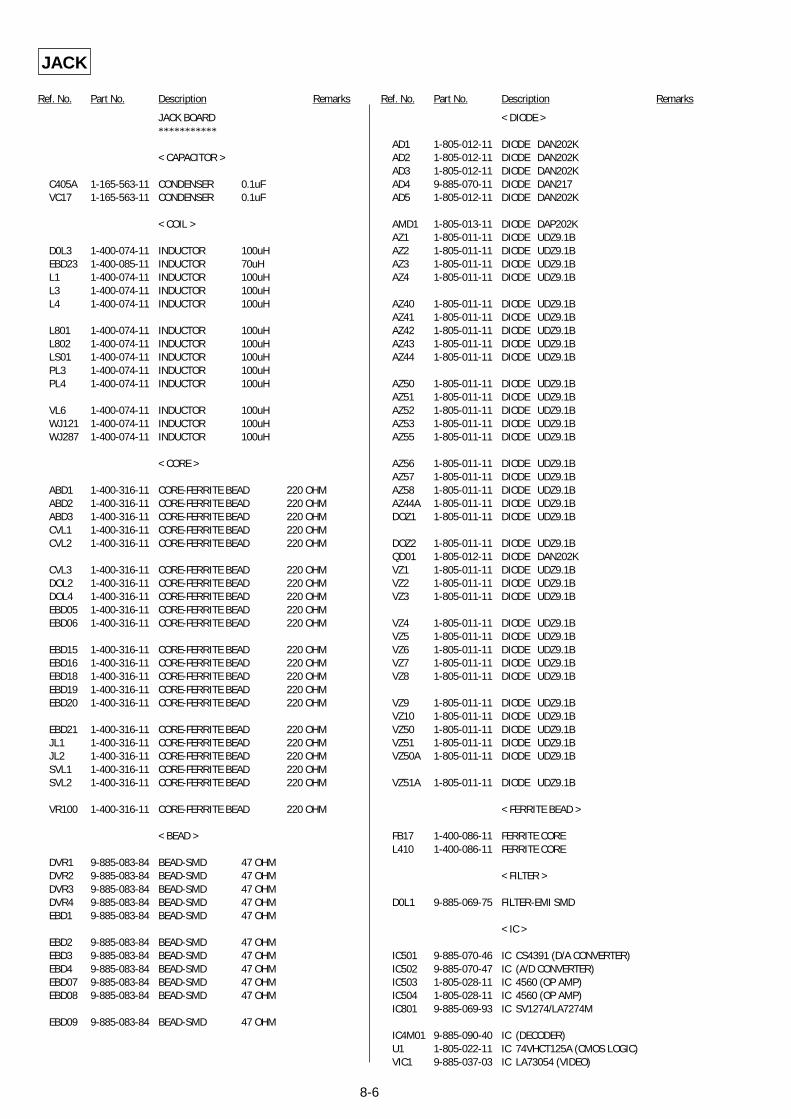
8-6
Ref. No. Part No. Description Remarks Ref. No. Part No. Description Remarks
JACK
JACK BOARD***********
< CAPACITOR >
C405A 1-165-563-11 CONDENSER 0.1uFVC17 1-165-563-11 CONDENSER 0.1uF
< COIL >
D0L3 1-400-074-11 INDUCTOR 100uHEBD23 1-400-085-11 INDUCTOR 70uHL1 1-400-074-11 INDUCTOR 100uHL3 1-400-074-11 INDUCTOR 100uHL4 1-400-074-11 INDUCTOR 100uH
L801 1-400-074-11 INDUCTOR 100uHL802 1-400-074-11 INDUCTOR 100uHLS01 1-400-074-11 INDUCTOR 100uHPL3 1-400-074-11 INDUCTOR 100uHPL4 1-400-074-11 INDUCTOR 100uH
VL6 1-400-074-11 INDUCTOR 100uHWJ121 1-400-074-11 INDUCTOR 100uHWJ287 1-400-074-11 INDUCTOR 100uH
< CORE >
ABD1 1-400-316-11 CORE-FERRITE BEAD 220 OHMABD2 1-400-316-11 CORE-FERRITE BEAD 220 OHMABD3 1-400-316-11 CORE-FERRITE BEAD 220 OHMCVL1 1-400-316-11 CORE-FERRITE BEAD 220 OHMCVL2 1-400-316-11 CORE-FERRITE BEAD 220 OHM
CVL3 1-400-316-11 CORE-FERRITE BEAD 220 OHMDOL2 1-400-316-11 CORE-FERRITE BEAD 220 OHMDOL4 1-400-316-11 CORE-FERRITE BEAD 220 OHMEBD05 1-400-316-11 CORE-FERRITE BEAD 220 OHMEBD06 1-400-316-11 CORE-FERRITE BEAD 220 OHM
EBD15 1-400-316-11 CORE-FERRITE BEAD 220 OHMEBD16 1-400-316-11 CORE-FERRITE BEAD 220 OHMEBD18 1-400-316-11 CORE-FERRITE BEAD 220 OHMEBD19 1-400-316-11 CORE-FERRITE BEAD 220 OHMEBD20 1-400-316-11 CORE-FERRITE BEAD 220 OHM
EBD21 1-400-316-11 CORE-FERRITE BEAD 220 OHMJL1 1-400-316-11 CORE-FERRITE BEAD 220 OHMJL2 1-400-316-11 CORE-FERRITE BEAD 220 OHMSVL1 1-400-316-11 CORE-FERRITE BEAD 220 OHMSVL2 1-400-316-11 CORE-FERRITE BEAD 220 OHM
VR100 1-400-316-11 CORE-FERRITE BEAD 220 OHM
< BEAD >
DVR1 9-885-083-84 BEAD-SMD 47 OHMDVR2 9-885-083-84 BEAD-SMD 47 OHMDVR3 9-885-083-84 BEAD-SMD 47 OHMDVR4 9-885-083-84 BEAD-SMD 47 OHMEBD1 9-885-083-84 BEAD-SMD 47 OHM
EBD2 9-885-083-84 BEAD-SMD 47 OHMEBD3 9-885-083-84 BEAD-SMD 47 OHMEBD4 9-885-083-84 BEAD-SMD 47 OHMEBD07 9-885-083-84 BEAD-SMD 47 OHMEBD08 9-885-083-84 BEAD-SMD 47 OHM
EBD09 9-885-083-84 BEAD-SMD 47 OHM
< DIODE >
AD1 1-805-012-11 DIODE DAN202KAD2 1-805-012-11 DIODE DAN202KAD3 1-805-012-11 DIODE DAN202KAD4 9-885-070-11 DIODE DAN217AD5 1-805-012-11 DIODE DAN202K
AMD1 1-805-013-11 DIODE DAP202KAZ1 1-805-011-11 DIODE UDZ9.1BAZ2 1-805-011-11 DIODE UDZ9.1BAZ3 1-805-011-11 DIODE UDZ9.1BAZ4 1-805-011-11 DIODE UDZ9.1B
AZ40 1-805-011-11 DIODE UDZ9.1BAZ41 1-805-011-11 DIODE UDZ9.1BAZ42 1-805-011-11 DIODE UDZ9.1BAZ43 1-805-011-11 DIODE UDZ9.1BAZ44 1-805-011-11 DIODE UDZ9.1B
AZ50 1-805-011-11 DIODE UDZ9.1BAZ51 1-805-011-11 DIODE UDZ9.1BAZ52 1-805-011-11 DIODE UDZ9.1BAZ53 1-805-011-11 DIODE UDZ9.1BAZ55 1-805-011-11 DIODE UDZ9.1B
AZ56 1-805-011-11 DIODE UDZ9.1BAZ57 1-805-011-11 DIODE UDZ9.1BAZ58 1-805-011-11 DIODE UDZ9.1BAZ44A 1-805-011-11 DIODE UDZ9.1BDOZ1 1-805-011-11 DIODE UDZ9.1B
DOZ2 1-805-011-11 DIODE UDZ9.1BQD01 1-805-012-11 DIODE DAN202KVZ1 1-805-011-11 DIODE UDZ9.1BVZ2 1-805-011-11 DIODE UDZ9.1BVZ3 1-805-011-11 DIODE UDZ9.1B
VZ4 1-805-011-11 DIODE UDZ9.1BVZ5 1-805-011-11 DIODE UDZ9.1BVZ6 1-805-011-11 DIODE UDZ9.1BVZ7 1-805-011-11 DIODE UDZ9.1BVZ8 1-805-011-11 DIODE UDZ9.1B
VZ9 1-805-011-11 DIODE UDZ9.1BVZ10 1-805-011-11 DIODE UDZ9.1BVZ50 1-805-011-11 DIODE UDZ9.1BVZ51 1-805-011-11 DIODE UDZ9.1BVZ50A 1-805-011-11 DIODE UDZ9.1B
VZ51A 1-805-011-11 DIODE UDZ9.1B
< FERRITE BEAD >
FB17 1-400-086-11 FERRITE COREL410 1-400-086-11 FERRITE CORE
< FILTER >
D0L1 9-885-069-75 FILTER-EMI SMD
< IC >
IC501 9-885-070-46 IC CS4391 (D/A CONVERTER)IC502 9-885-070-47 IC (A/D CONVERTER)IC503 1-805-028-11 IC 4560 (OP AMP)IC504 1-805-028-11 IC 4560 (OP AMP)IC801 9-885-069-93 IC SV1274/LA7274M
IC4M01 9-885-090-40 IC (DECODER)U1 1-805-022-11 IC 74VHCT125A (CMOS LOGIC)VIC1 9-885-037-03 IC LA73054 (VIDEO)
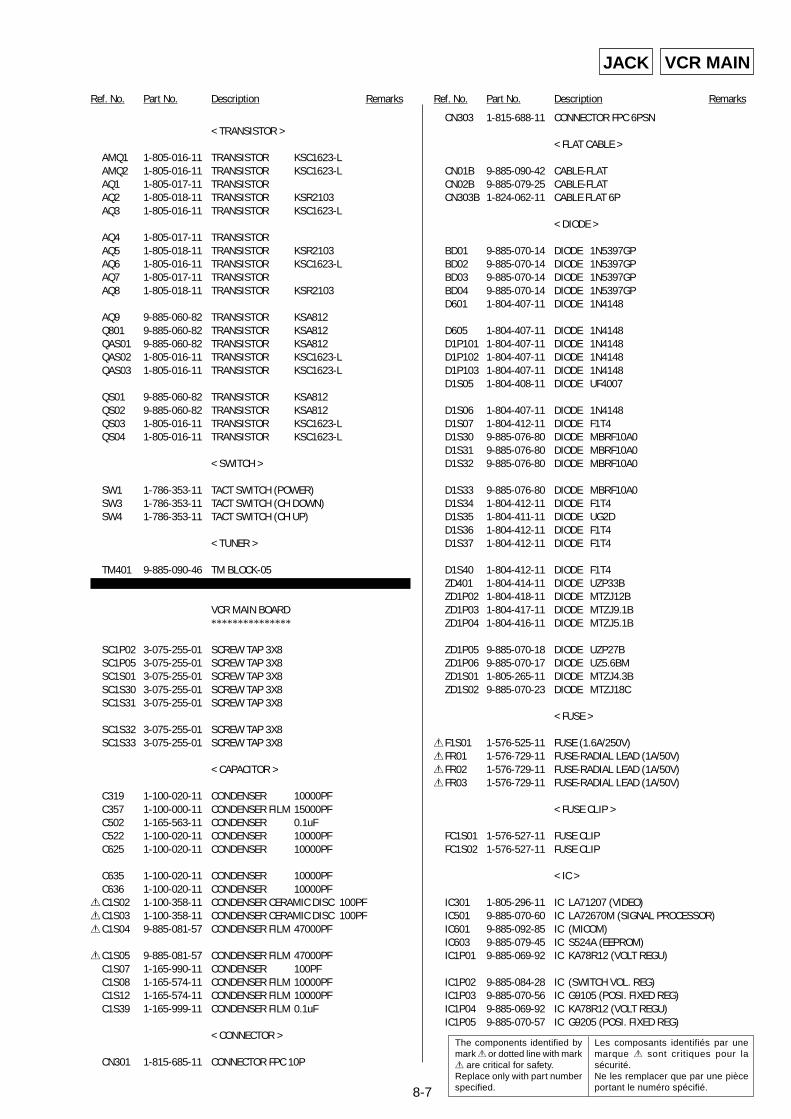
8-7
Ref. No. Part No. Description Remarks Ref. No. Part No. Description Remarks
VCR MAIN
< TRANSISTOR >
AMQ1 1-805-016-11 TRANSISTOR KSC1623-LAMQ2 1-805-016-11 TRANSISTOR KSC1623-LAQ1 1-805-017-11 TRANSISTORAQ2 1-805-018-11 TRANSISTOR KSR2103AQ3 1-805-016-11 TRANSISTOR KSC1623-L
AQ4 1-805-017-11 TRANSISTORAQ5 1-805-018-11 TRANSISTOR KSR2103AQ6 1-805-016-11 TRANSISTOR KSC1623-LAQ7 1-805-017-11 TRANSISTORAQ8 1-805-018-11 TRANSISTOR KSR2103
AQ9 9-885-060-82 TRANSISTOR KSA812Q801 9-885-060-82 TRANSISTOR KSA812QAS01 9-885-060-82 TRANSISTOR KSA812QAS02 1-805-016-11 TRANSISTOR KSC1623-LQAS03 1-805-016-11 TRANSISTOR KSC1623-L
QS01 9-885-060-82 TRANSISTOR KSA812QS02 9-885-060-82 TRANSISTOR KSA812QS03 1-805-016-11 TRANSISTOR KSC1623-LQS04 1-805-016-11 TRANSISTOR KSC1623-L
< SWITCH >
SW1 1-786-353-11 TACT SWITCH (POWER)SW3 1-786-353-11 TACT SWITCH (CH DOWN)SW4 1-786-353-11 TACT SWITCH (CH UP)
< TUNER >
TM401 9-885-090-46 TM BLOCK-05
VCR MAIN BOARD***************
SC1P02 3-075-255-01 SCREW TAP 3X8SC1P05 3-075-255-01 SCREW TAP 3X8SC1S01 3-075-255-01 SCREW TAP 3X8SC1S30 3-075-255-01 SCREW TAP 3X8SC1S31 3-075-255-01 SCREW TAP 3X8
SC1S32 3-075-255-01 SCREW TAP 3X8SC1S33 3-075-255-01 SCREW TAP 3X8
< CAPACITOR >
C319 1-100-020-11 CONDENSER 10000PFC357 1-100-000-11 CONDENSER FILM 15000PFC502 1-165-563-11 CONDENSER 0.1uFC522 1-100-020-11 CONDENSER 10000PFC625 1-100-020-11 CONDENSER 10000PF
C635 1-100-020-11 CONDENSER 10000PFC636 1-100-020-11 CONDENSER 10000PF
0C1S02 1-100-358-11 CONDENSER CERAMIC DISC 100PF0C1S03 1-100-358-11 CONDENSER CERAMIC DISC 100PF0C1S04 9-885-081-57 CONDENSER FILM 47000PF
0C1S05 9-885-081-57 CONDENSER FILM 47000PFC1S07 1-165-990-11 CONDENSER 100PFC1S08 1-165-574-11 CONDENSER FILM 10000PFC1S12 1-165-574-11 CONDENSER FILM 10000PFC1S39 1-165-999-11 CONDENSER FILM 0.1uF
< CONNECTOR >
CN301 1-815-685-11 CONNECTOR FPC 10P
CN303 1-815-688-11 CONNECTOR FPC 6PSN
< FLAT CABLE >
CN01B 9-885-090-42 CABLE-FLATCN02B 9-885-079-25 CABLE-FLATCN303B 1-824-062-11 CABLE FLAT 6P
< DIODE >
BD01 9-885-070-14 DIODE 1N5397GPBD02 9-885-070-14 DIODE 1N5397GPBD03 9-885-070-14 DIODE 1N5397GPBD04 9-885-070-14 DIODE 1N5397GPD601 1-804-407-11 DIODE 1N4148
D605 1-804-407-11 DIODE 1N4148D1P101 1-804-407-11 DIODE 1N4148D1P102 1-804-407-11 DIODE 1N4148D1P103 1-804-407-11 DIODE 1N4148D1S05 1-804-408-11 DIODE UF4007
D1S06 1-804-407-11 DIODE 1N4148D1S07 1-804-412-11 DIODE F1T4D1S30 9-885-076-80 DIODE MBRF10A0D1S31 9-885-076-80 DIODE MBRF10A0D1S32 9-885-076-80 DIODE MBRF10A0
D1S33 9-885-076-80 DIODE MBRF10A0D1S34 1-804-412-11 DIODE F1T4D1S35 1-804-411-11 DIODE UG2DD1S36 1-804-412-11 DIODE F1T4D1S37 1-804-412-11 DIODE F1T4
D1S40 1-804-412-11 DIODE F1T4ZD401 1-804-414-11 DIODE UZP33BZD1P02 1-804-418-11 DIODE MTZJ12BZD1P03 1-804-417-11 DIODE MTZJ9.1BZD1P04 1-804-416-11 DIODE MTZJ5.1B
ZD1P05 9-885-070-18 DIODE UZP27BZD1P06 9-885-070-17 DIODE UZ5.6BMZD1S01 1-805-265-11 DIODE MTZJ4.3BZD1S02 9-885-070-23 DIODE MTZJ18C
< FUSE >
0F1S01 1-576-525-11 FUSE (1.6A/250V)0FR01 1-576-729-11 FUSE-RADIAL LEAD (1A/50V)0FR02 1-576-729-11 FUSE-RADIAL LEAD (1A/50V)0FR03 1-576-729-11 FUSE-RADIAL LEAD (1A/50V)
< FUSE CLIP >
FC1S01 1-576-527-11 FUSE CLIPFC1S02 1-576-527-11 FUSE CLIP
< IC >
IC301 1-805-296-11 IC LA71207 (VIDEO)IC501 9-885-070-60 IC LA72670M (SIGNAL PROCESSOR)IC601 9-885-092-85 IC (MICOM)IC603 9-885-079-45 IC S524A (EEPROM)IC1P01 9-885-069-92 IC KA78R12 (VOLT REGU)
IC1P02 9-885-084-28 IC (SWITCH VOL. REG)IC1P03 9-885-070-56 IC G9105 (POSI. FIXED REG)IC1P04 9-885-069-92 IC KA78R12 (VOLT REGU)IC1P05 9-885-070-57 IC G9205 (POSI. FIXED REG)
JACK
The components identified bymark 0 or dotted line with mark0 are critical for safety.Replace only with part numberspecified.
Les composants identifiés par unemarque 0 sont critiques pour lasécurité.Ne les remplacer que par une pièceportant le numéro spécifié.
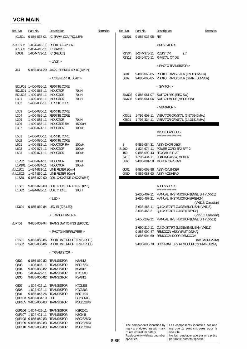
8-8
Ref. No. Part No. Description Remarks Ref. No. Part No. Description Remarks
IC1S01 9-885-037-01 IC (PWM CONTROLLER)
0 IC1S02 1-804-440-11 PHOTO COUPLERIC1S03 1-804-445-11 IC KA4318IC6B1 1-804-773-11 IC (RESET)
< JACK >
J1J 9-885-084-29 JACK-IEEE1394 4P/1C (DV IN)
< COIL/FERRITE BEAD >
BD1P01 1-400-086-11 FERRITE COREBD1S01 1-400-085-11 INDUCTOR 70uHBD1S02 1-400-085-11 INDUCTOR 70uHL301 1-400-085-11 INDUCTOR 70uHL302 1-400-086-11 FERRITE CORE
L303 1-400-086-11 FERRITE COREL304 1-400-086-11 FERRITE COREL305 1-400-085-11 INDUCTOR 70uHL306 1-400-083-11 INDUCTOR RA 1500uHL307 1-400-074-11 INDUCTOR 100uH
L501 1-400-086-11 FERRITE COREL502 1-400-086-11 FERRITE COREL601 1-400-082-11 INDUCTOR RA 100uHL602 1-400-074-11 INDUCTOR 100uHL603 1-400-074-11 INDUCTOR 100uH
L1P02 1-400-074-11 INDUCTOR 100uHL1P101 1-400-074-11 INDUCTOR 100uH
0L1S01 1-424-831-11 LINE FILTER 20mH0L1S02 1-424-830-11 LINE FILTER 30mH
L1S30 9-885-070-00 COIL CHOKE DR CHOKE (8*6)
L1S31 9-885-070-00 COIL CHOKE DR CHOKE (8*6)L1S32 1-424-828-11 COIL CHOKE 10uH
< LED >
LD601 9-885-060-84 LED-IR (T/S LED)
< TRANSFORMER >
0PT01 9-885-069-94 TRANS SWITCHING EER3531
< PHOTO INTERRUPTER >
PT601 9-885-060-86 PHOTO INTERRUPTER (S-REEL)PT602 9-885-060-86 PHOTO INTERRUPTER (R-REEL)
< TRANSISTOR >
Q302 9-885-060-82 TRANSISTOR KSA812Q303 1-805-016-11 TRANSISTOR KSC1623-LQ304 9-885-060-82 TRANSISTOR KSA812Q305 1-804-422-11 TRANSISTOR KTC3203Q306 9-885-060-82 TRANSISTOR KSA812
Q307 1-804-422-11 TRANSISTOR KTC3203Q308 1-804-422-11 TRANSISTOR KTC3203Q601 9-885-043-26 TRANSISTOR KSR1104Q1P103 9-885-084-19 FET GFP50N03Q1P105 9-885-060-83 TRANSISTOR KSC2328AY
Q1P106 1-804-429-11 TRANSISTOR KSR2001Q1P107 1-804-421-11 TRANSISTOR KSC945Q1P108 9-885-060-83 TRANSISTOR KSC2328AYQ1P109 9-885-060-83 TRANSISTOR KSC2328AYQ1P110 9-885-060-83 TRANSISTOR KSC2328AY
Q1S01 9-885-036-95 FET
< RESISTOR >
R1S04 1-244-373-11 RESISTOR 2.7R1S13 1-245-575-11 R-METAL OXIDE
< PHOTO TRANSISTOR >
S601 9-885-060-85 PHOTO TRANSISTOR (END SENSOR)S602 9-885-060-85 PHOTO TRANSISTOR (START SENSOR)
< SWITCH >
SW602 9-885-061-07 SWITCH REC (REC-SW)SW603 9-885-061-06 SWITCH MODE (MODE-SW)
< VIBRATOR >
XT301 1-795-603-11 VIBRATOR CRYSTAL (3.579545MHz)XT601 1-795-334-11 VIBRATOR CRYSTAL (14.31818MHz)
MISCELLANEOUS***************
8 9-885-084-31 ASSY-DVDR DECK0200 1-824-674-11 POWER CORD EP2 SPT-2
159 9-885-090-43 FFC CABLE-FLATB410 1-796-434-11 LOADING ASSY, MOTORB560 9-885-081-58 MOTOR CAPSTAN
G001 9-885-069-98 ASSY-CYLINDERG480 9-885-083-60 ASSY ACE HEAD
ACCESSORIES************
2-636-467-11 MANUAL, INSTRUCTION (ENGLISH) (VX515)2-636-467-21 MANUAL, INSTRUCTION (FRENCH)
(VX515: Canadian)2-636-468-11 QUICK START GUIDE (ENGLISH) (VX515)2-636-468-21 QUICK START GUIDE (FRENCH)
(VX515: Canadian)2-650-209-11 MANUAL, INSTRUCTION (ENGLISH) (VX511)
2-650-210-11 QUICK START GUIDE (ENGLISH) (VX511)9-885-090-47 REMOCON-ASSY (RMT-D224A)9-885-094-69 REMOCOM DOOR-REMOCOM
(for RMT-D224A)9-885-093-70 DOOR-BATTERY REMOCOM (for RMT-D224A)
VCR MAIN
8-8E
The components identified bymark 0 or dotted line with mark0 are critical for safety.Replace only with part numberspecified.
Les composants identifiés par unemarque 0 sont critiques pour lasécurité.Ne les remplacer que par une pièceportant le numéro spécifié.
— 152 —
RDR-VX511/VX515
Sony CorporationHome Electronics Network Company
9-874-886-11
2005G0500-1 © 2005.7
Published by Quality Assurance Dept.