Derivation of Arc Length Calculation for DC High Voltage Arc ...
Upload
khangminh22Category
view
0download
0
1Please read and understand this instruction manual carefully before the installation and operation of this equipment.
OPERATING MANUALKUMJRRW200 KUMJRRW160
© Welding Guns Of Australia PTY LTD 2015
YEARS Warranty
(Power Source)3

3

3
WARRANTY• 3 Years from date of purchase.
• Welding Guns Of Australia PTY LTD Ltd warranties all goods as specified by the manufacturer of those goods.
• This Warranty does not cover freight or goods that have been interfered with.
• All goods in question must be repaired by an authorised repair agent as appointed by this company.
• Warranty does not cover abuse, mis-use, accident, theft, general wear and tear.
• New product will not be supplied unless Welding Guns Of Australia PTY LTD has inspected productreturnedforwarrantyandagree’storeplaceproduct.
• Product will only be replaced if repair is not possible
• Please view full Warranty term and conditions supplied with machine or at www.unimig.com.au/ warranty.asp or at the back of this manual.
Thank you for your purchase of your UNI-MIG welding machine.We are proud of our range of welding equipment that has a proven track record of innovation, performance and reliability.Our product range represents the latest developments in Inverter technology put together by our professional team of highly skilled engineers. The expertise gained from our long involvement with inverter technology has proven to be invaluable towards the evolution and future development of our equipment range. This experience gives us the inside knowledge on what the arc characteris-tics, performance and interface between man and machine should be. Within our team are specialist welders that have a proven history of welding knowledge and exper-tise, giving vital input towards ensuring that our machines deliver control and performance to the utmost professional level. We employ an expert team of professional sales, marketing and technical personnel that provide us with market trends, market feedback and customer comments and requirements. Secondly they provide a customer support service that is second to none, thus ensuring our customers have con-fidencethattheywillbewellsatisfiedbothnowandinthefuture.UNI-MIG welders are manufactured and compliant with - AS/NZ60974.1 2006 - AS60974-6:2006 guaranteeing you electrical safety and performance.
CONTENTS PAGEWarranty 2Safety 4-5Technical Data, Product Information 6 Machine Layout Descriptions 7Installation & Operation for MMA (stick) Welding 8MMA General Description 9-11 Installation & Operation for DC TIG Welding with Lift Arc 12-13DC TIG General Description 14-16 26V TIG Torch Parts Breakdown 18-19 MMA (Stick) Welding Trouble Shooting 20TIG Welding Trouble Shooting 21-22SaprePartIdentification 23Warranty terms 24-27

4 5
SAFETY
Welding and cutting equipment can be dangerous to both the operator and people in or near the surrounding working area, if the equipment is not correctly operated. Equipment must only be used under the strict and comprehensive observance of all relevant safety regulations. Read and understand this instruction manual carefully before the installation and operation of this equipment.
• Do not switch the function modes while the machine is operating. Switching of the function modes during welding can damage the machine. Damage caused in this manner will not be covered under warranty.• Disconnect the electrode-holder cable from the machine before switching on the machine, to avoid arcing should the electrode be in contact with the work piece.•Operatorsshouldbetrainedandorqualified.
Electric shock: It can kill. Touching live electrical parts can cause fatal shocks or severe burns. The electrode and work circuit is electrically live whenever the output is on. The input power circuit and internal machine circuits are also live when power is on. In Mig/Mag welding, the wire, drive rollers, wire feed housing, and all metal parts touching the welding wire are electrically live. Incorrectly installed or improperly grounded equipment is dangerous.
• Connect the primary input cable according to Australian and New Zealand standards and regulations.• Avoid all contact with live electrical parts of the welding circuit, electrodes and wires with bare hands. The operator must wear dry welding gloves while he/she performs the welding task.• The operator should keep the work piece insulated from himself/herself. • Keep cords dry, free of oil and grease, and protected from hot metal and sparks. • Frequently inspect input power cable for wear and tear, replace the cable immediately if damaged, bare wiring is dangerous and can kill. • Do not use damaged, under sized, or badly joined cables. • Do not drape cables over your body.• We recommend (RCD) safety switch is used with this equipment to detect any leakage of current to earth.
Fumes and gases are dangerous. Smoke and gas generated whilst welding or cutting can beharmfultopeople’shealth.Welding produces fumes and gases. Breathing these fumes and gases can be hazardous to your health.
• Do not breathe the smoke and gas generated whilst welding or cutting, keep your head out of the fumes • Keep the working area well ventilated, use fume extraction or ventilation to remove welding fumes and gases. • Inconfinedorheavyfumeenvironmentsalwayswearanapprovedair-suppliedrespirator. Welding fumes and gases can displace air and lower the oxygen level causing injury or death. Be sure the breathing air is safe. • Do not weld in locations near de-greasing, cleaning, or spraying operations. The heat and rays of the arc can react with vapours to form highly toxic and irritating gases. • Materials such as galvanized, lead, or cadmium plated steel, containing elements that can give off toxic fumes when welded. Do not weld these materials unless the area is very well ventilated, and or wearing an air supplied respirator.
Arc rays: harmful to people’s eyes and skin. Arc rays from the welding process produce intense visible and invisible ultraviolet and infrared rays that can burn eyes and skin.
• Alwayswearaweldinghelmetwithcorrectshadeoffilterlensandsuitableprotectiveclothingincluding welding gloves whilst the welding operation is performed. • Measures should be taken to protect people in or near the surrounding working area. Use protective screensorbarrierstoprotectothersfromflash,glareandsparks;warnothersnottowatchthearc.
MACHINE OPERATING SAFETY

5
Fire hazard. Welding on closed containers, such as tanks,drums, or pipes, can cause them to explode. Flying sparks from the welding arc, hot work piece, and hot equipment can cause firesandburns.Accidentalcontactofelectrodetometalobjectscancausesparks,explosion,overheating,orfire.Checkandbesuretheareaissafebeforedoinganywelding.
• Thecuttingsparksmaycausefire,therefore removeanyflammablematerialswellawayfromtheworking area.Coverflammablematerialsandcontainerswithapprovedcoversifunabletobemovedfromthe welding area. • Do not weld on closed containers such as tanks, drums, or pipes, unless they are properly prepared according to the required Safety Standards to insurethatflammableortoxicvaporsandsubstancesare totally removed, these can cause an explosion even though the vessel has been “cleaned”. Vent hollow castings or containers before heating, cutting or welding. They may explode. •Donotweldwheretheatmospheremaycontainflammabledust,gas,orliquidvapours(suchaspetrol) • Haveafireextinguishernearbyandknowhowtouseit.Be alert that welding sparks and hot materials from welding can easily go through small cracks and openings to adjacent areas. Be aware that welding onaceiling,floor,bulkhead,orpartitioncancausefireonthehiddenside.
Gas Cylinders. Shielding gas cylinders contain gas under high pressure. If damaged, a cylin-der can explode. Because gas cylinders are normally part of the welding process, be sure to treat them carefully. CYLINDERS can explode if damaged.
•Protectgascylindersfromexcessiveheat,mechanicalshocks,physicaldamage,slag,openflames, sparks, and arcs. • Insure cylinders are held secure and upright to prevent tipping or falling over. • Never allow the welding electrode or earth clamp to touch the gas cylinder, do not drape welding cables over the cylinder. • Never weld on a pressurised gas cylinder, it will explode and kill you. • Open the cylinder valve slowly and turn your face away from the cylinder outlet valve and gas regulator.
Gas build up. The build up of gas can causes a toxic environment, deplete the oxygen content in the air resulting in death or injury. Many gases used in welding are invisible and odourless.
• Shut off shielding gas supply when not in use. •Alwaysventilateconfinedspacesoruseapprovedair-suppliedrespirator.
Electronic magnetic fields. MAGNETIC FIELDS can affect Implanted Medical Devices.
• Wearers of Pacemakers and other Implanted Medical Devices should keep away.• Implanted Medical Device wearers should consult their doctor and the device manufacturer before going near any electric welding, cutting or heating operation.
Noise can damage hearing. Noise from some processes or equipment can damage hearing. Wear approved hearing protection if noise level is high.
Hot parts. Items being welded generate and hold high heat and can cause severe burns. Do not touch hot parts with bare hands. Allow a cooling period before working on the welding gun. Use insulated welding gloves and clothing to handle hot parts and prevent burns.

6 7
CAUTION1. Working Environment.1.1 The environment in which this welding equipment is installed must be free of grinding dust, corrosive chemicals,flammablegasormaterialsetc,andatnomorethanmaximumof80%humidity.1.2Whenusingthemachineoutdoorsprotectthemachinefromdirectsunlight,rainwaterandsnowetc; the temperature of working environment should be maintained within -10°C to +40°C.1.3 Keep this equipment 30cm distant from the wall.1.4 Ensure the working environment is well ventilated.
2. Safety Tips.2.1 Ventilation This equipment is small-sized, compact in structure, and of excellent performance in amperage output. The fan is used to dissipate heat generated by this equipment during the welding operation. Important: Maintain good ventilation of the louvers of this equipment. The minimum distance between this equipment and any other objects in or near the working area should be 30 cm. Good ventilation is of critical importance for the normal performance and service life of this equipment.
2.2 Thermal Overload protection. Should the machine be used to an excessive level, or in high temperature environment, poorly ventilated area or if the fan malfunctions the Thermal Overload Switch will be activated and the machine will cease to operate. Under this circumstance, leave the machine switched on to keep the built-in fan working to bring down the temperature inside the equipment. The machine will be ready for use again when the internal temperature reaches safe level.
2.3 Over-Voltage Supply Regarding the power supply voltage range of the machine, please refer to “Main parameter” table. This equipment is of automatic voltage compensation, which enables the maintaining of the voltage range within the given range. In case that the voltage of input power supply amperage exceeds the stipulated value, it is possible to cause damage to the components of this equipment. Please ensure your primary power supply is correct.
2.4 Do not come into contact with the output terminals while the machine is in operation. An electric shock may possibly occur.
MAINTENANCEExposure to extremely dusty, damp, or corrosive air is damaging to the welding machine. In order to pre-vent any possible failure or fault of this welding equipment, clean the dust at regular intervals with clean and dry compressed air of required pressure. Please note that:lackofmaintenancecanresultinthecancellationoftheguarantee;theguaranteeofthisweldingequipmentwillbevoidifthemachinehasbeenmodified,attempttotakeapartthemachineoropen the factory-made sealing of the machine without the consent of an authorized representative of the manufacturer.
TROUBLE SHOOTINGCaution:Onlyqualifiedtechniciansareauthorizedtoundertaketherepairofthisweldingequipment. For your safety and to avoid Electrical Shock, please observe all safety notes and precautions detailed in this manual.
Note: Minimum Motor Generator Power Suggested:- 9.0KVA
EMC DECLARATIONIEC 60974-10:2007Arc Welding equipment - Part 10: Electromagnetic compatibility (EMC) requirements (Classification of ISM Equipment - According to IEC 60974-10:2007 and CISPR 11: 2033+A1:2004 Clause 4.1 and 4.2. The EUT Belongs to Apparatus Group2 Class A)

7
Raz
orweld •
3Years Warranty
UNIMIG WARRANTY(Power Source only
)
RAZOR160CTTIG Option
RAZOR160CAStandard Package
MMA option includes: ARC160 Machine, Earth Lead & Arc Lead 25mm x 4m
Product Code: KUMJRRW160CTTIG option includes: ARC160 Machine, Earth Lead & Arc Lead 25mm x 4m, 26V x 4m TIG Torch, UNI-FLAME Argon Flowmeter Regulator
Technical DataPower Supply / Phases (V-Ph) 240V - 1 ±15%Rated Input Power (KVA) 7.1Ieff 10ARated Output 160A/26.4V MMA
160A/16.4V TIGWelding Current Range 10~160ANo-Load Voltage (V) 9Duty Cycle @ 40ºC as per AS/NZ60974-1 20%@160Amps MMA
45%@160Amps TIG Power Factor 0.99Protection Class IP21SInsulation Class FSize (mm) 365 x 227 x 135Weight (kg) 6.5Warranty 3 years on power source
Overview The ARC160 is an inverter-based welding machine produced using the latest in IGBT technology. This machine is reliable, robust and stacked with features that you can expect from a quality welder. The DC MMA welding capability delivers a smooth and incredibly stable arc allowing easy welding with electrodes producing high quality welds including cast Iron, stainless and low hydrogen. The ARC160 is equipped with DC Lift Arc function, connection of the 26V TIG torch allows quality DC TIG welding of steel, stainless steel, bronze and copper. The Lift Arc function is superb and delivers perfect arc ignition every time without any sticking of the tungsten electrode to the work piece, a remarkably smooth stable arc produces high quality TIG welds. The ARC160 is an exceptional machine that is suitable for a wide range of industrial applications including, site welding, farming, along with repair and maintenance applications. The ARC160 gives you the best of both worlds great portability, with the power to get the job done.Built to our specification and manufactured in compliance to AS/NZ60974-1
Product Code: KUMJRRW160CA
Features• 10 Amp Plug
• Selectable VRD on/off (Voltage Reduction Device)
• Single PCB construction
• MMA
• PFC ( Power Factor Correction) for maximum electrical efficiency
- Hot start (improves electrode starting)
- Arc Force (boosts current to prevent electrode extinguishing)
- Excellent arc stability with all electrodes
• DC TIG
- Lift Arc ignition (prevents tungsten sticking during arc ignition)
- Ultra smooth DC TIG welding current
• Thermal overload protection
• IP21S rating for environmental/safety protection
• Generator compatible (recommend 7.5 KVA minimum)
• Auto-compensation for voltage fluctuation
• Minimal harmonic feedback to power grid
Industrial Rated 240V Single Phase 160 Amp DC Welder Small, Lightweight and Portable
Razorweld
Razorweld
™™
™™
RAZORWELD ARC 160MMA/TIG - 160 Amp DC Inverter WelderWelds: Steels, Stainless, Cast Iron, Bronze, Copper
10 AMP
Selectable VRD on/off
(Voltage Reduction Device)

8 9
Raz
orweld •
3Years Warranty
UNIMIG WARRANTY(Power Source only
)
RAZOR200CTTIG Option
RAZOR200CAStandard Package
MMA option includes: ARC200 Machine, Earth Lead & Arc Lead 25mm x 4m
Product Code: KUMJRRW200CTTIG option includes: ARC200 Machine, Earth Lead & Arc Lead 25mm x 4m, 26V x 4m TIG Torch, UNI-FLAME Argon Flowmeter Regulator
Technical DataPower Supply / Phases (V-Ph) 240V - 1 ±15%Rated Input Power (KVA) 9.0Ieff 15ARated Output 200A/28V MMA
200A/18V TIGWelding Current Range 10~200ANo-Load Voltage (V) MMA 9 VRD ON
69 VRD OFFDuty Cycle @ 40ºC as per AS/NZ60974-1 30%@200Amps MMA
45%@200Amps TIG Protection Class IP21SInsulation Class FSize (mm) 365 x 227 x 135Weight (kg) 6.5Warranty 3 years on power source
Overview The ARC200 is an inverter-based welding machine produced using the latest in IGBT technology. This machine is reliable, robust and stacked with features that you can expect from a quality welder. The DC MMA welding capability delivers a smooth and incredibly stable arc allowing easy welding with electrodes producing high quality welds including cast Iron, stainless and low hydrogen. The ARC200 is equipped with DC Lift Arc function, connection of the 26V TIG torch allows quality DC TIG welding of steel, stainless steel, bronze and copper. The Lift Arc function is superb and delivers perfect arc ignition every time without any sticking of the tungsten electrode to the work piece, a remarkably smooth stable arc produces high quality TIG welds. The ARC2000 is an exceptional machine that is suitable for a wide range of industrial applications including, site welding, farming, along with repair and maintenance applications. The ARC200 gives you the best of both worlds great portability, with the power to get the job done.Built to our specification and manufactured in compliance to AS/NZ60974-1
Product Code: KUMJRRW200CA
Features• Single PCB construction
• MMA
• PFC ( Power Factor Correction) for maximum electrical efficiency
• VRD (Voltage Reduction Device)
- Hot start (improves electrode starting)
- Arc Force (boosts current to prevent electrode extinguishing)
- Excellent arc stability with all electrodes
• DC TIG
- Lift Arc ignition (prevents tungsten sticking during arc ignition)
- Ultra smooth DC TIG welding current
• Thermal overload protection
• IP21S rating for environmental/safety protection
• Generator compatible (recommend 9.0 KVA minimum)
• Auto-compensation for voltage fluctuation
• Minimal harmonic feedback to power grid
Industrial Rated 240V Single Phase 200 Amp DC Welder Small, Lightweight and Portable
Razorweld
Razorweld
™™
™™
RAZORWELD ARC 200MMA/TIG - 200 Amp DC Inverter WelderWelds: Steels, Stainless, Cast Iron, Bronze, Copper
15 AMP
9
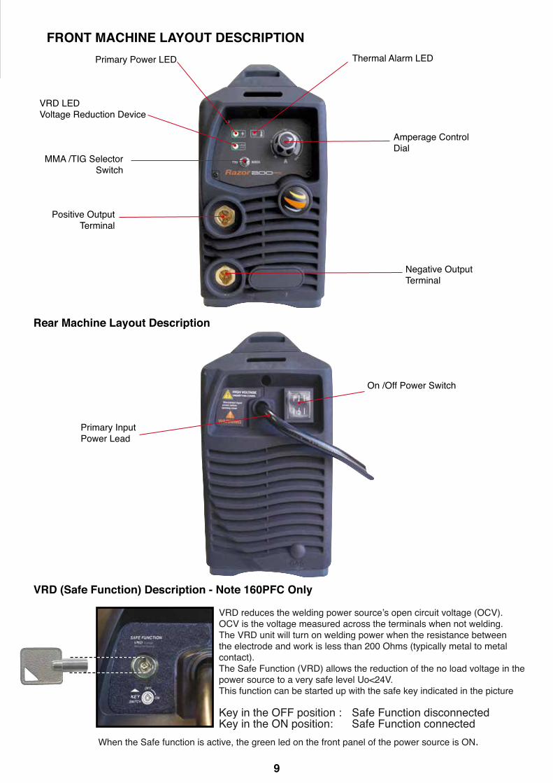
Amperage Control Dial
MMA /TIG Selector Switch
Negative Output Terminal
Positive Output Terminal
Primary Power LED Thermal Alarm LED
Primary Input Power Lead
On /Off Power Switch
Rear Machine Layout Description
VRD (Safe Function) Description - Note 160PFC Only
FRONT MACHINE LAYOUT DESCRIPTION
VRD LEDVoltage Reduction Device
VRDreducestheweldingpowersource’sopencircuitvoltage(OCV).OCV is the voltage measured across the terminals when not welding. The VRD unit will turn on welding power when the resistance between the electrode and work is less than 200 Ohms (typically metal to metal contact).The Safe Function (VRD) allows the reduction of the no load voltage in the power source to a very safe level Uo<24V. This function can be started up with the safe key indicated in the picture
Key in the OFF position : Safe Function disconnectedKey in the ON position: Safe Function connected
When the Safe function is active, the green led on the front panel of the power source is ON.

10 11
INSTALLATION SET UP FOR MMA (STICK) WELDING WITH MMA-TIG160/200PFCPlease install the machine strictly according to the following steps.The protection class of this machine is IP21, so avoid using it in rain.Connection of Input CablesPrimary input cable is supplied with this welding equipment. Connect the primary input cable with powersupply of required input voltage. Refer to data plate on machine for Input voltage, IMAX and IEFF.
(1) Turn the power source on and select the MMA function with the TIG/MMA selector switch.(2) Connection of Output Cables: Various electrodes require a different polarity for optimum results refer
to the electrode manufacturers information for the correct polarity. Most GP electrodes are Electrodeconnected to output socket, Earth Connected to the output socket
(3) Set the welding current relevant to the electrode type and size being used as recommended by theelectrode manufacturer.
(4) Place the electrode into the electrode holder and clamp tight(5) Strike the electrode on the work to create the arc and hold the electrode steady to maintain the arc(6) Hold the electrode slightly above the work piece to maintain the arc while travelling at an even speed
to create and even weld deposition(7) Tofinishtheweld,breakthearcbyquicklysnappingtheelectrodeawayfromtheworkpiece.(8) Wait for the weld to cool and carefully chip away the slag to reveal the weld metal underneath.
(2) Connect earthlead to
(1) Set TIG/MMA selectorswitch to MMA
(2) Connect the electrodelead to
(3) Set the welding current using the amperagecontrol dial.
(6) Hold the electrode slightly above the workmaintaining the arc while travelling at an evenspeed.
(4) Place the electrode into the electrode holderand clamp tight.
(7) Tofinishtheweld,breakthearcbyquicklysnapping the electrode away from the workpiece.
(5) Strike the electrode against the workpiece tocreate and arc and hold the electrode steady tomaintain the arc.
(8) Wait for the weld to cool and carefully chipaway the slag to reveal the weld metal below.

11
10
MMA (Manual Metal Arc) General DescriptionOne of the most common types of arc welding is manual metal arc welding (MMA) or stick welding. An electric cur-rent is used to strike an arc between the base material and a consumable electrode rod or ‘stick’. The electrode rod is made of a material that is compatible with the base material being welded and is covered with a ux that gives off gaseous vapours that serve as a shielding gas and providing a layer of slag, both of which protect the weld area from atmospheric contamination. The electrode core itself acts as ller material the residue from the ux that forms a slag covering over the weld metal must be chipped away after welding.
Core wire
Flux coating
Gas shield from ux melt
Arc with core wire melt
Flux residue forms slag coverWeld metal
Power Source
+
▬
• The arc is initiated by momentarily touching the electrode to the base metal.
• The heat of the arc melts the surface of the base metal to form a molten poolat the end of the electrode.
• The melted electrode metal is transferred across the arc into the molten pooland becomes the deposited weld metal.
• The deposit is covered and protected by a slag which comes from theelectrode coating.
• The arc and the immediate area are enveloped by an atmosphere ofprotective gas
Core wire
Flux coating
Base metal
Protective gas
Arc
Slag
Weld pool
Manual metal arc ( stick) electrodes have a solid metal wire core and a ux coating. These electrodes are identied by the wire diameter and bya series of letters and numbers. The letters and numbers identify the metal alloy and the intended use of the electrode.
The Metal Wire Core works as conductor of the current that maintains the arc. The core wire melts and is deposited into the welding pool.
The covering on a shielded metal arc welding electrode is called Flux.The ux on the electrode performs many different functions.These include:● producing a protective gas atmosphere around the weld area.● providing uxing elements and deoxidizers.● creating a protective slag coating over the weld as it cools.● establishing arc characteristics.● adding alloying elements.Covered electrodes serve many purposes in addition to adding ller metal to the molten pool. These additional functions are provided mainly by the cover-ing on the electrode.
MMA (Manual Metal Arc) WeldingOne of the most common types of arc welding is manual metal arc welding (MMA) or stick welding. An electric currentisusedtostrikeanarcbetweenthebasematerialandaconsumableelectroderodor‘stick’.Theelectroderodismadeofamaterialthatiscompatiblewiththebasematerialbeingweldedandiscoveredwithafluxthatgivesoff gaseous vapours that serve as a shielding gas and providing a layer of slag, both of which protect the weld area fromatmosphericcontamination.Theelectrodecoreitselfactsasfillermaterialtheresiduefromthefluxthatformsaslag covering over the weld metal must be chipped away after welding.
Core wire
Flux coating
GasshieldfromfluxmeltArc with core wire melt
Flux residue forms slag coverWeld metal
Power Source
+
▬
• The arc is initiated by momentarily touching the electrode to the base metal.
• The heat of the arc melts the surface of the base metal to form a molten pool at the end of the electrode.
• The melted electrode metal is transferred across the arc into the molten pooland becomes the deposited weld metal.
• The deposit is covered and protected by a slag which comes from the electrode coating.
• The arc and the immediate area are enveloped by an atmosphere of protective gas
Core wire
Flux coating
Base metal
Protective gas
Arc
Slag
Weld pool
Manualmetalarc(stick)electrodeshaveasolidmetalwirecoreandafluxcoating.Theseelectrodesareidentifiedbythewirediameterandbya series of letters and numbers. The letters and numbers identify the metal alloy and the intended use of the electrode.
The Metal Wire Core works as conductor of the current that maintains the arc. The core wire melts and is deposited into the welding pool.
The covering on a shielded metal arc welding electrode is called Flux.Thefluxontheelectrodeperformsmanydifferentfunctions.These include: ● producing a protective gas around the weld area ● providingfluxingelementsanddeoxidizers● creating a protective slag coating over the weld as it cools ● establishing arc characteristics ● adding alloying elements.Coveredelectrodesservemanypurposesinadditiontoaddingfillermetaltothe molten pool. These additional functions are provided mainly by the cover-ing on the electrode.

12 13
Electrode Size
Average Thickness Maximum Recommended of Material Electrode Diameter
1.0 - 2.0mm 2.5mm 2.0 - 5.0mm 3.2mm 5.0 - 8.0mm 4.0mm 8.0 - > mm 5.0mm
The size of the electrode generally depends on the thickness of the section being welded, and the thicker the section the larger the electrode required. The table gives the maximum size of electrodes that maybe used for various thicknesses of section based on using a general purpose type 6013 electrode.
Correct current selection for a particular job is an important factor in arc welding. With the current set too low,difficultyisexperiencedinstrikingandmaintaininga stable arc. The electrode tends to stick to the work, penetration is poor and beads with a distinct rounded profilewillbedeposited.Toohighcurrentis accompanied by overheating of the electrode resulting undercut and burning through of the base metal and
producing excessive spatter. Normal current for a particular job may be considered as the maximum, which can be used without burning through the work, over-heating the electrode or producing a rough spattered surface.The table shows current ranges generally recommended for a general purpose type 6013 electrode. Arc LengthTo strike the arc, the electrode should be gently scraped on the work until the arc is established. There is a simplerulefortheproperarclength;itshouldbetheshortestarcthatgivesagoodsurfacetotheweld.Anarctoolongreducespenetration,producesspatterandgivesaroughsurfacefinishtotheweld. An excessively short arc will cause sticking of the electrode and result in poor quality welds. General rule of thumb for down hand welding is to have an arc length no greater than the diameter of the core wire.
Electrode AngleThe angle that the electrode makes with the work is important to ensure a smooth, even transfer of metal. Whenweldingindownhand,fillet,horizontaloroverheadtheangleoftheelectrodeisgenerallybetween5and 15 degrees towards the direction of travel. When vertical up welding the angle of the electrode should be between 80 and 90 degrees to the work piece. Travel SpeedThe electrode should be moved along in the direction of the joint being welded at a speed that will give the size of run required. At the same time, the electrode is fed downwards to keep the correct arc length at all times. Excessive travel speeds lead to poor fusion, lack of penetration etc, while too slow a rate of travel will frequently lead to arc instability,slag inclusions and poor mechanical properties. Material and Joint PreparationThe material to be welded should be clean and free of any moisture, paint, oil, grease, mill scale, rust or any other material that will hinder the arc and contaminate the weld material. Joint preparation will depend onthemethodusedincludesawing,punching,shearing,machining,flamecuttingandothers.Inallcasesedges should be clean and free of any contaminates. The type of joint will be determined by the chosen application.
Welding Current (Amperage)
Electrode Size Current Range ø mm (Amps)
2.5mm 60 - 100 3.2mm 100 - 130 4.0mm 130 - 165 5.0mm 165 - 260
Electrode SelectionAs a general rule, the selection of an electrode is straight forward,in that it is only a matter of selecting an electrode of similar composition to the parent metal. However, for some metals there is a choice of several electrodes,eachofwhichhasparticularpropertiestosuitspecificclassesofwork.Itisrecommendto consult your welding supplier for the correct selection of electrode.
MMA (Stick) Welding Fundamentals
13
DISIM
ILAR
META
LSCA
ST IRON
LOW
H
YDRO
GEN
STAIN
LESS STEELH
ARD
FACIN
GM
ILD STEEL
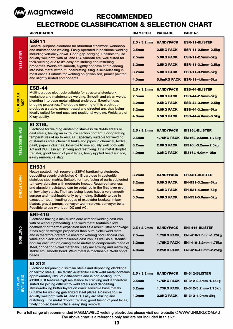
ESR11 General-purpose electrode for structural steelwork, workshop and maintenance welding. Easily operated in positional welding, including vertically-down. Good gap-bridging. Possible to use equally well both with AC and DC. Smooth arc, well suited for tack-welding due to it’s easy arc striking and restriking properties. Welds are smooth, slightly concave and blending into base metal without undercutting. Slag is self-releasing in most cases. Suitable for welding on galvanized, primer painted and slightly rusted components.
2.5 / 3.2mm HANDYPACK ESR-11-BLISTER
2.5mm 2.5KG PACK ESR-11-2.5mm-2.5kg
2.5mm 5.0KG PACK ESR-11-2.5mm-5kg
3.2mm 2.5KG PACK ESR-11-3.2mm-2.5kg
3.2mm 5.0KG PACK ESR-11-3.2mm-5kg
4.0mm 5.0mKG PACK ESR-11-4.0mm-5kg
2.5 / 3.2mm HANDYPACK ESB-44-BLISTER
2.5mm 5.0KG PACK ESB-44-2.5mm-5kg
3.2mm 2.5KG PACK ESB-44-3.2mm-2.5kg
3.2mm 5.0KG PACK ESB-44-3.2mm-5kg
4.0mm 6.5KG PACK ESB-44-4.0mm-6.5kg
2.5 / 3.2mm HANDYPACK EI316L-BLISTER
2.5mm 1.75KG PACK EI316L-2.5mm-1.75kg
3.2mm 2.0KG PACK EI316L-3.2mm-2.0kg
4.0mm 2.0KG PACK EI316L-4.0mm-2kg
3.2mm HANDYPACK EH-531-BLISTER
3.2mm 5.0KG PACK EH-531-3.2mm-5kg
4.0mm 5.0KG PACK EH-531-4.0mm-5kg
5.0mm 5.0KG PACK EH-531-5.0mm-5kg
2.5 / 3.2mm HANDYPACK ENI-416-BLISTER
2.5mm 1.75KG PACK ENI-416-2.5mm-1.75kg
3.2mm 1.75KG PACK ENI-416-3.2mm-1.75kg
4.0mm 2.25KG PACK ENI-416-4.0mm-2.25kg
2.5 / 3.2mm HANDYPACK EI-312-BLISTER
2.5mm 1.75KG PACK EI-312-2.5mm-1.75kg
3.2mm 1.75KG PACK EI-312-3.2mm-1.75kg
4.0mm 2.0KG PACK EI-312-4.0mm-2kg
DIAMETER PACKAGE PART No APPLICATION
ESB-44 Multi-purpose electrode suitable for structural steelwork, workshop and maintenance welding. Smooth and clean welds, blending into base metal without undercuts. Excellent gap bridging properties. The double covering of this electrode produces a stable, concentrated and directed arc, thus being ideally suited for root pass and positional welding. Welds are of X-ray quality.
EH531 Heavy coated, high recovery (235%) hardfacing electrode, depositing evenly distributed Cr, B carbides in austenitic stainless steel matrix. Suitable for hardfacing of parts subjected to heavy abrasion with moderate impact. Required hardness and abrasion resistance can be obtained in the first layer even on low alloy steels. The hardfacing layers have a very smooth surface and machinable only by grinding. Suitable to use in excavator teeth, leading edges of excavator buckets, mixer blades, gravel pumps, conveyor worn-screws, conveyor belts. Possible to use with both DC and AC.
RECOMMENDED ELECTRODE CLASSIFICATION & SELECTION CHART
EI 316LElectrode for welding austenitic stainless Cr-Ni-Mo steels or cast steels, having an extra low carbon content. For operating temperatures of up to +400˚C. Especially suitable for welding of stainless steel chemical tanks and pipes in chemical, textile, paint, paper industries. Possible to use equally well both with AC and DC. Easy arc striking and restriking. Fine metal droplet transfer, good fusion of joint faces, finely rippled bead surface, easily removable slag.
ENI-416Electrode having a nickel-iron core wire for welding cast iron with or without preheating. The weld metal features a low coefficient of thermal expansion and as a result , little shrinkage. It has higher strength properties than pure nickel weld metal and is therefore preferable used for welding nodular cast iron, white and black heart malleable cast iron, as well as austenitic nodular cast iron or joining these metals to components made of steel, copper or nickel materials. Easy arc striking and restriking, stable arc, smooth bead. Weld metal is machinable. Weld short beads.
EI 312Electrode for joining dissimilar steels and depositing claddings on ferritic steels. The ferritic-austenitic Cr-Ni weld metal contains approximately 50% of delta-ferrite and is non-scaling up to +1100˚C. It features high resistance to cracking and is therefore suited for joining difficult to weld steels and depositing stress-relaxing buffer layers on crack sensitive base metals. Suitable for welding galvanized steel plates. Possible to use equally well both with AC and DC. Easy arc striking and restriking. Fine metal droplet transfer, good fusion of joint faces, finely rippled bead surface, easy slag removal.
For a full range of recommended MAGMAWELD welding electrodes please visit our website @ WWW.UNIMIG.COM.AUThe above chart is a reference only and are not included in this kit.

14 15
INSTALLATION AND SET UP FOR DC TIG WELDING FOR MMA-TIG160/200PFC(1) Switch on the machine, select the TIG function with the TIG/MMA selector switch. (2) Insert the power cable plug of the TIG torch into the Negative socket on the front of the machine and tighten it.(3) Insert the earth cable plug into the Positive socket on the front of the machine and tighten it.(5) Connect the gas line of the TIG torch to regulator and connect the regulator to the gas cylinder. Carefullyopenthegascylindervalveandsettheflowratetobetween8-10l/min.(5) Set the welding current using the amperage control dial
Note: Photos show TIG torch with Suregrip option
(5) Set the welding current using the amperage control dial
(4) Carefully open the valve of the gas cylinder,settheflowto8-10l/min
(4) Connect the gas line to the regulator and connect to the gas cylinder
(2) Connect the TIG torch cable connector to
(3) Connect earth lead to
(1) Set TIG/MMA selectorswitch to TIG

15
LIFT ARC DC TIG OPERATION FOR MMA-TIG160/200PFCLift Arc ignition allows the arc to be started easily in DC TIG by simply touching the tungsten to the work piece and lifting it up to start the arc. This prevents the tungsten tip sticking to the work piece and breaking the tip from the tungsten electrode. There is a particular technique called “rocking the cup” used in the Lift Arc process that provides easy use of the Lift Arc function.
(6) Make sure the front end parts of the TIG torch are correctly assembled, use the correct size and type of tungsten electrode for the job, the tungsten electrode requires a sharpened point for DC welding.(7) Turn on the Gas Valve located on the TIG torch handle.(8) Lay the outside edge of the Gas Cup on the work piece with the Tungsten Electrode 1- 2mm from the work piece.(9) With a small movement rotate the Gas Cup forward so that the Tungsten Electrode touches the work piece. (10) Now rotate the Gas Cup in the reverse direction to lift the Tungsten electrode from the work piece to create the arc.
(7) Turn on the Gas Valve (8) Lay the outside edge of the Gas Cup on the work piece with the Tungsten Electrode 1- 2mm from the work piece.
(9) With a small movement rotate the Gas Cup forward so that the Tungsten Electrode touches the work piece.
(10) Now rotate the Gas Cup in the reverse direction to lift the Tungsten electrode from the work piece to create the arc.
IMPORTANT! - We strongly recommend that you check for gas leakage prior to operation of your machine. We recommend that you close the cylinder valve when the machine is not in use. Welding Guns Of Australia PTY LTD, authorised representatives or agents of Welding Guns Of Australia PTY LTD will not be liable or responsible for the loss of any gas.
6) Assemble front end parts of the TIG torch, fittingasharpenedtungstensuitableforDCwelding.

16 17
DC TIG WeldingThe DC power source uses what is known as DC (direct current) in which the main elec-tricalcomponentknownaselectronsflowinonlyonedirectionfromthenegativepole (terminal) to the positive pole (terminal). In the DC electrical circuit there is an electrical principle at work which should always be taken into account when using any DC circuit. WithaDCcircuit70%oftheenergy(heat)isalwaysonthepositiveside.Thisneedstobe understood because it determines what terminal the TIG torch will be connected to (this rule applies to all the other forms of DC welding as well ).
DC TIG welding is a process in which an arc is struck between a TUNGSTEN electrode and the metal work piece. The weld area is shieldedbyan inertgasflowtopreventcontaminationof the tung-sten, molten pool and weld area.When the TIG arc is struck the inert gas is ionized and superheat-edchangingit’smolecularstructurewhichconvertsitintoaplasmastream.Thisplasmastreamflowingbetween the tungstenand thework piece is the TIG arc and can be as hot as 19,000°C. It is a very pure and concentrated arc which provides the controlled melting of most metals into a weld pool. TIG welding offers the user the greatest amountofflexibilitytoweldthewidestrangeofmaterialandthicknessand types. DC TIG welding is also the cleanest weld with no sparks or spatter.
LIFT ARC IGNITION for TIG (tungsten inert gas) WeldingLift Arc is a form of arc ignition where the machines has low voltage on the electrode to only a few volts, with a current limit of one or two amps (well below the limit that causes metal to transfer and contamination of the weld or electrode). When the machine detects that the tungsten has left the surface and a spark is present, it immediately (within microseconds) increases power, converting the spark to a full arc. It is a simple, safe lower cost alternative arc ignition process to HF (high frequency) and a superior arc start process to scratch start.
arc ignitionestablished
TIG arc
gasflow
Theintensityofthearcisproportionaltothecurrentthatflowsfromthetungsten. The welder regulates the welding current to adjust the power of the arc. Typically thin material requires a less powerful arc with less heat to melt the material so less current (amps) is required, thicker material requires a more powerful arc with more heat so more current (amps) are necessary to melt the material.
30%
70%
high currentlow
current
power source
argon gas
nozzle
Lay the nozzle on the job without the tungsten touch-ing the work
Rock the torch sideways so that the tungsten touches the work & hold momentarily
Rock the torch back in the opposite direction, the arc will ignite as the tungsten lifts off the work
Lift the torch to maintain the arc
tungsten touches the work
tungsten off the work

17
TIG Welding with Filler Wire TechniqueItisnecessaryinmanysituationswithTIGweldingtoaddafillerwireintotheweldpool to build up weld reinforcement and create a strong weld. Once the arc is started the torch tungsten is held in place until a weld pool is created, a circular movement of the tungsten will assist is creating a weld pool of the desired size. Once the weld pool is established tilt the torch at about a 75° angle and move smoothly and evenly alongthejoint.Thefillermetalisintroducedtotheleadingedgeoftheweldpool.Thefillerwireisusuallyheldatabouta15°angleandfedintothelead-
ingedgeofthemoltenpool,thearcwillmeltthefillerwireintotheweldpoolasthetorchismovedforward.Alsoadabbingtechniquecanbeusedtocontroltheamountoffillerwireadded,thewireis fed into the molten pool and retracted in a repeating sequence as the torch is moved slowly and evenlyforward.Itisimportantduringtheweldingtokeepthemoltenendofthefillerwireinsidethegas shield as this protects the end of the wire from being oxidised and contaminating the weld pool.
75°15°
Form a weld pool
Travel direction
Angle torch AddTIGfillerwire
Retractthefillerwire Move the torch forward to the front of the weld pool
Repeat the process
gas shield
TIG Welding Fusion TechniqueManualTIGweldingisoftenconsideredthemostdifficultofalltheweldingprocesses.Because the welder must maintain a short arc length, great care and skill are required to prevent contact between the electrode and the workpiece. Similar to Oxygen Acety-lene torch welding, TIG welding normally requires two hands and in most instances requires thewelder tomanually feed a fillerwire into theweld poolwith one handwhile manipulating the welding torch in the other. However, some welds combining thin materialscanbeaccomplishedwithoutfillermetal likeedge,corner,andbutt joints.
This is known as Fusion welding where the edges of the metal pieces are melted together using only the heat and arc force generated by the TIG arc. Once the arc is started the torch tungsten is held in place until a weld pool is created, a circular movement of the tungsten will assist is creating a weld pool of the desired size. Once the weld pool is established tilt the torch at about a 75° angle and move smoothly and evenly along the joint while fusing the materials together.
75°
Form a weld pool Angle torch Move the torch slowly and evenly forward
Travel direction

18 19
Tungsten Electrodes
Tungsten is a rare metallic element used for manufacturing TIG welding electrodes. The TIG process relies on tung-sten’shardnessandhigh-temperatureresistancetocarrytheweldingcurrenttothearc.Tungstenhasthehighestmelting point of any metal, 3,410 degrees Celsius.Tungsten electrodes are nonconsumable and come in a variety of sizes, they are made from pure tungsten or an al-loy of tungsten and other rare earth elements. Choosing the correct tungsten depends on the material being welded, the amount of amps required and whether you are using AC or DC welding current.Tungstenelectrodesarecolour-codedattheendforeasyidentification.Below are the most commonly used tungsten electrodes found in the New Zealand and Australian market.
ThoriatedThoriatedtungstenelectrodes(AWSclassificationEWTh-2)containaminimumof97.30percenttungstenand1.70to 2.20 percent thorium and are called 2 percent thoriated. They are the most commonly used electrodes today and are preferred for their longevity and ease of use. Thorium increases the electron emission qualities of the electrode, which improves arc starts and allows for a higher current-carrying capacity. This electrode operates far below its melt-ing temperature, which results in a considerably lower rate of consumption and eliminates arc wandering for greater stability. Compared with other electrodes, thoriated electrodes deposit less tungsten into the weld puddle, so they cause less weld contamination. Thorium however is a low-level radioactive hazard and many users have switched to other alternatives. Regard-ing the radioactivity, thorium is an alpha emitter but when it is enclosed in a tungsten matrix the risks are negligible. Thus holding a stick of Thoriated tungsten in your hand should not pose a great threat unless a welder has open cuts ontheirskin.Thoriatedtungstenshouldnotgetincontactwithopencutsorwounds.Themoresignificantdangerto welders can occur when thorium oxide gets into the lungs. This can happen from the exposure to vapours during weldingorfromingestionofmaterial/dustinthegrindingofthetungsten.Followthemanufacturer’swarnings,instruc-tions, and the Material Safety Data Sheet (MSDS) for its use.
Ceriated (Color Code: Orange)Ceriatedtungstenelectrodes(AWSclassificationEWCe-2)containaminimumof97.30percenttungstenand1.80to2.20 percent cerium and are referred to as 2 percent ceriated. Ceriated tungstens perform best in DC welding at low current settings. They have excellent arc starts at low amperages and become popular in such applications as orbital tube welding, thin sheet metal work. They are best used to weld carbon steel, stainless steel, nickel alloys, and titanium, and in some cases it can replace 2 percent thoriated electrodes. Ceriated tungsten is best suited for lower amperages it should last longer than Thoriated tungsten higher amperage applications are best left to Thoriated or Lanthanated tungsten.
Lanthanated (Color Code: Gold)Lanthanatedtungstenelectrodes(AWSclassificationEWLa-1.5)containaminimumof97.80percenttungstenand1.30 percent to 1.70 percent lanthanum, and are known as 1.5 percent lanthanated. These electrodes have excellent arc starting, a low burn off rate, good arc stability, and excellent re-ignition characteristics. Lanthanated tungstens also share the conductivity characteristics of 2 percent thoriated tungsten. Lanthanated tungsten electrodes are ideal if you want to optimise your welding capabilities. They work well on AC or DC electrode negative with a pointed end, or they can be balled for use with AC sine wave power sources. Lanthanated tungsten maintains a sharpened point well, which is an advantage for welding steel and stainless steel on DC or AC from square wave power sources.
Zirconiated (Color Code: White)Zirconiatedtungstenelectrodes(AWSclassificationEWZr-1)containaminimumof99.10percenttungstenand0.15to 0.40 percent zirconium. Most commonly used for AC welding Zirconiated tungsten produces a very stable arc and is resistant to tungsten spitting. It is ideal for AC welding because it retains a balled tip and has a high resistance to contamination. Its current-carrying capacity is equal to or greater than that of thoriated tungsten. Zirconiated tungsten is not recommended for DC welding.
Tungsten Electrodes Rating for Welding Currents Tungsten DC Current Amps AC Current Amps AC Current Amps Diameter Torch Negative Un-Balanced Wave Balanced Wave mm 2% Thoriated 0.8% Zirconiated 0.8% Zirconiated
1.0mm 15 - 80 15 - 80 20 - 60 1.6mm 70 -150 70 - 150 60 - 120 2.4mm 150- 250 140 - 235 100 - 180 3.2mm 250 - 400 225 - 325 160 - 250 4.0mm 400 - 500 300 - 400 200 - 320

19
Electrode Included Angle/Taper - DC Welding Tungsten electrodes for DC welding should be ground longitudinally and concentrically with diamond wheels to a specificincludedangleinconjunctionwiththetip/flatpreparation.Differentanglesproducedifferentarcshapesandoffer different weld penetration capabilities. In general, blunter electrodes that have a larger included angle provide thefollowingbenefits:• Last Longer• Have better weld penetration• Have a narrower arc shape• Can handle more amperage without eroding.
Sharper electrodes with smaller included angle provide:• Offer less arc weld• Have a wider arc• Have a more consistent arcThe included angle determines weld bead shape and size. Generally, as the included angle increases, penetration increases and bead width decreases.
Tungsten PreparationAlways use DIAMOND wheels when grinding and cutting. While tungsten is a very hard material, the surface of a diamond wheel is harder, and this makes for smooth grinding. Grinding without diamond wheels, such as aluminium oxidewheels,canleadtojaggededges,imperfections,orpoorsurfacefinishesnotvisibletotheeyethatwillcontrib-ute to weld inconsistency and weld defects.Always ensure to grind the tungsten in a longitudinal direction on the grinding wheel. Tungsten electrodes are manu-factured with the molecular structure of the grain running lengthwise and thus grinding crosswise is “grinding against the grain.” If electrodes are ground crosswise, the electrons have to jump across the grinding marks and the arc can startbeforethetipandwander.Grindinglongitudinallywiththegrain,theelectronsflowsteadilyandeasilytotheendof the tungsten tip. The arc starts straight and remains narrow, concentrated, and stable.
grind longitudinal on the grinding wheel
don’tgrindacross the grinding wheel
flattip
2.5 times tungsten diameter
pointed tip
Electrode Tip/Flat The shape of the tungsten electrode tip is an important process variable in precision arc welding. A good selection oftip/flatsizewillbalancetheneedforseveraladvantages.Thebiggertheflat,themorelikelyarcwanderwilloccurandthemoredifficultitwillbetoarcstart.However,increasingtheflattothemaximumlevelthatstillallowsarcstartand eliminates arc wonder will improve the weld penetration and increase the electrode life. Some welders still grind electrodes to a sharp point, which makes arc starting easier. However, they risk decreased welding performance from melting at the tip and the possibility of the point falling off into the weld pool.
flatspotdiameter
included angle
Tungsten Diameter at Constant Included Current Range Current Range Diameter the Tip - mm Angle - Degrees Amps Pulsed Amps
1.0mm .250 20 05 - 30 05 - 60 1.6mm .500 25 08 - 50 05 - 100 1.6mm .800 30 10 - 70 10 - 140 2.4mm .800 35 12 - 90 12 - 180 2.4mm 1.100 45 15 - 150 15 - 250 3.2mm 1.100 60 20 - 200 20 - 300 3.2mm 1.500 90 25 - 250 25 - 350
20 21
Suregrip Series
*
Stubby series
Standard series
Gas lens series
Large gas lens series
Stubby gas lens series
Wear Parts Identification Next Page
2
35
7
6
8
129
10
11
1314 15
16
17
6
4
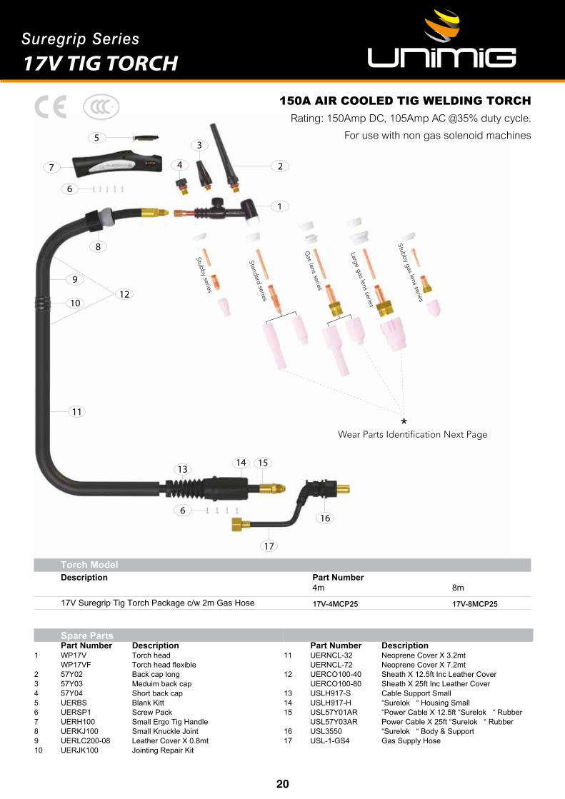
Torch Model Description Part Number 4m 8m
17V Suregrip Tig Torch Package c/w 2m Gas Hose 17V-4MCP25 17V-8MCP25
17V TIG TORCH
150A AIR COOLED TIG WELDING TORCH Rating: 150Amp DC, 105Amp AC @35% duty cycle.
For use with non gas solenoid machines
Spare Parts Part Number Description 1 WP17V Torch head WP17VF Torch head flexible 2 57Y02 Back cap long3 57Y03 Meduim back cap 4 57Y04 Short back cap5 UERBS Blank Kitt6 UERSP1 Screw Pack 7 UERH100 Small Ergo Tig Handle 8 UERKJ100 Small Knuckle Joint 9 UERLC200-08 Leather Cover X 0.8mt 10 UERJK100 Jointing Repair Kit
Part Number Description11 UERNCL-32 Neoprene Cover X 3.2mt UERNCL-72 Neoprene Cover X 7.2mt12 UERCO100-40 Sheath X 12.5ft Inc Leather Cover UERCO100-80 Sheath X 25ft Inc Leather Cover 13 USLH917-S Cable Support Small 14 USLH917-H “Surelok “ Housing Small 15 USL57Y01AR “Power Cable X 12.5ft “Surelok “ Rubber USL57Y03AR Power Cable X 25ft “Surelok “ Rubber 16 USL3550 “Surelok “ Body & Support 17 USL-1-GS4 Gas Supply Hose

21
Suregrip Series
17V TIG TORCHStandard Front End Parts
Part # Description18CG Cup Gasket
Part # Description10N22 Collet 1.0mm10N23 Collet 1.6mm10N24 Collet 2.4mm10N25 Collet 3.2mm
Part # Description10N30 Collet Body 1.0mm10N31 Collet Body 1.6mm10N32 Collet Body 2.4mm10N28 Collet Body 3.2mm
Part # Description10N50 Alumina Nozzle Ø 6mm #410N49 Alumina Nozzle Ø 8mm #510N48 Alumina Nozzle Ø 10mm #610N47 Alumina Nozzle Ø 11mm #710N46 Alumina Nozzle Ø 13mm #810N45 Alumina Nozzle Ø 16mm #1010N44 Alumina Nozzle Ø 19mm #12
Part # Description10N49L Long Alumina Nozzle Ø 8mm #5L53N48L Long Alumina Nozzle Ø 10mm #6L53N47L Long Alumina Nozzle Ø 11mm #7L
Part # Description54N01 Gas Lens Gasket
Part # Description45V25 Gas Lens Body 1.6mm45V26 Gas Lens Body 2.4mm45V27 Gas Lens Body 3.2mm
Part # Description54N14 Gaslensceramic8.0mm54N15 Gaslensceramic7.0mm54N17 Gaslensceramic5.0mm
Compact Gas Lens Front End Parts
Part # Description
TR0004-10 1.0mmx175mmthoriatedtungstenelectrode2%
TR0004-16 1.6mmx175mmthoriatedtungstenelectrode2%
TR0004-24 2.4mmx175mmthoriatedtungstenelectrode2%
TR0004-32 3.2mmx175mmthoriatedtungstenelectrode2%
TR0004-16
REDANSI/AWS A5.12-98
ISO 6848 WT20
2% Thoriated: Best stability at medium currents, good arc
starts, medium tendency to spit, medium erosion rate.
Commonly used for steel and stainless steel applications
1/16 x 7” (1.6mm x 175mm)3/32 x 7” (2.4mm x 175mm)1/8 x 7” (3.2mm x 175mm)
©All rights reserved. No part of this publication may be reproduced, stored in a retrieval system or transmitted by any means,electronic, mechanical, photocopying or otherwise without the prior permission of ©Uniarc® the copyright holder.

22 23
Suregrip Series
Wear Parts Identification Next Page
Stubby series
Standard series
Gas Lens series
Large Gas Lens series
Stubby Gas Lens series
*
2
357
6
8
9
10
11
12
1516
14
613
18
17
4
Torch Model Description Part Number 4m 8m
26V Tig Torch Package c/w 2m Gas Hose 26V-8MCP25 26V-4MCP50 26V-8MCP50
200A AIR COOLED TIG WELDING TORCH Rating:180Amp DC, 125Amp AC @35% duty cycle.
26V TIG TORCH
Spare Parts Part Number Description 1 WP26V Torch head WP26VF Torch head flexible 2 57Y02 Back cap long3 57Y03 Meduim back cap 4 57Y04 Short back cap5 UERBS Blank Kit6 UERSP1 Screw Pack 7 UERH200 Large Ergo Tig Handle 8 UERKJ200 Large Knuckle Joint9 UERLC200-08 Leather Cover X 0.8mt 10 UERJK200 Jointing Repair Kit
Part Number Description11 UERNCL-32 Neoprene Cover X 3.2mt UERNCL-72 Neoprene Cover X 7.2mt12 UERCO200-40 Sheath X 12.5ft Inc Leather Cover UERCO200-80 Sheath X 25ft Inc Leather Cover 13 USLH26-S Cable Support Large14 USLH26-H “Surelok “ Housing Large15 USLH26-C “Surelok “ Housing Cover16 USL46V28AR Power Cable X 12.5ft “Surelok “ Rubber USL46V30AR Power Cable X 25ft “Surelok “ Rubber17 USL3550 “Surelok “ Body & Support18 USL-1-GS4 Gas Supply Hose

23
Suregrip Series
26V TIG TORCHStandard Front End Parts
Part # Description18CG Cup Gasket
Part # Description10N22 Collet 1.0mm10N23 Collet 1.6mm10N24 Collet 2.4mm10N25 Collet 3.2mm
Part # Description10N30 Collet Body 1.0mm10N31 Collet Body 1.6mm10N32 Collet Body 2.4mm10N28 Collet Body 3.2mm
Part # Description10N50 Alumina Nozzle Ø 6mm #410N49 Alumina Nozzle Ø 8mm #510N48 Alumina Nozzle Ø 10mm #610N47 Alumina Nozzle Ø 11mm #710N46 Alumina Nozzle Ø 13mm #810N45 Alumina Nozzle Ø 16mm #1010N44 Alumina Nozzle Ø 19mm #12
Part # Description10N49L Long Alumina Nozzle Ø 8mm #5L53N48L Long Alumina Nozzle Ø 10mm #6L53N47L Long Alumina Nozzle Ø 11mm #7L
Part # Description54N01 Gas Lens Gasket
Part # Description45V25 Gas Lens Body 1.6mm45V26 Gas Lens Body 2.4mm45V27 Gas Lens Body 3.2mm
Part # Description54N14 Gaslensceramic8.0mm54N15 Gaslensceramic7.0mm54N17 Gaslensceramic5.0mm
Compact Gas Lens Front End Parts
Part # Description
TR0004-10 1.0mmx175mmthoriatedtungstenelectrode2%
TR0004-16 1.6mmx175mmthoriatedtungstenelectrode2%
TR0004-24 2.4mmx175mmthoriatedtungstenelectrode2%
TR0004-32 3.2mmx175mmthoriatedtungstenelectrode2%
TR0004-16
REDANSI/AWS A5.12-98
ISO 6848 WT20
2% Thoriated: Best stability at medium currents, good arc
starts, medium tendency to spit, medium erosion rate.
Commonly used for steel and stainless steel applications
1/16 x 7” (1.6mm x 175mm)3/32 x 7” (2.4mm x 175mm)1/8 x 7” (3.2mm x 175mm)
©All rights reserved. No part of this publication may be reproduced, stored in a retrieval system or transmitted by any means,electronic, mechanical, photocopying or otherwise without the prior permission of ©Uniarc® the copyright holder.

2520
1: No arc Possible Reason Suggested RemedyIncomplete welding circuit Check earth lead is connected. Check all cable connections.
Wrong mode selected Check the MMA selector switch is selected
No power supply Check that the machine is switched on and has a power supply
2: Porosity − small cavities or holes resulting from gas pockets in weld metal.Possible Reason Suggested RemedyArc length too long Check that pure Argon is being used
Work piece dirty, contaminated or moisture
Remove moisture and materials like paint, grease, oil, and dirt, including mill scale from base metal
Damp electrodes Use only dry electrodes
3: Excessive SpatterPossible Reason Suggested RemedyAmperage too high Decrease the amperage or choose a larger electrode
Arc length too long Shorten the arc length
Tungsten melting into the weld pool Check that correct type of tungsten is being used. Too much current for the tungsten size so reduce the amps or change to a larger tungsten
3: Weld sits on top, lack of fusionPossible Reason Suggested RemedyInsuf cient heat input Increase the amperage or choose a larger electrode
Work piece dirty, contaminated or moisture
Remove moisture and materials like paint, grease, oil, and dirt, including mill scale from base metal
Poor welding technique Use the correct welding technique or seek assistance for the correct technique
4: Lack of penetrationPossible Reason Suggested RemedyInsuf cient heat input Increase the amperage or choose a larger electrode
Poor welding technique Use the correct welding technique or seek assistance for the correct technique
Poor joint preparation Check the joint design and t up, make sure the material is not too thick. Seek assist-ance for the correct joint design and t up
5: Excessive penetration - burn throughPossible Reason Suggested RemedyExcessive heat input Reduce the amperage or use a smaller electrode
Incorrect travel speed Try increasing the weld travel speed
6: Uneven weld appearancePossible Reason Suggested RemedyUnsteady hand, wavering hand Use two hands where possible to steady up, practise your technique
7: Distortion − movement of base metal during weldingPossible Reason Suggested RemedyExcessive heat input Reduce the amperage or use a smaller electrode
Poor welding technique Use the correct welding technique or seek assistance for the correct technique
Poor joint preparation and or joint design
Check the joint design and t up, make sure the material is not too thick. Seek assist-ance for the correct joint design and t up
7: Electrode welds with different or unusual arc characteristicPossible Reason Suggested RemedyIncorrect polarity Change the polarity, check the electrode manufacturer for correct polarity
The following chart addresses some of the common problems of MMA welding. In all cases of equipment malfunction, the manufacturer’s recommendations should be strictly adhered to and followed.
MMA (Stick) WELDING TROUBLE SHOOTING
24 25

252521
1: Tungsten burning away quicklyPossible Reason Suggested RemedyIncorrect Gas Check that pure Argon is being used
No gas Check the gas cylinder contains gas and is connected and the torch gas valve is open
Inadequate gas ow Check the gas is connected, check hoses, gas valve and torch are not restricted. Set the gas ow between 10 - 15 l/min ow rate
Back cap not tted correctly Make sure the torch back cap is tted so that the o-ring is inside the torch body
Torch connected to DC + Connect the torch to the DC- output terminal
Incorrect tungsten being used Check and change the tungsten type if necessary
Tungsten being oxidised after weld is nished
Keep shielding gas owing 10–15 seconds after arc stoppage. 1 second for each 10 amps of weld current.
2: Contaminated tungstenPossible Reason Suggested RemedyTouching tungsten into the weldpool
Keep tungsten from contacting weld puddle. Raise the torch so that the tungsten is off of the work piece 2 - 5mm
Touching the ller wire to the tung-sten
Keep the ller wire from touching the tungsten during welding, feed the ller wire into the leading edge of the weld pool in front of the tungsten
Tungsten melting into the weld pool Check that correct type of tungsten is being used. Too much current for the tungsten size so reduce the amps or change to a larger tungsten
3: Porosity - poor weld appearance and colourPossible Reason Suggested RemedyIncorrect Gas Check that pure Argon is being used
Inadequate gas ow / gas leaks Check the gas is connected, check hoses, gas valve and torch are not restricted. Set the gas ow between 10 - 15 l/min ow rate. Check hoses and ttings for holes, leaks etc.,
Moisture on the base metal Remove all moisture from base metal before welding
Contaminated base metal Remove materials like paint, grease, oil, and dirt, including mill scale from base metal
Contaminated ller wire Remove all grease, oil, or moisture from ller metal.
Incorrect ller wire Check the ller wire and change if necessary
4: Yellowish residue / smoke on the alumina nozzle & discoloured tungstenPossible Reason Suggested RemedyIncorrect Gas Use pure Argon gas
Inadequate gas ow Set the gas ow between 10 - 15 l/min ow rate
Alumina gas nozzle too small for size of tungsten being used
Increase the size of the alumina gas nozzle
5: Unstable Arc during DC weldingPossible Reason Suggested RemedyTorch connected to DC + Connect the torch to the DC- output terminal
Contaminated base metal Remove materials like paint, grease, oil, and dirt, including mill scale from base metal.
Tungsten is contaminated Remove 10mm of contaminated tungsten and re grind the tungsten
Arc length too long Lower torch so that the tungsten is off of the work piece 2 - 5mm
The following chart addresses some of the common problems of DC TIG welding. In all cases of equipment malfunction, the manufacturer’s recommendations should be strictly adhered to and followed.
TIG WELDING TROUBLE SHOOTING
7: Arc wanders during DC weldingPossible Reason Suggested RemedyPoor gas ow Check and set the gas ow between 10 - 15 l/min ow rate
Incorrect arc length Lower torch so that the tungsten is off of the work piece 2 - 5mm
Tungsten incorrect or in poor condi-tion
Check that correct type of tungsten is being used. Remove 10mm from the weld end of the tungsten and re sharpen the tungsten
Poorly prepared tungsten Grind marks should run lengthwise with tungsten, not circular. Use proper grinding method and wheel.
Contaminated base metal Remove contaminating materials like paint, grease, oil, and dirt, including mill scale from base metal.
Contaminated ller wire Remove all grease, oil, or moisture from ller metal.
Incorrect ller wire Check the ller wire and change if necessary
26 27
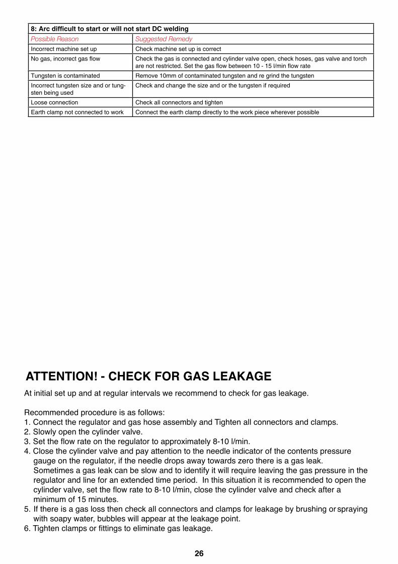
At initial set up and at regular intervals we recommend to check for gas leakage.
Recommended procedure is as follows:1. Connect the regulator and gas hose assembly and Tighten all connectors and clamps.2. Slowly open the cylinder valve.3.Settheflowrateontheregulatortoapproximately8-10l/min.4. Close the cylinder valve and pay attention to the needle indicator of the contents pressure gauge on the regulator, if the needle drops away towards zero there is a gas leak. Sometimes a gas leak can be slow and to identify it will require leaving the gas pressure in the regulator and line for an extended time period. In this situation it is recommended to open the cylindervalve,settheflowrateto8-10l/min,closethecylindervalveandcheckaftera minimum of 15 minutes.5. If there is a gas loss then check all connectors and clamps for leakage by brushing or spraying with soapy water, bubbles will appear at the leakage point.6.Tightenclampsorfittingstoeliminategasleakage.
ATTENTION! - CHECK FOR GAS LEAKAGE
22
8: Arc dif cult to start or will not start DC weldingPossible Reason Suggested RemedyIncorrect machine set up Check machine set up is correct
No gas, incorrect gas ow Check the gas is connected and cylinder valve open, check hoses, gas valve and torch are not restricted. Set the gas ow between 10 - 15 l/min ow rate
Tungsten is contaminated Remove 10mm of contaminated tungsten and re grind the tungsten
Incorrect tungsten size and or tung-sten being used
Check and change the size and or the tungsten if required
Loose connection Check all connectors and tighten
Earth clamp not connected to work Connect the earth clamp directly to the work piece wherever possible
At initial set up and at regular intervals we recommend to check for gas leakage.
Recommended procedure is as follows:1. Connect the regulator and gas hose assembly and tighten all connectors and clamps.2. Slowly open the cylinder valve.3. Set the ow rate on the regulator to approximately 8-10 l/min.4. Close the cylinder valve and pay attention to the needle indicator of the contents pressure gauge on the regulator, if the needle drops away towards zero there is a gas leak. Sometimes a gas leak can be slow and to identify it will require leaving the gas pressure in the regulator and line for an extended time period. In this situation it is recommended to open the cylinder valve, set the ow rate to 8-10 l/min, close the cylinder valve and check after a minimum of 15 minutes.5. If there is a gas loss then check all connectors and clamps for leakage by brushing or spraying with soapy water, bubbles will appear at the leakage point.6. Tighten clamps or ttings to eliminate gas leakage.
Important: We strongly recommend that you check for gas leakage prior to operation of your machine. We recommend that you close the cylinder valve when the machine is not in use.
Esseti NZ Ltd, authorised representatives or agents of Esseti NZ Ltd will not be liable or responsible for the loss of any gas.
ATTENTION! - CHECK FOR GAS LEAKS

27
SPARE PARTS IDENTIFICATION - ARC160PFC
Part Number Description 1. 10045765 front plastic panel2. 10043476 carry strap / handle3. 10004966 TIG/MMA selector switch4. 10004636 panel socket 35-505 10052313 front panel adhesive sticker6. 30000103 Amperage knob 7. 10052306 cable support assembly8. 10052508 rear plastic panel9. 10004949 ON/OFF switch
Part Number Description
10. 10006650 Single-phaserectifierbridge11. 10043327 main PCB 12. 10052250 control PCB13. 10037766 thermal switch14. 10052310 cover15. 10044009 fan-24V DC16. 10042320 base plate 17. 10043959 Insulation Sheet
2
3
4
1
56
7
8
9
14
10 11 12
14 17 13 16
292928
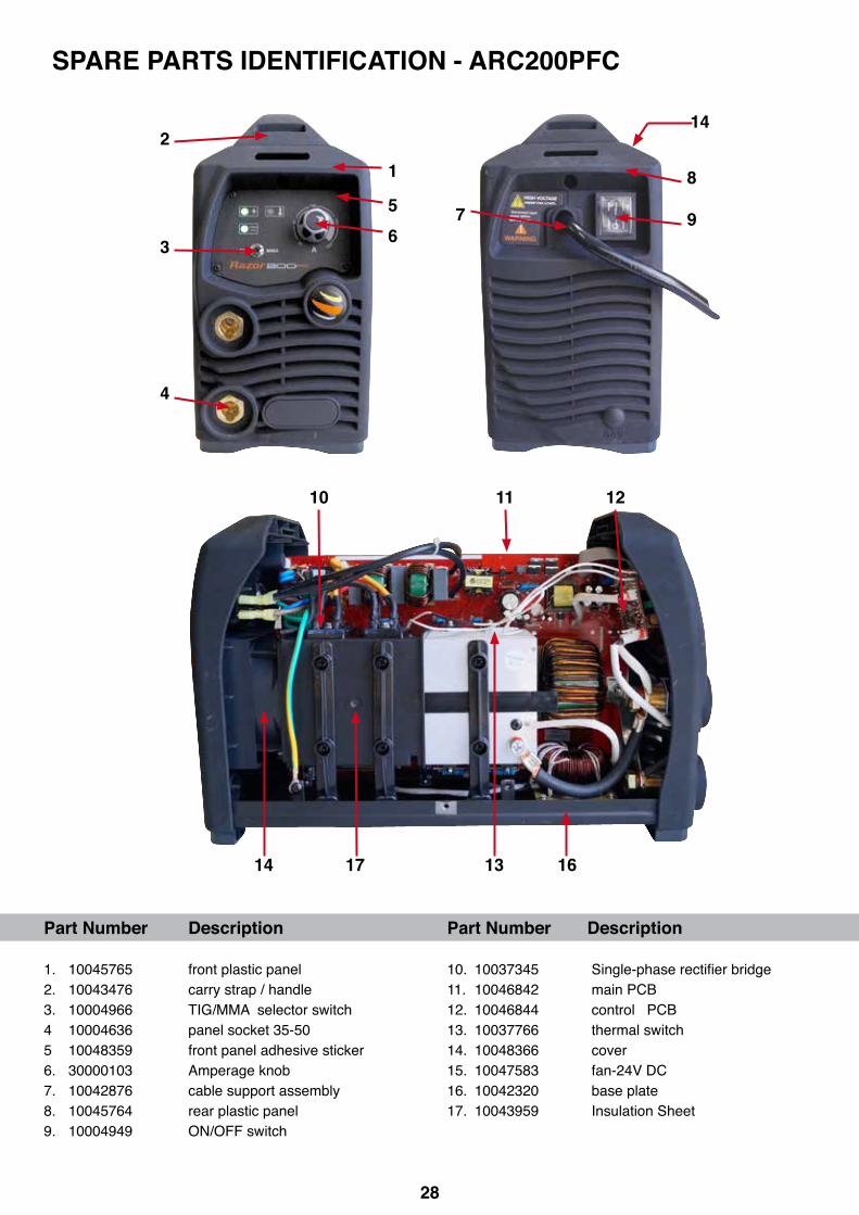
SPARE PARTS IDENTIFICATION - ARC200PFC
Part Number Description 1. 10045765 front plastic panel2. 10043476 carry strap / handle3. 10004966 TIG/MMA selector switch4 10004636 panel socket 35-505 10048359 front panel adhesive sticker6. 30000103 Amperage knob 7. 10042876 cable support assembly8. 10045764 rear plastic panel9. 10004949 ON/OFF switch
Part Number Description
10.10037345 Single-phaserectifierbridge11. 10046842 main PCB 12. 10046844 control PCB13. 10037766 thermal switch14. 10048366 cover15. 10047583 fan-24V DC16. 10042320 base plate 17. 10043959 Insulation Sheet
2
3
4
1
56
7
8
9
14
10 11 12
14 17 13 16

292928
Part Number Description
10.10037345 Single-phaserectifierbridge11. 10046842 main PCB 12. 10046844 control PCB13. 10037766 thermal switch14. 10048366 cover15. 10047583 fan-24V DC16. 10042320 base plate 17. 10043959 Insulation Sheet
Welding Guns Of Australia Pty Ltd (‘Us’, ‘We’) warrants that the following products under UNI-MIG, UNI-TIG, UNI-PLAS, UNI-FLAME, TECNA, T&R, HIT-8SS & ROTA, supplied by Us and purchased by you from an Authorised UNI-MIG, UNI-TIG, UNI-PLAS, UNI-FLAME, TECNA, T&R, HIT-8SS & ROTA Dealer throughout Australia are free of Material and Faulty Workmanship defects except for those products listed under ‘Warranty Exclusions’.
These terms and conditions supersede and exclude all former and other representations and arrangements relating to any warranties on these products.
WARRANTY PERIOD
We offer the following ‘Warranty Periods’ from ‘date of purchase’:An Extended Warranty Period of 6 months total shall apply only to Machinery where offered and warranty is registered online.
UNI-MIG WELDING MACHINES UNI-MIG DIY Series (Power Source Only) 2 Years (Clause 3)RAZORWELD Series (Power Source Only) 3 Years (Clause 1&3)UNI-MIG Procraft Series (Power Source Only) 3 Years (Clause 1&3) UNI-MIG Trade Series (Power Source Only) 3 Years (Clause 1&3)UNI-MIG Trade Series SWF (Power Source / Seperate Wire Feeder Only) 3 Years (Clause 1&3)) UNI-MIG Workshop Series (Power Source Only) 3 Years (Clause 1&3)UNI-MIG Workshop Series SWF (Power Source / Separate Wire Feeder Only) 3 Years (Clause 1&3)UNI-MIG Jasic Inverter MIG (Power Source Only) 3 Years (Clause 3)UNI-MIG Jasic Inverter MIG SWF (Power Source / Separate Wire Feeder Only) 3 Years (Clause 3)UNI-TIG Jasic Inverter TIG (Power Source Only) 3 Years (Clause 3)UNI-MIG Water Cooler 1 Year (Clause 3)T&R Pulse MIG (Power Source Only) 2 Year (Clause 3)T&R Pulse MIG SWF (Power Source / Separate Wire Feeder Only) 2 Year (Clause 3)UNI-PLAS (Power Source Only) 3 Years (Clause 3)UNI-PLAS Jasic Series (Power Source Only) 2 Years (Clause 3)UNI-PLAS Site Cut Series (Power Source Only) 1 Year (Clause 3)UNI-FLAME Gas Cutting and Welding Kits 3 Months (Clause 2&3)UNI-FLAME Straight Line & Gas Cutting Machines (Power Source Only) 1 Year (Clause 3)UNI-FLAME Regulators Argon/ Acetylene / Oxygen / LPG / Bobbin Flowmeter 1 YearUNI-FLAME Automatic Welding Helmet 2 YearsUNI-MIG Automatic Welding Helmets 2 YearsTECNA (Power Source Only) 1 Year (Clause 3)HIT-8SS Automatic Carriage (Power Source Only) 1 Year (Clause 3)ROTA 102 Rotating table 1 YearHOTBOX ElectrodeOven 1 YearSPOTCAR 3500 1 Year (Clause 3)TORCHES -GMAW, GTAW, MMAW, PLASMA, EARTH LEADS, INTERCONNECTING CABLES, GAS HOSE 3 Months (Clause 3)
(Clause 1) 3 year warranty on transformers, inductor and rectifier. 1 year warranty on PCB, and all other components, .
(Clause 2) Gas Hose, Flashbacks are subject to and covered by the Manufacture’s Individual Warranty, Contact the manufacturer for details
(Clause 3) This only Covers Manufactures defaults on all accesories for the first three months after date of purchase.
PO Box 3033, Lansvale NSW 2166, AUSTRALIA112 Christina Rd, Villawood, NSW 2163Phone: (02) 9780 4200Fax: (02) 9780 4244Email: [email protected] / Web: www.unimig.com.au Welding Guns Of Australia Pty Ltd
ABN: 14 001 804 422

30 31
WARRANTY / RETURNS / EXCHANGES
We understand that sometimes you may need to return a product you have purchased from Welding Guns Of Australia PTY LTD Authorised Dealer Network, to assist you, we have set out below the Welding Guns Of Australia PTY LTD Returns Policy that you should know.
Our Returns Policy includes the rights you have under the Australian Consumer Law and other relevant laws.Your Rights under the Australian Consumer Law - Our goods come with guarantees that cannot be excluded under the Australian Consumer Law. You are entitled to a replacement or refund for a major failure and for compensation for any other reasonably foreseeable loss or damage. You are also entitled to have the goods repaired or replaced if the goods fail to be of acceptable quality and the failure does not amount to a major failure.
• You shall inspect the Goods on delivery and shall within seven (7) days of delivery (time being of the essence) notify Welding Guns Of Australia PTY LTD of any alleged defect, shortage in quantity, damage or failure to comply with the description or quote.• You shall also afford Welding Guns Of Australia PTY LTD the opportunity to inspect the Goods within a reasonable time following delivery if you believe the Goods are defective in any way.• If you shall fail to comply with these provisions the Goods shall be presumed to be free from any defect or damage. For defective Goods, which Welding Guns Of Australia PTY LTD has agreed in writing that you are entitled to reject, Welding Guns Of Australia PTY LTD liability is limited to either (at the Welding Guns Of Australia PTY LTD discretion) replacing the Goods or repairing the Goods except where you have acquired Goods as a consumer within the meaning of the Trade Practices Act 1974 or the Fair Trading Acts of the relevant state or territories of Australia, and is therefore also entitled to, at the consumer’s discretion either a refund of the purchase price of the Goods, or repair of the Goods, or replacement of the Goods.
Returns will only be accepted provided that:(a) You have complied with the provisions outlined above, and(b) where the Goods are unable to be repaired, the Goods are returned at your cost within thirty (30) days of the delivery date, and(c) Welding Guns Of Australia PTY LTD will not be liable for Goods which have not been stored or used in a proper manner, and(d) the Goods are returned in the condition in which they were delivered and with all packaging material, brochures and instruction material in as new condition as is reasonably possible in the circumstances.
• Welding Guns Of Australia PTY LTD Accepts no responsibility for products lost, damaged or mislaid whilst in transit
• Welding Guns Of Australia PTY LTD may (at their sole discretion) accept the return of Goods for credit but this may incur a handling fee of up to fifteen percent (15%) of the value of the returned Goods plus any freight costs.
• Where a failure does not amount to a major failure, Welding Guns Of Australia PTY LTD is entitled to choose between providing you with a repair, replacement or other suitable remedy.
• Your rights under the Australian Consumer Law are not limited by a defined time. However, the Australian Consumer Law does recognise that the relevant time period can vary from product to product, depending on factors such as the nature of the product and the price. Welding Guns Of Australia PTY LTD adopts the same approach. As you can appreciate, the type of remedy we can offer you may also vary depending on how long it takes you to return the product to us.

31
MAKING A CLAIMIf you wish to make a claim under this Warranty, you should:• Return the product to the point of purchase either in person or on a prepaid courier; or• Contact Us by Telephone
Sydney Head Office: 02 9870 4200 or Mail PO Box 3033 Lansvale NSW 2166.Queensland: 07 3333 2855Victoria: 03 8682 9911Western Australia: 08 6363 5111
When returned, the product must be accompanied with the original invoice including the purchase price and disclosing the purchase date
All costs of installation, cartage, freight, travelling expenses, hiring tools and insurance are paid by the Customer.
To the extent permitted by law, our total liability for loss or damage of every kind related to the product in any waywhatsoever is limited to the amount paid to the retailer by you for the product or the value of the product.
No responsibility will be taken for products lost, damaged or mislaid whilst in transit.
WARRANTY EXCLUSIONSThis Warranty covers Material and Faulty Workmanship defects only.This Warranty does not cover damage caused by:
• Normal wear and tear due to usage• Misuse or abusive use of the UNI-MIG, UNI-TIG, UNI-PLAS, UNI-FLAME, TECNA, T&R, HIT-8SS & ROTA, • Failure to follow instructions supplied with the product.• Failure to clean or improper cleaning of the product • Failure to maintain the equipment such as regular services etc • Incorrect voltage or non-authorised electrical connections• Improper installation• Use of non-authorised/non-standard parts• Abnormal product performance caused by any ancillary equipment interference or other external factors• Failure or any breakage caused by overload, dropping or abusive treatment or use by the customer• Repair, modifications or other work carried out on the product other than by an Authorised UNI-MIG, UNI-TIG, UNI-PLAS, UNI-FLAME, TECNA, T&R, HIT-8SS & ROTA Service Dealer
Unless it is a manufacturing fault, this Warranty does not cover the following parts: MIG Welding Torches and Consumables to suit, such as: Gas Nozzels, Gas Diffusers, Contact Tip holder, Contact tip, Swan Necks, Trigger, Handle, Liners, Wire Guide, Drive Roller, Gas Nozzle Spring. Neck Spring, Connector Block, Insulator, Gas Nipple, Cap, Euro Block, Head Assembly, Gas Block, Trigger Spring, Spring Cable Support, Neck Insulator, Shroud Spring, Gun Plug Cover, Lock Nut, Snap On Head, Spring Cap, Ball, Motor 42 Volt, Pot 10K standard, Knob, Drive Roll Seat, Washer, Bow, Ball Bearing, Wire Condue Nipple, Central Plug, Printed Circuit Board, Gun Plug House, Cable Support, Gas Connector, Handle To Suit PP36 with Knobs, All Xcel-Arc/ Magmaweld Mig Welding Wires & Electrodes, Arc Leads, Welding Cable, Electrode Holder, Eatch Clamps.TIG Welding Torches and Consumables to suit, such as:Tungsten Electrodes, Collet, Collet Body, Alumina Nozzle, Torch Head, Torch Head water Cooled, Torch Head Flexible,Back Caps, Gas Lens, Torch Handle, Cup Gasket, Torch Body Gas Valve, O-ring, All UNI-MIG TIG Welding Rods, All Xcel-Arc/ Magmaweld Electrodes, Arc Leads, Welding Cable, Electrode Holder, Eatch Clamps.

32 33
PLASMA Cutting Torches and Consumables to suit, such as: All Cutting Tips, All Diffuser/Swirl Ring, All Electrode, Retaining Caps, Nozzle Springs, All Spacers, All Shield Caps, All Air and Power Cables, All Switches, All O-rings, All Springs, All Circle Guides and Cutting Kits, Torch Bodies, Air Filter Regulator, Arc Leads, Welding Cable, Electrode Holder, Eatch Clamps
STRAIGHT LINE CUTTING MACHINES and Consumables to suit, such as:Hoses, Fittings, Track, Cutting Nozzles.
HIT-8SS Welding Carriage Consumables to suit, such as:Input Cord, Inter-connecting Cord, Triggering Cable. This Warranty does not cover products purchased:
• From a non-authorised UNI-MIG, UNI-TIG, UNI-PLAS, UNI-FLAME, TECNA,T&R, HIT-8SS & ROTA Dealer (such as purchases from unauthorised retailers and purchases over the Internet from unauthorised local/international sellers or sites such as EBay)• At an auction;• From a private sellerUnless it is a manufacturing fault, this Warranty does not apply to any products sold to Hire Companies.
These conditions may only be varied with the written approval of the Directors of Welding Guns Of Australia PTY LTD
REMEMBER TO RETAIN YOUR ORIGINAL INVOICE FOR PROOF OF PURCHASE.
Notes

33

34 35

35

PO Box 3033, Lansvale NSW 2166, AUSTRALIA112 Christina Rd, Villawood, NSW 2163Phone: (02) 9780 4200Fax: (02) 9780 4244Email: [email protected] / Web: www.unimig.com.au
Welding Guns Of Australia Pty LtdABN: 14 001 804 422
© Welding Guns Of Australia PTY LTD 2015
Copyright © 2022 FDOKUMEN