Rationale, Design and Functionality for Secure, QoS-enabled Mobility Support in All-IP Networks -...
81
Technical University Berlin Telecommunication Networks Group Rationale, Design and Functionality for Secure, QoS-enabled Mobility Support in All-IP Networks – the SeQoMo Approach Tianwei Chen, Andreas Festag, Axel Neumann, Sven Hermann, Holger Karl, Günter Schäfer [chen,festag,neumann,hermann,karl,schaefer]@tkn.tu-berlin.de Berlin, 03/2003 TKN Technical Report TKN-04-012 TKN Technical Reports Series Editor: Prof. Dr.-Ing. Adam Wolisz
Transcript of Rationale, Design and Functionality for Secure, QoS-enabled Mobility Support in All-IP Networks -...

Technical University Berlin
Telecommunication Networks Group
Rationale, Design and Functionalityfor Secure, QoS-enabled MobilitySupport in All-IP Networks – the
SeQoMo ApproachTianwei Chen, Andreas Festag, Axel Neumann, Sven Hermann,
Holger Karl, Günter Schäfer[chen,festag,neumann,hermann,karl,schaefer]@tkn.tu-berlin.de
Berlin, 03/2003
TKN Technical Report TKN-04-012
TKN Technical Reports Series
Editor: Prof. Dr.-Ing. Adam Wolisz


Abstract
This document describes the Secure, Quality of Service (QoS)-enabled Mobility (SeQoMo) approachaddressing the issues of optimization of handover operations, low-latency QoS re-establishment forIP-level handover, authentication, QoS-aware authorization and Denial of Service (DoS) attack pro-tection. This work1 presents the rationale, design and functionality of this approach in a coordinatedframework.
1This work has been supported by Siemens AG, ICM N PG SP RC in the context of the project “Mobility in Multi-Domain, Multi-Technology, IP-based Network”.


Contents
1 Introduction 7
1.1 Background. . . . . . . . . . . . . . . . . . . . . . . . . . . . . . . . . . . . . . . 7
1.2 Project Goals. . . . . . . . . . . . . . . . . . . . . . . . . . . . . . . . . . . . . . 8
1.3 Steps To Achieve The Project Goals. . . . . . . . . . . . . . . . . . . . . . . . . . 9
2 Architecture 11
2.1 Requirements. . . . . . . . . . . . . . . . . . . . . . . . . . . . . . . . . . . . . . 11
2.1.1 Mobility . . . . . . . . . . . . . . . . . . . . . . . . . . . . . . . . . . . . 11
2.1.2 QoS. . . . . . . . . . . . . . . . . . . . . . . . . . . . . . . . . . . . . . . 11
2.1.3 Security. . . . . . . . . . . . . . . . . . . . . . . . . . . . . . . . . . . . . 12
2.2 Assumptions . . . . . . . . . . . . . . . . . . . . . . . . . . . . . . . . . . . . . . 12
2.3 Architecture Overview. . . . . . . . . . . . . . . . . . . . . . . . . . . . . . . . . 13
2.3.1 IHA . . . . . . . . . . . . . . . . . . . . . . . . . . . . . . . . . . . . . . . 14
2.3.2 QHC . . . . . . . . . . . . . . . . . . . . . . . . . . . . . . . . . . . . . . 15
2.3.3 QSE. . . . . . . . . . . . . . . . . . . . . . . . . . . . . . . . . . . . . . . 15
2.4 Component Interactions. . . . . . . . . . . . . . . . . . . . . . . . . . . . . . . . . 16
2.4.1 Mobile Node . . . . . . . . . . . . . . . . . . . . . . . . . . . . . . . . . . 16
2.4.2 Access Router. . . . . . . . . . . . . . . . . . . . . . . . . . . . . . . . . 16
2.4.3 Mobility Anchor Point . . . . . . . . . . . . . . . . . . . . . . . . . . . . . 17
2.4.4 Home Agent / Correspondent Node. . . . . . . . . . . . . . . . . . . . . . 17
3 Mobility 19
3.1 Problems . . . . . . . . . . . . . . . . . . . . . . . . . . . . . . . . . . . . . . . . 19
3.2 State of the Art Analysis. . . . . . . . . . . . . . . . . . . . . . . . . . . . . . . . 20
Copyright at Technical University Berlin.All rights reserved.
TKN-04-012 Page 1

CONTENTS
3.3 Design Rationale, Approach and Steps on Mobility. . . . . . . . . . . . . . . . . . 20
3.4 Hierarchical Mobile IP . . . . . . . . . . . . . . . . . . . . . . . . . . . . . . . . . 22
3.5 Multicast-Based Mobility Support. . . . . . . . . . . . . . . . . . . . . . . . . . . 24
3.6 Comparison of the Two Approaches. . . . . . . . . . . . . . . . . . . . . . . . . . 26
3.7 Conclusions. . . . . . . . . . . . . . . . . . . . . . . . . . . . . . . . . . . . . . . 28
4 QoS 30
4.1 State of the Art Analysis. . . . . . . . . . . . . . . . . . . . . . . . . . . . . . . . 30
4.2 Overview of QoS-Conditionalized BU Process. . . . . . . . . . . . . . . . . . . . . 30
4.3 Description of the Approach. . . . . . . . . . . . . . . . . . . . . . . . . . . . . . 31
4.4 Prototypical Implementation of the Approach. . . . . . . . . . . . . . . . . . . . . 34
4.5 Conclusions. . . . . . . . . . . . . . . . . . . . . . . . . . . . . . . . . . . . . . . 36
5 Security 39
5.1 Issues and Steps. . . . . . . . . . . . . . . . . . . . . . . . . . . . . . . . . . . . . 39
5.2 AAA and Mobile IP Authentication . . . . . . . . . . . . . . . . . . . . . . . . . . 40
5.3 QoS-aware Authorization. . . . . . . . . . . . . . . . . . . . . . . . . . . . . . . . 42
5.3.1 Goals and Requirements. . . . . . . . . . . . . . . . . . . . . . . . . . . . 42
5.3.2 Use Cases of the Authorization Processes. . . . . . . . . . . . . . . . . . . 43
5.3.3 Discussion on the Authorization Process. . . . . . . . . . . . . . . . . . . . 48
5.3.4 Summary. . . . . . . . . . . . . . . . . . . . . . . . . . . . . . . . . . . . 51
5.4 DoS Protection. . . . . . . . . . . . . . . . . . . . . . . . . . . . . . . . . . . . . 51
5.4.1 Motivations, Goals and Approach. . . . . . . . . . . . . . . . . . . . . . . 52
5.4.2 Description of the Cookie Mechanism. . . . . . . . . . . . . . . . . . . . . 52
5.4.3 Simulation Results. . . . . . . . . . . . . . . . . . . . . . . . . . . . . . . 55
5.4.4 Discussion on the Cookie Mechanism. . . . . . . . . . . . . . . . . . . . . 58
5.4.5 Conclusions. . . . . . . . . . . . . . . . . . . . . . . . . . . . . . . . . . . 60
6 Implementation and Demonstration 63
6.1 Implementation. . . . . . . . . . . . . . . . . . . . . . . . . . . . . . . . . . . . . 63
6.2 Demonstration. . . . . . . . . . . . . . . . . . . . . . . . . . . . . . . . . . . . . . 63
7 Conclusions and Future Work 67
Page 2 TKN-04-012 Copyright at Technical University Berlin.All rights reserved.

CONTENTS
8 Acronyms 69
Copyright at Technical University Berlin.All rights reserved.
TKN-04-012 Page 3

List of Figures
1.1 Goals of the SeQoMo project. . . . . . . . . . . . . . . . . . . . . . . . . . . . . 8
2.1 The SeQoMo architecture. . . . . . . . . . . . . . . . . . . . . . . . . . . . . . . 14
3.1 Hierarchy of Foreign Agents. . . . . . . . . . . . . . . . . . . . . . . . . . . . . . 23
3.2 Testbed for HMIP . . . . . . . . . . . . . . . . . . . . . . . . . . . . . . . . . . . 24
3.3 Testbed for MOMBASA . . . . . . . . . . . . . . . . . . . . . . . . . . . . . . . . 26
3.4 Conceptual comparison of HMIP and multicast. . . . . . . . . . . . . . . . . . . . 27
3.5 Illustration of the handover latency. . . . . . . . . . . . . . . . . . . . . . . . . . 27
3.6 Handover latency comparison among different mobility schemes. . . . . . . . . . . 28
4.1 QoS-Conditionalized BU: Reservation succeeds. . . . . . . . . . . . . . . . . . . 32
4.2 QoS-Conditionalized BU: Reservation fails. . . . . . . . . . . . . . . . . . . . . . 32
4.3 Testbed setup from IPv6 point of view. . . . . . . . . . . . . . . . . . . . . . . . . 34
4.4 Concrete testbed setup. . . . . . . . . . . . . . . . . . . . . . . . . . . . . . . . . 38
5.1 Trust relationships in AAA and Mobile IP infrastructure. . . . . . . . . . . . . . . 40
5.2 Authentication delay with symmetric cryptographic algorithm. . . . . . . . . . . . 41
5.3 Authentication delay with asymmetric cryptographic algorithm. . . . . . . . . . . 42
5.4 The registration process in case of inter-domain handover. . . . . . . . . . . . . . 44
5.5 BU and re-authorization in series. . . . . . . . . . . . . . . . . . . . . . . . . . . 46
5.6 Process flowchart of BU and re-authorization in series. . . . . . . . . . . . . . . . 47
5.7 BU and re-authorization in parallel. . . . . . . . . . . . . . . . . . . . . . . . . . 48
5.8 Process Flowchart of BU and re-authorization in parallel. . . . . . . . . . . . . . . 49
5.9 Resource exhaustion as a kind of DoS attack. . . . . . . . . . . . . . . . . . . . . 52
5.10 Signaling capacity depletion as a kind of DoS attack. . . . . . . . . . . . . . . . . 53
Page 4 TKN-04-012 Copyright at Technical University Berlin.All rights reserved.

LIST OF FIGURES
5.11 First cookie generation. . . . . . . . . . . . . . . . . . . . . . . . . . . . . . . . . 54
5.12 Cookie verification . . . . . . . . . . . . . . . . . . . . . . . . . . . . . . . . . . . 54
5.13 New cookie granting. . . . . . . . . . . . . . . . . . . . . . . . . . . . . . . . . . 55
5.14 Topology assumed in the simulation. . . . . . . . . . . . . . . . . . . . . . . . . . 56
5.15 Increase of attacking rate over time. . . . . . . . . . . . . . . . . . . . . . . . . . 58
5.16 Impact of increasing attacking rate on mean re-registration delay. . . . . . . . . . . 58
5.17 Impact of increasing attacking rate on number of tasks in AAAL. . . . . . . . . . . 59
5.18 Impact of increasing attacking rate on queue length of AAAL. . . . . . . . . . . . 59
5.19 An Analogy of the Cookie Concept. . . . . . . . . . . . . . . . . . . . . . . . . . 61
Copyright at Technical University Berlin.All rights reserved.
TKN-04-012 Page 5

List of Tables
3.1 Comparison of handover approaches with respect to general functions. . . . . . . . 21
Page 6 TKN-04-012 Copyright at Technical University Berlin.All rights reserved.

Chapter 1
Introduction
The combined effects of plummeting equipment costs, liberalization of the telecommunications sec-tors, and the expanding array of technologies able to exploit new areas of the radio frequency spectrumhave produced a dynamic but relatively immature field where clear answers are often not yet avail-able. The rapidity of developments has resulted in many differing schools of thought who have not yetreached agreement on the most appropriate way to make use of these new communications systems.
The developed technologies such as Wireless Local Area Network (WLAN), Bluetooth, Hiperlan oreven IrDA provide ways to liberate the tethered devices and let them go wireless. The devices can setup a connection with an access point and move around freely without losing connectivity.
To ensure normadic wireless access, the movement over distances exceeding coverage of a singleaccess point should not interrupt the consecutive sessions. The sessions should be handovered fromone access point to another. Many solutions have been proposed aiming at challenges posed bywireless communications.
Mobile IP (MIP) [11] is one of them to enable IP-based Internet services to a mobile node. Sincethe wireless link may have a substantially lower bandwidth and higher error rate than traditionalwired networks, as well as mobile nodes are likely to be battery powered, and minimizing powerconsumption is important, the number of administrative messages sent over the link by which a mobilenode is directly attached to the Internet should be minimized, and the size of these messages shouldbe kept as small as is reasonably possible.
1.1 Background
While Mobile IPv4 (MIPv4) [11] and Mobile IPv6 (MIPv6) [31] are designed for mobility manage-ment in IP networks, they result in high latency and signaling overhead during handover. Therefore,advanced mobility mechanisms improving Mobile IP are desirable to perform efficient handovers.Also, appropriate QoS support is needed for mobility-enhanced Internet Protocol (IP) in order tomeet end users’ expectations. QoS support should be in an end-to-end way, i.e., both wireless andwired parts that serve a mobile communication should support and maintain the required QoS forcommunicating peers, in particular, during and immediately after handover. However, this is not sup-
Copyright at Technical University Berlin.All rights reserved.
TKN-04-012 Page 7

CHAPTER 1. INTRODUCTION
ported by current MIP. In this context, the Internet Engineering Task Force (IETF) is developing therequirements for a QoS solution for MIP [7]. Furthermore, security measures are required to pro-tect network infrastructure. The provision of the Authentication, Authorization, Accounting (AAA)service in a mobile environment [4] [14] will require inter-domain exchange of AAA information,which is essential to provide access services and resource usages within the visited domain. How-ever, the Diameter processes do not address the low-latency feature in either inter-domain handoversor intra-domain handovers.
1.2 Project Goals
This project focuses on the Secure, QoS-enabled Mobility (SeQoMo) architecture addressing theabove issues concerning IP mobility. Figure1.1shows the goals of the SeQoMo project.
Optim
ization of handover operations
Low-latency Q
oS re-establishment
MobilitySecurity
QoS
Aut
hent
icat
ion
QoS
-aw
are
auth
oriz
atio
n
QoS
pro
tect
ion
agai
nst D
oS
IETF‘s security considerations for Mobile IP
Figure 1.1:Goals of the SeQoMo project
• Optimization of handover operations and low-latency QoS re-establishment for IP-level han-dover. In addition to basic mobility support (location management and handover), support ofhorizontal (intra-technology) as well as vertical (inter-technology) handover is desired. Fur-thermore, signaling overhead caused by mobility support as well as service interruption andpacket losses caused by handover should be minimized.Traffic flows should obtain QoS treatment as soon as the packet flow as such has been (re-)established after a handover, while additional signaling traffic overhead should be kept low. Inaddition, a handover to a particular Access Router (AR) should not be performed if minimalQoS requirements can not be met along such a new path that the user receives a service qualitylower than e.g., that he is willing to pay for. It is also desirable for higher layers to know if apath is unable to provide required QoS.
• Security considerations.The security considerations lie in the following aspects:
Page 8 TKN-04-012 Copyright at Technical University Berlin.All rights reserved.

1.3. STEPSTO ACHIEVE THE PROJECTGOALS
– Authentication.The visited network should verify the MN’s identity in both inter-domainhandover (including power-up) and intra-domain handover cases.
– Authorization.The visited network should control the resource consumption by the MNaccording to the total amount of resources which the MN is entitled to use.
– QoS protection against Denial of Service attacks.In an access network, a mobile usersends a request to an access point for a QoS. If there is no security check on QoS requests,attackers can also send requests to reserve resources. Extensive bogus requests fromattackers could reserve all resources along a path so that this path has no available resourcefor any legitimate users. This threat is a kind of DoS attacks.
Therefore, when an access point receives a QoS request, it must perform an securitycheck. If the access point communicates with an local security entity (e.g. a local AAAserver) for authentication and authorization checks, it is obvious that the propagation de-lay for this signaling is unfavorable for a fast handover. Furthermore, the same checkshave to be done to the requests from attackers. Thus, intensive and extensive bogus re-quests may degrade substantially the signaling capacity of the access network including apath and the local AAA server. This is another kind of DoS attacks.
The goal from the security considerations is to avoid these threats and support the optimization ofhandover operations and low-latency QoS re-establishment for IP-level handover.
1.3 Steps To Achieve The Project Goals
The steps to realize the projects goals are the following:
• Start with a "state of the art" analysis
• Identify requirements and open issues
• Collect required building blocks: chose existing approaches and concepts to meet requirements;and develop concepts to resolve open issues
• Integrate the chosen and developed concepts into one unified architecture
• Evaluate developed approach by simulation and measurement on a prototype testbed
• The above process is not a linear but an iterative one and it has to take into account currentdevelopments (new ideas, standardization, etc.)
Copyright at Technical University Berlin.All rights reserved.
TKN-04-012 Page 9

CHAPTER 1. INTRODUCTION
Page 10 TKN-04-012 Copyright at Technical University Berlin.All rights reserved.

Chapter 2
Architecture
This chapter presents the requirements for the project goal, the assumption and the architecture of theproject.
2.1 Requirements
The requirements of the three components (Mobility, QoS and Security) are explained separately inthe following sections.
2.1.1 Mobility
In addition to basic mobility support (location management and handover), the following require-ments have been identified:
• Support of heterogeneous end systems (palm-tops, notebooks, etc.) and heterogeneous accessnetworks (The Institute of Electrical and Electronics Engineers (IEEE) 802.11, General PacketRadio Service (GPRS), etc.);
• Support of horizontal and vertical (inter-technology) handover;
• Minimal signaling overhead caused by mobility support;
• Minimal service interruption and packet losses caused by handover.
2.1.2 QoS
The requirements for QoS support for handover are as follows:
• Support for traffic flows to obtain QoS treatment as soon as the packet flow as such has been(re-) established after a handover;
Copyright at Technical University Berlin.All rights reserved.
TKN-04-012 Page 11

CHAPTER 2. ARCHITECTURE
• Minimal additional overhead (e.g., signaling traffic);
• Ability to inform higher layers in case of inability of QoS support in a path;
• Ability to choose an access point that is best suited from the QoS perspective.
2.1.3 Security
The security requirements in this context are:
• When an MN enters an access network or it powers up, the network needs to authenticate itbefore granting rources or providing services : “who is the mobile node is trying to register?”
• The access network also needs to authorize QoS requests from the MN: “what resources orservices is the MN allowed to use”.
• The access network should prevent adversaries from reserving resources for malicious purposeswith bogus QoS requests.
• The whole security operations should not take long time to contribute non-trivial latency to the(re-)registration procedures.
2.2 Assumptions
This section lists some general assumptions about the network architecture for the project:
• We assume a cellular network in which different radio cells will generally be addressed indifferent IP subnetworks, each one under the control of one foreign agent (or another mobilitysupporting device). This implies, for example, that a handover from one Base Station Controller(BSC) to another one will result in a handover-operation in the IP layer and the Mobile Node(MN) will change its temporary IP address (Care-of Address (CoA)).
• However, if a specific technology allows to address multiple radio cells within a single IPaddress space (e.g. a GPRS-like architecture), this might interoperate with our approach withthe mobility within this subnetwork being “invisible” to the protocol functions developed in thecontext of this project.
• An eventually existing hierarchy of cells (macro- / micro- / pico-cells), e.g. motivated bythe underlying link-layer technology, will quite probably not be reflected in the IP addressingscheme in order to avoid fragmentation of IP address space.
• We assume the IP networks are composed of multiple domains, each of which can provide someQoS mechanism, e.g, Differentiated Services (DiffServ) [1] or Multi-Protocol Label Switching(MPLS).
Page 12 TKN-04-012 Copyright at Technical University Berlin.All rights reserved.

2.3. ARCHITECTUREOVERVIEW
• We assume that the visited network authenticates an MN when it receives a (re-)registrationrequest from an MN. Normally, the network needs to perform an authorization check to ensurethat the MN has right to access the requested resources before the network grants access to theMN. In brief, authentication and authorization are prerequisities for a successful reservationand guarantee.
2.3 Architecture Overview
To reach the goals, SeQoMo exploits the following capabilities:
• Hierarchical Mobile IPv6 (HMIPv6) [41] with enhanced mobility management by using layer-2trigger;
• QoS signaling for mobile hosts through the QoS-conditionalized handover scheme;
• protection for mobile communications by extending the Diameter MIPv6 extension with QoS-enabled mobility support in HMIPv6.
As shown in Figure2.1, the SeQoMo architecture framework is a joint architecture of HMIPv6 andAAA components.
In Hierarchical Mobile IP, the Mobile Anchor Point (MAP) will receive all packets on behalf of MNsit is serving and will encapsulate and forward them directly to the MN’s current address (Local Care-of Address (LCoA)). In the QoS-conditionalized binding updates approach, each QoS request is to bechecked and forwarded hop-by-hop from AR to the switching MAP. The hierarchy includes AR andthe MAP.
In the basic model of AAA servers, the local AAA server (AAAL) is the local AAA server whichis the local authority to perform AAA functions in the visited access network while home AAAserver (AAAH) standing for the home AAA server is MN’s home authority which knows the MN’sspecific authorization data in a user profile. AAAB is the broker authority which is used for managingtrust relationships among AAA servers and relaying authorization messages between AAAL andAAAH. It is possible, but not mandatory for the network with Corresponding Node (CN) to have anAAAL.
In the HMIPv6 and AAA joint architecture, SeQoMo consists of three functional components:
• an IP-level handover assistant (IHA), which improves the handover performance by a layer-2trigger and initiates a secure, QoS-aware handover process upon detection of an MN movement;
• a QoCoo controller (QHC), which performs an efficient QoS signaling by way of piggybackedQoS object(s) in the binding messages and QoS-conditionalized the handover process; and
• a QoS-aware security entity (QSE), which provides authentication and QoS-aware authoriza-tion services when an MN sends QoS requests to the visited network.
Copyright at Technical University Berlin.All rights reserved.
TKN-04-012 Page 13

CHAPTER 2. ARCHITECTURE
���
���
��� �������
������� �����������
����
������������������������������������������
��� ���!!�� ����������"���#�$%
&���� �����'�����
��$ ��� ���
����(���)
#���(��"���*)
��+�(� ,��*)
��
��
��
#&#&
��� ��� ������ ��������-���
�� ������
�&. �&/ �&0 �&1
����������������� �����������������
Figure 2.1:The SeQoMo architecture
2.3.1 IHA
In general, we differentiate between global and local mobility support. Local refers to mobility sup-port between access points belonging to the same access network, whereas global means mobilitysupport between different access networks. Hierarchical Mobile IPv6 is a scalable and efficient solu-tion to improve local mobility for Mobile IPv6, however, it does not explicitly provide mechanismsfor fast detection of MN movement.
The IHA in the SeQoMo architecture extends the HMIPv6 with fast detection of MN movementsbased on layer-2 (L2) information to assist the IP-level handovers. The discussion on Fast Handoversfor Mobile IPv6 and L2 triggers is covered in [35].
After the IHA obtains the knowledge of layer-3 (L3) information (the IPv6 address of the new ARas well as of the MAP) assisted by the L2 trigger, it initiates the QHC and the QSE processes (asdescribed below) and will finalize a handover upon positive results from the QHC and the QSE pro-cesses.
Page 14 TKN-04-012 Copyright at Technical University Berlin.All rights reserved.

2.3. ARCHITECTUREOVERVIEW
2.3.2 QHC
When several access points are available to an MN, it would be desirable for the MN to maintainan existing QoS assurance during handover but at the same time to conditionalize its handover uponthe availability of sufficient QoS resources along a new network path through another access point.Thus, QoS-conditionalized a handover upon the ability of providing required QoS in a new potentialpath (detected by the IHA) would be desirable. On the other hand, to overcome the long latency ofQoS-re-establishment introduced by RSVP-based approach, a mobility-piggybacked QoS signalingscheme would be beneficial.
This is done by the QHC. Triggered by the IHA, the QHC transfers QoS information required bymobile nodes along the new potential path, and ensures that QoS requirements can be met after ahandover (if this is at all possible, depending on the network situation the mobile is faced with aftermoving around). Note that the design for the QHC is to provide a generic means for signaling a mobilenode’s QoS requirements to the QoS-aware routers during handovers, the actual resource reservationprocess is out of scope and relies on underlying QoS provisioning models such as Integrated Services(IntServ), DiffServ or MPLS.
In order to do so, the QHC checks the resource availability in the QoS controllers (entities responsiblefor interpreting the user QoS parameters, optionally inserting/modifying the parameters accordingto local network QoS management policy, and invoking local QoS provisioning mechanisms [3])along the path, influences handover decisions and security policies. A detailed description of QoS-conditionalized handover scheme can be found in [25].
The QoS components in the intermediate QCs interpret the QoS information combined in the QoS-conditionalized binding update/acknowledgement messages to the internal resource reservation mech-anisms and finds or makes appropriate changes when necessary. Particularly, the QoS components inthe AR will inquire the security component for whether to reserve resources in the rest of path.
The QHC in the MAP (in case of local movement) or the HA/CN (in case of global movement)performs a handover provided that the following conditions are met: QoS requirements in the routethat the QoS-conditionalized binding update message travels are met and the QSE agrees to userequested QoS. If this succeeds, the QHC in the MAP will initiate a tear-down process (regardingQoS reservations) in the old path (optionally after some small delay, in order to allow the MN tosmoothly switch to the new path).
2.3.3 QSE
The QSE provides authentication and authorization services when mobile nodes demand serviceswith different QoS requirements in a visited network.
The QSE in the MN incorporates necessary security information in the registration message to initiatethe (re-)authentication and (re-)authorization process, which is integrated with the binding updateprocesses.
In the global movement (i.e., inter-domain) or power-up case, after processing the BU at MAP, theQSE sends an AA-Mobile-Node-Request (AMR) message which includes necessary Attribute ValuePairs (AVP)s to AAAL. The AAAL gets to know which is the MN’s home domain from the MN’s
Copyright at Technical University Berlin.All rights reserved.
TKN-04-012 Page 15

CHAPTER 2. ARCHITECTURE
network access identifier (NAI) and forwards the AMR to the MN’s AAAH. The AAAH authenti-cates the MN and authorizes the MN’s QoS request based the MN’s authorization data in its servicelevel agreement. Optionally after locating the HA and performing a handover at the HA or the CN,the AAAH responses an AA-Mobile-Node-Answer (AMA) message to the AAAL. Then the AAALforwards the AMA to the QSE.
After the first registration procedure is successfully complete, the associated AR grants the MN acookie for the purpose of preliminary authentication check in its next local movement.
In the local movement case, since the authentication and authorization data is already cached in theAAAL after its first registration in the visited domain, the re-authentication and re-authorization canbe done locally at the AAAL without involving the AAAH to reduce the latency caused by traversingbackbone networks.
In order to achieve the seamless local movement and prevent DoS attacks, an AR verifies the cookieafter receiving a re-registration request. If the verification passes, the AR starts the QoS-ConditionalizedBinding Update (QCB) process and re-authentication and re-authorization process.
2.4 Component Interactions
The integration of the mobility, QoS and security components in the SeQoMo framework involves theprotocol interactions in related network elements. The following section describes the interactions ofthree components of SeQoMo architecture in different network elements.
2.4.1 Mobile Node
In the MN, QoS component obtains the security information (including cookie when exists) fromthe security component and composes QoS option. When detecting a movement or power-up, mo-bility component notifies the QoS component to initiate the joint process of authorization and QoS-conditionalized BU.
When a registration acknowledgement message arrives, the QoS component gets to know how its QoSrequest is satisfied; if so, it triggers the mobility component. A cookie and the (re-)authentication and(re-)authorization results are sent to the security component.
2.4.2 Access Router
In the AR, the QoS component checks whether there is a cookie in the registration message. If no,it disables reservation function (i.e., only remain the finding function in the rest of path) of the QoSoption. If yes, the cookie is delivered to security component and a computation result (based oncookie-related information) - success or fail - will be returned. In case of fail, the registration requestmessage will be marked as security check failure (and possibly directly sent back to the MN). If thesecurity check is passed, the QoS component continues the binding update process.
Page 16 TKN-04-012 Copyright at Technical University Berlin.All rights reserved.

2.4. COMPONENT INTERACTIONS
2.4.3 Mobility Anchor Point
In the MAP, if a binding request received is destined to the MAP, the security component checkswhether the security policy (through AAAL even perhaps AAAH - in case of inter-domain movement)can accommodate the QoS request. In case the QoS can be fulfilled (or the unfulfilled QoS canbe tolerated) and security policy allows, the mobility component does the handover, then repliesto the MN with a registration acknowledge message (along with a cookie generated by the securitycomponent), with the type of QoS option is marked as reservation; meanwhile the security componentshould also send a cookie to the security entity in the MN. A cookie key should be periodicallydistributed by the MAP to all the security component in ARs to verify the cookie(s).
2.4.4 Home Agent / Correspondent Node
In the HA/CN, upon receipt of a registration request, the security component checks whether thesecurity policy (through AAAH) can accommodate the requested QoS. In case the QoS request can befulfilled (or the unfulfilled QoS can be tolerated) and security policy allows, the mobility componentdoes the handover, then replies to the MN with a registration acknowledgement message.
Copyright at Technical University Berlin.All rights reserved.
TKN-04-012 Page 17

CHAPTER 2. ARCHITECTURE
Page 18 TKN-04-012 Copyright at Technical University Berlin.All rights reserved.

Chapter 3
Mobility
At the initial stage of the project, the current development and trends in handover design for All-IPwireless networks were studied [21]. The issues and requirements of QoS and security support resultfrom the mobility study. Therefore, we first discuss the mobility components of the SeQoMo in thischapter, then we will discuss QoS and security in the following chapters.
3.1 Problems
Handover describes a mechanism in cellular networks that transfers the association of a mobile endsystem from one access point - which is presently active - to a new access point. In general han-dover is applied when a user moves through the coverage area of a cellular network and crosses cellboundaries. The handover between wireless cells of the same type (in terms of coverage, data rate andmobility) is often referred to as horizontal handover, whereas the handover between wireless cells ofdifferent type is characterized as vertical handover. Traditional IP-based mobility approaches, such asIETF Mobile IP, were designed with respect to horizontal handover. Thus, the vertical handover andother new services and network architectures pose new requirements on handover design. Neverthe-less the fundamental mobility problem in IP based networks still remains: IP protocols were designedfor stationary end systems. The IP address of an end system identifies a host uniquely and also the IPsubnet to which the host is attached.
Therefore the meaning of the IP address is twofold: end point identification and location identifica-tion. When a host changes its point of attachment the IP address must be modified in order to routepackets to the mobile’s new subnetwork. Unfortunately, ongoing TCP connections break since the IPaddress is part of the Transmission Control Protocol (TCP) connection identifier and used at TCP con-nection setup. Also, UDP sessions are interrupted since the IP addresses are used for communicationestablishment in the mobile host as well as the correspondent host.
Handover has received considerable attention in recent years. Foremost a number of system-specificsolutions have been developed for Global System for Mobile Communication (GSM), GPRS and Uni-versal Mobile Telecommuniation System (UMTS) networks, for mobile extensions of AsynchronousTransfer Mode (ATM) networks, as well as for wireless LANs, such as IEEE 802.11 networks. From
Copyright at Technical University Berlin.All rights reserved.
TKN-04-012 Page 19

CHAPTER 3. MOBILITY
the Internet point of view these solutions can be regarded as layer 2 solutions for wireless accessnetworks working transparently to the IP layer.
3.2 State of the Art Analysis
In this section recent research-oriented handover approaches are described:
• IETF Mobile IPv4
• Extensions of IETF Mobile IPv4
• IETF Mobile IPv6
• Reverse Address Translation (RAT)
• Multicast-Based Handover
• Handoff Aware Wireless Access Internet Infrastructure (HAWAII)
• Cellular IP
• Mobile People Architecture
• Internet Core Beyond the Third Generation (ICEBERG)
• Extended Session Invitation Protocol (SIP) Mobility.
In order to work out the basic assumptions behind the schemes, the description is organized accordingto the following structure: Motivation to develop a new approach; Addressing concept; Requiredmobility infrastructure; Routing of packets; Handover, in particular vertical handover; Advantagesand drawbacks of the approach. Details refer to [20, 21].
Table3.1gives a summary of these approaches.
3.3 Design Rationale, Approach and Steps on Mobility
Resulting from the state of the art analysis, we realize the design rationale, goals, approach and stepsfor the mobility research.
In addition to basic mobility support (location management and handover), the following require-ments have been identified:
• Support of heterogeneous end systems (palmtops, notebooks, etc.) and heterogeneous accessnetworks (IEEE 802.11, GPRS, etc.)
• Support of horizontal and vertical (inter-technology) handover;
• Minimal signaling overhead caused by mobility support;
Page 20 TKN-04-012 Copyright at Technical University Berlin.All rights reserved.

3.3. DESIGN RATIONALE , APPROACH ANDSTEPS ONMOBILITY
Ge
ne
ral
fun
ctio
ns
Bas
icM
obile
IPv4
(v6
)M
obile
IPw
ithH
iera
rchi
calF
A
Mos
quito
Net
’sE
xten
ded
Mob
ileIP
Mul
ticas
t-ba
sed
hand
over
RAT
Cel
lula
rIP
HA
WA
IIM
obile
Peo
ple
Arc
hite
ctur
eIC
EB
ER
GE
xten
ded
SIP
Mob
ility
Det
ectio
nof
new
link
avai
labi
lity
FAad
vert
isem
ent/
solic
itatio
n(r
ou
ter)
Sim
ilar
toba
sic
Mob
ileIP
Sim
ilar
toba
sic
Mob
ileIP
IGM
Pad
vert
isem
ent
bym
ultic
ast
rout
er
Acc
ess
netw
ork
spec
ific
Acc
ess
netw
ork
spec
ific
Acc
ess
netw
ork
spec
ific
Dep
ende
nton
polic
yD
epen
dent
onpo
licy
Acc
ess
netw
ork
spec
ific
Reg
istr
atio
nA
tFA
and
HA
(AtH
A)
AtF
A(s
)an
dH
AA
tHA
(Co-
loca
ted
FA)
Mul
ticas
tjoi
nop
erat
ion
Atr
egis
trat
ion
serv
erin
hom
ene
twor
k
Onc
eat
HA
,ro
ute
upda
tefo
rac
tive
host
s
Onc
eat
HA
,pa
thse
tup
for
activ
eho
sts
AtM
PA’
spe
rson
alpr
oxy
Atp
refe
renc
ere
gist
ryA
tSIP
Ser
ver
Reg
istr
atio
nup
date
Reg
istr
atio
nan
dbi
ndin
gup
date
atH
A(a
nd
CH
sfr
om
BU
list)
Reg
iona
lre
gist
ratio
nat
FA(s
)
Sim
ilar
toba
sic
Mob
ileIP
Mul
ticas
tjoi
n-/le
ave-
oper
atio
n
Atr
egis
trat
ion
serv
erin
hom
ene
twor
k
Rou
teup
date
tow
ards
the
gate
way
rout
er
Pat
hse
tup
upda
tefo
rac
tive
host
sto
war
dsD
omai
nR
ootR
oute
r
AtM
PA’
spe
rson
alpr
oxy
Atp
refe
renc
ere
gist
ryA
tSIP
Ser
ver
Dat
abas
efo
rlo
catio
nin
form
atio
n
Reg
istr
atio
nta
ble
inH
ome
Age
nt(a
nd
bin
din
gca
che
inC
Hs)
Reg
istr
atio
nta
ble
inH
Aan
dta
bles
inFA
s
Sim
ilar
toba
sic
Mob
ileIP
Dis
trib
uted
inm
ultic
ast
rout
ers
Reg
istr
atio
nse
rver
Rou
ting
and
pagi
ngca
ches
Hos
t-ba
sed
rout
ing
tabl
een
trie
san
dpa
ging
cach
es
Per
sona
lPro
xyP
refe
renc
ere
gist
ry,
nam
ing
serv
erS
IPse
rver
Add
ress
tran
slat
ion
Enc
apsu
latio
nE
ncap
sula
tion
Sim
ilar
toM
obile
IPor
dire
ctco
mm
unic
atio
n
Non
eN
ATN
one
Non
eD
irect
ory
serv
ice
Dire
ctor
yse
rvic
eV
iaS
IPse
rver
Rer
outin
gno
deH
Ain
hom
ene
twor
k(o
rC
Hd
irect
ly)
Sw
itchi
ngFA
invi
site
ddo
mai
nS
imila
rto
basi
cM
obile
IP
Mul
ticas
trou
ter
clos
eth
eba
sest
atio
n
Reg
istr
atio
nse
rver
inho
me
netw
ork
Inte
rd
om
ain:
Hom
eA
gent
Intr
ad
om
ain:
Nod
ecl
ose
tom
obile
Inte
rd
om
ain:
Hom
eA
gent
Intr
ad
om
ain:
Rou
ter
clos
eto
mob
ile
MP
A’s
pers
onal
prox
y
ICE
BE
RG
Acc
ess
Poi
nt(I
AP
)C
H/M
obile
Sup
port
ofus
erm
obili
tyN
AIe
xten
sion
sS
imila
rto
basi
cM
obile
IPS
imila
rto
basi
cM
obile
IPN
oN
oN
oN
oY
esY
esY
es
Sup
port
ofm
ultip
lein
terf
aces
inm
obile
Yes
,with
mul
tiple
IPad
dres
ses
Sim
ilar
toba
sic
Mob
ileIP
Yes
,with
mul
tiple
IPad
dres
ses
Yes
,with
sam
eIP
mul
ticas
tad
dres
ses
No
NA
NA
Yes
Yes
Yes
Sim
ulca
stin
gto
mul
tiple
base
stat
ions
Yes
,with
Sim
ulta
neou
sB
indi
ngO
ptio
n
Sim
ilar
toba
sic
Mob
ileIP
Yes
,si
mul
tane
ous
bind
ing
and
flow
-to-
inte
rfac
e-bi
ndin
gin
addi
tiona
lto
basi
cM
obile
IP
Yes
No
Yes
No
No
No
No
Diff
eren
tiatio
nof
activ
ean
did
leho
sts
No
No
No
No
No
Yes
,pag
ing
for
idle
host
sY
es,p
agin
gfo
rid
leho
sts
No
No
No
Diff
eren
tiatio
nbe
twee
nst
ate-
full
and
stat
e-fr
eese
ssio
ns
No
No
No
No
No
No
No
No
No
No
Loca
tion
priv
acy
Yes
Yes
Sel
ecta
ble
Yes
Mob
ilein
itiat
edse
ssio
ns:
No
CH
initi
ated
sess
ions
:Y
es
Yes
Yes
Yes
No
Yes
Table 3.1:Comparison of handover approaches with respect to general functions
Copyright at Technical University Berlin.All rights reserved.
TKN-04-012 Page 21

CHAPTER 3. MOBILITY
• Minimal service interruption and packet losses caused by handover.
For mobility support three basic assumptions have been made: First, the components of the system(router, gateway, access points and mobile) are IP capable. Second, host mobility is supported atnetwork level. Third, different solutions are used for global and local mobility support: mobilitybetween access networks is referred to as global mobility, whereas local characterizes mobility withinan access network. This differentiation offers the opportunity to utilize mobility mechanism andprotocols which are more suitable for certain requirements.
In the SeQoMo architecture, two approaches for local mobility support will be utilized: Addresstranslation and tunneling (IETF Mobile IP) and Multicast addressing and routing (Mobility Support- A Multicast Based Approach (MOMBASA)) [23]. Both options use and augment IETF Mobile IPfor global mobility support.
3.4 Hierarchical Mobile IP
Originally, the TCP/IP based Internet technologies were designed for wired networks with mostlyfixed hosts. The Internet Protocol (IP) routes packets to their destinations according to the networkprefix part of their IP addresses. And these IP addresses identify the network to which a host isattached. Additionally, a host is uniquely identified by the IP address. This identification is usedto establish communication between hosts by means of a socket interface. When a host becomesmobile and changes its point of attachment, the network prefix of the IP address can change. Thisin turn requires the re-establishment of ongoing communication relations between hosts and affectsadversely the communication service. Particularly, the TCP connection will be disrupted and must bere-established.
To solve this problem, MIP [11] extends IP by allowing the mobile host to effectively utilize two IPaddresses, one for host identification and the other for routing. When a mobile host moves to a newlocation, it registers its current care-of-address (e.g. in Mobile IPv4 the address of the foreign agentit connects to) with its home agent, which is attached to its home network. A host in the Internetsends packets to the mobile host s home address. The home agent intercepts the packet, translates theaddress(es) by means of IP encapsulation and tunnels the packet to the mobile host via the foreignagent. Mobile IPv4 [12] and Mobile IPv6 [32] are based on same principles. For Mobile IPv6 thebasic scheme is extended by mechanisms for address configuration and route optimization. In thisstudy the focus is on Mobile IPv4, nevertheless many statements can be generalized to Mobile IPv6,also.
However, Mobile IP faces several performance problems. Foreign agents providing small cells andfast moving mobile hosts result in frequent handovers between the access points and require theattached foreign agent to register with a home agent for each of such local handovers. Even whenthe foreign agent is distant from the home agent, frequent handover cause high overhead and furtheraggravates packet loss. While handover messages are transported to or from the home agent, themobile host is not connected to the Internet.
Mobile IP with hierarchical foreign agents [24] [26] is an extension of standard Mobile IP to meetthe requirements of high mobility. The solution distributes the functionality of the Mobile IP foreign
Page 22 TKN-04-012 Copyright at Technical University Berlin.All rights reserved.

3.4. HIERARCHICAL MOBILE IP
agents to multiple instances arranged in a hierarchy. This enables localized location updates in orderto reduce frequent location updates to the home agent.
InternetInternet
FA1
FA2 FA3
FA4 FA5 FA6
HA
MH@FA1
MH@FA2MH@FA3
MH@FA4
MH@FA5
MH@IF MH@IF
Movement
Figure 3.1:Hierarchy of Foreign Agents
Figure3.1shows a picture of hierarchy of foreign agents. The Lowest Foreign Agents send announce-ments which include the own address and the address of the next higher level (and possibly all otherlevels including the Highest Foreign Agent). When a mobile first arrives at a visited domain, it sendsa registration request to the Lowest Foreign Agent which creates an unacknowledged binding updateand forwards the registration request upwards to the next higher Foreign Agent.
When a handover occurs the mobile generates a registration request which is forwarded by the LowestForeign Agent. At some point the Switching Foreign Agent receives the request and detects that abinding update already exists but is coming from a different Lower Foreign Agent. This is interpretedas a handover. The Switching Foreign Agent replies to the mobile with a registration reply message.
The main advantages of this approach are:
• The rerouting node is close to the mobile. This results in a shorter service disruption and lesspacket loss.
• The amount of signaling is reduced since less signaling data is sent to the Home Agent (HA).This assumes that the lifetime of the binding is relatively long in order to avoid frequent bindingrefreshes sent from the mobile to the Home Agent.
Figure3.2shows the testbed for Hierarchical MIP (HMIP). The result will be shown in a later section.
Copyright at Technical University Berlin.All rights reserved.
TKN-04-012 Page 23

CHAPTER 3. MOBILITY
Figure 3.2:Testbed for HMIP
3.5 Multicast-Based Mobility Support
In general IP multicast supports location-independent addressing and routing in IP networks. Thisability is similar to the requirement of mobility support though in a different context. Thus the moti-vation of multicast-based handover is to reuse multicast mechanisms.
Principally, in the multicast-based handover approach a mobile gets assigned a temporary address,which is a unique IP multicast address. This address does not change for the lifetime of the sessioneven when the mobile moves to a new IP subnet.
In multicast-based handover approach is at least one multicast router located in every IP subnet, wheremulticast services are offered. Multicast routers can be regarded as the mobility infrastructure, butthe originally usage is efficient data distribution to a group of receivers.
The establishment of a session is based on multicast mechanisms and different from the unicast case:The mobile acquires a multicast address and joins the multicast group via registration at the tem-porary multicast router. The multicast router in turn joins the multicast distribution tree which isconstructed between the multicast routers with members of the particular multicast address with amulticast routing protocol (e.g. Distance Vector Multicast Routing Protocol (DVMRP), Protocol In-dependent Multicast - Sparse Mode (PIM-SM), etc.). The correspondent host sends packets with themobile s temporary IP multicast address and the packets are distributed via the multicast distributiontree. In the reverse direction the mobile uses the (unicast) IP address of the correspondent host.
Page 24 TKN-04-012 Copyright at Technical University Berlin.All rights reserved.

3.5. MULTICAST-BASED MOBILITY SUPPORT
When a handover occurs, the mobile registers at the new multicast router with the same IP multi-castaddress and the new multicast router joins the multicast distribution tree. The old multicast routerleaves the multicast distribution tree (e.g. due to a time out or an explicit leave operation).
There are different sub-approaches to utilize multicast-based handover. In [37], it is intended to usetoday’s IP multicast as it is available today in order to support handover. In [42] the IETF MobileIP approach is extended by multicast: The Mobile IP Foreign Agents carry IP multicast addresses.When an handover event occurs packets are delivered efficiently from the Home Agent to at leasttwo Foreign Agents and the handover latency can be decreased. In [22] an IP-style multicast isapplied which realizes multipoint-to-multipoint communication in a switched access network. In thisapproach packets are distributed over a direct multipoint distribution tree of virtual circuits.
In the multicast-based mobility approach followed in the SeQoMo approach the endpoint of the mul-ticast is located in the access point. The mobile host carries a unicast address, whereas this unicastaddress is mapped to a multicast address. The multicast-based mobility support is applied in an accessnetwork, only. Hence, multicast is utilized for local mobility and supplement an approach for globalmobility support, such as basic Mobile IP. The approach employs standard IP multicast according tothe Any Source Multicast (ASM) service model of IP and uses IGMP and PIM-SM [13, 15] as multi-cast protocols. Different handover policies are defined that utilize the underlying multicast scheme ina different way: With soft handover, the mobile host registers with the new access point immediatelywhen an advertisement from the new access point is received (eager cell switching). The access pointjoins the mobile host’s multicast group, and hence the old and the new access point belong to themulticast distribution tree for a certain duration of time. The soft handover scheme aims at a shortservice interruption caused by handover. With predictive handover, neighboring access points belongto the mobile host’s multicast group in advance of handover and buffer the packets. When the mo-bile host registers with one of these access points during a handover, the data are already availableand are immediately forwarded. Unlike the soft handover scheme, the predictive handover aims atreducing the packet loss at the cost of packet duplication, and hence an handover is initiated when theadvertisement lifetime of the old access point expires (lazy cell switching).
In general, the advantages of the multicast-based approach are:
• The network node for the rerouting operation is located in this node, where the old and the newroute diverge (and not e.g. in the home network distant from the mobile’s temporary location).
• A dedicated mobile infrastructure in the network is not required, since the multicast infrastruc-ture is re-used.
• It is not required that the mobile acquires a new multicast address when it has moved to a newsubnet, whereas an IP multicast address is acquired only once for a session.
• For vertical handover a simultaneous distribution of packets to access points at different hier-archical level decreases the handover latency. In that case the usage of multicast reduces theoverhead for traffic distribution in the backbone network.
Figure3.3shows the testbed for MOMBASA. The result will be shown in a later section.
Copyright at Technical University Berlin.All rights reserved.
TKN-04-012 Page 25

CHAPTER 3. MOBILITY
Figure 3.3:Testbed for MOMBASA
3.6 Comparison of the Two Approaches
We compare the two approaches conceptually as well as by means of their performance.
The conceptually comparison of the two approaches is shown is Figure3.4.
The metrics for the experimental evaluation of the two approaches are:
• Handover latency: service interruption caused by handover;
• Packetloss and duplication for UDP traffic;
• TCP goodput;
• Overhead for signaling and buffering.
Exemplary, the handover latency metric is explained. The handover latency is defined as the serviceinterruption caused by handover and is measured in the mobile host at the IP layer. A continuouspacket stream is sent downlink from the correspondent host to the mobile host. During the receive
Page 26 TKN-04-012 Copyright at Technical University Berlin.All rights reserved.

3.6. COMPARISON OF THETWO APPROACHES
With IGMP & routing protocol
With HALocation management
@MEP and MC router@FAs and HARegistration
With inherent multicastWith replicated unicastSoft handover
Close to base stationClose to base stationRerouting node
Multicast join- and leave-operation
Location update to FA of higher level or HA
Handover
Direct: via multicast tree
Indirect: w/ address translation in HA
Routing
MulticastUnicast (home+CoA)Addressing
Figure 3.4:Conceptual comparison of HMIP and multicast
process, the mobile host executes periodic handovers between both access points. The duration be-tween two subsequent handovers (cell dwell time of a mobile host in a particular cell) is exponentiallydistributed with a mean duration of 10s plus an offset of 5s. Each run took 1 hour with about 230handovers. Figure3.5shows the meaning of this metric.
����
������� ����
������������
������������������
�����������������
����������������� �����������������
���������������
���� �������
��!�� � �����
"��� "���
Figure 3.5:Illustration of the handover latency
In Figure3.6, the mean handover latency for MOMBASA (soft and predictive handover), hierarchicalMobile IP and basic Mobile IP is plotted. In the scenario, advertisements were sent at 100 ms intervalswith a lifetime of 300 ms. Each point in the graph is obtained by averaging the handover latency overabout 230 handovers. The handover latency for MOMBASA soft and predictive handover as well ashierarchical Mobile IP are independent of the round-trip time between the correspondent host and themobile host. More precisely, with hierarchical Mobile IP the handover latency is independent of theround trip time between mobile host and home agent. For basic Mobile IP the handover latency isconstantly growing with the round trip time (RTT).
The mean handover latency for MOMBASA soft handover is less than 200 ms, for MOMBASApredictive handover about 260 ms and for hierarchical Mobile IP about 350ms.
Copyright at Technical University Berlin.All rights reserved.
TKN-04-012 Page 27

CHAPTER 3. MOBILITY
0
100
200
300
400
500
600
700
0 50 100 150 200 250 300 350 400 450
Han
dove
r la
tenc
y [m
s]
RTT Mobile host and correspondent host [ms]
Basic Mobile IPHierarchical MIP
MOMBASA, soft handoverMOMBASA, predictive handover
Figure 3.6:Handover latency comparison among different mobility schemes
Hence, with soft handover the subscribe operation contributes to the handover latency, whereas withpredictive handover it does not. In comparison with hierarchical Mobile IP, the latency for MOM-BASA soft handover is twice of the latency of hierarchical Mobile IP. With predictive handover, thehandover latency amounts to 70 percent of the latency for hierarchical Mobile IP.
More performance results, also investigating other metrics (such as UDP packet loss and TCP through-put), are available in [16, 17, 19].
3.7 Conclusions
The experimental study shows that hierarchical Mobile IP as well as MOMBASA predictive handoverprovide fast handover with small service interruption whereas the MOMBASA predictive schemereduces the handover latency to a minimum. The remaining handover latency with the MOMBASApredictive scheme can not be considerably reduced further by means of network layer mechanismssince it is caused by the duration for handover detection. Under our experimental conditions, thehandover latency with the MOMBASA soft handover scheme is about 50% of the hierarchical MobileIP scheme. In comparison to Mobile IP, the handover latency of all schemes is independent from thedelay between mobile and correspondent host.
Hierarchical Mobile IP as well as MOMBASA predictive handover are superior to basic Mobile IP.The MOMBASA predictive scheme provides smooth handover, avoids any UDP packet loss at theexpense of overhead and significantly improves the TCP throughput in cases with high service inter-ruptions and frequent handover. With MOMBASA the mobile host may dynamically select betweenhandover policies, such as predictive and soft handover, and hence, the optimal policy that meets theneed of the application can be selected.
Handover detection based on advertisements significantly contributes to handover latency. The study
Page 28 TKN-04-012 Copyright at Technical University Berlin.All rights reserved.

3.7. CONCLUSIONS
of link layer trigger issue refers to [18].
Based on the fact that Mobile IP is widely accepted as a mobility management protocol and HMIPgets more support in the IETF community, the choice of HMIP with enhancement has been favoredIn SeQoMo architecture.
Copyright at Technical University Berlin.All rights reserved.
TKN-04-012 Page 29

Chapter 4
QoS
4.1 State of the Art Analysis
With the advent of various radio access technologies and increasing deployment of sophisticatedapplications in mobile end systems, IPv6- based networks will increasingly have to support Qualityof Service (QoS) in mobile environments. Mobile IPv6 ensures correct routing of packets to a mobilenode when the mobile node changes its point of attachment with the IPv6 network. However, it isalso required to provide proper QoS forwarding treatment to the mobile node’s packet streams atthe changed route in the network due to node mobility in a fast, flexible, and scalable way, so thatQoS-sensitive IP services can be supported over Mobile IPv6 [32]. A QoS scheme for Mobile IPv6should (i) be able to localize the QoS (re-) establishment to the affected parts of the packet path in thenetwork, and (ii) in cases where more than one access technology or Access Router (AR) is available,it may be desirable for the MN to choose an appropriate AR that can satisfy its QoS requirementsamong several potential new ARs when the MN moves into such a region (especially since in verticalhandover scenarios, choosing a "good" access router might be more important than the mere speedof reestablishing a QoS path). In these cases, a handover should not be performed if the MN’s QoSrequirement is not met; yet if the QoS can be met, handover should be performed as quickly aspossible.
In reference [7] a new IPv6 option called "QoS option" is introduced. One or more QoS objectsare included as a hop-by-hop option in IPv6 packets carrying Binding Update (BU) and BindingAcknowledgement (BA) messages. When one packet for this purpose traverses different networkdomains in the end-to-end path, the QoS option is examined at these intermediate network domainsto trigger QoS support for the MN’s data packets.
4.2 Overview of QoS-Conditionalized BU Process
The requirements of a QoS solution for mobile IP are discribed in [6].
The mechanism described in reference [7] outperforms RSVP [43] [2] in which its signaling overheadis decreased. However, it does not allow to check whether the QoS requirements are satisfied along
Page 30 TKN-04-012 Copyright at Technical University Berlin.All rights reserved.

4.3. DESCRIPTION OF THEAPPROACH
the new route before performing the handover. We therefore introduce a QoS- conditionalized bindingupdate. The node at which old and new paths diverge ("switching router") makes the final decisionwhether or not to update the binding, depending on the result of QoS checks. A binding update willonly take place (in the sense of modifying the route) if all nodes along the route between the AR andthe switching router are capable of complying with the QoS request, otherwise, the old route will stillbe used and a negative acknowledgement will be returned to the MN.
The proposed scheme is based on the architecture of Hierarchical Mobile IPv6 (HMIPv6) [41] tolocalize the QoS-conditionalized bindings. In HMIPv6, a new entity, the Mobility Anchor Point(MAP), is introduced and a MN only needs to perform one local BU through MAP when changingits layer 3 access point within the MAP domain. HMIPv6 is not able to express QoS requirements,let alone to provide feedback regarding the success of such request. We built on the work describedin reference [7] to overcome these limitations.
In the proposed scheme, a QoS hop-by-hop option is carried in the message containing the BU optionto the MAP - this message is called BU+QoS message. Each node concerned with QoS managementbetween the MN and the MAP (including the MAP) will pass the QoS requirement represented bythe QoS option to internal QoS mechanisms and check its resource availability. If resources areavailable locally, they are reserved and the message will be forwarded along its route. If specifiedin the BU+QoS message, reservations covering less than the desired amount of resources are alsobe possible; the request in the BU+QoS message is then updated accordingly. If resources are notavailable, negative feedback will be provided to the MN. Upon receiving the BU+QoS message, theMAP also checks resource availability and, if successful, will update the binding status and respondwith a positive BA+QoS message, including the actual amount of reserved resources, if different fromthe requested amount. Otherwise, no binding update is performed and a negative BA+QoS messageis returned to the MN.
By way of this scheme, QoS (re-)establishment due to local handovers is managed locally and trans-parently to the CNs, while in the worst case (global mobility) it is managed with Mobile IPv6 and[7]. Only if all routers along the new path find that sufficient resources are available will a handover(switching from old to new path) take place. In this sense, the handover process is conditional onthe availability of QoS resources and our scheme can take advantage of HMIPv6. The additionaladvantage, however, is that mobile terminals will only perform a handover to an AR that can fulfillthe QoS requirement (if there are multiple ARs to choose from; in case there is only a single AR ableto serve the mobile terminal, even best-effort service would likely be acceptable, however, this is anapplication-level concern).
4.3 Description of the Approach
Figure 4.1 and 4.2 show the QoS-conditionalized BU process in cases of reservation success andfailure.
The MN in our scheme behaves different to the one in the HMIPv6 basic mode when respondingto a few events: detecting connectivity to a new AR, loosing connectivity to an existing router, andthe arrival of BA+QoS. As a simplification, the processing here assumes that whenever a new ARbecomes available, a binding update to this AR should be attempted. In reality, more sophisticated
Copyright at Technical University Berlin.All rights reserved.
TKN-04-012 Page 31
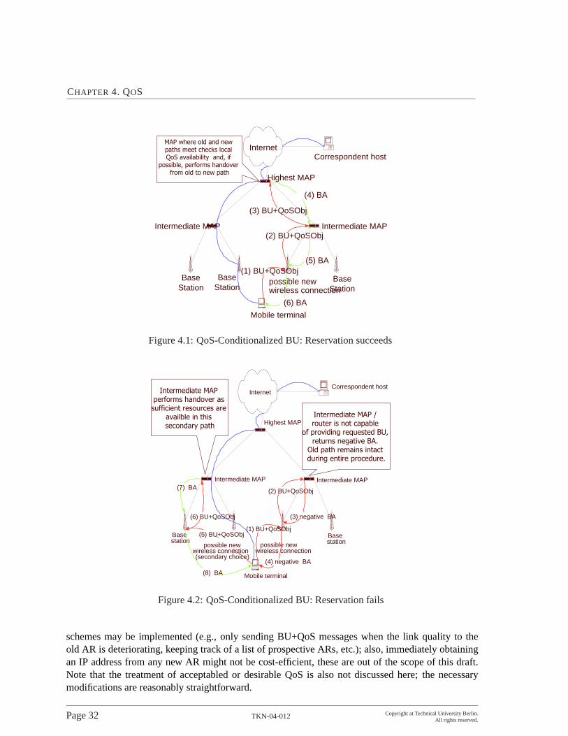
CHAPTER 4. QOS
Mobile terminal
BaseStation
BaseStation
Intermediate MAP Intermediate MAP
Highest MAP
InternetCorrespondent host
possible newwireless connection
(1) BU+QoSObj
(2) BU+QoSObj
(3) BU+QoSObj
(4) BA
(5) BA
(6) BA
������������� �� �������������������������������������� ������
������������������ ������������� �������
BaseStation
Figure 4.1:QoS-Conditionalized BU: Reservation succeeds
Mobile terminal
Basestation
Basestation
Intermediate MAP Intermediate MAP
Highest MAP
InternetCorrespondent host
possible newwireless connection
(1) BU+QoSObj
(2) BU+QoSObj
(3) negative BA
(4) negative BA
(5) BU+QoSObj
(6) BU+QoSObj
(7) BA
(8) BA
possible newwireless connection(secondary choice)
������������� ������������������������������������������� �����������������
������������� �����������������
���������������������������������������� ��������������������������������������
Figure 4.2:QoS-Conditionalized BU: Reservation fails
schemes may be implemented (e.g., only sending BU+QoS messages when the link quality to theold AR is deteriorating, keeping track of a list of prospective ARs, etc.); also, immediately obtainingan IP address from any new AR might not be cost-efficient, these are out of the scope of this draft.Note that the treatment of acceptabled or desirable QoS is also not discussed here; the necessarymodifications are reasonably straightforward.
Page 32 TKN-04-012 Copyright at Technical University Berlin.All rights reserved.

4.3. DESCRIPTION OF THEAPPROACH
The MN detects the connectivity to a new AR either by listening to Router Advertisements or per-forming Router Solicitation as specified in [32]. After MN acquires new local IP address (LCoA), itshould compose a BU+QoS message and send it towards MAP (via new AR).
If the MN receives a BA+QoS message, it should check whether the "F" bit is set in the QoS Option.If not set, the AR which this BA+QoS message passing through should be set as the default route forfuture data transmission. Otherwise no action is required: either still use old AR, or go with no QoSguarantees.
To optimize the QoS-conditionalized binding update procedure, the MN may maintain at least twolists of LCoA-AR-QoS pairs for which are available in connectivity and for which the MN has re-ceived positive BA+QoS messages. Once a BU+QoS message is responded with a negative BA+QoS,the QoS requirements embedded in the next BU+QoS message may differ from the previous one, e.g.,the desired level of QoS could be reduced. There are several possibilities of how the number of avail-able access routers could influence the setting of lowest acceptable QoS. E.g., acceptable QoS couldbe a function of the number of available ARs and/or the MN’s speed.
Upon receiving a BU+QoS message, a router should check whether the "F" bit is set. If not set, itshould ask QoS entity for resources. If sufficient resources are not available, this router should set "F"bit in QoS packet. If this router is the switching MAP, the MAP should compose a BA+QoS packetfrom the BU+QoS packet, with "F" bit set as in the BU+QoS packet and return the BA+QoS messageto the MN.
If "F" bit is not set, the switching MAP should update the MN’s binding to the new LCoA. It maycompose a negative BA+QoS message and send it along the old path to release reservations. A MAPwith MAP functionalities, but is not the switching MAP, behaves like a normal router.
Upon receiving a BA+QoS message, a router should check whether the "F" bit is set. If set, it shouldask QoS entity for releasing any possibly reserved resources. Note that a router MUST NOT interpretthe QoS option inside a BA+QoS as request for new resources, even when the "F" bit is not set.Rather, this QoS option is interpreted as providing more up-to-date information about a flow forwhich reservations have already been made.
Note that in order to correctly process the BA+QoS message, all routers concerned with QoS man-agement, such as MAPs, ARs, and possibly DiffServ and MPLS edge routers (ER), as well as IntServnodes need to maintain state for each flow. However, this is not an additional burden to these entitiesas they need to maintain this same state anyway: MAPs must maintain the binding cache, and alsothe AR has to keep information, including QoS information, for each MN. ERs typically act as ag-gregation routers, i.e. they (as opposed to interior routers) still know individual flows, just as IntServnodes do. Nevertheless, this constitutes an argument in favor of restricting QoS control to AR andMAP.
There are two ways to release the resources that have been reserved. One is to release them explicitlyvia a message carrying a QoS option with "F" bit set. Another is to use soft-state for the QoS reserva-tions and to rely on time-out of the reservation along an unused path. The timer of QoS option maydiffer from that for the BU option.
Copyright at Technical University Berlin.All rights reserved.
TKN-04-012 Page 33

CHAPTER 4. QOS
4.4 Prototypical Implementation of the Approach
This section introduces the implementation of the SeQoMo architecture. We first give an introductionabout the testbed, then we discuss several representative functional tests.
The experimental testbed of SeQoMo has been set up. Details refer to [38].
AN a: AN b:
WAN:
ARb1ARa2ARa1
MN
HA / BR / ARh CN
MAPa / ER MAPb / ER
AN delay
X:X:X:5::7 X:X:X:6::7
X:X:X:0::9
X:X:X:7::8
AN delay
X:X:X:0::1/64
X:X:X:1::3
WAN delay
X:X:X:2233::4 X:X:X:2244::4
Figure 4.3:Testbed setup from IPv6 point of view
Figure4.3shows a simplified testbed setup from a IPv6 point of view is illustrated. The relevant IPv6address of the different entities are given in the dark grey boxes. For the HA, ARa1, ARa2, and ARbthis is the address which is advertised by their RtAdvs. MN and CN are depicted with their HoA.The address depicted next to the MAPs is the address which is carried by means of MAP discovery tothe MNs. An artificial but controlled WAN-delay is enforced for all IPv6 packets traveling betweena MAP and the HA or CN. Another controlled transmission delay is introduced in the two AN of themodel and is referred in the following text as the AN-delay. This affects all packets traveling betweenany AR and the responsible MAP of each AN. Since no IPv6 enabled WAN emulator which is capableto enforce some controllable delay to traversing packets could be found, the Nist Net Delay tool [5]for IPv4 was used. To accomplish the delay of IPv6 packets, they are routed through an IPv4 tunnelvia an additional PC serving as IPv4- WAN- and AN-emulator.
A detailed description of the testbed setup is given in Figure4.4.
The Figure shows 6 physical Linux PCs where some of these machines virtually serve for multiplepurposes. These machines are named as HA, MAP, CN/WAN, ARa, ARb, and MN. The smaller,black-bordered boxes represent network interfaces, where those attached from the outside representreal physical interfaces and those in the inside virtual, tunnel or dummy interfaces. All interfaces areillustrated with an abbreviation for its type. If the interface is IPv6-enabled, its most relevant IPv6
Page 34 TKN-04-012 Copyright at Technical University Berlin.All rights reserved.

4.4. PROTOTYPICAL IMPLEMENTATION OF THE APPROACH
address is depicted in the dark grey box. If the interface is IPv4-enabled, its IPv4 address is given inthe light grey box.
All computers are Intel Pentium II machines with a CPU speed between 300 and 500 MHz. All NICsare 100BaseT 3Com cards. Because link b and f employ only a 10Mbps hub, the bandwidth of theselinks is reduced to 10 Mbps.
The WAN-delay is enforced to all IPv4 packets, which are sent or received from interface eth2 of theHA or eth0 of the MAP and which are routed via interface eth0 of the machine WAN. From IPv6point of view, the tunnel route provided by the sit2 interfaces on the HA and MAP is the only possiblepacket exchange route between HA and CN on one side and the MAP on the other side of the modeledwide area network. In this setup the HA also serves as ER for the CN which is physically located inthe same machine as WAN and AN emulator. However, since only the CN’s interface eth0 is IPv6enabled and the HA is the only known IPv6 default router, all IPv6 packets leaving the CN are routedvia the HA. The IPv6 layer of the CN does not know about the IPv6-in-IPv4 tunneled packets.
The machine MAP serves as MAP with two different address spaces and tunnel interfaces virtuallylike two MAPs for AN a and b. Therefore the SeQoMo-modified router advertisement daemon (radvd)is configured to advertise the availability of MAP (1) with the RCoA-address space X:X:X:2233::/64via interface sit3 and the availability of MAP (2) with the RCoA address space X:X:X:2244::/64 forAccess Network (AN) b via interface sit4.
The AN-delay between the MAP and the AR a and b is achieved in the same way as the WAN-delaydescribed above. None of the physical interfaces connected to link f is enabled for IPv6. For ANa, all packets traveling between the ARa and the MAP are IPv6-in-IPv4 tunneled and routed via theinterface eth1 of machine WAN. The machine WAN then delays the packets for a certain amount oftime (AR-delay). Finally the ARa serves as AR for its two interfaces eth1 and eth2.
The connection of the MN to the access links of HA, AR a, or AR b is controlled via an SNMPmanageable hub. All ports of the hub can be disabled and enabled through certain SNMP commands.When, for example, an overlapping movement from AR a eth1 to AR a eth2 is desired the corre-sponding ports are turned on and off respectively. In the following the MN’s link-connection statewill be given as a vector where the terms h, a1, a2, and b1 stand for the home, ARa1, ARa2 andARb1 link. These terms are followed by a “:0/1” indicating whether the connection to this link is dis-abled or enabled by the controlling hub. One disadvantage of the manageable hub used in this testbedis the indeterministic duration (between 2 and 6 seconds) it takes from sending the Small NetworkManagement Protocol (SNMP) command until the desired action is finally executed by the hub.
An alternative approach to emulate movements is provided by the Netfilter module. The basic ideais to let the MN physically always be connected to all potential AR interfaces, but drop packets fromcertain interfaces based on their MAC address. If the packets are dropped before they are furtherprocessed by the IPv6 layer, the MN has no means to deduce the connection to this particular link ofthe AR. By way of this, tools utilized for performance evaluation can immediately trigger a handoverand have the possibility to consider for example the time when a handover was executed with a muchbetter accuracy. Also it becomes possible to increase the maximal handover rate from only one HO in6 seconds (possible with the SNMP manageable hub) to more than one HO per second. This conceptof a “virtual manageable hub” is employed as a software module in the MN.
Simple connectivity test between the MN and the HA or CN were performed with the diagnostic tool
Copyright at Technical University Berlin.All rights reserved.
TKN-04-012 Page 35

CHAPTER 4. QOS
ping6. For evaluation of application packet loss a simple tool called udp6traffic was developed forsending and receiving User Datagram Protocol (UDP) messages between MN and CN. The trans-mitted messages and their content were monitored via selected interfaces with the tool tcpdump. Ifmonitoring of certain processing parameters of a node was desired this was achieved by insertingappropriate debug messages in the kernel code. The amount of debug message provisioning could beaccessed via an entry in the proc-file system, ranging from an error level where only serious problemsare reported to an informal level where all interesting function calls and variables are logged.
4.5 Conclusions
QoS support in all-IP mobile networks brings about great challenges and requirements. The QoS-conditionalized BU approach presents a hierarchical, edible, and scalable solution that makes use ofan IPv6 hop-by-hop option. Our scheme reduces the signaling bandwidth on the backbone by hidinglocal mobility while still providing ability to do QoS signaling. Our work extends the work in [7]by: 1)enabling mobile users to choose a good access point when several (or overlapping) ones areavailable (e.g.,WLAN and UMTS in hot spots); 2)having handovers QoS-conditionalized handoverscould be performed only when QoS requirements are met or most satisfied. The latency for QoSre-establishment is reduced compared to RSVP-based approaches during a handover.
In the work of the prototypical implementation and experimental testbed setup, a QoS-enabled mo-bility concept based on HMIPv6 [41] and the QoS-conditionalized BU approach [25] has been ac-complished. To achieve this, the following intermediate steps have been conducted. The leveragedarchitectures such as IPv6 and MIPv6 have been reviewed and relevant procedures for this work havebeen summarized.
The underlying concepts – described specifications of HMIPv6 and QoS-conditionalized BU ap-proach – have been analyzed. Their behavior has been re-examined in a more formal way to providea basis for the implementation design. Open issues and possible solutions according to the protocols’specifications have been identified. Especially the composition of a QoS option needed to be reorga-nized and the possibilities to release reserved resources on a stale data path has been neglected in thespecification and required additional investigation.
The implementation design has been adapted to the selected operating system and existing MIPv6implementation environment. Thereby, it was discovered that especially the proper management ofmovement detection, selection of a suitable new default router, and the execution of related registra-tion operations proved to be a difficult task.
A new method, based on a so-called “context field” (essentially summarizing the overall contextof a path, represented by an AR, in a single value), has been designed to overcome this challenge.This selection method can easily be extended to consider new information and different movementpolicies.
Based on the implementation design, a prototype implementation called QoCoo has been realizedto provide support for HMIPv6 and the QoS-conditionalized BU approach. QoCoo has been setupin an experimental testbed. Various representative scenarios have been successfully tested, with theobjective to demonstrate the key capabilities of the underlying protocols. Performance experiments
Page 36 TKN-04-012 Copyright at Technical University Berlin.All rights reserved.

4.5. CONCLUSIONS
showed that the packet loss per handover for micro movements can be reduced by more than 80percent (depending on the transmission delay between access network and CN) when using HMIPv6or the QoS-conditionalized BU approach instead of MIPv6. However, it was also shown that anenhanced movement detection mechanism is necessary to let the application layer benefit from thereduced signaling latency introduced by the use of HMIPv6.
Copyright at Technical University Berlin.All rights reserved.
TKN-04-012 Page 37

CHAPTER 4. QOS
physical link f
link a1
MANAGEABLE HUB
link a2 link b1
IPv6−in−IPv4 tunnelIPv4 route
link h
physical link b
v6: global addr/128v4: −
sit1 v6−in−v4
eth0 mac:..94E9v6: −v4: global addr./24
eth1 mac:..BF6Fv6: X:X:X:0::1/64v4: X.X.0.1/24
sit2 v6−in−v4v6: X:X:X:2211::7v4: −
eth0 mac:..30D9v6: −v4: X.X.1.4
sit2 v6−in−v4v6: X:X:X:1111::4v4: −
sit2 v6−in−v4v6: X:X:X:1111::1/128v4: −
eth2 mac:..C033v6: X:X:X:1::1/64v4: X.X.1.1/24
eth0 mac:..EEECv6: −v4: X.X.2.8
sit2 v6−in−v4v6: X:X:X:2222::8v4: −
v4: ..8
v6: ARb ::8
eth0 mac:..9559
v4: X.X.1.3v6: X:X:X:1::3
eth1 mac:..C139v6: −v4: X.X.2.3
eth1 mac:..8264v6: X:X:X:5::7v4: −
eth2 mac:..75C1v6: X:X:X:6::7v4: −
eth1 mac:..4BFCv6: X:X:X:7::8v4: −
v4: WAN (/AN−del). ..3
v6: CN ::3
v4: ..7
v6: ARa (1/2) ::7
v4: ..4
v6: MAP (a/b) ::4
eth0 mac:..9575v6: X:X:X:0::9v4: X.X.0.9
v4: ..9
v6: MN ::9
eth0 mac:..F186v6: −v4: X.X.2.7
v6: −v4: X.X.2.4
v4: ..1
v6: HA: ::1 (BRh,ARh)
dummy0 virtual
v4: −
v6: X:X:X:2244::4
dummy0 virtual
v4: −
v6: X:X:X:2233::4
sit4 v6−in−v4v6: X:X:X:2222::4v4: −
sit3 v6−in−v4v6: X:X:X:2211::4v4: −
eth1 mac:..9CEC
Figure 4.4:Concrete testbed setup
Page 38 TKN-04-012 Copyright at Technical University Berlin.All rights reserved.

Chapter 5
Security
The security aspect of the project lies in authentication, QoS-aware authorization for mobile usersand Denial of Service (DoS) protection of handover process. The visited network should verify theMN has the identity it claims to have. Also, the visited network needs to learn what kinds of servicesor how many QoS resources the MN is allowed to use and verify the resource usage of the MN toensure that the total resource consumption does not exceed what the MN is entitled to.
To support efficient handovers, it is also necessary to minimize the registration latency introduced byauthentication and authorization (AA) procedures in handovers taking place both within an adminis-trative domain and between such domains.
Furthermore, all AA messages should be stored and transmitted securely to prevent both passive andactive attacks.
5.1 Issues and Steps
Briefly, the issues are the following:
• Authentication performance during handovers: how to realize efficient identity check during ahandover should be addressed;
• Authorization of mobile devices in access networks: how to check what resources a mobilenode is allowed to use is another issue;
• Protection QoS against DoS attacks: how to ensure that QoS-reservation can not be abused toreduce the availability of an access network is a challenge.
To address the identified issues, we first evaluate the integrated AAA and Mobile IP authenticationwith a simulation, then we design the QoS-aware authorization processes and the appropriate DoSprotection mechanism, finally we evaluate the developed QoS protection scheme with a simulationand implement it on the testbed.
Copyright at Technical University Berlin.All rights reserved.
TKN-04-012 Page 39

CHAPTER 5. SECURITY
5.2 AAA and Mobile IP Authentication
The principal approach of the IETF to authenticate a mobile node during handover operations is tointegrate authentication during Mobile IP registration with a general AAA infrastructure based on theso-called Diameter protocol [4] [14].
The main focus of authentication in this respect is the problem of securely identifying entities for IPaccess in a mobile network with roaming capabilities. Strongly related to this problem is the taskof managing the cryptographic keys that are needed for secure entity authentication and data originauthentication for signalling messages, respectively. A special requirement to the authentication in-frastructure arises out of the fact that mobile devices require frequent handovers from one accesspoint to another. These handovers can either occur within an administrative domain (intra-domainhandover) or between two administrative domains (inter-domain handover). An important issue isthe performance of the (re-)authentication during a handover operation. In order to assess the perfor-mance impact of the authentication procedure on handover events we developed a simulation modelwhich takes into account three different types of handover events and analyzed this model with twodifferent traffic models [29].
Figure 5.1 shows the trust relationships in the AAA and Mobile IP joint architecture. It is notedthat static trust relationships between AAA attendants (e.g. FAs) and AAA servers, between AAAservers and brokers, between mobile node and its home AAA server already exist. The dynamic trustrelationships between an AR and HA, between MN and AR, between MN and HA are created by theAAA server in the home network (AAAH).
Figure 5.1:Trust relationships in AAA and Mobile IP infrastructure
The results of our simulation study show, that:
• The delay experienced by a mobile node in case of a full authentication dialogue involvingentities of the mobile node s home network is largely determined by the end-to-end delaybetween the foreign and the home network.
Page 40 TKN-04-012 Copyright at Technical University Berlin.All rights reserved.

5.2. AAA AND MOBILE IP AUTHENTICATION
• The workload of AAA servers remains moderate in case of a load- and mobility model inspiredby established values of GSM networks as well as in case of a more progressive mobility model.
• The workload of AAA servers grows infinitely under both mobility models if cryptgraphicalgorithms are used that require about 100 (30) times the processing capabilities of algorithmscurrently envisaged by the IETF (cryptographic hash functions and symmetric encryption).
An important consequence of the third finding is that the use of asymmetric cryptography wouldpossibly lead to overload situations under the investigated conditions, as those operations often requireprocessing capabilities in this range.
Figure5.2shows that the system is only under light load if operated with the symmetric cryptographicalgorithm and hash functions as intended by the IETF.
Figure5.3shows that if computationally intensive cryptographic operations (factor in the range 80 to100) are used, the system gets to overloaded because asymmetric cryptography is too "expensive" inthis context.
Figure 5.2:Authentication delay with symmetric cryptographic algorithm
Copyright at Technical University Berlin.All rights reserved.
TKN-04-012 Page 41

CHAPTER 5. SECURITY
Figure 5.3:Authentication delay with asymmetric cryptographic algorithm
5.3 QoS-aware Authorization
With the development of all-IP communications in mobile computing, a large amount of research ef-forts have been focusing on provisioning Quality of Service (QoS) to mobile users who are expectingsimilar services in a visited network as in their home network. From the service or resource provider’spoint of view, however, before allocating or reserving its available resources according to the mobileuser’s QoS requests, the visited network should authorize the request to make sure that the user haspermission to use the requested resources.
5.3.1 Goals and Requirements
The goal of the authorization work [8, 9, 10] is to design an authorization scheme for HMIP and AAAjoint networks aiming at QoS-capable and low-latency micro-mobility handovers.
The identified requirements are:
• Authorization information availability: When a MN registers in a visited network and requestsfor a service for the first time during an inter-domain handover, the network can authorize the
Page 42 TKN-04-012 Copyright at Technical University Berlin.All rights reserved.

5.3. QOS-AWARE AUTHORIZATION
QoS requests whether the MN has permission to use the requested resources with the help ofe.g. the MN’s home network.
• Mapping of authorization data expression to QoS: The authorization data expression shouldensure an unambiguous mapping to the QoS requests in order to make the QoS requests under-standable and verifiable at an authorization entity. Efficient handover support: It is necessarythat the authorization process adds minimal latency to the registration and handover procedures.
• Capability to handle an MN’s various activities: MN can upgrade its QoS requests dynamicallybased on the conditions of the network. The authorization scheme must be capable to handleQoS request upgrading cases without losing other optimizing features.
• Security considerations: Security measures are needed for both hop-by-hop QoS signaling pro-tection and end-to-end authorization protection against the attacks that a malicious node forgesor modifies legitimate MN’s QoS requests. Another security concern is MN’s misbehavior,which means that an MN could possibly attach to multiple access routers (ARs) at the sametime and try to use more resources than it is entitled to. Even if the requested QoS over eachlink meets the MN’s authorization limits, it could eventually happen that the total amount ofQoS requested in the visited network exceeds the limit. If the network can not efficiently checkthe ”credibility” of a QoS-request, malicious entities could flood the network with bogus QoS-requests in order to cause exhaustion of the available resources by temporal reservations.
5.3.2 Use Cases of the Authorization Processes
In this section, we describe the integrated processes of the three components in the SeQoMo archi-tecture.
When an MN enters the visited access network or just powers up, it can detect its movement anddistinguish whether the movement is the inter-domain or intra-domain handover based on L2/L3information. We will describe the (re-)registration process in inter-domain and intra-domain handovercases separately.
Inter-domain Handover
Figure5.4 illustrates the registration process in the inter-domain handover cases.
1. MN receives an advertisement from an AR (e.g. AR2), and its IHA indicates that it is in aninter-domain handover process;
2. MN composes a registration request message, including a range of QoS parameters, for ex-ample a Desired Bandwidth (DBW) and an Acceptable Bandwidth (ABW) in a Hop-By-Hopoption, assigning the address of MAP as the destination address;
3. AR2 receives the message. Since it notices that there is no cookie being presented, it indicatesthat the request will go through an inter-domain handover process. Then it starts the uplinkQoS-Conditionalized Binding Update (QCB) procedure. During this procedure, every node
Copyright at Technical University Berlin.All rights reserved.
TKN-04-012 Page 43

CHAPTER 5. SECURITY
MN AR1 MAP AAAL AAAH HA
2. Registrationrequest
7. AA check5. ARR
6. ARR 9. handover
8. HOR
10. HOA
11. ARA
13. ARA
1. Advertisement
4. Temporary handover
Indicate inter-domain handover
14. Validate the temporary handover
AR0
Release reserved resources in the old path
15. Downlink of QoS-cond. BU
3. Uplink of QoS-cond. BU
17. Registrationanswer
12. Cache AA information
16. Generate a cookie for the MN
Figure 5.4:The registration process in case of inter-domain handover
along the path, including AR2, intermediate routers and MAP, checks whether it can satisfy theDBW. If yes, it reserves the resource for the flow; if not but it can satisfy the ABW, it reserveswhat it can provide, modifies the range of requested QoS parameter according to satisfied value,and passes the message to the next node; if it can not satisfy even the ABW, it indicates anegative check result in the message;
4. MAP checks whether the path can satisfy the requested QoS. If not, it sends a ICMP messageto MN acknowledging registration fails; if yes, it creates an entry for the binding of LCoA andRCoA;
5. and it composes an AA-Registration Request (ARR) message with the destination address ofAAAH. The BU message destined to HA is embedded in ARR;
6. AAAL receives the ARR. When it realizes that it is under an inter-domain process, it forwardsthe message to AAAH;
7. AAAH checks the authentication and authorization of the QoS request from MN;
8. If the check succeeds, it composes a HOme-agent-Request (HOR) including the BU to HA;
9. HA caches the binding of MN’s RCoA and its home address;
10. HA sends a HOme-agent-Answer (HOA) to AAAH. Meanwhile, it initiates the process to re-lease the reserved resource on the old path;
11. AAAH generates a session key and inserts it in the AA-Registration Answer (ARA) message;
Page 44 TKN-04-012 Copyright at Technical University Berlin.All rights reserved.

5.3. QOS-AWARE AUTHORIZATION
12. AAAL caches the session key, the bandwidth value as MN’s Maximum Bandwidth (MBW) inorder to authorize the MN’s further QoS requests locally;
13. AAAL forwards the ARA to MAP;
14. MAP caches the session key, validates the handover and starts the downlink procedure of QoS-cond. BU;
15. During this procedure, each node along the path adjusts or confirms the reserved bandwidth;
16. AR2 caches the session key, generates a cookie, encrypts the cookie with the session key, andsends a registration answer to MN;
17. MN receives the registration answer message, decrypts the cookie with the session key. MNgets the session key due to its long term security association with AAAH.
Strictly, the QoS-Conditionalized Binding Update (QCB) procedure, which starts from MN and endsat MN, includes the steps of registration request and registration answer. It is noted that the illustratedprocedure is identical with the procedure of Diameter Mobile IPv6 application [14].
Intra-domain Handover
Figure5.5and Figure5.7illustrates the re-registration process in case of intra-domain handover whichdoes not involve the AAAH for the re-authorization. We propose two schemes how to integrate theQoS-cond. BU procedure and re-authorization procedure. We first describe the two schemes and thena comparison of them.
• BU and re-authorization in series
As shown in Figure5.5and5.6, the re-registration process is the following:
1. MN receives an advertisement from an AR (e.g. AR2), and its IHA indicates that it is inan intra-domain handover process;
2. MN composes a registration request message, including a range of QoS parameters, forexample a desired bandwidth (DBW) and an acceptable bandwidth (ABW) in a Hop-By-Hop option, assigning the address of MAP as the destination address, inserting thecookie;
3. AR2 receives the message. Since it notices that there is a cookie being presented, itindicates that the request will go through an intra-domain handover process. It first verifiesthe cookie. Details about the cookie mechanism refer to the patent application document.If the cookie verification fails, the request is dropped silently; if it passes, AR2 notifiesthe use of the presented cookie while starting the uplink QoS-Conditionalized BindingUpdate (QCB) BU procedure;
4. This procedure goes as in the inter-domain handover case;
Copyright at Technical University Berlin.All rights reserved.
TKN-04-012 Page 45

CHAPTER 5. SECURITY
MN AR2 MAP AAAL
2. Registration request
5. ARR
7. ARA
10. Registrationanswer
1. Advertisement
4. Uplink of QoS-cond. BU
6. Re-authorization
Indicate intra-domain handover
Validate the handover
AR1
3. Cookie checkCookie notification
Release reserved resources in the old path9. Re-authenticate;
Issue a new cookie
8. Downlink of QoS-cond. BU
Figure 5.5:BU and re-authorization in series
5. MAP checks whether the path can satisfy the requested QoS. If the path can satisfy theQoS request, it creates an entry for the binding of LCoA and Regional Care-of Address(RCoA). MAP also composes ARR and sends it to AAAL;
6. AAAL re-authorizes the request based on the cached MN’s authorization information (e.g.MBW);
7. If the re-authorization succeeds, AAAL composes a ARA message;
8. MAP validates the handover, includes the session key in the downlink Acknowledgement(ACK) message of QoS-Conditionalized Binding Update (QCB) process. Meanwhile, itinitiates to release reserved resource in the old path;
9. AR2 re-authenticates the MN with the session key. If it is successful, it generates a newcookie, encrypts it and sends it to MN;
10. MN receives re-registration answer message and gets the new cookie.
• BU and re-authorization in parallel
As shown in Figure5.7and5.8, the re-registration process is the following:
1. MN receives an advertisement from an AR (e.g. AR2), and its IHA indicates that it is inan intra-domain handover process;
2. MN composes a registration request message, including a range of QoS parameters, forexample a desired bandwidth (DBW) and an acceptable bandwidth (ABW) in a Hop-
Page 46 TKN-04-012 Copyright at Technical University Berlin.All rights reserved.

5.3. QOS-AWARE AUTHORIZATION
Figure 5.6:Process flowchart of BU and re-authorization in series
By-Hop option, assigning the address of MAP as the destination address, inserting thecookie;
3. AR2 receives the message. Since it notices that there is a cookie being presented, itindicates that the request will go through an intra-domain handover process. It first verifiesthe cookie. Details about the cookie mechanism refer to the patent application document.If the cookie verification fails, the request is dropped silently; if it passes, AR2 notifiesthe use of the presented cookie while starting both the uplink QoS-conditionalized (QoS-cond.) BU procedure and the re-authorization procedure;
4. The uplink procedure is the same as in the previous subsection; Meanwhile, AR2 com-
Copyright at Technical University Berlin.All rights reserved.
TKN-04-012 Page 47

CHAPTER 5. SECURITY
MN AR2 MAP AAAL
2. Registration request
4‘ . ARR
5‘ . ARA
5. downlink of QoS-cond. BU7. Registration
answer
1. Advertisement
4. Uplink of QoS-cond. BU
Re-authorization
AR1
3. Cookie checkCookie notification
Release reserved resources in the old path
6. Re-authenticate;Issue a new cookie
Figure 5.7:BU and re-authorization in parallel
poses the ARR message and sends it to AAAL for re-authorization;
5. ARA is sent back to AR2. It is assumed that the re-authorization result arrives earlier thanthe downlink of BU procedure;
6. If the two procedures result in positive acknowledgements, AR2 re-authenticates the MNwith the session key. If it is successful, it generates a new cookie, encrypts it and sends itto MN;
7. MN receives re-registration answer message and gets the new cookie.
• Comparison
The second scheme is more optimized in terms of low-latency re-registration. However, if re-authorization takes longer time especially when AAAL involves AAAH for the re-authorization,the downlink message of QoS-Conditionalized Binding Update (QCB) arrives at AR2 beforethe re-authorization result does. This is a tough situation for AR2 to deal with. If AR2 holdsthe downlink procedure and waits for the re-authorization result, the QoS-cond. procedure isinterrupted; if AR2 continues the downlink procedure without the re-authorization result, whena negative re-authorization result arrives later, it has to take some actions to adjust reservedresources or even tear down the path.
The first scheme avoids the potential trouble. But the QoS-cond. BU procedure is definitelyinterrupted by the re-authorization procedure.
5.3.3 Discussion on the Authorization Process
The authorization process in SeQoMo is the first QoS-aware authorization scheme in HMIPv6 archi-tecture.
In order to meet the requirement of low-latency (re-)registration process, a couple of measures aretaken:
Page 48 TKN-04-012 Copyright at Technical University Berlin.All rights reserved.

5.3. QOS-AWARE AUTHORIZATION
Figure 5.8:Process Flowchart of BU and re-authorization in parallel
• the (re-)authorization process takes place in a hierarchy-based AAA architecture;
• the (re-)authorization process is integrated with the BU process, or happens in parallel with theBU process;
• (re-)registration request enables a range of QoS parameters rather than a specific value as tosimplify the authorization negotiation process;
Copyright at Technical University Berlin.All rights reserved.
TKN-04-012 Page 49

CHAPTER 5. SECURITY
• Authorization data is cached at AAAL to authorize MN’s QoS request without involving AAAHif possible.
Additionally, in order to avoid expose the subscribed value of QoS parameters which is cached byMN’s AAAH, only the desired value or the resource the visited access network can provide is cachedat AAAL as the maximum value MN is entitled to use. When MN upgrades its QoS request orgenerates a new flow so that AAAL is not capable to authorize it, AAAL should communicate withAAAH for authorization. If the authorization succeeds, AAAL updates the cached “the maximumvalue”. Therefore, the authorization is a continuous process.
Comparison With Authorization Token
Authorization token is a Cryptographic Message Syntax (CMS) protected (digitally and encrypted)collection of objects [27, 28]. The “token” is generated by a policy server and transparently replayedthrough the host to the edge router where it is used as part of the policy-controlled flow admissionprocess. It can be used to allow Cross Application Signaling Protocol (CASP) nodes along the path toexecute policy based admission control or authorization check without triggering the communicationof Policy Execution Point (PEP) and Policy Decision Point (PDP) [39][40].
The use of authorization token raises some security concerns. For example, as mentioned in [44], theauthorization token might be eavesdropped by an adversary so that the adversary might replay it andgain access to resources with the successful verification.
In contrast, the cookie mechanism aims to prevent replay attacks and DoS attacks. If a cookie ex-tends to contain some authorization information (that means cookies with different colors representdifferent amount of resources being authorized to an MN.), it can be used to:
• provide authentication at the edge router;
• provide admission control at CASP nodes;
• authorize requested QoS to reserve resource;
• provide protection against replay attacks, message modification and DoS attacks.
Additionally, it can be useful to achieve optimized handovers.
Comparison With Context Transfer Protocol
The primary motivation of Context Transfer (CT) Protocol [34, 36] is the need to quickly re-establishcontext transfer-candidate services without requiring the mobile host to explicitly perform all protocolflows for those services from scratch. An additional motivation is to provide an inter-operable solutionthat works for any Layer 2 radio access technology.
Access Routers typically establish state in order to effect certain forwarding treatments to packetstreams belonging to nodes sharing the access router. For instance, an access router may establish
Page 50 TKN-04-012 Copyright at Technical University Berlin.All rights reserved.

5.4. DOS PROTECTION
an AAA session state and a QoS state for a node’s packet streams. When the link connecting amobile node and the access router is bandwidth- constrained, the access router may maintain headercompression state on behalf of the mobile node.
As described in [33], one of the more compelling applications of context transfer is facilitating the re-authentication of the mobile host and re-establishment of the mobile host’s authorization for networkaccess in a new subnet by transferring the AAA context from the mobile host’s previous AAA serverto another. This would allow the mobile host to continue access in the new subnet without having toredo an AAA exchange with the new subnet’s AAA server. Naturally, a security association betweenthe AAA servers is necessary so that the mobile host’s sensitive authentication information can besecurely transferred.
Therefore, the differences between CT and the authorization process in SeQoMo in terms of authen-tication and authorization are:
• In CT, AAA data are transferred from previous visited network to the current visited network; InSeQoMo, AAA is performed with AAAH. However, in the case that MN upgrades its requestedQoS so that the authorization can not be done based on the authorization information from theprevious network, is the authorization solution in SeQoMo is more flexible and generic;
• In CT, when MN’s movement is unpredictable, AAA information is transferred in a one-to-many manner in order to quickly re-establish the AA service; In SeQoMo, when MN sets upassociation with an AR which does not know it, a cookie can help AR to authenticate MN as apreliminary check. The further AA can be integrated with other processes e.g. BU process.
5.3.4 Summary
Our authorization scheme takes the following measures to support the efficient (i.e. low-latency)handover feature:
• the AAA protocol is integrated with the hierarchical Mobile IP. More precisely, the authoriza-tion process takes place in series with the BU process in inter-domain handover cases and inparallel with the BU process in intra-domain handover cases;
• QoS requests include a range of QoS parameter rather than a specific value so as to simplifythe authorization negotiation process;
• Authorization data is cached locally (i.e. at AAAL);
• A preliminary check is performed to protect QoS against DoS; (find details here).
5.4 DoS Protection
Quality of Service (QoS) mechanisms in networks supporting mobile Internet communications giverises to new threats that these mechanisms could be abused by malicious entities to launch so-calledDenial of Service (DoS) attacks, which aim to reduce the availability of services to legitimate users.
Copyright at Technical University Berlin.All rights reserved.
TKN-04-012 Page 51

CHAPTER 5. SECURITY
5.4.1 Motivations, Goals and Approach
In an access network, a mobile user sends a request to an access point for a QoS. If there is no securitycheck on QoS requests, attackers can also send requests to reserve resources. Intensive bogus requestsfrom attackers could reserve all resources along a path so that this path has no available resource forany legitimate users. This threat is a kind of DoS attacks as shown in Figure5.9.
Figure 5.9:Resource exhaustion as a kind of DoS attack
Therefore, when an access point receives a QoS request, it must perform an security check. If theaccess point communicates with an local security entity (e.g. a local AAA server) for authenticationand authorization checks. Obviously, the propagation delay for this signaling is unfavorable for afast handover. Furthermore, the same checks have to be done to the requests from attackers. Thus,intensive and extensive bogus requests may degrade substantially the signaling capacity of the accessnetwork including a path and the local AAA server. This is another kind of DoS attacks as shown inFigure5.10.
Therefore, we need to protect QoS-aware communications from DoS attacks and achieve an optimizedhandover by reducing the registration latency caused by the security checks. For these purposes, wepropose that before the resource reservation and authentication and authorization process, the accesspoint performs a preliminary check with a "cookie". The cookie mechanism is in a process of patentapplication. The detailed solution will be published soon.
5.4.2 Description of the Cookie Mechanism
A cookie contains the cookie information and a hash code.
The cookie information includes:
• Identity of the MN: the MN’s unique identifier in the access network. This can be a local uniqueidentifier the MN gets after its first registration.
Page 52 TKN-04-012 Copyright at Technical University Berlin.All rights reserved.

5.4. DOS PROTECTION
Figure 5.10:Signaling capacity depletion as a kind of DoS attack
• Identity of the AR who generates the cookie: the AR’s unique identifier. It can be the AR’s IPaddress or another unique identifier acceptable in the access network.
• Creation time: A timestamp when the cookie is generated. It is used to limit the cookie’s periodof validity.
• Random number: It is used to distinguish two cookies which are generated at the same time.
• Hash code: The hash code is a message digest of the cookie information and a cookie key. Thehash function can be of either Keyed-Hashing for Message Authentication using MD5(Message-Digest 5 (HMAC-MD5) or Keyed-Hashing for Message Authentication using SHA1(SecureHash Algorithm 1 (HMAC-SHA1). The cookie key is distributed from the MAP to each ARand updated by the MAP periodically, for example a new cookie key is distributed by the MAPonce per hour or day.
In summary, a cookie is defined according to the following formula:
CookieInfo :=(IdentityMN , IdentityARi, T imestampARi,
RandomNumberARi
)
CookieHash := HMAC(CookieKey, CookieInfo
)
Cookie :=(CookieInfo, CookieHash
)
Cookies are always generated by an AR. The first cookie the MN gets is generated by the AR towhich the MN attaches when it powers up or when it performs an inter-domain handover. That means,after its successful registration, this cookie is encrypted with the session key established between theMN and all ARs in the access network and transmitted from the AR to the MN along with the BUacknowledgement message. Figure5.11shows how MN gets the first cookie.
Each AR maintains two lists:a trusted listanda trusting list. The AR only accepts the cookiesgenerated by the ARs on the trusted list. On the trusting list are ARs who accept the cookies generated
Copyright at Technical University Berlin.All rights reserved.
TKN-04-012 Page 53

CHAPTER 5. SECURITY
MAP
Cookie is generated by AR2; Cookie is encrypted with the session key
AR1 AR2 AR3 AR4 AR8AR7AR6AR5
AAAL
MN
AAAH
Internet
Figure 5.11:First cookie generation
by this AR. Of course, it is necessary to contain corresponding entities in the trusting list and thetrusted list of the various ARs in the access network. An AR puts its neighboring ARs (at least theadjacent ARs) on its trusted and trusting list. The AR is on its own two lists since AR accepts thecookies generated by itself.
When the MN performs an intra-domain handover, it submits the cookie to the new AR in plaintext.The new AR then takes three actions as the verification:
• check the timestamp to see whether the cookie is expired;
• check the identity of the cookie generator to see whether the cookie is created by an AR on itstrusted list;
• If the above two checks pass, re-compute a key-hashed digest of the cookie information byusing the cookie key, and compare it to the hash digest contained in the cookie. If the two hashdigests match, the cookie check verification has been completed successfully.
MAP
AR1 AR2 AR3 AR4 AR8AR7AR6AR5
AAAL
MNnotification
area of validity of AR2‘s cookies= AR2‘s trusting list
Figure 5.12:Cookie verification
Page 54 TKN-04-012 Copyright at Technical University Berlin.All rights reserved.

5.4. DOS PROTECTION
Figure5.12shows how AR verifies a cookie. If the verification succeeds, the QoS-conditionalizedBU process and re-authorization process begin. The new AR will re-authenticate the re-registrationrequest when it gets the session key embedded in the BU ACK message from the MAP.
If the verification fails, the AR will drop the re-registration request silently in order not to devotefurther resources to this possibly bogus request. If after a certain amount of time the MN has notreceived any re-registration answer from the AR, it has to initiate an authentication and authorizationprocess involving AAAL and AAAH as in an inter-domain handover or power-up case since the oldcookie has been transmitted in plaintext and can not be used anymore. Thus the MN can not get thebenefit of the optimized handover processing. Even though the verification failure could happen dueto packet loss over wireless interfaces, cookie key updating or interfere by an attacker, the cookie-based preliminary check can prevent DoS attacks to the access network. However, it is assumed thatan MN does not experience this case very often during its normal operation (i.e. continuous movingwithout interrupting the service use).
After verifying a cookie, the new AR informs the old AR who generated the cookie about the cookieusage. The old AR then notifies all ARs on its trusting list except the new AR to invalidate the cookiepreventing the second cookie usage attempt at these ARs since an attacker could eavesdrop the cookiefrom the open wireless interface and replay it to cheat these ARs for access.
After the expiration of a cookie’s lifetime, all ARs can delete their knowledge about its usage.
A new cookie encrypted with the session key is granted to the MN for its next intra-domain han-dover unless the re-authentication check fails. The old cookie can not be used in the access networkanymore. Figure5.13shows MN is granted a new cookie.
MAP
AR1 AR2 AR3 AR4 AR8AR7AR6AR5
AAAL
MN
Cookie is generated by AR3; Cookie is encrypted with the session key
Figure 5.13:New cookie granting
5.4.3 Simulation Results
A performance evaluation is performed by simulating three cases in the re-registration processes inHMIPv6 intra-domain handovers with OMNET++(Objective Modular Network Testbed in C++), anobject-oriented modular discrete event simulator.
Copyright at Technical University Berlin.All rights reserved.
TKN-04-012 Page 55

CHAPTER 5. SECURITY
• Case 0: there is no cookie protection.
In the case that there is no cookie check at an AR, AR should contact AAAL for the purpose ofre-authentication and re-authorization (re-AA) after receiving a re-registration request. Whenit receives a positive re-AA ACK message for a request from AAAL, the AR starts a QoS-conditionalized BU process for the request. If the re-AA fails, AAAL drops the packets silentlywithout notifying the AR.
• Case 1: AR verifies the presented cookie and if the check passes, it starts two processes (QoS-conditionalized BU process and re-authorization) in series.
In this case, an AR performs a preliminary check with cookie, which is included in the Hop-by-Hop option in the IPv6 header, after receiving a re-registration request destined to the MAP.If the check passes, the AR continues the uplink of the BU process, as well as it does the noti-fication. When the message arrives at MAP and the path can satisfy at least the minimal QoS,MAP initiates an re-authorization process to AAAL. If the authorization succeeds, MAP sendsa downlink message of the BU process towards MN. When the AR receives the message, it per-forms the re-authentication with the knowledge of the session key. If the check is successful,it generates a new cookie, encrypts it with the session key, and inserts it in the Hop-by-Hopoption in the BU ACK message.
• Case 2: AR verifies the presented cookie and if the check passes, it starts two processes (QoS-conditionalized BU process and re-authorization) in parallel.
In this case, an AR performs a preliminary check with cookie, which is included in the Hop-by-Hop option in the IPv6 header, after receiving a re-registration request destined to the MAP.If the check passes, the AR start the two processes in parallel, as well as it does the notification.It is assumed that the result of the re-authorization process arrives earlier than that of the QoS-conditionalized BU process so that the time spent on the former process has no contribution tothe contribution to the re-registration delay.
MAP
AR1
AAAL
AR2 AR8...
MOBEN1 MOBEN2 MOBEN8
10Mb/s 10Mb/s 10Mb/s
100Mb/s 100Mb/s 10Mb/s
100 Mb/s
MN: traffic mode – possion distribution
ATT: traffic mode – deterministic (constant rate)
Figure 5.14:Topology assumed in the simulation
Figure5.14shows the topology used in the simulation.
Page 56 TKN-04-012 Copyright at Technical University Berlin.All rights reserved.

5.4. DOS PROTECTION
The simulation model consists of one AAAL, one MAP, eight ARs and eight mobile environment(MOBEN). The AAAL connects the MAP with a 100 Mbps Ethernet link; the MAP connects everyARs with 100 Mbps Ethernet links; Each AR is responsible for one MOBEN, which represents 4000MNs and one attacker. Each MN or the attacker sends requests to the corresponding AR as re-registration requests via a wireless link of 10 Mbps data rate.
At each AR, the inter-arrival traffic from legitimate MNs is modeled with a Poisson process with themean inter-arrival time of 0.5s [30]; Each of the 4000 MNs in one MOBEN performs 1.8 intra-domainhandovers per hour.
The traffic of an attacker is modeled with deterministic process. That means an attacker always sendsbogus requests with a constant rate.
To evaluate how efficient the cookie mechanism works in the re-registration processes, we focus onhow the attacking rate influences the following three parameters in three different cases:
• Mean re-registration delay: the duration between the transmission of the first bit of a re-registration request of a legitimate MN and the arrival of the last bit of the correspondingre-registration response. This parameter can reflect the signaling capacity of a path the effi-ciency of an intra-domain handover.
• Number of tasks in AAAL per second: how many re-AA tasks in Case 0 and how many re-authorization tasks in Case 1. When AAAL has too high throughput of re-AA, the computingcapacity is threaten by DoS attacks.
• The Queue length at AAAL: how many messages waiting in the incoming queue for beingprocessed. When AAAL has too many messages waiting in its queue, its storage capacity isbeing exhausted.
Figure5.15is given for illustrative purposes and shows how the attacking rates increases over timeduring the simulation. The starting point of the attacking rate is set to 100, and the attacking rateincreases by 10 every six minutes. During each six-minute period, the attacking rate is constant.
Figure5.16shows how the increasing attacking rate influences the average re-registration delay. Be-fore the attacking rate reaches 200 per second, the average re-registration delay stays relatively con-stant. That means attackers does not give the access network any trouble with the attacking rate lessthan 200 per second.
Afterwards, with the increasing of the attacking rate, the average re-registration delay in no-cookiecase (Case 0) goes up gradually while the parameter in cookie cases (Case 1 and Case 2) still keepsstable. This proves that the cookie mechanism is efficient in preventing depletion of signaling capacityand beneficial of optimized intra-domain handovers.
Figure5.17 shows that the cookie verification at ARs can prevent AAAL from heavily loaded byre-authentication and re-authorization works, and prevent AAAL’s queue from being filled up shownin Figure5.18.
Therefore, this performance evaluation shows that the cookie-based mechanism is efficient to dealwith DoS attacks as identified in Section5.4.1, and therefore improves the optimized and QoS-awarehandovers.
Copyright at Technical University Berlin.All rights reserved.
TKN-04-012 Page 57

CHAPTER 5. SECURITY
100
150
200
250
300
350
400
450
500
0 0.5 1 1.5 2 2.5 3 3.5 4
Atta
ckin
g ra
te
simulation time (hour)
Attacking Rate
Figure 5.15:Increase of attacking rate over time
0
0.05
0.1
0.15
0.2
0.25
0.3
0 0.5 1 1.5 2 2.5 3 3.5
Reg
istr
atio
n D
elay
(s)
simulation time (hour)
Registration Delay in Case 0 Registration Delay in Case 1Registration Delay in Case 2
Figure 5.16:Impact of increasing attacking rate on mean re-registration delay
5.4.4 Discussion on the Cookie Mechanism
A couple of concerns of the cookie mechanism might deserve further discussion:
• Discussion on session keys:Originally a session key is used to secure end-to-end communications between MN and MAPor MN and CN. In our cookie mechanism, the session key is used for authenticating the MN
Page 58 TKN-04-012 Copyright at Technical University Berlin.All rights reserved.

5.4. DOS PROTECTION
0
20
40
60
80
100
120
0 0.5 1 1.5 2 2.5 3 3.5 4
Num
ber
of T
asks
at A
AA
L pe
r S
econ
d
simulation time (hour)
Number of Tasks at AAAL per Second in Case 0Number of Tasks at AAAL per Second in Case 1
Figure 5.17:Impact of increasing attacking rate on number of tasks in AAAL
0
100
200
300
400
500
600
700
800
900
1000
0 0.5 1 1.5 2 2.5 3 3.5
Que
ue le
ngth
simulation time (hour)
Queue Length of AAAL in Case 0Queue Length of AAAL in Case 1
Figure 5.18:Impact of increasing attacking rate on queue length of AAAL
when the new AR gets the session key from MAP and encrypting a new cookie granted to theMN by the new AR.
It might be useful as the authentication key to protect message integrity of hop-by-hop BUpacket at each node along a QoS path.
Since the session key can be used for multiple purpose and is known by many entities such asARs, MAP and AAAL, it easily becomes compromised. The threat of a compromised session
Copyright at Technical University Berlin.All rights reserved.
TKN-04-012 Page 59

CHAPTER 5. SECURITY
key should be evaluated.
• Discussion on cookies:It theoretically proves that DoS attack to a path can be completely prevented with the assump-tion that notifications will arrive at destinations ahead of replayed cookies. However, whenthe cookie itself or the cookie key is compromised, the risk of DoS attacks can not completelyremoved.
If the cookie is compromised at MN before being sent out, an attacker can present the cookie togain access at the ARs who are on the cookie generator’s trusting list masquerading the victimMN. After the attacker gains access, it makes the ARs start the QoS-conditinalized BU process- reserving resources along the path for the malicious requests. The ARs can not realize theattack until the BU ACK arrives and ARs re-authenticate the requests with the session key. Ifthe session key for the victim MN is not compromised, the re-authentications surely fail. Butthe attacker has already make the attacked path reserving resources for nothing and make theARs computing the expensive cryptographic re-authentication check. Also the victim MN’srequest with the cookie will be rejected due to the used cookie; If the session key for the victimMN is also compromised, the re-authentications at the ARs can also pass! Hence, the attackercan get new cookies to continue its DoS attack on the ARs and the paths they lead. As aresult, the paths are blocked to any legitimate users and the reserved resources are charged tothe victim MN (potentially non-repudiation threat). This attack is strict within the area of thevalidity of the compromised cookie. Results will be: in the first case, the victim MN has tobe authenticated and authorized as a new user; in the second case, auditing should be useful tolimit the loss of the victim MN. This attack is not very serious.
If the cookie key is compromised, an attacker can forge as many cookies as it wants since itcan generate randomly user ID, random number if it knows the rule to create them and fillin the target AR’s ID and a timestamp. All paths in the access network may suffer the DoSattack by the so much amount of cookie-enabled malicious QoS requests. If the user ID doesn’texist, MAP cannot find a session key accordingly, and AAAL cannot find an authorizationrecord. Thus MAP starts the downlink process to release the reserved resources. Attackerthus deliberately keep the attacked paths busy with reserving and releasing; If the user ID doesexist, the reserved resources will be charged to the victim user. This attack spreads in the wholeaccess network. Solution: if the MAP notices so many non-existing user ID, it will update thecookie key invalidate the legitimate users’ cookies.
5.4.5 Conclusions
Conceptually, the cookie mechanism can be regarded as a method to classify the special users whohas cookies from the ordinary users who do not have cookies. We can imagine that two queues areformed at ARs: MNs with valid cookies are under a fast registration process while MNs without validcookies have to proceed the normal registration process as described in inter-domain handover cases.Figure5.19shows the concept.
Conclusively, the cookie mechanism is claimed to be:
• a method to speed up re-registration in the intra-domain handover case by parallelizing QoS
Page 60 TKN-04-012 Copyright at Technical University Berlin.All rights reserved.

5.4. DOS PROTECTION
Access Router
Node with a cookie
Node without a cookie
Priviliege gate Normal gate
Figure 5.19:An Analogy of the Cookie Concept
reservation process and re-AA process;
• a method to protect against DoS attacks in QoS reservation process in a distributed scenario;
• a method to reduce the risk of replayed cookies by implementing an“area of validity” in whicha cookie is acceptable, and by communicating cookies that have been used once at a particularAR to other ARs in the same area of validity.
The mechanisms of this solution furthermore can protect against the following depletion threats(which exist when re-authentication and resource reservation are performed in parallel or sequen-tially:
• against depletion of the memory of access routers that would have to maintain state while theauthentication of the MN is fetched from the AAAL;
• against depletion of signaling capacity in the access network (by preventing signaling trafficfor bogus requests which have not been verified before as being “credible”), and
• against depletion of the resources of the AAAL (by shielding the AAAL form re-authenticationrequests which result from bogus QoS requests).
However, it is not a scheme to deal with:
• DoS attacks when malicious nodes send bogus registration requests which cause the normalauthentication processes in the access network;
• the attacks played by credible nodes;
Copyright at Technical University Berlin.All rights reserved.
TKN-04-012 Page 61

CHAPTER 5. SECURITY
• the threat that an attacker eavesdropped a cookie in plaintext and replays it to ARs faster thanthe notification messages propagate.
Page 62 TKN-04-012 Copyright at Technical University Berlin.All rights reserved.

Chapter 6
Implementation and Demonstration
In the SeQoMo project, all the three components (Mobility, QoS and Security) have been integratedon a prototypical testbed as shown in Figure4.3and4.4.
6.1 Implementation
The prototypical implementation of the QoS-Conditionalized Handover (QoCoo) testbed has beendescribed in4.4. To integrate the cookie mechanism in the testbed, the following cookie-related stepsare implemented [9]:
• When MN sends a re-registration request packet to an AR, a cookie is appended to the Hop-by-Hop QoS option in IPv6 header.
• When the AR receives the packet with the QoS monitoring module, the verification is per-formed immediately before the QoS information is cached. Also the AR needs to remove thecookie before it forwards the packet.
• When MAP generates a BU ACK packet, it reserves a place for a cookie so that the AR caninsert a new cookie.
• When the AR receives the BU ACK packet, it generates a new cookie, encrypts it and appendsthe encrypted one to the Hop-by-Hop QoS option in IPv6 header.
• When MN receives the BU ACK packet, it extracts the cookie by decrypting it with the sessionkey.
6.2 Demonstration
A demonstration is shown based on Figure5.5 in Section5.3.2.
Copyright at Technical University Berlin.All rights reserved.
TKN-04-012 Page 63
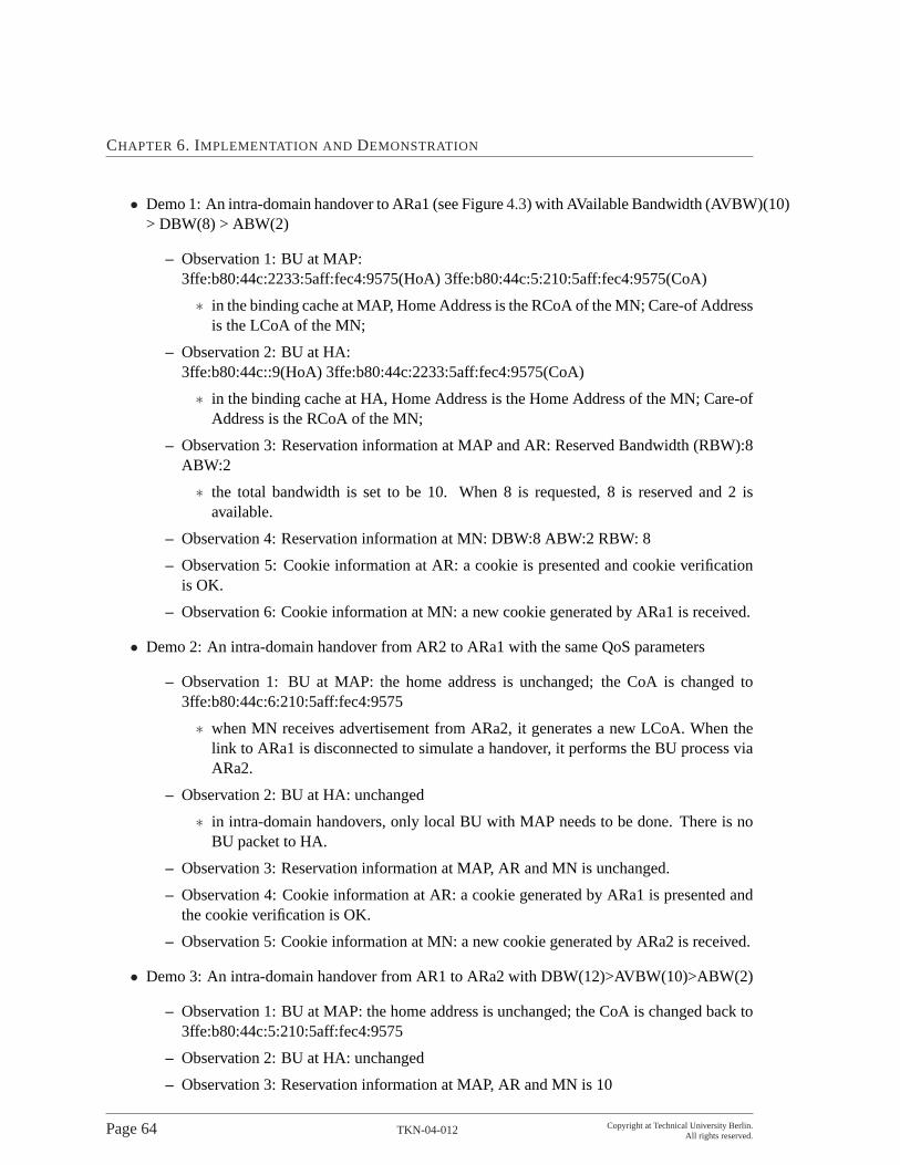
CHAPTER 6. IMPLEMENTATION AND DEMONSTRATION
• Demo 1: An intra-domain handover to ARa1 (see Figure4.3) with AVailable Bandwidth (AVBW)(10)> DBW(8) > ABW(2)
– Observation 1: BU at MAP:3ffe:b80:44c:2233:5aff:fec4:9575(HoA) 3ffe:b80:44c:5:210:5aff:fec4:9575(CoA)
∗ in the binding cache at MAP, Home Address is the RCoA of the MN; Care-of Addressis the LCoA of the MN;
– Observation 2: BU at HA:3ffe:b80:44c::9(HoA) 3ffe:b80:44c:2233:5aff:fec4:9575(CoA)
∗ in the binding cache at HA, Home Address is the Home Address of the MN; Care-ofAddress is the RCoA of the MN;
– Observation 3: Reservation information at MAP and AR: Reserved Bandwidth (RBW):8ABW:2
∗ the total bandwidth is set to be 10. When 8 is requested, 8 is reserved and 2 isavailable.
– Observation 4: Reservation information at MN: DBW:8 ABW:2 RBW: 8
– Observation 5: Cookie information at AR: a cookie is presented and cookie verificationis OK.
– Observation 6: Cookie information at MN: a new cookie generated by ARa1 is received.
• Demo 2: An intra-domain handover from AR2 to ARa1 with the same QoS parameters
– Observation 1: BU at MAP: the home address is unchanged; the CoA is changed to3ffe:b80:44c:6:210:5aff:fec4:9575
∗ when MN receives advertisement from ARa2, it generates a new LCoA. When thelink to ARa1 is disconnected to simulate a handover, it performs the BU process viaARa2.
– Observation 2: BU at HA: unchanged
∗ in intra-domain handovers, only local BU with MAP needs to be done. There is noBU packet to HA.
– Observation 3: Reservation information at MAP, AR and MN is unchanged.
– Observation 4: Cookie information at AR: a cookie generated by ARa1 is presented andthe cookie verification is OK.
– Observation 5: Cookie information at MN: a new cookie generated by ARa2 is received.
• Demo 3: An intra-domain handover from AR1 to ARa2 with DBW(12)>AVBW(10)>ABW(2)
– Observation 1: BU at MAP: the home address is unchanged; the CoA is changed back to3ffe:b80:44c:5:210:5aff:fec4:9575
– Observation 2: BU at HA: unchanged
– Observation 3: Reservation information at MAP, AR and MN is 10
Page 64 TKN-04-012 Copyright at Technical University Berlin.All rights reserved.

6.2. DEMONSTRATION
∗ Since the maximum bandwidth the path can provide is 10, only 10 is reserved eventhough the desired bandwidth is 12.
– Observation 4: Cookie information at AR: a cookie generated by ARa2 is presented andthe cookie verification is OK.
– Observation 5: Cookie information at MN: a new cookie generated by ARa1 is received.
• Demo 4: increase ABW to 12. i.e. DBW(12)=ABW(12)>AVBW(10)
– Observation 1: BU at MAP: The BU is gone.
∗ Since the path can not provide the minimum bandwidth MN requests, the BU at MAPfails and there is no micro-mobility support to this MN.
– Observation 2: BU at HA: 3ffe:b80:44c::9(HoA) 3ffe:b80:44c:5:210:5aff:fec4:9575(CoA)
∗ Since there is no micro-mobility support in the foreign domain, MN performs a BUwith its HA with only MIP support.
– Observation 3: Reservation information at MN, AR, MAP is 0
∗ Since there is no HMIP and QoS support, no resource is reserved in the foreigndomain.
• Demo 5: an attacker sends a QoS request (AVBW(10)>DBW(8)>ABW(2)) with a wrongcookie
– Observation : AR displays cookie verification fails. There is no BU entry at HA and MAPfor the attacker. Also there is no resource reservation at MAP and AR for the attacker.
∗ Since the cookie verification fails at AR, the AR just drops the request silently.
• Demo 6: MN sends normal QoS requests while the attacker sends QoS requests with wrongcookies at a constant rate.
– Observation 1: all the requests with wrong cookie fail.
∗ Since the cookie verification fails at AR, the AR just drops the request silently.
– Observation 2: The QoS-Conditionalized Binding Update (QCB) operations for MN’squests is not interrupted.
Copyright at Technical University Berlin.All rights reserved.
TKN-04-012 Page 65

CHAPTER 6. IMPLEMENTATION AND DEMONSTRATION
Page 66 TKN-04-012 Copyright at Technical University Berlin.All rights reserved.

Chapter 7
Conclusions and Future Work
The SeQoMo architecture supports advanced mobility mechanisms, security and QoS support basedupon IP protocol in a unified framework.
In this report, we described the rationale, design and functionality of the architectural components andtheir interactions. As a unified framework, SeQoMo architecture is implemented on a prototypicaltestbed and some typical functional tests and performance measurements are finished.
To address the difficult problem of efficient (low latency and low overhead with QoS-enabled securityprotection) handovers for mobile IP traffic, a couple of measures are taken:
• HMIPv6 is employed as the micro-mobility management protocol.
• In intra-domain handover cases, QoS signaling information is piggybacked in a BU packet.
• A range of a QoS parameter (e.g. upper and low bounds of bandwidth) rather than a specificvalue is used in a QoS request.
• Mobile node’s authorization information is cached locally at AAAL after its successful inter-domain handover in the foreign domain.
• A cookie is used for a preliminary authentication check to save time on performing a re-authenticate at AAAL before the QoS-Conditionalized Binding Update (QCB) process begins.
Additionally, the developed concepts and results also include that:
• a dynamically updated authorization process prevents disclosure of a mobile node’s subscribedQoS parameters;
• the cookie mechanism counters potential DoS attacks to the access network in the foreigndomain.
Future work includes investigations on using CASP as the signaling protocol in the SeQoMo archi-tecture, cooperating with other fast handover mechanisms regarding re-establishment of QoS andsecurity states.
Copyright at Technical University Berlin.All rights reserved.
TKN-04-012 Page 67

CHAPTER 7. CONCLUSIONS ANDFUTURE WORK
Furthermore, enhanced advertisements of access routers which include additional information suchas currently available bandwidth and price can help a mobile node to select the most suitable accessrouter as the target of its next QoS-conditionalized handover.
Page 68 TKN-04-012 Copyright at Technical University Berlin.All rights reserved.

Chapter 8
Acronyms
AA Authentication and Authorization
AAA Authentication, Authorization, Accounting
AAAL local AAA server
AAAH home AAA server
ABW Acceptable Bandwidth
ACK Acknowledgement
AMA AA-Mobile-Node-Answer
AMR AA-Mobile-Node-Request
AN Access Network
AP Access Point
API Application Program Interface
AR Access Router
ARR AA-Registration Request
ARA AA-Registration Answer
ARP Address Resolution Protocol
ASM Any Source Multicast
ATM Asynchronous Transfer Mode
AVBW AVailable Bandwidth
AVP Attribute Value Pairs
Copyright at Technical University Berlin.All rights reserved.
TKN-04-012 Page 69

CHAPTER 8. ACRONYMS
BA Binding Acknowledgement
BC Binding Cache
BdR Border Router
BR Binding Request
BSC Base Station Controller
BU Binding Update
BUL Binding Update List
CASP Cross Application Signaling Protocol
CIDR Classless Inter Domain Routing
CMS Cryptographic Message Syntax
CN Corresponding Node
CoA Care-of Address
CT Context Transfer
DAD Duplicate Address Detection
DBW Desired Bandwidth
DHCP Dynamic Host Configuration Protocol
DiffServ Differentiated Services
DLL Data Link Layer
DoS Denial of Service
DSCP DiffServ Code Point
DVMRP Distance Vector Multicast Routing Protocol
ER Edge Router
FTP File Transfer Protocol
GPRS General Packet Radio Service
GSM Global System for Mobile Communication
HA Home Agent
HAO Home Address Option
Page 70 TKN-04-012 Copyright at Technical University Berlin.All rights reserved.

HAWAII Handoff Aware Wireless Access Internet Infrastructure
HMIP Hierarchical MIP
HMIPv6 Hierarchical Mobile IPv6
HO Handover
HoA Home Address
HOA HOme-agent-Answer
HOf handover frequency
HOR HOme-agent-Request
HMAC-MD5 Keyed-Hashing for Message Authentication using MD5(Message-Digest 5
HMAC-SHA1 Keyed-Hashing for Message Authentication using SHA1(Secure Hash Algorithm 1
ICEBERG Internet Core Beyond the Third Generation
ICI Interface Control Information
ICMP Internet Control Message Protocol
ICMPv6 Internet Control Message Protocol version 6
ID identification
IDU Interface Data Unit
IEEE The Institute of Electrical and Electronics Engineers
IETF Internet Engineering Task Force
IHA IP-level handover assistant
IntServ Integrated Services
IP Internet Protocol
IPng IP Next Generation
IPv4 Internet Protocol version 4
IPv6 Internet Protocol version 6
IR Intermediate Router
L2 layer-2
L3 layer-3
Copyright at Technical University Berlin.All rights reserved.
TKN-04-012 Page 71
CHAPTER 8. ACRONYMS
LAN Local Area Network
LCoA Local Care-of Address
LXR Linux Cross Reference
MAC Medium Access Control
MAP Mobile Anchor Point
MAO Mobile Anchor Point Option
MBW Maximum Bandwidth
MD Movement Detection
MHC Manageable Hub Configuration
MIP Mobile IP
MIPL Mobile IP for Linux
MIPv6 Mobile IPv6
MIPv4 Mobile IPv4
MN Mobile Node
MOBEN mobile environment
MOMBASA Mobility Support - A Multicast Based Approach
MPLS Multi-Protocol Label Switching
NAI network access identifier
NbAdv Neighbor Advertisement
ND Neighbor Discovery
NbSol Neighbor Solicitation
NIC Network Interface Card
NSIS Next Steps in Signaling
OS Operating System
PDP Policy Decision Point
PDU Protocol Data Unit
PEP Policy Execution Point
Page 72 TKN-04-012 Copyright at Technical University Berlin.All rights reserved.

PIM-SM Protocol Independent Multicast - Sparse Mode
PIM-SSM Protocol Independent Multicast - Single Source Mode
QCB QoS-Conditionalized Binding Update
QHC QoCoo controller
QoS Quality of Service
QoCoo QoS-Conditionalized Handover
QSE QoS-aware security entity
RA Router Advertisement
radvd router advertisement daemon
RAT Reverse Address Translation
RBW Reserved Bandwidth
RCoA Regional Care-of Address
RD Redirect
RFC Request For Comment
RH Routing Header
RS Router Solicitation
RtAdv Router Advertisement
RtSol Router Solicitation
RSVP Resource Reservation Protocol
RTT round trip time
SAP Service Access Point
SDL Specification and Description Language
SIP Session Invitation Protocol
SNMP Small Network Management Protocol
SP Service Primitive
TBA To Be Added
TCP Transmission Control Protocol
Copyright at Technical University Berlin.All rights reserved.
TKN-04-012 Page 73

CHAPTER 8. ACRONYMS
TLV Type-Length-Value
UDP User Datagram Protocol
UMTS Universal Mobile Telecommuniation System
VoIP Voice over IP
WAN Wide Area Network
WLAN Wireless Local Area Network
Page 74 TKN-04-012 Copyright at Technical University Berlin.All rights reserved.

Bibliography
[1] S. Blake, D. Black, M. Carlson, E. Davies, Z. Wang, and W. Weiss. An Architecture for Differ-entiated Services. RFC 2475, December 1998.
[2] B. Braden, D. Clark, and S. Shenker. Integrated Services in the Internet Architecture: AnOverview. RFC 1663, June 1994.
[3] M. Brunner. Requirements of QoS Signaling Protocols, April 2002.
[4] P. R. Calhoun and C. E. Perkins. Diameter Mobile IPv4 Application, October 2002.
[5] M. Carson. Application and Protocol Testing through Network Emulation, September 1997.
[6] H. Chaskar. Requirements of a QoS Solution for Mobile IP. Internet Draft draft-ietf-mobileip-qos-requirement-03.txt, July 2003.
[7] H. Chaskar and R. Koodli. A Framework for QoS Support in Mobile IPv6. Internet Draftdraft-chaskar-mobileip-qos-01.txt, March 2001.
[8] T. Chen and G. Schäfer. Design of QoS-aware Authorization For Mobile Devices. SeQoMoproject deliverable D-Security-2, May 2002.
[9] T. Chen and G. Schäfer. Intermediate Implementation Report: Security measures in the SeQoMoproject. SeQoMo project deliverable D-Security-3, September 2002.
[10] T. Chen and G. Schäfer. QoS-aware Authorization for Mobile Devices. SeQoMo project deliv-erable D-Security-1, March 2002.
[11] C. Perkins (ed.). IP Mobility Support. RFC 2002, October 1996.
[12] C. Perkins (ed.). IP Mobility Support for IPv4. RFC 3344, August 2002.
[13] D. Estrin, D. Farinacci, A. Helmy, D. Thaler, S. Deering, M. Handley, V. Jacobson, C. Liu,P. Sharma, and L. Wei. Protocol Independent Multicast-Sparse Mode (PIM-SM): Protocol Spec-ification. Internet RFC 2362, June 1998.
[14] S. Faccin, B. Patil, and C. Perkins. Diameter Mobile IPv6 Application, March 2002.
[15] W. Fenner. Internet Group Management Protocol, Version 2. Internet RFC 2236, November1997.
Copyright at Technical University Berlin.All rights reserved.
TKN-04-012 Page 75

BIBLIOGRAPHY
[16] A. Festag. Performance Evaluation of MIP w and w/o Hierarchical FAs: Goal, Metrics, Param-eters and Testbed Setup SeQoMo project deliverable D-MM-3, February 2001.
[17] A. Festag. Performance Evaluation of Multicast-based Handover: Goal, Metrics, Parametersand Testbed Setup. SeQoMo project deliverable D-MM-8, October 2001.
[18] A. Festag. Optimization of Handover Performance by Link Layer Triggers in IP-Based Net-works; Parameters, Protocol Extensions, and APIs for Implementation. Technical Report TKN-02-014, Telecommunication Networks Group, Technische Universität Berlin, July 2002.
[19] A. Festag. Performance Comparison of HMIPv4 and MOMBASA SeQoMo project deliverableD-MM-10, March 2002.
[20] A. Festag. Update on Current Development and Trends in Handover Design for All-IP WirelessNetworks SeQoMo project deliverable D-MM-1, March 2002.
[21] A. Festag, H. Karl, and G. Schaefer. Current Developments and Trends in Handover Designfor ALL-IP Wireless Networks. Technical Report TKN-00-007, Telecommunication NetworksGroup, Technische Universität Berlin, August 2000.
[22] A. Festag, L. Westerhoff, A. Assimakopoulos, and A. Wolisz. Rerouting for Handover in MobileNetworks with Connection-Oriented Backbones - An Experimental Testbed. InProc. of ICATM2000, pages 491–499, June 2000.
[23] A. Festag and A. Wolisz. MOMBASA: Mobility Support - A Multicast-based Approach. InProc. of European Wireless 2000 together with ECRR 2000 (EW’2000), pages 491–499, Dres-den, Germany, September 2000.
[24] D. Forsberg, J.T. Malinen, J.K. Malinen, and H.H. Kari. Increasing Communication Availabil-ity with Signal-based Mobile Controlled Handoffs. InProc. of IP based Cellular Net-works(IPCN2000), May 2000.
[25] X. Fu, H. Karl, and C. Kappler. QoS-Conditionalized Handoff for Mobile IPv6. InProc. of theSecond IFIP-TC6 Networking Conf. - Networking2002, pages 721–730, Pisa, Italy, May 2002.Springer-Verlag.
[26] E. Gustavsson, A. Jonsson, and C. Perkins. Mobile IP Regional Registration. Internet-Draft:draft-ietf-mobileip-reg-tunnel-03.txt, July 2002.
[27] L-N. Hamer, B. Gage, M. Broda, B. Kosinski, and Hugh Shieh. Session Authorization forRSVP, June 2002.
[28] L-N. Hamer, B. Gage, M. Broda, and Hugh Shieh. Framework for Session Set-up with MediaAuthorization, June 2002.
[29] A. Hess and G. Schaefer. Performance Evaluation of AAA / Mobile IP Authentication. Techni-cal Report TKN-01-012, Telecommunication Networks Group, Technische Universität Berlin,August 2001.
Page 76 TKN-04-012 Copyright at Technical University Berlin.All rights reserved.

BIBLIOGRAPHY
[30] A. Hess and G. Schäfer. Performance Evaluation of AAA / Mobile IP Authentication. InProc.of 2nd Polish-German Teletraffic Symposium (PGTS’02), Gdansk, Poland, September 2002.
[31] D. Johnson and C. Perkins. Mobility Support in IPv6. Internet Draft draft-ietf-mobileip-ipv6-19.txt (work in progress), October 2002.
[32] D. Johnson, C. Perkins, and J. Arkko. IP Mobility Support for IPv6. Internet-Draft: draft-ietf-mobileip-ipv6-21.txt, February 2003.
[33] J. Kempf. Problem Description: Reasons For Performing Context Transfers Between Nodes inan IP Access Network, September 2002.
[34] G. Kenward. General Requirements for Context Transfer, October 2002.
[35] R. Koodli(ed.). Fast Handovers for Mobile IPv6. INTERNET DRAFT draft-ietf-mobileip-fast-mipv6-06.txt, March 2003.
[36] J. Loughney, M. Nakhjiri, and C. Perkins. Context Transfer Protocol, October 2002.
[37] J. Mysore and V. Bharghavan. A New Multicast-based Architecture for Internet Mobility. InACM MOBICOM 97, October 1997.
[38] A. Neumann. Prototypical Implementation and Experimental Testbed Setup of a QoS-EnabledMobility Concept Based on HMIPv6, October 2002.
[39] H. Schulzrinne, H. Tschofenig, X. Fu, and J. Eisl. A Quality-of-Service Resource AllocationClient for CASP, March 2003.
[40] H. Schulzrinne, H. Tschofenig, X. Fu, and A. McDonald. Cross-Application Signaling Protocol,March 2003.
[41] H. Soliman, C. Castelluccia, K. El-Malki, and L. Bellier. Hierarchical Mobile IPv6 mobilitymanagement (HMIPv6). Internet-Draft: draft-ietf-mobileip-hmipv6-07.txt, October 2002.
[42] M. Stemm and R. Katz. Vertical Handoffs in Wireless Overlay Networks. InACM MobileNetworking (MONET), Special Issue on Mobile Networking in the Internet, December 1998.
[43] M. Thomas. Analysis of Mobile IP and RSVP Interactions, February 2001.
[44] H. Tschofenig. NSIS Threats, July 2002.
Copyright at Technical University Berlin.All rights reserved.
TKN-04-012 Page 77