RAJKOT MUNICIPAL CORPORATION
241
5$-.27 081,&,3$/ &25325$7,21 e - Tender No.RMC/ENGG/WZ/21-22/02 Milestone dates for e-tendering is as under 1. Downloading of e-documents 06-08-2021 to 20-08-2021 17:00 hrs 2. Pre-bid meeting in the O/o City Engineer at WEST ZONE 10-08-2021 17:00 hrs 3. Last date for online submission of e - Tender 20-08-2021 upto 18:00 Hours 4. Submission of EMD, Tender fee and other Documents for verification by Regd.Post.A.D. /Speed Post only. 24-08-2021 upto18:00 Hours 5. Opening of Technical Bid 25-08-2021 11.00 Hours 6. Verification of submitted documents (EMD, e - Tender fee, etc.) 25-08-2021 11:00 Hours onwards 7 Agency to remain present with original documents for verification 26-08-2021 between 16:00 to 18:00 Hours 8. Opening of Price Bid (For Technically qualified bidders only) 27-08-2021 at 11:00 Hours 9. Bid Validity 180 Days 2021-22 CITY ENGINEER RAJKOT MUNICIPAL CORPORATION SHRI HARISINHJI GOHIL BHAVAN WEST ZONE OFFICE, 150’ RING ROAD, RAJKOT - 360005 (GUJARAT) %LG 'RFXPHQWV )RU LAYING OF DI PIPE LINE AT PUNIT NAGAR 80’ ROAD, SHRINATHJI SOC., VINAYAK NAGAR AND OTHER AREA IN WARD NO.12
-
Upload
khangminh22 -
Category
Documents
-
view
0 -
download
0
Transcript of RAJKOT MUNICIPAL CORPORATION

e - Tender No.RMC/ENGG/WZ/21-22/02
Milestone dates for e-tendering is as under
1. Downloading of e-documents 06-08-2021 to 20-08-2021 17:00 hrs2. Pre-bid meeting in the O/o City Engineer at WEST ZONE
10-08-2021 17:00 hrs
3. Last date for online submission of e - Tender 20-08-2021 upto 18:00 Hours
4. Submission of EMD, Tender fee and other Documents for verification by Regd.Post.A.D. /Speed Post only.
24-08-2021 upto18:00 Hours
5. Opening of Technical Bid 25-08-2021 11.00 Hours 6. Verification of submitted documents (EMD, e - Tender fee, etc.)
25-08-2021 11:00 Hours onwards
7 Agency to remain present with original documents for verification
26-08-2021 between 16:00 to 18:00 Hours
8. Opening of Price Bid (For Technically qualified bidders only)
27-08-2021 at 11:00 Hours
9. Bid Validity 180 Days
2021-22
CITY ENGINEERRAJKOT MUNICIPAL CORPORATION SHRI HARISINHJI GOHIL BHAVAN
WEST ZONE OFFICE, 150’ RING ROAD, RAJKOT - 360005 (GUJARAT)
LAYING OF DI PIPE LINE AT PUNIT NAGAR 80’ ROAD, SHRINATHJI SOC., VINAYAK NAGAR AND
OTHER AREA IN WARD NO.12


RAJKOT MUNICIPAL CORPORATIONe-TENDER NOTICE
The e-Tenders are invited with two bid system by e-Tendering from the experienced contractors registered in GWSSB / State Government / Central Government / Semi Government in appropriate class for below mentioned work: Sr No
Name of work
a) Estimated cost in Rs. b) EMD c) E-TENDER fee d) Time limit for completion of work
1 LAYING OF DI PIPE LINE AT PUNIT NAGAR 80’ ROAD, SHRINATHJI SOC., VINAYAK NAGAR AND OTHER AREA IN WARD NO.12
e-TENDER No.RMC/ENGG/WZ/21-22/02
a) Rs.3,01,88,000/- b) Rs.3,01,880/- c) Rs.7,500/- d) 10 months
Milestone dates for e-tendering is as under
1. Downloading of e-documents 06-08-2021 to 20-08-2021 17:00 hrs2. Pre-bid meeting in the O/o City Engineer at WEST ZONE
10-08-2021 17:00 hrs
3. Last date for online submission of e - Tender 20-08-2021 upto 18:00 Hours
4. Submission of EMD, Tender fee and other Documents for verification by Regd.Post.A.D. /Speed Post only.
24-08-2021 upto18:00 Hours
5. Opening of Technical Bid 25-08-2021 11.00 Hours 6. Verification of submitted documents (EMD, e - Tender fee, etc.)
25-08-2021 11:00 Hours onwards
7 Agency to remain present with original documents for verification
26-08-2021 between 16:00 to 18:00 Hours
8. Opening of Price Bid (For Technically qualified bidders only)
27-08-2021 at 11:00 Hours
9. Bid Validity 180 Days 1. All bidders must submit Bid security (EMD) as above either directly
deposited in ICICI Bank Account No.015305010638 (Rajkot Municipal Corporation) IFSC Code ICIC0000153 or submit at the below mentioned address in form of Demand Draft in favour of "Rajkot Municipal Corporation", Rajkot, from any Nationalized Bank or Scheduled Bank (except Co-operative Bank) in India. The receipt of professional tax paid for current year, address proof, tender appendix details and ID proof shall have to be submitted along with physical submission of required documents shall have to be done at the below mentioned address:
Office of the CITY ENGINEER Rajkot Municipal Corporation, SHRI HARISINHJI GOHIL BHAVAN, WEST ZONE Office, 150’ RING ROAD, Rajkot-360005 (Gujarat)

2. The e-tender fee will be accepted in form of Demand Draft only in favor of "Rajkot Municipal Corporation" Rajkot, from any Nationalized or Scheduled Bank (except Co-operative Bank) in India and must be delivered to above address.
3. The prequalification requirement is as under: i) Financial Criteria:
1. An average annual turnover of seven years should not be less than 50% of tender amount.
2. Working capital should not be less than 25% of the estimated amount. 3. Bidder must have minimum "A" Class registration 4. Minimum amount of solvency should be Rs.75.00 lakhs
ii) Experience Criteria: The bidder should posses following minimum experience :
1. Bidder should have completed at lWEST one work of similar nature 60% OR two works of 40% OR three works of 30% of tender amount in last seven years either in government or Semi-government as a main contractor.
2. Bidder should have enough machinery and experienced personnel to supervise the work.
4. The contractor shall have to quote their rates including GST and other
taxes and the Invoice with break-up of GST is to be submitted accordingly, failing which, such amount will be deducted from the bill of the agency and deposited accordingly.
The contractor shall have to purchase the material required for this tender work, only from the supplier having registered GST Number. RMC will not be responsible to pay any amount towards GST if the material is purchased from the unregistered supplier / not having GST Number.
5. Enhancement factor at 10 % per year will be applicable to arrive at average
annual turnover and finalize the magnitude of work done in last seven years 6. The tender of those bidders who fail to submit documents OR to produce the
originals for verification within time schedule of this tender will out rightly be rejected.
7. The bidder(s) submitting the tender shall also have to submit the
copy of ESIC & EPF Registration document along with the other documents, duly self attested, failing which, the tender of such bidder(s) will be considered as non-responsive and their online price bid will not be opened.
8. The Tender of those bidder(s) those who fails to submit the required
documents for verification within the stipulated date and time, will be treated as non responsive and their Price Bid will not be opened. The physical

submission of required documents received after the prescribed date and time will be out rightly rejected.
9. The bidder should not have been Black Listed by Government of India /
Government of Gujarat or any State Board / Corporations, since inception of the firm / Company. A Declaration in this regard on Rs.300/- Stamp Paper duly Notarized, shall have to be submitted as per Annexure, along with the tender documents.
10.The bidder should provide accurate information on any litigation history or
arbitration resulting from contracts completed or under execution by him over the last ten years. This should also include such cases, which are in process / progress. A consistent history of awards against the bidder may result in failure of the bid. In case the bidder has not provided such information and has come to the notice of the authority, the tender will be rejected at what so ever stage and in such case all the losses that will arise out of this issue will be recovered from the tenderer / bidder and he will not have any defense for the same.
11.After opening of Technical Bid, the procedure for the pre-qualification shall be
adopted and the Price Bid of only successful qualified bidder shall be opened for final evaluation of the contract. The decision of Municipal Commissioner regarding the pre- qualification shall be final and binding to all the bidders.
12.Conditional Tenders will be out rightly rejected.
13.Commissioner, Rajkot Municipal Corporation, Rajkot, reserves the right to
accept / reject any or all e-tender(s) without assigning any reasons thereof.
CITY ENGINEER Rajkot Municipal Corporation


1. Experience Criteria: The bidder should posses following minimum experience: 1. Bidder should have completed at lWEST one work of similar nature 60%
OR two works of 40% OR three works of 30% of tender amount as a main contractor in period of last seven years.
2. Bidder should have enough machinery and experienced personnel to supervise the work.
2. Financial Criteria
(1) An average annual turnover of seven financial years should not be less than 50% of estimated tender amount.
(2) Working capital should not be less than 25% of the estimated tender amount.
(3) Solvency must not be less than Rs.75 Lacs (4) Available bid capacity- ABC must be more than the estimated tender
amount. The bidding capacity shall be worked out using the following formula:
Bidding capacity = [2 * A * N] – B = (to be filled by Applicant)
where, A = Maximum value of works executed in any one year during the
last seven years (updated to ……* price level) taking into account the completed as well as works in progress.
N = Number of years prescribed for completion of the works for
which tenders are invited.
B = Value (…* price level) of existing commitments and on-going works to be completed during that next N year (period of completion of the works for which the tenders are invited)
3. Enhancement Factor
Following enhance factor for respective year will be considered to arrive at current financial year:
Sr Year Enhance factor1 Current Year (2021-22) 1.00 2 Current Year - 1 (2020-21) 1.10 3 Current Year - 2 (2019-20) 1.21 4 Current Year - 3 (2018-19) 1.33 5 Current Year - 4 (2017-18) 1.46 6 Current Year - 5 (2016-17) 1.61 7 Current Year - 6 (2015-16) 1.77 8 Current Year - 7 (2014-15) 1.95

4. Litigation History
The bidder should provide accurate information on any litigation history or arbitration resulting from contracts completed or under execution by him over the last seven years. This should also include such cases, which are in process/progress. A consistent history of awards against the bidder or any partner of a joint venture may result in failure of the bid. In case the bidder has not provided such information and has come to the notice of the Authority, the tender will be rejected at whatsoever stage and in such case all the losses that will arise out of this issue will be recovered from the Bidder/contractor and he will not have any defense for the same.
5. Even though the bidders meet the above criteria, they are subject to
be rejected, if they have: Misleading or false representation made in the form, statements and attachments Submitted And / Or having poor performance record such as abandoning the work, improper completion of contract, inordinate delays in completion, litigation history, financial failures, etc.
6. Brand names
Specific reference in the specifications any materials by manufacturer’s name (as per the prevailing list of GWSSB), or catalogue shall be constructed as establishing a standard or quality and performance and not as limiting competition, and the Bidder in such cases, will not at his option freely use only other product
CITY ENGINEER Rajkot Municipal Corporation
Name and signature of Bidder


INSTRUCTIONS TO BIDDER IT 1. GENERAL
The contract documents may be secured in accordance with the Notice Inviting E-TENDER for the work called. The work shall include supply of materials necessary for construction of the work.
IT 2. INVITATION TO E-TENDER The Rajkot Municipal Corporation hereinafter referred as the Corporation will receive e-Tenders for the work of as per the specifications and schedule of prices in the e-Tender document. The e-Tenders shall be opened online as specified in the e-Tender notice in the presence of interested Bidders or their representatives. The Corporation reserves the right to reject the lowest or any other or all e-Tenders or part of it which in the opinion of the Corporation does not appear to be in its best interest, and the Bidder shall have no cause of action or claim against the Corporation or its officers, employees, successors or assignees for rejection of his e-Tender.
IT 3. LANGUAGE OF e-TENDER E-TENDERs shall be submitted in English, and all information in the e-Tender shall also be in English, Information in any other language shall be accompanied by its translation in English. Failure to comply with this may make the e-Tender liable to rejection.
IT 4. QUALIFICATIONS OF BIDDERS A. The Bidders shall abide by the laws of the Union of India and of Gujarat State and
legal jurisdiction of the place where the works are located. B. The Bidder shall furnish a written statement of financial and technical parameters with
details and documents along with his e-Tender which contains namely as below: i. The Bidder’s experience in the fields relevant to this contract. ii. The Bidder’s financial capacity/resources and standing over at lWEST 7 (Seven)
years. iii. The Bidder’s present commitments (Jobs on hand). iv. The Bidder’s capability and qualifications of himself and his regular staff etc. v. Plants and Machinery available with the Bidder for the work e-Tendered.
C. The Bidder shall furnish original documents on the date mentioned in tender notice. The bid for those bidder will be treated as non-responsive who failing to produce original documents on specified date.
IT 5. e-TENDER DOCUMENTS The e-Tender documents and drawings shall comprehensively be referred to as e-TENDER document. The several sections form in the document are the essential parts of the contract and a requirement occurring in one shall be as binding as though occurring in all, they are to be taken as mutually, explanatory and describe and provide for complete works.
IT 6. EXAMINATION BY BIDDERS A. At this own expense and prior to submitting his e-Tender, each Bidder shall (a)
examine the Contract Documents, (b) visit the site and determine local conditions which may affect the work including the prevailing wages and other pertinent cost factors, (c) familiarize, himself with all central, state and local laws, ordinance, rules regulations and codes affecting the material supply including the cost of permits and licenses required for the work and (d) correlate his observations, investigations, and determinations with the requirements of the e-TENDER Documents, site & subsoil investigation.

B. The e-Tender is invited on ..%. rate and contractor shall have to quote his price on % bases above or below in the schedule -B./ Price Schedule. The works shall have to be completed in all respect as stated in the e-Tender document to the satisfaction of the Corporation.
C. The following comprises in Contract Documents at a price of Rs.7,500-00.
e-TENDER Document: Part-I
1. Notice inviting Bidders. 2. Instructions to the Bidder. 3. Formats
4. General conditions of contract
Part-II Technical specifications
Part-III a. Bid Form (With Price ) b. Preamble to Price schedule c. Price Schedule (Schedule-B)
D. Copy of the E-TENDER Document should be completed, checked in a responsible manner, digitally signed, and submitted. Security Bond shall be submitted in person by the stipulate date, which shall form the e-Tender.
The e-Tender is required to complete with all the pages in which entries are required to be made by the Bidder are contained in the e-Tender documents and the Bidder shall not take out or add to or amend the text of any of the documents except in so far as may be necessary to comply with any addenda issued pursuant to Clause IT.17 hereof.
IT 7. EARNEST MONEY DEPOSIT:
A. Each Bidder must submit a receipt of deposit as Tender guarantee towards Earnestmoney amounting to Rs.3,01,880/- in the form of crossed Demand Draft
acceptable to owner payable at Rajkot OR it can be directly deposited in the account of Rajkot Municipal Corporation as shown in Point No.1 of tender Notice on Page No.4. The Tender Bond, shall be valid for a period of not less than hundred and Twenty (120) days from the date the e-Tenders are opened and shall comply with the requirements for Bond as stipulated in the General conditions of contract. The Tender guarantee bond will be held by the owner as a guarantee that the Bidder, if awarded the contract, will enter into the contract agreement in good faith and furnish the required bonds. Any e-Tender not accompanied by a Tender guarantee in the form of earnest money deposited for the sum stipulated in the e-Tender Document will be summarily rejected.
B. The Earnest Money Deposit will be refunded to the unsuccessful Bidders after an award
has been finalized. C. The Earnest Money Deposit (Tender Guarantee) will be forfeited in the event, the
successful Bidder fails to accept the contract and fails to submit the “Performance Guarantee Bonds to the Owner as stipulated in this e-Tender documents within ten days. (10) days after receipt of notice of award of contract.

D. The Earnest Money Deposit of the successful Bidder shall be returned after the performance guarantee bond, as required, is furnished by the contractor.
E. No interest shall be paid by the owner on any e-Tender guarantee.
IT 8. INCOME TAX CLEARANCE CERTIFICATE : (DELETED) : Latest Income Tax clearance Certificates must accompany with the e-Tender without which the e-Tender is liable to be summarily rejected. The Income Tax Clearance Certificate obtained from the Income Tax Officer shall clearly indicate the Income Tax Pan No/Circle/Ward, District and the reference number of the assessment along with the assessment year.
IT 9. PREPARATION OF e-TENDER DOCUMENTS
Bidders are required to note the following while preparing the e-TENDER Documents:
A. e-TENDER shall be submitted on the e-TENDER form bound here in English. All statements shall be properly filled in. Numbers shall be stated both in words and in figures where so indicated.
B. All entries or prices and arithmetic shall be checked before submission of the e-
TENDER. If there is discrepancy between the rates quoted in figures and in words, the rates expressed in words shall be considered as binding.
C. Each e-Tender shall be accompanied by the prescribed e-Tender security bond and
other required documents and drawings. All witnesses and sureties shall be persons of status and probity and their full names, occupations and addresses shall be stated below their signature.
D. Variation to the contract Documents requested by the Bidder may be affixed and
duly signed and stamped. Such variations may be approved or refused by the Corporation is not obliged to give reason for his decisions.
IT 10. SUBMISSION OF e-TENDER DOCUMENTS
Bidders are requested to submit the e-TENDER Documents on following lines. A. Volume containing following documents :
I. Earnest Money Deposit. II. Certificates as registered contractor in appropriate class with Government of
Gujarat or appropriate authority. III. Bidder’s financial capability statement including last three years Income tax
returns, balance sheet, duly signed by registered chartered account. IV. Bidder’s experience in the field relevant to this contract. V. A list of the equipment the Bidder possesses and that which he proposed to
acquire and use for the purpose related to the work.
The time limit for receipt of e-Tender shall strictly apply in all cases. The Bidders should therefore ensure that their e-Tender is received by the competent authority The Rajkot Municipal Corporation at before expiry of the time limit. No delay on account of any cause for receipt of e-Tender shall be entertained.
The e-Tender must contain the name address of residence and place of business of the person or persons submitting the e-Tender and must be digitally signed.
e-TENDER by partnership firm must be furnished with the full names and addresses of all partners and be signed by one of the members of the partnership or by a legally authorized representative holding power of attorney followed by signature and designation of the person of person signing.
e-TENDER by Corporations/Companies must be signed with the legal name of the Corporation/Companies by the president/or by the secretary or other person or persons legally authorized to bind the Corporation/Company in the matter.
IT 11 TENDER VALIDITY PERIOD
The validity period of the e-Tender submitted for this work shall be of One Hundred and Twenty (120) calendar days from the date of opening of the e-Tender and that the Bidder shall not be allowed to withdraw or modify the e-Tender offer on his own during the validity period. The Bidder will not be allowed to withdrawn the e-Tender or make any modifications or additions in the terms and conditions on his own e-Tender. If this is done then the owner shall, without prejudice to any other right or remedy, be at liberty to reject the e-Tender and forfeit the earnest money deposit in full.
IT 12 GENERAL PERFORMANCE DATA
Bidder shall present all the information which sought for in the e-Tender document in form of various schedules if given. e-TENDERs may not be considered if left blank or the schedules are not properly filled in.
IT 13 SIGNING OF e-TENDER DOCUMENTS
If the Tender is made by an individual it shall be signed with his full name above his current address. If the Tender is made by a proprietary firm, it shall be signed by the proprietor above his name and the name of his firm with his current address.
If the e-Tender is made by a firm in partnership, it shall be signed by all the partners of the firm above their full names and current address, or by a partner holding the power of attorney for the firm, in which case a certified copy of the power of attorney shall accompany the e-TENDER. A certified copy of the partnership deed, current addresses of all the partners of the firm shall also accompany the e-Tender.
If the e-Tender is made by a limited company or a limited corporation, it shall be signed by a duly authorized person holding the power of attorney, shall accompany the e-Tender. Such limited company or corporation may be required to furnish satisfactory evidence of its existence before the contract is awarded.
If the e-TENDER is made by a group of firms, the sponsoring firm shall submit complete information pertaining to each firms in the group and state along with the bid as to which of the firms shall have the responsibility for e-Tendering and for completion of the contract documents and furnish evidence admissible in law in respect of the authority to such firms on behalf of the group of firms for e- Tendering and for completion of contract documents. The full information and satisfactory evidence pertaining to the participation of each member of the group of firms in the e-Tender shall be furnished along with the e-Tender.
All witnesses and sureties shall be persons of status and probity and their full names, occupations and addresses shall be stared below their signatures. All the signatures in the e-Tender document shall be dated.
IT 14 WITHDRAWAL OF TENDERS
If, during the tender validity period, the Bidder withdraws his Tender, Tender security (Earnest Money) shall be forfeited and Bidder will be debarred for next three years to quote in R.M.C.
IT 15 INTERPRETATIONS OF e-TENDER DOCUMENTS
Bidders shall carefully examine the e-TENDER Document and fully inform themselves as to all the conditions and matters which may in any way affect the work or the cost thereof. If a Bidder finds discrepancies, or omission from the specifications or other documents or should be in doubt as to their meaning, he should at once address

query to the CITY ENGINEER, R.M.C. The result of interpretation of the e-TENDER will be issued as addendum.
IT 16 ERRORS AND DISCREPANCIES IN e-TENDERSIn case of conflict between the figures and words in the rates the rate expressed in words shall prevail and apply in such cases.
IT 17 MODIFICATION OF DOCUMENTSModification of specifications and extension of the closing date of the e-Tender, if required will be made by an addendum. Each addendum will be made available online to all Bidders. These shall form a part of e-Tender. The Bidder shall not add to or amend the text of any of the documents except in so far as may be necessary to comply with any addendum.
ADDENDA Addenda form part of the Contract Documents, and full consideration shall be given to all Addenda in the preparation of e-Tender. Bidders shall verify the number of Addenda issued, if any and acknowledge the receipt of all Addenda in the e-TENDER Failure to so acknowledge may cause the e-Tender to be rejected.
A. The Owner may issue Addenda to advise Bidders of changed requirements. Such
addenda may modify previously issued Addenda.
B. No addendum may be issued after the time stated in the notice inviting e - Tenders.
IT 18 TAX AND DUTIES ON MATERIALS
All charge on account of excise duties, Central / State, sales tax, work contract tax and other duties etc. on materials obtained for the works from any source shall be borne by the contractors. No (P) or ‘C’ or ‘D’ form shall be supplied.
IT 19 EVALUATION OF E - TENDERS
While comparing e-Tenders, the Rajkot Municipal Corporation shall consider factors like price offer is workable with the market price, efficiency and reliability of construction method proposed, compliance with the specifications, relative quality, work done in past with Rajkot Municipal Corporation or other Government Organizations, litigation issues etc. Evaluation criteria specifically mentioned in the specification will also be taken into consideration in the evaluation of e- Tenders.
IT 20 TIME REQUIRED FOR COMPLETION
The completion period mentioned in this schedule is to be reckoned from the date of notice to proceed. Total completion period is 10 months from the date of issue of notice to proceed and contractor should adhere to this completion time. Monsoon period from 1st July to 30th September will be considered as non-working period and hence excluded in time limit.
IT 21 POLICY FOR TENDER UNDER CONSIDERATION
TENDER shall be termed to be under consideration from the opening of the e - Tender until such time any official announcement or award is made.
While e-Tenders are under consideration, Bidders and their representative or other interested parties are advised to refrain from contacting by any means any corporations personnel or representatives on matters related to the e-Tenders under study. The Corporation’s representatives if necessary will obtain clarification on e-Tenders by requesting such information from any or all the Bidders, either in writing or through personal contact, as may be necessary. The Bidder will not be permitted to change the substance of his e-Tender after e-Tenders have been opened. This

includes any post Tender price revision. Non-compliance with his provision shall make the Tender liable for rejection.
IT 22 PRICES AND PAYMENTS
The Bidder must understand clearly that the prices quoted are for the total works or the part of the total works quoted for and include all costs due to materials, labour, equipment, supervision, other services, royalties, taxes etc. and to include all extra to cover the cost. No claim for additional payment beyond the prices quoted will be entertained and the Bidder will not be entitled subsequently to make any claim on any ground.
IT 23 PAYMENT TERMS
The terms of payment are defined in the General Conditions of Contract and Technical specifications. The Corporation shall not under any circumstances relax these terms of payment and will not consider any alternative payment terms. Bidders should therefore in their own interest note this provision to avoid rejection of their e-Tenders.
IT 24 AWARD
Award of the contract or the rejection or e-TENDERs will be made during the Tender validity period. A separate Schedule-B (Price Schedule) is given. The contractors are requested to quote their price offer in % below or above on the given price in the schedule-B of Price Schedule only.
A. After all contract contingencies are satisfied and the Notice of Award is issued,
the successful Bidder shall execute the Contract Agreement within the time stated and shall furnish the Bond as required herein. The contract Agreement shall be executed, in form stipulated by the Owner.
B. If the Bidder receiving the Notice of Award fails or refuses to execute the
Contract Agreement within the stated time limit or fails or refuses to furnish the Bond as required herein. The Owner may annul his award and declare the e-Tender security forfeited and will take action as deemed fit.
C. A corporation, partnership firm or other consortium acting as the Bidder and
receiving the award shall furnish evidence of its existence and evidence that the officer signing the contract agreement and Bonds for the corporation, partnership firm or other consortium acting as the Bidder is duly authorized to do so.
IT 25 SIGNING OF CONTRACT
The successful Bidder shall be required to execute the contract agreement within 10 days of receipt of intimation to execute the contract, failing which the Corporation will be entitled annul to the award and forfeit the Earnest Money Deposit. The person to sign the contract document shall be person as detailed in Article IT.13 (signing of e-Tender documents).
IT 26 DISQUALIFICATION
A e-Tender shall be disqualified and will not be taken for consideration if, (a) The Tender fee and Tender Earnest Money Deposit is not deposited in full and in
the manner as specified as per Article IT.7 i.e. Earnest Money Deposit. (b) The e-Tender is in a language other than English or does not contain its English
Translation in case of other language adopted for e-Tender preparation. (c) The e-Tender documents are not signed by an authorized person (as per Article
IT. 13 i.e. signing of e-Tender documents). (d) The general performance data for qualification is not submitted fully (as per
Article IT 12 i.e. General performance Data). (e) Bidder does not agree to payment terms defined as per Article IT. 23 i.e.
payment terms.

A. A e-Tender may further be disqualified if, (a) Price variation is proposed by the Bidder on any principle other than those
provided in the e-TENDER Documents. (b) Completion schedule offered is not consistent with the completion schedule
defined and specified in e-Tender document. (c) The validity of e-Tender bond is less than that mentioned in Article IT. 11 i.e. e -
Tender validity period. (d) Any of the page or pages of e-Tender is/are removed or replaced. (e) Any conditional tender.
IT 27 PERFORMANCE GUARANTEE (SECURITY DEPOSIT)
As a contract security the Bidder to whom the award is made shall furnish a performance guarantee (Security deposit) for the amount of 5% of the contract price to guarantee the faithful performance, completion and maintenance of the works of the contract in accordance with all conditions and terms specified herein and to the satisfaction of the Engineer-in-charge and ensuring the discharge of all obligations arising from the execution of contract in the forms mentioned below:
A fixed deposit receipt of any Schedule Bank or Nationalized Bank (except Co-operative Bank) duly endorsed in favour of the Rajkot Municipal Corporation, Rajkot. The performance guarantee shall be delivered to the Corporation within ten (10) days of the notice of award and at lWEST three (3) days before the contract agreement is signed unless otherwise specified by the Engineer-in-charge. Alternatively, the contractor may at his option deposit an amount of 2.5% of the value of the contract price within ten days and the balance 2.5% to be recovered in installments through deduction @ the rate of 10% from the running account bills. It is further clarified that Performance Guarantee (SD) for extra work will also be recovered @ 10% from the bill of extra work i.e. works beyond tender amount. On due performance and completion of the contract in all respects, THE PERFORMANCE GUARANTEE (SECURITY DEPOSIT) WILL BE RELEASED TO THE CONTRACTOR WITHOUT ANY INTEREST AFTER DEFECT LIABILITY PERIOD IS OVER.
IT 28 STAMP DUTY
The successful Tenderer shall have to enter into an agreement on a non-judicial stamp paper of amount as per Stamp Duty Act in the form of the agreement approved by the Corporation. The cost of stamp paper and adhesive stamp shall be borne by the contractor.
IT 29 BRAND NAMES
Specific reference in the specifications to any material by manufacturer’s name, or catalogue shall be constructed as establishing a standard or quality and performance and not as limiting competition and the Bidder in such cases, may at his option freely use only other product, provided that it ensures an equal of higher quality than the standard mentioned and meets Corporation approval.
IT 30 NON TRANSFERABLEe-TENDER documents are not transferable.

IT 31 COST OF e-TenderingThe owner will not defray expense incurred by Bidders in e - Tendering.
IT 32 EFFECT OF e-TenderThe e-Tender for the work shall remain for a period of One hundred and Twenty (120) calendar days from the date of opening of the e-Tenders for this work and that the Bidder shall not be allowed to withdraw or modify the offer in his own during the period. If any Bidder withdraws or makes any modification or additions in the terms and conditions of his own e-Tender, then the Corporation shall, without prejudice to any other right or remedy, be at liberty to reject the e-Tender and forfeit the earnest money in full.
IT 33 CHANGE IN QUANTITY
The Corporation reserves the right to waive any information in any e-Tender and to reject one or all e-Tenders without assigning any reasons for such rejection and also to vary the quantities of items or group as specified in the scheduled of prices as may be necessary.
IT 34 NEW EQUIPMENT AND MATERIALAll materials, equipment and spare parts thereof shall be new, unused and originally coming from manufacturer’s plant to the Corporation. The rebuilt or overhauled equipment/materials will not be allowed to be used on works.
IT 35 RIGHTS RESERVED
The owner reserves the right to reject any or all e-Tenders, to waive any informality or irregularity in any e-Tender without assigning any reason. The owner further reserves the right to withhold issuance of the notice to proceed, even after execution of the contract agreement. No payment will be made to the successful Bidder on account of such withholding. The owner is not obliged to give reasons for any such action.
IT 36 ADDITIONAL RIGHTS RESERVED
The Commissioner, Rajkot Municipal Corporation, reserves right to reduce the scope of work & split the e-Tender on two or more parts without assigning any reason even after the awards of contract.
IT 37 MOBILIZATION ADVANCE
No mobilization advance or advance on machinery will be given. IT 38 CONDITIONAL e-Tenders
The scope of work is clearly mentioned in the e-Tender documents. The contractor shall have to carry out the work in accordance with the details specifications. No condition will be accepted. The conditional e-Tender will liable to be rejected.
IT 39 CESS & REGISTRATION:
For the welfare of labour working under construction Industry, the agency shall have to take the registration with competent authority as per Circular No.CWA/2004/841/M-3 dated 30-01-2006 of Government of Gujarat. Rajkot Municipal Corporation will deduct prevailing CESS of the value of work and will deposit the same in Government.

IT 40 ESI REGISTRATION: The contractors who are liable to be registered under ESI Act must possess ESI registration number at the time of filling of tender. The agency should follow all the rules and regulations of ESI Act as per prevailing norms.
IT 41 PROFESSIONAL TAX The bidder shall have to pay the Professional Tax for current financial year imposed by Government of Gujarat, and also the bidder shall have to produce Enrollment Certificate for the same.
IT 42 PF CODE: The contractors who are liable to be registered under EPF Act, 1950 must possess EFP code at the time of filling of tender. The agency should follow all the rules and regulations of the Act as prevailing currently.
IT 43 LABOUR LICENSE: The contractors who are liable to be registered under Contract Labour Act, 1970 must possess online Labour License at the time of filling of tender. The agency should follow all the rules and regulations of the Act as prevailing currently.
IT 44 FILLING OF e-TENDER The bidder shall have to fill all the details required in on-line bidding form of e-Tender. Incomplete OR inappropriate OR wrong information filled may cause the e-Tender to be rejected.
Addl/Asst. Engineer Dy.Ex.Engineer CITY ENGINEER R.M.C. R.M.C. R.M.C.
Signature of Contractor


Information / Details to be submitted by the Bidders in the Performa mentioned under Statement no 1 to 9. All the documents submitted herewith as supporting
documents shall be duly attested and certified true copy. _________________________________________________________________________
STATEMENT NO-1
DECLARATION
I/We hereby declared that I am / we partner(s) are not blacklisted or connected
with firm blacklisted in any states, CPWD / MES / Railways or any Government, Semi-
Government or Private body.
At present I am / we are registered as approved contractor(s), firms in
State, CPWD / MES / Railways.
We, the partners / owner of this firm, hereby give an undertaking that we are
jointly and severally responsible to meet all the liabilities ever and above the business of
this firm and make good the above financial loss sustained by the Rajkot Municipal
Corporation as a result of our abandoning the works entrusted to us.
Date: Seal and Signature of the Bidder

STATEMENT NO-2
APPLICABILITY OF PROVIDENT FUND AND MISCELLANEOUS PROVISIONS ACT 1952
Successful bidder i.e. the agency whose tender is accepted by the RMC shall have to
comply the necessary formalities under the employees provident fund and Miscellaneous
Provisions Act, 1952 as Contributory Provident Fund Scheme is applicable to labourers
engaged in construction activity and shall have to submit proofs regarding deduction of
provident fund and other dues and depositing the same with government department
under the act and the scheme regularly on monthly basis failing which no running / final bill
payment will be made by the RMC to the contractor in any circumstances.
A certificate to the above effect has to be given by the contractor as under.
Declaration Of
Depositing Provident Fund contribution
This to certify that we have deducted the employees’ P.F. and deposited the
same along with employer’s contribution towards provident fund on labour charges
/ wages paid by us to the labourers engaged for the work of
with Provident
Fund Authority under our Provident Fund Code No.
We produce herewith the copies of the challans for the provident fund
deduction and contribution deposited as mentioned above.
Date: Seal and Signature of the Bidder

STATEMENT NO. –3
CURRICULAM VITAE
Sr.No. Details of person
1. Name
2. Age
3. Qualifications
4. Experience in Project Related field
5. Other experiences
6. Employment Record.
Sr.No. Perio
d From - To
Organizationunder which work
Status /position in the
i ti

Note:
(1) Separate sheet for each person to be furnished as above. (2) The contractor’s Project Team should consist of persons
in the following disciplines.
a) Senior Engineer with experience of Building work b) Senior material Engineer. c) Senior Quantity Surveyor. d) Project management expert. e) Site in charge

STATEMENT – 4
INFORMATION REGARDING FINANCIAL CAPACITY OF THE CONTRACTORS
Sr. Details Amount (Rs. in lakhs) Remarks
1. Solvency A Banker’s Certificate of current financial year may please be attached.
2. Annual Turnover for the last five years.
Certified true copy to be attached
3. Price of biggest (road work) job
i d t
Certified true copy to be attached
STATEMENT NO. – 4/A
BIDDER’S FINANCIAL CAPACITY
Sr. No. Financial Year
AnnualTurnover in Engineering Project Rs.
Networth
Rs.
Net Cash Rs.
WorkingCapital
Rs.
1
2020-2021
2
2019-2020
3
2018-2019
4
2017-2018
5
2016-2017
6
2015-2016
7
2014-2015
Note:-
1) Figures to be taken from audited balance sheets. Duly certified
attested true copy 2) Copies of the balance sheet to be attached.. 3) The bidder shall have to provide that for a period of at lWEST 10
months the bidder has ability to sustain negative cash balance and how he proposes to meet with the same.
4) Cash Plan / Cash flow Statement.

STATEMENT NO. – 4 / B
AVAILABLE BID CAPACITY
2014-
152015-
162016-
172017-
182018-
192019-
202020-
21
Value of works executed in
The available bid capacity will be worked out as follows.
Available bid capacity = (A x N x 2) – B,
where A = Maximum of updated total amount of work executed in any one
year of the last five financial years. B = The amount of the existing commitments and ongoing works to be
discharge during time interval of N years from the bid due date. N = Number of years prescribed for completion of the proposed works

STATEMENT NO. – 5
LIST OF SINGLE PROJECT WORK OF NOT LESS THAN 70% OF THE ESTIMATED COST COMPLETED DURING THE LAST FIVE YEARS.
Sr.No.
Year ofConstruct- ionwork
Name ofProject
Name of owner & contactpersonof the project,address,phone
Totalcost ofthework
Totalvalue of workdone
Dateofstartingwork
Date of Actualcompletion of work
1 2 3 4 5 6 7 8 1
2
3
4
5
6
7
8
9
10
Note: Certificate from the owners in support of above works may be enclosed with this statement.
S
TATE
MEN
T N
O.
5/
A
Det
aile
d in
form
atio
n o
f si
mila
r ty
pe
of w
ork
cost
ing
not
les
s th
an t
end
er a
mou
nt
com
ple
ted
wit
h g
ood
q
ual
ity
and
wor
kman
ship
in
th
e p
ast
seve
n y
ears
.
Nam
e of
Con
trac
tor:
S
r.N
o.
Nam
eof
wo
rk
Nam
eof
clie
nt
Est
imate
d c
o s
t
of
wo
rk
(Rs
.La
kh
s)
Ten
der
ed
amo
un
t R
s.
(Lakh
s)
Da
te
of
aw
ard
o
fco
ntr
act
Ta
rge
t d
ate
of
com
ple
tio
n
Act
ua
l d
ate
of
com
ple
tio
n
Reas
on
fo
rd
elay
Am
oun
t of
wor
k d
one
du
rin
g l
ast
five
years
p
rece
din
g t
his
ten
der
(R
s.La
kh
s).
Am
ou
nt
of
wo
rk
don
eaft
er M
arc
h2
02
1(R
s.
Lak
hs
Rem
ark
s
2
01
4 - 15
20
15 - 16
20
16 - 17
20
17 - 18
20
18 - 19
20
19 - 20
20
20 - 21
No
te:
Cer
tific
ate
from
the
ow
ners
in s
uppo
rt o
f ab
ove
wor
ks m
ay b
e en
clos
ed w
ith t
his
stat
emen
t.

S
TATE
MEN
T N
O –
5/
BD
ETA
ILS
OF
IMP
OR
TAN
T C
ON
STR
UC
TIO
N P
RO
JEC
TS
Sr.
No
.
Nam
e of
P
roje
ct
Esti
mat
ed cost
Pre
scri
bed
tim
e of
p
erfo
rman
ce
Act
ual
Com
ple
tion
Act
ual
Com
ple
tion
Cos
t R
s.
Nam
e,ad
dre
ssan
d
Sta
rt
Dat
eC
omp
leti
onD
ate
Sta
rt
Dat
eC
omp
leti
onD
ate
1
2
3
4
5
6
7
8
9
No
te:
Cer
tific
ate
from
the
ow
ners
in s
uppo
rt o
f ab
ove
wor
ks m
ay b
e en
clos
ed w
ith t
his
stat
emen
t.

S
TATE
MEN
T N
O.
– 5
/C
D
ETA
ILS
OF
ON
GO
ING
PR
OJE
CT
Sr.
No
Nam
e of
pro
ject
V
alu
eof
re
mai
nin
gw
ork
Rs.
in
lakh
s.
Sta
rtd
ate
Like
ly
dat
e of
co
mp
leti
on
Nam
e, a
dd
ress
, te
lep
hon
e, f
ax n
o. o
f p
roje
ct a
uth
orit
y an
d
con
tact
per
son
.

STATEMENT NO.-6
DETAILS OF PLANT & MACHINERY TO BE DEPLOYED ON THIS WORK
Name of the contractor/company
Sr.No
Name of plants/machinery
Nos.available
(with make & year)
Nos.proposed to be deployed
for this project
Presentlocation
Presentvalue of plant/
machineries
1 2 3 4 5 6
Note:
Plant / machineries which are proposed to be procured shall have to be procured at the earliest after award of the work and before the start of the work.

STATEMENT NO. 7
METHOD STATEMENT AND WORK PLAN The Bidder shall have to provide a brief write up to be enclosed with the “Technical Bids” covering his approach and methodology to handle the project construction activities including his details work plan. The brief shall include the following aspects.
Sr.No.
Components
1. Methodology
2. Construction equipment availability and plan of deployment.
3. PERT / Construction chart / Bar chart.

Application Form(1) General Information
All individual firms and each partner of a consortium applying for qualification are requested to complete the information in this form. Nationality information to be provided for all owners or applicants who are partnerships or individually-owned firms.
Where the Applicant proposes to use named subcontractors for critical components of the works, or for work contents in excess of 10 percent of the value of the whole works the following information should also be supplied for the specialist subcontractor(s).
1. Name of Firm
2. Head office address
3. Telephone Contact
4. Fax Telex
5. Place of incorporation/registration Year of incorporation/ registration

Nationality of owners
Name Nationality
1.
2.
3.
4.
5.

Name of Bidders officers / Persons to be contacted
Name. Address Phone Nos. Fax.

Application Form (1A)
Structure and Organization
The applicant is an individual a proprietary firm a firm in partnership a Limited Company or Corporation a group of firms/consortium (if Yes, give completion information in respect of each partner)
Attach the Organization Chart showing the structure of the organization including the names of the Directors and position of officers
Number of years of experience :
as a Prime Contractor (contractor shouldering major responsibility in own country other countries (specify country)
in a consortium in own country other countries (Specify country)
as a sub-contractor (specify main contractor) in own country other countries (Specify country)
4. Name and address of any associates the applicant has in India (in case the applicant happens to be from foreign country) who are knowledgeable in the procedures of customs, immigration, taxes and other information necessary to do the work.
For how many years has your organization been in business of similar work under its present name? What were your fields when your organization was established? Whether any new fields were added in your organization? And if so, when?

5. Were you ever required to suspend
construction for a period of more than six months continuously after you started? If so, give the name of project and give reasons thereof.
6. Have you ever left the work awarded to you incomplete? If so, give name of project and reasons for not completing work.
In which fields of civil engineering construction do you claim specialization and interest?
Give details of your experience in mechanized cement concrete lining and in modern concrete technology for manufacture and quality control.
Give details of your experience in using heavy earth moving equipment and quality control in compaction of soils.
Give details of your experience in Underground Drainage work in rocky area.
Give details of civil work for drainage pumping station
Give details for construction of sewerage treatment plant
Give details for pumping machinery in drainage pumping station


:: TABLE OF CONTESTS ::
No. Description GC-1 Definitions and Interpretations GC-2 Location of site and accessibility GC-3 Scope of work GC-4 Ruling language GC-5 Interpretation of Contract Document GC-6 Contractor to understand himself fully GC-7 Errors in submissions GC-8 Sufficiency of E-TENDER GC-9 Discrepancies GC-10 Performance Guarantee (Security Deposit) GC-11 Inspection of work GC-12 Defect Liability GC-13 Power of Engineer-In-Charge to give further instructions. GC-14 Programme GC-15 Sub-letting of work GC-16 Sub-Contracts for temporary works, etc. GC-17 Time for completion GC-18 Extension of time GC-19 Contract Agreement GC-20 Liquidated damages GC-21 Forfeiture of Security Deposit GC-22 Action of Forfeiture of Security Deposit GC-23 No compensation for alteration in or restriction in work GC-24 In the event of death of contractor GC-25 Members of the owner not individually liable GC-26 Owner not bound by personal representations GC-27 Contractor's office at site GC-28 Contractor's subordinate staff and their conduct GC-29 Termination of sub-contract by owner GC-30 Power of entry GC-31 Contractor's responsibility with the other Contractor and
Agencies. GC-32 Other Agencies at site GC-33 Notices GC-34 Rights of various interests GC-35 Price adjustments GC-36 Terms of Payment GC-37 Retention Money GC-38 Payments due from the Contractor GC-39 Contingent Fee GC-40 Breach of Contract by Contractor GC-41 Default of Contractor GC-42 Bankruptcy GC-43 Ownership GC-44 Declaration against waiver GC-45 Laws governing the contract GC-46 Over payment and under payment GC-47 Settlement of disputes GC-48 Disputes of differences to be referred to GC-49 Arbitration

GC-50 Termination of the Contract
GC-51 Special risks GC-52 Change in Constitution GC-53 Sub-contractual relations GC-54 Patents and Royalties GC-55 Lien GC-56 Execution of work GC-57 Work in monsoon GC-58 Work on Sundays and Holidays GC-59 General Conditions for construction work GC-60 Drawings to be supplied by the Owner GC-61 Drawings to be supplied by the Contractor GC-62 Setting outwork GC-63 Responsibilities of Contractor for correctness of work GC-64 Materials to be supplied by the Owner GC-65 Conditions of issue of materials by the Owner GC-66 Materials procured with assistance of the Owner GC-67 Materials obtained from dismantling GC-68 Article of value of treasure found during construction GC-69 Discrepancies between instructions GC-70 Alternations in specifications and designs and extra work. GC-71 Action when no specifications are issued GC-72 Abnormal rates GC-73 Assistance to Engineer-In-Charge GC-74 Tests for quality of work GC-75 Action and compensation in case of bad workmanship GC-76 Suspension work GC-77 Owner may do part of the work GC-78 Possession prior to completion GC-79 Completion Certificate GC-80 Schedule of Rates GC-81 Procedure for measurement of work in progress GC-82 Running account payments to be regarded as advances GC-83 Notice for claim for additional payment GC-84 Payment of Contractor's Bill GC-85 Final Bill GC-86 Receipt for payment GC-87 Completion Certificate GC-88 Taxes, Duties, etc. GC-89 Insurance GC-90 Damage to Property GC-91 Contractor to Indemnify Owner GC-92 Implementation of Apprentice Act 1954 GC-93 Health and Sanitary arrangements for workers GC-94 Safety Code GC-95 Accidents


GC-01 DEFINITIONS AND INTERPRETATIONS : 1.0 In the contract (as hereinafter defined) the following words and
expressions shall, unless repugnant to the subject or context thereof, have the following means as signed to them.
1.1 The "Owner / Corporation" shall mean Rajkot Municipal Corporation and
shall include its Municipal Commissioner or other Officers authorized by the Corporation and also include owner's successors and assignees.
1.2 The "Contractor" shall mean the person or the persons, firm or Company
whose e-Tender has been accepted by the Owner and includes the Contractors legal representative, his successors and permitted assigned.
1.3 DELETED 1.4 The "Engineer-In-Charge" shall mean the person designated as such by
the owner from time to time and shall include those who are expressly authorized by the Corporation to act for and on its behalf for all functions pertaining to the operation of this contract.
1.5 Engineer-In-Charge's Representative shall mean any resident Engineer or
Assistant to the Engineer-In-Charge appointed from time to time by the owner to perform duties set forth in the E-TENDER Document whose authority shall be notified in writing to the Contractor by the Engineer-In-Charge.
1.6 "E-TENDER" – the offer or proposal of the Bidder submitted in the
prescribed form setting for the prices for the work to be performed, and the details thereof.
1.7 "Contract Price" shall mean total money payable to the Contractor under
the contract. 1.8 "Addenda" shall mean the written or graphic notices issued prior to
submission of e-Tender which modify or interpret the contract documents. 1.9 "Contract Time" – the time specified for the completion of work. 1.10 "Contract" shall mean agreement between the parties for the execution of
works including therein all contract documents. 1.11 "Contract Document" shall mean collectively the e-Tender documents,
designs, drawings, specifications, agreed variations, if any and such other documents constituting the e-Tender and acceptance thereof.
1.12 "The Sub-Contractor" shall mean any person, firm or company (other than
the Contractor) to whom any part of the work has been entrusted by the Contractor with the written consent of the Engineer-In-Charge and the legal representative successors and permitted assignee of such person, firm or company.
1.13 The "Specifications" shall mean all directions, the various Technical
Specifications, provisions and requirements attached to the contract which pertains to the method and manner of performing the work, to the quantities and qualities of the work and the materials to be furnished under the contract for the work and any order(s) or instruction(s) there under. It shall also mean the latest Indian Standard Institute Specification relative to the particular work or part thereof, so far as they are not

contrary to the E-TENDER specifications and in absence of any other Country applied in Indian as a matter of standard engineering practice and approved in writing by the Engineer-In-Charge with or without modification.
1.14 The "Drawings" shall include maps, plans, tracings, or prints thereof with
any modification approved in writing by the Engineer-In-Charge and as such other drawings as may, from time to time, be furnished or approved in writing by the Engineer-In-Charge in connection with the work.
1.15 The "Work" shall mean the works to be executed in accordance with the
contract or the part thereof as the case may be and shall include extra, additional, altered or substituted works as required for the purpose of the contract. It shall mean the totality of the work by expression or implication envisaged in the contract and shall include all materials, equipment and labour required for or relative or incidental to or in connection with the commencement, performance and completion of any work and / or incorporation in the work.
1.16 The "Permanent Work" shall mean works which will be incorporated in and
form part of the work to be handed over to the owner by the Contractor on completion of the contract.
1.17 The "Temporary Work" shall mean all temporary works of every kind
required in or about the execution, completion and maintenance of the work.
1.18 "Site" shall mean the land and other places, on, under, in or through
which the permanent works are to be carried out and any other lands or places provided by the Corporation for the purpose of the contract together with any other places designated in the contract as forming part of the site.
1.19 The "Construction Equipment" shall mean all appliances / equipment of
whatever nature required in or for execution, completion or maintenance of works or temporary works (as herein before defined) but does not include materials or other things intended to form or forming part of the permanent work.
1.20 "Notice in writing or written Notice" shall mean a notice written,
typed or in printed form delivered personally OR sent by Registered Post to the last known private or business address or Registered Office of the Contractor OR through e-mail OR mobile message shall be deemed to have been received in the ordinary course of post it would have been delivered.
1.21 The "Alteration / variation order" shall mean an order given in writing by
the Engineer-In-Charge to effect additions or deletions from or alterations in the work.
1.22 "Final Test Certificate" shall mean the final test certificate issued by the
owner within the provisions of the contract. 1.23 The "Completion Certificate" shall mean the certificate to be issued by the
Engineer-In-Charge when the work has been completed and tested to his satisfaction.

1.24 The "Final Certificate" shall mean the final certificate issued by the Engineer-In-Charge after the period of defects liability is over and the work is finally accepted by the owner.
1.25 "Defects Liability Period" shall mean the specified period between the issue
of Completion Certificate and the issue of final certificate during which the Contractor is responsible for rectifying all defects that may appear in the works.
1.26 "Approved" shall mean approved in writing including subsequent
confirmation in writing of previous verbal approval and "Approval" means approved in writing including as aforesaid.
1.27 "Letter of Acceptance" shall mean an intimation by a letter to Bidder that
his e-Tender has been accepted in accordance with the provisions contained therein.
1.28 "Order" and "Instructions" shall respectively mean any written order or
instruction given by the Engineer-In-Charge within the scope of his powers in terms of the contract.
1.29 "Running Account Bill" shall mean a bill for the payment of "On Account"
money to the Contractor during the progress of work on the basis of work done and the supply of non-perishable materials to be incorporated in the work.
1.30 "Security Deposit" shall mean the deposit to be held by the owner as
security for the due performance of the contractual obligations. 1.31 The "Appointing Authority" for the purpose of Arbitration shall be the
Municipal Commissioner, Rajkot Municipal Corporation. 1.32. "Retention Money" shall mean the money retained from R.A.Bills for the
due completion of the "LET WORS". 1.33 Unless otherwise specifically stated, the masculine gender shall include the
feminine and neuter genders and vice-versa and the singular shall include the plural and vice-versa.
GC-02 LOCATION OF SITE AND ACCESSIBILITY :
The site of tendered work is city roads in Rajkot lying in different wards. The intending bidders should inspect the site & make thyself familiar with site conditions and available communication facilities.
Non-availability of access roads shall in no case be the cause to condone delay in the execution of the work and no claim or extra compensation will be paid.
GC-03 SCOPE OF WORK :
The scope of work is defined broadly in the special conditions of contract and specifications. The Contractor shall provide all necessary materials, equipment and labour etc. for the execution and maintenance of the work. All material that go with the work shall be approved by the Engineer-In-Charge prior to procurement and use.
Power Supply :

The Contractor shall make his own arrangement for power supply during installation.
Land for Contractor's Field Office, Godown Etc.:
Owner will not be in a position to provide land required for Contractor's field office, godown, etc. The Contractor shall have to make his own arrangement for the same.
GC-04 RULING LANGUAGE :
The language according to which the contract shall be construed and interpreted shall be English. All entries in the contract document and all correspondence between the contractor and the Corporation or the Engineer-In-Charge shall be in English/Gujarati. All dimensions for the materials shall be given in metric units only.
GC-05 INTERPRETATION OF CONTRACT DOCUMENT : 1. The provision of the General Conditions of Contract and Special Conditions
of Contract shall prevail over those of any other documents of the contract unless specifically provided otherwise, should have there be any discrepancy, inconsistency, error or omission in the several documents forming the contract, the matter may be referred to the Engineer-In-Charge for his instructions and decision. The Engineer-In-Charge's decision in such case shall be final and binding to the Contractor.
2. Works shown upon the drawings but not described in the specifications or
described in the specifications without showing on the drawings shall be taken as described in the specifications and shown on the drawings.
3. The headings and the marginal notes to the clause of these General
Conditions of Contract or to the specifications or to any other part of e-Tender documents are solely for the purpose of giving a concise indication and not a summary of contents thereof. They shall never be deemed to be part thereof or be used in the interpretation or construction of the contract.
4. Unless otherwise states specifically, in this contract documents the
singular shall include the plural and vice-versa wherever the context so requires. Works imparting persons shall include relevant Corporations / Body of individual / firm of partnership.
5. Notwithstanding the sub-division of the documents into separate section
and volumes every part of each shall be supplementary to and complementary of every other part and shall be read with and into the context so far as it may be practicable to do so.
6. Where any portion of the General Conditions of Contract is repugnant to or
at variance with any provisions of the Special Conditions of Contract, then, unless a different intention appears, the provisions of the special conditions of contract shall be deemed to over ride the provisions of General Conditions of Contract to the extent of each repugnancy of variance.
7. The materials, design, and workmanship shall satisfy the relevant ISS, and
codes referred to. If additional requirements are shown in the specifications, the same shall be satisfied over and above ISS and other codes.

8. If the specifications mention that the Contractor shall perform certain work or provide certain facilities, it shall mean that the Contractor shall do so at his own cost.
9. Contractor to Collect His Own Information -
The details given in the e-Tender are arranged making necessary investigations for framing an estimate. However, when the work is being executed, changes in soil conditions are likely to be met with in view of the formation of soil, strata in Rajkot District. It is, therefore, desirable that the Contractor makes his own investigations or additional investigations as may be required for correctly assessing the cost of different items of work and submit his e-Tender accordingly. Any change in description or quantity of an item shall not vitiate the contract or release the Contractor from executing the work comprised in the contract according to the drawings and specifications at the e-Tendered rates. He is deemed to have know the scope, nature and magnitude of the work and the requirements of materials and labour involved and as to whatever work he has to complete in accordance with the contract. The Contractor is expected to visit the site and surroundings to satisfy himself as to the nature of all existing structures, if any, and also as to the nature and the conditions of railways, roads, bridges and culverts, means of transport and communications whether by land, air or water and as to possible interruptions thereto and the access and gross from the site, to have examined and satisfied himself as to the sites for obtaining sand, stones, bricks and other materials, the site for disposal of surplus materials, the available accommodation and make such enquiries as may be necessary for executing and completing the work, to have local enquiries as to the sub-soil, subsoil water and variation thereof, storms, prevailing winds, climatic conditions and all other similar matters, effecting work. He is expected to be familiar with his liability for payment of Government taxes, customs and excise duty and other charges etc. in contract with the execution of this contract.
GC-06 CONTRACTOR TO UNDERSTAND HIMSELF FULLY :
The Contractor by e-Tendering shall be deemed to have satisfied himself, as to all considerations and circumstances affecting the e-Tender price, as to the possibility of executing the works as shown and described in the contract and to have fixed his prices according to his own view on these matters and to have understood that no additional allowances except as otherwise expressly provided, will afterwards be made beyond the contract price. The Contractor shall be responsible for any misunderstanding or incorrect information, however, obtained.
GC-07 ERRORS IN SUBMISSIONS :
The Contractor shall be responsible for any errors or omissions in the particulars supplied by him, whether such particulars have been approved by the Engineer-In-Charge or not.
GC-08 SUFFICIENCY OF e-TENDER :
The Contractor shall be deemed to have satisfied himself before e-Tendering as to the correctness of the e-Tender rates which rates shall, except as otherwise provides for, cover all the Contractor's liabilities and obligations set forth or implied in the contract for the proper execution of the work for compliance with requirements of Article GC-19 thereof.
GC-09 DISCREPANCIES :

The drawings and specifications are to be considered as mutually explanatory of each other, detailed drawings being followed in preference to small-scale drawings and figured dimensions in preference to scale and special conditions in preference to General Conditions. The special directions or dimensions given in the specifications shall supercede all else. Should any discrepancies however, appear or should any misunderstanding arise as to the meaning and intent of the said specifications or drawings, or as to the dimensions or the quality of the materials or the due and proper execution of the works, or as to the measurement or quality and valuation of the work executed under this contract or as extra there upon, the same shall be explained by the Engineer-In-Charge and his explanation shall be subject to the final decision of the Municipal Corporation in case reference be made to it, be binding upon the Contractor and the Contractor shall execute the work according to such explanation and without addition or to deduction from the contract price and shall also do all such works and things necessary for the proper completion of the works as implied by the drawings and specifications, even though such works and things are not specially shown and described in the said specifications. In cases where no particular specifications are given for any article to be used under the contract, the relevant specifications of the Indian Standard Institution shall apply.
GC-10 PERFORMANCE GUARANTEE (SECURITY DEPOSIT) : 1. A sum of 5% of the contract price shall be deposited by the Bidder
(hereinafter called the contractor when e-Tender is accepted) as security deposit with the owner for the faithful performance, completion and maintenance of the works in accordance with the contract documents and to the satisfaction of the Engineer-In-Charge and assuring the payment of all obligations arising from the execution of the contract. This shall be deposited in one of the forms mentioned below :
a. By a Demand Draft on the Rajkot Branch of any Scheduled Bank except
co-operative bank. b. A Fixed Deposit Receipt of a Schedule Bank duly endorsed in favour of the
"RAJKOT MUNICIPAL CORPORATION", Rajkot. c. Irrevocable and unconditional Bank Guarantee of Equivalent amount of
any Schedule Bank except Co-operative Bank. d. The Contractor may pay 2.5% of the value of works as initial security
deposit and the balance 2.5% shall be recovered in installments through deductions at the rate of 10 (ten) percent of the value of each Running Account Bill till the total security execution exceeds the accepted value of e-Tender because of allotment of further work, further recoveries towards security deposit shall be effected at 10% of the R A Bills to make up the five percent security deposit of the revised value of contract. Alternatively, the Contractor may at his option deposit the full amount of 5 percent of security deposit within ten days of receipt by him of the notification accepting the e-Tender in the form as aforesaid. PERFORMANCE GUARANTEE (SECURITY DEPOSIT) WILL BE RELEASED TO THE CONTRACTOR WITHOUT ANY INTEREST AFTER DEFECT LIABILITY PERIOD IS OVER.
2. If the Contractor, sub-contractor or their employees shall break, deface or
destroy any property belonging to the owner or other agency during the execution of the contract, the same shall be made good by the contractor

at his own expense and in default thereof, the Engineer-In-Charge may cause the same to be made good by other agencies and recover expense from the Contractor (for which the certificate of the Engineer-In-Charge shall be final). These expenses can be recovered from the security deposit if recovery from other sources is not possible. The amount as reduced in security deposit will be made good by deduction from the next R A Bill of the Contractor.
GC-11 INSPECTION OF WORK : 1. The Engineer-In-Charge shall have full power and authority to inspect the
work at any time wherever in progress either on the site or at the Contractor's or any other manufacturer's workshop or factories wherever situated and the Contractor shall afford to Engineer-In-Charge every facility and assistance to carry out such inspection, Contractor or his authorized representative shall, at all time during the usual working hours and all times when so notified, remain present to receive orders and instructions.
Orders given to Contractor's representative shall be considered to have the same force as if they had been given to the Contractor himself. Contractor shall give not less than ten (10) days notice in writing to the Engineer-In-Charge before covering up or otherwise placing beyond reach of inspection and measurement any work in order that the same may be inspected and measured. In the event of breach of the above, the same shall be uncovered at Contractor's expenses for carrying out such inspection or measurement.
2. The material shall be dispatched from Contractor's store on site of work
before obtaining approval in writing of the Engineer-In-Charge. Contractor shall provide at all times during the progress of work and maintenance period of proper means of access with ladders, gangways, etc. and make necessary arrangement as directed for inspection or measurement of work by Engineer-In-Charge.
GC-12 DEFECT LIABILITY : 1. Contractor shall guarantee the work for a period of 3 YEARS. Any
damage or defect that may arise or that may remain undiscovered at the time of issue of Completion Certificate connected in any way with the equipment or materials supplied by him or in the workmanship shall be rectified or replaced by Contractor at his own expense as desired by Engineer-In-Charge or in default Engineer-In-Charge may cause the same to be made good by other agency and deduct expenses of which the certificate of Engineer-In-Charge shall be final from any sums that may then or any time thereafter become due to Contractor or from his security deposit or the proceeds of sale thereof or of a sufficient portion thereof.
2. From the commencement to completion of work Contractor shall take full
responsibility for the care of the work including all temporary works and in case any damages, occur from any cause whatsoever he shall at his own cost, repair and make good the same so that on completion, work shall be in good order and in conformity, in every respect, with the requirements of contract and as per the instructions of the Engineer-In-Charge.
3. If at any time before the work is taken over, the Engineer-In-Charge -
a) Decide that any work done or materials used by the Contractor are defective or not in accordance with the contract or that work or any

portion thereof is defective or do not fulfill the requirements of contract (all such materials being herein after called defects in this clause) he shall, as soon as reasonably practicably, give notice to Contractor in writing of the said defect specifying particulars of the same then Contractor shall at his own expense and with all speed make good the defects so specified.
b) In case Contractor fails to do so, owner may take, at the cost of the
Contractor, such stops as may in all circumstances be responsible to make good such defects. The expenditure so incurred by owner will be recovered from the amount due to Contractor. The decision of Engineer-In-Charge with regard to the amount to be recovered from Contractor will be final and binding on the Contractor.
GC-13 POWER OF ENGINEER-IN-CHARGE TO GIVE FURTHER
INSTRUCTIONS:The Engineer-In-Charge shall have the power and authority from time to time and at all times to give further instructions and directions as may appear to him necessary or proper for the guidance of the Contractor and the works and efficient execution of the works according to the terms of the specifications, and the Contractor shall receive, execute, obey and be bound by the same, according to the true intent and meaning thereof, as fully and effectively as though the same had accompanied or had been mentioned or referred to in the specifications. No work which radically changes the original nature of the contract shall be ordered by the Engineer-In-Charge and in the event of any deviation being ordered, which in the opinion of the Contractor changes the original nature of the contract, he shall nevertheless carry it out and any disagreement as to the nature of the work and the rate to be paid to thereof shall be resolved.
The time of completion of works shall, in the event of any deviations being ordered resulting in additional cost or reduction in cost over the contract sum, be extended or reduced reasonably by the Engineer-In-Charge. The Engineer-In-Charge's decision in the case shall be final and binding.
GC-14 PROGRAMME :
The time allowed for execution of works shall be the essence of the contract. The contract period shall commence from the date of notice of intimation to proceed. The Bidder at the time of submitting his e-Tender shall indicate in the construction schedule his programme of execution of work commencement with the total time specified. The Contractor shall provide the Engineer-In-Charge a detailed programme of time schedule for execution of the works in accordance with the specifications and the completion date. The entire programme to be finalized by the Contractor, has to conform to the execution period mentioned along with the Bill of Quantities in the e-Tender documents. The Engineer-In-Charge upon scrutiny of such submitted programme by Contractor, shall examine suitability of it to the requirement of contract and suggest modifications, if found necessary.
GC-15 SUB-LETTING OF WORK :
No part of the contract nor any share of interest thereon shall in any manner or degree be transferred, assigned or sublet by the Contractor directly or indirectly to any person, firm or Corporation whosoever except as provided for in the succeeding sub-clause, without the consent in writing of the owner.

GC-16 SUB-CONTRACTS FOR TEMPORARY WORKS ETC. :
The owner may give written consent to sub-contractors for execution of any part of the works at the site, being entered upon the contractor provided each individual contract is submitted to the Engineer-In-Charge before being entered into and is approved by him. List of sub-contractors to be supplied.
Not-withstanding any subletting with such approval as aforesaid and notwithstanding the Engineer-In-Charge shall have received of any sub-contractors, the Contractor shall be and shall remain solely responsible for the quality and proper and expeditious execution of the works and the performance of all the conditions of contract in all respects as if such subletting or subcontracting had not taken place and as if such works had been done directly by the Contractor.
GC-17 TIME FOR COMPLETION :
1. The work covered under this contract shall be commenced from the date the Contractor is served with a notice to proceed with the work and shall be completed before the date as mentioned in the time schedule of work. The time is the essence of the contract and unless the same is extended as mentioned in Clause GC-18 "Extension of Time", the Contractor shall pay liquidated damages for the delay.
2. The general time schedule for construction is given in the e-Tender document. Contractor shall prepare a detailed weekly or monthly construction programme in consultation with the Engineer-In-Charge soon after the agreement and the work shall be strictly executed accordingly. The time for construction includes, the time required for testing, rectifications, if any, retesting and completion of the work in all respects to the entire satisfaction of the Engineer-In-Charge except the items which are not coming in the way to commission the project.
3. Monsoon period from 1st July to 30th September shall be considered as non-working period hence excluded in time limit.
GC-18 EXTENSION OF TIME :
Time shall be considered as the essence of the contract. If, however, the failure of the Contractor to complete the work as per the stipulated dates referred to above arises from delays on the part of Corporation in supplying the materials or equipment, it has undertaken to supply under the contract or from delays on the quantity of work to be done under the contract, or force majeure an appropriate extension of time will be given by the Corporation. The Contractor shall request for such extension within one month of the cause of such delay and in any case before expiry of the contract period.
GC-19 CONTRACT AGREEMENT :
The successful Bidder shall enter into and execute the contract agreement within 10 (ten) days of the notice of award, in the form shown in e-Tender documents with such modifications as may be necessary in the opinion of the Corporation. It shall be incumbent on the Contractor to pay the stamp duty and the legal charges for the preparation of the contract agreement.
GC-20 LIQUIDATED DAMAGES :
If the Contractor fails to complete the work or designated part thereof within the stipulated completion date for the work or for the part, he shall pay liquidated damages at 0.1 (zero point one) percent of contract value

for per day of delay subject to maximum of 10% of the contract value or as decided by Municipal Commissioner.
The Contractor shall complete one-sixth quantum of work within one fourth period, four-tenth quantum of work within one-half period and eight-tenth quantum of work within three-fourth period, failing which, the Contractor shall be liable to pay liquidated damages an amount as specified above, or as decided by Municipal Commissioner.
The amount of liquidated damages shall, however, be subjected to a maximum of 10 percent of the contract value.
GC-21 FORFEITURE OF SECUEITY DEPOSIT :
Whenever any claim against the Contractor for the payment of a sum of money out of or under the contract arises, the Corporation shall be entitled to recover such sum by appropriating in part or whole, the security deposit of the Contractor. In case the security deposit is insufficient, the balance recoverable shall be deducted from any sum then due or which at any time thereafter may become due to the Contractor. The Contractor shall pay to the owner on demand any balance remaining due.
GC-22 ACTION OF FORFEITURE OF SECURITY DEPOSIT :
In any case in which under any Clause or Clauses of the contract, the Contractor shall committed a breach of any of the terms contained in this contract, the owner shall have power to adopt any of the following courses as he may deem best suited to his interest.
a) To rescind the contract (of which recession notice in writing to the
contractor under the hand of the owner shall be conclusive evidence) in which case the security deposit of the Contractor shall stand forfeited and be absolutely at the disposal of the owner.
b) To employ labour and to supply materials to carry out the balance work
debiting Contractor with the cost of labour employed and the cost of materials supplied for which a certificate of the Engineer-In-Charge shall be final and conclusive against the Contractor and 10% of costs on above to cover all departmental charges and crediting him with the value of work done at the same rates as if it has been carried out by the Contractor under the terms of his contract. The certificate of Engineer-In-Charge as to the value of the work done shall be final and conclusive against the Contractor.
c) To measure up the work of the contractor and to take such part thereof as
shall be unexecuted out of his hand and give it to another Contractor to complete, the same. in this case the excess expenditure incurred than what would have been paid to the original Contractor, if the whole work had been executed by him, shall be borne and paid by the original Contractor and shall be deducted from any money due to him by the owner under the contract or otherwise and for the excess expenditure, the certificate of the Engineer-In-Charge shall be final and conclusive.
In the event any of the above courses being adopted by the owner, the Contractor shall have no claims for compensation for any loss sustained by him by reason of his having purchased or procured any materials or entered into any agreements or made any advance on account of or with a view to the execution of the work or the performance of the contract.

In purchase the Contractor shall not be entitled to recover or be paid any sum for any work actually performed under this contract unless the Engineer-In-Charge will certify in writing the performance of such work and the value payable in respect thereof and he shall only be entitled to be paid the value so certified.
In the event of the owner putting in force the powers as stated in a, b, c, above vested in him under the proceeding clause, he may, if he so desires, take possession of all or any tools and plant, materials and stores in or upon the works or the site thereof belonging to the Contractor, or procured by him and intended to be used for the execution of the work or any part thereof paying or allowing for the same in account at the contract rates to be certified by the Engineer-In-Charge. The Engineer-In-Charge may give notice in writing to the Contractor or his representative requiring him to remove such tools, plant, materials or stores from the premises within the time specified in the notice and in the event of the Contractor failing to comply with any such notice, the Engineer-In-Charge may remove them at the Contractor's expenses or sell them by auction or private sale on account of the Contractor and his risks in all respects without any further notice as to the date, time or place of the sale and the certificate of Engineer-In-Charge as to the expense of any such removal and the amount of the proceeds and the expenses of any such sale shall be final and conclusive against the Contractor.
GC-23 COMPENSATION FOR ALTERATION IN OR RESTRICTION IN WORK :
If at any time from the commencement of the work, the owner shall for any reasons whatsoever not require the whole work or part thereof as specified in the e-Tender to be carried out, the Engineer-In-Charge shall give notice in writing of the fact to the Contractor, who shall have no claim to any payment or compensation whatsoever on account of any profit or advantage which he might have derived from the execution of the work in full but which he did not derive in consequence of full amount of the work not having been carried out. He also shall not have any claim for compensation by reasons of any alterations having been made in original specifications, drawings, designs and instructions which shall involve any curtailment of the work as originally contemplated.
When the Contractor is a partnership firm, the prior approval in writing of the owner shall be obtained before any change is made in the Constitution of the firm. Where the Contractor is an individual or a Hindu Undivided Family or business concern, such approval as aforesaid shall, likewise be obtained before Contractor enters into an agreement with other parties where under, the reconstituted firm would have the right to carry out the work hereby undertaken by the Contractor. In either case, if prior approval as aforesaid is not obtained, the contract shall be deemed to have been allotted contravention of subletting clause hereof and the same action may be taken and the same consequence shall ensure as provided in the subletting clause.
GC-24 IN THE EVENT OF DEATH OF THE CONTRACTOR :
Without prejudice to any of the rights or remedies under the contract, if the Contractor dies, the owner shall have the option of terminating the contract without compensation to the Contractor.
GC-25 MEMBERS OF THE OWNER NOT INDIVIDUALLY LIABLE :

No official or employee of the owner shall in any way be personally bound or liable for the acts or obligation of the owner under the contract, or answerable for any default or omission in the observance or performance of any acts, matters or things, which are herein, contained.
GC-26 OWNER NOT BOUND BY PERSONAL REPRESENTATIONS :
The Contractor shall not be entitled to any increase on the schedule of rates or any other rights or claims whatsoever by reason of representation, promise or guarantees given or alleged to have been given to him by any person.
GC-27 CONTRACTOR'S OFFICE AT SITE :
The Contractor shall provide and maintain an office at the site for the accommodation of his agent and staff and such office shall remain open at all reasonable hours to receive information, notices or other communications.
GC-28 CONTRACTOR'S SUBORDINATE STAFF AND THEIR CONDUCT : 1. The Contractor on award of the work shall name and depute a qualified
Engineer having experience of carrying out work of similar nature, whom equipments, materials, if any, shall be issued and instructions for work given. the Contractor shall also provide to the satisfaction of Engineer-In-Charge sufficient and qualified staff, competent sub-agents, foreman and loading hands including those specially qualified by previous experience to supervise the type of works comprised in the contract in such manner as will ensure work of the best quality and expeditious working. If, in the opinion of the Engineer-In-Charge additional properly qualified supervision staff is considered necessary, it shall be employed by the Contractor, without additional charge on account thereof. The Contractor shall ensure to the satisfaction of the Engineer-In-Charge that sub-contractors, if any, shall provide competent and efficient supervision over the work entrusted to them.
2. If and whenever any of the Contractor's or sub-contractor's agents, sub-
agents, assistants, foreman or other employees shall, in the opinion of the Engineer-In-Charge, be guilty of any misconduct or be incompetent or insufficiently qualified or negligent in the performance of their duties or that in the opinion of the owner or Engineer-In-Charge, it is undesirable for administrative or any other reason for person or persons to be employed in the works, the Contractor if so directed by the Engineer-In-Charge, shall at once remove such person or persons from employment thereon. Any person or persons so removed shall not again be re-employed in connection with the works without the written permission of the Engineer-In-Charge. Any person, so removed from the works shall be immediately replaced at the expense of the Contractor by a qualified and competent substitute. Should the Contractor be required to repatriate any person removed from the works he shall do so after approval of Engineer-In-Charge and shall bear all costs in connection therewith.
3. The Contractor shall be responsible for the proper behavior of all the staff,
foreman, workmen and others and shall exercise proper control over them and in particular and without prejudice to the said generality, the Contractor shall be bound to prohibit and prevent any employee from trespassing or acting in any way detrimental or prejudicial to the interest of the community or of the properties or occupiers of land and properties in the neighborhood and in the event of such employees so trespassing,

the Contractor shall be responsible therefore and relieve the owner of all consequent claims, actions for damages or injury or any other ground whatsoever. The decision of the Engineer-In-Charge upon any matter arising under this claim shall be final.
4. If and when required by the owner, the Contractor's personnel entering
upon the owner's premises shall be properly identified by badges of a type acceptable to the owner which must be worn at all times on owner's premises.
GC-29 TERMINATION OF SUB-CONTRACT BY OWNER :
If any sub-contractor engaged upon the works at the site execute any work which in the opinion of Engineer-In-Charge is not accordance with the contract documents, the owner may by written notice to the Contractor request him to terminate such sub-contract and the Contractor upon the receipt of such notice shall terminate such sub-contracts and the latter shall forthwith leave the works, failing which, the owner shall have the right to remove such sub-contractors from the site.
No action taken by the owner under the above clause shall relieve the Contractor of his liabilities under the contract or give rise to any right to compensation, extension of time or otherwise.
GC-30 POWER OF ENTRY :
If the Contractor shall not commence the work in the manner previously described in the contract documents or if he shall at any time, in the opinion of Engineer-In-Charge –
i) Fail to carry out works in conformity with the contract documents, or ii) Fail to carry out the works in accordance with the time schedule, or iii) Substantially suspend work or the works for a period of seven days
without authority from Engineer-In-Charge, or iv) Fail to carry out and execute the work to the satisfaction of the Engineer-
In-Charge, or v) Fail to supply sufficient or suitable construction plant, temporary works,
labour, materials or things, or vi) Commit breach of any other provisions of the contract on his part to be
performed or observed or persists in any of the above mentioned breaches of the contract for seven days after notice in writing shall have been given to the Contractor by the Engineer-In-Charge requiring such breach to be remedied, or
vii) Abandon the work, or viii) During the continuance of the contract becomes bankrupt, make any
arrangement or compromise with his creditors, or permit any execution to be levied or go into liquidation whether compulsory or voluntary not being merely a voluntary liquidation for the purpose of amalgamation or reconstruction then in any such case.
The owner shall have the power to enter upon the works and take possession thereof and of the materials, temporary works, constructional plant and stores therein and to revoke the Contractor's license to use the same and to complete the works by his agents, other Contractor or workmen, to relate the same upon any terms to such other person firm or Corporation as the owner in his absolute discretion may think proper to employ, and for the purpose aforesaid to use or authorize the use of any materials, temporary works, constructional plant, and stores as aforesaid with making payments or allowance to the Contractor for the said

materials other than such as may be certified in writing by the Engineer-In-Charge to be reasonable and without making any payment or allowance to the Contractor for the use of said temporary works, constructional plant and stock or being liable for loss or damage thereto. If the owner shall be reason of his taking possession of the works or of the work being got completed by other Contractor incurred excess expenditure be deducted from any money which may be due for the work done by the Contractor under the contract and not paid for. Any deficiency shall forthwith be made good and paid to the owner by the Contractor and the owner shall have power to sell in such manner and for such price as he may think fit all or any of the constructional plant, materials etc., consist constructed by or belonging to and to recoup and retain the said deficiency or any part thereof out of the proceeds of the sale.
GC-31 CONTRACTOR'S RESPONSIBILITY WITH THE OTHER CONTRACTOR
AND AGENCIES : Without repugnance to any other conditions, it shall be the responsibility of the Contractor executing the work, to work in close co-operation and co-ordination with other Contractors or their authorized representatives and the Contractor will put a joint scheme with the concurrence of other contractors or their authorized representatives showing the arrangements for carrying his portion of the work to the Engineer-In-Charge and get the approval. The Engineer-In-Charge before approving the joint scheme will call the parties concerned and modify the scheme if required. No claim will be entertained on account of the above. The Contractor shall conform in all respects with the provisions of any statutory regulations, ordinances or bylaws of any local or duly constituted authorities or public bodies which may be applicable from time to time to works or any temporary works. The Contractor s shall keep the owner indemnified against all penalties and liabilities of every kind arising out of non-adherence to such statutes, ordinance, laws, rules, regulations etc.
GC-32 OTHER AGENCIES AT SITE :
The Contractor shall have to execute the work in such place and condition where other agencies will also be engaged for other works, such as site grading, filling and leveling, electrical and mechanical engineering works etc. No claim shall be entertained for works being executed in the above circumstances.
GC-33 NOTICES :
Any notice under this contract may be served on the Contractor or his duly authorized representative at the job site or may be served by Registered Post direct to the official address of the Contractor. Proof of issue of any such notice could be conclusive of the Contractor having been duly informed of all contents therein.
GC-34 RIGHTS OF VARIOUS INTERESTS :
The owner reserves the right to distribute the work between more than one Contractor. Contractor shall co-operate and afford reasonable opportunity to other Contractor s for access to the works, for the carriage and storage of materials and execution of their works. Whenever the work being done by department of the owner or by other Contractor employed by the owner is contingent upon work covered by this contract, the respective rights of the various interests shall be determined by the Engineer-In-Charge to secure the completion of various portions of the work in general harmony.
GC-35 PRICE ADJUSTMENTS :
No adjustment in price shall be allowed and no price escalation will be allowed.
GC-36 TERMS OF PAYMENT :
The payment of bills shall be made progressively according to the rules and practices followed by the Corporation. The progressive payment unless otherwise provided in the contract agreement or subsequently agreed to by the parties shall be made generally monthly on submission of a bill by the Contractor in prescribed form of an amount according to the value of the work performed less the price of materials supplied by owner aggregate of previous progressive payments and as required by Clause GC-37 (Retention of Money) herein. All such progressive payments shall be regarded as payments by way of advance against final payment. Payment for the work done by the Contractor will be based on the measurement at various stages of the work, in accordance with the condition at clause GC-81 (measurement of work in progress).
GC-37 RETENTION MONEY :
Pursuance to clause GC-36 (Terms of Payment) any on at money due to the Contractor for work done, Corporation will hold as Retention money five (5) percent of the value of work. The retention money will not normally be due for payment until the completion of the entire work and till such period the work has been finally accepted by the Corporation and a completion certificate issued by the Corporation in pursuant to Clause-GC 79 (Completion Certificate).
GC-38 PAYMENTS DUE FROM THE CONTRACTOR :
All costs, damages or expenses, for which under the contract, Contractor is liable to the Corporation, may be deducted by the Corporation from any money due or becoming due to the Contractor under the contract or from any other contract with the Corporation or may be recovered by action at law or otherwise from the Contractor.
GC-39 CONTINGENT FEE : i) The Contractor warrants that he has not employed a person to solicit or
secure the contract upon any agreement for a commission, percentage, and brokerage contingent fee. Breach of this warranty shall give the Corporation the right to cancel the contract or to take any drastic measure as the Corporation may deem fit. The warranty does not apply to commissions payable by the Contractor to establish commercial or selling agent for the purpose of securing business.
ii) No officer, employer or agent of the Corporation shall be admitted to any
share or part of this contract or to any benefit that may rise there from.
GC-40 BREACH OF CONTRACT BY CONTRACTOR : If the Contractor fails to perform the work under the contract with due diligence or shall refuse or neglect to comply with instructions given to him in writing by the Engineer-In-Charge in accordance with the contract, or shall contravene the provisions of the contract, the Corporation may give notice in writing to the Contractor to make good such failure, neglect, or contravention. Should the Contractor fail to comply with such written

notice within 10 (Ten) days of receipt, it shall be lawful for the Corporation, without prejudice to any other rights the Corporation may have under the contract, to terminate the contract for all or part of the works, and make any other arrangements it shall deem necessary to complete the work outstanding under the contract at the time of termination. In this event, the performance Bond shall immediately become due and payable to the Corporation. The value of the work done on the date of termination and not paid for shall be kept as deposit for adjustment of excess expenditure incurred in getting the remaining work completed and the Corporation shall have free use of any works which the Contractor may have at the site at the time of termination of the contract.
If Contractor fails to carry out the work in timely manner as mentioned in clause 20 (Liquidated damages), Rajkot Municipal Corporation may give notice in writing to the Contractor to expedite the work, so that the work can be completed as per time schedule. If Contractor fails to expedite the work within 10 days of receipt of notice, Rajkot Municipal Corporation may terminate the contract and debar the Contractor for three years and the remaining work will be executed through other agency at the risk and cost of the Contractor.
GC-41 DEFAULT OF CONTRACTOR : i) The Corporation may upon written notice of default to the Contractor
terminate the contract circumstances detailed as under:
a) If in the opinion of the Corporation, the Contractor fails to make completion of works within the time specified in the completion schedule or within the period for which extension has been granted by the Corporation to the Contractor.
b) If in the opinion of the Corporation, the Contractor fails to comply with any
of the other provisions of this contract. ii) In the event, the Corporation terminates the contract in whole or in part
as provided in Article GC-50 (Termination of the Contract) the Corporation reserves the right to purchase upon such terms and in such manner as it may be deem appropriate, plant similar to one which is not supplied by the Contractor and the Contractor will be liable to the Corporation for any additional costs for such similar plant and / or for liquidated damages for delay until such time as may be required for the final completion of works.
iii) If this contract is terminated as provided in this paragraph GC-40 AND/OR
GC-30 (Power of Entry) (1) the Corporation in addition to any other rights provided in this clause, may require the Contractor to transfer title and deliver to the Corporation.
a) Any completed works b) Such partially completed information and contract rights as the Contractor
has specifically produced or acquired for the performance of the contract so terminated.
iv) In the event, the Corporation does not terminate the contract as provided
in the paragraph GC-50 (Termination of Contract) the Contractor shall continue performance of the contract, in which case, he shall be liable to the Corporation for liquidated damages for delay until the works are completed and accepted.

GC-42 BANKRUPTCY : If the Contractor shall become bankrupt or insolvent or has a receiving order made against him, or compound with his creditors, or being the Corporation commence to be wound up not being a member voluntary winding up for the purpose of amalgamation or reconstruction, or carry on its business under a receiver for the benefit of his creditors or any of them, the Corporation shall be at liberty to either (a) terminate the contract forthwith by giving notice in writing to the Contractor or to the receiver or liquidator or to any person or Organization in whom the contract may become vested and to act in the manner provided in Article GC-41 (Default of Contractor) as thought the last mentioned notice had been the notice referred to in such article or (b) to give such receiver, liquidator or other persons in whom the contract may become vested the option of carrying out the contract subject to his providing a satisfactory guarantee for the due and faithful, performance of the contract up to an amount to be agreed. In the event that the Corporation terminates the contract in accordance with this article, the performance bond shall immediately become due and payable on demand to Corporation.
GC-43 OWNERSHIP :
Works hand over pursuant to the contract shall become the property of the Corporation from whichever is the earlier of the following times, namely;
a) When the works are completed pursuant to the contract. b) When the contractor has been paid any sum to which he may become
entitled in respect thereof pursuant to Clause GC-36 (Terms of Payment). GC-44 DECLARATION AGAINST WAIVER :
The condemnation by the Corporation of any breach or breaches by the Contractor or an authorized sub-contractor of any of the stipulations and conditions contained in the contract, shall in no way prejudice or affect or be construed as a waiver of the Corporation's rights, powers and remedies under the contract in respect of any breach or breaches.
GC-45 LAWS GOVERNING THE CONTRACT :
This contract shall be construed according to and subject to the laws of India and the State of Gujarat and under the jurisdiction of the Courts of Gujarat at Rajkot.
GC-46 OVER PAYMENT AND UNDER PAYMENT :
Whenever any claim for the payment of a sum to the Corporation arises out of or under this contract against the Contractor, the same may be deducted by the Corporation from any sum then due or which at any time thereafter may become due to the Contractor under this contract and failing that under any other contract with the Corporation (which may be available with the Corporation), or from his retention money or he shall pay the claim on demand. The Corporation reserves the right to carry out post payment audit and technical examinations of the final bill including all supporting vouchers, abstracts etc. The Corporation further reserves the right to enforce recovery of any payment when detected, not withstanding the fact that the amount of the final bill may be included by one of the parties as an item of dispute before an Arbitrator, appointed under Article GC-49 (Arbitration) of this contract and notwithstanding the fact that the amount of the final bill figures in the arbitration award. If as a result of such audit and technical examinations any over payment is discovered in respect of any work done by the Contractor or alleged to have been done

by him under the contract, it shall be recovered by the Corporation from the Contractor as prescribed above. If any under payment is discovered by the Corporation, the amount due to the Contractor under this contract, may be adjusted against any amount then due or which may at any time thereafter become due before payment is made to the Contractor.
GC-47 SETTLEMENT OF DISPUTES :
Except as otherwise specifically provided in the contract, all disputes concerning questions of fact arising under the contract shall be decided by the Engineer-In-Charge subject to a written appeal by the Contractor to the Engineer-In-Charge and those decisions shall be final and binding on the parties hereto. Any disputes or differences including those considered as such by only one of the parties arising out of or in connection with this contract shall be to the extent possible settled amicably between the parties. If amicable settlement cannot be reached then all disputed issues shall be settled as provided in Article GC-48 (Disputes or differences to be referred to) and Article No.GC-49 (Arbitration).
GC-48 DISPUTES OF DIFFERENCES TO BE REFERRED TO :
If at any time, any question, disputes or differences of any kind whatsoever shall arise between the Engineer-In-Charge and the contractor upon or in relation to or in connection with this contract either party may forthwith give to the other, notice in writing of the existence of such question, dispute or difference as to any decision, opinion, instruction, direction, certificate or evaluation of the Engineer-In-Charge. The question, dispute or differences shall be settled by the Municipal Commissioner, Rajkot Municipal Corporation, who shall state his decision in writing and give notice of same to the Engineer-In-Charge and to the Contractor. Such decision shall be final and binding upon both parties. The contract and work on contract if not already breached or abandoned shall proceed normally unless and until the same shall be revised (or uphold) by any arbitration proceedings as hereinafter provided. Such decisions shall be final and binding on the Engineer-In-Charge and the Contractor unless the Contractor shall require the matter to be referred to an Arbitration panel as hereinafter provided.
GC-49 ARBITRATION :
In case of any dispute arising during the course of execution, the matter should be referred to Municipal Commissioner who will be sole Arbitrator whose decisions will be final and binding to the Contractor. The word "Arbitration" or "Arbitration Clause" wherever mentioned in this tender document, is to be treated to be referred to GC-49. In this context, an Order bearing No.RMC/Legal/1858 dated 18-02-2017 of Legal Department of Rajkot Municipal Corporation is uploaded separately along with this tender, which Order, will hereafter referred and taken into consideration for Arbitration related purpose.
GC-50 TERMINATION OF THE CONTRACT : i) If the Contractor finds it impracticable to continue operation owing to force
majeure reasons or for any reasons beyond his control and/or the Corporation find it impossible to continue operation, then prompt notification in writing shall be given by the party affected to the other.
ii) If the delay or difficulties so caused cannot be expected to cease or
become unavoidable or if operations cannot be resumed within two (2)

months then either party shall have the right to terminate the contract upon ten (10) days written notice to the other. In the event of such termination of the contract, payment to the Contractor will be made as follows :
a) The Contractor shall be paid for all works approved by the Engineer-In-
Charge and for any other legitimate expenses due to him.
b) If the Corporation terminates the contract owing to Force Majeure or due to any cause beyond its control, the Contractor shall additionally be paid for any work done during the said two (2) months period including any financial commitment made for the proper performance of the contract and which are not reasonably defrayed by payments under (a) above.
c) The Corporation shall also release all bonds and guarantees at its disposal
except in cases where the total amount of payment made to the Contractor exceeds the final amount due to him in which case the Contractor shall refund the excess amount within thirty (30) days after the termination and the Corporation thereafter shall release all bonds and guarantees. Should the Contractor fail to refund the amounts received in excess within the said period such amounts shall be deducted from the bonds or guarantees provided.
iii) On termination of the contract for any cause the Contractor shall see the
orderly suspension and termination of operations, with due consideration to the interests of the Corporation with respect to completion safeguarding of storing materials procured for the performance of the contract and the salvage and resale thereof.
GC-51 SPECIAL RISKS :
If during the contract, there shall be an outbreak of war (whether war is declared or not), major epidemic, earthquake or similar occurrence in any part of the world beyond the control of either party to the contract which financially or otherwise materially affects the execution of the contract, the Contractor shall unless and until, the contract is terminated under the provisions of this article use his best endeavors to complete the execution of the contract, provided always that the Corporation shall be entitled at any item after the onset of such special risks, to terminate the contract by giving written notice to the contractor and upon such notice being given this contract shall terminate but without prejudice to the rights of either party in respect of any antecedent breach thereof.
The Contractor shall not be liable for payment of compensation for delay or for failure to perform the contract for reasons of Force Majeure such as acts of public enemy, acts of Government, fires, floods, cyclones, epidemics, quarantine restrictions, lockouts, strikes, freight embargoes and provided that the Contractor shall within 10 (ten) days from the beginning of such delay notify the Engineer-In-Charge in writing, of the cause of delay, the Corporation shall verify the facts and grant such extension as the facts justify.
GC-52 CHANGE IN CONSTITUTION :
Where the Contractor is a partnership firm, the prior approval in writing of the owner shall be obtained before any change is made in the constitution of the firm. Where the Contractor is an individual or undivided family business concern such approval as aforesaid shall likewise be obtained

before the Contractor enters into any partnership agreement where under the partnership firm would have the right to carry out the works hereby undertaken by the Contractor. If prior approval as aforesaid is not obtained, the contract shall be deemed to have been assigned in contravention of contract.
GC-53 SUB-CONTRACTUAL RELATIONS :
All works performed for the contract by a sub-contractor shall be pursuant to an appropriate agreement between the Contractor and the sub-contractor, which shall contain provision to –
a) Protect and preserve the rights of the Corporation and the Engineer-In-
Charge with respect to the works to be performed under the sub-contracting party will not prejudice such rights.
b) Require that such work be performed in accordance with the requirements of contract documents.
c) Require under such contract to which the contractor is a party, the submission to the Contractor of application for payment and claims for additional costs, extension of time, damages for delay or otherwise with respect to the sub-contracted portions of the work in sufficient time, that the Contractor may apply for payment comply in accordance with the contract documents for like claims by the Contractor upon the Corporation.
d) Waive all rights the contracting parties may have against one another for damages caused by fire or other perils covered by the property insurance except such rights as they may have to the proceeds of such insurance held by the Corporation as trustee and,
e) Obligate each sub-contractor specifically to consent to the provisions of this Article.
GC-54 PATENTS AND ROYALTIES : 1. Contractor, if licensed under any patent covering equipment, machinery,
materials or composition of matter to be used or supplied or methods and process to be practiced or employed in the performance of this contract agrees to pay all royalties and license fees, which may be due with respect thereto. If any equipment, machinery, materials, composition matters, to be used or supplied or methods practiced or employed in the performance of this contract, is covered by a patent under which Contractor is not licensed, then the Contractor before supplying / using the equipment, machinery, materials, compositions, methods of process shall obtain such license and pay such royalties and license fees as may be necessary for performance of this contract. In the event Contractor fails to pay such royalty or to obtain any such license, any suit for infringement of such patents which is brought against the Contractor or the owner as a result of such failure will be defended by the Contractor at his own expenses and the Contractor will pay any damages and costs awarded in such suit. The Contractor shall promptly notify the owner if the Contractor has acquired knowledge of any plant under which a suit for infringement could be reasonably brought because of the use by the owner of any equipment machinery, materials, process methods to be supplied in hereunder. Contractor agrees to and does hereby grant to owner together with the right to extend the same to any of the subsidiaries of the owner an irrevocable royalty fee license to use in any Country, any invention made by the Contractor or his employees in or as a result of the performance of work under contract.
2. With respect to any sub-contract entered into by Contractor pursuant to
the provisions of the relevant clause hereof, the Contractor shall obtain

from the sub-contractor an understanding to provide the owner with the same patent protection that contracts is required to provide under the provisions of the clause.
3. The Contractor shall indemnify and save harmless the owner from any loss
on account of claims against owner for the contributory infringement of patent rights arising out of and based upon the claim that the use by the Corporation of the process included in the design prepared by the Contractor and used in the operation of the plant infringes on any patent rights.
GC-55 LIEN : If, at any time, there should be evidence of any lien or claim for which
owner might have become liable and which is chargeable to the Contractor, the owner shall have the right to retain out of any payment then due or thereafter to become due an amount sufficient to completely indemnify the owner against such lien or claim or if such lien or claim be valid the owner may pay and discharge the same and deduct the amount as paid from any money which may be due or become due and payable to the Contractor. If any lien or claims remaining unsettled after all payments are made, the Contractor shall refund or pay to the owner all money that the latter may be compelled to pay in discharging such lien or claim including all costs and reasonable expenses.
GC-56 EXECUTION OF WORK : The whole work shall be carried out in strict conformity with the provisions
of the contract document, detailed drawings, specifications and the instructions of the Engineer-In-Charge from time to time. The Contractor shall ensure that the whole work is executed in the most substantial, and proper manner with best workmanship using materials of best quality in strict accordance with the specifications to the entire satisfaction of the Engineer-In-Charge.
GC-57 WORK IN MONSOON : When the work continues in monsoon if required, the Contractor shall
maintain minimum labour force required for the work and plan and execute the construction and erection work according to the prescribed schedule. No extra rate will be considered for such work in monsoon. During monsoon and entire construction period, the Contractor shall keep the site free from water at his own cost. However, monsoon period from 1st July to 30th September will be excluded in time limit.
GC-58 WORK ON SUNDAYS AND HOLIDAYS : No work except curing shall be carried out on Sunday and holidays.
However, if the exigencies of the work need continuation of work on Sundays and Holidays, written permission of the Engineer-In-Charge shall be obtained in advance.
GC-59 GENERAL CONDITIONS FOR CONSTRUCTION WORK : Working hours shall be eight every day. The over time work in two shifts
could be carried out with the written permission of the Engineer-In-Charge but no compensation shall be paid for the same. The rate quoted shall include this. The Contractor shall plan his work in such a way that his labourers do not remain idle. The owner will not be responsible for idle labour of the Contractor. The Contractor shall submit to the owner progress report every week. The details and proforma of the report will be as per mutual agreement.
GC-60 DRAWINGS TO BE SUPPLIED BY THE OWNER : (N.A.) The drawings attached with the e-Tender documents shall be for general
guidance of the Contractor to enable him to visualize the type of work contemplated and scope of work involved. Detail working drawings according to which the work is to be done shall be prepared by the Contractor for executing the work.
GC-61 DRAWINGS TO BE SUPPLIED BY THE CONTRACTOR: Where drawings, data are to be furnished by the Contractor they shall be
as enumerated in special conditions of contract and shall be furnished within the specified time. Where approval of drawings has been specified it shall be Contractor's responsibility to have these drawings got approved before any work is taken up with regard to the same. Any changes becoming necessary in those drawings during the execution of the work shall have to be carried out by the Contractor at no extra cost. All final drawings shall bear the certification stamp as indicated below duly signed by both the Contractor and Engineer-In-Charge.
Certified true for………………………………………………………………………….Project Agreement No………………………………………………………………………………..
Signed ……………………………………………………………. Contractor Engineer-In-ChargeDrawings will be approved within three (3 weeks of the receipt of the same by the Engineer-In-Charge.
GC-62 SETTING OUT WORK : The Contractor shall set out the work on the site handed over by the Engineer-In-Charge and shall be responsible for the correctness of the same. The work shall be carried out to the entire satisfaction of Engineer-In-Charge. The approval thereof or partaking by Engineer-In-Charge or setting out work shall not relieve Contractor of any of his responsibilities. The Contractor shall provide at his own cost all necessary level posts, pegs, bamboos, flags, ranging rods, strings and other materials and labourers required for proper setting out of the work. The Contractor shall provide fix and be responsible for the maintenance of all stakes, templates, level markets, profiles and similar other things and shall take all necessary precautions to prevent their removal or disturbance and shall be responsible for the consequences for such removal or disturbance. The Contractor shall also be responsible for the maintenance of all existing survey marks, boundary marks, and distance marks and centerline marks either existing or face lines and cross lines shall be marked by small masonry pillars. Each pillar shall have distance mark at the center for setting up the theodolite. The work shall not be started unless the setting out is choked and approved by Engineer-In-Charge in writing but such approval shall not relieve the Contractor of his responsibilities about the correctness of setting out. The Contractor shall provide all materials, labour and other facilities necessary for checking at his own cost. Pillars bearing geodetic marks on site shall be protected by the Contractor. On completion of the work, the Contractor shall submit the geodetic documents according to which the work has been carried out.
GC-63 RESPONSIBILITIES OF CONTRACTOR FOR CORRECTNESS OF THE
WORK :

The Contractor shall be entirely and exclusively responsible for the correctness of every part of the work and shall rectify completely any errors therein at his own cost when so instructed by Engineer-In-Charge. If any error has crept in the work due to non-observance of this clause, the Contractor will be responsible for the error and bear the cost of corrective work.
1. Materials to be supplied by the Contractor:
Contractor shall procure and provide all the material required for the execution and maintenance of work including M S rods; all tools, tackles, construction plant and equipment except, the materials to be supplied by the owner detailed in the contract documents. Owner, shall make recommendations for procurement of materials to the respective authorities if desired by the Contractor but assumes no responsibility of any nature. Owner shall insist for procurement of materials with ISI marks supplied by reputed firms of the DGS & D list.
2. If however, the Engineer-In-Charge feels that the work is likely to be
delayed due to Contractor's inability to procure materials, the Engineer-In-Charge shall have the right to procure materials, from the market and the Contractor will accept these materials at the rates decided by Engineer-In-Charge.
GC-64 MATERIALS TO BE SUPPLIED BY THE OWNER : 1. If the contract provided certain materials or stores to be supplied by the
owner, such materials and stores transported by the Contractor at his cost from owner's stores or Railway Station. The cost from Contractor for the value of materials supplied by the owner will be recovered from the R.A.Bill on the basis of actual consumption of materials in the work covered and for which R A Bill has been prepared. After completion of the work, the Contractor has to account for the full quantity of materials supplied to him.
2. The value of store materials supplied by owner to the Contractor shall be
charged at rates shown in the contract document and in case any other material not listed in the schedule of materials is supplied by the owner, the same shall be charged at cost price including carting and other expenses incurred in procuring the same. All materials so supplied shall remain the property of the owner and shall not be removed from the site on any account. Any material remaining unused at the time of completion of work or termination of contracts shall be returned to owner's store or any other place as directed by the Engineer-In-Charge in perfectly good condition at Contractor's cost. When materials are supplied free of cost for use in work and surplus and unaccounted balance thereof are not returned to the owner, recovery in respect of such balance will be effected at double the applicable issue rate of the material or the market rates whichever is higher.
GC-65 CONDITIONS OF ISSUE OF MATERIALS BY THE OWNER: (N.A.) The materials specified to be issued by the owner to the Contractor shall
be issued by the owner at his store and all expenses for it carting site shall be borne by the Contractor will be issued during working hours and as per rules of owner from time to time.
Contractor shall bear all expenses for storage and safe custody at site of
materials issued to him before use in work.

Material shall be issued by the owner in standard / non-standard sizes as obtained from manufacturer.
Contractor shall construct suitable godowns at site for storing the
materials to protect the same from damage due to rain, dampness, fire, theft etc.
The Contractor should take the delivery of the materials issued by the
owner after satisfying himself that they are in good condition. Once the materials are issued, it will be the responsibility of the Contractor to keep them in good condition and in safe custody. If the materials get damaged or if they are stolen, it shall be the responsibility of the Contractor to replace them at his cost according to the instructions of the Engineer-In-Charge.
For delay in supply or for non-supply of materials to be supplied by the
owner, on account of natural calamities, act of enemies, other difficulties beyond the control of the owner, the owner carries no responsibilities. In no case the Contractor shall be entitled to claim any compensation for loss suffered by him on this account.
None of the materials issued to the contractor, shall be used by the
Contractor for manufacturing items which can be obtained from the manufacturer's. The materials issued by the owner shall be used for the work only and no other purpose.
Contractor shall be required to execute indemnity bond in the prescribed
form for the safe custody and account of materials issued by the owner. Contractor shall furnish sufficiently in advance a statement of his
requirements of quantities of materials to be supplied by the owner and the time when the same will be required for the work, so as to enable Engineer-In-Charge to make arrangements to procure and supply the materials.
A daily account of materials issued by the owner shall be maintained by
the contractor showing receipt, consumption and balance on hand in the form laid down by Engineer-In-Charge with all connected paper and shall be always available for inspection in the site office.
Contractor shall see that only the required quantities of materials are got
issued and no more. The Contractor shall be responsible to return the surplus materials at owner's store at his own cost.
GC-66 MATERIALS PROCURED WITH ASSISTANCE OF THE OWNER : Notwithstanding anything contained to the contrary in any of the clauses
of this contract, where any materials for the execution of the contract are procured with the assistance of the owner either by issue from owner's stock or purchase made under orders or permits or licenses issued materials as trustees for owner, and use such materials not disposed them off without the permission of owner and unserviceable materials that may be left with him after completion of the contract or at its termination for any reason whatsoever on his being paid or credited such price as Engineer-In-Charge shall determine having due regard to the conditions of the materials. The price allowed to Contractor shall not exceed the amount charged to him excluding the storage of breach of the aforesaid condition, the Contractor shall in terms of license or permits and/or for

criminal breach of trust be liable to compensate owner at double the rate or any higher rates. In the event of these materials at that time having higher rate or not being available in the market then any other rate to be determined by the Engineer-In-Charge at his decision shall be final and conclusive.
GC-67 MATERIALS OBTAINED FROM DISMANTLING : If the Contractor, in the course of execution of work, is called upon to
dismantle any part of work for reasons other than on account of bad or imperfect work, the materials obtained from dismantling will be property of the owner and will be disposed off as per instructions of Engineer-In-Charge in the best interest of the owner.
GC-68 ARTICLE OF VALUE OF TREASURE FOUND DURING CONS-
TRUCTION : All gold, silver and other minerals of any description and all precious
stones, coins, treasures, relics, antiques and other similar things which shall be found in, under or upon site shall be the property of the owner and the Contractor shall properly preserve the same to the satisfaction of the Engineer-In-Charge and shall hand over the same to the owner.
GC-69 DISCREPANCIES BETWEEN INSTRUCTIONS: If there is any discrepancy between various stipulations of the contract
documents or instructions to the Contractor or his authorized representative or if any doubt arises as to the meaning of such stipulation or instructions, the Contractor shall immediately refer in writing to the Engineer-In-Charge and shall hand over the same to the owner.
GC-70 ALTERATIONS IN SPECIFICATIONS & DESIGNS & EXTRA WORK : The Architect / Engineer-In-Charge shall have power to make any
alterations in, omission from, addition to substitution for, the schedule of rates, the original specifications, drawings, designs and instructions that may appear to him to be necessary or advisable during the progress of work and the Contractor shall be bound to carry out such altered / extra / new items of work in accordance with any instructions which may be given to him in writing signed by Engineer-In-Charge and such alteration omissions, additions or substitutions, shall not invalidate contract and any altered, additional or substituted work shall be carried out by the Contractor on the same conditions of contract. The time of completion may be extended by Architect as may be considered just and reasonable by him. The rates for such additional, altered or substitute work shall be worked out as under :
a) If the rates for additional, altered or substitutes work are specified in the
contract for work, the Contractor is bound to carry out such work at the same rates as specified in the contract.
b) If the rates for additional, altered or substituted work are not specifically
provided in the contract for the work, the rates will be derived from the rates of similar items of work in the contract work. The opinion of Engineer-In-Charge as to whether the rates can be reasonably so derived the items of contract will be final and binding to the Contractors.
c) If the rates of altered, additional or substitute work cannot be
determined as specified in (a) or (b) above, the rate shall be paid as per S.O.R. of RMC and if not available in RMC SOR than it will be paid according to SOR of R&B/GWSSB.

d) If the rates of altered, additional or substitute work cannot be determined
as specified in (a) or (b) or (c) above, the Contractor shall within seven days of the receipt of order to carry out the work inform the Architect / Engineer-In-Charge of the rate which he intends to charge for such work supported by rate analysis and the Architect / Engineer-In-Charge will determine the rate on the basis of prevailing market rates of materials, labour cost at schedule of labour plus 15% there on as Contractor's supervision overheads and profit. The opinion of Architect / Engineer-In-Charge as to the market rates of materials and the quantity of labour involved per unit of measurement will be final and binding on Contractor.
But under no circumstances, the Contractor suspends work or the plea of
non settlement of items falling under this clause. GC-71 ACTION WHEN NO SPECIFICAITONS ARE ISSUED : In case of any class of work for which no specifications is supplied by the
owner in the e-Tender documents, such work shall be carried out in accordance with relevant latest ISS and if ISS do not cover the same, the work shall be carried out as per General Technical Specification for building work; and if not covered in then it is to be with standard Engineering Practice subject to the approval of Engineer-In-Charge.
GC-72 ABNORMAL RATES : Contractor is expected to quote rate for each item after careful analysis of
cost involved for the performance of the completed item considering all specifications and conditions of contract.
GC-73 ASSISTANCE TO ENGINEER-IN-CHARGE: Contractor shall make available to Engineer-In-Charge free of cost all
necessary instruments and assistance in checking of any work made by the Contractor setting out for taking measurement of work etc.
GC-74 TESTS FOR QUALITY OF WORK : 1. All workmanship shall be of the best kind described in the contract
documents and in accordance with the instructions of Engineer-In-Charge and shall be subjected from time to time to such tests at Contractor's cost as the Engineer-In-Charge may direct at the place of manufacture of fabrication or on the site or at any such place. Contractor shall provide assistance, instruments, labour and materials as are normally required for examining, measuring and testing of any work of workmanship as may be selected and required by Engineer-In-Charge.
2. All tests necessary in connection with the execution of work as decided by
Engineer-In-Charge shall be carried out at an approved laboratory at Contractor's cost.
3. Contractor shall furnish the Engineer-In-Charge for approval when
requested or if required by the specification, adequate samples of all materials and finished goods to be used in work sufficiently in advance to permit tests and examination thereof. All materials furnished and finished goods applied in work shall be exactly as per the approved samples.

GC-75 ACTION AND COMPENSATION IN CASE OF BAD WORKMANSHIP : If it shall appear to the Engineer-In-Charge that any work has been
executed with materials of inferior description, or quality or are unsound or with unsound, imperfect or unskilled workmanship or otherwise not in accordance with the contract, the Contractor shall, on demand in writing from Engineer-In-Charge or his authorized representative specifying the work, materials or articles complained of, notwithstanding that the same may have been inadvertently passed, certified and paid for, forthwith rectify or remove and reconstruct the work, so specified. In the event of failure to do so within a period to be specified by the Engineer-In-Charge in his aforesaid demand, Contractor shall be liable to pay compensation at the rate of half a percent of the estimated cost of work for every work limited to a maximum of ten (10%) percent of the value of work while his failure to do so continues and in the case of any such failure, the Engineer-In-Charge may on expiry of the notice period rectify and remove and re-execute the work or remove and replace with others at the risk and cost of the Contractor. The decision of the Engineer-In-Charge as to any question arising under this clause shall be final and conclusive.
GC-76 SUSPENSION WORK : Contractor shall, if ordered in writing by Engineer-In-Charge or his
representative temporarily suspended the work or any part thereof for such time (not exceeding one month) as ordered and shall not after receiving such written notice proceed with the work until he shall have received a written order to proceed therewith. The Contractor shall not be entitled to claim compensation for any loss or damage sustained by him by reason of temporary suspension of work as aforesaid. An extension of time for completion of work will be granted to the Contractor corresponding to the delay caused by such suspension of work if he applies for the same provided the suspension was not consequent upon any default or failure on the part of the Contractor.
GC-77 OWNER MAY DO PART OF THE WORK : When the Contractor fails to comply with any instructions given in
accordance with the provisions of this contract, the owner has the right to carry out such parts of work as the owner may designate whether by purchasing materials and engaging labour or by the agency of another Contractor. In such case the owner shall deduct from the amount which otherwise might become due to Contractor, the cost of such work and materials with then (10) percent added to cover all departmental charges and should the total amount thereof exceed the amount due to contract, Contractor shall pay the difference to owner.
GC-78 POSSESSION PRIOR TO COMPLETION : The Engineer-In-Charge shall have the right to take possession of or to
use any completed or partly completed work or part of work. Such possession or use shall not be deemed to be an acceptance of any work completed in accordance with the contact. If such prior possession or use by Engineer-In-Charge delays the process of work, equitable adjustment in the time of completion will be made and the contract shall be deemed to be modified accordingly.
GC-79 COMPLETION CERTIFICATE : As soon as the work has been completed in accordance with contact
(except in minor respects that do not effect their use for the purpose for which they are intended and except for maintenance thereof) as per General Conditions of Contract the Engineer-In-Charge shall issue a

certificate (hereinafter called completion certificate) in which shall certify the date on which work has been completed and has passed the said tests and owner shall be deemed to have taken over work on the date so certified. If work has been divided in various groups in contract, owner shall be entitled to take over any group or groups before the other or others and there upon the Engineer-In-Charge will issue a completion certificate, which will, however, be for such group or groups so taken over.
In order that Contractor could get a completion certificate, he shall make
good will all speed any defect arising from the defective materials supplied by Contractor of workmanship or any act or omission of Contractor that may have been discovered or developed after the work or groups of works has been taken over. The period allowed for carrying out such work will be normally, one month. If any defect be not remedied within the time specified, owner may proceed to do work at Contractor's (Agency, or Firm) risk and expenses and deduct from the final bill such amount as may be decided by owner. If by reason of any default on the part of the Contractor, a completion certificate has not been issued in respect of every portion of work within one month after the date fixed by contract for completion of work, owner shall be at liberty to use work or any portion thereof in respect of which a completion certificate has been issued, provided that work or the portion thereof so used as aforesaid shall be afforded reasonable opportunity for completion of that work or the portion thereof so used as aforesaid shall be afforded reasonable opportunity for completion of that work for the issue of completion certificate.
GC-80 SCHEDULE OF RATES : 1. The rates quoted by the Contractor shall remain firm till the completion of
the work and shall not be subject to escalation. Schedule of rates shall be deemed to include and cover all costs, expenses and liabilities of every description and risks or every kind to be taken in executing, completing and handing over the work to owner by Contractor. The contractor shall be deemed to have known the nature, scope, magnitude and the extent of work and materials required though contract documents may not fully and precisely furnish them. He shall make such provision in the Schedule of Rates as he may consider necessary to cover the cost of such items of work and materials as may be reasonable and necessary to complete the work. The opinion of Engineer-In-Charge as to the item of work which are necessary and reasonable for completion of the work shall be final and binding on Contractor although the same may be not shown on drawings or described specifically in contract documents.
2. The Schedule of Rates shall be deemed to include and cover the cost of all
constructional plant, temporary work, materials, labour and all other matters in connection with each item in Schedule of Rates and the execution of work or any portion thereof finished complete in every respect and maintained as shown or described in the contract document or as may be ordered in writing during the continuance of the contract.
3. The Schedule of Rates shall be deemed to include and cover the cost of all
royalties and fees for the articles and processes, protected by letters patent or otherwise incorporated in or used in connection with work, also all royalties, rents and other payments in connection with obtaining material of whatsoever kind for work and shall include an indemnity to owner which Contractor hereby gives against all action, proceedings, claims, damages, costs and expenses arising from the incorporation in or use on the works of any such articles, processes or materials. Other

Municipal or local Board charges if levied on material, equipment or machineries to be brought to site for use on work shall be borne by the Contractor.
4. No exemption or reduction of custom duties, excise duties, sales tax or
any other taxes or charges of the Central or State Government or of any Local Body whatsoever will be granted or obtained and all such expenses shall be deemed to have been included in and covered by Schedule of Rates. Contractor shall also obtain and pay for all permits or other privileges necessary to complete the work.
5. The Schedule of Rates shall be deemed to include and cover risk on
account of delay and interference with Contractor's conduct of work which may occur from any cause including orders of owner in the exercise of his powers and on account of extension of time granted due to various reasons.
6. For work under unit rate basis, no alteration will be allowed in the
Schedule of Rates by reasons of work or any part of them being modified, altered, extended, diminished or omitted.
GC-81 PROCEDURE FOR MEASUREMENT OF WORK IN PROGRESS:1. All measurements shall be in metric system. All the work in progress will
be jointly measured by the representative of Engineer-In-Charge and Contractor's authorized agent. Such measurements will be got recorded in the Measurement Book by the Engineer-In-Charge or his authorized representative and signed by the Contractor or his authorized agent in token of acceptance. If the Contractor or his authorized agent fails to be present whenever required by the Engineer-In-Charge for taking measures for every reasons whatsoever, the measurement will be taken by the Engineer-In-Charge or his authorized representative not withstanding the absence of Contractor and these measurements will be deemed to be correct and binding on the Contractor.
2. Contractor will submit a bill in approved proforma in quadruplicate to the
Engineer-In-Charge of the work giving abstract and detailed measurements of various items executed during a month as mutually agreed. The Engineer-In-Charge shall verify the bill and the claim, as far as admissible, adjusted if possible, within 10 days of presentation of the bills.
GC-82 RUNNING ACCOUNT PAYMENTS TO BE REGARDED AS ADVANCES : 1. All running account payments shall be regarded as payments by way of
advance against the final payment only and not as payment for work actually done and completed and shall not preclude the requiring of bad, unsound and imperfect or unskilled work to be removed and taken away and reconstructed or rejected or to be considered as an admission of the due performance of contract or any part thereof.
2. Five (5) percent of the gross R A Bill amount shall be retained from each
bill as retention amount and the same will be paid with the final bill. GC-83 NOTICE FOR CLAIM FOR ADDITIONAL PAYMENT : If the Contractor considers that he is entitled to extra payment or
compensation or any claim whatsoever in respect of work, he shall forthwith give notice in writing to the Engineer-In-Charge about his extra

payment and / or compensation. Such notice shall be given to the Engineer-In-Charge within ten (10) days from the happening of any event upon which Contractor basis such claims and such notice shall contain full particulars of the nature of such claim with full details and amount claimed. Failure on the part of the Contractor to put forward any claim with the necessary particulars as above, within the time above specified shall be an absolute waiver thereof. No omission by owner to reject any such claim and no delay in dealing therewith shall waiver by owner or any rights in respect thereof.
GC-84 PAYMENT OF CONTRACTOR'S BILL : 1. The price to be paid by the owner to Contractor for the work to be done
and for the performance of all the obligations undertaken by the Contractor under contract shall be based on the contract price and payment to be made accordingly for the work actually executed and approved by the Engineer-In-Charge.
2. No payment shall be made for work costing less than Rs.2,00,000/- till the
work is completed and a certificate of completion for Construction is given. But in case of work estimated to cost more than Rs.2,00,000/-, Contractor on submitting the bill thereof will be entitled to receive a monthly payment proportionate to the part thereof, approved and passed by Engineer-In-Charge, whose certificate of such approval and passing of the sum so payable shall be final and conclusive against contractor. This payment shall be made after necessary deductions as stipulated elsewhere in the contract documents for materials, security deposit etc. The payment shall be released to the Contractor within two (2) month of submission of the bill duly pre-occupied on proper revenue stamp. Payment due to Contractor shall be made by the owner by ECS/RTGS mode in Indian currency. Successful bidder must furnish his Bank details for RTGS/ECS with Account Branch of RMC.
GC-85 FINAL BILL : The final bill shall be submitted by Contractor within one (1) month of the
date of physical completion of work, otherwise the Engineer-In-Charge's certificate of the measurement and of total amount payable for work shall be final and binding on all parties.
GC-86 RECEIPT FOR PAYMENT : Receipt for payment made on account of work when executed by a firm
must be signed by a person holding Power of Attorney in this respect on behalf of Contractor except when described in the e-Tender as a limited company in which case the receipt must be signed in the name of the Company by one of its principal officers or by some person having authority to give effectual receipt for the Company.
GC-87 COMPLETION CERTIFICATE : 1. When the Contractor fulfils his obligation as per terms of contract, he shall
be eligible to apply for Completion Certificate. Contractor may apply for separate Completion Certificate in respect of each such portion of work by submitting the completion documents along with such application for Completion Certificate.
The Engineer-In-Charge shall normally issue to Contractor the Completion
Certificate within one (1) month after receiving an application thereof from Contractor after verifying, from the completion documents and satisfying himself that work has been completed in accordance with and as set out in

the construction and erection drawings and the contract documents. Contractor after obtaining the Completion Certificate is eligible to present the final bill for work executed by him under the terms of contract.
2. Within one month of completion of work in all respects Contractor shall be
furnished with a certificate by the Engineer-In-Charge of such completion but no certificate shall be given nor shall work be deemed to have been executed until all (i) scaffolding, surplus materials and rubbish is cleaned off site completely, (ii) until work shall have been measured by the Engineer-In-Charge whose measurement shall be binding and conclusive and, (iii) until all the temporary works, labour and staff colonies etc. constructed are removed and the work site cleaned to the satisfaction of the Engineer-In-Charge. If Contractor shall fail to comply with the requirements as aforesaid or before date fixed for the completion of work, the Engineer-In-Charge may at the expense of Contractor remove such scaffolding, surplus materials and rubbish and dispose off the same as he thinks fit.
3. The following documents will form the completion documents:-
a) Technical documents according to which the work has been carried out.
b) Three sets of construction drawings showing therein the modifications and corrections made during the course of execution signed by the Engineer-In-Charge.
c) Completion Certificate for "Embedded" or "Covered" up work. d) Certificate of final levels as set out for various works. e) Certificate of test performed for various work. f) Material appropriation statement for the materials issued by owner for
work and list of surplus materials returned to owner's store duly supported by necessary documents. (N.A.)
4. Upon expiry of the period of defect liability and subject to Engineer-In-
Charge being satisfied that work has been duly maintained by Contractor during the defect liability period of fixed originally or as extended subsequently and that Contractor has in all respects made up any subsidence and performed all his obligations under contract, the Engineer-In-Charge (without prejudice to the rights of owner in any way) give final certificate to that effect. The Contractor shall not be considered to have fulfilled the whole of his obligation until final certificate shall have been given by the Engineer-In-Charge.
5. Final Certificate only evidence of completion: Except the final certificate, no other certificate of payment against a
certificate or on general account shall be taken to be an admission by owner of the due performance of contract or any part thereof of occupancy or validity or any claim by the Contractor.
GC-88 TAXES, DUTIES, ETC. :

1. Contractor agrees to and does hereby accept full and exclusive liability for the payment of any and all taxes including Sales Tax, Duties, etc., now or hereinafter imposed, increased or modified from time to time in respect of work and materials and all contributions and taxes for unemployment, compensation, insurance and old age pension or annuities now or hereinafter imposed by the Central or State Government authorities with respect to or covered by the wages, salaries or other compensation paid to the persons employed by Contractor.
If the Contractor is not liable to Sales Tax assessment, a certificate to that effect from the Competent Authority shall be produced without which final payment to the Contractor shall not be made No.P, 'C' and 'D' Form shall be supplied by the owner, and the Contractor shall be required to pay full tax as applicable.
2. Contractor shall be responsible for compliance with all obligations and
restrictions imposed by the labour law or any other law affecting employer-employee relationship.
3. Contractor further agrees to comply and to secure the compliance of all
sub contractors with applicable Central, State, Municipal and local laws and regulations and requirement. Contractor also agrees to defend, indemnify the hold harmless the owner from any liability or penalty which may be imposed by Central, State or local authority by reasons of any violation by Contractor or sub Contractor of such laws, regulations or requirements and also from all claims, suits or proceedings that may be brought against owner arising under, growing out of or by reasons or work provided for by this Contract by third parties or by Central or State Government authority or any administrative Sub-Division thereof.
The Sales Tax on work contract will be borne by Contractor. GC-89 INSURANCE : Contractor shall at his own expenses carry and maintain the reputable
Insurance Companies to the satisfaction of owner as follows : 1. Contractor agrees to and uses hereby accept full and exclusive liability for
compliance with all obligations imposed by the Employer's State Insurance Act, 1948 and Contractor further agrees to defend, indemnify and hold owner hardness from any liability or penalty which may be imposed by the Central or State Government or local authority by reasons of any assorted violation by Contractor or Sub-Contractor or the Employees State Insurance Act, 1948 and also from all claims, suits or proceedings that may be brought against owner arising under, growing out of or by reasons of the work provided for by this contract whether brought by employees of Contractor by third parties or by Central or State Government authority or any administrative Sub-division thereof.
Contractor agrees to fill in with the Employees State Insurance
Corporation, the declaration form and all forms which may be required in respect of Contractor's or sub-Contractor's employees whose aggregate remuneration is Rs.400/- p.m. or less and who are employed in work provided for or those covered by ESI from time to time under the agreement. The Contractor shall deduct and secure the agreement of the sub-Contractor to deduct the employees contribution as per the first schedule of the Employees State Insurance Act from wages. Contractor shall remit and secure the agreement of sub-contractor to remit to the

State Bank of Indian Employees State Insurance Accounts, the employee's contribution as required by the Act. Contractor agrees to maintain all cards and records as required under the Act in respect of employees and payments and Contractor shall secure the agreements of the sub contractors to maintain in such records, any expenses incurred for the contributions, making contributions or maintaining records shall be to Contractors or sub-contractors own account. owner shall retain such sum as may be necessary from the contract value until Contractor shall furnish satisfactory proof that all contribution as required by the Employees State Insurance Act, 1948 have been paid.
2. Workman's compensation and employees liability insurance:
Insurance shall be effected for all Contractors employees engaged in the performance of this contract. If any part of work is sublet, Contractor shall require the sub-Contractor to provide workman's compensation and employer's liability insurance, which may be required by owner.
3. Other Insurance required under law of regulations or by owner Contractor
shall also carry and maintain any and all other insurance which may be required under any law or regulation from time to time. He shall also carry and maintain any other insurance, which may be required by owner.
GC-90 DAMAGE TO PROPERTY : 1. Contractor shall be responsible for making good to the satisfaction of
owner any loss of and any damage to all structures and properties belonging to owner or being executed or procured or being procured by owner or of other agencies within the premises of all work of owner, if such loss or damage is due to fault and / or the negligence of willful act or omission of Contractor, his employees, agent, representatives or sub-Contractor s.
2. Contractor shall indemnify and keep owner harmless of all claims for
damage to properties other than property arising under by reasons of this agreement, such claims result from the fault and / or negligence or willful act or omission of Contractor, his employees, agents representative or sub-contractor.
GC-91 CONTRACTOR TO INDEMNIFY OWNER : 1. The Contractor shall indemnify and keep indemnified the owner and every
member, officer and employee of owner from and against all actions, claims, demands and liabilities whatsoever under the in respect of the breach of any of the above clauses and / or against any claim, action or demand by any workman / employee of the Contractor or any sub-contractor under any laws, rules or regulations having force of laws, including but not limited to claims against the owner under the workman compensation Act, 1923, the Employee's Provident Funds Act, 1952 and / or the contract labour (Abolition and Regulations) Act, 1970.
2. PAYMENTS OF CLAIMS AND DAMAGES : If owner has to pay any money in
respect of such claims or demands aforesaid, the amount so paid and the cost incurred by the owner shall be charged to and paid by Contractor without any dispute not withstanding the same may have been paid without the consent or authority of the Contractor.
3. In every case in which by virtue of any provision applicable in the
workman's Compensation Act, 1923 or any other Act, owner be obliged to pay compensation to workmen employed by Contractor the amount of

compensation so paid, and without prejudice to the rights of owner under Section-(12) Sub-section-(2) of the said Act, owner shall be at liberty to recover such amount from any surplus due to on to become due to the Contractor or from the security deposit. Owner will not be bound to contest any claim made under Section-(12) Sub-section-(2) of the said act except on written request of Contractor and giving full security for all costs consequent upon the contesting of such claim.
The Contractor shall protect adjoining sites against structural, decorative
and other damages that could be cased to adjoining premises by the execution of these works and make good at his cost, any such damage, so caused.
GC-92 IMPLEMENTATION OF APPRENTICE ACT 1954 : Contractor shall comply with the provisions of the apprentice Act 1954 and
the orders issued there under from time to time. If he fails to do so, it will be a breach of contract.
GC-93 HEALTH AND SANITARY ARRANGEMENTS FOR WORKERS: Contractor shall comply with all the rules and regulations of the local
Sanitary Authorities or as framed by owner from time to time for the protection of health and provide sanitary arrangements of all labour directly or indirectly employed on the work of this contract.
GC-94 SAFETY CODE : General : Contractor shall adhere to safe construction practice and guard against
hazardous and unsafe working conditions and shall comply with owner's rules as set forth herein.
1.0 First Aid and Industrial Injuries : 1.1 Contractor shall maintain First-Aid facilities for its employees and those of
his sub-contractors. 1.2 Contractor shall make outside arrangements for ambulance service and for
the treatment of industrial injuries. Name of those providing these services shall be furnished to Engineer-In-Charge prior to start of construction, and their telephone numbers shall be prominently posted in Contractor's field office.
1.3 All injuries shall be reported promptly to Engineer-In-Charge and a copy of
Contractor's report covering each personal injury requiring the attention of a physician shall be furnished to owner.
2.0 General Rules : 2.1 Carrying and striking, matches, lighters inside the project area and
smoking within the job site is strictly prohibited. Violators of smoking rules shall be discharged immediately. Within the operation area, no hot work shall be permitted, without valid gas, safety, fire permits. The Contractor shall also be held liable and responsible for all lapses of his sub-Contractor s / employees in this regard.
3.0 Contractor's Barricades : 3.1 Contractor shall erect and maintain barricades without any extra cost,
required in connection with his operation to guard or protect during the entire phase of the operation of this contract for -

i) Excavation ii) Hoisting areas iii) Areas adjudged hazardous by Contractor's OR Owner's inspectors. iv) Owner's existing property liable to be damaged by Contractor's
operations, in the opinion of Engineer-In-Charge / Site Engineer. 3.2 Contractor's employees and those of his sub-contractors shall become
acquainted with owner's barricading practices and shall respect the provisions thereof.
3.3 Barricades and hazardous areas adjacent to but not located in normal
routes of travel shall be marked by red lantern at night. 4.0 Scaffolding : 4.1 Suitable scaffolding shall be provided for workman for all works that
cannot safely be done from ladders. When a ladder is used, an extra mazdoor shall be engaged for holding the ladder and if the ladder is used for carrying materials as well suitable footholds and handholds shall be provided on the ladder and the same shall be given an inclination not steeper that 1 in 4 (1 horizontal and 4 vertical).
4.2 Scaffolding or staging, more than 3.6 M. (12') above the ground or floor,
swing or suspended from an overhead support or erected with stationary support shall have a guard rail properly attached, bolted, braced and otherwise fixed at lWEST 1.0 M (3') high above the floor or platform or scaffolding or staging and extending along the entire length of the outside ends thereof with only such openings as may be necessary for the delivery of materials. Such scaffolding or staging shall be so fastened as to prevent it from swaying from the building or structure.
4.3 Working platforms, gangways, and stairways should be so constructed
that they should not sag unduly or inadequately and if the height of the platform or the gangway of the stairway is more than 3.6 (12') above ground level or floor level, they should be closely boarded, should have adequate width and should be suitably fastened as described in 4.2 above.
4.4 Every opening in the floor of a building or in a working platform be
provided with suitable means to prevent the fail of persons or materials by providing suitable fencing or railing whose minimum height shall be 1.0 M (3'.0").
4.5 Safe means of access shall be provided to all working platforms and other
working places. Every ladder shall be securely fixed. No portable single ladder shall be over 9.0 M. (30') in length while the width between the side rails in rung ladder shall in no case be less than 30 cms (12 inches) for ladder up to and including 3.0 M. (10'), in longer ladders this width would be increased at lWEST 6 mm (1/4") for each addition 30 c.m. (1.0) of length. Uniform step spacing shall not exceed 30 cms. (12"). Adequate precaution shall be taken to prevent danger from electrical equipment. No materials on any of the side of work shall be so stacked or placed as to cause danger or inconvenience to any person or public. The Contractor shall also provide all necessary all necessary fencing and lights to protect the workers and staff from accidents, and shall be bound to bear the expenses of defence of every suit action or other proceedings at law that may be brought by any persons for injury sustained owning to neglect of the above precautions and to pay damages and costs which may be awarded in any such suit or action or proceedings to any such person, or

which, may be with the consent of the Contractor be paid to compromise any claim by any such person.
5.0 Excavation : 5.1 All trenches 1.2 M (4') or more in depth, shall at all time be supplied with
at lWEST one ladder. 5.2 Ladder shall be extended bottom of the trench to at lWEST 3" above the
surface of the ground. The side of the trench which are 1.5 M (5') or more in depth shall be stopped back to give suitable slope, or securely held by timber bracing, so as to avoid the danger of sides to collapse. The excavated materials shall not be placed within 1.5 M (5') of the trench of half of the trench depth whichever is more. Cutting shall be done from top to bottom. Under no circumstances, undermining or under cutting be done.
6.0 Demolition : 6.1 Before any demolition work is commenced and also during the progress of
the work all roads and open area adjacent to the work site shall either be closed or suitably protected.
6.2 No electric cable or apparatus which is liable to be a source of danger shall
remain electricity charged. 6.3 All practical steps shall be taken to prevent danger to persons employed
from risk of fire or explosion of flooding. No floor or other part of the building shall be so over loaded with debris or materials as to render it unsafe.
7.0 Safety Equipment : 7.1 All necessary personal safety equipment as considered necessary by the
Engineer-In-Charge should be made available for the use of persons employed on the site and maintained in a condition suitable for immediate use, and the Contractor should take adequate steps to ensure proper use of equipment by those concerned.
7.2 Workers employed on mixing asphaltic materials, cement and line mortars
shall be provided with protective footwear and protective gloves. 8.0 Risky Place : 8.1 When the work is done near any place where there is a risk of drowning,
all necessary safety equipment shall be provided and kept ready for use and all necessary steps taken for prompt rescue of any person in danger and adequate provision should be made for prompt first-aid treatment of all injuries likely to be sustained during the course of the work.
9.0 Hoisting Equipment : 9.1 Use of hoisting machines and tackles including their attachments, and
storage and supports shall conform to the following standards or conditions.
9.2 These shall be of good mechanical construction, sound material and adequate strength and free from patent defect and shall be kept in good condition and in good working order.
9.3 Every rope used in hoisting or lowering materials or as a means of suspension shall be of durable quality and adequate strength and free from patent defects.

9.4 Every crane driver or hoisting appliance operator shall be properly qualified and no person under the age of 21 years should be in-charge of any hoisting machine including any scaffolding.
9.5 In case of every hoisting machine and of every chain ring hook, shackle, swivel and pulley block used in hoisting or lowering or as means of suspension, the safe working load shall be ascertained by adequate means. Every hoisting machine and all gear referred to above shall be plainly marked with the safe working load and the conditions under which it is applicable shall be clearly indicated. No part of any machine or any gear referred to above in this paragraph shall be loaded beyond the safe working load except for the purpose of testing.
9.6 In case of departmental machine, the safe work load shall be notified by the Engineer-In-Charge, as regards Contractor s machine, the Contractor shall, notify, the safety working load of the machine to the Engineer-In-Charge. Whenever the Contractor brings any machinery to site of work he should get it verified by the Engineer-In-Charge concerned.
10.0 Electrical Equipment : Motors, gears, transmission, electric wiring and other dangerous parts of
hoisting appliances shall be provided with efficient safeguards, hoisting appliances should be provided with such means when will reduce to the minimum the risk of accidental descent of the load, adequate precautions shall be taken to reduce to the minimum the risk of any part or a suspended load becoming accidentally displaced. When workers are employed on electrical installations which are already energized, insulating mats, wearing apparel such as gloves, and booths as may be necessary shall be provided. The workers shall not wear any rings, watches and carry keys or other materials which are good conductors of electricity.
11.0 Maintenance of Safety Devices : All scaffolds, ladders and other safety devices as mentioned or described
herein shall be maintained in sound condition and no scaffold, ladder or equipment shall be altered or removed while it is in use. Adequate washing facilities should be provided at or near place of work.
12.0 Display of Safety Instructions : The safety provisions should be brought to the notice of all concerned by
display on a Notice Board at a prominent place at the work spot. The persons responsible for compliance of the safety code shall be named therein by the Contractor.
13.0 Enforcement of Safety Regulations : To ensure effective enforcement of the rules and regulations relating to
safety precautions, the arrangement made by the Contractor shall be open to inspection by the Welfare Officer, Engineer-In-Charge or Safety Engineer of the owner or their representatives.
14.0 No Exemption : 14.1 Notwithstanding the above clause 1.0 to 13.0 there is nothing to exempt
the Contractor from the operations of any other Act or Rules in force in the Republic of India.
14.2 In addition to the above, the Contractor shall abide by the safety code provisions as per C.P.W.D. safety code framed from time to time.
GC-95 ACCIDENTS : It shall be Contractor's responsibility to protect against accidents on the
works. He shall indemnify the owner against any claim for damage or for

injury to person or property resulting from, and in the course of work and also under the provisions of the workman's compensation Act. On the occurrence of an accident arising out of the works which results in death or which is so serious as to be likely to result in death, the Contractor shall within twenty-four hours of such accident, report in writing to the Engineer-In-Charge, the facts stating clearly and in sufficient details the circumstances of such accident and the subsequent action. All other accidents on the works involving injuries to person or damage to property other than that of the Contractor shall be promptly reported to the Engineer-In-Charge, stating clearly and in sufficient details the facts and circumstances of the accidents and the action taken. In all cases, the Contractor shall indemnity the owner against all loss or damage resulting directly or indirectly from the Contractor's failure to report in the manner aforesaid. This includes penalties or fines, if any, payable by the owner as a consequence of failure to give notice under the Workman's Compensation Act, or failure to conform to the provisions of the said act in regard to such accidents. In the event of an accident in respect of which compensation may become payable under the Workman's Compensation Act VIII of 1923 including all modification thereof, the Engineer-In-Charge may retain out of money due and payable to the Contractor such sum of sums of money as may in the opinion of Engineer-In-Charge be sufficient to meet such liability. On receipt of award from the Labour Commissioner in regard to quantum of compensation, the difference in amount will be adjusted.
Addl/Asst. Engineer Dy.Ex.Engineer CITY ENGINEER R.M.C. R.M.C. R.M.C.
Signature of Contractor


PART-II
SECTION – 3 TECHNICAL SPECIFICATIONS
CONTENT
SR NO PARTICULARSA GENERAL
1 Scope of Contract2 e-TENDER Price3 Completion Schedule4 General Technical Guideline5 Classification of Strata
B DETAILED TECHNICAL SPECIFICATIONB1 Material specification1 Providing and testing of SWG pipe
Providing and supplying precast M.H. & H.C.C. frame and cover
B2 Labour specification1 Excavation and Refilling2 Providing and laying CC bedding for pipes3 Providing sand/granular bedding for pipes4 Lowering ,laying and jointing of SWG and RCC NP3 pipe5 Removing surplus materials6 Appurtenances7 Breaking of Asphalt surface and re-instating of road
C GENERAL MATERIAL SPECIFICATION1 Concrete2 Form Work3 Reinforcement4 Brick Masonry5 Definition of Incomplete Work6 Contractor to observe all conditions
D ADDITIONAL CONDITIONSE SCHEDULE OF DRAWING

:: TECHNICAL SPECIFICATIONS :: A. GENERAL
1. SCOPE OF CONTRACT :
The work entitled comprise of excavation of trenches with shoring and strutting wherever required bailing out water wherever necessary, laying of pipes, jointing including supply of material and material required for jointing, testing as per specifications, Construction of appurtenances such as brick Masonry Manholes , house chambers etc. as per the type design specified entirely of the specification of various works stipulated in the e- Tender. The work includes supply of sewer pipes i.e. stone ware pipes of ISI Marked and R.C.C. precast manhole frames & covers which shall have to be supplied at site or Municipal store by the contractor at specified and shown in schedule “B”. Other material like cement etc shall have to supplied by the contractor from open market.
2. e-TENDER PRICE:
The rates quoted in the bill of quantities shall cover everything necessary for the due and complete execution of the work according to the drawings and other condition and stipulations of the contract including specifications of the evident, intend and meaning of all or either of them or according to customary usage and for periodical and final inspection and test and proof of the work in every respect and for measuring, numbering or weighing the same, including setting out and laying or fixing in position and the provision of all materials, power, tools, rammers, labour, tackle, platforms with impervious lapped joints for scaffolding, ranging roads, straight edged, cantering and boxing, wedges, moulds, templates, posts, straight rods, straight edged, cantering and boxing, wedges, moulds, templates, posts, straight rails, boning staves strutting, barriers, fencing lighting pumping apparatus, temporary arrangement for passage of traffic access to premises and continuance to drainage water supply and lighting (if interrupted by contractor’s work) temporary sheds, painting, varnishing, polishing establishment for efficient supervision and stating arrangements for the efficient protective of life and property and all requisite plant and machinery of every kind.
The contractor shall keep every portion of the work clear of accumulation from time to time and shall leave every portion of the work clean, clear, perfect and at the conclusion of whole, providing at their own cost all such material implement, appliances and labour as the Engineer in charge may require to prove if it to be so.
3. COMPLETION SCHEDULE:

The contract period shall be as prescribed in tender document, from the date of notice to proceed. The Contractor shall submit his completion schedule and the program of works together with this e-Tender in conformity with completion schedule given in the documents.
4. GENERAL TECHNICAL GUIDELINE:
4.1 All the items occurring in the work and as found necessary
during actual execution shall be carried out in the best workman like manner as per specifications and the written order of the Engineer in charge
4.2 Extra Claim in respect of extra work shall be allowed only if
such work is ordered to be carried out in writing by the Engineer in charge
4.3 The contractor shall engage a qualified Engineer for the Execution of work who will remain present for all the time on site and will receive instructions and orders from the Engineer in charge or his authorized representative. The instruction and orders given to the contractor representative on site shall be considered as it given to the contractor himself.
4.4 The work order book as prescribed shall be maintained on the site of the work by the contactor and the contractor shall sign the orders given by the inspecting offers and shall carry out them properly.
4.5 Quantities specified in the e-Tender may vary at the time of actual execution and the contractor shall have no claim for compensation on account of such variation
4.6 Unexcavated lengths shall be left wherever required and so directed by the Engineer in charge during the currency of the contract and shall be tackled. If required, before completion of work.
4.7 Diversion of road, if necessary, shall be provided and maintained during the currency of the contract by the contractor at his cost.
4.8 Figured Dimensions of drawing shall supersede measurements by scale, special dimensions or directions in the specifications shall supersede all other dimensions.
4.9 All levels are given on drawings and the contractor shall be responsible to take regular level on the approved alignment before actually starting the work. The levels shall be commence to the G.T.S. levels and shall be got approved

from the Engineer in charge 4.10 If the arrangement of temporary drainage is required to be
made during any work of this Contract, this shall be made by the Contractor without claiming any extra cost.
5 CLASSIFICATION OF STRATA:
5.1 All materials encountered in excavation will be classified in the following groups irrespective of mode of excavating the materials and the decision of the Engineer in charge in this regard shall be final and binding to the contractor.
5.2 Soils :
Soils of all sorts, silt, sand, gravel, soft murrum, stiff clay, kunkar and other soft excavation not covered in the items mentioned hereunder.
5.3 Hard Murrum :
Hard Materials comprising of all kinds of disintegrated rock or shale or indurate conglomerate interspersed with boulders, weathered and decomposed rock which could be removed with pick, bar, shove, wedges and hammers, though not without some difficulties.
5.4 Soft – Rock:
This shall include all materials which is rock but which does not need blasting and can be removed with a pick bar, wedges, pavement breakers, pneumatic tools etc.
5.5 Hard Rock:
This shall include rock accusing in mass or boulders which need blasting, this will also include rock to be removed by chiseling or any other method where blasting is not permissible.
6. The rates are inclusive of dewatering, if required. 7. Regarding water supply for hydro testing, necessary water, power,
labour, etc. required for necessary test shall be arranged by the contractor at his own cost.
8. During construction activity, proper care must be taken for labour
safety and must follow the provisions of the Labour laws. 9. TMT bars of Fe-415 should be confirming to IS:1786. The approved
makes shall be TATA, SAIL, Vizag, Gallent, Electrotherm or other
equivalent make as approved by engineer-in-charge. 10. Cement shall be ordinary portland cement conforming to IS:269,
IS:8112 or IS:12269 for all the works as per the instructions of engineer-incharge.
The approved makes shall be Ambuja, LOTUS, Siddhi, Sanghi, Hathi.
11. Testing of the materials like Brick, Sand, Aggregate, Reinforcement
steel, etc. should have to be tested peridiocally as suggested by the Engineer-in-charge at Government approved material testing Laboratory and testing charges for the same has to be borne by the contractor.
12. In case of any ambiguity found in inspections / drawings etc, the
decision of engineer-in-charge shall be final and binding to the contractor.

B. DETAILED TECHNICAL SPECIFICATIONS

B1 MATERIAL SPECIFICATION
1. Material:
M-1 Water:Water shall not be salty or brackish and shall be clean, reasonably clear and free from objectionable quantities of silt and traces of oil and injurious alkalis, salts, organic matter and other deleterious material which will either weaken the mortar of concrete or cause efflorescence or attack the steel in RCC container for transport, storage and handling of water shall be clean. Water shall conform to the standards specified in I.S. 456 - Latest edition.
If required by the engineer-in-charge, it shall be tested by comparison with distilled water. Comparison shall be made by means of standard cement tests for soundness, change in time of setting and mortar strength as specified in I.S. 269 (Latest edition). Any indication of unsoundness, change in time of setting by 30 minutes or more or decrease of more than 10 per cint in strength of mortar prepared with water sample when compared with the results obtained with mortar prepared with distilled water shall be sufficient cause for rejection of water under test.
Water for curing mortar, concrete or masonry should not be too acidic or too alkaline. It shall be free of elements which significantly affect the hydration reaction or otherwise interfere with the hardening of mortar or concrete during curing or those which produce objectionable stains or other unsightly deposits on concrete or mortar surface. Hard and bitter water shall not be used for curing. Potable water will generally found suitable for curing mortar of concrete.
M-2 Lime:
Lime shall be hydraulic lime as per I S 712 - Latest Edition. Necessary tests shall be carried out as per I S 6932 9 (Parts I to X) Latest edition.
The following field tests for limes are to be carried out:
i) A very rough idea can be formed about the type of lime by its visual examination i.e. fat lime bears pure white colour, lime in form of porous lumps of dirty white colour indicates quick lime and solid lumps are the unburnt lime stone.
ii) Acid tests for determining the carbonate content in lime, lime
Excessive amount of impurities and rough determination of lime. Storage shall comply with I S 712 - Latest Edition. The slaked lime, it stored, shall be kept in a weather proof and damp-proof shed with impervious floor and sides to protect it against rain, moisture, and weather and extraneous materials mixing with it. All lime that has been damaged in any way shall be and all rejected materials shall be removed from site of work. Field testing shall be done according to I S 269 (latest edition) to show the acceptability of materials.

M-3 Cement:
Cement shall be ordinary portland cement as per IS:269 or IS:8112 and IS:12669 (All Latest edition).
M-4 White Cement:The white cement shall conform to I S 8042-E Latest edition.
M-5 Colored Cement:Color cement shall be with white or grey portland cement as specified in the item of the work. The pigments used for colored cement shall be of approved quality and shall not exceed 10% of cement used in the mix. The mixture of pigment and cement shall be properly ground to have a uniform color and shade. The pigments shall have such properties as to provide for durability under exposure to sunlight and weather. The pigment shall have the property such that it is neither affected by the cement nor detrimental to it.
M-6 Sand:Sand shall be natural sand, clean well graded, hard strong, durable and gritty particles free from injurious amounts of dust, clay, kankar nodules, soft or flaky particles Shale, alkali, salts organic matter, loam, mica or other deleterious substances and shall be got approved from the engineer-in-charge. The sand shall not contain more than 8 percent of silt as determined by field test. If necessary, the sand shall be washed to make it clean. Coarse Sand:The fitness modules of coarse sand shall not be less than 2.5 and shall not exceed 3.0. The sieve analysis of coarse shall be as under: ----------------------------------------------------------------------------------- I.S. Sieve Percentage by weight IS Sieve percentage by weight Designation passing sieve Designation percent- age pass- ing sieve. ----------------------------------------------------------------------------------- 4.75 mm 100 600 Micron 30-100 2.36 mm 90 to 100 300 Micron 5-70 1.18 mm 70-100 150 Micron 0-50 ----------------------------------------------------------------------------------- Fine Sand:The fineness modules shall not exceed 1.0 The sieve analysis of fine sand shall be as under: ----------------------------------------------------------------------------------- I.S. Sieve Percentage by weight IS Sieve percentage by weight Designation passing sieve Designation percent- age pass- ing sieve. -----------------------------------------------------------------------------------

4.75 mm 100 600 Micron 40-85 2.36 mm 100 300 Micron 5-50 1.18 mm 75-100 150 Micron 0-10 -----------------------------------------------------------------------------------
M-7 Stone Dust:This shall be obtained from crushing hard black trap or equivalent. It shall not contain more than 8% of silt as determined by field test with measuring cylinder. The method of determining silt contents by fields test is given as under: A sample of stone dust to be tested shall be placed without drying in 200 mm measuring cylinder. The quantity if the sample shall be such that it fills the cylinder upto 100 mm mark, the clean water shall be added upto 150 mm mark. The mixture shall be stirred vigorously and content allowed to settle for 3 hours. The height of silt visible as settled layer above the stone dust shall be expressed as percentage of the height of the stone dust below. The stone containing more than 8% silt shall be washed so as to bring the content within the allowable limit. The fitness nodules of stone dust shall not be less than 1.80
M-8 Stone Grit: Grit shall consist of crushed or broken stone and be hard, strong dense durable clean of proper gradation and free from skin or coating likely to prevent proper adhesion of mortar. Grit shall generally be cubical in shape and as far as possible flaky elongated pieces shall be avoided. It shall generally comply with the provisions of IS 383 (Latest Edition). Unless special stone of particular quarries is mentioned, grit shall be obtained from the best black trap or equivalent hard stone as approved by the engineer-in-charge. The grit shall have no deleterious reaction with cement. The grit shall conform to the following gradation as per sieve analysis: ----------------------------------------------------------------------------------- I.S. Sieve Percentage passing IS Sieve percentage pass- Designation through sieve Designation ing through sieve ----------------------------------------------------------------------------------- 12.50 mm 100% 4.75 mm 0-20% 10.00 mm 85-100% 2.36 mm 0-25% -----------------------------------------------------------------------------------
The crushing strength will be such as to allow the concrete in which it used to build up the specified strength of concrete. The necessary tests for grit shall be carried out as per the requirements of I S 2386 (Part I to VIII) Latest edition as per instruction of engineer-in-charge. The necessity of test will be decided by the engineer-in-charge.
M-9 Cinder:Cinder is well burnt furnace residue which has been fused or sintered into lumps of varying sizes.

Cinder aggregates shall be well burnt furnaces residue obtained from furnace using coal fuel only. It shall be sound clean and free from clay, dirt, ash or other deleterious matter. The average grading for cinder aggregate shall be as mentioned below: ----------------------------------------------------------------------------------- I.S. Sieve Percentage passing IS Sieve percentage pass- Designation Designation ing ----------------------------------------------------------------------------------- 20 mm 100% 4.75 mm 70 10 mm 86 2.36 mm 52 -----------------------------------------------------------------------------------
M-10 Lime Mortar:
Lime: Lime shall conform to specification M-2. Water: Water shall conform to specification M-1. Sand: Sand shall conform to specification M-6. Proportion of Mix: Mortar shall consist of such proportions of slaked lime and sand as may be specified in item. the slaked lime and sand shall be measured by volume. Preparation of Mortar: Lime mortar shall be prepared by process as per IS 1625 Latest edition. Power drive mill shall be used for preparation of lime mortar. The slaked lime shall be placed in the mill in an even layer and ground for 180 revolutions with a sufficient water. Water shall be added as required during griding (care being taken not to add more water) that will bring the mixed material to a consistency of stiff paste. Thoroughly wetted sand shall then be added evenly and the mixture ground for another 180 revolutions. Storage: Mortar shall always be kept damp, protected from sun and rain till used up, covering it by tarpaulin or open sheds. All mortar shall be used as soon as possible after grinding. It should be used on the day on which it prepared. But in no case, mortar made earlier than 36 hours shall be permitted for use.
M-11 Cement Mortar:Water shall conform to specification M-1. Cement: Cement shall conform to specifications M-3. Sand: Sand shall conform to M-6. Proportion of Mix:Cement and sand shall be mixed to specified proportion, sand being measured by measuring boxes. The proportion of cement will be by volume on the basis of 50 kg/Bag of cement being equal to 0.342 Cu.M. The mortar may be hand mixed as directed.

Proportion of Mortar:In hand mixed mortar, cement and sand in the specifications shall be thoroughly mixed dry on a clean impervious platform by turning over at lWEST 3 times or more till a homogeneous mixture of uniform color is obtained. mixing platform shall be so arranged that no deleterious extraneous material shall get mixed with mortar or mortar shall flow out. While mixing, the water shall be gradually added and thoroughly mixed to form a still plastic mass of uniform color so that each particle of sand shall be completely covered with a film of wet cement. the water cement ratio shall be adopted as directed. The mortar so prepared shall be used within 30 minutes of adding water. Only such quantity of mortar shall be prepared as can used within 30 minutes.
M-12 Stone Coarse Aggregate for Nominal Mix Concrete.Coarse aggregate shall be of machine crushed stone of black trap or equivalent and be hard, strong, dense, durable clean and free from skin and coating likely to prevent proper adhesion of mortar. The aggregate shall generally be cubical in shape. Unless special stones of particular quarries are mentioned, aggregates shall be machine crushed from the best black trap or equivalent hard tone as approved. Aggregate shall have no deleterious reaction with cement. The size of the coarse aggregate for plain cement concrete and ordinary reinforced cement concrete shall generally be as per the table given below, however, in case of reinforced cement concrete the maximum limit may be restricted to 6 mm, less than the minimum lateral clear distance between bars of 6 mm less than the cover whichever is smaller. I S Sieve designa-tion
Percentage passing for single sized aggregates of nominal size
IS Sieve desig-nation
Percentage passing for single sized aggregates of nominal size
40 mm 20 mm 16 mm 40 mm 20 mm 16 mm
80 mm -- -- -- 12.5 mm
-- -- --
63 mm 100 -- -- 10 mm 0.5 -- 0.30 40 mm 85-100 100 -- 4.75 mm -- 0.20 0.5 20 mm 0-20 85-100 100 2.35 mm -- 0.50 -- 16 mm 8-100 -- -- -- --
Note:This percentage may be the engineer-in-charge when considered necessary for obtaining better density and strength of concrete. The grading test shall be taken in the beginning and at the change of source of materials. The necessary tests indicated in IS 383 Latest edition and IS 456 Latest edition shall have to be carried out to ensure the acceptability. The aggregates shall be stored separately and handled in such a manner as to prevent the intermixing of different aggregates. If the aggregates are covered with dust, they shall be washed with water to make them clean.

M-13 Black Trap or Equivalent Hard Stone Coarse:Aggregate for Design Mix concrete: Coarse aggregate shall be of machine crushed stone of black trap or equivalent hard stone and be hard strong, dense, durable, clean and free from skin and coating likely to prevent proper adhesion of mortar. The aggregates shall generally be cubical in shape. Unless special stones of particular quarries are mentioned, aggregates shall be machine crushed from the best, black trap or equivalent hard stones as approved. Aggregate shall have no deleterious reaction with cement. The necessary tests indicated in IS 383 Latest edition and IS 456 Latest edition shall have to carried out to ensure the acceptability of the material. If aggregate is covered with dust, it shall be washed with water to make it clean.
M-14 Brick Bats Aggregate:Brick bat aggregate shall be broken from well burnt or slightly over burnt and dense bricks. It shall be homogeneous in texture, roughly cubical in shape, clean and free from dirt of any other foreign material. The brick bats shall be of 40 mm to 50 mm size unless otherwise specified in the item. The under burnt of over brunt brick bats shall not be allowed. The brick bats shall be measured by suitable boxes as directed.
M-15 Bricks:The bricks shall be hard or machine moulded and made from suitable soils and burnt. They shall be free from cracks and flaws and nodules of free lime. They shall have smooth rectangular faces with sharp corners and shall be of uniform colors. The bricks shall be moulded with a frog of 100 mm x 40 mm and 10 mm to 20 mm deep on one of it's flat sides. The bricks shall not break when thrown on the ground from a height of 600 mm. The size of modular bricks shall be 190 mm x 90 mm. The size of the conventional bricks shall be as under: (9" x 4.3/8" x 2,3/4") 225 x 110 x 75 mm Only bricks of one standard size shall be used in one work. The following tolerances shall be permitted in the conventional size adopted in a particular work. Length ±1/8" (3mm) width : ± 1/16" (1.5mm) Height: ± 1/16" (1.5 mm) The crushing strength of the brick shall not be less than 35 kg/sq.cm. The average water absorption shall not be more than 20 percent by weight. Necessary tests for crushing strength and water absorption etc., shall be carried out as per IS: 3495 (Part I to IV) - latest edition.

M-16 Stone:
The stone shall be of the specified variety such as granite / trap stone / quarzite or any other type of good hard stones. The stones shall be obtained only from the approved quarry and shall be hard, sound, durable and free from defects like cavities cracks, sand holes flaws, injurious reins, patches of loose or soft materials etc. and weathered portion and other structural defects or imperfection tending to affected their soundness and strength. The stone with round surface shall not be used. The percentage of water absorption shall not be more than 5% dry or wet. When tested in accordance with I.S.1124 - Latest edition. The minimum crushing strength of the stone be 200 kg/sq.cm unless otherwise specified.
The samples of the stone to be used shall be got approved before the work is started. The khanki facing stone shall be dressed by chisel as specified in the item for khanki facing in required shape and size. The face of the stone shall be so dressed that the bushing on the exposed face shall not project by more than 40 mm from the general wall surface and on face to be plastered it shall not project by more than 19 mm nor shall it have depressions more than 10 mm from the average wall surface.
M-17 Laterite Stone Laterite stone shall be obtained from the approved quarry. It shall be
compacted, in texture, sound, durable and free from soft patchs. Its shall have minimum crushing strength of 10 Kg/sq.cm in its dry condition. It shall not absorb water more than 20 % of its own weight, when immersed for 24 hours in water After quarrying, the stone shall be allowed to weather for some time before using in work. '
The stone shall be dressed into regular rectangular blocks so that all faces
are free from waviness and unevenness, and the edges true and square. Those types of stone in which white cly occurs should not be used. Special corner stones shall be provided where so directed. M-18 Mild Steel Bars:
Mild steel bars reinforcement for RCC work shall confirm to IS 432 (Part-II) Latest edition and shall be of tested quality. It shall also comply with relevant part of IS 456 Latest edition. All the reinforcement shall be clean and free from dirt, paint, grease, mill scale or loose or thick rust at the time of placing. For the purpose of payment, the bar shall be measured correct upto 10 mm length and weight payable worked out at the rate specified below: 1 6 mm 0.22 Kg/Rmt 8 20 mm 2.47 Kg/Rmt 2 8 mm 0.39 Kg/Rmt 9 22 mm 2.98 Kg/Rmt

3 10 mm 0.62 Kg/Rmt 10 25 mm 3.85 Kg/Rmt 4 12 mm 0.89 Kg/Rmt 11 28 mm 4.83 Kg/Rmt 5 14 mm 1.21 Kg/Rmt 12 32 mm 6.31 Kg/Rmt 6 16 mm 1.58 Kg/Rmt 13 36 mm 7.99 Kg/Rmt 7 18 mm 2.00 Kg/Rmt 14 40 mm 9.86 Kg/Rmt
M-19 High Yield Strength Steel Deformed Bars:
High yield strength steel deformed bars shall be either cold twisted other rolled and shall conform to IS 1786 Latest edition and IS 1139 Latest edition respectively. Other provisions and requirements shall conform to specification No.M-18 for Mild Steel Bars.
M-20 High Tensile Steel Wires:The high tensile wires for use in prestressed concrete work shall conform to IS 2090 Latest edition. The tensile strength of the high tensile steel bars shall be as specified in the item. In absence of the given strength the minimum strength shall be taken as per part 6-1 of the IS 1785 Latest edition. Testing shall be done as per I S requirements. The high tensile shall be free from loose mill scale, rust, oil grease, or any other harmful matter. Cleaning of steel bars may be carried out immersion in solvent solution, wire brushing or passing through a pressure box containing carborundum. The high tensile wire shall be obtained from manufacturer in coil having diameter not less than 350 times the diameter of wire itself, so that wire springs back straight on being uncoiled.
M-20(A) Plain Carbon Drawn Steel Wires: The plain carbon drawn steel wires for use in precast concrete work shall be conform to IS 1785 (Part-II) Latest edition. The tensile strength of the P C steel bars shall be as specified in the item. In absence of the given strength, the minimum strength shall be taken as per IS:1785 Latest edition. Testing shall be done as per IS requirements.
The P C steel bars shall be free from loose mill scale, rust, oil grease, or any other harmful matter. Cleaning of steel bars may be carried out immersion in solvent solution, wire brushing or passing through a pressure box containing carborandum.
M-21 Mild Steel Binding Wire:
The mild steel wire shall be of 1.63 mm, 22 mm (16 or 18 gauge) diameter and shall conform to I S 280 Latest edition. The use of black wire will be permitted to binding reinforcement bars. It shall be free rust, oil paint, grease, loose mill scale or any other undesirable coating which may prevent adhesion of cement mortar.

M-22 Structural Steel:
All structural steel shall confirm to IS 226 Latest edition. The steel shall be free from the defects mentioned in IS 226 Latest edition and shall have a smooth finish. the material shall be free from loose mill scale, rust pits or other defects affecting the strength and durability. River bars shall conform to IS 1148 Latest edition. When the steel is supplied by the contractor, test certificate of the manufacturer shall be obtained according to IS 226 Latest edition and other relevant Indian Standards.
M-23 Galvanized Iron Sheets : The galvanized iron sheets shall be plain or corrugated sheets of guages
as specified in item. The G.I. Sheets shall conform to I.S.latest edition. The sheets shall be undamaged in carriage and handling either by rubbing off of zinc coating or otherwise. They shall have clean and bright surface and shall be free from bends, holes, rust or white powdery deposit.
The length and width G.I. sheet shall be as directed as per site condition. M-23-A : G.I. Valleys gutter, ridges :
The G.I. ridges and hips shall be of plain galvanized sheets Class-3 of the thickness as specified in item. These shall be 600 mm in and width and properly bent up to shape without damage to the sheets an in process of bending.
Valleys gutters and flashings shall also be of galvanized sheets of thickness as specified in item. Valleys shall be 900 mm. wide overall and flashing shall be 380 mm. wide overall. They shall be bent to the required shape without damage to the sheet in the process of bending.
M-24. Asbestos Cement Sheets : Asbestos cement sheets plain, corrugated or semi-corrugated shall -
conform shall conform to I.S. latest edition. The thickness of the sheets shall be as specified in The item. the sheets shall be free from all defects such as cracks, holes, deformities, edges or otherwise damaged.
Ridge & Hips : Ridge and hips shall, be of same thickness as that of A.C. sheets. The types of ridges shall be suitable for the type of sheets and location. Other accessories to be used in roof such as flashing pieces eaves filler pieces, valley gutters, north light and ventilator curves, barge boards etc. shall be of standard manufacture and shall be suitable for the type of sheets and location.
M-25. Manglore Pattern Roof Tiles : The mangalore pattern tiles shall conform to I.S. latest edition for Class
AA or class A type as specified in item. Sample of the tiles to be provided shall be got approved from the Engineer-in-charge. Necessary tests shall be carried out as directed.

M-26 Shuttering:The shuttering shall be either of wooden planking of 30 mm minimum thickness with or without sheet lining or of steel plates stiffened by steel angles. The shuttering shall be supported on battens and beams and props of vertical bullies properly cross braced together so as to make the centering rigid. In places of bullies props, brick pillar of adequate section built in mud mortar may be used. The form work shall be sufficiently strong and shall have camber, so that it assumes correct shape after deposition of the concrete and shall be able to resist forces caused by vibration of live load of men working over it and other incidental load associated with it. The shuttering shall have smooth and even surface. Its joints shall not permit leakage of cement grout. If at any stage of work during or after placing concrete in the structure, the form work sags or bulges out beyond the required shape of the structure, the concrete and adequately rigid form work. The complete form work shall be got inspected by and got approved from the engineer-in-charge before the reinforcement bars are placed in position. The props shall consist of bullies having 100 mm minimum dia. measurement at mid length and 80 mm at thin end and shall be placed as per design requirement. These shall rest squarely on wooden sole plates 40 mm thick and minimum bearing area of 0-10 sq.m laid on sufficiently hard base. Double wedges shall further be provided between the sole pite and the wooden props so as to facilitate tightening and easing of shuttering without jerking the concrete. The timber used in shuttering shall not be so dry as too absorbed water from concrete and swell or bulge nor so green or wet as the shrink after erection. The timber shall be properly sawn and planned on the sides and the surface coming in contact with concrete. Wooden form work with metal sheet lining or side plates stiffened by steel angles shall be permitted. As far as practicable, clamps shall be used to hold the forms together and use of nails and spikes avoided. The surface of timber shuttering that would come in contact with concrete shall be well wetted and coated with soap solution before the concreting is done. Alternatively, coat of raw linseed oil or oil of approved manufacturer may be applied in place of soap solution. In case of steel shuttering either soap solution or raw linseed oil shall be applied after thoroughly cleaning the surface. Under no circumstances, black or brunt oil shall be permitted. The shuttering for beams and slabs shall have camber of 4 mm per meter (1 in 250) or as directed by the engineer-in-charge, so as to offset the subsequent deflection for cantilevers, the camber of free end shall be 1/50 of the projected or as directed by the engineer-in-charge.

M-27. Expansion joints - Premoulded filler: The item provides for expansion joints in R.C.C. frame structures for
internal joints, as well as exposed joints, with the use of premoulded bituminous joint filler.
Premoulded bituminous joint filler, i.e. performed strip of expansion
joint filler shall not got deformed or broken by twisting, bending or other handling when exposed to atmospheric condition. Pieces of joint filler that have been damaged shall be rejected.
Thickness of the pre-moulded joint filler shall be 25 mm. unless otherwise specified.
Premoulded bituminous joint filler shall conform to I.S. Latest edition.
M-28. Expansion joints Copper strips & hold fasts : The item provide for expansion joints in R.C.C. frame structure for
internal joint as well as for exposed joints with the use of necessary copper strip and holdfasts.
Copper sheet shall be of 1.25 mm thick and of 1.25 mm width and the "U" shape in the middle. Copper strip shall have holdfast of 3 mm diameter copper rod fixed to the plate soldered on strip at intervals of about 30 cm or as shown in the drawing or as directed. The width of each flange (horizontal side) of the copper plate to be emvidded in the concrete work shall be 25 mm. depth of "U" to be provided in the expansion joint, in the copper plate shall be of 25 mm.
M-29. Teak wood : The teak wood shall be of good quality as required for the item to be
executed. When the kind of wood is not specifically mentioned, good Indian teak wood as approved shall be used.
Teak wood shall generally be free from large, loose, dead of cluster knots
flaws, shakes, warps, twists, bends; or any other defects. It shall generally be uniform in substance and of straight fibres as far as possible. It shall be free from rot, decay, harmful fungi and other defects of harmful nature, which will affect the strength, durability or its usefulness for the purpose for which it is required. The colour shall be uniform as far as possible . Any effort like paining, using any adhesive resinous materials made to hide the defects shall render the pieces liable to rejection by the Engineer-in-Charge.
All scantlings, planks etc. shall be sawn in straight lines and planes in the
direction of grains and of uniform thickness. The tolerances in the dimensions shall be allowed at the rate of 1.5 mm,
per face to be planed.

First class teak wood :
First class teak wood shall have no individual hard and sound knots,more than 6 sq.cm. in size and the aggregate area of such knots shall hot be than 1 % of area of piece, the timber shall be closed grained.
Second Class Teak Wood :
No individual hard and sound knots shall be more than 15 sq.cm. in size and aggregates area of such - knots shall not exceed 2 % of the area of piece.
M-29. A Non-teak wood :
The non-teak wood shall be chemically treated, seasoned as per I.S. Specification and of good quality. The type of, wood shall be got approved before collecting the same an site. Fabrication of wooden members shall be started only after approval.
For this purpose wood of Bio, Kalai, Sires, Saded, Behda, Jamun, Sisoo will be used for door where as only Kalai, Halda, Sires, Kalam etc. will be permitted far shutters after proper seasoning and chemical treatment, The non-teak wood shall be free from large, loose dead of cluster knots, flows, shakes, warps, bends or any other defects. It shall be uniform in substance and of straight fibres as far as possible. It shall be free from rots, decay, harmful fungi and other defects of nature which will effect the straight durability or its-usefulness for the purpose for which it is required. The colour of wood shall-be uniform as far as possible. The scantalings planks etc. shall be saw in straight lines and planes in the direction of grain and of uniform thickness. The department will use the Agency to produce certificate from Forest Department in event of Dispute and the decision of the Department shall be final and binding to the contractor: The tolerance in the dimension shall be allowed at 1.5 mm. per face to be planed.
M-30. Wooden flush door shutters (solid core) :
The solid core type flush door shutters shall be of decorative or non-decorative type as specified in the drawing. The size and thickness of the shutter shall be as specified in drawings or as directed. The timber species for core shall be used as per I.S. Latest edition. The timber shall be free from decay and insect attack. Knots and knot holes less than half the width of cross-section of the members in which they occur may be permitted. Pitch pockets, pitch streaks and harmless pin holes shall be permissible except in the exposed edges of the care members. The commercial plywood, cross-bands shall conform to I.S: latest edition.
The face panel of the shutters shall be formed by gluing by the hot press process on both faces of the care with either, plywood or cross-bands and face veneers. The lipping, rebating, opening of glazing; venetian etc. shall be provided if specified in the drawing.

All edges of the door shutters shall be square. The shutters shall be free from twist of warp in its plant Both faces of the shutters shall be sand papered to smooth even texture.
The shutters shall be tested for
(1) End immersion test : The test shall be carried out as per I.S.
latest edition. There shall be no delaminatian at the end of the test. (2) Knife test : The face panel when tested in accordance with I.S.
latest edition shall pass the test. (3) Glue adhesion test : The flush door shall be tested for glue
adhesive test in accordance with I.S.: latest edition. The shutters shall be considered to have passed the test if no delamination occurs in the glue lines in the plywood and if no single delamination more than 80 mm in length and more than 3 mm in depth has occured in the assembly glue lines between the plywood face and the style and rail. Delamination at the corner shall be measured continously around the corner. Delamination at the knots, knot holes and other permissible wood defects shall not be considered in assessing the sample.
The tolerance in size of solid care type flush door shall be as under: In Nominal thickness ± 1.2 mm in Nominal height ± 3 mm.
The thickness of the shutter shall be uniform throughout with a permissible variation of not more than 0:8 mm: when measured at any two points.
M-31. Aluminum doors, windows, ventilators : Aluminum alloy used in the manufacture of extruded window sections
shall conform to I.S. designation HEA-WP of LS. : latest edition and also to I.S. Designation WVG-.WP of I.S. latest edition. The section shall be as specified in the drawing and design. The fabrication shall be done as directed.
The hinges shall be cast or extruded aluminum hinges of same type as in
window but of larger size. The hinges shall normally be of 50 mm. projecting type. Non-projecting
type of hinges may also be used if directed. The handles of door shall be of specified design. A suitable lock for the door operable from outside or inside shall be provided. In double, shutter door, the first closing shutter shall have concealed aluminum alloy bolt at top and bottom,
M-32. Rolling Shutters. The rolling shutters shall conform to I.S. latest edition. Rolling shutters
shall be supplied of specified type with accessories. The size of the rolling shutters shill be specified in the drawings. The shutters shall be con-

structed with interlocking lath sections formed from cold rolled steel strips not less than 0.9 aim. thick and 80 mm. wide for shutters upto 3.5 mm, width not less than 1.25 mm, thick and 80 mm. wide for shutter 3.5 mm in width and above unless otherwise specified,
Hood covers shall be of mild steel deep channel section and of rolled
pressed or build up (fabricated) jointless construction. The thickness of sheet used shall not be less than 3.5 mm.
Hood covers shall be made of M S Sheets not less than 0.90 mm. thick.
For shutters having width 3.5 Meter and above, the thickness of M.S. sheet for the hood cover shall be not less than 1.25 mm.
The spring shall be of ,best quality and shall be manufactured from tested
high tensile spring steel wire or strip of adequate strength to balance the shutters in all position. The spiting pipe shaft etc, shall be supported on strong M.S. or malleable C.I. brackets. The brackets shall be fixed on or under the lintel as specified with rawl plugs and screws bolts etc.
The rolling shutters shall be of self rolling upto 8 Sq. m. clear area without
ball bearing and up to 12 Sq. rn. clear area with ball bearing. If the rolling shutters are of larger, than gear operated type shutters shall be used
The locking arrangement shall be provided at the bottom of shutter at both ends. The shutters shall be opened from outside,
The shutters completed with door suspension shafts, looking
arrangements, pulling hooks handles and other accessories. M-33. Collapsible Steel Gate : The collapsible steel gate shall be in one or two leaves and size as per
approved drawings or as specified. The gate shall be fabricated from best quality mild steel channels, flates etc. Either steel pulleys or ball - bearings shall be provided in every doubly channel, Unless otherwise specified the particulars of collapsible gate shall be as under :
(a) Pickets : These shall be of 20 mm. M.S. channels of heavy sections
unless otherwise shows on drawings. The distance center to center of pickets shall be 12 cms with an opening of 10 Cms.
(b) Pivoted M.& flats shall be 20 mm x 6 mm. (c) Top and bottom guides shall be from tee or flat iron of approved size. (d) The fittings like stoppers, fixing hold fasts, locking cleats brass handles
and cast iron rollers shall be of approved design and size. M-34. Welded Steel Wire Fabric Welded steel wire fabric for general purpose shall be manufactured from
cold drawn steel wire "as drawn" or galvanized steel conforming to LS. Latest edition with longitudinal and transverse wire securely connected at every intersection by a process of electrical resistance welding and conforming to I.S. latest edition. It shall be fabricated and finished in workmanlike manner and shall be free from injurious defects and shall be

rust proof. The type of mesh shall be oblong or square as directed. The mesh sizes and size of wire for square as well as oblong welded steel wire fabric shall be as directed. The steel wire fabric in panels shall be in one whole piece in each panel as far as stock sizes permit.
M-35. Expanded Metal, Sheets : The expanded metal sheets shall be free from flaws, joints, broken
strands, laminations and other harmful surface defects. Expanded metal steel sheet shall conform to I.S. latest edition, except that blank sheets heed not be with guaranteed mechanical properties. The seze of the size of the diamodd mesh of expanded metal and dimensions of strands (width and thickness) shall be as specified. The tolerance on nominal weight of expanded metal sheets shall be of 10 percent.
Expanded metal in panels shall be in one whole piece in each panel as far
as stocks sizes permit. the expanded metal sheets shall be coated with suitable protective coating to prevent corrosion,
M-36. Mild Steel Wire (Wire Gauze Jali) : Mild steel wire may be galvanized, as indicated. A11 finished steel wire
shall be well cleanly drawn to the dimensions, and size of wire as specified in item. The wire shall be sound, free from splits, surface flaws, rough jagged-and imperfect edges and other harmful surface defect and shall conform to I.S. latest edition.
M-37. Plywood The plywood for general purpose shall conform I.S. latest edition.
Plywood is made by cementing together thin boards or sheets of wood into panels. There are always an odd number of layers, 3, 5, 7, 9 ply etc. The plies are placed so that grain of each layer is at right angle to the grain in the adjacent layer.
The chief advantages of plywood over a single board of the same
thickness is the more uniform strength of the plywood, along the length and width of the plywood and greater ,resistance, to cracking and splitting with change in moisture content.
Usually synthetic resins are used for gluing, phenolic resions are usually
cured in a hot press which compresses and simultaneously heats the plies between hot plates which maintain a temperature of 90 degree C to 140 degree and a pressure of 11 to 14 Kg/Sq. Cm. on the wood. The time of heating may be anything from 2 to 60 minutes depending upon thickness.
When water glue are used the wood absorbs so much water that the
finished plywood must be dried carefully When synthetic resigs are used as adhesive the finished plywood must be exposed to an atmosphere of controlled humidity until the proper amount of moisture has been absorbed.
According to I.S. Latest edition, the plywood far general purpose shall be
of the grades namely BWR; WWR and CWR, depending upon the
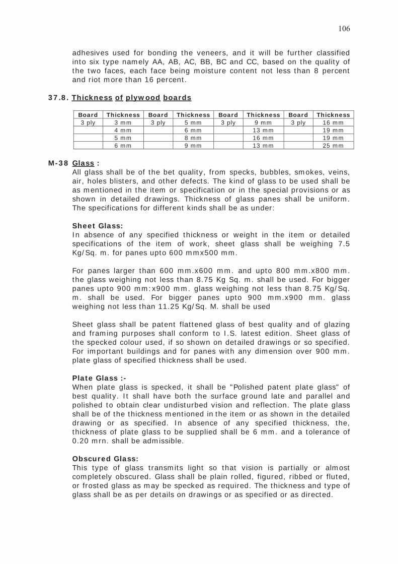
adhesives used for bonding the veneers, and it will be further classified into six type namely AA, AB, AC, BB, BC and CC, based on the quality of the two faces, each face being moisture content not less than 8 percent and riot more than 16 percent.
37.8. Thickness of plywood boards
Board Thickness Board Thickness Board Thickness Board Thickness3 ply 3 mm 3 ply 5 mm 3 ply 9 mm 3 ply 16 mm
4 mm 6 mm 13 mm 19 mm 5 mm 8 mm 16 mm 19 mm 6 mm 9 mm 13 mm 25 mm
M-38 Glass :
All glass shall be of the bet quality, from specks, bubbles, smokes, veins, air, holes blisters, and other defects. The kind of glass to be used shall be as mentioned in the item or specification or in the special provisions or as shown in detailed drawings. Thickness of glass panes shall be uniform. The specifications for different kinds shall be as under:
Sheet Glass: In absence of any specified thickness or weight in the item or detailed specifications of the item of work, sheet glass shall be weighing 7.5 Kg/Sq. m. for panes upto 600 mmx500 mm.
For panes larger than 600 mm.x600 mm. and upto 800 mm.x800 mm. the glass weighing not less than 8.75 Kg Sq. m. shall be used. For bigger panes upto 900 mm:x900 mm. glass weighing not less than 8.75 Kg/Sq. m. shall be used. For bigger panes upto 900 mm.x900 mm. glass weighing not less than 11.25 Kg/Sq. M. shall be used
Sheet glass shall be patent flattened glass of best quality and of glazing and framing purposes shall conform to I.S. latest edition. Sheet glass of the specked colour used, if so shown on detailed drawings or so specified. For important buildings and for panes with any dimension over 900 mm. plate glass of specified thickness shall be used.
Plate Glass :-
When plate glass is specked, it shall be "Polished patent plate glass" of best quality. It shall have both the surface ground late and parallel and polished to obtain clear undisturbed vision and reflection. The plate glass shall be of the thickness mentioned in the item or as shown in the detailed drawing or as specified. In absence of any specified thickness, the, thickness of plate glass to be supplied shall be 6 mm. and a tolerance of 0.20 mrn. shall be admissible.
Obscured Glass: This type of glass transmits light so that vision is partially or almost completely obscured. Glass shall be plain rolled, figured, ribbed or fluted, or frosted glass as may be specked as required. The thickness and type of glass shall be as per details on drawings or as specified or as directed.

Wired Glass : Glass shall be with wire netting embedded in a sheet of plate glass. Electrically welded 13 mm. Georgian square mesh shall be used. Thickness of glass shall not be less than 6 mm. Wired glass shall be of type and thickness as specified.
M-39 Acrylic Sheets :
Acrylic sheet shall be of thickness as specified in the item and of an specked shape size as the case maybe. Panels may be flat or curved. It should be light in weight. It shall be colourless or coloured or opaque as specified in the item. Colourless sheet shall be as transparent as the finest optical glass. Its light transmission rate shall be about 95%. Transparency shall not be affected for the sheets thickness of it shall be extremely resistant to sunlight, weather and temperatures. It shall not show any significant yellowing or change in physical properties or loss of light transmission over a longer period of use. The sheet shall be impact resistant also. Sheets should be of such quality that they can be cut, bent and jointed, as desired. Solution or the joints shall be used as per the requirement of manufacturer.
M-40. Particle board :
The particle boards used for face panels shall of best quality free from any defects. The particle boards shall be made with phenolamaldehyde adhesive. The particle boards shall conform to IS latest edition "Specifi-cation for wood particle board for general purpose" The size and the thickness shall be as indicated.
M-41. Expanded polystyrene or tamed styroper slabs
The expanded polystyrene ceiling boards and tiles shall be of approved make and shall be of size, thickness finish and colour as indicated. It shall be of high density and suitable for use as insulation material. The insulating material shall be like slab of Thermo Cole etc.
M-42. Resign bonded fiber glass :
The resign bonded fiber glass tiles or rolls shall be of approved make and shall be followed. For test of Mineral wool thermal insulation Blanker IS. : latest edition shall be of sizes, thickness and finish as indicated.
Insulation wood blanket shall be with the following coverings on one or both side as indicated. (1) Bituminised hessain Kraft paper for use in position where moisture
has to be excluded. (2) Hessian cloth or Kraft paper, for keeping out dust(3) G. I. wire netting, suitable for surfaces to be plastered over.
M- 43. Fixtures and fastenings
General

The fixtures and fastenings, that is butt, hinges, tee and strap hinges sliding door bolts tower bolts, door latch, bath-room latch, handless door stoppers, casement window fasteners, casement staysand ventilators catch shall be made of the metal as specked in the item or its specification.
They shall be of iron, brass, aluminum, chromium plated iron, chromium plated brass, copper oxidized iron, copper oxidized brass or anodized aluminum as specified.
The fixtures shall be heavy, medium or light type. The fixtures and fastenings shall be smooth finished and shall be such as will ensure ease of operations.
The sample of fixture and fastenings shall be got approved as regards, quality and shape before providing them in position.
Brass and anodized aluminum fixtures and fastening shall be bright finished. Holdfasts :
Holdfasts shall be made from mild steel flat 30 cm. length and one of the holdfasts shall be bent at right angle and two nos. of 6 mm- diameter holes, shall be made in it for fixing it to the frame with screws. At the other end, the holdfast shall be forked and bent at right angles in opposite directions
Butt hinges: Railway standard heavy type butt hinges shall be used when so specified. Tee and strap hinges shall be manufactured from M.S. Sheet
Siding door-bolts (Aldrops): The aldrops as specified in the item shall be used and shall be tot approved. Tower bolts (Barrel Type):
Tower bolts as specified in the item shall be used and shall be got approved.
Door Latch
The size of door latch shall be taken as the length of latch.
Bathroom Latch
Bathroom latch shall be similar to tower bolt.
Handle

The size of the handles shall be determined by the inside grip length of the handles. Handles shall have a base plate of length 50 mm. more than the size of the handle.
Door Stoppers Door Stoppers shall be either floor door stopper type or door catch type. Floor stopper shall be of overall size as specified and shall have a rubber cushion.
Door Catch
Door catch shall be fled at a height of about 900 mm. from the floor level such that one part of the catch is fitted on the inside of the shutter and the other part is fixed in the wall with necessary wooden plug arrangements for appropriate fixity. The catch shall be fixed 20 mm. inside the face of the door for easy operation of catch.
Wooden Door Stop with hinges Wooden door stop of size 100 mm X 60 mm.X 40 mm. shall be fixed on the door frame with a hinge of 75 mm. size and at a height of 900 mm. from the floor level. The wooden door stop shall be provided with 3 coats of approved oil paint.
Casement window Fastener Casement window fastener for single leaf window shutter shall be left or right handed as directed. Casement stays (Straight Peg Stay) :
The stays shall be made from a channel section having three holes at appropriate position so that the window can be opened either fully or partially as directed. Size of the stay shall be 250 mm to 300mm as directed.
Ventilator Catch
The pattern and, shape of the catch shall be as approved. PivotThe base and socket plate shall be made from minimum 3 mm. thick plate, and projected pivot shall not be less than 12 mm. diameter and 12 mm. length and shall be firmly riveted to the base plate in case of iron and in single piece in the case of brass pivot.
M-44. Paints :
Oil paints shall be of the specified colour arid shade, and as approved. The ready mixed paints shall only be used. However, if ready mixed paint of specified shade or tint is not available while ready mixed paint with approved stained will be allowed. In such a case, the contractor shallensure that the shade of the paint so allowed shall be uniform.
All the paints shall meet with the following general requirements
(i) Paint shall not show excessive setting in d freshly opened full can and
shall easily be redispresed with a paddle to a smooth homogeneous state. The paint shall show no curdling, livering, caking or colour separation and shall be free from lumps and skins.
(ii) The paints as received shall brush easily, Possess good leveling properties and show no running or sagging tendencies.
(iii) The paint shall not skin within 48 hour in a three quatereds filled closed container.
(iv) The paint shall dry to d smooth uniform finish free from roughness, grift, unevenness and other imperfections:
Enamel Paints: The enamel paint shall satisfy in general requirements in specification of oil paints: Enamel paint shall conform to IS : latest edition.
M-45 French Polish
The French polish of required tint and shade shall be prepared with the below mentioned ingredients and other necessary materials (i) Denatured spirit of approved quality (ii) Chandras (iii) Pigment.
The French polish so prepared shall conform to IS: Latest edition.
M-46 Marble chips for marble mosaic terrazzo :
The marble chips shall be of approved quality and shades: It shall be hard, sound, dense and homogeneous in texture with crystalline and coarse grains. !t shall be uniform in colour and free from stains, cracks, decay and weathering.
The size of various colour of marble chips ranging from the smallest upto 20 mm. shall be used where the thickness of top wearing layer is 6 mm. size. The marble chips of approved quality and colours only as per grading as decided by the Engineer-in-charge shall be used for marble mosaic tiles or works.
The marble chips shall be machine crushed. They shall be free from foreign matter, dust etc, except as above, the chips shall conform to IS latest edition.
M-47. Flooring Tiles :
(A). Plain Cement tiles
The plain cement tiles shall be of general purpose type. These are the tiles in the manufacture of which no pigments are used. Cement used in the manufacture of tiles shall be as per Indian Standards.
The tiles shall be manufactured from a mixture of cement and natural aggregates by pressure process. During manufacture, the tiles shall be subjected to pressure of not less than 140 Kg/Sq. Cm. The proportion of cement to aggregate in the backing of the tiles shall be-not less than 1:3 by weight. the wearing face though the tiles are of plain cement, shall be

provided with stone chips of 1 to 2 mm. size. The proportions of cement to aggregate in the wearing layer of the tiles shall be three parts of cement to one parts chips by weight. The minimum thickness of wearing layer shall be 3 mm. The colour and texture of wearing layer shall be uniform throughout its face and thickness. On removal from mould, the tiles kept in moist condition continuously at lWEST for seven days and subsequently, if necessary, for such long periods would ensure their conformity to requirements of IS. Latest edition regarding strength resistance to wear and water absorption.
The wearing face of the tiles shall be plane, free from projections, depressions and cracks and shall be reasonably parallel to the back face of the tile. All angles shall be right angle and all edges shall be sharp and true.
The size of tiles shall generally be square shape 24.85 Cm. x 24.85 Cm: or 25 Cm. x 25 Cm. The thickness of tiles shall be 20 mm.
Tolerance of length and breadth shall be plus or minus one millimeter. Tolerance on thickness plus 5 mm. The tiles shall satisfy the tests as regards transverse strength, resistance to wear and water absorption as per I.S. : Latest edition.
(B) Plain Coloured Tiles: These tiles shall have the same specification as for plain cement tiles as per (A) above expect that they shall have a plain wearing surface wherein pigments are used. They shall conform to I.S. Latest edition. The pigments used for colouring cement shall not exceed 10 percent by weight of cement used in the mix. The pigments, synthetic or otherwise, used for colouring tiles shall have permanent colour and shall not contain materials detrimental to concrete. The colour of the tiles shall be specified in the item or as directed.
(C) Marble Mosaic Tiles: The tiles same specification as per plain cement tiles except the requirements as stated below:
The marble mosaic tiles shall conform to I.S. latest edition. The wearing face of the tiles shall be mechanically ground and filled. The wearing face of tiles shall be free from projections, depressions and cracks and shall be reasonably parallel to the back face of the tiles. All angles shall be right angles and all edges shall be sharp and true.
Chips used in the tiles be from smallest upto 20 mm. size. The minimum thickness of wearing layer of tiles shall be 6 mm. For pattern of chips to be had on the wearing face, a few samples with or without their full size photographs as directed shall be presented to the Engineer-in-charge for approval.

Any particular samples, if found suitable shall be approved by the Engineer- in-charge, or he may ask for a few more samples to be presented. The samples shall have to be made by the contractor till a suitable sample is finally approved for use in the work. The Contractor, shall ensure that the tiles-supplied for the work shall be in conformity with the approved sample only, in terms of its dimensions thickness of backing layer and wearing surface, materials, ingredients, colour. shade chips, distribution etc. required.
The tiles shall be prepared for cement conforming to Indian Standards or coloured portland cement generally depending upon the colour of tiles to be or as directed.
(D) Chequered Tiles : `
Chequered tiles shall be plain cement tiles or marble mosaic tiles. The former shall have the same specification as per (A) above and the latter as per marble mosaic tiles as per (C) except as mentioned below The tiles shall be of nominal size of 250 mm. X 250 mm. if specified. The centre to centre distance of chequer shall not be less than 25 mm. and not more than 50 mm. The overall thickness of the tiles shall be 22 mm.
The grooves in the chequers shall be uniform and straight. The depth of the grooves shall not be less than 3 mm. The chequered tiles shall be plain, coloured or mosaic as specified. The thickness of the upper layer measured form the top of the chequers shall not be less than 6 mm. The tiles shall be given the first grinding with machine before delivery to site.
Tiles shall conform to relevant IS: latest edition. (E) Chequered Tiles For Stair Cases :
The requirements of these tiles shall be the same as chequered tiles as per (D) above except in following respects :
(1) The length of a tile including note shall be 330 mm: (2) The minimum thickness shall be 28 mm: (3) The nosing shall have also the same wearing layer as at the top: (4) The nosing edge shall be rounded. (5) The front portion of the tiles for minimum length of 75 mm. from and including the nosing shall have grooves running parallel to nosing and at centers not exceeding 25 mm. Beyond that the tiles shall have normal chequer pattern.
M-48. Rough Kotah Stone :
The kotah stones shall be hard, even, sound and regular in shape and generally uniform in colour, The colour of the stone shall generally be green. Brown coloured shall not be use. They shall be without any soft veins, cranks or flaws.
The size of the stones to be used for flooring shall be of size 600 mm. X 600 mm. abd / or size 600 mm. X 450mm as directed. However smaller
sizes will be allowed to be used to the extent of maintaining required pattern. Thickness shall be as specified.
Tolerance of minus 30 mm. on accounts of chisel dressing of edges shall be permitted for length as well as breadth. Tolerance in thickness shall be + 3 mm.
The edges of stones shall be truly chiselled and table rubbed with coarse sand before paving. All angles and edges of the stone of shall be true, square and free from chipping and the surface shall be true and plain. When machine cut edges are specified, the exposed and the edges at joints shall be machine cut. The thickness of the exposed machine cut edges shall be uniform.
M-49. Polished Kotah Stones :
Polished kot4h stone shall have the same specification as per rough kotah stone except as mentioned below:
The stones shall have machine polished surface. When brought an site, the stones shall be single polished or double polished depending upon its use. The stones for paving shall generally be single polished. The stones to be used for dedo, skiri thing sink, veneering, sills, steps, etc, where machine polishing after the stone are fixed in situ is not possible shall be double polished.
M-50. Dholpur Stone Stab :
Dholpur stone slab shall be of best quality as approved by the Engineer-in-charge: The stone slab shall be without any veins, cracks, and flaws.The stone slab be even, sound and durable regular in shape and of uniform colour.
The size of the stone shall be as specified in the item or detailed drawing of as approved by the Engineer-in-charge. The thickness of the stone shall be as specified in the item of work with the permissible tolerance of plus or minus 2 mm. the provisions in respect of polishing as for polished kotah stone shall apply to polished Dholpur stone also. All angles and edges of the face of the stone slab shall be fine chiselled or polished as specified in the item of work and ai6 the four edges shall be machine out. All angles and edges of the stone slab shall be true and plane. The sample of stone shall be got approved by the Engineer-in-charge for a particular work. It shall be ensured that the stones to be used in a particular work shall not differ much in shade or tint from the approved sample.
M-51. Marble Slab :
Marble slab shall be white or of other and of best quality as approved by the Engineer-in-charge.

Slabs shall be hard close, uniform and homogeneous in texture. They shall have even crystalline grain and free from defects and cracks. the surface shall be machine polished to an even and perfect plane surface and edges machine cut true and square. The rar face shall be rough to provide key for the mortar. Marble slabs with nature veins, if selected shall have to be laid as per the pattern given by the Engineer-in-charge. Size of the slab minimum 460 mm. X 450 mm: and preferably 600 min. X 600 mm. However smaller sizes will be allowed to be used to the extent of maintaining required pattern.
The slab shall not be thinner than the specified thickness at its thinnest part. A few specimen of finished slab to be used shall be deposited by the Contractor in the office for reference.
Except as above, the marble slabs shall conform to IS: Latest edition.
M-52. Granite Stone slab :
Granite shall be of approved colour and quality. The stone shall be hard, even sound and regular in shape and generally uniform in colour. It shall be without any soft veins, cracks of flaws.
The thickness of the stone shall be as specified in item. All exposed faces shall be double polished tender truly smooth and even reflecting surface. The exposed edges and corners shall be rounded off as directed. The exposed edges shall be machine cut and shall have uniform thickness.
M-53. PVC Flooring
PVC sheet for PVC, floor covering shall be of homogenous flexible type, conforming to I.S. Latest edition. The PVC covering shall neither develop any toxic effect while put to use for shall give off any disagreeable odour.
Thickness of flexible type covering Ales shall be as specified in the description of the item. The flexible shall be backed with hessian or other woven fabric. The following tolerances shall be applicable on the nominal dimensions of the folls or tiles : (a) Thickness ± 15 mm. (b) Lengh of Width :
1. 300 rnm. square tiles ± 0.20 mm 3. 900 mm, square tiles ± 0.60 mm, 2. 600 mm. Square tiles ± 0.40 mm. 4. Sheets and roll ± 0.10 percent. Adhesive:The adhesive for PVC flooring shall be of the type and make, recommended by the manufactures of PVC sheets/tiles.
M-54 Facing Tiles
The facing tiles (burnt clay facing bricks) shall be free from cracks and nodules of free lime. They shall be thoroughly burnt and shall have plane rectangular faces with parallel sides and sharps straight right angled faces.. The texture of the finished surface that will be exposed when in place shall

conform to an approved sample consisting not less than four stretch bricks each representing the texture desired. The facing tiles shall have a pleasing appearance sufficient resistance to penetration by rain and greater durability than common bricks. The tiles shall conform to I.S.Latest edition.
I The standard size of facing brick tiles shall be 19 x 9 x 4 cms. The facing brick tiles shall be provided with frog which shall conform to IS: Latest edition.
The permissible tolerance in dimensions specified above shall be as follows:
Size Tolerance for 1st class brick 2nd class brick
19 ± 6 mm ± 10 mm 9 ± 3 mm ± 7 mm 4 ± 1.5 mm ± 3 mm
The tolerance for distortion or warpage of face or edges of individual brick form a plane surface and from a straight line respectively shall be as follows:
Ficing dimensions Permissible tolerance Max. below 19 cms Max 2.5 mm --do-- above 19 mm Max 3.0 mm
The average compressive strength obtained as a sample of five tiles when tested in accordance with the) procedure laid as per IS: Latest edition shall be not less than 175 Kg/Sq. Cm. The average compressive strength of any individual bricks shall be not less than 160 Kg/Sq. Cm.
The average water absorption for five bricks tiles shall not exceed 12 percent of average weight of brick before testing. The absorption for each individual bricks shall not exceed 25 percent.
The brick tiles when tested in accordance with IS: Latest edition, the rate of efflorescence shall not be more than "Slightly effloresced'
M-55. White glazed tiles The tiles shall be of best quaky as approved by the Engineer- in-charge. They shall be foat and true to shape. They shall be free from cracks, crazing spots, chipped edges and corners. The glazing shall be of uniform shade.
Variation from the stated sizes, other than the thickness of tile shall be plus or minus 1.5 mm. The thickness of tile shall be 6 mm. Except as above the tiles shall conform to I.S. Latest edition.
M-56. Galvanized Iron Pipes and Fittings:Galvanized iron pipe shall be of the medium type and of required diameter and shall comply with IS: latest edition. The specified diameter of the pipes shall refer to the inside diameter of the bore.

Clamps, screw and all galvanized iron fittings shall be of the standard 'R' or equivalent make.
M-57. Bib cock and stop cock:A bib cock is a draw off tap with a horizontal inlet and free outlet. A stop cock is a valve with a suitable means of connection for insertion in a pipeline for controlling or stopping the flow. They shall be of screw down type and or brass chromium plated and of diameter as specified in the description of the item. They shall conform to IS: latest edition and they shall be of best Indian make. They shall be polished bright. The minimum finished weight of bib cock and stop cock shall be as given below: Diameter Bib cock Stop cock Diameter Bib cock Stop cock 8 mm 0.25 kg 0.25 kg 15 mm 0.40 kg 0.40 kg 10 mm 0.30 kg 0.35 kg 20 mm 0.75 kg 0.75 kg
M-58. Gun metal wheel valve:
The gun metal wheel valve shall be of approved quality. These shall be of gun metal fitted with wheel and shall be of gate valve opening full way and of the size as specified. These shall conform to IS: latest edition.
M-59. White glazed porcelain wash basin:Wash basin shall be of white porcelain first quality best Indian make and it shall conform to IS: latest edition. The size of the wash basin shall be as specified in the item. Wash basin shall be of one piece construction with continued over flow arrangements. All internal angles shall be designed so as to facilitate cleaning. Wash basin shall have single tap hole or two holes as specified. Each basin shall have a circular waste hole which is either revated or beveled internally with 65 mm diameter at top and 10 mm depth to suit the waste fitting. The necessary stud slot to receive the bracket on the under side of the basin shall be provided. Basin shall have an internal soap holder recess which shall fully drain into the bowl. White glazed pedestal of the quality and color as that of the basin shall be provided where specified in the item. It shall be completely recessed at the back for reception of supply and wash pipe. It shall be capable of supporting the basin rigidly and adequately and shall be so designed as to make the height from the floor to top of the rim of basin 750 mm to 800 mm as directed.
M-60. European type water closet with low level flushing:The European type water closet shall be white glazed porcelain first quality and shall be of wash down type conforming to IS: latest edition. 'S' trap shall be provided as required with water seal not than 50 mm. The solid plastic seal and cover shall be of best Indian make conforming

to IS: latest edition. They shall be made of moulded synthetic materials which shall be tough and hard with high resistance to solvents and shall be free from blisters and surface defects and shall have chromium plated brass hinges and rubber buffer of suitable size.
M-61. Orissa type water closet:The specification of Orissa type white glazed water closet of first quality shall conform to IS: latest edition and relevant specification of Indian type water closet except that pan will be with the integral squatting pan of size 580 x 440 mm with raised footrest.
M-62. Indian type water closet:The Indian type white glazed water closet of first quality shall be of size as specified in the item and conforming to IS: latest edition. Each pan shall have integral flushing. It shall also have an inlet at back or front for connecting flush pipe as directed. The inside of the bottom of the pan shall have sufficient slope from the front towards the outlet and surface shall be uniform and smooth. Pan shall be provided with 100 mm. diameter "P" or "S" trap with approximately 50 mm, Water seal and 50 mm. diameter vent horn.
M-62 A Foot Rests
A pair of white glazed ear-then ware rectangular foot of minimum size 250 mm. x 130 mm x 20 min shall be provided with the water closet.
M-63 Glazed Earthen Ware Sink The glazed earthen ware sink shall be of specified size, colour and quality.
The sink shall conform to I. S. latest edition. The brackets for sinks shall conform to IS: latest edition.
The pipes shall conform to I.S. latest edition for steel and lead pipes respectively. 32 min. brass waste coupling of standard pattern with brass chain and rubber plug shall he provided with sink.
M-64. Glazed earthen-ware Lipped type flat back urinal / corner type
urinal.The lipped type shall be flat. back or corner type as specified in the item and shall conform to IS: Latest edition. It shall be of best Indian make and size as specified arid approved by the Engineer-in-charge. The flat back or corner type urinal must be of 1st quality free from any defects, cracks etc.
M. 65. Low level enamel flushing tank
The low level enamel flushing tank shall be of 15 litres capacity. It shallconform to IS: latest edition. The flushing cistern shall be of best quality and free from any defects. The flushing tank shall have outlet 32 mm. diameter. The outlet shall he connected with WC. Pan by lead pipe or PVC pipe as specified. The flushing cistern shall be provided with inlet and outlet for fixing G.I. inlet pipes and overflow pipes The flushing cistern shall beprovided with chromium plated handle for flushing. The flushing tank shall

be provided with bracket of cast iron so that it can be fixed on wall at specified height. The, brackets shall conform to I.S. latest edition.
M-66. Cast iron flushing cistern.
The cast iron flushing cistern shall be of 15 litres capacity. It conform to IS. latest edition, The flushing cistern shall be of best quality free from any defects, The flushing cistern shall have outlet of 32 mm. diameter. The lead pipe shall conform IS: latest edition. For fixing G.I. inlet pipes and overflow pipe 20 mm dia inlet and outlet shall he got provided. The flushing, cistern shall be provided with galvanized iron chain and pull of sufficient length and shall be got approved from the engineer-in-charge. The cast iron flushing cistern shall be painted with one coat of anti-corrosive paint and two coats of paints. The flushing cistern shall be fixed on two C.I. brackets. The C.I. bracket shall conform to IS: latest edition.
M-67 Flush Cock Half turn flush cock (Heavy weight) shall be of gun metal chromium plated
of diameter as specified in the description of the item. The flush cock shallconform to relevant Indian Standard.
M-68 Cast iron pipes and fittings.
All soil, water, vent and antisyphonage pipe and fitting shall conform to IS: latest edition. The pipe shall have spigot and socket ends with head on spigot end. The pipes and fittings shall be true to shape, smooth, cylindrical their inner and outer surfaces being as nearly as practicable concentric. They shall be sound and nicely cast and shall be free from cracks, laps pinholes or other imperfection and shall be neatly dressed and carefully settled.
The end of pipes and fittings shall be, reasonable square to their axis.
The sand cast iron pipes shall be of the diameter as specified in the description and shall be in lengths of 1.5 M, 1.8 M. and 2 M. including socket ends of the pipe unless shorter lengths are either specified or required at junctions etc. The pipes and fittings shall he supplied. without ears unless specified or directed otherwise.
Tolerances
The standard weights and thickness of pipes shall be as shown in the following table: Sr No
Nominal dia. of bore
Thickness Overall Weight of pipe
Excluding ears
1
75 mm
5.0 mm
1.5 m long 12.83 kg
1.8 m long 16.52 kg
2 m long 18.37 kg
2 100 mm 5.0 mm 18.14 kg 21.67 kg 24.15 kg A tolerance upto minus 15 percent in thickness and 20 mm in length will be allowed. For fittings tolerance in lengths shall be plus 25 mm and minus 10 mm.

The thickness of fittings and their socket and spigot dimensions shall conform to the thickness and dimensions specified for the corresponding sizes of straight pipes. The tolerance in weights and thickness shall be the same as for straight pipes.
M-69. Nahni Trap:Nahni trap shall be of cast iron and shall be sound and free from porosity or other defects which affect serviceability. The thickness of the base metal shall not be less than 6.5 mm. The surface shall be smooth and free from craze, chips and other flaws or any other kind of defect which affect serviceability. The size of nahni trap shall be as specified and shall be of self cleaning design. The nahni trap shall be of quality approved by the engineer-in-charge and shall generally conform to the relevant Indian Standard. The nahni provided shall be with deep seal, minimum 50 mm except at places where trap with deep seal cannot be accommodated. The cover shall be cast iron perforated cover shall be provided on the trap of appropriate size.
M-70. Gully Trap:The gully trap shall conform to IS: latest edition. It shall be sound, free from defects such as fire cracks or hair cracks. The glaze of the traps shall be free from crazing. They shall give a sharp clear note when struck with light hammer. There shall be no broken blisters. The size of the gully trap shall be as specified in the item. Each gully trap shall have one C.I. grating of square size correspodning to the dimensions, of inlet of gully trap. It will also have a water tight C.I. cover with frame inside dimension 300 mm x 300 mm. The cover with frame inside dimensions 300 mm x 300 mm the cover weighing not less than 4.53 kg and the frame not less than 2.72 kg. The grating cover and frame shall be of sound and good casting and shall have truly square machined seating faces.
M-71. Glazed stone ware pipe and fittings:The pipes and fittings shall be of best quality as approved by engineer-in-charge. The pipe shall be of best quality manufactured from stoneware of fire clay, salt glazed thoroughly burnt through the whole thickness, of a close even texture, free from air blows, fire blisters, cracks and other imperfections, which affect the serviceability. The inner and outer surfaces shall be smooth and pefectly glazed. the pipe shall be capable to withstand presures of 1.5 m lead without showing sign of leakage. The thickness of the wall shall not be less than 1/12th of the internal dia. the depth of socket not be less than 38 mm. The socket shall be sufficiently large to allow a joint of 6 mm around the pipe. The pipes shall generally conform to relevant IS latest edition.

M-72. Wall Peg Rail:The aluminum wall peg rail shall have three aluminum pegs of approved quality and size. It shall be fixed on teak wood plank of size 450 mm x 20 mm. The teakwood shall be french polished or oil painted as specified.
M-73. G.I. Water Spot:The G.I. pipes of 40 mm dia shall be of medium quality and specials shall be of 'R' brand or equivalent of the best approved quality. The pipe shall have length as required for the thickness of wall in which it is fixed, and at outside end tee and bend cut at half the length shall be provided and at other end, coupling shall be provided to have better fixing. The water spout shall be provided as per detailed drawing or as directed.
M-74. Asbestos Cement Pipe (A.C. Pipe)
The asbestos cement pipe of diameter as specified in the description of the item shall conform to I.S. latest edition. Special like bends, shoes, cowls etc. shall conform to relevant Indian Standards. The interior of pipe shall have a smooth finish, regular, surface and regular internal diameter. The tolerance in all dimension shall be as per IS: latest edition.
M-75. Crydon Ball valve
Ball valve of screwed type including polythene float and necessary level etc. shall be of the size as mentioned in the description of item and shall conform to IS: latest edition.
M-76. Bitumen Felt For Water Proofing And Damp Proofing
Bitumen felt shall be on the fiber bases and shall be of type 2, self finished felt grade-2 and shall conform to IS: latest edition.
M-77. Selected Earth
The selected earth shall be that obtained from excavated material or shall have to be brought from outside as indicated in the item. If item does not indicate anything the selected earth shall have to be brought from outside.
The selected earth shall be good -yellow soil and shall begot approved from the Engineer-in-charge. In no case black cotton soil or similar expensive and shrinkable soil shall be used. It shall be clean and free from all rubbish and perishable materials, stones or brick bats. The clods shall be broken to a size of 50 mm. or less. Contractor shall make his own arrangement at his own cost for land for borrowing selected earth. The stacking of material shall be done as directed by the Engineer-in-charge in such a way as not to interfere with any constructional activities and in proper stacks.
When excavated material is to be used, only selected stuff got approved from the Engineer-in-charge shall be used. It shall lie stacked separately and shall comply with all the requirements of selected earth mentioned above.

M-78. Barbed Wire.
The barbed wire shall be of galvanized steel and it shall generally conform to IS: latest edition. The barbed wire shall be of type-I whose nominal diameter for line wire shall be 2.5 mm and point wire 2.24 mm. The nominal distance between two barbs shall be 75 mm, unless otherwise specified in the item. The barbed wire shall be formed by twisting together two line wires, one containing the barbs. The size of the line and point wires and barb spacing shall be as specified above. The permissible deviation from the nominal diameter of the line wire and point wire shall not exceed 0.08 mm.
The barbs shall carry four points and shall be formed by twisting two point wires, each two turns, lightly round one line wire, making altogether four complete turns. The barbs shall be so finished that the tour points are set and locked at right angles to each other. The barbs shall have a length of not less than 13 mm. and not more than 18 mm. The point shall be sharp and cut at an angle not greater than 35 degree of the axis of the wire forming the barbs.
The line and point wires shall be circular section, free from scale and other defects and shall be uniformly galvanized. The line wire shall be in continuous length and shall not contain any welds other than those in the rod before it is drawn. The distance between two successive splices shall not be less than 15 meters.
The lengths per 100 Kg. of bar-bed wire IS: type I shall be as under : Nominal 1000 meters. Minimum 934 Meter. Maximum 1066 Meter.
M-79 Admixture for mass concrete and mortar:
M-79A) Joint Sealant The sealant shall be best quality and from manufacturer like CICO, Fosroc MC-BAUCHEMIE, PIDILITE, HMP or equivalent as approved by engineer- in-charge. The prior approval for the source shall be taken from the engineer-in-charge. It shall be conformed to the relevant I.S. Code.
It shall be two component polysulphide rubber joint sealant, based on a low molecular weight polymer. It should not contain chloride or other corrosive substances.
It shall be used for sealing joints in water retaining structure, roofs, external wall, cladding, floors, partition, sealing, pavement surface etc. It shall have excellent property to adhere most of building material like aluminum, stainless steel, glass, concrete, marble, stone, brick, masonry block, plaster, ceramic, quarry tiles, timber etc. The modulus of elasticity of the sealant shall be less than 0.16 MPa, ±10% at 100% elongation. The shore "A" hardness of the sealant shall be 22±3 @ 250C.

The operating temperature range for the sealant shall be 250C to 800C. The permanent dynamic movement capability of the sealant shall be ±25%. The tensile strength of the sealant shall not be less than 0.4 MPa. The optimum width / depth ratio shall be 2:1. The specific gravity of the sealant shall be 1.6 Kg/Lit. The sealant should be capable to resist to attack of water, sunlight, oxidation, corrosive fumes, oils, petrol, diluted acids and alkalies, salt spray, aliphatic and aromatic solvent and shall not contain tar or bituminous ingredients.
It shall possess the properties like 550% elongation at break, non-toxicity when fully cured, no staining and shrinkage less than 1%. The trafficable strength shall be achieved within 24 hours and full at 7 days (at 250C and 250% RH). It shall posses excellent coverage capacity and more strength at low dry temperature.
M-79B) Abrasion Resistant Industrial Flooring Aggregate: The flooring aggregate shall be of best quality and from manufacturer like CICO, Fosroc or equivalent, as approved by the engineer-in-charge. The prior approval for the source shall be taken from the engineer-in- charge. It shall be conformed to the relevant I.S. Code.
The flooring aggregate shall be factory processed and specially graded non-oxidized, non-magnetic and chemically inert metallic flooring aggregate, free from oil and grease. It shall be used as a surface hardener to concrete floors. It is recommended forfactory floors, warehouses, hangers, car parks and such other areas subjected to heavy vehicular traffic. It shall also be used on open and continuously wet surfaces. The flooring aggregate shall build in wearing resistance and shall produce high abrasion resistant floor surfaces. It shall impart extreme surface density and shall offer resistance to oil and water penetration. It shall provide a non-rusting floor surface which is easy to maintain.
It shall be used with cement in the ratio, as per manufacturer's instruction and spread evenly on the surface to be treated, at the rate depending on the type of floor. The flooring aggregate shall be spread when the surface of the concrete floor is still fresh, i.e. as soon as the surface water has evaporated and then trawled, in stage, to bring about an uniform and smooth finish.
M-79C Concrete Hardener and Dust Proofer : The concrete hardener and dust proofer, shall be of the best quality and from manufacturer like CICO, Fosroc or equivalent, as approved by the engineer-in-charge. The prior approval for the source shall be taken from the engineer-in-charge. It shall be conformed to the relevant I.S. Code.
It shall have a specific gravity of 1.18 and shall be applied on concrete floors, at the ate of at lWEST 25 liter/100 m2/coat. A total of 3 coats shall be applied for permanently hardened concrete floor, with increased abrasion resistance, increased surface density, increased resistance to chemical attack and to eliminate dust accumulation. Drying time of 4 to 6 hours for each coat shall be allowed before the flooring is put to use or is applied with another coat of

the product. Precautions shall be taken while using the product, to avoid contact with eye and open wounds and to work in good ventilation. After application, the affected part shall be washed copiously. It shall not be stored for the period of more than two months before use.
M-79D Water Repellent Coating : The water repellent coating shall be of the best quality and from manufacturer like CICO, Fosroc or equivalent, as approved by the engineer-in- charge. The prior approval for the source shall be taken from the engineer-in-charge. It shall be conformed to the relevant I.S. Code.
Water repellent coatings for exterior exposed surfaces shall be acrylic resin based, having a Flash point of approx. 40°C and specific gravity of 0.95. It shall be suitably used for concrete, brick, stone and plastered surfaces preventing moisture penetration and thus any damage to the interiors. It shall be quick acting, long lasting, invisible i.e. colourless so as to maintain the original colour of the surface treated. It shall impart sealing characteristics so that the treated surface becomes stain and dust free. The coating itself shall not darken or turn yellow with age.
M-79E Accelerating, Water Reducing Admixture and Plasticiser : The Accelerating, Water reducing admixture and plasticiser, shall be of best quality and from manufacturer like CICO, Fosroc or equivalent, as approved by the Engineer. The prior approval for the source shall be taken from the Engineer. It shall conform to the relevant IS Code.
It shall be in liquid state with a specific gravity of 1.30 and complying with-ASTM C-494 Type E, IS : 9103 & IS: 2645. It shall accelerate the setting and hardening of the concrete mix, thereby achieving higher early age strength. It shall reduce the water content of the concrete without affecting its workability. It is useful for pre-cast/pre-stressed works, structural concrete works, floors, roads, runways, paving etc. It shall be used at the rate instructed by the manufacturer, with cement, depending on the amount of acceleration of hardening required, it should be compatible to all types of cement.
M-79F Retarding, Water Reducing Admixture and Plasticiser : The Retarding, water reducing admixture and plasticiser, shall be of best quality and from - manufacturer like CICO, Fosroc, Feb Roffe or equivalent, as approved by the Engineer. The prior approval for the source shall be taken from the Engineer. It shall conform to the relevant IS Code. It shall be in liquid state with a specific gravity of 1.22 and complying with ASTM C-494 Type B & D, IS 9103, CRD-C87 Type B & D, BS 5075 Part 1. It shall be added to the concrete mix during the mixing process, at the same time as the water or the aggregates. No extension of normal mixing time is necessary. It shall extend the period of time as to placing the concrete and compacting, i.e. delay the initial and final setting time. It shall help to spread the heat of hydration over a longer period of time. It shall give a highly workable concrete with a low W/C ratio. It shall be used at the rate instructed by the manufacturer, with cement, depending on

the amount of acceleration of hardening required. It should be compatible to all types of cement.
M-79G Water & Weather Proof Compound : The water & weather proof integral cement admixture shall be of best quality and from manufacturer like Feb Roffe's Roff Hyseal, Roff hyproof, Algiproof or equivalent, as approved by the Engineer. The prior approval for the source shall be taken from the Engineer. It shall conform to the relevant IS Code.
It shall be used as an excellent cement admixture in all types of concrete/plaster mortars, pointing mortars, masonry works, guniting works and pressure grouting works. It shall improve resistance of concrete surfaces to weathering and chemical attack. It shall be non-toxic so as to use for water proofing water tanks, reservoirs, bio-gas tank, leaking ceiling, basements, tunnels, lift wells etc.
It shall be mixed to concrete or plaster mortar, while mixing. First, water is added and then the admixture, at the rate instructed by the manufacturer. For use of the admixture, precaution shall be taken to use clean materials for preparation of mortar.
M-79H Plaster Admixture : An admixture which gives the plaster workability, durability and quality at aneconomical rate shall be of best quality from manufacturer like Feb Roffe (product name - Roff plaster master) or equivalent, as approved by the Engineer. It shall comply to the relevant IS Codes.
It shall keep the plastering mortar plastic for a longer time, giving higher strength on prolonged curing. It shall provide cohesiveness, workability and eliminate efflorescence. It shall reduce shrinkage, cracking and crazing to the minimum.
M-80 Fly Ash : Fly Ash of grade-I as per IS: 3812-1981 shall be from Sikka Thermal Power Station Only. Contractor has to manage for required size containers at site work for storing the Fly ash.
M-81 Anti-Corrosive Paints : M-81A Ferroshield: It shall be from STP Limited or equivalent, as approved by the Engineer.
It shall be a high build bituminous emulsion, specially formulated for protection against corrosion. It shall form a dry film, 2 mm. thick, which shall not crack at low temperatures nor crocodile at-very high temperatures. It shall also be used as waterproofing material on flat, sloped and steeped roofs. It shall be applied by brush and by heavy duty airless spraying. ..
M-81B Tankmastic: It shall be from STP Limited or equivalent, as approved by the Engineer. It shall conform to IS : 158- 9862.
It shall be special bituminous paint, which shall have no harmful reaction on

drinking water. It shall be used to protect the inside of water tanks and pipe connections, against corrosion. It shall be applicable on steel, wood, concrete, iron etc. It shall have a covering capacity of 12 m2/lit..
M-81C Pipekote: It shall from STP Limited or equivalent, as approved by the Engineer. It shall conform to IS: 158. It shall be a heavy duty bituminous paint, which shall not impart any odour or taste to water, carried in the steel water pipelines, tanks and pen-stocks. It shall be applied on the inside surface of the water pipe line, tanks and pen-stocks. It shall be resistant to mild acids, alkalis and shall withstand heat upto 150°C. It shall render a heavy body protective film. If zinc-rich, epoxy primer shall be used, better results of pipekote shall be obtained.
M-81D Silver Shield: It shall be from STP Limited or equivalent, as approved by the Engineer.
It shall be a bituminous aluminum-finish paint formulated for application over anti-corrosive paints. It shall have a covering capacity of 10 m2/lit..
M-81E Shalimastic HD: It shall be from STP Limited or equivalent, as approved by the Engineer. It shall comply with the US Dept. of interior bureau of reclamation specification CA-50.
It shall be a viscous, heavy-duty, anti-corrosive waterproof coal tar paint. It shall offer resistance to acids and alkalis. It shall be used for protection of all types of iron and steel structures.
M-82 Galvanized Iron Pipe: Galvanised iron pipe shall be of the medium type and of required diameter and shall comply with IS 1239-1975. The specified diameter of the pipes shall refer to all inside diameter of the bore, clamps, screw and all galvanised iron fittings shall be of standard 'R' or equivalent make as approved by the Engineer.
M-83 Acoustical Wall & Ceiling material :-M-83a Glass wool:-
I. Glass wool shall be conform as per relevant I.S. standard & specification.
II. Density, & thickness shall be used as per specified in item specification.
III. It shall be pure without dust & any foreign matter and shall be uniform in color, density & weight.
M-83b Aluminum foil or percolated sheet:-
I. Aluminum alloy used in the manufacture of extruded & sheet or section shall conform to I.S. designation HEA-WP of I.S. 733- 1975 and also to I.S. designation WVG-WP of I.S. 1285- 1975. & it shall be specified in the item specification. The fabrication shall be done

as directed. II. Aluminum shall be conform to I.S.733-1825, & relevant I.S.
standard & specification. III. Density, Grade & thickness shall be used as per specified in item
specification. M-83c Wood wool board :-
I. Acoustical Insulation shall be conforming to I.S. 8225-1987, and equivalent to ISO: 354 & ASTM. 423-90 A.
II. Thermal insulation shall be conform to B.S. :874 – 1965. III. Board shall be fire resistant conform to B.S. 476- part-5 Class-P,
part-6 I-4.11, Part-7 Class-1, & size, thickness and other special requirement shall be as per specified in item specification.
M-83d Acoustical Board & Gypsum board
Humidity resistant 99 % RH. Material fire performance Class- 0/ Class-1 ( B.S. 476 ) Sound Absorption (NRC.) 0.50
Frequency Hz 125 – 4000 Sound insulation 40dB.
CAC. 90% Light reflection. >85%
Thermal resistant. R=0.28 m2 k/W
Weight / Piece (600mm X 600mm. X 15mm. thick board without
Grid.) 2.35 Kg.
Surface finish Crisp subtly textured matt appearance with visible perforation finished with vinyl emulsion paint
Material Hydro synthesized Bio soluble long fiber with purified starch as binder.
Bending strength > 250N ( JIS A 6301 )
Sagging resistant < 5/1000.

Testing Method
Fire Propagation Test Class – 0 B.S. 476 PART- 6
Flame spread
Class 1 (0-25) ASTM – E84
Class-A U.S. Federal Spec. SS.-S-118-b
20 Underwriters LaboratoriesInc.
Class-1 BS. 476 Part-7
Thermal conductivity 0.045 Kcal/mh0C JIS A 1412
Light reflectance LR-1 (Over 80%) ASTM. C 523
NRC 0.55-0.70 ASTM. C 423
CAC 36 ASTM. E 413
I. Size, thickness and other special requirement shall be specified in the item specification. The fabrication shall be done as directed.
Signature of Contractor

B2 LABOUR SPECIFICATION

DETAIL TECHNICAL SPECIFICATIONS
Item No.1, 2 and 3:
EXCAVATION Excavation of pipe trenches incl. all safety provision using site rail & stacking excavated stuff up to lead of 90M clearing the site etc comp. For strata as specified including lifting and removal of Surplus earth and breaking of C.C. in front of every Houses. a Breaking of Asphalt surface,and C.C. road. b 0 to 1.50M & 1.51M to 3.0M depth in soft murrum/clay/sand c. 0 to 1.50M & 1.51M to 3.0M depth In Soft rocks, Masonry in CM or LM or LC d 0 to 1.50M & 1.51M to 3.0M depth In hard rocks EXCAVATION Excavation for pipe line trenches with shoring, strutting, bailing or pumping out watered from trenches whenever necessary of required length, width and depth including extra excavations for sockets and all safety measures and provisions such as site rails fencing, lighting, watching including refilling the trenches in layers including ramming and removing the excavated staff with 90m lead and clearing the site etc. as stipulated in the tender specification complete before starting work and after completion of work for all lifts and soil strata as specified.
a) In all sorts of soil soft murmur, hard murrum, boulders, macadam and
asphalt roads including breaking of lime and cement masonry and lime concrete.
b) In soft rock, cement concrete, hard rock, and cutting of cement concrete
and R.C.C. of any proportion, etc. with controlled blasting and or chiseling whichever is necessary and feasible as required by site conditions.
c) In hard rock,
1.1 Clearing of sites : 1.1.1 The site at which the pipe line is to laid and the area required for setting out and
other operations shall be cleared of all obstructions, loose stones, and rubbish of all kinds; stumps of trees, brushwood as well as all trees shall be removed as directed. The roots shall be entirely grubbed up.
1.1.2 The products of the clearings to be stacked in such a place and in such a manner, As directed by the Engineer-in-charge.
1.1.3 In site clearing, all trees not specially marked for preservation, bamboos jungle wood and brush wood shall be cut down and their roots grubbed up. All wood and materials from the clearing shall be the property of corporation and shall be arranged as directed by the Engineer-in-charge or his authorized agent. The materials found to be useful by the Engineer-in-charge shall be conveyed and properly stacked as directed within the specified limit. Unless materials will be burnt or otherwise disposed off as directed.

1.1.4 All holes or hollows, whether originally existing or produced by digging up roots, shall be carefully filled up with earth, well rammed and leveled off, as may be directed shall not be paid for. The contractor shall get approval of design of shoring. The shoring shall be of sufficient strength to resist side pressure and ensure safety from slips and blows and to prevent damage to work and property and injury to persons. It shall be removed as directed after all the items of work for which it is required are completed.
1.1.5 Protection : 1.1.5.1 The foundation pits and trenches, etc shall be strongly fenced and red light
Signals shall be kept at night in charge of watch-man to prevent accidents. Sufficient care and protective measure shall be taken to see that the excavation shall not affect or damage the adjoining structures. The contractor shall be entirely responsible for any injury to life and damage to the properties etc. Necessary protection work such as guide ropes, crossing places, barricades, the contractor at his own cost shall provide caution boards etc.
1.6 Classification of Strata : 1.6.1 The decision regarding classification of strata shall rest with the Engineer-in-
Charge and his decision shall be final and binding to the contractor.
1.6.2 All the materials encountered in the excavation shall be classified as described in 2.0 of general specifications.
1.7 Dewatering : 1.7.1 Unless specially provided for as a separate item in the contract, the rate of
excavation would include bailing or pumping out all water met with in excavation or which may accumulate in the excavation during the progress of the work either, by percolation, seepage, springs, rain or any other cause and diverting surface flow if any, by earthen bunds or by other means. The bunds shall be removed as soon as the work is completed.
1.7.2 Unless specially provided as a separate item of contract, pumping of water from
foundation pit, trenches etc shall be carried out by the contractor at his won cost and he shall arrange for required numbers of dewatering pumping sets for the above work. He shall take precaution to prevent any damage to the foundation trenches, concrete or masonry or any adjacent structure. The excavation shall be kept free from water by the contractor (1) during inspection and measurement (2) When concrete and/or masonry work are in progress and till the construction work reaches above the natural water level and (3) till the Engineer – in – charge considers that the mortar is sufficiently set. The rate shall be paid for cum. of excavation.
1.8 Excavation in Rock : 1.8.1 Blasting with Gun Power:
Blasting operations shall be carried out with the prior permission of sanctioning authority and in the presence of the Engineer – in – charge or his authorized representative and during fixed time hours of the day. All safety precautions such as providing safety nylon netting etc. shall be carried out as per instructions of the Engineer – in – charge.

Red danger flags shall be prominently displayed and all the people, except those who have actually to light the fuse must be away to a safe distance, not less than 200 meters. All fuses shall be cut to the length required before being inserted into the holes. The number of charges to be fired and the actual number of shots heard shall be compared and the person responsible must satisfy himself by examination that all the charges have exploded before work people are permitted to approach the scene. The withdrawal of a charge which has not exploded shall under no circumstances be permitted, but the tamping and charge shall be flooded with water and the hole marked in a distinguishing manner. The next hole to be fired shall be at a distance of about 500mm from the old hole and fired in the usual way. The contractor or any of his competent authorized person shall be in charge of the blasting operations and shall be held responsible for strictly observing the safety rules, particularly applicable to blasting operations, in addition to other safety rules. In blasting rocks with dynamite, the following general principles shall be observed. In general, the following diameter of drills shall be used for different depth of boreholes: From 1 – 2 metres 25 mm diameter From 2 – 3 metres 37 – 50 mm diameter From 3 – 4.75 metres 50 – 60 mm diameter The borehole should generally be not more than 1.3m deep and the distance apart should be from one and half to twice the depth. Cracks and fissures in the rock to be blasted shall be carefully studied to as certain the best portion forth the boreholes. Charge shall always be placed in a round piece of rock, if possible not nearer than 30mm from the crack.
Rules for blasting with dynamite and other high explosives: The person - in- charge must show that he is thoroughly acquainted with all blasting operations and that he understands the rules herewith laid down. He will be held responsible for any accident that may occur. Boreholes must be of such sizes that the cartridge can easily pass down them. The position of all holes to be drilled must be marked out with white paint and the person – in – charge must take particular note of these positions. The drilling operation being finished, the person – in – charge must make a second inspection and satisfy himself that the boreholes marked out by him have been drilled. The person – in – charge must prepare all charges necessary for boreholes. Only ten holes may be loaded and fixed at one time and the charges should be fixed simultaneously as far as practicable. Boreholes must be thoroughly cleared before a cartridge is inserted.

The loading is to be done by the person – in – charge himself and the position of the charge holes carefully noted by him. Wooden tamping rods only to be used in charging holes (not pointed but cylindrical throughout, one cartridge at a time must be inserted and gently pressed with the tamping rod. Immediately before firing blast, due warning must be given and the person – in – charge must see that all the labourers have retired to safety. The safety fuse of the charged holes are to be lighted in the presence of the person – in – charge, who must see that the fuses of the holes charged have properly ignited. After the blast, the person – in – charge must carefully inspect the work and satisfy himself that all the charges have exploded.
1.8.2 Misfires: Misfires are a source of great danger, if it is suspected that part of the blast failed to fire or is delayed, allow sufficient time to elapse before entering the danger zone. When fuse and blasting caps are used, a safe time, at lWEST of an hour should be allowed. None of the drillers are to work near this hole until the two following separations have been done by the person – in – charge. (a) The person – in – charge should very carefully extract the tamping with a wooden scrapper and withdraw the fuse with the primer and detonator attached, after which a fresh primer and detonator with fuse should be placed in this hole and fired or. The hole may be cleared of 300mm of tamping and the direction then ascertained by placing a stick in the hole. Another hole may then be drilled 150mm away and parallel to it, the hole to be then charged and fired. The person – in – charge shall also at once report to the Engineer – in charge all cases of misfire, that cause of the same and what steps have been taken in connection herewith.
1.8.2.1 Precautions against misfire:
The safety fuse should be cut in an oblique direction with a knife. All saw dust must be cleared from the inside of the detonator this can be done by blowing down the detonator and tapping the open end. No instrument shall be inserted into the detonator for this purpose. After inserting the fuse in the detonator, it shall be fixed by means of nippers. If there is water present, or if the boreholes be damp, the junction of the fuse and detonator must be made water tight by means of grease, white or lead. The detonator should be inserted into the cartridge, so that about one third of the copper tube is left exposed outside the explosives. The safety fuse outside the detonator, should be necessarily tied in position in the cartridge. Water proof fuse only to be used in the damp boreholes, or when water is present in the bore-holes.

If a misfire has been found to be due to defective fuse detonator or dynamite, the whole quantity or box from which the defective article was used shall be rejected. Storage of materials for blasting shall be as per regulations/stipulations of the concerned authorities. It shall be the contractor’s responsibilities to arrange proper storage of explosives and obtain required permission from concerned authorities. No separate payment will be made for the above. The refilling will generally refer to refilling of trenches up to ground level with excavated stuff.
Filling materials shall be from excavated stuff. Excavated stuff to be used shall be cleared of all rubbish, large size stones, brick bats etc. Big clods shall be broken down to a size of 50 mm or less.
1.9 Refilling :
After the pipes have been laid and jointed and the chambers are constructed and as soon as the joints have been inspected and passed by the Engineer-in-charge, the pipe line has been tested for water tightness, and after all concrete work thoroughly set the trenches shall be fulfilled with the materials taken there from. In refilling the trenches, the utmost care shall be exercised so as not to disturb, break or damage the jointed pipes. over and around every pipe, the finest selected material shall be put. No lumps of rock earth or other material around the pipe or be thrown into the trenches until the same has been broken to specified size and pipes covered by the fine material above referred to. The selected fine material shall be carefully placed next to the permanent work and well packed and well rammed in layers of 150mm for a depth of at lWEST 300mm over the top of the pipe. The remaining of the excavation shall be filled in with the best and most suitable portions of the excavated material in layers of not more than 600 mm deep, each layer shall be thoroughly rammed before the next layer is placed. One man shall be employed for hand ramming for every 30m of refilling up to the level of 300mm over the top of the pipe. Surplus soil shall be piled on top of the filling to the extent possible for expected subsidence. All road materials to from a compact neat surface. The surface of the filled in trench shall be hand rolled by a hand roller weighing not less the ½ tones as directed by the Engineer-in-charge. The contractor shall maintain all refilling and surfaces until reinstated. The contractor shall responsible for claims arising from accidents due to subsidence or inadequate maintenance or improperly refilling work.
The contractor shall be responsible for any settlement during the defects liability period including monsoon and the same shall be refilled with stuff brought from outside, if necessary.
Where excavated material is not considered suitable for refilling by the Engineer-in-charge, the Contractor will be required to cart selected surplus excavated materials in place of unsuitable materials. The contractor may also be instructed to supply suitable granular or other hard filling material for use in refilling.

Measurement:
The contractor’s shall be paid for the unit of one cubic meter of the quantity excavated limited to the dimensions and provisions specified in the specifications or as directed by the Engineer-in-charge. The extra excavation to provide for jointing pipes, shoring etc. will not be paid for. The rates shall include cleaning and clearing the trench site by cutting grass, shrubs and trees of girth (circumference) not exceeding 10 feet and removing their obstructing roots in the trench cleaning the site, setting out works as per sanctioned plans, provide shoring, excavation and removal of all material from trenches, backfilling the trenches up to natural ground level and all other operations described above. The wood obtained during site clearance shall be the property of the department concerned. Including lifting and removal of surplus earth.
The excavated quantity divided into two sub groups (a) Excavations up to depth of 1.5M (b) Excavation for depth from 1.5 M to 3.0M.
The trench section is to be provided with Max. width OD of pipe + 250mm to300mm either sides. Depth of trench shall be OD of pipe + 0.6 cover above the top of pipe (for 100 mm dia pipe) and OD of pipe + 1.0 cover above the top of pipe(for other dia pipe).
Item No. 4:Breaking of Road Cement Concrete excluding breaking of C.C. and Otta of Houses 1. The work shall consist of removing, as herein after set forth;
existing culverts, bridges, pavement, kerbs and other structures like guards- rails, fences, utility poles, manholes, catch basins, inlets, etc. Which are in place but interfere with the new construction or are not suitable to remain in place and of salvaging and disposing of the resulting materials and back-filling the resulting trenches and pits.
2. Existing culverts, bridges, pavements and other structures which
are within the work area and which are designated to be removed, shall be removed up to the limits and extent specified in the drawings or as indicated by the Engineer-in-charge.
3. Dismantling and removal operations shall be carried out
with such equipment and in such a manner as to leave undisturbed, adjacent pavement, structures and other work to be left intact.
4. All operations necessary for the removal of any existing structure
which might endanger new construction shall be completed prior to the start of new work.

5. The structures shall be dismantled carefully and the resulting materials so removed as not to cause any damage to the serviceable materials to be salvaged, the part of structure to be retained and any other properties or structures nearby.
6. Unless otherwise specified, the superstructure portion of
culverts / bridges shall be entirely removed and other parts removed to below the ground level or as necessary depending upon the interference they cause to the new construction. Removal of overlying of adjacent material if required in connection with the dismantling of the structures shall be incidental to this item.
7. Where existing culverts / bridges are to be extended or
otherwise incorporated in the new work only such part or parts of the existing structure shall be removed as are necessary to provide a proper connection to the new work. The connecting edges, shall be cut, chipped and trimmed to the required lines and grades without weakening or damaging any part of the structure to be retained. Reinforcing bars which are to be left in place so as to project into new work as dowels or ties shall not be injured during removal of concrete.
8. Pipe culverts shall be carefully removed in such a manner as to
avoid damage to the pipes. 9. Steel structures shall unless otherwise provided be carefully
dismantled in such a manner as to avoid damage to members thereof. If specified in the drawing or directed by the Engineer-in-charge that structure is to be removed in a condition suitable for re-erection, all members shall be match marked by the contractor with white lead paint before dismantling. End pins, nuts, loose, plates, etc. shall be similarly marked to indicate their proper location. All pins, pin holes and machined surfaces shall be painted with a mixture of white lead and tallow and loose parts shall be securely wired to adjacent members or packed in boxes.
10. Timber structures shall be removed in such a manner as
to avoid damages to such timber or lumber as is designated by the Engineer -in- charge to be salvaged.
11. In removing pavements, kerbs, gutters, and other structures, like
guard rails, fences, manholes, catch, basins, inlets etc. where portions of the existing construction are to be left in the finished work, the same shall be removed to an existing joint or cut and chipped to a true line with a face perpendicular to the surface of the existing structure. Sufficient removal shall be made to provide for proper grades and corresponding with the new work as directed by the Engineer-in-charge.
12. All concrete pavements base course in carriageway and shoulders
etc. designated for removal shall be broken to pieces whose

volumes shall not be exceed 0.02 cubic meter and, stockpiled at designated locations if the material is to be used later or otherwise arranged for disposal as directed.
13. Where directed by the engineer-in-charge holes and depressions
caused by dismantling operations shall be backfilled with excavated or other approved material and thoroughly compacted in line with surrounding area.
14. All materials obtained by dismantling shall be the property of
Government. Unless otherwise specified, materials having any salvage value shall be placed in neat stack of like material within the right-of-way as directed by the Engineer-in-charge, for which contractor will remain responsible for its safe custody and preservation for 60 days after recording measurements of the salvaged material.
15. Pipe culverts that are removed shall be cleared and neatly piled on
the right-of-way at points designated by the Engineer-in-charge. 16. Structural steel removed from old structure shall, unless otherwise
specified or directed be stored in a neat and presentable manner on blocking in locations suitable for loading. Structures or portions thereof which are specified in the contract for re-erections shall be stored in separate piles.
17. Timber of lumber from old structures which is designated
by the Engineer-in-charge as materials to be salvaged shall have all nuts and bolts removed from and shall be stored in neat piles in locations suitable for loading.
18. All the products of dismantling operations which in the opinion
of the Engineer-in-charge cannot be used or auctioned shall be disposed as directed, within 100 meters.
19. The work of dismantling structure shall be paid for in units indicated
below by taking measurement before and after, as applicable;
i) Dismantling brick / stone / concrete Cubic Meter (Plain and reinforced) masonry ii) Dismantling flexible and cement Cubic Meter concrete
pavement iii) Dismantling steel structure Ton iv) Dismantling timber structure Cubic Meter v) Dismantling pipes, guard rails, kerbs, gutters and fencing Linear Meter vi) Utility poles No.s vii) Removal of flooring – CC Precast Tiles / Shahbadi ladi / tiles flooring Sqr. Mtr viii) Removal of road divider strip No.s ix) Removal of Interlocking Paving Block Sqr. Mtr
20. The contract unit rates for the various items of dismantling shall be

for payment in full for carrying out the required operations including full compensation for all labor, materials, tools equipment, safeguard and incidentals necessary to complete the work. These will also include excavation and backfilling where necessary and for handling, salvaging, pilling and disposing of the dismantled material within all lifts and up to a lead of 100 meters.
Item No. 5:Breaking or Excavation of Paver/Asphalt surface Breaking of existing Payment surfaces of roads with breakers or with cutting tools, etc. Payment shall be made on Sq.mt bases.
Item No. 6:DI Pipes and SpecialsManufacture, Providing, supply and delivery of 100 mm to 300 mm Dia DI K-7 pipeline & specials DI K-12 Grade with internal cement mortar lining including all taxes, insurance, transportation, freight charges, octroi, inspection charges, loading, unloading, conveyance to departmental stores, stacking, excavation of trenches with shoring and strutting wherever required, bailing or pumping out water wherever necessary, laying of pipes, jointing of pipes including materials of jointing and testing as per specifications of various works stipulated in the tender etc. as directed by Engineer-in-charge 1.1. Tender price:
The tender price ( Pipe/specials Supply + all House connection supply items as shown in above scope of work and as per the detailed specifications + Labour work for laying jointing, testing & commissioning of complete service House connection street DI pipeline & house connections shall include all materials, labour, tools and tackles, plant and machinery etc. necessary for the proper manufacture of pipes and specials and for tests at the contractor’s works, for insurance and for delivery to RMC’s store or site of works indicated in the project area according to dispatch schedule and for laying and testing on site etc.
The rates quoted in the bill of quantities (Pipe /specials Supply + HC material supply + Labour work for laying jointing, testing & commissioning) shall cover everything necessary for the due and complete execution of the work according to the drawings and other conditions and stipulations of the contract including specifications or the evident intent and meaning of all or either of them or according to customary usage and for periodical and final inspection and test and proof of the work in every respect and for measuring, numbering or weighing the same, including setting out and laying or fixing in positions and the provision of all materials, power, tools, rammers, labour, tackle, platforms with proper lapped joints for scaffolding, ranging rods, straight edges, centering and boxing, wedges, moulds, templates, posts, straight rails, boning-staves, strutting, barriers, fencing, lighting, pumping apparatus, temporary arrangement for passage of traffic, access to premises and continuance of drainage, water supply and lighting (if interrupted by contractor’s work), temporary sheds, painting, varnishing, polishing, establishments for efficient supervision and watching arrangements for the efficient supervisions of life and property and all requisite plant and machinery of every kind except only such matter and things as it may be distinctly stated herein which are to be supplied to the contractor free. A rate for any one description of work is to be held to include such items of other classes of works as are obviously necessary for its due
completion and for these no separate/specific charges will be admitted. The contractor shall keep every portion of the work clear of accumulation from time to time and shall leave every portion of the work clean, clear and perfect, at the conclusion of whole work at their own cost. 1.2. Delivery Schedule: The contract time as described in the Tender from the notice to proceed. The contractor shall submit his delivery schedule and the program of works together with his tender in conformity with delivery schedule given in the documents. 1.3. Packing and Handling:
a. Necessary care shall be taken and required packing shall be provided to avoid
damage to pipe barrels and the edges of the pipe ends in transit.
b. Where the goods are required to be dispatched at Railway risk, special packing as per IRCA rules are absolutely necessary, which would be payable by the contractor himself.
c. The contractor shall use proper handling equipment or follow suitable standard
handling method for DI pipes & DI Specials as approved by the Engineer-in- charge to unload the materials at the delivery site to prevent damage to the goods.
d. The contractor shall take all care for Transportation & supply of HC connections
items to be stored at site under his store / the delivery site to prevent damage to the goods.
2.0 General Specifications : All the items occurring in the work and as found necessary during actual execution shall be carried out in the best workman like manner as per specifications and as per instructions of the Engineer-in-charge.
Extra claim in respect of extra work shall be allowed only if such work is ordered to be carried out in writing by the Engineer-in-charge and the same is made in a fortnight after its occurrence.
The contractor shall engage a qualified Engineer for the execution of work who will remain present for all the time on site and will receive instructions and orders from the Engineer-in-charge or his authorized representative. The instructions and orders given to the contractor’s representative on site shall be considered as if given to the contractor himself. A work order book as prescribed shall be maintained on the site of the work by the contractor and contractor shall sign the orders given by the inspecting officers and shall carry out them promptly.
Quantities specified in the tender may vary at the time of actual execution and the contractor shall have no claim for compensation on account of such variation.
Diversion of road, if necessary, shall be provided and maintained during the currency of the contract by the contractor at his cost.

Figured dimensions of drawings shall supersede measurements by scale. Special dimensions or directions in the specifications shall supersede all other dimensions. All levels are given in drawings and the contractor shall be responsible to take regular levels on the approved alignment before actually starting the work. The levels shall be connected to the G.T.S. levels and shall be got approved from the Engineer-in-charge.
If the arrangement for temporary drainage is required to be made during any work of this contract, this shall be made by the contractor without claiming any extra cost.
TECHNICAL SPECIFICATIONS FOR MANUFACTURE, TESTING & SUPPLY OF DI PIPE LINE & DI SPECIALS .
Ductile Iron Pipes Manufacture, Supply and Delivery Ductile Iron K-7 grade pipes for 100 mm to 300 mm nominal bore diameter with internal cement mortar lining including all taxes, insurance, transportation, freight charges, inspection charges, loading, unloading, transportation to sites of work etc complete ( IS : 8329 : 2000).
Ductile Iron Fittings/Specials
Manufacture, Supply & delivery of Ductile Iron Flange and Socket & Spigot Specials like Bends, Tees, reducer or any other specials as per BSEN-545/1995 Class-A series K-12 suitable for use with. Pipe manufactured as per IS:8329/2000 delivery of Specials is to be made to site of work including all taxes, loading, unloading, carting, stacking, insurance, inspection charges, octroi etc, complete. A] DUCTILE IRON PIPES & FITTINGS/SPECIALS :
Note: Wherever International Standards or Indian standards / specifications are mentioned, their equivalent or higher standards / specifications are also acceptable Supply and Delivery of Ductile Iron Pipe as per IS:8329-2000 & IS 9523 DI fittings or its latest revision or amendments if any including jointing material as EPDM ring as per IS 5382-1985 and ISO: 4633-1996 or its latest revision or amendments if any.
Standards
The following standards, specifications and codes are part of this specification. In all cases, the latest revision of the including all applicable official amendments and revisions shall be referred to. In case of discrepancy between this specification and those referred to herein, this specification shall govern. 1) ISO: 10803-1997 Design method for ductile iron pipes 2) IS:8329-2000 Centrifugally Cast (spun) ductile iron pressure pipes for water, gas and sewage & IS 9523 for DI Fittings/Specials. 3) ISO:2531-1991 Ductile iron pipes, fittings and accessories for pressure pipelines.

4) ISO:4179-1985 Ductile iron pipes for pressure and non pressure-Centrifugal cement mortar lining – General requirements. 5) IS:8112 Specification for 43 Grade ordinary Portland cement. 6) BS:3416 Bitumen based coatings for cold application, suitable for use in contact with potable water. 7) ISO:8179-1995 Ductile iron pipes-External coating-Part-1 Metallic Zinc with finishing layer. 8) IS:638 Sheet rubber jointing and rubber insertion jointing. 9) ISO:4633-1996 Rubber seals-Joint rings. 10) IS:5382-1985 Specification for Rubber sealing rings for gas mains, water mains and sewers. 11) AWWA C600 Installation of ductile iron water mains and their appurtenances. Applicable Codes:
The manufacturing testing, supplying, at work sites of Ductile Iron pipes shall comply with all currently applicable statutes, regulations, standards and codes. In particular, the following standards, specified herein shall be referred. In all cases, the latest revision of the codes shall be referred to. If requirements of specifications conflict with the requirements of the codes and standards, this specification shall govern.
IS: 8329 Specification for Centrifugally Cast (spun) Ductile Iron pressure pipes for water, gas and sewage specification. IS: 1387 General requirements for supply of metallurgical materials. IS: 1500 Methods for Brinell hardness test for metallic materials. IS: 9523 Ductile Iron fittings for pressure pipes for water, gas and sewage. IS: 12820 Dimensional requirements. of rubber gaskets for mechanical Joints and
push on joints for use with cast Iron pipes and fittings for carrying water, gas and
sewage. ISO: 4179 Ductile iron pipes for pressure and no pressure-Centrifugal cement mortar
lining – General requirements. ISO: 2531 Ductile iron pipes, fitting and accessories for pressure pipe lines. IS: 12288 Code of practice for use & laying of Ductile iron pipes.
1.0 Internal Diameter: The nominal values of the internal diameters of pipe, expressed in millimeters are approximately equal to the number indicating their nominal sizes DN.

2.0 Length: The working length of socket and spigot pipes shall be 5 m ,5.5 m, or 6 metres.
3.0 Thickness: The wall thickness of pipe 'e' in mm shall be calculated as a function of the nominal diameter by the following equation with minimum of 5 mm e = K(0.5 + 0.001 DN) where : e = wall thickness in mm, DN = the nominal diameter, K = the whole number coefficient
4.0 EPDM Rubber Gasket: Rubber Gasket shall be suitably for Push-on-Joint. The spigot ends shall be suitably chamfered or rounded off to facilitate smooth entry of pipe in the socket fitted with the rubber gasket. Rubber Gasket shall confirm to IS 5382-1985 and ISO : 4633-1996 its latest revision or amendments if any
5.0 Sampling Criteria: Sampling criteria for various tests, unless specified in IS 8329-2000, shall be as laid down in IS 11606. Mechanical test, Brinell Hardness test, Hydrostatic test etc are shall be as per IS 8329-2000
6.0 Tolerances on External Diameter: The nominal external diameter (DE) of the spigot end of socket and spigot pipes and when measured circumferentially using a diameter tape shall confirm to the requirements specified as follow. The positive tolerance is +1 mm and applies to all thickness classes of pipes. The maximum negative tolerance of the external diameter are specified as follow:
DN Nominal Positive Tolerance Negative Tolerance
80 98 +1 -2.2 100 118 +1 -2.8 125 144 +1 -2.9 150 170 +1 -3.0 200 222 +1 -3.0 250 274 +1 -3.1 300 326 +1 -3.3 350 378 +1 -3.4 400 429 +1 -3.5 450 480 +1 -3.6 500 532 +1 -3.8 600 635 +1 -4.0
7.0 Tolerance on Ovality: Pipes shall be as far as possible circular internally and externally. The tolerance for out-or-roundness of the socket and spigot ends is given below:
Nominal Diameter in mm Allowable Difference Between Minor Axis and DE in mm
80 to 300 1.0

350 to 600 1.75 700 2.0 750 to 800 2.4 900 to 1000 3.5
8.0 Tolerance in thickness The tolerance on wall thickness (e) and the flange thickness (b) of the pipes shall be as below:
Dimensions Tolerance in mm
Wall thickness (e) - (1.3 + 0.001 DN )1) Flange thickness (b) + (2+0.05b) & - (2+0.05b)
9.0 Coating Pipe shall be delivered internally and externally coated.
External Coating: Pipe shall be metallic zinc coated and after that it shall be given a finishing layer of bituminous paint as per IS - 8329-2000 Zinc coating shall comply with IS:8329/EN 545/ ISO 8179. Only molten zinc spray coating shall be acceptable. The average mass of sprayed metal shall not be less than 130 g/sqm with a local minimum of 110 g/sqm. Bitumen overcoat shall be of normal thickness of 70 microns unless otherwise specified. It shall be a cold applied compound complying with the requirements of BS 3416 Type II suitable for tropical climates factory applied preferably through an automatic process. Damaged areas of coating shall be repainted on site after removing any remaining loose coating and wire brushing any rusted areas of pipe.
Internal lining: Internally pipe shall be Portland Cement mortar lined (as per IS - 8329- 2000). The mortar shall contain by mass at lWEST one part of cement to 3.5 part of sand. All pipes and fittings shall be internally lined with cement mortar using high speed centrifugal process in accordance with IWO 4179/IS 8329. Cement mortar lining shall be applied at the pipe manufacturing shop in conformity with the aforesaid standards. No admixtures n the mortar shall be used without the approval of the Engineer. The sand to cement proportion of sand if justified by the sieve analysis. Pipe lining shall be inspected on site and any damage or defective areas shall be made good to the satisfaction of the Engineer. Lining shall be uniform in thickness all along the pipe. The minimum thickness of factory applied cement mortar lining shall be as per IS: 8329 Annex-B or ISO 4179. This is given below.
Nominal Pipe Size (mm) Nominal lining thickness (mm)
Up to 300 3 350-600 5 700-1200 6 1400-2000 9

10 Testing of Pipe : Inspection and Testing of pipes during manufacture.
The main test among others to be conducted shall be as per IS:8329-2000 or with its latest revision/amendments.
[a] Mechanical Tests Mechanical tests shall be carried out during manufacture of pipes as specified in the Standards. The frequency and sampling of tests for each batch of pipes shall be in accordance with IS 11606-1986. The test results so obtained for all the pipes and fittings of different sizes shall be submitted to Engineer. The method for tensile tests and the minimum tensile strength requirement for pipes and fittings shall be as per IS;8329/EN 545 for pipes and IS:9523/EN 545 for fittings. Also Test will be carried out as specified in IS: 8329 / IS: 9523. The frequency and sampling of tests for each batch of pipes shall be in accordance with IS: 8329. The method for tensile tests and the minimum tensile strength requirement for pipes and fittings shall be as per IS: 8329/IS: 9523.
[b] Brinell Hardness Test For checking the Brinell hardness the test shall be carried out on the test ring or bars cut form the pipes used for the ring test and tensile test in accordance with IS:1500. The test shall comply with the requirements specified in IS:1500/ISO 6506. For checking the Brinell hardness, the pipes used for the ring test and tensile test shall comply with the requirements specified in IS: 1500/IS: 8329.
[c] Re-tests If any test piece representing a lot fails in the first instance, two additional tests shall be made on test pieces selected from two other pipes from the same lot. If both the test results satisfy the specified requirements the lot shall be accepted. Should either of these additional test pieces fall to pass the test, the lot shall be liable for rejection. If any test piece representing a lot fails in the first instance, two additional tests shall be made on test pieces selected from two other pipes from the same lot. If both the test results satisfy the specified requirements, the lot shall be accepted. Should either of these additional test pieces fail to pass the test, the lot shall be liable for rejection.
[d] Hydrostatic Test
For hydrostatic test at works, the pipes and fittings shall be kept under test pressure as specified in the standard for a period of minimum 15 seconds during which the pipes shall be struck moderately with a 700 g hammer for confirmation of satisfactory sound. They shall withstand the pressure test without showing any leakage, sweating or other defect of any kind. The hydrostatic test shall be conducted before surface coating and lining. For hydrostatic test at works, the pipes and fittings shall be kept under test pressure as specified in IS: 8329 / IS: 9523 for a period of minimum 15 seconds, during which the pipes shall be struck moderately with a 700 g hammer for confirmation of satisfactory sound. They shall withstand the pressure test without showing any leakage, sweating or other defect of any kind. The hydrostatic test shall be conducted before surface coating and lining. The pipes shall be subjected to following tests for acceptance: Visual and dimensional check as per Clause 13 and 15 of IS 8329 Mechanical Test as per Clause 10 of IS 8329 Hydrostatic Test as per Clause 11 of IS 8329 The test report for the rubber gaskets shall be as per acceptance tests of IS 5832 and will be in accordance to Clause 3.8. The sampling shall be as per the provisions of the IS 8329.

Markings
All pipes will be marked as per Clause 18 of IS 8329 along with the requisite information as provided below:
Manufacturer name / stamp Nominal diameter Class reference A white ring line showing length of insertion at spigot end
Employers mark as “GUDM"
Coatings
Pipe shall be supplied internally (cement mortar lining) and externally with Zinc coating along with a finishing layer of bituminous coating as per IS 8329:2000. The materials and finishing shall be as per the relevant specifications.
11.0 Quality Assurance
The manufacturer shall have a laid down Quality Assurance Plan for the manufacture of the products offered which shall be submitted along with the tenders and successful tendered shall have to get its approval from RMC.
MANUFACTURING
General
1. The pipes shall be of centrifugally cast (spun) Ductile Iron pipes K-7 class with internal cement motor lining confirming to IS 8329: 2000. The pipes shall be of push on joint type (Rubber Gasket Joints). The flange connection shall be used only in case of fitting of specials or under special circumstances as directed by Engineer in Charge.
2. The pipes shall be coated with zinc coating and finishing layer shall be of bitumen and have factory provided internal cement mortar lining as per the provisions of IS 8329: 2000 the mortar thickness shall be minimum 5 mm as per Table 15 of the code. The tolerances for pipes and fittings regarding dimensions, mass, ovality and deviations from straight line in case of pipes shall be as per IS 8329/IS 9523.
3. The pipes shall be supplied in standard length of 5.50 and 6.00 meters length with suitably rounded or chamfered ends. Each pipe of the push on joint variety shall also be supplied with a rubber EPDM/ (SBR) gasket. The flanged joints shall confirm to Clause 6.2 of IS: 8329.The pipe supply shall include one rubber gaskets for each flange. Any change in the stipulated lengths will be approved by the Engineer- in -Charge. The gaskets shall conform to IS 5382:1985. The gaskets shall also be supplied by the contractor. They shall preferably be manufactured by the manufacturer of the pipes. In case they are not, it shall be the responsibility of the contractor to have them manufactured from a suitable manufacturer under

his own supervision and have it tested at his / sub contractors premises as per the instruction and to the satisfaction of the Engineer- in -Charge. The pipe contractor shall however be responsible for the compatibility and quality of the products. The flanged joints shall conform to Clause 6.2 of IS 8329
4. RAJKOT MUNICIPAL CORPORATION representative shall at all reasonable times have free access to the place where the pipes are manufactured for the purpose of examining and testing the pipes and for witnessing the test and manufacturing.
5. All tests specified either in this specification or in the relevant Indian
Standards shall be performed by the supplier/contractor at his own cost and in presence of employer’s representative if desired. For this, sufficient notice before testing of the pipes shall be given to employer.
6. If the test is found unsatisfactory, employer may reject any or all pipes of
that lot. The decision of MUNICIPAL CORPORATION Representative in this matter shall be final and binding of the contractor and not subject to any arbitration or appeal.
13 Joint Jointing of DI pipes and fittings shall be push-on type
Push-on-joints The Contractor shall source the push-on-joint gaskets only from the pipe manufactures. In turn the pipe manufacturer shall supply at lWEST 10% additional quantity of gaskets over and above the requirement to the Contractor at no extra cost. The gasket used for joints shall be suitable for natural and purified water conveyance. In jointing DI pipes and fittings, the Contractor shall take into account the manufacturer’s recommendations as to the methods and equipments to be used in assembling the joints. In particular the Contractor shall ensure that the spigot end of the pipe to be jointed is smooth and has been properly chamfered, so that once the rubber ring is correctly positioned before the joint is made, does not get damaged by friction or sharp edges of the spigot Chamfer. The rubber rings and the recommend lubricant shall be obtained only through the pipe manufacturer. Rubber ring bundles form every lot shall carry with them manufacturers test certificate for the following mechanical properties. 1. Hardness 2. Tensile strength 3. Compression set 4. Accelerated again test 5. Water absorption test 6. Stress relaxation test
Rubber rings shall be clearly labeled in bundles to indicate the type of ring, the type of joint, the size of the pipe with which they are to be used, the manufacturer’s name and trade mark, the month and year of manufacture and the shelf life.
Jointing of DI pipes and fittings shall be done as per IS 12288 and manufacturer’s
recommendations. Rubber sealing rings/gaskets used for jointing shall conform to IS 638, IS 12820 and IS 5382.
Spigot and Socket joints
These shall have sockets which are integral with the pipe and incorporate an elastomeric rubber ring gasket conforming to IS 12820. The gaskets/sealant used for joints shall be suitable for water conveyance. The material of rubber gaskets for use with mechanical joints and push-on-joints shall conform to IS: 5382.
Flanged Joints
These shall be of 10 bar rating and shall comply with dimensions and drilling details as specified in IS 8329. These shall have isolation gaskets between the flanges, isolation sleeves around all bolts and isolation washers under all bolt heads and nuts. The bolts shall be of mild steel unless otherwise specified. They shall be coated with cal tar epoxy coating after tightening.
Slip on Type Couplings
Slip-on type couplings shall include the following couplings: Straight flexible couplings Stepped flexible couplings Slip-on type couplings shall be procured from approved suppliers whose fittings meet the same Specification. The preparation of pipe ends for slip-on type couplings shall be in accordance with the requirements and the tolerances specified by the joint manufacturer. Couplings shall be installed fully in accordance with the manufacturer's recommendations. Slip-on type couplings shall be protected if buried with Densomastic and Densotape wrapping or similar approved material applied in accordance with the manufacturer's recommendations. Flexible joints shall be harnessed or tied where shown on the Drawings. Flexible couplings shall be supplied with transit protection.
LUBRICANT FOR PIPES AND SPECIALS
Lubricant for the assembly of Ductile Iron pipes and specials suitable for Tyton push-on rubber ring joints shall confirm to IS 9523.
DI PIPE HANDLING, LAYING, JOINTING, TESTING AND COMMISSIONING
Laying of DI pipes shall conform to IS: 12288. All pipes, fittings and material shall be tested and approved by the Engineer- in -Charge before being laid. Polyethylene sleeves wound pipes shall be used for water logged areas as directed by the Engineer- in -Charge. The transportation and handling of pipes shall be made as per IS 12288. Cranes or chain pulley block or other suitable handling and lifting equipment shall be used for loading and un-loading of heavy pipes. However, for pipes up to 400 mm nominal bore, skid timbers and ropes may be used. When using crane hooks at sockets and spigot ends; hooks shall be broad and protected by rubber or similar material, in order to avoid damage to pipe ends and lining. Damage to lining must be repaired before pipe laying according to the instructions of the pipe manufacturer. the trench must not be refilled before laying of the pipes.
All specials like bends, tees etc. and appurtenances like sluice or butterfly valves etc. shall be laid in synchronization with the pipes. No pipe shall be laid in wet trench conditions. On gradients of 1:15 or steeper, precautions should be taken to ensure that the spigot of the pipe laid does not move into or out of the socket of the laid pipe during the jointing operations. The designed anchorage shall be provided to resist the thrusts developed by internal pressure at bends, tees, etc. Where a pipeline crosses a watercourse, the design and method of construction should take into account the characteristics of the watercourse to ascertain the nature of bed, scour levels, maximum velocities, high flood levels, seasonal variation, etc. which affect the design and laying of pipeline. The assembly of the pipes shall be made as recommended by the pipe manufacturer using suitable tools. Where a pipe line crosses State highway, National highway, canals, railways etc., pipe shall be laid after taking approval of the competent authority. All the expenses in this regard shall be taken care by contractor.
PIPE TESTING AND COMMISSIONING
The pipeline shall be tested for tightness of barrels and joints, and stability of thrust blocks in sections. Preferably the pipeline stretches to be tested shall be between two chambers (air valve, scour valve, bifurcation, other chamber). Contractor shall test stretches not exceeding 1 km. After successful organization and execution of tests the length may be extended to more than 2 km after approval of the Engineer- in -Charge.
The water required for testing shall be arranged by the contractor himself. The Contractor shall fill the pipe and compensate the leakage during testing. Complete setting of the thrust blocks. Water used for testing should not be carelessly disposed off on land which would ultimately find its way to trenches. The testing conditions for the pipelines shall be as per the test pressures and condition laid out in IS 8329 for DI pipes. The testing conditions for the pipelines are summarized as follows:
Maximum hydrostatic test pressure for K7 pipes shall be 2.0 times of maximum design pressure in the pipeline. Pre test and saturation period with addition of make-up water Pressure: Test pressure Duration: 3 hrs for DI pipes without cement mortar lining / 24 hrs for DI pipes with cement mortar lining Pressure test with addition of make-up water Pressure: Test pressure Duration: 3 hrs Test criteria for DI pipes: Q=1 litre / km per 10mm of pipe per 30 m test pressure per 24 hrs. All pressure testing at site should be carried out hydrostatically. The pipes shall be accepted to have passed the pressure test satisfactorily, if the quantity of water required to restore the test pressure does not exceed the amount ‘Q’, calculated by the above formula. All pipes or joints which are proved to be in any way defective shall be replaced or remade and re- tested as often as may be necessary until a satisfactory test have been obtained.
Quality Assurance

The manufacturer shall have a laid down Quality Assurance Plan for the manufacture of the products offered which shall be submitted along with the tenders and successful tendered shall have to get its approval from RMC. All the materials, pipes, specials, valves etc. shall have to be inspected through Third Party Inspecting Agency.
Mode of Payment : Payment restricted to 70 % on completion of laying & jointing & 30% on giving hydraulic test. No payment for unlaid pipes will be made.
Item No. 7Lowering, laying and jointing D. I. Pipes of various classes with DI/ CI / MS specials of following diameters in proper position, grade and alignment as directed by Engineer-in-charge including transportation to site of work, labour, giving hydraulic testing as per IS code etc complete. for 100 mm to 300 mm dia D.I. K7 Pipes & fittings of DI- K-12
GENERAL: The pipes & joints shall be procured, supplied by the Contractor at work site at his own cost. Every care shall be taken in carting them to site. During transportation any damage shall be occurring to pipes for fittings the replacement of pipes given by the contractor at his own cost. The trenches shall be well leveled so that pipes are laid evenly along them. The pipes shall be fixed within two EPDM rings, if directed by the Engineer-in-charge or mentioned in item of Schedule B. The specification for titan joints i.e. EPDM Rubber Rings shall be as per details specification shown above. The contractor shall make his own arrangement for obtaining permission for storing & stacking of pipes etc. from land boards whether they are Government, Municipal Local Bodies or Private land owner. Every pipes before lowering into the trenches shall be got checked and thoroughly cleaned and the beds of the trenches shall be properly graded and leveled as required on the line, without any claim for extra cost whether it is required. The pipe shall be carefully lowered into the trenches with the help of a suitable type of chain pulley blocks, which shall first be approved by the Engineer-in-Charge. Each pipe shall be properly jacked and the spigot perfectly fixed into the socket. No jointing operation shall be started unless the gradients levels are approved by the Engineer-in-Charge or his representatives. The pipes shall be laid complete in centerline ranged accurately by means of a string attached to both marked center of site rails and no deviation shall be permissible without the permission of Engineer-in-Charge. The pipe shall be laid in reasonably dry trenches and no circumstances on slushy bedding. The pipes shall be brushed before lowering any laying or remove any soil or dirt etc. that may have accumulated. The inside socket and outside of the spigot-shall be carefully cleaned. The pipe shall be lowered carefully with socket and toward and the flow of water or up till or as directed and spigot and should be carefully inserted into the socket and the space shall be filled with the joint.

DI specials shall be conforming to IS 9523-2000 and flanges shall be of PN-10 class. PIPE CUTTING For the installation of bends, branches and valves, pipelines require pieces of pipes of varying lengths. The exact length can only be determined on the site and one must be able to cut the pipes easily, quickly and safely.
CUTTING MACHINES Today abrasive disc cutters with various kinds of power supply are used to cut ductile iron pipes. These cutters are powered by electric or compressed air connections or they can be driven indirectly by internal combustion engines. Many of the abrasive disc cutters in the market can be fitted with both abrasive cut off discs for cutting and with roughing discs for rounding off the cut edges. If only one machine is available on site then it should be suitable for both types of discs.
Stages in cutting operation
The pipe should be placed on level ground or on square timbers in such a way that during cutting, the cutting disc does not become jammed and the remaining pipe wall does not prematurely break away. Marking : A line marked all around the pipe facilitates a straight cut. The line is simply drawn along a steel band which is bent around the pipe. Cutting : Using the cutting disc, the ductile iron and cement mortar pipe wall is cut through completely at one point. The pipe is then cut along the marked line in a single operation. Rounding off : For jointing into sockets of the push - on type, the new spigot end must be chamfered as the original spigot end. Only then the spigot end can be correctly inserted in the socket without damaging the gasket or pressing it out of it’s seat. A roughing disc is used for chamfering. Re-coating : Subsequently, the bare metal surface should be recoated with zinc rich paint and a finishing layer of bitumen. Marking the insertion depth : Before assembling the joint, lines should be marked on the new spigot, showing the correct insertion depth of the spigot end in the socket. TESTING OF WATER PIPES: After each section of the pipeline has been completed it shall be tested for water tightness before being covered. The contractor shall at his own cost fill up water in pipe line and given necessary hydraulic test section by section and the pipe line shall stand the pressure which shall stand the pressure which shall exceed the working pressure by (a) 50% of the highest pressure in the section. (b) 30m whichever is less without showing any leakage or sweating anywhere in the pipes joints specials valves etc. it any defect are found the contractor shall be made good the same at his own cost. Any leaking joints shall be made good and above test pressure in to be lowered gradually after satisfactory test is & over. Municipal corporation will not be able to provide water for testing of the pipelines & water containers of the project. This shall have to be managed by the contractor at his costs and risk.

The hydraulic test shall be given again if considered necessary by the Engineer or his representative to show that no further leakages or sweating is there. The contractor shall have to make necessary arrangements for water testing as well as plugging the opened of pipes etc. as directed without claiming any extra cost. The pipelines shall be kept filled with water for a work lines shall be kept filled with water for a week or till it is situated for testing is done. If the pipe lines are laid in detached sanctioned & not in continuous length due to any reasons such as non availability of specials or due to obstacle etc. The contractor shall see that no end of pipes length is kept open-ends are immediately covered up either by suitable blank flange or cap slug or by means of double layer gunny bags clothes tied properly by mild steel wire without any claim for extra-cost. The pipe laying across the state highways, national highways etc. will have to be done either through open cut method or through push through method depending upon the requirement to be prescribed by the sanctioning authority. However, mostly it would be push through method.
Mode of Payment : Payment restricted to 70 % on completion of laying & jointing & 30% on giving hydraulic test.
Item No. 8 : DI SpecialsManufacture, Supply & Delivery of Ductile Iron Flange, socket spigot bends, tees, reducers or any other specials as per BS-EN-545/1995 Class-A series K12 suitable for use with D.I. Pipes manufactured as per IS:8329/1994 delivery of specials is to be made to site of works including all taxes, loading, unloading, carting, stacking, insurance, inspection charges, octroi etc. complete. With external bitumen & zinc coating & internal cement mortar lining
All Specials shall conform to the requirements of the UK Water Industry Specifications BS-EN-545/1995 Class-A series K12 suitable for use with D.I. pipes manufactured as per IS:8329/1994 for both Socket and Spigot Type and Flanged End Types of Fittings. Fittings/specials shall comply with all currently applicable status, regulation, standards and codes. In particular, the following standards, unless otherwise specified herein, shall be referred to. In all cases, the latest revision of the standards/codes shall be referred to. If requirements of this specification conflict with the requirements of' the standards/codes, this specification shall govern.
Codes of practice
IS:8329 Centrifugally cast (spun) Ductile Iron pressure pipe for water, gas
and Sewage. IS:3764 Excavation Work - Code of Safety.
IS:12288 Code of Practice for use and laying of Ductile iron pipes Quality Assurance The manufacturer shall have a laid down Quality Assurance Plan for the manufacture of the products offered which shall be submitted along with the tenders and successful tendered shall have to get its approval from RMC. All the materials, pipes, specials,

valves etc. shall have to be inspected through Third Party Inspecting Agency.
Mode of Payment : Payment restricted to 100 % on completion of laying & jointing and giving hydraulic test. No Payment for unlaid specials will be made. And there will be no responsibility of RMC for pending/unlaid specials after the completion of work.
Item No. 9:
Providing and supplying ISI mark Sluice Valves:
Sluice valve shall conform to IS 14846-2000 relevant internationally recognized standards. They shall be of non-rising spindle type. The valve shall be furnished with a bushing arrangement for replacement of packing without leakage. They shall also have renewable channel and shoe linings. The gap between the shoe and channel shall be limited to 1.5 mm. The gate face rings shall be securely pegged over the full circumference. Valve shall be provided with thrust bearing arrangement for ease of operation. And shall be provided with enclosed gear arrangement for ease of operation. The operation gear of all valves shall be such that they can be opened and closed by one man against an unbalanced head 15% in excess of the maximum specified rating. Valve and any gearing shall be such as to permit manual operation in a reasonable time and not exceed a required rim pull of 400N. All valves, spindles and hand wheels shall be positioned to give good access for operational personnel. All hand wheels shall be arranged to turn in a clockwise direction to close the valve, the direction of rotation for opening and closing being indicated on the hand wheels.
1.1 Specification for Sluice Valve
Standard: IS -14846:2000
Ends: Flanged and drilled as per IS-1538
1.2 Material of Construction
(A) Body: CI. IS 210 FG260
(B) Bonnet: CI. IS 210 FG260
(C) Non rising Stem: High tensile brass, IS 320 / 6912, Gr.HTB-2 / FHTB-2
or Stainless Steel, IS 6603, Gr.12Cr1304Cr 18Ni10
04Cr17Ni.12 MO2
(D) Wedge: CI. IS 210 FG260
(E) Stem Nut: Leaded tin Bronze, IS: 318,Gr.LTB-2
(F) Body seat ring, wedge face: Leaded tin Bronze, IS: 318, Gr.LTB-2 ring & bushes.

(G) Gland packing: Jute & Hemp, IS: 5414
(H) Hand Wheel: CI. IS 210 FG260
(I) Nuts: Carbon steel, IS–1363(Part-3), Class 4.0
(J) Bolts: Carbon steel, IS-1363 (Part-3), Class 4.6
(K) Bonnet Gasket: Rubber, IS-638, Type -B
1.3 Hydro test Pressure as per IS-14846:2000
Rating Test for Test Pressure
PN 1.0 Body 15 kg / cm² (1.5 MPa)
Seat 10 kg / cm² (1.0 MPa)
PN 1.6 Body 24 kg / cm² (2.4 MPa)
Seat 16 kg / cm² (1.6 MPa)
The Contractor has to prepare approved Quality Assurance Plan (QAP) as per Specification and latest IS Code provisions before manufacturing. Sluice valve as per IS: 14846 or its latest revision.
General
The contractor shall be covering manufacturing, supplying and delivery of sluice valve conforming to IS: 14846 or its latest revision (specification for sluice valves, 50 to 900 mm size) with ISI certification.
Standards
The CI sluice valves to be manufactured, supplied and delivered under the scope of this contract shall be manufactured in accordance with and conforming to Indian standard specifications as given below with ISI certification mark on each sluice valve.
Temperature Variation
All sluice valves manufactured, supplied and delivered shall be subjected to drinking water under variable temperature condition ranging from 4°C to 45°C.
Marking
The legible and indelible marking upon each valve shall indicate the following: (1) ISI certification mark on each sluice valve (2) Manufacture’s brand name and/or trade mark (3) Size of valve and nominal pressure of valve (4) Serial number of cast (5) Serial number in punch (6) Where a valve has been tested for only open-end-test, it should be marked ‘O’
distinctly and permanently (7) Any other important matter that the manufacturer deems fit to be inscribed
embossed

Test Certificate
The contractor shall provide manufacture’s test certificate for every batch / lot of valves manufactured and supplied. The contractor shall also produce, in addition to the manufacture’s test certificate, the inspection certificate issued by the authorized person / agency appointed by employer for the same purpose. The inspection charges of the authorized person / agency as fixed by employer shall have to be borne by the contractor and the necessary payment to the inspecting agency shall be paid by the contractor as per the terms and condition of employer.
Nominal Pressure
Sluice valves shall be designed by nominal pressure (PN) defined as the maximum permissible gauge working pressure in Mpa as “PN-II” (1 Mpa = 10 kgf/m2 approx.).
The nominal size shall refer to the nominal bore at any point, and shall not be less than the nominal size required.
Material
The materials for different component / parts of the sluice valve shall conform to the requirements given in table below:
Materials for Components / Parts of Sluice Valve
Sl. No.
Component Material Reference Grade of Designation
1 Body, bonnet, wedge, stuffing box, gland thrust plate, cap
Grey cast iron 210-FG 1978(1)
2 Stem High tensile brass 320-1962(2) Alloy 1 of 2
3 Wedge nut Leaded tin bronze 318-1962(3) 2
4 Body seat ring, wedge facing ring
Leaded tin bronze 318-1962(3) 2
5 Bolts Carbon steel 1367-1967(4) Class 4.6
6 Nuts Carbon steel 1367-1967(4) Class 4
7 Bonnet gasket Compressed fiber Board
2712-1971(5) C
8 Gland packing Jute & hemp 5414-1969(6) -
(1) Specification for grey iron castings (third revision) (2) Specification for high tensile brass roads and sections (revised) (3) Specification for leaded tin bronze ingots and casting (revised) (4) Specification for technical supply condition threaded fasteners (first revision) (5) Specification for compressed asbestos fiber jointing (first revision) (6) Specification for gland packing, jute and hemp

Manufacture
Sluice valve bodies for 80 mm to 900 mm size valves shall be provided with double-flanged-end connections.
Flanges
The flanges and their dimensions of drilling shall be in accordance with part IV and VI of IS: 1538 (Part I to XXII), 1976 (Specification for Cast Iron fittings for pressure pipes for water, gas and sewage) or its latest revision. Constructional Features
Standard IS: 2906 above 300 mm size and IS: 780 up to 300 mm size
Stem Non rising Ends Flanged, flat faced flanges having off-center bolt holes Bonnet Bolted Disc Solid wedge Operation Manually operated Seat Body - Renewable
Disc - Renewable Other requirements
Valves shall close in clockwise rotation of the hand wheel
Body & bonnet CI, IS: 210 GR 260 CI, IS: 210 GR 260 SS, AISI - 410 SS, AISI - 316 SS, AISI - 316 Bronze, IS: 318 Gr LTB2
Stuffing box CI, IS: 210 GR 260 Gland CI, IS: 210 GR 260 Packing Graphited Asbestos Bolts, studs & nuts
Carbon Steel, IS: 1367 Class 4.6 / 4
Cleaning and Painting
Prior to factory inspection, all manufacturing waste such as metal chips, debris and all other foreign material shall be removed from the interior of the valve. All mill scale, rust, oil, grease, chalk and all other material shall be removed from the interior and exterior surfaces.
Valves shall first be given two coats of zinc base primer after completely cleaning the surface and then it shall be coated with three coats of coal tar epoxy paint. The resulting coating shall be uniform and smooth and adhere perfectly to the surface.
The inside coating shall not contain any constituent soluble in water or any ingredient which could impart any taste or odor to the water.

Testing and Inspection
Valves shall be offered for visual inspection and dimensional check. The hydrostatic testing shall be witnessed by the Employer.
Valves above 300 mm size shall be tested as per IS: 2906. Valves up to 300 mm size shall be tested as per IS: 780.
Valve shall be dispatched only after MUNICIPAL CORPORATION approval for dispatch.
Quality Assurance The manufacturer shall have a laid down Quality Assurance Plan for the manufacture of the products offered which shall be submitted along with the tenders and successful tendered shall have to get its approval from RMC. All the materials, pipes, specials, valves etc. shall have to be inspected through Third Party Inspecting Agency.
Fixing of Valves
Loading at store and unloading at site of works shall be done carefully using suitable mechanical handling devices such as crane, chain pulley etc. The chambers for housing the valves shall have stable and firm foundations. The chamber and top roof cover with removable lid shall be provided so that it shall be possible to remove or replace or recondition the valves seats and to remove the parts without removing the valves from the pipe work. For this, suitable flange adapters may be provided. Valves shall have high nitrile rubber seats, preferably metal reinforced, unless otherwise specified and shall be installed in the pipe work in such a manner that they can be removed from the line for dismantling and replacement of rubber seats.
Where the valves are required to be operated electrically, actuators shall be sized to guarantee valves closures at maximum possible differential pressure across the valve. Each actuator shall be supplied with installation, instructions and wiring diagrams and sufficient spare parts.
Valves used on pipeline shall be straight, through type, and non chokable. Each valve or its operation equipment shall bear an approved name plate stating its function. All operation spindles, gears and head stocks shall be provided with adequate points for lubrications.
The tightening of nut and bolts shall be done smoothly in such a way that no excessive strain occurs on any one side. The nuts shall be tightened on diametrically opposite site at a time.
Mode of Payment : Payment restricted to 70 % on completion of laying & jointing & 30% on giving hydraulic test. No Payment of unlaid valves will be made.

Item No. 10:
Lowering, Laying, Jointing in position following D.I / C.I. Double Flanged Sluice valve including cost of all labour ,jointing material,including bolts and giving satisfactory hydraulic testing etc. complete
150 mm dia sluice valve 200 mm dia sluice valve 250 mm dia sluice valve 300 mm dia sluice valve FIXING OF SLUICE VALVES: Fixing double flange cast iron sluice valves including loading, unloading, carting from store to site including all jointing materials and testing etc, complete. The sluice valves and tail pieces shall be examined before laying for cracks and other flows. They shall be undamaged in all respect. The sluice valve shall be operated before laying. All grits and foreign material shall be removed from the inside of the valves before placing. All the four faces shall be thoroughly cleaned and coated with a thin layer of mineral grease. The tightening of gland shall be checked with a pair of inside calipers. Clearance between the top of the stuffing box and the underside of the gland shall be uniform on all the sides. Jointing materials: The contractor shall provide all necessary jointing materials such as nuts bolts, rubber packing, white zinc, jute, lead, wool etc. All tools and plant required for installation of sluice valve shall be provided by the contractor. All jointing materials shall be got approved from the Engineer-in-charge before use. The nut and bolts shall confirm to latest I.S.S. The rubber packing shall be good quality and approved by the Engineer-in-charge of the work. Installation: The sluice valve shall be lowered into the trench carefully, so that no part is damaged during lowering operation. If necessary tail pieces shall be fitted with sluice valve first outside the trench and then lowered into the trench. The rubber packing shall be three ply and of approved thickness. The packing shall be of full diameter of the flange with necessary holes and the sluice valve bore. If shall be even at both the inner and outer edges. The flange faces thoroughly greased. If flange faces are not free, the contractor shall use thin fibers of lead wood.

After placing the placing nuts and bolts shall be inserted and tightened to make the joints. The valve shall be tightly closed when being installed to prevent any foreign materials from getting in between the working parts of the valve. Each flange bolts shall be tightened a little at a time taking care to tighten diametrically opposite bolts alternatively. The sluice valve shall be installed in such a way that its spindle shall remain in truly vertical position. The other end of tail piece shall be fitted with pipes so that continuous lines can work. Extra excavation required for facility of lowering and fixing of sluice valve shall not be paid for. Testing: After installation of sluice valve the same is tested to 1 ½ times of its test pressure. The joints of sluice valve shall withstand the test pressure of pipe line. Defects noticed during test and operation of sluice valve shall be rectified by the contractor at his own cost without any extra claim to the entire satisfaction of the Engineer-in-charge. Mode of measurement and payment: The measurement shall be taken per number of sluice valve of specified size. The rate will be per number fitted in a pipe line. 5% amount shall be withheld for hydraulic test and same shall be released after satisfactory hydraulic test. FIXING OF AIR VALVE: Fixing of cast iron air valve including loading, unloading carting from store to site, drilling and treading, wherever necessary including all jointing materials testing etc. complete. The air valve shall be opened out cleaned and greased and checked properly before fixing. Before fixing the air valve shall be observed for any damage during transit. Jointing Materials: The contractor shall provide all jointing materials such as G.I. Nipple, M.S. Clamps, nuts, bolts grease white zinc, rubber packing etc. All tools and plant required for fixing air valves shall be provided by the contractor. All the jointing materials shall be got approved from the Engineer-in-charge before use. The nuts and bolts shall conform to latest I.S.S The rubber packing shall be of good quality and approved by the engineer-in-charge of the work. It shall be three ply of approved thickness. The packing shall be of full diameter of flange with necessary holes and control valve bore. It shall be of even thickness of both inner and outer edges. M.S. clamps shall be in two semi-circular pieces out of two coupling welded, suitable to the threads and size of single acting air valve.
Fittings: The air valve shall be lowered into the trench, carefully, so that no part is damaged during lowering operation. Double acting air Valve The flanges of the air valve and tail pieces or pipe shall be properly cleaned and greased or applied with white zinc. The rubber packing of approved quality and of required size shall be inserted on faces of air valve. If flange faces are not true the contractor shall use thin fiber of lead wool at his own cost. After placing the rubber packing the nuts and bolts shall be inserted and tightened evenly on all sided properly. Each bolt shall be tightened a little at a time taking care to tighten diametrically opposite holes alternatively. Testing: The air valve shall be tested during the tested during the testing of the pipe line. The joints and air valve shall be water tight. During test if the joint or air valve, found leaking, the same shall be re-done to the entire satisfaction of Engineer-in-charge. Mode of measurement of payment: The measurement shall be size wise per number and payment shall be made per number of valve fitted. 30 percent of amount shall be withheld for hydraulic test and shall be released after satisfactory hydraulic test. In case of zero velocity valves, Air cushion valves & pressure relief valves shall be tested while running of the pipe line. The measurement shall be taken for number of valve of specified size 30% Amount shall be withheld for hydraulic test and same shall be released after satisfactory hydraulic test. Mode of Payment : Payment restricted to 70 % on completion of laying & jointing & 30% on giving hydraulic test.
Item No. 11 AIR VALVE (Double Acting) (TEMPER PROOF)
Providing and supplying C. I. Air valves of approved make & quality of following class and diameter including all taxes, insurance, transportation, freight charges, octroi, inspection charges, loading, unloading, conveyance to departmental stores, stacking etc. Lowering, laying and jointing in position following Air valves including cost of all labour, jointing material, including pipe, nuts & bolts etc. all fixtures and giving satisfactory hydraulic testing etc. The cost should also include fixing valves with DI pipes complete:

General The contractor shall be covering manufacturing, supplying and delivery of: Air valve conforming to IS: 14846 or its latest revision (Specification for Air valves with ISI certification).
Classification Air valve shall be of two types (a) Single Air valve (b) Double Air valve Single air valve shall have single small or large orifice for releasing air during pipe filling and ventilating the pipe during emptying. Air valves up to 40 mm dia shall be directly screwed on the main. Double air valve having two ball chambers on outlet of large capacity shall be provided for admission and release of bulk volume of air during emptying and filling of the main. Another of small outlet type for the escape of smaller quantities of air accumulating under pressure. They shall be of flanged type.
Materials
Cast Iron Cast Iron for bodies’ pressure covers, splash covers, glands, caps, joints support rings shall be best gray iron of selected grade, 20 of I-S-210-1978 specification for grey iron castings. Gun Metal Gun metal shall be of mixture of 88% copper, 10% tin and 2% zinc having excellent hard wearing qualities, Ball guides of small orifice units and outlet bushes of large orifice valves shall be of gun metal. Forged Bronze Nipples, spindles shall be machined from rolled, extruded or forged high tensile brass or aluminum bronze. The produce shall possess much greater strength than ordinary cast product. Mild Steel Bolts, nuts, flanges etc. shall be of mild steel unless otherwise specified and shall confirm to IS: 226-1975 specification for structural steel. Material for Balls The balls shall be of rubber covered and vulcanite covered. The rubber shall have a smooth and hard surface. It shall be as per IS: 638-1965 specification for rubber and insertion jointing. Flange Jointing Materials The jointing material used between the flanges of components part of the valve shall be compressed fiberboard or rubber of thickness between 1.5 mm to 3 mm. The rubber shall be as per I.S. 683:1965 specifications for rubber and Insertion jointing. The fiberboard shall be impregnated with chemically natural mineral oil and shall have a smooth and hard surface.
Dimension

Dimension of the Air Valves shall be as per relative item mentioned in Schedule B of the tender.
Characteristics Small orifice valves shall have rubber covered balls and nipples of forged bronze or special alloy in to brass plug. Large orifice valve shall have vulcanite-covered ball closing on rubber sealing backed with leather and gunmetal outlet bushes. They shall be screwed or flanged. The flanged shall be faces and drilled to ISS. Air valves shall be sound in all respect and uniformly forged so as to have uniform bore. They shall be free from any defects such as unwanted projection, holes or roughness and shall have inner and outer surface perfectly smooth.
Coating Immediately after casting and before machining, all cast iron parts shall be thoroughly cleaned and before rusting commences shall be coated by dipping in a bath containing a composition having a tar base. The coating shall be such that it shall not impose any test of small to water. The coating shall be smooth glossy and sufficiently hard. It shall not chipped when scratched lightly with the point of penknife.
Inspection and Testing The Engineer-in-charge or his authorized representative shall have free access to the works for inspection at any stage of manufacture and to reject any materials, which does not confirm to the specified requirements. The manufacturer shall arrange to supply all labour and appliance for the tests if the testing is to be done at his works. Each valve shall be subjected to the hydraulic test and shall show no sign of leakage under these tests, i.e. the balls shall function properly. The valve shall be tested to double the maximum working pressure
Manufacturer’s Guarantee The manufacturers shall guarantee that if any defects chargeable to faulty
workmanship, design or materials are found in the valves within a period of one year of dispatch be shall replace any part that prove defective, free of charge at the place of dispatch.
Information Required The following information shall be cast on each valve body: (a) Manufacturer’s name or trademark. (b) Size of valve
Tender Price The tender price shall include all labour, material and machinery cost necessitated to be utilized for: a) Proper manufacturing of the valves b) All tests required to be undertaken at manufacturer’s premises c) Transportation of the valves either by rail and/or road services with all the
covers duly and appropriately insured

d) Delivery of specials with proper loading, unloading, stacking at MUNICIPAL CORPORATION store as indicated by Engineer-in-charge
(e) Further towards proper discharge of all contractual obligations, the storage of all specials to be manufactured, supplied and delivered under the scope of contracts shall in general be made as described in Technical Specifications document
Marking The methods of marking all the valves to be delivered under scope of contract shall ensure that all the information will remain legible even after transportation, storage in open space etc. In general the legible and indelible marking upon the valves shall indicate the followings: a) Manufacture’s brand name and/or trademark b) Diameter and class of valves c) Any other important matter that the manufacturer or purchase deems fit
to be inscribed Packing and Handling
The materials shall always be packed separately dispatched from manufacturer’s works with adequate protective measures to prevent damages deterioration while in transport or stored at any place. The packing shall always be so neat and tidy that may withstand any robust and rough handling. When the materials are transported at railway risk, special packing as per IRCA rules are absolutely necessary for which the extra cost, if any, shall be borne in total by supplier only. The supplier shall use proper handling instruments/equipment’s and shall follow to a suitable method of handling pipes as may be approved by Engineer, while unloading and stacking material in the stores.
Materials and Workmanship
General requirements of materials and workmanship shall mean any material or article either raw or finished one is required to be used in the manufacturing process of tanks.All the material shall be new and of high quality. In case, if material is not specified by relevant ISS for manufacturing part or the whole as item, the supplier shall prepare specifications in concurrence with manufacturer and shall seek an approval of Engineer prior to its use in the manufacture.
Test Certificate The supplier shall always provide manufacturer’s test certificate in accordance with every batch/lot of goods so manufactured and supplied. The supplier shall also produce in addition to manufacturer’s test certificate as mentioned under “inspection & testing above”, the inspection certificate issued by the employer or his authorized person / agency appointed.
Inspection

This clause is applicable in general to all materials such as all types of valves, pre-cast chambers, other specials and materials etc. which are to be supplied by the contractor. Inspection of materials will be carried out at factory site by MUNICIPAL CORPORATION or authorized person / agency appointed by MUNICIPAL CORPORATION The inspection call for Air Valves should be given. Inspection will be carried out normally within one weeks time and on receipt of such intimation the inspecting agency will inspect the materials as per the specification and on satisfying itself, will mark the inspection marks on all pipes and issued inspection note to the supplier and concerned consignee. For inspection purpose the manufacture has to go in for stenciling for identifying size and class for proper segregation. The stock of offered material shall be in a manageable batch with adequate space like spreading the pieces etc. to permit proper inspection and inspection authority to be present during stamping so as to ensure that only actually cleared material is stenciled. Manufacturer does not load material after sunset to avoid inadvertent dispatch of wrong material. Inspection note issued by the inspection agency to supplier as well as consignee (Concerned Executive Engineer) materials with inspection mark will be dispatched to stores stipulated in supply order and on receipt at stores the verification will be carried out by concerned Deputy Executive Engineer as regards quantity and quality. Here quality means physical soundness of materials as precaution against breakage during transit. The supplier has to submit the test certificate as well as detailed test results carried out by inspection authority to the consignee along with the dispatch documents of materials. The material shall be considered as received only on receipt given by the concerned Deputy Executive Engineer after verifying and satisfying the above requirements.
Mode of Payment : Payment restricted to 70 % on completion of laying & jointing & 30% on giving hydraulic test.
Item No. 12:Lowering, Laying & Jointing the Air Valve (Double Acting), Single Ball, Flanged / Screwed Type
i. The single acting air valve shall be supplied and carted by the contractor as per latest IS. The rate shall include loading, unloading and stacking at site.
ii. The materials shall be carted to store or site of work including all freight, loading, unloading including all taxes, insurance, including necessary jointing materials such as GI Nipple saddle pieces shall be brought by the contractor for fixing of air valve.
iii. A suitable hole shall be drilled on the pipeline. The pipeline shall be of any type such as AC, PVC or CI pipes. A clamp shall be got prepared with a nipple

welded on it. The clamp shall be fixed on pipe with bolts and nuts in such a way that the part of nipple fixed in the clamp shall remain in the hole drilled in pipe. The rubber packing shall be provided between the clamps and the pipe. White zinc spun yarn shall be used for fixing the nipple of air valve.
iv. Bolt holes shall be drilled according to center-lines. Bolt heads and nuts shall be hexagonal and shall conform to IS: 1363 (specification for black hexagonal bolts, nuts and lock nuts and black hexagonal screws).
v. The neoprene seat ring shall be held security in place under the low pressure cover by jointing support ring to prevent it from sagging when the ball is not soaking the orifice.
Jointing Material
i. Jointing material shall be brought by contractor with all necessary joint rings, nuts, bolts and washers for completing the joints on all the flanges of valve supplied under this contract including these flanges which will be jointed to pipe system. The lengths of bolts shall be assumed to be suitable for jointing material supported under the contract shall be inclusive of rates.
ii. Joint rings shall be of flat section at lWEST 3 mm thick. They shall be of rubber in accordance with Is: 638-1965 or its latest edition (specifications for rubber and insertion jointing) of hardness proven in practice so as form a water tight joint and use of jointing paste shall not be allowed.
Air Valves, Double Ball, Flanged Type General
i. The double acting air valves shall have to two ball chambers having one outlet of large capacity for admission and release of bulk volume of air during emptying and filling of the main and another having small outlet for escape of smallest quantities of entrapped air, This type of air valves shall be of flanged type with full conformation with IS: 1538 same valve shall be supplied and carted by the contractor as per latest IS. The rate shall include loading, unloading and stacking at site.
ii. The ball sealed orifice always remains open while air is exhausting and is immediately closed when water rises in the chamber, lifts the ball and seals the orifice. It shall also ensure that there are no recesses or pockets, sheltering, escaping air for the large orifice (low pressure) ball to drop into when the valve is open. Turbulent air at the time of filling of pipe shall not circulate in such cavities and cause the ball to blown in to.
iii. Double acting air valve shall be bolted-up evenly on all sides after providing necessary rubber packing etc. on the flange of the Tees. Where facing of the flange is not true a line, fiber or lead wood or rubber packing shall be used. It shall be rubber insertion cloth of two plays and of approved quality. Any defects in jointing observed during the test shall be made good by the contractor till there is no further leakages are there.
Air Riser (if required) Providing, supplying & installation of air riser pipe (GI medium duty) (Flanged pipe) of 6 m length on the pipeline at suitable place as per design and directed by Engineer-in-charge including MS flange pipe RCC foundation block & column in CC M-150 etc. complete.

Specifications for Air Riser for pipeline are as under: Column / Footings for Air Riser shall be carried out in cement concrete M-150 using trap metal as per instructions of the engineer in charge. Materials and workmanship shall be given in concrete section. Concrete protection block / column shall be cast in M-150. Minimum cover of concrete block to Riser Pipe shall be 100 mm all around as directed by Engineer-in-charge. The item Air Riser includes the cost of providing and laying cement concrete M-150 base, MS Flanges, clamp, GI heavy duty as per instruction, MS flange, nut, bolts, rubber packing and cement concrete column in M-150 etc. complete.
Mode of Payment : Payment restricted to 70 % on completion of laying & jointing & 30% on giving hydraulic test.
Item No. 13:
THRUST BLOCK/CEMENT CONCRETE WORK
CC work 1:2:4 using aggregate of size 10-20 mm, centring, curing, finishing etc. complete (without reinforcement) MATERIALS: The specification of materials as given in IS: is applicable here also. R.C.C. M:150: The proportion of concrete shall generally be one part of cement, two parts of sand and four parts of coarse aggregate by volume giving a strength of 150 kg/cm2 at 28 days. Coarse aggregates shall be of black trap crushed chips graded from 12 mm to 20 mm size.
1.0 Materials: Water shall confirm to M-1, cement shall confirm to M-3, Sand shall confirm to M-6, Grit shall confirm to M-8. Graded stone aggregate 20 mm, nominal size shall confirm to M-12.
2.0 General: 2.1 The concrete mix is not required to be designed by preliminary
tests. The proportion of concrete mix shall be 1:1:2 (1 Cement: 1 coarse sand: 2 graded stone aggregate 20 mm nominal size) and 1:2:4 (1 Cement: 2 coarse sand: 4 graded stone aggregate 20 mm nominal size) by volume. Concrete work shall have exposed concrete surface or as specified in the item.

2.2 The designation ordinary M-100, M-150, M-200, M-250 specified as per IS correspond approximately to 1:3:6, 1:2:4, 1:11/2:3 and 1:1:2 nominal mix of ordinary concrete by volume respectively.
2.3 The ingredients required for ordinary concrete containing one bag of
cement of 50 Kg by weight (0.0342 Cu.M) for different proportions of mix shall be as under:
Grade of concrete
Total quantity of dry aggregate by volume per
50 kgs of cement to be taken as the
sum of individual
volume of fine and coarse aggregates,
max.
Proportion of fine aggregate to
coarse aggregate
Quantity of water per 50Kgs of cement
maximum
M-100 (1:3:6) M-150 (1:2:4) M-200 (1:11/2:3)
300 Litres 220 Litres 160 Litres
Generally 1.2 for fine aggregate to coarse aggregate by volume
34 Litres 32 Litres 30 Litres
M-250 (1:1:2) 100 Litres but subject to an upper limit of 1:1.1/2 and lower limit 1:3
27 Litres
2.4 The water cement ratio shall not be more than specified in the above
table. The cement concrete of the mix specified in the Table shall be increased if the quantity of water in mix has to be increased to overcome the difficulties of placements and compaction so that water cement ratio specified on the table is not exceeded.
2.5 Workability of the concrete shall be controlled by maintaining a water
cement ratio that is found to give a concrete mix which is just sufficient wet to be placed and compacted without difficulty with the means available.
2.6 The maximum size of coarse aggregate shall be as large as possible
within the limits specified but in no case greater than one fourth of minimum thickness of the member, provided that the concrete can be placed without difficulty so as to surround all reinforcement thoroughly and to fill the corners of the form.
2.7. For reinforced concrete work, coarse aggregates having a nominal size
of 20 mm, are generally considered satisfactory.

2.8 For heavily reinforced concrete members as in the case of ribs main beams, the nominal maximum size of coarse aggregate should usually be restricted to 5 mm, less than the minimum the distance between the main bars, or 5 mm less than the minimum cover to the reinform or whichever is smaller.
2.9 Where the reinforcement is widely spaced as in solid slabs, limitations
of size of the aggregate may not be so important, and the nominal maximum size may some times be as greater as or greater than the minimum cover.
2.10 Admixture may be used in concrete only with approval of engineer-in-
charge based upon the evidence that with the passage of time, neither the compressive strength of concrete is reduced nor are other requisite qualities of concrete and steel impaired by the use of such admixtures.
3.0 Workmanship: 3.1 Proportioning:
Proportioning shall be done by volume, except cement which shall be measured in terms of bags of 50 kg. weight the volume of one such bag being taken as 0.0342 cu.metre. Boxes of suitable size shall be used for measuring sand aggregate. the size of boxes (internal) shall be 30 x 30 cms, and 38 cms deep while measuring the aggregate and sand the boxes shall be filled without shaking ramming or hammering. The proportioning of sand shall be on the basis of its dry volume and in case of damp sand, allowances for bulkage shall be made.
3.2 Mixing: 3.2.1 For all work, concrete shall be mixed in a mechanical mixer which
along with other accessories shall be kept in first class working condition and so maintained throughout the construction. Measured quantity of aggregate, sand and cement required for each batch shall be poured into the drum of the mechanical mixer while it is continuously running. After about half a minute of dry mixing measured quantity of water required for each batch of concrete mix shall be added gradually and mixing continued for another one and a half minute. Mixing shall be continued till materials are uniformly distributed and uniform color of the entire mass is obtained and each individual particle of the coarse aggregate shows complete coating of mortar containing its proportionate amount of cement. In no case shall the mixing be done for less than 2 minutes after all ingredients have been put into the mixer.
3.2.2 When hand mixing is permitted by the engineer-in-charge for small jobs
or for certain other reasons, it shall be done on the smooth water tight platform large enough to allow efficient turning over the ingredients of concrete before and after adding water. Mixing platform shall be so arranged that no foreign material gets mixed with concrete nor does the mixing water flow out. Cement in required number of bags shall be placed in a uniform layer on top of the measured quantity of fine and coarse aggregate, which shall also be

spread in a layer of uniform thickness on the mixing platform. Dry coarse and fine aggregate and cement shall then be mixed thoroughly by turning over to get a mixture to uniform color. Specified quantity of water shall then be added gradually through a rose can and the mass turned over till a mix of required consistency is obtained. In hand mixing quantity of cement shall be increased by 10 percent above that specified.
3.2.3 Mixers which have been out of use for more than 30 minutes shall
be thorough cleaned before putting in a new batch. Unless otherwise agreed to by the engineer-in-charge the first batch of concrete form the mixture shall contain only two thirds of normal quantity of coarse aggregate. Mixing plant shall be thoroughly cleaned before changing from one type of cement to another.
3.3 Consistency: 3.3.1 The degree of consistency which shall depend upon the nature of the
work and the methods of vibration of concrete, shall be determined by regular slump tests in accordance with IS 1199 - Latest edition. The slump of 10 mm to 25 mm shall be adopted when vibrators are used and 80 mm when vibrators are not used.
3.4 Inspection: 3.4.1 Contractor shall give the engineer-in-charge due notice before
placing any concrete in the forms to permit him to inspect and accept the false work and forms as to their strength, alignment, and general fineness but such inspection shall not relieve the contractor of his responsibility for the safety of men, machinery, materials and for results obtained. Immediately before concreting, all forms shall be thoroughly cleaned.
3.4.2 Centering design and its erection shall be got approved from the
engineer-in- charge. One carpenter with helper shall invariably kept present throughout the period of concreting. Movement of labor and other persons shall be totally prohibited for reinforcement laid in position. For access to different parts suitable mobile platforms shall be provided so that steel reinforcement in position is not disturbed. For ensuring proper cover, mortar blocks of suitable size shall be cast and tied to the reinforcement. Timber, kapachi or metal pieces shall not be used for this purpose.
3.5. Transporting and Laying: 3.5.1 The method of transporting and placing concrete shall be as
approved. Concrete shall be so transported and placed that no contamination, segregation or loss of its constituent material takes place. All form work shall be cleaned and made free from standing water dust, show or ice immediately before placing of concrete. No concrete shall be placed in any part of the structure until the approval of the engineer-in-charge has been obtained.

3.5.2 Concreting shall proceed continuously over the area between construction joints. Fresh concrete shall not be placed against concrete which has been in position for more than 30 minutes unless a proper contraction joint is formed. Concrete shall be compacted in its final position within 30 minutes of its discharge from the mixer. Expert where otherwise agreed to by the engineer- in-charge concrete shall be deposited in horizontal layers to a compacted depth of not more than 0.45 meter when internal vibrators are used and not exceeding 0.30 meter in all other cases.
3.5.3 Unless otherwise agreed to by the engineer-in-charge, concrete shall
not be dropped in to place from a height exceeding 2 meters. When trunking or chutes are used they shall be kept close and used in such a way as to avoid segregation. When concreting has to be resumed on a surface which has hardened it shall be roughened swept clean, thoroughly wetted and covered with a 13 mm thick layer of mortar composed of cement and sand in the same ratio as in the concrete mix itself. This 13 mm layer of mortar shall be freshly mixed and placed immediately before placing of new concrete. Where concrete has not fully hardened all laitance shall be removed by scrubbing the wet surface with wire of bristle brushes care being taken to avoid dislodgement of any particles of coarse aggregate. The surface shall then be thoroughly wetted all free water removed and then coated with neat cement grout the first layer of concrete to be placed on this surface shall not exceed 150 mm in thickness and shall be well rammed against old work particular attention being given to corners and close spots.
3.5.4 All concrete shall be compacted to produce a dense homogenous mass
with the assistance of vibrators unless otherwise permitted by the engineer-in- charge for exceptional cases such as concreting under water where vibrators cannot be used. Sufficient vibrators in serviceable condition shall be kept at site so that spare equipment is always available in the event of breakdowns. Concrete shall be judge to be compacted when the mortar fills the spaces between the coarse aggregate and begins to cream up to form an even surface mixture. During compaction, it shall be observed that needle vibrators are not applied on reinforcement which is likely to destroy the bond between concrete and reinforcement.
3.6 Curing:
Immediately after compaction, concrete shall be protected from weather including rain running water shocks vibration traffic rapid temperature changes frost and drying out process. It shall be covered with wet sacking hassian or other similar absorbent material approved soon after the initial set and shall be kept continuously wet for a period of not less than 14 days from the date of placement. Masonary work over foundation concrete may be started after 48 hours of its laying but curing of concrete shall be continued for a minimum period of 14 days.
3.7 Sampling and testing of concrete:
3.7.1. Samples from fresh concrete shall be taken as per IS 1199 - Latest edition, and cubes shall be made cured and tested at 7 days of 28 days as per requirements in accordance with IS 516 - Latest edition. A random sampling procedure shall be adopted to ensure that each concrete batch shall have a reasonable chance of being tested i.e. the sampling should be spread over the entire period of concreting and cover all mixing units. The minimum frequency of sampling of concrete of each grade shall be in accordance with following:
Quantity of
concrete in the work
No.of samples Quantity of concrete in the
work.
No.of samples
1-5 cmt 1 16-30 cmt 3 6-15 cmt 2 31-50 cmt 4 51 and above 4 ± one additional for each additional 50 m or part
thereof NOTE:- At lWEST one sample shall be taken from each shift. Ten test
specimens shall be made from each sample five for testing at 7 days and the remaining five at 28 days. The samples of concrete shall be taken on each days of the concreting as per above frequency. The number of specimens may be suitably increased as deemed necessary by the engineer-in-charge when procedure of tests given above reveals a poor quality of concrete and in other special cases.
3.7.2. The average strength of the group of cubes cast for each day shall not
be less than the specified cube strength of 150 Kg/Cm2 for concrete 1:2:4 and 200 Kg/cm2 for concrete 1:11/2:3 at 28 days. 20% of the cubes cast for each day may have value less than the specified strength. Such concrete shall be classified as belonging to the appropriate lower grade. Concrete made in accordance with the proportion given for a particular grade shall not, however, be placed in a higher grade on the ground that the test strength are higher than the minimum specified.
3.8 Stripping: 3.8.1. The engineer-in-charge shall be informed in advance by the
contractor of his intention to strike the form work. While fixing the time for removal of form, due consideration shall be given to local conditions, character of the structure, the weather and other conditions that influence the setting of concrete and of the materials used in the mix. In normal circumstances (generally where temperatures are above 200C) and where ordinary concrete is used, forms may be struck after expiry of periods specified below for respective item of work.
Stripping Time: In normal circumstances and where ordinary cement is used forms may be struck after expiry of following periods: a) Side of walls, columns and vertical - 24 to 48 hours.

faces of beams b) Beam softish (props. left under) - 7 days c) Removal of props slabs:
i) Slabs spanning upto 4.5 m - 10 days ii) Spanning over 4.5 m - 14 days Removal of props for beams and arches
i) Spanning upto 6 m - 14 days ii) Spanning over 6 m - 21 days
3.8.2. All form work shall be removed without causing any shock or
vibration as would damage the concrete. Before the soffit and struts and struts are removed, the concrete surface shall be gradually exposed, where necessary in order to ascertain that concrete has sufficiently hardened. Centering shall be gradually and uniformly lowered in such a manner as to permit the concrete to take stresses due to its own weight uniformly and gradually. Where internal metal ties are permitted, they or their removable parts shall be extracted without causing any damage to the concrete and remaining holes filled with mortar. No permanently embedded metal part shall have less 25 mm cover to the finished concrete surface. Where it is intended to re-use the form work, it shall be cleaned and made good to the satisfaction of the engineer-in-charge. After removal of work and shuttering, the City Engineer (Sp.) shall inspect the work and satisfy by random checks that concrete produced is of good quality.
3.8.3. Immediately after the removal of forms, all exposed bolts etc.
passing through the cement concrete member and used for shuttering or any other purpose shall be cut inside the cement concrete member to a depth of at lWEST 25 m below the surface of the concrete and the resulting holes be filled by cement mortar. All fins cussed by form joints, all cavities produced by the removal of form ties and all other holes and depressions, honeycomb spots, broken edges or corners and other defects, shall be thoroughly cleaned, saturated with water and carefully pointed and rendered true with mortar of cement and fine aggregate mixed in proportions used in the grade of concrete that is being finished and of as dry consistency as is possible to use. Considerable pressure shall be applied in filling and pointing to ensure through filling in all voids. Surfaces which are pointed shall be kept moist for a period of 24 hours. If pockets / honeycombs in the opinion of the engineer- in-charge are of such an extent or character as to affect the strength of the structure materially or to endanger the life of the steel reinforcement, he may declare the concrete defective and require the removal and replacement of the portions of structure affected.
(a) the bars shall be kept in position by the following methods :
(i) In case of beam and slab construction, sufficient number of
precast cover blocks in cement mortar 1 :2 (1 cement : 2 coarse sand) about 4 x 4 cms. section and of thickness equal to the specified cover shall be place between the bars and shuttering as to

secure and maintain the requisite cover of concrete over the reinforcement. In case of cantilevered or doubly reinforce beams or slabs, the-main reinforcing bars shall be held in position by introducing chain spacers or supports bars at 1.0. to 1.2 metres centers.
(ii) In case of columns and walls, the vertical bars shall be kept in position be means of timber templates slotes accurately out in them, the templates shall be removed after concreting has been done below it. The bars Ray also suitably tied by means of annealed steel wires to the shuttering to maintain .position during concreting.
1.2. All bars, projecting form pillars, Columns beams, slabs etc, to which other bars and concrete are to be attached or bounded to later on, shall be protected with a coat of thin neat cement grout, if the bars are not likely to be incorporated with succeeding mass of concrete within the following 10 days, This coat of thin neat cement shall be removed before concreting.
4.0. Mode of measurements & payment. 4.1. The consolidated cubical contents of concrete, work as specified in
item shall be measured. The concrete laid in excess of sections shown on drawing or as directed shall not be measured. No deduction shall be made for
(a) Ends of dis-simmilar materials such as joints, beams, posts, girders, rafters, purline trusses, corbels and steps etc. upto 500 sq.cm. in section,
(b) Opening upto 0.1 Sq. M. 4.2. The rate includes cost of all materials labour, tools and plant requited for
mixing, placing in position, vibrating and compacting, finishing, as directed. curing and all other incidental expenses for producing concrete of specified strength. The rate excludes the cost of form work.
4.3 The rate shall be for a unit of one cubic meter.
Mode of Payment : MEASUREMENTS :The payment shall be made on cu.m. of completed work including all operations and final finishing
Item No.14:Supplying, Cutting, Bending, Binding and Hooking and binding with wire for RCC work Tor steel TMT round bar including all cost.
Details/dimensions of reinforcement for encasing pipes & thrust blocks shall be as per type design approved by the Engineer-in-charge shall be provided by the contractor at this own cost. The reinforcement shall be of deformed steel bars of strength 415 Mpa complying with IS:1786 and in accordance with the requirements. The bars shall be free from oil, dirt, loose rust and scale. Reinforcement for C.C. work
for encasing pipes & thrust blocks also including work of cutting, bending, binding, and placing in position etc. All reinforcement steel shall be of TMT bars confirming to IS: 1786 of Make TATA VIZAG, SAIL, ELECTROTHERM, GALLANT, NEELKANTH, or equivalent make approved by Engineer-in-charge and welded wire fabric to IS: 1566 for water retaining structure. Reinforcement bars shall conform to IS-432, IS-226 or IS-1786 and welded wire fabrics to IS : 1566. Only TMT bars for reinforcement in RCC work shall be used which shall be clean, free from pitting, oil, grease, paint, loose mill scale, rust, dirty dust or any other such substance that will destroy or reduce bond. The rate shall be paid for kg. bases.
Item No. 15 Brick Masonry Work in CM 1:6 for valve chambers
Materials: Water shall conform to M-1.
Cement: Cement shall conform to M-3. Brick:The bricks shall be hard or machine moulded and made from suitable soils and burnt. They shall be free from cracks and flaws and nodules of free lime. They shall have smooth rectangular faces with sharp corners and shall be of uniform colors. The bricks shall be moulded with a frog of 100 mm x 40 mm and 10 mm to 20 mm deep on one of its flat sides. The bricks shall not break when thrown on the ground from a height of 600 mm. The size of modular bricks shall be 190 mm x 90 mm. The size of the conventional bricks shall be as under: (9" x 4.3/8" x 2, 3/4") 225 x 110 x 75 mm Only bricks of one standard size shall be used in one work. The following tolerances shall be permitted in the conventional size adopted in a particular work. Length ±1/8" (3mm) width : ± 1/16" (1.5mm) Height: ± 1/16" (1.5 mm) The crushing strength of the bricks shall not be less than 35 kg/sq.cm. The average water absorption shall not be more than 20 percent by weight. Necessary tests for crushing strength and water absorption etc., shall be carried out as per IS: 3495 (Part I to IV) - latest edition. Workmanship: i) Proportion: The proportion of the cement mortar shall be 1:6 (1-Cement, 6-Fine sand) by volume. Wetting of bricks:

The bricks required for masonry shall be thoroughly wetted with clean water for about two hours before use or as directed. The cessation of bubbles, when the bricks are wetted with water is an indication of thorough wetting of bricks. Laying: Bricks shall be laid in English bond unless directed otherwise. Half or cut bricks shall not be used except when necessary to complete the bond; closer in such case shall be cut to required size and used near the ends of walls. A layer of mortar shall be spread on full width for suitable length of the lower coarse. Each brick shall first be properly bedded and set frame by gently tapping with handle of trowel or wooden mallet. It's inside face shall be flushed with mortar before the next brick is laid and pressed against it. On completion of coarse the vertical joints shall be fully filled from the top with mortar. The work shall be taken up truly in plumb. All coarses shall be laid truly horizontal and all vertical joint shall be truly vertical. Vertical joints in alternate coarse shall generally be directly one over the other. the thickness of brick coarse shall be kept uniform. The brick shall be laid with frog upwards. A set of tools comprising of wooden straight edges, mason's spirit level, square half meter rub, and pins, string and plumb shall be kept on site of work for frequent checking during the progress of work. Both the faces of walls of thickness greater than 23 cms shall be kept in proper place. All the connected brick work shall be kept not more than one meter over the rest of the work. Where this is not possible, the work shall be raked back according to bond (and not left toothed) at an angle not steeper than 45 degrees. All fixtures, pipes, outlets of water, hold fasts of doors and windows etc. which are required to be built in wall shall be embedded in cement mortar. Joints: Bricks shall be so laid that all joints are quite flush with mortar. Thickness of joints shall not expose 12 mm. The face joints shall be raked out as directed by raking tools daily during the progress of work when the mortar is still green so as to provide key for plaster or pointing to done. The face of brick shall be cleaned the very day on which the work is laid and all mortar dropping removed. Curing: Green work shall be protected from rain suitably. Masonry work shall be kept moist on all the faces for a period of seven days. The top of masonry work shall be kept well wetted at the close of the day. Proportion of foundation bed: If the foundation is to be laid directly on the excavated bed, the bed shall be leveled, cleared of all loose materials, cleaned and wetted before string masonry is to be laid on concrete footing, the top of concrete shall be cleaned and moistened. The contractor shall obtain the engineer's approval for the foundation bed before foundation masonry is started. When precast flooring is to be provided flush with the top of plinth, the inside plinth offset shall be kept lower than the outside plinth top by the thickness of the following. Mode of measurement & Payment: The payment shall be made on M3 of completed work.

Item No. 16 Niru plaster for valve chambers Cement Plaster With Neeru + Cement Finish Material: Water shall confirm to M-1. Cement Mortar shall confirm to M-11 Workmanship: 12 mm thick cement plaster in single coat in CM 1:3 (1-cement : 3-sand) with a floating coat of neat cement slurry. Scaffolding: Wooden bullies, bamboos, planks, treatles and other scaffolding shall be sound. These shall be proper examined before erection and use. Stage scaffolding shall be provided for ceiling plaster which shall be independent of the walls. This kind of Plaster is normally for interior side or as specified location by Consultant to be applied as above. NORMAL CEMENT PLASTER and the surface shall be rubbed smooth after coating it with a thick coat of pure Portland cement slurry while the base coat is still fresh. If Neeru plus cement finish is specified floating with neat cement will not be required. Mode of Measurement & Payment: The rate shall include the cost of all materials labour and scaffolding etc. involved in the operations described under workmanship. All plaster shall be measured in square meter unless otherwise specified length, breadth or height shall be measured correct to a centimeter. Thickness of the plaster shall be exclusive of the thickness of the key i.e. grooves or open joints in brick work, stone work etc. or space between laths. Thickness of plaster shall be average thickness with minimum 10 mm at any point on this surface. This item includes plastering up to floor two level. The measurement of wall plastering shall be taken between the walls or partition (dimensions before plastering being taken) for length and from the top of floor or skirting to ceiling for height, depth of cover of cornices, if any, shall be deducted. Soffits of stairs shall be measured as plastering on ceilings. Elowigns soffits shall be measured separately. For jambs, soffits, sides, etc. for openings not exceeding 0.5 sq.mt. each in area for ends of joints, beams, posts girders, steps etc. not exceeding 0.5 sq.mt. each in area and for openings exceeding 0.5 sq.mt. and not exceeding 3.00 sq.mt. in each area deductions and additions shall be made in the following manner: a) No deductions shall be made for ends of joints, beams, posts etc. and openings
not exceeding 0.5 sq.mt. each and no addition shall be made for reverse, jambs, soffits, side etc. of these openings, for finish to plaster around ends of joints, beams, posts etc.
b) Deductions for openings exceeding 0.5 sq.mt. but not exceeding 3.00 sq.mt.
each shall be made as following and no addition shall be made for reverse, joints, soffits, sides, etc. of these openings.

i) When both faces of all walls are plastered with same plaster.
Deductions shall be made for one face only. ii)
For openings having door squares equal to or projecting beyond the thickness of wall. Full deduction for opening shall be made from each plastered face of the wall. In case of openings of area above 3 dq.mt. each deduction shall be made for opening but Jambs, soffits and slits shall be measured.
The rate shall be for a unit of square meter.
Item No. 17 MS SPECIALS:Iron works as per instruction for M.S. Specials and Valve chamber Frame and Plate, Plain ended and Flanged Ended
Manufacture, Supply & Delivery of MS Specials at store/ or site including all taxes, insurance, transportation, freight charges, octroi, inspection charges, loading, unloading conveyance to Department stores, stacking etc. complete. 1.1 General Specials, such as tees, Y-pieces, bends (single or composite), tapers, etc. shall necessarily be in steel and shall be manufactured from 6.3mm thick steel plate as per standards and tested and laid in the same manner as the pipes. Small branches, single piece bends, etc. may be fabricated at site, care being taken to ensure that the fabricated fittings have at lWEST the same strength as the pipeline to which they are to be jointed. 1.2 Bends (a) Bends shall be fabricated taking into account the vertical and horizontal angles for each case. (b) The bends shall have welded joints and the upstream and downstream ends of each bend shall have a straight piece of variable lengths as required. (c) Bends shall be designed with deflection angle of maximum 10 deg. between segments. (d) When the point of intersection of a horizontal angle coincides with that of a vertical angle, or when these points can be made to coincide, a single combined or compound bend shall be used, designed to accommodate both the angles. The combined bend should have a pipe angle equal to the developed angle, arrived at from appropriate formula. (e) All joints in bends shall be thermally stress relieved as specified. (f) Details of thrust collars anchor bolts, holding down straps, saddle plates should be furnished together with full specifications in Contractor's fabrication drawing. 1.3 Flanges Flanges shall be provided at the end of pipes or special where sluice valves, blank flanges, tapers, etc. have to be introduced. The flanges received from the manufacturers will have necessary bolt holes drilled. The Contractor shall assemble the flanges in the

exact position by marginal cutting, if necessary, so as to get the desired position of the sluice valves, etc. either vertical or horizontal and shall then fully weld the flanges from both sides in such a way that no part of the welding protrudes beyond the face of the flanges. In case the welding protrudes beyond the flanges and if the Engineer orders that such protrusions shall be removed, the Contractor shall file or chip them off. If required and when ordered by the Engineer, the Contractor shall provide and weld gusset stiffeners, as directed on site. The drilling pattern shall be matching with the drilling pattern of flanges of valves. 1.4 Blank Flanges Blank flanges shall be provided at all ends left unattended for the temporary closure of work and also for commissioning a section of the pipeline or for testing the pipeline laid. For temporary closures, non-pressure blank flanges consisting of mild steel plates, tack welded at the pipe ends may be used. For pipes subjected to pressures, the blank flanges or domes suitably designed as per Engineer's requirements shall be provided. 1.5 Stiffener Rings The Contractor shall provide stiffener rings wherever required by design. The Contractor shall weld the same to the pipes with one circumferential run on each side. All fillet welds shall have a throat thickness of not less than 0.7 times the width of welding. 1.6 Painting In inside the pipes & Specials, an epoxy painting of thickness 150 micron confirming to drinking water standards and as per ANNEX-B of IS 3589-2001 ( specifications for internal epoxy paint lining will be applied ) and outside the surface to pipe-Specials, heavy duty bituminous paint of three coat including primer shall be provided as prescribed in the relevant IS code of practice., 1.6 Field Hydraulic Test After erection at site and after the concrete anchor blocks have been constructed, the section of the pipeline shall be subjected to a hydraulic test as follows, to the test pressure as mentioned below: 1.6.1 The pressure test shall be conducted in as per IS- 5822-1986. 3.6.2 During the test, the pipe shall be struck sharp blows with 1 Kg hammer. Water shall not spout, ooze or sweat either through joints-welded or bolted or the body of the pipe. If any leakage noticed shall be repaired by the Contractor, which shall include coating and repairing of the damaged portion. Repairs and replacements and further testing including the cost of the plates and other raw materials shall be carried out by the Contractor at his own cost. If any leakages are observed during the defects liability period due to defective workmanship or material supplied by the Contractor, he shall repair the same to the entire satisfaction of the Employer, at his own cost. Weight of M.S.specials shall paid on weight per Kg bases.
Item No. 18:Job work for various Dia D.I. or MS pipe taping, Pipeline repairing work 300mm Dia Pipeline Job Work Pipeline repairing work (in existing network / connecting new network) for with excavation-filling in required length with traffic regulating, testing and all essential materials for repairing viz. Safedo, loose thread, Rubber Sheet, Nut-Bolt etc. for CI / DI / PVC / HDPE / AC Pressure / RCC / GI / MS / PS Pipe (excluding valve, joints, specials

etc. materials, de-watering work, cutting & welding of DI / MS / CI pipes as required) with all required equipments, in case of PL chowk up, like Steel rod / Hard rubber pipe for line cleaning to be provided by Contractor for 900 mm dia PL CIVIL WORKS
1.1.GENERAL:- i. The site on which the pipelines are to be laid and shown on plan and the area
required for setting out other operation cleared and all obstruction loose stones and materials. rubbish of all kinds slumps brushwood as well as trees shall be removed as directed the roots shall be entirely grubbed up.
ii. The products of the clearing to be stacked in such a place and in such a manner.
as directed by the engineer.
iii. In jungle clearing all trees not specially marked for preservation bamboos jungle wood and brushwood shall be out down their roots grubbed up. All wood and materials from the clearing shall be the properly of the Board shall be arranged as directed by the Board Engineer or his authorized agent the materials pronounced as useful by the engineer will be conveyed and properly stacked as directed within the specified limit. Useless materials will be burnt of otherwise disposed off as directed
1.2 SETTING OUT:- The centre lines of all pope trenches etc. shall be given by the Engineer-in-charge. and it will be the responsibility of the contractor to install substantial reference marks. Bench marks etc. and maintain then as long as required true to line. level curve and slopes. The Contractor shall assume full responsibility for alignment and dimension of each trench. The labor materials etc. required setting cut and establishing bench marks and other reference marks shall be arranged by the Contractor at his own cost.
1.3 EXCAVATION:- The excavation incl. dewatering for the pipe trenches shall incl. removal of all materials of whatever nature and whether wet or dry condition necessary for laying of pipe lines exactly in accordance with alignment levels grades and curves shown on the plants or as directed by the Engineer-in-charge. Trenches shall be excavated to the exact width and depth according to the size of pipe and the sides shall be left vertical as per as possible or according to the angle of response various soils. Unless there is a specific extra provision in the contract for shoring and strutting for cutting side slopes the contractor shall at his own do the necessary shoring and strutting or cutting of slopes to a safe of repose or both approved by the Engineer-in-charge when the state need such treatment. The Contractor shall notify the Engineer before starting excavation to enable him to take cross sectional levels for purpose of measurements before the ground is disturbed. The bottom of the trenches shall be leveled both longitudinally and transversely or sloped as directed by the Engineer. The Contractor shall, at his own cost to removes such portions of boulders of rocks. as are rectified to make the bottom of the trench level. No. filling shall be allowed to bring the trench to level. If by Contractor’s mistake excavation is made deeper than shown on the plans and if ordered by the Engineer the extra depth shall have to be
made with selected excavated stuff only with watering, ramming etc. as directed by the Engineer and at the cost of contractor. Other hard excavation shall be cleared of all sort and loose material and cut to a firm surface. Either level stepped as directed by the Engineer. The Engineer may order such charges in the dimensions and alignment of pipe trench as may be deemed necessary to secure satisfactory cover over pipeline. The Contractor shall, at his own expense, make provision for all pumping, dredging bailing out of draining water and the trenches shall be kept free of water during laying work. After each excavation is completed, the contractor shall notify the Engineer to that effect and no laying of pipe line will be allowed to laid until Engineer has approved the depth and dimensions of trenches level and measurements.
1.4 SHORING AND STRUTING:- Unless specifically mentioned in the contract, excavation of slopes to prevent falling in of sides or providing, fixing maintaining and removing, shoring, bracing etc. shall not be paid for. The Contractor shall be properly upheld. The Contractor shall got approval of design of shoring. The shoring shall be of sufficient strength of resist side pressure and ensure safety from slope and blows and to prevent to work and property injury persons. If shall be removed as directed after all the items for which it is required are completed. During excavation if water connections, sewerage connection, telephone lines etc. are damaged by the contractor. The same shall have to be restored by the Contractor without any extra payment.
1.5 PROTECTION:- The trenches shall be strongly fenced and red light single shall be kept at night in
charge of watchman to prevent accidents sufficient care protective measure shall be taken to see that the excavation shall not affect or damage the adjoining structure. The Contractor shall be entirely responsible for any injury to life and damage to the properties etc.Necessary protection work such as guide ropes crossing places. Barricades, caution boards etc. shall be provided by the Contractor.
1.6 Thrust Blocks Anchorage in the form of a thrust block at each deflection in the horizontal and/or in
vertical alignment of the pipeline shall be provided as per the design requirements to resist any unbalanced pressure at the bends. Gravity type thrust blocks shall be provided at horizontal and vertical deflections in the pipeline, which shall be designed according to the test pressure and the soil conditions at the site of the thrust block. Before designing the thrust blocks the Contractor shall assess the stability of the soil considering erosion due to wind and water. The general guidelines to be followed for providing and designing of thrust blocks shall be as under:
The thrust blocks may not be required for bend angles up to 5%. However, necessary calculations shall be submitted by the Contractor for approval by Employer to establish that the thrust shall be taken care by pipe itself and that it is safe not to have the thrust block.
The thrust shall be designed according to the field test pressure of the pipe.
For above ground pipelines, thrust blocks shall be designed to take 100% thrust.

For buried pipelines, thrust blocks on continuous pipe line sections shall be designed considering 50% thrust to be taken by block and balance by pipe as per CPHEEO manual.
For buried pipelines, thrust blocks near valve chambers and/or any other dismantling joints shall be designed to take 100% thrust.
In rock the passive pressure of rock shall be considered for thrust block design
The thrust blocks shall be of concrete M20, cast in-situ, with minimum surface reinforcement of 5 kg/m2. No formwork is required to be used for construction of thrust blocks in buried conditions, unless desired by the Contractor. The calculations for the dimensioning and the shape of the thrust blocks shall be approved by the Employer.
Anchor blocks shall also be located wherever there is a transition between above ground and buried pipelines. All such anchor blocks shall have flexible joints at either end to allow for small amounts of settlement to occur.
The Contractor shall construct the thrust blocks as early in the program of work as is practical, and at lWEST six months prior to installation of the above ground pipeline in order to reduce the risk of settlement imposing additional loads on the pipeline supports. All thrust blocks are to be completed on each section before the sectional hydraulic testing is conducted.
Where possible, the base of the thrust block shall be cast against solid rock in order to prevent any settlement. Any material overlying the rock shall be excavated and replaced with class M15 mass concrete. In the event of no rock being encountered, the base of the thrust block shall be cast against undisturbed ground. Any ground, which in the Employer opinion is unsuitable, shall be excavated and replaced with class M15 mass concrete.
1.7 Backfilling Backfilling of trenches for pipes shall be commenced after the pipes have been
successfully tested. The backfilling material shall be properly consolidated by watering and ramming, taking due care that no damage is caused to the pipes.
All fill material shall be subject to the Engineer’s approval. If any material is rejected
by the Engineer, the Contractor shall remove the same forthwith from the site. Surplus fill material shall be deposited/disposed of as directed by Engineer after the filling work is completed.
Back fill material To the extent available, selected surplus soils from excavations shall be used as
backfill provided that it complies to IS 12288 and such material consists of loam, clay, sand, fine gravel or other materials which are suitable for backfilling. All backfill material shall be free from clods, salts, sulphates, cinders, ashes, slag, refuse, rubbish, lumps, vegetable or organic material, lumpy or frozen material, boulders, rocks or stone or other foreign material. All lumps of earth shall be broken or removed. If fill material is required to be imported, the Contractor shall make arrangements to bring such material from outside borrow pits. The material and source shall be subject to the prior approval of the Engineer.

Backfilling of Pipe Trenches
For the purpose of back filling of the trenches shall be carried out simultaneously on both sides of the pipe to avoid unequal pressure on the pipe.
Where the excavation is made through permanent pavements, curbs, paved footpaths, or where such structures are undercut by the excavation, the entire back-fill to the subgrade of the structures shall be made with sand in accordance with IS 12288.
The Contractor shall take proper precautions against the risks of floatation. Should any section of the pipeline be affected by floatation shall be removed and reinstalled to the satisfaction of the Engineer
The Contractor shall carry out field tests that on each layer to confirm that the specified density has been obtained.
All excavations shall be backfilled to the level of the original ground surfaces unless otherwise shown on the drawings or ordered by the Engineer, and in accordance with the requirements of the specification. The material used for backfill, the amount thereof, and the manner of depositing and compacting shall be subject to the approval of the Engineer, but the Contractor will be held responsible for any displacement of pipe or other structures, any damage to their surfaces, or any instability of pipes and structures caused by improper depositing of backfill materials.
Trenches crossing a road shall be backfilled with selected material placed in layers not exceeding 15 cm in thickness after compacting, wetted and compacted to a density of not less than 90 percent of the maximum dry density at optimum moisture content of the surrounding material. Any deficiency in the quantity of material for backfilling the trenches shall be supplied by the Contractor at his expense.
The Contractor shall at his own expense make good any settlement of the trench backfill occurring after backfilling and until the expiry of the defects liability period.
On completion of pressure and leakage tests exposed joints shall be covered with approved selected backfill placed above the top of the pipe and joints in accordance with the requirements of the above specifications. The Contractor shall not use backfilling for disposal of refuse or unsuitable soil..
1.8 Inspection and Testing
The entire procedure of applying the paint as specified will be rigidly inspected right from the cleaning stage to the application of final coat by the Engineer. If, at any time, it is found that the procedure of applying the paint or defects noticed, all such painting work done shall be rectified or redone by the Contractor at his own cost, as directed by the Engineer.
Samples of the paint brought by the Contractor shall be sent to the testing laboratory for testing, as directed by the Engineer,. If any sample is found to be not conforming to the

specifications, the entire consignment to which the sample may pertain shall be rejected. Samples shall be taken at intervals at the option of the Engineer. The entire cost incidental to such testing shall be deemed to be included in the rates quoted by the Contractor.
1.9 Clearing of Site
All surplus materials, all tools and temporary structures shall be removed from the site as directed by the Employer and the construction site left clean to the satisfaction of the Employer.
1.10 Dynamic commissioning
The dynamic commissioning shall commence after the work has been physically completed to the satisfaction of the Employer- in -Charge. It shall simulate the design and operation conditions which are as follows:
Water being put into the system through overhead tank or direct pumping as the case maybe.
Closing of the valves against full static or dynamic pressure.
Operation of all valves including scour valves (open-close-open).
Operation of all air valves.
Payment shall paid on Nos. of Job bases.
Item No. 19 WELDING WORKWelding on site Extra welding of MS pipe/ Specials, cutting of pipeline & Lowering and laying pipes and specials in trenches. Welding in all positions with required number runs, for MS Pipes internally and/or externally including gauging wherever necessary, fixing appurtenances and other accessories in connection with pipe laying work as per specification. 4 to 7mm. The item includes following operations: i) Carting of pipes from departmental store to site of work ii) Lowering and laying pipes and specials in trenches. iii) Welding of pipes and specials as per IS 5822: 1994
iv)Testing of welded joint as specified in the IS 5822: 1994 para 6.2. & Tensile test for minimum one joint out of forty joints.
v)Hydraulic testing of the pipes M.S. pipe/specials shall be lowered, laid and jointed by welding including preparation of ends wherever required, grinding as per relevant IS code of welding, testing etc. complete with hydraulic testing complete as per IS: 5822-1994.
1.7.1 SPECIFICATIONS FOR WELDING: These specifications cover shop welding as well as site welding for requirement of M.S. pipe in particular length and M.S. specials. Following types of joints are considered for connecting the two pipes or pipe and specials. Fillet weld with swaging of one end of pipe

OR But weld without swaging of one end of pipe. 1.7.2 WELDING UNDER RAIN AND STRONG WIND: If welding is to be done during rain or strong wind, suitable protection shall be provided for the parts to be welded and the welder. Pre-heating of electrodes shall be done so as to remove any moisture. Where this is not practicable, no welding shall be done on piping under such conditions. All the types of bends, scour tees, air valve tees, tail pieces of valves and water meters etc. shall be fabricated as per standard practice from M.S. pipe to be supplied by Contractor. The contractor shall have to provide M.S. pipe pieces and 18 to 20 mm thick flanges of required diameter for branch of tees, reducers, enlargers, etc. and paid on m. basis in Item No.1 supply of M.S. pipe. Fillet or butt weld as may be required shall do joint. Holes of appropriate dia shall be drilled in flanges of specials at appropriate spacing to facilitate jointing of sluice valves, water meter, air valves and other types of valves. The following does are applicable for welding: IS 814 code for covered electrode for metal Arc welding for mild steel. IS 815 CLASSIFICATION AND CODING OF COVERED ELECTRODES FOR METAL Arc
WELDING OF MILD STEEL AND LOW ALLOY HIGH TENSILTE STEEL. IS 1663 Part – I/ Part – II regarding method of tensile testing of steel sheets and stripes. IS: 3600 codes of procedure for testing of fusion welding joints and weld metal in steel. 1.7.3 ELECTRODES: The contractor shall use preferably Advani Orelikon overcord S.S. Greecon (Blue) or other electrodes as approved by Engineer-in-Charge depending upon the thickness of the plate and type of joint. They shall use standard current and Arc Voltage required for the machine in use as per manufacturer’s directions. Welding electrode shall conform to test procedure of IS 814 and IS 815. The contractor shall submit manufacturer’s test certificate for each batch of electrode use by him. Electrodes shall be stored unopened in original containers. Electrodes when used shall be free of rust, oil, grease and all other matter which could be harmful for the good quality of welding. 1.7.4 QUALIFICATION OF WELDERS: Only such welders who are experienced and whose workmanship is satisfactory shall be employed for the work. Welders will be individually tested for the welding skill before they are allowed to work. 1.7.5 WELDING PROCESS: All welds shall be made down – hand by manual or automatic shielded arc welding process. Welding shall be done so that there shall be thorough fusion and complete penetration. Sealing runs in the inside shall be done manually. The joints for seams and circular welding shall be square but as per standard practice as per of IS: 816 shall be accepted. 1.7.6 END PREPARATION:

Ends to be welded will be preferably made by machining. However, preparation of ends may be made by flame cutting, provided all grooves and irregularities are ground off and all the oxidation is removed. 1.7.7 CLEANINIG: The ends to be welded shall be properly cleaned. All paint, oil, grease, rust and oxide as well as all earth, sand or any other material sticking which could be harmful to the welding should be removed. Ends shall be totally dry while welding. No dirt or debris will be permitted in the pipeline. Prior to alignment the inside of each joint shall be adequately scrapped by approved means to the satisfaction of the Engineer-in-charge. 1.7.8 ALIGNMENT AND SPACING: Pipes to be welded shall be aligned and fitted with external line up clamp and spaced in a suitable manner, so as to hold ends during welding at a distance to ensure full penetration. Root opening shall not be more than as specified. Internal off set shall not exceed 1.5 mm. The pipe piece to be butt-welded shall be coupled by means of pipe couplers or by yokes or bridge “c” clamps. Owner’s inspector may check and approve the joint fit-up and alignment prior to the commencement of welding. 1.7.9 WELDING TECHNIQUE: 1.7.9.1 FOR BUTT JOINTS: The maximum electrode size shall be 3.15 mm (10 SWG) and the electrode holder shall be connected, having due regard for the polarity requirement of the electrode approved for the use for pipe in horizontal position. Upward technique shall be used with the recommended values of current. The root pass of butt joints, regardless of the technique used, shall be such as to achieve full penetration. However, projection of weld metal in to the pipe bore shall not exceed more than 5 mm. Root grooves and defective restart of the welding shall is carefully avoided. For pipes having dia greater then 500 mm all circumferential joints shall be welded on both sides i.e. outside and inside. At each interruption of welding and on completion of each run, craters, weld irregularities and slag shall be removed by grinding or chiseling. After the welding is started and until the joint has been completed displacements, shocks, vibration or stresses shall be avoided in order to prevent cracks or breaks in the weld. 1.7.9.2 FOR FILLET WELDS: The maximum electrode size shall be 4 mm (8 SWG). On completion of the root pass, any visual defect or irregularity shall be ground off to avoid defects or irregularities in the next pass. 1.7.9.3 JOINT COMPLETION: Electrode size of more than 8 SWG (4 mm) shall not be allowed for filling of the weld upward technique shall generally be used for pipe in horizontal and vertical position welding. At each interruption of welding and after each run of welding is completed, chipping and slag removal shall be done. When the welding is completed, butt joints shall have a cover pass. It shall be slightly convex and fuse into the surface of the base metal in such a manner as to have a gradual notch free finish and good fusion at the joint edges. Welds shall have a regular appearance and shall be free from defects. Welder number shall be stamped alongside each weld whenever required by the Engineer-in-Charge / consulting engineer.

1.7.9.4 WELDING EQUIPMENT, TOOLS AND SUPPLIES: All welding machines, line up clamps, beveling machines, cutting torches and other equipment, tools and supplies used in connection with the welding work shall be kept in good working condition so as to produce sound welds. The welding machines shall have adequate controls for obtaining current adjustment for all pipeline-welding requirements. Ground clamps shall be of such design as to be dependable and should not deflect the pipe and with as large a contact area as is practicable. 1.7.9.5 PREPARATION OF PIPE FACE FOR WELDING: Before aligning, assembling and welding pipe faces shall be cleaned by scrapping by wire brushes or by any other method approved by Engineer-in-Charge. The correctness of shape and bevel edge will be checked with templates and required corrections carried out before welding. 1.7.10 WELDED JOINTS: As required in the welding work following points shall be observe. The contractor shall use the standard electrode depending on thickness of the plate and type of joints. They shall also use standard current and arc voltage required for the machine in use as per the direction of the Engineer-in-Charge. Welding electrodes shall confirm to IS 814 of Indian or equivalent foreign make of required quality approved by Engineer-in-Charge shall be used wherever possible. 1.7.11 GAS CUTTING: Gas cutting if required for preparing on site distance pieces, straps etc. and cutting out holes in the pipe line shall have to be carried out by the contractor at his own cost. After cutting the edges shall be made smooth and even by using electrical or pneumatic grinder so as to remove all inequalities. Care shall be taken to see that the shape of the material cut does not defect in any way at the time of cutting. 1.7.12 BLANK FLANGES: Blank flanges shall be provided at all ends left unattached for temporary closure of work and also for commissioning a section of pipeline for testing the line laid. For temporary closure non pressure blank flanges consisting of M.S. plate tack welded at the pipe ends may be used. The blank flanges or domes designed as per requirement shall be provided. Separate payment will not be made for the flanges or domes. 1.7.13 STRAPS: Whenever pipe line is to be done from two faces and / or required to be done in broken stretches due to any difficulty met at site the final connection has to be done by introducing straps to cover the gap upto 30 cm length. Such straps shall be fabricated in field by cutting pipes splitting them longitudinally and tapping them over the ends connected in the form of collar. The collar shall be in two halves and shall have the inside diameter equal to the outside diameter of pipe to be connected. A minimum lap of 8 cm on either end of the pipe shall be kept and fillet welds shall be run for circumferential joint. The longitudinal joint of the collar shall be butt welded. The material for straps and labour for doing above work is included in the rate, and nothing extra shall be paid for material as well as labour. The joints shall be provided with Reinforced cement mortar coating outside and cement mortar lining inside. 1.8 HYDRAULIC TEST: The final high pressure test on the completed sections over ground or in the trench shall be performed before back filling. The testing shall be carried out in strict compliance with the testing procedure that shall be specified by the Engineer-in-Charge / consultant. The final hydrostatic pressure test on the pipeline shall be performed with water. All arrangement required for testing should be made by the contractor and after testing they shall be removed to the entire satisfaction of the Engineer-in-Charge. Water to be

used for testing should be clean, arranged and supplied by the contractor. While the line is full, hydrostatic pressure shall be applied at 1.5 times the internal design pressure and maintained on the line without significant loss. The testing shall be at lWEST for 24 hours. Failure of the line disclosed by loss of pressure shall be located and reported by the contractor. Cost of required repairs shall be borne by the contractor. Before taking delivery and commencement he should inspect the pipes and if any defect is noticed at the time of taking over he should bring it to the notice of the Engineer-in-Charge. MEASUREMENTS: The payment shall be made on Centimeter of completed work.
Item No. 20,21,22:Cutting of DI Pipe - 80 to 500 mm Dia
DI PIPE CUTTING For the installation of bends, branches and valves, pipelines require pieces of pipes of varying lengths. The exact length can only be determined on the site and one must be able to cut the pipes easily, quickly and safely.
CUTTING MACHINES Today abrasive disc cutters with various kinds of power supply are used to cut ductile iron pipes. These cutters are powered by electric or compressed air connections or they can be driven indirectly by internal combustion engines. Many of the abrasive disc cutters in the market can be fitted with both abrasive cut off discs for cutting and with roughing discs for rounding off the cut edges. If only one machine is available on site then it should be suitable for both types of discs.
Stages in cutting operation
The pipe should be placed on level ground or on square timbers in such a way that during cutting, the cutting disc does not become jammed and the remaining pipe wall does not prematurely break away. Marking : A line marked all around the pipe facilitates a straight cut. The line is simply drawn along a steel band which is bent around the pipe. Cutting : Using the cutting disc, the ductile iron and cement mortar pipe wall is cut through completely at one point. The pipe is then cut along the marked line in a single operation. Rounding off : For jointing into sockets of the push - on type, the new spigot end must be chamfered as the original spigot end. Only then the spigot end can be correctly inserted in the socket without damaging the gasket or pressing it out of it’s seat. A roughing disc is used for chamfering. Re-coating : Subsequently, the bare metal surface should be recoated with zinc rich paint and a finishing layer of bitumen. Marking the insertion depth : Before assembling the joint, lines should be marked on the new spigot, showing the correct insertion depth of the spigot end in the socket. MEASUREMENTS: The payment shall be made on Centimeter of completed work.
Item No. 23R.C.C. Pricast Circular Manhole Cover of Diameter 600 m.m., including Supply and Fixing of 10 T Capacity
AND
Item No. 24R.C.C. Pricast Circular Frame for Cover of Diameter 600 m.m., including Supply and Fixing of 10 T Capacity
Precast RCC Circular Frame and Cover of 10 tonne capacity of approved quality shall be brought, Manhole cover and frame shall be fixed in line level as per the instructions of Engineer-in-charge. Payment shall be made on No of Manhole Cover and Frame. Item No. 25R.C.C. Pricast Valve Chamber of 75 mm Thick Wall and Depth of 400 mm and Dia of 500 mm clear opening of M-30 Grade Concrete and Steel RCC Pricast Valve Chamber of 72 mm Thick wall and Depth of 400 mm and Dia of 500 mm clear opening of M-30 Grade Concrete and steel, of approved quality shall be brought as per the instructions fo Engineer-in-Charge. Payment shall be made on No of Pricast Valve Chamber .
Item No. 26Fixing of RCC Precast Valve Chamber RCC Pricast Valve Chamber of 72 mm Thick wall and Depth of 400 mm and Dia of 500 mm clear opening of M-30 Grade Concrete and steel shall be fixed in line level as per the instructions of Engineer-in-charge. Payment shall be made on No of Pricast Valve Chamber.
Item No. 27Providing & Supplying 15 mm (ID) (½") Dia u PVC White pipe House Service Connection from distribution main to property limit, including following 1 Providing and Supplying Clamp Saddle (DI Strap Saddle) for Service Connection from DI
water distribution mains shall be of wrap around design
2 Providing Brass Ferule of good quality conforming to IS2692-1989 / Brass ferule ASTM-D-2466. - 1 No.

3 Providing Brass (metal) inserted Female Thread Adaptor as per ASTM- D- 2466 – 1 no.
4 Providing u PVC White pipe of Schedule-40 class Conforming to ASTM-D-1785 in required length – 5.0 m approx.
5 Providing Coupling ASTM-D-2466 Sch-80 about 02 nos for jointing the pipes
6 u PVC Ball valve as per ASTM-D-2466 with one side compression. and another side female threaded - 1 no.
7 Providing 90 degree Elbow - 2 No of standard ASTM-D-2466,
8 PVC Adhesive solution as per requirment (For one Connection)
Specifications for Clamp Saddle for Service Connections
General Specifications:
Clamp saddles for service connection from water distribution mains shall be of wrap around design, wide skirt and wide straps support, which shall reinforce the pipe while providing excellent stability to the saddle. Clamp Saddles for service connections shall be of fastened strap type with threaded outlet for service connection. The service connection threading sizes shall be conforming to IS: 554 Clamp saddles shall be suitable for DI pipes of nominal size 3” (NB 80) to 12” (NB 300) with nominal service connection size from ½” (NB 15), ¾” (NB 20), 1” (NB 25), 1 ¼” (NB 32), 1 ½” (NB 40) and 2”( NB 50). The straps shall be elastomer coated (insulated) type for firm grip on pipe as well as to protect the coating on the pipe and to insulate the un-identical metals. The saddles shall be single strap type up to pipe sizes of NB 600 and service outlet of ½”, ¾” and 1”. The saddles shall be double strap type for pipe sizes above NB 600 or when the service outlet is 1 ¼”, 1 ½” or 2”. Fasteners shall be of threaded nut-bolt-washer type. Nut-bolts of size ½” (M12) shall be used for saddles of size up to 4” (NB 100) and Nut-bolts of size 5/8” (M16) shall be used for saddles of size 6” (NB 150) and above. The sealing between the saddle and mains shall be obtained by using a profiled elastomer seal matching to the curvature of the pipe. The seal shall be of elastomer type, suitable for all potable water applications. The Material of construction of the body, straps, fasteners etc. shall be of a non corrosive material such as engineering plastic (PE/PP) or stainless steel or a combination of both. The design of the saddle body should be such that, the service connection outlet metal insert shall project out towards pipe side and align with the hole drilled on the pipe to

ensure positive locking against rocking or creeping on the pipe, as might be caused by vibration, pressure or excessive external loading. The clamp saddles shall be suitable for maximum working pressures up to 10 bars. Material and Design Specifications: Saddle Body: Non corrosive Engineering Plastic body moulded with Stainless steel threaded metal insert for tapping outlet. Also, the stirrup metal plate shall be duly embedded in the plastic body, except at the place of nut-bolt lugs. Threading size and dimensions shall conform to IS: 554. The body shall have retaining cavity housing for internal and external retention of the elasomeric seal. Sealing shall be achieved by pressure exerted by the body while fastening the saddle straps & body on the pipe. Saddle Strap: Saddle straps shall be made of stainless steel 304 grade to prevent corrosion over the long service life. Strap Insulation: Elasomeric (rubber) insulation / lining shall be such that none of the Stainless Steel Strap is in direct contact with the pipe. It shall ensure a firm non slip grip mounting on the pipe to prevent the saddle from rocking or creeping on the pipe, as might be caused by vibration, pressure or excessive external loading. Saddle Seal: It shall be virgin rubber SBR Grade 30 / NBR (NSF 61 approved). It shall be of type pressure activated hydro-mechanical design. It shall be contoured gasket to provide a positive initial seal which increases with increase in the line pressure. Gasket shall be gridded mat, with tapered ends, with the outlet section having oring contacting the saddle body multiple o-rings contacting the pipe, preferably with a Stainless steel reinforcing ring insert moulded to prevent expansion under pressure. Nuts-Bolts- washer: Stainless Steel Type 304, NC rolled thread, Tightening torque for ½” (M12) nut-bolt: 14-15 kg.m and for 5/8” (M 16) nut-bolt: 21-23 kg.m Brass ferrule for ½ ” (20mm OD) connection , 1” (32mm OD) connection , 11/2” ( 42mmOD) connection :
Shall be of brass material as per IS standard.
Saddle strap-for DI PIPES: Strap Saddle for service connection from water distribution mains shall be of wrap around design, wide skirt and wide straps support, which shall reinforce the pipe while providing excellent stability to the saddle. Saddles for service connections shall be of fastened strap type with threaded outlet for service connection. The service connection threading sizes shall conform to IS: 554. Saddles shall be suitable for DI pipes of nominal size 4” (NB 100) with nominal service connection size from ½” (NB 15). The straps shall be elastomeric coated (insulated) type for firm grip on pipe as well as to protect the coating on the pipe and to insulate the un-identical metals. Fasteners shall be of threaded nut-bolt-washer type. Nut-bolts of size ½” (M12) shall be used for saddles of size for 4” (NB 100). The sealing between the saddle and mains shall be obtained by using a profiled elastomeric seal matching to the curvature of the pipe. The seal shall be of elastomeric type, suitable for all potable water applications. The Material of construction of the body, straps, fasteners etc. shall be of a non corrosive material such as engineering plastic (PE/PP) or stainless steel or a combination of both. The design of the saddle body should be such that, the service connection outlet metal insert shall project out towards pipe side and align with the hole drilled on the pipe to ensure positive locking against rocking or creeping on the pipe, as might be caused by

vibration, pressure or excessive external loading. The clamp saddles shall be suitable for maximum working pressures upto 10 bars. Saddle Body Non corrosive Engineering Plastic body moulded with Stainless steel threaded metal insert for tapping outlet. Also, the stirrup metal plate shall be duly embedded in the plastic body, except at the place of nut-bolt lugs. Threading size and dimensions shall conform to IS: 554. The body shall have retaining cavity housing for internal and external retention of the elastomeric seal. Sealing shall be achieved by pressure exerted by the body while fastening the saddle straps & body on the pipe. Saddle Strap Saddle straps shall be made of stainless steel 304 grade to prevent corrosion over the long service life. Strap Insulation: Elastomeric (rubber) insulation / lining shall be such that none of the Stainless Steel Strap is in direct contact with the pipe. It shall ensure a firm non slip grip mounting on the pipe to prevent the saddle from rocking or creeping on the pipe, as might be caused by vibration, pressure or excessive external loading.
Saddle Seal It shall be virgin rubber SBR Grade 30 / NBR (NSF 61 approved). It shall be of type pressure activated hydro-mechanical design. It shall be contoured gasket to provide a positive initial seal which increases with increase in the line pressure. Gasket shall be gridded mat, with tapered ends, with the outlet section having oring contacting the saddle body multiple o-rings contacting the pipe, preferably with a Stainless steel reinforcing ring insert moulded to prevent expansion under pressure.
Nuts-Bolts- washer Stainless Steel Type 304, NC rolled thread, Tightening torque for ½” (M12) nut-bolt: 14-15 kg.m. The general arrangement of Strap Saddle with PP Compressive Male Thread Metal Insert Elbow is shown below; The joints in service connection between MDPE pipe and UPVC Ball Valve and the Water Meter shall be tamper proof / not easily dismantled by the Consumers as directed by the Engineer.
Ferrule Materials Ferrule saddle straps shall be of gunmetal to BS EN 1982 grade (ISO R1338) or equivalent, with two or four bolts depending upon the width of the saddle. Bolts shall be of stainless steel to BS6105 grade A2 with grade A4 nuts, BS EN ISO 3506 and be resistant to corrosion. The strap shall preferably be designed to have locating recesses to prevent the bolt head(s) from turning when the upper nut is being tightened. Ferrule outlets shall be either of a metallic material complying with the specification for ferrule saddle straps above, or of a thermoplastics material that does not suffer from corrosion in potable water (pH range 6 to 8) or low resistivity soils (200 ohm.cm or less).Compression fittings for house service connections shall comply with ISO 14236, with materials of construction as per clause 5 in the Standard as follows: Body - polypropylene Nut/cap - polypropylene Clip ring - POM (acetylic resin) Packing bush - polypropylene “O” ring - NBR

Threaded metal inserts - SS304 with BSP threads
For clear identification of water services, fitting nuts shall be coloured blue and the body black. All threads shall be BSP. The dimensions of compression fittings shall be in accordance with clause 7.1 of ISO 14236.The pressure rating of compression fittings shall be PN 10 as per clause 8 of ISO 14236. Performance testing shall be as follows: Clause 8.2.1 Leak tightness under internal pressure Clause 8.2.2 Resistance to pull-out Clause 8.2.3 Leak tightness under internal vaccuum Clause 8.2.4 Long term pressure test for leak tightness for assembled joint Clause 8.3.2.1 MRS value as per ISO 9080 Clause 8.3.3.1 Resistance to internal pressure All materials or components coming into contact with water shall comply with the following: Metallic components shall not constitute a toxic hazard, shall not support microbial growth and shall not give rise to unpleasant taste or odours or discoloration. Non-metallic components shall be approved as being free from adverse health effects. Compliance with national or international standards shall be demonstrated by production of appropriate third party certification. Compression fittings for conveyance of water for human consumption shall conform to BS 6920 for effects on water quality, and certificates demonstrating compliance with the following parameters shall be provided: odour and flavour of water, appearance of water, growth of micro-organisms, extraction of substances that may be injurious to public health (cyto toxicity), and extraction of metals. TECHNICAL SPECIFICATION FOR uPVC Pipes ( ASTM Standards) ASTM D 1784 -Rigid Ply Vinyl Chloride ( PVC) compounds. ASTM D 1785 -Ply Vinyl Chloride ( PVC) plastic pipes, SH 40 & SH80. ASTM D 2466 -Socket type Ply Vinyl Chloride ( PVC) plastic pipe fittings , SH 40. ASTM D 2467 -Socket type Ply Vinyl Chloride ( PVC) plastic pipe fittings , SH 80. ASTM D 2564 -Solvent cements for plastic pipes & fittings. ASTM F 1498 -Tapper pipe threads 60 deg. For thermoplastics pipe & fittings. ASTM D 2774 - Underground installation of Thermoplastic pipes. ISO7/1 -Pipe threads where pressure joints are made on threads- part-1 : Designation, Dimension & tolerances. (ASTM –American Society for Testing of Materials. ) PHYSICAL PROPERTIES :
Properties ASTM Test Method
PVC Unit
GENERAL :
Cell classification
ASTM D1784 12454-B -
Maximum Service Temperature (uPVC)
- 60 0C
Maximum Service Temperature ( MPVC)
- 83 0C
Specific Gravity @73o ASTM792 1.44 + - -

F (uPVC)
0.03
Water Absorption in 24hrs@77o F
ASTM D570 0.05 %weight increment
Hardness, Rockwell
ASTM D785 111-120 -
Hardness Durometer D
ASTM D2240 80+/- 3 -
Hazen-Williams Factor
- C=150 -
MECHANICAL:
Tensile Strength @73o F
ASTM D638 >45.3 MPa
Tensile Modulus of Elasticity @73o F
ASTM D638 >2758 MPa
Flexural Strength @73o
F
ASTM D790 14450 psi
Compressive Strength @73o F (min)
ASTM D695 9600 psi
Izod Impact, notched @73o F
ASTM D256 <0.65 Ft-lb/in.
Hydrostatic Design Stress
ASTM D1785 2000 psi
THERMAL:
Coefficient of linear Expansion
ASTM D696 2.9 x10⁻⁵ In/in/o F
Coefficient of Thermal Conductivity
ASTM C177 3.5 x 10⁻⁴ (Cal)(cm)(cm2)(sec)(0C)
Heat Deflection Temp under load, [email protected].
ASTM D648 >70 0C
Specific Heat ASTM D2766 0.25 Cal/(gm 0C) Vicat Softening Temperature (uPVC)
IS 4985 >80 0C
Vicat Softening Temperature (MPVC)
IS4985 >90 0C
FIRE PERFORMANCE :
Limiting Oxygen Index ( L.O.I)
ASTM D2863 43 %
Average Extent of Burning
ASTM D635 <25 Mm
Average Time of Burning
ASTM D635 <10 sec

These
ASTM Plumbing ASASTM Plumbing Systems (Solvent Weld) DIMENSION AND WATER PRESSURE RATING AT 23˚C FOR SOLVENT WELD PIPES AS PER ASTM D-1785
SCH 40 SCH80 Nominal
Bore Outside
Diametre Wall
Thickness Working Pressure
Wall Thickness
Working Pressure
(inch) (mm) (mm) Kg/cm² (mm) Kg/cm²
1/2" 21.34 ± 0.10 2.77 + 0.51 41.4 3.73 + 0.51 58.6
3/4" 26.67 ± 0.10 2.87 + 0.51 33.1 3.91 + 0.51 47.6
1" 33.40 ± 0.13 3.38 + 0.51 31.0 4.55 + 0.53 43.4
1 1/4 42.16 ± 0.13 3.56 + 0.51 25.5 4.85 + 0.58 35.9
1 1/2" 48.26 ± 0.15 3.68 + 0.51 22.8 5.08 + 0.61 32.4
2" 60.32 ± 0.15 3.91 + 0.51 19.3 5.54 + 0.66 27.6
Fittings :
Size ( inch) 1/2 1 1.1/2Thickness ‘t’min. 0.109 0.133 0.145
et Length ‘S/L’ ( min) 0.688 0.875 1.094ocket I.D. (min) 0.832 1.305 1.888
Socket I.D. max) 0.832 1.330 1.918Thread ( TPI) 14 11 11
UPVC BALL VALVES(STOP COCKS)
Ball Valves used for HOUSE Srevice Connections comply with ISO 4422, Part 4. Material of Construction: Ball Valve material shall confirm to as per clause 4 of ISO 4422. a. Body and Handle - UPVC b .Seals - PTFE c .O-rings – NBR/EPDM d. Material of Construction for compression end will as per specifications for compression fittings. Pressure Rating The Pressure of the Ball Valve shall be as per ISO 4422 shall be PN 16. Dimensions: The Dimensions of the Ball Valve shall be as per Table 3 of ISO 4422. Performance Requirements: The Ball valves shall be tested as per ISO 4422.Folowing test methods will be performed.

Clause 7.1 - Resistance of Valve Bodies to internal pressure Clause 7.2 - Crushing Test Clause 7.3 - Endurance Test Clause 7.4.2 - Seat and Packing Test Clause 7.4.1 - Operating torque Test The Ball Valves intended for conveyance of Potable water for Human consumption to be tested to comply with BS 6920 specifications in any of the laboratories like DVGW / KIWA / SPGN / WRc –NSF and certificate of compliance to be produced for the following parameters : a. Odour & Flavour of Water. b. Appearance of Water. c. Growth of Micro Organism d. Extraction of substances that may be of concern to Public Health (Cyto Toxicity) e. Extraction of Metals.
Mode of Payment : Payment restricted to 100 % on completion of laying and jointing and on giving hydraulic test.
Item No. 28Labor for fixing DI sheddle ,Tapping ferrule, fixing of UPVC pipe HSC with Compression fittings up to Consumer House for Sizes 15 mm (ID) (½") Dia
Labor for fixing DI sheddle ,Tapping ferrule, fixing of UPVC pipe HSC with Compression fittings up to Consumer House for Sizes 15 mm (ID) (½") Dia For each house connection, contractor shall have to procure all items as specified in above item and it shall be fitted as per the drawing /sketch enclosed including all testing etc complete. 1. Excavation in Soil, SM & HM & Refilling = Average 3.0 M3, including paver road
excavation 2. Drilling the hole suitable size in plinth/Wall with drill machine.
3. Drilling the required hole with special tool in DI pipeline including threading in the
DI pipe body taking care of in side lining. 4. Fixing the Ferule with service saddle on street DI pipe including all fitting like
washer packing and bolt-nuts. 5. Dismantling Floor in the courtyard of house with removal of excavated stuff.
6. Laying jointing & fixing all UPVC standard pipes approx 5.00 m & Fittings as per
Standard Drawing.
7. Testing the HC for leakage test Method of jointing :
Cutting the pipe : Cut the pipe square using hand saw with suitable guide or by pipe
cutter.

Joint preparation : Chamfer or deburr pipe or both, approximately at 10 - 15 . Remove
burrs from inside and outside diameters with a knife, file or abrasive paper.
Test dry fit of the joint : Insert the pipe into the fitting and check that the interference
occurs about 1/3rd to 2/3rd of the socket depth. Too tight or too loose fitment may lead
to leak, hence should be avoided.
Cleaning : Remove any dirt, moisture, or grease from pipe end and fitting sockets with a
clean dry rag.
Application of solvent cement : Apply cement lightly but uniformly to inside of socket and
outside of pipe end with a natural bristle nylon brush or suitable applicator. Apply a
second coat of cement to the pipe end. Apply cement quickly to prevent it from drying
and be sure to completely cover all jointing surface area of the pipe and fitting. Do not
apply excessive cement in bell socket
Assembly of joint : Immediately after applying the last coat of cement to the pipe and
while cement is still fluid or wet (within 20 second), forcefully bottom the male end of
the pipe in the socket, giving pipe or fitting ¼ turn (but not after pipe is bottomed) to
distribute the cement evenly. Remove excess cement from the pipe at the end of the
fitting socket. The joint must not be disturbed immediately after cementing, so that joint
can properly cure. Allow cement to cure before pressurizing the system. Recommended
curing time is 12 hours.
Mode of Payment : Payment restricted to 100 % on completion of laying and jointing and on giving hydraulic test.

ARRANGEMENT OF TRAFFIC DIVERSION DURING CONSTRUCTION
a) General: The contractor shall at all times carry out work on the road in a manner creating lWEST interference to the flow of traffic while consistent with the satisfactory execution of the same .For all work involving improvements to the existing road the contractor shall, in accordance with the directives of the Engineer-in-charge, provided and maintain, during the execution of the work, a passage for traffic along a part of the existing way under improvement, or along a temporary diversion constructed close to the road.
b) Passage of traffic along a Temporary Diversion: If in the opinion of the
Engineer-in- charge it is not possible to pass the traffic on part width of the carriage way for any reason, a temporary diversion close to the road shall be constructed as directed. It shall be paved with locally available materials such as hard murrum, gravel, brick or stone metal to the specified thickness and provided with bituminous surfacing, where directed. In all case, the alignment, gradients and surface type of the diversion, including its junctions, shall be approved by the Engineer-in-charge before the highway is detoured and closed to traffic. At cross drainage points, the contractor shall provide temporary crossings for the diversion according to the designs approved by the Engineer- in-charge.
c) T r a f f i c S a f e t y a n d c o n t r o l : The contractor shall take all necessary measures for the safety of traffic during construction and provide, erect and maintain such barricades, including signs, markings, flags, fights and flagmen as may be required by the Engineer- in-charge for the information and protection of traffic approaching or passing through the section of the road under improvement. Before taking up any construction, an agreed phased programme for the diversion of traffic on the highway shall be drawn up in consultation with the Engineer-in-charge. The barricades erected on either side of the carriage/portion of the carriage way closed to traffic, shall be of strong design to resist violation, and painted with alternate black and white stripes. Red lanterns or warning lights of similar type shall be mounted on the barricades at night and kept throughout from sunset to sunrise. At the point where traffic is to deviate from its normal path whether on temporary diversion or part width of the carriage way the channel for traffic shall be clearly marked with the aid of pavement markings painted drums or a similar device to the directions of the Engineer-in-charge. At night the passage shall be delineated with lanterns or other suitable light source. One way traffic operation shall be established wherever the traffic is to be passed over part of the carriage way inadequate for two-lane traffic. This shall be done with the help of flagmen kept positioned on opposite sides during all hours for regulation of traffic. The flagmen shall be equipped with red and green flags and lanterns/lights. On both sides suitable regulatory/warning s igns shall be installed for the guidance of road users, on each approach at lWEST two signs shall be up put one close to the point where transition of carriage way begins and the other 120 meters away. The signs shall be of approved design and of refractory type if so directed.

d) Maintenance of Diversion and traffic control Devices: Signs, lights, barrier and other traffic control devices as well as the riding surface of diversions shaft be maintained, in satisfactory conditions till such time they are required as directed by the Engineer-in- charge. The temporary travel way shall be kept free of dust by frequent application of water if necessary.
e) Measurements for payment traffic Arrangement: All arrangements for
traffic during construction including maintenance these off but excluding initial dressing and/or extra treatment of the shoulders and construction of temporary diversions shall be considered as incidental to the works and Contractor responsibility. Construction of temporary diversions, initial dressing of the shoulders and extra paving at passing places shall, however be paid for as provision sum, if written order is issued to do so by the Engineers-charge. The work in general shall be carried out as per instructions & approval of engineer in charge.

APPROVED VENDOR LIST
SR.NO. PARTICULARS DESCRIPTION
1.1 DI Pipes Electrosteel, Jindal, Lenco – Khalasthi, Electrothurm, Jai Balaji industries Ltd. & Tata
1.2 DI Specials Kejriwal Cating Ltd., Kiswok Industries Ltd., Kartar.
2.0 uPVC pipes ASTM Standards Supreme, Phinolex, Jain, Astral, Waterflo.
3.0 uPVC fittings Supreme, Phinolex, Jain, Astral, Waterflo.
4.0 MDPE Pipes Pn-16 Kimplas, Penwelt-Agru, Goa
5.0 MDPE-Fittings Kimplas or as per GWSSB approved Vendor List
6.0 DI Saddle Kimplas or as per GWSSB approved Vendor List
7.0 Miter Box Kimplas/or its equivalent or as per GWSSB approved Vendor List
8.0 Tapping Ferrules As per IS Standard but long body
9.0 Rigid PVC Saddle ISI Marked and reputed company
10.0 Sluice Valve / Buterfly Valve ISI Marked only
Kirloskar / IVC / IVI / FOURESS
11.0 Air Valve Upadhayay / IVC /FOURESS / R&D Multiple / Balaji
12.0 SLUICE VALVE/BUTTERFLY VALVE ISI Marked only.
KIRLOSKAR / IVC /UPADHYAY
Note:Rajkot Municipal Corporation’s circular No.RMC/C/28 dt.12/4/2018 is uploaded separately along with this temder document. Accordingly, Sr. No. mentioned in the aforesaid Circular is applicable to this tender work.
13.0 MS PIPE SPECIALS SAIL, WELSPUN, JINDAL, SAW, ESSAR STEEL & MANUFACTURERS IN GWSSB PRESENT VENDOR LIST.
14.0 Pressure Guage H Guru / BELLS & CONTROL / GENERAL INSTRUMENT

15.0 Flow Meter ACCUSONIC (U.S.A.) / DANFOS / RITTMEYER (I.S.K. ENGG. MUMBAI) / E+H / KROHNE MARSHALL / ULTRAFLUX (FRANCE)
16.0 Check Valve KIRLOSKAR / IVC / IVI / FOURESS
17.0 Corrosion Resistance Steel TMT FE 415/500
SAIL/TATA TISCON/RINL (VIZAG)
Note : Above Vender List is Provisional and bidder must get approval of Engineer In
charge before supply of Material to Rajkot Municipal Corporation. Bidder must Supply Material from the Supplier which is listed and approved as per GWSSB Vender List also.

Consider pipe and jointing material as Upvc
Addl/Asst. Engineer Dy.Ex.Engineer CITY ENGINEER R.M.C. R.M.C. R.M.C.
D. ADDITIONAL CONDITIONS

D. ADDITIONAL CONDITIONS: 1. The contractor shall have to provide his own level instrument for
this work.
2. Lowering, laying and jointing works of all the pipelines shall have to be carried out by using Sight Rails and Boning Staves.
3. Work is required to be carried out in residential area where all the services like water supply, sullage water pipeline, telephone / electric cable are existing. Under the circumstances, prior to starting the work agency shall have to excavate the trenches manually for up to 1 mt. depth. During the course of execution, all the services shall have to be maintained by the agency and any damage to any services or property, the agency shall have to get it repair at their cost.
4. For excavation of trench, use of JCB machine will not be permitted
directly on the top surface of the road. After excavation up to minimum 1.00 mt. depth from road surface or existing ground level, same shall have to be carried out manually or by using Breaker and after locating underground services like; water supply pipeline, water connection lines, pipe gutters, telephone cables, electric cables etc., and thereafter upon taking the prior approval of the Engineer-In-Charge, the excavation can be carried out by using JCB machine.
5. Rajkot Municipal Corporation shall recommend to the competent
authority to give Controlled Blasting License to the contractor for carrying out excavation in hard rock. In case of blasting license not permissible from the competent authority in some places then excavation is to be done by using wedges and hammers, chiseling, breakers, pneumatic tools, etc. Also in case where blasting license is permitted but even then if there is no possibility of carrying out the blasting for whatsoever reason, the excavation is to be done by using Wedges and hammers, chiseling, breakers, pneumatic tools etc. No extra payment shall be made for excavation to be carried out in any of the above mentioned both the situations.
6. Excavation in soft rock and hard rock shall have to be carried
out only by Chiseling, Breaker (pneumatic tools) etc., as far as possible. If excavation is not possible in terms of above and if excavation is required to be carried out with the help of blasting then the same shall have to be carried out only after taking prior approval and necessary license for blasting from the competent authority.

7. In case of excavation not possible manually or by chiseling in
certain place(s) as well as if blasting is also not possible due to various reasons i.e. to avoid damage to nearby water pipeline, pipe gutter, telephone cables / Duct, Raw houses / week buildings / narrow street etc., then the excavation by blasting will not be permitted. Under these circumstances, excavation shall have to be carried out only by Breaker (pneumatic tools) as per the instructions of the Engineer-In- Charge. No extra payment will be made for such type of excavation done by using Breaker. The rate for excavation shall be paid as per the rate of related item mentioned in Schedule-B.
8. The safety of the trenches is the prime important factor. Along
the trenches on both the side, a hump of excavated stuff of minimum height 3 to 5 ft shall have to be provided till the work is got completed. However, where there is no defined road, in such area, the fencing/ lighting etc., requires to be provided as per clause 1.1.15. Sign Board shall have to be provided at required locations, so that there will not be any fatal accident.
9. Regarding the width of excavation, as (a) it is difficult to carry
out the vertical trench excavation, (b) possibility of sliding the soil, and (c) uneven excavation trench width in case of blasting. In this connection, for every 1.5 mt lift if there is less width upto 5 cm at the bottom then the top width of excavated trench, it shall be considered as per the specified trench width or actual trench width carried out at the ground level by the contractor whichever is less. If excavation is carried out more than the specified width then the payment will be made only for the specified width of excavation. For mode of measurement for excavation, the width of excavation will be considered as given at the time of line out by engineer-in-charge or actual width done whichever is less.
10. The pipes shall be with ISI mark whereas that of manhole frame and cover shall be confirming to relevant IS.
11. After entering into an agreement, the agency shall have to finalize the agency for supply of the material like pipes, manhole / house connection chamber frame and covers etc., and the name of manufacturer / supplier should immediately be informed to Rajkot Municipal Corporation so that Rajkot Municipal Corporation can also expedite the manufacturer / supplier for the material. If necessary, Rajkot Municipal Corporation will visit and inspect the factory. During the inspection, if Rajkot Municipal Corporation is not satisfied then the contractor shall have to procure the material from

other manufacturer(s). 12. While the work in progress, there is possibility of change in
drainage line routes according to the site conditions. Under these circumstances, the contractor shall have to carry out the work accordingly, for which, no extra payment shall be made in such situations. Over and above, the decision of Engineer-in-charge for change in drainage line routes shall be final and binding to the contractor.
13. The quantity of various items mentioned in the schedule-B is liable to increase or decrease up to any extent. Under the circumstances, the contractor shall have to carry out the work accordingly without any rate escalation. Rajkot Municipal Corporation will not entertain any dispute in this regard.
14. In excavation, the decision regarding classification of strata shall rest with the Engineer-In-Charge and his decision in this regards shall be final and binding to the Contractor.
15. The rates are inclusive of dewatering, if required.
16. Regarding water supply for hydro / flow testing, necessary water,
power, labour etc. required for the necessary test shall be arranged by the contractor at his own cost.
17. During construction activity, proper care must be taken for labour safety and must follow the provisions of the Labour Laws.
18. Testing of the material like; Brick, Sand, Aggregate etc. should have to be tested periodically as suggested by the engineer-in-charge at Government approved material testing Laboratory and testing charges for the same has to be borne by the contractor.
19. In case of any ambiguity found in specifications / drawings etc. the engineer-in-charge is empowered to take necessary decision for rectification and same shall be final and binding to the contractor.
20. The contractor shall have to get registered under ESI (Employer's State Insurance)
21. Act and obtain ESI Registration number if the number of workers are 10 Nos. or more. Also, the agency shall have to give all the benefits to the workers as available under the ESI Act. The agency should follow all the rules and regulations of ESI Act as per prevailing norms.

22. The contractor will be responsible to avail P F Code as per the prevailing Circular of Government for the employees on work. The required documents regarding deduction of P F shall have to be submitted by the contractor to the competent authority.
CITY ENGINEER Rajkot Municipal Corporation
Signature of Contractor

BILL OF QUANTITIES AND PRICE
The Bill of quantities consists of following sections : CIVIL WORKS: Civil works requires following: Excavation of Trenches
Providing, supplying, lowering, laying, jointing, testing and commissioning of various dia. distribution & street service DI pipeline with DI Specials network as per the detailed specifications shown in Vol-II. Bedding for pipes with selected murrum Support of piping system, Thrust blocks of RCC in various concrete etc. Refilling the pipeline trenches with proper ramming All required necessary items as directed by engineer in charge.
The bill of quantities forms the most important part of the e-tender documents. The supply, lowering laying jointing, erection testing and commissioning of pipeline which form a part of total works are indicated in the schedules separated include in the documents. The e-tendering contractors shall price of this document.
Performance testing and commissioning: The bill of quantities, general conditions of contractor and the specifications which from an integral part of this contractor shall be read in conjugation. The bill of quantities, general conditions of contractor and the specifications which from an integral part of this contractor shall be read in conjugation. Payment for different items shall be paid on % ( percentage) above or below quoted by the contractor online in the given price bid. However for any extra items to be carried out with permission of engineer in charge rates will be decided by the Rajkot Municipal Corporation as per GC-70 wherever not specified in the tender. Whenever manufacturer is separate and contractor for lowering, laying, joining and testing is separate, the principal contractor shall enter in to an agreement with DI pipes & DI Specials manufacturer for satisfactory manufacturing as per the relevant code of practice, testing, transporting, stacking & testing after laying at site as per RMC requirement.

PART-III BILL OF QUANTITIES
(Attached in Separate Folder)

BID FORM(WITH PRICE)

CONTRACT No: RMC/ENGG/WZ/21-22/02 Bidders are required to fill up all blank spaces in this Bid Form The Commissioner Rajkot Municipal Corporation Dr. Ambedkar Bhavan Dhebar Road Rajkot Dear Sir, SUB : LAYING OF DI PIPE LINE AT PUNIT NAGAR 80’ ROAD,
SHRINATHJI SOC., VINAYAK NAGAR AND OTHER AREA IN WARD NO.12
1. Having visited the site and examined the Bid Documents, Drawings, Conditions of Contract, Specifications, Schedules, Annexures, Preamble to Price Schedules, Price Schedules etc. including Addenda/Amendments to the above, for the execution of the above Contract, we the undersigned offer to carry out as given in Conditions of Contract and in conformity with the Drawings, Conditions of Contract, Specifications, Preamble to Price Schedules, Price Schedules, Annexures, Bidding Documents, including Addenda Nos._______________(insert numbers) for _____________%age (in figure) ______________________________________________________ (in words) below / above than the rates given in Price Schedule.
2. I / We agree that (a) if we fail to provide required facilities to the Employer's
representative or any other person/agency by the employer to perform on his behalf for carrying out the inspection and testing of materials and workmanship
or (b) if we incorporate into the Works, materials before they
are tested and approved by the Engineer’s representative
or (c) if we fail to deliver raw water of required quantity
according to the conditions/stipulations of the Contract, the Engineer will be at liberty to take any action including termination of Contract and impose at his absolute discretion any penalties, and/or reject the work.

3. We undertake, if our Bid is accepted, to complete and deliver the
Works in accordance with the Contract within 10 months of construction period from the date of Work Order issued to us by you.
4. We agree to abide by this Bid for a period of 120 days from the date fixed for receiving the same and it shall remain binding upon us and may be accepted at any time before the expiry of that period.
5. In the event of our Bid being accepted, we agree to enter into a formal Contract Agreement with you incorporating the conditions of Contract thereto annexed but until such agreement is prepared this Bid together with your written acceptance thereof shall constitute a binding Contract between us.
6. We agree, if our Bid is accepted, to furnish Performance Bond/Security in the forms and of value specified in the Conditions of Contract of a sum equivalent to 5% of the Contract price for due performance of the Contract.
7. We have independently considered the amounts of liquidated damages shown in Appendix to Bid and agree that they represent a fair estimate of the damages likely to be suffered by you in the event of the Work not being completed by us in time.
8. We understand that you are not bound to accept the lowest or any Bid you may receive.
Dated this______day of___________ 2016. ___________________________ (Signature) Company Seal ___________________________ (Name of the person) ______________________ ___________________________ (Name of firm) (In the capacity of) Duly authorised to sign Bid for and on behalf of (Fill in block capitals) ________________________________________________ ________________________________________________ ________________________________________________ Witness Signature _______________________ Name _______________________ Address _______________________ ______________________


The bid is percentage rate bid for LAYING OF DI PIPE LINE AT PUNIT NAGAR 80’ ROAD, SHRINATHJI SOC., VINAYAK NAGAR AND OTHER AREA IN WARD NO.12. 1. The whole work is to be done under the supervision of RMC.
2. Before starting the work, the details survey has to be done by the
contractor and shall have to prepare and submit Survey and Level drawings in soft copy (Auto Cad) and Hard copy, and has to mark permanent levels at all necessary locations for Reference, for which, no extra payment will be made by Rajkot Municipal Corporation. After permission / approval from the engineering in charge, the work will have to be executed accordingly on site.
3. The rates and prices shall be submitted in the formats given in the enclosed Price Schedules. Rates and prices received in any other formats will be rejected and the Bids will be disqualified.
4. It will be entirely at the discretion of the Employer to accept or reject the bidder's proposal, without giving any reasons whatsoever.
5. In Price Schedule, bidder shall quote his percentage Equal/Above/Below for items listed in the schedule. Prices quoted in Schedule only will be considered for price evaluation & shall form a part of the Contract Agreement.
6. Only Price Schedule will be considered for financial evaluation of the bid with the successful bidder.
7. The bidder shall be deemed to have allowed in his price for provision, maintenance and final removal of all temporary works of whatsoever nature required for construction including temporary bunds, diverting water, pumping, dewatering, etc. for the proper execution of works. The rates shall also be deemed to include any works and setting out that may be required to be carried out for laying out of all the works involved.
8. Where there is a discrepancy between the unit rates and the amount entered, in the price schedule the latter shall govern.
9. The Price Schedules are to be read in conjunction with the Conditions of Contract, the Specifications and other sections of these bid documents and these documents are to be taken as mutually explanatory of one another.
10. Prices quoted by the bidder shall be firm for the entire period of

Contract without any escalation.
11. The bidder shall interpret the data furnished and carry out any additional survey work, or investigation work required at his own cost.
12. The prices quoted shall also include the cost of materials utilized for testing.
13. The bidder should acquaint himself with the site conditions including the access to Worksite. The successful bidder shall have to make suitable access to worksites at his own cost. These accesses will be used by the other contractors working for RMC.
14. From each Running Account Bill, labour cess will be deducted as per norms.
15. The quoted rates should be inclusive of all taxes and duties.
16. The prices shall have to be quoted firm & fix including all the taxes & dutes without any statutory variation. RMC will not consider any statutory variation as well as the price rise in the market and if any, those shall be on account of contractor.
17. The work contract tax will be borne by the agency.
18. Use of ready mix concrete may be permitted if it fulfils tender specifications.
19. No extra item or extra width will be paid due to excavating method or type of machinery.
20. For any type of license regarding labour, etc. has to be achieved by agency.
21. This office Circular bearing No. RMC/C/329 dated 22-12-2012 and Order No. RMC/C/132 dated 10-06-2013 are uploaded in tender document. The Contractors quoting their rates Above/Below shall have to read, implement, and submit the same duly signed along with the will be documents to be submitted during physical submission.
22. In reference to the above Circular and Order cited at above, the Contractor firm who have quoted their rates for this work will be called in person for verification of original documents. The date and time for verification of original documents will be intimated to the Contractors.

23. The routes and levels shown in the maps are indicative and not
final. There are possibilities of change in routes and levels at the time of execution of work and due to which the diameter of pipeline and depth of drainage line may increase or decrease. Under the circumstances, the contractor shall have to carry out the work accordingly at the approved rates without any extra cost. Rajkot Municipal Corporation will not entertain any dispute in this regard.
24. The contractor shall have to carry out the Sub-soil strata investigation at his own cost.
25. Flow Test shall be done in two stage: Stage 1 Pipe line shall be laid by resting the pipe line on supports at joints. The flow test and The drains, manholes and all joints of pipes shall be made thoroughly sound and water tight and any joint which may be observed to be leaky shall be immediately corrected. Thus after satisfactory flow test sand bedding shall be fill pipe line after laying pipe line. The refilling of trench shall be carried out then after.
Stage 2 After total laying & refilling of trenches, flow test shall be carried out again for particular section of length as suggested by engineer in charge.
26. If the progress of work is found slow then Extra security Deposit may be recovered from any running bill as decided by Engineer in charge up to maximum 5% amount of concerned R.A. Bill amount.
27. Wherever the sanction from Forest and State High Way (R & B) department is required that has to be procured and also any other sanction of any other Institute/Authority is required then contracting agency shall have to arrange itself i.e. whole liaison shall be on account of working agency. However, if required, RMC will recommend for the same wherever necessary. The expenditure incurred for this type sanctions will be reimbursed by RMC on submission of necessary documentary evidence like; Receipt, as proof.
28. Blasting may not be permitted in the areas having dense population or any other unsuitability.
29. Big machinery may not enter in the areas having narrow streets (3 to 4 Mtr. wide).

30. Kachcha houses shall not be get damaged. Considering this, manual labour work is more feasible in these types of areas.
31. No extra item or extra width will be paid due to excavating method or type of machinery.
32. The bidders are advised to visit the project area and get acquainted with the local condition as the said area is residential area with numbers of underground utility services like water supply pipe line, sullage water pipe line, gas pipeline, telephone/electric cable, KHALKuVAS etc, which requires to be maintained during the progress of work. The safety of the work is prime important factor and all the bidder should be very much vigilant for the same. Thus, there may be some locations where clear ROW or ROU may not be available due to certain reasons like TP Road open Issues, Permissions etc. If work of that much location is affected due to such reasons time limit may be extended considering that non-working period but in no case Price Escalation will be given for that extended period. Thus, it is to be clear that to work within utility services is a part of this work. If utilities are affected, it shall be the responsibility of contractor to make same as it was as before. The expenditure and arrangement shall be bear by contractor.
33. In case of Extra Item, No “On” %age i.e. +ve % age Rate will be
given but if there is Down %age i.e, -ve % age Rate that will be applied to that rate of that Extra Item.
34. Before procurement of Material the Quality Assurance Plan (QAP) shall be approved by RMC. QAP for approval shall be submitted in 3 Original copy duly signed and stamped by Manufacturer, TPI/PMC and Tenderer, The draft QAP has been attached herewith.
35. The contractor shall have to quote their rates including GST and other taxes and the Invoice with break-up of GST IS to be submitted accordingly, failing which, such amount will be deducted from the bill of the agency and deposited accordingly. The contractor shall have to purchase the material required for this tender work, only from the supplier having registered GST Number. RMC will not be responsible to pay any amount towards GST if the material is purchased from the unregistered supplier not having GST Number.
36. The contractor shall be responsible for Railway Crossing, Highway crossing etc and the detailed design shall have to be provided by

the contractor and carry out the same, for which, payment will be made as per norms.
37. The contractor shall have to obtain the approval from the concerned authorities for level crossing, Highway, Gas etc. However, Rajkot Municipal Corporation will extend its cooperation in obtaining the approval. The charges as per norms shall be paid by the agency and same will be reimbursed by Rajkot Municipal Corporation.
38. Engineering Store of Rajkot Municipal Corporation will accept the un-utilized D I Pipes 100% whereas the fittings / specials upto 10% of the quantity actually as may be confirmed at the time of work order.
39. Scope of Testing period: During the testing period, agency will have to look after the maintenance and rectification of fault, if any. No extra payment will be made by RMC for this purpose.
40. Only for existing house connection, if additional pipe is to be
provided over and above the 5 mt. for 15 mm connection then additional payment is to be made Acceptable (Rate of only 15 mm dia pipeline as per the rates of SOR of RMC).
41. e-Tender price:
The tender price ( Pipe/specials Supply as shown in above scope of work and as per the detailed specifications + Labor work for laying jointing, testing & commissioning) shall include all materials, labor, tools and tackles, plant and machinery etc. necessary for the proper manufacture of pipes and specials and for tests at the contractor’s works, for insurance and for delivery to RMC’s store or site of works indicated in the project area according to dispatch schedule and for laying and testing on site etc. The rates quoted by the contractor online in the given price bid ( Pipe /specials Supply + Labor work for laying jointing, testing & commissioning) shall cover everything necessary for the due and complete execution of the work according to the drawings and other conditions and stipulations of the contract including specifications or the evident intent and meaning of all or either of them or according to customary usage and for periodical and final inspection and test and proof of the work in every respect and for measuring, numbering or weighing the same, including setting out and laying or fixing in positions and the provision of all materials, power, tools, rammers, labour, tackle, platforms with proper lapped joints for scaffolding, ranging rods,

straight edges, centering and boxing, wedges, moulds, templates, posts, straight rails, boning-staves, strutting, barriers, fencing, lighting, pumping apparatus, temporary arrangement for passage of traffic, access to premises and continuance of drainage, water supply and lighting (if interrupted by contractor’s work), temporary sheds, painting, varnishing, polishing, establishments for efficient supervision and watching arrangements for the efficient supervisions of life and property and all requisite plant and machinery of every kind except only such matter and things as it may be distinctly stated herein which are to be supplied to the contractor free. A rate for any one description of work is to be held to include such items of other classes of works as are obviously necessary for its due completion and for these no separate/specific charges will be admitted. The contractor shall keep every portion of the work clear of accumulation from time to time and shall leave every portion of the work clean, clear and perfect, at the conclusion of whole work at their own cost.
42. FDR or Bank Guarantee will not be acceptable towards Tender fee
and Earnest Money Deposit. 43. The successful agency shall have to engage TPI agency for
pipe material inspection and testing at factory only. The TPI agency shall be from approved list of G.W.S. & S. Board. All necessary charges of TPI agency is to be borne by the contractor.
CITY ENGINEER
Rajkot Municipal Corporation
Signature of Contractor

Check List for submission of Documents
Tender Fee submitted as per Tender Yes / No
Tender Earnest Money Deposit submitted as per Tender
Yes / No
Registration documents submitted as per tender requirement
Yes / No
Financial Details:
Turnover details submitted as per requirement Yes / No
Working Capital as per requirement of tender is submitted
Yes / No
Valid Bank Solvency submitted Yes / No
Validity of Bank Solvency Date:
Experience Details:
Details of Technical Staff and details of machineries submitted
Yes / No
Address proof submitted Yes / No
Identity proof submitted Yes / No
Fresh Declaration on Non-Judicial Stamp Paper regarding not black listed or Terminated orDebarred, is submitted
Yes / No
Professional Tax Receipt of current year Yes / No
Note: Over and above, the agency shall also have to submit all other necessarydocuments as may be required for pre-qualification, failing which, the agencywill be treated as Non-responsive and will be DISQUALIFIED and also theonline price bid of such agency will not be opened.
Signature of contractor with seal

LAYING OF DI PIPE LINE AT PUNIT NAGAR 80’ ROAD, SHRINATHJI SOC., VINAYAK NAGAR AND OTHER AREA IN WARD NO.12


Rajkot Municipal Corporation Price Schedule - B
Name of work:LAYING OF DI PIPE LINE AT PUNIT NAGAR 80’ ROAD, SHRINATHJI SOC., VINAYAK NAGAR AND OTHER AREA IN WARD NO.12
Sr Quantity Description Rate Amount 1 Excavation of trench for Pipes in
Soft Murrum / Clay / Sand with all safety Provisions (with re-filling of trench) including of Lifting and Removal of Surplus Earth and breaking of C.C. in front of Every Houses for depth from.
1 (a) 12900.00 00.00m – 01.50m B.G.L. 96.60 M3 1246140.002 Excavation of trench for Pipes in
Soft Rock with all safety.Provisions (with re-filling of trench) including of Lifting and Removal of Surplus Earth and breaking of C.C. in front of Every Houses for depth from
2 (a) 3300.00 00.00m – 01.50m B.G.L. 220.80 M3 728640.003
Excavation of trench for Pipes in Hard Rock using Breaker / blasting / Chiezale / Hammer with all safety Provisions (with re-filling of trench) including of Lifting and Removal of Surplus Earth and breaking of C.C. in front of Every Houses for depth from
3 (a) 3300.00 00.00m – 01.50m B.G.L. 517.50 M3 1707750.004 100.00 Breaking of Road Cement
Concrete excluding breaking of C.C. and Otta of Houses
311.00 M3 31100.00
5 12900.00 Excavation of Paver Road 69.00 M2 890100.006
Providing and Supplying Ductile Iron Pipes with internal cement mortar lining and external Zinc coating with finishing layer of Bitumen; manufactured, tested and duly marked in strict accordance with and confirming to IS: 8329/2000 (as per latest amendment); suitable for push-on Jointing, along-with one number Rubber Gaskets for each length of pipe (EPDM Gasket as per IS: 5382/1985). Class- K7
Sizes in mm 6 (a) 12100.00 100 Dia D.I. K7 Pipe Line 908.00 Rm. 10986800.00

6 (b) 2100.00 150 Dia D.I. K7 Pipe Line 1355.00 Rm. 2845500.006 (c) 950.00 200 Dia D.I. K7 Pipe Line 1677.00 Rm. 1593150.006 (d) 950.00 250 Dia D.I. K7 Pipe Line 2200.00 Rm. 2090000.006 (e) 800.00 300 Dia D.I. K7 Pipe Line 2782.00 Rm. 2225600.00
7
Lowering, laying & jointing DI pipe with CI / DI / MS special in proper position, grade and alignment as directed by engineer-in-charge for dia
Sizes in mm 7 (a) 12270.00 100 Dia D.I. K7 Pipe Line 24.60 Rm. 301842.007 (b) 2260.00 150 Dia D.I. K7 Pipe Line 32.77 Rm. 74060.207 (c) 1130.00 200 Dia D.I. K7 Pipe Line 58.77 Rm. 66410.107 (d) 1130.00 250 Dia D.I. K7 Pipe Line 58.77 Rm. 66410.107 (e) 810.00 300 Dia D.I. K7 Pipe Line 88.00 Rm. 71280.00
8
Ductile Iron fittings like, bends, tees, reducers or any other specials as per IS-9523-2000 (as per latest amendment) use with D.I.Pipes manufactured as per IS:8329/1994 (With external bitumen & zink coating & internal cement mortar lining)
Socket & Spigot Type 8 (a) 5900.00 80 mm to 300 mm 106.00 Kg 625400.00
Flanged Ended 8 (b) 5900.00 80 mm to 300 mm 109.00 Kg 643100.00
Sluice Valve 9
Providing and supplying ISI mark Cast Iron Sluice Valve of following class and diameter including all taxes, insurance transportation, freight charges, octroi, inspection charges, loading, unloading, conveyance to departmental stores, stacking etc. complete.PN-1 with Cap Operated (PD type short body)
9(a) 8.00 150 mm Dia Sluice Valve 7180.00 No. 57440.009(b) 1.00 200 mm Dia Sluice Valve 12705.00 No. 12705.009(c) 7.00 250 mm Dia Sluice Valve 18560.00 No. 129920.009(d) 2.00 300 mm Dia Sluice Valve 23390.00 No. 46780.0010
Lowering, Laying, Jointing in position following D.I / C.I. Double Flanged Sluice valve including cost of all labour ,jointing material,including bolts and giving satisfactory hydraulic testing etc. complete
10(a) 8.00 150 mm Dia Sluice Valve 346.50 No. 2772.0010(b) 1.00 200 mm Dia Sluice Valve 394.10 No. 394.1010(c) 7.00 250 mm Dia Sluice Valve 545.20 No. 3816.4010(d) 2.00 300 mm Dia Sluice Valve 613.20 No. 1226.40
11 Air Valve
Providing and supplying C. I. Air valves of approved make &

quality of following class and diameter including all taxes, insurance, transportation, freight charges, octroi, inspection charges, loading, unloading, conveyance to departmental stores, stacking etc. complete. (Air Valves double acting (DS2)
4.00 150 mm Dia Double Acting Air Valve
22013.00 No 88052.00
12
Lowering, laying and jointing in position Air valves including cost of all labour, jointing material, including nut bolts and giving satisfactory hydraulic testing, etc. complete. (Air valve double ball flanged)
4.00 150 mm Dia Double Acting Air Valve
196.00 No 784.00
13 Thrust Block 50.00 CC work 1:2:4 using aggregate
of size 10-20 mm, centring, curing, finishing etc. complete (without reinforcement)
4144.00 M3 207200.00
14 Reinforcement 500.00 Supplying, Cutting, Beding,
Binding and Hooking and binding with wire for RCC work Tor steel TMT round bar including all cost
57.00 Kg 28500.00
15 50.00 Brick masonary work in CM 1:6
for valve chambers 4196.00 M3 209800.00
16 300.00 Niru plaster for valve chambers 182.00 M2 54600.0017 3153.00 Iron works as per instruction for
M.S. Specials and Valve chamber Frame and Plate, Plain ended and Flanged Ended
89.00 Kg 280617.00
18 Job work for various Dia D.I. or MS pipe taping,Pipeline repairing work (in existing network / connecting new network) for with excavation-filling in required length with traffic regulating, testing and all essential materials for repairing viz. Safedo, loose thread, Rubber Sheet, Nut-Bolt etc. for CI / DI / PVC / HDPE / AC Pressure / RCC / GI / MS / PS Pipe (excluding valve, joints, specials etc. materials, de-watering work, cutting & welding of DI / MS / CI pipes as required) with all required

equipments, in case of PL chowk up, like Steel rod / Hard rubber pipe for line cleaning to be provided by Contractor for various dia Pipe Line
18(a) 5.00 300 mm Dia Pipe Line Job 960.00 No. 4800.0019 150.00 Miscellenious Welding work for
MS pipes - 6 to 10 mm thickness
20.00 Cm. 3000.00
20 500.00 Cutting of DI Pipe - 80 to 200 mm
201.00 Cm. 100500.00
21 500.00 Cutting of DI Pipe - 250 to 350 mm
374.00 Cm. 187000.00
22 500.00 Cutting of DI Pipe - 400 to 500 mm
604.00 Cm. 302000.00
23 15.00 R.C.C. Pricast Circular Manhole Cover of Diameter 600 m.m., including Supply and Fixing of 10 T Capacity
1015.00 No. 15225.00
24 15.00 R.C.C. Pricast Circular Frame for Cover of Diameter 600 m.m., including Supply and Fixing of 10 T Capacity
526.00 No. 7890.00
25 45.00 R.C.C. Precast Valve Chamber of 75 mm Thick Wall and Depth of 400 mm and Dia of 500 mm clear opening of M-30 Grade Concrete and Steel
2255.00 No. 101475.00
26 45.00 Fixing of RCC Precast Valve Chamber
180.00 No. 8100.00
27 2000.00 Providing & Supplying 15 mm (ID) (½") Dia uPVC White pipe House Service Connection from distribution main to property limit.
740.00 No. 1480000.00
28 2000.00 Labor for fixing DI sheddle, Tapping ferrule, fixing of uPVC pipe HSC with Compression fittings up to Consumer House for Sizes 15 mm (ID) (½") Dia
330.00 No. 660000.00
Grand Total 30187879.30 Say 3,01,88,000.00
Addl/Asst. Engineer Dy.Ex.Engineer CITY ENGINEER R.M.C. R.M.C. R.M.C.
I/We agree to carry out the above said work at _(to be quoted online)__% Equal / above / below on the tendered rates shown in Schedule.
Signature of Contractor

Scanned by CamScanner

Scanned by CamScanner

1

2

3

4

5

6

7


Scanned by CamScanner