Rajasthan - Oil India Limited
222
OIL INDIA LIMITED 12, OLD RESIDENCY ROAD JODHPUR 342011 Rajasthan PHONE NO. : 0291 – 2433642 FAX NO. : 0291 – 2431689 ____________________________________________________________________________________________________________ VOLUME-I TENDER DOCUMENT FOR INTERNAL & EXTERNAL ELECTRICAL WORKS FOR OIL HOUSE AT JODHPUR. FOR CONSTRUCTION OF “OIL HOUSE” AT PLOT NO.2A, SARAWATI NAGAR JODHPUR (RAJASTHAN)
-
Upload
khangminh22 -
Category
Documents
-
view
0 -
download
0
Transcript of Rajasthan - Oil India Limited

OIL INDIA LIMITED 12, OLD RESIDENCY ROAD
JODHPUR 342011
Rajasthan
PHONE NO. : 0291 – 2433642 FAX NO. : 0291 – 2431689 ____________________________________________________________________________________________________________
VOLUME-I
TENDER DOCUMENT
FOR
INTERNAL
&
EXTERNAL
ELECTRICAL WORKS
FOR
OIL HOUSE AT JODHPUR.
FOR
CONSTRUCTION OF “OIL HOUSE” AT PLOT NO.2A, SARAWATI NAGAR
JODHPUR (RAJASTHAN)
1
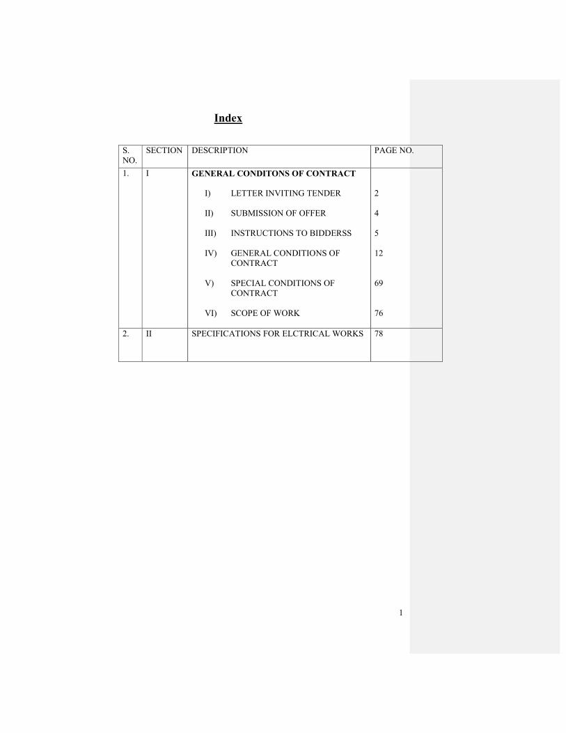
Index
S.
NO.
SECTION DESCRIPTION PAGE NO.
1. I GENERAL CONDITONS OF CONTRACT
I) LETTER INVITING TENDER
II) SUBMISSION OF OFFER
III) INSTRUCTIONS TO BIDDERSS
IV) GENERAL CONDITIONS OF
CONTRACT
V) SPECIAL CONDITIONS OF
CONTRACT
VI) SCOPE OF WORK
2
4
5
12
69
76
2. II SPECIFICATIONS FOR ELCTRICAL WORKS 78
2
FORWARDING LETTER
TENDER NO. : JCO 2037 P09/REV
To
_________________________
_________________________
SUBJECT: INTERNAL & EXTERNAL ELECTRICAL WORKS FOR OIL HOUSE
AT JODHPUR.
Dear Sir,
Rajasthan Project of Oil India Limited (OIL), a Govt. of India Enterprise, is engaged in exploration
and production of natural gas from Jaisalmer Basin and heavy oil/bitumen from Bikaner-Nagaur
Basin of western Rajasthan. The Company has decided to construct a multi-storied Base
Office/Project Office with modern amenities at Jodhpur, for which a plot of land measuring 4365.00
Sq.mtr. has been acquired at Saraswati Nagar, Jodhpur. In connection with the aforesaid, OIL
invites sealed bids from competent and reputed domestic firms under single stage two bid system
for the work as detailed below. A complete set of bid document covering OIL’s tender for Civil and
Structural works is being issued herewith for submitting your most competitive offer well before the
scheduled bid closing date and time.
For your ready reference, few salient points (covered in detail in this bid document) are highlighted
below.
1.0 TENDER NO. : JCO 2307 P09/REV Date 16/07/2009
2.0 TENDER FEE : Rs. 1000/- (Rupees one thousand only)
3.0 TYPE OF TENDER : Single Stage Two Bid System
4.0 BID CLOSING DATE & TIME : 18/08/2009 (15:00 Hrs. IST)
5.0 BID OPENING DATE & TIME : 18/08/2009 (15:15 Hrs. IST) (TECHNICAL BIDS)
Note: In the event of receipt of only a single offer against the tender within the bid closing
date, OIL reserves the right to extend the bid closing date as deemed fit by OIL. During the
extended period, the bidders who have already submitted the bids on or before the original
bid closing date (18/08/2009 ) shall not be permitted to revise their quotation.
6.0 NAME OF WORK :
Internal & External Electrical Works for “OIL HOUSE” at Plot No.–2A, Saraswati Nagar, Jodhpur,
Rajasthan.

3
7.0 PRE-BID CONFERENCE :
As per the original condition of Tender No. JCO2307P09 dated 04.02.2009, a Pre-bid Conference
was held for participation of the prospective bidders on 24th February 2009. Consequent upon the
pre-bid conference, few modifications have been incorporated in this revised tender document.
8.0 BID SECURITY / EARNEST MONEY DEPOSIT :
Bidders shall furnish as part of its Technical Bid, Bid security for Rs. 2.7 lakhs (Rupees two lakhs
seventy thousand only) in the form of a Bank guarantee in the prescribed format or Demand Draft in
favour of OIL INDIA LIMITED as stipulated in clause No. 2.4 of General Conditions of Contract.
9.0 PERFORMANCE BANK GUARANTEE / SECURITY DEPOSIT :
The firm whose tender may be accepted (herein after called the Contractor) shall within 10 (ten)
days of the date of issue of Letter of Intent, shall submit the Performance Bank Guarantee / Security
Deposit to OIL in the manner stipulated in Clause 3.4 of General Conditions of Contract.
10.0 TIME SCHEDULE :
The time allowed for carrying out the entire work in consistent with this tender will be 300 days
reckoned from the seventh date of issue of Letter of Award.
11.0 PLACE OF SUBMISSION OF BIDS :
Office of the CHIEF MANAGER (M & C)
OIL INDIA LIMITED
12, OLD RESIDENCY ROAD
JODHPUR - 342011
12.0 OIL reserves the right to accept or reject any or all the bids in part or in total without
assigning any reason whatsoever.
13.0 Bidders are requested to ensure numbering of pages of their offer.
14.0 Please acknowledge receipt of this letter with enclosures and confirm that you will submit
your tender on or before the due date. In case you decide not to participate in this tender,
return the complete set of enclosures at the earliest.
Thanking you,
Yours faithfully,
OIL INDIA LIMITED
Encl.:- as above
( P. DAS )
CHIEF MANAGER (M & C)
FOR EXECUTIVE DIRECTOR (RP)

4
SUBMISSION OF OFFER
From:
_______________________________________
_______________________________________
_______________________________________
Dear Sir,
We hereby submit our offer in full compliance with the terms and conditions of the attached
Document.
Earnest money deposit in the form as per clause 2.4.0 of GCC for an amount of Rs.270,000/-
(Rupees two lakhs seventy thousand only) valid up to six months from the date of submission of the
tender is enclosed.
Our offer shall remain valid for acceptance for a period of 180 days from the date of opening of
tender.
Very truly yours,
(Signature of the Bidder)
Full Name __________________________________
Title & Capacity______________________________
CERTIFICATE AS TO CORPORATE PRINCIPAL__________________ certify that I
am_____________________ Secretary of the Corporation organized under the laws of
_____________________and that ________________________who signed the above tender is
authorized to and the corporation by authority of its governing body.
_____________________________
5
INSTRUCTIONS TO BIDDERS
1.0 SITE INFORMATION
The work involves electrification of OIL HOUSE at Plot No. 2A, Saraswati Nagar, Jodhpur,
Rajasthan in accordance with the scope of work defined in this tender document.
2.0 SCOPE OF WORK
2.1 THE SCOPE OF WORK SHALL GENERALLY COMPRISE OF BUT NOT LIMITED TO
THE FOLLOWING:
2.1.1 This standard covers the technical requirements of electrical equipment and services required
for Oil House, OIL Jodhpur.
2.1.2 Design, engineering, manufacture, testing at works and delivery FOR site in well packed
condition of all electrical equipments and accessories specified herein.
2.1.3 Erection (including transportation & handling), testing and commissioning of all electrical
equipments and accessories specified herein.
2.1.4 Obtaining clearance from electrical inspectorate AND Govt. Statutory Bodies for complete
electrical works as required.
2.1.5 This standard shall be read in conjunction with all referred standards, associated drawing
specification sheets, Schedule of materials for Electrical Supply items, for Erection and for
Testing & Commissioning.
2.2 TENTATIVE DRAWINGS
A set of tentative Layout drawings and schematic drawings are enclosed with the tender.
These drawings are meant only for guidance to the bidders. Preparation of working drawings,
submission drawings and completion drawings for all systems to be executed.
Oil India Limited will have the right to amend, modify or supply additional designs and
drawings without affecting the terms of the Contract.
3 SUBMISION OF BID
The Tender is being processed according to Single Stage Two Bid system. Therefore, Bidders
are to submit their offers in two parts viz; Technical Bid (Un-priced) and Commercial Bid
(Priced) each in triplicate (one original plus two copies).
3.1 Each set of Technical Bid (un-priced) must contain all four volumes (Volume I to Volume IV)
of the tender document along with all requisite documents/information as sought for.
However, the Volume III to be enclosed in Technical Bid should not contain any rate/price. In
Volume III of Technical Bid, Bidders should only confirm the Schedule of Requirement/ Bill
of Quantities without quoting their corresponding rates/costs. Earnest Money/Bid Security
must also be included in the Technical Bid.

6
3.2 The Commercial Bid (Priced) should contain only the Volume III i.e., the Schedule of
requirements/Bill of quantities with rates/costs of each item therein.
3.3 Each Set of Technical Bid and Commercial Bid (three sets each) must be sealed in separate
envelopes and the following should be super scribed on the right hand top corner of each
envelope.
(i) ENVELOPE NO. 1 : TECHNICAL BID : (Original or Copies as the Case may be)
OIL’s Tender No. : …………………..
Bid Closing Date : …………………..
Bidder’s Name : …………………..
(ii) ENVELOPE NO. 2: COMMERCIAL BID : (Original or Copies as the Case may be)
OIL’s Tender No. : …………………..
Bid Closing Date : …………………..
Bidder’s Name : …………………..
3.4 The above mentioned separate envelopes containing Technical Bids and Commercial Bids
should then be put together in a single packet and submitted to CHIEF MANAGER (M & C),
OIL INDIA LIMITED, 12-OLD RESIDENCY ROAD, JODHPUR – 342011, RAJASTHAN.
The following must also be clearly super scribed on the packet containing bids to avoid
premature opening.
OIL’s Tender No. : JCO 2037 P09/REV
Bid Closing date : 18/08/2009
Bidder’s Name :
Other details as required to be submitted along with the Technical Bid of tender as given below:
a) Power of Attorney in the name of person(s) who has/have signed the Tender documents.
b) Partnerships deed in case of partnership firm or Memorandum and Article of Association in
case of limited Company.
c) Latest Income Tax Clearance Certificate in the Performa prescribed by the Government of
India should accompany the Tender. The ITC Certificate should be in the name of the
firm/individual quoting for the Tender
d) Program of works in shape of Bar chart covering major activities to meet the time schedule for
completion of work.
e) Documents evidencing bidders eligibility
f) Exception and Deviation.

7
4 VALIDITY OF OFFER :
Bids submitted by Bidders shall remain valid for acceptance for a minimum period of 180
days from the date of opening of the Tenders. In exceptional circumstance, the Company may
solicit the Bidder’s consent to extend the period of validity further. The request and the
response thereto shall be made in writing (or by fax or e-mail). A Bidder may refuse the
request for further extension without forfeiting their bid security/earnest money. However,
bidders granting the request will neither be required nor permitted to modify their bids, but
shall arrange suitable validity extension of their bid security/earnest money also.
5 RATES TO BE IN FIGURES AND IN WORDS
The Bids should be in English and rates/amounts quoted by the bidders must be written in
figures as well as in words in the schedule of rates of tender document submitted by the
contractor.
Prices quoted by the successful bidder must remain firm during its performance of the contract
and it is not subject to variation on any account.
If some discrepancies are found between the rates in figures and words of the amount shown
in the Tender Document the following procedure shall be followed:
a) When there is a difference between the rates in figures and words, the rate which corresponds
to the amount worked out by the Bidder shall be taken as correct.
b) When the rate quoted by the Bidder in figures and words tally but the amount is incorrect the
rate quoted by the Bidder shall be taken as correct.
c) When it is not possible to ascertain the correct rate by either of above methods, the rate quoted
in words shall be taken as correct.
6 AMENDMENT OF TENDER DOCUMENT :
At any time prior to the deadline for submission of bids, the Company may, for any reason,
whether at its own initiative or in response to a clarification requested by a prospective bidder,
modify the tender document through an amendment. Such amendments, if any, will be sent in
writing or by fax or e-mail to all prospective bidders who purchased the tender documents.
The Company may, at its discretion, extend the deadline for bid submission, if the bidders are
expected to require additional time in which to take the amendment in to account in
preparation of their bid or for any other reason.
7 Owner reserve the right to split up the above work between one or more contractor or award
the entire work to one contractor. Quoted rates should hold good for all such eventualities. No
revision in the quoted rates will be entertained at a later date on this account.
8
8 INCOME TAX CLEARANCE /SALES TAX REGISTRATION
Attested copy of Income Tax Clearances Certificate in the Proforma prescribed should
accompany the tender. The registration should be in the name of the firm/individual quoting
for the work.
9.0 DEADLINE FOR SUBMISSION OF BIDS
Bids must be received by the Company at the address specified in the forwarding letter above,
not later than 11:00 hrs. (IST) on the scheduled Bid Closing date. Any Bid received late (after
the aforesaid deadline for submission of Bids) shall be rejected and returned un-opened to the
bidder.
10.0 MODIFICATION AND WITHDRAWAL OF BIDS
The Bidders, after submission of bids, may modify or withdraw their bids by written notice
prior to bid closing. The Bidder’s modification or withdrawal notice must be delivered /
submitted to the Company’s CHIEF MANAGER (M&C) at Jodhpur prior to the deadline for
submission bids. No Bid can be modified subsequent to the deadline for submission of bids.
Subsequent to the bid closing, withdrawal of a bid within its validity period will result
forfeiture of bidder’s bid security/earnest money.
11.0 BID OPENING AND EVALUATION
11.1 Company will open first the Technical Bids, including submission(s) made pursuant to clause
No. 10.0 above, in the presence of Bidders’ authorized representatives who choose to attend at
the date, time and place mentioned in the forwarding letter. Only one representative against
each bid will be allowed to attend the tender opening. However, the Bidders’ representatives
must produce the authorization letter to the tender opening official of Company to qualify for
attending the proceedings.
11.2 Bid(s) (if any) for which an acceptable notice of withdrawal is received, shall not be opened.
On opening the remaining bids, Company will examine them to determine whether the same
are complete, requisite Bid security/Earnest Money are furnished, documents are properly
signed and produced as called for and the bids are generally in order.
11.3 At the bid opening, Company will announce the Bidders’ name, notice for
modification/withdrawal (if any), bid security/earnest money submitted or not and such other
details as the Company may considered appropriate.
11.4 Subsequently, to facilitate examination, evaluation and comparison of bids, Company may at
its option, ask the bidders for clarifications on its bid. The request for clarifications and
responses thereto shall be in writing and no change in the prices/rates or substance of the bid
shall be sought, offered or permitted.
11.5 Prior to detailed evaluation, the Company will determine the substantial responsiveness of
each bid to the tender document. A substantially responsive bid is one which conforms to all
the terms and conditions of the tender documents without material deviations. The Company’s
determination of bids’ responsiveness is to be based on the contents of the bid itself without
recourse to extrinsic evidence.
9
11.6 A Bid determined as not substantially responsive will be rejected by the Company and may not
subsequently be made responsive by the bidder by correction of the non-conformity.
11.7 Company may waive minor informality or non-conformity or irregularity on a bid that does
not constitute a material deviation, provided such waiver does not prejudice or affect the
relative ranking of any bidder.
11.8 After ascertaining the technical suitability, Company will open the Commercial Bids of the
technically qualified bidders only, on a predetermined date in presence of representatives from
the interested qualified bidders.
12.0 AWARD OF AGREEMENT
12.1 On opening the commercial Bids of technically qualified bidders, Company will examine the
priced bids to determine whether they are complete, any computational errors are made, the
documents are properly signed and the bids are generally in order.
12.2 Arithmetical errors (if any) will be rectified in the manner as spelt out in the BEC/BRC. If any
bidder does not accept the corrections of the errors, their bid will be rejected.
12.3 Company will award the contract to the Bidder whose bid is determined to be substantially
responsive and is determined as the lowest evaluated bid, provided further that the Bidders is
determined to be qualified to perform the contract satisfactorily.
12.4 Prior to expiry of the bid validity including extension, if any, Company will notify the
successful bidder in writing that their bid has been accepted. Such notification of award will
constitute formation of contract.
12.5 At the same time as the Company notifies the successful bidder about award of contract,
Company will either invite the Contractor for signing the formal agreement or send the formal
agreement which will include the General & Special Terms and Conditions, Technical
Specifications, Scope of Work, Schedule of rates and all other relevant documents like
drawings etc. as applicable. Within 15 days of receipt of final contract document, the
successful bidder shall sign and return the same to Company.

10
8.1 CHECK LIST :
Bidders shall submit the following checklist along with their Technical Bid duly filled up with their
confirmations and also specifying page nos. of their offer:-
S. No.
Subject
Details to be furnished
Confirmation/Page
Nos. Of the Offer.
1.
Item rate tender
and contract for
works. Letter of
Submission.
Bidders to confirm that their offer has been
submitted with their covering letter exactly
as per letter of submission enclosed.
Yes ( )
No ( )
2. Acknowledgment
letter
Bidders to confirm that “Acknowledge
Letter” to receipt of this tender with
confirmation to participate in the subject
tender had been submitted by them within
one week of receipt of tender.
Yes ( )
No ( )
3. Tender Security
EMD
Bidders to confirm that EMD has been
submitted by them as per following details:-
I. By Demand draft/ Bank Guarantee
No ………………..
Dated……………drawn on………..…
Bank…………………...Branch………
For Rs………………..….
Yes ( )
No ( )
4. Validity Confirm that your offer is valid for 180 days
from the date of opening of Technical Bid
(unpriced part).
5. Performa enclosed
with the tender
document.
Confirm that the following Proforma has
been submitted.
5.1 Latest ITCC & Sales Tax Registration
5.2 Deployment Schedule of Supervisory
personnel
5.3 Deployment list of construction equipments
5.4 Information about Bidders.
5.5 Curriculum Vitae
5.6 Exceptions and deviations, if applicable
11
S.No
Subject
Details to be furnished
Confirmation/Page
Nos. Of the Offer
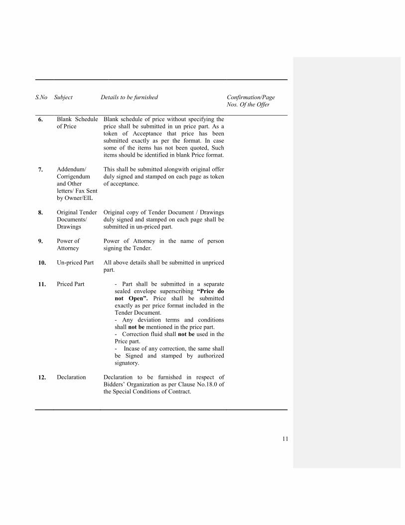
6. Blank Schedule
of Price
Blank schedule of price without specifying the
price shall be submitted in un price part. As a
token of Acceptance that price has been
submitted exactly as per the format. In case
some of the items has not been quoted, Such
items should be identified in blank Price format.
7. Addendum/
Corrigendum
and Other
letters/ Fax Sent
by Owner/EIL
This shall be submitted alongwith original offer
duly signed and stamped on each page as token
of acceptance.
8. Original Tender
Documents/
Drawings
Original copy of Tender Document / Drawings
duly signed and stamped on each page shall be
submitted in un-priced part.
9. Power of
Attorney
Power of Attorney in the name of person
signing the Tender.
10. Un-priced Part All above details shall be submitted in unpriced
part.
11. Priced Part - Part shall be submitted in a separate
sealed envelope superscribing “Price do
not Open”. Price shall be submitted
exactly as per price format included in the
Tender Document.
- Any deviation terms and conditions
shall not be mentioned in the price part.
- Correction fluid shall not be used in the
Price part.
- Incase of any correction, the same shall
be Signed and stamped by authorized
signatory.
12. Declaration
Declaration to be furnished in respect of
Bidders’ Organization as per Clause No.18.0 of
the Special Conditions of Contract.
12
GENERAL
CONDITIONS
OF CONTRACT
13
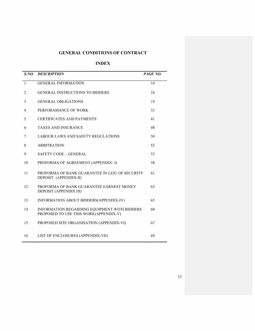
GENERAL CONDITIONS OF CONTRACT
INDEX
S.NO. DESCRIPTION
PAGE NO.
1. GENERAL INFORMATION 14
2 GENERAL INSTRUCTIONS TO BIDDERS
16
3 GENERAL OBLIGATIONS 19
4 PERFORAMANCE OF WORK 33
5 CERTIFICATES AND PAYMENTS 41
6 TAXES AND INSURANCE 48
7 LABOUR LAWS AND SAFETY REGULATIONS
50
8 ARBITRATION 52
9 SAFETY CODE – GENERAL 53
10 PROFORMA OF AGREEMENT (APPENDIX- I) 58
11 PROFORMA OF BANK GUARANTEE IN LEIU OF SECURITY
DEPOSIT (APPENDIX-II)
61
12 PROFORMA OF BANK GUARANTEE EARNEST MONEY
DEPOSIT (APPENDIX III)
63
13 INFORMATION ABOUT BIDDERS(APPENDIX-IV) 65
14 INFORMATION REGARDING EQUIPMENT WITH BIDDERS
PROPOSED TO USE THIS WORK(APPENDIX-V)
60
15 PROPOSED SITE ORGANISATION (APPENDIX-VI)
67
16 LIST OF ENCLOSURES (APPENDIX-VII)
69

14
1.0 GENERAL INFORMATION
1.1 DEFINITION OF TERMS
In the Contract document as herein defined where the context so admits, the following words and
expressions will have the following meanings:
The “Company” shall mean M/s Oil India Limited (OIL) having their Office at 12, Old Residency
Road, Jodhpur-342011, Rajasthan.
The “Contractor” mean the person or the persons, firm or company, whose tender has been
accepted by OIL and includes the contractor’s legal representatives, his/their successors, executors
and permitted assignees.
The “Engineer-in-Charge (Electrical)” means the person or persons designated by OIL and shall
include his authorized nominee or agent ; provided, however, that the Engineer-in-Charge
(Electrical) may be one person for certain aspects of his agreement and another person for other
aspects of work covered by this contract.
The “Work” shall mean each and every activities to be executed in accordance with the contract or
part thereof as the case may be and shall include all extra, additional, altered or substituted works
as required for performance of the contract.
The “Completion Certificate” shall mean the certificate to be issued by the Company when the
works have been completed to his satisfaction.
The “Final Certificate” in relation to a work means the certificate regarding the satisfactory
compliance of the various provisions of contract issued by OIL after the period of liability is over.
“Permanent Work” means and includes works which will be incorporated in and form a part of the
work to be handed over to Company by the Contractor on completion of the contract.
“Construction Equipment” means all appliances and equipment of whatsoever nature for use in or
about the execution, completion, operation and maintenance of work unless intended to from part
of permanent work.
“Site” means the areas or piece of land or any other place provided by Company on which the
permanent works are to be executed by the Contractor for the purpose of the Contract.
The” Contract Document “means collectively the tender documents, design, drawings,
specifications, agreed variations, if any, contract and other documents constituting the tender and
acceptance thereof.
The “Contract” shall mean the agreement between Company and the Contractor for the execution
of the works, however, including therein all contract documents.
The “Specification” shall mean various technical specifications attached and referred to in the
tender documents. It shall also include relevant Indian Standard Institution Specifications and
standards and specifications of any other country wherever applicable.
The” Drawing” shall include schematic line diagram and equipment layout diagram, and
foundation details including dimensions thereof with any modifications approved in writing by
Company and such other drawing as may, from time to time, be furnished or approved in writing
by Company.
15
The “Alteration Order” means an order given in writing by Company to effect additions to or
deletions from and alterations in the works.
The “ Sub-contractor” means any person or firm or company (other than the contractor) to whom
any part of the work has been entrusted by the Contractor with the written consent of Company
and the legal personal representatives, successors, executors and permitted assignees of such
person, firm or company.
The “Total Contract Value” shall, up to calculation of the entire remuneration and costs due to the
Contractor in terms of the contract on successful completion of the work.
“Running Account Bill” shall mean a Bill for the payment of “on account” moneys to the
Contractor in terms of Clause 5.4.0 hereof and associated clauses there under.
“Security Deposit” shall mean the Security Deposit as specified in Clause 3.4.0 hereof and
associated clauses there under.
“Schedule of Rates” shall mean the Schedule of Rates annexed to the Acceptance of Tender and
shall include any remuneration payable to the Contractor for any work, determined in accordance
with the conditions herein notified in the agreement.
“Agreed Variation” shall mean the Statement of Agreed Variation annexed to the Acceptance of
Tender or a further Amendment annexed to the Contractor forming part there of.
“Defect Liability Period” Shall mean the defect liability period as specified in the Contract.
1.2 Land for Contractor’s Field Office, Go down and Workshop
Company will at a its own discretion and convenience and for the duration of the execution of the
work make available land near the site within the plot, for construction of Contractor’s field office,
go down, workshops and assembly yard required for the execution of the contract.
On completion of the work under taken by the Contractor or even earlier if the exigencies of the
situation so demands, they shall remove all temporary works erected by them and have the site
cleared as directed by Company. If the Contractor shall fail to comply with these requirements, the
Company may at the expenses of the Contractor remove such surplus and rubbish materials and
dispose off the same as he deems fit and got the site cleaned as aforesaid and the Contractor shall
forthwith pay the amount of all expenses so incurred and shall have no claim in respect of any
such surplus materials disposed off as aforesaid. But the Company reserves the right to ask the
contractor to vacate the land by giving 7 day’s notice on Security reasons or on national Interest or
otherwise.
1.3 Land for residential Accommodation
It will not be possible for Company to provide land for residential accommodation for staff and
labour of the Contractor. Contractor will have to make their own arrangement at his cost for land
for the purpose of residential accommodation for their staff and labour.
1.4 Scope of work
The Scope of work is defined in the Special Conditions of Contract and Specifications.
The Contractor shall provide all necessary materials, equipment and labour etc. for the execution
and maintenance of work till completions. All materials that go with the work shall be approved
by Company prior to procurement and use.

16
2.0.0 GENERAL INSTRUCTIONS TO BIDDERS
2.1.0 SUBMISSION OF TENDER
2.1.1 Tenders must be submitted in original and as per details given in other clauses given
hereunder. The rates shall be filled in the Schedule given in the tender documents.
Reservations, if any, regarding the tender conditions should be clearly brought out in a
separate letter accompanying the tender vide “Statement of Compliance”.
2.1.2 Addenda to this tender document, if issued, must be signed and submitted along with the
tender document.
The tenders should write clearly the revised quantities in “Schedule of Rates” of Tender
document and should price the work based on the revised quantities when amendment for
quantities are issued in addenda.
2.1.0 DOCUMENTS
2.2.1 The tenders, as submitted, will consist of the following:-
a) Complete set of tender documents as issued duly filled in and signed by the Bidder as
prescribed in different clauses of the tender document.
b) Earnest Money in the manner specified.
c) Power of Attorney of a true copy thereof duly attested by a Gazetted officer in case an unauthorized representative who has signed the tender.
d) Income Tax Clearance Certificate and Sales Tax Clearance Certificate in original or true
copies duly attested by Government Gazetted Officer.
e) Information regarding Bidder in the proforma enclosed.
f) Any printing or typographical error/omission in tender document shall be referred to
Company and his interpretations regarding correction shall be final and binding on
contractor.
2.2.2 Rates to be in figures and words
The Bidder should quote in English both in figures as well as in words the rates and amounts
tendered by him in the Schedule of Rates for each item and in such a way that interpolation
if not possible. The amount for each item should be worked out and entered and requisite
totals given of all items, both in figures and in words. The tendered amount for the work
shall be entered in the tender and duly signed by the Bidder.
2.2.3 Corrections and Erasures
All corrections and alterations in the entries of tender papers will be signed in full by the
Bidder with date. No erasures or overwriting are permissible.
2.2.4 Signing of Bids
The Bidder shall prepare three copies of each Technical as well as Commercial Bids ,
clearly marking the original as “ORIGINAL BID” and rest “COPY OF BID”. In the event of
any discrepancy between them, the original shall prevail.
The original and all copies of the bids shall be typed in indelible inks and shall be signed by
the Bidder or a person or persons duly authorized to bind the Bidder to the contract. The
17
letter of authorization shall be indicated by written power of attorney accompanying the
bids. The person or persons signing the bids shall initial all pages of bids, except for the un-
amended printed literature.
The bid should contain no interlineations, white fluid erasures or overwriting except as
necessary to correct errors, in which case such corrections be initialed by the person or
persons signing the bids. Bids not meeting this requirement shall be liable for rejection.
2.2.5 Details of Experience
The Bidder should enclose documentary proof to evidence that he has previous experience
in having successfully completed in the recent past, works of this nature together with the
name of Owners/Client, location of sites and values of contract. Documentary evidences
must be submitted complying with the stipulations of Bid Rejection Criteria as set out in this
tender, failing which the offer will be rejected.
2.3.0 TRANSFER OF TENDER DOCUMENTS
Transfer of tender documents purchased by one intending Bidder to another is not permitted.
2.4.0 EARNEST MONEY / BID SECURITY
2.4.1 The Bidder must furnish the amount of Earnest Money as mentioned in the Notice/Letter
inviting tenders in any of the following forms:
Crossed Bank Demand Draft duly pledged to “Oil India Limited”, Jodhpur or a bank
guarantee from any Schedule ‘A’ bank in the form approved by Company and valid for a
period of 180 days from the bid closing date of the tender. Earnest money so deposited
against this tender will not accrue any interest.
2.4.2 The Earnest Money of the unsuccessful bidder will be discharged and/or returned within 30
days of expiry of the period of bid validity or finalization of contract. Successful bidder’s
bid security will be discharged upon their signing the contract and furnishing the
Performance Security/Security deposit.
2.4.3 The Earnest Money/Bid Security will be forfeited;
(a) If any bidder withdraws their bid during the period of bid validity (including any subsequent extension) specified by the bidder on bid form.
OR
(b) If the successful bidder fails;
(i) To sign the contract within reasonable time and within the period of bid validity, and/or
(ii) To furnish the Performance Bank Guarantee/Security Deposit.
2.5.0 VALIDITY
Tender submitted by Bidders shall remain valid for acceptance for a period of 180 days from
the bid closing date of the tender. The Bidders shall not be permitted during the said period
of validity, to revoke or cancel their bid or to vary the bid submitted or any terms thereof.
2.6.0 ADDENDA

18
2.6.1 Addenda to the tender documents may be issued prior to the date of opening of the tenders
to clarify documents or to reflect modifications in the design of contract terms.
2.6.2 Each addendum issued by Company will be distributed in duplicate, to each person or
organization to whom a set of tender documents has been issued. Each recipient will retain
one copy of each addendum for submission along with his tender and return one signed copy
to the client as acknowledgement of receipt of the addendum. All addenda issued by
Company shall become part of Tenders Documents.
2.7.0 RIGHT OF OWNER TO ACCEPT OR REJECT BIDS
The right of acceptance of tender will rest with Company. However, Company does not bind
itself to accept the lowest tender, and reserves to itself the authority to reject any or all the
tenders received without assigning any reason whatsoever. The whole work may be split up
between two or more contractor or accepted in part and not entirely, if considered expedient.
Tenders in which any of the particulars and prescribed information are missing or are
incomplete in any respect and/or the prescribed conditions are not fulfilled are liable to be
rejected.
Canvassing in connection with tenders is strictly prohibited and tenders submitted by the
Bidder who resort to canvassing will be labile to rejections.
Tender containing uncalled for remarks or any additional conditions are liable to be rejected.
2.8.0 PERFORMANCE BANK GUARANTEE / SECURITY DEPOSIT
The person/persons whose tender may be accepted (hereafter called the contractor) shall
within 30 (Thirty) days of the receipt by him of the notification of the acceptance of the
tender or Letter of Intent, shall remit the security deposit to OIL in the manner stipulated in
Clause 3.4 of General conditions of contract.
2.9.0 TIME SCHUEDULE
The time allowed for carrying out the job is as shown in Appendix-X (Special Conditions of
Contract). This shall be singed and submitted along with the tender.
2.10.0 COLLECTION OF DATA – BIDDERS’S RESPONSIBILITY
The Bidder shall visit the site and acquaint himself fully of the site and no claims
whatsoever will be entertained on the plea of ignorance of difficulties involved in execution
of work or carriage of materials.
2.11.0 RETIRED GOVERNMENT OR OWNER’S OFFICERS
No Engineer of Gazetted rank or other Gazetted officer, employed in Engineering or
administrative duties in an Engineering Department of the State/Central Government or of
Company is allowed to work as a contractor for a period of two years after his retirement
from Government service, or from the Employment of Company without the previous
permission of Company. The contract if awarded is liable to be canceled if either the
Contractor or any of his employees is found at any time to be such a person, who had not
obtained the permission of the State/ Central Government or Company as aforesaid before
submission of tender, or engagement in Contractor’s service as the case may be.
19
3.0 GENERAL OBLIGATION
3.1.0 INTERPRETATION OF CONTRACT DOCUMENTS
3.1.1 The several documents forming the contract are to be taken as mutually explanatory of one
another. Should there be any discrepancy, inconsistency, error or omission in the contract
documents, or any of them, the matter shall be referred to the Company for its decision
which shall be final and conclusive and the Contractors shall carry out the work in
accordance with such decisions.
3.1.2 Works shown upon the drawing but not mentioning in the specification or described in the
specifications without being shown on drawing shall nevertheless be held to be included in
the same manner as if they had been specifically shown upon the drawings and described in
the specifications.
3.1.3 The construction work is intended to be executed strictly in accordance with the concept,
structural design and drawings developed by Engineer-in-Charge (Electrical) and as
elaborated in this tender document. However, during the actual execution of work at site, if
some minor modifications/alteration in the original plan within the general scope of work is
envisaged or considered necessary by Company or Contractor without any substantial
change to the basic structural design, the Contractor shall carry out all such jobs including
preparation/modification of drawing etc. after obtaining Company’s written approval.
3.1.3 Heading and Marginal Notes
All headings of and marginal notes to the clauses of these general Conditions of Contract or
of and the specifications or any other tender document are solely for the purpose of giving a
concise indication and not a summary of the contents thereof, and they shall never be
deemed to be part thereof or be used in the interpretation or construction thereof or of the
contract.
3.1.4 Singular and Plural
In these contract document unless otherwise stated specifically, the singular shall include the
plural and vice versa wherever the context so requires.
3.2.0 SPECIAL CONDITIONS OF CONTRACT
3.2.1 Special Conditions of Contract shall be read in conjunction with the General Conditions of
contract, Specification of work, drawings and any other documents forming part of this
contract wherever the context so requires.
3.2.2 Notwithstanding the sub-division of the document into these separate sections and volumes
every part of each shall be deemed to be supplementary to and complementary of every
other part and shall be read with and into the contract so far as it may be practicable to do so.
3.2.3 Where any portion of the General Conditions of Contract is repugnant to or at variances with
any provisions of the Special conditions of Contract, then unless a different intention
appears, the provisions of the Special Conditions of Contract shall be deemed to over-ride
the provisions of the General conditions of Contract and shall, to the extent of such
repugnancy of variations prevail.
3.3.0 CONTRACTOR TO OBTAIN HIS OWN INFORMATION
20
The Contractor in fixing his rate shall for all purpose whatsoever be deemed to have himself
independently obtained all necessary information for the purpose of preparing his tender.
The correctness of the details, given in the tender document to help the Contractor to make
up the tender, is not guaranteed.
The contractor shall be deemed to have examined the contract documents, to have generally
obtained his own information in all matters whatsoever that might effect carrying out works
at the scheduled rates and to have satisfied himself to the sufficiency of this tender.
Any error in description or quantity or any other aspect in schedules rates omission there
from shall not vitiate the contract or release the contractor from executing the work
comprised in the contract according to drawings and specifications at the scheduled rates.
He is deemed to know the scope, nature and magnitude of the work and the requirements, of
materials and labour and the type of work involved etc.; and as to what all he has to do to
complete the work in accordance with the contract documents whatever be the defects,
omission or errors that may be found in the contract Documents. The Contract shall be
deemed to have visited the surroundings and to have satisfied himself as to the nature of all
existing structures, if any and also as to the nature and condition of the Railways, roads,
bridges and culverts, means of transport and communication whether by land, water or air,
and as to possible interruptions, there to and the access and agrees from the site to have
made inquires, examined and satisfied himself as to the site for obtaining sand, stones,
bricks and other material, the sites for disposal of surplus material the available
accommodation as to whatever required as depots and such other buildings as may be
necessary for executing and completing the work, to have made local independent inquiries
as to the subsoil, sub-soil water and variations thereof , storms prevailing winds, climatic
conditions and all, other similar matters affecting these works.
Contractor deemed to have acquainted himself as to his liability for payment of Government
taxes customs duty and other charges.
Any neglect or failure on the part of the contractor in obtaining necessary and reliable
information upon the foregoing or any other matters affecting the contract shall not relieve
him from any risk or liabilities or the entire responsibilities from completion of the work at
the schedule rates and time in strict accordance with the contract documents.
No verbal agreement or inferences from conversation with any officer or employee of
Company either before or after the execution of the contract agreement shall in any way
affect or modify any of the terms of obligations herein contained.
3.4.0 PERFORMANCE BANK GUARANTEE / SECURITY DEPOSIT
3.4.1 A sum of 10% of the value of contract shall be deposited by the person/persons whose
tenders may be accepted (hereinafter called the contractor) as security deposit with
Company. This may be deposited initially at 2-1/2% of the value of the contract (referred to
as initial Security Deposited) within 30 (thirty) days of receipt by him of the notification of
acceptance of tender or the letter of Intent and the balance 7-1/2% will be recovered in
installments through deductions at the rate of 10% of the value of each running account bill,
till the total security deposit amount is collected, after which no further deduction from bills
will be made on this account, subject to clause No. 3.4.3 below .
21
Alternatively, the Contractor may, at his option, deposit the full amount of 10% of the value
of contract towards the security deposit within 30 (thirty) days of receipt of the notification
accepting his tender or letter of Intent. 3.4.2 Contractor can furnish the initial or total security deposit amount (a) Demand draft or (b)
through a bank guarantee from any schedule “A” Bank in the form prescribed. Demand
drafts must be made payable to Company, at Jodhpur. The security deposit may be
converted to interest bearing Government securities from time to time and hypothecated to
Company, at the request of the Contractor. The earnest money deposited with the tender
shall be adjusted towards security deposit, provided it is furnished in cash or by demand
draft only.
3.4.3 All compensation or other sums of money payable by the contractor to Company under
terms of this contract may be deducted from or paid by the sale of a sufficient part of his
security deposit or from any sums which may be due or may become due to the contractor
by Company on any account whatsoever and in the event of his security deposit being
reduced by reasons of any such deductions or sale as aforesaid, the contractor shall within
ten days thereafter make good in cash, bank draft or Government securities endorsed as
aforesaid any sum or sums which may have been deducted from or realized by sale of his
security deposit , or any part thereof . No interest shall be payable by Company for sum
deposited as security deposit. 3.4.4 If the Company is of the opinion that the total contract value as specified in the Letter of
Acceptance does not correctly reflect the total contract value by virtue of an increase in
rates, quantities or works or for any other cause whatsoever, the Company may issue a
revised estimate of the total contract value for the purpose of Security Deposit, and on issue
of such revised estimate to the contractor in writing, such revised estimate shall be deemed
to be the total contract value for purposes of Security Deposit as specified in the letter of
Acceptance.
3.4.5 If during the performance of the contract by virtue of the revision in the total contract value
pursuant to Clause 3.4.4 hereof, the initial Security Deposit furnished by the Contractor is
less than 2 ½% (Two and a half percent) of the total contract value as deemed to be specified
in the Letter of Acceptance, or if there is any utilization or adjustment of the Security
Deposit by the Company, the Contractor shall forthwith upon demand by the Company,
make good the shortfall in the initial Security Deposit or the amount utilized or adjusted out
of the Security Deposit, as the case may be, with right in the Company (without prejudice to
any other mode of recovery) to apply any moneys for the time being due or becoming due to
the Contractor to make good shortfall or utilization or adjustment, as the case may be.
3.4.6 If after the completion of the work, by virtue an amendment in the total Contract value for
the purposes of the Security Deposit pursuant to provisions of Clause 3.4.4 hereof or by
utilization or by adjustment for the Security Deposit, the Security Deposit furnished by the
contractor is less than 10% (Ten Percent) of the total contract value as specified or as
deemed to be specified for the purposes of Securities Deposit in the Letter of Acceptance, as the case may be, the Contractor shall forthwith upon the demand of the Company, make
good the shortfall, utilization or adjustment, as the case may be, with right in the
Company(without prejudice to any other mode of recovery) to apply any moneys for the
time being due or becoming due to the Contractor to make good such shortfall.

22
3.4.7 The Contractor may at any time after issue of the completion Certificate with the permission
of the Company, substitute the Security Deposit held in cash for the time being remaining
unutilized in hands of the Company, if in excess of Rs.50, 000/-, by a Bank Guarantee from
a Scheduled Bank in a form prescribed by the Company, valid for a period of not less than
three months after the expiry of the Defect Liability Period.
3.5.0 TIME OF PERFORMANCE
3.5.1 The work covered by this contract shall be commenced within seven days after the issue of
the letter of acceptance of tender and be completed in stages on or before the dates as
mentioned in the time schedule of completion of works. The Contractor should bear in mind
that time is the essence of the agreement; unless such time is extended pursuant to the
provisions of the clause no. 3.6 requests for revision of Construction time after tenders are
opened will not receive consideration.
3.5.2 Time Schedule of Construction
The general time schedule for the completion of the construction work is given in the tender
document. Contractor should prepare a detailed program of work on week basis to the
satisfaction of the Company within seven days of the issue of Letter of Intent or Acceptance
of tender, which shall be strictly adhered to. The Company may at his discretion modify this
program after review from time to time.
3.6.0 FORCE MAJEURE
Any delay in or failure of performance of either party hereto shall not constitute default
hereunder of give to any claims for damages if and to the extent such delays or failure of
performance is caused by occurrence such as Acts of God or the Public enemy; expropriation or confiscation of facilities by Government authorities, compliance with any
order or request of any Governmental authority, acts of way rebellion or sabotage or damage
resulting there from, fires, floods, explosion, riots or illegal strikes. The contractor shall
keep record of the circumstances referred to above which are responsible for causing delays
in the completion of work an bring these to the notice of the Company within 72 hours of
alleged beginning and ending giving full particulars and satisfactory evidence in support of
its claim.
3.7.0 EXTENSION OF TIME
Request for an extension of the time if any for completion of the work by the Contractor on
the grounds of his having been unavoidably hindered in its execution or any other grounds
shall be in writing to the Company within ten days of the date of the hindrance on account of
which he desires such extension as aforesaid and the Company shall, if in its opinion (which
shall be final) reasonable grounds have been shown therefore authorizes such extension of
time as may in its opinion be necessary or proper.
3.8.0 COMPENSATION FOR DELAY
3.8.1 The time allowed for carrying out the work as entered in the contract, shall be strictly
observed by the Contractor. The work shall throughout the stipulated period of the
contractor proceeded with all the diligence (time being deemed to be the essence of the
contract), and the contractor shall pay to Company as compensation an amount equal to
0.5% on the amount of the contract value for every week or part thereof that the work may
23
remain incomplete as per the time schedule, subject to a maximum compensation of 7.5% of
the contract value after which period action will be taken by Company under the provisions
of the contract.
3.8.2 To ensure good progress during the execution of the work the contractor shall be bound, in
all cases in which the time allowed for any work exceeds one month, to complete one fifth
of the work before one-fourth of the time allowed under contract has elapsed, three-eighth of
the work before one half of such time has elapsed and three fourth of the work before three-
fourth of such time has elapsed. In the event of the contractor failing to comply with this
condition, he shall be liable to pay as compensation an amount as stipulated above. The
compensation so paid shall not relieve the contractor from his obligations to complete the
work or from any other obligations and liabilities under the contract.
3.8.3 SUM PAYABLE BY WAY OF COMPENSATION TO BE CONSIDERED AS
REASONABLE COMPENSATION WITHOUT REFERENCE TO ACTUAL LOSS
All sums payable by way of compensation under any of these conditions shall be considered
as reasonable compensation without reference to the actual loss or damage sustained by
Company and whether or not damage shall have been sustained.
3.9.0 RIGHTS OF COMPANY TO FORFEIT PERFORMANCE BANK GUARANTEE /
SECURTIY DEPOSIT
Whenever any claim against the contractor for the payment of a sum of money arises out of
or under the Contract, Company shall be entitled to recover such sum by appropriating in
part or whole, the security deposit of the contractor, and to sell government securities, etc.,
forming whole part of such security. In the event of the security being insufficient, then the
balance or the total sum recoverable, as the case my be, shall be deducted from any sum then
or which at any time there after may become due to the Contractor under this or any other
contract with Company and should this be not sufficient to cover recoverable amount the
contractor shall pay to Company on demand the balance remaining due.
3.10.0 ACTION WHEN WHOLE OF SECURTITY DEPOSIT IS FORFEITED
In any case, in which under any clause of this contract the contractor shall have forfeited the
whole of his security deposit (whether paid in one sum or deducted by installments) or have
committed a breach of any of the terms contained in this contract Company shall have power
to adopt any of the following courses as they deem best suited to its interest.
a) To rescind the contract (of which rescission notice in writing to the contractor shall be
conclusive evidence) in which case the security deposit of the contractor shall stand forfeited
and be absolutely at the disposal of Company.
b) To employ labour paid by Company and to supply materials to carry out the work or any
part of the work debiting contractor with the cost of labour and the price of the materials of
the amount of which cost and price, a certificate of the Company shall be final and
conclusive against the contractor, and crediting him with the value of the work done, in all respects in the same manner and at the same rates as if it had been carried out by the
Contractor under the terms of his contract. The certificate of the Company as to the value of
the work done shall be final and conclusive against the contractor.
c) To measure up the work of the contractor and to take such part thereof as shall be
unexecuted out his hands and to give it to another contractor to complete, in which case any
24
expenses which may be incurred in excess of the sum which would have been paid to the
original contractor, the whole work had been executed by him (of the amount of which
excess the certificate in writing of the Company shall be final and conclusive) shall be borne
and paid by the original contractor and may be deducted from any money due to him by
Company under the contract or otherwise or from his security deposit or from the proceeds
of sale thereof, or a sufficient part thereof.
In the event of any of the above courses being adopted by Company, the contractor shall
have no claim to compensation for any loss sustained by him reason of his having purchased
or procured any materials or entered into any agreements or made any advance on account
of or with a view to the execution of the work or the performance of the contract. And in
case the contract shall be rescinded under the provision aforesaid the contractor shall not be
entitled to recover or be paid any sum for any work therefore actually performed under this
contract unless and until the Company will certify in writing the performance of such work,
and the value payable in respect thereof and he shall only be entitled to be paid the value so
certified.
3.11.0 CONTRACTOR REMAINS LIABLE TO PAY COMPENSATION IF ACTION NOT
TAKEN UNDER CLAUSE 3.10.
In any case in which any of the powers conferred upon Company by clause 3.10 thereof
shall have become exercisable and the same had not been exercised, the non – exercise
thereof shall not constitute a waiver of any of the conditions hereof and such power shall
notwithstanding be exercisable in the event of any future case of default by the contractor
for which by any clause or clauses hereof he is declared liable to pay compensation
amounting to the whole of his security deposit, and the liability of the contractor for past and
future compensation shall remain unaffected. In the event of Company putting in force the power under sub-clause (1), (b) or (c) vested in it under the preceding clause, Company
may, if it so desires, take possession of all or any tools; plant materials and stores in or upon
the works or the site thereof or belonging to the contractor or procured by him and intended
to be used for the execution of the work or any part thereof paying or allowing for the same
in account at the contract rates or in case of these not being applicable in current market
rates to be certified by Company whose certificate thereof shall be final, otherwise the
Company may give notice in writing to the contractor or is clerk of the works, foramen or
other authorized agent requiring him to remove such tools, plant materials or stores from
the premises (within a time to be specified in such notice), and in the event of the contractor
failing to comply with any such requisition the Company may remove them at the
contractor’s expenses or sell them by auction or private sale on account of the contractor and
at his risk in all respects without any further notices as to the date, time or place of sale and
the certificate of the Company as to expense of any such removal and the amount of the
proceed & expenses of any such sale shall be final and conclusive against the contractor.
3.12.0 COMPANY NOT BOUND BY PERSONAL REPRESENTATION
The contractor shall not be entitled to any increase on the schedule of rates or any other right
or claim whatsoever by reason of any representation, explanation or statement alleged
representation, promise or guarantees given or alleged to have been given to him by any
person.
25
3.13.0 CHANGE IN CONSTITUTION
Where the contractor is a partnership firm the previous approval, in writing, of Company
shall be obtained before any change is made in the constitution of the firm. Where the
contractor is an individual or a Hindu undivided family business concern, such approval as
aforesaid shall likewise be obtained before such contractor enters into any agreement with
parties.
Where under, the reconstituted firm would have the right to carry out the work hereby
undertaken by the contractor. In either case if previous approval as aforesaid is not obtained,
the contract shall be deemed to have been allotted in contravention of clauses 3.19 hereof
and the same action may taken and the same consequence shall ensure as provided in the
said clause.
3.14.0 IF THE CONTRACTOR DIES
Without prejudice to any of the rights or remedies under this contract, if the contractor dies,
Company shall have the option of terminating the contract without compensation to the
contractor.
3.15.0 MEMBERS OF OWNER/COMPANY NOT INDUVIDUALLY LIABLE
No Director, or officer, official or employee of Company shall in any way be personally
bound or liable for the acts or obligations of Company under the contract or answerable for
any default or omission in the observance or performance of any of the acts, maters, or
things which are herein contained.
3.16.0 CONTRACTORS’S OFFICE AT SITE
The contractor shall provide and maintain an office at the site for the accommodation of his
agent and staff and such office shall be open at all reasonable hours to receive instructions
notices or other communications.
3.17.0 CONTRACTOR’S SUBORDINATE STAFF AND THEIR CONDUCT
a) Contractor’s field Engineer: The contractor should name the Engineer responsible for the
work, to whom equipment and materials, if any, will be issued and to whom all site
instructions and notices can be issued by Company. He should have necessary power of attorney which shall be deposited with the Company in original.
b) Contractor’s fields staff strength: The contractor shall provide, to the satisfaction of the Company sufficient and qualified staff to superintend the execution of the works, competent
sub-agents, Engineering assistants, foremen and leading hands including those specifically
qualified by previous experience to supervise the types of works comprised in the contract in
such a manner as will ensure work of the best quality, expeditious working and proper
supervision shall be employed, and whenever in the opinion of the Company this is not the
case, additional and properly qualified supervisory staff shall be employed by the contractor without additional charge on account thereof. The contractor shall ensure to the satisfaction
of Company the subcontractors, if any, shall provide competent and efficient supervision
over the work entrusted to them. Where so required, the contractor shall furnish a field
organization chart as well as full details of field staff.
26
c) Conduct of contractor’s field staff: The contractor shall be responsible for the proper behavior of all the staff, foremen, workmen and others, and shall exercise a proper degree of
control over them and in particular and without prejudice to the said generality, the
contractor shall be bound to prohibit and prevent any employees from trespassing or acting
in any way detrimental or prejudicial to the interests of the community or of the proprietor
or occupiers of land and properties in the neighborhood and in the event of such employee
so trespassing, the contractor shall be responsible therefore and relieve Company of all
consequent claims or actions for damages or injury or any other grounds whatsoever. The
decision of the Company upon any matter arising under this clause shall be final.
d) If and whenever any of the contractor’s or subcontractor’s agents, sub agents assistants, foremen, or other employee shall in the opinion of Company be guilty of any misconduct or
be incompetent or insufficiently qualified or negligent in the performance of their duties or
that in the opinion of the Company, it is undesirable for administrative or any other reason
for such person or persons to be employed in the works, the contractor, if so directed by the
Company, shall at once remove such persons from employment thereon. Any person of
persons so removed from the works shall not again be employed in connection with the
work without the written permission of the Company. Any person so removed from the
works shall be immediately replaced at the expense of the contractor by a qualified and
competent substitute. Should the contractor be requested to repatriate any person removed
from the works, he shall do so shall bear all costs in connection herewith.
e) If and when required by Company, all contractor’s personnel entering upon the premises
shall be properly identified by badges/identity cards of a type acceptable to Company which
must be worn at all times on the premises of the company and all work sites.
3.18.0 SUBLETTING OF WORK
a) Neither part of the contract nor any share of interest therein shall in any manner or degree be
transferred, assigned or sublet by the contractor directly or indirectly to any person firm or
corporation whomsoever except as provided for in the succeeding sub-clause, without the
consent in writing of the Company.
The Company may give written consent to sub-contract for the execution of any part of the
works at the site, being entered into by the contract or provided each individual sub contract
is submitted to the Company before being into and is approved.
b) List of Sub-Contractors to be supplied
At the commencement of every month the contractor shall supply to the Company list of all
subcontractors or other persons or firms engaged by the contractor and working at the site
during the previous month with particulars of the nature of the sub-contractors or works.
c)b) Contractor’s Liability not limited by subcontractors
Notwithstanding any sub-letting with such approval aforesaid and notwithstanding that the
Company shall have received copies of any subcontract, the contractor shall be and shall
remain solely responsible for the quality and proper and expeditious execution of the
contract in all respects as if subletting or subcontracting had not taken place and as if such
work had been done directly by the contractor.
Formatted: Bullets and Numbering
Formatted: Bullets and Numbering

27
d)c) Company may Terminate Subcontractors
If any subcontractor engaged upon the works at the site executes any work which in the
opinion of the Company is not accordance with the contract documents the Company may
give written notice to the contractor requiring him to terminate such subcontract and the
contractor upon the receipt of such notice shall terminate such subcontract and dismiss the
subcontractors and the latter shall forthwith leave the works, failing which the Company
shall have the right to remove such subcontractors from the site.
e) No remedy for action taken under this clause
No action taken by the Company under the clause shall reliever the contractor of any of his
liabilities under the contract or give rise to any rights to compensation extension of time or
otherwise, failing which the Company shall have the rights to remove such sub-contractors
from the site.
3.19.0 POWER OF ENTRY
If the contractor shall not commence the works in the manner as agreed upon and described
in the contract/agreement and at any time, if in the opinion of the Company, the Contractor;
a) Fails to carry on the works in conformity with the contract documents, or
b) Fails to carry on the works in accordance with the time schedule, or
c) Substantially suspends work or the works for a period of fourteen days without authority
from the Company, or
d) Fails to carry on and execute the works to the satisfaction of the Engineer-in- charge, or
e) Fails to supply sufficient or suitable constructional plant, temporary works, labour, materials
or tings, or
f) Commits or suffers, or permit any other breach of any of the provisions of the contract on
his part to be performed or observed or persist in any of the above mentioned breaches of the
contract for fourteen days, after notice in writing shall have been given to the contractor by
the Company requiring such breach to be remedied, or
g) If the contractor shall abandon the works, or
h) If the contractor during the continuance of the contract shall become bankrupt, make any
arrangements or composition with his creditors, or permit any execution to be levied or go
into liquidation whether compulsory, or voluntary (not being merely a voluntary liquidation
for the purpose of amalgamation or reconstruction).
Then, in any such case, the Company shall have the power to enter upon the works and take
possession thereof and of the materials, temporary works, constructional plant, and stock
thereon, and to revoke the contractor’s license to use the same, and to complete the works by
his agents, other contractors, or workmen, or to relent the same upon any terms and to such
other person, firm or corporation as the Company in his absolute discretion may think proper
to employ, and for the purpose aforesaid to use or authorize the use of any materials,
temporary works, considered plant, and stock as aforesaid, without making payment or
allowance to the contractor for the said materials other than such as may be certified in
writing by the Company to be reasonable, and without making any payment or allowance to
Formatted: Bullets and Numbering

28
the contractor for the use of the said temporary works, constructional plant and stock or
being liable for any loss for damage there to , and if the Company shall by reason of his
taking possession of the works or of the works being completed by other contractor (due
account being taken of any such extra work or works which may be omitted) than the
amount of such excess as certified by the Engineer – in- Charge shall be deducted from any
money which may due for work done by the contractor under the contract and not paid for
any deficiency shall forthwith be made good and paid to Company by the contractor and
Company shall have power to sell in such manner and for such price as Company may think
fit and or any of the constructional plant, materials etc.; Construction by or belonging to and
to recoup and retain the said deficiency or any part there of our of the proceed of the sale.
3.20.0 MAIN CONTRACTORS’S RESPONSIBILITY WITH THE CIVIL, MECHANICAL,
INTERCOMMUNICATION SYSTEM, AIR-CONDITIONING, FIRE FIGHTING,
LIFT, INTERIOR CONTRACTORS AND OTHER AGENCIES
Without repugnance to any other condition, it shall be the responsibility of the main
contractor executing the electrical work to work in close cooperation and coordinate the
work with the civil, mechanical, air-conditioning and inter communication contractors and
other agencies or their authorized representatives for execution of the works for which
necessary cooperation will be needed in providing the necessary grooves, recesses, cuts and
opening etc: in walls, slabs, beams and columns etc: and making good the same to the
desired finish as per specifications, for the placement of electrical and other equipment etc.
where required.
For the above said requirements in false ceiling and other partitions, the main contractor,
before starting up the works shall in consultation with the civil, mechanical,
intercommunication, air-conditioning contractors and other agencies prepare and put up a
joint scheme, showing the necessary openings, grooves, recesses, cuts the methods of fixing
required for the works of the aforesaid, and the finished therein, to the Company, and get the
approval. The main contractor before finally submitting the scheme to the Company shall
have written agreement of the other agencies. The Engineer-in Charge before
communications shall get the final agreement of all the agencies, which shall be binding. No
claim shall be entertained on account of the above.
3.21.0 OTHER AGENCIES AT SITE
The contractor shall have to execute the work in such place and condition where other
agencies will also be engaged for other works such as site grading, filling and leveling, civil,
and mechanical engineering, etc. No claim shall be entertained due to work being executed
in the above circumstances.
3.22.0 NOTICES
Any notice hereunder may be served on the contractor or his duly authorized representative
at the job site or may be served by registered, mail direct to the address furnished by the
contractor. Proof of issue by Company of any such notices would be conclusive of the
contractor having been duly informed of all the contents therein.

29
3.23.0 RIGHTS OF VARIOUS INTERESTS
3.23.1 Company reserves the right to distribute the work between more than one contractor the
contractor shall cooperate and afford other contractor reasonable opportunity for access to
the works for the carriage and storage of materials and execution of their works.
3.23.2 Wherever the work being done by any department of Company or by other contractors
employed by Company the respective rights of the various involved shall be determined by
the Engineer-in –charge to secure the completion of the various portions of the work in
general harmony.
3.24.0 DETERMINATION &TERMINATION OF CONTRACT
3.24.1 Right of Company to Determine &Terminate Contract
i) Company, shall at any time, be entitled to determine and terminate the contract, if in its
opinion the cessation of the work becomes necessary owing to paucity of funds, change in
scheme or from any other cause, whatsoever, in which case he cost of approved materials at
the site at current market rates as verified and approved by Company and of the value of the
work done to date by the contractor shall be paid for in full at the rates specified in the
contract. A notice in writing from the Company to the contractor of such determination and
termination and the reason therefore shall be the conclusive proof of the fact that the
contract has been so determined and terminated by Company.
ii) Should the contract be determined under sub clause (i) of this clause and the contractor
claims payments to compensate expenditure incurred by him in the expectation completing
the whole of the work, the Company shall consider and admit such claims, as are deemed
fair and reasonable and are supported by vouchers to his satisfaction. The decision of
Company on the necessity and proprietary of any such expenditure shall be final and
conclusive and be binding on the contractor.
3.24.2 Mutual Rescission
No mutual rescission of this contract, or the mutual rescission of any obligation of either
party hereto, shall be binding upon the other party unless such mutual rescission is in writing
and signed by both parties hereto.
3.24.3 Bankruptcy If a petition of bankruptcy be filled by or against the contractor, Company may at its opinion
and within sixty days of the filling of such petition cancel this contract and agreement
provisions contained in clause 3.24.1 above shall apply in such a case.
3.24.4 Determination &Termination of Contract.
Subject to other provisions contained in this clause, the Company may, without prejudice to
any other rights or remedy against the contractor in respect of any delay, inferior
workmanship, any claims for damaged and / or any other provisions of this contract or
otherwise and whether the date of completion has not elapsed, by notice in writing
absolutely determine the contract in any of the following cases:
i) If the contractor having been given by the Company a notice in writing to rectify,
reconstruct or replace any defective work or that the work is being performed in an
30
inefficient or otherwise improper or un-workman like manner shall omit to comply with the
requirement of such notice for a period of seven days thereafter.
ii) If the contractor has, without reasonable cause, suspended the progress of the work or has
failed to proceed with work with due diligence so that in the opinion of the Company (which
shall be final and binding) they will be unable to secure completion of the work by the date
for completion and continues to do so after a notice in writing of seven days issued by the
Company.
iii) If the contractor fails to complete the work within the stipulated date or items of work with
individual date of completion, if any stipulated, on or before such date (s) of completion and
does not complete them within the period specified in the notice given in writing in that
behalf by the Company.
iv) If the contractor persistently neglects to carry out his obligations under the contract and / or
commits default in complying with any other terms and conditions of the contract and does
not remedy it or take effective steps to remedy it within 7 days after a notice in writing is
given to him in that behalf by the Company.
When the contractor has made himself liable for action under any of the cases aforesaid the
Company shall have powers.
a) To determine or rescind the contract as aforesaid (of which termination or rescission notice
in writing shall be conclusive evidence). Upon such termination or rescission the full
security deposit recoverable under the contract shall be liable or forfeited and shall be
absolutely at the disposal of the Company. If any portion of the security Deposit has not
been paid or received it would be called for and forfeited.
b) After giving notice to the contractor to measure up the work already performed by the
contractor and to take such whole, or the balance or part thereof as shall be un-executed out
of his hands and to give it to another contractor to complete in which case any expenses
which may be incurred in excess of the sum which would have been paid to the original
contractor if the whole work had been executed by him (of the amount of which excess the
certificate in writing of the Company shall be final and conclusive ) shall be borne and paid
by the original contractor and may be deducted from any money due to him by Company
under his contract or on any other account whatsoever of from his security deposit or the
proceeds of sales thereof or a sufficient part thereof as the case may be. If the expenses
incurred by the department are less than the amount payable to the contractor at his agreement rates, the difference shall not be paid to the contractor.
In the event of anyone or more of the above courses being adopted by the Company the
contractor shall have no claim to compensation for any loss sustained by him by reasons of
his having purchased or procured any materials or entered into any engagements or made
any advances on account or with a view to the execution of the work or the performance of
the contract. And in case action is taken under any of the provision aforesaid the
performance of the contract. And in case action is taken under any of the provision aforesaid
the contractor under this contract unless and until the Company has certified in writing the
performance of such work and the value payable in respect thereof and he shall only be
entitled to be paid the value so certified.
3.25.0 PATENTS, ROYALTIES AND LIENS

31
3.25.1 The contractor, if licensed under any patent covering equipment machinery, materials
compositions of matter to be used or supplied or methods processes to be practiced or
employed in the performance of this contract, agrees to pay all royalties and license fees
which may be due with respect thereto, If any equipment, machinery, materials, composition
of matters, to be used or supplied or methods or processes to be practiced or employed in the
performances of this contract is covered by a patent, then the contractor, before supplying or
using the equipment machinery, materials, composition, method or process, shall obtain
such licenses and pay such royalties and license fees as may be necessary for performance of
this contract. In the event the contractor fails to pay any such royalty or obtain any such
license any suit for infringement of such patents which is brought against the contractor or
Company as a result of such failure will be defended by the contractor at this own expenses
and the contractor will pay any damages and costs awarded in such suit. The contractor
shall promptly notify Company if contractor has acquired knowledge of any plant under
which a suit for infringement could be reasonably brought because of the use by Company
of any equipment, machinery, materials, composition, process, methods to be supplied
hereunder.
3.25.2 The contractor agrees to and does hereby grant to Company together with the right to extend
the same to any of the subsidiaries of Company as irrevocable, royalty- free license to use in
any country: any invention made by the contractor or his employee in or as a result of the
performance of the work under the contract.
3.25.3 Company shall identify and same harmless the contractor form any loss of account of claims
against contractor for the contributory infringement of patent rights arising out and based
upon the claim the use by Company of the process included in the design prepared by
Company and used in the operation of the plant infringes on any patent rights. With
contractor pursuant to the provisions of the relevant clause hereof the contractor shall obtain
from the sub-contractor an undertaking provide Company with the same patent protection
that contractor is required to provide under the provisions of this clause.
3.25.4 All drawings, blue prints, tracings, reproducible, models, specifications and copies, thereof
furnished by Company as well as all drawings, tracings, reproducible, plans, specification,
design, calculations etc. prepared by the contractor for the purpose of execution of works
covered in or connected with this contract shall be the property of Company and shall not be
used for any other work but are to be delivered to Company at the completion of the
contract.
3.25.5 Where so desired by Company, the contractor agrees to respect the secrecy of any
documents, drawings etc. issued to him for the execution of this contract, and restrict access
to such documents drawings etc. to the minimum and further, the contractor agrees to
execute an individual SECRECY agreement from each or any person employed by the
contractor having access to such documents, drawings etc. In any event the contractor shall
not issue drawings and documents to any other agency or individual without the written
approval by Company
3.25.3 LIENS
a) If, at any time, there should be evidence of any lien or claim for which Company might have
become liable and which is chargeable to the contractor, Company shall have the right to
retain out of any payment then due or thereafter become due an amount sufficient to
completely indemnify Company against such lien or claim and if such lien or claim be valid
32
Company may pay an discharge the same and deduct the amount so paid from any money
which may be or may be or may become due and payable to the contractor. If any lien or
claim remaining unsatisfied after all payments are made, the contractor shall refund or pay
to Company all moneys that the latter may be compelled to pay in-discharging such lien or
claim including all costs and reasonable expenses.
b) The final payment shall not become due until the contractor delivers to the Company as
complete release or waiver of all lines arising or which may arise out of this agreement or
receipts in full or certification by the contractor in a form approved by Company that all
invoices for labour, materials and services have been paid in lien thereof and if required by
the Company in any case, an affidavit that so far as the contractor has knowledge or
information the releases and receipts include all the labour and material for which a lien
could be filled.
c) Contractor will identify and hold Company harmless for a period of two years after the issue
of final certificate from all liens and other encumbrances against Company on account of
debts or claims alleged to be due from the contractor or his sub-contractor to any person
including subcontractors and on behalf of Company will defend at his own expenses any
claim or litigation in connection therewith contractor shall defend at his own expenses any
fresh claim or litigation brought against Company or the Contractor by person including
even after the expiry of two years from the date of issue of final certificate.
d) Contractor shall identify and save harmless Company from and against all actions, suits
proceedings, losses, costs damages, charges claims and demands do every nature and
description brought or recovered against Company by reason of any act or omission of the
contractor, his agents or employees in the execution of the execution of the work or in
regarding the same. All sums payable by way of compensation to be applied to the use of
Company without reference to the actual loss or damage sustained and whether or not any
damage shall have been sustained.
e) PUBLICITY
Contractor will not disclose details of the work to any person or persons except those
engaged in its performance, and only to the required for the particular portion of the work
being done.
Contactor will not give any items concerning details of the work to the press or a news
dissemination agency without prior written approval from Company. Contractor shall not
take any picture on site without specified written approval of Company representative.
3.26.0 OPERATION OF CONTRACT
3.26.1 Law Governing
Regardless of the place of contracting, place of performance or otherwise, this agreement,
and all amendments modifications, alterations, or supplements thereto shall be governed by
the law of Indian and particularly the State of Rajasthan.
3.26.2 Non- waiver of Defaults Any failure by Company or contractor at any time, or from to Time, to enforce or require the
strict keeping and performance of any of the terms or conditions of this agreement or to
exercise a right hereunder, shall not constitute a waiver of such terms, conditions, or right
and shall not affect or impair same or the right of Company or Contractor, as the case may
be, at any time to avail itself of same.
33
4.0 PERFORMANCE OF WORK
4.1.0 EXECUTION OF WORKS
4.1.1 All the works shall be executed in strict conformity with the provisions of the contract
documents and with such explanatory detailed drawings, specifications and instructions as
may be furnished from time to time to the contractor by the Company whether mentioned in
the contract or not. The contractor shall be responsible for ensuring that works throughout
are executed in the most substantial proper workman like manner with the quality of
material and workmanship in strict accordance with the specifications and to the entire
satisfactions of the Company.
4.1.2 Wherever it is mentioned in the specification that the contractor shall perform certain work
or provide certain facilities/materials, it is understood that the contractor shall do so at his
cost.
4.1.3 The materials, design and workmanship shall satisfy the relevant Indian standards, the job
specifications contained herein and codes referred to. Where the job specification stipulate
requirements in addition to those contained in the standard codes and specification, these
additional requirements shall also be satisfied.
4.2.0 COORDINATION AND INSPECTION OF WORK
The coordination and inspection of the day-today work under the contract shall be the
responsibility of the Company. The written instructions regarding any particular job will
normally be passed by the Company of his authorized representative. A work order book
will be maintained by the Contractor for each section in which the aforesaid written
instructions will be entered. These will be signed by the contractor or his authorized
representative by way of acknowledgement within 12 hours. This shall be in addition to instructions or orders issued in writing by the Company.
4.3.0 GENERAL CONDITINS OF SUPPLY, INSTALLATION, TESTING AND
COMMISSIONING WORK
4.3.1 Work has to be executed during normal working hours on week days only. Normally work
in the night, on Sunday and other holidays observed by Company will not be permitted.
However, contractor should be prepared to work two or three shifts per day, if so required
by Engineering-Charge without any extra cost over the quoted rates. If at any time the
contractor wants to work more than one shift or on Sunday or beyond normal working
hours, he shall get the approval of Company at least 24 hours before hand. Refusal by
Company at any time for such extension of working hours shall not constitute any claim for
compensation or extension of time of completions.
4.3.2 The execution of the work may entail working in the monsoon season also. The contractor
must maintain a minimum labour force as may be required for the job plan and execute the
installation, testing and commissioning according to the prescribed schedule. No extra rate
will be considered for such work in monsoon.
4.3.3 The contractor must arrange for the placement of workers in such a way that the delayed
completion of the work or any part thereof for any reason whatsoever will not affect their
proper employment. Company will not entertain any claim for idle payment whatsoever.
34
4.4.0 DRAWINGS
4.4.1 DRAWINGS TO BE SUPPLIED BY THE COMPANY
4.4.1.1 A set of tentative Layout drawings and schematic drawings are enclosed with the tender.
These drawings are meant only for guidance to the bidders. Oil India Limited will have the
right to amend, modify or supply additional designs and drawings without affecting the
terms of the Contract.
4.4.1.2 The contractor shall be deemed to have gone through the Layout drawings and schematic
drawings supplied to him thoroughly and carefully and in conjunction with all other
connected drawings and bring to the notice of the Company discrepancies, if any, therein
before actually preparation of working drawings, submission drawings and completion
drawings for all systems to be carried out for execution of the work.
Copies of all detailed working drawings relating to the works shall be kept at the
contractor’s office on the site and shall be made available to the Company at any time
during the contract. The drawings shall be handed over to the Company on completion of
the works.
4.4.2 PLANS, DESIGNS & DRAWING TO BE FURNISHED BY CONTRACTOR
4.4.2.1 The contractor has to prepare all working drawings, submission drawings and
completion drawings for all systems. And these drawings have to be approved by
Engineer-in-Charge (Electrical) prior to start the job.
4.4.2.2 Where the Contractor shall, within the scope of work be required to prepare or furnish any
Plans, Drawings or Designs in respect of the work or any particular work the Contractor
shall within 15 (fifteen) days (or such other period as the Company may prescribe in this
behalf) of receipt of notification of Acceptance of Tender or within 15 (fifteen) days before
the proposed date of commencement of the relative work, whichever shall be entitled submit
to the Company for approval the relative plan (s)/ drawing(s)/ design(s). Company shall be
entitled at any time to suggest any amendment(s)/ modification(s)/ in the
plans/designs/drawing and the Contractor shall thereupon either convince the Company of
the un-necessaries in whole or portion of such amendment/modification or shall implement
the same and shall cause the plans/drawings/designs to be accordingly amended/ provided
that no such approval of or amendments/modifications in the plans drawings/designs by or
suggested or the Contractor’s plans/drawings/designs in the relative work(s) and the
fulfillment of all specifications and performance guarantees of the consequent works any
such approval or suggestion by Company as aforesaid being intended only by way of
assistance to Contractor without any attendant liability upon the Company.
4.4.2.3 The Contractor shall not permit any work to be done or any installation, material or
equipment to be supplied or fabricated or erected at variance with drawings/ designs
approved by the Company and/ or amended or modified as aforesaid.
4.4.2.4 Unless otherwise required at least 3 (three) sets of all approved plans/ drawings/ designs prepared by the Contractor, together with similar sets of all revisions/ amendments/
modifications therein shall be lodged with the Company for the record of the Company, such
sets of plans/ drawings/ designs to be signed by the Contractor and to indicate thereon the
number and date of each revision/ amendment and of the communication, of the Company
of nay other agency appointed by the Company for or relative to the approval thereof.
35
4.5.0 COMPLETION OF WORKS
4.5.1 On completion of works, the contactor must submit all test results duly certified by electrical
supervisor having valid license issued by Electrical Inspector / Government Statutory
Bodies.
4.6.0 MATERIALS TO BE SUPPLIED BY CONTRACTOR
4.6.1 The Contractor shall procure and provide the whole of the materials required for the
complete electrical work as specified in the BOQ.
4.6.2 Company will insist on the procurement of materials, which bear BIS stamp and/or which
are supplied by reputed suppliers borne on approved list. All materials procured should meet
the specifications given in the tender document. The Company may, at his discretion, ask for
samples and test certificates for any batch of any materials procured. Before procuring, the
Contractor should get the approval of Company for any material to be used for the works.
4.6.3 Manufacturer’s certificates shall be submitted for all materials supplied by the contractor. If
however, in the opinion of Company any tests are required to be conducted on the material
supplied by the contractor; these will be arranged by the contractor promptly at his own cost.
4.7.0 STORES SUPPLIED BY COMPANY
If the specification of the work provides for the use of any material of special description to
be supplied from Company stores or if it is required that contractor shall use certain stores to
be provided by the Company, such materials and stores, and price to be charged therefore as
herein after mentioned being so far as practicable for the convenience of the contractor, but
not so the meaning of the effect of this contract specified in the schedule of memorandum
hereto annexed the contractor shall be bound to purchase and shall be supplied such
materials and stores as are from time required to be used by him for the purpose of contract
only. The sums due from the contractor for value of material supplied by Company will be
recovered from the running account bills on the basis of the actual consumption of materials
in the work covered and of which the running account bill has been prepared. After the
completion of the works, however, the contractor has to account for the full quantity of
materials supplied to him as per relevant clauses in this document.
The value of the stores/ materials as may be supplied to the contractor by the Company will
be debited to the contractors account at the rates shown in the schedule of materials and if
they are not entered in the schedule, they will be debited at cost price, which for the purpose
of the contract shall include the cost of carriage and all other expenses whatsoever such as
storage and supervision charge which shall have been incurred in obtaining the same at
Company stores.
All materials so supplied to contractor shall remain the absolute property of Company and
shall not be removed on any account from site of the work, and shall be at all times open for
inspection to the Company. Any such materials remaining unused at the time of the
completion or termination of the contract shall be returned to Company stores or at a place
as directed by the Company in perfectly good condition.
4.8.0 MATERIALS OBTAINED FROM DISMANTLING
If the contractor in the course of executing of the work is called upon to dismantle any part
of work for reason other than those stipulated in clauses 4.19 and 4.23 hereunder, the
36
materials obtained in the work of dismantling etc. will be considered as the property of
Company and will be disposed off to the best advantage of Company as the Company deems
fit.
4.9.0 ARTICLES OF VALUE FOUND
All gold, silver and other minerals of any description and all precision stones, coins,
treasure, relics, antiquities and other similar things which shall be found in under or upon the
site shall be the property of Company and the contractor shall only preserve the same to the
satisfaction of the Company and shall from time to time deliver the same to such person or
persons indicated by the Company.
4.10.0 DISCREPANCIES BETWEEN ISTRUCTIONS
Should any discrepancy occur between the various instructions furnished to the contractor,
his agents or staff or any doubt arise as to the meaning of any such instructions or should
there be any misunderstanding between the contractor’s staff and the Company’s staff, the
contractor shall refer the matter immediately in writing to the Company whose decision
thereon shall be final in and conclusive and no claim for losses alleged to have been caused
by any such discrepancies between instructions, doubts, or misunderstanding shall in any
event be admissible. 4.11.0 ALTERATIONS IN SPECIFICATIONS AND DESIGNS & EXTRA WORK
The Company shall have power to make any alterations in omission from additions to or
substitutions for the schedule of rates, the original specifications, Drawings, Designs and
Instructions that may appear to him to be necessary or advisable during the progress of work
and contractor shall be bound to carry out such altered/extra/new items of work in
accordance with any instructions which may be given to him in writing signed by the
Company and such alternations, omissions, additions or substitutions shall not invalidate
contract and any altered additional or substituted work which contractor may be directed to
do in the manner above specified as part of the work shall be carried out by contractor on the
same conditions in all respects on which he agreed to do the work. The time for completion
of work may be extended for the part of the particular job at the discretion of the Company
for only such alterations, additions or substitutions or work, as he may consider as just and
reasonable.
The rates for such additional altered or substituted work under this clause shall be worked
out in accordance with the following provisions:
i) If the rates for additional, altered or substituted class for work are specified in contract for
work, contractor is bound to carry out the additional, altered or substituted work at the same
rates as are specified in contract.
ii) If the rates for the additional, altered or substituted work are not specifically provided in the contract for work the rates will be derived from the rates for similar class of work as are
specified in contract for work. The opinion of the Company as to whether or not the rates
can be reasonably so derived from the items in the contract will be final and binding on
contractor.
iii) If the rates for the altered, additional or substituted work cannot be determined in the
manner specified in the sub-clause (i) & (ii) above, then contractor shall, within seven (7)
days of the date of receipt of order to carry out work, inform the Company of the rate which
is his intention to charge for such class of work, supported by analysis of the rate of rates
37
being claimed, prepared in accordance with CPWD DSR and norms for analysis of rate, and
the Company shall determine the rate or rates on the basis of the issue rate for materials
issued by Company , prevailing market rates of other materials, component as per CPWD
DSR and labour cost at schedule of labour plus Fifteen percent (15%) thereon to cover
contractor’s supervision taxes, overheads and profit and pay the contractor accordingly. As
to the current market rates of materials and the quantum of labour involved per unit of
measurement the decision of the Engineer-in charge will be final and binding on contractor.
Provision contained in sub-clause (i) to (iii) above shall not however apply in case where the
value of addition of new items together with the value of alterations, additions/deletions or
substitutions exceeds by or is less than plus minus twenty five percent (25%) of the accepted
value of tender as given in the letter of acceptance of tender, the item rates in the schedule of
rates shall hold good for all such variations between the above-mentioned limits.
In case the total value of the work, including additional altered or substituted work exceeds
25 percent of value stipulated in the letter of acceptance of tender, the contractor shall for
the excess of work done over 25% claim revision of the rates for only those items which
have exceeded individually the limits 25% supported by a proper rate analysis. The
Company may revise the rates for such excess having regard to the market rates, and the
contractor shall be paid in accordance with the rates so fixed. The decision of the Company
in this respect shall be final and binding on the contractor. But, under no circumstances,
contractor shall suspend work on the plea of non –settlement of items falling under this
clause.
Lumpsum Job work (if any) specified to be done within the Contract, shall also allow for
any increase or decrease in the total quantity of work up to approximately twenty-five
percent (25%) of the quoted price and the contract value shall be adjusted accordingly based
on item-wise or work-wise schedule of rates suitable for evaluating the value of the work done & preparing running account bills, provided by contractor.
4.12.0 ACTION WHERE NO SPECIFICATION IS ISSUED
In case of any class of work for which there is no such specification supplied by Company
as is mentioned in the tender documents such work shall be carried out in accordance with
Bureau of Indian Standard (BIS) Specifications/CPWD Specification, both specifications do
not cover the same, the work should be carried out as per standard Engineering practice
subject to the approval of the Company.
4.13.0 ABNORMAL RATES
The contractor is expected to quote rate for each item after careful analysis of cost involved
for the performance of the completed item, considering all specifications and conditions of
contract. This will avoid loss of profit or gain in case of curtailment or change of
specification for any item. In case it is noticed that the rates quoted by the Bidder for any
item are unusually high or unusually low it will be sufficient cause for the rejection of the
tender unless Company is convinced about the reasonableness of the rates on scrutinizing
the analysis for such rate to be furnished by the Bidder on demand.
4.14.0 INSPECTION OF WORK
4.14.1 The Company will have full power and authority to inspect the works at any time wherever
in progress either on the site or at the contractor’s premises/workshops wherever situated,

38
premises/workshops of any person, firm or corporation where work in connection with the
contract may be in hand or where materials are being or are to be supplied, and the
contractor shall afford or procure for the Company every facility and assistance to carryout
such inspection. The Contractor shall, at all times at which, reasonable notice of the
intention of the Company or his representative to visit the works shall have been given to the
contractor, either himself be present to receive orders and instructions, or have a responsible
agent duly accredited in writing present for the purpose. Orders given to the contractor’s
agent shall be considered to have the same force as if they had been given to the contractor
himself. The contractor shall give not less than three days notice in writing to the Engineer-
in-Charge (Electrical) before covering up or otherwise placing beyond reach of inspection
and measurement of any work in order that the same may be inspected and measured. In the
event breach of above, the same shall be uncovered at the contractor’s expenses for carrying
out such measurement or inspection.
4.14.2 No material or construction equipment shall be dispatched from the Contractor’s stores
before obtaining the approval in writing of the Engineer-in Charge. The contractor is to
provide at all times during the progress of the work and the maintenance period proper
means of access with ladders, gangways, etc., and the necessary attendance to move and
adopt as directed for inspection or measurement of the works by Company.
4.15.0 ASSISTANCE TO THE ENGINEER
The contractor shall make available to the Engineer-in Charge free of cost all necessary
instruments and assistance in checking of setting out of works and in the checking of any
works made by the contractor for the purpose of setting out and taking measurements of
work. He shall also provide all instruments and labour free of cost for testing and inspection
of all works either under progress or on completion.
4.16.0 ACTION AND COMPENSATION IN CASE OF BAD WORK
If it shall appear to the Company that any work has been executed with unsound, imperfect
or unskilled workmanship, or with materials of any inferior description, or that any materials
or articles provided by the contractor for the execution of the work are unsound, or of a
quality inferior to the contracted for, or otherwise not in accordance with the contract, the
contractor shall on demand in writing from the Company or his authorized representative
specifying the work, materials or articles complained of, non withstanding that the same
may have been inadvertently passed, certified and paid for, forthwith rectify or remove and
re-execute the work so specified and provide other proper and suitable materials or articles
at his own charge and cost, and in the event of failure to do so within a period to be specified
by the Company in his demand aforesaid, the Contractor shall be liable to pay compensation
at the rate of half per cent of the estimated cost of the whole work for the value of the whole
work, while his failure to do so shall continue and in the case of any such failure the
Company may on expiry of notice period rectify or remove, and re-execute the work or
remove and replace with others, the materials or articles complained of as the case may be at
the risk and expense in all respect of the contractor. The decision of the Company as to any
question arising under this clause shall be final and conclusive.
4.17.0 SUSPENSION OF WORKS
4.17.1 Subject to the provisions of sub-para (ii) of this clause, the Contractor shall if ordered in writing by the Company, or his representative, temporarily suspend the works or any part
39
thereof for such period and such time as so ordered and shall not after receiving such written
orders, proceed with the work therein ordered to be suspended until he shall have received a
written order to proceeded therewith. The Contractor shall not be entitled to claim,
compensation for any loss or damage sustained by him by reason of this temporary
suspension of the works aforesaid. An extension of time for completion, corresponding with
the delay caused by any such suspension of the works as aforesaid will be granted to the
contractor should he apply for the same provided that the suspension was not consequent to
any default or failure on the part of the contractor.
4.17.2 In case of suspension of entire work, ordered by the Company, for a period of more than
four months, the contractor shall have the option to terminate to the contract.
4.18.0 COMPANY MAY DO PART OF WORK
Upon failure of the contractor to comply with any instructions given in accordance with the
provisions of this contract, Company shall have the right, instead of assuming charge of
entire work, to place additional labour force, tools, equipment and materials on such parts of
the work, as the Company designate or also engage another contractor to carry out the work.
In such cases, Company shall deduct from the amount which otherwise might be due to
contractor , the cost of such work and materials with Ten percent added and should the
amount thereof exceed the amount due to the contractor, the contractor shall pay the
difference to the Company.
4.19.0 POSSESSION PRIOR TO COMPLETION
The Company shall have the right to take possession of or use any completed or partially
completed work or part of the work. Such possession or use shall not be deemed to be an
acceptance of any work completed in accordance with the contract agreement. If such prior
possession or use by the Company delays the progress of work, equitable adjustment in the
time of completion will be made and the contract agreement shall be deemed to be modified
accordingly. 4.20.0 TWELEVE MONTHS PERIOD OF LIABILITY FROM THE DATE OF ISSUE OF
COMPLETION CERTIFICATE
4.20.1 The Contractor shall maintain the work for a period of 12 months from the date of
completion and if any damage shall happen to the work while in progress or after
completion from any cause whatever or any imperfection or defects become apparent either
in the materials supplied by the contractor or in the workmanship within the period of 12
months from the date of issue of completion certificate or start-up of the Plant whichever is
later, the contractor shall make the same good at his own expense or in default, the
Company may cause the same to be made by other workmen and deduct expenses (of which
certificates of the Company shall be final) from any sums that may be then or at any time
thereafter become due to the contractor or from his security deposited or the proceeds of sale
thereof or of a sufficient portion thereof .
4.20.2 If the contractor feels that any variation in work in quality of materials or proportions would
be beneficial or necessary to fulfill the guarantees called for, he shall bring this to the notice
of the Company in writing.

40
The work will not be considered as complete and taken over by Company until all the
temporary works, labor and staff colonies etc. constructed by contractor is removed and
work site cleaned to the satisfaction of the Company.
4.20.3 DEFECTS PRIOR TO TAKING OVER
If at any time before the work is taken over, the Company shall:
a) Decide that any work done or materials used by the contractor or any sub-contractor is or
are defective or not in accordance with the contract or that the works or any portion thereof
are defective or do not fulfill the requirements of contracts (all such matters being
hereinafter called ‘Defects’ in the clause), and
b) As soon as reasonably practicable gives to the Contractor notice in writing of the said
decision specifying particulars of the defects alleged to exist or to have occurred, then the
Contractor shall at his own expenses and with all speed made good the defects so specified.
In case the contractor shall fail to do so, Company may take, at the cost of the contractor,
such steps as may in all circumstances be reasonable to make good such defects. The
expenditures so incurred by Company will be recovered from the amount due to the
contractor. The decision of the Company with regard to the amount to be recovered from the
contractor will be final and binding on the contractor. As soon as the works have been
complete in accordance with the contract (except in minor respects that do not affect their
use for the purpose for which they are intended and except for maintenance there of
provided in clause 4.24.1 of General Conditions of Contract) and have passed the tests. On
Completion, the Company shall issue a certificate (hereinafter called completion certificate)
in which he shall certify the date on which the works have been so completed and have
passed the said tests and Company shall be deemed to have taken over the works on the date
so certified. If the works have been divided into various groups in the Contract, Company
shall be entitled to take over any group or groups before the other or others and thereupon
the Engineer-in Charge shall issue a completion certificate, in respect thereof. Such
completion certificate will, however, be for such group or groups so taken over only.
If by reason of any default on the part of the contractor a completion certificate has not been
issued in respect over of every portion of the works within one month after the date fixed by
the contractor for the completion of the works, Company shall be at liberty to use the works
or certificate has not been issued, provided that the works or the portion thereof so used as
aforesaid shall be reasonably capable of being used and that the contractor shall be afforded
reasonable opportunity for completing these works for the issue of completion certificate.
4.20.4 DEFECTS AFTER TAKING OVER
In order that the contractor could obtain a completion certificate he shall make good with all
possible speed any defect arising from the defective materials supplied by the contractor that
may have been noticed or developed after the works or group or the work has been taken
over: the period allowed for carrying out such work will be normally one month.
If any defect be not remedied within a reasonable time. Company may proceed to do the
work at the contractor’s risk and expense and deduct from the final bill, such amount as may
be decided by the Engineer-in Charge(Electrical)).

41
5.0.0 CERTIFICATES AND PAYMENTS
5.1.0 CONTRACTORS REMUNERATION
5.1.1 The price to be paid by Company to contractor for the whole of the work to be done and for
the performance of all the obligations undertaken by the Contractor under the contract
documents, shall be ascertained by the application of the respective schedule of rates (the
inclusive nature of which is more particularly defined by way of amplification be not of
limitation, with the succeeding sub-clause of this clause) and payment to be made according
to the work actually executed and approved by the Architect and the Company. The extents
expressly provided herein constitute the sole and inclusive remuneration of the contractor
under the contract and no further or other payment whatsoever shall be or become due or
payable to the contractor under the contract.
5.1.2 SCHEDULE OF RATES TO BE INCLUSIVE
Schedule of Rates shall be deemed to include and cover all cost, expenses and liabilities of
every description and all risks of every kind to be taken in executing, completing and
handing over the work of Company by the contractor. The contractor shall be deemed to
have known the nature, scope, magnitude and the extent of the works and materials required,
though the contract documents may not fully and precisely furnish them. He shall make such
provision in the Schedule of Rates as he may consider necessary to cover the cost of such
item of work and materials as may be reasonable and necessary to complete the works. The
opinion of the Company as to the items of work which are necessary and reasonable for
completion of work shall be final and binding on the contractor, although the same may not
be shown on or described specifically in contract documents.
5.1.3 Generality of this present provision shall not be deemed to cut down or limit in any way
because in certain cases it may and in other cases it may not be expressly started that the
contractor shall do or perform a work or supply articles or perform services at his own cost
or without additional payment or without extra charges or words to the same effects or that it
may be stated or not stated that the same are included in and covered by the Schedule of
Rates.
5.1.4 SCHEDULE OF RATE TO COVER CONSTRUCTIONAL PLANT, MATERIALS,
LABOUR ETC
Without in any way limiting the provisions of the preceding sub-clause the Schedule of
Rates shall be deemed to include and cover of cost of all constructional plant, temporary
works (except as provided for herein) pumps, materials, labour, insurance, fuel, stores and
appliances to be supplied by the contractor and all other matters in connection with each
item in every respect maintained and as shown or described in the contract documents or as
maybe ordered in writing during the continuance or the contract.
5.1.5 Schedule of rates to cover royalties, rents and claims
The Schedule of Rates shall be deemed to include and cover the cost of all royalties and fees
for all articles, processes, protected by letter, patent or otherwise incorporated in or used in
connection with the works, also all royalties, rents and other payments in connection with
obtaining materials of whatsoever kind for the works and shall include as indemnity to
Company which the contractor hereby give against all actions, proceedings, claims,

42
damages, costs and expenses arising from the incorporation or the use on the works of any
such articles, processes or materials. Octroi or other Municipal or local Board charge, if
levied on materials, equipment or machinery to be brought to site and removed from site for
use on work of after completion of the work, shall be borne by the contractor.
5.1.6 SCHEDULE OF RATES TO COVER TAXES AND DUES
No exemption or reduction of customs duties, excise duties, sales tax, service tax, works
contract tax or any other duties, transport carriages, stamp duties of Central or State
Government or other body including one company or dues, taxes or charges (from or of any
other body including the company), whatsoever will be granted or obtained all of which
expenses shall be deemed to be included in and cover by the Schedule of Rates. The
contractor shall also obtain and pay for all permits, or other privileges necessary to complete
work.
5.1.7 SCHEDULE OF RATES TO COVER RISKS OF DELAY
The Schedule of Rates shall be deemed to include and cover the risk of all possibilities of
delay and interference with the contractor’s conduct of the works which occur from any
cause including orders of Company in the exercise of his powers and on account of
extension of time granted due to various reasons and for all other possible causes of delay.
5.1.8 SCHEDULE OF RATES CANNOT BE ALTERED
For work under unit rate basis, no alteration will be allowed in the schedule of rates by
reason or works or any part of them being modified, altered, extended, diminished or
omitted. The schedule of rates are fully inclusive rates which have been fixed by the
contractor and agreed to by Company and cannot be altered.
For lump sum job work the payment will be made according to the element of work actually
carried out, for which purpose an item-wise or work-wise yardstick of payment and schedule
of rates shall be furnished by the Contractor, suitable for evaluating the value of work done
and preparing running account bills.
5.2.0 PROCEDURE FOR MEASURMENT & BILLING OF WORK IN PROGRESS
5.2.1 i) Measurements
All measurements shall be in metric system. All the works in progress will be jointly
measured by the authorized agent progressively. Such measurement will be got recorded in
the measurement book by the Company or his authorized representative and signed in token
of acceptance by the contractor or his authorized representative.
For the purpose of taking joint measurement the contractor’s representative shall be bound
to be present whenever required by the Company. If he is absent for any reasons whatsoever
the measurements will be taken by the Company or his representative and this will be
deemed to be correct and binding on the contractor.

43
Works that are likely to be covered up by subsequent operations should be got measured
before such covering up, failing which such covered works may be liable for not being
measured.
ii) Billing
The contractor will submit a bill in approved performa to the Company of the work giving
abstract and detailed measurement for the various items executed during a month, before the
expiry of the first week of the succeeding month. All measurement for the various items
executed, the mode of measurement will be as per latest CPWD specifications.
iii) Dispute in Mode of Measurement
In case of any dispute as to the mode of measurement not covered by the contract to be
adopted for any item or work, mode of measurement as per Indian Standard Specification
No. 1200 shall be followed.
5.3.0 LUMP-SUMS IN TENDER
For the item in tender where it includes lump sum in respect of parts of work, the contractor
shall be entitled to payment in respect of the items at the same rates as are payable under this
contract for such items, or if the part of the work in question is not in the opinion of the
Company capable of measurement or determination, Company may at his discretion, pay the
lump sum amount entered in the tender or a percentage thereof and the certificate in writing
of the Company shall be final to any sum or sums payable to him under the provisions of
this clause.
5.4.0 PAYMENTS OF RUNNING ACCOUNT TO BE REGARDED AS ADVANCES
All running account payments shall be regarded as payment by way of advance against the
final payment only and not as payments for work actually done and completed, and shall not
preclude the requiring of bad, unsound and imperfect or unskilled work to be removed and
taken away and reconstructed or re-executed or be considered as in admission of the due
performance of the contract, of any part thereof, this respect, or of the accruing of any claim
by the contractor, nor shall it conclude, determine or affect in any way the powers of the
Company under these conditions or any of them as to the final settlement and adjustment of
the accounts or otherwise, or in any other way vary or affect the contract. The final bill shall
be submitted by the contractor within one month of the date fixed for completion of the
work. Otherwise, the Company’s certificate of the measurement and of the total amount
payable for the work accordingly shall be final and binding on all parties.
5.5.0 NOTICE OF CLAIMS FOR ADDITIONAL PAYMENT
5.5.1 Should the Contractor consider that he is entitled to any extra payment or compensation in
respect of the works over and above the amounts due in terms of the Contract or should the
Contractor dispute the validity of any deductions made or threatened by the Company from
any Running Account Bills or any payments due to him in terms of the Contract, the
Contractor shall forthwith give notice in writing of his claim in this behalf to the Company
and the Engineer-in-Charge (Electrical) within 10 (Ten) days from the date of the issue of
orders or instructions related to any works for which the Contractor claim such additional
payment or compensation, or on the happening of other event upon which the Contractor
bases such claim and such notice shall give full particulars of the nature of such claim,
44
grounds on which it is based, and the amount claimed. The Contractor shall not be entitled
to raise any claim nor shall the Company anywise be liable in respect of any claim by the
Contractor unless notice of such claim shall have been given by the Contractor to the
Company and the Site Engineer in the manner and within the time aforesaid and the
Contractor shall be deemed to have waived any or all claims and all his rights in respect of
any claim nor notified to the Company and the Site Engineer in writing in the manner and
within the time aforesaid. 5.5.2 The Company and/or the Engineer-in-Charge (Electrical) shall be under no obligation to
reply to any notice of claim given or claim made by the Contractor within the provisions
aforesaid or otherwise or to otherwise reject the same, and no commission or failure on the
part of the Company/ Engineer-in-Charge (Electrical) to reject any claim made or notified
by the Contractor or delay in dealing therewith shall be deemed to be an admission by the
Company of the validity of such claim or waiver by the Company of any of its rights in
respect thereof, with the intent that all such claims otherwise valid within the provisions of
Clause 5.5.1 read with Clause 5.5.3 and 5.5.4 shall be dealt with/considered by the Company
at the time of submission of the Final Bill.
5.5.3 Any or all claims of the Contractor notified in accordance with the provision of Clause 5.5.1
hereof shall remain at the time of preparation of Final Bill prepared by the Contractor shall
be separately included in the Final Bill prepared by the Contractor in the form of a
Statement of Claims attached thereto, giving particulars of the Contractor in the claim,
grounds on which it is based, and the amount claimed and shall be supported by a copy(ies)
of the notice(s) sent in respect thereof by the Company and the Sire Engineer under Clause
5.5.1 hereof. In so far as such claim shall in any manner particular be at variance with the
claim notified by the Contractor within the provisions of Clause 5.5.1 hereof, it shall be
deemed to be a claim different from the notified claim with consequence in respect thereof
indicated in Clause 5.5.1 thereof, and with consequences in respect of the notified claim as
indicated in Clause 5.5.4 hereof.
5.5.4 Any and all notified claims not specifically reflected and included in the Final Bill in
accordance with the provisions of Clause 5.5.3 hereof shall be deemed to have been waived
by the Contractor, and the Company shall have no liability in respect thereof and the
Contractor shall not be entitled to raise or include in the Final Bill any claim(s) other than a
notified claim conforming in all respects in accordance with the provisions of Clause 5.5.3
hereof.
5.5.5 No claim(s) shall on any account be made by the Contractor after the Final Bill, with the
intent the Final Bill prepared by the Contractor shall reflect any and all claims whatsoever of
the contractor against the Company arising out of or in connection with the Contract or work
performed by the Contractor there under or relation thereto, and the Contractor shall
notwithstanding any enabling provision in any law or contract and notwithstanding any
claim in quantum merit that the Contractor could have is respect thereof, be deemed to have
waived any and all such claims not included in the Final bill and to have absolved and
discharged the Company from and against the same, even if in not including the same as
aforesaid, the Contractor shall have acted under a mistake of law or fact.
5.5.6 Notwithstanding the existence of any claim by the Contractor in terms hereof otherwise, the
contractor shall continue and be bound to continue and perform the works to completion in
all respects according to the Contract unless the Contract or works be priory determined by
45
the Company in terms hereof and shall remain liable and bound in all respects under the
contract.
5.5.7 The payment of any sum on account to the Contractor during the performance of any work
or item of work in respect of which a claim has been notified by the Contractor in terms of
Clause 5.5.1 hereof or the making or negotiation of any interim arrangements in respect of
the performance of such work or item or work by the Company, shall not be deemed to be
an acceptance of the related claim by the Company, or any part or portion thereof with the
intent that any such payment shall constitute merely a facility or assistance to the Contractor,
and not an obligation upon the Company.
5.6.0 PAYMENT OF CONTRACTOR’S BILL
Company will make payment to Contractor only once in every month during execution. All
payments due to the Contractor from Company will be made against Contractor’s monthly
bill/invoice as per provision of the contract based on the actual measurement of jobs
performed during the preceding month. Contractor will submit their monthly bills at the end
of each month, accompanied by duly certified measurement book/tally sheet, and Company
will make payment within 30 days of receipt of same after necessary deduction towards
security deposit etc.
Payment due to the contractor shall be made by the Company, through ‘Account Payee’
cheque forwarding the same to registered officer or the notified office of the contractor. In
no case will Company be responsible if the cheque is mislaid or mis-appropriated by
unauthorized persons. In all case, the contractor shall present his bill dully pre-receipt on
proper revenue stamp.
All payments shall be made in Indian currency.
5.7.0 RECEIPT FOR PAYMENT
Receipts for payment made on account of work when executed by a firm, must be signed by
a person holding due power of attorney in this respect on behalf of the contractor, except
when the contractor is described in his tender as a limited company in which case the
receipts must be signed in the name of the company by one of its Principal officers or by
some other persons having authority to give effectual receipt for the company.
5.8.0 COMPLETION CERTIFICATE
5.8.1 APPLICATION FOR COMPLETION CERTIFICATE
When the Contractor fulfills his obligations under clause 5.1.4 he shall be eligible to apply
for completion certificate. The Contractor may apply for separate completion certificate is
respect of each such portion of the work by submitting the completion documents along with
such application for completion certificate.
The Company/Company shall normally issue to the contractor completion certificate within
one month after receiving an application therefore from the Contractor after verifying from
the completion documents and satisfying himself that the work has been completed in
accordance with and as set out in the construction and erection drawings, and the contract
documents.
46
The contractor after obtaining the completion certificate is eligible to present the final bill
for the work executed by him under the terms of contract.
5.8.2 COMPLETION CERTIFICATE
Within one month of the completion of the work in all respects, the contractor shall be
furnished a certificate by the Company/Company for such completion, but no certificate
shall be given nor shall the work be deemed to have been executed until all scaffolding,
surplus materials and rubbish is cleaned off the site completely nor until the work shall have
been measured by the Company whose measurement shall be binding and conclusive.
If the contractor shall fail to comply with the requirements of this clause on or before the
date fixed for the completion of the work, the Company may at the expenses of the
Contractor, remove such scaffolding, surplus material and rubbish and dispose of the same
as he thinks fit and clean off such dirt as aforesaid, and the contractor shall forthwith pay the
amount of all expenses so incurred and shall have no claim in respect of any such
scaffolding or surplus materials as aforesaid except for any sum remaining after deducting
from the amount actually realized by the sale thereof, the full expenses incurred by
Company in removal and disposal of such scaffolding, surplus materials, debris, etc.
5.8.3 COMPLETION CERTIFICATE DOCUMENTS
For the purpose of clause 5.8.4 the following documents will be deemed to form the
completion documents:
i.) The Technical Documents according to which the work was carried out.
ii.) Three sets of Drawings showing therein the modification and corrections made during the
course of execution signed by the Company.
iii.) Completion Certificate for ‘embedded’ and ‘covered’ up works.
iv.) Certification of tests performed for various works.
v.) Certification of final levels as set out for various works.
5.8.4 FINAL DECISION AND FINAL CERTIFICATE
Upon the expiration of the liability and subject to the Company being satisfied that the
works have been duly maintained by the contractor during monsoon or such period as herein
before provided in Clause 4.20.1 and that the contractor has in all respect made up any
subsidence and performed all his obligations under the contract, the Company shall (with
prejudice to the rights or Company to retain the provisions of relevant clause here or
otherwise) give a certificate (herein referred to as the final certificate) to that effect and the
contractor shall not be considered to have fulfilled the whole or his obligations under the
contract until Final Certificate shall have been given by the Company notwithstanding and
previous entry upon the works and taking possession, working or using of the same or any
part thereof by Company.
47
5.8.5 CERTIFICATES AND PAYMENTS NO EVIDENCE OF COMPLETION
a) No certificate other that the final certificate or payments against a certificate or on general
account shall be taken to be an admission by Company of the due performance of the
contract any part there of or of occupancy of validity of any claim by the contractor.
b) Company shall have a lien on and over all or any moneys that may become due and payable
to the contractor under these present s and /or also on and over the deposit or security
amount or amounts made under the contract and which may become repayable to the
contractor under the conditions for, or in respect of any debt or sum that may become due
and payable to Company by the contractor either alone or jointly with another or others and
either under this or under any other contract or transactions of any nature whatever between
Company and the contractor.
c) Company reserve the right to carry out a post payment audit/or technical examination of the
works and the final bills including all supporting vouchers, abstracts etc. and to enforce
recovery if as a result of such examination any over-payment is discovered in respect of any
work done by the contractor or alleged to have been done by him under the contract and
such recovery will be made by Company from the contractor by any or all of the methods
presented above. Such audit and / or technical examination may be conducted by the Chief
Technical Examiner or the Central Vigilance Commission or any other authority as
appointed by OIL. If on the other hand any under payment is discovered, the amount shall
be duly paid to the contractor by Company. Further, Company reserves the right to make
such recovery and adjustment notwithstanding the fact that the amount of the final bill may
be included by one of the parties as an item of dispute before any Arbitrator appointed under
the Arbitration clause of the contract and notwithstanding the fact that the amount of the
final bill figures in the Arbitration award. And further, unless the contractor pays and clears
the claims of Company immediately on demand, Company shall, at all times by entitled to
deduct the said debt or sum from the sums due to the contractor or becoming payable to the
contractor under these presents or under any other contract or transaction whatsoever
between the contractor and the Company.
48
6.0.0 TAXES AND INSURANCE
6.1.0 TAXES, DUTIES, OCTROI ETC.
The contractor agrees to and does hereby accept full and exclusive liability for the payment
of any all taxes, duties, octroi, royalties etc. now or hereafter imposed, increased or
modified, and all sales tax duties, octroi, royalties etc. now in force and thereafter increased,
imposed or modified form time to time in respect of works and materials and all contribution
and taxes for unemployment compensation, insurance and old age pensions or annuities now
or hereafter imposed by any Central or State Governmental authority or other local
authorities which are imposed with respect to or covered by the wages, salaries, or other
compensations paid to by the persons employed by the contractor or by his subcontractor
and the contractor shall be responsible for the compliance with all obligations and
restrictions imposed by the Labour Law or any and the contractor further agrees to comply,
and to secure the compliance of all subcontractors, with all applicable Central, States,
Municipal and local laws and regulations and requirements of any Central, State or Local
Governmental or other agency or authority. Contractor further agrees to defend, indemnify
and hold harmless from any liability or penalty which may be imposed by the Central, State
or Local authorities by reason of any violation by contractor or subcontractor of such laws,
regulations or requirements and also from all claims, suits or proceedings that may be
brought against Company arising under growing out of, or by reason of the work provided
for by this contract, whether brought by employees of the subcontractor by third parties, or
by Central, or State Government authority of any administrative subdivision there of, or
other local authorities.
6.2.0 INSURANCE
Contractor shall at his own expenses carry and maintain insurance with reputable
insurer/underwriter to the satisfaction of Company as follows:
EMPLOYEES STATE INSURANCE ACT
The contractor agrees to and does hereby accept full and exclusive liability for the
compliance with obligations imposed by the Employees State Insurance Act, 1948 as a
amended from time to time and the Contractor further agrees to defend, indemnify and hold
Company harmless from any liability or penalty which may be impose by Central, State or
local authority by reason of any asserted violation by contractor or subcontractor of the
Employees State Insurance Act, 1948 and its amendments and also from all claims, suits or
proceedings that may be brought by employees of the contractor, the sub-contractor or his
employees by third parties or by Central or State Govt. authority or any administrative sub-
division thereof, or other local authorities.
The contractor agrees to fill in with Employees State Insurance Corporation, the Declaration
Forms and all forms which may be required in respect of the Contractor’s or Subcontractor’s
employees, whose aggregate remuneration is Rs.400 per month or less or such other sums as
the said Act may provide and who are employed in the work provided for or those covered
by ESI from time to time under the Agreement. The contractor shall deduct and secure the
agreement of the subcontractor to deduct the employees’ contribution as per the first
Schedule of the Employee’s Insurance Act from wages and affix Employee’s contribution
shall remit and secure the agreement of the subcontractor to remit of the State Bank of India,
49
Employee’s State Insurance corporation Accounts, the employer’s contribution as required
by the Act, the term employer being understood as the Contractor.
The Contractor agrees to maintain all cards and records as required under the Act in respect
of employees and payments and the contractor shall secure the agreement of the
subcontractor to maintain such records. Any expenses, incurred for making contributions or
maintaining records whether by contractor or his subcontractor shall be to the contractor’s
account.
Company shall retain such sum as may be necessary from the total contract0 value until the
contractor shall furnish satisfactory proof that all contributions as required by the Employees
States Insurance Act, 1948 and its amendments form time to time have been paid.
Workman’s Corporation & Employer’s Liability Insurance Insurance shall be affected for all the Contractor’s employees engaged in the performance of
this contract. If any of the work is sublet, the Contractor shall require the sub-contractor
provide Workman’s Compensation and employer’s responsibility insurance for the later’s
employees if such employees are not covered under Contractor’s Insurance.
Any other Insurance required under Law or Regulations or by Company Contractor shall also carry and maintain any and all other insurance, which he may be
required under any law or regulations from time to time. He shall also carry and maintain
any other insurance, which may be required by Company.
Automobile Liability Insurance Contractor shall take out Automobile liability insurance to cover all risks to Company for
each of his vehicles plying on works of this contract and this insurance shall be valid for the
total contract period. No extra payment will be made for this period. No extra payment will
be made for this insurance. Company shall not be liable for any damage or loss not made
good by the insurance company, should such damage or loss result form unauthorized use of
the vehicle.
6.3.0 DAMAGE TO PROPERTY
Contractor shall be responsible for making good to the satisfaction of the Company any loss
of and any damage to all structures and properties belonging to Company or being got
executed or procured or being procured by Company or of other agencies within the
premises of all the works of Company if such loss or damage is due to fault and /or the
negligence or willful act or omission of the contractor, his employees, agents,
representatives or sub-contractors.
50
7.0.0 LABOUR LAWS AND SAFETY REGULATION
7.1.0 LABOUR LAWS
i. No labourer below the age of fifteen years shall be employed on the work.
ii. The contractor shall no pay less than what is provided under law to laborers engaged by him or
his subcontractor on this work, for work done other than on item rates basis labour rates shall
not exceed the standard rates prevailing in locality for the respective classes of labour employed.
iii. The contractor shall at his expenses comply with all labour and keep the Company indemnified in
respect thereof.
7.2.0 CONTRACTOR INDEMNIFY COMPANY
i. The contractor shall indemnify Company and every member. Officer and employee of Company
also the Company and staff against all actions, proceedings, claims demands, costs and expenses
whatsoever arising out of any failure by the contractor in the performance of the obligations or
relevant labour laws, Acts, regulations, etc. And under the contract documents. Company shall
not be liable for in respect of any demand or compensation payable by law in respect or in
consequence of any accident or injury to any workmen or other person in the employment of the
contractor or his subcontractor and contractor shall indemnify Company against all such damage
and compensation and against all claims, damage, proceedings, costs, charges and expenses
whatsoever in respect thereof or in relation thereto.
ii. Payment of Claims and Damage
Should Company have to pay any money is respect of such claims or demands as aforesaid the
amount so paid and the costs incurred by Company shall be charged and paid by the contractor
and the contractor shall not be at liberty to dispute or question the right or Company to make
such payments, notwithstanding same may have been made without his consent or authority or
in law or otherwise to the contrary.
iii. In every case in which by virtue of the provision of section 12, sub-section (I) of workmen’s
compensation Act, 1923 or other applicable provision of workman’s compensation Act or any
other Act, Company if obliged to pay compensation to workman employed by the contractor in
execution of the Works, Company will recover from the contractor the amount of the
compensation so paid, and without prejudice to the rights under section 12, sub-section (20) of
the said Act, Company shall be at liberty to recover such amount or any thereof by deducting it
form the security: deposit or from any sum due to the contractor whether under this contract or
otherwise Company shall not be bound to contest any claim made under section 12, sub-section
(1) of the said Act, except on the written request of the contractor and upon his giving to
Company full security for all costs for which might become liable in consequence of contesting
such claim.
iv. Employment Liability
a) The contractor shall be solely and exclusively responsible for engaging or employing persons for
the executive of work. All employees engaged by the contractor shall be on his/their pay-roll
and paid by him/them. All disputes or differences between the contractor and his/their
employees shall be settled by him/them. Company has absolutely no liability whatsoever
concerning the employees of contractor. The contractor shall indemnify the Company against all
loss or damage or liability arising out of or in the course of his/their employing persons or
relations with his/their employees. The contractor shall make regular and full payment of wages
and salaries to his employees and furnish necessary proof whenever required by the Company.
51
In case of any complaint by any employee of the contractor of his sub-contractor regarding non-
payments of wages, salaries of other dues, Company reserves the right to make such payments
directly to such employee or subcontractor of the contractor and recover the amount in full from
the bills of the contractor, and the contractor shall not claim any compensation or reimbursement
thereof. The contract shall comply with the Minimum Wages Act applicable to the area with
regard to payment of wages of his employees and also of employees of his sub-contractor.
b) The contractor shall advise in writing to all his employees and the employees of his sub-
contractor as follows:
It is to be fully understood that your appointment is only in connection with our construction
contract with Company and that it does not gives you any right or claim for employment with
Company.
7.3.0 HEALTH AND SANITARY ARRANGEMENTS FOR WORKERS
In respect of all labour directly or indirectly employed in the works for the performance of the
contractor’s part of this agreement, the contractor shall comply with or cause to be complied
with all the rules and regulation of the local sanitary and other authorities or as framed by
Company from time to time for the protection of health and sanitary arrangements for all
workers, whether of the Contractor or other agency including workers of Company.
7.4.0 SAFETY REGULATIONS
(i) In respect of all labour, directly or indirectly employed in the work for the performance of
contractor’s part of this agreement, the contractor shall at his own expense arrange for all the
safety provisions as per safety codes of CPWD, Bureau of Indian Standards, The Electricity Act,
the Mines Act and such other Acts as applicable.
(ii) The contractor shall observe and abide by all fire and safety regulations of Company. Before
starting construction work contractor shall consult safety engineer of Company and Company
and must make good to the satisfaction of the Company any loss or damage due to fire to any
portion of the work done or to be done under this agreement or to any of the existing property of
Company.
7.4.1 The contractor undertakes to ensure due and complete compliance with all laws, regulations,
rules etc. whether of the Central Government or the State Government or of any other competent
authority applicable to the workmen employed or whose services are otherwise availed of by the
contractor whether in connection with the construction work at the site or otherwise. The
Company shall have the right to inspect the records maintained by the Contractor concerning
such workmen from time to time and the contractor shall whenever required by the Company
produce such records as the Company may call upon the contractor to produce for the Company
inspection in order to ascertain whether or not the requirements or all such laws, regulations,
rules etc, have been complied with by the contractor. In the event of any contravention of such
laws, regulations, rules etc, coming to light whether as a result of such inspection or to otherwise
the Company shall have the right to require the contractor to effect such compliance within such
time as the Company prescribe in that behalf and in the event of the contractor failing to effect
such compliance within the time prescribed by the Company then the Company shall without
prejudice to his other rights be entitled to withhold from the amount payable to the contractor
any amount payable to the workmen under any such laws, regulations or rules and to make
payment thereof to the workmen. The Company shall also have in that event the right to
terminate the contract with immediate effect and to exercise powers reserved to the
Company under the contract as a result of termination.
52
8.0.0 ARBITRATION
8.1.0 Settlement of Disputes by Arbitration (other than Mentioned in 8.2 bellow)
8.1.1. Except where otherwise provided in the contract any question, dispute or difference that shall arise between Company on the one hand and the Contractor on other hand as to the
construction, intent meaning or effect or the contract documents, designs, drawings,
specifications, estimates or any one of them or as to any further drawings to be prepared or
as to the application of the schedule of rates, to the measurements taken or as to the
materials or the quality thereof or as to execute the same whether arising during the progress
of work, or within six (6) months of completion or abandonment thereof as to any matter or
thing. Whether of the nature aforesaid or otherwise, however, arising out of or in any way
relating to or connected with the contract then every such question, dispute or difference
(expect where otherwise herein expressly provided) shall be referred to a sole arbitrator to
be appointed by the parties by mutual consent within one (1) month from the date of notice
of either party requiring an arbitrator to be appointed for resolving such disputes. In the
event of the parties being unable to agree to a sole arbitrator shall be appointed by the
Managing Director of the Company within one (1) month from the date of request made to
him in this behalf by either party such submission shall be deemed to be a submission to
arbitration within the meaning of the Indian Arbitration Act 1996 or any Statutory
notification thereof. The award of the sole arbitrator shall be final and binding upon the
parties.
The arbitration agreement between the parties clearly stipulates that the sole arbitrator shall
be required to give a speaking award.
Meanwhile in order to ensure the work being proceeded with continuity, the contractor shall
(in the case of any such question, dispute of difference) act upon and effect to the order of
the Company and no payment due or payable by the Company to the Contractor or vice
versa shall be withheld on account of such arbitration unless such payments are the direct
subject of such arbitration proceedings.
Upon every such reference the costs incidental to the reference and award shall in first
instance be incurred by respective parties and the arbitrator at his discretion may, determine
the amount thereof and direct as to by whom and to whom and in what manner the same
shall be finally borne & paid.
The arbitration proceedings shall be held at the place of the Office of the Company at
Jodhpur, only and the courts of the same place will have jurisdiction in the matter. It is also
a term of contract that the party invoking arbitration shall specify the dispute or disputes to
be referred to arbitration under this Clause together with the amount or amounts claimed in
respect of each such dispute.
It is also a term of the contract that if the contractor does not make any demand for
arbitration within six (6) months of intimation form the Company that the final bill is ready
for payment, the claim of the Contractor will be deemed to have been waived and absolutely
barred and the Company shall be discharged & released of all the liabilities under the
contract.
The decision of the Company regarding the quantum or reduction as well justification
thereof in respect of rate for substandard work which may be decided to be accepted, will be
final and would not be open to arbitration.
53
8.2.0 For the settlement of disputes between one government department and another and one
government department and public enterprise and one public enterprise and another.
In the event of any dispute or difference relating to the interpretation and application of the
provision of the contract, such disputes or difference shall be referred by either party to the
arbitration of one or the arbitrators in the department of public enterprises to be nominated
by the secretary to the government of India in charge of the bureau of public enterprises.
The Arbitration Act, 1996 shall not be applicable to the arbitration under this clause. The
award of the arbitrator shall be binding upon the parties to the dispute, provided, however,
any party aggrieved by such award may make a further reference for setting aside or revision
of the award to The Law Secretary, Department of Legal Affairs, Ministry Of Law And
Justice, Government Of India. Upon such reference the dispute shall be decided by the law
secretary or the special secretary/additional secretary when so authorized by; the law
secretary, whose decision shall bind the parties finally and conclusively. The parties to the
dispute will share equally the cost of arbitration as intimated by the arbitrator.
9.0.0 SAFETY CODE-GENERAL
9.1.0 GENERAL
Contractor shall adhere to safe construction practice and guard against hazardous and unsafe
working conditions and shall comply with safely rules of Company as set forth herein. Prior
to start of construction, contractor will be furnished extra copies of Company’s –Safety
Code for information and guidance.
9.2.0 FIRST AID AND INDUSTRIAL INJURIES
a) Contractor shall maintain First-Aid facilities for his employees and those of his sub-
contractors.
b) Contractor shall make outside arrangements for ambulance service and for the treatment of
industrial injuries. Names of those providing these services shall be furnished to Engineers-
in-Charge prior to start of construction, and their telephone numbers shall be prominently
posted in contractor’s field office.
c) All critical industrial injuries shall be reported promptly to the Company as also a copy of
contractor’s report covering each personal injury requiring the attention of a Physician shall
be furnished.
9.3.0 GENERAL RULES
No person shall carry any photographic films, inflammable material within the premises of
the project.
9.4.0 CONTRACTOR’S BARRICADES
9.4.1 Contractor shall erect and maintain barricades required in connection with his operation to
guard or project:
a) Excavations
b) Hosting areas.
c) Areas adjudged hazardous by inspectors of Owner.
d) Existing property subject to damage by Contractor’s operations
e) Railroad unloading spots.
54
9.4.2 Contractor’s employees and those of his subcontractor shall become acquainted with
barricading practice of Owner and shall respect the provisions thereof.
9.4.3 Barricades and hazardous area adjacent to and along normal routes or travels shall be
marked by approved type of electric rod flasher lights at night.
9.4.4 Suitable warning boards of standard traffic type shall be erected 30m away from each road
barricades as well as barricades for work spots with 2m of road curb.
9.5.0 SCAFFOLDING
I. Suitable scaffoldings should be provided foe workmen for all works that cannot be done safely
from ground or from solid construction except such short period work as can be done safely
from ladders. When a ladders is used an extra Mazdoor shall be engaged for holding the
ladder and if the ladders is used for carrying materials as well, suitable footholds and hand
holds shall be provided on the ladders and the ladders shall be given an inclination not steeper
than 1 in 4 ( 1 horizontal and 4 vertical).
II. Scaffolding or staging more than 3.5M above the ground or floor, swing suspended from an
overhead support or erected with stationary support shall have a guard rail properly attached,
bolted, brace and otherwise rewarded at least 1 m high above the floor or platform of such
scaffolding or staging and extending along the entire length of the outside and ends thereof
with only such openings and may be necessary for the delivery of materials. Such scaffolding
or staging shall do so fastened to prevent it from swaying form the building structure.
III. Working platform, gangways and stairways should be so constructed that they should not sag
unduly, unequally and if the height of the platform of the gangway Or the stair way is more
than 3.5m above ground level or floor level, they should be closed boarded, should have
adequate width and should be suitably fastened as described in (ii) above.
IV. Every opening in the floor of a building or in working platform be provided with suitable
means prevent the fall or persons or materials by providing suitable fencing or railing whose
minimum height shall be 1m.
V. Safe means of access shall be provided to platforms and other working places. Every ladder
shall be securely fixed. No portable single ladder shall be over 10m in length while the width
between the wide rails in rung ladder shall in no case be less than 300mm for ladder up to and
including 3m in length. For longer ladders this width should be increased at least 5mm for
each additional 300mm of length. Uniform step spacing shall no exceed 300mm. Adequate
precaution shall be taken to prevent danger from electrical equipment. No materials on any of
the sites of work shall be so stacked or placed as to cause danger or inconvenience to any
person or public.
VI. The contractor shall also provide all necessary fencing and lights to protect the workers and
staff from accidents and shall be bound to bear the expense of defense of every suit, action or
other proceeding of law that may be brought by any person for injury sustained owing to
neglect of the above precautions and to pay any such suit or action or proceeding to any such
55
person or which may with the consent of the contractor be paid to compromise any claim by
any such person.
9.6.0 EXCAVATION AND TRENCHES
All trenches, 1.2m or more in depth, shall at all times be supplied with at least one ladder foe
each 30m length or fraction thereof Ladder shall be extended from bottom of the trench to at
least 1 meter above the surface of the ground. The side of the trenches which are 1.5 m or
more in depth shall be stepped back to give suitable slope, or securely held by timber bracing,
so as to avoid the danger of sides to collapse, the excavated material shall not be placed within
2m of the edge of the trench or the trench depth whichever is more. Cutting shall be done form
top to bottom with proper slopes. Under no circumstances undermining or undercutting be
done.
9.7.0 DEMOLITION
Before any demolition work is commenced and also during the process of the work
a) All roads and open areas adjacent to the work site shall either be closed or suitably protected
b) No Electric cable or apparatus which is liable to be source of danger shall remain electrically
charged.
c) All practical steps shall be taken to prevent danger to persons employed from risk of fire or
explosion or flooding. No floor, roof or other part of building shall be so over loaded with
debris or material as to render it unsafe.
9.8.0 SAFETY EQUIPMENT
All necessary personal safety equipment as considered adequate by the Engineer-in-Charge
(Electrical)should be kept available for the use of the persons employed on the site and
maintained in a condition suitable for immediate use, and the contractor should take adequate
steps to ensure proper use of equipment by those concerned.
a) Workers employed on mixing asphaltic materials, cement and lime mortars shall be provided
with protective footwear and protective gloves.
b) Those engage in welding and cutting works, shall be provided with protective face and
eyeshields, hand gloves etc.
c) Stonebreakers shall be provided with protective goggles and protective clothing and seated at
sufficiently safe intervals.
d) When workers are employed in sewers and manholes, which are in use, the contractor shall
ensure that the manhole covers are opened and are ventilated at least for an hour before the
workers are allowed to get into the manholes, and the manholes so opened shall be cordoned
off with suitable railing and provided with warning signals or boards to prevent accident to the
public.
e) The contractor shall nor employ men below the age of 18 years and women on the work or
painting with products containing lead in any form. Wherever men above than age of 18 years
are employed on the work of lead painting, the following precautions should be taken.
56
1. No paint containing lead or lead product shall be used except in the form of paste or
readymade paint.
2. Suitable face masks should be supplied for use by the workers when paint is applied in the
form of spray or a suitable surface having lead paint dry rubbed and scrapped.
3. Overall shall be supplied by the contractor to the workmen and adequate facilities shall be
provided to enable the working painters to wash during and on cessation or work.
9.9.0 RISKY PLACES
When the work is done near any place where there is a risk of drawing, all necessary safety
equipment should be provided and kept ready for use and all necessary steps taken for prompt
rescue of any person in danger and adequate provision should be made for prompt first – aid
treatment of all injuries likely to be sustained during the course of the work.
9.10.0 HOISTING EQUIPMENT
Use of hoisting machine and tackle including their attachments, anchorage and supports shall
conform to the following standard conditions.
a) These shall be of good mechanical construction, sound materials and adequate strength and
free from patent defect and shall be kept in good repair and in good working order.
b) Every rope used in hoisting or lowering materials or as a means of suspension shall be of
durable quality and adequate strength and free from patent defects.
c) Every crane driver or hoisting appliance operator shall be properly qualified and no person
under the age of 21 years should be in charge of any hoisting machine including any
scaffolding winch or give signals to the operator.
d) In case of every hoisting machine and of every chain ring book, shackle, swivel and pulley
block used in hoisting or lowering or as means of suspension, the safe working load shall be
ascertained by adequate means. Every hoisting machine and all gear referred to above shall be
plainly marked with the safe working load and the conditions under which it is applicable
shall be clearly indicated. No parking of any machine or any gear referred to above in this
paragraph shall be loaded beyond the safe working load except for the purpose of testing.
e) In case of departmental machines, the safe working load shall be notified by the Engineer – in
– Charge. As regards Contractor’s machines, the contractor shall notify the safe working load
of machine to the Engineer – in – Charge, whenever he brings any machinery to site of work
and get it verified by; the Engineer – in – Charge.
9.11.0 ELECTRICAL EQUIPMENT
Motors, Gearing, Transmission, Electric Wiring and other dangerous parts of hoisting
appliance should be provided with efficient safe – guards. Hoisting appliances should be
provided with such means as will reduce to the minimum risk of accidental descent of the
load. Adequate precaution should be taken to reduce to the minimum risk of any part of a

57
suspended load becoming accidentally displaced. When workers are employed on electrical
installations which are already energized, insulating mask wearing apparels, such as gloves,
sleeves and boots and insulated tools as may be necessary should be provided. The workers
shall not wear any rings, watches and carry keys or other materials, which are good
conductors of electricity.
9.12.0 MAINTENANCE OF SAFETY DEVICES
All scaffolds, ladders and other safety devices mentioned or described herein shall be
maintained in safe conditions and no scaffold, ladder or equipment shall be altered or removed
while it is in use. Adequate washing facilities should be provided at or near places of work.
9.13.0 DISPLAY OF SAFETY INSTRUCTIONS
The safety provisions should be brought to the notice of all concerned by display on a notice
board at a prominent place at the work spot. The person responsible or compliance of the
safety code shall be named therein by the Contractor.
9.14.0 ENFORCEMENT OF SAFETY REGULATIONS
To ensure effective enforcement of the Rules and Regulations relating to Safety Precautions,
the arrangement made by the Contractor shall be open to inspection by the Welfare Officer,
Engineer – in – Charge of Safety Engineer.
9.15.0 NO EXEMPTIONS
Notwithstanding the above clauses there is nothing in these to exempt the Contractor from the
operations of any other Act or Rules in force in the Republic of India. The works throughout
including any temporary works shall be carried on in such a manner as not to interfere in any
way whatsoever with the traffic on any roads or footpath at the site or in the vicinity thereto or
any existing works whether the property of the company or a third party. In addition to the
above, the Contractor shall follow the Safety Code provisions as per CPWD Safety provisions
framed time to time.
58
APPENDIX - I
1 FORM OF CONTRACT
THIS CONTRACT made at ……………………………
.this……………………………………… day of ………………2009…BETWEEN Oil India
Limited, 12 - Old Residency Road, Jodhpur – 342011 “(COMPANY)” (which expression shall
include its successors and assign) of the one part
AND/…………………………………………………………S/O_______________________*
carrying on business sole proprietorship/*carrying on business in partnership under the name
and style of _______________________________a company registered in India under the
name and style of _____________________________company registered in Indian companies
Act* 1913 /1956, having its registered office at____________________________(hereinafter
referred to as the “Contractor” which expression shall include *his/*their/* its executors,
administrators, representatives and permitted assigns successors and permitted assigns) of the
other part:
WHEREAS
The OIL desires to have executed the works of
………………………………………………………
……………………………………………………………………………………………………
……more specifically mentioned and described in the contract documents (hereinafter called
the “work” which expression shall include all amendments therein and/or modifications thereof)
and has accepted the tender of the Contractor for the said work.
NOW, THEREFORE, THIS CONTRACT WITNESS AS FOLLOWS:
ARTICLE 1
CONTRACT DOCUMENTS
1.1 The following documents shall constitute the contract documents, namely;
a) This contract; b) Tender documents as defined in the general instructions to tenders;
c) Letter of Acceptance to tender along with Telegram of Intent.
1.2 A copy of each of the Tender Documents is annexed hereto and the said copies have been
collectively marked Annexure ‘A’ while a copy of the Letter of Acceptance of Tender
alongwith annexes thereto and a copy to Letter of Intent dated…………………are annexed
hereto & said copies have been collectively marked as Annexure-‘B’
ARTICLE 2
WORK TO BE PERFORMED
2.1 The Contractor shall perform the said work upon the terms and conditions and within the time
specified in the Contract Documents
59
ARTICLE 3
COMPENSATION
3.1 Subject to and upon the terms and conditions contained in the Contract Document OIL shall pay
Contractor compensation as specified in the Contract Document upon the satisfactory
performance of the said work and/or otherwise as may be specified in the Contract Documents.
ARTICLE 4
JURISDICTION
4.1 Notwithstanding any other courts having jurisdiction to decide the question(s) forming the
subject-matter of the reference if the same had been the subject matter of a suit, any and all
actions and proceeding arising out of or relative to the contract (including any arbitration in
terms thereof) shall lie only in the Court of Competent Civil Jurisdiction in this behalf at
_____________________(where this contract has been signed on behalf of the Company) and
only the said Court(s) shall have jurisdiction to entertain and try any such action(s) and/or
proceeding(s) to the exclusion of all other Courts.
ARTICLE 5
ENTIRE CONTRACT
5.1 The Contract Documents mentioned in Article-1 hereof embody the entire Contract between the
parties hereto, and the parties declare that in entering this Contract they do not rely upon any
previous representation, whether express or implied and whether written or oral, or any
inducement, understanding or agreement of any kind not included within the Contract
Document and all prior negotiations, representation, contract and/or agreements and
understandings are hereby cancelled.
ARTICLE 6
NOTICES
6.1 Subjects to any provisions in the Contract Documents to the contrary, any notice, or
communication sought to be served by the Contractor on the Company with reference to the
Contractor shall be deemed to have been sufficiently served upon the Company
(notwithstanding any enabling provisions under any law to the contrary) only if delivered by
hand or by Registered Acknowledgement due Post to the Company as defined in the General
Conditions of Contract.
6.2 Without prejudice to any other mode of service provided for in the Contract Documents or
otherwise available to the Company, any notice, order or other communication sought to be
served by the Company on the Contractor with reference to the Contract, shall be deemed to
have been sufficiently served if delivered by hand or through Registered Post
Acknowledgement Due to the principal office of the Contractor at
_______________________________.

60
ARTICLE 7 WAIVER
7.1 No failure or delay by the Company in enforcing any right or remedy of the Company in
terms of the Contract or any obligation or liability of the Contractor in terms thereof shall be
deemed to be a waiver of such right, remedy, obligation or liability, as the case may be, by
the Company and notwithstanding such failure or delay, the Company shall be entitled at
any time to enforce such right, remedy, obligation or liability, as the case may be.
ARTICLE 8 NON-ASSIGNABLITY
8.1 The contract and benefits and obligations thereof shall be strictly personal to the Contractor
and shall not on any account be assignable or transferable by the Contractor.
* IN WITNESS WHEREOF the parties hereto have duly executed this Contract in duplicate,
the place, day and year first above written/while the Contractor has executed these present
the day and year hereunder written against the Contractor’s execution.
SIGNED and DELIVERED
For and on behalf of
OIL INDIA LIMTED
by …………………………………………………………
In presence of:
1.
2.
SIGNED and DELIVERED
for and on behalf of
______________________(Contractor)
by_____________________________
(This day of ________________2009)
In the presence of:
1.
2.
• Strike off which ever is not applicable

61
APPENDIX –II
FORM OF BANK GUARENTEE IN LIEU OF SECURITY DEPOSIT
OIL INDIA LIMITED
___________________________________
___________________________________
Dear Sir,
In consideration of OIL INDIA LIMITED (herein after called “OIL” which expression shall include
its successors and assigns) having awarded certain work for and relative to Oil India Limited, 12
Old Residency Road, Jodhpur – 342011 to
_____________________________________________________(Name and Address of the
Contractor) ( herein after called “Contractor” which expression shall include its successors) upon
certain terms and conditions inter-alia mentioned in OIL Letter of Acceptance
No._____________dated ___________ read with the relative Tender Documents (herein after
collectively called “the contract”, which expression shall include any formal contract entered to
between OIL and the Contractor in suppression of the said Letter of Acceptance and all the
amendments and /or modifications in the contract) inclusive of the condition that OIL may accept
an Undertaking of a Scheduled bank in India in Lieu of cash Deposit of the Security Deposit as
provided for Clause _______________ of the ____________________________ forming part of
the said Tender documents.
We,______________________________, a body registered/ Constituted under the
________________________________________having registered and Head Office at
____________________(herein after called “the Bank”) at the request of the Contractor and with
the intent to which the bank and its successors and permitted assigns, do hereby unconditionally and
irrevocably undertake payment to OIL at Jodhpur of the unpaid balance of the security deposit up to
an aggregate limit of Rs.___________________/- (Rupees
___________________________________only)
AND the bank doth hereby further agree as follows:
i) The undertaking herein contained shall remain in full force and effect during the period that
would be taken for the performance of the said Contract and for the claims of OIL relative
hereto to be satisfied and/or discharged and until OIL accordingly discharges this undertaking
subject however, that OIL shall have no claim under this undertaking after this midnight of
____________________________, 19 unless a notice of the claim under this Undertaking has
been sent on the bank before the expiry of the said date.
ii) OIL shall have fullest liberty without reference to the bank and without affecting in any way
the liability of the Bank under this undertaking, at any time and /or from time to time to
anywise vary the said contract and/or any of the terms and conditions thereof or relative to the
said security deposit or to extend time for performance of the said Contract in whole or part or
to postpone for any time and/or from time to time any of the obligations of the contractor
and/or the powers or remedies exercised by OIL against the Contractor and either to enforce
or forbear from enforcing any of the terms and conditions of or governing the said contract or
the said security deposit or the securities available to OIL or any of them and the bank shall
not be released from its liability under these presents and the liability of the Bank shall remain

62
in full force and effect notwithstanding any exercise by OIL of the liberty with reference to
any or all the matters aforesaid or by reason of time being given to the Contractor or any other
forbearances, act or omission on the part of the contractor or of any indulgence by OIL to the
Contractors or of any other act, matter or thing whatsoever which under the law relating to
sureties could have the affect of realizing the Bank from its liability hereunder or any part
thereof.
iii) It shall not be necessary for OIL to proceed against the Contractor before proceeding against
the bank and the undertaking herein contained shall be enforceable against the bank
notwithstanding the existence of any other undertaking or security for any indebtedness of the
contractor to OIL (including relative to the said security deposit) and not withstanding that any
such undertaking or security shall at the time when claim is made against the back or
proceedings taken against the bank hereunder, be outstanding or unrealized.
iv) The amount stated by OIL in any demand, claim or notice as the unpaid balance of the said
security deposit for the time being shall as between the bank and OIL for the purpose of these
presents is conclusive of the said balance.
v) The liability of the Bank to OIL under this undertaking shall remain in full force and effect
notwithstanding the existence of any difference or dispute between the contractor and OIL, the
contractor and the bank and/or the bank and OIL or otherwise however touching or affecting
these presents for the liability of the contractor to OIL, and withstanding the existence of any
instructions or purported instructions by the contractor or any other person to the bank not to
pay or for any cause withhold or defer payment to OIL under these presents, the bank shall be
and remain liable to make payment to OIL in terms hereof.
vi) The Bank shall not revoke this undertakings during it’s currency except with the previous
consent of OIL in writing and also agrees that any change in the constitution of the contractor
or the Bank or OIL shall not discharge the Bank’s liability hereunder.
vii) The Bank both hereby declare that Shri _______________ (Name of the person signing on
behalf of the Bank) who is ___________________(his designation), is authorized to sign this
undertaking on behalf of the Bank and to bind the Bank thereby.
Dated this _________________day of _________________2009
Yours Faithfully
For ___________________________
Signature
Name and Designation
Name of the Bank
Notes :-
1.0 This Guarantee /undertaking is not to be witnessed
2.0 This Guarantee/undertaking is required to be stamped as an agreement according to the stamp
duty prescribed either in the State in which it is executed or at Delhi whichever is higher.

63
APPENDIX- III
BANK GUARANTEE FOR EARNEST MONEY DEPOSITS
Bank Guarantee no.___________________________
Dated______________________________________
Amount____________________________________
Valid upto_________________________________
To,
Oil India Limited
12, Old Residency Road
Jodhpur – 342 011
RAJASTHAN
Dear Sir,
In consideration of Oil India Limited (hereinafter called the OIL which expression shall include its
successors and assigns) having agreed, internist to consider the tender of
____________________________________________________________________________
having its Head Office/Registered Office at _________________________________________
(herein after called the “Tender” which expression shall include its successors and assigns) for
the work of ______________________________________upon the Bidders furnishing an
undertaking from Bank as hereinafter appearing in lieu of cash deposit of Earnest Money. We
_____________________________________a body registered constituted under the
______________________________________________having its Head Office/Registered Office
at ___________________________________________(hereinafter called the “Bank” which
expression shall include its successors and assigns so as to bind ourselves, our successors and
assign) do hereby undertake to pay the OIL forthwith on demand without protest demur and without
proof or condition the sum of Rs.____________________payable by the Bidders as by the way of
Earnest Money to the Corporation PROVIDED ALWAYS that our liability hereunder shall on no
account exceed Rs.___________________________/-
(Rupees ______________________________ )
THE BANK DOTH HEREBY AGREE AS FOLLOWS:
1. The Guarantee/Undertaking shall be valid for all recoveries and demands made by the OIL on
the______________________bank upto and until mid-night of _________2009________
provided that if the aforesaid work tendered for any part thereof shall be awarded to the
Bidders on or before the said date, whether on the basis of accompanying tender or any other
basis, then the validity of this guarantee/undertaking shall stand automatically extended for all
claims and demands made by the OIL upto until mid night of ___________________ 2009.
2. The OIL will have the fullest liberty without the reference to the Bank and without affecting in
any way the liability of the Bank under this Guarantee/ undertaking at any time and /or from
time to time anywise to postpone and/or vary the exercise of any of the powers, rights, and
obligations conferred on the OIL under the tender and/or under any contract consequent upon
any award of work and to enforce or to forebear from enforcing any power, right or obligation
or to do any other act which under law relating to the sureties could but for this provision have
the effect of releasing the Bank from all or any of its obligations here under.

64
3. It shall not be necessary for the OIL to proceed against the Bidders before proceeding against
the Bank and the guarantee/undertaking herein contained shall be enforceable against the bank
as Principal debtor notwithstanding the existence of any other security, for any indebtedness
of the Bidders to the OIKL an not with understanding that any such security shall at the time
when claim is made against the Bank or proceedings taken against the Bank hereunder, be
outstanding or unrealized.
4. The amount stated by the OIL in any demand claim, or notice, as the unpaid balance of the
said Earnest Money for the time being shall as between the Bank and OIL for the purpose of
these presents be conclusive of the said balance.
5. The liability of the Bank to the OIL under guarantee/undertaking shall remain in full force and
effect notwithstanding the existence of any difference or dispute between the Bidders and OIL
or otherwise howsoever attached or effecting these presents or the liability of the Bidders to
OIL and notwithstanding the existence of any instructions or purported instructions by the
Bidders any other person to the bank not to pay or for any cause to withhold or defer payment
to the oil under these presents with the intent that notwithstanding the existing of such
difference, dispute or instructions, the Bank shall be and remain liable to make payment to the
OIL in terms hereof.
6. This guarantee/ undertaking shall not be determined or affected by the liquidation or winding
up or dissolution or change of constitution or insolvency of the Bidders or any change in the
legal constitution of the Bank or the OIL.
The bank both hereby declare that
Shri ________________________________________ who is __________________________
is authorized to sign this guarantee/undertaking on behalf of the Bank & to bind the Bank thereby.
This _________________________day of ___________________2009.
Yours faithfully,
Signature ______________________________
Name_________________________________
Designation____________________________
Name of the Branch_____________________
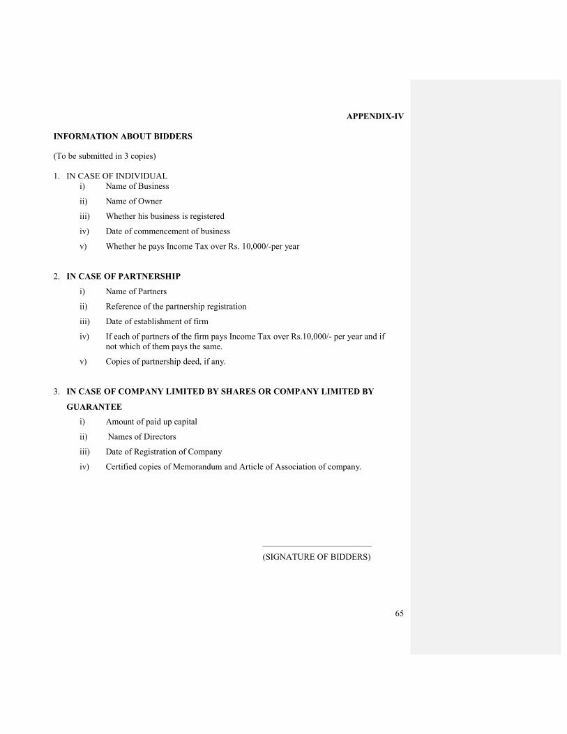
65
APPENDIX-IV
INFORMATION ABOUT BIDDERS
(To be submitted in 3 copies)
1. IN CASE OF INDIVIDUAL
i) Name of Business
ii) Name of Owner
iii) Whether his business is registered
iv) Date of commencement of business
v) Whether he pays Income Tax over Rs. 10,000/-per year
2. IN CASE OF PARTNERSHIP
i) Name of Partners
ii) Reference of the partnership registration
iii) Date of establishment of firm
iv) If each of partners of the firm pays Income Tax over Rs.10,000/- per year and if
not which of them pays the same.
v) Copies of partnership deed, if any.
3. IN CASE OF COMPANY LIMITED BY SHARES OR COMPANY LIMITED BY
GUARANTEE
i) Amount of paid up capital
ii) Names of Directors
iii) Date of Registration of Company
iv) Certified copies of Memorandum and Article of Association of company.
_________________________
(SIGNATURE OF BIDDERS)
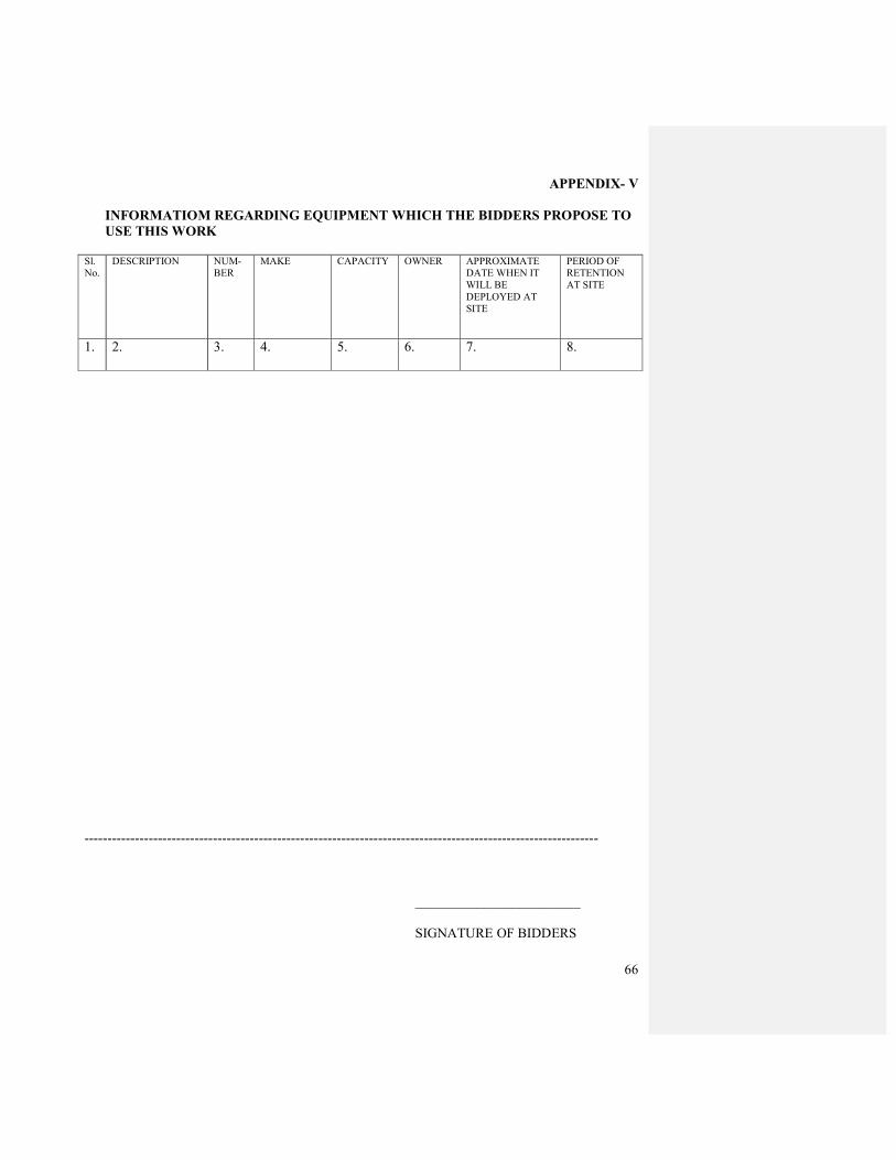
66
APPENDIX- V
INFORMATIOM REGARDING EQUIPMENT WHICH THE BIDDERS PROPOSE TO
USE THIS WORK Sl.
No.
DESCRIPTION NUM-
BER
MAKE CAPACITY OWNER APPROXIMATE
DATE WHEN IT
WILL BE
DEPLOYED AT
SITE
PERIOD OF
RETENTION
AT SITE
1. 2. 3.
4.
5.
6.
7.
8.
----------------------------------------------------------------------------------------------------------------
________________________
SIGNATURE OF BIDDERS
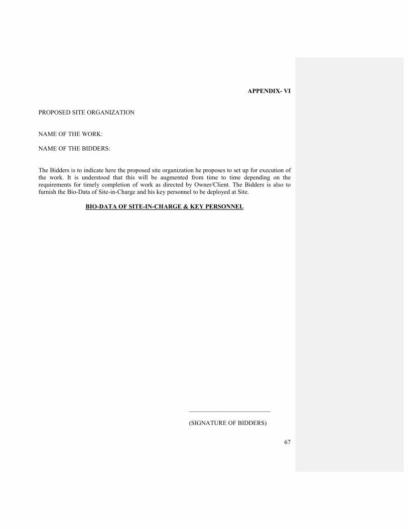
67
APPENDIX- VI
PROPOSED SITE ORGANIZATION
NAME OF THE WORK:
NAME OF THE BIDDERS:
The Bidders is to indicate here the proposed site organization he proposes to set up for execution of
the work. It is understood that this will be augmented from time to time depending on the
requirements for timely completion of work as directed by Owner/Client. The Bidders is also to
furnish the Bio-Data of Site-in-Charge and his key personnel to be deployed at Site.
BIO-DATA OF SITE-IN-CHARGE & KEY PERSONNEL
__________________________
(SIGNATURE OF BIDDERS)
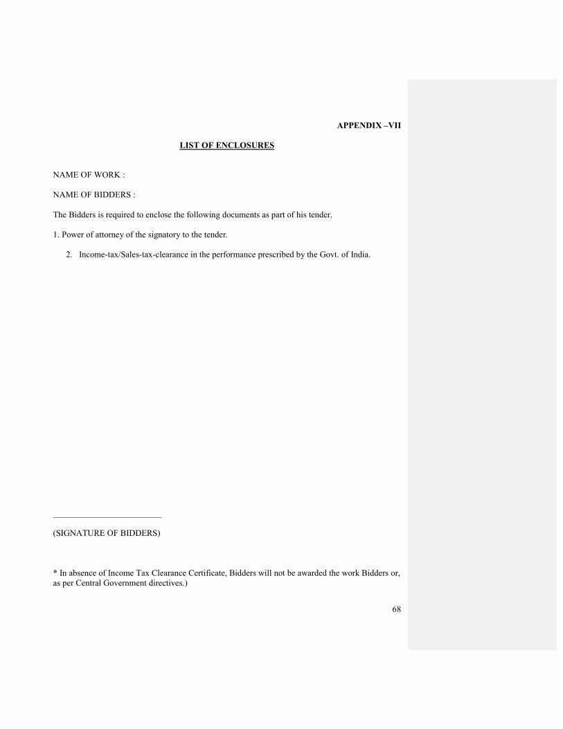
68
APPENDIX –VII
LIST OF ENCLOSURES
NAME OF WORK :
NAME OF BIDDERS :
The Bidders is required to enclose the following documents as part of his tender.
1. Power of attorney of the signatory to the tender.
2. Income-tax/Sales-tax-clearance in the performance prescribed by the Govt. of India.
_________________________
(SIGNATURE OF BIDDERS)
* In absence of Income Tax Clearance Certificate, Bidders will not be awarded the work Bidders or,
as per Central Government directives.)

69
SPECIAL
CONDITIONS
OF
CONTRACT
70
SPECIAL CONDITIONS OF CONTRACT
INDEX
______________________________________________________________________________
S.NO DESCRIPTION PAGE
______________________________________________________________________________
1. SPECIAL CONDITIONS OF CONTRACT 71
2. CLAUSES GENERAL HEALTH, SAFETY AND 80
ENVIRONMENTAL (HSE) ASPECTS (APPENDIX-IX)
3. TIME SCHEDULE (APPENDIX – X) 83
4. SCHEDULE OF FISCAL (APPENDIX – XI) 84
5. SCOPE OF WORK 86

71
SPECIAL CONDITIONS OF CONTRACT
1.0 GENERAL
1.1 Special CONDITIONS of contract shall be read in conjunction with the General Condition
of Contract. Schedule of Quantities specifications of work, drawings and any other
document part of this contract wherever the context so requires.
1.2 Notwithstanding the sub-division of the documents into these separate sections and volumes,
every part of each shall be deemed to be supplementary of every other part and shall be read
with and into the contract so far as it may be practicable to do so.
1.3 Where any portion of the General Conditions of contract is repugnant to or at variance with
any provisions of the Special conditions of Contract, then unless different intention appears,
provision(s) of the Special Conditions of Contract shall be deemed to override the
provision(s) of General Conditions of Contract only to the extent that such repugnance or
variance cannot be reconciled with the tender conditions of contract and shall be to the
extent of such repugnance of variations, prevail; it being understood that the provisions of
General Conditions of Contract shall otherwise prevail.
1.4 Wherever it is stated anywhere in this tender document that such and such a supply is to be
effected or such and such a work is to be carried out, it shall be understood that the same
shall be effected/carried out by the Contractor at his own cost, unless a different intention is
specifically and expressly stated herein or otherwise explicit from the context.
1.5 The materials, design and workmanship shall satisfy the relevant Indian Standards, the job
specifications contained herein & codes referred to. Where the job specifications stipulate
requirements in addition to those contained in the standard codes and specifications, these
additional requirements shall also be satisfied. In the absence of any Standard/
Specifications/ Codes of practice for detailed specifications covering any part of the work
covered in this tender, the instructions/directions of Engineer-in-Charge (Electrical) will be
binding on the Contractor.
1.6 The terms given under Schedule of Rates shall be read in conjunction with scope of work scope of supply (by owner as well as by contractor) and job specifications and in case of any
irreconcilable conflict between them the provision in the item under “Schedule of Rates”
will override the corresponding provision only if the scope work, scope of supply and job
specifications, which cannot be reconciled in such cases the decision of Engineer-in-Charge
(Electrical) shall be final and binding on the contractor.
1.7 In case of contradiction between Indian Standards, General Conditions of Contract, Special
Conditions of Contract, Specification Drawings, Schedule of Rates, the following shall
prevail in order of precedence.
(i) Letter of intent / Detailed Letter of intent along with statement of agreed Variations and its
enclosures.
(ii) Schedule of Rates and Quantities.

72
(iii) Special Conditions of Contract.
(iv) Job Specifications/CPWD Specifications.
(v) Drawings
(vi) General Condition of Contract
(vii) Indian standard/Technical/ Martial Specifications.
2. LOCATION OF SITE AND SITE PARTICULARS
The site of work is located at Plot No. 2A, Saraswati Nagar, Jodhpur, Rajasthan.
The intending tender shall be deemed to have visited the site and familiarized himself
thoroughly with the site conditions before submitting the tender. Non familiarity with the
site conditions will not be considered a reason either for extra claims or for not carrying out
the work in strict conformity with the drawings and specifications.
3. WATER AND POWER
No Water and Electricity shall be provided to the Contractor by the Owner. He shall make
his own arrangement for procurement, consumption, maintenance etc. and deposit all
charges fee etc. in connection with to the Municipal Authorities. However, contractor can tie
up with civil contractor for availing water and power connection at one point on chargeable
basis subject to availability.
4. TIME SCHEDULE
The time schedule is given separately in Appendix-X. The works shall be executed strictly
as per the time schedule.
5. Monthly/ Weekly execution program will be drawn up by the Engineer-in-Charge
(Electrical) jointly with the Contractor based on availability of materials, work fronts and
the joint program of execution as referred to above. The contractor shall scrupulously adhere
to the targets/programs by deploying adequate personnel, construction equipment, tools and
tackles and also by timely supply of required materials coming within his scope of supply as
per contract. In all matters concerning the extent of target set out in the weekly/ monthly
program and the degree of achievement, the decision of the Engineer-in-Charge (Electrical)
will be final and binding on the contractor.
6. Contractor shall give every day category-wise labour and equipment report along with the
progress of work done on previous day in the Performa prescribed by the Owner.
7. SCOPE OF SUPPLY
Owner does not envisages to supply any material for this work & contractor has to arrange
all materials at his own & the rates quoted shall deemed to include the same.
73
8. SCOPE OF WORK The SCOPE of work for this work shall be per SI.No.2 of Instruction to Tenderer.
9. SCHEDULE OF QUANTITIES/RATE
9.1 The quantities shown against the various items are only approximate and may vary to any
extent individually subject to relevant clause of General Conditions of Contract. Any
increase or decrease in the quantities shall not form the basis for alteration of rates quoted
and accepted including where low/high rates have been quoted by the successful Tenderer.
9.2 The Owner reserves the rights to interpolate or extrapolate the rate for any new item of work
not finding a place in the Schedule of rates, for similar items of lower and or higher
magnitude available in the Schedule of Rates.
9.3 In case any activity though specifically not covered in Schedule of Rates description but the
same of covered under scope of work/spec./drawing etc. no extra claim on this account shall
be entertained.
10. INCOME TAX
Income tax at prevailing rate shall be deducted from the contractor’s bills as per Income Tax
Act.
11. MOBILIZATION ADVANCE
No Mobilization advance shall be paid for item of work.
12. SECURED ADVANCE
No Secured advance shall be paid for item of work.
13. PRICE VARIATION
Owner require “FIRM PRICES” as indicated in General Conditions or Contract during
Contract period and no material or labour escalation shall admissible on any account
whatsoever. It is to be noted that no deviation on contract period requirements in this
connection will be acceptable.
14. MEASUREMENTS, BILLING & TERMS OF PAYMENT
All works shall be measured in metric system based on actual work done as per the terms
and conditions of the Tender documents. Running Accounts bills based on schedule of rates
shall be prepared and submitted based on joint measurements.

74
15. TERMS OF PAYMENT
Following shall be the terms of payments for the subject work:-
For Conduiting & Wiring:
1. 20% On conduits for ceiling on Prorata basis
2. 15% On down conduits for wall on prorate basis
3. 35% On wiring on prorate basis
4. 15% On switch/ socket on prorate basis
5. 10% On testing & commissioning on prorate basis
6. 05% On handing over & submission of drawings.
For major equipments: 1. 75% After receipt of material at site along with test report on
prorate basis
2. 10% After installations & alignment on prorate basis
3. 10% After testing and commissioning on prorate basis
4. 05% After handing over & submission of completion documents
including drawings, schematics, manuals, etc.
Major equipments shall be H.T./L.T/ S.D.B/ Capacitor panels, Transformers, Battery
Chargers, D.G. Sets, Pumps, Cooling tower, Cables, Light Fixtures.
Payment towards handing over shall not be released until electrical inspector clearance &
load sanction is obtained by the contractor.
For balance items:
Commensurate with work done as certified by Engineer-in-Charge (Electrical).
Running Account Bills: 100% of the progressive payments will be made within Fifteen (15) working days of the
acceptance and certification of the bill by Engineer-in–Charge. However, 10% of gross
value of each RA bill shall e retained by the Owner till such time the balance 7.5% of the
Security Deposit is recovered.
The above progressive payments are subject to deduction towards income tax and other
recoveries as applicable as per terms and conditions of contract.
13.3 FINAL BILL:
The final bill shall be submitted by the Contractor within three months of physical
completion of the work or within one month of the date of the final certificate of completion
furnished by the Company whichever is earlier. No further claims shall be made by the
Contractor after submission of the final bill and these shall be deemed to have been waived
and extinguished. Payments of those items of the bill in respect of which there is no dispute
and of items in dispute, for quantities and rates as approved by Company, will as far as
possible be made within 6 months, the period being reckoned from the date of receipt of the
bill by the Company, complete with no claim and no dues by contractor, No Objection
Certificate from labour officer and all completion documents including material
consumption statement.
Formatted: Bullets and Numbering

75
14. STATUTORY APPROVALS FOR WORK
All associated activates required for obtaining necessary clearance, permissions, approvals
and licenses from the concerned authorities in respect of works including obtaining load
sanction from supply authority inspection & approval of electrical installations from
electrical inspector, permission to run DG Set from supply authority & electrical inspector,
Clearance from pollution control board for DG Sets & all types of liasioning work with
statutory authority shall be responsibility of the contractor, the cost for which shall be
deemed to be included in the rates for various items of work of Schedule of Quantities by
the contractor. However actual statutory fee payable to the concerned authorities for the
same shall be borne by the owner on production of proof of payment made thereafter.
Handing over of the installation shall be done only after clearance from electrical inspector.
15. OFFICE ACCOMMOFATION/ STORES FOR CONTRACTOR
The contractor shall make his own arrangement for providing, erecting & maintaining site
office & store including furniture & this fixture at his own cost.
16. PAYMENT WITHHELD
The Engineer-in-Charge (Electrical) may cause to with held or on account of subsequently
discovered evidence, cause to nullify whole or part of any certificate to such extent as may
be necessary to protect the Owner from loss on account of:
16.1 Defective work not remedied.
16.2 Failure of the contractor to make payment properly to sub-contractor or for materials or
labour of equipment.
16.3 Damage to another contractor or sub-contractor.
16.4 A reasonable doubt that the contractor intends to leave work items incomplete.
16.5 Failure to provide samples, shop drawings, models or charts as called for.
17. DEDUCTIONS FOR INCORRECT WORK:
If, the Engineer-in-Charge (Electrical) deems it expedient to correct work damaged or not
done in accordance with the contract, an equitable deduction from the contract price shall be
made thereof and the decision of the Owner shall be final.
18. DECLARATION TO BE FURNISHED IN RESPECT FOR TENDERER’S
ORGANIZATION
Tenderer shall have to submit a declaration whether he is a relative of any Director of OIL
or tenderer is a firm in which Director or Owner or his organization or the Tenderer is a
Private company in which Director or Owner is a member or Director, along with his offer.
Such declaration is a must for considering the offer of the tenderer.
76
19. CONTRACT DRAWINGS
A set of tentative Architectural/ electrical Drawing will be enclosed as per SI No. 2.2 of
Instruction to Tenderer. Other drawings and details issued and shop drawings approved
during the currency of the contract shall also form part of the contract. The contract shall
keep at least one copy each of drawings, conditions of contract, specifications, instructions
and schedule of quantities at the site of works available for reference by any authorized
representative for Owner/ Engineer-in-Charge (Electrical), at all times during the progress of
the works. The drawings shall be displayed and arranged as directed by the Engineer-in-
Charge (Electrical).
20. INSURANCE
Contractor shall obtain “Contractors All Risk” Policy for the total contract value at his cost.
Contractor shall also take insurance cover for workmen compensation, employer’s liability
insurance etc. as mentioned in clause no.6.2 of GCC, if these are not covered in “CAR”
Policy
21.0 CONSTRUCTION EQUIPMENT AND SITE ORGANIZATION
21.1 Construction Equipment
The contractor shall without prejudice to his overall responsibility to execute and complete
the work as per specifications and Time Schedule, progressively deploy adequate and tools
and tackles and augment the same as decided by the Company depending on the exigencies
of the work so as to suit the construction schedule. The bidder shall submit a list of
construction equipment he proposes to deploy for the subject work along with deployment
schedule. No construction equipment shall be supplied by the Company.
21.2 Site Organization
Subject to the provision in the tender document and without prejudice to contractor’s
liabilities and responsibilities to provide adequate qualified and skilled personnel on the
work, contractor shall deploy site organization and augment the same as decided by the
Company depending on the exigencies of work. The bidder shall submit the details of
minimum site organization proposed by him, as per Forms given in the tender document.
22.0 UNDERGROUND AND OVERHEAD STRUCTURES
21.0All existing structures overhear lines, existing pipelines and utilities will be intimated to
the Contractor before taking up the execution of work. Contractor shall execute the work in
such a manner that the said structures, utilities, pipelines etc., are not disturbed/ damaged.
23.0 PROVIDENT FUND ACT
The Contractor should strictly comply with the provisions of the Employees Provident Fund
Act.
Formatted: Bullets and Numbering
77
It is to be noted that the subject contract would be awarded only to those agencies who have
fulfilled the following requirements:
a) Obtained License under Contract Labour (Abolition and Regulation) Act, 1970 and submitted to Company.
b) PF. Registration Number allotted to them by RPFC and submitted to Company.
c) The agencies should promptly deposit PF, deduction of the eligible contract employees plus
the employers’ contribution to the RPFC. For this purpose agency must submit a certificate
in their bill that PF amount has been deducted from the eligible employees and along with
employer’s contribution has been deposited with RPFC. In support of this the agency must
furnish the challan/receipt for the payment of RPFC for the earlier months along with bill.
24. DEFECT LIABILITY PERIOD
Defect liability period shall be as per Clause 4.24 of General of Contract.
25. QUALITY ASSURANCE
Tenderer shall include in his offer the Quality Assurance Program containing the overall
quality management and procedures which is required to be adhered to during the execution
of contract. After the award of the contract, detailed quality assurance program to be
followed for the execution of contract under various divisions of works will be mutually
discussed and agreed to.
The Contractor shall establish document and maintain an effective quality assurance system
as outlined in recognized codes.
Quality Assurance System plans/ Procedures of the Contractor shall be furnished in the form
of a QA manual. This document should cover details of the personnel responsible for the
quality assurance, plans or procedures to be followed for quality control in respect of design,
engineering, procurement, supply, installation, testing and commissioning. The quality
assurance system should indicate organizational approach for quality control and quality
assurance of the construction activities at all stages of work at site as well as at
manufacturer’s works and dispatch of materials.
The owner or their representative shall reserve the right to inspect/witness, review any or all
stages of work at shop/site as deemed necessary for quality assurance.
26. TAXES, DUTIES, OCTROI, LEVIES ETC.
The quoted prices shall be deemed to be inclusive of all taxes, duties, octroi, levies etc. till
the completion of the contract and contractor shall not be eligible for any compensation on
this account. However in the event of any change in the rate structure of statutory levies or
introduction of new statutory levies during the currency of contract, the same shall be
reimbursed by the Company. Recovery shall be made on account of reduction in rate &
similarly additional payment shall be made in case of increase in duty/ tax rate, subject to
production of documentary evidence.
78
27. TESTS AND INSPECTION
The contractor shall carry out the various tests as enumerated in the technical Specification
of this tender and technical documents will be furnished to him during the performance of
the work at no extra cost to the Owner. All major equipments shall be tested at
manufacturers work as per agreed inspection & test plans in presence of owner’s
representatives/ Engineer-in-Charge (Electrical) inspective of fact whether it is
specifically mentioned in specification or not. All costs towards arranging the
inspection shall be bone by contractor and shall be included in tendered rates.
The work is subject to inspection at all times by the Engineer-in-Charge
(Electrical)/Owner/or their authorized representative. The contractor shall carry out all
instructions given during inspection and shall ensure that the work is being carried out
according to the technical specifications of this tender, the technical documents that will be
furnished to him during performance of work and the relevant codes of practice.
The Contractor shall provide for purpose of inspection access ladders, lighting, equipment
for testing necessary instruments etc. at his own cost including low voltage lighting
equipment for tray fixing and inspection work.
All results of inspection and test will be recorded in the inspection reports, Proforma of
which will be approved by the Engineer-in-Charge (Electrical). These reports shall form part
of the Completion Documents. Any work not confirming to the execution drawings,
specifications or codes shall be rejected and the contractor shall carry out the rectification at
his own cost.
28. LICENSE & LABOUR REGULATION
The contractor shall posses a valid electrical contractors license and is registered under
Contract Labour (regulation Abolition Act 1970) and that workmen employed by him for
execution of works are suitably covered under workmen compensation act and that all
liabilities arising out of the said acts and ESI’s and other legislative enactment applicable to
such works and workmen shall be to the Contractors account. The contractor will ensure that
the prevalent labour laws and the minimum labour wages etc. (as applicable in the state) are
followed and shall indemnify the Owner’s from many claims of this nature whatsoever
during the course of the subject works. The contractor shall also indemnify and keep the
owners harmless against any claims, demands, actions, or proceedings that may be made or
adopted against the owners by reason of anything done by the contractor pursuant to any
work done by him in execution of the said work.
29. DRAWING APPROVAL
The contractor will submit 4 sets of working drawings indicating detailed layouts for
approval in advance and proceed with work thereafter. All fabrications drawings and other
literature will also be submitted in advance for approval. These drawings shall indicated
detailed layout of all systems covered by this contract as required for execution. Work at site
shall commence only after the layout drawings and all fabrication/ work shop drawing have
been approved by the owner or his representative.
79
30. COMPLETION DOCUMENTS
The contractor shall submit one complete set of original tracing and further three copies of
as built layout drawings to the Architect/ Owner after completion of the work. These
complete drawings shall give the following information:
a) Layout Sub station equipment.
b) Operation & Maintenance Manuals for all equipments.
c) Manufacturers test report & data sheets for equipments.
d) Layout of lighting & power wiring, telephone, UPS wiring Etc.
e) Location of DB’s, Sub-mains, cables & earthling.
f) Junction boxes and dummy conduits for other systems
g) Cable schedule, DB Charts
h) Schematic diagram for overall electrical distribution duly laminated
i) GA & schematic Drawings of HT MV Panel Distribution Boards bus duct
transformer, control panels etc.
In addition one complete set of all above drawings, data sheets, manuals etc. shall be
submitted as a soft copy inn CD.
31. SALES TAX ON WORKS CONTRACT
Contractor shall pay sales tax on all purchases made by him for fulfilling his obligations
under this contract and this should included in the price quoted by him. Sales tax on works
contract tax/ turnover tax shall be deducted from the contractor’s bilks as per prevailing rate
in Rajasthan state. However, if at a later date due to any statutory amendment for
increase/decrease i.e. variation in sales tax on works contract tax/ turnover tax paid by the
contractor shall be reimbursed/ deducted from the contractor subject to production of
documentary evidence.
32. GENERAL HEALTH, SAFETY AND ENVIRONMENTAL (HSE) ASPECTS
For Clauses on General Health, Safety and Environmental (HSE) aspects, please refer
Appendix-IX.
33. SET OFF
Any sum of money due or payable to the Contractor (including Security Deposit refundable
to them) under this or any other contract may be appropriated by Company and set off
against any claim of Company (or such other person or persons contracting through
Company) for payment of a sum of money arising out of this contract or under any other
contract made by the Contractor with Company (or such other person or persons contracting
through Company).
*******

80
APPENDIX-IX
CLAUSES GENERAL HEALTH, SAFETY AND ENVIRONMENTAL (HSE) ASPECTS
1. It will be solely the Contractor’s responsibility to fulfill all the legal formalities with respect
to the Health, Safety and Environmental aspects of the entire job (namely; the person
employed by him, the equipment, the environment, etc.) under the jurisdiction of the district
of that state where it is operating. Ensure that all sub-contractors hired by him comply with
the same requirement as the Contractor himself and shall be liable for ensuring compliance
all HSE laws by the sub or sub-sub contractors.
2. Every person deployed by the Contractor in a mine must wear safety gadgets to be provided
by the Contractor. The Contractor shall provide proper Personnel Protective Equipment as
per the hazard identified and risk assessed for the job and conforming to statutory
requirement and Company PPE schedule. Safety appliances like protective footwear, Safety
Helmet and Full Body harness has to be DGMS approved. Necessary supportive document
shall have to be submitted as proof. If the Contractor fails to provide the safety items as
mentioned above to the working personnel, the Contractor may apply to the Company for
providing the same. Company will provide the safety items, if available. But in turn,
Company will recover the actual cost of the items by deducting from Contractor's Bill. .
However, it will be the Contractor’s sole responsibility to ensure that the persons engaged
by him in the mines use the proper PPE while at work. All the safety gears mentioned above
are to be provided to the working personnel before commencement of the work.
3. The Contractor shall prepare written Safe Operating Procedure (SOP) for the work to be
carried out, including an assessment of risk, wherever possible and safe methods to deal
with it/them. The SOP should clearly state the risk arising to men, machineries & material
from the mining operation / operations to be done by the Contractor and how it is to be
managed.
4. The Contractor shall provide a copy of the SOP to the person designated by the mine owner
who shall be supervising the Contractor's work.
5. Keep an up to date SOP and provide a copy of changes to a person designated by the Mine
Owner/Agent/Manager.
6. Contractor has to ensure that all work is carried out in accordance with the Statute and SOP
and for the purpose he may deploy adequate qualified and competent personnel for the
purpose of carrying out the job in a safe manner. For work of a specified scope/nature, he
should develop and provide to the mine owner a site-specific code of practice in line.
7. All persons deployed by the Contractor for working in a mine must undergo Mines
Vocational Training, initial medical examination, PME. They should be issued cards stating
the name of the Contractor and the work and its validity period, indicating status of MVT,
IME & PME.
8. The Contractors hall submit to DGMS returns indicating – Name of his firm, Registration
number, Name and address of person heading the firm, Nature of work, type of deployment
of work persons, Number of work persons deployed, how many work persons hold VT

81
Certificate, how many work persons undergone IME and type of medical coverage given to
the work persons
9. The return shall be submitted quarterly (by 10th of April, July, October & January) for
contracts of more than one year. However, for contracts of less than one year, returns shall
be submitted monthly.
10. It will be entirely the responsibility of the Contractor/his Supervisor/representative to ensure
strict adherence to all HSE measures and statutory rules during operation in Company’s
installations and safety of workers engaged by him. The crew members will not refuse to
follow any instruction given by company's Installation Manager / Safety Officer / Engineer /
Official / Supervisor/Junior Engineer for safe operation.
11. Any compensation arising out of the job carried out by the Contractor whether related to
pollution, Safety or Health will be paid by the Contractor only.
12. Any compensation arising due to accident of the Contractor's personnel while carrying out
the job, will be payable by the Contractor.
13. The Contractor shall have to report all incidents including near miss to Installation Manager
/ departmental representative of the concerned department of Company.
14. The Contractor has to keep a register of the persons employed by him/her. The Contractor's
supervisor shall take and maintain attendance of his men every day for the work, punctually.
15. If the Company arranges any safety class / training for the working personnel at site
(company employee, Contractor worker, etc) the Contractor will not have any objection to
any such training.
16. The health check up of Contractor's personnel is to be done by the Contractor in authorized
Health Centers as per Company 's requirement & proof of such test(s) is to be submitted to
Company. The frequency of periodic medical examinations should be every five years for
the employees below 45 years of age and every three years for employees of 45 years of age
and above.
17. To arrange daily tool box meeting and regular site safety meetings and maintain records.
18. Records of daily attendance, accident report etc. are to be maintained in Form B, E, J (as per
Mines Rules 1955) by the Contractor.
19. A Contractor employee must, while at work, take reasonable care for the health and safety of
people who are at the employee’s place of work and who may be affected by the employee’s
act or omissions at work.
20. A Contractor employee must, while at work, cooperate with his or her employer or other
persons so far as is necessary to enable compliance with any requirement under the act or
the regulations that is imposed in the interest of health, safety and welfare of the employee
or any other person.
82
22. Contractor’s arrangements for health and safety management shall be consistent with those
for the mine owner.
23. In case Contractor is found non-compliant of HSE laws as required company will have the
right for directing the Contractor to take action to comply with the requirements, and for
further non-compliance, the Contractor will be penalized prevailing relevant
Acts/Rules/Regulations.
24. When there is a significant risk to health, environment or safety of a person or place arising
because of a non-compliance of HSE measures Company will have the right to direct the
Contractor to cease work until the non-compliance is corrected.
25. The Contractor should prevent the frequent change of his contractual employees as far as
practicable.
26. The Contractor should frame a mutually agreed bridging document between Company & the
Contractor with roles and responsibilities clearly defined.
27. For any HSE matters not specified in the contract document, the Contractor will abide the
relevant and prevailing Acts/rules/regulations/ pertaining to Health, Safety and
Environment.

83
Appendix – X
I. TIME SCHEDULE
Description of work
work
Time of completion of
Internal & External electrical works sub station & DG
sets. for Oil House at Jodhpur. for construction of
“OIL HOUSE” at plot no.2A, Sarawati Nagar Jodhpur
(Rajasthan)
365 days from the date of
award of contract
NOTE:
Time of commencement shall be reckoned from the seventh day of issue of Telefax/ Letter
of Acceptance, whichever is issued earlier.
The time indicated above is for completing the works in all respects as per design, drawings,
specification and instruction of Company.
(SIGNATURE OF BIDDER)
VOLUME
84
APPENDIX – XI
SCHEDULE OF FISCAL ASPECTS
Earnest money to be deposited : 2% of Estimated cost.
Possession of site : Immediately on award of contract.
Time of completion : As per Appendix-X (Max. 365 days)
Liquidated damages per week for : 0.5% of the contract value for delay in
completion of work in time per week or part
thereof, subject to a maximum of 7.5% of the
contract value.
Minimum interval between submissions : Monthly once of interim bills.
Security Deposit : Refer Clause 3.4 of GCC
Payment of RA Bills : 100% of the recommended payments duly
certified by Company within thirty (30) days of
receipt of undisputed bill.
Period of submitting final bill : Within three (3) months from the date of
completion of work in full to the satisfaction of
Company.
Release of security deposit : After expiry of defects liability period.
Defects Liability period : 12 (twelve) months from the date of virtual
completion, as mentioned in the completion
certificate conveyed by Company to contractor
except for water
proofing works.
Insurance etc. : Insurance cover for Contractor’s crew
machinery and equipment etc. as required are
to be entirely arranged and premium thereto to
be paid by Contractor. Company will not
assume any responsibility whatsoever in this
regard.

85
SCOPE OF WORK

86
SCOPE OF WORK
Brief details of work to be carried out by the contractor are as described below. This will include
supply storage laying, installation, jointing and testing, obtaining approvals, testing and
commissioning and completion of different works. The work shall be carried out as described in
schedule of quantities, specifications, and drawings, Indian Electricity Rules and as per byelaws laid
down by Electrical Supply Company.
The scope of work shall cover internal and external electrical works of building campus. The board
items/activities covered under internal electrical works shall include the followings:
i) Point wiring of all lights points. Ceiling fan points exhaust fan points, light plug points,
general power points, metal clad plug & socked outlet points etc. including supply and
fixing of light and power accessories etc. complete in all respects. The conduit for the
ceiling where false ceiling is coming shall be laid on surface and down conduit shall be
recessed type below false ceiling.
ii) Cables from Main Distribution Board to Sub Distribution Board sub main wiring from
main/sub distribution boards to various final distribution boards. Power wiring for lift
machine rooms.
iii) Provision for telephone system consisting of conduit and cabling from telephone distribution
board up to each outlet including main & sub tag blocks, conducting for LAN, telephone
outlets incoming GI/HDPE pipe etc. complete in all respects.
iv) HDPE/GI pipes for cables, manholes, cable tray and other items required to complete with
electrical installation work in all respects.
v) Main Distribution Boards, Sub Distribution Boards, Final Distribution Boards.
vi) Light fixtures, ceiling fans, exhaust fans.
vii) Earthing of electrical installation complete in all respects.
viii) Cabling, bus trunking/rising mains to various load centers and floor panels.
ix) Providing HT/LT Sub-station equipment like HT switchboard, distribution transformer LT
switchboard, bus ducts, capacitor panels etc.
x) External lighting & facade lighting.
xi) To prepare Layout and working drawings submission drawings and completion drawings for
all systems to be executed.
xii) To obtain clearances, approvals etc. form Electrical Inspector to State Govt., Electricity
Supply Company, Pollution Control Deptt. and or any other statutory authority as may be
applicable/required.
87
SECTION-II
TECHNICAL
SPECIFICATIONS
88
CHAPTER -1
TECHNICAL REQUIREMENTS & MEASUREMENT SYSTEM
1.0 SCOPE
This chapter covers the general technical requirements and measurement system of the
various components in Internal Electrical Installation works.
1.0 TERMINOLOGY
1.1.1 The definition of terms shall be in accordance with 18:732-1989 (Indian Standard Code of
Practice for Electrical Wiring), except for the definitions of point, circuit, and sub-main
wiring, which are defined in clauses 2.2.1, 2.3.1, and 2.3.2 hereunder.
1.2 POINT WIRING
1.2.1 Definition
A point (other than socket outlet point) shall include all work necessary in complete wiring
to the following outlets from the controlling switch or MCB. The scope of wiring for a point
shall, however, include the wiring work necessary in tapping from another point in the same
distribution circuit.
Ceiling rose or screw less connector (in the case of points for ceiling/exhaust fan points, pre-
wired light fittings, and call bells).
Ceiling rose (in the case of pendants except stiff pendants).
Back plate (in the case of stiff pendants).
Lamp holder (in the case of goose neck type wall brackets, batten holders and fittings which
are not pre-wired).
Note:- In the case of call bell points ,the words "from the controlling switch or MCB" shall be read
as "from the ceiling rose meant for connection to bell push".
1.2.2 Scope
Following shall be deemed to be included in point wiring.
Conduit, accessories for the same and wiring cables between the switch box and the point
outlet.
All fixing accessories such as screws, rawl plug etc. as required.
Metal switch boxes for control switches, regulators and sockets etc, recessed in walls.
Outlet boxes, junction boxes, pull-through boxes-etc, including metal boxes if any, provided
with switch boards for loose wires/conduit terminations.
Control switch or MCB, as specified.
89
Ceiling rose or connector as required. (2 pin and 5 pin socket outlet shall not be used).
Connections to ceiling rose, connector, socket outlet, lamp holder, switch etc.
Interconnecting wiring between points on the same circuit, in the same switch box or from
another.
Protective (loop earthing) conductor from one metallic switch box to another in the
distribution circuits, and for socket outlets. (The length of protective conductor run along
with the circuits/ sub-mains is excluded item the scope of points).
Bushed conduit or porcelain tubing where wiring cables pass through wall etc.
1.2.3 Measurement:
1.2.3.1 Point Wiring:
Unless and otherwise specified, there shall be no linear measurement for point wiring for
light points, fan points, exhaust fan points, 5/6amp plug points, 15/16 amp. plug points and
call bell points.
These shall be measured on unit basis by counting only.
No separate measurement will be made for interconnections between points in the same
distribution circuit and for the circuit wiring including protective (loop earthing) conductors
between metallic switch boxes.
1.2.3.2 Point wiring for socket outlet points:
The light plug (5A/6A) point and power (15A/16A) point wiring shall be measured as
indicated above.
The metal box with cover, switch/MCB, Socket outlet and other accessories shall be
measured and paid as a part of the item only.
The power point outlet may be 15A/5 A or 16A /6 A six pin socket outlet, where so
specified in the tender documents.
1.2.3.3 Group control points wiring:
In the case of points with more than one point controlled by the same switch, such points
shall be measured in parts i.e. (a) from the switch to the first point outlet as one point and for
the subsequent points. the distance from that outlet to the next one and so on shall be treated
as separate point(s).
The switch for controlling four or more outlets shall be of 15/16 amp. Rating and no extra
payment shall be made for the same.
No recovery shall be made for non-provision of more than one switch in such cases.
1.2.3.4 Twin control light points wiring:
A light point controlled by two numbers of two way switches shall be measured as two
points from the fitting to the switches on either side.
No recovery shall be made for non-provision of more than one ceiling rose or connector in
such cases.
90
1.3 CIRCUIT AND SUBMAIN WIRING:
1.3.1 Circuit wiring
Circuit wiring shall mean the wiring from the distribution board upto the tapping point for
the nearest first point of that distribution circuit, viz. upto the nearest first switch box. No
extra payment shall be made for circuit wiring.
1.5.2 Sub-main wiring:
Sub-main wiring shall mean the wiring item one main/distribution switchboard to another.
1.3.3 Measurement of sub-main wiring:
The sub main wiring shall be measured on linear basis and paid for separately.
1.4. OTHER WIRING WORKS:
Except as specified above for point wiring, circuit wiring and sub-main wiring, other types
of wiring 'shall be measured separately on linear basis along the run of wiring depending on
the actual number and sizes of wires run.
1.5 SYSTEM OF DISTRIBUTION AND WIRING:
1.5.1. Control at the point of entry of supply:
There shall be a circuit breaker on each live conductor of the supply mains at the point of
entry.
1.5.2 Distribution:
The wiring shall be done on a distribution system through main and/or branch distribution
boards. The system design as well as the locations of boards shall be as indicated in
BOQ/drawings or as specified by the OIL engineer.
Main distribution board shall be controlled by a circuit breaker. Each outgoing circuit shall
also be controlled by a circuit breaker.
The branch distribution board shall be controlled by a circuit breaker. Each outgoing circuit
shall be provided with a miniature circuit breaker (MCB) of specified rating on the phase or
live conductor.
The loads of the circuits shall be divided, as far as possible, evenly between the number of
ways of the distribution boards, leaving at least one spare circuit for future extension.
The neutral conductors (incoming and outgoing) shall be connected to a common link
(multilayer connector) in the distribution board and be capable of being disconnected
individually for testing purposes.
'Power' wiring shall be kept separate and distinct from 'Lighting' wiring, from the level of
circuits i.e., beyond the branch distribution boards.

91
Wiring shall be separate for essential loads (i.e., those fed through standby supply) and non
essential loads throughout.
1.5.3. Balancing of Circuits:
The balancing of circuits in three wire or poly phase installations shall be arranged before
hand to the satisfaction of the OIL engineer.
1.5.4 Wiring System:
Wiring shall be done only by the "Looping system". shall be looped at the switch boxes for
both phase or live conductors and neutral conductors.
Lights, fans and call bells shall be wired in the' lighting' circuits. 15A / 16A socket outlets
and other power outlets shall be wired in the 'Power' circuits. 5A / 6A socket outlets shall be
wired in the 'lighting' circuits.
The wiring throughout the installation shall be such that there is no break in the neutral wire
except in the form of linked switchgear.
1.5.5 Run of Wiring:
The wiring shall be in recessed metallic conduit.
Due consideration shall be given for neatness, good appearance and safety.
1.5.6 Passing through walls or floors:
When wiring cables are to pass through a wall, these shall be taken through a protection
(steel) pipe tube of suitable size such that they pass through in a straight line without twist or
cross in them on either end of such holes. The ends of metallic pipe shall be neatly bushed
with porcelain, PVC or other approved material.
All floor openings for carrying any wiring shall be suitably sealed after installation.
1.6 Joints in wiring:
No bare conductor in phase and / or neutral or twisted joints in phase, neutral, and / or
protective conductors in wiring shall be permitted.
There shall be no joints in the through-runs of cables. If the length of final circuit or sub
main is more than the length of a standard coil, thus necessitating a through joint, such joints
shall be made by means of, approved mechanical connectors in suitable junction boxes.
Termination of multi stranded conductors shall be done using suitable crimping type
thimbles.
1.7 RATINGS OF OUTLETS:
Incandescent lamps shall be rated at 100W.
92
Ceiling fans shall be rated at 60W. Exhaust fan, fluorescent tubes, compact fluorescent
tubes, HPMV lamps, HPSV lamps etc. shall be rated according to their capacity. Control
gear losses shall be also considered as applicable.
5A/6A and 15A/16A socket outlet points shall be rated at 100W and 1000W respectively,
unless the actual values of loads are specified.
1.8 CAPACITY OF CIRCUITS:
'Lighting' circuit shall not have more than a total of 10 points of light, fan and socket outlets,
or a total connected load of 800W, whichever is less.
'Power' circuit shall have only one outlet per circuit.
1.9 CONFORMITY TO IE ACT, IE RULES, AND STANDARDS:
All electrical works shall be carried out in accordance with the provisions of Indian
Electricity Act, 1910 and Indian Electricity Rules, 1956 amended up to date. List of Rules of
particular importance to building installations is given in Appendix for reference.
The works shall also conform to relevant Indian Standard Codes of Practice (COP) for the
type of work involved. (See Appendix B).
In all electrical installation works, relevant safety codes of practice shall be followed.
Guidelines on safety procedure outlined in Appendix' C' should be adopted.
1.10 GENERAL REQUIREMENTS OF COMPONENTS:
1.10.1 Quality of materials:
All materials and equipments supplied by the contractor shall be new. They shall be of such
design, size and material as to satisfactorily function under the rated conditions of operation
and to withstand the environmental conditions at site.
1.10.2 Ratings of components:
All components in a wiring installation, conductors, switches and accessories shall be of
appropriate ratings of voltage, current, and frequency, as indicated in BOQ.
1.10.3 Conformity to Standards:
All components shall conform to relevant Indian Standard Specification, as per board list
given in Appendix' A' including amendments or revisions there of up to the date of tender
acceptance, shall be applicable in the respective contracts.
1.10.4 Interchangeability:
Similar parts of all switches, lamp holders, distribution boards, switchgears, ceiling roses,
brackets, pendants, fans and all other fittings of the same type shall be interchangeable in
each installation.
1.11 CABLES:
93
1.11.1 Wiring cables:
Conductors of wiring cables shall be of copper.
The smallest size of conductor for' lighting' circuits shall have a nominal cross sectional area
of not less than 1.5 sq mm. The minimum size of conductor for 'power' wiring shall be 4 sq
mm stranded cable. All wiring cables shall be FR, single core, PVC insulated,
unsheathed,1100v grade, FIA, TAC, IS-694 approved with flexible copper conductor.
1.12 WIRING ACCESSORIES:
1.12.1 Control switches for points:
Control switches (single pole switches) carrying not more than 16A shall be of clamp on
type complete with plate, as specified, and the switch shall be #ON# when the knob is down.
The type and current rating of switch controlling a group of points, or discharge lamps, or a
single large load, shall be specified in the tender documents.
Control switch shall be placed only in the live conductor of the circuit. No single pole switch
or fuse shall be inserted in the protective (earth) conductor, or earthed neutral conductor of
the circuit.
1.12.2 Socket outlets:
Socket outlets shall also be of clamp on type complete with plate. These shall be rated either
for 5A/6A, or 15A/16A. Combined 5A/15A, or 6A/16A six pin socket outlet shall be
provided in 'power' circuits wherever specified.
Socket outlets and plugs shall only be of 3 pin type; the third pin shall be connected to earth
through protective (loop earthing) conductor. 2 pin or 5 pin sockets shall not be permitted to
be used.
The control switches for the 5A/6A and 15A/16A socket outlets shall be kept along with the
socket outlets.
1.12.3 Switch box covers:
These shall be molded type of suitable size.
1.12.4 Lamp holders:
Lamp holders may be of batten, angle, pendant or bracket holder type as indicated in BOQ.
The holder shall be made of brass and shall be rigid enough to maintain shape on application
of a nominal external pressure. There should be sufficient threading for fixing the base to the
lamp holder part so that they do not open out during attention to the lamp or shade.
Lamp holders for use on brackets and the like shall have not less than 1.3 cm nipple, and all
those for use with flexible pendant shall be provided with cord grips.
All lamp holders shall be provided with shade carriers.

94
1.13 FITTINGS:
1.13.1 Types:
The type of fittings shall be as specified in BOQ.
1.13.2 Indoor type fittings:
The conductors are required to be drawn through tube popularly known as conduit. The tube
or channel must be free from sharp angles or projecting edge, and of such size as will enable
them to be wired with the conductors used for the final circuit without removing the braiding
or sheathing. As far as possible all such tubes or channels should be of sufficient size to
permit looping back.
Fittings using discharge lamps shall be complete with power factor correction capacitors,
either integrally or externally. An earth terminal with suitable marking shall be provided for
each fitting for discharge lamps.
1.14 SWITCHGEAR AND CONTROLGEAR - General aspects:
All items of switchgear and distribution boards (DB’s) shall be metal clad type.
The types, ratings and/or categories of switchgear and protective gear shall be as specified in
the BOQ.
RCBs (ELCBs) where specified, shall conform to the requirements of current rating, fault
rating, single phase or three phase configuration and sensitivity laid down in the BOQ.
While each outgoing way of distribution board (DB) shall be of miniature circuit breaker
(MCB) as specified, and of suitable rating on the phase conductor, the corresponding earthed
neutral conductor shall be connected to a common neutral terminal block and shall be
capable of being disconnected individually for testing purposes.
(v) Independent earth terminal block:
Every distribution board (single phase as well as 3 phase) shall have an earth terminal block
identical to, but independent from neutral terminal block, to enable termination of protective
(loop earthing) conductors (incoming as well as outgoings) individually by screwed
connection and without twisting.
Earthing terminal (1 for single phase and 2 for 3 phases) shall be provided on the metal
cladding of switches and DB’s for body earthing. These shall be suitably marked.
Knock out holes, with or without end plates as per standard design of manufacturers, shall
be provided in the metal cladding of switches and DBs for termination of conduits/cables.
1.15 PRE-WIRED MCB DISTRIBUTION BOARDS:
Pre wired MCB DB’s shall be provided only where specified.
The complete board shall be factory fabricated and shall be duly pre wired in the works,
ready for installation at site.
95
The board shall be of wall mounted, cubical type construction, fabricated out of 1.6mm thick
sheet steel, with stove enameled paint finish.
The board shall also be provided with a loose wire box as a compartment for the complete
width and, depth of the board, and of minimum height of 125mm in case of TPN DB's, and
100mm in case of SPN DB's.
The board shall be provided with a hinged cover of 1.6mm thick sheet steel in the front.
Only the knobs of the MCB’s shall protrude out of the front covers through openings neatly
machine made for the purpose.
Knock out holes at the bottom, and detachable plate with knock out holes at the top of the
board shall be provided.
Each distribution board shall be provided with a circuit list giving details of each circuit
which it controls and the current rating of the circuit, and the size of the MCB.
The board shall be complete with the following accessories:
(a) 200 A copper bus bar(s).
(b) Neutral link.
(c) Common earth bar.
(d) DIN bar for mounting MCB’s
(e) Wago type terminal connectors suitable for incoming and outgoing cables.
(f) Earthing stud(s).
The board shall be fully prewired with single core PVC insulated copper
conductors/insulated solid copper links, and terminated on to extended type terminal
connectors, suitable for connections to the sizes of the respective conductors. '
All incoming and outgoing wiring to the pre wired MCB DB's shall be terminated only in
the Elemex type extended terminal connectors to be provided within the DB. The terminal
connectors shall, therefore, be so provided as to facilitate easy cable connections and
subsequent maintenance.
A common copper earth bar shall be provided within the loose wire box. The common
neutral bar as well as the terminal connectors shall, however, be provided within the main
compartment just below the loose wire box.
1.16 MINIATURE CIRCUIT BREAKERS (MCB's):
'B' series MCB's shall be used only for normal 'lighting' circuits.
'C' series MCB's shall be invariably used for motor loads, halogen lamp fittings,
sodium/mercury discharge lamps and all 'power' circuits.
Ratings (A), number of poles, type as MCB or isolator, etc. shall be as specified in the BOQ.
The MCB's shall be of minimum 10KA rupturing capacity.
1.17 SWITCH BOARD LOCATIONS:
96
1.17.1 General aspects:
Switch boards shall be located as indicated on the drawings.
1.18 SWITCH BOARD INSTALLATION:
A switch board shall not be installed so that .its bottom is within 1.25 m above the floor.
Where it is required to terminate a number of conduits on a board, it may be convenient to
provide a suitable MS adopter box for the purpose. Such boxes shall be provided with the
prior approval of the Engineer-in-Charge (Electrical)and this will not be paid for separately.
All wires to the boards shall be bushed at the entries to avoid damage to insulation.
No apparatus shall project beyond any edge of the panel.
All unused holes in the boards and in the mountings shall be plugged suitably to avoid entry
of insects.
1.19 WIRING OF SWITCH BOARDS AND DISTRIBUTION BOARDS:
All connections between pieces of apparatus, or between apparatus and terminals on a board
shall be neatly arranged in a definite sequence, following the arrangement of the apparatus
mounted thereon, avoiding unnecessary crossings.
Cables shall be connected to terminals either by crimped or soldered lugs, unless the
terminals are of such a form that they can be securely clamped without cutting away of cable
strands.
All bare conductors shall be rigidly fixed in such a way that a clearance of at least 2.5 cm is
maintained between conductors of opposite polarity or phase, and between the conductors
and any material other than insulating material.
The incoming and outgoing cables shall be neatly bunched and shall be fixed in such a way
that the door shall be capable of swinging through an angle of not less than 90 degrees.
1.20 MARKING OF APPARATUS:
(i) Marking of earthed neutral conductor:
On the switchgear, the earthed conductor of a two wire system, or an earthed neutral
conductor of a multi-wire system, an indication of a permanent nature shall be provided to
identify the earthed neutral conductor. In this connection Rule 32(1) of Indian Electricity
Rules 1956 (see Appendix C) shall be referred to. The neutral conductor shall be black in
colour.
(ii) Main earthing terminal:
The main earthing terminal in the main switch board shall be permanently marked as
"SAFETY EARTH - DO NOT REMOVE".
All distribution boards shall be marked 'L' for lighting, or 'P' for power and 'E' for essential
as the case may be.

97
When a board is connected to a voltage higher than 250V, all the terminals or leads of the
apparatus mounted on it shall be marked in the following colours to indicate the different
poles or phases to which the apparatus or its different terminals may have been connected:
Where a four wire, three phase wiring is done, the neutral shall preferably be in one colour,
and the other three wires in another colour.
Three phases - Red, Blue & Yellow AND Neutral – Black
All marking required under this rule shall be clear and permanent.
1.21 ATTACHMENT OF FITTINGS AND ACCESSORIES:
1.21.1 Conduit wiring system: All accessories like switches, socket outlets, call bell pushes and regulators shall be fixed in
flush pattern inside the switch/regulator boxes. Accessories like ceiling roses, brackets,
batten holders, etc. shall be fixed on metal outlet boxes. The fan regulators shall also be
fixed in metal outlet boxes.
Cadmium plated brass screws shall be used to fix the accessories to their bases.
The switch box / regulator box shall be mounted with their bottom 1.25m from floor level,
unless otherwise directed by the OIL engineer.
Dash fasteners shall be used for fixing to walls or ceiling.
1.22 FANS REGULATORS AND CLAMPS:
1.22.1 Exhaust fans:
Exhaust fans shall conform to relevant Indian Standards.
Exhaust fans shall be erected at the places indicated on the drawings. For fixing an exhaust
fan, a circular hole shall be provided in the wall to suit the size of the frame, which shall be
fixed by means of rag bolts embedded in the wall. The hole shall be neatly plastered to the
original finish of the wall. The exhaust fan shall be connected to the exhaust fan point,
which shall be wired as near to the hole as possible, by means of a flexible cord, care being
taken to see that the blades rotate in the proper direction.
1.22.2 Regulators:
The metallic body of regulators of ceiling fans/exhaust fans shall be connected to earth by
protective conductor.
1.23 WORKMANSHIP:
Good workmanship is an essential requirement to be complied with. The entire work of
manufacture/fabrication, assembly and installation shall conform to sound engineering
practice.
The work shall be carried out under the direct supervision of a first class licensed foreman,
or of a person holding a certificate of competency issued by the State Govt. for the type of
work involved, employed by the contractor, who shall rectify then and there the defects
pointed out by the Engineer-in-Charge (Electrical) during the progress of work.
98
1.24 COMMISSIONING ON COMPLETION:
Before the workman leaves the work finally, he must make sure that the installation is in
commission, after due testing.
1.26 DRAWINGS:
The work shall be carried out in accordance with the drawings enclosed with the tender
documents and also in accordance with modification thereto from time to time as approved
by the OIL engineer.
All circuits shall be indicated and numbered in the wiring diagram and all points shall be
given the same number as the circuit to which they are electrically connected.
******

99
CHAPTER 2
METALLIC CONDUIT WIRING SYSTEM
2.0 SCOPE:
This chapter covers the detailed requirements for wiring work in metallic conduits.
2.2 MATERIALS:
2.2.1 Conduits:
All rigid conduit pipes shall be ,of steel and be ISI marked. The wall thickness shall be not
less than 1.6 mm (16 SWG) for conduits up to 32 mm dia. and not less than 2 mm (14 SWG)
for conduits above 32 mm dia. These shall be solid drawn or reamed by welding, and
finished with stove enameled surface.
The maximum number of PVC insulated cables conforming to IS:694-1990 that can be
drawn in one conduit is given size wise in Table I, and the number of cables per conduit
shall not be exceeded. Conduit sizes shall be selected accordingly in each run.
No steel conduit less than 20mm in diameter shall be used.
2.2.2 Conduit accessories:
The conduit wiring system shall be complete in all respects, including their accessories.
All conduit accessories shall be of threaded type, and under no circumstances pin grip type
or clamp grip type accessories shall be used.
Bends, couplers etc. shall be solid type.
2.2.3 Outlets:
The switch box or regulator box shall be made of sheet metal on all sides, except on the
front. The wall thickness shall not be less than 1.2 mm (18 gauge) for boxes up to a size of
20 cm X 30 cm, and above this size 1.6 mm (16 gauge) thick MS boxes shall be used. The
metallic boxes shall be duly painted with anticorrosive paint before erection as per chapter
10 of these Specifications.
Where a large number of control switches and/or fan regulators are required to be installed
at one place, these shall be installed in more than one outlet box adjacent to each other for
ease of maintenance.
An earth terminal with stud and 2 metal washers shall be provided in each MS box for
termination of protective conductors and for connection to socket outlet/metallic body of fan
regulator etc.
Clear depth of the box shall not be less than 60 mm, and this shall be increased suitably to
accommodate mounting of fan regulators in flush pattern.
100
2.3 INSTALLATION:
(i) Conduit joints:
The conduit work of each circuit or section shall be completed before the cables are drawn
in.
Conduit pipes shall be joined by means of screwed couplers and screwed accessories only.
Threads on conduit pipes in all cases shall be between 13 mm to 19 mm long, sufficient to
accommodate pipes to full threaded portion of couplers or accessories.
Cut ends of conduit pipes shall have no sharp edges, nor any burrs left to avoid damage to
the insulation of the conductors while pulling them through such pipes.
The OIL engineer, with a view to ensuring that the above provision has been carried out,
may require that the separate lengths of conduit etc., after they have been prepared, shall be
submitted for inspection before being fixed.
No bare threaded portion of conduit pipe shall be allowed, unless such bare threaded portion
is treated with anticorrosive preservative or covered with approved plastic compound.
(ii) Bends in conduit:
All necessary bends in the system, including diversion, shall be done either by neatly
bending the pipes without cracking with a bending radius of not less than 7.5 cm, or
alternatively, by inserting suitable solid type normal bends, elbows or similar fittings, or by
fixing MS inspection boxes, whichever is most suitable for the particular situation.
No length of conduit shall have more than the equivalent of four quarter bends from outlet to
outlet.
(iii) Outlets:
All outlets such as switches, wall sockets etc. shall be flush mounting type.
All switches socket outlets and fan regulators shall be fixed on sheet cover of the same
manufacturer as that of the accessories.
(iv) Painting after erection:
After installation, all accessible surfaces of conduit pipes, fittings, switch and regulator
boxes etc. shall be painted in compliance with the clauses under Chapter 6 - 'Painting'.
2.3.1 Additional requirements:
(i) Making chase:
The chase in the wall shall be neatly made, and of ample dimensions to permit the conduit to
be fixed in the desired manner.
The conduits shall be buried in the wall before plastering, and shall be finished neatly after
erection of conduit.

101
(ii) Fixing conduits in chase:
The conduit pipe shall be fixed by means of staples, J-hooks, or by means of saddles, not
more than 60 cm apart.
An threaded joints of conduit pipes shall be treated with approved preservative compound-
to secure protection against rust.
(iii) Fixing conduits in RCC work:
The conduit pipes shall be laid in position and fixed to the steel reinforcement bars by steel
binding wires before the concreting is done. The conduit pipes shall be fixed firmly to the
steel reinforcement bars to avoid their dislocation during pouring of cement concrete and
subsequent tamping of the same.
Fixing of standard bends or elbows shall be avoided as far as practicable, and all curves shall
be maintained by bending the conduit pipe itself with a long radius which will permit easy
drawing in of conductors.
Location of inspection / junction boxes in RCC work should be identified by suitable means
to avoid unnecessary chipping of the RCC slab subsequently to locate these boxes.
(iv) Fixing inspection boxes:
Suitable inspection boxes to the minimum requirement shall be provided to permit
inspection, and to facilitate replacement of wires, if necessary.
These shall be mounted flush with the wall or ceiling concrete. Minimum 65 mm depth
junction boxes shall be used in roof slabs and the depth of the boxes in other places shall be
as per IS:2667-1977.
Suitable ventilating holes shall be provided in the inspection box covers,
(v) Fixing switch boxes and accessories:
Switch boxes shall be mounted flush with the wall. All outlets such as switches, socket
outlets etc. shall be flush mounting type.
(vi) Fish wire:
To facilitate subsequent drawing of wires in the conduit, GI fish wire of 1.2 mm (18 SWG)
shall be provided along with the laying of the recessed conduit.
2.3.1 Bunching of cables:
Cables shall always be bunched so that the outgoing and return cables are drawn into the
same conduit.
Where the distribution is for three phase loads only, conductors for all the three phases and
neutral wire shall be drawn in one conduit.
2.3.2 Earthing requirements:
The entire system of metallic conduit work, including the outlet boxes and other metallic
accessories, shall be mechanically and electrically continuous by proper screwed joints, or
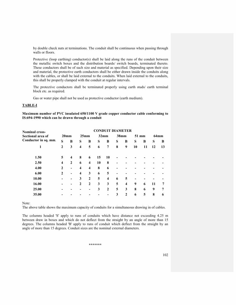
102
by double check nuts at terminations. The conduit shall be continuous when passing through
walls or floors.
Protective (loop earthing) conductor(s) shall be laid along the runs of the conduit between
the metallic switch boxes and the distribution boards/ switch boards, terminated thereto.
These conductors shall be of such size and material as specified. Depending upon their size
and material, the protective earth conductors shall be either drawn inside the conduits along
with the cables, or shall be laid external to the conduits. When laid external to the conduits,
this shall be properly clamped with the conduit at regular intervals.
The protective conductors shall be terminated properly using earth studs/ earth terminal
block etc. as required.
Gas or water pipe shall not be used as protective conductor (earth medium).
TABLE-I
Maximum number of PVC insulated 650/1100 V grade copper conductor cable conforming to
IS:694-1990 which can be drawn through a conduit
Nominal cross-
Sectional area of Conductor in sq. mm.
CONDUIT DIAMETER
20mm 25mm 32mm 38mm 51 mm 64mm
S B S B S B S B S B S B
1 2 3 4 5 6 7 8 9 10 11 12 13
1.50 5 4 8 6 15 10 - - - - - -
2.50 4 2 6 4 10 8 - - - - - -
4.00 2 - 4 4 8 6 - - - - - -
6.00 2 - 4 3 6 5 - - - - - -
10.00 - - 3 2 5 4 6 5 - - - -
16.00 - - 2 2 3 3 5 4 9 6 11 7
25.00 - - - - 3 2 5 3 8 6 9 7
35.00 - - - - - - 3 2 6 5 8 6
Note:
The above table shows the maximum capacity of conduits for a simultaneous drawing in of cables.
The columns headed 'S' apply to runs of conduits which have distance not exceeding 4.25 m
between draw in boxes and which do not deflect from the straight by an angle of more than 15
degrees. The columns headed 'B' apply to runs of conduit which deflect from the straight by an
angle of more than 15 degrees. Conduit sizes are the nominal external diameters.
*******

103
CHAPTER - 3
PAINTING
3.0 SCOPE:
This chapter covers the requirements of painting work in internal electrical installations,
carried out manually by brush. This does not cover spray painting work of factory made
items.
3.1 PAINTING WORK IN GENERAL:
3.1.1 Paints:
Paints, oils, varnishes etc. of approved make in original tin to the satisfaction of the
Engineer-in-Charge (Electrical)shall only be used.
3.1.2 Preparation of the surface:
The surface shall be thoroughly cleaned and made free from dust or foreign matter before
painting is started. The proposed surface may be inspected by the Engineer-in-Charge
(Electrical)before the paint is applied.
3.1.3 Application:
Paint shall be applied with brush. The paint shall be spread as smooth and even as possible.
Particular care shall be paid to rivets, nuts, bolts and overlapping. Before drawing out in
smaller containers, it shall be continuously stirred with a smooth stick, while painting work
is taken up.
Primer coat of anti-corrosive paint shall be given in the case of steel work, after preparing
the surface. In all cases of painting work, finishing shall be with 2 coats of paint in approved
shade.
Each coat shall be allowed to dry out sufficiently before a subsequent coat is applied.
3.1.4 Precautions:
All furniture, fixtures, glazing, floors etc. shall be protected by suitable covering. All stains,
smears, splashings, dropping etc. shall be removed. While painting of conduits etc. it shall
be ensured that the painting of wall and ceiling etc. is not spoiled in any way.
3.2 PAINTING OF CONDIDTS AND ACCESSORIES:
Requirement of painting of metallic conduits before installation on surface shall be met as
per clause 2.3. (iv).
*******
104
CHAPTER - 4
POWER CABLES:
4.1 MEDIUM AND LOW PRESSURE:
Cables should be steel armoured PVC insulated PVC sheathed with fire retardant compound,
staranded Aluminium / copper conductor conforming to the quality as specified in the
schedule of work and confirm to IS-1554. All cables, accessories and other materials should
conform to IS Specification. The jointing work should be carried out by a competent
authorized cable jointer.
4.2 LAYING OF CABLES:
All cables shall be laid as per C.P.W.D GENERAL SPECIFICATIONS FOR
ELECTRICAL WORKS (PART-II EXTERNAL) - 1974 with all up to date amendments.
4.3 TESTING THE CABLES:
All cables shall be tested as per C.P.W.D GENERAL SPECIFICATIONS FOR
ELECTRICAL WORKS (PART-II EXTERNAL) - 1974 with all up to date amendments.
4.4 GENERAL DESIGN AND CONSTRUCTIONAL FEATURES OF
PREFABRICATED CABLE TRAY:
Cable trays and accessories such as coupler plate, tees, elbows etc. shall be fabricated from 3
mm thick mild steel galvanized sheet.
G.I. tray and accessories shall have zink coating of 800 gm/sq. meter(as per IS-2629)
applied by hot dip galvanizing process. Galvanizing shall have uniform adherent, smooth
and free from defects.
The finished tray and accessories shall be free from sharp edges and corners, burrs and un-
evenness. Stepped arrangement of bending is not acceptable. The channel members in the
bending shall have uniform curvature and shall be made out of single piece.
*******
105
CHAPTER – 5
EARTHING
5.0 SCOPE:
This chapter covers the essential requirements of earthing system components and their
installation. For details not covered in these Specifications, IS Code of Practice on Earthing
(IS:3043-1987) shall be referred to.
5.1 APPLICATION
The electrical distribution system in the building campus is with earthed neutral (i.e., neutral
earthed at the transformer/ generator end). In addition to the neutral earthing, provision is
made for earthing the metallic body of equipments and non-current carrying metallic
components in the substation, as well as in the internal electrical installations.
Earthing requirements are laid down in Indian Electricity Rules, 1956, as amended from
time to time, and in the Regulations of the Electricity Supply Authority concerned.
5.2 MATERIALS:
5.2.1 EARTH ELECTRODES:
5.2.1.1 Types:
The type of earth electrode shall be Plate earth electrode.
5.2.1.2 Electrode materials and dimensions:
The materials and minimum sizes of earth electrodes shall be as per BOQ.
5.2.2 EARTHING CONDUCTOR:
The earthing conductor (protective conductor from earth electrode up to the main earthing
terminal/earth bus, as the case may be) shall be of the same material as the electrode, viz. GI
or copper, and in the form of wire or strip as specified in BOQ.
5.2.3 HARDWARE ITEMS:
All hardware items used for connecting the earthing conductor with the electrode shall be of
GI in the case of GI pipe and GI plate earth electrodes, and forged tirmed brass in case of
copper plate electrodes.
5.2.4 PROTECTIVE (Earth continuity/Loop earthing) CONDUCTOR:
The material and size of protective conductors shall be as specified in the BOQ.
5.3 LOCATION FOR EARTH ELECTRODES:
Normally an earth electrode shall not be located closer than 1.5 m from any building. Care
shall be taken to see that the excavation for earth electrode does not affect the foundation of
the building; in such cases, electrodes may be located further away from the building, with
the prior approval of the OIL engineer.
106
The location of the earth electrode will be such that the soil has a reasonable chance of
remaining moist as far as possible. Entrances, pavements and road ways, should be avoided
for locating earth electrodes.
5.4 INSTALLATION:
5.4.1 ELECTRODES:
5.4.1.1 Various types of electrodes
Plate electrode shall be buried in ground with its faces vertical, and its top not less than 3 m
below the ground level.
When more than one electrode (plate/pipe) is to be installed, a separation of not less than 2
m shall be maintained between two adjacent electrodes.
5.4.1.2 Artificial treatment of soil:
The electrode shall be surrounded by charcoal/coke and salt as indicated in tender drawings
5.4.1.3 Watering arrangement:
In the case of plate earth electrodes, a watering pipe 20 mm dia. medium class pipe shall be
provided and attached to the electrodes. A funnel with mesh shall be provided on the top of
this pipe for watering the earth.
The watering funnel attachment shall be housed in a masonry enclosure of size not less than
30 cm x 30 cm x 30 cm.
A cast iron /MS frame with MS cover, 6 mm thick, and having locking arrangement shall be
suitably embedded in the masonry enclosure.
5.5 EARTHING CONDUCTOR (Main earthing lead):
In the case of plate earth electrode, the earthing conductor shall be securely terminated on to
the plate with two bolts, nuts, check nuts and washers.
The earthing conductor from the electrode up to the building shall be protected from
mechanical injury by a medium class by 40 mm dia. medium class GI pipe in the case of
strip. The protection pipe in ground shall be buried at least 30 cm deep (to be increased to 60
cm in case of road crossing and pavements). the portion within the building shall be recessed
in walls and floors to adequate depth in due co-ordination with the building work.
The earthing conductor shall be securely connected at the other end to the earth stud/earth
bar provided on the switch board by bolt, nut and washer.
5.6 PROTECTIVE (Loop earthing /earth continuity) CONDUCTOR:
Earth terminal of every switch board in the distribution system shall be bonded to the earth
bar/terminal of the upstream switch board by protective conductor(s).
Two protective conductors shah be provided for a switch board carrying a 3 phase
switchgear thereon.
107
The earth connector in every distribution board (DB) shall be securely connected to the earth
stud/earth bar of the corresponding switch board by a protective conductor.
All metallic switch boxes and regulator boxes in a circuit shall be connected to the earth
connector in the DB by protective conductor (also called circuit protective or loop earthing
conductor), looping from one box to another up to the DB.
The earth pin of socket outlets as well as metallic body of fan regulators shall be connected
to the earth stud in switch boxes by protective conductor. Twisted earth connections shall
not be accepted in any case.
5.7 EARTH RESISTANCE:
The earth resistance at each electrode shall be measured. No earth electrode shall have a
greater ohmic resistance than 5 ohms as measured by an approved earth testing apparatus.
Where the above stated earth resistance is not achieved, necessary improvement shall be
made by additional provisions, such as additional electrode(s), different type of electrode, or
artificial chemical treatment of soil etc., as may be directed by the OIL engineer.
5.8 MARKING:
Earth bars/terminals at all switch boards shall be marked permanently, "E" or as;
Main earthing terminal shall be marked "SAFETY EARTH - DO NOT DISCONNECT".
TABLE VIII
MATERIALS AND SIZES OF EARTH ELECTRODES
Type of Electrode Material Size
------------------------------------------------------------------------------------------------------
Plate Copper 60 cm x 60 cm x 3 mm thick.
It shall be carried out as per C.P.W.D GENERAL SPECIFICATIONS FOR ELECTRICAL
WORKS (PART-I INTERNAL) - 1995 with all up to date amendments.
*******

108
CHAPTER – 6
TESTING OF INSTALLATION:
6.0 SCOPE:
This chapter describes the details of tests to be conducted in the completed internal electrical
installations, before commissioning.
6.1 GENERAL:
6.1.1 Tests: On completion of installation, the following tests shall be carried out :
1. Insulation resistance test.
2. Polarity test of switch.
3. Earth continuity test.
4. Earth electrode resistance test.
6.2 Witnessing of tests:
Testing shall be carried out for the completed installations, in the presence of and to the
satisfaction of the Engineer-in-Charge (Electrical)by the contractor.
All test results shall be recorded & submitted to the OIL engineer.
6.3 Test instruments: All necessary test instruments for the tests shall be arranged by the contractor.
6.4 INSULATION RESISTANCE:
6.4.1 The insulation resistance shall be measured by applying between earth and the whole
system of conductors, or any section thereof with all MCB.s in place, and all switches
closed, all lamps in position, or both poles of the installation otherwise electrically
connected together, a direct current pressure of not less than twice the working pressure,
provided it need not exceed 500 volts. Where the supply is derived from a poly phase AC.
system, the neutral pole of which is connected to earth either directly or through added
resistance, the working pressure shall be deemed to be that which is maintained between the
phase conductor and the neutral.
6.4.2 The insulation resistance shall also be measured between all the conductors connected to one
pole, or phase conductor of the supply, and all the conductors connected to the neutral, or to
the other pole, or phase conductors of the supply with all the lamps in position and switches
in "off" position, and its value shall be not less -than that specified in subclause7.2.3.
6.4.3 The insulation resistance in mega ohms measured as above shall not be less than 12.5 mega
ohms.
6.4.4 The term "outlet" includes every point along with every switch, except that a switch
combined with a socket outlet, appliance or lighting fitting is regarded as one outlet.
109
6.5 POLARITY TEST OF SWITCH:
6.5.1 In a two wire installation, a test shall be made to verify that all the switches in every circuit
have been fitted in the same conductor throughout, and such conductor shall be labeled or
marked for connection to the phase conductor of the supply.
6.5.2 In a four wire installation, a test shall be made to verify that every no linked single pole
switch is fitted in a conductor which is labeled, or marked for connection to one of the phase
conductors of the supply.
6.5.3 The installation shall be. connected to the supply for testing. The terminals of all switches
shall be tested by a test lamp, one lead of which is connected to the earth. Glowing of test
lamp to its full brilliance, when the switch is in "on" position irrespective of appliance in
position or not, shall indicate that the switch is connected to the right polarity.
6.6 TESTING OF EARTH CONTINUITY PATH:
The earth continuity conductor, including metal conduits shall be tested for electric
continuity. The electrical resistance of the same along with the earthing lead, but excluding
any added resistance, or earth leakage circuit breaker, measured from the connection with
the earth electrode to any point in the earth continuity conductor in the completed
installation shall not exceed one ohm.
6.7 MEASUREMENT OF EARTH ELECTRODE RESISTANCE:
6.7.1 Two auxiliary earth electrode, besides the test electrode, shall be placed at suitable distance
from the test electrode (see figure). A measured current is passed between the electrode 'A'
to be tested and an auxiliary current electrode 'C', and the potential difference between the electrode 'A' and auxiliary potential 'B' is measured. The resistance of the test electrode 'A' is
then given by
V R - Resistance of the test electrode in ohms
R= --------------, Where, V - Reading of the voltmeter in volts
I I - Reading of the ammeter in amps.
6.7.2 Stray currents flowing in the soil may produce serious errors in the measurement of earth
resistance. To eliminate this, hand driven generator shall be used.
If the frequency of the supply of hand driven generator coincides with the frequency of stray
current, there will be wandering of instrument pointer. An increase or decrease of generator
speed will cause this to disappear.
110
6.7.3 At the time of test, the test electrode shall be separated from the earthing system.
6.7.4 The auxiliary electrodes shall be of 13 mm diameter mild steel rod driven upto 1 m into the
ground.
6.7.5 All the three electrodes shall be so placed that they are independent of the resistance area of
each other. If the test electrode is in the form of a rod, pipe or plate, the auxiliary current
electrode 'C' shall be placed at least 30 m away from it, and the auxiliary potential electrode
'B' shall be placed midway between them.
6.7.6 Unless three consecutive readings of test electrode resistance agree, the test shall be repeated
by increasing the distance between electrodes A and C upto 50 m, and each time placing the
electrode B midway between them.
6.8. TEST CERTIFICATE:
On completion of an electrical installation, a certificate shall be furnished by the contractor,
countersigned by the certified supervisor under whose direct supervision the installation was
carried out. This certificate shall be in the prescribed form as given in Appendix in addition
to the test certificate required by the local Electric Supply Authorities.
*******

111
CHAPTER - 7
7.0 11 KV VACUUM CIRCUIT BREAKERS:
7.1 SCOPE:
This specification covers three-pole, 50Hz, llKV vacuum circuit breakers for indoor
installations in electrification system.
7.2 APPLICABLE STANDARDS:
Unless otherwise modified in this specification, the vacuum circuit breakers shall comply
with the following Indian Standards as amended From time to time:
IS-2516 : Circuit Breakers
IS-3156 : Voltage Transformers
IS-2705 : Current Transformers
7.3 RATED VOLTAGE:
The rated voltage for the circuit breaker shall be 12KV. This represents the highest system
voltage corresponding to the nominal system voltage of l1KV.
7.4 RATED CURRENT:
7.4.1 The standard rated normal current shall be 630A.
7.4.2 The bus-bar rating of the indoor type vacuum circuit breaker shall be 800A.
7.5 RATED SHORT-CURCUIT BREAKING CURRENT:
7.5.1 The effective value of the rated short-circuit breaking current shall be 18.4 KA.
7.5.2 The value of d.c. component shall be calculated in accordance with the recommendations
contained in IS :2516.
7.6 RATED SHORT -CIRCUIT MAKING CURRENT:
The rated short-circuit making current of the circuit breakers shall be taken as 2.5 times the
rms value of the a.c. component of the rated short-circuit breaking current.
7.7 TECHNICAL SPECIFICATION OF 11KV SINGLE PANEL VCB.
7.7.0 CUBICLE AND CIRCUIT BREAKER DETAILS
Cubicle and breaker and their accessories for 11kV, indoor VCB panel should be fully
factory built and assembled for direct installation. Designed, manufactured and tested in
accordance with IS-13118, 14658, 2071, 3427 & IEC-60056/60298 and having following
specifications. Circuit breaker & cubicle must have CPRI test certificate for design and
performance as per above standards.
7.7.1.0 CUBICLE.
7.7.1.1 The horizontal draw out and horizontal isolation type circuit breaker cubicles should be
fabricated using high quality sheet steel of minimum thickness 2.5 mm as per IS. The
112
sheet metal should be given seven tank anti corrosion treatment & then powder coated.
Colour- SIEMENS GREY.
7.7.1.2 The totally metal enclosed panel shall be compartmentalized with internal positioning of
insulated material of epoxy reinforced fiber glass to provide the following:
a) Bus bar compartment
b) Circuit Breaker Compartment.
c) CT and Cable Compartment.
d) Relay & Metering compartment (LT Chamber).
7.7.1.3 The L.T. chamber of suitable height shall be separated and suitably mounted on frame for
ease of testing and maintenance. Auxiliary controls, protective relay and measuring
equipment along with the switches and indications are to be accommodated in the L.T.
chamber. Three nos. of bright steel hinges shall be used on front door with door opening
limited tom 135 Degree (approx). All devices in the LT box are to be marked with
permanent labels. Panel rating plate shall be provided on the door.
7.7.1.4 Bus bar shall be rectangular in cross section and made from electrolytic grade electro
tinned copper having 99.99% conductivity. Busbar current rating-800 Amp. Fault rating-
18kA (Breaking). Heat shrinkable sleeve insulation of 11KV voltage grade should be
provided on busbar and its risers. Busbar arrangement should be such that in future similar
cubicles can be connected sidewise with this cubicle.
7.7.1.5 Cast epoxy insulator supports for busbar & cable termination links designed to withstand
full short circuit current at specified fault level for minimum 3 seconds shall be provided.
7.7.1.6 The circuit breakers shall be mounted on horizontal draw out truck. The circuit breaker
truck should have horizontal isolating system.
7.7.1.7 The front door shall have view glass to facilitate observation of mechanical ON/OFF
indication and operation counter.
7.7.1.8 The draw out truck shall have the following positions
a) Isolated
b) Test
c) Service
7.7.1.9 The CT and the incoming cable compartment shall be in the rear. The outgoing cable
compartment shall be provided on the side. The LT control cable terminal arrangement
shall be provided in the rear side and in a separate box so as to have isolation from high
voltage terminals. All the cable entry plates shall have removable gland plates.
7.7.1.10 The CT required for metering and protection shall be as per IS-2705 & shall be sized
adequately and its insulation will be epoxy cast type. Metering CT 15VA, Class-1, ratio
30-60/5. Protection CT, 15VA, Class-5P10, Ratio- 30-60/5. Short time rating-18ka for
minimum 1 sec.

113
7.7.1.11 PT shall be epoxy cast resin type & as per IS-3156. PT should be horizontal draw out type.
Ratio 11kv/110V (phase to phase), 100VA & protected with HRC fuse on both HT & LT
side.
7.7.1.12 Panel shall have proper protective earthing terminals for connection to external earth
straps.
7.7.1.13 Earthing connection between truck and cubicle shall be provided by means of sliding
contact. The truck earthing should be arranged in such a way that the truck is earthed in
isolated position when inserted. While the truck is being withdrawn, the earthing
connection shall not be interrupted until the truck has moved past the isolated position.
7.7.1.14 The following minimum safety interlocks shall be provided.
a) The truck cannot be moved from test to service position or vice versa, when the CB is ON.
b) The CB cannot be switched ON when the truck is in any position between test and service.
7.7.1.15 The following minimum safety devices shall be provided to ensure the safety of operating
personnel
a) Individual explosion vents for Bus bars/Breaker/Cable and CT chambers on the top of the
panel to let out the gases under pressure generated during unlikely event of a fault inside
the panel.
b) Front door/panel sides to be pressure tested to withstand arc faults.
c) CB and metal enclosure earthed in accordance with latest IS published by BIS(IS-2516,
part-1, section-1)
d) Self operating shutters, shielding live fixed contacts, shall be provided which closes
automatically when truck is withdrawn to test position. Locking arrangement should be
provided for the shutters.
7.7.1.16 Control wiring and CT wiring shall be done using single core, PVC insulated, stranded
copper cable of 1100V grade and 2.5 sq. mm. size. All cables and wires shall be numbered
with suitable ferrules. Suitable lugs shall be used for control wiring and ring type lugs
shall be used for CT wiring. All wires shall terminate on suitable Terminal Blocks. All
TBs shall have 10% spare terminals. TBs shall be marked. Reinforced flexible conduit
shall be used for wiring and PVC spiral shall be provided on exposed wires near the door
hinge in LT box. Colour coding of control cables shall be followed as required by ISI.
Control cables shall be approved by IS-694.
7.7.1.17 Panel shall be provided with space heaters and adjustable thermostats of suitable rating
along with protective HRC fuses and ON/OFF switch.
7.7.1.18 Lifting hooks shall be provided for the panels.
7.7.1.19 The switchgear panels shall have the following identification markings in a proper way in
permanent manner.
a) Panel name in front and rear.
b) Caution and danger board in front & rear.

114
c) CT specification name plate on CT and at panel cover at rear.
d) Incoming & outgoing cable box.
1.20 Insulation system of the cubicles should withstand extreme humid condition and suitable for
use under site condition mentioned in para 2.1.
2.0 PANEL EQUIPMENT AND ACCESSORIES :
1. MC type Ammeter 144 x 144 mm size, dual scale 0-30/60A for line current measurement.
Accuracy- 1%.Make: AE .
2. MC type Voltmeter 144 x 144 mm size, scale 0-15kV for line Voltage measurement.
Accuracy- 1%. Make: AE.
3. Digital type KWH Meter with additional facility for showing current, voltage, PF, MDI.
Meter approved by IS or IEC for performance and safety. Meter shall be suitable for
operation in tropicalised environment with 40 deg C temp and 90% humidity. Make:
Conserve, L&T,GE.
4. Ammeter and Voltmeter Selector switch : 1 no. each
5. Trip circuit check push button.
6. LED type Indication lamp for:
i) CB Close,
ii) CB open,
iii) Trip on fault,
iv) Trip circuit healthy.
v) Spring charged. LEDs to be LVGP. Binay make industrial type.
7. Breaker closing and tripping switch: For closing and tripping through 110V DC closing and 110V
DC shunt trip coil.
8. Control supply shall be taken from the PT through suitably rated Power Pack having
following specifications:
a. 110V AC input supply to the power pack shall be taken from PT output.
b. 3 phase rectifier with 800 PIV shall be used in power pack.
c. Surge suppressor suitable for numeric relays shall be provided in the power pack.
d. Power pack shall be protected through input HRC fuses.
115
e. Battery shall be provided in the power pack to provide DC power for 10 minutes after
incoming power failure.
f Suitable filters should be provided in the power pack to give ripple free DC output for
reliable relay operation.
9. One no. combined Numeric relay for overload, short circuit and earth fault protection of
transformer.
Type : Micom 122 of AREVA make.
10. Auxiliary relays for sounding alarm and tripping of VCB panel in case of transformer fault.
One buzzer type alarm shall be provided in the panel.
11. Trip circuit supervisory relay- 1 No. AREVA make.
12. One set of operating handles for manual spring charging and breaker racking in/out.
2.1 SITE CONDITION:
1. a) Maximum Ambient air temperature : 50 º C
b) Minimum Ambient air temperature : 2.0 º C
2. Maximum humidity at site ( at 40 º C) : 52 %
3. Surrounding atmospheric condition : Dry
4. Site altitude : 200 mtr
5. Seismic design co-efficient : As per IS : 1983
6. Rainfall : 27.94cm annually (average).
3.0 CIRCUIT BREAKER:
The breaker used shall be three pole VACUUM CIRCUIT BREAKER having the following
features:
a. Draw out type with Horizontal Isolation mounted on truck with rollers.
b. Truck cover with two handles and fixed to truck frame with four screws.
c. Truck earthing with welded boss.
d. Insulation bushings shall be epoxy cast resin type and suitable for ambient conditions
mentioned in para 2.1.
e. Bushings shall have suitable silver coated, flower contacts for firm connection.
f. Manual & motor operated spring charging system.
g. 11kV, Three pole, 800A continuous rating, 18kA fault level.
h. Auxiliary contacts (6 NO + 6NC ).
i. Operation counter of 5 digits.
j. High mechanical endurance of 50,000 (minimum) operations.
k. Mechanical ON/OFF indication.

116
l. Spring FREE/ CHARGED indication.
m. Position indicator : SERVICE/ TEST/ ISOLATE.
n. Low maintenance.
o. Manual ON and TRIP button.
p. Operating sequence: O: 0.3 min ; CO : 3 min ; CO.
q. Shunt trip coil, closing coil: 110v DC rated.
4.0 CABLE TERMINAL BOX:
HT cable boxes with termination links for termination of incoming and outgoing HT cables
should be provided in the rear and side of the unit. Rear incoming cable box should be of
suitable size for safe entry of one no. of incoming cable and should have suitable terminal
links for safe termination of incoming cable. One no. outgoing cable will be terminated in
the cable box mounted on side. Size for incoming and outgoing cables, 3 x 240sq. mm,
11kV grade, XLPE insulated, PVC sheathed, Aluminium Conductor, Armoured cable.
Suitable nos. of detachable gland plates with suitable size of heavy duty cable glands shall
be provided in the bottom entry plates of both the cable boxes. Separate gland plates shall be
provided for both the incoming cables in the incoming cable box.
Rear entry LT cable termination box with suitable single compression cable glands for
heater supply cable and control cable from transformer marshalling box should be provided.
5.0 MAKE:
Crompton Greaves, Siemens, ABB.
6.0 GENERAL NOTES FOR HT PANEL
1. The following documents are required to be submitted with the offer.
a. Detail as per specification mentioned above. Specific comment against each point is
required.
b. Copy of report of type tests done on similar panel & VCB at CPRI.
c. General arrangement drawing of the panel.
d. Guarantee confirmation as per point no. 5 of general notes for HT panel.
e. An undertaking from the panel manufacturer stating that in the event of an order on the
party the panel manufacturer will supply the panel through the party as per specifications
of the tender and order.
2. Detail foundation drawing, drawing of panel with detail of HT and LT cable boxes showing
termination details, wiring diagram and complete bill of material must be submitted to OIL
for approval within 30 days after placement of the order. The manufacture of panel should
start after approval of the drawings by OIL.
3. Following documents are to be supplied with the panel:

117
a. Four sets of installation, commissioning & operation manual of the Panel and Vacuum
Circuit Breaker (VCB).
b. Four sets of literature of main components like protection & auxiliary relays, powerpack.
c. Four copies of general arrangement, schematic diagram and wiring diagrams.
d. Two copies of foundation drawings.
e. Four sets of test report containing result of tests done at manufacture’s work during
inspection.
f. Four copies of Guarantee certificate duly signed by the party.
g. Recommended list of spares with part no. & price for maintenance of panel.
7. TEST AND INSPECTION:
All tests and inspection shall be made at the place of manufacture unless otherwise
especially agreed upon by the manufacturers and Engineer-in-Charge (Electrical) at the time
of purchase. The manufacturer shall provide the inspector representing the OIL engineer all
facilities, without charge, to satisfy him that the material is being furnished in accordance
with the specifications before dispatch.
The circuit breakers, voltage transformers and current transformers shall be subjected to the
following routine and type tests in accordance with the details specified in the relevant
Indian Standards, as amended from time to time.
7.1 CIRCUIT BREAKERS-1S:2516 (part IV/Section 2) - 1980 amended up to date:
7.1.1 Routine Tests: a) Power frequency voltage dry test on the main circuit.
b ) Voltage test on control and auxiliary circuits.
c) Measurement of resistance of the main circuit.
d) Mechanical Operating test.
7.1.2 Type Tests: a) Tests to prove mechanical performance.
b) Tests to prove mechanical operation.
c) Tests to prove that temperature rise of any part does not exceed specified limits.
d) Tests to prove that insulation complies with specified limits.
e) Tests to prove short-circuit making and breaking performance.
f) Tests to prove short-time current performance.
g) Tests to prove performance when breaking line charging current.
h) Tests to prove performance when breaking cable-charging current.
j) Tests to prove the performance when breaking single capacitor bank currents.
k) Tests to prove the performance when breaking small inductive currents.
7.2 Voltage Transformer- IS:3156 (part 1)-1978.

118
7.2.1 Routine Tests:
a) Verification of terminal markings and polarity.
b) Power-frequency dry withstand tests on primary windings.
c) Power frequency dry withstand tests on secondary windings.
d) Determination of errors according to the requirements of the appropriate accuracy class.
7.2.2. Type Tests:
a) Verification of terminal markings and polarity.
b) Power frequency dry withstand tests on primary windings.
c) Power frequency dry withstand tests on secondary windings.
d) Determination of errors according to the requirements of the appropriate accuracy class.
e) Temperature-rise test
f) Impulse voltage tests on voltage transformers for service in electrically exposed
installations.
7.3 CURRENT TRANSFORMERS-IS:270S (part I)-1964.
7.3.1 Routine Tests:
a) Verification of terminal markings and polarity
b) 'High voltage power-frequency test on primary windings.
c) High voltage power frequency test on secondary windings.
d) Over-voltage inter-turn test.
e) Determination of error according to the requirements of appropriate accuracy class.
7.3.2 Type Tests:
a) Verification of terminal markings and polarity.
b) High voltage power frequency test on primary windings.
c) High voltage power frequency test on secondary windings.
d) Over-voltage inter-turn test.
e) Determination of error according to the requirements of appropriate accuracy class.
f) Short-time current test.
g) Temperature-rise test.
h) Impulse voltage test for current transformers for service in electrically exposed
installations.
(i) The equipment shall be routine tested as per relevant IS and IEC standards at
manufacturer’s works.
(ii) Primary & secondary injection test for relay in accordance with IS shall be carried out at
the manufacturers works during inspection.

119
(iii) Polarity Test for PT.
8. GUARANTEE:
The panel and breaker must be guaranteed with all its components for a period of 12 months
after commissioning. Party will arrange for repair/ replacement, as required by OIL, of
defective parts within one month of reporting of the failure by OIL.
9. Material should be adequately packed to avoid damage and ingress of water during transit.
*******

120
CHAPTER – 8
TRANSFORMER:
TECHNICAL SPECIFICATIONS OF 630 kVA DRY TYPE TRANSFORMER
630kVA, 11kV/433V, 3 Phase, 50 Hz, double winding, copper conductor, Dry type, Cast
Resin Insulated, natural air cooled distribution transformer for indoor use & as per following
data sheet:
A. GENERAL:
1. Applicable Indian Standard: IS: 11171 with latest amendments.
2. Service duty : Continuous.
3. Installation : Indoor.
4. Auxiliary power supply : 240V AC ± 10 %
5. Control Voltage : 240V AC ± 10 %
6. Make: NGEF, Crompton Greaves, Bharat Bijlee, Siemens.
B. SITE CONDITION:
1. a) Maximum Ambient air temperature : 50 º C
b) Minimum Ambient air temperature : 2.0 º C
2. Maximum humidity at site ( at 40 º C) : 52 %
3. Surrounding atmospheric condition : Dry
4. Site altitude : 200 mtr
5. Seismic design co-efficient : As per IS : 1983
6. Rainfall : 27.94cm annually (average)
C. RATING AND GENERAL DATA:
1. Rating : 630kVA, continuously rated.
2. No. of phases : 3.
3. Frequency : 50 ± 3 %
4. Type of Insulation : Cast Resin winding, Class-F. Temp. rise-90 º C
5. Partial discharge: As per IS-11171, IS-6209.
6. Type of cooling: AN
7. Installation: Indoor
8. Vector group : Dyn 11
9. Percentage impedance: Below 5%. Tolerance as per IS-2026.
10. Nominal voltage ratio: 11kV/433V.
121
11. Type of neutral earthing : Directly grounded Neutral.
12. Symmetric short circuit withstand capacity : As per IS-11171.
13. Rated short duration power frequency withstand voltage : As per IS 11171.
14. Rated lightning impulse withstand voltage: As per IS 11171 (List-2).
15. TAP CHANGER:
Type : OFF Circuit.
Total tapping range : ± 5.0 %
Tapping steps : In steps of 2.5 %.
16. TERMINAL ARRANGEMENT:
HV winding line end : Cable box with bushings.
LV winding line end : Cable box with bushings.
One LV Neutral bushing inside the cable box and one (additional) outside the cable box.
17. BUSHING:
Made from non hygroscopic epoxy resin cast material suitable for site condition mention in
para- B & confirming to IS-2099.
18. CABLE BOX:
a) HV cable box should be suitable for termination of 1 no. 3 C, 240sq. mm XLPE,
armoured, aluminium conductor cable with heat shrink type cable termination. Bottom
plate should be detachable. Cable Box as per IP-54. Suitable non hygroscopic bushings are required for supporting the cable connection.
b) LV cable box should have brought out electro-tinned copper busbars of suitable rating &
size for termination of 3 nos. of 3 ½ C x 240 sq. mm PVCA Aluminium cable. The
busbar should have suitable holes (two nos. for each cable lug as lug with double hole will
be used for termination) and provided with hardwares for termination of cables. The cable
box should have detachable cable gland plate fitted with suitable heavy duty single
compression cable glands for the cables mentioned above. Support for busbar in LV cable
box should be made from FRP/SMC non hygroscopic material. Cable Box as per IP-54.
Supports should be able to withstand the short circuit stress.
c) Terminals should be marked as per IS: 2026 #1977.
19. TRANSFORMER CORE:
a) Material: High grade cold rolled grain oriented silicon steel for very low iron loss.
b) Structure : Grounded and sharp corners avoided.
c) Lamination: Treated and coated with suitable insulations. The core limbs & yokes are
banded by means of resiglass tape to reduce vibration & noise.
20. TRANSFORMER WINDING:
The winding material should be high conductivity electrolytic grade copper. The insulation
should be Cast Resin type, Class-F. Conductor should have thermally upgraded paper
(Nomex) insulation reinforced with fiberglass. The coil assembly is to be impregnated &

122
cast under vacuum with epoxy resin for achieving non-hygroscopic, acid & alkali resistant
insulation. The complete winding should have smooth cylindrical finish after impregnation
to ensure high mechanical strength. The thickness of resin should be uniform. The insulation
should be self- extinguishing type.
Joints in the winding should be as under.
a) Permanent joints : Welded/ brazed.
b) Bolted connection : Provided with locking devices.
21. ENCLOSURE:
The core & winding assembly should be housed inside a sheet steel enclosure with
removable inspection & tap changer covers. The enclosure should offer IP-23 protection as
per IS-2147 & should have suitably designed louvers for circulation of cooling air. All the
gaskets should be of neoprene rubber. Enclosure should be powder coated with DA Grey
paint after surface treatment for corrosion protection. All openings in enclosure should be
guarded with suitable screen to guard against entry of rodents and reptiles.
22. LIST OF FITTNGS AND ACCESSORIES:
a) HV bushings :
Inside HV cable box : 3 nos.
b) LV bushings -
Inside LV cable box : 4 nos.
Outside LV cable box : 1 no. for neutral earthing.
c) Winding temperature scanner connected with three nos. RTDs, one each for each LV
winding, should be provided in a metallic enclosure that is mounted on the main enclosure.
The scanner should provide indication, alarm & trip contacts. Winding temperature indicator
should show maximum temperature attained. The RTDs should be properly wired upto the
scanner terminals. Suitable hole with gland is required for control cable connecting scanner
alarm/ trip contacts to HT Breaker.
d) Lifting lugs.
e) Earthing terminals # 2 nos.
f) Jacking lugs.
g) Inspection cover
h) Base channels with bi-directional rollers.
i) Any other accessories which bidders think essential & required as per IS may also be
included.
D. GENERAL TERMS AND CONDITIONS FOR TRANSFORMER
1. Party should furnish all relevant technical particulars as mentioned in Appendix #B of IS:
2026 #1977, Part-I along with the offer. Offer should also cover all points mentioned above
under headings A, B & C.
2. Bidder should mention the no load losses, load losses & efficiency at 50% & 75% load (0.8
pf) on transformer with the offer.
123
3. The transformer will be housed inside a room with brick walls on one side & XPM sheet
wall on three sides. Bidder should mention in the offer the minimum size of the room and
the size of openings required for ventilation.
4. Bidder should submit with offer the list of customers to whom transformers of similar rating
& type (as per NIT) have been sold during last five years.
5. Type test certificate for similar transformer should be furnished along with the offer.
6. Dimensional / drawing of similar transformer including cable box (both HV and LV),
Marshalling box, etc. should be furnished along with the offer.
7. Confirmation to guarantee clause as per point no. 14 should be mentioned in the offer.
8. Offer must be complete with technical catalogue/ literature and drawings giving details as
required by NIT.
9. Party should submit with offer an undertaking from the transformer manufacturer that in the
event of an order on the party the transformer manufacturer will supply the transformer
through the party as per specifications of the tender and order.
10. In case of an order the party should get the detail transformer drawings approved from OIL
within one month of placement of order. The manufacture of the transformer should start
only after approval of drawings by OIL.
11. The transformer will be offered for pre-despatch inspection and all routine tests as per IS:
11171 will be carried out in presence of OIL engineer.
12. Four sets of manufacture’s routine test certificates as mentioned in point no. 11 above
should be provided to OIL’s engineer after inspection.
13. Four sets of instruction manuals for commissioning, operation and maintenance and four
copies of guarantee certificate are to be supplied with transformer.
14. The transformer should be guaranteed for trouble free operation for a period of 12 months
after commissioning.
15. Packing should be adequate to avoid transit damage and ingress of water.
E TESTING:
Each transformer shall be subjected to all the routine test as specified in IS. Tests certificates
shall be furnished for each unit. Type tests on similar transformers for Heat Run and
Impulse tests will be acceptable on submission of satisfactory test certificates.
Engineer-in-Charge (Electrical) shall have the right of inspection of all tests.
F INSTALLATION:
Installation shall conform to Indian Standard Code of Practices IS : 1886-1967 and meet
with the approval of the Electrical Inspectorate and other statutory bodies.
Transformers shall be positioned with acceptable clearance all round.
124
Visual inspection shall be conducted for mechanical damage to any part or parts and suitable
steps shall be taken to rectify the defects immediately.
Before connecting the transformers to the supply, the housing must be earthed by two
separate and distinct connections through two separate copper leads of not less than 50mm
X 5mm cross section each. All connections to the earthing system should be visible for
inspection.
The star point of L V winding shall be earthed by means of two separate and distinct,
Insulated earth conductors of not less than 50mmx6mm copper strip. Earth resistance shall
not exceed 1.0 Ohms. Contractor shall provide necessary earthing system to achieve the
required earth resistance.
G COMMISSIONING:
The following pre-commissioning tests shall be conducted and test results recorded.
a) Continuity of the windings
b) Insulation resistance between windings and also between windings and earth.
c) Earth resistance test.
In case the I R value are not found satisfactory, the transformers shall be dried out in the
manner described in IS : 1886-1967.
Insulation resistance tests shall be conducted after the drying out and the transformer shall
be energised only if the tests are satisfactory.
After energizing, transformer shall be kept on 'No Load' for a period of 24 hours before load
is switched. Thereafter Transformers shall be brought up to the full load.
*******
125
CHAPTER - 9
MAIN POWER CONTROL CENTER
The Non Draw out type LT Panel shall be with copper bus bars, indoor type, free standing, floor
mounting type, extensible on either side.
SITE CONDITONS:
Max. peak room temperature in shade: 45.C.
Altitude - 200 mtrs. above mean sea level.
STANDARDS:
The design, manufacture & testing of the various items are covered by the following standards:
IS 8623 – 1993 : Low Voltage switchgear & control gear assemblies.
IS 13947(P1 )-1993 : General requirement for Switchgear and Control gear for
voltages not exceeding 1000V.
IS 12729 – 1988 : General requirement for Switchgear and Control gear for
voltages exceeding 1000V.
IS 13947(P1)-1993 : Degree of protection provided by enclosure for low voltage
switchgear and -Controlgear.
IS 3619 - 1966) : Phosphate treatment.
IS 6005 - 1970)
IS 5 - 1978 : Colour for ready mixed paints & enamels.
IS 5082 - 1969 : Wrought aluminium for electrical purpose.
BS - 162 : Clearance & creepage for bus systems.
IS 5578 : Marking arrangement for bus bar / cable.
IS 13947 Part-l : Clearances & Creepages for devices.
IS 13945 : Push buttons & related control (part-I, Sec.-l)switches
including control contactors.
IS 13 703 Part I : HRC Fuses.
IS 13947 (P2) – 1993 : LV switchgear & Control gear circuit breakers.
IS 3231 -1965 : Protective relay.
IS 3156 – 1992 : Voltage transformers.
IS 2705 – 1992 : Current transformers.
IS 1248 - 1968 : Elect. indicating instruments.
IS 8878 – 1993 : Miniature Circuit Breakers.
IS 10118(P3) -1982 : Code of Practice for Installation of Switchgear

126
SPECIFICATIONS:
Rated System : 415V. 50Hz. TPN.
Rated insulation level : 1100V rms.
HV withstand level(for 1 min). : 2.5 KV rms for power circuit.
: 1.5 or 2.0KV rms for control circuit
Horizontal busbar rating. : As indicated in B.O.Q. / Drawings.
Rated short time : Upto 35kA rms for 1 sec.
rating of H.Bus & V.Bus.
Protection of enclosure. : IP54.
CONSTRUCTION:
Self supporting, indoor and industrial type, dust and vermin proof, floor mounting CFS Board
complete with floor stands, suitable for operation from front side. Bus chamber to be made of
2.0mm CRCA sheets and built upon suitably sized angle iron frame work with minimum 3.15 mm.
thick sheet steel, Danger Plate fitted on both sides. The entire framework & the sheet-work shall be
given seven tank anti-rust treatment as per IS before powder coating. All the outgoing switches
should be mounted on framework & suitably connected to busbar. The design should be as per IS-
8623, 13947,13703, 4237. Protection as per IP-54. Ambient-45°C (Max)/ 4°C (Min), Humidity-
80% (Max). All components used must be suitable for the environment as mentioned. All hardwires
should be of high tensile steel & Galvanised/ Zinc passivated. Size of spring washers & flat washers
should be as per relevant IS for individual bolt.
The Panel design shall be of single front cubicle with horizontal bus bars mounted at top, extensible
on either side. The breaker, instruments" and aux. equipments shall be accessible from front. The
cable terminations shall be accessible from the front side.
Each section shall be divided into 3 compartments, enclosing either Air Circuit Breakers, MCCB.
Max. of 2 tier ACB compartments shall be provided in one section.
A standard transportable shipping section shall contain max. three sections with length not
exceeding 3 m and weight not exceeding 2.5 tonnes.
The outgoing terminals of the breakers shall be connected to the busbar by suitable links. The
incoming terminals shall be extended in the cable chamber for direct Bus Truncking / cable
connections. These. shall be identified by coloured PVC tape/paint, wherever required link
extension to form busduct entry from top shall also be provided. Adequate shrouding and caution
notice plate shall be provided to prevent the accidental contact to live terminals.
The ACBs shall be Four pole, drawout type, mounted on the channel frame and shall be partitioned
at the top by insulated barrier on the either side by sheet metal barrier with necessary cutout for
power linking for control wiring. The control equipment, fuses, timers, contractors, etc., shall be
laid out in standard fashion on a painted base plate and fixed with screws to the frame at appropriate
location.
127
Each ACB module compartment shall be provided with front access door made out of 2 mm. thick
sheet steel.
Digital type ammeter, voltmeter and separate digital meter for KW, Hz, PF, KWh with MDI shall
be located in the top compartment of each Incomer Panel.
Analogue type MC type ammeter, 0.5% accuracy with selector switch, CTs and associated wiring
shall be provided in all outgoing feeders. Meters shall be identified with feeder identification name
plates when they are located away from feeder module.
Suitable inscription plates shall be provided to identify the feeders, function of the doors mounted
devices and caution plate shall be provided at appropriate locations.
Cubicle illuminating lamp, 240V, 5A, 3 pin plug and socket shall be provided with MCB for
protection in cable chamber a standard item in each compartment.
Suitable M.S. removable, undrilled gland plates shall be provided. For single core cables non
magnetic gland plates shall be provided.
BUS CHAMBER
Sheet steel clad Bus Chamber having front and rear bolted covers with a set of TP&N IACS
(International Annealed Copper Standard) 99.9% conductivity, rectangular section, electro-tinned
copper bus bars, conforming to IS & rated for 1500 Amps (current rating for sections in free air
without considering derating due to enclosure and proximity effect) for individual phases and
supported at required intervals to withstand max. short circuit fault levels of 50kA. The bus bars
shall be insulated with heat shrink PVC sleeve. Busbar supports shall be high impact, anti-tracking,
non-hygroscopic, arc resistant, flame retardant, self extinguishing GRP (Glass reinforced
plastics)/SMC, insulators. Neutral bar rating should not be less than 50% of the phase bus rating.
Busbar should be extendible type to facilitate addition of cubicles and switches in future.
INCOMER AND BUS COUPLER :
1000A, 690V(Ue),50hz, 1000V(Ui), 12kv Uimp, panel mounted, draw out type, Four pole Air
Circuit Breaker of 65kA (Ics) breaking capacity, confirming to IS- 13947 and IEC-60947, Degree
of pollution as per IEC-60664-1 Suitable for Class-2 tropicalisation, The air circuit breakers shall
have 100% certified rating when mounted in the panel. (All de-rating factors shall be clearly
indicated by the contractor in his offer). Electrically interlocked & each having the following features:
Similar to type NW 10 of Merlin Gerin. Make: ABB/ Merlin Gerin / Siemens.
1. Electrical closing coil, series tripping coil. Mechanical OFF buttons. Manual and electrical
spring charging mechanism. Spring charge indicator. Manual ON button shall be provided but
guarded with a safety shutter to prevent operation. However, bus coupler breaker shall not have
solid state trip unit and shall have shunt trip coil in place of series trip coil. All breakers shall
have sufficient nos. of aux contacts for proper operation of circuit logic and annunciation. All
control coils shall be 240v AC.
2. All control accessories accessible from the front.
3. Rear terminals connected to brought out links for cable termination.
4. Safety shutters.
128
5. Phase barriers breakers.
6. Inbuilt solid state, combined O/C, S/C and E/F, protection, metering and harmonics
measurement feature with adjustable current & time setting for each protection. EF tripping
shall be unrestricted type. Breaker should have indications for type of fault. In case type of fault
is not indicated on the breaker suitable indication for type of fault shall be provided in the panel
cover.
Make: Similar to Micro Logic Control Unit 6.0H of Merlin Gerin.
7. Suitable arrangement of brought out links of tinned copper in cable chamber box complete with
single compression cable glands on a detachable gland plate for 3 Nos. 3.5 core x 240 sq. mm
PVCA Copper/ Aluminium Cable should be provided. The size of terminating links should be
large enough for termination of each cable separately.
8. Indicating Lamps to indicate Breaker #ON/OFF/TRIP# & Supply ON. LED type lamps of
Binay make.
9. The panel builder will conduct current injection test on the breakers at the time of inspection of
the panel.
10. AUTO-OFF-HAND (AOH), programmable type Switch shall be provided in each ACB
Compartment for desired operation logic of all the ACBs.
129
SELIENT FEATURES OF FOR MAIN POWER CONTROL CENTER
All ACB’s Electrically operated Drawout type, 690V (Ue) AC, 50 HZ operation, 4P ,
65KA to be provided with the following :-
� UV Coil.
� Spring Charging Motor. Mechanical spring charging handle
� ON / OFF with Electrical Switch.
� Mechanical ON button but provided with safety shutter to prevent operation for safety
reasons.
� Mechanical OFF button.
� AUTO-OFF-HAND Control switch with locking key. Mounted on all Incomer panel
All MCCB shall be 4 pole, 415v, 36kA, Power Distribution Type with inbuilt OC/SC
protection. All MCCB panel shall have rotary type handle for ON/OFF operation. All
MCCB shall be fitted with spreader bar of copper supplied by MCCB manufacturer for
incoming and outgoing connections. MCCB trip unit shall be thermal magnetic type and
settings and ratings shall be as mentioned in the table. MCCB shall be suitable for
tropicalisation category-2 as per IEC and shall confirm to IS-13947-2 and IEC-60947-2
Make of MCCB: Merlin Gerin, Legrand, Siemens.
Incomer’s Control Logic:
� When Main Power from transformer T1 is available T1 ACB Switch On automatically
when AUTO-OFF-HAND switch in AUTO Mode. When AUTO-OFF-HAND switch is in
HAND mode ACB to be closed by the operator.
� When Main Power is off T1 ACB trips through UV coil.
� When Generator (G1) Starts, G1 ACB closes after Generator Power is available at its
input and AUTO-OFF-HAND switch is in Auto mode. In manual mode ACB is to be
closed by the operator.
� G2 ACB shall operate in the same logic as G1. Normally AUTO-OFF-HAND switch shall
be in Hand mode and ACB is to be closed from ON/OFF switch.
� Bus Coupler ACB :- ON when G1/T1 Breaker ON
or G2 Breaker ON
OFF when G1/T1 ON and G2 ON
130
GENERAL NOTES FOR MPCC
1. Special non-deteriorating Neoprene rubber gaskets between all joints shall be provided.
2. The tinned copper bus bars rated at 1500 Amps (current rating for sections in free air without
considering de-rating due to enclosure and proximity effect) shall be air insulated and PVC sleeved
and supported on SMC supports.
3. Adequate insulated barriers between the bus chamber and feeder shall be provided to achieve
FORM-2 SEPARATION AS PER IEC 439-1.
4. All main riser connections & brought out links shall be done by suitably sized tinned copper links as
recommended by the device manufacturer. Current rating of riser connections & links shall be
minimum 1.5 times the device rating.
5. No bimetallic joints shall be permitted in the links & riser connections (Bidder to confirm the
same with technical back-up in their quotation).
6. Control wiring shall be done with 2.5 sq. mm PVC insulated, flexible copper cable of 1100V grade.
Control wires should have ferrule numbers. CT wiring should be done with 2.5 sq. mm PVC
insulated, flexible copper cable of 1100V grade. ISI approved Cables shall be used for control & CT
wiring. Suitable lugs shall be used for control wiring and ring type lugs shall be used for CT wiring.
All control & CT wiring should be terminated on suitable TBs.
7. Brought out solid links, duly supported should be provided for all incoming and outgoing feeders.
8. All the hardwares should be of high tensile steel duly passivated for corossion protection &
fitted with proper sized heavy duty spring washer & two Nos. heavy duty flat washers.
9. Sufficient space should be provided for proper glanding, dressing, connecting up and maintenance
of cables. Adequate space should be provided for connecting the cable leads to the brought out
terminals.
10. A 50 x 6mm GI strip should be mounted on an angle iron with adequate holes (15mm dia) each
provided with nut bolts and washers for making earth connections. Panel shall be earthed by
connecting two nos. 50 x 6mm GI strip to earth electrode of the system.
11. Works Test Certificate for routine tests as per IS-8623, 5039, 12063 (with calibrated testing
equipment) and wiring diagrams should be provided along with the Equipment. Test certificate of
incomer breaker is also required.
12. Wiring cables from panel to door shall be protected with heavy duty PVC spiral binding.
13. All panel components and door shall be earthed with copper flexible loops/ braids as per IS-3043.
14. The LT Panel board should be properly packed to avoid ingress of rain water/ moisture and damage
during the transit.
15. The LT Panel board should be guaranteed for 12 months from the date of commissioning.
16 All items of the offered board must be approved by ISI (with latest amendments).
MAKE:
Panel Builder having successfully manufactured and supplied minimum 3 nos. of panel during last three
years, similar in rating and type to the panel mentioned above, to any Govt Dept, PSU, Reputed Pvt
Firm will be considered as approved make. Bidder to submit the credential of the offered party for
scrutiny and approval by OIL.
*******

131
CHAPTER-10
DETAILS OF MAIN DISTRIBUTION BOARD
SPECIFICATION OF MAIN LIGHTING AND UPS DISTRIBUTION BOARD
Self supporting, indoor and industrial type, dust and vermin proof, floor mounting panel Board
complete with floor stands, suitable for operation from front side. To be made of 2.0mm CRCA
sheets and built upon suitably sized frame work with minimum 3.15 mm. thick sheet steel, Danger
Plate fitted on both sides. The entire framework & the sheet-work shall be given seven tank anti-rust
treatment as per IS before powder coating. All the outgoing switches should be mounted on
framework & suitably connected to busbar. Panel shall have provision for grouting on floor.The
design should be as per IS-8623, 13947,13703, 4237. Protection as per IP-54. Ambient-45°C
(Max)/ 4°C (Min), Humidity-80% (Max). All components used must be suitable for the
environment as mentioned. All hardwares should be of high tensile steel & Galvanised/ Zinc
passivated. Size of spring washers & flat washers should be as per relevant IS for individual bolt.
The Panel design shall be of single front cubicle with horizontal bus bars, extensible on either side.
The equipments shall be accessible from front. The cable terminations shall be from Top.
Panel shall have one 415v, Four Pole, On load changeover switch as incomer. All the incoming
terminals of COS shall have terminal straps of electro-tinned copper straps and brought out in
incoming cable terminal box with suitable insulation supports of FRP. The outgoing from COS shall
be connected to incoming of MCCB through electro-tinned copper straps. Strap rating 1.5 times the
MCCB rating. Make of COS: GE/ Siemens.
All MCCB shall be 4 pole, 415v, 36kA, Power distribution type. All MCCB panel shall have rotary
type handle for ON/OFF operation. All MCCB shall be fitted with spreader bar of copper supplied
by MCCB manufacturer for incoming and outgoing connections. MCCB trip unit shall be thermal
magnetic type and settings and ratings shall be as mentioned in the table. MCCB shall be suitable
for tropicalisation category-2 as per IEC and shall confirm to IS-13947-2 and IEC-60947-2
Make of MCCB: Merlin Gerin, Legrand, Siemens.
All operating handles shall be accessible from front side.
A set of TP&N IACS (International Annealed Copper Standard) 99.9% conductivity, rectangular
section, electro-tinned copper bus bars, conforming to IS & rated for 150 Amps for individual
phases and supported at required intervals to withstand max. short circuit fault levels of 25kA. The
bus bars shall be insulated with heat shrink PVC sleeve. Busbar supports shall be high impact, anti-
tracking, non-hygroscopic, arc resistant, flame retardant, self extinguishing GRP (Glass reinforced
plastics)/SMC, insulators.Neutral bar rating should not be less than 50% of the phase bus rating.
All outgoing MCB shall be 415v AC, Four Pole, C curve, 10kA rated breaking capacity. Incoming
for MCBs shall be connected to busbar with 10 sq mm, single core, FR, 1100v grade, PVC
insulated, stranded copper cable. The outgoing from MCB shall be terminated on suitable terminal
links for outgoing feeder cable connection in cable chamber with same cable as mentioned above.
No of MCBs as per table.
Make of MCB: Merlin Gerin, Legrand, Siemens.
Analogue type ammeter, voltmeter shall be located in the top compartment of Incomer Panel.
Analogue type MC type ammeter, 0.5% accuracy with selector switch, CTs and associated wiring
shall be provided in all outgoing feeders. Meters shall be identified with feeder identification name
plates when they are located away from feeder module.
132
Make: AE/L&T.
Separate bus and cable chamber shall be provided with removable covers for inspection, connection
and maintenance. All cable entries shall be from top side.
Suitable inscription plates shall be provided to identify the feeders, function of the doors mounted
devices and caution plate shall be provided at appropriate locations.
Suitable M.S. removable, undrilled gland plates shall be provided for cable entry with single
compression cable glands.
Special non-deteriorating Neoprene rubber gaskets between all joints shall be provided.
Adequate insulated barriers between the bus chamber and feeder shall be provided to achieve
FORM-2 SEPARATION AS PER IEC 439-1.
Control wiring shall be done with 2.5 sq. mm PVC insulated, flexible copper cable of 1100V grade.
Control wires should have ferrule numbers. CT wiring should be done with 2.5 sq. mm PVC
insulated, flexible copper cable of 1100V grade. ISI approved Cables shall be used for control & CT
wiring. Suitable lugs shall be used for control wiring and ring type lugs shall be used for CT wiring.
All control & CT wiring should be terminated on suitable TBs.
ALL THE HARDWARES SHOULD BE OF HIGH TENSILE STELL DULY PASSIVATED FOR
COROSSION PROTECTION & FITTED WITH PROPER SIZED HEAVY DUTY SPRING
WASHER & TWO NOS HEAVY DUTY FLAT WASHERS.
Sufficient space should be provided for proper glanding, dressing, connecting up and maintenance
of cables. Adequate space should be provided for connecting the cable leads to the brought out
terminals.
A 25x 6mm GI strip should be mounted on with adequate holes (15mm dia) each provided with nut
bolts and washers for making earth connections.
Works Test Certificate for routine tests as per IS-8623, 5039, 12063 (with calibrated testing
equipment) and wiring diagrams should be provided along with the Equipment. Test certificate of
incomer breaker is also required.
MAKE:
Panel Builder having successfully manufactured and supplied minimum 3 nos. of panel during last
three years, similar in rating and type to the panel mentioned above, to any Govt Dept, PSU,
Reputed Pvt Firm will be considered as approved make. Bidder to submit the credential of the
offered party for scrutiny and approval by OIL.

133
SPECIFICATION OF MAIN POWER DISTRIBUTION BOARD.
Self supporting, indoor and industrial type, dust and vermin proof, floor mounting panel Board
complete with floor stands, suitable for operation from front side. To be made of 2.0mm CRCA
sheets and built upon suitably sized frame work with minimum 3.15 mm. thick sheet steel, Danger
Plate fitted on both sides. The entire framework & the sheet-work shall be given seven tank anti-rust
treatment as per IS before powder coating. All the outgoing switches should be mounted on
framework & suitably connected to busbar. Panel shall have provision for grouting on floor. The
design should be as per IS-8623, 13947,13703, 4237. Protection as per IP-54. Ambient-45°C
(Max)/ 4°C (Min), Humidity-80% (Max). All components used must be suitable for the
environment as mentioned. All hardwares should be of high tensile steel & Galvanised/ Zinc
passivated. Size of spring washers & flat washers should be as per relevant IS for individual bolt.
The Panel design shall be of single front cubicle with horizontal bus bars, extensible on either side.
The equipments shall be accessible from front. The cable terminations shall be from Top.
Incomer MCCB shall be 4 pole, 415v, 36kA, Power distribution type. MCCB panel shall have
rotary type handle for ON/OFF operation. MCCB shall be fitted with spreader bar of copper
supplied by MCCB manufacturer for incoming and outgoing connections. MCCB trip unit shall be
thermal magnetic type and settings and ratings shall be as mentioned in the table. MCCB shall be
suitable for tropicalisation category-2 as per IEC and shall confirm to IS-13947-2 and IEC-60947-2
Make of MCCB: Merlin Gerin, Legrand, Siemens.
All operating handles shall be accessible from front side.
A set of TP&N IACS (International Annealed Copper Standard) 99.9% conductivity, rectangular
section, electro-tinned copper bus bars, conforming to IS & rated for 400 Amps for individual
phases and supported at required intervals to withstand max. short circuit fault levels of 36kA. The
bus bars shall be insulated with heat shrink PVC sleeve. Busbar supports shall be high impact, anti-
tracking, non-hygroscopic, arc resistant, flame retardant, self extinguishing GRP (Glass reinforced
plastics)/ SMC, insulators. Neutral bar rating should not be less than 50% of the phase bus rating.
All outgoing MCCB shall be 4 pole, 415v, 36kA, Power distribution type. MCCB panel shall have
rotary type handle for ON/OFF operation. MCCB shall be fitted with spreader bar of copper
supplied by MCCB manufacturer for incoming and outgoing connections. MCCB trip unit shall be
thermal magnetic type and settings and ratings shall be as mentioned in the table. MCCB shall be
suitable for tropicalisation category-2 as per IEC and shall confirm to IS-13947-2 and IEC-60947-2. All incoming and outgoing connections for all outgoing MCCBs shall be connected to busbar and
outgoing TB with 16 sq mm, single core, FR, 1100v grade, PVC insulated, stranded copper cable.
The outgoing from MCCB shall be terminated on suitable terminal links for outgoing feeder cable
connection in cable chamber.
Make of MCB: Merlin Gerin, Legrand, Siemens.
Analogue type ammeter, voltmeter shall be located in the top compartment of Incomer Panel.
Analogue type MC type ammeter, 0.5% accuracy with selector switch, CTs and associated wiring
shall be provided in all outgoing feeders. Meters shall be identified with feeder identification name
plates when they are located away from feeder module.
Make: AE/L&T.
Separate bus and cable chamber shall be provided with removable covers for inspection, connection
and maintenance. All cable entries shall be from top side.
134
Suitable inscription plates shall be provided to identify the feeders, function of the doors mounted
devices and caution plate shall be provided at appropriate locations.
Suitable M.S. removable, undrilled gland plates shall be provided for cable entry with single
compression cable glands.
Special non-deteriorating Neoprene rubber gaskets between all joints shall be provided.
Adequate insulated barriers between the bus chamber and feeder shall be provided to achieve
FORM-2 SEPARATION AS PER IEC 439-1.
Control wiring shall be done with 2.5 sq. mm PVC insulated, flexible copper cable of 1100V grade.
Control wires should have ferrule numbers. CT wiring should be done with 2.5 sq. mm PVC
insulated, flexible copper cable of 1100V grade. ISI approved Cables shall be used for control & CT
wiring. Suitable lugs shall be used for control wiring and ring type lugs shall be used for CT wiring.
All control & CT wiring should be terminated on suitable TBs.
All the hardwares should be of high tensile stell duly passivated for corossion protection &
fitted with proper sized heavy duty spring washer & two Nos. heavy duty flat washers.
Sufficient space should be provided for proper glanding, dressing, connecting up and maintenance
of cables. Adequate space should be provided for connecting the cable leads to the brought out
terminals.
A 25x 6mm GI strip should be mounted on with adequate holes (15mm dia) each provided with nut
bolts and washers for making earth connections.
Works Test Certificate for routine tests as per IS-8623, 5039, 12063 (with calibrated testing
equipment) and wiring diagrams should be provided along with the Equipment. Test certificate of
incomer breaker is also required.
SPECIFICATION OF DISTRIBUTION BOARD FOR EXTERNAL/GARDEN LIGHTS
The DB shall be TPN, MCB DB with Incomer and outgoing as below.
415v, 3-phase, TPN MCB DB with Double metal door, IP-42 enclosure fitted with 4-pole 63 amp,
MCB as incomer. 12 nos. 20amp SPN, 2 nos. 25 amp TPN MCB shall be fitted as outgoing. All
MCB shall be C curve, 10kA rated. The DB shall be complete with copper busbars of 100amp for
phase. Neutral and earth bus with provision of connection for individual circuit neutral and earth
shall be provided. The DB unit shall have one additional metallic box of 2.0mm thickness duly
treated and painted for housing electronic timer, TP, 63 amp, AC-3 duty contactor for switching ON
power to garden DB. This contactor shall be mounted near the DB and shall be duly wired and shall
have control fuses for control circuit and sufficient space and TB for cable entry and terminations.
This contactor box shall be part of the DB.
*******

135
CHAPTER. 11
CAPACITOR BANKS:
L T Power factor improving capacitors shall be robust in construction and as per 1S:2834 of 1964
with latest amendments. Best quality capacitor tissue paper, polypropelene, conductors impregnant,
etc. shall be used for manufacturing the capacitors. Non-PCB oil shall be used at every stage
wherever and whenever required.
Elements shall be accurately and uniformly wound and shall be provided with its own built-in fuses.
Each element should be tested before assembly, under fault conditions.
Insulators shall be of metallic, ceramic material.
The properly assembled elements shall be dried under high vacuum and noninflammable
impregnants should be used for impregnation. The assembly shall then be placed in MS container
which will then be hermetically sealed.
Capacitor bank shall be Designed, supplied and installed for improvement of Power Factor from
0.7 to 0.99 for load of 500KVA.
Dry type, propylene type Capacitor shall be used along with 7% series reactance with
microprocessor based relay with display of over voltage, over current and power factor and
harmonics.
4 Nos CT of suitable rating shall be placed directly on the main BUS BAR to control the power
factor both normal Power and Emergency Generators.
The container shall be painted only after proper cleaning. Degreasing, phosphating and then coat of
Zinc Chromate Primer before the final two coats of the final paint.
Each capacitor shall be tested for loss angle and watt losses. Loss angle should not exceed 0.0004.
Capacitor shall also be tested for all leakage test ensuring that no oil leaks in 12 hours at 100˚C.
The capacitors shall be designed for 415 V, 50 Hz 450ambient temperature. This shall be designed
to withstand a voltage up to 110% of rated RMS voltage.
The banking of the capacitor shall be done with the help of suitable size copper bus bars and the
banks shall be mounted on angle iron frames (minimum size 50mmx50mmx6mm) duly painted with
epoxy paints.
*******
136
CHAPTER - 12
MISCELLANEOUS
12.1 FIRST AID BOX
Standard first aid box shall contain minimum following material as prescribed by St. John
Ambulance Brigade of Indian Red Cross. First Aid box should be of 18 Gauge M.S. sheet of size
14" x 7" x 5 "(minimum)
i) 6 wound dressings small (for injured fingers).
ii) 3 wound dressings medium for injured hands & feet.
iii) 3 wound dressings(for other injuries)
iv) 3 bum dressings (large)
v) One absorbent cotton wool 13 gms.
vi) One dressing scissors
vii) 1 bottle liquid iodine ID. 25 mls.
viii) 1 bottle spirit of sal volatile I.P. 25 mls.
ix) 1 packet potassium permanganate IP. 25 gms.
x) 1 snake bite lace.
xi) 1 packet of soda bi carb IP. 25 gms.
xii) 1 bottle of 100 tablets of 5 gms. aspirin
xiii) 1 tube of bum ointment (Bumol/Furocin)
xiv) 1 NO.Artificial Respirater.
12.2 TOOL BOX
A standard tool box shall be made of 16 SWG., M.S. sheet and be of minimum 400mm x
200mm x 200mm size. It shall contain minimum following tools for the operation and
maintenance of the sub-station equipment;
i) Spanner set having 10 pieces from 6mm to 38mm size, open end type.
ii) Spanner set having 10 pieces from 6mm to 38mm size, ring type.
iii) Box spanners with rod for transformer terminal nuts - 1 set.
iv) Insulated screw driver of300 mm size - 1 No,
iv) Insulated screw driver of 150 mm size - 1 No,
v) Rubber gloves suitable for U KV -2 No.s
vi) Line Tester - 1 No.
vii) Adjustable spanner of300 mm size - 1 No
viii) Insulated Pillar set 200 mm size - 1 No.
ix) Wire cutter and peeler for wires upto 6mm size - 1 No
137
12.3 DRAWINGS/LAYOUTS:
A standard set of drawings/layouts to be provided in the sub-station shall include the
followings. These drawings/layout shall be drawn on tracing cloth/film in ink, framed on
3mm thick hard board and covered with transparent polythene sheet. The minimum size of
each drawing shall be 900mm x 600mm.
i) Equipment layout in sub-station room including location of earth stations, earthing
conductor routes, H.T. & L.T. cable routes, bus duct routes, rising main routes clearance
between various equipments and walls.
ii) Schematic power wiring diagram indicating rating of feeders and size of cables/bus
ducts/rising mains.
iii) Control wiring diagram of H.T. & L.T. switchgear.
12.4 DRAWINGS & DOCUMENTS
12.4.1 Following drawings & documents shall be supplied.
Sl
No.
Name of the Document No. of
Copies With
Bid
No. of Copies After Order
For
Approval
Final
1. Specification Sheet 2 2 6
2. Technical particulars 2 2 6
3. Feeder Details 2 2 6
4. General Arrangement Drag. and Foundation
Plan/Layout. 2 2 6
5. Schematic/wiring Diagrams - 2 6
6. Calculation for Bus Bar sizing 2 2 -
7. Terminal Arrangement Drawing - 2 6
8. Illustrative and Descriptive Literature 2 - 4
9. Catalogues for brought out accessories. 2 - 4
10. Installation and operation and maintenance
manual - - 4
11. Test
Certificates
i) Switch Board, MCCB’s 2 - -
ii) Routine - - 4
12. Guaranty/Warranty Certificate - - 2
13. Spare Parts List - - 4
Note: All final drawings shall be submitted prior to despatch of equipment. These shall be
made in sets and shall be supplied in fine plastic coated folder.
138
12.5 ENTRY RESTRICTION BOARD:
A M.S. sheet board of 16 SWG. with 'ENTRY RESTRICTED TO AUTHORISED
PERSONS ONLY' shall be provide near the main entrance of the sub-station. The lettering
shall be with black paint on yellow back ground.
12.6 GENERAL:
The contractor shall make arrangements for watch and ward of the electrical installations
until the time he finally hands over the same to the clients. No extra payment shall be made
on this account.
12.7 It will be the responsibility of the contractor to arrange for obtaining the required electrical
connection sanctioned and released and also for the inspection of all medium pressure and
R.Y. installation by the Chief Electrical Inspectorate, Local Administration, etc. and see that
they are passed by him. All charges for first-inspection shall be borne by the Contractor as
per actual against proof of its payment. In case any defects are pointed out by the Electrical
Inspector, the contractor shall arrange to remove the same and arrange for the re-inspection.
Till such time he’ approves the installation and issues a certificate to that affect all charges
for re-inspection shall be borne by the contractor.
12.8 The Engineer-in-Charge (Electrical) shall have full powers to get the materials or the
workmanship, etc., inspected and tested by an independent body at the contractor’s
expense in order to ascertain soundness and adequacy of the same.
*******
139
CHAPTER - 13
DIESEL GENERATING SET
13.1 SCOPE OF WORK:
13.1.1 The offer shall cover complete supply, transportation, foundation, installation, testing and
commissioning of diesel engine alternator set. All minor civil works including Foundation,
electrical and other works associated with the testing, installation and commissioning of the
sets shall be carried out by the Bidders as per specification and schedule of item. The tender
should quote for complete job to be executed under the works contract. The bidders are
advised to inspect the site to obtain first hand information of all site conditions before
tendering.
13.1.2 Fuel Oil System from day tank to engine.
13.1.3 Lub Oil System and speed governing system.
13.1.4 Alternator with excitation system and automatic voltage regulator (A VR) and necessary
protection and metering CT's in terminal box of alternator.
13.1.5 Cooling system with Radiator.
13.1.6 Electrical Main Panel, Cabling, Earthing etc.
13.1.7 Obtaining statutory approvals for DG set system.
13.1.8 Acoustic DG Set Enclosure confirming to CPCB specifications.
13.1.9 Erection, testing and final checking up of the installation at site, commissioning and putting
the DG sets into successful operation in co-ordination with Main Panel AND AMF Panel.
AMF relay shall be used for auto ON and OFF in 400KVAGenerator control panel. The
make of AMF relay shall be (a) EC1AMF relay, SECG/CSPC (control & Switch Gear
protection) (b) CGM96SR, Conzerv Pvt. Ltd. (c) Legrand.
13.2 EQUIPMENTS & SERVICES EXCLUDED FROM THE SCOPE OF THIS
SPECFICATION:
All except minor civil works and foundation/platform for DG set is excluded from the
Contractor's scope of work. However, the responsibility of coordinating with the -civil
contractor ensuring completion of contract rests with the contractor.
13.3 DESIGN:
The design and workmanship shall be in accordance with the best engineering practices, to
ensure satisfactory performance and service life. The equipment offered by the contractor
shall be complete in all respect. Any material or accessories, which may not have been
specifically mentioned, but which are useful and necessary for the satisfactory and trouble
free operation and maintenance of the equipment, shall be provided without any extra cost to
the purchaser.
140
13.4 CODES & STANDARDS:
The design construction, manufacture, inspection, testing and performance shall comply
with all the currently applicable statues, safety codes, relevant Bureau of Indian Standards
(BIS) British Standards (BS), International Electro Technical Commission (IEC)
Publication, NEMA, VDE and DEMA Standards.
Some of the applicable Standards are listed below:
IS 1601 : Performance and testing of IC engines for General Purpose.
BS-649 : Performance and testing of diesel engines for General Purpose.
IS-4722 : Rotating electrical machines.
IS-4889 : Method of determination of efficiency of Rotating Electrical machinery.
IS-6491 : Degree of protection provided by enclosures for Rotating Electrical
machinery.
IS-4729 : Measurement and evaluation of vibration of Rotating Electrical machines.
AIEE-606 : Recommended specification for speed governing of internal combustion
(1959) engine generator units
IS-2705 : Current transformers.
IS-1248 : Electrical indicating instruments.
180-8528 : Reciprocating IC engine driven AC Gensets Section (part II)
13.5 GENERAL:
13.5.1 The DG set shall be silent type, water cooled with radiator, manually and automatically
operated, designed for continuous operation at 100% load at 100% time duty operation
except the time required for periodic maintenance. The DG set shall comprise of diesel
engine, coupled to four pole alternator on a single frame with integrated microprocessor
based genset monitoring and control system having self regulated, brushless/static excitation
system.
13.5.2 All equipment shall be of the class most suitable for working under the conditions specified
and shall withstand the atmospheric conditions without deterioration.
13.5.3 The contractor shall also indicate in his offer the time schedule for routine maintenance /
overhauling operations necessary for continuous satisfactory operation of DG set.
13.6 PERFORMANCE REQUIREMENT:
13.6.1 The equipment shall be capable of delivering continuously at the generator terminals, 100%
output at 100% load at 100% time except for periodical maintenance when operating under
the site and ambient conditions described in this specification. Genset should have minimum
50% single step loading capacity and it should be able to take full load within 25 seconds
from start.
The design parameters of the generator and excitation system shall be so chosen, that the set
is stable while running at any load between no-load and full load. It should have
141
synchronous speed control with load sensing governing system and should be capable of
paralleling between sets at synchronous speed.
13.6.2 Engine should be heavy duty' four stroke, turbo charged after cooled, V construction
Electrical start. Engine should have minimum lube oil change period of 500 hrs.
13.6.3 The DG set should be capable of running at 100% load continuously for minimum 500 hours
before any change of lube oil or filters.
13.6.4 Contractor to specify and guarantee maintenance contract cost and to give an undertaking to
take a comprehensive maintenance contract at a price with draft scheme papers.
13.7.2 One common base frame shall be provided for mounting the engine and alternator, complete
with electric suspension 'between generating set and foundation, leveling lines etc. as
required.
13.7.3 All externally mounted hardware shall be high tensile steel only.
13.7.4 The normal speed of engine shall preferably be 1500 RPM at standard operating conditions
as per BS - 5514 and the direction of rotation shall be clearly marked on the set.
13.7.5 The engine shall be fitted with an exhaust gas driven turbo charger of water cooled type
complete with its own self contained lubricating system. The turbo charger shall be
positioned at the free end of the engine. The turbo charger will be provided with a provision
to check its lube oil level.
13.7.6 The engine shall be fitted with a charge air intercooler of the air/water type. Air from the
turbocharger compressor passes through the inter cooler and then to the engine manifold.
The intercooler shall be of tubular construction or as per manufacturer design with
aluminum bronze tubes, mild sheet steel and cast iron water headers.
13.7.7 The engine shall be capable of starting and operating for a few minutes without water for
cooling. Contractor shall indicate the maximum time for which the diesel engine can so
operate.
13.8 FUEL OIL SYSTEM;
13.8.1 The manufacturer shall furnish a 3 mm thick mild steel day tank of 900 ltr. capacity. The
day tank shall be suitably located in the acoustic enclosure and shall be complete with gauge
glasses, filling, draining and vent connection with brass float valve and level switch for low
and high level alarm.
13.8.2 The fuel oil system shall be provided with full flow duplex oil cartridge filter
having the provision to change them while DG is running.
13.8.3 The fuel oil system shall be equipped with a crankshaft driven fuel oil transfer pump, which
will draw the fuel oil from the day tank via filters and shall be as per the engine
manufacturer design.
13.8.4 Direct injection system shall be designed, taking into account the type of fuel used, engine
speed, etc. so as to achieve safe knock tree performance with low emission smoke exhaust.
Exhaust system pollution level shall be indicated and has to be got approved from concerned
authorities.
142
13.8.5 The interconnected piping from day storage tank to engine together with piping, fitting,
relief valves, return line of surplus oil from the injectors and other accessories shall be
supplied & erected by the contractor without any extra charge.
13.8.6 Engine will be supplied with fuel leakage module to detect the fuel leakage from the engine
and transfer it back to day tank for reuse.
13.9 LUBRICATING OIL SYSTEM;
13.9.1 All lubricating parts of the engine shall be connected to pressurized lubricating oil
distributing piping system being continuously charged by gear type lube oil pump mounted
at the free end of the engine, and driven From the engine crank shaft. The pumps shall take
suction From a sump tank integral with the engine through a foot valve, suction filter
through oil cooler, and deliver oil to a main supply header. High pressure oil shall be
supplied to the main and big end bearings, crankshaft bearings, governor, auxiliary drive
gear etc. Suitable lubricating arrangement for engine cylinder valve gear, cams and pistons
at the required level shall be arranged. A pressure relief valve shall be mounted on the main
supply header for safety against too high pressure while starting with cold oil. A timer based
auto running (auto priming pump) shall be provided to keep engine lubricated all the time.
13.9.2 All necessary accessories such as pressure gauges temperature indicators, pressure relief
valves, bypass valves, pressure switches shall be furnished within the contract without any
extra charge.
13.10 COOLING SYSTEM;
This section comprises of the supply, erection, testing and commissioning of the radiator and
axial flow fans conforming to the specifications and in accordance with the requirements as
per equipment schedule.
13.11 ENGINE STARTING SYSTEM;
The electric starting system shall comprise starter motor, starter batteries (minimum 2 No. of
180AH each) and battery charger and all the required instrument and accessories as
required.
14.12 GOVERNING SYSTEM;
13.12.1 The governor shall be electronic type.
13.12.2 EXHAUST SYSTEM:
Engine exhaust system shall be fitted with residential type silencer, ducting, bends,
thermally insulated aluminum clad exhaust piping etc. shall be provided along with
structural support with stays for the engine, fully insulated and suitably supported class 'B'
MS Exhaust pipe of required size minimum 3.25m above the highest point of the terrace.
13.13 ENGINE MOUNTED INSTRUMENT PANEL:
Engine will be supplied with engine mounted microprocessor based fully integrated
generating set monitoring, metering and control system which should be equipped with
digital electronic governor along with digital AVR to starting control including integrated
fuel ramping to limit the black smoke frequency overshoot with optimized cold weather

143
starting. The indicating panel should have communication network facility to facilitate
remote hooking on a common network. Engine instrument panel should be equipped with
digital alarm and status mirage to monitor and display the following parameters of engine
and generator.
Engine Indicators : Digital tachometer
: Running hours counter
: Starting attempts counter
: Lube Oil pressure low (for idle and for rated speed)
: Lube Oil temperature high
: Turbocharger oil level low
: Coolant temperature high
: Coolant pressure high
: Exhaust gas temperature high
: Over speed
Electrical Indicators : 3 x current
: 3 x voltage
: Frequency
: Active power
: Reactive power
: Power factor
: Battery voltmeter
Signal alarms : Cranking bar missing
: Control panel fault
: 24 V dc fault
: Failure to start
: Fuel day tank level low
: Cooling Tower fan fault
: Water temperature low (inhibits rated speed)
: Battery low voltage
Controls and : Operating mode selector switch (stop, manual, auto, test)
selectors : Start/stop pushbuttons
: Manual control selector switch (idle, rated, synchro, loading)
: Emergency stop pushbutton
: Fault reset pushbutton
13.14 ALTERNATOR:
13.14.1 The alternator shall be 415v, 3- phase, 400 kva continuous output rating at 0.8 PF (lag),
industrial type, SPDP, 1P23 enclosure, IP-54 terminal Box, Class F insulation, self
ventilated, air cooled, rotating field, salient pole, brushless, machine with exciter and shall
be rated continuous duty with temperature rise class F. The alternator should comply to
standard IEC, VDE, BIS, ANSI.
13.14.2 The alternator shall have a continuous rating of not less than the value specified under
specific requirement in Annexure-I at 0.8 pf (lag) and the voltage specified
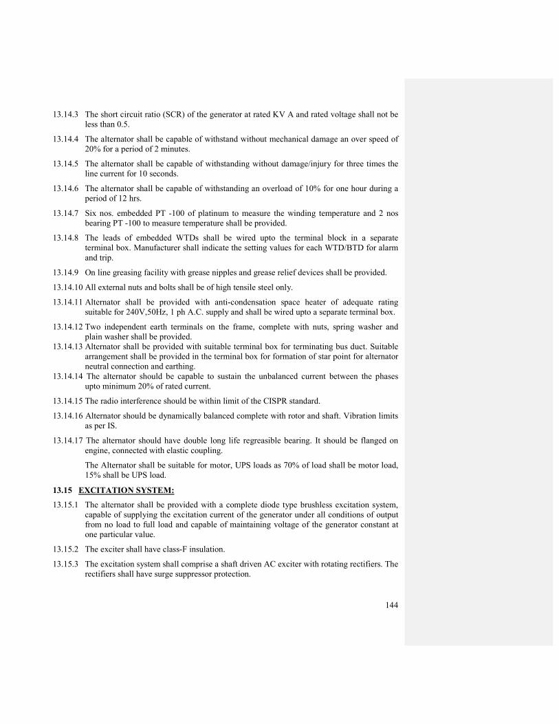
144
13.14.3 The short circuit ratio (SCR) of the generator at rated KV A and rated voltage shall not be
less than 0.5.
13.14.4 The alternator shall be capable of withstand without mechanical damage an over speed of
20% for a period of 2 minutes.
13.14.5 The alternator shall be capable of withstanding without damage/injury for three times the
line current for 10 seconds.
13.14.6 The alternator shall be capable of withstanding an overload of 10% for one hour during a
period of 12 hrs.
13.14.7 Six nos. embedded PT -100 of platinum to measure the winding temperature and 2 nos
bearing PT -100 to measure temperature shall be provided.
13.14.8 The leads of embedded WTDs shall be wired upto the terminal block in a separate
terminal box. Manufacturer shall indicate the setting values for each WTD/BTD for alarm
and trip.
13.14.9 On line greasing facility with grease nipples and grease relief devices shall be provided.
13.14.10 All external nuts and bolts shall be of high tensile steel only.
13.14.11 Alternator shall be provided with anti-condensation space heater of adequate rating
suitable for 240V,50Hz, 1 ph A.C. supply and shall be wired upto a separate terminal box.
13.14.12 Two independent earth terminals on the frame, complete with nuts, spring washer and
plain washer shall be provided.
13.14.13 Alternator shall be provided with suitable terminal box for terminating bus duct. Suitable
arrangement shall be provided in the terminal box for formation of star point for alternator
neutral connection and earthing.
13.14.14 The alternator should be capable to sustain the unbalanced current between the phases
upto minimum 20% of rated current.
13.14.15 The radio interference should be within limit of the CISPR standard.
13.14.16 Alternator should be dynamically balanced complete with rotor and shaft. Vibration limits
as per IS.
13.14.17 The alternator should have double long life regreasible bearing. It should be flanged on
engine, connected with elastic coupling.
The Alternator shall be suitable for motor, UPS loads as 70% of load shall be motor load,
15% shall be UPS load.
13.15 EXCITATION SYSTEM:
13.15.1 The alternator shall be provided with a complete diode type brushless excitation system,
capable of supplying the excitation current of the generator under all conditions of output
from no load to full load and capable of maintaining voltage of the generator constant at
one particular value.
13.15.2 The exciter shall have class-F insulation.
13.15.3 The excitation system shall comprise a shaft driven AC exciter with rotating rectifiers. The
rectifiers shall have surge suppressor protection.

145
13.15.4 The alternator should be complete with solid state AVR. The exciter shall be fast response
type and shall be designed to have a low time constant to minimize voltage transients
under severe load changes. The excitation voltage response ratio shall be at least 0.8.
13.15.5 The rated current of the main exciter shall be at least 10% more than the max. exciter
current reqd at full load and PF and it shall have a 40% overload capability for 10 seconds.
13.15.6 No external supply shall be required for controlling the excitation system during starting
and normal running of the alternator.
13.16 AUTOMATIC VOLTAGE REGULATOR:
13.16.1 An automatic high speed, dead band type voltage regulator shall be provided complete with
all accessories.
13.16.3 Voltage regulation and steady stage modulation shall be within ± 1% of the line voltage
with manual voltage adjustment capability within ± 5%.
13.16.4 Necessary equipment for field suppression and surge protection shall be provided.
13.16.5 The response time of the exciter and the generator shall be properly matched to avoid
hunting.
13.16.6AVR system shall be provided with equipment for automatic operation/control as required.
13.17 PAINTING
13.17.1 All steel surfaces, which are to be painted, shall be thoroughly cleaned, degreased and
supplied with primer prior to assembly and shall be applied with two coats of epoxy paint
shade 631 as per IS 5.
13.17.2 All castings shall be sand blasted, degreased and cleaned before painting.
13.18. TESTS:
13.19 DIESEL ENGINE
13.19.1 Following tests shall be carried out at the engine manufacturer's works in the presence of
OIL.
DG set and the auxiliaries shall be assembled at the manufacturer's works and the following
tests shall be performed.
a) One (1) hour at full load with fuel consumption
b) One (1) hour at 3/4 load with fuel consumption
c) One (1) hour at 50% load with fuel consumption
d) Four (4) hours at full load followed by a 1 hour continuous load at 110% and with fuel
consumption.
e) Engine starting time
f) I.H.P ./B.H.P. test
g) Noise/Vibration test

146
Before each test, the engine shall be brought to a steady state under the conditions of the
test.
13.19.2 The alternator shall be subjected to following routine tests:
a) Measurement of resistance of stator and rotor windings.
b) Insulation resistance of stator and rotor windings..
c) High voltage tests on stator and rotor windings.
d) Open circuit and short circuit tests.
e) Temperature rise test.
f) Regulation test.
g) Efficiency test.
h) Momentary overload test.
i) Vibration and noise level measurement.
In addition to the above routine tests temperature rise test on generator shall be conducted.
13.19.3 VOLTAGE REGULATOR
a) Sensitivity test
b) Response time test
13.19.4 TEST AT SITE:
a) The tests shall be performed after proper installation of the diesel generating unit at site
to prove the proper operation of interlock circuits and the capability of the engine to start
and pick-up load in the specified time, under supervision of the employer representative
responsible for supervision, testing and commissioning.
b) Guarantee tests to prove guaranteed performance of the DG set shall also be carried out
at site after proper installation. The load test with available load at site will be given for
about 36 hours.
13.19.5 TEST CERTIFICATE:
a) Test certificate shall be submitted in six (6) copies.
b) The test certificate shall be furnished to the AWHO Authorities for prior approval
before dispatch of any equipment from works and the approval in writing from
employer shall be essential to effect dispatch of the equipment.
c) The test reports shall. furnish complete identification of the data, including serial
number of each equipment.
13.20 SPECIAL TOOLS AND TACKLES:
The contactor/vendor shall supply tools as given below:
A standard tool box shall be made of 16 SWG, MS sheet duly painted and be of minimum
400mm x 200mm size.

147
Tool box shall contain minimum following tools for the operation and maintenance of
equipments (Make Mekastar/Taparia):
Spanner set having 10 pieces from 6mm to 38mm size, open end type. Spanner set having
10 pieces from 6mm to 38mm size, ring type.
Box spanner with rod for transformer terminal nuts - 1 set.
Insulated screw driver of 300m size - 1 No.
Digital Multimeter of Philips make - 1 No.
Adjustable spanner of 300mm size - 1 No.
Insulated Pillar set 200 mm size - 1 No.
Wire cutter and peeler set of wire up to 06 size - I Set.
13.21 SPARE PARTS:
No spareparts are needed along as a part of the contract.
List of spares required for two years is to be submitted with the genset.
13.22 DRAWINGS, DATA AND MANUALS:
Drawings and details as indicated elsewhere shall be furnished along with each of the bid.
13.23 DEVIATION:
Should the contractor desire to deviate from this specification in any way, he shall draw
specific attention to such deviation.
Unless such deviations are recorded in the deviation sheets, as submitted with offer, it will
be taken for granted that the offer is made in conformity with the specifications.
13.24 GUARANTEED PERFORMANCE:
The contractor shall furnish, along with the offer the technical particulars as called in the
Annexures. The performance figures quoted in the technical particulars sheet shall be
guaranteed with the tolerance permitted by relevant standards.
13.25 PACKING FOR SHIPMENT:
13.25.1 The equipment shall be suitable protected by respective packing for the14.25.2 For
transportation, if totally enclosed boxes are not used, the equipment shall be mounted on
skids and enclosed in the open frame wooden crates. However, items like instruments and
other components not assembled with equipment number and part number for case of
identification.
13.26 SYSTEM OPERATION:
Diesel- alternator sets function will as follows:
13.26.1Automatic Mode:
While the normal mains supply is healthy the diesel alternator set will be at rest and the load
will be supplied by the mains.

148
The AMF relay shall monitor the main supply voltage & when the main supply voltage
drops below a certain preset value, the system shall sense these conditions & shall give
automatic start command to the control systems.
After a time delay of 1. 5 seconds from the main supply failure the diesel engine shall start.
When the DG set attains its rated speed and voltage a closing signal shall be given to the
ACB of the DG set:
When the voltage in the mains gets restored, its quality is monitored for about one minute
and if proven satisfactory the main supply breaker shall close automatically for transfer of
the load from Diesel engine to the main supply at L. T. Panel.
The set shall stop after idle running time after restoration of main supply.
The diesel alternator set reverts to its standby conditions & its ready to start should the
mains supply fail again.

149
ANNEXURE – I
TECHNICAL PARTICULARS OF DIESEL GENERATOR SETS
1. Quantity and rating
400 KV A Diesel Generator
Unit for feeding office load like Lights, AC,
Computers etc on continuous basis.
2. Mode of operation Auto start
3. Alternator
3.1 Output rating at 0.8 p.f. (lag)
400 KV A continuous output at 100% load time and at
ambient temp. of 45°C except periodic maintenance.
3.2 Class of insulation for Stator & Rotor Class F
3.3 Rated voltage & frequency 415 V, 50 Hz
3.4 Maximum permissible time Building up
rated voltage From stand still Less than 20 seconds
3.5 Variation of voltage from No load to
full load ± 2 % of rated voltage
3.6 Frequency variation ± 1%
3.7 Capacity of largest rating Motor starting To be furnished
3.7.1
Dynamic voltage response &
permissible voltage drop during largest
rating motor Starting
Less than 10 % of rated voltage under
operating condition at 3.6 above.
3.9 Temperature detectors
8 nos. resistance temperature detectors of type PT -100
for winding temperature and bearing temperature
measurements
3.10 Type of excitation system Brushless with AVR
3.11 Type of control for voltage regulator. Automatic
4.00 Type of fuel for engine High speed diesel according to F-DMA or F-DMS as
per ISO 8217
4.01 Day oil tank capacity Sufficient to run for 12 hours continous generation
4.02 Lube Oil Viscosity SAE-40
4.03 Maximum permissible Starting
Starting time for attaining Full speed Less than 20 Seconds
4.04 Engine starting Electric starting system
4.05 Type of governor Electric controlled
4.06 Lubricating system Pressure fed type
4.07 Cooling System Radiator Cooling
4.08 Engine cranking system To be included

150
ANNEXURE-II
Minimum Bill of Material for the complete DG set
(a) Engine Specification:
- Engine governor and control box for coupled genset
- Speed control switch end of start and over speed
- Fuel and lube oil duplex cartridges filters
- Electric starting system
- Switches on lube oil pressure and temperature, water temperature and pressure, oil
sump level, after cooler air temperature, exhaust gas temperatures.
- Control panel
- Automatic lube oil filling
- Wiring box
- Electric pre-lubricating lube oil pump
(b) Generator
- According to the standard IEC, VDE, BS, ANSI
- Flanged on engine, connection with elastic coupling
- Long life re-greasable bearings
- Single fan and ventilated. Discharge at the drive end.
- Insulation class F,
- Temperature rise class F
- Enclosure: IP23, terminal Box-IP-54
- Excitation: Shunt and booster
- 6 stator and 2 bearing PT 100 sensors
- Preheating resistance
- Overload capacity : 110% for 1 hour every 12 hours at cosφ 0.8
- Unbalanced load : The Unbalance current between phases shall not exceed the
rated current by 30%.
Radio interference : Within limits of CISPR standard
Regulation performances : The voltage is kept constant within ± 1%
Manual voltage adjustment within ± 5%
Dynamic balancing of the complete rotor and shaft
Short circuit withstanding : 3 in during 10s
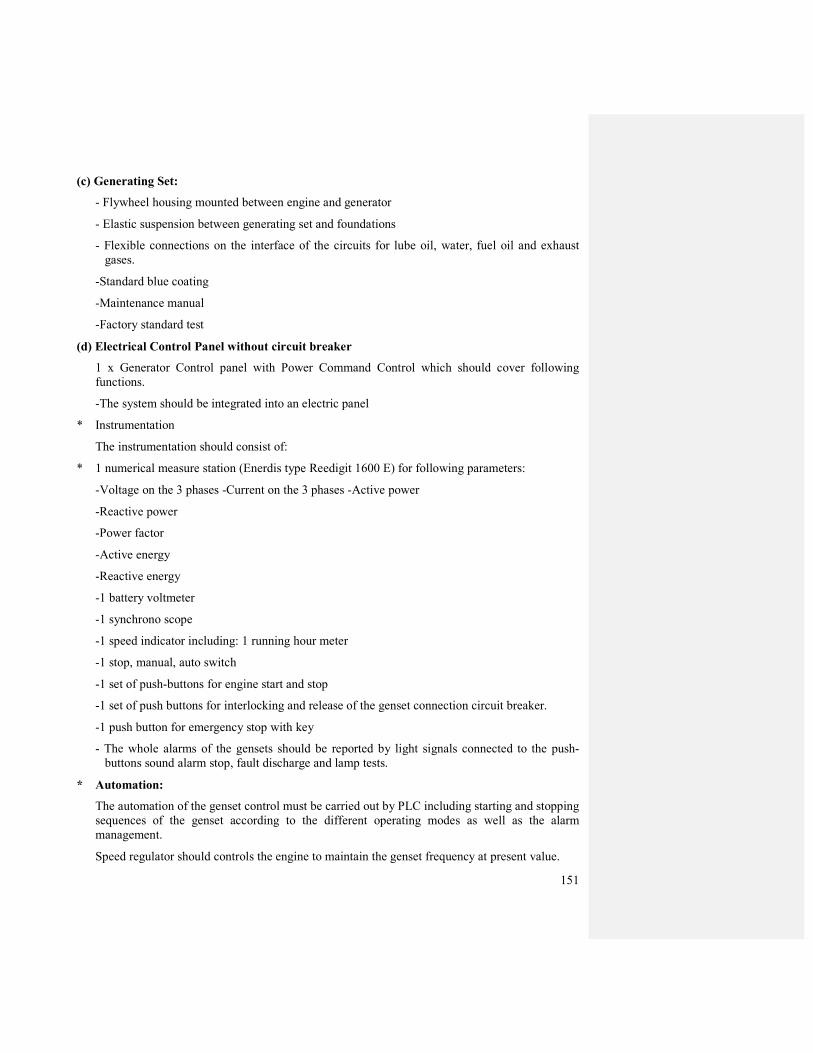
151
(c) Generating Set:
- Flywheel housing mounted between engine and generator
- Elastic suspension between generating set and foundations
- Flexible connections on the interface of the circuits for lube oil, water, fuel oil and exhaust
gases.
-Standard blue coating
-Maintenance manual
-Factory standard test
(d) Electrical Control Panel without circuit breaker
1 x Generator Control panel with Power Command Control which should cover following
functions.
-The system should be integrated into an electric panel
* Instrumentation
The instrumentation should consist of:
* 1 numerical measure station (Enerdis type Reedigit 1600 E) for following parameters:
-Voltage on the 3 phases -Current on the 3 phases -Active power
-Reactive power
-Power factor
-Active energy
-Reactive energy
-1 battery voltmeter
-1 synchrono scope
-1 speed indicator including: 1 running hour meter
-1 stop, manual, auto switch
-1 set of push-buttons for engine start and stop
-1 set of push buttons for interlocking and release of the genset connection circuit breaker.
-1 push button for emergency stop with key
- The whole alarms of the gensets should be reported by light signals connected to the push-
buttons sound alarm stop, fault discharge and lamp tests.
* Automation:
The automation of the genset control must be carried out by PLC including starting and stopping
sequences of the genset according to the different operating modes as well as the alarm
management.
Speed regulator should controls the engine to maintain the genset frequency at present value.
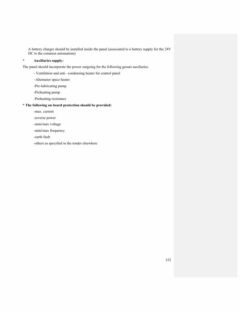
152
A battery charger should be installed inside the panel (associated to a battery supply for the 24V
DC to the common automatism)
* Auxiliaries supply:
The panel should incorporate the power outgoing for the following genset auxiliaries.
- Ventilation and anti –condensing heater for control panel
–Alternator space heater
-Pre-lubricating pump
-Preheating pump
-Preheating resistance
* The following on board protection should be provided:
-max. current
-reverse power
-mini/max voltage
-mini/max frequency
-earth fault
-others as specified in the tender elsewhere
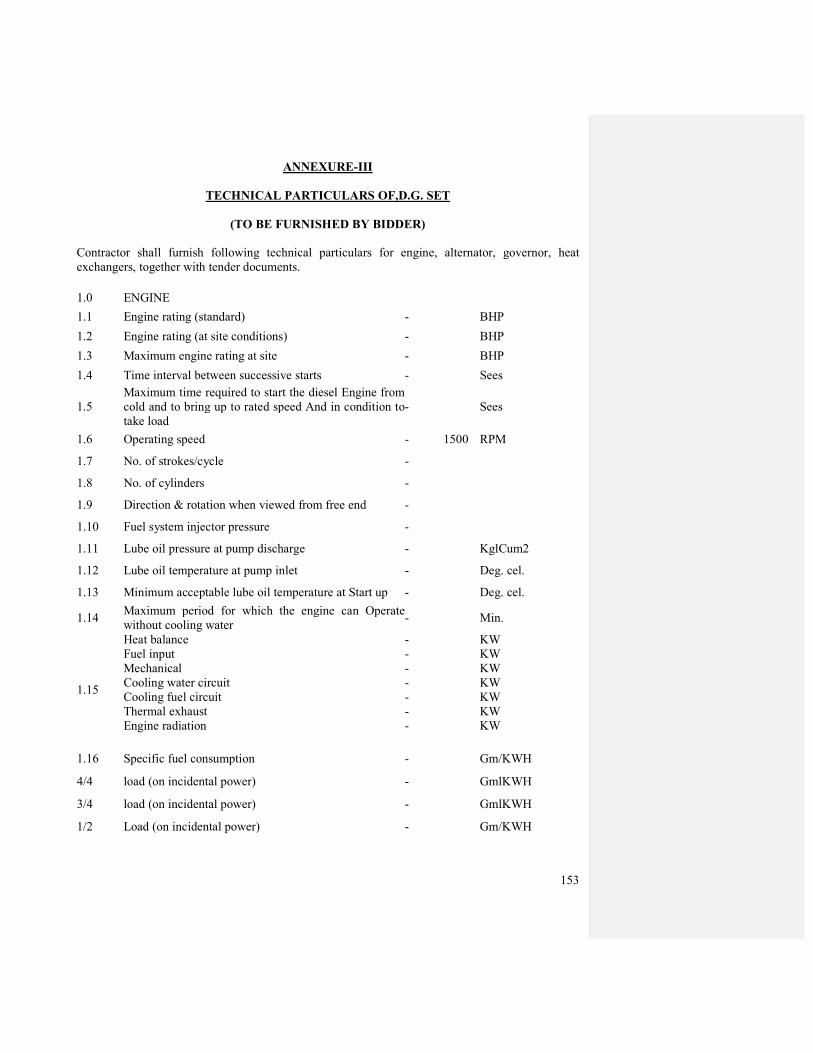
153
ANNEXURE-III
TECHNICAL PARTICULARS OF,D.G. SET
(TO BE FURNISHED BY BIDDER)
Contractor shall furnish following technical particulars for engine, alternator, governor, heat
exchangers, together with tender documents.
1.0 ENGINE
1.1 Engine rating (standard) - BHP
1.2 Engine rating (at site conditions) - BHP
1.3 Maximum engine rating at site - BHP
1.4 Time interval between successive starts - Sees
1.5
Maximum time required to start the diesel Engine from
cold and to bring up to rated speed And in condition to
take load
- Sees
1.6 Operating speed - 1500 RPM
1.7 No. of strokes/cycle -
1.8 No. of cylinders -
1.9 Direction & rotation when viewed from free end -
1.10 Fuel system injector pressure -
1.11 Lube oil pressure at pump discharge - KglCum2
1.12 Lube oil temperature at pump inlet - Deg. cel.
1.13 Minimum acceptable lube oil temperature at Start up - Deg. cel.
1.14 Maximum period for which the engine can Operate
without cooling water - Min.
1.15
Heat balance
Fuel input
Mechanical
Cooling water circuit
Cooling fuel circuit
Thermal exhaust
Engine radiation
-
-
-
-
-
-
-
KW
KW
KW
KW
KW
KW
KW
1.16 Specific fuel consumption - Gm/KWH
4/4 load (on incidental power) - GmlKWH
3/4 load (on incidental power) - GmlKWH
1/2 Load (on incidental power) - Gm/KWH
154
1.17 Emissions
Nox as N02 at 5% dry oxygen -
Nox as N02 (on incidental output) -
1.18 Cooling circuit
engine water inlet degree - degree C
engine water outlet degree - degree C
water flow rate - M3/h
1.19 Air Intake
Air intake flow - Kg/hr
Exhaust gas flow - Kg/hr
Exhaust gas temp. - Degree C
Max. exhaust back pressure - mm WG
1.20 Lube oil consumption - ltr/hr
1.21 Camshaft - Length mm
1.22 Crank Pin - Diameter mm
1.23 Bearing Material of Construction -
1.24 Supercharger Manufacturer/ (Turbo charger) -
Type Number -
Drive/Speed -
Bearing Cooling -
1.25 No. of inlet valves per cylinder head -
1.26 No. of exhaust valves per cylinder head -
1.27 Radiator -
1. Fluid circulated -
2. Quantity of fluid circulated in Kg/hr -
3. Temperature – inlet/outlet -
1.28 Crank case heater Type/Number Rating
1.29 Vibration limit.
1.30 Noise level
155
2.0 ALTERNATOR DESIGN DATA
2.1 GENERAL
2.1.1 Manufacturer/Type
2.1.2 Rating - Design/Site
2.1.3 Maximum rating - Design/Site
2.1.4 Rated Voltage, current & PF
2.1.5 Rated speed & frequency
2.1.6 Insulation class - stator/Rotor
2.1.7 Temperature rise above. 40°C - Stator/rotor/Core
2.1.8 Enclosure details.
2.1.9 Maximum rated KW of motor that can be started ‘Direct on line’ when generator is
a) Unloaded
b) 50%loaded
c) 85%loaded
2.1.10 Excitation
a) Voltage
b) Current
2.1.11 Rise in voltage when load is thrown off
a) With AVR
b) Without AVR
2.2 ALTERNATOR PARAMETERS:
Synchronous reactance - xd
Transient reactance – x’d
Sub-transient reactance – x”d
Zero sequence reactance – x0
Negative sequence reactance - x2
Short circuit ratio
Resistance of stator winding at operating temperature
Resistance of rotor winding at operation temperature

156
2.3 ALTERNATOR PERFORMANCE
GENERATOR LOSSES
a) Full load losses
b) Armature copper; loss
c) Rotor copper loss
d) Core loss
2.3.2 EFFICIENCY
a) Efficiency at full load
b) Efficiency at 3/4 load
c) Efficiency at 1/2 load
d) Efficiency at 1/4 load machine
2.3.3 Variation of terminal voltage and frequency %
2.3 .4 Load power factor
2.3.5 Form factor of the % deviation of the wave shape from standard
2.3.6 Maximum continuous & momentary unbalanced load capacity
2.3.7 Symmetrical short circuit current withstand and duration
2.3.8 Machine Time Constant
a) Open Circuit Transient time constant
b) Short Circuit Transient time constant
c) Short Circuit Sub-Transient time constant
d) Short Circuit armature time constant
2.3.9 Vibration limit
2.3.10 Noise level
2.4 ALTERNATOR AUXILIARIES & ACCESSORIES
2.4.1 Exciter
a) Type
b) Rated voltage/current
c) Voltage at rated speed but no load
157
d) Voltage at rated speed with full load
e) Response ratio
f) Class of insulation – Stator
2.5 Automatic voltage regulator
a) Type
b) Dead band
c) Response time
d) Voltage of operation
e) Line drop compensator for maintaining bus voltage constant provided
f) Range of voltage adjustment
g) Catalogues & characteristics curves attached
2.6 GOVERNOR
a) Make/Type
b) Steady state speed regulation
c) Steady state governing speed plus of minus % of rated speed
d) Momentary overspeed after full load rejection % of rated speed
e) Momentary underspeed of rated speed after sudden increase of 25% rated load
f) Prescribed speed band + rated speed
3.0 FUEL AND COOLING WATER REQUIREMENTS
3.1 Day oil tank for fuel:
a) Fuel consumption at full load Ltrs/Hr
at 75% load Ltrs/Hr
at 50% load Ltrs/Hr
at 25% load Lts/hr
b) Capacity of day oil tank Litres
c) Grade of fuel oil to be used
4.0 WEIGHT SCHEDULE
4.1 Weight of engine less flywheel including standard accessories Kgs.
Total shipping weight Kgs.
Weight of alternator Kgs.

158
Weight of exciter Kgs.
Heaviest piece to be handled in normal maintenance Kgs.
5.0 PIPING, FITTINGS & VALVES
5.1 Furnish valve schedule giving size, type of ends, manufacturer, materials of construction,
rating etc.
5.2 Furnish piping schedule giving size of pipes, wall 'thickness, codes, construction, rating etc.
5.3 Furnished all fittings, drains, vents, accessories, etc. as required.
6.0 CONTROLS AND INSTRUMENTS:
6.1 Pressure Indicator:
6.1.1 Make, type and range
6.1.2 Size of dial and accuracy
6.2 Flow indicator, Integrator, Recorder:
6.2.1 Make, type and range
6.2.2 Accuracy
6.3 Temperature Indicator
6.3 .1 Make, type and range
6.3 .2 Accuracy
6.4 Controller
6.4.1 Make and type
6.4.2 Details with loop
*******
159
CHAPTER-14
DRAWINGS:
The contractor shall submit six complete sets of as built drawings and test report of complete
system, equipment, conduit layout detail, cable schedule, panel drawings and specs, HV breaker,
transformer, earhing system to the Engineer-in-Charge (Electrical) after completion of the work
plus One set in CD.
These drawings must give the following informations:
a) Location of all equipments viz. transformers, H.T.Panel, L.T.panel; Bank, Capacitors and
earthing stations etc.
b) Cable routes clearly indicating the sizes & number of cables.
c) Earthing layout – indicating the type of earth station & size of earth.
d) Wiring diagram of L.T. Panels.
e) Complete single line diagram for Normal and Emergency supplies.
f) Any other information the OIL Engineer-in-Charge (Electrical)may deem fit.
No completion certificate will be issued until the drawings are submitted. Drawings will be
prepared and submitted by the contractor without any extra charge.
*******
160
CHAPTER 15
INSTALLATION OF GENERAL ELECTRICAL WIRING WORKS:
1. CONDUIT LAYING:
The laying of conduits shall be done in accordance with drawings. The contractor shall prepare
detailed layout drawing showing Junction boxes etc., and obtain Engineer-in-Charge (Electrical)
approval before carrying out work on site. Provisions as mentioned in NEC code shall be followed.
2. WIRING (SUB-MAIN, CIRCUIT & POINT WIRING):
PVC insulated flexible copper conductor cables shall be used for all wiring from the distribution
boards to the points and shall be pulled into conduits unless otherwise specified. No point wiring
shall have looped neutral. No reduction of strands is permitted at terminations.
SUITABLE SIZED ELECTRO TINNED COPPER CABLE LUGS ARE TO BE USED FOR TERMINATION AT SWITCHBOARDS, SOCKET OUTLETS & JUNCTION BOXES.
3. SWITCHES & SOCKETS OUTLETS:
Switches shall be connected on the live wire and controls of each circuit shall be continuous
everywhere having no fuse or switch installed in the line excepting at the main panels and boards.
4. LIGHTING FIXTURES (INTERNAL):
Light fixture shall be fixed in a sturdy and safe manner as per best trade practice and according to
the instructions of the manufacturers. Lighting fixtures which are recessed in the dropped ceiling
shall be thoroughly matched and co-ordinate with the pattern and design of the dropped ceiling as
shown in architectural drawings.
C. SPECIAL CONDITIONS:
1. GENERAL
a) These special conditions of contract shall be read in conjunction with the general conditions of contract, schedule of items. Technical specification, Drawings and other documents relating
to the works and shall have preference over laid down general conditions and specifications.
b) All electrical work shall be carried out in compliance with specifications given hereunder in
this section and in compliance with Indian Standard Specifications, NEC and Indian
Electricity Acts and Rules in force. The works shall also conform to any special requirement
of local state electricity board and State Licensing Board. In any case, the above-mentioned
rules, regulations etc. are not in accord. The decision of the Engineer-in-Charge (Electrical)
regarding rules to be followed or manner of execution of work shall be final and binding. The
work shall be executed, under the direct supervision of person holding and certificate of
competency issued by the State Government, Chief Electricity Inspectorate for the type of
works involved, in conformity with the best methods of modern engineering practice and to
the entire satisfaction of the Engineer-in-Charge (Electrical). The electricians and supervisors
engaged for the electrical works shall have valid electrical licence & experience in carrying
out internal electrification work. Contractor shall submit the copy of licence of his
electrician and supervisor to Head (Electrical) and produce the original for verification before starting the job. The contractor has to submit the test report at various stages of
completion and after completion as per requirement of the Engineer in charge.
161
c) The contractor shall provide all equipment, instruments, labour and such other assistance
required by the Engineer-in-Charge (Electrical) for measurement of the work, materials etc.
2. MATERIALS
a) All materials, equipment, fittings and fixtures used in electrical works shall conform to the
detail mentioned in annexure & BOQ. All material shall be new, soundly and robust in
construction and well finished. Surplus material after completion of work shall be taken back
by the contractor and the cost shall be recovered if the advance payment has been made
earlier by the client.
b) Two numbers of samples of all materials, fittings and fixtures to be supplied by the contractor shall be submitted to the Head (Electrical) for his approval. One sample shall
be retained by the Chief engineer (Electrical) and the other shall be returned back to the
contractor after due approval. The contractor shall not commence the work until the samples
are approved in writing from the Chief Engineer (Electrical). The contractor shall ensure that
all the materials incorporated in the work are identical in all respects with the approved
sample. All samples shall be returned to the contractor after completion of contract.
c) All materials shall be procured from manufacturers or from authorised dealer and all relevant
documents and test certificate and guarantee certificates to be provided by the contractor. All
material shall be guaranteed for one year after completion of all works and
commissioning. In case of failure of any item during guarantee period the same shall be
replaced by the contractor within 15 days without any cost to OIL.
d) Any material proved to be of inferior quality or of counterfeit shall be replaced free of cost
with the good quality/original material.
3. DRAWING:
a) The drawings, specifications and schedule of items shall be considered as a part of this
contract. Any work or materials shown on the drawings but not included in the schedule of
items or vice-versa, shall be executed as if specifically called for, in both without any
additional cost. The contract drawings indicate the extent and general arrangement of
various equipment and their wiring etc. and are essentially diagrammatic, however, any
minor change if found essential to co-ordinate the installation of this work with other trades
shall be made without any additional cost to the owner.
b) Layout drawings, schematic drawing, and any other drawing required for execution of
the job shall be submitted by the contractor 15 days before commencement of work for
approval by Head (Electrical). Job shall start only after approval of drawings by Head
(Electrical) in writing.
4. CLARIFICATION OF DISCREPANCIES:
In case of any discrepancy between specifications etc. furnished by the Engineer-in-Charge
(Electrical)(Electrical) or disputes in respect therefore the interpretation of the Engineer-in-Charge
(Electrical)(Electrical) shall be final and binding.
5.TEST AND DOCUMENTS:
a. A site order book will be maintained at site which will be in the custody of the Engineer-in-
Charge (Electrical)(Electrical) or his representative and all instructions given to the Contractor
will be recorded in the site order book and the same has to be signed by the contractor to comply
with the instruction given therein.
162
b. After completion of the work the installation shall be tested by the contractor in the
presence of the Engineer-in-Charge (Electrical)(Electrical). The tests shall comply the I.E.
Rules regulation. Test certificate shall be submitted in proper format while handing over
the installation after completion of electrification along with six copies of as built drawings and inventory list and guarantee certificates of electrical items. THE JOB SHALL BE
TREATED AS COMPLETE ONLY AFTER COMPLETION OF ALL WORKS AS PER
BOQ, SUBMISSION OF TEST REPORT AS PER IE RULES AND ANNEXURE AND
SIX TEST OF AS BUILT DRAWINGS WITH INVENTORY LIST, GUARANTEE
CERTIFICATE FOR ALL ITEMS AND ISSUE OF COMPLETION CERTIFICATE BY
HEAD (ELECTRICAL).
i) The result of the insulation test shall comply with the I.E.E. Regulations 1101 to 1108A and
1108B as may be applicable.
ii) Polarity test shall be carried out to ascertain that all the switches have been connected to the phase conductor(s).
In a 2 wire installation a test shall be made to verify that all switches in every circuit have been
fitted in the same conductor throughout and such conductor shall be labeled or marked for
connection to the phase conductor or to the non-earthed conductor of the supply.
In a 3 wire or 4 wire installation a test shall be made to verify that every non-linked single pole switch
is fitted in a conductor which is labeled or marked for connection to one or the phase conductor of
supply.
iii) The continuity test of the earthing system shall comply with the I.E.E. Regulations 1108 to 1109
to the latest addition.
If the results of the above tests does not comply with the I.E.E. Regulation the contractor shall
be bound to rectify the faults so that the required results are obtained.
The contractor shall be responsible to provide all the necessary testing equipment etc.for
carrying out the above tests.
c. The work will not be considered as complete and taken over by OIL INDIA LTD till all
the components of the work after being completed at site in all respects have been
inspected/tested by the Engineer-in-Charge (Electrical)(Electrical) to his entire satisfaction
and a completion certificate issued by the Engineer-in-Charge (Electrical)(Electrical) to
this effect.
6. WORK AND WORKMANSHIP:
a. The work shall be of the highest standard, both as regard its design and workmanship. Modern
tools and first clause, latest techniques shall be employed for its execution. The workmanship
shall be guaranteed for one year after commissioning and any defective workmanship

163
during guarantee period must be corrected by the contractor within 15 days after
reporting without any cost to OIL.
b. Any damage done to the building during the execution of work shall be the responsibility of the
contractor and it shall be made good by him, at his cost, to the entire satisfaction of the
Engineer-in-Charge (Electrical)(Electrical).
c. All electrical work shall be executed by skilled and duly licensed electrician under the
direct supervision of whole time electrical supervisor as defined in IE rules. Contractor
shall submit the copy of licence of his electrician and supervisor to Head (Electrical) and produce the original for verification before starting the job. The contractor shall submit list
and produce requisite evidence regarding the qualifications of his supervisor and other workers
before the start of the work.
d. The electrical contractor shall possess all the relevant and valid licenses as per the regulations of the Indian Electricity Rules and the Local Electrical Inspector’s requirements.
e. The work shall have to be coordinated with the building work and other allied jobs/trades to the
entire satisfaction of Engineer-in-Charge (Electrical).
f. Chief Engineer (Electrical) shall have full powers to get the materials or workmanship etc.
inspected and tested by an independent agency, the Contractor’s expenses in order to ascertain
their soundness and adequacy.
164
SAFETY GUIDELINES TO BE FOLLOWED WHILE EXECUTION OF ELECTRICAL
JOB BY CONTRACTOR:
1. Contractor shall follow all the safety regulations and environmental preservation points
mentioned hereunder:
(i) The contractor shall engage for the wiring and supervision job only highly skilled, competent
personnel having experience of at least two years in carrying out electrical wiring job and
valid supervisor, wireman license issued by Licensing Board, Assam. All jobs done by the
contractor’s employees must confirm to all the provisions of Indian Electricity Rules, BIS,
NEC and OMR.
(ii) The contractor shall ensure complete safety of the personnel engaged by him, and of all the
equipment they handle and must take full responsibility for their safety. Company shall not be
responsible for any work accident of contractor employees.
(iii) The contractor shall provide the necessary safety gears and personal protective equipment to
his personnel engaged for the wiring job. The personal protective equipment (PPE)/ safety
gear should include at least the following:
a) Safety shoes
b) Helmet
c) Safety belts.
d) Ladder with antiskid rubber shoes.
e) Switch Board with earth leakage circuit breaker for operation of drill machine.
f) Any other safety gear that may be required depending on the job nature.
(iv) It will be the responsibility of contractor and his employees to use PPE and safety gears. In
case the contractor employees are found to work without PPE and proper safety gears then
caution letter will be issued to contractor. In case such violation is noticed on three occasions
then the contractor will have to remove the concerned employee from the service. In case
contractor fails to comply with this requirement than company may terminate the contract. In
case the PPE and safety gears as mentioned above are not provided by the contractor to his
employees then Company may terminate the contract.
(v) Before starting electrical job, the contractor employees shall isolate the power, ensure with test
lamp for no power and then discharge the circuit to earth. A danger board has to be fixed on
the main switch/ DB if required.
(vi) All the packing material, cut ends of cables, casing capping, battens, damaged nails and screw,
glass pieces of lamps and other waste materials shall be collected by the contractor employees
from the work site and disposed in the dustbins.
2. Engineer in-charge or safety office of OIL shall visit the site every fortnight during execution of
the job and compliance of safety points by the contractor shall be recorded in the following tabular
form. Copy of this report shall be given to contractor and contractor shall ensure that all the
requirements as per the report are complied with within 7 days of the inspection and a compliance
certificate is issued by the contractor to this effect.
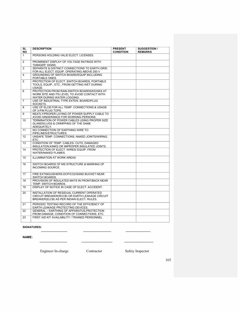
165
SL NO
DESCRIPTION PRESENT CONDITION
SUGGESTION / REMARKS
1 PERSONS HOLDING VALID ELECT. LICENSES.
2 PROMINENT DISPLAY OF VOLTAGE RATINGS WITH “DANGER” SIGNS.
3 SEPARATE & DISTINCT CONNECTIONS TO EARTH GRID FOR ALL ELECT. EQUIP. OPERATING ABOVE 250 V
4 GROUNDING OF SWITCH BOARD/EQUIP.INCLUDING PORTABLE ONES.
5 PROTECTION OF ELECT. SWITCH BOARDS, PORTABLE TOOLS, EQUIP., ETC., FROM GETTING WET DURING USAGE.
6 PROTECTION FROM RAIN-SWITCH BOARDS/KIOSKS AT WORK SITE AND ITS LEVEL TO AVOID CONTACT WITH WATER DURING WATER LOGGING.
7 USE OF INDUSTRIAL TYPE EXTEN. BOARD/PLUG SOCKETS.
,
8 USE OF ELCB FOR ALL TEMP. CONNECTIONS & USAGE OF 3-PIN PLUG TOPS.
9 NEATLY/PROPER LAYING OF POWER SUPPLY CABLE TO AVOID HINDERANCE FOR WORKING PERSONS.
10 TERMINATION OF POWER CABLES USING PROPER SIZE GLANDS/LUGS & CRIMPPING OF THE SAME ADEQUATELY.
11 NO CONNECTION OF EARTHING WIRE TO PIPELINES/STRUCTURES.
12 UNSAFE TEMP. CONNECTIONS, NAKED JOINTS/WIRING, ETC.
13 CONDITION OF TEMP. CABLES- CUTS, DAMAGED
INSULATION,KINKS OR IMPROPER INSULATED JOINTS.
14 PROTECTION OF ELECT. WIRES/ EQUIP. FROM WATER/NAKED FLAMES.
15 ILLUMINATION AT WORK AREAS
16 SWITCH BOARDS OF MS STRUCTURE & MARKING OF INCOMING SOURCE.
17 FIRE EXTINGUISHERS-DCP/CO2/SAND BUCKET NEAR SWITCH BOARDS.
18 PROVISION OF INSULATED MATS IN FRONT/BACK NEAR TEMP. SWITCH BOARDS.
19 DISPLAY OF NOTICE IN CASE OF ELECT. ACCIDENT.
20 INSTALLATION OF RESIDUAL CURRENT OPERATED CIRCUIT BREAKER(RCCB) OR EARTH LEAKAGE CIRCUIT BREAKER(ELCB) AS PER INDIAN ELECT. RULES.
21 PERIODIC TESTING RECORD OF THE EFFICIENCY OF
EARTH LEAKAGE PROTECTING DEVICES.
22 GENERAL – EARTHING OF APPARATUS,PROTECTION FROM DAMAGE, CONDITION OF CONNECTIONS, ETC.
23 FIRST AID KIT AVAILABILITY / TRAINED PERSONNEL
SIGNATURES: _________________ __________________ ________________
NAME: ________________ __________________ _________________
Engineer In-charge Contractor Safety Inspector
166
CHAPTER 16
INSTALLATION, EARTHING, TESTING AND COMMISSIONING OF HT PANEL,
TRANSFORMER AND MAIN PCC PANEL AND OTHER PANELS:
A. INSTALLATION
1. Entire installation, testing and commissioning work including supply of all items, materials,
tools, instruments, manpower etc required for the job shall be carried out by the party.
2. All equipment will be delivered to substation site and placed inside the substation by the
party. The party will arrange for proper storage of all equipment at its premises after receipt
from the factory and before transfer to site. The storage will be done as per recommendation
of manufacturer. Any damage to the equipment during transportation from factory to party#s
godown, storage at party#s godown and during transfer to Jodhpur and placement inside the
substation will be to party#s account and the party will have to carryout necessary repair or
replacement to OIL#s satifaction at their own cost. All tools, crane, vehicles, manpower and
any other facility required for storage, transfer & placement of equipment inside the
substation will be arranged by the party at their own cost. The delivery to site from the
party#s storage location & placement inside the room has to be completed during daytime
only.
3. After placement inside the substation the equipment will be checked for any defect /
discrepancies in presence of OIL#s engineer and rectification of the same will be done to
OIL#s satifaction by the party at their own cost.
4. Electrical grade ISI approved rubber/PVC mats of 10mm thickness shall be provided in front
of LT and HT panel. The length of the mat should be same as the panel length. The width of
the mat should be 1.0 mtr.
5. After placement inside the substation the equipment will be grouted to the floor by the party.
Wheels of the transformer shall be locked in its final installed position.
6. Substation shall be located in the basement of the building.
B. EARTHING:
1. All material required for earthing job as mentioned below shall be supplied and installed by
the party.
2. The earthing of neutral of the transformer and the enclosure of all equipment will be done by
the party as per IS-3043 and details mentioned below.
3. HT panel enclosure will be connected to two nos. of earth electrodes
4. Earth resistance shall be measured by the party and mentioned in the final test report.

167
C. COMMISSIONING OF HT PANEL
The following commissioning checks will be done on the HT Panel by the party.
1. External earth points of the panel should be properly connected to two nos. of earth
electrodes as per detail mentioned under EARTHING.
2. Remove covers of enclosure and cable box, check for any foreign object, clean the interior
with dry cloth or blower as required, check all the connections for specified tightness, check
all the insulating supports for any damage.
3. Check panel wiring for conformity to drawing.
4. Check VCB for proper racking in, rack out and manual ON/ OFF operation.
5. Check insulation resistance of VCB, CT, PT, busbar with 5.0kv megger. The values should
be as per manufacturer#s recommendation. In case the insulation value is lower than the
recommended value then necessary repair needs to be done by the party to OIL#s
satisfaction at their own cost.
6. In case the result of checks mentioned above are as per manufacture#s pre-commissioning
check list and acceptable to OIL then primary and secondary injection test will be done
on the main protection relay. After satisfactory test the relay should be set to the desired
field settings as required by OIL.
7. The incoming HT cable and LT power supply cable for heater and spring charging motor,
control cable from transformer marshalling box shall be connected in their respective cable
boxes. All the cables will be meggered after laying but before final connection. These LT
cables shall be supplied by OIL.
8. The HT power supply to the panel will be put ON. The output of PT and powerpack will be
checked for proper voltage.
9. The electrical spring charge and electrical ON/OFF will be checked. The alarm circuit and
tripping of breaker will be checked by simulating external faults from transformer
marshalling box.
10. The breaker will be switched off and removed from panel. The outgoing HT cable from
panel to the transformer will be connected in the outgoing cable box and the breaker
switched ON after clearance from OIL.
11. After successful operation with power ON for 72hrs the panel will be technically accepted to
OIL.
168
D. COMMISSIONING OF TRANSFORMER
The following commissioning checks will be done on the transformer by the party.
1. External earth and neutral point of the transformer should be properly connected to two nos.
of earth electrodes as per detail mentioned under EARTHING.
2. Remove inspection covers, check for any foreign object, clean the interior with dry cloth or
blower as required, check all the connections for specified tightness, check all the insulating
supports for any damage, set tap links as per site requirement and fix-back the inspection
cover.
3. Check insulation resistance and PI of HV (5.0kv megger) and LV (1.0kv megger) windings.
Their values should be as per manufacturer#s recommendation. In case the transformer
insulation needs drying up the same is to be done by the party as per manufacturer#s
recommendation and to OIL#s satisfaction at their own cost.
4. Check resistance of RTDs for three windings, their connections in the marshalling box.
5. All damaged or defective components must be replaced by the party at their own cost with
suitable replacement from the manufacturer.
6. In case the result of checks mentioned above are as per manufacture#s pre-commissioning
check list and acceptable to OIL then the HV power cables and power supply cable for RTD
monitor, control cable from marshalling box to HT panel shall be connected in their
respective cable boxes. All the cables will be meggered after laying but before final
connection.
7. The transformer will be energised in the presence of OIL#s engineer after clearance from
OIL.
8. The transformer output voltage will be checked for proper value and balancing. Tap switch
to be adjusted if required.
9. The transformer will be kept energised and observed for any abnormal heating, noise,
vibration for next 72 hrs.
10. After successful operation with power ON for 72hrs the transformer will be technically
accepted to OIL.
169
E. COMMISSIONING OF LT PANEL
The following commissioning checks will be done on the LT Panel by the party.
1. External earth points of the panel should be properly connected to two nos. of earth
electrodes as per detail mentioned under EARTHING.
2. Remove covers of enclosure and cable boxes of all incomer and outgoing, busbar and check
for any foreign object, clean the interior with dry cloth or blower as required, check all the
connections for specified tightness, check all the insulating supports for any damage.
3. Check panel wiring for conformity to drawing.
4. Check all ACBs for proper racking in, rack out and manual ON/ OFF operation.
5. Check all outgoing switches for rated fuses and proper operation.
6. Check insulation resistance of busbar with 1.0kv megger. The values should be as per
manufacturer#s recommendation. In case the insulation value is lower than the
recommended value then necessary repair needs to be done by the party to OIL#s
satisfaction at their own cost.
7. Lay and Connect LT cables from transformer LT cable box and generator panel to the
incoming cable terminals of incomers of LT panel.
8. Charge the panel and check incomer breakers for proper electrical operation. Second
incomer of the panel shall also be tested with power.
9. Switch ON the breaker to charge the busbar.
10. Check the outgoing breaker for proper electrical operation.
11. The panel will be technically acceptable to OIL after trouble free operation with power on
for 72 hrs.
170
F. GENERAL NOTES FOR INSTALLATION, TESTING AND COMMISSIONING.
1. Party should submit an undertaking with their offer confirming compliance to all point
mentioned in the headings A,B,C,D,E,F of this annexure.
2. All works of installation shall be carried out in complete with latest IS, IE rules and National
Electric Code.
3. All works of installation, testing and commissioning shall be performed by persons having
valid electrical license under the direst supervision of a competent service personnel of the
party having a minimum experience of at least 5 years in installation and commissioning of
HT switchgear and transformers and possessing appropriate licence. However the HT panel
and its protection relay will have to be commissioned by the service engineer of the HT
panel manufacturer.
4. Copy of license of all the persons engaged for installation and commissioning work has to
be submitted to OIL for approval before start of work.
5. All tests/ checks shall be done in presence of OIL#s Engineer-in- Charge or his
representative.
6. The supplier should obtain the permit to work from Engineer #in- Charge of respective
Installation Managers before taking up work, if any.
7. The party shall be responsible for safe custody and proper storage of materials till handing
over.
8. The substation building shall be constructed by OIL but minor masonry jobs such as
grouting, levelling of equipment shall be done by party.
9. All tools and instruments and equipment required for installation, testing and commissioning
shall be arranged/ provided by the party.
10. All safety and local/government regulations shall be followed during installation, testing and
commissioning. Party shall be responsible for compliance to such regulations on their own.
11. All tests results shall be recorded in a proper manner. Four sets of all the test results and
checks for all the equipment as required shall be submitted to OIL. The results shall be typed
and properly documented.
12. All equipment shall be treated as successfully commissioned after installation, testing and
commissioning as mentioned under para nos. A,B,C,D,E and technically accepted to OIL
and submission of four sets of test results signed by licensed supervisor, corrected wiring
diagram in bound form and all the documents mentioned against each equipment in the
respective equipment description.
*******
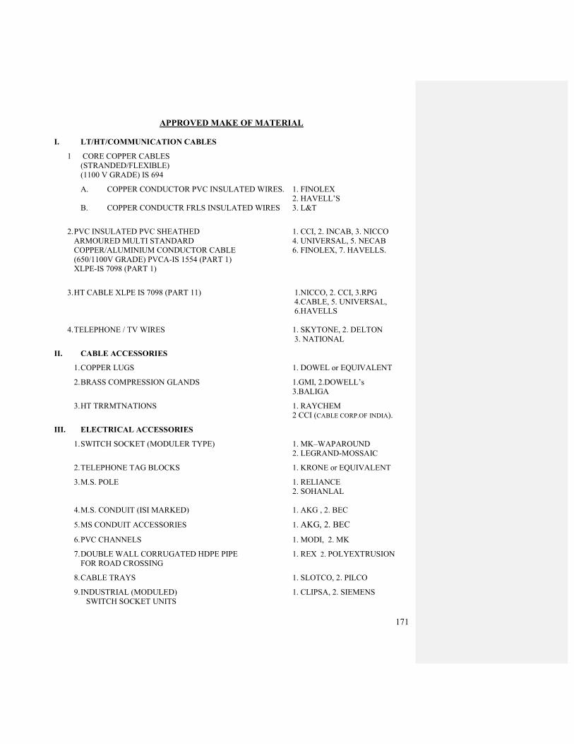
171
APPROVED MAKE OF MATERIAL
I. LT/HT/COMMUNICATION CABLES
1 CORE COPPER CABLES
(STRANDED/FLEXIBLE)
(1100 V GRADE) IS 694
A. COPPER CONDUCTOR PVC INSULATED WIRES. 1. FINOLEX
2. HAVELL’S
B. COPPER CONDUCTR FRLS INSULATED WIRES 3. L&T
2. PVC INSULATED PVC SHEATHED 1. CCI, 2. INCAB, 3. NICCO
ARMOURED MULTI STANDARD 4. UNIVERSAL, 5. NECAB
COPPER/ALUMINIUM CONDUCTOR CABLE 6. FINOLEX, 7. HAVELLS.
(650/1100V GRADE) PVCA-IS 1554 (PART 1)
XLPE-IS 7098 (PART 1)
3. HT CABLE XLPE IS 7098 (PART 11) 1.NICCO, 2. CCI, 3.RPG
4.CABLE, 5. UNIVERSAL,
6.HAVELLS
4. TELEPHONE / TV WIRES 1. SKYTONE, 2. DELTON
3. NATIONAL
II. CABLE ACCESSORIES
1. COPPER LUGS 1. DOWEL or EQUIVALENT
2. BRASS COMPRESSION GLANDS 1.GMI, 2.DOWELL’s
3.BALIGA
3. HT TRRMTNATIONS 1. RAYCHEM
2 CCI (CABLE CORP.OF INDIA).
III. ELECTRICAL ACCESSORIES
1. SWITCH SOCKET (MODULER TYPE) 1. MK–WAPAROUND
2. LEGRAND-MOSSAIC
2. TELEPHONE TAG BLOCKS 1. KRONE or EQUIVALENT
3. M.S. POLE 1. RELIANCE
2. SOHANLAL
4. M.S. CONDUIT (ISI MARKED) 1. AKG , 2. BEC
5. MS CONDUIT ACCESSORIES 1. AKG, 2. BEC
6. PVC CHANNELS 1. MODI, 2. MK
7. DOUBLE WALL CORRUGATED HDPE PIPE 1. REX 2. POLYEXTRUSION
FOR ROAD CROSSING
8. CABLE TRAYS 1. SLOTCO, 2. PILCO
9. INDUSTRIAL (MODULED) 1. CLIPSA, 2. SIEMENS
SWITCH SOCKET UNITS
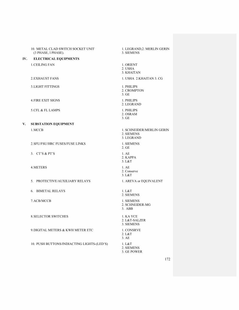
172
10. METAL CLAD SWITCH SOCKET UNIT 1. LEGRAND,2. MERLIN GERIN
(3 PHASE, I PHASE). 3. SIEMENS
IV. ELECTRICAL EQUIPMENTS
1. CEILING FAN 1. ORIENT
2. USHA
3. KHAITAN
2. EXHAUST FANS 1. USHA 2.KHAITAN 3. CG
3. LIGHT FITTINGS 1. PHILIPS
2. CROMPTON
3. GE
4. FIRE EXIT SIGNS 1. PHILIPS
2. LEGRAND
5. CFL & FL LAMPS 1. PHILIPS
2. OSRAM
3. GE
V. SUBSTATION EQUIPMENT
1. MCCB 1. SCHNEIDER/MERLIN GERIN
2. SIEMENS
3. LEGRAND
2. SFU/FSU/HRC FUSES/FUSE LINKS 1. SIEMENS
2. GE
3. CT’S & PT’S 1. AE
2. KAPPA
3. L&T
4. METERS 1. AE
2. Conserve
3. L&T
5. PROTECTIVE/AUXILIARY RELAYS 1. AREVA or EQUIVALENT
6. BIMETAL RELAYS 1. L&T
2. SIEMENS
7. ACB/MCCB 1. SIEMENS
2. SCHNEIDER-MG
3. ABB
8. SELECTOR SWITCHES 1. KA YCE
2. L&T-SALZER
3. SIEMENS
9. DIGITAL METERS & KWH METER ETC 1. CONSRVE
2. L&T
3. AE
10. PUSH BUTTONS/INDIACTING LIGHTS-(LED’S) 1. L&T
2. SIEMENS
3. GE POWER
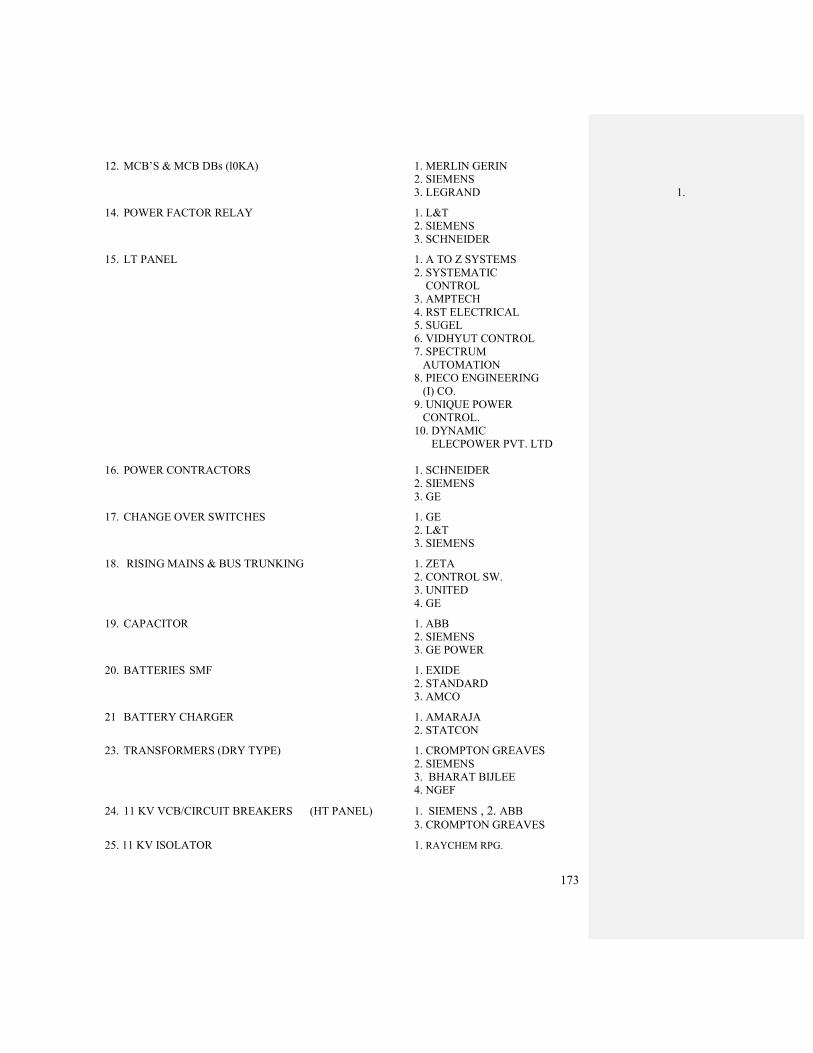
173
12. MCB’S & MCB DBs (l0KA) 1. MERLIN GERIN
2. SIEMENS
3. LEGRAND 1.
14. POWER FACTOR RELAY 1. L&T
2. SIEMENS
3. SCHNEIDER
15. LT PANEL 1. A TO Z SYSTEMS
2. SYSTEMATIC
CONTROL
3. AMPTECH
4. RST ELECTRICAL
5. SUGEL
6. VIDHYUT CONTROL
7. SPECTRUM
AUTOMATION
8. PIECO ENGINEERING
(I) CO.
9. UNIQUE POWER
CONTROL.
10. DYNAMIC
ELECPOWER PVT. LTD
16. POWER CONTRACTORS 1. SCHNEIDER
2. SIEMENS
3. GE
17. CHANGE OVER SWITCHES 1. GE
2. L&T
3. SIEMENS
18. RISING MAINS & BUS TRUNKING 1. ZETA
2. CONTROL SW.
3. UNITED
4. GE
19. CAPACITOR 1. ABB
2. SIEMENS
3. GE POWER
20. BATTERIES SMF 1. EXIDE
2. STANDARD
3. AMCO
21 BATTERY CHARGER 1. AMARAJA
2. STATCON
23. TRANSFORMERS (DRY TYPE) 1. CROMPTON GREAVES
2. SIEMENS
3. BHARAT BIJLEE
4. NGEF
24. 11 KV VCB/CIRCUIT BREAKERS (HT PANEL) 1. SIEMENS , 2. ABB 3. CROMPTON GREAVES
25. 11 KV ISOLATOR 1. RAYCHEM RPG.

174
25. TERMINAL BLOCKS 1. ELMEX
2. CONECTWELL
VI. DG SETS & EQUIPMENTS
1. DG SETS 1. CUMMINS, 2.VOLVO
3.CATTERPILLAR 2. ALTERNATORS 1. STAMFORD
2. CATERPILLAR
3. CG
3. INVERTOR 1. LUMINUS, 2. SU-KAM
VII. OTHER ITEMS :
AS APPROVED BY THE ENGINEER IN-CHARGE OR AS PER BOQ AND SPECS
*******
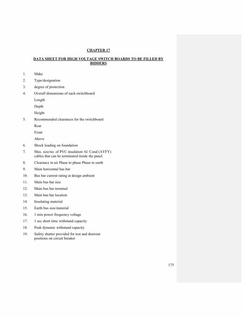
175
CHAPTER 17
DATA SHEET FOR HIGH VOLTAGE SWITCH BOARDS TO BE FILLED BY
BIDDERS
1. Make
2. Type/designation
3. degree of protection
4. Overall dimensions of each switchboard
Length
Depth
Height
5. Recommended clearances for the switchboard
Rear
Front
Above
6. Shock loading on foundation
7. Max. size/no. of PVC insulation AI. Cond (AYFY)
cables that can be terminated inside the panel.
8. Clearance in air Phase to phase Phase to earth
9. Main horizontal bus bar
10. Bus bar current rating at design ambient
11. Main bus bar size
12. Main bus bar terminal
13. Main bus bar location
14. Insulating material
15. Earth bus size/material
16. 1 min power frequency voltage
17. 1 sec short time withstand capacity
18. Peak dynamic withstand capacity
19. Safety shutter provided for test and drawout
positions on circuit breaker
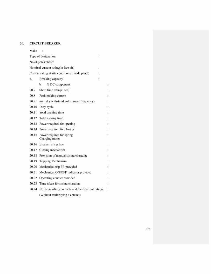
176
20. CIRCUIT BREAKER
Make :
Type of designation :
No.of poles/phase:
Nominal current rating(in free air) :
Current rating at site conditions (inside panel) :
a. Breaking capacity :
b % DC component :
20.7 Short time rating(l sec) :
20.8 Peak making current :
20.9 1 min. dry withstand volt (power frequency) :
20.10 Duty cycle :
20.11 total opening time :
20.12 Total closing time :
20.13 Power required for opening :
20.14 Power required for closing :
20.15 Power required for spring :
Charging motor
20.16 Breaker is trip free :
20.17 Closing mechanism :
20.18 Provision of manual spring charging :
20.19 Tripping Mechanism :
20.20 Mechanical trip PB provided :
20.21 Mechanical ON/OFF indicator provided :
20.22 Operating counter provided :
20.23 Time taken for spring charging :
20.24 No. of auxiliary contacts and their current ratings :
(Without multiplying a contact)

177
TRANSFORMER DATA SHEET TO BE FILLED IN BY BIDDERS
1.0 Rating of transformer (KV A)
2.0 Performance
2.1 No load Losses :
At 100% V (KW) :
At 110% V (KW) :
2.2 FL Copper Losses (KW at 75°C) :
2.3 No load current :
At 100% V :
At l10%V :
2.4 Efficiency at FL at 75° C (%) :
At 0.8 pf :
At 1.0 pf :
2.5 Efficiency at ¾ load at 75°C (%) :
At 0.8 pf :
At 1.0 pf :
2.6 Efficiency at ½ load at 75°C (%) :
At 0.8 pf :
At 1.0 pf :
2.7 Maximum efficiency :
2.8 Load at which max. efficiency occurs :
2.9 Percentage regulation at 75°C :
At 1.0 pf :
At 0.8 pf :
3.0 Mechanical data:
3.1 Core winding weight(Kg) :
3.2 Center to center distance between roller(mm) :
3.3 Wheel gauge (diameter mm) :
3.4 Overall dimension(mm) :
Length :
Breadth :
Height :
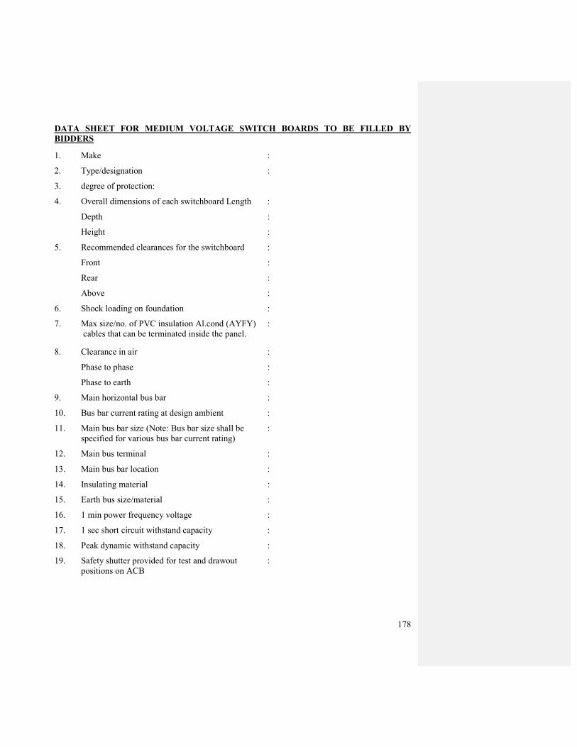
178
DATA SHEET FOR MEDIUM VOLTAGE SWITCH BOARDS TO BE FILLED BY
BIDDERS
1. Make :
2. Type/designation :
3. degree of protection:
4. Overall dimensions of each switchboard Length :
Depth :
Height :
5. Recommended clearances for the switchboard :
Front :
Rear :
Above :
6. Shock loading on foundation :
7. Max size/no. of PVC insulation Al.cond (AYFY) :
cables that can be terminated inside the panel.
8. Clearance in air :
Phase to phase :
Phase to earth :
9. Main horizontal bus bar :
10. Bus bar current rating at design ambient :
11. Main bus bar size (Note: Bus bar size shall be :
specified for various bus bar current rating)
12. Main bus terminal :
13. Main bus bar location :
14. Insulating material :
15. Earth bus size/material :
16. 1 min power frequency voltage :
17. 1 sec short circuit withstand capacity :
18. Peak dynamic withstand capacity :
19. Safety shutter provided for test and drawout :
positions on ACB

179
21. CIRCUIT BREAKER
Make :
Type of designation :
No.of poles/phase :
Nominal current rating(in free air) :
Current rating at site conditions (inside panel) :
a. Breaking capacity :
b % DC component :
20.7 Short time rating(l sec) :
20.8 Peak making current :
20.9 1 min. dry withstand volt (power frequency) :
20.10 Duty cycle :
20.11 total opening time :
20.12 Total closing time :
20.13 Power required for opening :
20.14 Power required for closing :
20.15 Power required for spring Charging motor :
20.16 Breaker is trip free :
20.17 Closing mechanism :
20.18 Provision of manual spring charging :
20.19 Tripping Mechanism :
20.20 Mechanical trip PB provided :
20.21 Mechanical ON/OFF indicator provided :
20.22 Operating counter provided :
20.23 Time taken for spring charging :
20.24 No. of auxiliary contacts and their current :
ratings (Without multiplying a contract)

180
DATA SHEET FOR DG SET ALTERNATORS AND DC POWER SUPPLY TO BE FILLED
IN BY BIDDERS
1. DG SET ALERNATOR
1.1 rating performance details
Make :
Design ambient :
Frame designation :
Rated output :
Applicable code :
Terminal voltage :
Enclosure :
Rated PF :
Phase/ connection /no. of terminals :
Full load current :
Speed :
Rated frequency :
Cooling system :
Max permissive inductive loading :
Excitation system :
Steady state 3 phase S.C currents :
Type of voltage regulator :
phase SC withstanding time :
Stator wdg. Test volt :
Insulation class :
Max permissible impact load :
Temperature rise at full load :
Efficiency 25% Load 50% Load 75% Load 10% Load
% Rated P.F.
Rated P.F.
1.2 Reactances (Mtr To indicate tolerances)
Direct axis transient reactance Xd’ :
Direct axis sub transient reactance Xd’ :
Synchronous reactance Xd :
Zero sequence reactance X2 :
Negative sequence X2 :
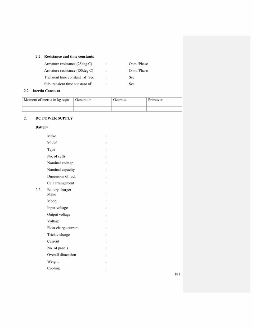
181
2.2 Resistance and time constants
Armature resistance (25deg.C) : Ohm /Phase
Armature resistance (l00deg.C) : Ohm /Phase
Transient time constant Td’ Sec : Sec
Sub-transient time constant td’ : Sec
2.2 Inertia Constant
Moment of inertia in kg-sqm Generator Gearbox Primover
2. DC POWER SUPPLY
Battery
Make :
Model :
Type :
No. of cells :
Nominal voltage :
Nominal capacity :
Dimension of racl. :
Cell arrangement :
2.2 Battery charger
Make :
Model :
Input voltage :
Output voltage :
Voltage :
Float charge current :
Trickle charge :
Current :
No. of panels :
Overall dimension :
Weight :
Cooling :

182
APPENDIX A
TERMINOLOGY
This appendix indicates some of the commonly used and important terms, relevant for the Internal
EI works.
1. Exposed conductive part –
A conductive part of electrical equivalent, which can be touched and which is not normally
live, but which may become the earth potential.
2. Direct contact –
Contact of persons or livestock with live parts which may result in electrical shock.
3. Indirect Contact –
Contact of persons or livestock with exposed conductive parts made live by a fault and
which may result in electric shock.
4. Live Part –
A conductor or conductive part intended to be energised in normal use, including a neutral
conductor but, by convention, not a PEN conductor.
5. Touch Voltage –
The potential difference between a grounded metallic structure and.a point on the earth
surface separated by a distance equal to the normal maximum horizontal reach of
approximately 1 meter.
6. Danger –
Danger to health or danger to life or limb from shock, bum or injury from mechanical
movement to persons (and livestock where present), or from fire attendant upon the use of
electrical energy.
7. Earth –
The conductive mass of the earth, whose electric potential at any point is conventionally
taken as zero.
8. Earth electrode –
A conductor or group of conductors in intimate contact with and providing an electrical
connection to earth.
9. Earth fault loop impedance-
The impedance of the earth fault current loop (phase to earth loop), starting and ending at
the point of earth fault.
183
10. Earth leakage current –
A current which flows to earth, or to extraneous conductive parts, in a circuit which is
electrically sound.
11. Earth conductor –
A protective conductor connecting the main earth terminal to an earth electrode
12. Residual current –
The algebraic sum of the instantaneous values of current flowing through all the live
conductors of a circuit at a point of the electrical installation.
13. Residual current device (RCD) –
A mechanical switching device, intended to cause the opening of the contacts ,when the
residual current attains a given value under the specified conditions.
14. Switchboard-
An assembly of switchgear with or without instruments, but the term does not apply to a
group of local switches in a final circuit.
15. Switchgear-
An assembly of main and auxiliary switching apparatus for operation, regulation, protection
or other control of electrical installations. Should the mains supply fail again.
184
APPENDIX - B
IMPORTANT INDIAN STANDARDS
STANDARDS TITLE
(1) IS:732 – 1989 Code of practice for electrical wiring installations.
(2) IS:4648 – 1968 Guide for electrical layout in residential buildings.
(3) IS:8061 – 1976 Code of practice for design, installation and
aintenance of service lines up to and including
650V.
(4) IS:8884 – 1978 Code of practice for installation of electric
bells and call system.
(5) IS:5578 – 1985 Guide for conductor marking of insulated
(6) IS:11353- 1985 Guide for uniform system of marking and
dentification of conductors and apparatus terminals.
(7) IS:5728 – 1970 Guide for short-circuit calculations.
(8) IS:7752(part-l)-1975 Guide for improvement of power factor in
consumer installation Low and medium supply
voltages.
(9) IS:3 646(part-l )-1966 Code of practice for interior illumination. Principles
for good lighting and aspects of design.
(10) IS:3646(part-2)-1966 Code of practice for illumination. Schedule of
interior illumination and glare index.
(11) IS:3646(part-3)-1968 Code of practice for interior illumination.
Calculation of coefficients of utilization by the BZ
method lighting.
(12) IS:2672 – 1966 Code of practice for library lighting.
(13) IS:lOI18(part-l)-1982 Code of practice for selection, installation and
maintenance switchgear and of controlgear General.
(14) IS:lOI18(part-2)-1982 Code of practice for selection, installation and
maintenance of switchgear and controlgear .
(15) IS:l 0 118(part-3 )-1982 Code of practice for selection, installation and
maintenance of switchgear and controlgear
installation.
(16) IS:I0118(part-4)-1982 Code of practice for selection, installation and
maintenance of switchgear and controlgear
Maintenance.
(17) IS:4146 – 1983 Application guide for voltage transformers.

185
(18) IS:4201 – 1983 Application guide for current transformers.
(19) IS:5547 – 1983 Application guide for capacitor voltage
transformers
(20) IS:2309 – 1989 Code of practice for the protection and allied
structures against lightning.
(21) IS:3043 – 1987 Code of practice for earthing.
(22) IS :5216(part-l )-1982 Guide for practices safety procedures and in
electrical work General.
(23) IS:5216(part-2)-1982 Guide for safety procedures and practices in
electrical work: Life saving techniques
(24) IS:3696(part-2)-1966 Safety code For scaffolds and ladders: Ladders
(25) IS:374- 1979 Electric ceiling type fans and regulators.
(26) IS:2997 – 1964 Air circulator type electric fans and regulators.
(27) IS:11037- 1984 Electronic type fan regulators.
(28) IS:12155- 1987 General and safety requirements for fans and
regulators for household and similar purposes.
(29) IS:4237 – 1983 General requirements for switchgear and
controlgear for voltages not exceeding 1000 V ac or
1200V DC.
(30) IS:6875(part-1)-1973 Control switches ( switching Devices for control
and auxiliary circuits including contactor relays) for
voltages up to and including 1000 V AC and 1200V
DC : General requirements and tests.
(31) IS:6875(part-2}.1973 Control switches ( switching devices for control and
auxiliary circuits including contactor relays) for
voltages up to and including 1000 V AC and 1200V
DC : Push- buttons and related control switches.
(32) IS:6875(part-3)-1980 Control switches (switching devices for control and
auxiliary circuits including contactor relays) for
voltages upto and including 1000 V AC and 1200 V
DC: Rotary control switches.
(33) IS:10027-1981 Composite units of air-break switches and
rewireable type fuses for voltages not exceeding
650 V AC.
(34) IS:4064(part-1)-1978 Air break switches, air break disconnectors, air-
break switch disconnectors and fuse-combination
186
units for voltages not exceeding 1000 V AC or 1200
V DC : General requirements
(35) IS:2675 – 1983 Enclosed distribution fuse-boards and cutouts for
voltage not exceeding 1000V
(36) IS:8828 – 1978 Miniature air break circuit breakers for voltages not
exceeding 1000 volt.
(37) IS:13032- 1991 Miniature circuit breaker boards for voltages up to
and including 1000 volts AC.
(38) IS:12640- 1988 Residual current operated circuit breakers.
(39) IS:2959 – 1985 Contactors for voltages not exceeding 1000 V AC
or 1200 V DC
(40) IS:8623(part-1)-1977 Factory built assemblies of switchgear and
controlgear for voltages up to and including 1000 V
AC and 1200V DC : General requirements.
(41) IS’:8623(Part-2)-1980 Factory built assemblies of switchgear and
controlgear for voltages upto and including 1000 V
AC and 1200V DC . Particular requirements for
busbar trunking system (busways).
(42) IS:694 – 1990 PVC Insulated cables for working voltages upto and
including 1100 V
(43) IS:l554(part-1)-1988 PVC insulated (heavy duty) electric cables: For
working voltages upto and including 1100 V
(44) IS:3 961 (part-5) 1968 Recommended current ratings for cables: PVC
insulated light duty cables.
(45) IS:4288 - 1988 PVC insulated (heavy duty) electric cables with
solid aluminium conductors for voltages upto and
including 1100 V
(46) IS:9537(part-1)-1980 Conduits For electrical installations :General
requirements.
(47) IS:9537(part-2)-1981 Conduits for electrical installations Rigid steel
conduits
(48) IS:3480 – 1966 Flexible steel conduits for electrical wiring.
(49) IS:2667 – 1988 Fittings for rigid steel conduits for electrical wiring
(50) IS:3837 – 1976 Accessories for rigid steel conduits for electrical
wiring
(51) IS:5133(part-l)-1969 Boxes for enclosure of electrical accessories: Steel
and cast iron boxes.
187
(52) IS:2412 – 1975 Link clips for electrical wiring
(53) IS:371 - 1979 Ceiling roses
(54) IS:3854 – 1988 Switches for domestic and similar purposes
(55) IS:4615 – 1968 Switch socket outlets (non interlocking type).
(56) IS:4160 – 1967 Interlocking switch socket outlet.
(57) IS:1293 - -1988 Plugs and socket outlets of rated voltage up to and
including 250volts and rated current upto and
including 16 amperes
(58) IS:418- 1978 Tungsten filament general service electric lamps.
(59) IS:2418(part-l)-1977 Tubular fluorescent lamps for general lighting
service:Requirements and tests.
(60) IS:1258 – 1987 Bayonet lamp holders
(61) IS:3323 – 1980 Bi-pin lamp holders for tubular fluorescent lamps
(62) IS:3324 – 1982 Holders for starters for tubular fluorescent lamps
(63) IS:2215 – 1984 Starters for fluorescent lamps
(64) IS:1534(part-l)-1977 Ballast for fluorescent lamps: For switch start
circuits.
(65) IS:1569 – 1976 Capacitors for use In tubular fluorescent high
pressure mercury and low pressure sodium vapor
discharge lamp circuits.
(66) IS:1913(part-l)-1978 General and safety requirements for luminaries:
Tubular fluorescent lamps
(67) IS: 1 03 22(part-l )-1982 Luminaries: General requirements.
(68) IS:10322(part-2)-1982 Luminaires Constructional requirements
(69) IS:10322(part-5/Sec-l) Luminaries Particular requirements: Recessed
luminaries.
(70) IS:1777 – 1978 Industrial reflectors luminaries with metal reflector
(71) IS:302- 1979 General and safety requirements for household and
similar electrical appliances.
(72) IS:2268 – 1988 Electric call bells and buzzers for indoor use.
(73) IS:6236 – 1971 Direct recording electrical measuring instruments.

188
(74) IS:1248(part-l)-1983 Direct acting indicating analogue electrical
measuring instruments and their accessories:
General requirements.
(75) IS:1248(part-2)-1983 Direct acting indicating analogue electrical
measuring instruments and their accessories.
Ammeters and voltmeters.
(76) IS:722(part-l)-1988 AC electricity meters: General requirements and
tests.
(78) IS:2551 -1982 Danger notice plates
(79) IS:2448(part-1)-1963 Adhesive insulating tapes for electrical
purposes: Tapes with cotton textile substrates
(80) IS:1885(part-1)-1961 Electrotechnical vocabulary : Fundamental
definitions
(81) IS :1885(part-16/Sec-1) Electrotechnical vocabulary: Lighting: General -
1968 aspects
(82) IS:1885(part-16/Sec-2) Electrotechnical vocabulary:Lighting: General -
1968 illumination, lighting fittings and lighting for
traffic and signaling.
(83) IS:1885(part-17)-1979 Electrotechnical vocabulary : Switchgear and
controlgear
(84) IS:1885(part-32)-1971 Electrotechnical vocabulary: Cables, conductors
and accessones for electricity supply.
(85) IS:2629 Recommended practice for hot dip galvanizing on iron
and steel.
(86) IS: 4759 Hot dip zink coatings on structural steel and other
allied products.
189
APPENDIX-C
SAFETY PROCEDURE
1. The Indian Electricity Rules 1956, as amended upto date, are to be followed in their entirety.
Any installation or portion of installation which does not comply with these rules should be
got rectified immediately.
2. The detailed instructions on safety procedures given in B.I.S. Code No. 5216-1969-"Code of
Safety Procedures and Practices in Electrical Works" shall be strictly followed.
3. No inflammable materials shall be stored in places other than the rooms specially
constructed for this purpose in accordance with the provisions of Indian Explosives Act. If
such storage is unavoidable, it should be allowed only for a short period and in addition,
special precautions, such ascutting off the supply to such places at normal times, storing
materials away from wiring and switch boards, giving electric supply for a temporary period
with the permission of consultants shall be taken.
4. The electrical switchgears and distribution boards should be clearly marked to indicate the
areas being controlled by them.
5. Before energizing on an installation after the work is completed, it should be ensured that all
tools have been removed and counted, no person is present inside any enclosure of the
switch board etc. any earthing connection made for doing the work has been removed.

190
APPENDIX-D
FORM OF APPLICATION FOR OBTAINING COMPLETION CERTIFICATE
I/We certify that the installation detailed below has been installed by me/us and tested and that to
the best of my/our knowledge and belief it complies with Indian Electricity Rules, 1956, as well as
the C.P.W.D. General Specifications of Electrical Works 1992.
Electrical installation at __________________________________________________________
Voltage and system of supply______________________________________________________
1. Particulars of work:
(a) Internal Electrical Installation
No. Total load: Type or system of wiring
i) Light point
ii) Fan point
iii) Plug point
a) 3 pin 5 Amp.
b) 3 pin 15 Amp
(b) Others
Description HP/KW Type of starting
(a) Motors: (i)
(ii)
(iii )
(b) Other plants:
II. Earthing
(i) Description of earthing electrode.
(ii) No. of earth electrodes.
Ill.Test results :
(a) Insulation resistance
(i) Insulation resistance of the whole system of conductors to earth………... .Megaohms.

191
(ii) Insulation between the phase conductor and neutral
Between Phase R and neutral . . . . . . . . . .Megaohms
Between Phase Y and neutral . . . . . . . . . .Megaohms
Between Phase B and neutral . . . . . . . . . .Megaohms
iii) Insulation resistance between the phase conductors in case of poly phase supply.
Between Phase R and Phase Y. . . . . . . . .Megaohms
Between Phase Y and Phase B. . . . . . . . .Megaohms
Between Phase B and Phase R . . . . . . . . . .Megaohms
(b) Polarity test
Polarity of non linked single pole branch switches.
(c) Earth continuity test
Maximum resistance between any point in the earth continuity conductor including
metal conduits and main earthing lead………………Ohms.
(d) Earth electrode resistance
Resistance of each earth electrode
(i) . .. . Ohms.
(ii). . . . Ohms.
(iii) .. Ohms.
(iv) .. Ohms
(e) Lightning protective system
Resistance of the whole of lightning protective system to earth before any bonding is
effected with earth electrode and metal in/on the structure ......…….Ohms.
Signature and Name of the
OIL INDIA LIMITED
12, OLD RESIDENCY ROAD
JODHPUR 342011
RAJASTHAN
PHONE NO. : 0291 – 2433642 FAX NO. : 0291 –
2431689
VOLUME-II
BID REJECTION CRITERIA (BRC) / BID EVALUATION
CRITERIA (BEC)
&
CRITERIA FOR PRE-QUALIFICATION OF CONTRACTORS
AND
EVALUATION OF PERFORMANCE.
FOR
INTERNAL
&
EXTERNAL
ELECTRICAL WORKS
FOR
OIL HOUSE AT JODHPUR.
FOR
OIL HOUSE, Jodhpur Volume II 1
CONSTRUCTION OF “OIL HOUSE” AT PLOT NO.: 2A,
SARAWATI NAGAR
JODHPUR (RAJASTHAN)
OIL HOUSE, Jodhpur Volume II 2
VOMUME-II
BID REJECTION CRITERIA (BRC) / BID EVALUATION CRITERIA (BEC)
A. BID REJECTION CRITERIA (BRC)
The bids shall conform generally to the Scope of Work and Terms and Conditions given in
the bidding document. Bids will be rejected in case it does not conform to the required
parameters stipulated in the tender document. Notwithstanding the general conformity of the
bids to the stipulated specification, the following requirements will have to be particularly
met by the bidders without which the offers will be considered as non-responsive and
rejected.
1.0 TECHNICAL:
1.1 The bidders should have successfully completed three similar nature of works (at least one
should be in Central Govt./Central Autonomous Bodies/Central Public Sector Undertaking),
each of value greater than Rs. 50.00 lakhs or two similar nature of works, each of value
greater than Rs. 65.00 lakhs or one work equal to Rs. 100.00 lakhs during the last 7 (seven)
years ending on the last day of month previous to the one in which bids are invited.
Note: Similar nature of work means ELECTRIFICATION of multistoried office building/
any prestigious building/ hospital/ commercial complex/ multistoried housing
complex.
1.2 Minimum average annual turnover in the last three completed financial years should be Rs.
40.00 lakhs.
1.3 Minimum Solvency should be Rs. 50.0 lakhs.
1.4 The bidder must have experience of installation, testing and commissioning of 11KV VCB
Panel, 11KV/415V transformer of rating 400KVA or above. All relevant documents are to
be submitted with the bid.
1.5 The bidder must furnish the list of equipment and details of technical and administrative
personnel to be deployed for the work as per format provided in the bid document (Form E
& F). All tools, equipments, meters, injection test units etc shall be as per tender specs.
1.6 Bidder must have valid electrical license issued by licensing board for electrification works
in Rajasthan. All electrical works are to be carried out by licensed electricians under the
supervision of a licensed supervisor. All relevant documents are to be submitted with the
bid.
1.7 Bid Security/Earnest Money shall be furnished as a part of technical bid in a separate
envelope. The bid amount of Bid Security shall be as specified in the tender document. Bid
not accompanied by a proper Bid Security will be rejected.
2.0 COMMERCIAL:
2.1 Bids are to be submitted in triplicate under Single Stage Two Bid System i.e. Technical Bid
(Un-priced) and Commercial Bid (Priced) submitted in separate sealed envelopes. Only the
OIL HOUSE, Jodhpur Volume II 3
Commercial Bid should contain the prices/rates. The bids will be summarily rejected if the
Technical Bids contain the prices/rates.
2.2 Prices quoted by the bidders must remain firm throughout execution of the contract and not
subject to variation on any account.
2.3 Bids received after the scheduled bid closing time and date will be rejected.
2.4 Bids shall be typed or written in indelible ink and the original bid shall be signed by the
bidder or his authorized representative(s) on all pages, failing which the bid will be rejected.
2.5 Bids shall contain no interlineations, erasures or over writing, except as necessary to correct
errors made by the bidder, in which case such corrections shall be initialed by the person(s)
signing the bid. However, correcting fluid should not be used for making correction. Any bid
not meeting this requirement shall be rejected.
2.6 Bids containing false statement will be rejected.
2.7 Bids with inadequate validity shall be rejected.
2.8 Conditional offers will be rejected.
2.9 Bidders must quote clearly and strictly in accordance with the Price Schedule outlined in Price
Bid proforma (Volume-III) of bidding document, otherwise the bid will be summarily rejected.
2.10 Bidders must accept and comply with the following clauses as given in the tender document in
toto, failing which the offers will be rejected.
a) Performance Security
b) Tax liability c) Insurance d) Force majure
e) Termination
f) Arbitration
g) Liability h) Withholding
i) Applicable law
j) Obligation of bidders
k) Liquidated damages and penalty
3.0 GENERAL:
3.1 The Compliance Statement (Proforma-I) should be duly filled up and should form a part of
Technical Bid. In case bidder takes exception to any clause of tender document not covered
under BEC/BRC, then the Company has the discretion to load or reject the offer on account of
such exceptions if the bidder does not withdraw/modify the deviations when/as advised by the
Company. The loading so done by the Company will be final and binding on the bidders.
3.2 To ascertain the substantial responsiveness of bids, the Company reserves the right to ask the
bidders for clarifications in respect of clauses covered under BEC/BRC also and such
clarifications fulfilling the BEC/BRC clauses in toto must be received on or before the dead line
given by the Company, failing which the offer will be summarily rejected.

OIL HOUSE, Jodhpur Volume II 4
3.3 The bid documents are non-transferable. Offers made by a bidder who has not purchased the
tender document from the Company will be rejected.
3.4 The Company also reserves the right to cancel/withdraw the tender or annul the bidding process
at any time prior to award of contract, without thereby incurring any liability to the bidders or
any obligation to inform the bidders of the grounds of Company’s action.
3.5 If any of the clauses in the BEC/BRC contradicts with other clauses of bid document elsewhere,
them the clauses in BEC/BRC shall prevail.
B. BID EVALUATION CRITERIA (BEC)
The bids conforming to Scope of Work, terms and conditions stipulated in the bidding
document and considered to be responsive after subjecting to Bid Rejection Criteria will be
considered for further evaluation as per Bid Evaluation Criteria.
1.0 TECHNICAL:
1.1 The eligibility of the bidder will be evaluated from the documents as per the format provided
with the tender document for financial strength, experience in similar works, performance
on works, personnel and establishment and plant and equipment. Marking will be done as
per format enclosed.
2.0 COMMERCIAL:
2.1 Evaluation will be done as a whole considering rates quoted against all the items in
commercial bid. However, the quantity indicated therein are based on the best assessment of
company and are for bid evaluation purpose only. Payment will be made based on
measurement of actual work executed.
2.2 Bidders should quote rates both in figures and in words. In case of any discrepancy between
the rates in figures and words, the rates quoted in words would prevail.
2.3 Similarly, in case there is any discrepancy between unit rate and corresponding amount (unit
rate X quantity) quoted by the bidder, the unit rate so quoted will be treated as correct and
the total amount will be amended and considered for bid evaluation accordingly.
2.4 The lowest evaluated bidder amongst the technically acceptable parties will be awarded the
contract.
*****
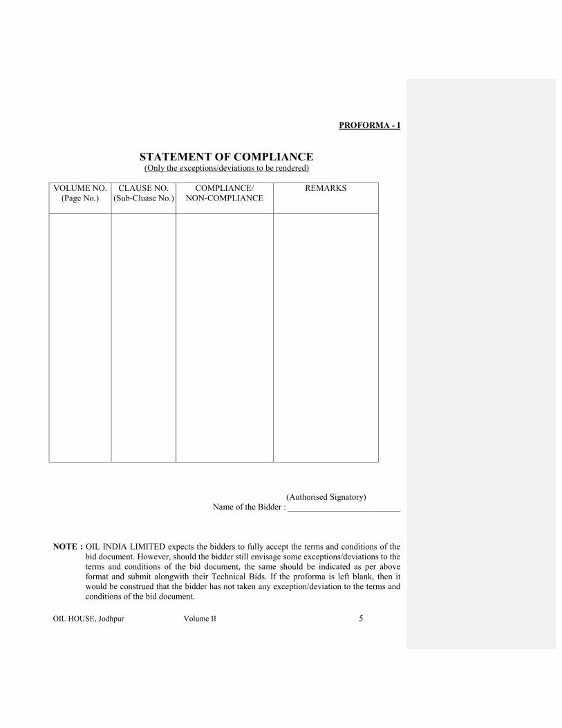
OIL HOUSE, Jodhpur Volume II 5
PROFORMA - I
STATEMENT OF COMPLIANCE (Only the exceptions/deviations to be rendered)
VOLUME NO.
(Page No.)
CLAUSE NO.
(Sub-Cluase No.)
COMPLIANCE/
NON-COMPLIANCE
REMARKS
(Authorised Signatory)
Name of the Bidder : __________________________
NOTE : OIL INDIA LIMITED expects the bidders to fully accept the terms and conditions of the
bid document. However, should the bidder still envisage some exceptions/deviations to the
terms and conditions of the bid document, the same should be indicated as per above
format and submit alongwith their Technical Bids. If the proforma is left blank, then it
would be construed that the bidder has not taken any exception/deviation to the terms and
conditions of the bid document.

OIL HOUSE, Jodhpur Volume II 6
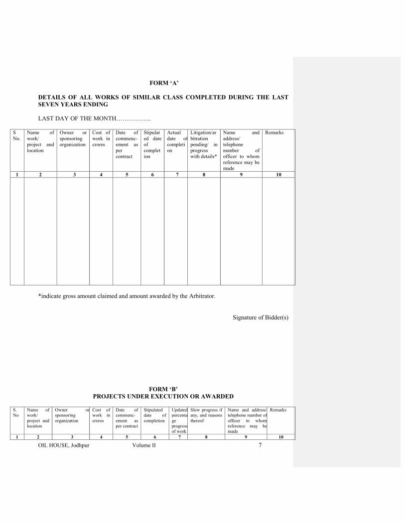
OIL HOUSE, Jodhpur Volume II 7
FORM ‘A’
DETAILS OF ALL WORKS OF SIMILAR CLASS COMPLETED DURING THE LAST
SEVEN YEARS ENDING
LAST DAY OF THE MONTH……………..
S
No.
Name of
work/
project and
location
Owner or
sponsoring
organization
Cost of
work in
crores
Date of
commenc-
ement as
per
contract
Stipulat
ed date
of
complet
ion
Actual
date of
completi
on
Litigation/ar
bitration
pending/ in
progress
with details*
Name and
address/
telephone
number of
officer to whom
reference may be
made
Remarks
1 2 3 4 5 6 7 8 9 10
*indicate gross amount claimed and amount awarded by the Arbitrator.
Signature of Bidder(s)
FORM ‘B’
PROJECTS UNDER EXECUTION OR AWARDED
S.
No
Name of
work/
project and
location
Owner or
sponsoring
organization
Cost of
work in
crores
Date of
commenc-
ement as
per contract
Stipulated
date of
completion
Updated
percenta
ge
progress
of work
Slow progress if
any, and reasons
thereof
Name and address/
telephone number of
officer to whom
reference may be
made
Remarks
1 2 3 4 5 6 7 8 9 10
OIL HOUSE, Jodhpur Volume II 8
Signature of Bidder(s)
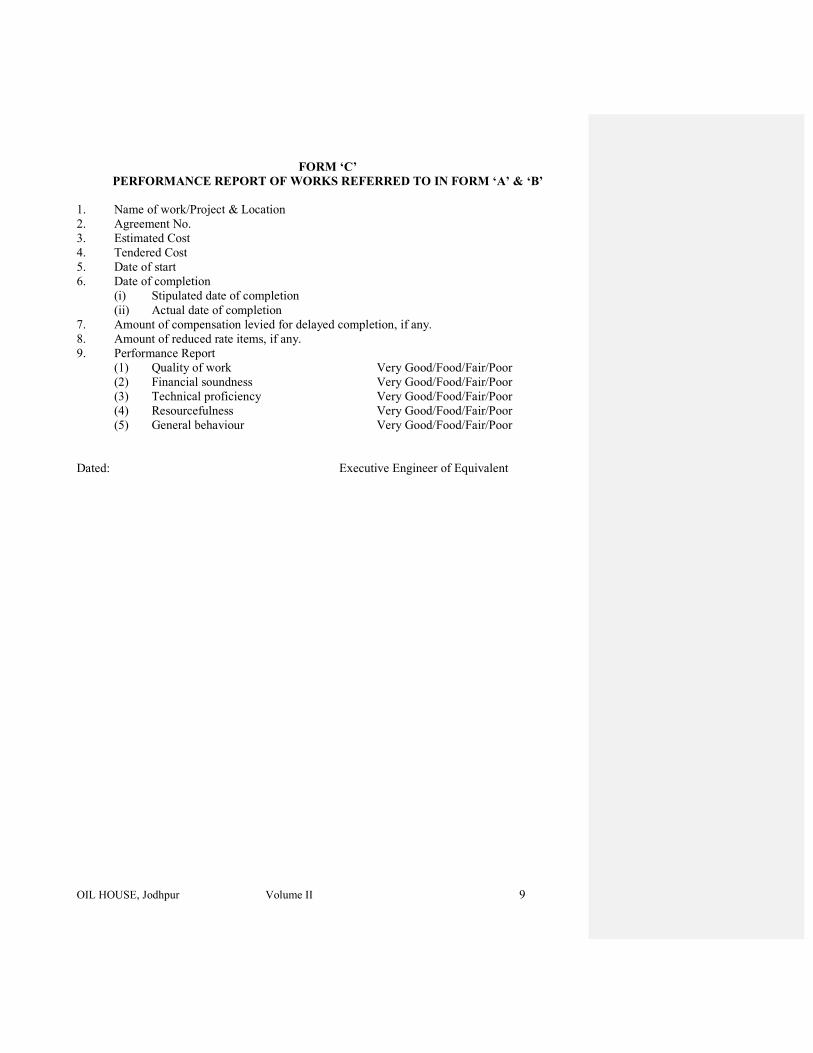
OIL HOUSE, Jodhpur Volume II 9
FORM ‘C’
PERFORMANCE REPORT OF WORKS REFERRED TO IN FORM ‘A’ & ‘B’
1. Name of work/Project & Location
2. Agreement No.
3. Estimated Cost
4. Tendered Cost
5. Date of start
6. Date of completion
(i) Stipulated date of completion
(ii) Actual date of completion
7. Amount of compensation levied for delayed completion, if any.
8. Amount of reduced rate items, if any.
9. Performance Report
(1) Quality of work Very Good/Food/Fair/Poor
(2) Financial soundness Very Good/Food/Fair/Poor
(3) Technical proficiency Very Good/Food/Fair/Poor
(4) Resourcefulness Very Good/Food/Fair/Poor
(5) General behaviour Very Good/Food/Fair/Poor
Dated: Executive Engineer of Equivalent
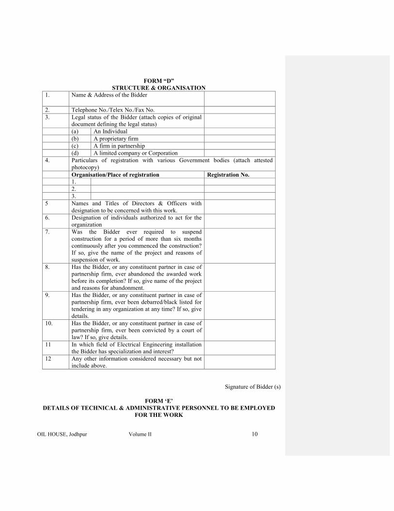
OIL HOUSE, Jodhpur Volume II 10
FORM “D”
STRUCTURE & ORGANISATION
1. Name & Address of the Bidder
2. Telephone No./Telex No./Fax No.
3. Legal status of the Bidder (attach copies of original
document defining the legal status)
(a) An Individual
(b) A proprietary firm
(c) A firm in partnership
(d) A limited company or Corporation
4. Particulars of registration with various Government bodies (attach attested
photocopy)
Organisation/Place of registration Registration No.
1.
2.
3.
5 Names and Titles of Directors & Officers with
designation to be concerned with this work.
6. Designation of individuals authorized to act for the
organization
7. Was the Bidder ever required to suspend
construction for a period of more than six months
continuously after you commenced the construction?
If so, give the name of the project and reasons of
suspension of work.
8. Has the Bidder, or any constituent partner in case of
partnership firm, ever abandoned the awarded work
before its completion? If so, give name of the project
and reasons for abandonment.
9. Has the Bidder, or any constituent partner in case of
partnership firm, ever been debarred/black listed for
tendering in any organization at any time? If so, give
details.
10. Has the Bidder, or any constituent partner in case of
partnership firm, ever been convicted by a court of
law? If so, give details.
11 In which field of Electrical Engineering installation
the Bidder has specialization and interest?
12 Any other information considered necessary but not
include above.
Signature of Bidder (s)
FORM ‘E’
DETAILS OF TECHNICAL & ADMINISTRATIVE PERSONNEL TO BE EMPLOYED
FOR THE WORK
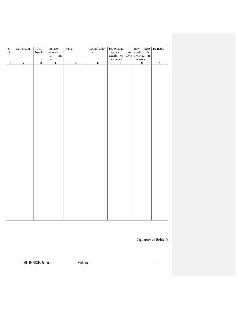
OIL HOUSE, Jodhpur Volume II 11
S.
No.
Designation Total
Number
Number
available
for this
work
Name Qualificatio
ns
Professional
experience and
details of work
carried out
How these
would be
involved in
this work
Remarks
1 2 3 4 5 6 7 8 9
Signature of Bidder(s)
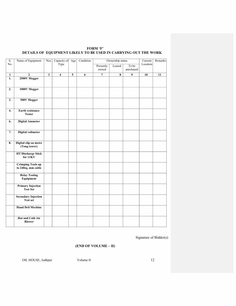
OIL HOUSE, Jodhpur Volume II 12
FORM ‘F’
DETAILS OF EQUIPMENT LIKELY TO BE USED IN CARRYING OUT THE WORK
S.
No.
Name of Equipment Nos. Capacity of
Type
Age Condition Ownership status Current
Location
Remarks
Presently
owned
Leased To be
purchased
1 2 3 4 5 6 7 8 9 10 11
1. 2500V Megger
2. 1000V Megger
3. 500V Megger
4. Earth resistance
Tester
6. Digital Ammeter
7. Digital voltmeter
8. Digital clip on meter
(Tong tesrer)
HT Discharge Stick
for 11KV
Crimping Tools up
to 240sq. mm cable
Relay Testing
Equipment
Primary Injection
Test Set
Secondary Injection
Test set
Hand Dril Mechine
Hot and Cold Air
Blower
Signature of Bidder(s)
(END OF VOLUME – II)
OIL INDIA LIMITED
12, OLD RESIDENCY ROAD
JODHPUR 342011
RAJASTHAN
PHONE NO. : 0291 – 2433642 FAX NO. : 0291 – 2431689
VOLUME-III
BILL OF QUANTITY & PRICE BID PROFORMA
FOR
INTERNAL
&
EXTERNAL
ELECTRICAL WORKS
FOR
OIL HOUSE AT JODHPUR.
FOR
CONSTRUCTION OF “OIL HOUSE” AT PLOT NO.: 2A, SARASWATI NAGAR
JODHPUR (RAJASTHAN)
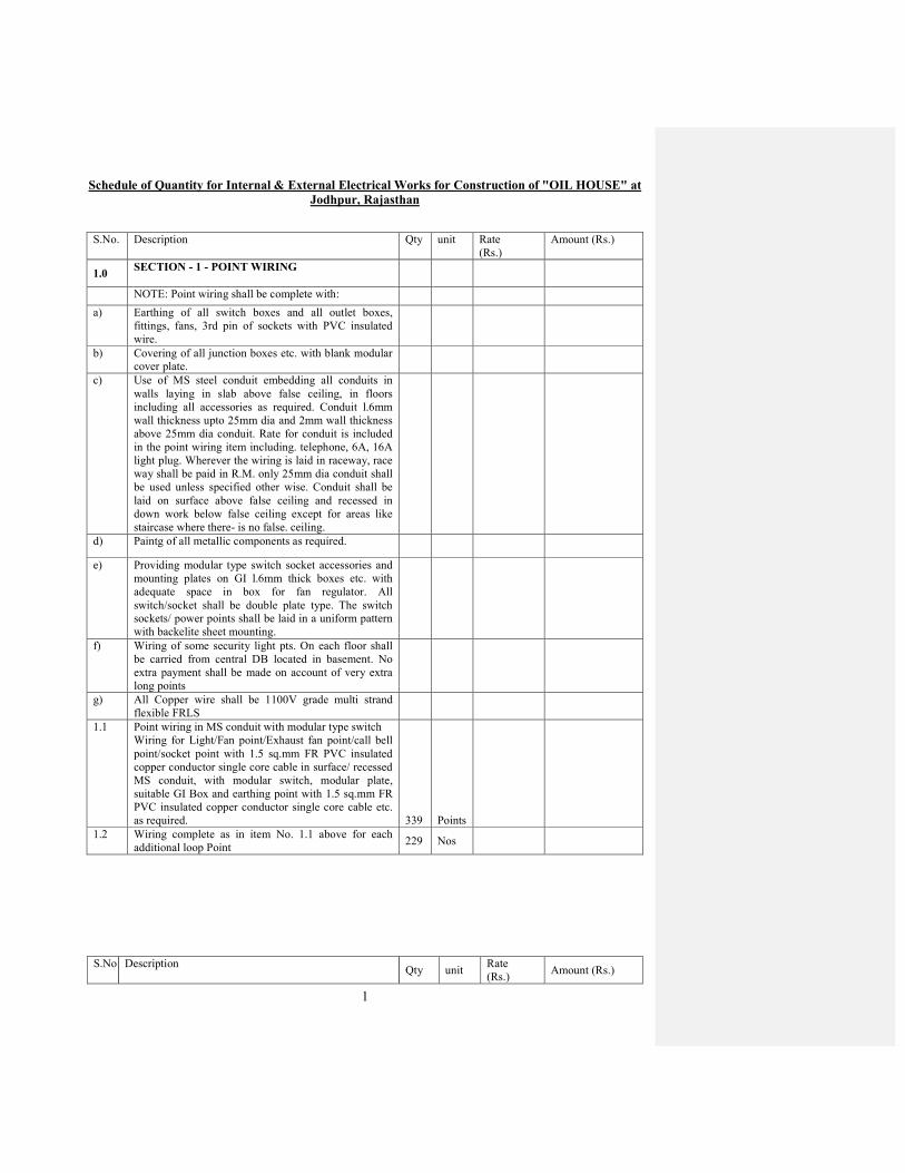
1
Schedule of Quantity for Internal & External Electrical Works for Construction of "OIL HOUSE" at
Jodhpur, Rajasthan
S.No. Description Qty unit Rate
(Rs.)
Amount (Rs.)
1.0 SECTION - 1 - POINT WIRING
NOTE: Point wiring shall be complete with:
a) Earthing of all switch boxes and all outlet boxes,
fittings, fans, 3rd pin of sockets with PVC insulated
wire.
b) Covering of all junction boxes etc. with blank modular
cover plate.
c) Use of MS steel conduit embedding all conduits in
walls laying in slab above false ceiling, in floors
including all accessories as required. Conduit l.6mm
wall thickness upto 25mm dia and 2mm wall thickness
above 25mm dia conduit. Rate for conduit is included
in the point wiring item including. telephone, 6A, 16A
light plug. Wherever the wiring is laid in raceway, race
way shall be paid in R.M. only 25mm dia conduit shall
be used unless specified other wise. Conduit shall be
laid on surface above false ceiling and recessed in
down work below false ceiling except for areas like
staircase where there- is no false. ceiling.
d) Paintg of all metallic components as required.
e) Providing modular type switch socket accessories and
mounting plates on GI l.6mm thick boxes etc. with
adequate space in box for fan regulator. All
switch/socket shall be double plate type. The switch
sockets/ power points shall be laid in a uniform pattern
with backelite sheet mounting.
f) Wiring of some security light pts. On each floor shall
be carried from central DB located in basement. No
extra payment shall be made on account of very extra
long points
g) All Copper wire shall be 1100V grade multi strand
flexible FRLS
1.1 Point wiring in MS conduit with modular type switch
Wiring for Light/Fan point/Exhaust fan point/call bell
point/socket point with 1.5 sq.mm FR PVC insulated
copper conductor single core cable in surface/ recessed
MS conduit, with modular switch, modular plate,
suitable GI Box and earthing point with 1.5 sq.mm FR
PVC insulated copper conductor single core cable etc.
as required. 339 Points
1.2
Wiring complete as in item No. 1.1 above for each
additional loop Point 229 Nos
S.No Description Qty unit
Rate
(Rs.) Amount (Rs.)

2
1.3 Twin Control point wiring in MS conduit, with modular
type switch:
Wiring for twin control light point with 1.5 sq.mm FR
PVC insulated copper conductor single core cable in
surface! recessed MS conduit, 2 way modular switch,
modular plate, suitable GI box and earthing the point
with 1.5 sq.mm FR PVC insulated copper conductor
single core cable etc as required. 6 point
1.4
Supplying and fixing of 1 set of 2 Nos. 3 pin 6 Amps
modular socket outlet & 2 Nos 6A modular switch point
with cover plate, G.I. Box and connection etc. as required
a) With G.I. Box 144 Nos.
1.5
Wiring in existing conduit:
Supplying and drawing following sizes of FR PVC
insulated copper conductor, single core, flexible cable in
the existing surface/ recessed steel! PVC conduit as
required.
a) 3 x 2.5 sq.mm 2000 Meter
b) 3 x 1.5 sq. mm 1100 Meter
c) 3 x4 sq. mm 4500 Meter
1.6 S/F light plug point modular type accessories:
Supplying and fixing suitable size GI box with modular
plate and cover in front on surface or in recess, including
providing and fixing 3 pin 5/6 amps modular socket outlet
and 5/6 amps modular switch, connection, painting etc. as
required. (For Light plugs to be used in non residential
buildings) 184 Each
1.7 S/F light plug point modular type accessories:
Supplying and fixing suitable size GI box with modular
plate and cover in front on surface or in recess, including
providing and fixing 6 pin 15/16 & 5/6 amps modular
socket outlet and 15/16 amps modular switch,
connection, painting etc. as required.
200
Each
1.8 Supply, fixing, erection & testing battery invertor with
bypass arrangement, battery rack and battery accessories
conforming to following particulars: Inverter should give a
pure sine wave output with THD of less than 3%. 1 No.
Load /Capacity / rating : 5KVA
Output voltage : 230 v + 10%
Output frequency : 50 Hz ± 1 Hz
Charging Rate
Boost : 16 Amps.
Trickle : 1 Amp
Battery rating :12v 120Ah or180 Ah / 8Nos.
A.C. input voltage : 230 V± 5%
Backup duration : Full load 3 hours
Efficiency : 80%
Load power factor : < 0.8
Type of Batteries : S.M.F. Exide Make
S.No. Description
Qty unit
Rate
(Rs.) Amount (Rs.)
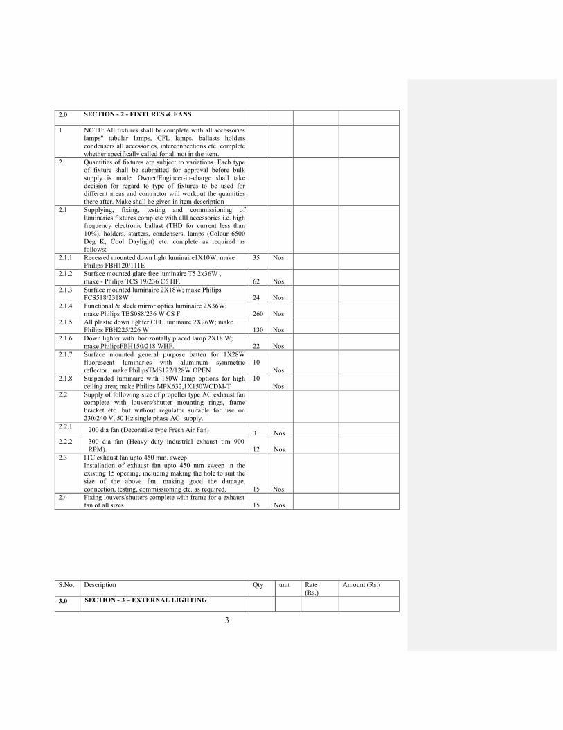
3
2.0 SECTION - 2 - FIXTURES & FANS
1 NOTE: All fixtures shall be complete with all accessories
lamps" tubular lamps, CFL lamps, ballasts holders
condensers all accessories, interconnections etc. complete
whether specifically called for all not in the item.
2 Quantities of fixtures are subject to variations. Each type
of fixture shall be submitted for approval before bulk
supply is made. Owner/Engineer-in-charge shall take
decision for regard to type of fixtures to be used for
different areas and contractor will workout the quantities
there after. Make shall be given in item description
2.1 Supplying, fixing, testing and commissioning of
luminaries fixtures complete with allI accessories i.e. high
frequency electronic ballast (THD for current less than
10%), holders, starters, condensers, lamps (Colour 6500
Deg K, Cool Daylight) etc. complete as required as
follows:
2.1.1 Recessed mounted down light luminaire1X10W; make
Philips FBH120/111E
35
Nos.
2.1.2 Surface mounted glare free luminaire T5 2x36W ,
make - Philips TCS 19/236 C5 HF. 62 Nos.
2.1.3 Surface mounted luminaire 2X18W; make Philips
FCS518/2318W 24 Nos.
2.1.4 Functional & sleek mirror optics luminaire 2X36W;
make Philips TBS088/236 W CS F 260 Nos.
2.1.5 All plastic down lighter CFL luminaire 2X26W; make
Philips FBH225/226 W 130 Nos.
2.1.6 Down lighter with horizontally placed lamp 2X18 W;
make PhilipsFBH150/218 WHF. 22 Nos.
2.1.7 Surface mounted general purpose batten for 1X28W
fluorescent luminaries with aluminum symmetric
reflector. make PhilipsTMS122/128W OPEN
10
Nos.
2.1.8 Suspended luminaire with 150W lamp options for high
ceiling area; make Philips MPK632,1X150WCDM-T
10
Nos.
2.2 Supply of following size of propeller type AC exhaust fan
complete with louvers/shutter mounting rings, frame
bracket etc. but without regulator suitable for use on
230/240 V, 50 Hz single phase AC supply.
2.2.1 200 dia fan (Decorative type Fresh Air Fan)
3 Nos.
2.2.2 300 dia fan (Heavy duty industrial exhaust tim 900
RPM). 12 Nos.
2.3
ITC exhaust fan upto 450 mm. sweep:
Installation of exhaust fan upto 450 mm sweep in the
existing 15 opening, including making the hole to suit the
size of the above fan, making good the damage,
connection, testing, commissioning etc. as required. 15 Nos.
2.4 Fixing louvers/shutters complete with frame for a exhaust
fan of all sizes 15 Nos.
S.No. Description Qty unit Rate
(Rs.)
Amount (Rs.)
3.0 SECTION - 3 – EXTERNAL LIGHTING
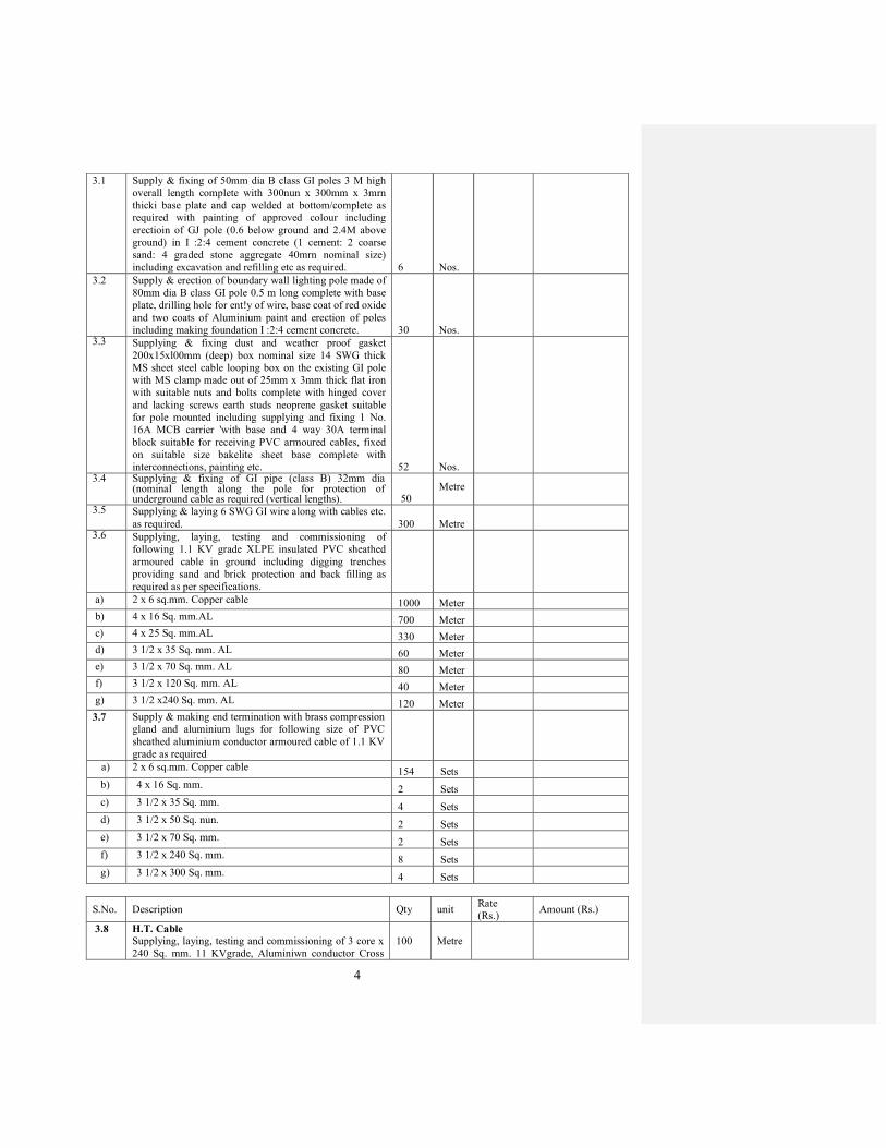
4
3.1 Supply & fixing of 50mm dia B class GI poles 3 M high
overall length complete with 300nun x 300mm x 3mrn
thicki base plate and cap welded at bottom/complete as
required with painting of approved colour including
erectioin of GJ pole (0.6 below ground and 2.4M above
ground) in I :2:4 cement concrete (1 cement: 2 coarse
sand: 4 graded stone aggregate 40mrn nominal size)
including excavation and refilling etc as required. 6 Nos.
3.2 Supply & erection of boundary wall lighting pole made of
80mm dia B class GI pole 0.5 m long complete with base
plate, drilling hole for ent!y of wire, base coat of red oxide
and two coats of Aluminium paint and erection of poles
including making foundation I :2:4 cement concrete. 30 Nos.
3.3
Supplying & fixing dust and weather proof gasket
200x15xl00mm (deep) box nominal size 14 SWG thick
MS sheet steel cable looping box on the existing GI pole
with MS clamp made out of 25mm x 3mm thick flat iron
with suitable nuts and bolts complete with hinged cover
and lacking screws earth studs neoprene gasket suitable
for pole mounted including supplying and fixing 1 No.
16A MCB carrier 'with base and 4 way 30A terminal
block suitable for receiving PVC armoured cables, fixed
on suitable size bakelite sheet base complete with
interconnections, painting etc. 52 Nos.
3.4
Supplying & fixing of GI pipe (class B) 32mm dia (nominaI length along the pole for protection of underground cable as required (vertical lengths). 50
Metre
3.5
Supplying & laying 6 SWG GI wire along with cables etc.
as required. 300 Metre
3.6
Supplying, laying, testing and commissioning of
following 1.1 KV grade XLPE insulated PVC sheathed
armoured cable in ground including digging trenches
providing sand and brick protection and back filling as
required as per specifications.
a) 2 x 6 sq.mm. Copper cable 1000 Meter
b) 4 x 16 Sq. mm.AL 700 Meter
c) 4 x 25 Sq. mm.AL 330 Meter
d) 3 1/2 x 35 Sq. mm. AL 60 Meter
e) 3 1/2 x 70 Sq. mm. AL 80 Meter
f) 3 1/2 x 120 Sq. mm. AL 40 Meter
g) 3 1/2 x240 Sq. mm. AL 120 Meter
3.7 Supply & making end termination with brass compression
gland and aluminium lugs for following size of PVC
sheathed aluminium conductor armoured cable of 1.1 KV
grade as required
a) 2 x 6 sq.mm. Copper cable 154 Sets
b) 4 x 16 Sq. mm. 2 Sets
c) 3 1/2 x 35 Sq. mm. 4 Sets
d) 3 1/2 x 50 Sq. nun. 2 Sets
e) 3 1/2 x 70 Sq. mm. 2 Sets
f) 3 1/2 x 240 Sq. mm. 8 Sets
g) 3 1/2 x 300 Sq. mm. 4 Sets
S.No. Description Qty unit Rate
(Rs.) Amount (Rs.)
3.8
H.T. Cable
Supplying, laying, testing and commissioning of 3 core x
240 Sq. mm. 11 KVgrade, Aluminiwn conductor Cross
100
Metre

5
Linked Polyethylene Insulated (XLPE) individual core
screened, flat steel strip armoured, PYC sheathed cable in
the existing. Trench/Duct, complete as required.
3.9 H.T. Cable Joint
Supplying and making indoor cable end termination of 3
core x 240 Sq.mm. 11 KVgrade XLPE, Aluminium
conductor insulated armoured H.T.cable with heat shrink
joint including all accessories including Sockets, lugs,
glands, ferrules, etc. complete in all respects as required.
4
Set
3.10 Supply & laying of 150mm dia size double walled
corrugated HDPE pipes for road crossing upto a depth of
0.75M below ground level including excavation making
of joints at collars and sealing of ends refilling and
handing over the pipes clean and clear at complete as
required.
50
Metre
3.11
Compact sturdy general purpose flood lighting with
High Pressue sodium vapour 1X150W; make Philips
SWF230-SK/150(Sym) 30 Nos.
30
Nos.
3.12 Post top lanterns suitable for with High Pressure sodium
Vapour; make Philips SPC106/70(I)HPF 15 Nos.
15
Nos.
3.13 Mini Bollard FGC202/118 with PL-C luminaire; make
Philips
15
Nos.
3.14
Supply & fixing of Foot Lighting luminaire complete
with all accessories, control gear & 15Watt (Product
code:CFLLUKH C05115099; LINEAR ; HAVELLS.) 6
Nos.
6
Nos.
3.15
Compact study general proposed low wattage floodlight
with integral geat 1X70W; make Philips
RVP339/1XCDm- TD 70W PR 8 Nos.
3.16
Wall mounted up down light, integral uni, die cast
construction single reflector and toughened glass cover
IP65; make Philips DC721/CDM-T-70W CRESSIDA,
UP- DOWN 6 Nos.
3.17
Compact sturdy non integral high performance flood lifgt
luminaire suitable foor use with High Pressure Sodium
Vapour 2 X 400W lamp; make Philips RVP301/2X400W
HPI-T 6 Nos.
3.18
Supply and fixing of LED Spot luminaire complete with
all accessories, control gear, transformer & lamp LED
Spot; Philips BGS066/I AM. 6 Nos.
S.No. Description Qty unit
Rate
(Rs.) Amount (Rs.)
4.0 SECTION - 4 - SUB STATION EQUIPMENT
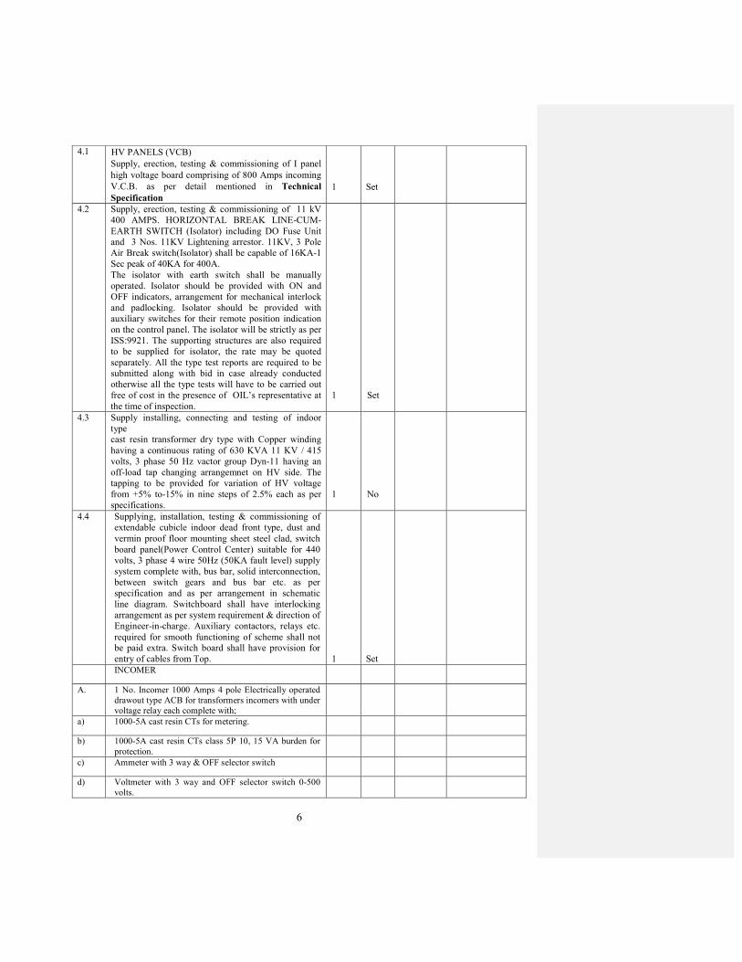
6
4.1
HV PANELS (VCB)
Supply, erection, testing & commissioning of I panel
high voltage board comprising of 800 Amps incoming
V.C.B. as per detail mentioned in Technical
Specification
1
Set
4.2 Supply, erection, testing & commissioning of 11 kV
400 AMPS. HORIZONTAL BREAK LINE-CUM-
EARTH SWITCH (Isolator) including DO Fuse Unit
and 3 Nos. 11KV Lightening arrestor. 11KV, 3 Pole
Air Break switch(Isolator) shall be capable of 16KA-1
Sec peak of 40KA for 400A.
The isolator with earth switch shall be manually
operated. Isolator should be provided with ON and
OFF indicators, arrangement for mechanical interlock
and padlocking. Isolator should be provided with
auxiliary switches for their remote position indication
on the control panel. The isolator will be strictly as per
ISS:9921. The supporting structures are also required
to be supplied for isolator, the rate may be quoted
separately. All the type test reports are required to be
submitted along with bid in case already conducted
otherwise all the type tests will have to be carried out
free of cost in the presence of OIL’s representative at
the time of inspection.
1
Set
4.3 Supply installing, connecting and testing of indoor
type
cast resin transformer dry type with Copper winding
having a continuous rating of 630 KVA 11 KV / 415
volts, 3 phase 50 Hz vactor group Dyn-11 having an
off-load tap changing arrangemnet on HV side. The
tapping to be provided for variation of HV voltage
from +5% to-15% in nine steps of 2.5% each as per
specifications. 1
No
4.4
Supplying, installation, testing & commissioning of
extendable cubicle indoor dead front type, dust and
vermin proof floor mounting sheet steel clad, switch
board panel(Power Control Center) suitable for 440
volts, 3 phase 4 wire 50Hz (50KA fault level) supply
system complete with, bus bar, solid interconnection,
between switch gears and bus bar etc. as per
specification and as per arrangement in schematic
line diagram. Switchboard shall have interlocking
arrangement as per system requirement & direction of
Engineer-in-charge. Auxiliary contactors, relays etc.
required for smooth functioning of scheme shall not
be paid extra. Switch board shall have provision for
entry of cables from Top. 1 Set
INCOMER
A. 1 No. Incomer 1000 Amps 4 pole Electrically operated
drawout type ACB for transformers incomers with under
voltage relay each complete with;
a) 1000-5A cast resin CTs for metering.
b) 1000-5A cast resin CTs class 5P 10, 15 VA burden for
protection.
c) Ammeter with 3 way & OFF selector switch
d) Voltmeter with 3 way and OFF selector switch 0-500
volts.
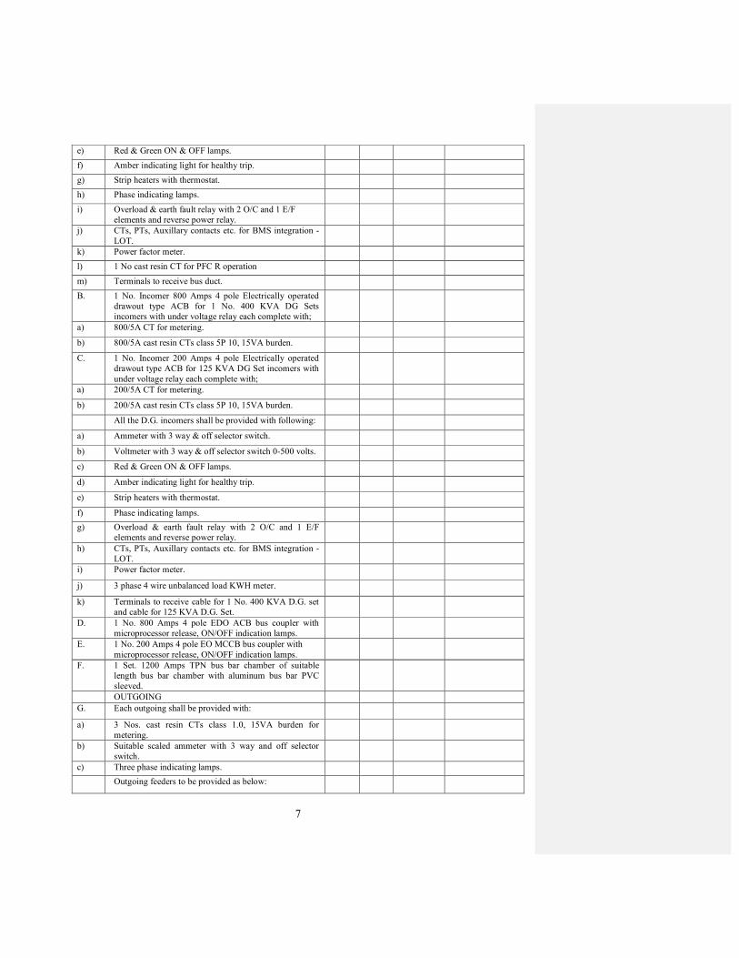
7
e) Red & Green ON & OFF lamps.
f) Amber indicating light for healthy trip.
g) Strip heaters with thermostat.
h) Phase indicating lamps.
i) Overload & earth fault relay with 2 O/C and 1 E/F
elements and reverse power relay.
j) CTs, PTs, Auxillary contacts etc. for BMS integration -
LOT.
k) Power factor meter.
l) 1 No cast resin CT for PFC R operation
m) Terminals to receive bus duct.
B. 1 No. Incomer 800 Amps 4 pole Electrically operated
drawout type ACB for 1 No. 400 KVA DG Sets
incomers with under voltage relay each complete with;
a) 800/5A CT for metering.
b) 800/5A cast resin CTs class 5P 10, 15VA burden.
C. 1 No. Incomer 200 Amps 4 pole Electrically operated
drawout type ACB for 125 KVA DG Set incomers with
under voltage relay each complete with;
a) 200/5A CT for metering.
b) 200/5A cast resin CTs class 5P 10, 15VA burden.
All the D.G. incomers shall be provided with following:
a) Ammeter with 3 way & off selector switch.
b) Voltmeter with 3 way & off selector switch 0-500 volts.
c) Red & Green ON & OFF lamps.
d) Amber indicating light for healthy trip.
e) Strip heaters with thermostat.
f) Phase indicating lamps.
g) Overload & earth fault relay with 2 O/C and 1 E/F
elements and reverse power relay.
h) CTs, PTs, Auxillary contacts etc. for BMS integration -
LOT.
i) Power factor meter.
j) 3 phase 4 wire unbalanced load KWH meter.
k) Terminals to receive cable for 1 No. 400 KVA D.G. set
and cable for 125 KVA D.G. Set.
D. 1 No. 800 Amps 4 pole EDO ACB bus coupler with
microprocessor release, ON/OFF indication lamps.
E. 1 No. 200 Amps 4 pole EO MCCB bus coupler with
microprocessor release, ON/OFF indication lamps.
F. 1 Set. 1200 Amps TPN bus bar chamber of suitable
length bus bar chamber with aluminum bus bar PVC
sleeved.
OUTGOING
G. Each outgoing shall be provided with:
a) 3 Nos. cast resin CTs class 1.0, 15VA burden for
metering.
b) Suitable scaled ammeter with 3 way and off selector
switch.
c) Three phase indicating lamps.
Outgoing feeders to be provided as below:
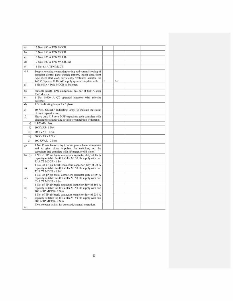
8
a) 2 Nos. 630 A TPN MCCB.
b) 5 Nos. 250 A TPN MCCB.
c) 5 Nos. 125 A TPN MCCB.
d) 7 Nos. 100 A TPN MCCB. Set
e) 1 No. 63 A TPN MCCB.
4.5 Supply, erecting connecting testing and commissioning of
capacitor control panel cubicle pattern, indoor dead front
type sheet steel clad, sufficiently ventilated suitable for
440 V, 3 phase 50 Hz AC supply system complete with. 1 Set
a) 1 No.800A 4 Pole MCCB as incomer.
b) Suitable length TPN aluminium bus bar of 800 A with
PVC sleeves.
c) 1 No. 0-600 A CT operated ammeter with selector
switches
d) 1 Set indicating lamps for 3 phase.
e) 10 Nos. ON/OFF indicating lamps to indicate the status
of each capacitor unit.
f) Heavy duty 415 volts MPP capacitors each complete with
discharge resistance and solid interconnection with panel.
i) 5 KVAR- I No.
ii) 10 KVAR- 1 No.
iii) 20 KVAR - I No.
iv) 50 KVAR - 2 Nos.
v) 100 KVAR - 2 Nos.
g) 1 No. Power factor relay to sense power factor correction
and to give phase impulses for switching on the
capacitors and complete with PF meter. (solid state).
h) (i) I No. of TP air break contactors capacitor duty of 16 A
capacity suitable for 415 Volts AC 50 Hz supply with one
32 A TP MCCB - 1 Set
ii)
1 No. of TP air break contactors capacitor duty of 30 A
capacity suitable for 415 Volts AC 50 Hz supply with one
32 A TP MCCB - 1 Set
iii)
1 No. of TP air break contactors capacitor duty of 55' A
capacity suitable for 415 Volts AC 50 Hz supply with one
63 A TP MCCB - 1 Set
iv)
1 No. of TP air break contactors capacitor duty of 160 A
capacity suitable for 415 Volts AC 50 Hz supply with one
100 A TP MCCB - 2 Sets
v)
1 No. of TP air break contactors capacitor duty of 250 A
capacity suitable for 415 Volts AC 50 Hz supply with one
200 A TP MCCB - 2 Sets
vi)
I No. selector switch for automatic/manual operation.

9
S.No. Description Qty unit Rate
(Rs.)
Amount (Rs.)
5.0
SECTION - 5 - D.G. SET ACCESSORIES
5.1
Supply, transporting, loading, unloading, erecting, testing
and commissionig etc. of Silent Type Diesel Generating
Sets of 400 KVA with AMF, 3 phase & neutral, 50 c/s.
415 A.C. rating, comprising of following Diesel Engine,
Heat exchanger with oil cooler, Alternator, Sound
Attenuated Acoustic Enclosure as detailed in of Technical
Specifications and other associated accessories: 1 set
A. DIESEL ENGINE:
a) Type: Multi-cylinder with direct radiator, Turbo charged
with Heat Exchanger with oil cooler.
b) No. of strokes : 4
c) Fuelinjection :Direct
d) Maximum speed : 1500 RPM
e) Rated power : 450 BHP (minimum)
f) Cooling of : Water cooled
Cylinders with Oil cooled remote Radiator
g) Engine : Battery starting.
Starting
h) Starting : Universal. Auto/Manual position
i) Engine
(i) Cummins
(ii) Caterpiller
B. ALTERNATOR;
a) Type : Brushless.
b) Actual Power 400 KVA at 50 deg.C (or 500 KVA @
40oC)
c) Rated power : 400 KVA @ 40oC
d) Frequency : 50 Cycles/sec.
e) Supply system :3 phases & neutral
f) Connection : Star.
g) Rated voltage: 415 Volts.
h) Rated rpm. : 1500 rpm. max.
i) Casing : As per IP-23
j) protection
k) Insulation : Class `H'.
l) Voltage : Automatic voltage
m) regulator regulator (Motorised)
n) Power factor : 0.8.
C. ACCESSORIES:
The Diesel Engine shall be equipped with minimum
following/ as indicated in the specifications, devices/
accessories built-in type including all standard fittings.
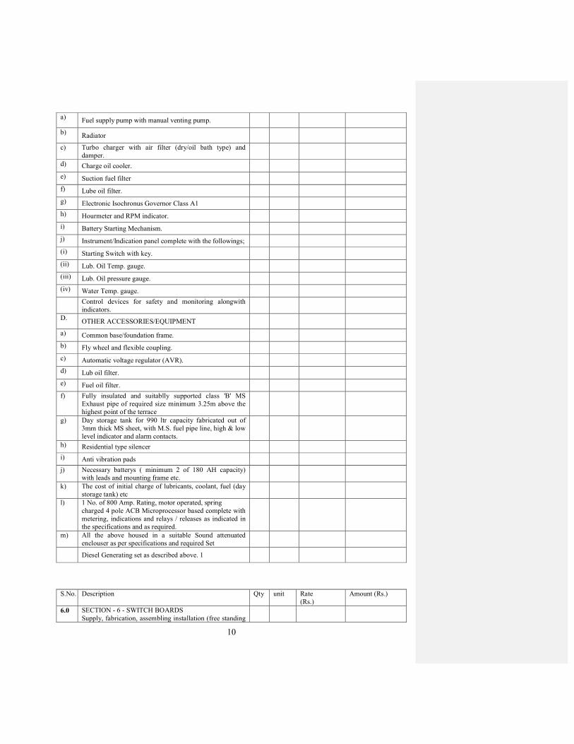
10
a) Fuel supply pump with manual venting pump.
b) Radiator
c) Turbo charger with air filter (dry/oil bath type) and
damper.
d) Charge oil cooler.
e) Suction fuel filter
f) Lube oil filter.
g) Electronic Isochronus Governor Class A1
h) Hourmeter and RPM indicator.
i) Battery Starting Mechanism.
j) Instrument/Indication panel complete with the followings;
(i) Starting Switch with key.
(ii) Lub. Oil Temp. gauge.
(iii) Lub. Oil pressure gauge.
(iv) Water Temp. gauge.
Control devices for safety and monitoring alongwith
indicators.
D. OTHER ACCESSORIES/EQUIPMENT
a) Common base/foundation frame.
b) Fly wheel and flexible coupling.
c) Automatic voltage regulator (AVR).
d) Lub oil filter.
e) Fuel oil filter.
f) Fully insulated and suitablly supported class 'B' MS
Exhaust pipe of required size minimum 3.25m above the
highest point of the terrace
g) Day storage tank for 990 ltr capacity fabricated out of
3mm thick MS sheet, with M.S. fuel pipe line, high & low
level indicator and alarm contacts.
h) Residential type silencer
i) Anti vibration pads
j) Necessary batterys ( minimum 2 of 180 AH capacity)
with leads and mounting frame etc.
k) The cost of initial charge of lubricants, coolant, fuel (day
storage tank) etc
l) 1 No. of 800 Amp. Rating, motor operated, spring
charged 4 pole ACB Microprocessor based complete with
metering, indications and relays / releases as indicated in
the specifications and as required.
m) All the above housed in a suitable Sound attenuated
enclouser as per specifications and required Set
Diesel Generating set as described above. 1
S.No. Description Qty unit Rate
(Rs.)
Amount (Rs.)
6.0
SECTION - 6 - SWITCH BOARDS
Supply, fabrication, assembling installation (free standing
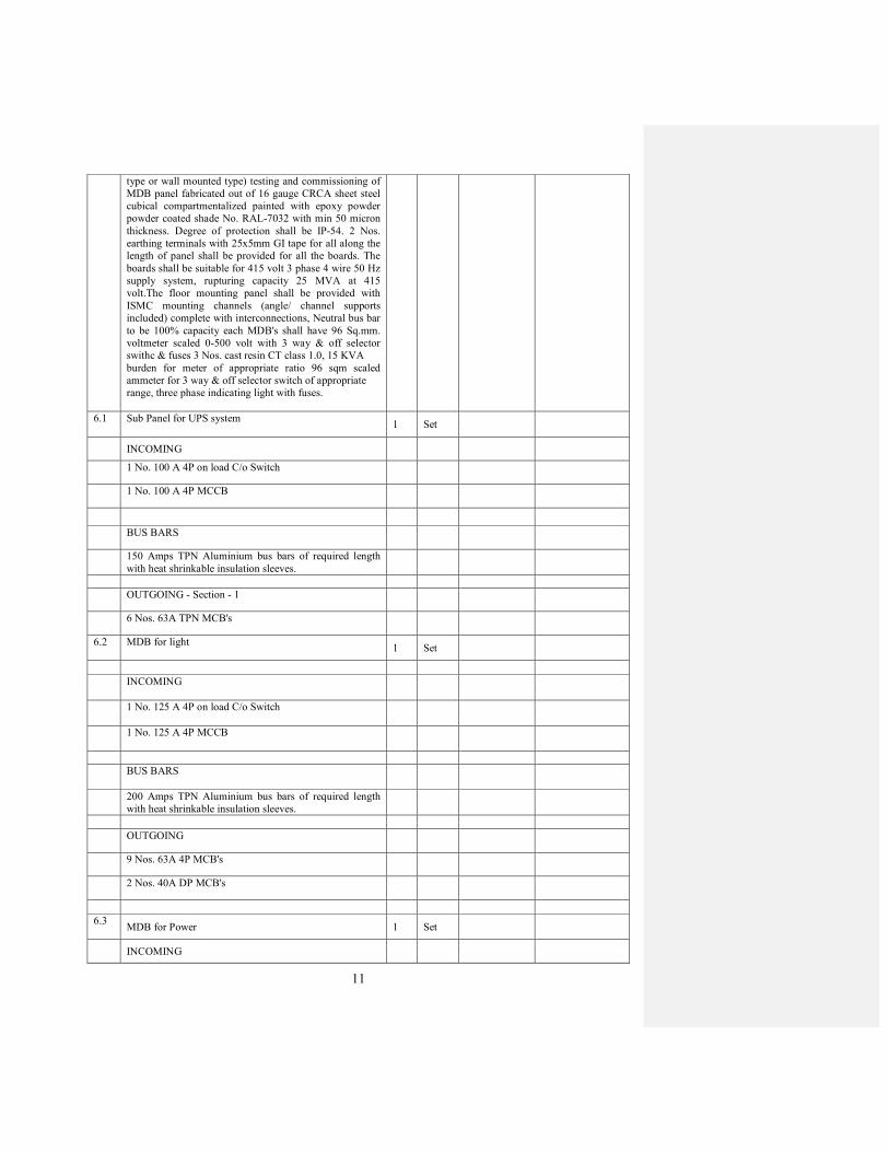
11
type or wall mounted type) testing and commissioning of
MDB panel fabricated out of 16 gauge CRCA sheet steel
cubical compartmentalized painted with epoxy powder
powder coated shade No. RAL-7032 with min 50 micron
thickness. Degree of protection shall be IP-54. 2 Nos.
earthing terminals with 25x5mm GI tape for all along the
length of panel shall be provided for all the boards. The
boards shall be suitable for 415 volt 3 phase 4 wire 50 Hz
supply system, rupturing capacity 25 MVA at 415
volt.The floor mounting panel shall be provided with
ISMC mounting channels (angle/ channel supports
included) complete with interconnections, Neutral bus bar
to be 100% capacity each MDB's shall have 96 Sq.mm.
voltmeter scaled 0-500 volt with 3 way & off selector
swithc & fuses 3 Nos. cast resin CT class 1.0, 15 KVA
burden for meter of appropriate ratio 96 sqm scaled
ammeter for 3 way & off selector switch of appropriate
range, three phase indicating light with fuses.
6.1
Sub Panel for UPS system
1 Set
INCOMING
1 No. 100 A 4P on load C/o Switch
1 No. 100 A 4P MCCB
BUS BARS
150 Amps TPN Aluminium bus bars of required length
with heat shrinkable insulation sleeves.
OUTGOING - Section - 1
6 Nos. 63A TPN MCB's
6.2 MDB for light
1 Set
INCOMING
1 No. 125 A 4P on load C/o Switch
1 No. 125 A 4P MCCB
BUS BARS
200 Amps TPN Aluminium bus bars of required length
with heat shrinkable insulation sleeves.
OUTGOING
9 Nos. 63A 4P MCB's
2 Nos. 40A DP MCB's
6.3
MDB for Power 1 Set
INCOMING
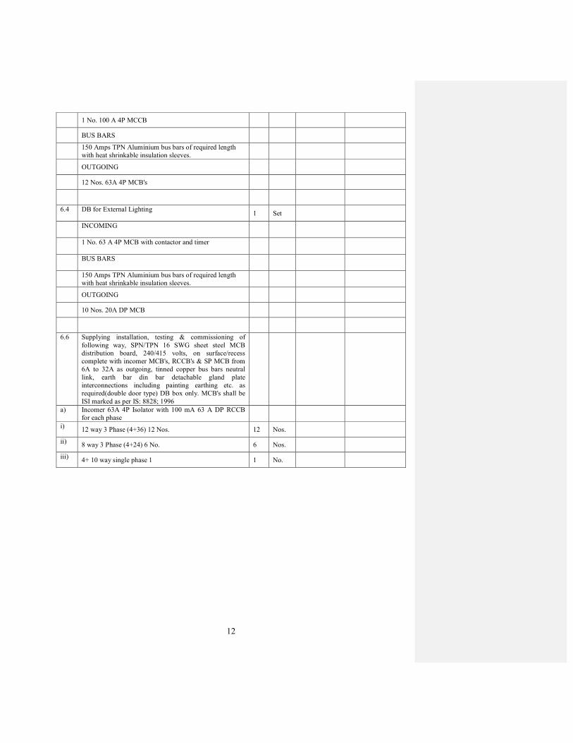
12
1 No. 100 A 4P MCCB
BUS BARS
150 Amps TPN Aluminium bus bars of required length
with heat shrinkable insulation sleeves.
OUTGOING
12 Nos. 63A 4P MCB's
6.4 DB for External Lighting
1 Set
INCOMING
1 No. 63 A 4P MCB with contactor and timer
BUS BARS
150 Amps TPN Aluminium bus bars of required length
with heat shrinkable insulation sleeves.
OUTGOING
10 Nos. 20A DP MCB
6.6 Supplying installation, testing & commissioning of
following way, SPN/TPN 16 SWG sheet steel MCB
distribution board, 240/415 volts, on surface/recess
complete with incomer MCB's, RCCB's & SP MCB from
6A to 32A as outgoing, tinned copper bus bars neutral
link, earth bar din bar detachable gland plate
interconnections including painting earthing etc. as
required(double door type) DB box only. MCB's shall be
ISI marked as per IS: 8828; 1996
a) Incomer 63A 4P Isolator with 100 mA 63 A DP RCCB
for each phase
i) 12 way 3 Phase (4+36) 12 Nos. 12 Nos.
ii) 8 way 3 Phase (4+24) 6 No. 6 Nos.
iii) 4+ 10 way single phase 1 1 No.

13
S.No. Description Qty unit Rate
(Rs.)
Amount (Rs.)
7.0
SECTION - 7 - TELEPHONE & SUBMAIN &
DUMMY CONDUITS
7.1
Supply & fixing of following sizes of MS steel conduit
along with accessories in recessed / surface including draw
boxes, pull boxes, cutting the wall and making good the
same in case of recessed conduit as required.
a) 25mm dia 1.6mm thick 6000 Metre
b) 32mm dia 2mm thick 500 Metre
c) 20mm dia 1.6mm thick 2200 Metre
7.2
Telephone wiring in existing conduit:
Supplying and drawing following 2 Pair , 0.5 sq. mm FR
pve insulated copper conductor, unarmoured telephone
cable in the existing. surfacelrecessed steel conduit as
required.
5000 Metre
7.3 Supply & fixing modular plate RJ-Il telephone jack.
With-G.I. Box
250 Nos.
7.4
Supplying installation, testing and commissioning of
following sizes of telephone tag block complete with
disconnector modules, mounting frame in powder coated
sheet steel enclosure 16 s.w.g. including termination's of
cable as required.
a) 20 Pair 1 No.
b) 80 Pair 1 No.
c) 150 Pair 2 Nos.
7.5
Wiring for sub-mains with 2 x 2.5 Sq.mm. size of pvc
insulated copper conductor single core cable in existing MS
steel conduit including earthing with 1.0 sq.mm. pvc
insulated wire.
R.O. Metre
7.6
Supplying, laying, fixing & commissioning of multi core
annealed tinned electrolytic copper conductor insulated and
sheathed twisted wires bunched together in concentric
layers telephone armoured cables as follows:
a)
10 Pair 0.61 nun dia
30
Metre
b) 40 Pair 0.61 nun dia 40 Metre
c)
50 Pair 0.61 nun dia
100 Metre
7.7
Supplying & fixing of under floor access outlet complete in
all respect etc as required (make; MK)
2
Sets
7.8
Supplying & fixing under floor vertical access unit etc as
required (make; MK).
2
Sets
7.9 Supply & fixing joint sleeves (make; MK). 2 Sets
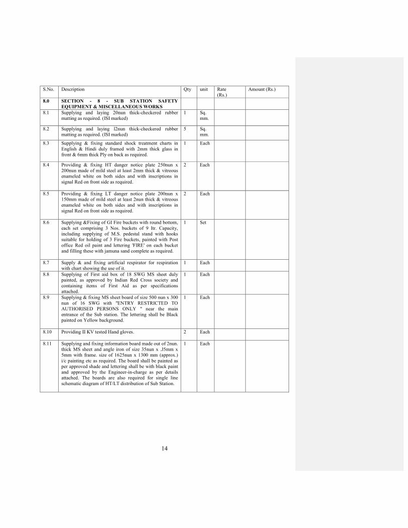
14
S.No. Description Qty unit Rate
(Rs.)
Amount (Rs.)
8.0
SECTION - 8 - SUB STATION SAFETY
EQUIPMENT & MISCELLANEOUS WORKS
8.1 Supplying and laying 20nun thick-checkered rubber
matting as required. (ISI marked)
1 Sq.
mm.
8.2 Supplying and laying l2nun thick-checkered rubber
matting as required. (ISI marked)
5 Sq.
mm.
8.3 Supplying & fixing standard shock treatment charts in
English & Hindi duly framed with 2mm thick glass in
front & 6mm thick Ply on back as required.
1 Each
8.4
Providing & fixing HT danger notice plate 250nun x
200nun made of mild steel at least 2mm thick & vitreous
enameled white on both sides and with inscriptions in
signal Red on front side as required.
2
Each
8.5
Providing & fixing LT danger notice plate 200nun x
150mm made of mild steel at least 2nun thick & vitreous
enameled white on both sides and with inscriptions in
signal Red on front side as required.
2
Each
8.6
Supplying &Fixing of GI Fire buckets with round bottom,
each set comprising 3 Nos. buckets of 9 Itr. Capacity,
including supplying of M.S. pedestal stand with hooks
suitable for holding of 3 Fire buckets, painted with Post
office Red oil paint and lettering 'FIRE' on each bucket
and filling these with jamuna sand complete as required.
1 Set
8.7 Supply & and fixing artificial respirator for respiration
with chart showing the use of it.
1 Each
8.8 Supplying of First aid box of 18 SWG MS sheet duly
painted, as approved by Indian Red Cross society and
containing items of First Aid as per specifications
attached.
1 Each
8.9
Supplying & fixing MS sheet board of size 500 nun x 300
nun of 16 SWG with "ENTRY RESTRICTED TO
AUTHORISED PERSONS ONLY " near the main
entrance of the Sub station. The lettering shall be Black
painted on Yellow background.
1
Each
8.10 Providing II KV tested Hand gloves.
2
Each
8.11
Supplying and fixing information board made out of 2nun.
thick MS sheet and angle iron of size 35nun x .J5mm x
5mm with frame. size of 1625nun x 1300 mm (approx.)
i/c painting etc as required. The board shall be painted as
per approved shade and lettering shall be with black paint
and approved by the Engineer-in-charge as per details
attached. The boards are also required for single line
schematic diagram of HT/LT distribution of Sub Station.
1 Each
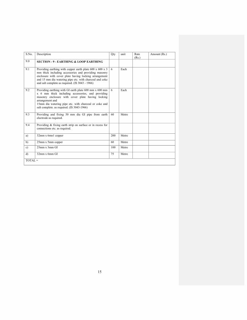
15
S.No. Description Qty unit Rate
(Rs.)
Amount (Rs.)
9.0
SECTION - 9 - EARTHING & LOOP EARTHING
9.1
Providing earthing with copper earth plate 600 x 600 x 3
mm thick including accessories and providing masonry
enclosure with cover plate having locking arrangement
and 15 mm dia watering pipe etc. with charcoal and coke
and salt complete as required. (IS 3043 - 1966)
6
Each
9.2
Providing earthing with GI earth plate 600 mm x 600 mm
x 6 mm thick including accessories, and providing
masonry enclosure with cover plate having locking
arrangement and
15mm dia watering pipe etc. with charcoal or coke and
salt complete. as required. (IS 3043-1966)
6
Each
9.3 Providing and fixing 50 mm dia GI pipe from earth
electrode as required.
60 Metre
9.4 Providing & fixing earth strip on surface or in recess for
connections etc. as required.
a) 32mm x 6mn1 copper 200 Metre
b) 25mm x 5mm copper 60 Metre
c) 25mm x 3mm GI 100 Metre
d) 32mm x 6mm GI 75 Metre
TOTAL =

16
S.No. Description Qty unit Rate
(Rs.)
Amount
(Rs.)
10.0
SECTION -10 – HYDROPNEUMATIC SYSTEM
10.1
Supplying, Installation, Testing and Commissioning of
skid mounted factory assembled Hydropneumatic System
consisting of 3 pumps (2Working + 1 Standby) each of
100 lpm capacity against a head of 45 meter, with
following equipments and accessories.
1 Set
a)
Horizontal / Vertical inline multistage centrifugal
pumping set with stainless steel casing, SS impeller , SS
shaft, cast iron suction and discharge casing, connected to
suitable rating (Minimum 15 HP capacity each) TEFC
induction motor suitable 415 V +_ 10%, 3 phase 50 Hz 3
Nos. (2 working + 1 standby)
b)
MS Pressure vessel, 100 Ltr. Capacity, non corrosive
composite construction nitrogen filed butyle rubber bags
with interconnecting valves and GI pipes heavy duty with
motor control panel.
c)
Electrical control panel with Programmable Logic
controller (PLC) with Proportionate Integrative
Derivative(PID) controller with 16 inputs and 12 outputs,
digital display with fluorescent screen with 2 lines of 20
character each and equipped with 8 function keys and 9
service keys, 1 No. 3 phase 415 V+_ 10% AC variable
speed drive of suitable rating with inbuilt class A RFI
filter, complete with all accessories like contactors, over
load relays, MCB’s , volt meter and ammeter, frequency
meter, cooling fan, ON / OFF indicators, rotary selector
switch for Manual / Auto operation of suitable size and
rating. It should have built in sequence program for cyclic
operation of pumps for equal aging., the pump working
sequence should change after every operation.
d)
Electronic pressure switches of suitable rating having
maximum pressure and differential scale conforming of
BC 6134 standards and IP 55 protection class.
e)
Complete system to be mounted on a common MS base3
frame foundation with vibration eliminators and as per
manufacturer’s design & standards and detailed
specifications.
f) PVC insulated, sheathed armoured copper cable with
earthing of suitable rating from control panel to pump
assembly.
Note: Quantities mentioned above are estimated only and for tender evaluation purpose. However, payments will be
made as per actual job requirements