
RAILWAY - National Academic Digital Library of Ethiopia
620
SATISH CHANDRA Professor, Department of Civil Engineering, Indian Institute of Technology Roorkee M.M. AGARWAL Retired Chief Engineer, Northern Railways RAILWAY ENGINEERING 1
-
Upload
khangminh22 -
Category
Documents
-
view
0 -
download
0
Transcript of RAILWAY - National Academic Digital Library of Ethiopia
SATISH CHANDRAProfessor, Department of Civil Engineering,
Indian Institute of Technology Roorkee
M.M. AGARWALRetired Chief Engineer,
Northern Railways
RAILWAYENGINEERING
1
3YMCA Library Building, Jai Singh Road, New Delhi 110001
Oxford University Press is a department of the University of Oxford.It furthers the University’s objective of excellence in research, scholarship,
and education by publishing worldwide in
Oxford New YorkAuckland Cape Town Dar es Salaam Hong Kong KarachiKuala Lumpur Madrid Melbourne Mexico City Nairobi
New Delhi Shanghai Taipei Toronto
With offices inArgentina Austria Brazil Chile Czech Republic France GreeceGuatemala Hungary Italy Japan Poland Portugal SingaporeSouth Korea Switzerland Thailand Turkey Ukraine Vietnam
Oxford is a registered trade mark of Oxford University Pressin the UK and in certain other countries.
Published in Indiaby Oxford University Press
© Oxford University Press 2007
The moral rights of the author have been asserted.
Database right Oxford University Press (maker)
First published 2007
All rights reserved. No part of this publication may be reproduced,stored in a retrieval system, or transmitted, in any form or by any means,
without the prior permission in writing of Oxford University Press,or as expressly permitted by law, or under terms agreed with the appropriate
reprographics rights organization. Enquiries concerning reproductionoutside the scope of the above should be sent to the Rights Department,
Oxford University Press, at the address above.
You must not circulate this book in any other binding or coverand you must impose this same condition on any acquirer.
ISBN-13: 978-0-19-568779-8ISBN-10: 0-19-568779-5
Typeset in Times Romanby Le Studio Graphique, Gurgaon 122001
Printed in India by Ram Book Binding House, New Delhi 110020and published by Oxford University Press
YMCA Library Building, Jai Singh Road, New Delhi 110001
RAILWAYENGINEERING
Preface iii
Preface
There have been major technological developments in railways around the world in therecent past to meet the challenges of heavier traffic and higher speeds. In Indian Railwaysespecially, the track structure has been modernized in a big way in the last three decades.Long welded rails, concrete sleepers, and elastic fastenings have been used on high-speed routes to provide stable and resilient structures. Metro railways are also beingintroduced in metropolitan cities to ease the problem of congestion on roads. Diesel andelectric locomotives, which have superior performance capabilities, have replaced steamlocomotives. In addition, modern signalling, automatic warning, and centralized trafficcontrol systems are being adopted to ensure safety and maximum utilization of trackcapacity.
It is very important for engineering students and new entrants into the field of railwaysto be aware of not only the fundamentals of railway engineering but also latestdevelopments with regard to railway tracks, locomotives and rolling stock, signallingand interlocking, etc.
About the Book
This book deals with all aspects of railway engineering, from fundamental concepts tomodern technological developments, with special focus on Indian Railways. It is anamalgamation of the vast experiences of the authors—of teaching the subject as well asof serving in Indian Railways. The text presents the theories and field practices as wellas the modern techniques in detail.
Content and Coverage
The book treats the theoretical and practical aspects of the subject exhaustively andincorporates the latest provisions adopted by Indian Railways (IR).
Chapter 1 presents a historical account of railways around the world with specialfocus on the important features of IR. Chapter 2 discusses the various gauges adoptedby IR and the problems associated with multigauge systems. Chapter 3 explains thefactors affecting track alignment. Chapter 4 describes the different types of engineeringsurveys required to be undertaken before launching a new railway project as well as theconstruction of new lines including doubling and gauge conversions. Chapter 5 presentsthe details of track specifications and structures for different gauges on IR. It alsodiscusses the forces acting on a track and the stresses generated in track components.
Chapters 6 to 10 describe the various components of a railway track—rails, sleepers,ballast, formation, and fittings and fastenings. It also discusses the recent provisionsadopted by IR with respect to these components.
Chapter 11 explains the causes and remedial measures for creep in rails. Chapter 12presents the basic aspects of the geometric design of railway tracks. Chapter 13 discussesthe detailed design of the horizontal and vertical curves on a railway line. Chapter 14and 15 elaborate on the various types of track junctions and their designs, layouts ofturnouts, and the factors affecting speed on turnouts.
Chapter 16 discusses rail joints and the methods used for welding rail joints.Chapter 17 describes the developments in welded railway tracks including long welded

iv Preface
rails (LWRs) and continuous welded rails (CWRs). It also explains the detailed procedurefor laying LWRs and the track specifications for long and short welded rails. Chapter 18describes the calendar system of track maintenance being followed by Indian Railways,which includes the conventional track maintenance operations of through packing,systematic overhauling, and picking up slacks. Chapter 19 details the track drainagesystem, along with the drainage of station platforms, yards, and subsurface drains.Chapter 20 describes the modern methods of track maintenance followed by IndianRailways employing track machines. It presents the details of measured shovel packing(MSP) equipment on IR. The chapter also describes Directed Track Maintenance(DTM)—IR’s annual programme—and its future scope.
Chapter 21 elaborates on the methods of track rehabilitation and the renewal of trackcomponents. It also discusses some new machines used by IR for track renewal. Chapter22 discusses accident and disaster management, which assumes significance because ofgreater emphasis being placed on safety by Indian Railways. Chapter 23 describes levelcrossings and the measures taken to prevent accidents at such crossings. Chapter 24includes the design and maintenance features of locomotives and other rolling stock.Chapter 25 provides the details of train resistances and their evaluation. It also definestractive effort and hauling capacity of locomotives.
Chapters 26 and 27 include details of station yards and the various equipment usedin railway stations, respectively. Chapter 28 discusses the construction of new railwaylines, track material required for BG tracks, doubling of railway lines, and gaugeconversion. Chapter 29 exclusively discusses suburban railways in metropolitan cities,which is the latest trend in the Indian context, so that this subject is fully appreciated bythe readers. Chapter 30 is devoted to the specialized subject of railway tunnelling,describing the various techniques of construction and maintenance of tunnels in differenttypes of soils.
Chapter 31 on signalling and interlocking gives the details of various signals,interlocking techniques, and modern developments concerning train control. Chapter 32discusses the various modernization plans of IR, covering tracks, locomotives, and rollingstock for high-speed trains, with the aim of widening the readers’ understanding of thescope of railway engineering.
AcknowledgementsWhile writing this book, references have been made to several Indian Railways codesand manuals and other documents published by RDSO (Research Design and StandardsOrganisation, India). We have liberally used these documents and gratefully acknowledgeRDSO. We are grateful to our family members for their moral support and cooperationwhile the book was being written.
Though every care has been taken to produce an error-free text, some errors mayhave gone unnoticed. We will be grateful to the users of the book for bringing any sucherrors to our notice, so that these can be rectified in subsequent editions. Constructivesuggestions and comments for further improvement of the content are welcome.
SATISH CHANDRA
M.M. AGARWAL
Contents v
Contents
Preface iii
1. History and General Features of Indian Railways 1Developments in Indian Railways 1, Different Modes of Transport 6,Organization of Indian Railways 8, Indian Railway Finances and theirControl 13, Commission of Railway Safety 13, Long-term CorporatePlan of Indian Railways 14, Classification of Railway Lines in India16,General Features of Indian Railways 18, Important Statistics of IndianRailways 21, Undertakings Under Ministry of Railways 25
2. Railway Track Gauge 31Gauges on World Railways 31, Different Gauges on IndianRailways32, Choice of Gauge 32, Problems Caused by Change ofGauge 33, Uni-gauge Policy of Indian Railways 35, Loading Gauge36,Construction Gauge 37
3. Alignment of Railway Lines 39Importance of Good Alignment 39, Basic Requirements of an IdealAlignment 39, Selection of a Good Alignment 40, MountainRailways45, Rack Railways 45
4. Engineering Surveys and Construction of New Lines 47Need for Construction of a New Railway Line 47, PreliminaryInvestigations for a New Railway Line 48, Types of Surveys 48, TrafficSurvey 48, Reconnaissance Survey 49, Preliminary Survey 51,Preliminary Engineering-cum-traffic Survey 53, Final LocationSurvey53, Modern Surveying Techniques for Difficult Terrain 56,Construction of New Lines 57
5. Track and Track Stresses 63Requirements of a Good Track 64, Maintenance of Permanent Way68,Track as an Elastic Structure 69, Forces Acting on the Track 70, Coningof Wheels 78, Tilting of Rails 79
6. Rails 81Function of Rails 81, Types of Rails 81, Requirements for an IdealRail Section 82, Rail Manufacture 86, Rail Wear 92, Other Defects inRails 94, Rail Failure 95, Rail Flaw Detection 97
7. Sleepers 106Functions and Requirements of Sleepers 106, Sleeper Density andSpacing of Sleepers 107, Types of Sleepers 108, Wooden Sleepers109,Steel Channel Sleepers 115, Steel Trough Sleeper 115, Cast IronSleepers 117, Concrete Sleepers 122
vi Contents
8. Ballast 138Functions of Ballast 138, Types of Ballast 138, Sizes of Ballast 140,Requirements of a Good Ballast 140, Design of Ballast Section 141,Specifications for Track Ballast 143, Collection and Transportationof Ballasts 146, Methods of Measurement 147, Laboratory Testsfor Physical Properties of Ballast 147, Assessment of BallastRequirements149, Guidelines for Provision of Sub-ballast 149
9. Subgrade and Formation 152Slopes of Formation 153, Execution of Earthwork in Embankmentsand Cuttings 154, Blanket and Blanketing Material 156, Failure ofRailway Embankment 157, Site Investigations 163
10. Rack Fittings and Fastenings 166Rail-to-Rail Fastenings 167, Fittings for Wooden Sleepers 170, Fittingsof Steel Trough Sleepers 173, Fittings of CI Sleepers 177, ElasticFastenings 178, Other Fittings and Fastenings 186, Testing ofFastenings 189
11. Creep of Rails 191Theories for the Development of Creep 191, Causes of Creep 192,Effects of Creep 193, Measurement of Creep 194, Adjustment ofCreep194, Creep Adjuster 194, Portions of Track Susceptible toCreep195, Measures to Reduce Creep 195
12. Geometric Design of Track 197Necessity for Geometric Design 197, Details of Geometric Design ofTrack 197, Gradients 198, Grade Compensation on Curves 200
13. Curves and Superelevation 201Circular Curves 201, Superelevation 210, Safe Speed on Curves 217,Transition Curve 226, Compound Curve 232, Reverse Curve 233, ExtraClearance on Curves 234, Widening of Gauge on Curves 237, VerticalCurves 238, Realignment of Curves 242, Cutting Rails on Curves 249,Check Rails on Curves 250
14. Points and Crossings 254Important Terms 254, Switches 256, Design of Tongue Rails 258,Crossing 259, Number and Angle of Crossing 263, Reconditioning ofWorn Out Crossings 265, Turnouts 266, Turnout with CurvedSwitches273, Layout of Turnout 273, Trends in Turnout Design onIndian Railways 274, Inspection and Maintenance of Points andCrossings 275
15. Track Junctions and Simple Track Layouts 279Turnout of Similar Flexure 279, Turnout of Contrary Flexure 280,Symmetrical Split 280, Three-throw Switch 281, Double Turnout 282,Crossover Between Two Parallel Tracks with an Intermediate StraightLength 283, Diamond Crossing 285, Scissors Crossover 287,
Contents vii
Gauntletted Track 288, Gathering Line 289, Triangle 290, DoubleJunctions 291
16. Rail Joints and Welding of Rails 294Ill Effects of a Rail Joint 294, Requirements of an Ideal Rail Joint295,Types of Rail Joints 295, Welding a Rail Joint 298, Gas PressureWelding 298, Electric or Metal Arc Welding 299, Flash ButtWelding299, Thermit Welding of Rails 304, Recent Developments inWelding Techniques 310
17. Modern Welded Railway Track 313Development of Welded Rails 314, Theory of Long Welded Rails 315,Prohibited Locations for LWR 316, Track Structure for LWR 317,Rail Temperature and its Measurement 320, Maintenance of LongWelded Rails 321, Switch Expansion Joint 322, Buffer Rails 323,Short Welded Rails 323, Continuous Welded Rails 324, Buckling ofTrack325
18. Track Maintenance 329Necessity and Advantages of Track Maintenance 329, Essentials ofTrack Maintenance 330, Measuring Equipment and Maintenance Toolsfor Tracks 335, Maintenance of Rail Surface 336, Deep Screening ofBallast 339, Track Drainage 340, Maintenance of Track in Track-circuited Lengths 340, Organization Structure for TrackMaintenance341, Protection of Track for Engineering Work 347,Patrolling of Railway Tracks 350, Track Tolerances 350
19. Track Drainage 353Need for Proper Track Drainage 353, Sources of Percolated Water inthe Track 354, Requirements of a Good Track Drainage System 354,Practical Tips for Good Surface Drainage 355, Track DrainageSystems355, Sub-surface Drainage 358
20. Modern Methods of Track Maintenance 360Mechanized Methods of Track Maintenance 361, Off-trackTampers362, On-track Tampers 364, Future of Track Machines onIndian Railways 366, Measured Shovel Packing 368, Directed TrackMaintenance 380
21. Rehabilitation and Renewal of Track 384Classification of Track Renewal Works 384, Criteria for RailRenewals385, Through Sleeper Renewals 388, Execution of TrackRenewal or Track Re-laying Work 389, Mechanized Re-laying 391,Track Renewal Trains 393, Requirement of Track Material 395
22. Railway Accidents and Disaster Management 397Train Accidents 397, Classification of Railways Accidents 398,Derailment and its Causes 401, Restoration of Traffic 403, FloodCauseway 405, Safety Measures on Indian Railways 406, DisasterManagement 406
viii Contents
23. Level Crossings 411Classification of Level Crossings 411, Dimensions of LevelCrossings413, Accidents at Level Crossings and RemedialMeasures413, Maintenance of Level Crossings 414, Inspection ofLevel Crossings by PWI and AEN 415
24. Locomotives and Other Rolling Stock 417Types of Traction 417, Nomenclature of Steam Locomotives 418,Classification of Locomotives 418, Preventive Maintenance ofLocomotives 425, Rolling Stock 427, Brake Systems 428, Maintenanceof Coaches and Wagons 430, Design Features of Modern Coachingand Goods Stock 433
25. Train Resistance and Tractive Power 436Resistance Due to Friction 436, Resistance Due to Wave Action 436,Resistance Due to Wind 437, Resistance Due to Gradient 438,Resistance Due to Curvature 439, Resistance Due to Starting andAccelerating 441, Tractive Effort of a Locomotive 441, Hauling Powerof a Locomotive 447
26. Railway Stations and Yards 451Purpose of a Railway Station 451, Selection of Site for a RailwayStation 451, Facilities Required at Railway Stations 452, Requirementsof a Passenger Station Yard 452, Classification of Railway Stations453,Station Platforms 463, Main Building Areas for Different Types ofStations 465, Types of Yards 466, Catch Sidings and Ship Sidings 472
27. Equipment at Railway Stations 474Platforms 474, Foot Over Bridges and Subways 475, Cranes 475,Weigh Bridge 475, Loading Gauge 475, End Loading Ramps 476,Locomotive Sheds 476, Ashpits 479, Water Columns 480,Turntable481, Triangles 482, Traverser 482, Carriage WashingPlatforms 483, Buffer Stop 483, Scotch Block, Derailing Switch, andSand Hump 484, Fouling Mark 485
28. Construction of New Railway Lines and Track Linking 487Construction of New Lines 487, Requirement of Track Material forBG Track 492, Doubling of Railway Lines 492, Gauge Conversion493
29. Suburban Railways in Metro Cities 498Urban Transport 499, The Delhi Ring Railways 505, Mass RapidTransit System in Delhi 506, Kolkata Metro 515, Mumbai SuburbanSystem 517, Chennai Suburban System 518
30. Railway Tunnelling 520Necessity/Advantages of a Tunnel 520, Tunnel Alignment andGradient521, Size and Shape of a Tunnel 521, Methods ofTunnelling522, Ventilation of Tunnels 530, Lighting of Tunnels 532,
Contents ix
Drainage of Tunnels 532, Shaft of Tunnels 532, Lining ofTunnels533, Maintenance of Railway Tunnels 534, Safety in TunnelConstruction535
31. Signalling and Interlocking 537Objectives of Signalling 537, Classification of Signals 538, FixedSignals 540, Stop Signals 549, Signalling Systems 551, MechanicalSignalling System 552, Electrical Signalling System 561, Systems forControlling Train Movement 563, Interlocking 567, Modern SignallingInstallations 574
32. Modernization of Railways and High Speed Trains 579Modernization of Railways 579, Effect of High-speed Track 580,Vehicle Performance on Track 581, High-speed Ground TransportationSystem 581, Ballastless Track 582
Index 586
History and General Features of Indian Railways 1
History and General Features
of Indian Railways
Introduction
The history of railways is closely linked with civilization. As the necessity arose,human beings developed various methods of transporting goods from one place toanother. In the primitive days goods were carried as head loads or in carts drawnby men or animals. Then efforts were made to replace animal power with mechanicalpower. In 1769, Nicholes Carnot, a Frenchman, carried out the pioneering work ofdeveloping steam energy. This work had very limited success and it was only in theyear 1804 that Richard Trevithick designed and constructed a steam locomotive.This locomotive, however, could be used for traction on roads only. The credit ofperfecting the design goes to George Stephenson, who in 1814 produced the firststeam locomotive used for traction in railways.
The first public railway in the world was opened to traffic on 27 September1825 between Stockton and Darlington in the UK. Simultaneously, other countriesin Europe also developed such railway systems; most introduced trains for carriageof passenger traffic during that time. The first railway in Germany was openedfrom Nurenberg to Furth in 1835. The USA opened its first railway line betweenMohawk and Hudson in 1833.
The first railway line in India was opened in 1853. The first train, consisting ofone steam engine and four coaches, made its maiden trip on 16 April 1853, when ittraversed a 21-mile stretch between Bombay (now Mumbai) and Thane in 1.25 hours.Starting from this humble beginning, Indian Railways has grown today into a giantnetwork consisting of 63,221 route km and criss-crossing this great country fromthe Himalayan foothills in the north to Cape Comorin (Kanyakumari) in the southand from Dibrugarh in the east to Dwarka in the west. Indian Railways has a gloriouspast of more than 150 years. The developments in Indian Railways, its organization,and its working are explained in the following sections of this chapter.
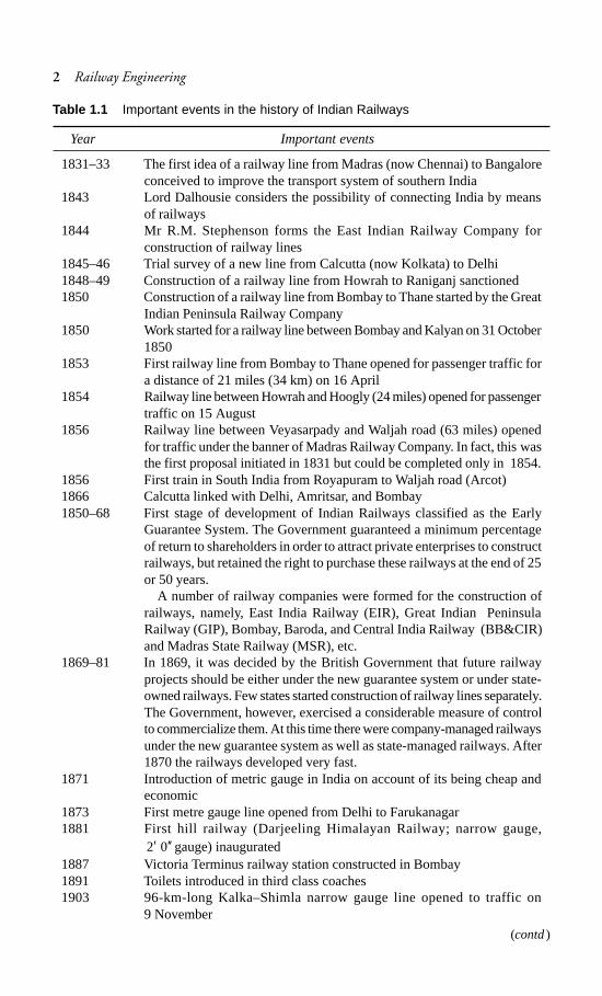
1.1 Developments in Indian Railways
Important developments in Indian Railways have been chronologically listed inTable 1.1.
CHAPTER
1
2 Railway Engineering
Table 1.1 Important events in the history of Indian Railways
Year Important events
1831–33 The first idea of a railway line from Madras (now Chennai) to Bangaloreconceived to improve the transport system of southern India
1843 Lord Dalhousie considers the possibility of connecting India by meansof railways
1844 Mr R.M. Stephenson forms the East Indian Railway Company forconstruction of railway lines
1845–46 Trial survey of a new line from Calcutta (now Kolkata) to Delhi1848–49 Construction of a railway line from Howrah to Raniganj sanctioned1850 Construction of a railway line from Bombay to Thane started by the Great
Indian Peninsula Railway Company1850 Work started for a railway line between Bombay and Kalyan on 31 October
18501853 First railway line from Bombay to Thane opened for passenger traffic for
a distance of 21 miles (34 km) on 16 April1854 Railway line between Howrah and Hoogly (24 miles) opened for passenger
traffic on 15 August1856 Railway line between Veyasarpady and Waljah road (63 miles) opened
for traffic under the banner of Madras Railway Company. In fact, this wasthe first proposal initiated in 1831 but could be completed only in 1854.
1856 First train in South India from Royapuram to Waljah road (Arcot)1866 Calcutta linked with Delhi, Amritsar, and Bombay1850–68 First stage of development of Indian Railways classified as the Early
Guarantee System. The Government guaranteed a minimum percentageof return to shareholders in order to attract private enterprises to constructrailways, but retained the right to purchase these railways at the end of 25or 50 years.
A number of railway companies were formed for the construction ofrailways, namely, East India Railway (EIR), Great Indian PeninsulaRailway (GIP), Bombay, Baroda, and Central India Railway (BB&CIR)and Madras State Railway (MSR), etc.
1869–81 In 1869, it was decided by the British Government that future railwayprojects should be either under the new guarantee system or under state-owned railways. Few states started construction of railway lines separately.The Government, however, exercised a considerable measure of controlto commercialize them. At this time there were company-managed railwaysunder the new guarantee system as well as state-managed railways. After1870 the railways developed very fast.
1871 Introduction of metric gauge in India on account of its being cheap andeconomic
1873 First metre gauge line opened from Delhi to Farukanagar1881 First hill railway (Darjeeling Himalayan Railway; narrow gauge,
2 0′ ′′ gauge) inaugurated1887 Victoria Terminus railway station constructed in Bombay1891 Toilets introduced in third class coaches1903 96-km-long Kalka–Shimla narrow gauge line opened to traffic on
9 November
(contd)
History and General Features of Indian Railways 3
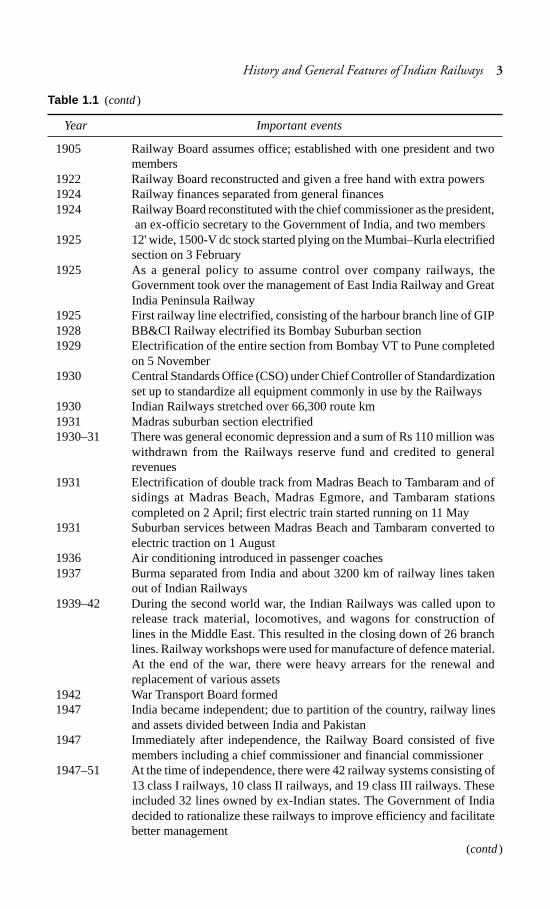
Year Important events
1905 Railway Board assumes office; established with one president and twomembers
1922 Railway Board reconstructed and given a free hand with extra powers1924 Railway finances separated from general finances1924 Railway Board reconstituted with the chief commissioner as the president,
an ex-officio secretary to the Government of India, and two members1925 12' wide, 1500-V dc stock started plying on the Mumbai–Kurla electrified
section on 3 February1925 As a general policy to assume control over company railways, the
Government took over the management of East India Railway and GreatIndia Peninsula Railway
1925 First railway line electrified, consisting of the harbour branch line of GIP1928 BB&CI Railway electrified its Bombay Suburban section1929 Electrification of the entire section from Bombay VT to Pune completed
on 5 November1930 Central Standards Office (CSO) under Chief Controller of Standardization
set up to standardize all equipment commonly in use by the Railways1930 Indian Railways stretched over 66,300 route km1931 Madras suburban section electrified1930–31 There was general economic depression and a sum of Rs 110 million was
withdrawn from the Railways reserve fund and credited to generalrevenues
1931 Electrification of double track from Madras Beach to Tambaram and ofsidings at Madras Beach, Madras Egmore, and Tambaram stationscompleted on 2 April; first electric train started running on 11 May
1931 Suburban services between Madras Beach and Tambaram converted toelectric traction on 1 August
1936 Air conditioning introduced in passenger coaches1937 Burma separated from India and about 3200 km of railway lines taken
out of Indian Railways1939–42 During the second world war, the Indian Railways was called upon to
release track material, locomotives, and wagons for construction oflines in the Middle East. This resulted in the closing down of 26 branchlines. Railway workshops were used for manufacture of defence material.At the end of the war, there were heavy arrears for the renewal andreplacement of various assets
1942 War Transport Board formed1947 India became independent; due to partition of the country, railway lines
and assets divided between India and Pakistan1947 Immediately after independence, the Railway Board consisted of five
members including a chief commissioner and financial commissioner1947–51 At the time of independence, there were 42 railway systems consisting of
13 class I railways, 10 class II railways, and 19 class III railways. Theseincluded 32 lines owned by ex-Indian states. The Government of Indiadecided to rationalize these railways to improve efficiency and facilitatebetter management
Table 1.1 (contd)
(contd)
4 Railway Engineering
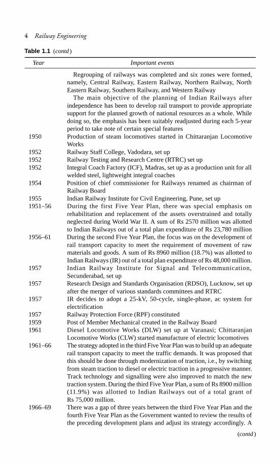
Year Important events
Regrouping of railways was completed and six zones were formed,namely, Central Railway, Eastern Railway, Northern Railway, NorthEastern Railway, Southern Railway, and Western Railway
The main objective of the planning of Indian Railways afterindependence has been to develop rail transport to provide appropriatesupport for the planned growth of national resources as a whole. Whiledoing so, the emphasis has been suitably readjusted during each 5-yearperiod to take note of certain special features
1950 Production of steam locomotives started in Chittaranjan LocomotiveWorks
1952 Railway Staff College, Vadodara, set up1952 Railway Testing and Research Centre (RTRC) set up1952 Integral Coach Factory (ICF), Madras, set up as a production unit for all
welded steel, lightweight integral coaches1954 Position of chief commissioner for Railways renamed as chairman of
Railway Board1955 Indian Railway Institute for Civil Engineering, Pune, set up1951–56 During the first Five Year Plan, there was special emphasis on
rehabilitation and replacement of the assets overstrained and totallyneglected during World War II. A sum of Rs 2570 million was allottedto Indian Railways out of a total plan expenditure of Rs 23,780 million
1956–61 During the second Five Year Plan, the focus was on the development ofrail transport capacity to meet the requirement of movement of rawmaterials and goods. A sum of Rs 8960 million (18.7%) was allotted toIndian Railways (IR) out of a total plan expenditure of Rs 48,000 million.
1957 Indian Railway Institute for Signal and Telecommunication,Secunderabad, set up
1957 Research Design and Standards Organisation (RDSO), Lucknow, set upafter the merger of various standards committees and RTRC
1957 IR decides to adopt a 25-kV, 50-cycle, single-phase, ac system forelectrification
1957 Railway Protection Force (RPF) constituted1959 Post of Member Mechanical created in the Railway Board1961 Diesel Locomotive Works (DLW) set up at Varanasi; Chittaranjan
Locomotive Works (CLW) started manufacture of electric locomotives1961–66 The strategy adopted in the third Five Year Plan was to build up an adequate
rail transport capacity to meet the traffic demands. It was proposed thatthis should be done through modernization of traction, i.e., by switchingfrom steam traction to diesel or electric traction in a progressive manner.Track technology and signalling were also improved to match the newtraction system. During the third Five Year Plan, a sum of Rs 8900 million(11.9%) was allotted to Indian Railways out of a total grant ofRs 75,000 million.
1966–69 There was a gap of three years between the third Five Year Plan and thefourth Five Year Plan as the Government wanted to review the results ofthe preceding development plans and adjust its strategy accordingly. A
Table 1.1 (contd)
(contd)
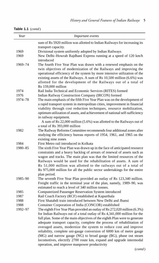
History and General Features of Indian Railways 5
Year Important events
sum of Rs 5920 million was allotted to Indian Railways for increasing itstransport capacity.
1969 Divisional system uniformly adopted by Indian Railways1969 New Delhi–Howrah Rajdhani Express running at a speed of 120 km/h
introduced1969–74 The fourth Five Year Plan was drawn with a renewed emphasis on the
twin objectives of modernization of the Railways and improving theoperational efficiency of the system by more intensive utilization of theexisting assets of the Railways. A sum of Rs 10,500 million (6.6%) wasallotted for the development of the Railways out of a total ofRs 159,000 million
1974 Rail India Technical and Economic Services (RITES) formed1976 Indian Railway Construction Company (IRCON) formed1974–78 The main emphasis of the fifth Five Year Plan was on the development of
a rapid transport system in metropolitan cities, improvement in financialviability through cost reduction techniques, resource mobilization,optimum utilization of assets, and achievement of national self-sufficiencyin railway equipment.
A sum of Rs 22,000 million (5.6%) was allotted to the Railways out ofa total of Rs 393,000 million
1982 The Railway Reforms Committee recommends four additional zones afterstudying the efficiency bureau reports of 1954, 1961, and 1965 on theexisting nine zones
1984 First Metro rail introduced in Kolkata1980–85 The sixth Five Year Plan was drawn up in the face of anticipated resource
constraints and a heavy backlog of arrears of renewal of assets such aswagon and tracks. The main plan was that the limited resources of theRailways would be used for the rehabilitation of assets. A sum ofRs 51,000 million was allotted to the railways out of a total ofRs 975,000 million for all the public sector undertakings for the entireplan period.
1985–90 The seventh Five Year Plan provided an outlay of Rs 123,340 million.Freight traffic in the terminal year of the plan, namely, 1989–90, wasestimated to reach a level of 340 million tonnes.
1985 Computerized Passenger Reservation System introduced1987 Rail Coach Factory (RCF) established at Kapurthala1988 First Shatabdi train introduced between New Delhi and Jhansi1988 Container Corporation of India (CONCOR) established1992–97 The eighth Five Year Plan provided an outlay of Rs 272,020 million (6.3%)
for Indian Railways out of a total outlay of Rs 4,341,000 million for thefull plan. Some of the main objectives of the eighth Plan were to generateadequate transport capacity, complete the process of rehabilitation ofoveraged assets, modernize the system to reduce cost and improvereliability, complete uni-gauge conversion of 6000 km of metre gauge(MG) and narrow gauge (NG) to broad gauge (BG), phase out steamlocomotives, electrify 2700 route km, expand and upgrade intermodaloperation, and improve manpower productivity
Table 1.1 (contd)
(contd)

6 Railway Engineering
Year Important events
1998 Konkan Railway system becomes fully operational on 26 January1998 Guiness Certificate for Fairy Queen—the oldest working steam locomotive
in the world1999 Darjeeling Himalayan Railway declared World Heritage Site by UNESCO1999 Centenary celebrations of the Nilgiri Mountain Railway1999 Guiness certificate for Delhi main station equipped with the world’s largest
route relay interlocking system2000 Railway Board consisted of seven members including a Chairman1997–2002 The ninth Plan envisages an outlay of Rs 454,130 million, which is 14.1%
of the total outlay of Rs 8,592,000 million for the full plan. Some of themain objectives were generation of adequate transport capacity forhandling additional traffic, modernization and upgrading of the railtransport system, completion of the process of rehabilitation, replacementand renewal of overaged assets, and continuation of the policy of unitgauge.
2002 150th year of Indian Railways starts with effect from 16 April 20022002 Jan Shatabdi trains introduced2002 East Cental Railway (HQ in Hazipur) and North Western Railway (HQ in
Jaipur) become operational with effect from 1 October.2003 Indian Railways has 16 (earlier 9) zones and 67 (earlier 59) divisions
with effect from 1 April 20032003 Indian Railways completes 150 years of existence on 15 April 20032002–07 The Tenth Five Year Plan envisages an outlay of Rs 606,000 million,
which is 4% of a total outlay of Rs 15,256,390 million for the full plan.The main objectives of the plan have been outlined in Section 1.7.6.
1.2 Different Modes of Transport
Our environment consists of land, air, and water. These media have provided scopefor three modes of transport—land transport, air transport and water transport.Rail transport and road transport are the two components of land transport. Eachmode of transport, depending upon its various characteristics, has intrinsic strengthsand weaknesses and can be best used for a particular type of traffic as given below.
Rail transport Owing to the heavy expenditure on the basic infrastructure required,rail transport is best suited for carrying bulk commodities and a large number ofpassengers over long distances.
Road transportOwing to flexibility of operation and the ability to provide door-to-door service, road transport is ideally suited for carrying light commodities anda small number of passengers over short distances.
Air transport Owing to the heavy expenditure on the sophisticated equipmentrequired and the high fuel costs, air transport is better suited for carrying passengersor goods that have to reach their destinations in a very short period of time.
Table 1.1 (contd)

History and General Features of Indian Railways 7
Water transport Owing to low cost of infrastructure and relatively slow speeds,water transport is best suited for carrying heavy and bulky goods over long distances,provided there is no consideration of the time factor.
1.2.1 Railway as a Mode of Land Transport
There are two modes of land transport, railways and roads, and each has its relativeadvantages and disadvantages. These have been summarized in Table 1.2.
Table 1.2 Rail transport versus road transport
Feature Rail transport Road transport
Tractive resistance The movement of steel wheels The tractive resistance of aon steel rails has the basic pneumatic tyre on metalledadvantage of low rolling roads is almost five timesresistance. This reduces compared to that of wheels onhaulage costs because of low rails.tractive resistance.
Right of way A railway track is defined on Roads, though having well-two rails and is within defined limits, can be used byprotected limits. Trains work as any vehicular traffic and evenper a prescribed schedule and by pedestrians they are open tono other vehicle has the right all.of way except at specified levelcrossings.
Cost analysis Owing to the heavy The cost of construction andinfrastructure, the initial as well maintenance of roads isas maintenance cost of a railway comparatively cheaper.line is high
Gradients and The gradients of railways tracks Roads are constructed normallyCurves are flatter (normally not more with steeper gradients of up to 1
than 1 in 100) and curves are in 30 and relatively muchlimited up to only 10° on sharper curves.broad gauge.
Flexibility of Due to the defined routes and Road transports have muchmovement facilities required for the more flexibility in movement
reception and dispatch of trains, and can provide door-to-doorrailways can be used only services.between fixed points.
Environment Railways have minimum Road transport createspollution adverse effects on the comparatively greater pollution
environment. than the railways.Organization and Railways are government Barring member statecontrol undertakings, with their own government transport, road
organization. transport is managed by theprivate sector.
Suitability Railways are best suited for Road transport is best suited forcarrying heavy goods and large carrying lighter goods andnumbers of passengers over smaller numbers of passengerslong distances. over shorter distances.

8 Railway Engineering
1.2.2 Role of Indian Railways
Since its inception, Indian Railways has successfully played the role of the primecarrier of goods and passengers in the Indian subcontinent. As the principalconstituent of the nation’s transport infrastructure, the Railways has an importantrole to play.
(a) It helps integrate fragmented markets and thereby stimulate the emergenceof a modern market economy.
(b) It connects industrial production centres with markets as well as sources ofraw material and thereby facilitates industrial development.
(c) It links agricultural production centres with distant markets as well as sourcesof essential inputs, thereby promoting rapid agricultural growth.
(d) It provides rapid, reliable, and cost-effective bulk transportation to the energysector; for example, to move coal from the coalfield to power plants andpetroleum products from refineries to consumption centres.
(e) It links people with places, enabling large-scale, rapid, and low-costmovement of people across the length and breadth of the country.
(f) In the process, Indian Railways has become a symbol of national integrationand a strategic instrument for enhancing our defence preparedness.
1.3 Organization of Indian Railways
Indian Railways (IR) is at present the biggest public undertaking of the Governmentof India, having a capital-at-charge of about Rs 560,000 million. The enactmentsregulating the construction and operation of railways in India are the Indian TramwayAct of 1816 and the Indian Railway Act of 1890 as amended from time to time.The executive authority in connection with the administration of the railways vestswith the Central Government and the same has been delegated to the RailwayBoard as per the Indian Railway Act referred to above.
1.3.1 Railway Board
The responsibility of the administration and management of Indian Railways restswith the Railway Board under the overall supervision of the Minister for Railways.The Railway Board exercises all the powers of the Central Government in respectof the regulation, construction, maintenance, and operation of the Railways.
The Railway Board consists of a chairman, a financial commissioner for railways,and five other functional members. The chairman is the ex-officio principal secretaryto the Government of India in the Ministry of Railways. He reports to the Ministerfor Railways and is responsible for making decisions on technical and administrativematters and advising the Government of India on matters of railway policy. Allpolicy and other important matters are put up to the Minister through the chairmanor other board members.
The financial commissioner for railways is vested with the full powers of theGovernment of India to sanction railway expenditure and is the ex-officio secretaryto the Government of India in financial Ministry of Railways matters. The membersof the Railway Board are separately in charge of matters relating to staff, civil

History and General Features of Indian Railways 9
engineering, traffic, mechanical engineering, and electrical engineering. Theyfunction as ex-officio secretaries to the Government of India in their respectivespheres.
To be able to effectively tackle the additional duties and responsibilities arisingfrom increased tempo of work, the Railway Board is assisted by a number oftechnical officers designated additional members and executive directors, who arein-charge of different directorates such as civil engineering, mechanical, electrical,stores, traffic and transportation, commercial, and planning and are responsiblefor carrying out technical functions. These officers, however, do not make majorpolicy decisions.
1.3.2 Research Design and Standards Organisation
The Research Designs and Standards Organisation (RDSO) is headquartered atLucknow. It is headed by a director general who has a team of specialists fromdifferent fields of railways. RDSO functions as a technical adviser and consultantto the Railway Board, the zonal railways, and production units as well as to publicand private sector undertakings with respect to the designs and standardization ofrailway equipment.
RDSO has also been approved for its quality management system ISO 9001:2000.
1.3.3 Zonal Railways
The entire railway system was earlier divided into nine zonal railways. To increaseefficiency, the Railway Ministry decided to set up seven new railway zones, namely,North Western Railway at Jaipur, East Central Railway at Hajipur, East CoastRailway at Bhubaneswar, North Central Railway at Allahabad, South WesternRailway at Bangalore, West Central Railway at Jabalpur, and South East CentralRailway at Bilaspur. All the new railway zones have been fully functional from 1April 2003.
Presently, Indian Railways is divided into 16 zones, each having differentterritorial jurisdictions which vary from 2300 to 7000 route km. The route kilometresof various zonal railways are given in Table 1.3.
Table 1.3 Zonewise track length as on 31 March 2004
Zone Railway Headquarter Route kilometre* Running Total
BG MG NG Total track trackkm† Km‡
Central CR Mumbai 3226 0.00 573 3799 5766 8072Eastern ER Kolkata 2252 0.00 133 2385 3922 6447East ECR Hajipur 2668 817 0.00 3485 4883 7490CentralEast Coast EcoR Bhubaneswar 2426 0.00 90 2516 3635 4639Northern NR Delhi 6459 88 261 6808 8421 11,463North NCR Allahabad 2598 193 289 3080 4346 4900Central
(contd)

10 Railway Engineering
Zone Railway Headquarter Route kilometre* Running Total
BG MG NG Total track trackkm† Km‡
North NER Gorakhpur 1518 1893 0.00 3411 4280 4873EasternNortheast NFR Maligaon 1939 1922 87 3949 4159 5807FrontierNorth NWR Jaipur 2831 2625 0.00 5456 6077 6842WesternSouthern SR Chennai 3163 2072 0.00 5234 6629 8340South SCR Secunderabad 4705 1044 0.00 5749 7530 9144CentralSouth SER Kolkata 2316 0.00 106 2422 4701 6681EasternSouth East SECR Bilaspur 1599 0.00 798 2398 3360 4095CentralSouth SWR Hubli 2621 450 0.00 3071 3476 3892WesternWestern WR Mumbai 3559 2186 787 6532 7700 10,271West WCR Jabalpur 2926 0.00 0.00 2926 4974 5530Central
Grand total 46,806 13,290 3124 63,221 83,859 108,486
* Route kilometre indicates the length of a route from one point to another point.† Running track kilometre is the length of running track on that route; on a double-line section,
the running track kilometre is about twice the route kilometre.‡ Total track kilometre indicates the running track kilometre including turnouts, etc., after taking
their due weightage into account.
The zonal railways take care of the railway business in their respective areasand are responsible for management and planning of all work. Each zonal railwayis administered by a general manager assisted by additional general managers andheads of departments of different disciplines, namely, civil engineering, mechanical,operating, commercial, accounts, security, signals and telecommunications,electrical, personnel, medical, etc. The typical organization of a zonal railway isgiven in Fig. 1.1. The duties of the various heads of departments are given inTable 1.4.
Fig. 1.1 Typical organization chart of a zonal railway
CPO FA&CAO COM CCM CE CME CSTE CEE CSC COS CMO CAO(C)
General Manager (GM)
SDGM AGM Secretaryto GM
Deputy[3M(G)]
CPRO
Table 1.3 (contd)

History and General Features of Indian Railways 11
Table 1.4 Duties of the various principal heads of the department of zonal railways
Designation Abbreviation Brief duties
General manager GM Overall incharge of a zonal railway ofabout 2500 to 7000 route
Additional general AGM Second in position. In charge of generaladministration
Senior deputy general SDGM Chief vigilance officer and in charge ofallotment of houses, etc.
Chief public relations CPRO Public relation workofficerChief personal officer CPO Establishment matters and labour relationsFinancial adviser and FA&CAO Accounting and all financial matterschief accounts officerChief operations manager COM Running of trains and transport of
passengers and goodsChief commercial CCM Sales and marketing of passenger andmanager goods servicesChief engineer CE Maintenance and management of track
bridges and civil engineering assetsChief mechanical CME Maintenance and repair of locomotives,engineer coaches, and wagonsChief signal and CSTE Maintenance and construction oftelecommunication signalling and telecommunicationengineer facilitiesChief electrical engineer CEE Maintenance and repair of electric
locomotives, electric multiple units(EMUs) stock, and all electric installations
Chief security CSC Security of railway installationscommissionerController of stores COS Procurement and supply of all stores itemsChief medical officer CMO Medical attention and healthcare of all
railway employeesChief administrative CAO (c) Construction of all major engineeringofficer (construction) projects
1.3.4 Production Units
Apart from zonal railways, there are six production units. The details given inTable 1.5.
Table 1.5 Production or manufacturing units
Unit Headquarters Production
Chittranjan Locomotive Works Chittaranjan Electric locomotivesDiesel Locomotive Works Varanasi Diesel locomotivesIntegral Coach Factory Chennai CoachesDiesel Components Works Patiala Diesel componentsRail Coach Factory Kapurthala CoachesWheel and Axle Plant Bangalore Wheels and axles

12 Railway Engineering
1.3.5 COFMOW
The Central Organisation for Modernization of Workshops (COFMOW) was setup in 1979 as a specialized agency to implement the various workshopmodernization programs of Indian Railways. Most of the workshops of IR are over100 years old and COFMOW is modernizing these workshops in a planned waywith the assistance of the World Bank.
COFMOW also provides consultancy and engineering inputs for technologyupgradation, productivity improvement, machinery selection, and procurementbesides training of personnel in operation and maintenance of manufacturinginfrastructure.
COFMOW has been actively involved in the conversion of metre gauge rollingstock repair workshops to broad gauge repair shops by identifying and selectingcompatible machinery and plants. At present, COFMOW is actively involved inthe upgradation of manufacturing facilities at DLW and CLW to equip them tomanufacture state-of-the-art locomotives of General Motors and Alstom design,respectively.
COFMOW has recently assisted Indian Railways in placing an order for 12locomotive simulators at a total cost of Rs 980 million. These simulators will helpthe Railways in providing safe and efficient operation of trains to meet the demandsof increasing traffic by training the staff under simulated operating conditions.
1.3.6 Divisions
Zonal railways work on the divisional system. Each railway is divided into three tosix divisions, each division having approximately 700 to 1000 route km in itsterritory. There are about 67 divisions of Indian Railways. Each division worksunder the overall control of a divisional railway manager, who is assisted by one ortwo additional divisional railway managers. There are divisional officers in chargeof each discipline either in the junior administrative grade or the senior scale,namely, divisional superintending engineer (DSE) or divisional engineer for civilengineering, senior divisional mechanical engineer or divisional mechanicalengineer for mechanical engineering, senior divisional commercial manager ordivisional commercial manager for commercial work, etc.
In the case of the engineering branch, the DSE or senior divisional engineer isnormally the head of the unit in the division. Under each DSE, there are two tothree divisional engineers (DENs), each in charge of approximately a 800 to 1000integrated track km and assisted by two to three assistant engineers (AENs) in themaintenance of track and works. An AEN has about 400 integrated track km underhis charge. The total number of DENs and AENs for maintenance work in IndianRailways is approximately 300 and 600, respectively. The AENs are assisted bypermanent way inspectors (PWI) for maintenance of track structure. Each PWIhas a jurisdiction of 50–70 route km of the track. The total number of PWIs fornormal maintenance work on Indian Railways is roughly 3000.

History and General Features of Indian Railways 13
1.4 Indian Railway Finances and their Control
The finances of Indian Railways were separated from the general finances of thecountry in 1924 by a resolution of the Central Legislature. Under the separationconvention, the Railways are required to pay a dividend at a fixed rate on theircapital, which has been advanced by the Central Government, subject to theobligation to pay a dividend at the prescribed rates to the General Exchequer andobservance of the national economic policies. The railways are free to pursue theirown financial policies to their best advantage. The dividend rates as well as otherfinancial arrangements between the Railways and General Finance are determinedperiodically by the convention committee, which is an Indian Parliament committee.Indian Railways was required to pay a dividend at 4.5 per cent on capital investedup to March 1964, 5.5 per cent for fresh investments up to the years 1980–85, and6.5 per cent thereafter for the seventh plan period, i.e., for the years 1985–90.Railway finances and policies are controlled by the Parliament through discussionsand debates on the annual railway budget, interpellations during the question hourwhenever the Parliament is in session, and Parliamentary committees such as theRailway Convention Committee, the Estimates Committee, and the Public AccountsCommittee.
The railway administration also gets a feel of public opinion and secures people’scooperation through Railway Users’ Consultative Committees at various levelsand also through advisory committees for specific purposes such as the PassengerAmenities Committee and Time Table Advisory Committee.
1.5 Commission of Railway Safety
Initially, to exercise effective control over the construction and operation of therailways in India, which were entrusted to private companies, consulting engineerswere appointed under the Government of India. Later, when the Governmentundertook the construction of the Railways, the consulting engineers weredesignated Government inspectors. In 1883, their position was statutorilyrecognized. Later, the Railway Inspectorate was placed under the Railway Board,which was established in 1905.
The Railway Inspectorate was subsequently placed under the Ministry ofTransport and Communication in the year 1940. In an attempt to give it a betterstatus, the Railway Inspectorate was re-designated the Commission of RailwaySafety in the year 1961.
Presently the Commission of Railway Safety is headed by a chief commissioner;the commission headquartered at Lucknow under the Ministry of Civil Aviation.Under the administrative control of the chief commissioner of Railway Safety,who looks after the safety aspects and other statutory functions of the various zonalrailways, nine commissioners of railway safety are stationed at various locationssuch as Lucknow, Mumbai, Delhi, Kolkata, Chennai, Bangalore, and Secunderabad.
The responsibility for safety in the working and operation of the railways restssolely with the Railway Board and the zonal railway administrations. The maintask of the Commission of Railway Safety, however, is to direct, advise, and caution

14 Railway Engineering
railway executives with a view to ensure that all reasonable precautions are takenwith regard to the soundness of rail construction and safety of train operation.
1.6 Long-term Corporate Plan of Indian Railways
The Railways has a crucial role in the planned economic development of the country.In an environment of rapid technological changes, faster economic growth, andenhanced expectations of people, a long-term perspective of railway developmentis vital. A corporate plan provides this perspective, and spells out the objectives tobe achieved and the strategies to be followed.
The first corporate plan of Indian Railways, covering a period of 15 years up to1988–89, was published in 1976. Subsequently, a fresh corporate plan for theperiod 1985–2000 was prepared, which had envisaged an investment of aboutRs 461,700 million in the railways system up to 2000 AD.
A new corporate plan for the period 2001–2012 has been prepared recently byIndian Railways. Some of the salient features of the new corporate plan are asfollowing:
(i) Core value Customer above everything else; valuing the customer andproviding them safety, security, punctuality, and reliability.
(ii) Core purpose To provide cost-effective rail and integrated intermodal/multimodal transportation/logistics services with state-of-the-art, eco-friendlytechnology (including information technology) while maintaining thefinancial viability of the system.
(iii) The annual fund requirement for the corporate plan at 2000–2001 prices isestimated at about Rs 170,000 million.
1.6.1 Strengths of Indian Railways
The following are the strengths of the Indian Railways system.(a) For a vast country with great distances and a large population, the railways
have an inherent advantage over other modes of transport in their suitabilityfor movement of large volumes of passenger and goods traffic over longdistances.
(b) The movement of steel wheels on steel rails in the railway system has thebasic advantage of low rolling resistance, which reduces energy requirementsand haulage costs.
(c) Railways are more efficient than roadways in terms of land use.(d) Railways are an energy-efficient mode of transport, particularly for freight
traffic, and can use different forms of energy. Railways also cause relativelyless environmental pollution than roadways.
(e) In densely populated urban centres, a rapid transit rail-based system is themost appropriate mode of transport for suburban intra-urban travel, as partof a city’s integrated transport system.
(f) Indian Railways is a well-established organization with a large pool of skilledand trained personnel.

History and General Features of Indian Railways 15
(g) Being part of the Central Government, Indian Railways has the Government’sfinancial backing. At the same time, they have considerable financialautonomy.
(h) Indian Railways is a self-reliant system with respect to its major equipmentneeds.
1.6.2 Weaknesses of Indian Railways
The following are the weaknesses of the Indian Railways system.(a) A large portion of the railway’s infrastructure is overaged, and in urgent
need of replacement or rehabilitation. This includes track, motive powerand rolling stock, signalling, operational, and maintenance equipment.
(b) In certain parts of the infrastructure, the technology is 20–25 years behindsome of the developed railway systems. Consequently the productivity levelsare comparatively low.
(c) Indian Railways has a large force of unskilled manpower. The trainingfacilities need augmentation and modernization.
(d) A persistent resource constraint in the past has adversely affected theRailways’ development.
(e) Indian Railways carries a substantial ‘social burden’ in the form of continuedoperation of un-remunerative branch lines, subsidies on passenger andsuburban travel, and even freight subsidy on certain commodities.
(f) In certain areas, pilferage and vandalism seriously affect operationalefficiency.
(g) Railways are not suited for carriage of small quantities of freight particularlyover short distances.
(h) Heavy investments are needed to build up railway transport capacity and thegestation periods are long.
(i) Transport capacity is volatile and cannot be recouped if not utilizedcontinuously.
1.6.3 Planning Strategy
The development plans of Indian Railways have been drawn up within theframework of the national five year plans. Plan outlays of Indian Railways as wellas those for the transport sector as a whole are shown in Table 1.6.
Tenth Five Year Plan (2002–2007)
The objectives of the tenth Five Year Plan are the following:(a) Strengthening high-density networks—Investments towards building up
capacity through National Rail Vikas Yojana for national projects and towardsthe completion of sanctioned rail projects.
(b) Technologically upgrading assets for improving efficiency, output, and theaverage speed of trains.
(c) Utilizing information technology for creating better customer interfaces.(d) Improving the safety of operations by replacing overaged assets using the
special railway safety fund.

16 Railway Engineering
Table 1.6 Plan outlay for the transport sector
Head Allocation in rupees (millions)
1950–74 Fifth plan Sixth plan Seventh plan1974–78 1980–85 1985–90
Railways outlay 32,000 15,230 65,550 165,490Transport sector outlay 60,390 40,780 138,410 295,480Total plan outlay 309,880 289,910 1,092,920 2,187,290Transport outlay as % of 19.5 14.1 12.7 13.5total plan outlayRailways outlay as % of 10.3 5.3 6.0 7.6total plan outlay
Head Allocation in rupees (millions)
Eighth plan Ninth plan Tenth plan1992–97 1997–2000 2002–2007
Railways outlay 272,020 454,130 606,000Transport sector outlay 539,660 1,213,240 2,259,770Total plan outlay 4,341,000 8,592,000 15,256,390Transport outlay as % of 12.4 14.1 14.8total plan outlayRailways outlay as % of 6.3 5.3 4.0total plan outlay
(e) Rationalizing fund allocation to rail projects.(f) Reducing energy expenditure by direct purchase of power from central
generating agencies and by setting up power plants through joint ventures.(g) Mobilizing additional resources through private/public participation in
railway projects.(h) Increasing freight and passenger traffic during the term of the plan.
1.7 Classification of Railway Lines in India
The Railway Board has classified the railway lines in India based on the importanceof the route, the traffic carried, and the maximum permissible speed on the route.The complete classification is given below.
1.7.1 Broad Gauge Routes
All the broad gauge (BG) routes of Indian Railways have been classified into fivedifferent groups based on speed criteria as given below.
Group A lines
These lines are meant for a sanctioned speed of 160 km/h:l New Delhi to Howrah by Rajdhani routel New Delhi to Mumbai Central by Frontier Mail/Rajdhani route

History and General Features of Indian Railways 17
l New Delhi to Chennai Central by Grand Trunk routel Howrah to Mumbai VT via Nagpur
Group B lines
These lines are meant for a sanctioned speed of 130 kmph:l Allahabad–Itarsi–Bhusavall Kalyan–Wadi Raichur–Madrasl Kharagpur–Waltair–Vijayawadal Wadi–Secunderabad–Kazipetl Howrah–Bandel–Burdwan–Barharwa over Farakka–Malda townl Barsoi–New Jalpaiguril Sitarampur–Kiul–Patna–Mughalsarail Kiul–Sahibganj–Barharwal Delhi–Ambala Cantt–Kalkal Ambala Cantt–Ludhiana–Pathankotl Ambala Cantt–Moradabad–Lucknow–Paratapgarh–Mughalsarail Arkonam–Erode–Coimbatorel Vadodara–Ahemdabadl Jalapet–Bangalore
Group C lines
These lines are meant for suburban sections of Mumbai, Kolkata, and Delhi.
Group D and D Spl lines
These lines are meant for sections where the maximum sanctioned speed is 100 km/h.
Group E and E Spl lines
These lines are meant for other sections and branch lines.
D Spl and E Spl routesBased on the importance of routes, it has been decidedthat few selected routes presently falling under D and E routes will be classified asD special and E special routes. This has been done for the purpose of track renewaland priority allotment of funds. The track standards for these routes will be 60-kg90 ultimate tensile strength (UTS) rails and prestressed concrete (PSC) sleeperswith sleeper density of 1660 per km.
1.7.2 Metre Gauge Routes
Depending upon the importance of routes, traffic carried, and maximum permissiblespeed, the metre gauge (MG) tracks of Indian Railways were earlier classified intothree main categories, namely, trunk routes, main lines, and branch lines. Thesetrack standards have since been revised and now the MG routes have been classifiedas Q, R1, R2, R3, and S routes as discussed below.
Review of track standard for MG Routes
A committee of directors, chief engineers, and additional commissioner of railwaysafety (ACRS) was formed in 1977 to review the track standards for MG routes.

18 Railway Engineering
The committee submitted its report in December 1981, in which it recommendedthat MG routes be classified into four categories, namely, P, Q, R, and S routes,based on speed criteria. The committee’s recommendations were accepted by theRailway Board after certain modifications. The final categories are as follows.
Q routes Routes with a maximum permissible speed of more than 75 kmph.The traffic density is generally more than 2.5 GMT [gross million tonne(s) per km/annum].
R routes Routes with a speed potential of 75 kmph and a traffic density of morethan 1.5 GMT. R routes have further been classified into three categories dependingupon the volume of traffic:
(i) R1—traffic density more than 5 GMT(ii) R2—traffic density between 2.5 and 5 GMT(iii) R3—traffic density between 1.5 and 2.5 GMT
S routes Routes with a speed potential of less than 75 kmph and a traffic densityof less than 1.5 GMT. These consist of routes that are not covered in Q, R1, R2,and R3 routes. S routes have been further subclassified into three routes, namely,S1, S2, and S3. S1 routes are used for the through movement of freight traffic, S3routes are uneconomical branch lines, and S2 routes are those which are neither S1nor S3 routes.
1.8 General Features of Indian Railways
Indian Railway is the second largest state-owned railway system in the world (afterRussian Railways) under unitary management. The important features of IndianRailways are described here.
1.8.1 Track
Track or permanent way is the single costliest asset of Indian Railways. It consistsof rails, sleepers, fittings and fastenings, ballast, and formation. Complete detailsof the track are given in Chapter 5.
1.8.2 Locomotives
In the year 2003–04, Indian Railways owned a fleet of 7817 locomotives including45 steam locomotives, 4769 diesel locomotives, and 3003 electric locomotives.The number of steam locomotives reached its peak in 1963–64 with 10,810 units.It then declined gradually, as the production of steam locomotives was stopped in1971. Diesel and electric locomotives, which are more than twice as powerful assteam locomotives, have progressively replaced steam locomotives. Owing to theheavy investments involved in replacing all the existing steam locomotives withdiesel and electric locomotives, steam locomotives were gradually phased out, andit was decided that these should be retained in service till the expiry of their codallife or 2000 AD, whichever is earlier. Accordingly, most steam locomotives of theIndian Railways have been phased out.

History and General Features of Indian Railways 19
Apart from replacing steam locomotives with diesel and electric locomotives inareas of heavy traffic density, a large number of diesel shunting engines are alsobeing introduced as replacements for steam shunting locomotives. This has enabledIndian Railways to improve operational efficiency in both passenger and freightoperations.
1.8.3 Traction
The traction mix has significantly changed in the last two decades and Railwayshave been progressively switching over to diesel and electric traction. Thoughsteam locomotion involves the least initial costs, it is technologically inferior todiesel and electric traction in many respects. On the other hand, diesel and electriclocomotives have superior performance capabilities, the electric locomotive beingthe more powerful one of the two. Electric traction is also the most capital intensiveand, therefore, requires a certain minimum level of traffic density for its economicuse. In broad terms, the traction policy on Indian Railways envisages the extensionof the electrification of high-density routes as dictated by economic and resourceconsiderations and the dieselization of the remaining services.
The passenger and freight traffic in the year 2003–04 in terms of train kilometresas well as gross tonne kilometres is given in Table 1.7.
Table 1.7 Details of passenger and goods traffic
Type of traffic Percentage of traffic in 2003–04
Diesel traction (%) Electric traction (%)
Passenger traffic in terms of 53.2 46.8train kilometresPassenger traffic in terms of gross 52.4 47.6tonne kilometresFreight traffic in terms of train 43.0 57.0kilometresFreight traffic in terms of gross 39.1 60.9tonne kilometres
1.8.4 Electrification and Electric Traction
Electric traction using 1500-V dc was first introduced in 1925 in a small section ofthe Mumbai area, and till 1957 it was confined to less than 466 km, comprisingmainly the suburban sections of Mumbai and Chennai. Electrification on the mainline sections was, however, taken up towards the end of the second Five Year Planusing a 25 kV, single-phase ac system.
The electrification of the Howrah–Burdwan suburban section of Kolkata on theEastern Railway was taken up during the first Five Year Plan (1951–56) andcompleted in 1958. Thereafter, the electrification of Indian Railways has continuedin a planned manner on the trunk routes connecting the four metropolitan cities ofKolkata, Delhi, Mumbai, and Chennai and other high-density routes.

20 Railway Engineering
The electrified route kilometres of Indian Railways constitute about 27.68% ofthe total route kilometres. Out of a total of 17,500 electrified route kilometres,about 1500 are in suburban sections and the balance in heavy-density freight routes.During 2003–04, 47 per cent of passenger kilometres and 61.3 per cent of BGfreight gross tonne kilometres were operated on electric traction.
The route length as on 31 March 2004 in each gauge, indicating double/multiplelines, single lines, and the electrified route, is given in Table 1.8:
Table 1.8 Route length of Indian Railways
Gauge Single line Total Double or more lines (km)kilometres
Electrified Non- Electrified Non-electrified electrified
BG 4404 26,169 30,573 12,939 3295MG 135 12,108 13,243 25 22NG — 3124 3124 — —
Total 4539 42,401 46,940 12,964 3317
Gauge Total Total electrified Grand totalkilometres kilometres kilometres
BG 16,234 17,343 (37.1%) 46,807MG 47 158 (12%) 13,290NG — — 3124
Total 16,281 17,501 63,221
Source: Indian Railways Year Book 2003–04.
1.8.5 Dieselization and Diesel Traction
Diesel and electric locomotives are comparatively more efficient than steamlocomotives. They provide greater hauling capacity, have better acceleration anddeceleration, and are capable of higher speeds. They have less servicing needs,and, therefore, their availability for traffic is comparatively more. Thus,electrification and dieselization lead to considerable savings as well as improvementof line capacity.
Diesel traction started on the ex North Western Railway prior to the secondworld war with the introduction of diesel shunting engines. Diesel traction got offto a real start with the use of diesel locomotives on the newly laid MG line toGandhidham in 1955–56. It progressed rapidly after the introduction of the BG mainline locomotives in the heavy-density sections of the eastern region in 1958–59 toensure speedy and adequate transportation of raw materials and finished productto and from steel plants. Diesel traction has subsequently been extended to otherhigh-density routes and routes situated away from coalfields. Today, diesel electrictraction is significant in the motive power scene in Indian Railways.

History and General Features of Indian Railways 21
1.8.6 Rolling Stock
The fleet of the Indian Railways rolling stock is presented in Table 1.9.
Table 1.9 Rolling stock of Indian Railways
Type of rolling stock Number as on Details of rolling stock31 March 2004
Locomotives 7817 45 steam, 4769 diesel, and 3003electric
Total coaching stock 45,806 4713 EMU, 35,772 conventionalpassenger coaches, and 5321 othercoaching vehicles
Total goods stock 228,170 30.3% covered, 47.6% open, 17.1%special box and bobs, and 5%departmental wagons
Indian Railways is in the process of modernizing its rolling stock by inductingnewer designs of fuel-efficient locomotives, high-speed coaches, and modern high-speed bogies for freight traffic. The Railways are also gradually replacing four-wheeler stock with bogie wagons that have a higher pay loads and speed potential foroptimum utilization of line capacity. These include BCN, BTPN, BOXN wagons, etc.
1.9 Important Statistics of Indian Railways
Certain statistical data of Indian Railways regarding passenger and freight traffic,operating efficiency, railway employees and their training, and social costs of IndianRailways as well as engineering data are given in the following sections.
1.9.1 Passenger Traffic
Indian Railways carried 5112 million originating passengers in 2003–04. Some ofthe salient features of passenger traffic are given in Table 1.10.
Table 1.10 Passenger traffic on Indian Railways
Item Unit Non-suburban Suburban Totaltraffic traffic
Number of originating Million 2126 2986 5112passengers (%) (41.6) (58.4) (100)Total passengers Million 445,227 95,981 541,208
(%) (82.3) (17.7) (100)Revenue earned (Rs) Million 120,040 12,560 132,600
(%) (90.5) (9.5) (100)
Source: Indian Railways Year Book 2003–04.
The analysis of passenger figures for the last 50 years leads to the followingconclusions.

22 Railway Engineering
1. Over the years, there has been a steady increase in passenger traffic outputin terms of passenger kilometres.
2. Since 1950–51, originating passengers have increased by 298% andpassenger kilometres by 71.3%.
3. Suburban as well as mail/express traffic has shown a higher rate of growthsince 1950–51 than the overall average growth rate.
1.9.2 Freight Traffic
With the pace of economic growth picking up, Indian Railways is being calledupon to provide greater and stronger infrastructure support to the economy. Someimportant statistics on revenue-earning freight traffic for the year 1950–51 as wellas those for 2003–04 are given in Table 1.11.
Table 1.11 Freight traffic on Indian Railways
Item Unit 1950–51 2003–04
Revenue traffic Million tonnes 73.2 557.4Average lead Kilometre 513 684Net tonnes kilometre Million 37,565 381,241Wagon kilometre Million 4370 28,811
The Railways as a means of transport are more suitable (for carrying) bulktraffic in train loads, which is mainly offered by the core sector. However, therehas been a decline in the Railways, share of transport, particularly in the case ofcement, petroleum, and iron and steel, largely on account of competition fromother modes of transport, namely, highways, pipelines, coastal shipping, etc.
The Railways, besides rationalization of the freight structure and effecting noacross-the-board increase in freight rates during the last two years, has taken severalinitiatives to retain and attract traffic.
1.9.3 Utilization of Assets
The utilization indices of tracks and other assets for the year 1950–51 as well asfor the year 2003–04 are given in Table 1.12.
Table 1.12 Utilization of assets by Indian Railways
Item 1950–51 2003–04
BG MG BG MG
Traffic density in terms of net tonne 1.50 0.25 8.14 0.23kilometres (million) per route kilometre
Traffic density in terms of passenger 1.77 0.85 10.76 2.75kilometres (million) per route kilometre
Wagon turnround in days 11.0 6.7 7.2 10.0
Average freight train speed in km/h 17.4 15.0 23.3 17.0
Average gross tram load in tonnes 1068 435 2777 713including weight of engine

History and General Features of Indian Railways 23
1.9.4 Operating Efficiency Index
The operating efficiency indices of Indian Railways compare favourably with someadvanced railway systems of the world as shown in Table 1.13.
Table 1.13 Operating efficiency of world railways
Railway Wagon km/ Net tonne km/ Net tonne km/tonnewagon/day wagon/day of wagon capacity
French National Railways 73.4 1600 11,681German Federal Railways 70.6 1115 9,139Italian State Railways 53.4 962 8,006Japanese National Railways 258.4 3481 36,713Indian Railways (BG) 2002–03 204.6 2468 40,3412003–04 187.3 2570 42,237
Source: Indian Railways Year Book 2003–04; International Railway Statistical Book.
1.9.5 Railway Employees
Indian Railways has employed a workforce of 1.441 million employees with awage bill of Rs 209,280 million during the year 2003–04 as per the break up givenin Table 1.14.
Table 1.14 Staff strength as on 31 March (in thousands)
Year Group A and B Group C Group D Total Expenditure(Rs in million)
1950–51 2.3 223.5 687.8 913.6 1,1381970–71 8.1 583.2 782.9 1374.2 4,5991990–91 14.3 891.4 746.1 1651.8 51,6632000–01 14.8 900.3 630.2 1543.3 188,4142003–04 14.3 860.1 567.1 1441.5 209,287
Source: Indian Railways Year Book 2003–04.
Training of Railway Employees
Indian Railways has developed its own facilities for conducting extensive trainingprograms for its officers and staff to enable them to improve upon their skill/abilitiesand equip them with the latest technological developments. Training for officers isorganized in six centralized training institutions (CTIs):
1. The Railway Staff College, Vadodra2. Indian Railways Institute of Civil Engineering, Pune3. Indian Railways Institute of Signal and Telecommunication Engineering,
Secunderabad4. Indian Railways Institute of Mechanical Engineering, Jamalpur5. Indian Railways Institute of Electrical Engineering, Nasik6. Indian Railways Institute of Transport Management, Lucknow

24 Railway Engineering
Apart from probationary training, the CTIs also cater to the various specializedtraining needs of serving officers. The Railway Staff College provides inputs ingeneral management, strategic management, and function-related areas for servingrailway officers. Other CTIs conduct specialized technical training courses in theirrespective functional areas.
The training needs of non-gazetted staff are being taken care of by over 200training centres located in different parts of the country. Training has been mademandatory at different stages to make it more effective for staff belonging to someof the safety categories.
1.9.6 Social Costs of Indian Railways
Indian Railways is a public utility undertaking of the Government of India. Theydo not have the freedom to adjust their freight and fare rates corresponding to theincrease in the prices of the various inputs used by them. They also carry certainessential commodities, as also passenger traffic, at rates which do not even covertheir cost of movement. In addition, traffic bound for flood-affected and drought-hit areas is carried at concessional rates. Certain non-remunerative branch linesare also being operated purely in public interest. Such social obligations, whichIndian Railways has carried out all along, are not usually borne by purely commercialundertakings. Losses incurred on this account are termed Social Service Obligation.
The net Social Service Obligation borne by IR in 2003–04 was Rs 38,390 millionexcluding staff welfare cost (Rs 12,770 million) and law and order cost(Rs 7750 million).
The main items involved in this Social Service Obligation are the following.(a) Essential commodities carried at concessional rates below actual costs such
as food grains, salt, fodder, sugarcane, edible oils, and fruit and vegetables.(Rs 1100 million).
(b) Subsidized suburban and some other passenger services (Rs 8070 millionfor suburban traffic only).
(c) 112 uneconomic branch lines (Rs 4100 million).(d) Freight concessions on relief material and other miscellaneous social costs
including expenditure on Railway Protection Force (RPF) and GovernmentRailway Police (GRP).
(e) Staff welfare measures such as health, education, and subsidized housing(12,770 million).
(f) Law and order cost (Rs 7750 million).
Table 1.15 Important engineering data of IR as on 31 March 2004
Item Quantity Details
Total route kilometres 63,221 BG 46,807; MG13,290; NG 3124Running track kilometres 83,859 BG 66,754; MG13,976; NG 3129Total track kilometres 108,486 BG 88,547; MG16,489; NG 3450Number of bridges 119,984 Important 565, major 9792, and
minor 10,962
(contd)

History and General Features of Indian Railways 25
Item Quantity Details
Number of level crossings 37,345 Manned 16,317; unmanned 22,346Length of track on gradients 33% BG 32%; MG 33%; NG 49%steeper than 1 in 300Average length of track on 16.3% BG and MG 16%; NG 20%curvesTotal Railways land in 4.23 Under track and structures 3.37; morehectares food and afforestation 0.55; licensing 0.04;
and Encroachment 0.02; Vvacant land 0.22
1.10 Undertakings Under Ministry of Railways
Several agencies provide technical and consultancy services to the Railways. Theseagencies work under the control of the Ministry of Railways, Government of India.For example, the funds for the Railways are raised by the Indian Railway FinanceCorporation (IRFC). Similarly, the catering and internet ticketing services of IRare looked after by another agency called Indian Railway Catering and TourismCorporation Ltd (IRCTC). A brief description of the various agencies workingunder the Ministry of Railways is given in the following sections.
1.10.1 Rail India Technical and Economic Services Ltd
The Rail India Technical Economic Services Ltd (RITES), a Government of IndiaUndertaking, provides consultancy services on all aspects of the Railways fromconcept to completion. RITES is closely linked with Indian Railways and is in aprivileged position to draw freely upon the huge pool of experience, expertise, andtechnical know-how acquired over a century of operations for Indian Railways.
RITES is a multidisciplinary, ISO 9001: 2000 certified consultancy organizationin the field of transportation infrastructure and related technologies. It is a MiniRatna Company and provides consultancy services from concept to commissioningin the fields of railways, urban transport, urban development and urban engineering,roads and highways, airports, ropeways, inland waterways, ports and harbours,information technology, and export packages of rolling stock and railway-relatedequipment. Its diversified device packages include among others, feasibility, designand detailed engineering, multimodal transport studies, project management andconstruction supervision, quality assurance and management, materialsmanagement, workshop management, operations and maintenance, systemengineering, economic and financial evolution, financing plan and privatization,property development, railway electrification, signalling and telecommunication,environment impact assessment, and training and human resources development.
RITES had a total turnover of 2850 million in 2003–04 and earned a before-taxprofit of Rs 820 million.
Table 1.15 (contd)

26 Railway Engineering
1.10.2 Indian Railways Construction Company Ltd
IRCON International Ltd, a public sector undertaking under the Ministry ofRailways, was incorporated in 1976 as an Indian Railway construction company,as a specialized agency to undertake major railways projects both in India andabroad. This organization was set up with a view to channelize the export ofconstruction services, technological know-how, and special skills gained by IndianRailways in the last 150 years. IRCON is in the ideal position to undertake theentire spectrum of construction activities concerning the various railwaydisciplines—civil, mechanical, electrical, signalling, telecommunications, etc.
From being an exclusive railway construction company, IRCON diversified itsactivities in 1985 to other sectors such as roads, highways, expressways, roadbridges, flyovers, cable stayed bridges, mass rapid transit systems, buildings,industrial and residential complexes, airports, and hangers. In 1993, IRCONincluded BOT (build, operate, and transfer), BOOT (build, operate, own, andtransfer), BLT (build, lease, and transfer) projects, business relating to leasing,real estate, etc., and in 1997, business relating to commercial operations of airtransport was included and extended. In order to provide a full range of telecomand IT services in India and abroad, telecommunication was added in 1999.
Presently, IRCON is listed 128th amongst the top 225 international constructioncontractors, and is amongst the top ten in Engineering News-Record mass transitand rail rankings (published by McGraw-Hill).
IRCON is an ISO 9002 certified construction company and has completedprojects in Algeria, Angola, Bangladesh, Indonesia, Iraq, Jordan, Italy, Lebanon,Malaysia, Nepal, Nigeria, Saudi Arabia, Syria, Tanzania, Turkey, United Kingdom,and Zambia.
During the year 2003–04 IRCON had a total turnover of Rs 7920 million, witha net profit of Rs 620 million and net foreign exchange earnings of Rs 1140 million.
1.10.3 Indian Railway Finance Corporation
IRFC was incorporated as a public limited company in December 1986 with thesole objective of raising funds for the railways from the market based on therequirement of the Ministry of Railways to partly finance the plan outlay and meetthe developmental needs of IR.
IRFC has successfully met its targets year after year. It raises funds through byissuing taxable and tax-free bonds, through term loans from banks/financialinstitutions, and through external commercial borrowings/export credit.
Since its inception, IRFC has consistently earned profits and has already paidRs 6980 million (including an interim dividend of Rs 650 million for the fiscal year2003–04) as dividend to the Government on the paid-up capital of Rs 2320 million.
1.10.4 Container Corporation of India Ltd
Container Corporation of India Ltd (CONCOR) was incorporated in March 1988under the Companies Act 1956 as a public sector enterprise under the Ministry ofRailways. It was set up to promote, provide for, and manage multimodal transport

History and General Features of Indian Railways 27
in the country with the prime objective to support the country’s growing internationaltrade as well as for the transport of domestic cargo in containers by adopting thelatest technology and practices. The company commenced operations in November1989.
The corporation was set up with an authorized capital of Rs 1000 million. Thepaid-up capital of the company is Rs 650 million. The Government of India hasgradually divested its equity holding in the company through three divestmentexercises in 1994–95, 1995–96, and 1998–99. Currently the Government holds63% equity in the company and the remaining 37% is held by financial institutionsand individuals.
CONCOR has evolved a strategy to transform the company from an operationalentity into a market-driven organization in order to ensure its leadership in themultimodal market. The four specific areas identified under this strategy are totallogistics solutions, cold chain, coastal shipping, and extension of intermodal servicesto neighbouring countries.
As a terminal and warehouse operator, CONCOR has created a network of 51container terminals across the country. Except the few terminals which areexclusively road-fed inland container depots (ICDs), the majority of the terminalson its network are linked by rail.
CONCOR’s custom bonded ICDs are dry ports in hinterland and serve thepurpose of bringing all port facilities, including customs clearance, to the customers’doorstep. Its terminals provide a spectrum of facilities in terms of warehousing,container parking, repair facilities, and even office complexes. CONCOR had a totalincome of Rs 18,070 million in 2003–04, with a net profit of about Rs 3680 millionafter tax.
1.10.5 Konkan Railway Corporation Ltd
Konkan Railways is the first railway project in the country to be executed on theBOT principle. The company was formed with the participation of four states,namely, Maharashtra, Goa, Karnataka, and Kerala, along with the Ministry ofRailways with Rs 8000 million as equity and Rs 27,500 million raised in bonds,funding the total cost of the project of Rs 35,500 million. Construction work beganin 1990 and the whole 760-km line was completed in 1998 and dedicated to thenation on 1 May 1998. At present there are 13 pairs of express trains and 5 pairs ofpassenger trains running over the Konkan Railway route. These have reduced thedistance and travel time to Southern India.
Some of the technologies used by Konkan Railway Corporation Ltd (KRCL)are listed here.
(a) The innovative roll-on–roll-off scheme has enabled the transport of morethan 50,000 trucks in 5 years.
(b) The various special safety measures adopted by KR on its route are installationof inclinometers in soil cuttings for pre-warning about the collapse of thecutting, coupled with raksha dhaga and anti-collision devices (ACDs) forwarning an approaching train.

28 Railway Engineering
(c) Konkan Railways is making extensive usage of the developments in IT tomodernize its working style and make its day-to-day operations more efficient.
KRCL’s gross revenue from traffic during the year 2003–04 was Rs 2350 million.
1.10.6 Indian Railway Catering and Tourism Corporation Ltd
IRCTC is a new corporation under the Ministry of Railways. Some of the importantprojects undertaken by the corporation are the following:
Catering servicesIRCTC has awarded 17 contracts for on-board catering servicesin trains, taking the total number of trains covered to 71. These include 5 Rajdhani,2 Shatabdi, 17 Jan Shatabdi, and 47 mail/express trains.
Internet ticketing systemThe facility of booking railway tickets through theInternet has been extended to 120 cities across the country. Payment is acceptedthrough credit cards, debit cards, or direct debit to the account of the customer.
Packaged drinking water projectThe first Rail Neer plant of the corporation wasinaugurated in May 2003, and a second in February 2004. Good quality drinkingwater is supplied to passengers and other rail users.
1.10.7 RailTel Corporation of India Ltd
RailTel is a public sector undertaking under the administrative control of the Ministryof Railways. RailTel was incorporated in September 2000 with an authorized capitalof Rs 10,000 million. The main objectives of the company, inter alia, include buildinga nationwide telecom multimedia network for laying optical fibre cables (OFCs)with a view to modernize the Railways’ communication systems for safe and efficienttrain operation and to generate revenue through the commercial use of the system.
1.10.8 Rail Vikas Nigam Ltd
Rail Vikas Nigam Limitd (RVNL) is a special purpose organization set up to executetwo vital components of National Rail Vikas Yojna launched by the Governmentof India. Its main objectives are to undertake projects of development, financialresource mobilization, and execution of projects on a commercial basis using largelynon–budgetary funds. These projects are expected to remove capacity bottleneckson the golden quadrilateral (railway line connecting Delhi, Mumbai, Chennai, andKolkata) and its diagonals and to augment port connectivity. RVNL is expected totake up only bankable projects which can attract market funding withoutGovernment guarantee.
1.10.9 Pipavan Railway Corporation Limited
Pipavan Railway Corporation Ltd (PRCL), a joint venture of the Ministry ofRailways and Gujarat Pipavan Port Limited (GPPL) with equal equity participation,was formed to execute the Surendra Nagar–Rajula–Pipavan port gauge conversion/new line project. This is the first railway infrastructure executed through privatesector participation. PRCL has the concessionary rights to construct, operate, andmaintain this project line for 33 years. It is entitled to the rights, obligations, and

History and General Features of Indian Railways 29
duties of a railway administration as enumerated in the Railways Act 1989. Thisproject line was commissioned in March 2003 for freight operation. During theyear 2003–04, PRCL handled 266 trains, including 112 container trains, andtransported 0.4 million tonnes of cargo.
1.10.10 Centre for Railway Information Systems
Centre for Railway Information Systems (CRIS), which is an autonomous bodyunder the patronage of Ministry of Railways, was established as a non-profit-makingorganization and entrusted with the design, development, and information of allmajor computer services of the Railways. During the last few years CRIS hasmade substantial progress in the freight operation information system (FOIS),passenger reservation system (PRS), national train enquiry system (NTES),microprocessor-based self-printing ticketing machines, and track managementsystem.
1.10.11 Indian Railway Welfare Organisation
Indian Railway Welfare Organisation (IRWO) an autonomous body under thepatronage of Ministry of Railways, was registered on 25 September 1989 underthe Societies Registration Act for meeting the specific needs of housing for servingand retired railway employees; its headquarters is at New Delhi. IRWO has beenconstructing houses in different cities and towns all over the country on a self-financing basis for serving and retired railway employees purely as a welfare activityon a ‘no-profit–no-loss’ basis.
In the last few years, IRWO has already acquired land in about 20 places andhas announced group housing schemes at Noida, Gurgaon, Gorakhpur, Kolkata,Chennai, Indirapuram (Ghaziabad), Hyderabad, Chandigarh, and a few other places.They have already completed housing projects at Noida, Gurgaon, Gorakhpur,Hyderabad, Kolkata, Chandigarh, and Mumbai in record time and handed over theflats to their owners.
Summary
The Indian Railways has played an integral role in the social and economicdevelopment of the country. The Railways has been performing the dual role offunctioning as a commercial undertaking and a provider of public utility service.The key challenge for the Indian Railways in the passenger traffic segment is tomaintain its social obligation on low-price service lines while at the same timeincreasing both capacity and utilization in the upper class services, through a strategyfor higher growth in traffic as well as appropriate tariff balancing. The administrativecosts of the Railways have been increasing rapidly. With about 1.55 millionemployees, the Indian Railways is the largest employer among public sectorundertakings in the country. The real reason for the financial problems confrontingthe Railways is, in fact, overstaffing.

30 Railway Engineering
Review Questions
1. What are the different modes of transport? Compare rail transport with roadtransport, listing advantages and disadvantages of both.
2. What are the objectives of the long-term corporate plans of Indian Railways?How do they compare with the existing level of achievements?
3. Discuss the role of Indian Railways in the social and economic developmentof the country. Mention briefly the strengths and weaknesses of the IndianRailways.
4. Give the complete classification of a railway line as adopted by IndianRailways.
5. Discuss the organizational structure of Indian Railways. How are the dutiesdistributed in a typical zonal railway headquarter?
6. What is the staff strength of Indian Railways? List the training institutionswhere the officers of Indian Railways are trained.
7. Discuss the merits and demerits of diesel and electric traction.8. What are the social obligations of Indian Railways? Discuss the main
components of Social Service Obligation.9. Write short notes on the following.
(a) RITES(b) IRCTC(c) Rail Vikas Nigam Limited(d) Commission of Railway Safety
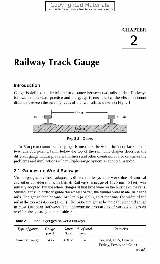
Railway Track Gauge 31
Railway Track Gauge
Introduction
Gauge is defined as the minimum distance between two rails. Indian Railwaysfollows this standard practice and the gauge is measured as the clear minimumdistance between the running faces of the two rails as shown in Fig. 2.1.
Fig. 2.1 Gauge
In European countries, the gauge is measured between the inner faces of thetwo rails at a point 14 mm below the top of the rail. This chapter describes thedifferent gauge widths prevalent in India and other countries. It also discusses theproblems and implications of a multiple-gauge system as adopted in India.
2.1 Gauges on World RailwaysVarious gauges have been adopted by different railways in the world due to historicaland other considerations. In British Railways, a gauge of 1525 mm (5 feet) wasinitially adopted, but the wheel flanges at that time were on the outside of the rails.Subsequently, in order to guide the wheels better, the flanges were made inside therails. The gauge then became 1435 mm (4' 8.5" ), as at that time the width of therail at the top was 45 mm (1.75" ). The 1435-mm gauge became the standard gaugein most European Railways. The approximate proportions of various gauges onworld railways are given in Table 2.1.
Table 2.1 Various gauges on world railways
Type of gauge Gauge Gauge % of total Countries(mm) (feet) length
Standard gauge 1435 4' 8.5" 62 England, USA, Canada,Turkey, Persia, and China
CHAPTER
2
(contd)
Rail Rail
Gauge
Sleeper
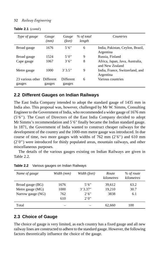
32 Railway Engineering
Type of gauge Gauge Gauge % of total Countries(mm) (feet) length
Broad gauge 1676 5' 6" 6 India, Pakistan, Ceylon, Brazil,Argentina
Broad gauge 1524 5'0" 9 Russia, FinlandCape gauge 1067 3' 6" 8 Africa, Japan, Java, Australia,
and New ZealandMetre gauge 1000 3' 3.5" 9 India, France, Switzerland, and
Argentina23 various other Different Different 6 Various countriesgauges gauges gauges
2.2 Different Gauges on Indian Railways
The East India Company intended to adopt the standard gauge of 1435 mm inIndia also. This proposal was, however, challenged by Mr W. Simms, ConsultingEngineer to the Government of India, who recommended a wider gauge of 1676 mm(5' 6" ). The Court of Directors of the East India Company decided to adoptMr Simms’s recommendation and 5' 6" finally became the Indian standard gauge.In 1871, the Government of India wanted to construct cheaper railways for thedevelopment of the country and the 1000-mm metre gauge was introduced. In duecourse of time, two more gauges with widths of 762 mm (2' 6" ) and 610 mm(2' 0" ) were introduced for thinly populated areas, mountain railways, and othermiscellaneous purposes.
The details of the various gauges existing on Indian Railways are given inTable 2.2.
Table 2.2 Various gauges on Indian Railways
Name of gauge Width (mm) Width (feet) Route % of routekilometres kilometres
Broad gauge (BG) 1676 5' 6" 39,612 63.2Metre gauge (MG) 1000 3' 3.37" 19,210 30.7Narrow gauge (NG) 762 2' 6" 3838 6.1
610 2' 0"
Total – – 62,660 100
2.3 Choice of Gauge
The choice of gauge is very limited, as each country has a fixed gauge and all newrailway lines are constructed to adhere to the standard gauge. However, the followingfactors theoretically influence the choice of the gauge.
Table 2.1 (contd)

Railway Track Gauge 33
Cost Considerations
There is only a marginal increase in the cost of the track if a wider gauge is adopted.In this connection, the following points are important.
(a) There is a proportional increase in the cost of acquisition of land, earthwork,rails, sleepers, ballast, and other track items when constructing a wider gauge.
(b) The cost of building bridges, culverts, and tunnels increases only marginallydue to a wider gauge.
(c) The cost of constructing station buildings, platforms, staff quarters, levelcrossings, signals, etc. associated with the railway network is more or lessthe same for all gauges.
(d) The cost of rolling stock is independent of the gauge of the track for carryingthe same volume of traffic.
Traffic Considerations
The volume of traffic depends upon the size of wagons and the speed and haulingcapacity of the train.
(a) As a wider gauge can carry larger wagons and coaches, it can theoreticallycarry more traffic.
(b) A wider gauge has a greater potential at higher speeds, because speed is afunction of the diameter of the wheel, which in turn is limited by the widthof the gauge.
(c) The type of traction and signalling equipment required are independent ofthe gauge.
Physical Features of the Country
It is possible to adopt steeper gradients and sharper curves for a narrow gauge ascompared to a wider gauge.
Uniformity of Gauge
The existence of a uniform gauge in a country enables smooth, speedy, and efficientoperation of trains. Therefore a single gauge should be adopted irrespective of theminor advantages of a wider gauge and the few limitations of a narrower gauge.
2.4 Problems Caused by Change of Gauge
The need for uniformity of gauge has been recognized by all the advanced countriesof the world. A number of problems have cropped up in the operation of IndianRailways because of the use of three gauges. The ill effects of change of gauge(more popularly known as break of gauge) are numerous; some of these areenumerated here.
Inconvenience to Passengers
Due to change of gauge, passengers have to change trains mid-journey alongwiththeir luggage, which causes inconvenience such as the following.
(a) Climbing stairs and crossing bridges

34 Railway Engineering
(b) Finding seats in the compartments of the later trains(c) Missing connections with the later trains in case the earlier train is late(d) Harassment caused by porters(e) Transporting luggage(f) Uncertainty and delay in reaching the destination
Difficulty in Trans-shipment of Goods
Goods have to be trans-shipped at the point where the change of gauge takes place.This causes the following problems.
(a) Damage to goods during trans-shipment.(b) Considerable delay in receipt of goods at the destination.(c) Theft or misplacement of goods during trans-shipment and the subsequent
claims.(d) Non-availability of adequate and specialized trans-shipment labour and staff,
particularly during strikes.
Inefficient Use of Rolling Stock
As wagons have to move empty in the direction of the trans-shipment point, theyare not fully utilized. Similarly, idle wagons of one gauge cannot be moved onanother gauge.
Hindrance to Fast Movement of Goods and Passenger Traffic
Due to change in the gauge, traffic cannot move fast which becomes a major problemparticularly during emergencies such as war, floods, and accidents.
Additional Facilities at Stations and Yards
(a) Costly sheds and additional facilities need to be provided for handling thelarge volume of goods at trans-shipment points.
(b) Duplicate equipment and facilities such as yards and platforms need to beprovided for both gauges at trans-shipment points.
Difficulties in Balanced Economic Growth
The difference in gauge also leads unbalanced economic growth. This happensbecause industries set up near MG/NG stations cannot send their goodseconomically and efficiently to areas being served by BG stations.
Difficulties in Future Gauge Conversion Projects
Gauge conversion is quite difficult, as it requires enormous effort to widen existingtracks. Widening the gauge involves heavy civil engineering work such as wideningof the embankment, the bridges and tunnels, as well as the tracks; additionally, awider rolling stock is also required. During the gauge conversion period, there areoperational problems as well since the traffic has to be slowed down and evensuspended for a certain period is order to execute the work.

Railway Track Gauge 35
2.5 Uni-gauge Policy of Indian Railways
The problems caused by a multi-gauge system in a country have been discussed inthe previous section. The multi-gauge system is not only costly and cumbersomebut also causes serious bottlenecks in the operation of the Railways and hindersthe balanced development of the country. Indian Railways therefore took the bolddecision in 1992 of getting rid of the multi-gauge system and following the uni-gauge policy of adopting the broad gauge (1676 mm) uniformly.
2.5.1 Benefits of Adopting BG (1676 mm) as the Uniform Gauge
The uni-gauge system will be highly beneficial to rail users, the railwayadministration, as well as to the nation as described below.
No Transport Bottlenecks
There will be no transport bottlenecks after a uniform gauge is adopted and thiswill lead to improved operational efficiency resulting in fast movement of goodsand passengers.
No Trans-shipment Hazards
There will no hazards of trans-shipment and as such no delays, no damage togoods, no inconvenience to passengers of transfer from one train to another train.
Provisions of Alternate Routes
Through a uni-gauge policy, alternate routes will be available for free movementof traffic and there will be less pressure on the existing BG network. This is expectedto result in long-haul road traffic reverting to the railways.
Better Turnround
There will be a better turnround of wagons and locomotives, and their usage willimprove the operating ratio of the railway system as a whole. As a result thecommunity will be benefited immensely.
Improved Utilization of Track
There will be improved utilization of tracks and reduction in the operating expensesof the railway.
Balanced Economic Growth
The areas presently served by the MG will receive an additional fillip, leading tothe removal of regional disparities and balancing economic growth.
No Multiple Tracking Works
The uni-gauge project will eliminate the need for certain traffic facilities and multipletracking works, which will offset the cost of gauge conversions to a certain extent.

36 Railway Engineering
Better Transport Infrastructure
Some of the areas served by the MG have the potential of becoming highlyindustrialized; skilled manpower is also available. The uni-gauge policy will helpin providing these areas a better transportation infrastructure.
Boosting Investor’s Confidence
With the liberalization of the economic policy, the uni-gauge projects of the IndianRailways have come to play a significant role. This will help in boosting theinvestors’ confidence that their goods will be distributed throughout the country intime and without any hindrance. This will also help in setting up industries in areasnot yet exploited because of the lack of infrastructure facilities.
2.5.2 Planning of Uni-gauge Projects
The gauge-conversion programme has been accelerated in Indian Railways since1992. In the eight Plan (1993–97) itself, the progress achieved in gauge-conversionprojects in 5 years was more than the total progress made in the last 45 years. Theprogress of gauge-conversion projects is briefly given in Table 2.3.
Table 2.3 Gauge-conversion projects in India
Year Progress in gauge Remarksconversion (km)
1947–1992 2500 Approx. figure1993–1997 6897 Actual1997–1998 847 Actual1998–1999 693 Actual1999–2000 260 Actual2000–2001 92 Actual2001–2002 211 Actual2002–2003 830 Actual2003–2004 854 Actual
2.6 Loading Gauge
The loading gauge represents the maximum width and height to which a rollingstock, namely, a locomotive, coach, or wagon, can be built or loaded. Sometimes,a loading gauge is also used for testing loaded and empty vehicles as per themaximum moving dimensions prescribed for the section. In Indian Railways, themaximum height and width of rolling stock prescribed as per the loading gaugeare given in Table 2.4.
Table 2.4 Maximum dimensions of rolling stock on Indian Railways
Gauge Maximum height of rolling stock Maximum width of rolling stock
BG 4140 mm (13' 7" ) 3250 mm (10' 8" )MG 3455 mm (11' 4" ) 2745 mm (9' 0" )

Railway Track Gauge 37
In order to ensure that the wagons are not overloaded, a physical barrier is madeby constructing a structure as per the profile of the loading gauge (see Fig. 2.2).This structure consists of a vertical post with an arm from which a steel arc issuspended from the top. The function of this structure is to ensure that the topmostand the widest portion of the load will clear all structures such as bridges andtunnels, etc. along the route.
Fig. 2.2 Loading gauge
2.7 Construction Gauge
The construction gauge is decided by adding the necessary clearance to the loadinggauge so that vehicles can move safely at the prescribed speed without anyinfringement. The various fixed structures on railway lines such as bridges, tunnels,and platform sheds are built in accordance with the construction gauge so that thesides and top remain clear of the loading gauge.
Summary
Three types of track gauges have been adopted in Indian Railways. The basicconsideration behind the adoption of the metre gauge and narrow gauge was toprovide access to undeveloped areas with low cost of construction. The multiple-gauge system has caused many problems and caused serious bottlenecks in theoperation of the Railways. The work of gauge conversion has been accelerated onIndian Railways since 1992. The uni-gauge system will be highly beneficial to railusers, the railway administration, and the nation.
Review Questions
1. Define gauge problems with special reference to Indian Railways and bringout the effects of variations in the width of the gauge.
Horizontal post
Steep arc
Rail level
Rails

38 Railway Engineering
2. Why is it desirable to have, as far as possible, a uniform gauge for the railwaynetwork of a country?
3. What is the standard gauge in Indian Railways? State the disadvantages ofhaving a multiple gauge system.
4. List out the various gauges prevailing in India with their gauge widths. Whatfactors govern the selection of a suitable gauge? Discuss.
5. What is the uni-gauge policy of Indian Railways? Describe the benefits of theuni-gauge system.
6. What do you understand by loading gauge? How is it different from theconstruction gauge?
7. How many gauges exist in Indian Railways? Give their widths and routekilometres.
8. Write short notes on the following.(a) Break of gauge (b) Standard gauge(c) Cape gauge (d) Metre gauge

Alignment of Railway Lines 39
Alignment of Railway Lines
Introduction
Alignment of railway line refers to the direction and position given to the centreline of the railway track on the ground in the horizontal and vertical planes.Horizontal alignment means the direction of the railway track in the plan includingthe straight path and the curves it follows. Vertical alignment means the directionit follows in a vertical plane including the level track, gradients, and vertical curves.The various factors affecting alignment, and types of track alignments and theirsuitability in different terrains are discussed in this chapter.
3.1 Importance of Good Alignment
A new railway line should be aligned carefully after proper considerations, asimproper alignment may ultimately prove to be more costly and may not be able tofulfill the desired objectives. Railway line constructions are capital-intensiveprojects, once constructed, it is very difficult to change the alignment of a railwayline because of the costly structures involved, difficulty in getting additional landfor the new alignment, and such other considerations.
3.2 Basic Requirements of an Ideal Alignment
The ideal alignment of a railway line should meet the following requirements.
Purpose of the New Railway Line
The alignment of a new railway line should serve the basic purpose for which therailway line is being constructed. As brought out earlier, the purpose may includestrategic considerations, political considerations, developing of backward areas,connecting new trade centres, and shortening existing rail lines.
Integrated Development
The new railway line should fit in with the general planning and form a part of theintegrated development of the country.
CHAPTER
3

40 Railway Engineering
Economic Considerations
The construction of the railway line should be as economical as possible. Thefollowing aspects require special attention.
Shortest route It is desirable to have the shortest and most direct route betweenthe connecting points. The shorter the length of the railway line, the lower the costof its construction, maintenance, and operation. There can, however, be otherpractical considerations that can lead to deviation from the shortest route.
Construction and maintenance costThe alignment of the line should be so chosenthat the construction cost is minimum. This can be achieved by a balanced cut andfill of earthwork, minimizing rock cutting and drainage crossings by locating thealignment on watershed lines, and such other technical considerations. Maintenancecosts can be reduced by avoiding steep gradients and sharp curves, which causeheavy wear and tear of rails and rolling stock.
Minimum operational expensesThe alignment should be such that the operationalor transportation expenses are minimum. This can be done by maximizing thehaulage of goods with the given power of the locomotive and traction mix. Thiscan he achieved by providing easy gradients, avoiding sharp curves, and adoptinga direct route.
Maximum Safety and Comfort
The alignment should be such that it provides maximum safety and comfort to thetravelling public. This can be achieved by designing curves with proper transitionlengths, providing vertical curves for gradients, and incorporating other suchtechnical features.
Aesthetic Considerations
While deciding the alignment, aesthetic aspects should also be given due weightage.A journey by rail should be visually pleasing. This can be done by avoiding viewsof borrow pits and passing the alignment through natural and beautiful surroundingswith scenic beauty.
3.3 Selection of a Good Alignment
Normally, a direct straight route connecting two points is the shortest and mosteconomical route for a railway line, but there are practical problems and othercompulsions which necessitate deviation from this route. The various factorsinvolved is the selection of a good alignment for a railway line are given below.
Choice of Gauge
The gauge can be a BG (1676 mm), an MG (1000 mm), or even an NG (762 mm).As per the latest policy of the Government of India, new railway lines are constructedon BG only. The various gauges have been discussed in detail in Chapter 2.

Alignment of Railway Lines 41
Obligatory or Controlling Points
These are the points through which the railway line must pass due to political,strategic, and commercial reasons as well as due to technical considerations. Thefollowing are obligatory or controlling points.
Important cities and towns These are mostly intermediate important towns, cities,or places which of commercial, strategic, or political importance.
Major bridge sites and river crossingsThe construction of major bridges forlarge rivers is very expensive and suitable bridge sites become obligatory pointsfor a good alignment.
Existing passes and saddles in hilly terrainExisting passes and saddles shouldbe identified for crossing a hilly terrain in order to avoid deep cuttings and highbanks.
Sites for tunnels The option of a tunnel in place of a deep cut in a hilly terrain isbetter from the economical viewpoint. The exact site of such a tunnel becomes anobligatory point.
Topography of the Country
The alignment of a new railway line depends upon the topography of the country ittraverses. The following few situations may arise.
Plane alignment When the topography is plane and flat, the alignment presentsno problems and can pass through obligatory points and yet have very easy gradients.
Valley alignment The alignment of a railway line in valley is simple and does notpose any problem. If two control points lie in the same valley, a straight line isprovided between these points with a uniform gradient.
Cross-country alignment The alignment of a railway line in such terrain crossesthe watersheds of two or more streams of varied sizes. As the levels vary in cross-country, the gradients are steep and varying and there are sags and summits. Thecontrolling or obligatory points for cross-country alignment may be the lowestsaddles or tunnels. It may be desirable to align the line for some length along thewatersheds so that some of the drainage crossings may be avoided.
Mountain alignment The levels in mountains vary considerably, and if normalalignment is adopted, the grades would become too steep, much more than theruling gradient (allowable gradient). In order to remain within the ruling gradient,the length of the railway line is increased artificially by the ‘development process’.The following are the standard methods for the development technique:
Zigzag line methodIn this method, the railway line traverses in a zigzag alignment(Fig. 3.1) and follows a convenient side slope which is at nearly right angles to thegeneral direction of the alignment. The line then turns about 180° in a horseshoepattern to gain height.
Switch-back methodIn the case of steep side slopes, a considerable gain inelevation is accomplished the switch-back method (Fig. 3.2). This method involvesa reversal of direction achieved by a switch, for which the train has to necessarily

42 Railway Engineering
stop. The switch point is normally located in a station yard. In Fig. 3.2, A and B aretwo switches and A1 and B1 are two buffer stops. A train coming from D will stopat B1 and move in back gear to line BA. It will stop at A1 again and then follow theline AC.
Fig. 3.1 Zigzag line alignment
Fig. 3.2 Switch-back alignment
9590
85
8075 70
65
4540
35
65
7075
8085
90
95
A1 D
A 5055
60
65
80
85
90 75
C B1
B

Alignment of Railway Lines 43
Spiral or complete loop methodThis method is used in a narrow valley where asmall bridge or viaduct has been constructed at a considerable height to span thevalley (Fig. 3.3). In this case, normally a complete loop of the railway line isconstructed, so that the line crosses the same point a second time at a height througha flyover or a tunnel.
Fig. 3.3 Complete loop alignment
Geometrical Standards
Geometrical standards should be so adopted as to economize as much as possibleas well as provide safety and comfort to passengers. This can be done by adoptinggradients and curves within permissible limits. Transition as well as vertical curvesshould be used to provide better comfort and safety.
Geological Formation
The alignment should be so selected that it normally runs on good and stable soilformation as far as possible. Weak soil and marshy land present a number ofproblems including those of maintenance. Though rocky soil, provides a stableformation, it is a costly proposal.
Effect of Flood and Climate
The alignment should normally pass through areas which are not likely to be flooded.The climatic conditions should also be taken into consideration for alignment. Inhot climate and sandy areas, the alignment should pass by those sides of sanddunes that face away from the direction of the wind. Similarly, in cold regions, thealignment should pass by those sides of hills that face away from the direction ofthe wind. A sunny side is more desirable.
Track Bridge
River
River

44 Railway Engineering
Position of Roads and Road Crossings
A railway line should cross a road at right angles so as to have a perpendicularlevel crossing and avoid accidents.
Proximity of Labour and Material
The availability and proximity of local labour and good and cheap building materialshould also be considered when deciding the alignment.
Location of Railway Stations and Yards
Railway stations and yards should be located on level stretches of land, preferablyon the outskirts of a town or village so as to have enough area for the free flow oftraffic.
Religious and Historical Monuments
The alignment should avoid religious and historical monuments, as it is normallynot possible to dismantle these buildings.
Cost Considerations
The alignment should be such that the cost of construction of the railway line is aslow as possible. Not only the initial cost of construction but also the maintenancecost should be as low as possible. For this purpose, the alignment should be asstraight as possible, with least earthwork, and should pass through terrain withgood soil.
Traffic Considerations
The alignment should be so selected that it attracts maximum traffic. In this context,traffic centres should be well planned; so that the railway line is well patronizedand the gross revenue arising out of traffic receipts is as high as possible.
Economic Considerations
Keeping in mind the various considerations, it should be ensured that the alignmentis overall economical. For this purpose, various alternate alignments are consideredand the most economical one, which is cost effective and gives the maximumreturns is chosen.
The maximum annual return ( )γ is calculated by the formula
γ −= R E
Iwhere R is the gross revenue earned by the railway line and E denotes the annualrunning expenses.
It may be noted here that R depends upon the route that proves to be advantageouswhen taking traffic into consideration and, therefore, should be given due weightage.The other way to maximize the annual return is to have sound and economicalconstruction work so as to reduce the annual running expenses. A suitable balancehas to be achieved between construction cost and operating expenses.

Alignment of Railway Lines 45
Political Considerations
The alignment should take into account political considerations. It should not enterforeign soil and should preferably be away from common border areas.
3.4 Mountain Railways
There are few hills or mountains that have been connected by railway lines. Someof the important features of these mountain railways are the following.
Gradients The gradients of mountain tracks are very steep. Normally tracks withgradients of 3% or more are considered mountain tracks.
Gauge Normally narrow gauges with gauge widths of 762 mm or 610 mm areadopted for mountain railways.
Curvature The curvature of mountain tracks is very sharp. Curvatures of up to40° are normally adopted.
Alignment Mountain alignment is quite zigzag and not straight in order to gainheights easily. The type of alignments normally followed are zigzag, switch-back,and spiral.
Purpose Mountain railways have mostly been constructed for tourist traffic. Insome cases, they may be constructed for exploiting hinterland or new areas.
Cost considerationsThe cost of construction of mountain railways is quite highbecause of the need for a large number of bridges and heavy earthwork. The cost,however, gets considerably reduced by adopting a smaller gauge, narrow gauge(0.762 m or 0.61 m), and then it is possible to have very steep gradients and sharpcurvature.
Some of the important mountain railways existing in India today are: (i) Kalka–Shimla Railway, (ii) Nilgiri Mountain Railway, (iii) Matheran Light Railway,(iv) Darjeeling Himalayan Railway, (v) The Kangra Valley Railway, and(vi) Haldwani–Kathgodam Railway.
3.5 Rack Railways
In the case of very steep gradients, much steeper than 3%, it becomes difficult fora locomotive to pull the train load and hence is possible for the train slide down orslip back along the down grade.
The rack railway system consists of three rails, i.e., one extra toothed rail in themiddle in addition to two normal rails. The locomotive also has a toothed pinionwheel whose teeth fit into the grooves of the central toothed rail. This lockingarrangement helps to haul the train load and does not let the locomotive slip back.There are various such systems existing in the Indian Railways, such as the Fellsystem, Abt system, Riggenbach system, and Marsh system, each with its owncharacteristics.
With the help of this rack and pinion system, it is possible to move trains evenon very steep gradients such as 1 in 5.

46 Railway Engineering
Summary
The alignment of a railway line is extremely important as subsequent costs ofconstruction and operation depend heavily on it. The basic requirements and factorsaffecting alignment have been discussed in this chapter. The various types ofengineering surveys required to mark the alignment of a railway line are describedin the next chapter.
Review Questions
1. State and discuss briefly the factors that control the alignment of a railwaytrack.
2. In the process of selecting a suitable alignment for a railway line, what factorsand parameters are kept in view? What analysis is done to assess the economicviability of the alignment?
3. Describe in brief the basic requirements of a good alignment. What are thefactors that control the alignment of a railway line?
4. What do you understand by mountain railways? Describe in brief the varioustypes of alignments used for mountain railways.
5. Write short notes on the following.(i) Spiral method(ii) Zigzag method(iii) Rack railway

Engineering Surveys and Construction of New Lines 47
Engineering Surveys and
Construction of New Lines
Introduction
The construction of a new railway line is a capital-intensive project and eachkilometre of a new railway line costs in the range of Rs 6 to 10 million dependingupon the topography of the area, the standard of construction, and such otherfeatures. It is, therefore, natural that a lot of thought be given when making a finaldecision as to whether a new railway line is at all necessary or not.
4.1 Need for Construction of a New Railway Line
The need for construction of a new railway line arises because of one or more ofthe following considerations.
(a) Strategic reasons It is sometimes necessary to extend the existing railwayline to a new point of strategic importance so that the defence forces canmove quickly to the same areas in case of any emergency such as the threatof war.
(b) Political reasons A new line sometimes becomes necessary to serve thepolitical needs of the country, for example, the railway line from Pathankotto Jammu.
(c) Development of backward areas Railway lines are sometimes constructedto develop backward areas. Experience has shown that once railwaycommunication is available, backward areas develop very fast. The Assamrail link can be classified in this category.
(d) To connect new trade centres Sometimes new trade centres are connectedwith railway lines for the quick transportation of goods between two tradecentres or from the point of production to the point of consumption.
(e) To shorten the existing rail link The existing routes between two importantpoints may be longer than required. New railway lines are constructed on ashorter alignment in such cases. A short route is not only economical, butalso helps in the faster movement of goods and passengers. The KonkanRailway is a typical example.
CHAPTER
4

48 Railway Engineering
Doubling of existing single railway lines is also done in a few cases tocope up with the additional requirement of traffic. Recently, a large numberof projects have also been under taken for converting the existing metregauge lines into broad gauge lines in order to have a uniform gauge for thesmooth flow of traffic.
4.2 Preliminary Investigations for a New Railway Line
Whenever the construction of a new railway line is under consideration, preliminaryinvestigations are done by the railway administration to determine how the proposedline will fit in with the general scheme of future railway development. Thepreliminary investigations are normally based on a careful study of the following:
(a) Existing topo sheets and other maps of the area(b) Published figures of trade and population of the area to be served(c) Statistical data of existing railway lines in similar terrain in other areasAs a result of these investigations, it becomes possible to decide whether or not
the new railway line is required and surveys should then be undertaken to get moredetails of the new line being contemplated.
4.3 Types of Surveys
Once a decision has been taken during preliminary investigations about the generalfeasibility and desirability of a railway line, surveys are undertaken before theconstruction of the new line. The following types of surveys are normally conducted:
(a) Traffic survey(b) Reconnaissance survey(c) Preliminary survey(d) Final location surveyThe details of these surveys are discussed in the following sections.
4.4 Traffic Survey
Traffic survey includes a detailed study of the traffic conditions in the area with aview to determine the
(a) most promising route for the railway in the area,(b) possible traffic the railway line will carry, and(c) standard of railway line to be followed.Traffic surveys are normally undertaken in conjunction with reconnaissance or
preliminary engineering surveys so that the technical feasibility and relative costsof alternative proposals can be formulated. The traffic survey team should work inclose cooperation with the engineering survey team. The survey team should visitall trade centres in the area and consult local bodies, state governments, andprominent citizens regarding trade and industry and propose the most suitablealignment for the new line.
Traffic survey consists of an economic study of the area keeping in mind thefollowing considerations, information on which should be collected in detail:

Engineering Surveys and Construction of New Lines 49
(a) Human resources(b) Agricultural and mineral resources(c) Pattern of trade and commerce(d) Industries located and projected(e) Prospects of tourist traffic(f) Existing transport facilities(g) Locations of important government and private offices(h) Planning for economic development of the areaThe traffic survey team should make an assessment of the traffic likely to be
carried by to the new line. While carrying out the survey, details of traffic likely tobe offered by various government organizations, public bodies, or private enterprisesshould be gathered.
At the end of the survey, a report should be formulated by the officer-in-chargeof the survey. The formation of the report is governed largely by the nature of theterms of reference and the investigations made. The traffic survey report shouldnormally contain the following information:
(a) History of the proposal and terms of reference(b) General description(c) Potentials and prospects(d) Industrial and economic development and traffic projections(e) Population projection and volume of passenger traffic(f) Existing rates and rates to be charged(g) Location of route or routes examined, alternate routes, and possible extensions(h) Station sites and their importance(i) Train services, section capacity, and various alternative ways of increasing
capacity(j) Coaching earnings(k) Goods earnings(l) Working expenses and net receipts
(m) Engineering features(n) Telecommunication facilities(o) Financial appraisal(p) Conclusions and recommendations
4.5 Reconnaissance Survey
This survey consists of a rapid and rough investigation of the area with a view todetermine the technical feasibility of the proposal as well as the rough cost of oneor more alternatives to the new line. The reconnaissance survey (RECCE) isnormally based on contoured survey maps and other data already available withoutcarrying out detailed investigations in the field. With the help of the maps, differentalternative alignments of the new line are studied.
The general topography of the country is studied by the survey team and thenfield data are collected.

50 Railway Engineering
4.5.1 Survey Instruments
The reconnaissance survey is mostly conducted using survey instruments that rapidlymeasure approximate distances and heights. The survey instruments used are thefollowing:
Prismatic compassTo get magnetic bearings of the proposed alignment.
Aneroid barometer To ensure relative heights of various points.
Abney level or hand level or clinometerTo measure the gradients or angles ofslopes.
Binocular To view the physical features.
Pedometer To get an idea of the total length traversed while walking.
4.5.2 Modern Surveying Instruments and Techniques
Modern surveying instruments make extensive use of infrared beams, laser beams,as well as computers. Using these instruments, it is possible to carry out fairlyaccurate surveying efficiently at all times, eliminating human error.
Electromagnetic Distance Measurement (EDM) Instruments
EDM instruments rapidly and automatically measure both horizontal and verticaldistances. The readings can be displayed on built–in computer screens. Examplesof such instruments are the geodimeter and the tellurimeter, which have been usedin the past for electronic distance measurement of up to 80 km during day or night.Modern EDM instruments are much more advance and versatile.
Use of Computers
The results of the field survey are recorded in the form of angles and distances inthe normal field book or electronic notebook. Using computers, it is possible to doall calculations as well as plot accurately. Thus, output from the EDM can be fedinto the computer, which in turn can plot plans and sections.
Use of Laser in Surveying
Laser is an acronym for light amplification by stimulated emission of radiation. Itsproperty of low diversion is used for alignment purposes. The invisible line ofsight in ordinary survey instruments is replaced by the bright red beam of theLaser. This beam is intercepted by the target composed of light-sensitive cellsconnected to the display panel. Its most important aspect is that the beam is in aperfect straight line. Distances up to 70 km can be measured using laser. For shortdistances infrared beams are used.
4.5.3 Field Data
The following field data are collected during the reconnaissance survey.(a) General topography of the country(b) Approximate heights of the different points falling on the alignment

Engineering Surveys and Construction of New Lines 51
(c) Positions of rivers, streams, and some hydrological details of the same(d) Positions of roads and highways(e) Nature of soil at different places(f) Rough location of various station sites(g) Controlling points on the alignment, through which the railway line must
pass(h) Facilities for construction
4.5.4 Project Report for Reconnaissance Survey
Based on the above data, a report should be prepared by the engineer in charge ofthe project bringing out clearly from the financial point of view whether or not theprospects of the line surveyed are such as to make it worthwhile to undertakefurther investigations to construct the line. The project report should be accompaniedby an abstract estimate of the cost of the line.
The report and estimate should be accompanied by a map of the area on a scaleof 20 km to 1 cm and an index map of 2.5 km to 1 cm.
4.6 Preliminary Survey
The preliminary survey consists of a detailed instrumental examination of the routeto be selected as a result of the reconnaissance survey in order to estimate the costof the proposed railway line. Based on the preliminary and traffic survey reports,the railway administration decides whether or not the proposed railway line is tobe constructed.
4.6.1 Instruments for Preliminary Survey
The instruments to be used for a preliminary survey will depend on the topographyof the country and its flora. The survey instruments normally used are the following.
(a) Theodolite for traversing and pegging the centre line(b) Tacheometer for plotting the main features(c) Dumpy level for taking the longitudinal and cross levels(d) Plane table for getting details of various features(e) Prismatic compass for measuring the magnetic bearings of a particular
alignment
4.6.2 Field Survey
The route selected is surveyed in greater detail in the preliminary survey. The surveynormally covers a width of 200 m on either side of the proposed alignment. Thefollowing survey work is carried out.
(a) An open traverse is run along the centre line of the proposed alignment withthe help of a theodolite, tacheometer, or a compass.
(b) Longitudinal and cross levelling on the proposed route for a width of 200 mon either side in order to make an accurate contour map.
(c) Plane tabling of the entire area to obtain various geographical details.

52 Railway Engineering
(d) Special survey of station sites, level crossings, and bridges using the planetable.
4.6.3 Data
The following information should normally be collected during a preliminary survey.(a) Geological information such as type of soil strata and the nature of rocks.(b) Source of availability of construction materials such as sand, aggregate,
bricks, cement, and timber.(c) Facilities for construction such as the availability of labour and drinking
water.(d) Full details of the land and buildings to be acquired.(e) Details of existing bridges and culverts along with information about
proximity of tanks, bunds, etc., which may affect the design of bridges.(f) Details of road crossings along with the angles of crossing and the traffic
expected on the level crossings.(g) High flood level and low water level of all the rivers and streams falling on
the alignment.(h) Full details of station sites along with the facilities required.
4.6.4 Preparation of Project Report
A report based on the preliminary survey is prepared after obtaining an estimate ofthe cost. The project report should contain the following details.
(a) Introduction(b) Characteristics of the project area(c) Standard of construction(d) Route selection(e) Project engineering including cost estimate and construction schedule(f) Conclusions and recommendations
4.6.5 Cost Estimate
The report should be accompanied by cost estimate. The estimate based on thepreliminary report should be sufficiently accurate to enable a competent authorityto take a decision regarding the construction of the new line. The estimate shouldcontain the following details.
(a) An abstract cost estimate of the line surveyed accompanied by an abstractestimate of junction arrangements.
(b) Detailed estimates of land, tunnels, major bridges, minor bridges, onekilometre of permanent way, rolling stock, and general charges.
The report and estimate should be accompanied by the following drawings.(a) Map of the area (scale 20 km = 1 cm)(b) Index plan and section (scale 0.5 km to 1 cm horizontal and 10 m to 1 cm
vertical)(c) Detailed plans and sections

Engineering Surveys and Construction of New Lines 53
(d) Plans of station yards(e) Plans of junction arrangements
4.7 Preliminary Engineering-cum-traffic Survey
In practice, and quite often, both the traffic survey and the preliminary engineeringsurvey are carried out simultaneously in order to expedite the project. In suchcases techno-economic survey reports based on preliminary-cum-traffic surveysare compiled. Such techno-economic survey reports contain the following details.
(a) Introduction(b) Traffic projections(c) Analysis of alternatives(d) Characteristics of project area(e) Standards of construction (for new lines, multiple tracking schemes, gauge
conversions)(f) Route selection and project description(g) Project engineering (for new lines, multiple tracking schemes, and gauge
conversions)(h) Cost, phasing, and investment schedules(i) Financial appraisal(j) Recommendations
4.8 Final Location Survey
Once a decision has been taken for a particular railway line to be constructed, afinal location survey is done. The instruments used are generally the same as in thecase of the preliminary survey. Final location survey is done to prepare workingdetails and make accurate cost estimates in certain cases. The principal differencesbetween the preliminary survey and the final survey are as follows.
(a) In the final location survey, the alignment is fully staked with the help of atheodolite, whereas it is not obligatory to do so in the case of preliminarysurvey.
(b) In the final location survey, a more detailed project report is prepared andsubmitted.
(c) All working drawings are prepared in the final location survey.
The following tasks are carried out in the final location survey.(a) The centre line is fully marked by pegs at 20 m. At each 100 m, a large peg
should be used.(b) Masonry pillars are built at tangent points of curves and along the centre
line at intervals of 500 m.(c) Longitudinal and cross levelling is done to ascertain the final gradient of the
alignment. All gradients are compensated for curves.(d) The sites for station yards are fully demarcated.In the final location survey, the following set of drawings is prepared.(a) General map of the country traversed by the project at a scale of about 20 km
to 1 cm

54 Railway Engineering
(b) Index map, scale about 2.5 km to 1 cm(c) Index plan and sections(d) Detailed plans and sections(e) Plans and cross section(f) Plans of station yards(g) Detailed drawings of structures(h) Plans of junction arrangements
4.8.1 Objectives
The following broad objectives should be kept in mind when selecting the bestpossible alignment in the final location survey.
(a) Correct obligatory points(b) Easy grades and flat curves(c) Minimum cost of construction(d) Minimum adverse effect on environment(e) Ease of construction(f) Potential for high speeds(g) Avoidance of constraints for future expansion(h) Minimum maintenance cost
4.8.2 Project Report
A final project report is prepared based on the final location survey. The reportconsists of the following.
Introduction
In this segment of the report, the following details are covered.(i) Object of investigation and background(ii) Programme and methodology of investigation(iii) Special features of investigation
Characteristics of the Project Areas
In this segment the topographical outline of the areas and geographical features ofthe country are given to the extent to which these are likely to affect the alignment,probable stability of the line, cost of construction, working expenses, or futureprospects of the proposed line. Climatic and rainfall characteristics andenvironmental characteristics such as the presence of corrosive factors, pollution,etc., which may have an effect on the design and maintenance of structures andbridges, are also brought out.
Standard of Construction
This segment gives details of the following.
Gauge The gauge adopted for the proposed line and the reasons, if any, for adoptingit.

Engineering Surveys and Construction of New Lines 55
Category of line The category of the line, the maximum speed potential of theline, the maximum axle load, the loading standard of bridges, and the basis foradopting the same.
Ruling gradient The gradient adopted and the basis for its selection.
Curves The sharpest degree of curvature adopted, the basis for its adoption, andits impact on the projected speed compatible to the category of line.
Permanent way The rail section adopted, the decision as to whether welding ofthe rails will be carried out or not, and the type and density of sleepers provided inthe project estimate.
Ballast The type and depth of ballast cushion provided.
Stations Spacing of stations in the case of new lines, provision for futureintermediate stations, and the scale of facilities contemplated at stations.
Signalling and telecommunicationThe standard of signalling adopted and thescale of communication facilities provided.
Traction The type of traction proposed.
Other details Road crossings, station machinery, residential accommodation,service and maintenance facilities, etc.
Route Selection
This segment provides relevant information and data related to the variousalternative routes examined and gives an insight into the factors influencing thechoice of the route adopted for the project.
Project Engineering
This section furnishes information and data for the project manager to enable himto understand the scope and extent of the project and to assist him in formulatingthe strategy for the execution and management of the project. It must focus on theproblems likely to be encountered, identify the areas requiring special attention,and place the knowledge and information gathered at the investigation stage forevolving optimal solutions.
Estimation of Cost and Construction Schedule
This segment gives a cost estimate of preliminary expenses, land, formation, bridges,permanent way, station building and residential quarters, road crossings, stationequipment, signalling and interlocking, rolling stock, etc. The schedule of ’construction as well as investment is also given. A network should be developedfor projects costing above Rs 5 million.
Project Organization
This section details the organizational structure for the execution of the project,the proposed headquarters of the project manager and other construction officers,as well as the allocation of the various construction activities. Health and hygenicconditions provided to the staff as well as the provision of necessary medical

56 Railway Engineering
establishments may be indicated, along with suggested plans providing for thehousing of staff and labour and the construction of temporary office buildings.Comments regarding the availability of water for construction purposes and itssuitability for drinking purposes may also be given. The purpose and final costallocation of such plans may also be indicated.
Tabulated Details
The report is accompanied by tabulated details of curve abstract, gradient abstract,bridge abstract, important bridges, stations, machinery, stations, and station sites.
Arrangement of Documents in the Report
All the documents pertaining to a final location survey report should be in thefollowing order.
1. Covering note2. Index3. Report4. A list of drawings accompanying the report5. Appendices to the report
(a) Historical and geographical aspects(b) Location report(c) Rates for construction work
4.9 Modern Surveying Techniques for Difficult Terrain
In difficult terrains, particularly in hills, modern techniques and survey aids can beutilized for the preliminary survey of railway lines. Some of these survey aids arethe following
(a) Satellite imagery (remote sensing data)(b) Aerial photographs(c) Topographic maps/contour maps(d) Digital terrain modelling (DTM)(e) Photogrammetric plotted sheetsModern techniques were utilized e.g., for carrying out the survey of a proposed
railway line in Kashmir valley from Udhampur to Qazigund. This area consists ofdifficult terrain, full of mountains and valleys and sensitive to terrorist activities,making fieldwork very difficult.
Satellite Imagery
Satellite imagery provides a bird’s eye view of large areas. Such maps are availablefrom the Indian Space Research Organisation and are updated about once a month.Ground conditions can be well appreciated with a combination of satellite imagesand topographic maps. Using these, two or three promising alternative corridorscan be marked. The corridor that satisfies the survey objectives best is then chosenfor further analysis. The use of satellite data in the initial stages of planning hasbeen greatest in those areas for which the existing map coverage and support dataare inadequate, and where field evaluation is extremely difficult.

Engineering Surveys and Construction of New Lines 57
Aerial Photographs
Aerial photographs of the entire country are taken once every 3 to 5 years andthese are available with the Survey of India. These photographs are used to gatherfurther details of the chosen corridor. A critical examination of the corridor usingthe photographs helps in finalizing river crossings, tunnel locations, station sites, etc.
Digital Terrain Modelling
Further details of the railway line are worked out with the help of digital terrainmodelling and contour maps. Computer aids are used for defining the mosteconomical alignment. Ground stations are then fixed in the form of two mutuallyvisible points about a kilometre apart in a 10-km stretch. All other details for thepreliminary survey can be worked out with the help of contour maps,photogrammetric plotted sheets, and other computer aids.
4.10 Construction of New Lines
The main work involved in the construction of a new line is the following.(a) Land acquisition(b) Earthwork and bridges(c) Station building, staff quarters, and other allied facilities, including platforms
and sheds(d) Plate laying, including ballasting of track(e) Opening of section for traffic
4.10.1 Land Acquisition
The work of land acquisition should start well in advance so that all legal andfinancial formalities are completed on time and possession of the land can be takenfor starting construction work. Land acquisition is done with the help of the memberstate government as per the procedure laid down in the land acquisition act. NormallySections 4 and 6 of the Land Acquisition Act are applied for acquisition of land inIndia. Land is generally acquired after giving a notice and paying compensation tothe previous occupants. In the case of an emergency, land can also be acquiredurgently by operating the Special Sections 9 and 17 of the Land Acquisition Act inIndia.
The land to be acquired should be adequate for the formation, berm, and borrowpits. It should also have adequate provision for future expansion. Even when asingle line is to be constructed, the land available should be sufficient for theconstruct of a double line for future expansion. Normally a strip of 25 to 35 m ofland is acquired for the construction of a railway line. For station yards, an extrawidth of land is acquired. For small stations, the width normally adopted is 150 ×1000 m.
The minimum land to be arranged should conform to the following.(i) Width of formation: The land should be adequate to accommodate the width
of formation.

58 Railway Engineering
(ii) Side slope: The side slope depends on the nature of the soil and is normallytaken as 2:1 (horizontal:vertical).
(iii) Width of berms: The usual width of the berm is kept at 3 m.(iv) Borrow pits: If the land is not very costly, adequate land should be made
available for borrow pits also. Borrow pits may be on one side of the trackfor low banks and on both sides for medium and high banks. When the landis costly, borrow pits need not be provided for and earth can be borrowedfrom adjoining areas. Extra land is, however, required for station yards, levelcrossings, and bridge approaches.
4.10.2 Earthwork for Formation
The formation may be in an embankment or a cutting depending upon the rail leveland general contour of the area. A formation in an embankment is normally preferredfrom the point of view of good drainage. The height of the embankment also dependson the high flood level of the area and a reasonable free board is provided abovethis level. The standard width of formation is given in Table 4.1.
Table 4.1 Standard width of formation
Gauge Type of formation Width of formation (m)
Single line Double line
BG Embankment 6.10 10.82Cutting 5.40 10.21
MG Embankment 4.88 8.84Cutting 4.27 8.23
Some points worth noting with regard to the specifications for earthwork are asfollows.
(a) Earthwork is normally done in 30-cm-deep layers so that the soil is wellcompacted.
(b) Mechanical compaction is normally done after each layer with the help of a‘sheep foot roller’ to obtain 90% of the maximum dry density at optimummoisture content.
(c) A shrinkage allowance of 5% is made from the final cross section forconsolidation in the case of mechanical compaction. For other types ofcompaction the shrinkage allowance is 10%.
(d) When the soil is not good, a 30-cm-thick blanket is provided at the top of theembankment.
(e) In areas where there are both cuttings and embankments, the earth from thecuttings should be used for the embankments up to an economical lead. Theeconomical lead of moving earth in the longitudinal direction is determinedby the mass–haul curve.
(f) For the early execution of earthwork, the section is normally divided intodifferent convenient zones, each zone having earthwork requirement costingapproximately Rs 1.5 to 3 million. Tenders are invited for each zone separatelyso that work can progress simultaneously in all zones.

Engineering Surveys and Construction of New Lines 59
4.10.3 Bridges
Bridges should be designed for the heaviest locomotive likely to pass that section.Depending upon the topography of the country and the type of stream to be crossed,hume pipe culverts, reinforced cement (RCC) slab bridges, plate girders orprestressed concrete (PRC) girder bridges or steel bridges, are designed. Bridges,being important structures, are normally made for double-line tracks, even in single-line sections, with a view to plan for future expansion.
For the construction of important bridges, separate tenders are called, with designand construction details included in the tender documents. Minor bridges andculverts are normally included in the earthwork zones mentioned above.
4.10.4 Service Buildings and Staff Quarters
Service buildings include the station master’s office, telegraph office, etc., whichare basically required for providing services for running the trains. Apart fromthis, staff quarters and other passenger amenity works such as platforms, foot overbridges, waiting halls, and retiring rooms are also provided at stations. Many otherancillary facilities such as water supply, drainage, telephone lines, and electricityare also made available.
All these constructions are simultaneously taken up by civil engineers, electricalengineers, and signal engineers so that they can progress together.
4.10.5 Plate Laying or Track Linking
Once the formation is ready, plate laying or track linking is required. It consists oflaying rails, sleepers, and fastenings. The following methodology is adopted forplate laying.
Tram Line Method
In this method, a temporary line known as the ‘tram line’ is laid by the side of theproposed track for taking track materials to the site. This method is useful in flatterrain, where laying the tram line on natural ground may be comparatively easier.This method is, however, seldom used in practice.
A modification of the above method is the side method. This method is usedwhere track and bridge material is carried to the site on trucks on a service roadparallel to the track. The material is then unloaded near the work site. This methodis used only in cases where comparatively flat gradients are available.
American Method
In the American method, rails and sleepers are first assembled in the base depotand pre-assembled track panels are then taken to the site along with the necessarycranes, etc. The track panels are unloaded at the work site either manually or withthe help of cranes and are then laid in the final position. This procedure is used inmany developed countries, particularly those where concrete sleepers are laid, sincethese sleepers are quite heavy and it is not easy to handle them manually.

60 Railway Engineering
Telescopic Method
This method is widely used on Indian Railways. In this method, the rails, sleepers,and other fittings are taken to the base depot and unloaded. The track material isthen taken to the rail head and the track is linked and packed. The rail head is thenadvanced up to the extent of laid track. The track material is then taken up to theadvanced rail head with the help of a dip lorry and the track is again linked andpacked. In this way, the rail head goes on advancing till the full track is linked. Themain operations involved are as follows.
Unloading of materials The track material is taken to the base depot and unloadedwith the help of material gangs. The first base depot is the junction of the existingline and the new line to be constructed. All track material is taken from the basedepot with the help of a dip lorry (a special type of trolley) to the rail head. The railhead goes on advancing till the track is sufficiently linked. After that, a subsidiarydepot is established at a distance of about 5 km where the track material is takenwith the help of a material train. Alternatively, the track material is moved from thebase depot with the help of dip lorry only up to a distance of about 2 km and bymaterial train beyond this distance. In the base depot, advance arrangements suchas adzing and boring of the sleeper and arrangement of matching materials aremade so that the track is linked as soon as possible to the site.
Track linking Once the track material is unloaded, the track is linked with thehelp of linking gangs. The following procedure is normally adopted.
1. A string is first stretched along the centre line of the alignment and sleepersare laid with their centres on the string. The sleepers are laid roughly at thedesired spacing, keeping the total number of sleepers per rail intact.
2. The rails are carried by rail tongs and kept on the cess of the bank almost inthe final position. As carrying rails is a very strenuous job (each rail weighsabove 600 kg and about 12–15 gangmen are required to carry one rail), aspecial type of rail carrier known as the Anderson rail carrier can be usedfor carrying rails with lesser strain.
3. The sleepers are spread out on the formation. The rails have markings wherethe final position of the sleepers should come.
4. Small fittings such as fish plates and bolts are placed near the joints, otherfittings required for each sleeper are placed near the end of the sleeper.
5. The rails are then placed on the sleeper and fixed with the help of fittingsdepending upon the type of sleeper. For example, in the case of woodensleepers, rail screws are used for fixing the rails to the wooden sleepers. Inthe case of steel sleepers, rails are fixed with the help of a key. Bearingplates are also provided wherever required, as per the prescribed trackstandards.
6. The rails are joined to each other keeping a proper gap. Now-a-days, normallythree rail panels are initially used for laying the track. In the case of single-rail panels as well as three–rail panels, adequate expansion gaps should beleft. The recommended expansion gaps are provided with the help of steelliners or shims of correct thickness (1–4 mm), which are fixed between thetwo rail ends.

Engineering Surveys and Construction of New Lines 61
Track packing The track is then thoroughly packed with the help of beaters by‘packing-in-gangs’. The following aspects should be checked.
(a) The track should have a proper gradient.(b) The track should have proper curvature, if it is on a curve(c) The cross levels should be even. If superelevation is to be provided, the
outer rail should be raised so as to have the recommended superelevation.(d) The track should be thoroughly packed and no spaces should be left.
Ballasting of track The ballast is normally spread on the railway lines after theembankment has settled well and at least two monsoons have passed over it.Ballasting is generally done with the help of ballast trains, which have specialhoppers through which the ballast can be automatically unloaded onto the track.Alternatively, the ballast is carried on the cess and then laid on the track manually.Using either method, the ballast is thoroughly packed and inserted under the track.
Summary
The purpose for constructing a new railway line in an area may be strategic, political,or developmental. The new construction requires extensive thinking, planning,and investment. At this stage, preliminary investigations are carried out to determinethe feasibility of the new project. Various kinds of surveys are conducted to thisend. The money spent on surveys is non-recoverable and, therefore, it is extremelyimportant to conduct survey work as precisely as possible. Various types of surveysare carried out using the appropriate instruments. The outcome of these surveys isa detailed project report and elaborate working drawings.
Review Questions
1. What are the various factors to be kept in mind when conduction areconnaissance survey for a railway track?
2. Set the order in which the following surveys are carried out for a new railwayalignment:
(a) Preliminary survey(b) Reconnaissance survey(c) Final location survey(d) Traffic Survey
3. Describe in detail the objectives and steps involved in the preliminary surveyfor a new railway alignment.
4. List the various surveys that need to be undertaken for the construction of anew railway line and outline their essential objectives.
5. Describe briefly the principal features of a preliminary survey.6. Explain the following briefly (a) reconnaissance survey, (b) preliminary survey,
(c) final location survey.7. What is the basic difference between a preliminary survey and a final location
survey? Describe briefly the instruments used in preliminary surveys and thedetails to be given in the project report of a final location survey.

62 Railway Engineering
8. Write short notes on the following.(a) Modern surveying instruments and techniques(b) Cost estimate(c) Project report
9. List the different tasks involved in the construction of a new railway line.Describe the procedure of land acquisition.

Track and Track Stresses 63
Track and Track Stresses
Introduction
The track or permanent way is the railroad on which trains run. It consists of twoparallel rails fastened to sleepers with a specified distance between them. Thesleepers are embedded in a layer of ballast of specified thickness spread over levelground known as formation. The ballast provides a uniform level surface anddrainage, and transfers the load to a larger area of the formation. The rails arejoined in series by fish plates and bolts and these are fastened to the sleepers withvarious types of fittings. The sleepers are spaced at a specified distance and areheld in position by the ballast. Each component of the track has a specific functionto perform. The rails act as girders to transmit the wheel load of trains to the sleepers.The sleepers hold the rails in their proper positions, provide a correct gauge withthe help of fittings and fastenings, and transfer the load to the ballast. The formationtakes the total load of the track as well as of the trains moving on it.
The permanent way or track, therefore, consists of the rails, sleepers, fittingsand fastenings, the ballast, and the formation as shown in Fig. 5.1.
Fig. 5.1 Various components of a track
In the early days, a temporary track used to be laid for carrying earth and otherbuilding material for the construction of a railway line; this temporary track usedto be removed subsequently. The track is also called the permanent way in order todistinguish the final track constructed for the movement of trains from the temporarytrack constructed to carry building material.
CHAPTER
5
Centre of trackRail
SleeperGaugeRail screwBearing plate
Formation
Ballast
2:12:1
1.5:11.5:1
Natural ground

64 Railway Engineering
The specifications adopted by Indian Railways for various types of railway tracksare discussed here. The stresses developed in the different components of a railwaytrack due to moving wheel load are also elaborated.
5.1 Requirements of a Good Track
A permanent way or track should provide a comfortable and safe ride at themaximum permissible speed with minimum maintenance cost. To achieve theseobjectives, a sound permanent way should have the following characteristics.
(a) The gauge should be correct and uniform.(b) The rails should have perfect cross levels. In curves, the outer rail should
have a proper superelevation to take into account the centrifugal force.(c) The alignment should be straight and free of kinks. In the case of curves, a
proper transition should be provided between the straight track and the curve.(d) The gradient should be uniform and as gentle as possible. The change of
gradient should be followed by a proper vertical curve to provide a smoothride.
(e) The track should be resilient and elastic in order to absorb the shocks andvibrations of running trains.
(f) The track should have a good drainage system so that the stability of thetrack is not affected by waterlogging.
(g) The track should have good lateral strength so that it can maintain its stabilitydespite variations in temperature and other such factors.
(h) There should be provisions for easy replacement and renewal of the varioustrack components.
(i) The track should have such a structure that not only is its initial cost low, butalso its maintenance cost is minimum.
5.1.1 Track Specifications on Indian Railways
Most of the railway lines on Indian Railways are single lines, generally with aformation 6.10 m (20 ft) wide for broad gauge and 4.8 m (16 ft) wide for metregauge. The formation is generally stable except in areas where clayey soil or othertypes of shrinkable soils are found. Most of the track is straight except for 16% ofthe track on BG and MG and 20% of the track on NG, which is on curves. Themaximum degree of curvature permissible is 10° on the broad gauge, 16° on themetre gauge, and 40° on the narrow gauge.
The ballast used most often is broken stone ballast, but in some areas, sand,moorum, and coal ash have also been used. About a 20 cm to 30 cm (8" to 12")cushion of ballast is normally provided below the sleepers to transfer the loadevenly and to impart the necessary resilience to the track.
The different materials used to construct sleepers are wood (31%), cast iron(42%), and steel (27%). Experience has shown that cast iron sleepers are not suitablefor high-density routes. Prestressed concrete sleepers have recently been developedby Indian Railways and are proposed to be progressively laid on group A and Broutes. Sleepers are laid to various sleeper densities varying from (M + 7) to (M + 4)

Track and Track Stresses 65
or 1540 per km to 1310 per km depending upon the weight and volume of traffic.Here M stands for length of rail in metres. (M + 7) means 20 sleepers per raillength for BG and 19 sleepers per rail length for MG.
The rails standardized for Indian Railways are 60 kg and 52 kg for BG and90 R, 75 R and 60 R, for MG (in 90 R, 75 R, etc., R stands for revised Britishspecifications). Rails are normally rolled in 13 m (42 ft) lengths for BG lines and12 m (39 ft) lengths for MG lines. The rails are welded together to form longer railsand are laid progressively on the track in order to reduce maintenance costs andnoise levels and thereby provide more comfortable travel. The rails are welded indepots in three rail panels, normally by the flash-butt welding method, to formshort welded rails (SWRs). Long welded rails (LWRs) are also being progressivelyintroduced on various routes of Indian Railways. Thermit welding is normally doneat the site to convert short welded rails into long welded rails. The fastenings usedare mostly screw and rail spikes, keys, etc. In recent times, elastic fastenings such aselastic rail clips and IRN202 clips have also been standardized on Indian Railways.
The turnouts used are normally 1 in 8 5 for goods trains and 1 in 12 as well as 1in 16 for passenger trains. 1 in 20 turnouts were also designed sometime back forpermitting higher speeds on the turnout side, but these have since been discontinued.Curved switches and thick web tongue rails have also been recently introduced topermit higher speeds at turnouts.
5.1.2 Recommended Track Structure for BG and MG Routes
Indian Railways (IR) has modernized its track structure in the recent past to meetthe challenges of heavier loads and faster traffic. More than 10,000 km of the trackis laid with 60-kg rails and more than 40,000 km is laid with concrete sleepers. Thepresent IR standards for BG and MG routes are elaborated in the following sections.
Track structure for BG routes
The track on Indian Railways for BG sections is classified into five broad categoriesbased on speed. These are group A, B, C, D, and E routes. Also, D spl and E splroutes have been subsequently added as explained in Section 1.8. The track standardon BG routes has been reviewed and revised from time to time based on theobtainable speeds and traffic conditions. The present BG track structure is detailedin Table 5.1.
Table 5.1 Track structure for BG system of IR (W—wooden sleeper, ST—steelsleeper, SD—sleeper density, PRC—prestressed concrete)
Traffic Routedensity(GMT)* A B C D spl D E spl E
Rail section
> 20† 60 kg 60 kg 60 kg 60 kg 60 kg 60 kg 60 kg10–20 60 kg 60 kg 60 kg 60 kg 52 kg/90 60 kg 52 kg/90‡
5–10 60 kg 52/90¶ 52/90 52/90 52/90 52/90 52/90(contd)

66 Railway Engineering
Traffic Routedensity(GMT)* A B C D spl D E spl E
Under 5 52/90 52/90 52/90 52/90 or 52/90 or 52/90 or 52/90§
60 kg 60 kg 60 kg (SH) or(SH) (SH) (SH) 60 kg
(SH)Number of sleepers per km
>20** 1660 1660 1660 1660 1660 1660 154010–20 1660 1540 1540 1660 1540 1660 1540< 10 1660 1540 1540 1660 1540 1660 1310††
Sleeper, fastening, and ballast
Type of PRC, W PRC, W PRC and PRC PRC, W, PRC PRC, W,sleeper and ST and ST W EF EF ST¶¶ EF ST¶¶
fastening EF‡‡ EF existing existingstandard standard
Loop lines and sidings
Loop Rails§§ 52 kg (SH) SleepersPRC, ST SDand W 1310
Rails 52 kg (SH and Sleepers PRC SDT-18) and ST 1310
Ballast 300 300/250 300 300 300/200 300 300/200
* GMT stands for gross million tonnes per km/annum.† 60-kg rails are to be used on all routes identified for carrying 22 t axle load wagons.‡ The existing 90 R rails may be allowed to remain for speeds not exceeding 110 km/h.¶ 52/90 represents 52 kg/90 UTS (ultimate tensile strength) rail section.§ Second-hand 52-kg rails may be used on a case-to-case basis, with the prior approval of the
Railway Board, depending upon the quality of released rails available.** For routes identified for running 22.1 t axle load wagons, a sleeper density of 1660 per km
should be maintained.†† Where primary renewals are undertaken and there is potential for LWR tracks, sleeper density
may be kept as 1540.‡‡ EF stands for elastic fastening.¶¶ CST-9 sleepers can also be provided as an interim measure.§§ Head-hardened rails should be used for (i) local lines where there is an EMU stock running,
(ii) sections with gradients steeper than 1 in 150 and/or curves sharper than 2°, and (iii) locationswhere the rate of wear of rails necessitates rail renewal at a frequency of 10 years or so. Theserails should be laid on continuous and long stretches.
The various track standards for private sidings are listed in Table 5.2
Table 5.1 (contd)

Track and Track Stresses 67
Table 5.2 Track standards for private sidings
Siding Track standard
Sidings with operating speeds of more Track structure as specified for D routesthan 80 km/h
Sidings with operating speeds of more Track structure as specified for E routesthan 50 km/h and up to 80 km/h
Where BOX’N or 22.1 t axle wagon ply 52 kg Indian Railway Standards T-12 secondand operating speed exceeds 30 km/h quality rails or 52 kg second hand rails
For sidings with operating speeds of 52-kg Indian Railway Standards T-12 thirdup to 30 km/h quality rails or 52 kg second hand rails
Track structure for MG routes
Tracks on MG routes have been classified based on speed and GMT in categoriesQ, RI, R2, R3, and S routes. The S route of MG has been further classified as S1,S2, and S3 routes as per the details given below.
(a) Routes with a through movement of freight traffic are identified as S1 routes.(b) Uneconomic branch lines are identified as S3 routes.(c) Routes that are neither S1 nor S3 are identified as S2 routes.The track standards being followed on MG routes are given in Table 5.3.
Table 5.3 Recommended track structures for MG lines
Item Q routes R routes for speeds up to 75 km/h S routes Remarksfor speeds for speeds> 75 km/h, R1 routes, R2 routes, R3 routes, < 75 km/hGMT > 2.5 GMT > 5 GMT GMT and GMT
2.5–5 1.5–2.5 < 1.5
Rails 90 R new 90 R new 90 R (SS) 90 SS or SS rails of With EFor 75 R 75 R new 90 R for S1
new and 75 R forfor S2 and60 R for S3
Sleepers Concrete Concrete Concrete Concrete Concrete *As ansteel steel CST-9 CST-9 CST-9 interim
CST-9* CST-9* measureof up to
110 km/hSleeper M + 7 or M + 7 or M + 7 or M + 4 or M + 4 or *Wheredensity 1540 per 1540 per 1540 per 1380 per 1380 per LWR is
km km km km and M km and M contem-+ 7* or + 7* or plated
1540 per 1540 perkm km
Ballast 300 mm* 300 mm* 250 mm* 250 mm* 150 mm* * Forcushion or 250 nm or 250 nm or 200 nm or 200 nm or 200 nm speeds of
with SWR or 100 km/h250 mm* or above

68 Railway Engineering
The following are MG track standard specifications.(a) Heavy haul routes identified for the movement of 14 t axle load wagons
should be laid to the minimum standard prescribed for R1 routes even ifthese routes are classified in lower categories.
(b) Concrete sleepers, wherever provided, should have a minimum ballastcushion of 250 mm.
(c) New rails should be laid as LWR and concrete sleepers should be used forLWR as far as possible.
(d) Released rails of a higher section of (up to 90 R) may be used if the prescribedsections of rails are not available.
(e) Released BG CST-9 (Central Standard Track, 9th series) sleepers (90 R)may be used for secondary renewals on Q and all other routes of MG.
5.2 Maintenance of Permanent Way
The permanent way is the backbone of any railway system, and the safety andcomfort of the travelling public primarily rests on its proper maintenance. Till adecade ago, the Indian Railways tracks were mostly manually maintained by beaterpacking as per a fixed timetable round the year. In recent years, however, on accountof heavier and faster traffic and due to economic considerations, modern methodsof track maintenance such as measured shovel packing, mechanized maintenance,and directed track maintenance have been tried and are in vogue on some sectionsof Indian Railways, particularly on high-speed routes.
Mechanical maintenance of the track has been introduced on about 14,500 kmof high-density BG routes and the rest of the track is maintained through manuallabour. The labour force directly employed for this task is about 190,000. About3000 km of track is being maintained at present by measured shovel packing,which is an improved method of manual packing. A need-based directed trackmaintenance system, which initiates maintenance work only when there is actualrequirement, is being increasingly introduced in order to eliminate unnecessarymaintenance work. It makes the labour force more productive. About 20,000 kmof track is covered by this system.
A major portion of the track, however, continues to be maintained on apredetermined cyclic programme by the manual method of maintenance, i.e., betterpacking. The full details of these methods of maintenance have been discussed insubsequent chapters.
5.2.1 Track Utilization
With the introduction of high-capacity bogie wagons and the replacement of steamlocomotives with more powerful diesel and electric locomotives, the tracks havebeen subjected to heavier axle loads and higher operating speeds. During the period1950–51 to 1994–95 the average density of traffic (in terms of net million tonnekms per route km) has increased from 5.24 to 18.40 millions on BG and from 1.19to 2.65 millions on MG. The increased track loading has necessitated improvementin the track structure and maintenance practices, specially over high-density andhigh-speed routes.

Track and Track Stresses 69
5.3 Track as an Elastic Structure
In the year 1888, Zimmerman propounded the theory that the track is an elasticstructure. Rails are continuous beams carried on sleepers, which provide elasticsupport. The elastic nature of the rail supports affects the distribution of the wheelload over a number of sleepers in a rather complicated manner. The mode ofdistribution of load depends on the stiffness of the rails as well as the elasticity ofthe bed (sleepers and the ballast and formation taken together) on which the railrests.
5.3.1 Track Modulus
Track modulus, like the modulus of elasticity, is an index of measurement ofresistance to deformation. It is defined as the load in kilograms per unit rail lengthrequired to produce one unit depression in the rail bottom. The unit of track modulusis kg/cm2.
The Research, Designs and Standards Organisation (RDSO) of Indian Railwayshas carried out a large number of investigations to determine the track modulusand vertical bending stresses in rails due to static loads on BG and MG tracks.These empirical studies reveal that the rail depression immediately below the loadis not directly proportional to the load in the entire load range. Due to slacks andvoids in the track structure, the track depression is disproportionately higher in theinitial stages of loading. These slacks and voids get closed under the initial loadand thereafter further depression per unit load is smaller and becomes proportionateto the increase in the load. It is found that an initial load of 4 t for BG and 3 t forMG gives the best results.
There are, thus, two well-designed load ranges, and the value of the track modulusis not able to completely define the load–depression characteristics of a track. Thecomplete relationship can be expressed by assuming that a linear load–depressionrelationship exists in the initial stage of the load and that there are two values oftrack modulus—one is the initial track modulus (Ui) and the other is the elastictrack modulus (Ue).
The track modulus varies with the gauge as well as with the track standard,namely, the type of rails, sleepers, sleeper density, and ballast cushion. The valuesof track modulus adopted on Indian Railways are given in Table 5.4.
Table 5.4 Details of track modulus
Gauge Track standard Initial track Elastic trackmodulus (kg/cm2) modulus (kg/cm2)
BG 90 R rails, N + 3 SD and 75 300200 mm ballast cushion52-kg rails, N + 6 SD 120 380250 mm ballast cushion
MG Rails 60 R and 75 R; 50 250sleeper density N + 3 and200 mm ballast cushion

70 Railway Engineering
5.4 Forces Acting on the Track
A rail is subjected to heavy stresses due to the following types of forces.(a) Vertical loads consisting of dead loads, dynamic augment of loads including
the effect of speed, the hammer blow effect, the inertia of reciprocatingmasses, etc.
(b) Lateral forces due to the movement of live loads, eccentric vertical loading,shunting of locomotives, etc.
(c) Longitudinal forces due to tractive effort and braking forces, thermal forces,etc.
(d) Contact stresses due to wheel and rail contact.(e) Stresses due to surface defects such as flat spots on wheels, etc.
5.4.1 Vertical Loads
Dead load of vehicles at rail–wheel contact
The value of dead load is usually taken from the axle-load diagram. It is, however,brought out that for various reasons the actual wheel loads, even in the static stateon a level and perfect track, may be different from the nominal values. Cases havesometimes come to notice where a steam locomotive had a higher axle load thanthe nominal load or had different right and left wheel loads.
Dynamic augment of vertical loads
On account of vertical impact due to speed and rail vibrations, etc., the dynamicload is much more than the static load. The dynamic wheel load is obtained byincreasing the static wheel load by an incremental amount given by the speedfactor. Till 1965 Indian Railways used the ‘Indian Formula’ for calculating thespeed factor. This formula is the following:
3Speed factor
V
µ= (5.1)
where V is the speed in miles per hour and µ is the track modulus in psi.After 1966, the ‘German formula’ given by Schram was adopted, which is as
follows.(a) For speeds up to 100 km/h:
2
Speed factor30,000
V= (5.2)
(b) For speeds above 100 km/h:
2 3
5 7
4.5 1.5Speed factor –
10 10
V V= (5.3)
where V is the speed in km/h.At a speed of 60 mph, the Indian formula gives a speed factor of 55%, whereas
the German formula, as used by RDSO, gives a speed factor of 30%. Investigationshave been carried out by RDSO and different values of speed factors have beenrecommended for different types of vehicles running at different speeds.

Track and Track Stresses 71
Hammer blow effect
The centrifugal forces due to revolving masses in the driving and coupled wheelsof a locomotive, such as crank pins, coupling rods, and parts of the connecting rod,are completely balanced by placing counterweights near the rim of the wheel,diametrically opposite to the revolving masses. The reciprocating masses of thepiston, piston rod, cross head, and part of the connecting rod, by virtue of theirinertia and oscillatory movement, produce alternating forces in the direction of thestroke and tend to cause the locomotive to oscillate sideways and nose across thetrack. In order to reduce this nosing tendency, a weight is introduced onto thewheels at the opposite side of the crank. The horizontal component of the centrifugalforce of this added weight balances the inertial force in the line of stroke, but thevertical component throws the wheel out of balance in the plane perpendicular tothe line of stroke. The vertical component of the centrifugal force of the weightintroduced to balance the reciprocating masses causes variation in the wheel pressureon the rail, and is called the hammer blow. The heavier the weight added to balancethe reciprocating masses, the greater the hammer blow.
The hammer blow effect occurs only in the case of steam locomotives. Thehammer blow can be calculated as follows (Fig. 5.2):
2Hammer blow (2 ) sinπ θ= Mr n
g(5.4)
Fig. 5.2 Steam effect, hammer blow effect andeffect of inertia of reciprocating masses
where M is the net overweight in lbs, r is the crank pin diametre in ft, n is thenumber of revolutions of the wheel per second, and θ is the crank angle.
Steam effect
A steam locomotive works by converting coal energy into steam energy. Steampressure acts on the piston and is transmitted to the driving wheels through the
Steam effectHammer below
Effect ofinertia ofreciprocatingparts
0 90 180 270 360
–2.0
–1.0
0
+1.0
+2.0

72 Railway Engineering
crank pins and connecting rod. The vertical component of the crank pins andconnecting rod is at an angle to the piston rod. Its value is given by the formula
2 sinVertical component
4
r hd p
L
π θ ±= (5.5)
where L is the length of the connecting rod in inches, h is the height of the crosshead above the centre line of the driving wheel in inches, and θ is the crank angle,i.e., the angle traversed by the crank since the beginning of the stroke.
The steam effect (Fig. 5.2) does not scynchronize with the hammer blow effectdue to overbalance and is additional to the hammer blow only during some part ofthe revolution of the crank shaft.
Inertia of reciprocating masses
The reciprocating masses, due to their inertia and acceleration, alter the forces onthe piston, and hence the force in the connecting rod is also affected during therevolution of the wheel.
2 sin(2 ) cos cos2v
M r r hF r n
g L L
θπ θ θ ± = + × (5.6)
where M is the mass of the reciprocating parts, L is the length of the connectingrod, n is the number of revolutions per second, h is the height of the cross headabove the centre line of the driving wheel, and θ is the crank angle.
The maximum combined force of the hammer blow, the steam effect, and inertiafor each driving wheel and the hammer blow effect of the coupled wheels do notact simultaneously due to the phase difference in the angular position of thecounterweights in the coupled and driving wheels. The maximum combined effectof these forces is obtained by summing up the three curves for one completerevolution of the wheel.
Bending stresses on the rail due to vertical loads
The general theory of bending of rails is based on the assumption that the rail is along bar continuously supported by an elastic foundation. Due to vertical loads,the rail is subjected to bending or flexural stresses. The bending stresses that a railis subjected to as a result of vertical loads are illustrated in Fig. 5.3. The theory ofstresses in rails takes into account the elastic nature of the supports. Based on thistheory, the formula for bending moment is
/0.25 sin cos− = − x l x x
M pel l
(5.7)
where M is the bending moment, P is the isolated vertical load, 1/4( / )µ=l EI is thecharacteristic length, EI is the flexural stiffness of the rail, µ is the track modulus,and x is the distance of the point from the load.
According to Eqn (5.7), the bending moment is zero at points where/4, 3 /4π π=x l l and maximum where 0, /2, 3 /2,x l lπ π= etc.

Track and Track Stresses 73
Fig. 5.3 Bending stresses due to vertical loads
For calculating the stresses acting on the rail, first the maximum bending momentcaused due to a series of loads moving on the rail is calculated as per Eqn (5.7).The bending stress is then calculated by dividing the bending moment by thesectional modulus of the rail. The permissible value of bending stress due to avertical load and its eccentricity is 23.5 kg/mm2 for rails with a 72 UTS.
5.4.2 Stresses on the Track
Stresses on the track due to the various kinds of forces applied on it are discussedin the following sections.
Length of track
+20
–20
–40
–60
–80
–100
0
FMB as apercentageof themaximum
–100.00
–36.67
+0.00
+16.50
+20.80
+18.40
+13.48
+8.60
+4.32
+1.59
+0.00
x
π4l π
2l π3
8l π l π5
4l
Maximum bending moment = 4pl
0 π 8l π 4l π3 8l π 2l π5 8l π3 4l π7 8l π l π9 8l π5 4l
= − / sin cos
4xP x x
EM e ll
l l
µ =
1/ 4where
EIl

74 Railway Engineering
Lateral forces
The lateral force applied to the rail head produces a lateral deflection and twist inthe rail. Lateral force causes the rail to bend horizontally and the resultant torquecauses a huge twist in the rail as well as the bending of the head and foot of the rail.Lateral deflection of the rail is resisted by the friction between the rail and thesleeper, the resistance offered by the rubber pad and fastenings, as well as theballast coming in contact with the rail.
The combined effect of lateral forces resulting in the bending and twisting of arail can be measured by strain gauges. Field trials indicate that the loading wheelsof a locomotive may exert a lateral force of up to 2 t on a straight track particularlyat high speeds.
Longitudinal forces
Due to the tractive effort of the locomotive and its braking force, longitudinalstresses are developed in the rail. Temperature variations, particularly in weldedrails, result in thermal forces, which also lead to the development of stresses. Theexact magnitude of longitudinal forces depends on many variable factors. However,a rough idea of these values is as follows:
(a) Longitudinal forces on account of 30–40% weight of locomotive of tractiveeffort for alternating current (ac).
(b) Longitudinal forces on account of 15–20% of weight of braking force of thelocomotive and 10–15% weight of trailing load.
Tensile stresses are induced in winter due to contraction and compressive stressesare developed in summer due to compression. The extreme value of these stressescan be 10.75 kg/mm2 in winter and 9.5 kg/mm2 in summer.
Contact stresses between rail and wheel
Hertz formulated a theory to determine the area of contact and the pressuredistribution at the surface of contact between the rail and the wheel. As per thistheory, the rail and wheel contact is similar to that of two cylinders (the circularwheel and the curved head of the rail) with their axes at right angles to each other.The area of contact between the two surfaces is bound by an ellipse as shown inFig. 5.4.
The maximum contact shear stress (F) at the contact point between the wheeland the rail is given by the empirical formula
1/2
4.13 = P
FR
(5.8)
where F is the maximum shear stress in kg/mm2, R is the radius of the fully wornout wheel in mm, and P is the static wheel load in kg + 1000 kg for on-loading oncurves
Contact stress for the WDM2 locomotiveStatic wheel load (P) = 9400 + 1000= 10,400 kg. Radius of worn out wheel for maximum wear of 76 mm (38 mmradius reduction):

Track and Track Stresses 75
1092 76508 mm
2 2= − =R
1/2
4.13 = P
FR
1/2210,400
4.13 18.7kg/mm508
= =
Fig. 5.4 Contact stresses between rail and wheel
The contact stress for the WDM2 locomotive as such is 18.7 kg/mm2. Themaximum value is, however, limited to 21.6 kg/mm2, which is 30% of the UTSvalue (72 kg/mm2) of the rail.
Surface defects
A flat on the wheel or a low spot on the rail causes extra stresses on the rail section.Empirical studies reveal that an additional deflection of about 1.5 times the depthof the flat or low spot occurs at the critical speed (about 30 km/h). Additionalbending moment is caused on this account with a value of about 370,000 kg cmfor the BG group A route with the WDM4 locomotive.
Stresses on a sleeper
The sleepers are subjected to a large number of forces such as dead and live loads,dynamic components of tracks such as rails and sleeper fastenings, maintenancestandards, and other such allied factors. Based on the elastic theory, the maximumload on a rail seat is given by the following formula:
Maximum load on rail seat = µµ
=P PSS
Z l Zl (5.9)
Top surfaceor rail (partof a cylinder)
Wheel(assumed to
be a cylinder)
RX
Y
Z
r

76 Railway Engineering
where P is the wheel load, µ is the track modulus, S is the sleeper spacing, l is thecharacteristic length, and Z is the modulus of the rail section.
The maximum load on the rail seat is 30%–50% of the dynamic wheel load,depending on various factors and particularly the packing under the sleeper.
The distribution of load under the sleeper is not easy to determine. The patternof distribution depends on the sleeper as well as on the firmness of the packingunder the sleeper. As the ballast yields under the load, the pressure under the sleeperis not uniform and varies depending on the standard of maintenance. The followingtwo extreme conditions may arise.
End-bound sleeper The newly compacted ballast is well compacted under thesleeper and the ends of the sleepers are somewhat hard packed. The deflection ofthe sleeper at the centre is more than that at the ends.
Centre-bound sleeperAs trains pass on the track, the packing under the sleepertends to become loose because of the hammering action of the moving loads. Thesleeper thus tends to be loose under the rail seat. Alternatively, due to defectivepacking, the sleeper is sometimes hard packed at the centre.
Stresses on ballast
The load passed onto the sleeper from the rail is in turn transferred to the ballast.The efficacy of this load transmission depends not only on the elasticity of thesleeper but also on the size, shape, and depth of the ballast as well as the degree ofcompaction under the sleeper. Professor A.N. Talbot has analysed the pressuredistribution in the ballast under the sleeper and investigations reveal that the pressuredistribution curve under the sleeper would be shaped like bulbs as shown in Fig. 5.5.
The following are the important conclusions drawn from Fig. 5.5.(a) The pressure on the sleeper is maximum at the centre of its width. This
pressure decreases from the centre towards the ends.(b) The vertical pressure under the sleeper is uniform at a depth approximately
equal to the spacing between the sleepers.
Pressure on formation or subgrade
The live as well as dead loads exerted by the trains and the superstructure arefinally carried by the subgrade. The pressure on the subgrade depends not only onthe total quantum of the load but also on the manner in which it is transferred to thesubgrade. The spacing between the sleepers; the size, depth, as well as compactionof the ballast under the sleeper; and the type of subgrade play an important role inthe distribution of pressure on the subgrade.
The values of maximum formation pressure permitted on Indian Railways arethe following:
For motive power 3.5 kg/cm2 for BG2.5 kg/cm2 for MG
For goods wagons 3.0 kg/cm2 for BG2.3 kg/cm2 for MG

Track and Track Stresses 77
Fig. 5.5 Stresses in the ballast
Relief of stresses
A train load consists of a number of wheel loads close to each other which actsimultaneously on the rail. A single isolated wheel load creates much more bendingmoment in the rail as compared to a group of wheel loads, which on account of thenegative bending moment under adjacent wheels provide what known as a ‘reliefof stresses’. The rail stresses in this case are comparatively smaller. The value ofrelief of stresses depends upon the distance of the point of contraflexure of the railand the spacing between the wheels, but its value can be as high as 50%.
Permissible stresses on a rail section
The permissible bending stresses due to vertical load and its eccentricity, and lateralload on a rail section on Indian Railways is given in Table 5.5.
Table 5.5 Permissible bending stress
kg/mm2 t/in2
Permissible stress due to bending 36.0 23.00Minimum ultimate tensile strength 72.0 46.0
The stresses on a rail are measured by any of the following methods dependingupon the facilities available.
Sleeper Sleeper
P P
S S
0
7.5
15.0
22.5
30.0
37.5
45.0
52.5
60.0
67.5
75.067.5 60 52.5 45 37.5 30 22.5 15 7.5 0 7.5 15 22.5 30 37.5 45 52.5 60 67.5
Distance from the centre line of the middle sleeper (cm)
Dep
th (
cm)
160
100
50
40
1 1
10 10
30 30
160 160
100 100
50 50
40 40
38 38 38 37 37 37 38 38 38 38 37 37 37 38 38 38 38

78 Railway Engineering
(a) Photo-elastic method(b) Electric resistance strain gauge method(c) Method employed using special test frameAt present, Indian Railways mostly uses the electric resistance strain gauges for
measuring rail stresses.
Whenever a new locomotive or rolling stock design is introduced on the Railways,a detailed study is carried out followed by field trials to ensure that the permittedspeed of the new locomotive or rolling stock does not cause excessive stresses onthe track. The same stipulations are made whenever there is an increase in thespeed or axle load of the existing locomotive or rolling stock design.
The various parameters and their limiting values required to be checked for BGare given in Table 5.6.
Table 5.6 Limiting values of stresses on BG
Parameter Permissible value
Bending stress on the rail 36.0 kg/mm2
Contact stress between the rail and the wheel 21.6 kg/mm2
Dynamic overloads at rail joints due to 27 t for locomotives andunsuspended masses 19 t for wagonsFormation pressure 3.5 kg/cm2 for locomotives and
3.0 kg/cm2 for wagonsFish plate stresses 30 kg/mm2
Bolt hole stresses 27 kg/mm2
5.5 Coning of Wheels
The tread of the wheels of a railway vehicle is not made flat, but sloped like a conein order to enable the vehicle to move smoothly on curves as well as on straighttracks. The wheels are generally centrally aligned on a straight and level surfacewith uniform gauge, and the circumference of the treads of the inner and outerwheels are equal as can be seen in Fig. 5.6.
Fig. 5.6 Coning of wheels
WheelsWheel flange
Rail
1 in 20 Rail 1 in 20
Slope1 in 20
1 in 20Inner rail
Axle Outerwheel
Inner wheel
Coning ofwheels Slope
1 in 20
Slope1 in 20
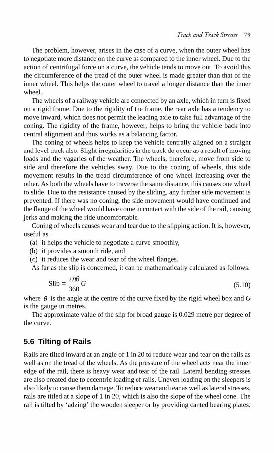
Track and Track Stresses 79
The problem, however, arises in the case of a curve, when the outer wheel hasto negotiate more distance on the curve as compared to the inner wheel. Due to theaction of centrifugal force on a curve, the vehicle tends to move out. To avoid thisthe circumference of the tread of the outer wheel is made greater than that of theinner wheel. This helps the outer wheel to travel a longer distance than the innerwheel.
The wheels of a railway vehicle are connected by an axle, which in turn is fixedon a rigid frame. Due to the rigidity of the frame, the rear axle has a tendency tomove inward, which does not permit the leading axle to take full advantage of theconing. The rigidity of the frame, however, helps to bring the vehicle back intocentral alignment and thus works as a balancing factor.
The coning of wheels helps to keep the vehicle centrally aligned on a straightand level track also. Slight irregularities in the track do occur as a result of movingloads and the vagaries of the weather. The wheels, therefore, move from side toside and therefore the vehicles sway. Due to the coning of wheels, this sidemovement results in the tread circumference of one wheel increasing over theother. As both the wheels have to traverse the same distance, this causes one wheelto slide. Due to the resistance caused by the sliding, any further side movement isprevented. If there was no coning, the side movement would have continued andthe flange of the wheel would have come in contact with the side of the rail, causingjerks and making the ride uncomfortable.
Coning of wheels causes wear and tear due to the slipping action. It is, however,useful as
(a) it helps the vehicle to negotiate a curve smoothly,(b) it provides a smooth ride, and(c) it reduces the wear and tear of the wheel flanges.As far as the slip is concerned, it can be mathematically calculated as follows.
2Slip
360
πθ= G (5.10)
where θ is the angle at the centre of the curve fixed by the rigid wheel box and Gis the gauge in metres.
The approximate value of the slip for broad gauge is 0.029 metre per degree ofthe curve.
5.6 Tilting of Rails
Rails are tilted inward at an angle of 1 in 20 to reduce wear and tear on the rails aswell as on the tread of the wheels. As the pressure of the wheel acts near the inneredge of the rail, there is heavy wear and tear of the rail. Lateral bending stressesare also created due to eccentric loading of rails. Uneven loading on the sleepers isalso likely to cause them damage. To reduce wear and tear as well as lateral stresses,rails are titled at a slope of 1 in 20, which is also the slope of the wheel cone. Therail is tilted by ‘adzing’ the wooden sleeper or by providing canted bearing plates.

80 Railway Engineering
Summary
The permanent way consists of rails, sleepers, the ballast, sleeper fittings, and thesubgrade. The strength of each of these components is essential for the safe runningof trains. The stresses developed in each component due to the movement of wheelloads should be within permissible limits as specified for different types of tracks.The concept of load distribution in a railway track is based on the elastic theory,but most of the equations used to calculate stresses in the different componentslack a theoretical background. The coning of wheels helps reduce the wear andtear of the wheel flanges, providing a smooth ride. The ill effects of coning onhorizontal curves are reduced by laying the rails at a slope of 1 in 20.
Review Questions
1. What do you understand by a railway track or a permanent way? Mention therequirements of an ideal permanent way.
2. What are the component parts of a permanent way?3. Draw a typical cross section of a BG double track in embankment and show
therein all the components of the track.4. What is meant by ‘track modulus’? Indicate its usual range of values for a
broad gauge track.5. How is track modulus expressed? State the factors affecting it and give the
values of at least one of these factors for the tracks in our country.6. Draw a typical cross section of a permanent way. Explain briefly the functions
of the various components of the railway track.7. Discuss the necessity and effects of the coning of wheels.8. What are the various types of stresses induced in a rail section? Explain briefly
how these are evaluated.9. Explain the following terms.
(a) Track modulus(b) Coning of wheels(c) Tilting of rails(d) Permanent way

Rails 81
Rails
Introduction
Rails are the members of the track laid in two parallel lines to provide an unchanging,continuous, and level surface for the movement of trains. To be able to withstandstresses, they are made of high-carbon steel. Standard rail sections, theirspecifications, and various types of rail defects are discussed in this chapter.
6.1 Function of Rails
Rails are similar to steel girders. These are provided to perform the followingfunctions in a track.
(a) Rails provide a continuous and level surface for the movement of trains.(b) Rails provide a pathway which is smooth and has very little friction. The
friction between the steel wheel and the steel rail is about one-fifth of thefriction between the pneumatic tyre and a metalled road.
(c) Rails serve as a lateral guide for the wheels.(d) Rails bear the stresses developed due to vertical loads transmitted to them
through axles and wheels of rolling stock as well as due to braking andthermal forces.
(e) Rails carry out the function of transmitting the load to a large area of theformation through sleepers and the ballast.
6.2 Types of Rails
The first rails used were double headed (DH) and made of an I or dumb-bell section(Fig. 6.1). The idea was that once the head wore out during service, the rail couldbe inverted and reused. Experience, however, showed that while in service thebottom table of the rail was dented to such an extent because of long and continuouscontact with the chairs that it was not possible to reuse it. This led to the developmentof the bull headed (BH) rail, which had an almost similar shape but with moremetal in the head to better withstand wear and tear (Fig. 6.2). This rail section hadthe major drawback that chairs were required for fixing it to the sleepers.
A flat-footed rail, also called a vignole rail (Fig. 6.3), with an inverted T-typecross section of inverted T- type was, therefore, developed, which could be fixeddirectly to the sleepers with the help of spikes. Another advantage of the flat-footed
CHAPTER
6

82 Railway Engineering
rail is that it is a more economical design, giving greater strength and lateral stabilityto the track as compared to a BH rail for a given cross-sectional area. The flat-footed (FF) rail has been standardized for adoption on Indian Railways.
Fig. 6.1 Double headed rail
Fig. 6.2 Bull headed rail
Fig. 6.3 Flat-footed rail
6.3 Requirements for an Ideal Rail Section
The requirements for an ideal rail section are as follows.(a) The rail should have the most economical section consistent with strength,
stiffness, and durability.
Head
Fishing angle
Foot
WebHeight

Rails 83
(b) The centre of gravity of the rail section should preferably be very close tothe mid-height of the rail so that the maximum tensile and compressivestresses are equal.
(c) A rail primarily consists of a head, a web, and a foot, and there should be aneconomical and balanced distribution of metal in its various components sothat each of them can fulfil its requirements properly. The requirements, aswell as the main considerations, for the design of these rail components areas follows.Head: The head of the rail should have adequate depth to allow for verticalwear. The rail head should also be sufficiently wide so that not only is a widerrunning surface available, but also the rail has the desired lateral stiffness.Web: The web should be sufficiently thick so as to withstand the stressesarising due to the loads bone by it, after allowing for normal corrosion.Foot: The foot should be of sufficient thickness to be able to withstandvertical and horizontal forces after allowing for loss due to corrosion. Thefoot should be wide enough for stability against overturning. The design ofthe foot should be such that it can be economically and efficiently rolled.Fishing angles: Fishing angles must ensure proper transmission of loadsfrom the rails to the fish plates. The fishing angles should be such that thetightening of the plate does not produce any excessive stress on the web ofthe rail.Height of the rail: The height of the rail should be adequate so that the railhas sufficient vertical stiffness and strength as a beam.
6.3.1 Standard Rail Section
The rail is designated by its weight per unit length. In FPS units, it is the weight inlbs per yard and in metric units it is in kg per metre. A 52 kg/m rail denotes that ithas a weight of 52 kg per metre.
The weight of a rail and its section is decided after considerations such as thefollowing:
(a) Heaviest axle load(b) Maximum permissible speed(c) Depth of ballast cushion(d) Type and spacing of sleepers(e) Other miscellaneous factorsThe standard rail sections in use on Indian Railways are 60 kg, 52 kg, 90 R,
75 R, 60 R and 50 R. The two heavier rail sections, 60 kg and 52 kg, were recentlyintroduced and are designated in metric units. Other rails are designed as per therevised British Standard specifications and are designated in FPS units thoughtheir dimensions and weight are now in metric units. In the nomenclature 90 R,75 R, etc., R stands for revised British specifications.
Every rail rolled has a brand on its web, which is repeated at intervals. As perIRS–T–12–88, the brand marks are as follows:
IRS-52 kg – 710 – TISCO – II 1991 → OBThe definitions for the various abbreviations are as follows:

84 Railway Engineering
(a) IRS-52-kg: Number of IRS rail section, i.e., 52 kg(b) 710: Grade of rail section, i.e., 710 or 880(c) TISCO: Manufacturer’s name, e.g., Tata Iron and Steel Co.(d) II 1991: Month and year of manufacture (February 1991)(e) → : An arrow showing the direction of the top of the ingot(f) OB: Process of steel making, e.g., open hearth basic (OB)The brand marks on the rails are to be rolled in letters at least 20 mm in size and
1.5 mm in height at intervals of 1.5 to 3.0 m.The standard rail sections and standard rail length prescribed on Indian Railways
are given in Table 6.1.
Table 6.1 Standard rail sections
Gauge Rail section Type of section Rail length
Broad gauge 60 kg/m UIC 13 m (42 ft as per old standards)52 kg/m IRS90 lb/yd RBS
Metre gauge 90 lb/yd RBS 12 m (39 ft as per old75 lb/yd RBS standards), except 90-lb rails,60 lb/yd RBS which are of 13 m length
Narrow gauge 50 lb/yd RBS 12 m (39 ft as per old standards)
UIC—International Union of Railways, IRS—Indian Railway Standard, RBS—Revised BritishStandard.
Detailed dimensions of standard rail sections are shown in Fig. 6.4 and Table 6.2.
Fig. 6.4 Standard flat-footed rail section
1:3 1:3
E
Horizontal axisNeutral
C
D
Com
pres
sion
side
Tens
ion
side
1:61:6
F
B
A
Neu
tral
vert
ical
axi
s

Rails 85
Table 6.2 Details of standard rail sections
Rail section Wt/ Area of Dimensions (mm)metre section(kg) (mm2) A B C D E F
50 R 24.80 3168 104.8 100.0 52.4 9.9 32.9 15.160 R 29.76 3800 114.3 109.5 57.2 11.1 35.7 16.775 R 37.13 4737 128.6 122.2 61.9 13.1 39.7 18.790 R 44.61 5895 142.9 136.5 66.7 13.9 43.7 20.6
52 kg (IRS) 51.89 6615 156.0 136.0 67.0 15.5 51.0 29.060 kg (UIC) 60.34 7686 172.0 150.0 74.3 16.5 51.0 31.5
It may be mentioned here that the 90 R rail section is adequate only for anannual traffic density of about 10 GMT (gross million tonnes per km/annum),speeds of up to 100 kmph, axle loads up to main line (ML) standard, and a servicelife of about 20–25 years. Realizing to these limitations, the Indian Railways, inthe year 1959, designed a heavier rail section of 52 kg/m to meet the requirementsof heavier and faster traffic. This rail section was recommended for use on all BGmain line routes with future speeds of up to 130 kmph and traffic density of 20–25GMT. The important dimensions of 52-kg and 60-kg rails are shown in Fig. 6.5.
Fig. 6.5 (a) 52-kg rail (b) 60-kg rail
The traffic density on the BG track routes of Indian Railways is increasing veryfast. Accordingly, to meet the future requirements of traffic, a new design has beenfinalized for the 60-kg UIC section rail. The rail section has been designed forspeeds of up to 160 kmph and a traffic density of about 35 GMT.
C(67)
13R
2R1 in 2.75
E
DNeutralhorizon axis
Com
pres
sion
sid
e
A (
172)
Tens
ion
side
F 20R
B (137)
Com
pres
sion
sid
e
(B 150)
F
Tens
ion
side
A (
156)
DNeutralhorizon axis
1 in 2.75
13R2R
C(74.3)
E
40R 7R
2.75
(a) (b)
4R

86 Railway Engineering
Weight of rails
Though the weights of a rail and its section depend upon various considerations,the heaviest axle load that the rail has to carry plays the most important role. Thefollowing is the thumb rule for defining the maximum axle load with relation tothe rail section:
Maximum axle load = 560 × sectional weight of rail in lbs per yardor kg per metre
For rails of 90 lbs per yard,Maximum axle load = 560 × 90 lbs = 50,400 lbs or 22.5 t
For rails of 52 kg per m,Maximum axle load = 560 × 52 kg = 29.12 t
Length of rails
Theoretically, the longer the rail, the lesser the number of joints and fittings requiredand the lesser the cost of construction and maintenance. Longer rails are economicaland provide smooth and comfortable rides. The length of a rail is, however, restricteddue to the following factors.
(a) Lack of facilities for transport of longer rails, particularly on curves.(b) Difficulties in manufacturing very long rails.(c) Difficulties in acquiring bigger expansion joints for long rails.(d) Heavy internal thermal stresses in long rails.Taking the above factors into consideration, Indian Railways has standardized a
rail length of 13 m (previously 42 ft) for broad gauge and 12 m (previously 39 ft)for MG and NG tracks. Indian Railways is also planning to use 26 m, and evenlonger, rails in its track system.
6.4 Rail Manufacture
The steel used for the manufacture of rails is made by the open hearth or duplexprocess and should not have a wide variation in its chemical composition. Thereare essentially four stages of rail manufacturing.
(a) Steel manufacturing process using a basic oxygen/electric arc furnace,including argon rinsing and degassing
(b) Continuous casting of blooms(c) Rail rolling process including controlled cooling(d) Rail finishing including eddy current testing, ultrasonic testing, and finishing
workA typical flow chart for the manufacture of rails at the Bhilai steel plant in India
is given in Fig. 6.6.
6.4.1 Rail Specifications (IRS-T-12-96)
These specifications apply to flat-bottom symmetrical rails. The quality of steel,manufacturing process, chemical composition, acceptance tests, qualifying criteria,and other technical conditions are given below.

Rails 87
Quality of steel The steel for rails should be of fully killed quality and should conformto the chemical composition and mechanical properties specified in Table 6.3.
Branding and stamping Rails should be hot branded on one side of the webshowing relevant details. Each rail should be identified by hot stamping at leastonce every 4.0 m on the web and should be colour coded in order to distinguish thegrade, class, length, and other special requirements.
Fig. 6.6 Process of rail manufacture at Bhilai steel plant, India
Table 6.3 Desirable properties of steel for rails
(a) Chemical composition
Grade C Mn Si S (max.) P (max.) Al (max.) Liquidhydrogen
880 0.6–0.8 0.8–1.3 1.3–0.5 0.035* 0.035* 0.02 3.00
* The maximum value for finishing is 0.040.
(b) Mechanical properties
UTS Elongation % on gauge Running surface hardness(MPa; min.) length = 5.65/S* (min.)
880 10.0 Min. 260†
* S = cross-sectional area of piece in mm2.† Desirable values.
Blastfurnace
850-mmfinishingstands
Hot saws
Inspectionbeds
Coldcarbide
saws andmilling
machines
130 Tconverter shop
800-mmintermediate
stands
Onlinecomputerized
stampingmachine
Onlineultrasonic
testing machine
Refinishinggroup
Vacuum arcdegassing
950-mmroughingstands
Cooling beds
Online eddycurrent testing
Despatchsection
Four-standbloom caster
Reheatingfurnace
Slow coolingpits
Biplaner railroller
straighteningmachine
Hot metal Liquid steel Clean liquid steel with H2
Blooms

88 Railway Engineering
Rolling quality Each section of the rail should be accurately rolled to its respectivetemplate (prepared by the manufacturer and approved by the purchaser or inspectingagency) within permissible tolerance or variations.
Free from defects The rails should be free from all detrimental defects such ascracks of all kinds, flaws, piping, and lack of metal that have an unfavourableeffect on the behaviour of rails in service.
Straightness The rail should be absolutely straight. Tolerances for end straightnessare very stringent as indicated in Table 6.4.
Table 6.4 Tolerances for end straightness
Straightness Tolerance
Class A rails Class B rails
Horizontal Deviation of 0.5 mm measured Deviation of 0.7 mm measuredas maximum ordinate from the as maximum ordinate from thechord of 2.0 m standard sraight chord of 1.5 m standardedge straight edge
Vertical(a) Up sweep Deviation of 0.4 mm measured Deviation of 0.5 mm measured
as maximum ordinate from the as maximum ordinate from thechord of 2.0 m the standard chord of 1.5 m standardstraight edge straight edge
(b) Down sweep — —
Permissible Variations in Dimensions
The tolerances allowed in the various parameters of a rail section are given inTable 6.5. These tolerances are subject to the condition that the actual weightdetermined by weighing the rail piece falls 0.5% below and 1.5% above thecalculated weight.
Table 6.5 Permissible variation in dimensions of rails
Item Permissible variations in dimensions of rails
Overall height + 0.8 mm to –0.4 mm
Width of head ±0.5 mm (width of head measured 14 mm below the rail top)
Width of flange ±1.0 mm (for sections less than 60 kg/m)+ 1.2 mm, –1.0 mm (for sections 60 kg/m and above)
Thickness of web + 1.0 mm to –0.5 mm (measured at the point of minimumthickness)
Vertical flange ±1.2 mm (for flange width less than and equal to 150 mm)The base of the rail should be true and flat, but a slight concavity not exceeding 0.40 mm is permissible.
Length of rails + 2.0 mm to –10 mm
(contd)

Rails 89
Item Permissible variations in dimensions of rails
Fishing surfaces The standard template for the rail fishing surface should not standaway from the contour of the web by more than 1.20 mm and theclearance at the finishing surfaces should not exceed 0.18 mm atany point.
End squareness The deviation from the square in both horizontal and verticaldirections should not exceed 0.60 mm.
Straightness The maximum permissible deviation should be 0.70 mm,measured as the maximum ordinate on a chord of 1.5 m. Wavy,kinky, and twisted rails should not be accepted.
End straightness Rails are classified into A and B categories. The details are givenin Table 6.4.
Fishbolt holes Diameter of holes: ±0.70 mm centring and positioning of holesvertically and ±0.70 mm horizontally
Important tests for rails
The following tests are conducted to determine the serviceability of a rail section.
Falling weight or tup test A rail piece of 1.5 m (5 ft) is cut. The rail is supportedbetween the bearers at a prescribed distance. A tup of specified weight (1000 kgfor a 90 R rail) is dropped from a height of 7.2 m on the centre of the test piece.The specimen should withstand the blow without any fracture. One falling weighttest is done for every cast of 100 metric t. The weight of the tup, distance betweenthe centres of the bearings, and the weight of the drop for different rail sections isgiven in Table 6.6.
Table 6.6 Details of the tup test
Rail section Wt of tup Distance between centres Height of drop(kg) of bearings (m) (m)
60 kg/m 1270 1.07 8.452 kg/m 1270 1.20 7.6
90 R 1000 1.10 7.275 R 1000 1.10 6.0
Tensile test A test piece is taken from the head of a rail section and subjected tothe tensile test. The tensile strength of the rail should not be less than 72 kg/mm2,with a minimum elongation of 14% for medium manganese rails and 12% forcarbon quality rails. This test is optional and is to be carried out when required bythe inspecting official.
Hammer test The foot of the test rail piece is rigidly gripped in a vertical positionand the head of the rail is struck with a 4.5 kg hammer. Sufficient number of blowsare given till the web bends and the dimensional value of A given in Table 6.7(Fig. 6.7) is achieved. No fracture should occur or a lap be disclosed, otherwise
Table 6.5 (contd)

90 Railway Engineering
the batch is rejected. This test is no longer required as per IRS/T- 18-88. Thevalues of A for various rail sections are listed is Table 6.7.
Fig. 6.7 Hammer test
Table 6.7 Values of A for different rail sections
Rail section 52 kg/m 90 R 75 R 60 R 50 R
Dimension A in mm 157 144.5 130 117.7 108
6.4.2 Second Quality Rails
Rails that have been rejected either individually or by cast for having failed tofulfil the requirements of IRS specification no. T-12 with regard to chemicalcomposition, or have failed due to defects in surface dimensions and length, maybe accepted as second quality rails (T-18) for use in loops and sidings. These secondquality rails should conform to the following specifications.
Chemical composition
The chemical composition of the rails should conform to the values given inTable 6.8.
Table 6.8 Required chemical composition for second quality rails*
Element % in carbon steel % in medium Revised % in mediummanganese steel manganese steel
Carbon 0.50–0.70 0.40–0.60 0.40–0.65Manganese 0.60–0.95 0.90–1.45 0.85–1.45Sulphur 0.06 max. 0.06 max. 0.06 max.Phosphorus 0.06 max. 0.06 max. 0.06 max.Silicon 0.03–0.30 0.03–0.30 0.03–0.30
* As per the revised specifications, the percentage of C + Mn should in no case be less than 1.3%.In case carbon exceeds 0.6%, then C + Mn should not exceed 2%.
Surface defects
The following maximum dimensions of the rail surface are considered as minordefects. Rails with these defects are acceptable.
A

Rails 91
Table of the rail: 0.80 mmSide of head of the rail: 1.60 mmBottom and side of the rail: 1.60 mm
Permissible variations in dimensions
Overall height of the rail: + 1.60 mm, –0.80 mmWidth of head: + 1.20 mmThickness of web: + 1.60 mm, –0.60 mmLength of rail: ±25 mmDifference in theoretical and actual weight: 1%
Such rails are identified by chamfering a 6-mm-diameter hole at either end,along the centre of the rail and in the middle of the web. These rails are to be usedonly on loop lines/sidings with a speed restriction of 50 kmph. These rails arepainted orange on both sides of the web for a length of 1 m from each end for easyidentification.
6.4.3 Third Quality Rails
These are rails that do not conform to the standards set for first or second qualityrails but are still fit for use on the railway track. For safety considerations, theseare used in industrial sidings where speeds are restricted to 30 kmph for BG and25 kmph for MG.
Such rails are identified by chamfering a 12-mm-diameter hole at either end,along the centre of the rail and in the middle of the web. A 18 mm marking ‘I.U.’ isstamped on both end faces of the rail. Third quality rails are painted white on theend face on both sides of the flange for a length of 500 mm from each end foridentification.
Third quality rails are manufactured using rejected heats/rails which do notconform to IRS T-12 or T-18 standards with regard to chemical composition, surfacedefects, dimensions, and straightness.
6.4.4 90 UTS Rails
Indian Railways has mostly been using medium manganese rails with an ultimatetensile strength (UTS) of 72 kg/mm2 manufactured by the Bhilai steel plant. Theservice life of 52 kg (72 UTS) rails is only about 350 GMT. On a section with anannual traffic density of about 20 GMT, the renewal cycle is just about 17–18 years,which is rather short as compared to the service life of 50 years of a concretesleeper. Moreover, such rails wear faster on curves and gradient sections.
In view of the above considerations, Indian Railways has been importing 52-kgand 90 R, 90 UTS rails for some time. These rails have the following mainadvantages.
1. The service life of 90 UTS rails is about 50% more than that of conventionalmedium manganese 72 UTS rails.
2. The total GMT that 72 and 90 UTS rails can carry during their primaryservice life is as follows:

92 Railway Engineering
52 kg (72 UTS): 350 GMT52 kg (90 UTS): 525 GMT60 kg (90 UTS): 900 GMT
3. 90 UTS rails are more resilient against wear and have a hardness of about270 BHN (Brinell hardness number) as against that of 220 BHN of mediummanganese rails with 72 UTS.
4. The allowable shear stress of 90 UTS rails is much higher, as can be seenfrom the comparative figures given below:
Rails Allowable shear stress
Medium manganese rails (72 UTS) 18.0 kg/mm2
Wear-resistant rails (90 UTS) 22.5 kg/mm2
Studies have shown that the maximum shear stress due to BOX N wagons couldbe of the order of 20.0 kg/mm2, which is in excess of the permissible shear stressfor medium manganese 72 UTS rails. Therefore, for routes on which BOX N wagonsare running, it is desirable to have 90 UTS rails.
End-hardened rails
These are rails with ends that are hardened by oil or water quenching. The wearand tear and end batter of such rails is considerably less.
Head-hardened rails
These are rails with heads that have been hardened by passing them through athermal treatment plant. The head is hardened for a depth of about 12 mm from thesurface. Head hardened rails have a longer service life that extends up to 2–3 timesmore compared to as ordinary medium manganese rails.
The chemical composition of head-hardened steel (grade 1080) is prescribed asgiven in Table 6.9.
Table 6.9 Chemical composition of head-hardened rail
Item Carbon Manganese Silicon Sulphur Phosphorus
Limit of values 0.72–0.82 0.75–1.05 0.05–0.30 0.035 max. 0.035 max.
6.5 Rail Wear
Due to the passage of moving loads and friction between the rail and the wheel,the rail head gets worn out in the course of service. The impact of moving loads,the effect of the forces of acceleration, deceleration, and braking of wheels, theabrasion due to rail–wheel interaction, the effects of weather conditions such aschanges in temperature, snow, and rains, the presence of materials such as sand,the standard of maintenance of the track, and such allied factors cause considerablewear and tear of the vertical and lateral planes of the rail head. Lateral wear occursmore on curves because of the lateral thrust exerted on the outer rail by centrifugalforce. A lot of the metal of the rail head gets worn out, causing the weight of therail to decrease. This loss of weight of the rail section should not be such that the

Rails 93
stresses exceed their permissible values. When such a stage is reached, rail renewalis called for.
In addition, the rail head should not wear to such an extent that there is thepossibility of a worn flange of the wheel hiting the fish plate.
6.5.1 Type of Wear on Rails
A rail may face wear and tear in the following positions:(a) on top of the rail head (vertical wear)(b) on the sides of the rail head (lateral wear)(c) on the ends of the rail (battering of rail ends)Wear is more prominent at some special locations of the track. These locations
are normally the following:(a) on sharp curves, due to centrifugal forces(b) on steep gradients, due to the extra force applied by the engine(c) on approaches to railway stations, possibly due to acceleration and
deceleration(d) in tunnels and coastal areas, due to humidity and weather effects
6.5.2 Measurement of Wear
Wear on rails can be measured using any of the following methods.(a) By weighing the rail(b) By profiling the rail section with the help of lead strips(c) By profiling the rail section with the help of needles(d) By using special instruments designed to measure the profile of the rail and
record it simultaneously on graph paper
6.5.3 Methods to Reduce Wear
Based on field experience, some of the methods adopted to reduce vertical wearand lateral wear on straight paths and curves are indicated below.
(a) Better maintenance of the track to ensure good packing as well as properalignment and use of the correct gauge
(b) Reduction in the number of joints by welding(c) Use of heavier and higher UTS rails, which are more wear resistant(d) Use of bearing plates and proper adzing in case of wooden sleepers(e) Lubricating the gauge face of the outer rail in case of curves(f) Providing check rails in the case of sharp curves(g) Interchanging the inner and outer rails(h) Changing the rail by carrying out track renewal
6.5.4 Rail End Batter
The hammering action of moving loads on rail joints batters the rail ends in duecourse of time. Due to the impact of the blows, the contact surfaces between therails and sleepers also get worn out, the ballast at places where the sleepers are

94 Railway Engineering
joined gets shaken up, the fish bolts become loose, and all these factors furtherworsen the situation, thereby increasing rail end batter.
Rail end batter is measured as the difference between the height of the rail at theend and at a point 30 cm away from the end. If the batter is up to 2 mm, it isclassified ‘average’, and if it is between 2 and 3 mm, it is classified as ‘severe’.When rail end batter is excessive and the rail is otherwise alright, the ends can becropped and the rail reused.
Rail lubricators are provided on sharp curves, where lateral wear is considerable.The function of lubricators is to oil the running face of the outer rail in order toreduce the friction. It has been noticed that this considerably reduces the wear, byup to 50%. There are many mechanical devices that can be attached to the wheelsto provide such lubrication. In these mechanical arrangements, the wheels of movingtrains normally cause the lubricant to flow on the side of the rail either by theaction of the wheels pressing the plunger up and down or by ramps on account ofthe rails being depressed by wheels. Sometimes the movement of trains also causelubricants to flow. Based on the principle of the plunger being pressed by movingwheels, P and M type lubricators have been provided on curves in some sectionssuch as the ‘Ghat section’ of Central Railway and these are working verysatisfactorily. For more details on wear, including limit of wear, refer to Chapter 23.
6.6 Other Defects in Rails
Rail wear and the battering of rail ends are the two major defects in rails. However,some other types of defects may also develop in a rail and necessitate its removalin extreme cases. These are described below.
Hogging of rails
Rail ends get hogged due to poor maintenance of the rail joint, yielding formation,loose and faulty fastenings, and other such reasons. Hogging of rails causes thequality of the track to deteriorate. This defect can be remedied by measured shovelpacking. (For details, refer to Chapter 20.)
Scabbing of rails
The scabbing of rails occurs due to the falling of patches or chunks of metal fromthe rail table. Scabbing is generally seen in the shape of an elliptical depression,whose surface reveals a progressive fracture with numerous cracks around it.
Wheel burns
Wheel burns are caused by the slipping of the driving wheel of locomotives on therail surface. As a consequence, extra heat is generated and the surface of the railgets affected, resulting in a depression on the rail table. Wheel burns are generallynoticed on steep gradients or where there are heavy incidences of braking or nearwater columns.

Rails 95
Shelling and black spots
Shelling is the progressive horizontal separation of metal that occurs on the gaugeside, generally at the upper gauge corner. It is primarily caused by heavy bearingpressure on a small area of contact, which produces heavy internal shear stresses.
Corrugation of rails
Corrugation consists of minute depressions on the surface of rails, varying in shapeand size and occurring at irregular intervals. The exact cause of corrugation is notyet known, though many theories have been put forward. The factors which helpin the formation of rail corrugation, however, are briefly enumerated here.
(a) Metallurgy and age of rails(i) High nitrogen content of the rails(ii) Effect of oscillation at the time of rolling and straightening of rails.
(b) Physical and environment conditions of track(i) Steep gradients(ii) Yielding formation(iii) Long tunnels(iv) Electrified sections
(c) Train operations(i) High speeds and high axle loads(ii) Starting locations of trains(iii) Locations where brakes are applied to stop the train
(d) Atmospheric effects(i) High moisture content in the air particularly in coastal areas(ii) Presence of sand
The corrugation of rails is quite an undesirable feature. When vehicles passover corrugated rails, a roaring sound is produced, possibly due to the locking ofair in the corrugation. This phenomenon is sometimes called ‘Roaring of rails’.This unpleasant and excessive noise causes great inconvenience to the passengers.Corrugation also results in the rapid oscillation of rails, which in turn loosens thekeys, causes excessive wear to fittings, and disturbs the packing.
Corrugation can be removed by grinding the rail head by a fraction of a millimeter.No method has been standardized on Indian Railways to grind rail surfaces. Theproblem of corrugation, however, has been tackled in great detail on GermanRailways, where two types of equipment are normally used for rail grinding.
(i) Hand or motor-driven trollies that move on the rails at slow speeds andgrind the individual rails one by one.
(ii) Rail grinding train, which moves at a speed of 30 kmph and grinds both railssimultaneously.
6.7 Rail Failure
A rail is said to have failed if it is considered necessary to remove it immediatelyfrom the track on account of the defects noticed on it. The majority of rail failuresoriginate from the fatigue cracks caused due to alternating stresses created in therail section on account of the passage of loads. A rail section is normally designed

96 Railway Engineering
to take a certain minimum GMT of traffic, but sometimes due to reasons such as aninherent defect in the metal, the section becomes weak at a particular point andleads to premature failure of the rail.
6.7.1 Causes of Rail Failures
The main causes for the failure of rails are as follows.
Inherent defects in the railManufacturing defects in the rail, such as faulty chemicalcomposition, harmful segregation, piping, seams, laps, and guide marks.
Defects due to fault of the rolling stock and abnormal traffic effectsFlat spots intyres, engine burns, skidding of wheels, severe braking, etc.
Excessive corrosion of railsExcessive corrosion in the rail generally takes placedue to weather conditions, the presence of corrosive salts such as chlorides andconstant exposure of the rails to moisture and humidity in locations near watercolumns, ashpits, tunnels, etc. Corrosion normally leads to the development ofcracks in regions with a high concentration of stresses.
Badly maintained jointsPoor maintenance of joints such as improper packing ofjoint sleepers and loose fittings.
Defects in welding of jointsThese defects arise either because of impropercomposition of the thermit weld metal or because of a defective welding technique.
Improper maintenance of trackIneffective or careless maintenance of the track ordelayed renewal of the track.
DerailmentsDamages caused to the rails during derailment.
6.7.2 Classification of Rail Failures
The classification of rail failures on Indian Railways has been codified for easyprocessing of statistical data. The code is made up of two portions—the first portionconsisting of three code letters and the second portion consisting of three or fourcode digits.
First portion of the code The three code letters make up the first portion anddenote the following.
(i) Type of rail being used (O for plain rail and X for points and crossing rails)(ii) Reasons for withdrawal of rail (F for fractured, C for cracked, and D for
defective)(iii) Probable cause for failure (S for fault of rolling stock, C for excessive
corrosion, D for derailment, and O for others)
Second portion of codeThe second portion of code the consisting of three orfour digits gives the following information.
(i) Location of the fracture on the length of the rail (1 for within fish platelimits and 2 for other portions on the rail)
(ii) Position in the rail section from where the failure started (0 for unknown, 1for within rail head, 2 for surface of rail head, 3 for web, and 4 for foot)
(iii) Direction of crack or fracture (0 to 9)

Rails 97
(iv) Any other information about the fracture, where it is necessary to providefurther subdivision. No specific system is recommended for this code.
6.7.3 Metallurgical Investigation
The following types of defective rails should normally be sent for metallurgicalinvestigation.
(i) Rails that have been removed from the track as a result of visual or ultrasonicdetection
(ii) Rail failures falling in categories in which cracks or surface defects developat specified locations.
6.8 Rail Flaw Detection
A defect in a rail which will ultimately lead to the fracture or breakage of the rail iscalled a flaw. From the point of view of the ultimate consequence of the flawresulting in a fracture, it is necessary to detect these flaws and take timely action toremove them. Rail flaws can be detected either by visual examination of the railends or by rail flaw detection equipment.
Visual examination of rail ends In this method, the joint is first opened afterremoving the fish plates. The rail ends are then cleaned using kerosene oil andvisually examined in detail with the help of a magnifying glass for any hair crack, etc.White chalk is sometimes rubbed on the rail ends so as to identify the flaw clearly.A mirror is used to reflect light on the joint in case sufficient light is not available.
Ultrasonic rail flaw detectors Ultrasonic rail flaw detectors (USFDs) have beenprogressively used in recent years on Indian Railways for the detection of flaws.This method is also known as the non-destructive method of testing rails.
6.8.1 Theory of Ultrasonic Rail Flaw Detectors
Vibration waves of a frequency of more than 20,000 cycles per second are termedas ultrasonic waves. These waves have the property of being able to pass throughmaterials and following the normal principles of light waves of refraction, reflection,and transmission. Whenever there is a change of medium, some of the ultrasonicenergy gets reflected and the rest gets transmitted. The amount of energy reflecteddepends upon the physical properties of the two media. When travelling throughsteel, if these waves come across air either from the bottom of the steel or from anyflaw inside the steel, the reflection is almost 100%. This property has been foundmost useful for detecting flaws in rails. Thus, when ultrasonic waves are fed froma location on a rail, they pass through the rail metal and are normally reflected onlyfrom the foot. However, if a discontinuity exists in the rail metal due to some flaw,the ultrasonic waves get reflected back from the location of the flaw, which can bepicked up and the defect located.
Production of ultrasonic waves
There are several methods of producing ultrasonic energy. The most common andsimple method of producing ultrasonic frequency is by using ‘crystal transducers’,

98 Railway Engineering
which normally produce ultrasonic waves of a frequency of up to 15 MHz. Thecrystals generally used for this purpose are made either of quartz or of bariumtitanate, cut to special size, shape, and dimensions. These crystals have the peculiarproperty of changing dimensions and generating vibrations in a particular directionwhen an oscillating electric charge is applied to the crystal faces. Also, when thesecrystals are made to vibrate, they produce an oscillating electric current. The crystals,as such, have the potential of generating ultrasonic vibrations, as also of convertingthe waves received after reflection into electric current. They also possess reversibleproperties.
These crystals are housed in metal holders protected by superior quality Perspexand then termed probes. There are two types of probes used for ultrasonic testing.
Normal probe This probe consists of two semi-cylindrical thin crystals with avertical separating layer through the crystals and Perspex. These probes transmitultrasonic waves vertically downwards when put on the rail and are suitable fordetecting horizontal or inclined flaws, including bolt hole cracks.
Angle probe In this probe, crystals are mounted on an angular surface capable oftransmitting pulses at an outward angle, which may be forward or backward orboth, with separate transmitting and receiving crystals. The waves emitted by theseprobes follow an inclined path and are suited to detect inclined and vertical defects.
Techniques of ultrasonic testing
A number of techniques have been used in ultrasonic testing to suit the design ofdifferent equipment. Some of these techniques are the following.
(a) Frequency modulation(b) Pulse echo(c) Transmission(d) Resonance(e) Acoustic rangeIndian Railways uses the frequency modulation and pulse echo techniques and
only these are discussed in detail here.
Frequency modulation technique In instruments utilizing frequency modulationultrasonic waves are created with the help of a probe crystal and transmittedcontinuously into the rail at rapidly changing frequencies. It is necessary for therail head to be wet to enable the ultrasonic waves to pass efficiently from thecrystal to the rail. The waves that get reflected from the opposite face are receivedcontinuously by the crystal. There is interference between the transmitted wavesand the reflected waves, which causes resonance. As the frequencies of thetransmitted waves are changing constantly, such resonance takes place at regularintervals. When the position of reflection is changed due to a flaw in the metal, theresonance gets affected, which can be easily detected by the operator. Instrumentsmanufactured on this principle such as the Audi-gauge are light, portable, andsimple in mechanism. However, these instruments have certain limitations.
(a) Fine vertical cracks are not readily detected because the single vertical probedoes not find any surface defect from which it can be reflected.

Rails 99
(b) Cracks wholly below bolt holes are also not detected, as the vibrations areinterrupted by the hole.
Pulse echo systemIn the pulse echo technique, a pulsed ultrasonic beam of veryhigh frequency is produced by a pulse generator and sent in to the rail. At theopposite face, the ultrasonic waves are reflected and the echo is picked up by thecrystal transducers. A discontinuity or defect in the rail will also produce the echo.The time interval between the initial pulse and the arrival of the echoes is measuredwith the help of a cathode ray tube. There may be multiple reflections of the echobut the one arising due to a fault can easily be determined by its relative positionand amplitude.
The more sophisticated types of instruments that are based on the pulse echosystem are being manufactured by the firm Kraut Kramer at present.
6.8.2 Kraut Kramer Multi Probe Rail Testing Trolley
This is the most common type of equipment used on Indian Railways for detectingflaws in the rail Fig. 6.8. The equipment is fitted on a hand trolley that is carried onthe rails. There are two probes: a normal probe and an angle probe, both actindependently. The probe material used for the production of ultrasonic waves isbarium titanate, which produces and transmits vertical ultrasonic waves of fourmegacycles frequency through the vertical probe and 2 mega cycles frequencythrough the angle probe. The cylindrical probe is mounted on a knuckle jointedholder frame and has a renewable bakelite wear plate at the base. As the probe isworked over the rail, the bakelite piece takes the wear completely. The height ofthe probe above the rail surface can be adjusted in the holder assembly. The normalprobe is powerful enough to scan the entire rail depth for defects. It can detectlongitudinal discontinuities in the head at the junction of either the web and thefoot or the web and the head as well as cracks from bolt holes. It cannot, however,detect vertical cracks. The defects detected by the normal probe are represented onthe oscilloscope screen in the form of firm echoes protruding from a base line.Ordinarily, two echoes are visible on the screen, the initial echo due to the partialreflection of the waves from the rail top and the back echo from the bottom of therail. Any echo between the initial and the back echo with a corresponding reductionin the height of the back echo is termed a flaw echo and is indicative of a flaw. Theposition of the flaw can be known by reading the distance of this intermediate echofrom the initial echo, which will be the distance of the flaw from the rail top.
The ultrasonic rail testing trolley can be used without any block protection, butone has to be vigilant about the movement of trains. Progress depends upon theexperience and the efficiency of the operator. The work is quite strenuous in natureand a single operator cannot observe the screen continuously for a long time. Workcan also not be done during the middle of the day in the summer months becausethe operator will not be able to pick up the signals clearly. On account of theselimitations, the work progresses rather slowly and approximately 2–3 km of railare covered per day with two operators.

100 Railway Engineering
Fig. 6.8 Ultrasonic rail testing trolley
6.8.3 Classification of Rail Flaws
Depending upon the nature and extent of internal flaws, traffic density, and speedon the section, the defects noticed by rail flaw detection methods have been classifiedinto three major categories, i.e., IMR, REM, and OBS.
IMR defects A defect that is serious in nature and can lead to sudden failure isclassified as IMR. Immediately after detection, clamped fish plates should beprovided for the defective portions and a speed restriction of 30 kmph imposed tillthe IMR rail is removed by a sound-tested rail piece of not less than 6 m. A watchmanshould be posted till the clamped fish plates are provided to avoid any mishaps.IMR stands for immediate removal.
REM defects These are the type of defects that warrant early removal of the railfrom the track. These defects are marked with red paint. REM stands for remove.
OBS defectsThese are defects that are not so serious. The rail need not be removedin such cases but should be kept under observation. These defects are marked withyellow paint. OBS stands for observe. OBS defects have been further classified asOBS (E) and OBS (B). An OBS defect located within the fish-plated zone isdesignated OBS (E). Similarly, an OBS defect on major bridges and up to 100 mon their approaches is designated OBS (B).
In the case of the need-based concept of ultrasonic testing (explained inSection 6.8.6), there are only two types of defects, IMR and OBS. However, if thedefects occur at welded joints, they are called IMR (R) and OBS (W) defects.
The actions to be taken upon the detection of defective rails are summarized inTable 6.10.

Rails 101
Table 6.10 Actions to be taken upon the detection of defective rails
Classification Action required Speed restriction to be imposed ifof defects the required action is delayed
IMR Immediate replacement Impose 30 km/h and depute a(red - 3 stars) (not later than 3 days) watchman till defective part replaced
REM Replace within 15 days Impose 30 km/h if not replaced(Red - 2 stars) within 15 days
OBS (E) Replace or end crop Impose 30 km/h if not replaced(red - 1 star) within 15 days within 15 days
OBS (B) Replace within 15 days Impose 30 km/h if not replaced(Red - 1 star) within 15 days
In the case of OBS rails other than OBS (E) and OBS (D), permanent wayinspector (PWI) should observe each OBS location with a magnifying glass andduly record his observations once a month, to see if the crack has developed anyfurther, in which case the same action as for REM defects should be taken. ThePWI should maintain sleepers, fittings, and the ballast at such locations in soundcondition. The assistant engineer should also test-check some of the OBS locationsand record his observations during his monthly push trolley inspection of eachsection.
6.8.4 Ultrasonic Rail Flaw Testing Car
As the portable ultrasonic rail flaw detector can test only 2–3 km of rails everyday,advanced railways such as German Railways have developed a rail testing car thatcan test a much longer length of track much more effectively. The test car tests thetrack at a speed of 30 kmph and each of the two rails is tested ultrasonically bymeans of five probes (0°, ±35°, ±70°) and an airborne sound assembly. The testresults are recorded photographically on a tape, a subsequent examination of whichcan reveal all the flaws. The flaws can then be properly classified. Their position inthe track can also be pinpointed with respect to kilometrage to an accuracy of 1 m.This special car tests the track during the day and covers 100–200 km per day. Thecar covers approximately 20,000 km of track every year on German Railways. Theaverage cost of testing is Rs 300–500 per km of the track. With the present trend inincrease in speed, the need for ultrasonic inspection of rails is felt all the more toavoid hazards due to rail fractures, and in this context, the use of the test car onIndian Railways is considered a technical and operational necessity.
6.8.5 Self-propelled Ultrasonic Rail Testing Car
Indian Railways has recently procured a self-propelled ultrasonic rail testing(SPURT) car of make MATRIX-VUR-404 from Sa Matrix Industries, Paris, at atotal cost of approximately Rs 25 million, inclusive of ancillary equipment. TheMATRIX car is capable of detecting, measuring, recording, and simultaneouslyanalysing the internal defects of rails using a non-destructive method of rail flawdetection. The rail testing car has been designed for simultaneous examination of

102 Railway Engineering
rails, points, and crossings at a maximum speed of 40 kmph. It consists of thefollowing parts.
(a) An ultrasonic detection lorry(b) An electronic unit including all circuit transmitters, receivers, selectors, and
auxiliaries(c) Two multi-track recorders installed at either end of the car(d) A real-time automatic defect analyserThe various components of rail flaw detecting equipment are shown in the
schematic diagram in Fig. 6.9. Testing is done using five probes at different angles,which are able to detect rail flaws.
Fig. 6.9 Various components of ultrasonic rail flaw detecting equipment
The SPURT car can detect most rail defects that normally develop under trafficduring service. The type of defect, its size, and its position in the rail section isautomatically determined. The SPURT car is able to screen the rail sectioncompletely in the web and almost completely in the head and the zone of the footbelow the web. The flange of the foot and the top corners of the head, however, arenot screened. The defects recorded are automatically analysed. The results aregiven in a synthesized form in a prescribed manner.
It is expected that the SPURT car will be used intensively on Indian Railwaysand that it will be possible to control rail fractures/failures on Indian Railways to aconsiderable extent.
6.8.6 Need-based Concept of USFD Testing
Indian Railways has decided to introduce on its system a need-based concept ofUSFD testing based on a Russian concept. As per the present policy, need-basedrail inspection is being progressively introduced on A (not covered by the SPURT
Rail
Probe
Cathodetube
SelectorReceiver
Transmitter

Rails 103
car), B, and D routes on Indian Railways. The introduction of this concept willrequire changing the present classification of defects, frequency of inspection,detection equipment, organization, etc.
The following are the important features of the need-based scheme of USFDtesting.
Traffic density and periodicity In the need-based concept, the stipulated frequencyof ultrasonic inspection is one after the passage of every 8 GMT, with periodicityvarying from 2 to 6 months, depending on the sectional GMT.
Important related parameters The system has been evolved based on theconsideration of two important related parameters: permissible condemning defectssize and inspection frequency. Other important factors such as microstructure ofrail steel and nature and orientation of cracks, have not been taken into consideration.
Defect sizeUnder the concept, a defect size of 12 mm and above in the head and5 mm and above in the web junction is taken into account for the classification ofdefects. Therefore, defects sized below 12 mm and 5 mm are allowed to continuein the tracks as unclassified defects. Further, the same size of artificial flaw, i.e.,12 mm, is considered when classifying the weld defect too. Attenuation or absorptionof ultrasonic energy is supposed to be more in SKV/AT welded joints due to coarsegrain, whereas absorption of energy is less in rail steel. (SKV is a German wordmeaning short preheating. AT denotes alumino thermit.) Obviously, the specified60% peak height will not be available in the same grain setting in the case of welds.
Frequency of testing of rails and weldsAn inspection frequency of 8 GMT hasbeen prescribed for the need-based concept of ultrasonic testing. A higher inspectionfrequency may be fixed depending upon the incidence of defects. In view of this,whenever the defect generation rate (failures in service and defects detected duringUSFD inspection) exceeds 1 per km between successive tests in a stretch, theinspection frequency should be doubled in that particular stretch. When calculatingthe defect generation rate, only rail defects (IMR) or fractures with an apparentorigin other than the bolt area and detectable by USFD should be considered.
Testing of rails After the initial testing of rails in the rail manufacturing plant, thefirst re-test normally need not be done until the rails have covered 15% of theirservice life in GMT as given in Table 6.11. For rails rolled in April 1999 and later,the test-free period will be 25% instead of 15%.
Table 6.11 Service life of rails
Gauge Rail section Assessed GMT service Assessed GMT servicelife for T-12-72 UTS rails life for T-12-90 UTS rails
BG 60 kg 550 80052 kg 350 52590 R 250 375
MG 75 R 150 22560 R 125 –

104 Railway Engineering
Whenever rails are not tested in the rail manufacturing plant, the test-free periodwill be applicable, and rail testing will be done at the periodic interval given inTable 6.12 right from the day of its laying in the field. This table gives the frequencyof ultrasonic testing after the passage of 8 GMT, subject to a maximum interval ofone year.
Table 6.12 Frequency of ultrasonic testing for all BG routes
GMT Testing frequency (months)
Up to 8 128 < GMT < 12 912 GMT < 16 616 < GMT < 24 424 GMT < 40 3> 40 2
In the need-based concept, the actions suggested in Table 6.13 are taken whendefective rails are detected.
Table 6.13 Action to be taken after detection of rail/weld defects
Classification Painting on Action to be taken Interim actionboth faces of the web
IMR/ Three crosses The flawed portion PWI/USFD (ultrasonic flawIMR (W) made with should be replaced detecting officer) shall impose
red paint by a sound-tested speed restriction of 30 kmph rail piece of not immediately and this to be less than 6 m length continued till the flawed rail within three days of weld is replaced. He shoulddetection communicate the location of
the flaw to the sectional PWI,who shall ensure that aclamped, joggled fish plate isprovided within 24 hrs.
OBS/ One cross Rail/weld to be l PWI/USFD to adviseOBS (W) made with provided with sectional PWI within 24 hrs
red paint clamped, joggled about flaw location.fish plate within l Keyman to watch duringthree days. daily patrolling till it isPWI/USFD to joggled fish plated.specifically recordhis observations ofthe location in hisregister insubsequent roundsof testing.

Rails 105
Summary
Various types of rail sections and their specifications have been discussed in thischapter. Flat–footed rails are commonly used on Indian Railways. A rail sectionmay develop different types of defects during its service life. The defect in a railshould immediately be attended to, otherwise it will lead to the failure of the rail.The various types of defects in a rail and the remedial measures to be adopted havebeen highlighted in this chapter.
Review Questions
1. What are the functions of rails? Name the various types of rails in use. Whichone is widely used now? How is the weight of a rail section usually determined?
2. Enumerate the various stresses a rail is subjected to in a track. Describe thenature of contact stresses between the wheel and the rail, distinguishing thecases of new and worn wheels.
3. It is observed that at present tracks, are mostly laid with flat-footed rails. Givereasons for this preference in relation to other types of rail sections.
4. Defects in rails can be divided into the following three ctaegories:(a) Defective rail steel(b) Surface defects(c) Service defects
Explain these defects clearly.5. What is meant by wear of rails? Categorize the types of rail wear and enumerate
the methods by which wear in rails can be measured.6. What factors govern the permissible limit of rail wear?7. Determine the suitable rail section for a locomotive carrying an axle load of
22.5 t. (Ans: 90 R)

106 Railway Engineering
Sleepers
Introduction
Sleepers are the transverse ties that are laid to support the rails. They have animportant role in the track as they transmit the wheel load from the rails to theballast. Several types of sleepers are in use on Indian Railways. The characteristicsof these sleepers and their suitability with respect to load conditions are describedin this chapter.
7.1 Functions and Requirements of Sleepers
The main functions of sleepers are as follows.(a) Holding the rails in their correct gauge and alignment(b) Giving a firm and even support to the rails(c) Transferring the load evenly from the rails to a wider area of the ballast(d) Acting as an elastic medium between the rails and the ballast to absorb the
blows and vibrations caused by moving loads(e) Providing longitudinal and lateral stability to the permanent way(f) Providing the means to rectify the track geometry during their service life.Apart from performing these functions the ideal sleeper should normally fulfil
the following requirements.(a) The initial as well as maintenance cost should be minimum.(b) The weight of the sleeper should be moderate so that it is convenient to
handle.(c) The designs of the sleeper and the fastenings should be such that it is possible
to fix and remove the rails easily.(d) The sleeper should have sufficient bearing area so that the ballast under it is
not crushed.(e) The sleeper should be such that it is possible to maintain and adjust the
gauge properly.(f) The material of the sleeper and its design should be such that it does not
break or get damaged during packing.(g) The design of the sleeper should be such that it is possible to have track
circuiting.
CHAPTER
7

Sleepers 107
(h) The sleeper should be capable of resisting vibrations and shocks caused bythe passage of fast moving trains.
(i) The sleeper should have anti-sabotage and anti-theft features.
7.2 Sleeper Density and Spacing of Sleepers
Sleeper density is the number of sleepers per rail length. It is specified as M + x orN + x, where M or N is the length of the rail in metres and x is a number that variesaccording to factors such as (a) axle load and speed, (b) type and section of rails,(c) type and strength of the sleepers, (d) type of ballast and ballast cushion, and(e) nature of formation.
If the sleeper density is M + 7 on a broad gauge route and the length of the railis 13 m, it means that 13 + 7 = 20 sleepers will be used per rail on that route. Thenumber of sleepers in a track can also be specified by indicating the number ofsleepers per kilometre of the track. For example, 1540 sleepers/km. Thisspecification becomes more relevant particularly in cases where rails are weldedand the length of the rail does not have much bearing on the number of sleepersrequired. This system of specifying the number of sleepers per kilometre exists inmany foreign countries and is now being adopted by Indian Railways as well.
The spacing of sleepers is fixed depending upon the sleeper density. Spacing isnot kept uniform throughout the rail length. It is closer near the joints because ofthe weakness of the joints and impact of moving loads on them. There is, however,a limitation to the close spacing of the sleepers, as enough space is required forworking the beaters that are used to pack the joint sleepers. The standard spacingspecifications adopted for a fish-plated track on Indian Railways are given inTable 7.1. The notations used in this table are explained in Fig. 7.1.
Table 7.1 Spacing of sleepers for a fish-plated track
Spacing of sleepers Broad gauge Meter gaugecentre-to-centre centre-to-centrespacing (mm) spacing (mm)
Wooden Metal Wooden Metal
Between joint sleepers (a) 300 380 250 330Between joint sleepers and the first 610 610 580 580shoulder sleeper (b)Between first shoulder sleeper and 700 720 700 710second shoulder sleeper (c) for sleeper (640)* (630) (620) (600)density M + 4Between intermediate sleepers (d) 840 830 820 810for sleeper density M + 4 (680) (680) (720) (640)
* Values within parentheses are those for sleeper density M + 7.
Now-a-days sleeper density is also indicated in terms of the number of sleepers/km. The sleeper spacing required for various sleeper densities is given in Table 7.2.

108 Railway Engineering
Fig. 7.1 Spacing of sleepers on a fish-plated track
Table 7.2 Spacing of sleepers for welded track
No. of sleepers Exact centre-to-centre Centre-to-centre spacing toper km spacing required as per be provided in the field (mm)
calculation (mm)
LWR track SWR track
1660 602.4 600 –1540 649.3 650 6601310 763.3 – 780
7.3 Types of Sleepers
The sleepers mostly used on Indian Railways are (i) wooden sleepers, (ii) cast iron(CI) sleepers, (ii) steel sleepers, and (iv) concrete sleepers. Table 7.3 compares theimportant characteristics of these types.
Table 7.3 Comparison of different types of sleepers
Characteristics Type of sleeper
Wooden Steel CI Concrete
Service life 12–15 40–50 40–50 50–60(years)
Weight of 83 79 87 267sleeper for BG(kg)
Handling Manual Manual Manual No manualhandling; no handling; no handling; handling; getsdamage to damage to liable to break damaged bysleeper while sleeper while by rough roughhandling handling handling handling
Rail Joint rail
d c b a b c d
Inter-mediatesleeper
Secondshouldersleeper
Firstshouldersleeper
Jointsleeper
Jointsleeper
Firstshouldersleeper
Secondshouldersleeper
Inter-mediatesleeper
(contd)

Sleepers 109
Characteristics Type of sleeper
Wooden Steel CI Concrete
Type of Manual or Manual or Manual Mechanizedmaintenance mechanized mechanized onlyCost of High Medium Medium LowmaintenanceGauge Difficult Easy Easy No gaugeadjustment adjustment
possibleTrack circuiting Best Difficult; Difficult; Easy
insulating pads insulating padsare necessary are necessary
Damage by Can be No damage by Can be No damage bywhite ants and damaged by white ants but damaged by white ants orcorrosion white ants corrosion is corrosion corrosion
possibleSuitability for Suitable for Suitable for CF Suitable for CF Suitable for EFfastening CF* and EF† and EF only onlyTrack elasticity Good Good Good BestCreep Excessive Less Less MinimumScrap value Low Higher than High None
wooden
* CF stands for conventional fastening.† EF stands for elastic fastening.
7.4 Wooden Sleepers
The wooden sleeper is the most ideal type of sleeper, and its utility has not decreasedwith the passage of time. The wooden sleeper has the following features.
SpecificationsThe size of a wooden sleeper should be economical. It should providethe desired strength to the sleeper as a beam as well as adequate bearing area. Thedepth of a sleeper governs its stiffness as a beam and its length and width controlthe necessary bearing area. The bearing length under each rail seat is 92 cm (3 ft)for a BG wooden sleeper, thereby giving an area of 2325 cm2 under each rail seat.The sizes of sleepers used for BG, MG, and NG as well as the bearing area persleeper are given in Table 7.4.
Table 7.4 Sizes of wooden sleepers and bearing areas
Gauge Size (cm) Bearing areaper sleeper (m2)
BG 275 × 25 × 13 0.465MG 180 × 20 × 11.5 0.3098NG 150 × 18 × 11.5 0.209
Table 7.3 (contd)

110 Railway Engineering
Wooden sleepers required for bridges, points, and crossings are of a thickersection—25 cm × 15 cm or 25 cm × 18 cm.
Composite sleeper indexThe composite sleeper index (CSI), which evolved froma combination of the properties of strength and hardness, is an index used todetermine the suitability of a particular timber for use as a sleeper from the point ofview of mechanical strength.
The CSI is given by the formula
10CSI
20
S H+= (7.1)
where S is the figure for the general strength for both green and dry timber at 12%moisture content and H is the figure for the general hardness for both green anddry timber at 12% moisture content. The minimum CSI prescribed on IndianRailways are the following.
Type of sleeper Minimum CSI
Track sleeper 783Crossing sleeper 1352Bridge sleeper 1455
Bearing plates are invariably used on sleepers with a CSI value of 82 or less.The CSI values for some of the timber species recommended by Indian Railwaysfor making sleepers are as follows.
Sal 112Teak 82Deodar 63Chir 54
Wooden sleepers have the following main advantages and disadvantages.
Advantages(a) Cheap and easy to manufacture(b) Absorbs shocks and bears a good capacity to dampen vibrations; therefore,
retains the packing well(c) Easy handling without damage(d) Suitable for track-circuited sections(e) Suitable for areas with yielding formations(f) Alignment can be easily corrected(g) More suitable for modern methods of maintenance(h) Can be used with or without stone ballast(i) Can be used on bridges and ashpits also(j) Can be used for gauntleted track
Disadvantages(a) Lesser life due to wear, decay, and attack by vermin(b) Liable to mechanical wear due to beater packing(c) Difficult to maintain the gauge(d) Susceptible to fire hazards(e) Negligible scrap value

Sleepers 111
At present wooden sleepers are being procured from the State Forest Departments.A detailed inspection of sleepers is done at the time of procurement to ensure thatthe sleepers accepted are of good quality and free from defects. The main defectsnormally found in sleepers are
(a) Centre heart(b) Presence of knots, warps, wanes, and shakes(c) Split ends(d) Twisted or cross grainsThe normal service life of wooden sleepers in India is only about 15 years as
against a much longer service life obtained on other advanced railways. The weatherconditions, particularly the rains, humidity, etc., are responsible for the shorterlife-span of these sleepers in India. A committee was appointed by the RailwayBoard in the year 1972 to examine the measures for increasing service life andimproving the utilization of wooden sleepers. The main recommendations of thiscommittee are as follows.
(a) Sleepers should be procured in nominated sleeper depots of the Railways.The inspection of sleepers should also be done by the Railways in additionto the Forest Department.
(b) The net retention of creosote and fuel oil (in the ratio of 1:1) for the sleepershould be a minimum of 8 lb/ft3.
(c) Bearing plates and elastic fastenings as well as modern methods ofmaintenance such as measured shovel packing (MSP) and mechanicaltamping should be progressively used with wooden sleepers to avoid damageto the sleepers and ensure a longer life for them. Bearing plates should becompulsorily used when traffic density exceeds 20 GMT on BG routes and5 GMT on MG routes as well as on joint sleepers and on curves of radius1,500 metre and sharper curves.
(d) Spike-killed sleepers should be systematically reconditioned.(e) Track depots should be organized in each railway to undertake the operations
of end-binding, adzing, and pre-boring of sleepers.
7.4.1 Durable and Non-durable Types of Sleepers
Wooden sleepers may be classified into two categories, durable and non-durable.
Durable type
Durable sleepers do not require any treatment and can be laid directly on the track.The Indian Railway Board has classified particular categories of sleepers as thedurable type. These are sleepers produced from timbers such as teak, sal, nahor,rosewood, anjan, kongu, crumbogam kong, vengai, padauk, lakooch, wonta, milla,and crul.
Non-durable type
Non-durable sleepers require treatment before being put on the track. Non-durablesleepers are made of wood of trees such as chir, deodar, kail, gunjan, and jamun.

112 Railway Engineering
If a non-durable type of sleeper is put onto the track directly without anypreservative treatment, the sleeper will decay in a very short time. If, however,such sleepers are treated before use, they last longer and their life is comparable tothat of durable sleepers. Fir sleepers, however, have not provided good service andtheir use has been restricted to only those trunk routes and main lines where trafficdensity is not more than 10 GMT [gross million tonne(s) per km/annum]. Theprimary service life of a wooden sleeper is approximately as follows:
BG MGDurable 19 years 31 yearsNon-durable 12.5 years 15.5 years
7.4.2 Treated and Untreated Sleepers
Wooden sleepers are also sometimes classified as hard wood and soft wood sleepersdepending upon the origin or species of the wood of which these are made. Broadlyspeaking, timber produced from trees with broad leaves is known as hard woodand that obtained from trees bearing long leaves is considered soft wood. Some ofthe hard wood varieties also require treatment before being used in the track. Asper the recommendations of the committee, the use of the terms ‘durable’ and‘non-durable’ as well as ‘hard’ and ‘soft’ should be done away with to avoidconfusion. The committee recommended that for simplification and rationalization,wooden sleepers should be classified in two categories:
(a) ‘U’ or Untreated sleepers comprising of all the sleepers made of wood fromnaturally durable species.
(b) ‘T’ or Treated sleepers consisting of the rest of the sleepers.
Treatment of sleepers
Indian Railways has set up four sleeper treatment plants at the locations givenbelow for treating non-durable sleepers:
Dhilwan (Punjab) in Northern Railways 1923Naharkatia (Assam) in North Frontier 1928Clutterbuckganj (UP) in North East 1955Olvakot (Kerala) in Southern Railways 1957
All these plants utilize the pressure treatment process and the preservative isforced into the wood under pressure using any one of the following three methods.
Full cell (Bethell) processIn the Bethell process, a cylinder loaded with the chargefor about 300–400 sleepers is first subjected to a vacuum of 55–60 cm of mercuryfor 20–30 minutes by means of a vacuum pump. Hot creosote oil is then forcedinto the cylinder at a pressure of 150–180 psi at a temperature of 180°F. Thispressure is maintained for a period of 50–70 minutes till the desired amount ofabsorption is obtained. Thereafter, the pressure is reduced and the cylinder is drainedoff the creosote oil. A final vacuum of 55 cm of mercury is applied to free thetimber of excess preservative. The whole process takes about 2–3 hours. This processis normally used when maximum retention of creosote oil is required for a particulartype of sleeper such as that made of kail, deodar, fir, etc. At present this method isin use in Olvakot, Clutterbuckganj, and Dhilwan plants for various types of wood.

Sleepers 113
Empty cell (Rueping) processIn the Rueping process, wooden sleepers loadedinto the cylinder are first subjected to an initial air pressure of 3.5 to 5.25 kg/cm2
for about 20–30 minutes. Afterwards, without reducing the pressure, hot creosoteoil is forced into the cylinder at a temperature of 180°C to 210°C. The pressure isthen raised to a value of 10.5–19.6 kg/cm2 and maintained for a period of 20–30minutes till the desired absorption is achieved. Finally, the pressure is released, thecylinder is drained off the creosote, and a final vacuum of 55 cm of mercury iscreated to drain off the excess preservative. The whole process of treatment takesabout 2–3 hours per charge. This process is generally employed for treating poroustimbers and is used in Dhilwan and Clutterbuckganj depots for chir sleepers. Inthis process, air in the cell is entrapped, thereby limiting the preservative to beabsorbed by the sleeper to a certain extent.
Empty cell (Lowry) processIn the Lowry process, the cylinder loaded with timbercharge is filled and then subjected to a pressure of 180 lb, which is sufficient toensure proper impregnation. The cylinder is then drained off and the timber subjectedto a final vacuum of 55 cm of mercury for a period of 45 minutes or so. The airentrapped in the timber cells forces the excess preservative out. Preservativerecovery is greater in this case than in the full cell process but is less than in theRueping process. This process is used in the Naharkatia plant for very green speciesof timber.
Prophylactic treatment of sleepersProphylactic treatment is given to the sleepersby using patent chemicals such as arsenic pentaoxide, copper sulphate, andpotassium dichromate solution in water 1:3:4 wt (60%) to prevent infection at theforest head and in the treatment plant. This is necessary an as appreciable amountof time elapses in transferring the sleepers from the forest depots to the treatmentplant.
Seasoning of sleepers
Wooden sleepers are seasoned to reduce the moisture content so that their treatmentis effective. The Indian Standard code of practice for preservation of timber laysdown that the moisture content in the case of sleepers to be treated by pressuretreatment should not be more than 25%.
The seasoning of sleepers can be done by any one of the following processes.
Artificial seasoning in kiln This is a controlled method of seasoning the timber,normally used in the USA and other advanced countries, under conditions oftemperature and relative humidity, which are in the range of natural air seasoning.
Boulton or boiling under vacuum processThis is a process in which unseasonedwood is treated with hot preservative to remove the moisture content. This is adoptedin the Naharkatia depot.
Air seasoning This is the method adopted extensively for the seasoning of woodensleepers in India. The sleepers are stacked in the timber yard and a provision ismade for enough space for the circulation of air in between the sleepers. The sleepersare stacked in any one of the following ways:

114 Railway Engineering
(a) One and nine method (Fig. 7.2)(b) Close crib method(c) Open crib method (Fig. 7.3)
Fig.7.2 One and nine method
Fig. 7.3 Open crib method
Normally, the one and nine method is adopted on Indian Railways for stackingthe sleepers. About 6 months are required to air season the timber fully by thismethod.
7.4.3 Laying of Wooden Sleepers
Great care should be taken in laying wooden sleepers. Untreated wooden sleepersshould be laid with the sapwood side upwards and the heartwood side downwardsso as to ensure minimum decay due to fungus, etc., attacking from below. Moremoisture would also percolate into the sleepers if laid otherwise. In the case oftreated sleepers, however, the heartwood side is kept upwards and the sapwoodside downwards. This is done because the sapwood side contains more creosoteand is liable to less damage from vermin and fungus.
7.4.4 Adzing of Wooden Sleepers
In order to enable the rails to be slightly tilted inwards at a cant of 1 in 20, woodensleepers are required to be cut to this slope at the rail seat before laying. Thisprocess of cutting the wooden sleeper at a slope of 1 in 20 is known as ‘adzing ofthe wooden sleeper’.
It may be pointed out that adzing or cutting of a wooden sleeper at a slope of 1in 20 is done with great care, otherwise the slope will vary from sleeper to sleeperresulting in a rough ride. The adzed surface of a wooden sleeper is treated with

Sleepers 115
coal tar or creosote to ensure proper protection of the surface. Normally, adzing ofa wooden sleeper is done only when bearing plates are not provided.
7.5 Steel Channel Sleepers
In view of the great shortage of wooden sleepers, steel channel sleepers have beendeveloped by Indian Railways particularly for use on girder bridges. Steel channelsleepers can be used for welded plates, riveted plates, as well as open web girders.
Composite sleepers have been developed indigenously in India as a replacementfor wooden sleepers. These are made from waste products such as used rubbertyres, and the manufacturers claim a lifespan of about 40 years for these sleepers.The Patel Group of Industries is one such firm that has developed these compositesleepers.
Composite sleepers are similar to wooden sleepers and use similar fittings. Thesesleepers are under trial and the results so far have been quite encouraging.
7.6 Steel Trough Sleeper
About 27% of the track on Indian Railways is laid on steel sleepers (Fig. 7.4). Theincreasing shortage of timber in the country and other economical factors are mainlyresponsible for the use of steel sleepers in India. Steel sleepers have the followingmain advantages/disadvantages over wooden sleepers.
Fig. 7.4 Steel trough sleeper (BG 90 R)
Advantages(a) Long life(b) Easy to maintain gauge and less maintenance problems(c) Good lateral rigidity(d) Less damage during handling and transport(e) Simple manufacturing process(f) Very good scrap value(g) Free from decay and attack by vermin(h) Not susceptible to fire hazards
Disadvantages(a) Liable to corrode(b) Unsuitable for track-circuited areas
305
216
12.7 thick
Sec. At A-A
914
A
A2680
106
216

116 Railway Engineering
(c) Liable to become centre-bound because of slopes at the two ends(d) Develops cracks on rail seats during service(e) Design is rail specific
7.6.1 Design Features
The steel trough sleeper essentially consists of a rolled steel plate of about 2 mmthickness pressed into a suitable trough shape and the rail seat canted to 1 in 20.The ends of the rolled section are flattened out in the shape of a spade to retain theballast. Two alternative types of sleepers have been designed for each rail sectionas per the following details.
1. In one type, the lugs or jaws are pressed out of the plate itself to accommodatethe foot of the rail and the key (Fig. 7.5). There are several maintenanceproblems with these pressed up lugs, as they give way due to the movementof the keys as well as due to the vibrations and impact of the moving loads.
2. In order to obviate this defect, another sleeper design has been adopted. Inthis design, two holes are punched into either side of the plate to accommodatespecially designed ‘loose jaws’ (Fig. 7.6). The rails are held with the help oftwo standard keys driven either into the pressed up lugs or into the loosejaws.
Fig. 7.5 ST sleeper with pressed up lugs
Fig. 7.6 Sleeper with losse jaws inserted into holes
Pressedup lug
1 in 20
S.T. Sleeper
Key
Key
Loose jawinsertedinto holes
Key Loose jawinsertedinto holes
S.T. sleeper

Sleepers 117
The adjustment of the gauge to the extent of ± 3 mm is done by properly drivingin the keys. In the double-line section, the keys are driven in the direction of thetraffic. The approximate weight of a standard BG trough sleeper is 81 kg and thatof an MG sleeper is 35 kg. The steel trough (ST) sleeper has an average life ofabout 50 years. It is an acceptable type of sleeper for use with long welded railsbecause of its lateral stability and its adaptability for use along with elastic fastenings.
7.6.2 Classification
All steel sleepers conforming to Indian Railways specifications T-9 are classifiedas first quality sleepers. The sleepers not accepted as first quality but free from thefollowing defects are termed second quality steel trough sleepers.
(a) Inward tilt at rail seat beyond the limits of 1 in 15 to 1 in 25(b) Sleepers with a twist(c) Heavy scale fitting or deep grooves or cuts(d) Deep guide marks at heads, blisters, etc.All first quality sleepers are normally marked by a green dot. Sleepers that have
been rejected as first quality sleepers on account of pipes, seams, and laps but arefree from the defects indicated above are marked with a cross (×) in yellow paint atthe centre. All other second quality steel trough sleepers are marked distinctly witha 15-cm-wide strip of yellow paint at one end. Sleepers that are unfit as secondquality are given a distinct red paint mark to avoid mixing them up with first andsecond quality sleepers during loading.
7.6.3 Maintenance Problems
It has been noticed that the keys used to fix rails on steel sleepers tend to becomeloose due to the bending of the pressed up lugs or due to wear at the rail seat. Theholes also get elongated during service. Special types of shims and liners areprovided in these cases to hold the gauge well. Mota Singh Liner is a very effectivetype of liner used for holding the correct gauge for oblong holes with loose jaws.Another maintenance problem with steel trough sleepers is that these tend to becomecentre-bound if due care is not taken while packing. The ballast is normally removedfrom the centre of the sleepers after packing so as to ensure that centre binding ofthe sleepers does not take place. Sometimes the alignment of steel sleeper tracksalso gets affected by the overdriving of the keys.
7.7 Cast Iron Sleepers
Cast iron sleepers are being extensively used on Indian Railways and about 45%of the track at present consists of CI sleepers, which may be either pot type or platetype. The main advantages and disadvantages of CI sleepers over steel troughsleepers are the following.
Advantages(a) Less corrosion(b) Less probability of cracking at rail seat

118 Railway Engineering
(c) Easy to manufacture(d) Higher scrap value
Disadvantages(a) Gauge maintenance is difficult as tie bars get bent(b) Provides less lateral stability(c) Unsuitable for track-circuited lines(d) Not very suitable for mechanical maintenance and/or MSP because of
rounded bottom(e) Susceptible to breakage
CI pot sleepers
Cast iron pot sleepers (Fig. 7.7) consist of two hollow bowls or pots of circular orelliptical shape placed inverted on the ballast section. The two pots are connectedby a tie bar with the help of cotters and gibs; the gauge can be adjusted slightly[± 3 mm (1/8")] by changing their positions. The rail is placed on top of the pots ina rail seat provided with a cant of 1 in 20 and is held in position with the help of akey. The pot sleeper suffers from the drawback that it cannot be used on curvessharper than 4° on BG. Most of the fittings are hidden and their inspection andmaintenance is quite difficult. These sleepers have become obsolete now and arenot being procured by the Indian Railways any more.
Fig. 7.7 CI pot sleeper (dimensions in mm)
CST-9 sleepers
The CST-9 sleeper is a standard sleeper and is being most extensively used onIndian Railways (IR). It is called CST-9 (Central Standard Trial-9) (Fig. 7.8) becauseit is the ninth of the series produced by the Central Standard Office. The sleeper isa combination of pot, plate, and box sleepers. It consists of two triangular invertedpots on either side of the rail seat, a central plate with a projected keel, and a boxon top of the plate. The two CI plates are connected by a tie bar with the help offour cotters. The rails are held to the sleeper by two-way keys provided at each railseat on the side of the gauge face. The gauge is adjusted to a value of ± 5 mm byaltering the relative positions of the four cotters.
508
130.17
Tie bar
Gib
KeyClip
Gauge face

Sleepers 119
Table 7.5 Details of CST-9 sleeper (Fig. 7.9)
Rail Gauge RDSO drawing Wt A B C Dnumber (kg) (mm) (mm) (mm) (mm)
52 kg BG T-478 (M) 43.55 800 330 140 8990 R BG T-478 (M) 43.55 800 330 140 8990 R MG T-2366 – 700 300 132 8575 R MG T-498 (M) 24.50 650 270 114 7760 R MG T-10257 20.07 650 270 114 7750 R NG T-438 – 533 228 108 69
Fig. 7.8 CST-9 sleeper
The rail seat of a CST-9 sleeper is 115 mm wide along the length, and thisnarrow bearing tends to reduce the rocking of the sleeper under the wave motionof the rail. The sleeper is designed to provide a firm support to the rail and providesfairly good lateral and longitudinal stability to the rails. The dimensions of CSTsleepers in use on IR are given in Table 7.5. The sleeper provides a bearing areaapproximately equal to the effective bearing area of a standard BG wooden sleeper,i.e., 5 sq. ft, for both the plates. CST-9 plates are also available with reverse jaws(T-443 type) to serve as an anti-sabotage measure; a few of these are provided ineach rail length. Normally, three reverse jaw CST-9 sleepers are provided per railto serve anti-sabotage purposes. The weight of a CST-9 sleeper assembly alongwith fastenings for BG is 102 kg and for MG is 58 kg.
The CST-9 sleeper is one of the most popular sleepers on Indian Railways atpresent. The sleeper has, however, certain limitations when combined with themodern track as mentioned in the following.
Two way keyCotter
D
Tie bar KeelA
Elevation
Cotter
C
Tie bar KeyCotter
Rail
B
Plan

120 Railway Engineering
(a) As the sleeper does not have a flat bottom, it is not quite suitable for MSPand mechanical maintenance with tie tamers.
(b) The suitability of a CST-9 sleeper on LWRs, particularly on the breathinglengths, is doubtful because of rigid fastenings and the inability of thefastenings to hold the rail with a constant toe load.
(c) The rail seat wears out quickly causing the keys to come loose.(d) The sleeper has only limited longitudinal and lateral strength to hold LWRs,
particularly in the breathing length.(e) Due to the use of less metal under rail seat, the shocks and vibrations are
directly transmitted to the ballast, resulting in poor retention of packing (loosepacking) and hence an increased frequency of attention.
CST-9 sleeper for MG
A new design of the CST-9 sleeper has recently been developed by Indian Railwaysfor 90 R rails on MG lines as shown in Fig. 7.9.
CST-10 sleepers
The CST-10 sleeper is an improvement on the design of the CST-9 sleeper to suitthe requirements of a modern track. The basic design feature of this sleeper is thesame as that of a CST-9 sleeper except the following improvements.
(a) The rail is held with clips and double-coil spring washers instead of a fixedlug and key.
(b) An insulating liner is provided between the rail and the sleeper.(c) A rubber pad is provided below the rail seat.A CST-10 sleeper gives certain amount of elasticity to the track by virtue of its
double-coil spring washer. The sleeper, however, has the limitation that it cannotbe used with elastic fastenings.
CST-11 sleepers
The CST-11 sleeper is an improvement over the CST-10 sleeper. A special shoulderis provided to accommodate the Pandrol clip instead of clips and double-coil springwashers. An elastic rubber pad is provided between the sleeper and the rail seatinstead of the rail resting directly on the sleeper. The CST-11 sleeper has the potentialof being used on the modern track. The sleeper, however, is still in the experimentalstage and the results are not very encouraging at present. Its design details areshown in Fig. 7.10.
CST-12 sleepers
CST-12 sleepers are designed to suit the IRN-202 clip, instead of the Pandrol clip.In this case the casting is quite complicated due to the shape of the clip. No firmhas undertaken the manufacture of this sleeper as yet.
CST-13 sleepers
The purpose of the CST-13 sleeper is to use the existing CST-9 sleeper with certainadditions and alternations made in the local workshop. It consists of the CST-9

Sleepers121
Fig. 7.9 CST-9 sleeper for MG (units in mm)
700
130
93.5
135.576
35.1 IN 20
87.3
97
12 R
334
12
16
82.54.8
63.5
33168.3
9310 R
45 R
334110 50
6860 R
20
90
12
54.15
20
12
15
50 R
8.5
3
64130
10 R 27.5
90
20
12
54.15
16
1.5
45 R

122 Railway Engineering
plate with the rubber pad under the rail and an additional rubber head to fill the gapoccupied by the key. The rail is fastened to the sleeper by a sigma clip, similar tothe ‘fist fastening’ used on Swedish Railways. To reduce the cost of the sleeper,the inner cotter is dispensed with. No adjustment of gauge is possible in this sleeper.The CST-13 sleeper is still under trial.
7.8 Concrete Sleepers
The need for concrete sleepers has been felt mainly due to economic considerationscoupled with changing traffic patterns. In the early days of Indian Railways, woodwas the only material used for making sleepers in Europe. Even in those days, theoccasional shortage of wooden sleepers and their increasing price posed certainproblems and this gave a fillip to the quest for an alternative material for sleepers.With the development of concrete technology in the nineteenth century, cementconcrete had established its place as a versatile building material and could beadopted suitably to meet the requirements of a railway sleeper. In the year 1877,Mr Monnier, a French gardener and inventor of reinforced concrete, suggestedthat cement concrete could be used for making sleepers for railway tracks. Monnierin fact designed a concrete sleeper and obtained a patent for it, but his design didnot work successfully. The design was further developed and the railways of Austriaand Italy produced the first concrete sleepers with a promising design around theturn of the nineteenth century. This was closely followed by other European railways,where large-scale trials of concrete sleepers were done mostly due to economicconsiderations.
However, not much progress could not be achieved till the second world war,when wooden sleepers practically disappeared from the European market and theirprices shot up. Almost at the same time, as a result of extensive research carriedout by French Railways and other European railways, the modern track was born.Heavier rail sections and long welded rails came into existence. The necessity of aheavier and better type of sleeper that could fit the modern track was felt. These
Fig. 7.10 CST-11 sleeper
of s
leep
er
of r
ail
1676 mm
357 mm41 mm52 kg
Pandrol PR401 clipRD50/7-384
Rubber padCotter
Tie bar398 mm 398 mm
C C

Sleepers 123
conditions gave a spurt to the development of concrete sleepers and countries suchas France, Germany, and Britain went a long way in developing concrete sleepersto perfection.
Development
The development of concrete sleepers that took place on various railway systemswas mainly based on the following concepts of design.
(a) RCC or prestressed sleepers similar in shape and size to wooden sleepers(b) Block-type RCC sleepers connected by a steel tie bar(c) Prestressed concrete blocks and a steel or an articulated concrete tie bar(d) Prestressed (pre-tensioned or post-tensioned) type of concrete sleepersThese four concepts of design are the basis of the development of present-day
concrete sleepers.
Advantages and disadvantages
Concrete sleepers have the following advantages and disadvantages.
Advantages(a) Concrete sleepers, being heavy, lend more strength and stability to the track
and are specially suited to LWR due to their great resistance to buckling ofthe track.
(b) Concrete sleepers with elastic fastenings allow a track to maintain bettergauge, cross level, and alignment. They also retain packing very well.
(c) Concrete sleepers, because of their flat bottom, are best suited for modernmethods of track maintenance such as MSP and mechanical maintenance,which have their own advantages.
(d) Concrete sleepers can be used in track-circuited areas, as they are poorconductors of electricity.
(e) Concrete sleepers are neither inflammable nor subjected to damage by pestsor corrosion under normal circumstances.
(f) Concrete sleepers have a very long lifespan, probably 40–50 years. As suchrail and sleeper renewals can be matched, which is a major economicadvantage.
(g) Concrete sleepers can generally be mass produced using local resources.
Disadvantages(a) Handling and laying concrete sleepers is difficult due to their large weights.
Mechanical methods, which involve considerable initial expenditure, haveto be adopted for handling them.
(b) Concrete sleepers are heavily damaged at the time of derailment.(c) Concrete sleepers have no scrap value.(d) Concrete sleepers are not suitable for beater packing.(f) Concrete sleepers should preferably be maintained by heavy ‘on track’
tampers.

124 Railway Engineering
Design considerations
Two different concepts are being adopted by German and French Engineers indesigning the section of a concrete sleeper. The Germans, having adopted a beamtype sleeper, consider the sleeper as a rigid, stiff, and continuous beam supportedon a firm and unyielding bed. The French engineers however, consider the sleeperas two separate blocks connected by a tie bar and resting on a resilient ballast bed.The former design is based on static loading, while the latter theory caters for aslightly differential settlement of ballast support. As the calculations based on thelatter theory are quite complicated and difficult, the sleeper design based on thisconcept has been evolved mostly on an empirical basis.
The forces and factors considered in the design of concrete sleepers are thefollowing.
(a) Forces acting on a sleeper(b) Effects of the geometric form including shape, size, and weight(c) Effect of the characteristics of fastenings used(d) Provision of failure against derailments
Need for concrete sleepers in India
In India there has been a chronic shortage of wooden sleepers over the last fewdecades. Wooden sleepers of various species in India have a short life-span ofabout 15–20 years. In view of this drawback of wooden sleepers, cast iron andsteel trough sleepers have been used extensively. The consumption of these metalsleepers at present is quite high and Indian Railways consumes about 40% of theentire pig iron production in the country. There is a need to reduce pig ironconsumption by the Railways so that the iron can be made available in largequantities for defence purposes and other heavy engineering industries. In addition,higher speeds, welding of rails, and installation of long welded rails have recentlybeen introduced in Indian Railways. A sleeper for a long welded track has to beheavy and sturdy and should be capable of offering adequate lateral resistance tothe track. Wooden and steel sleepers were found to be totally lacking in theserequirements. Both these considerations led to investigations for selecting a suitableconcrete sleeper for use on Indian Railways.
Loading conditions adopted by Indian Railways
Concrete sleepers have been designed by the Research Design and StandardOrganization (RDSO) wing of Indian Railways for the following different loadingconditions.
BG sleeper(a) 15 t vertical loads at the rail seat.(b) Vertical load of 15 t at rail seats plus a reaction at the centre of the sleeper
equal to half of the load under the rail seat.(c) A vertical load of 13 t and a lateral load of 7 t directed towards the outside of
one rail only.The sleeper is designed to resist a bending moment of 1.33 t m at the rail seat
and 0.52 t m at the centre of the sleeper.

Sleepers 125
MG sleeper(a) Vertical loads of 10 t at the rail seats plus a reaction at the centre of sleeper
equal to half of that under the rail seat.(b) Vertical loads of 8 t at the rail seats with 4.5 t lateral force directed towards
the outside of one rail only.
7.8.1 Types
The various types of concrete sleepers (prestressed, pre-tension, post-tension, andtwo-block) being manufactured by Indian Railways have been described inTable 7.6.
Table 7.6 Different types of concrete sleepers being manufactured by IndianRailways
Gauge Type of Rail section Standard drawing Sleeper designsleeper number number
BG Mono block 60 kg RDSO/T-2496 PDS-14BG Mono block 52 kg RDSO/T-2495 PDS-12BG Mono block 60 kg/52 kg RDSO/T-3602 Post-tension typeBG Mono block 90 R/75 R RDSO/T-2521 RCS-6BG Mono block 90 R RDSO/T-2503 PCS-17MG Twin block 75 R/60 R RDSO/T-3518 PCS-12BG Twin block 75 R RDSO/T-153 PCS-11
Mono-block prestressed concrete sleepers with pandrol clips
The mono-block prestressed concrete sleeper (Fig. 7.11), which is similar to theGerman B-58 type of sleeper, has an overall length of 2750 mm and a weight of270 kg approximately. The sleeper has a trapezoidal cross section with a width of154 mm at the top and 250 mm at the bottom and a height of 210 mm at the railseat. A cant of 1 in 20 is provided on the top surface of the sleeper for a distance of175 mm on either side of the centre line of the rail to cover the area of rail fittings.The sleeper is prestressed with 18 high tensile steel (HTS) strands of 3 × 3 mmdiameter and 12 6-mm-diameter mild steel links. The initial prestressing of thesteel is 100 kg/cm2. The 28-day crushing strength of the concrete is normally notless than 525 kg/cm2.
Fig. 7.11 Mono-block prestressed concrete sleeper
1676 mmguage
Rubber padPandrol clip
2750 mm

126 Railway Engineering
The rail rests on a grooved 130 × 130 mm rubber pad, with the grooves lyingparallel to the axis of the rail. The fastenings provided for the 52-kg rail are Pandrolclips, which are held in malleable cast iron inserts as shown in Fig. 7.12.
Fig. 7.12 Details at rail seat of a prestressed concrete sleeper
PCS-12 and PCS-14
PCS-12 is the latest type of prestressed concrete (PRC) sleeper for use on BGroutes with 52-kg rails and elastic rail clips. For use with 60-kg rails and elastic railclips, the PCS-14 sleeper has been standardized on Indian Railways.
Fig. 7.13 PCS-12 mono-block concrete sleeper (units in mm)
The important dimensions of both of these types of sleepers are shown in Fig. 7.13and listed as follows.
l Length = 2750 mml Weight = 267 kgl Reinforcement: Eighteen 3 × 3 mm diameter strandsl Concrete is to be of controlled quality with a minimum 28-day crushing
strength of 525 kg/cm2
l Each strand to be tensioned with an initial tensile force of 2730 kg
Pandrol clip
MCI Insert
Groovedrubber pad
Insulating
Liner
254
141
270
185235
50
154
220
180
18 Nos 3 × 3 mm dia strands
249
154
211
111
89
210
End elevation At centre section At rail seat section

Sleepers 127
Mono-block post-tension type of concrete sleepers for BG
The first factory in India for the manufacture of post-tension type of mono-blockconcrete sleepers was set up by Northern Railways at Allahabad in collaborationwith M/s Dyckerhoff and Widmann (D&W) of West Germany. The factory, whichstarted production in 1981, has a planned capacity of manufacturing 300,000concrete sleepers per year. The salient feature of post-tension type of concretesleepers are the following.
Size of sleeperl Length = 2750 mml Width at centre = 160 mm (top)
200 mm (bottom)l Depth at centre = 180 mml Weight = 295 kg
Design featuresl Initial prestressing force = 37 tl Final prestressing force = 31 tl Minimum concrete strength in 28 days = 550 kg/cm2
l Minimum strength of concrete at the time of applying prestress = 450 kg/cm2
The use of concrete sleepers using the post-tension method has not been successfulon Indian Railways and its manufacture has since been stopped.
Mono-block PRC sleepers for MG (PCS-17)
A design for mono-block PRC sleepers (PCS-17) has recently been standardizedfor MG. The sleeper has a trapezoidal cross section similar to that of a BG sleeper.The concrete should have a 28-day compressive strength of 525 kg/cm2. The salientfeatures of this sleeper are the following (Fig. 7.14).
Fig. 7.14 PCS-17 concrete sleeper for MG (units in mm)
l Length = 2000 mml Weight = 158.5 kgl Reinforcement: Twelve 3 × 3 mm diameter strand of HTS wire tensioned to
initial force of 2730 kg
End elevation Rail seat section
224 220
164
154
185
154
175160
12 HTS 2 × 3 mm strands

128 Railway Engineering
PRC sleepers can be used for 90 R rails with elastic rail clips and glass fillednylon liners (GFN 66) and on sole plates.
Two-block RCC sleeper for BG yards
A design for a two-block RCC sleeper for BG yards has been standardized byRDSO as per drawing number RDSO/T-2521 for extensive trials on IndianRailways. There is a general scarcity of wooden and CST-9 sleepers for use in BGyards and the new RCC sleepers will ease the situation in a big way. Some of thesalient features of this sleeper are as follows.
l Considering low speeds in yard lines and less impact effect, the rail seatdesign load has been taken only as 10 t without any lateral thrust.
l Size at rail seat (top width × bottom width × depth) = 22 cm × 30 cm ×17 cm
l Overall length of the sleeper = 247.5 cml Weight of the sleeper = 170 kgl Main reinforcement in each blockn At top: Five 8-mm-diameter steel barsn At bottom: Two 8-mm-diameter steel bars
l The fastenings used are steel clips and a spring washer with screw fitted toa polythene dowel.
Two-block concrete sleeper for MG yards
Two-block concrete sleepers for use in MG yards have recently been developed.The sleeper consists of two cement concrete blocks, each weighting about 36 kgand consisting of an MS reinforcement of about 7 kg. The two RCC sleeper blocksare connected by an angle tie bar of 55 × 50 × 6 mm section and 1.5 m length. Therail is fixed to the sleeper block either by a clip and bolt arrangement or by polythenedowels and rail screws. A pad is provided below the rail seat to provide cushioning.
Mono-block versus two-block concrete sleepers
There are relative advantages and disadvantages of mono-block and two-blockconcrete sleepers. Some of these are enumerated below.
(a) Mono-block sleepers give better longitudinal and lateral stability to the trackcompared to two-block concrete sleepers.
(b) The mono-block concrete sleeper, being a monolithic concrete mass, is likelyto have a longer working life compared to the two-block concrete sleeperconnected with a tie bar. In the latter case, a tie bar is weak and has acomparatively shorter life due to corrosion, etc.
(c) The mono-block concrete sleeper requires heavy capital expenditure for itsmanufacture, being a prestressed reinforced concrete unit, compared to thetwo-block sleeper, which is an ordinary reinforced concrete sleeper.
(d) In a mono-block prestressed concrete sleeper, a crack that develops becauseof overstressing is likely to close down upon return to normal condition,whereas in a two-block sleeper, such a crack will continue to remain open.
(e) Mono-block sleepers are likely to become centre-bound unlike two-blocksleepers.

Sleepers 129
(f) During derailments and rough handling the tie bars of two-block sleeper getdeformed, thereby affecting the gauge.
(g) In a two-block sleeper, the two blocks are not likely to rest on the ballast ina way that each rail is properly inclined to the vertical, a feature which couldaffect the alignment and gauge of the track.
7.8.2 Sleepers for Turnouts
A railroad turnout is a mechanical installation that enables trains to be guided fromone line of rail tracks to another. In this section we discuss sleepers and sleeperdesigns for turnouts.
Prestressed concrete sleepers for turnouts
Due to the acute shortage of wood, especially of long timbers required for pointsand crossings, it was felt necessary to develop PRC sleepers for use on turnouts intrack-circuited areas. RDSO developed a PRC sleeper design with a rectangular crosssection in July 1986 for 1 in 12 left-hand turnouts with a 7730-mm curved switchfor use with 52-kg rails. These PRC sleepers for turnouts have been manufacturedin the PRC sleeper factory at Khalispur, and these sleepers are on trial on NorthernRailways at present. The salient features of these sleepers are the following.
(a) The sleepers have a rectangular cross section.(b) There are 74 sleepers comprising 2l sleepers in switch assembly, 3 in
intermediate sub-assembly and 18 in crossing sub-assembly.(c) The sleepers are of varying lengths and design. There are 16 different turnout
sleeper designs.(d) These sleepers require the use of a number of fittings different from the
existing standard fittings. The grooved rubber pads are of a standard 4.5 mmthickness, but of varying size.
New fan-type concrete sleeper for turnouts
The prestressed concrete sleepers discussed above are suitable only for 1 in 12turnouts. RDSO has developed a new fan-type sleeper that can be used for 1 in 8.5as well as 1 in 12 turnouts.
The new design of concrete sleepers has the following characteristics.(a) The cross section of the sleeper in the new design is trapezoidal instead of
rectangular as in the earlier design.(b) The layout of the sleepers is fan shaped and the same design of sleepers can
be used for right-hand as well as left-hand turnouts by rotating them 10° ina horizontal plane.
(c) Apart from approach sleepers, 54 concrete sleepers are used for 1 in 8.5turnouts and 83 concrete sleepers are used for 1 in 12 turnouts.
(d) The concrete used has a 28-day crushing strength of 600 kg/cm2.(e) The sleepers are laid perpendicular to the main line on the switch portion. In
the lead portion, sleepers are laid equally inclined to the straight and turnouttracks. In the crossing portion, the sleepers are laid perpendicular to thebisecting line of the crossing.

130 Railway Engineering
(f) The sleepers under the switch portion have dowels for fixing slide chairswith the help of screws. These sleepers are laid perpendicular to the mainline and, therefore, can be used for both left-hand and right-hand turnouts.
(g) The mark ‘RE’ is provided on the fan-shaped PRC turnout sleepers at oneend. The sleepers should be so laid that the end with the RE mark is alwayslaid on the right-hand side.
Laying of the concrete sleepers on turnouts
The turnout locations where concrete sleepers are to be laid should have a cleanballast cushion of 30 cm thickness. Extra ballast should be available on the cessand the area should have good drainage. Depending upon the availability of spaceand various other site conditions, one of the following three methodologies ortheir combinations can be adopted for laying concrete sleeper turnouts.
l Assembling the turnout at the site and replacing it during the block periodby means of either cranes or rollers.
l Carrying parts of the assembled turnout on dip lorries and replacing themduring the block period.
l Replacing the existing turnout sleeper by sleeper except for the switch portion,which can be assembled as one unit.
The assembling and laying should normally be done using a crane of suitablecapacity. After removing old turnout sleepers, the ballast bed at the level of thebottom of the concrete sleepers for turnouts should be evened out. Vibrating rollersshould be employed to the extent possible for compaction of ballast bed.
Turnouts with concrete sleepers can be maintained in any one of the followingways:
(a) using points and crossing tamper,(b) using off-track tampers with lifting jacks, or(c) measured shovel packing.In the case of emergencies such as derailments, when the sleepers may be
damaged, temporary repairs should be carried out by interlacing wooden sleepersfor permitting traffic with restricted speed. The damaged concrete sleepers arereplaced by a fresh lot of turnout concrete sleepers as a permanent measure asearly as possible. The wooden sleepers and any other damaged sleepers are replacedone by one with new turnout sleepers.
7.8.3 Manufacture
Prestressed concrete sleepers can be of the pre-tensioned or post-tensioned type.In the case of pre-tensioned sleepers, the force is transferred to the concrete throughbonds or through a combination of bonds and positive anchors. Bond transmissionlengths and the losses in prestress vitally affect the design and determine the qualityof manufacture. In the post-tensioned type of sleeper, the force is transferred onlythrough positive anchors.

Sleepers 131
Mono-block prestressed
Mono-block concrete sleepers are generally manufactured by the ‘long line method’.In this method, at a time, 30–40 moulds for casting concrete sleepers are kept inabout 100–120-m-long casting beds. High tensile steel wires with diameters of5 mm are anchored at the end block between the tension towers and moulds, andstretched by a specially designed tensioning method. The tensile stress in the wiresshould not exceed 70% of the specified minimum UTS (ultimate tensile stress).High-quality concrete, with a pre-designed mix, is then filled into the moulds. Thenewly laid cement concrete is thoroughly mixed and consolidated by means ofhigh-frequency vibrators. The concrete is then cured after about 3 hours, preferablyby steam. The wires are then destressed by Hover’s method of destressing. Thewires are cut and the line is released. The sleepers are further cured by submergingthem into a water tank for a period of 14 days. Alternatively, the sleepers can alsobe steam cured.
Another method adopted sometimes for the manufacture of prestressed mono-block concrete sleepers is the short line method or ‘stress bench method’. Thisprocess involves the use of short stress benches that accommodate 4–5 sleepers.The ends of the benches serve as anchor plates and comprise an iron frame to bearthe initial prestressing force. The benches are on wheels and are mobile. Theprestressing is done as in the case of the long line method. The concreting, vibrating,etc. is, however, done at a fixed place, the stress benches being moved into positionone after another. This leads to better quality control in concrete mixing andcompaction. Generally, after casting the benches are taken into steam chambersfor curing with an overall turnround period of about 24 hours and a steam curingcycle of about 16 hours. This method of manufacture gives qualitatively betterresults and has been adopted by M/s Daya Engineering Works Pvt. Ltd, Gaya, andM/s Concrete Products and Construction Co., Chennai.
Prestressed mono-block concrete sleepers can also be manufactured by theindividual mould method. This method is generally used when prestressing istransferred to concrete through bonds and positive anchorages in the case of pre-tensioned sleepers or only by positive anchors in the case of post-tensioned sleepers.The mould for the pre-tensioned type is designed to take the initial prestressingforce and hence has to be sturdier than the moulds used in other systems. Themoulds can adjust one to three sleepers, and as they move along the assembly line,various tasks, such as cleaning of moulds, insertion of high tensile stress wires,prestressing of wires, fixing inserts, concreting, vibrating, steam curing, andremoulding, are carried out on the manufacturing belt. This system involves agreater degree of automation, yields qualitatively better results, and requires theleast amount of work force. In India, factories utilizing this technique have currentlygone into production at Secunderabad and Bharatpur.
Two-block
The manufacture of two-block concrete sleepers is simple and similar to that ofany other ordinary precast RCC unit. These sleepers are manufactured in a mouldin which the necessary reinforcement and tie bar are placed in position. Concrete

132 Railway Engineering
of designed mix is then poured into the mould and vibrated. The mould is removedafter the concrete is set and the blocks are cured in water for a period of 14 days.
Post-tension
Post-tension type of concrete sleepers were earlier manufactured in the concretesleeper plant at Allahabad as per the design submitted by D&W of Germany, whichwas approved by the Railway Board. The specialty of this patent design of D&Wlies in the use of high tensile steel rods bent into the U shape known as ‘hair pins’,slits, and nuts. This process also involved the instantaneous demoulding of theproducts.
The technology of post-tension concrete sleepers has become outdated overtime. The sleepers manufactured in the concrete sleeper plant (CSP) at Allahabadhave been quite uneconomical and their rejection rate has also been quite high. Inview of this, the manufacture of concrete sleepers by the post-tension method hasbeen stopped in the CSP at Allahabad since July 1995.
7.8.4 Testing
In addition to the control checks exercised on the material and manufacturingprocess, the concrete and the finished sleepers are subjected to the followingperiodical checks and tests.
(a) The minimum 28-day compressive strength of the test cube should not beless than 525 kg/cm2. Sleepers from occasional batches in which the minimumcrushing strength falls below 525 kg/cm2 but not below 490 kg/cm2 may beaccepted subject to their passing the increased frequency of testing for staticbending strength.
(b) The minimum compressive strength of the test cube of concrete atdetensioning should not be less than 370 kg/cm2.
(c) The modulus of rupture should be as specified in the Concrete Bridge Code.(d) The dimensional tolerance and surface finish of the sleepers should be
checked using suitable templates and gauges.(e) The cracking and failure moments of the sleepers should be tested at the
following sections by applying suitable loads:(a) Positive cracking moment at rail seat bottom(b) Negative cracking moment at centre section top(c) Positive cracking moment at centre section bottom(d) Failure moment at rail seat bottom
(f) For the abrasion resistance test, the concrete sleeper is subjected to a vibratingload under specified conditions. After 300 hours of operating time, the lossin weight due to abrasion should not be more than 3%.
7.8.5 Handling
Concrete sleepers weigh about 215 to 270 kg and about 6 to 8 persons are requiredto handle one sleeper. The mechanical handling of concrete sleepers is, therefore,desirable for safety purposes.

Sleepers 133
7.8.6 Prohibited Locations
Concrete sleepers, because of their heavy weight and rigidity of structure, are notsuited to yielding formations, fish-plated joints, and places where uniform packingcannot be achieved. Concrete sleepers as such are normally laid at only thoselocations where LWRs are permissible. These sleepers should not be laid at thefollowing locations:
(a) New formation in banks unless specially compacted(b) Any rock cuttings, except where a minimum depth of 300 mm of ballast
cushion has been provided(c) Un-ballasted lines in yards(d) Curves of radius less than 500 m(e) Troublesome formations(f) Near ashpits and other locations where drivers habitually drop ash(g) At locations where excessive corrosion is expected(h) On un-ballasted bridges and on arch bridges, where the height between the
arch and the bottom of the ballast section is less than 1 m, and on slabbridges, where the ballast cushion between the bottom of the sleepers andthe top of the slab is less than 300 mm
(i) With fish-plated tracks. Should be used only with long welded rails. Fish-plated joints on concrete sleeper tracks, where unavoidable, should havewooden sleepers at joints.
7.8.7 Laying
Concrete sleepers are heavy, and as such manual handling of concrete sleepers isnot only difficult, but may generally damage the sleeper as well. In exceptionalcases, however, manual handling, including manual laying of concrete sleepers, isresorted to after taking adequate precautions.
In the case of the mechanical relaying system, normally two portal cranes areused on Indian Railways and relaying is done using prefabricated panels. Theexisting rail panels are removed by gantry cranes, the ballast is levelled up, andprefabricated panels are then laid with the help of portal cranes. The followingoperations are involved.
(a) Preparation work at the site of relaying(b) Pre-assembly of panels in base depots(c) Actual relaying operation(d) Post-relaying workThe full details of the manual relaying method as well as of the mechanical
relaying system are given in Chapter 21.
7.8.8 Maintenance
The following points need attention in the maintenance of concrete sleepers.(a) Concrete sleepers should normally be maintained with heavy on-track
tampers. For spot attention, MSP or off-track tampers may be used. The sizeof chips for MSP should be 8 mm–30 mm as required

134 Railway Engineering
(b) Only 30 sleeper spaces are to be opened out at a time between two fullyboxed track stretches of 30 sleepers length each in case a LWR track exists.
(c) Concrete sleepers should be compacted well and uniformly to give a good ridingsurface. Centre binding of mono-block concrete sleepers should be avoided,for which the central 800 mm of the sleeper should not be hard packed.
(d) Both ends of the concrete sleepers should be periodically painted withanticorrosive paint to prevent corrosion of the exposed ends of prestressingwires. In the case of two-block sleepers, the tie bars should be examinedevery year, and if any sign of corrosion is noticed, the affected portion shouldbe painted with an approved paint.
(e) Mechanical equipment should be used for laying and maintaining concretesleepers as far as possible.
(f) Wherever casual renewal of concrete sleepers is to be done, the normalprecautions followed for LWR tracks should be taken.
(g) The elastic rail clip should be driven properly to ensure that the leg of theclip is flush with the end face of the insert. Overdriving and underdrivingshould be guarded against, as these cause eccentric loading on the insulations,resulting in their displacement and in the variation of load.
(h) A vigilant watch should be kept to ensure that no creep occurs in any portionof the concrete sleeper track or there is no excessive movement near theswitch expansion joint (SEJ).
(i) It must be ensured that the rubber pads are in their correct positions. Wheneverit is found that the rubber pads have developed a permanent set, these shouldbe replaced by new ones. Such examinations can be done at the time ofdestressing. Toe load can also be lost due to ineffective pads.
(j) Nylon or composite insulating liners used with Pandrol clips should beexamined periodically for signs of cracking and breakage. Adequate careshould be exercised when driving the clip at the time of installation to preventdamage.
(k) One of the biggest problems regarding the maintenance of a concrete sleepertrack is that the elastic rail clips get seized with malleable cast iron (MCI)inserts not only during regular maintenance, but also during destressing,other incidental works, and derailments. The following remedial measuresare suggested.(i) At the base depot, all the elastic rail clips and MCI inserts should be
thoroughly cleaned. Grease should then be applied on the central leg ofthe elastic rail clip (ERC) and the eye of the MCI insert. These shouldthen be driven into place at the time of assembly of the service pan.
(ii) During service all the elastic rail clips must be taken out from the MCIinserts and cleaned with a wire brush and emery paper, specially on thecentral leg. The eyes of the MCI inserts must also be cleaned of anydebris or rusted material. The central leg of the ERC should then becovered with good quality grease. The eyes of the MCI inserts shouldbe smeared with the same grease before the treated ERCs are drivenback. This has to be repeated every one year in corrosion prone areas. Amaintenance checklist for concrete sleepers is given in Table 7.7.

Sleepers 135
Table 7.7 Maintenance checklist for concrete sleepers
Item Points for checking
Location of concrete � Concrete sleepers should normally be laid on a LWR/sleepers CWR track, first preference being given to high-speed
routes and then to other routes. The track standard for theuse of a concrete sleeper has been specified in chapter 5.
� Concrete sleepers should be used only at permittedlocations. See section 7.8.6.
Sleeper spacing � Spacing should be uniform, 60 cm for a sleeper densityof 1660/km and 65 cm for a sleeper density of 1540/km.
Ballast section � The specified ballast section for LWR should befollowed.
� In two-block RCC sleepers, a 1033-mm-wide centraltrough should be provided to avoid corrosion of the tiebar.
Handling of concrete � Preferably mechanized means such as gentry cranessleepers should be used. In exceptional cases, manual handling
should be done using sleeper slings and rail dollies,taking proper precautions to avoid damage to the sleeper.
Laying concrete � Mechanical means, i.e., portal cranes with a pre-sleepers assembled panel should be adopted.
� Manual laying should be adopted only in exceptionalconditions and that too with proper precautions.
Maintenance of � On-track tampers should be used for regular maintenanceconcrete sleepers of long stretches.
� Off-track tampers such as Chinese tampers or measuredshovel packing should be used for isolated or shortstretches.
� In emergencies, a blunt end beater should be used forpacking.
Maintenance of � Overdriving or underdriving of Pandrol clips should befastenings used with guarded against.concrete sleeper track � It should be ensured that the rubber pad is in its correct
position and renewed when these develop permanent set.� Care should be taken while driving the clip into position
to avoid damage to liners. Cracked liners should bereplaced.
� At the time of initial laying as well as during service, allthe MCI inserts and ERCs should be thoroughly cleanedand then grease applied on the central leg of ERC and theeye of the MCI insert.
7.8.9 Derailment
Derailment is a kind of accident that occurs when the wheels of a vehicle mountthe rail head. It causes excessive damage to the track in general and sleepers inparticular.

136 Railway Engineering
The following actions should be taken in the eventuality of a derailment on atrack with concrete sleepers.
(a) When the damage to concrete sleepers is not extensive and it is possible toallow the traffic to pass at a restricted speed, suitable speed restriction shouldbe imposed after assessing the damage to the track. Sleepers should bereplaced as in the case of casual renewals while taking all precautions. Afterall the damaged sleepers are replaced, the affected portion as well as theportions 100 m on either side adjacent to it should be distressed, and normalspeed should be restored after consolidation.
(b) When the damage to the concrete sleeper is extensive and the track is distortedin such a way that it is not possible to allow traffic to pass even at a restrictedspeed, the affected portion should be isolated by introducing buffer rails oneither end of it. The distorted track should be removed and replaced by thetrack laid on single-rail panels using the available rails and sleepers. Thesection should then be converted into long welded rails using concretesleepers, taking the usual precautions laid down in the LWR manual.
7.8.10 Concrete Sleepers on Indian Railways
Indian Railways is modernizing its track in a big way to meet the challenges ofheavier traffic at faster speeds. The modern track consisting of long welded 52-kg/60-kg rails, concrete sleepers, and elastic fastenings can meet the aboverequirements.
Prestressed concrete sleepers are most economical and technically best suitedfor high speeds and heavy traffic density. They provide a stable track structure,which requires less maintenance efforts. Maintenance of concrete sleepers trackshould, however, be done using track machines only.
It has been proposed that concrete sleepers should be provided on all importantroutes of Indian Railways. Adequate capacity has been developed for the productionof these sleepers to meet all the requirements of IR. During 2003–04, 8.86 millionconcrete line sleepers (highest ever production) and 3426 sets of concrete turnoutsleepers were produced. The intake of wooden sleepers for main lines has beencompletely stopped and emphasis is being laid on using concrete sleepers onturnouts.
Indian Railways is the world leader in the manufacture of concrete sleepers andis presently manufacturing about 60% of the total concrete sleepers in the world.These concrete sleepers have a very bright future on Indian Railways.
Summary
Sleepers support rails and transfer the live load of moving trains to the ballast andformation. Wooden sleepers are the best, as they satisfy almost all the requirementsof an ideal sleeper. Scarcity of timber has led to the development of metal andconcrete sleepers. Concrete sleepers have high strength and a long life, and aremost suitable for modern tracks. Indian Railways has developed designs forprestressed concrete sleepers and these are being extensively used on all importantroutes.

Sleepers 137
Review Questions
1. What are the requirements of sleepers used in a railway track? Give a neatsketch of a typical BG mono-block prestressed sleeper. What are its advantagesand drawbacks?
2. List the various types of sleepers used on Indian Railways. Which one wouldyou consider to be the best for modern tracks and why?
3. Enumerate the loading conditions adopted by RDSO for the design of mono-block prestressed concrete sleepers in India.
4. List the various types of metal sleepers in use on Indian Railways. Describemono-block prestressed concrete sleepers with a neat sketch. What are thereasons for their ever-increasing adoption the world over?
5. Using a sleeper density of N + 5, determine the number of sleepers requiredfor the construction of a 1800-m BG track. (Ans: 100)
6. Discuss the factors on which sleeper density depends. How is sleeper densityexpressed? Determine the number of sleepers required for the construction ofa 640-m-long BG railway track, ensuring a sleeper density of (N + 7).
(Ans: 32)7. Compare the characteristics of the different types of sleepers used in our
country.8. Compare the characteristics of wooden sleepers and reinforced concrete
sleepers used on Indian Railways.9. Explain the functions of sleepers and ballast in a railway track. Explain how
the spacing of sleepers is determined. Give specific reasons for the necessityof regular maintenance of the ballast.
10. Draw a neat sketch of the prestressed concrete sleeper used on Indian Railwaysfor broad gauge tracks. Give details of the location of wires and the seatingand fastening arrangements.
11. What are the different types of sleepers used in the track on Indian Railways?Write down in brief the advantages and disadvantages of each type.
12. What are the advantages and disadvantages of steel trough sleepers? What isthe function of tie bars in the case of cast iron pot sleepers? What is therelation between sleeper density and the width of ballast?
13. What is the difference between treated and untreated wooden sleepers?Describe briefly the use and methods of treatment of wooden sleepers beingadopted on Indian Railways.
14. What are the loading conditions adopted by Indian Railways for the design ofconcrete sleepers? Discuss briefly the relative advantages and disadvantagesof mono-block sleepers two-block sleepers.
15. What are the various methods of manufacture of concrete sleepers? Discussbriefly one of these methods on Indian Railways.
16. What is the future scope of concrete sleepers on Indian Railways? Discussbriefly the planning being done for the production of concrete sleepers inIndia.

138 Railway Engineering
Ballast
Introduction
The ballast is a layer of broken stones, gravel, moorum, or any other granularmaterial placed and packed below and around sleepers for distributing load fromthe sleepers to the formation. It provides drainage as well as longitudinal and lateralstability to the track. Different types of ballast materials and their specificationsare discussed in this chapter.
8.1 Functions of Ballast
The ballast serves the following functions in a railway track.l Provides a level and hard bed for the sleepers to rest on.l Holds the sleepers in position during the passage of trains.l Transfers and distributes load from the sleepers to a large area of the
formation.l Provides elasticity and resilience to the track for proper riding comfort.l Provides the necessary resistance to the track for longitudinal and lateral
stability.l Provides effective drainage to the track.l Provides an effective means of maintaining the level and alignment of the
track.
8.2 Types of Ballast
The different types of ballast used on Indian Railways are described in the following.
Sand ballast
Sand ballast is used primarily for cast iron (CI) pots. It is also used with woodenand steel trough sleepers in areas where traffic density is very low. Coarse sand ispreferred in comparison to fine sand. It has good drainage properties, but has thedrawback of blowing off because of being light. It also causes excessive wear ofthe rail top and the moving parts of the rolling stock.
CHAPTER
8

Ballast 139
Moorum ballast
The decomposition of laterite results in the formation of moorum. It is red, andsometimes yellow, in colour. The moorum ballast is normally used as the initialballast in new constructions and also as sub-ballast. As it prevents water frompercolating into the formation, it is also used as a blanketing material for blackcotton soil.
Coal ash or cinder
This type of ballast is normally used in yards and sidings or as the initial ballast innew constructions since it is very cheap and easily available. It is harmful for steelsleepers and fittings because of its corrosive action.
Broken stone ballast
This type of ballast is used the most on Indian Railways. A good stone ballast isgenerally procured from hard stones such as granite, quartzite, and hard trap. Thequality of stone should be such that neither is it porous nor does it flake off due tothe vagaries of weather. Good quality hard stone is normally used for high-speedtracks. This type of ballast works out to be economical in the long run.
Other types of ballast
There are other types of ballast also such as the brickbat ballast, gravel ballast,kankar stone ballast, and even earth ballast. These types of ballast are used only inspecial circumstances.
The comparative advantages, disadvantages, and suitability of different typesof ballast are given in Table 8.1.
Table 8.1 Comparison of different types of ballast
Type of ballast Advantages Disadvantages Suitability
Sand ballast � Good drainage � Causes excessive � Suitable for CI potproperties wear sleeper tracks
� Cheap � Blows off easily � Not suitable forhigh-speed tracks
� No noise produced� Poor retentivityon the track of packing
� Good packing � Track cannot bematerial for CI maintained to highsleepers standards
Moorum � Cheap, if locally � Very soft and turns � Used as a sub-ballastballast available into dust
� Prevents water � Maintenance of � Initial ballast for newfrom percolating track the difficult construction
� Provides good � Quality of trackaesthetics average
(contd)

140 Railway Engineering
Type of ballast Advantages Disadvantages Suitability
Coal ash or � Easy availability � Harmful for steel � Normally used incinder on railways sleepers yards and sidings
� Very cheap � Corrodes rail � Suitable for repairsbottom and steel of formations duringsleepers floods and
emergencies� Good drainage � Soft and easily � Not fit for high-speed
pulverized tracks� Maintenance is
difficult
Broken stone � Hard and durable� Initial cost is high � Suitable for packingballast when procured with track machines
from hard rocks� Good drainage � Difficulties in � Suitable for high-
properties procurement speed tracks� Is stable, and � Angular shape may
resilient to the injure woodentrack sleepers
� Economical inthe long run
8.3 Sizes of Ballast
Previously, 50-mm (2") ballasts were specified for flat bottom sleepers such asconcrete and wooden sleepers and 40-mm (1.5") ballasts were specified for metalsleepers such as CST-9 and trough sleepers. Now, to ensure uniformity, 50-mm(2") ballasts have been adopted universally for all type of sleepers.
As far as points and crossings are concerned, these are subjected to heavy blowsof moving loads and are maintained to a higher degree of precision. A small sized,25-mm (1") ballast is, therefore, preferable because of its fineness for slightadjustments, better compaction, and increased frictional area of the ballast.
8.4 Requirements of a Good Ballast
Ballast material should possess the following properties.(a) It should be tough and wear resistant.(b) It should be hard so that it does not get crushed under the moving loads.(c) It should be generally cubical with sharp edges.(d) It should be non-porous and should not absorb water.(e) It should resist both attrition and abrasion.(f) It should be durable and should not get pulverized or disintegrated under
adverse weather conditions.(g) It should allow for good drainage of water.(h) It should be cheap and economical.
Table 8.1 (contd)

Ballast 141
8.5 Design of Ballast Section
The design of the ballast section includes the determination of the depth of theballast cushion below the sleeper and its profile. These aspects are discussed below.
8.5.1 Minimum Depth of Ballast Cushion
The load on the sleeper is transferred through the medium of the ballast to theformation. The pressure distribution in the ballast section depends upon the sizeand shape of the ballast and the degree of consolidation. Though the lines of equalpressure are in the shape of a bulb, yet for simplicity, the dispersion of load can beassumed to be roughly 45° to the vertical. In order to ensure that the load istransferred evenly on the formation, the depth of the ballast should be such that thedispersion lines do not overlap each other.
For the even distribution of load on the formation, the depth of the ballast isdetermined by the following formula (refer to Fig. 8.1):
Fig. 8.1 Minimum depth of ballast cushion (dimensions in mm)
Sleeper spacing = width of the sleeper + 2 × depth of ballast (8.1)If a BG track is laid with wooden sleepers with a sleeper density of N + 6, then
the sleeper spacing would be 68.4 cm. If the width of the sleeper is 25.4 cm, thenthe depth of the ballast cushion would be
68.4 25.421.5cm
2d
−= =
A minimum cushion of 15–20 cm of ballast below the sleeper bed is normallyprescribed on Indian Railways.
8.5.2 Ballast Profile for Fish-plated Track
The ballast profile for a fish-plated track is shown in Fig. 8.2. The requirements ofballast for different groups of railway lines as adopted by Indian Railways aregiven in Table 8.2.
Sleeper spacing 635
254 381 254
45° 45°190.
5

142 Railway Engineering
Fig. 8.2 Standard ballast profile for BG (Other than LWR/CWR)
Table 8.2 Ballast requirement for fish-plated tracks
Group Recommended Quantity of ballast required/metredepth of ballast
On straight lines and On curves of radiuscushion Y (mm)
curves of radius greater lower than 600 mthan 600 m (m3) (m3)
A 300* 1.588 1.634B and C 250 1.375 1.416D 200 1.167 1.202E 150 0.964 0.996
* In the case of ordinary fish-plated tracks, to be increased on the outside of the curves to 400mm in the case of sharper curves of a radius more than 600 m. In short welded panel tracks, it isto be increased to 400 mm on the outside of all curves flatter than 875 m and to 450 mm in thecase of sharper curves with a radius more than 875 m. To be increased to 550 m on the outside ofthe turn on curves of turnouts in passenger yards. In the case of a short welded rail (SWR) track,the minimum depth of cushion should be 200 mm.
8.5.3 Ballast Profile for Long Welded Rail Tracks
The ballast profile for a long welded rail (LWR) track is shown in Fig. 8.3. Therequirements of ballast for different types of sleepers on a BG railway line aregiven in Table 8.3.
The minimum clean stone ballast cushion below the bottom of sleeper (A) is250 mm. For routes where speeds are to be more than 130 kmph, A is 300 mm–200 mm along with 150 mm of sub-ballast. Suitable dwarf walls should be providedin the case of cuttings, if necessary, for retaining the ballast.
Centre of track
3350
2740305 305
1676
Y1 in 40 1 in 40
1:1 1:1
6850

Ballast 143
Fig. 8.3 Ballast profile for LWR track (single line BG)
Table 8.3 Ballast requirement (mm) for single-line BG LWR tracks
Type of A B C* D E* F F1 H Quantity of ballastsleeper per metre (m3)
Straight Curvedtrack track
Wooden 250 350 500 2270 2420 6850 6250 540 1.682 1.646300 350 500 2270 2420 6850 6250 590 1.782 1.853† 350 500 2270 2420 6850 6250 640 1.982 2.060
Steel trough 250 350 500 2270 2430 6850 6250 550 1.762 1.827300 350 500 2270 2440 6850 6250 600 1.962 2.035† 350 500 2270 2430 6850 6250 650 2.162 2.242
Prestressed 250 350 500 2270 2510 6850 6250 630 1.954 2.032concrete 300 350 500 2270 2510 6850 6250 680 2.158 2.243
† 350 500 2270 2510 6850 6250 730 2.362 2.455Two-block 250 350 500 2270 2510 6850 6250 630 2.110 2.193
300 350 500 2270 2510 6850 6250 680 2.314 2.405† 350 500 2270 2510 6850 6250 730 2.518 2.616
* On the outer side of the curves only. Cess may be widened where required depending on localconditions and the outer ends of the curves.† 200 mm over 150 mm sub-ballast.
8.6 Specifications for Track Ballast
The following specifications of ballast, which have recently been revised (June2004), are followed on Indian Railways. These specifications are applicable forthe stone ballast to be used for all types of sleepers on normal tracks, turnouts,tunnels, and deck slabs on all routes.
If necessary, asuitable dwarfwall is providedin a cutting forretaining the ballast
100 B GC
Of track
100
Ballast profilewhen LWR onCST-9 sleeperis laid
Suitableslope
Suitableslope 1 in 40 1 in 40A
ED
F1 (for cutting)
F (for embankment)
H
C

144 Railway Engineering
8.6.1 General Qualities
The ballast material should possess the general qualities described below.
Basic quality The ballast should be hard, durable, as far as possible angular alongedges/corners, and free from weathered portions of parent rock, organic impurities,and inorganic residues.
Particle shapeBallasts should be cubical in shape as far as possible. Individualpieces should not be flaky and should have flat faces generally with not more thantwo rounded/sub-rounded faces.
Mode of manufactureBallasts for all BG main lines and running lines, except onE routes, but including E special routes, should be machine crushed. For other BGlines and MG/NG routes planned or sanctioned for conversion, the ballast shouldpreferably be machine crushed. Hand broken ballast can be used in exceptionalcases with the prior approval of the chief track engineer or the CAO (chiefadministrative officer). Such approval should be obtained prior to the invitation oftenders. Hand broken ballasts can be used without any formal approval on MGand NG routes not planned or sanctioned for conversion.
8.6.2 Physical Properties
All ballast samples should possess the physical properties given in Table 8.4 whentested in accordance with IS:2386 (IV)–1963.
Table 8.4 Physical requirements of ballast
Characteristics BG, MG, and NG NG and MG (other than those(planned/sanctioned planned for conversion)
for conversion)
Aggregate abrasion 30% maximum* 35% maximumAggregate impact 20% maximum* 30% maximumWater absorption 1% –
* In exceptional cases, relaxable on technical and/or economic grounds up to 35% and 25%,respectively, by the chief track engineer (CTE) in open lines and the chief administration officer(construction) (CAO/C) for construction projects. Relaxation in abrasion and impact values isgiven prior to the invitation of tender and should be incorporated in the tender document.
8.6.3 Size and Gradation
The ballast should satisfy the size and gradation requirements given in Table 8.5.
Table 8.5 Ballast gradation
Size of sieve % retained
65 mm 5% maximum40 mm 40% to 60%20 mm Not less than 98% for machine crushed and not less than 95%
for hand broken

Ballast 145
8.6.4 Oversized Ballast
(a) Retention on 65-mm square mesh sieve A maximum of 5% ballast retainedon a 65-mm sieve is allowed without deduction in payment. In case theballast retained on a 65-mm sieve exceeds 5% but is less than 10%, paymentat a 5% reduction of 5% in the contracted rate is made for the full stack.Stacks retaining more than 10% of ballast on a 65-mm sieve are rejected.
(b) Retention on 40-mm square mesh sieve In case the ballast retained on a40-mm square mesh sieve (machine crushed only) exceeds the 60% limitprescribed above, payment at the following reduced rates is made for thefull stack in addition to the reduction as worked out above.(i) 5% reduction in contracted rates if the retention on a 40-mm square
mesh sieve is between 60% (excluding) and 65% (including).(ii) 10% reduction in contracted rates if retention on a 40-mm square mesh
sieve is between 65% (excluding) and 70% (including).(iii) In case the retention on a 40-mm square mesh sieve exceeds 70%, the
stack is rejected.(iv) In the case of hand broken ballast supply, 40-mm-sieve analysis may
not be carried out. The executive may, however, ensure that the ballastis well graded between 65 mm and 20 mm.
8.6.5 Undersized Ballast
The ballast is treated as undersized and rejected if(a) retention on a 40-mm sieve is less than 40% and(b) retention on a 20-mm sieve is less than 98% (for machine crushed ballast) or
95% (for hand broken ballast).
8.6.6 Shrinkage Allowance
Payment is made for the gross measurements either in stacks or in wagons withoutany deduction for shrinkage/voids. However, when ballast is supplied in wagons,up to 8% shrinkage is permitted at the destination by the consignee verifying thebooked quantities.
8.6.7 Sampling and Testing
The following procedure is specified for the sampling and testing of the ballast.(a) A minimum of three samples of ballast should be taken for sieve analysis for
measurement done on any particular date, even if the number of stacks to bemeasured is less than three.
(b) The tests for abrasion value, impact value, and water absorption should bedone in approved laboratories or in the Railways’ own laboratories (A list ofthese laboratories should be given in the tender document).
(c) In order to ensure the supply of a uniform quality of ballast, the specificationsgiven in Table 8.6 should be followed with respect to sampling, testing, andacceptance of the ballast. The tests given in this table may be carried outmore frequently if warranted at the discretion of the Railways.

146 Railway Engineering
(d) On supply of the first 100 m3, tests for size gradation, abrasion value, impactvalue, and water absorption (if prescribed) should be carried out by theRailways. Further supply should be accepted only after the first batch satisfiesthese tests. The Railways reserves the right to terminate the contract as perthe general conditions of contract (GCC) at this stage itself in case the ballastsupply fails to meet any of these specifications.
Table 8.6 Frequency of tests for ballast supply
Item Supply in stacks Supply in wagons
For a stack of For a stack of volumne less volume more than 100 m3 than 100 m3
Number of size One for each stack One for each stack One for each wagonand gradation testsSize of one 0.027 0.027 for every 0.027sample* (m3) 100 m3 or part
thereofAbrasion value, impactvalue, and water One test for every 2000 m3 of ballastabsorption test†
* This sample should be collected using a wooden box of internal dimensions 0.3 m × 0.3 m ×0.3 m from different parts of the stack/wagon.† These tests should be done for the purpose of monitoring the quality during supply. In case thetest results are not as per the prescribed specifications at any stage, further supplies should besuspended till suitable corrective action is taken and supply as per specifications is ensured.
8.7 Collection and Transportation of Ballasts
The collection and transportation of ballasts can be done by either of the followingmethods.
l Collecting the ballast at ballast depots and transporting it to the site in ballasttrains.
l Collecting the ballast along the cess and putting the same on the track directly.The mode of collection is decided taking into account the proximity of the quarry,
availability of good stone ballast, serving roads along side the railway line for thecarriage of ballast, availability of ballast trains, turnround of ballast trains, andavailability of traffic blocks for unloading.
8.7.1 Collection at Ballast Depots
The following procedure is adopted when ballasts are being collected at ballastdepots.
(a) The space along side the railway line meant for stacking is divided into aconvenient number of zones and demarcated.
(b) For each depot, a diagram indicating the site details of all the measuredstacks is maintained.

Ballast 147
(c) Each stack in each zone is serially numbered.(d) Operations of collecting and training out materials should not be carried out
at the same time in any zone.(e) The ground on which the stacks are made should be selected and levelled.(f) Measurements should be taken for complete stacks. The measured stack
should be identified suitably by lime sprinkling or any other method.(g) As soon as a stack is lifted, it should be recorded on the depot diagram,
which should always be kept up-to-date. Challans should be prepared afterloading the ballast into wagons.
8.7.2 Collection of Ballast Along the Cess
In case the ballast is collected along the side of the cess, the inspector in chargeshould maintain a separate register showing the measurement of stacks as well asits disposition (from km to km). The stacks should be serially numbered betweensuccessive posts. Entries should be made in a register whenever stacks are removedand ballast is put onto the track. The record should state the place where the removedballast has been used as well as the date of removal of the stack. Materials passingthrough a 6-mm square mesh are classified as ‘dust’ (limited to 1%).
8.8 Methods of Measurement
The quantity of the ballast can be measured either in a stack or in a wagon. Bothmethods are described below.
8.8.1 Stack Measurement
Stacking should be done on an almost plane and firm ground with good drainage.The height of the stack should not be less than 1 m except in hilly areas, where itmay be 0.5 m. The top width of the stack should not be less than 1 m and should bekept parallel to the ground plane. The side slopes of the stack should not be flatterthan 1.5:1 (horizontal:vertical). The volume of each stack should normally not beless than 30 m3 in plain areas and 15 m3 in hilly areas.
8.8.2 Wagon Measurement
In the case of the ballast supply being directly loaded into wagons, a continuouswhite line should be painted inside the wagon to indicate the level up to which theballast can be loaded. The volume in cubic metres corresponding to white lineshould also be painted outside the wagon on both sides. In addition to the paintedline mentioned above, short pieces of flats (cut pieces of tie bars or otherwise)punched with the volume should be welded in the centre of all the four sides of thewagon.
8.9 Laboratory Tests for Physical Properties of Ballast
The following tests are recommended to judge the suitability of the ballast materialfor a railway track.

148 Railway Engineering
8.9.1 Aggregate Abrasion Value
To check for aggregate abrasion, a test sample of 10 kg of clean ballast conformingto the following grading is taken
Passing the 50-mm sieve and retained on the 40-mm square mesh sieve: 5000 gPassing the 40-mm and retained on the 25-mm square mesh sieve: 5000 gThe sample, along with the abrasive charge, is placed in the Los Angeles machine,
which is rotated at a speed of 30–33 rpm for 1000 revolutions. The sample issieved and material coarser than the 1.70-mm sieve is washed, dried, and weighed.The difference between the original weight (A) and the final weight of the sample(B) is expressed as a percentage of the original weight of the test sample. Thisvalue is reported as the abrasion value.
Aggregate abrasion value 100A B
A
−= × (8.2)
8.9.2 Aggregate Impact Value
To check for aggregate impact, the test sample is prepared out of the track ballastin such a way that it has a grading that passes the 12.5-mm sieve and is retained onthe 10-mm sieve. The ballast sample is oven dried and placed duly tamped in thedifferent stages in a cylindrical metal container with 75 mm diameter. and 50 mmdepth (weight A). The cup of the impact testing machine is fixed firmly in positionon the base of the machine and entire test sample is placed in it and compacted by25 strokes of the tamping rod. The test hammer weighing about 14 kg is raised380 mm above the upper surface of the cup and dropped. The test sample issubjected to a total of 15 such blows. The sample is then removed and sieved usinga 2.36-mm sieve and the weight of quantity retained is measured (weight B):
Aggregate impact value 100A B
A
−= × (8.3)
8.9.3 Flakiness Index
The flakiness index of an aggregate is the percentage by weight of the particleswith a least dimension (thickness) less than three-fifths of their mean dimension.The test is not applicable to sizes smaller than 6.3 mm.
Track ballast sample of sufficient quantity is taken to provide a minimum of200 pieces, which is weighed (weight A). The sample consisting of aggregates issieved as per the prescribed procedure in a series of sieves. The flaky material isseparated and weighed (weight B). The flakiness index is then determined by thetotal weight of the material passing the various sieves, expressed as a percentageof the total weight of the sample gauged.
Flakiness index 100B
A= × (8.4)

Ballast 149
8.9.4 Specific Gravity and Water Absorption Test
A sample consisting of at least 2000 g of aggregate is washed thoroughly to removefiner particles and dust. The whole material is then drained, placed in a wire basket,and immersed in distilled water at a temperature between 22°C and 32°C. Thesample is shaken, jolted, and dried as per specific procedure. The sample is finallyplaced in an oven in a shallow tray at a temperature of 100°C to 110°C. It is thenremoved from the oven, cooled in the container, and weighed (weight C). Thespecific gravity and water absorption is calculated as follows:
Specific gravityC
B A=
− (8.5)
100 ( )Water absorption (% by weight)
−= B C
C(8.6)
where A = weight in grams of saturated aggregate in water, B = weight in grams ofsaturated dry aggregate in air, and C = weight in grams of oven-dried aggregate inair.
8.10 Assessment of Ballast Requirements
The requirements of the ballast should be assessed separately for(a) correcting the deficiencies existing in the track as well as those arising out
of overhauling, through packing and deep screening,(b) providing adequate cushion for mechanical tamping, and(c) providing extra cushion while converting into LWR.The ballast required for maintenance purposes is estimated by assessing the
quantity approximately, if necessary by a survey, over every 1 km of rail length.Care should be taken to ensure that the cores under the sleepers are not disturbed.
In the case of deep screening, the ballast required for recoupment and providinga standard section should be assessed by deep screening the ballast on a trial basis.For this, full depth screening is done for a length of 2–3 sleepers at every 0.5 to1 km interval. In this case, the screening is done under the sleepers as well. Thequantity of ballast required for deep screening is roughly taken as 1.5% of theexisting quantity of ballast based on field trials.
The quantities assessed above will be the net quantities of ballast required torecoup the deficiencies or to provide required profiles/sections. These net quantitiesof ballast may be enhanced suitably (say by 8%) to arrive at the gross quantities ofballast needed for the purpose of procurement in case the measurements areproposed to be taken in stacks or wagons at the originating station.
8.11 Guidelines for Provision of Sub-ballast
The sub-ballast is normally made of granular material and is provided between theformation and the ballast in order to distribute the load evenly over the formation.The following points should be kept in mind while selecting a material for sub-ballasts.

150 Railway Engineering
(a) The material should consist of coarse granular substance such as river gravel,stone chips, quarry grit, and predominantly coarse sand. Ash, cinder, andslag containing predominantly fine and medium sand should not be used.
(b) The material should be non-cohesive and graded. The uniformity coefficientshould be more than 4 to ensure that the sub-ballast is well graded.
(c) The material should not contain more than 15% of fines that measure lessthan 75 microns.
(d) The thickness of the sub-ballast should not be less than 150 mm.
Summary
The ballast is a layer of granular material provided below and around sleepers todistribute load from the sleepers over a larger area of the formation. Any granularmaterial can be used as ballast if it satisfies certain requirements of strength, size,and gradation. The ballast gets crushed because of the dynamic action of the wheelload and, therefore, requires regular maintenance. The thickness of the ballastcushion under the sleepers depends upon the axle load, type of sleepers, sleeperdensity, and other related factors.
Review Questions
1. Mention the properties required of a good ballast for a railway track.2. Explain briefly how the pressure created by wheel loads is transmitted through
the ballast. What factors of the ballast influence the intensity of the pressureon the formation?
3. (a) What are the functions of the ballast in a railway track?(b) Explain the elastic-cum-frictional behaviour of ballast under passing wheel
loads.(c) What types and sizes of ballast are required for measured shovel packing?
4. What is the ballast? Why is it used in the railway track? Briefly describe thevarious types of ballasts used.
5. Explain the following with respect to the ballast used on Indian Railways.(i) Functions(ii) Requirements of ideal ballast material(iii) Different materials used for ballast and their relative merits
6. Name six materials commonly used as ballast on Indian Railways. Write downthe specifications of an ideal stone ballast.
7. Determine the optimum thickness of the stone ballast required below sleepersof density M + 7 on a BG track. (Ans: 19.8 cm)
8. Sketch a typical section of an MG line on wooden sleepers and show theballast cushion and side slopes for a sleeper density of M + 3.
9. What size of ballast is used for the main line, and points and crossings onIndian Railways?
10. Write short notes on the following.(a) Abrasion test

Ballast 151
(b) Impact test(c) Oversized ballast(d) Sub-ballast

152 Railway Engineering
Subgrade and Formation
Introduction
Subgrade is the naturally occuring soil which is prepared to receive the ballast.The prepared flat surface, which is ready to receive the ballast, sleepers, and rails,is called the formation. The formation is an important constituent of the track, as itsupports the entire track structure. It has the following functions.
(a) To provide a smooth and uniform bed for laying the track.(b) To bear the load transmitted to it from the moving load through the ballast.(c) To facilitate drainage.(d) To provide stability to the track.The formation can be in the shape of an embankment or a cutting. When the
formation is in the shape of a raised bank constructed above the natural ground, itis called an embankment. The formation at a level below the natural ground iscalled a cutting. Normally a cutting or excavation is made through a hilly or naturalground for providing the railway line at the required level below the ground level.
The formation (Fig. 9.1) is prepared either by providing additional earthworkover the existing ground to make an embankment or by excavating the existingground surface to make a cutting. The formation can thus be in the shape of eitheran embankment or a cutting. The height of the formation depends upon the groundcontours and the gradients adopted. The side slope of the embankment dependsupon the shearing strength of the soil and its angle of repose. The width of theformation depends upon the number of tracks to be laid, the gauge, and such otherfactors. The recommended widths of formation as adopted on Indian Railways forBG, MG, and NG are given in Table 9.1.
The following points are relevant with respect to the dimensions given inTable 9.1.
(a) The widths have been calculated for a minimum width of 900 mm in banksand 600 mm in cuttings and a ballast profile slope of about 1:1.
(b) The width of a double-line section has been calculated with a track centre of5.30 m on BG and 3.96 m on MG. These dimensions are based on a ballastcushion of 300 mm.
(c) The side drain should have a minimum of 0.30 m horizontal berm on theside (i.e., on other than the track side) in order to be fully effective.
CHAPTER
9

Subgrade and Formation 153
Table 9.1 Width of formation for different tracks
Gauge Type of Single-line section Double-line sectionsleepers Bank width Cutting Bank width Cutting
(m) width (m) (m) width (m)
BG W,* ST,† 6.85 6.25 12.155 11.555and concrete
MG W, ST, 5.85 5.25 9.81 9.21CST-9, and
concreteNG W, ST, and 3.70 3.35 7.32 7.01
CST-9
* W stands for wooden sleepers.† ST stands for steel trough sleeper.
Fig. 9.1 Typical cross section of bank and cuttingfor BG double line (dimensions in mm)
9.1 Slopes of Formation
The side slopes of both the embankment and the cutting depend upon the shearingstrength of the soil and its angle of repose. The stability of the slope is generallydetermined by the slip circle method. In actual practice, average soil such as sandor clay may require a slope of 2:1 (horizontal:vertical) for an embankment and 1:1or 0.5:1 or even steeper particularly when rock is available for cutting.
900
Cross section of bank
4725(min)
2:1 2:1
2750 2750
1676
c c
11,850
1 in 40 1 in 40
300
300
600 600 475 1375
300
350
2750 2750
1 in 40 1 in 40
10,980
c c4725(min)
Cross section of cutting
1676

154 Railway Engineering
To prevent erosion of the side slopes due to rain water, etc., the side slopes areturfed. A thin layer of cohesive soil is used for this purpose. Alternatively, theslopes are turfed with a suitable type of grass. Sometimes the bank also gets erodeddue to standing water in the adjoining land. A toe and pitching are provided suchcases.
9.2 Execution of Earthwork in Embankments and Cuttings
The stability of the formation depends, apart from other factors, upon the subgradematerial and the methods of construction. Experience has shown that many of theproblems in the maintenance of the track are due to incorrect methods of executionof earthwork. In order to have a certain uniformity in practices, guidelines havebeen laid down by Indian Railways for the execution of earthwork in embankmentsand cuttings in new constructions, doubling, and conversion projects. Theseguidelines, given briefly in the following sections, are required to be modified tosuit local conditions and prevailing circumstances.
Mechanical compaction of earthwork
For mechanical compaction, earthwork should be done in layers not exceeding athickness of 300 mm to 650 mm in the loose state using static and vibratory rollers,respectively. The layers should be compacted preferably at or near the optimummoisture content with suitable rollers so as to achieve the dry density 98% forlaboratory density.
The top of the formation should be finished to a slope of 1 in 30 away from thecentre. An extra wide bank of 50 cm should be rolled on either side and thendressed to size to avoid any loose earth at the shoulder.
Proper quality control should be exercised during mechanical compaction.Coarse-grained soil which contains fines up to 5% passing through a 75-micronsieve should be compacted to get the relative density of a minimum of 70%.However, all other types of soil, when compacted, should normally have at least98% of the maximum dry density determined by using Proctor’s compaction.
9.2.1 Soil Classification
Soil exploratory surveys are carried out in the beginning by taking soil samplesfrom the site. The soil is then classified as ‘good’ or ‘other-than-good’ dependingupon its grain size and consistency limits. Broadly speaking, coarse-grained soilscome under the category of good soils. Fine-grained soils such as inorganic clay,silts, sandy soils, and clayey soils are grouped under the category of other-than-good soils. However, the Indian Standard method of soil classification, which isalso based on grain size distribution and consistency limits of the soil, is morescientific and elaborate. The grain size is determined by mechanical analysis of thesoil. The soil is screened through a set of sieves, and based on the sieve analysis,the soil is classified as gravel (coarser than 2.00 mm), coarse sand (2.00–0.60 mm),medium sand (0.60–0.20 mm), fine sand (0.20–0.60 mm), silt (0.06–0.002 mm),or clay (finer than 0.002 mm).

Subgrade and Formation 155
Black cotton soil
Black cotton soil is a type of shrinkable soil which changes its propertiesconsiderably with change in moisture content. With the addition of water, this typeof soil swells, thereby losing its strength. Loss of moisture may result in cracks inthe soil. During dry seasons, the ballast penetrates into these cracks causing thetrack to sink. The situation worsens during the rainy season, when water enteringthese cracks makes the soil soft, and with the hydrostatic pressure and impact ofmoving loads, deeper ballast pockets are formed. This undesirable property ofswelling and shrinkage of black cotton soil presents a lot of problems in themaintenance of proper levels of subgrade.
Remedial MeasuresThe suggested remedies for the problems discussed are asfollows.
(a) Treating the top layer of the soil with quick lime so as to reduce the harmfuleffects of the soil.
(b) Providing a blanket of a graded inverted filter at the top of the embankment.(c) Consolidating the soil at optimum moisture content.(d) Providing a bituminous carpet or other similar intercepting material such as
polythene sheets to intercept the surface water getting into the formation.(e) Improving the drainage conditions of the formation at surface and sub-surface
levels.
9.2.2 Specifications for Embankments in Good Soil
The following guidelines are followed by Indian Railways for embankmentconstruction on good soil.
For embankments up to 6 m high
The earthwork should be carried out manually in layers not exceeding 30 cm inthickness. All clods of earth should be broken. Earthwork should be carried out inthis manner for a height of up to 1 m below the formation. The earthwork is then tobe exposed to rains for one season before taking up the remaining work. Theremaining earthwork is carried out by mechanical compaction of the soil in layersnot exceeding 30 cm at optimum moisture content in order to obtain at least 90%of the maximum dry density.
For embankments more than 6 m high
In the first working season, up to 6 m or less of earthwork should be done andexposed to the rains. In the second working season, earthwork should be progressedfurther up to a distance of 1 m lower than the formation level and exposed to rains.The remaining earthwork should be done in the third working season by mechanicalcompaction. The work can also be completed in the second working season ifmechanical compaction is used.
On high-speed and heavy-density routes, a blanket of suitable material or a sub-ballast of 30 cm thickness may be provided. The formation should be given a crossslope of 1 in 40 or 1 in 30 from the centre towards the cess.

156 Railway Engineering
9.2.3 Specifications for Cuttings in a Good Soil
The following guidelines are followed by Indian Railways for cuttings in goodsoil.
(a) If the normal dry density of the top 30 cm of soil is less than 90% of themaximum dry density, the formation should be rolled to obtain the desireddensity.
(b) The road bed should be given a cross slope of 1 in 40 or 1 in 30 from thecentre towards the drains on either side.
9.2.4 Embankments in Other-than-good Soils
The guidelines adopted by Indian Railways for embankment construction in soilthat is not categorized as good are given below.
(a) The earthwork should be compacted to full height at optimum moisturecontent in layers not exceeding 30 cm in thickness in order to obtain 90% ofthe maximum dry density.
(b) A blanket of suitable material of height not less than 30 cm should be providedon the road bed and should be compacted.
(c) A cross slope of 1 in 30 should be provided from the centre towards thecess.
9.2.5 Cuttings in Other-than-good Soils
The guidelines listed here are followed by Indian Railways for digging cuttings insoil that is not categorized as good.
(a) The cutting should be provided with drainage.(b) A 30-cm-thick blanket of suitable material should be provided in two layers
at optimum moisture content and duly compacted.(c) A cross slope of 1 in 30 should be provided.
Track drainage
Track drainage is defined as the interception, collection, and disposal of waterfrom upon or under the track. It is accomplished by a surface and sub-surfacedrainage system. Proper drainage of the subgrade is very vital, as excess waterreduces the bearing capacity of the soil as well as its resistance to shear. The fulldetails about track drainage can be obtained from Chapter 19 where this subject isdealt with in depth.
9.3 Blanket and Blanketing Material
A blanket can be defined as an intervening layer of superior material that is providedin the body of the bank just underneath the ballast cushion. It is different from thesub-ballast, which is provided above the formation. The functions of the blanketare twofold:
(a) to minimize the puncturing of the stone ballast into the formation soil and(b) to reduce the ingress of rain water in to the formation soil.

Subgrade and Formation 157
The blanket should generally cover the entire width of the formation from theshoulder, except in the case of sand or similar erodable material, where it shouldbe confined within berms of a width of 60–75 cm. The depth of the blanket shouldnormally be about 30 cm in ordinary clayey soil. However, if the formation soil isparticularly weak, a thicker layer of up to 60 cm may be necessary, depending onthe shear properties of the formation soil. The blanket material should have thefollowing properties.
For sand, quarry grit, gravel, and other non-cohesive materials(a) The blanket material should be coarse and granular.(b) If the material contains plastic fines, the percentage of fines (particles
measuring up to 75 microns) should not exceed 5. If the fines are non-plastic,then they can be allowed up to a maximum of 12%.
(c) The material should be properly graded and its particle size distributioncurve should lie within the standard enveloping curves.
For Macadam(a) The liquid limit should not exceed 35 and the plasticity index should be
below 10.(b) The uniformity coefficient should be above 4, preferably above 7. The
coefficient of curvature, which is D230/D60 × D10, should be between 1 and 3.
(c) When macadam is used as the blanketing material, it should be compactedin a suitable number of layers at or near the optimum moisture content so asto achieve not less than 90% of the maximum dry density as determined byProctor’s test using heavy compaction.
(d) If an erodable material is used as a blanket, it should be confined in a trenchand sand drains should be provided across the track and the blanket. Thesecross sand drains with adequate slope should be 5–30 cm below the bottomof the blanket and spaced 2–4 m apart.
9.4 Failure of Railway Embankment
A railway embankment may fail due to the following causes.(a) Failure of the natural ground(b) Failure of the fill material in the embankment(c) Failure of the formation topWhatever may be the cause of failure, the normal symptoms are the following.(a) Variation in cross levels(b) Loss of ballast(c) Upheaval of the ground beyond the toes of the embankment(d) Slips in bank slopesThese failures are discussed in the subsequent sections.
9.4.1 Failure of Natural Ground
The natural ground on which the embankment is made can fail either due to shearfailure or due to excessive settlement. Failure of this kind is generally associatedwith the upheaval of the ground beyond the toes of the embankment. Shear failure

158 Railway Engineering
of natural ground generally takes place when construction is in progress orimmediately after construction. Once the ground stabilizes, it hardly fails underexisting embankments.
The following remedial measures are generally adopted to improve the load-carrying capacity of natural ground and hasten the process of settlement.
(a) Provision of suitably spaced sheet or ordinary piles on either side of theembankment, which will check shear failure by obstructing the slipping mass.
(b) Provision of a balancing embankment to increase the load on the naturalground to check its heaving tendency.
(c) Provision of sand drains to help quicker consolidation.
9.4.2 Failure of the Fill Material of Embankments
Sometimes shear failure and excessive settlement of an embankment takes placedue to the failure of the fill material of the embankment. This can easily be avoidedby judicious selection of the fill material, better construction procedures, andadopting a suitably designed section for a new embankment. The main reasons forthis type of failure are the following.
(a) Heavy traffic causing excessive stress in the soil, beyond its safe limit(b) Inadequate side slopes of the bank(c) Percolation of water in the embankment, thereby increasing the weight of
the soil on one hand and reducing its bearing capacity and shear resistanceon the other. Shear failure of existing embankments is quite common andoccurs due to slips. Other causes of failure are the weights of the embankmentand the moving loads on it. The forces resisting the failure are the cohesionand internal friction of the fill material.
The following types of slip failures may occur along different planes, as shownin Fig. 9.2.
l A slip passing through the toe of the bank known as toe failure.l A slip passing below the toe of the bank through its base known as base
failure.l A slip passing above the toe of the bank through its slope known as slope
failure.The remedies effective for such failures are listed below.(a) Providing vertical piles on the slope on either side of the track, spaced at
suitable intervals. These piles, which may be of scrap rail, bullies, etc., helpcheck shear failure by causing an obstruction for the slip mass. This methodwas adopted on Ganga Bridge, Mokameh, and was found to be quitesuccessful.
(b) Providing balancing embankments on either side of the embankment asshown in Fig. 9.2.
(c) Flattening the side slopes.(d) Reducing the height of the embankment.(e) Providing a lighter material at the top of the embankment, replacing the
older material.(f) Providing proper surface and sub-surface drainage.

Subgrade and Formation 159
Fig. 9.2 Slope failure, toe failure, and base failure
9.4.3 Failure of Formation Top
Failure of the formation top is very common in clayey soils during or just aftermonsoons. Some locations may trouble throughout the year. The main causes forsuch failures are the following.
Low bearing capacity of the soil Sinking of the ballast and the track, and theheaving up of cesses and bulging of side slopes as a consequence. The ballastpunches into the formation causing ballast pockets.
Action of water and moving loads The top soil becomes soft and gets pumpedup resulting in the sinking of the ballast. The ballast also gets clogged and loosesits drainage property.
Effect of weather Cracks develop on the formation during the summer monthsand the ballast sinks through the cracks, resulting in the settlement of the track.The situation gets further worsened during the monsoons when water seeps throughthese cracks, turning the upper layers of the formation to slush and resulting in theformation of deeper ballast pockets.
The impact of moving loads and the development of hydrostatic pressure furtherdeepens the ballast on the side slopes as well and can lead to slips in extremecases. These failures present considerable problems in the maintenance of the track.Not only is the track geometry affected thereby requiring frequent attention, butalso huge quantities of ballast are lost every year, making its maintenance difficultand expensive.
The following remedial measures can be adopted depending upon the situation.
Provision of an inverted filter
The bearing capacity of the soil is improved by the provision of a blanket of adequatethickness (inverted filter, Fig. 9.3) between the ballast and the weak formation.The blanket should be of a non-cohesive material with adequate bearing capacityto withstand the load thereon. The blanketing material should conform to thefollowing specifications.
(a) The liquid limit of the blanketing material should not be greater than 35 andthe plasticity index should not be greater than 15.
(b) The blanketing material should have such a grain size that the fine soil fromthe bottom does not mix up with the water. The material should, therefore,conform to the specifications of an inverted filter.
Slope failure
Balancingembankment
Toe failure
Base failure
Balancingembankment

160 Railway Engineering
Fig. 9.3 Inverted filter and underground drainage
(c) The blanketing material should be well graded, starting from a fine size to asize slightly smaller than stone ballast, the finer size lying at the bottom.
The inverted filter blanket is a very effective method of improving the bearingcapacity of the soil. It serves as a barrier for the upward movement of the clay. Italso provides a porous medium to drain off the surface water. The blanket alsoworks as a capillary cut-off layer. The blanket can be inserted by imposing a trafficblock of 4–5 hours or by temporarily operating only one line.
Improvement of surface drainage
Surface drainage can be improved by diverting ground water, providing catch waterdrains, etc., as well as draining the sub-surface structure.
Cement grouting
For cement grouting, a slurry or grout of cement and sand is pumped into theembankment by pneumatic injections. A 25-mm-diameter steel pipe is coupledwith a rubber hose pipe of the same diameter, and through this grout of cement andsand in the ratio of 1:2 to 1:6 is injected under a pressure of 60 psi with the help ofa pneumatic hammer. The injection points are kept close to both ends of the sleeperin a staggered position at an interval of 1.5 m or so. Pumping is continued till thegrout appears through the ballast and reaches its top surface.
Cement grouting is considered to be a very effective method of treating thesubgrade. It fills the cracks, preventing the water from flowing into the subgrade,and seals off the moisture entering into it. The soil is stabilized and develops betterproperties and strength.
Sand piling
In sand piling (Fig. 9.4), a series of 30-cm-diameter holes are drilled verticallyinside and outside the rail to a depth of 2–3 m by means of augers or other devices.The holes are then filled up with clean sand and the track is resurfaced (Fig. 9.4). The
1.676M
Gravel Stone ballast
Silt Fine sand
1:30
Min. Thickness of inverted filter 30 cm (12”)
Coarse sand
1:30

Subgrade and Formation 161
sand piles are so arranged that the cross-sectional area of the sand piles is about 20%of the formation area. Sand piles compact the soil and provide mechanical supportto the subgrade just like wooden piles. The drainage of the subgrade also improves,as water rises to the surface through the sand piles by capillary action and evaporates.
Fig. 9.4 Sand piling
Deep screening of ballast and drainage of water pockets
The problem of ballast pockets can be tackled by assessing the depth of thepenetration of the ballast in the bank. For this purpose, about five vertical trialbores are drilled to get a complete picture of the drainage condition of the sub-surface structure. Water pockets can then be removed by any of the followingmethods, depending upon the situation.
(a) If the problem has just started, it can be remedied by deep screening and theprovision of a pervious layer of 30–60 cm on the cess. If necessary, thewater pockets can be drained using a perforated pipe drain inserted with thehelp of a jack, as shown in Fig. 9.5.
(b) Cement grouting can also be done to seal the water pockets in case theproblem is in a very small stretch. This method is, however, very expensive.
(c) If the problem is extensive, a geological survey should be done to assess thetype of soil strata available. In case there is impervious soil under the waterpocket, it can be drained out using a perforated pipe (Fig. 9.5)—deepscreening of the ballast is done, the water pockets are drained out using aperforated pipe, and then an inverted filter of about 30 cm thickness isprovided.
(d) Counterfeit drains are sometimes provided to drain the water pockets. Suchdrains are generally 60 cm wide and spaced at intervals of 10 m or so,depending upon the extent of the problem.
(e) Water may also be held up in the ballast pockets by an impervious layer ofsoil over a good pervious layer of soil of fissured strata. In this case theremedy lies in drilling a tap hole in the thin impervious strata, allowing the
P
P
P
PP
P
P
P P
PPP
P P
P
P
P
P
P
P
P
P
P
P P
P
PP
P
Rails
Rails
Sleeper
P denotes 30 cm (12”) diameter sand piles

162 Railway Engineering
water to go into the pervious subsoil, where it gets drained automatically(Fig. 9.6).
Fig. 9.5 Drainage of ballast pockets
Fig. 9.6 Drainage of water pocket by puncturing holes through impervious strata
9.4.4 Soil Stabilization by Geotextiles
A new method of stabilization of soil using geotextiles has recently been developedin many countries. Geotextiles are made up of polymers and have the uniqueproperty of allowing water, but not soil fines, to pass through. Geotextiles not onlywork as separators and filters but also help drain the water and provide reinforcementto the soil bed (Fig. 9.7).
A layer of geotextile is normally either laid directly below the ballast orsandwiched between layers of sand. On Indian Railways, the geotextile is proposedto be sandwiched between a 50-mm layer of sand on top and a 25-mm layer ofsand below so that the ballast does not rest directly on the geotextile and incidencesof tear and puncture are reduced.
Pervious cess
Perforated pipe
Embankment
Ballast pocket
Hole to bepunched
Water pocket
Embankment
Track
Imperviousstrata
Pervious soil or fissured rock
Imperviousstrata

Subgrade and Formation 163
Fig. 9.7 Functions of geotextiles
Figure 9.8 illustrates how geotextiles are laid.
Fig. 9.8 Laying of geotextiles
9.5 Site Investigations
The following data should be collected for determining the type of treatment to begiven to the formation.
History of the affected sectionThis includes information about the period ofconstruction, method of construction, date of opening to traffic, sub-soil, banksettlement slips, speed restrictions, etc.
Site detailsThese include various details of the site such as bank heights, depth ofcuttings, nature of existing slopes, drainage conditions, stagnation of water,condition and proximity of borrow pits, signs of movement and bulging of theslopes, and groundwater level and its position during rains.
Number of visits to trackThe particulars of the number of visits to the track shouldbe obtained from the gang charts for the last five years to get an idea of trackmaintainability. Man-days utilized for maintenance per kilometre should also bedetermined vis-à-vis the total number of men required for normal maintenance.
Ballast penetration profilesBallast penetration profiles should be obtained atregular intervals from one telegraph post to indicate the extent of ballast penetrationand the condition of the ballast.
Separator Filter
ReinforcementDrain
Rail Sleeper
Ballast
SubsoilGeotextilefabric Moisture
Soil finesretainedbelow fabric
Moisturetransportedalong planeof fabric andthroughballast

164 Railway Engineering
Exact nature of present problemThe exact nature of the present problem shouldbe identified.
Remedial measures
The relevant remedial measures should be formulated based on the site investigationsand soil testing. Some of the suggested remedial measures for the formationproblems generally encountered are listed in Table 9.2.
Table 9.2 Remedial measures for foundation problems
Nature of problem Remedial measure
Track level variations due to
Inadequate drainage due to high cess, Improve side drainage by lowering thedirty ballast cess and screening the ballast
Weakening of soil at the top of the Cationic bituminous emulsion belowformation upon contact with rain water, ballast; provision of a moorum/sandresulting in mud pumping blanket of depth 20–30 cm below ballast;
laying of geotextiles
Strength failure below ballast or Provision of a 30–60-cm-deep blanketbetween sleepers causing heaving of cess below ballast; provision of sub-ballast
Seasonal variations in the moisture Treatment with lime slurry pressurecontent of the top of the formation in injection; Use of a macadam blanket ofexpansive soils, causing alternate heaving depth 30–45 cm with macadam liningand shrinkage of formation
Gradual subsidence of the bank core Cement grouting of ballast pockets ifunder live loads due to inadequate initial ballast pockets are permeable; sand orcompaction/consolidation of embankment boulder drains
Gradual consolidation of earth below Lime pilling in subsoil; sand drains inembankment subsoil
Creeping away of formation soil Easing of side slopes
Coal ash pockets due to treatment of Sand drains below deepest level of coalprevious slips ash; cement pressure grouting
Instability of bank/cutting slopes due to
Inadequate side slopes causing bank slips Flattening of slopes and provision ofafter prolonged rains berms; improvement in drainage
Consolidation/settlement of subsoil Providing of sand drains to expeditecausing bank slips consolidationHydrostatic pressure built up because of Draining out ballast pockets by sand orlive loads in ballast pockets containing boulder drains; Cement sand pressurewater, causing bank slips grouting of ballast pockets
Creeping of soil Reducing stresses by the provision of sideberms or by flattening the slopes
Swelling of over-consolidated clay slopes Flattening side slopesin cuttings causing loss of shear strengthand slipping
Erosion of banks Providing turfing, mats, etc.

Subgrade and Formation 165
Summary
Subgrade is the natural soil which is prepared and compacted at its maximumdensity to receive the ballast and the track. It is also called the formation. The trackshould be so designed that the stresses transmitted to the formation do not exceedthe permissible limits. The bearing capacity of the soil depends upon the type ofsoil and the degree of compaction. The formation may fail in different modes, andremedial measures should be taken in time to safeguard the track.
Review Questions
1. Briefly describe the normal and special measures adopted to ensure the stabilityof railway embankments.
2. Define Good-soil and other-than-good soil. Give the specifications ofembankment in good soil and other-than-good soil.
3. Prepare a neat sketch of a typical cross section of an embankment with theballast section for a double-line broad gauge track and indicate its dimensionsand salient features.
4. Discuss the requirements for the stability of an embankment and theprecautionary measures commonly adopted against failure. What are therequirements of the subgrade material for a railway track?
5. What are the main causes of failure of a railway embankment? Discuss theremedial means for each one of them.
6. What is formation width? Give the standard formation width for a BG trackin cutting and embankments. Illustrate your answer with suitable sketches.
7. What are the main causes of failure of a railway embankment? Suggestremedial measures for failure of formation.
8. What are the main functions of formation? Give the width of embankmentand cutting for BG and MG tracks. If concrete sleepers are provided, whatwill their dimensions be?
9. Write short notes on the following.(i) Blanket and blanketing material(ii) Stabilization by geotextiles(iii) Black cotton soil(iv) Sand piling

166 Railway Engineering
Track Fittings and Fastenings
Introduction
The purpose of providing fittings and fastenings in railway tracks is to hold therails in their proper position in order to ensure the smooth running of trains. Thesefittings and fastenings are used for joining rails together as well as fixing them tothe sleepers, and they serve their purpose so well that the level, alignment, andgauge of the railway track are maintained within permissible limits even duringthe passage of trains. The important fittings and fastenings commonly used in Indiaare listed in Table 10.1.
Table 10.1 Types of track fittings
Purpose and type Details of fittings and fastenings
Joining rail to rail Fish plates, combination fish plates, bolts,and nuts
Joining rail to wooden sleepers Dog spikes, fang bolts, screw spikes, andbearing plates
Joining rail to steel trough sleepers Loose jaws, keys, and linersJoining rail to cast iron sleepers Tie bars and cottersElastic fastenings to be used with Elastic or Pandrol clip, IRN 202 clip, HMconcrete, steel, and wooden sleepers fastening, MSI insert, rubber pads, and
nylon liners
The number of various fittings and fastenings required per sleeper for ordinaryor conventional fastening as well as elastic fastening for different types of sleepersare summarized in Table 10.2.
Table 10.2 Number of fastenings
Type of Ordinary fastenings Number Elastic fastening Numbersleeper per sleeper per sleeper
Wooden Dog spikes or 8 CI bearing plates 2Screw spikes 8 Plate screws 8Keys for CI bearing 4 Pandrol clips 4plates Rubber pads 2
CHAPTER
10
(contd)

Track Fittings and Fastenings 167
Type of Ordinary fastenings Number Elastic fastening Numbersleeper per sleeper per sleeper
Concrete No ordinary fastening – Pandrol clips 4Nylon liners 4Rubber pads 2MCI inserts 4
Steel trough Keys 4 Modified loose jaws 4Loose jaws 4 Pandrol clips 4
Rubber pads 2CST-9 Plates 2 Pandrol clips 4
Tie bar 1 Rubber pads 2Cotters 4Keys 4
All these fittings and fastenings together with other ancillary features, arediscussed in this chapter.
10.1 Rail-to-Rail Fastenings
Rail-to-rail fastenings involve the use of fish plates and bolts for joining rails inseries. Detailed descriptions of these are given in the following sections.
10.1.1 Fish Plates
The name ‘fish plate’ derives from the fish-shaped section of this fitting (Fig. 10.1).The function of a fish plate is to hold two rails together in both the horizontal andvertical planes. Fish plates are manufactured using a special type of steel (IndianRailways specification T-1/57) with composition given below:
Carbon: 0.30–0.42%Manganese: not more than 0.6%Silicon: not more than 0.15%Sulphur and phosphorous: not more than 0.06%
Fig. 10.1 Fish plate
Table 10.2 (contd)
Joint
Fish bolt
Rail
Fish plate

168 Railway Engineering
The steel used for fish plates should have a minimum tensile strength of 5.58 to6.51 t/cm2 with a minimum elongation of 20%. Fish plates are designed to haveroughly the same strength as the rail section, and as such the section area of twofish plates connecting the rail ends is kept about the same as that of the rail section.As fish plates do not go as deep as the rail, the strength of a pair of fish plates isless than that of the rail section, about 55%, when only vertical bending is takeninto consideration. Fish plates are so designed that the fishing angles at the top andbottom surface coincide with those of the rail section so as to allow perfect contactwith the rail as shown in Fig. 10.2. The details of standard fish plates used onIndian Railways for different rail sections are given in Table 10.3.
Fig. 10.2 Fish plate for 90 R rails
Table 10.3 Details of standard fish plates
Rail Drawing Weight per Total length Length from Diametresection number pair (kg) of fish plate centre to centre of fish bolt
[mm (in.)] of hole holes (mm)[mm (in.)]
52 kg 090 M 28.71 610 (24) 166 (6.5) 2790 R 071 M 26.11 610 (24) 166 (6.5) 2790 R 059 M 19.54 460 (18) 114 (4.5) 2775 R 060 M 13.58 420 (16.5) 102 (4) 2760 R 961 M 9.98 410 (16) 102 (4) 2450 R 1898 M 8.31 410 (16) 102 (4) 20
Fish plate
67
4.76 R1:3
146
Fish bolt
136.5
1 in 6 1 in 6

Track Fittings and Fastenings 169
10.1.2 Combination Fish Plates
Combination or junction fish plates (Fig. 10.3) are used to connect rails of twodifferential sections. These are designed to cover the rail section at either endadequately up to the point in the centre where the rail section changes. Anotherdesign feature in these junction fish plates is the elimination of the expansion gapin order to give them more strength. In spite of the varying depths of the combinationfish plates used in the fitting of 52 kg/90 R, 90 R/75 R, 75 R/60 R, etc. rail sections,the use of junction fish plates provides a common top table for the two rail sectionsthey join. A uniform system of marking and exact nomenclature is adopted foreach junction fish plate for proper identification. Fish plates are marked right in,right out, left in, and left out depending upon their position with respect to thedirection from the lighter rail to the heavier rail (as shown in Fig. 10.4). In the caseof any difficulty in obtaining a combination fish plate, the following alternatearrangement can be made.
Fig. 10.3 Combination fish plate (dimensions in mm)
Fig. 10.4 Marking of combination fish plates
Right out
Right inLighterrail
Direction
Left out
Left inHeavier
rail
Lighter rail sectionHeavier rail section
No space forexpansion allowedJoint
Rail top
458
Left in
Left out
Right out
Lighterrails
Right inHeavierrails

170 Railway Engineering
1. First the composite rail, normally of a length not less than 4 m, is preparedby welding together two rail pieces of different rail sections.
2. This composite rail piece is then inserted at the joint in lieu of the combinationfish plate.
3. Normal fish plates are then used to join the composite rail piece to the raillengths on either side, which have a rail section identical to that of thecomposite rail piece.
10.2 Fittings for Wooden Sleepers
Rails are fixed to wooden sleepers with the help of simple types of fastenings suchas spikes, screws, and bearing plates.
10.2.1 Dog Spikes
This fastening is named dog spike (Fig. 10.5) because the head of this spike lookslike the ear of a dog. Dog spikes are used for fixing rails to wooden sleepers. Thenumber of dog spikes normally used is as follows:
Location Number of dog spikes
l On straight track 2 (1 on either side and duly staggered)l On curved track 3 (2 outside and 1 inside)l Joint sleepers, bridges 4 (2 outside and 2 inside)
The dog spike has a 16-mm square section and its length varies depending uponthe location at which it is placed, as given in Table 10.4.
Table 10.4 Details of dog spikes
Location of dog spike Length of dog spike
mm in.
BG points and crossings 160 6.5BG track with canted bearing plates; MG points 135 5.375and crossingsMG track with canted bearing plates; NG points 120 4.75and crossingsMG track without bearing plates; NG track with 110 4.5or without bearing platesBG track without bearing plates 120 4.75
10.2.2 Round Spikes
Round spikes (Fig. 10.5) are used along with anticreep bearing plates for fixingrails to sleepers. These are also used for fixing assemblies of switches onto woodensleepers. The round spike has a round section of a diameter of 18 mm, and itslength depends upon the purpose it serves. Round spikes have become obsoletenow.

Track Fittings and Fastenings 171
10.2.3 Fang Bolts
Fang bolts (Fig. 10.5) are employed under the switches for fastening slide chairs tothe sleepers. These are used in locations where the gauge is to be preserved.
Fig. 10.5 Dog spike, round spike, and fang bolt
10.2.4 Screw Spikes
Indian Railways has developed screw spikes with diameters of 20 mm and 22 mm(Fig. 10.6) to be used on high-speed, main, and trunk routes in order to increasethe lifespan of wooden sleepers. Screw spikes with a diameter of 20 mm are called‘plate screws’ and are used in place of round spikes for fixing rails to sleepers withthe help of anticreep bearing plates while screw spikes with a diameter of 22 mmare called ‘rail screws’ and are used to directly fasten the rails to the sleepers withor without the use of bearing plates. They are also used on bridges and platformlines. Plate and rail screws should be preferred to round and dog spikes in order toconserve the life of wooden sleepers.
10.2.5 Bearing Plates
Bearing plates are used for fixing wooden sleepers to rails. The different types ofbearing plates in use on Indian Railways are described below.
19
16
Side elevation
Bottom plan
Top plan
Plan of bottom
6.3512.7
30
19
120.6
12.7
9.5
16
1.616
19
11
44
19
3
63.5
38Dia
120.6
6
51

172 Railway Engineering
Fig. 10.6 Screw spikes
Mild steel canted bearing platesMild steel canted bearing plates are used on alljoints and curves to provide a better bearing area to the rails. They have a cant of1 in 20 and a groove in the centre to prevent rocking. Mild steel (MS) cantedbearing plates with only round holes are sanctioned for use on the Railways. Thenormal size of this kind of bearing plate is 260 mm × 220 mm × 18 mm for 52 kgand 90 R rails (Fig. 10.7).
Fig. 10.7 Canted MS bearing plate for 90 R
Flat MS bearing plates Flat MS bearing plates are used at points and crossings inthe lead portion of a turnout. No cant is provided in these bearing plates. The size ofthis bearing plate is 260 mm × 220 mm × 19 mm for 52 kg and 90 R rails (Fig. 10.8).
8 diameterholes for dog spikes
1 in 20
1110
63
260
22
Rail screwPlate screw
80
160
12
20
16
30
120
16
32030
25R
3 25R
20

Track Fittings and Fastenings 173
Fig. 10.8 Flat MS bearing plate
Cast iron anticreep bearing plates Cast iron (CI) anticreep bearing plates areprovided with wooden sleepers at locations where the rails are likely to developcreep. These bearing plates have a cant of 1 in 20 and can be fixed using normalround spikes. The size of this bearing plate is 285 mm × 205 mm for BG tracks(Fig. 10.9).
Fig. 10.9 CI anticreep bearing plate
Special CI bearing plates for BH rails Special cast iron bearing plates are usedfor fixing bull headed (BH) rails. The rail is held in position with the help of aspring key (Fig. 10.10).
Fig. 10.10 CI bearing plate for BH rail
10.3 Fittings of Steel Trough Sleepers
The fittings required for metal sleepers are different form those used for woodensleepers. Loose jaws, keys, and rubber pads are used to fix rails to steel sleepers.
19 mm
19 mm (¾”) square holesfor dog spikes
Two-way keyJaw
1 in 20
155
65
286
Space forsteel wedge
Spring key
Jaw
Holes forspike

174 Railway Engineering
Loose jaws
Loose jaws (Fig. 10.11) and keys are used for holding the rail and the steel troughsleeper together. The older type of trough sleepers were easily damaged, cracked,or deformed due to the provision of pressed-up lugs. There problems have beensolved by introducing spring steel loose jaws, which have been standardized onIndian Railways. These jaws can be easily replaced whenever necessary. They aremanufactured using spring steel and the weight of 100 loose jaws is approximately28.8 kg.
Fig. 10.11 Spring steel loose jaw
Two-way keys
Two-way keys (Fig. 10.12) are universally used for fixing trough sleepers, potsleepers, and CST-9 sleepers. A two-way taper is provided at both ends of a two-way key and as such the key can be driven in either direction. These keys aremanufactured using a special rolled section. The length of the keys for BG is about190 mm with a taper of 1 in 32. A gauge variation of ±3 mm can be adjusted byaltering the extent to which these keys are driven in.
The various methods of driving keys for different types of sleepers are listed inTable 10.5.
Rubber-coated and epoxy-coated fish plates
Some time back, rubber-coated fish plates were used at insulated joints on IndianRailways on a trial basis. The results indicated that these fish plates get damagedearly in service, thereby limiting their life. Therefore, epoxy-coated fish plates arenow being tried.
10.3.4 Mota Singh Liner
The holes in trough sleepers get elongated during service due to the wear and tearcaused on account of moving loads. The Mota Singh liner (Fig. 10.13) is liner usedeffectively with loose jaws for overcoming the problem of elongated holes.

Track Fittings and Fastenings
175
Fig. 10.12 Two-way keys
Section XX
PlanX
X
Elevation
48°
End elevation
22.23.2 39
127.4
39
127.4
3.2
29
48°
102
12.7
12.7 190

176 Railway Engineering
Table 10.5 Methods of driving keys
Type of sleeper and track Direction of driving
Single lineCST-9 sleeper (fish-plated, SWR, All the keys in one sleeper should be driven inand LWR tracks) the same direction. Keys on alternate sleepers
should be driven in the reverse direction.Steel trough sleeper (all types of The outer keys on the sleeper should be driven intracks) one direction and the inner keys in alternate
sleepers should be driven in the opposite direction.
Wooden sleeper� Anticreep bearing plates with All keys should be driven in the same direction. single-key configuration Keys should be driven in reverse direction in
alternate sleepers.� Anticreep bearing plates with The outer keys on a sleeper should be in one double-key configuration direction and the inner keys in the opposite
direction. The pattern of driving keys should be reversed in alternate sleepers.
Double lineCST-sleeper� Fish-plated and SWR track The direction of 75% of the keys should be in the
direction of the traffic and that of 25% should bein the opposite direction.
� LWR track in non-breathing 75% of the keys should be driven in the direction length of traffic and 25% should be driven in the
opposite direction.� LWR track in breathing length All keys should be driven in one direction on one
sleeper and in the opposite direction on the nextsleeper. The same scheme should be followed upin subsequent sleepers.
ST sleeper� Fish-plated and SWR track 75% of the sleepers should have all four keys
driven in the direction of the traffic and 25% ofthe sleepers should have the keys driven in thedirection opposite to that of the traffic.
� LWR track in non-breathing 75% of the sleepers should have all four keys length driven in the direction of traffic and 25% of the
sleepers should have all the keys driven in thedirection opposite to that of the traffic.
� LWR track in breathing length Two inner keys should be driven in one directionand the other keys in the other direction. Also,the direction of the keys should be reversed inalternate sleepers so as to prevent relativemovement between the rail and the sleeper.

Track Fittings and Fastenings 177
Fig. 10.13 Mota Singh liner (all dimensions are in milimetres)
10.4 Fittings of CI Sleepers
Rails are fixed to cast iron sleepers using cotters and tie bars. These fittings aredescribed below.
Cotters
Cotters (Fig. 10.14) are used for fixing tie bars to CI sleepers. Cotters are classifiedaccording to their methods of splitting. The four different types of cotters beingused on Indian Railways are as follows.
Fig. 10.14 MS cotters (all dimensions are in milimetres)
19
32
B
A
1.6 14 1.6
Section A-B
12.7
9.5
12.7
127 max. 127 max.
112 min. 112 min.
152
152
Split
Centre split cotter T-401Split
Solid end split cotter T-423
Side split cotter T-432
Bent plate cotter T-424
5 5
10
4290° 23
42
38
4290° 23 42
10
Split90°
152
23
90°
152
23

178 Railway Engineering
(a) Centre split cotter(b) Side split cotter(c) Solid end split cotter(d) Bent plate cotterThe overall dimensions, taper, etc. of these four cotters are by and large identical;
they only differ in their methods of splitting. The length of a cotter is 152 mm andthe approximate weight is 0.80 lb per piece.
MS tie bars
MS tie bars are used for holding the two plates of CST-9 sleepers together. Thenormal length of a tie bar is 2720 mm for BG and 1870 mm for MG. The section ofa BG tie bar measures 50 mm × 13 mm and that of an MG tie bar measures 45 mm× 10 mm.
10.5 Elastic Fastenings
The primary purpose of a fastening is to fix the rail to the sleeper. The rail may befixed either directly or indirectly with the help of fastenings. In the process, thefastening gets subjected to strong vertical, lateral, and longitudinal forces. Theforces, which are predominantly dynamic, increase rapidly with increasing loadsand speeds. In addition, vibrations are generated by moving loads mainly on accountof geometrical irregularities in the track and due to the forces set up by the imbalancein the rolling stock. The traditional rigid fastening, which so far has fulfilled itstask to a certain extent, is no longer able to effectively meet the present challengeof heavy dynamic forces and, therefore, becomes loose under the impact of high-frequency vibrations of the order of 800 to 1000 cycles per second, even at amoderate speed of 100 kmph. In fact, this type of fastening is unable to hold therail to the sleeper firmly for a satisfactory length of time because of the constantpressure exerted by moving loads. Due to the shocks and vibrations caused bymoving loads, the rigid fastenings become loose, an interplay between thecomponents of the track develops, track parameters get affected, and rapiddeterioration of the track begins. To solve these problems a fastening which couldsafeguard track parameters and dampen the vibrations is required. This has led tothe development of the elastic fastening.
10.5.1 Requirements of an Elastic Fastening
The ideal elastic fastening should meet the following requirements.(a) It should hold the gauge firmly in place.(b) It should have an adequate toe load which should not reduce under service.(c) It should provide sufficient elasticity to absorb the vibrations and shocks
caused by moving loads.(d) It should help in keeping the track well maintained.(e) It should offer adequate resistance to lateral forces in order to maintain the
stability of the track.

Track Fittings and Fastenings 179
(f) It should provide adequate resistance to the longitudinal forces that are aresult of the acceleration of moving loads and other miscellaneous factors.These longitudinal forces tend to cause the development of creep in thetrack.
(g) It should be of the ‘fit and forget’ type so that it requires least maintenance.(h) It should not lose its properties even when it is used over and over.(i) It should have as few parts as possible and these parts should be easy to
manufacture, lay, and maintain.(j) It should be irremoveable so that once fitted it cannot be taken out and as
such it should not be vulnerable to sabotage or theft.(k) It should be universally applicable so that it can be used with wooden, steel,
or concrete sleepers.(l) It should be cheap and long lasting.
10.5.2 Types of Elastic Fastenings
An elastic fastening is usually in the form of a clip. Various types of clips havebeen developed over the years; these are discussed here in detail.
Pandrol clip or elastic rail clip
The Pandrol PR 401 clip (also known as an elastic rail clip) (Fig. 10.15) is a standardtype of elastic fastening used on Indian Railways, earlier manufactured by MessrsGuest, Keens & Williams. It is a ‘fit and forget’ type of fastening that requires verylittle attention towards its maintenance. The clip is made of a silico–manganesespring steel bar with a diameter of 20.6 mm and is heat treated. It exerts a toe loadof 710 kg for a nominal deflection of 11.4 mm. The toe load is quite adequate toensure that no relative movement is possible between the rail and the sleeper. Pandrolclips can be driven with the help of an ordinary 4-pound hammer and require nospecial tools. In order to ensure that the correct toe load is exerted, the Pandrol clipshould be driven to such an extent that the outer leg of the clip is flush with theouter face of the CI insert. Figure 10.16 shows an isometric view of the clip fixedon the rail while Fig. 10.17 shows the clip fixed to a rail seat.
Fig. 10.15 Pandrol clip or elastic rail clip

180R
ailway Engineering
Fig. 10.16 Isometric view of Pandrol clip
Cotter
Tie bar 398 mm 398 mm
Rubber pad
Pandrol Pr401 clipRD50/7-384
357 mm
1676 mm
41 mm
52 kg
C o
f rai
l
C o
f sle
eper

Track Fittings and Fastenings 181
Fig. 10.17 Pandrol clip fixed to the rail seat
The Pandrol or elastic clip can be fixed on wooden, steel, cast iron, and concretesleepers with the help of a base plate and some other ancillary fittings. Pandrolclips are the most widely used clips with concrete sleepers on Indian Railways.Therefore, it becomes imperative that a detailed account of the same be given.
Concrete sleepers with Pandrol/elastic clipsIn the case of concrete sleepers,malleable cast iron inserts are punched directly into the sleepers during manufacture.The Pandrol clip is fixed in the holes of the CI insert. A 4.5-mm-thick groovedrubber pad is provided under the rail seat to make it doubly elastic. Insulated linersprovide the necessary insulation (Fig. 10.18).
Fig. 10.18 Pandrol clip with concrete sleeper
Insulator
Malleable iron shoulder
Resiilent pad
Pandrol clip

182 Railway Engineering
Drawbacks of Pandrol clip The Pandrol clip suffers from the following drawbacks1. Their use makes the adjustment of the gauge impossible.2. The Pandrol clip has a point contact and this causes indentation on the foot
of the rail due to a heavy toe load and a small contact area.3. It does not provide enough safeguard from theft or sabotage because it can
easily be taken out using an ordinary hammer.4. It gets caught inside the malleable cast iron (MCI) insert during service.
Toe load measuring deviceThis device consists of a lever made of silico–manganese steel and is designed to grip the Pandrol rail slip toe. It is used inconjunction with a suitable block which is fitted on the rail head and acts as thefulcrum. To operate the device, a force is gradually applied to the handle and thereading of the dial gauge at which the Pandrol clip toe is just lifted above the railseat is noted. The reading of the dial gauge indicates the toe load, which is pre-calibrated in the laboratory.
IRN 202 clip
The IRN 202 clip (Fig. 10.19) is an elastic fastening designed by RDSO to suittwo-block reinforced cement concrete (RCC) sleepers. The clip is manufacturedby the Republic Forge of Hyderabad using a silico–manganese spring steel bar ofdiameter of 18 mm, suitably heat treated to Brinel hardness number (BHN) 375–415. The assembly is designed for a toe load of 1000 kg and a toe deflection of18.5 mm. The assembly has a creep resistance generally equal to 50% of the totaltoe load of the rail.
Fig. 10.19 IRN 202 clip
The clip essentially consists of outer legs connected by means of two coils. It isheld in position by a bolt and clamp arrangement. The clamp is made up of thesame material as the clip. The bolt, which has a diameter of 19 mm, is made ofmild steel. The clip holds the track gauge easily and effectively. The inner legs restagainst the bottom flange of the rail to provide an elastic gauge check. After theclip is placed in position, the nut is tightened to depress the inner legs with respectto the toe till these touch the sleeper surface. This stage depends on the designedtoe load and the toe load deflection. At this stage, it is not possible to tighten thenut any further. The nut will remain in position for quite some time, as the tensionin the bolt does not vary much during summer.

Track Fittings and Fastenings 183
The advantage of the IRN 202 clip is that the rail can be changed withoutremoving the fastening simply by loosening the bolt and pushing the rail out.However, the IRN 202 clip suffers from the following drawbacks.
1. The corrosion of the highly stressed part (heel) of the assembly can lead tothe development cracks.
2. It is not a fit and forget type of fastening and requires frequent attentionsuch as oiling and tightening of the nuts to maintain the required toe load.
3. It is a comparatively costlier and heavier clip.
Lock spikes
Lock spikes (Fig. 10.20) are manufactured by Messrs Lock Spike Ltd, London foruse with wooden sleepers. The lock spike type LG-20 has been tried on IndianRailways. It is a 165-mm- (6.5-in.) long spike with a round section of diameter16 mm (5/8"). The sizes of the holes bored into the sleeper are 14 mm and 12 mmfor hard wood, and soft wood respectively. The spike, which appears to have agood future, is still under trial.
Fig. 10.20 Lock spike
Spring steel clip
A large number of spring steel clips (Fig. 10.21), supplied mostly by Messrs Guest,Keens & Williams, have been tried on Indian Railways. The assembly consists ofa double elastic fastening used on a prestressed concrete sleeper. In this assembly,the rail rests on a grooved rubber pad and is held vertically by a pair of spring clipsat each rail seat. The clip is pressed with the help of a nut tightened on a 22-mm
Double shank elastic spike
Lock plate
37.5 mm
165 mm
15.5 mm

184 Railway Engineering
bolt, which is inserted from the underside of the sleeper. The clip is manufacturedusing EN-48 steel. The nut is tightened to a torque of 100 ft lb to obtain a resistanceof 1 t per pair of clips. The clip is still in its experimental stage on Indian Railways.
Fig. 10.21 Spring steel clip
Elastic rail clip MK-III
The RDSO has designed a new type of elastic rail clip known as ERC MK-III(Fig. 10.22) which suits both 52-kg and 60-kg rails along with 6-mm-thick rubberpads. In the case of 60-kg rails, two liners of 16 mm thickness are used, whereas inthe case of 52-kg rails, one liner of 16 mm thickness is used on the non-gauge sideand another liner of 10 mm thickness is used on the gauge side. The clip can alsobe used with 6-mm-thick rubber pads in place of the usual 4.5-mm-thick rubberpads on the existing 52-kg PRC sleeper.
Fig. 10.22 Pandrol clip (ERC rail clip) MK III
22 mm diameter bolt
Spring clip
C of rail
Spring washer
175 mm 175 mm130 mm
Latest two digitsof year of manufactureto be stamped here
60 mm
114 mm
20.64 mmdiameter

Track Fittings and Fastenings 185
The ERC MK-III clip has been modified from the standard elastic rail clip tothe extent that the distance of the toe of the clip has increased with respect to thecentre leg. The space curves of the clip have also been modified to achieve a highertoe load. The diameter of the standard ERC has been retained, i.e., 20.6 mm.
The new ERC MK-III has a toe load of 900–1100 kg with a toe deflection of15.5 mm. The clip is still under trial.
Limitations of elastic rail clip The elastic clip (or Pandrol clip) presently beingused on Indian Railways has the following limitations.
1. The elastic rail clip (ERC) does not permit 52-kg rails to be interchangdwith 60-kg rails. Therefore, whenever traffic requirements demand thereplacement of 52-kg rails with 60-kg rails, the sleepers also have to bereplaced or costlier special steel alloy rails have to be used.
2. The ERC can be easily removed from the track.3. The ERC gets jammed/rusted in the insert and tends to lose the designed toe
load.The only fastenings in the world proven to permit the interchangeability of 52-
kg rails with 60-kg rails are the HM fastenings of German design and the NABLAfastenings of French design. The RDSO has recently designed an elastic rail clip(mark III) which also permits interchangeability of the two types of rails, but it isstill in its trial stage.
Herbert Meir fastening
The Herbert Meir (HM) fastening (Fig. 10.23) basically consists of four coachscrews which are tightened against the plastic dowels of the PRC sleepers andpress the HM clip assembly to give the desired toe load. Each clip weighs about510 g and can give a toe load of about 1 t. The gauge is maintained with the help ofan angled guide plate. A thin insulated shim is placed between the angled plate andthe concrete sleepers. A grooved rubber pad is placed below the seat to provide thenecessary dampening effect and resistance to the lateral movement of rails.
Fig. 10.23 HM fastening
Centre line of rail
Rail section
Rubber pad
Plastic dowel
Insulator
Angled guide plate
HM Clip
Coach screw

186 Railway Engineering
The HM fastening can be used for 52-kg as well as 60-kg rails by using a suitablesize of angled guide plates and insulating shims.
10.6 Other Fittings and Fastenings
This section discusses malleable cast iron inserts, rubber pads, composite liners,and pilfer-proof elastic fastenings.
10.6.1 MCI Inserts
Malleable cast iron inserts are directly fixed onto concrete sleepers duringmanufacture. MCI inserts are manufactured according to the Indian RailwayStandard (IRS) specification T-32-76. These inserts are of two types.
(a) Stem-type MCI insert for use in normal pre-tension concrete sleepers. Thisinsert is provided in concrete sleepers being manufactured in all the concretesleeper factories in India except the one located at Allahabad. The weight ofthe stem-type insert is about 1.6 kg per piece.
(b) Gate-type MCI insert for use in the post-tension concrete sleepers beingmanufactured at Allahabad. The approximate weight of the gate-type MCIinsert is 1.7 kg per piece.
10.6.2 Rubber Pads
A rubber pad (Fig. 10.24) is an integral part of an elastic fastening. It is providedbetween the rails and the sleepers and has the following functions.
Fig. 10.24 Rubber pad
11
130
110.6
125
15
32

Track Fittings and Fastenings 187
(a) It absorbs shocks.(b) It dampens and absorbs vibrations.(c) It resists the lateral movements of the rails.(d) It prevents the abrasion of the bottom surface of the rail, which would
otherwise come in direct contact with the sleepers.(e) It provides electrical insulation between the rails in an electrified area.Indian Railways uses grooved rubber pads of 4.5 mm thickness made of special
quality rubber. The grooves aid in the uniform distribution of the load on sleepersand help to limit the lateral expansion of the rubber under the pressure of dynamicloads.
The RDSO has recently designed 6-mm-thick grooved rubber pads with horns(Drg. No. RDSO/T-37) for use on 60-kg rails (Fig. 10.25). It was noticed thatnormal 4.5-mm-thick rubber pads (IRST-37-1982) got crushed wihtin 6–7 yearsand, therefore, thicker, grooved rubber pads with a service life of 15–20 yearswere designed particularly for use on 60-kg UIC rails. These rubber pads are stillunder trial.
Fig. 10.25 6-mm-thick grooved rubber pad
10.6.3 Composite Liners
The Indian Railways mostly uses nylon insulating liners. These liners, however,get crushed under the toe load exerted by Pandrol clips. To eliminate such prematurefailure, the following two types of composite liners have been evolved by RDSO.
(a) Composite liner with malleable cast iron and nylon components (Drg. No.RDSO/T653/1)
188
1111 2
160
14 14
125 80
188
160
3
3 R3 R

188 Railway Engineering
(b) Composite liners with MS and nylon components (Drg. No. RDSO/T-1895)These liners have been developed on the basis of the designs of the liners adopted
on British Railways, which have been reported to provide trouble-free service.Composite liners have been used on Indian Railways for the last few years and areserving the railways well.
Glass-filled nylon liners
The RDSO has developed glass-filled nylon liners (Fig. 10.26) (GFN-66) of 4 mmthickness particularly for track-circuited areas and sections subject to servercorrosion. These glass-filled nylon liners are considered to be technically superiorto other liners because they are single piece, have a longer life, and are free fromcorrosion. These liners are used extensively on Indian Railways particularly withthe ERC clip assembly on 60-kg and 52-kg rails and PRC sleepers.
Fig. 10.26 Glass-filled nylon liner
It has been noticed that the GFN-66 liners tend to break, particularly in yardswhere these liners have been fitted in the ERC clip assembly on concrete sleepers.This happens due to the rusting of the rail surface and uneven seating. To avoidbreakage of GFN-66 liners, it is necessary that proper precautions be taken duringinitial laying to ensure that the rail surface is free from rust, etc. and that the linersare fitted evenly on the 1 in 6 sloping surface of the rail flange.
A new design of GFN-66 liners with a thickness of 6 mm (Drg. No. DSO/T-2505 Alt II) has recently been developed and is expected to be sturdier and providea better service life.
10.6.4 Pilfer-proof Elastic Fastenings for Concrete Sleepers
The present design of elastic fastenings (Pandrol clips) is such that they can beeasily removed by a single stroke of a hammer. A new type of elastic rail clip,which is pilfer-proof, has been recently developed by RDSO. A pilfer-proof elasticfastening may be defined as an elastic fastening system which is easy to fit in theassembly but is difficult to remove without damaging the system.
The design of a pilfer-proof elastic rail fastening consists of clip of almost thesame design as that of the normal elastic fastening as well as a new fitting knownas the pilfer-proof circlip. The circlip is a standard mechanical componentmanufactured according to IS specifications and is generally used for restrainingthe axial movements of the components mounted on shafts.

Track Fittings and Fastenings 189
10.7 Testing of Fastenings
Both elastic and rigid fastenings are tested in the laboratory for their suitability inthe field. The vibrogir and pulsator are used to test these fastenings.
The vibrogir is used in laboratories for checking the effectiveness of variousfastenings. With the help of this equipment it is possible to produce high-frequencyvibrations in the laboratory, very similar to those produced on a real track. Byapplying a frequency of 50 Hz, the rail and sleeper are made to vibrate at a rate of700–800 Hz with an acceleration of 70 g and an amplitude of the order of 0.1–0.3 mm. One hour of working of a vibrogir corresponds to almost 4.05 GMT oftraffic and 300 hours of its working creates the same effect on a fastening as 20 yearsof service under normal track conditions.
The pulsator not only simulates vibrations just like the vibrogir, but also appliesvertical and lateral pressure on the rail fastening at a frequency of 250–500 cycles/minute.
Tests carried out with the help of vibrogirs and pulsators clearly establish thesuperiority of elastic fastenings over rigid fastenings.
Summary
Fittings hold rails in position and thus help provide a smooth ride. Fish plates andbolts are used to join the rails in series while different types of fastenings are usedto fix the rails to the sleepers. The traditional rigid types of fastenings are not ableto meet the challenges posed by heavy dynamic forces and become loose underhigh-frequency vibrations. Elastic fastenings are found to be very suitable for high-speed tracks. New design of elastic fastenings are being developed to overcome asmany drawbacks as possible.
Review Questions
1. With the help of a suitable sketch explain the assembly of the Pandrol clip inelastic fastenings for concrete sleepers.
2. Illustrate with sketches the various fastenings used to fasten rails to sleepers.Discuss their merits and demerits.
3. Explain briefly the functions of the following in a railway track.(a) Hook bolt(b) Fish plate(c) Tie bar(d) Cotters(e) Screw spike
4. What do you understand by anchors and what are their functions in railways?What are the advantages and disadvantages of bearing plates?
5. Name the different types of track fittings. Name the different types of spikesgenerally used and draw a sketch of any one of them.
6. Draw the details of a rail held to a wooden sleeper by the following.(a) Dog spikes on an MS bearing plate

190 Railway Engineering
(b) Anticreep keys on a CI bearing plate(c) Pandrol clip on a CI bearing plate
What are the advantages and disadvantages of these fastenings?7. What is the difference between an ordinary fish plate and a combination fish
plate?8. What are the requirements of an elastic fastening? Briefly describe the various
elastic fastenings being used on Indian Railways.9. Describe the various type of fittings used for wooden sleepers and steel trough
sleepers.10. What are the requirements of an elastic fastening? Draw a sketch of an elastic
rail clip and explain how it is fixed to a concrete sleeper.11. Describe the functions of a rubber pad. Draw a dimensioned sketch of the
same.12. Differentiate between the following.
(a) Fat bearing plate and canted bearing plate(b) Dog spike and screw spike(c) Ordinary fish plate and combination fish plate(d) Cotters and liners(e) Elastic rail clip and spring steel clip(f) Glass-filled nylon liners and Mota Singh liners
13. Write short notes on the following.(a) Loose jaw(b) HM fastening(c) Pilfer-proof elastic fastening(d) Vibrogir and pulsator

Creep of Rails 191
Creep of Rails
Introduction
Creep is defined as the longitudinal movement of the rail with respect to the sleepers.Rails have a tendency to gradually move in the direction of dominant traffic. Creepis common to all railway tracks, but its magnitude varies considerably from placeto place; the rail may move by several centimetres in a month at few places, whileat other locations the movement may be almost negligible.
11.1 Theories for the Development of Creep
Various theories have been put forward to explain the phenomenon of creep andits causes, but none of them have proved to be satisfactory. The important theoriesare briefly discussed in the following subsections.
11.1.1 Wave Motion Theory
According to wave motion theory, wave motion is set up in the resilient trackbecause of moving loads, causing a deflection in the rail under the load. The portionof the rail immediately under the wheel gets slightly depressed due to the wheelload. Therefore, the rails generally have a wavy formation. As the wheels of thetrain move forward, the depressions also move with them and the previouslydepressed portion springs back to the original level. This wave motion tends tomove the rail forward with the train. The ironing effect of the moving wheels onthe wave formed in the rail causes a longitudinal movement of the rail in the directionof traffic resulting in the creep of the rail (Fig. 11.1).
11.1.2 Percussion Theory
According to percussion theory, creep is developed due to the impact of wheels atthe rail end ahead of a joint. As the wheels of the moving train leave the trailingrail at the joint, the rail gets pushed, forward causing it to move longitudinally inthe direction of traffic, and that is how creep develops. Though the impact of asingle wheel may be nominal, the continuous movement of several of wheels passingover thc joint pushes the facing or landing rail forward, thereby causing creep(Fig. 11.2).
CHAPTER
11

192 Railway Engineering
Fig. 11.1 Wave motion theory for development of creep
Fig. 11.2 Percussion theory for development of creep
11.1.3 Drag Theory
According to drag theory, the backward thrust of the driving wheels of a locomotivehas the tendency to push the rail backwards, while the thrust of the other wheels ofthe locomotive pushes the rail in the direction in which the locomotive is moving.This results in the longitudinal movement of the rail in the direction of traffic,thereby causing creep.
11.2 Causes of Creep
The main factors responsible for the development of creep are as follows.
Ironing effect of the wheel The ironing effect of moving wheels on the wavesformed in the rail tends to cause the rail to move in the direction of traffic, resultingin creep.
Starting and stopping operationsWhen a train starts or accelerates, the backwardthrust of its wheels tends to push the rail backwards. Similarly, when the trainslows down or comes to a halt, the effect of the applied brakes tends to push therail forward. This in turn causes creep in one direction or the other.
Unloaded position of rail
Direction of movement
Rail table
Lift
Trailing rail
Direction of movement
Wheel
Rail joint Landing rail

Creep of Rails 193
Changes in temperatureCreep can also develop due to variations in temperatureresulting in the expansion and contraction of the rail. Creep occurs frequentlyduring hot weather conditions.
Unbalanced traffic In a double-line section, trains move only in one direction,i.e., each track is unidirectional. Creep, therefore, develops in the direction of traffic.In a single-line section, even though traffic moves in both directions, the volumeof the traffic in each direction is normally variable. Creep, therefore, develops inthe direction of predominant traffic.
Poor maintenance of track Some minor factors, mostly relating to the poormaintenance of the track, also contribute to the development of creep. These are asfollows.
(a) Improper securing of rails to sleepers(b) Limited quantities of ballast resulting in inadequate ballast resistance to the
movement of sleepers(c) Improper expansion gaps(d) Badly maintained rail joints(e) Rail seat wear in metal sleeper track(f) Rails too light for the traffic carried on them(g) Yielding formations that result in uneven cross levels(h) Other miscellaneous factors such as lack of drainage, and loose packing,
uneven spacing of sleepers.
11.3 Effects of Creep
The following are the common effects of creep.
Sleepers out of squareThe sleepers move out of their position as a result ofcreep and become out of square. This in turn affects the gauge and alignment ofthe track, which finally results in unpleasant rides.
Disturbance in gaps get disturbedDue to creep, the expansion gaps widen atsome places and close at others. This results in the joints getting jammed. Unduestresses are created in the fish plates and bolts, which affects the smooth workingof the switch expansion joints in the case of long welded rails.
Distortion of points and crossingsDue to excessive creep, it becomes difficultto maintain the correct gauge and alignment of the rails at points and crossings.
Difficulty in changing rails If, due to operational reasons, it is required that therail be changed, the same becomes difficult as the new rail is found to be either tooshort or too long because of creep.
Effect on interlocking The interlocking mechanism of the points and crossingsgets disturbed by creep.
Possible buckling of track If the creep is excessive and there is negligence in themaintenance of the track, the possibility of buckling of the track cannot be ruledout.

194 Railway Engineering
Other effects There are other miscellaneous effects of creep such as breaking ofbolts and kinks in the alignment, which occur in various situations.
11.4 Measurement of Creep
Creep can be measured with the help of a device called creep indicator. It consistsof two creep posts, which are generally rail pieces that are driven at 1-km intervalson either side of the track. For the purpose of easy measurement, their top level isgenerally at the same level as the rail. Using a chisel, a mark is made at the side ofthe bottom flange of the rail on either side of the track. A fishing string is thenstretched between the two creep posts and the distance between the chisel markand the string is taken as the amount of creep.
According to the prescribed stipulations, creep should be measured at intervalsof about three months and noted in a prescribed register, which is to be maintainedby the the permanent way inspector (PWI). Creep in excess of 150 mm (6 in.)should not be permitted on any track and not more than six consecutive rails shouldbe found jammed in a single-rail track at one location. There should be no creep inapproaches to points and crossings.
11.5 Adjustment of Creep
When creep is in excess of 150 mm resulting in maintenance problems, the sameshould be adjusted by pulling the rails back. This work is carried out after therequired engineering signals have been put up and the necessary caution ordersgiven. The various steps involved in the adjustment of creep are follows.
1. A careful survey of the expansion gaps and of the present position of railjoints is carried out.
2. The total creep that has been proposed to be adjusted and the correctexpansion gap that is to be kept are decided in advance.
3. The fish plates at one end are loosened and those at the other end are removed.Sleeper fittings, i.e., spikes or keys, are also loosened or removed.
4. The rails are then pulled back one by one with the help of a rope attached toa hook. The pulling back should be regulated in such a way that the railjoints remain central and suspended on the joint sleepers.
5. The pulling back of rails is a slow process since only one rail is dealt with ata time and can be done only for short isolated lengths of a track. Normally,about 40–50 men are required per kilometre for adjusting creep.
6. When creep is required to be adjusted for longer lengths, five rail lengthsare tackled at a time. The procedure is almost the same as the precedingsteps except that instead of pulling the rails with a rope, a blow is given tothem using a cut rail piece of a length of about 5 m.
11.6 Creep Adjuster
A creep adjuster is normally used when extensive work is involved. The creepadjuster is set at the centre of the length of the track, to be tackled, with the widejoints behind it and the jammed joints ahead of it. The following steps are adopted.

Creep of Rails 195
1. Expansion liners of the correct size are put in all the expansion gaps.2. All the keys on this side of the creep adjuster are removed and all fish bolts
loosened.3. The creep adjuster is then used to close up the gaps to the required extent by
pushing the rails forward. A gap of a few inches is left behind between therail ends opposite the adjuster.
4. The corrected rails are then fastened with keys. After that, the rails on theother side of the adjuster are tackled.
5. The operation leaves some of the expansion gaps too wide which are tackledby the creep adjuster when it is set in the next position.
6. The corrected rails are then fastened and the adjuster is shifted to the newposition.
7. The whole process is repeated again and again till the requisite attention hasbeen paid to the entire length of the rail. In the end it may be necessary touse a rail with the correct size of closure (bigger or smaller) to complete thework.
11.6 Portions of Track Susceptible to Creep
The following locations of a track are normally more susceptible to creep.(a) The point where a steel sleeper track or CST-9 sleeper track meets a wooden
sleeper track(b) Dips in stretches with long gradients(c) Approaches to major girder bridges or other stable structures(d) Approaches to level crossings and points and crossings
11.7 Measures to Reduce Creep
To reduce creep in a track, it should be ensured that the rails are held firmly to thesleepers and that adequate ballast resistance is available. All spikes, screws, andkeys should be driven home. The toe load of fastenings should always be slightlymore than the ballast resistance. Creep anchors can effectively reduce the creep ina track. At least eight of these must be provided per panel. Out of the large numberof creep anchors tried on Indian Railways, the ‘fair T’ and ‘fair V’ anchors, havebeen standardized for use. The fair ‘V’ anchor, which is more popular, is shown inFig. 11.3. The creep anchor should fit snugly against the sleeper for it to be fullyeffective. The following measures are also helpful in reducing creep.
(a) The track should be well maintained—sleepers should be properly packedand the crib and shoulder ballast should be well compacted.
(b) A careful lookout should be kept for jammed joints that exist in series. In thecase of a fish-plated track, more than six consecutive continuously jammedjoints should not be permitted. In the case of SWR tracks, more than twoconsecutive jammed joints should not be permitted at rail temperatures lowerthan the maximum daily temperature (tm) in the case of zones I and II andlower than (tm – 5°C) in the case of zones III and IV. Regular adjustmentmay be necessitated on girder bridges.

196 Railway Engineering
(c) Anticreep bearing plates should be provided on wooden sleepers to arrestcreep, but joints sleepers should have standard canted bearing plates withrail screws.
Fig. 11.3 Fair V anchor
Summary
Creep is the longitudinal movement of rails with respect to sleepers. It is commonin all tracks and is a severe type of track defect. In servere cases, it can result in thebuckling of the track and can eventually derail the train. Therefore, it is veryimportant to attend to creep immediately after it has been detected. Certainpreventive measures can be taken to reduce creep, but it cannot be eliminatedcompletely.
Review Questions
1. Define ‘creep of rail’. What are its effects?2. What are the effects of creep of rails? What leads to the increase of creep?
What are the limits of creep that call for immediate remedial measures?3. Discuss briefly the causes and effects of creep in the railway track.4. What are the causes of creep? How can creep be adjusted?5. What are the various theories that have been put forward to explain the
development of creep? Describe wave motion theory.6. When does creep take place?7. Describe various measures adopted to reduce creep. Which portions of the
track are more suceptible to creep?
Rail

Geometric Design of Track 197
Geometric Design of Track
Introduction
The geometric design of a railway track includes all those parameters whichdetermine or affect the geometry of the track. These parameters are as follows.
1. Gradients in the track, including grade compensation, rising gradient, andfalling gradient.
2. Curvature of the track, including horizontal and vertical curves, transitioncurves, sharpness of the curve in terms of radius or degree of the curve, cantor superelevation on curves, etc.
3. Alignment of the track, including straight as well as curved alignment.It is very important for tracks to have proper geometric design in order to ensure
the safe and smooth running of trains at maximum permissible speeds, carryingthe heaviest axle loads. The speed and axle load of the train are very important andsometimes are also included as parameters to be considered while arriving at thegeometric design of the track.
12.1 Necessity for Geometric Design
The need for proper geometric design of a track arises because of the followingconsiderations
(a) To ensure the smooth and safe running of trains(b) To achieve maximum speeds(c) To carry heavy axle loads(d) To avoid accidents and derailments due to a defective permanent way(e) To ensure that the track requires least maintenance.(f) For good aesthetics
12.2 Details of Geometric Design of Track
The geometric design of the track deals with the various aspects described in thefollowing.
Alignment of railway trackThe subject of railway track alignment has been coveredin Chapter 2.
Curves Details regarding curves and their various aspects have been discussed inChapter 13.
CHAPTER
12

198 Railway Engineering
Gradients Details regarding gradients are discussed in the following section.
12.3 Gradients
Gradients are provided to negotiate the rise or fall in the level of the railway track.A rising gradient is one in which the track rises in the direction of the movement oftraffic and a down or falling gradient is one in which the track loses elevation inthe direction of the movement of traffic.
A gradient is normally represented by the distance travelled for a rise or fall ofone unit. Sometimes the gradient is indicated as per cent rise or fall. For example,if there is a rise of 1 m in 400 m, the gradient is 1 in 400 or 0.25%, as shown inFig. 12.1.
Fig. 12.1 Rising and falling gradient
Gradients are provided to meet the following objectives.(a) To reach various stations at different elevations(b) To follow the natural contours of the ground to the extent possible(c) To reduce the cost of earthwork.The following types of gradients are used on the railways.(a) Ruling gradient(b) Pusher or helper gradient(c) Momentum gradient(d) Gradients in station yards
12.3.1 Ruling Gradient
The ruling gradient is the steepest gradient that exists in a section. It determinesthe maximum load that can be hauled by a locomotive on that section. Whiledeciding the ruling gradient of a section, it is not only the severity of the gradientbut also its length as well as its position with respect to the gradients on both sidesthat have to be taken into consideration. The power of the locomotive to be putinto service on the track also plays an important role in taking this decision, as thelocomotive should have adequate power to haul the entire load over the rulinggradient at the maximum permissible speed.
The extra force P required by a locomotive to pull a train of weight W on agradient with an angle of inclination θ is
1 m
400 m 400 m
Rising gradient
1 in 400
(0.25%) Falling gradient(0.25%)
1 on 400

Geometric Design of Track 199
P = W Sinθ= W tanθ (approximately, as θ is very small)= W × gradient
Indian Railways does not specify any fixed ruling gradient owing to enormousvariations in the topography of the country, the traffic plying on various routes,and the speed and type of locomotive in use on various sections. Generally, thefollowing ruling gradients are adopted on Indian Railways when there is only onelocomotive pulling the train.
In plain terrain: 1 in 150 to 1 in 250In hilly terrain: 1 in 100 to 1 in 150Once a ruling gradient has been specified for a section, all other gradients
provided in that section should be flatter than the ruling gradient after making duecompensation for curvature.
12.3.2 Pusher or Helper Gradient
In hilly areas, the rate of rise of the terrain becomes very important when trying toreduce the length of the railway line and, therefore, sometimes gradients steeperthan the ruling gradient are provided to reduce the overall cost. In such situations, onelocomotive is not adequate to pull the entire load, and an extra locomotive is required.
When the gradient of the ensuing section is so steep as to necessitate the use ofan extra engine for pushing the train, it is known as a pusher or helper gradient.Examples of pusher gradients are the Budni–Barkhera section of Central Railwaysand the Darjeeling Himalayan Railway section.
12.3.3 Momentum Gradient
The momentum gradient is steeper than the ruling gradient and can be overcomeby a train because of the momentum it gathers while running on the section. Invalleys, a falling gradient is sometimes followed by a rising gradient. In such asituation, a train coming down a falling gradient acquires good speed andmomentum, which gives additional kinetic energy to the train and allows it tonegotiate gradients steeper than the ruling gradient. In sections with momentumgradients there are no obstacles provided in the form of signals, etc., which maybring the train to a critical juncture.
12.3.4 Gradients in Station Yards
The gradients in station yards are quite flat due to the following reasons.(a) To prevent standing vehicles from rolling and moving away from the yard
due to the combined effect of gravity and strong winds.(b) To reduce the additional resistive forces required to start a locomotive to the
extent possible.It may be mentioned here that generally, yards are not levelled completely and
certain flat gradients are provided in order to ensure good drainage. The maximumgradient prescribed in station yards on Indian Railways is 1 in 400, while therecommended gradient is 1 in 1000.

200 Railway Engineering
12.4 Grade Compensation on Curves
Curves provide extra resistance to the movement of trains. As a result, gradientsare compensated to the following extent on curves
(a) On BG tracks, 0.04% per degree of the curve or 70/R, whichever is minimum(b) On MG tracks, 0.03% per degree of curve or 52.5/R, whichever is minimum(c) On NG tracks, 0.02% per degree of curve or 35/R, whichever is minimum
where R is the radius of the curve in metres. The gradient of a curved portion of thesection should be flatter than the ruling gradient because of the extra resistanceoffered by the curve.
Example 12.1 Find the steepest gradient on a 2° curve for a BG line with aruling gradient of 1 in 200.
Solution(i) Ruling gradient = 1 in 200 = 0.5%(ii) Compensation for a 2° curve = 0.04 × 2 = 0.08%(iii) Compensated gradient = 0.5 – 0.08 = 0.42% = 1 in 238
The steepest gradient on the curved track is 1 in 238.
Summary
The geometric design of a railway track is the scientific method of laying the variouscomponents of the track. It ensures the safety of the trains when they run at themaximum permissible speed and carry heavy axle loads. The gradient is a featureof the geometric design that is controlled by the hauling capacity of the engine.Other design features are horizontal curves, superelevation, and vertical curves.These features are discussed in Chapter.
Review Questions
1. Define (a) ruling gradient, (b) pusher gradient, (c) momentum gradient, and(d) Compensated gradient for curvature.
2. What is meant by grade compensation for curvature? To what extent should aruling gradient of 1 in 150 on a broad gauge line be downgraded toaccommodate a 3° curve? (Ans. 1 in 183)
3. Find the gradient for a broad gauge track where the grade resistance togetherwith curve resistance due to a 2° curve is equal to the resistance due to aruling gradient of 1 in 200. (Ans. 1 in 238)
4. What do you understand by the geometric design of a track? Enumerate theparameters which affect the geometrical design.
5. Write short notes on the following.(a) Gradient in station yard(b) Objectives for gradients(c) Momentum gradient

Curves and Superelevation 201
Curves and Superelevation
Introduction
Curves are introduced on a railway track to bypass obstacles, to provide longerand easily traversed gradients, and to pass a railway line through obligatory ordesirable locations. Horizontal curves are provided when a change in the directionof the track is required and vertical curves are provided at points where two gradientsmeet or where a gradient meets level ground. To provide a comfortable ride on ahorizontal curve, the level of the outer rail is raised above the level of the innerrail. This is known as superelevation.
13.1 Circular Curves
This section describes the defining parameters, elements, and methods of settingout circular curves.
Radius or degree of a curve
A curve is defined either by its radius or by its degree. The degree of a curve (D) isthe angle subtended at its centre by a 30.5-m or 100-ft chord.
The value of the degree of the curve can be determined as indicated below.
Circumference of a circle 2 Rπ=Angle subtended at the centre by a circle with this circumference = 360°Angle subtended at the centre by a 30.5-m chord, or degree of curve
36030.5
2π°= ×R
= 1750/R (approx., R is in metres)In cases where the radius is very large, the arc of a circle is almost equal to the
chord connecting the two ends of the arc. The degree of the curve is thus given bythe following formulae
D = 1750/R (when R is in metres)D = 5730/R (when R is in feet)
A 2° curve, therefore, has a radius of 1750/2 = 875 m.
CHAPTER
13

202 Railway Engineering
Relationship between radius and versine of a curve
The versine is the perpendicular distance of the midpoint of a chord from the arc ofa circle. The relationship between the radius and versine of a curve can be establishedas shown in Fig. 13.1. Let R be the radius of the curve, C be the length of the chord,and V be the versine of a chord of length C.
Fig. 13.1 Relation between radius and versine of a curve
AC and DE being two chords meeting perpendicularly at a common point B,simple geometry can prove that
AB × BC = DB × BEor
V(2R – V) = (C/2) × (C/2)or
2RV – V2 = C2/4V being very small, V2 can be neglected. Therefore,
2
24
CRV =
or
2
8
CV
R= (13.1)
In Eqn (13.1), V, C, and R are in the same unit, say, metres or centimetres. Thisgeneral equation can be used to determined versines if the chord and the radius ofa curve are known.
Case I: Values in metric units Formula (13.1) can also be written as2
100 8
V C
R=
where R is the radius of the curve, C is the chord length in metres, and V is theversine in centimetres, or
2 100
8
CV
R
×=
A
D B EV
2R – V
C/2C/2
C
C

Curves and Superelevation 203
2 212.5 125cm or mm
C C
R R(13.2)
Case II: Values in fps units When R1 is the radius in feet, C1 is the chord lengthin feet, and V1 is the versine in inches, Formula (13.1) can be written as
21 1
112 8
V C
R=
or
21
11
1.5CV
R= (13.3)
Using formulae (13.2) and (13.3), the radius of the curve can be calculated oncethe versine and chord length are known.
Determination of degree of a curve in field
For determining the degree of the curve in the field, a chord length of either 11.8 mor 62 ft is adopted. The relationship between the degree and versine of a curve isvery simple for these chord lengths as indicated below.
Versine on a 11.8-m chord212.5
cmC
VR
= [from formula (13.2)]
1750D
R= (as specified before)
From the two equations given above, the degree of the curve for a 11.8-m chordcan be determined as follows. Substituting the value of 212.5 / ,R C V=
2 2
1750 1750
12.5 12.5 × (11.8)
V VD
C= =
= V approx. (cm)
Versine on a 62-ft chord
2
11
1.5in
CV
R= [from formula (13.3)]
1
5730D
R= (as specified before)
The degree of the curve for a 62-ft chord can be determined as follows.Substituting the value of
1 11 2 2
1
5730 5730
1.5 1.5 (62)
V VR
C= =
×= V1 approx. (in.)

204 Railway Engineering
This important relationship is helpful in determining the degree of the curve atany point by measuring the versine either in centimetres on a 11.8-m chord or ininches on a 62-ft chord. The curve can be of as many degrees as there are centimetresor inches of the versine for the chord lengths given above.
Maximum Degree of a Curve The maximum permissible degree of a curve on atrack depends on various factors such as gauge, wheel base of the vehicle, maximumpermissible superelevation, and other such allied factors. The maximum degree orthe minimum radius of the curve permitted on Indian Railways for various gaugesis given in Table 13.1.
Table 13.1 Maximum permissible degree of curves
Gauge On plain track On turnouts
Max. degree Min. radius (m) Max. degree Min. radius (m)
BG 10 175 8 218MG 16 109 15 116NG 40 44 17 103
Elements of a circular curve
In Fig. 13.2, AO and BO are two tangents of a circular curve which meet or intersectat a point O, called the point of intersection or apex. T1 and T2 are the points wherethe curve touches the tangents, called tangent points (TP). OT1 and OT2 are thetangent lengths of the curve and are equal in the case of a simple curve. T1T2 is thechord and EF is the versine of the same. The angle AOB formed between thetangents AO and OB is called the angle of intersection ( 1)∠ and the angle BOO1is the angle of deflection ( )φ∠ . The following are some of the important relationsbetween these elements:
Fig. 13.2 Elements of a circular curve
1 180φ∠ + ∠ = °
Tangent pointF
A B
E
O1O
φ
1T 2T
1

Curves and Superelevation 205
Tangent length 1 2OT OT tan2
Rφ= = =
T1T2 = length of the long chord 2 sin2
Rφ=
Length of the curve 2
360 180
R Rπ π φφ= × =
13.1.1 Setting Out a Circular Curve
A circular curve is generally set out by any one of the following methods.
Tangential offset method
The tangential offset method is employed for setting out a short curve of a lengthof about 100 m (300 ft). It is generally used for laying turnout curves.
In Fig. 13.3, let PQ be the straight alignment and T be the tangent point for acurve of a known radius. Let AA , BB , CC ,′ ′ ′ etc. be perpendicular offsets fromthe tangent. It can be proved that
Value of offset 21
1 2
CO
R=
where C1 is the length of the chord along the tangent. Similarly,22
2 2
CO
R=
23
3 2
CO
R=
2
2n
nC
OR
=
Fig. 13.3 Tangential offset method
A
B
CD
P
Obstruction
Q
T
4C
3C
2C
1C
1O
2O
3O
4OC′
D′
B′
A′

206 Railway Engineering
The various steps involved in the laying out of a curve using this method are asfollows.
(a) Extend the straight alignment PT to TQ with the help of a ranging rod. TQ isnow the tangential direction.
(b) Measure lengths C1, C2, C3, etc. along the tangential direction and calculatethe offsets O1, O2, O3, etc. for these lengths as per the formulae given above.For simplicity, the values of C1, C2, C3, etc. may be taken in multiples ofthree or so.
(c) Measure the perpendicular offsets O1, O2, O3, etc. from the points A, B, C,etc. and locate the points A , B , C ,′ ′ ′ etc. on the curve.
In practice, sometimes it becomes difficult to extend the tangent length beyonda certain point due to the presence of some obstruction or because the offsetsbecome too large to measure accurately as the length of the curve increases. Insuch cases, the curve is laid up to any convenient point and another tangent isdrawn out at this point. For laying the curve further, offsets are measured at fixeddistances from the newly drawn tangent.
Long chord offset method
The long chord offset method is employed for laying curves of short lengths. Insuch cases, it is necessary that both tangent points be located in such a way that thedistance between them can be measured, and the offsets taken from the long chord.
In Fig. 13.4, let T1T2 be the long chord of a curve of radius R.
Fig. 13.4 Long chord offset method
Let the length of the long chord be C and let it be divided into eight equal partsT1 A, AB, BC, CD, etc., where each part has a length x = C/8. Let PW be a lineparallel to the long chord and let O1, O2, and O3 be the offsets taken from points R,Q, and P.
Versine V from the long chord C is calculated by the formula
2
8
CV
R=
21 2( )
8
T TDS
R= = (13.4)
Offset O1 from the line PW is calculated by the formula
P Q R VUS W
V
GFEDCBA
B'
C'
A'
E'
F'
G’
3O2O 1O
1T3V 2V 1V 3V2V1V
1O2O
3O
2T

Curves and Superelevation 207
2 2 2
1(RS )
2 2 128
x CO
R R R= = =
or
2
RC =128
C
R′ (13.5)
Using formulae (13.4) and (13.5), the values of the perpendicular offsets V1, V2,V3, etc. can be calculated as follows:
2 2 2
115 15
–8 128 16 8 16
C C CV V
R R R= = × =
2 2 2
2(2 ) 12 12
8 128 16 8 16
C C CV V
R R R= − = × =
2 2 2
3(3 ) 7 7
8 128 16 8 16
C C CV V
R R R= − = × =
During fieldwork, first the long chord is marked on the ground and its lengthmeasured. Then points A, B, C, etc. are marked by dividing this long chord intoeight equal parts. The values of the perpendicular offsets V1, V2, V3, etc. are thencalculated and the points A , B , C ,′ ′ ′ etc. identified on the curve.
Quartering of versine method
The quartering of versine method (Fig. 13.5) is also used for laying curves of shortlengths, of about 100 m (300 ft). In this method, first the location of the two tangentpoints (T1 and T2) is determined and then the distance between them is measured.The versine (V) is then calculated using the formula
2125(mm)
CV
R=
Fig. 13.5 Quartering of versine method
V is measured in the perpendicular direction at the central point O of the longchord. The tangent points T1 and T2 are joined and the distance AT1 measured. As
D
B
V/16
FF'
V/4
D'
V/4
O
V
C'
V/16E'
E
V/16V/16
AC
B
1T 2T

208 Railway Engineering
AT1 is almost half the length of chord T1T2 and as versines are proportional to thesquare of the chord, the versine of chord AT1 is V/4.
For laying the curve in the field, the versine V/4 is measured at the central pointB on chord AT1 and the position of point B is thus fixed. Similarly, a point is alsofixed on the second half of the curve. AB is further taken as a sub-chord and theversine on this sub-chord is measured as V/16. In this way the points D and F arealso fixed. The curve can thus be laid by marking half-chords and quartering theversines on these half-chords.
Chord deflection method
The chord deflection method of laying curves is one of the most popular methodswith Indian Railways. The method is particularly suited to confined locations, asmost of the work is done in the immediate proximity of the curves. In Fig. 13.6, letT1 be the tangent point and A, B, C, D, etc. be successive points on the curve. LetX1, X2, X3 and X4 be the length of chords T1A, AB, BC, and CD. In practice, allthe chords are of equal length. Let the value of these chords be c. The last chordmay be of a different length. Let its value be c1. It can be proved that
Fig. 13.6 Chord deflection method
First offset 2 21A A =
2 2
x c
R R′ =
Second offset 2 2
1 2 2B B2 2
x x x c
R R R′ = + =
Third offset 2 2
2 3 3C C = 2 2R
x x x c
R R′ + =
Last offset 2 2
– 1 1 1 1 1( )N N
2 2 2 2 2n n n
x x x cc c c c c
R R R R R
+′ = + = + =
The procedure for laying the curve is as follows.
Tangent point
A'
A
Tangent line
B
D
D'C
OApex point
B' C'
1T
1X
2X 3X
4X

Curves and Superelevation 209
1. The position of the tangent point T1 is located by measuring a distance equalto the tangent length tan /2R φ from the apex point O. In this case, φ is thedeflection angle.
2. A length equal to the first chord (c) is measured along the tangent line T1Oand point A ′ is marked.
3. The zero end of the tape is placed at the tangent point T1. It is then swungand the arc A1A marked. Then the first offset on the arc is measured. Thevalue of the offset is c2/2R. The position of point A is thus fixed.
4. The chord T1A is extended to point B and AB′ is marked as the secondchord length equal to c.
5. The position of point B is then fixed on the curve since the value of thesecond offset is known and is equal to c2/R.
6. Similarly, the positions of other points C, D, etc. are also located.7. The last point on the curve is located by taking the value of the offset as
1 1( )/+c c c R, where c1 is the length of the last chord.The various points on the curve should be set with great precision because if
any point is fixed inaccurately, its error is carried forward to all subsequent points.
Theodolite method
The theodolite method for setting out curves is also a very popular method withIndian Railways, particularly when accuracy is required. This method is also knownas Rankine’s method of tangential angles. In this method, the curve is set out usingtangential angles with the help of a theodolite and a chain or a tape.
In Fig. 13.7, let A, B, C, D, etc. be successive points on the curve with lengthsT1A = x1, AB = x2, BC = x3, CD = x4, etc. Let 1 2 3 4, , ,δ δ δ δ be the tangential anglesOT1A, AT1B, BT1C, and CT1D made by the successive chords amongst themselves.
Let 1 2 3 4, , , and∆ ∆ ∆ ∆ be the deflection angles of the chord from the deflectionline.
Fig. 13.7 Theodolite method
Angle subtended at centre by a 100-ft chord = D°Tangential angle for a 100-ft chord = D/2Tangential angle for an x-ft chord, δ = (D/2) × (1/100)x degree
= (5730/2R) × (1/100) × 60x minutes= 1719(x/R)
Tangent point
A
O
B
C
E
D1T
1∆2∆
3∆4∆
1X
2X 3X
4X
1A
1B
1C
1D
3δ
4δ
1δ
2δ

210 Railway Engineering
where δ is the deflection angle in minutes, x is the chord length in feet, and R isthe radius in feet. It is seen that
1 1δ∆ =
2 1 2 1 2δ δ δ∆ = + = ∆ +
3 1 2 3 2 3δ δ δ δ∆ = + + = ∆ +The procedure followed for setting the curve is as follows.(a) The theodolite is set on the tangent point T1 in the direction of T2O.(b) The theodolite is rotated by an angle 1,δ which is already calculated, and
the line T1A1 is set.(c) The distance x1 is measured on the line T1A1 in order to locate the point A.(d) Now the theodolite is rotated by a deflection angle 2δ to set it in the direction
of T1B1 and point B is located by measuring AB as the chord length x2.(e) Similarly, the other points C, D, E, etc. are located on the curve by rotating
the theodolite to the required deflection angles till the last point on the curveis reached.
(f) If higher precision is required, the curve can also be set by using twotheodolites.
13.2 Superelevation
The following terms are frequently used in the design of horizontal curves.
Superelevation or cant Superelevation or cant (Ca) is the difference in heightbetween the outer and the inner rail on a curve. It is provided by gradually liftingthe outer rail above the level of the inner rail. The inner rail is taken as the referencerail and is normally maintained at its original level. The inner rail is also known asthe gradient rail. The main functions of superelevation are the following.
(a) To ensure a better distribution of load on both rails(b) To reduce the wear and tear of the rails and rolling stock(c) To neutralize the effect of lateral forces(d) To provide comfort to passengers
Equilibrium speed When the speed of a vehicle negotiating a curved track issuch that the resultant force of the weight of the vehicle and of radial accelerationis perpendicular to the plane of the rails, the vehicle is not subjected to anyunbalanced radial acceleration and is said to be in equilibrium. This particularspeed is called the equilibrium speed. The equilibrium speed, as such, is the speed atwhich the effect of the centrifugal force is completely balanced by the cant provided.
Maximum permissible speedThis is the highest speed permitted to a train on acurve taking into consideration the radius of curvature, actual cant, cant deficiency,cant excess, and the length of transition. On cruves where the maximum permissiblespeed is less than the maximum sectional speed of the section of the line, permanentspeed restriction becomes necessary.
Cant deficiency Cant deficiency (Cd) occurs when a train travels around a curveat a speed higher than the equilibrium speed. It is the difference between thetheoretical cant required for such high speeds and the actual cant provided.

Curves and Superelevation 211
Cant excessCant excess (Ce) occurs when a train travels around a curve at aspeed lower than the equilibrium speed. It is the difference between the actual cantprovided and the theoretical cant required for such a low speed.
Cant gradient and cant deficiency gradientThese indicate the increase ordecrease in the cant or the deficiency of cant in a given length of transition. Agradient of 1 in 1000 means that a cant or a deficiency of cant of 1 mm is attainedor lost in every 1000 mm of transition length.
Rate of change of cant or cant deficiencyThis is the rate at which cant deficiencyincreases while passing over the transition curve, e.g., a rate of 35 mm per secondmeans that a vehicle will experience a change in cant or a cant deficiency of 35mm in each second of travel over the transition when travelling at the maximumpermissible speed.
13.2.1 Centrifugal Force on a Curved Track
A vehicle has a tendency to travel in a straight direction, which is tangential to thecurve, even when it moves on a circular curve. As a result, the vehicle is subjectedto a constant radial acceleration:
Radial acceleration = g = V2/Rwhere V is the velocity (metres per second) and R is the radius of curve (metres).This radial acceleration produces a centrifugal force which acts in a radial directionaway from the centre. The value of the centrifugal force is given by the formula
Force = mass × accelerationF = m × (V2/R)
= (W/g) × (V2/R)where F is the centrifugal force (tonnes), W is the weight of the vehicle (tonnes), Vis the speed (metre/sec), g is the acceleration due to gravity (metre/sec2), and R isthe radius of the curve (metres).
To counteract the effect of the centrifugal force, the outer rail of the curve iselevated with respect to the inner rail by an amount equal to the superelevation. Astate of equilibrium is reached when both the wheels exert equal pressure on therails and the superelevation is enough to bring the resultant of the centrifugal forceand the force exerted by the weight of the vehicle at right angles to the plane of thetop surface of the rails. In this state of equilibrium, the difference in the heights ofthe outer and inner rails of the curve known as equilibrium superelevation.
13.2.2 Equilibrium Superelevation
In Fig. 13.8, if θ is the angle that the inclined plane makes with the horizontalline, then
superelevationtan
gaugeθ = = e
G
Also,
centrifugal forcetan
weight
F
Wθ = =

212 Railway Engineering
From these equations
e F
G W=
orG
e FW
= ×
2 2W V G GVe
g R W gR= × × =
where e is the equilibrium superelevation, G is the gauge, V is the velocity, g is theacceleration due to gravity, and R is the radius of the curve. In the metric systemequilibrium superelevation is given by the formula
2
127
GVe
R= (13.6)
where e is the superelevation in millimetres, V is the speed in km/h, R is the radiusof the curve in metres, and G is the dynamic gauge in millimetres, which is equalto the sum of the gauge and the width of the rail head in millimetres. This is equalto 1750 mm for BG tracks and 1058 mm for MG tracks.
Fig. 13.8 Equilibrium superelevation
13.2.3 Thumb Rules for Calculating Superelevation in the Field
A field engineer can adopt the following thumb rules for determining thesuperelevation of any curve.
(a) Superelevation for BG in cm
2speed in km/h degre of curve
10 13 = ×
Centre of gravity
W
F
θ
θ
θ

Curves and Superelevation 213
(b) For MG tracks the value of superelevation is taken as three-fifths of thevalue calculated using the preceding formula. The equilibrium speed is usedin this formula.
For example, if the maximum sanctioned speed (MSS) of the section is100 km/h, the equilibrium speed may be taken as 75% of the MSS, i.e.,75 km/h. The superelevation for a 1° curve as calculated by the thumb ruleis as follows:
275 1
SE × 4.32cm 43.2 mm 10 13
= = = Note that presuming that the MSS is 100 km/h, the thumb rule is that for
every 1° of curve, the cant is approximately 43 mm for BG tracks and 25 mmfor MG tracks.
13.2.4 Equilibrium Speed for Providing Superelevation
The amount of superelevation that is to be provided on a curve depends not onlyon the maximum speed of the fastest train, but also on the average speed of thegoods traffic moving on that section. A compromise, therefore, has to be achievedby providing superelevation in a way that fast trains run smoothly without causingany discomfort to the passengers and slow trains run safely without fear of derailmentdue to excessive superelevation.
Earlier stipulations
Earlier the equilibrium speed prescribed on a level track under average conditionswas as follows.
(a) Where the maximum sanctioned speed of the section on both BG and MGtracks was over 50 km/h (30 mile/h), three-fourths of the maximum sanctionedspeed of the section was taken as the equilibrium speed, subject to a choicebetween minimum speed of 50 km/h (30 mile/h) and the safe speed of thecurve, whichever was less.
(b) Where the maximum sanctioned speed of the section on both BG and MGtracks was 50 km/h (30 mile/h) or less, the maximum sanctioned speed ofthe section or the safe speed of the curve, whichever was less, was taken asthe equilibrium speed.
Revised standards
The standards for deriving the equilibrium speed stated in the preceding sectionhave been revised by Indian Railways recently. As per the revised standards, thechief engineer (CE) should decide the equilibrium speed that would be requiredfor the determination of the cant to be provided on a curve after careful deliberationand taking into consideration the following factors.
(a) The maximum permissible speed which can actually be achieved both byfast trains and by goods trains
(b) Permanent and temporary speed restrictions(c) Number of stoppages

214 Railway Engineering
(d) Gradients(e) Composition of both slow and fast trainsAfter deciding the equilibrium speed as described, the amount of superelevation
to be provided is calculated using the following formula:
2 213.76
127
GV Ve
R R= = (for BG)
28.33V
R= (for MG)
where e is the superelevation in mm, V is the speed in km/h, G is the dynamicgauge (1750 mm for BG and 1058 mm for MG tracks), and R is the radius of thecurve in metres.
13.2.5 Maximum Value of Superelevation
The maximum value of superelevation has been laid down based on experimentscarried out in Europe on a standard gauge for the overturning velocity, taking intoconsideration the track maintenance standards. The maximum value of thesuperelevation generally adopted around many railways around the world is1/10th to 1/12th of the gauge. The values of maximum superelevation prescribedon Indian Railways are given in Table 13.2.
Table 13.2 Maximum value of superelvation
Gauge Group Limiting value of cant (mm)
Under normal With specialconditions permission of CE
BG A 165 185BG B and C 165 –BG D and E 140 –MG – 90 100NG – 65 75
According to Table 13.2, a cant of 185 mm may be provided for the purpose ofsetting up permanent structures, etc. besides curves that have been laid on newconstruction sites and doublings on group A routes, which have the potential forallowing an increase in speed in the future. The transition length should also beprovided on the basis of this cant of 185 mm for the purpose of planning andlaying curves.
13.2.6 Cant Deficiency and Cant Excess
Cant deficiency is the difference between the equilibrium cant that is necessary forthe maximum permissible speed on a curve and the actual cant provided. Cantdeficiency is limited due to two considerations:
(a) higher cant deficiency causes greater discomfort to passengers and

Curves and Superelevation 215
(b) higher cant deficiency leads to greater unbalanced centrifugal forces, whichin turn lead to the requirement of stonger tracks and fastenings to withstandthe resultant greater lateral forces. The maximum values of cant deficiencyprescribed for Indian Railways are given in Table 13.3.
Table 13.3 Allowable cant deficiency
Gauge Group Normal cant Remarksdeficiency (mm)
BG A and B 75 For BG groupBG C, D, and E 75 A and B routes; 100 mm cant deficiency
permitted only for nominated stock androutes with the approval of the CE
MG – 50NG – 40
The limiting values of cant excess have also been prescribed. Cant excess shouldnot be more than 75 mm on broad gauge and 65 mm on metre gauge for all types ofrolling stock. Cant excess should be worked out taking into consideration the bookedspeed of the trains running on a particular section. In the case of a section thatcarries predominantly goods traffic, cant excess should be kept low to minimizewear on the inner rail. Table 13.4 lists the limiting values of the various parametersthat concern a curve.
Table 13.4 Limiting values of various parameters concerning curves
Parameter Limiting values
BG MG
Maximum degree 10° 16° for MG and 40° for NG
Maximum cant Groups A, B, and C—65 mm 90 mm (100 mm with specialGroups D and E—140 mm permission of chief engineer)
Maximum cant In normal cases—75 mm (in 50 mmdeficiency special cases, 100 mm for
group A and B routes with anominated rolling stock andwith permission of the chiefengineer)
Cant excess 75 mm 65 mm
Maximum cant 1 in 720 (in exceptional 1 in 720gradient cases, 1 in 360 with
permission of CE)
Rate of change of Desirable—35 mm/sec Desirable—35 mm/seccant or cant Maximum—55 mm/sec Maximum—35 mm/secdeficiencyMinimum cant 75 mm 50 mmdeficiency inturnout

216 Railway Engineering
13.2.7 Negative Superelevation
When the main line lies on a curve and has a turnout of contrary flexure leading toa branch line, the superelevation necessary for the average speed of trains runningover the main line curve cannot be provided. In Fig. 13.9, AB, which is the outerrail of the main line curve, must be higher than CD. For the branch line, however,CF should be higher than AE or point C should be higher than point A. These twocontradictory conditions cannot be met within one layout. In such cases, the branchline curve has a negative superelevation and, therefore, speeds on both tracks mustbe restricted, particularly on the branch line.
Fig. 13.9 Negative superelevation
The provision of negative superelevation for the branch line and the reductionin speed over the main line can be calculated as follows.
(i) The equilibrium superelevation for the branch line curve is first calculatedusing the formula
2
127
GVe
R=
(ii) The equilibrium superelevation e is reduced by the permissible cant deficiencyCd and the resultant superelevation to be provided is
x = e – Cdwhere, x is the superelevation, e is the equilibrium superelevation, and Cd is75 mm for BG and 50 mm for MG. The value of Cd is generally higher thanthat of e, and, therefore, x is normally negative. The branch line thus has anegative superelevation of x.
(iii) The maximum permissible speed on the main line, which has a superelevationof x, is then calculated by adding the allowable cant deficiency (x + Cd). Thesafe speed is also calculated and smaller of the two values is taken as themaximum permissible speed on the main line curve.
C
A
P
D
B
E
F
Main line
Branch line

Curves and Superelevation 217
13.3 Safe Speed on Curves
For all practical purposes safe speed means a speed which protects a carriage fromthe danger of overturning and derailment and provides a certain margin of safety.Earlier it was calculated empirically by applying Martin’s formula:
For BG and MG
Transitioned curves
4.4 70V R= − (13.7)
where V is the speed in km/h and R is the radius in metres.
Non-transitioned curvesSafe speed = four-fifths of the speed calculated usingEqn (13.7).
For NG
Transitioned curves
3.65 6V R= − (13.8)(subject to a maximum of 50 km/h).
Non-transitioned curves
2.92 6V R= − (13.9)(subject to a maximum of 40 km/h).
Indian Railways no longer follows this concept of safe speed on curves or thestipulations given here.
13.3.1 New Formula for Determining Maximum PermissibleSpeed on Transitioned Curves
Earlier, Martin’s formula was used to work out the maximum permissible speed orsafe speed on curves. This empirical formula has been changed by applying aformula based on theoretical considerations as per the recommendations of thecommittee of directors, chief engineers, and the ACRS. The maximum speed fortransitioned curves is now determined as per the revised formulae given below.
On Broad Gauge
a da d
( ) 0.27 ( ) ×
13.76
+ ×= = +
C C RV C C R (13.10)
where V is the maximum speed in km/h, Ca is the actual cant in mm, Cd is thepermitted cant deficiency in mm, and R is the radius in m. This equation is derivedfrom Eqn (13.6) for equilibrium superelevation and is based on the assumptionthat G = 1750 mm, which is the centre-to-centre distance between the rail heads ofa BG track with 52-kg rails.
On Metre Gauge
a d0.347 ( )= +V C C R (13.11)
This is based on the assumption that the centre-to-centre (c/c) distance betweenthe rail heads of an MG track is 1058 mm.

218 Railway Engineering
Narrow Gauge (762 min.)
3.65 6V R= − (subject to a maximum of 50 km/h) (13.12)
13.3.2 New Criteria for Determining Maximum Speedon Curves Without Transition
As per the procedure being followed at present, the determination of the maximumpermissible speed on curves without transitions involves the concept of virtualtransitions. The linear velocity of a train moving with uniform velocity on a straighttrack begins to change into angular velocity as soon as the first bogie reaches thetangent point. This change continues till the rear bogie reaches the tangent point,at which moment the train acquires full angular velocity. The change in the motionof the train from a straight line to a curve takes place over the shortest distancebetween the bogie centres and is considered a virtual transition. Normally, thisdistance is l4.6 m on BG, 13.7 m on MG, and 10.3 m on NG, commencing on astraight line at half the distance before the tangent point and terminating on thecurve at half the distance beyond the tangent point. The deficiency of cant isconsidered as being gained over the length of the virtual transition and the cant hasto be gained in a similar manner. The cant gradient must not be steeper than 1 in360 on BG and 1 in 720 on MG and NG under any circumstance.
The safe speed should be worked out on the basis of the the cant that can bepractically provided based on these criteria, and increased by the permissible amountof cant deficiency. In the case of non-transitioned curves, where no cant is provided,the safe speed for the curve can be worked out by calculating the permissible cantdeficiency after taking into consideration the rate at which the cant deficincy isgained or lost over the virtual transition.
13.3.3 Maximum Permissible Speed on a Curve
The maximum permissible speed on a curve is the minimum value of the speedthat is calculated after determining the four different speed limits mentioned here.The first three speed limits are taken into account for the calculation of maximumpermissible speed, particularly if the length of the transition curve can be increased.For high-speed routes, however, the fourth speed limit is also very important, ascases may arise when the length of the transition curve cannot be altered easily.
(i) Maximum sanctioned speed of the sectionThis is the maximum permissiblespeed authorized by the commissioner of railway safety. This is determined afteran analysis of the condition of the track, the standard of interlocking, the type oflocomotive and rolling stock used, and other such factors.
(ii) Maximum speed of the section taking into consideration cant deficiencyThis is the speed calculated using the formula given in Table 13.5. First, theequilibrium speed is decided after taking various factors into consideration and theequilibrium superelevation (Ca) calculated. The cant deficiency (Cd) is then addedto the equilibrium superelevation and the maximum speed is calculated as per thisincreased superelevalion (Ca + Cd).

Curves and Superelevation 219
Table 13.5 Calculation of permissible speed on curves
Type of curve Procedure for calculating max. permissible speedor safe speed
Fully transitioned curve (i) For BG V = 0.27 a d( )R C C+
(ii) For MG V = 0.347 a d( )R C C+
(iii) For NG V = 3.65 6R− (subject to a maximumof 50 km/h)
Non-transitioned curve with (i) Cant to be gained over virtual transition is 14.6 mcant on virtual transition on BG, 13.7 m on MG, and 10.3 m on NG, and the
cant gradient is to be calculated accordingly(ii) The cant gradient is not to exceed 1 in 360
(2.8 mm/m) on BG and 1 in 720 (1.4 mm/m) onMG and NG.
Non-transitioned curves (i) Calculate permissible cant deficiency that is towith no cant be gained or lost over the virtual transition
(ii) The desirable value of rate of change of cantdeficiency is 35 mm/sec for BG and 55 mm/secfor MG
Curves with inadequate (i) Calculate the actual cant or cant deficiency whichtransition can be provided taking into consideration its
limiting value(ii) The cant or cant deficiency has to be run over
the transition length. The rate of change of cantor cant deficiency should not exceed its limitingvalue. For BG, the desirable value is 35 mm/secand the maximum permissible value is 55 mm/sec.
(iii) Maximum speed taking into consideration speed of goods train and cantexcessCant (Ca) is calculated based on the speed of slow moving traffic, i.e.,goods train. This speed is decided for each section after taking various factors intoaccount, but generally its value is 65 km/h for BG and 50 km/h for MG.
The maximum value of cant excess (Ce) is added to this cant and it should beensured that the cant for the maximum speed does not exceed the value of the sumof the actual cant + and the cant excess (Ca + Ce).
(iv) Speed corresponding to the length of the transition curvesThis is theleast value of speed calculated after taking into consideration the various lenths oftransition curves given by the formulae listed in Table 13.6.
The following points may be noted when calculating the maximum permissiblespeed on a curve.
(a) Criterion (iv) is to be used only in cases where the length of the transitioncurve cannot be increased due to site restrictions. The rate of change of cantor cant deficiency has been permitted at a rate of 55 mm/sec purely as aninterim measure for the existing curves on BG tracks.

220 Railway Engineering
(b) For high-speed BG routes, when the speed is restricted as a result of the rateof change of cant deficiency exceeding 55 mm/sec, it is necessary to limitthe cant deficiency to a value lower than 100 mm in such a way that optimumresults are obtained. In this situation, the maximum permissible speed isdetermined for a cant deficiency less than 100 mm, but gives a higher valueof the maximum permissible speed. This concept is further explained withthe help of the following solved problems.
Table 13.6 Various lengths of transition curves to beconsidered when calculating speed
Criteria for length of transition Desirable length of Minimum length ofcurve transition curve* transition curve
When the rate of change of cant is a m/125=C V a m/198=C Vtaken as 35 mm/sec for normal (0.008 CaVm)cases and 55 mm/sec forexceptional cases
When the rate of change of cant d m/125=C V d m/198=C Vdeficiency is taken as 35 mm/sec (0.008 CdVm)for normal cases and 55 mm/secfor exceptional casesTaking the cant gradient into Cant gradient not to Cant gradient not toaccount exceed 1 in 720 exceed 1 in 360 for BG
and 1 in 720 for MGand NG
* Notation used in the table: Ca is the value of actual cant in mm, Vm is the maximurm permissiblespeed in km/h, and Cd is the cant deficiency in mm.
Example 13.1 Calculate the superelevation and the maximum permissible speedfor a 2° BG transitioned curve on a high-speed route with a maximum sanctionedspeed of 110 km/h. The speed for calculating the equilibrium superelevation asdecided by the chief engineer is 80 km/h and the booked speed of goods trains is50 km/h.
Solution
(i) 1750 1750875m
2R
D= = =
(ii) Superelevation for equilibrium speed = 2
127
GV
Rwhere G = 1750 mm (c/c distance of 52-kg rail) V = 80 km/h and R = 875 m.
21750 × 80SE 100.8 mm
127 875= =
×(iii) Superelevation for maximum sanctioned speed (110 km/h):

Curves and Superelevation 221
2 21750 × 110190.6 mm
127 127 875
GV
R= =
×Cant deficiency = 190.6 – 100.8 = 89.8 mm
(which is less than 100 mm and hence permissible).(iv) Superelevation for goods trains with a booked speed of (50 km/h)
2 21750 × 5039.4 mm
127 127 875
GV
R= =
×Cant excess = 100.8 – 39.4 = 61.4 mm (which is less than 75 mm and hencepermissible).
(v) Maximum speed potential or safe speed of the curve as per theoreticalconsiderations, being a high-speed route:
a da d
( )0.27 ( ) ×
13.76
C C RV C C R
+ ×= = +
where Ca = 100.8 mm, Cd = 89.8 mm, and R = 875 m.
(100.8 89.8) 875110.1 km/h
13.76V
+ ×= =
(vi) The maximum permissible speed on the curve is the least of the following:n maximum sanctioned speed, i.e., 110 km/h.n maximum or safe speed over the curve based on theoretical considera-
tions, i.e., 110.1 km/h.n Also, there is no constraint on speed due to the transition length of the
curve.Therefore, the maximum permissible speed over the curve is 110 km/h andthe superelevation to be provided is 100.8 mm or approx. 100 mm.
Simplified method of calculating permissible cant and speed
Often a simplified method is used for calculating the permissible cant and themaximum permissible speed in the field. This simplified method is applicable tomost cases except those involving very flat curves.
Step 1 Calculate the cant for the maximum sanctioned speed of the section, say,110 km/h, using the standard formula 2/127C GV R= . This is C110.
Step 2 Calculate the cant using the same standard formula as for the slowest traffic,i.e., for a goods train which may be running at, say, 50 km/h. This is C50. To thisadd cant excess. This becomes C50 + Ce.
Step 3 Calculate the cant for equilibrium speed (if decided) using the same standardformula. Let it be 80 km/h. This value is C80.
Step 4 Adopt the lowest of the three values obtained from the preceding steps andthat becomes the permissible cant (Ca). The three values are C110, C50 + Ce, andC80.
Step 5 Taking this cant value (Ca), add the cant deficiency and find the maximumpermissible speed using the Eqn (13.10).

222 Railway Engineering
Solution to example 13.1
Step 1
2
1101750 110 110
190.6mm127 127 875
GVC
R
× ×= = =×
(i)
Step 2
2
501750 50 50
39.4mm127 127 875
GVC
R
× ×= = =×
On adding cant excess,Ca + Ce = 39.4 + 75 = 114.4 mm (ii)
Step 3
2
801750 80 80
100.8mm127 127 875
GVC
R
× ×= = =×
(iii)
Step 4 The lowest of the three values calculated in the preceding steps is 100.8 mm.Therefore, 100 mm is adopted as the actual cant.
Step 5Cant to be provided 100 mm, cant deficiency = 75 mm
a d0.27 ( ) 0.27 (100 75) 875V C C R= + × = + ×= 110.1 = 110 km/h approx.
Therefore, the maximum cant to be provided 100 mm and the maximumpermissible speed is 110 km/h.
Example 13.2 Calculate the superelevation, maximum permissible speed, andtransition length for a 3° curve on a high-speed BG section with a maximumsanctioned speed of 110 km/h. Assume the equilibrium speed to be 80 km/h andthe booked speed of the goods train to be 50 km/h.
Solution
(i) Radius of curve = 1750 1750
583.3 m3D
= =
(ii) Equilibrium superelevation for 80 km/h = 2 21750 80
127 127 583.3
GV
R
×=×
= 151.2 mm
(iii) Equilibrium superelevation for maximum sanctioned speed (110 km/h)
21750 110285.5 mm
127 583.3
×= =×
(iv) Cant deficiency = 285.8 mm – 151.2 mm = 134.6 mmThis value of cant deficiency is more than 100 mm (the permitted value ofCd), therefore, take Cd as 100 mm. Now,
Actual cant = 285.8 – 100 = 185.8 mm

Curves and Superelevation 223
However, actual cant is to be limited to 165 mm, and, therefore, this valuewill be adopted.
(v) Equilibrium superelevation for a goods train with a speed of 50 km/h
21750 × 5059 mm
127 583.3= =
×(vi) Cant excess = actual cant – 59 mm
= 165 – 59 = 106 mmwhich is in excess of 75 mm—the permitted value. With 75 mm taken ascant excess, the actual cant to be provided now is 75 + 59 mm = 134 mm.Therefore, a cant of 135 mm should be provided (rounding off to the highermultiple of 5).
(vii) Safe speed or speed potential (for high-speed route)
a d( ) × (135 100) × 583.3
13.76 13.76
C C R+ += =
= 99.6 km/h (or approx. 100 km/h).(viii) Maximum permissile speed on the curve is the least of the following:
n maximum permissible speed of the section, i.e., 110 km/hn safe speed on the curve, i.e., 100 km/h
The maximum permissible speed on the curve is, therefore, 100 km/h.(ix) The length of transition is the maximum value from among the following:
n When taking the rate of change of cant into consideration (35 mm/sec),L = 0.008 (Ca × Vm) = 0.008 × 135 × 100 m = 108 m
n When taking the rate of change of cant deficiency into consideration(35 mm/sec),
L = 0.008 (Cd × Vm)= 0.008 × 100 × 100 m= 80 m
n When taking the cant gradient into consideration (1 in 720),L = 0.72 × e = 0.72 × 135 m = 97.2 m
Therefore, the superelevation to be provided is 135 mm, the maximumpermissible speed over the curve is 100 km/h, and the length of transitioncurve is 108 m.
Example 13.3 Calculate the maximum permissible speed on a curve of a highspeed BG group A route having the following particulars: degree of the curve = 1°,superelevation = 80 mm, length of transition curve = 120 m, maximum speedlikely to be sanctioned for the section =160 km/h.
Solution(i) Radius of curve = 1750/D = 1750/1 = 1750 m(ii) Safe speed over the curve as per theoretical considerations, this being a
high-speed route,
a d0.27 ( )V C C R= + ×where Cd = 100 mm (assumed), Ca = 80 mm, R = 1750 m

224 Railway Engineering
0.27 (80 100) 1750 151.3km/hV = + × =(iii) Speed based on transition length:
(a) Rate of gain of cant (not to exced 55 mm/sec)
m198 198 × 120
297.0 km/h80
= = =LV
E(b) Rate of gain of cant deficiency (not to exceed 55 mm/sec)
md
198 198 × 120237.6 km/h
100= = =L
VC
(c) Cant gradient
120 × 1000 mm1 in 1 in 1500
80mm= =
(which is not steeper than 1 in 720).(iv) Maximum permissible speed is the least of the following:
n maximum sanctioned speed of the section, i.e., 160 km/hn safe speed based on theorectical considerations, i.e., 151.3 km/hn speed based on the transition length, i.e., 237.6 km/h
Therefore, the maximum permissible speed over the curve is 151.3 km/h orabout 150 km/h. As the controlling factor in this case is the safe speed basedon theoretical considerations (and not the rate of change of Cd), hence nofurther analysis is necessary.
Example 13.4 Calculate the maximum permissible speed on a 1° curve on aRajdhani route with a maximum sanctioned speed of 130 km/h. The superelevationprovided is 50 mm and the transition length is 60 m. The transition length of thecurve cannot be increased due to the proximity of the yard.
Solution(i) Radius of the curve = 1750/D = 1750/1 = 1750 m(ii) Safe speed on the curve as per theoretical considerations,
a d0.27 ( ) ×V C C R= +where
Ca = 50 mm, Cd = 100 mm, R = 1750 m
0.27 (50 100) × 1750 138.3 km/h= + =V
(iii) Speed based on transition length:(a) Rate of change of cant (not to exceed 55 mm/sec)
md
198 198 ×60237.6 km/h
50
LV
C= = =
(b) Rate of change of cant deficiency (not to exceed 55 mm/sec)
md
198 198 × 60118.8 km/h
100
LV
C= = =

Curves and Superelevation 225
(c) Cant gradient 60 1000 mm
1 in 120050 mm
×= =
(which is not steeper than 1 in 720).(iv) Maximum sanctioned speed on the curve is the least of the following:
n Maximum speed sanctioned for the section, i.e., 130 km/hn Safe speed based on theoretical considerations, i.e., 138.3 km/hn Speed based on transition length, i.e., 118.3 km/h.
In this case, the speed has to be restricted to 118.8 km/h, because of the constraintof transition length. A cant deficiency of 100 mm has been assumed, which is itsmaximum possible value. On the field, the cant deficiency may be somewhat lower,giving a lower rate of change of Cd for the given transition length and a higherpermissible speed. The optimum value of this maximum permissible speed can befound from the following equation:
Equilibrium superelevation = actual cant + cant deficiency for maximumpermissible speed for a given transitionlength
or
2 198actual cant
127= +GV L
R Vwhere G = 1750 mm, R = 1750 m, L = 60 m, and V is the maximum permissiblespeed. Therefore,
21750 198 × 6050
127 × 1750
V
V= +
Solving this equation, V = 133 km/h. This value however, cannot be more thanthe MSS of the section, i.e., 130 km/h. Therefore, the maximum permissible speedover the curve is 130 km/h.
With d198 198 × 60
130km/h ,130
LV C
V
×= = =
= 91.4 mmwhich is less than 100 mm. Therefore, the maximum permissible speed over thecircular curve is 130 km/h and that over the transition curve is 118 km/h.
Example 13.5 A BG branch line track takes off as a contrary flexure through a1 in 12 turnout from a main line track of a 3° curvature. Due to the turnout, themaximum permissible speed on the branch line is 30 km/h. Calculate the negativesuperelevation to be provided on the branch line track and the maximum permissiblespeed on the main line track (when it takes off from a straight track).
Solution(i) For a branch line track, the degree of the curve is 4 – 3 = 1°
Radius = 1750/D = 1750/1 = 1750 m
2 21676 306.8 mm
127 1270 1750
GVe
R
×= = =×

226 Railway Engineering
After rounding it off to a higher multiple of 5, it is taken as 10 mm.(ii) The value of negative superelevation for a branch line track,
x = e – Cd = 10 mm – 75 mm = 65 mm (negative)(iii) The superelevation to be provided on the main line track is 65 mm, which is
the same as the superelevation of the branch line track, but in the oppositedirection.
(iv) The maximum permissible speed is calculated by taking the actualsuperelevation of the main line track (65 mm) and adding it to the cantdeficiency (75 mm), and then using this value of superelevation, i.e., 140 mm(65 + 75) in the formula for equilibrium speed. The main line track has a 3°curve, i.e., 1750/3 = 583.3 m radius.Therefore, the maximum permissible speed on the main line track,
2 21676140mm
127 127 583.3
GV Ve
R
×= = =×
or
127 583.3 14078.7km/h
1676V
× ×= =
Alternatively, the maximum permissible speed can also be calculated asfollows
a d0.27 ( )= + ×V C C R
0.27 (65 75) 583.3= + ×= 77.16 km/h
Therefore, the maximum permissible speed on the main line track is77.16 km/h. After rounding it off to a lower multiple of 5, it becomes 75 km/h.
13.4 Transition Curve
As soon as a train commences motion on a circular curve from a straight line track,it is subjected to a sudden centrifugal force, which not only causes discomfort tothe passengers but also distorts the track alignment and affects the stability of therolling stock. In order to smoothen the shift from the straight line to the curve,transition curves are provided on either side of the circular curve so that thecentrifugal force is built up gradually as the superelevation slowly runs out at auniform rate (Fig. 13.10). A transition curve is, therefore, the cure for anuncomfortable ride, in which the degree of the curvature and the gain ofsuperelevation are uniform throughout its length, starting from zero at the tangentpoint to the specified value at the circular curve. The following are the objectivesof a transition curve.
(a) To decrease the radius of the curvature gradually in a planned way frominfinity at the straight line to the specified value of the radius of a circularcurve in order to help the vehicle negotiate the curve smoothly.

Curves and Superelevation 227
(b) To provide a gradual increase of the superelevation starting from zero at thestraight line to the desired superelevation at the circular curve.
(c) To ensure a gradual increase or decrease of centrifugal forces so as to enablethe vehicles to negotiate a curve smoothly.
Fig. 13.10 Transition curve
13.4.1 Requirements of an Ideal Transition Curve
The transition curve should satisfy the following conditions.(a) It should be tangential to the straight line of the track, i.e., it should start
from the straight part of the track with a zero curvature.(b) It should join the circular curve tangentially, i.e., it should finally have the
same curvature as that of the circular curve.(c) Its curvature should increase at the same rate as the superelevation.(d) The length of the transition curve should be adequate to attain the final
superelevation, which increases gradually at a specified rate.
13.4.2 Types of Transition Curves
The types of transition curves that can be theoretically provided are describedhere. The shapes of these curves are illustrated in Fig. 13.11.
Fig. 13.11 Different types of transition curves
Sine curve
Cubic parabola
Spiral
Bernoulli'slemni scate
P
Majo
r
axis
45°
45° 30φ = °α
Transition curve
Straight
P
y
Regular curve
R
l
x
φ

228 Railway Engineering
Euler’s spiral This is an ideal transition curve, but is not preferred due tomathematical complications. The equation for Euler’s sprial is
2
2φ = l
RL(13.13)
Cubical spiral This is also a good transition curve, but quite difficult to set on thefield.
2
6= l
yRL
(13.14)
Bernoulli’s lemniscate In this curve, the radius decreases as the length increasesand this causes the radial acceleration to keep on falling. The fall is, however, notuniform beyond a 30° deflection angle. This curve is not used on railways.
Cubic parabola Indian Railways mostly uses the cubic parabola for transitioncurves. The equation of the cubic parabola is
3
6= x
yRl
(13.15)
In this curve, both the curvature and the cant increase at a linear rate. The cantof the transition curve from the straight to the curved track is so arranged that theinner rail continues to be at the same level while the outer rail is raised in the linearform throughtout the length of the curve. A straight line ramp is provided for suchtransition curves.
The notations used in Eqns (13.13) to (13.15) are as follows: φ is the anglebetween the straight line track and the tangent to the transition curve, l is the distanceof any point on the transition curve from the take-off point, L is the length of thetransition curve, x is the horizontal coordinate on the transition curve, y is thevertical coordinate on the transition curve, and R is the radius of the circular curve.
S-shaped transition curve In an S-shaped transition curve, the curvature andsuperelevation assume the shape of two quadratic parabolas. Instead of a straightline ramp, an S-type parabola ramp is provided with this transition curve. Thespecial feature of this curve is that the shift required (‘shift’ is explained in thefollowing section) in this case is only half of the normal shift provided for a straightline ramp. The value of shift is
2
48
LS
R= (13.16)
Further, the gradient is at the centre and is twice steeper than in the case of astraight line ramp. This curve is desirable in special conditions—when the shift isrestricted due to site conditions.
The Railway Board has decided that on Indian Railways, transition curves willnormally be laid in the shape of a cubic parabola.

Curves and Superelevation 229
13.4.3 Shift
For the main circular curve to fit in the transition curve, which is laid in the shapeof a cubic parabola, it is required be moved inward by a measure known as the‘shift’ (Fig. 13.12). The value of shift can be calculated using the formula
2
24
LS
R= (13.17)
where S is the shift in m, L is the length of the transition curve in m, and R is theradius in m.
Fig.13.12 Shift
The offset (in centimetres) from the straight line to any point on the transitioncurve is calculated using the equation.
2
16.7 x
yLR
= (13.18)
where y is the offest from the staight line in cm, x is the distance from thecommencement of the curve in m, L is the length of transition in m, and R is theradius of curve in m.
13.4.4 Length of Transition Curve
The length of the transition curve prescribed on Indian Railways is the maximumof the following three values:
L = 0.008Ca × Vm = a d×
125
C C(13.19)
L = 0.008Cd × Vm = d m×
125
C V(13.20)
L = 0.72Ca (13.21)where L is the length of the curve in m, Ca is the actual cant or superelevation inmm, and Cd is the cant deficiency in mm.
S/2
Centre of curve
L/2
L/2
Tang
ent p
oint Tangent length
Shift ShiftCircularcurve
Tran
sition
curv
e Radius of curve
Transition
curve

230 Railway Engineering
Formulae (13.19) and (13.20) are based on a rate of change of a cant or cantdeficiency of 35 mm/sec. Formula (13.21) is based on a maximum cant gradient of1 in a 720 or 1.4 mm/m.
Other provisions made to meet the requirements of special situations are asfollows.
(a) When deciding the length of transition curves, particularly on high-speedroutes, future speeds expected to be implemented on those tracks, such as160 km/h for group A routes and 130 km/h for group B routes, may be takeninto account.
(b) In exceptional cases, when there is no space available for providing fulllength transition curves, particularly on high-speed routes as per the precedingcalculations, the length of the transition curve may be reduced to two-thirdsof the desirable length as worked out by Eqns (13.19) and (13.20). This isbased on the assumption that the rate of change of cant or cant deficiencywill not exceed 55 mm/sec and the maximum cant gradient will not be steeperthan 1 in 360 or 2.8 mm/m. This relaxation is permitted only for BG sections.For MG and NG sections, however, the cant gradient should not be steeperthan 1 in 720 or 1.4 mm/h. For MG sections, the change of cant or cantdeficiency should not exceed 35 mm/sec.
(c) At locations where the length of the transition curve is restricted and as suchmay be inadequate to permit the maximum speed calculated for the circularcurve, the design should be such that both the cant and the cant deficiencyare lowered, which will reduce the maximum speed on the transition curveto permit the highest speed on the curve as a whole.
Example 13.6 A curve of 600 m radius on a BG section has a limited transitionof 40 m length. Calculate the maximum permissible speed and superelevation forthe same. The maximum sectional speed (MSS) is 100 km/h.
Solution In a normal situation, a curve of a 600 m radius will have quite a longtransition curve for an MSS of 100 km/h. However, as the transition curve hasbeen restricted to 40 m, the cant should be so selected that the speed on the maincircular curve is equal to the speed on the transition curve as a whole.
(i) For the circular curve, the maximum speed is calculated from Eqn (13.10):
a d0.27 ( )V R C C= +The most favourable value of speed is obtained when Ca = Cd.
(ii) For the transition curve, the maximum change of cant is taken as 55 mm/secand the maximum speed is then calculated:
a m
a
× 198or
198
C V LL V
C= =
Therefore,
a da
1980.27 ( )
LR C C
C+ =
or

Curves and Superelevation 231
aa
198 × 400.27 (600 2 )R C
C+ =
On solving this equation, Ca = 89.50 mm ≅ 90 mm.(iii) On limiting the value of Cd to 75 mm,
Maximum speed = a d0.27 ( )R C C+
0.27 600(90 75)= += 84.95 or approx. 85 km/h
(iv) Cant gradient 90 mm
40 × 1000=
= 1 in 444which is within the permissible limits of 1:360.Therefore, the maximum permissible speed is 85 km/h and the superelevationto be provided is 90 mm.
13.4.5 Laying a Transition Curve
A transition curve is laid in the following steps (Fig. 13.13).
Fig. 13.13 Laying a transition curve
1. The length of the transition curve is calculated by the formulae given inEqns (13.19) to (13.21).
2. This transition length is divided into an even number of equal parts, usuallyeight.
3. The equations for a cubic parabola and the shift [Eqns (13.15) and (13.17)],reproduced here, are used for calculations.
3 3
0.167 6
x xy
RL RL= = (i)
2 2
0.042 24
L LS
R R= = (ii)
(all measurements are in the same units).
Length of transition curve
S/2
1 2 3 4 5 6 7 8
Cubic parabola
Junction with circular curve
Shift
1Y 2Y 3Y 4Y 5Y 6Y 7Y 8Y

232 Railway Engineering
4. The shift is calculated using Formula (ii).5. The ordinates are then calculated at points 1, 2, 3, etc. using Formula (i).
3
1( /8)
6 128
L Sy
RL= =
3
2( /4)
6 16
L Sy
RL= =
3
3(3 /8)
0.2116
Ly S
RL= =
3
4( /2)
= 0.5006
Ly S
RL=
3
5(5 /8)
0.9766
Ly S
RL= =
3
6(6 /8)
1.6886
Ly S
RL= =
3
7(7 /8)
2.6806
Ly S
RL= =
3
8 46
Ly S
RL= =
6. The point at which the transition curve starts is then determined approximatelyby shifting the existing tangent point backwards by distance equal to halfthe length of the transition curve.
7. The offsets y1, y2, y3, etc. are measured perpendicular to the tangent to getthe profile of the transition curve.
13.5 Compound Curve
A compound curve (Fig. 13.14) is formed by the combination of two circular curvesof different radii curving in the same direction. A common transition curve may beprovided between the two circular curves of a compound curve. Assuming thatsuch a connecting curve is to be traversed at a uniform speed, the length of thetransition curve connecting the two circular curves can be obtained from the formula
L = 0.008 (Cal – Ca2) × Vor
L = 0.008 (Cd1 – Cd2) × Vm, whichever is greaterwhere Ca1 and Cd1 are the cant and cant deficiency for curve 1 and Ca2 and Cd2 arethe cant and cant deficiency for curve 2 in millimetres. L is the length of the transitioncurve, in m,and Vm is the maximum permissible speed in km/h.

Curves and Superelevation 233
Fig. 13.14 Compound curve
13.6 Reverse Curve
A reverse curve (Fig. 13.15) is formed by the combination of two circular curveswith opposite curvatures. A common transition curve may be provided betweenthe two circular curves of a reverse curve. The total length of the transition curve,from the common circular curve to the individual circular curve, may be obtainedin the same manner as explained for a compound curve in Section 13.15.
Fig. 13.15 Reverse curve
It has been stipulated that for high-speed group A and B routes, a minimumstraight length of 50 m should be kept between the two curves constituting a reversecurve. In the case of a high-speed MG route, the distance to be kept should be30 m. Straight lines between the circular curves measuring less than 50 m on BGsections of group A and B routes and less than 30 m on high-speed MG routesshould be eliminated by suitably extending the transition lengths. When doing so,it should be ensured that the rate of change of cant and versine along the twotransition lengths being extended is kept the same. When such straight lines betweenreverse curves cannot be eliminated and their lengths cannot be increased to over
T
O
T1T 2T
1T2R
2S2x
1x 3x1S
A
Centre
O
B
Tangent
T
Centre
Centre
Tangent
3T3T
3R1O
3R
2R 2R
2O
1R1R
1T1T

234 Railway Engineering
50 m in the case of BG routes and 30 m in the case of MG routes, speeds in excessof 130 km/h on BG routes and 100 km/h on MG routes should not be permitted.
13.7 Extra Clearance on Curves
Extra clearances are provided on horizontal curves keeping the followingconsiderations in mind.
Effect of curvature
When a vehicle negotiates a horizontal curve, its frame does not follow the path ofthe curve, since, being a rigid structure, it is unable to bend. The vehicle, therefore,projects towards the inside of the curve at its central point and toward the outsideof the curve near its ends. The distance by which the longitudinal axis of the bodyof vehicle moves out from the central line of the track is the extra clearance required(Fig. 13.16).
Fig. 13.16 Effect of curvature on long vehicle
(i) The extra clearance required at the centre of the vehicle, which projectstowards the inside of the curve, is called overthrow and is given by theequation
2
EF8
C
R= (13.22)
(ii) The extra clearance required at the ends of the vehicle, which project towardsthe outside of the curve, is called end-throw and is given by the equation
2 2–AP or BQ
8
L C
R= (13.23)
where L is the length of the vehicle, C is the centre-to-centre distance betweenthe bogies and R is the radius of the curve.
Effect of leaning due to superelevation
On account of the superelevation provided on a curve, the vehicle leans towardsthe inside of the curve, thereby requiring extra clearance as shown in Fig. 13.17.The extra clearance required for leaning is as follows:
Lean = he/Gwhere h is the height of the vehicle, e is the superelevation, and G is the gauge.
Endthrow
P
A
E End throw
Q
B
Over throw
F
L
C

Curves and Superelevation 235
In case the superelevation is not known, it is suggested that its value be assumedto be 70 mm up to a 1° curve and 115 mm for curves above 1°. No extra clearance,however, is required for leaning on the outside of the curve.
Fig. 13.17 Effect of lean due to superelevation
Effect of sway of vehicles
On account of unbalanced centrifugal forces caused due to cant deficiency or cantexcess, the vehicles tend of experience an additional sway. The extra clearancerequired on the inside of the curve due to the sway is taken as one-fourth of theclearance necessary due to leaning.
On summarizing, the total extra clearance (in mm) required on curves is asfollows:
(i) Extra clearance inside the curve = overthrow + lean + sway
2
11
Ec ×8 4
C eh eh
R G G= + + (13.24)
(ii) Extra clearance outside the curve = end-throw
2 2
2Ec8
L C
R
−= (13.25)
where C is the centre-to-centre distance between bogies, which is 14,785 mmfor BG routes and 13,715 mm for MG routes, R is the radius of the curve inmm, L is the length of a bogie, which is 21,340 mm for BG routes and19,510 mm for MG routes, e is the superelevation in mm, h is the height ofthe vehicle, which is 3350 mm for BG tracks and 3200 mm for MG tracks, andG is the gauge, which is 1676 mm for BG tracks and 1000 mm for MG tracks.
The empirical formulae normally adopted in the field for determining the extraclearance due to the curvature effect are as follows:
C
e
Leaning dueto curve
Vehicle position onsuperelevated track
Vehicle position onlevel track
h

236 Railway Engineering
BG MGOverthrow (mm) 27,330/R 23,516/REnd-throw (mm) 29,600/R 24,063/R
These empirical formulae are based on standard BG and MG bogie lengths andthe value of R is in metres.
13.7.1 Extra Clearance Required in Various Situations
This section discusses the extra clearances required in different situations withregard to the track and the platform.
Between adjacent and curved tracks
In this case, the lean will not be taken into consideration, as both the tracks will havealmost the same superelevation. The extra clearance required in this case will be thesum of the clearances required on the inside and the outside of the curve as follows:
Ec = (Ec1 – lean) + Ec2= Overthrow + sway + end-throw
2 2 21
8 4 8
C eh L C
R G R
−+ × + (13.26)
where e is the superelevation in mm, h is the height of the vehicle (3.35 m for BGand 3.2 m for MG), and G is the gauge.
For adjacent tracks with structures in between
When there is a structure between two adjacent tracks, each track is treatedindependently and extra clearances are provided by considering each track withrespect to the structure.
For platforms
In the case of platforms, it has been observed that the provision of extra clearanceon curves as discussed may lead to excessive gap between the footboard and theplatform. It is, therefore, stipulated that next to platforms this extra clearance bereduced by 51 mm (2 in.) on the inside of the curve and 25 mm (1 in.) on theoutside of the curve.
Example 13.7 Two high-level platforms are to be provided on the inside as wellas the outside of a 2° curve on a BG track with a superelevation of 100 mm. Whatshould the required extra clearances for these platforms, both on the inside and theoutside of the curve, be? (Length of bogie = 21,340 mm, c/c bogie distance =14,785 mm, height of platform = 840 mm.)
Solution Radius of the curve = 1750/D = 1750/2° = 875 m.(i) Extra clearance required on the inside of the curve,
Ec1 = overthrow + lean + sway – 51 mm.
2 151mm
8 4
C eh eh
R G G+ + × −

Curves and Superelevation 237
In this example, C = 14,875 mm, R = 875,000 mm, e = 100 mm, G = 1676 mm,and h = 840 mm. Therefore,
2
114,785 100 × 840 1 100 × 840
Ec – 51mm8 875,000 1676 4 1676
= + + ××
= 42.88 mm = 45 mm approx.(ii) Extra clearance required on the outside of the curve,
2 2
2Ec End-throw – 25 mm = 258
L C
R
−= −
where L = 21,340 mm, C = 14,875 mm, and R = 875,000 mm. Therefore,2 2
221,340 14785
Ec 258 × 875,000
−= −
= 33.83 – 25 mm = 8.83 mm or approx. 10 mmTherefore, an extra clearance of 45 mm should be provided for the outside
platform on the inner side of the curve and of 10 mm for the inside platform on theouter side of the curve.
13.8 Widening of Gauge on Curves
A vehicle normally assumes the central position on a straight track and the flangesof the wheels stay clear of the rails. The situation, however, changes on a curvedtrack. As soon as the vehicle moves onto a curve, the flange of the outside wheel ofthe leading axle continues to travel in a straight line till it rubs against the rail. Dueto the coning of wheels, the outside wheel travels a longer distance compared tothe inner wheel. This, however, becomes impossible for the vehicle as a wholesince the rigidity of the wheel base causes the trailing axle to occupy a differentposition. In an effort to make up for the difference in the distance travelled by theouter wheel and the inner wheel, the inside wheels slip backward and the outerwheels skid forward. A close study of the running of vehicles on curves indicatesthat the wear of flanges eases the passage of the vehicle round curves, as it has theeffect of increasing the gauge. The widening of the gauge on a curve has, in fact,the same effect and tends to decrease the wear and tear on both the wheel and thetrack.
The stipulations laid down with regard to the gauge on straight tracks and curveson Indian Railways are given in Table 13.7.
The widening of the gauge on curves can be calculated using the formula
Extra width on curves (w) = 213( )B L
R
+(13.27)
where B is the wheel base of the vehicle in metres, R is the radius of the curve inmetres, L = 0.02 2 1/2( )+h Dh is the lap of the flange in metres, h is the depth offlange below top of the rail, and D is the diameter of the wheel of the vehicle.

238 Railway Engineering
Table 13.7 Gauge standard for curves
Type of track Gauge tolerances Gauge tolerances forfor BG MG and NG
Straight track including curves –5 mm to + 3 mm MG: – 2 mm to + 3 mmof 350 m for BG, 290 m for MG, NG: – 3 mm to + 3 mmand 400 m and more for NG
For curves of radius less than Up to + 10 mm Up to +10 mm350 m for BG, 290 m for MG,and 400 m to 100 m for NG
For curves with radius less – up to + 15 mmThan 100 m for NG
* The gauge on a track with wooden sleepers need not be disturbed if it is likely to cause spikekilling of sleepers.
Example 13.8 The wheel base of a vehicle moving on a BG track is 6 m. Thediameter of the wheels is 1524 mm and the flanges project 32 mm below the top ofthe rail. Determine the extra width of the gauge required if the radius of the curveis 168 m. Also indicate the extra width of gauge actually provided as per IndianRailways standards.
Solution
(i) Lap of flange 20.02= +L h Dh
where h = 3.2 cm is the depth of the flange below the top of the rail andD = 152.4 cm is the diameter of the wheel. Therefore,
20.02L h Dh= +20.02 3.2 (152.4 3.2) 0.446m= + × =
(ii) Extra width of gauge (w) = 213( )B L
R
+
213(6 0.446)3.21cm 32.1 mm
168
+= = =
(iii) As per Indian Railways standards, an extra width of 5 mm is provided forcurves with a radius less than 400 m in actual practice.
13.9 Vertical Curves
An angle is formed at the point where two different gradients meet, forming asummit or a sag as explained in Fig. 13.18. The angle formed at the point of contactof the gradients is smoothened by providing a curve called the vertical curve in thevertical plane. In the absence of a vertical curve, vehicles are likely to have a roughrun on the track. Besides this, a change in the gradient may also cause bunching ofvehicles in the sags and a variation in the tension of couplings in the summits,resulting in train parting and an uncomfortable ride. To avoid these ill effects, the

Curves and Superelevation 239
change in gradient is smoothened by providing a vertical curve. A rising gradientis normally considered positive and a failing gradient is considered negative.
A vertical curve is normally designed as a circular curve. The circular profile en-sures a uniform rate of change of gradient, which controls the rotational acceleration.
Fig. 13.18 Summits and sags in vertical curves
13.9.1 Calculating the Length of a Vertical Curve (Old Method)
The length of a vertical curve depends upon the algebraic difference between thegradients and the type of curve formed (summit or sag). The rate of change ofgradient in the case of summits should not exceed 0. 1% between successive 30.5-m (100-ft) chords, whereas the corresponding figure for sags is 0.05% per 30.5-m(100-ft) chord. The required length of a vertical curve for achieving the maximumpermissible speed is given by the formula
L = (a/r) × 30.5 m (13.28)where L is the length of the vertical curve in m, a is the per cent algebraic differencebetween successive gradients, and r is the rate of change of the gradient, which is0.1% for summit curves and 0.05% for sag curves.
13.9.2 Existing Provisions on Indian Railways
As per the existing provisions, vertical curves are provided only at the junction ofgradients, when the alegebraic difference between the gradients is equal to or morethan 0.4 per cent. The minimum radii for vertical curves are given in Table 13.8.
Table 13.8 Minimum radii for vertical curves
Broad gauge (BG) Metre gauge (MG)
Group Min. radius (m) Group Min. radius (m)
A 4000 All routes 2500B 3000
C, D, and E 2500
Level LevelFall Rise
Level Level
Ris
e FallRise
Fall
Fall
Rise
Less rise
Steeperfall
Summits
Sags
Fall Rise
Fall
RiseLessfall
Ste
eper
rise

240 Railway Engineering
13.9.3 Setting a Vertical Curve
A vertical curve can be set by various methods, such as the tangent correctionmethod and the chord deflection method. The tangent correction method, which isconsidered simpler than the other methods and is more convenient for the fieldstaff, is described here (Fig. 13.19). It involves the following steps.
Fig 13.19 Setting out a vertical curve
1. The length of the vertical curve is first calculated. The chainages and reducedlevels (RL) of the tangent points and apex are then worked out.
2. Tangent corrections are then computed with the help of the followingequation:
y = cx2 (13.29)
and 1 2
4.
g gC
n
−=
where y is the vertical ordinate, x is the horizontal distance from the springingpoint, g1 is gradient number 1 (positive for rising gradients), g2 is gradientnumber 2 (negative for falling gradients), and n is the number of chords upto half the length of the curve.
3. The elevations of the stations on the curve are determined by algebraicallyadding the tangent corrections on tangent OA.
Example 13.9 Calculate the length of the vertical curve between two gradientsmeeting in a summit, one rising at a rate of 1 in 100 and the other falling at a rateof 1 in 200.
SolutionGradient of the rising track (1 in 100) = 1% (+)Gradient of the falling track (1 in 200) = 0.5% (–)Change of gradient (a) = 1 – (–0.5) = 1 + 0.5% = + 1.5%Rate of change of gradient (r) for summit curve = 0.1%
Length of vertical curve 1.5 1.5
30.5 m 30.50.1 0.1
a
r= × = ×
= 457.5 m
A C D E F G
O
1G
2G
C′D′ E′ F′
G′

Curves and Superelevation 241
13.9.4 New Method of Calculating Length of Vertical Curve
According to the new method, the length of a vertical curve is calculated as follows:L = RQ (13.30)
where L is the length of the vertical curve, R is the radius of the vertical curve asper the existing provisions given in Table 13.8, and Q is the difference in thepercentage of gradients (expressed in radians).
It is seen that the length of the vertical curve calculated as per the new practiceis relatively small compared to the length calculated using the old method. Thelength of the vertical curve according to the new practice is considered veryreasonable for the purpose of laying the curve in the field, as can be seen from thenext solved example.
Note that when the change in gradient (a) is positive it forms a summit andwhen it is negative it forms a sag.
Example 13.10 A rising gradient of 1 in 100 meets a falling gradient of 1 in 200on a group A route. The intersection point has a chainage of 1000 m and its RL is100 m. Calculate the length of the vertical curve, and the RL and the chainage ofthe various points in order to set a vertical curve at this location.
SolutionFirst gradient = 1 in 100 (rising) = + 1%Second gradient = 1 in 200 (falling) = –0.5%Difference in gradient = (+ 1) – (–0.5) = 1.5%Length of vertical curve = L = RQ
= 4000 × (1.5/100) = 60 mChainage of point A (refer Fig. 13.19) = 1000 – 30 = 970 mChainage of point B = 1000 + 30 = 1030 mRL of point A = 100 – (30/100) = 99.70 mRL of point B = 100 – (30/200) = 99.85 mIncrease in RL for 60 m = 99.85 – 99.70 = 0.15 m
Increase in RL for 10 m 0.15 10
0.025m60
×= =
First offset on vertical curve ( )
2
x L x
R
−=
where L = 60 m, R = 4000 m, and x = 10 m.The calculations for the RL of different points on the curve are shown in
Table 13.9.
Table 13.9 Setting a vertical curve
Chainage Point RL of point Offset = Points on RL of points on [x(L – x)]/2R vertical curve
curve
970 A 99.700 0.0000 A 99.7000
(contd)

242 Railway Engineering
Chainage Point RL of point Offset = Points on RL of points on [x(L – x)]/2R vertical curve
curve
980 C 99.7000 + 0.02510 50
0.06252 4000
× =× C 99.725 + 0.0625
= 99.725 = 99.7875
990 D 99.725 + 0.02520 40
0.10002 4000
× =× D 99.750 + 0.1000
= 99.750 = 99.850
1000 E 99.750 + 0.02530 30
0.11252 4000
× =× E 99.775 + 0.1125
= 99.775 = 99.8875
1010 F 99.775 + 0.02540 20
0.10002 4000
× =× G 99.800 + 0.100
= 99.800 = 99.900
1020 G 99.800 + 0.02550 10
0.06252 4000
× =× G 99.825 + 0.0625
= 99.825 = 99.88751030 B 99.825 + 0.025 0.0000 B 99.850
= 99.850
13.10 Realignment of Curves
A rail curve is likely to get distorted from its original alignment with the passage oftime due to the following reasons.
(a) Unbalanced loading on both the inner and outer rails due to cant excess atslower speeds or cant deficiency at higher speeds instead of the equilibriumspeed for which the cant has been provided.
(b) Effect of large horizontal forces exerted on the rails by passing trains. Theseforces tend to make a curve flatter at certain locations and sharper at othersand the radius of the curve thus varies from place to place. These result in arough ride on the curve due to the change in the radial acceleration fromplace to place. Realignment of the curve, therefore, becomes necessary torestore the smooth running of vehicles on these curves.
13.10.1 Criteria for Realignment of Curves
The Indian Railway Way Manual and the Indian Railway Works Manual had earlierprescribed that a curve should be realigned when, during an inspection, the runningon a curve is found to be unsatisfactory. No hard and fast rule was laid as to whena curve should be realigned. Subsequently, the Railway Board prescribed thefollowing criteria for the realignment of a curve.
Table 13.9 (contd)

Curves and Superelevation 243
Cumulative frequency diagram
For group A and B routes, the need for curve realignment should be determined bydrawing a cumulative frequency diagram showing the variation of the field versineover the theoretical versine. The versine variations measured on a 20-m chordshould be limited to 4 mm and 5 mm for group A and B lines, respectively.Realignment should be taken up when the cumulative percentage of the versineslying within these limits is less than 80.
Station-to-station versine difference
The type of ride over a curve depends not only on the difference between theactual and the proposed versine but also on the station-to-station variation of theactual versine values. The station-to-station variation of versine determines therate of change of radial acceleration, on which the comfort of the ride would depends.The following stipulations have been made regarding the different gauges adoptedon the Indian Railways.
Broad gauge On curves where speeds in excess of 100 km/h are permitted, thestation-to-station variation of versines at stations 10 m apart should not exceed15 mm, and for speeds of 100 km/h and less, these variations should not exceed20 mm or 20% of the average versine of the circular portion, whichever is more.
Metre gauge On curves which permit speeds in excess of 75 km/h, the station-to-station variation the versine at stations 10 m apart should not exceed l5 mm. Forspeeds of 75 km/h and less, such variations should not exceed 20 mm or 20% ofthe average versine of the circular portion, whichever is more.
The decision to completely realign a curve should be taken after ascertainingthe type of ride the curve provides, on the basis of the cumulative frequency diagramor the distribution of the variation of versines between stations as described here.
Curve realignment can also be taken up under the following circumstances.
Unsatisfactory running of track
For other routes, curve realignment should be taken up when a curve is found to beunsatisfactory as a result of inspection done by trolley, from the footplate of thelocomotive, by rear carriage, or as a result of various track tests that may have beencarried out.
Local adjustment
When there is an abrupt variation of versines between adjacent stations, localadjustments should be done to achieve a versine variation which is within reasonablelimits. Such corrections should be carried out before complete curve realignmentis taken up.
13.10.2 String Lining Method of Realignment of Curves
The realignment of existing curves using a theodolite is difficult and laboriouswork. Therefore, curves are realigned by measuring the versines with the help of a

244 Railway Engineering
string and then correcting these versines. This method is known as the string liningmethod on Indian Railways. It is based on the following basic principles.
(a) The sum of all versines taken on equal chords of any two curves betweenthe same tangents are equal. It follows that the final value of the sum of thedifferences between the existing and proposed versine must be zero.
(b) The throw at any station is equal to twice the second summation of thedifferences of the proposed and existing versine up to the previous station.
Procedure
Realigning a curve using the string lining method consists of the following threeoperations.
1. Survey of the existing curve for measurement of versines.2. Computation of slews, including provision of proper transition and
superelevation for the revised alignment.3. Slewing of the curve to the revised alignment.
Survey of existing curves
Existing curves are surveyed as follows.(a) Versine readings are taken on the gauge face of the outer rail of the curve at
10-m intervals, using 20-m chords.(b) Versine readings are taken with the help of a nylon fishing cord. The cord is
kept tight and at a preferred distance of 20 mm away from the gauge faceside of the outer rail, with the help of a special gadget.
(c) Versine readings should be taken for at least six stations beyond the apparenttangent point.
Computation of slews
Slews are computed as follows.1. The length of the transition curve is determined based on the permissible
speed and degree of curvature as per standard practice. The versine gradient,i.e., the rate of change of versine per unit length, is then calculated once thelength of the transition curve and the theoretical versine proposed to beadopted are known. After calculating the versine gradient, the versinesproposed to be adopted for the transition length can be easily computed.
2. The theoretical ideal versine proposed to be adopted for the transition lengthis calculated either exactly by detailed mathematical calculations orapproximately by geometrical methods. In the geometrical method, theversines are plotted on a graph with respect to the number of stations and anaverage figure of versines is estimated by drawing a mean line in betweenthe peaks and depressions of the graph as shown in Fig. 13.20.
3. A tabular statement is then prepared as shown in Table 13.10. In this table,the station numbers and existing versines (VE) are given in columns 1 and2. The versines proposed to be adopted (VP) for the circular curve as well asfor the transition length, as calculated before, are given in column three. Itshould be ensured that the sums of the proposed and existing versines areequal.

Curves and Superelevation
245
Ver
sine
s in
(m
m)
Stations at 10 m intervals
Existing versines
Proposed versines20
18
16
14
12
10
8
6
4
2
00 1 2 3 4 5 6 7 8 9 10 11 12 13 14 15 16 17 18 19 20 21 22 23 24 25 26 27 28 29 30
Fig. 13.20 Graphical solution to find average versines

246 Railway Engineering
4. Versine differences between the existing and proposed versines (VP – VE)are then calculated for each station and given in column 6, shifting it by halfthe station.
5. The first summation of the versine difference is S(VP – VE) written in column5 and in between, shifting is done by half the station, i.e., nth row of column5 + (n + 1)th row of column 4 = (n + 1)th row of column 5—this must bezero in the end.
6. The second summation of versines SS(VP – VE) is calculated by adding toit the first summation of versine difference. This is written in column 6,shifting it by half the station again. It should be ensured that the secondsummation of the difference of versines, which is also equal to half the slew,is zero at the first and last stations and at obligatory points, if any. If thiscondition is not satisfied, correcting couples are applied as described next.
7. The correcting couples (CC) are applied (column 7) by changing the proposedversines in such a way that this brings down the second summation of thedifference of versines at one place and makes the second summation negativeat another place, keeping a proper distance, i.e., the correct number of stations,in between.
The first and second summations of the correcting couples, S(CC) andSS(CC), are given is done in columns 8 and 9, respectively. The correctingcouple is applied depending upon the value of the second summation ofversine difference derived against the last station, so that the final value,after adding the effect of the couple, becomes zero. Similarly, correctingcouples are applied to control the slews at obligatory points. Otherwise too,slews must be limited to the minimum possible values in the entire curve.
8. The resultant half slews (column 6 + column 9) and full slews (2 × columns10) are shown in columns 10 and 11. The final versines (column 3 + column 7)to be adopted are written in column 12.
9. The value of cant to be provided, rate of introduction of cant, and points ofzero and maximum cant are also calculated. These are shown in column 13.
Slewing curve to the new alignment
The following points should be kept in mind when a curve is slewed to the newalignment.
(a) A positive slew indicates an inward slew and a negative slew indicates anoutward slew.
(b) The curve should be slewed to an accuracy of ±2 mm. After the realignment,the versine of the new curve should be measured for uniformity.
(c) The necessary superelevation, which is already determined, should be givento the curve. The superelevation is zero at the tangent point.
(d) Curve indication posts should be fixed at important locations for checks tobe carried out during maintenance, if required.
Use of computers for calculation of slew
As the normal method for calculating slew is slow and tedious, computerizing thesame would be well appreciated. Eastern Railways has already developed two

Curves and Superelevation
247
Table 13.10 Realignment of curve based on string lining method
Station VE VP VP – VE S SS Correcting Half slew Full slew Resultant SE(VP – VE) (VP – VE) couple (CC) [SS (VP – VE) slew
+ SS (CC)] (2 × col. 10) (VP + CC)CC S (CC) SS (CC)
0 1 1 0 0 0 01 0 3 +3 +3 0 0 0 0 0 3 42 6 6 0 +3 +3 0 0 +3 +6 6 83 15 9 –6 –3 +6 0 0 +6 +12 9 124 14 12 –2 –5 +3 0 0 +3 +6 12 165 15 15 0 –5 –2 0 0 –2 –4 15 206 9 15 +6 +1 –7 0 0 –7 –14 15 207 9 15 +6 +7 –6 0 0 –6 –12 15 208 17 15 –2 +5 +1 +1 +1 0 +1 +2 16 209 13 15 +2 +7 +6 +1 +2 +1 +7 +14 16 20
10 21 15 –6 +1 +13 +2 +3 +16 +32 15 2011 18 15 –3 –2 +14 +2 +5 +19 +38 15 2012 15 15 –3 –2 +14 +2 +9 +19 +38 15 2013 18 15 –3 –5 +10 +2 +9 +19 +38 15 2014 21 14 –6 4 +5 +2 +11 +16 +32 15 2015 9 15 +6 –5 –6 +2 +13 +7 +14 15 2016 13 15 +2 –3 –11 +2 +15 +4 +8 15 2017 13 15 +2 –1 –14 +2 +17 +3 +6 15 2018 13 15 +2 +1 –15 +2 +19 +4 +8 15 2019 16 15 –1 0 –14 +2 +21 +7 +14 15 2020 21 15 –6 –6 –14 +2 +23 +9 +18 15 2021 14 15 +1 –5 –20 +2 +25 +5 +10 15 2022 11 15 +4 –1 –25 –1 +1 +27 +2 +4 14 20
(contd)

248R
ailway Engineering
Station VE VP VP – VE S SS Correcting Half slew Full slew Resultant SE(VP – VE) (VP – VE) couple (CC) [SS (VP – VE) slew
+ SS (CC)] (2 × col. 10) (VP + CC)CC S (CC) SS (CC)
23 14 15 +1 0 –26 –1 0 +28 +2 +4 14 2024 12 15 +3 +3 –26 0 +28 +2 +4 15 2025 21 15 –6 –3 –23 0 +28 +5 15 15 2026 9 12 +3 0 –26 0 +28 +2 +4 12 1627 9 12 +3 0 –26 0 +28 +2 4 9 1228 7 6 –1 –1 –26 0 +28 +2 +4 6 829 3 3 0 –1 –27 0 +28 +1 +2 3 430 0 1 +1 0 –28 0 +28 0 0 1 6
All dimensions are in mm. Positive slews indicate inward slews and negative slews indicate outward slews.
Table 13.10 (contd)

Curves and Superelevation 249
programs on the IBM 1401 computer, one for calculating slews for simple curvesand the other for calculating the same for compound curves with obligatory pointsso as to obtain solutions for curve realignment. The time taken is computing arealignment solutions for a curve with 150 stations is about 1.5 minutes. Besidessaving time, computerized calculations provide much better precision.
13.10.3 Curve Correctors Cum Recorders
Indian Railways has procured about 50 curve correctors which continuously recordthe versines of curves and help in improving their alignments. The utility of thisequipment increases if it can also be used for measuring gauge variations andunevenness, and this can be done easily by making suitable modifications to it.Accordingly, the RDSO has developed special attachments to be used with existingcurve correctors for recording the unevenness and gauge parameters, thus convertingthe existing curve correctors into track recorder cum curve correctors. This newequipment measures the following:
(a) Alignment over a 10-m chord(b) Unevenness over a 10-m chord(c) Sleeper-to-sleeper gauge variation
13.10.4 Realignment of Curves on Double or Multiple Lines
On double or multiple tracks, each curve should be string lined independently. Noattempt should be made to realign a curve by slewing it to a uniform centre-to-centre distance from another realigned curve due to the following reasons:
(a) The existing track centres may not be uniform, and a relatively small throwon one track may entail a much larger (even prohibitively larger) throw onthe adjacent track.
(b) It is nearly impossible to measure the centre-to-centre distance of curvedtracks along the true radial line, and a small error in the angular direction ofmeasurement would mean an appreciable error in the true radial distance.
(c) The transition lengths at the entry and exit may measure differently, whichmake it impracticable to maintain uniform centres on them, even though thedegree of the circular curves is nearly the same.
13.11 Cutting Rails on Curves
Rails on curves are usually laid with square joints. The inner rail gradually gainsthe lead over the outer rail on a curved track. The excess length D, which the innerrail gains over the outer rail for a length L of the circular curve is calculated asfollows (Fig. 13.21).
(i) Difference in circumference of outer rail and inner rail (i.e., gain):
2 2 ( ) 2π π π− − =R R R G G
(ii) Gain for length 2 2π π=R G
Gain for length 2
2
G GLL L
R R
ππ
= × =

250 Railway Engineering
for BG and for MG1000 1654
DL DL=
where L is the length of outer rail of the circular curve, R is the radius of outer railof the circular curve, D is the degree of curvature of outer rail, and G is the dynamicgauge (i.e., gauge + width of rail head), which is 1750 mm for BG and 1058 mmfor MG.
Fig. 13.21 Cutting rails on curves
Normally, when the inner rail of the curve leads over the outer rail by an amountequal to half the pitch of the fish bolt holes, the inner rail is cut by an amount equalto one full pitch and another hole is drilled for fastening the joint with a fish plate.The number of rails to be cut for a particular curve is worked out depending uponthe degree and length of the curve and the pitch of the bolt holes.
13.12 Check Rails on Curves
Check rails (Fig. 13.22) are provided parallel to the inner rail on sharp curves toreduce the lateral wear on the outer rail. They also prevent the outer wheel flangefrom mounting the outer rail and thus decrease the chances of derailment of vehicles.Check rails wear out quite fast but since, normally, these are worn out rails, furtherwear is not considered objectionable.
According to the stipulations presently laid down by Indian Railways, checkrails are provided on the gauge face side of the inner rails on curves sharper than8° on BG, 10° on MG, and 14° on NG routes. The minimum clearance prescribedfor check rails is 44 mm for BG and MG routes and 41 mm for NG routes.
O Inner rail Outer rail
R
R G+
A
B
A′
B′

Curves and Superelevation 251
Fig. 13.22 Check rails on curves
Summary
The design of the horizontal and vertical curves is extremely important for railwaytracks. Both the speed and safety of the vehicles greatly depend on the design ofthe horizontal curves. Important stipulations laid down by Indian Railways withresepct to the design of horizontal curves are highlighted in this chapter. The methodsof calculating superelevation, lengths of transition curves, and extra clearance onhorizontal curves are also discussed.
Review Questions
1. What is superelevation? Why is it necessary to provide superelevation on thecurves of a railway track?
2. A 8° curve track diverges from a main curve of 5° in the opposite direction. Inthe layout of a BG yard, calculate the superelevation and the speed on thebranch line when the maximum speed permitted on the main line is 45 km/h.
3. Explain the objective of providing transition curves on either side of a circularcurve.
4. Why is the widening of gauge required on sharp curves? Determine the extentof gauge widening required for a board gauge track on a 5° curve, given thefollowing data: B = 6 m is the rigid wheel base, D = 1.5 m is the diameter ofwheel, and h = 3.2 m is the depth of flange below rail top.
5. For a main line and a branch line on 5° curves, calculate the superelevationand the speed on the branch line if the maximum speed permitted on the mainline is 48 km/h.
6. Define the terms equilibrium cant and cant deficiency on a railway track.Calculate cant deficiency for a 4° curve on a BG track.
7. A 5° curve diverges from a 3° main curve in the reverse direction in the layoutof a broad gauge yard. If the speed on the branch line is restricted to 35 km/h,determine the restricted speed on the main line.
8. Calculate the maximum permissible speed on a curve on a Rajdhani routewith a maximum sanctioned speed of 130 km/h. The superelevation providedis 50 mm and the transition length is 60 m. Also, the transition length of thecurve cannot be increased due to proximity of the yard.
Inner railOuter rail
Check rail
Gauge1676 mm
41 mm

252 Railway Engineering
9. Calculate the superelevation to be provided for a 1.5 in. transitioned curve ona high-speed route. The maximum sanctioned speed in the section is 120 km/h. The speed for calculating the superelevation is set at 88 km/h. What is thelength of the transition to be provided?
10. Explain the following terms and state the circumstances under which theyoccur:
(a) Negative superelevation(b) Grade compensation on curves(c) Realignment of curves
11. Clearly explain the string lining method to realign the original curve.12. Explain ‘degree of a simple rail track curve’ and derive a simple expression
for the radius of a curve in terms of its degree.13. A transition curve is to be laid to join the ends of a 3° circular curve with
straight track. The length of the transition curve is 10 m. Work out the shiftand the offset at every 20-m interval for setting the transition curve. Describehow the transition curve can be set.
14. Define equilibrium speed and cant deficiency. A 1 in 8.5 BG turnout takes offfrom the outside of a 2° curve. Allowing for a speed of 20 km/h (32 km/h) onthe turnout and 3 in. (7.5 cm) cant deficiency, both for the line and the turnout,find the maximum permissible speed for the main line.
15. Work out the complete data needed for setting out both the circular andtransition portions of a 3° curve for a BG track. The deflection angle is 20°–30°. Cant gradient should be taken as 1 in 720. Maximum speed is 100 km/h.Describe the process of laying out the curve on ground with the data that havebeen worked out.
16. What would be the equilibrium cant on a curved MG track with a 7° curve foran average speed of 50 km/h? Also calculate the maximum permissible speedafter allowing a maximum cant deficiency of 5 cm. The formula given by theRailway Board is
4.35 67V R= −17. The design speed on a BG track for a circular curve with transitions is
96 km/h. Determine the length of transition. Assume suitable values for theother data required to solve the problem.
18. What are the elements to be considered for the geometric design of a railwaytrack? A BG branch line tracks off as a contrary flexure through a 1 in 12turnout from the main line of a 2° curve. The maximum permissible speed onthe branch line is 40 km/h. Calculate the negative superelevation to be providedon the branch line and the maximum permissible speed on the main line track.
19. Why are vertical curves provided? Calculate the length of vertical curvebetween two gradients, one rising at a rate of 1 in 200 and the other falling ata rate of 1 in 400.
20. What are the extra clearances provided on a curved track? Describe the extraclearances provided between two adjacent curved tracks.
21. Establish a relationship between the radius and versine of a curve. How is thedegree of a curve determined in the field?

Curves and Superelevation 253
22. Enumerate the various methods of setting out a circular curve. Describe thetangential offset method for laying a circular curve.
23. What do you understand by equilibrium superelevation? Describe the thumbrules for calculating superelevation in the field.

254 Railway Engineering
Points and Crossings
Introduction
Points and crossings are provided to help transfer railway vehicles from one trackto another. The tracks may be parallel to, diverging from, or converging with eachother. Points and crossings are necessary because the wheels of railway vehiclesare provided with inside flanges and, therefore, they require this special arrangementin order to navigate their way on the rails. The points or switches aid in divertingthe vehicles and the crossings provide gaps in the rails so as to help the flangedwheels to roll over them. A complete set of points and crossings, along with leadrails, is called a turnout.
14.1 Important Terms
The following terms are often used in the design of points and crossings.
Turnout It is an arrangement of points and crossings with lead rails by means ofwhich the rolling stock may be diverted from one track to another. Figure 14.1(a)shows the various constituents of a turnout. The details of these constituents aregiven in Table 14.1.
Direction of a turnout A turnout is designated as a right-hand or a left-handturnout depending on whether it diverts the traffic to the right or to the left. InFig. 14.1(a), the turnout is a right-hand turnout because it diverts as the traffictowards the right side. Figure 14.1(b) shows a left-hand turnout. The direction of apoint (or turnout) is known as the facing direction if a vehicle approaching theturnout or a point has to first face the thin end of the switch. The direction istrailing direction if the vehicle has to negotiate a switch in the trailing directioni.e., the vehicle first negotiates the crossing and then finally traverses on the switchfrom its thick end to its thin end. Therefore, when standing at the toe of a switch, ifone looks in the direction of the crossing, it is called the facing direction and theopposite direction is called the trailing direction.
Tongue rail It is a tapered movable rail, made of high-carbon or -manganese steelto withstand wear. At its thicker end, it is attached to a running rail. A tongue rail isalso called a switch rail.
Stock rail It is the running rail against which a tongue rail operates.
CHAPTER
14

Points and Crossings 255
Fig. 14.1 (a) Constituents of a turnout
Fig. 14.1 (b) Left-hand turnout
Table 14.1 Parts of a turnout
Name of the main assembly Various constituents of the assembly
Set of switches (Figs 14.1 and 14.2) A pair of stock rails, a pair of tongue rails, apair of heel blocks, several slide chairs, twoor more stretcher bars, and a gauge tie plate
Crossing A nose consisting of a point rail and splicerails, two wind rails, and two check rails
Lead rails (Fig. 14.1) Four sets of lead rails
Points or switch A pair of tongue and stock rails with the necessary connectionsand fittings forms a switch.
Crossing A crossing is a device introduced at the junction where two rails crosseach other to permit the wheel flange of a railway vehicle to pass from one track toanother.
Check rail
Left-hand switch
Facing direction
Right-hand switch
Main line
Crossing
Turnout
Check rail
Stock rail (AB)
Stretcher barOverall length
Check rail
Wing rail
Outer curveLead railInner straight lead rail
Rail Throat
Inner curve lead rail
Tonguerail (RS)
Toe of switchCheck rail
Flare
Wingrail
Theoretical nose of crossing (TNC)
Actual nose of crossing (ANC)
N
M
TOuter straight lead rail
End ofstock rail
Facingdirection
Throwof switch
D E
S
OB
C
P
A
R
α

256 Railway Engineering
14.2 Switches
A set of points or switches consists of the following main constituents (Fig. 14.2).
Fig. 14.2 Details of a switch
(a) A pair of stock rails, AB and CD, made of medium-manganese steel.(b) A pair of tongue rails, PQ and RS, also known as switch rails, made of
medium-manganese steel to withstand wear. The tongue rails are machinedto a very thin section to obtain a snug fit with the stock rail. The tapered endof the tongue rail is called the toe and the thicker end is called the heel.
(c) A pair of heel blocks which hold the heel of the tongue rails is held at thestandard clearance or distance from the stock rails.
(d) A number of slide chairs to support the tongue rail and enable its movementtowards or away from the stock rail.
(e) Two or more stretcher bars connecting both the tongue rails close to the toe,for the purpose of holding them at a fixed distance from each other.
(f) A gauge tie plate to fix gauges and ensure correct gauge at the points.
14.2.1 Types of Switches
Switches are of two types, namely, stud switch and split switch. In a stud type ofswitch, no separate tongue rail is provided and some portion of the track is movedfrom one side to the other side. Stud switches are no more in use on Indian Railways.They have been replaced by split switches. These consist of a pair of stock railsand a pair of tongue rails. Split switches may again be of two types—loose heeltype and fixed heel type. These are discussed below.
Loose heel typeIn this type of split switch, the switch or tongue rail finishes atthe heel of the switch to enable movement of the free end of the tongue rail. Thefish plates holding the tongue rail may be straight or slightly bent. The tongue railis fastened to the stock rail with the help of a fishing fit block and four bolts. All
Tongue railsStock rails
Hee
l of
switc
h
Toe
of
switc
h
Gaugetieplate
A
P
R
C
Pull rod
Lever boxSlide chairStock rail Tongue rail
Heel block
B
Q
S
D

Points and Crossings 257
the fish bolts in the lead rail are tightened while those in the tongue rail are keptloose or snug to allow free movement of the tongue. As the discontinuity of thetrack at the heel is a weakness in the structure, the use of these switches is notpreferred.
Fixed heel type In this type of split switch, the tongue rail does not end at the heelof the switch but extends further and is rigidly connected. The movement at the toeof the switch is made possible on account of the flexibility of the tongue rail.
Toe of switches
The toe of the switches may be of the following types.
Undercut switch In this switch the foot of the stock rail is planed to accommodatethe tongue rail (Fig. 14.3).
Fig. 14.3 Undercut switch
Overriding switch In this case, the stock rail occupies the full section and thetongue rail is planed to a 6-mm (0.25") -thick edge, which overrides the foot of thestock rail (Fig. 14.4). The switch rail is kept 6 mm (0.25") higher than the stock railfrom the heel to the point towards the toe where the planing starts. This is done toeliminate the possibility of splitting caused by any false flange moving in the trailingdirection. This design is considered to be an economical and superior design dueto the reasons given below.
(a) Since the stock rail is uncut, it is much stronger.(b) Manufacturing work is confined only to the tongue rail, which is very
economical.(c) Although the tongue rail has a thin edge of only 6 mm (0.25"), it is supported
by the stock rail for the entire weakened portion of its length. As such, thecombined strength of the rails between the sleepers is greater than that ofthe tongue rail alone in the undercut switch.
Overriding switches have been standardized on the Indian Railways.
6 mm
Stock rail Switch rail

258 Railway Engineering
Fig. 14.4 Overriding switch
14.2.2 Important Terms Pertaining to Switches
The following terms are common when discussing the design of switches.
Switch angle This is the angle between the gauge face of the stock rail and that ofthe tongue rail at the theoretical toe of the switch in its closed position. It is afunction of the heel divergence and the length of the tongue rail.
Flangeway clearanceThis is the distance between the adjoining faces of therunning rail and the check rail/wing rail at the nose of the crossing. It is meant forproviding a free passage to wheel flanges. Table 14.2 gives the minimum andmaximum values of flangeway clearance for BG and MG tracks.
Table 14.2 Flangeway clearance
Flangeway clearance
Gauge Maximum value (mm) Minimum value (mm)
BG 48 44MG 44 41
Heel divergenceThis is the distance between the gauge faces of the stock railand the tongue rail at the heel of the switch. It is made up of the flangeway clearanceand the width of the tongue rail head that lies at the heel.
Throw of the switch This is the distance through which the tongue rail moveslaterally at the toe of the switch to allow movement of the trains. Its limiting valuesare 95–115 mm for BG routes and 89–100 mm for MG routes.
14.3 Design of Tongue Rails
A tongue rail may be either straight or curved. Straight tongue rails have theadvantage that they are easily manufactured and can be used for right-hand as well
Wheel
Spring washer
Stock rail
Tongue rail

Points and Crossings 259
as left-hand turnouts. However, get jolted trains while negotiating with straighttongue rails turnouts because of the abrupt change in the alignment. Straight tonguerails are normally used for 1 in 8.5 and 1 in 12 turnouts on Indian Railways.
Curved tongue rails are shaped according to the curvature of the turnout fromthe toe to the heel of the switch. Curved tongue rails allow for smooth turning oftrains, but can only be used for the specific curvature for which they are designed.Curved switches are normally used for 1 in 16 and 1 in 20 IRS (Indian RailwayStandard) turnouts on Indian Railways. Recently Indian Railways has also startedlaying 1 in 8.5 and 1 in 12 turnouts with curved switches on important lines.
14.3.1 Length of Tongue Rails
The length of a tongue rail from heel to toe varies with the gauge and angle of theswitch. The longer the length of the tongue rail, the smoother the entry to theswitch because of the smaller angle the switch rail would make with the fixed heeldivergence. The longer length of the tongue rail, however, occupies too much layoutspace in station yards where a number of turnouts have to be laid in limited space.The length of the tongue rail should be more than the rigid wheel base of a four-wheeled wagon to preclude the possibility of derailment in case the points movefrom their position when a train is running on the switch. Table 14.3 gives thestandard lengths of switches (tongue rails) for BG and MG tracks.
Table 14.3 Length of tongue rail
Gauge Length of tongue railand type
1 in 8.5 1 in 12 1 in 12 1 in 16 1 in 20straight straight curved curved curved(mm) (mm) (mm) (mm) (mm)
BG (90 R) 4725 6400 7730 9750 1,1150MG (75 R) 4116* 5485* 6700 7420
* These dimensions hold good for NG tracks also.
14.4 Crossing
A crossing or frog is a device introduced at the point where two gauge faces crosseach other to permit the flanges of a railway vehicle to pass from one track toanother (Fig. 14.5). To achieve this objective, a gap is provided from the throw tothe nose of the crossing, over which the flanged wheel glides or jumps. In order toensure that this flanged wheel negotiates the gap properly and does not strike thenose, the other wheel is guided with the help of check rails. A crossing consists ofthe following components, shown in Fig. 14.6.
(a) Two rails, the point rail and splice rail, which are machined to form a nose.The point rail ends at the nose, whereas the splice rail joins it a little behindthe nose. Theoretically, the points rail should end in a point and be made asthin as possible, but such a knife edge of the point rail would break offunder the movement of traffic. The point rail, therefore, has its fine end

260 Railway Engineering
slightly cut off to form a blunt nose, with a thickness of 6 mm (1/4"). The toeof the blunt nose is called the actual nose of crossing (ANC) and thetheoretical point where gauge faces from both sides intersect is called thetheoretical nose of crossing (TNC). The ‘V’ rail is planed to a depth of6 mm (1/4") at the nose and runs out in 89 mm to stop a wheel running in thefacing direction from hitting the nose.
Fig. 14.5 Details of a crossing
Fig. 14.6 Point rail and splice rail
(b) Two wing rails consisting of a right-hand and a left-hand wing rail thatconverge to form a throat and diverge again on either side of the nose. Wingrails are flared at the ends to facilitate the entry and exit of the flanged wheelin the gap.
(c) A pair of check rails to guide the wheel flanges and provide a path for them,thereby preventing them from moving sideways, which would otherwisemay result in the wheel hitting the nose of the crossing as it moves in thefacing direction.
Overall length
SplicerailFlare
Crossingangle
Railing
direction
Facing
direction
AN
CT
NCLeft-hand
wing rail
Flange way
Flangeway
Pointrail
Flare
Gap
Right-handwing rail
Toe
of c
ross
ing
Hee
l of c
ross
ing
Throat α
FlareSplice rail
Hee
l
Point railLeft-hand wing
Toe
Right-hand wing
Elb
ow o
f win
g th
roat
The
oret
ical
nos
e of
cro
ssin
g
Act
ual n
ose
of c
ross
ing
Flare

Points and Crossings 261
14.4.1 Types of Crossings
A crossing may be of the following types.(a) An acute angle crossing or ‘V’ crossing in which the intersection of the two
gauge faces forms an acute angle. For example, when a right rail crosses aleft rail, it makes an acute crossing. Thus, unlike rail crossings form anacute crossing (A and C of Fig. 15.9).
(b) An obtuse or diamond crossing in which the two gauge faces meet at anobtuse angle. When a right or left rail crosses a similar rail, it makes anobtuse crossing (B and D of Fig. 15.9).
(c) A square crossing in which two tracks cross at right angles. Such crossingsare rarely used in actual practice (Fig. 14.7).
Fig. 14.7 Square crossing
For manufacturing purposes, crossings can also be classified as follows.Built up crossing In a built-up crossing, two wing rails and a V section consistingof splice and point rails are assembled together by means of bolts and distanceblocks to form a crossing. This type of crossing is commonly used on IndianRailways. Such crossings have the advantage that their initial cost is low and thatrepairs can be carried out simply by welding or replacing each constituent separately.A crossing becomes unserviceable when wear is more than 10 mm (3/8"). A built-up crossing, however, lacks rigidity. The bolts require frequent checking andsometimes break under fast and heavy traffic.
Cast steel crossingThis is a one-piece crossing with no bolts and, therefore,requiring very little maintenance. Comparatively, it is a more rigid crossing sinceit consists of one complete mass. The initial cost of such a crossing is, however,quite high and its repair and maintenance pose a number of problems. Recentlycast manganese steel (CMS) crossings, which have longer life, have also beenadopted.
Combined rail and cast crossingThis is a combination of a built-up and caststeel crossing and consists of a cast steel nose finished to ordinary rail faces toform the two legs of the crossing. Though it allows the welding of worn out wingrails, the nose is still liable to fracture suddenly.

262 Railway Engineering
14.4.2 CMS Crossing
Due to increase in traffic and the use of heavier axle loads, the ordinary built-upcrossings manufactured from medium-manganese rails are subjected to very heavywear and tear, specially in fast lines and suburban sections with electric traction.Past experience has shown that the life of such crossings varies from 6 months to2 years, depending on their location and the service conditions. CMS crossingspossess higher strength, offer more resistance to wear, and consequently have alonger life. The following are the main advantages of CMS crossings.
(a) Less wear and tear.(b) Longer life: The average life of a CMS crossing is about four times more
than that of an ordinary built-up crossing.(c) CMS crossings are free from bolts as well as other components that normally
tend to get loose as a result of the movement of traffic.These days CMS crossings are preferred on Indian Railways. Though their initial
cost is high, their maintenance cost is relatively less and they last longer. However,special care must be taken in their laying and maintenance. Keeping this in view,CMS crossings have been standardized on Indian Railways. On account of thelimited availability of CMS crossings in the country, their use has, however, beenrestricted for the time being to group A routes and those lines of other routes onwhich traffic density is over 20 GMT. These should also be reserved for use onheavily worked lines of all the groups in busy yards.
14.4.3 Spring or Movable Crossing
In a spring crossing, one wing rail is movable and is held against the V of thecrossing with a strong helical spring while the other wing rail is fixed (Fig. 14.8).When a vehicle passes on the main track, the movable wing rail is snug with the
Gau
ge
Fixed wing
Helical spring
Turnout track
Gau
ge
Machinetrack
Gau
ge
StopHold down boxMoveablewing
Fig. 14.8 Spring or movable crossing

Points and Crossings 263
crossing and the vehicle does not need to negotiate any gap at the crossing. In casethe vehicle has to pass over a turnout track, the movable wing is forced out by thewheel flanges and the vehicle has to negotiate a gap as in a normal turnout.
This type of crossing is useful when there is high-speed traffic on the main trackand slow-speed traffic on the turnout track.
14.4.4 Raised Check Rails for Obtuse Crossings
In order to provide a guided pathway in the throat portion of a 1 in 8.5 BG obtusediamond crossing, the check rails are raised by welding a 25-mm-thick MS plate.This arrangement is considered satisfactory for BG as well as MG routes.
14.4.5 Position of Sleepers at Points and Crossings
Sleepers are normally perpendicular to the track. At points and crossings, a situationarises where the sleepers have to cater to the main line as well as to the turnoutportion of the track. For this purpose, longer sleepers are used for some length ofthe track as shown in Fig. 14.9.
Fig. 14.9 Sleepers for points and crossings
14.5 Number and Angle of Crossing
A crossing is designated either by the angle the gauge faces make with each otheror, more commonly, by the number of the crossing, represented by N. There arethree methods of measuring the number of a crossing, and the value of N alsodepends upon the method adopted. All these methods are illustrated in Fig. 14.10.
Centre line method
This method is used in Britain and the USA. In this method, N is measured alongthe centre line of the crossing.
Curved track
Straight track
Poi
nts

264 Railway Engineering
1cot
2 2
α = ÷N
or
1cot
2 2N
α=
Fig. 14.10 Different methods of measuring number (N) and angle of crossing
Right angle method
This method is used on Indian Railways. In this method, N is measured along thebase of a right-angled triangle. This method is also called Coles method.
cot1
Nα =
orcotN α=
Isosceles triangle method
In this method, N is taken as one of the equal sides of an isosceles triangle.
1/2 1sin
2 2N N
α = =
or
cosec 22
Nα =
1cosec
2 2N
α=
N 1 m
1 m
1 m
Centre line method
N
N
Right angle method
Isosceles triangle method
α
α
α

Points and Crossings 265
The right angle method used by Indian Railways, in which N is the cotangent ofthe angle formed by two gauge faces, gives the smallest angle for the same valueof N.
To determine the number of a crossing (N) on site, the point where the offsetgauge face of the turnout track is 1 m is marked. The distance of this point (inmetres) from the theoretical nose of crossing gives N.
14.6 Reconditioning of Worn Out Crossings
Generally, noses of crossings and wing rails ungergo the maximum amount ofwear in a turnout. The limiting wear for a crossing is 10 mm, after which it isrequired to be replaced. A worn out crossing is generally reconditioned at the stagewhen the wear is only 6 mm (1/4"). In the case of tongue rails, the limit of verticalwear for 52-kg and 90 R rails is 6 mm (1/4") and that of lateral wear is 8 mm.Similarly, the limit of vertical wear for 60 R and 75 R rails is 6 mm and that oflateral wear is 5 mm. Normally gas welding is adopted to recondition crossings atthe site itself. The sequence of operation is as follows.
1. An advance party carries out the preliminary work in which complete anddetailed attention is paid to the turnout including through packing,replacement of worn out fittings, tightening of fittings, squaring, spacing ofsleepers, etc.
2. Both the vertical and side wear are measured with the help of an 1.8-mstraight edge. The area where welding is to be done is cleaned, and burns,etc., are removed using chalk.
3. The surfaces to be welded are also cleaned, and burns, etc. are removedusing chisels.
4. Welding is done with the help of an oxyacetylene flame using suitable weldingrods after pre-heating the surface for about 5 minutes. When the section isbuilt up to the thickness required, the deposit metal is hammered to make auniform level surface. The prepared surface is then checked with the help ofa straight edge.
5. A caution order is sent out while the work is in progress and no speedrestriction is necessary.
6. One welding party consisting of one permanent way mistry (craftsman),two welders, and six khalasis (labourers) including lookout men can weldone crossing or two pairs of switches every working day. The consumableitems required for reconditioning work are ilsted in Table 14.4.
Table 14.4 Consumables required for reconditioning of crossings
Component Requirement of Requirement of Requirement ofoxygen (m3) acetylene (m3) welding rods (kg)
One crossing 5.7 6.5 1.60One pair of switches 2.3 3.0 0.75

266 Railway Engineering
14.7 Turnouts
The simplest arrangement of points and crossing can be found on a turnout takingoff from a straight track. There are two standard methods prevalent for designing aturnout. These are the (a) Coles method and the (b) IRS method.
These methods are described in detail in the following sections.The important terms used in describing the design of turnouts are defined as
follows.
Curve lead (CL) This is the distance from the tangent point (T) to the theoreticalnose of crossing (TNC) measured along the length of the main track.
Switch lead (SL) This is the distance from the tangent point (T) to the heel of theswitch (TL) measured along the length of the main track.
Lead of crossing (L) This is the distance measured along the length of the maintrack as follows:
Lead of crossing (L) = curve lead (CL) – switch lead (SL)
Gauge (G) This is the gauge of the track.
Heel divergence (D)This is the distance between the main line and the turnoutside at the heel.
Angle of crossing ( )αα This is the angle between the main line and the tangent of
the turnout line.
Radius of turnout (R) This is the radius of the turnout. It may be clarified thatthe radius of the turnout is equal to the radius of the centre line of the turnout (R1)plus half the gauge width.
R = R1 + 0.5GAs the radius of a curve is quite large, for practical purposes, R may be taken to beequal to R1.
Special fittings with turnouts
Some of the special fittings required for use with turnouts are enumerated below.
Distance blocksSpecial types of distance blocks with fishing fit surfaces areprovided at the nose of the crossing to prevent any vertical movement between thewing rail and the nose of the crossing.
Flat bearing plates As turnouts do not have any cant, flat bearing plates areprovided under the sleepers.
Spherical washersThese are special types of washers and consist of two pieceswith a spherical point of contact between them. This permits the two surfaces to lieat any angle to each other. These washers are used for connecting two surfaces thatare not parallel to one another. Normally, tapered washers are necessary forconnecting such surfaces. Spherical washers can adjust to the uneven bearings ofthe head or nut of a bolt and so are used on all bolts in the heel and the distanceblocks behind the heel on the left-hand side of the track.

Points and Crossings 267
Slide chairs These are provided under tongue rails to allow them to move laterally.These are different for ordinary switches and overriding switches.
Grade off chairs These are special chairs provided behind the heel of the switchesto give a suitable ramp to the tongue rail, which is raised by 6 mm at the heel.
Gauge tie platesThese are provided over the sleepers directly under the toe of theswitches, and under the nose of the crossing to ensure proper gauge at these locations.
Stretcher bars These are provided to maintain the two tongue rails at an exactdistance.
Coles method
This is a method used for designing a turnout taking off from a straight track(Fig. 14.11). The curvature begins from a point on the straight main track ahead ofthe toe of the switch at the theoretical toe of switch (TTS) and ends at the theoreticalnose of crossing (TNC). The heel of the switch is located at the point where theoffset of the curve is equal to the heel divergence. Theoretically, there would be nokinks in this layout, had the tongue rail been curved as also the wing rail up to theTNC. Since tongue rails and wing rails are not curved generally, there are thefollowing three kinks in this layout.
Fig. 14.11 Turnout from a straight track (Coles method)
(a) The first kink is formed at the actual toe of the switch.(b) The second kink is formed at the heel of the switch.(c) The third kink is formed at the first distance block of the crossing.The notations used in Fig. 14.11 are the following.
Curve lead (CL) = AE = TE'Switch lead (SL) = TL
Switch lead (SL)
Divergence ( )d
Lead
Angle of crossing
Tangent points
EA
Curve lead (CL)
R
R
OO
Radius of curve = RNumber of crossing = N
M
CL
Gau
ge (
G)
T E’
α
/2α/2α
α

268 Railway Engineering
Lead of crossing (L) = LE'Gauge of track (G) = AT = EE'
Angle of the crossing ( ) CEA ECEα ′= ∠ = ∠Heel of divergence (d) = LM
Number of the crossing (N) = cotαRadius of outer rail of turnout curve (R) = OE = OT(O is the centre of the turnout curve)
Calculations
Curve lead (CL) In ATE,∆
AT and AET2
α= ∠ =G
ATtan
2 AE curve lead
Gα = =
or
Curve lead cot2
α= G
Also,Curve lead = E'C + CT
= E'C + CE (as CT = CE)
= cot cosecG Gα α+
= 21 ( cot )GN G N as Nα+ + =or
= 2GN (approximately)
Switch lead (SL) TL is the length of the tangent with an offset LM = D = heeldivergence.
From the properties of triangles,SL × SL = d(2R – d)
or
Switch lead = 22 −Rd d
Lead of crossing (L)L = curve lead – switch lead
= 2cot 2
2
α − −G Rd d
Radius of curve (R) In AOE,∆OE = OT = R, OA = R – GOE2 = OA2 + AE2
OE2 = (R – G) 2 + (curve lead)2

Points and Crossings 269
or,
2 2 2( ) ( 1 )R R G GN G N= − + + +
= R2 – 2RG + G2 + G2N + G2 (1 + N2) + 2 G2N 21 N+
2RG = 2G2 (1 + N2) + 2G2N 21 N+or
R = G (1 + N2) + GN 21 N+= 1.5G + 2GN2 (approximately)
Summarizing the formulae derived,
Curve lead (CL) = cot2
Gα
or 2GN approx. (14.1)
Switch lead (SL) = 22 −Rd d (14.2)
Lead of crossing (L) = 2cot 22
α − −G Rd d
22 2= − −GN Rd d (14.3)
Radius of curve (R) = 1.5G + 2GN2 (14.4)
Heel divergence (d) = 2( )
22
SLG
R +
(14.5)
Example 14.1 Calculate the lead and radius of a 1 in 8.5 BG turnout for 90 Rrails using Coles method.
SolutionG = 1.676 m d = 120 mmα = 6° 42' 35'' N = 8.5
(i) Curve lead (CL) = 21 N+
21.676 8.5 1.676 1 8.5= × + += 28.6 m
(ii) Radius of turnout curve (R) = 1.5G + 2GN2
= 1.5 × 1.676 + 2 × 1.676 × 8.5= 245 m
(iii) Switch lead (SL) 22= −Rd d
= 22 2.45 0.12 0.12× × −= 7.67 m
(iv) Lead = CL – SL = 20.6 – 7.7 = 20.9 m

270 Railway Engineering
IRS method
In this layout (Fig. 14.12), the curve begins from the heel of the switch and ends atthe toe of the crossing, which is at the centre of the first distance block. The crossingis straight and no kink is experienced at this point. The only kink occurs at the toeof the switch. This is the standard layout used on Indian Railways. The calculationsinvolved in this method are somewhat complicated and hence this method is usedonly when precision is required.
Fig. 14.12 Turnout from a straight track (IRS method)
Lead of crossing (L) In BMH,∆BM = MH (as both are tangents)
MHB MBH2
α β−∠ = ∠ =
BC = AD – (AB + CD) = G – ( sin )α+d h
Therefore, crossing lead
( sin ) cot cos2
α βα α−= − − +L G d h h (14.6)
Radius of curve (R) OBH,∆BOH α β∠ = −
BH 2 sin2
Rα β−= (14.7)
HeelA
ToeT
dB
C
N
M
hH
Lead
P E
G
D
R
O
R
αβ
α β−
2α β−
2α β+
α β−
α

Points and Crossings 271
In BHC,∆
BC sinBH
sin sin2 2
αα β α
− −= =+ +
G d hB (14.8)
Equating Eqns (14.7) and (14.8)
sin2 sin
2 sin2
α β αα β
− − −=+
G d hR
or
sin
2sin sin2 2
αα β α β
− −=+ −×
G d hR
sin
cos cos
αβ α
− −=−
G d h(14.9)
Example 14.2 Calculate the lead and radius of a 1 in 8.5 BG turnout with straightswitches. Use the IRS method.
SolutionG = 1676 mm, d = 136 mm, h = 864 mm
α = 6° 42' 35'', β = 1° 34' 27''
(i) Lead = ( sin ) cot cos2
α βα α+− − +G d h h
= (1676 – 136 – 864 × 0.1168) × 13.8089 + 864 × 0.993= 20,729.89 mm or approx. 20,730 mm
(ii) Radius = sin
2sin sin2 2
αα β α β
− −+ −×
G d h
1676 136 864 0.1168222,360 mm
2 0.7223 0.0448
− − ×= =× ×
Example 14.3 A turnout is to be laid off a straight BG track with a 1 in 12crossing. Determine the lead and radius of the turnout with the help of the followingdata: heel divergence (d) = 133 mm, crossing angle ( )α = 4° 45' 49'', switch angle( )β = 1° 8' 00'', straight length between the theoretical nose of crossing and thetangent point of crossing (h) = 1.418 m.
Solution
α = 4° 45' 49'', β = 1° 8' 0''G = 1.676 m, d = 0.133 mN = 12, h = 1.418 m

272 Railway Engineering
(i) Radius sin
cos cos
αβ α
− −=−
G d hR
1.676 0.133 1.418 sin 4 45 49
cos1 8 0 cos4 45 49
′ ′′− − °=′ ′′ ′ ′′° − °
= 437.38 m
(ii) Crossing lead (L) = cos ( sin ) cot2
α βα α ++ − −h G d h
= 1.418 cos 4° 45' 49'' + (1.676 – 0.133 – 1.418 sin4° 45' 49'') ×cot 2° 56' 54''
= 1.418 × 0.9965 + 1.425 × 19.415= 29.084 m
Standard turnouts and permissible speeds
On Indian Railways, normally 1 in 8.5 turnouts are used for goods trains while 1 in12 and 1 in 16 turnouts are used for passenger trains. Recently 1 in 20 and 1 in 24turnouts have also been designed by the RDSO, to be used to permit higher speedsfor fast trains on the turnout side. The maximum speeds permitted on these turnoutsare given in Table 14.5.
Table 14.5 Permissible speeds on turnouts
Gauge Type of Switch angle Permissible speed (km/h)turnout
BG 1 in 8.5 1° 34' 27'' 10* for straight switch and 15 for curvedswitch for 52/60 kg on PSC sleepers
BG† 1 in 8.5 Symmetrical 30 for curved switch as well as SS withsplit (SS) 52/60 kg on PSC sleepers; 15* for curved0° 27' 35'' switch for 52/60 kg on PSC sleepers‡
BG 1 in 16 1° 8' 0'' 50 or 60¶
0° 24' 27''MG 1 in 8.5 1° 35' 30'' 10 for straight as well as curved switch
0° 29' 14''MG 1 in 12 1° 09' 38'' 15 for straight switch and 15 for partly
0° 24' 27'' curved switchMG 1 in 16 0° 24' 27'' 30
Source: Indian Railway Permanent Way Manual (IRPWM)—Correction slip no. 94 dated 1 June2004.* As per the Indian Railway way and works (IRWW) manual, a speed of 15 km/h was originallypermitted on 1 in 8.5 turnouts. However, due to a subsequent number of derailments of passengertrains on turn-in curves, the speeds on these turnouts have row been reduced to 10 km/h only.† The figures in the second row correspond to curved switches.‡ A speed of 30 km/h is also permitted on 1 in 12 turnouts on those interlocked sections where allturnouts over which a running train may pass are 1 in 12 throughout the section and the locomotivesare fitted with speedometers. In all other cases, speed is restricted to 15 km/h only.¶ 60 km/h permitted only for high-speed turnouts to Drg. No. RDST/T-403.

Points and Crossings 273
14.8 Turnout with Curved Switches
The following formulae are used for the calculation of turnouts with curved switches
sin sin
cos cos2sin sin2 2
G t h G t hR
α αα β α β β α
− − − −= =+ − −×
(14.10)
sin ( sin ) cot2
I R G t hα βα α += − − − (14.11)
{ sin (1 cos )}V G h Rα α= − + − (14.12)
Switch lead 22 ( ) ( ) 1= − − − −R d y d y (14.13)
Lead ( sin ) cot SL cos2
G t h hα βα α+= − − − − (14.14)
where R is the radius of the outer lead rail, G is the gauge, h is the lead of thestraight leg of the crossing ahead of TNC up to the TP of the lead curve, t is thethickness of the switch at the toe, I is the distance from the toe of the switch to thepoint where the tangent drawn to the extended lead curve is parallel to the mainline gauge face, V is the distance between the main line gauge face and the tangentdrawn to the lead curve from a distance l from the toe, y is the vertical ordinatealong the Y-axis, α is the crossing angle, and β is the switch angle.
14.9 Layout of Turnout
To lay out a turnout in the field, the values of offsets from the gauge face of thestraight track to the gauge face of the turnout may be adopted from Table 14.6.
Table 14.6 Laying turnouts in the field*
Distance Offset from gauge face of straight track to gauge face of turnoutfrom heel
1 in 8.5 1 in 12 1 in 12 1 in 8.5 1 in 12 1 in 124725-mm 6400-mm 7730-mm 4115-m 5485-mm 6700-mm straight ST switch curved ST ST curved
(ST) switch switch switch switch switch
3000 – – – 241 – –4500 – – – 330 – –6000 382 293 322 437 313 3627500 469 365 381 564 386 4459000 565 403 445 709 468 537
10,500 672 466 515 – 559 63812,000 790 512 589 – 659 74713,500 917 606 668 – 769 –15,000 1055 685 752 – – –16,500 1202 767 841 – – –
(contd)

274 Railway Engineering
Distance Offset from gauge face of straight track to gauge face of turnoutfrom heel
1 in 8.5 1 in 12 1 in 12 1 in 8.5 1 in 12 1 in 124725-mm 6400-mm 7730-mm 4115-m 5485-mm 6700-mm
ST ST switch curved ST ST curvedswitch switch switch switch switch
18,000 – 856 935 – – –19,500 – 950 1033 – – –21,000 – 1047 1137 – – –22,500 – 1151 1246 – – –24,000 – 1260 1359 – – –
Total number 51 70 70 37 47 47of sleepers
Switch angle 1°34'27'' 1°8'0'' 0°27'35'' 1°35'30'' 1°9'38'' 0°24'27''Crossing 6°42'35'' 4°45'49'' 4°45'49'' 6°42'49'' 4°45'49'' 4°45'49''
angleDrg. no. TA TA TA TA TA TA
20,104 5268(M) 20,171 20,171 20,401 20,484and and and and and
20,804 20,801 21,831 21,004 20,001
* All dimensions are in millimetres.
14.10 Trends in Turnout Design on Indian Railways
The main factors responsible for low speeds over turnouts on Indian Railways areas follows.
(a) A sudden change in the direction of the running edge upon entry onto theswitch from a straight track
(b) Absence of a transition between the curved lead and the straight crossing(c) Non-transitioned entry from the curved lead to the straight crossing(d) Absence of superelevation over the turnout curve(e) Gaps in the gauge face and the running table at the crossing(f) Variation in cross level caused by raised switch railsIn order to achieve higher speeds on turnouts, it is necessary that all the limitations
of the design of a turnout be overcome as far as possible. In European countries,the design of turnouts has been greatly improved and speeds of more than 100 km/h are permitted on turnout curves. The main features of the design of these turnoutsare the following.
(a) Long curved switches are provided to avoid the abrupt change in the directionof the vehicle at the entry to the switch.
(b) Switches and crossings are curved to the same radius as the lead curve or,alternatively, a transition curve is provided between the toe of the switchand the nose of the crossing. This provides a smooth passage to the trains onthe turnout curve.
Table 14.6 (contd)

Points and Crossings 275
(c) Higher cant deficiency is permitted so that the disadvantage of not providingsuperelevation on the turnout curve is duly compensated.
In keeping with the trend in the railways of the world to permit higher speeds onturnouts, Indian Railways is considering standardization of high-speed turnoutsfor the following conditions of the track.
(a) For goods yards for a maximum permissible speed of 25 km/h and forpassenger yards for maximum permissible speed of 50 km/h.
(b) In peripheries of big yards for bypass lines for a maximum permissible speedof 75 km/h.
(c) At junction joints of single-line and double-line sections for a maximumpermissible speed of 100 km/h.
A design of 1 in 12 turnouts for passenger yards with thick web tongue rails andCMS crossings (RDSO Drg. no. T-2733) has already been finalized for enabling amaximum permissible speed of 50 km/h. Similarly, a new design of 1 in 24 turnouts for BG routes with curved switches and thick web tongue rails with a speedpotential of 160 km/h is being finalized by Indian Railways.
14.11 Inspection and Maintenance of Points and Crossings
Points and crossings should be inspected in detail, as the quality of a train ridegreatly depends on their maintenance. The following important points should bechecked.
Condition of tongue rails and stock rails There should be no wear on the top aswell as the gauge face side of the tongue rail. Badly worn out rails should bereplaced. It should be ensured that the turnout side stock rail is provided with therequisite bend ahead of the toe of the switch; otherwise the alignment at this spot isbound to be kinky.
Condition of fittings of tongue and stock rails The fittings should be tight andthe spherical washers must be placed at their correct locations. The slide chairsshould be cleaned and greased with graphite for smooth operation of the points.The fish plates should be provided with the correct amount of bend at the looseheel joint. A gauge tie plate should be added if provisions for the same have notbeen made.
Gauge and cross level at switch assemblyThe gauge and cross levels should bechecked for correctness at the following locations: (i) the stock joint, (ii) 150 mm(6") behind the toe of the switch, (iii) the mid-switch for the straight track and forthe turnout side, and (iv) the heel of the switch for the straight track and for theturnout side.
Clearance between stock and tongue rails at the heel of the switchThe correctdivergence to be provided at heel of the switch should be as follows:
1 in 16 or 1 in 12 1 in 8.5BG—133 mm (5.25") 120 mm (4.25")MG—117 mm (4.65") 120 mm (4.75")
Throw of the switch The throw of the switch should be as follows

276 Railway Engineering
Recommended MinimumBG 115 mm (4.5") 95 mm (3.25")MG 100 mm (4") 89 mm (3.5")
Condition of crossing and tongue railThe condition of the crossings and of thefittings should be checked. The maximum vertical wear permitted on a point orwing rail is 10 mm and these should be reconditioned when the wear is 6 mm. Theburn burrs should also be removed and the fittings should be tightened. Themaximum vertical wear permitted on a tongue rail is 6 mm, whereas the permittedlateral wear is 8 mm for 90 R and 52-kg rails and 5 mm for 60 R and 75 R rails. Thetongue rail should be replaced or reconditioned before this value is reached. TheRailway Board has recently decided that the maximum vertical wear on wing railsand the nose of the crossings should be limited to 4 mm on the Rajdhani andShatabdi routes and 6 mm on all other routes. The wear limits for CMS crossingsare, however, 5.5 mm for Rajdhani and Shatabdi routes and 7.5 mm for all otherroutes.
Gauge and cross level of crossing assemblyThe gauge and cross level shouldbe checked at the following locations and should always be correct: (i) 1 m aheadof the nose on straight tracks and on turnouts, (ii) 150 mm (6") behind the ANC onstraight tracks and on turnouts, and (iii) 1 m behind the ANC on straight tracks andon turnouts.
Check rails The condition of check rails should be ascertained. Check railclearances should be as follows:
Maximum MinimumBG 48 mm 44 mmMG 44 mm 41 mm
Lead curvature The curvature should be checked either by the offset method orby the versine method. The curvature should be correct and uniform.
Cross levels on straight tracks and turnoutsThe cross levels on straight tracksand turnouts should be checked to see that they are correct at all places.
SleepersThe condition of the sleepers and their fittings should be checked andunserviceable sleepers should be replaced. The squaring and spacing of sleepersshould be proper and they should be well packed.
Ballast and drainage Enough quantity of ballast should be available so as toprovide an adequate cushion. The drainage should be proper.
Any other defects If there are any other defects in the layout, these should bechecked and corrected.
Special attention is required to ensure that the sleepers are well packed, all fittingsare tightened, gauge and cross levels are properly maintained, and the wear on thetongue rail as well as on the crossing is within permissible limits. It should also beensured that proper distance blocks are provided at correct locations. The scheduleof inspection followed on Indian Railways is given in Table 14.7.

Points and Crossings 277
Table 14.7 Schedule of inspection
PWI (permanent Once in 3 months in rotation for passenger lines and once inway inspector) 6 months in rotation for other lines. The interval between twoIII and PWI inspections for passenger lines of the same turnout should not(in charge) exceed 4 months
AEN (assistant Once in 12 months for all passenger lines and test checking ofengineer) 10% of other points and crossings
DEN (divisional Test checking of certain number of points and crossings,engineer) particularly in running lines and those recommended for renewals.
Summary
A turnout is an integral part of a railway track. It is a combination of lead rails andpoints and crossings. These are provided when two tracks are to be connected orwhen a branch line is to be introduced. The various features and designs of aturnout have been discussed in this chapter. Design examples have also beenincluded. It is possible to have various types of track junctions with differentcombinations of points and crossings. These are described in Chapter 15.
Review Questions
1. Design a turnout for a BG track if the number of the crossing is 12 and theheel divergence is 114 mm. Assume a simple circular curve from the toe ofthe switch to the TNC.
2. Draw a neat sketch of a right-hand turnout taking off from a straight broadgauge track and name thereon the various component parts and importantterms connected with the layout. Show the disposition of the sleepers.
3. A turnout is to be laid off a straight broad gauge track with a 1 in 12 crossing.Determine the lead and radius for the turnout given the following data heeldivergence d = 133 mm, the straight length between the TNC and the tangentpoint of the crossing curve, h = 1.418 m, crossing angle α = 4°45'49'', andswitch angle β = 1°9'00''.
4. Draw a neat sketch of a left-hand turnout and name its various components.Describe any one method of designing a turnout and give the detailed procedurefor calculating the (a) lead, (b) radius, and (c) heel divergence.
5. Calculate the elements required to set out a 1 in 8.5 turnout taking off from astraight BG track, with its curve starting from the heel of the switch and endingat a distance of 864 mm from the TNC, given that the heel divergence is136 mm and the switch angle is 1° 34' 27''. Make a freehand sketch showingthe values of the calculated elements.
6. Explain with the help of neat sketches the points and crossings used in railways,indicating the precautions to be taken while laying the same.
7. On a straight broad gauge track a turnout takes off at an angle of 6° 42' 35''.Design the turnout when it is given that the switch angle is equal to 1° 34' 27''and the length of the switch rails is 4.73 m. The heel divergence is 11.43 cm.

278 Railway Engineering
The straight arm is 0.85 m long.8. Draw a neat sketch of a crossover between two parallel straight MG tracks
spaced at 5 m centre-to-centre distance. Show the position of the switches asthey would be when trains would be diverted from one track to the other. Alsoshow the following particulars on the sketch of the crossover: (a) overall lengthof turnout, (b) overall length of the crossover, (c) any two wing rails, (d) anytwo check rails, (e) any two stock rails, (f) any two switch rails, (g) two heelblocks, (h) one pull rod.
9. Calculate all the necessary elements for a 1 in 12 turnout taking off from astraight BG track, with its curve starting from the toe of the switch, i.e.,tangential to the gauge face of the outer main rail and passing through theTNC, given that the heel divergence is 11.4 cm.
(a) Find the crossing angles of the 1 in 12 crossing using the right anglemethod.
(b) Draw a labelled section for the points at the toe of the switch.10. A crossover is to be laid connecting two BG parallel tracks spaced 4.5 m
apart. Assuming that 1 in 8.5 crossings are to be used, work out the variousdetails required for setting out the crossover.
11. Calculate the principal dimensions required to connect a parallel siding to amain line with the help of a 1 in 8.5 turnout, the spacing between these BGparallel tracks being 6 m c/c. For a 1 in 8.5 crossing the detailed dimensionsare as follows: theoretical length of switch rail = 4950 mm, actual length ofswitch rail = 4725 mm, heel divergence = 136 mm, distance between the endsof the switch and stock rails = 840 mm, distance between TNC and the firstdistance block (tangent point) at the toe of the crossing = 864 mm. Draw adetailed dimensioned sketch for this turnout connecting two parallel tracksand label therein the various parts of the turnout.
12. Find the crossing angles for a 1 in 12 crossing using the centre line method.13. What are the standard turnouts prescribed on Indian Railways? What are the
special fittings that are provided with turnouts and what are their functions?14. When is it necessary to recondition worn out crossings? Describe in detail
one of the methods of reconditioning a crossing.15. What are the various points required to be checked during the inspection of
points and crossings? Give the schedule laid down by Indian Railways for theinspection of these points and crossings.
16. Describe the main constituents of a crossing. Draw neat sketches to show apoint rail and a splice rail.
17. What is a CMS crossing? Describe its advantages.18. Differentiate between the following.
(a) Stud switch and split switch(b) Stock rail and tongue rail(c) Flangeway clearance and heel divergence(d) Flat bearing plate and anticreep bearing plate(e) Slide chairs and grade-off chairs

Track Junctions and Simple Track Layouts 279
Track Junctions and
Simple Track Layouts
Introduction
Track junctions are formed by the combination of points and crossings. Their mainobjective is to transfer rail vehicles from one track to another or to enable them tocross from one track to another. Depending upon the requirements of traffic, therecan be several types of track junctions with simple track layouts. The most commonlyused layouts are discussed in the following sections.
15.1 Turnout of Similar Flexure
A turnout of similar flexure (Fig. 15.1) is one that continues to run in the samedirection as the main line curve even after branching off from it. The degree of theturnout curve is higher than that of the main line curve. The degree and radius ofthe turnout curve are given by the formulae
Fig. 15.1 Turnout of similar flexure
Dt = Ds + Dm (15.1)
m st
m s
=+
R RR
R R (15.2)
where Ds is the degree of the outer rail of the turnout curve from the straight track,Dm is the degree of the rail of the main track on which the crossing lies, i.e., the
CHAPTER
15
Mainline
Turnout
m( )D
t( )D

280 Railway Engineering
inner rail in Fig. 15.1, Dt is the degree of the rail of the turnout curve on which thecrossing lies, i.e., the outer rail, Rs is the radius of the outer rail of the turnout curvefrom the straight track, and Rt is the radius of the rail of the turnout curve on whichthe crossing lies, i.e., the outer rail.
15.2 Turnout of Contrary Flexure
A turnout of contrary flexure (Fig. 15.2) is one that takes off towards the directionopposite to that of the main line curve. In this case, the degree and radius of theturnout curve are given by the following formulae:
Dt = Ds – Dm (15.3)
s mt
m s
R RR
R R=
− (15.4)
Fig. 15.2 Turnout of contrary flexure
Here Dm is the degree of the rail of the main track on which the crossing lies,i.e., the outer rail in Fig. 15.2.
15.3 Symmetrical Split
When a straight track splits up in two different directions with equal radii, thelayout is known as a symmetrical split (Fig. 15.3). In other words, a symmetricalsplit is a contrary flexure in which the radii of the two curves are the same. Thesalient features of a symmetrical split are the following.
(a) The layout consists of a pair of points, one acute angle crossing, four curvedlead rails, and two check rails.
(b) The layout is symmetrical about the centre line. This means that the radii ofthe main track as well as of the branching track are equal.
(c) The layout provides facilities for diverting vehicles both towards the leftand the right.
(d) It is suitable for locations with space constraints, as it occupies comparativelymuch less space than a turnout from the straight track.
Main line
Turnout
m(
)D
t( )D

Track Junctions and Simple Track Layouts 281
Fig. 15.3 Symmetrical split
15.4 Three-throw Switch
In a three-throw arrangement, two turnouts take off from the same point of a mainline track. A three-throw switch can have contrary flexure or similar flexure, asshown in Figs 15.4 and 15.5, respectively. Three-throw switches are used incongested goods yards and at entry points to locomotive yards, where there is agreat limitation of space.
Fig. 15.4 Three-throw switch (contrary flexure)
A three-throw switch has two switches and each switch has two tongue railsplaced side by side. There is a combined heel block for both the tongue rails of theswitch. The switches can be operated in such a way that movement is possible in
Facing direction
/2α
/2α
Facing direction
Heel blocks
1α
α
1α

282 Railway Engineering
three different directions, i.e., straight, to the right, and to the left. Three-throwswitches are obsolete now as they may prove to be hazardous, particularly at higherspeeds, because the use of double switches may lead to derailments.
Fig. 15.5 Three-throw switch (similar flexure)
15.5 Double Turnout
A double turnout or tandem is an improvement over a three-throw switch. In adouble turnout, turnouts are staggered and take off from the main line at two differentplaces. This eliminates the defects of a three-throw switch, as the heels of the twoswitches are kept at a certain distance from each other. The distance between thetwo sets of switches should be adequate to allow room for the usual throw of thepoint.
Fig. 15.6 Double turnout with similar flexure
Double turnouts can be of similar flexure, when the two turnouts take off on thesame side of track (Fig. 15.6) or of contrary flexure, when the two turnouts take offin two different directions (Fig. 15.7).
Double turnouts are mostly used in congested areas, particularly where traffic isheavy, so as to economize on space.
Heel blocks
Facing direction
Facingpoints
1α
2α
α
Main line
Branch line 1
Branch line 2
B B’
A A’

Track Junctions and Simple Track Layouts 283
Fig. 15.7 Double turnout with contrary flexure
15.6 Crossover Between Two Parallel Trackswith an Intermediate Straight Length
The crossover between two parallel tracks with an intermediate straight length canbe designed by applying any one of two methods.
Coles design
Coles design is a simple layout. In this case, two parallel tracks at a distance Dfrom each other are connected by a crossover with a small length of the straightportion of the track lying between the two theoretical noses of the crossing. Thestraight portion of the track (ST) can be calculated using the formula
Straight track (ST) 2( ) 1= − − +D G N G N (15.5)
where G is the gauge of the track and N is the number of the crossing. The overalllength (OL) of the crossover from the tangent point of one track to the tangentpoint of the other track is found by adding the lengths of the curve leads of the twoturnouts and the length of the straight portion in between the two TNC (Fig. 15.8).
Overall length = OL of one turnout + ST + OL of other turnout
22 ( ) 1 2= + − − + +GN D G N G N GN
2( ) (4 1 )= − + − +D G N G N N (15.6)
Since the value of N2 is very large as compared to 1, the value 21 N+ can be
taken approximately as N. Simplifying Eqn (15.6),Total length (TL) = (D + 2G) N
= 2GN + ST + 2GN= 4GN + ST (15.7)
A C
B D

284 Railway Engineering
Fig. 15.8 Crossover between two parallel tracks
Example 15.1 A 1 in 8.5 crossover exists between two BG parallel tracks withtheir centres 5 m apart. Find the length of the straight track and the overall lengthof the crossover. Use Coles method. Given D = 5 m, N = 8.5, G =1.676 m.
Solution
(i) 2ST ( ) 1= − − +D G N G N
2(5 1.676)8.5 1.676 1 N= − − += 13.91 m
(ii) OL = ST + 4GN= 13.91 + 4 × 1.676 × 8.5 = 70.89 m
Example 15.2 A crossover is laid between two BG straight tracks placed at adistance of 5 m c/c. Calculate the (i) overall length, (ii) radius of the curved lead,(iii) lead distance. Heel divergence of 1 in 12 crossing = 133 mm.
Solution The crossing number is equal to 12 and the intermediate portion isstraight.
(i) 2ST ( ) 1= − − +D G N G N
where D = 5 m, G = 1.676 m, and N = 12,
ST = (5 – 1.676) 12 – 1.676 1 144+= 39.88 – 20.18 = 19.69 m
(ii) OL = ST + 4GN= 19.69 + 4 × 1.676 × 12= 100. 13 m
(iii) Radius of the turnout curve (R):R = 1.5G + 2GN2
= 1.5 × 1.676 + 2 × 1.676 × 12 × 12= 485 m
TL
GA
BC
E F
D
2GN ST 2GN
α

Track Junctions and Simple Track Layouts 285
(iv) Lead of crossing (L) = curve lead – switch lead
22 2= − −GN Rd d
22 1.676 12 2 485 0.133 (0.133)= × × − × × −= 40.2 – 11.4 = 28.8 m
IRS design
In IRS design, the distance from the TNC measured along the straight track isgiven by the formula
ST ( sec ) cotα α= − −D G G (15.8)On simplification
ST cot cot /2α α= −D G (15.9)where ST is the distance from TNC to TNC along the straight track, D is the distancefrom centre to centre of two tracks, G is the gauge, and α is the angle of crossing.
Similarly, the distance from TNC to TNC along the crossover is given by theformula (Fig. 15.8)
CF ( sec ) cosec tanα α α= − − +D G G G (15.10)where CF is the distance from TNC to TNC along the crossover, D is the distancefrom centre to centre of two tracks, G is the gauge, and α is the angle of crossing.
Example 15.3 A 1 in 12 crossover of IRS type is laid between two BG paralleltracks with their centres 5 m apart. Calculate ST and the distance from TNC toTNC along the crossover.
SolutionG = 1.676 m, N = 12, D = 5.0 m, α = 4° 45' 49"
(i) ST cot cot /2α α= −D G
= 5 × 12 – 1.676 × 24.04= 19.7 m
(ii) CF ( sec ) cosec tanα α α= − − +D G G G
= (5.0 – 1.676 – 1.682) × 12.04 + 1.676 × (1/12)= 19.91 m
15.7 Diamond Crossing
A diamond crossing is provided when two tracks of either the same gauge or ofdifferent gauges cross each other. It consists of two acute crossings (A and C) andtwo obtuse crossings (B and D). A typical diamond crossing consisting of twotracks of the same gauge crossing each other, is shown in the Fig. 15.9.
In the layout, ABCD is a rhombus with four equal sides. The length of thevarious constituents may be calculated as follows.
EB DF AE cot GNα= = =
AB BC cosecG α= =

286 Railway Engineering
Diagonal AC cosec /2G α=
Diagonal BD sec /2G α=
Fig. 15.9 Diamond crossing
It can be seen from the layout that the length of the gap at points B and Dincreases as the angle of crossing decreases. Longer gaps increase the chances ofthe wheels, particularly of a small diameter, being deflected to the wrong side ofthe nose. On Indian Railways, the flattest diamond crossing permitted for BG andMG routes is 1 in 8.5.
Along with diamond crossings, single or double slips may also be provided toallow the vehicles to pass from one track to another.
15.7.1 Single Slip and Double Slip
In a diamond crossing, the tracks cross each other, but the trains from either trackcannot change track. Slips are provided to allow vehicles to change track.
The slip arrangement can be either single slip or double slip. In single slips,there are two sets of joints, the vehicle from only one direction can change tracks.In the single slip shown in Fig. 15.10, the train on track A can change to track D,whereas the train on track C remains on the same track, continuing onto track D.
Fig. 15.10 Single slip
In the case of double slips, there are four sets of points, and trains from bothdirections can change tracks. In the double slip shown in Fig. 15.11, the trains onboth tracks A and C can move onto either track B or D.
A
C
A D
B
D
Diamondcrossing
Single slip
D
B
A
C
1A 1D
2A 2D
Diamond
1 1 2 2A D and A D
E
A
B
D F
C
G

Track Junctions and Simple Track Layouts 287
Fig. 15.11 Double slip
15.7.2 Improvements in the Design of Diamond Crossings
In order to smoothen the ride over a diamond crossing, the following improvementsare generally made.
(a) Provision of 25 mm higher check rails(b) Reduction in the check rail clearance by 3 mm in the case of obtuse crossings.
Example 15.4 Two BG tracks cross each other at an angle of 1 in 10. Calculatethe important dimensions of the diamond crossing.
Solution The data given are as follows (Fig. 15.9):(i) Number of the crossing (N) = 10
Gauge (G) = 1.676 m
(ii) cot or 10 cotN α α= =
Therefore, 5 42 38α ′ ′′= °
(iii) EB DF AE cot GNα= = == 1.676 × 10 = 16.76 m
(iv) AB BC G cosecα= == 1.676 × 10.05 = 16.85 m
(v) AC cosec /2G α=
5 42 381.67 cosec
2
′ ′′°= ×
= 1.676 × 20.10 = 33.70 m
(vi) BD sec /2G α=
5 42 381.676 sec
2
′ ′′°=
=1.676 × 1.014 = 1.70 m
15.8 Scissors Crossover
A scissors crossover (Fig. 15.12) is meant for transferring a vehicle from one trackto another track and vice versa. It is provided where lack of space does not permitthe provision of two separate crossovers. It consists of four pairs of switches, sixacute crossings, two obtuse crossings, check rails, etc.
Diamondcrossing
DoubleslipA1 D1 + A2 D2C1 B1 + C2 B2
C
D
B
B
DA
C
AA1
A2
D1
D2
A
B
D
C
C1 B1
B1C1

288 Railway Engineering
Fig. 15.12 Scissors crossover
The scissors crossovers commonly used are of three types depending on thedistance between the two parallel tracks they join. A brief description of thesecrossovers follows.
(a) In the first type, the acute crossing of the diamond falls within the lead ofthe main line turnout. In this case, the lead of the main line turnout isconsiderably reduced and hence this is not a satisfactory arrangement.
(b) In the second type, the acute crossing of the diamond falls opposite thecrossing of the main line turnout. Here, both the crossings lie opposite eachother, resulting in a simultaneous drop of the wheel and this results in jolting.This is also not a desirable type of layout.
(c) In the third type of scissors crossover, the acute crossing falls outside thelead of the main crossing. Thus, the acute crossing of the diamond is faraway from the crossing of the main line track. This is the most satisfactoryarrangement out of these three layouts.
15.9 Gauntletted Track
This is a temporary diversion provided on a double-line track to allow one of thetracks to shift and pass through the other track. Both the tracks run together on thesame sleepers. It proves to be a useful connection when one side of a bridge on adouble-line section is required to be blocked for major repairs or rebuilding. Thespeciality of this layout is that there are two crossings at the ends and no switches[Fig. 15.13 (a)].
Fig. 15.13 (a) Gauntletted track
Track under repair
Parallel rail
X
A A
CD
TNC TNCE F

Track Junctions and Simple Track Layouts 289
Gauntletted tracks are also used on sections where trains have to operate onmixed gauges, say, both BG and MG, for a short stretch. In such cases both thetracks are laid on the same set of wooden sleepers [Fig. 15.13(b)].
Fig. 15.13 (b) Gauntletted track for mixed gauge
The salient features of the gauntletted track are as follows.(a) Two tracks are laid on the same sleepers with two sets of crossings without
any switches.(b) Gauntletted tracks can be economically used for mixed gauge, i.e., say, for
tracks with both BG and MG.(c) This layout is used when part of a double-line bridge is under repair. It is
also used to economize the cost of a double-line bridge.
15.10 Gathering Line
A gathering line (also called a ladder track) is a track where a number of paralleltracks gather or merge. Alternatively, a number of parallel tracks also branch offfrom a gathering line. A gathering line is defined by the turnout angles and theangle of inclination of the ladder track to the parallel tracks (Fig. 15.14).
Gathering line at crossing angle
When the angle of inclination of the gathering line is the same as that of the turnout,it is said to be laid at the angle of crossing. In this situation, there is some gapbetween the back leg of the crossing of the turnout and the stock joint of the nextturnout and a closure rail has to be used. The angle of the ladder track being equalto the angle of crossing, the two tracks intersect at the theoretical nose of crossingand no curve is introduced at the turnout crossing to connect the parallel tracks.
Gathering line at limiting angle
In this case the angle of the gathering line is greater than the crossing angle and acurve follows the back leg of the crossing. The back leg of the crossing is followedby the stock joint of the next turnout and no space is wasted. The limiting angle ofthe gathering line is given by following formula:
Space between two adjacent parallel tracksSine of limiting angle =
Overall length of turnout
(15.11)
BG
MG
BGMG
Bridge

290 Railway Engineering
= D
xGathering lines can also be laid at 2α or 3 ,α i.e., at twice or thrice the crossing
angle. Such gathering lines are generally found in marshalling yards and are knownas balloon layouts. This layout of a marshalling yard based on the Herringbonegrid is used when the various sidings of the marshalling yard are almost of equallength. This is not a very popular design (Fig. 15.15).
Fig. 15.14 Gathering line
Fig. 15.15 Herringbone grid
15.11 Triangle
A triangle (Fig. 15.16) is mostly provided in terminal yards for changing the directionof an engine. Turntables are also used for this purpose, but are costly, cumbersome,and present a lot of problems in maintenance. Normally, a triangle is provided ifenough land is available. A triangle consists of one symmetrical split at R and twoturnouts at P and Q along with lead rails, check rails, etc.
To change the direction of an engine standing at P, it is first taken to R, then toQ, and then back to P. By following these movements, the direction of the enginegets changed. The concept of change of direction of the engine was more relevant
A E’
E
CD
B
D’ C’ B’
Loop 1
Main line
Loop 2
x
dc
Loop 3
D
D
D
α
α
α

Track Junctions and Simple Track Layouts 291
in the case of steam locomotives and is not applicable to electric and diesellocomotives, which can be operated conveniently from both sides. With the phasingout of steam locomotive on Indian Railways, the triangle is mostly redundant.
Fig. 15.16 Triangle
15.12 Double Junctions
A double junction (Fig. 15.17) is required when two or more main line tracks arerunning and other tracks are branching off from these main line tracks in the same
C
D
Branch line 1
Branc
hlin
e2
Diamond Main lineE
F
A
B
Main line
C′D′
A′
B′
E′
F′
Fig. 15.17 Double junction
P
C.L
A
S
B
C
C.L
Q
S
R
Radius
R G- /22R 1R
S′
2A
2P
1P 1A 1C 1Q
2C

292 Railway Engineering
direction. The layout of a double junction consists of ordinary turnouts with one ormore diamond crossings depending upon the number of parallel tracks.
Double junctions may occur either on straight or curved main lines and thebranch lines may also be either single or double lines. These types of junctions arequite common in congested yards.
Summary
Track junctions are required to transfer railway vehicles from one track to anotheror enable a train to cross a track. Several types of junctions can be laid usingdifferent combinations of points and crossings. The commonly used layouts havebeen discussed in this chapter with the help of sketches and solved examples.
Review Questions
1. A BG turnout takes off a straight track, with a 1 in 12 crossing. Given: heeldivergence (d) is 13.3 cm, distance between TNC and tangent point of crossing(w) is 1.346, angle of crossing ( )α and switch angle ( )β are 4° 45' 49" and1° 9 0", respectively. Calculate the lead of the turnout and the radius of thecurve. What would be the lead if no straight length is provided at the crossing?
2. A BG branch line takes off in contrary flexure through a 1 in 12 turnout fromthe main line. The maximum permissible speed on the branch line is 40 km/h.Calculate the negative superelevation to be provided on the branch line andthe maximum permissible speed on the main line (the degree of turnoutcurvature for the 1 in 12 crossing is about 4°).
3. Write short notes on the following.(a) Gathering line(b) Scissors crossover
4. What is a crossover? A crossover with a 1 in 12 turnout and a straightintermediate portion is to be laid between two parallel straight broad gaugetracks. Determine the various design elements.
5. Draw a neat sketch of a right-hand crossover between two parallel straightrailway tracks and list the principal components and terms connected with itslayout.
6. Draw a neat sketch of a symmetrical split of a railway track.7. Draw a neat sketch of a diamond crossing and list its important features.8. Two parallel railway lines are to be connected by a reverse curve, each section
having the same radius. The centre lines of the two tracks are 8 m apart andthe maximum distance between the tangent points is 32 m. Find the maximumallowable radius that can be used.
9. Sketch a typical diamond crossing and label all its components. Design adiamond crossing between two BG tracks crossing each other at an angle of 1in 10.
10. A turnout takes off a 4° curved BG track in contrary flexure. What would bethe degree of curvature for the turnout, if a 1 in 8.5 crossing is used? Explainwhy a square Diamond Crossing is not very desirable.

Track Junctions and Simple Track Layouts 293
11. Draw a scissors crossover showing the different rail pieces and gaps distinctly.12. Calculate the (a) lead distance, (b) radius of the curved lead rail, and (c) overall
length of the crossover installed between two BG straight parallel tracks spacedat 5 m from centre to centre. Two 1 in 12 crossings are connected by anintermediate straight track in this layout. Also make a dimensioned sketch ofthe crossover in question, properly labelling the wing rail, switch rails, andcrossing angle.

294 Railway Engineering
Rail Joints and Welding of Rails
Introduction
Although a rail joint has always been an integral part of the railway track, it islooked upon as a necessary evil because of the various problems that it presents.Earlier, rails were rolled in short lengths due to difficulties in rolling and the problemof transportation. With increase in temperature, rails expand and this expansionneeds to be considered at joints. It was, therefore, felt that the longer the rail, thelarger the required expansion gap, and this too limited the length of the rail. A railjoint is thus an inevitable feature of railway tracks, though it presents a lot ofproblems in the maintenance of the permanent way. This chapter discusses thevarious types of rail joints and their suitability on a railway track.
16.1 Ill Effects of a Rail Joint
A rail joint is the weakest link in the track. At a joint, there is a break in the continuityof the rail in both the horizontal and the vertical planes because of the presence ofthe expansion gap and imperfection in the levels of rail heads. A severe jolt is alsoexperienced at the rail joint when the wheels of vehicles negotiate the expansiongap. This jolt loosens the ballast under the sleeper bed, making the maintenance ofthe joint difficult. The fittings at the joint also become loose, causing heavy wearand tear of the track material. Some of the problems associated with the rail jointare as follows.
Maintenance effort
Due to the impact of moving loads on the joint, the packing under the sleeperloosens and the geometry of the track gets distorted very quickly because of whichthe joint requires frequent attention. It is generally seen that about 30% extra labouris required for the maintenance of a joint.
Lifespan
The life of rails, sleepers, and fastenings gets adversely affected due to the extrastresses created by the impact of moving loads on the rail joint. The rail endsparticularly get battered and the hogged and chances of rail fracture at joints areconsiderably high due to fatigue stresses in the rail ends.
CHAPTER
16

Rail Joints and Welding of Rails 295
Noise effect
A lot of noise pollution is created due to rail joints, making rail travel uncomfortable.
Sabotage chances
Wherever there is a rail joint, there is a potential danger of the removal of fishplates and rails by miscreants and greater susceptibility to sabotage.
Impact on quality
The quality of the track suffers because of the excessive wear and tear of trackcomponents and rolling stock caused by rail joints.
Fuel consumption
The presence of rail joints results in increased fuel consumption because of theextra effort required by the locomotive to haul the train over these joints.
16.2 Requirements of an Ideal Rail Joint
The ideal rail joint is one that provides the same strength and stiffness as the parentrail. The characteristics of an ideal rail joint are briefly summarized here.
Holding the rail ends An ideal rail joint should hold both the rail ends in theirprecise location in the horizontal as well as the vertical planes to provide as muchcontinuity in the track as possible. This helps in avoiding wheel jumping or thedeviation of the wheel from its normal path of movement.
Strength An ideal rail joint should have the same strength and stiffness as theparent rails it joins.
Expansion gapThe joint should provide an adequate expansion gap for the freeexpansion and contraction of rails caused by changes in temperature.
Flexibility An ideal rail joint should provide flexibility for the easy replacementof rails, whenever required.
Provision for wear An ideal rail joint should provide for the wear of the rail ends,which is likely to occur under normal operating conditions.
Elasticity An ideal rail joint should provide adequate elasticity as well as resistanceto longitudinal forces so as to ensure a trouble-free track.
Cost The initial as well as maintenance costs of an ideal rail joint should be minimal.
16.3 Types of Rail Joints
The nomenclature of rail joints depends upon the position of the sleepers or thejoints.
16.3.1 Classification According to Position of Sleepers
Three types of rail joints, come under this category.

296 Railway Engineering
Supported joint In this type of joint, the ends of the rails are supported directlyon the sleeper. It was expected that supporting the joint would reduce the wear andtear of the rails, as there would be no cantilever action. In practice, however, thesupport tends to slightly raise the height of the rail ends. As such, the run on asupported joint is normally hard. There is also wear and tear of the sleeper supportingthe joint and its maintenance presents quite a problem. The duplex sleeper is anexample of a supported joint (Fig. 16.1).
Fig. 16.1 Supported rail joint
Suspended joint In this type of joint, the ends of the rails are suspended betweentwo sleepers and some portion of the rail is cantilevered at the joint. As a result ofcantilever action, the packing under the sleepers of the joint becomes looseparticularly due to the hammering action of the moving train loads. Suspendedjoints are the most common type of joints adopted on railway systems worldwide,including India (Fig. 16.2).
Fig. 16.2 Suspended joint
Bridge joints The bridge joint is similar to the suspended joint except that thetwo sleepers on either side of a bridge joint are connected by means of a metal flat[Fig. 16.3(a)] or a corrugated plate known as a bridge plate [Fig. 16.3(b)]. Thistype of joint is generally not used on Indian Railways.
Joint
Rail Rail
Sleeper Sleeper
Sleeper
Rail joint Sleeper
Rail joint

Rail Joints and Welding of Rails 297
Fig. 16.3 (a) Bridge joint with metal flat
Fig. 16.3 (b) Bridge joint with bridge plate
16.3.2 Classification Based on the Position of the Joint
Two types of rail joints fall in this category.
Square joint In this case, the joints in one rail are exactly opposite to the joints inthe other rail. This type of joint is most common on Indian Railways (Fig. 16.4).
Fig. 16.4 Square joint
Staggered joint In this case, the joints in one rail are somewhat staggered and arenot opposite the joints in the other rail. Staggered joints are normally preferred oncurved tracks because they hinder the centrifugal force that pushes the track outward(Fig. 16.5).
Joint
Rail Rail
Sleeper
Bridge of metal
Sleeper
Joint
Rail Rail
Sleeper Bridge plate Sleeper
Rails
Joint
Joint

298 Railway Engineering
Fig. 16.5 Staggered joint
16.4 Welding a Rail Joint
The purpose of welding is to join rail ends together by the application of heat andthus eliminate the evil effects of rail joints. There are four welding methods usedon railways.
(a) Gas pressure welding(b) Electric arc or metal arc welding(c) Flash butt welding(d) Thermit weldingThe detailed descriptions of these methods are given below.
16.5 Gas Pressure Welding
In this type of welding, the necessary heat is produced by the combination of oxygenand acetylene gases. The rail ends to be welded are brought together and heat isapplied through a burner connected to oxygen and acetylene cylinders by means ofregulators and tubes. A temperature of about 1200°C is achieved. At this temperature,the metal of the rail ends melts, resulting in the fusion and welding together of theends.
The rails to be welded are clamped at the wall by applying a pressure of 40 tpressure, heated to a temperature of about 1200°C to 1400°C, and butted with anupset pressure of about 20 t. Then the joint is again heated to a temperature of850°C and allowed to cool naturally. It has been seen that this method of weldingis cheaper as compared to flash butt welding. The quality of this welding joint isalso claimed to be quite good. There are both stationary and mobile units availablefor gas pressure welding.
The process, though simple, has not yet been adopted on a large scale by IndianRailways. The main reason behind this is its limited output and the difficult andirregular availability of gas. India has only one plant that offers gas pressure welding,which is located at Bandel on the ER (Eastern Railways) and the progress in thisplant has been nominal.
Joints
Rails
Joints

Rail Joints and Welding of Rails 299
16.6 Electric or Metal Arc Welding
In this method, heat is generated by passing an electric current across a gap betweentwo conductors. A metal electrode is energized by a voltage source and then broughtclose to another metal object, thereby producing an arc of electric current betweenthe two objects. A lot of heat is generated by this electric arc, causing the two railends to fuse or weld. This type of welding can be done using any of the followingmethods.
(a) Insert plate technique(b) Scheron process(c) Enclosed space techniqueIndian Railways has recently started welding rail joints using the metal arc process
on a trial basis and the performance so far has been satisfactory.
16.7 Flash Butt Welding
In flash butt welding, heat is generated by the electric resistance method. The endsof the two rails to be welded are firmly clamped into the jaws of a welding machine.One of the jaws is stationary, while the other one is moveable and as such the gapbetween the two rail ends can be adjusted. It is not necessary to specially preparethe rail ends, though these can be preheated with an oxy-acetylene torch, if necessary.The rail ends are brought so close together that they almost touch each other. Anelectric current of 35 kA is passed between the interfaces of the two rails, developinga voltage of 5 V. The rails are subjected to a predetermined number of preheats (15for 52-kg rails and 13 for 90 R rails) before they are welded. A lot of flashing(sparking) occurs and considerable heat is generated by the passage of electricalcurrent between the rail ends. The rail ends are automatically moved to and fro bythe machine till the temperature rises to a fusion limit in the range of 1000°C to1500°C. At this juncture, the rail ends are pressed together with an upset pressureof about 37 t and final flashing takes place joining the two rail ends together. Theprocess is so well regulated that any steel that might have been oxidized during thepreheating phases gets completely eliminated. The total time taken for welding ajoint is 150–200 sec and the loss in rail length is about 20 mm for each weld. In thecase of 90 R rails, the total welding time is 161 sec, which includes a burn-offperiod of 20 sec, on-preheat time of 65 sec (13 × 5 sec), off-preheat time of 36 sec(12 × 3 sec), and final flashing time of 40 sec.
High-quality welded joints are produced by the flash butt welding method. Thecost of a welded joint using this method is also quite low compared to other methodsof welding. The method, however, can be adopted most economically and efficientlyonly in a workshop, for which capital investment is required.
The flash butt welding method is the standard method of welding of rails onIndian Railways. Most railways have one or more flash butt welding plants whererails are welded together. The existing plants for Indian Railways are listed inTable 16.1.

300 Railway Engineering
Table 16.1 List of welding plants for Indian Railways
Name of the Railway Site of flash butt welding plant
Central Railway Chalisgaon and KalyanEastern Railway Bandel and MughalsaraiNorthern Railway MeerutSouthern Railway ArkonamSouth Eastern Railway JharsugudaSouth Central Railway MaulaliWestern Railway Sabarmati
The stepwise procedure for the flash butt welding of rails is as follows.
Pre-straightening of rails The rails are straightened before they are welded inorder to ensure that the welded rail has a good alignment.
End cleaning The ends of the rails are cleaned for a length of 150–225 mm usingelectric or pneumatic grinders.
Adjustment of rail ends The rail ends are then brought together in the flash buttwelding machine and longitudinally and vertically aligned by suitably adjustingthe machine.
Welding The rail ends are then welded in the flash butt welding machine. Mostmachines on Indian Railways are those manufactured by A.I. Welders, Inverness,Scotland. The important characteristics of a typical machine manufactured by A.I.Welders are presented in Table 16.2.
Stripping As soon as the rails are welded, they are made to pass through a strippingmachine, where all the extra metal, called upset metal, is chipped off.
Table 16.2 Characteristics of a welding machine
Characteristics 52-kg rail 90 R rail
Maximum clamping force 60 t 60 tMaximum butting force 37 t 37 tTemperature achieved 1500°C 1500°CNumber of preheats 15 13Preheat time 5.5 sec 5.0 secTotal time of welding 190 sec 161 secFlashing stroke 13 mm 13 mmButting stroke 10 mm 10 mm
Hot chipping In case there is no stripping machine available, the extra materialon the rail head is chipped off manually using pneumatic chisels while the metal isstill hot.
Spray cooling After the hot metal is chipped off, the rails are cooled by spraycooling.
Profiling The rails are then correctly profiled.

Rail Joints and Welding of Rails 301
Post straightening The rails are straightened in the post straightening machine,which removes both horizontal and vertical kinks, if any, so as to ensure perfectalignment in both directions.
Ultrasonic inspection The rails as well as the welds are examined to ensure thatthere are no flaws in them. This is particularly important for second-hand rails.
Examination and inspection The rail ends are finally examined and inspectedwith regard to specified tolerances so that the welded surface has a good finish.
16.7.1 Output and Cost
The average time taken for welding a joint is about 6 min. for 52-kg rails and5.5 min. for 90 R rails, and about 70–90 joints can be welded per 8-h shift. Theflash butt welding plant at Meerut (Northern Railways) welds about 160 joints perday by working in double shifts. The approximate cost comes to about Rs 350 perweld including overheads, depreciation charges, etc.
16.7.2 Welding Recorder
The quality of the welding can be checked using a ‘welding recorder’, whichautomatically records all the parameters that control the quality of a weld. Thefollowing parameters are recorded by this device.
(a) Primary amperage(b) Voltage(c) Butting pressure(d) Loss of lengthA graphical study of the records of these parameters helps in judging the quality
of the welding, after which the desired action can be taken if any one of theseparameters is found to be improperly regulated. A few of these welding recordershave recently been purchased by Indian Railways and are being used in flash buttwelding plants.
16.7.3 Automatic Flash Butt Welding Machine
Indian Railways has procured a few of the latest superior quality Mark IV type offlash butt welding machines (APHF-60). The new design of this machine permitsthe welding of rails of sections up to 60 kg/m or above made up of mediummanganese and of the wear resistant type. Most of the operations in this machineare automatic. These machines are capable of aligning and de-twisting the rail endto facilitate the formation of high-quality welded joints. The technical characteristicsof this machine are given in Table 16.3.
Table 16.3 Characteristics of APHF-60
Characteristics Value
Maximum clamping force 122 tMaximum forging force 61 t
(contd)

302 Railway Engineering
Characteristics Value
Horizontal and vertical adjustment 6 mmMaximum starting welding gap 190 mmMaximum finished welding gap 100 mmMaximum force of rail alignment and anti-twist unit 15.5 tAverage out put of the machine 20 welds/h
The new automatic flash butt welding machine has many supplementary machineslike th grinding machine, pre- and post-straightening machines, the short blastingor brushing machine for end cleaning, generators, etc. The cost of the ensemble ofsupplementary machines is about Rs 90 million whereas the cost of the main weldingmachine is about Rs 40 million. The new welding machine is able to perform mostof the operations automatically and the time taken for welding a 52-kg rail isapproximately 70 sec. The average output of the machine is 20 welds per hour.
16.7.4 Manual for Flash Butt Welding of Rails
The code of practice for the flash butt welding of rails has been standardized byIndian Railways from time to time. The latest instructions in this regard are containedin the Manual for Flash Butt Welding of Rails 1994. The manual describes the typeand suitability of the rails to be welded and the general procedure to be followed,and enlists the tolerances for the finished joints as well as the acceptance tests thejoints must undergo to ensure quality control.
Tolerances for flash butt welded joints
Each completed flash butt welded joint should be checked for its straightness,alignment, and finish using 1-m and 10-cm-long straight edges. The permissibletolerances are given in Table 16.4. These tolerances also apply to thermit weldedjoints barring the web zone, where the tolerance specified is +10 mm and –0.0 mm.
Table 16.4 Limits of tolerances
Item Tolerances for welds Tolerances for weldswith new rails with old rails
Vertical misalignment +0.3 mm and –0.0 mm at the ±0.5 mm at the centre ofcentre of a 1-m straight edge a 1-m straight edge
Lateral misalignment ±0.3 mm at the centre of a ±0.5 mm at the centre of1-m straight edge a 1-m straight edge
Head finishing ±0.25 mm on the gauge side ±0.3 mm on the gauge(one side) at the centre of a 10-cm side at the centre of a
straight edge 10-cm straight edgeHead finishing (on top +0.2 mm and –0.0 mm at the ±0.2 mm at the centre oftable surface) centre of a 10-cm straight edge a 10-cm straight edgeWeb zone (underside of +0.3 mm and –0.0 mm of the +3.0 mm and –0.0 mm ofhead, web, top of base, and parent contour the parent contourboth fillets on each side)
Table 16.3 (contd)

Rail Joints and Welding of Rails 303
Testing of rail joints
A rail joint should be tested for its strength and hardness before it is consideredacceptable for use in railways. The following tests are prescribed on Indian Railways.
Transverse testOne joint should be tested using the transverse test daily beforework starts in all flash butt welding depots where there is no provision of weldingrecorders. In depots where recorders have been provided, one in every 1000 jointsshould be tested using the transverse test.
In the transverse test, a 1.5-m-long test piece with a weld in the centre is takenand placed on two cylindrical supports that have a diameter of 30 to 50 mm and areplaced 1 m apart. When pressure is applied in the form of a load at the centre of thetest piece, it should show the minimum recommended deflection without any signof cracking (Fig. 16.6).
Fig. 16.6 Transverse test
Metallurgical test A macro graphic examination of the flash butt weld is doneafter every 5000 welds. This test checks the presence of any porosity due to cracks,slag inclusion, or other welding defects.
Hardness test A hardness test may also be carried out for the welded head affectedzone. The Brinell hardness number (BHN) should be between 210 and 250,presuming that the BHN of the parent rail is 230.
Ultrasonic flaw detection Every joint is USFD (ultrasonic flaw detection) testedusing normal 45°/37°, 70°, and 80° probes to cover the head, web, and foot.
Fatigue test Testing is done for two stress ranges with a 20% reversal.+27.5 kg/mm2 to –5.5 kg/mm2 (range 33 kg/mm2)+25 kg/mm2 to –5 kg/mm2 (range 30 kg/mm2)
Welding of second-hand rails
Second-hand rails can be welded conveniently in flash butt welding depots afterbeing cropped for use on branch lines. European countries implement the welding
Load
0.75 m (minimum) 0.75 m (minimum)
Flash butt welded joint
Foot of rail
0.5 m 0.5 m
1 m span

304 Railway Engineering
of second-hand rails on a large scale in order to economize. The aspects that requireparticular attention in the welding of second-hand rails are as follows:
(a) Checking of the dimensions of old rails as per specifications(b) Matching the old rails(c) Sawing the rail ends(d) Planing the rail head(e) Permissible wear of the rails to be welded(f) Marking the gauge side(g) Ultrasonic inspection of the rails
16.8 Thermit Welding of Rails
This is the only form of site welding which is being adopted universally. The methodwas first developed by Gold Schmidt of Germany towards the end of the nineteenthcentury. A code of practice for welding rail joints using the alumino-thermic processhas been developed by Indian Railways. The code defines the method of weldingand the precautions and steps to be taken before, during, and after welding for theproduction of satisfactory weld joints.
16.8.1 General Principles
The principle behind this process is that when a mixture of finely divided aluminiumand iron oxide, called thermit mixture, is ignited, a chemical reaction takes placewhich results in the evolution of heat and the production of iron and aluminiumoxide:
Fe2O3 + 2Al = 2Al2O3 + 2Fe + heatIn this reaction, 159 g of iron oxide combines with 54 g of aluminium to give
102 g of aluminium oxide, 112 g of iron, and 182 kcal of heat. The reaction isexothermic and it takes about 15–25 sec to achieve a temperature of about 2450°C.The released iron is in the molten state and welds the rail ends, which are keptenveloped in molten boxes. The aluminium oxide, being lighter however, floats ontop and forms the slag.
16.8.2 Different Types of Thermit Welding
There are two types of alumino-thermic welding processes sanctioned for thewelding of rails on Indian Railways. These are conventional welding and SKVwelding. SKV is the short form of the German phrase ‘Schweiss-Verfahran mitKurz vorwarmung’ meaning the short preheat welding method. The technique istherefore also termed SPW (short preheat welding). The Railway Board, as a matterof general policy, has decided that the SKV welding technique should be introducedas soon as possible on the Indian Railways. Table 16.5 gives the details of thesetwo types of thermit welding.

Rail Joints and Welding of Rails 305
Table 16.5 Details of different types of thermit welding
Process Mode of Preheating Type of Source of energy topreheating time (min.) mould achieve full fusion
Conventional Side heating by 45 ± 5 Green Mainly from prolongedwelding a burner with moulds preheating and partly
an air–petrol from the superheatedfuel mixture molten thermit steelusing acompressor
Short Top heating by 15 ± 5 Prefabricated Partly from shortpreheating or a burner with moulds preheating and mostlySKV welding an air–petrol from superheated
fuel mixture molten thermit steelusing a hand-operatedcompressor
16.8.3 Thermit Welding Operations
Thermit welding involves the following operations.(a) A special type of moulding mixture is used to create moulds of the rail in
halves. For green moulds this moulding mixture is essentially high silicasand mixed with bentonite sieved to the required gradation so that it is coarseenough to permit ventilation. The sand should neither be too dry not toowet. It is mixed with dextrin (a form of molasses) to make it as pliable asdesired. The moulds are clamped at the rail joint in such a way that there isadequate peripheral clearance around the rail profile. Normally, green sandmoulds are used for conventional thermit welding and prefabricated carbondioxide sand moulds are used for SKV welding.
(b) After fixing and luting the moulds, the rail ends are heated with a blue flameso as to attain a temperature of 950°C to 1000°C for the conventional processand 600°C for the short preheating process. In case of conventional welding,heating should be continued till the rail ends have turned yellowish red ororange, which can be checked visually through a coloured glass.
An opening is provided in the mould through which heat is supplied bythe means of burners that use any one of the following fuels:(i) air and petrol(ii) oxygen and cooking gas (LPG—liquefied petroleum gas)(iii) oxygen and propane.
The time taken for preheating is about 30–45 minutes for conventionalwelding and 10–12 minutes for short preheating (SKV) welding.
(c) A special type of crucible lined with magnetite is fixed near the rail joint insuch a way that, when required, it can be swung round and brought exactlyover the joint. A hole is provided in the bottom of the crucible which isplugged with a closing pin and has asbestos wool sprinkled over it to protect

306 Railway Engineering
it from the molten steel. Powdered slag is then strewn over the asbestoswool so that it lies undisturbed. (Fig. 16.7).
Fig. 16.7 Thermite welding equipment
(d) The thermit mixture is then placed inside the crucible. About 4–7 kg of themixture is required for conventional thermit welding and about 9.0–15 kgof it is required for SKV welding.
(e) As soon as preheating is completed, the thermit mixture is ignited usingspecial igniters made up of barium peroxide and aluminium. A violent reactiontakes place in the crucible that leads to the evolution of heat, and the thermitmixture turns into a molten bath. The slag, being lighter, floats to the topand the molten iron remains at the bottom. The reaction takes place forabout 15–25 sec and an extra margin of about 5 sec is kept for the separationof the slag. A temperature of about 2540°C is reached during the process.
(f) The crucible is then swung round and the closing pin is taped up. Molteniron flows down and fills the peripheral area around the mould. The crucibleis then swung further and the slag flows out.
(g) The molten thermit steel fuses around the preheated surface of the rail endsand a homogeneous weld is made.
(h) The moulds are removed after about 5 min. When demoulding, only thehead, and not the foot and the web, should be exposed. The excess metal ischipped off from top of the rail and the gauge face while it is still red hot.
16.8.4 Post-welding Operations
The following operations are carried out after the welding of the rail ends iscomplete.
(a) The rail ends are cooled for 3–4 min.; controlled cooling is required foralloy steel rail joints.
Thermit mixture
Crucible
Seal
Closing pin
Mould
Sand

Rail Joints and Welding of Rails 307
(b) In order to ascertain that the rail profile is correct, the finish of the weldedjoint is achieved either by the use of hand files or portable grinders.
(c) The welded joint is now ready. The sleepers are shifted to their originalpositions and properly packed. At least 30 min. should have elapsed sincethe pouring of the metal before the first train is allowed to pass on the weldedjoint.
(d) The USFD testing of new welds made by thermit welding should becompleted within 30 days of executing the welds.
The thermit process is a very convenient form of welding for times when workneeds to be carried out work at the site. No extra power is required and there isenough heat generated during the chemical reaction. The welded joint, however, isfound to be weak in strength as compared to the flash butt welded joint. Theconventional process has generally been abandoned on Indian Railways to paveway for the short preheat process.
16.8.5 Short Preheat Thermit Welding Technique
The short preheat welding (SPW or SKV) method has recently been developed byIndian Railways for medium manganese, wear resistant, and special alloy rails.With this technique, it is possible to reduce the total time taken for welding andchipping by about 30 minutes.
The main feature of this technique is that only a length of 3–5 mm at each endof the rails to be welded is heated to a temperature of 6000°C, as against the heatingof the entire cross section of the rail to 1000°C over a length of 10–15 mm in theconventional method of thermit welding. The large quantity of heat necessary forheating the rail ends is supplied by the use of a large quantity of thermit mixture.
16.8.6 Conventional Welding Versus SKV Welding
The salient features of conventional thermit welding in the case of 52-kg mediummanganese rails versus those of short preheat welding are listed in Table 16.6.
Table 16.6 Important features of conventional and SKV welding
Item/characteristic Conventional Short preheat thermitalumino–thermic welding (SKV)
welding
Weight of the thermit mixture 7 kg 10.5–13 kg*Preheating time with petrol and air 45 min. 10–12 min.Total time taken from mould 60–65 min. 20–30 min.assembly to final chippingInitial gap between rail ends 12–14 mm 23–25 mmPreheating technique Side heating Top heatingType of moulds Green sand mould Prefabricated mouldPetrol consumption 3.4 L 1.0 L
* Lately a new SKV welding technique with thin collar has been designed for use with lesseramounts of thermit mixture.

308 Railway Engineering
16.8.7 Precautions During Thermit Welding
In order to ensure the quality of thermit welded joints, the following precautionsshould be taken.
Follow prescribed procedure Thermit welding of joints should be carried outstrictly as per the prescribed norms. The horizontal and vertical alignment of tworail ends require special attention at the joint. In particular, case should be taken tosee that the rail ends are square and that their alignment is perfect.
Equipment in good order All the relative equipment and gadgets should be inworking order and be available at the site. The important welding equipment andgadgets are rail thermometer, rail tensor, stop watch, 10-cm straight edge, feelergauge, leather glove, blue goggles, wire brush, slag container, spatula, and first aidbox.
Qualified welder Thermit welding should be done only by a qualified welderwho holds a valid competency certificate.
Effective supervision Thermit welding should be done only under the supervisionof a qualified PWI/PWM (permanent way inspector/permanent way mistry) with avalid competency certificate.
End cropping Second-hand rails should not be welded before their ends havebeen cropped. The rail ends should be cropped vertically and thoroughly cleanedwith kerosene oil with the help of a brush.
Proper gaps In order to get good results, proper gaps should be ensured betweenthe two rails to be welded. The standard gaps recommended are the following:
Conventional welding 11 ± 1 mmSPW or SKV welding 24 ± 1 mm50-mm welding 50 ± 2 mm
Adequate block When the conventional method is used for the thermit weldingof rails on a running line, the work should normally not be completed in a timeblock of less than 75 min. In the case of SKV/SPW welds, the same work shouldnot be done in a block of less than 50 minutes.
Use of rail tensor A rail tensor must be used for maintaining the correct gapwhen thermit welding rails in a decreasing range of temperature and also whenrepair welding on LWR/CWR (long welded rail/continuous welded rail) tracks. Inthe case of repair welding, 100 m on either side of the weld should be destressed inorder to get good results.
Work to be done on cessIn the field, thermit welding should be done on the cessas far as possible to ensure the quality of the welded joints. Luting should be doneafter ensuring that the moisture content is minimum so as to improve the quality ofthe weld. In the case of cess welding, rails should be supported by about 10 woodenblocks under each rail seat.
Adequate pressureWelding should normally be done at a pressure of 100–110 psi.The time taken for preheating should normally be about 10–12 minutes.

Rail Joints and Welding of Rails 309
Use of wooden planksThe portion of the rail to be welded should be kept onwooden planks to ensure that moisture does not enter these portions.
Finishing of joint After welding, the joint should be given a proper finish on boththe gauge as well as the non-gauge side and any extra collar should be removed inorder to enable SFD testing.
Joggled fish plate After thermit welding of LWR, the joint should be joggle fishplated and supported on wooden blocks till it has cleared the USFD test.
16.8.8 Testing of Thermit Welded Joints
A rail joint should be tested for its strength and hardness before it can be accepted foruse on the railways. To this end, the following tests are prescribed on Indian Railways.
Reaction test The characteristic reaction of the thermit mixture when it is placedin a standard crucible is scrutinized to ensure that it conforms to the specifiedstandards. The alumino-thermit steel is extracted out of the melted metal and itschemical composition is determined. The aluminium content should be between0.3% and 0.7%. The reaction test should be carried out on the mixture for every250 portions or part thereof.
Hardness test The Brinell hardness test is carried out in welded zones, in heat-affected zones, on the parent metal of the rail, and at the top and sides of the headof the test weld using a 3000-kg load and 10-mm-diameter ball for 10 sec. Theaverage Brinell hardness number (BHN) for welded and heat-affected zones aswell as for the parent metal of different rail sections should be as given in Table 16.7.
Table 16.7 Value of BHN for different rail sections
Description Medium 90 kg/mm2 UIC Chrome UIC chromeof metal manganese IRS UTS and UIC manganese vanadium alloy
T-12 rails alloy steel steel
Parent metal 230 280 310 310hardnessWelded zone 230–250 280–300 310–330 310–330hardnessHeat-affected 210–250 260–300 290–330 290–330zone hardness
Transverse breaking load testThe test weld is positioned on cylindrical or semi-cylindrical supports of diameter 30–50 mm at a distance of 1 m from centre tocentre, with the weld placed at the centre of the span and loaded in such a mannerthat the foot of the rail is in tension. The load is gradually increased till a ruptureoccurs in the weld. The test weld should withstand the minimum deflection thathas been specified for all the different sections and types of rails.
One out of every 100 welded joints should be picked up at random and be subjectedto both the hardness and transverse tests. For 90 UTS rails weighting 50–60 kg/m,the minimum breaking load is 80 t with a minimum deflection of 15 mm at the

310 Railway Engineering
centre. The tolerances for the various dimensions of thermit welded joints are thesame as specified for flash butt welded joints.
The important features of flash butt welding and thermit welding are compared inTable 16.8.
Table 16.8 Comparison of flash butt and thermit welding
Description of item Flash butt welding Thermit welding
Principles of welding Welding is done by Welding is done by initiatingpassing a 35,000 A an exothermic chemicalelectric current reaction between iron oxidebetween two rail ends and aluminium
Quality of welding Excellent GoodStrength of welding Good in fatigue Weak in fatigueTime required for welding About 3–6 min. 10–12 min. for SKV and
30–45 min. for conventionalPlace of welding Welding normally done Welding done onsite
in workshopCost of welding Rs 400–600 per weld Rs 700–1200 per weldTolerance Very high NormalControl on the quality Quality can be Quality control is possibleof welding controlled with the help only by working dilegently
of a welding recorder and no monitoring is possible
16.9 Recent Developments in Welding Techniques
The welding methods described above have been further improved in the recentpast by employing new techniques and equipment. These techniques and equipmentare described below in detail.
Automatic welding recorder The invention of a welding recorder, for controllingthe quality of welding in the flash butt welding method is a recent development.The recorder is able to not only identify the defects in the flash butt welded joint,but also indicate the reasons for the same. A very sophisticated recording systemhas recently been developed by the German Railways with the help of Siemens.This system gives visible and audible indications whenever any parametercontrolling the quality of the weld transgresses the predetermined limits. Therecorder helps considerably in exercising proper control on the quality of welding.
Thermit welding without pre-heating A new method of thermit welding railsthat does not involve preheating is currently being tested on German Railways. Thenecessary heat is produced by much larger quantities of a specially manufacturedalumino-thermit mixture. This method also involves the use of special prefabricatedmoulds made from pure quartz sand. This method of welding requires considerablyless amount of time due to the prior solidification of the material in the mould. Asimilar method is also being tried on Indian Railways on an experimental basis.

Rail Joints and Welding of Rails 311
Flame cutting and welding techniqueA new flame cutting and welding techniqueis under trial on Northern Railways. It is proposed that this technique beimplemented to get the desirable gap in a welded track or to repair welding wheresite conditions so warrant. The time taken in flame cutting is only 2 min. as againstthe 15–20 min. that it takes for cutting by hacksaw.
Welding with 50-mm gap A new technique of welding joints by introducing50-mm gaps has recently been standardized on Indian Railways. In this technique,a gap of 50 mm is created by cutting the defective joint. The gap is held in positionwith the help of a tensor. This gap is fitted with a wider mould and heated for20 min. The welding mixture is taken in much larger quantities and ignited, andafter the reaction is complete, the same is poured into the mould. Demoulding iscarried out after about 5 min. and a joint with a perfect tolerance is created.
Thermit welded joint with 50% decrease in height of collar At present,experiments are being conducted on Northern Railways to produce thermit weldswith a reduction of 50% in the height of the collar. This will help in reducing thejoggle in the joggled fish plate. The bottom collar is also likely to be designed as aplate rather than a curve. This will facilitate testing by ultrasonic rail flaw detection(USFD) equipment.
Mobile flash butt welding machines In order to produce good quality weldedjoints, Indian Railways has recently procured a few K335-type mobile flash weldingmachines manufactured by Messers Plasser and Theureri as shown in Fig. 16.8.
Fig. 16.8 Mobile flash butt welding equipment
The new machine is self-propelled with a separate electric generator and canweld about 60 joints per day under field conditions. The approximate cost of weldingcomes to about Rs 500 per joint using this machine.
Summary
Rail joints are used to join rails in series and are the weakest links in the track.Fish-plated joints are particularly weak. The continuous hammering at the jointsresults in the battering and wear of rail ends. Welded rail joints are the most suitableas they satisfy almost all the requirements of an ideal rail joint. There are several
Workingcabin
Engine andhydraulic
equipmentAlternator290 kVA
Engine andhydraulic
equipment Workcabin
Rear axlebogie
Hydraulicdrive
Chasis Welding headfitted to gantry crane

312 Railway Engineering
methods of welding rails but the flash butt and thermit welding methods are normallypreferred. Flash butt welding is cheaper than thermit welding and also gives betterresults. Recent developments in welding techniques have made it possible to producehigh-quality welded joints.
Review Questions
1. List the requirements of an ideal rail joint. What are the problems that arisedue to rail joints? Enumerate the different types of rail joints.
2. Why is the welding rails necessary? Obtain an expression for the force requiredto prevent the expansion of rails due to temperature variations.
3. Name the different methods of welding rails. Describe any one method.4. What are the different methods of welding rails? What are their advantages
and disadvantages? Discuss any one method in detail and elaborate on thetests conducted to check the quality of the weld.
5. How are rails welded using the thermit welding method? What are its relativeadvantages/disadvantages vis-à-vis flash butt welding method?
6. What are the specifications laid down on Indian Railways for flash butt weldingof rails? What are the tolerances prescribed for flash butt welded joints? Brieflydescribe the various tests required to be conducted before a welded joint isaccepted for use on a railway track.
7. What are the recent developments in welding techniques on Indian Railways?8. Describe in detail the various steps involved in flash butt welding. What are
the various tests for determining whether the welds are of the right quality?9. What is the principle of thermit welding? Describe the various steps involved
in the thermit welding of a rail joint.10. Write short notes on (a) SKV welding, (b) suspended joint, (c) welding of
second-hand rails, (d) automatic welding recorder.

Modern Welded Railway Track 313
Modern Welded Railway Track
Introduction
As mentioned earlier, a rail joint is the weakest link in the railway track. The illeffects of the rail joint are well known, including the fact that a track with jointsrequires about 30% extra maintenance work as compared to a plain track. The bestremedy for the problems caused by rail joints lies in welding the rails and reducingthe number of joints to the extent possible. The modern welded railway trackincorporates systematic welding of rails, which provides it the potential to carrytrains at faster speeds, provide better riding conditions, and reduce maintenancecosts. The following terms are commonly used with respect to welded tracks.
Long welded rail The long welded rail (LWR) is a welded rail in which the centralportion does not undergo any longitudinal contraction or expansion due totemperature variations (thermal expansion). Normally, a rail with a length greaterthan 250 m on BG and 500 m on MG functions as an LWR (Fig. 17.1). In theIndian setting, the maximum length of the LWR is normally restricted to one blocksection.
Fig. 17.1 Long welded rail
Continuous welded rail The continuous welded rail (CWR) is a type of LWRthat continues through station yards, including points and crossings.
Short welded rail The short welded rail (SWR) is a welded rail that contracts andexpands throughout its length.
Breathing length Breathing length is the length at each end of an LWR that issubjected to expansion or contraction on account of variations in temperature.
CHAPTER
17
Breathing length
Switch expansion joint
Total length of LWR
Non-breathing length
Switchexpansionjoint

314 Railway Engineering
Anchor length (la) The anchor length is the length of the track that is required toresist the pull exerted by the rail tensor on the rails.
Switch expansion joint The switch expansion joint (SEJ) is an expansion jointinstalled at each end of an LWR to permit the expansion or contraction of theadjoining breathing lengths due to temperature variations.
Buffer rails Buffer rails are a set of rails provided at the ends of an LWR to allowthe expansion or contraction of the breathing lengths due to temperature variations.
DestressingDestressing is an operation undertaken with or without the use of railtensors to attain a stress-free LWR at a specified rail temperature.
Rail temperature This is the temperature of the rail as recorded by an approvedrail thermometer at the site. This is different from the ambient temperature, whichis the atmospheric temperature as reported by the meteorological department.
Mean rail temperature (tm) The mean rail temperature for a section is the averageof the maximum and minimum rail temperatures recorded for the section.
Installation temperature (ti) This is the average rail temperature achieved whenthe rails are being fastened to the sleepers at the time of installation of LWRs.
Standard installation temperature (ts) This is the installation temperature atwhich a standard gap of 6 mm is provided for fish-plated joints.
Prevailing rail temperature (tp) This is the prevailing temperature of the rail atthe time of any operation connected with destressing being carried out.
Stress free temperature (to) This is the rail temperature at which the rail is freeof thermal stresses.
Destressing temperature (td) This is the average rail temperature at the time ofthe fastening of rails to sleepers after destressing an LWR without the use of railtensors.
17.1 Development of Welded Rails
Indian Railways, keeping in pace with the advanced railways of the world, hasadopted welded rails in the last few decades. The development of the welded railhas been necessitated due to economic considerations coupled with the technicaladvantages of a welded track over a fish-plated track. Rails were initially weldedinto panels of three, five, and ten rails. The development of these rail panels, calledshort welded panels (SWP) or short welded rails (SWR), was the first stage in thedevelopment of welded rails in the country. In the due course of time, there wereconsiderable advancements in track technology, and a new concept of ‘locking upof stresses’ in the rail, which thereby resisted any changes in the length of the rail,was developed. Accordingly, long welded rails of varying lengths of up to 1 kmwere laid to eliminate rail joints and make the most of all the advantages thatwelding offers.
The concept of continuous welded rails is now developing rapidly and weldedrails are being laid continuously so as to get the full advantage of a jointless track.

Modern Welded Railway Track 315
17.2 Theory of Long Welded Rails
It is well known that metals expand and contract with increase or decrease intemperature, i.e., undergo thermal expansion. Thus, a rail expands and contractsdepending upon the variations in temperature. The expansion of a rail is a functionof the coefficient of the linear expansion of the rail material, the length of the rail,and the variations in the rail temperature. Normally, a free rail would undergoalterations in its length corresponding to the variations in rail temperature, but asrails are fastened to sleepers, which in turn are embedded in the ballast, theirexpansion and contraction due to temperature changes are restricted. The restraintput on the thermal expansion of rail gives rise to locked up internal stresses in therail metal. The resulting force, known as the thermal force, is given by the followingequation:
P E A Tα= (17.1)
where P is the force in tonnes, E is the modulus of elasticity of rail steel = 2.15 ×10⁶ kg/cm2 or 2150 t/cm2, A is the cross-sectional area of steel in cm2 and dependsupon the individual rail section (for a 52-kg rail it is 66.15 cm2), α is the coefficientof linear expansion = 0.00001152 per °C, and T is the temperature variation in °C.Substituting the values of E, A, α , and T, the force for every 1° rise of temperaturefor a 52-kg rail can be derived as follows:
P = (2.15 × 106) × 66.15 × 0.00001152 × 1 × 10–3
= 1.638 t per °CThe values of E and α are fixed for each type of rail steel. The value of the
cross-sectional area depends upon the sectional weight of the rail. Substituting thevalue of sectional weight in kg/m Eqn (17.1), the force P can also be given by theformula
P = 31.5ATwhere, P is the force in kilograms, A is the sectional weight in kg/m, and T is thetemperature variation in °C. For a 52-kg rail
P = 31.5 × 52 kg per unit °C= 1638 kg = 1.638 t per °C
17.2.1 Longitudinal Thermal Expansion of LWRand Breathing Length
In the case of LWR, the thermal expansion of the rail takes place at the rail endsbecause of temperature variations and the inability of the resisting force offered bythe rail and the ballast to overcome the same. A long welded rail continues toexpand at its ends up to that particular length at which an adequate resisting forceis developed towards the centre. A stage is finally reached at a particular length ofthe rail from its ends when the resistance offered by the track structure becomesequal to the thermal forces created as a result of temperature variations. There isno alternation in the rail length beyond this point. The cumulative value of theexpansion or contraction of these end portions of the rail (breathing lengths) isgiven by the formula

316 Railway Engineering
2
tαδ = ll (17.2)
where, δ l is the amount of expansion or contraction of the rail, l is the breathinglength of the rail, α is the coefficient of thermal expansion of the rail, and t is thevariation in temperature. This value of expansion or contraction of the rail is halfthe value that would have been attained if the rail had been free to expand onrollers without any ballast resistance. This alteration in length is confined to only acertain portion at the ends of the LWR. The central portion of the LWR, where theforce is constant, is immobile and does not undergo any change in its length.
The portion at the end of the long welded rail, which undergoes thermalexpansion, is called the breathing length. On Indian Railways this length is equalabout 100 m at either end of the rail in the case of BG tracks.
Example 17.1 Calculate the minimum theoretical length of LWR beyond whichthe central portion of rail would not be subjected to any thermal expansion, giventhe following data: cross-sectional area of a 52-kg rail section = 66.15 cm2,coefficient of thermal expansion of rail steel = 11.5 × 10⁻⁶ per °C, temperaturevariation = 30° C, modulus of elasticity of rail steel = 2 × 10⁶ kg/cm2, sleeperspacing = 65 cm, and average restraining force per sleeper per rail = 300 kg.
Solution(a) Using Eqn (17.1) and the given values, the thermal force P is given by
P = (2 × 106) × 66.15 × 11.5 × 10–6 × 30= 45.6 t
(b) Resistance offered per sleeper = 300 kg = 0.3 t(c) Number of sleepers required to restrain a force of 45.6 t
45.6152 sleepers at each end
0.3= =
(d) Breathing length at each end when sleeper spacing is 0.65 m= 152 × 0.65 = 98.8 m= 100 m approx at either end
(e) Total breathing length on both sides presuming the zero portion in centre= 100 × 2 m = 200 m
Therefore, the minimum theoretical length of the LWR is 200 m.
17.3 Prohibited Locations for LWR
Due to the technical problems arising on account of the use of long welded rails,the Indian Railways have specified locations where the laying of LWRs is prohibited.These locations are listed below.
(a) New constructions and doublings of lines, where the formation and the trackis not fully stabilized. However, if mechanical compaction of the earthworkis done, LWRs may be laid on the new lines at the initial stage itself with theapproval of the chief engineer.

Modern Welded Railway Track 317
(b) Locations where rails are subjected to heavy wear, corrugation, or corrosion,or require frequent renewal.
(c) Locations where the formation is weak and track deformations are extensive,which may lead to buckling.
(d) Locations where the formation soil is susceptible to pumping and the ballastis likely to get heavily contaminated, thereby necessitating the frequentopening of the track and the screening of the ballast.
(e) Locations where frequent breaches, flooding, and subsidence may occur.(f) On curves with a radius sharper than 500 m. In the case of reverse curves,
the limiting value is 1500 m.(g) The steepest gradient permitted for LWRs is 1 in 100. At every change of
gradient, vertical curves should have the minimum radii listed in Table 17.1.
Table 17.1 Minimum radii for vertical curves at gradient changes
Route Minimum radius (m)
Group A 4000Group B 3000Groups C, D, and E 2500All MG routes 2500
All other locations besides those listed in Table 17.1 are known as permittedlocations for LWRs.
17.4 Track Structure for LWR
The minimum length required for a rail to function as an LWR depends upon therange of temperature variation, the section of the rail, the resistance offered by theballast to the thermal expansion of the sleepers, and the resistance offered by therail and sleeper assembly to any thermal expansion of the rails. Normally, a raillength of about 100 m on BG and 150 m on MG is subjected to thermal expansionat each rail end. Thus a length of more than 200 m on BG and 300 m on MG isgenerally necessary for a welded rail panel to function as an LWR.
17.4.1 Formation
The formation should not pose any problems in the laying of LWRs. In stretcheswhere the formation is bad, it should be stabilized before the LWRs are laid. Across slope of 1 in 40 should be provided at the time of screening and laying ofLWRs. In the case of concrete sleeper tracks, an extra cess width is provided to theextent of 90 cm for embankments and 60 cm for cuttings.
17.4.2 Ballast
A clean ballast cushion of a minimum depth of 250 mm (10") should be providedbelow the bottom of the sleeper for LWRs. In order to increase resistance, theshoulder width of the ballast should measure 350 mm in the case of straight tracks

318 Railway Engineering
and the inside of curves and 500 mm in the case of the outer ends of curves. Theballast should also be humped to a height of 150 mm on both shoulders.
The typical ballast profiles for LWRs for single-line and double-line BG concretesleeper tracks with a 250 mm (10") ballast cushion are given in Figs 17.2 and 17.3,respectively and are also, respectively, summarized in Tables 17.2 and 17.3.
Fig. 17.2 Ballast profile for single-line LWR track (all dimensions in mm)
Table 17.2 Ballast profile for single-line LWR track
Gauge Sleeper A B C D E F F1 H
Wooden 250 350 500 2270 2420 6850 6250 540BG Steel 250 350 500 2280 2430 6850 6250 590
Concrete 250 350 500 2525 2675 6850 6250 640Wooden 250 350 500 1760 1930 5850 5250 510
MG ST 250 350 500 1790 1940 5850 5250 520CST/9 250 350 500 1730 1880 5850 5250 510Concrete 250 350 500 2025 2175 5850 5250 590
All dimensions are in millimetres.
Table 17.3 Ballast profile for double-line LWR track
Gauge Sleeper A B C D E F F1 H J
Wooden 250 350 500 2300 2340 12,155 10,210 570 5250BG Steel 250 350 500 2310 2350 12,155 10,210 580 5250
Concrete 250 350 500 2525 2460 12,155 10,980 700 5250Wooden 250 350 500 1890 1810 9810 9210 535 3960
MG ST 250 350 500 1890 1810 9810 9210 535 3960CST/9 250 350 500 1750 1810 9810 9210 535 3960Concrete 250 350 500 2025 1970 9810 9210 595 3960
All dimensions are in millimetres.
If followed by a non-LWR track, the ballast section and depth of the LWR trackshould be continued over the switch expansion joint or buffer rail assembly andalso up to the rail lengths beyond it.
1676
1 in 40 1 in 40
of track
100
2360
5490 (for cutting)6100 (for embankment)
500 100
2510
350
C

Modern W
elded Railw
ay Track
319
Fig. 17.3 Ballast profile in mm for double-line LWR track
100
660
350
1 in 40 1 in 40
2390 2420
1676 500
C of track C of track
100
1 in 40 1 in 40
4725 (for cutting)10210 (for embankment)
100350 1676 500
100
4725
Of t
rack
Of t
rack
C

320 Railway Engineering
17.4.3 Sleepers Prescribed for LWR and CWR
The sleepers prescribed for LWR and CWR tracks are listed below.
Broad gauge (BG)
(i) Concrete sleepers with elastic fastenings.(ii) Untreated or hard (U category) wooden sleepers with fastenings for speeds
not exceeding 160 km/h.(iii) Steel trough sleepers with elastic fastenings for speeds not exceeding
130 m/h (as an interim measure for speeds up to 160 m/h).However, as an interim measure, steel trough sleepers with loose jaws and keys,
untreated wooden sleepers, and CST-9 sleepers are also permitted.
Sleeper density for BGOn BG tracks the sleeper density on LWR/CWR shouldbe as follows:
GMT > 20 1660 sleepers per kilometre for all routes except theE route, where 1540 sleepers per km may be permitted
For GMT 10–20 1660 sleepers per kilometre for route A; 1540 perkilometre for routes B, C, D, and E
For GMT < 10 1660 sleepers per kilometre for route A; 1540 perkilometre routes for B, C, and D, 1310 per kilometrefor route E (1540 per kilometre if LWRs is provided).
Meter gauge (MG)
The prescribed sleepers for MG tracks are concrete sleepers, steel trough sleepers,durable wooden sleepers, and CST-9 sleepers.
Sleeper density for MG On MG tracks, the sleeper density should be 1540 sleepersper kilometre for speeds up to 100 km/h and 1660 sleepers per kilometre for speedsabove 100 km/h. On the existing LWR/CWR tracks, the decision to retain or changethe existing sleeper density is taken by the chief engineer.
17.4.4 Rails
LWRs should be laid with 60-kg, 52-kg, or 90 R rails on BG and 90 R or 75 R railson MG barring the portions already laid with 60 R rails. Generally, new rails withfish bolt holes should not be used for LWRs. Further, level crossings should notfall within the breathing lengths of LWRs and switch expansion joints or bufferrails should be located at the end of the LWRs.
17.5 Rail Temperature and its Measurement
Rail temperature is the temperature of the rail as recorded by a rail thermometer atthe site. In Northern India, the maximum rail temperature in summer is about 20°Cabove the maximum ambient temperature and the minimum rail temperature isabout 2°C to 3°C below the minimum ambient temperature.
The track on Indian Railways has been geographically divided into four railtemperature zones as per the following criteria:

Modern Welded Railway Track 321
Zone I 40°C to 50°CZone II 51°C to 60°CZone III 61°C to 70°CZone IV 71°C to 76°C
The mean annual rail temperature (tm) is the average of the maximum andminimum rail temperatures during the year. The value of tm, therefore, dependsupon the range of temperature. The maximum and minimum rail temperatures forone year should be recorded in order to determine the mean annual rail temperature,although a record of five years is preferable.
Rail thermometers are used for measuring the rail temperature. The differenttypes of thermometers available on Indian Railways are the following.
(a) Embedded type(b) Dial type(c) Continuous recording-typeThe most commonly used amongst these is the embedded-type thermometer
(Fig. 17.4). This type of thermometer consists of an ordinary thermometer insertedinto a cavity in a piece of rail head. The cavity is filled with mercury and sealed.The rail piece containing the thermometer is exposed to the same conditions as therails in the track. The temperature recorded by the thermometer at that time is therail temperature. It takes about 25–30 min. to record the rail temperature.
Fig. 17.4 Embedded-type rail thermometer
17.6 Maintenance of Long Welded Rails
Some important points which generally help in ensuring the safety and effectivemaintenance of LWR tracks are the following.
(a) A well-compacted ballast bed should be available below the sleepers at alltimes to give adequate lateral and longitudinal resistance to the track inorder to prevent buckling and excessive alterations in the sleeper lengths ofthe LWR track.
(b) The track should be left undisturbed as far as possible and only essentialtrack maintenance work should be carried out at temperatures close to thedestressing temperature (td).
Thermometer bulbMercury bathPiece of rail headMild steel clamp
Seal
Centigrade thermometerreading up to 100°C
Handle

322 Railway Engineering
(c) Regular maintenance should be completed well before the onset of summerand confined to the hours when the rail temperature is below td + 10°C.
(d) The track should preferably maintained mechanically with ‘on-track’ tietamping machines.
(e) At no time during manual maintenance should more than 30 sleeper spacesbe opened in a continuous stretch between two stretches of 30 sleeper lengthsthat are fully boxed.
(f) Packing or renewal of a single isolated sleeper may be done by a gang mate,provided that at least 50 sleeper spaces on either side are left untouched fora minimum of 24 hours after such work is done.
17.6.1 Special Equipment for Maintenance of LWR Tracks
The staff should be allocated additional equipment as detailed below for thesystematic maintenance of LWRs and for emergencies.
Additional equipment with gangs(a) A pair of joggled fish plates with special clamps(b) 30-mm-long rail closure pieces(c) A rail thermometer with markings for temperature ranges(d) Special 1-m-long fish plates with clamps
Additional equipment with PWIs(a) Sufficient number of joggled fish plates and clamps(b) Sufficient number of rail thermometers(c) 1-m- and 10-cm-long straight edges(d) Callipers and feeler gauges of sizes 0.1 mm to 2 mm(e) Special 1-m-long fish plates with clamps(f) Rail sawing machines(g) Equipment for thermit welding(h) Equipment for destressing(i) Punch and hammer
17.7 Switch Expansion Joint
The switch expansion joint (Fig. 17.5) is a device installed at the end of LWRs toallow the thermal expansion of the breathing length. Presuming a breathing lengthof 100 m for a BG track and a maximum temperature variation of ±35°C from themean temperature in India, the breathing length would shift or move byapproximately ±20 mm from its mean position. Switch expansion joints, however,are designed to accomodate a total length modification of ±60 mm. The extraallowance has been made to cater to the likely occurrence of fractures in thebreathing length, creep, and the wrong positioning of the SEJ. Switch expansionjoints are situated at the ends of LWRs, i.e., after a length of 1 km or so. They arepositioned in the facing direction in the case of double lines and in the direction ofheavier traffic in the case of single lines.

Modern Welded Railway Track 323
Fig. 17.5 Switch expansion joint
17.8 Buffer Rails
Buffer rails can also be used at the end of LWRs instead of switch expansionjoints. Buffer rails are ordinary rails but of a much higher standard with respect toproper alignment at the fish-plated joints and proper gaps between the rail ends. Agap of 7.5 mm is left at the end of each buffer rail; the ends of these buffer railsshould butt evenly against each other with thermal expansion. To permit freeexpansion and contraction, buffer rails are laid on wooden sleepers with MS cantedbearing plates and 22-mm-diameter rail screws. The portion of the LWR that bearsthe buffer rail should be maintained by measured shovel packing only. The bufferrails should be used at the end of an LWR only when an SEJ is not readily available.
The use of buffer rails has been discontinued on Indian Railways because thedifficulties encountered in their maintenance were adversely affecting the safetyof the trains.
17.9 Short Welded Rails
A short welded rail (SWR) is a welded rail that undergoes thermal expansionthroughout its length. These rails are composed of 3, 5, or 10 rails welded together.
It has been experienced on Indian Railways that short welded panels of morethan three rail lengths produce excessive thermal forces and it is felt that the extraeffort required for their proper maintenance cannot be economically and technicallyjustified. Short welded rails of three rail lengths (3 × 13 m for BG and 3 × 12 m forMG) have, therefore, been standardized on Indian Railways.
17.9.1 Track Specifications for Short Welded Rails
Indian Railways enumerates the following specifications for a track to be laid withSWRs.
Foundation and alignment An SWR should be laid on a stable and efficientlydrained formation. It should not be laid on a track curved sharper than 3° on metal
6050 mm13,350 mm
Meanposition oftongue rail
Meanpositionof stockrailG
auge
Referencerail post
Welded jointGapless joint

324 Railway Engineering
or concrete sleepers and 2° on wooden sleepers in the case of BG tracks. In thecase of MG tracks it should not be laid on curves sharper than 5° on metal orconcrete sleepers and 3° on wooden sleepers.
Rails Only new rails or good-quality second-hand rails must be used for SWRs.The minimum rail section specified for three rail panels is 90 R for BG tracks and60 R for MG tracks for all temperature zones. However, 60-kg rails should, however,be laid as 3 × 13 m SWR panels only in temperature zones I, II, and III.
Sleepers and sleeper densityOnly the following type of sleepers should be usedfor SWRs.
(a) Wooden sleepers with anticreep or elastic fastenings(b) Cast iron sleepers with key-type or elastic fastenings(c) Steel trough sleepers with key-type or elastic fastenings(d) Concrete sleepers with elastic fasteningsWooden sleepers should preferably be used at all fish-plated joints when SWRs
are to be laid on metal sleepers and these may preferably be provided with MSbearing plates with non-anticreep fastenings.
The minimum sleeper density specified for BG and MG tracks is M + 4, exceptin the case of 60-kg rails on BG tracks, where it should be M + 7.
Ballast Only stone ballast should be used with SWRs. The minimum ballast cushionbelow the sleeper should measure 200 mm both on BG and MG tracks. An extra100 mm width of shoulder ballast over and above the standard ballast section on astraight track should be provided on the outer edges of the curves.
17.9.2 Regular Maintenance Operations of SWRs
Regular track maintenance work including all operations involving packing, lifting,aligning, local adjustments of curves, screening of ballast other than deep screening,and scattered renewal of sleepers may be carried out without restriction when therail temperature is below tm + 25°C.
All major lifting, major realignment of track, deep screening, and renewal ofsleepers in continuous lengths should normally be done when the rail temperatureis below tm + 15°C after suitable precautions have been taken. If it becomesnecessary to undertake such work at rail temperatures exceeding tm + 15°C, adequatespeed restrictions should be imposed.
17.10 Continuous Welded Rails
On Indian Railways, the length of long welded rails has been limited to only 1 kmtaking into consideration the convenience of laying, destressing, and maintenance.Welded panels longer than 1 km have also been tried and are known as continuouswelded rails. Such rails have been laid from station to station, but the conventionalinsulation joints and turnouts have been left out and isolated by switch expansionjoints. Trials for LWR/CWR passing through points and crossings are also inprogress.

Modern Welded Railway Track 325
The theory behind continuous welded rails is the same as for long welded rails.Once the concept of locking up of longitudinal thermal forces is accepted, there isno reason why the length of LWR should be limited to only 1 km. However, theswitch expansion joints or buffer joints that are provided after every 1 km of LWR.have been a source of weakness in the track, requiring heavy maintenance. It wasto avoid this effort that continuous welded rails were laid from station to station. Infact, on European Railways, particularly on German and British Railways, LWRor continuous welded rails have been laid for several miles together, without theinclusion of any SEJ, which pass through stations, yards, etc. The important featuresof SWR, LWR, and CWR are presented in Table 17.4.
Table 17.4 Comparison of SWR, LWR, and CWR
Item SWR LWR CWR
Definition A welded rail, which A welded rail, the A welded rail like theexpands and central portion of LWR, which has tocontracts through which does not be destressed inout its length undergo any stages
thermal expansion
Length 3–5 rail lengths 0.5–1 km Above 1 km
Expansion Expansion gap Switch expansion Switch expansionarrangement joint joint
Relevant theory Normal expansion/ Theory of locked Same as LWRand occurrence contraction theory up stresses in theof stresses rail with no stresses
Destressing of Not required Can be done in one Has to be done inrails stage stages
Maintenance Can be maintained Regulated Same as LWRprecautions any time in any way maintenance in
specifiedtemperature ranges
Cost of laying Minimum More than SWR Almost the same as
LWR
Comfort in Minimum due to a Better than SWR Besttravelling large number of
joints
Type of Manual Both manual and Same as LWRmaintenance mechanized
17.11 Buckling of Track
A rail track is liable to get distorted, particularly in hot weather when the compressiveforces in the track exceed the lateral or longitudinal resistance of the track. Thebuckling of the track is a matter of grave concern as it may lead to derailments andeven serious accidents.

326 Railway Engineering
17.11.1 Causes
A track can buckle due to the following reasons.(a) Inadequate resistance to track due to deficiencies in the ballast(b) Ineffective or missing fastenings(c) Laying, destressing, maintaining, or raising the track outside the specified
rail temperature range, especially is hot weather(d) Failure to lubricate the SEJs in time(e) Excessive creep, jammed joints, sunken portions in a welded track
17.11.2 Symptoms
Buckling in a track becomes noticeable when the track displays the followingsymptoms.
(a) Presence of kinks in the track(b) Absence of gaps in the SWR portion of the track in the morning hours of hot
days.(c) Expansion/contraction at SEJ is ±20 mm more than the theoretical range
given in the LWR manual(d) High percentage of hollow sleepers
17.11.3 Precautions
Buckling can be avoided by taking the following precautions.(a) Proper expansion gaps as specified in the manual should be provided in the
SWR portion of the track.(b) As buckling is likely to occur between the 11th and 17th hour of the day,
rosters of key men should be so adjusted that there is proper patrolling of theLWR portions of the track when the temperature exceeds tm + 20°C.
(c) No work of track maintenance including packing, laying, aligning, major/minor realignment of tracks, screening of ballast should be done outside thespecified temperature.
(d) Wherever the track structure is weak and vulnerable to buckling, immediateaction should be taken to strengthen by the provision of extra shoulder ballast,increase in sleeper density, provision of adequate anticreep fastenings,replacement and tightening of missing and loose fastenings, etc.
17.11.4 Actions
As soon as a tendency towards buckling is detected in the track, traffic should besuspended and the track should be fully protected. The track should be stabilizedby heaping the ballast on the shoulders up to the top of the web of the rail. Whenbuckling takes place, traffic on the affected track should be suspended and remedialwork should be carried out in the following stages under the personal supervisionof a PWI.
(a) The temperature of the rail is brought down as far as possible by pouringwater on the rails.

Modern Welded Railway Track 327
(b) Emergency or permanent repairs and destressing should be carried asspecified in the LWR manual.
(c) In the case of fish-plated or SWR tracks, a gentle reverse curve may beprovided in the rear of the buckled track to ease out the stress. The buckledrail should then be cut at two places that are more than 4 m apart. The trackshould then be slewed to correct the alignment and rails of the requiredlengths should be cut and inserted to close the gaps.
Summary
Short welded rails (SWRs) are rails that are welded in panels of two, three, or fiverails. In an SWR, the entire length of the rail is subjected to expansion or contractiondue to changes in temperature (thermal expansion). In the case of an LWR (longwelded rail), however, only the end portions of the rails are subject to thermalexpansion. The central portion of an LWR remains clamped and does not undergoany change in length. Continuous welded rails (CWRs) are rails that are welded inlengths greater than 1 km. LWRs and CWRs are part of modern high-speed tracksand require very little maintenance as compared to fish-plated tracks.
Review Questions
1. Welded rails have played an important role in the modernization of the railwaysystem. Explain the benefits of using welded rail tracks. Do they have anyassociated disadvantages?
2. Given the following track data, calculate the minimum theoretical length of along welded rail beyond which the central portion of the rail would not besubjected to thermal expansion.
Rail section adopted—52 kg of cross-sectional area = 65.15 cm2
Coefficient of thermal expansion of rail steel = 11.5 × 10⁻⁴/°CTemperature variation in rail after laying of track = 30°CModulus of elasticity of rail steel = 2 × 10⁶ kg/cm2
Sleeper spacing = 65 cmAverage restraining force per sleeper per rail = 300 kg
3. What are the advantages of welding rail joints? What initial precautions shouldbe taken to prevent the possibility of buckling in long welded rail tracks?
4. What are the different steps involved in the maintenance of LWRs? Explainthe function of switch expansion joints.
5. Discuss the concept of long welded rails. How can an existing short weldedrail track be converted into an LWR track?
6. What are the recommendations regarding track structure with respect toformation, ballast, sleepers, and rails when LWRs are to be used? What arethe permitted and prohibited locations for long welded rails on IndianRailways?
7. Discuss the theory regarding the maintenance of LWR tracks and how thesame is put into practice.

328 Railway Engineering
8. What is the concept behind LWR? What is the measurement of the breathinglength and what is the expansion in this portion? How is this expansionaccommodated?
9. What do you understand by short welded rails? Briefly describe the standardspecifications for short welded rails.
10. What do you understand by the buckling of a track? What are its causes?Briefly describe the steps to be taken when buckling takes place.
11. Compare the salient features of short welded rails, long welded rails, andcontinuous welded rails.

Track Maintenance 329
Track Maintenance
Introduction
Railway tracks can be maintained either conventionally by manual labour or bythe application of modern methods of track maintenance such as mechanical tampingor measured shovel packing. In India, maintaining tracks has traditionally been amanual activity and the ‘calendar system of maintenance’ has taken deep roots. Inthis system, a timetable or programme that outlines the track maintenance work tobe done by the gangs in the course of a year is drawn out and generally followed.As per the timetable or calendar, the 12-month cycle of maintenance consists ofthe following operations.
(a) Through packing(b) Systematic overhauling(c) Picking up slacksThis chapter discusses these operations together with the organizational structure
of track maintenance incorporated by Indian Railways.
18.1 Necessity and Advantages of Track Maintenance
The railway track should be maintained properly in order to enable trains to runsafely at the highest permissible speeds and to provide passengers a reasonablelevel of comfort during the ride. Track maintenance becomes a necessity due tofollowing reasons.
(a) Due to the constant movement of heavy and high-speed trains, the packingunder the sleepers becomes loose and track geometry gets disturbed. Thegauge, alignment, and longitudinal as well as cross levels of the track thusget affected adversely and the safety of the track is jeopardized.
(b) Due to the vibrations and impact of high-speed trains, the fittings of thetrack come undone and there is heavy wear and tear of the track and itscomponents.
(c) The track and its components get worn out as a result of the weatheringeffect of rain, sun, and sand.
A well-maintained track offers a safe and comfortable journey to passengers. Ifthe track is not maintained properly, it will cause discomfort to the passengers andin extreme cases may even give rise to hazardous conditions that can lead toderailments and a consequential loss of life and property. Track maintenance ensures
CHAPTER
18

330 Railway Engineering
that such situations do not arise. The other advantages of track maintenance are asfollows.
(a) If the track is suitably maintained, the life of the track as well as that of therolling stock increases since there is lesser wear and tear of their components.
(b) Regular track maintenance helps in reducing operating costs and fuelconsumption.
(c) Small maintenance jobs done at the appropriate time such as tightening abolt or key, hammering the dog spike, etc., helps in avoiding loss of theconcerned fitting and thus saving on the associated expenditure.
(d) When track maintenance is neglected for a long time, it may render the trackbeyond repair, calling for heavy track renewals that entail huge expenses.
18.2 Essentials of Track Maintenance
As mentioned earlier, a well-maintained track provides the base for a safe andcomfortable journey. Therefore, for a track to serve its purpose well, the followingcharacteristics are required of it.
(a) The gauge should be correct or within the specified limits(b) There should be no difference in cross levels except on curves, where cross
levels vary in order to provide superelevation(c) Longitudinal levels should be uniform(d) The alignment should be straight and kink-free(e) The ballast should be adequate and the sleepers should be well packed.(f) There should be no excessive wear and tear of the track and all its components
and fittings should be complete.(g) Track drainage should be good and the formation should be well maintained.To achieve these standards, the major maintenance operations performed in a
calendar year are described in the following sections.
18.2.1 Through Packing
Through packing is carried out in a systematic and sequential manner as describedhere.
Opening of road The ballast is dug out on either side of the rail seat for a depth of50 mm (2") below the bottom of the sleeper with the help of a shovel with a wireclaw. On the outside, the width of the opening should extend up to the end of thesleeper. On the inside, it should extend from the rail seat to a distance of 450 mm(18") in the case of BG, 350 mm (14") in the case of MG, and 250 mm (10") in thecase of NG.
Examination of rails, sleepers, and fasteningsThe rails, sleepers, and fasteningsto be used are thoroughly examined. Defective sleepers are removed and loosefastenings are tightened. Any kinks in the rails are removed using a Jim Crow.
Squaring of sleepersThe sleepers get out of square quite frequently resulting ingauge variations and kinks. To avoid this, one of the rails is taken as the sightingrail and the correct sleeper spacing is marked on it. The position of the sleeper is

Track Maintenance 331
checked with reference to the second rail with the help of a T-square. The sleepersare attended to after their defects have been established, which may include theirbeing out of square or at incorrect spacing.
Aligning the track The alignment of the track is normally checked visually,wherein the rail is visually assessed from a distance of about four rail lengths or so.Small errors in the alignment are corrected by slewing the track after loosening thecores at the ends and drawing out sufficient ballast at the end of the sleepers.Slewing is carried out by about six people by planting crowbars deep into theballast at an angle not exceeding 30° from the vertical.
Gauging The gauge should be checked and an attempt should be made to providea uniform gauge within permissible tolerance limits. Table 18.1 lists the tolerancesprescribed for gauge variation, keeping in mind the side wear that occurs at thetime of laying of tracks. This is done to ensure a comfortable ride for the passengers,provided that uniform gauge can be maintained over long lengths.
Table 18.1 Gauge tolerance for different tracks
Type of track Gauge tolerance Gauge tolerance forfor BG MG and NG
Straight track –6 mm to +6 mm –3 mm to +6 mm
On curves with radius more –6 mm to +15 mm –6 mm to +15 mmthan 400 m for BG, 290 mfor MG, and 175 m for NG
On curves with radius less Up to + 20 mm Up to + 20 mmthan 400 m for BG, 290 mfor MG, and 175 m for NG
The gauge is adjusted in accordance with the type of sleeper under considerationas described in the following.
Wooden sleepersIn the case of wooden sleepers, gauge adjustment is possibleonly by removing the dog spikes and refitting them at a new location. Therefore,gauge adjustment should be avoided as far as possible unless the gauge is quietirregular. When the gauge must be adjusted, all the spikes on the inside and half ofthose on the outside are removed while the remaining half are loosened. The oldspike holes are plugged and new holes are bored in correct places. The gauge oneach sleeper is adjusted and the spikes are re-driven.
Steel trough sleepersIn the case of steel trough sleepers, gauge adjustment is donewith the help of keys. When the gauge is slack, the keys on the inside are loosenedwhile those on the outside are driven. The procedure is reversed when the gauge istight. The maximum possible adjustment of the gauge is 2.5 mm to +4.0 mm.
CST-9 sleepersIn the case of CST-9 sleepers, gauge adjustment is done with thehelp of cotters. Normally a gauge is adjusted by ±5 mm. The maximum extent towhich a gauge can be adjusted –3 mm to +10 mm. It has been noticed that adjustingthe gauge may sometimes disturb the alignment, which is taken care of prior to

332 Railway Engineering
gauging as per the standard practice. In such cases, the track has to be realignedonce gauging is completed.
Packing of sleepers
The base rail is identified by the mate and the dip or low joints are lifted correctlyto ensure that the longitudinal level of the rail is perfect. The sleepers are thenpacked by applying the scissors packing method. Four men tackle one sleepersimultaneously, two at each rail. The ballast under the sleeper bed is properly packedby the men who stand back to back and work their beaters diagonally by liftingthem up to chest level. While the packing is being carried out, the second rail isbrought to the correct cross levels thereby ensuring perfect surfacing of the track.In the case of wooden and steel trough sleepers, it should be ensured that thesleepers are not centre-bound and that as such the trough is made in the ballastsection at the centre of the sleepers. After packing is completed, the alignment andtop should be checked carefully and minor adjustments made as needed.
Repacking of joint sleepersThe joint sleepers are then packed once again andthe cross levels checked.
Boxing ballast section and dressingAfterwards the ballast section is properlyboxed and dressed with the help of a special template. The cess should also bedressed or covered similarly and its level maintained in a way that proper drainageis ensured. Through packing follows a programme which requires that it isundertaken after the monsoon and that it extends from one end of the section to theother. Through packing must be carried out at least once every year.
A gangman normally accomplishes about 11 m to 12 m of through packing on BG,16 m to 17 m on MG, and 23 m to 24 m on NG tracks.
18.2.2 Systematic Overhauling
The track should be overhauled periodically with the object of ensuring that thebest possible standards of track conditions are met and maintained. The systematicoverhauling of the track should normally commence after the completion of onecycle of through packing. It involves the following operations in sequence.
(a) Shallow screening and making up of ballast section(b) Replacement of damaged or broken fittings(c) All items included in through packing(d) Making up the cess
The frequency of overhauling depends upon a number of factors such as thetype and age of track structure, the maximum permissible speed and volume oftraffic, the mode of traffic, the mode of traction, the rate of track deterioration, andthe amount of rainfall in the region. On the basis of these factors the chief engineerdecides, the length of the track to be overhauled but normally the plan is so drawnthat the systematic overhauling of a section is completed in about 3 to 4 years. Thestretch of track to be tackled in a particular year should be in continuation of the

Track Maintenance 333
length overhauled during the previous year. If possible, gap adjustment, includingjoint survey and adjustment of creep, should be done prior to systematic overhauling.
Lubrication of rail joints
The lubrication of rail joints is an important part of the work done on the permanentway and is incidental to systematic track maintenance. Joints are lubricated for thefollowing purposes.
(a) To allow for free expansion and contraction of rail(b) To reduce wear and tear on the fishing planes of rails and the fish platesAll rail joints, are lubricated once a year during the moderate season. This is
also known as the oiling and greasing of fish plates. This work is not done duringthe rainy season. The lubricant used is a paste of workable consistency that consistsof the following proportions of plumbago, kerosene oil, and black oil.
Plumbago (dry graphite) 5 kgKerosene oil (second quality) 3.5 LBlack or reclaimed oil 2.75 LFor 100 joints of 52 kg/90 R or for 125 joints of 75 R/90 R sometimes only
plumbago and kerosene oil are used in the ratio of 3:2 for lubricating fish plates.Black oil is, however, used for oiling fish bolts and nuts.
Rail joints should be lubricated only after ensuring that their surfaces are properlycleaned, preferably with the help of wire brushes and clean jute. Joints should notbe lubricated in extreme temperatures or when the rails are in tension as a result ofcreep. Joints should be opened one at a time for lubrication. Even when opening ajoint, only one fish plate should be tackled at a time and at no time during theoperation should there be less than one fish plate and three fish bolts connectingthe two rails.
18.2.3 Picking up Slacks
Slacks are those points in the track where the running of trains is faulty orsubstandard. Slacks generally occur in the following cases.
(a) Stretches of yielding formation(b) Poorly maintained sections that have loose packing, bad alignment, and
improper longitudinal and cross levels(c) Improperly aligned curves(d) Approaches to level crossings, girder bridges, etc., particularly in sags(e) Portions of track with poor drainage(f) Sections with an inadequate or unclean ballast cushion(g) Other miscellaneous reasonsIn every working season, a certain number of days in each week (normally one
or two days) are allotted to the picking up of slacks, depending upon the monsoonpattern and other local conditions. However, no through packing is done duringthe rainy season and slacks are only picked up in order to keep the track safe and ingood running condition. In areas with less than 750 mm of rainfall, the alloted timemay not be used only to attend to the slack but also to carry out through packing.

334 Railway Engineering
Slack may be sometimes picked up by packing only the following segments of thetrack.
(a) Joint sleepers and the two other sleepers on either side of the joint, i.e., firstshoulder and second shoulder sleepers
(b) A few sleepers in the approaches to level crossings and bridges(c) Intermediate sleepers(d) Stretches of track that adversely affect the running of trains as revealed by
inspection notesIt may be noted here that points and crossings should be attended to throughout
the year. In sections with no points and crossings, the alloted time may be utilizedfor creep adjustment and other such track maintenance work. Two separate charts,one for main line work and another for yard work, are maintained by each gangand kept in the personal custody of the gang mate.
A recommended annual programme is drafted for regular track maintenance, inwhich each major activity is specified a certain time slot as per a fixed timetable(calendar). Table 18.2 shows the timetable for regular track maintenance. Concretesleeper tracks are maintained by on-track tie tamping machines. Details of theannual programme drawn up for the maintenance of concrete sleeper tracks aregiven in Chapter 20.
Table 18.2 Timetable for regular track maintenance
Period Work to be done
Post-monsoon: for Run down lengths in the entire gang beat to be dealt with inabout six months order to restore the quality of the section.after the end of the One cycle of systematic through packing/systematic directedmonsoon track maintenance from one end of the gang length to the other,
including overhauling of nominated sections.Normally 4–5 days per week should be allotted for throughpacking/overhauling and the remaining days should be set asidefor picking up slacks and for attending to bridge approaches,level crossings, and points and crossings over the entire gangbeat. Other essential maintenance work such as lubrication ofrail joints, joint gap adjustment, and realignment of curvesshould also be done during this period.
Pre-monsoon: for Normally 2–4 days in a week should be devoted to clearing sideabout two months and catch water drains, earthwork repairs of the cess, clearingprior to the break of waterways, and picking up slacks. Normal systematicthe monsoon maintenance should be carried out during the remaining days.
During the monsoon: Attention given to the track as required. This will consistfor about four months primarily of picking up slacks and attention to side and catch
water drains and waterways. During abnormally heavy rains, theline should be patrolled by the gangs in addition to regularmonsoon patrolling.

Track Maintenance 335
18.3 Measuring Equipment and Maintenance Tools for Tracks
The measuring equipment and tools commonly used for track maintenance, togetherwith their purpose, are presented in Table 18.3. Sketches of some of the tools usedfor the maintenance of tracks are given in Fig. 18.1.
Table 18.3 Measuring equipment and maintenance tools
Name of equipment/tool Function
Measuring equipment
Rail gauge To check the gauge
Straight edge and spirit level To check the alignment as well as the cross level
Gauge-cum-level To check the gauge as well as the cross level
Cant board To check the difference in cross levels or thesuperelevation
Mallet or wooden hammer To check the packing of the sleepers
Canne-a-boule A modern equipment used to assess the voidsunder the sleepers
T-square To check the squareness of sleepers
Stepped feeler gauge To measure wear or clearances
Maintenance tools
Sleeper tong To carry sleepers
Rail tong To lift and carry rails
Beater To pack ballast under the sleeper
Crowbar To correct track alignment and to lift the track forsurfacing. Clawed crowbars are used for taking outdog spikes.
Jim Crow To bend or break the rails(a) Spiking hammer To drive spikes(b) Keying hammer To drive keys
Spanner To tighten bolts
Wire claw or ballast rake To draw or pull out ballast while screening,packing, etc.
Phowrah (shovel) To cut earth or to pull out ballast
Auger To bore holes in wooden sleepers
Box spanner For driving rail screws or plate screws
Wire basket For screening the ballast
Pan iron motor For leading earth/ballast

336 Railway Engineering
Fig. 18.1 Tools used for the maintenance of tracks
18.4 Maintenance of Rail Surface
The surface of rails is susceptible to certain defects in the absence of proper careand maintenance. Each defect should be dealt with carefully at the proper time.
18.4.1 Hogged Joints
The hogging of a joint is a phenomenon in which the two rail ends at the joint getdepressed on account of the poor maintenance of the rail joint, loose and faulty
Sleeper tong Rail tong
Sleeper tong
Beater or pickaxe
114
Jim Crow Handle hammer Spanner
Wire claw Phowrah Ballast rake
539
381
530
535
126
102
1680 7687
22 559
63
51
22 19
95 35
16
190
101
315
330 11
411
464 68
6
5125
4

Track Maintenance 337
fastenings, and other such reasons. The hogging of joints brings about deteriorationin the running quality of the track. The various techniques for removing this defectare as follows.
(a) By measured shovel packing as explained in Chapter 20.(b) If hogging occurs on a small scale, the joint sleepers are overpacked and the
fittings are tightened, which may finally remedy the defect. Use of linersand shims may also help in removing the defect in case the fittings are loose.
(c) By cropping the hogged portions of the rail (preferably 450 cm), reusing therail after the necessary drilling of holes, etc.
(d) By dehogging the rail, i.e., removing the vertical bends on the reverse sideof the rail with the help of a dehogging machine.
18.4.2 High Joints
High joints result in a very uncomfortable ride on the track. High joints are theoutcome of the following.
(a) Changes in track structure, e.g., provision of wooden sleepers in a track thatis normally laid with metal sleepers. Since it is easier to maintain woodensleepers as compared to metal sleepers, this discrepancy in the type of sleepersresults in high joints, which in turn produces the effect of camel back riding.
(b) Sinking of intermediate sleepers(c) Overpacking of joint sleepersThis defect is removed by lifting and packing the intermediate sleepers.
18.4.3 Blowing and Pumping Joints
A joint is called a blowing joint when it blows out fine dust during the passage ofa train. The surroundings of such a joint are always coated with fine dust. A blowingjoint becomes a pumping joint during the rainy season when it pumps out mud andwater from the mud pockets formed below the joint. This defect is caused becauseof poor maintenance of the joint, particularly of the packing of the joint sleepers,unclean ballast, and bad drainage, and also sometimes due to surface defects in therail such as scabbing. As moving loads pass over the joint, the joint sleepers getdepressed and lifted up constantly. As this happens, the dust or mud gets sucked upand spreads in the vicinity of the joint. The remedy lies in
(a) deep screening the ballast below the joint and shoulder sleepers,(b) packing the joint sleeper and shoulder sleepers thoroughly,(c) providing proper drainage at the joint,(d) tightening loose fittings, and(e) adjusting the creep, if any.
Lifting of track
Normally, lifting a track becomes necessary when the track undergoes regrading.This may be due to yard remodelling, construction of a bridge, etc., or in an effortto eliminate the sags that develop in the approaches to level crossings and bridgesand at other locations made vulnerable due to defective maintenance or yielding

338 Railway Engineering
formation. The points regarding the lifting of tracks that require special mentionare as follows.
(a) A maximum of 75 mm (3") of the track should be lifted at a time. Wheneverheavy lifting is involved, it should be done in different stages, with each liftbeing not more than 75 mm.
(b) On single lines, lifting should commence from the downhill gradient andcontinue in the direction of the rising gradient. In the case of double lines, itshould proceed in the direction opposite to that of the traffic, taking care notto exceed the easement grade.
(c) Lifting should be done under the supervision of a PWI after imposing suitablespeed restrictions and setting up the obligatory engineering signals.
Lowering of track
The lowering of a track becomes necessary when the track is re-graded for variousreasons such as yard remodelling, provision of level crossings, etc. It should beavoided until it becomes inevitable, as lowering the track makes it unstable and isquite a difficult, time-consuming, and costly proposal.
18.4.4 Longitudinal Sag in the Track
Normally a track between two rigid structures such as bridges, level crossings,etc., settles due to the passage of moving loads. The settlement of the track alsotakes place on yielding formation owing to the weakness of the formation and thepuncturing of the ballast into the formation. Whereas a longitudinal unevenness inthe shape of a vertical curve may not be noticeable, an irregular longitudinal sagmay make the ride on the track uncomfortable. In such cases, a proper survey ofthe track should be carried out, pegs should be fixed at the correct longitudinallevel with the help of a levelling instrument, and the track should then be lifted.The track should not be lifted more than 75 mm at a time. An adequate quantity ofballast should be collected in advance so that both packing and lifting can be doneeffectively. If excessive lifting is involved, the work should be done under speedrestrictions.
18.4.5 Centre-bound Sleeper
This defect is generally noticed in wooden and steel trough sleeper tracks. Thisdefect occurs when, as a consequence of plying traffic, the sleeper starts to receivesupport at the centre instead of at the ends. If proper care in not taken duringthrough packing and the middle portion of the sleeper is also packed, the defectcan develop very early. Even under normal circumstances, the ballast under thesleeper ends, where the sleeper rests, gets more depressed compared to the ballastat the centre because of the impact of the moving loads and in the process thesleeper, instead of resting at the ends, stats to rest at the centre.
Centre binding of the sleepers leads to the rocking of the trains and is detrimentalto the quality of the track. The defect can be removed by loosening the ballast atthe centre of the sleeper. It is considered a good practice to make a small recess ordepression in the ballast section at the centre of the sleeper.

Track Maintenance 339
18.5 Deep Screening of Ballast
Deep screening of the ballast is done to ensure that a clean ballast cushion of therequired depth is available below the lower half of the sleepers, which is necessaryfor providing the proper drainage and elasticity to the track. In the absence of aclean ballast cushion of the desired depth, track geometry may get disturbed,affecting the performance of the track.
Deep screening is normally carried out under speed restrictions without obtaininga traffic block. It is desirable to proceed with deep screening in a direction oppositeto that of the traffic. An adequate quantity of ballast, the necessary equipment andtools, and the required labour should all be arranged well in time. Work should notbe carried out during monsoons. The procedure for deep screening is as follows.
(a) A group of four sleepers are tackled one at a time in sequence. As shown inFig. 18.2, each of the sleepers (numbered 1, 2, 3, and 4, etc.) is tackledindividually.
Fig. 18.2 Deep screening of ballast
(b) The ballast from spaces A and B is removed right down to the formation andwooden blocks are put in its place to support the track. Precautions are takento avoid digging out the consolidated top of the formation.
(c) The ballast is removed from under sleeper 1, screened, placed under thesame sleeper, packed.
(d) The wooden block is removed from space A.(e) The ballast from space C is removed and placed after screening in space A.
If additional ballast is required, it may be taken from the extra ballast trainedout in advance along the side of the track.
(f) The wooden block that was removed from space A is placed in space C.Sleeper 2 is provided with wooden blocks on either side in order to supportthe track.
Rail
Sleepers
A B
1 2 3 4
C D E
3352.8 mm
1676.4 mm
Ballast
1:40 1:40
1.5:1
1.5:1
340 Railway Engineering
(g) The ballast under sleeper 2 is removed, a screened ballast is provided in itsplace, and the sleeper is packed.
(h) Ballast from space D is removed, screened, and placed in space B. Anyextra ballast that my be needed is taken from the track.
(i) The wooden block from space B is removed and put in space D to supportthe rail.
(j) The procedure is repeated till the work is completed.It can be seen from this procedure that work is done in such a way that when the
ballast is being excavated from under one sleeper, there are at least four sleepersbetween this sleeper and the next sleeper that is being worked upon. The track isalso lifted, if required. This should only be done at a rate of 50 mm (2") at a time.It should be ensured that the packing, cross level, and grading-off are satisfactorybefore closing the day’s work.
Deep screening is done under a speed restriction of 15 km/h. This speed can bereleased to normal speeds in the following ways.
Manual packing By manual packing four times in succession and by picking upslacks over a period of 21 days.
Machine packing Packing with the help of tie machines, by tamping the trackthrice followed by picking up slacks over a period of 10 days.
18.6 Track Drainage
Track drainage can be defined as the interception, collection, and disposal of waterfrom the track. It is accomplished by introducing a proper surface and sub-surfacedrainage system. This subject has been discussed in detail in Chapter 19.
18.7 Maintenance of Track in Track-circuited Lengths
The length of track connected by an electric circuit to the signal cabin, blocktelegraph apparatus, etc. required for indication of light is called a track circuit.Thus, a track circuit functions to indicate whether the track is occupied or not.
Special precautions are necessary in the maintenance of track-circuited lengthsas accidental short circuiting of a circuit in the track may cause serious delay intraffic. Some of the noteworthy points in this regard are as follows.
(a) The permanent way inspector should instruct the staff not to touch or placeany tool or metal object across the two rails in the track, as this will causeshort circuiting of the track circuit.
(b) All gauges, straight edges, and trolleys used in the track-circuited lengthshould be insulated.
(c) The ballast must be clean throughout the track-circuited length and care shouldbe taken to see that the ballast is kept clear of the rails and rail fastenings.The clearance from the foot of the rail must not be less than 40 mm.
(d) Proper drainage of the track should be ensured to avoid the flooding of thetracks during the rains. Ashpits, water columns, and platform lines shouldbe specially watched.
Track Maintenance 341
18.7.1 Insulated Joints
Track-circuited sections are electrically insulated from the rest of the track byinsulation joints that are present on either side of these sections. The most commontype of insulation joints are as given below.
(a) One type of insulation joint is made up of a planed fish plate fitted with fibreor nylon insulation consisting of ferrules or bushes for the fish bolts, sidechannels between the fish plates and rails, and end posts between the railends.
(b) The other type of insulation joint consist of rubber-coated fish plates. Thereare two designs of this insulation joint. In one design, the fish plate is coatedwith synthetic rubber or nylon on the fishing surface. In the other design,the fish plates are completely coated with rubber or nylon, including thebolt holes. These insulation joints were tried in the field but provedunsuccessful owing to the fact that the rubber coating gets cut easily.
(c) Recently, insulated glued joints have been developed using resin adhesives.These joints consist of web-fitting type of fish plates glued to the rails usinga high polymer adhesive and bolted with high tensile bolts. Insulation isprovided by special insulating side channels, bushes, and posts made out offibreglass cloth. These joints do not exhibit the movement and hence allmaintenance problems are completely eliminated.
18.8 Organization Structure for Track Maintenance
Track maintenance on Indian Railways is a well-organized affair as described below.
18.8.1 Organization at the Headquarters
The primary duty of maintaining the track lies with the civil engineering branchheaded by the principal chief engineer stationed at the head quarters of each zonalrailway. He is assisted by a number of functional chief engineers such as the chieftrack engineer (CTE), the chief bridge engineer (CBE), the chief engineer planningand design (CPDE), and the chief engineer general (CGE). Normally, one functionalchief engineer is in charge of one division or more and supervises the work of thatdivision in all civil engineering matters. Each chief engineer is assisted by deputychief engineers, executive engineers, etc., who are responsible for planning,designing, and providing the necessary materials along with providing any otherassistance that may be required by the field engineers.
18.8.2 Organization at the Divisions
The direct responsibility of the maintenance of civil engineering assets, includingthe track, lies with the division. In each division, there are one or more divisionalsuperintending engineers (DSE) or senior divisional engineers (sr DEN) who workunder the administrative control of the divisional railway manager and the technicalcontrol of the chief engineer. Figure 18.3 gives the details of the divisionalorganization for track maintenance.
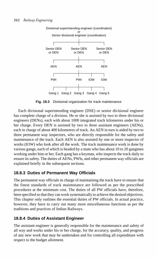
342 Railway Engineering
Fig. 18.3 Divisional organization for track maintenance
Each divisional superintending engineer (DSE) or senior divisional engineerhas complete charge of a division. He or she is assisted by two to three divisionalengineers (DENs), each with about 1000 integrated track kilometres under his orher charge. Every DEN is assisted by two to three assistant engineers (AENs),each in charge of about 400 kilometres of track. An AEN in turn is aided by two tothree permanent way inspectors, who are directly responsible for the safety andmaintenance of the track. Each AEN is also assisted by one or more inspector ofworks (IOW) who look after all the work. The track maintenance work is done byvarious gangs, each of which is headed by a mate who has about 10 to 20 gangmenworking under him or her. Each gang has a keyman, who inspects the track daily toensure its safety. The duties of AENs, PWIs, and other permanent way officials areexplained briefly in the subsequent sections.
18.8.3 Duties of Permanent Way Officials
The permanent way officials in charge of maintaining the track have to ensure thatthe finest standards of track maintenance are followed as per the prescribedprocedures at the minimum cost. The duties of all PW officials have, therefore,been specified so that they can work systematically to achieve the desired objectives.This chapter only outlines the essential duties of PW officials. In actual practice,however, they have to carry out many more miscellaneous functions as per thetraditions and practices of Indian Railways.
18.8.4 Duties of Assistant Engineer
The assistant engineer is generally responsible for the maintenance and safety ofall way and works under his or her charge, for the accuracy, quality, and progressof any new work that may be undertaken and for controlling all expenditure withrespect to the budget allotment.
Divisional superintending engineer (coordination)or
Senior divisional engineer (coordination)
Senior DEN Senior DEN Senior DENor DEN or DEN or DEN
AEN AEN AEN
PWI PWI IOWIOW
Gang 1 Gang 2 Gang 3 Gang 4 Gang 5

Track Maintenance 343
The essential duties of an AEN are as follows.(a) Inspection and maintenance of track and all track structures to ensure
satisfactory and safe performance(b) Preparation of plans and estimates; execution and assessment of work(c) Verification of stores held by stockholders(d) Submission of proposals for inclusion in the track renewal programme,
estimates of revenue budget, and work programmeAn AEN is also required to carry out the following inspections.
Trolley inspection The entire subdivision should be inspected once a month byassistant engineer, as far as possible with the help of a push trolley. This inspectionshould be intensive and should include the checking of gang attendance, the workdone by the gang, the equipment used, and an examination of gang charts/diarieswith reference to the prescribed track maintenance schedule. During the inspection,the assistant engineer should check the work done by one or two gangs under eachPWI and record his or her observations.
Fast train inspection Either the foot plate of the engine or the last vehicle of afast train should traverse the entire length of the subdivision once a month.
Inspection of level crossingsThe assistant engineer should inspect all mannedlevel crossings once every six months. He or she should examine the gatemen’sknowledge of the rules and check the equipment, track, road approaches, and allother safety aspects of each crossing.
Checking of curves The AEN should verify the versine and superelevation of atleast one curve under the jurisdiction of every PWI every quarter.
Checking of points and crossingsOnce a year the AEN should inspect all thepoints and crossings on passenger lines and 10% of the points and crossings onother lines.
Monsoon patrolling During monsoon patrolling, the assistant engineer shoulduse either a train, push trolley, or motor trolley once every month to check thepatrolman’s work.
Scrutinizing of registers during inspection The AEN should scrutinize thevarious registers maintained by the PWI such as the creep register, curve register,and the points and crossings register.
Inspection of bridges The AEN should inspect all the bridges of his or hersubdivision once every year after the monsoon is over and record the inspectiondetails in the bridge register. Tracks on girder bridges should also be inspected aspart of the annual bridge inspection.
Inspection of office and storesThe AEN should inspect each office and store ofall the PWIs and IOWs under his or her charge at least once a year. When checkingstores, he or she should pay particular attention to the allocation of the imprestengineering indicators, protection equipments, and other important items in thestores.
An AEN also has the following additional duties.(a) To ensure that all work is done as per the standard plans and specifications.

344 Railway Engineering
(b) To witness the payments made under one inspector once every month.(c) To record the measurements of the ballast or to carry out a thorough check
of its quality and quantity if the same has already been recorded by aninspector. Also, to test check the measurements of other works.
(d) To reach an accident site as early as possible and to take the necessarymeasures to restore traffic on the affected track.
(e) To accompany any track recording or oscillograph car runs in his or hersection.
(f) To exercise control on expenditure so as to contain it within the allotedbudget.
(g) To train probationers in their work.(h) To inspect water purification systems once every three months.(i) To inspect all steel structures once every six months.(j) To look after the welfare of the staff and to inculcate discipline in them.(k) To accompany the GM or other senior railway officials during inspection.(l) To coordinate with officials of other departments.
18.8.5 Duties of a PWI in Overall Charge
The PWI is generally responsible for the following.(a) Maintenance and inspection of the track to ensure satisfactory and safe
performance.(b) Efficient execution of all works incidental to track maintenance, including
track relaying work.(c) Accounts and periodical verification of the stores and tools in his or her
charge.(d) Maintenance of land boundaries between stations and at important stations
as may be specified by the administration.The PWI also carries out inspections of the following facets of a track.
Testing the track He or she should run a test check on the foot plate of the engineof fast trains at least twice a month and in a rear brake van of a fast vehicle once amonth, and make a note of sections where the quality of running is defective andget them rectified.
Inspection of track and gangsThe PWI should inspect the entire section withthe help of a push trolley at least once a week or more often if necessary.
Level crossing inspection(a) He or she should check the equipment assigned to the gateman once a month.(b) He or she should periodically examine knowledge of safety rules.(c) He or she should ensure that all level crossings are safe.
Points and crossings inspectionThe PWI should inspect the points and crossingson passenger lines once in three months and those on other lines once in six months.
Curve inspection The PWI should check the versines and superelevation of eachcurve once in six months. Based on his or her observations, the PWI should takethe appropriate action to correct the curve, if necessary.

Track Maintenance 345
Inspection diagram The PWI should maintain an inspection diagram of allinspections carried out during the month as per the schedule laid down in the proforma and submit the same every month to the divisional engineer via the AEN,bringing out the reasons for failure in adhering to the schedules of inspections, ifany.
Safety of track The PWI is directly responsible for the safety of the track. He orshe should be vigilant so as to promptly locate faults in the permanent way and getthem repaired without delay.
In addition to the inspections, a PWI also carries out the following duties.(a) To accompany high officials during their inspections along with the relevant
records. The PWI should carry all the important measuring equipment suchas the gauge-cum-level, flange gauges, fishing chord, tape, and inspectionhammer on these inspections.
(b) To accompany any track recording and oscillograph car that runs in his orher section.
(c) To check the proximity of trees that are likely to damage the track and getthem removed.
(d) To check night patrolling at least once a month by train as well as by trolley.(e) To take the necessary safety measures while executing maintenance work
that affects the safety of the track.(f) To rush to the site of an accident and take the necessary measures to safeguard
the line and restore traffic.(g) To periodically inspect and supervise LWR tracks to ensure their safety.(h) To ensure the cleanliness of station yards.(i) To keep proper records of the training out of ballast.(j) To witness the payments made out to the staff every month.(k) To look after all establishment work, including the welfare of the staff
working under his charge, and to maintain their service records.(l) To ensure the safety of the track during the execution of work that affects
the track.Based on the system of maintenance, the permanent way inspector in charge of
the section should prepare detailed short-term plans covering a month’s work (splitinto weekly programs) at least a month in advance of the commencement of actualwork. The PWI should ensure that adequate arrangements have been made for therequisite tools, materials, and manpower for the allotted task and that work isexecuted within the specified time. The following procedure of track maintenanceis followed on Indian Railways.
(a) Each mate should be supplied with a gang chart and a gang register. Thegang chart should have a record of the day-to-day track maintenance workto be done over the gang length, maintained by the permanent way inspector(PWI) according to specified instructions. The gang registers contain a recordof the weekly programme of the work to be carried out, also maintainedentered by the PWI in charge of the section. At the end of the week, the PWIshould qualitatively and quantitatively assess the completed work and record

346 Railway Engineering
his/her observations in the gang register after a detailed inspection of thework done during the previous week.
(b) Gang charts or gang registers should be checked by the assistant engineerand divisional engineer during their inspections. After inspecting the sectionby trolley, they should record their observations in the gang register.
(c) On withdrawal of old gang charts or gang registers and supply of fresh ones,the PWI should carefully analyse the work done and make a note of thosestretches of the track that frequently gave trouble during the year, with aview to formulate such special measures as may be necessary.
18.8.6 Duties of Mates
Every mate should make sure that the length of line under his charge is kept safefor the passage of trains. Sections needing urgent attention should be taken care ofwithout waiting for orders from PWIs.
Working of permanent way gangs
The track on Indian Railways is mostly maintained by permanent way gangs. Eachpermanent way gang has a strength of about 10–20 people and a beat of about 6–10 km. The gangs normally follow the annual programme set for regular trackmaintenance and complete at least one round of through packing in a year, dependingon various circumstances. A gang works under the control of a mate who assignstrack maintenance works to the permanent way gangmen.
Tools used by a PW gangEach gang should have the following maintenancetools and equipment. Worn out tools and equipment should be replaced every month.
(a) Gauge-cum-level(b) One set of red hand-signal flags, two hand-signal lamps for the nights, and
12 detonators(c) 30-cm-long steel scale, 1-m-long straight edge, square, hemp, cord, and
marking chalk(d) Wooden mallet or canne-a-boule, fish bolt spanner, keying and spiking
hammer, and measured shovel packing (MSP) equipment if MSP is required(e) A sufficient number of shovels, phowrahs, beaters, crowbars, ballast forks
or rakes, and mortar pans or baskets
Knowledge of safety measuresThe permanent way mistry (PWM) mate and allother gang men should have complete knowledge of the following safety measures.
(a) Method of protecting the line in an emergency or during maintenance workthat affects the running of trains, including methods of fixing detonators,banner flags, etc.
(b) Displaying the obligatory signals with or without a hand-signal flag duringthe day and with a hand-signal lamp during the night.
(c) Action to be taken when a train is noticed to have parted.(d) Patrolling of lines on LWR tracks during heavy rains, storms, sandstorms,
and during hot weather.(e) Awareness of ‘safety first’ rules.

Track Maintenance 347
Gang strength for track maintenance
A track is maintained manually by gangmen. Each gang has about 10 to 20 personsand a jurisdiction of about 4 to 6 km. In order to ensure uniformity of practice,Indian Railways has prescribed a standard formula known as the special committeeformula for calculating the number of men to be included in each gang.
N = MKE = MKLU(1 + A + B + C)where N is the number of men per km, M is the manpower factor, K is the correctionfactor due to modernization of track, standard of maintenance, etc., E is the numberof equated track kilometres (ETKM) and is equal to L × U(1 + A + B + C), A, B,and C are variable factors, L is the length of a single track, and U is the trafficdensity that varies from 0.4 to 1.4 depending upon whether the section is a sidingor a busy section with heavy gradients.
The manpower factor M is the weightage for the actual man-days required tocarry out normal permanent way maintenance work in a year vis-à-vis the actualnumber of man-days available. The correction factor K is required as a result of themodernization of the track. It has been felt that the effort required to maintain shortwelded rails and long welded rails is much less as compared to a fish-plated track.
The variable factors, A, B, and C denote the following. A is the formation factor,which varies from 0 to 0.20 depending upon the type of soil, B is the alignmentfactor and is equal to 0 where the track is straight and 0.25 when the entire track ison a curve, and C is the rainfall factor and varies from 0.10 to 0.20 depending uponwhether there is little or heavy rainfall.
18.8.7 Duties of Keymen
Once a day, the keyman should inspect both the track and the bridges on his/herbeat. He should go along one rail on his outward journey and return along theopposite rail on his return journey.
18.8.8 Knowledge of Rules and Signals
Every mate, keyman, and gangman should have the correct knowledge of handlingdetonating signals and should be conversant with the following measures of trackmaintenance.
(a) Protecting the line in an emergency and during the execution of maintenancework
(b) Action to be taken when a train is noticed to have parted(c) Knowledge of ‘safety first’ rules(d) Action to be taken when sabotage is suspected(e) Patrolling during emergencies
18.9 Protection of Track for Engineering Work
There are certain engineering works such as track renewal work, bridgerehabilitation work, etc., that stretch over a few days and thus the track is requiredto be protected to ensure the safe journey of trains.

348 Railway Engineering
18.9.1 Engineering Indicators
When a track is under repair, trains are required to proceed with caution at restrictedspeeds and may even be required to stop. Temporary engineering indicators(Fig. 18.4) are set up at the affected portion of the track to alert the drivers toreduce the speed of (or even stop) the train and also to resume the normal speedonce the affected portion has been treated. The following indicators are used.
Fig. 18.4 Protection of track for works of long duration
Caution indicator This indicator cautions the driver to get ready to reduce thespeed of the train (Fig. 18.5). It is placed at a distance from the stop indicator—1200 m away on BG tracks and 800 m away on MG and NG tracks.
Fig. 18.5 Caution indicator
Termination indicator This signal indicates that the driver can resume normalspeed and that the speed restriction zone has ended (Fig. 18.6).Speed indicatorThe driver has to reduce the speed of the train at location bearingthis indicator (Fig. 18.7).Stop indicator The driver is required to stop at locations bearing this indicator(Fig. 18.8). It is normally placed 30 m away from the obstruction.
These indicators are also called temporary fixed engineering signals and areprovided in the direction of the approaching train in the case of double-line tracksand in both directions in the case of single-line tracks. These signs or indicatorsshould be luminous as per the latest policy of the Railway Board.
Cau
tion
indi
cato
r
Sto
p in
dica
tor
Length oflongestpassengertrain
TP TG
Length of longestgoods train
30 m
1200 m BG800 m MG/NG
1.4 m0.4 m
0.4
m
WhiteYellow
White
0.3
m
Signalpost

Track Maintenance 349
Fig. 18.6 Termination indicator
Fig. 18.7 Speed indicator
Fig. 18.8 Stop indicator
Signal post0.3 m
1.4 m
RedRedRed
Red light(for night)
0.4 m
Lamp
1.0 m
BlackYellow25 mm black band
0.3m
Signal post
Lamp
Yellow
Black
0.1 m
0.3 m
Signal post
10

350 Railway Engineering
18.10 Patrolling of Railway Tracks
Railway tracks are patrolled to ensure the safety of the track and of the trafficmoving over it. Patrolling basically involves to and fro movement of the patrolman/watchman along the track as per the specified programme in order to look out forany unusual occurrence that may threaten the safety of the track. The various typesof patrolling that are in vogue on Indian Railways are presented below.
Keyman’s daily patrolThe keyman inspects the track daily on foot. He or shenormally inspects one rail as he moves forward and the other rail as he returns tothe point from where he started. He or she tighten the keys and other fittings andensures the safety of the track.
Gang patrol during abnormal rainfall or stormEither at his or her own initiativeor under instructions from the PWI, the mate organizes the patrolling of the tracklength affected by rains or storm. He or she, along with other gangmen, patrols thetrack and looks for any unusual occurrences that may be harmful to the track.
Night patrolling during monsoonNight patrolling is done in a programmed wayon specified sections of the railway track to detect damage such as breaches andsettlements caused by floods to ensure safety.
18.11 Track Tolerances
The safety and comfort of travel depend primarily on track geometry and the standardat which it is maintained. In practice, it is not possible to obtain a flawless andperfect track; the parameters governing track geometry always show certainvariations due to various reasons. Track tolerances may be defined as the limits ofvariability of various parameters pertaining to track geometry.
18.11.1 Track Parameters
Tolerances are generally laid down for the following track parameters.
Gauge variation This is measured as the deviation from the nominal gauge, whichis 1676 mm for BG and 1000 mm for MG. The gauge is measured as the minimumdistance between the running faces of two rails.
UnevennessThis is measured in terms of the difference in longitudinal levelsover a fixed base. Unevenness is generally measured over a base of a length of3.5 m. It is measured separately for left and right rails.
Cross level differenceThis is measured in terms of the relative differences in thelevel of two rail tops measured at the same point. Cross level difference also includesthe variations in superelevation.
Twist This is measured in terms of the change in cross levels per unit length ofmeasurement. Twist is calculated after knowing the cross levels and the differencebetween two points over a fixed base of, say, 3.5 m and dividing the cross leveldifference by this base length. This is normally denoted as mm/m.

Track Maintenance 351
18.11.2 Safety Tolerances
Safety tolerances are the limits of variation beyond which the movement of trafficon the track becomes dangerous or unsafe. The kind of unsafe conditions that arisedepend not only up on the condition of the track but also on the type of vehicle, itsriding characteristics, and its standard of maintenance. The factors that governthese unsafe conditions are so variable and indeterminate that almost none of therailway systems in the world have laid down any safety tolerances. It is generallybelieved that possibly the track would have to deteriorate to a great extent for it toreach these unsafe limits.
18.11.3 Track Tolerances for Good Riding Quality
The limits of track tolerance prescribed in order to guide engineering officialsregarding the suitability of the standards of track maintenance on BG tracks with asanctioned speed of above 100 km/hr and up to 140 km/hr are presented inTable 18.4.
Table 18.4 Limits of track tolerances on IR
Parameter Value Remarks
Alignment defects 5 mm for a straight track Up to 10 mm at isolated(versine measured over locations7.5 m under floating Curve ±5 mm Up to ±7 mm at isolatedconditions) Total change of versine locations
from chord to chord<10 mm
Twist 2 mm/m for straight and Up to 3 mm/m at any(measured on a base of curved track isolated location3.5 m) 1 mm/m for the transition Up to 2.1 mm/m for
of curves isolated locations
Gauge variation for ±6 on a straight track –3 to +6 on a straight MGBG (mm) track
–6 to +15 mm on curves –3 to +15 mm on curveswith radius of 350 m or with a radius 290 m ormore moreUp to +20 mm on curves Up to 20 mm on curveswith radius less than 350 m with radius less than 290 m
Unevenness of rail joint General: 10 mm 15 mm for isolateddepressions (measured on a chord of locations
3.5 m)
There are no special tolerance limits for cross level defects. The track should bemaintained at a standard that is generally superior to that of main line tracks whereunrestricted speeds of up to 100 km/hr are permitted.
The provisions and tolerances mentioned here and elsewhere in the chapter havebeen provided with a view to maintain track geometry so as to ensure a comfortable

352 Railway Engineering
ride and not from the point of view of stability or safety. (Source: ACS No. 96 of2004 issued under Railway Board letter no. 2004/CE-II/CS-I dated 22 July).
Summary
The track should be maintained properly to enable trains to run safely at maximumpermissible speeds. Through packing, overhauling, and picking of slacks are thethree main operations of maintenance in one calendar year. The money and labourto be spent on track maintenance should be optimally utilized to keep the track ingood working condition. There are various railway officials who are assignedspecific duties in regard to track maintenance. Also, there are limits assigned forthe variability in the different parameters that affect track geometry, known astrack tolerances.
Review Questions
1. Categorize and briefly describe the various duties of a permanent way inspector.2. Explain the system of annual maintenance of rail tracks on straight portions,
including the several operations involved therein. Explain these operations indetail?
3. The following defects were recorded upon inspection of a railway track.(a) Battered ends of rail joints(b) Angular cracking of rails(c) Excessive closing and opening of spaces at rail joints
Give reasons for these defects and suggest any remedial measures.4. Describe the procedure involved in the annual through maintenance of a track
commonly known as through packing.5. What is the need for the proper maintenance of a track? Discuss the various
methods that ensure that a track is well maintained.6. What is meant by through packing? Describe the various steps involved in
this procedure. What is the programme of annual track maintenance followedon Indian Railways?
7. Differentiate between the following.(a) Hogged joint and high joint(b) Lifting and lowering of track(c) Insulated joint and fish-plated joint(d) Defective sleeper and centre-bound sleeper
8. What do you understand by deep screening of ballast? Describe the procedure.9. What are the duties of an assistant engineer on Indian Railways? What is the
schedule of his or her inspection?10. Write short notes on the following.
(a) Gang strength(b) Blowing and pumping joint(c) Tools of a permanent way gang(d) Maintenance of track in track-circuited areas.

Track Drainage 353
Track Drainage
Track drainage can be defined as the interception, collection, and disposal of waterfrom, upon, or under the track. It is accomplished by installing a proper surfaceand sub-surface drainage system.
19.1 Need for Proper Track Drainage
Water is the greatest threat to a railway track, and the most prominent factor thatadversely affects track maintenance is improper drainage. Excess water affects thestability of the embankment, and the bearing capacity of the soil and its resilienceto shear gets considerably reduced. Railway engineers give maximum importanceto the proper drainage of the track and the need to do so is felt because of thefollowing concerns.
Settlement of embankmentExcess water may cause the embankment to settle.An unequal settlement may lead to variation in cross levels as well as longitudinallevels thereby affecting the safety and riding quality of the track.
Reduction in bearing capacity The bearing capacity of the soil as well as itsresistance to shear diminishes due to excess water in the soil. This in turn leads tonumerous problems and finally affects the safety and stability of the track.
Failure of embankment The percolation of water in the embankment increasesthe weight of the soil on the one hand and reduces its bearing capacity and shearresistance on the other. This makes the formation unstable. This is a common reasonfor the failure of embankments, which occurs in the form of slips.
Formation of ballast pockets Excess moisture leads to punctures in the formation.The constant hammering action of running trains causes the sleepers to move upand down, resulting in ballast pockets, pumping sleepers, and other such problems.All these factors lead to poor riding quality.
Shrinkage and cracking of banksThe embankment soil cracks and shrinks onceexcess water dries up. The problem becomes acute in the case of poor soils. This inturn leads to many problems such as the loss of ballast in the cracks and unevensettlement, which have an adverse effect on track maintenance.
Adverse effects of black cotton soilThere are certain soils, such as black cottonsoil, which become plastic in nature due to the accumulation of excess water. The
CHAPTER
19

354 Railway Engineering
formation shrinks due to change in moisture content. The bearing capacity of thesoil is greatly reduced due to the excess water. These problems imperil the safetyof the track.
Formation of slush Slush is formed due to the dynamic load of running trains. Itis forced out, thus badly clogging the ballast. This makes the maintenance of thetrack very difficult.
19.2 Sources of Percolated Water in the Track
Water can percolate to the formation of the track through any of the followingmethods.
By gravity This includes water that collects due to rains, etc., moving into thesubgrade because of the effect of gravity. This movement is resisted by thepermeability of the soil. The effective ways of reducing the progress of water bythis method are the following.
(a) Provision for drainage on the top of the embankment in the form of crossfall, side drains, lowering of cess, etc.
(b) Turfing of side slopes of the embankment.
By capillary action At times water rises into the subgrade by way of capillaryaction. The capillary rise of water can be prevented by providing a pervious layerin the embankment which serves a capillary break.
From adjacent areas In this case, water from some nearby source seeps into thesubgrade. Water seepage can be reduced by taking the following steps.
(a) Diverting the original source of water(b) Providing effective paved catch water drains(c) Providing inverted filters and underground drains
By hydroscopic action from atmosphereThe moisture present in the atmosphereis comparatively very small and has very little effect on the total moisture contentof the soil.
19.3 Requirements of a Good Track Drainage System
A good drainage system should satisfy the following requirements.
Surface water should not percolate to trackOne of the basic requirements of agood track drainage system is that surface water from rains and adjacent areasshould not percolate and seep into the formation of the track.
Effective side drains The size of the side drains should be adequate with a properslope, so that they effectively carry all the surface water away.
Longitudinal drains to be saucer-shapedThe longitudinal drains providedbetween two tracks should preferably have a saucer-shaped cross section so thatthey can collect water from both sides.
Provision for clearing and inspection The drains provided for drainage shouldbe such that they can be inspected and cleared periodically.

Track Drainage 355
Drain top to be below cess levelNormally, the drain top should not be above thecess level for the effective drainage of the ballast bed.
No erosion of banksThe flow of water along the slope and across the track shouldnot cause erosion of the banks or the slopes of the banks.
Formation to be of good soil Ideally, the formation and subgrade should be madeof a pervious, coarse-textured soil. Such soils are more permeable, retain lesscapillary water, and respond more favourably to a surface drainage system.
Proper sub-surface drainageArrangements should be made for a good sub-surface drainage system to drain off the water being retained is the track. This ismore relevant in the case of defective formations.
Proper outfall Longitudinal drains should be designed so as to provide a properoutfall, from where the water can eventually drain off.
Special arrangements for waterlogged areas and other difficult situationsAgood track drainage system should have special arrangements for the drainage ofwaterlogged areas and for all other related perennial problems.
19.4 Practical Tips for Good Surface Drainage
The following measures will ensure that the track drainage system gives a goodperformance.
Maintain proper cess level Tracks on embankments get drained as long as theproper cess levels are maintained and the ballast is clean. However, in cuttings andin yards, where water cannot recede freely and quickly from the track, a well-planned drainage system must be provided.
No vegetation There should be no growth of vegetation in the track, as this indicatesclogging of the ballast and a lack of adequate track drainage. Such stretches oftracks should be overhauled or deep screened. The ballast should be clean so thatrainwater can easily flow out of the track.
Area below rail foot to be clear About 25 to 50 mm of the area below the railfoot should be kept clear of any ballast, earth, or cinder on all lines inside andoutside the yards. This would enable good surface flow as well as avoid corrosionand failure of track circuits.
Cleaning and repair of drains All drains should be cleaned and repaired as apart of annual through packing, not only on run-through lines but also on all otherrunning lines in yards.
19.5 Track Drainage Systems
As mentioned earlier, a good track drainage system should essentially ensure thatno water percolates into the track at either the surface or the sub-surface levels,and the arrangements for the drainage of sub-surface water should be good andeffective wherever required. Track drainage should be handled in two distinctivephases.

356 Railway Engineering
Surface drainage Surface water due to rain or snow, or from adjacent areas shouldbe drained off properly by designing well-planned and effective surface drains.
Sub-surface drainageIn case water percolates into the formation due to bad soilor such other reasons, the formation gets adversely affected and this has a bearingon the safety and stability of the track. Complete details of the same are given inChapter 9.
In the following sections, surface drainage is dealt with in three different stagescovering the entire length of the track.
(a) Drainage in mid-sections between railway stations(b) Drainage in station yards(c) Drainage of station platforms
19.5.1 Drainage in Mid-sections Between Railway Stations
A drainage system between two railway stations consists of the following features.
Side drains Side drains should be provided along the track in cuttings and zerofill locations, where the cess level is not above the ground level. The typical crosssection of a side drain is shown in Fig. 19.1. All drains must have an adequategradient to enable the free flow of the collected water.
Fig. 19.1 Typical cross section of side drain
Lining of drains Side drain lining is imperative on Group A routes and preferableon other routes, except those routes where the drains are in rocky strata.
Adequate opening under level crossingIn order for all the water to flow out ofthe side drains in cuttings, adequate openings should be provided under levelcrossings, around trolley refuges, and around the overhead electric masts.
Catch water drain Catch water drains should be provided wherever necessary,in cuttings. Their size should be worked out according to the volume of the waterthe drain is expected to carry.
No surplus ballast Surplus ballast in the shoulders of the track retards drainageand encourages vegetation growth. All extra ballast should be taken out of thetrack and stacked in small heaps beside the track.
610 mm for BG450 mm for MG
Side drain
300 mm
Standard ballast profile
Side drain300 mm

Track Drainage 357
19.5.2 Drainage in Station Yards
When planning the drainage of station yards, the following guidelines should bekept in mind.
Open surface drains Surface drains should generally be left open to make cleaningand inspection convenient. When designing in-yard drains, a velocity range of0.5 to 1.0 m/s may be allotted for earthen drains and 1.0 to 2.0 m/s for lined (ormasonry).
Saucer-shaped drainsAs mentioned earlier, the longitudinal drains that liebetween two tracks should be saucer-shaped with curved sides. However, drainswith vertical sides may be provided wherever saucer-shaped drains are notpracticable.
Drain top not to be above cess levelNormally, the drain top should not be abovethe cess level for the effective drainage of the ballast bed. However, if it is essentialthat a drain with a higher top level be provided in order to retain the ballast, weepholes must also be provided at the assumed cess level and the drain so designedthat the water it carrier does not flow the base level of the weep holes.
Outflow and slope Wherever there is a proper outfall available at either end of ayard, the longitudinal drains provided should have their slopes facing in the directionopposite to the middle of the yard. This will ensure the minimum size and depth ofthe drains.
Position of ballast sectionsThe ballast section in station yards should be thesame as that on the main line.
Network of cross and longitudinal drains Every station yard should have anetwork of cross and longitudinal drains, whether earthen or masonry, which allowswater collected due to storms to be carried away in the least possible time. Thearrangements for surface drainage at water columns and carriage watering pointswith washing hydrants should be efficiently maintained. At these locations, Watermust be adequately trapped and borne away in a pipe or a lined drain.
Open drain section Figure 19.2 shows a detailed sketch of the open drains thatare provided between two tracks on a railway line.
Fig. 19.2 Open drain between tracks (all dimensions in mm)
Concretesleeper
Silt levelOpen drain
Cement concrete 1:4:8
25 mm cement concrete1:2:4 finished smooth
355
16764725
355 355 1676230
230
230

358 Railway Engineering
19.5.3 Drainage of Station Platforms
The following points should be taken into account when planning the drainagesystem of a platform.
Slopes away from track Normally, all end platforms should be sloped away fromthe track. The details of the drainage system of a platform are illustrated in Fig. 19.3.
Fig. 19.3 Drainage of platform
Discharge on non-track sideAll drains from platform shelters, tea stalls, toilets,water taps, etc., should be enclosed in pipes and should normally discharge orrelease their contents on the non-track side of the platform. Covered longitudinaldrains should be provided on the platform, if necessary.
Discharge not towards run-through lines In the case of island platforms, alldrains should discharge their contents on the less important side of the track andnot towards run-through lines.
19.6 Sub-surface Drainage
Water normally reaches the sub-surface due to capillary action, seepage fromadjacent areas, or percolation of rainwater. When water reaches the sub-surface, itimmediately affects the stability of the formation. The situation becomes worseparticularly if the soil is bad. A variety of problems arise due to the proximity ofthe water to the subgrade. The nature of the problems faced and the remedialmeasures for the same have been discussed in detail in Chapter 9.
The various sub-drainage systems used under different conditions are brieflysummarized here.
Provision of inverted filter Some sub-drainage systems consist of a blanket of anon-cohesive graded material, which acts as a capillary break (Fig. 9.3 of Chapter 9).
Paving of catch water drains The entrance of water into the subgrade can bechecked by constructing effective catch water drains that are duly paved.
575
Platform levelGrating
Centre lineof track
230, 230
Slope 1:60
Drainagewater
100Ø (diameter)CI pipecess level
Lime concrete
Open drain in between two sleepers
Cement concrete
Drain
GL
300
Cement plaster 1:3
Precast RCC slab16762362
1375 1375
1905
890
115
460
610 415
760
1676 (gauge)
460
1:1.5
75
75100

Track Drainage 359
Provision of sand piling Some drainage systems are provided with an adequatenumber of sand piles of a diameter of about 20 cm. This improves sub-surfacedrainage (Fig. 9.4 of Chapter 9).
Drainage of water pockets by perforated pipePerforated pipes with a diameterof about 30 cm are provided at appropriate places to drain off the water pockets(Fig. 9.5 of Chapter 9).
Cement grouting Cement can be used to grout the water pockets so as to ease thesituation.
Drainage of water pockets by puncturing holesIn special situations where wateris trapped in ballast pockets because of an impervious layer that lies over a goodpervious layer, puncturing holes into the impervious layer can help drain away thewater (Fig. 9.6 of Chapter 9).
Summary
The presence of water can reduce the stability and strength of the track or erodethe banks of an embankment. The lifespan of a track can be considerably increasedby providing a proper drainage system. Whatever be the source of water enteringthe track, its removal from the track should be quick and effective. In the case ofsoft soils, sub-surface drainage may be necessary to keep the track safe.
Review Questions
1. Why is it necessary to provide adequate drainage facility for a railway track?Suggest remedial measures to solve the following problems that occur due topoor drainage.
(a) Clogging of the ballast because of wet earth(b) Sinking of ballast into the wet earth
2. What are the requirements of a good track drainage system? How can a gooddrainage systems be provided on railway tracks?
3. Describe the drainage systems required for the following areas in detail.(a) Drainage in station yards(b) Drainage of station platforms(c) Drainage in areas between stations
4. What are the various sources of percolated water in the track?5. Write short notes on the following.
(a) Inverted filter(b) Ballast pockets(c) Sub-surface drainage(d) Catch water drain

360 Railway Engineering
Modern Methods of
Track Maintenance
Introduction
Modern methods of track maintenance employ track machines and other moderntrack equipment for the maintenance of tracks as opposed to the traditional methodsof manual packing. The methods used generally are the following.
(a) Mechanized maintenance of track with the help of track machines(b) Measured shovel packing (MSP)(c) Directed track maintenance (DTM), which is maintenance based on need,
particularly if DTM is done by MSP.In these methods, the emphasis is not only on modern maintenance techniques
but also on the identification and rectification of defects, the implementation ofproper quality control in a systematic manner, and the use of proper tools andequipment.
For over a century, tracks on Indian Railways have been maintained by themethod of ‘beater packing’ using manual labour and the performance has beenexcellent. It is now being felt that this method of manual maintenance, which hasstood the test of time, may require a revision in view of all the recent technologicaland social advancements. The European Railways, which was also in a similarposition a few decades ago, has already switched over to modern methods ofmaintenance to suit the requirements of the modern track. Such a system ofmaintenance of track has given the men working on the permanent way a bettersocial status, as it requires lesser physical strength and higher mechanical skill ontheir part. The system has also enabled them to maintain the modern track moreeconomically and effectively in order to cater to the requirements of higher speedsand heavier axle loads. There is no doubt that the mechanized maintenance oftrack has become a technical necessity for the modern track structure with its longwelded rails and concrete sleepers. In spite of changes in our socio-technicalbackground and the increasing emphasis on the modernization of the track to allowfor higher speeds the following question arises: Is there really a need for the completemechanization of the process of track maintenance, particularly when India hassuch a large labour force and is faced with a serious problem of unemployment?
CHAPTER
20

Modern Methods of Track Maintenance 361
20.1 Mechanized Methods of Track Maintenance
The need to switch over from manual to mechanized methods of track maintenanceis progressively being felt due to the following reasons.
(a) Beater packing is a very hard and strenuous job and thus the labourers havea tendency to shirk from doing this type of work.
(b) It is difficult to ensure the uniform quality of the compaction under thesleepers carried out by manual means due to the uncertainties associatedwith the varying physical strength of the labourers, commitment of theworkers, varying weather conditions, and other allied factors.
(c) The intensity of the pressure and shock that the ballast is subjected to whenthe beater is being used is very high and in many cases exceeds the crushingstrength of the stone. This results in the progressive clogging of the ballastsection.
(d) Traffic densities, axle loads, and speeds have increased considerably on IndianRailways considerably in the recent past. Beater packing does not enabletrack geometry to be maintained within the tolerances prescribed for asatisfactory length of time.
(e) The retention of the packing done via manual maintenance is not very goodand the track geometry gets distorted in a short time due to high-speed traffic.
(f) Manual maintenance is not much suited to the modern track, which consistsof long welded rails and heavy concrete sleepers.
(g) With the increase in traffic density, the time available between trains isbecoming progressively short. It is, therefore, becoming increasingly difficultto maintain tracks by manual methods, which take a considerably long time.
(h) When a track is maintained manually, it takes considerable time for it to getfully consolidated and, therefore, speed restrictions exist for a long periodafter track renewal work has been completed.
(i) Manual methods do not emphasize on the identification of defects andmonitoring of the work being done. These are, however, done in the case ofmodern methods of track maintenance, thereby giving move effective results.
Some of the important heavy track machines being used on Indian Railways(IR) are listed in Table 20.1.
Table 20.1 Track machines in use on IR
Type of track Functions Remarks and outputmachine
Plassermatic Tamping, levelling, and aligning. Consists Output is about 70006-16-USLC of 16 tamping tools and can tamp one sleeper sleepers per hour
sleeper at a time.
Plassermatic Tamping, levelling, and lining simultaneously. Output is 100008 Unomatic Consists of 16 tamping tools and can tamp one sleepers per hourtamper sleeper at a time.
(contd)

362 Railway Engineering
Type of track Functions Remarks and outputmachine
Plassermatic Tamping, levelling, and lining simultaneously. Output is 200008 Dnomatic Consists of 32 tamping tools and can tamp two sleepers per hourtamper sleepers at a time.
Plasser 09 Tamping, levelling, and lining simultaneously. Latest track machineCSM tamper The machine advances continuously, while with an output of
tamping is done from sleeper to sleeper. 2500 sleepers perhour
Plasser 08-275 Tamping points and crossings. Consists of 16 Good machine forunimat P and independent tiltable tamping tools, which can tamping points andC tamper tamp points and crossings as well as plain crossings. Can tamp
tracks. 1 turnout in a 4-hourblock.
Plasser Used for crip and shoulder consolidating so Output is 1000VDM-800 as to improve the retention of packing. sleepers per hourconsolidator
DGS-62 N Dynamic track stabilizer that uses vibrating Output is 500stabilizer rollers to further stabilize the track. sleepers per hour
Matisa R-7 To regulate ballast profile by transferring Can regulate ballastballast ballast from one place to another. of 1 km of track perregulator hour
Plasser RM- Ballast cleaning machine used to excavate, Can handle 650 m3
80 BCM clean, and put the screened ballast back in of ballast per hourthe track and to remove unwanted material.
Switch To remove and install parts or complete Can relay about tworelaying assemblies of points and crossings. sets of points andmachine crossings every dayWm-22
Track relaying Relaying the entire track automatically with Latest state-of-thetrains (TRT) very little manual effort. Consists of four art machine. Can
different units and other ancillary machines accomplish thewith a total cost of over Rs 100 million. relaying of 1 km of
track per day in a4-hour block.
On railways, the mechanized maintenance of tracks normally involves the useof mechanical tampers, which are used to tamp or pack the ballast. Mechanicaltampers are generally of two types, namely, off-track tamper and on-track tampers.
20.2 Off-Track Tampers
Off-track tampers are portable and can be quickly taken off the track by just twopeople. These tampers work during the interval between the passage of trains anddo not require any traffic blockage (Fig. 20.1). They consist of tools driven by
Table 20.1 (contd)

Modern Methods of Track Maintenance 363
compressed air, electricity, or petrol. There are generally two types of tampers,namely, self-contained tampers and those that are worked from a common powerunit. Tampers may be vibratory or of the percussion type or a combination of both.In the vibratory type, tamping is achieved by vibration as well as by the weight ofthe tamper itself, while in the percussion type. tamping is achieved by impartingblows. The important off-track tampers tried on Indian Railways are Cobra tampers,Jackson tampers, Shibaura tampers, and Kango tampers.
Fig. 20.1 Off-track tamper
20.2.1 Use of Off-track Tampers
Off-track tampers are placed diagonally under the rail and worked in pairs fromthe opposite sides of the sleepers in order to ascertain the maximum consolidationof the ballast. Using beaters, the ballast is first loosened around the rail seat in thecrib for a length of 450 mm (18") on either side of the foot of the raft. The tamperis then inserted vertically and the tamping tool blades are kept about 75 to 100 mmaway from the sleeper so that enough ballast is available between the two as shownin Fig. 20.1. During its working, the head of the tamper should be moved slightlybackward in the shape of an arc of a circle so that the surrounding ballast is wellcompacted. The operator should not exert force on the tamper while tamping isbeing done using either the vibratory system or the percussion system.
The average progress achieved by one set of off-track tampers is about 3 km permonth, after taking the repairs, overhauling , etc. into consideration.
20.2.2 Limitations of Off-track Tampers
Off-track tampers have not been much of a success on Indian Railways because ofthe following reasons.
(a) The maintenance of these tampers has been found to be extremely difficultbecause of the non-availability of spare parts, which are mostly imported.
(b) Transporting off-track tampers along with their power units to the site ofwork in the mid-section is quite problematic.
Gap (75–100mm)
Sleeper cushion
Tamper
Rail
Tamping blade
Handle

364 Railway Engineering
(c) Tamping with off-track tampers is very strenuous and a worker normallygets fatigued after 30–40 minutes. The quality of work done after this durationis likely to deteriorate.
(d) Intensive supervision is required to ensure the correct use of these tampersso that the work done is of the desired quality. This type of supervisionbecomes particularly difficult in the mid-section.
(e) The quality of tracks maintained using tampers is not very high compared tothose maintained by manual methods.
(f) The use of off-track tampers following deep screening and relaying workhas been found to be very unsuitable for the early restoration of normalspeed.
However, off-track tampers are yet to be tried under the following conditionson Indian Railways.
(a) For packing the points and crossings where normal packing cannot be doneeffectively due to limited space.
(b) For packing newly realigned curves, on which the track requires immediateconsolidation so that its alignment remains undisturbed and normal speedcan be restored along its length as early as possible.
20.3 On-track Tampers
On-track tampers are self-propelled vehicles which facilitate automatic tamping ofsleepers through the controls provided in the operator’s cabin. Heavy on-tracktampers weigh 20 to 30 t and cannot be easily removed from the track. It is thereforevital that the work be done after putting up the necessary traffic blocks. However,the tamper can be put off the track using special equipment, provided that there areadequate bank extensions available. These tampers can automatically andsimultaneously perform the tasks of lifting, aligning, levelling, and tamping. OnAmerican railroads, a sleeper is referred to as a tie. Therefore, since on-track tampersare used for tamping sleepers (or ties), they are also called tie tamping machines.
20.3.1 Principles of Working of On-track Tampers
The principles of the working of an on-track tamper (tie tamping machine) aredescribed below.
Tamping
Tamping is the most important application of tie tamping (TT) machines. Tampingconsists of packing the ballast under the sleeper. This is achieved by vibrating theballast, thereby making it fluid, and then compressing it by squeezing as shown inFig. 20.2. Tamping is done with the help of either 16 or 32 tamping tools, dependingupon whether single or double sleepers are to be packed at a time. Tamping is doneby either the synchronous or the non-synchronous system of vibration. In thesynchronous system, the movements of the two tamping tools on either side of asleeper are similar and simultaneous, synchronizing with each other. In the case ofnon-synchronous systems, the two tools work independently.

Modern Methods of Track Maintenance 365
Fig. 20.2 Squeezing of ballast
Aligning the track
The alignment of the track is corrected by the two-chord system in the case ofmachines manufactured by Messrs Plasser and Theurer. In this method, two chords oflengths 24 m and 12 m are taken and placed in the area between two rails, where theyare stretched parallel to the track and kept a certain distance apart from each other.
Fig. 20.3 Principle of alignment—two-chord system
It can be geometrically proved that the versine BQ of the short chord ACmeasured at a quarter point B’ is one-third of the ordinate BB' measured for a longchord at the same quarter point (Fig. 20.3). The ordinate at the quarter point of the24-m chord H and the versine at the centre of the 12-m chord h are measured usinga measuring bogie. In a circular curve, the ratio of H:h is equal to 3:1 as indicatedabove. The two dimensions are measured at the same point by means of themeasuring bogie and if the ratio is found to be equal to 3:1, it indicates that thecurve is in order and that the alignment is correct. In the case of any defects,special rollers attached to the rail are used to slew the track at the location of thecentre bogie till this ratio is achieved.
This procedure is used for correcting alignment defects to a value that is one-sixth the value of the original fault because of the relative positions of the measuringbogie and the central bogie as shown in Fig. 20.4. The latest TT machines can beused to correct alignment defects using the three-chord and four-chord methods.
Levelling
Longitudinal levels are corrected on the basis of the principle of proportionallevelling with the help of tampers along with an infrared transmitter, a shadow
A
BQ = (1/3) × BB’BB = (3/4) × CC' ’
B’
hQ H
B
C'
PX
D’
E
CD
24m
6m 6m 6m 6m
Tamping tools
SleeperRail
Ballast

366 Railway Engineering
board, and photocells. The distance between these three units is fixed and is soarranged that any error in the longitudinal level is reduced to one-fifth of its value,as is clear from Fig. 20.5.
Fig. 20.4 Correction of alignment defect
Fig. 20.5 Principle of levelling
20.4 Future of Track Machines on Indian Railways
Indian Railways has purchased over 430 tie tamping machines during the last fewyears, which have been giving satisfactory results. These machines have been foundmost suitable for wooden and concrete sleepers and the condition of the sleepersmaintained using these tie tampers is definitely superior to those maintained by theconventional method of beater packing. Indian Railways is systematicallyintroducing long welded rails and concrete sleepers on high-speed routes and the
Infrared transmitter
Projector lamp
Working direction
Photo cell receiverparabolic mirror
Shutter mask
LiftInfrared beam
ModularScale
Lift
Front bogieLongitudinal track (To be attained)
Shadow board
Amplifier
Measuringbogie
Sleeper tobe tamped
5L
L
H/5
H
L/41/4
L/4 L/4 L/4
L
F/4 × 1/8
Existing trackposition
Original curve
Dire
ctio
nal f
ault
2 /12 = /6F F
Tig
hten
ing
bogi
e
Working direction
Cen
tral
bog
ie
Mea
surin
g bo
gie
Tig
hten
ing
bogi
e
F
F

Modern Methods of Track Maintenance 367
tie tamping machine is ideally suited for the maintenance of such tracks. However,the following points require special consideration for the successful implementationof mechanical methods of maintenance on Indian Railways.
Blocks Adequate time blocks of about 3 to 4 hours/day should be made availableso as to make mechanized maintenance effective and economical.
Ballast cushion A clean ballast cushion of a depth of about 20 cm (8") should beavailable below the sleeper bed of each track that is to be maintained mechanically.
Repair facilities Adequate facilities for repair and overhauling should be madeavailable at the site and in the workshop.
Spare parts A good stock of spares should be kept ready at hand to ensure thatthe machines are always in good working order.
Training of staff The staff employed for working the tie tamping machine shouldhave thorough knowledge of the principles and method involved in its working. Afull-fledged training school equipped with the necessary models and equipmentshould be made available to train the staff hired for the mechanical maintenance oftracks.
20.4.1 Tier System of Track Maintenance
With the introduction of concrete sleepers and on-track tamping machines on IndianRailways, three-tier system of track maintenance is being adopted on all sectionsnominated for mechanized maintenance. This system consists of the followingthree tiers of track maintenance.
(a) On-track machines units (OMU)(b) Mobile maintenance units (MMU)(c) Sectional gang
Tier 1: On-track machines unit
The work of systematic mechanized maintenance of track is done with help ofheavy on-track machines, which include tie tamping machines for plain tracks aswell as points and crossings, shoulder ballast cleaning machines, ballast cleaningmachines, ballast regulating machines, and dynamic track stabilizers. Thesemachines are used when the following tasks are to be performed.
(a) Systematic tamping of plain track as well as of points and crossings(b) Intermediate tamping of plain tracks as well as of points and crossings(c) Shoulder ballast cleaning, ballast profiling/redistribution, track stabilization,
periodical deep screening
Tier 2: Mobile maintenance units
Picking up of slacks and other related works are done with the help of mobilemaintenance units (MMU). The Railways use two kinds of MMUs whose functionsare as listed below.
MMU-1 (Rail-cum-road vehicle based)One such unit is provided to each PWIin charge of a 40–50 km long double line or a 90–100 km long single line with aview to carrying out the following work.

368 Railway Engineering
(a) Need-based spot tamping(b) Casual renewal and repairs, except planned renewals; in situ rail welding(c) Overhauling of level crossings(d) Replacement of glued joints as well as rail cutting or drilling and chamfering(e) Permanent repair of fractures(f) Creep or gap adjustments involving the use of machines; destressing of LWR/
CWR(g) Loading/unloading of materials and other miscellaneous functions
MMU-II (Road vehicle based) One such unit should be kept aside for eachsubdivision. It is used for the reconditioning of turnouts and for the minor repairsof the various equipment that are a part of the MMUs. A list of all the equipmentincluded in the two MMUs is given below.
Components of MMU-I Spot tamping machines such as track tampers and liftingjacks, rail cutting and drilling equipment, rail welding equipment, destressingequipment for rail tension, etc., gas cutting equipment, material handling equipment,safety and protection equipment, inspection gadgets and communication equipment.
Components of MMU-II Reconditioning equipment for points and crossings suchas the welding generator, arc welding equipment, hand-held rail grinder, equipmentsuch as spanner and gadgets for minor repairs.
Tier 3: Sectional gangs
Under the three-tier system of track maintenance the section gangs are required toperform the following functions.
(a) Patrolling of the track, namely, the keyman’s daily patrol, hot/cold weatherpatrolling, monsoon patrolling, patrolling of vulnerable locations
(b) Dealing with emergencies by carrying out temporary repairs as in the caseof fractures
(c) Giving need-based attention to bridges, turnouts, SEJs, and approaches tolevel crossings
(d) Greasing of ERCs, lubrication of joints, casual changing of rubber pads andother fittings
(e) Minor cess repairs, cleaning of drains, and boxing of ballast(f) Paying attention to loops(g) Creep and gap adjustment not involving the use of machines(h) Cleaning of crib ballast for effective cross drainage(i) Pre- and post-tamping attention(j) Assistance in the working of MMU and OMU as required
20.5 Measured Shovel Packing
Measured shovel packing (MSP) is an improved form of manual packing, whichaims to provide a scientific method of track maintenance that does not use anysophisticated mechanical aid. This method, which was perfected on SNCF (FrenchRailways) about 40 years ago, was the standard method of track maintenance inthe UK prior to the introduction of mechanical maintenance. Even today, tracks on

Modern Methods of Track Maintenance 369
SNCF are mostly maintained by MSP. This method makes it possible to maintainfish-plated and LWR tracks for speeds of up to 160 km/h in these countries. Assuch, this method has the potential of being used as a standard method ofmaintenance for high-speed routes, particularly for flat-bottomed sleepers. It isdefinitely an asset for controlling the overall economy by way of direct savings inlabour and maintenance of the track, and long-term savings in terms of longer lifeof rails, sleepers, and fastenings due to improved track maintenance.
20.5.1 Essentials of MSP
MSP essentially consists of taking accurate measurements of track defects,particularly of any existing unevenness and voids, caused in the course of serviceand attending to the same by placing a measured quantity of small-sized stonechips under the sleeper to bring the track levels to their predetermined state. Thecompaction of these stone chips occurs as a consequence of the passage of traffic.The extent to which the track is required to be lifted is calculated by measuring thelongitudinal unevenness in the track once the cross levels and the voids under thesleepers have been corrected. The longitudinal levels are measured with the helpof two optical instruments—the viseur and the mire—while the voids under thesleeper bed are assessed by a ball-ended rod called canne-a-boule and checkedwith the help of a mechanical device called the dansometer. The track is lifted by40 mm by means of special types of non-infringing jacks, and a measured quantityof stone chips is then placed in the sleeper bed with the help of a particular type ofpacking shovel. The jacks are then tripped off and the alignment is finally corrected.
20.5.2 Scope of MSP
The process of MSP is suitable for the following types of work.(a) Through packing of flat-bottomed sleepers(b) Packing of joint wooden sleepers in metal sleeper tracks(c) Through packing of points and crossings with wooden and steel sleepers(d) Dehogging of rail ends
20.5.3 Advantages and Disadvantages of MSP
Even though MSP is an excellent method of track maintenance, it does have itsdrawbacks. The following are the advantages and disadvantages of MSP.
Advantages of MSP
(a) The work carried out is precise, wherein the track is worked upon as close tothe tolerances as possible because of the finer adjustments that are permissiblein MSP.
(b) The retentivity of packing, particularly for joint sleepers, is more in the caseof MSP as compared to other modes of maintenance.
(c) MSP gives increased output per gangman and is, therefore, economical.(d) A minimum clean ballast cushion is not needed when work is done through
MSP.

370 Railway Engineering
(e) MSP does not require any traffic blocks.(f) MSP does not damage the undersides of wooden sleepers, which are
otherwise damaged in manual methods of maintenance.(g) MSP is less strenuous and labourers do not shirk in doing the required work.(h) The gangman and the supervisory staff are able to pick up the uncomplicated
technique with very little training and experience.
Disadvantages of MSP
(a) Normally, MSP can be done only in the case of flat-bottomed sleepers andthis puts a severe limitation on the scope of its application.
(b) This procedure requires special size stone chips, which may not be easilyavailable.
(c) MSP is not effective in maintaining newly screened tracks. A consolidatedbed is a prerequisite for maintaining a track by means of MSP.
(d) MSP makes use of delicate instruments and devices that can get damagedeasily.
(e) Although MSP is not a complicated process, it still requires a certain amountof skill, for which the labourers have to be educated and trained.
20.5.4 Equipment Used in MSP
Special types of equipment are used to carry out MSP. A brief description of eachof these instruments is given in the following paragraphs.
Canne-a-boule
A canne-a-boule is used for assessing the extent of voids in the packing under thesleepers. In the case of wooden sleepers, it consists of an iron ball of a diameter of100 mm with a 1.20-m-long mild steel rod handle that has a diameter of 20 mm(Fig. 20.6). In the case of steel trough sleepers, a 1.20-m-long wooden canne-a-boule is used with a cylindrical wooden block that is 155 mm long and has adiameter of 100 mm. The canne-a-boule is dropped from a height of 40 cm at bothends of the sleeper. The height of the rebound and the sound emitted in the processdetermines the extent of the existence of packing voids. A value of ‘zero’ is givento a sleeper that gives a good rebound and produces a solid sound. The valuesincrease as the sound gets dull and the rebound decreases.
Dansometer
A dansometer is used for measuring the voids in the packing under the sleeper ends.The tripod legs (Fig. 20.7) are fixed in the ballast bed while the dancing rod rests onthe sleeper. The extent to which the friction sleeve can shift from its original positionhelps in determining the presence of voids under the sleeper in dynamic conditions.
Fleximeter
A fleximeter is used to measure the depression of the rail under the weight ofplying traffic. It determines the degree to which voids occur in the packing togetherwith the play in the fastenings, i.e., the gap between the rail foot and the sleeper. Itis used in conjunction with the dansometer to check the tightness of fastenings.

Modern Methods of Track Maintenance 371
The difference between the fleximeter and dansometer readings indicates the extentto which the fittings between the rail and the sleeper have become loose (Fig. 20.8).
Fig. 20.6 Canne-a-boule
Fig. 20.7 Dansometer
Fig. 20.8 Fleximeter
100
mm 20 mm
1.20 m
Thumb screw
Sliding bracket
Graduating scale
Clip pointer
Rail bearing flat
Collars
Spring
Spindle rod
Play nut
Base plate
Handle
Friction sleeve
Housing top
End connections
Tripod legHousing bottom
SpringTripod leg
Wooden sleeper
Dancing rod

372 Railway Engineering
Viseur and mire
The viseur and mire are used to measure the unevenness of the tail top and forrectifying the alignment. The viseur is a type of telescope that has a magnifyingpower of about 12 and is supported on a stand which can be fixed to the rail seatwith the help of two clamps [Fig. 20.9(a)]. The mire is a staff bearing five graduatedscales, in millimetres. It has a supporting frame that can be fixed to the rail head bymeans of bent clamps [Fig. 20.9(b)].
Fig. 20.9 (a) Viseur
Fig. 20.9 (b) Mire
Gauge-cum-level
The gauge-cum-level is used for measuring the gauge of the track as well as the crosslevels (Fig. 20.10). The cross level is measured with the help of an approximately200-mm-long sensitive spirit level with a sensitivity of 2' 30". The cross level canbe measured to an accuracy of 1 mm with the help of this instrument.
Packing shovel
A packing shovel is used for placing stone chips over the full width of the sleeperunder the rail seat. It is about 1 m long and has a pan for collecting the chips under
EyepieceTelescope
Rear standHandle
Focusing knob
Left handed thread
Right handed threadRail top flat
Bent clampClamp screwW
hite
zone
Red
zone
Spring clip
Frame
Graduatedscale

Modern Methods of Track Maintenance 373
the sleeper bed. The throw of the blade is 100 mm for BG lines and 85 mm for MGlines (Fig. 20.11).
Fig. 20.10 Gauge-cum-level
Fig. 20.11 Packing shovel
Dosing shovel
A dosing shovel is used for picking up a measured quantity of stone chips forpacking. This shovel has a series of holes at different levels. By picking up chips toa specified height in the shovel (Fig. 20.12), the quantity of the chips can bemeasured.
Measuring can
A measuring can is used to check the accuracy of the dosing shovel. It is a cylindricalcontainer of a height of 150 mm for BG lines and 120 mm for MG lines, withperforated holes at calibrated intervals (Fig. 20.13).
Non-infringing track jacks
Non-infringing track jacks (Fig. 20.14) are used for lifting the rail to a desiredheight. The jacks are referred to as ‘non-infringing’ because the lifted rail caneasily be returned to its normal position in the case of an approaching train withlittle manipulation and because they can be left on the track as none of theircomponents project above the rail level and infringe on movement. These jacksare designed for a safe working load of 5 t and for a maximum lift of 200 mm and160 mm in the case of BG and MG lines, respectively.
Fixed end
Spirit levelScale
Handle Sliding bracketrail seat
Handle
Chute
Blade tip

374 Railway Engineering
Fig. 20.12 Dosing shovel (BG)
Fig. 20.13 Measuring can (BG)
Fig. 20.14 Non-infringing track jack
88
140
Cross section at XX
Wooden handle
Support
4 mm diameter holes
X20 25
Note: All dimensionsare in millimetres
200X
30
97
31
5
8
2
64
10
170 diameter
45
150
100 diameter

Modern Methods of Track Maintenance 375
20.5.5 Through MSP of Flat Bottomed Sleeper Tracks
MSP has been found to be very suitable for flat-bottomed sleepers, particularlywooden ones. About 33% of the running track on Indian Railways is on woodensleepers and MSP can only be done on this length. The sequential description ofthis procedure is given in the following paragraphs.
Measurements of voidsA sleeper is assessed to see whether it is fully packed ornot. If not, the extent of the existence of packing voids is determined with the helpof a canne-a-boule.
Fixation of high points The high points are then marked on each rail with thenaked eye. At these high points, the cross levels are measured accurately up to1 mm using a gauge-cum-level and any cross level errors are then corrected. Thesehigh points are called ‘PH points’ as per French terminology. These are normallyspaced not more than 25 m apart.
Converting high points to good pointsThe track is normally given a general liftof 10 mm for the first round of MSP and 5 mm for the second round of MSP, sothat packing under the sleepers may be done effectively. New points, referred to asgood points (or ‘PB points’), are then marked on both the rails. For a higher rail,the PB value will be equal to the value of the general lift, i.e., 10 mm as a result ofthe first MSP, and for the lower rail, it will be equal to the sum of the value of thegeneral lift and the cross level.
Longitudinal leveling Longitudinal levels are then measured between two highpoints on every alternate sleeper with the help of a viseur and a mire. The readingson intermediate sleepers are obtained by interpolation.
Total lift The total lift is calculated by adding the value of the voids assessed inthe packing to the amount of lift discerned as per the requirement of the longitudinallevels. This value is called ‘mark definitive’ and is marked on the inside of the footof the rail.
Opening out of ballast The ballast section is then opened out with the help ofballast rakes or special types of beaters as shown in (Fig. 20.15).
Lifting and packing of tracks Normally, a party of nine men is required for liftingand packing a track. The track is lifted with the help of non-infringing jacks. Thesejacks are placed nine sleepers apart on an evenly made up ballast bed. Not morethan 4 cm of track should be lifted at a time to ensure that bigger ballast pieces donot roll in under the sleeper. The track is packed with the help of a special packingshovel. Depending upon the amount of voids present and the lifting done, therequired quantity of small-sized stone chips is picked up by means of a dosingshovel from the wheelbarrow. For the first round of MSP, the quantity of chipsrequired is about 3 m3 for 250/300 sleepers on BG/MG lines with a general liftmeasuring 10 mm and for the second and subsequent rounds of MSP it is 3 m3 for1000/1250 sleepers on BG/MG lines with a general lift equal to or less than 5 mm.About 2.0, 1.5, or 1.0 m3 of chips are required for the MSP of one turnout of 1 in16, 1 in 12, and 1 in 81/2, respectively.

376 Railway Engineering
Fig. 20.15 Opened ballast section lifted by jack
Provision of ramps Ramps are provided to gradually ease off the difference inthe longitudinal levels of the track between the portion of the track that has beenattended to and the portion that is yet to be attended to. The provision of such rampsbecomes necessary either in the case of an approaching train or at the end of a day’swork. A provisional ramp of 3 mm per sleeper is provided in the face of approachingtrains, whereas a ramp of 1 mm per sleeper is provided at the end of a day’s work.
Alignment After correcting the longitudinal and cross levels of the track, thealignment is checked with the help of a viseur and a mire, using the vertical line onthe rear side of the mire as a target. The use of guides is very important whenalinging tracks, as the guides ensure that the viseur and mire are undisturbed whileslewing is in progress.
Boxing and dressing of ballastAfter the surfacing and alignment of the trackhas been taken case of, the removed ballast is put back in the track by means ofballast rakes and the ballast section is boxed and dressed properly.
Majoration of joints Joints are checked for a second time on the following dayand if any low joints are discovered, they are attended to. This second attentionthat is paid to the joints is technically called majoration of joints.
Checking of work done The cross levels and the longitudinal levels of the portionof the track that has already been attended to are checked after the passage of twotrains. The variation in the cross level should not be more than 3 mm at any sleeperand the variation from sleeper to sleeper should not exceed 1 mm.
20.5.6 MSP of Joint Wooden Sleepers on Metal Sleeper Track
A joint is the weakest link in the track and special attention has to be paid towardsits maintenance. The maintenance of joint sleepers is not very effective in the caseof the conventional beater packing method because of the close spacing of the
15–20 cm
d
d
d
d
d = 25 cm
XXPlan
Section-XX
Direction of approaching train
Opened out portion
1A 2A 3A 4A 5A

Modern Methods of Track Maintenance 377
sleepers at the joint. The loosening of the packing at the joints results in a numberof maintenance problems. MSP has been found to be very effective for packingjoint wooden sleepers.
This method involves the usual through beater packing of the intermediatesleepers followed by MSP of the joint sleepers so as to bring the surface of thetrack to longitudinal and cross levels consistent with that of metal sleeper tracks. Adetailed account of this procedure follows.
Calculation of total lift The total lift required is calculated by evaluating thevoids at the joint sleepers and adding this value to the longitudinal lift required onaccount of the general sag of the track. The total lift for the two rails is then assessedas follows:
Total lift for sighting rail = longitudinal lift + voids under the sighting railTotal lift for second rail = fleximeter reading on sighting rail + voids under
the second rail + cross level difference atthe joint
The cross levels are then correctly noted with the help of an accurate gauge-cum-level.
Lifting and packing of joint sleepers Joint sleepers are lifted to the requiredextent, but not more than 40 mm by means of non-infringing jacks. The requiredquantity of small stone chips are placed under the joint sleepers with the help ofpacking shovels. The jacks are then released from their positions and the sleepersare tamped with the help of blunt-ended crowbars so that they are evenly seated onthe layer of chips.
Alignment corrections General alignment corrections are made while work isunderway on the intermediate sleepers by way of the conventional beater packingmethod. Any disturbances that occur in the alignment during the MSP of jointsleepers are subsequently corrected.
20.5.7 Dehogging of Rail Ends
Hogged rail ends can be dehogged with the help of MSP in the following manner(Fig. 20.16).
1. The dip at the joint sleeper (a) is measured by using a 1.5-m straight edgeand a feeler gauge at a distance of 50 mm from the rail end.
2. The dance at the joint sleepers (d), which is the gap between the sleeper andthe ballast, is measured by a canne-a-boule or dansometer.
3. The joint sleepers are lifted and packed to a value equal to d + a + a', whered is the value of dance, a is the amount of dip, and a' is equal to a or 5 mm,whichever is lower.
After allowing traffic to run on the track for a period of two days, the adjoiningsleepers are beater or shovel packed depending upon whether it consists of metalor wooden sleepers. The dehogging of rail ends is achieved because of the trainloads. It may be necessary to repeat this procedure in case the rails are not completelydehogged.

378 Railway Engineering
Fig. 20.16 Dehogging of rail ends
20.5.8 MSP of Turnouts
The MSP of turnouts laid on wooden sleepers is quite effective. This processinvolves the following steps.
Measurement of voidsVoids in the main line as well as on the turnout side aremeasured by a canne-a-boule.
Location of high pointsThe high points are then located using a gauge-cum-leveland these are marked on the stock rail.
Conversion of high points to good pointsHigh points are converted into goodpoints on the stock rail.
Longitudinal levelling Longitudinal levels on the stock rail are measured by meansof a viseur and a mire.
Total lift Total lift is the sum of the number of packing voids and the difference inthe longitudinal levels.
Shovel packingThe ballast between sleepers is completely removed and the trackis lifted by using track jacks.
Putting back the ballastAfter packing, the ballast is put back and the joints aretackled once again, if necessary.
Alignment correction The main line is aligned with the help of a viseur and amire.
Attention to approachesApproaches to the turnout are dealt with by means ofMSP or beater packing to adjust the longitudinal levels.
20.5.9 Organization of Labour for MSP
Proper organization of labour is necessary for successfully implementing the MSPprogramme on Indian Railways. Normally, a gang of 9 to 15 persons khalasis andone mate headed by a PWI grade III are employed for carrying out various MSPworks. A rough estimate of the strength of the MSP task force is given in Table 20.2along with the average progress achieved by it.
a
d dTotal feed = + +
= but not greaterthan 5 mm
d a aa a
’
’

Modern Methods of Track Maintenance 379
Table 20.2 Progress of MSP
Type of MSP Strength of MSP Progress likely to Remarkstask force be achieved per
excluding PWI dayand mate
Through MSP 9 men 243 sleepers Output approx. 27of wooden sleepers/man/daysleepered roadMSP of joint 8 men 28 points Output three to fourwooden sleepers joints/man/dayMSP of turnout 12 men 1 turnout One turnout completed
in 8 hrs
20.5.10 Equipment Required
Table 20.3 lists the equipment normally required for carrying out the MSP ofdifferent works.
Table 20.3 Equipment needed for MSP
Particulars Number required for each type
Trough MSP Joint MSP Turnout
Viseur and mire 1 – 1Packing piece sets (1 to 10 mm) 2 – 2Canne-a-boule for wooden sleepers 1 1 1Canne-a-boule for metal sleepers 1 – 1Dansometers 4 2 4Fleximeters 2 2 2Dosing shovels 2 2 4Measuring can 1 1 1Packing shovels 2 2 –Plain shovels 2 2 2Track jacks (non-infringing type) 4 2 4Gauge-cum-level 1 1 1Blunt-ended crowbars 6 6 6Ballast rakes or specially shaped heaters 7 4 –Monorail wheelbarrow 1 1 2Stepped feeler gauge 1 1 11.5-m-long straight edge 1 1 110-m-long nylon cord 1 1 –Steel scale graduated in mm 1 1 1Hooters 2 2 2Grating/louvred shovels – – 4
20.5.11 Future of MSP on Indian Railways
MSP, though introduced only recently, has shown great potential for being usedextensively on Indian Railways. The method is simple but scientific. It provides a

380 Railway Engineering
better and lasting surface to the tracks and has also proved to be very beneficial tothe economy. The method is particularly suited to Indian conditions due to theabundance of cheap labour and use of simple equipment manufactured indigenously.It was earlier believed that the method was suitable only for flat-bottomed sleeperssuch as wooden and concrete sleepers, but recent trials have proved that thetechnique can be used for maintaining steel and CST-9 sleepers as well.
20.6 Directed Track Maintenance
As the name suggests, directed track maintenance (DTM) is a method of maintainingthe track on the basis of directions that are given in this regard every day, and notas a prescribed routine. Directed track maintenance essentially consists of need-based maintenance rather than routine maintenance. In the case of DTM, trackmaintenance is done by proper identifying any defects in track geometry andrectifying these defects by attending to the track at the affected locations underclose supervision, thereby maintaining the track at predetermined standards.
20.6.1 Objectives
The two main objectives of DTM are as follows.(a) To maintain high standards of track maintenance as per predetermined
tolerances.(b) Reduction in the cost of maintenance mainly by the avoidance of unnecessary
work.In order to achieve the desired objectives, the following special features are
incorporated in DTM vis-à-vis the conventional system of maintenance.(a) The level of supervision is improved by hiring a well-trained and qualified
permanent way mistry.(b) A thorough record of the track defects identified before and after the
completion of work is maintained to assess the inputs and also to help deviseremedial measures of a more permanent nature by carrying out a scientificstudy based on the assimilated facts.
(c) Increasing the length of the unit especially on single lines increases thenumber of the gangmen available, resulting in an improvement in theproductivity of the gang as well as the quality of work.
(d) The track is aimed to be brought to a predetermined level of service tolerances.
20.6.2 Work Done Under DTM
The maintenance operations to be carried out in a section where DTM has beenintroduced can be placed into the following four categories.
(a) Systematic overhaulingIn DTM, while the emphasis is on need-basedmaintenance, the intention is not to completely dispense with routine maintenanceworks such as systematic overhauling. Instead, the frequency of systematicoverhauling is suitably increased, say by three to four years or as decided by thechief engineer, depending on local factors such as the condition of the track and

Modern Methods of Track Maintenance 381
the formation, traffic density, permissible speed, and rainfall. A certain number ofworking days in the appropriate months of the year are earmarked for this work soas to cover one-third or one-fourth of the gang length by systematic overhauling,depending on the site conditions.
(b) Periodic maintenance work This includes works such as the lubrication ofjoints, cleaning of side drains, catch water drains, and repairs of the formation andcess. In the annual program, an adequate number of working days should be setaside during the appropriate months for periodic maintenance work.
(c) Occasional maintenance workThis includes other works such as scatteredrenewal of rails, sleepers, and other track components, adjusting creep, restoringcorrect spacing between sleepers, building damaged rail ends, realigning curves,overhauling level crossings as well as points and crossings, and properly removingany deficiencies in the ballast section. The permanent way inspector assesses thequantum of such works that are to be carried out periodically in the order of theirpriority and draws up a programme in consultation with engineers after taking intoconsideration the availability of track material, ballast, welding parties, etc.
(d) Need-based maintenanceThe remaining working days in the annualprogramme are devoted to need-based maintenance, which is a new concept andforms the main distinguishing feature of DTM as compared to the conventionalsystem of maintenance. The operations involved in need-based maintenance are asfollows.
(a) Location of defects by analysing the results of the track recording car/oscillograph car/hallade recorder and by foot plate/rear vehicle/trolley/footinspection.
(b) Identification of defects by means of systematic inspection and by groundmeasurements taken by trained supervisors using precision instruments.
(c) Recording of the observations.(d) Rectifying track defects by attending only to the defective portion followed
by a post check of the same portion conducted by the supervisor to check itsquality and output.
20.6.3 Annual Program for DTM
Table 20.4 depicts a typical chart showing the annual program of track maintenanceunder DTM.
The following points need to be mentioned with respect to the data given inTable 20.4.
(a) The chart is only for guidance, and the chief engineers of zonal railways canmake variations to suit the local conditions.
(b) The chart is for that section of the track where manual methods ofmaintenance are adopted. Whenever maintenance involves the use ofmachines, the DTM unit will assist in the same by taking care of the work ofpre-tamping and post-tamping and other operations not covered by machines.

382 Railway Engineering
Table 20.4 Annual program of DTM
Month Work to be done No. of days per week
January (a) Lubrication of fish-plated joints 4(b) Need-based maintenance 2
Feb. to (a) Occasional maintenance work As programmed byApril AEN/PWI
(b) Need-based maintenance Rest of the days
May (a) Pre-monsoon work such as cleaning of side 4 drains, catch water drains, and waterways
(b) Need-based maintenance 2
June to (a) Periodic maintenance works incidental As requiredAug. of the monsoon season, such as attention
to drainage, patrolling(b) Need-based maintenance Rest of the days
Sept to (a) Systematic overhauling 4Nov. (b) Need-based maintenance 2
December (a) Occasional maintenance works As programmed byAEN/PWI
(b) Need-based maintenance Rest of the days
Summary
Manual methods of track maintenance are not suitable for modern tracks consistingof long welded rails and heavy concrete sleepers. Mechanized maintenance hasmany advantages over manual maintenance. Measured shovel packing (MSP) anddirected track maintenance (DTM) are two modern methods of track maintenancethat have been found suitable for high-speed tracks in India. They are cost effective,time effective, and efficient. Indian Railways is slowly switching over to thesemethods of track maintenance.
Review Questions
1. Explain the following methods of packing of tracks that are a part of theperiodic correction of track geometry.
(a) Beater packing(b) Measured shovel packing(c) Packing by track tamping machines
2. What is directed track maintenance (DTM)? In what way does it differ fromthrough packing?
3. List the methods used for the maintenance of high-speed tracks and discussthe suitability of each method under Indian conditions.
4. What do you understand by modern methods of track maintenance? Why aremodern methods of track maintenance required?
5. What is an on-track tamper? What kind of work is it used for? Describe theprinciples behind the working of a on-track tamper. What is the differencebetween an on-track and an off-track tamper?

Modern Methods of Track Maintenance 383
6. What do you understand by measured shovel packing (MSP)? What are itsadvantages with respect to other methods of track maintenance? Brieflydescribe the main equipment used for MSP.
7. Briefly describe the procedure adopted for the MSP of a wooden sleeper track.How is the dehogging of rail ends achieved through MSP?
8. What are the various track components that are attended to under directedtrack maintenance? Name the equipment required to be kept with each unit ofDTM.
9. Write short notes on(a) MSP of turnout(b) Viseur and mire(c) Dehogging of rail ends(d) Non-infringing track jack

384 Railway Engineering
Rehabilitation and
Renewal of Track
Introduction
The dynamic impact of running trains causes heavy wear and tear of the track. Itbecomes necessary to rehabilitate or renew the track periodically to ensure that itcontinues to be safe and efficient. Heavy track renewals are carried out on IndianRailways every year to keep the track safe and in a good running condition as wellas to bring down the cost of maintenance as much as possible. The cost of trackrenewals carried out on Indian Railways runs into several thousand million. Thesetrack renewals consist of complete track renewal, through sleeper renewal, throughrail renewal, etc.
About 2000 to 3000 km of track renewal is done annually. As track renewalsare costly proposals, they are formulated after a lot of deliberation and are wellscrutinized at various administrative levels before they are finalized and includedin the annual works programme.
Generally, there is heavy backlog of track renewal work on account of theshortage of permanent way material and the lack of adequate funds for track renewalprogrammes. Retaining the service of overaged tracks not only leads to an increasedcost of maintenance but also affects the safety and fluidity of the movement oftraffic. Due to delays in track renewals, incidents of rail fractures have beenprogressively increasing. Long stretches of track have also been placed under speedrestrictions owing to this backlog in track renewals.
The Indian Railways has undertaken a massive programme of track rehabilitation,and as per the current plan, the backlog in track renewal will be completely clearedin the next few years.
21.1 Classification of Track Renewal Works
Track renewals can be broadly classified as under.
Complete track renewal This implies the renewal of all the components of atrack over a particular length. The necessary recoupment of the ballast and theprovision of a full ballast cushion is also done along with complete track renewal(CTR).
CHAPTER
21

Rehabilitation and Renewal of Track 385
Through rail renewal Through rail renewal or TRR involves the renewal of allthe rails between one point and the next.
Through sleeper renewalsThis entails the renewal of the entire lot of sleepersfrom one point to another. The necessary recoupment of the ballast and the provisionof a full ballast cushion is also done along with TSR (through sleeper renewal).
Casual renewal This implies the replacement of some of the unserviceable railsor sleepers or both with serviceable, released rails and sleepers of a similar typeand age.
Primary renewals This refers to renewals that are done using new permanentway materials.
Secondary renewalsThis refers to renewals that are done using released,serviceable permanent way material.
21.2 Criteria for Rail Renewals
The need for rail renewal can be felt because of any one of the following reasons.(a) Incidences of rail fractures or failures(b) Wear of rails(c) Maintaining tracks at the prescribed standards(d) Shortened service life of rails(e) Plan-based renewalThese criteria are discussed in detail in the subsequent sections.
21.2.1 Incidences of Rail Fractures or Failures
Since this factor has a direct and vital bearing on the safety of the track, it shouldtake precedence over all other factors when deciding on the rail renewals to becarried out. A spate of rail fractures or failures on a particular length of a track maynecessitate rail renewal. In such cases, an ultrasonic test of the rails should becarried out, the results scrutinized, and the section is considered for rail renewal onlyif the rail fractures are high for a particular season (4% in a year or 10% overall).
21.2.2 Wear of Rails
Rail renewals may also become necessary because of excessive wear. This wearcan be of various types as a result of the following.
Limiting loss of section
Rail renewal is called for when the loss in the weight of the section exceeds theprescribed limits given in Table 21.1. In such cases, the rails should be testedfrequently using ultrasonic rail flaw detectors because such rails are more prone torail failures.
The loss of weight can be assessed either directly by measuring the actual weightor empirically by measuring the horizontal and vertical wear of the rail.

386 Railway Engineering
Table 21.1 Limiting loss in weight of rail sections
Gauge Rail section Loss in weight
BG 52 kg/m 6.0%90 R 5.0%
MG 75 R 4.20%60 R 3.25%
Wear due to corrosion
Rails get corroded due to the vagaries of weather, atmospheric conditions, andchemical reactions that take place when certain materials come in contact with railmetal, thereby resulting in wear. Such wear is more prominent in coastal areas.Corrosion beyond 1.5 mm in the web and the foot of the rail is specified as thecriterion for rail renewal due to corrosion.
Vertical wear
When vertical wear (Fig. 21.1) causes a reduction in the depth of the rail head untila point beyond which there is a risk of the wheel flanges grazing the fish plates, therails should be renewed. The limits of vertical wear for the different rail sectionsare given in Table 21.2.
Fig. 21.1 Vertical wear
Lateral wear
Lateral wear (Fig. 21.2) is measured at a distance of 13 to 15 mm below the rail toptable. The profile of the worn out rail is recorded and superimposed over a newprofile to determine lateral wear. Excessive lateral wear causes lateral hunting ofvehicles, resulting in an uncomfortable ride. This condition will manifest itself inthe form of high values of the ride index during oscillograph car runs. When it
25°New profile
Worn out profileVerticalwear
Gauge face
Centre line

Rehabilitation and Renewal of Track 387
becomes uneconomical to maintain such a track, through rail renewal becomescrucial. The permissible limits of lateral wear under various conditions on theRailways are presented in Table 21.3.
Table 21.2 Limits of vertical wear
Gauge Rail section Vertical wear (mm)
BG 60 kg/m 13.0052 kg/m 8.00
90 R 6.00MG 75 R 4.00
60 R 3.00
Fig. 21.2 Lateral wear
Table 21.3 Permissible limits of lateral wear
Section Gauge Category of track (route) Lateral wear (mm)
Curves BG Group A and B 8BG Group C and D 10MG Q and R 9
Straight BG Group A and B 6BG Group C and D 8MG Q 6MG R 8
21.2.3 Maintaining Tracks at the Prescribed Standards
There may be situations in which renewals become necessary even though theservice life of a rail has not yet expired, due to local factors such as curves, steep
Lateral wear
Wear measured ata point 13 to 15mmbelow the rail table New profile
Worn out profile

388 Railway Engineering
gradients, high speeds, heavy axle loads, burrs, scabbing, and wear of rails thathave the following adverse effects on the track.
(a) Poor running quality of track in spite of the extra maintenance labour engagedon the section.
(b) Disproportionate cost of maintaining the track under safe conditions.(c) Poor condition of the rail due to hogging, battering, scabbing, wheel burn,
etc. and other causes such as the excessive corrugation of the rail and whichmake track maintenance difficult and uneconomical and affect riding quality.
21.2.4 Shortened Service Life of Rails
Due to the passage of moving loads, alternating stresses are created in the railsection. The number of reversals in the stresses are directed to the weight in grossmillion tonnes (GMT) borne by the rails. The majority of rail fractures originatefrom fatigue cracks, which develop after a rail has borne the threshold GMTapproved for it, as given in Table 21.4.
Table 21.4 Appearance of cracks in rails as related to GMT
Gauge BG BG BG BG BG MG MG
Rail section 60 kg 60 kg 52 kg 52 kg 90 R 75 R 60 RUTS 90 72 90 72 72 – –GMT carried for 800 550 525 350 250 150 125T-12 mm rails
21.2.5 Plan-based Renewals
Plan-based renewals are planned with the objective of modernizing the trackstructure on selected routes in the quickest possible time. It may sometimes involvea premature renewal of the track also.
21.3 Through Sleeper Renewals
Through sleeper renewals should be done when the percentage of unserviceablesleepers is equal to 30% on trunk routes/main lines and 35% on branch lines.Various conditions warrant the renewal of each type of sleeper, as explained in thefollowing.
Wooden sleepersWooden sleepers become unserviceable only when they aresplit, broken, burnt, or rounded on the underside with deeply cut rail seats. Theyare also considered unserviceable when the spikes that fix the rails on them losetheir gripping power or when there is general deterioration in the structure of thesleepers as a whole due to an insect attack, etc.
Steel sleepersSteel sleepers become unserviceable when there is excessivecorrosion and also when the rail seats or lugs crack or give way. The life of a steelsleeper is reckoned to be about 40 to 50 years.

Rehabilitation and Renewal of Track 389
CI sleepers CI (cast iron) sleepers become unserviceable when there is excessivecorrosion of the tie bar and the rail seat, when the sleeper plate breaks or developsa crack, or when the wear of the lug and rail seat is so excessive that the sleeper nolonger grips the rail firmly and the keys become loose resulting in creep. Theaverage life of a CI sleeper is 40 to 50 years. Generally, these sleepers can beconsidered unserviceable when they are unable to either hold the gauge or retainthe packing.
The renewal of worn out fish plates should be considered when the gap betweenthe fishing planes of the rails and the fish plates exceeds 1.5 mm at the centre.
21.4 Execution of Track Renewal or Track Re-laying Work
Track renewal or track re-laying work can be done either manually or by mechanicalmeans. These works involve the following steps.
(a) Survey of the section(b) Preliminary works(c) Actual execution of track renewal works
21.4.1 Survey of the Section
The section to be re-laid should be surveyed in advance. The survey includes thepreparation of the longitudinal sections of the track, including the existing raillevels, at every 100 m and at obligatory points such as level crossings, road overbridges, and overhead crossings. The cross sections are taken at every 50 m instation yards and on platform lines, at the site of foot over bridges, overhead wateringarrangements, etc.
21.4.2 Preliminary Works
Preliminary works are the minor works undertaken prior to the actual work involvedin track renewal. These works include the following tasks.
(a) Unloading track materials(b) Ballasting the section(c) Fixing level and centre-line pegs(d) Arranging traffic blocksEach one of these preliminary works is briefly discussed here.
Unloading track materials It should be ensured that the relevant materials areunloaded at the precise location where they are to be laid, as explained in thefollowing.
Rails These should be unloaded in pairs on the cess on either side of the track in thecase of single-line sections and between two tracks in the case of double-line sections.
SleepersThe sleepers are taken directly to the site in wagons and unloaded on thesection. They are piled in small stacks and subsequently laid at their final location.Alternatively, they are laid ‘end on’ with respect to their future location, whereverpossible.

390 Railway Engineering
Fittings Small fittings are likely to be lost or stolen. These should, therefore, beunloaded in depots, gang huts, gate lodges, etc., and taken to the site as and whenrequired. New fish plates are graphited and fish bolts and nuts are oiled andlubricated before use.
Ballasting the sectionAn adequate quantity of ballast is provided in advance andis unloaded at the site, preferably with the help of ballast trains. Some of the ballastcan also be collected, or even procured, at the cess to avoid ballast deficiency. Theballast should preferably be deep screened in advance.
Fixing centre-line and level pegsCentre-line and level pegs are provided at every50 m.
Arranging traffic blocks The arrangement of traffic blocks should be finalized inconsultation with the operating department. A joint memorandum of understandingshould be prepared for drawing up the exact programme of traffic blocks.
21.4.3 Actual Execution of Track Renewals Work
Once the preliminary works are completed, the actual work of track renewal canstart. This involves the following tasks.
Setting up traffic block A traffic block of about 2 to 4 hours is set up in order toexecute the work of track re-laying.
Dismantling old track The old track is dismantled by removing the fish-bolts andfish plates as well as the sleeper fastenings. The old rails and sleepers are thenremoved and stacked on the side of the track opposite the new material.
Deep screeningThe ballast should be deep screened if this was not done earlieralong with the other preliminary works. The ballast should be dressed and properlylevelled in accordance with the correct profile.
Linking new track After the ballast has been laid in keeping with the correctlevel, the sleepers are laid almost in their correct places, and the rails are linkedover them using proper expansion liners.
Packing new trackThe track is then lifted to the correct level, aligned, and packedeither manually or with the help of machines.
21.4.4 Progress and Output
On an average, the renewal of about 0.4 km of track can be achieved by 15 to30 gangs in a 3 to 4 hour traffic block. The deep screening of the ballast should,however, have been completed ahead of re-laying work.
21.4.5 Rail Dolly
The rail dolly (Fig. 21.3) is an equipment used for the quick and easy transportationof rails. It consists of a tabular frame fitted with a chain that ends in a rail clamp.There are two double-flanged wheels with ball bearings, which run on rails. Aleverage handle is available for operating and moving the rails. The equipment,weighing about 55 kg, is extremely useful for carrying rails and sleepers to the site

Rehabilitation and Renewal of Track 391
of work. In the event of an approaching train, the rail as well as the equipment canbe cleared off the track within 10 seconds.
Fig. 21.3 Rail dolly (all dimensions in mm)
21.5 Mechanized Re-laying
A concrete sleeper weighs more than 200 kg and, therefore, unlike wooden ormetal sleepers, cannot be handled easily by manual labour. Apart from being heavy,a concrete sleeper is brittle in nature and is likely to get damaged if dropped fromsome height or handled roughly. Furthermore, the conventional method of re-laying,which employs manual labour, is quite slow and the quality of the work done isalso not very good.
The need for mechanized re-laying has been increasingly felt on account ofthese limitations, particularly in view of the large-scale use of concrete sleepers onIndian Railways.
Mechanical re-laying can be done by either one of the following methods.(a) Semi-mechanized re-laying using prefabricated panels, in which the main
work of re-laying is done mechanically with the help of PQRS (Plesser quickrelaying system) equipment but all other minor works are done manually.
(b) Fully mechanized re-laying with the help of track re-laying trains.
21.5.1 Mechanical Re-laying using Pre-fabricated Panels
On Indian Railways, mechanical re-laying is mostly done with the help of PQRSequipment. This equipment is manufactured by an Austrian firm Messrs Plasserand Theurer in a factory near Faridabad, India. The equipment basically consistsof two self-propelled portal cranes, each capable of lifting 5 to 9 t. The portalcranes run on an auxiliary track with a 3.4-m gauge. Track panels consisting ofconcrete sleepers, rails, and fittings are prefabricated in the base workshop andused for re-laying the track. These prefabricated panels are loaded in special BFR-type wagons and taken to the work site along with portal cranes, etc. [BFR is aclassification scheme for freight wagons on IR. B indicates bogie wagon, F indicatesflat car, and R indicates rapid (forced) discharge]. The old track is dismantled andnew panels are laid with the help of portal cranes. A fully equipped train called thePQRS rake that consists of the following parts is then taken to the site of work.
3100
460 1375 1260
700
404 thick plate
1550
660 × 50 × 10 thick plate
25 GI pipe 40 mm dia GI Pipe

392 Railway Engineering
(a) Engine(b) Coal wagon (for recoupment of coal in the engine)(c) Crew rest van (for the staff to stay and rest in)(d) Guard compartment (for controlling the movement of the train)(e) Mobile workshop-cum-rest van (for urgent repairs to be done at the site)(f) Special wagon called BFR loaded with two portal cranes(g) Two empty BFRs for loading released panelsSemi-mechanized track renewal work is then carried out in the following
sequence.1. The auxiliary track with a 3.4-m gauge is first laid at the location where re-
laying is to be done. The rails of the existing track are also replaced with13-m service rails.
2. A fully equipped train comprising of the various components and loadedwith prefabricated panels is taken to the work site after setting up a trafficblock, and also a power block in the case of an electrified section.
3. The portal cranes are then unloaded mechanically on the auxiliary track of a3.4-m gauge.
4. The portal cranes are utilized to dismantle the two panels of the existingtrack and load them onto empty BFRs.
5. The ballast bed is prepared manually and levelled up to a predeterminedpoint.
6. On the return trip, the portal cranes are utilized to lift the pre-assembled panelsof concrete sleepers from the BFRs and lay them on the levelled ballast bed.
7. The procedure is repeated so that in the forward trip, the portal cranes liftthe dismantled panels and place them in empty BFRs, and on the return trip,the portal cranes lift the two pre-assembled panels from the loaded BFRsand lay them on the prepared bed (see Fig. 21.4).
Fig. 21.4 Portal cranes lifting concrete sleeper panels

Rehabilitation and Renewal of Track 393
8. The new panels are then connected using fish plates, fittings, and fastenings.This method of re-laying is quick and independent and is best suited to Indian
conditions. It is possible to achieve an average output of about 200 m per effectivehour of working. About 0.8 km of re-laying can be accomplished in a 4-hr block.
21.6 Track Renewal Trains
Indian Railways has recently purchased two track renewal trains (TRTs) (Fig. 21.5)of modern design, which can carry out track re-laying work automatically withminimum manual effort. These trains are of the P-811 model and are manufacturedby the Tamper Corporation of the USA. The cost of a TRT along with all ancillaryunits is about Rs 100 million.
Fig. 21.5 Track relaying train
21.6.1 Structure of Track Relaying Train
A track relaying train is designed to simultaneously and continuously perform allthe operations involved in the replacement of rails and sleepers. The train carriesout multifarious functions such as removal of old rails, removal and stacking ofold sleepers, levelling and compacting of the ballast bed, placing new sleepers intheir proper positions, laying of new rails, and removal of released rails.
The train consists of three main units, which are described in the subsequentparagraph.
Main vehicle
The main vehicle weighs about 110 t and has an overall length of about 45 m. Itfurther comprises of the following parts.
(a) A sleeper handling device which removes the old sleepers and replaces themwith new ones with the help of several conveyors.
(b) A power vehicle fitted with a rail lifting and guidance system for dissectingthe old rails at the side of the track.
(c) A triangular smoothing plough and a compaction plate to prepare the ballastfor new sleepers.
Handling gantry
The train has a handling gantry for transporting old and new sleepers. The gantryweighs about 6.6 t and has a lifting force of about 50 kN. It can lift about 20concrete sleepers at a time and travel at a maximum speed of 15 km/h.
Double chainconveyor
Power unitand drive
Cabin
Front(driven)bogie
Doublechain
conveyor
Sledge(non-driven)
bogie
Rear(driven)bogie

394 Railway Engineering
Fig. 21.6 Details of main vehicle of a TRT
A set of BFRs
These are used for the storage of old and new sleepers. They are fitted with aninterconnecting rail track on which the handling gantry runs. The renewal can becoupled with a normal train and can reach a speed of up to 100 km/h. The traincan, however, move independently with the help of a hydraulic drive and can achievea maximum speed of 720 m/h when in use.
21.6.2 Working of TRTs
The following steps are involved in the working of track relaying trains.
Removal of fasteningsThe fastenings joining the old rails to the sleepers areremoved ahead of the commencement track renewal work.
Placement of new railsThe duly welded rails are placed in advance either besidethe track duly welded or fish plated, at a distance of 1.5 m from the track.
Positioning on the track The main vehicle is now positioned on the track to berenewed. The design of the machine is such that with the help of a guidance sled itis possible to acquire an accurate reproduction of the old track layout without theaid of an external guidance system.
Lifting of old rails The old rails, which are already free from their fastenings, arelifted with the help of the rail lifting and guidance frame. The machine continuouslylifts the old rails and deposits them on either side of the track. The ballast can besimultaneously screened if necessary, while the rails are resting on the ends of thesleepers.
Picking up of old sleepersThe old sleepers are picked up with the help of asleeper pick-up system and placed upright on the conveyor system.
Levelling and compaction of ballast bedThe TRT also consists of a vibratoryplough and compactor. The plough levels the ballast readies it to accept the newsleepers. The plough can be adjusted vertically to remove the ballast as necessary.It can remove up to 80 mm of ballast from below the base of the sleepers andtransfer it to the shoulders. Thus, a smooth track bed is made and compacted withthe help of the plough and compactor.
Doubleconveyor
chain Sleeper laying system
Layingframe
Central railguidance
Balljoint
Old sleeperpick-up
Double-chainconveyor
Intermediatestorage area

Rehabilitation and Renewal of Track 395
Laying of new sleepersNew sleepers are already stacked in wagons. They arenow automatically placed at specified distances using a wheel of definite diameter.Due to the unique geometry of this mechanism, the system ensures that the sleepersare laid squarely at specified distances.
Laying of new rails The new rails, which are already laid along the track, arethen lifted and placed in their appropriate positions on the sleepers. The equipmentis so designed as to cause minimum stress in the rails being lifted.
Fixing insulators and elastic rail clips Elastic rail clips and insulators are thenfixed to the rail with the help of a small mechanical appliance. These items arenormally carried in a separate wagon.
Picking up of old rails The final operation is the removal of old rails. It isimperative that prior to rail pick up, the rails are cut into lengths of 39 m to ensurethat they are handled properly. The wagons, which are towed by a utility vehicle(UTV), contain a mobile crane that picks up the old rails and places them into thewagons for transportation to the depot.
The manufacturers claim that a TRT can lay 16 sleepers/minute and give an averageout put of about 300 to 400 m/h. In an average traffic block of 4 hours per day, it isexpected that this train will give an average output of 200 to 250 km per year.
21.7 Requirement of Track Material
It is important that the exact quantities of track material are conveyed to the site.Any excess material gets wasted, whereas shortage of material results in difficultiesand delays in carrying out renewal work. It is normally desirable to have a smallspare stock of extra material ready in case of unforeseen contingencies.
The exact quantity of material required for 1 km of track is calculated as givenbelow.
If the track is an ST sleeper track with 52-kg rails and sleeper density M + 7(where M is the length of the rail in metres, which is normally 13 m on BG), thenthe calculations are as follows.
Rails
1000 1000Number of rails per km = 2 2 76.9 2
13M× = × = ×
= approx. 154Weight of rails per km = 154 × 52 kg
= 8008 kg = 8.08 Mt
Sleepers
total number of railsNumber of sleeper per km = ( 7)
2+ ×M
154(13 7) 1540
2= + × =

396 Railway Engineering
Fish bolts Each joint requires four fish bolts:Number of fish bolts = 4 × number of rails per km
= 4 × 154 = 516
Fish plates Each joint requires two fish plates:Number of fish plates = 2 × number of rails per km
= 2 × 154 = 308
Keys Four keys are required per sleeper:Number of keys = 4 × 1540 = 5160
Loose jaws Four loose jaws are required per sleeper:Number of loose jaws = 1540 × 4 = 5160
Summary
Track renewals are required every year to keep the track safe and in good runningcondition. The tracks on Indian Railways require heavy renewal since they arevery old and have been in use for a very long time. Track renewal is done to rectifydefects in rails, fish plates, and sleepers. The track renewal train is used on IndianRailways for mechanized renewal of the track. It can lay 16 sleepers per minuteand is able to give an average output of 200–250 km/year.
Review Questions
1. Categorize the different types of rail wear and enumerate the steps to reducethe same.
2. Discuss the standard method of re-laying a track. Also discuss the variousaspects to be kept in mind when replacing a track.
3. What is meant by spot and through renewal of track components? Discuss thereasons for the same along with the methods employed.
4. Why is re-laying of a track required? Describe the standard method of re-laying a track on single-line sections.
5. What is the criterion laid down on Indian Railways for track renewal works?6. What do you understand by mechanized re-laying? How is the same done on
the Railways?7. In brief give the various steps involved in carrying out the manual re-laying
of track.8. Write short notes on the following.
(a) Service life of rails(b) Sleeper renewals(c) Track relaying train(d) Track laying standards

Railway Accidents and Disaster Management 397
Railway Accidents and
Disaster Management
Introduction
Any occurrence that does or may affect the safety of the railways, its engines,rolling stock, permanent way, works, passengers, or personnel or cause delays totrains or losses to the railways is termed an accident. It is the duty of every railwaypersonnel to take the following actions whenever any accident comes to his notice.
(a) Take immediate steps to stop the train if it is still in motion, since any furthermovement is likely to worsen the situation.
(b) Provide all possible assistance in order to relieve the injured and strandedpassengers.
(c) Take immediate steps to remove any obstructions or remedy the situation,i.e., do whatever one is able to do competently.
(d) Report the incident to the nearest station master by the quickest possiblemeans.
22.1 Train Accidents
In pursuance of the recommendations made by the Railway Accident InquiryCommittee (Sikri Committee), 1978, the Railway Board has decided that allincidents that result in mishaps should be termed train accidents. Train accidentscan broadly be classified under two distinct categories.
Consequential train accidentsThese include collisions, derailments, accidentsat level crossings, train fires, and similar accidents that have serious repercussionsin terms of casualties and damage to property.
Miscellaneous train accidentsThese include certain types of train accidents thatdo not come under the first category. For example, accidents where trains run overcattle without an ensuing derailment and also accidents caused during shunting inyards/sidings.
Serious accidents
Every accident that affects a train or is caused by a train, resulting in the loss ofhuman life, damage to railway property in excess of Rs 2,500,000, or occurring as
CHAPTER
22

398 Railway Engineering
a result of natural causes such as landslides, breaches, floods, or derailments, andwhich leads to an interruption in the service of any important through line ofcommunication for at least 24 hours is deemed to be a ‘serious accident’.
Indicative accidents
Indicative accidents include those caused by breach of block rules, averted collisions,trains passing danger signals, equipment failures, and any unusual occurrences.Such mishaps are not categorized as train accidents and are known as indicativeaccidents.
On Indian Railways, it is a practice to sound different types of hooters accordingto the type of accident that has occurred, as indicated in Table 22.1.
Table 22.1 Types of accidents and corresponding hooters
Description of accident No. of hoots to be sounded*
Accident in the locomotive shed or traffic yard Two longadjoining the locomotive shedAccident at the out-station where the main line Three longis clearAccident at the out-station where the main line is Three long and one shortclear and the relief train is to be accompanied bythe medical carAccident at the out-station where the main line is Four longblocked and the relief train is not accompaniedby the medical carAccident at the out-station where the main line Four long and one shortis blocked and the relief train is to beaccompanied by the medical car
* The duration of the long hoot is 30 sec and that of the short hoot is 5 sec.
Whenever there is an accident resulting in damage to any part of the permanentway and affecting the free passage of trains, the PWI and AEN of the sectionshould proceed to the accident site as soon as possible. If possible, the men andmaterial required to deal with the emergency should be collected on the way to thesite.
In case the traffic is interrupted, the divisional engineer should also proceed tothe site if the circumstances of the case at hand require his personal supervisionand guidance. In the event of an accident taking place in a division at a point whereassistance could be more expeditiously rendered by officials of an adjacent division,the concerned officials should be alerted. These officials should proceed to thescene of the accident immediately and render all possible assistance.
22.2 Classification of Railways Accidents
Railway accidents are categorized into different classes according to the type ofaccident (Table 22.2).

Railway Accidents and Disaster Management 399
Table 22.2 Accident classification on IR
Class Type of accident
A CollisionB DerailmentC Averted collisionD Train passing danger signalE Breach of block rulesF Fire in trains, etc.G Train running into road traffic at level crossingH Failure of engine and rolling stockJ Failure of permanent wayK Train wreckingL Other train and trolley accidentsM CausalitiesN Unusual incidentsP Miscellaneous
Out of the accidents listed in Table 22.2, the more important ones are discussedin detail in the following subsections.
Collisions
Collision refers to one train crashing or running into another train or rolling stock.These type of accidents are dreaded the most, and though they constitute only 7%of all accidents, they are responsible for 38% of the total number of deaths. Thereare three major types of collisions, namely, head-on collisions, rear-end collisions,and side collisions. The main causes behind these collisions are failure of the stationstaff or technical staff to carry out their duties effectively and failure of drivers dueto a communication error. The remedial measures for avoiding collisions are asfollows.
(a) Development of human resources(b) Modern signalling technologies and electronic gadgets: The new technologies
adopted to compensate for the error of human judgement mostly consist ofimproved signalling methods and innovative electronic systems. Some ofthese technologies include automatic block signalling and continuous track-circuiting, automatic train protection and warning systems, block provingby axle counters, panel and solid-state interlocking, and the anti-collisiondevice (ACD). These systems send out a timely warning or automaticallyapply brakes to prevent an accident even in the case of human failure.
Derailments
A derailments occurs when a train skids off the track because of some obstructionor abnormality. The main causes of derailments are track defects, vehicle defects,signalling and interlocking defects, human failure including defective operation ofrailway equipment, and other miscellaneous causes. The remedial measures forpreventing derailments are follows.

400 Railway Engineering
(a) Improvement in track structure and track maintenance procedures(b) Use of a modern rolling stock with planned maintenance schedules(c) Use of modern signalling and electronic equipment with innovative
techniques(d) Development of human resources
Accidents at level crossings
Out of the 37,345 level crossings existing on Indian Railways as on 31 March2004, only 16,607 level crossings were manned and had gatekeepers; the rest wereunmanned and did not have gatekeepers. Only 14,500 level crossings had telephonesystems connected them to the stations.
Fire accidents in trains
Train fires, particularly fires in passenger trains, take a heavy toll on life and property.These fires may occur due to a short circuit in the wiring of the coaches, the presenceof inflammable material such as petrol, kerosene oil, and gas cylinders inside thetrains, etc. The following measures have been taken to avert train fires.
Design of coachesWooden coaches have been replaced with steel coaches andthe inside of the coaches are gradually being equipped with fire-resistant materials.
Electric lighting The railways have switched over from gas lighting to electriclighting. Even in this case, a short circuit in the 24-V system, which draws a heavycurrent, can cause the electric wires to get overheated resulting in a fire in thecoach. In view of this danger, Indian Railways is gradually changing the system tothat of 110 V, of which will reduce the possibilities of such fires.
Publicity campaigns Even though the railways have strict rules regarding thetransportation of explosives and dangerous materials, these rules need to beimplemented more rigorously. The railways are introducing new publicity campaignsto educate the public in this regard.
Accidents due to floods and breaches
Railway bridges and embankments are likely to get adversely affected, due to heavyrains and sudden cloudbursts that result in floods and breaches, thereby creatingunsafe conditions on the tracks and causing accidents. Therefore, the followingsafety measures should be taken during heavy rains to ensure the safety of thetrack.
(a) Gang patrolling during an abnormal rainfall or storm to check damages ifany, to the track and bridges.
(b) Night patrolling during monsoons to detect the damages if any, caused byfloods, including breaches, settlements, slips, and scours, and takingimmediate action on perceiving any damage so as to protect the trains.
(c) Daily foot patrolling by the keyman to inspect the entire track. The keymanshould also take immediate action upon discovering any unsafe conditionthat may be a result of unexpected occurrences such as rains and floods.
(d) Watchmen should be stationed at all vulnerable locations such as bridgesand flooded causeways in order to provide safety to railway tracks.

Railway Accidents and Disaster Management 401
22.3 Derailment and its Causes
As mentioned earlier, out of all the various types of railway accidents, derailmentsare the most common. In the case of a derailment, an engine or a wagon skids offthe railway track due to one or more relevant factors crossing their safety limits.Derailment may generally be of two types.
Sudden derailments due to wheel jumping off the railsThis type of derailment isnot characterized by a mounting mark on the rails but by a drop mark on the sleepers.It occurs when the derailing forces are high enough to force the wheel to suddenlyjump off the rails. The probable causes of this type of derailment are listed below.
(a) Excessive speeds, particularly at a curve or turnout(b) Sudden shifting of load(c) Improperly loaded vehicles(d) Sudden variation in drawbar forces caused due to braking or acceleration or
improper train operation(e) Resonant rolling, rising, or hunting(f) Broken wheels or axles(g) Failure of vehicle components(h) Presence of some obstruction on the track(i) Failure of track components. If both the wheels drop on the inside of the
track, it may be a case of track distortion or gauge expansion.
Gradual derailment due to flange climbing This type of derailment is causedby the wheel flanges gradually climbing onto the rails, thus leaving mounting markson the rail. Such a derailment occurs when the derailing forces overcome thestabilizing forces but are not high enough to cause a sudden derailment. In thiscase, the unstable condition of the track causes the wheels to climb onto the rail,ride over it, and finally slip and slide off it. It is difficult to establish the prima faciecause behind this kind of derailment, and detailed investigations need to be carriedout so as to finally arrive at the exact cause for the same. The reason for such anaccident may be the single or joint effect of the following factors.
(a) Track defects(b) Vehicular defects(c) Unfavourable operating techniquesAll these causes are further elaborated upon in Table 22.3.
Table 22.3 Details of defects that lead to derailments
Type of defect Details of the defect that may contribute to derailments
Defects in track(a) Failure of formation Unequal settlement, slip, submergence, yielding
formation, water pockets, etc.
(b) Failure of rails Fracture or corrosion in rails
(c) Failure of sleepers Old or broken sleepers
(d) Gauge variations Excessive slack of gauge (slack of gauge equal to19 mm is permitted on curves)
(contd)

402 Railway Engineering
Type of defect Details of the defect that may contribute to derailments
(e) Cross level defects Huge variations in cross levels (a super elevation of75 mm is permitted on curves)
(f) Defective maintenance Opening out of long welded rails in hot weather,missing or broken fittings, inadequate ballast,poor track geometry
Vehicular defects(a) Flange defects Thin flange, sharp flange, worn out root, false flange,
flat tyre
(b) Wheel defects More than permissible difference in wheel treaddiameter, excessive wheel gauge
(c) Defects in axle boxes, Hot box, broken axle box, deficient axle face plate, bent axle guards, etc. axle guard, broken bridle bar
(d) Spring and camber Excessive free camber, difference in working camber, defects broken springs, cracked shackle pin
(e) Buffer defects Dead buffer, unequal buffer heights, defective buffer,dropping buffer, cracks in the head of the buffer
(f) Underframe defects Bent head stock, deficient truss loads bracket, out ofsquare trolley frame, breaking of drawbar
(g) Brake defects Deficient brake bock or broken gear parts, missingbraking system, deficient safety hanger
Unfavourable operating Excessive speed, eccentric load, sudden shift in load,techniques sudden braking or acceleration, wrong marshalling of a
train, e.g., an empty wagon marshalled between twoloaded wagons
22.3.1 Derailments on Turnouts
A large number of derailments occur on turnouts because this is where vehicleschange the track they are on. The reasons for these derailments are generally asfollows.
(a) Improper manipulation of points(b) Gaping points(c) Track defects(d) Worn out wheel flanges(e) High wing rail and loose crossing bolts
22.3.2 Nadal’s Formula for Derailment Analysis
At the time of derailment, when the wheel flange is in the process of climbing ontothe rail, certain forces act at the part of contact between the rail and the wheel,which lie at positive angularity to each other as shown in Fig. 22.1.
Nadal’s formula for safety against derailment is
tan
1 tan
β µµ β
−>+
Y
Q (22.1)
Table 22.3 (contd)

Railway Accidents and Disaster Management 403
Fig. 22.1 Forces at rail–wheel contact with positive angularity
where Y is the flange force, Q is the instantaneous wheel load, R is the normalreaction of the rail, Rµ is the frictional force acting upwards, µ is the coefficientof friction between the wheel flange and the rail, and β is the flange angle. Y/Q isknown as the derailment coefficient. Nadal’s formula provides an important criterionfor the assessment of the stability of rolling stock. It also has practical use in theinvestigation of derailments. Based on Nadal’s formula, the factors that contributeto derailments, whether due to track defects, vehicular defects, or unfavourableoperational techniques, are as follows.
(a) Increase of flange force Y(b) Decrease of instantaneous wheel load Q(c) Increase of coefficient of friction between the wheel flange and the rail ( )µ .
This is normally the consequence of a rusted rail, a newly turned wheelstanding on the rail, sharp flanges, etc.
(d) Increase in positive angle of attack condition ( )β(e) Increase in positive eccentricity. This increases primarily due to the slope of
the wheel flange becoming steeper.(f) Persistent angular running of the axle.
22.4 Restoration of Traffic
After the necessary information has been collected, immediate and prompt actionshould be taken to restore traffic on the line. In the case of causeways, etc., it maybe necessary to restore traffic by making temporary arrangements such as theinsertion of a rail cluster or the provision of a temporary diversion. Arrangementsshould be made for adequate labour and permanent way material and the damagedtrack should be attended to as soon as possible.
It may be emphasized here that adequate labour is the most predominantrequirement for the restoration of traffic. All engineers and inspectors shouldthoroughly acquaint themselves with all possible sources from where labour canbe readily obtained in the event of a breach or a serious derailment in their section.
Q
Y
R
β
β
βµR

404 Railway Engineering
22.4.1 Diversions
Diversions are set up at those points in a track where there is some obstruction orwhere some reconstruction work is in progress. They may be classified into twomain categories.
(a) Temporary diversions constructed around an obstruction to traffic, whichare not likely to be used for more than 10 days.
(b) Semi-permanent diversions constructed for the special purpose of facilitatingthe reconstruction of lines, bridges, etc., which are likely to be used for aperiod of more than 10 days.
All trains must stop before entering a temporary diversion and proceed at highlyminimized speeds. On a semi-permanent diversion, trains may proceed at a non-stop but reduced speed but only after an adequate period of construction.
Normally semi-permanent diversions are provided on Indian Railways with aninitial speed requirement of zero, though this may be relaxed after the consolidationof the bank. A semi-permanent diversion should be laid according to thespecifications presented in Table 22.4.
Table 22.4 Geometric elements for semi-permanent diversions
Item BG MG NG
Radius of curve Not less than Not less than Not less than450 m 300 m 45 m
Gradient Not steeper than Not steeper than Not steeper than1 in 100 1 in 80 1 in 40
Superelevation Normally there is no superelevation, but if it is provided, itshould be limited to suit the speed permitted on the diversion andshould run out at a rate not exceeding 12 mm (1/2") in 10 m (30 ft)
In difficult terrain, it may be necessary to lay curves of radius not less than 225 m on BG and 125m on MG and adopt the steepest gradient on the section.
In addition to the standards specified in Table 22.4, it is desirable that a semi-permanent diversion have the following features.
(a) The existing bank should not be cut to lay the diversion.(b) The gradient should be suitably compensated for curvature in order to ensure
that in spite of the curvature, the gradient does not exceed the limiting valuespecified in Table 22.4.
(c) If the diversion includes a bridge with cribs, a straight and level portion of30 m (100 ft) should be provided on either approach to the bridge.
(d) To guard against the possible settling of the diversion a blanket of coal ashshould be provided on the new embankment and rolled if possible.
Plan and longitudinal section of diversion
The plan laid to ensure that the diversion settles in its place is illustrated in Fig. 22.2.The formulae used in connection with the same are the following:

Railway Accidents and Disaster Management 405
Fig. 22.2 Plan and longitudinal section of diversion
2 242
SL C RD D= + − + (22.2)
2
RDT
SL C
=− +
(22.3)
where L is the length of half the diversion measured along the original alignment,D is the maximum distance of diversion from the original alignment, C is thestraight line between the two reverse curves connecting the original alignment tothe diversion, which is not less than 30 m (100 ft), S is the straight portion of thediversion that is parallel to the original alignment, R is the radius of the curve, andT is the length of tangent.
22.5 Flood Causeway
When a causeway gets flooded and the velocity of water is not too high, trains maybe allowed to pass, subject to the following conditions.
(a) The PWI has examined the track on foot and is satisfied as to the safety andintegrity of the permanent way.
(b) The depth of water does not exceed the following values:Passenger trains Goods trains
BG 300 mm 450 mmMG 225 mm 225 mmNG 225 mm 225 mm
Straightandlevel
S/2
T
RR
R
T
LS/2
30 m
R RR
TT
L
Straightand level
RR
T
T
Level onexistingbank
T
T
Min
. 30
m
Level onexistingbank
Gradient > 1 in 100 Gradient > 1 in 100
Plan
Section
Min. 30 m
1L 1L
2X 1X2X1X + 160m WW

406 Railway Engineering
When a track gets flooded, trains should be made to halt and then proceed at aspeed of 8 km/h subject to the following conditions.
(a) If the water rises over the ballast level, but remains below the rail level, thenbefore the passage of every train, at least two men should walk abreast thelength of the track, one at either end of the sleepers. The train should beallowed to pass only if the track is undamaged.
(b) When the water covers the rails, the PWI should conduct probes along thelength of the track in order to ascertain whether it is safe and only thenshould trains be allowed to pass.
22.6 Safety Measures on Indian Railways
Indian Railways gives high priority to safety in train operation and this has helpedin minimizing train accidents. Some of the important safety measures taken by theRailways are listed below. These measures are regularly reviewed by the railwayadministration and new measures are adopted based on these reviews as well as onthe recommendations of the Commission of Railway Safety and the departmentalenquiry committees.
(a) Rehabilitation of assets such as tracks, bridges, and rolling stock.(b) Inspections of signalling gear, wagons, and locomotive maintenance depots
and quality checks of workshop products.(c) Monitoring the training and performance of the operational staff.(d) Counselling the drivers about their driving techniques.(e) Extension of technical aids, i.e., auxiliary warning system, axle counters,
route relay interlocking, and track circuiting.(f) Surprise checks to verify that no inflammable or explosive substances are
being carried on passenger trains.(g) Providing whistle boards/speed breakers and road signs at unmanned level
crossings and making provisions to improve visibility for drivers.(h) Audio-visual publicity to educate road users on how to safely use level
crossings.(i) Holding disaster management courses for staff and officers in training
institutes.(j) Making the safety of the Railways a multi-disciplinary affair for effectiveness.
22.7 Disaster Management
A disaster is a sudden and great calamity, which causes deep distress to passengers,staff, and their families. In the context of railways, disaster management envisagesexpeditious, orderly, effective, and adequate relief measures in the case of a disaster.The term ‘disaster management’ first came to be used on Indian Railways in 1986,and has been in vogue ever since. In some respects, this term redefines an accidentas a disaster.
22.7.1 Classification of Disasters
The following chart gives a broad classification of disasters on the Railways.

Railway Accidents and Disaster Management 407
Disasters
Natural disasters Disasters related to train accidents(a) Earthquakes(b) Floods(c) Cyclones
(a) Collisions Fires in trains(b) Derailments(c) Level crossing accidents
22.7.2 Details of Disaster Management
Disaster management on railways may be broadly divided into the following stages.
Disaster mitigation and prevention
This stage consists of strengthening the basic infrastructure such as the track,bridges, rolling stock, and signalling equipment as well as introducing systemsand procedures to ensure that accidents are minimized, if not prevented.
Disaster management planning and preparedness
The successful management of a disaster depends on the ability to foresee andcontrol it in time. Planning is thus vital for minimizing disaster effects, quickrecovery, and resumption of work. The key to developing an effective disaster planis to anticipate every possible vulnerability and taking the appropriate action totackle the same effectively. In this context it is necessary to identify the availableresources and utilize them most efficiently. The duties of various officials shouldbe defined in detail so that work can proceed as per the planned strategy. Themanagement should be fully prepared to face a disaster and should possess a properaction plan for dealing with the same.
Post-disaster management including rescueand relief arrangement
This comprises of all the work that is undertaken by the railways following a trainaccident.
First responsibility of the railways The first responsibility of the railways in thecase of accidents is to reach and extricate accident victims and organize effectivetrauma care. The basic principle of trauma management is speed and expediency,as most trauma patients can be saved within the first hour. This hour is called ‘thegolden hour’.
Accident relief measuresThe Railways should have full-fledged arrangementsfor rescue and relief operations in the case of railway accidents. Steps must be

408 Railway Engineering
taken to provide prompt and effective relief to the affected passengers in the eventof train accident.
Relief train Depending upon the type of an accident, a relief train equipped withtool vans and a medical van must be arranged, which proceeds to the site of accidentwithin stipulated time.
Restoration processAfter rescue and relief arrangements have been made forthe affected passengers, and the necessary information has been collected from thesite for investigative purposes, immediate action must be taken to restore traffic onthe damaged track. This encompasses the following work.
(a) Mobilization of adequate resources consisting of men, material, equipment,and specialized machinery for restoration work. Apart from local assistance,the help of adjoining divisions and zonal railways should also be taken. Ifnecessary, contact can also be established with villagers, local administration,civil authorities, and defence establishments for the necessary aid.
(b) Restoration work should be started immediately by way of removal of debrisand establishment of new track connections after the necessary earthworkhas been done. In case a bridge is affected, either a diversion or a temporarybridge can also be planned. Once the damaged track has been repaired, trainsare allowed to traverse it at a restricted speed, which is slowly restored tothe normal speed in subsequent stages.
(c) All efforts must be made to ensure that restoration work is done expeditiouslyand that trains start using the affected section as soon as possible.
22.7.3 Actions Taken by Engineering Officials
The first engineering official to arrive at the site of the accident should take thefollowing actions.
(a) Take steps to protect the train.(b) Coordinate first aid and rescue efforts.(c) Carry out a cursory examination of the entire site.(d) Advice the nearest station master.(e) Carry out a detailed examination of the site.(f) Draw a dimensional sketch of the site giving full details.(g) Collect and preserve any clues pertaining to the accident.(h) Record the track geometry.(i) Measure the vehicle after it has met with an accident.(j) Examine the operating features.(k) Prepare a preliminary report.(l) Lay out the follow up action to be taken with regard to repair.
22.7.4 Availability of Resources
The resources available in the case of a major accident may be grouped into fourdifferent units, depending on the time frame within which they can be made availableafter an accident. These groups are the following.

Railway Accidents and Disaster Management 409
(a) Resource unit-I—Railway and non-railway resources available on the trainand in the nearby surroundings
(b) Resources unit-II—Railway resources available on the accident relief trainwith medical van/accident relief train (ARMV/ART) depots and elsewherewithin the division
(c) Resources unit-III—Railway resources available at ARMV/ART depots andelsewhere on adjoining zones and divisions
(d) Resources unit-IV—Non-railway resources available within or outside thedivision
22.7.5 Unlifted Command Centre/CombinedAssistance and Relief Enclosure
There are two aspects of disaster management work carried out at an accident site,as described below.
(a) Rescue, relief, and restoration operations, which are carried out by one setof functionaries. This work is done under the control of the Unified CommandCentre (UCC) on Indian Railways.
(b) The second aspect pertains to the rehabilitation of the accident affectedpassengers, taking care of dead bodies, dealing with relatives of the deadvictims, etc., for which a different set of functionaries is required. This workis done by the Combined Assistance and Relief Enclosure (CARE) on IndianRailways.
22.7.6 Review of Disaster Management
A high-level committee was constituted in September 2002 to review disastermanagement on Indian Railways and to modernize it. The committee presented itsrecommendations in a report in April 2003, which was subsequently approved andaccepted. The implementation of these recommendations would require an estimatedRs 4000 million.
The various aspects that would help in the modernization of disaster managementare given below.
(a) Faster response(b) Better facilities and equipment(c) Expanding resources to meet requirements in major accidents(d) Better customer focus(e) Training and preparedness
Summary
Accidents and derailments result in heavy loss of life and property, and disruptionof normal traffic. Accidents are classified into different groups depending upontheir nature and severity; the more severe accidents are collision, derailment, andfire accidents. Although it is practically impossible to eliminate accidents completely,attempts should be made to reduce their probability as much as possible. Disastermanagement helps in dealing with the aftermath of a train accident.

410 Railway Engineering
Review Questions
1. Defining derailment coefficient, explain how it indicates the proneness of asection to a derailment. Describe the various defects in the permanent waythat may contribute to derailments.
2. A portion of a track is washed away during floods. What are the emergencymeasures adopted under such circumstances?
3. A temporary diversion has to be laid for releasing a single-span 12 m girderover a canal bridge. The rail level is 3 m above the water level of the canal,which is not navigable. 4" curves and suitable gradients are to be provided forthe diversion. Draw a dimensioned sketch of the diversion and show thepositions of the temporary signals.
4. What is derailment? Discuss the reasons for train derailments. What is Nadal’sformula and how does it help in analysing the cause of derailments?
5. Discuss and analyse the various types of derailments and their probable causes.6. What is a diversion? What is the difference between a temporary and a semi-
permanent diversion? Give the specifications of a semi-permanent diversion.7. When is a diversion required? What are the various features of a diversion?8. Write short notes on the following?
(a) Hooters(b) Classification of railway accidents(c) Flooded causeways(d) Safety measures adopted on railways

Level Crossings 411
Level Crossings
Introduction
Level crossings are provided on railway lines to allow road traffic to pass acrossthe track. As the level of the passing road traffic is the same as that of the railwaytrack, the crossing is referred to as a level crossing. Other types of crossings areroad over bridge or road under bridge, where road traffic passes over or under therailway track. In both these cases, the necessary clearance between the road bedand the railway track is kept as prescribed in the schedule of dimensions.
23.1 Classification of Level Crossings
Level crossings may be manned or unmanned. One or more gatemen are posted atmanned level crossings to regulate the traffic. In an unmanned level crossing, thereis no gateman and road users cross the railway line at their own risk after takingthe necessary precautions.
The typical layout of a square level crossing is shown in Fig. 23.1. The sketchdepicts the locations of guard rails, gates, gate lodge, fencing, and railway boundaryon a metalled road.
Level crossings can be classified into different categories depending upon theclass of the road, visibility conditions, volume of road traffic, and the number oftrains passing over the level crossing. The classification of level crossings is asfollows.
Special class
These are the busiest level crossings in terms of road traffic. Most of the busy levelcrossings on the national highway are special class level crossings. Normally thegates are open to road traffic but whenever a train passes by, the gates are closed toroad traffic. The gates of the level crossings are interlocked with signals. They aremanned round the clock by three gatemen working 8-hour shifts.
‘A’ class
These level crossings are also busy in terms of road traffic. All level crossings onimportant roads are mostly A class level crossings. In this case also, the gates arenormally open to road traffic. All other provisions are the same as for special classlevel crossings except that these level crossings are provided with only two gatemen
CHAPTER
23

412 Railway Engineering
who work in 12-hour shifts, as these crossings are not as busy as special class levelcrossings.
Fig. 23.1 A typical layout of a level crossing
‘B’ class
These level crossings are relatively less busy. Normal B class level crossings canbe found on metalled roads. The gates are normally closed to road traffic, but canbe kept open to road traffic provided that the gates are interlocked with signals.They are provided with two gatemen working 12-hour shifts.
‘C’ class
These level crossings are mostly provided on unmetalled roads. Some of theselevel crossings are unmanned because of low volume of road traffic.
‘D’ class
These level crossing are provided for cattle; they are normally used by cattle orpedestrians.
Indian Railways presently has about 42,000 level crossings, including about20,000 unmanned level crossings and 3500 cattle crossings.
Fencing
Not lessthan 7.5 m
Checkrail Fencing
CabinNot lessthan 6m
A
C
D
CB
G G
Roa
d lim
it
Fencing Gate
Checkrails
Railwaylines
Railwaylimit
Formationwidth
RoadGate
Metalled fullwidth of gate
Level

Level Crossings 413
23.2 Dimensions of Level Crossings
Some of the important dimensions of square A class and B class level crossings aregiven in Table 23.1. It may be mentioned here that the angle of crossing betweenthe centre line of the railway and the road should not be less than 45°.
Table 23.1 Dimensions of A class and B class level crossings
Description of item A class level crossing B class level crossingon a class-I road on a class-II road
Maximum width of gates 9 m 7.5 m
Minimum length of guard rails 11 m 9.5 m
Position of gates when open to Always from or towards, Same as A classroad traffic but not across, the line
Maximum distance of gate post 3 m 3 mfrom the centre line of the track
Maximum distance of gate lodge 6 m 6 mfrom the centre line of the nearesttrack
Minimum width of metalled road Same as the width of the Same as the width ofbetween gates gate the gate
Level and gradients (a) between gates Level Level (b) beyond gates Level up to a distance of Level up to a distance
8 m; a grade of 1 in 30 of 8 m; a grade of 1 inbeyond that 20 beyond that
Minimum length of road outside 22.5 m 15 mthe gates
Minimum fencing on lines 15 m 15 mparallel to the track
Provision of light indicators at the Red when the gate is Same as A classgates for the benefit of road users closed and white when it
is open to road traffic
23.3 Accidents at Level Crossings and Remedial Measures
Level crossings are vulnerable to accidents due to a number of reasons, but themain reason behind these accidents is the negligence of road users. Whatever maybe the cause of an accident on a level crossing, the railways come under severecriticism whenever such an accident occurs, and there is concern at all levels todetermine the corrective action that should be taken to minimize these accidents.Some of the safety measures that can be taken to reduce accidents on level crossingsare as follows.
Manning of level crossingsBusy unmanned level crossings, particularly atlocations where buses ply, should be manned in a phased manner.

414 Railway Engineering
Providing lifting barriers Lifting barriers should be provided in preference togates to quickly clear road traffic.
Level crossing indicators At the approaches to all unmanned C class levelcrossings or manned level crossings where the view is obstructed, bilingual whistleboards should be erected along the track at a distance of 600 m from the levelcrossing to enjoin the drivers of approaching trains to give an audible warning ofthe approach of the train to road users. The drivers of approaching trains shouldblow the train whistle continuously from the time they pass the whistle boards tillthe time they have negotiated the level crossing.
Stop signs for level crossingsStop signs should be provided on either side of theroad approaches to all unmanned C class level crossings at suitable points withinthe railway boundary.
Speed breaker at level crossingsA series of three speed breakers (bumps) spaced100 m apart should be provided within the railway boundary on either side of allunmanned level crossings with metalled approaches, where motor vehicles ply.The speed breakers should have a smooth parabolic profile so that the vehicles canslow down without experiencing extra jerks.
Rumble strips at level crossingsRumble strips should be provided by roadauthorities on the road approaches on either side of all manned level crossingswhere road travellers face poor visibility conditions with a view to making themalert and vigilant. Rumble strips consist of intermittent raised bituminous overlaysof 15–20 mm height and 200–300 mm width across the roadway. About 15 to 20such strips spaced at about 1 m centre-to-centre distance are provided in theapproaches to level crossings to caution the motorist.
Following extant rules Normally level crossings should not be kept open to roadtraffic in contravention of extant orders. On each railway, all cases where the gatesof the level crossing are open normally to road traffic should be reviewedimmediately and it should be ensured that such instances are permitted only instrict conformity to extant orders.
Job analysis Wherever the gates of a level crossing are kept open to road traffic,the work of the gatemen must be analysed a fresh and, where required, an extragateman may be provided as per the rules for intensive work, thereby increasingthe number of gatemen from two to three.
Visibility Approaching trains should be adequately visible from the road. Wheneveran obstruction is discovered on the track, immediate action must be taken toremove it.
Surprise checks Surprise checks should be made to ensure that the gatemen arealert and that road vehicles follow the regulations properly.
23.4 Maintenance of Level Crossings
Level crossings and their approaches require special attention from the permanentway staff because of the change in track structure that occurs at these locations.The following points need to be particularly addressed.

Level Crossings 415
(a) Each level crossing should be opened out and the condition of the sleepers,fittings, rails, and fastenings inspected at least once a year and given therequisite attention.
(b) The gates and signal discs should be painted at regular intervals.(c) All trees, bushes, or undergrowth that interfere or tend to interfere with the
view from the railway track or the roadway at the approaches to levelcrossings should be cut down while taking care that the safety of the track isnot jeopardized.
(d) The following components of the track require special checking and attentionduring routine inspections of level crossings.(i) The top table of the running rail and the check rail should be in the
same plane.(ii) The gauge should be in order. The approaches to level crossings should
be well packed.(iii) The road surface of the level crossing should be properly levelled,
watered, and rammed. The gradients of the approaches to level crossingsshould not be steeper than specified.
(iv) The clearances between check rails and the depth of the check blocksshould be scrutinized by inspecting officials. The flanges of check railsshould be kept clear of dust, musk, etc. The clearances of these checkrails should be as given in Table 23.2.
Table 23.2 Clearances for check rails
Item BG MG NG
Minimum clearance of check rails at level 51 51 51crossings
Maximum clearance of check rails at level 57 57 57crossings
Minimum depth to be provided below the 38 35 31rail level for the wheel flanges
(v) The whistle boards and stop boards provided on the approaches to levelcrossings should be well maintained.
(vi) It should be ensured that the flank fencing provided at a distance of15 m (50 ft) on either side of level crossings should be in good condition.The gate stoppers should be in working order.
(vii) All equipment and registers should be well maintained and available atthe level crossing.
23.5 Inspection of Level Crossings by PWI and AEN
The PWI should inspect level crossings once a month, check the equipment to beused by the gatemen, examine their knowledge of safety rules, and carry out otherroutine inspections. She or he should also carry out surprise inspections of levelcrossings to ensure that the gateman is in attendance and is alert. In addition to the

416 Railway Engineering
aforementioned duties, the PWI should inspect the rails, sleepers, and fasteningsat least once a year after getting the level crossings fully opened out.
The AEN should inspect all the equipment at every manned level crossing thatcomes under her or his subdivision once every six months and quiz the gatemanregarding rules during the inspection. She or he should scrutinize the manuscriptregisters of level crossings that are maintained by the PWI and inspect as manylevel crossings as possible when they are opened completely during the year.
Summary
The level crossing is a point where a railway line and a road cross each other at thesame level. These are classified into different categories depending upon theimportance of the road and the track. Level crossings are quite prone to accidentsand all care must be taken to avoid the same. This includes proper maintenanceand regular inspection by the appointed railway personnel.
Review Questions
1. What is a level crossing? Draw a neat sketch of an A class level crossinggiving its typical dimensions and details.
2. How are level crossings classified in India? Discuss their important features.3. ‘Level crossings are potential accident sites’. Comment.4. What are the special precautions to be taken regarding the safety of level
crossings? Describe the inspection schedule of PWIs for level crossings.5. Write short notes on the following.
(a) Level crossing indicators(b) Speed breakers and rumble strips(c) B class level crossings.

Locomotives and Other Rolling Stock 417
Locomotives and
Other Rolling Stock
Introduction
The locomotive is a powerhouse mounted on a frame that produces the motivepower needed for traction on railways. There are three distinct locomotives usedon the railways, each drawing its power from a different energy source. In a steamlocomotive, the motive power is the steam generated in a pressure vessel called theboiler. Thus the thermal energy of fuel is converted into the mechanical energy ofmotion. In a diesel locomotive, the motive power is an internal combustion engine,which uses high-speed diesel oil as its source of energy. An electric locomotivederives its power from an electric conductor running along the track.
24.1 Types of Traction
There are three types of traction on Indian Railways.(a) Steam traction by steam locomotives(b) Diesel traction by diesel locomotives(c) Electric traction by electric locomotivesDiesel and electric locomotives are comparatively more efficient than steam
locomotives. They have greater hauling capacity, permit better acceleration anddeceleration, and are capable of carrying heavy loads at higher speeds. In view ofthese factors, diesel and electric locomotives are fast replacing steam locomotives,as can be seen from Table 24.1.
Table 24.1 Different types of locomotives on Indian Railways
Year Number of locomotives Average tractive effortper locomotive (kg)
Steam Diesel Electric Total BG MG
1950–51 8120 17 72 8209 12,801 74971960–61 10,312 181 131 10,624 14,733 82011970–71 9837 1169 602 11,158 17,303 9607
CHAPTER
24
(contd)

418 Railway Engineering
Year Number of locomotives Average tractive effortper locomotive (kg)
Steam Diesel Electric Total BG MG
1980–81 7469 2403 1036 10,908 19,848 10,4291990–91 2915 3759 1743 8417 21,088 12,4381994–95 347 4259 2302 6908 21,960 12,6272003–04 45 4769 3003 7817 29,978 18,603
It may be noted here that though the total holdings of locomotives on IndianRailways have been decreasing since the last 25 years, the average tractive efforthas increased progressively due to the provision of more efficient diesel as well aselectric traction in place of steam traction.
24.2 Nomenclature of Steam Locomotives
A steam locomotive is normally identified by the arrangement of its wheels. Thislocomotive generally has two types of wheels.
Driving wheels These wheels are coupled with each other and are directlyconnected with the pistons. The higher the diameter of the driving wheels, thegreater the tractive power, but the lower the speed.
Idle wheels These wheels distribute the load of the locomotive on the track.A locomotive is normally designated by a three-digit code. The first digit indicates
the number of idle wheels in the front, the middle digit indicates the number ofdriving wheels, and the last digit denotes the number of idle wheels that come afterthe driving wheels. A locomotive with a nomenclature of 4-6-2 indicates four idlewheels in the front, six driving wheels, and two idle wheels after the driving wheels(Fig. 24.1).
It may be noted here that the middle digit indicating the driving or coupledwheels is the most important of all. The hauling capacity of the locomotive isdecided by the number of driving wheels.
24.3 Classification of Locomotives
The first locomotive, which hauled the first train in India in 1853 from Bombay(now Mumbai) to Thane, was imported from England and was named the LordFalkland locomotive. The locomotive was of the 2-4-0 type. Since then, more than5000 types of steam locomotives have been imported or manufactured for differentgauges.
Indian Railways standardized the classification of various locomotives in theyear 1929. Locomotives are classified by a two-digit code as given in Table 24.2.
Table 24.1 (contd)

Locomotives and Other Rolling Stock 419
Table 24.2 Classification of locomotives
First digit, representing gauge Second digit, representing service
Digit Meaning Digit Meaning
X or W Broad gauge A or L Light passengerY Meter gauge B or P Standard passengerZ Narrow gauge C Heavy passenger
D or G Standard goodsE Heavy goodsM Mixed goods and passenger
U/M/T/W Shuttle or shunting
In the case of diesel or electric locomotives, one additional alphabet—D, A, orC—is used to indicate diesel, ac electric, or dc electric engines, respectively. Thus,YP indicates a steam locomotive for MG for a standard passenger train. WAGindicates a broad gauge ac electric locomotive used to haul a goods train. Table 24.3enlists the salient features of some of the typical locomotives in use on IndianRailways.
Table 24.3 Salient features of some typical locomotives
Class Service Type Axle Overall IPH Max.load length (h.p.) speed
(m) (t) (km/h)
Broad gauge locomotives
XA Light passenger 4-6-2 13.2 19.2 933 75XB Standard passenger 4-6-2 17.3 23.1 1257 75XC Heavy passenger 4-6-2 20.1 23.2 1379 95XD Standard goods 2-8-2 17.3 23.3 1115 75XE Heavy goods 2-8-2 22.9 24.00 1668 65
Meter gauge locomotives
YB Standard passenger 4-6-2 16.2 18.3 700 75YC Heavy passenger 4-6-2 12.2 18.3 700 60YD Standard goods 2-8-2 10.2 18.2 717 55
Narrow gauge locomotives
ZB Standard passenger 2-6-2 6.1 12.8 689 40ZE Heavy goods 2-8-2 8.1 14.6 574 50
24.3.1 Steam Locomotive
Figure 24.1 shows the sketch of a typical steam locomotive while the various partsof a steam locomotive are described in detail in the following subsections.

420 Railway Engineering
Fig. 24.1 Steam locomotive
Boiler
A boiler consists of a fire box, a barrel, and a smoke box. Coal is fired in the firebox, where water is converted into steam. The smoke and gases from the fire boxpass through the smoke pipe and finally get discharged through the chimney. Thechemical energy of the fuel is thus converted into the heat energy of the steam.
Steam engine
The steam engine consists of a cylinder, piston, and other moving parts. It convertsthe heat energy of the steam into rotary energy in the following manner.
1. The steam from the boiler is first admitted into a cylinder fitted with a valve.The valve is operated mechanically.
2. Steam enters into the cylinder on one side from behind a steam-tight pistonthat is fitted inside the cylinder. The piston can move forward and backward.
3. The steam exerts a force of several tonnes on the piston. This force istransmitted to a crank pin fitted out of centre on each wheel (away from thecentre of the wheel) through rods and other connections. The linear motionof the piston is converted into rotary motion and the wheel starts rotating.
Wheel and frame
The locomotive has idle as well as loaded wheels. The frame is supported on thewheels; it carries the boiler and also holds the steam engine and other parts of thelocomotive.
Tender
A tender is provided behind the locomotive to store fuel. The tender is a type ofmini-wagon that is supported on wheels and is coupled with the main locomotive.
General
Indian Railways has phased out all steam locomotives and no steam locomotive ispresently being manufactured by or used on the Railways.
Steam engine boilerconnecting rod
Pistonrod
PistonCounterweight
Coupling rod
Fire box
Tender
Tenderwheel
Rear idlewheel
Crank pin
Driving couplerwheels
Bogie carrieror idle wheels
Cylinder

Locomotives and Other Rolling Stock 421
24.3.2 Diesel Locomotives
The diesel locomotive (Fig. 24.2) works on the principle of a diesel engine. It usesdiesel oil as fuel and combustion takes places inside a cylinder. The air inside thecylinder is compressed, raising the temperature of the air. The fuel is injected insidethe cylinder, causing spontaneous combustion. The diesel engine mostly comprisesof four-stroke cycles consisting of suction, compression, ignition, and exhaust.The energy thus generated is utilized for driving the locomotive.
The horse power generated in a diesel locomotive is transmitted to its wheels inthe following manner
(a) Mechanical transmission in the case of conventional diesel locomotives(b) Hydraulic transmission in the case of diesel-hydraulic locomotives(c) Electric transmission in the case of diesel-electric locomotives.Diesel-electric locomotives have become quite popular because of economy in
operation and high tractive effort even at low speeds. All the standard main lineBG and MG locomotives on Indian Railways function via electric transmission.The different types of diesel locomotives in use on Indian Railways are as follows:
Broad gauge WBM1, WBM2, and WBM3Meter gauge YDM1, YDM2, and YDM3
Indian Railways has, however, recently standardized WBM2 diesel locomotivesfor BG lines and YDM4 diesel locomotives for MG lines. Both these locomotivesare of the ALCO design and are currently being manufactured in DLW Varanasi.The WDM2 locomotives have a horsepower of 2600 and are capable of hauling3600 t of train load at a speed of 72 m/h on a level track. The maximum speed thatcan be achieved using this locomotive is 120 km/h.
The latest series of locomotives are the WDG2 locomotives for goods trafficand WDP1 and WDP2 locomotives for passenger traffic. These locomotives havegreater horsepower and superior performance capabilities.
24.3.3 Electric Locomotives
In electric locomotives (Fig. 24.3), movement is brought about by means of electricmotors. These motors draw power from an overhead distribution system throughpantographs (joined frameworks conveying current to an electric train fromoverhead wines) mounted on the locomotives. There are different systems forfeeding power to these locomotives, namely 1500-V dc, 750-V dc, 25-kV ac single-phase, and ac three-phase. The most economical way of transmitting and distributingpower is to directly transmit ac power at industrial frequency, whereas the motorsmost suited for electric traction are dc series motors. Indian Railways haslocomotives that have the best of both systems, i.e., locomotives with dc seriesmotors that collect power at 25 kV ac single-phase at an industrial frequency of 50cycles. The voltage is stepped down to a lower voltage by means of a transformerpresent inside the locomotive, converted from 1500 V or 750 V ac to dc by meansof silicon rectifiers, and this power is then fed to the dc series motors inside theelectric locomotives. This system has been adopted in India since 1957 and isbased on the system adopted by French National Railways.

422R
ailway Engineering
Fig. 24.2 Diesel locomotive WDP4
42.91(1090)
”
25.19(640)
”
7 158
82(2083)
”
9
120 (3048)”
84(2134)
”
14 8 11 12 13
786 (19,964 mm)”
546 (13,868 mm)”
120 (3048)”
8 10 9 8 7
654
2120
3
18
19
21716
1
1. Head light2. Inertial filter air inlet3. Starting fuse and battery knife switch4. Handrails5. Cooling system air inlet
6. Radiator and fan access7. Coupler ‘E/F type8. Sanding box (8)9. Jacking pads (4)10. Wheels (6)
11. Fuel tank12. Compressed air system main reservoirs13. Battery box14. Trucks (three axles two motors
HTSC type); qty 2
15. Underframe16. Dynamic brake grids17. Dynamic brake fans (2)18. Front or mechanical part19. Motor20. Engine part21. Transmission partClass
WMP4
Type
A-A-1
Gauge
1676 mm
Service
Passenger

Locomotives and O
ther Rolling Stock
423
Fig. 24.3 Electric locomotive WAG3
1596
2970
3095
5260 5260
1300 1300 2600
10,400
15,800
17,092
1 2 3 4 6 7 8 12 14
413111095
1.2.3.4.5.6.7.8.9.
10.11.12.13.14.
Driver’s deskDriver’s seatPneumatic equip. compt.Traction motor blowerAir compressorPneumatic equip. cubicleExhausterBraking resistor setBatteryMain transformerSilicon rectifier blockElect. equip. compt.Braking excitation transformerAux. electric equip. compt.

424 Railway Engineering
Earlier, Indian Railways had an electric traction system that worked using 1500-V dc and 3000-V ac. The electrification of a locomotive in India was first undertakenbetween 1925 and 1932 at 1500-V dc. This consisted of 304 route km on CentralRailways from Bombay VT to Igatpuri and Pune, 62 km on Western Railwaysbetween Churchgate and Virar, and 32 km between Madras beach and Tambaram.These sections still use a 1500-V dc system to power their locomotives. In addition,142 route km around Calcutta were electrified using a 3000-V dc system in 1954–58, which has subsequently been converted into a 25-kV ac system.
The details of the four different types of electric locomotives in use on IndianRailways (IR) are given in Table 24.4.
Table 24.4 Details of electric engines on IR
Gauge ac or dc Type of electric locomotives
BG ac WAM1, WAM2, WAM3, WAM4, WAP1WAG1, WAG2, WAG3, WAG4, and WAG5
BG ac WCM1, WCM2, WCM3, WCM4, WCG1BG ac/dc WCG2, WCM1MG ac/dc YAM1
The WAM1, WAG1, WAG3, and WAG4 locomotives are based on Europeandesign whereas the WAM4, WAP1, WCM1, and WAG5 locomotives have beendesigned in India with a six wheel arrangement for its bogies, which is similar todiesel WDM locomotives. Some of these locomotives are capable of hauling thelatest type of BOX-N wagons with air brake arrangement.
It may be mentioned here that the WAP1 is a passenger locomotive that has avacuum as well as an air brake system and is designed to run at speeds of up to 130km/h. The Rajdhani Express on the Delhi–Howrah route is hauled by suchlocomotives. The horsepower, weight, and maximum service speed of differenttypes of locomotives are given in Table 24.5.
Table 24.5 Horsepower, weight, and service speed of various locomotives
Type of Horsepower Weight of Maximum servicelocomotive locomotive (t) speed (km/h)
WAP1 3800 108.80 130WAM1 2840 75.20 112WAM2 2812 76.03 112WAM4 3640 112.60 120WAG1 2840 85.20 80WAG2 3200 85.20 80WAG4 3150 87.60 80
WAG5A 3850 118.80 80YAM1 1600 52.00 80

Locomotives and Other Rolling Stock 425
24.4 Preventive Maintenance of Locomotives
The efficient operation of railways depends on the reliability and availability oflocomotives. The proper and efficient maintenance of locomotive is the basis foreconomical train operation. Maintenance practices have evolved on the basicprinciple that necessary attention should be paid to all assets before deteriorationthrough wear and tear makes them prone to failure. This is known as preventivemaintenance. The preventive maintenance of locomotives can be broadly classifiedunder two heads, namely, periodical overhaul and schedule repairs.
24.4.1 Steam and Diesel Locomotives
The prescribed life of steam and diesel locomotives is 40 and 36 years, respectively.In view of the long lifespan, it is imperative that both these assets are properly andperiodically maintained to ensure that there is no deterioration in their condition.The preventive maintenance of steam and diesel locomotives is done in the followingmanner.
Periodical overhaul
Periodical overhaul (POH) of these locomotives is undertaken in railway repairworkshops. The frequency of the periodical overhauling of steam and diesellocomotives is as follows:
Diesel locomotives 6 years(or 0.8 million km for BG and 0.6 million km for MG lines)
Steam locomotives(a) Passenger 0.3–0.35 million km(b) Goods 0.2–0.25 million km(c) Inferior services 5 years (or about 0.2 million km)During POH, the loco is completely stripped and all its parts and components
are repaired and/or replaced, as their condition warrants. After POH, the locomotivesare in an ‘almost new’ condition.
Schedule shed maintenance
Various examination schedules have been drawn up as a part of preventivemaintenance so that specific components and parts of the locomotives may begiven need-based attention at intervals. The examination schedules list all the variousaspects that should be taken care of at the time of maintenance, which are dependenton the wear and tear of the components. The total number of kilometres that shouldhave been covered before these examinations can be carried out have also beenspecified:
Steam locomotivesTable 24.6 outlines the various types of schedules approvedfor the maintenance of steam locomotives based on the total distance in kilometrescovered by the locomotives.

426 Railway Engineering
Table 24.6 Schedule of maintenance for steam locomotives
Type of schedule km covered by WP/WG km covered by YP/YG
Schedule I 1600 950–1100Schedule II Every month –Schedule III 24,000 20,000Schedule IV 48,000 40,000
Diesel locomotivesA trip (or weekly) schedule, a fortnightly schedule, a monthlyschedule, a three-month schedule, a six-month schedule, a yearly schedule, a three-year schedule, and a six-year schedule (POH) have been drafted for diesellocomotives.
These preventive maintenance schedules have been worked out on the basis ofexperience and informed investigations into the causes leading to the breakdownof locomotives. Compared to a steam locomotive, the diesel traction unit is farmore complex, usually incorporating an indirect control system with much moreelaborate ancillary equipment. As a result of this greater complexity, it is moreliable to be rendered unserviceable by the failure of a particular component.Therefore, in order to ensure a high standard of reliability, various schedules havebeen instituted for its inspection and maintenance. The ‘servicing’ of minorschedules, i.e., trip, fortnightly, monthly, etc., involving routine inspections, minorattention, and the like, takes about 4 to 12 hours. The major schedules take a longertime, lasting from 6 to 14 days, since they require repair and replacement of majorcomponents.
24.4.2 Electric Locomotives
The schedules for inspection and checks given in Table 24.7 are generally followedon Indian Railways to ensure the proper maintenance of electric locomotives.
Table 24.7 Schedule of maintenance of electric Locomotives
Frequency Code Time period Nature of attentionalloted for completion
Weekly/trip Trip 1 hr Weekly or trip inspection(within 1500 km)
15 days Fortnightly 1 to 2 hrs Fortnight inspection
Monthly IA 2 hrs Incidental inspection
Two months IB 8 hrs Complete/partial inspection
Four months IC 8 hrs Complete inspection
Every third IC AOH 16 hrs Annual inspection
At 300,000 km or IDH 15 days General inspection orafter 3 years intermediate overhauling
At 600,000 km or POH 30 days Through overhauling orafter 6 years periodical overhauling

Locomotives and Other Rolling Stock 427
The frequency and duration of various schedules have been defined after takingthe several failures of locomotives, the existence of indigenous components, andthe atmospheric levels of heat and dust in the country into consideration. Comparedto steam and diesel locomotives, electric locomotives include more contactors,relays, and auxiliaries/equipment. Electrical quantities and changes in the conditionof the locomotive are not physically visible. Therefore, it is essential to check theequipment, contactors, and relays periodically to ascertain the condition of thevarious equipment without too much of dismantling. Most of the equipment getsinspected during four monthly inspections and, therefore, these equipment areexcluded from the annual inspections. During such inspections, the equipment aredisconnected from mechanical fixtures, assemblies are stripped and cleaned, andworn out or damaged parts are replaced and reconnected.
Trip or weekly and fortnightly inspections are conducted at outstation runningsheds, and all other schedule inspections, except POH, are carried out at sheds.POH is, however, carried out in the workshops.
24.5 Rolling Stock
Rolling stock includes locomotives, passenger coaches, goods wagons, and allother types of coaches and wagons such as electric multiple units (EMUs), dieselrail cars, and special wagons such as BOX wagons. This section gives some of thedetails of passenger coaches and goods wagons.
24.5.1 Coaching Stock
The different types of passenger coaches include the electric multiple units that area part of suburban trains and conventional coaches such as II class, I class, IIsleeper, ac three tier, ac two tier and ac I class coaches.
In 1994–95, Indian Railways had a stock of about 3600 EMU coaches and30,000 conventional coaches capable of carrying a total of about 3.7 millionpassengers. These coaches have three basic structural designs.
(a) Integral coaches built by the Integral Coach Factory (ICF), Perambur, Chennai(b) Integral coaches built by Bharat Earth Movers Ltd (BEML), Bangalore(c) Non-integral wooden body coaches made in accordance with the Indian
Railways standard design (IRS)Some of the salient features of these three types of coaches are given in
Table 24.8.
Table 24.8 Salient features of IRS, ICF, and BEML coaches
IRS ICF BEML
Type of body Wooden Light metal Light metal
Type of structure Wooden body All metal, all Similar to an ICFresting on rigid welded integral coach except thatsteel underframe coach of a tabular here load is taken
construction by the floor(contd)

428 Railway Engineering
IRS ICF BEML
Coach dimensions Overall width 3250 mm 3250 mm 3250 mm Overall length 21,031 mm 21,337 mm 21,336 mm Overall height 3886 mm 3886 mm 3926 mm
Damage during Extensive Less damage Same as ICFcollisions and damage because of thederailments presence of an
anti-telescopicstructure in theend walls toabsorb shocks
24.5.2 Goods Wagons
Goods wagons are primarily meant for the carriage of goods traffic. Indian Railwayspresently has a stock of about 0.29 million goods wagons with a haulage capacityof about 10 million t. These goods wagons mostly consist of covered and openwagons as well as special wagons such as BOX wagons for carrying coal andother bulk traffic.
Until the middle of the last century, practically all the goods traffic wastransported in general-purpose wagons or in covered, open high-sided, and openlow-sided wagons. The standard wagon on the broad gauge was a four wheelerwith a 22.19 t haulage capacity, while the standard wagon on the metre gaugeweighed 5.69 t and had the capacity of carrying 18.69 t of goods. Recently, anumber of new bogie wagons have been designed and put into service, which layemphasis on a higher payload and on the provision of facilities for the loading andunloading of special type of traffic. These include the BOX, BCX, BOBX, BOY,BOXN, CRT, wagons, etc. It has been decided that only bogie wagons will be putinto service on the Railways, as the four wheeler wagon is a non-viable unit in thepresent context of the bulk movement of commodities. In the above-mentionedclassification of wagons, B stands for bogie wagon, C for centre discharge, O foropen wagon, X for high-sided (also for both centre and side discharge), and Y forlow-sided walls. N is used for air braked, C for covered wagon, R for rail-carryingwagon, and T for transition coupler. The B indication is sometimes omitted as allnew wagons are bogie stock.
24.6 Brake Systems
Brakes in the locomotive are applied to stop a moving train. There are basicallytwo types of brakes.
Compressed air brakes
This brake system is made up of a brake cylinder containing a piston and leverarrangement, which is provided under each vehicle. A brake pipe running is also
Table 24.8 (contd)

Locomotives and Other Rolling Stock 429
provided under each vehicle, which extends from the main reservoir to thelocomotive. The reservoir is provided in that part of the locomotive wherecompressed air is fed in through the air pump (Fig. 24.4). When compressed air isadmitted into the system, the movement of the piston results in the application ofthe brakes.
Fig. 24.4 Compressed air brake system
Vacuum brakes
The equipment consists of a vacuum brake cylinder with a piston and leverarrangement provided under each vehicle. The cylinder is connected to the trainpipe running from one end of the vehicle to the other. A direct admission valveprovided with each coach is also used for applying brakes in the case of anemergency. A vacuum of about 20 inches of mercury is maintained in the vacuumcylinder on one side of the piston in order to operate the brake system. This vaccumexerts an effective working pressure of about 10 psi on the piston when the brakesare applied. The vacuum cylinders are designed to supply the required amount ofbrake power at the wheels by making use of this vacuum (Fig. 24.5).
Fig. 24.5 Vaccum brake system
Compressedair
Brake cylinder
Piston
LeverTo brakes
Train pipe
Brake cylinder
Piston
Directadmissionvalve
Levers

430 Railway Engineering
24.6.1 Vacuum Brakes Versus Air Brakes
It has become necessary to run longer, heavier, and faster trains on account of theconstant increase in traffic on the Railways. Therefore, whereas the prevalentautomatic vacuum brake system is continuously being improved, the feasibility ofusing air brakes is also being explored. The fundamental considerations whichgovern the performance of a railway braking system are summarized here.
(a) The fast propagation of air along the entire train length to ensure the uniformapplication of brakes.
(b) A very rapid initial filling up of the cylinder so that the brake blocks arequickly brought in contact with the wheel to start the process of deceleration.
(c) A slower subsequent filling up of the cylinders to allow a gradual retardationof the wagons.
(d) A fast release of brakes throughout the train length so that trains can restartquickly after having come to a stop.
The air brake system claims superiority over the existing vacuum brake systemin all these spheres. However, air brake system has a few comparative disadvantages,which are as follows.
(a) A long train gives a sluggish response to the control of the driver, as the timerequired for the compressed air to reach the last vehicle is considerable.
(b) If for some reason the train gets divided into two parts, the front portion ofthe train gets receives the power to operate the air brakes whereas the rearportion does not receive it. This can result in an accident.
24.7 Maintenance of Coaches and Wagons
The prescribed economic lifespan of coaches and wagons is 30 years and 40 years,respectively. Coaches and wagons go through cycles of periodic maintenance inorder to ensure that they are in good working order throughout their lifespan. Asstated earlier, the basic principle followed under the preventive maintenance systemis that the equipment should be paid the necessary attention so that there is no wearand tear and consequent deterioration and the wagons do not become prone tofailure. Some of the principles followed under such a scheme of plannedmaintenance are outlined here.
(a) The implementation of the scheme should be as simple as possible involvingminimum amount of paperwork.
(b) A maintenance schedule must be prepared for every item that requires plannedpreventive maintenance.
(c) When the schedule is executed, a brief description of the action taken, thetype of labour employed, and the time taken should be noted down.
Preventive maintenance, as applied to coaches and wagons on the Railways, isclassified under the following heads.
(a) Periodical overhaulling in workshops(b) Schedule and breakdown maintenance in carriage and wagon depots or sick
lines(c) Running repairs at terminals or yards

Locomotives and Other Rolling Stock 431
24.7.1 Periodical Overhaulling in Workshops
Coaching stock is periodically overhauled in workshops at prescribed intervalsbased on the type of service for which it is used. The frequency of POH variesfrom 12 to 24 months. Such an overhaul consists of lifting, which involves athorough examination of all components, and the execution of such repairs as maybe necessary to enable the vehicle to remain in service until the next periodicaloverhaul. The prescribed intervals for the periodical overhaulling of goods stockare presented in Table 24.9.
Table 24.9 Periodicity of POH of goods stock
Type of wagon Interval of first Interval of subsequentPOH (yr) POH (yr)
BOX wagons 4.5 4Brake vans 4 1Containers 1.5 1Departmental stock, etc. 4 4All other wagons 4 3.5
24.7.2 Schedule Maintenance
The maintenance of different types of rolling stock as per approved schedules isdescribed below.
Coaching stock
Between consecutive overhauls, coaches are serviced in coaching depots on thebasis of a schedule known as intermediate lifting. This is normally done after sixmonths of the date of the last POH or lifting. During the process of lifting, trolleys,underframe members, the body and floor of the coaches, etc. are thoroughlyexamined and the necessary repair and replacement of the components of the runninggear are carried out. The side bearer/centre pivot oil is also replenished. Similarly,coaching stock fitted with plain-bearing axle boxes (as distinguished from roller-bearing axle boxes) undergo the process of ‘repacking’ at general periodicity asfollows:
Mail and express train coaches Two monthsPassenger train coaches Three to four monthsOther coaches Four to six months
Goods stock
All axle boxes with bearings of the entire goods stock are periodically repacked atmaintenance depots according to prescribed schedules. In addition, the axle boxesare packed whenever a wagon is lifted off its wheels. Roller-bearing axle boxesare attended to in workshops during overhaul maintenance.

432 Railway Engineering
Coaching and goods stock
There are a few schedules that are common to both coaching and goods stock.Some of the important maintenance work done in compliance with these schedulesis the following.
(a) Vacuum brake cylindersThe vacuum brake fitted on the stock must beoverhauled at intervals of 18 months in the case of coaching stock and 18 to24 months in the case of goods stock. Normally there is a separate sectionfor vacuum cylinder overhauling in the maintenance depot.
(b) Axle boxesThe axle boxes (plain-bearing) of coaching and goods stock areoiled periodically. The coaching stock on passenger trains is oiled every 15days. A goods stock with permanently secured face plates must be lubricatedwith at least 225 g of oil per axle box at intervals of one month, either inmaintenance depots or in the originating/terminating yards.
(c) There are many other scheduled maintenance works such as alarm chainapparatus testing, tank wagon valve testing, water tank painting, etc., whichare implemented in the maintenance depots at the prescribed frequencies.
24.7.3 Breakdown Maintenance
The maintenance depots attend to all the breakdowns or failures of the rollingstock. Breakdowns are unusual incidents resulting either from human failure or dueto the failure of the equipment. Some of these breakdowns even result in accidents.
The most common failure of a coach or a wagon is the one that occurs as aresult of the axle box heating up in the course of the run, popularly known as ‘hotbox’. Every journal (the part of the axle at its ends, which bears the weight of thewheels) that becomes hot during the run of the train, thereby necessitating thedetachment of the coach or wagon from the train before it can reach its bookeddestination, is considered a hot box.
There are many other kinds of breakdowns which must be attended to inmaintenance depots to ensure the safely of the wagon or box.
(a) Cracked wheel tyre(b) Expanded axle guard(c) Bent sole bar(d) Dead buffer(e) Leaking water tank(f) Wheel defects, etc.
24.7.4 Running Maintenance at Terminals and Yards
The rolling stock is on the move most of the time. Since the major scheduledmaintenances such as overhaulling are done only when due, and call for thetemporary immobilization of the stock, the normal maintenance of the stock isdone in the course of its service at terminals and yards.
This maintenance mainly involves an examination or inspection of the coachesor wagons of the train and is carried out in two stages.

Locomotives and Other Rolling Stock 433
Stage I: At the approach to the terminal or yard when the train is still inmotion.
Stage II: At the terminal or yard where the train normally stops.The first stage of the inspection helps in discovering those defects of the under-
gear that are indicated by unusual sounds or disjointed/broken hanging components.For example, a flat tyre is indicated by the heavy thudding of the train as it passesover the rails. In the second stage, each coach or wagon is thoroughly examinedand all defects, both exterior and interior, are recorded for rectification. Coachesor wagons found with defects that can be attended to only in maintenance depotsare marked for handling there. The remaining coaches and wagons are attended toat the terminal (washing line) or in the yard itself.
24.8 Design Features of Modern Coaching and Goods Stock
The introduction of high-speed trains on Indian Railways has necessitated somechanges in the design of the rolling stock. The important design features of moderncoaches and goods wagons are described in the following sections.
24.8.1 Coaching Stock
The need for increasing the number of passengers in every coach along withproviding them with greater comfort, introducing having more coaches in everytrain, and running trains at progressively increasing speeds has necessitated themodernization of the rolling stock.
The coaches manufactured by the Integral Coach Factory, Chennai are of thelatest design. The body of the coach is made of a lightweight metal and has atubular structure. The trough under-flooring, the sides, and the roof are weldedtogether to form an integral unit. The floor consists of cross-beams, speciallydesigned head stocks, sole bars, etc., all of which are welded together. The steeltrough flooring run under the cross-beams and is welded to the head stocks and thesole bars. The advantage in this is that a trough section can withstand greaterlongitudinal loads and still help in keeping a check on the weight of the coach. Thecurved body of the coach reduces wind resistance and helps stability. The ends arealso specially designed to absorb heavy impact shocks. Further, at the ends, theunder-flooring is designed to be collapsible so that in the case of an accident, itabsorbs the maximum force of the impact. The tubular structure ensures that thecoach does not collapse inwards and thus ensures maximum passenger safety againstheavy impacts. ICF coaches are, therefore, called ‘anti-telescopic’ coaches.
Like the coach body, the rest of the ICF bogie is also of a welded, lightweightdesign with a 9' 6" rigid wheel base running on roller bearings and mounted onpendulum-type axle boxes. The axle box guides are fitted with dash pots forabsorbing the effects of the lateral bumps. Lateral shock absorbers prevent or absorblateral shocks. All these fittings and the coiled spring design of the bogies ensurethat they provide a very smooth side.

434 Railway Engineering
24.8.2 Goods Stock
The BOX-type open wagon is the most significant of all the new wagons. It has atare weight of 25 t and a haulage capacity of about 55 t. It has a robust structureand is fitted with centre buffer couplers at the ends that provide have automaticcoupling. It runs on two bogies fitted with roller-bearing axle boxes. These wagonsare most suited for long block rakes (consisting of 35 to 45 box wagons per train)carrying bulk commodities at high speeds.
The covered version of this type of wagon is the BCX wagon measuring 14.5 min length, about 3 m in width, and about 2.5 m in height from the inside and with ahaulage capacity of 52 to 78 t. It has two wing-cum-flap doors on each side and isprovided with centre-buffer couplers.
The effort behind the design of these wagons has been directed towards increasingtheir size. The average haulage capacity of a wagon has progressively increased ina bid to absorb the growth in traffic as much possible without increasing the linecapacity, which is costly in terms of both money and time.
Summary
There are three types of traction on Indian Railways, namely, steam traction, dieseltraction, and electric traction. Steam traction has gradually been replaced by dieseland electric traction. Electric traction has many advantages over diesel and streamtraction and is most suitable for high-speed and super-high-speed tracks.Locomotives, coaches, and wagons are the three components of rolling stock.Rolling stock for the modern tracks on Indian Railways are designed andmanufactured by the Integral Coach Factory, Chennai. Special attention is paid tothe maintenance of these coaches, which have been modified to suit the growingneeds of the Railways.
Review Questions
1. With the help of a neat sketch, describe a vacuum brake and its workingprinciple.
2. Explain slipping and skidding of wheels.3. What are the requirements of a locomotive? Briefly the describe merits of the
different type of tractions commonly in use in India.4. What is a locomotive? What do you understand by a locomotive with a
nomenclature 4-6-2? Describe the various components of a steam locomotive.5. What do you understand by the preventive maintenance of locomotives? What
are the various schedules prescribed for the maintenance of steam and diesellocomotives?
6. Where are the coaches for Indian Railways manufactured? Compare thestructural design of coaches manufactured at different sources. What do youunderstand by anti-telescopic coaches?
7. Describe the salient features of the vacuum brakes and compressed air brakesused on Indian Railways. Discuss their relative advantages/disadvantages.

Locomotives and Other Rolling Stock 435
8. What are the special design features of the modern coaching and goods stockon Indian Railways?
9. Write short notes on following.(a) Railway traction(b) Compressed air brake(c) Preventive maintenance(d) Breakdown maintenance

436 Railway Engineering
Train Resistance and
Tractive Power
Introduction
Various forces offer resistance to the movement of a train on the track. Theseresistances may be a result of the movement of the various parts of the locomotivesas well as the friction between them, the irregularities in the track profile, or theatmospheric resistance to a train moving at great speed. The tractive power of alocomotive should be adequate enough to overcome these resistances and haul thetrain at a specified speed.
25.1 Resistance Due to Friction
Resistance due to friction is the resistance offered by the friction between the internalparts of locomotives and wagons as well as between the metal surface of the railand the wheel to a train moving at a constant speed. This resistance is independentof speed and can be further broken down into the following parts.
Journal friction This is dependent on the type of bearing, the lubricant used, thetemperature and condition of the bearing, etc. In the case of roll bearings, it variesfrom 0.5 to 1.0 kg per tonne.
Internal resistance This resistance is consequential to the movement of the variousparts of the locomotive and wagons.
Rolling resistance This occurs due to rail-wheel interaction on account of themovement of steel wheels on a steel rail. The total frictional resistance is given bythe empirical formula
R1 = 0.0016W (25.1)where R1 is the frictional resistance independent of speed and W is the weight ofthe train in tonnes.
25.2 Resistance Due to Wave Action
When a train moves with speed, a certain resistance develops due to the waveaction of the train. Similarly, track irregularities such as longitudinal unevennessand differences in cross levels also offer resistance to a moving train. Such
CHAPTER
25

Train Resistance and Tractive Power 437
resistances are different for different speeds. There is no method for the precisecalculation of these resistances but the following formula has been evolved basedon experience:
R2 = 0.00008WV (25.2)where R2 is the resistance due to wave action and track irregularities on account ofthe speed of the train, W is the weight of the train in tonnes, and V is the speed ofthe train in km/h.
25.3 Resistance Due to Wind
When a vehicle moves with speed, a certain resistance develops, as the vehicle hasto move forward against the wind. Wind resistance consists of side resistance,head resistance, and tail resistance, but its exact magnitude depends upon the sizeand shape of the vehicle, its speed, and wind direction as well as velocity. Windresistance depends upon the exposed area of the vehicle and the velocity anddirection of the wind. In Fig. 25.1, V is the velocity of wind at an angle θ . Thehorizontal component of wind, V cosθ , opposes the movement of the train. Windnormally exerts maximum pressure when it acts at an angle of 60° to the directionof the movement of the train.
Fig. 25.1 Resistance due to wind
Wind resistance can be obtained by the following formula:R3 = 0.000017AV2 (25.3)
where A is the exposed area of vehicle (m2) and V is the velocity of wind (km/h).Studies also support the fact that the important factors that affect wind resistance
are the exposed area of the vehicle and the relative velocity of the wind vis-à-visthat of the vehicle. In fact, wind resistance depends upon the square root of thevelocity of the wind. The following formula has been empirically established onthe basis of studies.
R3 = 0.0000006WV2 (25.4)where R3 is the wind resistance in tonnes, V is the velocity of the train in km/h, andW is the weight of the train in tonnes.
Direction of wind andvelocity of wind ( )V
Direction of train movement
θcosVθ
θ
sinV θ

438 Railway Engineering
25.4 Resistance Due to Gradient
When a train moves on a rising gradient, it requires extra effort in order to moveagainst gravity as shown in Fig. 25.2.
Fig. 25.2 Resistance due to gradient
Assuming that a wheel of weight W is moving on a rising gradient OA, thefollowing forces act on the wheel.
(a) Weight of the wheel (W), which acts downward(b) Normal pressure N on the rail, which acts perpendicular to OA(c) Resistance due to rising gradient (R4), which acts parallel to OAThese three forces meet at a common point Q and the triangle QCD can be
taken as a triangle of forces. It can also be geometrically proved that the two trianglesQCD and AOB are similar. From QCD,∆
sinR W θ=
From OAB,∆
AB
OAR W= ×
In actual practice, the gradients are very small and, therefore, OA is approximatelyequal to OB. Therefore,
AB % slope
OB 100
WR W
×= = =
4% slope
100
WR
×= (25.5)
This means that if the weight of the train is 50 t and the slope is 1 in 50 (2%), theresistance due to gradient is
4% slope 50 2
1t100 100
WR
× ×= = =
Q
Wheel
Rail
A
90°O
D
W
R
90°
B
N
C
θ
θ

Train Resistance and Tractive Power 439
It may be noted here that when a train ascends a slope, extra effort is required toovercome the resistance offered by the gradient. The position is, however, reversedwhen the train descends a slope and the resistance offered by the gradient helps inthe movement of the train.
25.5 Resistance Due to Curvature
When a train negotiates a horizontal curve, extra effort is required to overcome theresistance offered by the curvature of the track. Curve resistance is caused basicallybecause of the following reasons (Fig. 25.3).
(a) The vehicle cannot adapt itself to a curved track because of its rigid wheelbase. This is why the frame takes up a tangential position as vehicle tries tomove in a longitudinal direction along the curve as shown in Fig. 25.3. Onaccount of this, the flange of the outer wheel of the leading axle rubs againstthe inner face of the outer rail, giving rise to resistance to the movement ofthe train.
Fig. 25.3 Resistance due to curvature
(b) Curve resistance can sometimes be the result of longitudinal slip, whichcauses the forward motion of the wheels on a curved track. The outer wheelflange of the trailing axle remains clear and tends to derail. The positionworsens further if the wheel base is long and the curve is sharp.
(c) Curve resistance is caused when a transverse slip occurs, which increasesthe friction between the wheel flanges and the rails.
(d) Poor track maintenance, particularly bad alignment, worn out rails, andimproper levels, also increase resistance.
(e) Inadequate superelevation increases the pressure on the outer rail and,similarly, excess superelevation puts greater pressure on the inner rails, andthis also contributes to an increase in resistance.
CausingrubbingTending to
derailTrailingaxle
B Leading axle
Play
Tending of derailR
Causingrubbing
R

440 Railway Engineering
The value of curve resistance can be determined by the following equation:
Curve resistanceFG
CR
= (25.6)
where F is the force of sliding friction, G is the gauge of the track, R is the meanradius of the curve, and C is the constant, which is dependent on various factors.This equation indicates that
(a) curve resistance increases with increase in gauge width and(b) resistance is inversely proportional to the radius, i.e., it increases with an
increase in the degree of the curve.Empirical formulae have been worked out for curve resistance, which are as
follows:Curve resistance for BG (R5) = 0.0004WD (25.7)Curve resistance for MG (R5) = 0.0003WD (25.8)Curve resistance for NG (R5) = 0.0002WD (25.9)
where W is the weight of the train in tonnes and D is the degree of the curve. Itmeans that for a 4° curve on a BG line, the curve resistance for a train weighing250 t would be 0.0004 × 250 × 4 = 0.4 t.
Compensated gradient for curvature
Curve resistance is quite often compensated or offset by a reduction in the gradient.In this way, the effect of curve resistance is translated in terms of resistance due togradient. The compensation is 0.04% on BG, 0.03% on MG, and 0.02% on NGlines for every 1° of the curve. This will be clear through the solved example givenbelow.
Example 25.1 Calculate the compensated gradient on a BG track with a 4°curvature on a ruling gradient of 1 in 200.
SolutionRuling gradient = 1 in 200 = 0.5%Compensation for curvature = 0.04 × 4 = 0.16%Compensated gradient = 0.05 – 0.16 = 0.34% = 1 in 294
Special characteristics of curve resistance
Certain characteristics of curve resistance have been observed over the years. Theseare enumerated here.
(a) Curve resistance increases with the speed of the train.(b) Curve resistance depends upon the central angle of the curve. For example,
if there are two curves of different radii, but with the same central angle, thetotal curve resistance would be the same.
(c) Though curve resistance depends on the weight of the train, the length ofthe train has no appreciable effect on it.
(d) Curve resistance is less with new rails compared to that with old rails.(e) Depending upon various factors, curve resistance can be as low as 0.20 kg
per tonne per degree curve when the track is in good condition and may goas high as 1.0 kg per tonne per degree curve for worn out rails, rough tracks,and other unfavourable conditions of the track.

Train Resistance and Tractive Power 441
25.6 Resistance Due to Starting and Accelerating
Trains face these resistances at stations when they start, accelerate, and decelerate.The values of these resistances are as follows:
Resistance on starting, R6 = 0.15W1 + 0.005W2 (25.10)Resistance due to acceleration, R7 = 0.028aW (25.11)
where W1 is the weight of the locomotive in tonnes, W2 is the weight of the vehiclesin tonnes, W is the total weight of the locomotive and vehicle in tonnes, i.e. W1 +W2, and a is the acceleration, which can be calculated by finding the increase invelocity per unit time, i.e., (V2 – V1)/t, where V2 is the final velocity, V1 is the initialvelocity, and t is the time taken.
Table 25.1 summarizes the various resistances faced by a train.
Table 25.1 Details of various resistances
Nature of resistance Value of resistance Remarks
Resistance due to friction (R1) 0.0016W Resistance independent ofspeed
Resistance due to wave action, 0.00008WV Resistance dependent ontrack irregularities, and speed speed(R2)
Resistance due to wind, or 0.0000006WV2 Resistance dependent onatmospheric resistance (R3) square root of speed
Resistance due to gradient (R4)% of slope
100
W ×Resistance dependent on slope
Curve resistance for BG (R5) 0.0004WD Resistance dependent ondegree of curve
Resistance due to starting (R6) 0.15W1 + 0.005W2 Resistance dependent onweight
Resistance due to acceleration 0.028aW Resistance dependent on(R7) weight and acceleration
25.7 Tractive Effort of a Locomotive
The tractive effort of a locomotive is the force that the locomotive can generate forhauling the load. The tractive effort of a locomotive should be enough for it to haula train at the maximum permissible speed. There are various tractive effort curvesavailable for different locomotives for different speeds, which enable thecomputation of the value of tractive effort. Tractive effort is generally equal to or alittle greater than the hauling capacity of the locomotive. If the tractive effort ismuch greater than what is required to haul the train, the wheels of the locomotivemay slip.
A rough assessment of the tractive effort of different types of locomotives isprovided in the following sections.

442 Railway Engineering
25.7.1 Steam Locomotive
The tractive effort of a steam locomotive can be calculated by equating the totalpower generated by the steam engine to the work done by the driving wheels.
Assume P to be the difference in steam pressure between the two sides of thecylinder, A is the area of the piston of the engine, d is the diameter of the piston ofthe engine, L is the length of the stroke of the engine, D is the diameter of thewheel of the locomotive, and Te is the mean tractive effort of the locomotive.Work done by a two-cylinder steam engine
= 2 × difference in steam pressure × area of the piston ×2 × length of the stroke
= 2P × A × 2L
22( )
2 24
dP L Pd L
π π= × × = (25.12)
Work done in one revolution of the driving wheel of the locomotive:= tractive effort × circumference of the wheel
= Te Dπ× (25.13)
on equating Eqns (25.12) and (25.13),2Pd L Te Dπ π= ×
or2
TePd L
D= (25.14)
It is clear from Eqn (25.14) that tractive effort increases with an increase insteam pressure difference and the diameter and length of the piston, but decreaseswith an increase in the diameter of the driving wheel of the locomotive.
25.7.2 Diesel Locomotive
Tractive effort of a diesel-elective locomotive can be assessed by the followingempirical formula.
308 RHPTe (kg)
×=V
(25.15)
where Te is the tractive effort of a diesel-electric locomotive, RHP is the ratedhorsepower of the engine, and V is the velocity in km/h.
25.7.3 Electric Locomotive
The tractive effort of an electric locomotive varies inversely with the power ofspeed. The empirical formulae for calculating the approximate value of tractiveeffort are as follows.
For an dc electric locomotive: Te = a/V3 (25.16)For an ac electric locomotive: Te = a/V5 (25.17)
where a is a constant depending upon the various characteristics of the locomotive.
The important characteristics of three types of tractions are compared in Table 25.2.

Train R
esistance and Tractive Pow
er443
Table 25.2 Comparison of steam, diesel and electric traction
Characteristics Steam locomotive Diesel locomotive Electric locomotive
Design characteristics
Source of energy and basic Coal or oil is burnt to generateDiesel oil is used for the Electric energy is supplied from adesign characteristics steam; a steam engine converts generation of power with the helpstationary prime mover, which is
the heat energy of the steam into of a diesel engine, the generated converted into mechanical energythe rotary energy of the moving power is transmitted by means offor propelling the wheels.wheels. a mechanical, hydraulic, or
electrical transmission system forpropelling the wheels.
Simplicity of design The design of the engine is The design is not as simple andThe design is complicated but thesimple. The engine itself is heavy compact, the engine weighs weight is comparatively low.and bulky. less.
Tractive effort Tractive effort is low because Tractive effort is higher becauseAn even higher tractive effort istorque is not uniform. torque is uniform. obtainable.
Adhesion (ratio of tractive 0.20–0.25 because torque 0.25 for electric transmission,0.25 dceffort to weight on wheels, is not uniform. 0.33 for hydraulic transmission. 0.33 acbeyond which slipping occurs)
Ratio of horse power and weight 75 kg per horsepower 45 kg per horsepower 25 kg per horsepowerOverload capacity 10%–25% overload capacity. Only 6%–10% overload capacity, Over 50% overload capacity, as
which is the overload capacity of energy is drawn from an outsidethe diesel engine. source.
Thermal efficiency About 7% About 25% About 90%
Technical experience on Indian Simple machinery, over hundredMore complicated machinery, Some experience on 1500-V dcRailways years of experience. very limited experience in our systems, experience being acquired
country. on 25-kV ac systems.
(contd)

444R
ailway Engineering
Characteristics Steam locomotive Diesel locomotive Electric locomotive
Cost of locomotive About Rs 5 million About Rs 15 million About Rs 18 million
Reversing arrangement A steam locomotive requires a Reversing of engine is not Reversing of locomotive is notturntable for reversing its required. Only the driver and required.direction. guard have to change their
positions.
Life of locomotive About 40 years About 30 years Over 30 years
Utilization of power Fuel is consumed from the There is no wastage of power There is no wastage of power whenmoment it is lighted, whether the when idle if the engine has beenidle.locomotive is in use or not. switched off.
Operational characteristics
Requirement of staff for One driver and two firemen One driver One driveroperation
Smoke and fire Both fire and smoke present. No fire and little smoke. No smoke and no fire.
Promptness of service Takes time for igniting coal and Service is readily available. Ready service without any wastageraising enough steam for the of time.engine to start.
Importance of driving skill Driving skill is important because There is not much variance inDriving is simpler and normalthe driver is required to control the regulating factor and so thedriving skills are sufficient.each regulating factor separately. driver’s skill is not important.
Normal working hours About 12 hours a day About 21 hours a day About 21 hours a day
Monthly kilometrage 3500 km/month 9000 km/month 10,000 km/month
Table 25.2 (contd)
(contd)

Train R
esistance and Tractive Pow
er445
Characteristics Steam locomotive Diesel locomotive Electric locomotive
Speeds Only low speeds are possible; on Higher speeds can be achieved;Very high speeds; can negotiategradients, speed gets reduced even on gradients, better speedssteep grades because of high arefurther. possible. overload capacity.
Rate of acceleration Very low Better Best
Flexibility in haulage Can haul only a limited number Can haul a greater number of Can haul a large number ofof coaches to ensure the coaches. coaches.economic utilization of power.
Condition of track The track gets damaged due to No such damage is caused. Movement is smooth and there ishammer blow action. no damage.
Shed arrangement and time Shed should have arrangementShed is simpler than for a steam Shed is simple like the diesel ones.required for service for turning. General service and locomotive. Maintenance requiresMaintenance required is about 4
boiler maintenance require about about 20 hours a month. hours a month.70 hours per month.
Transport of fuel Carries its own fuel supply of The quantity of oil required is Does not require fuel. Overheadwater and coal, this consumes a about one-eighth that of coal; cost electric lines are required for powerlot of power. of transport of fuel is much lower. transmission.
Fuelling points Intermediate fuelling points Intermediate fuelling points No intermediate fuelling points arerequired for replenishing the required for filling diesel oil. required.supply of coal and water.
Repairs and renewals Frequent. Comparatively less. Minimum.
Suitability � Wherever traffic density is � For heavy traffic. � For heavy loads and on not heavy. gradients. For underground
railways.
Table 25.2 (contd)
(contd)

446R
ailway Engineering
Characteristics Steam locomotive Diesel locomotive Electric locomotive
� Wherever coal is available � As an intermediate stage � For high speed. at cheap rates. between steam operation and
electric traction. � Wherever water is available. � As intermediate traction. � For suburban traffic and for
quick acceleration/deceleration.
Future prospects � Steam locomotives have � Bright prospects; more � Best prospects. An increasing been phased out on IR. diesel locomotives are number of electric locomotives
being procured. are being procured.
Table 25.2 (contd)

Train Resistance and Tractive Power 447
25.8 Hauling Power of a Locomotive
The hauling power of a locomotive depends upon the weight exerted on the drivingwheels and the friction between the driving wheel and the rail. The coefficient offriction depends upon the speed of the locomotive and the condition of the railsurface. The higher the speed of the locomotive, the lower the coefficient of friction,which is about 0.1 for high speeds and 0.2 for low speeds. The condition of the railsurface, whether wet or dry, smooth or rough, etc., also plays an important role indeciding the value of the coefficient of function. If the surface is very smooth, thecoefficient of friction will be very low.
Hauling power = number of pairs of driving wheels × weight exerted onthe driving wheels × coefficient of friction
Thus, for a locomotive with three pairs of driving wheels, an axle load of 20 t,and a coefficient of friction equal to 0.2, the hauling power will be equal to 3 ×20 × 0.2 t, i.e., 12 t.
Example 25.2 Calculate the maximum permissible load that a BG locomotivewith three pairs of driving wheels bearing an axle load of 22 t each can pull on astraight level track at a speed of 80 km/h. Also calculate the reduction in speed ifthe train has to run on a rising gradient of 1 in 200. What would be the furtherreduction in speed if the train has to negotiate a 4° curve on the rising gradient?Assume the coefficient of friction to be 0.2.
Solution(a) Hauling power of the locomotive = number of pairs of driving wheels × wt
exerted on each pair × coefficient of friction = 3 × 22 × 0.2 = 13.2 t(b) The total resistance negotiated by the train on a straight level track at a
speed of 80 km/h:R = Resistance due to friction + resistance due to wave action and
track irregularities + resistance due to wind= 0.0016W + 0.00008WV + 0.0000006WV2
Substituting the value of V = 80 km/hR = 0.01184W
Assuming total resistance = hauling power,W × 0.01184 = 13.2 t
or
13.21114.86 t
0.01184W = = Approx. 1115 t
(c) On a gradient of 1 in 200, there will be an additional resistance due to gradientequal to W × % of slope. Since hauling power = total resistance,
13.2 = 0.0016W + 0.00008WV + 0.0000006WV2 + 0.5
100W
= W (0.0016 + 0.00008V + 0.0000006V2 + 0.005)Since W = 1114.8 t,
13.2 = 1114.8 (0.0016 + 0.000008V + 0.0000006V2)

448 Railway Engineering
On solving the equation further,V = 48.13 km/h
Reduction in speed = 80 – 48.13 = 31.87 km/h = 32 km/h(d) On a curve of 4° on a rising gradient of 1 in 200, curve resistance will be
equal toR = 0.0004 × degree of curve × wt
= 0.0004 × 4 × W = 0.0016WHauling power of locomotive = total resistance. Therefore,
13.2 = 0.0016W + 0.00008WV + 0.0000006WV2 + 0.005W + 0.0016WBy substituting the value of W = 1114.8 t in the equation and solving further,
V = 43.68 km/hFurther reduction in speed = 48.13 – 43.68 = 4.45 km/h. Therefore,Maximum permissible train load = 1115 tReduction in speed due to rising gradient = 31.87 tFurther reduction in speed due to curvature = 4.45 km/h
Example 25.3 Compute the steepest gradient that a train of 20 wagons and alocomotive can negotiate given the following data: weight of each wagon = 20 t,weight of locomotive = 150 t, tractive effort of locomotive = 15 t, rolling resistanceof locomotive = 3 kg/t, rolling resistance of wagon = 2.5 kg/t, speed of the train =60 km/h.
Solution(a) Rolling resistance due to wagons = rolling resistance of wagon × weight of
wagon × number of wagons= 2.5 × 20 × 20 = 1000 kg = 1 t
(b) Rolling resistance due to locomotive= rolling resistance of locomotive × wt of locomotive= 3 × 150 = 450 kg = 0.45 t
(c) Total rolling resistance = rolling resistance due to wagons + rolling resistancedue to locomotive = 1.00 + 0.45 t = 1.45 t
(d) Total weight of train = weight of all wagons + wt of locomotive= 20 × 20 + 150 = 550 t
(e) Total train resistance = rolling resistance + resistance dependent on speed +resistance due to wind + resistance due to gradient
= 1.45 + 0.00008WV + 0.0000006WV2 + W/g= 1.45 + 0.00008 × 550 × 60 + 0.0000006 × 550 × 602 + (550/g)= 1.45 + 2.64 + 1.19 + (550/g) = 5.28 + (550/g)
where g is the gradient.(f) Tractive effort of locomotive = Total train resistance
15 = 5.28 + (550/g)or
g = 56.5= 1/56 = 1 in 56
Therefore, the steepest gradient that the train will be able to negotiate is 1in 56.

Train Resistance and Tractive Power 449
Example 25.4 Calculate the maximum permissible train load that can be pulledby a locomotive with four pairs of driving wheels with an axle load of 28.42 t eachon a BG track with a ruling gradient of 1 in 200 and a maximum curvature of 3°,travelling at a speed of 48.3 km/h. Take the coefficient of friction to be 0.2.
Solution(a) Hauling capacity of locomotive
= no. of pairs of driving wheels × axle load × coefficient of friction= 4 × 28.42 × 0.2 = 22.736 t
(b) Total resistance of train = resistance due to friction + resistance due to speed+ resistance due to wind + resistance due to gradient + resistance due tocurve
= 0.0016W + 0.00008WV + 0.0000006WV2 + W(1/g) + 0.0004WD= 0.0016W + 0.00008W × 48.3 + 0.0000006W × (48.3)2 + W ×
(1/200) × 0.0004 × W × 3(c) Hauling capacity = total resistance
22.73 = 0.01306Wor
W = 1740 tTherefore, the maximum weight of the train is 1740 t.
Summary
There are various types of resistances or forces that oppose the movement of atrain on a track. These resistances may be due to the atmosphere, track condition,gradient, curvature, or any other factor. The tractive effort of a locomotive shouldbe sufficient to overcome these resistances so that the desired speed can bemaintained. Steam locomotives have gradually been replaced with diesel and electriclocomotives on Indian Railways. There are numerous advantages of electric tractionover steam and diesel traction.
Review Questions
1. Differentiate between the hauling capacity and the tractive effort of alocomotive.
2. (a) A BG locomotive has three pairs of driving wheels with an axle load of20 t. If this locomotive is running at a speed of 120 km/h, what is the trainweight in t that the locomotive can pull on a straight level track?(b) What is the train weight that the same locomotive will be able to haul on a2° curve and a 1 in 100 gradient?
3. (a) List and explain the various resistances that a locomotive in motion has toovercome.(b) Determine the maximum permissible train load that a locomotive withfour pairs of driving wheels of a 22.86 t axle load each can pull on a levelbroad gauge track at a speed of 90 km/h. Also determine the reduced speed ofthe train if it has to ascend a gradient of 1 in 200 with the same train load.

450 Railway Engineering
(Assume the hauling capacity of the locomotive to be one-sixth of the load onthe driving wheels).
4. What are the requirements of a locomotive? Briefly describe the merits of thedifferent types of traction commonly used in India.
5. A train with 20 wagons, each weighing 18 t, is supposed to run at a speed of50 km/h. The tractive effort of a 2-8-2 locomotive with a 22.5 t load on eachdriving axle is 15 t. The weight of the locomotive is 120 t. The rolling resistanceof the wagons and locomotive are 2.5 kg/t and 3.5 kg/t, respectively. Theresistance, which depends upon the speed, is computed to be 2.65 t. Find outthe steepest gradient for these conditions.
6. Discuss how the hauling capacity of a locomotive is worked out. Computethe steepest gradient that a train of 20 wagons and a locomotive can traverse.Use the following data: weight of each wagon = 20 t, weight of locomotive(with tender) = 150 t, tractive effort of locomotive = 15 t, rolling resistance ofwagons = 2.5 kg/t, speed of the train = 60 km/h.
7. What will be the gradient for a BG track when the gradient resistance togetherwith curve resistance due to a 3° curve is equal to the resistance due to rulinggradient of 1 in 200? What would be the resistance when an 8° curve is providedon an MG line and a train with a total weight of 914.85 t is passing over it.
8. What resistances does a locomotive have to overcome for hauling a train inhilly terrains? A goods train with 80 wagons weighing 30 t each is to run at aspeed of 50 km/h, while ascending a 0.25% gradient with 2° curves. The trainis hauled by a 2-8-4 locomotive with 18.5 t load on each driving axle. Findout whether the locomotive will be able to haul the load at the desired speed.Assume the coefficient of rail–wheel friction to be 0.2.
9. Name the different train resistances that a locomotive has to overcome inhauling a train under adverse circumstances. Explain the factors that wouldaffect speed-dependent resistances. What do you understand by gradientcompensation on curved alignment?
10. Compare the various characteristics of steam, diesel and electric traction.

Railway Stations and Yards 451
Railway Stations and Yards
Introduction
A railway station is that place on a railway line where traffic is booked and dealtwith and where trains are given the authority to proceed forward. Sometimes onlyone of these functions is carried out at a station and accordingly it is classified as aflag station or a block station. In the case of a flag station, there are arrangementsfor dealing with traffic but none for controlling the movement of the trains. In thecase of a block station, a train cannot proceed further without obtaining permissionfrom the next station and traffic may or may not be dealt with. However, mostrailway stations perform both the functions indicated above.
26.1 Purpose of a Railway Station
A railway station is provided for one or more of the following purposes.(a) To entrain or detrain passengers(b) To load or unload goods or parcels(c) To control the movement of trains(d) To enable trains to cross each other in the case of a single-line section(e) To enable faster trains to overtake slower ones(f) To enable locomotives to refuel, whether it be diesel, water, or coal(g) To attach or detach coaches or wagons to trains(h) To collect food and water for passengers(i) To provide facilities for change of engines and crew/staff(j) To enable sorting out of wagons and bogies to form new trains(k) To provide facilities and give shelter to passengers in the case of emergencies
such as floods and accidents, which disrupt traffic
26.2 Selection of Site for a Railway Station
The following factors are considered when selecting a site for a railway station.
Adequate land There should be adequate land available for the station building,not only for the proposed line but also for any future expansion. The proposed areashould also be without any religious buildings.
Level area with good drainageThe proposed site should preferably be on afairly level ground with good drainage arrangements. It should be possible to provide
CHAPTER
26

452 Railway Engineering
the maximum permissible gradient in the yard. In India, the maximum permissiblegradient adopted is 1 in 400, but a gradient of 1 in 1000 is desirable.
Alignment The station site should preferably have a straight alignment so that thevarious signals are clearly visible. The proximity of the station site to a curvepresents a number of operational problems.
Easy accessibilityThe station site should be easily accessible. The site should benear villages and towns. Nearby villages should be connected to the station bymeans of approach roads for the convenience of passengers.
Water supply arrangement When selecting the site, it should be verified thatadequate water supply is available for passengers and operational needs.
26.3 Facilities Required at Railway Stations
The passenger station is the gateway through which people find their way into atown or community. A first impression is a lasting one and, hence, a well designedstation building with well-maintained surroundings is important. Whilst service isthe main consideration, the type and finish of a station building should be, as far aspracticable, in keeping with the best standards of civic amenities available in thatarea. A large passenger station should provide for facilities corresponding to theanticipated demands of at least the first 20 years of its life, with provisions forfuture expansion. The facilities required at stations are broadly classified into thefollowing main groups.
Passenger requirements
This includes waiting rooms and retiring rooms, refreshment rooms and tea stalls,enquiry and reservation offices, bathrooms and toilets, drinking water supply,platform and platform sheds, and approach roads.
Traffic requirements
This includes goods sheds and platforms, station buildings, station master’s officeand other offices, signal and signal cabins, reception and departure lines and sidings,arrangements for dealing with broken down trains, and station equipment.
Locomotive, carriage, and wagon requirements
This includes the locomotive shed, watering or fuelling facilities, turntable,inspection pits, ashpits, ashtrays, etc.
Staff requirements
This includes rest houses for officers and staff, running rooms for guards and drivers,staff canteens, etc.
26.4 Requirements of a Passenger Station Yard
The main requirements of a passenger yard are the following.

Railway Stations and Yards 453
(a) It should be possible to lower the signals for the reception of trains fromdifferent directions at the same time. This facility is particularly necessary atjunction stations so that all the trains what are to be connected with eachother may be received at the same time.
(b) Unless all trains are booked to stop at the station, it should be possible to runa train through the station at a prescribed speed.
(c) In the case of an engine changing station, an engine coming from or goingto a shed should cause minimum interference in the arrival and departure oftrains.
(d) An adequate number of platforms should be provided so that all trains canbe dealt with at the same time.
(e) There should be convenient sidings where extra carriages can be stabledafter having been detached from trains or before their attachment to trains.
(f) There should be provision of facilities for dealing with special traffic such aspilgrim and tourist traffic, parcels in wagon loads, livestock, and motor cars.
(g) Stabling lines, washing lines, sick lines, etc., should be provided as perrequirement.
26.5 Classification of Railway Stations
Railway stations can broadly be sorted into various classes on the basis of twomain considerations.
Operational considerations
As per the general and subsidiary rules of Indian Railways stations are classifiedas block stations and non-block stations. Block stations are further classified as Aclass, B class, and C class stations. Non-block stations are classified as D class orflag stations.
Functional considerations
Stations are classified based on the functions they are required to perform. Underthis category, stations are classified as halt stations, flag stations, crossing stationsor wayside stations, junction stations, and terminal stations.
The following factors are taken into consideration when classifying a railwaystation.
Railway station
Block station Non-block stationor D class station
Flag station DK stationC classB classA class

454 Railway Engineering
(a) Least expenditure with regard to the provision of the least number of signals(b) Flexibility in shunting operations(c) Increasing the line capacity(d) Faster movement of trains
26.5.1 Block Stations
A block station is a station at which the driver has to obtain an ‘authority to proceed’in order to enter the next block section. In a railway system that is inclusive ofblock stations, the entire railway line is divided into convenient block sections of 5to 10 km and a block station is provided at the end of each block. This systemensures that a suitable ‘space interval’ is provided between running trains so thatthere are no collisions and accidents. There are three types of block stations.
A class station
A class stations are normally provided on double-line sections. At such stations a‘line clear’ signal cannot be granted at the rear of a station unless the line on whicha train is to be received is clear and the facing points set and locked. No shuntingcan be done after line clear has been granted.
A class stations are suitable for sections where traffic passes rapidly. It is essentialfor the driver of the train to have an advance knowledge of the layout of the blockstation. The typical layout of an A class station with two-aspect signalling is shownin Fig. 26.1.
Fig. 26.1 A class station
The signals required at an A class station are as follows.
Class A double-line station
HomeStarter
Advance starterWarner
Advance starter
HomeStarter
Warner
Block section ...
Class A single-line station
HomeStarter
Starter
Home
WarnerBlock section
Warner

Railway Stations and Yards 455
Warner A warner signal is placed at a warning distance from the home signal, themain function of which is to indicate whether the section beyond is clear or otherwise.
Home A home signal, which is the first stop signal.
Starter A starter signal is placed at an adequate distance from the home signal andmarks the point up to which the line should be clear so that the train can be givenpermission to approach.
Advance starterThis signal is optional and is provided to allow the drivers tofurther increase the speed of the trains.
Advantages
(a) More economical vis-à-vis B class stations because of the use of fewer signals.(b) Ensures the safety of the train because of the provision a warner signal ahead
of a home signal.(c) Trains normally stop within the station limits.
Disadvantages
(a) No shunting is possible once line clear has been granted.(b) Another clear disadvantage of A class stations, is that a line at the station has
to be kept clear up to the starter signal once the line clear signal has beengiven, and as such the flexibility of working and shunting is restricted.
B class station
This is the most common type of station and is provided on single-line as well asdouble-line sections. At a B class station (Fig. 26.2), the line has to be clear up toan adequate distance beyond the outer signal before ‘permission to approach’ canbe given to a train. The minimum signals required at a B class station are as follows.
Fig. 26.2 B class station
Class B double-line station
Outerwarner
Home StarterAdvance starter
Advance starter
Single line station
Advance starter orshunting limit board
StarterAdvance starter orshunting limit board
OuterwarnerHomeStarter
Outer warner
Home StarterOuterwarner
Home
Block sectionStation section
Block sectionStation section

456 Railway Engineering
Outer An outer signal, which is the first stop signal. The outer signal can also bebelow the warner also.
Home A home signal, which protects the facing point and is placed at an adequatedistance from the outer signal.
Starter A starter signal is also provided on a double-line section.The B class station is the most common station in use on Indian Railways because
it offers greater flexibility of working. By providing a warner on the outer armpost, this station can also cater to fast traffic while permitting shunting of vehicleseven when a clear signal has been given.
C class station
The C class station (Fig. 26.3) is only a block hut where no booking of passengersis done. It is basically provided to split a long block section so that the intervalbetween successive trains is reduced. No train normally stops at these stations.The minimum signals required are as follows.
Fig. 26.3 C class station
Warner A warner signal placed at an adequate warning distance from the homesignal to indicate whether the section ahead is clear or not.
Home A home signal, which is the first stop signal.The advantage of a C class station is that it ensures the faster movement of
trains and increases line capacity. The disadvantage, however, is that no shuntingis possible and trains cannot stop at these stations.
26.5.2 Non-block Stations or D Class Stations
D class or non-block stations are located between two block stations and do notform the boundary of any block section. No signals are provided at D class stations.
A D class station that serves an outlying siding is called a DK station. At such astation, the siding takes off through a crossover, which can be operated only withthe help of a key, which in turn is released with the help of a ball token. A D classstation that serves no siding is called a flag station.
Class C double-line station
HomeWarner
Block section
Single-line section Home Warner
Warner Home
Block sectionHome Warner

Railway Stations and Yards 457
26.5.3 Functional Classification of Stations
The layout of stations varies in size and importance according to the type andvolume of traffic handled and according to their locations with respect to cities orindustrial areas. Broadly speaking, the layouts required for passenger stations andtheir yards can be divided into the following categories for the purpose of study.
(a) Halts(b) Flag stations(c) Roadside or crossing stations(d) Junction stations(e) Terminal stations
Halt
A halt (Fig. 26.4) is the simplest station where trains can stop on a railway line. Ahalt usually has only a rail level platform with a name board at either end. Sometimesa small waiting shed is also provided, which also serves as a booking office. Thereis no yard or station building or staff provided for such types of stations. Someselected trains are allotted a stoppage line of a minute or two at such stations toenable passengers to entrain or detrain. The booking of passengers is done bytravelling ticket examiners or booking clerks. A notable example of the halt is aGurhmukteshwar bridge halt, which is situated on the bank or river Ganga.
Fig. 26.4 Layout of a halt station
Flag station
A flag station (Fig. 26.5) is more important as a stop-over for trains than a halt andis provided with a station building and staff. On controlled sections, a flag stationis equipped with either a Morse telegraph or a control phone, which is connectedto one of the stations on either side to facilitate easy communication. A flag stationis usually provided with a small waiting hall and booking office, platforms andbenches, and arrangements for drinking water. Sometimes a flag station is alsoprovided with a siding for stabling wagons booked for that station.
Wayside or crossing station
After a flag station comes the wayside or crossing station. While a flag station hasarrangements for dealing with traffic but none for controlling the movement of thetrains, a crossing station has arrangements for controlling the movement of trainson block sections. The idea of a crossing station was initially conceived for single-line sections, to facilitate the crossing of trains going in opposite directions so thatthere may be a more rapid movement of trains.
Nameboard Rail level platform (250 m long)
Railway line
Nameboard

458 Railway Engineering
Fig. 26.5 Layout of a flag station
Crossing stations may be further classified as (a) Roadside small- and medium-sized stations and (b) Major stations. Some of the important tasks dealt with thesestations are the following.
Operating work The main operations performed at these stations include attendingto the passing and crossing of trains, giving precedence to important trains, andother miscellaneous works done for stopping passenger trains. Slow passengertrains mostly stop at small stations whereas mail and express trains stop at majorstations.
Goods traffic These stations mostly deal with parcel traffic only. Piecemeal wagonload goods traffic is now being accepted on roadside stations as per the new policyof the Railway Ministry with effect from December 1994.
Operation of points and signalsThe operation of points and signals is controlledeither by a central cabin or two cabins at either end of the station.
Reception and dispatch of trainsThe reception and dispatch as well as shuntingof trains is handled as per the instructions laid down in the ‘station working order’.Block instruments are provided either in the station master’s office or in the cabin,but the entire responsibility of carrying out these operations lies with the stationmaster.
Station master’s duty for run-through trainsWhen a train runs through the station,the station master should stand opposite his office in proper uniform and exchange‘all right’ signals with the driver and guard of the train. He should watch the runningtrain carefully and if there are any unusual occurrences such as the incidence of ahot box, he should instruct the station officials in advance to stop and examine thetrain.
Wayside or crossing station on a single-line sectionIncreasing traffic on a single-line section necessitates the construction of a three-line station, which provides anadditional line as well as more facilities for passing traffic. A typical layout of athree line station providing one additional line and simultaneous reception facilitiesis given in Fig. 26.6. It may be possible to improve the facilities further byintroducing an additional line to deal with goods traffic.
The following are some of the important features of this track layout.
Nameboard
Station building
Latrine block
NameboardRail level platform (250 m long)
Railway line

Railway Stations and Yards 459
Fig. 26.6 A wayside or crossing station on a single-line section
(a) It is a three-line station and provides facilities for the simultaneous receptionof trains from both sides because of the proximity of sand humps in eachdirection.
(b) There are two platforms, namely, an island platform and a platform near thestation building. The island platform can deal with two stopping trainssimultaneously. Also, if a goods train has to be stopped at an island station,it can be accommodated on the loop line of the platform, thus keeping themain line free for run-through traffic. Important trains can be made to halton the platform near the station building.
(c) There is a dead end siding at either end of the station to accommodate wagonsthat are marked sick.
(d) The foot over bridge (FOB) helps the passengers to reach the island platformfrom the station building and vice versa.
Double-line crossing station with an extra loopIn the case of a double-linesection, which consists of separate up and down lines to deal with traffic movingin either direction, the layout of a station yard is somewhat different.
Figure 26.7 shows a double-line station with three lines receiving, with onecommon loop for trains coming from both sides. Some of the important features ofthis layout are as follows.
Fig. 26.7 Double-line crossing station with three lines
Dead end sidingStation building
Pass platform
Sand humpLoop lineMain line
FOB
Island platform
Dead end sidingSand hump
Loop line
Common loop
Sand hump
FOBDouble main line
Up main line
Station building
Sand hump
Platform

460 Railway Engineering
(a) This is a wayside station for a double-line section with almost minimumfacilities.
(b) In addition to two main lines an up line and a down line, there is a commonloop that can receive trains from either direction. There is a total of threelines only.
(c) It consists of two platforms, one an island platform and the other a platformbeside the station building.
(d) There is a foot over bridge to connect the station building to the islandplatform and back.
(e) There are emergency crossovers provided on either side of the station sothat it can be converted into a single-line station in the case of an emergency.
Double-line crossing station with four linesThe more common layout of a stationyard on a double-line section has four lines station as shown in Fig. 26.8. Theimportant features of this layout are as follows.
Fig. 26.8 Double-line crossing station with four lines
(a) This is a four-line station, where, apart from two up and down main lines,there are two extra loops. These loops are directional loops, i.e., one is knownas a down loop as it is meant for down trains while the other is an up loopand is meant for up trains.
(b) There are two platforms provided with connection loops. One of theseplatforms can also be an island platform.
(c) There is provision of a foot over bridge to connect the two platforms.(d) Two emergency crossovers are provided on either side of the station so that
is can be converted into a single-line station in the case of an emergency.
Junction stations
A junction station is the meeting point of three or more lines emerging from differentdirections. Normally at junctions, trains arrive on branch lines and return to thesame station from where they started or proceed to other stations from where theyagain return to their originating stations.
The typical layout of a junction station with a single main line and a single branchline is shown in Fig. 26.9. The important features of junction stations are as follows.
Station building
Down
Down loop
Down main
UP main
UP loop
Platform
Sand hump
UP
Emergencycross over
Platform
Sand hump

Railway Stations and Yards 461
Fig. 26.9 Junction station with single main line and single branch line
(a) There are two platforms—one is the main line platform and the other is anisland platform. In case the timings of two trains match, both the trains canbe received and made to wait on either side of the island platform. Thishelps in the easy trans-shipment of passengers and luggage. Also, main lineas well as branch line trains can be received on the main platform.
(b) A foot over bridge is provided for passengers to move between the stationplatform and the island platform.
(c) It is provided with a small goods siding and a goods platform to deal withgoods traffic.
(d) A turntable is provided for reversing the direction of an engine, if required.(e) The emergency crossover on provided either side of the station helps in
switching to a single-line set-up in the case of an emergency.A few examples of junction stations are the Ghaziabad, Allahabad, Itarsi, Nagpur,
and Jabalpur junctions. The typical layout of a junction station on a double-linesection with one or two branch lines coming in from one or two different directionsis shown in Fig. 26.10. The most important feature of this layout is that such astation receives traffic from four different directions, i.e., up main line, down main
Station buildingGoods shed
Sandhump Loop
Foot over bridge Main line
T turn table1Loop line
Branch line
PlatformPlatform
Fig. 26.10 Junction station with double main line and two branch lines
Goods shedGoods platform
Dead line
SidingBranch line 2
Island platform
Island platform
Station buildingBranchlin
e 1

462 Railway Engineering
line, branch line 1, and branch line 2. Most of the facilities provided at this stationare almost the same as described for the layout shown in Fig. 26.9.
Terminal station
The station at which a railway line or one of its branches terminates is known as aterminal station or a terminal junction (Fig. 26.11). The reception line terminatesin a dead end and there is provision for the engine of an incoming train to turnaround and move from the front to the rear of the train at such a station. In addition,a terminal station may need to be equipped with facilities for watering, cleaning,coaling, fuelling, and stabling the engines; storing, inspecting, washing and chargingthe carriages; and such other works.
Fig. 26.11 Terminal station with run round line
On unimportant branch lines, the terminal station will have only one platform,but there are big terminal stations such as the Howrah and Mumbai stations, whichare provided with elaborate facilities. The general layout of a big terminal stationis shown in Fig. 26.12.
Fig. 26.12 Layout of a big terminal station
Platform
Platform
Platform
Con
cour
se
H
H
Road
Road
Platform 1
Exi
tE
ntry
Platform 2Platform 3
Platform 4
Track 1
Track 2
Track 3
Track 4
(H denotes hydraulic buffers)
Che
ckin
g sp
ace
Circ
ulat
ing
area
Roa
d
Entry

Railway Stations and Yards 463
It may be noticed that access from one platform to another is via a concourseand that there are no overbridges provided for this purpose.
Grand Central Station at New York Figure 26.13 depicts the circular loopprovided at the Grand Central Station, New York. The provision of circular loopsenables the trains to pass through a terminal station without any delay. A furtheradvantage attached to the loop system is that it enables the provision of specialstations for dealing with suburban traffic at underground locations away from thecongested area of the main terminal and in close proximity to business districts,thus affording direct connections with other stations.
26.6 Station Platforms
Station platforms are provided for the entraining and detraining of passengers.Platforms can be rail-level, low-level, or high-level platforms depending upon theexpected passenger traffic at each station. The general policy of Indian Railways isto provide high-level platforms at all important main line stations, low-levelplatforms at less important main line stations, and rail-level platforms at unimportantwayside stations.
The height of rail level platforms coincides with the rail level, low-level platformslie at a height of 455 mm (1'–6"), and high-level platforms lie at a height of 760 mmto 840 mm (2'–6" to 2'–9") in the case of BG lines and 305 mm to 405 mm (1'–0"to 1'–4") in the case of MG lines. Other details of these platforms are given inTable 26.1.
Table 26.1 Important features of passenger and goods platforms
Item Details
Passenger platforms
Height of platform High-level platforms (for all 0.76–0.84 m on BG,important main line stations) 0.305–0.405 m on MGLow-level platforms (less 0.455 m on BGimportant than these for mainline stations)Rail-level platforms (for At rail levelunimportant wayside stations)
Length of platform Enough length to accommodate the longest passenger train onthe station. Minimum length of platform to be 180 m.Normally, a platform of a length of 450 m is provided on amain line to accommodate 20 bogies.
Width of platform Platform to be wide enough to accommodate the entire trainload of passengers. The suggested yardstick for the width of aplatform is 1.5 m2 per passenger for main line and 1.0 m2 perpassenger for suburban trains. Minimum width of platform tobe 3.66 m.
End of platform A ramp is provided with a slope of 1 in 6.
(contd)

464R
ailway Engineering
Platform
Platform
Platform
Platform
Platform
Concourse
Platform
Platform
Platform
PlatformPlatform
Platform
Platform
Platform
Platform
Concourse
Circularloop
Fig. 26.13 Circular loop at Grand Central Station, New York

Railway Stations and Yards 465
Item Details
Platform cover Platform to be covered as per passenger requirement.Minimum length of platform cover to be 60 m.
Water supply The number of taps approved is two taps per 100 passengers.
Toilets, urinals, and The prescribed scale is four toilet seats per 100 passengers,bathrooms one urinal per 100 passengers, and one bathroom per 200
passengers.
Station name boards Two station name boards to be placed, one on each side of theplatform, perpendicular to the track. Name of the station to bewritten in Hindi, English, and the regional language. Heightof underside of boards to be 1.8 m.
Goods platforms
Height of platform BG 1.07 m, MG 0.69 m, and NG 0.61 m
Length of platform Adequate enough to deal with goods received or dispatched;normally not less than 60 m.
Width of platform Depends upon volume of traffic, minimum width specifiedis 3.1 m.
Other facilities Weighing facilities, direct access road, paved platform, etc.
26.7 Main Building Areas for Different Types of Stations
The main facilities provided in the case of a small station are a waiting hall, bookinghall, assistant station master’s (ASM) office, and storeroom. Different designs havebeen standardized for each type of station by the various railways, which provideall the facilities required by small and medium-sized stations. When considering bigstations, however, the design of an individual station building has to be drafted basedon the requirement of passenger traffic with due regard to its architectural features.
Central Railways has prepared a type drawing for wayside stations, whichprovides different facilities for different types of station buildings as summarizedin Table 26.2.
Table 26.2 Facilities at different types of stations
Type of Plinth area Scale of facilitiesstation (m2)
Type A 118.6 Waiting hall, booking and ASM office, and storeroomType B 159.3 Waiting hall, booking and ASM office, parcel office,
and storeroom.Type C 269.4 Waiting hall, booking and ASM/SM office, parcel
office, inspection room, and storeroom.Type D 406.0 II class waiting hall, upper class waiting hall, booking
office, ASM/SM office, storeroom, parcel office,inspector’s waiting room
Table 26.1 (contd)

466 Railway Engineering
26.8 Types of Yards
A yard is a system of tracks laid out to deal with the passenger as well as goodstraffic being handled by the railways. This includes receipt and dispatch of trainsapart from stabling, sorting, marshalling, and other such functions. Yards arenormally classified into the following categories.
Coaching yard
The main function of a coaching yard is to deal with the reception and dispatch ofpassenger trains. Depending upon the volume of traffic, this yard provides facilitiessuch as watering and fuelling of engines, washing of rakes, examination of coaches,charging of batteries, and trans-shipment of passengers.
Goods yard
A goods yard provides facilities for the reception, stabling, loading, unloading,and dispatch of goods wagons. Most goods yards deal with a full train load ofwagons. No sorting, marshalling, and reforming is done at goods yards except inthe case of ‘sick’ wagons or a few wagons booked for that particular station. Separategoods sidings are provided with the platforms for the loading and unloading of thegoods being handled at that station.
Marshalling yard
A goods yard which deals with the sorting of goods wagons to form new goodstrains is called a marshalling yard. This is discussed in detail in Section 26.8.1.
Locomotive yard
This is the yard which houses the locomotive. Facilities for watering, fuelling,examining locomotives, repairing, etc., are provided in this yard. The yard layoutis designed depending upon the number of locomotives required to be housed inthe locomotive shed. The facilities are so arranged that a requisite number oflocomotives are serviced simultaneously and are readily available for hauling thetrains. Such yards should have adequate space for storing fuel. The water supplyshould be adequate for washing the locomotives and servicing them.
Sick line yard
Whenever a wagon or coach becomes defective, it is marked ‘sick’ and taken tosick lines. This yard deals with such sick wagons. Adequate facilities are providedfor the repair of coaches and wagons, which include examination pits, cranearrangements, train examiner’s office and workshop, etc. A good stock of spareparts should also be available with the TXR (train examiner) for repairing defectiverolling stock.
26.8.1 Marshalling Yard
The marshalling yard (Fig. 26.14) is a yard where goods trains are received andsorted out, and new trains are formed and finally dispatched to various destinations.

Railw
ay Stations and Yards467Fig. 26.14 Marshalling yard with a common hump and common sorting yard
Up train torec.yard
Sorting yard
Up pass platform
Dn pass platform
Up engine to shed
Up main
Dn main
Dn engine to shed
Up yardDn yard
Up dept.
Hump
Up pass loop
Dn main line
Hump
Dn train fromdeparture yard
Up deptDn dept
Engine to dn dept.
HumpUp sorting
Train from updeparture yard
Up rec.
Engine toup dept
Station building
Up main line
Dn pass loop
Dn sorting Dn dept.
Marshalling yard with separate humps and separate sorting lines
Dn rec.
Cross tra
ffic
Cross traffic
Dn train toreceivingyard

468 Railway Engineering
This yard receives loaded as well as empty goods wagons from different stationsfor further booking to different destinations. These wagons are separated, sortedout, properly marshalled, and finally dispatched bearing full trainloads to variousdestinations. The marshalling of trains is so done that the wagons can beconveniently detached without much shunting en route at wayside stations.
Functions
A marshalling yard serves the following functions at the specified locations withinthe yard itself.
Reception of trains Trains are received in the reception yards with the help ofvarious lines.
Sorting of trains Trains are normally sorted with the help of a hump with a shuntingneck and sorting sidings.
Departure of trains Trains depart from departure yards where various lines areprovided for this very purpose. Separate yards may be provided to deal with upand down traffic as well as through trains, which need not be sorted out.
Principles of design
A marshalling yard should be so designed that there is minimum detention of wagonsin the yard and as such sorting can be done as quickly as possible. These yardsshould be provided with the necessary facilities such as a long shunting neck,properly designed hump, braking arrangement in the shape of mechanical retarders,etc., depending upon the volume of traffic. The following points should be kept inmind when designing a marshalling yard.
(a) Through traffic should be received and dispatched as expeditiously aspossible. Any idle time should be avoided.
(b) There should be a unidirectional movement of the wagons as far as possible.(c) There should be no conflicting movement of wagons and engines in the
various parts of the yard.(d) The leads that permit the movement of wagons and train engines should be
kept as short as possible.(e) The marshalling yard should be well lighted.(f) There should be adequate scope for the further expansion of the marshalling
yard.
Types
Marshalling yards can be classified into three main categories, namely, flat yards,gravitation yards, and hump yards. This classification is based on the method ofshunting used in the marshalling yard.
Flat yard In this type of yard, all the tracks are laid almost level and the wagonsare relocated for sorting, etc., with the help of an engine. This method is costly, asit involves frequent shunting, which requires the constant use of locomotive power.The time required is also more as the engine has to traverse the same distance twice,

Railway Stations and Yards 469
first to carry the wagons to the place where they are to be sorted and then to returnidle to the yard. This arrangement, therefore, is adopted when
(a) there is limitation of space,(b) there is a severe limitation of funds, or(c) the number of wagons dealt with by the marshalling yard is very low.
Gravitation yard In this yard, the level of the natural ground is such that it ispossible to lay some tracks at a gradient. The tracks are so laid that the wagonsmove to the siding assigned for the purpose of sorting by the action of gravity.Sometimes, shunting is done with the help of gravity assisted by engine power.However, it is very seldom that natural ground levels are so well suited forgravitation yards.
Hump yard In this yard, an artificial hump is created by means of proper earthwork.The wagons are pushed up to the summit of the hump with the help of an enginefrom where they slide down and reach the sidings under the effect of gravity. Ahump yard, therefore, can be said to be a gravitation yard as shunting is done underthe effect of gravity. The gradients normally adopted in this regard are listed inTable 26.3. These are, however, only recommended gradients and the final gradientfor a particular yard is decided after a test run of the trains over the humps, takinginto consideration the rolling quality of different types of wagons and the spacingbetween successive groups of wagons. The topography of the location of the yardalso plays an important role in deciding the gradient.
Table 26.3 Gradients in marshalling yards
Item Gradients to be adopted for
Mechanical yards Non-mechanical yards
Rising gradient of 1 in 50 to 1 in 125 1 in 50 to 1 in 100approach
Top of hump Level Level
First falling grade after 1 in 17 to 1 in 20 1 in 25 to 1 in 35apex of hump
Intermediate grade up to 1 in 50 to 1 in 60 1 in 80 to 1 in 200the point where thetrains start
Final falling gradient up 1 in 200 to level 1 in 80 to 1 in 200to clearance of points
Gradient of the sidings Down-gradient eased off Falling gradient 1 in 400and then an up-gradient to 1 in 600given to stop wagons atthe end
Regulation of speeds in hump yardsThe speed of the wagons is regulated toensure that they are kept in a stable condition in the siding where they are to besorted, so that there is least damage to them. The regulation of speed is done asfollows.

470 Railway Engineering
Mechanical methodIn this method, wagons are slowed down automatically withthe help of ‘retarders’ (Fig. 26.15). Retarders’ normally in the shape of bars fixedon either side of the track, operate electrically or electromechanically and offerresistance to the movement of wagons by pressing against the sides of the movingwheels. This finally stops the wagons at the appropriate place. Such mechanicalretarders are used extensively in Germany and on other developed railways.
Fig. 26.15 Gradients in mechanical hump yard
Non-mechanical yardIn a non-mechanical yard, the speed of the wagon isregulated manually with the help of hand brakes or skids. A shunting porter runsalongside the wagons and applies a hand brake to the wagon at an appropriateplace, making the wagon slip and stop. Skids are also used to slow down the wagons.Skids are placed on the track; they get dragged by the rolling wagon and the frictionthus developed reduces the speed of the wagon and stops it at the desired location.
Design of various constituents
The design details of the various components of a marshalling yard are discussedbelow.
Spacing of marshalling yards This depends upon the average distance that along-distance train can go. If the lead is 500 km and the section train can go up to100 km, the approved spacing of a marshalling yard is 400 km.
1 in
300
1 in
200
1 in
160
1 in
80
1 in
85
1 in
80
1 in
223
1 in
400
Crest of hump
123.
72
127.
30
128.
35
129.
72
132.
58
131.
08
123.
72
8200
9100
9300
9400
9500
9620
1030
0
New Katni—grades in hump yard
Hump Movements under gradientsPushing
1 in
40
Leve
l
1 in
20
1 in
100
1 in
300
Typical gradients in mechanized hump yard

Railway Stations and Yards 471
Siting of marshalling yard A marshalling yard is normally sited at a junctionpoint, a depot yard to a group of collieries, a feeder yard for a big terminal point, ora steel plant, etc.
Reception yard The number of lines to be included in a reception yard dependsupon the number of trains to be received and on the frequency of their arrival.Normally one reception line is provided for every three to four trains. The approvedlength of a siding is normally 700 m for BG and 650 m for MG.
Shunting neck The length of the shunting neck should be longer than the longesttrain.
Hump The hump should be designed to meet the following objectives.(a) It should be such that even the wagon whose movements are affected the
worst by the most adverse weather conditions can clear the fouling mark,when sent to the outermost siding.
(b) It should be such that a successive group of wagons are separated from eachother to the extent that it enables the point between them to be operatedupon so that the wagons can be sent to various sidings.
(c) The hump should be such that the speed of the wagons is so regulated thatthere is no damage to the wagons when they bump against each other in thesorting lines. The figures given in Table 26.4 can be taken as a rough guidefor choosing the design of the humps.
Table 26.4 Design of humps
Design element Suggested value
Average gradient from the hump to the 2% for empty and 1.5% for loaded wagonsend of switching zone
Average height of ordinary hump 2.5–3 m (8–10 ft)
Average height of mechanized hump 3.5–6 m (12–20 ft)
Sorting yard The number of lines to be included in the sorting yard dependsupon the number of destinations for which the trains are to be assembled. Thelength of each sorting line is about 15 to 20% more than that of a normal train sothat there is provision of some space behind the wagons. The layout of the sortingyard may be of the ladder or the balloon type. The speed of the wagons is controlledby hand brakes while the skids and the mechanical retarders are controlled bymanual and mechanical means, respectively.
Departure yard The number of lines to be included in a departure yard dependsupon the number of trains proposed to be dispatched from the yard and on thefrequency of their departure. Some engineers feel that there is no need for a separatedispatching yard because it unnecessarily increases the length of the marshallingyard. According to them, trains should be dispatched straight from the sortinglines. This arrangement, however, runs into problems if the departure of the trainsis delayed on account of operational reasons.

472 Railway Engineering
The pattern of transportation of goods traffic has changed drastically in the recentpast. Now, most goods traffic is carried as trainloads from point to point. Theloading of piecemeal wagons has also been drastically reduced. Consequently, theneed and importance of goods marshalling yards has reduced considerably.
26.9 Catch Sidings and Slip Sidings
Catch sidings are provided in the case of hilly terrains, where the gradients nearrailway stations are very steep. The purpose of catch sidings is to arrest the movementof the vehicles if they start to roll down the grade, which may eventually foul upthe running lines. A separate siding is provided outside the station yard so that thevehicles can be collected there.
In Fig. 26.16, DEF is a running line and AB is a dead end siding. BC is the catchsiding connected to the dead end siding preferably by the means of a spring-operatedpoint. The catch siding lies on a rising gradient and its length is so designed thatthe vehicle loses its kinetic energy when it reaches the dead end. Thus the vehicleis protected from damage and the safety of the trains on the running line is ensured.There is a sand hump provided at the end of the catch siding to prevent any minordamage to the vehicle.
Fig. 26.16 Catch siding
In the case of hilly terrains, normally one siding is provided at each end of thestation as explained here.
Catch sidings These are provided at the higher level or upper end of a stationwhen it starts to slope downwards along the track in an unauthorized manner fromthe previous station.
Slip sidings These are provided at the lower level on the lower end of the station.If by chance the vehicle is not caught in a catch siding and enters the station premises,the same will be caught and shipped into the slip siding.
Clapham Junction (London) of the Southern Region on British Railways is probablythe greatest junction station in the world. It has 17 platforms but 12 of these linesare used by trains that either make only an ordinary station stop or do not stop atall. The other five platforms are used for miscellaneous purposes and are chieflyprovided for trains transporting milk and other similar articles, which require asignificant stop before the lines can be cleared. Thus, as many as 2500 trains can
Dead end
Dead end sidingCatch siding
Sand hump
CB
A
D E F
Running line

Railway Stations and Yards 473
run daily with ease from this station, as very few trains occupy the platform formore than a minute or so.
Summary
Stations and yards are provided to control the movement of trains, passengers, andgoods. Stations are classified based on their operational and functionalcharacteristics. The facilities to be provided at a station depend upon the type ofstation it is. Similarly, yards are also classified as coach yards, goods yards,marshalling yards, or locomotive yards depending upon their purpose. The efficiencyof a station largely depends on the efficiency of its yards.
Review Questions
1. (a) What are marshalling yards and where are they usually located?(b) Enumerate the principal types of marshalling yards and the basic facilitiesthat should be provided with each one of them.(c) Approximately estimate the yard capacity of a marshalling yard that isrequired to deal with 1000 wagons a day with an average detention of wagonsof 18 hours during the peak season. To ensure proper fluidity, assume a suitableyard balance.
2. (a) Name the different types of marshalling yards. With the help of a neatsketch explain how goods train arriving at such a yard from different directionscould be rearranged into their proper order.(b) Explain the following.
(a) Flag station and block station(b) Island platform and dock platform(c) Junction and terminal
3. What is the purpose of providing marshalling yards? What are the points tobe considered in the design of marshalling yards? What are the main sidingfeatures of marshalling yards?
4. What are the functions of a railway station? Explain briefly the variousrequirements of a railway station at an important city.
5. Draw a diagrammatic and dimensioned layout of a BG three liner crossingstation with the minimum provisions for goods handling. Also mark the signalsat either end at the appropriate distances. Assume the station to be a B classstation with standard III interlocking and 70 wagons loop capacity.

474 Railway Engineering
Equipment at Railway Stations
Introduction
A lot of equipment is required at railway stations and yards for the efficient workingof the railway system. This equipment serves the following purposes.
(a) Providing facilities for the convenience of passengers—platforms, foot overbridges, and subways.
(b) Receipt and dispatch of goods traffic—cranes, weigh bridges, loading gauges,and end loading ramps.
(c) Equipment for locomotives and coaches—locomotive sheds, examinationpits, ashpits, water columns, turntables, and triangles.
(d) Isolation of running lines—and derailing switch, scotch block, sand humps,buffer stops, and fouling marks.
The details of some of the important railway equipment are given in this chapter.
27.1 Platforms
The following types of platforms are provided on Indian Railways.
Passenger platforms
These are provided to facilitate the movement of passengers and to help thementrain and detrain. Passenger platforms can be of three types, namely, rail-levelplatforms, low-level platforms, and high-level platforms. These have been discussedin detail in Chapter 26.
Goods platforms
These platforms are provided for the loading and unloading of goods and parcelsonto and from wagons. The essential features of these goods platforms are thefollowing.
(a) A goods platform is normally surfaced with bituminous carpet or concrete. Inthe case of light traffic, moorum or water-bound macadam can also be used.
(b) The height of a goods platform is l.07 m for BG, 0.69 m for MG, and 0.61 mfor NG lines. The height of the platform is measured from the rail level andis such that the platform surface is flush with the floor of the wagon for theeasy loading and unloading of goods.
CHAPTER
27

Equipment at Railway Stations 475
(c) Adequate storage accommodation is provided on goods platforms for thestorage of goods and parcels.
(d) Mobile cranes or fixed overhead gantry cranes are provided for the handlingof bulky and heavy parcels.
27.2 Foot Over Bridges and Subways
Foot over bridges are provided for the movement of passengers and light baggagefrom one platform to another. Bulky or heavy goods are taken from one platformto another by means of a handcarts, which are carried across the tracks near theend of the platform in order to reach the requisite platform. Some stations are alsoprovided with subways for the movement of the passengers and goods betweenplatforms.
27.3 Cranes
Cranes are normally provided in goods sheds to load and unload bulky or heavymaterial such as heavy machines and logs from wagons. These are normally ofthree types.
Fixed jib crane This crane is fixed at a convenient location on the goods platformfor the purpose of loading and unloading bulky and heavy goods from wagons.
Mobile crane This crane is mounted on a wagon or a truck and can be movedanywhere on the platform as per requirement to load or unload bulky parcels.
Overhead gantry cranes It consists of two horizontal girders or beams supportedon a number of vertical posts. A travelling platform is fixed in between the twogirders, which is fitted with equipment for hoisting goods and is capable of movingto and fro on the girders. Wagons or road vehicles are brought under the gantry forloading and unloading materials.
27.4 Weigh Bridge
A weigh bridge is used to weigh a loaded wagon so as to get an idea of the weightof its contents. It is basically a small length of track on a platform that is supportedon beams. The beams are located in a pit under the track and rest on knife edgesattached to levers. When a wagon is placed on the weigh bridge, its weight isindicated by a pointer on a graduated disc located in an adjoining structure. Aweigh bridge is normally provided on a siding and not on a through track.
27.5 Loading Gauge
The loading gauge is the gauge or profile up to which a vehicle can be loaded inorder to maintain a minimum clearance between the loaded top of the wagon andthe underside of a structure such as a bridge, tunnel, or signal post. The dimensionsof the load of the wagon are kept within the fixed limits by erecting a loadinggauge across the track in the shape of a steel frame, which causes an obstruction if

476 Railway Engineering
the wagon is loaded to an extent that exceeds the loading gauge (see Fig. 2.2 inChapter 2).
Loaded wagons whose dimensions exceed the normal permissible loads areknown as oversized dimensioned consignments (ODCs). ODC parcels can also besanctioned up to a certain level after taking the following precautions.
(a) Trains carrying ODCs should move at a restricted speed, which is specifiedfor the purpose.
(b) Such trains should not move at night.(c) Train carrying ODCs should be accompanied by a supervisor whose duty is
to ensure the safely of the train along the route.
27.6 End Loading Ramps
End loading ramps (Fig. 27.1) are provided to allow the unloading of the wagonsat their rear end. Such ramps are also used for unloading cars and other mobilevehicles. An end loading ramp has the following essential features.
Fig. 27.1 End loading ramp
(a) It has a dead end siding with a buffer stop and a platform with a ramp.(b) The platform is at a height of 1.3 m for BG and 0.86 m for MG lines.(c) A small gap is maintained between the buffer stop and the ramp platform to
minimize the damage to the platform. This gap is covered by the hingedplates of the wagon while it is being unloaded.
27.7 Locomotive Sheds
Locomotive or running sheds are meant for the maintenance and servicing oflocomotives. The location and design of a locomotive shed depends on the volume
Cars
BG MG
Plan
Road
Railway wagon
h
Railway trackElevation
End loadingramp
Road

Equipment at Railway Stations 477
and pattern of traffic, the layout of the terminal station and the marshalling yard,and other allied factors. Locomotive sheds are normally spaced at about 250 to300 km apart in order to avoid the idle movement of locomotives and crew.Locomotive sheds are basically of two types.
Homing sheds These are provided to house locomotives and attend to theirmaintenance and servicing. Equal stress is laid on the servicing and maintenanceof locomotives in these sheds. These sheds are normally designed to house about80 to 100 locomotives.
Turn round sheds These are provided for servicing locomotives and bringingthem back to the homing sheds. They may also be provided for attending to certainminor repairs. These sheds are normally designed to hold about 30 to 50locomotives.
27.7.1 Layout of Locomotive Sheds
The layout of locomotive sheds is normally of three different types, namely, roundhouse type, rectangular type, and mixed type.
Round house locomotive shed
The round house shed (Fig. 27.2) consists of a number of locomotive repair andstabling lines radiating from a turntable in the centre. The shed is normally in theshape of a circle or a polygon. The incoming engine is taken to the turntable andtransferred to a particular line for repair. The provision of a turntable eliminatesthe need for shunting.
Fig. 27.2 Round house locomotive shed
The locomotive enters and leaves from the same end and, therefore, in the eventof the turntable becoming inoperative, the movement of all the locomotives isdiscontinued until the turntable is repaired. This type of shed layout is notrecommended for Indian Railways.
Rectangular-type locomotives shed
These sheds (Fig 27.3) are rectangular in shape and are most commonly used onIndian Railways. A rectangular-type shed can be a blind shed, a through shed, or amixed-type shed. In the blind type of shed, all the repair bays terminate at deadends and locomotives can enter and exit from one end only, thus leading to conflicts
Turntable
Round house
Office

478 Railway Engineering
in the movement of the locomotives. However, these types of sheds are cheapbecause they save on the amount of space needed for tracks and turnouts at the rearend. Such rectangular sheds can be planned for small locomotive holdings.
Fig. 27.3 Rectangular-type locomotive shed
In a through rectangular shed, the locomotives move from one end to the otherin the correct sequence of the operations that are to be performed for servicing.Such a shed offers considerable scope for future expansion and tenders the maximumflexibility in shed operations.
Mixed-type shed
A mixed-type shed has the characteristics of both a blind and a through type. Thesesheds are suitable for locations that require expansion in the near future but lackthe requisite.
27.7.2 Essentials of a Well Laid Out Locomotive Shed
A locomotives shed should satisfy the following conditions.(a) As far as possible, the design of the shed should allow the engines to move
only in one direction. The multidirectional movement of the engine, apartfrom creating unsafe conditions, would invariably slow the engine downand cause them to be unduly detained.
(b) The design should be such that the time taken by the engine in passingthrough the shed is reduced to the minimum.
(c) The layout should be such that it is possible to skip one or more stages ofservicing, as all engines do not require the entire cycle of servicing.
(d) There should be adequate stabling accommodation, both covered and open,for all engines.
(e) There should be adequate facilities for the servicing and repairs of engines.(f) There should be a separate shed for carrying out heavy repairs involving the
lifting of engines or dropping of wheels.(g) It should be provided with an adequate water supply for the servicing of
locomotives as well as for domestic use.(h) There should be provision for stores and a tool room for general maintenance
and repair work. Adequate office accommodation should also be madeavailable for the supervisors and the staff.
Office Store Repair shop
Examinationrepair andservice pit
Ashpit
From running Sump
Lines
Water column
Hydrant
To running
lines
Traverser

Equipment at Railway Stations 479
(i) The sequence of operations normally followed in locomotive sheds is asfollows: inspection → cooling → turning → fire cleaning → placement→ repairs → outgoing inspection → departure to traffic yard.
27.8 Ashpits
Ashpits (also called de-ashing Pits) (Fig. 27.4) are provided to collect the ashesfalling from the locomotives. They are rectangular in shape and of a depth of about1 m and are lined with fire bricks. The length of the ashpits should be adequate sothat the longest locomotive can be de-ashed on the pit. The length is normally 15.9m (52 ft) for BG locomotives. The ashpits are suitably sloped from the centretowards the ends so that water can be drained effectively.
Fig. 27.4 Ashpit
The ashpits should be cleaned as often as possible. The ashes should first bedumped outside the pit and subsequently removed and stored at a suitable placefor further disposal. The area around the ashpit should be paved and ample spaceshould be provided for the picking up and storage of cinder.
Ashpits are normally provided at those points in the locomotive sheds wherethe locomotives turn for cleaning or dropping of fire. These are also provided inbig stations at places where the locomotives collect water for de-ashing.
27.8.1 Ash Pans
Ash pans are also used for the de-ashing of locomotives. These consist of U-shapedprecast reinforced concrete units placed side by side for the retention of ashes. Ashpans are normally provided in station yards. Though these pans have a very lowcapacity, they still have the following advantages.
(a) Easy to construct(b) Very economical
GaugeLevel
Level
Rail
Formation
Fire bricksliningCement
conc.1:2:4
2.6M
Drain
B HRailCement conc. 1:3:6
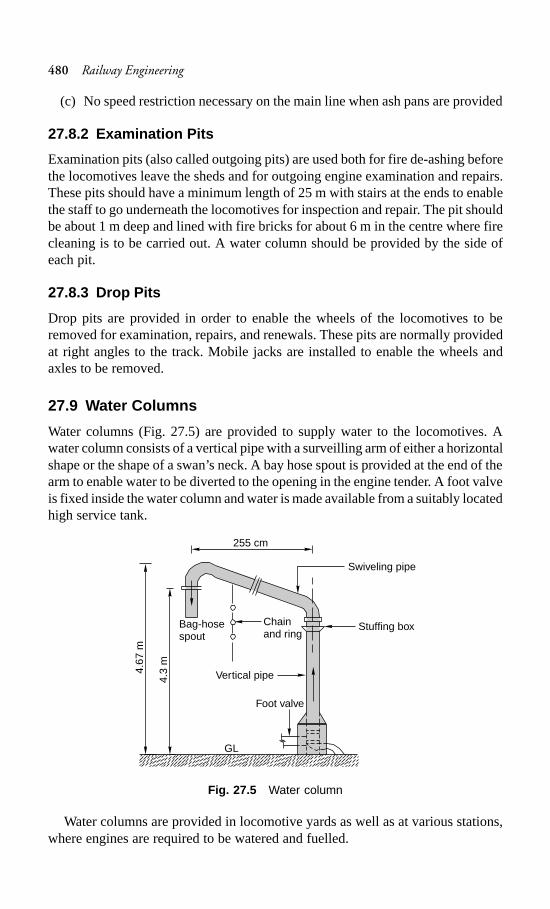
480 Railway Engineering
(c) No speed restriction necessary on the main line when ash pans are provided
27.8.2 Examination Pits
Examination pits (also called outgoing pits) are used both for fire de-ashing beforethe locomotives leave the sheds and for outgoing engine examination and repairs.These pits should have a minimum length of 25 m with stairs at the ends to enablethe staff to go underneath the locomotives for inspection and repair. The pit shouldbe about 1 m deep and lined with fire bricks for about 6 m in the centre where firecleaning is to be carried out. A water column should be provided by the side ofeach pit.
27.8.3 Drop Pits
Drop pits are provided in order to enable the wheels of the locomotives to beremoved for examination, repairs, and renewals. These pits are normally providedat right angles to the track. Mobile jacks are installed to enable the wheels andaxles to be removed.
27.9 Water Columns
Water columns (Fig. 27.5) are provided to supply water to the locomotives. Awater column consists of a vertical pipe with a surveilling arm of either a horizontalshape or the shape of a swan’s neck. A bay hose spout is provided at the end of thearm to enable water to be diverted to the opening in the engine tender. A foot valveis fixed inside the water column and water is made available from a suitably locatedhigh service tank.
Fig. 27.5 Water column
Water columns are provided in locomotive yards as well as at various stations,where engines are required to be watered and fuelled.
255 cm
Bag-hosespout
Chainand ring
Swiveling pipe
Stuffing box
Vertical pipe
Foot valve
GL
4.67
m
4.3
m
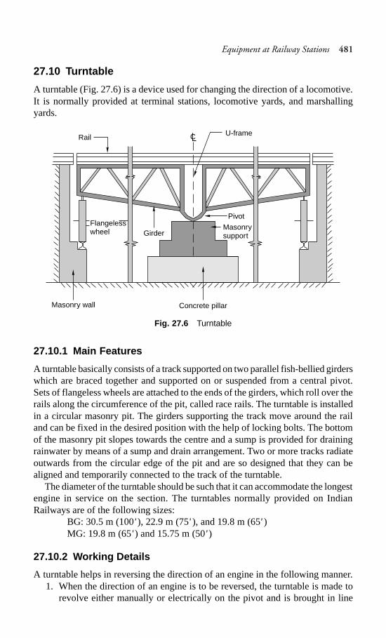
Equipment at Railway Stations 481
27.10 Turntable
A turntable (Fig. 27.6) is a device used for changing the direction of a locomotive.It is normally provided at terminal stations, locomotive yards, and marshallingyards.
Fig. 27.6 Turntable
27.10.1 Main Features
A turntable basically consists of a track supported on two parallel fish-bellied girderswhich are braced together and supported on or suspended from a central pivot.Sets of flangeless wheels are attached to the ends of the girders, which roll over therails along the circumference of the pit, called race rails. The turntable is installedin a circular masonry pit. The girders supporting the track move around the railand can be fixed in the desired position with the help of locking bolts. The bottomof the masonry pit slopes towards the centre and a sump is provided for drainingrainwater by means of a sump and drain arrangement. Two or more tracks radiateoutwards from the circular edge of the pit and are so designed that they can bealigned and temporarily connected to the track of the turntable.
The diameter of the turntable should be such that it can accommodate the longestengine in service on the section. The turntables normally provided on IndianRailways are of the following sizes:
BG: 30.5 m (100' ), 22.9 m (75'), and 19.8 m (65' )MG: 19.8 m (65' ) and 15.75 m (50' )
27.10.2 Working Details
A turntable helps in reversing the direction of an engine in the following manner.1. When the direction of an engine is to be reversed, the turntable is made to
revolve either manually or electrically on the pivot and is brought in line
RailU-frame
Flangelesswheel Girder
Pivot
Masonrysupport
Masonry wall Concrete pillar
C
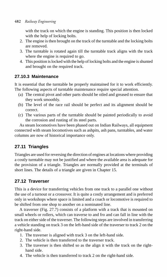
482 Railway Engineering
with the track on which the engine is standing. This position is then lockedwith the help of locking bolts.
2. The engine is then brought on the track of the turntable and the locking boltsare removed.
3. The turntable is rotated again till the turntable track aligns with the trackwhere the engine is required to go.
4. This position is locked with the help of locking bolts and the engine is shuntedand brought on the required track.
27.10.3 Maintenance
It is essential that the turntable be properly maintained for it to work efficiently.The following aspects of turntable maintenance require special attention.
(a) The central pivot and other parts should be oiled and greased to ensure thatthey work smoothly.
(b) The level of the race rail should be perfect and its alignment should becorrect.
(c) The various parts of the turntable should be painted periodically to avoidthe corrosion and rusting of its steel parts.
As steam locomotives have been phased out on Indian Railways, all equipmentconnected with steam locomotives such as ashpits, ash pans, turntables, and watercolumns are now of historical importance only.
27.11 Triangles
Triangles are used for reversing the direction of engines at locations where providinga costly turntable may not be justified and where the available area is adequate forthe provision of a triangle. Triangles are normally provided at the terminals ofshort lines. The details of a triangle are given in Chapter 15.
27.12 Traverser
This is a device for transferring vehicles from one track to a parallel one withoutthe use of a turnout or a crossover. It is quite a costly arrangement and is preferredonly in workshops where space is limited and a coach or locomotive is required tobe shifted from one shop to another on a nominated line.
A traverser (Fig. 27.7) consists of a platform with a track that is mounted onsmall wheels or rollers, which can traverse to and fro and can fall in line with thetrack on either side of the traverser. The following steps are involved in transferringa vehicle standing on track 3 on the left-hand side of the traverser to track 2 on theright-hand side.
1. The traverser is aligned with track 3 on the left-hand side.2. The vehicle is then transferred to the traverser track.3. The traverser is then shifted so as the align it with the track on the right-
hand side.4. The vehicle is then transferred to track 2 on the right-hand side.
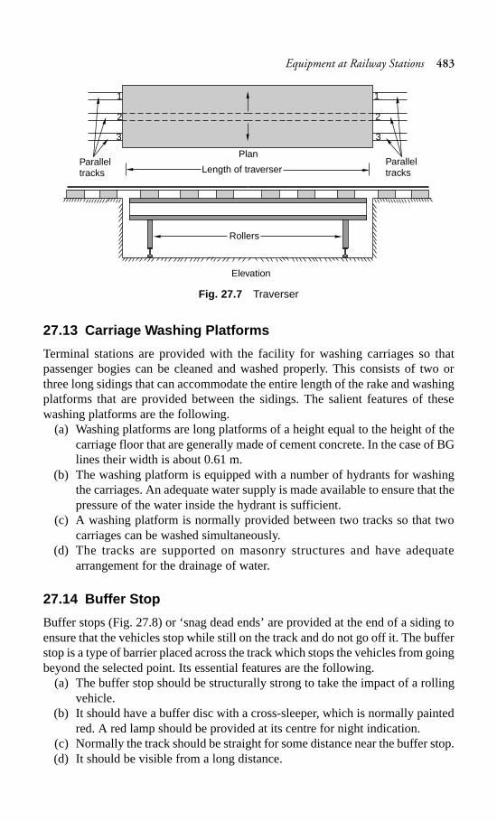
Equipment at Railway Stations 483
Fig. 27.7 Traverser
27.13 Carriage Washing Platforms
Terminal stations are provided with the facility for washing carriages so thatpassenger bogies can be cleaned and washed properly. This consists of two orthree long sidings that can accommodate the entire length of the rake and washingplatforms that are provided between the sidings. The salient features of thesewashing platforms are the following.
(a) Washing platforms are long platforms of a height equal to the height of thecarriage floor that are generally made of cement concrete. In the case of BGlines their width is about 0.61 m.
(b) The washing platform is equipped with a number of hydrants for washingthe carriages. An adequate water supply is made available to ensure that thepressure of the water inside the hydrant is sufficient.
(c) A washing platform is normally provided between two tracks so that twocarriages can be washed simultaneously.
(d) The tracks are supported on masonry structures and have adequatearrangement for the drainage of water.
27.14 Buffer Stop
Buffer stops (Fig. 27.8) or ‘snag dead ends’ are provided at the end of a siding toensure that the vehicles stop while still on the track and do not go off it. The bufferstop is a type of barrier placed across the track which stops the vehicles from goingbeyond the selected point. Its essential features are the following.
(a) The buffer stop should be structurally strong to take the impact of a rollingvehicle.
(b) It should have a buffer disc with a cross-sleeper, which is normally paintedred. A red lamp should be provided at its centre for night indication.
(c) Normally the track should be straight for some distance near the buffer stop.(d) It should be visible from a long distance.
Length of traverserParalleltracks
3
2
1
Elevation
Rollers
PlanParalleltracks
3
2
1
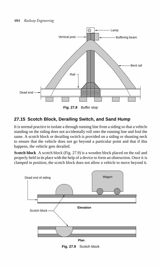
484 Railway Engineering
Fig. 27.8 Buffer stop
27.15 Scotch Block, Derailing Switch, and Sand Hump
It is normal practice to isolate a through running line from a siding so that a vehiclestanding on the siding does not accidentally roll onto the running line and foul thesame. A scotch block or derailing switch is provided on a siding or shunting neckto ensure that the vehicle does not go beyond a particular point and that if thishappens, the vehicle gets derailed.
Scotch block A scotch block (Fig. 27.9) is a wooden block placed on the rail andproperly held in its place with the help of a device to form an obstruction. Once it isclamped in position, the scotch block does not allow a vehicle to move beyond it.
Fig. 27.9 Scotch block
Rail
Dead end
Vertical post Buffering beam
Lamp
Bent rail
Dead end of siding
Scotch block
Plan
Wagon
Elevation
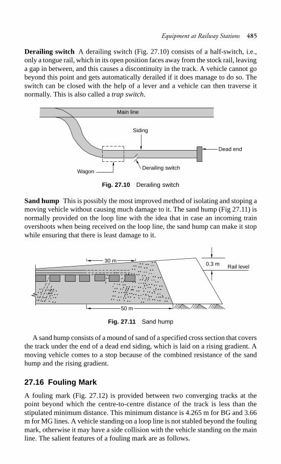
Equipment at Railway Stations 485
Derailing switch A derailing switch (Fig. 27.10) consists of a half-switch, i.e.,only a tongue rail, which in its open position faces away from the stock rail, leavinga gap in between, and this causes a discontinuity in the track. A vehicle cannot gobeyond this point and gets automatically derailed if it does manage to do so. Theswitch can be closed with the help of a lever and a vehicle can then traverse itnormally. This is also called a trap switch.
Fig. 27.10 Derailing switch
Sand hump This is possibly the most improved method of isolating and stoping amoving vehicle without causing much damage to it. The sand hump (Fig 27.11) isnormally provided on the loop line with the idea that in case an incoming trainovershoots when being received on the loop line, the sand hump can make it stopwhile ensuring that there is least damage to it.
Fig. 27.11 Sand hump
A sand hump consists of a mound of sand of a specified cross section that coversthe track under the end of a dead end siding, which is laid on a rising gradient. Amoving vehicle comes to a stop because of the combined resistance of the sandhump and the rising gradient.
27.16 Fouling Mark
A fouling mark (Fig. 27.12) is provided between two converging tracks at thepoint beyond which the centre-to-centre distance of the track is less than thestipulated minimum distance. This minimum distance is 4.265 m for BG and 3.66m for MG lines. A vehicle standing on a loop line is not stabled beyond the foulingmark, otherwise it may have a side collision with the vehicle standing on the mainline. The salient features of a fouling mark are as follows.
WagonDerailing switch
Siding
Dead end
Main line
Rail level0.3 m30 m
50 m
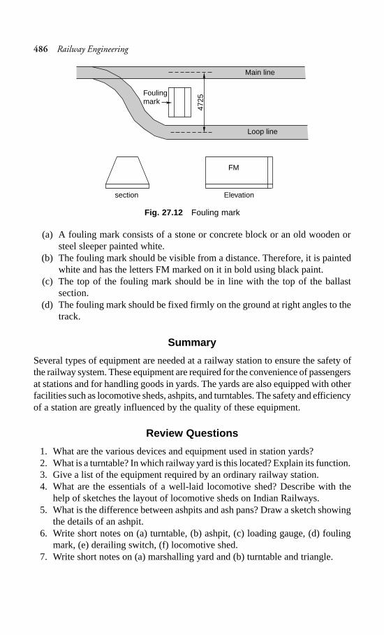
486 Railway Engineering
Fig. 27.12 Fouling mark
(a) A fouling mark consists of a stone or concrete block or an old wooden orsteel sleeper painted white.
(b) The fouling mark should be visible from a distance. Therefore, it is paintedwhite and has the letters FM marked on it in bold using black paint.
(c) The top of the fouling mark should be in line with the top of the ballastsection.
(d) The fouling mark should be fixed firmly on the ground at right angles to thetrack.
Summary
Several types of equipment are needed at a railway station to ensure the safety ofthe railway system. These equipment are required for the convenience of passengersat stations and for handling goods in yards. The yards are also equipped with otherfacilities such as locomotive sheds, ashpits, and turntables. The safety and efficiencyof a station are greatly influenced by the quality of these equipment.
Review Questions
1. What are the various devices and equipment used in station yards?2. What is a turntable? In which railway yard is this located? Explain its function.3. Give a list of the equipment required by an ordinary railway station.4. What are the essentials of a well-laid locomotive shed? Describe with the
help of sketches the layout of locomotive sheds on Indian Railways.5. What is the difference between ashpits and ash pans? Draw a sketch showing
the details of an ashpit.6. Write short notes on (a) turntable, (b) ashpit, (c) loading gauge, (d) fouling
mark, (e) derailing switch, (f) locomotive shed.7. Write short notes on (a) marshalling yard and (b) turntable and triangle.
section
Foulingmark
Loop line
FM
Main line
Elevation47
25
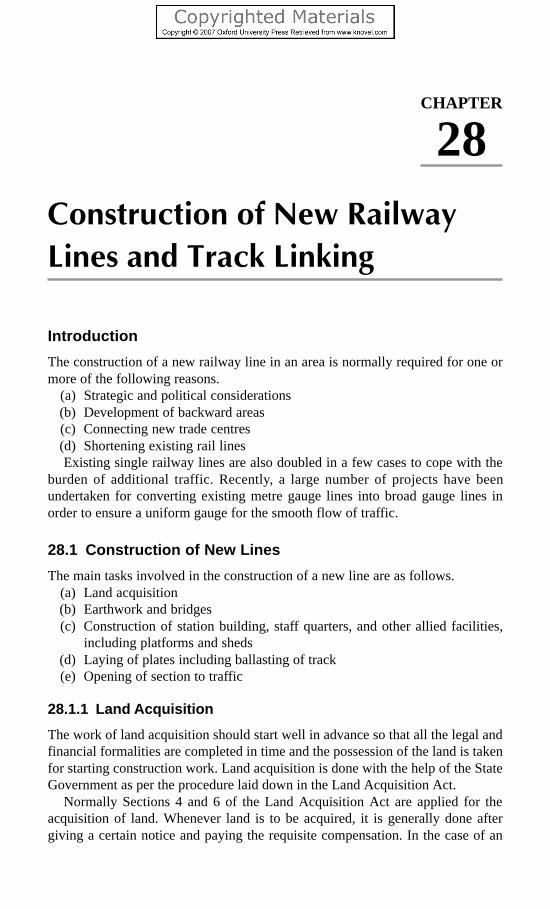
Construction of New Railway Lines and Track Linking 487
Construction of New Railway
Lines and Track Linking
Introduction
The construction of a new railway line in an area is normally required for one ormore of the following reasons.
(a) Strategic and political considerations(b) Development of backward areas(c) Connecting new trade centres(d) Shortening existing rail linesExisting single railway lines are also doubled in a few cases to cope with the
burden of additional traffic. Recently, a large number of projects have beenundertaken for converting existing metre gauge lines into broad gauge lines inorder to ensure a uniform gauge for the smooth flow of traffic.
28.1 Construction of New Lines
The main tasks involved in the construction of a new line are as follows.(a) Land acquisition(b) Earthwork and bridges(c) Construction of station building, staff quarters, and other allied facilities,
including platforms and sheds(d) Laying of plates including ballasting of track(e) Opening of section to traffic
28.1.1 Land Acquisition
The work of land acquisition should start well in advance so that all the legal andfinancial formalities are completed in time and the possession of the land is takenfor starting construction work. Land acquisition is done with the help of the StateGovernment as per the procedure laid down in the Land Acquisition Act.
Normally Sections 4 and 6 of the Land Acquisition Act are applied for theacquisition of land. Whenever land is to be acquired, it is generally done aftergiving a certain notice and paying the requisite compensation. In the case of an
CHAPTER
28
488 Railway Engineering
emergency, land can also be acquired urgently by the application of Special Sections9 and 17 of the Land Acquisition Act.
The land being acquired should be sufficient for the formation, berm, and borrowpits. It should also have adequate provision for any future expansion. Even when asingle line is to be constructed, it should be ascertained that the land made availableis suitable for future conversion into a double line. Normally a strip of 15 to 25 mof land is acquired for the construction of a railway line. An extra width of land isacquired for station yards. In the case of small stations, the width normally adoptedis 150 × 1000 m.
The minimum measurements of the selected land should be such that it cancater to the following requirement.
Width of formation The land should be adequate so as to accommodate the widthof the formation.
Side slopeThis depends on the nature of the soil and is normally taken as 2:1(horizontal:vertical).
Width of berm The width of the berm is usually kept as 3 m.
Borrow pits If the land is not very costly, adequate land should also be madeavailable for borrow pits. Borrow pits may be provided on one side of the track forlow banks and on both sides of the track for medium and high banks.
When the land is expensive, borrow pits need not be provided and instead earthcan be borrowed from adjoining areas. Extra land is, however, required for stationyards, level crossings, and bridge approaches.
28.1.2 Earthwork for Formation
Depending upon the rail level and general contour of the area, the formation maybe laid in an embankment or in a cutting. A formation laid in an embankment isnormally preferred because it affords good drainage. The height of the embankmentalso depends on the high flood level (HFL) of the area and a reasonable free boardshould be given above the HFL.
The standard widths of the formation for BG and MG lines are given in Table 28.1
Table 28.1 Standard width of formation
Gauge Type of formation Width of formation (m)
Single line Double line
BG Embankment 6.10 10.82Cutting 5.40 10.21
MG Embankment 4.88 8.84Cutting 4.27 8.23
Some of the points to be kept in mind with regard to earthwork are given below.(a) Earthwork is normally done in 30-cm layers so that the soil is well compacted.
Construction of New Railway Lines and Track Linking 489
(b) Mechanical compaction is normally done after each layer of earthwork withthe help of a sheep foot roller to obtain 90% maximum dry density at anoptimum moisture content.
(c) A shrinkage allowance of 5% is made for the consolidation of the final crosssection in the case of mechanical compaction. The shrinkage allowance isincreased to 10% if no mechanical compaction is involved.
(d) A blanket of a thickness of about 30 cm is provided at the top of theembankment where the soil is not of good quality.
(e) In areas where there are both cuttings and embankments, the soil from thecuttings should be used for the embankments up to an economical lead. Theeconomical limit of moving the earth in the longitudinal direction isdetermined by the mass-haul curve.
(f) For the early execution of earthwork, the section is normally divided intoconvenient zones, with each zone requiring earthwork costing Rs 1.5 to 3million approximately. Tenders are separately invited for each zone so thatwork can progress simultaneously in all the zones.
28.1.3 Bridges
Bridges should be designed to bear the load of the heaviest locomotive likely topass the section. Depending upon the topography of the location and the type ofstream to be crossed, hume pipe culverts, RCC slab bridges, plate girders, PRCgirder bridges, or steel bridges are designed. Bridges, being important structures,are normally constructed to accommodate a double line even in those sectionswhere only a single line is being set up so that future expansions can be planned.
Separate tenders are invited for the construction of important bridges so that thebridge design and construction can also be included in the tender documents. Minorbridges and culverts are normally included in the earthwork zones mentioned earlier.
28.1.4 Service Buildings and Staff Quarters
Service buildings include buildings such as the station master’s office or telegraphoffice, which are basically required for providing assistance in the running of trains.Apart from this, staff quarters and other passenger amenities such as platforms,foot over bridges, waiting halls, and retiring rooms are also provided at the stations.Many other ancillary facilities such as water, drainage, telephone lines, andelectricity are also made available at every station.
All these constructions are taken up simultaneously by civil engineers, electricalengineers, and signal engineers so that all work can progress together.
28.1.5 Plate Laying or Track Linking
Once the formation is ready, plate laying or track linking should be done, whichbasically consists of laying rails, sleepers, and fastenings. The following methodscan be adopted for plate laying.
490 Railway Engineering
Tram line method
In this method, a temporary line known as a tram line is laid by the side of theproposed track for transporting track material to the site. This method can be usefulin flat terrains, where laying of a tram line on the natural ground may becomparatively easier. This method is, however, seldom used in actual practice.
A modification of the above method, called side method, is also in practice,where track and bridge material such as steel girders and RCC slabs is carried tothe site in trucks on a service road that runs parallel to the track. These materialsare then unloaded near the work site. This method is used only in cases where theterrain is comparatively flat.
American method
In this method, rails and sleepers are first assembled in the base depot, and the pre-assembled track panels are then conveyed to the site along with the necessarycranes, etc. The track panels are then unloaded at the site of work either manuallyor with the help of cranes and laid in their final position.
This procedure is used in many developed countries, particularly where concretesleepers are laid, which are quite heavy and not very easy to handle manually.
Telescopic method
This method is widely used on Indian Railways. In this method, the rails, sleepers,and other fittings are taken to the base depot and unloaded. The track material isthen taken to the rail head, where the tracks linked and packed. The rail head isthen advanced up to the point where the track has been laid. The track materialsare then taken up to the extended rail head with the help of a dip lorry and the trackis linked and packed again. Thus the rail head goes on advancing till the entiretrack has been linked. The main operations involved in this method are as follows.
Unloading of materials The track materials are taken to the base depot andunloaded with the help of material gangs. The first base depot lies at the junctionof the existing line and the new line to be constructed. All the track material istaken from the base depot to the rail head with the help of a dip lorry (a special typeof trolley). The rail head goes on advancing till the track is sufficiently linked.After that, a subsidiary depot is established at a distance of about 5 km and trackmaterial carried to this depot with the help of a material train. Alternatively, trackmaterial is transferred from the base depot with the help of a dip lorry up to adistance of about 2 km and by the means of a material train beyond this distance.The base depot has arrangements for advanced processes such as adzing and boringof sleepers as well as for matching materials, etc. to ensure the speedy linking ofthe track at the site.
Linking of track Once the track material is unloaded, the track is linked with thehelp of linking gangs. The following procedure is normally adopted for this purpose.
1. A string is first stretched along the central line of the alignment and thesleepers are laid with their centres on the string. The sleepers are laid roughlyat the desired spacing, keeping the total number of sleepers per rail intact.
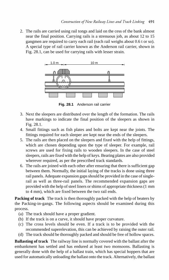
Construction of New Railway Lines and Track Linking 491
2. The rails are carried using rail tongs and laid on the cess of the bank almostnear the final position. Carrying rails is a strenuous job, as about 12 to 15gangmen are required to carry each rail (each rail weighs about 0.6 t or so).A special type of rail carrier known as the Anderson rail carrier, shown inFig. 28.1, can be used for carrying rails with lesser strain.
Fig. 28.1 Anderson rail carrier
3. Next the sleepers are distributed over the length of the formation. The railshave markings to indicate the final position of the sleepers as shown inFig. 28.1.
4. Small fittings such as fish plates and bolts are kept near the joints. Thefittings required for each sleeper are kept near the ends of the sleepers.
5. The rails are then placed on the sleepers and fixed with the help of fittings,which are chosen depending upon the type of sleeper. For example, railscrews are used for fixing rails to wooden sleepers. In the case of steelsleepers, rails are fixed with the help of keys. Bearing plates are also providedwherever required, as per the prescribed track standards.
6. The rails are joined with each other after ensuring that there is sufficient gapbetween them. Normally, the initial laying of the tracks is done using threerail panels. Adequate expansion gaps should be provided in the case of single-rail as well as three-rail panels. The recommended expansion gaps areprovided with the help of steel liners or shims of appropriate thickness (1 mmto 4 mm), which are fixed between the two rail ends.
Packing of track The track is then thoroughly packed with the help of beaters bythe Packing-in-gangs. The following aspects should be examined during thisprocess.
(a) The track should have a proper gradient.(b) If the track is on a curve, it should have proper curvature.(c) The cross levels should be even. If a track is to be provided with the
recommended superelevation, this can be achieved by raising the outer rail.(d) The track should be thoroughly packed and should be free of hollow spaces.
Ballasting of track The railway line is normally covered with the ballast after theembankment has settled and has endured at least two monsoons. Ballasting isgenerally done with the help of a ballast train, which has special hoppers that areused for automatically unloading the ballast onto the track. Alternatively, the ballast
1.0 m 10 m
492 Railway Engineering
is taken to the cess and then placed on the track manually. Either method ensuresthat the ballast is thoroughly packed and inserted properly under the track.
28.2 Requirement of Track Material for BG Track
Rails
The standard length of the rails is 13 m for BG and 12 m for MG lines.
No. of rails per km for BG lines 1000
213
= ×
= 77 × 2 = 154Wt of 52-kg rails per km = 52 × 154
= 8008 kg
Number of sleepers
The number of sleepers to be used depends upon the sleeper density. Assume sleeperdensity to be M + 7, where M is the length of the rail in metres.
Number of sleepers per rail = 13 + 7 = 20Number of sleepers per km = 77 × 20 = 1540
Fittings and fastenings
(a) No. of fish plates per km = 2 × number of rails per km= 2 × 154 = 308
(b) No. of fish bolts = 4 × number of rails per km= 4 × 154 = 616
(c) No. of bearing plates = number of sleepers × 2= 1540 × 2 = 3080
(iv) Number of dog spikes = number of sleepers × 4= 1540 × 4 = 6160
The requirement of track materials for MG lines can also be calculated in thesame manner.
28.3 Doubling of Railway Lines
The doubling of a railway line refers to the construction of an additional line. Thisis normally done when a single line is no longer capable of carrying all the trainsthat ply on the section. The main steps involved in the doubling of a railway lineare described here.
Engineering-cum-traffic survey This survey is conducted to examine the trafficprospects of the section and to roughly identify the quantum of work and costinvolved. The Railway Board finally sanctions the work and authorizes the railwayto execute the same.
Specification of work During the execution of the work, it is necessary to clearlyunderstand and follow the standards of construction and the specifications thathave been laid down. The track standard should also be decided during the survey
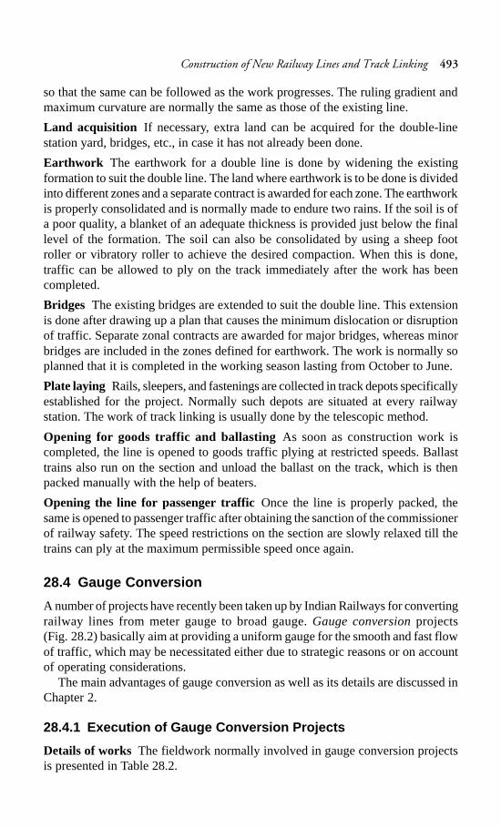
Construction of New Railway Lines and Track Linking 493
so that the same can be followed as the work progresses. The ruling gradient andmaximum curvature are normally the same as those of the existing line.
Land acquisition If necessary, extra land can be acquired for the double-linestation yard, bridges, etc., in case it has not already been done.
Earthwork The earthwork for a double line is done by widening the existingformation to suit the double line. The land where earthwork is to be done is dividedinto different zones and a separate contract is awarded for each zone. The earthworkis properly consolidated and is normally made to endure two rains. If the soil is ofa poor quality, a blanket of an adequate thickness is provided just below the finallevel of the formation. The soil can also be consolidated by using a sheep footroller or vibratory roller to achieve the desired compaction. When this is done,traffic can be allowed to ply on the track immediately after the work has beencompleted.
Bridges The existing bridges are extended to suit the double line. This extensionis done after drawing up a plan that causes the minimum dislocation or disruptionof traffic. Separate zonal contracts are awarded for major bridges, whereas minorbridges are included in the zones defined for earthwork. The work is normally soplanned that it is completed in the working season lasting from October to June.
Plate laying Rails, sleepers, and fastenings are collected in track depots specificallyestablished for the project. Normally such depots are situated at every railwaystation. The work of track linking is usually done by the telescopic method.
Opening for goods traffic and ballasting As soon as construction work iscompleted, the line is opened to goods traffic plying at restricted speeds. Ballasttrains also run on the section and unload the ballast on the track, which is thenpacked manually with the help of beaters.
Opening the line for passenger trafficOnce the line is properly packed, thesame is opened to passenger traffic after obtaining the sanction of the commissionerof railway safety. The speed restrictions on the section are slowly relaxed till thetrains can ply at the maximum permissible speed once again.
28.4 Gauge Conversion
A number of projects have recently been taken up by Indian Railways for convertingrailway lines from meter gauge to broad gauge. Gauge conversion projects(Fig. 28.2) basically aim at providing a uniform gauge for the smooth and fast flowof traffic, which may be necessitated either due to strategic reasons or on accountof operating considerations.
The main advantages of gauge conversion as well as its details are discussed inChapter 2.
28.4.1 Execution of Gauge Conversion Projects
Details of works The fieldwork normally involved in gauge conversion projectsis presented in Table 28.2.
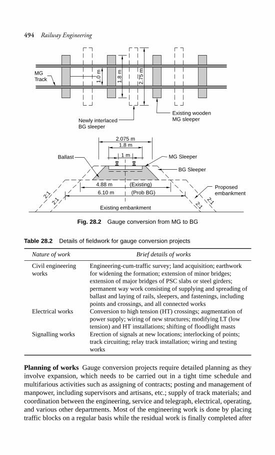
494 Railway Engineering
Fig. 28.2 Gauge conversion from MG to BG
Table 28.2 Details of fieldwork for gauge conversion projects
Nature of work Brief details of works
Civil engineering Engineering-cum-traffic survey; land acquisition; earthworkworks for widening the formation; extension of minor bridges;
extension of major bridges of PSC slabs or steel girders;permanent way work consisting of supplying and spreading ofballast and laying of rails, sleepers, and fastenings, includingpoints and crossings, and all connected works
Electrical works Conversion to high tension (HT) crossings; augmentation ofpower supply; wiring of new structures; modifying LT (lowtension) and HT installations; shifting of floodlight masts
Signalling works Erection of signals at new locations; interlocking of points;track circuiting; relay track installation; wiring and testingworks
Planning of works Gauge conversion projects require detailed planning as theyinvolve expansion, which needs to be carried out in a tight time schedule andmultifarious activities such as assigning of contracts; posting and management ofmanpower, including supervisors and artisans, etc.; supply of track materials; andcoordination between the engineering, service and telegraph, electrical, operating,and various other departments. Most of the engineering work is done by placingtraffic blocks on a regular basis while the residual work is finally completed after
MGTrack 1.
0 m
1.8
m
2.75
m
Existing woodenMG sleeperNewly interlaced
BG sleeper
2.075 m1.8 m
1 mBallast
4.88 m (Existing)
6.10 m (Prob BG)
2:1
2:1 2:12:1Existing embankment
Proposedembankment
MG Sleeper
BG Sleeper
Construction of New Railway Lines and Track Linking 495
placing an extended traffic block of several consecutive days on the route, duringwhich time gauge conversion works are executed on a war footing.
Manpower requirement The manpower required for the various tasks involvedin a gauge conversion project is to the tune of about 80 labourers per km to ensurethat gauge conversion is completed within 30 days in all respects. One PWI andone AEN should be assigned for one- and two-block sections, respectively, for thecontinuous monitoring of the progressing work to ensure the requisite qualitycontrol. The contractor should also engage at least two competent supervisors perblock section in addition to the trained permanent way mates appointed for eachgang.
Speed potentialTwo rounds of packing by light off-track tampers such as phooltasor chinese tampers are required to make the track fit for a speed of 50 km/h. This isfurther supplemented by two more rounds of packing using heavy on-track tietamping machines for making the track fit for a speed of 100 km/h.
Economy measuresGauge conversion projects are capital intensive and adequatefinancial resources have to be mobilized to meet these ambitious targets. TheRailway Ministry has, therefore, taken a decision that all schemes of gaugeconversion are to be carried out in the most economical way. By cutting down thecost of gauge conversion in various ways, the Railways plan to carry out gaugeconversion works at an economical cost of Rs 6 to 7 million per km as against thenormal cost of Rs 9 to 10 million per km, thereby saving about 30 to 40% on theinitial cost. The guidelines to be followed in this regard are the following.
(a) The maximum permissible speed on the converted BG section need not bemore than what was previously specified for the MG section.
(b) The facilities required at the stations should not be more than what has alreadybeen provided except that the loop length should be 686 m.
(c) The length of the platform at those stations that currently serve as stops formail/express trains should be just enough for accommodating l6 coaches. Ifthe existing platform needs to be extended, the extended portion should beconstructed at rail level. On suburban sections, the length of the platformshould be enough for 12 coaches. At important stations, the platform lengthshould be sufficient for no more than 22 coaches with added provisions forfuture expansion to include 26 coaches.
28.4.2 Civil Engineering Works of Gauge Conversion Projects
Engineering-cum-traffic surveys The survey is done to examine the technicalfeasibility of the proposal and the economical aspects of the same.
Land acquisition The land requirement for converting the track from MG to BGis assessed and, if necessary, extra land is acquired as per the existing procedurelaid down in the Land Acquisition Act.
Earthwork Earthwork is done on either side of the existing formation of a single-line track to increase its width from 4.88 m (16 ft) to 6.10 m (20 ft) in the case ofembankments and from 4.27 m (14 ft) to 5.49 m in the case of cuttings.
496 Railway Engineering
Bridges and culverts The existing bridges and culverts are extended to suit theBG formation and to conform to the standards adopted for BG sections. Theextension of these bridges is properly planned to ensure the minimum dislocationof traffic.
Track linking Track linking involves the following operations.
Unloading of track materialTrack material such as rails, sleepers, and fasteningsare taken from the base depot to the work site and unloaded at the final location.Preliminary works such as boring and adzing of sleepers, proper matching of rails,and drilling of holes in the rails are planned in advance.
Interlacing of sleepersWooden sleepers are best suited for gauge conversionprojects, if available. They are interlaced with the existing sleepers of the track andthe two are spiked together.
Arrangements of men and materialsThe deployment of manpower, includingthe supervising staff, is planned in detail so that the conversion of the track fromMG to BG is achieved with minimum interruption of traffic. Normally 50 to 100 menper km work are required on the track during a traffic block. In addition, the workof skilled artisans such as blacksmiths is also required for track conversion. Alltrack material, including fittings, are properly organized and arranged at the site.Tools and equipment such as augers and drills, Jim Crows, crowbars, rail tongs,sleeper tongs, and spanners are also arranged in adequate quantities.
Traffic blocks Traffic is suspended on the railway line for a period of 15 to 30 daysdepending upon the length of the track to be dealt with, so that the work of gaugeconversion can be carried out at one stretch. During a traffic block, traffic is divertedon alternate routes or trans-shipped onto road vehicles.
Linking the new track During the traffic block, the existing rails are removed andnew rails placed in what is to be their final position on the BG track. The newsleepers are also placed in their proper position and the rails are spiked to thesleepers as per BG requirements. The track is properly levelled and aligned andtraffic is allowed on the new line at a restricted speed after obtaining the sanctionof the commissioner of railway safety.
Ballasting and packingAn adequate quantity of ballast is then put in the trackand the track is properly packed. The speed restrictions are gradually relaxed asthe stability of the track improves.
Summary
Both passenger and goods traffic is increasing at a very fast rate on Indian Railways.Therefore, the construction of new lines or the doubling of the existing single-linetracks becomes important. The latter is brought about through extensive gaugeconversion projects, which involve land acquisition, earthwork, construction ofbridges and station buildings, and many other activities. The project should beplanned and executed following the standard norms to ensure that the trains runsafely.
Construction of New Railway Lines and Track Linking 497
Review Questions
1. Using a sleeper density of n + 6, determine the number of sleepers requiredfor constructing a BG railway track that is 768 m long, if the length of the railis 13 m.
2. Describe the principal operations involved in the plate laying method usedextensively in India.
3. Define plate laying and give an elaborate description of the same.4. You are placed in charge of a plate laying operation for the construction of a
BG railway track. Give a detailed and step by step account of how you wouldcarry out the work to achieve the desired result.
5. A 5-km-long BG main line straight track with CST-9 sleepers and duplexjoint sleepers is to be constructed. Estimate the total quantity of track materialrequired with respect to 90 R rails and a N + 5 sleeper density.
6. Discuss briefly the factors affecting track alignment and describe in brief themethods one would adopt to align a railway track in a region where a heavygradient is unavoidable. Using a sleeper density of N + 5, determine the numberof sleepers required for constructing a railway track of a length of 640 m on aBG section.
7. Work out the quantities of the various track materials required for laying asingle-line BG track for a length of 1 km. Make suitable assumptions for allthe other data that may be required.
8. Briefly discuss the various steps involved in the construction of a new BGrailway line.
9. Write notes on (a) doubling of a railway line (b) gauge conversion project.
498 Railway Engineering
Suburban Railways
in Metro Cities
Introduction
The term ‘metropolitan city’ is commonly used for major or important cities. Mostmetropolitan cities in India have grown in an unplanned and hapazard manner.Even in places where city masterplans were available, the actual lands barelyresembles what was envisaged in the plans. Delhi is one such example. The rapidgrowth in the population and economy of metropolitan cities has resulted in severalsocial and economic problems. The imbalance in the distribution of populationand economic activity in these cities has led to large-scale intracity movementresulting in a serious transportation problem.
There are generally many limitations in the movement of people in thesemetropolitan cities due to the following reasons.
The main problems of metropolitan cities are outlined below.(a) The traffic capacity of the roads in the major metropolitan cities has not kept
pace with the growing demands of traffic and this has resulted in severecongestion on the roads, particularly during peak hours and in central businessdistricts.
(b) The average vehicular speed in these cities is about 20 to 30 km/hr and insome of the congested parts of the core areas, speeds have been reduced toas low as 5 to 10 km/hr. A heavy, often unidirectional, peak load is requiredto be carried through certain routes during specific hours everyday. Thedesign and capacity of these roads are unable to meet the requirements oftraffic and because of the several architectural structures that have comeupon their either side; the further widening of these roads is not possible.
(c) The number of road vehicles has increased considerably in the last few years,of the order of 5 to 10% per year in the four metropolitan cities. In Delhialone, the number of registered vehicles has multiplied in the last 10-yearperiod. These cities keep expanding in all directions at an alarming rate,placing additional demands on the existing transport system.
(d) Environment pollution is widespread in metropolitan cities on account ofthe increase in vehicular traffic and all round congestion. This has led to
CHAPTER
29
Suburban Railways in Metro Cities 499
increased levels of noise and dust, increased vehicular emissions, and a lossof sunlight and daylight.
(e) The congestion on the roads in metropolitan cities has resulted in a largenumber of accidents. About 1.2 million road accidents take place annuallyin India, killing about 85,000 people and injuring more than 0.1 million.
(f) There is a considerable wastage of time of a large number of people stayingin metropolitan cities on account of the slow movement of vehicles and theformation of long queues on the roads.
A possible solution to these problems is to establish a proper mass transportsystem. The existing transport facilities must be suitably augmented and expandedto meet the growing traffic demands. All types of road transport such as twowheelers, autorickshaws, cars, and buses have a maximum load capacity. Dependingon the traffic density, one possible solution would be to strengthen and developelectric rail services, which, besides providing high-capacity transit facilities, alsohelp substantially in energy conservation and environmental preservation. Further,from the point of view of relieving the roads of excess traffic and also of conservingenergy, there is a need for urgent and deliberate measures that will discouragecommuters from using personal modes of transport and promote the use of publicconveyances instead.
29.1 Urban Transport
The basic objective of urban transport is to provide residences with access to activitysuch as workplaces, schools, shopping centres, etc. The different forms of urbantransport in use in most cities of the world are the following.
(a) Motorbuses(b) Trolley buses(c) Tramways(d) Surface railways(e) Underground railways(f) Elevated railways(g) Monorails(h) Tube railways
29.1.1 Motorbuses
This is the most convenient form of transport and is used extensively in metropolitancities. These buses run mostly on diesel oil and their exhaust emissions have anadverse effect on the environment. Moreover, these buses, though very convenientfor transporting passengers, have very limited seating capacity.
29.1.2 Trolley Buses
These are buses that derive their energy through overhead electric transmission.Trolley buses are superior to motorbuses as they do not pollute the environment.On the other hand, huge expenses are incurred in providing overhead traction forsupplying power to these buses.
500 Railway Engineering
29.1.3 Tramways
Tramways require a track on which the trams can run and as such require theinfrastructure of a proper railway track. Their initial cost is quite high. They causeminimal air pollution; however, they contribute significantly to noise pollution.Tramways are almost obsolete now and are used only in some parts of the countrysuch as in Kolkata.
29.1.4 Surface Railways
Surface railways are the cheapest and most extensively used form of railway servicein the world. In such a system, the track is laid on a ground that has a suitableembankment or cutting, depending upon the topography of the area. Metropolitanrailways use electric traction because of the following advantages.
(a) Electric traction does not pollute the environment.(b) The acceleration and deceleration of trains is faster.(c) Electric traction ensures the availability of power for improved and modern
signalling.(d) An electric locomotive can haul a train with the same efficiency in both the
directions and there is no need for reversing the direction of the locomotive.(e) This system uses special type of coaches called electric multiple units
(EMUs), which can carry more traffic than conventional coaches.
Cost considerations
The construction of surface railways with an overhead electric transmission systemis quite costly and comes to about Rs 10 to 15 million per km (excluding the costof the land) in normal terrain. The cost, however, increases considerably in denseand thickly populated areas, where the cost of the land to be acquired is quitesteep. In addition, the railway line may have to be constructed across roads, someof which may be quite busy.
Type of crossings
The points where the roadways and the railways cross each other are providedwith a level crossing, a road under bridge, or a road over bridge, depending uponthe volume of traffic being carried by rail or road, availability of financial resources,road level vis-à-vis rail level, proximity of land, and other allied factors. The specialcharacteristics of each one of these crossings are given in subsequent paragraphs.
Level crossing At this crossing, the railway track and the road cross each other atthe same level. In urban areas, most level crossings are manned by two to threewatchmen who are responsible for operating the same. Normally the level crossingremains closed to road traffic and is opened only when road vehicles need to crossto the other side. Though quite cheap and convenient, level crossings have thefollowing limitations.
(a) Gatemen have to be provided for manning level crossings, which proves tobe quite costly.
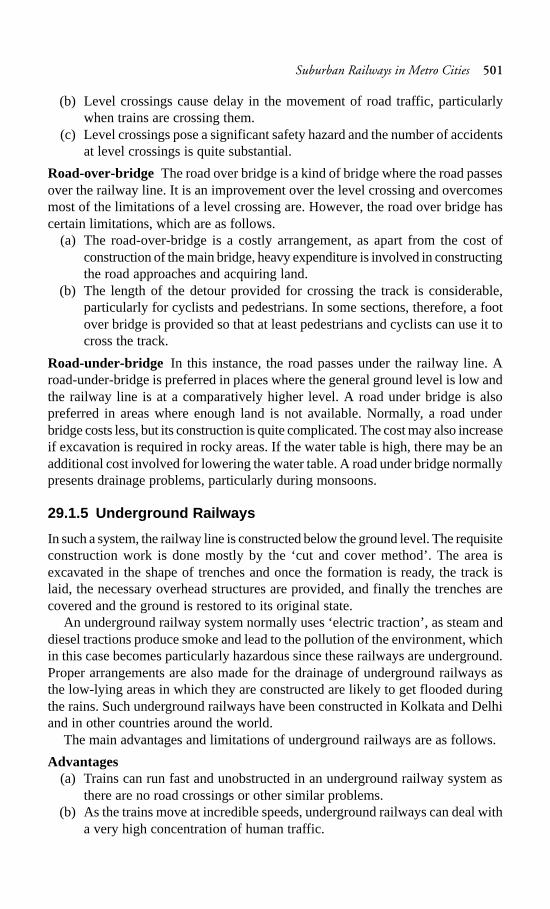
Suburban Railways in Metro Cities 501
(b) Level crossings cause delay in the movement of road traffic, particularlywhen trains are crossing them.
(c) Level crossings pose a significant safety hazard and the number of accidentsat level crossings is quite substantial.
Road-over-bridge The road over bridge is a kind of bridge where the road passesover the railway line. It is an improvement over the level crossing and overcomesmost of the limitations of a level crossing are. However, the road over bridge hascertain limitations, which are as follows.
(a) The road-over-bridge is a costly arrangement, as apart from the cost ofconstruction of the main bridge, heavy expenditure is involved in constructingthe road approaches and acquiring land.
(b) The length of the detour provided for crossing the track is considerable,particularly for cyclists and pedestrians. In some sections, therefore, a footover bridge is provided so that at least pedestrians and cyclists can use it tocross the track.
Road-under-bridge In this instance, the road passes under the railway line. Aroad-under-bridge is preferred in places where the general ground level is low andthe railway line is at a comparatively higher level. A road under bridge is alsopreferred in areas where enough land is not available. Normally, a road underbridge costs less, but its construction is quite complicated. The cost may also increaseif excavation is required in rocky areas. If the water table is high, there may be anadditional cost involved for lowering the water table. A road under bridge normallypresents drainage problems, particularly during monsoons.
29.1.5 Underground Railways
In such a system, the railway line is constructed below the ground level. The requisiteconstruction work is done mostly by the ‘cut and cover method’. The area isexcavated in the shape of trenches and once the formation is ready, the track islaid, the necessary overhead structures are provided, and finally the trenches arecovered and the ground is restored to its original state.
An underground railway system normally uses ‘electric traction’, as steam anddiesel tractions produce smoke and lead to the pollution of the environment, whichin this case becomes particularly hazardous since these railways are underground.Proper arrangements are also made for the drainage of underground railways asthe low-lying areas in which they are constructed are likely to get flooded duringthe rains. Such underground railways have been constructed in Kolkata and Delhiand in other countries around the world.
The main advantages and limitations of underground railways are as follows.
Advantages(a) Trains can run fast and unobstructed in an underground railway system as
there are no road crossings or other similar problems.(b) As the trains move at incredible speeds, underground railways can deal with
a very high concentration of human traffic.
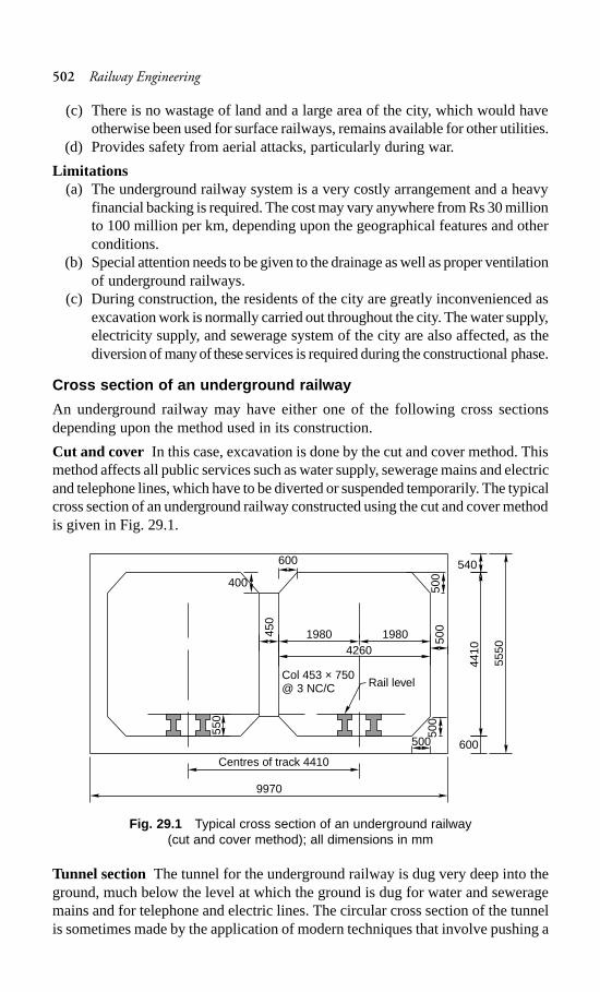
502 Railway Engineering
(c) There is no wastage of land and a large area of the city, which would haveotherwise been used for surface railways, remains available for other utilities.
(d) Provides safety from aerial attacks, particularly during war.
Limitations(a) The underground railway system is a very costly arrangement and a heavy
financial backing is required. The cost may vary anywhere from Rs 30 millionto 100 million per km, depending upon the geographical features and otherconditions.
(b) Special attention needs to be given to the drainage as well as proper ventilationof underground railways.
(c) During construction, the residents of the city are greatly inconvenienced asexcavation work is normally carried out throughout the city. The water supply,electricity supply, and sewerage system of the city are also affected, as thediversion of many of these services is required during the constructional phase.
Cross section of an underground railway
An underground railway may have either one of the following cross sectionsdepending upon the method used in its construction.
Cut and cover In this case, excavation is done by the cut and cover method. Thismethod affects all public services such as water supply, sewerage mains and electricand telephone lines, which have to be diverted or suspended temporarily. The typicalcross section of an underground railway constructed using the cut and cover methodis given in Fig. 29.1.
Fig. 29.1 Typical cross section of an underground railway(cut and cover method); all dimensions in mm
Tunnel section The tunnel for the underground railway is dug very deep into theground, much below the level at which the ground is dug for water and seweragemains and for telephone and electric lines. The circular cross section of the tunnelis sometimes made by the application of modern techniques that involve pushing a
5550
Centres of track 4410
Rail levelCol 453 × 750@ 3 NC/C
19801980
4410
9970
50045
0
600
500400
500
500
540
600
550
4260
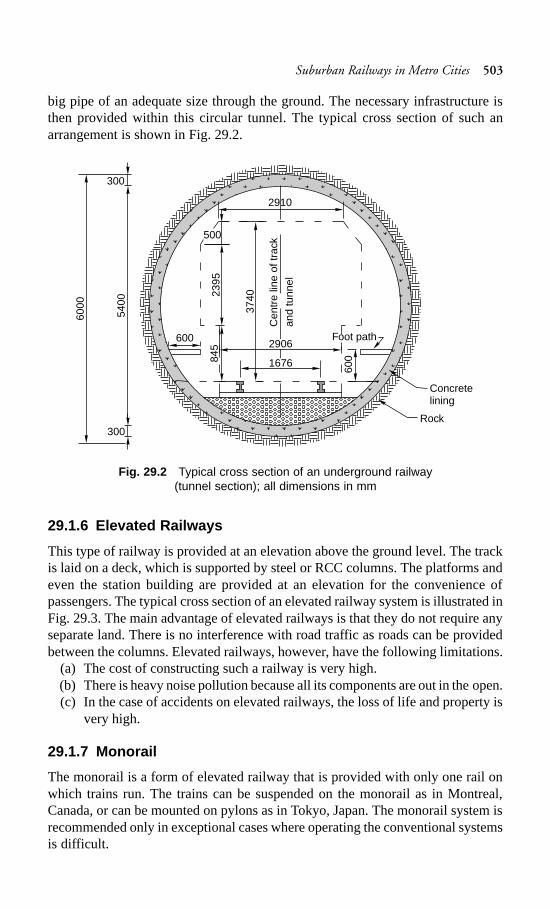
Suburban Railways in Metro Cities 503
big pipe of an adequate size through the ground. The necessary infrastructure isthen provided within this circular tunnel. The typical cross section of such anarrangement is shown in Fig. 29.2.
Fig. 29.2 Typical cross section of an underground railway(tunnel section); all dimensions in mm
29.1.6 Elevated Railways
This type of railway is provided at an elevation above the ground level. The trackis laid on a deck, which is supported by steel or RCC columns. The platforms andeven the station building are provided at an elevation for the convenience ofpassengers. The typical cross section of an elevated railway system is illustrated inFig. 29.3. The main advantage of elevated railways is that they do not require anyseparate land. There is no interference with road traffic as roads can be providedbetween the columns. Elevated railways, however, have the following limitations.
(a) The cost of constructing such a railway is very high.(b) There is heavy noise pollution because all its components are out in the open.(c) In the case of accidents on elevated railways, the loss of life and property is
very high.
29.1.7 Monorail
The monorail is a form of elevated railway that is provided with only one rail onwhich trains run. The trains can be suspended on the monorail as in Montreal,Canada, or can be mounted on pylons as in Tokyo, Japan. The monorail system isrecommended only in exceptional cases where operating the conventional systemsis difficult.
300
5400
300
6000
500
2395
845
600 Foot path60
0
2910
Concretelining
Rock
2906
1676
Cen
tre
line
of tr
ack
and
tunn
el
3740
504 Railway Engineering
Fig. 29.3 Typical cross section of an elevated railway (all dimensions in mm)
29.1.8 Tube Railways
In this rail system, the underground railways are generally provided at a depth ofmore than 25 m. The railway line is constructed in a tunnel that is circular ortubular. The main reason for taking the railway so deep into the ground is to avoidit interfering with the water supply mains, sewerage system, telephone lines, gaslines, etc., which are normally located within 10 m of the natural ground. Some ofthe salient features of the tube railway are given below.
(a) The railway stations of the tube railway are generally cylindrical in shape.(b) Only electric traction is used for hauling trains in order to avoid smoke and
the resulting environmental pollution.(c) For the convenience of passengers, escalators are provided for accessing
and existing the stations.(d) An automatic signal is provided for the faster and effective movement of
trains. The trains stop automatically when the signal indicates impendingdanger. Human error is thus avoided to the maximum possible extent.
(e) In order to ensure the safety of passengers, it is essential that the doors of thecompartments are closed before the train can start. This is done by means ofa centrally operated switch installed in the driver’s cabin.
(f) Automatic ticket issuing machines are installed in the concourse in order toreduce the need for manpower and to ascertain that tickets are issued speedilyfor the convenience of passengers.
9285
1000
1500
3860
600
2930
1800
550
1000
500
1400
1700
1100
5500
1200
3500
300
Rail level
600
Suburban Railways in Metro Cities 505
(g) Adequate indication and warning boards are displayed at significant locationsso that the passengers have ready information regarding the timing of thetrains and the platform number for each train without making too manyenquiries.
Superiority of rail transport over road transport
Rail transport is becoming increasingly popular all over the world as far as itsrelation to urban transport is concerned. This is due to the following advantagesthat rail transport has over a road transport system.
(a) Its passenger carrying capacity per lane space is 10 times more than that ofroad transport.
(b) It is less prone to accidents and, therefore, the loss of life is less as againstthe frequent road accidents due to acute congestion on the roads that take aheavy toll on life.
(c) It has an inherent advantage in respect of reduced levels of air, noise, andother forms of environmental pollution. It is free from smoke and dust, whichcause serious health problems.
(d) It ensures energy conservation, as it is run on electricity, whereas road vehiclesdepend on oil the world reserves of which are fast running out.
(e) It is cheaper than road transport. The subsidy required for rail transport perkilometre is less than that required for road transport.
Study of MRTS
It has been experienced the world over that road transport alone cannot efficientlymeet the needs of intra-urban transport in the case of large cities. Rail-based masstransport has been found necessary for keeping road congestion within acceptablelimits. The need for a rail-based mass rapid transport system for the four metropolitancities of India, namely, Delhi, Kolkata, Mumbai, and Chennai, was recognized inthe early 1970s. Accordingly, the Planning Commission set up MRTS study teamsfor each of the four cities under the guidance of the Ministry of Railways. Thestudy reports were finalized in the mid-1970s. On account of the massiveinvestments that were required and the simultaneous paucity of funds, the projectremained on paper except for a corridor in Kolkata, which was taken upsubsequently. For various reasons, progress on the Kolkata project was slow andwas commercially operated for the first time in October 1984.
29.2 The Delhi Ring Railways
Most of the traffic requirements of Delhi commuters are met by the road transportsystem, which is managed by the Delhi Transport Corporation (DTC). In additionto this, electric multiple unit services were introduced on the Ring Railway inAugust 1982 in the suburban area of Delhi. These services originate at Nizamuddinand cover Safdarjang, Patel Nagar, Dayabasti, and New Delhi before terminatingat Nizamuddin. The total distance covered is 36 km and the EMU services takeabout 55 min for one complete trip. Recently EMU services have also been initiatedbetween the Delhi and New Delhi stations and the Ghaziabad station.
506 Railway Engineering
29.3 Mass Rapid Transit System in Delhi
At the time of independence, the population of Delhi was a mere 0.6 million.Starting from this humble figure, the population of the metropolis grew to 5.7 millionin 1981, 12 million in 1998, and 13.78 million in 2001. In the absence of an efficientmass transport system, the number of motor vehicles in Delhi has increased from3 million in 1998 to about 5 million in 2006. The large number of vehicles lead tocongestion on roads, which leads to a slowing down of vehicular speeds, therebyresulting in fuel wastage, increased air pollution, and an increase in road accidents.
It is a well-known fact that out of all the cities in the country, the process ofurbanization has been the fastest in Delhi. The city witnesses about 11.7 milliontransit trips per day, of which no less than 62% are by public transport. Among thevarious public transport options available, 99% are road based and only 1% arerail based, despite the fact that Delhi has 144 route kilometres of rail tracksconverging into the city from five different directions.
In 1989 a study for an MRTS network for Delhi was undertaken at the instanceof the Delhi Government. The report brought out the urgent need for a rail-basedtransit system comprising a network of 181 route km that consisted of 29.5 km ofunderground alignments, 40.5 km of elevated route, and 111 km of surface/elevatedroute length. Nearly 99 km of the route length was analogous with the existing railnetwork and was proposed as a surface (or at-grade) corridor. This scheme, whichwas the basis of the Delhi Master Plan 2001, however, remained unimplemented.
Corridors for MRTS
There are two distinct types of corridors planned for the MRTS in Delhi.
Rail corridor The system is basically located on the surface (at-grade) or onelevated ground and works on 25-kV ac traction and consists of a rolling stockwith sealed doors and windows that remain closed while in motion.
Metro corridor The system is underground except for depot connections andlines, which may be partly at-grade.
29.3.1 Phase I of Delhi Metro System
Once the Government decided to take up the Delhi metro project, the Delhi metrorail corporation (DMRC) was set up in 1995 for the implementation and subsequentoperation of the Delhi MRTS. The DMRC, however, became effectively functionalin 1998, after the appointment of general consultants and a team to execute theproject.
Before starting with the implementation of the project, the corridors included inphase I were reviewed and it was finally decided to include three corridors coveringa route length of 62.1 km, which included 12.1 km of underground, 38.2 km ofelevated, and 11.8 km of at-grade alignment (Fig. 29.4). The first phase of theDelhi metro system consists of three lines, as presented in Table 29.1.
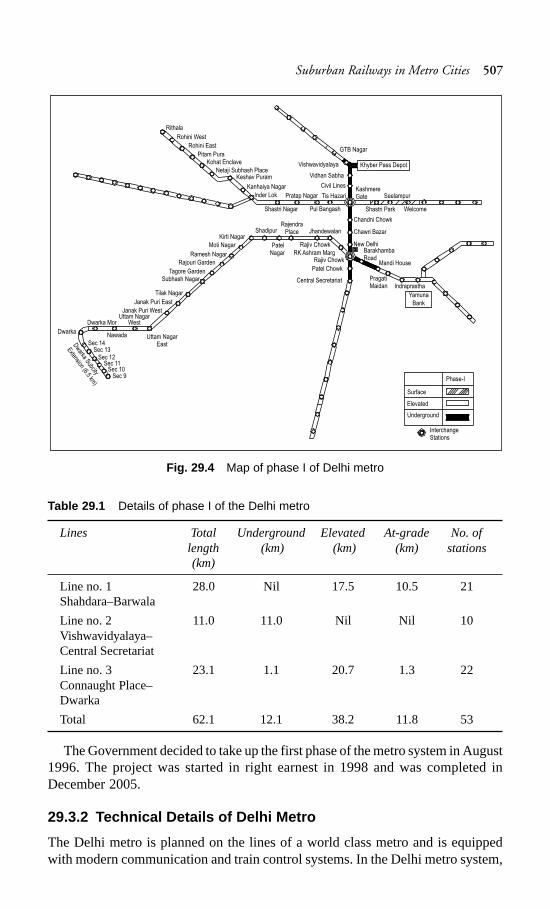
Suburban Railways in Metro Cities 507
Fig. 29.4 Map of phase I of Delhi metro
Table 29.1 Details of phase I of the Delhi metro
Lines Total Underground Elevated At-grade No. oflength (km) (km) (km) stations(km)
Line no. 1 28.0 Nil 17.5 10.5 21Shahdara–Barwala
Line no. 2 11.0 11.0 Nil Nil 10Vishwavidyalaya–Central Secretariat
Line no. 3 23.1 1.1 20.7 1.3 22Connaught Place–Dwarka
Total 62.1 12.1 38.2 11.8 53
The Government decided to take up the first phase of the metro system in August1996. The project was started in right earnest in 1998 and was completed inDecember 2005.
29.3.2 Technical Details of Delhi Metro
The Delhi metro is planned on the lines of a world class metro and is equippedwith modern communication and train control systems. In the Delhi metro system,
GTB Nagar
Khyber Pass DepotVishwavidyalaya
Vidhan Sabha
Civil LinesKashmereGate Seelampur
Shastri Park Welcome
Chandni Chowk
Chawri Bazar
New DelhiBarakhambaRoad
Mandi House
PragatiMaidan Indraprastha
Yamuna
Bank
Tis Hazari
Pul BangashShastri Nagar
Pratap NagarInder Lok
Kanhaiya Nagar
Keshav PuramNetaji Subhash Place
Kohat EnclavePitam Pura
Rohini East
Rohini West
Rithala
Patel Chowk
Central Secretariat
Rajiv Chowk
Rajiv Chowk
Jhandewalan
RK Ashram Marg
RajendraPlace
PatelNagar
ShadipurKirti Nagar
Moti Nagar
Ramesh Nagar
Rajouri Garden
Tagore GardenSubhash Nagar
Tilak Nagar
Janak Puri East
Janak Puri West
Uttam NagarEast
Uttam NagarWestDwarka Mor
NawadaDwarka
Sec 14Sec 13
Sec 12Sec 11
Sec 10Sec 9 Phase-I
Surface
Elevated
Underground
InterchangeStations
Dw
arkaSubcity
Extension(6.5
km)
508 Railway Engineering
trains are available at a three-minute frequency during peak periods. The entrancesand exits of metro stations are monitored by flap doors operated by smart cards.For the convenience of commuters, an adequate number of escalators are installedat the metro stations. A special feature of the Delhi metro will be its integrationultimately with other modes of public transport, enabling the commuters tointerchange between one mode and another. The technical details and designparameters of the Delhi Metro system are briefly described below.
Rolling stock
The rolling stock is the mainstay of a metro rail system. Metro coaches arelightweight, air-conditioned coaches with stainless steel bodies that are equippedwith features such as three-phase ac motors. All systems in the coach are monitoredby a microprocessor-based train integrated management system (TIMS). All coachesare of the same type and each coach is able to accommodate nearly 380 passengers.The coaches have a width of 3.2 m and an overall length of 22 m (including sittingand standing passengers).
Some of the important features of the metro rolling stock are listed below.(a) Automatic electric door closing mechanism.(b) All doors fully open within 2.5 sec and fully close within 2.5 to 3.5 sec.(c) The train cannot move unless all the doors are properly closed and
automatically locked.(d) The train can be halted with the application of the emergency brake, should
a door open during running.(e) Emergency evacuation facility in the form of emergency front door.(f) Emergency illumination and ventilation in the case of a power failure.The initial plan involves running four-coach trains, each consisting of two motor
coaches that are out fitted with propulsion equipment and two driving trailer coaches,with a total carrying capacity of 1500 passengers. Subsequently, six-coach andeight-coach trains are likely to run to meet increasing traffic demands. These trainsare planned to run at an average speed of 32 to 35 km/hr over an average interstationdistance of 1.1 to 1.3 km.
Signalling and train control
Delhi metro trains are provided with the latest signalling technology and controlsystem as described in the subsequent paragraphs.
Signalling It has been decided that the trains plying underground and in surfacecorridors will run at a 3-minute interval in peak hours. The signalling system isdesigned for an ultimate headway of two minutes, with a continuous automaticsignalling system comprising of the following special features.
Automatic train protection Automatic train protection will consist of cabsignalling, whereby the drivers will get information as regards the condition of theline beforehand and so that they can control the speed of the trains in advance asper the track status or obstruction. Normally the driver will apply the brakes in thecase of any perceived obstruction on the track. In case a driver fails to do so, the
Suburban Railways in Metro Cities 509
emergency brakes are applied automatically and all these events are recorded inthe appropriate system device for the purpose of establishing accountability.
Automatic train supervisionAutomatic train supervision (ATS) is a sophisticatedcomputer-based supervisory system, which will take over the critical functions ofthe controller in the control room and will drastically reduce the workload of thestation master. The assistance of ATS is necessary in cases where trains run at aclose headway of 2 minutes. The train describer system of ATS displays the positionsof the trains while they are in motion in visual form in the control room as well asprovide precise information with regard to passengers.
Automatic train operation This feature is required to be provided for undergroundcorridors only. It enables the train to be driven without any human intervention,thereby providing a high level of operational efficiency.
Interlocking of yards An advanced interlocking system with high-speed (50 km/hr) turnouts has been recommended for the yards. The entire section is to be circuitedwith audio frequency track circuits, which should eliminate any failures on accountof the insulated joints giving way, thus requiring replacement.
Telecommunication The telecommunication network between various stationsand services is like a backbone of optic fibre, which will have an enormous capacityfor channelling data and voice communication. It will carry all train controlinformation through telemetry links, which will bear the details regarding therunning of the train and also the data collected by the passenger information system.
Passengers information systemIn the system that has been proposed, the centraltrain describer will provide precise information to the passengers at every platformon a real time basis by furnishing online information through the central computer.All the stations will be provided with centrally synchronized clocks on the variousplatforms to maintain time standards. The public address system will enablecentralized as well as local announcements on all stations platforms.
CCTV system Closed circuit TVs are provided at all the critical locations in thestation premises to monitor every safety aspect.
Power supply
To ensure the continuous availability of quality power for the running of metrotrains, the utmost efforts have been made to plan and design a power supply systemwith the degree of reliability found in other world class metros. The Delhi metrosystem derives its operating power in the form of 25-kV ac traction.
Tracks
The design standards for the track of the metro system are briefly described in thefollowing paragraphs.
Spacing of tracks The metro routes consist of two broad gauge tracks spaced4.10 m apart, which is less than the 4.725 m standard spacing on Indian Railways.The reduced spacing has been feasible due to the fact that the doors of the coachesare closed and none of the doors open outward as is the case with the goods wagons
510 Railway Engineering
of Indian Railways. The points and crossings are 1 in 12 and 1 in 8.5, as in the caseof Indian Railways.
Gradients The steepest gradient permissible is 3.0%. Gradients steeper than 2.5%are adopted only in exceptional cases.
Curves Curves of radius less than 450 m are adopted sparingly on running lines.No curve on a running line may have a radius less than 300 m.
Tracks on stations On stations, tracks are not to be laid on gradient steeper than0.1% (1 in 1000) and they should also not be laid on curves with radius less than1000 m. Vertical curves normally have a radius of 2500 m at points where there isa change in the gradient. In the case of transition curves, the rules followed are thesame as those on Indian Railways. The other features of the metro track are asfollows.
(a) The metro track consists of 60-kg UIC rails on level tracks, which rest onconcrete sleepers and are fixed using elastic fastenings (Pandrol clip mark11). The sleeper density is 1660 sleepers per km.
(b) The ballast cushion is prepared using hard stone ballast and measures 300 mmin thickness.
(c) 60-kg head hardened rails have been used to enhance the service life of therails, particularly on sharp curves and steep gradients.
(d) To minimize the need for track maintenance and reduce the dimensions ofstructures that are consequential to the quality of the run, a ‘ballastless track’is being laid on elevated sections, viaducts, and tunnels. These stretches areprovided with 60-kg rails that are fixed with the help of Vossloh fastenings.
(e) To improve the standard of maintenance and ensure a comfortable ride, railsare mostly welded as long welded rails and efforts have been made to ascertainthat the entire track is almost ‘joint-less’. For this purpose, even the turnoutshave been integrated into the long welded rails. Specially designed turnoutsare used with thick web switches and CMS crossings by means of weldedleg extensions.
Metro stations
There are about 53 metro stations, including 12 underground stations on phase 1of the Delhi metro. Metro stations are normally two-line stations with side or islandplatforms. The platforms are 185 m long, so as to accommodate eight-coach trains.The platform surface lies 1.08 m above the rail level, so that the floor of the coachesis almost level with the platform. The width of the platform is normally 6 m in thecase of side platforms and 10 m in the case of island platforms.
Tracks at stations with side platforms are placed 4.1 m apart, while these withisland platforms, are placed around 13.3 m apart. Stations located in well-populatedareas are normally spaced 1 km apart. The interstation distance can, however, varymarginally to suit site conditions.
Stations situated on an elevated corridor along the central verge of the road canbe provided with tracks at a height of about 12 m above the road level. Most of theunderground metro stations are generally two-level stations between 270 m to 300 min length. A typical station is 20 m wide and 15 m deep. The first level boasts of
Suburban Railways in Metro Cities 511
various passenger facilities together with ventilation and electronics andcommunication equipment rooms and the lower level comprises the platform withelectric equipment rooms at each end of the box. Island platforms are providedwith stations that are adjacent to board tunnel sections while side platforms areprovided with cut and cover tunnels. All stations have been designed with theoption to accommodate platform screen doors.
29.3.3 Civil Works
Some of the new technologies and innovations in construction techniques that arebeing deployed for the Delhi MRTS are briefly mentioned here.
Construction of bridges
Several innovative construction techniques were used in the construction of thebridges. For example, a new Yamuna bridge (12 spans of 46.2 m each) wasconstructed using modern techniques during the construction of the Delhi Metro.The substructure of this bridge consists of capsule-shaped piers that rest on well(caisson) foundations of 10 m diameter with a steining thickness of 1.0 m, whichhave been sunk up to a depth of about 39 m. The ‘jack-down’ method, supplementedwith air/water jetting, has been used for sinking the wells. This method involvedpushing the well assembly down into the ground by applying pressure to counterthe resistance arising due to skin friction around the periphery of the wells andbelow the cutting edge. Soil dredging has been carried out inside the wellsimultaneously. The new techniques resulted in the faster sinking of the wells.Also, the wells have been sunk plumb into the water with the help of minimum tiltsor shifts.
The superstructure of the bridge comprises of a single box girder of a constantdepth of 3.5 m that has been launched using an incremental launching technique.This technique involved casting the girder on the bridge approach behind theabutment in segments of length 23.1 m, which is half the length of one span. Eachsegment has been cast behind the previous unit. After a sufficient concrete strengthwas attained, the new unit was post-tensioned to the previous one. The assemblyof units was pushed forward to permit the casting of the succeeding segment. Thistechnique resulted in a single continuous girder of a length of 554 m with nojoints.
The innovative features of the Yamuna bridge are summarized below.(a) Second incrementally launched bridge in India, the first being the Panvel
Nadi bridges of the Konkan Railway.(b) First box girder in India carrying dual unballasted tracks.(c) An innovative technique for sinking the wells; the jack-down method has
been adopted for sinking 15 wells. Ground anchors have been installed nearthe well staining, which have been used for taking the reaction of the speciallydesigned hydraulic jacks at the top.
512 Railway Engineering
Elevated viaduct
The elevated viaduct simply comprises of supported spans with lengths varyingfrom 21.1 m to 29.1 m. It has been constructed by the precast segmental techniquewith epoxy bonded joints and traditional internal pre-stressing. The span lengthshave been determined mainly on the basis of the site constraints at the ground levelfor the location of the foundations and piers. All precasting has been done at acentralized casting yard.
An aesthetic form of the substructure has been evolved so as to harmonize withthe flow of the forces. In this structure the pier gradually tapers outward at the topto support the bearings under the box webs. All the piers have been cast in placeusing rigid steel which was poured in a single attempt in order to avoid anyconstruction joints. The use of bolts in the concrete has not been permitted. Boredpiles of a diameter of 1.2 m that have been cast in situ have been included byemploying modern hydraulic rigs. To ensure a standard span, groups of nine pileswith a length of 23 m to 28 m have been stacked in the soil. In rocky terrains, pileshave been stacked in the rock in groups of six up to a depth equal to 1.5 to 3.0times the diameter of the pile, depending on the type of rock encountered. Atemporary casing has been employed for the stabilization of the bore holes.
Cut and cover tunnels
It is possible to construct tunnels by excavating the ground surface, hence the cutand cover method has been employed for tunnel construction in these stretches.Cut and cover tunnels are generally designed as a single structural unit with adividing wall, and walkways for each track giving an average box width of 10 m.The over-run tunnels are used as sidings and contain three tracks while at the depotspur the tunnels contain four tracks. The construction methodology for cut andcover tunnels is similar to that of cut and cover stations.
Cut and cover construction, though economical, results in a lot of publicinconvenience if planned improperly. As such, it requires exhaustive planning withregard to utilities, traffic management, and environmental concerns such as cuttingof trees and air and noise pollution.
Bored tunnel construction
The bored tunnel construction technique has been used at many places in the metrocorridor tunnels. The internal diameter of such tunnels is about 5.6 m and they aregenerally lined with precast reinforced concrete segments. Tunnel boring machines(TBMs) have been used in place of conventional tunnelling methods that employingvarious hand mining techniques, since conventional tunnelling methods suffer frommajor handicaps with regard to slower progress and risks to existing structures inthe vicinity of tunnel excavation.
Since the bored tunnel construction for the Delhi metro involved tunnellingthrough both quartzite and soft ground, two types of TBMs have been used, namely,rock TBM for rocky ground and earth pressure balance machine (EPBM) for softground. In the case of an EPBM, the excavated face is supported by pressurizingthe soil that has been dug up, together with additives if necessary, to give it a
Suburban Railways in Metro Cities 513
plastic texture. A screw auger is used to remove the excavated material. The earthpressure within the cutter head is maintained by balancing the rate at which itadvances with the rate at which the spoil material is removed and adjusting theparameters as required. The gap between the excavation surface and the precastconcrete lining is filled by means of an automatic injection from the tail of themachine, which minimizes ground settlement. Watertightness at the tail is ensuredby injecting grease into the three rows of brush seals.
29.3.4 Underground Versus Elevated Alignment
Underground construction is a much costlier option than elevated alignment. Thecurrent average cost per route kilometre for construction on an elevated alignment,including stations, rolling stock, signalling, and electrical equipment as well asland and incidental works, is Rs 1000 million as compared to Rs 3000 million forunderground construction. On account of the vast cost difference, the choice ofunderground construction is restricted to areas where elevated alignment is notsuitable. In the case of Delhi metro, underground construction is restricted to thecore area of Delhi on the North–South and East–West corridors, which intersect inthe Connaught Place area. Most of the route length outside the core area is likelyto be constructed as an elevated route.
In the case of elevated segments of the MRTS, the alignment on city roadsusually follows the central verge of the road. Piers of about 2 m diameter arespaced 20–30 m apart along the central verge. The arrangement of girders abovethe pier cap is shown in the general arrangement given in Fig. 29.5. Tracks aregenerally laid 8.5–9.5 m above the road level on elevated routes outside the station.The desirable minimum width of the roads for locating an elevated MRTS on thesame is 30 m, although a road width of 40–45 m is preferable. The geometry of theroad should be favourable for the adoption of curves adhering to the minimumMRTS standards. In the case of underground construction on stretches outside thestation, the rail level lies at a minimum depth of 9 m below the road surface. Thisis done with the object of 2–3 m of space below the road for electrical cables,telephone cables, and drains.
A corridor need not be wholly underground or elevated. An underground corridorin the core city area could get converted into an elevated corridor in the outer parts,where the conditions are favourable for such constructions. It is crucial that anextra stretch of aligned road surface be available between the point where theunderground section ends and the elevated section starts. The alignment in thisstretch should rise from about 9 m below the ground to 9 m above the road level. Inorder to ensure that the length of the at-grade stretch is not unduly long, the tracksare provided with a steep gradient for negotiating this difference in the level. Thisstretch can measure 400–500 m in length depending on the site characteristics.
In the at-grade stretch, the MRTS tracks are walled on both sides, their outerfaces being nearly 10 m apart. This implies that the road width is effectively reducedby about 11 m on this stretch. This factor is of great importance in choosing thelocation for an at-grade ramp.
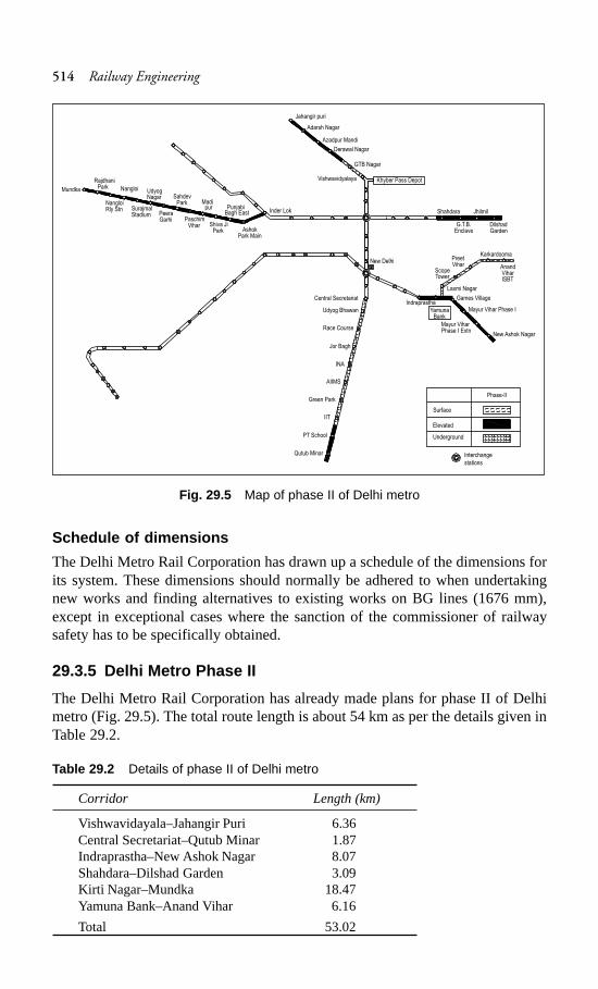
514 Railway Engineering
Fig. 29.5 Map of phase II of Delhi metro
Schedule of dimensions
The Delhi Metro Rail Corporation has drawn up a schedule of the dimensions forits system. These dimensions should normally be adhered to when undertakingnew works and finding alternatives to existing works on BG lines (1676 mm),except in exceptional cases where the sanction of the commissioner of railwaysafety has to be specifically obtained.
29.3.5 Delhi Metro Phase II
The Delhi Metro Rail Corporation has already made plans for phase II of Delhimetro (Fig. 29.5). The total route length is about 54 km as per the details given inTable 29.2.
Table 29.2 Details of phase II of Delhi metro
Corridor Length (km)
Vishwavidayala–Jahangir Puri 6.36Central Secretariat–Qutub Minar 1.87Indraprastha–New Ashok Nagar 8.07Shahdara–Dilshad Garden 3.09Kirti Nagar–Mundka 18.47Yamuna Bank–Anand Vihar 6.16
Total 53.02
Jahangir puri
Adarsh Nagar
Azadpur Mandi
Derawal Nagar
GTB Nagar
Khyber Pass DepotVishwavidyalaya
G.T.B.Enclave
DilshadGarden
Shahdara Jhilmil
New Delhi
Indraprastha
YamunaBank
Laxmi Nagar
ScopeTower
PreetVihar
Karkardooma
AnandViharISBT
Games Village
Mayur Vihar Phase I
New Ashok Nagar
Mayur ViharPhase I Extn
Inder Lok
AshokPark Main
Shiva JiPark
PaschimVihar
PeeraGarhi
PunjabiBagh East
Madipur
SahdevPark
SurajmalStadium
NangloiRly Stn
Mundka UdyogNagar
Nangloi
RajdhaniPark
Central Secretariat
Udyog Bhawan
Race Course
Jor Bagh
INA
AIIMS
Green Park
IIT
PT School
Qutub Minar
Phase-II
Surface
Elevated
Underground
Interchange
stations
Suburban Railways in Metro Cities 515
The preparation of detailed project reports for the corridors of phase II of theDelhi metro is complete and the Government of Delhi has already made budgetaryprovisions for the same. Work on phase II is scheduled to be completed before2010.
With the success of the Delhi metro, several state governments have approachedthe DMRC for preparing detailed project reports for metros for their cities. Suchreports have already been prepared for Bangalore and Hyderabad and submitted tothe Karnataka and Andhra Pradesh state governments, respectively. Investigations/studies are presently underway for the preparation of detailed project reports forconstructing metro rail systems in Mumbai, Ahmedabad, Kolkata, and Kochi.
29.4 Kolkata Metro
Most of the suburban traffic in Kolkata is borne by Eastern Railways for distancesextending to over 100 km. On the South-Eastern Railway, the suburban sectionsextend from Howrah to Balichak, which lie at a distance of 92 km from each other.The railway system in Kolkata terminates at Howrah on one side and Sealdah onthe other, both of which lie on the periphery of the central business district ofKolkata. In view of this, commuters have to cover the distances within the city byother modes of transport or on foot.
City buses carry a major portion of commuters from one place to another place.Besides the suburban rail and bus transport services, the tramways are an importantmode of mass transport system in Kolkata. The Kolkata Tramway Company hasabout 400 trams. The underground metro railway in Kolkata started functioningfrom 24 October 1984 between Esplanade and Bhawanipore. It stretches fromDum Dum to Tollygunge and covers a route length of 16.45 km. The constructionwork of this underground railway was done by the cut and cover method in theopen area. However, the driven shield tunnelling method was adopted whereverthe metro alignment passed under residential buildings or a canal.
29.4.1 New Technologies used in Kolkata Metro
The construction of a metro is of a very complex nature requiring the applicationof several new technologies in the fields of civil, electrical, signalling, andtelecommunication engineering. For the first time in India, engineers, backed bytheir own experience and supplemented by the knowledge gained through theirstudies abroad, have incorporated the following advanced technologies with regardto the construction of the Kolkata metro.
(a) Cut and cover method of construction using diaphragm walls and sheet piles.(b) Use of extensive decking to keep the traffic flowing over the cut while
construction was in progress underneath.(c) Shield tunnelling using compressed air and airlocks.(d) Integration of a ballastless track using elastic fastenings, rubber pads, epoxy
mortar, and nylon inserts.(e) Air conditioning and ventilation system for controlling the atmosphere of
stations and tunnels.
516 Railway Engineering
(f) Third rail current collection system for traction.(g) Underground substations with dry-type transformers and SF-6 circuit
breakers.(h) Continuous automatic train control system.(i) Tunnel-train VHF-radio communication system.(j) Train control and supervisory remote control systems fitted with
microprocessors for substations.(k) Automatic ticket vending and checking system.
29.4.2 Benefits of Kolkata Metro
The Kolkata metro, like all other mass rapid transit systems in the world, cannot befinancially remunerative, as subsidies are inevitable in the operation of such anexpansive system. However, introducing a system that covers the entire city hasresulted in the following benefits to the public.
(a) The social benefits of the Kolkata metro far outweigh the burden of thesubsidies.
(b) It carries more than 0.5 million commuters per day in trains that follow eachother at intervals of about 5 min during the peak hours.
(c) The commuters are assured of a pollution-free, safe, punctual, andcomfortable journey.
(d) Commuting time is drastically reduced.The salient features of the Kolkata metro are listed in Table 29.3.
Table 29.3 Salient features of Kolkata metro railway
Features Details
Total route length 16.45 kmNo. of stations 17Coaches per train 8Maximum permissible speed 55 km/hAverage speed 30 km/hVoltage 750-V dcTotal power requirement 94 million kwhMethod of current collection Third railTravel time fromDum Dum to Tollygunge 33 minDum Dum to Girish Park 11 min.Tollygunge to Central 18 min.Capacity of each coach 278 standing, 48 sittingCapacity of each train 2500 passengers (approx.)Interval between trains 5.5 minutes in peak hoursEstimated cost Rs 15.4 billion (at 1993–94 rates)Environment control Forced ventilation with washed and cooled air
The expansion of the Kolkata metro is also being planned. The detailed projectreport for the East-West corridor from New Dass Nagar to Salt Lake Sector 5 hasbeen submitted to the State Government by the DMRC. The corridor is 16 km long
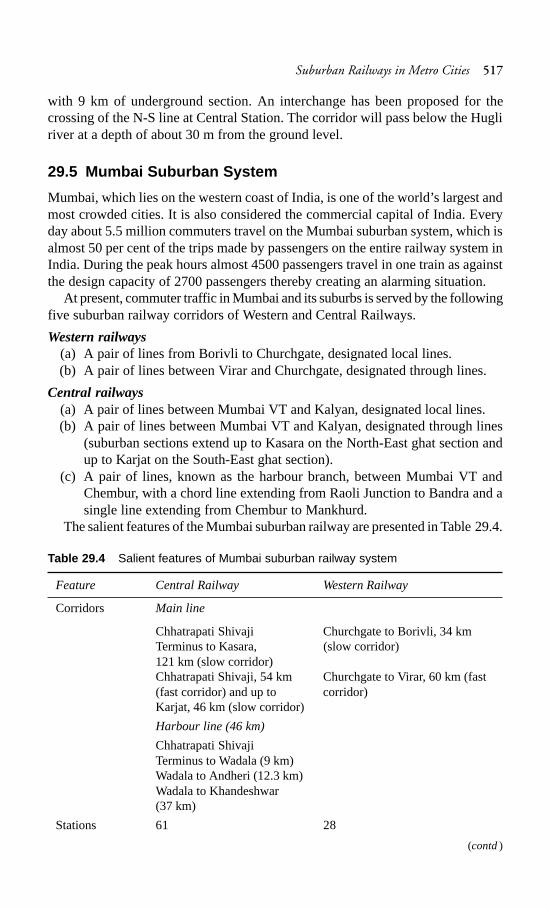
Suburban Railways in Metro Cities 517
with 9 km of underground section. An interchange has been proposed for thecrossing of the N-S line at Central Station. The corridor will pass below the Hugliriver at a depth of about 30 m from the ground level.
29.5 Mumbai Suburban System
Mumbai, which lies on the western coast of India, is one of the world’s largest andmost crowded cities. It is also considered the commercial capital of India. Everyday about 5.5 million commuters travel on the Mumbai suburban system, which isalmost 50 per cent of the trips made by passengers on the entire railway system inIndia. During the peak hours almost 4500 passengers travel in one train as againstthe design capacity of 2700 passengers thereby creating an alarming situation.
At present, commuter traffic in Mumbai and its suburbs is served by the followingfive suburban railway corridors of Western and Central Railways.
Western railways(a) A pair of lines from Borivli to Churchgate, designated local lines.(b) A pair of lines between Virar and Churchgate, designated through lines.
Central railways(a) A pair of lines between Mumbai VT and Kalyan, designated local lines.(b) A pair of lines between Mumbai VT and Kalyan, designated through lines
(suburban sections extend up to Kasara on the North-East ghat section andup to Karjat on the South-East ghat section).
(c) A pair of lines, known as the harbour branch, between Mumbai VT andChembur, with a chord line extending from Raoli Junction to Bandra and asingle line extending from Chembur to Mankhurd.
The salient features of the Mumbai suburban railway are presented in Table 29.4.
Table 29.4 Salient features of Mumbai suburban railway system
Feature Central Railway Western Railway
Corridors Main line
Chhatrapati Shivaji Churchgate to Borivli, 34 kmTerminus to Kasara, (slow corridor)121 km (slow corridor)Chhatrapati Shivaji, 54 km Churchgate to Virar, 60 km (fast(fast corridor) and up to corridor)Karjat, 46 km (slow corridor)
Harbour line (46 km)
Chhatrapati ShivajiTerminus to Wadala (9 km)Wadala to Andheri (12.3 km)Wadala to Khandeshwar(37 km)
Stations 61 28
(contd)
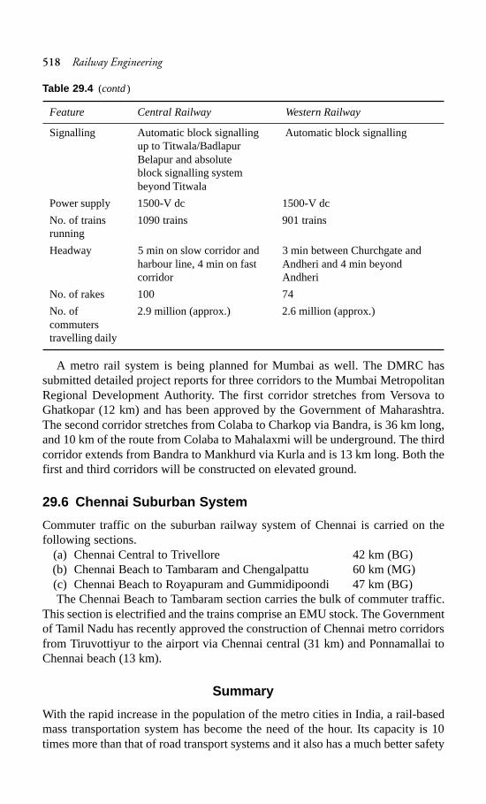
518 Railway Engineering
Feature Central Railway Western Railway
Signalling Automatic block signalling Automatic block signallingup to Titwala/BadlapurBelapur and absoluteblock signalling systembeyond Titwala
Power supply 1500-V dc 1500-V dc
No. of trains 1090 trains 901 trainsrunning
Headway 5 min on slow corridor and 3 min between Churchgate andharbour line, 4 min on fast Andheri and 4 min beyondcorridor Andheri
No. of rakes 100 74
No. of 2.9 million (approx.) 2.6 million (approx.)commuterstravelling daily
A metro rail system is being planned for Mumbai as well. The DMRC hassubmitted detailed project reports for three corridors to the Mumbai MetropolitanRegional Development Authority. The first corridor stretches from Versova toGhatkopar (12 km) and has been approved by the Government of Maharashtra.The second corridor stretches from Colaba to Charkop via Bandra, is 36 km long,and 10 km of the route from Colaba to Mahalaxmi will be underground. The thirdcorridor extends from Bandra to Mankhurd via Kurla and is 13 km long. Both thefirst and third corridors will be constructed on elevated ground.
29.6 Chennai Suburban System
Commuter traffic on the suburban railway system of Chennai is carried on thefollowing sections.
(a) Chennai Central to Trivellore 42 km (BG)(b) Chennai Beach to Tambaram and Chengalpattu 60 km (MG)(c) Chennai Beach to Royapuram and Gummidipoondi 47 km (BG)The Chennai Beach to Tambaram section carries the bulk of commuter traffic.
This section is electrified and the trains comprise an EMU stock. The Governmentof Tamil Nadu has recently approved the construction of Chennai metro corridorsfrom Tiruvottiyur to the airport via Chennai central (31 km) and Ponnamallai toChennai beach (13 km).
Summary
With the rapid increase in the population of the metro cities in India, a rail-basedmass transportation system has become the need of the hour. Its capacity is 10times more than that of road transport systems and it also has a much better safety
Table 29.4 (contd)
Suburban Railways in Metro Cities 519
record. The Delhi metro has been a successful experiment and other stategovernments are also preparing plans for introducing a similar system in theirmetro cities.
Review Questions
1. Distinguish between surface and underground railway systems. Enumeratethe factors that favour the selection of one over the other.
2. In what way has the underground railway system assumed considerableimportance and promise for the metropolitan transport system? Describe brieflythe principle tasks involved in the construction of an underground railwaysystem.
3. Briefly state the problems of a metro tube railway.4. What do you understand by a metropolitan town? What are the problems of a
metropolitan town with regard to its transport system?5. Discuss briefly the various types of transport that can be provided in a
metropolitan town and the relative advantages and limitations of the same.6. What are the essential features of an underground railway? What do you
understand by the cut and cover method of construction of an undergroundrailway?
7. Briefly discuss the problem of transport in Delhi. Give the salient details ofthe MRTS scheme of Delhi.
8. What are the salient features of the Kolkata metro railway? Enumerate thetechnologies used in its construction.
520 Railway Engineering
Railway Tunnelling
Introduction
A tunnel can be defined as an underground passage for the transport of passengers,goods, water, sewage, oil, gas, etc. The construction of a tunnel is normally carriedout without causing much disturbance to the ground surface.
The history of tunnels is very old. The first tunnel was constructed about 4000years ago in Babylon to connect two buildings. The first railway tunnel in theworld was constructed at the end of the nineteenth century to connect Switzerlandand Italy. The cross section of the tunnel was in the shape of a horseshoe and itslength was about 20 km. On Indian Railways, the first tunnel was constructed nearThane on Central Railways known as the Parsik tunnel. It is the longest railwaytunnel of India with a length of about 1317 m.
30.1 Necessity/Advantages of a Tunnel
The necessity of constructing a tunnel may arise because of one of the followingconsiderations.
(a) A tunnel may be required to eliminate the need for a long and circuitousroute for reaching the other side of a hill, as it would considerably reducethe length of the railway line and may also prove to be economical.
(b) It may be economical to provide a tunnel instead of a cutting, particularly ina rocky terrain. Depending upon various factors, a rough calculation wouldindicate that for a small stretch of land the cost of constructing a tunnel isequal to the cost of a cutting in a rocky terrain.
(c) In hills with soft rocks, a tunnel is cheaper than a cutting.(d) In metropolitan towns and other large cities, tunnels are constructed to
accomodate underground railway systems in order to provide a rapid andunobstructed means of transport.
(e) A tunnel constructed under a river bed may sometimes prove to be moreeconomical and convenient than a bridge.
(f) In the case of aerial warfare transportation through tunnels provides bettersafety and security to rail users compared to a bridge or deep cutting.
(g) The maintenance cost of a tunnel is considerably lower than that of a bridgeor deep cutting.
CHAPTER
30
Railway Tunnelling 521
However, the construction of tunnels is also disadvantageous in certain ways,as enumerated here.
(a) The construction of a tunnel is costly as it requires special constructionmachinery and equipment.
(b) The construction of a tunnel involves the use of sophisticated technologyand requires experienced and skilled staff.
(c) It is a time-consuming process.
30.2 Tunnel Alignment and Gradient
A precise and detailed survey is necessary before setting the alignment of a tunnelon the ground. A small error in setting the alignment would result in the two endsnever meeting at all. When starting work, both the ends of the tunnel as well as thecentre line are marked with precision on the ground so that the correct length ofthe tunnel can be determined. An accurate survey is then carried out to ensure thatthe centre line of the alignment and the levels are transferred properly to theirunderground positions.
The following points require special attention when deciding the alignment andgradient of a tunnel.
(a) The alignment should be straight as far as possible since normally such aroute would be the shortest and most economical.
(b) The minimum possible gradient should be provided for a tunnel and itsapproaches.
(c) Proper ventilation and adequate lighting should be provided inside the tunnel.(d) The side drains in a tunnel should be given a minimum gradient of 1 in 500
for effective drainage. In longer tunnels, the gradient should be providedfrom the centre towards the ends for effective and efficient drainage.
30.3 Size and Shape of a Tunnel
The size and shape of a tunnel depend upon the nature and type of ground it passesthrough and also on whether it is designed to carry a single or a double railwayline. The shape of a tunnel should be such that the lining is able to resist the pressuresexerted by the unsupported walls of the tunnel excavation.
If the ground is made up of solid rock, then the tunnel can be given any shape.Tunnels in rocky terrains are generally designed with a semicircular arch withvertical sidewalls. In the case of soft ground such as that consisting of soft clay orsand, the pressure from the sides and the top must be resisted. A circular tunnel isgenerally best suited for resisting both internal and external forces regardless ofthe purpose for which the tunnel is used. Theoretically, a circular section providesthe largest cross-sectional area for the smallest diameter, which provides greaterresistance to external pressure. But this type of cross section is more useful fordrains carrying sewage and fluids and for aquaducts built for irrigation purposes.For railway track, the circular portion at the bottom of the tunnel has to be levelledin order to lay the track and facilitate the easy removal of muck and placing ofconcrete. The typical cross section of a tunnel is shown in Fig. 30.1. The sections
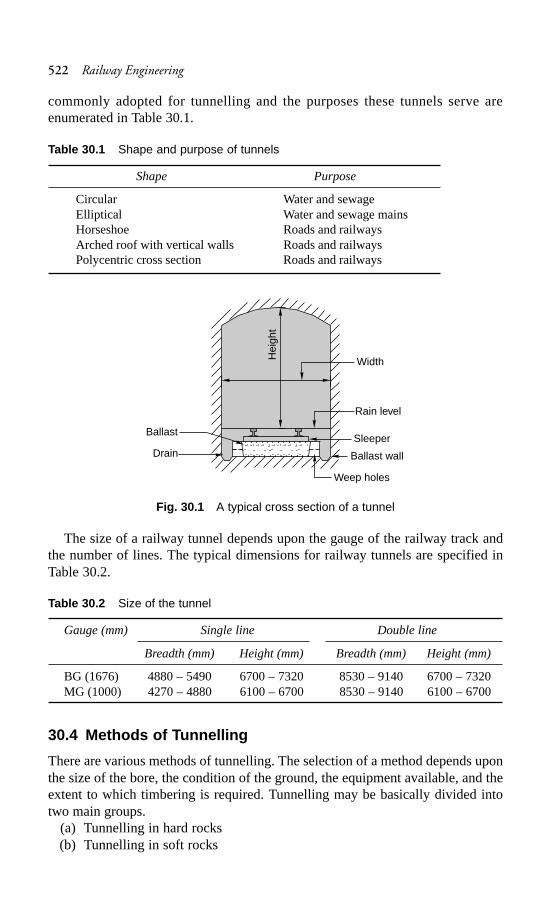
522 Railway Engineering
commonly adopted for tunnelling and the purposes these tunnels serve areenumerated in Table 30.1.
Table 30.1 Shape and purpose of tunnels
Shape Purpose
Circular Water and sewageElliptical Water and sewage mainsHorseshoe Roads and railwaysArched roof with vertical walls Roads and railwaysPolycentric cross section Roads and railways
Fig. 30.1 A typical cross section of a tunnel
The size of a railway tunnel depends upon the gauge of the railway track andthe number of lines. The typical dimensions for railway tunnels are specified inTable 30.2.
Table 30.2 Size of the tunnel
Gauge (mm) Single line Double line
Breadth (mm) Height (mm) Breadth (mm) Height (mm)
BG (1676) 4880 – 5490 6700 – 7320 8530 – 9140 6700 – 7320MG (1000) 4270 – 4880 6100 – 6700 8530 – 9140 6100 – 6700
30.4 Methods of Tunnelling
There are various methods of tunnelling. The selection of a method depends uponthe size of the bore, the condition of the ground, the equipment available, and theextent to which timbering is required. Tunnelling may be basically divided intotwo main groups.
(a) Tunnelling in hard rocks(b) Tunnelling in soft rocks
Ballast
Drain Ballast wall
Sleeper
Rain level
Width
Weep holes
Hei
ght
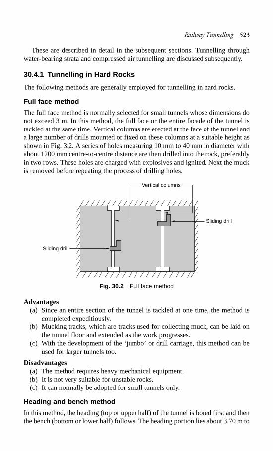
Railway Tunnelling 523
These are described in detail in the subsequent sections. Tunnelling throughwater-bearing strata and compressed air tunnelling are discussed subsequently.
30.4.1 Tunnelling in Hard Rocks
The following methods are generally employed for tunnelling in hard rocks.
Full face method
The full face method is normally selected for small tunnels whose dimensions donot exceed 3 m. In this method, the full face or the entire facade of the tunnel istackled at the same time. Vertical columns are erected at the face of the tunnel anda large number of drills mounted or fixed on these columns at a suitable height asshown in Fig. 3.2. A series of holes measuring 10 mm to 40 mm in diameter withabout 1200 mm centre-to-centre distance are then drilled into the rock, preferablyin two rows. These holes are charged with explosives and ignited. Next the muckis removed before repeating the process of drilling holes.
Fig. 30.2 Full face method
Advantages(a) Since an entire section of the tunnel is tackled at one time, the method is
completed expeditiously.(b) Mucking tracks, which are tracks used for collecting muck, can be laid on
the tunnel floor and extended as the work progresses.(c) With the development of the ‘jumbo’ or drill carriage, this method can be
used for larger tunnels too.
Disadvantages(a) The method requires heavy mechanical equipment.(b) It is not very suitable for unstable rocks.(c) It can normally be adopted for small tunnels only.
Heading and bench method
In this method, the heading (top or upper half) of the tunnel is bored first and thenthe bench (bottom or lower half) follows. The heading portion lies about 3.70 m to
Sliding drill
Sliding drill
Vertical columns
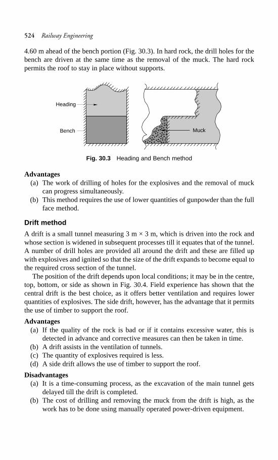
524 Railway Engineering
4.60 m ahead of the bench portion (Fig. 30.3). In hard rock, the drill holes for thebench are driven at the same time as the removal of the muck. The hard rockpermits the roof to stay in place without supports.
Fig. 30.3 Heading and Bench method
Advantages(a) The work of drilling of holes for the explosives and the removal of muck
can progress simultaneously.(b) This method requires the use of lower quantities of gunpowder than the full
face method.
Drift method
A drift is a small tunnel measuring 3 m × 3 m, which is driven into the rock andwhose section is widened in subsequent processes till it equates that of the tunnel.A number of drill holes are provided all around the drift and these are filled upwith explosives and ignited so that the size of the drift expands to become equal tothe required cross section of the tunnel.
The position of the drift depends upon local conditions; it may be in the centre,top, bottom, or side as shown in Fig. 30.4. Field experience has shown that thecentral drift is the best choice, as it offers better ventilation and requires lowerquantities of explosives. The side drift, however, has the advantage that it permitsthe use of timber to support the roof.
Advantages(a) If the quality of the rock is bad or if it contains excessive water, this is
detected in advance and corrective measures can then be taken in time.(b) A drift assists in the ventilation of tunnels.(c) The quantity of explosives required is less.(d) A side drift allows the use of timber to support the roof.
Disadvantages(a) It is a time-consuming process, as the excavation of the main tunnel gets
delayed till the drift is completed.(b) The cost of drilling and removing the muck from the drift is high, as the
work has to be done using manually operated power-driven equipment.
Heading
Bench Muck
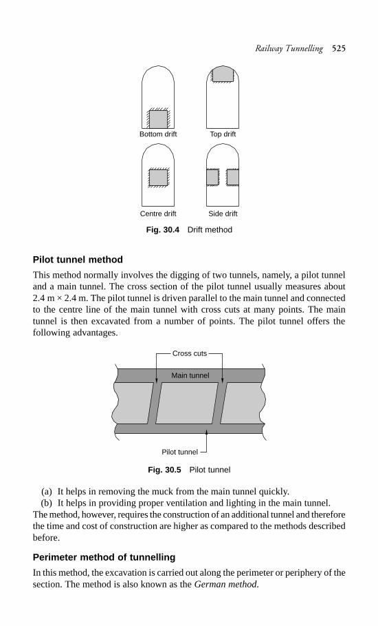
Railway Tunnelling 525
Fig. 30.4 Drift method
Pilot tunnel method
This method normally involves the digging of two tunnels, namely, a pilot tunneland a main tunnel. The cross section of the pilot tunnel usually measures about2.4 m × 2.4 m. The pilot tunnel is driven parallel to the main tunnel and connectedto the centre line of the main tunnel with cross cuts at many points. The maintunnel is then excavated from a number of points. The pilot tunnel offers thefollowing advantages.
Fig. 30.5 Pilot tunnel
(a) It helps in removing the muck from the main tunnel quickly.(b) It helps in providing proper ventilation and lighting in the main tunnel.
The method, however, requires the construction of an additional tunnel and thereforethe time and cost of construction are higher as compared to the methods describedbefore.
Perimeter method of tunnelling
In this method, the excavation is carried out along the perimeter or periphery of thesection. The method is also known as the German method.
Bottom drift Top drift
Centre drift Side drift
Pilot tunnel
Cross cuts
Main tunnel
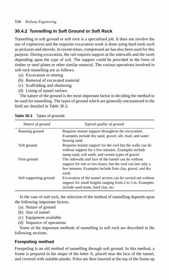
526 Railway Engineering
30.4.2 Tunnelling in Soft Ground or Soft Rock
Tunnelling in soft ground or soft rock is a specialized job. It does not involve theuse of explosives and the requisite excavation work is done using hard tools suchas pickaxes and shovels. In recent times, compressed air has also been used for thispurpose. During excavation, the rail requires support at the sidewalls and the roofsdepending upon the type of soil. The support could be provided in the form oftimber or steel plates or other similar material. The various operations involved insoft rock tunnelling are as follows.
(a) Excavation or mining(b) Removal of excavated material(c) Scaffolding and shuttering(d) Lining of tunnel surfaceThe nature of the ground is the most important factor in deciding the method to
be used for tunnelling. The types of ground which are generally encountered in thefield are detailed in Table 30.3.
Table 30.3 Types of grounds
Nature of ground Typical quality of ground
Running ground Requires instant support throughout the excavation.Examples include dry sand, gravel, silt, mud, and waterbearing sand.
Soft ground Requires instant support for the roof but the walls can dowithout support for a few minutes. Examples includedamp sand, soft earth, and certain types of gravel.
Firm ground The sidewalls and face of the tunnel can do withoutsupport for one or two hours, but the roof can last only afew minutes. Examples include firm clay, gravel, and dryearth.
Self-supporting ground Excavation of the tunnel section can be carried out withoutsupport for small lengths ranging from 2 to 5 m. Examplesinclude sand stone, hard clay, etc.
In the case of soft rock, the selection of the method of tunnelling depends uponthe following important factors.
(a) Nature of ground(b) Size of tunnel(c) Equipment available(d) Sequence of operationsSome of the important methods of tunnelling in soft rock are described in the
following sections.
Forepoling method
Forepoling is an old method of tunnelling through soft ground. In this method, aframe is prepared in the shape of the letter A, placed near the face of the tunnel,and covered with suitable planks. Poles are then inserted at the top of the frame up
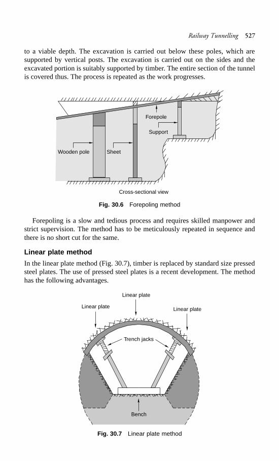
Railway Tunnelling 527
to a viable depth. The excavation is carried out below these poles, which aresupported by vertical posts. The excavation is carried out on the sides and theexcavated portion is suitably supported by timber. The entire section of the tunnelis covered thus. The process is repeated as the work progresses.
Fig. 30.6 Forepoling method
Forepoling is a slow and tedious process and requires skilled manpower andstrict supervision. The method has to be meticulously repeated in sequence andthere is no short cut for the same.
Linear plate method
In the linear plate method (Fig. 30.7), timber is replaced by standard size pressedsteel plates. The use of pressed steel plates is a recent development. The methodhas the following advantages.
Fig. 30.7 Linear plate method
Wooden pole Sheet
Forepole
Support
Cross-sectional view
Linear plate
Linear plate
Linear plate
Trench jacks
Bench
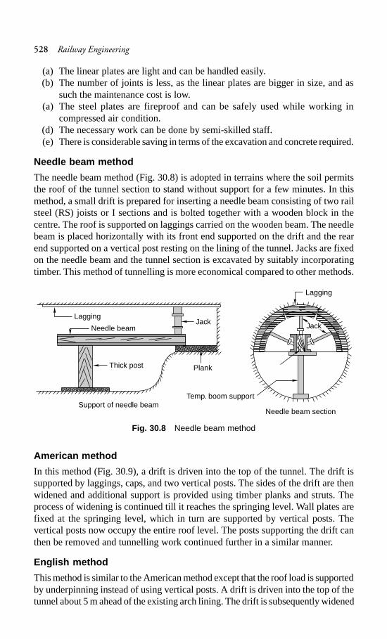
528 Railway Engineering
(a) The linear plates are light and can be handled easily.(b) The number of joints is less, as the linear plates are bigger in size, and as
such the maintenance cost is low.(a) The steel plates are fireproof and can be safely used while working in
compressed air condition.(d) The necessary work can be done by semi-skilled staff.(e) There is considerable saving in terms of the excavation and concrete required.
Needle beam method
The needle beam method (Fig. 30.8) is adopted in terrains where the soil permitsthe roof of the tunnel section to stand without support for a few minutes. In thismethod, a small drift is prepared for inserting a needle beam consisting of two railsteel (RS) joists or I sections and is bolted together with a wooden block in thecentre. The roof is supported on laggings carried on the wooden beam. The needlebeam is placed horizontally with its front end supported on the drift and the rearend supported on a vertical post resting on the lining of the tunnel. Jacks are fixedon the needle beam and the tunnel section is excavated by suitably incorporatingtimber. This method of tunnelling is more economical compared to other methods.
Fig. 30.8 Needle beam method
American method
In this method (Fig. 30.9), a drift is driven into the top of the tunnel. The drift issupported by laggings, caps, and two vertical posts. The sides of the drift are thenwidened and additional support is provided using timber planks and struts. Theprocess of widening is continued till it reaches the springing level. Wall plates arefixed at the springing level, which in turn are supported by vertical posts. Thevertical posts now occupy the entire roof level. The posts supporting the drift canthen be removed and tunnelling work continued further in a similar manner.
English method
This method is similar to the American method except that the roof load is supportedby underpinning instead of using vertical posts. A drift is driven into the top of thetunnel about 5 m ahead of the existing arch lining. The drift is subsequently widened
Lagging
Needle beam
Thick post
Jack
Plank
Support of needle beamNeedle beam section
Temp. boom support
Lagging
Jack
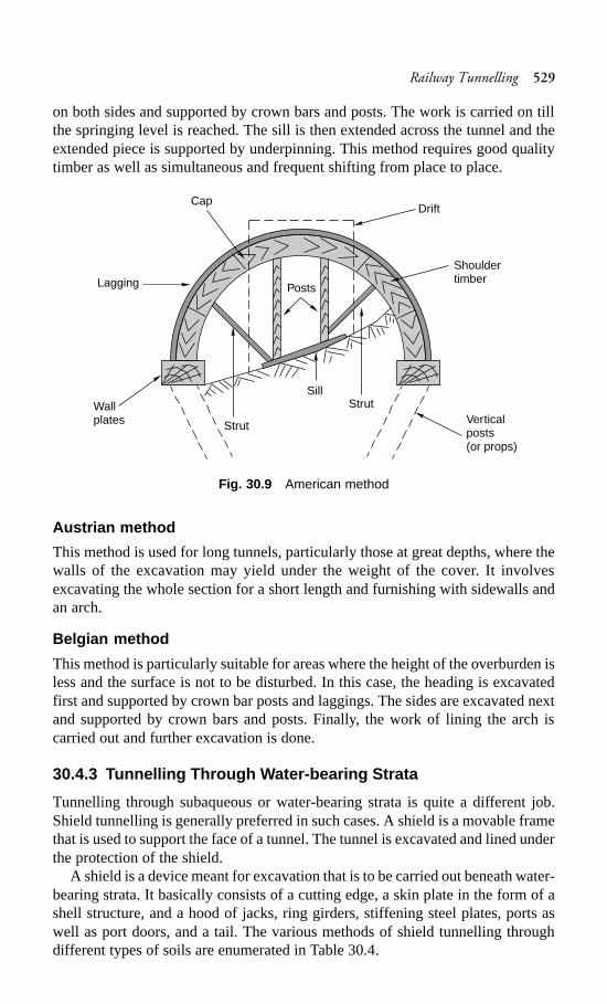
Railway Tunnelling 529
on both sides and supported by crown bars and posts. The work is carried on tillthe springing level is reached. The sill is then extended across the tunnel and theextended piece is supported by underpinning. This method requires good qualitytimber as well as simultaneous and frequent shifting from place to place.
Fig. 30.9 American method
Austrian method
This method is used for long tunnels, particularly those at great depths, where thewalls of the excavation may yield under the weight of the cover. It involvesexcavating the whole section for a short length and furnishing with sidewalls andan arch.
Belgian method
This method is particularly suitable for areas where the height of the overburden isless and the surface is not to be disturbed. In this case, the heading is excavatedfirst and supported by crown bar posts and laggings. The sides are excavated nextand supported by crown bars and posts. Finally, the work of lining the arch iscarried out and further excavation is done.
30.4.3 Tunnelling Through Water-bearing Strata
Tunnelling through subaqueous or water-bearing strata is quite a different job.Shield tunnelling is generally preferred in such cases. A shield is a movable framethat is used to support the face of a tunnel. The tunnel is excavated and lined underthe protection of the shield.
A shield is a device meant for excavation that is to be carried out beneath water-bearing strata. It basically consists of a cutting edge, a skin plate in the form of ashell structure, and a hood of jacks, ring girders, stiffening steel plates, ports aswell as port doors, and a tail. The various methods of shield tunnelling throughdifferent types of soils are enumerated in Table 30.4.
Drift
Posts
Shouldertimber
Cap
Lagging
Verticalposts(or props)
StrutSill
Strut
Wallplates
530 Railway Engineering
Table 30.4 Methods of shield tunnelling in different soils
Type of soil Method of tunneling
Silt One or two port doors are opened. The material is excavated anddeposited at the bottom of the tunnel.
Clay One or two ports are opened and the material flows continuouslyinto the tunnel. Excavation is carried out and the soil is removedimmediately after the excavation.
Sand In this case, tunnelling is of the open type. The sand settles onthe floor of the shield and it should be continuously removed.Proper care should be taken to ensure that the material does notblock the propelling jacks and other equipment.
Running sand The bulk head shield is used in this case. Other details regardingtunnelling in such a soil are the same as for sand.
Tunnels constructed using the shield method usually have a circular sectionbecause of the following considerations.
(a) The rotation of the shield is easy in a circular section.(b) It grants protection to the primary lining.(c) The circular section provides the maximum cross-sectional area with the
smallest perimeter.(d) The circular section is ideally suited to resist the semi-fluid pressure exerted
by the soft ground.
30.4.4 Compressed Air Tunnelling
This method is possibly the most modern method of tunnelling. The compressedair, which has a pressure of about 1 kg/cm2, is forced into the enclosed spacewithin the tunnel so that the sides and top of the tunnel do not collapse and remainin their position. The equipment for tunnelling consists of a bulk head, which is anairtight diaphragm with an airlock. The airlock is an airtight cylindrical steel chamberwith a door at each end opening inwards.
Tunnelling by means of compressed air is quite a difficult process because ofthe following reasons.
(a) The pressure inside the earth varies from the bottom to the top of the tunnel.(b) It is not possible to ascertain the pressure on the floor of the tunnel as it
depends upon the nature of the strata.(c) The pressure varies from strata to strata depending upon the moisture content,
which is difficult to ascertain.(d) The compressed air normally escapes through the pores and the air pressure
diminishes continuously. The application of air pressure has to be variedfrom time to time in order to achieve a balanced value. The determination ofthis value depends more on experience than on technical considerations.
30.5 Ventilation of Tunnels
A tunnel should be properly ventilated during as well as after the construction forthe reasons given below.
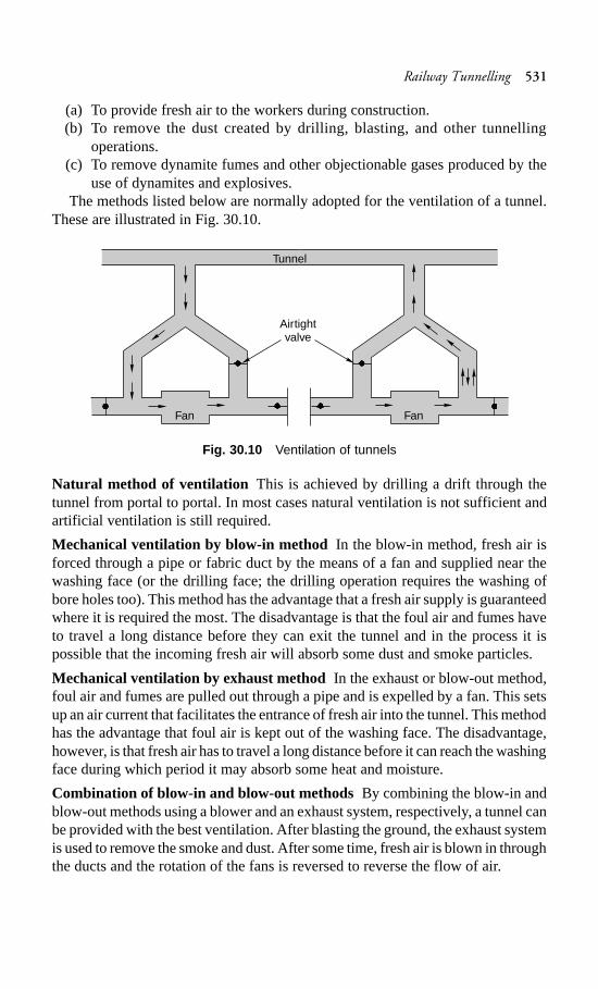
Railway Tunnelling 531
(a) To provide fresh air to the workers during construction.(b) To remove the dust created by drilling, blasting, and other tunnelling
operations.(c) To remove dynamite fumes and other objectionable gases produced by the
use of dynamites and explosives.The methods listed below are normally adopted for the ventilation of a tunnel.
These are illustrated in Fig. 30.10.
Fig. 30.10 Ventilation of tunnels
Natural method of ventilation This is achieved by drilling a drift through thetunnel from portal to portal. In most cases natural ventilation is not sufficient andartificial ventilation is still required.
Mechanical ventilation by blow-in method In the blow-in method, fresh air isforced through a pipe or fabric duct by the means of a fan and supplied near thewashing face (or the drilling face; the drilling operation requires the washing ofbore holes too). This method has the advantage that a fresh air supply is guaranteedwhere it is required the most. The disadvantage is that the foul air and fumes haveto travel a long distance before they can exit the tunnel and in the process it ispossible that the incoming fresh air will absorb some dust and smoke particles.
Mechanical ventilation by exhaust methodIn the exhaust or blow-out method,foul air and fumes are pulled out through a pipe and is expelled by a fan. This setsup an air current that facilitates the entrance of fresh air into the tunnel. This methodhas the advantage that foul air is kept out of the washing face. The disadvantage,however, is that fresh air has to travel a long distance before it can reach the washingface during which period it may absorb some heat and moisture.
Combination of blow-in and blow-out methods By combining the blow-in andblow-out methods using a blower and an exhaust system, respectively, a tunnel canbe provided with the best ventilation. After blasting the ground, the exhaust systemis used to remove the smoke and dust. After some time, fresh air is blown in throughthe ducts and the rotation of the fans is reversed to reverse the flow of air.
Tunnel
Airtightvalve
Fan Fan
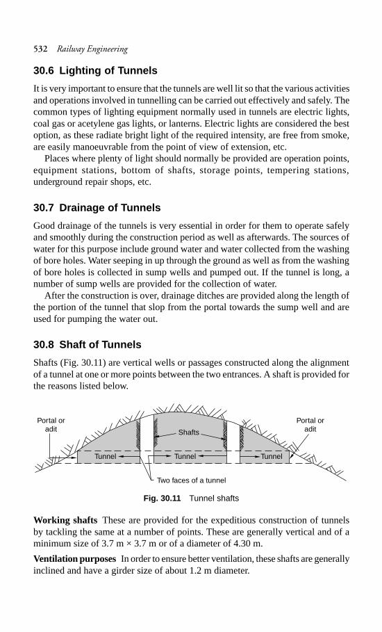
532 Railway Engineering
30.6 Lighting of Tunnels
It is very important to ensure that the tunnels are well lit so that the various activitiesand operations involved in tunnelling can be carried out effectively and safely. Thecommon types of lighting equipment normally used in tunnels are electric lights,coal gas or acetylene gas lights, or lanterns. Electric lights are considered the bestoption, as these radiate bright light of the required intensity, are free from smoke,are easily manoeuvrable from the point of view of extension, etc.
Places where plenty of light should normally be provided are operation points,equipment stations, bottom of shafts, storage points, tempering stations,underground repair shops, etc.
30.7 Drainage of Tunnels
Good drainage of the tunnels is very essential in order for them to operate safelyand smoothly during the construction period as well as afterwards. The sources ofwater for this purpose include ground water and water collected from the washingof bore holes. Water seeping in up through the ground as well as from the washingof bore holes is collected in sump wells and pumped out. If the tunnel is long, anumber of sump wells are provided for the collection of water.
After the construction is over, drainage ditches are provided along the length ofthe portion of the tunnel that slop from the portal towards the sump well and areused for pumping the water out.
30.8 Shaft of Tunnels
Shafts (Fig. 30.11) are vertical wells or passages constructed along the alignmentof a tunnel at one or more points between the two entrances. A shaft is provided forthe reasons listed below.
Fig. 30.11 Tunnel shafts
Working shafts These are provided for the expeditious construction of tunnelsby tackling the same at a number of points. These are generally vertical and of aminimum size of 3.7 m × 3.7 m or of a diameter of 4.30 m.
Ventilation purposes In order to ensure better ventilation, these shafts are generallyinclined and have a girder size of about 1.2 m diameter.
Portal oradit
Portal oradit
Two faces of a tunnel
Shafts
Tunnel Tunnel Tunnel
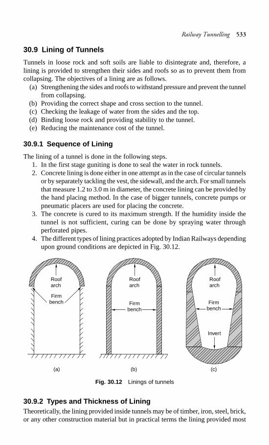
Railway Tunnelling 533
30.9 Lining of Tunnels
Tunnels in loose rock and soft soils are liable to disintegrate and, therefore, alining is provided to strengthen their sides and roofs so as to prevent them fromcollapsing. The objectives of a lining are as follows.
(a) Strengthening the sides and roofs to withstand pressure and prevent the tunnelfrom collapsing.
(b) Providing the correct shape and cross section to the tunnel.(c) Checking the leakage of water from the sides and the top.(d) Binding loose rock and providing stability to the tunnel.(e) Reducing the maintenance cost of the tunnel.
30.9.1 Sequence of Lining
The lining of a tunnel is done in the following steps.1. In the first stage guniting is done to seal the water in rock tunnels.2. Concrete lining is done either in one attempt as in the case of circular tunnels
or by separately tackling the vest, the sidewall, and the arch. For small tunnelsthat measure 1.2 to 3.0 m in diameter, the concrete lining can be provided bythe hand placing method. In the case of bigger tunnels, concrete pumps orpneumatic placers are used for placing the concrete.
3. The concrete is cured to its maximum strength. If the humidity inside thetunnel is not sufficient, curing can be done by spraying water throughperforated pipes.
4. The different types of lining practices adopted by Indian Railways dependingupon ground conditions are depicted in Fig. 30.12.
Fig. 30.12 Linings of tunnels
30.9.2 Types and Thickness of LiningTheoretically, the lining provided inside tunnels may be of timber, iron, steel, brick,or any other construction material but in practical terms the lining provided most
(a) (b) (c)
Roofarch
Roofarch
Roofarch
Firmbench Firm
benchFirm
bench
Invert
534 Railway Engineering
commonly is that of reinforced concrete or concrete surface. Concrete lining isprovided in tunnels because of (a) its superiority in structural strength, (b) ease ofplacement, (c) its durability, and (d) lower maintenance cost.
The thickness of concrete lining depends upon various factors such as conditionsof the ground, size and shape of the tunnel, soil pressure, and the method ofconcreting. The thickness of concrete is calculated by the following empiricalformula:
T = 0.083D (30.1)where T is the thickness of the lining in centimetres and D is the diameter of thetunnel in metres.
On the basis of field experience, railway engineers have devised a thumb ruleof providing 2.5 cm of lining for every 30 cm of the diameter of the tunnel. As perthis thumb rule, the thickness of the lining of a tunnel with a 1 m diameter wouldbe (100/30) × 2.5 cm = 8.3 cm.
30.10 Maintenance of Railway Tunnels
The proper maintenance of railway tunnels is very important from the point ofview of the safety of the trains as well as that of the travelling public. In order toensure that the railway tunnel is in a good condition all year around, it is inspectedin the following ways.
Inspection by assistant engineerApart from routine inspection, the tunnel isinspected in detail by the AEN once a year before the onset of the monsoons. Allthe substructures of the tunnel are inspected and the aspects that require attentionare recorded.
Inspection by permanent way inspectorThe PWI inspects, the tunnel in detailonce in a year after the monsoons are over, paying particular attention to the trackand its components. The aspects requiring attention are taken care of immediately.
Inspection by works inspector The structural portion of the tunnel is inspectedin detail once in a year by the IOW. All the sub-components of the structure areexamined in detail. The parts requiring attention are attended to in a planned way.
30.10.1 Details of a Tunnel Inspection
The following features of a tunnel require detailed inspection and examination.
Portal at either end This is inspected to ascertain whether there are any signs ofslips in the slopes above the portals or whether the masonry is in any way cracked,shaken, or bulging, or whether there are any apparent signs of movement.
Section of tunnel in relation to moving dimensionsThis inspection is done tocheck if the section, whether on straight routes or curves, conforms to the scheduleof dimensions.
Tunnel walls and roofing These are inspected in the case of lined tunnels toascertain whether the lining is in a satisfactory condition. Doubtful places, such asloose projections, should be tapped to check for hollow sound or loose rock.
Railway Tunnelling 535
Drainage This is inspected to ascertain whether the side drains are adequate andfunctional.
Ventilation shafts These are inspected to ascertain whether the ventilation shaftsare adequate and free from vegetation and other growth.
Lighting equipment and special toolsThis inspection of these features is requiredto ascertain whether the lighting equipment and special tools, wherever supplied,are in a good state.
Track The track is inspected to ascertain whether its line and level are correct,including that of the approaches. Rails, sleepers, and fastenings should beparticularly examined for corrosion.
30.11 Safety in Tunnel Construction
Tunnelling is a difficult, hazardous, and time-consuming process and the wholeoperation has to be done systematically so that safety is ensured at all times.Normally accidents in a tunnel occur under the following circumstances.
(a) Falling rocks(b) During the loading and hauling of muck(c) Poor handling of explosives(d) During shaft operations(e) Cramped working spaceThe following tips are suggested for preventing accidents during tunnelling
operations.(a) Equipment and tools should be in good working condition.(b) Regular and detailed inspections should be carried out during tunnelling
operations.(c) Visual inspections should be done to detect seams and planes of weakness
so as to avoid the falling of rocks.(d) There should be provision of sufficient support by ensuring that tunnelling
is done properly in order to avoid the collapsing of the tunnel as well asfalling rocks.
(e) There should be provision of good lighting and non-slippery walkways, whichpartially help in relieving the strain of a cramped working space.
(f) Provisions should be made for the removal of extra debris and refuge aswell as for good drainage in order to avoid accidents. Efforts should also bemade to provide good ventilation.
(g) Telephone facilities should be provided, particularly inside the shaft and atother places in the tunnel, to ensure smooth and accident-free operations.
(h) Firefighting equipment should be provided at all key points.(i) Safety sign boards should be provided at all key locations.(j) All workers should be medically fit to work inside the tunnel and they should
be examined periodically. Doctors and first aid facilities should be availableat the site.
(k) Wearing of helmets by all workers employed in a tunnel should be mademandatory.
536 Railway Engineering
Summary
Tunnels are required in special circumstances as in when the track cannot be laidon natural ground or when it is not economical. The construction of a tunnel isvery tedious and specialized work and, therefore, a very judicious decision isrequired when it comes to tunnel selection. The method and equipment required toconstruct a tunnel would depend on the nature of the soil. The tunnel should beprovided with adequate light, ventilation, and other safety features.
Review Questions
1. Discuss the points to be considered when determining the shape and size oftunnels.
2. Why are railway tunnels necessary? Draw a sketch to illustrate a single-trackrailway tunnel.
3. Briefly describe the construction cycle for tunnelling. How are drainage andventilation facilities provided in railway tunnels?
4. Why is a tunnel necessary? Describe the advantages and disadvantages ofconstructing a tunnel.
5. Name the various methods of tunnelling in hard and soft rocks. Describe onein each case.
6. What do you understand by shield tunnelling? Discuss the various methodsof shield tunnelling adopted in different types of soils.
7. What is the importance of ventilation during tunnelling? Describe the variousmethods of providing ventilation in a tunnel.
8. Write notes on(a) Lighting of tunnels(b) Drainage of tunnels(c) Lining of tunnels(d) Compressed air tunnelling
9. Why is it necessary to maintain a tunnel? Describe the various inspectionscarried out to ensure that tunnels are properly maintained.
10. Describe the various points to be kept in mind to ensure the safety of tunnels.What are the causes behind accidents in tunnels?
11. Differentiate between the following.(a) Full face method and drift method of tunnelling(b) Heading and bench method and plot tunnel method
Signalling and Interlocking 537
Signalling and Interlocking
Introduction
The purpose of signalling and interlocking is primarily to control and regulate themovement of trains safely and efficiently. Signalling includes the use and workingof signals, points, block instruments, and other allied equipment in a predeterminedmanner for the safe and efficient running of trains. Signalling enables the movementof trains to be controlled in such a way that the existing tracks are utilized to themaximum.
In fact in railway terminology signalling is a medium of communication betweenthe station master or the controller sitting in a remote place in the office and thedriver of the train.
The history of signalling goes back to the olden days when two policemen onhorseback were sent ahead of the train to ensure that the tracks were clear and toregulate the movement of the trains. In later years, policemen in uniform wereplaced at regular intervals to regulate the movement of trains. Railway signallingin its present form was introduced for the first time in England in 1842, whereasinterlocking was developed subsequently in 1867.
31.1 Objectives of Signalling
The objectives of signalling are as follows.(a) To regulate the movement of trains so that they run safely at maximum
permissible speeds.(b) To maintain a safe distance between trains that are running on the same line
in the same direction.(c) To ensure the safety of two or more trains that have to cross or approach
each other.(d) To provide facilities for safe and efficient shunting.(e) To regulate the arrival and departure of trains from the station yard.(f) To guide the trains to run at restricted speeds during the maintenance and
repair of tracks.(g) To ensure the safety of the train when it comes in contact with road traffic at
level crossings.
CHAPTER
31
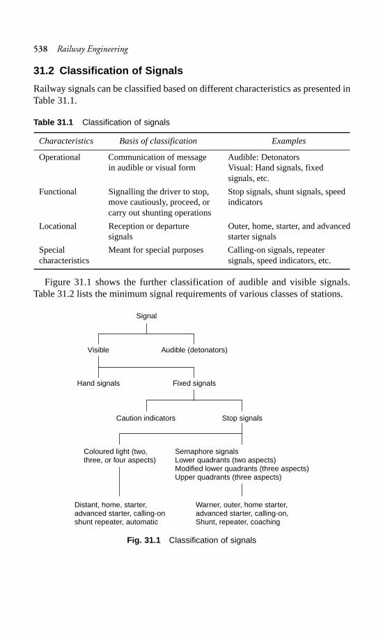
538 Railway Engineering
31.2 Classification of Signals
Railway signals can be classified based on different characteristics as presented inTable 31.1.
Table 31.1 Classification of signals
Characteristics Basis of classification Examples
Operational Communication of message Audible: Detonatorsin audible or visual form Visual: Hand signals, fixed
signals, etc.
Functional Signalling the driver to stop, Stop signals, shunt signals, speedmove cautiously, proceed, or indicatorscarry out shunting operations
Locational Reception or departure Outer, home, starter, and advancedsignals starter signals
Special Meant for special purposes Calling-on signals, repeatercharacteristics signals, speed indicators, etc.
Figure 31.1 shows the further classification of audible and visible signals.Table 31.2 lists the minimum signal requirements of various classes of stations.
Fig. 31.1 Classification of signals
Signal
Visible
Hand signals
Audible (detonators)
Fixed signals
Caution indicators
Coloured light (two,three, or four aspects)
Distant, home, starter,advanced starter, calling-onshunt repeater, automatic
Stop signals
Semaphore signalsLower quadrants (two aspects)Modified lower quadrants (three aspects)Upper quadrants (three aspects)
Warner, outer, home starter,advanced starter, calling-on,Shunt, repeater, coaching
Signalling and Interlocking 539
Table 31.2 Signals required at stations
Classification Minimum requirement Remarksof station of signals
A class Warner, home, and An outer signal can be providedstarter after obtaining special permission
B class Outer and home In multiple-aspect upper quadrant(MAUQ) areas, distant home and outersignals are provided
C class Warner and home In MAUQ areas, the warner signal isreplaced by a distant signal
Further details regarding the different types of stations are furnished in Chapter 26.
31.2.1 Audible Signals
Audible signals such as detonators and fog signals are used in cloudy and foggyweather when hand or fixed signals are not visible. Their sound can immediatelyattract the attention of drivers. Detonators contain explosive material and are fixedto the rail by means of clips. In thick foggy weather, detonators are kept about90 m ahead of a signal to indicate the presence of the signal to the drivers. Oncethe train passes over the detonators thereby causing them to explode, the driverbecomes alert and keeps a lookout for the signal so that he/she can take the requisiteaction.
31.2.2 Visible Signals
These signals are visible and draw the attention of the drivers because of theirstrategic positions.
Hand signals These signals are in the form of flags (red or green) fixed to woodenhandles that are held by railway personnel assigned this particular duty. If the flagsare not available, signalling may be done using bare arms during the day. In thenight, hand lamps with movable green and red slides are used for signallingpurposes.
Fixed signal These are firmly fixed on the ground by the side of the track and canbe further subdivided into caution indicators and stop signals.
Caution indicators These are fixed signals provided for communicating to thedriver that the track ahead is not fit for the running the train at normal speed. Thesesignals are used when engineering works are underway and are shifted from oneplace to another depending upon requirement.
Stop signalsThese are fixed signals that normally do not change their position.They inform the drivers about the condition of the railway line lying ahead.
The stop signals normally used on railways are semaphore signals, colouredlight signals, and other such signals as explained in subsequent sections.
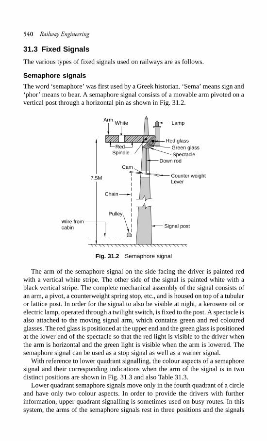
540 Railway Engineering
31.3 Fixed Signals
The various types of fixed signals used on railways are as follows.
Semaphore signals
The word ‘semaphore’ was first used by a Greek historian. ‘Sema’ means sign and‘phor’ means to bear. A semaphore signal consists of a movable arm pivoted on avertical post through a horizontal pin as shown in Fig. 31.2.
Fig. 31.2 Semaphore signal
The arm of the semaphore signal on the side facing the driver is painted redwith a vertical white stripe. The other side of the signal is painted white with ablack vertical stripe. The complete mechanical assembly of the signal consists ofan arm, a pivot, a counterweight spring stop, etc., and is housed on top of a tubularor lattice post. In order for the signal to also be visible at night, a kerosene oil orelectric lamp, operated through a twilight switch, is fixed to the post. A spectacle isalso attached to the moving signal arm, which contains green and red colouredglasses. The red glass is positioned at the upper end and the green glass is positionedat the lower end of the spectacle so that the red light is visible to the driver whenthe arm is horizontal and the green light is visible when the arm is lowered. Thesemaphore signal can be used as a stop signal as well as a warner signal.
With reference to lower quadrant signalling, the colour aspects of a semaphoresignal and their corresponding indications when the arm of the signal is in twodistinct positions are shown in Fig. 31.3 and also Table 31.3.
Lower quadrant semaphore signals move only in the fourth quadrant of a circleand have only two colour aspects. In order to provide the drivers with furtherinformation, upper quadrant signalling is sometimes used on busy routes. In thissystem, the arms of the semaphore signals rest in three positions and the signals
Red
ArmWhite Lamp
Red glassGreen glass
Spindle SpectacleDown rod
Cam
Counter weightLever
Chain
7.5M
Pulley
Signal postWire fromcabin
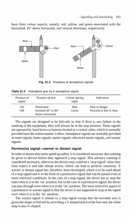
Signalling and Interlocking 541
have three colour aspects, namely, red, yellow, and green associated with thehorizontal, 45° above horizontal, and vertical directions, respectively.
Fig. 31.3 Positions of semaphore signals
Table 31.3 Indications give by a semaphore signal
Position of Position of arm Colour during Indicationsignal night
On Horizontal Red Stop or dangerOff Inclined 45° to 60° Green Proceed or line is clear
below horizontal
The signals are designed to be fail-safe so that if there is any failure in theworking of the equipment, they will always be in the stop position. These signalsare operated by hand levers or buttons located in a central cabin, which is normallyprovided near the station master’s office. Semaphore signals are normally providedas outer signals, home signals, starter signals, advanced starter signals, and warnersignals.
Permissive signal—warner or distant signal
In order to ensure that trains speed up safely, it is considered necessary that warningbe given to drivers before they approach a stop signal. This advance warning isconsidered necessary, otherwise the drivers may confront a ‘stop signal’ when theyleast expect it and take abrupt action, which can lead to perilous situations. Awarner or distant signal has, therefore, been developed, which is to be used aheadof a stop signal and is in the form of a permissive signal that can be passed even inmost restricted conditions. In the case of a stop signal, the driver has to stop thetrain when it is in the ‘on’ position, but in the case of a permissive signal, the drivercan pass through even when it is in the ‘on’ position. The most restrictive aspect ofa permissive or warner signal is that the driver is not supposed to stop at the signaleven when it is in the ‘on’ position.
The warner signal is similar to a stop signal except that the movable arm isgiven the shape of fish tail by providing a V-shaped notch at the free end; the whitestrip is also V-shaped.
Red
White
GreenRed
Red
White
542 Railway Engineering
In the case of signalling using coloured light, the permissive signal isdistinguished from the stop signal by the provision of a P marker disc on the signalpost.
The warner signal is intended to warn the driver of a train regarding the followingaspects as explained in Table 31.4.
(a) That the driver is approaching a stop signal.(b) To inform the diver as to whether the approach signal is in an ‘on’ or ‘off’
position.
Table 31.4 Position of warner arm or distant signal
Position Day indication for Night indication Aspectsemaphore signal for semaphore
signal*
On Arm horizontal Red light Proceed with caution and beprepared to stop at the nextstop
Caution Arm inclined 45° Yellow light Proceed cautiously so as toin the upward pass the next stop signal at adirection restricted speed
Off Arm inclined 90° is Green light Proceed at full permissiblethe upward or 45° speed, next stop signal is alsois the downward greendirection
* Also day and night indication for a coloured light signal.
The warner signal can be placed at either one of the following locations.(a) Independently on a post with a fixed green light 1.5 m to 2 m above it for
night indication.(b) On the same post below the outer signal or the home signal.In case a warner is fixed below an outer signal the various positions of the outer
and warner signals and their corresponding indications are given in Fig. 31.4.
Coloured light signals
These signals use coloured lights to indicate track conditions to the driver bothduring the day and the night. In order to ensure good visibility of these light signals,particularly during daytime, the light emission of an electric 12-V, 33-W lamp ispassed through a combination of lenses in such a way that a parallel beam offocused light is emitted out. This light is protected by special lenses and hoods andcan be distinctly seen even in the brightest sunlight. The lights are fixed on avertical post in such a way that they are in line with the driver’s eye level. Thesystem of interlocking is so arranged that only one aspect is displayed at a time.Coloured light signals are normally used in suburban sections and sections with ahigh traffic density. Coloured light signals can be of the following types.
(a) Two-aspect, namely, green and red
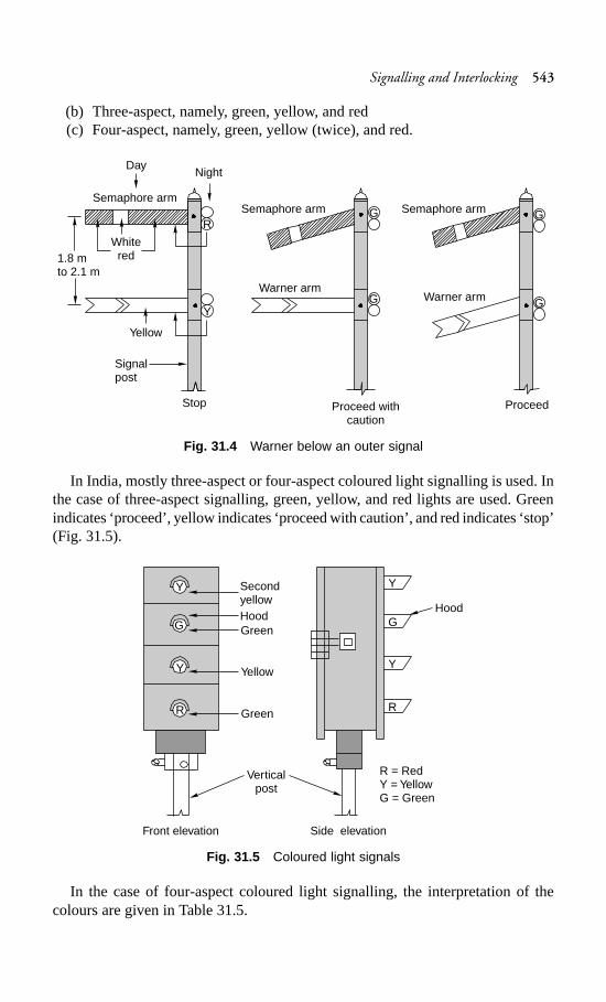
Signalling and Interlocking 543
(b) Three-aspect, namely, green, yellow, and red(c) Four-aspect, namely, green, yellow (twice), and red.
Fig. 31.4 Warner below an outer signal
In India, mostly three-aspect or four-aspect coloured light signalling is used. Inthe case of three-aspect signalling, green, yellow, and red lights are used. Greenindicates ‘proceed’, yellow indicates ‘proceed with caution’, and red indicates ‘stop’(Fig. 31.5).
Fig. 31.5 Coloured light signals
In the case of four-aspect coloured light signalling, the interpretation of thecolours are given in Table 31.5.
1.8 mto 2.1 m
Day
Whitered
Semaphore arm
Night
R
Y
Yellow
Signalpost
Stop
G
G
Semaphore arm
Warner arm
Proceed withcaution
Semaphore arm
Warner arm
G
G
Proceed
SecondyellowHoodGreen
Yellow
Green
Hood
Y
G
Y
R
Y
G
Y
R
Verticalpost
Front elevation Side elevation
R = RedY = YellowG = Green
544 Railway Engineering
Table 31.5 Indications of coloured light signals
Colour of signal Interpretation
Red Stop dead, danger aheadYellow Pass the signal cautiously and be prepared to stop at the next
signalTwo yellow lights Pass the signal at full speed but be prepared to pass the nextdisplayed together signal, which is likely to be yellow, at a cautious speedGreen Pass the signal at full speed, next signal is also off
In conventional semaphore signals, the ‘on’ position is the normal position ofthe signal and the signals are lowered to the ‘off’ position only when a train is due.In the case of coloured light signals placed in territories with automatic signalling,the signal is always green or in the ‘proceed’ position. As soon as a train enters asection, the signal changes to ‘Red’ or the ‘stop’ position, which is controlledautomatically by the passage of the train itself. As the train passes through theblock section, the signal turns yellow to instruct the driver to ‘proceed with caution’and, finally, when the train moves onto the next block section, the signal turnsgreen indicating to the driver to ‘proceed at full permissible speed’.
Thus it can be seen that each aspect of the signal gives two pieces of informationto the driver. The first is about the signal itself and the second is about the conditionof the track ahead or of the next signal. This helps the driver to manoeuvre the trainsafely and with confidence even at the maximum permissible speed.
Calling-on signal
This consists of a small arm fixed on a home signal post below the main semaphorearm (Fig. 31.6). When the main home signal is in the horizontal (on) position andthe calling-on signal is in on inclined (off) position, it indicates that the train ispermitted to proceed cautiously on the line till it comes across the next stop signal.Thus the calling-on signal is meant to ‘call’ the train, which is waiting beyond thehome signal.
The calling-on signal is useful when the main signal fails, and in order to receivea train, an authority letter has to be sent to the driver of the waiting train to instructhim/her to proceed to the station against what is indicated by the signal. In bigstations and yards, the stop signals may be situated far off from the cabin and thecalling-on signal expedites the quick reception of the train even the when signal isdefective.
Co-acting signal
In case a signal is not visible to the driver due to the presence of some obstructionsuch as an overbridge or a high structure, another signal is used in its place,preferably on the same post. This signal, known as the co-acting signal, is an exactreplica of the original signal and works in unison with it.
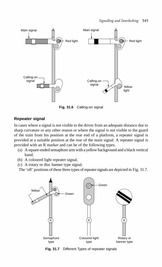
Signalling and Interlocking 545
Fig. 31.6 Calling-on signal
Repeater signal
In cases where a signal is not visible to the driver from an adequate distance due tosharp curvature or any other reason or where the signal is not visible to the guardof the train from his position at the rear end of a platform, a repeater signal isprovided at a suitable position at the rear of the main signal. A repeater signal isprovided with an R marker and can be of the following types.
(a) A square-ended semaphore arm with a yellow background and a black verticalband.
(b) A coloured light repeater signal.(c) A rotary or disc banner type signal.The ‘off’ positions of these three types of repeater signals are depicted in Fig. 31.7.
Fig. 31.7 Different Types of repeater signals
Main signal
Red light
Calling-onsignal
Main signal
Red light
Calling-onsignal
Yellowlight
YellowGreen
R
Semaphoretype
RR
Green
Coloured lighttype
Rotary orbanner type
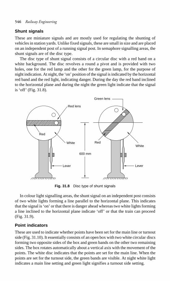
546 Railway Engineering
Shunt signals
These are miniature signals and are mostly used for regulating the shunting ofvehicles in station yards. Unlike fixed signals, these are small in size and are placedon an independent post of a running signal post. In semaphore signalling areas, theshunt signals are of the disc type.
The disc type of shunt signal consists of a circular disc with a red band on awhite background. The disc revolves a round a pivot and is provided with twoholes, one for the red lamp and the other for the green lamp, for the purpose ofnight indication. At night, the ‘on’ position of the signal is indicated by the horizontalred band and the red light, indicating danger. During the day the red band inclinedto the horizontal plane and during the night the green light indicate that the signalis ‘off’ (Fig. 31.8).
Fig. 31.8 Disc type of shunt signals
In colour light signalling areas, the shunt signal on an independent post consistsof two white lights forming a line parallel to the horizontal plane. This indicatesthat the signal is ‘on’ or that there is danger ahead whereas two white lights forminga line inclined to the horizontal plane indicate ‘off’ or that the train can proceed(Fig. 31.9).
Point indicators
These are used to indicate whether points have been set for the main line or turnoutside (Fig. 31.10). It essentially consists of an open box with two white circular discsforming two opposite sides of the box and green bands on the other two remainingsides. The box rotates automatically about a vertical axis with the movement of thepoints. The white disc indicates that the points are set for the main line. When thepoints are set for the turnout side, the green bands are visible. At night white lightindicates a main line setting and green light signifies a turnout side setting.
Red lens
Red
White
Lever
Green lens
WhiteRed
600 mm
Lever
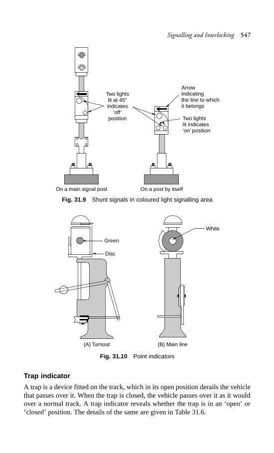
Signalling and Interlocking 547
Fig. 31.9 Shunt signals in coloured light signalling area
Fig. 31.10 Point indicators
Trap indicator
A trap is a device fitted on the track, which in its open position derails the vehiclethat passes over it. When the trap is closed, the vehicle passes over it as it wouldover a normal track. A trap indicator reveals whether the trap is in an ‘open’ or‘closed’ position. The details of the same are given in Table 31.6.
Two lightslit at 45°indicates
‘off’position
Arrowindicatingthe line to whichit belongs
Two lightslit indicates‘on’ position
On a main signal post On a post by itself
Green
Disc
White
(A) Turnout (B) Main line
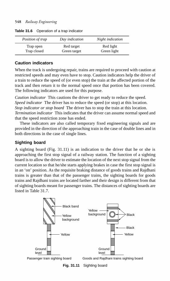
548 Railway Engineering
Table 31.6 Operation of a trap indicator
Position of trap Day indication Night indication
Trap open Red target Red lightTrap closed Green target Green light
Caution indicators
When the track is undergoing repair, trains are required to proceed with caution atrestricted speeds and may even have to stop. Caution indicators help the driver ofa train to reduce the speed of (or even stop) the train at the affected portion of thetrack and then return it to the normal speed once that portion has been covered.The following indicators are used for this purpose.
Caution indicatorThis cautions the driver to get ready to reduce the speed.Speed indicatorThe driver has to reduce the speed (or stop) at this location.Stop indicator or stop boardThe driver has to stop the train at this location.Termination indicatorThis indicates that the driver can assume normal speed andthat the speed restriction zone has ended.
These indicators are also called temporary fixed engineering signals and areprovided in the direction of the approaching train in the case of double lines and inboth directions in the case of single lines.
Sighting board
A sighting board (Fig. 31.11) is an indication to the driver that he or she isapproaching the first stop signal of a railway station. The function of a sightingboard is to allow the driver to estimate the location of the next stop signal from thecurrent location so that he/she starts applying brakes in case the first stop signal isin an ‘on’ position. As the requisite braking distance of goods trains and Rajdhanitrains is greater than that of the passenger trains, the sighting boards for goodstrains and Rajdhani trains are located farther and their design is different from thatof sighting boards meant for passenger trains. The distances of sighting boards arelisted in Table 31.7.
Fig. 31.11 Sighting board
Black band
Yellowbackground
Yellow
Groundlevel
Groundlevel
BlackYellowbackground
Black
Yellow
Passenger train sighting board Goods and Rajdhani trains sighting board
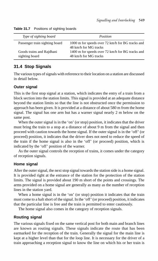
Signalling and Interlocking 549
Table 31.7 Positions of sighting boards
Type of sighting board Position
Passenger train sighting board 1000 m for speeds over 72 km/h for BG tracks and48 km/h for MG tracks
Goods trains and Rajdhani 1400 m for speeds over 72 km/h for BG tracks andsighting board 48 km/h for MG tracks
31.4 Stop Signals
The various types of signals with reference to their location on a station are discussedin detail below.
Outer signal
This is the first stop signal at a station, which indicates the entry of a train from ablock section into the station limits. This signal is provided at an adequate distancebeyond the station limits so that the line is not obstructed once the permission toapproach has been given. It is provided at a distance of about 580 m from the homesignal. The signal has one arm but has a warner signal nearly 2 m below on thesame post.
When the outer signal is in the ‘on’ (or stop) position, it indicates that the drivermust bring the train to a stop at a distance of about 9 m from the signal and thenproceed with caution towards the home signal. If the outer signal is in the ‘off’ (orproceed) position, it indicates that the driver does not need to reduce the speed ofthe train if the home signal is also in the ‘off’ (or proceed) position, which isindicated by the ‘off’ position of the warner.
As the outer signal controls the reception of trains, it comes under the categoryof reception signals.
Home signal
After the outer signal, the next stop signal towards the station side is a home signal.It is provided right at the entrance of the station for the protection of the stationlimits. The signal is provided about 190 m short of the points and crossings. Thearms provided on a home signal are generally as many as the number of receptionlines in the station yard.
When a home signal is in the ‘on’ (or stop) position it indicates that the trainmust come to a halt short of the signal. In the ‘off’ (or proceed) position, it indicatesthat the particular line is free and the train is permitted to enter cautiously.
The home signal also comes in the category of reception signals.
Routing signal
The various signals fixed on the same vertical post for both main and branch linesare known as routing signals. These signals indicate the route that has beenearmarked for the reception of the train. Generally the signal for the main line iskept at a higher level than that for the loop line. It is necessary for the driver of atrain approaching a reception signal to know the line on which his or her train is
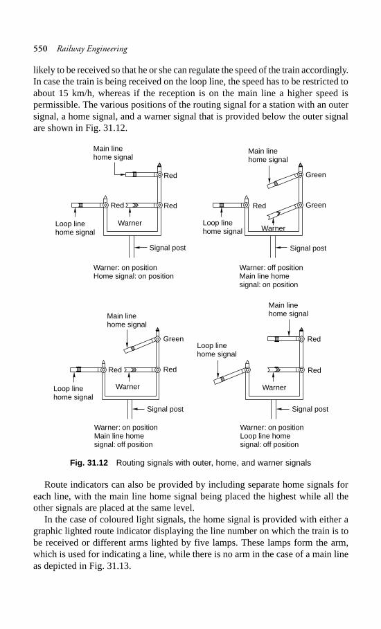
550 Railway Engineering
likely to be received so that he or she can regulate the speed of the train accordingly.In case the train is being received on the loop line, the speed has to be restricted toabout 15 km/h, whereas if the reception is on the main line a higher speed ispermissible. The various positions of the routing signal for a station with an outersignal, a home signal, and a warner signal that is provided below the outer signalare shown in Fig. 31.12.
Fig. 31.12 Routing signals with outer, home, and warner signals
Route indicators can also be provided by including separate home signals foreach line, with the main line home signal being placed the highest while all theother signals are placed at the same level.
In the case of coloured light signals, the home signal is provided with either agraphic lighted route indicator displaying the line number on which the train is tobe received or different arms lighted by five lamps. These lamps form the arm,which is used for indicating a line, while there is no arm in the case of a main lineas depicted in Fig. 31.13.
Main linehome signal
Warner
Red Red
Loop linehome signal
Signal post
Warner: on positionHome signal: on position
Warner: off positionMain line homesignal: on position
Red
Main linehome signal
Loop linehome signal Warner
Red
Signal post
Green
Green
Main linehome signalMain line
home signal
Red
Warner
Loop linehome signal
Signal post
Red
Warner: on positionLoop line homesignal: off position
Warner: on positionMain line homesignal: off position
Red
Green
Red
Warner
Signal post
Loop linehome signal
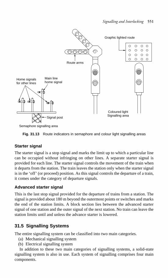
Signalling and Interlocking 551
Fig. 31.13 Route indicators in semaphore and colour light signalling areas
Starter signal
The starter signal is a stop signal and marks the limit up to which a particular linecan be occupied without infringing on other lines. A separate starter signal isprovided for each line. The starter signal controls the movement of the train whenit departs from the station. The train leaves the station only when the starter signalis in the ‘off’ (or proceed) position. As this signal controls the departure of a train,it comes under the category of departure signals.
Advanced starter signal
This is the last stop signal provided for the departure of trains from a station. Thesignal is provided about 180 m beyond the outermost points or switches and marksthe end of the station limits. A block section lies between the advanced startersignal of one station and the outer signal of the next station. No train can leave thestation limits until and unless the advance starter is lowered.
31.5 Signalling Systems
The entire signalling system can be classified into two main categories.(a) Mechanical signalling system(b) Electrical signalling systemIn addition to these two main categories of signalling systems, a solid-state
signalling system is also in use. Each system of signalling comprises four maincomponents.
Main linehome signal
Home signalsfor other lines
Signal post
Route arms
Coloured lightSignalling area
Graphic lighted route
Semaphore signalling area
552 Railway Engineering
(a) Operated units such as signals and points(b) A transmission system such as single- or double-wire transmission or
electrical transmission(c) Operating units such as levers and press buttons(d) Monitoring units such as detectors, treadle bars, and track circuitingThe comparison between mechanical and electrical signalling based on these
four broad components is given in Table 31.8.
Table 31.8 Comparison of signalling systems
Component Mechanical Electrical
Operated units
Signals Mechanically operated signals Coloured light signals with two-as per lower quadrant or upper aspect, three-aspect or four-aspectquadrant signalling signalling
Points Mechanically operated points; Electrically operated points (bylocking with the help of point converting the rotary movement oflocks, stretcher bars, and electric motors into linear push ordetectors pull); locking with the help of
slides and solid rods.
Level crossing Manually operated swing leaf Electrically operated liftinggates gate or mechanically operated barriers
lifting barriers
Transmission Single- or double-wire Electrical transmission throughsystems transmission to the requisite overhead wires or underground
points by means of rods or cablesdouble wires
Operating units Hand levers with a range of Push buttons, rotary switches, or500 to 2000 m used in electrical signalling equipmentcollaboration with single-wireor double-wire lever frames
Mechanical interlocking with Interlocking throughtappets, etc. electromagnetic switches known
as relays or solid-state switchingdevices
Monitoring Monitoring of points with the Monitoring with the help of directunits help of detectors; monitoring current track circuits, alternating
of the passage of trains using a current track circuits, electronictreadle, which is an electro- track circuits, axle counters, etc.mechanical device
31.6 Mechanical Signalling System
The mechanical signalling system mostly involves signals and points as explainedin this section.
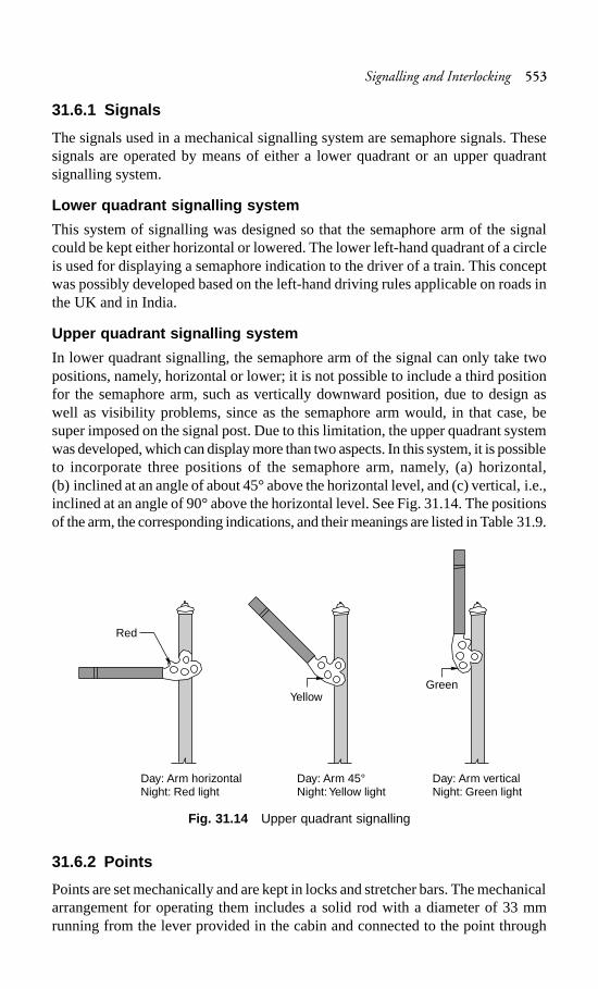
Signalling and Interlocking 553
31.6.1 Signals
The signals used in a mechanical signalling system are semaphore signals. Thesesignals are operated by means of either a lower quadrant or an upper quadrantsignalling system.
Lower quadrant signalling system
This system of signalling was designed so that the semaphore arm of the signalcould be kept either horizontal or lowered. The lower left-hand quadrant of a circleis used for displaying a semaphore indication to the driver of a train. This conceptwas possibly developed based on the left-hand driving rules applicable on roads inthe UK and in India.
Upper quadrant signalling system
In lower quadrant signalling, the semaphore arm of the signal can only take twopositions, namely, horizontal or lower; it is not possible to include a third positionfor the semaphore arm, such as vertically downward position, due to design aswell as visibility problems, since as the semaphore arm would, in that case, besuper imposed on the signal post. Due to this limitation, the upper quadrant systemwas developed, which can display more than two aspects. In this system, it is possibleto incorporate three positions of the semaphore arm, namely, (a) horizontal,(b) inclined at an angle of about 45° above the horizontal level, and (c) vertical, i.e.,inclined at an angle of 90° above the horizontal level. See Fig. 31.14. The positionsof the arm, the corresponding indications, and their meanings are listed in Table 31.9.
Fig. 31.14 Upper quadrant signalling
31.6.2 Points
Points are set mechanically and are kept in locks and stretcher bars. The mechanicalarrangement for operating them includes a solid rod with a diameter of 33 mmrunning from the lever provided in the cabin and connected to the point through
Red
YellowGreen
Day: Arm horizontalNight: Red light
Day: Arm 45°Night:Yellow light
Day: Arm verticalNight: Green light
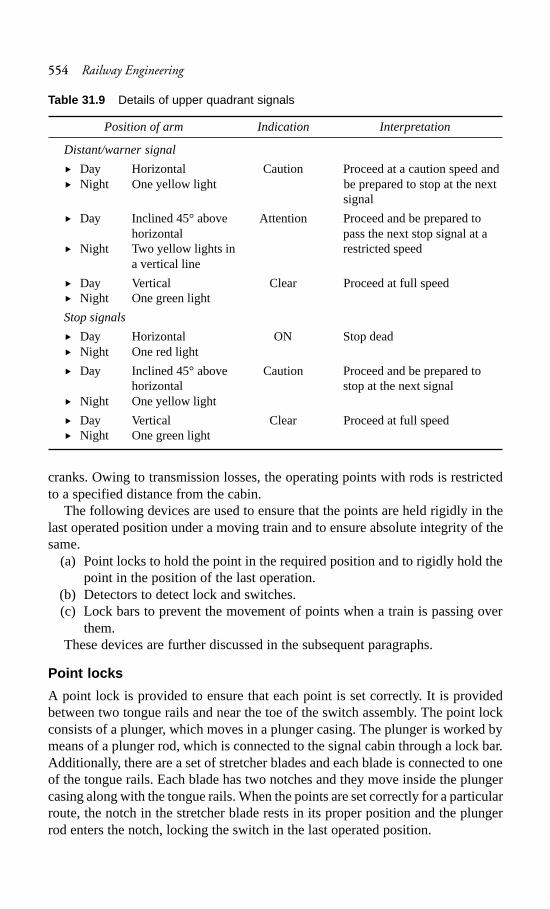
554 Railway Engineering
cranks. Owing to transmission losses, the operating points with rods is restrictedto a specified distance from the cabin.
The following devices are used to ensure that the points are held rigidly in thelast operated position under a moving train and to ensure absolute integrity of thesame.
(a) Point locks to hold the point in the required position and to rigidly hold thepoint in the position of the last operation.
(b) Detectors to detect lock and switches.(c) Lock bars to prevent the movement of points when a train is passing over
them.These devices are further discussed in the subsequent paragraphs.
Point locks
A point lock is provided to ensure that each point is set correctly. It is providedbetween two tongue rails and near the toe of the switch assembly. The point lockconsists of a plunger, which moves in a plunger casing. The plunger is worked bymeans of a plunger rod, which is connected to the signal cabin through a lock bar.Additionally, there are a set of stretcher blades and each blade is connected to oneof the tongue rails. Each blade has two notches and they move inside the plungercasing along with the tongue rails. When the points are set correctly for a particularroute, the notch in the stretcher blade rests in its proper position and the plungerrod enters the notch, locking the switch in the last operated position.
Table 31.9 Details of upper quadrant signals
Position of arm Indication Interpretation
Distant/warner signal
� Day Horizontal Caution Proceed at a caution speed and� Night One yellow light be prepared to stop at the next
signal
� Day Inclined 45° above Attention Proceed and be prepared tohorizontal pass the next stop signal at a
� Night Two yellow lights in restricted speeda vertical line
� Day Vertical Clear Proceed at full speed� Night One green light
Stop signals
� Day Horizontal ON Stop dead� Night One red light
� Day Inclined 45° above Caution Proceed and be prepared tohorizontal stop at the next signal
� Night One yellow light
� Day Vertical Clear Proceed at full speed� Night One green light
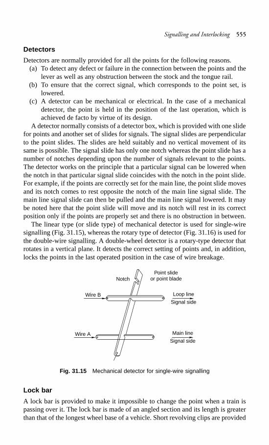
Signalling and Interlocking 555
Detectors
Detectors are normally provided for all the points for the following reasons.(a) To detect any defect or failure in the connection between the points and the
lever as well as any obstruction between the stock and the tongue rail.(b) To ensure that the correct signal, which corresponds to the point set, is
lowered.(c) A detector can be mechanical or electrical. In the case of a mechanical
detector, the point is held in the position of the last operation, which isachieved de facto by virtue of its design.
A detector normally consists of a detector box, which is provided with one slidefor points and another set of slides for signals. The signal slides are perpendicularto the point slides. The slides are held suitably and no vertical movement of itssame is possible. The signal slide has only one notch whereas the point slide has anumber of notches depending upon the number of signals relevant to the points.The detector works on the principle that a particular signal can be lowered whenthe notch in that particular signal slide coincides with the notch in the point slide.For example, if the points are correctly set for the main line, the point slide movesand its notch comes to rest opposite the notch of the main line signal slide. Themain line signal slide can then be pulled and the main line signal lowered. It maybe noted here that the point slide will move and its notch will rest in its correctposition only if the points are properly set and there is no obstruction in between.
The linear type (or slide type) of mechanical detector is used for single-wiresignalling (Fig. 31.15), whereas the rotary type of detector (Fig. 31.16) is used forthe double-wire signalling. A double-wheel detector is a rotary-type detector thatrotates in a vertical plane. It detects the correct setting of points and, in addition,locks the points in the last operated position in the case of wire breakage.
Fig. 31.15 Mechanical detector for single-wire signalling
Lock bar
A lock bar is provided to make it impossible to change the point when a train ispassing over it. The lock bar is made of an angled section and its length is greaterthan that of the longest wheel base of a vehicle. Short revolving clips are provided
NotchPoint slide
or point blade
Loop line
Signal side
Main line
Signal side
Wire B
Wire A
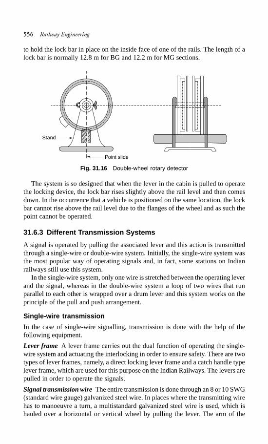
556 Railway Engineering
to hold the lock bar in place on the inside face of one of the rails. The length of alock bar is normally 12.8 m for BG and 12.2 m for MG sections.
Fig. 31.16 Double-wheel rotary detector
The system is so designed that when the lever in the cabin is pulled to operatethe locking device, the lock bar rises slightly above the rail level and then comesdown. In the occurrence that a vehicle is positioned on the same location, the lockbar cannot rise above the rail level due to the flanges of the wheel and as such thepoint cannot be operated.
31.6.3 Different Transmission Systems
A signal is operated by pulling the associated lever and this action is transmittedthrough a single-wire or double-wire system. Initially, the single-wire system wasthe most popular way of operating signals and, in fact, some stations on Indianrailways still use this system.
In the single-wire system, only one wire is stretched between the operating leverand the signal, whereas in the double-wire system a loop of two wires that runparallel to each other is wrapped over a drum lever and this system works on theprinciple of the pull and push arrangement.
Single-wire transmission
In the case of single-wire signalling, transmission is done with the help of thefollowing equipment.
Lever frame A lever frame carries out the dual function of operating the single-wire system and actuating the interlocking in order to ensure safety. There are twotypes of lever frames, namely, a direct locking lever frame and a catch handle typelever frame, which are used for this purpose on the Indian Railways. The levers arepulled in order to operate the signals.
Signal transmission wireThe entire transmission is done through an 8 or 10 SWG(standard wire gauge) galvanized steel wire. In places where the transmitting wirehas to manoeuvre a turn, a multistandard galvanized steel wire is used, which ishauled over a horizontal or vertical wheel by pulling the lever. The arm of the
Point slide
Stand
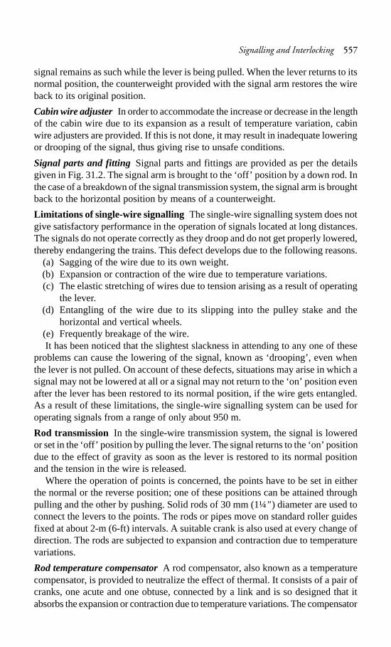
Signalling and Interlocking 557
signal remains as such while the lever is being pulled. When the lever returns to itsnormal position, the counterweight provided with the signal arm restores the wireback to its original position.
Cabin wire adjusterIn order to accommodate the increase or decrease in the lengthof the cabin wire due to its expansion as a result of temperature variation, cabinwire adjusters are provided. If this is not done, it may result in inadequate loweringor drooping of the signal, thus giving rise to unsafe conditions.
Signal parts and fitting Signal parts and fittings are provided as per the detailsgiven in Fig. 31.2. The signal arm is brought to the ‘off’ position by a down rod. Inthe case of a breakdown of the signal transmission system, the signal arm is broughtback to the horizontal position by means of a counterweight.
Limitations of single-wire signalling The single-wire signalling system does notgive satisfactory performance in the operation of signals located at long distances.The signals do not operate correctly as they droop and do not get properly lowered,thereby endangering the trains. This defect develops due to the following reasons.
(a) Sagging of the wire due to its own weight.(b) Expansion or contraction of the wire due to temperature variations.(c) The elastic stretching of wires due to tension arising as a result of operating
the lever.(d) Entangling of the wire due to its slipping into the pulley stake and the
horizontal and vertical wheels.(e) Frequently breakage of the wire.It has been noticed that the slightest slackness in attending to any one of these
problems can cause the lowering of the signal, known as ‘drooping’, even whenthe lever is not pulled. On account of these defects, situations may arise in which asignal may not be lowered at all or a signal may not return to the ‘on’ position evenafter the lever has been restored to its normal position, if the wire gets entangled.As a result of these limitations, the single-wire signalling system can be used foroperating signals from a range of only about 950 m.
Rod transmission In the single-wire transmission system, the signal is loweredor set in the ‘off’ position by pulling the lever. The signal returns to the ‘on’ positiondue to the effect of gravity as soon as the lever is restored to its normal positionand the tension in the wire is released.
Where the operation of points is concerned, the points have to be set in eitherthe normal or the reverse position; one of these positions can be attained throughpulling and the other by pushing. Solid rods of 30 mm (1¼" ) diameter are used toconnect the levers to the points. The rods or pipes move on standard roller guidesfixed at about 2-m (6-ft) intervals. A suitable crank is also used at every change ofdirection. The rods are subjected to expansion and contraction due to temperaturevariations.
Rod temperature compensatorA rod compensator, also known as a temperaturecompensator, is provided to neutralize the effect of thermal. It consists of a pair ofcranks, one acute and one obtuse, connected by a link and is so designed that itabsorbs the expansion or contraction due to temperature variations. The compensator
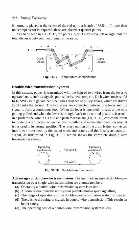
558 Railway Engineering
is normally placed at the centre of the rod up to a length of 36.5 m. If more thanone compensator is required, these are placed at quarter points.
As can be seen in Fig. 31.17, the points, A or B may move left or right, but thetotal distance between them remains the same.
Fig. 31.17 Temperature compensator
Double-wire transmission system
In this system, power is transmitted with the help of two wires from the lever tooperated units such as signals, points, locks, detectors, etc. Each wire consists of 8to 10 SWG solid galvanized steel wires attached to pulley stakes, which are drivenfirmly into the ground. The two wires are connected between the lever and thesignal to form a continuous loop. When the lever is operated, it leads to the wiregetting pulled and when the lever is brought back to its normal position, it resultsin a push to the wire. This pull and push mechanism (Fig. 31.18) causes the drumto rotate in one direction when the lever is pulled and in the other direction when itis restored to its normal position. The rotary motion of the drum is then convertedinto linear movement by the use of cams and cranks and this finally actuates thesignal, as illustrated in Fig. 31.19, which shows the complete double-wiretransmission system.
Fig. 31.18 Double-wire mechanism
Advantages of double-wire transmissionThe main advantages of double-wiretransmission over single-wire transmission are enumerated here.
(a) Operating a double-wire transmission system is easier.(b) A double-wire transmission system permits multi-aspect signalling.(c) The range of operations of the double-wire transmission system is greater.(d) There is no drooping of signals in double-wire transmission. This results in
better safety.(e) The operating cost of a double-wire transmission system is less.
A
Crank(Acute)
Link
Crank(obtuse)
B
B
A
Operatingmechanism
OperatingmechanismPull wire 1
Pull wire 2
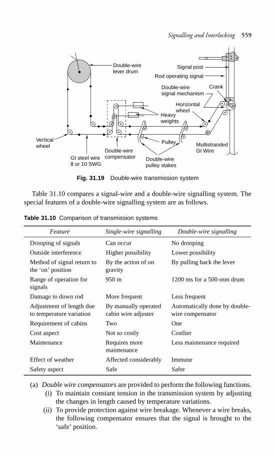
Signalling and Interlocking 559
Fig. 31.19 Double-wire transmission system
Table 31.10 compares a signal-wire and a double-wire signalling system. Thespecial features of a double-wire signalling system are as follows.
Table 31.10 Comparison of transmission systems
Feature Single-wire signalling Double-wire signalling
Drooping of signals Can occur No drooping
Outside interference Higher possibility Lower possibility
Method of signal return to By the action of on By pulling back the leverthe ‘on’ position gravity
Range of operation for 950 m 1200 ms for a 500-mm drumsignals
Damage to down rod More frequent Less frequent
Adjustment of length due By manually operated Automatically done by double-to temperature variation cabin wire adjuster wire compensator
Requirement of cabins Two One
Cost aspect Not so costly Costlier
Maintenance Requires more Less maintenance requiredmaintenance
Effect of weather Affected considerably Immune
Safety aspect Safe Safer
(a) Double wire compensators are provided to perform the following functions.(i) To maintain constant tension in the transmission system by adjusting
the changes in length caused by temperature variations.(ii) To provide protection against wire breakage. Whenever a wire breaks,
the following compensator ensures that the signal is brought to the‘safe’ position.
Double-wirelever drum
Verticalwheel
GI steel wire8 or 10 SWG
Double-wirecompensator Double-wire
pulley stakes
Pulley MultistrandedGI Wire
Heavyweights
Horizontalwheel
Double-wiresignal mechanism
Crank
Rod operating signal
Signal post
560 Railway Engineering
(b) Jockey weights are added to the main compensator weight to cater to a greateroperating force.
(c) Coupling devices are provided to detect the couplings of two levers in acommon transmission.
(d) Double-wire detectors are provided to detect the correct setting of the pointsand locks.
31.6.4 Operating Mechanism
In mechanical signalling, the signals and points are operated mechanically. Theoperation of these units, therefore, requires sufficient amount of power. To facilitatethe quick and smooth operation of these equipment, levers are used in single-wireas well as in double-wire mechanical transmission. These levers may be installedindividually near an operated unit such as a point or a signal or may be groupedtogether in a lever frame depending upon the type and standard of signalling. Leverframes may be of the following types.
Single-wire lever frame
In this type of lever frame, the lever is a bar fulcrumed on a shaft. The longer endof the bar rests towards the lever while the shorter end rests towards the signal orthe point in order to gain mechanical advantage. Pulling the lever results in amovement of 200 mm in the case of points and 300 mm in the case of signaloperation. All the levers that are required to operate different units such as pointsand signals are grouped together on a common fulcrum shaft in a compact leverframe, which is kept below the level of the operation platform. Only a convenientlength of the lever is allowed to protrude beyond the platform to facilitate easyoperation. A latch arrangement is also provided with the lever arm to maintain thelever in the position in which it was last operated.
Double-wire lever frames
Unlike single-wire systems, a double-wire transmission system is in the form of aloop, one end of which is wrapped across a drum that is provided with an arm.When this arm is rotated about the centre of the drum, it imparts a stroke of 550 mmor 600 mm depending upon the type of lever used. There are six types of double-wire levers used on Indian Railways that impart strokes of 500 mm to 600 mm.
When referring to points, normally a 500-mm stroke drum is capable of operatingall the equipment satisfactorily up to a distance of 500 m. In the case of any difficulty,600-mm stroke levers may be used.
The interlocking of these operating mechanisms is discussed in Section 31.9.
31.6.5 Monitoring Units
Monitoring units are provided to ensure that points are set properly and locked forthe safe passage of trains. These units are also sometimes used to monitor thepassage of trains. Detectors and treadles are used as monitoring devices on IndianRailway. Detectors have been discussed in Section 31.6.2.
Signalling and Interlocking 561
Treadle for monitoring passage of train
It is not always possible for a train to pass immediately after the route has been setfor its reception or departure and the signals have been placed in the ‘off’ position.There is generally a time gap between these two events. During this interveningperiod, the operator has to conduct many other operations in the yard such as theshunting of some other train, monitoring the movement of other trains, and bookingtickets, and in the process, the operator is likely to forget about the passage of thetrain on the route set by him. In order to eliminate human error, some devices areprovided to monitor the presence or passage of a train over a defined portion of thetrack. Most of these devices are either electrical or electronic. However, the basicelectro-mechanical device used for monitoring the passage of a train is a treadle. Atreadle unit is fastened with the rails. The passage of the train deflects the point ofcontact, which is transmitted to the cabin thereby proving and confirming thepassage of the train.
31.7 Electrical Signalling System
The electrical signalling system is progressively replacing the mechanical signallingsystem on Indian Railways, especially with the coming up of railway electrificationprojects. The main reasons behind this are as follows.
(a) There are a number of movable parts in the mechanical signalling systemsuch as rods, wires, and cranks, which cause heavy wear and tear, frictionallosses, and many of these parts can be sabotaged by unauthorized persons.
(b) The arms of the semaphore signals used in mechanical signalling affordpoor visibility during the day. The night indications of these signals are alsonot satisfactory.
(c) The operational time of the mechanical signalling system is much greaterthan that of the electrical signalling system.
In the electrical signalling system, electrical energy is used for displaying signals.The transmission of power is done electrically and the units are operated by electricalpush buttons while system is monitored by electrical systems.
31.7.1 Operated Units
The operated units consist of signals and points. The electrical signalling system iseither coloured light signals or signals with semaphore arms operated by electricmotors.
A point is operated by converting the rotary movement of the electrical pointmachines fastened on the sleepers near the point into a linear push or pull force.There are low-voltage point machines operated with a 24-V dc supply and high-voltage point machines operated using a 110-V dc supply. The operation of a pointmachine involves first unlocking the lock, bringing the point from normal to reverseor reverse to normal as the case may be, and then locking the point once again. Theoperating time of these point machines varies between 3 and 5 sec.
562 Railway Engineering
31.7.2 Transmission Medium
The medium of transmission for operating electrical equipment is either an overheadalignment or an underground cable. The overhead alignment is used when thenumber of conductors is limited. In areas provided with 25-kV ac traction, it is notpossible to use overhead alignments due to the induced electromotive force (EMF)generated as a result of electrostatic and electromagnetic induction. In big yards,cables are used as a medium of transmission for the operation of point machines.The cables are either hung on hooks and run by the side of the track or laidunderground. In areas provided with ac traction, under ground screened cables areused.
31.7.3 Operating System
Normally push buttons and rotary switches are used for operating signallingequipment that work on electricity. The complete yard layout is represented on theface of a console. Signals, tracks, points, and the gates of level crossings are depictedin their geographical positions on this console and the positions of these switchesare then marked at the foot of signals and on various tracks.
Complete interlocking is achieved through electromagnetic switches known asrelays. The two methods of interlocking available are panel interlocking or routerelay interlocking. The details of these two systems of interlocking are given inSection 31.9.
31.7.4 Monitoring System
It mainly consists of point detectors, track circuits, and axle counters, all of whichare discussed here in detail.
Electrical point detector
The electrical point detector detects and ensures that points are properly set. It alsoworks on a ‘slide system’ as used in the mechanical system. These slides are soadjusted that a gap of 3 mm is left between the switch rail and the stock rail so thatthe two do not come is contact and, therefore, it is not possible to turn the signal offat any time.
Track circuit
The track circuit is an electric circuit formed along with the running rails andconnected to the signal and cabin. Its function is to indicate the presence of a train(or vehicle) on the track. In order to set up a track circuit, the ends of the railsforming the circuit are isolated by insulating the rail joints. The rails are laid onwooden sleepers so that they are electrically insulated from each other. The endsof the rail on one side of the track are connected to a battery through resistances,etc., while on the other side of the track, the ends of the rails are connected to arelay. When the track is free, energy from the battery reaches the relay and energizesit. As soon as the track is occupied, the two rails are short-circuited because of thewheels and axle of the train and the relay does not get any feed from the battery. It,
Signalling and Interlocking 563
therefore, gets de-energized, thereby breaking the circuit connected with the signals,thus ensuring that the necessary signals are set to indicate danger. The varioustypes of track circuits used on the Railways are as follows.
(a) Direct current track circuit(b) Alternating current track circuit(c) Electronic track circuit
Axle counters
As already mentioned, two consecutive rails need to be insulated from each otherfor setting up a track circuit. The most essential requirement for track circuiting isthe use of wooden sleepers. Due to the shortage of wooden sleepers on IndianRailways, an attempt is being made to progressively use a device known as an axlecounter, which can be used as a substitute for track circuiting to detect the presenceor absence of a vehicle on a track. A pair of rail inductors are installed at either endof the track for counting the axles. As soon as a train enters the track section fromone end, the number of axles entering the section are counted automatically.Similarly, when the train leaves the track section at the other end, the axles arecounted once again at the other end. If the same number of axles are counted atboth the ends, it indicates that the section is free or unoccupied. If the number ofaxles counted at the exit end are less than the axles counted at the entrance to thesection, it means that the section is still occupied.
31.8 Systems for Controlling Train Movement
The system adopted for controlling the movement of trains should be such that itallows the trains to run in either direction as well as facilitates faster trains toovertake slower trains, thus ensuring the complete safety of trains. The followingsystems are chiefly used for controlling the movement of trains on Indian Railways.
Time interval system
In this system, there is a time interval between two successive trains. A train isdispatched only after sufficient time has elapsed since the departure of the previoustrain. This system works fine just as long as everything goes well with the previoustrain, but if there is a mishap and the previous train is held up, the system fails,jeopardizing the safety of the trains.
Space interval system
In this system, there is a space interval between two consecutive trains. Only onetrain is permitted to occupy a particular length of the track. A succeeding train ispermitted to occupy the same track length from either side only after the first trainhas cleared it. This system guarantees safety as only one train is in motion at one time.
31.8.1 Methods of Controlling Train Movement
Based on these systems, the following methods are adopted for controlling themovement of trains on Indian Railways.
564 Railway Engineering
One-engine-only system
This system permits only one train to remain in a section at one time. The movementof trains is controlled with the help of a wooden staff or a token with suitableidentification marks, which are in the possession of the driver of the train. As thesame object cannot be at two places at the same time, the safety of trains is fullyensured. This system is possible only on short branch lines that have limited traffic.Normally there is only one train, which works to and fro on the same section. Thesystem fails if it becomes necessary to dispatch more than one train in the samedirection. This system does not require a ‘line clear’ directive.
Following-train system
In this system, trains follow each other after a time interval that is generally lessthan 15 min. Trains scheduled after the first train can run at a maximum speed of25 km/h. As an adequate time interval is kept between two successive trains, safetyis ensured to a limited extent. The system is used under the following circumstances.
(a) In the case of emergencies such as the failure of block instruments and thetelephone system
(b) In short double-line stretches
Pilot guard system
In such a system, one person, known as the pilot guard, accompanies a train byriding on the foot plate of the engine (or gives a ticket personally to the guard ofthe train, which is authority to proceed) and returns to the same station with anothertrain. The pilot guard is normally identified by his or her prescribed uniform, whichis red in colour, or the badge that he or she wears and is an authority for the train toproceed. Even in this system trains can follow each other after a fixed time intervalof not less than 15 min. The system is applicable in short single-line sections or inthe case of failure of communication between two stations.
Train staff and ticket system
This system is similar to the pilot guard system. The authority to proceed in thiscase is either a wooden staff or a ticket. There is only one wooden staff for asection and the same is kept at one of the two stations on that section. Each stationhas a ticket box which contains printed tickets and is kept locked. The woodenstaff is interlocked with the box in a way that it cannot be taken out so long as thebox is locked. A train can only be dispatched from the station that has the staff. Incase only one train is to leave the station, then the staff is handed over to the driverof the train. If more than one train is to be dispatched from the same station, thepreceding trains are dispatched on the authority of the ticket while the last one isdispatched along with the staff. The time gap between two successive trains is notless than 15 min and the speed of the trains is restricted to 25 km/h. A similarsystem is followed for dispatching trains from the other station. In this system, thesafety of the trains is ensured on account of the fact that only one ticket can beissued at one time and the driver insists on seeing the staff before accepting theticket as his authority to proceed.
Signalling and Interlocking 565
Absolute block system
This system involves dividing the entire length of the track into sections calledblock sections. A block section lies between two stations that are provided withblock instruments (explained later). The block instruments of adjoining stationsare connected through railway lines and a token can be taken from the blockinstrument of a particular station with the consent of both the station masters.
In the absolute block system, the departure of a train from one station to anotheris not permitted until and unless the previous train has completely arrived at thenext station, i.e., trains are not permitted to enter the section between two stationsat the same time. The procedure by which this system is maintained is known asthe lock and block procedure. The instruments used for this purpose are known asblock instruments.
Block instrumentsEach station has two block instruments; one for the station aheadand the other for the previous station. The block instruments of two adjacent stationsare electrically interconnected. These block instruments are operated with theconsent of the station masters of the stations on either end of the block section,who are also responsible for giving the line clear indication. Normally a roundmetal ball called a ‘token’ is taken as the authority to proceed in a block section.This token is contained inside the block instrument.
There following different types of block instruments are used on Indian Railwaysdepending upon various requirements.
Single-line token instruments These are meant for stations with single lines. Notrain is authorized to enter the block section without a token. The token can betaken out of the block instrument of the departure station only when the stationmaster turns the handle of the block instrument towards the end labelled ‘Traingoing to side’. This can be done only with the consent of the station master of thestation on the other side of the block section, who turns the handle of his or herblock instrument towards the end labelled ‘Train coming from side’. It is not possibleto turn the signal permitting the entry of the train into the block section off until thehandle of the block instrument has been turned towards the ‘Train going to side’label. In this situation, the handles of both these instruments get locked in the lastoperated position and it is not possible to normalize both the block instrumentsuntil the train arrives at the next station and the token has been inserted into theblock instrument of that station. This phenomenon of keeping the block instrumentslocked and releasing them only during the passage of a train is the previouslymentioned lock and block procedure.
Single-line tokenless block instrumentsThere have been occasions when a trainhas had to be brought to a halt because of the driver misplacing the token, causingthe trains to get detained for long periods. In order to avoid such occurrences,tokenless block instruments have been developed. The same principle as that ofthe block system is followed here but without the use of a token. The last stopsignal permitting the entry of the train into the block section, which is normally theadvanced starter signal, is interlocked with the block instrument in such a way thatit is not possible to turn this signal off unless the block instrument has obtained theline clear command.
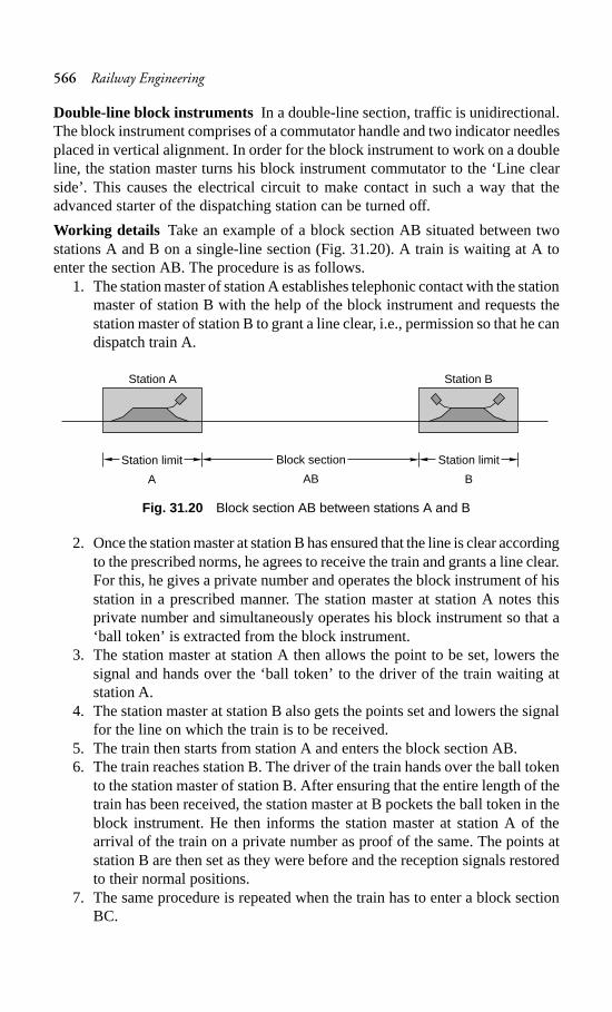
566 Railway Engineering
Double-line block instruments In a double-line section, traffic is unidirectional.The block instrument comprises of a commutator handle and two indicator needlesplaced in vertical alignment. In order for the block instrument to work on a doubleline, the station master turns his block instrument commutator to the ‘Line clearside’. This causes the electrical circuit to make contact in such a way that theadvanced starter of the dispatching station can be turned off.
Working details Take an example of a block section AB situated between twostations A and B on a single-line section (Fig. 31.20). A train is waiting at A toenter the section AB. The procedure is as follows.
1. The station master of station A establishes telephonic contact with the stationmaster of station B with the help of the block instrument and requests thestation master of station B to grant a line clear, i.e., permission so that he candispatch train A.
Fig. 31.20 Block section AB between stations A and B
2. Once the station master at station B has ensured that the line is clear accordingto the prescribed norms, he agrees to receive the train and grants a line clear.For this, he gives a private number and operates the block instrument of hisstation in a prescribed manner. The station master at station A notes thisprivate number and simultaneously operates his block instrument so that a‘ball token’ is extracted from the block instrument.
3. The station master at station A then allows the point to be set, lowers thesignal and hands over the ‘ball token’ to the driver of the train waiting atstation A.
4. The station master at station B also gets the points set and lowers the signalfor the line on which the train is to be received.
5. The train then starts from station A and enters the block section AB.6. The train reaches station B. The driver of the train hands over the ball token
to the station master of station B. After ensuring that the entire length of thetrain has been received, the station master at B pockets the ball token in theblock instrument. He then informs the station master at station A of thearrival of the train on a private number as proof of the same. The points atstation B are then set as they were before and the reception signals restoredto their normal positions.
7. The same procedure is repeated when the train has to enter a block sectionBC.
Station limit
B
Block section
AB
Station limit
A
Station A Station B
Signalling and Interlocking 567
The system is absolutely safe and works on the principle of providing spaceintervals. Most stations on Indian Railways work on this principle. The followingare the essential features of the absolute block system.
(a) No train is allowed to leave a station unless ‘permission to approach’ hasbeen received in advance from the block station.
(b) On double lines, permission to approach is not given until the line is clear,not only up to the first stop signal of the next station, but also for an adequatedistance beyond it.
(c) On a single line, ‘permission to approach’ is not given until the followingconditions are satisfied.(i) The line is clear of trains running in the same direction, not only up to
the first stop signal of the next station, but also for an adequate distancebeyond it.
(ii) The line is clear of trains running in the opposite direction.(d) When two trains are running in the same direction on the same track,
permission to approach should not be given to the second train till the entirelength of the first train is within the limits of the home signal, the ‘on’ statusof all the signals behind the first train has been restored, and the line is clear,not only up to the first stop signal of the station, but also up to an adequatedistance beyond it.
Automatic block system
In the space interval system, clearing a long block section is a protracted event andthe subsequent train has to wait till the preceding train clears the entire blocksection. This impairs the capacity of the section with regard to the number of trainsit can clear at a time. In order to accommodate more trains in the same section, theblock section is divided into smaller automatic block sections. This is particularlydone for sections that are long and have turned into bottlenecks. The essentials ofan automatic block system on a double line are as follows.
(a) The line should be provided with continuous track circuiting.(b) The line between two adjacent block stations may, when required, be divided
into a series of automatic block signalling sections, entry into each of whichwill be governed by a stop signal.
(c) The track circuits should control the stop signal governing the entry into anautomatic block signalling section in the following manner.(i) The signal should not assume the ‘off’ position unless the line is clear
in advance, not only up to the next stop signal, but also for an adequatedistance beyond it.
(ii) The signal should automatically turn on as soon as the train passes it.
31.9 Interlocking
Interlocking is a device or a system meant to ensure the safety of trains. With theincrease in the number of points and the signals and introduction of high speeds, ithas become necessary to eliminate human error, which would otherwise lead tomassive losses of life and property. The points and signals are set in such a way
568 Railway Engineering
that the cabin man cannot lower the signal for the reception of a train unless thecorresponding points have been set and locked. The signal is thus interlocked withthe points in a way that no conflicting movement is possible and the safety oftrains is ensured.
Interlocking can, therefore, be defined as an arrangement of signals, points, andother apparatus so interconnected by means of mechanical or electrical lockingthat they can be operated in a predetermined sequence to ensure that there is noconflicting movement of signals and points and trains run safely.
The signal and interlocking system is so designed that the failure of anyequipment results in the turning on of the signal, thus ensuring train safety.
31.9.1 Essentials
Lever frames and other apparatus provided for the operation and control of signals,points, etc., must be so interlocked and arranged as to comply with the followingessential regulations.
(a) It should not be possible to turn a signal off unless all points for the line onwhich the train is to be received are correctly set, all the facing points arelocked, and all interlocked level crossings are closed and inaccessible toroad traffic.
(b) The line should be fully isolated before the signal is turned off, i.e., no loosewagons should be able to enter this line.
(c) After the signal has been turned off, it should not be possible to makeadjustments in the points or locks on the route, including those in the isolatedline. Also, no interlocked gates should be released until the signal is replacedin the ‘on’ position.
(d) It should not be possible to turn any two signals off at the same time, as thiscan lead to conflicting movements of the trains.
(e) Wherever feasible, the points should be so interlocked as to avoid anyconflicting movement.
31.9.2 Standards
The speed of a train depends on a number of factors such as the haulage capacityof the locomotive, the fitness of the track, the fitness of the rolling stock, the loadof the train, etc., and the speed for a particular section is determined based on allthese factors. Depending upon the maximum speeds permitted in a section, thestations are interlocked in keeping with the prevalent standards, and signallingequipment and other facilities are provided accordingly. There are four standardsof interlocking based on the maximum permissible speeds prevailing on IndianRailways. These refer to the speeds over the main line with respect to the facingpoints and the yard.
Table 31.11 lists the stipulations laid down by Indian Railways for signals,isolation, points, and interlocking arrangements. The details of each of theseinterlocking standards are enumerated in Table 31.12.
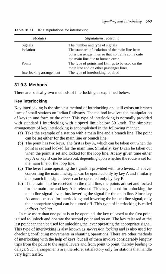
Signalling and Interlocking 569
Table 31.11 IR’s stipulations for interlocking
Modules Stipulations regarding
Signals The number and type of signalsIsolation The standard of isolation of the main line from
other passenger lines so that no trains come ontothe main line due to human error
Points The type of points and fittings to be used on themain line and on other passenger lines
Interlocking arrangement The type of interlocking required
31.9.3 Methods
There are basically two methods of interlocking as explained below.
Key interlocking
Key interlocking is the simplest method of interlocking and still exists on branchlines of small stations on Indian Railways. The method involves the manipulationof keys in one form or the other. This type of interlocking is normally providedwith standard I interlocking with a speed limit below 50 km/h. The simplestarrangement of key interlocking is accomplished in the following manner.
(a) Take the example of a station with a main line and a branch line. The pointcan be set either for the main line or branch line.
(b) The point has two keys. The first is key A, which can be taken out when thepoint is set and locked for the main line. Similarly, key B can be taken outwhen the point is set and locked for the loop line. At any given time eitherkey A or key B can be taken out, depending upon whether the route is set forthe main line or the loop line.
(c) The lever frame operating the signals is provided with two levers. The leverconcerning the main line signal can be operated only by key A and similarlythe branch line signal lever can be operated only by key B.
(d) If the train is to be received on the main line, the points are set and lockedfor the main line and key A is released. This key is used for unlocking themain line signal lever, thus lowering the signal for the main line. Since keyA cannot be used for interlocking and lowering the branch line signal, onlythe appropriate signal can be turned off. This type of interlocking is calledindirect locking.
In case more than one point is to be operated, the key released at the first pointis used to unlock and operate the second point and so on. The key released at thelast point can then be used for unlocking the lever operating the appropriate signal.This type of interlocking is also known as succession locking and is also used forchecking conflicting movements in shunting operations. There are other methodsof interlocking with the help of keys, but all of them involve considerably lengthytrips from the point to the signal levers and from point to point, thereby leading todelays. Such arrangements are, therefore, satisfactory only for stations that handlevery light traffic.
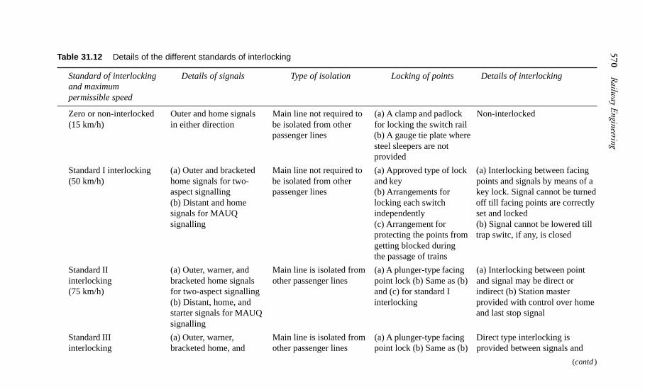
570R
ailway Engineering
Table 31.12 Details of the different standards of interlocking
Standard of interlocking Details of signals Type of isolation Locking of points Details of interlockingand maximumpermissible speed
Zero or non-interlocked Outer and home signals Main line not required to(a) A clamp and padlock Non-interlocked(15 km/h) in either direction be isolated from other for locking the switch rail
passenger lines (b) A gauge tie plate wheresteel sleepers are notprovided
Standard I interlocking (a) Outer and bracketed Main line not required to(a) Approved type of lock (a) Interlocking between facing(50 km/h) home signals for two- be isolated from other and key points and signals by means of a
aspect signalling passenger lines (b) Arrangements for key lock. Signal cannot be turned(b) Distant and home locking each switch off till facing points are correctlysignals for MAUQ independently set and lockedsignalling (c) Arrangement for (b) Signal cannot be lowered till
protecting the points from trap switc, if any, is closedgetting blocked duringthe passage of trains
Standard II (a) Outer, warner, and Main line is isolated from (a) A plunger-type facing(a) Interlocking between pointinterlocking bracketed home signals other passenger lines point lock (b) Same as (b)and signal may be direct or(75 km/h) for two-aspect signalling and (c) for standard I indirect (b) Station master
(b) Distant, home, and interlocking provided with control over homestarter signals for MAUQ and last stop signalsignalling
Standard III (a) Outer, warner, Main line is isolated from (a) A plunger-type facingDirect type interlocking isinterlocking bracketed home, and other passenger lines point lock (b) Same as (b)provided between signals and
(contd)
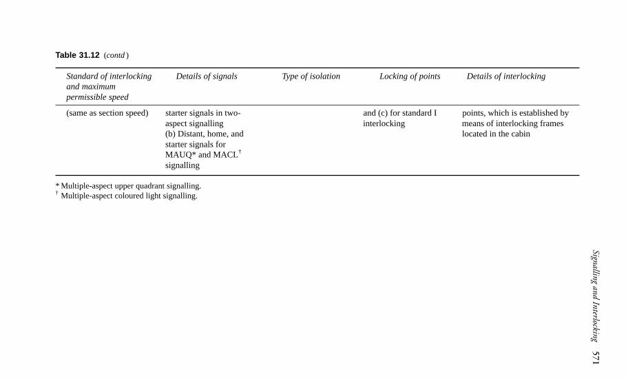
Signalling and Interlocking571
Standard of interlocking Details of signals Type of isolation Locking of points Details of interlockingand maximumpermissible speed
(same as section speed) starter signals in two- and (c) for standard I points, which is established byaspect signalling interlocking means of interlocking frames(b) Distant, home, and located in the cabinstarter signals forMAUQ* and MACL†
signalling
* Multiple-aspect upper quadrant signalling.† Multiple-aspect coloured light signalling.
Table 31.12 (contd)
572 Railway Engineering
Mechanical interlocking
Mechanical interlocking or interlocking on lever frames is an improved form ofinterlocking compared to key locking. It provides greater safety and requires lessmanpower for its operation. This method of interlocking is done using plungersand tie bars. The plungers are generally made of steel sections measuring 30 cm ×1.6 cm and have notches in them. The tie bars are placed at right angles to theplungers and are provided with suitably shaped and riveted pieces of cast iron orsteel that fit exactly in the notches of the tappets.
The main components of an interlocking system are a locking frame, pointfittings, signal fittings, and connecting devices for connecting the locking frame tothe point and signal fittings. The locking frame consists of a number of levers,which work various points, point locks, signal levers, etc. The levers are arrangedtogether in a row in a frame. Pulling a point lever operates the point to which it isconnected through a steel rod. Similarly, pulling a signal lever changes the indicationof the signal by pulling the wire connecting the lever and the signal. To each leveris attached a plunger which has suitably shaped notches to accommodate the lockingtappets. The entire arrangement is provided in a locking trough where tappets areprovided, which move at right angles to the plungers.
When a lever is pulled, it causes the plunger to which it is connected to move.Due to wedge action, the tappet accommodated in the notch of the plunger ispushed out at right angles to the movement of the plunger. The motion is transmittedto all other tappets that are connected to this tappet through a tie bar. As a result ofthis motion, the other tappets either get pushed into or out of the respective notchesof the other plunger depending upon the type of interlocking provided. In case theother tappet is free but slips inside the notch of the other plunger, it locks the leverconnected to this plunger. In consequence, the other lever gets locked in that positionand cannot be operated. However, if the tappet was earlier positioned in the notchof the plunger, thereby locking the lever, and is now out of the notch, the otherlever becomes free to be operated.
31.9.4 Different Cases
The following cases of interlocking are encountered in practical application.
Normal locking In this case, pulling one lever locks the other lever in its normalposition.
Back locking or release lockingIn this case, when the lever is in its normalposition, it also blocks the other lever in its normal position, but when this lever ispulled it releases the other lever, which can then also be pulled. Furthermore, oncethe second lever is also pulled, the first lever gets locked in the ‘pulled’ positionand cannot be returned to its normal position unless the second lever is restored toits normal position.
Both wall locking In this case, once a lever is pulled, it locks the other lever in itscurrent position, i.e., in the normal or pulled position.
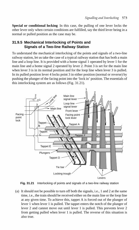
Signalling and Interlocking 573
Special or conditional locking In this case, the pulling of one lever locks theother lever only when certain conditions are fulfilled, say the third lever being in anormal or pulled position as the case may be.
31.9.5 Mechanical Interlocking of Points andSignals of a Two-line Railway Station
To understand the mechanical interlocking of the points and signals of a two-linerailway station, let us take the case of a typical railway station that has both a mainline and a loop line. It is provided with a home signal 1 operated by lever 1 for themain line and a home signal 2 operated by lever 2. Point 3 is set for the main linewhen lever 3 is in its normal position and for the loop line when lever 3 is pulled.In its pulled position lever 4 locks point 3 in either position (normal or reverse) bypushing the plunger of the facing point into the ‘lock in’ position. The essentials ofthis interlocking system are as follows (Fig. 31.21).
Fig. 31.21 Interlocking of points and signals of a two-line railway station
(a) It should not be possible to turn off both the signals, i.e., 1 and 2 at the sametime, i.e., the train should be received either on the main line or the loop lineat any given time. To achieve this, tappet A is forced out of the plunger oflever 1 when lever 1 is pulled. The tappet enters the notch of the plunger oflever 2 and cannot move out until lever 1 is pulled. This prevents lever 2from getting pulled when lever 1 is pulled. The reverse of this situation isalso true.
Loop
line
Main line
Facingpointlock
Main linesignal lever
Loop linesignal lever
Front lever
Facing pointlock lever
Tappet ATappetB
TappetC Tappet F
Tappet D
Tappet E
Plungers
Tie bar
Locking trough
Levers
2
3
1
12
3
4
574 Railway Engineering
(b) It should not be possible to turn a signal off until and unless the point is setand locked. If an effort is made to pull either lever 1 or 2, the same cannot bepulled. This is because of the following reasons. Tappets B and C are rivettedwith a tie bar that is in turn connected with tappet D. Since tappet D isbutting against the face of the plunger of lever 4, tappet B or C cannot bemoved. This plunger can move only when lever 4 is pulled, thereby bringingthe notch of the plunger opposite tappet D. Once this happens, it is notpossible to restore the position of lever 4 till lever 1 or 2 has been broughtback to its normal position. This is a case of release locking. Levers 1 and 2are released by pulling lever 4, which in turn locks the point.
(c) Lever 4 is a lock lever and locks point 3 in either position. The same can bevisualized for tappet E.
(d) Similarly, the main line home signal lever 1 cannot be pulled if point lever 3is pulled, i.e., if it is set for the loop line, as the tappet F cannot be pushed,which allows lever 1 to be pulled when the notch in the plunger of lever 3that lies opposite tappet F has been shifted from its position due to the pullingof lever 3. With lever 3 normal, lever 1 can be pulled conveniently,simultaneously resulting in the locking of lever 2 in it normal position bytappet A.
This example indicates that, with proper planning, it is possible to mechanicallyinterlock the movement of points and signals and thus ensure complete safety.
31.9.6 Electrical Interlocking of Points andSignals of a Two-line Railway Station
Electrical interlocking is achieved through electric switches known as relays. Themanipulation of relays achieves interlocking, whereas lever locks that are attachedwith the levers in place of plungers or in addition to plungers prevent a lever fromgetting pulled, or allow it to get pulled or normalized if the interlocking so permits.
Relays use the simple principle of electromagnetism, whereby a soft iron corewrapped inside a wire coil turns into electromagnet when current is passed throughthe wire. An armature is attached to this electromagnet, which has a number offinger contacts that come into contact with each other when the armature is attractedto the magnet and break the contact when the armature is not attracted to it. Thewhole system is housed in a glass or metal box and is known as relay.
31.10 Modern Signalling Installations
Advancements in electrical engineering and electronics have greatly contributedto the modernization of signalling installations, leading to better safety, increasedspeeds, and quicker movement of trains. Some of these modern signallinginstallations are described below.
Panel interlocking
In panel interlocking, all points and signals are operated electrically from a centrallocation and the switches for operating these points and signals are mounted on a
Signalling and Interlocking 575
panel, which also bears the diagram of the yard layout. Electrical interlocking ofthese points and signals is achieved by means of relays. The main advantage ofpanel interlocking is that the various functions of all the points and signals, eventhough the same cover great distances, can be centrally controlled, therebyeliminating the need for multi-cabin operations of the same. With the eliminationof intercabin control and slotting, the time that is normally lost in coordination issaved and the line capacity increases so that a greater number of trains can be runby a smaller operating staff.
Route relay interlocking
Route relay interlocking is an improvement over panel interlocking. Unlike panelinterlocking, where each point in the route has to be individually set with a respectiveswitch and where the clearance of the signal is obtained by operating the signalswitch, route relay interlocking involves the use of only a pair of switches to performall these operations automatically. Using this pair of switches, the desired route forthe train is set automatically by putting all the points along the route in their desiredpositions. The required signal is then cleared automatically too.
During this operation, it is also ascertained that there is no conflicting movementof the trains in progress or in the offing and also that the route is clear for themovement of a train, including at the overlap. One of the essential requirementsfor this is that the entire yard has got to be track circuited. The condition of thetrack circuits and the various indications of all the signals on the route are mirroredon the panel that carries the diagram of the yard. By looking at these indications,the panel operator can easily discern which portion of the track is clear or occupiedand which signal has been cleared for the movement of the train. Once the route isset to allow the passage of a train, the relevant portion of the diagram on the panelgets illuminated with white lights. The lights turn red when the track is occupiedby the train. When the train has cleared the track, the lights automatically go off.
Route relay interlocking is very useful in busy yards such as the Mumbai suburbansection, where traffic density is very heavy. As route relay interlocked yards arefully track circuited, they ensure complete safety with regard to the movement oftrains.
Centralized train control
The operation of all the points and signals of the various stations of a section iscentralized at one place in such a system. Thus all the points and signals arecontrolled by a single official called the centralized train control (CTC) operator.A CTC operator virtually takes over the work of the station masters of severalindividual stations and operates all the points and signals at a station through remotecontrol.
The CTC panel is normally provided at a central location and controls variousstations up to a distance of about 120 km on either side. There is a separate panelprovided for the operator, which depicts the entire section, including the points,crossings, signals, etc. The signals, routes, points, etc., are operated from the panelby means of separate knobs. This panel also depicts whether the various tracks areoccupied or otherwise.
576 Railway Engineering
In a CTC system, panel interlocking is provided at all stations, which ensurescomplete safety. The CTC operator sends commands to the station equipment inthe form of coded electric pulses by pressing the relevant buttons. The stationequipment receives these commands, and sets the points to the desired position,and clears the appropriate signals. After the task is completed, indication signalsare automatically sent back to the CTC panel in the form of coded electric pulsesand the positions of the points and signals are indicated on the panel. In the routeinterlocking system, instructions regarding the running of trains, arrangement ofcrossings, etc. are issued by the control office through phone calls placed to variousstation masters and the actual control of the movement of the trains between thestations is exercised by the station masters. In the CTC system, all the functions ofthe controller and the station masters are carried out by the CTC operator, who isalways aware of the position of all the trains in the section through the illuminatedpanel and who can remotely operate the various signals and points at all the stations.He or she can, therefore, make judicious plans regarding how the trains will moveforward and how they will cross each other. Moreover, the automatic block systemis always adopted in conjunction with CTC with the result that the number oftrains in a block section can also be increased. The major advantages of the CTCsystem are enumerated below.
(a) There is considerable saving in the amount of time taken by trains to completea run and as such the line capacity of the section is increased. In fact, withthe introduction of CTC the necessity of doubling the track can be overlooked.
(b) No trained station masters, points men, etc. are required at the various stations.The CTC operator does all the work from the central panel. Thus there isconsiderable reduction in the number of skilled staff members required.
(c) The system has the potential to detect any defects in the track.
Automatic warning system
Any amount of safety features incorporated in signalling and interlocking equipmentwill be of no use if the driver ignores a danger signal. The automatic warningsystem (AWS) is a device that triggers the automatic application of brakes if thesignal is indicating danger and the driver has not taken any action. The systemconsists of a track device located at a desirable braking distance at the rear end ofthe first stop signal. The track device is activated when the signal indicates dangerand is ineffective when the signal is ‘clear’. When the locomotive passes over thetrack device with the signal indicating that the line ahead is clear, nothing happens.However, if the signal happens to be indicating danger, a red lamp gets lighted assoon as the locomotive passes over it followed by the ringing of an alarm bell. Ifthe driver presses the acknowledgement button and applies the brake, the alarmstops ringing and no further action is taken by the AWS. If, on the other hand, noaction is taken by the driver, the bell continues to ring. The emergency brakes arethen applied automatically and the train is brought to a stop.
Last vehicle check device
One of the important features of the absolute block system is that a train should notbe allowed to enter the block section unless the last train has arrived at the station
Signalling and Interlocking 577
from either end of the block section. This must be verified by the operator responsiblefor operating the block instrument by observing the last vehicle board or last vehiclelight. It has been observed that in quite a few cases the operator has been foundcareless in certifying the last vehicle. To eliminate human error, a device known asthe last vehicle check device has been developed. This consists of a passiveequipment that the guard hangs on the last vehicle of the train. Each station isprovided with a corresponding active equipment that emits waves of a predeterminedfrequency. This equipment is fitted at the entrance of each station. The coupling ofthe instruments takes place whenever the last vehicle passes by the active equipment,which is sensed by the last vehicle check device (LVCD). The operator receives anindication of the same and can now close the block instrument and issue a freshline clear. The last vehicle check device eliminates human error in ensuring thesafe arrival of the complete train.
Summary
Signals are used to regulate the movement of trains and interlocking ensures thesafe working of signals. There are many different kinds of signals and each one ofthem gives vital information regarding track conditions. These signals have separateindicators for day and night. There are various methods of interlocking startingwith the simple key method to the advanced automatic train control system. Withadvancement in signalling as well as interlocking systems, it has become possibleto run trains at smaller intervals, ensuring optimum use of the track capacity.
Review Questions
1. Give the classification of signals according to their locations in station yardsalong with suitable sketches.
2. (a) What are the objectives of interlocking? Explain the tappet and lock systemof interlocking.(b) Briefly describe the absolute block system of controlling the movement oftrains for single and double lines.
3. What essential purposes are served by signalling and interlocking? What ismeant by route relay interlocking?
4. (a) Briefly describe the locations and purposes of the following signals:(a) warner, (b) outer, (c) home, (d) starter, (e) advance starter.(b) What are the minimum signal requirements in each direction for a two-aspect signalling system in class A, B, and C stations?(c) What are the essentials of interlocking? Distinguish between direct andindirect interlocking.
5. (a) Explain what you understand by interlocking in a railway system.(b) What purposes does the lock bar serve?(c) Distinguish between the following pairs of terms.
(a) Repeating and co-acting signals(b) Warner and distant signals
578 Railway Engineering
(c) Absolute block system and automatic block system(d) Track circuit and rail circuit
6. Describe the three aspects in upper quadrant signalling. Briefly describe onemethod of interlocking used on Indian Railways.
7. Write short notes on (a) absolute block system (b) rudimentary interlocking,and (c) MAUQ signalling. How many standards of interlocking are in vogueon Indian Railways? What requirements must be met by each of them?
8. Briefly describe semaphore signals and coloured light signals.9. Explain with the help of sketches the use of the compensator device in
signalling with regard to the thermal expansion of wires.10. Mention the objectives of signalling. How are signals classified? Mention the
functions of each signal.
Modernization of Railways and High Speed Trains 579
Modernization of Railways
and High Speed Trains
Introduction
Indian Railways, in keeping pace with the advanced railways of the world, hasbeen modernizing its railway system for quite some time. The maximum permissiblespeed on the BG sections of Indian Railways was increased to 120 km/h by firstintroducing it on the Delhi–Howrah route in 1969. This increase in speed waspossible after carrying out extensive investigations and trials on the Rajdhani routeusing a WDM-4 locomotive and all-coiled coaches. The study was based on thefundamental concept that safety and comfort at high speeds depends upon theinteraction of the track and the vehicle. If the suspension system of the rollingstock is very good, then even though track maintenance may be of a comparativelyaverage quality, a reasonable level of comfort will still be achieved. To a limitedextent, track stability can be economically introduced on Indian Railways withoutcarrying out major changes in the track structure, by simply selecting betterlocomotives and rolling stocks and adhering to a slightly higher standard of trackmaintenance. It was for this reason that the Rajdhani Express was hauled by aWDM-4 locomotive and included all-coiled coaches. The speed of the train, whichwas originally 120 km/h, has been increased to 140 km/h and Indian Railways isnow planning to increase the speed to 160 km/h.
Similarly, in the case of meter gauge, the long existent limit of 75 km/h has finallybeen overcome and trains consisting of a YDM-4 locomotive and all-coiled IntegralCoach Factory (ICF) coaches are running at speeds of up to 100 km/h sinceDecember 1997.
32.1 Modernization of Railways
Railways are modernized with the objective of allowing heavier trains to run safelyand economically at faster speeds, of improving productivity, and of providingbetter customer service to rail users. This consists of upgrading the track, use ofbetter designed rolling stock, adopting a superior form of traction, better signallingand telecommunication arrangements, and using other modern techniques in thevarious operations of a railways system. A railway track is modernized byincorporating the following features in the track.
CHAPTER
32
580 Railway Engineering
(a) Use of heavier rail sections such as 52 kg/m and 60 kg/m and the use of wear-resistant rails for heavily used sections so as to increase the life of the rails.
(b) Use of curved switches of 1 in 16 and 1 in 20 type for smoother arrival atyards.
(c) Use of prestressed concrete sleepers and elastic fastenings such as Pandrolclips to provide resilience to the track and ensure the smooth movement oftrains at high speeds.
(d) Use of long welded rails and switch expansion joints to ensure a smooth andfast rail journey.
(e) Modernization of track maintenance methods to include mechanizedmaintenance, measured shovel packings, etc., in order to ensure better trackgeometry, to facilitate high speeds and smooth travel.
(f) Track monitoring using the Amsler car, portable accelerometer, Hallade trackrecorder, etc. to assess the standards of track maintenance and plan for bettermaintenance, if required.
Other aspects of modernization of the railways generally include making thefollowing provisions.
(a) Use of better designed all-coiled, anti-telescope ICF coaches with betterspring arrangements and better braking systems for safe and smoother railtravel.
(b) Provisions of universal couples to ensure uniformity in the coupling of thecoaches.
(c) Introduction of diesel and electric traction in order to haul heavier loads atfaster speeds.
(d) Introduction of modern signalling techniques to enable trains to move athigh speeds without any risks.
(e) Setting up of a management information system for monitoring and movingfreight traffic in order to avoid idle time and increase productivity.
(f) Computerization of the train reservation system to avoid human error andprovide better customer service for reservation of berths.
(g) Use of computers and other modern management techniques to design andmaintain railway assets more efficiently and economically, to ensure efficienthuman resource development (HRD), to increase productivity, and to providebetter customer service.
32.2 Effect of High-speed Track
Investigations carried out in connection with high-speed trains have revealed thatan increase in speed does not necessarily result in a corresponding increase in thedeformation and stresses in track components, which necessitates the use of a heaviertrack structure. The loads, deformations, and stresses in the track components werefound to be augmented as a result of the incongruous movement of vehicles on thetrack including pitching, rolling, bouncing, etc., which occur when the track ispoorly maintained. Therefore, it is possible to operate the same vehicles at a higherspeed on a given track structure without imposing any additional loads and stresses,provided that the standards of maintenance of the track and the vehicles are
Modernization of Railways and High Speed Trains 581
sufficiently improved so as to control these inhibiting movements of the vehiclewhen it runs at higher speeds. The existing track structure on the Rajdhani routeis considered to be of adequate standard for speeds reaching as high as 120 to140 km/h.
To achieve still higher speeds of the order of 160 to 200 km/h, the standard ofmaintenance needs to be very high, as very close track tolerances will have to bemaintained. Maintaining the existing tracks at such tolerance limits may beuneconomical and may necessitate the adoption of an improved track structure,which can be maintained at closer tolerance limits at a comparatively low costs.The modern track structure, consisting of long welded rails with concrete sleepers,elastic fastenings, and ballastless tracks may well fulfil this requirement. The costof this modern track may be comparatively high, but its maintenance will involvelimited expenditure.
32.3 Vehicle Performance on Track
When judging the performance of a high-speed vehicle on the track, it is ascertainedthat the following requirements are fulfilled.
(a) At the defective locations in the track, the variations in the vertical andlateral wheel loads should not reach a level where the wheels can get derailedbecause of the incidence of mounting.
(b) At defective portions of the track, the variations in the vertical and lateralwheel loads should not reach a level where they can lead to derailment as ofa result of the distortion to the track.
(c) It should be ensured that the passengers are generally comfortable while thevehicle plies on the track and that goods are carried without any damage.
(d) In the case of diesel and electric locomotives, it is specified that a lateralforce lasting more than 2 m should not normally exceed 40% of the axleload plus 2 t. The values of acceleration recorded in the cab at locationsshould, as far as possible, be limited to 0.3g, both in the vertical and thelateral direction. A peak value of 0.35g may be permitted in case the recordsdo not indicate a significant tendency of this value to be repeated. The rideindex is calculated for the purpose of comfort analysis, based on the lateraland vertical acceleration values obtained from acceleration output graphs.The ride index should normally not be greater than 4; a value of 3.75 ispreferred.
In the case of carriages, the values of horizontal and lateral accelerations shouldgenerally not increase beyond 0.3g, and an occasional value of 0.35g is permissible,as stipulated in the case of locomotives. The value of the ride index should notincrease to 3.5, though a value of 3.25 is preferred.
32.4 High-speed Ground Transportation System
The high-speed rail ground transportation system (HSGT) is a concept developedto meet the challenges of the increasing demands of passenger transportation andrecover their share of traffic from road and other modes of transport. The details
582 Railway Engineering
and developments of the high-speed rail system are presented in Tables 32.1 and32.2, respectively.
Table 32.1 Details of the high-speed rail system
Speed range (km/h) Details
200–250 � Diesel electric trains (including the British HST)� Electrified tilt-body trains (including the Swedish X2000,
the Italian Pendolino, the Spanish Talgo)� Electrified non-tilting the rains (including the US
Metroliner)
250–350 � Electrified non-tilting trains (including the JapaneseShinkansen, the French TGV, the German ICE)
Above 350 � Maglev systems developed in Japan and Germany. Theseare a combination of superconducting magnets and linearmotor technology and have a non-adhesive drive systemthat is independent of wheel and rail frictional forces
Table 32.2 Development of the high-speed rail system
Year Country Details
1964 Japan Tokyo-Osaka, covers 515 km in 3 hrs 10 m(Shinkansen network expansion)
1981–83 France Paris-Lyon, covers 410 km in 2 hrs (TGV network)
1991 Germany ICE trains in Germany (Hanover-Wurzberg, covers327 km in 2 hrs.)
1992 Spain Madrid-Seville, covers 471 km in 2 hrs 15 m (AVEand Talgo trains)
1994 Eurostar in the UK, France, and Belgium
1995–2003 Finland, Italy, Sweden, USA, Australia, China, Switzerland, SouthKorea, and other countries
In the year 2000–01, HSGT operations stretched over a distance of around4900 km across the world and work on another 680 km was in progress or in theplanning stages in various countries.
32.5 Ballastless Track
The technical concept of a railway track consisting of ballast, sleepers, and rails isvery old and has stood the test of time. Such a system is simple and can be rapidlyextended, renewed, or dismantled. The general problem that occurs with ballastedtracks is that the ballast material slowly deteriorates due to the load of the traffic.The breaking of the ballast under the pressure exerted by the load causes geometricalunevenness and clogging of the ballast bed by fine particles. Therefore, regularmaintenance is needed to restore track alignment. The experience in Germany andother countries has been that the conventional track may be used for speeds of up
Modernization of Railways and High Speed Trains 583
to 250 km/h but not beyond that. For higher speeds, the construction of a ballastlesstrack is required. In a ballastless track, the rails are directly fastened to the concreteslab using elastic fastenings. A ballastless track is expensive but is likely to requirelittle or no maintenance during its lifetime. The success of a ballastless track isprimarily based on the following advantages it offers.
Stability, precision, and comfort A ballastless track assures a permanently stabletrack and can withstand the heavy load of high-speed train traffic. Its performanceis characterized by top quality, functionality and safety. The precise adjustment ofthe track up to the last millimetre while it is being assembled at the constructionsite is the prerequisite for ride comfort as well as reduction of pressure loadsexperienced by the rolling stock.
Long life-span with practically no maintenance With a service life of at least60 years and with little or no requirement for service or maintenance, a ballastlesstrack offers great viability and unmatched cost effectiveness in high-speedoperations.
Flexibility and end-to-end effectiveness in applicationWith its comparativelylow structural height and the possibility of the achievement of the optimal trackalignment, ballastless track technology offers highly attractive and beneficialsolutions as an end-to-end system technology for main-track and turnout sections.This technology can be applied on a uniform basis on embankments, bridges, andtunnels.
Basis for optimal routing of rail lines
The use of a ballastless track for high-speed operations enables a more direct routingof train lines, with tighter radii and greater slopes. These benefits enable thereduction, or even elimination, of the costs of and the work required on civilengineering structures. These benefits have led to the application of ballastlesstrack technology in the major projects for rail lines currently being undertaken inGermany, where approximately 800 km of ballastless track has been installed since1991, as well as in other major projects around the world. The ballastless track hasfound applications in many areas, as detailed in Table 32.3.
Table 32.3 Applications of ballastless tracks
Area of application Remarks
Main lines Suitable for axle loads of 15 to 35 t
Urban light rail Low-vibration profile and good aesthetics, suited for use inintracity commuter lines
Tunnels and Poor drainage and tamping difficulties are major problems withunderground tracks respect to the conventional track. A ballastless track with a centre
drain provides a low-maintenance, geometrically stablealternative.
Stations The use of ballast results in continuously varying rail-to-platformheights. This is dangerous for passengers.
(contd)
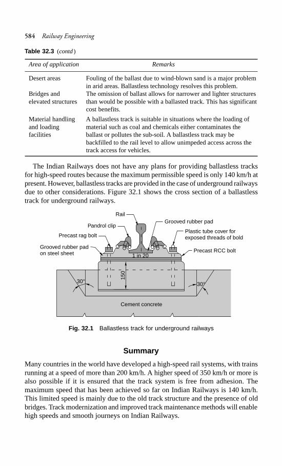
584 Railway Engineering
Area of application Remarks
Desert areas Fouling of the ballast due to wind-blown sand is a major problemin arid areas. Ballastless technology resolves this problem.
Bridges and The omission of ballast allows for narrower and lighter structureselevated structures than would be possible with a ballasted track. This has significant
cost benefits.
Material handling A ballastless track is suitable in situations where the loading ofand loading material such as coal and chemicals either contaminates thefacilities ballast or pollutes the sub-soil. A ballastless track may be
backfilled to the rail level to allow unimpeded access across thetrack access for vehicles.
The Indian Railways does not have any plans for providing ballastless tracksfor high-speed routes because the maximum permissible speed is only 140 km/h atpresent. However, ballastless tracks are provided in the case of underground railwaysdue to other considerations. Figure 32.1 shows the cross section of a ballastlesstrack for underground railways.
Fig. 32.1 Ballastless track for underground railways
Summary
Many countries in the world have developed a high-speed rail systems, with trainsrunning at a speed of more than 200 km/h. A higher speed of 350 km/h or more isalso possible if it is ensured that the track system is free from adhesion. Themaximum speed that has been achieved so far on Indian Railways is 140 km/h.This limited speed is mainly due to the old track structure and the presence of oldbridges. Track modernization and improved track maintenance methods will enablehigh speeds and smooth journeys on Indian Railways.
Table 32.3 (contd)
Rail
30° 30°
Cement concrete
150
Pandrol clip
Precast rag bolt
Grooved rubber padon steel sheet 1 in 20
Grooved rubber pad
Plastic tube cover forexposed threads of bold
Precast RCC bolt
Modernization of Railways and High Speed Trains 585
Review Questions
1. Write short notes on the track requirements for high-speed trains.2. Enumerate all the important work which may have to be undertaken for
strengthening and improving an existing track so that higher speeds arepermissible on it.
3. What are the various measures normally taken to improve the track for it toaccommodate high speeds?
4. Write short notes on ballastless track and movable crossings.
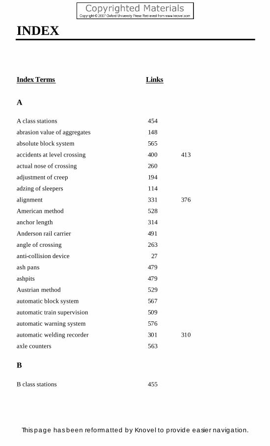
INDEX
Index Terms Links
A
A class stations 454
abrasion value of aggregates 148
absolute block system 565
accidents at level crossing 400 413
actual nose of crossing 260
adjustment of creep 194
adzing of sleepers 114
alignment 331 376
American method 528
anchor length 314
Anderson rail carrier 491
angle of crossing 263
anti-collision device 27
ash pans 479
ashpits 479
Austrian method 529
automatic block system 567
automatic train supervision 509
automatic warning system 576
automatic welding recorder 301 310
axle counters 563
B
B class stations 455
This page has been reformatted by Knovel to provide easier navigation.
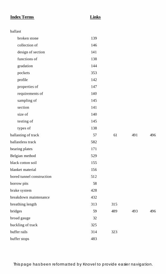
Index Terms Links
ballast
broken stone 139
collection of 146
design of section 141
functions of 138
gradation 144
pockets 353
profile 142
properties of 147
requirements of 140
sampling of 145
section 141
size of 140
testing of 145
types of 138
ballasting of track 57 61 491 496
ballastless track 582
bearing plates 171
Belgian method 529
black cotton soil 155
blanket material 156
bored tunnel construction 512
borrow pits 58
brake system 428
breakdown maintenance 432
breathing length 313 315
bridges 59 489 493 496
broad gauge 32
buckling of track 325
buffer rails 314 323
buffer stops 483
This page has been reformatted by Knovel to provide easier navigation.
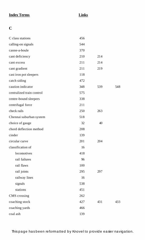
Index Terms Links
C
C class stations 456
calling-on signals 544
canne-a-boule 370
cant deficiency 210 214
cant excess 211 214
cant gradient 211 219
cast iron pot sleepers 118
catch siding 472
caution indicator 348 539 548
centralized train control 575
centre-bound sleepers 338
centrifugal force 211
check rails 250 263
Chennai suburban system 518
choice of gauge 32 40
chord deflection method 208
cinder 139
circular curve 201 204
classification of 16
locomotives 418
rail failures 96
rail flaws 100
rail joints 295 297
railway lines 16
signals 538
stations 451
CMS crossing 262
coaching stock 427 431 433
coaching yards 466
coal ash 139
This page has been reformatted by Knovel to provide easier navigation.
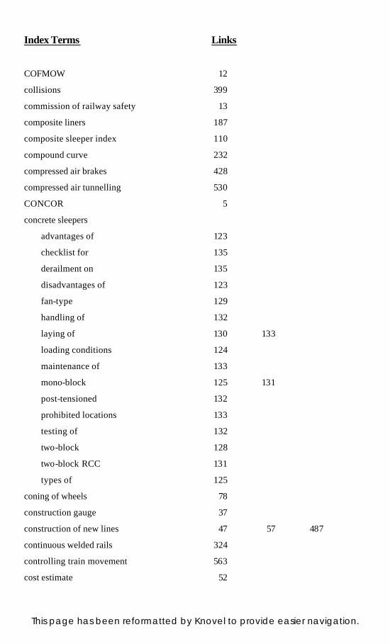
Index Terms Links
COFMOW 12
collisions 399
commission of railway safety 13
composite liners 187
composite sleeper index 110
compound curve 232
compressed air brakes 428
compressed air tunnelling 530
CONCOR 5
concrete sleepers
advantages of 123
checklist for 135
derailment on 135
disadvantages of 123
fan-type 129
handling of 132
laying of 130 133
loading conditions 124
maintenance of 133
mono-block 125 131
post-tensioned 132
prohibited locations 133
testing of 132
two-block 128
two-block RCC 131
types of 125
coning of wheels 78
construction gauge 37
construction of new lines 47 57 487
continuous welded rails 324
controlling train movement 563
cost estimate 52
This page has been reformatted by Knovel to provide easier navigation.
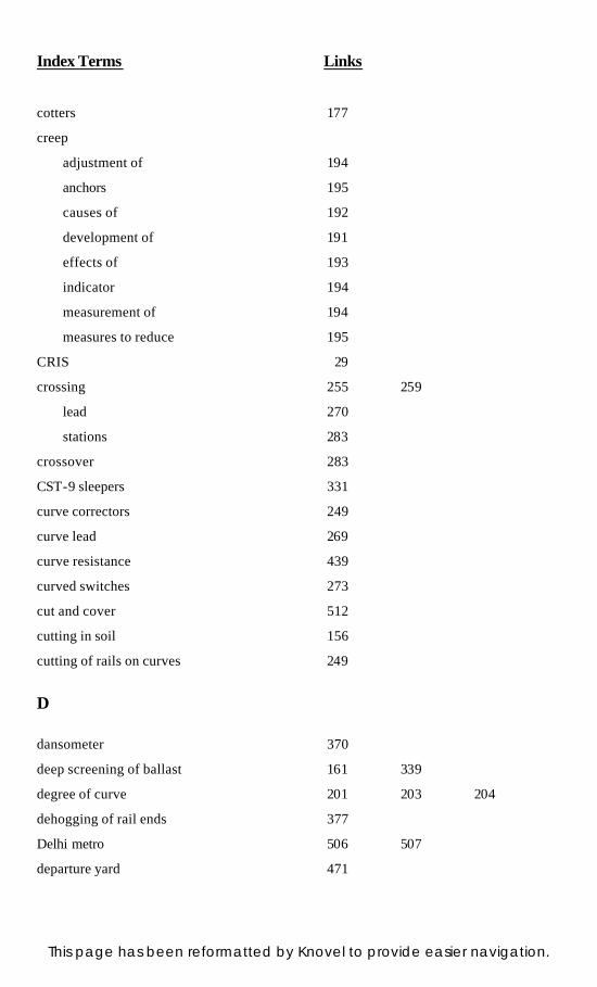
Index Terms Links
cotters 177
creep
adjustment of 194
anchors 195
causes of 192
development of 191
effects of 193
indicator 194
measurement of 194
measures to reduce 195
CRIS 29
crossing 255 259
lead 270
stations 283
crossover 283
CST-9 sleepers 331
curve correctors 249
curve lead 269
curve resistance 439
curved switches 273
cut and cover 512
cutting in soil 156
cutting of rails on curves 249
D
dansometer 370
deep screening of ballast 161 339
degree of curve 201 203 204
dehogging of rail ends 377
Delhi metro 506 507
departure yard 471
This page has been reformatted by Knovel to provide easier navigation.
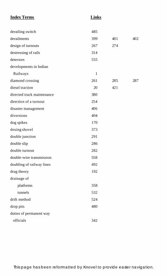
Index Terms Links
derailing switch 485
derailments 399 401 402
design of turnouts 267 274
destressing of rails 314
detectors 555
developments in Indian
Railways 1
diamond crossing 261 285 287
diesel traction 20 421
directed track maintenance 380
direction of a turnout 254
disaster management 406
diversions 404
dog spikes 170
dosing shovel 373
double junction 291
double slip 286
double turnout 282
double-wire transmission 558
doubling of railway lines 492
drag theory 192
drainage of
platforms 358
tunnels 532
drift method 524
drop pits 480
duties of permanent way
officials 342
This page has been reformatted by Knovel to provide easier navigation.
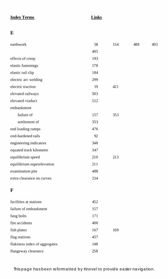
Index Terms Links
E
earthwork 58 154 488 493
495
effects of creep 193
elastic fastenings 178
elastic rail clip 184
electric arc welding 299
electric traction 19 421
elevated railways 503
elevated viaduct 512
embankment
failure of 157 353
settlement of 353
end loading ramps 476
end-hardened rails 92
engineering indicators 348
equated track kilometre 347
equilibrium speed 210 213
equilibrium superelevation 211
examination pits 488
extra clearance on curves 234
F
facilities at stations 452
failure of embankment 157
fang bolts 171
fire accidents 400
fish plates 167 169
flag stations 457
flakiness index of aggregates 148
flangeway clearance 258
This page has been reformatted by Knovel to provide easier navigation.
Index Terms Links
flash butt welding 299
flat yards 468
fleximeter 370
flood causeway 405
foot over bridge 475
forepoling method 526
formation 63 152
slope 153
width 153
fouling mark 485
full face method 523
G
gang strength 347
gas pressure welding 298
gathering line 289
gauge 32
broad 32
choice of 32 40
construction 37
conversion 493
conversion projects 493
definition 31
loading 36
on different railways 32
on Indian Railways 32
standard 31
tolerance 331
uniformity of 33
gauntletted track 288
geometric design of track 197
This page has been reformatted by Knovel to provide easier navigation.
Index Terms Links
geotextiles 162
goods wagons 428 431 433
goods yards 466
grade compensation 200 440
grade resistance 438
gradients 198
gravitation yards 469
H
halt stations 457
hammer blow effect 71
hauling power 447
head-hardened rails 92
heading and bench method 523
heel divergence 258
herringbone grid 290
high-speed ground transporta-
tion system 581
high-speed tracks 580
HM fastenings 185
hogging of rails 94 336
hooters for accidents 398
hump yards 469
I
impact value 148
Indian Railways 1
corporate plan 14
developments 1
division 12
engineering data 34
This page has been reformatted by Knovel to provide easier navigation.
Index Terms Links
Indian Railways (Cont.)
general features 18
operating efficiency 23
organization 8
role of 8
social cost 24
statistics 21
strengths 14
uni-gauge policy 36
weaknesses 15
indicative accidents 398
indicators
caution 348 539 548
point 546
route 550
speed 348 548
stop 348 548
termination 348 548
trap 547
insulated joints 341
interlocking
key 569
mechanical 572
panel 574
route relay 575
internal resistance 436
inverted filter 160
IRCON 26
IRCTC 28
IRFC 26
IRN 202 clip 182
IRWO 29
This page has been reformatted by Knovel to provide easier navigation.
Index Terms Links
J
journal friction 436
junction stations 460
K
Kolkata metro 515
KRCL 27
L
land acquisition 57 487 493 495
last vehicle check device 576
lateral wear 386
length of transition curve 229
level crossing 500
accidents at 400 413
classification of 411
dimensions of 413
inspection of 415
layout of 412
maintenance of 414
levelling 365
lifting of track 337
lighting of tunnels 532
linear plate method 527
lining of tunnels 533
loading gauge 475
lock spikes 183
locomotive sheds 476
locomotive yards 466
This page has been reformatted by Knovel to provide easier navigation.
Index Terms Links
locomotive 20
classification of 418
diesel 20 421 426
electric 20 421 426
maintenance of 425
nomenclature of 418
steam 419 425
yards 466
long chord offset method 206
long welded rails
definition 313
maintenance of 321
prohibited locations for 316
theory of 315
track structure for 317
loose jaws 174
lower quadrant signals 553
M
maintenance of rail surface 336
marshalling yards 466
mass rapid transit system 506
mass–haul curve 58
MCI inserts 186
measured shovel packing 368 378
measurement of wear 93
mechanical re-laying 391
mechanized maintenance 361
metre gauge 32
metro stations 510
modernization of railways 579
This page has been reformatted by Knovel to provide easier navigation.
Index Terms Links
modes of transport 6
monorails 503
moorum ballast 139
Mota Singh liner 174
motorbuses 499
mountain railways 45
movable crossing 262
MS tie bars 178
Mumbai suburban system 517
N
Nadal’s formula 402
needle beam method of
tunnelling 528
negative superelevation 216
number of crossing 263
O
obligatory points 41
off-track tampers 362
on-track tampers 364
overriding switch 257
oversize ballast 145
P
packing
shovel 372
sleepers, of 332
track, of 491
Pandrol clip 179
passenger yards 452
This page has been reformatted by Knovel to provide easier navigation.
Index Terms Links
patrolling of track 350
percussion theory 191
periodical overhaul 425 430
permanent way
definition 63
maintenance 68
requirements 64
permissible speed on curves 217 218 219
picking up slacks 329 333
pilot tunnel 525
plan outlay 15
plate laying 59 489 493
platforms 463 474
drainage of 358
point indicators 546
point locks 554
points and crossings 254
post-tensioned concrete
sleepers 127 132
post-welding operations 306
PRCL 28
pressure on formation 76
pulsator 189
R
rack railway 45
radius of curve 201 270
rail failure
causes 96
classification 96
This page has been reformatted by Knovel to provide easier navigation.

Index Terms Links
rail flaw
classification 100
detection 97
rail joints
classification 295 297
requirements 295
types of 295
Rail Neer 28
rail
bending stresses 72
branding 87
chemical composition 90
contact stress 74
corrugation of 95
dolly 390
end batter 93
end-hardened 92
functions 81
head-hardened 92
hogging of 94
joints 295
lateral forces 74
length of 86
longitudinal forces 74
lubricators 94
manufacture of 86
permissible stress 77
renewal 385
requirements of 82
second quality 90
service life of 388
standard section of 83 84
This page has been reformatted by Knovel to provide easier navigation.
Index Terms Links
rail (Cont.)
temperature 320
test for 89
testing trolley 99
third quality 91
tilting 79
types of 81
wear in 92 385
weight of 86
RailTel 28
railway
as mode of transport 6 7
finances 13
history 1
rack 45
track 18
zonal 9
Railway Board 8
railway employees 23
training of 23
railway lines 16
BG routes 16
classification 16
group A 16
group B 17
MG routes 17
railway stations
A class 454
B class 455
C class 456
classification of 453
crossing 457
This page has been reformatted by Knovel to provide easier navigation.
Index Terms Links
railway stations (Cont.)
equipment at 474
facilities at 452
flag 457
halt 457
junction 460
purpose of 451
site selection 451
terminal 462
wayside 457
RDSO 4 9
realignment of curve 242 249
reception yards 471
reconditioning of crossing 265
relief of stresses 77
reverse curve 233
RITES 25
road over bridge 501
road under bridge 501
rolling resistance 436
rolling stock 21 427 508
round spikes 170
route relay interlocking 575
rubber pads 186
RVNL 28
S
safe speed on curves 217
sand ballast 138
sand drains 160
sand hump 485
This page has been reformatted by Knovel to provide easier navigation.

Index Terms Links
sand piling 160
schedule maintenance 431
schedule of dimensions 514
schedule shed maintenance 425
scissors crossover 287
Scotch block 484
screw spikes 171
second quality rails 90
serious accidents 397
service life of rails 388
setting of curve 205
shaft of tunnels 532
shift 229
short preheat welding 307
short welded rails
maintenance of 324
track specification for 323
sighting boards 548
signalling 508
objects of 537
signals
advanced starter 551
audible 539
calling-on 544
classification of 538
coloured light 542
distant 541
electrical 551 561
fixed 539 540
home 549
lower quadrant 553
outer 549
This page has been reformatted by Knovel to provide easier navigation.

Index Terms Links
signals (Cont.)
repeater 545
routing 549
semaphore 540
shunt 546
starter 551
upper quadrant 553
visible 539
warner 541
single slip 286
single-wire transmission 556
site investigations 163
size of ballast 140 144
sleeper density 107
sleeper renewal 388
sleepers
at points and crossings 263
cast iron (CI) 117
CI pot 118
concrete 122
CST-9 118 331
density 107
design features 116 124
fan-type concrete 129
functions 106
mono-block PRC 125 131
requirements of 106
seasoning of 113
spacing 107
steel trough 115 331
two-block RCC 131
types of 108
This page has been reformatted by Knovel to provide easier navigation.
Index Terms Links
sleepers (Cont.)
wooden 109 331
slew 244
slip 79 286
slip siding 472
soil classification 154
soil stabilization 162
sorting yards 471
spacing
sleepers, of 107
tracks, of 509
yards, of 470
specific gravity of aggregates 149
speed factor 70
speed indicator 548
speed on turnouts 272
spring steel clip 183
standard gauge 32
standard rail section 83 84
station platforms 463
stations 451
steam effect 71
steam locomotive 419 425
steam traction 418
steel sleepers 115
stock rails 254
stop indicators 548
stresses
in ballast 76
in rails 72
in sleepers 75
string line method 243
This page has been reformatted by Knovel to provide easier navigation.
Index Terms Links
sub-ballast 149
sub-surface drainage 356 358
subgrade 152
subways 475
superelevation 210 214
surface defects 336
surface drains 356
surface railways 500
survey
field 51
final location 53
instruments 50 51
modern 50 56
preliminary 51
reconnaissance 49
traffic 48
types of 48
sway of vehicles 235
switch 255 256
angle 258
expansion joint 314 322
lead 269
rails 256
switch-back method 41
symmetrical split 280
systematic overhauling 332
T
tangent correction method 240
tangential offset method 205
terminal stations 462
This page has been reformatted by Knovel to provide easier navigation.
Index Terms Links
termination indicator 548
testing
concrete sleepers, of 132
rail joints, of 309
theodolite method 209
thermit welding 304
third quality rails 91
three-throw switch 281
three-tier maintenance 367
through packing 329 330
throw of switch 258
tilting of rails 79
tongue rails 254 259
track
alignment 376
ballasting of 57 61 491 496
circuits 562
drainage 156 340 354
fitting 166
forces on 70
junctions 279
linking 59 60 489 496
maintenance 329
materials 395 492
modulus 69
packing 61
renewal train 393
renewal works 384
specifications 64
structure 65 67
tolerances 350
utilization 68
This page has been reformatted by Knovel to provide easier navigation.

Index Terms Links
track alignment
cross-country 41
importance 39
plane 41
requirements 39
valley 41
zigzag 41
traction 20
diesel 20 417
electric 20 417
tractive effort 441
traffic survey 48
train accidents 397
train resistances 436 441
tram line method 59 490
tramways 500
transition curve 226 229 231
trap indicators 547
traverser 482
triangle 290 482
trolley buses 499
tube railway 504
tunnel
advantages of 520
alignment 521
disadvantages of 521
drainage 532
grade 521
inspection of 534
lighting of 532
lining of 533
maintenance of 534
This page has been reformatted by Knovel to provide easier navigation.
Index Terms Links
tunnel (Cont.)
necessity of 520
pilot 525
shape of 521
size of 521
ventilation in 530
tunnelling
compressed air 530
drift method of 524
in hard rocks 522
in soft rocks 526
needle beam method of 528
turnout 254 266 279
turntable 481
two-way keys 174
types of fittings 166
types of rail joints 295
U
ultrasonic rail flaw detector 97 101
undersize ballast 145
undercut switch 257
underground railway 501
uni-gauge policy 36
uni-gauge projects 36
upper quadrant signals 553
urban transport 499
V
vacuum brakes 429
vehicle performance 581
This page has been reformatted by Knovel to provide easier navigation.
Index Terms Links
ventilation of tunnels 530
versine of curve 202
vertical curves 238 239 240 241
vertical wear 386
vibrogir 189
viseur and mire 372
W
washing platforms 483
water absorption of aggregates 149
water columns 480
wave motion theory 191
wayside station 457
wear of rails 92 93 385
types of 93
weigh bridge 475
weight of rails 86
welding a rail 298 303
wheel burns 94
widening of gauge 237
width of berms 58
width of formation 57 153
wooden sleepers
durable 111
fitting for 170
laying of 114
non-durable 111
seasoning of 113
treated 112
treatment of 112
untreated 112
This page has been reformatted by Knovel to provide easier navigation.
Index Terms Links
Y
yards
coaching 466
departure 471
drainage in 357
flat 468
goods 466
gravitation 469
hump 469
locomotive 466
marshalling 466
reception 471
sick line 466
sorting 471
spacing of 470
This page has been reformatted by Knovel to provide easier navigation.