Radon Reduction Techniques for Existing Detached Houses
335
-
Upload
khangminh22 -
Category
Documents
-
view
0 -
download
0
Transcript of Radon Reduction Techniques for Existing Detached Houses


EPA/625/R-93/011October 1993
Radon Reduction Techniques forExisting Detached Houses
Technica~ Guidance (Third Edition)for
Active Soil Depressurization Systems
.I'
D. Bruce Henschel
Air and Energy Engineering Research LaboratoryOffice of Environmental Engineering and Technology Demonstration
Office of Research and DevelopmentU.S. Environmental Protection Agency
Research Triangle Park, North Carolina 27711
@ Printed on Recycled Paper

EPA Disclaimer Notice
The u.s. Environmental Protection Agency (EPA) strives to provide accurate, complete,and useful infonnation. However, neither EPA nor any person contributing to the preparation of this document makes any warranty, expressed or implied, with respect to theusefulness or effectiveness of any infonnation, method, or process disclosed in thismaterial. Nor does EPA assume any liability for the use of, or for damages arising from theuse of, any infonnation, method, or process disclosed in this document.
Mention of firms, trade names, or commercial products in this document does notconstitute endorsement or recommendation for use.
ii

Preface
This technical guidance document has been prepared to serve as a comprehensive aid in thedetailed selection, design, installation, and operation of indoor radon reduction measures .for existing houses based on active soil depressurization techniques. It is intended for useby radon mitigation contractors, building contractors, concerned homeowners, state andlocal officials, and other interested persons.
This document is the third edition ofEPA's technical guidance for indoor radon reductiontechniques. This document addresseS primarily radon reduction techniques based on activesoil depressurization technology, which is one of the most widely used approaches forreducing radon in existing houses. The document also addresses active soil pressurizationand passive soil depressurization techniques, because these less widely used techniquesbear a number of similarities to active depressurization systems.
This edition incorporates additional and updated information on active soil depressurization techniques, reflecting new results and perspectives that have been obtained in thisdeveloping field since the second edition ofEPA's technical guidance (BPN625/5-87/019)was published in January 1988. Thus, this document should be viewed as replacing Section5 ("Soil Ventilation") of the second edition.
This document does not provide guidance regarding indoor radon reduction techniquesother than active soil depressurization (and active soil pressurization and passive soildepressurization). Persons interested in other techniques, including house ventilation, entryroute sealing, house pressure adjustments, air cleaners, and well water treatment, arereferred to the second edition of the technical guidance document.
Homeowners and occupants who are interested in a briefoverview of the alternative radonreduction techniques available, and of the steps to follow in getting a radon reductionsystem installed in their home, are referred to the booklet entitled Consumer's Guide toRadon Reduction, EPA-402-K92-003. Copies of that booklet, and of the second and thirdeditions of the detailed technical guidance document, can be obtained from the stateagencies and the EPA regiol1lal offices listed in Section 15. Copies of the second and thirdeditions of the technical guidance document can also be obtained from
ORD Publications OfficeCenter for Environmental Research Information
U.S. Environmental Protection Agency26 West Martin Luther King Drive
Cincinnati, OH 45268-1072
iii


Contents
Preface iii'Figures xiTables xiiiAcknowledgments xivGlossary xvMetric Equivalents xxii
HOW TO USE TInS DOCUMEN1: H~l
1 Introduction 11.1 Purpose 1·
1.2 Scope 2
1.3 Content 2
1.4 Reason for Focus on Active Soil Depressurization 3
2 Principles, Applicability, and Past Perfonnance of Soil Depressurization Systems 52.1 Principles o~Active Soil Depressurization ~ ~ 5
2.1.1 •Active Sub-Slab Depressurization (SSD) 7
2.1.2 Active SumpjDrain-Tile Depressurization (SumpjDTD) 72.1.3 Active Drain-Tile Depressurization (Above-Grade/Dry-Well Discharge) 11
2.1.4 Active Block-Wall Depressurization (BWD) 13
2.1.5 Active Sub-Membrane Depressurization (SMD) in Crawl Spaces 13
2.2 Applicability of Active Soil Depressurization ; 18
2.2.1 Active Sub-Slab Depressurization.. 192.2.2 Active Sump/Drain-Tile Depressurization 20
2.2.3 Active Drain-Tile Depressurization (Above-Grade/Dry-Well Discharge) 212.2.4 Active Block-Wall Depressurization 222.2.5 Active Sub-Membrane Depressurization 23
2.3 Perfonnance of Active Soil Depressurization Systems 24
2.3.1 Active Sub~Slab Depressurization 25
2.3.2 Active Sump/Drain-Tile Depressurization 37
2.3.3 Active Drain-Tile Depressurization (Above-Grade/Dry-Well Discharge) 412.3.4 ~;tive Block-Wall Depressurization 44
2.3.5 'ACu.ye Sub-Membrnn.e Depressurization ~ 52'2.4 Perfonnanceof Active Soil Pressurization Systems 64
2.4.1 Acti.\~ Sub-Slab Pressurization 65
2.4.2 Active Block-Wall Pressurization 67
·2.5 Perfonnance of Passive Soil Depressurization Systems 67
v

3.5.43.5.53.5.6
Contents (continued)
3 Pre-Mitigation Diagnostic Test Procedures for Soil Depressurization Systems 733.1 General 73
3.1.1 Purposes of Pre-Mitigation Diagnostics : 733.1.2 Diagnostic Tests That Can Be Considered 73
3.2 Procedures for the Visual Survey ~ 763.3 Procedures for Sub-Slab Suction Field Extension Measurements 81
3.3.1 Qualitative Assessment of Suction Field Extension 833.3.2 Quantitative Assessment of Suction Field Extension 88
3.4 Procedures for Radon Grab Sampling and Sniffmg 923.5 Procedures for Other Types of Diagnostic Tests 98
3.5.1 Sub-Slab Flows 983.5.2 Well Water Radon Analysis 1003.5.3 Measurements to Determine Significance of Building Materials
as a Radon Source 101
Pressure Differential Measurements Across the House Shell 103Blower Door Measurements 106Tracer Gas Testing 107
4 Design and Installation of Active Sub-Slab Depressurization Systems 1094.1 Selection of the Number of Suction Pipes 109
4.1.1 Houses Having Good Sub-Slab Communication 1094.1.2 Houses Having Marginal or Poor Sub-Slab Communication 110
4.2 Selection of Suction Pipe Location 1124.2.1 Houses Having Good Sub-Slab Communication 1124.2.2 Houses Having Marginal or Poor Sub-Slab Communication 114
4.3 Selection of Suction Pipe Type and Diameter 1154.3.1 Type of Suction Pipe 1154.3.2 Dimneter of Suction Pipe 116
4.4 Selection of the Suction Fan '............................. 1184.4.1 Centrifugal In-Line Tubular Fans 1204.4.2 In-Line Radial Blowers 1234.4.3 High-SuctionlLow-Flow Blowers , 123
4.5 Installation of Suction Pipes Beneath the Slab 1254.5.1 Vertical Pipe Installed Down Through Drilled Hole Indoors 1254.5.2 Vertical Pipe Installed Down Through Large Hole Indoors (Large Sub-Slab Pit) 1304.5.3 Vertical Pipe Installed Into Unused Sump Pit Indoors 1344.5.4 Horizontal Pipe Installed Through Foundation Wall from Outdoors 1344.5.5 Horizontal Pipe Installed Through Foundation Wall from Inside Basement 1374.5.6 Suction Pipe Installed from Inside Garage 137
4.6 Design/Installation of the Piping Network and Fan 1404.6.1 Suction Loss in the Piping Network 1404.6.2 Considerations in Pipe Routing Between Suction Points and Fan 145
4.6.3 Considerations in Pipe Installation Between Suction Points and Fan 148
vi

COlntents (continued)
4.6.4 Design and Installation of the Fan and Exhaust Piping-Interior Stacks 151
4.6.5 Design and Installation of the Fan and Exhaust Piping-Exterior and Garage Stacks , 162
4.1 Slab Sealing in Conjunction with SSD Systems , 176
4.7.1 Perimeter Channell Drains 177
4.7.2 Other Major Holes Through Slab , ~ 1804.7.3 UntrappedFloor Drains Connected to the Soil 181
4.7.4 Sumps ; 181
4.7.5 Intermediate Openings Through the Slab , 182
4.7.6 Openings in Block Foundation Walls " 183
4.8 Gauges/Alarms and Labelling : ~ 1834.8.1 Gauges and AlanTl1s 184
4.8.2 System Labelling , 185
5 Design and Installation of Active Drain-Tile Depressurization Systems(Sump Depressurization) 1875.1
5.2
5.3
5.4
5.5
5.6
5.75.8
Selection of the Number of Suction Pipes:Need for a SSD Component to Sump/DID System 187
Selection of DID Suction Pipe Location: At Sump or Remote 188
Selection of Suction Pipe Type and Diameter , 189
Selection of Suction Fan " 190
Installation of aSuction Pipe into the Drain Tile Loop 1905.5.1 Suction Drawn on Tiles Remote from Sump , 190
5.5.2 Suction Drawn on Capped Sump ~ : 191DesignfInstallation of the Piping Network and Fan ; 195
Slab Sealing in Conjunction with Sump/DID Systems 195
Gauges/Alarms and Labelling ,..... 196
6 Design and Installation of Active Drain-Tile Depressurization Systems(Above-Grade/Dry-Well Discharge) 1976.1 Selection of the Number of Suction Pipes: Need for a SSD Component to the
DTD/R.emote Discharge System 1986.2 Selection of DID Suction Pipe Location .. 199
6.3 Selection of Suction Pipe Type and Diameter , , ; 2006.4 Selection of the Suction Fan 2006.5 Installation of a Suction Pipe into the Drain Tiles 2016.6 DesignfInstallation of the Piping Network and Fan : 203 .
6.7 Slab Sealing in Conjunction with DID/R.emote Discharge Systems , 204
6.8 Gauges/Alarms and Labelling 204
7 Design and Installation of Active Block-Wall Depressurization Systems ; 2077.1 Selection of the Number of Suction Pipes 210
7.1.1 IndividuaI-Pipe Variation , , 210
7.1.2 Baseboard Duct Variation 210
vii
Contents (continued)
7.2 Selection of Suction Pipe Location 211
7.2.1 Individual-Pipe Variation 211
7.2.2 Baseboard Duct Variation 213
7.3 Selection of Suction Pipe Type and Diarneter 214
7.3.1 Individual-Pipe Variation 214
7.3.2 Baseboard Duct Variation 214
7.4 Selection of the Suction Fan 215
7.5 Installation of Suction Pipes Into the Block Walls 216
7.5.1 Individual-Pipe Variation 216
7.5.2 Baseboard Duct Variation 217
7.6 Design/Installation of the Piping Network and Fan 219
7.7 Wall and Slab Sealing in Conjunction with BWD Systems 220
7.7.1 Wall Openings 220
7.7.2 Slab Openings 223
7.8 Gauges/Alarms and Labelling 223
8 Design and Installation of Active Sub-Membrane Depressurization Systems 2258.1 Selection of the Approach for Distributing Suction, and the Number of Suction Pipes 225
8.1.1 Approach for Distributing Suction 225
8.1.2 Number of Suction Pipes 227
8.2 Selection of Suction Pipe Location ; 228
8.2.1 Individual-Pipe/SMD Approach 228
8.2.2 Sub-Membrane Piping/SMD Approach 228
8.3 Selection of Suction Pipe Type and Diameter 229
8.3.1 Individual-Pipe/SMD Approach 229
8.3.2 Sub-Membrane Piping/SMD Approach 230
8.4 Selection of the Suction Fan 231
8.5 Installation of the Membrane and the Suction Pipes 232
8.5.1 Installation of the Membrane 232
8.5.2 Installation of the Suction Pipes 235
8.6 Design/Installation of the Piping Network and Fan 241
8.7 Sealing in Conjunction with SMD Systems 242
8.7.1 Sealing the Membrane 242
8.7.2 Sealing the Block Foundation Wall c 242
8.8 Gauges/Alarms and Labelling ; 242
9 Considerations for Active Soil Pressurization Systems 2459.1 Selection of the Number of Pressurization Pipes 245
9.1.1 Sub-Slab Systems 245
9.1.2 Block-Wall Systems 247
9.2 Selection of Pressurization Pipe Location 247
9.3 Selection of Pressurization Pipe Type and Diameter 247
9.4 Selection of Pressurization Fan ~ 248
viii

Clontents (continued)
9.5 Installation of Pressurization Pipes Beneath the Slab or Into the Block Walls 2489.5.1 Sub-Slab Systems : 248
9.5.2 Block-Wall Systems 249
9.6 Design/Installation of Piping Network and Fan 249
9.7· Sealing in Conjunction with Soil Pressurization Systems 251
9.8 Gauges/Alarms and Labelling 251
10 Considerations for Passive Soil Depressurization Systems 25310.1 Selection of the Number of Suction Pipes 253
10.1.1 Passive SSD Systems 25310.1.2 Passive DID Systems 25410.1.3 .Passive SMD Systems 254
10.2 Selection of Suction Pipe Location 25410.2.1 Passive SSD Systems ; ~ ; 254
10.2.2 Passive DID Systems 255
10.2.3 Passive SMD Systems .........................................•...................................................... 25510.3 Selection of Suction Pipe Type and Diameter : 256
lOA Selection of a Supplemental Suction Fan 25610.5 Installation of Suction Pipes 256
10.5.1 Passive SSD Systems : 256 .10.5.2 Passive DID Systems 256
10.5.3 . Passive SMD Systems 25710.6 Design/Installation of Piping Network 25710.7 Sealing in Conjunctionwith Passive Soil Depressurization Systems , 25910.8 Gauges/Alarms and Labelling 259
11 Post-Mitigation Diagnostic Test Procedures for Soil Depressurization Systems 261·11.1 General 261
11.1.1 Purposes of Post-Mitigation Diagnostics 26111.1.2 Diagnostic Tests that Can Be Considered 261
11.2 Procedures for the VisuaJl Inspection 263.11.3 Procedures for Suction (and Flow) Measurements in the System Piping , ; 263
1104 Procedures for Indoor Radon Measurements ; 2651104.1 Initial Short-Term Radon Measurement.. 2651104.2 Subsequent Radon Measurements 265
11.5 Procedures for Checking Combustion Appliance Backdrafting ; 26511.5.1 Backdrafting Test Procedures for Mitigators 266
11.5.2 Backup Backdrafting Test Methods for House Occupants 26811.5.3 Steps Required When Backdrafting Is Observed 268
11.6 Procedures for Suction Field Extension Measurements 26911.6.1 Qualitative Check with Chemical Smoke 26911.6.2 Quantitative Measurement with Micromanometer , 270
11.7 Procedures for Radon Grab Sampling and Sniffmg 27211.8 Procedures for Chemical Smoke Flow Visualization Tests 273
ix
Contents (continued)
11.9 Procedures to Test for Exhaust Re-Entrainment 273
11.10 Procedures for Well Water Radon Analysis : 274
11.11 Procedures to Detennine the Significance of Building Materials as a Radon Source 274
12 Operation and Maintenance Requirements for Active Soil Depressurization Systems 27512.1 Instructions Following Installation 27512.2 Operating and Maintenance Requirements 275
12.2.1 System Fan 275
12.2.2 Piping Network, and System and Foundation Seals 277
12.2.3 Follow-Up Indoor Radon Measurements 278
13 Installation and Operating Costs for Active Soil Depressurization Systems 28113.1 Sub-Slab Depressurization Costs 282
13.1.1 SSD Installation Costs .........................•...................................................................... 282
13.1.2 SSD Operating Costs .....................................•............................................................ 28313.2 SumpJDrain-Tile Depressurization Costs 284
13.2.1 Sump/DlD Installation Costs 284
13.2.2 Sump/DlD Operating Costs 28413.3 Drain-Tile Depressurization/Remote Discharge Costs ~ 285
13.3.1 DlD/Remote Discharge Installation Costs ~ 28513.3.2 DTD/Remote Discharge Operating Costs : 285
13.4 Block-Wall Depressurization Costs 28513.4.1 BWD Installation Costs 28513.4.2 BWD Operating Costs •............................................................................, 286
13.5 Sub-Membrane Depressurization Costs 286
13.5.1 SMD Installation Costs 286
13.5.2 SMD Operating Costs 287
13.6 Active Soil Pressurization Costs 28813.6.1 Soil Pressurization Installation Costs 288
13.6.2 Soil PressUrization Operating Costs 28813.7 Passive Soil Depressurization Costs 288
13.7.1 Passive Soil Depressurization Installation Costs 288
13.7.2 Passive Soil Depressurization Operating Costs 28913.8 Summary of ASD Installation and Operating Costs 289
14 References : 291
15 Sources of Information 299
x

Figures
H-l A summary of the steps to be followed in using this document. H-2
1 Sub-slab depressurization (SSD) using pipes inserted down through the slab from indoors 8
2 Sub-slab depressurization (SSD) using pipes inserted horizontally through the foundationwall from outdoors ~ ; 9
3 Drain-tile depressurization (DID) where the tiles drain to a sump in the basement 10
4 Drain-tile depressurization (DID) where the tiles drain to an above-grade dischargeremote from the house : 12
5 Block-wall depressurization (BWD) using the individual-pipe approach , 14
6 Sub-membrane depressurization (SMD) for the case where individual suction pipespenetrate the membrane (SSD analogue) , : 15
7 Sub-membrane depressurization (SMD) for the case where suction is drawn on .perforated piping beneath the membrane (DTD analogue) ~ 16
8 Example of a visual survey form : 77. ,
9 Experimental configuration for quantitative pre-mitigation sub-slab suction fieldextension,and flow diagnostics using a vacuum cleaner 83
,10 Example of siting vacuum cleaner suction hole and sub-slab suction test holes forquantitative suction field extension testing, when slab is fully finished..; 89
11 Example of graphical interpretation of the results [rom quantitative suction field ,extension measurements : ; 91
12 Procedure for calculatiIig sample radon concentrations from measured countswhen using the alpha scintillation cell technique for grab sampling :.......................•.............. 96
13 Suction loss per 100 linear ft of straight piping, asa function of gas volumetric flow rateand pipe diameter, for circular pipe having smooth walls 117
14 Alternative approaches for iinstalling the SSDsllction pipe in the slab, in cases where ,the weight of the suction pipe is not supported' at the slab penetration : : 127
15 Alternative approaches for installing the SSD suction pipe in the stab, in cases wherethe weight of the suction pipe is supported at the slab penetration , 128
16 Some alternative approaches for supporting the weight of a suction pipe when there isa horizontal piping run, in cases where the pipe is not supported at the slab penetration 131
17 Some alternative approaches for supporting the weight of a suction pipe when the piperises directly up through the overhead floori~% with no horizontal run ; ; 132
18 A typical configuration for treating~ ~djornmg slab on grade using a horizontal suctionpipe penetrating the stem wall from mSlde th~basement ; 138
19 One possible method for angling a suction pi~ beneath the living-area slab of a ,slab-on-grade house, from inside an adjoini~larage " 139
20, One representative SSD piping configuratiQil il!.ustrating an interior exhaust stack. 141
21 One representative SSDpiping configuration illUstrating an exterior exhaust stack. 142
22 Two of the alternative methods for provi~ngproper drainage when a horizontal pipingrun must be routed over or under obstructions, creating low points in the piping 147
xi
Figures (continued)
23 A representative method for mounting a fan in the attic above an interior stack. 155
24 Some options for supporting a fan and exhaust piping in an attic in cases wherethere is no horizontal piping run in the attic. 157
25 Some alternative approaches that can sometimes be considered for wiring SSD fansmounted in attics 159
26 Two possible configurations for vent caps on SSD stacks 160
27 A representative method for mounting an exterior fan at the base of an exterior stack 164
28 Some of the alternative methods for offsetting exterior stacks against the house 167
29 Some alternative methods for supporting an exterior stack against the side of a house 169
30 Options when an exterior stack reaches the roof overhang. 170
31 Some alternative methods for supporting exterior stacks where they are routed arounda roof overhang 171
32A Cross-section of a sealed perimeter channel drain, illustrating water drainage channels .both above and below the seal. 178
32B Method for sealing the sump and the slab channel leading to the sump in cases whereperimeter channel drains empty into a sump in the basement. .. 179
33 Some alternative sump cover designs (illustrated for the case where suction is beingdrawn at the sump) 193
34 Some approaches for connecting individual BWD suction pipes into a SSD system 20835 Block-wall depressurization (BWD) using the baseboard-duct approach 209
36 One specific example of a baseboard duct BWD configuration with a majorSSD component, for the case where a sump and sump pump are installedas part of the radon mitigation system 218
37 Some options for closing major wall openings at the top ofblock foundation walls,in conjunction with BWD systems 221
38 Some alternative approaches for increasing block wall treatment by a SMD system 236
39 Some of the alternative approaches for installing individual SMD suction pipes throughthe membrane 238
40 Sub-slab pressurization using one typical approach 246
xii

Tables
1 Examples of In-Line Tubular Fans Which Have Been Marketed for Radon Mitigatibn 121
2 Perfonnance Characteristics of Some In-Line Radial Blowers Being Marketed forRadon Reduction Systems 123
3 Perfonnance Characteristics of Some High-Suction/Low-Flow Blowers Suitable for .Radon Reduction Systems 124
4 Number of Feet of Straight Pipe Required to Create the Same Suction Loss As Createdby the Flow Obstruction in One Fitting 143
5; Assumptions Used in Estimating Annual Operating Costs for ASD Systems 282
6' Summary of Installation and Operating Costs for ASD and Related Systems 290
7, Radon Contacts for Individual States 300
8 Radiation Contacts for EPA Regional Offices : 303
xiii

Acknowledgments
These acknowledgments must begin by recognizing the contlibutions of the large numberof researchers and mitigators who, through their efforts over the years, have defined thestate of the art of radon mitigation technology. This manual is a documentation of thecombined contributions of these many individuals. Many of these individuals are recognized through citations that appear in the list ofreferences (Section 14), although it was notpossible through this mechanism to acknowledge everyone who has aided in the advancement of this field.
Special recognition is given to several individuals who devoted particularly large amountsof time in reviewing the draft of this document and in providing consultation to help ensurethat the manual rigorously reflects field experience around the U.S. These individualsinclude Terry M. Brennan of Camroden Associates, Inc., Oriskany, NY; William P.Brodhead of WPB Enterprises, Inc., Riegelsville, PA; Douglas L. Kladder and Steven R.Jelinek of Colorado Vintage Companies, Inc., Colorado Springs, CO; Marc Messing ofInfJ1tec Radon Control, Falls Church, VA; and John W. Anderson, Jr., and Jack C.Bartholomew, Jr., of Quality Conservation, Spokane, WA.
Appreciation is also expressed to the large number of other individuals who reviewed thedraft of the manual. Their comments have significantly improved the accuracy andcompleteness of this document Of the reviewers outside ofEPA, the author is particularlyindebted to William J. Angell, Director of the Midwest Universities Radon Consortium,University of Minnesota; Richard'S. Bainbridge of Aarden Testing; Kenneth J. Gadsby ofPrinceton University; David H. Saunders of the National Association of Home BuildersResearch Center; Arthur G. Scott of Arthur Scott and Associates; and Bradley H. Turk ofMountain West Technical Associates.
Of the reviewers within the Agency, particuiarappreciation is expressed to David J. Priceand David M Murane of the Radon Division, Office of Radiation and Indoor Air; andrepresentatives of EPA's regional offices, especially Larainne G. Koehler of Region 2,Lewis K. Felleisen of Region 3, Paul Wagner of Region 4, James C. Benetti of Region 5,Stephen G. Chambers of Region 7, Philip C. Nyberg of Region 8, and David Holguin ofRegion 9.
The author also wishes to express particular appreciation to Frank T. Princiotta, EverettL.Plyler, Michael C. Osborne, and Timothy M. Dyess ofEPA's Air ,and Energy EngineeringResearch Laboratory, for their technical input, guidance, and support throughout thepreparation of this document
, xiv
Glossary
Backer rod-A compressible, closed-cell polyethylene foammaterial, which is formed into ropes or cords of alternativediameters. Backerrod can be force-ftt into wide cracks andsimilar openings to serve as a support for caulking material.
Backdrajting (of combustion appliances)-A condition wherethe normal movement of combustion products up a flue,resulting from the buoyant forces on the hot gases, isreversed, so that the combustion products can enter thehouse. Backdrafting of combustion appliances (such asftreplaces and furnaces) can occur when depressurizationin the house overwhelms the buoyant force on the hotgases. Backdrafting can also be caused by high air pressures at the chimney or flue termination.
The tertij. "aggregate" is also sometimes used in someareas to refer to sand or sand/pebble mixtures, which canalso be used to support slabs and provide a capillary break.Howeve~, in this document, the term is used only to referto gravel or crushed rock. '
ABS (acrylonitrile butadiene styrene)-A plastic that is resistant to deterioration (e.g., by soil chemicals), similar toPVC. ABS is used to make rigid piping that is commonlyused; e.g., for residential sewer lines and for perforateddrain tiles. '
Aggregate-As used here, aggregate refers to gravel or crushedrock that is placed beneath concrete slabs during construction to provide an even, well-supported base for the concrete and to provide a capillary break for moisture purposes. The term ','gravel" may refer to crushed rock (e.g., Band joist-Also called header joist, header plate, or rimpea gravel) or to naturally occurring material (e.g., river- joist. A board (typically 2 x 10 in. l
) that rests (on its 2-in.run gravel). The presence of sub-slab aggregate often dimension) on top of the sill plate around the perimeter ofresults in, good sub-slab communication. The optimal ag- the house. The ends of the floor joists are nailed into thegregate from the standpoint of radon mitigation is clean, header joist that maintains spacing between the floor joists.coarse aggregate, without substantial ftne material to blockthe open spaces between the larger rocks. ' ' Baseboard duct-,-A continuous system of sheet metal or
plastic channel ducting that is sealed over the joint between the wall and floor around the entire perimeter of thebasement. Holes drilled into hollow blocks in the wallallow suction to be drawn on the walls and joint to removeradon through the ducts to a release point away from theinside of the house.
Active soil depressuriZlltion (ASD)-A cla'>s of techniquesfor reducing radon concentrations inside buildings. Thesetechniques function by drawing radon-containing soil gasaway from the foundation and exhausting it outdoorsbefore it can enter the, building.
Air changes per hour (ach)-The number of times within 1hour that,the volume of air inside a house would nominallybe replaced, given the rate at which outdoor air is inftltrating the house. If a house has 1 ach, it means that all of theair in the house will be nominally replaced in a I-hourperiod
Alarm-As .used here, a device that gives a visual or auditorysignal (such as a light or a buzzer) when the suction in anASD system moves outside the acceptable operating rangefor that system. An alarm mayor may not also include agauge to provide a reading of the actual suction in thesystem. '
Alpha particles-A positively charged sub-atomic particle,comparable to the nucleus of a helium atom, emittedduring decay of certain radioactive elements, such asradon and some of its progeny. The type of radiationresponsible for the lung cancer risk associated with radondecay products. Many of the measurement devices used todetect ralion are based on the detection of alpha particles.
Basement-A type of house construction where the bottomlivable level has a slab (or occasionally an earthen floor)that averages 3 ft or more below gnlde level on one ormore sides of the house.
Block cavities, block voids-The air space(s) within concreteblock or cinder block often used to construct foundationwalls. The block cavities form an interconnected matrixwithin afmished wall.
Block-wall depressurization (BWD)-A variation of the ASDtechnology, where the system is attempting to depressurize the interconnected cavities inside the hollow-block'foundation wall.
Readers more familiar with metric units may use the equivalentslisted at the end of the front matter.
xv

Glossary (continued)
Blowerdoor-A device consisting ofan instrumented fan thatcan be mounted in an existing doorway of a house. Bydetermining the air flows through this fan required toachieve different degrees of house depressurization, theblower door permits detennination of the tightness of thehouse shell, and an estimation of the natural filtration rate.
Chemical smoke-An inert fine powder, resembling smoke,which is released at selected locations during diagnosticsin order to visualize the direction of air movement at thoselocations. Chemical smoke might be used, for example, todetennine whether soil gas appears to be entering thehouse through selected openings in the slab. Chemicalsmoke can be dispensed from specially designed guns,bottles, or tubes, often by squeezing a rubber bulb on oneend of the device or by squeezing the sides of the plasticbottle.
Cold air return-The registers and ducting that withdrawhouse air from various parts of the house and direct it to acentral forced-air furnace or heatpump. The return ductingis at low pressure relative to the house because the centralfurnace fan draws air out of the house through this ducting.
Communication (as in "sub-slab communication")-A measure of how well openings beneath the slab (e.g., throughporous gravel or soil under the slab) connect the sub-slabregion, permitting suctions (or flows) generated at onepoint to extend to other points beneath the slab. Sub-slabcommunication is classified here in three categories: good,marginal, and poor. The concept of communication canalso be applied to communication between the sub-slabregion lUld the cavities in block foundation walls, communication beneath crawl-space membranes, etc.
Contracwr (as in "radon contractor")-A building tradesprofessionnl who works for profit to correct radon problems; a radon remediation expert. Also referred to as arodon mitigator. Through EPA's Radon Contractor ProficicncyProgmm (RCPP), contractors can voluntarily demonstrate their proficiency. Some state radiological healthoffices also maintain lists of qualified professionals.
Com'ective movement-As used here, the bulk flow ofradoncontaining soil gas into the house as the result of pressuredifferences between the house and the soil. Distinguishedfrom diffusive movement.
Coring drill-A large power drill that can cut circular cores(e.g., of4- to S-in. diameter) out of concrete slabs. Coringdrills can be operated dry (e.g., with a carbide bit) or wet(e.g., with a diamond bit).
Crawl space-An area beneath the living space in somehouses, where the floor of the lowest living area is elevatedabove grade level. This space (which generally providesonly enough head room for a person to crawl in) is not
living space but often contains utilities. Distinguishedfrom slab-on-grade or basement construction..
Crawl-space depressurization-A radon reduction approachthat has sometimes been applied to crawl-space houses,where an exhaust fan (blowing crawl-space air outdoors)causes the crawl space to become depressurized relative tothe living area above. This approach prevents radon-containing crawl-space air from flowing up into the livingarea Appears to be second only to S:MD as an effectivealternative for treating crawl-space houses.
Cubic feet per minute (cfm)-A measure of the volume of afluid (measured in cubic feet) flowing within a fixedperiod of time (expressed in minutes).
Depressurization-In houses, a condition that exists when theair pressure inside the house is slightly lower than the airpressure outside or the soil gas pressure. The lower levelsof houses are essentially always depressurized during coldweather because of the buoyant force on the warm indoorair (creating the natural thennal stack effect). Houses canalso be depressurized by winds and by appliances thatexhaust indoor air. ASD systems attempt to depressurizethe soil (i.e., to reduce the soil gas pressure to a valuelower than the pressure in the house).
Detached houses-Single family dwellings as opposed toapartments, duplexes, townhouses, or condominiums. Thosedwellings that are typically occupied by one family unitand which do not share foundations and/or walls withother family ,dwellings.
Diagnostic testing:"-Tests conducted before or after the installation of a radon reduction system to aid in decidingwhich radon reduction technology· to use, designing theselected system, or evaluating the reasons why an installedsystem is not performing as anticipated.
Diffusive movement-The random movement of individualatoms or molecules, such as radon atoms, in the absence of(or independent of) bulk (convective) gas flow. Atoms ofradon can diffuse through tiny openings or even throughunbroken concrete slabs. Distinguished from convectivemovement.
Drain tile-Perforated piping, usually constructed of flexiblecorrugated black high-density polyethylene or polypropylene, or of rigid ABS, PVC, or baked clay. Such tiles areburied beside the foundation of the house to collect wateraround the foundation and route it away from the foundation via a sump or a remote discharge.
Drain-tile depressurization (DTD)-A variation Of the ASDtechnology, where the area around the foundation is depressurized by drawing suction on drain tiles.
xvi
Glossary (continued)
Effective leakage area-A pammeter detennined from blowerdoor testing, giving a meaSure of the tightness of the houseshell. Conceptually, this leakage area reflects the squareinches of open area through the house shell, through whichajr can infiltrate or exfiltrate.
Entry routes-Pathways by which soil gas can flow into ahouse. Openings through the flooring and walls where the-house contacts the soil.
EPDM (ethylene propylene diene monomer; a terpolymer ofthat monomer)-A heavy rubberized membrane used forwaterproofing flat roofs as a substitute for built-up tarand-felt roofs. For SMD systems in crawl-space houses,EPDM is one logical material to be laid on top of thepolyethylene sheeting along the routes of expected foottraffic within the crawl space to protect the polyethylenefrom being punctured.
EXfiltration-The movement of indoor air out of the house.
Exhaustfan-A fan oriented so that it blows indoor air out ofthe house. Exhaust fans cause outdoor air (and soil gas) toinfiltrate at other locations in the house, to compensate forthe exhausted air.
Expansion joint-A gap through a concrete slab, usuallyabout l/2-in. wide and filled with asphalt-impregnatedfibrous material. In some regions, such joints are installedaround the slab perimeter as the wall/floor joint. In othercases, they are installed across the middIe of the slab(perpendicular to the front and rear walls). They are referred to as expansion joints because they would compressif the slab ever expanded. They would also reduce cracking if a segment of the slab shifted vertically relative to thefoundation walls or relative to another segment of the slab.
Flowable caulk-Refers to caulks (often urethane caulks inthis document) that are sufficiently fluid such that theytend to flow like a viscous liquid prior to curing. Plowablecaulks have the advantage of flowing into cracks andirregularities in the opening being sealed, thus fmming aneffective seal.
Footing(s)-A concrete or stone base, supporting a foundation wall, that is used to distribute the weight of the houseover the soil or subgrade underlying the house.
Forced-air furnace (or heat pump)-A central furnace orheat pump that functions by recirculating the house airthrough a heat exchanger in the furnace. A forced-airfurnace is distinguished from a central hot-water spaceheating system or electric resistance heating.
Furring strip-A small strip of wood (usually 1- by 2-in. or .1- by 4-in.) that is commonly attached vertically to theinterior of block or poured concrete foundation wallsinside basements to support interior panelling being in-
stalled over the foundation walls; used in lieu of standard2- by 4-in. studs. In radon mitigation, one occasional useof furring strips can be to attach the crawl-space membrane for SMD systems to the perimeter foundation wall.
Gamma meter-Aportable, hand-held instrument that can beused to measure the rate of energy release by gammaradiation in microroentgens per hour.
Gamma radiation-Electromagnetic radiation released fromthe nucleus of some radionuclides during radioactive decay. Some gamma radiation, caused by radionuclides inthe suri.-ounding soil and rock and cosmic radiation fromspace, will exist in all houses. In infrequent cases, indoorgamma radiation can also result from building materialshaving elevated radionuclide concentrations.
Gauge-As used here, a device that provides a conti,nuous,quantitative measurement of the suction within the pipingof an ASD system. Gauges mayor may not also beequipped with an alarm that provides a visual or auditorysignal if the suction moves outside the acceptable range forthe system.
Grade (above or below)-The t:enn by which the level of theground surrounding a house is known. In construction,grade typically refers to the surface of the ground. Struc-tures can be located at grade, below grade; or above graderelative to the surface of the ground. .
Ground fault interrupter switch-A switch that can be installed in the power cord leading to masonry drills that arebeing used to drill or core holes through concrete slabs.The switch is intended to reduce the risk of electricalshock to the workers by shutting off power to the drill ifthere were a power surge (e.g., if there were a short circuitin the drill) or if the bit hit an electrical conduit beneath theslab.
Heat exchanger-A device used to transfer heat from onestream to another. In air-to-air heat exchangers for residential use, heat from exhausted indoor air is transferred toincoming outdoor air, without mixing the two streams.
Heat recovery ventilators-Also known as air-to-air heaterexchangers or heat exchangers.
Hollow-block wall, Block wall-A wall constructed usinghollow rectangular masonry blocks. The blocks might befabricated using a concrete base (concrete block) Or usingash remaining after combustion of solid fuels (cinderblock). Walls constructed using hollow blocks fonn aninterconnected network with their interior hollow cavities.Foundation walls are most commonly constructed either ofhollow block or ofpoured concrete, although other materials (such as fieldstone or wood) are sometimes also used.
xvii
Glossary (continued)
House air-Synonymous with indoor air. The air that occupies the space within a house.
Indoor air-That air that occupies the space within a house orother building.
ItJjU/ration-The movement of outdoor air or soil gas into ahouse. The infiltration that occurs when all doors andwindows are closed is referred to in this document as thenatural closed-house infIltration rate. The reverse of exfIltmtion.
Installatron costs-As used here, the cost to the homeownerof having an indoor radon reduction system installed in ahouse. If the system is installed by a professional mitigator. installation costs will include labor (including fringebenefits). materials, overhead, and profit.
Ionizing radiation-Any type of radiation capable ofproducing ionization in materials it contacts. Ionizing radiationincludes high energy charged particles, such as alpha andbetaparticles, and non-particulate radiation, such as gammarays and X-rays. By comparison, wave radiation, such asvisible light and radio waves, does not ionize adjacentatoms.
Joist-Any ofthe parallel horizontal beams (commonly 2- byIO-in. boards) set from wall to wall to support the flooringfor a living space or attic overhead. For example, joists inthe basement ceiling will support the flooring for the firstfloor. If the basement has a plasterboard ceiling, the ceiling plasterboard will also be attached to these joists fromunderneath.
LfJad-bearing-A tenn referring to walls or other structuresin a house that contribute to supporting the weight of thehouse.
Make-up air, Outdoor source of draft air (to address combustion appliance backdrafting)-As used here, an outdoor supply of fresh air into the house to provide therequired draft air (and combustion air) needed for propermovement of products of combustion up the flues ofcombustion appliances. Such make-up air may be neededin cases where an ASD system is found to be creatingbackdrafting of combustion appliances through depressurization of the house. The teoo "make-up air" can also beused to describe the supply of outdoor air into the house ingeneral, to prevent house depressurization by combustionappliances and exhaust fans, in cases where an ASDsystem has not been installed. "Make-up air" can also beused to refer to fresh air drawn into the cold air return ofrorced-air furnace systems to ventilate and perhaps evenpressurize the house.
Mallometer-A pressure-sensing device that displays pressure differences between two locations by the level of a
colored liquid. Two types of such manometers (a V-tubeand a curved inclined manometer) are commonly used aspressure gauges peooanently mounted on ASD installations.
MagnehelicR gauge-A pressure gauge manufactured by theDwyer Instrument Co. that displays pressures on a calibrated face. Such gauges are sometimes used as permanently mounted pressure gauges on ASD installations.
Membrane-As used here, sheeting (commonly polyethylene) that is laid over the earthen or gravel floor of a crawlspace as part of a sub-membrane depressurization system.
Micromanometer-A pressure-sensing device capable of detecting pressure differences as low as 0.001 in. WG.Commonly used in diagnostic testing; e.g., to assess subslab depressurizations created by a diagnostic vacuumcleaner or a SSD system.
Microroentgen-The roentgen (R) is a unit of measure of thetotal ionizing energy being produced by radiation in a unitmass ofair. A microroentgen (~) is 1 millionth (10-6
) ofaroentgen. Gamma radiation is commonly measured inunits of J.IR/hr; i.e., the rate at which ionizing energy isreleased by the gamma rays per mass of air.
Mitigator-See Contractor.
Non-flowable caulk, Gun-grade caulk-Refers to caulks thatare sufficiently viscous such that the caulk bead will tendto retain its shape prior to curing. Distinguished fromflowable caulks. Non-flowable caulks are less effective atsettling into cracks and irregularities in the opening bei.ngsealed but are required in cases where the opening does notprovide a channel to contain the fluid movement of theflowable caulks or where the opening is on a verticalsurface.
Operating costs-The costs to the homeowner/occupant ofcontinued operation of the radon reduction system. Operating costs include electricity to operate the ASD fan, thehouse heating/cooling penalty resulting from the exhaustof treated house air by the ASD system, system maintenance (such as occasional fan repair/replacement), and thecosts for periodic follow-up radon measurements to ensurethat the system is continuing to be effective.
Passive soil depressurization-Soil depressurization techniques that are analogous to ASD systems but which relyon natural phenomena (thermal and wind effects) ratherthan an active fan to develop the suction in the system.Passive suctions will be much lower than fan-developedsuctions, and the performance ofpassive soil depressurization systems will always be lower, less reliable, and morevariable than that for active systems.
xviii

Glossary (continued)
.PE (polyethylene)-A polymeric, plastic-like material similar to PVC. Rigid polyethylene piping is sometimes usedin ASD system piping. Thin sheets of polyethylene (usually 6 to 10 mils thick) are commonly us('A! as the membrane over the crawl-space floor for SMD systems.
Perimeter channeldrain, Canal drain (sometimes referred toas a "French" drain}-A water drainage technique in-·stalled in ~asements of some houses during initial construction. If present, typically consists of a 1- or 2-in. gapbetween the basement block wall and the concrete floorslab around the entire perimeter inside the basement. This .gap allows water seeping through block foundation wallsor flowing from on top of the slab to drain into the fillbeneath the slab. Often, this approach is utilizing the subslab fill as a dry well. Sometimes, an interior sub-slabdrain tile loop (or, rarely, the channel drain itself) channelsthis water to a sump in the basement. The term "Frenchdrain" is sometimes also used to refer to a large gravelfilled dry well on the exterior of the house (rather thandirectly under the slab), which drains water away from thefoundation; that is not the definition intended in this document
Picocurie (pCi)-A unit of measurement of radioactivity. Acurie is the amount of any radionuclide that undergoesexactly 3.7 x 10¹⁰ radioactive disintegratiollis per second, Apicocurie 'is one trillionth (10-12) of a curie, or 0.037disintegrations per second.
Picocurie per liter (pCiIL)-A common unit of measurementof the concentration of radioactivity in a gas. A picocurieper liter corresponds to 0.037 radioactive disintegrationsper second in every liter of air.
Plenum-A chamber into which air is forced, drawn, orcollected, prior to distribution to other locations.
Polyethylene-see PE.
Post-mitigation-Refers to any steps taken following theinstallation of a radon reduction system in a house.
Poured concrete wall-A foundation wall constructed bypouring concrete within forms that are removed afterconstruction. The most common alternative to hollowblock walls.
Pre-mitigation-Refers to any steps taken prior to the installation of a radon reduction system in a house.
P-trap-In plumbing applications, a horizontal section ofpiping containing a U-shaped dip at one end (resembling ahorizontal letter "P") installed directly below drains. Theintent is for water to stand in the U, creating a plug thatprevents odors or vermin from the sewer from entering thehouse through the drain.
PVC (polyvinyl chloride}-A polymeric, plastic material thatis resistant to deterioration (e.g., by soil chemicals) and isused in a wide variety of products. It is used to make rigidpiping that is commonly used; e.g., in residential sewerlines, and as the piping for ASD systems. Flexible PVCcouplings can be used to join sections of rigid PVC piping.
Radon-The only naturally occurring radioactive elementthat is a gas. Technically, the term "radon" can refer to anyof a number of radioactive isotopes having atomic number86. In this document, the term is used to refer specificallyto the isotope radon-222, the primary isotope presentinside houses. Radon-222 is directly created by the decayofradium-226 in the uranium decay chain, and has a halflife of 3.82 days. Another common isotope of radon (radon-220, also known as thoron) is a decay product ofradium-224, in the thorium decay chain; thoron has amuch shorter half-life (56 seconds) than does. radon-222and, hence, is generally not a serious problem insidehouses. However, where high thorium concentrations existin the soil very near the house or where high soil permeability permits rapid movement of the thoron into thehouse, thoron can sometimes be an important contributor
.to total radon concentrations.
Radon Contractor Proficiency Program (RCPP)-A voluntary program established by the U.S. Environmental Protection Agency through which a radon mitigator,by passing an examination and by meeting certain other requirements, can demonstrate proficiency in this field.
Radon decay products (or radon progeny)-The four radioactive elements that immediately follow radon-222 in thedecay chain. These elements are polonium-218, lead-214,bismuth-214, and polomum-214. These elements havesuch short half-lives that they exist only in the presence ofradon. The progeny are ultrafine solids that tend to adhereto other solids, including dust particles in the air and solidsurfaces in a room. They adhere to lung tissue wheninhaled; the two decay products that are alpha emitters(polonium-218 and polonium-214) can then bombard thetissue with alpha particles, thus creating the health riskassociated with radon. Also referred to as radon daughters.
Re-entrainment-Us.ed in this document to refer to the flowof ASD exhaust gases back into the house after they havebeen discharged outdoors. Re-entrained exhaust can prevent indoor radon concentrations from being reduced tothe extent that would otherwise be possible by the ASDsystem. Discharge of the ASD exhaust above the houseeave and away from .openings in the house shell is intended to reduce (if not totally eliminate) re-entrainment.
xix

Glossary (continued)
Rotor] hammer drill, Hammer drill-An electric power drillthat includes a hammering motion in addition to the rotation of the drill bit, suitable for drilling through concrete.The hammering motion is created by metal-to-metal contact within the drill. These drills are smaller and lesspowerful than are electro-pneumatic roto-stop hammers.
RotO-Slop hammer, Electro-pneumatic row-stop hammerA large electrically driven power drill that provides ahammering motion in addition to the rotation of the drillbit, and which is larger and more powerful than a rotaryhammer drill. The hammering motion is created pneumatically, using compressed air generated by a compressorwithin the device. The hammer usually requires two handsto operate. The term "rota-stop" refers to the fact that thedevice can be adjusted to eliminate the rotary motion sothat it can be used as a chisel or electric jackhammer.
Sealing-Measures to close openings through slabs, foundation walls, crawl-space membranes, or other parts of thehouse. Sealing can be intended to prevent soil gas fromentering the structure through the particular opening or toprevent house air from leaking out through the opening(short-circuiting into an operating ASO system). ''True''sealing would refer to a 100% airtight seal, preventing allconvective air movement through the opening (and, usually, preventing diffusive radon movement as well). Inpractice, many seals will not be 100% effective at preventing convective and diffusive movement. To adequatelyreduce short-circuiting of house air into ASO systems,"true" seals are not necessary.
Sill pIale-A horizontal band (typically 2 x 6 in.) that rests ontop of a block or poured concrete foundation wall andextends around the entire perimeter of the house. The endsof the floor joists that support the floor above the foundation wall rest upon the sill plate.
Slab-A layer of concrete, typically about 4-in. thick, thatcommonly serves as the floor of any part of a housewhenever the floor is in direct contact with the underlyingsoil.
Slab below grade-A type of house construction where thebottom floor is a slab that averages between 1 and 3 ftbelow grade level on one or more sides.
Slab on grade-A type of house construction where thebottom floor of a house is a slab that is no more than 1 ftbelow grade level on any side of the house.
Sniffing (to estimate radon concentrations)-A specific adaptation of grab sampling techniques for radon measurement, to obtain a rapid estimate of the radon concentrationat potential entry routes (e.g., under slabs and inside blockwall cavities). Relative to standard grab sampling, uses amuch shorter counting time, and thus provides a less
quantitative radon measurement. Most commonly used inpre-mitigation diagnostic testing.
Soil depressurization-Reducing the soil gas pressure (generally relative to the pressures inside a house), usually withthe objective of preventing the convective flow of soil gasup into the house.
Soilgas-Gas that is always present underground in the smallspaces between particles of the soil or in crevices in rock.Major constituents of soil gas include nitrogen and oxygen(from the outdoor air), water vapor, and carbon dioxide.Since radium-226 is essentially always present in the soilor rock, trace levels ofradon-222 will exist in the soil gas.
Soil ventilation-Dilution of the soil gas with air drawn fromelsewhere, usually from the outdoors or from inside thehouse. Such ventilation reduces the radon concentration inthe soil gas, thus reducing the amount ofradon that wouldenter the house when the soil gas enters. Note the significant distinction between "soil depressurization" and "soilventilation." Sub-slab pressurization probably functionslargely by a soil ventilation mechanism. SSO systems,while often functioning largely by a soil depressurizationmechanism, may also have a tme soil ventilation component.
Source term-Refers to the "strength" of the radon source inthe soil and rock underlying a house. This strength isdetermined by the radium content of the soil and rock, thefraction of the radon that actually enters the soil gas whenthe radium decays, and the ease of soil gas movementthrough the soil toward the house. In this document, theterm "source term" is often used to refer to the concentration of radon in the soil gas.
Stack effect-The upward movement of house air when theweather is cold caused by the buoyant force on the warmhouse air. House air leaks out at the upper levels of thehouse, and outdoor air (and soil gas) leaks in at the lowerlevels to compensate. The continuous exflltration upstairsand inflltration downstairs maintain the stack effect airmovement, so named because it is similar in principle tohot combustion gases rising up a ftreplace or furnace fluestack. .
Sub-membrane depressurization (SMD)-A variation of theASD technology commonly applied to crawl-space houses,in which suction is drawn beneath. a membrane that hasbeen placed over the earthen or gravel crawl-space floor.
Sub-membrane piping-Perforated piping, like drain tile,that has been placed beneath the membrane of SMDsystems to aid in the distribution of the suction fieldbeneath the membrane.
xx

Glossary (continued)
SUb-slab depressurization (SSD)-A variation of the ASDtechnology, where suction is drawn beneath the concreteslab in abasement, slab-on-grade, or slab-below-gradehouse.
Suction field extension-A measure of how well suctionapplied at one point (e.g., beneath the slab) extends toother parts of the sub-slab region.
Suction pipes-Pipes, usually PVC, ABS, or PE, which areinstalled (e.g., through slabs, walls, and membranes) inorder to maw suction as part of an ASD system.
Sump-A pit through a basement floor slab, designed tocollect water and thus avoid water problems in the basement. Water is often directed into the sump by dtain tilesaround the inside or outside of the footings.
Sump pump-A pump to move collected water out of thesump pit, to an above-grade discharge remote from thehouse. "Submersible" sump pumps are desi.gned for operation with the entire unit near or below the water level in thesump, and the motors are thus designed to be corrosionresistant. Submersible pumps are necessary any time thesump pit is to be covered as part of the radon mitigationsystem to resist rusting of the pump motor.
Tight house--i.-A house with a low air exchange rate. If0.5 to0.9 ach is typical of modem housing, a tight house wouldbe one with an exchange rate well below 0.5 ach.
Top voids-The air space in the top course of blocks inhollow-block foundation walls; that is, the course of blockto which the sill plate is attached and on which the walls ofthe house rest.
Veneer, Brick veneer-A single layer ofbrick constructed onthe exterior face of an outer wall of a house or otherbuilding (e.g., in lieu ofwooden siding), to provide protection, insulation, and ornamentation. The brick veneer issecurely attached to the load-bearing frame or masonrywall behind it, to prevent the brick from pulling away fromthe house. However, the veneer is not designed to supporta load itself, other than the weight of the bricks.
Ventilation rate (of a house)-The rate at which outdoor airenters the house, displacing house air. The ventilation ratedepends on the tightness of the house shell, weather conditions, and the operation of appliances (such as fails) influencing air movement. Commonly expressed in terms ofairchanges per hour, or cubic feet per minute.
Visual survey (of a house)-A mandatory component of premitigation diagnostic testing. Involves inspection of thehouse to aid in the selection and design of the radonreduction measure.
Walllfloor joint-The junction between the slab (of a basement or slab-on-grade house) and the foundation walls. Inmany cases, this junction will be a small crack which isperhaps only a hairline crack, or it can be perhaps 1/16~in.
.wide. In other cases, where this joint is a perimeter channeldrain, the gap will be 1 to 2 in. wide. In still other cases, theperimeter wall/floor joint may consist of an expansionjoint (a l/2-in.-wide gap filled with asphalt-impregnatedfibrous material), usually to better accommodate any verti~cal shifting of the slab relative to the foundation walls.Where the slab and the footings/foundation wall have beenpoured as a monolithic pour, there may be no crack, otherthan potential settling cracks.
Warm air supply-The ducting and registers that direct heatedhouse air from the forced-air furnace, to the various partsof the house. The supply ducting is at elevated pressurerelative to the house because the central furnace fan isblowing air through this ducting.
Waterless trap-A trap, similar in function to the P-trapcommonly used in plumbing applications but not requiringwater in order to block sewer (or soil) gas from flowing upinto the house via floor drains, etc. The trap is designedsuch that a weighted ball or ring seats in a manner toprevent gas entry, even if the water in the trap dries out.Very useful in sealing floor drains or providing a waterpath through sump covers in radon mitigation systems, incases where water flow is likely to be so infrequent that astandard water trap might dry out. Marketed under thetrade name DranjerR• .
WG, in. WG-The term "WG" stan4s for "water gauge."Inches of water is a unit of measure of pressure (orsuction); 1 in. of water pressure would be that pressureable to sustain the weight of a column of water I in. high.Atmospheric pressure (i.e., the pressure created on thesurface of the earth by the weight of air in the atmosphere)is 33.9 ft, or about 407 in., of water at standard conditions.One inch of water gauge (1 in. WG) is the reading thatwould be provided by a pressure measurement device (a"gauge") if the pressure actually being measured by thedevice were I in. of water greater than atmospheric (i.e., ifthe absolute pressure being measured were 408 in. ratherthan 407 in. of water). Also expressed as WC ("watercolumn").
Working level (WL)-A unit of measure of the exposure rateto radon and radon progeny defined as the quantity ofshort-lived progeny that will result in 1.3 x lOS MeV ofpotential alpha energy per liter of air. Exposures are measured in working level months (WLM); e.g., an exposureto 1 WL for 1 working month (170 hours) is I WLM.These units were developed originally to measure cumulative work place exposure of underground uranium minersto radon and continue to be used today as a measurementof human exposure to radon and radon decay products.
xxi
Metric Equivalents
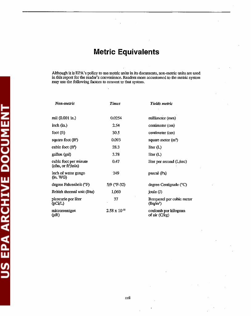
Although it is EPA's policy to use metric units in its documents, non-metric units are usedin this report for the reader's convenience. Readers more accustomed to the metric systemmay use the following factors to convert to that system.
Non-metric Times Yields metric
mil (0.001 in.) 0.0254 millimeter (mm)
inch (in.) 2.54 centimeter (cm)
foot (ft) 30.5 centimeter (cm)
square foot (ff) 0.093 square meter (m2)
cubic foot (fe) 28.3 liter (L)
gallon (gal) 3.78 liter (L)
cubic foot per minute 0.47 liter per second (LIsee)(cfm, or ft3jmin)
inch of water gauge 249 pascal (pa)(in. WG)
degree Fahrenheit (OF) 5/9 (OF-32) degree Centigrade (OC)
British thermal unit (Btu) 1,060 jou1e (J)
picocurie per liter 37 Beequerel per cubic meter(pCi/L) (Bqfm3)
microroentgen 2.58 x 10⁻¹⁰ cou1omb per kilogram(J.tR) of air (Cjkg)
xxii

How to Use This Document
This document has been designed as a comprehensivereference document that will most commonly be used byprofessional mitigators or by other persons interested inthe detailed design and installation of indoor radonreduction sy~tems for existing houses. As a result, thedocument is lengthy. Because of the tremendous amountof material to be covered, the discussion of the majorindividual steps in selecting, diagnosing, designing, andinstalling mitigation systems has necessarily been separated into different sections. The size of this documentcan complicate its effective use, especially by the firsttime user.
This section· is a step-by-step summary of how to usethis document. To some extent, it is also an overview onhow to go about selecting, designing, installing, andoperating a radon reduction system for an existing house.The steps in this process are summarized in Figure H-1.
Many of the steps involved in this process will often beconducted by a professional mitigator. However, somesteps (such as long-tenn operation of the system) willcommonly be the responsibility of the homeowner oroccupant.
Step 1. Determine that the hOllIse has aradon problem and initiate actionto·accomplish mitigation.
This step will be initiated or conducted by thehomeowner, relocation finn, etc., prior to involvement by the mitigator.
IA. Measure radon levels in the house todetermine whether there is a radon prob-lem. '
• Can be done by homeowner using charcoalor alpha-track detectors; or owner can havemeasurement done by a professional finn(using anyone of a variety of measurementmethods).
Use EPA-recommended radon measurementprotocols. SeeEJ;>A 402-R-92-004 (Refer-
H-1
ence EPA92d) and EPA 402-R-92-003(EPA93).
• A summary ofthese measurementprotocolsfor homeowners is presented in A Citizen'sGuide to Radon, EPA/402-K92-001(EPA92a).
lB. Take temporary measures to reduce radon levels, prior to permanent mitigation, as warranted and as feasible.
The homeowner/occupant can increase houseventilation and/or seal major soil gas entryroutes, as temporary measures while awaiting the installation of the pennanent mitigation system.
o Guidance for carrying out these temporarymeasures is provided in Section 2.3 on page
. 24 of the second edition of the TechnicalGuidance, EPA/625/5-87/019 (EPA88a).Guidance for identifying radon entry routesis provided in Section 2.2 (page 15) of thesecond edition.
Ie. Arrange for permanent mitigatiolJ ofthe,house.
• The homeowner, relocation firm, etc., willtalk with one or more professional mitigators prior to selecting one to install a pennanent mitigation system in the house.
• Owners should not consider installing a system on a do-it-yourself basis unless theyfeel fully conversant with the principles ofmitigation and with the infonnation in thismanual.
• See Section 2.5.1 (page 41) of the secondedition of Technical Guidance.
• For assistance in locating and selecting amitigator, see the sources of informationlisted in Section 15 of this document.

FigurcH·1.
Step 1. Determine if house has a radon problem1A. Measure radon levels (References EPA92d and EPA93).18. Take temporary measures to reduce radon, if warranted.1C. Arrange for mitigation.
LStep 2. Select the appropriate radon reduction technique
2A. Conduct a visual inspection (Section 3.2).- Should a technique other than ASD be considered?
(In the large majority of cases, ASD will give the greatest,most reliable, best demonstrated, and most cost-effectivereductions.)
- Assuming that ASD is the technique of choice, which variationof the ASD technology is appropriate? (Sections 2.2 and 3.2)
28. Conduct other diagnostic testing if needed in special cases toassess whether techniques other than ASD should be considered(Section 3.5). (Such diagnostics will often not be necessary.)
~Step 3. Design the ASD radon reduction system
3A. Conduct a visual inspection (Section 3.2).38. Conduct other diagnostic testing if needed (Sections 3.3, 3.4, 3.5)
(Such diagnostics will not always be necessary.)3C. Develop the detailed design (Sections 4 through 10).
- Select number of suction pipes (Sections 4.1, 5.1, etc.).- select location of suction pipes (Sections 4.2, 5.2, etc.).- Select suction pipe type and diameter (Section 4.3, 5.3, etc.).- select suction fan (Section 4.4, 5.4, etc.).- Design piping network and exhaust system (Section 4.6, 5.6, etc.).- Identify sealing effort required (Section 4.7, 5.7, etc.).
3D. Estimate the installation cost (Section 13).
lStep 4. Install the ASD radon reduction system
- Installation of suction pipes (Section 4.5, 5.5, etc.).- Installation of piping network and fan (Section 4.6, 5.6, etc.).- Completion of sealing steps (Sections 4.7, 5.7, etc.).- Installation of gauges/alarms and labelling (Section 4.8, 5.8, etc.).
lStepS. Confirm that installed ASD system is operating properly
SA. Conduct routine post-mitigation diagnostics to confirm properperformance (Sections 11.2 through 11.5).
58. Conduct trouble-shooting diagnostics when system is not performingadequately (Sections 11.6 through 11.11).
lStep 6. Ensure proper long-term operation'and maintenance
6A. Provide basic operation/maintenance information to owner/occupant(Section 12.1).
68. Continue to operate and maintain the system (owner/occupantresponsibility) (Section 12.2).
6C. Make periodic follow-up indoor radon measurements (Section 12.2.3).60. Owner/occupant should understand system operating costs
(Section 13).
A summary of the steps to be followed in using this document.
H-2
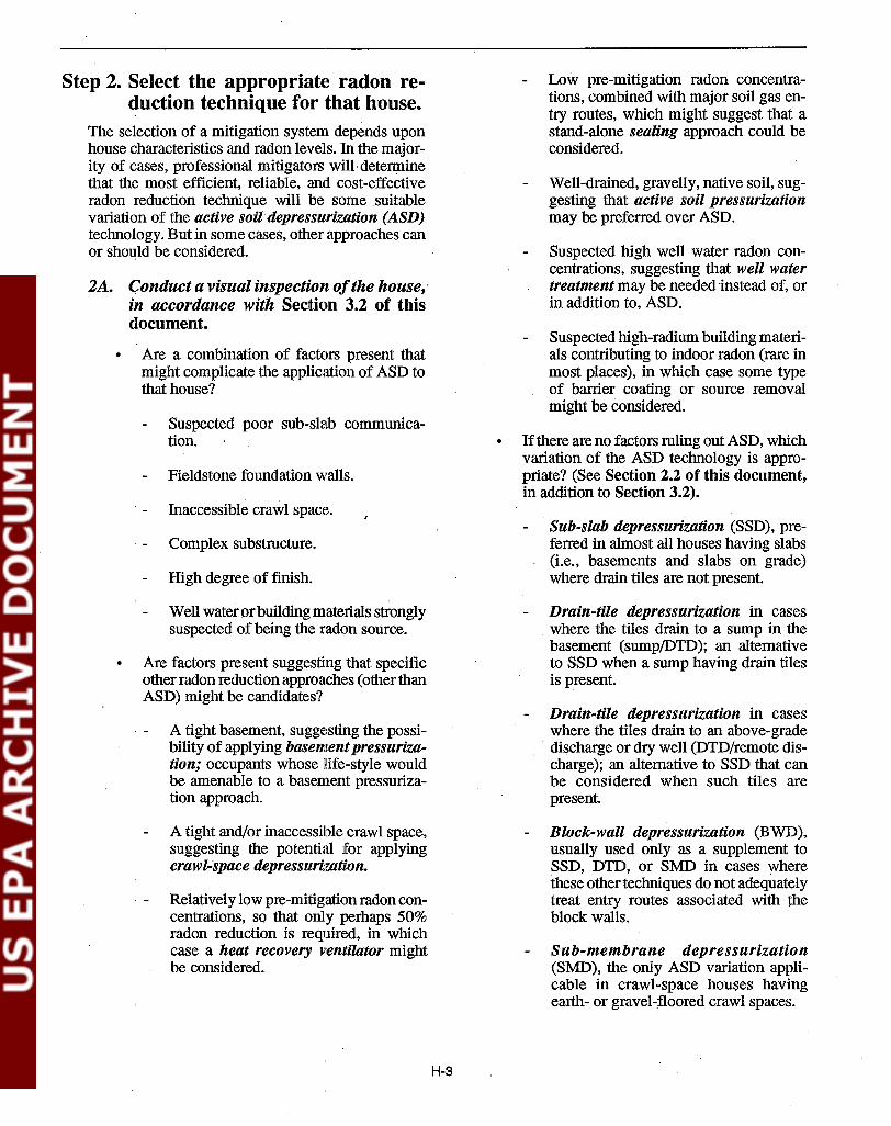
Step 2. Select the appropriate radon re-duction technique for that house.
The selection of a mitigation system depends uponhouse characteristics and radon levels. In the majority of cases, professional mitigators will· determinethat the most efficient, reliable, and cost-effectiveradon reduction technique will be some suitablevariation of the active soildepressurization (ASD)technology. But in some cases, other approaches canor should be considered.
2A. Conduct a visual inspection ofthe house,·in accordance with Section 3.2 of thisdocument.
Are a combination of factors present that. might complicate the application of ASD tothat house?
Suspected poor sub-slab communication.
Fieldstone foundation walls.
Inaccessible crawl space.
Complex substructure.
High degree of finish.
Well water orbuilding materials stronglysuspected of being the radon source.
Are factors present suggesting that specificother radon reduction approaches (other than
. ASD) might be candidates?
A tight basement, suggesting the possibility of applying basementpressurization; occupants whose Hfe-style wouldbe amenable to a basement pressurization approach.
A tight and/or inaccessible crawl space,suggesting the potential for applyingcrawl-space depressurization.
Relatively low pre-mitigation radon concentrations, so that only perhaps 50%radon reduction is required, in whichcase a heat recovery ventilator mightbe considered.
H-3
Low pre-mitigation radon concentrations, combined with major soil gas entry routes, which might suggest that astand-alone sealing approach could beconsidered.
Well-drained, gravelly, native soil, suggesting that active soil pressurizationmay be preferred over ASD.
Suspected high well water radon concentrations, suggesting that well watertreatment may be needed instead of, orin addition to, ASD.
Suspected high-radium building materials contributing to indoor radon (rare inmost places), in which case some typeOf barrier coating or source removalmight be considered.
• Ifthere are no factors ruling out ASD, whichvariation of the ASD technology is appropriate? (See Section 2.2 of this document,in addition to Section 3.2).
Sub-slab depressurization (SSD), preferred in almost all houses having slabs(Le., basements and slabs on grade)where drain tiles are not present.
Drain-tile depressurization in caseswhere the tiles drain to a sump in thebasement (sump/DTD); an alternativeto SSD when a sump having drain tilesis present.
Drain-tile depressurization in caseswhere the tiles drain to an above-grade
. discharge or dry well (DTD/remote discharge); an alternative to SSD that canbe considered when such tiles arepresent
Block-wall depressurization (BWD),usually used only as a supplement toSSD, DTD, or SMD in cases wherethese other techniques do not adequatelytreat entry routes associated with the .block walls.
Sub-membrane depressurization(SMD), the only ASD variation applicable in crawl-space houses havingearth- or gravel-floored crawl spaces.

2B. Conduct any other pre-mitigation diagnostic testing required to enable finalselection ofthe appropriate radon reduction approachfor that house. (See appropriate portions ofSection 3 of this document.)
In many cases, no diagnostic testing beyondthe visual survey will be needed to make thefinal selection of the radon reduction technique.
• Blower door testing (Section 3.5.5) to detennine if the basement is sufficiently tightto warrant practical consideration of basement pressurization. Basement pressurization is usually considered only when application ofASD is complicated (e.g., by poorsub-slab communication and/or by fieldstone foundation walls) and alternatives toASD are thus being weighed.
• Blower door testing (Section 3.5.5) to detennine if a crawl space is sufficiently tightto make crawl-space depressurization aneffective alternative to SMD.
• Blower door testing (Section 3.5.5) to detennine if the house is sufficiently tight towarrant practical consideration of a heatrecovery ventilator to achieve the desireddegree of radon reduction. (Usually conducted only where alternatives to ASD mustbe weighed; e.g., due to poor communication, fieldstone walls, and/or homeownerpreference for an HRV.)
• Well water analysis (Section 3.$.2) to detennine whether well water treatment shouldbe considered as a supplement to, or replacement for, ASD in order to adequatelyreduce airborne radon concentrations.(Would usually be conducted only in caseswhere wells in the area have been observedto contain significantly elevated radon levels.)
• Gammaradiation measurements orflux measurements (Section 3.5.3) to determinewhether building materials are a significantsource of radon arid, hence, whether barriers or source removal may be needed. (Often conducted only where local experience
suggests that building materials may be asource.)
Step 3. Design the radon reduction tech-nique for that house.
Since this document addresses only ASD, the following' discussion focuses on the design of ASDsystems. For the design of other radon reductiontechniques, refer to the appropriate section of thesecond edition of Technical GUidance, EPA/625/587/019 (EPA88a).
3A. Conduct a visual inspection ofthe house,in accordance with Section 3.2 of thisdocument.
The visual survey discussed in Step 2A above,in connection With selection of the reductiontechnique, will also provide most of the information needed for effective design ofthe ASDsystem. Often, this survey will be the only"pre-mitigation diagnostic testing" needed todesign an ASD system.
• Factors that would influence the numberand location of SSD suction pipes (e.g.,observed sub-slab aggregate, house floorplan and finish, sub-slab utilities).
• Factors that would influence the design of acrawl-space SMD system (e.g., size of crawlspace, nature of the crawl-space floor, accessibility).
• Factors that would influence the routing of .the ASD exhaust piping (e.g., house finish,accessibility of an existing utility chase,presence or absence of an attic, location ofan adjoining garage).
• Factors that would influence the degree ofslab or wall sealing that would be required(e.g., the presence of a perimeter channeldrain between the slab and the foundationwall).
• Driving forces for radon entry that mightinfluence ASD design (Le., major exhaustfans that could depressurize the house sufficiently to provide a major challenge to thesystem). See also Section 2.2 on page 15 ofthe second edition of Technical Guidance.
H-4

3B. Conduct any other pre-mitigation diagnostic testing needed to permit effectivedesign ofthe ASD system. (See·appropriate portions of Section 3 of this document.)
• If any pre-mitigation diagnostic test is required in addition to the visual survey, thistest will most often be a qualitative assessment of sub-slab communication (Section3.3.1 of this document).
Tells qualitatively whether sub-slabcommunication is good, marginal, orpoor.
Is conducted primarily when visual evidence or other experience in the areaprovides no clue regarding the generalnature of the sub-slab communication;i.e., whether the system is likely to needone SSD suction pipe or several.
• Other diagnostic tests to aid in ASD design(beyond the qualitative communication test)will often not be cost-effective for professional mitigators. These other tests include
Radon grab sampling or "sniffing" beneath the slab, inside block walls, and atsuspected soil gas entry routes (Section3.4).
Quantitative measurement of sub-slabcommunication (Section 3.3.2).
Quantitative measurement of the flowsproduced by the sub-slab region (Section 3.5.1).
3C. Develop the detailed design of the ASDsy~tem, using one of the fo.llowing sections of this document:
• Section 4 (Jor SSD systems)
• Section 5 (Jor sump/DTD systems)
• Section 6 (Jor DTD/remote discharge systems)
Section 7 (Jor BWD systems)
• Section 8 (Jor crawl-space SUD systems)
• Section 9 (Jor active soil pressurizationsystems)
• Section 10 (Jor passive soil depressurization systems)
The informationbase supporting the design guidance forthe ASD systems in Sections 4 through 8 is presentedin Section 2.3 of this document. Data supporting theguidance for active pressurization systems are ill Section 2.4, and for passive depressurization systems inSection 2.5.
Guidance for selecting the number of suction pipes is presented in the first sub-section within Sections 4 through 10 (e.g., inSection 4.1 for SSD systems).
Guidance for selecting the location of thesuction pipes is presented in the secondsub-section (e.g., Section 4.2).
Guidance for selecting the type and diameter of the suction pipes is presented in thethird sub-section (e.g., Section 4.3).
• Guidance for selecting the suction fan ispresented in the fourth sub-section (e.g.,Section 4.4).
• Guidance for the design of the piping network and exhaust system is presented inthe sixth sub-section (e.g., Section 4.6).
• Guidance for the design of the sealing effort required in conjunction with the ASDsystem is presented in the seventh sub-section (e.g., Section 4.7).
3D. Estimate the costs to install the designedASD system.
.. The cost for installation by a professionalmitigator will depend on.the house and mitigationsystem characteristics, the mitigator'spractices, and the mitigator's labor rates(induding fringe benefits), materials costs,overhead, and profit margin.
.. Typical installation costs for each variationof the ASD technology are presented inSection 13 of this document (e.g., in Section 13.1.1 for SSD systems, Section 13.2.1for sump/DTD systems,etc.)~
See summary of installation costs forthe alternative ASD variations in Table6, Section 13~8.
H-5

Step 4. Install the radon reduction sys-teln in that house.
Since this document addresses only ASD, the following discussion focuses on the installation ofASD systems. For installation of other radon reduction techniques, refer to the appropriate section ofthe second edition of Technical Guidance (EPA/625/5-87/019).
4A. Proceed with the installation of the system in accordance with the design, usingthe appropriate section of this document(Sections 4 through 10).
As with the design guidance in Step 3C above,the data base supporting this installation guidance is presented in Sections 2.3, 2.4, and 2.5of this document.
• Guidance for installing the suction pipes inthe slab, wall, or membrane is presented inthe fifth sub-section within Sections 4through 10 (e.g., in Section 4.5 for SSDsystems).
• Guidanc~ for installing the piping networkand tlte exhaust system is presented in thesixth sub-section (e.g., Section 4.6).
• Guidance for completing the sealing stepsrequired in conjunction with the ASD system is presented in the seventh sub-section(e.g., Section 4.7).
• Guidance for installing gauges and/oralanns on the systems, and for labelling thesystem components, is presented in theeighth sub-section (e.g., Section 4.8).
Step 5. Confirm that the installed systemis operating properly.
SA. Conduct post-mitigation diagnostic teststhat are required in all cases, even whenthe ASD system appears to be operatingwell, as described in Section 11 of thisdocument.
• Complete a visual inspection of the installedsystem as a routine quality assurancestep, as described in Section 11.2, to confirm that all details have been completedproperly.
H-G
• Measure suction (and possibly flow) in thesystem piping, a step that can be completedwhile a pressure gauge is being installed inthe system piping. See Section 11.3.
• Measure the indoor radon concentrationsachieved by the system since this is the realmeasure ofsystem performance, as describedin Section 11.4.
Complete a short-term radon measure-ment within 30 days after system instal-lation or ensure that the homeowner/occupant completes such a measurement·(Section 11.4.1).
Recommend that the· owner/occupantalso make a long-term radon measure-ment (Section 11.4.2).
• Test for combustion appliance backdraft-ing, as described in Section 11.5.
SB. Conduct post-mitigation diagnostic testson a trouble-shooting basis, to determinehow a system that is not performing ad-equately can be improved.
• Conduct suction field extension measure-ments beneath the slab, inside the blockwall, or beneath the SMD membrane (Sec-tion 11.6).
Probably the most effective and mostcommonly used post-mitigation diag-nostic when ASD systems do not per-form well.
Most common reason for inadequateperformance is that suction field is notextending adequately.
• Conduct radon grab sampling or "sniff-ing" measurements (Section 11.7).
Can be used to assess the relative im-portance of alternative potential entryroutes.
As one specific example, high residualradon concentrations inside an individualblock foundation wall in houses havinga SSD, DTD, or SMD system couldsuggest that a BWD component shouldbe added to the system to treat that wall.

• Conduct chemical smoke flow visualization tests, as described in Section 11.8, tohelp identify potential entry routes not being adequately depressurized.
• Conduct well water radon analyses orgamma surveys to assess building materials as a radon source, as discussed in Sections 11.10 and 11.11, if these tests werenot conducted prior to mitigation and if allother possible reasons for elevated residualpost-mitigation radon levels have been eliminated.
'Step 6. Ensure proper long-term operation and maintenance of the ASDsystem.
6A. Provide the homeowner/occupant withinformation to help ensure proper operation and maintenance ofthe system (Section 12.1).
This step is the responsibility of the professional mitigator.
• According to EPA's interim mitigation standards (Reference EPA91b), the owner/occupant shall be provided with the followinginfonnation.
A description of the system, at a centrallabel.
The system characteristics representative ofproper operation (e.g., the properrange of readings that can be expectedon any pressure gauge mounted on thesystem piping).
The name and telephone number of themitigator, to contact if the system stopsperfonning properly.
A statement indicating any requiredmaintenance by the owner/occupant.
Other infonnation that might be provided,depending on the mitigator's practice, indudes
Copies ofwarranties and manUfacturer'sbrochures.
- The operating principles of the system.
H-7
Corrective action that can be taken ifthe system operation ever moves outside the acceptable range (induding ,steps the occupant can take directly priorto calling a professional mitigator forrepairs).
6B. Continue to operate and maintain thesystem properly.
This step is the responsibility of the homeowner or occupant.
• Ensure continued proper operation of thesystem fan (Section 12.2.1 of this document).
When the house is occupied, do not tumthe fan off or down to a lower powersetting than that at which it was left bythe mitigator.
Best radon reduction perfonnance is obtained when the fans are operated at fullpower.
Take appropriate action if the suctionsin the system piping, as indicated on agauge, fall below (or rise above) theacceptable range marked on the gaugeby the mitigator; or, if there is no gauge,if a system alann or some other indicator suggests that the system may not beoperating properly. (See specific procedures in Section 12.2.1.)
A professional mitigator may have to becalled in to make repairs.
There are some simple diagnostic stepsthe owner or occupant can take directly·prior to calling a mitigator.
At some interval (4 to 10 years), the fanwill have to be repaired or replaced.
G Periodically inspect the system piping in aneffort to ensure that blockage by ice ormoisture does not occur·(see Section12.2.2).
. G Periodically inspect seals in the system piping, and seals that were installed in thehouse foundation as part of the mitigationsystem (Section 12.2.2).

Repair seals as necessary.
With crawl-space SMD systems, "sealrepair" may involve occasional majorrepairs or replacement ofmembrane.
6C. flrfake periodic follow-up indoor radonmeasurements to confinn that the mitigation system is continuing to perfonnadequately (Sections 12.2.3 and 13.1.2).
• EPA recommends re-testing at least onceevery 2 years.
Can be done directly by homeowner/occupant using a charcoal or alpha-trackdetector; or, aprofessional measurementfirm could be hired.
Measurement should be made in frequently occupied part of house.
Long-term measurement (e.g., with alpha-track detector) is probably advisable unless some recent apparent changein system performance warrants a morerapid measurement (e.g., using a charcoal detector).
H-8
• Measurements more frequent than once every 2 years are advisable if there is anyapparent change in system performance (e.g.,a change in system suctions) or if the househas been modified.
6D. EPA recommends that the owner/occupant be advised of the annual operatingcosts associated with operation and maintenance of the ASD system (Section 13).
The operating costs consist offour elements:
The electricity to operate the fan.
The house heating/cooling penalty, resulting from treated house air being exhausted by the system.
The cost of system maintenance (repair/replacement of fans on all ASD systems, repair of seals, and occasionalmajor repair/replacement of membranefor crawl-space SMD systems).
The cost of periodic follow-up indoorradon measurements.
The range oj values jor these operatingcosts are summarized in Table 6 in Section13.8, jor the alternative ASD variations.

Section 1Introduction
1.1 PurposeThis technical guidance dOCument is designed to aid in theselection, design, and operation of indoor radon reductiontechniques using soil depressurization in existing houses. Inparticular, it draws from the experience of numerous researchers and radon mitigators over the past eight years and distillsthis information into practical guidance. The guidance shouldenable the design, installation, and evaluation of soil depressurization systems with increased confidence, with reducedsystem costs, and/or improved system performance, under avariety of conditions.
As the term is used here, "guidance" represents a recommendation of what EPA considers to be a reasonable course ofaction for a given set of conditions, based oil experience todate. Often, al~mative reasonable courses of action are possible. Where this situation occurs, this document attempts toprovide readers with sufficient background to permit an informed decision for their specific sets of circumstances. Amitigator will Sometimes face special circumstances wherethe guidance in this document might not represent the preferred approach in that specific case; a careful, informedjudgement of the necessary approach must be made in suchspecial cases. Following the EPA guidance will not, in allcases, guarantee a fully successful mitigation system. However, by effectively drawing upon the prior experience, use ofthe guidance should reduce the risk of installing an unsuccessful system and Should facilitate making the subsequent modifications needed to achieve success.
The term "guidance" must be distinguished from the term"standard." Guidance is a recommendation of what generallyappears to be good practice. In many cases here, the guidanceis a recommendation of multiple alternative cOUifses of actionthat apP,ear reasonable, from among which the user can choose.Users of this document have the option of following theserecommendations or of using a different approach wherewarranted by their particular circumstances.
By comparison, standards are prescribed procedures or requirements which must be met. As discussed later, EPA hasissued interim standards and is in the process of developingfmal standards that radon mitigation contractors must followif they wish to be listed under the Agency's Radon ContractorProficiency Program (RCPP). Many of these standards arementioned at appropriate locations in this document. Whereindividual standards are mentioned, the text clearly indicateswhich features are standards (and are thus considered manda-
tory for RCPP-listed mitigators) and which features are guidance (and are thus subject to the judgement of the user).
This document updates and replaces Section 5 (Soil Ventilation) of the second edition of EPA's Technical Guidance(EPA88a). Other EPA publications providing information onindoor radon reduction in houses include
- Consumer's Guide to Radon Reduction (EPA92c), a booklet which provides a concise overview for homeowners ofalternative radon reduction techniques.
- Application ofRadonReduction Methods (EPA89a), whichis intended to direct a user through the steps of diagnosing a radon problem, selecting a reduction method, anddesigning/installing/operating a radon reduction systemin existing houses, Withless detail than is presented in thetechnical guidance documents. .
- Radon Contractor Proficiency Program Interim RadonMitigation Standards (EPA91b), which list the criteriathat commercial mitigators are expected to meet if theyare listed as proficient under the RCPP. Final radonmitigation standards, which will replace the interim standards, are currently in preparation.
- Radon Reduction in New Construction: An Interim Guide(EPA87a), a brochure summarizing features that can beincorporated into a house during construction to reduceindoor radon levels.
- Radon-Resistant Construction Techniques for New Residential Construction: Technical Guidance (EPA91a),EPA's technical guidance document specifically for radon reduction in houses during construction.
Further information on the indoor radon problem in generalcan be obtained from the following EPA publications, amongothers:
- A Citizen's Guide to Radon (Second Edition) (EPA92a),abookletproviding background concerning radon and summarizing health risks, measurement methods, and reduction approaches.
- Technical Support Document for the Second Edition ofthe Citizen's Guide to Radon (EPA92b); this supportdocument provides the information supporting the guidance in the Citizen's Guide.

- Radon Rejerence Manual (EPA87b), which provides additional background infonnation on indoor radon (e.g.,nature and origin, health effects, geographic distribution,and measurement).
1.2 ScopeThis technical guidance document addresses the design, installation, and operation of soil depressurization systems forrodon reduction in existing houses. Alternative radon reduction methods, including structure ventilation, sealing of entryroutes, structure pressure adjustments, air cleaning, and wellwater treatment, are not addressed here. Until the third editionof the Technical Guidance is expanded in the future to updatethese other reduction methods, readers interested in theseother methods are referred to the second edition.
The emphasis in this document is on active soil depressurization, i.e., on systems which use a fan to depressurize the soil.However, active soil pressurization, where the system fan isreversed to blow outdoor air into the soil, is covered inSection 9. In addition, passive soil depressurization is alsoaddressed in Section 10; with passive systems, natural phenomOM, including the indoor vs. outdoor temperatures andthe flow ofwinds over the roof-line, are relied upon to providethe depressurization instead of a fan.
nlis document focuses on the retrofit of radon reductionmethods into existing houses as distinguished from the incor-.porotion or radon-resistant features into new houses duringconstruction. Separate guidance has been issued on the subject of new construction (EPA87a, EPA91a). The soil depressurization methods described in this document will be generally applicable to new construction. However, incorporationof reduction methods during the construction phase pennitscertain house construction features to be modified to improvesystem performance. Thus, the approach to system design andinstallation and the utilization of other reduction approaches(such as sealing) can be quite different for new constructionrelative to retrofit into existing houses.
As reflected by the title, this document focuses on detachedhouses, as distinguished from multi-family dwellings (apartments, condominiums) and from large buildings, such asschools and commercial buildings. Separate technical guidance has been issued fOf. school buildings (EPA89b). Theactive soil depressurization methods described in this document will be generally applicable to these other types ofbuildings. However, because of the size and of some impor.:tant differences in construction methods used in these largerbuildings, the approach used in system design and installationof the soU depressurization system can be different. Moreover, other reduction approaches (such as building pressurendjustment through modifications to the ventilation system)can more often playa role in these large buildings.
As discussed in Section 2.1, this document addresses allvariations of the soil depressurization approach, includingsub-slab depressurization, drain-tile depressurization, blockwall depressurization, and sub-membrane depressurization incmwl spaces. One or more of these variations can be appliedto each of the house substructure types (basements, slabs on
grade, crawl spaces, and combinations of these). These techniques can be applied to address essentially any pre-mitigation radon concentration, from extremely elevated to onlyslightly elevated.
Soil depressurization techniques can treat only that radonentering the house as a component of soU gas. Thus, thisdocument addresses only those cases where the radon problem is due to naturally occurring uranium/radium in theunderlying soil and rock or to contaminated ftll underneaththe house (e.g., uranium mill tailings). Soil depressurizationtechniques cannot treat cases where the airborne radon in thehouse enters with the well water or emanates from the building materials (due to, for example, contaminated aggregateused in the concrete ).
1.3 ContentThis document consists of five major elements.
1. General infonnation on soil depressurization technology,including the principles involved with each variation ofsoil depressurization (Section 2.1) and the conditionsunder which each variation is particularly applicable orinapplicable (Section 2.2). This information also includesa detailed summary of the available data demonstratingthe performance of each variation as a function of therange of house design, house operation, system design,system operation, and geology/climate variables (Sections 2.3, 2.4, and 2.5).
2. A description of the diagnostic test procedures that can beused prior to mitigation to enable cost-effective designand installation of systems. See Section 3. Procedures aredescribed for the full range of possible pre-mitigationdiagnostic tests. Emphasis is placed on the three premitigation diagnostic tests most commonly found to becost-effective in aiding the design of soil depressurizationsystems: a visual survey of the house; sub-slab suctionfield extension measurements; and radon grab samplingand sniffing.
3. Detailed guidance on the design and installation of eachvariation of the soil depressurization technique. Thisdetailed guidance is included in Sections 4 through 8,with one section devoted to each of the soil depressurization variations. Guidance on design and installation of
, active soil pressurization and of passive soil depressurization-to the extent possible, given the much morelimited experience with these two approaches-is presented in Sections 9 and 10, respectively.
4. A description of the diagnostic test procedures that shouldbe used following installation of a system to ensure thatthe system is operating properly and/or to diagnose thecause of the problem if it is not performing adequately.See Section 11.
5. A description of system operation and maintenance requirements (Section 12).
2

In addition, estimated installation and operating cost rangesfor these systems are presented in Section 13. These costranges should be inclusive of most, but not all, of the soildepressurization installations throughout the continental U.S.,in 1991 dollars.
1.4 Reason for Focus on J!ictiveSoil DepressurizationThis revision to the second edition ofEPA's Technical Guidance focuses on active soil depressurization for two reasons.
1. Active soil depressurization is the most consistently effective ra«;ion reduction method in existing houses, and isthe technique most widely used by commercial mitigators.
Active soil depressurization systems have consistentlybeen found to provide high indoor radon reductions withgood relrnbility. Most commercial mitigators appear toinclude active soil depressurization as the central component in most of their installations, especially when reductions greater than perhaps 50% are required. By comparison, the other mitigation approaches-house or crawlspace ventilation (with or without heat recovery), entryroute sealing, house pressurization (or crawl-space pressurization or depressurization), and indoor air cleanershave each been found to be distinctly less effective and/orless reliable than active soil depressurization. In addition,some of tliese techniques offer other drawbacks-e.g., apotential impact on occupant comfort and life-style in thecase of house pressurization and uncertainty regardingthe actual effect on health risk in the case of some of theparticle-removal based air cleaners. In part for thosereasons, these other techniques are less well demonstrated than is active soil depressurization. Many of theseother techniques offer little, if any, reduction in installation or operating cost relative to active soil depressurization. These other techniques are most commonly used
a) by homeowners on a do-it-yourself basis. Some ofthese techniques can sometimes be implemented easily without special skills, and some of them are rela-
tively inexpensive when a mitigator's labor costs donot have to be incurred.
b) by mitigators, either in conjunction with active soildepressurization or in circumstances where active soildepressurization is not applicable.
2. The available data for active soil depressurization hasincreased the most signIficantly since the second editionwas published in 1988; hence, it is for this technique thatthe most significant improvements in technical guidancecan be provided.
This document includes sections on active soil pressurizationand on passive soil depressurization, as well as on active soildepressurization. The pressurization and passive techniquesare included here because they each have certain similaritiesto active soil depressurization, and because this technicalguidance document thus provides the most appropriate context in which to present these techniques. However, it must berecognized that
- Pressurization and passive techniques are far less welldemonstrated than is active soil depressurization; hence,less rigorous technical guidance can be provided for theseother techniques, and the guidance that is presented hereis less well supported.
- Passive soil depressurization techniques will always beless effective than active soil depressurization. The effectiveness of passive soil depressurization techniques inexisting houses is unpredictable, higffly variable, andoften moderate, at best. Passive systems will likely fmdtheir greatest application in new construction, where features can be incorporated into the house during construction to help improve passive performance.
- Although active soil pressurization techniques will occasionally provide greater radon reductions than does activesoil depressurization in a given house (usually where theunderlying native soil is highly permeable), these occasions appear to be fairly infrequent.
3


Section 2Principles, Applicability, and Past Performance. of Soil D.~pressurization Systems
2.1 Principles of Active SoilDepress~rization
The general principle of soil depressurization is to drawradon-containing soil gas away from the house foundationbefore it can enter and to exhaust this soil gas outdoors.Where a fan is used to create the necessary suction, theapproach is referred to as active soil depressurization (ASD).The vast majority of soil depressurization systems that havebeen installed are ASD systems.
There are several common variations of the ASD process. Forthe purposes of this document, these variations are defined asfollows:
- Sub-slab depressurization (SSD). One or more suctionpipes are inserted into the aggregate or soil beneath aconcrete slab (either vertically down through the slabfrom the space above, or horizontally through a foundation wall below slab level, from outdoors or frominside an adjoining basement). Suction is then drawnon these pipes using the fan, with the collected soil gasthen vented outdoors.
- Drain-tile depressurization (DID). Some hl,Juses havea loop of perforated drain tile immediately beside thefooting, either inside or outside the footing, for waterdrainage purposes. The nature of the DTD systemdepends on how the drain tiles have been designed to
. direct the water away from the house:
whe~e the tiles drain to a sump inside a basement,'the sump is capped, and the fan draws suction onthe sump/drain tile network (referred to as "sump/DTI)");
where the tiles drain to an above-grade discharge ata low spot on the lot or to a dry well, the tile loop istapped into at an appropriate point outdoors, and thefan connected to depressurize the loop (referred toas "DID/remote discharge").
- Block-wall depressurization (BWD). One or more individual suction pipes are inserted into the void networkwithin a block foundation wall and connected to thefan. Alternatively', in what is referred to as the "baseboard duct" approach, a series of holes is drilled into
the void network around the perimeter of a basement,just above slab level; these holes are then enclosedwithin a plenum ("baseboard") sealed to the wall andslab around the perimeter, and the plenum is connectedto a fan.
- Sub-membrane depressurization (SMD), for crawl-spacehouses having dirt floors. Plastic sheeting' is placedover some or all of the dirt floor, creating a plastic"slab." One or more individual suction pipes penetratethis sheeting to draw suction under the plastic (analogous to SSD), or suction is drawn on a loop of perforated drain tiles placed under the plastic (analogous toDID).
The primary mechanism by which ASD often functions is tocreate a negative pressure in the soil or aggregate immediatelyunder/beside the foundation, i.e., under the concrete floorslab, or inside the hollow-block foundation wall, or underneath a membrane laid over a dirt crawl-space floor. If the gaspressure in the soil under/beside the foundation surface isnegative relative to that inside the house, then flows throughany openings through the foundation (e.g., through slab cracksand block pores) will consist of clean house air flowingoutward through these openings, rather than soil gas flowinginward. For the system to be effective, this soil depressurization must be maintained at least near the major openings/entryroutes. (Good depressurization can be less crucial; e.g., incentral, uncracked regions of slabs where there are no entryroutes for convective soil gas flow into the house.) Especiallyin cases where a SSD or DID system is found to be maintaining an excellent suction field in the aggregate underneath aslab, it is clear that flows through the slab openings have thusbeen reversed everywhere.
A second mechanism by which ASD appears to function-toa greater or lesser extent in different circumstances-is dilution of the radon-containing soil gas beneath the slab andaround the foundation. ASD systems can draw house air andoutdoor air down into the soil around the foundation, dilutingthe radon in the soil gas. Thus, even when a negative soil gaspressure is not being maintained immediately under/besidethe foundation in some places, any soil gas entering the houseat those locations may contain less radon, and the ASD systemcan sometimes still be effective if the dilution is sufficient.
5
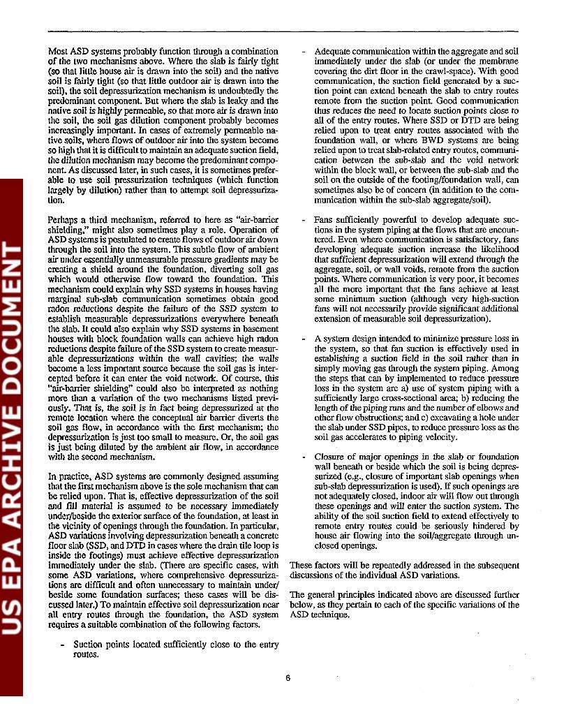
Most ASO systems probably function through a combinationof the two mechanisms above. Where the slab is fairly tight(so Ulat little house air is drawn into the soil) and the nativesoil is fairly tight (so that little outdoor air is drawn into thesoil). the soil depressurization mechanism is undoubtedly thepredominant component. But where the slab is leaky and thenative soil is highly penneable, so that more air is drawn intothe soil, the soil gas dilution component probably becomesincfC.'\Singly important. In cases of extremely penneable native soils. where flows of outdoor air into the system becomeso high that it is difficult to maintain an adequate suction field,tlle dilution mechanism may become the predominant component. As discussed later, in such cases, it is sometimes preferable to use soil pressurization techniques (which functionlargely by dilution) mther than to attempt soil depressurization.
Perhaps a third mechanism, referred to here as "air-barriershielding." might also sometimes play a role. Operation ofASD systems is postulated to create flows ofoutdoor air downthrough the soil into the system. This subtle flow of ambientair under essentially unmeasurable pressure gradients may becreating a shield around the foundation, diverting soil gaswhich would otherwise flow toward the foundation. Thismechanism could explain why SSO systems in houses havingmarginal sub-slab communication sometimes obtain goodradon reductions despite the failure of the SSD system toestablish measurable depressurizations everywhere beneaththe slab. It could also explain why SSD systems in basementhouses with block foundation walls can achieve high radonreductions despite failure of the SSD system to create measurable depressurizations within the wall cavities; the wallsbecome a less important source because the soil gas is intercepted before it Can enter the void network. Of course, this·'air-barrier shielding" could also be interpreted as nothingmore than a variation of the two mechanisms listed previously. That is, the soil is in fact being depressurized at theremote location where the conceptual air barrier diverts thesoil gas flow. in accordance with the first mechanism; thedepressurization is just too small to measure. Or, the soil gasis just being diluted by the ambient air flow, in accordancewith the second mechanism.
In practice. ASO systems are commonly designed assumingthat the flrst mechanism above is the sole mechanism that canbe relied upon. That is. effective depressurization of the soiland flU material is assumed to be necessary immediatelyunder/beside the exterior surface of the foundation, at least inthe vicinity of openings through the foundation. In particular,ASO variations involving depressurization beneath a concretefloor slab (SSD, and DID il).. cases where the drain tile loop isinside the footings) must achieve effective depressurizationimmediately under the slab. (There are specific cases, withsome ASO variations, where comprehensive depressurizations are difficult and often unnecessary to maintain under/beside some foundation surfaces; these cases will be discussed later.) To maintain effective soil depressurization nearall entry routes through the foundation, the ASD systemrequires a suitable combination of the following factors.
- Suction points located sufficiently close to the entryroules.
- Adequate communication within the aggregate and soilimmediately under the slab (or under the membranecovering the dirt floor in the crawl-space). With goodcommunication, the suction field generated by a suction point can extend beneath the slab to entry routesremote from the suction point. Good communicationthus reduces the need to locate suction points close toall of the entry routes. Where SSD or DTD are beingrelied upon to Q"eat entry routes associated with thefoundation wall, or where BWD systems are beingrelied upon to treat slab-related entry routes, communication between the sub-slab and the void networkwithin the block wall, or between the sub-slab and thesoil on the outside of the footing/foundation wall, cansometit:nes also be of concern (in addition to the communication within the sub-slab aggregate/soil).
- Fans sufficiently powerful to develop adequate suctions in the system piping at the flows that are encountered. Even where communication is satisfactory, fansdeveloping adequate suction increase the likelihoodthat sufficient depressurization will extend through theaggregate, soil, or wall voids, remote from the suctionpoints. Where communication is very poor, it becomesall the more important that the fans achieve at leastsome minimum suction (although very high-suctionfans will not necessarily provide significant additionalextension of measurable soil depressurization).
- A system design intended to minimize pressure loss inthe system, so that fan suction is effectively used inestablishing a suction field in the soil rather than insimply moving gas through the system piping. Amongthe steps that can by implemented to reduce pressureloss in the system are a) use of system piping with asufficiently large cross-sectional area; b) reducing thelength of the piping runs and the number ofelbows andother flow obstructions; and c) excavating a hole underthe slab under SSD pipes, to reduce pressure loss as thesoil gas accelerates to piping velocity.
- Closure of major openings in the slab or foundationwall beneath or beside which the soil is being depressurized (e.g., closure of important slab openings whensub-slab depressurization is used). If such openings arenot adequately closed, indoor air will flow out throughthese openings and will enter the suction system. Theability of the soil suction field to extend effectively toremote entry routes could be seriously hindered byhouse air flowing into the soil/aggregate through unclosed openings.
These factors will be repeatedly addressed in the subsequentdiscussions of the individual ASD variations.
The general principles indicated above are discussed furtherbelow, as they pertain to each of the specific variations of theASD technique.
6

2.1. 1 Active Sub-Slab Depressurization(SSD)In active SSD, a fan is used to draw soil gas away from thefoundation by means of individual suction pipes which areinserted into the region under a concrete slab. The pipes arecommonly inserted vertically downward through the slabfrom inside the house, as illustrated in Figure 1. When moreconvenient, they can also be inserted horizontally through afoundation wall at a level beneath the slab, as in Figure 2.Horizontal penetration through a foundation wall is mostlikely to be convenient when the slab is near grade level, andthe penetration can be made from outdoors (as shown inFigure 2) or through the stub wall from inside an adjoiningbasement.
The intent of the SSD system is to create a low-pressureregion underneath the entire slab. If a depressurization can bemaintained under the slab which is sufficiently large so as notto be overwhelmed by depressurizations created inside thehouse by weather effects and homeowner activities, this wouldprevent soil gas from entering the house through cracks andother openings in the slab. It could also reduce or prevent soilgas entry into the void network inside hollow-block foundation walls in the region around the footings, thus at leastpartially preventing radon entry via the walls. Sometimes, thedepressurization can extend under the footings or through theblock walls to inhibit soil gas entry into the house throughbelow-grade openings in the exterior face of the foundationwall.
Were the system to function solely by the primary mechanismdiscussed earlier, i.e., by maintaining a measurable depressurization in the soil everywhere that it contacts the foundation, asoil depressurization of about 0.015 in. WG, measured duringmild weather, would nominally be required to ensure thatsubsequent cold weather and winds would rarely depressurizethe house sufficiently to overwhelm the system. If exhaustappliances were off during the measurement, the soil wouldnominally have to be depressurized by an additional 0.01 to0.02 in. WG to ensure that the system would not be overwhelmed when these appliances were turned on. However,some experience suggests that the other mechanisms mentioned earlier, including soil gas dilution and perhaps airbarrier shielding, can come into play to varying degrees,depending upon the circumstances. These other mechanismscould explain why good radon reductions are often achievedby SSD systems even in cases where portions of the sub-slabare only marginally depressurized, to an extent far less thanthe nominally required 0.025 to 0.035 in. WG. They couldalso explain why SSD systems appear to prevent radon entrythrough wall~related entry routes in many (but definitely notall) cases, even when no depressurization (or only minimaldepressurization) can be measured inside the wall voids.
The central issues with SSD systems are the number ofsuction pipes needed, where they must be placed, and thesuction that the fan must maintain in the pipes, in order toestablish an adequate sub-slab depressurization near all (or atleast the major) soil gas entry routes. The resolution of theseissues is determined largely by the communication beneaththe slab, i.e., by the ease with which suction at one point can
extend to other parts of the slab and to the surrounding soil.Where a good and uniform layer of aggregate (gravel orcrushed rock) was placed under the slab during construction,communication immediately underneath the slab will generally be very good. In such cases, one (or perhaps two) suctionpipes will generally be sufficient, and can be located withsome flexibility, even if the communication within the nativesoil, underlying the aggregate, is poor. Where there is goodaggregate, the system can be pictured as using the aggregatelayer as a large collector or plenum, into which the soil gas inthe vicinity of the house is drawn and then exhausted outdoors. Where there is not a good layer of aggregate, or wherethe layer is uneven or interrupted to a significant degree, moresuction pipes will commonly be needed, and their locationnear to the major entry routes (such as the wall/floor joint)will be increasingly important, depending upon the communication within the underlying soil.
Although poor communication within. the underlying soil willnot impact the ability of SSD to depressurize slab-relatedentry routes when sub-slab aggregate is present, it wouldhinder the suction field from extending through the soil underthe footings. Thus, it could impact the ability of SSD todepressurize entry routes associated with the outer face of thefoundation walls. It would also reduce the flow of outdoor airdown through the soil, thus reducing the possible roles ofsoilgas dilution and air-barrier shielding as mechanisms in determining SSD performance.
Where drain tiles are located inside the footings und~r theslab, the drain~tile depressurization approaches described inSections 2.1.2 and 2.1.3 are essentially a variation of SSD.However, in this document, the term "sub-slab depressurization" is used only to refer to cases where individual pipes areinserted into the sub-slab region in the manner depicted inFigures 1 and 2, or in closely-related adaptations of thatapproach.
SSD has been one of the most widely applied and effectiveapproaches used by the radon mitigation industry, especiallyin treating high-radon houses. SSD should be one of the firsttechniques considered in any house, especially where there isno sump and where sump/ DTD is thus not an option.
2.1.2 Active Sump/Drain-TileDepressurization (Sump/DTD)Drain tiles surround part or all of some houses in the vicinityof the footings to collect water and drain it away from thefoundation. The drain tiles may be perforated rigid plastic(usually ABS or PVC), perforated flexible plastic (high-density polyethylene or polypropylene), or porous clay. Draintiles will generally be located right beside, or just above, theperimeter footings. They can be either on the side of thefootings away from the house (in which case they are referredto here as "exterior" drain tiles), or on the side toward thehouse (referred to as "interior" drain tiles). In houses withslabs, interior drain tiles would be under the slab, embeddedin any sub-slab aggregate. Sometimes (although not commonly) interior drain tiles are not located beside the footingsbut extend underneath the slab in some different pattern:Exterior drain tiles are usually buried in a bed of aggregate
7

Connection to Other.Suction Point(s),If Any
. ,.'
..
Floor
Slope Horizontal LegsDown toward Sub-SlabHole, to Permit CondensateDrainage
I--L-- Strapping (or 2
Other Support)
Notes:1. Detail for interior and exterior
stacks shown in later figures.
2. Options for effectivelysupporting horizontal andvertical piping runs shown inlater figures.
3. Detail shown for pipingpenetrations through slab is oneoption among several. Otheroptions shown in later figures.
4. Closing of various slab openingswill sometimes be important forgood SSD performance.
Sealant Around3 '
Suction Piper----: House Air Through1'--,-~-,-.-.-.-~-'-.'~."".JG'."l Unclosed Openings
4
... .. ..
1
To Exhaust FanMounted in Attic
Exhaust Option 1:Exhaust Stack throughHouse Interior
1
.~ ~
"; :.; :
.; : Suction~; : Pipe";:.; ~
~; :
"; :
I.:.~:";:";:
";:.:
.; :
Sealant4
.:
.:
'~ , ~~.'
.. .... "
. '.. ' .. ~~
~ . Footing' ~~. .,' , .e~ • ~ ,".. .. •• ' .... :.; ... A'" ", •••• --.L-~"'. ',~.''-''''::..>~. ~ ~. '... :.; )':::"::'. : .' Open' Hole
.'.~ '. . .:.'. ..... '. ,,". '.' ."., '... : . , , . (6" to 18"~: ',' '. . Radius)
. "
, ,". ,"~. l. * '
' ..
", ."~ <~" • ..., ~ •
Exhaust (ReleasedAbove Eave)
~l
"" .' Soil ~as
/~, I~haustFan •(Rated forExterior Useor Enclosed)
\ !/ - \"-f----l
Flexible~Coupling--n f=::=lrr-'lhr
I I...... -""\\ 1\. I'--.t-_.."..,."."....--
Flguro 1. Sub·slab depressurization (SSD) using pipes inserted down through the slab from indoors.
8

Suction Pit
2. Sealing pipe penetrationthrough wall isimportant to reduceleakage of outdoor airand air from blockcavities into SSD system.
1. The exterior downspoutexhaust stack illustratedhere is one of severalpossible stackconfigurations, asdiscussed later.
Notes:
House Air LeakageThrough Wall/Floor Joint
Stud
Wallboard
45° Fittings (4" Dia.Round PVC) to Offset~Stack against House
1
Exhaust (ReleasedAbove Eave)
3"X4" Rectangular'1
Metal Downspout
4" Round-to-3"X4"Rectan~ular
Adapter,, FlexibleCoupling
Exhaust Fan (Rated forExterior Use or EnclosE~d)-/f-----'I
Header Connecting to Other Su~iion···Points If Any (See Inse~ A~CIV~~: '. '~~01.:',..~¥J~~
.' :;.. ... ." ....: .. ' .Horizontal Pipe Sloped.; '. '.:'; ..... :. ,; . ~'. :. ' .. '.Down Toward Pit for ., .... . :..~...:.:.....;:";J"=';,l,=;=;d:':;:t,'"-,-',::.,.':.,~:":':'.::. '.:' ...;.,. :.:Condensate Drainage :' : .: . • '. ~. ;' . ":" .' . '..
One possibl~ configuration for a mUlti-pipE~ system
: . ' .... ' .. '. '.''. ... '"" '.
Figure 2. SUb-slab depressurization (SSO) using pipes inserted horizontally through the foundation wall from outdoors.
beside the footings; this exterior aggregate bed is sometimes(but not always) covered with a material such as geotechnicalcloth or roofing felt, intended to reduce pluggage of the gravelbed with dirt.
IBoth interior and exterior drain tiles can discharge collectedwater by either one of three methods. If the lot is sufficiently
, sloped, the water can be routed to an above-grade discharge ata low point on the lot, remote from the house. As an alternative, the water can be directed to a dry well away from thehouse. Or, in basement houses when the lot is not sufficientlysloped, the water is drained to a sump inside the basement,from which the water is pumped to an above-grade discharge.,This section addresses the case where the tiles drain to asump.
A typical sump/DTD system is illustrated in Figure 3. An airtight cover is sealed over the sump pit. Suction is then drawnon the drain tile network by connecting a suction pipe to thesump/drain tile system. While the suction pipe can be installedthrough the sump cover, it can be advisable instead to connectthe suction pipe to the tiles at a location remote from thesump, as illustrated in the figure.· Installation of the suctionpipe remote from the sump will facilitate subsequent maintenance of the sump pump, and will reduce the suction loss thatwill result if air leaks develop around the sump cover (e.g., asa result of improper re-installation of the cover after subsequent sump pump maintenance).
The drain tiles shown in Figure 3 are interior tiles, although,exterior tiles can also drain to a sump. Where the drain tiles
:9

Exhaust Optf0ll 2:exterior Stack
Notes:
~.:& ", : ...:" ..: .
" .... . .. '
.. ' .. ," • .., .6 ...... ' ...>,' , .Footing '.' " ,• , .....", • .:.... ,.' ",' > ..
. . ... ' . . ' ......' ." . ",,' , ..
WaterDischargePipe
Caulk orGrommetsto SealPenetrations
5. Detail for interior and exterior stacksis shown in later figures.
6. Closing various slab openings,especially the perimeter wall/floorjoint, will sometimes be important forgood sumplDTD performance.
4. Options for supporting horizontal andvertical piping runs are shown in laterfigures.
3. Alternative sump cover designs arediscussed later.
2. Detail shown for pipe penetrationthrough slab and connection to draintile can vary. Other options areshown later.
1. Figure depicts suction pipe installedremote from sump. Suction pipe couldalso be installed through sump cover.
E)cisting InteriorDrain Tile LoopCircling House
I-"-'''I--../--/'-I "",1-- Sump Liner1 -r=::...L-__----l1:...=J
SubmersibleSump Pump
Sealant AroundSuction Pipe
2
MasonryBolt
Joist
Ir Strapping(or Other
4Support)
StraightFitting
Floor
'----II----l--- Slope HorizontalPipe Down TowardSuction Pipe
SuctionPipe
Exhaust Option 1:Interior Stack
5
To Exhaust FanMounted in Attic
.:.
.~.
.~.
Exhaust Fan(Rated forExterior Useor Enclosed)
',0
,.
. '.... .. ... .:..
:.~:~:lS·::fl:· ..·.....•.. . Gas: .' Hole in .
Drain TileNear SuctionP
. 2Ipe
Gasket (or
Sl/Icone Caulk) ~======::.
. '. "
IJ iL---)lWJ
I I....-"'"\ 1-\. I
....... -.t-_7"7.MT',,-
Sealant
Grade Level
Figuro 3. Drain-tile depressurization (DTD) where the tiles drain to a sump in the basement.
10
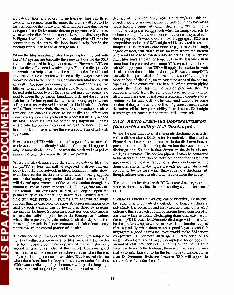
are exterior tiles, and where the suction pipe taps into theseexterior tiles remote from the sump, the piping will connect tothe tiles outside the house and will look more like that shownin Figure 4 for DTD/remote discharge systems. (Of course,when exterior tiles drain to a sump, the remote discharge linein Figure 4 will be absent, and the suction pipe will thus beconnecting to the drain tile loop immediately beside thefootings rather than to the discharge line.)
Where the tiles are interior tiles, the principles involved withthis DTD system are basically the same as those for the SSDvariation described in the previous section. However, DID oninterior tiles offers two key advantages. First, the tiles providea network that helps distribute the suction under the slab andare located in a zone which will necessarily always have beenexcavated and backfilled during construction (and hence willgenerally have some communication, even under houses wherelittle or no aggregate has been placed). Second, the tiles arelocated right beside two of the major soil gas entry routes: thejoint between the perimeter foundation wall and the concreteslab inside the house; and the perimeter footing region wheresoil gas can enter the void network inside block foundation.walls. Thus, interior drain tiles provide a convenient, in-placenetwork that enables suction to be easily and effectivelydrawn over a wide area, particularly where it is usually neededthe most. These features are particularly important in caseswhere sub-slab communication is marginal or poor; they areless important in cases where there is a good layer of sub-slabaggregate.
Because sump/DTD with interior tiles generally ensures effective suction immediately beside the footings, this approachmay be more likely than SSD to treat the block walls at pointsaround the perimeter where the tiles are present.
Where the tiles draining into the sump are exterior tiles, thesump/DTD system will still be expected to divert soil gasaway from the void network in block foundation walls. However, because the suction on exterior tiles is being appliedoutside the footings, any suction field created beneath the slabwill depend upon extension of the exterior suction through thebottom course of blocks or beneath the footings, into the subslab region. This extension, in turn, will depend upon thepermeability of the underlying native soil. Limited suctionfield data from sump/DTD systems with exterior tile loopssuggest that, as expected, the sub-slab depressurizations created by such systems can be lower than those by systemshaving interior loops. Suction on an exterior loop does appearto treat the w~/floor joint inside the footings, at locationswhere tile is present, but the reduced sub-slab d~pressuriza
tions might result in lesser treatment of slab-related entryroutes toward the central portion of the slab.
The chances of achieving effective treatment with sump suction (with either interior or exterior tiles) are greatest when thetiles form a nearly complete loop around the perimeter (i.e.,around at least three sides of the house). However, goodperformance can sometimes be achieved even when there isonly a partial loop, on one or two sides. This is especially truewhen there is.an interior loop and aggregate under the slab.With exterior tiles, good performance with partial loops appears to depend on good permeability in the native soil.
Because of the typical effectiveness of sump/DID, this approach should be among the first considered in any basementhouse having a sump with drain tiles. Sump/DTD will commonly be the preferred approach when the sump connects toan interior loop of tiles, whether or not there is a layer of subslab aggregate. However, when there is aggregate, SSD is acompetitive option, and SSD might still be selected instead ofsump/DID under some conditions (e.g., if there is a high.degree of floor/wall fmish at the location where the suctionpipe would have to be inserted into the drain tiles). Where thedrain tiles form an exterior loop, SSD in the basement maysometimes be preferred over sump/DTD, especially if there issub-slab aggregate, since SSD will apply the suction beneaththe slab rather than outside the footings. However, sump/DIDcan still be a good choice if there is areasonably completeexterior loop of tiles (i.e., on at least three sides of the house),especially if the owner wants to keep all of the system pipingoutside the house (tapping the suction pipe into the tilesoutdoors, remote from the sump). If there are only exteriortiles, and if these tiles do not form a reasonably complete loop,suction on the tiles will not be delivered directly to someportion of the perimeter; this will be of greatest concern whenthe native soil has low permeability. In such cases, SSD mightwarrant greater consideration as the initial approach.
2.1.3 Active Drain-Tile Depressurization(Above-GradeIDry-Well Discharge) .Where the tiles drain to an above-grade discharge or to a drywell, a different basic DID design is required, as illustrated inFigure 4. A check valve is installed in the discharge line, toprevent outdoor air from being drawn into the system via thedischarge line. Suction is then drawn on the drain tile network, as illustrated. The suction pipe will often be connectedto the drain tile loop immediately beside the footings; it canalso connect to the discharge line, as shown in Figure 4. Thedrain tiles shown in the figure are exterior tiles, which willcommonly be the case when there is remote discharge, although interior tiles can also drain remote from the house.
The principles involved with DTD/remote discharge are thesame as those described in the preceding section for sump/DTD.
Because DID/remote discharge can be effective, and becausethe system will be entirely outside the house (making itpotentially less obtrusive and less expensive than other ASDoptions), this approach should be among those considered inany case where remotely-discharging drain tiles exist. As inthe sump/DID case, DID/remote discharge will most oftenbe the preferred approach when there is an interior loop oftiles, especially when there is not a good layer of sub-slabaggregate; a good aggregate layer would make SSD morecompetitive. DTD/remote discharge will also often be selected when there is a reasonably complete exterior loop (i.e.,around at least three sides of the house). When the drain tileloop is exterior to the footings, there is an increased chancethat SSD may turn out to be the technique of choice, ratherthan DID/remote discharge, because SSD will apply thesuction directly under the slab.
11

Notes:Exhaust (ReleasedAbove Eave)
1. For clarity, suction pipe is depictedInstalled in the drain tile dischargeline. Commonly, the suction pipe mightinstead be installed directly in thetile loop beside the footings.
2. Figure depicts one option forconnecting the rigid 4" dlam. suctionpipe to 4" flexible corrugateddrain tlle. Alternative methods ofconnection to 3" and 4" flexibletile, or to rigid plastic or claytlle, are presented In text.
SealantS
, ... ",'
, ,..
.. : . : . :':" ". .. .. : ','
4" Round-to-3"X4"4Rectangular Adapter
3"X4" Rectangular4
Metal D,ownspout
.. ;
• 0 ••
'..... ' ..... • .. .A
• .' ~. ~ " Footing. ,,' ... '
.. >.. '.II
" '
,', Existing Drain Tile ' ", Loop Circling House'
RiserConnectingDrain Tileto Fan -'---*
, .," '
',' '
4. The exterior downspout exhauststack illustrated here Is one ofseveral possible stackconfigurations.
5. Closing various slab openings,especially the perimeter joint,will sometimes be important forgood DTD performance.
3. The reverse flow valve shownrepresents one design currentlyon the market. Other valveconfigurations are available.
Reverse FlowValve (InPVC Pipe), toPrevent Air fromBeing Drawn intoSystem fromDischarge:!·
Aguro 4. Drain-tile depressurization (DTD) where the tiles drain to an above-grade discharge remote from the house.
12

2.1.4 Active Block-Wall Depressurization(BWD)When the foundation wall is constructed of hollow concrete orcinder blocks, the interconnected network of block cavitieswithin the wall can serve as a conduit for soil gas. Soil gaswhich enters the wall through mortar joint cracks, pores, andother openings in the exterior face of the blocks below gradecan move either vertically or laterally throughout the wallinside this void network. Where the house has a basement,with the interior face of the blocks inside the basement, thesoil gas can then be drawn into the house through any openings in the interior face, such as holes around utility penetrations, mortar joint cracks, and the pores in the block itself.Even more importantly, if the cavities in the top course ofblock open to the basement, the walls will act as a chimney,with soil gas flowing up through the void network and into thebasement through these uncapped top voids. Even in slab-ongrade or crawl-space houses with hollow-block foundations, itis sometimes possible (if the top cavities are not closed) forsoil gas in the block voids to. flow up into the wooden framingresting on top of the wall, and hence into the house, eventhough the foundation wall itself does not extend up into theliving area. I
The principle of BWD is to draw the soil gas out of this voidnetwork using a fan drawing suction on the voids. The fanwould presumably increase the flow of soil gas into the voids,but would draw the soil gas into the system piping and exhaustit outdoors rather than permitting it to enter the basement.Where the block walls are the primary entry route, and wherethe BWD system is able to adequately depressurize the voidnetwork, this. approach would most directly treat that entryroute. The depressurization created within .the voids by aBWD system will sometimes extend under the slab, depending upon the.communication between the voids and the subslab, and upon the communication within the sub-slab fill.Thus, the walVfloor joint, and perhaps some slab-related entryroutes more remote from the walls, will sometimes also betreated by a BWD system.
Figure 5 illustrates one method for implementing BWD. Thisapproach, referred to as the "individual pipe" approach, involves insertion of one or two suction pipes into the voidnetwork in each wall to be treated; these pipes are thenconnected to ,One or more fans. A second approach for implementing BWD, referred to as the "baseboard duct" approach,has been used occasionally. In this approach, a series of holesis drilled into the void network around the perimeter of abasement, just above slab level; these holes are then enclosedwithin a plenum ("baseboard") sealed to the wall and slabaround the perimeter, and the plenum is connected to a fan.For clarity, Figure 5 shows BWD being used as a stand-alonetechnique; however, more commonly where BWD is used, theprimary mitigation system will be a SSDsystem, with depressurization of one or more selected walls implemented as acomponent of that SSD system.
A key problem with BWD is that the numerous and oftenconcealed wall openings (especially open top wall voids, andblock pores) are very difficult to close adequately. Thus,despite efforts to close these openings, large amounts of house
air (and possibly outdoor air) will leak into the BWD systemthrough these openings. Therefore, it has often proven to bedifficult or impractical to maintain sufficient depressurizationthroughout the entire wall. Thus, the wall-related entry routeshave sometimes not been adequately treated (along with centrally located slab-related routes), with the result that radonreductions have not been consistent either within a givenhouse over time, or between houses, when BWD is used as astand-alone method. As an added concern, substantial houseair leakage into a BWD system has sometimes depressurizedthe basement sufficiently to cause backdrafting of fireplacesand. other combustion appliances (as well as increasing theheating/cooling penalty of the system). Where backdraftingoccurs, an outdoor supply of combustion air must be provided, or else the BWD system might be operated in pressureinstead of suction. Basement depressurization resulting fromBWD systems can also increase soil gas influx through walland slab-related entry routes not adequately depressurized bythe system, thus reducing net radon reduction performance,and sometimes even increasing basement concentrations (e.g.,House 19 in Reference Sc89).
In view of these concerns, BWD is looked upon as a techniquewhich would be used largely as an occasional supplement toSSD systems, rather than as a method that would commonlybe used by itself. The role of BWD as a supplement to SSDcan be very important in some cases. Even where a SSDsystem has very effectively depressurized the entire sub-slabregion, occasional cases have been encountered where thissub-slab depressurization did not adequately prevent soil gasfrom entering the void network, requiring simultaneous treatment of the walls using BWD (e.g., Houses.3 and 16 inReference Fi91).
2.1.5 Active Sub-MembraneDepressurization (SMD) in Crawl SpacesIn houses having a crawl space with a dirt floor (including dirtfloors covered with gravel and/or with a plastic vapor barrier),a variation of SSD or DID can be implemented if a "slab" (inthe form of a plastic membrane) is placed over the dirt floor.Suction can be drawn underneath this plastic "slab," eitherusing individual suction pipes penetrating the membrane(analogous to SSD), or through suction on a length or a loopof perforated drain tile placed beneath the plastic (analogousto DID). Examples ofboth SMD approaches are illustrated inFigures 6 and 7.
SMD has been demonstrated to be the most effective radonreduction method for crawl-space houses. It should be one ofthe frrst methods considered in any crawl-space house wherethe crawl space is accessible for system installation and wherethe required radon reductions are sufficiently great (greaterthan about 50%) such that natural ventilation of the crawlspace will not be adequate. Use of an exhaust fan to depressurize the entire crawl space, preventing radon-containingcrawl-space air from flowing up into the living area, has alsobeen found to be eff~tive, as well as less expensive thanSMD to install. However, crawl-space depressurization isusually less effective than SMD, and has a much higherheating penalty, since much of the air exhausted by the
13

Notes:
6" Dia.CollectionPipe
2. Options for use of individual pipeBWD as a supplement to SSD areillustrated in a later figure.
1. Closure of top block voids can bevery important to avoid degradationof BWD performance and increasedheating/cooling penalty caused byexcessive leakage of house air intothe system.
Strapping (orOther Support)
?
~-- Suction Pipe
t
11-foIIr----I---t--- Close Major Mortar Cracks and
Holes in Wall
.J.--~~ Basement Air Through Block Pores,.....-I~-~ Unclosed Cracks, and Holes
".., ... ".' .......
Exhaust Fan(Rated forExterior Useor Enclosed)
[
Veneer GapExhaust Option 1
To Exhaust FanMounted in Attic
.:' . ' .'. ... :. .. '.
Exhaust Option 2
Exhaust ReleasedAbove Eave
... \', ,
..' ,..,
Top Void
Concrete Block
BrIck Veneer ---r:;'77';7J1
", .'
,":",:: .',',:,":",><, Soil G'a~:.:: : .' ." . . '.I • ", ~ ., .' '" ,."",,~
Close Top Voids 1
Flexible -~!!iCoupling
f) --
~----~~~j
r--\..\
r~.G~n....a..
\ I From Connections- into Other Walln
' ......-l-~~ur:!;;~~:=):==t-==~========Sealant r
Aguro 5. Block-wall depressurization (BWD) using the individual-pipe approach,
14

-----.----- I-I I
-----.---- -lJ-
Exhaust Option 2
Exhaust ReleasedAbove Eave
Connection toOther SuctionPoint(s), If Any-
Strapping (or OtherSupport) Will SometimesBe Necessary
Exhaust Option 1
To Exhaust FanMounted in Attic
"-----.J--!---L'- Slope Horizontal LegsDown Toward Membrane
2. The membrane seams must always be sealed near the suctionpoint. Sealing of more remote seams may not always benecessary, but is advisable.
3. The membrane can often be effectively sealed against thefoundation wall using a continuous bead of properly selectedsealant (urethane caulk for cross-laminated polyethylenes,other adhesive for regular polyethylenes). Other optionsfor sealing the membrane against the wall are discussed intext.
'I. The specific configuration depicted for the pipe penetrationthrough the membrane is one of a number of alternatives. 'Other options are shown in a later figure.
CrawlSpace
Notes:
Floor
Joist
.:
.:
FlexibleCoupling
Exhaust Fan(Rated forExterior Useor Enclosed)
Sealant
, ' .. .
...".' ..
Sealant
k---- PVC Suction Pipe
Semi-Rigid PlasticPlate Resting on Topof the T-Fitting, toPrevent Membrane fromBeing Sucked into theEnds of the T-Fitting'
Membrane
)Membrane SealedAgainst Wallwith Bead ofCaulk orAdhesive2,3
Hose Clamp andCaulk, SealingMembraneAround PipePenetration'
PVC T-Fitting UnderMembrane, to Support .Pipe and to Help ,Distribute Suction
1
• A • •
, .'. '.. '
.~ .". ~
, ., .'. .. ~
. '.
. '.';:"~=--==,=,,,=.-.--~:""--'M==::::!:::~~=~~::::;:.:;::::.;=::::::::~0;: . . ...
,.,-~":""'!!='~'=;:::.¥=il:.....:,~-.:..., , , " ' Dirt Floor in ' , " '... ,....,..., . " ...' '. Crawl Space'" , : " ,:', .' .. : ..' '.' '. , ,
. .' . . . . ~ '. .. '., .. .' .Adjoining Sheets ofMembrane Overlappedby about 12 InchesSealed with Caulk orOther Adhesive
2
.' .'A 'A'
" ''--__,--__-''--'- -J
. ":, '.'
Hollow-Block . . . _.. :Foundation Wall ~ :~"==l='=::I1
Figure 6. Sub-membrane depressurization (SMD) for the case where individual suction pipes penetrate the membrane (SSD analogue);
15
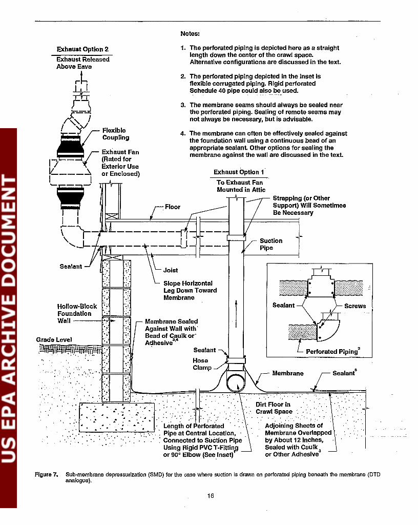
Notes:
Screws
Perforated Plping2
Strapping (or OtherSupport) Will SometimesBe Necessary
Sealant
Membrane Sealant3
.~ : .Adjoining Sheets ofMembrane Overlapped "by About 12 Inches,Sealed with Caulk 3
or Other Adhesive
Dirt Floor In .Crawl Space " : " ' " .... . ,: . '.
1
4. The membrane can often be effectively sealed againstthe foundation wall using a continuous bead of anappropriate sealant. Other options for sealing themembrane against the wall are discussed in the text.
2. The perforated piping depicted in the inset isflexible corrugated piping. Rigid perforatedSchedule 40 pipe could also be,.used.
3. The membrane seams should always be sealed nearthe perforated piping. Sealing of remote seams maynot always pe necessary, but is advisable.
Exhaust Option 1
To Exhaust FanMounted In Attic
1. The perforated piping is depicted here as a straightlength down the center of the crawl space.Alternative configurations are discussed in the text.
Sealant
HoseClamp
Slope HorizontalLeg Down TowardMembrane
Membrane SealedAgainst Wall with'Bead of Caulk or'Adhesive3,4
4.:,',:.
.:
',:, ,
.:
"0:'
.:
.", ,.'
· ,~ .• '
· .."
" . , .~ ~
, :., ":Fl:'=~I" ..- .~:
'.': ,.... ,.~.. '
· -:,.."
. ,
~. . .... . :.. . ~ . ' .. "..... . . ... '~, ..' .'. . ..• • ~. .. ~ " :'. 0.' •• , • ' ''.. ,~ • •
. ,', : .' ~ '; , • ~ .~ .' Length of Perforated. ':.: ' '. . ".' ~ .". . : '.:. '.', : : Pipe at Central Location, ..'. : " , ' ": '.': " . . .: Connected to Suction Pipe
Using Rigid PVC T-Fittinpor 90° Elbow (See,'nset)
Hollow-Block ....'FoundationWall
'. :,
.:
Sealant
Exhaust Option 2
Exhaust ReleasedAbove Eave
r~
~~I
W;FleXlbleCoupling
Exhaust Fan
1"""1
1- ~ r (Rate? for
'( exterior Use1L. ~ or Enclosed)
L,,~
I I"'--"'\..,\ ,\.'--.L-r-,.-n".-
';,-. ,'.
"
Grade Level
Aguro 7. Sub-membrane depressurization (SMO) for the case where suction is drawn on perforated piping beneath the membrane (DIDanalogue).
16

depressurization fan will be treated house air drawn downfrom the living area.
The principles involved in SMD are similar to those for SSDand DID.
- If adequate suction can be maintained beneath theplastic, soil gas entry into the crawl space should bereduced or eliminated By this sub-membrane depressurization mechanism, gas flows through seams orpunctures in the membrane should be crawl-space airbeing drawn down into the sub-membraneregion, ratherthan soil gas flowing up into the crawl space, fromwhich it might enter the living area.
- The other mechanisms discussed earlier for ASD systems may also come into'play: dilution of the soil gasradon levels under the membrane, resulting from theincreased flows of air into the sub-membrane region(from the crawl space, the block walls, and outdoors);and air-barrier shielding.
- In crawl spaces having block foundation walls, theSMD system might help prevent soil gas entry throughthe block cavities into the crawl space and into theliving area overhead, analogous to SSD and DID.However, there are not sufficient data in houses whereblock crawl-space walls are a major living-area entryroute to assess how consistently or reliably SMD willthus treat the walls.
In addition, there may be an element of crawl-space depressurization contributing to the performance of SMD systems.Significant leakage of crawl-space air into the SMD systemthrough membrane openings can cause such depressurizationof the entire crawl space relative to the living area, reducing orcompletely reversing the normal flow of crawl-space air upinto the living area. This can be an effective mitigationmethod in its own right (He92).
Where the crawl space has a floor ofbare earth, which is oftenthe case-Le., where there is not a layer of gr'avel on the floorbene~th the membrane-suction beneath a Slvro membrane isanalogous to SSD with no aggregate under the slab. Thus, justas with SSD in houses having poor sub-slab communication,the sub-membrane depressurizations maintained in SMD systems are generally fairly low, and measurable suction fieldextension beneath the membrane is limited. These lowerdepressurizations may mean that SMD systems will be lesslikely; e.g., to treat wall-related entry routes, in cases wherethat might be necessary. However, SMD systems have generally proven to be very effective in crawl-space houses, despitereduced sub-membrane suctions.
Where the crawl space is large, where significant reductionsin indoor radon concentrations are desired (e.g., to 2 pCiIL orless), and/or where the soil comprising the crawl-space floorhas very low permeability (with no gravel on the floor), it hassometimes been found necessary to take steps to help the submembrane suction field extend adequately around the crawlspace. The most common steps are installing additional suction pipes through the membrane (analogous to installing
multiple suction pipes in a SSD system), or connecting thesuction system to perforated piping under the membrane (as inFigure 7).
A key remaining issue in the design of SMD systems is howmuch effort should be made to reduce crawl-space air leakageinto the system by sealing the membrane against perimeterfoundation walls and interior piers, and at seams betweensheets of plastic. Some results suggest that such comprehensive sealing of the membrane may not always be necessary inorder to achieve good radon reductions in the living area. Thisresult is probably a commentary on the limited sub-membranedepressurizations needed to adequately reduce soil gas flowinto the crawl space in some cases. It may also be a commentary on the relative benefits of the mechanisms other than submembrane depressurization discussed above, especially submembrane soil gas dilution and crawl-space depressurization.
Comprehensive sealing of the membrane is often conductedroutinely by mitigators. Mitigators report that complete sealing is needed in order to ensure the best radon reductionperformance. Complete sealing also will help avoid possiblebackdraftingof combustion appliances in the crawl space as aresult of the crawl-space depressurization that can occur if theSMD fan draws too much crawl-space air out through theunsealed seams. Furthermore, complete sealing will reducethe amount of treated air drawn out of the living area andexhausted by the SMD system, thus reducing the heating/cooling penalty. Until further research confirms the conditions under which incomplete membrane sealing is acceptable, it is advisable to seal the membrane everywhere.
This issue extends to the question of whether the entire crawlspace floor even has to be covered by the membrane. Thisquestion is important because portions of crawl spaces areoften inaccessible or are occupied by, for example, the furnace and water heater. Good radon reductions have sometimes been achieved even in cases where the dirt floor was notentirely covered. This result could be suggesting that a) somesections of the dirt floor are less significant sources of radonthan others; b) suction on a portion of the soil can extendsufficiently to intercept the soil gas before it reaches theuncovered sections of floor; and/or c) depressurization of theentire crawl space is contributing to the observed reductions,through a' different mechanism than soil depressurization.Until this question is better understood, it is advisable toensure that the entire crawl-space floor is covered by themembrane, if at all possible.
In isolated cases, relatively good radon reductions have beenachieved with "sub-membrane depressurization" without themembrane, i.e., by drawing suction on pipes embedded in thebare soil in the crawl space. Referred to here as "site ventilation," this approach is analogous to the "radon wells" inSweden, and would appear to require certain geological characteristics in order to be successful. The soil would have to berelatively permeable laterally, and less permeable verticallytoward grade, so that the suction field would extend throughthe soil over the area of the crawl space, but would not bedissipated by extensive leakage of crawl-space air down fromabove. A strata ofporous, gravelly soil, capped with a layer ofclaysoil, would be an ideal example of a geology conducive
17

In basement houses having drain tiles draining to a remote above-grade discharge or dry well, DTD/remotedischarge will be one of the first options considered, withthe same considerations listed in a) above for the sump/DTD case. It should be anticipated that a supplementalSSD system could turn out to be required, in addition tothe DID system if installed, if the drain tiles form anexterior loop around fewer than three sides of the house.
a) very poor sub-slab communication, requiring a largenumber of suction pipes;
reductions at less long-term capital and operating cost than theother alternatives for achieving moderate reductions, namely,house ventilation and entry route sealing.
Techniques other than ASD would be considered most seriously in unusually difficult houses having combinations of thefollowing complications:
d) homeowner resistance to aspects of the ASD system, e.g.,appearance, need to maintain a fan, etc.
a) In basement houses having sumps with drain tiles, sump/DTD will be one of the frrst ASD options considered.Sump/DID will most likely be successful when the draintiles form a loop inside the footings, or when there isgood aggregate beneath the slab regardless of the draintile configuration. Sump/DID will least likely be successful when the drain tiles are outside the footings andform only a partial loop (i.e., a loop around fewer thatthree sides of the house).
Where ASD is being considered for a specific house, theapplicable variation of the technology is usually selected asfollows:
b) fieldstone foundation walls which are an important entryroute, since such walls can be difficult to treat and are notamenable to BWD;
c) a very high degree offloor/wall/ceiling finish on the storyin contact with the soil, thus complicating the placementand routing of suction pipes;
Generally, anyone of the above complications, by itself,could be overcome by suitable design. However, especiallywhen there are multiple problems, the effort required toovercome them could make the ASD system more expensive(or would create a greater aesthetic impact) than would analternative mitigation approach, such as house pressurizationor house ventilation. Of course, the applicability of one ofthese other approaches would itselfdepend upon other characteristics of the house, such as the pre-mitigation radon leveland the natural ventilation rate of the house (which woulddetermine the effectiveness of house ventilation), and thetightness of the basement (which would impact basementpressurization). Mitigation experience to date suggests thatonly afew percent of the houses in this country are likely to betruly inappropriate for ASD (Bro90, Mes90b, Sh90, St90,We90).
to Olis approach. Site ventilation cannot be expected to besufficient by itself in most locations. However, the fact thatSMD can sometimes be effective even when the membranedoes not cover the entire floor could be indicating that a siteventiJation component may exist in some SMD installations..
c) Other approaches are generally less well demonstrated.House pressurization has been successfully tested in onlya limited number ofhouses; most of the other alternativesto ASD listed in a) and b) are also less well demonstratedthan ASD.
~ Some other approaches are more expensive to install thanASD. Air-to-air heat exchangers for house ventilationhave an average installation cost of $1,606 according toReference Ho91. Entry route sealing as a stand-alonemethod can sometimes be more expensive than ASD,depending upon the extent of the sealing and the amountof floor/wall fmish that must be removed and re-installedto pennit the sealing.
b) Most odler approaches are less effective than ASD. Airto-air heat exchangers provide reductions no greater than25-75%; entry route sealing as a stand-alone methodprovides 0-50%; natural crawl-space ventilation provides0-50%.
2.2 Applicability of Active SoilDepressurizationWhere properly designed and operated, ASD systems (especially SSD, DTD, and SMD) have consistently demonstratedhigh, reliable radon reductions in a wide range of houses.Radon reductions greater than 90% are common when premitigation levels are significantly elevated. Performance hasbeen demonstrated in thousands of commercial installations(and numerous experimental installations) over the past 8years, in houses having the full range of substructure types.Installation costs of ASD systems are typically moderate.Exact costs can vary from house to house: a range of $80052,500 appears generally representative for most commercially installed ASD systems (He91b, He91c, H091, EPA92c),with an average cost of $1,135 for SSD and DID obtainedfrom an EPA survey of private-sector mitigation (H091).Other radon reduction approaches have one or more of thefollowing disadvantages, relative to ASD:
In view of their demonstrated high radon reductions in a widevariety of houses, and in view of their moderate cost, ASDsystems should be one of the fIrSt approaches considered inessentially any house. These systems are applicable in treatinghouses having very high pre-mitigation radon concentrations(e.g., above 100 pCi/L). ASD will generally be required inorder to reliably achieve 4 pCi/L and less in any house where b)the pre-mitigation level is above about 8 to 16 pCi/L. (Onlyhouse pressurization and crawl-space depressurization appearto offer potential for achieving reductions as great as ASD,and these other techniques are much less well demonstrated,are not as widely applicable, and can offer other complications.) And ASD can also be cost-effective in treating houseshaving only slightly elevated pre-mitigation levels (e.g., 4 to10 pCiIL), potentially providing greater and more reliable
18

c) In any base,ment or slab-on-grade house, SSD will generally always:be one of the fIrst ASD variations considered.Where the house has drain tiles, SSD can be consideredas an ,alternative or supplement to sump/DTD or DID/remote discharge. The exact design of the SSD systemwill have to be developed reflecting the degree of subslab communication, degree of interior fInish, etc.
d) BWD would generally never be installed initially as astand-alone mitigation method unless prior experiencewith similar houses in the locality indicated that the blockwalls were the predominant source and were suffIcientlyleak-tight (e.g., top voids capped), such that BWD offered clear potential for being the most cost-effectiveapproach in that hous,e. Likewise, unless experience withother similar houses in the locality suggested otherwise, itwould generally not be effIcient to install a BWD component on a SSD system, until initial operation of the ,SSDsystem confmned that it was not effectively treating thewall-related entry routes and that a BWD component isindeed required.
e) SMD would be the ASD technique used in any crawlspace house, or in the crawl-space wing of a combinedsubstructure house if that wing is found to need treatment.
The subsections below list in further detail the specifIc housefeatures which determine when each of the in(lividual ASDvariations is likely to be most applicable.
2.2.1 Active Sub-Slab Depressurization
SSD will be most applicable under the following conditions.
• In any house having a concrete floor slab (basements,slabs on grade, and paved crawl spaces).
• In houses having good communication immediately beneath the slab, although houses having poor communication can also be treated. Good communication is mostcommonly associated with a good layer of aggregate(gravel or crushed rock) under the slab. Poor communication can result from a) lack of, or uneven distribution of,aggregate (combined with a relatively impermeable native soil underlying the slab); or from b) sub-slab obstructions (such as forced-air supply ducts and interior footings or grade beams) which interrupt the aggregate.
With good communication, design of a SSD system issimplifIed, with only one or two suction pipes commonlyneeded, and with flexibility in choosing where the pipesare located. Poor communication does nOlt render SSDinapplicable; however, it does require more care in selecting the number and location of suction pipes, and perhapsalso in other design aspects (such as a higher-suctionfan). Mitigation performance might still be reduced despite this increased care. Very poor communication (requiring a large number ofcarefUlly located suction pipes)combined with extensive interior fmish (complicating thesiting and installation of pipes indoors) could warrantmore serious consideration of mitigation techniques other
19
than SSD, or of installation of the SSD pipes fromoutdoors. Some obstructions that cause poor communication, such as sub-slab forced-air supply ducts, will sometimes not signifIcantly increase the number of suctionpipes required, if there is a layer of aggregate (Fi90,He91a). In such cases, the system may be functioningmore by soil gas dilution or by air-barrier shielding (asdiscussed in Section 2.1), rather than by creating anunambiguous depressurization beneath the slab.
• In houses which a) do not have drain tiles (so that DTD isnot an option); or b) which have only a partial loop oftiles outside the footings (so that DTD is likely to leavesome portion of the perimeter ,foundation untreated).However, if sub-slab communication is good, SSp cansometimes still be the best selection even in a house'having drain tiles, in cases where the system pipe routingis simplifIed by avoiding the need to tap into the dram 'tiles; the extent or condition of the drain tiles is questionable; or rain gutter downspouts, window well drains, orother such drains empty into the drain tiles, making thetiles diffIcult to seal and depressurize. '
• In houses having any pre-mitigation radon concentration(high, moderate, or only slightly elevated).
SSD is capable of achieving the very high radon reductions required in houses having extremely high pre-mitigation concentrations (e.g., above 100 pCi/L). It (alongwith DTD, where drain tiles exist) is the most reliableapproach available for providing the necessary reductionsin any basement or slab-on-grade house requiring morethan about 50-75% radon reduction (i.e., any house having pre-mitigation concentrations greater than 8 to 16pCi/L). The one other approach which appears capable ofachieving reductions greater than 50-75%, in addition toASD, is house pressurization. This technique has been farless well demonstrated than ASD, and is applicable primarily when the basement can be reasonably well isolated from the living area to permit pressurization of thebasement. (The presence of forced-air furnace ductingbetween the basement and the living area could seriouslycomplicate efforts to isolate the two levels.)
Even when pre-mitigation concentrations are less than 8to 16 pCi/L, and other less effective techniques can beconsidered (such as house ventilation and entry routesealing), SSD is still a viable candidate approach. It canbe less expensive than some of these other approaches(e.g., air-to-air heat exchangers and extensive sealingefforts), and will commonly provide much greater radonreductions. For example, a house having a pre-mitigationlevel of6 pCiIL mightbe expected to be reduced to 3 pCi/L by a house ventilation approach that doubled the ventilation rate, but could realistically be expected to bereduced to 1 to 2 pCiIL with SSD. This is important if anobjective is to achieve near-ambient levels indoors.
• In houses with hollow-block foundation walls as well aspoured concrete foundation walls. SSD can also be applicable in houses having fIeldstone walls, although there isan increased chance that some other mitigation technique

will be needed to supplement or replace SSD. Whilehollow-block walls increase the significance of wallrelated entry routes, and thus increase the chance thatsome additional wall-related treatment might be needed,adequate reductions can commonly be achieved withSSD alone in houses having such walls. If there is reasonably good sub-slab communication, and/or if the SSDsuction pipes are located sufficiently close to the walls,SSD often (but not always) appears to adequately reduceor prevent soil gas entry through wall-related routes. Inthe case of block walls, the system is probably intercepting the soil gas in the vicinity of the footings, reducing orpreventing its entry into the void network through mortarjoint cracks and other openings near the base of the wall.Depending upon the permeability of the native soil, thesuction field may also extend under the footings, possiblytreating entry routes on the exterior face of block orfieldstone walls.
Depending upon the nature and significance of the wallrelated entry routes, and the ability of SSD to interceptsoil gas before it reaches the exterior face of the wall,there are definitely cases SSD does not adequately reduceor prevent entry through wall-related routes. In thosecases, SSD will have to be supplemented by some additional wall treatment (e.g., BWD treating selected blockwalls).
In houses having fieldstone foundation walls, SSD canstill be a reasonable choice (or a reasonable component ofa combined mitigation system) if the slab is an importantentry route. However, if sub-slab communication is poorand if the fieldstone wall is a major entry route, SSD maynot be able to develop an adequate suction field or airflow in the soil to intercept the soil gas entering throughthe wall. In such cases, a technique other than SSD maybe needed-basement pressurization, house ventilation,or sealing or isolation/ventilation of the fieldstone wall.
• In houses where at least a portion of the slab is notfinished, so that suction pipes can be installed through theslab where required in an aesthetically acceptable mannerwithout disturbing the existing wall, floor and ceilingfmish. However, even where the slab is entirely finished,pipes can usually be a) installed in an inconspicuouslocation (e.g., in closets); or b) concealed behind newfmish (e.g., boxed in behind new wall-board); or c)inserted under the slab from outside the living area, as inFigure 2. Some of these steps in finished houses willincrease costs, but will often not be so severe as to renderSSD inapplicable in practice. Almost all houses have atleast some portion of the slab unfinished (e.g., a utilityroom); where sub-slab communication is good, that limited unfmished space can be sufficient, wherever it happens to be locat!Xl on the slab.
In summary, SSD can be one of the first options considered inany house having a slab. It can be considered regardless of thesub-slab communication, the pre-mitigation radon concentration, the nature of the foundation wall, or the degree of interiorfinish. In general, only very poor sub-slab communication,combined with heavy interior finish which limits suction pipe
placement (or combined with fieldstone foundation walls),will render SSD impractical on the basis of technical and/orcost considerations. In houses having slabs and no drain tiles(so that DTD is not an option), and having pre-mitigationlevels above 8-16 pCijL, the only other options availablebesides SSD for achieving post-mitigation levels of 4 pCijLand less are a) BWD; b) basement/house pressurization; or c)measures involving modifications to the house, e.g., removalof the existing slab and pouring a new slab over a good bed ofclean, coarse aggregate. These other options will not alwaysbe applicable or practical, either.
2.2.2 Active Sump/Drain-TileDepressurizationSump/DTD will be most applicable under the following conditions.
• In any (basement or "slab-below-grade") house having asump pit with drain tiles entering the sump. Sump/DTDshould always be one of the first mitigation approachesconsidered when a sump with tiles is present. It should benoted that sometimes a sump pit will exist but will nothave tiles draining into it; suction on such a sump pitwould not be DTD, but rather, would be SSD, with thetile-less sump simply serving as a ready-made hole throughthe slab.
• In houses where the tiles that drain into the sump form aloop beside the footings that is nearly complete (i.e., on atleast three sides of the house). This is especially true ifeither a) the tiles are outside the footings, and sub-slabcommunication is good to marginal; or b) they are insidethe footings, and the communication beneath the slab ismarginal to poor. A nearly complete loop is not importantif the tiles are under the slab and if there is good communication immediately beneath the slab. (An incompleteloop would also exist in the case where a portion of acomplete loop is damaged or blocked with silt.) Sump/DTD can also be tried as the initial approach even whenthe loop is not nearly complete and communication ismarginal, but there would be an increased chance that thisinitial installation might subsequently have to be supplemented with a SSD system.
Where the tile loop is outside the footings, the system willbe depending upon extension of the suction field throughthe native soil beneath the footings, through the blockfoundation wall, or through below-grade utility channelspenetrating the foundation, to treat the sub-slab region.Likewise, the system will be depending upon extensionof the field through the native soil to treat sections of thefooting where the tile does not exist. Probably for thesereasons, the best results with exterior tiles have beenobserved (with good to marginal sub-slab communication) when the tiles exist on at least three sides of thehouse (Fi91, KIn). Similar concerns exist when the tilesare inside the footings, but sub-slab communication ismarginal to poor. There have been cases where moderateto high radon reductions (40 to 90+%) have been achievedwith exterior loops on less than three side~ (Mi87, Sc88,He89, Kl92); the higher reductions with partial exterior
20

loops likely have been obtained in cases where the nativesoil had relatively good permeability.
Where the tiles are inside the footings, and where communication is good, the extent of the tiles is far lesssignificant. Just as a SSD system can perform very wellwith only one SSD suction pipe when communication isvery good, likewise a sump/DTD system can performwell with a limited segment of drain tile when communication is good.
• In houses without potential major soil gas entry routesremote from the perimeter walls, in cases with exteriordrain tiles. Such remote entry routes could include, forexample, interior load-bearing walls (especially hollowblock walls) or fireplace structures which penetrate theslab and rest on footings underneath the slab; and interiorexpansion joints in the slab. While the suction.applied toan exterior loop of tiles has been shown to e~tend underthe slab (Fi91, Kl92), this extension may be weaker thanthat with SSD or with interior tiles. The perimeter foundation walls and waWfloor joint are receiving the strongest treatment; these perimeter entry routes ,are commonly the major ones (especially with block walls), sothat effective treatment of these routes is oftensufficientwh~re there are not major interior entry routes. Wherethere are interior routes remote from the perimeter, theserout.es will provide the system with an increased challenge. Available data suggest that, if the exterior loop iscomplete and if the fan performance is slllfficient, DTDon exterior loops can produce significant reductions inindoor radon in houses with such interior entry routes,
. especially if the sub-slab communication is good and/orif the permeability of the native soil is relatively good.However, the risk of reduced performance is increased.
• In houses having any pre-mitigation radon concentration(high, moderate, or only slightly elevated). In view of thehigh radon removals and the moderate cost of sump/DTD systems, they can be considered for treating anypre-mitigation level, as discussed for the case of SSD inSection 2.f..1.
• In houses having any type of foundation wall (block,poured concrete, or fieldstone), as discussed for SSD inSection 2.2.1.
• In houses where the area over the slab is largely fmishedliving space. The installation can generally be confined tothe area immediately over the sump, if the suction pipetaps into the sump. If the suction pipe taps into the tiles ata point remote from the sump, the installation will beconfined to that one point around the. perimeter, whichcan be selected to minimize the impact; if the tiles forman exterior loop, this point will be outdoors. Thus, inhouses having moderate to poor sub-slab communication,so that a SSD system would require multiple suctionpipes, it is likely !hat a sump/DTD system can be installed
. with a less significant aesthetic impact or with less significant modifications to the existing finish, compared toSSD.
• In houses where extensive wall finish or other obstructions do not hinder installation of a suction pipe into thesump or into the perimeter tiles remote from the sump. Ifaccess to the sump and tiles is constrained, and if there isgood sub-slab communication, SSD may be preferredover sump/DTD even in cases where a sump with anearly-complete loop of tiles is present.
• In houses where the drain tiles do not become flooded,Le., where the sump pump is operating properly. If thedrain tiles become blocked with water, the suction beingdrawn by the fan will not be distributed around the tileloop.
In some cases, there will be some uncertainty whether the tilesaround a given house form a complete loop, or whether theyare partially silted shut, or whether they are inside or outsidethe footings. In such cases, judgement mustbe used. If there isa reasonable likelihood that the tiles go around three sides ofthe house, the advantages of the sump/DTD approach mightmake it cost-effective to attempt before proceeding to SSD orsome other approach, especially if only moderate radon reductions (50 to 85%) are required.
As indicated above, there will be cases where SSD may be themost applicable technique for a given house, rather thansump/DTD, even in cases where a sump and a complete loopof tiles is present. These cases include, for example, houseswhere the sump or tiles cannot be conveniently accessed, orhouses where there is a drainage problem.
2.2.3 Active Drain-Tile Depressurization(Above-GradeIDry-Well Discharge)DTD/remote discharge will be most applicable under thefollowing conditions.
• In any (basement or "slab-below-grade") house havingdrain tiles draining to an above-grade discharge or drywell. DTD/remote discharge should be one of the firstmitigation approaches considered when a such a drain tilesystem is present.
• In houses where the drain tiles form a loop beside thefootings that is nearly complete (i.e., on at least threesides of the house), if either a) the tiles are outside thefootings, and· sub-slab communication is good to marginal; or b) if they are inside the footings, as will commonly be the case with remote discharge, and the communication beneath the slab is marginal to poor. If thetiles are under the slab and if there is good communication immediately beneath the slab, it will be sufficient ifthe tiles form only a partial loop (less than three sides ofthe house) or form some other pattern. Partial exteriorloops may be sufficient in cases where the permeabilityof the native soil is relatively good. The rationale for thiscriterion is as described previously in Section 2.2.2, forthe sump/DTD case..
• In houses without potential major soil gas entry routesremote from the perimeter walls, in cases with exteriordrain tiles, as discussed in Section 2.2.2.
21

• In houses having any pre--mitigation radon concentration(high, modemte, or only slightly elevated), as discussedfor in Sections 2.2.1 and 2.2.2.
• In houses having any type of foundation wall (block,poured concrete, or fieldstone), as discussed for SSD inSection 2.2.1.
• In houses where the area over the slab is heavily finishedliving space. Because the DID/remote discharge systemis usually installed entirely outside the house, this systemwill tend to be less expensive and less obtrusive thanother approaches that could necessitate modifications inthe finished space.
• In houses where the drain tiles do not become flooded, forthe reason discussed in Section 2.2.2. Flooding would bemost likely in cases where the tiles drain to a dry well.
2.2.4 Active Block-Wall Depressurization
BWD applies only to houses having hollow-block foundationwalls. Among block-wall houses, BWD will be most applicable under the following oonditions.
• In houses where a SSD system has already been installed,and where post-mitigation diagnostic testing and indoorradon measurements indicate that this SSD system is notadequately reducing mdon entry through the block walls.
BWD systems, as stand~aloneinstallations (Le., without aSSD component), have generally proven less effectiveand less consistent than SSD systems. Therefore, a SSDsystem will often be the first choice, with a BWD component being added only if the SSD system by itself provesunable to adequately reduce wall-related entry. Wherepost-mitigation diagnostics indicate that the initial SSDsystem is not adequately reducing radon concentrationsinside the block walls, a combined SSD+BWD systemmay either be required, or may be preferable to thepossible option of adding additional SSD pipes near thewalls.
It can be difficult to predict the need for a BWD supplement prior to the installation of the initial SSD system; asa result, the BWD component may often be added follow- .ing the initial installation. SSD systems may sometimestreat wall-related entry through interception of the soilgas before it enters the void network, rather than byactually creating a measurable depressurization withinthe block cavities. As a result, if pre-mitigation sub-slabsuction field extension measurements are conducted using a diagnostic vacuum cleaner, failure of the vacuumcleaner to create measurable depressurization inside thecavities might not necessarily mean that an operatingSSD system will notadequately reduceradonentry throughthe walls. In addition, high radon concentrations in thewalls prior to mitigation might well not reflect the concentrations that will exist after a SSD system beginsope.mtion. Thus, the ability to use pre-mitigation diagnostics to foresee when a SSD system will need to besupplemented by a BWD component will depend upon
22
experience in a given locale, where trends may becomeapparent of the conditions under which a BWD component is typically required.
• In houses where one or more of the block walls is aparticularly important entry route, especially in caseswhere sub-slab communication is sufficiently poor suchthat it will be more difficult for a SSD system to addressthis wall-related entry. Notwithstanding the fact that SSDwill usually be the frrst technique of choice, as discussedabove, many mitigators can relate experiences where astand~alone BWD system treating one or two selectedwalls proved to be extremely effective.
• In houses where there are no major openings in the blockwalls, or where the openings are accessible for reasonably convenient closure. This includes not only the perimeter foundation walls, but also any interior block wallswhich are to be treated by the BWD system, and whichpenetrate the slab and rest on footings underneath theslab. Block walls are commonly so leaky that largeamounts of air are drawn through the walls and into theBWD system from the basement (assuming a basementhouse, the substructure to which BWD is most commonlyapplied). In addition to creating a significant house heating/cooling penalty, this leakage makes it very difficult tomaintain a suction field inside the wall cavities, potentially resulting in radon reductions which are insufficientand unpredictable, and which are variable over time. It isimpractical to make a block wall air-tight; even paintingthe wall to close the block pOres and hairline mortar jointcracks would not make the wall air-tight, and such extensive effort is not generally required for BWD to bereasonably successful. However, it is crucial that majoropenings not be present in the wall to be treated, or, ifpresent, that they be closed.
In particular, BWD treatment ofa wall will most likely besuccessful in cases where
- a course of solid cap block closes the top of the wall.Or, ifthere is no solid cap block, the open voids in thetop course are accessible for effective closure.
- there is no frreplace or chimney structure built into thewall, potentially concealing routes for air leakage andsoil gas entry.
- there is no exterior brick veneer, concealing a gapbetween the veneer and the interior block or sheathingthrough which air can flow down into the void network.
- the block does not have particularly high porosity,since high porosity facilitates air flow through the faceof the block. True cinder block (as distinguished fromconcrete block) is often highly porous. Concrete block,which is much more common than cinder block, willoccasionally have higher-than-normal porosity whenthere is a reduced amount of cement present in the mixfrom which the blocks were fabricated. Particularlyporous blocks are characterized by more sharply-de-

fmed grains of aggregate on the surface, deeper pitsbetween the grains, and a rougher .te:xture. In lessporous blocks, these features are more smoothed out bythe cement.
- the wall is reasonably integral, and does not contain anexcessive number of wide mortar joint cracks or missing mortar. (All walls will have some hairline mortarjoint cracks.)
• In houses where the block wall is reasonably accessible,i.e., is not covered with sheetrock or panelling, and is nototherwise blocked. Effective treatment .of a wall willrequire one or more individual pipes penetrating thatwall, or a baseboard duct running the length of the wall. Ifthe wall is difficult to access, this can add significantly tothe installation cost.
• In houses where there are no obvious major slab-relatedsoil gas entry routes remote from the wall, in cases whereBWD is being considered as a stand-alone method without SSD. EPA data (He87, Fi91) indicate that BWD byitself can create a weak suction field beneath the slab,potentially treating some slab-related entry routes remotefrom the wall. However, this suction field will not alwaysextend effectively under the slab, even if the wall openings are effectively closed. Thus, houses with badlycracked slabs, for example, would not be good candidatesfor BWD,except in conjunction with SSD.
• In conjunction with SSD, individual-pipe BWD is applicable in houses having any pre-mitigation radon concentration (high, moderate, or slightly elevated), as discussedin Section 2.2.1. When used in conjunction with SSD, theBWD treatment can some-times be limited to perhapsone or two walls which diagnostics indicate are the majorentry routes not being treated by the SSD system. Thelikely moderate.cost of such a SSD+BWD system, combined with its high effectiveness, makes it a good candidate even when only a moderate degree of radon reduction is required.
As a stand-alone technique, however, BWD can sometimes be more expensive, ifall walls must be treated. Thiscould limit its applicability to houses having pre-mitigation concentrations greater than 8 to 16 pCijL, where therequired level of reduction would be sufficient to justifythe increased system cost.
The increased costs result from the possible need to treatall walls in the.stand-alone case rather than just one ortwo, which increases the cost ofpipe/duct installation andof wall sealing. In the case of the baseboard duct BWDvariation, installation of the baseboard duct around theentire perimeter has consistently made this the mostexpensive ASD approach. The average installation costof the baseboard variation according to EPA's surveywas $1,588 (H091), compared to $1,135 for SSD, although costs above $2,000 could be anticipated in somecases. In the case of the individual-pipe BWD variation,the average cost reported in the survey was $1,045; thiscost is somewhat less than that of SSD, suggesting that
not all of the walls may have had to be treated by some ofthe respondents to the survey. EPA's experience hasindicated that where any significant closure of wall opencings is required (e,g., closure of·open voids in the topcourse of block), and where all walls must be treated, thelabor involved will almost always result in an installationcost greater than the average reported in the survey.
• In houses of any substructure where the block foundationwalls can provide an entry route into the living area.BWD has most commonly been used in houses havingbasements. However, on occasion, BWD componentshave also been found to be an important addition to SSDinstallations in slab-on-grade houses, in some cases whereopen voids on the top of the stem foundation wall (at slablevel) provided access to the living area. No data havebeen found defining experience withBWD in crawlspace houses having block foundations.
• The baseboard duct BWD approach would best be considered in houses having a perimeter channel drain (sometimes referred to as a "canal" drain or "French" drain)around the perimeter wall/floor joint. SSD would still beone of the fITst mitigation approaches considered, evenwhere a perimeter channel drain is present. However, thedrain should be closed in an appropriate manner, asdiscussed in Section 4.7.1, in order to ensure effective,reliable performance of the SSD system and to reduce theheating/cooling penalty; this closure will increase the.cost of the SSD system. Application of the baseboardduct BWD approach where a perimeter channel drain ispresent covers the drain, a step which is likely to berequired regardless of the mitigation approach used, whilea) taking advantage of this ready-made access under theslab to provide sub-slab treatment around the entire slabperimeter; and b) uniformly treating the wall voids closeto the footing region. When used as a stand-alone technique, baseboard 9uct BWD over a perimeter channeldrain is in fact a combination of SSD and BWD.
2.2.5 Active Sub-MembraneDepressurizationS:MD will be most applicable under the following conditions:
• In houses having dirt-floored crawl spaces (including dirtfloors covered with gravel or a vapor barrier), or inbasement houses where a portion of the basement has adirt floor. SMD has consistently been found to be themost ·effective approach. for reducing radon concentrations in houses with dirt-floored crawl spaces (Fi90,Py90), although not necessarily the least expensive; itshould always be one of the fITst approaches consideredfor such houses. Crawl spaces having concrete slab floorswould generally be treated using SSD. Crawl spaceshaving concrete wash floors (i.e., floors consisting of anunfinished layer of concrete about 2 in. thick or less) maybe treated using SMD if the concrete wash is too badlycracked to enable SSD.
• In crawl-space houses where the crawl space is reasonably accessible, i.e., has adequate headroom, a reason-
23
ably level floor, and limited obstructions (such as furnaceand water heater, interior load-bearing walls and supportpiers, storage, etc.). It has been found that completecove.rage of the crowl-space floor with the plastic membrone, and sealing the membrane at all junctions, areoflen not necessary. Thus, inability to access some limited portion of a crawl space due to one or more of theabove problems does not necessarily render SMD inapplicable. However, SMD will provide its best performance when the crawl space is entirely or largely accessible. SMD will be inapplicable in crawl spaces which arelargely or completely inaccessible (e.g., "suspendedfloors," which sometimes provide no more than 12 in. ofheadroom anywhere in the "crawl space," and whichsometimes have no access to the "crawl space").
• In crawl-space houses where natural crowl-space ventilation (opening foundation vents) is not an option forradonreduction, i.e., in houses where radon reductions of morethan about SO% are required in the living area, or wherecold winters and the presence of water pipes in the crawlspace complicate or discourage the use of natural ventilation.
Available data (Na8S, Tu8?, Fi89, Py90, Py91, Fis92)suggest that the living-areareductions achievable by opening foundation vents are variable, and typically no greaterthan about 50%. Thus, where greater reductions are re~
quired, natural ventilation is not a reliable option. Evenwhere reductions no greater than 50% are needed toachieve, for example, 4 pCiIL in the living area, SMDcould still be a desirable option, since it could provideeven greater reductions and thus reduce living area concentrations to even lower values.
Also, in cold climates, open vents could result in waterpipe freezing in the crowl space, and cold floors in theliving area above. While the pipes can be insulated, thesedifficulties might discourage some homeowners fromusing natural ventilation on a year-around basis.
• In crawl-space houses where crowl-space depressurization is less likely to be a viable radon mitigation option,i.e., in houses where the crawl space is not well-isolatedfrom the outdoors and/or from the living area, or wherethere are combustion appliances (such as a gas-firedfurnace) in the crawl space.
Crawl-space depressurization has consistently been foundto be second only to SMD in effectiveness for reducingradon levels in crawl-space houses (Fi89, Fi90, Py90,Py91, Tu9lc). It is less expensive than SMD to install,but it is commonly more expensive to operate because itgenerally draws a greater amount of treated house air outof the living area.
Crawl-space depressurization will be most effective incases where the crawl space is well isolated, i.e., wherethe perimeter walls are relatively tight, and where theflooring between the crawl space and the overhead livingarea (or the wall between the crawl space and any adjoining basement) are relatively tight. Where the crawl space
is not well isolated, there is an increased chance that a)crawl-space depressurization will not be able to effectively depressurize the crawl space, and will thus not beable to provide effective radon reductions at reasonableexhaust fan capacity; b) the amount of treated house airdrawn down from the living area will be high, thusincreasing the heating and cooling penalty associatedwith crawl-space depressurization; and/or c) the installation cost of the crawl-space depressurization system willbe increased, due to the effort required to provide theneeded isolation. Poor crawl-space isolation thus wouldtend to make crawl-space depressurization less competitive with SMD. Features that tend to make the crawlspace less tight include forced-air heating ducts penetrating the flooring between the crawl space and the livingarea, other unclosed openings through the flooring, absence of a wall separating the crawl space from anadjoining basement, and the presence offoundation vents.
However, even where the crawl space is relatively tight,SMD will commonly provide greater radon reductions atlower exhaust flows (i.e., lower heating/cooling penalty).Thus, SMD should always be considered, even where thehouse may be amenable to crawl-space depressurization.
The presence of combustion appliances in the crawlspace could make crawl-space depressurization inapplicable, due to concerns that that approach could causeback-drafting of the appliances.
• In crawl-space houses having either hollow-block orpoured concrete foundation walls. In the relatively limited testing to date in crawl-space houses, there has beenno clear indication that possible radon entry into thecrawl space or living area via the void network insideblock walls presents a problem that cannot be treated bySMD. To be safe, when treating crawl-space houseshaving block foundations, some mitigators design theSMD system in a manner to increase its likelihood oftreating the wall cavities.
2.3 Performance of Active SoilDepressurization SystemsThis section reviews the experience· to date with each of theASD variations, to suggest the performance that might be'expected with these techniques under various conditions.Available results are summarized from research, development, and demonstration projects, and from the experience ofcommercial radon mitigators.
The subsequent discussions for each ASD variation will address the current understanding of the effects of the followingclasses of variables on system pelformance:
a) House design variables, including, for example, sub-slabcommunication, forced-air ducts and other obstructionsunder the slab, the nature of any drain tile loop, foundation wall material of construction, house size, presence ofan adjoining wing on the house, presence of major/.inaccessible radon entry routes, and crawl-space features,such as accessibility and nature of the floor.
24

b) House operating variables, including, for example, thecharacteristics of the heating/ventilating/ ,air conditioning(HVAC) system, and the operation of any exhaust fans.
c) Mitigation system design variables, including, for ex'ample, the number, nature, and location of SSD suctionpipes, the nature of any. suction pit excavated under theslab where the SSD pipes penetrate, the degree of slabsealing carried out in conjunction with ASD installation,configuration of the SMD system in the crawl space, etc.
d) Mitigation system operating variables, including, for example, the capacity of the suction fan.
e) Geology and climate variables that could influence system operation and performance, e.g., the source strength(or the concentration of radon in the soil gas), the permeability of the underlying native soil, and weather conditions that could influence radon entry (temperature, winds,precipitation). .
Much of the information summarized here has become available since the second edition of this document was publishedin January 1988 (see Section 5 in Reference EPA88a). WhileEPA88a accurately indicates the general performance of (andconfidence in) these systems, there is now a broader and, moreextensive understanding of the conditions which influencesystem performance.
2.3. 1 Active Sub-Slab Depres~iurization
Active SSD has been one of the most widely used radonreduction techniques. While there is notan accurate count ofthe number of SSD installations that have been made over thepast six years, the number appears to be greater than tenthousand (H091). Such systems have been installed throughout the United States, and in some other countries.
SSD systems have consistently provided radon reductions of80 to 99%, except in cases where sub-slab communicationwas extremely poor, where well water was a significantcontributor to airborne radon concentrations, or where certaindesign problems arose. In some cases, a BWD or SMDcomponent had to be added to the SSD system to achievethese high reductions. The highest percentage reductions areobtained when the pre-mitigation level is highly elevated.Because the system can never reduce indoor concentrationsbelow outdoor levels (which average roughly 0.4 pCi/L aroundthe country), a SSD system could not achieve percentagereductions as great as 90% when pre-mitigation levels are inthe range of 4 pCi/L.
The EPA research, development and demonstration programhas tested SSD (sometimes in combination with other ASDvariations) in a total of 85 basement houses, representing arange of house design and geology/climate variables (Re87,Mi87, Sc88, Fi89, He89, Ni89, Tu89, Du90, Gi90, Mes90a,Py90, Du91). These 85 houses had pre-mitigation valuesranging from a low ofabout 10 pCi/L, to a high of over 1,000pCi/L. Over 80% of these houses were reduced to postmitigation values below 4 pCi/L in the basement (and typically even lower values upstairs); over 50% were reduced to 2
pCi/L and less, and about 25% were reduced to 1 pCi/L andless. Those houses still above 4 pCijL remain elevated due toone or more of the following reasons: extremely poor sub-slabcommunication; re-entrainment of SSD exhaust back into thehouse, in some cases where the radon concentrations in theeXhausts were dramatically elevated (Mi87, Fi91, He91d);and contributions to the airborne levels from radon in the wellwater (Ni89, Fi91, He91d). The re-entrainment problem canbe addressed through additional care in the design of thesystem exhaust; the problem with the well water would require that a water treatment step be installed. The problem ofvery poor communication may be more difficult to address,with possible solutions including the addition ofmore suctionpipes, increasing the fan capacil:y or making other changes insystem design, adding, for example, a BWD component, orattempting another mitigation approach, such as basementpressurization.
The percentage of these basement houses that were reduced to2 pCi/L and less could presumably also be increased byfurther imProvements on the current SSD installations. At thetime that many of these installations were made early in theprogram, efforts commonly stoppedonce the ability to achieveEPA's initial guideline of 4 pCi/L was demonstrated.
The post-mitigation measurements reported for the 85 basement houses represent a range of measurement methods anddurations, ranging from several-day measurements with continuous monitors and charcoal detectors, to 3- to 12-monthalpha-track detector measurements. Thus, some of these measurements better represent the long-term performance of theseSSD systems than do others. However, it is clear that, overall,the SSD systems are being very effective.
The EPA program has tested SSD in 40 slab-on-grade houses,representing a range of house and geology/climate variables(Fi89, Fo89, Fi90, Gi90, Mes90a, Roe91 , Tu91b, Tu91c,F092). These 40 houses fall into two categories: 11 representthe mid-Atlantic coast and the Midwest (Fi89, Fi90, Gi90,Mes90a), and are characterized by a good layer of aggregateunder the slab; the remaining 29 represent Florida and theSouthwest (F089, Roe91, Tu91b, Tu91c, F092), and are characterized by low-permeability packed sand (and/or clay) under the slab, generally with no aggregate. The pre-mitigationindoor levels ranged between 7 and 30 pCi/L at all locations,except for nine of the Florida houses (F089, Roe91, F092),where some individual pre-mitigation readings were as highas 40 to 100 pCi/L.
Of the EPA slab-on-grade study houses having good aggregate, one- or two-pipe SSD systems were sufficient to reduceall 11 of them below 4 pCi/L, 10 of them to 2 pCi/L and less,and 7 of them (almost two-thirds) to 1 pCi/L and less. Thesereductions were achieved despite the presence of sub-slabforced-air heating supply ducts, disrupting the communication beneath the slabs in a number of the houses. However, ofthe 29 houses in Florida and the Southwest with poor sub-slabcommunication, only 19 of these houses (about two-thirds)have to date been reduced to 4 pCi/L and less, despite the useofmultiple suction pipes (as many as nine pipes in one Floridahouse). These 19 houses reduced to 4 pCi/L and less represent5 of the 6 of New Mexico houses, and 14 of the 23 Florida
25

houses. Seven of the 29 houses (about one-quarter) have beenreduced to 2 pCi/L and less, and only two (both in NewMexico) have been reduced to I pCi/L and less, based uponshort-tenn measurements. The apparent conclusion is that,where a good aggregate layer exists, relatively simple SSDsystems can provide excellent reductions in slab-on-gradehouses, despite sub-slab obstructions. But where the materialdirectly under the slab is a low-penneability packed sand!clay, more extensive SSD systems will be needed, and residual (post-mitigation) mdon levels will tend to be higher.TIle difficulty experienced in achieving residual levels below2 to 4 pCi/L in the Florida houses could also be in part due tothe higher pre-mitigation values in some of th~e houses.
This experience with SSD in basement and slab-on-gradehouses under the EPA R,D&D program is also generallyreflected in the experience of other researchers (Er84) andcommercial mitigators. Respondents to EPA's mitigator survey (H09!) indicated that SSD (or, where appropriate, DTD),sometimes in conjunction with sealing, is the technique usedin about 90% ofbasement and slab-on-grade houses. In aNewJersey survey (DeP9I), 75 to 85% out of almost 1,200 commercial installations surveyed in that state were found toinvolve SSD. In addition, discussions with a number of mitigators who have installed 250 mitigation systems or moreapiece, confirm that SSD is very effective over a broad rangeof applications (Bar90, Bro90, Mes90b, Sh90, St90, We90).According to these mitigators, one- or two-pipe SSD systemsare sufficient in a large majority of the houses mitigated. Forsome more difficult basement and slab-on-grade houses (asfew as 10 to 20% of the total in some geographical locations),three, four, or more suction pipes are required in order forSSD to be effective, or a BWD component is required. In onlyabout 1% of the houses treated by these mitigators wereconditions so unfavorable that SSD was practically not applicable; these cases usually involved extremely poor sub-slabcommunication (such as wet clay under the slab), high degrees of interior imish, irregular house configurations, andadditions to the house.
The following discussion summarizes the results to date, asthey address each of the house, mitigation system, and geology/climate variables that can influence system design, operation, and perfonnance.
a) House design variables
• SUb-slab communicatwn. Numerous studies in bothbasement and slab-on-grade houses having good communication (Tu89, Du90, Fi89, Gi90, Mes90a, Fi91), as wellas commercial experience, have consistently demonstratedthat such houses can be reduced below 4 pCi/L, andgenerally below 2 pCi/L, with only one or two suctionpipes. "Good communication" generally coincides with alayer of aggregate beneath the slab. (See definition of"aggregate" in the Glossary.) Where communication ispoor (F089, Tu89, Py90, Du91, Fi91, Roe91, Tu91b,Fo92), reductions below 4 pCi/L are still commonlyachieved, but generally require more suction pipes andmore careful pipe placement to ensure that an adequatesuction field is established everywhere beneath the slab.
26
Ability to reliably achieve 2 pCi/L and less is not welldemonstrated in poor-communication houses.
• Nature ojjoundlltion wall. In a majority of basementhouses where sub-slab communication is good, SSD perfonnance appears generally similar regardless of whetherthe foundation wall is constructed of poured concrete orof hollow block (He87, Gi90). Often, any reduced performance observed in block-foundation basement housesrelative to poured-foundation houses appears small, perhaps even within the uncertainty of the radon measurements (He87). However, there will be some percentage ofcases where SSD clearly is not adequately treating theentry routes associated with block walls, and a BWDcomponent will be required, or will be more practicalthan attempting to address the wall entry routes throughmore SSD pipes (He87, Sc88, Ni89, Tu89, Py90, Sh90).The potential need to add a BWD component appears tobe greatest when sub-slab communication is poor, hindering interception of soil gas by the SSD system beforeit enters the void network. In infrequent cases, presumably where the walls are particularly important radonsources, wall treatment has sometimes been requiredeven when communication has been reasonably good,and when the SSD system has appeared to be effectivelydepressurizing the entire sub-slab (Section 7.3 in Fi91).
An attempt was made to study the effect of the foundationwall on SSD performance in slab-on-grade houses inOhio having good sub-slab aggregate (Fi90, He91a); Asit turned out, any effect of wall material could not beseparated out from the effect of house size, because all ofthe large houses (generally greater than 1,700 fe) hadblock foundations, and all of the small ones (less than1,400 ft2) had poured concrete. All of the smaller houseswith poured foundations were reduced from pre-mitigation levels of 13 to 30 pCiIL down to 1 pCi/L and lesswith one suction pipe. However, the larger, block-foundation houses were usually reduced only to within therange of 1 to 3 pCi/L, and sometimes required twosuction pipes to reach that range. The one small (1,100fe) house with a block foundation did perform morepoorly than the small poured-foundation houses, achieving only 1.5 to 2.5 pCi/L with one suction pipe. One slabon-grade house with good aggregate tested in Maryland(Mes90a) had a block foundation and was larger than anyof the Ohio houses, yet was reduced from pre-mitigationlevels of 7 to 16 pCi/L down to below 1 pCiIL with onlyone SSD pipe, comparable to the Ohio poured-foundationhouses. This Maryland house had styrofoam insulationboard on the interior face of the foundation wall belowthe slab, possibly reducing the short-circuiting of outdoorair into the system through the wall and thus contributingto the good performance. (In all of the houses, the slabwas elevated above grade by 6 to 12 inches in at leastsome locations around the perimeter, creating the possibility that outdoor air could leak into the system throughthe walls.)
From the above data, it appears that air leakage into thesystem via the block walls might be contributing (alongwith house size) to reduced SSD performance in slab-on-

grade hO\lses having good aggregate. This effect could bereduced when there is insulation board inside the blockfoundation. Any detrimental effect of lhe block wallsdoes not appear adequate to prevent achieving levelsbelow 4 pCi/L with one to two suction pipes in slab-ongrade houses with good aggregate, even when sub-slabforced-air supply ducts are present, and even when thesuction pipes are placed near the perimeter. However,wall effects could increase the number of pipes requiredto achieve near-ambient indoor levels in block-foundation houses. The relatively small effect of the blockfoundation in the good-aggregate case might be attributedto adequate extension of the suction field beneath theslab, through the aggregate, despite any leakage of outdoor air that might be occurring through. the foundationwalls.
But in slab-on-grade houses in Florida, where sub-slabcommunication is often very poor, block walls appear tohave a more significant impact on SSD performance. Inone house (House C4) where SSD suction pipes weretested both toward the slab interior and near the slabperimeter, pre-mitigation indoor levels of 38 to 67 pCi/Lwere reduced to 5.5 pCi/L by the operation of two suctionpipes toward the interior of the slab, but only to 9.4 pCi/Lby two pipes near the perimeter (according to 3- to 4-daycontinuous radon monitor measurements) (F092). Thepoorer performance with the perimeter pipe locations ispresumably due to outdoor air short-circuiting into thesystem via the walls, which commonly extend perhaps 12in. above grade. In a second house (House C1), originallyat 40-70 pCi/L, four interior pipes generally reducedindoor levels to 2.2-3.4 pCi/L, whereas five perimeterpipes achieved a level of only 4.5 pCiJL. In a third house(C5), originally at about 20 pCi/L, two interior pipesreduced levels to 8.0 pCi/L, whereas two perimeter pipesachieved only 11.0 pCi/L. This wall effect is conf'mnedby measurements in test slabs and by computer modelling(Fu91). Where communication beneath the slab is verypoor, the impact of air leakage into the system throughblock walls might be expected to have a more visibleeffect.
Not all slab-on-grade houses having very poor communication and block foundations have exhibited the samedifficulties encountered in the Florida houses. Three suchhouses were tested in New Mexico (Houses AL02, AL03,and AL04 in Tu91b). Two of these houses have beenreduced below 4 pCi/L with one to three suction pipes,and one has been reduced below 2 pCi/L, despite placement of the pipes near the perimeters. This difference inachievable radon levels between the Florida and NewMexico houses may be due to better suction field extension around the foundation or through the underlying soilin New Mexico resulting from the geology or dry climatein the Southwest, or resulting from local constructionpractices (e.g., the presence of insulation board aroundthe foundation in some cases). It could also result, in part,from the fact that the pre-mitigation levels in New Mexicowere lower, 7 to 18 pCi/L in these three houses, compared to levels up to 103 pCi/L in a few of the Floridahouses.
27
With either basement or slab-on-grade houses havingblock foundation walls, another wall-related variablewhich could influence the performance of SSD alone iswhether the voids in the top course of block were cappedduring construction. If the top voids are capped, there isan increased likelihood that better reductions will beachieved with fewer SSD pipes, and that a BWD component will not be needed in the ASD system. In basementhouses, the closure of the top voids during constructionwould be apparent from the presence of a solid cap blockas the top course. In slab-on-grade houses, the closurewould take the form ofeither a) a solid top block (whichcould be an L-block), with the slab poured inside the stemwall (or to the notch in theL); orb) the slab poured on topof the stem wall, closing the top cavity. The nature ofblock stem wall in a slab-on-grade house can be difficultto determine.
• House size. Where there is a good layer of sub-slabaggregate and where there are no complicating factors,one or two SSD pipes have sometimes treated residentialbasement slabs and slabs on grade as large as 1,850 to2,700 ff, reducing indoor levels to 1 to 2 pCi/L and less(Fi89, Fi90, Mes90a). Such reductions in such largehouses have sometimes been observed even where somecomplicating factor is present (e.g., sub-slab forced-airsupply ducts, very high pre-mitigation concentrations, orblock foundation walls, as discussed above). Where suchcomplicating factors are present, one or two pipes willcommonly be sufficient to reduce large houses to 3 to 4pCi/L and less, ifnot below 1 to 2 pCi/L (Fi90, Mes90a),when there is good aggregate. In such cases, house size isnot a significant variable.
Underscoring this/conclusion from residential testing,tests on large slab-on-grade schools and commercialbuildings have demonstrated that where communication isgood and there are not sub-slab obstructions, a singlesuction pipe (and a properly sized fan) can be sufficient totreat slab areas as great as 50,000 ff (Cr92b). No housewould be anywhere near this size.
But where sub-slab communication is not good, largehouse slabs will require a greater number of suction pipeslocated properly in order to provide sufficient suctionfield extension.
• Atfjoining wings. In basement houses having an adjoining slab-on-grade or crawl-space wing, a SSD'systemtreating the basement slab alone, without direct treatmentof the adjoining wing, is sometimes sufficient to providethe needed radon reductions throughout the entire house(Sc88, Fi89, Mes90a). The adjoining wing is most likelyto also require direct treatment when a) the adjoiningwing provides important entry routes, and has distinctlyelevated soil gas radon concentrations under its foundation; and b) communication beneath the basement slab ispoor, hindering the extension of the basement suctionfield under the adjoining wing, and hindering interception of soil gas before it reaches the foundation of theadjoining wing (Mes90a).

• Sub-slab obstructiolls. Obstructions can be present underthe stabs in basement and stab-on-grade houses whichcould potentially interrupt suction field extension even incases where aggregate is present. Such obstructions inctude footings supporting interior load-bearing walls,grade beams, sub-slab forced-air supply or return ducts,and sunken living rooms in slab-on-grade houses.
Testing in seven slab-on-grade houses in Ohio havingsub-slab forced-air supply ducts has indicated that, wherea good layer of aggregate exists, SSD performance is notdramatically reduced by such ducts, even though sub-slabdepressurization measurements suggest that the ducts areinterrupting suction field extension (Fi90, He91a). Theducts did appear to increase the likelihood that two suction pipes would be required to reduce the house below 4pCi/L, and that the fan would have to be operated at fullcapacity. However, even the largest house in the Ohioproject (2,600 ft2 slab) was reduced below 2 pCi/L withtwo suction pipes (89% reduction), despite sub-slab ducts.In one large (2,700 ft2) slab-on-grade house in Marylandhaving sub·slab supply ducts and good aggregate, levelswere reduced below 1 pCi/L (over 90% reduction) with asingle suction pipe (Mes90a).
Even in one 1,900 ft2 slab-on-grade house (House AL04)in New Mexico having no aggregate (slab resting directlyon dry sand/clay soil), the house has been reduced to 1 to2 pCi/L (a reduction of about 85%) with only three SSDpipes despite the presence of sub-slab supply ducts(Tu91b). In one other house with sub-slab supply ductsand no aggregate (House AL02, having a slab of 2,000ft2). levels were reduced below 4 pCi/L with only onepipe; however. these post-mitigation levels tend to spikewith decreases in barometric pressure, for reasons thatmayor may not be associated with the sub-slab ducts.
More data would be required in poor-communicationhouses before a conclusion could be drawn regardinghow consistently the degree ofsuccess seen with sub-slabducts in the New Mexico project might be expected inother such houses. In addition, no data exist on SSDpcrfonnance in houses having forced-air return ductsunder the slab (with or without aggregate). Since returnducts operate at low pressure, they would be competingwith the SSD system for the soil gas, and would provideSSD systems with a greater challenge than do supplyducts.
There is not a definitive data base available on the effectsof the other types of obstructions under house slabs. Inthe testing of SSD systems in large slab-on-grade schoolbuildings, which are more likely than houses to haveinterior footings and grade beams, experience has beenthat. even when aggregate is present, slab treatment by agiven SSD pipe will not reliably extend past an interiorfooting supporting an interior block load-bearing wallwhich completely bisects the slab (Cr91). However, intesting in houses where such an interior footing commonly appears in the form of a stem wall separating abasement from an adjoining slab-on-grade wing, suctionon the basement slab alone has been found adequate to
treat the adjoining slab on grade when there is goodaggregate, as discussed previously (Mes90a). This effectmight sometimes be due to interception of soil gas beforeit reaches the slab-on-grade foundation, and not always toa measurable extension of the basement suction field intothe aggregate beneath the slab on grade. The permeabilityof the underlying native soil could also playa role. Whereaggregate is present, grade beams (thickened slabs) arelikely to be poured on top of the aggregate, so that suctionfields have been observed to extend past grade beams(Cr91). The effect of interior footings and grade beamson SSD systems will likely depend upon the permeabilityof the underlying soil, to permit the suction to extendunder the interior obstruction.
Where sub-slab communication is poor, it would beanticipated that interior obstructions would generally create a more serious problem than they do in the goodcommunication case.
b) House operating variables
• .Operation of central furnace fan, and exhaustfans. Operation of a central furnace fan in a basementhouse, when the cold air return ductwork is in the basement, has been found to cause incremental increases inbasement depressurization typically ranging between 0.002and 0.02 in. WG (Mi87, Ha89, Hu89, Ma89b, Tu89,Tu90). Similar increases in depressurization have beenobserved in rooms within slab-on-grade houses, whencold air returns are in those rooms (Cu92). This depressurization results because the low-pressure cold air returnducting is typically very leaky, so that the central fan iswithdrawing significant amounts of air from the basement and distributing most of it to other locations in thehouse. Various exhaust fans in basement houses havebeen found to be creating increases in basement depressurization ranging from 0.001 to 0.02 in. WG for clothesdriers (Mi87, M.a89b, Tu90), 0.004 to 0.008 in. WG for awhole-house fan (Tu90), and 0.008 to 0.02 in. WG for anattic fan (Tu90). Again, similar increases in depressurization have been observed in the living area of slab-ongrade houses from operation ofsuch exhaust fans (Cu92).
SSD systems can be designed to develop sufficient subslab depressurizations during cold weather with the exhaust appliances off, so that the system will nominallynot be overwhelmed by these additional basement depressurizations when the appliances come on. Where agood layer of aggregate exists, sub-slab depressurizationssometimes well in excess of 0.01 to 0.02 in. WG can bemaintained under most or all of the slab by one or twosuction pipes, during cold weather with the appliances off(e.g., Gi90, Mes90a, Fi91). Where there is not an aggregate layer, more suction pipes would be required tomaintain sub-slab depressurizations that great, and it ismore important to locate the pipes near the entry routes(especially the wall/floor ioint) to help ensure that thedepressurization extends to those entry routes.
Depending upon site-specific factors, there may not necessarily be a significant impact on long-term average
28
indoor concentrations if the pressure differential· acrosssome portion of the slab is occasionally reversed byoperation of these exhaust fans. Moreover, since SSDseems to work by mechanisms in addition to soil depressurization(in particular, .by soil gas dilution), it may infact not be necessary to guarantee that the sub-slab de.pressurizations being establishedby the system are greaterat every sub-slab location than every potential basementdepressurization that the system may ever encounter.However, where the SSD system can reasonably be designed to provide sub-slab depressurizations of about0.01 to 0.02 in. WG everywhere during cold weather withthe appliances off, in order to ensure that Ithe system willessentially never be overwhelmed, it is advisable to do so.
Where slab pressure measurements are made during mildweather, the (conservative) target sub-slab depressurization with .exhaust appliances off would be increased to0.025 to 0.035 in. WG, to include the further basementdepressurization caused by the thermal stack effect dur~
ing cold weather. (This conservative maximum basementdepressurization is thought to be high; combustion appliances would back-draft if such basement depressurizations wer~ maintained for an extended period.) The stackeffect is discussed further in 2.3. Ie (Climatic conditions).
Where forced-air supply ducts are located under the slab,then the SSD system faces an even greater challenge. Notonly must the system overcome any depressurization ofthe house caused by leaky cold air returns, but it mustalso overcome pressurizationof the sub-slab region causedby the supply ducts. Testing in a total of eight slab-ongrade houses having sub-slab supply ducts (Fi89, Fi90,Mes90a) has demonstrated that, where good aggregate ispresent, the SSD system can generally maintain goodradon reductions despite operation of a central furnacesystem having such ducts. There are no data available onthe effects offorced-air return ducts under the slab, whichwould present the SSD system with an entirely differentchallenge than do supply ducts.
c) Mitigation system design variables
• Number ofsuctionpipes. Where there has~en a goodaggregate layer beneath the slab, radon reductions to 2pCi/L and less have commonly been achieved in bothbasementand slab-on-grade houses using only one or twosuction pipes (Tu89, Br090, Du90, Fi89, Gi90, Mes90a,Mes90b, We90, Fi91). Residential slab areas as great as1,850 ft2(Fi89) to 2,700 ft2 (Mes90a) have been tt:eatedby a single suction pipe under favorabk conditions, ashave school slabs as large as 50,OQO ft2 (Cr92b).
.But when communication is marginal or poor, more pipeswill be required to maintain adequate sub-slab depressurization at the major entry routes. Mitigators report two tofour suction pipes commonly being required in "typical"marginal-communication houses (Br090, Mes90b), aboutone pipe per 350 to 750 ft2. However, depending uponhow poor the communication is, how widely the entryroutes are distributed, and how large the house is, evenmore pipes can be required. Three to five pipes (corre-
29
sponding to one pipe per 350 to 750 ftz) have proveninadequate to reliably achieve less than 4 pCi/L in someFlorida slab-on-grade houses having poor sub-slab communication (F092). Some commercial installations havebeen reported having as many as eight (St90) to eleven(Bro90) .suction pipes in worSt-case basement houseswhere communication was truly poor. In one large basement house (2,260 ft2 slab) with no measurable suctionfield extension beneath the slab, 20 suction pipes (aboutone pipe per 100 ft2) reduced 3-month winter-quarterconcentrations in the basement to 2 pCi/L (Sc88), raisingdoubts regarding the viability of achieving near-ambient
. radon concentrations with SSD alone in that house, atleast in the basement during cold weather.
Where communication is moderate to poor, various investigators have used pre-mitigation diagnostic tests toaid in deciding how many suction pipes will be needed atwhat locations in order to adequately depressurize thesub-slab (EPA88b, F090, Fi91, Tu91a, and Tu91b, amongothers). These tests commonly involve use of a vacuumcleaner to determine the ease of suction field extensionunder the slab. A large number of mitigators report thatthe vacuum cleaner testing, although useful as a qualitative indicator of good vs. poor communication, generallyappears to over-predict the number of SSD pipes actuallyrequired to achieve the required radon reductions whenused for quantitative design (F090, Fi91, Si91, Sau92).That is, the sub-slab suction field generated by the vacuumcleaner is more limited than it should be, suggesting thatmore SSD pipes will be needed to provide the desireddepressurization than are in fact required to adequatelyreduce indoor radon levels. Perhaps in some cases, thedisagreement between the vacuum cleaner and the SSDresults occurs because the vacuum cleaner diagnostic testhas not been conducted properly-e.g., insufficient timehas been allowed for the vacuum cleaner to establish itssuction field at remote test holes (Hj92). (See Section3.3.2.) This result may also be indicating that the SSDsystem is working by mechanisms in addition to depressuriZation-e.g., by soil gas dilution, which the vacuumcleaner flows are sometimes too low to reproduce.
• Location ofsuctionpipes. Where there is a good layerof aggregate, the one or two suction pipes can usually belocated just about anywhere, as necessary to avoid finished areas and to accommodate the homeowners' livingpatterns. If there is no constraint regarding pipe location,placement of the pipes near what would appear to be themore important potential entry routes would intuitivelyseem to be advisable (e.g., toward the fully below-gradeblock foundation wall in a walk-out basement); but the
. pipes should never be placed too close to a major slabopening, such as an unsealed perimeter channel drain,which would permit excessive air short-circuiting into thesystem. If there are constraints on pipe location, this isgenerally not a problem when sub-slab communication isgood; there are numerous instances where large slabshave been very effectively treated (reducing'indoor levelsto 1 to 2 pCi/L) with a single pipe at one end. Examplesinclude House 21 in Reference Sc88, House 43 in Reference Fi89, and House 488 in Reference Mes90a.

Where the sub-slab region can conveniently be accessedfrom outdoors, as is often the case in slab-on-gradehouses, pipes penetrating through the foundation wallfrom outdoors appear to give reductions comparable tothose achieved when the pipes penetrate down throughtheslab from indoors when communication is good (Fi90).Such exterior penetrations have even been successfullyused in basement houses, in cases where the basement isso heavily finished that interior pipes are not practical(KI89).
When communication is moderate to poor, more care isrequired in locating the multiple suction pipes near themajor entry routes, since the suction field will not extendso far from the pipes. General experience, together withmeasurements of the "radon entry potential" around slabs(Tu9la, Tu91b), have indicated that the wall/floor joint,and block foundation walls where present, are consistently among the major entry routes. Interior slab locations are usually major routes only where there is somemajor slab opening at an interior site (e.g., a cold joint, oran interior block foundation wall or fireplace structurewhich penetrates the slab). Consequently, suction pipesare commonly placed near the perimeter walls whencommunication is poor (e.g., Sc88, Tu91b), with pipesplaced at interior locations primarily when there is aninterior entry route. Again, a suction pipe should not beplaced too close to a major unsealed slab opening, toavoid excessive short-circuiting of house air into thesystem.
In addition to having the pipes near the major entryroutes, location of the pipes around the perimeter in poorcommunication cases also takes advantage of the fact thatsub-slab communication will generally be best in thevicinity of the footings. The region around the footingshad to be excavated and backfilled during construction;thus, the soil will tend to be looser and more permeable attlk'lt location, and some soil subsidence may even havetaken place there after the slab was poured, possiblycreating an air gap under the slab.
TIle one case where perimeter placement of suction pipesappears to be undesirable in poor-communication houseshas been in sIab-on-grade houses with block foundationsand shallow footings in Florida (F090, F092), as discussed above under Nature offozlndation wall. A similarresult has been reported in Arizona and southern California (Kl92). Because of the extremely poor sub-slab communication in the Florida houses, location of the SSDpipes near the perimeter probably is resulting in enoughoutdoor air short-circuiting into the SSD system throughthe above-grade block foundation wall andperhaps throughthe soil under the footings, to unacceptably reduce thealready-weak suction field extension through the subslab fill material. Location of suction pipes near perimeter block walls in slab-on-grade houses has not beenfound to be a significant problem at other sites, includingOhio (Fi90) and Maryland (Mes90a), where aggregate ispresent under the slabs. Nor did it appear to be a majorproblem in New Mexico sIab-on-grade houses, despite
30
the fact that the communication under the New Mexicoslabs appears as poor as that under the Florida slabs.
• Size of suction pipes. The suction loss in the systempiping is detem'lined by the gas velocity in the pipe (andhence the pipe diameter), as well as by the length ofpiping and the number of elbows and other obstructionsin the piping. For a given piping configuration, the pipediameter necessary to adequately reduce suction loss canbe calculated based upon the capabilities of the SSD fanbeing used and upon the suction that must be maintainedbeneath the slab. Four-inch diameter pipe has been thesize most commonly used, since 4-in. PVC piping isreadily available, and provides reasonably low suctionloss over the range of flows typical of most SSD installations (commonly 25 to 100 cfm in houses having goodcommunication). Three-in. diameter piping can usuallybe considered where desirable for aesthetic reasons (e.g.,to permit concealment within stud walls), where flowsare sufficiently low, and/or the piping run is sufficientlyshort, and/or fan capacity is adequate. When very lowflows (e.g., 10 cfm) are expected in a particular suctionpipe in poor-communication houses, 2-in. piping can beconsidered for that particular pipe.
Another consideration in selecting pipe size is to reduceflow noise in the piping. As fl<1w"velocity in the pipebecomes greater than roughly 1,000 to 1,500 ft/min, pipenoise becomes increasingly audible (An92, Br92). Thesevelocities correspond to roughly 90-130 cfm in a 4-in.pipe, or 50-75 cfm in a 3-in. pipe. The noise level tends tobe greatest at elbows and other flow obstructions.
• Pit size under SSD pipe. Excavating a pit beneath theslab, at the point where the SSD pipe penetrates, decreases the pressure drop experienced by the soil gas inaccelerating from its low velocity beneath the slab up tothe velocity that exists in the system piping. Such pitswould thus permit the suction being developed by the fanto more effectively produce a suction field beneath theslab, rather than being consumed in accelerating the soilgas. In addition to reducing the pressure loss due to gasacceleration, pits may also function in some cases byintersecting more permeable fractures and strata in thesoil/fIll underlying the slab.
Pits are most important where the sub-slab communication is marginal or poor, where the fan can use all the helpit can get in developing an adequate sub-slab suctionfield. Pits will also be beneficial in gOOd-communicationcases. The higher flows when communication is goodmight result in suction losses due to acceleration evengreater than those in the low-flow poor-communicationcases, if the pit were not present. However, the goodcommunication houses would be better able to sustainthat suction loss without as great an impact on SSDperformance. Thus, pits are typically excavated in goodcommunication as well as poor-communication houses,although the pits are probably most cruCial for the poorcommunication cases.

The benefits of increasing the pit size in poor-communication hou~es will depend upon the nature of the sub-slabfill material and of the underlying soil-(i.e., the presenceof fractures and strata in the underlying material). In onestudy (Ma89a), increasing pit depth from zero to 4 ftincreased the effective distance over which the measurable suction field extended, by factors ranging up to 10 infourpoor-communication basement houses in Tennessee.These increases resulted from reduced acceleration pressure losses, as predicted by a mathematical model ofsuction field extension, and also from increases sometimes observed in the effective permeability of the subslab soil/fill, presumably achieved through intersection offractures and strata.
In another study (F089, F092), in four poor-communication slab-on-grade houses in Florida, tests were madewith three different pit configurations (no pit, pit 10 in.square by 12 in. deep, pit 15 in. square by 19 in. deep).The results showed that the pits could increase measurable sub-slab depressurizations by up to 0.005 to 0.02 in.WG at test holes 15 to 20 ft from the SSD suction pipe.However, there was not a clear relationship between pitsize and the resulting increase in depressurization.
In a third study (Py90), the effects of a range of pitdimensions were tested in four basement houses in Tennessee having poor communication. In this study, wide,shallow pits (28 in. square by 10 in. deep) provided bettersub-slab depressurizations in two houses (by 0.002 to0.05 in. WG) at distances of 8 to 25 ft from the suctionpipe, than did narrow, deep pits (4 in. square by 30 in.deep). In two other houses, pit -sizes were increased fromzero (no pit) to, first, 10 in. square by 12 in. deep (10 x 12in.); then to 20 x 16 in.; and then to 24 x 18 inches. Subslab depressurizations generally increased with increasing pit size, with some important differences between thetwo houses. In the fIrst of these latter two houses, whichhad better communication thap. did the other, the depressurizations were increased by 0.001 to 0.064 in. WG atdistances of 9 to 38 ft from the suction pipe, and increasing the pit size above 20 x 16 in. did not provide significant impn,wements. But in the second house, no increasein pit size was able to make the measurable suction fieldextend beyond 8 ft from the suction pipe; within that 8-ftdistance, the depressurization continued to increase dis- tinctly with increasing pit size, even above 20 x 16inches.
From the above results, it is apparent that pits can definitely be helpful in extending the suction field in houseshaving poor sub-slab communication, consistent withtheory. The most cost-effective size for a pit will be sitespecific. Depending upon how low the sub-slab permeability is, and depending upon whether fractures arepresent in the sub-slab material, pits will not always serveto extend the measurable suction field to distances significantly greater than can be achieved without pits.However, pits will usually increase the Ineasurable depressurization that is achieved within this distance.
All three of the studies discussed above focused on theeffect of pit size on measured sub-slab depressurizations,not the effect of the pits on the actual radon reductionperformances of the SSD systems. Given the Previousobservations that measurable depressurizations everywhere under the slab are not always required for effectiveradon reductions, the effect of the pits on radon reductions might have been better than their effect on thedepressurizations in some of the cases where depressurizations were not significantly increased by the pits.
In practice, most mitigators excavate a sub-slab pit of 6 to18 in. radius, the size that can be conveniently preparedby reaching through the hole that has been drilled throughthe slab for the suction pipe. From the standpoint ofreducing suction losses due to soil gas acceleration, cal- _culations indicate that there would be no significant ben-
_efit in making the pit any larger than 12 to 18 in. (Br92).The only potential benefit of a larger pit would be increased possibility of intersecting permeable fissures orstrata.
• Degree of slab sealing. Sealing of the wall/floor jointand of other slab openings would generally be expectedto improve SSD performance, by improving the distribution of the suction field beneath the slab. Slab sealingwould also be expected to reduce the amount of house airwithdrawn by the system, thus reducing the house heatingand cooling penalty, A variety of generally anecdotalmeasurements have been made by individual investigators regarding the effect of slab sealing on system performance, usually in cases where some major opening (suchas an initially unclosed perimeter channel drain) appearedto be degrading the performance of an existing SSDsystem. The effects of such sealing would be expected tobe site-specific, depending upon such factors as the sizeof the slab opening, the sub-slab communication, and theproximity of the suction pipe to the opening.
d) Mitigation system operating variables
• Fan capacity. The centrifugal in-line tubular fans currently being installed in many residential mitigation systems typically range in size from approximately 50 wattswith 4-in. diameter couplings (capable of moving about125 cfm at zero static pressure) to approximately 90 wattswith 6-in. couplings (capable of moving about 270 cfm atzero static pressure). Fans as small as 29 watts have beenused by some mitigators (Str91). In general, the 90-wattfans will provide more effective treatment of entry routesin a given house, lower indoor concentrations, and betterinsurance against the system being temporarily overwhelmed by weather effects or homeowner activities,compared to the 50-watt fans. However, these larger fanscreate a higher system operating cost, due to increasedpower consumption and an increased heating/coolingpenalty resulting from withdrawal of a greater amount oftreated air out of the house.
Where a 90-watt in-line fan at full power is not necessaryto achieve the desired reductions, an operating cost savings of roughly $70 per year (He91b, He91c) might be
31

achieved by using a SO-watt fan, or by operating a 90watt fan at reduced power. But this reduction in operatingcost will essentially always be accompanied by an increase in the residual radon levels in the house, even iflevels remain below 4 pCi/L. Therefore, it is recommended that a safety factor be used in selecting the fansize and operating conditions, rather than risking increases in homeowner exposure by under-sizing the fanin an effort to achieve relatively modest reductions inoperating cost.
TIle annual cost savings of $70 from switching to the'smaller fan translates into only $S to $6 per monthsavings in electricity and heating/cooling costs, a differential which many homeowners may not be able to distinguish within the nonnal monthly variations in their utilitybills. The reductions in the capital cost of the fan wouldalso be only modest, with the 90-watt fans currentlybeing no more than $10 more expensive than the SO-wattfans (He91b, He91e). On a national scale, however, consistent use of the larger fan will result in increasedpollutant release from electrical power plants and increased consumption of natural resources (coal, oil andgas). The trade off between reduced indoor radon levelswith the larger fan, on the one hand, vs. increased energycosts, increased power generation requirements, and increased resource consumption on the other hand, is adecision that each individual mitigator and homeownerwill have to make for their individual situations.
Testing in both basement and slab-on-grade houses hasshown that the 90-watt centrifugal in-line fans can sometimes be operated at reduced power and still achieveindoor levels of 4 pCi/L and less, if communication isgood, if the source strength is not too high, and if thehouse is not too large. However, even where there is goodaggregate, a reduction in fan power results in someincrease in radon levels, even though levels remain below4 pCi/L. In one basement house in New Jersey (House 3)having good communication and a 2-pipe SSD system(Du90), a 9O-watt fan reduced basement concentrationsfrom 180 pCi/L to 0.8-1.0 pCi/L in two separate6-daymeasurements with the fan at full power; levels increasedto 1.8 to 2.3 pCi/L in two 6-day measurements with thefan reduced to 7S% offull power, and to 3.7 to 4.6 pCi/Lin two several-day measurements with the fan reduced to50%. In another good-communication basement househaving an adjoining paved crawl space (House 7 inDu90), with a SSD + BWD variation involving suctionon a baseboard duct over a perimeter channel drain, postmitigation levels in the basement increased from 0.3 pCi/L to 2.7 pCi/L when the 90-watt fan was reduced fromfull power to 50% of full power. (Pre-mitigation levelswere 34 pCi/L.)
In another study (Ma88) in three basement and basementplus-craWl-space houses having good communication andtwo-pipe SSD systems (OR-IS, -17, and -18), reductionofa 9O-watt fan to 2S to SO% of full flow resulted in onlylimited increases, if any, in indoor radon levels. In onebascment-plus-slab-on-grade house in Washington statehaving good communication and a one-pipe SSD system
32
(Rouse ESP113 in Pr87), living-area radon levels increased from 4.3 to S.OpCi/L when fan power wasreduced sufficiently to decrease the suction in the systempiping from 1.7 to 0.8 in. WG, and the flows from 36 to23 cfm.
The effect of reduced fan capacity was' also tested in nineslab-on-grade houses in Ohio having good sub-slab aggregate (Fi90, Re91a). In most houses having two SSDpipes, the effect of fan capacity was tested with bothpipes operating, and also with each pipe operating individually. Where the system was reliably treating thehouse with the fan at full power, decreasing the 90-wattfan from full power to ;:me-eighth of full power increasedindoor radon levels from an average of 1.1 pCi/L to anaverage of 2.2 pCi/L (averaged over all houses). In threeof these cases, decreasing fan power did not increaseindoor levels. Only in cases where the SSD system wasmarginal with the fan at full power, were indoor levelsincreased above 4 pCi/L when fan power was reduced.
Occasionally, the 90-watt centrifugal in-line tubular fanswill not be 3,(lequate for a given SSD installation. Underthese circumstances, the question shifts from one of howsmall the fan can be, to one of whether an even larger fan(or multiple fans) might be warranted.
If the problem in a given installation is that system flowsare too high (so that the 90-watt fan cannot move enoughair to develop adequate sub-slab depressurization), then ahigher-volume fan is needed. Higher-volume centrifugalin-line fans that have mostcommonly been used include100-watt units with either 6- or 8-in. couplings, capableof moving up to 410 cfm at zero static pressure. (Increased volume can also be achieved by operating twosmaller fans in parallel; however, for a given total volumetric flow rate, a single larger fan will generally havelower capital and operating costs than two smaller oneshaving a combined volumetric flow capacity equal to thatof the one larger fan.) From a practical standpoint, SSDsystems in residential applications will not commonlyhave this problem ofthe flows being too high. Ifflows areso high that a 41O-cfm fan appears to be needed, it islikely that air is short-circuiting. into the system somewhere, and the need is for some additional sealing ratherthan for a larger fan. .
More commonly, the problem with SSD systems wherethe 90-watt fan is inadequate will be that the 90-watt fanis drawing very little flow. This will be the case whensub-slab communication is poor. In poor-communicationcases, the typical SO- and 90-watt centrifugal tubular fansoperate at maximum suction and at low flows, at theextreme end of their normal performance curve. Underthese conditions, some investigators have considered using high-suction, low-flow fans and blowers better designed to operate at those conditions (EPA88b, F090,Cra91). High-suction fans and blowers can generate fromperhaps 4 to more than 40 in. WG suction, compared to 1to 2 in. WG maximum for the centrifugal in-line fans.These high-suction units have the disadvantages of significantly greater capital and operating costs; in addition,

units not manufactured specifically for radon mitigationare commonly much more noisy. Several high-suctionsblower currently being marketed for radon reduction arequiet, but have a higher capital cost (more than $600,compared to less than $100 for a 90-watt in-line fan) anda higher power consumption (generally greater than 150watts) (Cra91, Ra92). Another disadvantage of some ofthese blowers. is that since their performance curve isdesigned for low-flow operation, a relatively small increase in flows (due, for example, to leaks that develop inthe system over time) could cause the fan to becomeoverwhelmed, losing its effectiveness.
High-suction regenerative blowers were tested in twobasement houses in New York, each having poor communication and pre-mitigation concentration basement concentrations of 21 pCi/L (Houses OP-Ol and OP-09 inNi89). In each house, the blower drew on four SSD pipesaround ea<;;h basement perimeter. In House OP-09, thishigh-suction system reduced basement concentrations to3.4 pCilL. But in OP-Ol, the regenerative blower reducedbasement .levels to only 11 pCilL. By comparison, atypical tubular fan drawing on a single, central SSD pipein House OP-Ol providedonly slightly poorer reductions,to 14 pCi/L. It was subsequently found that the blockfoundation wall was the primary entry route requiringdirect treatment in this particular house, and OP-Ol wasulthnately reduced below 4 pCilL with a combinedSSD+BWD system. The regenerative blower was clearlynot much more able than the in-line fan to extend suctionto the points (perhaps outside the foundation) where soilgas was entering the wall void network, despite thelocation of suction pipes immediately beside the wall.
In testing on one of the poor-communication slab-ongrade houses in Florida (F089), measurements were madecomparing the sub-slab depressurizations created by thestandard 90-watt centrifugal tubular fan «2 in. WG), andby two different blowers capable of developing 2.3 and 6in. WG static pressure. The results showed. that the highsuction blowers increased the sub-slab depressurizationat test holes (within about 15 ft of the suction hole) wherethe in-line fan had generated measurable depressurizationto begin with. Sub-slab depressurization ~t these holeswas increased by an amount proportional to the increasedsuction in the SSD pipe. However, the blowers did notextend the measurable suction field to greater distancesthan the in-line fan had provided. These tests did notinclude measurements of the effects of the different fans/blowers on the radon levels in the house.
One firm reports having tested a high-sllction blower(typically operating in the range of 4 to 14 in. WG) in 42basement houses in New England having very poorcommuni-cation, with packed sand and/or clay beneaththe slab, and with system flows of about 20 cfm (Cra91).Indoor levels were reportedly reduced below 2 pCi/L inall of these houses, usually with only two suction pipes,based upon short-term post-mitigation measurements.Three-quarters of the houses were reportedly reducedbelow 1 pCiIL. Pre-mitigation indoor concentrations averaged about 20 pCi/L. The two suction pipes corre-
sponded. to about one pipe per 500 ftz of slab area, on theaverage.
In summary, available data on the use of high-suctionfans/blowers are limited. In very poor-communicationhouses with low flows, such blowers would be operatingmore comfortably on their performance curve than wouldthe standard in-line fans, and they thus might have alonger lifetime. However, at the present time, the limitedresults are mixed regarding whether radon reduction performance would be significantly improved by such blowers. It has not been demonstrated that such high-suctionfans/blowers will in fact consistently result in an extension of a sub-slab suction field to portions of the slab thatwould not be reached by a standard 90-watt in-line centrifugal fan, although some additional extension wouldintuitively be expected. Accordingly, definitive guidancecannot currently be given regarding under what conditions such blowers would be worth the increased cost(and sometimes increased noise) that they would entail.
• Fan in suction vs. pressure. The case where the SSDfan is reversed, so that it pressurizes the sub-slab regionwith outdoor air rather than depressurizing it, will beaddressed in Section 2.4.
e) Geology/climate variables
• Source strength. "Source strength" refers to the amountofradon which the underlying soil can supply to a house,and depends upon both the radon concentration in the soilgas and the rate at which the soil gas can move throughthe soil. Most commonly, a high source strength resultsfrom a high radon concentration in the soil gas; in thisdocument, soil gas concentrations greater than 2,000 pCi/L will be referred to as "high~"
High source strengths necessitate more care in the designof SSD systems, even where sub-slab communication isgood, because:
a) any soil gas entry route lef~ untreated by the systemwill be potentially significant, in view of the concentration of radon that can enter the house through thatopening; and
b) re-entrainment of the SSD system exhaust back intothe house can be more significant, in view of theradon concentrations that will exist in the exhaust(with re-entrainment of only 0.1% of the exhaustbeing sufficient in worst-case houses to create indoor'levels of 4 pCi/L and greater) (Fi91).
Basement and slab-on-grade houses having high sourcestrengths have commonly demonstrated the greatest difficulty in achieving post-mitigation indoor levelssignificantly below 4 pCi/L (Sc88, F089, Fi91, F092). Suchhouses may have difficulty achieving near-ambient indoor levels.
• Permeability oj underlying soil. In most cases, theperformance of a SSD system is determined by the com-
33

munication within (the permeability of) the material immediately below the slab, rather than that of the nativesoil. The material below the slab will commonly begravel or crushed rock, or perhaps native soil that hasbeen disturbed during construction of the house; suchmaterials will generally have better permeability than theundisturbed native soil. If the native soil is relativelyimpermeable but the material directly under the slab isfairly permeable, good SSD performance is commonlyachieved (e.g., Fi90).
However, the permeability of the native soil can beimportant in some cases. Soils having moderate permeability might aid the SSD system in treating entry routesassociated with block foundation walls, either throughextension of the sub-slab suction field under footings tothe exterior face ofthe wall, or through dilution of the soilgas with ambient air dmwn through down the soil. Thisstatement is based on the observation that a BWD component has more commonly seemed to be needed, in addition to or instead of SSD, when the sub-slab communication has been very poor (Ni89, Py90, Fi9!).
Where the permeability of the native soil is relativelyhigh, SSD performance can suffer, apparently becauseoutdoor air flowing down through the soil and into thesystem can interfere with the extension of the suctionfield. This problem was encountered in basement housesbuilt on glacially deposited, excessively drained sandyand gravelly soils in the Spokane River Valley (Tu87). In5 of these houses where both pressurization and depressurization of the sub-slab were tested, reversing the fan topressurize the sub-slab (an approach which depends uponthe ability to maintain high flows through the system)was consistently found to provide better radon reductionsthan did SSD (which is better able to maintain adequatesuction fields in cases where flows are moderate to low).Similar results were observed in 1 house built on a verywell-dmined gravel soil in New York (KIl90).
Another way of stating the above observation is that atleast two mechanisms are contributing to SSD performance, as discussed earlier: soil depressurization and soilgas dilution. With relatively tight native soils, soil depressurization is likely the more important of the twomechanisms, and SSD is the technique of choice. Butwith highly permeable native soils, high air flows areestablished through the soil; soil gas dilution becomes thepredominant mechanism, and maintenance of a sub-slabsuction field becomes more difficult, with the result thatactive soil pressurization may become the technique ofchoice.
• Climatic conditions. Weather conditions can influencethe performance of SSD systems in several ways.
a) Cold temperatures will increase the depressurizationcreated by the thermal stack effect on the lower levelof the house, depending upon the height of the houseand the temperature difference between indoors andoutdoors. This depressurization will increase the driving force for radon entry, and will give the SSD
34
system a greater indoor depressurization to overcome.Basement depressurization in a two-story house created by the stack effect during cold weather would beapproximately 0.015 in. WG (Sau89).
If sub-slab depressurizations being created by a SSDsystem were being measured during mild weatherwith exhaust appliances off, the conservative rule ofthumb would thus be that the system should be designed to maintain a depressurization of at least 0.015in. WG everywhere to avoid being overwhelmed bythe stack effect when cold weather arrives. In addition, to avoid being overwhelmed by the incrementalbasement depressurization created when exhaust appliances are turned on during cold weather, the SSDsystem should nominally maintain an additional subslab depressurization of up to 0.01 to 0.02 in. WG, asdiscussed previously in Section 2.3.1b. Thus, ideally,sub-slab depressurizations measured during mildweather with appliances off should total about 0.025to 0.035 in. WG everywhere in order to ensure that thesystem will never be overwhelmed during cold weatherwith the appliances on.
But as re-iterated several places in this document, thistarget depressurization is usually a very conservativedesign goal. Commonly, sub-slab depressurizationsmuch less than these ideal targets will still providesatisfactory SSD performance. Thus, an expensiveupgrade of a SSD system in an attempt to achievethese high depressurizations is often unnecessary.However, where the SSD system can reasonably bedesigned to achieve such depressurizations, it is probably advisable to do so.
Furthermore, this conservative maximum basementdepressurization of 0.025 to 0.035 in. WG due tothermal and appliance effects is thought to be high formany cases. Houses which are in milder climates,which are leaky, or which do not have some of themajor depressurizing appliances (e.g., clothes driers,whole house fans, central furnace fans) will encounterlower worst-case basement depressurizations. In addition, the upper end of the range assumes that the majordepressurizing appliances are operating during thecoldest weather; among these appliances, whole-houseand attic fans will in fact not be operated in coldweather, and clothes driers will be operated onlyintermittently. Combustion appliances in the basement would backdraft if depressurizations as great as0.035 in. WG were actually maintained for any extended period. But although this basement depressurization range may be conservatively high for manyhouses, it is used throughout this document as areasonable, conservative design tool which can beuseful as long as it is properly understood.
Where an aggregate layer exists beneath the slab, SSDsystems can commonly achieve sufficient sub-slabdepressurizations to compensate for the worst-casestack effect and exhaust appliance effects with one ortwo suction pipes (e.g., Gi90, Mes90a, Fi91). Where

sub-slab communication is not good, more suctionpipes, and more careful placement of the pipes, wouldbe necessary to achieve 0.025 to 0.035 in. WG.
Where slab pressure measurements are made duringcold weather with exhaust appliances on-i.e., withthe system experiencing its worst-case challengeany measurable sub-slab depressurization should besufficiept (0.001 to 0.002 in. WG).
.b) Winds blowing against a house will create negativepressures across the house shell on the downwind sideat the roof, and will create positive pressures on theupwind side. The net effect of these pressure changeson SSD system performance will vary from house tohouse, depending upon where the major openingsthrough the house shell are, and where the major soilgas entry routes are. Data on wind speeds and directions around mitigated houses have bee:n collected inonly a few studies (fu87, Ma88, Tu88a, Du90, Tu91b).The data from these studies has not been fully analyzed. From the analysis to date, no generally applicable, unambiguous effect of wind velocity has beendemonstrated.
c) Decreases in barometric pressure sometimes appear tocreate significant short-term spikes in indoor radonlevels and brief degradations of SSD performance. Intwo slab-on-grade houses in New Mexico (fu91b),decreases in barometric pressure were found to consistently cause spikes to 10 to 20 pCijL, where theSSD system was otherwise maintaining levels below2 to 4 pCi/L. This barometric pressure effect appearedto be independent of other weather-related variablesoften associated with barometric pressure changes,namely, winds and precipitation. Similarly, othershave reported that indoor radon concentrations commonly spike when barometric pressure falls (Kl92).The probable mechanism responsible for this barometric effect is that the indoor pressure decreasesrapidly in conjunction with the drop in barometricpressure, while the soil gas pressure decreases moreslowly. This lag in equilibration of the soil gas pressure results in a temporary increase in the housedepressurization relative to the soil, increasing thedriving force dramatically (by an amount potentiallyon the order of inches of water) and overwhelming theSSD system.
d) Precipitation, in the form of rain or snow, mightinfluence SSD performance via two different mechanisms.
In the first mechanism, the resulting cap of snow orwater-saturated soil at grade level can divert soil gastoward the foundation which would otherwise escapeto the outdoor air remote from the house. As oneexample of how this might create a problem, thisdiverted soil gas might result in increased entry viathe exterior face of a block foundation wall which isnot being treated by the SSD system. In this hypothetical case, failure of the system to treat the exterior
face might not be a problem when the soil gas is notthus diverted by the cap. Another possible way ofviewing this could be that the moisture cap on thesurface could be blocking the flow of ambient airdown through the soil into the SSD system, thusreducing the benefits of the soil gas dilution and airbarrier shielding mechanisms postulated at the beginning of Section 2.1
In the second mechanism by which precipitation mightaffect SSD performance, moisture in the fIll under theslab could reduce the communication within the fill,possibly reducing performance (unless the moisturealso blocks radon entry). Such changes in sub-slabcommunication with precipitation have been reportedin Florida (F090), although the actual effects on SSDperformance have not been closely studied.
Of the investigators who have measured precipitationas part of mitigation projects (Tu87, Ma88, Tu89,Du90, Tu91b), those reporting results to date generally indicate no discernible effect of precipitation onSSD performance (Tu89, Du90). However, more definitive data are needed.
t) Mitigation system durability
• A number of investigators have made measurementsaround SSD systems, installed either as parts of a R,D&Dproject or as a commercial installation, in order to assesshow well the systems were performing 1 to 4 yearsfollowing installation (Ni89, Pr89, Du91, Fi90, Fi91,Gad91, Ha91). These studies have addressed both theradon concentrations being maintained in the houses, andthe reasons for any observed degradation in performance(decreases.in system suctions and flows, hardware failure, or homeowner intervention).
• Radon reduction performance. In general, exceptwhere a SSD fan failed or where the system was turnedoffby the homeowner, systems that were installed as partof a R,D&D project have maintained fairly consistentindoor radon concentrations over the 1- to 4-year periodscovered by the various studies. .
One of the largest and longest-term durability studies(Fi91) has addressed 38 basement houses in eastern Pennsylvania having very high pre-mitigation concentrations,where systems were installed under an EPA project during the period 1985-87 (Sc88). Twenty of these houseshad SSD systems (one with a BWD component). Winterquarter alpha-track detector measurements in the basements and living areas were compared for the winters of1986-87, 1987-88, and 1988-89 (Sc89, Sc90b). In 7 of the20 SSD houses, the 1988-89 winter-quarter reading wasgreater than the average over all three winters by 1.0 pCi/L. or more, suggesting a possible degradation in systemperformance over the two to four years since installation.
. The value of 1.0 pCi/L represents the estimated 95%confidence interval in the measurements, consideringboth the alpha-track measurement uncertainty and thenatural radon variations in the house. Testing indicated
35
that, in four of the seven houses varying by more than 1.0pCi/L., the increase was likely due to variations in reentrainment of the SSD exhaust (containing up to 8,000pCi/L), or in radon released from well water. In a fifthhouse, the increase was demonstrated to be due to adnunntic increase in radon entry through an openingthrough the poured concrete foundation wall, well abovethe slab; basement concentrations were reduced to 2 pCilL by closing that wall opening. In only two of the sevenhouses could the increase not be explained by one of thefactors above. In these two, 1988-89 readings varied fromthe three-winter average by 1.0 and 1.3 pCi/L, respectively. In view of the conservative nature of the ± 1.0 pCilL confidence interval, and in view of the small absolutevariation in concentrations over the three winters, it is notclear that the observed increases in fact represent any realsystem degradation. Measurements ofsystem piping flowslsuctions, and of sub-slab depressurizations, confirm thatin none of these cases were the radon increases due toreduced fan perfonnance, or to failure to adequatelydepressurize the sub-slab.
In summary, it was concluded from the Pennsylvaniatesting that, ovemll, none of the SSD systems have experienced any significant degradation over the years in theirnbility to treat the radon entry routes, except in caseswhere the fan failed (discussed later) or where the homeowner turned the system off.
In another study (Ha91, Gad9l), three- to six-monthalpha-track detector measurements were made in tenbasement houses in New Jersey over a 2-year period,after SSD systems had been installed as part of an earlierR,D&D project (Tu89, Du90). In none of the houses didthere appear to be any significant deterioration in radonlevels in the house, except in two cases where the homeowner turned off the fan. ([wo of the houses did showseasonal variations in radon levels.)
In a third study (Ou91), continuous radon measurementswere conducted for a year or more in four basementhouses in the Tennessee Valley having SSD systems (twohaving SMD components) installed under a R,D&Dproject (Ma88, Ma89a, Ma89b). While radon measurements did increase slightly in all four houses over theyC<1r, in no case was the increase greater than 0.9 pCi/L(with the ave.rage increase being 0.5 pCi/L), and in nocase did the indoor levels exceed 2.7 pCilL. No cleardegradation of system perfonnance is apparent.
In 10 houses in Ohio having SSD systems (Fi90), quarterly alpha-track measurements conducted over a I-yearperiod generally remained in the range of 1 to 2 pCi/Land less, with no quarter-to-quarter deterioration apparent over the year. No seasonal variation was apparent.
In an earlier study (Ni89), 14 New York houses whichhnd received radon mitigation systems as part of a 1984project (Ni85) were re-visited in 1986-87 to assess thelong-tenn effectiveness of these early installations. Ofthe six basement houses having SSD systems, radonlevels appeared to have increased by 4 to 20 pCilL in two
36
of the six, and marginally (by 1 to 3 pCiIL) in threeothers. The increases resulted from condensate pluggingthe exhaust piping in one house, partial blockage of thegrade-level exhaust pipe in two others, and radon leakageout of the pressure side of the fan (which was inside. thebasement) in one or two others. These problems reflectthe fact that these SSD installations were some of the ftrstin the U.S., and were among those contributing to theunderstanding that now exists regarding sloping exhaustpiping to avoid condensate accumulation, and avoidingfans inside the house.
While some preliminary measurements have been madeto assess the durability of SSD systems installed byprivate mitigators (Ha9l, Gad9l), defmitive results arenot yet available:
• System suctions and-flows. System suctions and flowshave remained relatively steady over time in those durability test projects where those data have been reported(Pr89, Fi9l). In the SSD installations in Pennsylvania(Fi9l), system conditions remained remarkably steadyover the two to four years that the systems had beenoperating, except when the fan failed. It was found that,when the capacitor in the fan circuitry fails, the fan cancontinue to operate for an extended period at dramaticallyreduced suction and flow, as discussed later.
• Sub-slab depressurizations. In four basement housesin the Tennessee Valley (Du9l), sub-slab depressurizations showed no discernible change over the course of ayear, when the mitigation systems were operating normally. In 20 Pennsylvania houses having SSD systems(Fi9l), sub~slal)depressurizations remained generally highafter 2 to 4 years of operation.
• Equipment durability. Of the 20 fans.operating since1985-87 on SSD systems in the Pennsylvania project,four have failed to date, all due to failure of the capacitorin the fan circuitry (Fi91). All 20 ofthese fans are 90-wattcentrifugal in-line tubular fans from one vendor. Of the14 SSD installations in New Jersey (Tu89, Du90), three90-watt tubular fans have failed since 1986-87, two dueto capacitor failure and one due to bearing failure (Ha9l,Gad91). One private mitigator who has installed approximately 100 fans of the same type that is in the Pennsylvania study houses, estimates that roughly 10 failures haveoccurred over the past 5 years, about one-third due tocapacitors and two-thirds due to bearings (Mes90b). Thevendor of these particular fans has indicated that, at leastin the earlier models, the capacitors installed in the fanshad a rated operating lifetime of 40,000 hours (about 4.5years of continuous operation), in which case additionalfailures can be expected in the near future as theseinstallations age. Depending upon the brand of fan, capacitors can often be replaced relatively easily.
When the capacitor fails, the fan will commonly stopoperating after a relatively short time because the coils inthe motor will bum out. However, in one case (Fi9l), the·fan continued to operate at dramatically reduced powerfor a year or more after the capacitor failed. Due to the

drop in fan perfonnance, radon levels in the house increased significantly (from 1.9 to 8:8 pCi/L in the basement, compared to pre-mitigation values of 148 pCi/L).Yet, because the fan was running, it would have soundedto the homeowner as if it were operating nonnally. Thisresult underscores the need for an flow- or suctionactuated alarm or indicator on SSD systems,
If power to the fan is interrupted after the capacitor fails,the fan will not re-start when power is restored.
• Homeowner intervention. Homeowners have occasionally turned SSD systems off, commonly due to fannoise, or in an effort to reduce the cost ofelectricity whenwindows are open during mild weather (Fi91, Ha91).Fans have been turned off when the owners were away. Intwo inStarlces, the fans were turned off because the speedcontroller on the fan created radio interference (Fi90,Ha91). Fans were recorded as having been turned off ineight of the 38 study houses in Pennsylvania (Fi91), andin two of the eight houses tested during the durability
. testing in New Jersey (Ha91).
With the centrifugal tubular fans commonly used in SSDsystems, fan noise can be largely eliminated if the fan ismounted properly with flexible couplings, to avoid vibration in the exhaust piping and the house structural mem-bers. '
Turning the fan off when windows are open during mildweather should be discouraged, since it is generally impractical to ensure that the fan is consistently turned backon when windows are closed. Annual alpha-track measurements in the Pennsylvania study houses (Sc90b),where pre-mitigation levels were very high, showed thatthe open windows did not generally compensate for thesystem being off. The result was that annual averagelevels in houses with the fans off during the summer,were usually greater than the winter-quarter values inthese same houses, since the systems were usually left onall winter.
There is usually no problem with fans being turned offwhile the house is unoccupied, as long as the fans areconsistently turned back on when the owners return.
In those instances where radio interference occurs due tothe speed controller, options include a) re-Iocating thecontroller in a manner to shorten and re-Iocate the wirebetween the controller and the fan, thus modifying thesource of the interference; b) using a more expensivecontroller; or c) eliminating the controller, operating thefan at full power.
2.3.2 Active SumplDrain-TileDepressurizationActive sump/DTD is probably the second most used variationof the ASD technology, after SSD. Sump/DTD is likely themost common system installed in houses having a sumpconnected to drain tiles. (As discussed in Sections 2.1.2 and2.2.2, SSD can sometimes be selected rather than sump/DTD
even when a sump with tiles is present.) While the exact countis uncertain, sump/DTD systems have likely been installed inthousands of houses.
As with SSD systems, sump/DTD systems have commonlyprovided radon reductions of 80 to 99%. Exceptions havegenerally occurred primarily in cases where poor sub-slabcommunication is combined with other problems, such as anincomplete drain tile loop and a high source strength. Thehighest percentage reductions are obtained when the premitigation level is highly elevated. In some cases where thebasement house had an adjoining slab-on-grade or crawlspace wing, the sump/DTD system had to be combined with aSSD or SMD component treating the adjoining wing.
The EPA research program has tested sump/DTD in a total of16 basement houses, sometimes in conjunction with SSD orSMD treating an adjoining slab-on-grade or crawl-space wing(Re87, Mi87, Sc88, Fi89, Ni89, Du90, Gi90, Mes90a). Thesehouses had pre-mitigation concentrations ranging from about10 pCi/L to greater than 2,000 pCi/L. In all 16 houses, aninterior loop of tiles (inside the footings) drained into thesump, although some houses (Mi87) reportedly had exteriorloops also; none of the sumps had only exterior tiles. All but 1of these 16 houses were reduced below 4 pCi/L; 11 werereduced below 2 pCi/L, and 7 (more than 40%) were reducedbelow 1 pCi/L.
All seven of the houses reduced below 1 pCi/L were in theWashington, D. C., area (Gi90, Mes90a), where achievingsuch low concentrations has generally proven to be easier thanin many other parts of the country. The readings below 1 pCi/L have been confmned by annual alpha-track measurementsin five of the seven houses. The sub-slab communication wasgood in all seven houses, and pre-mitigation concentrationswere generally below 10-20 pCiIL.
The one house which was not reduced below 4 pCi/L wasHouse C32D in Mi87, which remained elevated (with postmitigation readings of 5-13 pCi/L) even though the sump/DTD system was creating a very effective depressurization(over 0.1 in. WG) everywhere beneath the basement slab(Br92). This house probably remained elevated for two reasons.
The house had an extremely high source strength, withone pre-mitigation measurement as high as 1,357 pCi/L. As discussed previously,
a high source strength increases the significance ofany entry route left untreated by the system. Although the slab was effectively depressurized, it isbelieved that the surrip/DTD system was not ad'equately preventing the flow of very high-radonsoil gas via the block wall cavities. .
a high source strength means that any re-entrainment of system exhaust will present an increasedproblem, since radon levels in the exhaust will alsolikely be very high. Re-entrainment had been anearly problem in this house, and some reduced'reentrainment may have been continuing even ·after
37

initial modifications had been made to the system totake care of this problem.
- The house had an adjoining crawl-space wing whichwas not treated.
AU four of the houses which were reduced below 4 but notbelow 2 pCi/L were among the earlier houses tested in theEPA program. and most of them offered various complications. Two of them (Houses C30A and C39A in Mi8?) hadextremely high source strengths, and had adjoining slabs ongrade which might not have been being adequately depressurized by the SSD component treating the slab-on-grade wing.Another house (House AR-20 in Ni89) had an unclosedperimeter channel drain at the time that the post-mitigationreading of 2.3 pCi/L was obtained. and showed a notabledegradation in system performance a year later when themeasurement was repeated with the perimeter channel drainclosed, casting some doubt on the final results.
In summary, sump/DTD with interior drain tile loops appearsconsistently able to reduce even high-level basement housesto 4 pCi/L and less. except in instances where there is acombination of difficulties such as high source strength anduntreated adjoining wings. Incomplete drain tile loops combined with poor sub-slab communication might also be expected to present a problem. Where communication is reasonably good, sump/DTD with interior tiles wil1likely achieve 2pCi/L and less in the large m~orityof cases.
The EPA data base does not include testing in houses wherean exterior loop (outside the footings) drains into the sump.However. as discussed later. mitigators in some regions of thecountry have reported extensive experience with such systems(KI92).
Thepost-mitigation measurements reported for these 16 housesrepresent a range of measurement methods and durations.Some of these measurements are from annual alpha-trackmeasurements. while others are from 4-day to 2-week continuous radon monitor readings. However. it is clear that,overall, the sump/DTD systems are being very effective.
The positive experience under the EPA R,D&D program withsumplDTD systems having interior tiles. is generally reflectedin the experience of other investigators and of commercialmitigators.
Radon reductions of 70 to 95% were reported with four earlysump/DTD installations in basement houses in New York(Ni85). Three of these houses were reduced below 4 pCijL inthe basement. one of them below 2 pCi/L. These reductionswere achieved despite a variety ofcomplications, including a)two of the basements had adjoining crawl spaces (which wereeither actively or passively ventilated as part of the mitigationeffort); b) one of the houses (with a crawl space) had only apartial exterior drain tile loop, which would generally beexpected to give poorer performance than interior loops; andc) tlle 24-watt fans used were much smaller ilian the 90-wattunits commonly used today. All four houses had pebbleaggreg.1te under the slab (Br92). In addition to the one househaving an partial exterior loop. two of ilie other houses had a
complete interior loop (Br92). The nature and extent of thetiles in ilie other house were not reported.
Active sump/DTD systems were installed in a number ofblock basement houses as part of remedial work in severalmining communities in Canada (Ar82). Radon reductions of60 to 80% were reported for these early installations. Some ofthe key details regarding these installations were not reported.such as the nature and extent of the drain tile loops. and thenature of the sub-slab communication. In addition. other steps(such as source removal) were commonly implemented inconjunction with the DTD. so that the effects of the DIDsystem alone cannot always be separated out.
Numerous commercial mitigators have reported installinglarge numbers of sump/DTD systems in cases where ilie draintiles form interior loops. inside ilie footings (e.g., Mes91,Br092). The performance of iliese systems is reported to begenerally high. although comprehensive performance data forall of these installations are not available.
Mitigators working in some regions of the country. such as theeastern slopes of ilie Rocky Mountains, have reported extensive experience with sump/DTD systems in cases where thetiles which drain into the sump are outside the footings(KI92). These systems have been reported to give consistentlygood performance when the exterior tiles form a completeloop around full basements. The underlying soil in thesehouses is commonly decomposed granite. a gravel/clay mixwith a permeability that is variable. but sometimes relativelyhigh. There is often no imported crushed rock placed underthese basement slabs. with the native decomposed granitehaving been used in lieu of crushed rock. The good performance of these exterior-loop systems. despite the absence ofcrushed rock, may be due in some cases to the relatively goodpermeability which sometimes exists in the native soil.
The following discussion summarizes the results to date withsump/DTD systems, addressing each of the house, mitigationsystem, and geology/climate variables that can influence system design. operation, and perfOlmance. In many cases. theeffects of the variables on sump/DTD systems are similar tothe effects discussed for SSD systems in Section 2.3.1; inthose cases, the discussion here is abbreviated.
a) House design variables
• Sub-slab communication. Among the EPA studyhouses where communication was known to be good (13of the 16 houses). sump/DTD reduced levels below 4pCi/L in all but one case. That one case was House C32Din Mi8? where a very high source strength and anadjoining wing were complications. In 10 of these 13good-communication houses, levels fell below 2 pCiIL.Even in the one EPA study house where the communication was reported to be marginal (House AR~16 in Ni89),levels were reduced to below 2 pCijL. In the two EPAstudy houses where ilie communication was not reported(Mi8?), levels were reduced below 4 pCi/L. despite highsource strengths. In the four sump/DTD installationsreported in Ni85. all of which involved good communication.levels were reduced below 4 pCijL by three of them.
38

despite the use of low-power (24-watt) fans and, in somecases, incomplete loops and untreated adjoining wings. Inall of these houses (except for one or two in ReferenceNi85), the drain tiles were inside the footings.
Where sub-slab communication is good and where thetiles are inside the footings, mitigators report routinelyachieving concentrations well below 4 pCi/L with sump/DTD (Mes91, Bro92).
Thus, when the tiles are inside the footings, sump/DTDconsistently gives good performance when communication is good (Sc88, Fi89, Ni89, Du90, Gi90, Mes90a,Mes91, Bro92). Even where communication is marginal,sump/DTI> might be expected to give reasonable performance with interior tiles (Ni89). The drain tiles would bedistributing the suction near the major entry routes (theperimeter walVfloor joint and the base of the block foundation walls). Sump/DTD systems with interior tiles aremost likely to be inadequate as stand-alone methodswhen ther~ is a combination of complications, includingpoor sub-slab communication, an incomplete tile loop, ahigh source strength, and/or an untreated adjoining wingwhich is an important radon source. But even in thosecases, sunip/DTD could still be an important componentof any system that is installed.
As indicated earlier, good radon reductions have beenreported i~ basements. having no sub-slab crushed rockand with exterior drain tiles, when the tiles form a nearly
. complete loop around the house (Kl92). At least in some·cases, relatively good permeability in the underlyingdecomposed granite may be contributing to this effectiveness.
• Extent of drain tile loop. Since most of EPA's studyhouses and many of the commercially-mitigated housesappear to have nearly complete interior drain tile loops,there are not sufficient data to quantify the effects of thisvariable. Where there is good communication and wherethe drain tiles are inside the footings, it willI probably notbe so important that a complete loop be present. Wherethe communication is poor, or when the tiles are outsidethe footings as in Colorado (Kl92), the n{',ed for a complete loop will likely be more important, to ensure thatsuction reaches the entire perimeter. The effect of incomplete exterior loops is discussed in Section 2.3.3a, inconnection with drain tiles that discharge remote from thehouse.
• Nature offoundation wall. Where sub-slab communication is reasonably good, the nature of the foundationwall (block vs. poured concrete) does not appear to makeany difference on sump/DTD performance. Of the 11EPA study houses reduced below 2 pCi/L by sump/DTD,and of the 7 reduced below 1 pCiIL, more than half hadblock foundations. However, the data are too limited todetermine. whether block foundations become more of aproblem when communication is poor.
Of the five EPA study houses not reduced to 2 pCiIL orless, four had block foundations; howeve:r, as indicated
39
earlier, some of these had other complications which mayhave been playing more ofa role than was the block wall,such as very high source strengths and inadequatelytreated adjoining wings. In the one house which was notreduced below 4 pCi/L (House C32D in Mi87), postmitigation diagnostics suggested that the block foundation walls were apparently still a radon source, despiteexcellent depressurization of the sub-slab by the sump/DTD system (Br92); but again, the continued importanceof the block walls was likely due to the unusually highsource strength under· this house. The one house withmarginal communication that was reduced below 2 pCi/L(Ni89) did happen to have a poured concrete wall.
In summary, sump/DTD with complete interior drain tileloops would generally be expected to do a fairly good jobat treating block foundation walls. The suction is beingdistributed around the entire perimeter of the wall at its .base, thus potentially preventing soil gas from enteringthe void network inside the wall. However, where potentially complicating factors exist, such as a high sourcestrength (or perhaps such as poor sub-slab communication and an incomplete tile loop), the limited data suggestthat the presence of a block wall rather than a pouredconcrete wall may increase the chances that system performance will be reduced.
• House size. One of the EPA study houses had a basement floor slab larger than 2,000 ft2, and was reducedbelow 2 pCi/L with the sump/DTD system (Fi89). Thishouse had a complete interior drain tile loop and aggregate beneath the slab. With the drain tiles aiding indistribution of the suction, it would be expected thatsump/DTD should be. able to treat fairly large slabs. Thiswould especially be true when the tile loop is completeand/or where there is good sub-slab communication.
• Adjoining wings. The one study directly addressing theneed to treat adjoining wings in basement houses (Mes90a)found that, with either a SSD or a sump/DTD system inthe basement, the need to treat the adjoining slab on gradeor crawl space was greatest when a) the adjoining wingprovides important entry routes; and b) communicationbeneath the basement slab is poor. Five of. EPA's 16sump/DTD study houses were not reduced to 2 pCi/L orless; of these, 4 had adjoining wings which were potentially important sources, in view ofthe source strengths inthose studies (Mi87, Sc88). In one of those cases (HouseC32D in Mi87), the adjoining wing was not being treated .at all.
In some cases where the drain tiles are outside the footings, these tiles have sometimes been observed to extendaround the slab-on-grade wing as well as the basement insplit-level houses (Kl92). In such cases, sump/DTD wouldhave an increased likelihood of treating both wings effectively. (It should be noted that, when there are interiortiles leading to the basement sump, it is much less likelythat these tiles will extend around the adjoining slab ongrade.)

• Sllb-slab obstructions. No data are available on theability of sump/DTD systems to deal with sub-slab obstructions, such as interior footings or forced-air ducts. Ifthe tiles draining into the sump are interior tiles, then,unless the obstructions interrupt the tiles, it would beanticipated that the sump/DTD system would likely do abetter job than SSD in distributing the suction fieldaround these obstructions. If the tiles are exterior tiles,and especially if the obstruction is an interior footingsupporting a load-bearing wall penetrating the slab, or isotherwise an interior entry route, it would be anticipatedthIl.t the obstruction would have a greater likelihood ofdegrading sumpl DTD performance.
b) House operating variables
• Operatioll. of celltral furnace fan, alld exhaustfans. See comments in Section 2.3.1b, regarding theeffect of these variables on SSD systems.
c) Mitigation system design variables
• Size ofsuction pipe. Active sump/DTD systems generally have system flows toward the upper end of the rangeobserved for SSD systems. Because the drain tiles facilitate air collection from around the entire perimeter, flowsare generally greater than 50 cfm, and are often greaterthan 100 cfm, with the 90-watt fans. At these flows,mitigators will probably often fmd that pipe diameters ofat least 4 in. will be desirable to limit the suction loss andpipe flow noise.
• Degree of slab sealing. No data have been reportedquantifying the effect of slab sealing on sump/DTD performance. Since the drain tile loop enables the system toeffectively draw air from around the entire perimeter, itwould be expected that caulking the wall/floor joint,whereveraccessible, might significantly reduce the amountof air entrained by the system, if the joint is more than ahairline crack. Such reduced entrainment would reducethe heating/cooling penalty, if not improve system performance.
d) Mitigation system operating variables
• Fan capacity. Except possibly for a few of the earliestinstallations. all 16 of the sump/DTD systems installedunder the EPA program have used 90-watt centrifugal inline tubular fans with 6-in. couplings, operating at fullcapacity. Some mitigators report that, where communication is good, good radon reductions can be achieved withsmaller fans (e.g., 50-watt fans with 5-in. couplings),despite the lower flows and suctions with those fans~es91). '
Data have not been reported quantifying the effect of fancapacity on system performance. Because of the higherflows sometimes observed from sump/DTD systems, useof smaller, lower-flow fans might sometimes reduce theradon reduction performance of the system.
It would not generally be expected that higher-flow fans,larger than the 90-watt fans (capable of moving up to 270cfm at zero static pressure), would be needed on residential sump/DTD systems. Flows too great to be handled bythe 90-watt fans would usually be suggesting that air wasshort-circuiting into the system. '
• Fan in suction vs. pressure. See Section 2.4. No datahave been found where a system has been installed topressurize a sump/drain tile network. Soils so poorlydrained that a sump is necessary in the house, will probably not be sufficiently permeable to warrant sump/draintile pressurization rather than depressurization.
However, cases may occasionally be encountered wherea sump has been installed in a house built on a highlypermeable native soil, because of a particular builder'sstandard procedures or because of code requirements inthe region. In such cases, sump pressurization might beconsidered.
e) Geology/climate variables
• Source strength. As with SSD systems (Section 2.3.1e),sump/DTD systems installed in houses having high sourcestrengths have demonstrated the greatest difficulty inachieving post-mitigation indoor levels of 2 pCi/L andless (Mi87).
• Permeability of the underlying soil. See the discussion concerning SSD systems (Section 2.3.1e). Although
.the data base with sump/DTD systems is limited, it mightbe expected that, with the drain tiles located immediatelybeside the foundation walls, these systems might sometimes be better able than SSD systems to treat entryroutes associated with block foundation walls, when thepermeability of the underlying soil is poor. When thedrain tiles are outside the footings, as commonly reportedin Colorado (Kl92), relatively good permeability in theunderlying soil may be among the factors that can contribute to extension of the suction field beneath the footings and beneath the slab (which, in that part of thecountry, is commonly poured on the native soil with nocrushed rock).
• Climatic conditions. Although less data are availablefor sump/DTD systems than for SSD systems regardingthe effects of climatic variables, the SSD results discussed in Section 2.3.1e would be expected to be generally applicable to sump/DTD systems as well.
f) Mitigation system durability
• Radon reduction performance. Of the 38 EPA mitigation installations in eastern Pennsylvania which havebeen monitored since 1985-87 (Fi91), one (House 29)involved sump/DTD with interior tiles. Winter-quarteralpha-track detector measurements in that house over the3 years following installation remained very steady, withno one winter's reading varying from the three-winteraverage (1.9 pCi/L) by more than ± 0.5 pCi/L.
40

In another study (Gad91), 4- to 6-month alpha-trackmeasurements were repeated over a 2-year period in onehouse in New Jersey having a sump/DID system (House4 from Du90). Concentrations in the basement remainedsteady between 2 and 3 pCilL during all five measurement periods.
In two houses in Ohio having sump/DID systems (Fi90),quarterly alpha-track measurements over a I-year periodgenerally remained steady between 1 and 2 pCi/L in thebasement, except during one quarter in one of the houseswhen the fan failed due to improper mounting.
During the year following installation of five sump/DIDsystems in Maryland (Mes90a), annual alpha-track measurements were conducted (Mes90c). All five housesremained at 1 pCilL and less over the year.
• System suctions andflows. System suctions and flowsremained steady over the 3 years since installation, in theone sump/DID installation among the 38 systems thathave been monitored in Pennsylvania (Fi91).
• Sub-slab depressurizations. In the one Pennsylvaniahouse (Fi91), sub-slab depressurizations remained veryhigh (0.64-0.69 in. WG) in the 3 years since installation.
• Equipment durability. Nine of the 16 EPA sump/DIDinstallations were monitored for a year or more followinginstallation. Only one of the nine fans failed, a wallmounted unit in Ohio (Fi90). That failure was the resultof improper mounting, rather than to an inherent problemwith the fan.
• Homeowner intervention. No cases of homeownerintervention were reported for EPA's sump/DTD installations.
In general, the frequency of such intervention for sump/DTD systems would be expected to be somewhat greaterthan that discussed in Section 2.3.1e in connection withSSD systems. The owner or service personnel will occasionally have to remove and re-install the sutrnp cover forsump pump maintenance, and there would be some riskthat the cover may not be re-installed properly.
2.3.3 Active Drain-Tile Depressurization(Above-GradeIDry-Well Discharg'e)Active DTD, in cases where the tiles discharge remote fromthe house (to an above-grade outfall or to an und.erground drywell), is less common than is sump/DID in many parts of thecountry, but is fairly common in some locations.
Drain-tile systems with remote discharges commonly (but donot always) involve exterior drain tile loops, outside thefootings. DID systems on exterior tiles are expected to bemore dependent upon the presence of nearly complete loopsto ensure adequate treatment. That is, the loop should ideallyextend around all four sides of the house in full basements, oraround the three buried sides in walk-out basements. The needfor a nearly complete loop is expected because the suction
field from incomplete exterior loops will not always effectively extend throughrelatively impermeable native soil aroundthe outside of the footings to reach sections of the foundationwhere tiles are not present, to treat the foundation wall and thewall/floor joint at those locations. Also, the exterior suctionfieldcan be hindered in extending underneath the footings orthrough the foundation wall to reach any entry routes that mayexist in the central portion of the slab. However, cases havebeen reported where good reductions were a.chieved withDTD/remote discharge when the exterior tiles extended beside only one or two sidesof the house; this good performancemay be the result of relatively high permeability in the nativesoil.
By comparison, interior drain tiles (more common when thetiles drain to a sump) can better extend suction around theperimeter and to interior entry routes even when the loop isnot complete, at least when aggregate is present beneath theslab. Because results to date from active DID/remote discharge system,s are all from systems treating exterior tiles, the .observed performance with DTD/remote discharge are variable, depending upon the extent of the drain tile loop and thepermeability of the native soil, probably among other factors.
Most ofEPA's direct data on the performance of DTD/remotedischarge systems are from tests in eight houses in Pennsylvania (Sc88, He89, Fi91). In all of these houses, the tiles wereoutside the footings, and drained to an above-grade discharge.The houses were all basements with block foundation walls.
Five of these houses had essentially complete exterior draintile loops (Houses 10, 12, 15,26 and 27). From winter-quarteralpha-track measurements in these houses over the 3 yearsfollowing installation, three of these houses were reducedbelow 4 pCi/L in the basement, and two (Houses 15 and 26)were reduced below 2 pCi/L. Of the two houses not reducedbelow 4 pCilL according to the alpha-track measurements(Houses 10 and 27), it has been demonstrated (Fi91) that the.failure of the system to achieve levels below 4 pCi/L was notdue to inadequate treatment of the foundation by the DID/remote discharge system, but rather, was due to a) re-entrainment of the system exhaust (radon levels in the exhausts were650 to 2,300 pCilL); and b) in the case of House 10, radonreleased from well water (which contained 26,000 pCilL). Redirection of the system exhausts, and treatment of the wellwater in House 10, reduced basement concentrations in bothhouses to below 2.5 pCi/L.
In summary, in all five EPA study houses having completeexterior loop/>, DID/remote discharge reduced all five tobelow 4 pCilL in the basement (actually, below 3pCi/L), andreduced two below 2 pCi/L, when supplemented in one caseby well water treatment. These concentrations generally correspond to radon reductions of 90 to 99+%, except in the caseof House 12, where the relatively low pre-mitigation concentration (11 pCilL) caused the percentage reduction to be lower(77%).
The remaining three houses with DTD/remote discharge systems in the Pennsylvania study had incomplete exterior loops(Houses 13, 14; and 16). In none of these houses was the DTDsystem by itself able to reduce the house below about 10 pCiI
41

L (5c88. He89). In House 13. where the tiles may have beenbeside portions ofthree sides of the house, the DTD system byitself reduced basement concentrations to 11 pCi/L (84%reduction). based upon short-term measurements. Adding aseparate one-pipe SSD system to supplement the DTD systemin House 13 decreased levels to 2.5 pCi/L, based on 3- to 4month alpha-track measurements during each of three winters. The other two houses had tiles beside only two sides ofthe house. or had an entire wing without tiles. The DTDsystem reduced basement levels to 15 pCi/L in House 14(74% reduction) and 150 pCi/L in House 16 (37% reduction)(Sc88. He89). In these cases, the DTD systems were abandoned in favor of BWD systems.
In summary, in the three EPA study houses where the exteriorloop was incomplete, the DTD system sometimes providedmodemte to high reductions (74 to 84%) even when the tileswere beside only two or three sides of the house. In one case,only low reductions (37%) were achieved when the tiles didnot ex.tend around a wing of the house. Thus, even when thetiles are incomplete, depressurization of an exterior drain tileloop can sometimes be considered where only moderate reductions are needed. However, with the high pre-mitigationlevels in the Pennsylvania houses, where high reductions wererequired, in no case was DTD adequate by itself to reducelevels below 4 pCi/L when the loop was not complete.
Commercial mitigators havereported good success with DTD/remote discharge in hundreds of houses in and near Coloradowhere exterior drain tile loops extended around all four sidesof the house (full basements) or around the three buried sides(walk-out basements) (Kl92). In a few cases, good reductionswere reported even in cases where the tiles extended besideonly one or two sides of the house. These results wereobtained despite the fact that there was no crushed rockbeneath the slab; the slab was resting directly on graded nativesoil, which is commonly decomposed granite (a gravel/claymix. of variable permeability). The effective performance isattributed to possibly good permeability in the native soil insome cases, permitting the suction field to extend through thesoil beneath the footings and beneath the slab; and the tendency of the ex.terior dmin tiles to intersect channels throughwhich utility lines penetrate through the foundation, thusproviding a relatively high-penneability route for the suctionfield to extend through the foundation walJ/footings and beneath the slab (Kl92).
In one other early study (Sa84), 80% radon reduction (to apost-mitigation level of 8 pCi/L) was achieved in one houseby suction on an exterior dmin tile loop with above-gradedischarge. The tiles apparently extended around the threesides of the house that were below grade, fonning a U witheach leg of the U discharging to grade. Suction was drawn bytwo 50- to 6O-watt squirrel-cage blowers, one on each leg ofthe U; squirrel-cage blowers tend to produce higher flows andlower suctions than do the 90-watt centrifugal fans commonlyused ~oday. This was a "berm" house with poured concretefoundation walls, good sub-slab aggregate, and forced-airsupply ducts beneath the slab.
The following discussion summarizes the results to date withDTD/remote discharge systems, addressing the individualvariables.
a) House design variables
• Sub-slab communication. The effect of sub-slab communication on the performance of the exterior DTDsystems discussed above is unclear.
Many of the numerous Colorado houses discussed above(Kl92) did not have crushed rock beneath the slab, suggesting limited communication; yet, good radon reductions were reported. This result could be suggesting thatsub-slab communication may not be critical if the exte~
rior tiles are beside all three or four buried sides of thehouse. The permeability of the native soil in this region isvariable; in some cases, this permeability may have beenhigh enough to help compensate for the lack of crushedrock. Also, it is not recorded to what extent these housesmay have had soil gas entry routes at the interior of theslab, which might have challenged the DID system inthese potentially poor-communication cases if the suctionfield were extending only weakly inward from the perimeter. Sub-slab communication would be expected to beless important for exterior DTD performance if the mainsoil gas entry routes are the perimeter walls and theperimeter wall/floor joint.
Among the EPA study houses, the two Pennsylvaniahouses giving the best results above (Houses 15 and 26,both having complete loops and achieving less than 2pCi/L in the basement), were the two houses having thepoorest communication (Fi91). This result would suggestthat, with exterior tiles (which are probably functioningby treating the base of the block foundation wall and thewall/floor joint), the completeness of the tile loop is moreimportant than good communication beneath the slab.The other three houses having complete loops and ultimately being reduced to 2 to 4 pCi/L (Houses 10, 12, and27), had much better communication than did Houses 15and 26.
Among these five Pennsylvania houses having completeexterior loops, the two houses having poor sub-slab communication had the lowest sub-slab depressurizationscreated by the exterior DTD system (with no depressurization measured at some of the test holes in House 26,and respectable readings of generally 0.014-0.048 in.WG in House 15). By comparison, two of the threehouses having good communication achieved better subslab depressurizations, 0.056-0.085 in. WG; the thirdhouse with good communication (House 12) had readingsmore comparable to the poor-communication houses,0.014-0.018 in. WG. (For reference, the one sump/DIDinstallation in Pennsylvania with interior tiles and goodcommunication achieved sub-slab depressurizations of0.625-0.685 in. WG.) From the above measurements, itwould appear that good sub-slab communication improves the chances that adequate sub-slab depressurizations will be achieved with exterior DTD systems, increasing the likelihood that any entry routes in the central
42

portion of the slab would be treated. However, from theHouse 12 results, good sub-slab communication does notensure that these systems will necessarily achieve highdepressurizations. And, especially from the House 26results, where both communication and sub-slab depreSsurizations were poor, but where levels below 2 pCi/Lwere consistently achieved nevertheless, it is apparentthat good communication and good depressurization arenot necessarily required for good radon reductions. Thisconfmns that treatment of the perimeter block walls andthe wall/floor joint (generally aided by having a completedrain tile loop), rather than achieving good sub-slabdepressurization, is the key requirement for exterior DIDsystems.
The three Pe;',nsylvania houses having only partial exterior loops (Houses 13, 14, and 16) each had variablecommunication, ranging from excellent under some portions of each slab to very poor under other parts (Fi91).House 16 had generally good communication beneath thebasement slab, but very poor communication beneath theadjoining paved crawl-space addition where the draintiles did not extend. Thus, in these houses, it is notpossible to assess to what extent the inadequate performance of the DID/remote discharge system was due tothe incomplete tile loops, and to what extent it wasimpacted by poor sub-slab communication. But, as indicated above, it is suspected that, in the absence of majorentry routes in the central portion of the slab, the completeness of the loop is probably the more importantvariable.
The one house addressed in Sa84, which had essentially acomplete loop (on the three sides of the house belowgrade), had good aggregate. However, due to the sub-slabforced-air ducts, communication was probably not good.The lower percentage reduction (80%) and higher residual radon levels (8 pCi/L) in this house were morelikely due to the unusual features of this house (a bermhouse) and to the design of this early DID system, than to .the nature of the sub-slab communication.
• Extent of drain tile loop. As discussed above, theexterior tiles common with DTD/ remote discharge systems may function to a large extent by treating the base ofthe foundation wall and the wall/floor joint. The extent towhich the suction field from these systems will extendbeneath the slab is quite variable, and is not alwaysclearly related to how good the sub-slab communicationis. In addition, with the exterior tiles, the suction fieldprobably extends only weakly through the native soiloutside the footings to regions where the tiles are notpresent, if the native soil has relatively low permeability.Under these conditions, the extent of the drain tile loopcould be a very important variable in determining theeffectiveness of these systems with exterior tiles. It mayoften be important that the tiles be located on three orfour sides of the house.
However, ¢xperience with DID/remote discharge in Colorado indicates that suction on exterior tiles can sometimesbe effective even in cases where the tiles are on only one
or two sides of the house (Kl92). Success with suchpartial loops appears to depend upon relatively goodpermeability in the native soil underlying the foundation.Under this condition, the suction field from the partialloop might be expected to better extend around the portion of the perimeter without tiles, and beneath the slab. .
• Entry routes in center of slab. The available data arenot adequate to quantify the effects of interior entryroutes on theperformance ofexterior DTD systems. Onlyone of the Pennsylvania houses had a major interior route(House 27, which had a hollow-block structure penetrating the middle of the slab to support a fireplace on thefloor above) (He87). The system in House 27 achievedlevels below 4 pCi/L (93% reduction) despite this interiorentry route, perhaps because the complete loop and thegood sub-slab communication resulted in sub-slab depressurizations of 0.056-0.081 in. WG.
From the preceding discussion, it would be expected thatinterior entry routes will likely be most important in caseswhere poor sub-slab communication, poor permeabilityin the native soil, an incomplete drain tile loop, or otherfactors prevent the suction field from the exterior tilesfrom extending beneath the slab.
• Nature ofthe foundation wall. The available data arenot sufficient to determine the impact if the foundationwall were poured concrete rather than block.
All of the houses in Pennsylvania had block foundations.Complete drain tile loops are ideally located to treat entrythrough block walls, so that the nature of the foundationwall may not be particularly important when the loop iscomplete. Since poured concrete walls substantially reduce wall-related entry routes, exterior DTD systemswith partial loops may perform better when the wall ispoured, since leaving a portion of the wall untreatedwould then be less of a problem. Poured concrete wallsmight further hinder the extension of the exterior DIDsuction field into the region beneath the slab, compared torelatively porous block walls.
• House size. The data are insufficient to enable a definitive statement regarding the effect of house size. Onlyone of the five Pennsylvania houses having completeloops had a slab larger than 1,000 ff (House 10, wherethe slab was 1,300 ff). Presumably, if the exterior draintile loop were complete and were thus treating the entireperimeter, the size of the slab would not be particularlyimportant, unless there was a significant entry route in thecentral portion of the slab.
• Atfjoining Wings. Experience in Colorado suggests that,in many cases, exterior tiles around a basement will alsoextend around an adjoining slab-on-grade wing (K192).In such cases, it would be anticipated that.DTD/remotedischarge may effectively treat both wings.
The reader should be aware that, in other parts of thecountry, it is possible that exterior drain tiles will notextend around the adjoining wing, possibly leaving un-
43

treated both the adjoining wing and the side of the basement abutting the wing. None of the EPA study houses inPennsylvania where DTD/remote discharge has been effectively tested had adjoining wings.
• Sub-slab obstructions. The house in Sa84, with subslab forced-air ducts, is the only house reported with anexterior DTD system having sub-slab obstructions. Theolher unique features of this berm house prevent a clearinterpretation of the effects of these ducts on systemperformance.
Where an obstruction is not associated with an interiorentry route, it might be expected that the obstruction willnot significantly interfere with exterior DTD performance,since the system appears to perform largely by treatingthe foundation wall and walVfloor joint immediately adjacent to the tiles. But where the obstructions are associated with interior entry routes-e.g., an interior loadbearing wall or sub-slab ducts-it could be expected thatthe obstruction will sometimes degrade system performance, by providing an entry route potentially not effectively treatable by the exterior system.
b) House operating variables
• Operatio1l. of central furnace fan, and exhaustfans. See comments in Section 2.3.1b. To the extent thatexterior DTD/remote discharge systems will sometimesprovide lesser sub-slab depressurizations that will SSD orsump/interior DTD systems, the exterior DTD systemmay sometimes be more prone to being overwhelmed bybasement depressurizations created by these fans.
c) Mitigation system design variables
• Size of suction pipe. Four-in. diameter pipe has beenlIsed on all of the EPA-sponsored DTD/remote dischargeinstallations (Sc88). The flows from all five of the systems still operating in Pennsylvania have been above 100cfm, confmning that pipe of at least that size will generally be needed. Flows in the Colorado systems havegenerally been somewhat lower, 50 to 80 cfm (Kl92); 4in. piping has routinely been used in the Colorado installations as well. The 4-in. piping is also convenient forconnecting to the exterior drain tiles, which are usuallyeither 3 or 4 in. in diameter.
• Degree of slab sealing. No data have been reportedquantifying the effect of slab sealing on DTD/remotedischarge performance. As with the sump/DTD systems(Section 2.3.2c), because the tiles are immediately besidethe footings, caulking the walVfloor joint would usuallybe a desirable step wherever the joint is accessible andwhenever it is more than a hairline crack.
d) J\.1itigation system operating variables
• Fan capacity. All five of the exterior DTD systems inPennsylvania have the 90-watt centrifugal tubular fans.Given the relatively high flows in these systems (>100cfin) and the need for high suctions in an attempt to
extend the suction field under the slab, the 90-watt fanswill usually be the logical choice, rather than a smallerunit. The 90-watt fans have also routinely been used inthe Colorado installations.
• Fan in suction vs. pressure. See Section 2.4. Soils sopoorly drained that drain tiles are necessary will notusually be sufficiently permeable to warrant DTD pressurization rather than depressurization.
e) Geology/climate variables
See the discussion for these variables in Sections 2.3.le.
f) Mitigation system durability
• Radon reduction performance. The only durabilitydata on DTD/remote discharge systems are from the fivehouses in Pennsylvania (Fi91). In all cases except House10, where exhaust re-entrainment and well water contributions caused larger fluctuations, none of the winterquarter alpha-track measurements over a three-year period varied from the three-winter average by more than ±1 pCi/L. In no case was a progressive degradation inperformance apparent.
• System suctions and flOWS. In all five Pennsylvaniahouses, the suctions and flows in the DTD suction piperemained steady, within the accuracy of the measurement, over the 3 to 4 years following installation.
• Sub-slab depressurizations. No degradation in subslab depressurizations were apparent over the 3 to 4 yearsafter installation.
• Equipment durability. One of the five 90-watt DTD/remote discharge fans (in House 15) failed over the 4years since installation. This fan failed due to bearingfailure, the only fan in Pennsylvania to fail for a reasonother than capacitor failure. This failure rate (one in five)is roughly the same as the rate for fans on the SSDsystems.
• Homeowner interventioll. In one case (House 15), thehomeowner turned the fan off due to the noise created bythe worn bearings.
2.3.4 Active Block-Wall Depressurization
BWD has occasionally been used as a supplement to SSD inbasement houses, in both R&D study houses and in commercial installations, when one or more of the block foundationwalls had appeared to be an important radon entry route whichhas not been adequately treated by SSD alone. The BWDcomponent in these combined SSD+BWD systems is usuallyaccomplished using the "individual pipe" approach, i.e., byinserting a PVC pipe into one or more of the block cavities inthe wall(s) to be treated, and tying this pipe into the SSDsystem piping.
In the large majority of cases, SSD alone will be sufficient,and the BWD component will be unnecessary. However, in
44

some parts of the country-in particular where basement subslab communication is poor or where the source strength ishigh-mitigators are commonly prepared to supplement SSDsystems with BWD components in block-foundation houses,where high radon concentrations inside the walls or otherlocal conditions suggest that a BWD leg into one or more ofthe walls might be necessary (Mes90b, Sh90, J091).
BWD as a stand-alone method, without SSD, has been testedin a few R&D study houses having basements. It does notappear to have been widely used commercially, althoughmitigators have occasionally encountered isolated cases whereone or two block walls were particularly important radonentry routes and where a stand-alone BWD system treatingthose walls proved to be extremely effective. One fmn markets a "baseboard-duct" BWD system nationally through licensees (E188), sometimes used in conjunction with basementwater control. But even this BWD system often has a SSDcomponent; the baseboard ducts are often connected to aretrofitted, perforated sump crock installed through the basement slab to handle water collected in the baseboard ducting,and the suction is drawn on this sump (providin,g SSD) as wellas on the baseboard channel drain.
From the limited available data, BWD as a stand-alone methodcan be effective in basement houses suited to this approach.Well-suited houses include houses which permit good closureof all major wall openings and which do not have major slab- .related entry routes remote from the walls. Usually, standalone BWD will be considered primarily in houses where thewalls are the predominant entry route, and where marginal orpoor sub-slab communication will prevent a SSD system fromadequately treating the walls.
Stand-alone BWD has also been made to perform reasonablywell in less suitable houses, though this has often requiredsome effort to adequately close wall openings and to boostsuction in the walls (e.g., with multiple fans or more suctionpipes). Moreover, the ability to reliably achieve indoor levelsbelow 4 pCi/L with stand-alone BWD systems in such lessamenable houses has not been consistently demonstrated. .EPA's experience has suggested than one cannot alwaysreliably predict which houses will be truly suitable, nor howmuch effort will be required to make the stand-alone BWDsystem give the desired reductions. In addition, due to theamount of house air that can be drawn into the system throughthe walls, the house heating/cooling penalty and the threat ofcombustion appliance backdrafting are likely to be increased,especially in houses less amenable to the BWD approach.
Results from stand-alone BWD systems have been reportedonly for seven basement houses in Pennsylvania (He87, Sc88),one basement house having an adjoiriing slab on grade in NewJersey (Tu89),and three basement houses in New York (Ni89).(The Pennsylvania study also included five other basementhouses having block-wall pressurization systems, discussedin Section 2.4.) .
Of the seven houses in Pennsylvania, six (Houses 3, 7, 8, 14,16, and 19) involved the individual-pipe variation of the BWDprocess. In these five, there were one or more pipes installedin each of the perimeter walls, with House 16 having nine
pipes. Among these six houses having stand-alone individualpipe BWD systems,
- All six of the houses except House 19 achieved radonreductions of 92 to 99% in the basement. The percentage reductions are high because the pre-mitigationlevels were extremely elevated, as great as 400 pCi/L.Thus, despite the high percentages, only three of thehouses were reduced below 4 pCi/L (with two of thesethree being reduced to 2 pCi/L and less, and one to 1pCi/L).
- Four of these houses (Houses 3, 8, 14, and 19) wereparticularly suitable for BWD: the walls were unfinished and accessible, the top block voids were generally accessible for closure, and there were no complications such as a block fireplace structure in the walls,exterior veneer, or high block porosity. Houses 3, 8,and 14 were reduced below 4 pCi/L with a single fandepressurizing the system; Houses 3 and 14 were reduced below2 pCilL. These low post-mitigation levelshave been confirmed by winter~quarteralpha-track measurements over the 3 years following installation. Thesethree houses, which were apparent beforehand as beingdistinctly amenable to the BWD approach, are the onlyPennsylvania houses where BWD has been unambiguously successful.
- The fourth "amenable" house above (House 19) hasconsistently averaged 31 pCi/L in the basement sinceinstallation (no reduction from the pre-mitigation valueof 32 pCi/L) (Fi91). All major openings in the wallshad been effectively closed, and smoke tracer testingconfmned that the single fan was depressurizing thewall voids every-where. The slab in this house is badlycracked, and diagnostic testing confmned that soil gasis entering the house through these cracks. Thus, theBWD system would appear to be effectively treatingthe walls, but the suction field is not extending beneaththe slab to treat the slab-related routes remote from thewalls. As aresult, the ability to identify a priori houseswhich will be truly amenable to stand-alone BWD is inquestion. As a minimum, the absence of potentiallyimportant slab-related entry routes remote from thewalls would appear to be one of the criteria for determining amenability. The walls (and the walVfloor joint)must be the primary (or sole) entry routes.
As a point of interest, the BWD system in House 19so unsuccessful in reducing basementconcentrationsis extremely effective in reducing levels upstairs, tobelow 1 pCilL (Sc89, Fi91). The BWD system isthought to be depressurizing the basement, preventingthe flow of the 31 pCi/L basement air upstairs.
- Two ofthe six Pennsylvania houses having stand-aloneindividual-pipeBWD systems (Houses 7 and 16) offered difficulties in wall closure. These difficultiesincluded inaccessible top voids, and exterior brick veneer. While radon reductions of 92 and 98% wereachieved in these houses, respectively, basement levelsremained elevated (32 pCilL in House 7 according to
.45
shon-tenn measurements, 5.3 pCi/L in House 16 basedupon three winters of alpha-track measurements). Toachieve these reductions, various special steps weretaken in system design (using two suction fans inHouse 7, using 6-in. diameter piping for the majorpiping run in House 16 to reduce pressure loss). Hadthe pre-mitigation concentrations in these two housesbeen lower, the percentage reductions would have beenlower, but it is possible that post-mitigation levelsmight have gotten below 4 pCi/L. These results indicate that in houses not amenable to stand-alone BWD,good reductions can sometimes still be achieved, butspecial steps may be required, and the ability to reducelevels below 4 pCi/L is uncertain. In these cases, standalone BWD is not the best choice.
In House 16, the nine-pipe BWD system was subsequently temporarily replaced with a three-pipe SSDsystem, to determine which would perform better (Fi91).The two SSD pipes in the basement very effectivelydepressurized the entire basement slab (to 0.323-0.363in. WG), although the one SSD pipe in the adjoiningpaved crawl-space addition achieved more marginalsub-slab depressurizations in that wing (0.001-0.020in. WG). Even with apparently excellent treatment ofthe basement slab, the SSD system alone resulted indistinctly higher indoor radon levels than did the BWDsystem alone (13 pCi/L in the basement, compared to 4pCi/L with the BWD system, and 5 pCi/L upstairs,compared to 2 pCi/L with the BWD system). While themarginal treatment of the paved crawl space by theSSD system might have been contributing to the reduced perfonnance of that system, these results suggestthere can be cases where SSD systems cannot adequately treat all of the wall-related entry routes, evenwhen the system is depressurizing the sub-slab verywell. Thus, there will be cases where the SSD systemmust be supplemented with a BWD system. Possibly,placement of additional SSD pipes near the walls inHouse 16 could have improved the wall treatment bythe SSD system. However, House 16 would appear tobe a case where a combination of SSD + BWD couldbe the optimum approach for reliably reducing thehouse below 4 pCi/L.
111c one house tested with a stand-alone BWD system in NewJe.rsey (Tu89) was an individual-pipe system in a basementhouse having an adjoining slab on grade (House LBL-I0).Two BWD suction pipes were installed in the wall voids ofthe stem wall separating the two wings. This relatively simpleBWD system reduced basement concentrations from 146 pCi/L to 3 pCi/L. By comparison, a stand-alone SSD system testedin this house (with two SSD pipes extending all the waythrough the stem wall to beneath the adjoining slab on grade)gave about the same results. The success of the two-pipeBWD system in New Jersey is very different from the experience with the more extensive systems in Pennsylvania Thedifference might result from the stem wall being a particularlyimportant source in the New Jersey house, and/or to somedepressurization beneath the adjoining slab being obtained bythe BWD system.
The three New York houses (AR-Ol, OP-Ol, and OP-16)having stand-alone BWb systems were all individual-pipeinstallations in houses having marginal sub-slab communication (Ni89). In the. two houses which either had solid capblocks (AR~Ol) or where a substantial effort was undertakento close the voids in the top course of block (OP-16), suctionon one to three walls reduced radon levels to about 2 pCi/L(from pre-mitigation levels of 17 to 55 pCi/L). BWD had beenselected for these houses because higher radon levels hadbeen measured inside the block cavities than beneath the slab,suggesting that wall entry was important.
Even in the third New York house (OP-Ol), where no wallsealing was performed and where suction was drawn only onone wall, levels were reportedly reduced from 21 to about 3pCi/L. In House OP-Ol, this one-wall BWD system gavelower post-mitigation readings than did a one-pipe SSD system which was tested back-to-back with the BWD system.The SSD system alone gave readings of 5 to 7 pCi}L, compared to the 3 pCiIL for the BWD system alone. The apparentsuccess of the BWD system in House OP-Ol was achieveddespite several factors which would suggest that it would notbe amenable to BWD as a stand-alone method: unsealable topblock voids; the ability to treat only one of the walls; high subslab radon concentrations; and an extensively cracked slab,offering entry routes remote from the foundation walls. Thissuccess in OP-Ol may have been due, at least in part, to thefollowing factors (Br92):
- the block foundation walls extended all the way up tothe attic. Thus, even though the top voids (in the attic)could not be sealed, there would be an increased resistance to air flow from the top voids down into theBWD system, increasing the suctions that could bemaintained inside the cavities at basement level.
- three suction pipes were installed in the one wall, withthe result that suction is thought to have extendedaround the comers into the adjoining walls. Thus, atleast parts of two other walls were also being treated.Perhaps these three walls were the major entry routes.
- the post-mitigation level was probably depressed bythe fact that this measurement was made during mildweather. Cold-weather post-mitigation results were notreported.
One of the seven Pennsylvania houses having a stand-aloneBWD system (House 11) received the baseboard-duct variation of the technology (He87, Sc88). This particular housewas in fact one (end) unit in a multi-unit townhouse structure,with a perimeter channel drain around the entire structure.Only moderate radon reductions (about 65%, to 21 pCi/L)were achieved. The testing in this one unit could not fairlyrepresent the results that might be achieved in a detachedhouse where the full perimeter channel drain could be accessed;· in addition, the owners of this house discontinuedparticipation in the project before testing could be completed.Thus, the results from this townhouse are not felt to be a fairrepresentation of the performance that might be expected witha stand-alone baseboard-duct system in a detached house.
46

BWD (generally the individual-pipe variation) has been testedin a number of cases as a supplement toa SSD system. Thebenefits of adding a BWD component to a SSD system willdepend upon the significance of the walls as an entry routes,and the abilitY of the SSD system by itself to address wallrelated entry. A BWD component is most commonly neededwhen sub-slab communication is poor, hindeting the extension of the SSD suction field around the base of the walls.
In three houses in Pennsylvania, SSD Systems were testedwith and without a BWD component. In each case, the BWDcomponent consisted of one or more individual pipes intoeach of the petimeter walls, connected into the SSD pipingand treated by a single fan. In one house with moderate togood communication (House 3), a one-pipe SSD system depressutized the sub-slab to 0.024-0.093 in. WG, and wasadequate to reduce basement levels to about 3 pCi/L; asupplemental five-pipe BWD component further reduced levels below 2 pCi/L (Fi9l). In the second house, House 20,which had poor communication (He87, Sc88), a BWD component was necessary in order to reduce basement concentrations to near 4 pCi/L; the SSD system by itself was marginallyinadequate, achieving 5 to 8 pCi/L in the basement. In thishouse, the BWD component consisted of one 2-in. diameter(equivalent) wall suction pipe tapped into each of the five 4in. SSD pipes, which were immediately beside the walls. TheBWD pipes caused suction in the SSD pipes to fall from about0.9 in. WG to about 0.2 in. WG. (Well water treatment wasalso necessary in House 20, as discussed in Fi91.)
But in the third house in Pennsylvania (House 7), with variable communication (ranging from low to good), addition ofaBWD component caused performance to degrade significantly (increasing basementconcentrations from about 4 to 26pCi/L). Analogous to House 20, the BWD component inHouse 7 was achieved by tapping one 2-in. (equivalent) wallsuction pipe into each of the seven 4-in. SSD pipes. As inHouse 20, the air flow out of the BWD component of thesystem in House 7 caused the suction in the SSD pipes todecrease significantly, from about 0.9 in. WG to about 0.1 in.WG. But in House 7, the reduced suction in the SSD pipingresUlted in a significant reduction in the performance of theSSD component of the system which more than offset anybenefits from the BWD treatment of the walls.
In one basement house in New Jersey having an adjoiningpaved crawl space and having poor communication (LBL-12in Tu89), SSD in the basement reduced levels only to 5 pCi/L.Addition of a 'suction pipe into the cavities of the block wallseparating the two wings, and connecting it to the SSDsystem, reduced levels to 2.3 pCi/L.
In testing in New York (Ni89), BWD was tested in conjunction with SSD in four houses. One of these houses (OP-Ol), afull basement house, has been discussed earlier in connectionwith testing of BWD alone and SSD alone. In House OP-Ol,combined operation of the one-pipe SSP system and theBWD system on one wall reduced basement levels from 21
~,~.pCi/L to about 3 pCi/L during cold weather. By compadson,SSD alone had achieved only 5-7 pCi/L; BWD alone hadachieved 3 pCi/L, but that had been during mild weather.
The other three New York houses had been basement houseshaving adjoining slabs on grade (AR-04, -05, and -09), reportedly with relatively good communication beneath the base- .ment slab. Grab radon measurements inside the block cavitieswere in all cases comparable to, or higher than, the radonmeasured beneath the basement slab, indicating the importance of wall-related entry. In each case, a SSD system in thebasement was supplemented by a BWD leg treating the stemwall between the two wings. In all three houses, adding theBWD component made a significant improvement comparedto the SSD component alone. In two of the cases, the BWDcomponent was required to reduce basement concentrationsbelow 4 pCi/L (achieving levels of about 2 pCi/L).
In these three New York houses (Ni89), and in New JerseyHouse LBL-12 discussed previously (Tu89), the depressurization of the stem wall may have also been providing somedepressurization beneath the adjoining slab on gnide. To thatextent, these results woUld be generally consistent with resultsobserved by others (Mes90a), indicating that, in basementhouses having adjoining slabs, SSD beneath the adjoiningslab is sometimes required in addition to SSD in the basement.Where a BWD component is being added to a basement SSDsystem, the stem wall separating the basement from anyadjoining wing is commonly the first wall to which suction isapplied; it will often contain the highest radon levels, and, asstated above, suction on this stem wall may also be treatingthe adjoining wing.
In three basement houses in Tennessee having adjoining crawlspaces (Py90), with poor communication beneath the basement slab, a BWD component (along with sealing of the topblock voids and, in one case, the surface of the highly-porousblock wall) was required, in addition to two-pipe, two-fanSSD systems, in order to reduce levels to 4 pCi/L. In the twohouses where crawl-space soil was exposed, a SMD component was required also.
The preceding discussion has focused on BWD (and SSD +BWD) systems in basement houses, since almost all of theBWD data have been obtained on that substructure type.BWD components to SSD systems have been tested in threecases in slab-on-grade houses.
In one slab-on-grade house in Ohio having a block foundationwall beneath the slab petimeter (House 1 in He9la), suctionwas drawn on a hole cored hotizontally all the way throughthe foundation wall from outdoors, below slab level. The 90watt fan was mounted directly over this hole, with no pipeextending through the wall, and with no attempt to close theblock cores surrounding the hole. Under these circumstances,there should be a significant BWD component to thisSSD+BWD system. This combined system reduced indoorlevels from about 20 to about 3 pCi/L. By compadson, whenthe fan was remounted on a pipe inserted through the wall,and the surrounding voids foamed in an effort to reduce theBWD component, levels rose to about 8 pCi/L. Levels fellagain when the pipe and foam were removed, re-establishingthe BWD component. Thus, the BWD component can-clearlybe important in some cases. Based upon results from some ofthe other slab-on-grade houses tested in the Ohio project, theBWD component appeared to be most important where the
47

SSD system was marginal (i.e., in large slabs having only onesuction point).
In two other slab-on-grade houses in New Jersey (Os89a), acombination of SSD + BWD was tested, again using suctionpipes penetrating horizontally through the block foundationwall from outdoors. In each of these houses, there were threesuction pipes manifolded to a single fan, with one pipe penetrating all the way through the wall into the sub-slab region,and the other two pipes temlinating inside the block cavities.Radon reductions of 99% were obtained in both of thesehouses, reducing indoor levels from pre-mitigation values of7()()'I,OOO pCifL, to post-mitigation concentrations of 6-8pCi/L. (1'he effects of deleting the BWD component were nottested.)
TIle importance of the BWD component in these slab-ongrade houses probably resulted from the treatment of wallrelated soil gas entry, and from extension ofa sub-slab suctionfield through the relatively permeable backftll material aroundthe perimeter immediately inside the footings. As discussed inSection 2.3.1c, in connection with perinleter placement ofSSD pipes in Florida slab-on-grade houses (F090, F092), airshort-circuiting into the SSD+BWD system through the porous blocks might sometimes be expected to degrade systemperformance. In the Ohio house discussed above, theSSD+BWD system was subject to being overwhelmed whenthe forced-air furnace fan (with sub-slab supply ducts) wasoperated continuously. Tlms, reliable guidance cannot currently be offered regarding the conditions under which aBWD component can best be added to a SSD system in slabon-grade houses.
The following discussion summarizes the results to date withBWD, addressing the individual variables.
a) House design variables
• Sub-slab communication. A stand-alone BWD system (or a BWD component on a SSD system) appearsmost applicable when sub-slab communication is poor(Ni89, Tu89, Py90, Sh90, Fi91, J091). This is undoubtedly because the poor sub-slab communication preventsthe SSD system from effectively intercepting the soil gasbefore it enters the wall void network.
However, where the walls are major entry routes, BWDcomponents can occasionally stillbe important even whensub-slab communication is good. The results from Houses3 and 16 in Pennsylvania (Fi91) demonstrate that, evenwhen communication is good and a SSD system caneffectively depressurize the entire sub-slab, a BWD component can still provide improved performance. In thecase of House 16, a stand-alone BWD system providedbetter reductions than a stand-alone SSD system. Theunusually high source strengths under these houses maybe the explanation why effective sub-slab depressurization by the SSD system was unable to adequately reduceradon entry through the walls.
On the other hand, where sub-slab communication ismargin.al, adding a multi-pipe BWD component to a SSD
48
system can sometimes actually reduce overall systemperformance. In House 7 in Pennsylvania, high suctionswere needed in the SSD system piping in order to achieveadequate suction field extension beneath the slab; addition of the BWD pipes resulted in high air flows from thewalls which reduced the system suction and degraded theoverall performance.
• Access to close major wall openings. Best resultswith BWD systems have consistently been achieved incases where major wall openings either have not existedor have been accessible for closure (He87, Sc88, Ni89,Py90). It is particularly imPOltant that the block voids atthe top of the wall be closed, either with a solid cap blockinstalled during construction, or through a sealing effortduring mitigation. When major wall openings exist andcannot be effectively closed, there is an increased likelihood had poorer BWD performance will be achieved(e.g., Houses 7 and 16 in Sc88). One house where goodBWD performance was achieved despite the inability toclose the top block voids (House OP-Ol in Ni89) wasatypical; the block walls extended up into the attic, creating increased flow resistance for air flowing down throughthe top voids, thus increasing the suction that the BWDsystem was able to maintain in the cavities at basementlevel.
• Entry routes in center of slab. The data from House19 in Pennsylvania (He87, Sc88) suggest that slab-relatedentry routes remote from the walls (such as extensive slabcmcking) can sometimes make it impossible for a standalone BWD system to adequately treat the house, necessitating a SSD component. However, occasional cases havebeen reported where a stand-alone system gave adequateperformance despite extensive slab cracking (House OP01 in Ni89). The ability of stand-alone BWD to adequately treat such houses will depend upon a) whetherthe perinleter walls are the predominant entry route,despite the slab cracks; and/or b) the ability of BWDsuction to extend under the slab to treat the interiorcmcks.
Stand-alone BWD systems have been found to createmeasurable (but often marginal) depressurizations beneath the slab; depressurizations ranging from 0.001 to0.012 in. WG have been measured under the central slabin Houses 8, 14, and 16 in Pennsylvania (Fi91). Underthese conditions, some ability to treat interior slab entryroutes would be anticipated. Nevertheless, it is recommended that SSD components always be considered inconjunction with BWD systems, especially when thereare interior slab-related entry routes.
• Nature ofthe foundation wall. BWD is applicable, ofcourse, only with block foundation walls. Best performance has generally been observed where the walls: a)have solid cap blocks as the top course, or have top voidaccessible for closure; b) walls not containing complicating entry routes such as block frreplace structures; and c)are not unusually porous.

• House size. The data are insufficient to enable a definitive statement regarding the effect ()f house size. Amongthe houses where stand-alone BWD systems have giventhe best results, many have had relatively small slabs(570 to 860 fe), but one (House 14 in Pennsylvania) hada slab of' 1,300 fe. And among the houses where standalone BWD systems have given poorer results, one had asmall slab (570 ft2), one a larger slab (1,100 ft2). Intuitively, houses having longer perimeters are likely torequire more BWD suction pipes with stand-alone systems; for, example, House 16, with 1,040 ft2 of slab area,received nine BWD pipes, and is still not reliably below 4pCi/L in the basement.
There is no evidence that slab size plays a role in determining whether a BWD leg must be added to a SSDsystem, unless perhaps the increased slab size is combined with poor communication.
• Adjoining wings. In a total of four basement houseshaving adjoining slab-on-grade or paved crawl-spacewings (Ni89, Tu89), depressurization of the block stemwall separating the wings proved to be necessary inconjunction with SSD in the basement. This could besuggesting that, with adjoining wings, the stem wall canbe a particularly important entry route, perhaps becausethe soil adjoining the basementbeside that wall is "capped"with a slab that helps direct the soil gas toward that wall.
SSD beneath an adjoining slab on grade or paved crawlspace, asa supplement to SSD beneath the basement slab,has sometimes been found to be necessary to effectivelytreat such combined-substructure houses (Sc88, Mes90a).The BWD treatment of the stem wall in the four houses inNi89 and Tu89 may well have also been providing a SSDcomponent under the adjoining slab. And likewise, theSSD treatment of the adjoining wings in Sc88 and Mes90awas likely also providing a BWD compolllent treating thestem wall. In all cases in Sc88 and Mes90a, the SSDpipes treating the adjoining slab were inserted horizontally through the stem wall from inside the basement;hence, the suction beneath the adjoining slab was beinggenerated immediately beside the stem wall.
In summary, it is likely that, in combined-substructurehouses with block foundations, the radon entry associatedwith the adjoining wing is a combination of a) entry intothe basement through the block stem wall; and b) entrydirectly into the adjoining wing through routes in thatwing. The relative importance of these two pathways willlikely vary depending upon site-specific factors. Thestem-wall BWD components added in Ni89 and Tu89,and the adjoining-slab SSD legs added in Sc88 andMes90a, were both likely providing a combination ofSSD + BWD treating both pathways. The adjoining-slabSSD approach, where the pipes penetrate all the waythrough the wall into the region beneath the adjoiningslab, would likely be better at treating the entry directlyinto the adjoining wing.
The data base for stand-alone BWD systems in combined-substructure houses is inadequate to permit an assessment regarding the effect of an adjoining wing on thedesign and performance of such systems. BWD as astand-alone technique has been reported in only onehouse having an adjoining wing (House 16 in Sc88,where three individual BWD pipes in an adjoining pavedcrawl space supplemented six BWD pipes in the basement). In this case, the treatment of the walls in bothwings was inadequate to reliably reduce the basementfrom 395 pCiIL to below 4 pCilL (achieving 5.3 pCiILaccording to winter-quarter alpha-track averages). Theliving area was reduced below 2 pCilL, according to thewinter-quarter alpha-tracks. It is suspected that residualradon levels would have been higher if BWD pipes hadnot been extended into the walls of the adjoining crawlspace. Poor communication beneath the crawl-space slabwas probably preventing the BWD pipe in the basementstem wall from establishing much of a SSD componentbeneath that adjoining slab. However, testing was notconducted with and without the BWD pipes in the wallsof the adjoining wing; thus, it is not possible to quantifyhow important it was to treat the adjoining wing in thatway, nor to understand the complications being createdby the adjoining wing in this one house.
b) House op~rating variables
• Operation of central furnace fan, and exhaustfans. As discussed in Section 2.3.1b, central furnace fans(with cold air returns in the basement), and various otherexhaust fans (including whole-house exhaust fans, atticfans, and clothes driers), have been observed to causebasement depressurizations of 0.001 to 0.02 in. WG. Noquantitative measurements have been reported for thedepressurizations created by BWD systems inside blockwalls. However, pressure measurements in the BWDpiping are generally low, 0.01 to 0.15 in. WG (Sc88),one-tenth or less of what is commonly measured in SSDpipes. These low suctions in the piping suggest that thedepressurizations inside the wall are probably quite low,and perhaps not measurable in some locations. Standalone BWD systems have been reported to create subslab depressurizations ranging from 0.001 to 0.012 in.WG in three Pennsylvania houses having moderate togood sub-slab communication (Fi91); these depressurizations are much lower than are commonly measured withSSD systems when communication is good.
Based upon the above discussion, it is expected thatstand-alone BWD systems will be much more subjectthan SSD systems to being overwhelmed by the basementdepressurizations created by appliances.
c) Mitigation system design variables
• Method ofdistributing suction to walls (individualpipe vs. baseboard-duct approach). Insufficient data areavailable to permit a meaningful comparison of the relative performance of these two approaches. Most published data address the individual-pipe approach. In no
49
cases have both approaches been tested back-to-back in asingle house, to compare performance.
• Number ofsuction pipes. In all six ofthe Pennsylvaniahouses where the individual-pipe BWD approach hasbeen tested as a stand-alone measure, one or more BWDpipes were installed in each perimeter foundation walland in each interior load-bearing block wall that penetrated the slab. Where there was a discontinuity in awall, dividing the wall into two sections, a pipe wasinstalled in each section. As indicated previously, thiscomplete coverage of the walls was adequate to reducethe three most amenable houses below 2 to 4 pCi/L in thebasement during the winter, but was inadequate to reducethe less amenable houses below 4 pCi/L in the basement.No testing was conducted to reduce the number of pipesin the amenable houses, to determine whether fewer pipeswould have been sufficient in those cases. Qualitative(smoke tracer) measurements suggested that suction onone perimeter wall would sometimes extend around thecorner into the adjoining perimeter wall, but would notconsistently do so.
The one house in New Jersey having a stand-alone individual-pipe BWD system (Tu89) achieved substantialreduction (from 146 to 3 pCi/L in the basement) with twoBWD pipes in only one of the basement walls (the stemwall beside the adjoining slab on grade).
Of the two amenable houses in New York having standalone BWD systems (Ni89), reductions to about 2 pCi/Lin the basement were achieved with BWD pipes in onlyone to three oftheperimeter walls. The one less amenablehouse (OP-O!) appears to have been significantly reducedwith three suction pipes in one wall, although there arenot cold-weather data with only the BWD system operating to confmn this favorable result.
In summary, with stand-alone individual-pipe BWD systems, there are some limited data (from New Jersey andNew York) suggesting that installation of a suction pipeinto each wall is not always necessary, especially whenthe house is amenable to BWD. This result is consistentwith isolated experiences of commercial mitigators. Thissituation will occasionally occur when one or two wallsare the predominant entry routes, perhaps due to a highsource strength near those walls. However, there areother limited data (from Pennsylvania) suggesting that,when a house is not amenable to BWD, one pipe in eachwall will not be sufficient. Given the limitations of thedata, if a stand-alone individual-pipe BWD system isbeing considered for a given house, it would appearlogical during the planning process to anticipate that onepipe will be required on each perimeter and interior loadbearing wall, unless or until evidence becomes availableindicating that fewer pipes will be sufficient.
No data are available from stand-alone baseboard-ductBWD systems, indicating whether it will sometimes besufficient to install baseboard ducts on only some of thewalls, or along only a portion of a wall. Presumably, thebaseboard-duct approach would be at least comparable to
50
the individual-pipe approach, in terms of its ability to besuccessful when fewer than all four walls are directlytreated.
• Location of suction pipes. No defmitive data areavailable regarding the optimum point at which to insertan individual BWD sl,1ction pipe into a block wall. Commonly, pipes have been installed roughly midway between the two ends of the wall, although obstructionshave often required that the pipes be installed off thismid-point. Where multiple pipes have been installed in asingle wall, the pipes have been installed at roughly equaldistances from the two ends of the wall and from eachother. In the Pennsylvania houses (Sc88), BWD pipeswere generally installed near the bottom of the wall, in aneffort to improve the treatment of the wall/floor joint andthe footing region, and to improve extension of the suction field under the slab.
• Size of suction pipes. Where BWD has been used as astand-alone technique, flows have been high, due to theleakiness of the walls. Under these conditions, piping ofat least4 in. diameter has essentially always been used, toreduce pressure losses in the piping. In some cases inPennsylvania, to further reduce pressure losses, the 4-in.diameter legs into the walls were connected to a 6-in.diameter trunk line leading to the exhaust fan. Sinceexhaust flows with the 90-watt centrifugal fans weresometimes as great as 150 to 200 cfm with these systems,piping pressure losses were sometimes as great as 0.25 in.WG. But in none of the Pennsylvania cases did pressurelosses between the fan and the wall entry points appear tobe a primary cause of poor system performance.
Where a BWD component has been tapped into a SSDsystem, and the combined piping directed to a single fan,it has commonly been necessary to restrict flow into theBWD piping. Otherwise, system suction can be reducedto such an extent that performance of the SSD componentdeteriorates, offsetting any benefits adding of the BWDcomponent. This restriction ofBWD flow can be accomplished by using 4-in. pipe for both the SSD and theBWD piping, and by installing dampers or valves in theBWD legs to allow the flow from those pipes to bereduced. Perhaps more commonly, this restriction hasinstead been achieved by reducing the BWD legs to 1or 2in. in diameter.
As discussed previously, tapping 2-in. BWD suctionpipes into 4-in. diameter SSD pipes in two houses inPennsylvania (Houses 7 and 20 in Sc88) resulted incomparable drops in the suctions in the SSD pipes in bothhouses (from about 0.9 to about 0.1-0.2 in. WG). However, the impacts on basement radon concentrations weredifferent in the two houses. In House 20, the BWDcomponent improved performance, whereas in House 7,
, performance degraded, despite effective depressurizationof the block walls. Apparently because of the specificcharacteristics of House 7, a pipe diameter even smallerthan 2 in. would be warranted, ifa BWD component is tobe helpful at all.

Commercial mitigators also report using 1- to 2-in. diameter BWD suction pipes, when adding BWD componentsto SSD systems (Mes90b, Kl92). Some mitigators alsouse dampered or valved 4-in. pipe for the BWD legs,although other mitigators express concern :regarding possibly inadequate reliability of the dampers and high costsof the valves. The successful SSD + BWD installationsthat have been reported using 4-in. pipe for the BWD legswithout dampers or valves, have been cases where theBWD component consisted of one or two pipes treatingonly the stem wall between a basement and an adjoiningslab on grade (Ni89, Tu89).
• Degree of wall sealing. Best performance with standalone BWD systems has consistently been achieved inhouses where the block wall had a top course of solid capblocks, or where the open voids in the top course wereaccessible for effective closure. However, the actual effect of closing the top voids has not been well quantified;in almost all cases, the closure was completed beforesystem performance measurements were made. In onlyone case have results been reported with and without thetop voids Closed (House OP-16 in Ni89). In that house,pre-mitigation concentrations in the basement (about 55pCi/L) fell only to 23 pCi/L when a stand-alone individual-pipe BWD system was activated without closingthe top voids (according to a I-week continuous measurement made in March). Closure of the top voids reducedbasement levels to 2.3 pCi/L, based upon a 5-day continuous measurement the following July. The differencein weather between the two measurements, as well as theclosure of the top voids, could have contributed to themuch lower reading obtained after closure.
The effects of other types of wall closure on BWDperformance have not been well defined. In one Tennessee house where a basement SSD system was beingsupplemented by BWD on a block wall on the interior ofa stone foundation wall (House DW43 in Py90), coatingthe porous face of the.block wall with a surface bondingcement reduced basement radon levels from about 18pCi/L to 4-5 pCi/L with the system operating. Suchcoating of the block surface is usually necessary onlywhen the block is unusually porous.
d) Mitigation system operating variables
• Fan capllrcity. Most of the testing ofBWD systems, andof SSD+BWD systems, appears to have been conductedusing the 90-watt, 270-cfm centrifugal in-line tubularfans at full power. In view of the generally high flowsexpected from BWD systems, use of smaller fans wouldnot appear to be advisable. No data have been reportedquantifying the effect of fan capacity on BWD pelformance.
• Fan in slJction vs. pressure. Block-wall systems withthe fans operating to pressurize the wall cavities, arediscussed in Section 2.4.
e) Geology/climate variables
• Source strength. High source strength could be contributing to some of the apparent effects of other variablesdiscussed earlier for stand-alone BWD systems. Both ofthe Pennsylvania houses which offered difficulties inwall closure and which were not consistently reducedbelow 4 pCiIL in the basement (Houses 7 and 16) alsolikely had the highest source strengths of any of thehouses tested with stand-alone BWD systems. As anindicator that the source strengths were likely high, thepre-mitigation radon concentrations in these basementswere 402 and 395 pCi/L, respectively, the highest amongthe tested houses. Thus, source strength, as well as difficulties in wall closure, could have been contributing tothe lesser success in these two houses.
On the other hand, the one house in New York (OP-Ol)where BWD successfully reduced levels below 4 pCiILdespite the fact that suction was drawn on only oneuncapped wall, also had one ofthe lowest source strengths.Cold-weather pre-mitigation radon levels in the basementwere 21 pCiIL. The relatively lower source strength could·have facilitated the apparent success of BWD in thishouse.
Intuitively consistent with the above results is the factthat both of the houses which were reduced below 2 pCi/L with stand-alone BWD systems (House 14 in Pennsylvania, House AR-Ol in New York) appeared to haverelatively low source strengths (with pre-mitigation basementconcentrations of36 and 17 pCiIL), combined withthe ability to effectively close the top voids. The remaining houses which were reduced below 4 pCiIL, but notbelow 2 pCi/L, all had higher pre-mitigation levels (55 to350 pCi/L).
However, it is noted that even houses which apparentlyhave relatively high source strengths (with pre-mitigationbasement concentrations of 150 to 350 pCiIL) have beenreduced below 4 pCi/L with stand-alone BWD systems,where the house was amenable. And conversely, in onehouse where the source strength appeared relatively lower(House 19 in Pennsylvania, with a pre-mitigation basement level of 32 pCi/L), BWD was unsuccessful. Thus,the source strength (or the pre-mitigation indoor concen- .tration, as a surrogate for source strength) does not, byitself, suggest whether a stand-alone BWD system mightbe successful.
A high source strength could be an important factor indetermining whether a BWD component needs to beadded to a SSD system. Failure of a stand-alone SSDsystem to fully treat a block wall will be more seriouswhen the remaining soil gas which continues to enter thewall has extremely elevated radon concentrations.
• Permeability of underlying soiL There are no datarelating the performance ofBWD systems (or the need toadd a BWD component to a SSD system) to soil permeability. However, it might be anticipated that poor soilpermeability could increase the likelihood that a BWD
51
component might be needed on a SSD system, since thiscould reduce the ability of the SSD system to treat theexterior face of the block wall, or to intercept the soil gasbefore it reaches the foundation.
• Climatic conditions. Because of the relatively lowdepressurizations created inside the wall cavities andbeneath the slab by stand-alone BWD systems, it wouldbe expected that BWD will be much more subject thanSSD to being overwhelmed by weather-induced depressurizations of the basement. The thermally induced depressurization of the basement during cold weather wouldbe about 0.015 in. WG in a two-story house (Sau89). Bycomparison, the sub-slab depressurizations maintainedby stand-alone BWD systems have been measured ranging from 0.001 to 0.012 in. WG in houses having moderate to good sub-slab communication (Fi91). Depressurizations inside the walls have not been reported, but theyare likely well below the suctions of 0.01 to 0.15 in. WGmeasured in BWD pipes near the point where they penetrate into the wall.
1) Mitigation system durability
• Radon reductionperformance. Of the 38 EPA mitigation installations in eastern Pennsylvania which havebeen monitored since 1985-87 (Fi91), five have beenstand-alone BWD systems. Winter-quarter alpha-trackmeasurements in those houses over the 3 years followinginstallation have remained very steady in all five houses.Only in one house (House 19) did anyone winter'sreading vary from the three-winter average by more than±0.5 pCi/L. And even in House 19, where depressurization of the basement by basement air leakage into theBWD system apparently was increasing radon entrythrough slab cracks, basement concentrations remainedremarkably steady over the years (31.3 ± 2.5 pCi/L).
• System suctions andflows. System suctions and flowsremained steady over the 3 years since installation, in thefive stand-alone BWD installations that have been monitored in Pennsylvania (Fi91).
• Equipment durability. There have been no fan failuresamong the five stand-alone BWD installations under thePennsylvania project. Two of these five fans are thestandard 90-W8tt centrifugal tubular units; the remainingthree are 9O-watt wall-mounted centrifugal units havingcomparable fan curves.
• Homeowner intervention. Two of the five BWD fansin Pennsylvania are known to have been turned offat onetime or another over the 3 years following installation. Inone case, the fan became unplugged accidentally; in thesecond, the owner turned the fan off during the summerwhen windows were commonly opened. This experienceis consistent with that for other ASD techniques.
2.3.5 Active Sub-MembraneDepressurizationActive SMD has consistently proven to be the most effectiveapproach for treating crawl-space houses. Radon reductions inthe living area of the house have commonly been reduced by80 to 98% by SMD in EPA study houses. Lesser reductionshave been observed in some cases, where pre-mitigationlevels were low, where there was an untreated adjoining wing,or where a combination of factors prevented adequate distribution of suction beneath the membrane (large crawl space,very poor soil permeability, inadequate number of suctionpipes through the membrane, or inadequate sealing of themembrane). In houses where a basement or a slab-on-gradeliving wing adjoins the crawl space, a SSD or DTD systemtreating the adjoining wing is often advisable, in addition to(or perhaps instead of) the SMD component in the crawlspace.
SMD has occasionally been tested back-to-back against othercrawl-space treatment techniques: natural crawl-space ventilation (i.e., opening foundation vents); forced (fan-assisted)crawl-space ventilation with the fan mounted to blow crawlspace air outdoors (in an effort to achieve crawl-space depressurization); and forced ventilation with the fan blowing outdoor aii into the crawl space (in an effort to achieve crawlspace pressurization). SMD has always provided distinctlybetter reductions than have the other approaches (Fi90, Py90,Py91, He92). The technique which has generally provensecond in effectiveness, after SMD, has been crawl-spacedepressurization. There is undoubtedly a crawl-space ventilation/ depressurization component to SMD systems, as well,since crawl-space air leaks into the SMD system throughopenings in the membrane and is exhausted. However, concentrating the ventilation/depressurization in the region beneath the membrane appears to more effectively intercept theradon and prevent its entry into the living area.
Based on EPA's mitigator survey (H091), commercial mitigators report using SMD over one-third of the time in crawlspace houses. According to this survey, about one-third of thecrawl-space houses are treated using natural crawl-space ventilation or forced ventilation (crawl-space pressurization ordepressurization), and the remaining third are treated usingbarriers or sealing. From discussions with mitigators in regions where crawl-space houses are relatively common (Sh91,An92, How92, Kl92), SMD is the technique of choice inhouses having an accessible crawl space with no adjoiningwing. Where there is an adjoining basement or slab-on-gradewing which is being treated using SSD or DTD, the crawlspace wing may be treated using one of the ventilation approaches or sealing rather than SMD, although sometimes aSMD component is added to supplement the SSD system.Where the crawl space is inaccessible for installation of aSMD system, a crawl-space ventilation approach is usuallyemployed' (Tu91c, He92, Kl92).
EPA has obtained results from testing SMD systems in 10crawl-space houses not having adjoining wings (Ni89, Os89b,Fi90, Py90, Du91). Pre-mitigation concentrations in the livingarea typically ranged from 3 to 33 pCi/L, although one househad a level of 160 pCi/L. Nine of these houses were reduced
52

below 4 pCi/L, and six were reduced below 2 pCiIL. Thehouse having the pre-mitigation level of 160 pCiIL was amongthose reduced below 2 pCiIL, although the SMD system hadto be supplemented with a BWD component and a well watertreatment system to achieve this reduction (Ni89). The apparent performance in this latter house may be exaggerated, sincepost-mitigation measurements made in April are being compared against pre-mitigation measurements made the preceding October through December. The one house not reducedbelow 4 pCiIL had an unusually shaped crawl space (100 ftlong and 23 ft wide), and was reduced from 33 to 5 pCi/L inthe living area (Py90). In an effort to treat this long house withhighly impermeable soil, porous matting was placed beneathportions of the, membrane to aid in extension of the suctionfield, two suction pipes penetrated the membrane, and themembrane was' sealed everywhere (Py90).
All of the houses except one had radon reductions of 80% orgreater in the living area. The house having a lesser percentage reduction (63%) experienced this relatively low percentage because of low pre-mitigation concentrations, 7 pCi/L(Py90). A secon.d house with low pre-mitigation levels (3 pCi/L) might also have had living-area reductions below 80%, butthis is uncertain because post-mitigation levels in the livingarea were not reported (Os89b).
The installations in the 10 houses above vary in their designs.In some cases, more than one suction pipe penetrated themembrane. In some cases, the SMD suction pipe was drawingsuction oli a length or a loop ofperforatedpiping placed underthe membrane. In some cases, the membrane was sealedeverywhere (at seams between sheets, around the crawl-spaceperimeter, around interior piers); in other cases, it was sealedonly in some locations, or nowhere. In a f~~w cases, themembrane did not cover the entire crawl-space floor. In twocases, porous matting was placed beneath at least a portion ofthe membrane to improve suction field distlibution. In anumber of these cases, the system performance might havebeen improved,by taking additional steps, such as increasingthe number of suction pipes or increasing the membranesealing effort. Such additional steps might have increased thenumber of the houses reduced below 2 pCi/L.
The pre- and post-mitigation measurements reported for the10 houses represent a range of measurement methods anddurations, ranging from several-day measurements with continuous monitors or charcoal detectors, to 3- to 12-monthalpha-track detector measurements. Thus, some of these measurements better represent the long-term performance of theseSMD systems than do others. However, it is clear that, overall, the SMD systems are being very effective.
In addition to the results from the 10 "pure" crawl-spacehouses (having no adjoining wings), EPA has also obtainedresults from SMD systems in 14 houses where a basement orslab-on-grade living wing adjoined the crawl space (Sc88,Gi90, Mes90a, Py90, Du91). In 11 of the 14 houses, a basement adjoined the crawl space; in all of these houses, theSMD system was supplemented with a SSD or DTD system inthe basement. In the three houses where a slab on gradeadjoined. the crawl space, the slab-on-grade wing was notdirectly treated;
In all 11 houses where an adjoining basement was also beingtreated, the combined SSD/DID + SMD system achievedradon reductions greater than 90%. All of the houses werereduced below 4 pCi/L, and 9 of the 11 were reduced below 2pCi/L in the basement.
Among the three houses with an untreated adjoining slab-ongrade living wing (Py90), two were reduced below 4 pCi/L,and none were reduced below 2 pCi/L in the living area abovethe crawl space. Both houses reduced below 4 pCi/L experienced radon reductions of 80% or greater. The one having thebest results (92% reduction, to a post-mitigation level of 2.2pCi/L) had no membrane at all, but was being treated by foursuction pipes buried in bare soil (i.e., what is referred to in thisdocument as site depressurization). The one house not reduced below 4 pCi/L achieved only moderate reductions(from 28 to 15 pCi/L, a reduction of 46%). It is not clear whythe SMD system in this last house performed so poorly.Perhaps the slab on grade was an important radon source,although it was relatively small (a 300 ft2 converted garage)compared to the crawl space (900 ftz).
The expelience of commercial mitigators with SMD systemshas been more limited than with SSD and DID systems.Houses having a crawl-space substructure represent a relatively limited percentage of the housing stock (about 14% ofthe total new housing starts in the U.S~ between 1976 and1983, according to the National Association of Home Builders). Moreover, crawl-space houses may be less prone tohaving elevated radon levels in the living area. Mitigatorsworking in regions having a relatively high percentage ofcrawl-space houses report that properly designed SMD systems are consistently very effective, commonly reducing indoor radon levels below 2 pCi/L (Sh91, An92, How92, K.l92).
The following discussion summarizes the results to date foreach of the variables that can influence system design, operation, and performance.
a) House design variables
• Nature ojcrawl-space floor. Many crawl spaces havefloors comprised of bare native soil. In some cases, thissoil flooris covered with a layer of gravel, and/or with aplastic vapor barrier. Crawl spaces having a concrete slabas a floor, or an integral unfmished concrete "wash"floor, are usually considered for treatment using SSD,and are thus not considered in this discussion of SMD.
Where the crawl-space floor is bare soil, the permeabilityin the native soil is often poor. Despite this, good performance of SMD systems has generally been achievedwithout special provisions to extend the suction field,unless the crawl space has been larger than about 1,500ff. In those cases where permeability was poor and the'crawl space was large, performance has been improvedthrough the use of perforated piping under the membrane(Fi90, Du91, An92, K.l92), multiple individual suctionpipes (Py90), or sub-membrane matting (Py90). As discussed later, the effects of one vs. two suction pipes insuch cases have been defined (Py90). Unfortunately, thesystems have not been tested with and without perforated
53

piping. or with and without matting. so that the exacteffects of those design selections are not clear..
In one house in Tennessee where the permeability of thefloor soU seemed relatively good from visual appearance(House DW31 in Py90). a reduction of92% was achievedin the living area (to 2.2 pCilL) wiili no membrane at all(i.e.. site depressurization). In that case. four suctionpipes were installed. drawing suction on covered pits inthe four quadrants of the crawl space. Testing ofa simplersite depressurization system in four crawl-space housesin Ohio (Fi90). where the clay soil was impermeable. andwhere the system consisted of a single pipe embeddedabout 10 ft deep into the soU outside the crawl space,gave no measurable indoor reductions. Site depressurization would be expected to work best in cases where asuction could be drawn on a relatively permeable soillayer capped by a relatively impermeable layer. HouseDW31 in Tennessee is the only house where the sitedepressurization approach has been successfully demonstrated to date in the U.S.
Where the crawl-space floor is covered with gravel•. itwould be expected that the gravel would facilitate thedistribution of suction beneath the membrane with asingle suction pipe. analogous to the effect of gravelbeneath a basement slab. Gravel could also increaseflows beneath the membrane. facilitating the leakage ofcrawl-space air into the system via any unsealed seams inthe membrane. This increased air flow mayor may notmake complete sealing of the membrane more importantwhen gravel is present. Gravel was present on the floorsof 5 of the 24 EPA study houses discussed previously(F190. Mes90a). The crawl spaces with gravel in Fi90were relatively large. one as big as 2,700 ft;2; however. theSMD systems all used sub-membrane perforated piping.so that any role of the gravel in enabling a single pipe totreat such large houses was not determined. The crawlspaces with gravel in Mes90a were small (300 ftZ) wingsadjoining basements; such small wings would be expected to be effectively treated whether there were gravelor not. and. in addition. the effects of the basementtreatment masked any role of the gravel. The crawlspaces in a given project having gravel floors did notproduce higher flows or lower suctions in the SMDpiping than did those in the same project having floors ofbare soil.
In summary. it would be expected that gravel couldimprove SMD performance. by improving suction fieldextension. However, the available data are not sufficientto permit determination of the effect of gravel floors.
In many cases. a pr~existing vapor barrier will alreadybe down on some portion of ilie crawl-space floor. Suchp~existing barriers may not be sufficiently complete, orsufficiently neatly deployed. to serve as the membranefor a SMD system. However. such existing sheeting hascommonly been incorporated into the membrane for thesystem. with the pre-existing plastic being straightenedout and overlapped, and with new plastic being put downover areas not already covered. Where the pre-existing
54
plastic is in good condition, it does not generally appearthat SMD performance is degraded by making use of theexisting plastic (Fi90). "
Most of the crawl-space houses tested in the EPAprojectshave had relatively flat. even floors, which facilitatedplacement of the membrane sheets over the floor. Moreirregular floors. such as those with rock outeroppings,could impact the ability to cover the entire floor, or couldrequire sub-membrane matting (or a thicker membrane)to reduce the risk of membrane punctures due to traffic inthe crawl space. Typically, with flat floors, 6- to 10-mililiick polyethylene membranes (or thinner cross-laminated membranes of equivalent thickness), without mat~ting. have been used both in the EPA projects and commercially. More expensive 15- to 20-mil polyethylenehas been used in two of the EPA projects where floorswere flat but heavy traffic was expected (Os89b. Gi90);reinforced resin industrial pit liner material has been usedin one study where extremely rugged floors were encountered in northern Alabama (Ma88). In one house in NewYork having rock outcroppings in the crawl space (HouseOP-05 in Ni89), matting was placed beneath the membrane where it covered the" rocks, apparently in part toimprove sub-membrane communication as well as toprovide puncture resistance.
• Crawl space accessibility. In some cases. inaccessibleportions of the crawl space can apparently be left uncovered by ilie membrane without serious degradation inSMD performance.
In one house in Ohio where the central portion of thecrawl space was inaccessible due a forced-air air conditioning unit, no attempt was made to cover the centralcrawi space (House 24 in Fi90). (Pre-existing vaporbarrier material was present in the central portion of thisslab, but it did not cover the floor completely.) Newmembrane for the SMD system was extended out fromthe perimeter wall for the width ofone sheet (about 8 ft),around the entire perimeter. Suction was drawn on a loopofperforated piping placed around the perimeter. beneaththe membrane. Living area concentrations were reducedfrom 16 to below 2 pCi/L with this system. Because theperforated piping was immediately beside the perimeterwall, it was felt necessary to carefully seal the perimeterof the membrane to the wall, to reduce crawl-space airleakage into the system. The results from this house showthat complete coverage of the floor is not always necessary. However. in this case, the cost saving achieved byavoiding coverage of the central area was partially offsetby the cost involved in sealing the membrane to theperimeter wall, a step which might have been less necessary had the suction been drawn toward the central portion of the slab.
In some cases. the crawl space is largely or completelyinaccessible. For example, some crawl spaces have onlyabout a foot ofheadroom throughout ("suspended floors").In such cases, SMD is not an option. Forced exhaustventilation of the crawl space (crawl-space depressurization) will commonly be preferred in such cases; however,

if backdrafting of combustion appliances is a concern,crawl-space pressurization may be preferred (Tu91c).
• Nature offoundation wall. There are insufficient dataon SMD systems to enable an assessment of the effect ofblock vs. poured concrete foundation walls. All but threeofEPA's 24 crawl-space study houses had block foundations; the three having poured foundations did not achievebetter reductions than did those having block foundations. Since all but 2 of the 24 houses were reduced below4 pCiIL. and since 15 were reduced below 2 pCi/L, itwould appear that to the extent that the blocks may havebeen contributing to radon entry, the SMD system waslargely addressing that entry route.
Some mitigators take steps to help ensure that a SMDsystem will treat the block wall (Sh9l, An92, KI92).Steps include, for example, extending the membrane upthe entire interior face of the wall inside the crawl space(Sh9l), or drilling holes through the interior block facebeneath the level at which the membrane is attached(K192). There are no data defming the effectiveness ofthese steps.
• House size. In summary, the data are too limited, giventhe number ofvariables being varied, to make a defmitivestatement regarding the effect of house size on. SMDperformance. However, it would appear that where perforated piping is placed beneath the membrane, or perhapsif gravel is preseht on the crawl-space floor. the size ofthe crawl space is not critical. With perforated pipingand/or gravel, crawl spaces as large as 2,700 ft2 haveconsistently been reduced below 2 pCi/L.
But where perforated piping is not placed beneath themembrane, and where there is no gravel on the floor,SMD performance seems consistently to be reduced.Levels still often appear to be reduced below 4 pCi/Lunder these conditions, even with crawl-space floor areasas large as 1,500 to 2,000 ft2. However, without submembrane perforated piping or gravel, then~ is an increased likelihood that multiple suction pipes through themembrane will be required; and/or living-area concentrations will be less effectively reduced (or may even remainelevated).
Accordingly, with crawl spaces of 1,500 to 2,000 ft2where no gravel is present, and, in some cases, in evensmaller crawl spaces, serious consideration should begiven to installing perforated piping beneath the membrane, especially if it is desired to reduce living-areaconcentrations to 2 pCiIL and less. Some mitigators havereported often achieving levels below 2 pCi/L with SMDsystems having one individual suction pipe and no submembrane perforated piping (Sh9l, How92). However.the data from EPA's relatively limited number of studyhouses suggests that living-area levels below 2 pCiILmay not be reliably achieved, even in relatively smallcrawl spaces, unless perforatedpiping or gravel are present.
One EPA study house having a crawl-~pace floor area of2.700 ft2 was reduced from 17 pCi/L to below 1-2 pCi/L
55
in the living area with a SMD system and no adjoiningbasement wing (House 22 in Fi90). The good performance in that particular house may be due in part to thefact that there was gravel over the floor. and a perimeterloop ofperforated piping was installed, facilitating distribution of the suction field beneath the membrane. In asecond house, having a crawl space of 2,050 ff (House28 in Fi90), living area levels were also brought below 12 pCiIL even though there was no gravel to aid in suctionfield distribution. But· again. two parallel lengths ofperforated piping were installed beneath the membrane; in addition, the membrane was sealed everywhere, and the pre-mitigation levels were onlyslightly elevated (5 pCi/L).
All of the other 13 crawl-space study houses that werereduced below 2 pCi/L in the living area were smaller(with crawl-space floor areas ranging between 300 and1,300 ff). Each of these other houses also had one ormore other factors working in their favor: low pre-mitigation concentrations (as low as 3 to 5 pCiIL in severalcases); an adjoining basement wing that was also beingtreated with SSD or DID (responsible for most of themeasured radon reductions); sub-membrane perforatedpiping; gravel on the floor; or, in one case, simultaneousBWD and well water treatment supplementing the SMDsystem.
Among the 15 EPA study houses that were reduced to 2pCi/L and less (out of the 24 houses total). only threehouses were reduced below 2 pCi/L in the living area bySMD alone (without SSD in an adjoining basement)which did not have sub-membrane perforated piping tohelp distribute the suction field in the crawl space. One ofthe three houses had a 300 ft2crawl space and an adjoining basement, but obtained levels below 2pCi/L whenonly the SMD leg of the mitigation system was operating(House 582 in Mes90a). The second house had a 930 ft2
crawl space (Os89b). The third house (House OP-05 inNi89) had a 1,500 ff crawl space (Br92). Each of thesehouses had other circumstances that may have aided inachieving the low levels. The house with the 300 ft2crawlspace. in addition to having only a small crawl spacewing, had a gravel floor and a low pre-mitigation radonconcentration (4.3 pCi/L). The second house had low premitigation levels in the living area to begin with (3 pCiIL,based on grab samples), and did not have good postmitigation measurements in the living area. The thirdhouse. House OP-05, included fibrous matting underportions of the membrane over bedrock outcroppings, toaid in suction field extension. Moreover, this house required BWD and water treatment components to be reduced below 2 pCifL, and the low post-mitigation measurement was made during mild weather (April).
The nine EPA study houses not reduced to 2 pCijL or lesshad neither perforated piping nor gravel beneath themembrane. Seven of these nine houses were reduced toliving-area concentrations below 4 pCifL, though notbelow 2 pCiIL; these seven houses had crawl-space floorareas ranging from 300 to 2,000 ft2. Only one of theseseven houses had a crawl-space floor area greater than

1,500 fl1 (House DW29 in Py90, with a floor area of2,000 ft1 and a pre-mitigation level of 16 pCiIL). In thishouse, a one-pipe system achieved only 7 pCi/L in theliving area, and a second pipe had to be installed toreduce living-area levels to 3 pCi/L.
Of the two EPA study houses not reduced below 4 pCi/Lby SMD, one (House DW27 in Py90) had an unusuallyelongated floor plan, with a crawl-space floor area of2.300 ft1, which likely contributed to its poor performance. Even a second individual suction pipe through themembrane could not reduce levels below 5 pCi/L. Theother house (DW60 in Py90) had a crawl-space floor areaof only 900 ftl, but had an untreated adjoining slab-ongrade wing. Again, neither had sub-membrane perforatedpiping or gravel on the floor.
• Adjoining wings. Where the EPA study houses havehad basement wings adjoining the crawl spaces, treatment of the basement (using SSD or DTD) has commonlysupplemented the crawl-space SMD system. In mostcases, the relative contributions of the SSD/DTD component and the SMD component have not been isolated, sothat it cannot be determined how necessary the SMDcomponent was (or how necessary the SSD/DTD component was).
In three basement-plus-crawl-space houseS in Marylandwhere the individual contributions of the two componentswere separated out (Mes90a), the two components together always achieved lower indoor radon levels thandid either component alone. But in two of the threehouses, basement treatment alone was sufficient to reduce levels below 1-2 pCilL, and the SMD componenthad only a minor incremental effect The one housewhere the SMD component was important (House 1357)was the only house where basement sub-slab communication was poor, and where the crawl-space appeared tobe an important radon source based upon soil radonconcentrations. In that house, basement concentrationswere reduced from 11 to 3 pCi/L with SMD treatmentonly. whereas basement SSD by itself (with a one-pipeSSD system) reduced levels only to 6 pCi/L. The twocomponents together reduced the basement to 1.2 pCi/L.The success of the basement-orny treatment in the othertwo houses could be due in part to the low pre-mitigationconcentrations in these other houses (4.2-4.8 pCilL).
The three EPA study houses which had slab-ongrade living areas adjoining the crawl spaces wereall treated with SMD only, with no attempt to applySSD to the adjoining slab (Py90). In two of thesehouses. treatment of the crawl space alone wassufficient to reduce living-area concentrations from16-26 pCi/L, down to 2-3 pCi/L. These two housesinclude one (DW31) where the slab-on-grade wing wasalmost as large as the crawl space, and where the SMDsystem included four suction pipes and no membrane(i.e., site depressurization). However, the third housewirh an adjoining slab on grade was reduced only from 28to 15 pCi/L. despite the fact that the crawl space wasrelatively small (900 ft2) and the adjoining slab was
significantly smaller (a converJ:ed garage having only 300ff).
Of the 15 EPA crawl-space study houses reduced below 2pCi/L, 9 had adjoining basement wings which were beingtreated with SSD or DTD, supplementing the crawl-spaceSMD system. Stated another way, out of the 11 studyhouses having an adjoining basement wing being treatedby SSD or DTD, only 2 were not reduced below 2 pCi/L.
While not definitive, the above data, taken overall, seemto be clearly suggesting that any wing adjoining the crawlspace should normally be treated in addition to (or insteadof) SMD in the crawl space. The relative importance oftreating the adjoining wing vs. the crawl space may vary .from house to house. However, in most cases, SSD orDTD in the adjoining wmg will probably be important;and, in many cases, it will likely be more important thanSMD in the crawl space.
b) House operating variables
• Operation of central furnace fan. Investigatorswho have measured sub-membrane depressurizationsin SMD systems not having perforated piping or gravelbeneath the membrane, consistently report that depressurizations drop below 0.01 in. WG within 6 to 10ft of the suction pipe (Os89b, Py90), and below 0.001in. WG within 10 to 15 ft (Py90).
Where a central forced-air furnace is present in the crawlspace, operation of the furnace fan can be expected tohave several complex effects. One effect will be that theleaky cold-air return ducts will create some depressurization of the crawl space, mitigated to some extent by thegeneral leakiness of crawl spaces. This depressurizationwould work against the sub-membrane depressurizationcreated by the SMD system, tending to draw sub-membrane gases up into the crawl space through leaks in themembrane. A second effect will be that the radon-containing crawl-space air that is sucked into the returnducting will be distributed throughout the house, dramatically increasing the interzonallTansfer of air between thecrawl space and the living area.
The question is whether the furnace fan will depressurizethe crawl space sufficiently to overwhelm the sub-membrane depressurization, drawing more soil gas into thecrawl'space and then helping to distribute it throughoutthe house. Based upon the data from Os89b and Py90above, a crawl-space depressurization as low as 0.001 in.WG could nominally be sufficient to overwhelm thesystem.
Limited data have been reported for two Alabama housesregarding the effects of a central furnace fan in the crawlspace on crawl-space pressures (Houses HUll and0012inMa89b). In 0012, central fan operating decreased thepressure in the crawl space (relative to outdoors) by lessthan 0.001 in. WG. Nominally, this increase in crawlspace depressurization could help to overwhelm submembrane depressurization at pointS remote from the
56

S:MD suction pipes. But in House HUll, operation of thecentral fan appeared to increase the crawl space pressure(by somewhat more than 0.001 in. WG) relative to outdoors. If. this measurement is correct, the central fanwould be aiding the S:MD system, increasing the effectivesub-membrane depressurization relative to the crawl space.These reported central fan effects are somewhat in question. The pressure effects are small (often. below thesensitivity of the measurement device); and the numbersare the average of several measurements made over thecourse of a day, so that temporal variations could haveinfluenced the results.
The measurements of crawl-space pressmes in Ma89bwere not accompanied by measurements of crawl-spaceradon concentrations or of S:MD system performance.Thus, it is unknown whether the measured pressure effects would have in fact overwhelmed a SMD system, orhave increased indoor radon levels.
The effects of. the central furnace fan on interzonal airtransfer between the crawl space and the living area havebeen reported on these same two houses (Ma89b). Thesedata, based upon freon tracer testing, confrrm that interzonal flows can increase significantly (e.g., from about50 to about 200 cfm in HUll). Thus, to the extent that acentral fan in the crawl space did increase crawl-spaceradon levels, the forced-air system would serve to distribute the ra(lon through the house.
c) Mitigation system design vari.ables
• Method ofdistributing suction beneath membrane.Two primary approaches are considered for distributingsuction: 1) drawing suction on perforated piping beneaththe membrane (analogous to DID); and 2) installing oneor more individual suction pipes through the membraneat various points, with no sub-membrane perforated piping (analogous to SSD). No data exist comparing a S:MDsystem in .a single house with and without perforatedpiping beneath the membrane.
In summary, as discussed previously under the section onHouse size, the data are not fully definitive, given thenumber of variables that were being varied. However, thetrend clearly suggests that perforated piping may beimportant in a crawl space of any size if the living area isto be reduced to 2 pCi/L or less. And, especially if thecrawl-space floor area is larger than 1,500 to 2,000 ft2,perforated piping may be important to ensure levels below 4 pCi/L, at least without multiple suction pipes.
All nine of EPA's S:MD installations using sub-membrane perforated piping were reduced below 2 pCi/L,regardless of floor area (up to 2,700 ft2). Only 3 of the 12,stand-alone S:MD systems without perforated piping reduced the living area below 2 pCi/L, and all of these hadspecial circumstances which aided the achievement ofthis low level. Of the two houses larger than 1,500 ftz nothaving sub-membrane perforated piping, one requiredtwo suction pipes to be reduced below 4 pCi/L, and the
57
other remained above 4 pCi/L despite the use of twosuction pipes.
In addition to the results on 'these EPA-sponsoredinstallations, commercial mitigators report routinelyusing sub-membrane perforated piping whenever levels below 2 pCi/L are desired and/or when the crawlspace is sufficiently large (An92, How92, KI92).
All nine of the EPA study houses which have used submembrane piping have been reduced to 2 pCi/L and lessin the living area (Sc88, Fi90, Gi90, Du91). The premitigation concentrations in these houses were typically15-30 pCi/L, but were 40-60 pCi/L in two cases. Thesereductions were achieved despite relatively large crawlspaces (most ranging from 1,000 to 2,700 ftZ, except inthree houses where the crawl-space was a 200 to 600 ftzwing adjoining a basement). In three of the four "pure"crawl-space houses in Ohio (Fi90), this good performance might have been aided by the presence of gravelon the crawl-space floor. In the two Alabama houses(Du91), the two Maryland houses (Gi90), and the onePennsylvania house (Sc88), which had basements adjoining the crawl spaces, simultaneous SSD or DTD in thebasement wing was undoubtedly contributing significantly to the high reductions achieved by the SSD + S:MD(or DTD + S:MD) systems.
Among the nine essentially "pure" crawl-space houseswhere no perforated piping was installed beneath themembrane (Ni89, Os89b, Py90), in only two cases wereconcentrations in the living area reduced below 2 pCi/L(although levels were reduced below 4 pCi/L in all buttwo of the houses, as discussed in the section on Housesize). Among the two houses where concentrations werereduced below 2 pCi/L, one had a very low pre-mitigation level of 3 pCi/L (Os89b); the second required aBWD and a water treatment component, in addition to athree-pipe SMD system, to achieve this level in mildweather (Ni89).
Six of EPA's crawl-space study houses had adjoiningbasements being treated by SSD or DID, with no perforated piping beneath the membrane in the S:MD component (Mes90a, Py90). Of these six, four were reducedbelow 2 pCi/L without the perforated piping (Mes90a).However, the crawl-space wings in these four combinedsubstructure houses were relatively small (300 to 600 ftz),and the basement SSD or DID component of the mitigation system was playing the major role in achieving thehigh reductions. In only one of these houses (House 582)was the SMD component adequate by itself to reducebasement concentrations below 2 pCi/L; and this househad the benefit of a low pre-mitigation level (less than 5pCi/L in the basement) and gravel on the crawl-spacefloor to aid in extending the suction field.
The other two houses with adjoining basements andwithout sub-membrane perforated piping on the S:MD legof the system (Houses DW14 and DW78 in Py90) werereduced below 4 pCi/L, but not below 2 pCi/L. These two

houses had crawl-space wings of about 300 and 1,100 ft2,respectively.
Another approach that has been considered to aid insuction field extension beneath the membrane is to placeporous matting beneath the membrane. This approach hasthe additional benefit of providing support to reduce therisk of membrane punctures, but the matting would addsignificantly to the installation cost. Sub-membrane matting has been tested in only two houses (Ni89, Py90). Theresults have not been defmitive, with one of the housesstill above 4 pCi/L (Py90), and the other requiring aBWD and water treatment component (and three S:MDpipes) to be reduced below 4 pCi/L (Ni89).
• Number of suction pipes (where perforated piping isnot placed beneath membrane). No systematic study hasbeen conducted to assess the effect of the number ofindividual SMD suction pipes penetrating the membranein cases where no sub-membrane perforated piping isused. In general, only one suction pipe has been installed.The only houses in which the effect ofone vs. two suctionpipes has been tested have been those cases where thefU"St pipe proved to be insufficient to reduce living-areaconcentrations below 4 pCi/L.
In summary, a single pipe has commonly been sufficientto reduce crawl-space houses as large as 1,500 ft2 below 4pCi/L in the living area, even when there is no gravel onthe floor. This is the case despite the fact that the limitedsub-membrane suction field extension data suggest that,theoretically, a single pipe should not be able to effectively treat an area that large, and despite the fact that themembrane has not always been fully sealed. However,one pipe has generally been insufficient to reduce thesehouses below 2 pCi/L, except where the crawl space issmall (600 ft1 or less, from the available data) and is awing adjoining a basement which is also being treated.
Data are limited from houses having crawl spaces largerthan 1,500 ft2• However, these limited .data suggest that,with such larger crawl spaces, more than one suction pipewill likely be needed, at least when there is no gravel onthe floor. Ifgravel were present to help extend the suctionfield, it might be expected that a one-pipe system woulddo a better job. Intuitively, complete sealing of the membrane should help reduce the number of suction pipesneeded in these larger houses, although the available dataare too limited to pennit a definitive statement regardingthe benefits of membrane sealing.
Where sub-membrane depressurizations have been measured (Os89b, Py90), measurable depressurizations (i.e.,down to 0.001 in. WG) have usually been found to extendno more than about 10 to 15 ft from the suction pipe incases where the crawl-space floor is bare soil (no gravel,no malting). The rule of thumb discussed in Section2.3.1e for basement houses is that, ideally, sub-slab depressurizations of approximately 0.015 in. WG (measured during mild weather) would be desirable to ensurethat a SSD system is not overwhelmed by the thermalstack effect during cold weather. Sub-slab depressuriza-
58
tions below 0.002 to 0.005 in. WG (measured during coldweather) may be sufficient; however, such limited depressurizations may occasionally be overwhelmed byexhaust appliance operation. Sub-membrane depressurizations have been found to drop below that value within6 to 10 ft of the SMD suction pipe. Thus, on the basis ofmeasured sub-membrane depressurizations, one wouldestimate that, where no gravel is present to aid suctionfield extension, one S:MD suction pipe would be requiredroughly every 100 to 400 rf if a depressurization of 0.01in. WG were desired, or every 400 to 900 ft2 if a depressurization of 0.001 in. WG were sufficient.
But in apparent contradiction to this calculation, houseswith crawl spaces as large as 1,500 ft2 have consistentlybeen reduced below 4 pCiIL in the living area (from premitigation levels as high as 20 pCiIL) with a singlesuction pipe penetrating the membrane at a central location. This has been the case even when there is no gravelon the floor to help distribute the suction field, and whenthe membrane is not fully sealed.
The EPA program has included 13 crawl-space studyhouses (including 6 with adjoining wings) having crawlspaces of 1,500 ff or smaller, where S:MD systems havebeen installed with no sub-membrane perforated piping(Ni89, Os89b, Gi90, Mes90a, Py90). Of these 13, in onlyone case was one pipe insufficient to reduce living-areaconcentrations below 4 pCi/L (House DW60 in Py90,with a 900 ft2 crawl space, which had a small adjoiningslab-on-grade living area). On the other hand, the onlyhouses among these 13 which were reduced below 2 pCi/L with a single pipe were four of the houses where thecrawl space.was a relatively smaIl (300 to 600 ft2) wingadjoining a basement which was also being treated usingSSD or DTD (Gi90, Mes90a). It is known that the basement SSD or DTD component, not the SMD component,was responsible for the low levels achieved in those fourhouses.
Data are available from only two houses having crawlspaces larger than 1,500 fe, where no perforated pipingwas placed beneath the membrane (Py90). Neither househad gravel on the crawl-space floor. The f]fst house,House DW27, had an unusually long" narrow crawl space(approximately 100 ft by 23 ft, with a total floor area of2,000 ff). One S:MD suction pipe, toward one end of thiscrawl space, could reduce the living-area concentrationsin this house only from 33 to 8-12 pCi/L. Adding asecond suction pipe, located toward the other end of thecrawl space, could reduce levels only to 5 pCi/L, despitethe fact that the membrane was sealed everywhere (aroundthe perimeter and around piers, and at seams betweensheets), and despite the fact that porous matting wasstrategically placed beneath portions of the membrane toimprove suction field distribution. A smaIl section (250ft2) at one end of the crawl space had been paved, andserved as a basement on the same level as the crawlspace; this small basement was not treated with SSD, andthus could have been partly responsible for the failure ofthis house to be reduced below 4 pCiIL.
The second house having a large crawl space, HouseDW29, had a crawl-space floor area of 2,000 ff and anadjoining slab-on-grade living area (a converted garage)of 600 ff. With the membrane sealed around piers andseams near the pipe penetrations but nowhere else, andwith no treatment of the slab on grade, one pipe towardone end of the crawl space reduced living-area concentrations from 16 to 6-7 pCi/L. A second pipe, toward theother end, reduced levels to 3 pCi/L.
There may be several reasons why a single SMD suctionpipe is able to treat a floor area greater than would beestimated based upon the 0.015 in. WG rule of thumb.
- Sub-membrane depressurizations much smaller than0.015 in. WG-perhaps too small to be measuredquantitatively-may be sufficient to make the SMDsystem effective. Chemical smoke visualization testingaround the unsealed perimeter of many of the membranes in Reference Py90 confmned that, although themeasurable sub-membrane depressurization extendedonly 10 to 15 ft from the suction point, some suctionwas in fact extending all the way to the perimeter, sincesmoke was being clearly drawn beneath the membraneat that location (Br92).
- The rule of thumb is based on the assumption that theSMD systems function only by the mechanism ofreversing the direction of air flow between across themembrane. That mechanism would suggest that thesub-membrane region must in fact be depressurizedessentially everywhere almost all of the lime if theSMD system is to maintain good perfonnance. In fact,another mechanism can also contribute---ventilation ofthe sub-membrane region, and dilution of sub-membrane radon concentrations.
- Or, depressurization of the entire crawl space, createdby leakage of crawl-space air into the SMD system,could be reducing air flow up into the living area fromthe crawl space and could be increasing crawl-spaceventilation, thus introducing a third mechanism.
Results have been reported from one house where sitedepressurization was tested in the crawl space, i.e., "SMD"with no membrane (House DW31 in Py90).The househad a moderately sized crawl space (800 ff), and anadjoining slab on grade living area of comparable size. Inthis system, the suction pipes tenninated in pits excavatedin the soil floor, covered with treated plywood. The effectof two vs. four suction pipes was tested. With two pipesoperating, one in each of two diagonally opposing quadrants of the crawl space, living-area conce:ntrations werereduced from 26 to ab<;mt 10 pCi/L. With four pipesoperating, one in each quadrant, levels fell to 2-4 pCi/L.Suction measurements in test holes drilled about 1 ft deepinto the soil floor confmned that, with all four pipesoperating, the soil was depressurized by 0.005 in. WG orgreater at distances of 6 ft from the suction pipes.
• Location Ofsuction pipes (or ofperforatedpiping).The available data do not pennit an assessment of theeffect of pipe location.
Where perforated piping has been placed beneath themembrane, the data are insufficient to identify any difference between placement of the piping as a loop aroundthe perimeter vs. alternative configurations in a morecentral location. Some mitigators who use perforatedpiping prefer'a strip of piping down the middle of thecrawl space, for simplicity and to minimize air leakageinto the system through the perimeter seam and throughthe block walls. Other researchers suggest a perimeterloop of piping, because wind effects may cause thegreatest radon flux out of the soil to occur around theperimeter (Sc90a); also, a perimeter loop would be expected to provide the best treatment of block foundationwalls, if the walls are thought to be a source. All perforated piping configurations have appeared to work well.
Where no perforated piping has been placed beneath themembrane, singie-suction-pipe systems have generallyhad the one pipe penetrating the membrane at a centrallocation. Two-pipe systems have had one pipe in eachhalf of the crawl space, sometimes toward (but neverimmediately beside) the perimeter wall. Since the suctionfield appears to extend in roughly the same manner in alldirections from the suction pipes (Os89b, Py90), i.e.,since sub-membrane communication appears generallyunifonn, such central location of the pipes would seem tomake sense. Intuitively, it wouldbe desirable to locate thepipe penetrations away from unsealed seams in the membrane, to reduce the short-circuiting of crawl-space airinto the system. For example, if the perimeter of themembrane is not sealed against the foundation wall, itwould seem desirable to locate the pipes at least 6 to 10 ftfrom the walls, since that appears to be about how far themeasurable suction field may extend.
• Size of suction pipes. The lowest SMD system, flowswould be expected in cases where the membrane iscompletely sealed, there is no gravel on the floor, andthere is not perforated piping beneath the membrane.Where system flow measurements have been reportedunder these conditions, flows have been between about20 and 40 cfm with the standard 90-watt fans or equivalent operating at full power (Os89b, Mes90a, How92).Where the membrane is not completely sealed but conditions are otherwise similar (no gravel, no perforatedpiping), limited data suggest a somewhat higherrange, 30to 100 cfm (Py90, Br92). Where gravel is present butconditions are otherwise similar (membrane completelysealed, no perforated piping), again, limited data suggesta somewhat higher range, 30 to 100 cfm (Mes90a).
This range of flows from SMD systems with no submembrane perforated piping (20 to 100 cfm) is almostidentical to that reported in Section 2.3.1c for SSD systems. As discussed in that earlier section, the properpiping size for a given installation will depend upon thespecific piping configuration and fan perfonnance curvefor that particular installation. However, in general, the
59

commonly used 4-in. diameter piping will probably be areasonable choice. Three-in. piping can usually be considered in cases' where desired for aesthetic reasons,where the flows are sufficiently low, the piping runsufficiently short, and/or the fan performance curve suitable. In selecting the pipe size, it should be recognizedthat flows from SMD systems may increase over time assome of the membrane seals break, or as the membranebecomes punctured.
Where the membrane is completely sealed and there is nogravel, as in the lowest-flow case above, but wheresuction is being drawn on sub-membrane perforated piping, the observed range of SMD flows is 20 to 110 cfm(Se88, Fi90, B09l, Kl92). This range is similar to thatobserved above where there is no sub-membrane piping(including tlle no-perforated-piping cases without complete sealing and with gravel). Thus, where the membrane is completely sealed and where there is no gravelwith systems having sub-membrane piping, the considerations in selecting the proper pipe diameter are the sameas those discussed above for systems without such piping.
The highest SMD flows might be expected in systemswhere the membrane is not completely sealed, there isgravel on the floor, and suction is being drawn on perforated piping under the membrane. In two such installations where flows were reported (Fi90), flows were indeed high, 190 to 200 cfm with a 90-watt fan operating atfull capacity. In each ofthese cases, the perforated pipingformed a loop around the crawl-space perimeter; themembrane was sealedagainst the foundation wall, but didnot always completely cover the interior. In two otherinstallations where the membranes were completely sealedbut where conditions were otherwise similar (gravel,perforated piping), flows were 100 cfm in one 300 ft2crawl space and 220 cfm in a second, 1,300 ft2 crawlspace. The particularly high flows in the larger housemay have resulted in part because the perforated pipingmatrix included three lengths of parallel piping, connected to a single header.
In systems having flows in the range of 200 cfm, the useof the common 4-in. piping could result in a significantsuction loss through the piping, depending upon theconfiguration of the piping system. Thus, if the system infact has to be operated at such high flows, a mitigatormay sometimes have to consider the use of larger piping.However, in the three houses having the flows between190 and 220 cfm with the fan at full power, the systemswere so effective with the perforated piping and thegravel, that the fans could be operated at significantlyreduced power and still maintain indoor levels below 2pCi/L. The fmal installations in these houses, with thefMS left operating at reduced power, typically had flowsin the range of 50 to 100 cfm, comparable to that intypical SSD systems. Thus, again, 4-in. piping may commonly be sufficient, but may not be crucial in some casesif there is a pressing need to use smaller-diameter pipingfor p:lrt of the piping route.
60
• Pits beneath membrane where pipes penetrate. Inhouses having slabs with poor sub-slab communication,an attempt is sometimes made to improve suction fieldextension by excavating a pit beneath the slab at the pointwhere the SSD pipe penetrates. This pit could functionboth by reducing the pressure losses as the sub-slab gasesaccelerate to pipe velocity, and by intersecting fissures orgood-communication strata beneath the soil surface. Apit beneath the SMD membrane at the point where anindividual suction pipe penetrates (in cases where submembrane perforated piping is not being installed) mightbe envisioned as working by similar mechanisms.
The available data are not sufficient to quantify theperformance benefits of excavating pits of various sizes,compared against other methods for installing individualsuction pipes through the membrane.
Pits were excavated in the eight SMD installations inReference Py90, including one in which there was nomembrane (site depressurization). No results are reportedassessing the effect of pit size.
More commonly in commercial installations, no pit isexcavated. Instead, the suction pipe is supported in somemanner on the floor ofthe crawl space, and the membraneis sealed around the pipe at a height of perhaps a footabove floor level (see Figure 6). Various approaches foraccomplishing this are described later, in Section 8.5.2.This method effectively provides a "pit" beneath theplastic "slab" which would serve the function ofreducingthe pressure losses from gas acceleration. The only difference is that in this case, the "pit" is created by raising the"slab" rather than by excavating the soil.
Although raising the membrane will reduce pressure lossesdue to acceleration as effectively as would excavation ofa pit, it will not accomplish the second objective of a pit,namely, to intersect fissures and strata in the soil beneaththe SMD membrane. Since SMD probably functionslargely by sweeping away the radon that enters the regionbetween the membrane and the soil, the failure to helpextend a suction field through sub-surface fissures maynot be important. In any event, with the limited dataavailable, no improvement in radon reductions has beendemonstrated for the excavated pit versus the raisedmembrane approach.
• Nature oj membrane. Almost all of the EPA projectsand the reported commercial installations have used polyethylene sheeting as the membrane material. Where thecrawl-space floor is relatively smooth and not muchtraffic is expected, standard polyethylene sheeting as thinas 6 mil has been used (Py90). Such standard sheeting issubject to puncture, and is protected by strips of heaviermaterial, such as ethylene propylene diene monomer(EPDM), a rubberized roofmg material, along expected
. traffic routes in the crawl space. More commonly, thicker,8- to 10-mil standard polyethylene, or cross-laminatedsheeting which is 8- to 10-mil equivalent, and is reportedly much more puncture-resistant than the standard material, has been used (Bro90, Fi90, Mes90a, J091, Sh91,

An92, Kl92). In a few cases, especially in walk-in crawlspaces where heavy traffic is expected, 15- to 20-milmaterial (or equivalent) has been used, even where thefloor has been relatively smooth (Os89b, Gi90).
In several houses in Alabama where the. crawl-spacefloors were rocky and irregular, heavy-duty reinforcedindustrial pit liner material was used as the membrane(Ma88).
• Extent of membrane. In almost all of the EPA studyhouses and reported commercial installations, the SMDmembrane has covered the crawl-space floor completely.The limited exceptions include
a) two houses in Ohio (Houses 22 and 24 in Fi90), wherean 8-ft wide strip of membrane was placed around thecrawl-space perimeter (covering a perimeter perforated piping loop), and was connected to sheets ofpreexisting vapor barrier which covered the central portion of the floor to a large extent (but not completely).
b) one house in Tennessee (House DW31 in Py90),where no membrane was installed (ii.e., where thetechnique used was site depressurization).
In no case has back-to-back testing been reported ofdifferent degrees of floor coverage.
As discussed previously, excellent results were obtainedin the Ohio houses, reducing living-area concentrationsfrom pre-mitigation values of 16-17 pCijL down to below2 pCi/L with the SMD fan at reduced power. But the tileloop, and the gravel on the floors of both crawl spaces,were likely contributing to the success of these installa-:tions. Moreover, the central portions of the floors werenot completely uncovered, since the pre··existing vaporbarrier was providing at least a partial membrane. Thus, itis not clear how universally, and under what other conditions, partial floor coverage will be satisfactory. Smoketracer testing in House 24 with the SMD system operatingdid show that, at an uncovered portion of the centralcrawl space, flow did appear to be upward from thegravel into the crawl space.
These results in the Ohio houses suggest that, in fact,flow reversal everywhere may not always be necessaryfor good performance, and that, under tlile right conditions, complete floor coverage might not be needed.However, the data are so limited that no definitive conclusions can be drawn regarding when only partial coverage may be acceptable. Thus, at the present time, it isrecommended that the crawl-space floor be completely
. covered if this is at all possible:
Because the perforated piping loops were immediatelybeside the foundation wall in the two Ohio houses, it wasfelt to be necessary to effectively seal the membraneagainst the wall, to reduce air short-circuiting into thesystem. To ensure a permanent seal, this perimeter sealing was accomplished by adhering the plastic sheeting tothe walls with a bead of sealant; then mechanically at-
61
taching the plastic by sandwiching it between the walland a furring strip secured with explosively driven nails.Testing was not conducted to confirm that this rigorousperimeter sealing approach was indeed required. But ifsuch a time-consuming perimeter sealing effort did infact prove to consistently be necessary when the tiles arebeside the foundation wall, the increased cost of thissealing effort could largely offset. any savings achievedby not having to cover the central portion of the floor(He91b, He91c).
As also discussed previously, the four-pipe site depressurization system in Tennessee House DW31 achievedgood results, reducing levels in the living area from 26 tojust above 2 pCi/L. This result demonstrates that, in somecases, no membrane is required at all. Since these resultswere obtained on only one house, it is not at all clear howwidely this approach will be applicable. It would beexpected that site depressurization will be applicable onlyin cases where the native soil in the floor is reasonablypermeable, as it visually appeared to be in DW31. Ideally, the permeable soil stratum on which suction is beingdrawn should be covered by a less permeable layer, toreduce the short-circuiting ofcrawl-space air down throughthe soil into the system. Terminating the suction pipes incovered pits, as in DW31, is also likely an importantconsideration in the design of a site depressurizationsystem, in order to reduce pressure losses resulting fromsoil gas acceleration and possibly to intersect more permeable fissures/strata.
A variation ofsite depressurization was attempted in fourcrawl-space houses in Ohio (Fi90). In these houses, asingle 4-in. diameter pipe was embedded about 10 ft deepinto the soil outside the house, immediately beside thefoundation, and suction was drawn with a 90-watt fan. Noradon reduction was obtained in the living areas of thesehouses. The lack of success in these installations waslikely due primarily to the impermeability of the nativeclay soil. Other contributing factors could have been theinability to excavate a suction pit beneath the pipe, andthe fact that the suction was not being drawn inside thefoundation.
From these results in Tennessee and Ohio, it wouldappear that the no-membrane site depressurization approach will be applicable only in potentially isolatedcases where special geological conditions are present.
• Degree of membrane sealing. Where alternative degrees of membrane sealing have been tested in a givenhouse, the limited results suggest that good performancecan often be obtained even when the membrane is notsealed anywhere except in the vicinity of the suction pipepenetration through the membrane. But to achieve suchgood performance, the SMD fan must have adequatecapacity to handle any increase in flows resulting fromleakage through unsealed seams. The standard 90-wattfans appear generally sufficient to handle unsealed membranes, but significantly reduced performance has sometimes been observed when the fan has been operated atreduced power under such conditions.

Although reasonable SMD performance has often beenobserved in the relatively limited number of cases wherethe membrane has not been completely sealed, the bestradon reductions at a given system flow have generallybeen observed when the membrane has been completelysealed, as would be expected. Where perimeter blockfoundation walls are thought to be a potential source,careful sealing of the membrane will be most likely toextend the SMD suction field adequately to treat wallrelated entry routes. Moreover, by reducing the amountof crawl-space air drawn into the system, sealing willreduce the risk of backdrafting combustion appliances inthe crawl space. and should reduce the amount of treatedhouse air drawn into the system (hence reducing theheating/cooling penalty). For these reasons, most mitigators routinely seal SMD membranes everywhere in commercial installations. At the present time, complete sealing of the membrane is recommended, if this is at allpossible. Complete sealing includes sealing at seamsbetween sheets; around the crawl-space perimeter; andaround interior piers or any other obstructions. (Sealingaround the suction pipe penetration through the membrane is required in all cases.)
In House 28 in Ohio (Fi90), the initial SMD configuration tested consisted of inserting two individual suctionpipes through the pre-existing vapor barrier. which covered most of the floor. The seams between the sheets ofplastic were caulked where possible, but such caulkingwas not possible everywhere. No effort was made to sealthe plastic to the perimeter foundation wall. There was nogravel on the floor. With the 90-watt fan at full power,this system reduced living-area concentrations from 5-7pCijL, down to 1.0 pCi/L. This initial system was thenreplaced with two parallel lengths of perforated pipingbeneath an entirely new membrane. The sheets of the newmembrane were overlapped by a foot, and attached toeach other with polyethylene adhesive. The membranewas attached to the perimeter walls with sealant and afurring strip; it was not sealed around interior piers oraround an interior iIreplace support structure. With thefan again at full power, this upgraded system resultedinliving-area concentrations of 0.5 pCijL. The difference inradon levels with the two systems is so small that it is notclear tIlat the improved system had any real effect; and tothe extent it did have an effect, that effect could be due inpurt to the addition of perforated piping beneath themembrane. not just to the membrane sealing effort. Theflows from the two systems were the same, 130 cfm,suggesting that the sealing did not reduce air leakage intothe system.
In a second Ohio house (House 33 in Fi90), the SMDsystem was tested with and without the membrane beingsealed around the perimeter. (The membrane was sealedat seams between sheets in all cases.) The system in thishouse consisted of three parallel lengths of sub-membrane perforated piping, on a gravel floor. With themembrane unsealed around the perimeter, living-areaconcentrations were reduced from 17 pCijL to 13 pCijL,wilh the fan at very low speed (exhausting 18 cfm); and0.4 pCi/L. with the fan at maximum speed (exhausting
62
224 cfm). Mter the perimeter was sealed, indoor levelswere reduced to 1.0 pCiIL, with the fan at a low speedwhich was inadvertently higher than the very low speedtested prior to sealing (exhausting 54 cfm); and 0.4 pCi/Lwith the fan at maximum speed (exhausting 118 cfm).Thus, at full fan power, similar indoor radon reductionswere achieved with and without perimeter sealing, butsealing reduced the exhaust rate about in half. This signmcant impact of sealing on flows is probably due in partto the presence of gravel. The effect of sealing at lowerfan speed cannot be determined, since the reduced speedstested before and after sealing were different.
While the comparison and interpretation of the figuresfrom House 33 is complicated by the differences in fanspeeds tested before and after perimeter sealing, twopossible effects of the sealing effort are apparent. First, ifthe fan capacity is great enough, very good SMD performance can be achieved even with the membrane perimeter unsealed. Second, when the membrane is sealed,comparable performance may sometimes be achievedwith lower system flow rates than is possible withoutsealing, thus reducing the risk of backdrafting and, likely,the heating/cooling penalty. The good reductions observed in these houses without complete membrane sealing may have been due in part to the facts that a) submembrane perforated piping was being used in bothcases, helping to ensure good distribution of the suctionfield even with membrane leakage; and b) the gravel inHouse 33, again helping to ensure good suction iIelddistribution.
In four Maryland houses where a basement adjoined thecrawl space, the crawl-space SMD system was testedwith and without the membrane sealed to the foundationwall around the perimeter (Mes90a). In all cases, themembrane was sealed at seams between sheets. Theresults with and without perimeter sealing were conducted with only the SMD system operating; the SSD orDTD system in the adjoining basement was disconnectedduring this testing. The SMD systems consisted of singlesuction pipes penetrating the membrane at a centrallocation. Two of the houses had gravel on the floor, two didnot. In all four cases, sealing the membrane perimeterreduced radon concentrations in both the basement andthe upstairs living area, usually by 0.5 to 1.6 pCiIL. (Premitigation levels in these houses were generally low, 3 to11 pCiIL; thus, these relatively small changes in theabsolute radon reduction represented a fairly signmcantincrease in the percentage reduction.) While the absolutereductions in radon concentrations were relatively small,and thus subject to some uncertainty, the fact that levelsconsistently went down after perimeter sealing suggeststhat this could be a real effect.
In most other reported studies, the SMD systems wereeither tested only with the membrane sealed everywhere(Ni89, Gi90, Py90, Du91), or with the membrane sealednowhere except near the suction pipe penetration (Py90).The number of houses involved is too few, and thenumber of other variables being varied is too great, to

pennit any assessment of the effects ofmembrane sealing·from these other studies.
d) Mitigation system operating variables
• Fan capacity. Most of the reported SMD installationshave involved the 90-watt fans operating at full power.Since fan capacity has generally not been varied, notmuch can be said at this time regarding the ability toachieve adequate radon reductions with smaller fans orwith the 90-watt fans at reduced power. Given the moderate flows usually measured in SMD systems (commonly20 to 100 cfm, as discussed under Size of suction pipesabove), and given the suction that appears to be necessaryto extend a suction field beneath the membrane (seeNumber of suction pipes above), use of 90-watt fans atfull power in SMD applications appears reasonable.
The one study reporting the use of 90-watt fans at reduced power has been the testing on four crawl-spacehouses in Ohio (Fi90). These houses all had perforatedpiping beneath the membrane, and three had gravel on thefloor, improving the potential for success with the fans atreduced power. In three of these houses, operation of thefan at low power, to exhaust about 50 cfm, reducedliving-area concentrations below 2 pCi/L, and often to 1pCi/L and less (from pre-mitigation levels of5-17 pCi/L).In the fourth house (House 22), the fan had to be operatedat medium power, exhausting about 100 cfm, to be reduced below 2 pCi/L. But even in this fourth house,operation at low power (exhausting 50 <:fm) was sufficient to reduce levels from 17 to below 4- pCi/L. Toachieve these flows and reductions at reduced fan power,it was generally necessary to have sealedl the membraneat seams and around the perimeter.
Operation of the fan at full power in the Ohio houses(exhausting 130 to 224 cfm) gave further marginal reductions, reducing living-area concentrations below 1 pCi/Lin all cases. Moreover, as the experience in House 33showed (see Degree of membrane sealing above), fullpower operation made sealing of the perimeter and seamsless necessary; at maximum fan power, indoor levelsbelow 1 pCi/L were achieved even without sealing themembrane perimeter.
It is re-emphasized that the success with reduced fancapacity in the Ohio houses is likely due to the facts thatthere is sub-membrane perforated piping and, in three ofthe houses, gravel on the floor to help distribute thesuction. The flows observed in those houses with the fanat low to medium power (50 to 100 cfm, often with themembrane sealed) are the same as (or higher than) thoseobserved with a 90-watt fan at full power in houseswithout perforated piping or gravel.
In summary, a 90-watt fan at full power is advisable whenthe SMD system has no perforated piping under themembrane, when the membrane is not completely sealed,and when there is not gravel on the floor. When there isperforated piping, the membrane is sealed, and there isgravel-i.e., when there is good sub-membrane commu-
nication, and the necessary flows can be obtained withless fan capacity-operation at reduced fan power (orwith a smaller, 50-watt fan) may be satisfactory. But evenin this latter case, there will likely always be someimprovement in perfonnance with full-power operation.Where there is doubt regarding whether full-power operation is required, the operating cost savings resultingfrom operation at reduced power is probably often notsufficient to justify the risk of operation at less than full
. power (He91b, He91c).
• Fan in suction vs. pressure. Operation of SMD systems with the fan reversed to blow outdoor air beneaththe membrane, has not been tested. Based upon theexperience with fan reversal in other ASD techniques andrecognizing the general leakiness of SMD membranesrelative to slabs, as well as the poorerperfonnance generally observed when the crawl-space is ventilated withforced-air supply from outdoors (crawl-space pressurization) vs. forced-air exhaust from the crawl space (depressurization), it would be expected that sub-membranepressurization would likely be less effective than SMD.See Section 2.4.
e) Geology/climate variables
• Source term. With the possible exception of House OP05 in New York (Ni89), none of the tested crawl-spacehouses has been reported to have high soil gas radonlevels (above 2,000 pCi/L). Thus, the effects of sourcetenn on SMD systems cannot be assessed.
• Permeability of underlying soil. Except for HouseDW31 in Tennessee (Py90), which visually appeared tohave relatively loose soil as the crawl-space floor, all ofthe tested crawl-space houses have apparently been builton fairly impenneable clay. Thus, an assessment of theeffects of soil penneability is not possible based upon thedata.
A four-pipe site depressurization system gave good reductions in House DW31, reducing indoor levels from 26to 2.2 pCi/L, suggesting that "SMD without a membrane"may become possible when soil penneability is good. Ingeneral, site depressurization would be expected to workbest when the penneable soil was in a stratum beneath aless penneable layer which would serve as a cap toreduce the short-circuiting of crawl-space air into thesystem.
Intuitively, penneable soil on the crawl-space floor wouldbe expected to play a role analogous to that of gravelbeneath the membrane of a SMD system, namely, helping to distribute the suction field under the membrane.This could potentially improve perfonnance of SMDsystems not having perforated piping under the membrane.
• Climatic conditions. There are no data indicating theeffects of temperature, winds, barometric pressure, orprecipitation on SMD perfonnance. Since sub-membranedepressurizations generally drop below 0.001 in. WG
63

within 10 to 15 ft of a suction pipe, crawl-space depressurizations created by thennal and wind effects might beexpected to more readily overwhelm a SMD systemcompared to a SSD system, since sub-slab depressurizations are often greater. But on the other hand, a crawlspace is leakier than a basement, at least when the crawlspace is vented and unheated; the crawl space might thusbe expected to become less depressurized than a basement, and thus provide less of a challenge to the low submembrane depressurizations.
f) Mitigation system durability
• Radon reduction performance. Little data are available on long-tenn radon reductions achieved by SMDsystems. The one DTD +SMD installation in a basementplus-crawl-space house in Pennsylvania has consistentlymaintained basement concentrations below 2 pCi/L according to winter-quarter alpha-track detector measurements over the three years since installation (Sc89, Fi91).In three of the four "pure" crawl-space houses in Ohiowhere an annual alpha-track detector measurement wassuccessfully completed following installation, living-areaconcentrations remained below 2 pCi/L (and below 1pCi/L in two of them) (R090). In two of the four crawlspace houses in Maryland having adjoining basements(M:es90a), where annual alpha-track measurements weresuccessfully completed following installation, the combined SSD/DTD + SMD systems in these houses maintained concentrations well below 1 pCi/L in both thebasement and the upstairs living area (Mes90c).
• System sllctions andjlows. System suctions and flowsremained steady in the one Pennsylvania house having acombined basement DID system plus crawl-space SMDsystem, over the three years following installation (Fi91).
• Equipment durability. No fan failures have been reported for SMD systems in any of the EPA study houses.
In addition to fan failures, another concern in SMDinstallations is the integrity of the membrane over time,including ruptures in the plastic itself, and failures inmembrane seals. Failures could result from foot traffic inthe crawl space, or to the drying or embrittlement of thesealants and plastic over time due to, for example, UVeffects. Such failures in membrane integrity could degrade system perfonnance, especially if the breach occurred near the penetration of a suction pipe through themembrane or for some length beside sub-membrane perforated piping.
Essentially no data exist on the various potential types ofmembrane failures, or on the effects of any such failureson SMD performance. Two mitigators report having observed cases where rodents had caused extensive damageto membranes within less than a year of installation, inIowa and Florida (Wi90, Ba92); however, other mitigators report that such rodent damage is not a commonproblem (An92, How92, Sh91).
2.4 Performance of Active SoilPressurization SystelnsAll of the preceding discussion has addressed soil ventilationsystems where the fan is oriented to draw suction on the soil.As discussed in Section 2.1, soil depressurization systemsfunction by a) maintaining a negative pressure in the soilrelative to the pressure inside the house, thus preventing soilgas from entering the house; and b) probably by one or moreother mechanisms, including true soil ventilation, which involves dilution of the soil gas with air from the house andoutdoors. The ftrst mechanism probably tends to be the moreimportant in most cases. H('l'\ce, soil depressurization systemstend to function best in cases where system flows are notparticularly high, because such conditions make it easier forthe fan to maintain reasonable suctions in the soil.
In some cases where flow is unusually high, it can be desirable to reverse the fan, so that the fan blows outdoor air underthe foundation. This approach is referred to as active soilpressurization. In high-flow cases, it can sometimes be difftcult for a.soil depressurization system to maintain adequatesuctions in the soil, and the second mechanism listed above(true soil ventilation) becomes increasingly important. Inthese high-flow cases, soil pressurization is an alternative toplacing a larger fan on a soil depressurization system.
Specific cases where active soil pressurization has been foundto be a potentialIy viable alternative include
1) Sub-slab pressurization systems, as an alternative toSSD systems, where the underlying soil is a highlypenneable, well-drained gravel (Tu8?, Kn90), or ahighly penneable, highly ftssured shale or limestone(Br8~)..Mod~Ii!lg studies also suggest that sub-slabpressurization may perform better than SSD when thenative soil is highly permeable (Ga92). Outdoor airleaking into the system through the penneable soil orrock interferes with suction field extension by theSSD system. In such cases, switching to sub-slabpressurization may be preferred over the options ofadding more SSD suction pipes or using a highercapacity SSD fan.
If the house had drain tiles, drain-tile pressurizationcould be considered instead of DTD when the nativesoil is highly penneable. Houses on such well-drainedsoils are less likely to require drain tiles, althoughdrain tiles may still sometimes be present.
2) Block-wall pressurization systems, as an alternative toBWD, in cases where depressurization of the leakyblock walls draws enough air out of the basement tocause back-drafting of combustion appliances in thebasement (Sc88).
Where the fan is operated to pressurize the soil, the system isprobably operating by two mechanisms. First, the outdoor airbeing blown underneath the slab creates a region around thefoundation that is pressurized relative to the surrounding soil,thus preventing soil gas from flowing toward the house byconvection. Second, if the underlying soil is sufficiently po-
64

rous, the air being forced under the slab (or into the walls)may flow into the soil with a sufficient velocity to overwhelmdiffusive movement of radon toward the foundation. To theextent that these two mechanisms are not fully effective, anyradon that continues to enter the sub-slab region (or the walls)by either convection or·diffusion will be forced into the houseby the pressurization system, and system effectiveness will bereduced.
The failure of pressurization systems to match the performance of depressurization systems in many cases, as discussed later, probably results because the pressurization systems are not able to establish sufficient pressures or air flowsin the soil to completely prevent convective and diffusiveradon movement to the foundation. The reason why pressurization systems often do not perform as well under tight-soil,low-flow conditions is probably that flows of air into the soilare not sufficiently high to overwhelm radon diffusion underthose conditions.
Under high-flow conditions, both pressurization and depressurization systems may have problems maintaining pressures(or suctions) everywhere under the slab (or in the wall). Thereason why pressurization systems sometimes perform betterunder these conditions may be that pressurization is at leastpartially forcing the radon away from the foundation, whereasdepressurization draws it toward the foundation.
Another criterion for effective pressurization performance, inaddition to highly permeable soil, may be that the soil gas
. radon concentration should not be particularly high (e.g.,perhaps on the order of 1,000 pCi/L or less) (Br89).
Where outdoor .air is being blown into a block wall-wherethe high flows are being created by the leakiness of the blockwalls rather than by high permeability in the native soil-theblock-wall pressurization system may also be working in partby basement pressurization or basement ventilation with unconditioned outdoor air.
Various potential problems have been suggested which mightresult from operation of systems in pressure. These include 1)potential freezing around the foundation in cold climates,when cold outdoor air is blown beneath the slab, potentiallyleading to structural problems; 2) potential freezing insideframed walls in block-wall pressurization systems, especiallyin humidified basements, due to the exftltration of relativelymoist indoor air created by the basement pressurization component of the system; 3) possible condensation of indoormoisture on slab or wall surfaces being cooled by the outdoorair, during cold weather; and 4) potentially increased levels oftermiticides, spores, or soil moisture inside the house, due tothe increased flow of sub-slab gas up into the house created bythe pressurization system. For the most part, insufficient dataare available regarding soil pressurization systems to enablean assessment of the seriousness of these potential problems.
2.4. 1 Active Sub-Slab Pressurization
Active sub-slab pressurization systems have been reported infive basement houses near Spokane (Tu87), and in four basement houses in New York (Br89, Kn90), where highly perme-
able native soils resulted in sub-slab pressurization providinggreater indoor radon reductions than did SSD. One mitigatorin the Spokane area (Bar90) has also reported that sub-slabpressurization systems sometimes provide better reductionsthan do SSD systems.
In the five Spokane houses, sub-slab pressurization systemswith one to four pressurization pipes were initially able toreduce all of the houses to 3 pCi/L and less in the living area,based on short-term measurements. Pre-mitigation levels inthese house were typically 15 to 50 pCi/L, although one househad a pre-mitigation level of 106-141 pCi/L. To achieve 3pCi/L in several of the houses, the sub-slab pressurization fansbeing used had to be operated at full power. For these fans inthese houses, full power produced a pressure of 1.25 to 2 in.WG in the pipes near the slab, and a flow ofabout 50-200 cfmin the total system. By comparison, when the fans werereversed to operate in suction, two of these five houses werereduced to 3 to 5 pCi/L in the living area, and the other threewere reduced only to 7 to 19. pCi/L.
In one of the houses in New York (Kn90), a two-pipe SSDsystem with a standard 90-watt in-line duct fan reduced thebasement concentrations from a pre-mitigation level of 169pCi/L to a 12-day post-mitigation average of 10.5 pCi/L. Thesub-slab appeared to be being depressurized everywhere, although in some locations the depressurization was less than0.001 in. WG. When the fan was reversed to pressurize thesub-slab, basement levels fell to a 6-day average of 3.3 pCi/L.
,In the other three New York houses (Br89), sub-slab pressurization reduced indoor radon to about 2 pCi/L, from levelswhich sometimes rose to several hundred pCi/L. SSD or DIDhad initially been tested in two of these houses. In one ofthesetwo, the depressurization system had given no radon reductions; in the other, depressurization could reduce levels onlyto 18 pCi/L.
The effect of sub-slab pressurization vs. SSD has also beentested in 16 basement houses and 7 slab-on-grade houseswhere the underlying soil had low permeability (Ma88, Sc88,Tu89, Du90, Fi90, Py90). In none of these cases was theperformance of the pressurization system better than that ofthe SSD system. Occasionally, the performance was comparable, but most commonly, the pressurization system gavemuch poorer reductions.
The 16 basement houses were in the states of New Jersey(Tu89, Du90), Pennsylvania (Sc88), and Tennessee (Ma88,Py90). All but three of these houses had ·one or two sub-slabventilation pipes; these other three had four to five pipes. Thecommunication beneath the basement slab ranged from good·to poor among these houses. The native soil was commonly alow-permeability clay. Half of the basements had adjoiningslab-on-grade or crawl-space wings; where there was an adjoining slab, there was often (but not always) at least oneventilation pipe inserted beneath the adjoining slab.
With the systems in these 16 basement houses operating insuction 14 of the houses (almost 90%) were reduced to 4 pCi/L and less; and 10 (about 60%) were reduced to 2 pCi/L andless in the basement (from pre-mitigation levels ranging from
65

All five of the Spokane houses had at least one quarterlyalpha-track above 4 pCi/L in the living area (compared toshort-tenn post-mitigation measurements indicating about 2pCi/L and less immediately after installation). In all cases,homeowners reported that the system had been turned off atleast part of the time during mild weather, undoubtedly contributing to the elevated levels. In one house, a system failureresulted in significant vibration noise which resulted in the fanbeing turned off for most of the 2-year period, so that livingarea concentrations remained at pre-mitigation values (around30 pCiIL). In a second house, a similar failure resulted insignificant air leaks between the fan and the ventilation pipes,although the system was left operating. In this second house,living-area concentrations rose to about 30 pCi/L toward theend of the 2-year period (compared to a pre-mitigation valueof 140 pCi/L), after having remained between 2 and 4 pCi/Lfor the year and a half prior to the failure. The problems withthe installations in these latter two houses do not reflect aninherent problem with the durability of sub-slab pressurization systems, but rather, reflect the fonnative stage of radonmitigation system design at the time that these systems wereinstalled (Winter 1985-86).
In summary, the fact that some radon measurements exceeded4 pCi/L in all five of the Spokane houses over the 2 yearsfollowing installation does not necessarily reflect an inherentproblem with the durability of sub-slab pressurization systems. The elevated levels may result from a combination of a)correctable problems in the design of these particular earlyinstallations; and b) homeowner intervention, in turning thesystems off. Accordingly, a definitive statement cannot bemade from these limited results regarding the durability ofsub-slab pressurization systems being designed today. If filters are required in order to prevent debris buildup in thesystem, the homeowner is going to have to be alert to need forcontinuing maintenance of this filter.
Pressure and flow measurements in the five Spokane systemsafter 2 years of operation showed that system pressures hadincreased since installation, and flows had decreased, in allcases. Inspection in two of the houses showed that dust and
. debris had accumulated on the surface of the soil under theslab, at the point where the ventilation pipe tenninated justbelow the slab. Presumably, this debris had been entrained inthe fan inlet, which had no screen, and blown into the systempiping. Removal of this debris in the two houses resulted in asubstantial recovery toward original pressures and flows. Theapparent increases in indoor radon levels in these housescould be due in part to the reduced flows caused by this debris,which may have plugged the interstices between soil particles.It was recommended that future sub-slab pressurization systems be installed with cleanable filters on the fan inlet, andwith gauges to alert the homeowner if system pressure ischanging (Pr89).
Some results have been presented regarding the durability ofthe five successful pressurization systems in Spokane (Pr89).These follow-up measurements included quarterly alpha-trackmonitoring during a 2-year period after installation, and system inspection and flow measurements after 2 years of opera
. tion.
12 to 156 pCi/L). By comparison, when the fans were reversed to pressurize the sub-slab, the results were dramati- .cally poorer only two of the houses (less than 15%) werereduced below 4 pCi/L; and only two (these same two) werereduced to 2 pCi/L and less.
With the systems in these seven slab-on-grade houses operating in suction, all of the houses were reduced below 4 pCi/L,and six (about 85%) were reduced below 2 pCiIL. With thefans reversed to pressurize the sub-slab, reductions weredramatically poorer: only three of the houses were still below4 pCi/L, and only one was below 2 pCiIL. Operation inpressure caused post-mitigation levels to increase by 1 to 13pCi/L, compared to the post-mitigation levels during operation in suction. But again, the sub-slab pressurization systemdid provide some reduction in radon, compared to pre-mitigation concentrations.
Two of these studies (Sc88, Py90) reported increases in soilgas odors \vithin the house when the SSD fan was reversed tooperate in pressure. One of the studies (Py90) measuredroughly five- to ten-fold increases in the tenniticide aldrin inthe basement air of one house when the fan was reversed,although aldrin levels appeared to have returned to theiroriginal values after the system had operated in pressure for10 weeks.
Operation in pressure caused post-mitigation levels to increase by 4 to 40 pCijL in all but two of the 16 houses,compared to the post-mitigation levels when the system operated in suction. In those two, the increase was 0 to 1 pCi/L. Innone of these 16 houses did operation in pressure result inreduced post-mitigation concentrations compared to operation in suction. But in all cases, operation in pressure didp,rovide some reduction in indoor levels compared to premitigation concentrations; i.e., in no case were post-mitigation concentrations greater than the pre-mitigation levels during operation in pressure.
The seven slab-on-grade houses with low soil penneabilitywhere the SSD fans were reversed were all in Ohio (Fi90). Allof these systems had one or two ventilation pipes. There was agood layer ofaggregate beneath the slab in all of these houses,although communication in some of them was interrupted bysub-slab forced-air supply ducts. The underlying native soilwas a low-penneability clay.
There is insufficient experience with active sub-slab pressurization systems to pennit a definitive review of the effects ofthe various house design and operating variables, and thevarious system design and operating variables, analogous tothat presented in Section 2.3.1 for SSD. Some of the infonnation presented in Section 2.3.1 would be applicable to, orcould be adapted to, pressurization systems.
In summary, sub-slab pressurization has consistently givenbetter reductions than has SSD in houses built on well-drainedgravel soils and on highly fractured rock. Sub-slab pressurization has consistently given poorer reductions than has SSD inhouses built on low-permeability soils, regardless of whetheror not there is a good layer of aggregate beneath the slab.
66

Because of the limited applicability of, and experience with,sub-slab pressurization systems, the emphasis in this document is on SSD (Section 4). Sub-slab pressurization is addressed more briefly, in Section 9. .
2.4.2 Active Block-Wall Pressurization
Active block-wall pressurization systems have been reportedin three basement houses in Pennsylvania (Houses 2, 5, and 9in Sc88). In Houses 2 and 9, the block-wall system was of the"baseboard duct" design, and each house had two fans blowing into the duct; House 5 had an "individual-pipe" configuration, with one fan. All three houses had a very high sourceterm, and pre-mitigation concentrations in the basement ranging from 110 to 533 pCi/L. In each case, BWD had been.attempted first, but had been converted to a pressurizationsystem because of back-drafting of wood stoves and fireplaces.
Unfortunately, in none of the Pennsylvania houses was thesame block-wall ventilation system tested back-to-back insuction and pressure, to enable a direct comparison of the twoapproaches. In all cases, some other system modification (useofdifferent fans, additional sealing) accompanied the reversal.of the fan. However, the radon reductions achieved in suctionand in pressur~ were generally comparable, with pressureseeming to give slightly greater reductions in two of thehouses, and suction slightly greater in the third house.
In only one of the three houses, House 2, was the block-wallpressurization system able to reduce basement concentrationsbelow 4 pCi/L (when supplemented by a well water treatmentsystem), based upon short-term measurements immediatelyafter installation. Houses 5 and 9 achieved basement concentrations of 5 and 7 pCijL, respectively, based upon the shortterm measurements, although about 3 pCi/L of the residual.level in House 9 might have been due to well water.
Winter-quarter: alpha-track. detector measurements in thesehouses during the three winters following installation haveshown basement and living-area concentrations holding relatively steady at values above 4 pCi/L (Fi91). In House 2, theaverage basement reading over the three winters has been 4.3pCi/L; in House 5, 4.8 pCijL; and in House 9,11.5 pCi/L.
These concentrations represent substantial percentage reductions from the high pre-mitigation levels, but reveal that someentry routes are.not being adequately treated by Ithese systems.Sub-slab pressure field extension measurements in House 2indicated that the sub-slab in that house was apparently beingeffectively pressurized by the basebOard duct system. (Subslab measurements were not completed in the other twohouses.) Presumably, the flows that could be maintained bythe systems were not adequate to sufficiently dilute the highradon concentrations around the foundation of these highsource-term houses, and were not adequate to prevent someradon from entering the wall void network If the radon couldreach the sub-slab and wall void regions, the pressurizationsystem would force it up into the house.
None of these three houses were optimal for block-walltreatment, due to inaccessible top voids in the block wall, and
due to fireplace structures. As discussed regarding BWDsystems in Section 2.3.4, neither of the two stand-alone BWDsystems in this Pennsylvania project that were installed innon-optimal houses achieved basement concentrations below4 pCijL, either.
In summary, from the very limited results available withblock-wall pressurization systems, it is not apparent that blockwall pressurization is either less or more effective than BWD.Neither approach appears to be a reliable method for reducinglevels below 4 pCi/L when applied as a stand-alone method,especially not in houses which have high pre-mitigation levelsand which are not optimal for block-wall treatment. BWDappears to have an advantage in that it can be used as asupplement to SSD systems.
2.5 Performance of Passive SoilDepressurization SystemsAll of the preceding discussion of soil depressurization systems has addressed the case where an electrically powered fanis being used to draw suction on the soil. It is the use ofthe fanthat results in these systems being referred to as active soildepressurization systems. The fans commonly used are capable of developing suctions of about 1 in. WG and higher inthe system piping. With that amount of suction in the systempiping, the chances are improved that the suction field willextend beneath the entire slab and around the foundation, andthat the conservative goal will be met of maintaining about0.025 to 0.035 in. WG depressurization everywhere beneaththe slab during mild weather with exhaust appliances off. (SeeSection 2.3.1b, Operation ofcentral furnace fan, and exhaustfans, and Section 2.3. Ie, Climatic conditions).
Nominally, soil depressurization systems can also be operatedin the passive mode, i.e., without a fan. Passive systems relyon natural phenomena to develop the suction in the stackThese natural phenomena include a) thermal effects, createdwhen the stack temperature is warmer than the outdoor air,causing the soil gas inside the stack to rise; and b) windmovement over the roofline, which creates a low-pressureregion over the roof.
Passive soil depressurization systems may operate by twomechanisms. One mechanism is soil depressurization, as withactive systems, using the fairly low naturally-induced suctionslisted in the preceding paragraph. The second possible mechanism is development of a "pressure break" in the aggregatebed beneath a slab or in the region under a SMD membrane,i.e., an equalization of sub-slab or sub-membrane pressureswith outdoor pressures, providing a buffer isolating the soilfrom the depressurized house. Such a pressure break couldreduce the house-induced suction on the soil, and henceamount of radon drawn out of the soil.
In passive systems, the exhaust stack generally extends upthrough the house indoors, providing a direct route to the rooffrom the suction pipe penetrations through the slab, sumpcover, or crawl-space membrane. To the extent that passivesystems rely upon the first mechanism above (soil depressurization), the important thermal contribution to the passivesuction would be largely lost during cold weather if the stack
67

extended up outside the house or through an unheated garage,as is sometimes done with active systems. The thermal effectsin p.1ssive soil depressurization systems are exactly analogous(and similar in magnitude) to the thermal stack effect which isdmwing soil gas into the house. The difference is that thestack is providing the soil gas with a direct "thermal bypass"up to the roof.
The primary problem with passive operation is that the naturalsuctions produced in the stacks are quite low. The thermallyinduced depressurization that would be created in a two-storystack during cold weather would be on the order of 0.015 in.WG, the same as the thermally-induced depressurization inthe basement. Depressurizations that have been measured inpassive stacks have consistently been lower than 0.1 in. WG,and often less than 0.05 in. WG (Gi90). These passive depressurizations are 10 to 100 times lower than those usuallymaintained in active system piping. With such low suctions,passive systems can have difficulty maintaining adequatedepressurizations everywhere beneath the slab or membrane,to the extent that passive systems rely on the soil depressurization mechanism.
To the extent that passive systems rely on the pressure breakmechanism, an analogous problem may exist, i.e., difficulty inbuffering the soil from the house at all locations using only asingle pressure-relief pipe. From the standpoints of both thesoil depressurization mechanism and the pressure break mechanism, perhaps connection of the passive stack to a network ofperforated piping under the slab or the SMD membrane would~ud in the extension of the suction field or Of the pressurebre.'lk buffer. However, there are no defmitive data quantifying the benefit of such sub-slab or sub-membrane piping.
An added concern is that the performance of passive systemsmay be variable, changing as the temperatures and windschange, varying the natural suction in the stack.
One key advantage ofpassive systems, if they perform well, isthat they avoid the need for homeowner maintenance ofa fan.111e risk is thus eliminated that house occupants might besubjected to high radon exposures over a long period if thehomeowner fails to notice or repair a malfunctioning fan, apotentially important consideration. However, passive systems will not necessarily be maintenance-free; they mayrequire homeowner attention in maintaining seals of slabcracks/openings (since system flows/suctions will be too lowto tolerate much short-circuiting), in ensuring that the stackoutlet does not get restricted by debris such as leaves (sinceflows may be too low to blow debris ~way), and in verifyingthat system suctionS/flows are being maintained. Anotheradvantage of passive systems is that they avoid any noiseassociated with fan operation or with the rapid release ofexhnust gas from the stack outlet. (Generally, noise associatedwith fan operation in active systems can be significantlyreduced by proper mounting of the fan and piping.)
Passive systems will also avoid the cost of electricity foroperation of a fan, and, because of their low flows, willsignificantly reduce the heating/cooling penalty associatedwith active systems. The maximum savings in electricity andheating/cooling bills resulting from these factors will be on
the order 0£$7.50 per month (He9lb, He9lc), an amountwhich many homeowners will not notice, but an amountwhich would add up over time and which could have animpact on national energy consumption. Fan maintenancecosts would be eliminated. Eliminating the fan would alsoreduce system installation costs by an amount equal to thecost of the fan and the associated wiring, although there couldbe offsetting installation cost increases due to increased foundation sealing requirements, efforts to improve the extensionof the weak suction field, and the need for an interior stack.
In summary, there are some advantages associated with passive systems. However, these advantages will be achieved atthe expense of reduced radon reduction performance compared to active systems, based upon data available to date. Thereduced performance of passive systems relative to activesystems likely results because any benefits resulting from thepassive pressure break mechanism are not sufficient to compensate for the greatly reduced role of the soil depressurization mechanism caused by the generally weak passive suctionfield.
From a practical standpoint, passive soil depressurization willlikely prove to be applicable only in cases where sub-slabcommunication is very good. Good communication will benecessary to permit reasonable extension of the weak passivesuction field, or for the development of a reasonable pressurebreak with a single passive stack. A tight slab (or SMDmembrane) will also likely be required. Significant air leakage into the sub-slab region from any source will likelyoverwhelm the weak passive suction field; significant openings between the sub-slab region and the house would tend todefeat the pressure break.
On this basis, it would be expected thatpassive soil depressur-·ization systems will likely work best in houses where there isgood aggregate under the slab, and where the slab is tight or isaccessible for sealing. The presence of an interior drain tileloop might be expected to aid in the distribution of the weaksuction field! or in development of the pressure break; however, there are no definitive data demonstrating that such adrain tile loop will in fact be beneficial. Passive soil depressurization will not be applicable in cases where high systemflows would be expected, such as DID or SSD systems inhouses having badly cracked slabs than cannot be effectivelysealed, or such as BWD systems. Passive operation of a DIDor SSD system might be expected to perform best when thefoundation wall is constructed of poured concrete, so that thesystem would not have to address radon entry into (and airflows from) hollow block foundation walls. .
Under the favorable conditions defmed above, passive systems can sometimes be sufficient to reduce slightly elevatedhouses below 4 pCi/L. However, the performance in a givenhouse cannot be predicted prior to installation. Also, theperformance may be expected to vary over time, as outdoortemperatures and winds change (varying the suction in thepassive stack) and as exhaust appliances are operated (potentially overwhelming both the low passive suction and thepressure break). Thus, whenever a passive system is installed,the homeowner should be prepared to make frequent measurements in the house for a period of time after installation, in
68

order to understand the conditions (such as wann temperatures, low winds, and appliance operation) that result in thepassive system being overwhelmed. The mitigator or ownermust also be prepared to install or activate a fan on the systemif these measurements show that a fan is necessary.
The available data base on the performance of passive soildepressurization systems is very limited.
In one project where passive systems were retrofit into existing houses in Maryland (Gi90), testing was conducted on tenpassive SSD installations (with no perforated piping beneaththe slab), two DTD systems, and two SMD systems. Thenature and extent of the drain tiles in the ~",o sump/DTDsystems are unknown. Both of the SMD systems included anetwork of perforated tiles beneath a completely sealedmembrane. The aggregate beneath the slabs was good in somecases, and poo.r or uneven in other cases.
The passive systems in these 14 existing Maryland housestypically provided moderate radon reductions (30 to 70%),although reductions ranged from a low of zero to a high of90%. In only two of the houses (047 and 079) was the passivesystem adequate to reduce indoor levels below 4 pCijL.
The two Maryland houses giving the best reductions (Houses004 and 079, achieving up to 80 to 90% reduction) had SSDsystems with no sub-slab piping, but had good aggregate andpoured concrete foundation walls. two houses having poor/uneven aggregate (054 and 074) gave poor performances withpassive SSD systems (0 to 40%). However, good communication was not sufficient, by itself, to ensure high radon reductions. Houses with poured foundations consistently gave better reductions than those with block foundalions, with thehighest reductions in block-foundation houses being 50%.
Of the two houses having sumps with at least partial drain tileloops to help distribute the suction, one (061) achieved onlylow to moderate reductions (15 to 50%), while the other (096)did somewhat better (35 to 75%). Of the two houses havingpassive SMD ~ystems, only one (047) gave reasonably goodreductions (20 to 70%), undoubtedly due in part to the factthat the "passive stack" in this house consisted. of the furnaceflue, which increased the passive suction when the furnacewas operating.
The passive suctions measured in these Maryland stacksranged from zero to 0.1 in. WG. The passive SSD systemswere found to create measurable sub-slab depressurizations asfar as40 ft away from the suction pipe in one case, but morecommonly, the measurable sub-slab suction did not appear toextend more than about 20 ft from the pipe.
When these passive soil depressurization systems were activated using a standard 90-watt in-line duct fan, radon reductions increased to 90-99% in all cases, reducing indoor levelsto 1 to 2 pCiIL or less (Gi90). In no case did activation of thesystem fail to provide significant additional reductions beyond those achieved with the passive system.
Another study addressed two. newly constructed basementhouses in the Washington, D.C., area, which had been built
with a good layer ofaggregate, with perforated piping beneaththe slab, and with slab sealing at the wall/floor joint and atslab penetrations, in order to facilitate radon mitigation. Bothhouses had poured concrete foundation walls, aiding the performance of the passive system. A passive stack drawingsuction on the sub-slab piping in these houses provided average radon reductions of 75 to 90% (Sau91a).
These reductions in the two Washington, D.C. houses wereobtained in both summer and winter, indicating reasonableperformance even in wann weather when· thermal effectswould not be contributing to the natural suction. In one house,the passive stack was sufficient by itself to reduce the housebelow 4 pCiIL, from pre-mitigation levels as high as 20 pCi/Lduring the winter. In the second house, the passive systemreduced winter levels from 29 to 7.5 pCi/L; activation of thesystem reduced levels below 1 pCi/L. In the summer, thepassive stack by itself reduced levels from 2-4 pCijL to below1 pCi/L in both houses. The low radon levels achieved duringmild weather (when the passive depressurization mechanismmight be expected to be playing only a minimal role) could bea commentary on the importance ofthe pressure break mechanism, as well as the naturally reduced driving for:ces existingduring mild weather. .
While moderate to high radon reductions were achieved withthe passive stack in both houses, indoor levels were subject tooccasional spikes, presumably due to basement depressurization caused by weather effects and forced-air furnace operation.
As an extension of the previous study, measurements werecompleted in 15 newly-constructed houses in the Washington,D. C., area having passive stacks (Sau91b). As with the twohouses discussed in the preceding paragraph, these houses allhad a good aggregate layer, perforated piping beneath theslab, and slab sealing. Based upon 1- to 2-wyek continuousradon measurements with and without thepassivestackcapped,the passive systems were providing red.uctions ranging from 9to over 90%, with average reductions of 64 to 70%. Radonconcentrations were reduced from an average of 8-18 pCijL,to an average of2.5-6 pCiIL. Eight of these 15 houses werereduced below 4 pCijL by the passive system, although acouple of these houses had pre-mitigation levels below 4pCi/L to begin with. Operation of a mitigation fan on six ofthese houses provided substantial additional reductions beyond those achieved with the passive system, reducing levelsbelow 1 pCi/L in all six cases. Again, it is believed thatbasement depressurization by forced-air return ducts in thebasement contributed to overwhelming of the passive systems.
Of the 15 houses in the preceding study (Sau91b), the passivesystem provided reductions of at least 50% in all but 5 ofthem. All five of these less successful houses exhibited some
. problem potentially explaining the reduced passive performance. In three of these houses, sub-slab communication wasfound to be lower than would have been expected had thespecified sub-slab aggregate been properly installed. In theother two, the passive stack was in an unheated garage, thusreducing the contribution of thermal effects to the passivesuction.
69

In another project, passive SSD or DID was tested in two newbasement houses in Pennsylvania which had been built with agood aggregate layer, capped sumps with an interior drain tileloop beneath the slab, and with sealing of the wall/floor joint(Br9I~. Both houses had poured concrete foundation walls.In the fl1'St house (House PAl), a single SSD pipe penetratedthe stab and was not directly connected to the sump or draintiles. The passive stack was routed through the roof of a onesta,ry wing ofthe house, adjoining the two-story wing over thebasement (Br92). Passive operation of this system in HousePAl provided essentially no reduction in the basement radonconcentrations (8-10 pCi/L), based upon back-to-back I-weekmeasurements with and without the stack capped. Activationof the system reduced levels to 1-2 pCi/L.
The system in House PAl was later modified to direct thestack straight up through the two-story wing of the houseabove the basement (Br92). With this new configuration,passive operation of the system reportedly reduced basementlevels to about 2 pCi/L, with suctions of about 0.005 to 0.01in. WG under the slab.
In the second Pennsylvania house (House PAZ), where thesystem drew suction directly on the sump, passive operationreduced basement levels from 5 pCi/L to 1.5 pCifL, againbased upon I-week measurements (Br91a).
In addition to these recent research results, one mitigator hasreported occasionally obtaining moderate reductions applyingpassive S:MD commercially in about 20 crawl-space houses,reportedly reducing indoor levels from 8 pCijL down to below3 pCi/L in "pure" crawl spaces with poured concrete foundation walls (Kl92). In these particular installations, the membrane was sealed well, with a length of perforated pipingbeneath. The passive "stack" from the sub-membrane pipingpenetrated the crawl-space band joist and exhausted at gradelevel. This type of stack forfeits the passive suction that wouldbe developed by the thennal stack effect, since the stack doesnot rise through the heated space. Rather, it relies upon windinduced natural suction and on the pressure break mechanism,along with any reduction resulting purely from the sealing ofamembrane over the crawl-space floor.
Passive soil depressurization systems have also been tested ina number of earlier remedial efforts in the U.S. and Canada(Vi79. Ar82, Ta8S).
Reference Ar82 summarizes results from passive systems thatwere retrofit into a number of existing Canadian and U.S.houses contaminated with uranium mill tailings. Radon reductions of 70 to 90% were reported in many of these houses.However, the interpretation of these reductions, in tenns ofthe actual perfonnance of the passive system, is complicatedby the fact that the reported reductions often also include theeffects of other mitigation measures that were implementedsimultaneously. These other measures included removal ofmill tailing source material from under the slab, and varioussealing efforts such as trapping of floor drains. An additionallimitation is that the pre- and post-mitigation radon and working level measurements were likely obtained by multiple grabsamples in many of the cases, thus providing a less rigorousmeasure of system perfonnance.
In another project involving new residential construction inuranium mining and processing communities in Canada (Vi79),very extensive sub-slab perforated piping networks were installed beneath the slabs ofa number of houses during construction, apparently in a good bed of aggregate. In 18 of thesehouses, a vertical stack extended from this network up throughthe interior of the house to the roof. Passive depressurizationof the networks in these 18 houses reportedly gave satisfactory reductions during the winter, maintaining indoor levels at0.02 WL and less. However, during mild weather, when thethennal contribution to the natural suction in the stack wouldbe reduced or eliminated, perfonnance of the passive systemsreportedly degraded. As a result, based upon multiple grabsample measurements, ten of the houses averaged above 0.02WL over the entire measurement period, despite the extensivepiping network. Under these conditions, the systems had to beactivated; each of the 18 houses averaged below 0.015 WLafter activation.
A major effort was made to retrofit a passive system into oneexisting house having a very high source tenn (resulting fromnatUrally occurring radium in the underlying soil and rock)and having block foundation walls (Ta85). The existing slabsfor both the basement and the adjoining slab below grade inthis house were tom out. Some of the underlying soil and rockwas removed, and replaced with aggregate. Loops of perforated drain tile were placed around the perimeter of each slab,and beside the footings for an interior load-bearing wall in thebasement. Each loop connected to a passive stack which rosethrough the house to the roof. The slabs were re-poured, withefforts to make the slabs as tight as possible. Based uponperiodic grab samples over a several-month period after mitigation, the radon levels were reportedly reduced by greaterthan 99%, from about 13.5 WL before mitigation to below0.02 WL. One significant spike (to 1 WL) was measuredduring one of the grab sampling campaigns, and a small fanwas installed in each of the vent stacks to boost suction,bringing concentrations back down to acceptable levels. Thefan on one of the two vent stacks is still operated frequently bythe homeowner. Grab samples do not reveal the variations inradon levels, or the average levels, that exist between sampling campaigns.
In summary, the available results with passive soil depressurization systems suggest that
- Passive SSD or DID systems have commonly beenshown to give moderate indoor radon reductions, sometimes as high as 70 to 90% if sub-slab communicationis good and the slab is tight. However, passive performance is not predictable, and may vary with time.
- A given soil depressurization system in a given housealways gives much higher reductions when operated inthe active mode, with a fan, than when operated passively.
- Good sub-slab communication is mandatory for goodpassive SSD or DID performance. However, goodcommunication is not sufficient by itself to ensuregood perfonnance.
70

- Passive SSD and DID have often provided their bestreductions in new construction where steps have beentaken to tighten the· slab during construction (e.g.,caulking the wall/floor joint). Such slab tightening·should be conducted in new houses if it is desired toimprove the chances that a passive system will performwell. H9wever, there are no defmitive results quantifying the benefits of such slab sealing.
- Best results with passive SSD or DID systems haveconsistently been obtained where the foundation wall ispoured concrete, rather than hollow block.
Because of the apparent limitations and uncertainties in theperformance of passive systems, the discussion of systemdesign and installation in the subsequent sections will focuson active systems. However, much of the information ondesign and installation ofactive systems can be readily adaptedfor use with passive systems, with the guidance given above.
71


Section 3Pre-Mitigation Diagnostic Test Procedures
for Soil D.~pressurizationSystems3.1 General3.1. 1 Purposes of Pre-MitigationDiagnosticsThe primary purposes of diagnostic testing pilor to the designand installation of a radon reduction system are to:
a) improve the radon reduction performance of the system ultimately installed; and
b) reduce the cost to the homeownerof achieving a givenlevel of radon reduction.
If the diagnostic testing does not have a reasonable likelihoodof improving performance and/or reducing costs, there is nopUIpOse in conducting it.
Pre-mitigation diagnostics can be used to help select whichmitigation technology can best be applied in a specific situation (e.g., whether basementpressurization or a house ventilation approach might be more suitable than A~D). O~ce thedecision is made to install an ASD system, the diagnostics canaid in the design of the ASD system.
3.1.2 Diagnostic Tests That Can BeConsideredOnce a mitigator is familiar with the housing characteristics inhis/her area, and the way in which these characteristics influence radon entry and the performance of ASD (and other)systems, it will often be possible to select and design an ASDsystem with a minimum of pre-mitigation diagnostics.
A pre-installation visual inspection will be the one diagnosticthat will generally be required prior to tmal selection anddesign of the system in all cases. In many cases, this will bethe only pre-mitigation diagnostic test necessary. In caseswhere the sub-slab communication is poor, uneven, or uncertain, sub-slab suction field extension testing may sometimesbe cost-effective, using a vacuum cleaner or a jportable ASDfan test stand to generate the suction field, in order to facilitateefficient determination of where suction pipes should belocated. Especially where suction field diagnostics are needed,grab sampling (or "sniffing") to determine radon concentrations at locations under the slab or around potential soil gasentry routes may sometimes be helpful in sekcting suctionlocations.
Most mitigators will rarely have to utilize pre-mitigationdiagnostic tests other than those listed in the preceding paragraph, except in special cases.
A more complete summary of the diagnostics that can beconsidered, and the cases under which they might be useful, isgiven below. They are listed in the approximate or~er offrequency with which they might be used. While the discussion here focuses on their use as pre-mitigation diagnostics,some of them can sometimes be used during mitigation orafter mitigation (see Section 11).
• Visual inspection. This "diagnostic test", in one formor another, will be required prior to mitigation in everyhouse. Most major questions, such as whether a house isa suitable candidate for ASD (or for other techniques),whether the house will be relatively simple or relativelydifficult to mitigate, where suction pipes might be locatedand how the exhaust piping might be routed, etc., can beat leastpartially addressed by the visual inspection, without any measurements.
• Suction field extension. This is the second most common diagnostic technique for ASD systems, after visualinspection. It is necessary only if: a) the visual inspectionand the mitigator's prior experience do not provide sufficient basis for a reasonable judgement regarding thelikely sub-slab communication; or b) inspection and/orprior experience suggest that communication will be pooror uneven, but do not suggest the logical number andlocation of SSD suction pipes. A relatively simple measurement of sub-slab depressurizations created at a fewremote test holes by an industIial vacuum cleaner canhelp confirm whether a house has relatively good orrelatively poor communication. A more complex testprocedure, involving a greaternumber of test holes, wouldbetter quantify how far the suction field from a singleSSD pipe might extend, and where discontinuities incommunication exist, to aid in a more rigorous selectionof pipe number and location.
Rather than a vacuum cleaner, some mitigators mightelect to use a portable ASD fan test stand to generate thesuction field. The portable ASD fan would give a morerigorous and easily-interpreted indication of how far theeventual system suction field will extend, and of theflows tbatcan beexpected, compared to a vacuum cleaner.Where the flexibility exists, some professionals sometimes use an ASD fan mounted on the initial suction pipe
73
installed through the slab during installation, proceedingon a "design-as-you-install" basis. Suction field extension testing is also common as a post-mitigation diagnostic tool (with the ASD system operating), to assess whyan installed system is not providing the desired performance.
• Sub-slab flows. As an extension of the suction fieldextension test, one could measure the flows developed inthe vacuum cleaner nozzle (or in the piping to the portable fan test stand) at various suctions induced by thevacuwn under the slab. The results could help quantifythe preferred performance curve for the fan to be installedon the ASD system.
Such sub-slab flow measurements will probably not beneces.snry for many mitigators in most houses. An assessment of whether a standard moderate-suction/high-flowfan willbe appropriate, orwhethera high-suction/low-flowfan would be preferred in a given house, can generally bemade based upon the mitigator's experience and thesuction field extension results, without the more rigoroussub-slab flow measurement at multiple suctions. At most,if suction field extension tests are being performed, amitigator might measure the flow in the vacuum cleanerat the one suction used for that testing, to determinewhether the sub-slab flows are high or low. If the diagnostic vacuum cleaner is not set up to enable flow measurements, some researchers suggest simply listening tothe sound of the vacuum motor as a qualitative indicatorof whetherit is moving a lot ofair, or only a little (Br91b,Bro92).
• Radon grab sampling and Usniffing." "Measurement ofradon concentrations nearpotential entry routese.g., under the slab near slab cracks and openings, orinside hollow-block foundation walls-can suggest therelative importance of these potential entry routes, andthus can help guide ASD design. For example, especiallywhere sub-slab communication is not good, SSD pipesmight be located toward those cracks/ openings havingthe highest sub-slab concentrations. Block walls havinghigh rndon levels in the cavities would be those mostlikely to warrant a BWD component complementing theSSD system. Such grab sampling will likely be of valueprimarily when sub-slab communication is not good, orwhen the radon levels in the soil gas are very high, andwhen the location of the ASD suction pipes thus becomesof increased importance. Poor-communication houses arethe houses where sub-slab suction field extension measurements are most likely to be helpful, in which case testholes would be being drilled through the slab for suctionfield testing; it would make sense to expand the suctionfield measurements to include grab sampling through theslab holes, and through utility openings in the blockwalls.
• Well water radon analysis. If it is suspected fromexperience in the mitigator's service area that radon inwell water might bea significant contributor to the indoorradon levels, and if the homeowner has not had a watermeasurement conducted, it can be desirable to conduct a
74
water measurement. This measurement would permit arealistic assessment of how much airborne radon is likelybeing contributed by the well water, recognizing that anASD system could not address the water-related contribution to the indoor air levels. Mitigators wotking primarily in houses served by municipal water supplies, or inareas where well water radon concentrations are typicallylow, would rarely (ifever) fmd it necessary to make watermeasurements. Mitigators working in areas where veryhigh concentrations of radon in water sometimes occurmight want to have a water measurement made, if thehomeowner has not already done so, before guaranteeingthat a post-mitigation level of 4 pCi/L will be achievedwith an ASD system alone.
A gamma measurement against the well water pressuretank, against the water piping, or at a toilet bowl, is asimple screening measurement that can be made to suggest whether a more rigorous water analysis is warranted.
• Flux measurements orgamma measurements. Measurements of radon flux from interior building surfaces(or, more conveniently, measurements of gamma radiation near the surfaces, if a gamma meter is available) areneeded only in cases where there is reason to suspect thatbuilding materials may be an important contributor toindoor radon levels. These measurements would qualitatively indicate whether the building materials might be animportant radon source, thus limiting the effectiveness ofASD (which can only address the soil gas source). Mostmitigators will rarely, if ever, have the need to conductthese diagnostics. Building materials will be a significantcontributor only in unusual cases where, e.g., uraniummill tailings, or natural materials with very high radiumcontents, have been used as fill around the house or asaggregate in the concrete. Unless there is some basis forsuspecting building materials to be a source, flux orgamma measurements would more likely be conducted aspost-mitigation trouble-shooting diagnostics, to determinewhy radon levels are still elevated, rather than aspre-mitigation diagnostics.
• Pressure differential measurements across thehouse shell (above or below grade). Sometimes, usuallyfor research purposes, pressure measurements are madebetween indoors and outdoors above grade. Such measurements will rarely be useful in designing commercialinstallations, except in assessing the threat of combustionappliance back-drafting. In addition, pressure measurements can be made across the slab (with no suction beingdrawn under the slab). These below-grade measurementsare conducted in conjunction with the suction field extension testing discussed earlier.
Pressure differential measurements might be used to aidin interpreting sub-slab suction field extension test data.They could indicate whether the existing driving forceduring the suction field diagnostics were much less thanthe estimated maximum ddving force that would beexpected during cold weather with exhaust appliancesoperating. If the existing driving force during the diagnostics were much less than the estimated expected maxi-

mum, the additional sub-slab depressurizations needed tocompensate for the higher driving forces could then befactored into the ASD design. Pressure differential measurements across the shell could also be used to assesshouse depressurization with various house appliances inoperation (e.g., a central furnace fan or a whole-houseexhaust fan), or under different weather conditions, in aneffort to quantify the actual maximum driving forces thatmight exist in a particular house (rather than relying onthe conservative rule-of-thumb values, 0.025 to 0.035 in.WG for combined thermal and exhaust appliance effects).
For the above purposes, the preferred pressure differential to measure is that across the slab, between the houseand the sub· :;lab region (with the sub-slab vacuum oft).·That is the differential against which the ASD system willhave to cpmpete. The pressure differential between in-.doors and outdoors above grade will nOffilally tend to beslightly greater than that across the slab. Where a mitigator plans to conduct sub-slab suction field extensiondiagnostics anyway, it makes sense to include pressuremeasurements across the slab with the vacuum off, to aidin data interpretation. Most mitigators never makepre-mitigation indoor-outdoor pressure differential measurements above grade to aid in interpreting sub-slabsuction field extension diagnostics.
The pressure differential across the shell above g~ade issometimes measured as an indicator of whether the housemight be prone to back-drafting of combustion appliances. If the house is depressurized relative to outdoorsby a certain amount during cold weather prior to mitigation-e.g., by 0.02 in. WG or more, according to somereferences (CMHC88, lEC92)-then there is a threat ofback-drafting that could be exacerbated by an ASD system. Many mitigators use diagnostic approaches otherthan pressure measurements across the shell above gradeto assess the risk of back-drafting. Since many mitigatorsconduct back-drafting tests as apost-mitigation diagnostic, tests aimed at identifying back-drafting are discussedin Section 11.
• Blower door testing. A blower door is a calibrated fanwhich can temporarily be mounted in the doorway of ahouse, either blowing house air out or blowing outdoorair in. From measurements of the fan flows required tomaintain various pressure differentials across the houseshell, one can calculate the effective le.:'lkage area between the house and outdoors. This type of information isgenerally 110t necessary for the design of an ASD system..Thus, in the large majority of houses where a mitigatorcan tell immediately that ASD is the mitigation techniqueof choice, blower door testing will not be conducted.
Blower door testing will be considered only in thosehouses where house ventilation techniqU(~s or basementpressurization appear to be candidates, because the housein not amenable to ASD for some reasons (poor communication, high finish, complex substructure, fieldstonefoundation walls, etc.). The house leakage area can beused to estimate natural ventilation rates, which can be
75
used, say, to select the capacity (or to estimate the effectiveness) ofan air-to-air heat exchanger. The blower doorflows required to maintain a given basement pressurization would suggest the practicality of (and the requiredfan size for) a basement pressurization system. Thisinformation could aid in the decision ofwhether to force-fitan ASD system into a non-amenable house, or to try ahouse ventilation or basement pressurization approach.
Even where a house in not amenable to ASD, blower doortesting will not always be necessary to aid in evaluationthese other approaches. For example, a house withpre-mitigation levels above 10 to 15 pCijL will generallynot be reduced below 4 pCi/L with a typically sizedair-to-air heat exchanger, since 200 cfm units wouldgenerally be expected to provided no more that perhaps50 to 75% radon reduction (EPA88a). Thus, blower doordiagnostics would not be needed to assess the potentialfor using an air-to-air heat exchanger in a house havingvery high pre-mitigation levels. As another example,houses with open stairwells or other significant openingsbetween the basement and upstairs would not be able toachieve adequate basement pressurization without highflows, which would likely create an unacceptable heating/cooling penalty and unacceptable drafts. No blowerdoor testing would be necessary to role out basementpressurization in those types of houses.
• Tracer gas testing. Various tracer gases have sometimes been used for various purposes associated withradon mitigation work, usually in research applications.Tracer gas measurements would almost never be used bya commercial mitigator, especially not as a pre-mitigationdiagnostic tool.
Sulfur hexafluoride (SF6) andperfluorocarbon (PFT) tracers are commonly used to measure house ventilation rate.House ventilation information is not necessary for thedesign of an ASD system, as discussed previously; thus,these tracer measurements would not be needed whenever it is immediately apparent that ASD is the system ofchoice. Where ventilation information would be useful toassess house ventilation and basement pressurization options, blower door testing would generally be the approach of choice to obtain that information. The equipment and level of effort needed to make SF6 measurements are unrealistic for use in anything other than aresearch setting. 'PFTs are relatively simple to use, buteven in this 'case, the costs of the PFT analysis, and thetime that would be required on the part of the mitigator todeploy andretrieve thePFT emitters and detectors, wouldnot be practical in most commercial mitigation settings.
In previous research projects, halogenated hydrocarbonshave sometimes been used as tracer gases for qualitativediagnostics. Halogenated hydrocarbons marketed undertrade names such as Freon4l> and Genetron4l> are widelyused as refrigerants as well as blowing agents, cleaningagents, and fire ex,tinguishing materials. They were attractive for use as tracer gases because they are widelyavailable (e.g., through the refrigeration and
To properly interpret these results, the mitigator mustknow enough about how the measurements were conducted to be able to make a reasonable judgement regarding how representative the results are of annual averagesin the house. The type of information needed would
will often be all the diagnostics that are required for effectivedesign of an ASD system.
The discussion below reviews the type of information thatmitigators should always collect, and why it is needed, irrespective of the specific survey form that is used.
• Pre-mitigation radon measurement results. In mostcases, the mitigator will not be responsible for conductingthe pre-mitigation measurements of indoor radon concentrations. However, in order to properly select and designthe mitigation system, the mitigator must fInd out fromthe homeowner· what the pre-mitigation levels are, andwhat the measurement method and measurement conditions were. For example, a high pre-mitigation concentration would rule out house ventilation as a candidatemitigation technique; the large increase that would berequired in ventilation rate would likely result in unacceptable energy costs and discomfort, and would bebeyond the increase in ventilation that could realisticallybe achieved by air-to-air heat exchangers. Very highlevels could be suggesting a very high source term,suggesting the possibility of high radon concentrations inthe ASD exhaust and hence the need for extra care indesigning the exhaust configuration.
A number ofhouse survey forms have been proposed to aid inthe conduct of the visual inspection (EPA88a, EPA88b, Tu88b,F090, among others). One simple form is presented inFigure 8.
Some portion of the "visual survey" might in fact be conducted over the telephone. However, in no case could all ofthe necessary detail be obtained without an actual visit to thehouse.
There will be two general components to a visual survey. Onecomponent will be an interview with the homeowner, todetermine homeowner expectations and house usage patterns.If the homeowner saw the house under construction or duringremodelling, the homeowner interview may also provide important building construction information (such as the presence of sub-slab aggregate) that might not be apparent duringthe mitigator's visit. The second component of the visualsurvey will be an inspection to identify house characteristicswhich could influence system design.
Advanced refrigerants-hydrotluorocarbons (HFCs), suchas R-134a-do not contribute to ozone depletion, andtheir venting by the refrigeration industry is not currentlybanned. Thus, they are the one refrigerant gas that mightstill be considered for diagnostic use.
Concerns about the environmental impacts of halogenated hydrocarbons aside, most mitigators will probablyfind it technically unnecessary to conduct diagnosticsusing these gases in commercial application. Sufficientinfonnation for ASD design will probably be obtainedfrom prior experience and from the visual inspection (aswell as from sub-slab suction field measurements, ifneeded), without the use of these gases.
However, BPA no longer recommends the use of mosthalogenated hydrocarbons for radon mitigation diagnostics, due to global concerns about stratospheric ozonedepletion. The original chlorofluorocarbon (CFC) refrigerants, such as R-12, are particularly damaging to theozone layer; more recent, so-called "transition" refrigeranlS-hydrochlorofluorocarbons (HCFCs), such as R-22are less damaging. The venting of either of these classesof compounds by the refrigeration industry is banned by Every form that has been proposed includes some items thatthe Clean Air Act Amendments of 1990. Although this some mitigators will not really need at least some of the time.venting ban does not explicitly preclude the release of The purpose of the forms is to provide a systematic method toCFCs and HCFCs in small quantities in connection with.... help an investigator ensure that key items will not be overmelon mitigation diagnostics, the use of these gases for looked during the survey. Because information that may bediagnostics would seem inappropriate. important to one mitigator in one house may not be important
to another mitigator in another house, even the most practically oriented general form will always have some entries thatsome mitigators will find unnecessary for system design.
air-conditioning industry), and portable detectors for thegases are relatively inexpensive and simple to use.
Among the pre-mitigation tests that individual mitigatorshave conducted with halogenated hydrocarbons havebeen:a) injection of the tracer beneath an adjoining slab ongrade, and detection of the tracer in the exhaust from avacuum cleaner drawing suction beneath the basementslab, in an effort to better determine. whether suctiondrawn beneath the basement slab would extend to theadjoining slab; and b) injection of the tracer into a draintile entering a sump, and detection of the tracer in theexhaust from a vacuum cleaner drawing suction on asecond drain tile entering the sump, in an effort to determine if the tiles form a complete loop.
3.2 Procedures for the VisualSurveySome type of visual survey will be required in every houseprior to installation, to conf'mn that ASD is the appropriatemitigation technology for the house, and to determine thebasic design of the ASD system. The visual survey, togetherwith the mitigator's prior experience with houses in the area,
The following subsections address specific procedures forconducting those diagnostics which are most commonly useful to mitigators, along with discussion of how the results ofthe diagnostic testing can be used in ASD design. Furtherdiscussion of how the results can be used will be presented inSections 4 through 8.
76
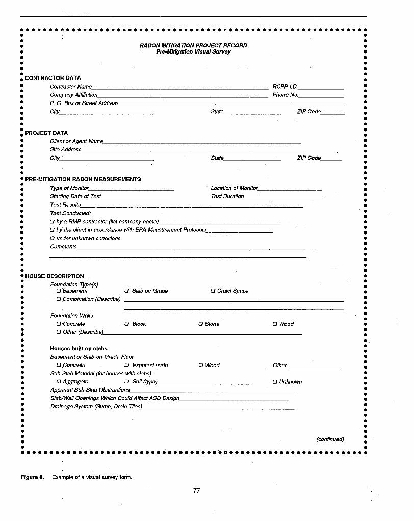
•••••••••••••••••••••••••••••••••••• e •••••••••••••••••••••••••• •• •• RADON MITIGATION PROJECT RECORD •• ' Pre-Mitigation Visual Survey •• •• •• •• •• CONTRACTOR DATA •
• Contractor Name RCPP I.D. •• •• Company Affiliation Phone No. •
• P. O. Box or Street Address •• •• City. State ZIP Code •
• •• •: PROJECT DATA :
• CUentorAgentName •: S~A~ffiss :
• CitY. ' State ZIP Code •• •• •• •• PRE-MITIGATION RADON MEASUREMENTS •• •• Type of Monitor Location of Monitor •
• Starting Date of Test Test Duration •• •• Test Results •: ~~~ :• Q by a RMP contractor (Ust company name) •
: Q by the client in accordance with EPA Measurement Protocols :
• Q under unknown conditions •• •• Comments •
• •• •• •• •• HOUSE DESCRIPTION •
: Foundation Type(s) :• Q Basement Q Slab on Grade Q Crawl Space •
: Q Combination (Describe) :
• •• Foundation Walls •• •• Q Concrete Q Block Q $tone Q Wood •, Q Other (Describe) :., .: Houses built on slabs :
• Basement or Slab-on-Grade Floor •• •• Q ,Concrete Q Exposed earth Q Wood Other •
• Sub-Slab Material (for houses with slabs) •• •• Q Aggregate Q Soil (type) Q Unknown •
• Apparent Sub-Slab Obstructions •• •• SlablWall Openings Which Could AffectASD Design •
: Drainage System (Sump, Drain Tiles) :
• •• •• •• •• •• ~OOM~~ •· " .••••••••••••••••••••••••••••••••••• ~o ••••••••••••••••• ••••••••
Figure 8. Example of a visual survey form.
77

••••••••••••••••••••••••••••••••••••••••••••••••••••••••••• $ ••
• •• •• •• Houses built over crawl spaces •
• Crawl-Space Roor •• •• 0 Exposed Earth 0 Gravel Over Earth D Vapor Barrier Over Earth •
• 0 Concrete or concrete wash Q Other •• •• Accessibility of Crawl Space: •
• Aocess Door Headroom •• •• Obstructions In Crawl Space •
• •• •: Stories Above Grade or Basement :
• 0 ona 0 two D three Comment •• •• Attic Space: 0 yes Q no •
• Other comments about house SUbstructure/design •• •• •• Hestinglcoollng system (Describe fuel type, equipment, distribution system) •• •• •• •• •• Possible sources ofsignificant house depressurization (e.g., attic fan) •• •• •• •• •• Features Suggesting Mitigation Approaches Other Than ASD •• Water Supply: 0 Private Well D Public Well D Public Surface Water System •• •• Any rsason to expect bUilding materials may be a source) •
• Any features suggesting that basement pressurization should be considered) •· -.• •• Any features suggesting that house ventilation should be considered) •• •• •: Any features suggesting that crawl-space depressurization (or other crawl-space treatment, :
• otil6r than SMD) should be considered) •• •• •• Sketch the envisioned mitigation system, showing: •
: House features which will affect ASD suction pipe location, such as slab or crawl-space floor dimensions, finish or other:• above-grade obstructions, sub-slab obstructions, or accessibility. •
• • House features which will affect ASD exhaust pipe routing, including interior (and/or exterior) finish and obstructions. •• •• • Any sealing steps that will be necessary. •
• - Other steps, required to make mitigation systems other than ASD work •• •• - Ail Important components of the mitigation system. •
• •• •• •• •• •• •• •• •· .-• •• •• •• •• •• Form completed by: •• •• RCPP I.D. •· ~~ .• •• ••••••••••••••••••••••••••••••••••••••••••••••••••••••••••• 0 •••
Figure 8. {continued}
78

include: the type of measurement device that was used;the duration of the measurement; the general climaticconditions during the test; where the measm"ement wasmade (e.g" cornmning that a detector was not placed in acrawl space or sump); and the degree to which the houseremained Closed during the test.
• Factors determining which ASD variation is used.These factors include:
- House substructure (basement, slab on grade, crawlspace, or combination of these). The substlUcture willdetermine whether SSD, SMD, or a combination oftechniques is used.
- Presence or absence of a sump with visi.ble dram tiles,or of exterior drain tiles draining to an above-gradedischarge (along with the apparent or reported completene~s of the drain tile loop). The presence of thesefeatures will determine whether sump/DTD or DTD/remote discharge are options.
- Nature of the foundation wall (poured concrete vs.hollow-block vs. fieldstone; if block, are top voidsopen, and is the wall otherwise very leaky?). Thisinformation would help determine whether a BWDcomponent might be needed as a supplement to a SSDor DID system, or (along with other information)whether BWD might be considered as a stand-alonetechnique.
- Presence of a perimeter channel drain. If thebaseboard-duct configuration of BWD is going to beconsidered, houses having perimeter channel drainswould be the best candidates for this approach (especially when the basement is not fmished.).
• Factors suggesting house is not amenable to ASD,or is amenable to' alternative' approaches. Thesefactors include:
- Known poor sub-slab communication (from observable or homeowner-reported lack of aggregate, andfrom experience in other houses in the area); complexsubstructure (e.g., multiple wings); high degree ofbasement finish; and/or fieldstone foundation walls. Thesefactors, especially in combination, could seriously complicate application of SSD, BWD, or SSD in combination with BWD or SMD.
- A crawl space which is inaccessible or Imusually cluttered, preventing application of SMD.
- A basement which is relatively tight (no forced-airducts, stairwell between basement and upstairs hasdoor which can be closed, no other major openingsbetween the basement and upstairs such as laundrychute), which would suggest the possible applicabilityof basement pressurization,
- Homeowners amenable to the lifestyle required forbasement pressurization to be successful (e.g., willing
79
to keep the' door closed between the basement andupstairs, acceptance of drafts and possible heating!cooling penalty that might result).
- A crawlspace which is relatively tight (e.g., no forced-airducts, no foundation vents), suggesting the crawl-spacedepressurization might be an option.
- House is served by a private well, and a high radonconcentration has been measured in the well water (orthere is some other basis for expecting high radonconcentrations in the water). In such cases, a watertreatment system might need to be considered as asupplement to ASD. '
- Underlying soil is well-drained gravelly soil, in whichcase soil pressurization might be considered instead ofASD.
• Factors which would influence the number and, positioning of SSD suction pipes. Such factors in
clude:
- Aggregate observedbeneath the slab through slab openings (e.g., at the bottom of sump pits, registers forsub-slab forced-airsupply ducts, utility openings underbathtubs, etc.); or, aggregate reported to be present byhomeowner, from observations of house during construction; or,' aggregate believed to be present basedupon code requirements or common construction practice in the area. Good aggregate would, of course,suggest the need for only one or two SSD pipes.
- Slab size. Especially where sub-slab communication issuspected to be poor or uneven, a larger slab maysuggest the need for additional suction pipes.
- House floor plan, degree of floor/wall/ceiling finish,and living patterns. Suction pipes will preferentially beinstalled in unfinished areas (such as unfinished portions of basements, or utility rooms) or in concealed~eas (such as closets). In urnmished areas, pipes wouldbe placed out of the normal traffic patterns.
- Homeowner pl~s and preferences. The owners' plansto finish a currently unfmished area, or personal preferences for aesthetic or other reasons, would influencepipe location.
- Observed or reported sub~slab utilities (such as sewerlines and forced-air ducting) and in-slab utilities (suchas heating coils built into the slab), which could limitlocations where pipe penetrations can be made.
- Exterior driveways, patios, walkways, etc., which wouldaffect where below-grade penetrations might be madefrom outdoors.
- Apparent entry routes through the slab. Such entryroutes might suggest that suction pipe placement mightbe biased toward those entry routes in order to helpensure effective treatment. (Where the slab openings

are significant, location of a suction pipe too near suchentry routes without at least partial sealing of theopenings could result in significant air short-circuitinginto the system.) Entry routes of concern might include: a region toward the interior of the slab wherethere is extensive cracking; a block structure towardthe interior of the slab, which penetrates the slab andrests on footings underneath; and a perimeter blockfoundation wall that extends the deepestbelow grade ina wa}k-<>ut basement.
- Observed or reported sub-slab obstructions which divide slab into segments, such as interior footings andforced-air supply or return ducts. While it will notalways be necessary to ensure that a SSD suction pipeis placed in each segment of the slab if there is goodaggreg<''l.te, it may sometimes be necessary, and themitigator should be aware that this problem mightarise.
- Evidence of water entry into a basement through slabor wall cracks, suggesting that drainage is poor in thatpart of the basement and that suction pipes at thatlocation may become blocked by water during wetweather.
• Factors wltich would influence the design of acrawl-space SMD system. These factors would include:
- nle size of the crawl space. Larger crawl spaces willincre.1Se membrane materials and installation cost, andwould increase the likelihood that sub-membrane perforated piping ormultiple suctionpipes wouldbe neededto adequately distribute suction beneath the membrane.
- The nature of the crawl-space floor. Gravel on the floorwould facilitate suction field extension under the membenne. Irregular floors, e.g., with protruding rocks,could require heavier membranes, and more effort inmembrane installation.
- nle accessibility of the crawl space, including headroom IDld major obstructions such as forced-air heating/cooling systems. Poor access to some portions ofthe crawl space could increase installation costs andperhaps require design modifications which includeleaving portions of the floor uncovered. (poor access tothe entire crawl space could require the use ofa mitigation approach other than SMD.)
- Expected traffic patterns in the crawl space. Ifparticularly heavy traffic is anticipated over some significantportion of the crawl-space floor (e.g., due to the location of appliances in the crawl space), it may be necessary to place heavier membrane-in extreme cases, 45or 6O-mil sheets of EPDMI'M (a rubber-like roofingmembrane), or some other appropriate material-ontop of (or in place of) the polyethylene membrane intIle heavy-traffic areas to protect the membrane frombeing punctured.
80
• Factors which would influence the routing oj theexhaustpiping. These factors include:
- The availability of a convenient route for an interiorstack up through the house, through either: closets orother concealed areas on any floors above the slab orcrawl space; or utility chases. The location of such aconvenient exhaust route could also influence SSDpipe location.
- Convenient access to an adjoining slab-on-grade garage, so that the exhaust stack can be routed up throughthe adjoining garage instead of through the house.
- Locations where the exhaust piping can reasonablypenetrate through the basement band joist, and wherean exterior stack/exhaust can be installed.
The presence and accessibility of an attic where the fanfor an interior stack can be mounted, ifan interior stackis planned.
- The nature and degree of f'misb in the areas throughwhich the exhaust piping may have to pass. If anexhaust piping route cannot be identified which largelyavoids finished areas, this could increase installationcosts and have an aesthetic impact. The nature of thebasement ceiling is one particularly important elementof the fmish; an unfmished or a suspended ceiling willgreatly simplify horizontal piping runs, relative to asheetrock ceiling.
- Any obstructions (such as ducts and utility pipes) whichmay complicate routing, e.g., by requiring that a horizontal piping run make a vertical bend which couldhinder maintaining proper pipe slope for condensate .drainage purposes.
- Any exterior fmish which would influence the abilityto penetrate the house shell near grade and extend astack up the outside of the house, where an exteriorstack is planned. Such finish could include, e.g., exterior brick or stone cladding at the point where theexhaust piping would penetrate the shell, or the natureof the exterior siding and roof overhang; if it is aesthetically important to box in or otherwise finish theexterior fan and stack.
• Factors affecting the degree oj sealing required.Significant slab or wall openings that could require somefonn ofclosure during installation should be noted. Openings of particular importance include:
- Wide gaps at the perimeter Wall/floor joint (including,in the extreme case, a perimeter channel drain). Theaccessibility of this joint should also be noted, sincethat will significantly influence the practicality of (orthe installation effort required for) closure of this gap.
- Other major slab openings, such as sump holes, untrapped floor drains, cold joints, and utility penetrations.
- Major wall openings (in particular, open top voids inhollow.,.block foundation walls)~ This is of particularimportance when a BWD component to the ASD system is anticipated.
• Driving forces for radon entry which could influence ASD design. The house design and opelatingfeatures which influence radon entry driving forces willnot often be that important to a: mitigator when there isgood sub-slab communication. Under those conditions,the sub-sIal? is likely to be depressurized sufficiently towithstand the depressurizations created by appliances; .and the flows induced by thermal bypasses. However,where communication is marginal, general knowledge ofthe challenges that the system might be facing could aidin Judging how conservatively the system should bedesigned. Features that can be noted include:
- Appliances that can contribute to depressurization ofthe lower level of the house. These appliances includecombustion appliances (furnaces and boilers, rrreplaces,wood stoves, and water and space heaters), if theseappliances burn fuel (i.e., are not electric), and if theyare operated with any frequency. Depressurizing appliances also include exhaust fans (clothes driers, roomexhaust fans, whole-house exhaust fans, and exhaustfans on kitchen ranges).
Where cold-air return ducting is located inside thelivable space, as is commonly the case, central forced-airfurnace fans can often serve essentially as exhaust fansfor that portion of the house in which the return ducting.is present. This situation will exist if there are notsufficient supply registers in that portion of the houseto compensate for the air withdrawn by return registersand by the leaky, low-pressure return ducting. Or, if theforced-air supply ducting is located outside the livablespace (such as in the attic or garage), a similar situationcould occur.
If, in aggregate, the appliances present appear as thoughthey might be sufficient to create significant depressurization when operating, the ASD system may warrnntadditional suction pipes or other measures in an effortto increase the sub-slab or sub-membrane depressurizations created by the system.
The presence of combustion appliances, especially inbasements, would also alert the mitigator to check forback-drafting if the ASD system has unusually highexhaust flows. This can be a particular problem if aBWD system is being considered.
.,. Thermal bypasses, which could increase the flow ofsoil gas into the house through entry rollltes if the entryroutes are not adequately depressurized by the ASDsystem. Major thermal bypasses include., e.g., unclosedstairwells between house stories, laundry chutes, utilitychases, chases around flues, openings associated withforced-air ducts, etc. Thermal bypasses will often notbe a significant concern in ASD design in most cases,but if communication is marginal and if the thermal
bypasses are extensive, the mitigator may want to besomewhat more conservative in system design.
In the conduct of a visual survey, the tools most likely to berequired are a flashlight, a screwdriver, and a stiff brush. Thescrewdriver might be used, e.g., to pry grilles off of a floordrain in order to see if it is trapped; the brush might be used toscrape away dirt and concrete wash at !he wall/floor joint inorder to better see the nature of the Clack there. Some mitigators also utilize heatless chemical smoke devices, to enablevisualization of air flows. Chemical smoke could indicatewhether air flow is into the house at various openings, suggesting the possible importance of those openings; it couldalso be used around flues ofcombustion appliances, to assesswhether the appliances are drafting properly or whether thehouse is near back-drafting conditions prior. to mitigation.
One output from the visual survey will be a recommendationregarding any further diagnostic testing that is needed beforethe mitigation system can be designed. If no further diagnostics are found to be necessary, the final output of the visualsurvey will be the design of the system, as suggested by thelast page of Figure 8 (the sketch of the mitigation system).The level of written detail desirable for the design depends onwhether the person(s) who conducts the visual survey and thedesign will be on-site at the house during the actual installation, with less detail being needed if the designer is going tobe present to give directions to the workmen. A floor plan ofthe lowest level of the house roughly to scale, showing, forexample., the pipe penetrations and routing for the envisionedsystem, the fan location, and key house features influencingdesign, will generally be advisable, to help the mitigatorvisualize the system and determine materials requirements,and to aid in communication with the workmen and thehomeowner.
3.3 Procedures for Sub-SlabSuction Field ExtensionMeasurements
If there is not evidence of a reasonably consistent aggregatelayer beneath the slab, from either the mitigator's observationor from the homeowner's experience and if the mitigator'sprior experience in the area does not suggest whether thehouse is likely to have aggregate, then sub-slab suction fieldextension measurements may be advisable.
Suction field extension measurements involve generation of asuction field under the slab prior to installation of the mitigation system, and then measuring the suction field inducedunder the slab at test holes remote from the suction point.Commonly, this pre-mitigation suction field is generated using an industrial vacuum cleaner. Another option that hasbeen suggested but does not appear to have been used to dateis to utilize an ASD fan, mounted on a 4-in. pipe in a portabletest stand, to generate the suction. Use of a fan and pipesimilar to that which is to be used in the ultimate systemwould provide more meaningful and easy-to-interpret suctionfield and flow data than would a vacuum cleaner, since thevacuum cleaner motor has a much different performancecurve than do ASD fans.
. 81

Rather than using a portable ASD fan test stand, some mitigators use the mitigation system itself to generate the suctionfield, installing the first suction pipe, mounting the fan, andturning the system on. If the results show inadequate extension of the suction field, additional suction pipes are installedwhere needed. This approach might be viewed asduring-mitigation, rather than pre-mitigation, diagnostics.
In the discussion here, it will generally be assumed that avacuum cleaner is being used, because vacuum cleaners arecommonly employed, and because more care is usually neededin the conduct of the test and the intexpretation of the resultswhen a vacuum cleaner is used. Where necessary, it will beindicated how the procedure would differ ifan ASD fan ratherthan a vacuum cleaner were being used to generate the suction.
Suction field extension measurements can be conducted withtwo different approaches.
The first, qualitative approach is simply to determine whethersub-slab communication is relatively good or poor. This approach involves fewer test holes (e.g., one in each comer ofthe basement), and indicates whether suction is generallyextending well in various directions. (It can also indicatewhether system flows will be relatively low or high.) This isthe approach to start with any time that communication isunknown and might be good. If this test shows that communication is good (by virtue of good sub-slab depressurizationsinduced by the vacuum cleaner in the slab comers), then nofurther diagnostics may be needed. But if the results indicateth.'\t suction field extension is marginal, poor, or uneven, moresub-slab data may be desirable to design the system. In thatcase, the testing can be extended to provide more quantitativeresults, per the second approach below, by drilling more testholes and more carefully controlling the speed of the vacuumcleaner.
The second, more quantitative approach can be useful whensub-slab communication is marginal or poor. By adjusting thevacuum to better reproduce SSD flows, and by measuringvncuum-induced sub-slab depressurizations through more testholes, a more defmitive estimate can be developed regardinghow far the suction field from a SSD suction pipe mightextend, and thus how many SSD pipes might be needed (andwhere they might best be located). As discussed later, thesemore extensive tests with a vacuum cleaner may not predictexactly how far the suction field from a 4-in. SSD pipe willextend. Most often, the vacuum cleaner diagnostics tend toover-predict the number ofSSD pipes required. Any diagnostic testing conducted using a SSD fan test stand or using theinitL:1l SSD system to generate the suction field will almostautomatically reproduce SSD flows and thus almost automatically be quantitative, ifa sub-slab suction pit is excavated andif the suction losses in the system piping are simulated.
The experimental setup for quantitative suction field extension testing using a vacuum cleaner is illustrated in Figure 9.The details of this configuration will be discussed later, inSection 3.3.2. This figure will also be helpful in understandingthe qualitative testing approach, as well as some of the keyconcepts regarding suction field extension testing.
In conducting sub-slab diagnostics using a vacuum cleaner, amitigator must be aware that the suction-vs.-flow performance curve of the vacuum cleaner will be very different from·that of the ASD fan that will ultimately be installed. Thus.care must be taken in cases (such as with the quantitativeapproach) where it is desired to attempt to reproduce actualSSD flows and suctions using the vacuum. The approach forsimulating the SSD system is to adjust the vacuum cleanerspeed so that the sub-slab depressurization measured at abaseline test hole 8 to 12 inches· away from the vacuumnozzle-Le., at a point that would be in the sub-slab suctionpit under a SSD pipe, were the SSD pipe to be insciuled wherethe vacuum nozzle is-is about equal to that which the SSDpipe is expected to produce in the sub-slab pit. See Figure 9.Simple theory regarding sub-slab flow dynamics predicts thatif the these sub-slab depressurizations are equal, then theflows in the vacuum cleaner should nominally be the same asthe flows in the SSD system, despite their very differentperformance curves. And under these conditions, the sub-slabdepressurizations generated by the vacuum at more remotetest holes will nominally be the same as those generated by aSSD system. If the sub-slab depressurization with the vacuumat this baseline test hole is not set equal to that expected withthe SSD pipe, then the flows and depressurizations generatedby the vacuum will have no quantitative relationship to thosethat will be generated by the SSD system.
In slabs having good aggregate, flows may be sufficientlyhigh such that the relatively low-flow vacuum cleaner will beunable to achieve the desired suction at the baseline test holeas specified above. In these cases, the vacuum will be unableto simulate a SSD system. But in cases where aggregate isgood and flows high, quantitative suction field diagnosticswill be unnecessary anyway.
From a practical standpoint, some mitigators might fmd itmore cost-effective to perform the sub-slab diagnostics during the installation, as mentioned earlier, when sub-slab communication is uncertain. In this case, additional suction pipeswould be added as necessary if the initial pipe(s) provedunable to extend a sufficient suction field. An added advantage of proceeding in this manner is that, since the suctionfield is being created by the system fan, there is no concernabout whether a diagnostic vacuum cleaner is properly representing the system fan. A disadvantage of this approach is thatthe mitigator will notknow what complications may be presentuntil installation is well underway.
If a mitigator decides to skip the pre-mitigation sub-slabdiagnostics, and if the initial hole(s) drilled through the slab toinstall suction pipes show no aggregate or other evidence oflikely poor communication, then it is advisable to proceedwith during-mitigation (or post-mitigation) suction field testing, as discussed above. The cost ofconducting these diagnostics while the installation crew is on site is estimated to beroughly $45 (with a standard deviation of $47) in unfmishedbasements (He91b, He91c). By comparison, if the crew leavesthe site and depends upon a post-mitigation radon measurement to alert them that the system is not functioning asdesired, this cost may increase by roughly $150, due to thetime required for the crew to return to the site. Or, as anotheroption, the mitigator might elect to simply install a second
82

Pitot tube or other device to measure the flowof sub-slab gas into the vacuum cleaner;needed if it is desired to measure sub-slabflow characteristics to aid in selecting the SSDfan having the optimum performance CUrvl~. ---....
PVC ball valve, to allow room air to bleedinto vacuum cleaner intake as necessary telachieve the desired sub-slab depressurizationat the baseline test hole, (This is an alternativeto the use ota speed controller on the vacuumcleaner motor as a method for adjusting theinduced sub-slab depressurization at the'baseline hole,)
1.25" PVC pipe: rigid pipe facilities mountingin slab and enables measurement of flow intovacuum, if desired, -----------,
Magnehelic® gauge or micromanometer, capableof measuring sub-slab depressurizations in therange that will be developed by the SSD suctionpipe (commonly 0,5-1.5 in, WG, sometimes higher),Room air bleed into the vacuum cleaner intake(or vacuum motor speed) must be adjusted untilthis gauge shows that the vacuum cleaner ismaintaining the sub-slab depressurization thatthe SSD fan is expected to produce at thislocation (i.e, in the suction pit),
Micromanometer, to measure the sub-slabdepressurization at remote test holes, If thevacuum cleaner can be adjusted so that thesub-slab depressurization at the baseline testhole with the vacuum is identical to that whichthe SSD fan will produce at that location (i,e, inthe pit beneath the SSD suction pipe), then the'measured sub-slab depressurizations at remotetest holes with the vacuum should be identical
. to that which the SSD fan will produce at theremote holes,
...... '.......
RemoteTest Hole
.... ' ,
•• 0
. ~.
. .'.. '
....
RopeCaulk---,
FlexibleTubing
.. ~.' .. ~~ . ....... ,,' ..,' ..... '.;", ~ '. ~.' ". ~ . .. .. . .. ... . ,,' .
1-------=---s.:.OU-C-"t-i;] L-& &_....... ·~-.-B-a-S-e-Iin-e--"'--l
Hole L I Test Hole8"·12"-..1
Industri~1
VacuumCleaner
FlexibleVacuum Hose
ExhaustDischargedOutdoors
Figure 9. Experimental configuration for quantitative pre-mitigation sub-slab suction field extension and flow diagnostics using a vacuumcleaner.
suction pipe at a convenient location without spending theestimated $45 to do the diagnostics. Installation of a secondpipe adds roughly $135 (standard deviation $44) to $225(standard deviation $90) to the cost, depending upon degree offmish. It is a jQdgement call regarding whether it is a reasonable gamble to spend $135-$225 to install a suction pipewithout first spending roughly $45 for diagnostics to see if thepipe is necessary and where it should optimally be located.
The following discussion describes the equipm~mt and materials needed, the test procedure, and the means for interpreting!
utilizing the test results, for each of the two measurementavproaches.
3.3. 1 Qualitative Assessment of SuctionField ExtensionThis suction field extension measurement approach providesa qualitative indication of whether communication is relatively good or poor, and of how uneven it may be.
y, 83

• Equipment and materials required
- Industrial vacuum cleaner (assuming, as discussedabove, that a vacuum cleaner is being used rather thanan ASD fan). While units having various performancecharacteristics are available, typical vacuum cleanersused in diagnostics can develop suctions up to 80 in.WG at zero flow, and flows ofperhaps 100 cfm at zerostatic pressure. (If an ASD fan were used instead of avacuum, so that flows during the diagnostics approximated ASD system flows, this test could almost automatically become quantitative, as mentioned previously.)
- Sufficient vacuum cleaner hose to permit the vacuumto be located outdoors during the tests, or, if the vacuumwere indoors, to permit the vacuum exhaust to berouted outdoors. Directing the exhaust outdoors willavoid the discharge into the house of high-radon soilgas and of dust that is not captured by the vacuum. Ifthe vacuum itself were outdoors, fugitive soil gas anddust escaping from the vacuum would be preventedfrom entering the house. The vacuum is depicted indoors in Figure 9 for convenience.
- A suitable masonry drill for drilling holes through theconcrete slab. An electric rotary hammer drill is commonly used for this purpose.
- Drill bits for the masonry drill, including: one bitslightly larger than the nozzle of the vacuum cleaner(typically about 1.25 in. diameter), to drill the holethrough which the vacuum nozzle will penetrate theslab; and one bit for the test holes (1/4- to l/2-in.diameter).
- Pressure sensing device, for determining sub-slab depressurizations at the remote test holes. This device canbe one of the following:
Preferably, a digital micromanometer as shown inFigure 9, capable of detecting pressures as low as0.001 in. WG. This device provides a quantitativemeasurement. Flexible tubing of a diameter similarto that of the test hole is required to connect themicromanometer to the sub-slab through the testhole.
A heatless chemical smoke device. Chemical smokemay sometimes be more sensitive than the micromanometer in detecting depressurizations, sincesmoke might be drawn down into the test hole atsuctions below 0.001 in. WG. For qualitative assessments ofsuction field extension, the qualitativeindication of depressurization provided by smokesticks may sometimes be sufficient. However, thequantitative result from a micromanometer is extremely useful in telling the mitigator whether thesuction field extension is marginal or strong. Another concern about the use of smoke is that the testhole will not be sealed by tubing, as with a micromanometer; when the sub-slab suction is marginal,
84
the open test hole may be sufficient to neutralize thesub-slab depressurization at that location (Gad92).
Thermally generated smoke (from a punk stick orcigarette) should never be used for this purpose.The natural thermally-induced rise of this smokecould mask or prevent any flow down into the holein response to sub-slab depressurization. Also, thereis a fire hazard.
- Rope caulk or putty, to provide an air-tight seal wherethe vacuum cleaner nozzle and the micromanometertubing penetrate through the slab. In addition, the ropecaulk can be used to temporarily close individual testholes while measurements are being made at anotherhole, to prevent the measurements from being influenced by air leakage through the other holes.
- Hydraulic cement or other non-shrinking cement, topermanently close all of the holes following testing.
- (Optional) A pitot tube (or some other suitable device,such as an anemometer or a calibrated orifice) to determine.flows in the vacuum cleaner nozzle, as shown inFigure 9. Relatively high flows in the nozzle wouldconfirm observed good communication, and wouldsuggest that a relatively high-flow fan is needed on theASD system. (It could also be suggesting air leakageinto the sub-slab near the vacuum cleaner, possiblyexplaining poor communication). Relatively low flowswould tend to confirm poor communication, and possibly suggest the need for a low-flow, high-suction ASDfan. For this qualitative testing, some investigatorssuggest dispensing with the pitot tube, and simplyjudging whether the vacuum flow is high or low fromthe sound of the vacuum motor (Br91b).
- Note that the Magnehelic® gauge shown in Figure 9,mounted in a baseline test hole near the vacuum nozzle,in not included on this list for the qualitative test. Theadditional effort involved in installing this gauge in abaseline hole, and in adjusting the vacuum to achievethe desired depressurization at that hole, is a key factordistinguishing between the qualitative and quantitativeprocedures.
• Test procedure
- From the house floor plan, select the location for the1.25-in. vacuum cleaner suction hole through the slab.
If a SSD system is being considered, the suctionhole ideally shoul9 be located at a site where a SSDsuction pipe will potentially be installed. This selection not only reduces the number of places wherethe slab is penetrated, but also reduces the potentialfor differences between the diagnostic results andthe actual system performance, in the event thatcommunication varies at different locations aroundthe slab. (Note that if an ASD fan on a 4-in. pipe isbeing used to generate the suction field rather than avacuum cleaner, the 4-in. hole through the slab

would almost certainly be drilled at the site of apennanent suction pipe.)
The goal of locating the vacuum cleaner hole at apotential SSD pipe site means that the vacuum holemay be near the slab perimeter, especially if poorcommunication is suspected. Most radon entry willoften be through the perimeter wall/floor joint andblock foundation walls, so that it is most importantto detennine that the suction field is extendingeffectively at the perimeter. The suction hole shouldbe at least 6 to 12 in. from the wall, to avoid thefooting (EPA88b, Gad89, Br92). The vacuum holemust not be near any major slab opening. If there is
. a large wall/floor joint-in particular, if there is aperimeter channel drain-substantial air leakagethrough the perimeter joint can overwhelm thevacuum cleaner, which cannot move a lot of air(perhaps 100 cfm). In such cases, the vacuum holeshould be toward the center of the slab, even if theultimate installation may involve closure of theperimeter gap and location of SSD pipes near theperimeter.
In cases where SSD pipes should not be placed nearthe perimeter walls, such as in slab-on-grade housesin Florida, it has been suggested that the vacuumhole be located between 6 and 15 ft from exteriorwalls (F090).
Consistent with the selection of sites for SSD pipes,the vacuum cleaner suction hole should be in anunfmished area (such as an unfinished basement ora utility room) or in an inconspicuous area (such asa closet), acceptable to the homeowner.
As with SSD pipe site selection, the vacuum suctionhole site should be selected in an effort to avoidsub-siab or in-slab utilities.
If there is a sump with a drain tile loop, and sump/DTD is the intended mitigation technique, thevacuum cleaner can draw suction at the sump, avoiding the need to drill a 1.25-in. hole through the slab.
- Select the location for the suction measurement testholes.
For this qualitative measurement, one test hole ineach quadrant of the slab, generally toward thecomers, would be appropriate. Because of the importance of suction field extension around the perimeter, location of the test holes near the walls isgenerally preferred, but not so close to a wide wall/floor crack that the suction field will have droppednear zero. Some investigators suggest locating theslab test holes at about the middle of each wall,about 6 in. out from the wall (EPA88b). If it issuspected that communication is good, some mitigators may wish to start with only one or two testholes, at locations the most remote from the suctionhole (Gad89); by this approach, additional suction
85
holes would be drilled only if the pressure measurements at the first hole(s) indicate that communication is not good. The holes should not be immediately beside major openings, suchas perimeter channel drains, since, even with good communication,sub-slab depressurizations will have declined towards zero near such major air leakage points.
As with other slab holes, the test hole locationsshould be selected to be inconspicuous, and toavoid utility lines.
- Drill 1/4- to lI2-in. suction test holes.
If initial testing is being conducted on only one ortwo test holes, because good communication issuspected, drill these frrst.
If the hole is .being drilled throughasbestos-containing floor tile over the slab, somemitigators place a wet sponge (or some other material, such as shaving cream) on top of the tile at thedrilling site, to prevent asbestos fibers from becoming airborne during drilling.
Make sure the drill bit penetrates through the slaband any vapor barrier, into the sub-slab fill.
Try to assess the nature of the sub-slab fill. Oneapproach for doing this (Bro92) is to stop the drilljust after it penetrates the slab. Then, push the drilldown into the sub-slab material to detennine howcompact it is. Turn the drill back on for a second,thenpull it out and inspect the bit. If it is clean, thissuggests that aggregate may be present, or that thesoil under the slab may have subsided. If there isdirt on the bit, that will indicate that aggregate is notpresent, and will suggest the type and wetness of thesoil immediately under the slab.
This infonnation will aid in the interpretation of thesuction field extension test results. If aggregate.ispresent at all of the initial test holes, a decision maybe made not to continue with the suction fieldextension test (depending upon prior experiencewith the evenness of aggregate layers in that area),avoiding the need to drill the remaining test holes orthe vacuum cleaner suction hole.
Vacuum up the dust created by drilling, to avoidplugging of the micromanometer sampling tube(and of the grab sampler ftlter, if grab sampling isperfonned), and to pennit effective sealing of thegap between the sample tube and the slab. If asub-slab grab sample is to be drawn for a radonmeasurement, the vacuum .should be operated asbriefly as possible (for only a few seconds), tominimize any artificial reduction in the sub-slabradon level.
Temporarily close test holes with rope caulk.

(Optional) If a grab sample is to be taken to determine sub-slab radon concentrations at the test holes,that sample would be taken at this time. Followingthe vacuuming step above, the hole shouldremainedclosed with the rope caulk for awhile before thesample is taken, to let the sub-slab concentrationsre-equilibmte after possible dilution due to the drilling and vacuuming.
- Drill 1.25-in. suction hole through slab for vacuumcleaner nozzle, and insert nozzle.
See comments above for drilling test holes, forcases where asbestos-containing floor tiles are covering the slab.
Make certain drill bit penetrates through the slaband any vapor barrier, into the sub-slab fIll.
Inspect the nature of the material under the slab, asdiscussed above for the test holes. Again, if aggregate appears to exist everywhere, continuation ofthe suction field extension diagnostics is probablyunnecessary.
Vacuum up the dust created by the drilling, topermit effective sealing of the gap between thenozzle and the slab. Minimize operation of vacuumif it is planned to draw sub-slab grab samples forradon measurements.
(Optional) Any grab sample for radon measurements would be taken at this time, if planned. Seecomments above in connection with the test holes.
Insert the nozzle into the hole, to a depth about onehalf the thickness of the slab. Insertion of the nozzleall the way to the underside of the slab might resultin partial blockage ofthe nozzle by the sub-slab fill.Tightly press rope caulkorputty around the circumference of the nozzle, at the joint between the sideof the nozzle and the top of the slab. Failure to sealthis gap will result in significant air leakage downthrough the gap, reducing suction field extension.
The vacuum cleaner hose attached to this nozzleshould be long enough to extend to the vacuumcleaner located outdoors. Alternatively, if thevacuum is in the house near the suction point, thehose on the vacuum cleaner exhaust should exhaustoutdoors.
If the vacuum is to draw suction on an existingsump, rather than through a hole drilled in the slab,seal a sheet of plastic over the sump, and seal thevacuum nozzle through the plastic. Alternatively,seal the vacuum nozzle into an exposed drain tilewhere it enters the sump, and temporarily seal theends of any other drain tiles entering the sump.
- Place the house in the condition that will be usedthroughout this testing. In general, it is recommended
86
that this condition be with exhaust appliances operating, to simulate the most challenging conditions in thatparticular house. If no sub-slab depressurizations aremeasured under those conditions, the appliances mightbe turned off (and perhaps windows opened), to see ifsome sub-slab depressurization is being achieved under non-challenging conditions.
- With the vacuum cleaner off, measure the sub-slabpressurization (or depressurization) at each test holewith the micromanometer. This will indicate the "baseline" pressure difference across the slab under theweather and appliance operation conditions existingduring the tests. As discussed in Section 3.5.4, thismeasurement will indicate how the existing conditionscompare against the expected maximum slab pressuredifferential (Le., the expected maximum driving forces),and may thus aid in interpreting the results with thevacuum operating.
Remove temporary rope caulk seal over each hole;replace after measurement is completed.
Insert sample tube from micromanometer, to a depthabout half the thickness of the slab. Press a ropecaulk seal around the tubing circumference, at jointbetween tubing and top of slab. Failure to effectively seal this gap will result in serious measurementerror.
Observe reading on micromanometer. Reading willlikely fluctuate somewhat, as a result of minorpressure changes inside the house due to winds, etc.Record the observed range, and/or the average.
Check the zero on the micromanometer often, preferably before each reading in cases where the measured pressures are very low.
If the mitigator has only a chemical smoke device,and not a micromanometer, a quantitative measureof existing pressures would notbe possible, and thisbaseline measurement would thus be of less value.However, when the smoke testing is done duringoperation of the vacuum (see below), it would stillbe worthwhile to turn the vacuum off during thetesting at each test hole, to see if these is a distinctdifference in smoke flow with and without thevacuum operating.
- Measure the depressurization created beneath the slabat each test hole when the vacuum cleaner is operating.On vacuum cleaners having speed controllers, operatethe vacuum at full power for this relatively qualitativetest.
With tape covering other test holes, insert sampletube from micro-manometer into each test hole inturn. Seal gap between the tubing and the top of theslab with rope caulk or putty.

Where communication is marginal to poor, it maytake a minute, or perhaps several minutes, for thesuction from the vacuum to become established,especially at remote test holes.
Observe the reading on the micromanometer ateach hole. Record the range and/or the average ofthe readings. Compare these values with the valuesmeasured before the vacuum cleaner was turned on.
Check the zero on the micromanometer often, prefembly before each reading in cases where the measured depressurizations are very low.
Be careful if any test holes are near the suctionpoint The high suctions that can sometimes existnear the vacuum cleaner when flows are low (tensof inches of water) can be high enough to damagesome micromanometers.
If a chemical smoke device is used, release only asmall quantity of smoke very near to the test hole.The smoke patterns can sometimes be obscured byair currents in the room when the pressure difference across the slab is quite small. Back-lightingthe smoke with a flashlight can be helpful in seeingthe smoke patterns (EPA88b).
If the vacuum cleaner nozzle is not fitted with apitot tube (or other device for measuring flow), aqualitative assessment of whether the flows seem tobe high or low ,should be noted from either thesound of the vacuum motor (Br91b, Br092) of fromthe apparent velocity of the vacuum eXhaust (Br092).The sound of the motor (or the feel of the exhaustjet) at high and low flows can be determined byoperating the vacuum, first with the nozzle in freeair (high flow), then with the nozzle blocked (lowflow).
(Optional) If the vacuum cleaner nozzle is fittedwith a flow measurement device, the flows in thenozzie should be recorded.
- All holes that have been drilled through the slab mustbe permanently cemented closed after testing js complete.
• Interpretation ofresults
- Communication is probably reasonably good and reasonably uniform if induced sub-slab depressurizationscould be distinctly measured with the micro-manometerat each test hole (or the smoke flow was distinctlydown ~nto each test hole) with the vacuum cleaneropemting.
The stronger the measured depressurizations, themore confident one can be in this result
Also, if the house was probably near the maximumdriving force during the testing (cold weather, ex-
87
haust appliances opemting), one can be more confi- ', dent in this result
As an option, a mitigator might qualitatively compare the baseline (vacuum oft) pressure differentials measured during the testing with theroughly-projected worst-case maximums for coldclimates (about 0.025 to 0.035 in. WG). As a qualitative approximation, was the vacuum developingsub-slab depressurizations of the right order to potentially compensate for worst-case conditions? (SeeNote below.)
Relatively high flows in the vacuum cleaner wouldgenerally tend to support these suction field observations.
The confidence that communication is good is in. creased if aggregate was observed through the test
holes.
If sub-slab depressurizations are marginal but flowsare high, this could be indicating that communication is good but that the relatively low-flow vacuumcleaner is being overwhelmed by the available flow.In such cases, the ASD system (with perhaps doubleor treble the flow capacity of the vacuum) mightperform well. (Marginal depressurizations and highflow could also be suggesting a leak through theslab near the vacuum.)
Note: It is re-emphasized that, in this qualitativetesting, no effort has been made to try to make thevacuum cleaner simulate an actual ASD fan. Thus,the actual sub-slab depressurizations measured withthe vacuum cleaner will be different from those thatwill be established by the ASD system. Thus, anyuse of the actual sub-slab depressurizations measured with the vacuum---e.g., to assess whetherthey mightbe sufficient to compensate for worst-casehouse depressurization, as suggested above-canbe done in only a qualitative manner.
- When communication thus appears to be reasonablygood and uniform, only one or two SSD pipes willlikely be sufficient, and there will be flexibility inselecting where the pipes are to be located. (Or, if asump/DTD system is being considered, confidence isincreased that the system will perform well, even if thedrain tile loop is not complete.) ,
- If the results are inconclusive, with distinct depressurizations in some test holes, but with no (or marginal)depressurization in other holes, this may be suggestingthat communication is not uniform or that the suctionfield is having difficulty extending to the more remoteportion of the slab. In this case, the logical next step isdetermined based upon the mitigator's experience withother houses in the area.
-- 'The mitigator might elect to proceed with the installation of a one- to two-pipe SSD system, if one or

more of the following conditions exist a) flows inthe vacuum were high, and there are no nearby slabopenings through which air could have beenshort-circuiting into the vacuum, suggesting thatthe vacuum cleaner was simply being overwhelmedby high flows from a sub-slab region having goodcommunication; b) aggregate appeared to be present;c) the poor depressurizations were observed only ata few of the most remote test holes; d) the housewas tested under challenging conditions (coldweather and exhaust appliances operating), so thatthe risk is reduced that the observed marginal depressurizations mightbe overwhelmedby more challenging conditions later; and e) local experiencesuggests that houses such as the one tested can beadequately treated by one or two pipes.Post-mitigation sub-slab suction field measurementsshould be performed to confirm that, in fact, theslab is being adequately treated.
Ifconditions a) through e) above are not present, themitigator might elect to proceed with the installation, installing a conservatively-designed system(with additional suction points). Again,post-mitigation suction field measurements shouldbe performed.
The mitigator might elect to proceed with the installation, conducting suction field measurements during installation. The frrst one or. two suction pipeswould be installed, the system fan turned on; andthose results used to determine where any additional suction pipes should be located.
The mitigator might elect to conduct more quantitativecommunieation diagnostic testing (Section 3.3.2)in order to better quantify SSD pipe requirements.
- If the results suggest poor suction field extension, withno (or only marginal) depressurizations observed inmost or all of the test holes, then poor communicationshould be assumed. Under these conditions, the mitigator would be well advised either to conduct morequantitative suction field extension diagnostics (Section 3.3.2) prior to installation, or to proceed with theinstallation doing the diagnostics during installation.
-- Relatively low vacuum nozzle flows would be ex-pected in these cases. .
3.3.2 Quantitative Assessment ofSuction Field ExtensionAs indicated above, one option when sub-slab communicationappears to be marginal or poor is to proceed with quantitativesuction field extension diagnostic testing. The primary distinction between quantitative and qualitative testing is that,with quantitative testing, the flows in the diagnostic systemare adjusted to simulate the actual expected ASD flows. Thissimulation can be achieved either by adjusting a vacuumcleaner to achieve the proper depressurization at a baselinetest hole 8 to 12 in. away from thevacuum nozzle; or, by using
an ASD fan to draw the suction through a4-in. pipe, includinga suction pit under the pipe and simulating the expectedsuction losses in the ASD system piping. Another feature ofquantitative testing is that, in general, more test holes aredrilled at different distances from the suction pipe (rather thantwo to four holes at the comers of the slab).
The baseline test hole is located at a distance from the vacuumnozzle such that if it were a SSD suction pipe rather than avacuum nozzle at that location, the baseline hole would be inthe sub-slab suction pit under the pipe. If the sub-slab depressurization at the· baseline test hole during vacuum cleaneroperation is adjusted to equal that expected in the SSD suctionpit, then, by simple fluid dynamic theory, the flow in thevacuum will nominally be the same all that in the SSD pipe,despite the fact that the vacuum motor has a very differentperformance curve from that of the ASD fan. And because theflows are the same, the sub-slab depressurizations at remotetest holes should nominally be the same. .
In many (but not all) cases where the more quantitativesuction field diagnostics have been conducted, it has beenfound that the vacuum cleaner diagnostics over-predict thenumber of SSD pipes that will be required to treat the house(Ma89a, F090, Fi91, Si91, Sau92). A variety of possibleexplanations have been offered for why this occurs, including:a) failure of the diagnostician to allow enough time (sometimes several minutes or more in tight soils) for thevacuum-induced suction field to become established underthe slab (Hi92); b) failure to properly adjust the vacuumcleaner flows; c) inability of a measurement at the baselinetest hole to accurately reflect the suction that a SSD pipewould produce in an open pit at that location (Hi92, Sau92);d) small leaks around the sample tubing while micromanometer readings are being made at remote test holes, partiallyneutralizing any sub-shib depressurization that the vacuummay be producing (Hi92); and e) local inhomogeneities at thepoint where the vacuum nozzle is inserted (Hi92). Despite thisfrequent over-prediction, with proper interpretation, this diagnostic testing still can provide useful guidance regarding ASDsystem design. Efforts are continuing to develop better guidance on how to interpret the results of this testing, to accountfor its tendency to over-predict pipe requirements.
Again, the quantitative approach for suction field extensionmeasurements needs to be considered only in cases wheresub-slab communication is poor or uneven.
The basic setup for quantitative suction field extension testingusing a vacuum cleaner is illustratedin Figure 9.
• Equipment and materials required
- The more quantitative suction field extension measurements require the same equipment and materials asrequired for the qualitative testing (Section 3.3.1), except that the chemical smoke stick is no longer anoption for detennining sub-slab depressurizations. Thedigital micromanometer, which permits quantitativedetermina.tion of the suctions, is required.
88

- A Magnehelic@gauge, with a scale extending above1.5 in. WG, is now mandatory to monitor the sub-slabdepressurization at the baseline test hole, as illustratedin Figure 9. (The suctions produced in the baseline testhole when a 90-watt fan is being simulated-often 0.2to 1.5 in. WG-are within the upper scale of somemicromanometers. However, there may sometimes beexcursions to much higher suctions (up to 80 in. WG),and sometimes higher-suction fans will be simulated,perhaps 25 in. WG or higher. These suctions woulddamage many micromanometers, SO that the micromanometer is not recommended for use at this location.)
- In addition, the vacuum cleaner must be equipped witha speed controller or other means of flow adjustment,so that flows can be adjusted to achieve the desiredsuction in the baseline test hole. In Figure 9, this flowadjustment is illustrated as being achieved by a valveallowing adjustment of the amount of ambient airbleeding into the vacuum intake nozzle.
• Test procedure
Select the location for one or more 1.25-in. vacuumcleaner suction holes.
I
The criteria for site selection are similar to those forthe more qualitative approach. If the qualitativesuction field testing (Section 3.3.1) was conductedinitially, the same suction hole can be used for thistesting..
Since the poor communication will likely preventthe vacuum cleaner suction from extending to portions of the slab remote from the suction hole, itmay be desirable to have a second suction hole in asection of the slab remote from the first one. Testingat the second hole can serve to comrrm the measurements made at the first hole, or to suggestwhether communication varies in different parts ofthe slab.
- Select the locations for the 1/4- to 1/2--in. suction testholes.
A baseline test hole must be drilled about 8 to 12 in.away from each vacuum suction hole. The ability tointerpret the test results will depend upon the maintenance of the proper sub-slab depressurization atthis baseline test hole. The vacuum cleaner must beoperated with the depressurization at that hole being maintained at the level which a SSD fan wouldbe ~.ble to maintain in a sub-slab pit beneath a SSDsuction pipe.
Several remote test holes must be drilled. Ideally,about three such test holes would be drilled-oneabout 3 ft from the suction hole, another about 10 ft,and a third as far from suction hole as possible-ineach of two or three directions away from thesuction hole. The distance of the most remote hole
can be selected based upon experience regardinghow far away suction from the vacuum might beexpected to be detected. If the qualitative testing(Section 3.3.1) was conducted initially in the house,the test holes drilled for that testing can be utilizedin the quantitative testing, if convenient.
The actual locations where remote test holes canpractically be sited will be determined by the finishon the slab, and the location of sub-slab utility linesand other obstructions. Figure 10 illustrates a possible scenario for locating suction and test holes ona fully fmished slab, by drilling the holes in thecorners of closets, under carpeting, and in availableunfmished areas.
- Drill the suction hole and the test holes, to the extentthat these holes were not already drilled during priorqualitative suction field testing.
(Optional) If a grab sample is to be taken to determine sub-slab radon concentrations at the test holes,that sample would be taken at this time, after a briefvacuuming to remove dust. Preferably, the holeshould remain closed with rope caulk for awhilebefore sampling to permit re-eqiIili.bration ofsub-slab
Note: Test holes indicatedby small circles
/f------o
L-
/
L: I,,~ ,...:........................1
IIII
~ IBaseline I
!I
Test HoleII
~ "r_____L Suction I
_Hole ,-r-' 10/II
IIIIII
IIIIII
Figure 10. Example of siting vacuum cleaner suction hole andsub-slab suction test holes for quantitative suction fieldextension testing, when slab is fully finished.
89

concentrations. See the related discussion in Section 3.3.1.
Vacuum the holes carefully to remove dust anddrilling debris that may block the holes.
Inspect the nature of the sub-slab material, possiblyusing the drill bit, to aid in the interpretation of theresults, as discussed in Section 3.3.1.
Seal the vacuum cleaner nozzle into the suctionhole, using rope caulk or putty to close the gapbetween the nozzle and the top of the slab. Thenozzle should extend down about half the thicknessof the slab.
Insert the sample tube from the Magnehelic gaugeinto the baseline test hole, extending the tube downabout half the thickness of the slab. Seal the sampletube into the hole using rope caulk to close the gapbetween the tubing and the top of the slab.
Temporarily close the test holes with rope caulk.
- Place the house in the condition that will be usedthroughout this testing. It is recommended that thiscondition be with exhaustappliances operating, to simulate challenging conditions. If no sub-slab depressurizations are measured under these conditions, the appliances mightbe turned off(andperhaps windows opened)to determine performance under less challenging conditions (see Section 3.3.1).
- With the vacuum cleaner off, measure the sub-slabpressurization (or depressurization) at each test holewith the micromanometer, to determine the "baseline"pressure difference across the slab under the weatherand appliance conditions existing during the test. Seeprocedure for this measurement described in Section3.3.1. This baseline measurement will indicate how theexisting conditions compare against the expected maximum slab pressure differential, and may thus aid ininterpreting the results with the vacuum operating (seeSection 3.5.4).
- Turn on the vacuum cleaner, and adjust the speedcontroller so that the sub-slab depressurization measured by the Magnehelic gauge at the baseline test holeis approximately that which is expected to exist in thesub-slab suction pit beneath a SSD pipe when theintended SSD fan is operating. This step is critical inachieving quantitative results.
With the standard 90-watt ASD fans in relativelylow-flow conditions, this suction will be roughly1.5 in. WG.
In higher-flow cases, with the 50- or 90-watt fans,the suction can range from roughly 0.25 to over 1in. WG, depending on system flow.
90
With the high-suction/low flow fans sometimes usedin very poor communication cases, this suction canbe several inches of water.
If the vacuum is unable to develop these desiredsuctions, and if there are no nearby slab openingsthrough which air might be short-circuiting into thevacuum, this result suggests that sub-slab flows arehigh. While the vacuum will thus not be able toquantitatively simulate the ASD system, the resultsuggests that sub-slab communication is good andquantitative diagnostics may thus not be necessary.
Note: If an ASD fan mounted on a 4-in. pipe isbeing used to develop the suction field, rather than avacuum cleaner, then the suction field will automatically reflect that which would be generated bya SSD system. In that case, no baseline test holewould be needed, and no effort will be required tocontrol the depressurization there. This would bethe case if: a) a sub-slab suction pit has been excavated under the 4-in. pipe; and b) the diagnostic fansystem has been designed to simulate the suctionlosses in mitigation system piping. If the diagnosticASD fan is in fact the permanent fan mounted onthe initial pipe of a SSD system, i.e., if"during-installation" diagnostics are being performed, as discussed earlier, then system suctionlosses will be simulated by definition. If a portableASD fan test stand is being used, piping losses canbe simulated by reducing fan power, or by addingpiping with elbows upstream or downstream of thefan.
- (Optional) If the vacuum cleaner is fitted with a pitottube or other flow measurement device, the flows in thevacuum nozzle should be recorded as the suctions atthe baseline hole are adjusted. These flow measurements would comprise the sub-slab flow diagnosticsdiscussed in Section 3.5.1. From the sub-slab depressurization data at the baseline hole, and from the flowdata, a mitigator can judge what kind of fan will beneeded and roughly what suction it will maintain in thesuction pit given observed flows. This rough assessment can be used to select the sub-slab depressurization at the baseline hole to be used for these suctionfield extension diagnostics. (As a minimum, if there isno pitot tube, qualitatively assess vacuum flows throughthe sound of the motor or the feel of the exhaust.)
- With the micromanometer, measure the depressurization created beneath the slab at the remote test holes,with the vacuum cleaner adjusted to maintain the properdepressurization at the baseline hole as selected above.
With the rope caulk closing the other test holes, .insert sample tube from the micromanometer intoeach teSt hole in turn, to a depth about half thethickness of the slab. Carefully seal gap betweentubing and slab with rope caulk or putty. Failure toeffectively seal this penetration could partially neutralize the sub-slab suction, significantly impacting

results when the sub-slab depressurizations are marginal to begin with.
If communication is poor, it may take several minutes with the vacuum cleaner operating for thesuction field to become established. Where communication is marginal but not poor, the suction fieldmay become established within 30 seconds or less.If initial measurements show unacceptably low depressurizations induced by the vacuum, and if these
. measurements were made before the vacuum hadoperated for several minutes, they should be repeated after several minutes.
Observe the reading on the micromanometer ateach test hole. Record the range an<Vor average ofthe readings. Compare these values with the valuesmeasured before the vacuum cleaner was turned on.
Check the zero on the micromanometer often, preferably before each reading in cases where the measured depressurizations are very low.
Periodically re-check the Magnehelic gauge to ensure that proper depressurizations are being maintained at the baseline test hole.
Mter testing is complete, permanently close all of theslab holes drilled for this testing using hydraulic cement or other non-shrinking cement.
• Interpretation ofresults
- The measured depressurizations can be used to plotlines ofconstant sub-slab depressurization on the housefloor plan. See Figure 11.
Since the number of test holes will be limited, andcommunication can vary in different directions awayfrom the suction hole, the actual curves that can bedrawn in practice will be more approximate andirregular than those shown in Figure 11.
As discussed previously, because the depressurization being maintained by the vacuum cleaner at thebaseline test hole was about the same as that whichwould be maintained by a SSD fan in a sub-slabsuction pit, the lines of constant depressurization inFigure 11 theoretically should be about the same asif a SSD pipe had been operating at the location ofthe vacuum nozzle.
- By this interpretation, the e!fectivesuction radius of a.SSD pipe would be the distance from the baseline testhole to that constant-depressurization line wheresub-sl~b depressurization has fallen to the "minimumacceptable" level.
If the house was depressurized during the diagnostic testing-if the house was CIOSI~d, the weatherwas cold, and exhaust appliances were operatingthe isobars represent depressurizations achieved
Figure 11. Example of graphical interpretation of the results fromquantitative suction field extension measurements.(Adapted from Reference FogO)
under challenging conditions. Under these conditions, the "minimum acceptable" sub-slab depressurization may be the lowest suction measurablewith the micromanometer (about 0.001 in. WG),since, after installation, the ASD system will rarelysee house depressurizations greater than those experienced during the testing.
If the house was being depressurized by operationof exhaust appliances during the diagnostic testing,but if the weather was mild, the "minimum acceptable" sub-slab depressurization should be greatenough to account for the increased house depressurization that might be expected due to thermaleffects in cold weather. Thermally induced depressurization will depend upon the local climate; in atwo-story house in cold climates, the depressurization in the basement could be roughly 0.015 in.WG. In theory, ideally, the "minimum acceptable"sub-slab depressurization in mild weather should beabout this level in cold climates.
As discussed in Section 3.5.4, review of the pressure differentials measured across the slab beforethe vacuum cleaner was turned on can provide someguidance regarding whether the goal under these
91

3.4 Procedures for Radon GrabSampling and Sniffing
Particular attention should be placed on ensuringthat the proper depressurization is achieved aroundthe slab perimeter, and near any other locationswhere significant soil gas entry might be anticipated. Maintaining good depressurization is probably somewhat less important in the center of unbroken slabs.
be conservatively high for many houses, it is used hereas a conservative but reasonable design tool which canbe useful as long as it is properly understood.
Identification of regions of unusually high radon concentrations beneath slabs. In selecting the locations for SSDpipes, pipe location might be biased toward regions wherehigh sub-slab radon concentrations are near slab openings.
- Superimposing this effective suction radius onto a housefloor plan, the number and location of SSD suctionpipes can then be selected in an effort to ensure that all(or most) of the slab achieves the desired sub-slabdepressurization.
Grab sampling/sniffmg can be considered in any case where amitigator's prior experience has suggested that it might becost-effective, reducing the overall costs to the homeowner.Where suction field extension testing is being conducted(usually where communication is unknown or poor), grabsampling/sniffmg beneath the slab is a relatively easy additional measurement to make, if the mitigator has the properequipment.
b) Identification of hollow block foundation walls havingunusually high radon levels inside the cavities. A wallhaving a high concentration might warrant a BWD component being added to the SSD system.
In houses having fieldstone foundation walls, determination of radon concentrations in the chinks between thestones. High radon levels would suggest that the wall isan important entry route, and that SSD treating the slabalone may not be sufficient.
d) I4entification of radon levels in floor drains or otheropenings, to assess their potential importance as entryroutes.
In some cases, grab sampling or sniffing, to determine radonconcentrations inside or near potential soil gas entry routes,may help identify the most important entry routes and maythus aid in the design of the ASD system. Examples of wheresuch radon measurements might help include:
.e) Identification of radon levels in crawl spaces adjoiningbasements or slabs on gmde, to assess the potentialimportance of the crawl space as an entry route comparedto the adjoining wing.
conditions should in fact be to achieve 0.015 in.WG sub-slab depressurization with the vacuum on.Were the exhaust appliances depressurizing thehouse during mild weather to a degree approaching0.025 to 0.035 in. WG, the conservatively estimatedcold-weather maximum discussed in Sections 2.3.1band 2.3.1e (perhaps due to operation of awhole-house exhaust fan that would not be operating in cold weather)? If so, the target "minimumacceptable" sub-slab depressurization with thevacuum cleaner on under these conditions could below (around 0.001 in. WG), since the diagnostictests were apparently being conducted undernear-worst-case conditions despite the mild weather.
If the suction field diagnostics were conducted whenthe weather was mild and without operation ofexhaust appliances, the "minimum acceptable"sub-slab depressurization would nominally equal c)the conservative maximum estimated house depressurization resulting from combined thermal andappliance operation effects (0.025 to 0.035 in. WG).
If the house was not being depressurized by opera-tion of exhaust appliances, but if the weather wascold, the "minimum acceptable" sub-slab depressurization should be great enough to account for theincreased house depressurization that might be expected due to appliance operation. As discussed inSection 2.3.1b, appliance-induced depressurizationscan be as high as 0.01 to 0.02 in. WG. In theory, itwould thus be logical for the "minimum acceptable" sub-slab depressurization to be about 0.01 to0.02 in. WG under these conditions. Again, asdiscussed above, review of the pressure differentials across the slab with the vacuum cleaner off a)might provide some guidance about how closely theexpected maximum house depressurizations werebeing approached during the testing, and thuswhether the ASD system in fact needs to be designed to accommodate an increased challenge asgreat as 0.01 to 0.02 in. WG.
In practice, SSD systems tend to perform effectivelywith fewer pipes than would be predicted based uponthe effective suction radius derived from these diagnostics. Thus, the "minimum acceptable" sub-slab depressurization used in this analysis can probably be on thelow end of the values discussed above.
In addition, as discussed in Section 2.3.1e (Climaticconditions), this conservative maximum basement depressurization range due to combined thermal and appliance effects (0.025 to 0.035 in. WG) would be lessin mild climates, or in cases where the house was leakyor did not have some of the more common exhaustappliances (such as central furnace fans, clothes driers,and attic fans). The upper end of this conservativernnge assumes that major depressurizing applianceswill be operating in cold weather; but in fact, amongthese appliances, whole-house and attic fans will not beoperated then, and clothes driers will be operated onlyintermittently. Although this depressurizationrange may
92

A distinction is drawn between "grab sampling" and "sniffing." Both of these approaches involve drawing a gas sampleover a very short time period-no more than five minutes,often less. The distinction between the two approaches is:
a) Grab sampling is a quantitative approach. Dependingupon the particular grab technique, the sample is collected, allowed to age, or counted for a long enoughperiod to permit the concentration of radon in the sampleto be quan;titatively determined with an acceptable sensitivity. For perhaps the most common grab samplingapproach (use of an alpha scintillation cell), this periodcan be about four hours; the sample needs to age forabout this period to ensure equilibrium bev,veen the radongas and its decay products.
b) Sniffing is a less accurate, semi-quantitative approach.Measurement accuracy and sensitivity are sacrificed inorder to obtain essentially immediate results, enablingrapid identification of those sampling locations whichwere the "hottest" In these measurements, no time isallowed for sample aging, and sample counting time isreduced to a minimum.
To the extent that such radon measurements are included inpre-mitigation diagnostic testing, sniffing will ofienbe thepreferred approach for commercial mitigators. The simplicityand reduced time requirements for sniffing will be importantin keeping costs down. The improved accuracy of grab sampling will generally not be needed, in view of the anticipatedqualitative use of the results.
Several techniques are available for conducting grab samplmgand sniffing.
a) Alpha scintillation cell. This is perhaps the most commontechnique, and is one of three grab sampling techniquescovered in EPA's measurement protocols (EPA92d). Asample is drawn into a cell having a zinc sulfide phosphorcoating on its interior surfaces. As the radon and itprogeny decay, the alpha particles released cause lightpulses (scintillations) when they impact the phosphor;these scintillations are counted using a photomultipliertube and scaler. In practice, an alpha-scintillation-basedcontinuous radon monitor is often used for· these measurements. For quantitative grab sampling, the samplemust be aged for a sufficient period after collection(usually about four hours) to ensure that the radon and itsdecay products are in equilibrium. The calibration of thescintillation cell (i.e., the number of counts for eachpicocurie per liter) assumes that the alpha particles arebeing released by radon and progeny.in equilibrium. Forsniffing, the sample from a given sampling location ispumped rItrough the scintillation cell continuously, andthe counting is completed in a very brief period (usuallywithin about 5 minutes or less, as discussed later). In thesniffing case, it is recognized that the sample is nowherenear equilibrium, and that the counts per minute recordedby the device thus cannot be quantitatively related to aradon concentration (except, in specific cases, via sophisticated calculations).
b) Activated charcoal. In another technique covered in EPA'sprotocols (EPA92d), a grab sample from a given locationis drawn through a charcoal-filled cartridge for about anhour. The cartridge is then analyzed by placing it on asodium iodide gamma scintillation system or a germanium gamma detector. This technique does not appear tobe as widely used as is alpha scintillation. Also, becauseof the required sampling duration, it is not applicable forsniffing. Accordingly, it is not addressed further here.
c) Pulsed ion chamber. One continuous radon monitor onthe market operates on the principle ofdetecting, using anelectrometer, ion pulses generated when radon gas decays. In this device, radon decay products are constantlyremoved from the measurement chamber, and thus nominally do not contribute to the electrometer reading. As aresult, there is no need to age the sample in order toachieve equilibrium, as is necessary with alpha scintillation cells. The manufacturer offers a pumped(flow-through) variation of this monitor with an improved electrometer that can be used for grab samplingand sniffing (Fe92). With the pump continuously drawing sample through the chamber, this device reportedlyhas adequate sensitivity to provide readings after 2 to 20minutes of sampling. While the required duration willdepend upon the radon concentration, it may generally beviewed that longer sampling/measurement periods willtend to give the accuracy and sensitivity associated withquantitative grab samples, while shorter periods will tendtoward less accurate, more semi-quantitative sniffingsamples. Although the pulsed ion chamber approach isnot currently included in EPA's grab sampling protocols,it is a convenient method for grab sampling, and isutilized by a number of investigators.
d) Ionization meter. Another device which has been marketed to provide immediate readings of radon concentrations is based upon measurement of the total ionizationexisting in the air (IL90). This meter is thus distinguishedfrom the pulsed ion chamber above, which measures ion
. pulses caused by radon decay. The accuracy and sensitivity of the ionization meter for radon grab sampling applications has not been tested by EPA, and experience withthis device is very limited in the U. S. Accordingly, theionization meter is not discussed further here.
In interpreting the results from radon grab sampling/sniffing,the mitigator must recognize that the real contribution from apotential entry route will depend, not only on the radonconcentration at/in the opening, but also on the flow rate ofsoil gas into the house through the opening. Thus, the radonlevels alone do not necessarily determine how important apotential entry route may be. An opening with a less elevatedradon level but a high flow (such as an uncapped hollow-blockwall) can be a more important contributor to indoor radonthan one with a high radon concentration but low flow (suchas a hairline slab crack). As another example, sub-slab radonconcentrations may be relatively high in the central portion ofan uncracked slab, but almost none of this sub-slab radon willbe entering the house, since convective flow is zero anddiffusion through the unbroken concrete is negligible. Bycontrast, the sub-slab radon concentrations near the slab pe-
93

rimeter may be lower, but flows into the house through thewall/floor joint and the block foundation walls can be relatively significant, often making the slab perimeter an important location for SSD pipes despite somewhat lower sub-slabradon concentrations there.
In research studies. more elaborate diagnostic procedureshave been developed which consider potential flow as well asradon levels at slab test holes, in order to obtain a betterme.'lsure of radon entry potential around the slab (Tu90).However, in commercial mitigation installations, efforts todetermine flows will probably almost never be cost-effective.The logical approach is to try to "guesstimate" whether flowsinto the house are likely to be relatively high or low throughthe entry route being sampled. For sub-slab measurementsthrough test holes in the slab, are there significant slab openings near the test hole? For concentrations inside block foundation walls, the focus should probably be on whether theselevels are significantly higher than is observed in the house,and whether one wall in the house seems more elevated thanthe other walls. The qualitative nature of this interpretationunderscores the statement above, that the more qualitativesniffer approach will likely be adequate for these measurements in many cases, and that the additional time and effortrequired for more accurate grab sampling may often not bewammted commercially.
The radon measurement procedures being discussed here arefor diagnostic purposes only, to aid in ASD system design. Aspresented here, these procedures are not intended to determinethe indoor radon concentrations in the house.
The applications of grab sampling/sniffing discussed abovefocus on its possible utility as a pre-mitigation diagnostic test.It may be more important as a post-mitigation diagnostic, fortrouble-shooting in cases where the initial mitigation installation is not performing as expected.
The equipment and procedures listed below address the scintillation cell and the pulsed ion chamber approaches. Additional discussion of the alpha scintillation cell approach canbe found in References EPA88b, Fo90, and EPA92d.
• Equipment and materials required (alpha scintillation cell approach)
- Alpha scintillation cells. Either single-valve (evacuated) cells or double-valve (flow-through) cells can beused for grab sampling; flow-through cells are requiredfor sniffmg. Commonly, cells having a volume ofabout 100 to 300 mL are used for these diagnos*s.Cells ranging from 100 mL to 2 L are available; thelarger cells provide greater sensitivity, unnecessary forthe purposes of mitigation diagnostics.
- For flow-through cells, a battery-operated pump todraw gas sample into the scintillation cell. Ahand-operated suction bulb could also be used to drawthe gas sample. If a continuous radon monitor is usedfor this testing, as is usually the case, the pump associated with the monitor will be used.
94
- For evacuated cells, a pump capable of evacuating thecells to at least 25 in. of mercury before use.
- Portable photomultiplier tube and scaler to count thescintillations, with a digital display or printer to indicate counts per unit time. Most commonly, a continuous radon monitor fitted with a scintillation cell will beused in the field; this monitor will incorporate thesample pump, the photomultiplier tube, and the scaler.
- Flexible sample tubing, to fit through the test hole anddraw the sample into the scintillation cell.
- 0.8-micron filter assembly, to be mounted in sampletubing upstream of scintillation cell, to prevent dust(e.g., from the sub-slab) from contaminating the cell.The fIlter will also remove radon decay products, whichis important in interpreting results when short agingtimes are used.
- Rope caulk, to seal the gap between the sample tubingand the face of the slab. Duct tape can also be usefulwhen the tubing is inserted through large openings,e.g., in a block wall.
• Test procedure (alpha scintillation cell approach)
- Prior to visiting house, purge the scintillation cells withoutdoor air and allow to age overnight. Because thesesamples are for the purpose of mitigation diagnosticsrather than for determining indoor radon concentrations, it is not necessary to purge the cells with aged airor nitrogen as specified in EPA's indoor measurementprotocols (EPA92d). Perform a background count overa period of 2 minutes (Fo90) to 10 minutes (EPA92d)with the portable photomultiplier tube/scaler, to confirm that the background has been reduced to an acceptably low level. The background counts per minuteshould be less than 10% of the expected sample countsper minute. Cells which will be used for high-radonsamples (e.g., from beneath the slab) can tolerate ahigher background count than those that may be usedfor lower-level samples.
- For sub-slab samples, gas samples will normally bedrawn through 1/4- to 1/2-in. diameter test holes drilledthrough slab, often in connection with suction fieldextension testing.
After the test hole is drilled, clean the dust out of thehole, operating the vacuum cleaner as briefly aspossible (only a few seconds) in order to minimizeany artificial reduction in the sub-slab radon level.
Ideally, the hole should be temporarily closed withrope caulk or duct tape for 15 to 30 minutes, topermit the sub-slab concentrations to recover fromany dilution resulting from the drilling and vacuuming process (F090). In practice, a delay this longmay not always be practical. In such cases, a delayof only a few minutes may be sufficient-especially with flow-through cells, which draw a large

sample volume-in view of the qualitative way inwhich the results will generally be interpreted, aslong· as all of the test holes are treated in the sameway.
Insert sample tube into test hole, and use rope caulkto seal the gap between the tubing and the top of theslab. The measured radon concentration will besignificantly reduced if the gap is not effectivelysealed, because significant amounts of house airwill be drawn down through the hole, diluting thesoil gas sample.
- For samples from inside a block foundation wall, gassamples will normally be drawn through pre-existingholes through the blocks, e.g., around utility penetrations such as water/sewer lines and electrical junctionboxes.
After the sample tube has been inserted throughsuch wall openings, an effort should be made toclose the remainder of the opening using rope caulk,ducttape, or plastic sheeting (depending on the sizeof the hole), to reduce the amount of house airdrawn in with the sample.
- Likewise, samples drawn from inside other openings(such as floor drains and chinks in stone foundationwalls) would be drawn by inserting the sampling tubeinto the opening and then closing the ope~ningwith ducttape or plastic sheeting as possible, to reduce dilutionof the sample.
Leaving the opening closed in this manner for someperiod of time before drawing the sample wouldgive the radon concentrations in the opening anopportunity to rise toward their maximum levels.
- Samples ofair from largeregions (such as crawl spaces)would be obtained simply by drawing the sample froma central position within that region.
- The sample train will consist of:
A short length of sample tubing, leading from thetest hole to the 0.8-micron fIlter;
A second length of tubing, leading from the fIlter toone port of the scintillation cell;
For flow-through cells, a third length of tubing,leading from the second port of the scintillation cellto the sample pump (or hand suction bulb)..
- The preferred sampling and counting procedure forgrab sampling is as follows:
If using an evacuated cell, open the valve for 10 to15 seconds to allow the sample to fill the cell.(Note: One possible advantage of evacuated cells isthat they draw only one-third to one-tenth the samplevolume drawn by comparably sized flow-through
95
cells, thus minimizing any impact of the samplingprocess on the radon concentrations in the regionbeing sampled.)
Ifusing a flow-through cell, operate the pump sufficiently long to draw at least three cell volumes ofsample gas through the cell. For indoor radon measurements, EPA recommends 10 cell volumes(EPA92d). This should ensure that the sample gashas effectively displaced almost all of the previous(outdoor air) sample. Depending upon the volume'·of the cell and the flow rate of the pump, thesampling time required could range from a less thana minute, to several minutes.
Close the cell.valve(s) immediately after sampling.Allow the cell to sit for four hours, to permit theradon progeny to come into equilibrium with theradon gas.
Place the cell in the photomultiplier/scaler scintillation counter, if necessary. (If a continuous radonmonitor is being used, the cell will already be in thecounter.) If the cell is being placed in a separatecounter, allow a 2-minute delay after the cell isplaced in the counter before commencing counting,to avoid counting spurious scintillations caused whenthe window of the cell is exposed to bright ambientlight.
Count for as long as necessary to obtain the numberof counts needed to provide the desired sensitivity,in view of background counts. Counting time willdepend upon the radon concentration in the sample,and hence the counts registered per minute. Forradon mitigation diagnostics, some sources feel thatonly 100 counts is sufficient for semi-quantitativepurposes; for typical cell efficiencies (counts/minuterecorded per pCi/L in sample), 100 counts would be
.. obtained within a fraction of a.minute (for sampleswell over 20 pCi/L) to perhaps 10 minutes (forsamples below 4 pCi/L), depending on concentration. EPA's protocols for indoor radon measurements (EPA92d) recommend at least 1,000 countsfor good statistics; this number of counts would beobtained within about 15 seconds to an hour. Thetime over which the counts are measured must bemeasured, if the counter is not part of a continuousradon monitor that counts for specified periods oftime.
Convert the resulting counts into the radon concentration, using the calculational procedure indicatedin Figure 12 (adapted from EPA92d).
After counting, purge the cell with outdoor air (orwith aged air or nitrogen) to minimize the buildupof the cell background. Cells which were exposedto particularly high-radon samples may have to situnused for a day before the background counts perminute has returned to acceptably low values.

•••••••••••••••••••••••••••••••••••••••••••••••••1 •••••••••••••
• 1. Dlvfde the total number of observed scintillation counts or •: by the total counting time, to determine the average :• counts par minute (cpm). C = (1.00378)" where N = number of hours over which sample •• was counted. •• 2. Calculate the radon concentration in picocuries per liter •• using the foHewing formula: The figure in the second equation is saying that the equilibrium •• cpm at the beginning of a i-hour counting period will be •: Radon concentration (pCIIl) = 0.378% greater than the average cpm over the entire period. :
• •For example, if the sample was counted for 30 minutes (0.5• (opm from sample)-(background cpm) 1 C hour): •• .. x x- •• Cen effICiency (opm per pCIIl) Cell volume (L) A •• C =(1.000063)30 =(1.00378)°·5 =1.00189. •• In this equation. C and A are correction factors account- •• ing for decay of radon and its decay products in the 4. A is a factor accounting for the decay of the originally present •: sample during the aging and counting processes, ob- radon and decay products in the sample during the time that :• tained as discussed In 3 and 4 below. In radon mitigation the sample is aging, priono counting. •
diagnostics. where aging and counting times may be: reduced and where Inaccuracies in the measurement are A = (0.99987)" where N = number of minutes over which :• being aocepted, the ratio CIA will generally be so close to sample was aged, or •• 1 that this term can be Ignored. •
• A = (0.99248)" where N = number of hours over which sample ••• 3. C Is a factor accounting for the radioactive decay of the was aged. :
equilibrium radon and decay prodUCts in the sample
: during counting. The figure in the second equation is saying that, after one hour :• of aging, 99.248% of the radon still remains. •• C. (1.000063)" where N =number of minutes over which •• the sample was counted •••••••••••••••••••••••••••••••••••••••••••••••••••••••••••••••Figure 12. Procedure for calculating sample radon concentrations from measured counts when using the alpha scintillation cell technique for
grab sampling. .
- A modified sampling and counting procedure for grabsampling, intended to reduce the sample aging time atthe expense of accuracy, is as follows.
Obtain the sample as in the preferred procedureabove.
Allow the scintillation cell to sit for only 5 to 10minutes after the end of sampling, rather than 4hours. This period permits reasonable grow-in ofthe fIrst radon decay product, polonium-218-oneof the two alpha-emitting progeny-so that thesample is beyond the initial period of rapid alphagrowth. It also provides time for essentially complete decay of any thoron in the sample along withthe first thoron decay product, both of which arealpha emitters.
The sample is then counted as above.
The number of scintillation counts obtained by thisapproach can be converted to a reasonably accurateradon concentration, despite the non-equilibriumconditions existing during counting, by appropriatemathematical treatment of the non-equilibrium situation (Sc92). If the approach in Figure 12 is used,which assumes equilibrium, the result must be considered only semi-quantitative.
96
- The sampling and counting procedure for sniffing is asfollows (EPA88b, F090):
-- Because the scintillation cell must be used in aflow-through mode with frequent counting, from apractical standpoint, this procedure requires analpha-scintillation-based continuous radon monitorequipped with a flow-through cell. Evacuated cellsand passive cells cannot be used in this application.
Operate the sampling pump continuously, so that agas sample is being continuously drawn through thescintillation cell during counting.
Set the counter to make counts over a fairly briefinterval, just long enough to give a reasonable number of counts for the radon concentrations in thesamples being drawn. Commonly, a 30-secondcounting interval is used. A shorter interval couldbe used for very high-concentration samples, and alonger interval may be useful for low concentrations.
After beginning to draw a sample from the selectedsniffmg location, allow the system to cycle througha number of counting intervals, until the number ofcounts per interval becomes acceptably steady. Commonly, ten intervals are used. When the counts perinterval have become reasonably steady, the lastseveral intervals might be averaged to give the

value for that sampling location. Others suggestsimply taking the counts for the last interval.
The results must be left in the form of number ofcounts, and treated as a qualitative/semi-quantitativenumber. There is no theoretical basis for convertingthese counts to an actual radon concentration, although some investigators have developed an empirical. correlation between sniffmg counts and actual r~don levels for their particular equipment(EPA88b).
Since the background counts in the cell will beimpacted by the samples drawn from the initialsniff'mg locations, it is recommended that the cellperiodically be purged with outdoor air. Duringpurging, the monitor would be taken outdoors for afew minutes, the pump operated continuously, andthe counts per interval observed ul1til the background counts have dropped to an acceptably lowvalue.
If the previous sample had a particularly high radonconcentration, thebackground created by this samplemay be sufficiently high that it will 110t return to asuitable value in a short period of time. In that case,this cell should not be used for another samplehaving a potentially lower radon level,. until thebackground from the previous sample has had anadequate chance to decay.
• Equipment and procedure (pulsed ion chamberapproach)
- In place of the alpha scintillation cells and photomultiplier tube/scaler required for the alpha scintillationapproach, the pulsed ion chamber approach requires anionization chamber with an electrometer system todetect and count the ion pulses generated when radonatoms release alpha particles. Radon decay productsare continuously removed from the chamber electrostatically, and thus nominally do not contribute to theion pulses by their decay. In practice, the ion chamber,the electrometer system, and the pump required to drawsamples through the chamber in this application, are allcontained in a continuous radon monitor (Fe92).
- The pulsed ion chamber requires the same type ofsample train as that listed previously for the scintillation cell approach: flexible sample tubing; a filter to beplaced in the tubing between the sampling location andthe monitor; and rope caulk or other material to seal thegap between the sample tubing and the slab or wallopening though which the sample is being drawn.
- During sampling, the sampling pump operates continuously, drawing a sample through the ionization chamber. Ion pulses are counted as the sample is beingdrawn. Sampling must continue until an adequate number of pulses have been recorded to provide the desiredaccuracy and sensitivity. Since radon decay productsplay no role in the counts, there ~s no need to be
97
concerned about time required for sample aging, aswith scintillation cells.
- The necessary counting duration will depend upon theradon concentration in the sample, and hence the ionpulse rate. The manufacturer recommends a countingtime of either 2 or 20 minutes (Fe92).
- With this device, a grab sample may be viewed as onewhere the concentration and counting time are suchthat the number of counts are sufficient to give reason.able accuracy. A sniffing sample may be viewed as onewhere the number of counts is so low that the resultsmust be considered semi-quantitative.
• Interpretation ojresults (scintillation cell or pulsedion chamber approach)
- If the sub-slab radon concentration in one part of theslab is significantly greater than that in other parts (by afactor of three or more), and if there are potential entryroutes in that part of the slab, then a SSD suction pipeshould probably be placed in that part of the slab (ifcommunication is not good), or at least biased towardthat part (if communication is relatively good).
If there are not slab openings in the vicinity of the"hot spot," SSD pipe location should usually bebiased toward the entry routes preferentially overthe high-radon areas.
Note that radon distributions under a slab can sometimes be influenced by weather conditions, such aswinds and precipitation.
- If radon concentrations inside a hollow-block foundation wall are unusually high, then the mitigator mightbe prepared to supplement the SSD or DID systemwith a BWD component treating that wall.
-- Weather conditions, especially wind velocity, caninfluence radon concentrations inside block walls.
- If high radon levels are found in the joints of fieldstonefoundation walls, this result suggests that the wall maybe an important entry route. Unless the native soil isfairly permeable, a SSD system may not be expected totreat the soil on the exterior face of the wall, and thusmay not treat wall-related entry. Especially if this resultis found in combination with poor sub-slab communication, some mitigation technique other than ASD (e.g.,basement pressurization or ventilation) should be considered
- Ifhigh radon levels are found in a floor drain, the floordrain is probably not trapped. The drain should betrapped, both to prevent radon entry through this routeand to avoid potential leakage ofhouse air down throughthe drain into an ASD system.
- If high radon concentrations are found in the air in acrawl space adjoining a basement, the mitigation sys-

tern may need to include an SMD leg in the crawl spaceto supplement the SSD or DID leg in the basement.
3.5 Procedures for Other Types ofDiagnostic TestsAs discussed in Section 3.1.2, there are a variety of otherdiagnostic tests that a mitigator may sometimes choose toperfonn, in addition to the visual survey (Section 3.2), suctionfield extension measurements (Section 3.3), and grab sampling/sniffmg (Section 3.4). These other tests will have apractical benefit, and be cost-effective, less often than willthose discussed in Sections 3.2 through 3.4. They will generally be warranted as pre-mitigation tests only when particularconditions exist.
These other diagnostic tests are discussed below.
3.5.1 Sub-Slab Flows
This diagnostic test involves measurement of the flows generated in the vacuum cleaner, as an add-on to the suction fieldextension testing discussed in Section 3.3. Commonly, this isdone using a pito,t tube. Other options are measurement of thepressure drop across a calibrated flow orifice in the vacuumcleaner nozzle, or some type of anemometer.
Sub-slab flow measurements can be used to aid in interpretingthe suction field extension results, and in selecting anappropriately-sized fan for an ASD system.
• Simple sub-slab flow measurement
In its simplest fonn, sub-slab flow testing involves recordingthe flow in the vacuum as the suction field extension test isbeing mnde, i.e., at the one vacuum cleaner speed setting usedfor the suction field testing. In the qualitative approach forsuction field extension measurements, the flow measurementwould thus be made at maximum speed in the vacuum (seeSection 3.3.1). Under these conditions, the measured flows inthe vacuum cleaner would not represent flows that could beexpected in the SSD system, but would be only a qualitativeindicator of whether sub-slab flows are high or low. In thequantitative approach, it would be made at the vacuum speedthat was selected to maintain the sub-slab depressurization atthe baseline test hole at the suction expected to be maintainedby the ASD fan in the SSD suction pit (Section 3.3.2). Underthese conditions, the vacuum flows should nominally simulatethe ultimate SSD flows.
Such flow measurements are so easy to make that they shouldbe considered any time pre-mitigation suction field extensiondiagnostics are being done. As a minimum, the flows shouldalways be qualitatively estimatedfrom the sound ofthe vacuummotor or the feel of the exhaust (Br92, Bro92).
Ifa mitigator is unfamiliar with the flow characteristics of thevacuum cleaner being used, flows in the nozzle should bemeasured: a) with the nozzle in free air, to show the highestexpected flows; and b) with the open end of the nozzle closedfairly tightly (e.g., by pressing it against some suitable sur-
face), to defme "low" flows. These measurements will enableinterpretation of observed flows during sub-slab testing.
Relatively high flows in the vacuum during sub-slab testingwould tend to confirm observed good sub-slab communication. With good flows and good communication, the typical50- or 90-watt centrifugal in-line tubular fan will generally bethe appropriate choice for the ASD system, because these fansgenerate adequate suction at relatively high flows (1-2 in. WGat zero flow, 125-270 cfm at zero static pressure). High flowsmight also be revealing short-circuiting of air into the vacuumfrom some nearby slab opening, especially if they are observed in conjunction with limited suction field extension. Ifinspection suggests that short-circuiting is the cause of thehigh flows, then sealing of the leakage points may be animportant component of the system installation; or, to the
. extent that complete sealing is not possible, the selected fanmust be able to provide the necessary suctions while handlingthis leakage flow.
Relatively low flows in the vacuum cleaner during sub-slabtesting would tend to confmn observed poor sub-slab communication. Depending upon how low the flows are, the 50- or90-watt in-line tubular fans may still be a reasonable choice.However, at very low flows, a much higher-suction fan designed for low-flow operation may need to be considered, asdiscussed in Section 4.4.2. If flows are low but communication is good, this could be indicating a very tight slab andnative soil with a good aggregate bed under the slab. Again,the 50- to 90-watt fans could be a good choice, to handle anyincrease in the flows that will occur if leaks develop in theslab.
Thus, the simple flow measurement can possibly providesome insights to aid in interpreting the suction field results,and may help confmn the selection of the system fan.
• More extensive sub-slab flow measurement
The more extensive sub-slab flow measurement involves operation of the diagnostic vacuum cleaner at a range of speeds,rather than at only a single speed as in the '~simple" case.Operation over a range of vacuum suctions and flows willenable detennination of the effect of vacuum speed on nozzleflow. This information allows the calculation of asuction-vs.-flow "performance curve" for the sub-slab material, which can then nominally be used to aid in selecting anASD fan having the optimum perfonnance characteristics(EP,A.88b, F090).
For this testing to be useful, the vacuum cleaner must beoperated with the sub-slab depressurizations at the baselinetest hole being carefully adjusted (as discussed for the quantitative suction field extension testing in Section 3.3.2), so thatthe vacuum cleaner will nominally reproduce the flows that aSSD system would create. Otherwise, the vacuum cleanersuction-vs.-flow curve would be meaningless for system design. (If an ASD fan mounted on a 4-in. pipe is being used togenerate the suction, instead of a vacuum cleaner, representative flows will almost automatically result, if the fan test standis operated considering the likely suction losses in the pipingof an actual system.)
98

There is some question regarding how often such extensive(multi-suction) sub-slab flow measurements will in fact beuseful, beyond the simple (one-suction) flow measurementdiscussed previously. As discussed in Section 3.1.2, the selection of the fan for a given installation will most commonly bemade based upon experience in the geographical area, perhapswith some gui~ce from the simple flow measurement. The50- or 90-watt centrifugal tubular fans (or some appropriateequivalent) will commonly be used whenever there is anyreasonable flow and communication. Very high-suction units,discussed in Section 4.4.2, may be selected when the flows areunusually low and the communication is unusually poor. It isnot clear how often the more extensive sub-slab flow measurements will be sufficiently accurate to permit meaningfulfme-tuning of fan selection, beyond the relatively gross comparison just indicated. That is, it is not clear how often themulti-suction flow results could permit more rigorous selection of the particular fan brand and model having the optimumperformance curve for a specific house.
Some mitigators have found the results from the more extensive flow measurements to provide useful insights in aidingASD design. A common procedure for conducting such measurements is given below.
The equipment and materials required for this measurementare essentially,the same as those listed in Section 3.3.2 for thequantitative suction field extension measurements. However,for the flow measurements, it is now required that a pitot tube(or some other device) be available for measuring the nozzleflows.
The vacuum cleaner is operated to generate a range ofsub-slabdepressurizations in the baseline test hole, 8 to 12 in. from thesuction hole. The baseline test hole is the hole where depressurizations are being maintained ata level similar to thatwhich would be generated in the sub-slab pit under a SSDsuction pipe by an ASD fan. The suction at the baseline holemust be varied through several values within the range thatthe expected ASD fan would produce in the pit These valueswould vary, depending on the particular fan envisioned.
For example, a 50-watt tubular fan might typically generatepit suctions between 0.1 and 0.75 in. WG, depending on flow;a 90-watt tubular fan might generate suctions between 0.25and 2 in. WG. Thus, to help decide between a 50- and 90-wattfan, reasonable baseline suction values might be approximately 0.2, 0,75, 1, and 2 in. WG. The high-suction fansmight generate suctions between 0.1 and perhaps 40 in. WG,depending on the specific fan and the flow rate. For these fans,reasonable baseline suction values might be 2" 10, and 20 in.WG. (If one of these high-suction fans is not generating atleast a couple inches of water suction, the flows are probablytoo high to warrant a fan of this type.)
At each of these baseline sub-slab depressurizations, the flowin the vacuum nozzle is measured. '
The results (baseline sub-slab depressurization vs. flow in thevacuum cleaner) are then plotted on a curve, with suction asthe ordinate and flow as the abscissa. This curve, which willshow flow increasing as suction increases, might be referred
to as a "sub-slab performance curve." The basic approach forusing these flow data to select a suitable fan is to compare thissub-slab performance curve with alternative fan performancecurves (which will show flow decreasing as suction increases).The fan that would be selected would be the one for which thefan performance curve intersected the sub-slab performancecurve at a point about mid-range on the fan curve. The basisfor this selection is that that fan would be operating at acomfortable point, and should be able to handle increases ordecreases in flow that might result over time, e.g., as theunderlying soil dried out or became moist during differentseasons, or as small cracks developed in the slab.
In fact, there is some inaccuracy in directly comparing thesub-slab and fan performance curves.. The sub-slab performance curve is based upon suction under the slab; the fanperformance curve is based upon suction at thefan. There aretwo reasons why sub-slab depressurization at the baselinehole does not equal suction at the fan: 1) suction losses as thegas in the pit accelerates up to SSD pipe velocity; and 2)suction losses in the SSD piping, between the slab and the fan.Accordingly, the sub-slab performance curve should be modified to account for these factors, and the fan performancecurves then compared against the modified sub-slab performance curve, if this interpretation is to be rigorous.
Using standard equations for suction losses at abrupt entrances (Ca60), it can be calculated that the suction losses dueto Item 1 above will usually be small at the velocities typicalin SSD pipes; assuming that 1,500 ft/min is the highest pipevelocity that can be tolerated due to flow noise in the piping,the maximum suction loss due to pit gas acceleration wouldbe on the order of 0.05 in. WG, depending on pipe diameter.As a result, this first factor can usually be neglected.
Thus, only the suction losses due to piping friction (Item 2above) usually need to be considered. To' address this, themitigator would have to estimate what the suction losses inthe envisioned system piping will be as a function of flowrate, using the procedures discussed in Section 4.6.1. Thesub-slab depressurization vs. vacuum flow performance curvewould then have to be corrected accordingly. For example,assume that the vacuum cleaner flow testing showed a flow of30 cfm at a baseline sub-slab suction of 0.75 in. WG, and aflow of 40 cfm at 1.5 in. WG. And assume that the pipingsuction loss calculations suggested that piping losses wouldbe about 0.08 in. WG at 30 cfm and 0.14 in. WG at 40 cfm.Under these conditions, the modified sub-slab performancecurve would be plotted using a flow of 30 cfm at 0.75 + 0.08=0.83 in. WG, and a flow of 40 cfm at 1.5 + 0.14 = 1.64 in.WG. That is to say, the fan would have to be able to maintaina suction at thefanofO.83 in. WG when the flow is 30 cfm,inorder to maintain a suction in the suction pit of 0.75 in. WG atthat flow.
In some cases, when the flows are low, the suction losses dueto pipe friction might be low enough to be neglected, just asthe losses due to pit acceleration. In those cases, the measuredsub-slab performance curve could be used without modifica-tion. '
99

The decision regarding whether or not the more extensivesub-slab flow measurements are a cost-effective diagnostictest rest with the individual mitigator, and will be based uponthe specific conditions that the mitigator encounters. However, it is expected that most mitigators will tmd this diagnostic test unnecessary most of the time.
3.5.2 Well Water Radon Analysis
Radon released from the surrounding soil and rock will dissolve to a certain degree in the underground aquifers fromwhich wells draw. If a house is served by a private orcommunity well, and if the well water is not aerated beforeuse in the house, a significant fraction of the dissolved radonwill be released into the air when the water is used. Therelease of the waterborne radon will be especially great whenthe water is aerated during use (e.g., when sprayed through ashower nozzle or in a dishwasher), and when the water isheated. The waterborne radon will thus contribute to theairborne radon levels in the house.
Water that is drawn from reservoirs and rivers, and water thathas been treated by municipal water authorities will generallyhave very low mdon concentrations. Thus, only water that isdrawn directly from wells (without any intennediate aerationstep) may be of concern.
Based upon typical water usage rates in a house, typicalnatural ventilation rates, and typical house volumes, a rule ofthumb is that 10,000 pCi/L of radon in well water willcontribute approximately 1 pCilL to the indoor air concentrations, on the average over time, and on the average throughoutthe house (Bru83). By this rule of thumb, 40,000 pCiIL in thewater would contribute an average airborne level equal toEPA's original action level of 4 pCilL. Of course,water-induced airborne concentrations would be greatest atthe time that the water was' being used, in the immediatevicinity of where it was being used. While the exact contribution of the well water to the airborne levels will vary fromhouse to house, because water usage rates, natural ventilationrates, and other parameters will vary from the typical values~lSSumed, it has generally been found that the 10,000:I rule ofthumb is reasonably good (Be84, Fi91).
Any radon that is being contributed to the indoor air by thewell water will not be impacted by an ASD system, which canaddress only that portion of the radon entering the house withsoil gas. In the large majority of cases (although not always),the soil gas contribution to indoor levels will be much greaterthan that from well water. However, in geographical areaswhere elevated radon concentrations in the well water arecommon, radon from water can sometimes complicate theability to achieve indoor levels below 4 pCiIL with ASDalone. In those cases, a water treatment step could be requiredin addition to ASD. In cases where it is desired to reduce theindoor concentration to levels well below 4 pCiIL, the radoncontribution from well water will become increasingly important.
Mitigators working in areas where elevated water concentrations are sometimes encountered will be well advised toconfum the water radon levels. This knowledge will pennit
the mitigator to provide the best guidance to the homeownerregarding the reductions that might be anticipated with theASD system. It will also save the mitigator from offering aguarantee to achieve 4 pCi/L (or some lower level) with ASDwhen in fact the water source might be sufficient to preventthat level from being achieved without water treatment.
In some cases, the homeowner might have already obtained awell water radon measurement. through contacts with state orlocal agencies. But where the homeowner has not done this,the mitigator may be called upon to provide guidance on howthe homeowner can get the water measurement made, orperhaps to arrange for the measurement himself.
The following discussion describes how to proceed in obtaining an analysis of the radon concentrations in water. Asemphasized in the preceding discussion, such analyses arenecessary only if: a) the house is served by a well; and b)experience in the area shows that well water radon concentrations can sometimes be high; and c) the homeowner has notalready had an analysis completed.
• Screening using a gamma meter
Before incurring the cost of sending a water sample to alaboratory for analysis, a simple, qualitative screening test canbe conducted using a gamma meter to assess whether waterradon concentrations might be high.
If radon levels in the water are sufficiently elevated, radondecay products and lead-21O deposited in the plumbing system will result in gamma radiation in the plumbing significantly above background levels. A gamma reading might betaken against the well water tank inside the house. Onecomplication in using the water tank is that, if other radionuelides such as uranium or radium are present in the water,these elements will also contribute to the gamma radiation atthe tank. It would be preferred to make the gamma measurements at some other location where a mass of water stands,but where uranium and radium will not be deposited. Onelocation that meets these criteria is a commode.
If the gamma levels measured at a commode or elsewhere inthe plumbing are significantly above the background levelsmeasured in the house remote from the plumbing, this suggests that well water radon concentrations may be elevated. Inthis case, it would be advisable to have a water sample sent toa laboratory for quantitative analysis.
• Analysis by a laboratory
The analysis of the water sample mQst be conducted by aqualified laboratory. Thus, the role of the mitigator would beto ensure that a good sample is properly drawn and providedto the lab. In some cases, a state agency may operate alaboratory which can conduct the analysis. Or, the state maybe able to indicate laboratories in the area that can conductsuch analyses, if the mitigator is not already aware of asuitable lab. Thus, the logical fIrst step would be a contactwith the appropriate state agency listed in Section 15 of thisdocument. If the state cannot conduct the analyses or identifycandidate laboratories, various laboratories offer analytical
100
serVices by mail. These laboratories advertise in the tradeliterature.
Whichever laboratory is selected for the analysis will providea vial in which to collect the sample. The lab will also provideinstructions for collecting the sample, which will then bereturned to the lab. The person collecting the sample shouldfollow the instructions from the specific laboratory that he/sheis dealing with.
Depending upon the particular lab, the house water samplemight be injected (in known quantity) directly by the samplecollector into a "cocktail" of organic compounds. The compounds in the' scintillation cocktail emit photons of energyupon excitation by the alpha particles released! by the radon,thus permitting the alpha emissions to be counted in the lab.Sometimes a known quantity of water sample :is injected intoa vial containing mineral oil, which extracts the radon out ofthe water and which is subsequently mixed with the cocktailat the laboratory. Alternatively, the sample could be collectedby filling an empty sample vial, with the injection of thesample into the cocktail being handled later at the lab.
The typical sampling procedures discussed below addressesboth sampling methods.
- Identify a tap in the house plumbing (indoors or outdoors) where a water sample can be drawn, prior to anycarbon filter that may be present, and preferably priorto any water softener. This tap must be a cold water tap,so that the water sample will not have been heated (andthus potentially de-gassed) in the water heater.
Before sampling, allow the water to run from the tapfor a period of time to flush the "old" water out of thatbranch of the plumbing. This step is particularly important at taps (such as outside spigots) which may nothave been used in days or weeks; some significantportion ,of the radon originally present illl the old water .rilay have decayed away.
- If the sample is being collected in an empty vial provided by the lab (which will most commonly be thecase):
Place a rubber adapter over the selected tap, connected to a length of tubing which directs the waterto the sampling vial. The adapter prevents anyaeration of the sample as it leaves the tap, even ifthe tap has an aerator. (If there is any doubt, removethe aerator.)
Allow the water to flow, via the length of tubing,into the open sample vial. The end of the tubingshould be placed wellbelow the water surface in thevial, to avoid aeration. The water is allowed to flow,overflowing at the mouth of the vial, until the vialhas been flushed a number of times.
The vial is then immediately capped, using care toavoid any air bubble in the vial.
Alternatively, instead of the rubber adapter; fill abowl or bucket with water continuously runningfrom the tap, with the tap outlet (including anyaerator) below the water surface in the bucket.Water will be continuously overflowing the top ofthe bucket. Submerge the capped vial in the bucket;remove the cap beneath the tap, allowing the vial tofill; then re-cap the vial under water, making surethat no air is trapped.
The vial is then immediately delivered or mailed tothe lab for analysis.
- If the sample is to be injected directly into the cocktail(or into mineral oil) by the sample collector:
Where a rubber adapter with tubing has been placedover the tap, allow the water to flow, via the lengthof tubing, into a suitable small open container. Theend of the tubing is placed well below the watersurface in the container, to avoid aeration where thewater leaves the tubing. The water is allowed toflow until the container has been flushed a numberof times.
Using a syringe, a known quantity of water in thecontainer (as specified by the lab) is withdrawn, andis injected into the capped vial containing the cocktail. The vial is then vigorously shaken, to mix thewater sample and the cocktail. The sample withdrawn from the container using the syringe shouldbe withdrawn well below the surface of the water inthe container.
Alternatively, instead of filling a container, bendthe tubing upward and turn the tap on slowly, sothat the water slowly overflows the upward-directedend of the tubing. Insert the syringe needle downinto the open end of the tubing, and withdraw thewater sample from well below the surface. If thewater sample is being drawn from an outside spigot,a short length of hose screwed onto the spigotwould serve this same purpose.
The vial is then immediately delivered or mailed tothe lab for analysis;
3.5.3 Measurements to DetermineSignificance of Building Materials as aRadon SourceOn infrequent occasions. materials used in the construction ofthe building may be important contributors to indoor radonlevels. This will usually be the case only where stone with anunusually high natural radium content has been used as aggregate in the concrete, or perhaps for structures such as fireplaces. It can also occur if, e.g., uranium mill tailings havebeen used in the aggregate or as fill around the house.
In most areas of the country. mitigators will rarely see a casewhere building materials are making any significant contribution to indoor radon. In those areas, pre-mitigation tests
101

addressing building materials will not be warranted. But inthose areas where building materials are occasionally animportant source, a mitigator may be well advised to make agamma survey (and/orperhaps a flux measurement) whereverconditions look suspicious, before guaranteeing that 4 pCi/Lwill be achieved with an ASD system alone.
In worst-case situations, removal and replacement of theelevated building materials or coating them with some appropriate radon barrier may be required in order to reduce thehouse below 4 pCi/L. It is doubtful whether such steps wouldbe warranted in cases other than, e.g., uranium mill tailingcontamination; tl1ese steps would thus be beyond the scope ofthe typical mitigator. And the treatment of this building material source would be required for the purpose ofprotecting theoccupants from gamma radiation, as well as from radon.
Two approaches can be considered for estimating the relativeimportance of building materials. The simplest approach isthe use of a meter to determine gamma radiation at variouslocations around the house. Materials having a high concentration of radium (and also, necessarily, of other radionuclides) will also have high gamma emissions. Thus, highgamma radiation is evidence of possibly high potential forradon release. The second approach for estimating buildingmaterials effects is the "flux measurement," where a containeris sealed over the surface of, e.g., the slab, and the increase inradon concentration over time is measured.
Of the two approaches, tbe gamma survey is ilie easiest toconduct, and permits numerous, rapid measurements aroundthe house to locate hot spots. Thus, mitigators in areas wherebuilding materials may be a common problem should probably obtain a gamma meter to pennit such surveys, as discussed later. The flux measurement may provide a morequantitative estimate of the potential for radon emission fromthe building surface. However, the flux measurement takesmore time to conduct, and the number of test locations is thuslimited. The flux measurement approach is probably mostapplicable in cases where the results from a previous gammasurvey indicate that the building surface is "hot," and a morequantitative estimate is desired of how much radon may infact be being released from the materials.
• Gamma sllrvey
Gamma radiation is naturally present in the environmentaround any house, as a result of naturally-occurring radionuelides in the surrounding soil and rock, and as a result ofcosmic radiation. Natural outdoor ground-level gamma readings vary around the country, but a typical range is 5 to 20micro-Roentgens per hour CJ.tRIhr).
Commonly, if there are not elevated levels of radionuclides inthe concrete aggregate or in other stone-based building materials, the g.'Ul1ma radiation levels inside a house will beslightly lower than those outdoors, because the house shell isproviding some shielding from the natural radiation. But ifgumma levels at specific locations indoors are higher than thelevels outdoors, this would suggest that the building materialsin the immediate vicinity of the high indoor readings have a
higher radionuclide content than does the native soil and rockaround the house.
The gamma survey thus consists of making gamma measurements at several locations indoors, and comparing these readings against those made at several locations outdoors.
A hand-held scintillometer that measures ionizing radiation inunits of~ should be used. Such a "micro-R" meter is themost convenient and commonly-available instrument to provide the results required here.
The micro-R meter must be calibrated (i.e., the number ofmeter counts/sec per~must be detennined). Commonly,these instruments are calibrated in a laboratory using a knowncesium-137 source. La'boratory calibrations using aradium-226source are not recommended; meters calibrated using radiumappear to give readings in the field that are high by a factor ofabout two, due to differences in the gamma energy of thisradionuclide relative to the spectrum of gamma-ray energiesnonnally found in nature. A more scientifically rigorous calibration is possible, by calibrating the meter against a pressurized ion chamber. Alternatively, specially-prepared radioactive test pads could be used which better represent the nonnalnatural spectrum ofgamma-ray energies. These more rigorouscalibrations will generally not be conveniently available to amitigator, and they are not really warranted in any event. Theimproved accuracy that these better calibrations would provide is not necessary, given the comparative manner in whichthe results are used (indoor vs. outdoor levels).
Readings with the micro-R meter should be made at multipleindoor locations around the lowest level of the house, makingsure that readings are made near all major structures containing earth-based building materials. These structures wouldinclude the slab, the foundation walls, and fireplace structures. At each test location, a reading should be taken: a) withthe meter flush against the building surface; and b) with themeter 3 ft away from the surface. The gamma radiationemitted by a surface will drop significantly as the meter ismoved away; repeating the measurements flush with thesurface and 3 ft away will help confirm the extent to which theobserved radiation is in fact coming from the surface ratherthan from other sources.
Readings with the micro-R meter should also be made atseveral locations outdoors, around the perimeter of the house.Again, at each location, readings should be taken flush againstthe ground and also at a height of 3 ft.
The indoor vs. outdoor readings are then compared. In general, the indoor readings should be about the same as theoutdoor readings, or perhaps one or two~ lower. Ifindoor levels are slightly higher (by, say, one or two ~),this result would suggest that the material used in constructionis slightly more elevated than the native soil and rock, but thebuilding materials are not contributing significantly to indoorradon levels. However, ifany significant number of the indoorreadings are significantly greater than the outdoor background(by, say, 10 to 20~ or more), suggesting that somesignificant amount of the building material is distinctly elevated relative to background, then the mitigator should be
102

alerted that building materials might be contributors to theindoor radon levels. One mitigator uses a guideline that stonefoundation walls can be expected to be important radonsources when gamma readings flush against the wall are twicethe background level (Br092).
If it thus appears that building materials mightbe a source, themitigator has two options.
1. If the mitigator's experience enables a reasonable judgement from the micro-R readings regarding what the building material contribution may be, i.e., if it is reasonablyclear thatbuilding materials are not the sole or predominant source, and that some soil gas treatment step is thusstill necessary, then one option is for the mitigator toadvise the homeowner of this situation, warning thatsome residual radon levels will remain after installationof the ASD system, due to the building materials.
2. If the building material contribution may be a majorcomponent of the indoor radon levels, it may be advisableto conduct a flux measurement, to better quantify howmuch radon is in fact being released from the buildingmaterials.
It is emphasized that a structure must be of relatively significant size, and/or have distinctly elevated gamma readings, topose a significant threat in terms or radon I~missions. Anisolated stone frreplace with slightly elevated gmnma readingswill probably not be a significant source. Rock collections, orcollections ofradium-dial clocks, will almost never be significant sources, despite elevated localized gamma readings.
In additIon to revealing the possible contributions ofbuildingmaterials to indoor radon, gamma surveys can also provideother information that can· be helpful in system selection anddesign. As mentioned in Section 3.5.2, a high gamma readingat a commodeinside the house (resulting from accumulatedradon decay products) will suggest whether there may beelevated radon levels in the well water. In special cases wherehigh-radium strata exist in the underlying soil, hot spotsidentified by the gamma meter around the slab.may suggestwhere the strata may b.e surfacing around the foundation,information which mayor may not be useful in ASD design.
• Surface flux measurements
Flux measurements attempt to determine the actual rate atwhich radon IS being released from a solid surface, inpicoCuries per unit area of the surface per unit time. Since theactual release of radon is being measured, rather than usinggamma radiation as a surrogate, flux measurements would beexpected to provide a more rigorous estimate than would agamma survey of the actual radon contribution from a building surface.
As indicated previously, flux measurements rure not suitableas a routine pre-mitigation test for potential buIlding materialcontributions to indoor radon. If a mitigator is working in anarea where potential building material contributions are a·common concern, the gamma survey approach should be
utilized. Flux measurements will be cost-effective under onlycertain circumstances, discussed earlier.
A procedure for flux measurements has been discussed elsewhere (EPA88b); due to the limited applicability of thismeasurement, the full procedure will not be repeated here. Insummary, a container of known volume having one open endofknown area is sealed, open end down, onto the surface fromwhich the flux is to be determined. A radon grab sample iswithdrawn from the sealed container at the beginning of thetest, and than again after some period, typically 30 minutes toan hour. From the measured increase in radon concentrationinside the container over this time, a radon flux (e.g., in unitsof pCi/ft2/hr) can be calculated.
From typical uncracked concrete surfaces, the radon emanation (due to naturally occurring radium in the aggregate, about1 pCi per gram of concrete) is roughly 10 to 40 pCi/ft2/hr.Measured levels significantly above that range would suggestthat the concrete is an above-average contributor to indoorradon levels.
It is emphasized that the flux container must be sealed over asolid, uncracked section ofthe building surface. The objectiveof the test is to determine the emanation of radon from radiumin the building material (or the diffusion of radon through thesolid, unbroken material). If the flux container is sealed overan opening, such as a crack in the slab or such as the poroussurface of a block foundation wall, then the radon that appearsin the container will be the combined result of multiplemechanisms: 1) emanation from the material (or diffusionthrough the solid material); and 2) diffusive movement (orconvective flow) through the opening.
Measurement of the diffusive/convective flux ofradon throughopenings has sometimes been utilized (often in research set-·tings) in an effort to understand which entry routes may be themost important among alternative candidates. Such a use offlux measurements, over openings, is not discussed here.From a mitigator's standpoint, this information is either unnecessary as a pre-mitigation tool for ASD design, or can beestimated from more direct and simpler measurements, suchas direct grab sampling/sniffing beneath the slab or insideblock walls. In any event, the thrust of the flux measurementsbeing discussed in this section is to determine the possiblecontribution of building materials, and location of the fluxcontainer over an opening would invalidate the test for thatpurpose.
3.5.4 Pressure DifferentialMeasurements Across the House ShellPressure differential measurements across the house shell canbe made at two locations:
- Above grade, across the walls between the house interior and the outdoors.
- Below grade, across the slab (i.e., between the houseand the sub-slab region). In this context, the sub-slabpressure measurements would be made without anysuction being drawn on the sub-slab region by a vacuum
103

clenner or fan, for the purpose of determining thenatural depressurization of the house relative to thesub-slab.
Pressure differential measurements across the shell can becoosidered for at least two different purposes, in connectionwith ASD systems:
- To permit more rigorous interpretation of the sub-slabsuction field extension results when designing an ASDsystem. For this purpose, below-grade measurements(across the slab) would be the most meaningful; theywould also be easily conducted in conjunction with thesuction field extension testing.
- To indicate whether the house may be prone to combustion appliance backdmfting, which could be exacerbated by an ASD system. For thispurpose, above-grademeasurements would be appropriate.
Pressure differential diagnostics could also be considered incoojunction with blower door operation, in the selection!design of basement pressurization systems. This testing couldsuggest how much supply flow is required through the blowerdoor (and hence how large a system fan would be required) inorder to adequately pressurize a basement relative to thesub-slab. An analogous measurement could aid in the designof crawl-space depressurization systems, although in thatcase, the question would be how large a fan would be neededto depressurize the crawl space relative to the living area.
Uses of pressure differential measurements to aid ininterpreting suction field extension test results. Thereare two ways in which pressure measurements across the shellmight be used to aid in interpreting sub-slab suction fieldextension test results.
- Sub-slab suction field extension measurements sometimes have to be made when the weather is not verycold, or without all exhaust appliances operating. Insuch cases, pressure measurements across the shell,conducted in parallel with the sub-slab suction fieldtesting, would indicate how the driving force existingduring the diagnostics compares against the estimatedmaximum driving force that might be estimated to existduring cold weather with the exhaust appliances operating. The pressure differential measurements mightshow that the existing driving force during the diagnostics was much less than this estimated maximum (perhaps 0.025 to 0.035 in. WG, according to the conservative rule of thumb discussed in Sections 2.3.1b and2.3.1e). In that case, the pressure measurements wouldreveal what sub-slab depressurizations the diagnosticvacuum cleaner (or fan test stand) would have to establish during the diagnostics in order to compensate forthe higher driving forces that would be expected later.
For this purpose, the preferred pressure differential tomeasure is that across the slab, between the house andthe sub-slab region (with the sub-slab vacuum off); thatis the differential against which the ASD system willhave to compete. The pressure differential between
indoors and outdoors above grade will normally tend tobe slightly greater than that across the slab, and couldthus tend to give a slightly elevated indication of whatthe actual driving force is. Not only is the differentialacross the slab the preferred measurement for thispurpose, but it is easy to obtain if holes have alreadybeen drilled through the slab in conjunction with suction field extension tests.
- Pressure differential measurements across the shell canbe made under a variety of conditions with differentexhaust appliances operating, or perhaps at differentweather conditions, in an effort to identify the mostchallenging house depressurization driving forces in aparticulnrhouse. The mitigator might then elect toensure that any suction field extension tests are conducted under those most challenging conditions. Or,when interpreting the suction field extension results toensure the ability of the system to handle the worst-casedriving force, the mitigator can then use the actualexpected maximum depressurization for that house,rather than the rule of thumb values for thermal andapp1iaDce effects (0.025 to 0.035 in. WG). Again, thepreferred pressure differential to measure would be thatacross the slab, with the sub-slab vacuum off. ... . .
In practice, whenever a mitigator plans to conduct sub-slabsuction field extension diagnostics anyway, it makes sense toinclude pressure measurements across the slab with the vacuumoff. These results would then be used to aid in data interpretation, as discussed in the preceding paragraphs. Such measurements with the vacuum off are already included in the protocols described in Sections 3.3.1 and 3.3.2 for suction fieldextensiondiagnostics. On this basis, pressure differential measurements across the house shell (slab) would be conductedany time suction field extension measurements are felt to bewarranted, i.e., primarily when sub-slab communication isunknown or poor.
Where suction field extension diagnostics are conducted, theyshould be made with the exhaust appliances operating, simulating worst-case conditions as closely as possible. Ifworst-casehouse depressurizations cannot be fully simulated, then theslab pressure measurements with the vacuum off can be usedto make any necessary corrections in the suction field resultsbased upon the rules of thumb. For example, if the diagnosticsare not performed during mild weather-at a time when thepressure differential across the slab was about zero with thevacuum off-it would be assumed that the sub-slab depressurizations measured with the diagnostic vacuum cleaner operating should be at least about 0.015 in. WG, to account for theincreased driving force expected from thermal effects duringcold weather. (Alternatively, if the suction field extensiondiagnostics are performed during mild weather, the housecould be deliberately depressurized using a blower door during the testing to simulate cold-weather depressurizations;this is not commonly done.)
Most mitigators never make pre-mitigation indoor-outdoorpressure differential measurements above grade as part ofsub-slab diagnostics.
104

Uses of pressure differennal measurements to assessthe risk ofbackdrafting. One potential concern with ASDsystems is whether the air drawn out of the house by thesystem may be sufficient to cause backdrafting of combustionappliances, possibly exposing the occupants to carbon monoxide. Backdrafting as a result of ASD operation is mostlikely to occur when: a) the house is particularly tight, as invery cold climates or in other climates where the house hasbeen intensively tightened for energy efficiency; b) the flue ispartially blocked or improperly designed, reducing the draft;c) other major depressurizing appliances are also operating; ord) the ASD system is exhausting a significant amount ofhouse air, as with BWD systems. ASD systems will generallynot cause backdrafting except in cases where the house draftwas marginal to begin with. Many mitigators will encounterASD-induced backdrafting only infrequently, except in verycold climates (Wi91, Ang92, Fit92). However, the consec
quences are of backdrafting are so severe that mitigators mustalways be alert to this threat.
There are several options for testing for backdrafting. Becausemitigators often conduct backdrafting tests as apost-mitigationdiagnostic, at which time they are required by EPA's standards(EPA91b), these options are discussed inSection 11.5of this document However, since one of the test optionsinvolves pressure measurements across the house shell abovegrade, and sinc~ a mitigator might choose to perform thistesting prior to mitigation, to assess whether selection ofASDfor a given house might potentially contribute to backdraftingproblems, this issue isaddressed briefly here.
Measurement of the pressure differential across the shellabove grade as an indicator of possible backdrafting assumesthat: a) the draft in the flues of furnaces, water heaters, etc.,can be expected to be a predictable value reilative to theoutdoor pressure; and b) backdrafting should not occur aslong as the depressurization ofthe house (relative to outdoors)is less than that value. The draft in a well-connected, unobstructed flue during cold weather may typically be about0.028 in. WG (Br92). Thus, for example, two draft protocolssuggest that, to be conservative, house depressurization by0.020 in. WG 0;1:' more, as measured across the shell abovegrade, should be viewed as a threat that backdrafting mayoccur in traditional gas-fired furnaces (CMHC88, TEC92).
However, in fact, the draft can sometimes be well below 0.028in. WG (sometimes falling to about 0.01 in. WG or less) whenthe weather is mild, when the flue is obstructed, or when theflue is not properly connected to the appliance (Fit92, Ne92).Thus, it will be wise to supplement any pressure differentialmeasurements across the shell with a more positive determination of whether combustion product spillage is in factoccurring (e.g., using chemical smoke tracer around drafthoods). See Section 11.5.
Procedure for pressure differential measurementsacross the house shell. The procedure for maF.ing pressuredifferential measurements across the house sheJll at the slabhas been discussed in connection with sub-slab suction fieldextension testing, in Sections 3.3.1 and 3.3.2.
The procedures for making pressure differential measurements across the house shell above grade have been describedin other documents (F090). Because of the limited applicability of these measurements for ASD design, only a summary ofthe procedure will be presented here.
The equipment required for the measurements is a digitalmicromanometer, sensitive to ± 0.001 in. WG, the samedevice required for the sub-slab suction field extension measurements described in Section 3.3. Also required are one ortwo lengths offlexible (but not collapsible) tubing that can beconnected to the micromanometer ports.
One length of tubing must be long enough to run from thereference port of the manometer to the outdoors, through acrack in a door or window that can be closed over the tubingwithout pinching it. The micromanometer itself (or the end ofthe sample tube connected to its second port) would be at theindoor location where house depressurization (or pressurization) is to be measured. This indoor location will depend uponthe specific objectives of the testing. For example, if theobjective is to assess the possible risk of backdrafting, theindoor location will be near where the combustion appliancesare located.
It is usually difficult to obtain a reliable measurement of thepressure differential across the house shell above grade whenany wind is blowing. Winds will tend to pressurize the upwindside of the house, and depressurize the downwind side. Thesepressure effects will vary as the wind velocity varies. Inaddition, wind blowing directly into the open end of thesample tube outdoors will create a dynamic effect on thepressure readings obtained by the micromanometer, a dynamic effect that will fluctuate as the wind varies.
Several approaches have been suggested in an effort to reducethe fluctuations in the pressure measurements created by thedynamic effects of winds. In concept, one approach would beto ensure that the end of the outdoor sample tube is alwaysoriented perpendicular to the wind direction, so that the windis always blowing perpendicular to the opening and the measured pressure is the static pressure. This is impractical, sincethe wind direction is not steady and is difficult to monitor atthe precise location of the sample tube. A more practicalapproach is to place some diffuser material over the open endof the tube, to reduce flow-induced effects. Fritted glass(F090), cotton (F090), and open-cell foams such as used in airdiffusers for aquariums (Tu92), have been suggested for thispurpose. Yet another approach would be to mount the end ofthe tubing between two parallel plates (Br92), or to mount it ina section of pipe perpendicular to the tube and open at bothends. [One mitigator uses a soda can for this purpose (Bro92)].This approach would ensure that air flow is always perpendicular to the opening in the tube, and hence that it is the staticpressure being measured.
In addition to the concern about avoiding wind-induced dynamic pressure effects so that a static pressure can be measured, there is also concern about the variation in the staticpressure. The static pressure on a given side of the house willchange as the wind velocity varies. In addition, the staticpressure will be different on different sides of the house, so
105

that the pressure differential result will vary depending uponwhere the outdoor measurement is made.
In selecting the measurement location, the effects of the houseon the outdoor staticpressure can be avoided by extending theoutdoor sample tube a distance away from the house. Asanother option, one could make individual measurementsacross theshell on all four sides of the house, and then averagetl1CSC in an effort to "average out" the effectof location aroundthe house. Some investigators have extended sample tubing toall four sides of the house, manifolding all of the tubestogether to provide a single integrated pressure reading; thisapproach will not normally be warranted during commercialdiagnostic testing; in addition, some investigators suggest thatthis approach will not in fact provide an effective integration(Br92).
TIle house conditions during the measurements are selectedbased upon the specific test objectives. These conditionsinclude: exterior doors and windows open vs. closed; interiordoors open vs. closed; and exhaust appliances on vs. off.When the objective is to assess the driving force for radonentry: the exterior doors and windows are normally closed;interior doors are often open, but tests are sometimes alsorepeated with the doors closed to assess depressurization inparticular rooms that may often be closed off by the occupants; and exhaust appliances are often on, but tests may berepeated with the appliances off. When the objective is toassess the threat ofbackdrafting (e.g., based on the proceduresin References CMHC88 and Ne92): the exterior doors andwindows are normally closed; the interior doors are oftenselectively closed in a pattern to maximize depressurization inrooms having combustion appliances; and exhaust appliancesare normally on, again with the intent ofcreating a worst-casesituation.
3.5.5 Blower Door Measurements
A blower door is a calibrated fan which can be mounted in adoorway ofa house with the remainder of the doorway sealed,blowing out of or into the house. The fan can be adjusted tooperate at different flow rates (up to about 3,000 cfm) tomaintain alternative selected degrees of depressurization orpressurization within the house, typically in the range of 0.06to 0.24 in. WG. The air flow rates through the fan at thesedifferent depressurizations are measured.
From these results, the "effective leakage area" through thehouse shell (as defined by a Lawrence Berkeley Laboratoryinfiltration model) or the "equivalent leakage area" (as defmed by the National Research Council of Canada) can becalculated. The effective leakage area is the nominal area ofthe openings through the shell that would have to exist inorder to explain the blower door flows that would be predictedwhen the measured results are extrapolated down to 0.016 in.WG lftltese openings were combined into a singlebell-mouthednozzle. The equivalent leakage area is the nominal area ofshell openings when the results are extrapolated down to0.040 in. WG. if the openings were combined into a singleround. sharp-edged orifice.
In concept, this approach is generally analogous to the standard orifice flow calculation. If an orifice of known diameteris mounted in a pipe, and if the pressure'drop created by gas orliquid flow across this orifice is measured, the flow velocity ofthe gas or liquid in the pipe can be calculated. In· the case ofthe blower door, the flow rate is measured for a knownpressure drop, alloWing the orifice size (i.e., the effective orequivalent leakage areas) to be calculated.
It is emphasized that the blower door calculations assume thatall of the openings to be combined into a single bell-mouthednozzle or into a single sharp-edged orifice, whereas the actualopenings are in fact numerous small gaps of varying configurations with much different flow characteristics than a nozzleor a round orifice. As a result, the calculated effective orequivalent leakage areas are not the actual combined areas ofall of the openings. Nevertheless, the effective or equivalentleakage areas can still be useful numbers which allow onehouse to be compared with others in terms of leakiness.
Depending upon the manner in which the blower door isoperated, it can be used to determine the effective leakagearea for the entire house, or for an individual story of thehouse.
Commonly, the effective leakage area is used, in conjunctionwith a mathematical model and various assumptions, to estimate the average natural ventilation rate of a house. It shouldbe understood that any such calculation of the ventilation ratefrom blower door data is only an estimate. The blower doordetermines effective leakage area, not ventilation rate. Theactual ventilation rate at any point in time will depend heavilyon weather conditions, house characteristics, nature and location of the openings, and homeowner activities; to the extentthat these features are incorporated into the models used toestimate ventilation rate from blower door data, they can beincorporated in only a gross, averaged manner.
As a rough rule of thumb, the average natural ventilation rateofa house (expressed in cfm) is estimated to be approximatelyone-twentieth of the blower door flow rate (in cfm) when theblower door is depressurizing (or pressurizing) the house by0.20 in. WG. While this simple correlation gives a roughindication of average natural ventilation rate, possibly adequate for many field mitigation purposes, it can be in error bya factor of 2 or more in some cases.
The effective leakage area of a house, or the ventilation ratecalculated from blower door results, will rarely, if ever, beinformation that can aid in ASD design. Thus, mitigatorsplanning to install an ASD system ina house will essentiallynever conduct a blower door diagnostic test for ASD designpurposes. Blower door testing will be warranted primarilywhen the features of a particular house require a mitigator toassess specific alternative mitigation options other than ASD.
Blower door tests are most likely to be considered whenbasementpressurization, crawl-space depressurization, or houseventilation are among the mitigation techniques being assessed. The blower door result would indicate the tightness ofthe basement (or crawl space), providing a direct measure ofhow large a fan would be required to maintain the desired
106

pressurization of the basement (or depressUlization of thecrawl space). Or, if·house ventilation were being considered,the blower door would provide an estimate of the averagenatural ventilation rate of the house, permitting a calculationof how many cfm of fresh air would be required to increasethe ventilation rate adequately to get the desired radon reduction.
Procedures for operating blower doors and for converting theresults to effective leakage areas and estimated natural ventilation rates have been described elsewhere (She80, ASTM87,TEC87, EPA88b, Tu88b). The standard procedure is presented in ASTM E 779-87, "Standard Test Method for Determining Air Leakage Rate by Fan Pressurization" (ASTM87).Because blower door testing in not usually wammted for ASDdesign, no disCI!Ssion of blower door procedures will bepresented here.
3.5.6 Tracer Gas Testing
Three types of tracer gases have been used for various purposes associated with radon mitigation: halogenated hydrocarbons, commonly used as refrigerants; PFTs; and SF6' Ofthese, only halogenated hydrocarbons would be convenientfor practical use by a commercial mitigator for pre-mitigationtesting in connection with ASD systems, and even they wouldlikely have lim.ited value. PFTs might be used infrequently forpre-mitigation ventilation rate measurements, in cases wherea house ventilation technique is being considered for mitigation. Both halogenated hydrocarbons and PFTs might alsoinfrequently find some use as a post-mitigation diagnostic toolfor trouble-shooting ASD systems that are not peIforming asexpected. The use of SF6 (usually todeternune house ventilation rate) requires such elaborate equipment, and is so laborintensive, that SF6 would not be considered outside of aresearch setting.
• Halogenated hydrocarbons
The advantage of halogenated hydrocarbons, marketed undersuch trade names as Freon<l!l and Genetron<l!l, is that both thegases and the detectors are relatively. inexpensive, simple touse, and readily available through the refrigeration and airconditioning industry.
The primary disadvantage of chlorinated refrigerants is thatthey are destructive to the Earth's stratospheric ozone layer.For this reason, the original chlorofluorocarbon (CFC) refrigerants (such as R-12) and the so-called "transition"hydrochlorofluorocarbon (HCFC) refrigerants (such as R-22),are being largely phased out of production over a 10- to25-year period; in accordance with the Clean Air Act Amendments of 1990 (Public Law 101-549, Title VI). Venting ofthese substances by the refrigeration industry is now bannedby those Amendments. While the Amendments do not explicitly ban the use of small quantities of CFCs and HCFCs astracer gases for radon mitigation diagnostics, EPA recommends that these gases never be used for witigation diagnostics.
Only the chlorine-free advanced refrigerants-hydrofluorocarbons (HFCs), such as R-134a-are not damaging to the
ozone layer. The venting of these gases by the refrigerationindustry is not currently banned. Therefore', to the extent that amitigator might wish to conduct this type of diagnostic testing, HFCs should be used.
Refrigerant gases can be obtained in conveniently sized compressed cylinders. Durable hand-held detectors, designed topinpoint the source of refrigerant leaks, can be obtained forabout $200 to $300. These detectors, which are usuallybattery-powered andportable, are sensitive to refrigerant concentrations as low as 5 to 50 ppm. Many of these detectorsgive an audible signal when trace levels of the refrigerant aredetected, with the signal varying in intensity depending uponthe concentration present in the air. The output is thus qualitative, which is usually sufficient for radon diagnostic purposes.
It must be ensured that any detector that is purchased iscapable ofdetecting the specific refrigerant that is going to beused as the tracer. The older, CFC-based detectors, whichfunction by detecting chlorine, will not detect HFCs.
Most mitigators will find testing using halogenated hydrocarbons as a tracer gas to be unnecessary as a pre-mitigationdiagnostic in most cases. Especially where sub-slab communication is good, sufficient information for ASD design willusually be obtained from prior experience, from the visualsurvey, and from suction field extension testing (if needed).Testing using HFC tracers will not be needed.
However, there might occasionally be situations where innovative utilization of HFC tracer testing prior to mitigation·might be cost-effective. Among the examples, indicated inSection 3.1, are:
- Injection of the tracer beneath an adjoining slab ongrade, and detection· of the tracer in the exhaust from avacuum cleaner drawing suction beneath the adjoiningbasement slab, in an effort to assess whether the suction field from a basement SSD system would extendbeneath the adjoining slab on grade.
- Injection of the tracer into one drain tile entering asump, and detection of the tracer in the exhaust from avacuum cleaner drawing suction on a second drain tileentering that sump, in an effort to determine whetherthe tiles form a contiguous loop.
Halogenated hydrocarbons have also occasionally been usedfor post-mitigation diagnostic tests, as discussed in Section11. For example, HFCs injected into ASD exhaust piping canbe used to detect where exhaust gases may be re-entraininginto the house.
• Perfluorocarbon tracer gases (PFTs)
In the most common application of PFTs, one or more2-in.-Iong vials which emit a selected PFT gas are deployed inselected locations around the house. These emitters passivelyrelease anyone of several alternative (slightly different) perfluorocarbon compounds at a steady rate, dependent on temperature. After the PFT concentrations in the house have beengiven a chance to reach steady state, PFT detectors are de-
107

In research projects, PFTs have sometimes been used for •post-mitigation measurements in ASD systems. For example,some investigators have released PFTs inside the house andmeasured the amounts appearing in the ASD exhaust gas.TIlcse tests were conducted to estimate the amount of indoorair being exhausted by the ASD system, and hence the systemhC<'l.ting and cooling penalty (B091, Fi9l). It is doubtful that amitigator would often have occasion to conduct such testscommercially. In one project (Fi91), a PFr emitter was placedinside ASD exhaust piping to measure the amount of exhaustre-entrained into the house. However, this approach is experimenL:'l.1, and would likely not be practical for trouble-shootinga commercial installation.
ployed at selected locations. These detectors adsorb any of theseveral PFr gases that are being used.
TIle emitters and the detectors are purchased from a designated laboratory. After the detectors have been exposed for aselected period of time (commonly two days to one year), thedetector is returned to the laboratory for analysis. Based uponinformation supplied by the tester regarding the test conditions, the laboratory report calculates the ventilation rate(where the emitter and detector are placed in the same zone)or the flow rate of air between zones (when the emitter anddetector are placed in different zones).
Because multiple PFr compounds are available, it is possibleto emit different compounds simultaneously in different zonesin the house (e.g., with one compound emitted in the bas~
ment, one in the living area, and one in an adjoining crawlspace). Detectors would be deployed in all zones. From theresults, it would be possible to calculate not only the totalventilation rate of the house, but also the rate ofair movementbetween the different zones within the house.
It is important to recognize that the ventilation rates determined by PFrs will be integrated (i.e., averaged) over theentire period that the detector was deployed. Ventilation ratesin houses can vary significantly over time, e.g., as windpatterns change, as windows are opened, etc. The PFr resultwill average all of these effects. It is also important to recognize that, since ventilation rates and interzonal flow rates varywith environmental and house operating conditions, measurements made under one set of conditions will not address whatthe rates would be under different conditions.
To the extent that PFTs might have a practical use in commercial pre-mitigation diagnostics, it would be to determine average house ventilation rates as part of designing a houseventilation system. PFrs are relatively easy to use, but they dotake time to deploy and retrieve, they are relatively costly, andthere is commonly a delay in obtaining analytical results backfrom the laboratory. Thus, although PFrs provide a morerigorous measure of house ventilation rates than do the estimates obtained from blower door testing, many mitigatorsneeding to make ventilation rate measurements will probablyfind it more convenient to use the blower door.
The procedures for utilizing PFTs for ventilation measure- ,ments are discussed elsewhere (Di86). Because PFTs willrarely be used in conjunction with commercial ASD installations, the procedures are not discussed in further detail here.
• Sulfur hexafluoride iracer gas (SF,)
With proper apparatus. SF6 tracer gas can be used to monitorhouse ventilation patterns on a continuous basis, thus providing more comprehensive ventilation information than is possible with the time-integrated results obtained using PFTs.However, the labor and the equipment required to use SF6 areso extensive that testing using this tracer gas cannot beafforded outside of a research setting.
A commercial mitigator will never have the need for suchcontinuous ventilation results. As discussed above, a mitigator considering an ASD system will generally not requireinformation on house ventilation rates at all, and thus wouldnot need to conduct even PFT testing, let alone the moreelaborate SF6 testing. Even a mitigator considering a houseventilation approach would consider, at most, thetime-integrated PFT measurements (or, more likely, the moreapproximate blower door approach to estimating house ventilation rates).
Although SF6 will never be used in the design and installationof a commercial radon mitigation system, a brief review ofhow it is used is presented here as background, since mitigators will occasionally see references to tests using SF6•
SF6 is injected into the house from a compressed gas cylinder.Concentrations in the house air are then measured either usinga gas chromatograph located in the house, or by collectinghouse air samples for chromatographic analysis at a remotelaboratory. The SF6 is utilized by one of three techniques:
- the dilution technique, where the tracer gas is initiallybrought up to a uniform concentration inside the house,and where the ventilation rate is then determined byobserving the drop-off in the concentration over time(generally several hours). A standard method for usingthe dilution technique has been published (ASTM83).
- the steady state injection rate technique, where thetracer gas is continuously fed into the house at aconstant rate, and the ventilation rate is determined byobserving the concentration in the house air that isbeing maintained by this constant feed.
- the constant concentration technique, where the flow oftracer gas into the house is continually adjusted asnecessary in order to maintain a constant concentrationof the gas in the house. The ventilation rate is determined from the flows of tracer that are required.
108

Section 4Design and Installation of Active Sub-Slab
Deprc9ssurization SystemsThe discussion in this section draws heavily from the detailedreview of available data on active SSD systems, presented inSection 2.3.1.
4.1 Selection of the Number ofSuction PipesThe number of SSD pipes required will depend upon sub-slabcommunication. In this document, three categories ofcommunication are considered: good, marginal, and Jpoor.
The objective in selecting the number of suction pipes is tomaintain adequate sub-slab depressurization everywhere. Asdiscussed in Sections 2.3.1b, 2.3.1e, and 3.3.2, ideally, theSSD system should be maintaining the sub~slab depressurization at: any measurable value (about o.cxn in. WG), ifdepressurization is measured during worst-case conditions of coldweather and exhaust appliance operation; about 0.015 in. WG,if measured during mild weather but with appliances operating; about 0.01-0.02 in. WG, ifmeasured during cold weatherwithout appliances operating; and about 0.025-0.035 in. WG,if measured during mild weather without appliances operating. As has been discussed previously, these are probablyconservative figures.
4.1.1 Houses Having Good Sub-SlabCommunicationAs discussed;in Section 2.3.1a (House size) and 2.3.1c (Number of suction pipes), one or two suction pipes will generallybe sufficient for a SSD system to treat essentially any residential basement slab or slab on grade when sub-slab communication is good. This has been demonstrated on houses withslabs as large as 2,700 ft2 (and on schools as large as 50.000fe). One pipe can be sufficient even when the house hashollow-block foundation walls. When a good layer of aggregate is preseIit, one or two pipes can sometimes be sufficienteven in houses where there are sub-slab obstmctions such asinterior footings or forced-air supply ducts, which could beexpected to reduce or interrupt the communication.
Where multiple separate slabs are present in a given house--e.g., when a slab on grade adjoins a basement-it may beadvisable to install at least one suction pipebeneath each slab.Installing a suction pipe beneath the adjoining slab on grade(often from inside the basement). in addition to installing apipe through the basement slab. frequently appears to improveradon reductions throughout the house. However, it is notalways necessary for the purpose of reducing concentrations
below 4 pCi/L when basement sub-slab communication isgood. The possibility of avoiding the need for a pipe beneaththe adjoining slab may be improved by installing the basement suction pipe near the stem wall separating the twowings.
Sometimes a second slab will exist on the same level asanother. with a footing/foundation wall in between. Thissituation can occur. for example. when a subsequentslab-on-grade addition has been added on to an olderslab-on-grade house, or when the house (as initially constructed) was completely bisected by a load-bearing foundation wall resting on footings beneath the slab. When communication is good beneath both slabs, it mayor may not benecessary to install a SSD suction pipe beneath each slab. Iflocal experience does not provide guidance on this matter, themitigator should perform diagnostics. or should be preparedto add a suction pipe in the second slab if treatment of the frrstslab proves inadequate by itself.
The decision to install a second (or additional) suction pipe ina given slab in a given good-communication house will bedetermined by a mitigator's general practices. and by experience with houses in that geographical area. Where there are anumber of factors present that suggest the possible need for asecond pipe. a mitigator will often find it cost-effective tosimply install the second pipe at the outset. or to performduring-mitigation suction field diagnostics. as discussed inthe introductory portion of Section 3.3, rather than to risk acall-back if an initial one-pipe system does not perform adequately. Factors which, in combination, might suggest theneed for a second pipe include:
- a particularly large slab;
- house or geological features which suggest that therewill be significant air leakage into the system frominside the house or outdoors. thus increasing air flowand reducing suction field extension. such as:
significant slab openings which cannot be closed(e.g.• a perimeter channel drain partially concealedbehind wall fmish. or a hollow-block fireplace structure which penetrates the slab);
block foundation walls which extend above gradein slab-on-grade houses, which can allow outdoorair to flow through the block into suction pipesplaced near the perimeter; and
109
_. highly permeable native soils, which can allowoutdoor air to flow through the soil into the system.
• experience in the geographical area which suggests thateven a reasonably good aggregate layer can sometimesbe uneven or interrupted, or which suggests that certainobstructions that are observed or suspected (such asforced-air ducts or grade beams/thickened slabs) cansignificantly degrade SSD performance, despite thepresence of good aggregate;
- hollow-block foundation walls;
- a high source term (i.e., soil gas radon concentrationsgreater than about 2,000 pCi/L), when present in combination with. some of the other factors listed here,since failure to adequately treat even a small fraction ofthe entry routes can be important when soil gas concentrations are very elevated;
- the presence of appliances that might be expected tocreate significant house depressurization, which mightoverwhelm the SSD system if sub-slab depressurizations are only marginal.
Clearly, some of the above factors will be more importanttImn others, depending upon the situation. The combinationsof these factors which will warrant a second SSD pipe ingood-aggregate cases may vary by geographical area.
nle procedures for deciding whether a house has "goodcommunication" have been discussed in Sections 3.2 and 3.3.
In general, houses having an uninterrupted bed of aggregatebeneath the slab will have good communication. The communication will be especially likely to be good if the aggregate isclean, coarse stone (i.e., without a lot of fme material to blockthe voids between the larger stones); however, communication will probably be reasonably good even if the aggregatehas not been washed and if some fine material is present. Asdiscussed in Section 3.2, the presence of aggregate can sometimes be determined by visual inspection, if it is visiblethrough slab openings, or if the homeowner observed thehouse during construction and can confmn its presence. Thelikely presence of aggregate can also often be inferred fromlocal building codes, and from experience with other housesin the area.
Oood communication can sometimes exist, at least underparts of the slab, even when aggregate is not present. Suchcommunication can be provided by: a) permeable native soilsunderlying the slab (such as well-drained gravel soils); b)subsidence offIll material beneath the slab, usually around theperimeter where excavations for the footings were backfilledduring construction, leaving an air gap between the soil andthe bottom of the slab; and c) insulation board or other suchmaterial placed beneath the slab before it was poured, if thismaterial is itselfporous, or ifair gaps have developed betweenthe material and the slab or soil.
In the absence ofaggregate, the mere presence of one of theseother three features will not necessarily guarantee sufficient
communication to permit effective treatment of the slab with asingle SSD pipe, unless vacuum cleaner suction field extension testing confmns that adequate suction field extension canindeed be achieved. Highly permeable native soils can sometimes result in such high air flows from outdoors that multiplesuction pipes will be needed (and perhaps that the fan shouldbe reversed to operate the system in pressure, as discussed inSection 2.4.1). Subsidence of backftlled soil cannot be relledupon to be sufficiently complete to permit effective extensionof the suction field from a single SSD pipe around the entireperimeter, if communication is otherwise poor. Experiencewith insulation board beneath the slab is too limited to permitdefinitive statements about its possible role in improvingcommunication in otherwise-marginal cases.
The presence of a good aggregate layer will not necessarilyensure good communication (i.e., good extension of the measurable suction field) where there are interruptions in theaggregate, e.g., by forced-air supply ducts, or by interiorfootings or grade beams. However, as discussed in Section2.3.1a (Sub-slab obstructions), one SSD pipe can often still besufficient, despite these obstructions, if there is otherwise agood layer of aggregate everywhere. The success with aone-pipe system in such cases will depend on the ability of thesuction field to extend through or under the obstruction.
Where the nature of the underlying aggregate is unknown, orwhere the aggregate layer IS known to be incomplete, thedetermination of whether or not the communication is. relatively good can be made using the qualitative suction fieldextension measurement procedure described in Section 3.3.1.Alternatively, a mitigator could decide to proceed with theinstallation of the first SSD suction pipe, and measure thesub-slab suction field produced by this pipe in deciding uponthe nature of the communication and any need for additionalpipes (the during-mitigation diagnostic approach discussed inthe introductory portion of Section 3.3).
4.1.2 Houses Having Marginal or PoorSub-Slab CommunicationWhere sub-slab communication is marginal or poor, moreSSD suction pipes will be required, as discussed in Section2.3.1a.
In houses having marginal communication, one suction pipeper 350 to 750 ftz of slab area has typically been found to berequired, corresponding to 2 to 4 SSD pipes in a typicallysized basement slab. In cases where communication beneaththe basement slab is this marginal, it will be increasinglyimportant that any adjoining slab on grade wing also bedirectly treated with additional SSD pipes.
In some extreme cases, sub-slab communication will be sopoor that even 2 to 4 SSD pipes will prove to be inadequate.For most mitigators, such truly poor-communication houseswill prove to be only a few percent of the local market,although in some regions of the country, such houses may beencountered more fr~quently. These houses commonly havetheir foundations built into bedrock, or into a very tight (andsometimes moist) sand, or into wet clay, with no aggregate.Mitigators have reported installing as many as 8 to 11 suction
110

pipes in such houses, with 20 pipes installed in one housebeing studied under a research project (corresponding to about1 pipe per 100 ftz).
Various steps can be considered to reduce the number ofsuction pipes in poor-communication cases, as discussed later.These steps include excavation of pits beneath the slab wherethe pipes penetrate, use of very high-suction/low-flow fans, orperhaps the use of high-pressure air or water jets beneath theslab to drill channels between the soil and the underside of theslab (in an effort to improve communication). But it is clearthat, whatever is done, there will be a significantly increasedlabor effort and/or materials cost involved in installing SSDsystems in such houses, and there will likely continue to be asignificant number of suction pipes, even if the number can bereduced by the steps just listed. In houses having such poorcommunication, it would be appropriate to give considerationto mitigation approaches other than ASD, prior to selectingthat technology.
As with houses having good communication, houses havingmarginal or poor communication may have some characteristics that will become apparent during the visual inspection.These can include: a lack of aggregate visible through slabopenings; observations by the homeowner that no aggregatewas placed during construction; knowledge that lbuilding codesor practices at the time of construction did not include use ofaggregate; familiarity with the local geology; and experiencewith other similar houses in the area.
In the absence· of such guidance from the visual inspection,the fact that the communication is not good cannot be determined until the qualitative suction field extension measurement is conducted, as described in Section 3.3.1. These qualitative diagnostics would identify whether the communicationis good or not good. However, if communication is not good,the qualitative diagnostics might not reveal whether it ismarginal or poor. The vacuum cleaner suction might fail toextend to the remote test holes used in the qualitative approach, whether the communication is marginal or whether itis poor, providing no basis for distinguishing bellWeen the two.And the qualitative tests wouldprovide no defmitive guidanceregarding the number of suction pipes required.
Thus, if the qualitative suction field extension testing showsthat sub-slab communication is not good, the mitigator hasseveral options:
- If local experience suggests that the communication isprobably marginal, rather than poor, proceed to installa two- to four-pipe SSD system without furtherpre-mitigation diagnostics. Post-mitigation suction fielddiagnostics would be advisable to ensure that an adequate suction field has been established. The subsequent retrofit of additional pipes into the system mightbe necessary if the initial two- to four-pipe systemproves to be inadequate in reducing radon levels. Itmight be advisable to install the system with T fittingsat appropriate locations to simplify the retrofit of additional pipes if needed.
- Install a one-pipe (or perhaps two-pipe) SSD system,with provisions to add additional suction pipes. Beforeputting the fmish on the installation, operate the systemfan and measure the sub-slab suction field developed.Add the number of additional suction pipes needed toachieve the required depressurizations, as indicated inthe introductory portion of Section 4.1. This is theduring-mitigation diagnostic approach referred to earlier, and will provide the most defmitive design guidance. It is, by definition, a quantitative diagnostic approach, because the system flows and depressurizations will automatically be equal to the flows andsuctions developed by the SSD system.
- Proceed with quantitative suction field extension measurements using a vacuum cleaner, as described inSection 3.3.2, to determine how many suction pipes areneeded before the system is installed.
Many (but not all) investigators have observed that quantitative suction field extension diagnostics with a vacuum cleanertend to over-predict the number of suction pipes needed, as
. discussed at the beginning of Section 3.3.2, when the properflows are maintained in the vacuum. As indicated in thatearlier discussion, some of the reasons for the over-predictionmay procedural errors in conducting the diagnostics or inherent limitations on the ability to reproduce SSD sub-slabdepressurizations using a vacuum cleaner. Other possibleexplanations why fewer-than-predicted suction pipes canachieve good radon reductions are that: a) the higher-flowSSD system is creating a sub-slab ventilation component thatthe vacuum cleaner cannot reproduce; and b) the goal depressurizations (up to 0.025-0.035 in. WG) are conservative.
If sub-slab suction field measurements are made using any ofthe three options above, and if "effective radii" (as in Figure11) are drawn, either figuratively or literally, the interpretation of those results to determine the number of suction pipesmust be done in conjunction with the determination of pipelocation, discussed in Section 4.2.2. Given that the objectiveis to achieve proper coverage of the slab with a suction field,there are two alternatives for deciding upon what propercoverage entails.
- Complete coverage ofthe slab. If it is desired to ensurethat the selected depressurization is maintained beneath all points of the slab, one would have to identifypractical sites for pipes on the house floor plan. Pipeswould be distributed among those sites as necessarysuch that the effective radii overlapped each other andthe entire house perimeter, theoretically maintainingthe desired depressurization essentially everywhereunder the slab. This approach is desired any time that:a) there are important entry routes in the interior of theslab, not just at the perimeter; and/or b) it is notdesirable to locate the pipes J.lear the perimeter for onereason or another, e.g., due to local concerns regardingair leakage into the system through perimeter blockfoundation walls. Due in part to air leakage experienced with perimeter SSD pipes in slab-on-grade houseswith very poor communication in Florida, this is the
111

approach recommended in Reference F090 for suchhouses.
- Coverage ofperimeter only. Alternatively, one mightdecide to place the pipes near the perimeter, since themost common major entry routes (the wall/floor jointand, if present, the hollow-block foundation wall) willbe located there. Also, the sub-slab communicationwill commonly be somewhat better immediately besidethe perimeter, due to the excavation and backfill thatImd to occur in that region when the footings werepoured during construction. In this case, the effectiverndius might be used to select the pipe spacing aroundthe perimeter, to ensure that the desired sub-slab depressurization is maintained at all points around theperimeter. By this approach, if the effective radii didnot extend sufficiently far to adequately depressurizethe entire interior portion of the slab, it might bedecided to leave that interior portion not fully treated,with the assumption that there are no major entryroutes there.
Many mitigators and researchers focus on the perimeter treatment approach in many instances (Sc88, Tu91b, Gad92, KI92,Mes92).
4.2 Selection of Suction PipeLocation4.2.1 Houses Having Good Sub-SlabCommunicationWhen sub-slab communication is good, the location of the oneor two suction pipes can be fairly flexible.
One primary consideration in location selection will be theconvenience of the home-owner. This criterion will generallydictate that the pipes be located in unfmished space, such asthe unfinished portions of basements, or in utility rooms orworkshops in otherwise-fmishedbasements and slabs on grade.If no unfinished space is available, the pipes can be locatedinside closets. The pipes should be located so that they do notinterfere with occupant traffic patterns, i.e., they should generally be near other already-existing obstructions, or nearwalls. If the homeowner has plans to finish a portion of acurrently unfinished basement, or otherwise has preferencesregarding pipe location, these factors would also influencesite selection.
One-pipe SSD systems do not require that the single pipe becentrally located. If necessary, the pipe can usually be at oneend ofthe house, near the perimeter wall. Where two pipes areused, it would be appropriate to space them as uniformly aspossible. For example, if half of a basement is unfinished, itwould generally be logical to locate both pipes in the unfmished portion (one pipe at one end of the house, the secondnear the central wall dividing the fmished and unfmishedportions). But if only one room is unfinished, it will benecess<1lY to locate the second pipe in a finished portion of theslab.
The routing of the exhaust piping will often play an importantrole in locating the suction pipe. For example, if the exhaustpiping is to be routed from a basement into an adjoiningslab-on-grade garage and then through the garage roof, itwould be logical to insert the suction pipe through the basement slab at a convenient location near the wall adjoining thegarage, in order to reduce the length of the horizontal pipingrun. Or, if the exhaust is to be routed up through an existingutility chase, the suction pipe might be located near that chase.
Factors associated with the slab could play a role in locatingthe pipes. If an unfinished sump pit is present, for example, apit with no drain tiles or sump pump, hence not providing anopportunity for sump/DTD, and if this pit is to be used as aready-made hole through the slab for a SSD suction pipe, thiswould clearly dictate suction location. Observed or reportedsub-slab utility lines, or areas having heating coils built intothe slab, could rule out certain parts of the slab, to avoiddamaging these utilities when drilling through the slab. However, some mitigators recommend deliberately locating suction pipes near sub-slab utility lines when there are interiorfootings or other sub-slab obstructions (Bro92, KI92); thechannel excavated for the utility line may penetrate throughthe obstruction, thus providing an avenue for the suction fieldto extend through the obstruction.
If a given house has multiple slabs, each having good communication, it may be desirable (although not always necessary)to locate a suction pipe in each slab, as discussed in Section4.1.1. One such case would be a basement house having anadjoining slab on grade. Location of the basement suctionpipe near to the stem wall between the two wings may reducethe likelihood that a separate pipe will be needed to treat theadjoining slab.
Where more than one suction pipe is planned, it would bedesirable to locate the pipes so that they can most conveniently be manifolded together, if possible, so that they couldbe connected to a single fan.
The desirability of locating a suction pipe in a garage dependsupon how well the garage slab communicates with theliving-area slab. For example, in basement houses where thegarage is on the same level as the basement, the garage slaband the living-area slab may be integral; such houses areeffectively walk-out basements, with the garage being thegrade-level portion of the basement. In such cases, the suctionpipe can be placed in the garage with no penalty. But asanother example, slab-on-grade houses having attachedslab-on-grade garages commonly (by code) have the garageslab offset several inches below the living-area slab, sometimes with a footing/stem wall between the two slabs. Evenwhen both slabs were poured at the same time, the communication between the two may be uncertain. In these cases, asuction pipe in the garage may not be fully effective intreating the living area unless the pipe is installed to drawsuction beneath the living-area slab, as discussed in Section4.5.6.
It would generally be good practice to locate the suction pipestoward suspected important entry routes to help ensure effective treatment of those routes, when this can be done without
112

resulting in undue air leakage into the system. While this isgenerally good practice, it is not always necessary ingood-communication cases, since the suction field will tend toextend to that entry route even when the suction pipe isremote. For example, in a walk-out basement, the front wallmay be completely below grade while the rear wall is completely above grade; it would be logical in this case to locatethe suction pipe toward the below-grade wall. Or if there is ablock fIreplace structure in the middle of the slab whichpenetrates the slab and rests on footings underneath, it mightbe appropriateto bias the pipe toward that structure (althoughnot necessarily to place the pipe immediately beside thestructure).
However, where the entry route is a major opening, it wouldbe best to try to close this opening rather than attempting totreat it, without closure, by placing a SSD suction pipe nearby.For example, locating a suction pipe near to an unclosedperimeter channel drain could result in substantial house airleakage into the system, potentially preventilllg the suctionfield from effectively extending to more remote points underthe slab while also increasing the house heating/cooling penalty.
Suction pipes are commonly installed vertically down throughthe slab from inside the house, such as shown in Figure 1.Alternatively, the pipes can be inserted horizontally throughthe foundation wall from outdoors, just below slab level, suchas illustrated in Figure 2. Vertical interior pipes will typicallybe preferred for basement slabs, due to the depth of excavation that would be necessary to get below slab level fromoutdoors.. However, where the basement slab is very highlyfmished, horizontal extension of the pipe beneath the footingfrom outdoors is sometimes preferred for aesthetic reasons(Kl89). In slab-on-grade houses, where the slab is near tograde level, vertical pipes inside the house are often stillpreferred, especially in one-story houses with attics. In thesecases, penetration of the SSD pipe up through the ceiling andinto the attic provides a convenient exit route for the exhaustpiping which is more aesthetic than the exterior fan and stackthat a penetration from outdoors could necessitate.
Horizontal penetration of the SSD pipe from outdoors willmost commonly be applied in slab-on-grade houses where it isnot desired to take an exhaust stack up through the house andthrough the roof. Good examples are houses with a flat roofand no attic (a feature characteristic of the Southwest), andhouses with a cathedral ceiling. But as indicated above, penetration from outdoors can be used in any slab-on-grade orbasement house where, due to interior finish, it is desired tokeep all piping outdoors.
If the suction pipes are to be installed horizontally fromoutdoors, the .location of the wall penetrations would beselected based upon:
- Aesthetics. Any horizontal suction pipe that is to beabove grade should preferably be in the rear of thehous.e, away from the street.
- Accessibility. The presence of driveways, patios, landscaping, etc., immediately beside the house would complicate access to the foundation wall.
- The possible presence of sub-slab utility lines in theVicinity. .
- The desired spacing between suction pipes, if there areto be more than one, and the possible need to treatmultiple slabs, ifpresent.
Horizontal penetration of the suction pipe through the foundation wall is also widely used in cases where a slab-on-gradewing adjoins a basement. In these cases, suction pipe(s) totreat the adjoining slab on grade are inserted horizontallythrough the stem. wall from inside the basement, just belowthe adjoining slab. This piping is then commonly manifoldedtogether with the vertical interior suction pipe(s) penetratingthe basement slab, and connected to a single fan. Treating theadjoining slab with a horizontal penetration from inside thebasement is usually simpler, less expensive, and more aesthetic than the options of installing a vertical pipe inside thefmished living area on the upper slab, or of installing ahorizontal pipe from outdoors. It also facilitates tying togetherthe piping treating the upper and lower slabs into a single-fansystem.
Many mitigators prefer locating suction pipes near the slabperimeter. The perimeter is often the most aesthetic locationand the most convenient for the occupant. In many cases, itmay also be the best location from the standpoint of radonreduction; the suction field may extend effectively around theperimeter, treating this region having the highest radon entrypotential. (This latter point may be less crucial ingood-communication cases, where the suction field is likelyto extend effectively around the perimeter regardless of pipelocation.)
A concern has been raised that location of pipes near theperimeter of slabs at grade (slab-on-grade houses, or thegrade-level side ofwalk-outbasements) could permit substantial amounts of outdoor air to flow into the system throughblock foundation walls or through the soil beneath shallowfootings, interfering with suction field extension (F090, K192).This could be a potential problem either with horizontal/exterior pipes, which will almost always be near the perimeter·of a grade-level slab, or with vertical/interior pipes that arelocated near the perimeter. However, as discussed in Section2.3.lc (Location of suction pipes), experience suggests thatwhen sub-slab communication is good, perimeter location ofSSD pipes in such slabs does not generally appear to present asufficiently severe air leakage problem to seriously impactSSD design or performance, even with block foundations thatextend above grade. Perhaps leakage would become more of aproblem in cases where the underlying native soil is highlypermeable (e.g., well-drained, gravel soils). The problem withperimeter location in such houses appears to arise whencommunication is not good.
It would thus appear that mitigators do not have to feelconstrained against perimeter placement of SSD pipes ingrade-level slabs having good communication. However, for
113

safety's sake, it may still be desirable to locate the pipes awayfrom grade-level perimeters, especially with block foundations and shallow footings, if another location is availablewhich is also convenient.
4.2.2 Houses Having Marginal or PoorSub-Slab CommunicationLocation of the SSD suction pipes will become more importnnt when communication is marginal or poor, because favorable sub-slab characteristics can no longer be relied upon toextend the suction field to the places where it is needed most.Thus, it is more important that the pipes be located near themajor soil gas entry routes. (However, if the entry route is asignificant opening that cannot be at least partially sealed, thesuction pipe should not be so near that excessive air leakageinto the SSD system results.)
In particular, major entry routes include the perimeter walVfloor joint, the wa1Vfioorjoint where any interior load-bearingwall (or fireplace structure) penetrates the slab, andhollow-block foundation walls, where present. Thus, exceptperhaps in som~ cases involving grade-level slabs, discussedlater, it would appear generally desirable to locate the suctionpipes near the foundation walls, where the radon entry potential is usually the greatest. The pipes should be about 6 in.away from the walls, perhaps a little further in some cases,just far enough away to avoid the footings and to providespace for operating any equipment (such as a coring drill)required to prepare the hole through the slab. Location of thepipes in this manner reflects emphasis on the approach referred to as Coverage ofperimeter only, discussed at the endof Section 4.1.2.
Locating the pipes near the foundation walls has anotheradvantage, in addition to being near the major entry routes. Inpoor-communication houses, the sub-slab communication islikely to be best around the perimeter. Even if much of theslab is poured on undisturbed, impermeable native soil orbedrock, some excavation and back-filling would have had tohave taken place when the footings were poured. Thisback-filled soil is likely to be more permeable than the undisturbed soil, and may even have subsided, creating an air gapbetween the soil and the underside of the slab. Thus, a suctionpipe located in this region may be able to treat a much greaterlength of the perimeter than would be predicted by the effective suction radius determined from quantitative suction fieldextension diagnostics conducted in the middle of the slab.
In houses with marginal communication where two suctionpipes are felt to be needed, one logical configuration would beto place the one pipe near the middle of each of two opposingwalls, if these pipes can then conveniently be manifoldedtogether. Such manifolding of remote pipes will be mostconvenient in certain cases, such as: vertical/interior pipes inunfmished basements; vertical{mterior pipes in slabs on gradewhere horizontal runs to connect the pipes can be made in theattic; or horizontaVexterior pipes where the pipes can beconnected via a buried loop of piping around the houseperimeter outdoors. Where such manifolding is not convenient, the mitigator might wish to try pipes on two adjacentwalls. In houses where four pipes are needed, one logical
configuration would be to place one pipe near the middle ofeach perimeter wall, in an effort to best distribute the suction.
In some cases, there may be important entry routes toward theinterior of the slab, such as frreplace structures which penetrate the slab, extensive 'slab cracking, etc. In these cases, itmay be desirable to place one or more of the pipes at aninterior location, near these entry routes. Likewise, if there isa load-bearing interior foundation wall which penetrates theslab and rests on footings, this interior foundation wall mayrequire a pipe nearby, just as in the case of the perimeterfoundation walls.
In the few percent of houses where sub-slab communication istruly poor, rather than just marginal, one pipe beside eachperimeter wall (and beside major interior routes), as justdiscussed, may be inadequate. In these cases, suction pipescan be spaced around the perimeter at the intervals required tomaintain the desired sub-slab depressurizations (as summarized in the introductory portion of Section 4.1) at the perimeter, consistent with the Coverage ofperimeter only approachin Section 4.1.2.
Ifquantitative suction field diagnostics have been performed,the pipes can be positioned so that the effective suction radii(as discussed under Interpretation ofresults in Section 3.3.2)overlap around the perimeter. This approach assumes that thesub-slab communication around the perimeter is the same as itis at the location where the suction field extension diagnosticswere conducted, which may well have been toward the slabinterior; this is probably a conservative assumption. Or, themitigator could utilize the during-mitigation diagnostic approach, installing the frrst few SSD pipes, measuring perimeter sub-slab depressurizations with the system fan operating,and then continuing to add pipes at the necessary locationsuntil the desired depressurizations are achieved everywherearound the perimeter.
By the above method,no attempt is made to ensure that thesuction also covers the entire interior of the slab (the Complete coverage of the slab approach in Section 4.1.2), unlessthere are apparent significant entry routes there.
But where the slab is above grade, with a hollow-blockfoundation/stem wall and/or shallow footings, it may sometimes be desirable to locate the suction pipes away from theperimeter when communication is poor. In such cases, theComplete coverage of the slab approach may be necessary.Where this approach is necessary, the pipe locations can againbe selected based either on quantitative diagnostics orduring-mitigation diagnostics, as above, except that now theobjective is to achieve adequate depressurization everywhere.
The possible need to locate pipes away from the perimeter inpoor-communication slab-on-grade houses with shallow blockfoundations is based upon experience in slab-on-grade housesillFlorida (F090, F092), and is supported by some experiencein Arizona and southern California (Kl92). In some of theFlorida cases, perimeter locations provided lesser radon reductions than did pipes more toward the interior, suggestingthat the benefits of perimeter placement were being outweighed by the disadvantage of increased outdoor air leakage
114

into the system through the stem wall or through the soil underthe footings. However, perimeter placement will not alwaysbe ruled out in such houses. In New Mexico, where communication was also very poor, with slabs above grade and blockfoundations, good radon reductions were achieved with perimeter pipes (Tu91b). The more favorable results apparent inNew Mexico may be due, in part, to the fact that the sourceterm was much lower there than in Florida.
If it were desired to locate the suction pipe toward the interiorwhen inserting the pipe horizontally through the foundationwall from outdoors, it would be necessary to auger horizontally beneath the slab for some distance. This would add to thecomplexity and cost, and would increase the risk of hittingsub-slab utility lines. In most cases where the suction pipemust be located toward the interior, it will probably be preferred to use verticallinterior suction pipes.
In some cases where sub-slab communication is poor oruneven, the slab may in effect be divided into segments, witha suction field in one segment not effectively extending intoadjoining segments. In these cases, it would be desired toinstall at least one suction pipe in each segment. The qualitative and quantitative suction field extension diagnostics described in Section 3.3.1 and 3.3.2 might provide some indication of the presence and location of these segments. However,it is likely that the number of test holes (and the single vacuumcleaner suction point) will be inadequate to map the sub-slabcharacteristics sufficiently completely. The suggestion givenpreviously, that suction pipes be placed beside two to four ofthe perimeter foundation walls (and near any Dlajor unclosedinterior entry routes), should generally help ensure that allsuch sub-slab segments will be treated. However, in caseswhere this does not occur, it will be necessary to conductpost-mitigation diagnostics, as discussed in Section 11, toidentify the areas of the slab not being adequately treated.
In addition to the above considerations regarding the placement of SSD suction pipes in marginal- orpoor-communicationhouses, the constraints which pertain to placement ingood-communication houses also apply. As discussed in Section 4.2.1, among these constraints are:
- Location of the pipes in unf'mished space or in closets.
- Location of pipes so that they do not interfere withoccupant traffic patterns (which should be achieved ifthey are near the perimeter walls, as discussed above).
- Location of pipes to facilitate the manifolding of themultiple pipes together, ifpossible, and to facilitate therouting of the system exhaust.
- Location of pipes away from sub-slab utility lines.[Some mitigators recommend location of the pipesnear such lines, since improved communication maybe found in the sub-slab trench that was excavated forthese lines, and since the lines may penetrate sub-slabobstructions such as interior footings (Bro92, Kl92)].
- Location of pipes in garages only in cases where it isknown that these pipes will communicate with the
region beneath the basement or living-area slab, orwhen the pipes are installed in a manner which willtreat the livable-area slab (Section 4.5.6).
- Insertion of pipes either vertically from indoors, orhorizontally from outdoors.
In houses having multiple slabs, the need to have suctionpipes beneath each slab is increased when communication ismarginal or poor. Quite possibly, multiple pipes will beneeded for each slab.
The discussion in Sections 4.1.2 and 4.2.2 focuses on carefulselection of the number and location of suction pipes as ameans for successful application of SSD to marginal- andpoor-communication houses. Other approaches can also beconsidered in an effort to reduce the number of suction pipesrequired. These other approaches include:
- Methods for improving the performance of a given·suction pipe, given the marginal or poor communication. Such methods include: excavating a larger pitbeneath the slab at the point where the pipe penetrates,to further reduce pressure losses and to intersect additional fissures/permeable strata not in direct contactwith the underside of the slab (see Section 4.5.1, Excavating a pit beneath the slab); using a higher-suctionfan, capable of developing· suctions as great as 25-40in. WG under the low-flow conditions commonly observed in poor-communication houses (see Sections4.4.2 and 4.4.3); or possibly mounting two mitigationfans in series, to increase suction. More comprehensivepre-mitigation suction field extension measurements,to more completely map the sub-slab region and thuspermit more informed selection of pipe number andlocatiori, might also be considered as a method in thiscategory.
- Methods for improving the communication. One developmental method that has been explored experimentally has been the use of high-pressure air or water je~beneath the slab, in an effort to drill channels betweenthe soil and the underside of the slab. (Note that waterjets should never be used where the underlying soil isan expansive clay.)
It is emphasized that each of the above methods will involvesome effort and cost, which will at least partially offset anysayings that might be achieved by reducing the number ofsuction pipes or facilitating their placement. But in verypoor-communication cases, one or more of these measuresmay be needed, in addition to multiple pipes, in .order topractically achieve adequate radon reductions.
4.3 Selection of Suction Pipe Typeand Diameter4.3.1 Type of Suction Pipe
Rigid, non-perforated polyvinyl chloride (PVC) piping is thestandard piping used in the industry, being readily availableand having the structural integrity suitable for this application.
115

Schedule40 is now required for mitigation systems in specificapplications, such as new constmction (KI92).
In some cases, rigid, non-perforated polyethylene (PE) pipingor acrylonilrile butadiene styrene (ABS) piping have alsobeen reported to have been used, having an appearance andphysical characteristics generally similar to PVC piping. Where At least two types of Schedule 40 PVC piping are available:PE or ABS piping is used, it must be noted that the PVC pressure-rated (solid PVC); and foam-core, suitable for waste,cement used to join PVC piping and fittings can be ineffective drain, and vent use (Kl92). The Schedule 40 foam-core pipingon the-se materials. The fittings must be of the same material . and fittings are much less expensive than the pressure-ratedas the piping, and the appropriate cleaning solvents and adhe- . material, provide better durability than the thin-walled piping,sives for that material must be used to join the pipes and and offer some of the same advantages as the thin-walled infillings. terms ofbeing easier to handle and cut than the pressure-rated
Schedule 40.In cases where the suction pipes are being inserted horizontally from outdoors, some mitigators have reported usingflexible corrugatedpolyethylene orpolypropylenepiping (similar to drain tiles, but not perforated) for horizontal runs belowgrade outdoors, due to ease of installation in this situation(KI89. Kl92). This flexible non-perforated piping has beenused: to extend horizontally through the foundation wall inslabs on grade, as in Figure 2; as a manifold connectingmultiple horizontal suction pipes of the type shown in Figure2; and, in basement houses, to extend beneath the footing intothe sub-slab region from outdoors.
In cases where an exhaust stack extends above the eave theoutside of the house, many mitigators 3- by 4-in. aluminumdownspouting (or mock PVC downspouting having a 3.5-in.square cross-section) for the exterior stack, for aesthetic reasons. Regular 2- by 3-in. aluminum downspouting has sometimes been used also, but creates a substantial back-pressure.
Other types of dueting are not advised for SSD systems.Flexible ducting and flexible clothes drier hose should neverbe used in any part of the system. This type of hose is subjectto being tom, and can sag, creating a site for accumulation ofcondensed moisture. Also, it can be difficult to obtain sufficiently gas-tight joints with this hose.
Many mitigators use thin-walled PVC piping, rather thanthicker-walled Schedule 40 piping. The thin-walled pipingprovides significant savings in materials costs (He91c), although the amount of this savings will vary around the country depending upon the local market. Labor time may bereduced somewhat because the thin-walled piping is lighter(and thus easier to handle), and much easier to cut. Also, it issomewhat flexible, allowing it to be flexed slightly to simplifyits installation (e.g., in aligning it simultaneously through acored hole in the slab and through a hole in the ceiling above).The quality of thin-walled piping and fittings can vary significantly (Bron); mitigators using thin-walled piping shouldlocate a source of high-quality material.
The Schedule40 piping has the advantage ofgreater structuralintegrity, and should be considered in cases where the pipingmay be subject to physical impacts, or where the increasedrigidity of the heavier pipe is desired. While many mitigatorsuse thin-walled pipe extensively, considering it to be sufficiently strong and durable for this application, others refuse touse anything other than Schedule 40 due to its increaseddumbility. Some fittings, such as the 6-to-4-in. bushing discussed later as an option for supporting the suction pipe at theslab, are available only in Schedule 40. In some locations,
Thin-walled piping does not fit properly into Schedule 40fittings (joints, elbows, tees), and vice-versa (F090, Br092,Mes92). The mitigator should not attempt to mix PVC pipingand fittings of different weights.
Resistance to ultraviolet (UV) radiation over years is a generalconcern for PVC piping located outdoors (e.g., in exteriorstacks). Eventually, the pipe exposed to sunlight will becomebrittle and crack if not properly protected. This concern isgreatest for thin-walled piping. Any length of PVC pipinglocated outdoors shoul~ be painted, regardless of weight, orcoated with a UV protectant. Due to UV degradation, nosignificant length of thin-walled piping should be used outdoors even with a coating.
4.3.2 Diameter of Suction Pipe
Two factors are considered in selecting the diameter of thepiping used in SSD systems.
- First, the pipe should be of sufficiently large diametersuch that there is not excessive suction loss resultingfrom air flow through the piping. The suction loss for agiven length of piping, which results from frictionbetween the gas and the pipe wall, increases as the airvelocity increases. For a given air flow rate (in cfm),velocity increases as pipe diameter decreases. Thus, thesmaller the pipe diameter, the more of a given fan'ssuction capacity will be consumed in moving air/soilgas through the piping, and the less will be available tomaintain suction beneath the slab.
Likewise, the pipe should be sufficiently large so thatthe velocity is low enough to avoid excessive flownoise inside the pipe and noise where the exhaust jet isreleased. Mitigators report that flow noise and exhaustjet noise tends to become objectionable when it gets ashigh as 1,000-1,500 ft/min, which would correspond toroughly 90-130 cfm in a 4-in. diameter pipe. The flownoise can become a problem at even lower velocitieswhen the pipe is routed through a bedroom Closet.Noise problems will be the worst at fittings, such aselbows and size reducers.
- Second, the pipe should be of sufficiently smalldiameter to reduce aesthetic impact and to facilitate installation.
Typically, flows in SSD systems are in the range of20 to 100+cfm when operating with one of the commonly utilized 50- to
116

90-watt centrifugal in-line tubular fans mounted in 4-in. piping, although individual installations will be encounteredoutside that flow range.
may also be visible in some basements. It is readily availableas either thin-walled piping or as Schedule 40, and it isreasonably easy to handle.
Using the procedure discussed in Section 4.6.1, a mitigatorwould have to calculate the impact of a given length of 3-in.piping in any particular system under consideration. FromFigure 13, with 3-in. piping, the friction losses at 20 to 100cfm range from roughly 0.15 to 2.5 in. WG per 100 ft of pipe.(In fact, with 3-in. piping, the flow range would be lower than20-100 cfm, due to the increased suction loss.) Using theexample system considered previously for the 4-in. case (35 ftof straightpiping plus two elbows, which now has a resistanceequivalent to 60 ft of straight 3-in. piping), the total loss in thesystem would be 0.09 to 1.5 in WG. At the lower flows(giving 0.09 in. WG suction loss), both the 50- and 90-wattfans (which develop 0.75 and 1.5 in. WG, respectively, atthose flows) could easily tolerate the entire system beinginstalled with 3-in. piping. However, at the higher flows,where the two fans sustain suctions ofaboutOA and 1 in. WG,respectively, the 1.5 in. WG suction loss resulting when theentire system consists of 3-in. pipe could not be tolerated. Asa result, use of 3-in. piping throughout would cause both thesystem flows and the sub-slab depressurization to be reducedwith either the 50- or 90-watt fan. The. impact on flows andsub-slab depressurizations at the higher flows would be less ifa 110- to 140-watt in-line radial blower, recently on themarket (Ra92), were used (see Section 4.4.2).
Three-in. diameter piping is useful for any portion of thepiping run that must be located inside stud walls. The 2-in. by4-in. studs will not provide a gap between the sheets ofsheetrock large enough to accommodate a 4-in. diameter pipe,but 3-in. piping will fit conveniently. The 3-in. piping willhave a greater suction loss than the 4-in. piping, as indicatedin Figure 13. And the velocity at which flow noise is expectedto become objectionable occurs at a flow rate of about 50-75cfm with 3-in. piping, a flow range which might commonly beachieved.
The detailed procedure for estimating system suction loss is .discussed later, in Section 4.6.1. For the purposes here, it issufficient to assume that the equivalent length ofpiping for anexample system is about 70 ft (consisting of about 35 ft ofstraight piping total upstream and downstream of the fan, plustwo mitered 90° elbows adding a flow resistance equivalent toabout.a 35-ft length of straight 4-in. piping). As shown inFigure 13, in the typical range of SSD volumetric flow ratesobserved in reasonably good-communication houses with standard 50- and 90-watt tubular fans (about 20 to 100 cfm),friction losses are roughly 0.03 to 0.6 in. WG per 100 ft ofstraight 4-in. pipe. For the example piping configuration with70 linear ft, the total loss would be in the range of 0.02 to 0.4in. WG. These losses can be handled by the 90-watt in-linefans, which develop 1 to 1.5 in. WG static pressure or more atthose flow rates. Except at the highest flows (which the50-watt fans probably would not generate), the friction lossescan also be handled by the 50-watt in-line fans, which developsuctions of 0.4 to over 0.75 in. WG at these flows. Thesefigures thus confmn the reasonableness of selecting 4-in.diameter piping in the typical case.
10010Air Flo~ (Ct:.N1)
0.01 -t---L..-+-i--i-'i--H-i+¥---f--4---+-+-f-+-,H-!
1
~u.0 10....a3:genen0...JC0
0.1U.;::u.
In practice, most mitigators usually use 4-in. diameter PVC,PE, or ABS piping in SSD systems, except in cases where themitigator routinely encounters very low-flow situations, orwhere space limitations (such as the need to fit the pipe insidea stud wall) dictate the use ofsmaller-diameterpiping. Four-in.piping represents a reasonable compromise between the twofactors listed above. It is sufficiently wide to limit suctionlosses and flow noise to reasonable levels even in cases whereactual flows are at the upper end of the commonly observedrange for SSD systems, as discussed below. It is also wideenough to keep flow velocities below the value at which flownoise is reported to become a problem, except perhaps at thehighest SSD flow rates. It is sufficiently small to not be tooobtrusive; and it resembles some of the sewer piping which
10
Figure 13. Suction loss per 100 linear ft of straight piping, as afunction of gas volumetric flow rate and pipe diameter, forcircular pipe having smooth walls. (Derived from Refer
. ence CaGO.)
Figure 13 shows the suction loss per 100 ft of piping as afunction of the flow rate, with pipe diameter as a parameter,calculated using standard fluid dynamic equations as presented in Reference Ca60. This calculation assumessmooth-walled pipe having average wall friction. The flexiblecorrugated polyethylene or polypropylene piping, with a corrugated wall, would have much higher suction losses (about1.8 times as high, according to Reference KI92).
117

Rather than constructing the entire example system out of3-in. pipe, one might use 4-in. pipe for much of the system,and, say, use 20 ft of straight 3-in. pipe (and a 4-to-3-in.reducer) for the segment that extends up between the studwalls. In this case, the suction loss for the total system overtIle range of20-1oo cfm would be about 0.1-0.8 in. WG. Mostof tIlis range could be tolerated by the 90-watt fan, exceptperhaps at the highest flows, and part of it could be toleratedby the 50-watt fan.
It must be recognized that if the suction loss becomes too highfor the fan to handle at the assumed flows, the effect wiII betIt.:1l the system flows will drop, and the fan wiII operate at adifferent point on its perfonnance curve. As a result of thisdrop in flows, sub-slab depressurizations wiII also drop. SinceSSD systems in gOOd-communication houses are sometimesover-designed anyway, this drop in flows and sub-slab depressurizations may not be serious in tenns ofradon reductionperfonnance.
In view of the above discussion, it is believed that if thesub-slab communication is good and if a 90-watt fan isutilized, a segment of3-in. piping in the system (or sometimeseven use of 3-in. piping throughout the system) wiII beacceptable unless the flows are in the upper part of the rangeand/or the segment of 3-in. piping is long. That is, the increased suction loss created by this smaller piping may beaccommodated by the 90-watt fan, so long as the sub-slabcommunication is good enough such that high sub-slab depressurizations do not have to be maintained at the suctionhole.
TIrrce-in. piping is slightly less expensive than is 4-in. pipingof the same weight, and is a little easier to handle, because aworker's hoods will easily fit around its circumference (He91b,He9Ie). However, 3-in. piping and fittings are less readilyavailable in some areas. Also, a mitigator who stocks primarily 4-in. piping will encounter some additional time requirements in planning for the use of 3-in. piping in a singleinstallation, ood in procuring the proper amount of the smallerpipe.
In poor-communication eases where flow is very low-on theorder of about 10 cfm or less per suction pipe-1.5- to 2-in.diameter piping has sometimes been used, to facilitate installation and improve system aesthetics. At such low flows,system suction losses and flow noise should not be a problem.However, as discussed below, if flows became as high as25-35 cfm, suction losses could become unacceptable formany fans, and flow velocities would surpass the 1,000-1,500ft/min value at which noise can become objectionable.
From Figure 13, the friction loss in 2-in. piping at a flow rateof 10 cfm is roughly 0.3 in. WG per 100 ft. For the examplesystem considered above (35 ft of piping plus two elbows,now having a flow resistance equivalent to 52 linear ft of2-in.piping), the system loss (assuming the entire system consistsof 2-in. piping) would be 0.15 in. WG. This loss can behnndled by the standard 90-watt centrifugal tubular fans (whichcan develop about 1.5 in. WG static pressure at 10 cfm), the110- to 140-watt in-line radial blowers (which develop 2.5 to4 in. WG at this flow), and the high-presstireflow-flow fans
(capable of about 20 to over 40 in. WG atthis flow). However,at 35 cfm, the friction loss in the 2-in. piping rises to about 3in. WG per 100 ft, or about 1.5 in. WG for the 52-ft examplesystem. The loss in the example system is about equal to thetotal static pressure that can be developed by the 90-wattin-line fans at 35 cfm; it is also greater than the static pressurethat can be developed by many of the high-pressureflow-flowfans at this flow rate, which is higher than many low-flow fansare designed to handle. The loss could be handled by the140-watt in-line radial blower, which reportedly generatesalmost 3.5 in. WG at 35 cfm (Ra92).
Thus, with essentially all of the 90-watt and higher-poweredfans, 2-in. piping can be considered for individual SSD suction pipes in poor-communication houses, if desired for convenience or aesthetic reasons, when flows in the riser are inthe range of 10-20 cfm and less. Where flows are sufficientlylow and the fan suction sufficient great, analysis analogous tothat in the preceding paragraph indicates that 1.5-in. pipingcan also be considered...
Systems in houses having poor communication often consistof a number of suction pipes connected to a manifold pipe,which in tum leads to a single fan. As indicated above, 1.5- to2-in. piping may be satisfactory for the individual suctionpipes, which may be contributing less than 10 cfm apiece tothe system. However, the manifold pipe, which will carry thecombined flow from all of the suction pipes, should probablybe 4-in. piping, if the combined flow is greater than rougWy25-35 cfm (depending upon the fan/blower performance curveand the length of piping).
As implied in the preceding discussion concerning the example piping configuration, suction losses in the system for agiven pipe diameter will depend not only on the length ofstraight piping, but on the number and type of fittings in thenetwork (e.g., elbows, tees, 6-to-4-in. reducers). These fittingscreate a flow resistance/suction loss equivalent to certainlengths of straight piping. Depending upon the number andtype of fittings, the fittings can sometimes be a more important contributor to suction loss than is the straight piping. Themethod ofusing Figure 13 to calculate the total suction loss indifferent piping systems is presented in more detail in Section4.6.1, in connection with design of the piping network.
If flows have been measured during pre-mitigation suctionfield extension testing (as described in Section 3.3.1 and3.3.2), or if more extensive sub-slab flow measurements havebeen made (as described in Section 3.5.1), the mitigator willhave an early indication of whether the system is likely to bemoderate- to high-flow (suggesting the need for 3- to 4-in.piping), or if it is likely to be very low-flow (in which case1.5- to 2-in. piping can be considered, if desired). In somecases, the likelihood that a house may present a very low-flowcase will be apparent to a mitigator prior to any diagnostictesting, based upon the visual survey and upon experience inthe geographical area.
4.4 Selection of the Suction FanThe fan must be able to maintain an appropriate suction in thepiping (and hence beneath the slab) at the flows encountered
118

in the system. Thus, the appropriate fan for a given systemwill depend upon the flow characteristics of the sub-slab andthe difficulty expected in achieving an adequate suction fielddistribution.
Tubular fans. While many commercially available fans andblowers might be considered for use in mitigation systems, themost widely utilized fans to date are centrifugal in-line fans,typically rated to draw 50 to 90 watts maximum. These fansare referred to in this document as tubular fans, consistentwith the terminology used in the heating, ventilating, and airconditioning industry (ASHRAE88). Because of their widespread use, in-line tubular fans are the type of fan illustrated inthe various figures in this document.
Where sub-slab communication is good, the smaller 50- to70-watt tubular fans will sometimes give adequate sub-slabdepressurizations, if flows' are not real high. However, ingeneral, the 90-watt fans are recommended for use in anyhouse having good or marginal sub-slab communication, because of their, ability to generate relatively high suctions(generally 1 to over 1.5 in. WG) over the full range of flowsobserved in SSD systems (20 to 100 cfm). The 90-watt tubularfans have also been applied successfully in houses havingpoor sub-slab communication, although the flows in suchhouses are often so low that the fan would not be operating atan optimum point on its performance curve.
High-suction/low-flow blowers. In poor-communicationhouses, where system flows can be very low, and a highsuction might aid in extending the suction field beneath theslab, high-suction regenerative or high-speed centrifugal blowers have been llsed in some cases. High-suction blowers thathave been specifically designed for radon mitigation applications can develop suctions as high as 5 to 50 in. WG at the lowflow rates commonly encountered in poor-communicationsystems (around 20 cfm) (Pe90, Ra92). The purchase price ofthese high-suction blowers is much greater than that of thestandard centrifugal in-line tubular fans, and their powerconsumption is much higher (about 200-300 watts maximum). These high-suction blowers are not configured forin-line use, andthus have a different appearance from the fansillustrated in this document.
Success with the use of these blowers has been reported in anumber of installations (Cra91, Py92, Zu92). According to themanufacturers, a fairnumber of these blowers have been sold(Zu92). However, a rigorous comparison has not been conducted of the effectiveness of the high-suction blowers vs. the90-watt tubular fans in poor-communication installations.
A potential problem with some of these high-sUiction blowersis that they are designed for low flows, with maximum flowsoften no higher than 25-50 cfm. If flow increases after installation (e.g., due to development of new air leaks through theslab), the blower may be overwhelmed and suction may dropto low values. Some users also report that these blowers canbe noisier than the tubular fans.
In-line radial blowers. A series of in-line radial blowersdesigned for radon mitigation applications has recently comeon the market, offering a performance curve' intermediate
betweenthe 90-watt tubular fans and the high-suction/low-flowblowers. Unlike the high-suction blowers, these new blowersreportedly can handle the higher flows sometimes observed inSSD systems, being able to maintain suctions of almost 1 in.WG at flows of 100 cfm, similar to the 90~wattfans. But theseblowers can reportedly develop suctions ofover 2 to 4 in. WGas flows drop, compared to the 1.5+ in. WG maximum withthe 90-watt fans. These in-line radial blowers could thus be areasonable choice in marginal- or poor-communication houses.
However, the radial blowers use somewhat more power thanthe 90-watt fans (95 to 140 watts maximum), and they aresomewhat more expensive to purchase (although the leastpowerful radial model is comparable in price to the 90-wattfans). Their performance (in terms of reliability, durability,and noise levels) has not been as widely demonstrated as it hasfor the tubular fans, although the manufacturer claims that alarge number have been successfully installed to date.
The radial blowers have an appearance similar to that of thein-line tubular fans.
Basis for fan/blower selection. In the large majority ofcases, the fan will be selected based upon experience in otherhouses in the area If sub-slab aggregate is observed duringthe visual inspection (Section 3.2) or is known to be present,communication will be good. In this case, flows are morelikely to be toward the middle or upper portion of the 20-100+coo SSD flow range (although this is by no means assured),and a 50- to 90-watt tubular fan will usually be the appropriatechoice.
Ifno aggregate is presentbased upon the visual inspection, thefan selection must be based on experience. A 90-watt fan willprobably be a reasonable choice in any case. Unless the nativesoil is highly permeable or air leakage is otherwise expectedto be high, a 95- to 140-watt radial blower could also be areasonable choice, if these prove successful in practice. Ahigh-suction/low-flow blower would not be a good choicebased solely on visual inspection (without further, sub-slabdiagnostics), unless local experience has demonstrated thatflows in such cases are consistently very low.
If suction field extension diagnostics have been conducted(Sections 3.3.1 and 3.3.2), and if flows were qualitativelyjudged or quantitatively measured during these diagnostics,the flow and communication results could help in fan selection. Moderate flows and excellent communication mightsuggest that a 50- to 70-watt fan would be satisfactory. But inmost cases, especially when flows are high or communicatioriis not excellent, a 90-watt fan would be suggested. Ifflows aremoderate and communication is marginal or poor, a 110- to140-watt in-line radial blower might be suitable. Only ifquantitative flow measurements during quantitative suctionfield testing show flows below 10-20 cfm should a high-suction!low-flow blower be considered.
Where pre-mitigation sub-slab flow measurements are conducted to aid in fan selection, the qualitative flow estimationapproach (see Section 3.3.1, Test procedure) or the simplequantitative approach (see Section 3.5.1, Simple sub-slab flowmeasurement) will usually be sufficient, if flow results are
119

needed at all. These approaches will reveal whether sub-slabflows are generally high, moderate, or low. The more comprehensive, quantitative flow measurement approach discussedin Section 3.5.1 (More extensive sub-slabflow measurements)will probably be of value infrequently, ifever, to most mitigators. The performance curve for each of the individual fans onthe market covers a fairly broad range; thus, it is doubtful thatthe more extensive flow testing would often provide information that would aid in any meaningful fine-tuning of fanselc,ction (i.e., enabling the mitigator to pinpoint the preferredbrnnd or model of fan for a specific house), beyond what canbe done with the simpler information from the suction fieldtesting.
The one case in which the more extensive pre-mitigation flowmeasurements might be of value is the case where sub-slabflows are ve.ry low, and the mitigator is trying to decide onwhether to utilize one of the high-suction/low-flow blowers.The performance curves of these blowers can vary significantly from one another, and from those of the in-line tubularfans and radial blowers. A high-suction/low-flow blower canbe overwhelmed if flows are only slightly higher than expected. Thus, when one of these blowers is being considered,it could be well worth the investment to take the time to makea more extensive, quantitative pre-mitigation flow measurement to ensure that such a blower is indeed the best choice.Fortunately, the industrial vacuum cleaners often used toconduct the diagnostics commonly have the performanceCharacteristics needed to simulate the high-suction blowersreasonably well.
Another question that a mitigator might like to address withe:<tensive, quantitative sub-slab flow diagnostics is whether aSO- to 70-watt tubular fan might be sufficient ingood-communication cases, avoiding the need for a 90-wattfan. Unfortunately, that question often cannot be effectivelyanswered by this test, ifa vacuum cleaner is being used for thepre-mitigation diagnostics. Flows in good-communicationhouses will often be too high to permit a vacuum cleaner toreproduce SSD flows. To address this question with thesediagnostics, the mitigator would have to useportable ASD fantest stands, as discussed in the introductory text in Section 3.3,utilizing 50-, 70-, and/or 90-watt fans to accurately reproducethe flows and suctions that such fans would generate in thatparticular house.
4.4.1 Centrifugal In-Line Tubular Fans
The 50- to 90-watt centrifugal in-line tubular fans have become the standard fans used in the industry, for a variety ofre."lsons.
- Their performance curve--i.e., the suctions developedat different flows-are in the range needed for SSDapplications. In particular, the 90-watt fans providereasonably high suctions over the full range of SSDflows.
• Their in-line COnfIguration makes them convenient forinstallation in the system piping.
- Theirpurchase price is reasonable, ranging from roughly$90 for the 50- to 70-watt fans (with 4- to 5-in. couplings), to roughly $100 for the standard 90-watt fanwith 6-in. couplings, to roughly $130-$150 for thelarger, 100-watt fans with 6- to 8-in. couplings, basedupon 1991 costs (He91b, He91c).
- They are quiet (about 2 to 4 sones), if mounted properly to avoid vibration.
Table 1 lists some of the tubular fans that are being marketedfor radon mitigation, from three manufacturers. This list isprovided as an illustration of the types of fans available, and isnot to be construed as a complete listing offan manufacturers,or of the models offered by the manufacturers listed. To putthe capabilities of these fans into some perspective, the listingis subdivided into six general categories, according to ascending power requirements or fitting diameter.
Of the six categories of fans listed in Table 1, the Category 4fans (the 90-watt fans having 6-in. fittings) are the ones whichappear to be the most universally applicable. They shouldprovide ample suction and flow in essentially all good- and .marginal-communication houses. In some cases, they do acredible job even in poor-communication houses.
The performance curve for each fan is summarized by theflow-vs.-suction columns on the right-hand side of Table 1.The 90-watt fans are rated as being able to move 270 cfm atzero static pressure, i.e., the condition that would exist if afree-standing fan with no upstream or downstream couplingsor piping were operating at full power in free air, withessentially ambient (0 in. WG) pressure at both the inlet andoutlet. When this fan is mounted in a piping network with theresistance of the sub-slab and the suction piping and couplingson the suction side, and with the resistance of any exhaustpiping and stack on the pressure side, flows will decreasesignificantly below 270 cfm, reflecting the extent of thesuction at the inlet and of the back-pressure at the outlet.Simply installing a 6-in.-to-4-in. coupling on each side of the90-watt fan, as would be necessary to install this fan, with its6-in. fittings, into a network of 4-in. piping, would createenough resistance to reduce the flow to roughly 180 cfm(Br92).
In good- and marginal-communication houses, the 90-wattfans typically draw flows ranging from below 20 to over 100cfm, depending upon the resistance of the sub-slab and thesuction loss in the piping network. In accordance with theirperformance curve, the fans can maintain a suction of about1.0 in. WG at the upper end of this flow range; but in fact, thesuctions in the SSD system piping near the slab penetrationwill sometimes be below 0.5 in. WG at 100 cfm due to frictionlosses in the piping. (See the discussion in Sections 4.3.2 and4.6.1.) At the lower end of the flow range, the fans canmaintain a suction somewhat greater than 1.5 in. WG. (Although Table 1 indicates a suction> 1.0 in. WG at zero flowfor the Category 4 fans, based upon manufacturers' literature,these fans have been widely demonstrated to generate something close to 1.7 in. WG at no flow.) At such low flows,friction losses in the piping will be much reduced, and thesuction being maintained in the piping will be close to the
120

Table 1. Examples of In-Line Tubular Fans Which Have Been Marketed for Radon Mitigation1•2
Fitting Max.Fan Fan Max. Horse- • Diameter Flow (cfm) Suction
Category I.D3 Watts power (in.) RPM @Oin.WG @ 1 in. WG (in. WG)
K4 1/40 .4 2800 122 >0.75R100 50 4 2900 124 >0.75
2 F/FR100 70 4 2500 160 60 >1.0K4XL 1/20 4 2450 179 50 >1.5
3 F125 70 1/30 5 2500 205K5 1/40 5 2800 158 >0.75T1 1/40 5 2800 158 >0.75R125 50 5 2900 146. >0.75
4 F/FR150 90 1/20 6 2500 270 110 >1.0K6 1/20 6 2150 270 110 >1.012 1120 6 2150 270 110 >1.0R150 90 6 2350 270 102 >1.0
5 F/FR160 100 1/15 6 2150 361 122 >1.0K6XL 1/15 6 2150 360 122 >1.0
6 F/FR200 100 1/15 8 2150 410 135 >1.0K8 1/15 8 2150 410 135 >1.0T3A 1/15 8 2150 410 135 >1.0R200 125 8 2800 541 324 >2.0
1 This listing is intended as an example of the types of fans which have been utilized in, or marketed for, radon mitigation systems. This list isnot intended to be a comprehensive compilation of fans suitable for this application, nor does inclusion of a fan on this list signify endorsementby EPA.
2 All fan specifications presented here are taken directly from the manufacturers' literature.3 The fan identifiers refer to the following manufacturers: F and FR =Fantech; K =Kanalflakt; R =Rosenberg; T =Kanalflakt.
maximum which can be generated by the fan. In general, thepoorer the communication, the lower the flow and hence thegreater the suction. .
In houses having good communication, the 50- to 70-watt fans(Categories 1,2, and 3 in the table) can be sufficient to reduceindoor levels· below 4 pCilL, unless flows are very high.AlternativelY,the 90-watt fans could be turned down to operate at reduced power; this step would probably prolong fanlife, so long as the fan was not turned down so far that thereduced air flow could not adequately cool the motor. However, as discussed in Section 2.3.1, use of a smaller fan, orreducing the fan power, can result in increases in the residualindoor radon level, even if levels remain below 4 pCi/L.
There are several incentives to use a smaller fan. Theseinclude reductions in the system installation and operatingcosts and, on a national scale, reduced consumption of naturalresources (coal, oil, gas) and reduced pollution from thegeneration of electrical power to operate the larger fans. Interms of the installation cost, the savings in the purchase priceof the smaller fans, relative to the 90-watt fans is fairly small,about $5 to $10 in 1991 dollars. Use of a 50-watt fan willreduce operating costs (due to fan electricity and the househeating/cooling penalty) by roughly $70 per year relative tothe 90-watt fan, or about $5.50 per month, in an "average" .climate (Washington, D.C.) (He91b, He91c). The actualoperating cost savings can vary significantly, depending on,
e.g., the local climate and fuel costs. Each mitigator andhomeowner will need to make their own decision regardingthe tradeoffs between the increase in health risk due to increased radon exposure likely with the smaller fan, versus thesomewhat reduced costs and reduced environmental impact ofthe smaller fan.
Another potential advantage of using a smaller fan is reducedrisk of backdrafting combustion appliances, due to the reduced amount ofair drawn out of the house. Backdrafting willbe a serious situation if it occurs and should be checked as partof post-mitigation diagnostics (Section 11.5) or perhaps during pre-mitigation diagnostics (Section 3.5.4). However, asdiscussed elsewhere, backdrafting usually occUrs in conjunction with SSD systems only when the house was in a backdraftcondition or had only a marginal draft prior to mitigation. Thisissue will need to be addressed regardless of the SSD fanselection. Thus, it is doubtful that concern about backdraftingwill often influence the choice between a 90-watt fan and a50- to 70-watt fan. .
Based upon experience, in very few cases should the 90-wattfans be inadequate to handle the volume of air withdrawnfrom the sub-slab in residential SSD installations. Flowsgreater than perhaps 150-180 cfm combined with suctions lessthan perhaps 0.25-0.35 in. WG in the system piping near the.slab penetration (and confmned by low depressurizationsmeasured beneath the slab) would suggest that the 90-watt fan
121

might be inadequate. If flows are so high from a residentialinsla1Jation that the 90-watt fan cannot move enough air tomaintain adequate sub-slab depressurizations, the ftrst stepwould be to look for (and close) major unclosed slab openingswhich may be permitting large amounts of house air to enterthe system. The system piping might also be checked forleaks. Ifthe high flows are found to be due to an unavoidablecause, such as highly permeable native soil, or major slabopenings that are not practical to close, such as a perimeterchannel drain concealed behind wall ftnish, then options otherthan a larger fan might be considered next These optionscould include addition of more suction pipes, or conversion ofthe system to a sub-slab pressurization system in the case ofhighly permeable native soils.
If the decision is made to remain with a SSD system, the90-watt fan may be replaced with a lOO-watt fan. As shown inTable I, the loo-watt units with 8-in. couplings can moveabout 410 cfm or more at zero static pressure, compared to270 cfm for the 90-watt fans, and can develop suctions at zeroflow which are at least comparable to those with the 90-wattfans. These fans have a purchase price about $30-$50 morethan the 90-watt fans (1991 prices), and will have a somewhatgreater operating cost, due to the modest increase in powerrequirements and to the increased amount of treated air that islikely to be withdrawn from the house. Alternatively, a second90-watt fan could nominally be mounted in parallel with thefteSt, a step which would likely increase flows more thanwould a switch to a lOO-watt fan. Use ofa second 90-watt fanwould also result in a greater increase in purchase price (a$100 increase rather than a $30-$50 increase), and a greaterincrease in operating cost due to electricity and heating!cooling penalty.
It is re-emphasized that the loo-watt high-flow fans would beconsidered only in cases where flows were unusually high. Ifthe problem is that flows are very low" as inpoor-communication houses, the use of lOO-watt fans (in anattempt to better extend the suction field) would not be asuitable response. Rather, in low-flow cases, the appropriateoption to consider would be use of higher-suction blowers, asdiscussed in Sections 4.4.2 and 4.4.3. (Alternatively, two90-walt fans could be nominally be mounted in series toroughly double the suction, although these fans might not beoperating at an optimum point on their performance curves.)
In assessing the actual operating costs of SSD systems, itshould be noted that thepower ratings presented in Table I arethe maximum power that the fan would draw, if the fan wereoperating at maximum flow and zero suction. In most cases,the fan will be operating at an intermediate point on itsperformance curve, and will be drawing less power. Forexample, in one study where fan power drawn by SSD fanswas measured, the 90-watt fans were in fact drawing 60-65watts (Tu91c); in a second study, they drew 59-72 watts,averaging 68 watts (B09l).
One other consideration in selecting a fan will be whether thefan is rated for outdoor use. Of the general exhaust configurations discussed in Section 4.6, two have the fan located in anenclosed space: the case where the exhaust stack rises upthrough the interior of the house, with the fan in the attic; and
the case where the piping from a basement SSD system isrouted out through the basement band joist into an adjoiningslab-on-grade garage, with the fan in the garage. For theseconftgurations, the fan would not have to be rated for outdooruse.
However, two other exhaust configurations envision the fanbeing outdoors: the case where the piping from a basementsystem is routed out through the band joist to outdoors, withthe fan mounted on the piping outdoors; and the case wherethe suction pipes penetrate beneath the slab horizontally fromoutdoors, with the fan necessarily mounted on a riser from thehorizontal pipe(s) outdoors. In these cases, if the fan were notrated for oUUl90r use, it would have to be suitably enclosed.As discussed in Section 4.6, EPA's interim mitigation standards rule against location of the fans within liveable space(such as inside basements) due to concerns about leaks ofhigh-radon exhaust gas from the pressure side of the fan.Thus, when a fan is not rated for outdoor use, locating it insidethe basement is not considered an appropriate approach foraddressing this issue.
Many of the fans listed in Table I are not currently UL listedfor outdoor applications, due to concerns about whether theelectrical components are adequately weather-proof. Some ofthese fans have been incorporated in numerous outdoor installations over the years, and have demonstrated reasonabledurability during that time period, as discussed in Section2.3.1. However, occasional failures have been reported in fansnot rated for outdoor use due to rainwater entering the electrical box on the side of the fans (Br092). This has beenobserved when the coupling is not tight where the wire entersthe box; it has also been observed when the electrical switch'on the outside of the house is higher than the fan, so thatrainwater will run down the wire into the coupling. Onepossible solution to this problem that has been used in practiceis to drill a hole near the base of the fan's electrical box, sothat the water will drain out and not flood the box (Br092).Infrequent cases have also been encountered where the fan,' selectrical box has flooded by condensate inside the piping,when the wiring leading from the box to the fan motor insidethe housing has not been adequately sealed where it enters thebox from the interior of the fan (Mes92).
At the ti~e of this writing, only one of the fan manufacturerslisted in the table is marketing fans UL listed for outdoormounting; others are currently working on models that will berated for outdoor use.
One other consideration in selecting a fan is that the fanhousing should preferably be integral, and otherwise designedto reduce leakage of high-radon exhaust gas on the pressureside. Even though fans in attics, crawl spaces, and garages areoutside the living area, it is generally desirable to eliminateleakage of exhaust gases in those areas. In general, fanshaving integral plastic bodies minimize leakage; this includesall of the fans in Table 1 except for the KanaIflakt K seriesfans. Where there areJeakage points around the fan housing,these should generally be caulked before installation.
122

4.4.2 In-Line Radial Blowers
In-line nidial blowers designed specifically for radon mitigation applications have recently been introduced onto the market. From the manufacturer's performance data, these blowersshould be able to produce suctions comparable to those of the90-watt tubular fans at flows toward the upper end of thetypical SSD flow range (i.e., about 1 in. WG at 100 cfm).Thus, the radial blowers should perform as well as the standard tubular fans at relatively high-flow conditions.
But these radial blowers offer the advantage of much highersuctions (over:2 to 4 in. WG) at the low flows, compared tojust over 1.5 in. WG with the 90-watt fans. Thus, these newblowers would be expected to provide higher suctions overmuch of the SSD flow range. This feature could help extendthe suction field in marginal- and poor-communication housesusing fewer suction points than would be needed with astandard fan; it could also accommodate the piping frictionloss where small-diameter piping must be used.
While these in~line radial blowers provide lower suctions thando the high-suction/low-flow blowers discussed in Section4.4.3 at"low flows (e.g., 10-20 cfm), they offer a potentiallysignificant advantage in that they can handle much higherflows (over 100 cfm). Flows this high would overwhelm thehigh-suction/low-flow units, reducing their suctions to lowlevels. Thus, the in-line radial blowers could be considered inmarginal-communication cases where flows would be toohigh for the high-suction units, and will be better able tohandle increases in system flows over time inpoor-communication houses if, e.g., new air leaks appear inthe slab after installation.
The performance characteristics of three in-line radial blowers are summarized in· Table 2. This list is intended forillustration of the types of units available; it is not intended asa comprehensive compilation of blowers having these characteristics, nor does inclusion of a blower on this list signifyendorsement by EPA. The particular blowers included on thelist are being marketed specifically for radon mitigation. Allof the data in the table were provided by the manufacturer(Ra92, Zu92).
Because these blowers are relatively new on the market, theyhave been less widely demonstrated in the field than have thetubular fans. Thus, at this time, it is not possible to rigorously
compare the actual radon reductions achieved in the fieldcompared to reductions with the 90-watt fans, or to rigorouslycompare the noise levels associated with the blowers vs. thefans. Nor can anything be said regarding the durability of theradial blowers. However, the manufacturer claims that a largenumber of the radial blowers have been successfully installedto date, and that they are about as quiet as the tubular fans(Zu92).
The GP20l has a capital cost (according to 1993 prices) aboutthe same as do the 90-watt tubular fans in Section 4.4.1(generally a little below $100). The GP201 also draws aboutthe same amount of power (95 watts maximum, compared to90 watts maximum for the tubular fan), so that it should havea similar cost for electricity. The other two blowers in Table 2have a somewhat higher capital cost (about $110 to $160)than do the tubular fans; they also draw more power (110 to140 watts maximum), thus suggesting a somewhat higher costfor electricity. The radial blowers might be considered whenany increase in installation and operating costs would beoffset by cost savings resulting from reductions in the nUmberof suction points that would otherwise be needed with the90-watt tubular fans.
Because these blowers are designed for in-line mounting, theycan be mounted on the piping in the same manner as thein-line tubular fans discussed in Section 4.4.1. The blowercouplings are 3 in. diameter; they would thus be mounted in 3in. piping, or, if4-in. piping is used, wouldrequirea4- to 3-in.adapter coupling.
4.4.3 High-SuctionILow-Flow Blowers
The 90-watt centrifugal in-line tubular fans have sometimesgiven fair radon reductions in houses having poor sub-slabcommunication and low flow (10-20 cfm or less) when therehave been sufficient SSD suction points, although the fanswere operating at the low-flow end of their performancecurve. Better reduction performance (or comparable reductions with fewer suction points) might be achieved by usingthe in-line radial blowers, if these prove successful in practice.The in-line radial blowers will provide higher suctions, but,like the tubular fans, are designed to operate routinely at flowshigher than those seen in true poor-communication houses.
Where flows are in fact as low as 10 to 20 cfm and less, betterperformance (with fewer suction points) and longer fan life
Table 2. Performance Characteristics of Some In-Line Radial Blowers Being Marketed for Radon Reduction Systems
Fitting Max.Brand Fan Max. Diameter Flow (cfml SuctionName I.D Watts (in.) RPM @Oin.WG @1 in. WG (in. WG)
DynaVac GP201 95 . 3 3000 -130 77 2.0
GP301 110 3 3000 -140 92 2.6
GP501 140 3 3000 -140 95 >4.0
123

might be achieved by using high-suction/low-flow blowers,designed to operate routinely at these very low flows. Thevery high suctions in these high-suction/low-flow units (18 to50 in. WG maximum) might extend more effectively beneaththe slab with a reduced number of suction points, compared tothe 1.5+ in. WG maximum achievable with the 90-watt tubulnr fans and the 2.5-4 in. WG maximum with the in-line radialblowers.
TIle perfonnance characteristics of two brands ofhigh-suction!low-flow blowers are summarized in Table 3, based uponmanufacturer literature (Pe90, Ra92). This list is intended forillustration of the types of fans available; it is not intended asa comprehensive compilation of blowers suitable for thisapplication, nor does inclusion of a fan on this list signifyendorsement by EPA. The particular blowers included on thelist are being marketed specifically for radon mitigation, andhave reportedly been soundproofed for acceptably quiet operation.
The Pelican S-3 blower is a centrifugal regenerative blower,specifically configured and soundproofed for residential radon mitigation use. Although it is being used for mitigationinstallations being made by its manufacturer, it is not currently being marketed for use by othermitigators. The DynaVacunits are high-speed centrifugal blowers.
The radon reduction perfonnance of these blowers has notbeen extensively compared against that of a 9O-watt tubularfan (or a no- to 140-watt in-line radial blower) in a givenhouse. Some mitigators working in poor-communication housesreport that the use of one of these high-suction blowers hasreduced the required number ofsuction points by one or more,compared to use ofa standard fan (Bro92, Kl92). However, itis not possible at this time to provide specific guidanceregarding the benefits of using one of these blowers ratherthan one of the other units under specific conditions.
It is re-emphasized that these high-suction/low-flow unitsgenerally cannot handle flows above the low end of the SSDflow range. As shown in Table 3, all but one of the units fallsto zero suction once the flow increases to about 25-50 cfm. Asa result, if olle of theseblowers is installed in a system initiallyhaving a very low flow. and if the flow subsequently increasesafter installation, for example. due to new openings created inthe slab or due to a drying and increased permeability in theunderlying soil, these low-flow units could be overwhelmed,
and the radon reduction perfonnance could be seriously degraded.
The manufacturers claim that these high-suction/low-flowblowers are acceptably quiet if mounted properly to avoidvibration, although exact figures are not available to compareagainst the 2-4 sones for the tubular fans. The units areenclosed within a soundproofed casing. In practice, somemitigators report that with one or two of the blowers in Table3, exhaust mufflers and careful siting of the fan can berequired to reduce the blower noise to levels that homeownersdo not fmd objectionable.
None of these units can be supported by the PVC piping; bothmust be mounted on (or suspended from) rafters, joists, theside of the house, or other members. They are thus somewhatless convenient than the in-line tubular fans and in-line radialblowers, but the piping can be readily designed to account forthe configuration of these units.
A main disadvantage of.the high-suction/low-flow blowers isthat they are significantly more expensive than the tubularfans. An individual Pelican unit retailed for $695 in 1991(Pe90), compared to about $100 for the 90-watt tubular fan;individual DynaVac blowers retail for $630-$660 in 1992(Ra92). At near-zero flow, these blowers would draw a maximum of 200-300 watts, although, at higher flows, the powerconsumption would be well below that. This maximum consumption is roughly 100-200 watts more than the maximumconsumption of the 90-watt tubular fan, which would increasethe annual cost of electricity to run the fan by $70-$140, ifelectricity costs $0.08 per kWh. These blowers would mostoften be considered in cases where these increased installationand operating costs are offset by savings resulting from reductions in the number of suction points required.
Because there has been less experience with these high-~uction
fans, there is less infonnation on their durability.
In addition to the two brands ofhigh-suction fans listed above,there are a variety of industrial blowers on the market that canoperate at low flows and generate high suctions. But theseother blowers have not been designed with residential radonmitigation applications in mind. Of particular concern, manyare too noisy for residential applications. In addition, theirfittings may not be configured for easy connection to PVCpiping, and the fan casing itself may not be configured for
Table 3. Performance Characteristics of Some High-Suction/Low-Flow Blowers Suitable for Radon Reduction Systems
FanManufacturer
Pelican Environmental Corp
DynaVac
Fan1.0.
S-3
HS2000
HS3000
HS5000
Max.Watts
210
270
195
320
124
Flow (cfm)@ 0 in. WG @ 10 in. WG
27 22
110 72
44 37
53 47
Max. Suction@Ocfm(in. WG)
26
18
34
50

convenient mounting in a house. The housings around someof these blowers may not be leak-tight, so that caulking of thehousing leaks would be required. Like thefans listed above,these other blowers have a higher purchase price and a higherpower requirement (150-250 watts) than do the tubular fans.
4.5 Installation of Suction PipesBeneath the Slab4.5.1 Vertical Pipe Installed DownThrough Drilled Hole IndoorsProbably the most common method of installing SSD suctionpipes is to drill a 4.5- to 6-in. diameter hole through thebasement slab or the slab on grade inside the house, and tomount the pipe vertically through that hole. This method isillustrated generically in Figure 1, although there are a varietyof acceptable methods for actually installing the pipe in thehole, as discussed later.
Selecting the specific hole location. The general locationof each suction hole will have been selected during systemdesign based upon a number of criteria, described in Section4.2. During the actual installation, described here, a morespecific identification will be required of exactly where thehole is to be drilled.
Several factors will contribute to this selection. For one thing,the hole will have to be far enough from the foundation walland any other obstructions (at least 6 in.) to avoid the footing(which commonly extends out 4 in.) and to provide theworkers with sufficient clearance to operate thl~ drilling equipment. In addition, sometimes a SSD suction pipe in a basement is to be connected by a horizontal run to another suctionpipe, Of is to be routed to a remote point where it will exit fromthe basement. In these cases, if the basement ceiling is unfinished, it will often be optimal to locate the suction pipedirectly beneath the space between two joists suppOrting thefloor above, so that the pipe can easily be connected to thehorizontal run between the joists. Or, if there is a suspendedceiling, the mitigator may wish to locate the pipe centrallyunder a ceiling panel for easy penetration of the ceiling. If thepipe will extend straight up through the ceiling as part of aninterior stack, the mitigator may wish to line up the slab holewith the hole in the ceiling above; finish on the floor above, orobstructions in the attic, might influence the precise locationof the ceiling hole.
Since the slab hole is often an inch or two larger in diameterthan is the pipe, there will be some flexibility for shifting thepipe an inch or so one way or another, in order to get the pipestraight and precisely lined up with any overhead connections.
In selecting the specific hole location, the installers shouldalso consider some of the criteria that should have been usedto select the general location during system design. In particular, the installers should be alert to the possible location ofsub-slab (on in-slab) utility lines, and to the availability of aconvenient route for connecting the suction pipe to othersuction pipes and to the exhaust point.
Drilling the hole through the slab. The hole that is madethrough the slab will usually be between 4.5 and 6 in. indiameter when the 4-in. piping (which is 4.5 in. outsidediameter) is being used. The desired diameter of the slab holefor 4-in. piping will depend upon how the suction pipe is to bemounted in the slab, as discussed later. When smaller-diameterpiping is to be used, the slab hole could nominally be smaller,although it will still have to be large enough to accommodatea worker's hand or an auger ifa pit is to be excavated beneaththe slab, as discussed later.
To make the hole through· the slab, many mitigators use arotary hammer drill, an electric power drill which includes ahammering motion. The rotary hammer drill is used to drillholes, typically 1/2 in. diameter, through the slab around thecircumference of the desired suction hole. A chisel bit is thenused to break out the concrete in the center.
Another option for drilling the slab holes is a coring drill witha 4.5- to 6-in. bit. A coring drill uses a hollow bit the size ofthe desired hole to remove a plug of concrete of that diameter,leaving a slab hole having a smooth perimeter. Coring drillscan be operated dry using a carbide bit or wet using a diamond
.bit. With wet drills, where water is used to cool the bit duringdrilling, a dike must be used to capture· the water duringdrilling. Dikes have been fabricated out of sand (Sc88), tempered masonite (Ba92), and 1/8-in. thick flexible plastic sheeting (Ba92). Also, a wet vacuum cleaner or some other approach must be used to remove the resulting slurry. Althoughwet coring drills are quieter than dry drills, the mess associated with wet drills can preclude their use in heavily iInishedareas.
Compared to the coring drill approach, the rotary hammerapproach takes longer and leaves a hole having a more raggedperimeter. However, coring drills are much larger and moreexpensive than rotary hammers; two operators may be required; and, with the wet coring drills, care must be taken tocapture and dispose of the slurry. Accordingly, many mitigators commonly use rotary hammers ,for residential applications, and rent a coring drill for those cases where many holeswill be required (e.g., in the large slabs often encountered inschools and large buildings). Mitigators installing large numbers of systems may find it cost-effective to purchase a coringdrill directly.
It is recommended that the installers attempt to control thedrill so that it penetrates no deeper than the bottom of the slab,insofar as possible. The concern is to avoid damage to utilitylines that may unexpectedly be beneath the slab despite theefforts that were made to locate the hole where no lines wouldbe present. (Stopping the drill at the bottom of the slab wouldnot avoid damage to utilities embedded in the slab.) Ifa rotaryhammer drill is being used, the mitigator may wish to probecarefully beneath the slab with the drill bit after making thefirst holes around the core circumference, pushing the bitsomewhat deeper, to try to identify the presence and nature ofany sub-slab obstructions (such as a utility line or a footing)before drilling further holes. Mter the concrete core is removed, the fill should be inspected. If this inspection showsthat no lines are present and if the sub-slab material is
125

hard-packed, the drill might then be used to penetrate deeperinto the hard sub-slab material, to aid in excavation of a pit.
Another option to avoid damage to sub-slab or in-slab utilitylines is a safety cut-off switch that has been developed by onemitigator (Bro92). This switch would open, and shut offpower to the drill, if the drill bit touches anything metal in orbeneath the slab, such as metal water lines, gas lines, andelectrical conduits. The circuit for such a safety switch couldbe assembled in a box; the power cord from the drill wouldplug into the box, and a cord from the box would plug into anelectrical outlet in the house. Two leads would extend fromthis box; one would be clipped to the drill, and the otherwouldbe clipped to a water pipe or other metal pipe extendingtllrough the slab, creating a low-voltage circuit. Since allmetal utilities effectively interconnect, connecting the oneclip to any accessible metal line entering the sub-slab willeffectively include all metal utilities in this circuit. If the drillbit touches any metal line in or under the slab, the low-voltagecircuit will be closed, activating a relay which will open aswitch in the wiring providing power to the drill, thus shuttingorf the drill.
It is recommended that avisual indicator (such as a light bulb)also be included in the low-voltage circuit, so that the lightcomes on when the drill bit touches metal (B(092). This lightmay flash before the relay switch is activated, alerting theworkers that a problem exists before damage is done to theutility line.
Mitigators would have to construct this cut-off switch themselves. A circuit diagram for this switch is included in Reference EPA89c. This safety cut-off switch would not work if thesub-slab utilities were water or sewer lines made of plastic.
Some mitigators also use a ground fault interrupter (GFI) inthe power cord to the drill, to protect the workers. The GFIwould shut offpower to the drill if there were a short-circuit inthe drill. Thus, a GFI could be helpful when working underwet conditions, when short-circuits might be created by thepresence of water. The GFI would also shut off the drill if thedrill cut into a sub-slab electrical conduit, creating an electrical surge in the drill; in this case, the GFI might reducedamage to the conduit, but would not prevent damage altogether, and would not necessarily prevent electrical shock tothe worker. For this application, GFIs are mounted on a shortlength of cord which is plugged in between the electricaloutlet and the drill.
Except with the wet coring drill, some dust is generatedduring the drilling process. Continuous operation ofa vacuumcleaner immediately beside the drill bit is generally helpful inreducing the amount of dust in the air around the installers,and the amount deposited in the house. The vacuum cleanershould exhaust outdoors; vacuums depending upon bags tocapture the dust should be located outdoors. If a dry coringdrill is being used in a fmished area, temporary dust curtainshave been suggested to isolate the drilling area from thefmished part of the house, although many mitigators fmd thisunnecessary. In cases where the drilling process generatessignificant amounts of dust and noise, the workers should beprovided with respiratory and ear protection. The work area
should be ventilated, to reduce the concentration of dust andradon.
Excavating apitbeneath the slab. As discussed in Section2.3.1, excavation of a pit directly under the slab hole willoften aid in the distribution of the suction field beneath theslab. The pit will reduce the suction loss encountered assub-slab gases remote from the pipe (initially moving at onlya few feet per minute or less) accelerate to pipe velocity(perhaps 100 to 1000 ft/min). The loss is much less if thisacceleration occurs in the free space of a pit rather than in thepore space within soil or gravel.
Stated in another way, the pit significantly increases thesurface area of the exposed soil face through which the soilgas flows. Increasing this surface area reduces the maximumvelocity of the soil gas through the soil pores, and hence thesuction loss. To illustrate this point, with a pit of sufficientsize, the gas beneath the slab will never be moving at avelocity as high as it will be after it enters the suction pipe.But if the pipe were resting directly on the soil, so that theexposed soil face were equal to the cross-sectional area of thepipe, the gas under the slab near the pipe entrance wouldnecessarily have to be moving at a greater velocity than that inthe pipe, since the void space in the soil is much less than theopen area in the pipe.
Another benefit of excavating a pit is that the pit will potentially intersect fissures or permeable strata at some distancefrom the suction hole, or at some depth beneath the slab. Inaddition, the pit will help prevent sub-slab water from blocking the suction pipe.
From a practical standpoint, such pits are probably not reallynecessary when there is an aggregate layer under the slab.Because of the good communication in such houses, thesystem could still perform well despite sustaining the in'creased suction loss resulting from the lack of a pit. Inaddition, the suction loss might be less in the relativelyIargepores between pieces of aggregate (compared to the loss thatwould take place in the tiny pores between hard-packed soilparticles). However, pits are usually relatively easy to digwhen aggregate is present, to the extent that some mitigatorsare not able to separate out the labor hours/costs required todig ·the pit from the total labor/costs required to drill the hole(He91b, Re91c).
Thus, it is recommended that a pit always be excavatedbeneath the cored hole. Where there is good aggregate, this isdone because it is easy to do, it might help, and there is noreason not to do it. When there is good aggregate, a relativelysmall pit will probably be sufficient. Where there is not goodaggregate, the pit is excavated because it can be important inimproving the performance of the system; in this case, a largerpit may be warranted. In general, the more packed the soil(and the harder it is to excavate the pit), the more importantthe pit probably is.
The pit is often excavated largely by hand, by reachingthrough the 4.5- to 6-in. hole in the slab. If it is clear that thereare no utility lines buried in the soil under the hole, the rotaryhammer drill or coring drill that was used to make the hole
126

B) Use of expanding foam and flowable caulk.
. FlowableUrethane Caulk
Note: When using expandingfoam, care must be takenthat the pipe opening does
.not become blocked
Flowable
Suction Urethane Caulk
Pipe.Backer Rod
AA A
A ""Slab Jl .<I .<I
SuctionExpandingPipeUrethane Foam
AA
A A
.<I .<I d
A ..."" ""
. "" ""A ""~ ---J I.. ~I '------:.:..-~
_I: 1/2" 0.0;.15" to 6"(fyp.)
A) Use of backer rod and f10wable caulk.
A hole roughly 1 to 3 ft in diameter and 4 to 18 in. deep can bereasonably excavated in this manner. Thus, a pit as large asabout 10-14 ft3 (about 75-100 gal) could nominally be dug.This is much larger than is necessary based on fluid flowconsiderations (Br92), and pits are significantly smaller inmost cases (commonly 1-3 ft3, or roughly 5-25 gal). While theappropriate size and shape of the pit will depend upon theparticular house and geological conditions, some mitigatorsreport often finding it preferable to increase pit diameterrather than to increase depth (Br092).
Usually, this pit is left as an empty void. In some cases wherethere is no aggregate under the slab, some mitigators suggestplacing some gravel in the bottom of the pit to help preventth~ sides from caving in as a result of sub-slab moisture(Ba92);
Because of the high radon concentrations that can exist underthe slab, the worker digging through the open slab hole maysometimes need to wear a respirator, depending upon sub-slablevels and the time it takes to excavate the pit. Radon measurements at the slab by one mitigator in a region having onlymoderate sub-slab radon concentrations and good aggregate(so that excavating a sub-slab pit took only 10 minutes),suggested that no significant additional radon exposure occurred during pit excavation (Mes92). If the vacuum cleaner isused to remove dirt, it should be exhausted outdoors.
through the slab might be used to help break up hard-packedsoil immediately under the slab, to simplify the excavation. Avariety of power and hand tools can also be used to loosen thehard-packed soil. Some mitigators insert an auger or somesimilar tool through the slab hole to break up the soil. Theseaugers can be driven by a power drill, possibly fitted to drill ata right angle. The shaft on the auger can be about 2 ft long.Many mitigators imd it convenient to use the industrial vacuumcleaner to remove the loosened soil through the slab opening,rather than digging it out with a trowel.
Mounting suction pipes through slab. A variety of acceptable methods exist for mounting the suction pipe in theslab. Figure 14 illustrates several methods for the case wherethe weight of the pipe is not being supported at the slab; inthese cases, the piping will have to be SUPpOlted overhead insome manner, as· discussed below. Figure 15 shows severalmethods for mounting the suction pipe in cases where the pipeweight is being supported at its slab penetration.
In essentially all cases, the bottom of the pipe ends somewhatabove the underside of the slab, or roughly even with theunderside. This is to prevent the pipe opening becomingplugged with soil over time if the pit caves in, or blocked bywater if the pit floods during wet periods. The pipe must notrest on the bottom of the pit; this would restrict air flow intothe pipe, anq could result in the pipe becoming blocked bycave-ins and water. In the one example shown where the pipeis supported by the bottom of the pit (Figure 15E), notcheswhich extend up to the underside of the slab have been cut inthe pipe to avoid these problems (An92).
Note: Mortar providesadditional supportagainst lateralmovement of the pipe.
oC) Use of mortar and flowable caUlk.
Another common feature in all of these options is that the gapbetween the outer circumference of the pipe and the concrete
Figure 14. Alternative approaches for installing the SSD suction pipein the slab, in cases where the weight of the suction pipeis not supported at the slab penetration.
127
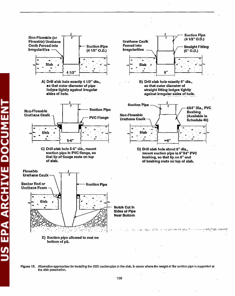
Suction Pipe(4 1/2" 0.0.)
Straight Fitting(5" 0.0.)
1-----'{.<I
... ...Slab ..s
... b....5"
I
Urethane CaulkForced intoIrregularities
. ..s'
......
...
Suction Pipe(4 1/2" 0.0.)
41/2"I
'I----1/..s...
Slab ..s
Non-Flowable (orFJowable) UrethaneCaulk Forced intoIrregularities
A) Drill slab hole exactly 4 1/2" dia.,so that outer diameter of pipelodges tightly against irregularsides of hole.
B) Drill slab hole exactly 5" dia.,so that outer diameter ofstraight fitting lodges tightlyagainst irregul~~ ~i.~~~ ~f.ho~~: .
Suction Pipe6X4" Dia., PVCSuction PipeBushing
PVC FlangeNon-Flowable (Available inUrethane Caulk Schedule 40)
...... ... ....<I Slab .<I .<I
b. ... b. b.
5-6"... ...
....6" ...A'
Slab.... ...
.... ....
Non-FlowableUrethane Caulk
C) Drill slab hole 5-6" dia., mountsuction pipe in PVC flange, sothat lip of flange rests on topof slab.
D) Drill slab hole about 6" dia.,mount suction pipe in 6"X4" PVCbushing, so that lip on 6" endof bushin~ rests on top of slab.
FlowableUrethane Caulk
Backer Rod orUrethane Foam
Notch Cut inSides of PipeNear Bottom
."' , ... ""
E) Suction pipe allowed to rest onbottom of pit.
Figure 15. Alternative approaches for installing the SSD suction pipe in the slab, in cases where the weight of the suction pipe is supported atthe slab penetration.
128

must be effectively caulked closed. Since this slab opening isright at the point where suction is being drawn, this openingwould have a particularly detrimental effect on suction fielddistribution if left unsealed. Urethane caulks are recommendedfor this application, because they bond better to the concretethan silicone caulks. If the gap around the perimeter is fairlynarrow (e.g., less than about 1/4 in. wide), a gun-grade(non-flowable) polyurethane caulk is probably the best choice;this caulk should be forced down into the gap, in order tomaximize the pipe and concrete surface area that it contacts,to improve bonding. If the gap is wider than 1/4 in., it willlikely be necessary to force some appropriate material (suchas backer rod) down into the gap (see Section 4.7) to providesupport for the caulk. In this case, a flowable urethane caulkcan be used; the flowable caulks work their way into irregularities in the surfaces, providing a better seal.
In the details in Figure 14, the caulk, foam, or mortar must beapplied after the entire piping network is in place. Otherwise,the vertical pipe may shift somewhat during the remainder ofthe installation process, causing the se31 to be broken at theslab.
Figure 14A shows one common approach when the piping isnot supported at the slab (Bro92). This is the specific methodillustrated in Figure 1. The 4.5-in. O.D. suction pipe is inserted into a 5- to 6-in. diameter slab hole. Backer rod (aclosed-cell foam which is sold in rope form) is stuffed downinto the gap between the pipe and the slab, and the channelabove the backer rod is flooded with flowable urethane to adepth of less, than 1 in. (consistent with the instructionsprovided by the caulk manufacturers). One possible disadvantage of this approach is that the caulk and backer rod do notprovide much support against lateral movement of the pipe.
Figure 14B is similar to 14A, except that the support for theflowable caulk is now provided by expandable foam ratherthan backer rod (An92). The foam may provide some additional support against lateral movement. In this case, thebottom of the pipe is shown slightly below the underside ofthe slab, in an effort to avoid plugging of the pipe by theexpanding foam.
Figure 14C shows a method for providing further supportagainst lateral movement (An92). In this case, a layer ofmortar is placed between the foam and the caulk. Mitigatorsusing this technique report that the flowable caulk can beapplied directly on top of the wet mortar, without waiting forthe mortar to set (An92). Applying the caulk while the mortaris still wet prevents the caulk from adhering to the mortar, butapparently does not prevent adequate bonding to the side ofthe pipe and to the concrete slab.
A variety of approaches can be used to support the pipingweight at the 'slab penetration, some of which are shown inFigure 15. One method is to drill the slab hole to be just aboutequal to the 4.5-in. O.D. of the suction pipe, as shown inFigure 15A (Mes92); the pipe is forced down into the holeuntil it lpdges tightly against the sides of the hole. This ispossible in part because the face of the concrete inside thehole is irregular, if the hole was prepared using a rotaryhammer drill. A similar approach is shown in Figure 15B
(Mes92); however, in this case, a straight fitting is cementedonto the end of the pipe, so that the hole diameter can now be5 in. instead of4.5 in. (somewhat facilitating the excavation ofa sub-slab pit). In both of these cases, the residual gapbetween the pipe and the slab will probably have to be caulkedwith non-flowable urethane caulk, unless the fit is indeed tightenough that flowable caulk can be used.
Another method for supporting the suction pipe is illustratedin Figure 15C (F090). In this case, the end of the suction pipeis cemented into a PVC flange having an inside diameter of 4in. The outer diameter of the flange, about 5 in., is slightlysmaller than the slab hole. The lip of the flange, about 6 in. indiameter, rests on the top of the slab as shown in the figure,supporting the pipe. A non-flowable caulk must be forced intothe gap between the outer circumference of the flange and theconcrete, and a good bead of the caulk should be placedbetween the lip of the flange and the top of the slab, before theflange is pressed down into the hole. The suction pipe shouldbe effectively cemented to the interior of the flange, to preventleaks at the seam between the pipe and the flange.
Another effective approach is to use a 6- by 4-in. bushing, asshown in Figure 15D (Kl92), a fitting which is available inSchedule40. At one end, this bushing is designed to fit aroundthe 4.5-in. O.D. ofa4-in. suction pipe; at this end, the bushingitself has an O.D. of about 5 in. At the other end, the bushingis designed to fit inside a 6-in. pipe; the main extension of thebushing will thus be about 6 in. O.D. at this end, but it has a lipwhich is about 6.5 in. diameter, equivalent to the O.D. of 6-in.pipe. The 4-in. suction pipe is cemented into the smaller endof the bushing; the 6-in. end of the bushing is placed downinto the'slab hole, which should be about 6 in. diameter; andthe 6.5-in. wide lip rests on the top of the slab, supporting thepiping. Non-flowable urethane caulk is forced between thesides of the bushing and the hole, and between the undersideof the lip and the top of the slab.
In Figure I5E, the weight of the pipe is supported by allowingthe pipe to rest against the bottom of the pit (An92). To avoidflow restriction and to avoid pluggage of the pipe with soil orwater, notches are cut in the side of the pipe, extending at least'as high as the underside of the slab. In the figure, the gapbetween the pipe and the slab is sealed with backer rod andflowable urethane caulk.
Another option that has been used (Mes92) is to partiallyembed one or more large masonry nails (spikes) laterally intothe side-wall of the slab hole, at a depth perhaps halfwaybetween the top and underside of the slab. A portion of eachspike extends into the hole opening. The pipe then rests oil theexposed portions of the spikes.
In the cases shown in Figure 14, where the weight of thepiping is not supported at the slab, some means for supportingthe pipe will be required to prevent it from dropping all theway down to the bottom of the hole. This will be done usinghangers and/or strapping, or perhaps pipe clamps. The exactmanner in which hangers, strapping, and/or clamps will beused to support the suction pipe will depend upon the configuration of the remainder of the piping network.
129
Discussion of the configuration and support of the overallpiping network is presented in Section 4.6.3. The discussionhere addresses only the immediate support of the individualvertical suction pipe. in cases where it is not supported at theslab penetration.
Figure 16 illustrates some alternative methods for supportingthe suction pipe in the case where the vertical suction pipeconnects to a horizontal piping run. There are two categoriesconsidered for this case: a) the horizontal run is perpendicularto the overhead floor joists. below the joists; and b) the run isparallel to the joists. up between the joists.
Figure 17 shows some alternative methods for supporting thesuction pipe in the case where the pipe extends straightupward through the overhead flooring.
In all cases, the support is provided in a manner that attemptsto reduce oravoid the transmission ofvibration noise from thepipe to the joists or flooring. In cases where there is ahorizontal run of piping. supports should be provided every 4to 10 ft along the run; one of these supports should be near thevertical pipe.
One common support material is plastic strapping, perhaps 1in. width. Figure 16A shows two possible methods for usingstrapping to support a horizontal pipe running below the joist.The ends of the strap are nailed into the joist. It is importantthat the pipe be suspended a short distance below the joist, asshown, rather than being held against the joist, to avoidtransmission of vibration. Vibration is not transmitted wellthrough the strapping itself. Where the pipe is parallel to andup between the joists. the upper inset in Figure 16B shows acommon way to suspend the piping between the joists. Thereclanglc labelled "Strapping loop" in the lower diagram ofFigure 16B is attempting to depict such strapping suspendingthe pipe between the joists. (Such a suspending strapping loopis also what is being depicted by the rectangle labelled "Strapping" in Figure 1 and subsequent figures.)
As shown in Figure 17A. strapping can also be used to supportvertical pipes. However. in this case. the strapping must beattached to the pipe by screws in order to prevent the pipefrom slipping down through the strapping. (When screwsmust be inserted into pipes, it may be advisable to use Schedule 40 piping. since the thin-walled pipe may be prone tocrack.)
For horizontal runs. hangers can also be used to support thepipe. as illustrated in Figures 16A and 16B. One common typeof hnngeris a plastic J-hook, shown in two of the insets. Themethod of using the hook will depend upon whether the pipeis parallel or perpendicular to the joists.
Where the pipe extends straight up through the overheadflooring, the weight of the piping can also be supportedagainst the flooring. As shown in Figure 17B. some mitigatorscement a straight fitting. or pipe coupling, into the pipe at justthe right position; the lip of the fitting rests on top of theoverhead floor, providing the support. Alternatively, as shownin Figure 17C, a two-piece pipe clamp can be clamped tightlyaround the pipe at that location. resting on the flooring. In this
case, it may be desirable to place some type of cushion (suchas closed-cell insulation) between the clamp and the floor toreduce the transmission of vibration noise to the flooring.
Figures 16 and 17 show the suction pipe extending straightupward from the slab. Where the suction pipe is installed neara perimeter wall, another option used by some mitigators forsupporting the pipe involves offsetting the pipe so that theriser is flush against the wall (Br092, K192). To accomplishthis, a vertical pipe stub about a foot long would be installed inthe slab, and two 45° bends would be attached to this stub toprovide the desired offset. In this case. the pipe would besupported by attachment against the wall, using one of theapproaches described in Section 4.6.5 for attaching an exteriorstack against the side of a house (see Exhaust piping fromexteriorfans - support ofstack against house).
4.5.2 Vertical Pipe Installed DownThrough Large Hole Indoors (LargeSub-Slab Pit)When a 4.5- to 6-in. diameter hole is cored through the slab, asdescribed in Section 4.5.1, the size of the sub-slab pit that canbe excavated is detennined by the length of an arm, or thelength of an auger that can be inserted through the hole. Thelargest feasible pit excavated through a slab hole would thusbe roughly 18 in. radius and 18 in. deep. or about 10-14 ft3
maximum (about 75-100 gal). Many pits are probably muchsmaller than this. due to the practical.difficulties in carryingout the excavation.
In tenns of reducing suction loss due to acceleration of soilgas up to pipe velocity, a 10- to 15-gal pit is probably largerthan is necessary, even for the highest pipe velocities, basedon fluid flow calculations (Br92). Thus, from this standpoint,there is no incentive to make the pit any larger. However. alarger pit would potentially help intersect fissures or penneable strata more remote from the suction hole. On this basis.some investigators have postulated that a larger pit might beuseful to help extend the suction field in verypoor-communication houses.
Excavation of a larger pit would require that a larger hole bemade through the slab. using a jackhammer or some othermeans. From a practical and structural standpoint, the largestsuch slab hole that might be considered would be about 3 ft by3 ft. This hole size would pennit the excavation to extend to agreater radius than 18 in. and a greater depth. Such a largehole would increase the cost of the installation. by about $200per hole (Re91b, Re91c). With slabs that are tiled or otherwise fmished, it would increase the aesthetic impact as well.
The data presented in Section 2.3.1 show that increases in pitsize can sometimes, although not always, improve the measured suction field extension in houses having poor sub-slabcommunication. Most of the pits studied were smaller thanthose that would be achieved by creating a 3 x 3-ft hole in theslab, preventing a rigorous assessment of the practical benefits of making a pit that large. The largest pit studied inReference Py90 (24 in. square and 18 in. deep) did notsignificantly increase suction field extension relative to smaller
130

Strapping LoopAttached to theTwo AdjoiningFloor Joists.See Inset Above.
PlasticJ-Hook
Floor
Continuous Loop ofPlastic Strapping
SuctionPipe
. Bracket
Joist
FloorJoist
Overheadflooring
,IIII.IIIIIIIIIIIIIIIIIIIIII
'11
Pipe Hanger Attached toOverhead Floor Joist,Firmly SupportingVertical Suction Pipe.(Repeated Every 4-10 Ft.Along Horizontal PipingRun.) See Insets Above.
HangingClamp
Continuous Loop ~of Plastic Strapping /Around Pipe
Joist
SuctionPipe
90° Elbow FittingTightly Cementedto Adjoining Piping
1=:;=;=d===!=====r=r===1
FloorJoist
OverheadFlooring
Floor
PlasticJ-Hook'
A} Horizontal piping run isperpendicular to floorjoists.
B} Horizontal piping run isparallel to the floor joists.
Figure 16. Some alternative approaches for supporting the weight of a suction pipe when therl~ is a horizontal piping run, in cases where thepipe is not supported at the slab penetration.
131
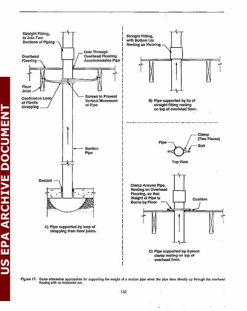
Clamp(Two Pieces)
Bolt
Top View
C) Pipe supported by 2-piececlamp resting on top ofoverhead floor.
Pipe
B) Pipe supported by lip ofstraight fitting restingon top of overhead floor.
A,
Around Pipe,g on Overheadng, so thatt of Pipe Is Cushionby Floor
~...>
1
"",>-
- '--
AV
AV
t Fitting,ttom Lipon Flooring "'\
...:.
1
...>
- '-
Ar
ClampRestinFlooriWeighBorne
Screws to PreventVertical Movementof Pipe
I
'
I. Straighwith Bo
I Resting
Hole Through IOverhead Flooring IAccommodates Pipe I
IIIIIIIIIIIIIIIIIIIIIIIIIIIIIIIIIIIII
. II
- SuctionPipe
1
A) Pipe supported by loop ofstrapping from floor Joists.
Sealant
Straight Fitting,to Join TwoSections of Piping
Flguro 17. Soma a1temative approaches for supporting the weight of a suction pipe when the pipe rises directly up through the overheadflooring with no horizontal run.
132

pits (20 in. square by 16 in. deep) of the size that might beexcavated through a 6-in. diameter slab hole.
In summary, there is no experimental basis for believing that alarge pit (beyond that which can be excavated through a 6-in.slab hole) will be helpful in improving SSD performance inpoor-communjcation houses. The only theoretical basis forconsidering large pits in residential cases, i.e., the hope ofintersecting remote fissures or permeable strata, will be verysite-dependent; the potential for actually intersecting fissures!strata by making a large pit has not been demonstrated.
As a result, preparation of a large opening in the slab toexcavate a large pit will not commonly reflect good practice.Consequently, this approach is addressed here only briefly,insofar as it differs from the approach in Section 4.5.1. Thisapproach is considered here because some mitigators mayoccasionally face geological situations where it may be applicable.
Making the hole through the slab. If the pit is to be leftopen, rather than being filled with aggregate -- so that therestored slab will be suspended over an open cavity -- the pitshould probably be no more than about 4 x 4 ft, .or perhapssomewhat larger, for structural reasons. (Ifa much larger pit isplanned, the mitigator should check with a structural expert toensure that the suspended slab will have adequate strength.)The mitigator will have to decide how large the slab holeshould be to enable excavation of a pit of the desired size. Aslab hole of about 2 x 2 ft to 3 x 3 ft might be reasonable toprovide the needed access.
A jackhammer or an electro-pneumatic roto-stop· hammerwould be logical tools for creating such a hole in the slab. Thejackhammer or electro-pneumatic could be rented for thispurpose. Alternatively, if the mitigator has a coring drill, thelarge slab hole could be created by drilling multiple adjacent6-in. circular holes. It is recommended that the hole be prepared with the sides at an angle (i.e., with the hole dimensionsbeing smaller at the bottom of the slab than at the top). Theresulting slant in the vertical face of the old concrete will helpsupport the weight of the new concrete which will be pouredto restore the slab.
As discussed in Section 4.5.1, the installers should use care toavoid rupturing any unexpected utility lines beneatl:l the slab.
. Use of a safety cut-off switch would help avoid damage toutilities.
Excavating apit. Once the hole has been crl"dlted in the slab,the excavation of the pit can be accomplished using a varietyof tools. If the underlying soil is hard-packed or is rock, thejackhammer (or other appropriate power equipment) can beused to break up the soil.
The pit would be excavated out under the slab to the desireddimensions (e.g., 4 x 4 ft). If the pit is not at least 3 x 3 ft, thereis no point in making the large hole through the slab, since apit approximately 3 x 3 ft can often be excavated through a6-in. slab hole. If it is known that a permeable stratumunderlies the surface soil at some reasonable depth, an effortmight be made to penetrate down to that stratum.
It is suggested that the pit be left as an open cavity when theslab is restored. This will maximize the benefits of the pit,providing the greatest reduction in suction loss resulting fromacceleration of the soil gas to pipe velocity through the pit.The other option, back-filling the pit with clean, coarse aggregate, would simplify the restoration of the slab, but wouldsomewhat increase the suction loss.
Mounting suction pipes through the slab. Some type ofplywood or sheet metal form must be prepared to permit newconcrete to be poured, to restore the slab. While a variety ofapproaches are possible for preparing this form, one approachthat has been used with some success in this application(Cr92a) is to prepare a piece of plywood slightly larger incross-section than the slab hole, with a 4.5-in. hole cut generally near the center to accommodate the suction pipe. Thisplywood is then cut in half, so that it can be fit down throughthe slab hole. Masonry nails or spikes are partially drivenlaterally into the side-wall of the slab hole at intervals aroundits perimeter. The two sections of the plywood form are thenpulled up tightly against the underside of the slab, by attaching wire to the plywood and pulling this wire tight around theprotruding nails.
Another approach for supporting the plywood form would beto cut the plywood so that it is slightly larger than the bottomdimensions of the slab hole, but smaller than the dimensionsat the top of the slab (Br092). The plywood will thus lodgeagainst the sloped sides of the slab hole near the bottom of theslab. With this approach, the re-poured segment of slab willnecessarily be slightly less than 4 in. thick.
The suction pipe is placed vertically down through the 4.5-in.hole in the plywood sheet. The pipe IS inserted such that itslower end is just below the sheet and the underside of the slab(i.e., such that the pipe ends in the open space within the hole,and is not r~tjng on the bottom of the hole). The pipe issupported in this suspended position by hangers, strapping, orclamps attached to the joists or flooring overhead, using oneof the methods illustrated in Figures 16 and 17.
Fresh concrete is then poured on top of the plywood, restoringthe slab, with the pit remaining as an open cavity underneath.While the concrete is soft, a groove perhaps l/2-in. deepistooled around the perimeter of tJ1e slab hole, where the newconcrete meets the original slab; a groove is also tooledaround the circumference of the suction pipe, where it penetrates the new concrete. When the concrete has set, thesegrooves will be flooded with flowable urethane caulk, in aneffort to keep these seams gas-tight. A follow-up visit to thehouse will be required to conduct this subsequent caulkingstep.
Over time, the plywood or sheet metal support may decay orrust away. This is not a problem. After the concrete coveringthe hole is dry, its weight will be borne by the slanted sides ofthe original slab.
As one alternative to this approach, the pit could be back-filledwith clean, coarse aggregate. The suction pipe would then
133

Drilling the hole through the foundation wall. Ifpipinghaving a 4-in. inside diameter will be used, a hole 4.5 to 6 in.diameter must be drilled horizontally through the foundationwall of slab-on-grade houses. Some excavation will usuallybe necessary to expose the wall beneath the slab, and workingspace immediately beside the wall may thus be limited. Especially where the foundation wall is block, and is hence rela-
As with vertical interior pipes, installers using horizontalexteriorpipes must be alert to sub-slab utility lines or forced-airducts beside the foundation wall. If it is planned to auger somedistance horizontally beneath the slab -- so that the SSD pipewill extend beneath the slab instead of ending immediatelybeside the foundationwall -- attention must be paid to utilitylines that might be beneath the slab within that distance.
The exact depth beneath the slab at which the hole is drilledmay require judgement. For example, if the foundation stemwall for a slab-on-grade house is hollow block capped with asolid L block, as shown in Figure 2, it could be desirable todrill through the course of hollow block immediately belowthe L block. But the hole should not be too far below the slab,since it is desired to access any aggregate layer immediatelybeneath the slab.
In basement houses, where the foundation wall generally doesnot extend below the slab, the suction pipe will usuallypenetrate beneath the footing. The pipe can also be routedbeneath the footing in slab-on-grade houses when the footingis very shallow (in mild climates).
Exterior horizontal pipes would most commonly be considered in slab-an-grade houses, or basement houses havingslabs only moderately below grade. However, cases have beenreported where exterior penetrations have been used in fullbasement houses, due to extensive fmish in the basement anddue to homeowner preference (Kl89).
Selecting the specific hole location. The criteria for selecting the specific location for the suction hole on the exterior face of the foundation wall will be similar to those forselecting the specific slab locations for vertical interior pipes.There must be adequate space beside the house to pennitexcavation and use of the drilling equipment (e.g., away frombushes, patios, and chimneys). The location must permitconvenient mounting of the fan and routing of the exhauststack. For example, the pipe should not be mounted directlyunder windows through which the fan and stack would bevisible from indoors; it should be located so that the pipingwill be least obtrusive outdoors.
4.5.4 Horizontal Pipe Installed ThroughFoundation Wall from Outdoors
4.5.3 Vertical Pipe Installed Into UnusedSump Pit Indoors
In some cases, it may be desirable to insert the suction pipeshorizontally through the foundation wall from outdoors, suchas illustrated in Figure 2. This approach will reduce theaesthetic impact indoors, but can increase the impact outdoors(especially when compared with interior suction pipe-s having
It must be ensured that the unused sump pit is communicatingwith the sub-slab region. For example, if the walls and, bottomof the sump are fonned by a plastic sump liner having nopenetrations, or by poured concrete, the SSD pipe would bedrawing suction on a closed box; the suction would not bee.ffectively extending under the slab. In such cases, it wouldbe necessary to ensure that a number of holes were drilledthrough the walls of the sump lining, at a level immediatelybeneath the slab.
Cost analysis indicates that the presence of such an unusedsump pit will not reduce the installation cost of a SSD system(Re91b, Re91c). The savings in labor achieved by avoidingthe need to drill a hole through the slab will be approximatelyoffset by the increase in labor required in sealing a cover overthe sump. In fact, the installation cost will be somewhathigher with the sump pit, by an amount equal to the materialscost for the sump cover. However, where such a pit exists, itstilI will genemlly make sense to use the pit as the SSDsuction hole. Even if the suction pipe were to be installedthrough the slab at another location instead, the sump pitwould still have to be capped, to prevent radon entry and toreduce the amount of house air that would flow into the SSDsystem through an uncapped sump.
penetrate into this aggregate. to a depth just below the underside of the slab. A layer of plastic sheeting. or perhaps ofroofing material, would be placed over the top of the aggregate. to prevent the wet concrete from settling down into theaggregate and plugging the pore space. The slab would thenbe restored, as above, with grooves tooled to permit subsequent caulking.
an exhaust stack rising inside the house). As discussed inSection 4.2.1, installation of the pipes horizontally from outdoors is most likely to be attractive when: a) the slab is neargrade level, so that less excavation is required to get below theslab outdoors; b) interior fmish is extensive, so that the cost,complexity, and aesthetic impact of interior pipes would besignificant; and/or c) the house is not amenable to an interiorstack with a fan in the attic (including houses having flat roofsor cathedral ceilings with no attic), so that the aesthetic impactof an exterior fan and stack would be unavoidable even with
. interior suction pipes.On occasion. a mitigator may encounter a basement having asump pit having no drain tiles and never containing any water.Such unused sump pits may be encountered, for example, incases where codes require installation ofa sump but where theparticular lot involved has no drainage problem, so that thebuilder or homeowner did not install drain tiles or a sumppump.
On those occasions where unused sump pits are encountered,they may be used as ready-made holes through the slab for aSSD system. avoiding the need for drilling a hole with a rotaryhammer or a core drill. The pit would be capped with agas-tight cover, and a suction pipe would be installed throughthis cover, as discussed in connection with sump/DID systems in Section 5. Ifdrain tiles were present in the sump, thiswould be a sump/DID system; but since no tiles are present inthis case, it is considered a SSD system.
134
tively easy to. drill through, the rotary hammer drill willusually be the'appropriate tool; a series of l/2-in. holes wouldbe drilled around a 4.5- to 6-in. circumference, and the interiorchiseled out).
Even where the wall is poured concrete 8 in. thick, the rotaryhammer drill may still be preferred. To use a coring drill onpoured concrete walls, it would be necessary to clear a sufficient area to accommodate the drill, and to block up orotherwise support the drill in a horizontal position whiledrilling the hole. The coring drill bits are often only 6 in. deep;consequently, it would be necessary to drill into the wall to adepth of 6 in., chip out the still-attached core, then drill theremaining 2 in. through the 8-in. wall. As a result, it willusually not be convenient to try to operate a coring drillsideways to prepare the hole, even when a coring drill isavailable.
If it is desired to extend the hole horizontally for somedistance beneath the slab, an auger can be used to carefullyextend the hole horizontally through the sub··slab fill. If thehole is to extend several feet, powerful augers can be rented orpurchased. For shorter distances (2 ft or less), a smaller augerbit that can be driven by a power drill could be used (the sameauger bit that can be used to excavate sub-slab pits). Thesmaller auger bit could be driven by a right-angle drill if thereis not sufficient clearance to accommodate the shaft of theauger straight on. The drill must have a torque adjustmentfeature, so that the drill does not begin spinning and injure theoperator if the auger binds.
Such augering has been found to be desirable inpoor-communication slab-on-grade houses with block foundations in Florida (F090, F092) and in Arizona and southernCalifornia (Kl92). In those houses, the apparent problem wasair leakage into the system through the block foundation wallswhen the suction point was near the wall. Such leakageappears clearly to be less ofa problem in good-communicationhouses and in houses with poured concrete foundations. Evenin some poor-communication slabs on grade with block foundations, it will sometimes be possible avoid the need foraugering, based upon the experience in New Mexico (Tu91b).
If augering is performed, and if the hole through the foundation wall is not immediately below the slab, e.g., if it has beenlowered in order to miss a course of solid L blocks, care mustbe taken that the augered hole be horizontal. If the hole isangled upwards, toward the bottom of the slab, a low spot willbe created in the piping near the exterior face of the foundation wall. Condensed moisture could accumulate at that point,potentially blocking flow.
To avoid damaging sub-slab utility lines, it would be desirableto initially drill only to the interior face of the foundation wall.Sometimes forced-air ducts are located immediately besidethe foundation wall. It could be helpful to use a safety cut-offswitch and perhaps a GFI (as discussed in Section 4.5.1,Drilling the hole through the slab) with the rotary hammer,coring drill (if used), or auger.
If the horizontal pipe is being installed from outside a basement house, the foundation wall usually will not extend
beneath the slab; the slab will be resting on the footings. As a· result, the effort described above to drill through the founda- .
tion wall will be unnecessary. In this case, excavation throughthe soil under the footing will be required, by hand or using anauger.
·Excavating apit beneath the slab. If the suction pipe is toend near the interior face of the foundation wall (i.e., if thehole has not been extended with an auger), a sub-slab pitshould be excavated inside the foundation wall. As discussedin Section 4.5.1, this should be done regardless of whether ornot there is aggregate under the slab. Possible pit sizes, andthe procedures for excavating the pit are generally the same asthose discussed in that earlier section for verticallinteriorpipes.
The pit should always extend upward to the underside of theslab, as illustrated in Figure 2, ensuring that the suction pipe iscommunicating with the layer of aggregate (if present) beneath the slab. This is particularly important in cases wherethe hole has been drilled through the wall some distancebelow slab level. Even where there is no aggregate, there maybe a region of improved communication immediately underthe slab, due to subsidence of the soil or to an air gapassociated with sub-slab insulation, if present.
Especially where communication is poor, the pit should alsoextend as far toward the interior of the slab as possible.
Investigators in Florida recommend that the pit not extend tothe left and right, exposing the interior face of the foundationwall, when the walls are constructed of hollow block (F090).Air leakage into perimeter suction pipes through block wallswas a significant problem in Florida, and the concern was thatexposure of the interior face of the block wall would exacerbate this problem. Leakage would be much less of a concernwith poured concrete foundation walls.
The pit should extend downward below the wall hole. Thiswill reduce the risk of the pipe becoming blocked by soil or
· water if the soil walls of the pit shift over time, or if watercollects in the pit due to condensation in the pipe or due to wetseasons.
If the hole is extended using an auger, a pit might be created atthe end of the augered hole by manipulation of the auger,angling it up and down, and side to side.
Mounting suction pipes through the waU. When thisconfiguration is used in slab-on-grade houses, the suction pipewould be mounted horizontally through the foundation wallfrom outdoors. Unless an extended hole has been augered, thepipe should terminate within a few inches of the interior faceof the wall, within the open space of the excavated pit. Inbasement houses, the pipe is mounted horizontally under thefooting, again terminating in the sub-slab pit.
The suction pipe must not be sloped upward toward theunderside of the slab. The greatest risk of this occurring iswhen the hole through the wall has been made at somedistance below slab level. Such a slope would create a lowpoint in the piping at the exterior face of the wall where
135
condensate would accumulate, blocking gas flow. Where thehorizontal pipe is at a depth beneath the aggregate layer,communication between the pipe and the aggregate must beprovided by extending the suction pit upward, rather than bysloping the pipe upward. In fact, sloping the pipe slightlydownward beneath the slab to facilitate condensate drainagemay be desirable, if this is possible.
The horizontal pipe should be well supported on the exteriorof the wall by soil underneath. Unless this pipe is beingconnected by a horizontal run to other suction points aroundthe house perimeter, the outer end of this pipe will be directed900 upwards to a fan and an exterior stack above grade, asdiscussed in Section 4.6.5. Even if this fan and stack aresupported by brackets or strapping, some of the weight willlikely be borne by the end of the horizontal pipe. If this end ofthe pipe is not adequately supported underneath, the torqueapplied by the fan/stack weight could cause the end of thepipebene..'\th the slab to shift upwards, creating the low point forcondensate accumulation discussed in the preceding paragraph.
The gap between the outer circumference of the horizontalpipe nnd the foundation wall must be closed, to reduce theamount ofambient air that would be drawn down through the(usually shallow) soil into the system. Since this annularopening will be on the vertical face of a wall, flowableurethane caulk will not be applicable, since it would just drainaway. Gun-grade (non-flowable) polyurethane caulk could beone choice. The wall and hole surfaces would be cleaned asappropriate (e.g., the drilling dust vacuumed up), to removeloose dust and dirt that would hinder bonding of the caulk: tothe wall surfaces. The caulk should be worked into the horizontal gap to a reasonable depth, to increase the contact areafor bonding.
Expanding closed-cell foams are perhaps the most commonchoice to seal this gap. Foams could be particularly appealingwhere the foundation wall is hollow block. Properly injected,the foam could seal not only the gap at the exterior face of thewall, but also the gap between the interior hollow-block coreand the pipe, and the gap at the interior face of the wall (underthe slab). In this way, the foam would block not only theambient air flowing down through the soil along the exteriorface of the wall, but also ambient and indoor air that might bedrawn down through the block cores. The foam might beiJ\iected into the cavity through the gap between the suctionpipe and the exterior face of the wall (Br092), or throughsmall specially drilled holes in the exterior face above andbelow the pipe (Kl92). When using foam to seal the entireblock cavity, some type of support may have to be placedinside the block below the pipe in order to prevent the foamfrom dropping down into the cavities below.
If foam is used, care must be exercised to ensure that the foamdoes not expand into the sub-slab pit ill a manner whichblocks the suction pipe. Such blockage of the pipe has occasionally been observed when the pipe ends immediately beside the interior face waIl (under the slab). To be sure, thefoam should be injected before the vertical riser is connectedto the horizontal pipe, so that the horizontal pipe can be
inspected and rodded out, to detect and clear away any foamthat may have expanded into the sub-slab end of the pipe.
The use of foam to close this gap for block walls has theadvantage of reducing air leakage into the system through theblock cores, but at the same time, necessarily reduces anyblock-wall depressurization component of this SSD system.Use of foam in this manner has generally appeared to beadvantageous, or at least not detrimental, in terms of the radonreduction performance of the system; i.e., any BWD component was either insignificant or unnecessary. In only one studyhouse (a large slab on grade with good aggregate and sub-slabforced-air supply ducts) did the BWD component appear to beimportant, with the use of foam creating a measurable deterioration in system performance (House 1 in Re91a).
In addition to gun-grade polyurethane caulk and expandingfoam, cement or quiCk-setting mortar have also sometimesbeen used to seal the gap around the suction pipe (An92,Br092). One mitigator reports that termites and ants havesometimes been observed to chew through expanding foam insome regions, so that cement might be preferred at least forthe outer seal for this below-grade application in such regions(Br092).
In cases where the hole has been extended with an auger, anda horizontal pipe is being inserted for some distance beneaththe slab, it will be particularly important to rod out the pipeafter it has been inserted. The end of the pipe beneath the slabmay have become plugged with soil as the pipe was beingpushed through the augered hole. This problem can be reduced by inserting the pipe only part way into the augeredhole (Kl92), although it must be inserted far enough so thatthe open end of the pIpe is reasonably isolated from theinterior face of the block wall (thus avoiding the excessive airleakage into the system through the wall that the augering stepwas intended to avoid).
Mter the suction pipe has been installed and the exteriorexcavation around the pipe is being re-ftlled, it would beadvisable to pack the back-filled dirt in an effort to reduce thepossible leakage of ambient air down through loose fill andinto the system.
Rigid PVC, PE, or ABS piping is a reasonable choice forexterior suction pipes, just as for pipes installed indoors.However, one mitigator (K189, Kl92) reports success usingflexible corrugated polyethylene and polypropylene pipingfor the horizontal below-grade penetrations throughslab-on-grade foundation walls, beneath basement footings,and beneath slab-on-grade footings in cases where the footings are shallow. This corrugated piping is similar to thematerial commonly used for drain tiles, except it is not perforated. Use of the flexible piping simplifies installation. It canbe considered for use in this exterior application because it issupported horizontally by the underlying soil, potentiallyavoiding sagging; and, being below grade, there is less concern regarding leakage through the difficult-to-seal seamsbetween piping segments, and regarding damage to the flexible material. This flexible piping is then connected to rigidPVC piping to serve as the riser on which the fan is mountedabove grade.
136

Where non-peiforated flexible piping is used for exteriorsuction pipes, it must be buried at least 18 in. below grade(Kl92) to avoid excessive ambient air leakage into the systemthrough the unsealed seams between piping segments. Also,care must be taken to lay this flexible piping on a reasonablyflat-bottomed channel, since it can sag, providing low sites forcondensate accumulation.
4.5.5 Horizontal Pipe Installed ThroughFoundation Wall from Inside BasementPerhaps the most common use of horizontal suction pipes is to·treat adjoining slabs on grade in basement houses having suchadjoining slabs. The pipes are inserted horizontally throughthe stem wall separating the basement and the adjoining slab,at a level just below the adjoining slab. Treating the adjoiningslab in this manner avoids the need to install pipes in theliving area on the adjoining slab (which will usually be highlyfmished), and greatly simplifies connection of the SSD pipingtreating the slab on grade into the suction pipes treating thebasement slab.
A typical configuration for installing a horizontal suction pipebeneath an adjoining slab on grade from inside the basementand for connecting the horizontal pipe into a basement SSDsystem is illustrated in Figure 18.
The methods for installing horizontal suction pipes throughthe stem wall from inSIde the basement are sinlilar to thosedescribed in Section 4.5.4, for the case where the pipes areinstalled from outdoors. There are only a few differences. Inselecting the specific location for drilling through the stemwall, some attention will now be required to the nature of thebasement fmish. Assuming that the horizontal pipe is to beconnected to a vertical riser from the basement slab, the holein the stem wall must be located near a basement riser (or in aposition to otherwise facilitate connection to a riser).
As with exterior horizontal penetrations, a rotary hammer drillmay be the best approach for making the hole through thestem wall, especially if the stem wall is hollow block. If thewall is poured concrete and if it is desired to make the hole bysupporting a coring drill sideways, sufficient space must beavailable for using the drill in this position and for supportingit in this manner from below or above. See Section 4.5.4,Drilling the hole through the foundation wall.
The pit excavated beneath the adjoining slab should extendupward to the underside of that slab. It should extend outwardand downward enough to prevent the horizontal pipe frombecoming blocked with soil if the sides of the pit shift overtime.
With the configuration shown in Figure 18, the horizontalpipe could be sloped in either direction to avoid condensatebuildup in the pipe. Any condensate in the horizontal pipecould drain either to the pit beneath the slab on grade, or to thevertical riser in the basement.
Care is needed in sealing the horizontal pipe into the stem wallto reduce the amount of basement air drawn into the SSDsystem around this penetration. Thus, whether the wall is
poured concrete or hollow block, the gap in the face of thewall toward the basement (the right-hand face in Figure 18)must always be carefully sealed.
When the stem wall is block, mitigators report that significantamounts of air can be drawn into the system via the hollowblocks, even when care has been taken to seal the gap aroundthe penetration in the face of the block inside the basement(Bra92; Mes92). This leakage, which adds a BWD componentto the system,. will reduce the suction that can be maintainedin the SSD piping. The reduced suction can be a problem inmany cases, especially when sub-slab communication is marginal or poor and when maximum suction is thus needed in thepiping. As a result, it is often important that the gap also besealed at the "outer" face of the block; the outer face isdefined here as the face against the soil under the adjoiningslab, or the left-hand face in Figure 18. Sealing of the outerface will reduce the amount of air from inside the leaky blockcavities being drawn into the pit and thus into the system.
Ifthe hole through the "inner" face of the stem wall (inside the .basement) is sufficiently large, this could facilitate injectingfoam around the gap in the outer face by inserting a wandfrom inside the basement,' before the inner face is sealed(Mes92). The foam might seal not only the gap in the outerface, but also the block cavity around the pipe to further insurethat air leakage via the block wall will. be reduced. Onemitigator recommends drilling small holes through the innerface of the blocks just above and below the suction pipe, andinjecting foam into the block cavity through these holes(Kl92). To aid in foaming the block cavity, it may be necessary to stuff some type of supporting material into the voidbeneath the pipe, to prevent the foam from dropping downinto the voids below as it is being injected. Care inust be takento ensure that the foam does not expand into the pit beneaththe adjoining slab in a manner which blocks the suction pipe.
The below-grade horizontal pipes discussed in Section 4.5.4are supported by the soil beneath the pipe. When the horizontal pipe is inside the basement, it may be supported at itsconnection with the vertical riser when the horizontal pipe isas short as suggested in Figure 18. If the horizontal pipe is notnear a riser, and must run for some horizontal distance beforeconnecting to a riser, this horizontal run will have to besupported by hangers or strapping .as discussed in Section4.5.1 (Figure 16) and Section 4.6.3.
4.5.6· Suction Pipe Installed from InsideGarageIn houses having an adjoining garage, it would be veryconvenient to be able to insta1l the mitigation system in thegarage. Especially when the garage is a one-story slab ongrade with its own roof, placement of the suction pipes andthe fan entirely in the garage would eliminate the aestheticimpact in both the living area and outdoors, and would commonly result in the entire system being remote from thebedroom wing.
In basement houses having walk-out basements with a garageslab on the same level as the basement, the garage slab willoften be integral with the slab of the adjoining basement. In
137

Slab onGrade
expandIng UrethaneFoam or other Sealant
••': <. eo: .'.".•.•. ,°.°•.,.. ~ .. .~ '.~,
".. .. "" ."
.- .- . " .--,
1
Note: Careful sealing of pipepenetration through outer faceof block can be important toprevent excessive leakage ofair into the system via theblock wall.
Hole through Face ofBlock Inside BasementMust Be SufficientlyLarge to Provide Accessto Outer Face fOI' ProperSealing of Penetration
Basement
Open Hole (6"to 18" Radius)
FIguro18. A typical configuration for treating an adjoining slab on grade using a horizontal suction pipe penetrating the stem wall from insidethe basement
these cases, if communication is good, vertical suction pipesinside the garage may well treat the entire slab. In basementhouses having an adjoining slab-on-grade garage, suction onthe garage slab will likely have only limited impact on theliving area, and the garage will thus be of no use for locatingsuction pipes. (However, in this latter case, the garage couldstill provide an excellent location for possible routing of theexhaust stack and mounting of the fan, eliminating the needfor a stack inside the living area or outdoors.)
Of primary concern in this section are slab-on-grade houseshaving an adjoining slab-on-grade garage. In such houses, theliving-area slab will essentially always be a few inches higherthan the garage slab, for code reasons. In some cases, there
will be a foundation wall (supporting the living-area slab)separating the region under the garage slab from the regionunder the living-area slab. In other cases, there will not be aseparating foundation wall, but there will still be the stepbetween the slabs; the concrete for both slabs may have beenpoured at the same time, with a form having been used tocreate the step.
In eithercase, the communication between the garage slab andthe living-area slab will be uncertain and will vary from houseto house. This will always be true in houses having generallypoor sub-slab communication. It can also be true in caseswhere there is aggregate beneath the living-area slab, especially when there is a separating foundation wall. Therefore, it
138
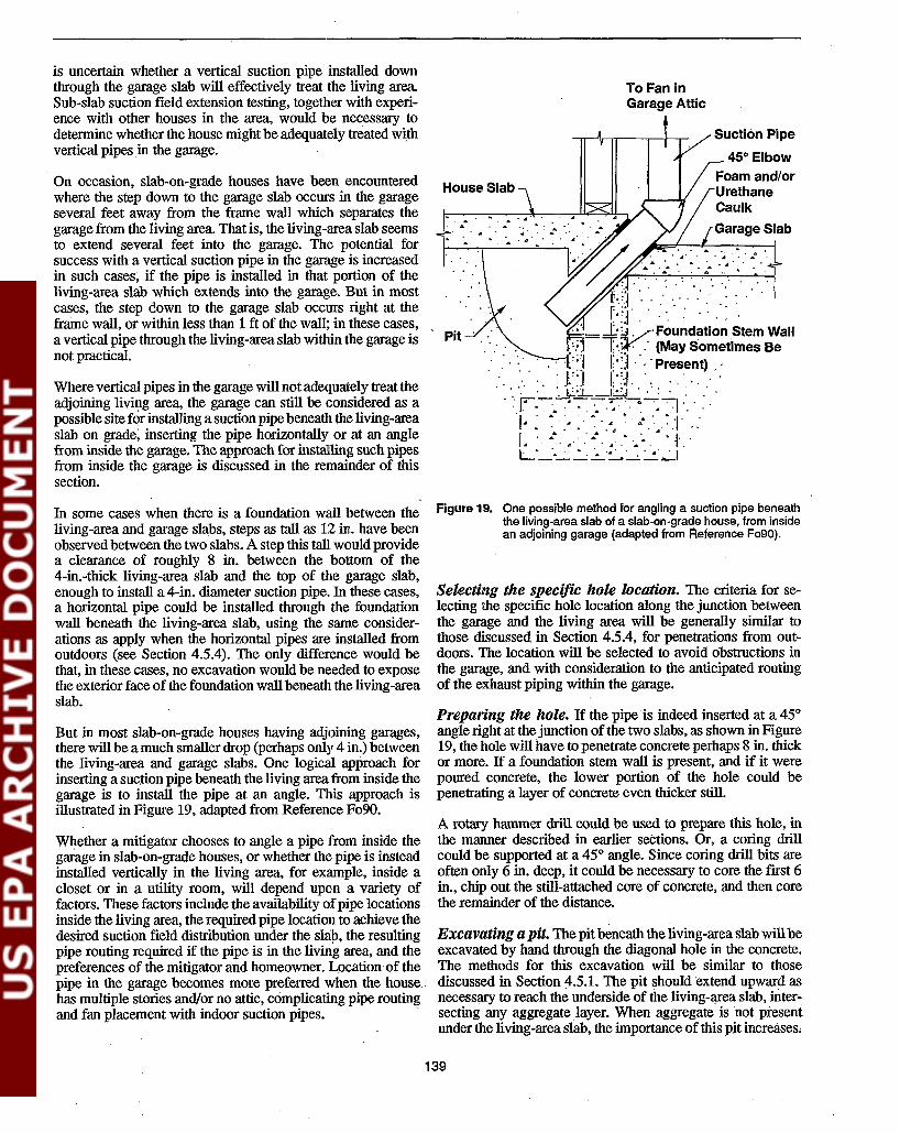
is uncertain whether a vertical suction pipe installed downthrough the garage slab will effectively treat the living area.Sub-slab suction field extension testing, together with experience with other houses in the area, would be necessary todetennine whether the house might be adequately treated withvertical pipes .in the garage.
On occasion, slab-on-grade houses have been encounteredwhere the step down to the garage slab occurs in the garageseveral feet away from the frame wall which separates thegarage from the living area. That is, the living-area slab seemsto extend several feet into the garage. The potential forsuccess with a vertical suction pipe in the garage is increasedin such cases, if the pipe is installed in that portion of theliving-area slab which extends into the garage. But in mostcases, the step cown to the garage slab occurs right at theframe wall, or within less than 1 ft of the wall; in these cases,a vertical pipe through the living-area slab within the garage isnot practical.
Where vertical pipes in the garage will not adequately treat theadjoining living area, the garage can still be considered as apossible site for installing a suction pipe beneath the living-areaslab on grade; inserting the pipe horizontally or at an anglefrom inside the garage. The approach for installing such pipesfrom inside the garage is discussed in the remainder of thissection.
...
Pit
To Fan inGarage Attic
Suction Pipe
45° ElbowFoam and/orUrethaneCaulk
Garage Slab
In some cases when there is a foundation wall between theliving-area and garage slabs, steps as tall as 12 in. have beenobserved between the two slabs. A step this tall. would providea clearance of roughly 8 in. between the bottom of the4-in.-thick living-area slab and the top of the garage slab,enough to install a 4-in. diameter suction pipe. In these cases,a horizontal pipe could be installed through the foundationwall beneath the living-area slab, using the same considerations as apply when the horizontal pipes are installed fromoutdoors (see Section 4.5.4). The only difference would bethat, in these cases, no excavation would be needed to exposethe exterior face of the foundation wall beneath the living-areaslab.
But in most slab-on-grade houses having adjoining garages,there will be a.much smaller drop (perhaps only 4 in.) betweenthe living-area and garage slabs. One logical approach forinserting a suc.tion pipe beneath the living area from inside thegarage is to install the pipe at an angle. This approach isillustrated in Figure 19, adapted from Reference F090.
Whether a mitigator chooses to angle a pipe from inside thegarage in slab-on-grade houses, or whether the pipe is insteadinstalled vertically in the living area, for example, inside acloset or in a utility room, will depend upon a variety offactors. Thesefactors include the availability ofpipe locations.inside the living area, the required pipe location to achieve thedesired suction field distribution under the slah, the resultingpipe routing required if the pipe is in the living area, and thepreferences of the mitigator and homeowner. Lpcationof thepipe in the garage becomes more preferred when the house.has multiple stories and/or no attic, complicating pipe routingand fan placement with indoor suction pipes. .
Figure 19. One possible method for angling a suction pipe beneaththe living-area slab of a slab-on-grade house, from insidean adjoining garage (adapted from Reference FogO).
Selecting the specific hole location. The criteria for selecting the specific hole location along the junction betweenthe garage and the living area will be generally similar tothose discussed in Section 4.5.4, for penetrations from outdoors. The location will be selected to avoid obstructions inthe garage, and with consideration to the anticipated routingof the exhaust piping within the garage.
Preparing the hole. If the pipe is indeed inserted at a 45°angle right at the junction of the two slabs, as shown in Figure19, the hole will have to penetrate concrete perhaps 8 in. thickor more. If a foundation stem wall is present, and if it werepoured concrete, the lower portion of the hole could bepenetrating a layer of concrete even thicker still.
A rotary hammer drill could be used to prepare this hole, inthe manner described in earlier sections. Or, a coring drillcould be supported at a 45° angle. Since coring drill bits areoften only 6 in. deep, it could be necessary to core the first 6in., chip out the still-attached core of concrete, and then corethe remainder of the distance.
Excavating a pit. Thepit beneath the living-area slab willbeexcavated by hand through the diagonal hole in the concrete.The methods for this excavation will be similar to thosediscussed in Section 4.5.1. The pit should extend upward asnecessary to reach the underside of the living-area slab, iDtersecting any aggregate layer. When aggregate is not presentunder the living-area slab, the importance of this pit increases,
139

The pit should be sufficiently deep and wide such that shiftingof the dirt sides of the pit over time or entry of water into thepit during wet seasons will not block the suction pipe.
MOllnting the suction pipe. The suction pipe is insertedthrough the angled hole, as shown in Figure 19. The end of thepipe beneath the slab should be in the open space within thepit, above the bottom of the pit. The gap between the outercircumference of the pipe and the sides of the hole must besealed with non-flowable polyurethane caulk or with expanding closed-cell foam. This angled section ofpipe will be heldin this position by the hangars/strapping which will be securing the piping run overhead in the garage.
4.6 Design/Installation of thePiping Network and FanAfter the individual suction pipes are installed by one of themethods discussed in Section 4.5, they will need to be connected to a fan which will exhaust outdoors. There are alternative methods for configuring the overall piping network andfan/exhaust system. and there are a variety of approaches forthe detailed design and installation of the piping and fan!exhaust system. Sections 4.6.2 and 4.6.3 address the designand installation of the piping network leading from the individual suction pipes to the fan; Sections 4.6.4 and 4.6.5 covertile mounting of the fan and the design and installation of theexhaust piping/stack on the exhaust side of the fan.
When there is more than one SSD suction pipe. these pipeswill generally be joined together by a horizontal run of PVCpiping. The resulting single manifold pipe must be routed to asingle fan. Usually, the amount ofsoil gas flow drawn by SSDsystems is sufficiently low such that it is not necessary to usemore thM onc fan for the entire system. Multiple fans will bewarranted only in cases where it is not practical to manifoldthe suction pipes together for one reason or another, and itdecided to install two or more separate systems (with differentpipes routed to different fans) rather than trying to connect thepipes.
For the purposes of this discussion, there are two fundamentaltypes of exhaust configuration:
1. Interior stack. A representative version of this configuration is illustrated in Figure 20. When the suction pipes areinside the house, the piping can be routed up through theinterior of the house, usually through closets or otherinconspicuous areas on the floors overhead, or via anexisting utility chase. Ifthere is an attic, the fan should bemounted in the attic. exhausting through the roof. Mounting the fan in the attic protects the fan from the weather(especially important when the fan is not UL rated forexterior use), and improves aesthetics outdoors. Ifthere isno attic. the fan could be on the roof.
2. Exterior stack. One representative version of this configuration is shown in Figure 21. In basement houses, theexhaust piping penetrates the basement band joist orfoundation wall just above (or below) grade. It is recommended that the fan be mounted on this piping outdoorsnear grade, and that a stack on the discharge side of the
fan be installed to release the exhaust above the eaves.This approach usually minimizes the aesthetic impactinside the house, but increases the impact outdoors due tothe stack extending up outside the house.
One common variation of· the exterior stack configuration,which can be used when a basement house has an adjoiningslab-on-grade garage, is to route the piping through the basement band joist into the garage. The discharge stack is thendirected up inside the garage through the garage roof, assuming that there is no living area above the garage. In thisapproach, referred to here as a "garage stack," the fan could bemounted in the garage attic, if present, or near the garage slabat the base of the stack.
Mitigators have tried a variety of other variations to theexterior stack configuration, with the primary intent of minimizing the aesthetic impact of the exterior stack. In onevariation, the exhaust piping penetrating the basement shell isextended horizontally below grade for some distance awayfrom the house, where the exhaust pipe then comes abovegrade at a less visible location. In another variation, theexhaust stack has" been deleted altogether, with the fan discharging immediately beside the house at grade; in somecases, the fan has even been placed inside the basement tofurther reduce the impact outdoors. Elimination of the exhauststack, and location of the fan inside the basement, are inconsistent with EPA's interim mitigation standards (EPA91b).
Where the suction pipe has been installed horizontally throughthe foundation wall from outdoors, as discussed in Section4.5.4 above, the exhaust configuration will almost alwaysinvolve an exterior stack. Of course, the exact configurationwould necessarily look different from that illustrated in Figure21 for vertical indoor suction pipes.
4.6.1 Suction Loss in the Piping Network
Calculation of the suction loss in the piping network wasdiscussed previously in Section 4.3.2, in connection with theselection of the suction pipe diameter. It is also referred to inSection 4.4, in connection with selection of the appropriatefan. In this current section, this calculation is covered moredefinitively, in connection with the overall design of thepiping network (such as illustrated in Figures 20 and 21) inconjunction with the selection of pipe diameter and fan performance.
The suction loss in the piping network will depend upon: a)the velocity in the pipe, which in turn depends upon thevolumetric flow rate (in dm) and the pipe diameter; and b) thelength of piping and the number and nature of the flowobstructions, such as fittings. (It will also depend upon thepipe wall friction, which would be higher for corrugatedflexible piping than for smooth-walled PVC; onlysmooth-walled pipe is being considered in this discussion.)The system fan has to be selected to provide the neededsub-slab depressurizations after compensating for the suctionloss in the piping.
In practice, rrwst mitigators will have little occasion to perform piping loss calculations in residential applications. The
140

1
Strapping (or otherSupport) to SupportPiping Weight (Every4 - 10 Ft.). See EarlierFigure.
Insulation May BeNeeded on Attic Pipingin Very Cold Climates
Horizontal PipingSloped to DrainCondensate towardOne of the SuctionPipes
Exhaust
..Joist
HorizontalPiping SlopedDown TowardStack
PVC T-Fitting,Cemented Tightlyto AdjoiningPiping
~J::~~~.::::U~~~l;+-----Strapping (or otherL Support) to SupportPiping and Fan
1. Horizontal piping run in atticshown only for illustration.Stack could have penetratedstraight upward throughroof, if there were sufficientheadroom to install fanat that location.
2. Electrical wiring tofan illustrated inlater figure.
Figure 20. One representative SSD piping configuration illustrating an interior 'exhaust stack.
141

Notes:
3. Electrical wiring to fanillustrated in later figure.
1. Figure depicts one configurationutilizing 3"X4" metal downspoutas the exterior stack. Otherpossible configurations usingPVC piping as the stack areshown in a later figure.
1
Strapping (or OtherSupport) to SupportPiping Weight (Every4-10 Ft.). See EarlierFigure.
Horizontal PipingSloped to DrainCondensate TowardOne of the SuctionPipes
2. Figure depicts stack beingsupported at rain gutter bystrapping attached throughoutside lip of gutter. Othermethods of support at thegutter, and against the fasciaIn the absence of a gutter, areshown in a later figure.
•
Suction Indicator(or Other FailureIndicator!Alarm)
PVC T-Fitting,Cemented Tightlyto Adjoining Piping
Standard Bracket toAttach Downspout toSide of House
4" Dla. RoundPVC 450 Elbow --'"
3"X4" MetalDownspout UsedAs Stack1
---.----'
One Bracket AsClose to OverhangAs Possible
4" Round-to-3"X4"Rectan~ular
Adapter
2StrappIng
Figuro 21. One representative SSO piping configuration illustrating an exterior exhaust stack.
142

most common use will be in cases where it is necessary todetermine whether 2- or 3-in. diameter piping can be substituted for 4-in. piping in selected cases without encounteringundue suction losses. In some cases, where sub-slab communication is marginal or where the piping network is particularly long or convoluted, it may also be helpful in fan selection (e.g., to assess whether a higher-suction radial blower ofthe type discussed in Section 4.4.2 might be necessary). Andwhen interpreting the more extensive sub-slab flow diagnostics described in Section 3.5.1 to aid in selecting a fan, suctionloss calculations would be required to convert the sub-slabdepressurizations measured at the baseline test hole to thesuctions at the fan inlet (so that a desired fan performancecurve could be plotted).
On the other hand, it is unlikely that a mitigator will oftenhave much choice regarding the length of piping and thenumber and type of fittings. The piping configuration willprobably often be determined by other factors: the need tolocate suction points in order to achieve an adequate sub-slabsuction field distribution; the location and nature of finishinside and around the house; and the practical routing of theexhaust stack. Assuming that the suction pipe location and thepiping configuration have been selected intelligently to beginwith, there will probably not be much flexibility for reducingthe length or number of fittings if calculations suggest thatsuction losses may be significant.
And, in general, there will probably not often be a majorconcern with suction losses in the piping network in residential applications, if4-in. piping has been used and ifone of the90-watt tubular fans (or equivalent) has been used, as dis-cussedlateL '
Thus, the mitigator should locate the suction points and designthe system piping in an effort to reduce the length of piping(upstream and downstream of the fan) and to reduce thenumber of fittings, consistent with the need to achieve adequate suction field extension and to have and acceptablyaesthetic system. With this approach, suction loss calculationsof the type discussed below will usually be limited to caseswhere small-diameter piping or where long or convolutedlengths of piping are being considered.
Calculation procedure. The suction losses in the pipingwill result from two factors: 1) friction between the air and thewalls of the pipe, calculated as loss per unit length of straightpipe; and 2) turbulence created by flow obstructions in thepiping system, namely, fittings such as elbows, tees, and sizereducers. .
The losses in straight pipe due to wall friction can be calculated based upon standard fluid flow considerations, depend
. ing upon the friction resistance of the pipe wall. The losses per'100 ft of smooth-walled pipe having average wall frictionwere presented in Figure 13 in Section 4.3.2. The figurepresents the suction loss as a function of volumetric flow rateand pipe diameter, i.e., as a function of gas velocity.
Suction losses associated with flow obstructions are handledby expressing that loss in terms of the loss in an equivalentlength of straight pipe. For many fittings, a LID ratio can beobtained from the literature, that is, the length of straightpiping (L) that would give the same friction loss as that causedby the fitting, divided by the diameter of the piping (D). Thelosses associated with various fittings are presented in Table4, derived from Reference Ca60. The figures in the tableinclude both the LID ratio for the fitting, and the equivalentlength of straight piping that would give the same suctionlosses as a function of pipe diameter.
Note that the suction loss in a 900 elbow can vary dramatically, depending upon whether the elbow makes a smooth vs.a sharp turn. The internal dimensions of many commonlyavailable PVC elbows appear to be a cross between a smoothturn (on the outer circumference) and a mitered tum (on theinner circumference). Thus, the actual LID ratio for the elbows commonly used in mitigation applications will probablybe somewhere between 9 and 65.
Other common obstructions include size expanders or reducers, for example, the 4- to 6-in. couplings used to connect fanshaving 6-in. unions onto 4-in. piping. The suction gains due tosuch expanders and the losses due to reducers, which dependupon velocity, can be calculated based upon tables and equations in Reference Ca60.
Once the piping network has been designed for a given SSDinstallation, such as illustrated in Figures 20 and 21, the
Table 4. Number of Feet of Straight Pipe Required to Create the Same Suction Loss As Created by the Flow Obstruction in One Fitting
Type of FittingUD
RatioEquivalent Feet of Pipe, for Different Pipe Diameters
Pipe Diameter 2 in. 3 in. 4 in.
Tee -60* 10 ft 15 ft 20 ft
90° elbow- smooth round curve 9 1.5 ft 2 ft 3 ft- mitered (sharp turn) 65 11 ft 16 ft 22 ft
45° elbow- smooth round curve 4.5 0.8 ft 1 ft 1.5 ft- 3-piece elbow 61ft 1.5 ft 2 ft
* This UD ratio, for gas flow around the 90° bend within a tee fitting, varies slightly with gas velocity. The ratio for flow straight through the teewould be less than that for the flow making the turn from the branch.
143

approximate suction loss that will occur in the network can becalculated as follows:
1. Convert the flow obstructions in the anticipatedfittings inthe total piping network (upstream and downstream ofthe fan) into an equivalent length of straight piping, usingTable 4;
2. Add this equivalent length to the total length of straightpiping anticipated (upstream and downstream of the fan);
3. Obtain from Figure 13 the approximate suction loss per100 ft ofstraight piping, for the anticipated pipe diameterand system volumetric flow.
4. Multiply the total number of feet derived in 2) above,divided by 100, times the loss per 100 ft obtained in 3).This will be the total estimated suction loss in the pipingnetwork at the projected air flow.
If there are sevcral90° elbows or tees in the piping network, itwould not be unusual for these fittings to make a largercontribution to the total suction loss than that from the straightpiping.
Note that this calculation procedure addresses the piping andfittings on the discharge (pressure) side of the fan, as well asthose on the suction side. Such piping and fittings on thepressure side couId result, e.g., the exterior stack shown inFigure 21. The flow resistance on the pressure side will createa back pressure that will reduce flows, and will reduce thefan's ability to develop suction. Thus, flow resistance on thepressure side must. be considered on the same basis as resistance on the suction side, for the purposes of calculating thesuction that can be established.
Interpretation of results. The total piping suction losscalculated in 4) should be subtracted from the suction that canbe maintained by the planned fan at the flow rate anticipatedin the system, obtained from the fan performance curve. Thisdifference will be the suction that the fan will maintain in tl'!.esuction pipe at the point where the pipe penetrates the slab. Itwill also roughly equal the suction existing immediately underthe slab in the sub-slab pit; at typical flows, there will be onlya small suction loss resulting from the acceleration of the gasin the pit to pipe velocity. (See the calculation procedure forsuction losses due to "abrupt entrances" in Reference Ca60.)
If the calculated suction in the pipe near the slab is unacceptably low, then steps may need to be taken to improve it. Ifsmall-diameter piping has been planned, it may be necessaryto switch to larger-diameter piping, at least in some parts ofthe system (such as the manifold pipe to which the individualsuction pipes connect). One could also switch to a fan whichcan develop higher-suction at the anticipated flows, such asthose discussed in Sections 4.4.2 and 4.4.3, or could mounttwo standard tubular fans in series. One could also considerreducing the length of piping or number of fittings, althollgh,in many cases, it is doubtful that there would be sufficientfie:dbiIity in adjusting the piping configuration to achievesubstantial reductions in suction losses by this method.
It is not possible to rigorously define the minimwn acceptablesuction in the pipe near the slab that would trigger designchanges. The real measure will be how well this suctionextends beneath the slab. This will vary from case to case,depending upon communication and flow. As a rough rule ofthumb based upon experience, with a 90-watt in-line duct fanin houses having reasonably good communication, the pipesuction near the slab should probably not fall much below 0.5in. WG; however, where communication is good, lower suctions may be acceptable. In poorer-communication cases, ahigher suction would be desirable. (A higher suction wouldalso be expected; since flows are often quite low inpoor-communication houses, large pressure drops through thepiping would be less likely.)
The use of Figure 13, in accordance with Step 3) above,requires some estimate, prior to system installation, of whatSSD system flows will be. If no pre-mitigation diagnosticshave been performed other than a visual inspection, thisestimate will be very rough, based upon the mitigator's expe
I"rience with other similar houses in the area. If a simple(qualitative or semi-quantitative) measurement of sub-slabflows has been made using a vacuum cleaner prior to mitigation, as discussed in Section 3.5.1, the estimate of SSD flowswould be somewhat more reliable, but still fairly rough. Onlyif the more extensive, quantitative, pre-mitigation sub-slab·flow measurements have been made with the diagnosticvacuum cleaner and only if the piping system suction losseshave been calculated based upon the suction-vs.-flow characteristics of the sub-slab region as discussed in Section 3.5.1will the flow estimates in the piping be reasonably accurate.
Evaluation ofneedfor suction loss calculations. At thebeginning of Section 4.6.1, it was stated that there will probably not often be a major concern with suction losses in thepiping network in residential applications, if 4-in. piping hasbeen used and if one of the 90-watt tubular fans (or equivalent) has been used. The calculation procedure describedabove can be used to supPort this statement.
Suppose that sub-slab communication is good and that, as aresult, flows are at the high end ofthe SSD range (100+ cfm).At those flows, losses in the 4-in. piping would be 0.6 in. WGper 100 ft, from Figure 13 in Section 4.3.2. The 90-watt fanswould maintain about 1 in. WG at their inlet at 100 cfm. Thus,the fans could tolerate a piping length (including the equivalent length contributed by fitting resistances) of 100 to 150 ftwhile still maintaining several tenths of an inch WG under theslab, which may well be sufficient suction ingood-communication cases. A piping length of 120 ft wouldcorrespond to, for example, 40 linear ft of straight 4-in. pipingplus four 90° elbows or tees; this could often be sufficient fora system in a two-story basement house requiring some horizontal run in the basement or attic in addition to the verticalrise up to the roofline.
In fact, with an extended length of piping, flows might dropbelow 100 cfm, and suction correspondingly increase in accordance with the fan performance curve. But again, withgood communication, some reduction in flow will often not bea problem, unless the high flows are resulting from excessiveleakage through a major unclosed entry route in the slab, or
144

through highly penneable soil. In those cases, more suctionpoints or a larger fan might be warranted.
Suppose, on the other hand, that sub-slab communication ispoor, and that flows were at the low end of the SSD range(about 20 cfm). At this flow, the 90-watt fans develop suctions at the fan of perhaps 1.7 in. WG, and, from Figure 13,the suction loss in 4-in. piping is roughly 0.03 in. WG per 100ft. At such low suction losses, the fan would still be maintaining about 1.5 in. WG suction under the slab even if the pipingrun were 300 ft equivalent. It is difficult tq imagine a pipingconfiguration so long and convoluted as to have an equivalentlength greater than this, even with multiple suction points and 'numerous elbows and tees. Consequently, piping length/configuration becomes almost irrelevant with 4-in. piping whenflows are so low. The only question in a case such as this iswhether more suction pipes or a higher suction fan may beneeded due to the poor communication.
In summary; whether communication is good or poor, it isdoubtful that a mitigator will often encounter a piping configuration so long or convoluted in residential applicationsthat it would be justified to increase SSD piping diameterabove 4 in., when a 90-watt tubular fan is being used. Accordingly, when the intent is to install an SSD system with 4-in.piping with such a fan, piping suction loss calculations willusually not be necessary.
4.6.2 Considerations in Pipe RloutingBetween Suction Points and FanIf there is more than one SSD suction pipe, the multiple pipeswill usually be connected by a horizontal run of piping. Thispiping run will then continue to a point where it can penetratethe shell of the living area and lead to a single fan. Tworepresentative routings are illustrated in Figur€'.$ 20 and 21.
This piping should be routed so that it does not interfere withnonnal traffic patterns in the house, or with the adjustment,operation, or maintenance ofany mechanical equipment. (Theone exception to this can be the sump pump in sump/DTDsystems, discussed in Section 5.) It should also be as aesthetically acceptable as possible.
Connection ofmultiple pipes in basements having unfinished or suspended ceilings. In an unfinished or partially finished basement, vertical interior suction pipes willnonnally extend upward to the basement ceiling, to the levelof the perimeter band joist which rests on top of the founda,tion wall. If a vertical suction pipe is to be connected to one ormore other suction pipes elsewhere in the basement, a horizontal pipe is, run across an unfinished ceiling (or above asuspended ceiling) to pennit the suction pipes to be manifoldedtogether.
If one suction point is by the front or rear wall of the houseand if a second pipe is needed, it would be logical to try tolocate the second pipe directly opposite the frrst on the opposite wall (between the same two overhead floor joists), if thislocation would provide the needed suction field distribution.In this case, the horizontal pipe joining the two points wouldbe parallel to the floor joists (which usually run from front to
rear), and the horizontal piping run could be up between thejoists, making it as unobtrusive as possible. This is the configuration illustrated in Figures 20 and 21.
If the two suction points are on opposite ends of the house, sothat the connecting horizontal run is perpendicular to the floorjoists, the horizontal pipe will necessarily have to be belowthe joists. Four-in. horizontal pipe running perpendicular tothe floor joists would never be run through cored holesthrough the joists, not only because 'Of installation effortinvolved, but also because of structural concerns, as discussedin Section 4.6.3 below. If there is a support beam runningfrom one end of the house to the other, providing support tothe floor joists in the middle of the basement, the horizontalpiping can logically be run beside this support beam, justbelow (and perpendicular to) the floor joists. If there are anumber of suction pipes along the length of the basement,horizontal legs from the various pipes can tap into the centralhorizontal pipe along its length.
Selection of where the piping exits the basement. Atsome convenient location, the collection pipe must be routedup through the house to a fan in the attic, as in Figure 20. Or,the pipe must be routed through the band joist to a fanoutdoors or in the garage, as in Figure 21. (Occasionally, amitigator may choose to penetrate the foundation wall belowthe band joist.)
. Where the exhaust piping will rise through the house, thelocation for this interior stack will be selected to provide themost convenient and aesthetic route (e.g., up through a utilitychase, or through closets on the floors above). Itwould be niceto avoid routing the pipes through bedroom closets, if thiswere possible, to avoid the risk that the flow noise in the stack .might disturb sensitive occupants.
If the piping is to exit through the band joist, the location forthis penetration would be selected based on a number ofcriteria. Existing constraints may prevent all of these criteriafrom being simultaneously met in the optimum manner. Thesecriteria include:
- Achieving the shortest and least visible horizontal runinside the house, avoiding indoor obstructions.
- Minimizing the visual impact of the fan and stackoutside the house; this will often mean that the penetration should be on the rear (or perhaps side) of thehouse, preferably where the fan at the base of the stackmight be concealed behind shrubbery.
- Avoiding obstructions on the exterior face of the housethat would interfere with extension of the exterior stackup to the eave; thus, the piping cannot penetrate directly beneath any windows (through which the stackcould be seen from inside the house), and especiallynot directly below overhung bay windows.
- Ensuring that the fmal discharge point (usually justabove the eave directly above the penetration) will beat least 10 ft away from upstairs windows, skylights, orother openings in the house shell, consistent withEPA's
145

interim radon mitigation standards (EPA91b), as discussed in Section 4.6.4.
- Avoiding location of the fan, the stack, or the finaldischarge point near bedrooms, if possible. The noiseassociated with the fan and stack, although often subtle,can occasionally be objectionable to sensitive occupants, especially ifgenerated near a bedroom window.The noise results from: fan noise heard at the fan, andfan noise transmitted inside the exhaust pipe and heardat the discharge point; stack vibration transmitted fromthe fan, or vibration in the house siding to which thestack is attached; flow noise in the stack, if the gasvelocity is high enough; and turbulence in the exhaustescaping thepipe. Noise can be a particularly importantconsideration when using one of the high-suction!low-flow fans discussed in Section 4.4.3, since thesetend to be noisier than the tubular fans.
- Locating the penetration relatively near to an electricaljunction box inside the house, to facilitate connectionof the fan wiring into the house circuitry, discussed inSection 4.6.5.
Where the fan and stack are inside an adjoining garage, manyof the above criteria will be more easily met The fan andstack will not be visible outside the house, avoiding concernsabout reducing the visual impact outdoors. There should beincreased flexibility in routing the stack around any obstructions in the garage. The piping can be routed horizontally inthe garage attic if necessary to ensure that the exhaust is atleast 10 ft from any openings in the living area. The fan andstack will likely be away from thebedroom wing, unless therearc bedrooms above the garage.
Pipe routing considerations when there is only oneSSD sllction point. If there is only one suction pipe penetrating the slab, the only horizontal run needed in the systemwould be the run over to the band joist penetration or to thelocation where the interior stack is to rise through the house.The location of the suction point would normally be selectedin an effort to minimize this horizontal run. Where the stack isto extend up through the house, it could be possible to locatethe suction point directly under the path of the stack, so that no .horizontal run would exist at all.
Diameter ofthe piping network. In houses where there are4-in. diameter suction pipes, the horizontal piping whichconnects the individual suction pipes will generally also be4-in. diameter piping. As discussed in Section 4.6.1, flows iIiSSD systems should almost never be high enough to warrantthe use of larger-diameter piping for the central horizontalpipe. Where such high flows are encountered in a SSD system, the problem is probably one of leakage through slabopenings or piping joints, suggesting a need for sealing ratherthan for larger piping. .
In poor-communication houses where a number of 2-in. or3-in. diameter vertical suction pipes have been installed, itmay be advisable to use 4-in. piping for the horizontal collec~tor, depending upon the actual flows and the fan used. Although flows in individual suction pipes will be low, the
combined flows· from all pipes could be sufficiently high tocreate an unacceptable suction loss in a 2-in. diameter horizontal collection pipe.
ReqUirement that horizontal piping runs be sloped. Atall locations in the system, the horizontal piping must slopeslightly downward towards the vertical suction pipes, so thatcondensed nwisture can drain away_ There must be no lowpoints in the system piping where condensate can accumulate(unless provisions are made for drainage, as discussed later).Soil gas has a high moisture content. This moisture willcondense inside the pipes whenever the piping run is exposedto a temperature below that of the soil gas, which will occurduring cold weather in piping runs which are outdoors or inunheated areas such as attics. Ensuring that all horizontalpiping is sloped back toward the vertical suction pipes willpermit any condensed moisture to flow back down beneaththe slab through these risers.
If the horizontal piping were sloped down away from therisers, the condensate could accumulate at the low end of thepiping. As a minimum, such accumulation would reduce theeffective diameter of the piping, thus reducing the flow andincreasing the suction loss. This could potentially reducesystem performance, even if the slope appears to be onlyslight. In the extreme case, if the slope is great enough, thewater could block flow entirely, thus rendering the systemcompletely ineffective.
The degree of slope towards suction pipes can be fairly slight.Some mitigators use slopes as great as 1 in. per 4 to 8 linear ftwhen the horizontal run is relatively short, consistent withsewer codes. However, this degree of slope could sometimesbe inconvenient in long horizontal runs of 4-in. piping; forexample, a 30-ft run perpendicular to the floor joists wouldterminate at a suction pipe 6 in. below the joists if the slopehad to be 1 in. per 5 ft. In fact, since the flows involve onlycondensate, the more rigorous slopes specified in sewer codesare probably not necessary for this application. Some mitigators use more gradual slopes, ranging from 1 in. per 10 ft to 1in. per 40 ft, with one mitigator proposing 1 in. per 100 ft.
Approaches when the piping must be routed over orunder obstructions. A low point in the horizontal pipingcan be creat~ if the piping has to jut up or down in order topass over or under some utility piping or other obstructionalong the basement ceiling. If the piping forms an inverted"U" to pass over the obstruction, the horizontal segment onthe far side of the obstruction could become a low point,unless there is a vertical suction pipe on each side of theinverted "U" to drain the moisture away. If the piping forns a"U" to pass under the obstruction, this "U" creates a trapwhich could accumulate water over time. The placement ofthe vertical risers and the routing of any horizontal pipingshould be selected in an effort to avoid such low points in thepiping.
Figure 22 illustrates two approaches for addressing this issuewhere potential low points are unavoidable. If the pipingforms a "0" over the obstruction, as in Figure 22A, it wouldbe optimal to place a vertical suction pipe on each side of the"U," with the horizontal run on either side of the "U" sloping
146

Figure 22. Two of the alternative methods for providing proper drainage when a horizontal piping run must be routed over orunder obstructions, creating low points in the piping.
B) Piping run is routed under the obstruction; suctionpipe at iow point in dip permits condens~ltedrainageto sub-slab with no risk of pluggage.
A third option for handling extensively-fmished basementswould be to take each pipe out through the band joist, and toconnect each pipe to its own fan outdoors, avoiding thecomplications involved in connecting the pipes. As a fourthoption, the pipes could be taken out below the band joist, sothat they penetrated the shell below grade level, in which casethe multiple pipes might be connected via a horizontal loop ofpipe buried around the perimeter outdoors. In this case, avertical riser for the fan would be tapped into the loop at alocation suitable for an exterior fan and stack (see Selection ofwhere the piping exits the basement above). A fIfth optionwould be to install the suction pipes horizontally from out-doors, discussed later. .
Another option would be to install the suction pipes horizontally from outdoors.
Pipe routing considerations for slabs on grade. Inslab-on-grade houses having an attic, especially houses having only one story, it will commonly be most convenient toinstall vertical suction pipes inside the house, extending upthrough the ceiling into the attic. Horizontal piping runs canbe made in the attic relatively easily, to connect the differentsuction pipes (if there is more than one), and to route thepiping to a point where the fan can be mounted (on a verticalsegment of piping inside the attic) such that the fan exhaustthen penetrates straight up through the roof on the rear slope.
Pipe routing considerations for basements with finished ceilings. The preceding discussion focused on basement houses which were partially or largely unfInished, whereany required horizontal piping could be run across an unfmished ceiling or above a suspended ceiling. Where the ceilingand walls are fmished with sheetrock and/or panelling, thepiping installation may be more complicated and more expensive, in order to reduce the aesthetic impact.
Routing considerations with attic piping runs. Withattic piping runs in either basement or slab-on-grade houses,the routing of the horizontal piping should be selected toavoid any obstructions in the attic, and to be out of the way ofexpected traffIc patterns, to the extent possible. Again, caremust always be taken that the horizontal piping slope slightlydownward toward the riser pipes with no low points, to pennitdrainage of condensate. '
is mounted, so that the fan will be mounted vertically. Verticalfan mounting will ensure that condensate will drain out of thefan and not accumulate in the fan housing.
One option would be to install the horizontal piping runs inthe basement, as before, but providing any. additional fInishthat would be required (including framing around the piping,as necessary) in order to make the installation aestheticallyacceptable. A second option would be to take each suctionpipe straight up through the house (e.g., through closets on thefloors above) into the attic, avoiding any horizontal runs in thebasement; if there is more than one pipe, the horizontal runs toconnect the pipes would be located in the attic. See the laterdiscussion of attic piping in slab-on-grade houses.
Suction Pipe Installedat Bottom of Dip'
Hanger
downward toward the appropriate riser. If the piping fonns a"U" beneath the obstruction, as in Figure 22B, the mostfail-safe approach would be to locate a suction pipe directlyunder the "U" as shown.
Floor Joist
Strapping
Vertical mounting offans. Whether the piping is routedqut through the band joist or up inside the house, the pipingshould always turn upward prior to the point at which the fan
.Suction Pipe on CZ:::sewer PipeEither Side of Hump (Cross-Section) or
other Obstruction
A) Piping run is routed over the obstruction; suctionpipes on both sides of hump permit condensatedrainage to sub-slab.
If it is not practical to locate vertical pipes as suggested inFigures 22A and B, a less preferred option would be to drill a
. hole at least 1/2 in. diameter through the bottom of the pipingat the low point. Flexible tubing of this diameter should befIrmly mounted into the hole, leading to some location wherethe condensate can drain: for example, a nearby verticalsuction pipe, a floor drain, or the voids inside a nearbyhollow-block wall. Tubing at least 1/2 in. diameter is requiredto reduce the risk of plugging. Care must be taken to avoidkinks in the tubing. Also, drain tubes should not be located inunheated areas where the tube might become plugged withice. This design may result in some suction loss in the system,due to air being drawn into the pipe through the tubing;however, unless the system is marginal to begin with, thissmall air leak should not noticeably impact system perfor~
mance.
147

If there is only one riser pipe entering the attic from the livingarea, as in Figure 20, the only horizontal run needed in theauic would be that required to route the piping to the point inthe attic where exhaust pipe can penetrate up through the roof.'This will usually also be the point at which the fan is mounted,in the manner illustrated in the figure. This generally shouldbe somewhere away from the bedroom wing in an effort toavoid fan noise there, especially when one of the high-suction/low·flow fans is to be used. This location should also be onthe rear slope of the roof, so that the exhaust pipe will not bevisible from the street. Other considerations in fan locationinclude: ensuring that the exhaust point is at least 10 ft awayfrom openings in the house shell, such as skylights or windows in adjoining wings, in accordance with EPA's interimstandards (EPA91b); adequate headroom in the attic to mountthe fan; access for maintenance; and convenient access to apower supply. In climates having heavy snowfall, it has alsobeen suggested that the exhaust pipe penetrate the roof slopeat a point sufficiently close to the peak so that substantial icedams will not build up behind the pipe, causing damage to theroof or shingles (K192). In any climate, it is desirable topenetrate as far up on the roof slope as possible to reduce reentrainment.
If the single riser pipe can penetrate into the attic directlybelow the roof penetration point, there would not have to beany horizontal attic run at all.
Where there is more than one vertical riser pipe entering theattic, these pipes must be connected by a horizontal run insome logical pattern. If there are a number of suction pipesentering along the length of the attic, a horizontal collectionpipe can be located down the center of the attic, with horizontal legs from the various suction pipes tapping into the horizontal pipe along its length. The horizontal collection pipeshould be mounted at an elevation slightly above that at whichthe risers end, so that the horizontal legs tapping into theconection pipe will be sloped downward toward the risers. Atsome convenient location, the collection pipe must be routedto the point in the attic where the fan will be mounted andwhere the fan exhaust can penetrate through the roof. Insystems having relatively high flows, connection of the faninto the horizontal collection pipe at a central location between the vertical suction pipes will help ensure comparablesuctions in the individual suction pipes.
As with the basement piping, 4-in. diameter pipe will often bedesirable for the horizontal collection pipe (depending uponflows and fan capability), even in cases where flows are lowenough such that 2- or 3-in. piping is adequate for the individual suction pipes.
Pipe routing considerations with horizontal penetration ofsuction pipes from outdoors. In those cases wherethe suction pipe penetrates horizontally through the foundation wall from outdoors, it will be common for the piping torise straight up from the horizontal suction pipe, with the fanmounted vertically on this riser, in the manner indicated inFigure 2. Where there are multiple horizontal suction pipes,they may be connected by a horizontal length or loop ofpiping buried around the perimeter of the house. One representative configuration for such a horizontal length of piping
is illustrated by the three-dimensional inset in Figure 2. Theriser and fan would then tap into this loop at an acceptablelocation (see Selection ofwhere the piping exits the basementabove). To avoid condensate buildup, this connecting loop ofpiping must be buried at an elevation slightly above that atwhich the horizontal suction pipes penetrate through the wall,so that the "horizontal" suction pipes are in fact slopedslightly downward. Ifflexible piping is used for any portion ofthe below-grade horizontal run, care must be taken that thefloor of the trench is flat, so that no part of the piping sags· toform a low point for condensate buildup.
4.6.3 Considerations in Pipe InstallationBetween Suction Points and FanA number of factors should be considered when the pipingruns are installed.
• The rigid PVC, PE, or ABS piping is commonly obtainedin 1O-ft lengths, which must be cut to the desired lengthor spliced together with straight fittings (or couplings)where runs longer than 10 ft are needed. Other PVCfittings commonly used in the piping network are tees,90° elbows, 45° and 22.5° bends, Y fittings, and sizereducers or expanders (e.g., 2-in.-to-4-in. adapters, forconnecting a 2-in. diameter suction pipe to a tee in a 4-in.diameter central collection pipe).
• The fittings must be of the same material (PVC, PE, orABS) and of the same weight (thin-walled or Schedule40) as the piping.
• All piping and fittings must be carefully cemented together with cement formulated for the particular materialused (PVC, PE, or ABS), to ensure a permanent andgas-tight connection. Simple pressure fits will not provide a sufficiently gas-tight seal. While simple pressurefits might sometimes look tight, a significant fraction ofthe fan capacity could be consumed in drawing house airinto the piping through the leaky joints. In addition, somesimple pressure fits could become disconnected due towear and tear over time.
• As emphasized previously, all horizontal piping runsshould be slightly sloped (1 in. drop for every 4 to 100linear ft), so that condensed moisture will drain backdown into the sub-slab region via the suction pipes. Lowpoints in the piping, where condensate could accumulate,should be avoided. If low points are unavoidable, avertical suction pipe should be installed under the lowpoint, if possible, as shown in Figure 22; otherwise, adrain tube at least 1/2 in. diameter should be installed.
• The pipiIig network must be properly supported. Horizontal runs should be supported every 4 to 10 ft. Severalalternative methods for providing such support to horizontal runs are shown in Figure 16, using pipe hangers orplastic strapping attached to the overhead floor joists inbasements. See also the discussion associated with thesefigures, toward the end of Section 4.5.1. Methods forsupporting horizontal runs in attics, attaching the hangersor strapping to braces and rafters in roof trusses, are
148

illustrated later in Section 4.6.4. The piping should neverbe supported against any other utility piping, ducting, ormechanical equipment that may subsequently be movedduring servicing or relocated.
Vertical runs can be supported from wooden members ofthe house using methods such as those illustrated inFigure 17; Vertical suction pipes can also be supported atthe slab, by a method such as those shown in Figure 15.
Even the simplest piping network should be supported at,at least, two locations. One of these locations can be atthe slab. One of the support locations should be near thevertical suction pipe, to ensure that it does not drop intothe sub-slab pit, and one should be near the fan (seeSections 4.6.4 and 4.6.5).
Strapping can effectively support the weight of the piping, but will usually notproVide significant support againstlateral movement of the piping. Where strapping is theprimary support, a mitigator may wish to include somemeasures to reduce lateral movement Lateral supportwill usually be provided by the slab penetration, and bythe penetration through the band joist (exterior stacks) oroverhead flooring (interior stacks). Caulking the seamsaround the penetration through band joist for exteriorstacks, required in any event to prevent water entry, mayfurther reduce lateral movement of the pipe at that location. Likewise, caulking of the seam around the penetration through the overhead flooring with interior stackswill provide lateral support as well as improving appearance (Br092).
• In supporting the pipes from wooden members in thebasement and attic, the pipes may have to be isolatedfrom the wooden member to reduce the transmission ofvibration to the wooden members, thus reducing noise.The hangers and strapping shown in the various figuresensure that the piping does not contact the wood. Wherethere is "hard" contact with the wood, as with the pipeclamp resting on the flooring in Figure 17, some cushioning material should be placed between the clamp and theflooring.
• As discussed in Sections 4.6.4 and 4.6.5, fans are usuallymounted vertically on the rigid piping using flexiblecouplings, e.g., in the form of 4-to-6-in. adapters in caseswhere the 90-watt fans (with 6-in. diameter couplings)are connected to 4-in. piping. These flexible PVC couplings, which have the appearance of lUbber, greatlyreduce the transmission of fan vibration to the piping,thus reducing noise. The flexible couplings must beclamped tightly to both the fan and the piping to avoidleaks.
• In very cold climates, any piping runs in unheated butprotected space (such as attics and vented crawl spaces)may need to be ~Trappedwith insulation. Such insulationwill reduce the amount of condensation inside the pipe,and, in particular, will reduce the risk that this condensatewill freeze and plug the pipe with ice. Pipe insulation in
attics and vented crawl spaces appears less important inclimates that are only moderately COld.
• In cold climates, some mitigators find it important toinsulate exterior piping (outdoor stacks), to avoid iceblockage of the exterior stack during cold weather. Forsuch exterior use, one mitigator (Wi92) reports using theblack closed-cell foam insulation commonly used aroundthe refrigerant lines running to outdoor air conditioningcompressors. This tubular insulation can be obtained indiameters that fit around the outside of PVC piping.Another approach that has been suggested for insulatingoutdoor piping involves use of Schedule 40 PVC pipinghaving a foam core; this piping, which is not pressurerated, has foam in the center with layers of rigid PVC onthe inner and outer surfaces. In the extreme, a mitigatorcould enclose the PVC stack using framing or aluminumchases, as discussed later, so that regular fiberglass insulation (not suitable for outdoor use) could then be usedaround the piping.
In an effort to avoid the need for insulation, some mitigators try to place exterior stacks on the southern side of thehouse, to increase sun exposure (KIn). Where aluminumdownspouting is used as the exterior stack for appearancepurposes, insulation of the stack would be somewhatmore difficult, and would likely defeat the key purpose ofusing the downspouting, namely, to make the stack unobtrusive.
• Some mitigators also consider insulating certain indoorpiping under the following conditions:
- Interior stacks rising through bedroom closets, to reduce noise. Such insulation becomes increasingly imPOrta.llt when the flow velocity in the pipe reachesabout 1,000 to 1,500 ft/min, at which velocity increasing numbers of occupants find the noise objectionable.
- To reduce possible "sweating" on the outside of thepipes during hot, humid weather, in cases where suchcondensate on the outside of the pipes could causedamage to house fmish. Insulation for this purposewould be important for piping running through finishedareas or above suspended ceilings.
• Where a suspended ("drop-down" or "false") ceiling is .present, location of horizontal piping runs above thesuspended ceiling is a relatively simple method for installing the piping which greatly reduces the visual impact of the system.
• Where pipes are installed in fmished space, or outside thehouse, it will sometimes be necessary to enclose the pipesfor aesthetic purposes, depending upon homeowner preferences. One option is to box the pipes in using furringstrips and sheetrock, painted to match the pre-existingfinish. One mitilJator (J091) has reported using.pre-fabricated tt sided aluminum chases with flanges,obtained in 10-1 19thS, which can be attached to thewall enclosing piping. These pre-fabricated metal
149

chases are relatively quick to install, and avoid the needfor carpentry.
• Where PVC, PE, or ABS piping extends outdoors, if it isnot boxed in, some mitigators paint the pipe (for appearance purposes and to protect it from UV radiation), orcoat it with a UV protectant. Only UV-protected Schedule 40 piping (or piping which is inherentlyUV-resistant)should be used outdoors.
• Holes for the piping through wooden members such asband joists are commonly made using a hole saw (acircular blade that fits onto a power drill). Holes throughsub-flooring can be made with a standard hand saw, orwith a hole saw.
• Where a pipe penetrates a load-bearing wooden member,this penetration must be made in a manner which does notseriously reduce the structural integrity of the member.
At least 2 in. should always remain between the hole andboUt the top and bottom of the member, even in the caseof band joists (which are supported underneath by thefoundation wall). With members which are not supportedunderne..1.Ut (floor joists and rafters), an additional requirement is Utat the hole not have a diameter greater thanone-third the height of the member. With such unsupported members, the distance between the bottom of thehole and the bottom ofthe member should be greater than2 in., if possible; the lower part of the member will be intension, and thus will be more likely to fail than the upperpart, which will be in compression.
These guidelines mean that a 4 in. diameter pipe can beinserted through a 2- by lO-in. bandjoist (or even a 2- by8-in. band joist, when encountered); at least 2 in. willremain at the top and bottom, assuming the penetration isneM the center of the band joist. But a 4-in. pipe cannotbe installed through a 2- by lO-in. floor joist, because 4in. is greater than one-third of the lO-in. height of thejoist. A 2-in. pipe could be inserted through the floorjoist, since it would constitute less than one-third of thejoist height.
In addition, floor joists should not be notched at thebottom to accommodate the piping, since this may unacceptably reduce the strength of the joist. For example, ifa2-in. notch is cut into the bottom of a 2- by lO-in. floorjoist, the entire joist will be to the strength of a 2- by 8-in.joist.
• When Ii hole is being cut through the basement bandjoistto route the piping outdoors near grade level, care must betaken to extend Ute hole neatly through the exterior finish(usually siding or brick veneer) on the outside of the bandjoist. MlUlY mitigators make this hole just large enough toaccommodate the pipe (typically about 4.5 in. outsidediameter).
When the exterior finish is brick veneer, a good approachwould be to drill two pilot holes from inside the house out .through the veneer, using a rotary drill with a small bit.
This will show outdoors where the hole needs to be inorder to properly line up with the band joist and pipingindoors. The hole through the wall is then made fromoutdoors, to minimize damage to the bricks. First, ahammer and chisel are used to remove the necessarybricks and expose the sheathing; then, a hole saw can beused to make the hole through the sheathing and the bandjoist. Following installation of the piping, the originalbricks can be cut as necessary and re-pointed.
When the exterior finish is wood, vinyl, or aluminumsiding, a similar procedure is used. Two pilot holes aredrilled from indoors to identify the necessary location ofthe hole outdoors. The hole is then drilled with a hole sawfrom outdoors, to ensure that the hole is located in thecenterofa strip ofsiding, and to minimize visible damageto the siding; also, access is usually better from outdoors,pennitting a neater job. The hole should probably be inthe center of a strip of siding, ifpossible, for the purposesof convenience and neatness. To accomplish this, thehole may need to be shifted upward or downward somewhat compared to the position indicated by the pilotholes; in that case, it would no longer be exactly in thecenter of the band joist. (However, in no case should thehole be shifted to an extent that the space between thehole and either the top or bottom of the band joist is lessthan 2 in.)
• In cases where the exterior fmish covering the band joistis particularly decorative or difficult to cut (e.g., a stoneveneer), some mitigators elect to penetrate the basementfoundation wall below the band joist (and below the pointat which the fmish ends on the exterior). This often meansthat the penetration is below grade level. Some mitigatorsconsider penetration of the foundation wall below theband joist for aesthetic reasons even in cases where theexterior finish is regular siding or brick veneer. Althoughdrilling through the block or concrete wall below grade ismore complicated than sawing through the bandjoist, thisapproach avoids the complexity and aesthetic impact oftrying to deal with and restore the exterior finish. When ahole is made through the foundation wall below grade,careful sealing is required in order to avoid water problems indoors.
• Where the piping through the basement band joist entersan adjoining slab-on-grade garage, the fmish on the garage side of the band joist will usually be fire-ratedsheetrock. In this case, the hole through the joist is madein the same manner as that described above, for the caseof exterior siding.
• In mounting the piping horizontally through the holethrough the band joist, many mitigators simply insert anintegral section of the rigid piping through the hole, assuggested in Figure 1.
One mitigator (Kl92) has sometimes found it advisable toplace a straight 4- by 4-in. flexible coupling (analogous tothe 4- by 6-in. couplings used for mounting the fans) overthe section of pipe where it penetrates the joist, to reducethe transmission of vibration to the band joist. (In this
150

case, the hole through the band joist may have to besomewhat larger than 4.5 in.) Other mitigators report thattransmission to vibration to the band joist is usually not aproblem.
• Following mounting of the pipe through the hole, thepenetration must be :fmished in an appropriate manner(e.g., the brick veneer must be re-pointed), and the gapbetween the pipe and the wall must be caulked well fromoutside (e.g., using non-flowable urethane caulk). This ismandatory to prevent rainwater that runs down the outside of the pipe from entering the house and damaging theband joist and other wooden members.
If the gap is closed with mortar during the repair of brickveneer, rather than being closed with caulk, a non-shrinkmortar should be used, so that it does not pull away fromthe pipe or foundation during curing.
• The frame wall between the living space and an adjoiningslab-on-grade garage is considered a fIre wall accordingto most building codes, and is covered with fIre-ratedsheetrock. Where SSD exhaust piping penetrates througha basemen~ band joist (and through the sheetrock on thegarage side of the joist) into the adjoining garage, thiswould be considered a breach of the fire wall. Theconcern is that, in the event of a fire in the garage, thePVC pipe would melt, leaving a 4-in. diameter openingthrough the wall which could nominally facilitate thespread of the fIre into the living area.
According to codes, an appropriate fIre break needs to beinstalled in the piping at that penetration. Three types offIre breaks can be considered:
- The fusible linkage type. Such a fire breaks consist of ashort segment of metal pipe containing a spring-loadedmetal damper held open by a fusible linkage. Thissegment of metal pipe would fIt in the hole through theband joist, with PVC piping connecting on either side.In the event of a fIre, the fusible linkage would melt,allowing the damper to close, closing th(~ hole throughthe joist When such a unit is installed, care must betaken to ensure that the damper is in fact properly open,since inadvertent closure of the damper would blockthe exhaust pipe, rendering the SSD system ineffective.
- The intumescent wrap type. Strips of intumescent material are wrapped around the outside of the PVC pipein the annular gap between the pipe and band joist. Or,if this gap is too small to accommodate the strips, thestrips are placed at the seam between the pipe and thejoist, enclosed within a metal collar that will force thematerialinto the joist hole if the pipe melts. In the eventof a fire, if the pipe melts, the intumescent materialwould expand into the hole, sealing the hole.
- The framing-in approach. If the SSD stack within thegarage is completely enclosed with framing andfrre-rated sheetrock, including the poinlt at which thepipe penetrates into the garage from the basement, this
penetration would no longer be considered a breach inthe :frre wall.
• Where a pipe penetrates an overhead ceiling into the storyabove, care must be taken to locate the overhead hole toavoid obstructions on the floor above. Before any hole ismade through a ceiling, it should be verifIed that there arenot radiant heating coils in the ceiling, and that there isnot electrical wiring, forced-air ducting, or other utilitiesabove a suspended or sheetrock ceiling.
If the ceiling hole is to be lined up with a hole in the slabdirectly below, special care will be needed in siting thetwo holes. The piping can be manipulated to fIt throughthe two holes by slipping the base down to the bottom ofthe sub-slab pit, the sliding it upward through the ceilinghole. The use of thin-walled piping (which will flexslightly) may simplify mounting a length ofpiping throughthe two holes.
• Where a ceiling penetration is being considered, itshould be recognized that the ceiling will sometimesbe considered a frre break, similar to the wall betweenthe living area and the garage. The ceiling may beconsidered a fire break in multi-family housing, or inlarge buildings such as schools, though not usually insingle-family houses. The ceiling may sometimes beconsidered a fire break in residential garages. Wherethe ceiling is considered a :frre break, one of the threeapproaches indicated above for the garage frre wallshould be implemented whenever that ceiling is penetrated by a PVC, PE, or ABS pipe.
4.6.4 Design and Installation of the Fanand Exhaust Piping-·lnterior StacksThe preceding two sections addressed the routing and installation of the piping between the suction pipe and the fan. Thenext two sections address the mounting of the fan onto thispiping·network, and the design and installation of the pipingleading from the fan to the ultimate discharge point.
As discussed in the introduction to Section 4.6, two basicexhaust confIgurations are considered for the purposes of thisdocument: an interior stack, with the stack rising through theliving area to a fan usually mounted in the attic; and anexterior (or garage) stack, with the fan and exhaust stackmounted outdoors (or in the garage). Section 4.6.4 addressesthe frrst of these cases; exterior and garage stacks are addressed in Section 4.6.5.
Overall design considerations for all stack configurations. There are two general guidelines that are considered inthe design of the exhaust system. Both of these guidelinesresult from the fact that there can be high radon concentrationsin the exhaust (often more than 100 pCijL and occasionallygreater than 1,000 pCijL).
1. The fan should be outside the livable envelope of thehouse.
151
2. The exhaust should be released at a point wherere-entrainment of the exhaust back into the house will beminimized, and where exposure of persons in the yardand in neighboring houses will be minimized.
Regarding the frrst guideline above, the fan should be outsidethe livable envelope due to a concern that leaks might developover the years in the fan housing or in the pipe couplings orfittings on the pressure (discharge) side of the fan. Such leakscould result due to aging of the cement sealing the joints, ordue to wear and tear on the piping over the years. Ifpressure-side leaks develop and if the pressure-side piping isinside the livable space, some of the potentially high-radonexhaust gas would be forced into the livable space. Such leakscould go undiscovered for years. While the amount of leakagecould be small in many cases, there have been some caseswhere indoor pressure-side leaks have caused a distinct increase in indoor radon levels compared to post-mitigationlevels with the leaks sealed.
No cases have been identified where indoor pressure-sideleaks in an otherwise properly installed SSD system weresufficiently severe to cause indoor levels to increase abovetheir pre-mitigation values. However, this nominally couldhappen if tlle leakage was significant enough.
There are no defmitive data on the frequency or severity ofsuch pressure-side leaks in the exhaust piping. Nor are t1leredata on how alternative methods for careful sealing andsupponing of the exhaust piping might reduce the risk of suchleaks. In concept, it should be possible to design the exhaustpiping to reduce this risk. However, in the absence ofany dataon the effectiveness and practical durability of such measuresand in view of the problems that could potentially arise if thefan, in fact, wound up blowing sub-slab radon into the house,EPA's Interim Radon Mitigation Standards (EPA91b) conservatively specify that the fan should be outside the livableenvelope.
To be outside the livable envelope, the fan should be in theattic (for the stack configurations discussed in this section), oroutdoors or in an adjoining garage (for the stack configurations discussed in Section 4.6.5). House air flow patternstypically involve air movement from the living area up intothe attic and out through vents and leakage points around theroof. Thus, any pressure-side leakage associated withattic-mounted fans would generally tend to be carried awayfrom the living area by this natural flow. Attached garages aresufficiently well isolated from the living space, such t1lat ifthere were any leakage from garage-mounted fans, only asmall fraction of this leakage would circulate into the livingarea. Mounting the fan in t1le attic of the garage would furtherreduce such circulation, although such attic mounting probably will not usually be necessary.
EPA's interim mitigation standards specify that fans not bemounted in crawl spaces, since air flow patterns would tend todraw any pressure-side leakage from crawl-space-mountedfans up into the living area. Crawl-space-mounted fans wouldbe of greatest concern in cases where the crawl space is notventilated, and especially where the crawl space is effectivelyconditioned space (e.g., where the crawl space is completely
open to an adjoining basement). Where the crawl space is notconditioned, and has foundation vents around the perimeter,any leakage would be diluted by outdoor air.
Regarding the second guideline listed above-minimizingexhaust re-entrainment and exposure to persons outdoorsEPA recommends that the exhaust be released velticallyabove tlle house (or garage) eave wherever possible. EPA'sInterim Radon Mitigation Standards (EPA9Ib) currentlyspecify that tlle discharge point be at least 10 ft: above gradelevel; away from any window, door, or other opening (such asan operable skylight); away from any private or public access;and away from any opening in an adjacent building. It isanticipated that EPA's fmal mitigation standards will explicitly require t1lat the exhaust be discharged above the eave,preferably the highest eave. Design of the exhaust in thismanner should help ensure that t1lere is significant dilution oft1le exhaust by outdoor air before it can be re-entrained intot1le house, or before it can reach persons in the yard or inneighboring houses. The interior or exterior stack that isrequired to discharge the exhaust in this manner can add about$100 or more to the SSD installation cost (compared to thealternative of exhausting immediately beside t1le house atgrade level) (He91b, He9Ic), and can sometimes create anaesthetic impact.
Very little data exist quantifying the effects of SSD exhaustre-entrainment, as a function of the key variables (includingexhaust configuration, exhaust location, exhaust velocity/momentum, house characteristics, and weather conditions). Documented cases where exhaust re-entrainment in fact caused asignificant deterioration in SSD perfonnance all involve caseswhere: the exhaust was directed downward toward the soilimmediately beside the house, as with a drier vent or wit1l a90° downward elbow on the fan exhaust (Mi87); or where theexhaust was directed straight upward immediately beside thehouse, or horizontally parallel to the house, especially whenthere were doors or windows nearby (Fi91). The very limiteddata which are available directly comparing above-eave andgrade-level exhausts suggest that grade-level exhausts, directed horizontal to grade and aimed 90° away from thehouse, can result in re-entrainment no more severe than thatexperienced when the exhaust is discharged vertically abovethe eave (Fi91). Ofcourse, tlle relative effects of the grade-levelvs. above-eave exhaust might vary for differing weather conditions, exhaust velocities, etc.
Also, grade-level exhaust would not necessarily prevent exposure of persons in t1le yard immediately beside the exhaust.Limited data suggest that the radon in the exhaust will oftenbe substantially diluted within a few feet of the dischargelocation.
In summary, exhaust vertically above the eave, or use of the10-ft criteria currently specified in EPA's standards, represents a conservative effort to help minimize re-entrainmentand exposure ofpersons outdoors. This conservative approachis currently preferred because data are not presently availableto quantify those conditions under which grade-level exhaustwill result in acceptably low re-entrainment and outdoorexposure. The effects of a given amount of re-entrainmentwill be less when the exhaust concentration is relatively low
152

(e.g., below about 100 pCi/L), suggesting that measures toreduce re-entrainment might potentially be less crucial at suchrelatively low exhaust levels.
General considerations with interior smcks. One representative example of an interior stack is illuslrated in Figure20.
The decision to install an interior stack instead of an exterioror garage stack will depend upon the specific situation in agiven house, and upon the preferences of the mitigator andhomeowner. An interior stack will most likely be preferredwhen: a) there is a convenient utility chase leading from thebasement to the attic through which an interior stack might berouted; b) in the absence of a chase, there is some otherconvenient route for directing an interior stack up through thefloor(s) above the basement into the attic; c) there is an atticwhere the fan can be located; and/or d) there is no adjoininggarage, or it is impractical to route the stack through the
.garage, so that a garage stack is not an option.
Where it is practical to route the exhaust piping up through thehouse, and where there is an attic in which the fan can bemounted, the· interior stack/attic fan exhaust configurationoffers several advantages.
- The aesthetic impact outside the housle is essentiallyeliminated. The only part of the system visible outdoors will be a foot or two of the 4-in. diameter exhaustpipe, which will normally be on the rear slope of theroof (away from the street), and which will have thegeneral appearance of a plumbing vent.
- The fan in the attic will be protected from the weather(particularly important for fans not raled for outdooruse) while being outside the livable envelope of thehouse. Likewise, all electrical wiring for the fan will beindoors, somewhat simplifying the wiring. At the sametime, the fan and wiring will be out of sight fromindoors as well as outdoors.
- The discharge will be well above the ea.ve (and clearlymore than 10 ft above grade), in accordance withEPA's interim standards, since the exhaust can penetrate through the roof at a point toward the peak. Thedischarge point will almost automaticalIly be at least 10ft away from windows, doors, private or public accessroutes, and adjacentbuildings, in accordance with EPA'sstandards. And it should be relatively easy to ensurethat the discharge is at least 10 ft away from otheropenings through the house shell, such as operableskylights, air intakes, and gable or soffit vents.
The primary disadvantage of the interior stack/attic fan configuration is that a route must be identified by which thepiping can extend up inside the house. Where the house is aone-story slab on grade (so that the pipes can penetrate theceiling directly into the attic), or where there is an accessibleutility chase providing a direct path to the attic, routing thepiping up inside the house will not be complicated. But wheresuch a convenient path does not exist, the piping will have tobe routed through, e.g., closets on the floor(s) above the slab.
In such cases, if there is an adjoining slab-on-grade garage, amitigator may wish to consider a possibly more convenientoption of routing the piping into the adjoining garage, sincegarage stacks offer many of the same advantages as interiorstacks.
A cost analysis (He9lb, He9lc) has shown that installing thestack up through closets in the house can sometimes be nomore expensive than installing the stack exterior to the houseor in an adjoining garage. The cost impact of the interior stackwill depend upon the exact characteristics of the house, andthe experience of the mitigator's crew with interior stacks.
Selecting the location of interior stacks. Interior stackswill be extended up through the house through a utility chase,if available, or through closets or other inconspicuous areas inthe floors above the slab, as discussed in. Section 4.6.2.Routing is easiest when there is an accessible chase, or whenthe house is a one-story slab-on-grade so that the pipespenetrating the living-area ceiling enter the attic directly.
Selecting the location offans for interior stacks. Withthe interior stacks, the fan is usually mounted in the attic. Asdiscussed under Overall design considerations above, fansmounted in attics are considered outside the livable envelopeof the house, in accordance with EPA's interim standard. Anyleakage of exhaust from the pressure side of the fan shouldflow outdoors in response to normal flow patterns up throughthe house, rather than being drawn down into the living area.
Within the attic, the fan is commonly mounted directly belowthe point at which the exhaust pipe will penetrate up throughthe roof, as shown in Figure 20. On this basis, the criteria forselecting the specific location for the fan within the attic arediscussed in Section 4.6.2 (see Routing considerations withattic piping runs). These criteria include criteria associatedwith the fan (e.g., access to fan in attic) and criteria associatedwith the exhaust penetration (e.g., penetration on rear slope).Occasional situations may be encountered where it is preferred to mount the fan at some location other than that atwhich the exhaust pipe penetrates, e.g., to provide easieraccess to the fan for maintenance, or to simplify the wiring.
Considerations in designing and installing the piping networkin the attic, leading to the fan, are discussed in Section 4.6.2(see Routing considerations with attic piping runs) and Section 4.6.3. In most cases, some horizontal run will be neededto direct the piping to the point where the fan will be mountedand/or where the stack will penetrate the roof. A horizontalrun will always be required when multiple risers penetrateinto the attic and must be manifolded together. Even whereonly one riser enters the attic, there may still have to be ahorizontal run in the attic if the vertical piping leading up tothe attic cannot be placed directly below the roof penetration.
Where there is not an attic or where any attic is inaccessible(e.g., where there is a cathedral ceiling or a flat roof), the fanfor any interior stack would have to be installed on the roof.Roof mounting of the fan would eliminate some of the advantages of this exhaust configuration. The aesthetic impactoutdoors would be increased, since the fan would now bevisible. In addition, when the roof is flat, penetration of the
. 153

stack through the roof can create water leakage problems overtime unless the penetration is sealed very carefully. Wherethere is no attic, the interior stack may sometimes still be aviable option, but an exterior stack could be preferable.
Criteriajor selectingjamjor interior stacks. The selection of the appropriate fan to achieve adequate SSD performance has been discussed in Section 4.4. In the figures anddiscussion in this section, the focus is on the in-line tubularfans covered in Section 4.4.1. Ifanother type offan were used,the details regarding the mounting and support of the fanwould have to be adjusted accordingly, for that other type offan.
With interior stacks having the fan mounted in the attic, it isnot necessary for the fan to be UL-rated for exterior use.
If the fan were mounted on the roof, the fan would no longerbe protected, and it would have to be UL-rated for outdooruse. Or, a protective housing would have to be installedaround the fan. Where a roof-mounted fan is required, a fanmodel specifically designed for wall or roof mounting couldbe considered, although the in-line models discussed in Sections 4.4.1 and 4.4.2 could still be practical.
MOllnting jans in attics. A detailed diagram illustrating arepresentative technique for mounting a fan in the attic ispresented in Figure 23.
The fan should always be mounted vertically. Vertical mounting of the fan is crucial, so that condensed moisture (and anyprecipitation that enters the stack) will drain down through thefan and down to the sub-slab region via the system piping. Ifthe fan were mounted horizontally, the condensed moisturecould accumulate in the lower portion of the fan housing.Such accumulated moisture would interfere with the rotationof the fan blades, significantly reducing fan performance andshortening fan lifetime.
If only one horizontal pipe is running over to the fan location,as in Figure 20, a 90° elbow is installed on the end of thehorizontal pipe. The fan is then mounted on a vertical segmentofpiping extending up from this elbow. Ifhorizontal pipes arerunning to the fan from two directions, as in Figure 23, a teefitting would be used. If there is no horizontal run, the fanwould be mounted directly on the vertical riser penetrating theceiling into the attic.
The fan must be mounted on the vertical pipe with an air-tightcoupling. Commonly, flexible PVC couplings, such as thosemarketed by Fernco, Indiana Seal, and Uniseal. These flexiblecouplings should help reduce the vibration transmitted to thepiping by the fan, compared to what would be expected ifrigid PVC couplings were used. But even with these flexiblecouplings, some vibration can still be transmitted (Br092).
Figure 23 (and the other figures in this document) illustrate anin-line tubular fan having 6-in. diameter couplings, such asthe 9O-watt "Category 4" fans listed previously in Table 1,being connected to 4-in. diameter piping. Thus, a 4-in.-to-6-in.flexible coupling is shown both below the fan, and also above,where the 6-in. fan outlet is reduced back to 4-in. exhaust
piping that penetrates the roof. Ifone of the smaller fans listedin Table 1 were being used, the couplings would be a straight4-in. couplings or a 4- to 5-in. couplings. If one of the radialblowers discussed in Section 4.4.2 were being used along with3-in. suction piping, 3- to 3-in. couplings would be used.
The flexible couplings are clamped tightly to the fan and tothe pipe using standard circular hose clamps, to avoid leakage.Leakage at the outlet coupling of the fan would force somehigh-radon exhaust gas out beside the house (or in the garageattic). Leakage at the inlet coupling would draw outdoor airinto the system, increasing system flow and potentially reducing the suction that could be maintained in the SSD pipes. Thehose clamps must be tightened sufficiently to prevent leakage;however, severe over-tightening could cause distortion of thepipe or fan, potentially increasing leakage (Br092).
If there is uncertainty regarding the air-tightness of the fit,tests could be conducted with a chemical smoke stick to detectleaks. Ifleakage is occurring, the coupling should be adjusted;if adjustment does not eliminate the leakage, the seams between the flexible coupling and the piping or fan could becaulked. Any such caulking should be done with an easilyremovable caulk, such as silicone caulk, rather than polyurethane, so that the fan can be easily removed later for maintenance. Caulking should not normally be necessary.
Subsequent removal of the fan for maintenance or replacement would involve loosening the flexible couplings andsliding the fan up or down as necessary to remove the unit.The short length of stack above the fan in Figure 23 may bewithdrawn down through the flashing as part of this procedure. If the stack is thus removed and re-installed as part of thefan maintenance, care should be taken to ensure that any sealbetween the stack and the top of the flashing remains tightwhen the stack is re-installed.
Many of the plastic-bodied in-line duct fans on the markettoday have integral, essentially air-tight housings, so thatthere will not be leakage into or out of the fan housing.However, some fan models (especially those with metal bodies) have seams in the housings which will permit exhaust toleak out (or attic air to leak in) if not caulked properly. Anysuch leaks in the fan housing must be detected and effectivelycaulked.
The mounting configuration illustrated in Figure 23 represents the in-line tubular fans discussed in Section 4.4.1. It alsorepresents the in-line radial blowers discussed in Section4.4.2. Other types of fans may have to be mounted in differentways. For example, if they were to be mounted in an attic, theDynaVac HS series of high-suction/low-flow fans listed inTable 3 (Section 4.4.3) would have to be bolted into verticalwooden members nailed into, or part of, the roof truss. ThePelican high-suction blower can be suspended from a horizontal brace in the truss, using a mounting intended to reduce thetransmission of vibration to the brace.
Support jor jans in attics. The fan and piping must beadequately supported.
154

Notes:
1. Figure depicts fan hard-wired intoexisting 110-volt house circuit. Otheroptions are illustrated in a later figure.Wire should be stapled against wooden·member every 18 in.
Flashing, ProperlyBlended in withExisting Shingles;Sealed If Necessary
Horizontal RunsSloped Down TowardPipe Rising fromLiving Area, forCondensate Drainage
To OtherRiser, If Any
Wooden Supportfor Wiring, IfNeeded
1
Insulation MayBe Needed On
,Attic PipingIn Very ColdClimates
110-Volt Wiring1
Electrical Switch(Accessible andwithin Sight of Fan)
1
Existing 110-VoltJunction Box
1
Exhaust
o
Strapping toSupport Weightof Fan andl Piping
2
ATIIC
Ceiling of,Living Area
Stack Rising fromSuction Plpe(s)through Slab Below
Joist
3. When strapping does not support fal1l weightdirectly, some step may be necessary toprevent fan assembly from slipping downon vertical pipe below.
2. Figure depicts end of each horizontalrun being supported near fan by strappingattached to brace in roof truss. ApprClpriatemethod of support in a given house will bedetermined by exact configuration of pipingand wooden members. Some alternative methodsof support are suggested in a previous anda later figure.
Figure 23. A representative method for mounting a fan in the attic above an interior stack.
155

When there is a horizontal piping run in the attic supporting afan at one end, the weight of the fan could cause the piping runto sag at that end. This would create a low point wherecondensed moisture could accumulate. One way of avoidingsuch sagging is to support each horizontal piping run at a pointnear the fan, using hangers or strapping attaching the pipe tomembers in the roof truss. Figures 20 and 23 show strappingattaching the horizontal piping to a horizontal roof brace.Each horizontal run is supported in Figure 23. Other approaches using hangers and strapping can also be considered,ad.'lpting some of the alternatives shown in Figure 16 forsupporting basement runs from overhead floor joists; thedifference would be that, in this case, the supporting memberswould be components of the roof truss instead of floor joists.
If the horizontal run were parallel to the attic floor joists, itcould be down between the joists, suspended by a strappingloop analogous to the top diagram in Figure 16b.
Some investigators consider supporting the horizontal pipingdirectly on the attic floor joists, or by placing some type ofsolid support between the tee fitting in Figure 23 and theunderlying joist, so that the piping and fan weight is borne byUle joist. Ifthis approach were used, it would be important thatsufficient padding beplaced between the piping and the joists,to prevent fan vibration from being transmitted to the joists.
Support could also be provided directly at the fan, supplementing or possibly replacing any support at the horizontalpiping. The fan could besupported by strapping looped tightlyaround the bottom flexible coupling, and attached to a roofbmce or rafter. Two of the three diagrams in Figure 24 areexamples this approach; although this figure is for the casewhere there is no horizontal run in the attic, those two approaches for supporting the fan would also be applicablewhen a horizontal run is present. The fan could also besupported directly using a fan mounting bracket, attaching thefan to wooden members in the roof truss. Use of a bracketcould result in transmission of vibration to the truss.
However the support is provided, it is important that supportof e.1ch horizontal run be provided near the fan. And (or), thefan itself should be supported directly. It may also be advisable to support each horizontal run in the attic at the endremote from the fan (although such remote support is notshown in Figure 20), depending upon how the interior stack issupported on the stories below.
In some cases, there may be 110 horizontal piping run in theattic -- i.e., the riser penetrating the ceiling into the atticextends straight up tllrough the roof. Figure 24 illustrates tllreepossible alternatives for providing support in the attic forstraight vertical runs. Two of the options show strappinglooped around the flexible coupling beneath the fan andattached to either a brace or a rafter in the truss. The thirdoption involves strapping looped around the pipe at the levelof the attic floor joists, and attached to the two adjacent joists;this option is analogous to that illustrated in Figure 17A, for avertical pipe in a basement extending up between the overh~d floor joists. For this third option, a screw would have toattach the strapping to the pipe, to prevent the pipe fromslipping down through the strapping (Br92). Schedule 40
piping would probably be required in this case, to prevent thescrew from causing a split in the plastic.
A fan mounting bracket, attaching the fan to the roof truss,would be another alternative for use with straight verticalruns.
As discussed in Section 4.6.3, any piping network should besupported at at least one other location, in addition to near thefan. If there is a horizontal run on a story below (e.g., in abasement), support sh9uld be provided on each end of thatbasement run, near the suction pipe on one end and near theinterior stack on the other, as in Figure 20. When the interiorstack extends straight up through the house from the suctionpoint in the slab, it is increasingly important that the systemalso be supported on the stories below, so that the entireweight of the stack is not suspended from the connection inthe attic. The most positive support for such an interior stackwould be at the slab, usillg one of the approaches in Figure 15or equivalent. Another option would be to support the stack ata floor penetration, e.g., using one of the approaches in Figure17.
The weight of the fan is supported directly only in the ftrst twocases in Figure 24, where the strapping is looped around thelower coupling on the fan; it would also be directly supportedif a fan mounting bracket were used. But in the third case inFigure 24, and in Figure 23, the support is being applied to thepiping leading to the fan; these configurations are relying onthe piping to support the weight of the fan. Where the fan isthus not supported directly, there may be a concern that, overtime, the weight of the fan may cause it and the lower flexiblecoupling to slide down over the vertical pipe below, especiallyin hot climates. Such slippage could result in the vertical pipeunder the fan being shoved upward into the fan. This couldinterfere with the rotation of the rotor, reducing system performance and possibly damaging the fan. At least one mitigatorreports having encountered this problem, perhaps because thelower coupling was not suffIciently tightened (Kl92); othershave not experienced it (Mes92).
To address this possible problem, one mitigator (Kl92) suggests installing a screw into the pipe immediately below thelower coupling, to prevent this coupling from sliding downthe pipe in cases where the'fan is not directly supported. Sucha screw under the coupling is shown in Figure 23 and the thirdoption in Figure 24. Another option would be to make thevertical pipe beneath the fan short enough so that the lowercoupling could be supported by the lip of the tee fitting (or 900
elbow) beneath.
Wiringfans in attics. The fan must be connected to a powersource in a manner consistent with the National ElectricalCode and any additional local regulations.
A common approach is to hard-wire the fan into the housecircuitry in the manner indicated in Figure 23. Since thein-line duct fans commonly used with SSD systems draw lessthan 1 ampere of electrical current, they can usually be wiredinto any convenient existing 1l0-volt circuit (e.g., a nearbyelectrical junction box, as shown in the ftgure). But where theaddition of the mitigation fan causes the total connected load
156

Brace
Strapping LoopedTightly AroundBottom Coupling,Attached to Brace
Note: When the piping formsa straight vertical run, asdepicted here, with nohorizontal run, it would beadvisable to ensure that thepiping is also supported at theslab penetration or elsewherein the livable area, as well asin the attic.
Brace
Two Ends of StrapAttached Togetherto Rafter or Brace
Strapping LoopedAround Pipe, Screwedinto Pipe; Ends ofStrap Attached toAdjoining CeilingJoists
Joist
Strapping LoopedAround Bottom .Coupling, and theTwo Ends of theStrap StapledTogether
Screw
Strapping
t~s-- Screw
Figure 24. Some options for supporting a fan and exhaust piping in an attic in cases where there is no horizontal piping run in the attic.
157
on the circuit to exceed 80% of that circuit's rated capacity, asepnrate, dedicated circuit should be installed to power to fan.
The National Electrical Code requires that a switch (to turnthe fan power on and off) be placed in the circuit within sightof the fan. Ideally, this switch would be relatively close to theattic access, to facilitate access by the occupant
'l11e wiring connects to the fan inside the electrical boxmounted on the side of the fan. The wiring leads from the fan,through the on/oCf switch, to the junction box. Where codesrequire that the wiring be stapled every 18 in., a verticalwooden support may have to be installed in some cases suchas that illustrated in Figure 23, where the wiring drops fromthe truss brace to a pre-existing junction box mounted on anattic floor joist. No suspended length of wire should beinstalled within arm's length of an attic access door, to avoidthe risk that someone may inadvertently grab the wire whenentering or exiting the attic (Bro92).
Because all of the wiring is in the attic, the wiring and switchcan be rated for interior use.
In some locations, codes may permit the fan to simply beplugged in to a nearby electrical outlet, as shown in Figure25A. In this case, the plug may be construed as the switchwithin sight of the fan. The electrical cord will usually have tobe no longer than 6 ft for this approach to be acceptable. Insome areas, it may never be acceptable to simply plug in acontinuously operating appliance such as a mitigation fan,regardless of cord length.
If the fan cord is plugged into an existing electrical outlet inthe attic, it must be ensured that the power to that outlet willnot be interrupted In particular, the power to outlets incorporated into attic light fixtures may go off when the attic light isswitched off.
When fans are installed by mitigators, codes generally requirethat the installation of 1l0-volt wiring be conducted by alicensed electrician, if this wiring consists of anything morethan simply plugging a 6-ft cord into a nearby outlet. Tosimplify the installation in cases where the distance is longerth..w 6 ft., one vendor is marketing the system illustrated inFigure 25B, where the wiring is only 24 volts. Wiring of thatlow voltage can generally be installed without a licensedelectrician. A transformer in the wiring where it is pluggedinto the house electrical outlet steps the system voltage downfrom 110 to 24 volts. In this product, the transformer box alsoincludes an ammeter which measures the current being drawnthe fan, thus serving as a failure indicator. The wiring laidbetween the transformer and the fan is thus 24 volts. Atransformer within the tubular fan steps the voltage back up to110 volts, for normal fan operation. Because the wiring leading to the fan is only 24 volts, the vendor indicates that aswitch is no longer needed within sight of the fan; the "switch"is now the ItO-volt plug within sight of the transformer/ammeter (in the basement in Figure 25B).
Exhaust pipingfrom fans mounted in attic. An exhaustpipe on the pressure side of the fan must be installed upthrough the roof. Assuming that the fan is mounted directly
beneath the point at which the roof will be penetrated, thisexhaust piping will consist ofa length of straight pipe severalfeet long, as shown in Figure 23.
The hole through the roof can be cut with a hole saw or areciprocating saw. Because the water-tightness of the roofwill have to be restored with flashing and sealant, it is desirable that this hole be reasonably small and neat. The holeshould be only slightly larger than the pipe, to facilitateinstallation and to allow fot.: any expansion or contraction, andshould be cut as close to vertical as possible.
After the length of exhaust pipe is installed on the fan outlet,extending up through the roof, steps must be t:a1<:en to preventleaks around the penetration. Flashing must be installed whichfits snugly around the pipe, and which must be carefully fittedunder the existing shingles above and beside the penetration.Some shingles will have to be loosened or removed andreplaced to install the flashing, a step which must be carriedout carefully in order to avoid tearing the shingles.
While caulking around the flashing is nominally not requiredif the flashing is properly installed, it is advisable to caulkaround the perimeter of the flashing where it contacts theadjacent shingles after the flashing has been nailed in place.Caulking the perimeter will help ensure against leakage during heavy rains (Br092). Some mitigators also recommendcaulking the heads of the nails holding the flashing in place,and placing a bead of caulk at the seam between the flashingand the exhaust pipe, at the top of the flashing (Mes92).
Where the penetration has been made through a flat roof, theseam between the pipe and the roofmust be thoroughly sealedwith liberal quantities of roofing tar.
The exhaust pipe should extend above the roof by a foot ortwo. The primary concern in selecting stack height is to ensurethat the discharge point will not become blocked by drifts ofsnow or leaves. Taller stacks might be expected to improveexhaust dispersion, helping the exhaust jet to penetrate theboundary layer of air flowing over the roofline. However,there are no data demonstrating a need to make the stack tallerthan I to 2 ft. It is likely that any reduction in re-entrainmentresulting from making the stack taller than 1 to 2 ft would beoffset by the increased aesthetic impact the taller stack.
Where the stack above the fan is only a few feet long, it isusually not necessary to provide separate support for thestack. But where this stack is much more than about 3 or 4 ftlong, one mitigator recommends supporting it separately,usually with strapping connected to the members in the rooftruss (K192).
Caps on the exhaust stack. Some mitigators install a ventcap on top of the stack, primarily to prevent precipitation fromentering the stack. The concern is that excessive amounts ofrainwater being channeled to the sub-slab region via thesuction pipe might reduce sub-slab communication near thesuction pipe, thus reducing system performance. However,there is some question whether rainwater entry into the pipewill indeed be excessive in many climates. For example, aI-in. rainfall would nominally introduce 0.05 gal of water into
158

-
110-Volt ElectricalCord, No LongerThalll6 Ft.
o
Existing 110Volt ElectricalOutlet, Within6 Ft. of Fan
----
A) Fan plugged into accessible,existing 110-volt electricaloutlet with cord no longerthan 6 ft.
24-to-1.10-VoltTransformer Builtinto Modified Fan
•
24-VoIt Cable, NoLonger Than 50 Ft.
Control Box (110-to24-Volt TransformerWith Ammeter Built In,or With Other FailureIndicator/Alarm).
~ 110-Volt Electrical. Cord, No Longer
Than 6 Ft.
Existing 110-Vol~
Electrical Outlet
B) Transformer used to stephouse voltage down to 24volts, so that cable betweenoutlet and fan can be 24-voltcable, simplifying installation.
Figure 25. Some alternative approaches that can sometimes be considered for wiring SSD fans mounted in attics.
.a 4-in. diameter stack, an amount which will usually be smallcompared to the condensate expected from the soil gas. And,at least where aggregate is present beneath the slab, it may beexpected that any water will often drain away and not interferewith suction field extension through the aggregate layer.
A vent cap would also prevent leaves, other debris, andanimals from entering and potentially plugging the stack. The
momentum of the air leaving the stack should generallyprevent light debris such as leaves from entering the stack,without a cap. While many mitigators report occasional problems due to birds, bats, squirrels, bees, or other animalsentering the stack when there is no cap, these experiencesappear to be infrequent (Bro92, Kl92, Mes92).
159

A number of mitigators feel that vent caps are unnecessary(An92, Bro92, Mes92, KI92). Caps can even be undesirable,because many cap designs will increase back-pressure in thesystem. contribute to ice buildup at the discharge point duringcold weather, and potentially reduce dispersion of the exhaust.For these reasons, vent caps have not been included in any ofthe preceding figures.
Two possible designs for vent caps are shown in Figure 26.The design in Figure 26A, which focuses on preventing theentry of rainwater into the piping, is not commonly used inresidential radon mitigation installations, but is widely used invarious other commercial applications. This design would notcreate any back-pressure in the piping; however, neither wouldit help prevent the entry of debris into the stack, if that is aserious concern.
Raincap~ SupportsPVC St k Att.aching
ac Ram Capto Stack
TopVi~w
\
RoundedPVC Cover ------:~~
PVC GrillePVC Collar, toAttach to Top of4-ln. Diam. Stack
-- - Exhaust
3-Dimensional View\Rain Hits Sides of
\ \ Cap, Drips Out throughAnnulus between Cap\87d
\
\
\
PVC Stack -----<~
A) Annular rain cap (section ofduct having somewhat largerdiameterthan PVC stack).
B) Rounded PVC cap
FIguro 26. Two possible configurations for vent caps on SSD stacks.
160

Figure 26B shows a cap design more widely marketed forradon mitigation applications. The cap itself resembles asection ofPVC piping sliced in half down its axis, and fitted atits ends with ~VC grilles. This cap is held in place on top ofthe stack by a circular PVC collar at its base, which slips downover the exhaust pipe like a fitting and can be cemented inplace. This cap should effectively prevent the entry of bothprecipitation and debris but would be expected to create someback pressure and potentially reduce dispersiolll.
There is also an aluminum cap on the market. The cap has aperforated cylindrical wall, somewhat larger in diameter thanthe 4-in. exhaust pipe, with a solid plate on top. A circularaluminum collar at its base fits tightly inside the PVC exhaustpipe.
Another design sometimes utilized involves placing one ortwo 90° elbows on top of the stack, creating an inverted "L" or"U" so that the discharge is directed horizontally or downtoward the roof. The inverted U, in particular, should beeffective at preventing entry of precipitation and debris, butagain, would create back pressure and potentially reducedispersion.
One mitigator (Kl92) reports placing hardware cloth screen(1/4-in. mesh) over the stack opening, primarily to keepanimals out. The screen is bent to fit inside the pipe, where itwill initially remain in place by pressure fit; the screen is thensecured in place by sheet metal screws. This screen should notsignificantly influence system back pressure 01' reduce dispersion.
One of the potential problems with some cap designs isincreased back pressure on the fan. These caps serve as flowobstructions on the pressure side of the fan, potentially reducing the suction that the system can maintain beneath the slab.In particular, the cap in Figure 26B, the aluminum cap, andthe inverted L and U, might be expected to offer this disadvantage. However, this back pressure may in fact not be aserious problem except in cases where flows are high, if thefan is properly selected. One group of investigators (CI91) hasfound that the back pressure created by the cap in Figure 26B .will be about 0.002 to 0.02 in. WG at flows of 20 to 70 cfm.This pressure loss will usually be insignificalllt compared tothe suctions typically maintained in the suction piping by thein-line tubular fans (typically several tenths of an inch ofwater, up to more than 1.5 in. WG). An inverted U, with twoelbows, would have a higher pressure loss, 0.01 to 0.2 in. WGover the typical SSD flow range (20 to 100 cfm). At the higherflows, this loss might occasionally be important in marginalsystems.
Another potential disadvantage of the cap in Figure 26B, thealuminum cap, and the inverted. L is that they deflect theupward-flowing stream, causing it to discharge horizontallyinstead of vertically upward, and reducing its momentum. Theinverted U would cause the exhaust to discharge verticallydownward, and would further reduce exhaust momentum. Bychanging the direction and reducing the momentum of theexhaust, these caps will reduce the potential for the exhaustgas "jet" to penetrate the boundary layer created by air movement over the roofline of the house, thus hindering dispersion
of the exhaust outside of the building wake. Intuitively, theexhaust will probably still be diluted sufficiently well thatre-entrainment should not be a serious problem; however,there are no data or calculations to confirm this intuition.
Another concern regarding any rain cap is that it may contribute to the accumulation of ice at the discharge during coldweather, restricting flow and creating significant back pressure. By providing more cold surface area and reducing theexhaust momentum, a cap could add to the tendency of waterdroplets in the exhaust to collect and freeze.
In summary, there are no data conf'mning that rain caps arereally necessary; from the discussion above, it would seemthat they should not be necessary in many cases. On the otherhand, neither are there data confirming that rain caps will doany harm; perhaps the greatest risk would be one of increasedice accumulation during cold weather. Under these conditions, it is left to the discretion of the mitigator regardingwhether or not to install a cap. At least one fan manufacturerreportedly now requires a rain cap on the stack, as part of thefan warranty, to keep precipitation out of the fan.
Mufflers on exhaust stack. Sometimes sufficient noise isemitted at the point where the exhaust is discharged, that somehomeowners fmd the sound objectionable. This noise couldresult from: a) fan noise which is transmitted inside the stack;and b) turbulence in the exhausted gas as it escapes. Fan noiseinside the pipe is generally higher for the higher-poweredfans, such as the high-suction/low-flow units in Section 4.4.3.The noise from gas turbulence would be expected to increaseas exhaust velocity increases, and to be greater when there isan obstruction (such as a fitting or vent cap) at or near theexhaust point .
Mufflers are marketed which can be installed in SSD exhauststacks downstream of the fan to reduce this noise. Mufflersare commonly 6- to 12-in. long sections of pipe lined O£\ theinside with a sound-deadening material (such as acousticfoam) which "captures" some of the sound waves beingtransmitted inside the piping due to the fan. Unless the mufflerincreases the diameter of the exhaust stack at its dischargepoint, thus reducing exhaust velocity, it is not .clear whether itwill significantly reduce the noise associated with the turbulence in the escaping gas. It is suspected that much of thenoise associated with the exhaust may often be fan noise.
In the case of interior stacks with attic fans, the muffler, ifneeded, would logically be installed in the attic above the fan.Alternatively, it could be installed outdoors after the pipinghas penetrated the roof. .
Mufflers are generally required on the exhausts from thehigh-suction/low-flow fans. They are not often used with thein-line tubular fans in Section 4.4.1. However, even with thetubular fans, situations have occasionally been encounteredwhere the sound from the exhaust point -- although subtle -- isobjectionable to sensitive occupants. Mitigators will have todecide on the value of a muffler on a case-by-case basis.
161

Since muffiers are not commonly used with the in-line tubularfans, they have not been included in the figures in thisdocument.
Considerations wizen fan must be on tlze roof. All of thepreceding discussion has assmned that the fan will be insidean attic. Where an accessible attic exists, that will generally bethe preferred location for the fan. Where there is no attic, orwhere the attic is inaccessible, the interior stack exhaustconfigumtion would necessitate that the fan be on the roof.This situation would take away some of the advantages of theinterior stack.
If the fan must be on the roof, this will impact the design andinstallation approach described above in several ways.
1. Ifthere is no attic, any horizontal piping runs will have tobe inside the house or on the roof, which can be morecomplicated and/or less aesthetic than locating them inthe attic.
2. If the roof is flat or is over a cathedral ceiling, making thehole in the roof for the pipe penetmtion may be morecomplicated. With flat roofs, careful sealing around thepenetmtion will be necessary, since flat roofs create anincre.'lSCd threat of water leakage. With cathedral ceilings, the slope may be steeper; moreover, since the roofpenetration may be in fmished living area, the conditionsunder which the hole is drilled can be more exacting.
3. The fan will have to be rated for exterior use. A fandesigned for roof or side-wall mounting may be considered. mther than an in-line tubular fan.
4. The wiring that is outdoors will have to besunlight-resistant, and otherwise mted for exterior use.Likewise, the switchbox will have to be wet-proof, ratedfor exterior use, assuming that it is outdoors (e.g., on theroof) in order to be within sight of the fan. The procedures for wiring exterior fans are discussed in Section4.6.5.
4.6.5 Design and Installation of the Fanand Exhaust Piping-Exterior andGarage StacksGeneral considerations with exterior andgarage stacks.One representative example of an exterior fan and stack isillustmted in Figure 21. If a slab-on-grade garage adjoined thebasement at the point where the piping exits the basement, thefan and stack would be inside the garage, with the stackpenetmting the garage roof (assuming that there is no livingarea above the garage).
The decision to install an exterior or garage stack instead ofaninterior stack will depend upon the specific situation in agiven house, and upon the preferences of the mitigator andhomeowner. An exterior stack will most likely be preferredwhen: a) there is not a convenient utility chase leading fromthe basement to the attic through which an interior stack mightbe routed; b) there is not an acceptable route for directing aninterior stack up through the floor(s) above the basement into
the attic; c) there is no attic; d) there is no adjoining garage, orit is impractical to route the stack through the garage for onereason or another; or e) the suction pipes penetrate the foundation wall horizontally from outdoors. A garage stack willoften be preferred when: a) an adjoining garage exists; b) thesuction pipes penetrate the slab indoors (rather than horizontally from outdoors); and c) the location of the suction pipes,the presence of living area on the overhead floors, or otherfactors make it more convenient to route the piping throughthe wall adjoining the garage than to install and exterior orinterior stack.
When the fan and the stack are outdoors, this exhaust configuration ~reates a greater aesthetic impact outdoors, comparedto the interior stack/attic fan configuration. However, exteriorstacks can reduce the aesthetic impact indoors, especially incomplex or highly finished houses, and may sometimes bepreferred by the homeowner and mitigator. The exterior stackwill often be less expensive than, or comparable in price to, aninterior stack. unless the house is particularly amenable to aninterior stack (one-story slabs on grade and houses withaccessible utility chases) (He91b. He91c). The cost increaseassociated with an interior stack appears to be the least whenthe mitigator's crew is experienced with interior stacks. Another potential concern with exterior stacks is an increasedrisk restriction or pluggage due to the freezing of condensateduring cold weather; such freezing problems have been reported in cold climates.
Where there is an adjoining garage, locating the fan and stackin the garage can offer the advantages of both the interiorstack and the exterior stack. Like the interior stack, the garagestack will essentially eliminate the aesthetic impact outdoors;it will keep the fan and wiring in a protected location; and itwill usually avoid the risk of stack freezing during coldweather. Like the exterior stack, the garage stack will avoidaesthetic impacts inside the living area. A garage stack may beroughly $100 more expensive than an exterior stack becauseof the firebreak that is often needed where the pipe penetratesfrom the basement into the garage and because of the costsassociated with penetmting the garage roof (a cost which theexterior stack avoids unless it penetrates the roof overhang,also discussed later) (He91b, He91c). A garage stack may beeither more or less expensive than an interior stack, dependingupon the particular house characteristics and the experience ofthe mitigator with interior stacks.
Selecting the location ofexterior or garage stacks. Thecriteria for deciding where the exterior or garage stack will belocated have been discussed in Section 4.6.2 (see Selection ofwhere the piping exits the basement).
An additional consideration in locating exterior stacks is thatthe risk of the stack becoming plugged with frozen condensateduring cold weather can be reduced if the stack can be locatedon the south side of the house, where it will be exposed tomore sunlight (Kl92). '
Selecting the location ofexterior orgarage fans. Wherethere is an exterior stack, EPA's standard specifies that the fanmust be outdoors (EPA91b), as emphasized previously. Withgarage stacks, the fan must be in the garage. Location of the
162

fans outside the .livable area is intended to reduce the risk ofincreases in radon levels if leaks develop over the years in thefan housing or piping on the pressure side of the fan.
Exterior fans are commonly mounted near grade level immediately outside the foundation wall, at the base of the exhauststack, as shown in Figures I and 21. This location will reducethe visual impact of the fan, compared to the alternative ofmounting it higher in the stack, and will improve the ability topotentially conceal the fan behind shrubbery. Location neargrade also facilitates access to the fan for maintenance, andmay simplify the electrical wiring. Also, in view of the factthat aluminum downspouting is sometimes used for -exteriorstacks for aesthetic reasons, attempting to mount the fan ontop of the artificial downspout would represent an addedcomplication.
One potential disadvantage of having the fan at the base ofexterior stacks is that, in cold climates, ice that has formedinside the necessarily uninsulated stack during the winter maybecome dislodged and fall down into the fan during thaws,preventing proper system operation and potentially damagingthe fan. One mitigator who has occasionally observed thisproblem reports that although the fallen ice did sometimesprevent rotatiOll of the fan rotor and hence interfere withsystem performance, it did not seem to damage the fans(Kl92).
With garage stacks, one potential disadvantage of having thefan near the slab is that any pressure-side leaks would releasehigh-radon exhaust near the living area However, unless thegarage is conditioned space, the garage is usually sufficientlywell isolated from the living area (and the amount of exhaustreleased will usually be sufficiently small) such that thisconcern should not necessitate that the fan be moved up to thegarage attic, if placement in the attic is otherwise not desired.
If the garage does have an accessible floored attic, location ofthe fan in the garage attic could be considered. If the fan islocated in a garage attic, selection of the exact location withinthe attic would be made as discussed in Section 4.6.2 (seeRouting considerations with attic piping runs) and Section4.6.4.
Criteria for selecting exterior and garage fans. Theselection of the appropriate fan to achieve adequate SSDperformance has been discussed in Section 4.4. In the figuresand discussion in this section, the focus is on the in-linetubular fans covered in Section 4.4.1. If another type of fanwere used, the details regarding the mounting and support ofthe fan would have to be adjusted accordingly, for that othertype offan.
, With exterior fans and stacks, the fan should be UL-rated forexterior use. This will mean that the wiring box and connection on the s~de of the fan will have to be properlyweather-proofed. With fans mounted in garages, rating forexterior use is unnecessary.
Mounting exterior or garage fans. In accorc:Ia:nce with thediscussion in Sections 4.6.2 and 4.6.3, the system piping willhave been installed through the basement hand joist and
exterior finish to the outdoors (for exterior stacks), or throughthe foundation wall below the exterior finish. With garagestacks, the piping will have been installed through the basement band joist and the fire-rated sheetrock in the garage;also, the fan wiring could be somewhat different in garagesbecause it will be in an enclosed space, as discussed later.
A detailed diagram illustrating a representative technique formounting an exterior fan is presented in Figure 27. This figureis for the case where the suction pipes are installed inside abasement, and is a detailed enlargement of a portion thesystem shown in Figure 21. If the suction pipes penetratedhorizontally from outdoors, ofcourse, the portion of the figurebelow the fan would look as shown in Figure 2. If the fan andstack were in a garage, the pipe from the basement would bepenetrating fITe-rated sheetrock on the exterior face of thewall, rather than brick veneer as shown.
As discussed earlier in Section 4.6.4 (see Mounting fans inattics), the fans should be mounted vertically, so that condensate and rainwater will drain out of the fan. As shown inFigure 27, a 900 elbow is usually installed on the end of thehorizontal pipe penetrating through the house shell. The fan isthen mounted on a vertical segment of piping extending upfrom this elbow. .
For convenience in supporting the fan, some mitigators havesuggested mounting exterior fans horizontally, directly on thepipe penetrating the house'wall. By this approach, a drain holeperhaps 1/4 to 1/2 in. diameter would be drilled at the lowpoint in the fan housing, on the underside of the fan, to permitwater to drain out. Based upon simple orifice calculations, ahole of this size should result in a maximum leakage into thesystem of only a few cfm of air, and thus should not createexcessive suction loss with the in-line tubular fans. However,much experience suggests that, even though the soil gaspassing through the fan will be at a temperature well abovefreezing even during the winter, the drain hole can still iceshut in outdoor fans during extended cold weather. If the drain'hole becomes plugged with ice, condensate will accumulate inthe fan housing. In addition, horizontal mounting will void thewarranty of some fans. Thus, vertical mounting is recommended.
The fan is commonly mounted on the vertical pipe usingflexible PVC couplings, to help reduce the vibration transmitted to the piping by the fan. See the discussion under Mounting fans in attics in Section 4.6.4. The flexible couplings areclamped tightly to the fan and to the pipe using circular hoseclamps, to avoid leakage. As in other figures in this document,Figure 27 illUStrates a 4-in.-to-6-in. coupling, connecting atubular fan with 6-in. couplings onto 4-in. piping. The coupling size would vary if the fan or pipe size varied.
Figure 27 shows a short segment of 4-in. piping below thelower. flexible coupling (between the coupling and the 900
elbow), and another such segment above the upper coupling.These segments should be sufficiently long so that, when thecouplings are loosened, the couplings can be slid up or downas necessary to remove the fan for repair or replacement. Withinterior stacks, the length of the pipe stub under the attic fanwill sometimes be of less concern since, at least with the
163

Joist
•
Existing 110-VoltJunction Box
..Wet-Proof SWifchBox, Near Fan ----*
Fan Rated forExterior Use,or Enclosed
11D-Volt Wiring,Rated forExterior Use
Female End Up at Notes:Seams Where Segmentsof Downspout Are 1. For clarity, switch box is shown belowJoined, to Reduce 5 pipe penetration through wall. More
. Risk of Ice Buildup commonly, switch box will be up besidefan or pipe penetration. Wiring from
Caulk switch to interior junction box maypenetrate house through separate
3"X4" Rectangul~hole through band joist, as shownhere, or may enter via same
Metal Downspout penetration as suction pipe, outsidethe pipe.
Shim BetweenBracket and 4 2. Other configurations for the fittingsHouse, If Needed and piping immediately above the fan
are illustrated later.Standard DownspoutBracket, to Attach 3. Other options for attaching the stackDownspout to Side to the house are presented later.of House
3
4. Shim between bracket and house may be
4" Round-to-3X4"needed if piping configuration or
Rectan9.tularirregularities on face of house force
Adapterstack to be too far away from house.
Regular 45° Fittings5. Male end up at downspout seams would
create a lip inside the stack against(4" Dia. Round PVC) which condensate running downto Offset Stack
2 interior might collect and freeze inAgainst House cold climates.
FIguro 27. A representative method for mounting an exterior fan atthe base of an exterior stack.
164

configuration shown in Figure 23, the short length of stackabove the fan could be removed with the fan if necessary.However, with exterior stacks, which will be firmly attachedto the side of the house, it is important that the fan be able tobe removed without movement in the piping either above or .below.
If the particular fan model being used does 'not have anessentially air-tight housing, any leaks in the fan housing mustbe detected and effectively caulked.
As one variation of the mounting configuration in Figure 27,an ABS plastic enclosure is being marketed which can bemounted around exterior fans to improve appearance andprovide some protection. This housing screws against the sideof the house. It encloses the fan and its couplings, the elbowand the wall penetration below the fan, and the fittings abovethe fan (which serve to offset the stack against the side of thehouse). The commercially available enclosure comes with a"transition box" which offsets the stack against the house,taking the place of the fittings above the fan; otherwise, themounting of the fan inside the enclosure is· essentially identical to that illustrated in the figure.
The mounting configuration illustrated in Figure 27 represents the in-line tubular fans and radial blowers discussed inSections 4.4.1 and 4.4.2. The DynaVac HS series ofhigh-suction/low-flow fans listed in Table 3 (Section 4.4.3)bolt directly onto the side of the house when used withexterior stacks. The Pelican high-suction fan is not designedfor use with exterior stacks.
Supportfor exterior and garage fans. The weight of thefan must be adequately supported. The weight of the stackabove the fan must also be supported separately; support forthe stack is discussed later (see Exhaust piping from exteriorfans below).
The horizontal pipe extending through the wall below the fanwill be supported at its penetration through the band joist, andby hangers or strapping inside the basement. This pipe shouldadequately support the weight of an in-line fan, if the pipeextends out from the house only as far as is required toprovide clearance between the fan housing and the house.
Many mitigators find that no further support for exterior orgarage fans is needed in many cases. However, for additionalsupport, some mitigators have. sometimes attached the failhousing directly to the side of the house using a fan mountingbracket. If thi$ is done, the bracket must be attached tightly tothe house, to reduce the transmission of vibration; .if there iswood siding, the bracket should be screwed into studs in thewall. As another way of providing additional support, sometype of support could be placed between the ground and theelbow beneath the fan, so that the fan weight is borne by theground. Some mitigators have sometimes accomplished thisby installing aT-fitting under the fan, instead of the 90° elbowin Figure 27, with one leg directed upward and one downward; the fan is then mounted on the upward leg, while alength of rigid pipe is installed into the downward leg and isembedded in the ground under the fan. Ont occasion, asanother alternative for providing additional support, the fan
has been attached to a post embedded in ground beside thefan.
Since these additional support features for the fan are notusually necessary, they are not shown in Figure 27.
Wiring exteriorandgaragefans. Considerations involvedin the electrical wiring for fans have been discussed in Section4.6.4 (see Wiring fans in attics).
When the fan is inside a garage, the wiring considerations willbe very similar to those for attic fans. The fan can be hard-wiredinto a convenient existing house circuit with an on/off switchin sight of the fan; since, the wiring is inside the garage, thewiring and switch can be rated for interior use. Where codespermit, the fan may be plugged into a nearby electrical outletusing a cord no longer than 6 ft.
Where the fan is outdoors, more care in the wiring is required.See Figure 27. To be within sight of the fan, the on/off switchwill often have to be mounted outdoors on the side of thehouse near the fan, as in the figure. In some cases, the switchis located indoors. in sight of the fan. Commonly, an outdoorswitchbox will be mounted at an accessible location close tothe electrical box on the fan, so that a short length of outdoorelectrical conduit can connect the fan to the exterior switchboxwith a minimum run of the conduit along the side of the house.Runs of conduit along the face of the house should be stapledevery 18 in.
Wiring from an outdoor switchbox penetrates the house shelland is hard-wired into the house circuitry (e.g., at an existingjunction box in the basement, as in Figure 27). In the figure,the wiring penetrates the wall through a separate hole drilledespecially for the wiring. Alternatively, if there is a gaparound the 4-in. hole that has been drilled for the exhaust pipe,the wire might enter the house through this gap between theoutside of the pipe and the wall. Such a gap may exist, forexample, when the hole has been made through a blockfoundation wall with a rotary hammer drill, and is thus slightlyirregular. The National Electrical Code prohibits runningelectrical wiring inside air. ducts; thus, it would be againstcode to route the wiring into the house inside the SSD piping,drilling a small hole in the pipe just outside and just inside thehouse to accommodate the wire.
Any wiring or conduit used outdoors must be rated for exterior use. Likewise, if the switehbox is mounted outdoors, itmust be weather-proof and rated for exterior use.
Exhaust piping from exterior fans-selection ofstackmaterial. When an exterior fan is mounted near grade level .as in Figures 21 and 27, an exhaust stack must extend vertically above the fan, if the exhaust is to be at least 10 ft abovegrade in accordance with EPA's interim standards (EPA91b).This exterior stack generally extends to or above the eaves.There are numerous options in designing exterior stacks.
The exterior stack can be PVC, PE, or ABS piping of roundcross-section, like the remainder of the piping in the system.The diameter of the stack will commonly be the same as thatin the rest of the system. The back-pressure created by this
165

stack will have the same impact on sub-slab suctions as wouldan equivalent length of piping on the suction side of the fan.Use of round piping for the stack has the greatest aestheticimpact among the alternatives, since it will clearly look like astack. Also, UV-resistant Schedule 40 pipe must be used forexterior stacks, to reduce embrittlement over time. Paintingthe sUlek would help address both of these concerns.
Instead ofround pipe, some mitigators commonly used aluminum rain gutter downspouting for the stack, so that the stackresembles a downspout. Where this is done, it is advisable touse downspouting of 3- by 4-in. cross-section, rather than the2- by 3-in. downspouts common in residential applications.The larger downspouting has a cross-sectional area similar tothat of 4-in. diameter piping, thus reducing systemback-pressure and flow noise compared to the smaller downspout. Aluminum downspout stacks can be noisier than PVCstacks due to vibration, unless care is taken during installation, as discussed later (Bro92, Kl92). Aluminum downspoutstacks may also be more prone to condensate freezing duringcold weather (Kl92); use of the downspouting with the largercross section should reduce the risk of complete pluggagewith ice.
As another alternative, PVC piping ofrectangular cross-sectionis being marketed. This rectangular piping is intended toresemble a downspout once painted to match the house.
Exhaust piping from exterior fans-offset' againsthouse. Whatever material is used for the stack, the pipingimmediately above the fan is almost always offset toward thehouse, so that the stack will be against the house. Thisimproves the appearance and facilitates supporting the stack.Even with this offset, the stack may have to stand at least afraction of an inch away from the house, due to the dimensions of the fittings and obstructions on the face of the house.For example, if the fan is mounted beside a brick veneer butthe story above has wood siding (which will protrude out fromthe veneer), the stack will have to stand offfrom the veneer bya fraction of an inch in order to clear the siding above.
There is a wide variety of methods for achieving this offset, afew ofwhich are discussed here.
In Figure 27, a pair of regular 450 fittings of 4-in. diameterPVC (or PE or ABS) are installed above the fan, with shortlengths ofstraight 4-in. PVC piping in between as necessaryto mount the fittings. Since the figure assumes that the stack is3- by 4-in. aluminum downspouting, a PVC adapter fitting isshown above the upper 450 elbow, to serve as the transitionbetween the round piping and the downspout. The PVCfittings and piping would be tightly cemented together. Thebottom of the downspout would be fit inside the 3- by 4-in.opening in the PVC adapter, being bent or crimped as necessary to accomplish a good fit; the seam between the PVC andthe aluminum would then be effectively caulked.
Some of the other alternatives for achieving the offset areillustrated in Figure 28. The fIrst option is almost identical totl1<'1t in Figure 27 (a pair of 450 fittings and an adapter with adownspout stack). The difference is that, in this case, the 450
elbows are "street" fittings rather than regular fittings. With
street fittings, one end of the fitting is narrowed so that itsoutside diameter becomes the same diameter as the outsidediameter of the straight lengths of piping; normally, the fittings are about 1/2 in. wider. The use of street fittings enablesthe two 450 fittings to be cemented together and to the adapterabove without the need to insert a short length of straight pipe(perhaps 4 in. long) in between.
The second option iIi. Figure 28 differs from that in Figure 27in that two regular 900 fittings are used above the fan, insteadof 450 fittings. The use of 900 fittings requires that the fan beslightly farther awayfromthe house.
The third option differs from the second in that the adapter toconvert from the round fittings to the 3- by 4-in. downspouting is omitted. The rectangular aluminum downspout is crimpedas necessary to fit directly into the round fitting, and theresidual gap is carefully sealed with caulk. When the bottomof the 3- by 4-in. downspouting is properly bent, it reportedlyfits reasonably well into a round 4.5-in. i.d. fitting.
The fourth option in Figure 28 differs from the others in that isshows the use of 4-in. round PVC piping as the stack, ratherthan 3- by 4-in. downspouting.
Exhaustpipingfrom exteriorfans-connection ofstacksegments. Where PVC (or PE or ABS) piping of round orrectangular cross-section is used as the exterior stack, thesegments of piping are connected with straight fittings/couplings. The piping and fittings are cemented tightly together,as is done with piping runs inside the house. Assuming thatthe stack is above the fan, and hence is operating underpressure, cementing the joints is necessary to prevent theescape of high-radon exhaust gas immediately beside thehouse through leaks between piping segments. It also improves the physical integrity of the stack.
When aluminum downspout is used as the stack, some mitigators always or sometimes seal the seams between segmentsusing urethane caulk (Br092). Some mitigators rarely caulkthe seams, relying on a tight pressure fit between the segments(Kl92). Others sometimes caulk seams, when the seams arenear openings in the house shell (Mes92). Downspout stacksmay be inherently somewhat leakier than PVC stacks, because the joints between segments cannot be cemented andcan be difficult to effectively and permanently seal (Br092).
In cold climates, downspout stacks may have an increased riskthat condensate will freeze inside the stack. To reduce the riskoffreezing, one mitigator recommends that segments ofdownspouting be joined in a manner such that the wide end of lowersegment joins with the narrow end of the upper segment,rather th~ vice-versa. See Figure 27. If this were reversed, sothat the narrow end of the lower segment were pointingupward inside the upper segment, a lip would be created;condensate running down inside the stack could collect on thislip, possibly increasing the risk of freezing.
Exhaust piping from exterior fans-support of stlJ,ckagainst house. The exterior stack must be effectively supported against the side of the house, to prevent it fromdropping and to maintain its integrity.
166

3"x4" RectangularMetal Downspout
4" Round-to-3x4"RectangularAdapter
45° StreetFittings (4" Dia.PVC) AvoidingNeed for
. Segments ofStraight PipeBetween theFittings
3"x4" RectangularMetal DownspoutForced Dir~ctly into4" Round Adapter;Gaps Caulked Well
Regular 90°Fittings (4"Dia. Round PVC)
'l-....'-'..::JJ.U-A-_.....,I
--+i
3"x4" RectangularMetal Downspout
4" Round-to-3x4"RectangularAdapter --'-----rr
Regular 90°Fittings (4"Dia. RoundPVC)
4" Dia. RoundPVC Stack ----....
Regular 45°Fittings (4"Dia. Round PVC)
Figure 28. Some of the alternative methods for offsetting exterior stacks against the house.
. 167

A wide variety of approaches have been used for supportingthe stack, depending upon the whether the stack is PVC oraluminum downspouting. Some of the methods that differentmitigators have reported using are shown in Figure 29.
Whatever support method is used, several such supports arelikely to be needed, at intervals along the stack run. At leastone support will be needed for each stack segment; sometimes, a support may be warranted at each end ofa segment. Asupport will definitely be required toward the upper end of thetop segment, close to the point where the stack extendsoutward around the roof overhang; routing the stack aroundthe overhang is discussed later. Some mitigators recommendthat the lowest support be some distance above the fan, in aneffort to reduce the amount of fan vibration transmitted to thesiding (Kl92).
Minimizing the transmission ofvibration noise to the house isa possible concern any time a rigid support is used (i.e., in allof the cases in Figure 29 except for the strapping in Figure290). It is also of concern when the stack is in direct contactagainst the house; this may be particularly common when thestack is downspouting. Transmission of vibration noise seemsto be worse with downspout stacks than with PVC stacks(Br092). In addition to placing the lowest support a sufficientdistance above the fan, other approaches that have sometimesbeen used in an effort to reduce vibration noise include:
a) Placing a cushioning material between the stack and therigid support (Figures 29A, 29B, and 29F). If there is ashim between the stack and the house to cause the stack .to stand offfrom the house as discussed below and if thestack is drawn tightly against the shim, a cushioningmaterial might be placed between the stack and the shim.
b) Placing a cushioning material between the support andthe house (Figures 29C and 29B), or between the shimand the house. This may be somewhat less effective thana) above, since, once vibration has been transmitted to thesupport, it may still get through to the siding via thescrews which will necessarily penetrate any cushion.
c) Using strapping, as in Figure 290. Strapping will be lesslikely to transmit vibration, in cases where it can be usedwithout drawing the stack tightly against the house.
d) Avoiding direct contact between the stack and the house,except via cushioned supports and shims. However, direct contact can improve the integrity and appearance ofthe stack, and is especially common for downspout stacks.Supports such as those in Figures 29A and 290 usuallyresult in direct contact, with the stack drawn tightlyagainst the house.
e) Supporting the stack tightly against a surface that is lesslikely to vibrate, such as brick veneer rather than woodsiding, where this is an option.
In cases where the side of the house is basically flat, as withuninterrupted brick veneer, the stack may often be installedflush against the house, depending upon the type of supportused. Placing the stack flush against the house will be most
common with downspout stacks, one possible reason whydownspout stacks sometimes seem to be noisier than PVCstacks. In these cases, Figure 21 and the other figures may besomewhat misleading, in that they suggest that the downspoutstack is a couple of inches away from the veneer.
In other cases, there may be obstructions along the wall whichwill require that the stack stand off from the wall by a fractionof an inch or more. One example would be a two-story housewith veneer on the lower story and wood siding on the upper;the siding would extend a fraction of an inch out from theveneer. In such cases, the stack may have to stand offfrom theveneer in order to clear the siding. Some stack supports, suchas those in Figures 29C and 29B, inherently create a stand-off.Other supports, such as those in Figures 29A, 290, and 29F,tend to draw the stack tightly against the house. With suchsupports, a shim of appropriate thickness could be used tocreate the necessary stand-off. Shims would commonly bepieces of treated wood which are inserted between the houseand the support. Shims are shown in Figures 29B and 29F.
It will commonly be appropriate for a shilTl to extend laterallyall the way behind the stack, from the right-hand connectionbetween a given support and the house, to the left-handconnection. In such cases, the support will usually draw thestack tightly against the shim. Figures 29B and 29F do notshow the shim extending in this manner. Rather, they reflect acase where there are two small shims for each support, onelocated on each side of the .stack where the bracket or clampattaches to the house.
The support methods shown in Figure 29 reflect some·of themore common alternatives. Figure 29A is a standard metalbracket that fits around downspouts, of the type commonlyused to attach the downspouting from rain gutters. Figure 29Bis the same type of bracket, but with a shim to serve as astand-off. Figure 29C is a standard downspout bracket of adifferent design, which fits entirely behind the downspoutrather than wrapping around it. Figure 290 shows a continuous loop of plastic strapping, wrapped around· the stack anddrawing it tightly against the house. Figure 29B represents atwo-piece metal pipe clamp; the two sections bolt together onthe outside of the stack, and are held by a metal channel whichscrews into the side ofthe house. Figure 29F shows standardgalvanized metal strapping which extends tightly around thestack and screws into the wall on each side; in this example, ashim is shown to provide a stand-off.
There are a variety ofother possible approaches. With downspout stacks which are flush against the house, one mitigatorsometimes screws the downspout directly into the house,inserting a screw through the rear of the downspout frominside the downspout, near the jointbetween segments (Br092).Another option would be to screw a galvanized metal strapvertically up the side of the house, directly behind the stack;the stack could then be attached to this strap, e.g., usingstainless steel hose clamps tightened around the stack and themetal strap (Br092).
Where the support is being attached to siding, galvanizedscrews suitable for outdoor use would be an appropriatechoice. Where the support is being attached to veneer, a
168

Shim,lfNecessary
Cushion?
SI:rew intoSide ofHouse
w..-- 3"X4"Downspout
Cushion Betwe,en IBracket .and Downspout to ReduceVibration Noise?
Bracket
A) Standard sheet metal bracketaround 3"X4" metal downspouts~ck.
Bracket
.Cushion?I
....--- D()wnspout
C) Standard sheet metal bracketon back of 3"X4" metal downspoutstack.
B) Standard sheet metal bracketaround 3"X4" downspout with shimbetween bracket and house topermit stack to stand off fromhouse as necessary to clearirregularities on face of house.
One End ofStrappingAttached toSide of Houseon Each Sideof Stack
ContinuousLoop ofPlasticStrapping
D) Plastic strapping
BoltAttachingTwo ClampPieces
One Piece of .Two-PieceMetal PipeClamp
4--- 4" Dia.RoundPVC Stack
Cushion?
Metal Channel intoWhich Pipe ClampLocks. Screwed intoSide of House
Cushion? Shim,lfNecessary forStand-Off
Metal Clampor Strapping
E) Two-piece metal clamp aroundcircular stack. F) Metal clamp or strapping
around circular stack.
Figure 29. Some alternative methods for supporting an exterior stack against the side of a house.
169

Figure 30. Options when an exterior stack reaches the roof overhang.
A) PVC stack extends horizontallyunder soffit and around raingutter
Joist
4" Dia.PVC' Pipe
Metal Clamps-~==~~II4" Dia.PVC Pipe
Straight Fitting(as Necessary)
. B) PVC stack penetrates soffitand roof
. Metal Clamp
Horizontal Run Offset FarEnough Below Soffit toClear Fascia Board andRain Gutter; Sloped DownToward Side of House.
Note: Penetration of the overhangmay not be advisable In regionshaving heavy snowfall, where iceaccumulation on the roof behindthe stack might have sufficientweight to damage overhang.
Each of the options in Figures 30A and 31 show the verticalexhaust at a point several inches above the bottom roofshingle (and 6 to 12 in. above the lip of the rain gutter). Thisheight is necessary to ensure that water overflowing the raingutter does not enter the top of the stack, and that snow,leaves, or other debris accumulating on the roof or in theguttcr do not enter or block the stack opening.
When the stack is ofPVC, one approach (illustrated in ~igure
30A) is to bring the stack up just below the soffit, then todirect it horizontally outward with a 90° elbow. This horizontal ron would have to be at a sufficient distance below thesoffit to clear the fascia, which usually extends lower thandocs tlle rain gutter. Once this horizontal ron has extendedbeyond the rain gutter, a second 90° elbow directs the stack
Figure 30A shows one approach for supporting the stackwhcn it is routed around the overhang. Some of the alternatives are shown in Figure 31.
Whatever option is used for routing the stack around theoverhang, the best discharge approach will be to dischargevertically upward above the eave, as illustrated in all of theoptions in Figures 30A and 31. Discharging upward willprobably best accomplish the goal of reducing re-entrainmentback into the house. Some mitigators delete the last verticallength of stack shown in the figures, discharging horizontally(or nearly horizontally) away from the house near soffit level.This horizontal soffit-level exhaust would meet EPA's interim guideline requiring discharge at least 10 ft above grade(EPA91b); however, it is unclear that it could be as effectiveas the vertical-upward exhaust in helping avoid entrainmentof the exhaust gas in any air circulation zone beside the housebeneath the eave. While the horizontal soffit-level exhaustdirected away from the house can meet EPA's standard, itwould seem that -- since the cost and aesthetic impact ofinstalling an exterior stack have been incurred -- it would beadvisable to install the last vertical segment of stack that willhelp ensure that the desired benefits of that exterior stack arein fact realized.
Routing the stack out and around the overhang is the easiestoption for exterior stacks. It will always be the choice whendownspouting is used for the stack. Penetration of the overhang is the more expensive option, but may offer betterappearance when the stack is PVC piping. Penetration of theoverhang may not be advisable in climates where snowfall isheavy; ice accumulation behind the stack during the wintermay have sufficient weight to damage the overhang.
masonry screw or nail could be used. Or a lag bolt could beused, with a hole being drilled in the brick to accommodatethe lag, and the screw then screwed into the lag.
Exhaust piping from exterior fans-routing stackaround or through roof overhang. Where an exteriorstack reaches the roof overhang, there are two options inconfiguring the stack: to angle the stack outward around theoverhang and rain gutter, extending the stack above the eaveoutside the gutter; or to penetrate straight up through theoverhang. These options are illustrated in Figure 30, for thecase where the stack is 4-in. diameter PVC piping.
170

Screw AttachingStrapping to
Gutter TI~
PlasticStrapping
Screw
3x41n.DownspoutStack -_-I
4" Dla.PVC Stack
Metal Clamp(Example)
Shim, IfNecessary
A) Plastic strapping looped throu~lh slitin outer lip of rain gutter, or SClrewedonto lip of gutter.
Note: This approach mayincrease vibration noiseby causing vibration inrain gutter.
Screw
C) Metal downspout stack screwed .directly into lip of rain gutter.
B) Nylon tie or plastic strapping nailedto roof under shingle.
Shim to OffsetVertical ExhaustPipe as Necessaryto Clear ShingleOverhang
MetalClamp
Shim to OffsetHorizontal Run as
.Necessary to ClearFascia Board
D) Stack attached directly to fasciawith clamp, when there is no gutter.
MetalClamp
Figure 31. Some alternative methods for supporting exterior stacks where they are routed around a roof overhang.
171

upward. As usual, the horizontal run should be sloped slightlydownward toward lhe house to prevent accumulation of condens..·ue or rainwater at low spots.
To support this extension of the stack away from the house, itis ndvis..,ble to support the vertical riser against the house asclose to the soffit as possible. In Figure 30A, this is shownbeing accomplished using a clamp (e.g., as in Figure 29B) orgalvanized metal strapping (as in Figure 29F) attached to theveneer just below the ftrst elbow. For added security, Figure30A also shows a second clamp or metal strap supporting thehorizontal run from the somt overhead. Because the horizontal run must be offset below the soffit in order to clear thefascia, a shim is shown between the horizontal pipe and thesoffit. In practice, this offsetting shim would extend all theway from the sofftt to the pipe; in this regard, the depiction inFigure 30A is misleading.
The ftnal vertical segment of the stack extending above thegutter is also commonly supported from the roof or gutter. InFigure 30A, this is accomplished by a continuous loop ofplastic strapping that loops tightly around the stack and isscrewed into (or inserted through a slit in) the lip of the raingutter. Another screw through the strapping into the PVC pipeprevents the pipe from slipping down through the strappingloop over time. The strapping (as well as the downspouting)can be painted to match the existing house ftnish.
Figure 31B shows another possible approach for supporting aPVC stack near the gutter. In this case, nylon tie material(perhaps 3/8 in. wide) or plastic strapping is looped tightlyaround the stack and is nailed into the roof beneath the lowershingle.
If there is no rain gutter, as in Figure 31D, the stack can beattached directly to the fascia board (in this example, using aclamp or galvanized metal strapping). Since the lower shinglecan extend out from the fascia by an inch or more, the stackwill have to stand off from the fascia by that distance. For thisreason, a shim is shown in the ftgure to create the stand-off.(In pmcdce, the shim would extendall the way from the fasciato the pipe.) Alternatively, one could notch the lower shingleto accommodate the stack, avoiding the need for a stand-offshim. However, a mitigator is probably well advised not to doanything (such as notching a shingle) which might cause (orbe perceived to cause) subsequent water problems on the roof,unless it is absolutely necessary.
When downspouting is used as the stack, the vertical downspout against the house will angle outward and upward awayfrom the house at a point a couple of feet below the soffit. Itthen bends back to the vertical as soon as it has cleared therain gutter. This situation is depicted in Figures 21, 31A, andSIC. As with the PVC stack, the downspout stack should beattached tightly to the house just below the point at which itbends away from the house. The ftnal vertical segment shouldalso be attached to the rain gutter or roof. For example, it canbe attached to the gutter using a tight loop ofplastic strappingscrewed into (or inserted through a slit in) the lip of the gutter,as illustrated in Figures 21 and 31A. This is the same approach shown for PVC pipe in Figure 30A. As other options,it could be attached using methods analogous to those shown
for PVC pipe in Figur~ 3IB and 31D. Another possiblealternative, screwing the downspout directly into the gutter, isillustrated in Figure 3iC. This latter alternative could increasethe amount of vibration noise transmitted to the gutter.
Where an exterior stack penetrates straight up through theroof overhang (Figure 30B), the stack is supported against theside of the house, up to the soffit The stack must be positioned so that it will penetrate the sofftt and roof in betweenthe joists and rafters. The hole through the sofftt and the holethrough the roof can be cut with a hole saw or a reciprocatingsaw, with much care taken to align these two holes.
The procedure for installing the stack through the overhangpenetration, and for restoring the water-tightness of the roof,is· the same as that described previously for installing theexhaust from an attic-mounted fan through the roof. SeeExhaust piping from fans mounted in attic in Section 4.6.4.Some caulking and ftnishing around the hole through thesofftt would be desirable to improve the appearance. As withthe attic-mounted fan, the exhaust stack should extend abovethe roof by a foot or two.
Exhaustpiping from exterior fans-finish around thestack. Where the exterior exhaust stack is downspouting, the[mal ftnish will usually involve painting the downspoutingand the downspout supports to match the existing rain gutterdownspouts.
Where the exterior stack is Schedule 40 PVC piping, paintingthe stack (or coating it with a UV-protectant) will be evenmore important. Not only will the painting improve appearance, but it will provide some protection from UV damage.Another method for protecting the exterior stacks and improving their appearance is to box them in, and to paint theresulting enclosure to match the house. The stacks could beframed and boxed in using exterior wood. One mitigator(J091) reports using pre-fabricated three-sided aluminumchases with flanges on the open side, obtained in 10-ft lengths.These chases can be attached to the side of the house coveringthe stack, avoiding the need for carpentry.
Considerations when SSD pipes penetrate horizonmllyfrom outdoors. The preceding discussion of exterior stacksunder Section 4.6.5 has generally assumed the case where theSSD suction pipes have been installed vertically down througha basement slab from indoors, and where the piping has thenpenetrated the basement band joist to an exterior fan andstack.
Where the SSD suction pipes penetrate horizontally throughthe foundation wall from outside the house as in Figure 2, thefan and the stack will necessarily be outdoors. This situation ismost likely to be encountered in slab-on-grade houses or inwalk-out basements.
The detailed considerations in selecting, mounting, and wiring the fan, and in designing the exterior stack, are exactly thesame for horizontal exterior SSD pipes as those describedabove for vertical interior SSD pipes. The only difference isthat the exterior fan will be mounted on a riser extendingupward from the horizontal exterior suction pipe as in Figure
172

2, rather than being mounted on a segment of pipe extendingout through the foundation wall as in Figure 27.
E~haust piping from garage fans-general considerations. When the stack is inside a garage, the considerationsin designing and installing the exhaust piping above the fanwill differ somewhat from those discussed above for exteriorstacks.
As discussed previously in Section 4.6.5 (see Selecting thelocation of exterior or garage fans), fans for garage stacksm~y be located eitJIer n~ the garage slab, or in the garageattIC. The fan locatIOn will have some impact on stack design.I~ the f~ is lo~at~ near the slab, the basic exhaust configuratIon will be sIml1ar to that shown in Figure 21 for exteriorstacks. If the fan is in the garage attic, the configuration wouldbe similar to that described in Section 4.6.4 for fans in houseattics. ~ocation of the fans in the attic could be particularlyconvement when the garage has an accessible floored attic.
"Exhaust piping from garage fans-selection of stackmaterial. Whether the garage fan is near the slab or in theattic, exhaust piping inside a garage will usually always bePVC (or PE or ABS) ofround cross section. Because the stackwill not be visible outdoors, there is no longer an incentive touse downspouting as the stack material, or to go to theexpense of using PVC of rectangular cross section.
Exhaust piping from garage fans-offset against garage wall. If the fan is in the attic, the piping penetrating intothe garage can be routed upward immediately beside thegarage wall, so that the stack riser can be almost flush againstthe wall. Since the fan is in the attic, there is no need toprovide clearance for a fan below the stack riser. Hence, theneed to offset the piping back against the house (or, in thiscase, the garage wall), so important for exterior fans, is notanissue.
If the fan is near the slab, so that clearance for the fan must beprovided at the base of the riser, it mayor may not benecessary to offset the stack against the garage wall. Such anoffset may no longer be necessary from the~ standpoint ofappearance, since the stack is inside the garage. Nor may it benecessary from the standpoint of supporting the stack, if thestack can be effectively supported from members in the atticroof truss. But an offset against the garage wall may still bedesired in some cases, to get the stack out of the way of the
.occupant, or to enable support of the pipe by attachment to thewall studs behind the fire-rated sheetrock.
Exhaustpipingfrom garagefans-connection ofstacksegments. As with exterior stacks and the rest of the pipingnetwork, the joints between the segments of stack and thefittings must be cemented tightly. If the fan is near the slableaks in the stack riser would result in radon-containingexhaust being forced into the garage. If the fan is in the attic,leaks would result in garage air leaking into stack, reducingthe suction being maintained at the slab.
Exhaust pip;~g from garage jans-support of stack.The support of exterior stacks against the sidle of the house
was discussed above. When the. stack is in the garage -- and incases where the garage stack is nearly flush against the garagewall -- the stack could be supported against the garage wall(for example, using adaptations of the methods illustrated inFigure.29). In this case, the strapping, brackets, or clampsaround the PVC stack would need to be screwed into the wallstuds, or perhaps attached to the sheetrock using lag bolts.
However, the stack can also be supported overhead from atticfloor joists or from braces and rafters in the roof truss in thegarage attic. Depending upon how the stack and exhaust
. piping are routed in the garage attic, the support could beaccOl~nplishedusing strapping, hangers, or clamps, using adaptahons ?f the methods illustrated in Figures 16, 17, 20, and23, and discussed in Section 4.6.4 (see Support for fans inattics). When a garage stack is supported in this manner, andespecially when the fan is in the attic, the configuration will~esemble an interior stack in most respects, and the guidance111 Section 4.6.4 would apply.
EXhaus~piping from garage fans-piping runs in garage attic. Whether or not the fan is in the garage attic theexhaust piping may have to make ahorizontal run in the ~tticso that the exhaust pornt through the garage roof will be at anappropriate location. The criteria for selecting the location ofthe roof penetration have been discussed in Section 4.6.2 (seeRouting considerations with attic piping runs) and in Section4.6.4 (see Selecting the location offansfor interior stacks)..
In this regard, one particular consideration for garage stacks isthat garages are commonly one-story structures attached totwo-story living areas. Since the garage stack will be immediately be~ide the wall between the garage and the living area,p~netrahon.of the stack straight up through the garage roofWIth no honzontal run would result in its discharging immediately beside the second story of the adjoining living wing. Asa result, the exhaust piping will require some horizontal run inthe garage attic in order to locate the discharge point at least10 ft from any windows, attic gable vents, etc., in the upstairsliving area overlooking the garage roof.
On the other hand, it is also common to encounter cases wherethe garage roof is at the same level as the roof of the livingarea In these cases, it will be more common to encountersituations where the stack can extend straight up through thero?f directly a~ve the point where it enters the garage,WIthout any honzontal run in the garage attic. This would bepossible when the penetration from the basement into thegarage can be made at a point where a straight vertical stackwould result in an exhaust location that would meet the othercriteria discussed in Section 4.6.2 (e.g., the exhaust will be onthe rear slope of the root). .
Once the appropriate point has been identified for extendingthe exhaust pipe through the garage roof, the procedure forinstalling the attic piping, the fan (if it is in the garage attic),and the exhaust piping through the roof would be the same asthat described in Section 4.6.4 for the interior stack/attic fancase.
Exhaust piping from garage fans-finish around thestack. Because the piping associated with garage fans will be
173
inside the garage, the need to paint the garage stack, or tofnune it in for the sake of appearance, will usually be greatlyreduced compared to the case of exterior stacks.
As discussed toward the end of Section 4.6.3, it may sometimes be decided to frame in garage stacks as a means formeeting code requirements for a lIre break where the plasticpiping has penetrated the flrewall between the basement andthe gnmge. Fnuning in the garage stack would be an alternative to use ofa fusible linkage or intumescent wrap type offIrebreak.
Caps and mufflers on the exhaust stack. The consideratioos regarding the decision to install a cap or muffler on anexterior or garage stack are essentially the same as thosediscussed in Section 4.6.4 for interior stacks.
Caps are not usually thought to be necessary. With exteriorstacks, where the stack is discharging near the eave, there maybe an increased risk that the cap, in deflecting the upwarde.xhaustjet near the eave, CQuid cause the exhaust to be sweptback down under the overhang and re-entrained into thehouse. The caps would also tend to defeat a key objective ofstacks fabricated from downspouting, namely, to make thestacks inconspicuous.
Where a downspout is used as a stack, one should not attemptto simulate a cap by bending the downspout into a ''D'' at theeave, so the exhaust is directed at back downward beside theeave. This configuration could be directing the exhaust downinto the recirculation zone beside the house, increasing therisk of re-entrainment.
Mufflers will usually be needed for the high-suction/low-flowfans, but are not often needed with the in-line tubular fans.
Since most caps and all mufflers on the market are designedfor use with round PVC piping, some adaptations would benecessary if they were to be installed in an exterior stackfabricated from downspouting.
Remote exhaust--a variation of the exterior stack.Some mitigators and homeowners are concerned about theaesthetic impact created by an exterior stack immediatelybeside the house, as in Figure 21. Where there is no garage,and where the exhaust system must be outdoors, one optionth.:'lt has been considered to avoid this impact has been toextend the exhaust pipe horizontally below grade to somepoint remote from the house, perhaps 10 ft or more away(ElSS, Wi91, Bro92). At this remote location, the buriedhorizontal piping is routed above grade and exhausted Whenusing this approach, some mitigators mount the fan where thepiping comes above grade; others mount the fan in the buriedsection of the piping, inside a buried enclosure.
Assuming the case of a basement with SSD suction pipesinstalled through the slab vertically indoors, the exhaust piping from these suction pipes would penetrate the house shellbelow grade. This will usually mean penetrating the basementfoundation wall below the band joist. A trench is dug from thepoint of the wall penetration to the point in the yard where thedischarge point is to be installed; this location may be behind
shrubbery, or in some other inconspicuous location. By EPA'smitigation standards, this remote location should be at least 10ft from any public or private access routes, or from openingsin adjacent buildings.
The horizontal run of piping between the penetration and theexhaust location is buried in this trench. If the fan is to bemounted above grade, .Qne logical conflguration would be toinstall a tee fitting on the remote end of this piping, with oneleg oriented 'upwards and one downwards. A vertical riserwould be installed on .the uppe~ leg, with the fan mountedvertically on this riser above grade. A stub of piping on thelower leg of the tee would extend down into a bed of gravel, ina pit excavated at that location. The purpose of this dry wellbelow the fan is drain away any condensate or rainwater, andis especially important in cases where the contours of the lotnecessitate that the pipe be sloped downward away from thehouse. One possible uncertainty with this conflguration iswhether the dry well may become flooded during wet periods.
If the contour of the lot is such that the buried horizontal pipeis sloped downward toward the house, the condensate andrainwater would drain back into the SSD riser in the basement. In that case, the dry well below the fan would be lessnecessary.
Another option that may sometimes exist for handling drainage when the pipe is sloped away from the house, is to extendthe buried piping run to the point where it reaches grade level.In this case, the system would become identical to the remoteportion of a DID/remote discharge system as depicted inFigure 4: a trap is placed between the fan riser and the
. discharge line to preventoutdoor air from being drawn throughthe discharge line by the fan, and any condensate or rainwaterdrains away through the above-grade discharge. In this case,the dry well would be unnecessary.
The fan is secured vertically on the riser using flexible PVC·couplings, perhaps a couple of feet above grade. By EPA'scurrent standards, it would not be acceptable to simply allowthe fan to discharge vertically at that height. Rather, in orderto reduce exposure by persons· in the yard nearby to thepotentially high-radon exhaust, a stack would have to beappended to the fan discharge, so that the exhaust point wouldbe at least 10 ft above grade. For structural stability, such astack would have to be supported, e.g., with posts installed forthis purpose, or perhaps with guy wires. Such a stack wouldoften eliminate the aesthetic benefits of moving the exhaustaway from the house.
If the stack were not installed, contrary to standards, the fanexhaust would have to be protected in order to prevent debrisand animals from dropping into the blades, or to keep childrenfrom getting their fingers caught in the blades. Some fanmanufacturers sell grilles that could be installed on the exhaust side of the fan for this purpose. Alternatively, a shortlength ofPVC piping might be installed on the exhaust side ofthe fan,. perhaps with a hardware cloth screen on top.
While such remote location of the fan and exhaust systemwould improve aesthetics if a IO-ft stack were not required,
. there are some potential disadvantages to this design. Even if
174
no lO-ft stack is needed on the remote fan, this configurationwill be more expensive than the case where the exterior fanrises immediately beside the house, due to the trenchingrequired to bury the horizontal run away from the house, anddue to the added effort involved in coring through the foundation wall below grade rather than sawing through the bandjoist (He9lb, He91c). The electrical wiring will be complicated slightly, since a conduit will now have to be laid out tothe remote fan. There will be some suction loss in the lengthof buried piping, although this will generally not be a seriousproblem when 90-watt fans are being used, and it will becomparable to the back-pressure loss that would be created bya stack above the eave.
The preceding discussion assumes the remote fan is installedabove grade. Some mitigators install the fan in a buriedenclosure, for aesthetic reasons. The enclosure is accessiblevia an access door in the top of the enclosure at grade. Toreduce the size of the excavation for the fan enclosure, somefmns mount the fan horizontally; the buried horizontal pipingrun penetrates the enclosure on each side, connecting to thefan. A hole is drilled on the underside of the fan housing, andgravel is installed below the open-bottomed enclosure, toallow condensate entering the fan housing to drain away.Others make the enclosure larger and deeper, so that the fancan be mounted vertically. With proper excavation, any of theapproaches just discussed with a remote fan mounted vertically above grade could be installed with the fan verticallybelow grade.
With any system having the fan below grade, great care mustbe taken to ensure that the piping and the dry well beneath thefan drain properly. Cases have been reported where careless
. installation res~lted in the ultimate flooding of the entire fanenclosure and underground piping run. Also, the lifetime offans mounted in potentially humid underground enclosureshas not been demonstrated.
Because of these concerns, it is anticipated that EPA's fmalmitigation standards will prohibit mounting of fans belowground.
Requirement 'that fans be outside livable envelope ofhouse. As emphasized at the outset of Section 4.6.4 (seeOverall design considerations for all stack configurations)and elsewhere in the preceding discussion, EPA's interimmitigation standards require that SSD fans be outside thelivable envelope of the house. Although extensive data are notavailable documenting the frequency and effects ofpressure-side exhaust leaks when fans are indoors, the potential risk of such leaks is considered great enough that itwarrants the aesthetic impacts and other complications involved in placing the fan outdoors when an exterior stack isused.
Mounting a fan indoors is contrary to EPA's standards. If aninstaller were to consider mounting a fan indoors because itwas truly impractical to mount the fan outdoors, that installershould consider special precautions in an effort to reduce therisk of exhaust leakage into the livable area. It must berecognized that there is no evidence that any such precautionswould compensate for the risks incurred if the fan were
mounted indoors. Such precautions thus could never be considered as a substitute for abiding by the standards.
Among the precautions that might be considered could be thefollowing: a) using a fan having an integral housing, to avoidleakage through seams in the housing; b) using Schedule 40(heavy gauge) PVC, PE, or ABS for all system piping; c)installing only a minimal length of exhaust piping on thepressure side of the fan inside the house; d) fmnly supportingthe interior piping against both vertical and lateral movement,especially on the pressure side of the fan, so that any physicalstresses that might be imposed on the fan or piping by theoccupants would be unable to create any flexing of this pipingnetwork that would loosen or break piping seals; and e)carefully caulking all seams in the piping on the pressure sideof the fan would, even though they have been carefullycemented and may appear to be gas-tight at the time ofinstallation. These seams include those in the flexible PVCcouplings connecting the fan to the piping (even though thehose clamps appear to have produced a gas-tight seal), andseams between PVC piping and fittings (even though thesejoints have been cemented).
Requirement that exhaust be discharged at .least 10itabove grade. As emphasized at the outset of Section 4.6.4(see Overall design considerations for all stack configurations) and elsewhere, EPA's interim mitigation standardsrequire that SSD exhausts be released at least 10 ft abovegrade, among other requirements. For exterior stacks, thisrequirement generally means that a stack must extend upbeside the house, usually to a point above the eave. It isanticipated that EPA's fmal standards will explicitly requirethat the exhaust be discharged above the eave, preferably thehighest eave. The objective of this requirement is to reducethe risk of exhaust re-entraining back into the house or exposing persons outdoors. While there is not an extensive database defining the extent of re-entrainment or exposure withdifferent exhaust configurations, the health risks that couldresult are considered sufficiently great that they warrant theaesthetic impact and cost of installing an exterior stack toavoid the increased risks that might be anticipated if theexhaust discharged at grade level.
Exhausting at grade level immediately outside the house, i.e.,installing a system similar to that in Figure 21, but eliminatingthe exterior stack up to the eave, is contrary to EPA's standards. Ifan installer were to consider exhausting at grade levelbecause it was truly impractical to install an interior or exterior stack, that installer should consider special precautions inan effort to reduce the risk of exhaust re-entraInment andexposure to persons outdoors. It must be recognized that thereis no evidence that any such precautions would compensatefor the risks incurred if the exterior stack were eliminated.Such precautions thus could never be considered as a substi~
tute for abiding by the standards.
Results to date suggest that if the exhaust were released atgrade, least re-entrainment is likely to occur if the exhaustwere directed horizontal to grade, 900 away from the house.Limited results suggest that exhaust horizontally at grade,directed 900 away from the house, can sometimes result inre-entrainment no more severe than that resulting when the
175

exhaust is vertical above the eave, at least under the conditions tested (Fi91).
Intuitively, to reduce re-entrainment, it would seem desirablefor the grode-level exhaust to be at least some minimumdistance (e.g., at least 10 ft) from openings in the house shell(primarily windows and doors), if at all possible. To reduceexposure of persons outside the house, the other EPA exhauststandards should be met: the discharge location should be atleast 10 ft from public or private access, and from openings inadjacent buildings. In particular, the exhaust should not benear patios or under decks.
One approach for directing the exhaust away from the houseat grade would be to replace the exterior stack shown inFigure 21 with the following. A short length of vertical pipewould be attached to the coupling above the fan, to provide aconnection for a 90°elbow. The elbow would be cemented tothe top of this short vertical pipe, with the outlet of the elbowbeing horizontal to grade, directed away from the wall of thehouse. A short length of horizontal pipe cemented into theoutlet of this elbow could be important, so that the exhaustgases develop a clear momentum away from the house beforebeing discharged. If the gases were discharged directly fromthe horizontal end of the elbow, without the length of piping,there would be a turbulence resulting from their deflection inthe elbow that could cause them to mix more rapidly with theoutdoor air, rather than being expelled away from the house ina clearly defined jet.
If there is not going to be a stack above the fan, another optionwould be to install the fan vertically downwards, rather thanupwards as in all of the preceding figures. In this case, the 90°elbow that is attached to the end of the horizontal pipe throughthe wall would be directed down instead of up. Downwardmounting might reduce the visibility of the fan in cases wherethe exhaust piping penetrates the foundation wall at a sufficient height. Again, it is recommended that the exhaust fromthe fM be ro-directed horizontally away from the house by anelbow on the outlet of the fan, as discussed in the precedingparagraph.
A grode-level exhaust must not be directed parallel to the sideof the house, immediately beside the house. Specifically, itmust not be directed downward toward grade b,eside thefoundation, or upward beneath the eave along the face of thehouse, or horizontal to grade parallel to the house. In manyinst:lllations where re-entrainment has been confirmed to havebeen a problem in the past, the exhaust has been parallel to theside of the house. In one commonly encountered configuration which should always be avoided, the grade-level exhaustis directed down toward grade by a dryer vent mounted on theside of the house, connected to the end of the piping penetrating the foundation from inside the basement
4.7 Slab Sealing in Conjunctionwith SSD SystemsHouse air wiII leak into the SSD system through any unclosedopenings in the slab. Such leakage can interfere with theextension of the suction field beneath the slab (potentiallyreducing radon reduction performance). It will also increase
the house heating and cooling penalty; heated or air-conditionedair will be drawn out of the house by the system through theunclosed cracks, and will be replaced by infJ.Itration of outdoor air. If sufficient house air is drawn into the system viaunclosed slab openings, the SSD system could also contributeto depressurization of the basement or house, thus potentiallycontributing to back-drafting of combustion appliances.
For the purposes of this discussion, slab openings are subdivided into three categories: "major" openings, which shouldalways be sealed as part of SSD installation unless sealing istruly impractical; "intermediate" openings, which should generally be sealed, if this is reasonably possible; and hairlinecracks, for which sealing can be helpful but is often notrequired.
Major openings. The sealing of major slab openings can bevery important in achieving good performance and reducingoperating costs. "Major" entry routes are defined here as thosewhich are relatively large and distinct, such as perimeterchMnel drains, large openings through the slab around utilitypenetrations, floor drains connecting to the soil or the sub-slabregion, and sump pits.. Such major routes should always besealed. In cases where such major routes are inaccessible -such as a perimeter channel drain concealed behind floor andwall finish -- a conscious decision may sometimes be made toaccept the penalties of leaving the opening unsealed, ratherthan incurring a cost that the homeowner would find unacceptable in trying to seal this opening. However, in suchcases, the homeowner should be consulted on this decision,and advised of the reductions in performance and the increasein operating costs that may result
Intermediate openings. In· addition to the "major" slabopenings discussed above, there will often be smaller, but stillpotentially important, openings ofintermediate size. Examplesof such "intermediate" openings include, e.g., the wall/floorjoint when there is a modest but distinctly visible gap (perhaps1/32 to 1/16 in. wide or greater), partially open expansionjoints, and small openings through the slab (e.g., aroundindividual utility pipes penetrating the slab). Such intermediate openings should routinely be sealed closed. However,where such intermediate openings are inaccessible, e.g., wherea 1/32- to 1/16-in. wide wall/floor joint disappears behindwall finish in a finished part of the basement, the inability toseal this opening will be less ofa concern, compared to major·openings.
Hairline cracks. Hairline cracks include, for example, settling cracks or wall/floor joints which are tight, with no (orvery little) separation. Given their length, the total leakagearea represented by hairline cracks could be meaningful despite their narrow width. However, such cracks can be difficult to seal properly and effectively. Simply applying a beadofcaulk on top of this crack in a basement may be helpful, butit is unclear how effective this sealing would be, or howdurable. To seal such cracks effectively, a channel might haveto be routed in the concrete along the crack, to provideadequate surface area for adhesion of the sealant (see Section4 in Reference EPA88a); such a procedure would betime-consuming, and could significantly increase the cost ofthe installation.
176

Experience has indicated that a properly designed SSD systemcan usually handle the leakage from hairline cracks without asignificant reduction in system performance. Therefore, sincesealing the cracks is difficult and is often not necessary forgood system performance, special efforts to seal hairlinecracks will often not be warranted. Attempts to seal hairlinecracks will likely be most warranted in cases where sub-slabcommunication is very poor and the cracks are near the SSDsuction pipes. Any leakage through the cracks inpoor-communication cases might reduce the performance ofamarginal SSD system, which would be having a hard timeextending a suction field even in the absence of such leakage.
Because caulking of hairline cracks may reduce the heating/cooling penalty and possibly improve system performance,mitigators who routinely apply a bead of cauUk: to accessiblewall/floor joints, even when the crack is only a hairline andthere is no gap, should continue to do so. Homeowners whoare installing their own systems (and who are thus not concerned about the labor costs of applying the caulk) may wishto do this. However, it must be recognized that the seal maynot be durable or fully effective, and that it mayor may not bepossible to detect the benefits of such caulking.
General comments on sealing. In the discussion here, theword "seal" is not used in the sense of a true air-tight seal.While such a true seal would be desirable, it is often difficultto achieve such a true seal, and almost impossible to maintainit permanently as the foundation shifts over the years. In thecontext here, where the objective is to significantly reducehouse air flow into the SSD system, a seal is consideredadequate if it closes the opening (and reduces the air flowthrough it) to a large degree, even if not 100%. Thus, forexample, if an opening through the slab is sealed with caulk,and if the bond between the caulk and the surrounding concrete breaks over time (due, e.g., to foundation shifting), thecaulk may still be blocking a large amount of the air flowthrough the opening.
Detailed procedures for sealing slab openings are discussed inSection 4 of Reference EPA88a. The discussion below reviews key features for sealing some of the openings of par-
. ticular concern from the standpoint of SSD performance.
4.7.1 Perimeter Channel Drains
Perimeter channel drains, also known as canal drains or"French" drains, are 1- to 2-in. wide gaps around the perimeter of basements (i.e., 1- to 2-in. wide wall/floor joints). Aperimeter channel drain is often intended primarily to drainwater that enters the basement through the porous face ofblock foundation walls during wet weather; in some cases,holes are drille4 through the face of the lower course of block,at a level below the top of the slab, to facilitate tins water flow.The drains will also handle water entering from on top of theslab, e.g., due to a clothes washer overflow. Perimeter channeldrains can also be specifically designed to handle waterentering from beneath the slab, although many are not.
The water entering the perimeter channel drain is commonlyrouted to the region beneath the slab. In some cases, there aredrain tiles under the slab, draining to an existing sump in the
basement or to a remote discharge; much of the water from theperimeter channel drain would be expected to enter these tilesand drain to the sump or discharge. In other cases, there willbe no drain tiles, in which case the sub-slab aggregate will beserving as a dry well. In still other cases, the perimeterchannel drain may drain, via an underground channel ofaggregate, to a dry well installed remote from the house.Where the basement is finished, the perimeter channel drainwill be concealed behind the wall finish.
Perimeter channel drains can be expensive to seal properly,even when they are accessible. Accordingly, some mitigatorshave reported installing SSD systems without sealing theperimeter channel drain, and obtaining reasonably good radonreductions, at least when sub-slab communication is reasonably good. To avoid undue leakage of house air into thesystem, the SSD suction pipes were installed toward thecenter of the slab, away from the perimeter. No studies havebeen conducted to evaluate the effect of leaving the perimeterchannel drain unsealed. But since the opening created by theperimeter channel drain is so large, so widely distributed, andso strategically located, some penalties might be expected toresult from this approach. Indoor radon concentrations mightbe expected to rise during cold weather; the ability of the SSDtreatment to extend to block foundation walls would seem tobe greatly reduced; and the heating/cooling penalty wouldintuitively be greater than average.
Thus, serious consideration should always be given to properly sealing perimeter channel drains, except in those caseswhere they are concealed behind wall fmish (so that the costof sealing could be prohibitive) or where water drainage·problems or code violations might be created by sealing. Adecision not to seal part or all of the perimeter channel drainshould be made with consultation from the homeowner. Themitigator should be prepared to seal the channel drain, or tootherwise modify the system to compensate for air leakagethrough the drain, if an initial nritigation system does notachieve adequate radon reductions due to the open drain.
In some locales, perimeter channel drains are required bycode. In some cases, the drains have an important waterdrainage function, as discussed above. Thus, any steps to sealthe drains must be taken with care to properly maintain thedrainage function.
Where the perimeter channel drain is known to have no waterdrainage function either from above or below the slab andwhere codes do not require that the drain be left open, the 1- to2-in. wide cap can simply be mortared closed. While mortaring the drain closed may be the simplest approach, it can be arisk for mitigators. The mitigator may be considered liable forany subsequent drainage problems that might be attributed tothe closure of this supposedly non-functioning drain.
When the perimeter channel drain has a water drainage function, it can be sealed in a manner which maintains thatfunction. See Figure 32A, and Section 4 ofReference EPA88a.The objective of this sealing approach is to install a caulk sealin the channel at a level beneath the top of the slab;· so thatthere is still: a channel beneath the seal (to handle waterentering through weep holes at the base of the block wall, or
177

·.'oil :
Layer of Flowable Urethane Caulk (-112" Deep)
Drainage Channel Above Seal (for WaterEntering Drain from Above the Slab) ,
Drainage Channel Below Seal (for WaterEntering Drain from Below the Slab)
Weep Hole (H Present): Must Be Below Seal
Note: Sealing a perimeter channeldrain in this manner may necessitatethe installation of a sump, if the ..drain is used to collect waterentering from above. If water flowfrom above is heavy, sealing thechannel drain may not be advisable
A A.. A .. ASlab
AAA A
~ ....• 4 ~· ..
·.'. :
~ ...., .. ~
A. AA ..
A .. Footing" A A.. A A
A .. ..A. A
Rguro 32A. Cross·secti,on of a sealed perimeter channel drain, illustrating water drainage channels both above and below the seal.
otherwise entering from beneath the slab); and a channelabove the seal (to handle water entering through the blockface above the slab, or otherwise entering from on top of theslab).
By this approach, backer rod of a diameter slightly greaterthml the width of the perimeter channel drain (or some otherappropriate material) must be stuffed down into the gapbetween the slab and the foundation wall, to support a layer ofsealant. Backer rod is a compressible, closed-cell polyethylene foam material which is fanned into cords of alternativediameters. The top of the backer rod must be at least 1/2 to 1in. below the top ofthe slab; the bottom ofthe backer rod mustbe at least 1 to 2 in. above the bottom of the slab (or the top ofthe footing). Ifweep holes have been drilled through the faceof the block wall at a level below the top of the slab, to allowwater inside the block cavities to flow into the perimeterchannel drain, the bottom of the backer rod must be abovethose holes, so that they remain open.
The top of the perimeter channel drain is then closed with anappropriate sealant, supported by the backer rod. The sides ofthe perimeter channel drain must be clean (and preferablyshould be dry) when the sealant is applied, to ensure a goodadhesive bond between the sealant and the concrete. The
preferred sealant is flowable urethane caulk, since this caulkwill effectively fill in the irregular space between the top ofthe backer rod and the slab, and will adhere well to theconcrete. The urethane caulk layer should not be more thanabout 1/2 in. deep, since it may not cure properly if it is muchdeeper than this; see the instructions from the manufacturer.The top of the urethane caulk sealing the drain must be belowthe top of the slab, by perhaps 1/2 in. or more, creating achannel on top of the seal.
This sealing approach prevents house air from flowing downthrough the perimeter channel drain into the sub-slab region.But at the same time, it pennits water flowing through theweep holes beneath the seal to flow into the gap under thebacker rod, and from there into the sub-slab aggregate (or towherever the perimeter drain was originally designed to directthe water). Also, any water entering from above the slab has achannel in which to collect, on top of the caulk seal.
If a significant amount of water is expected to enter the drainfrom above the slab, the channel above the caulk seal willhave to be designed in a manner which will allow this water todrain away. One approach could be to leave gaps in the seal atintervals around the perimeter, so that the water in the upperchannel can drain down through those gaps ~to the sub-slab
178

region as originally intended. These gaps should be located inparticulM along those walls where water flow from above thechannel is expected to be heaviest. Such gaps in the sealwould, of course, result in house air leakage into the SSDsystem through those gaps (and, potentially, radon entry intothe house through the gaps). However, since most of theperimeter channel drain would be sealed, the seal would besignificantly reducing the amount of air flow. Where a gapwas left in the seal, the channel under the seal should be sealedon the sides of that gap, so that the sub-seal channel remainssealed off from the basement.
Another option if there is significant water entering fromabove the slab would be to utilize an existing sump, ifpresent,or to retrofit a new sump into one corner of the basement tohandle this water. See Figure 32B. This figure assumes thatdrain tiles had been installed under the slab during construction to collect water from the perimeter drain, and that the tilesdrain to an existing sump. Use of a sump may not always besatisfactory in cases where water enters the top channel atpoints remote from the sump, since the water may not reliablyflow through the shallow channel over extended distances tothe point at which the sump is located, without overflowingonto the slab at some other location.
Whether an existing sump is available, or whether a new sumphas to be installed, a channel would have to be routed in thetop of the concrete slab, directing the water in the top channelof the sealed perimeter drain into the sump, as shown in thefigure. Especially in cases such as that in Figure 32B, wherethe existing or new sump connects to the sub-slab region, thesump must be capped so that it is not a major unsealed slabopening (see Section 4.7.4). Because the top channel in thesealed perimeter channel drain will be routinely directingwater into the sump from above, the sump cover will have tobe fitted with a trap so that the water drainage function of thesump can continue while the cover remains air-tight. Sumpcovers are discussed in detail in Section 5.5.
The preceding discussion concerning the capping of the sumpassumes the case where it has been decided not to drawsuction directly on the sump, and where a SSD suction pipethrough the slab remote from the sump is the preferred approach. If the sump is an existing sump with drain tilesemptying into it, as in Figure 32B, one might commonly electto install sump/DTD instead of SSD, as discussed jn Section5. The steps for sealing the sump and the perimeter channeldrain would be essentially the same if sump/DTD were theintended mitigation approach, as discussed in Section 5.7.
· ,·.A' • :· ,· ..
PerimeterDrainSealant
~--+ ChannelAbove
:t;":::j.~====~ Drain Seal
..............+-------l- BackerRod
Existing DrainTile, If Present'
Water from ChannelAbove Perimeter DrainSeal (Via Channelon Top of Slab
Channel Routedin Top of Slab
.0- .. .0- ....b- b-
Ab- b- b- A
A b-
b- b-
Sump FootingLiner A b-
b- tl... ...0-
Waterless Trapin Sump Cover
Sump (Existingor Retrofit) -
Sump Cover, Restingon Top Lip of SumpLiner -
Figure 328. Method for sealing the sump and the slab channel leading to the sump in cases where perimeter channel drains empty into asump in the basement.
179

If a sump were not already present, and if a sump had to bere,trofit in order to handle water from on top of the sealedperimeter clk1Jlnel drain, this would add to the SSD installation cost In some cases, the perimeter channel drain will haveinitially been designed to route the water into the sub-slabaggregate with the aggregate serving as a dry well (i.e., withno drain tiles to handle the water); in other cases, the channeldrain will route the water into a gravel channel leading to aremote dry well. In such cases, the sump installed as part ofthe clk'mnel drain sealing process could do the same, and itwould not be necessary to install a sump pump and waterdischarge line in the sump.
In mnny cases, a portion of the perimeter channel drain maybe inaccessible, for example, concealed behind wall iInish. Insuch cases, it may be decided to seal the accessible portion ofthe perimeter channel drain (in the unfinished part of thebasement), but to leave the inaccessible portion (in the finished part) unsealed, at least initially, due to the costs involved in removing and replacing the imish. When this isdone, the exposed open ends of the sub-seal channel must becaulked shut where the seal ends, so that house air cannot leakinto tJle sub-seal channel. When a portion ofa channel drain isscaled, ilie mitigator should understand how that particularchannel drain functions (e.g., using aggregate as dry well, orutilizing sub-slab drain tiles), to ensure that drainage problems will not be created.
4.7.2 Other Major Holes through Slab
In addition to perimeter channel drains, there will be othercases where major holes exist through the slab. One commonexample is the opening, commonly about 2 ft square, oftenleft in ilie slab around the water and sewer lines that come upthrough tlte slab under bathtubs and shower stalls iliat areinstalled on slabs. This opening is intended to provide theplumber some flexibility when installing the bathtub. (Theremay also be openings around the water and sewer penetrationsunder sinks and commodes in the bathroom, but these willgenerally be smaller ilian iliat around the bathtub plumbing.)Some oilier examples include unused sump holes, or a hole atthe site of some former structure in the basement. An extremeexample of a large hole through the slab would be the casewhere some portion of ilie slab is missing, leaving bare earthexposed. This latter situation could occur, e.g., when smallwings to ilie basement (soch as root cellars or greenhouses)are left with bare-earth floors.
Slab holes around bathtub plumbing. Where a bathroomhas been installed on a basement slab or a slab on grade, theplumbing for the bathtub (and the slab opening around thisplumbing) is commonly accessible through an access doorthrough the frame wall at ilie head of the tub. This slab holecould be mortared shut, with the water and sewer lines penetrating the new mortar. However, this could potentially interfere wiili any subsequent plumbing work that may have to bedone on the system, A simpler approach might be to close theslab opening using an expandable closed-cell polyurethanefomn. The foam expands as it hardens and cures, tightlyclosing the opening. If access to the plumbing below the slabis subsequently needed, portions of tlte foam can be cut away(e.g., with a utility knife) as necessary to expose the plumb-
ing. Mter the plumbing repairs have been made, any holes cutin the hardened foam can be filled with new foam, or withcaulk or other suitable sealant.
In some cases, no access door will be provided for the bathtubplumbing, and the major slab opening under the bathtub willnot be as conveniently accessible. In such cases, a decisionmust be made regarding whether to leave the bathtub slabopening unclosed, or to incur the expense of creating and thenrestoring an opening in ilie wall to allow the sealing to beaccomplished. Some mitigators routinely make the hole throughthe wall and seal the slab. One mitigator reports installing anair vent grille (such as tltose used with forced-air heatingsystems) in the wall hole after the slab is sealed, as a convenient and neat approach for restoring the wall hole (Ba92).
Other mitigators recommend postponing efforts to seal suchinaccessible bathtub slab openings (KI92). Where sub-slabcommunication is reasonably· good and radon levels are notreal high, it may sometimes be advisable to initially install theSSD system without closing the inaccessible bathtub opening,witlt the intent iliat that sealing step could be taken later if theinitial SSD installation did not achieve adequate perfonnance.
Miscellaneous major slab holes. Where holes of anysignificant size exist through the slab, and where these holesserve no function, the holes should be closed.
If the soil is not level beneath the slab at the location of theslab hole and if the hole is sufficiently large, it may benecessary to fill in the sub-slab region up to the underside ofthe slab, using some suitable fill material. To reduce subsequent settling of this fill, and cracking of the patch that will beapplied on top, any such fill should be compacted.
Especially where the hole is in an exposed location wherethere will be foot traffic, the hole will best be closed usingconcrete or non-shrink mortar. Use of concrete or mortar mayalso provide the best appearance, blending in with tlte remainder of the slab. The sides of the slab around the perimeter ofthe opening should be cleaned, in an effort to improve thebond between the new and the old slab. New concrete ormortar is poured to fill the hole, and the perimeter of the patch(between the new and old concrete) is tooled to provide achannel about I/2-in. deep. When the new concrete or mortarhas hardened, this channel should be flooded with flowableurethane caulk, in and effort to plug any crack that may formas the new mortar shrinks and settles.
In some cases, when ilie hole is in a remote or less accessiblelocation, one might elect to close it using expanding foam, asdiscussed previously for the case of slab openings underbathtubs.
Sections ojmissing slab. From time to time, entire sectionsof basement slab have been found to be missing in certainhouses. For example, the basement may have a smalleartlten-floored wing which is used as a root cellar. Or, somesignificant portion of the basement floor may have been leftunpaved, for one reason or another.
180

In such cases, the best course of action will be detennined bythe specific circumstances. Depending upon the size and useof the unpaved area, it may be recommended to the homeowner that a slab be poured (with aggregate beneath) for thatsection.
In other cases, perhaps the best approach would be to treat itas an unpaved crawl space wing adjoining the slab. In thiscase, plastic sheeting would be sealed over theexposed soil. IfSSD on the paved portion of the basement proved to beinsufficient to adequately reduce radon levels, the SSD system might be supplemented by a sub-membrane depressurization under this plastic sheeting (see Section 8).
4.7.3 Untrapped Floor Drains Connectedto the SoilFloor drains in a basement slab can present: a significantproblem, if they: a) drain to soil (e.g., via perforated drain tilesbeneath the slab, or via pipes to a septic system); and b) arenot trapped.
When the drain empties through perforated piping that passesthrough the sub-slab region and when the drain is not trapped,house air can· be drawn into the SSD system through theuntrapped drain and through the perforations in the drain tiles.The length of tiles leading from the drain could be "intercepting" the sub-slab suction field, providing a source of leakageair that could prevent the suction field from extending furtherbeneath the smb.
Due to the amount ofair that can move through the floor drainand drain tile, the SSD system may not be able to adequatelydepressurize the soil surrounding the drain t.ile. Thus, theuntrapped floor drain may continue to serve as a significantradon entry route into the house.
One technique to detennine whether a particular floor drain isuntrapped would be to remove the top grille and inspect usinga flashlight during the visual inspection of the house (Section3.2). Other techniques include chemical smoke testing at thedrain during the visual inspection, to assess whether air isflowing up through the drain; and radon grab sampling in thedrain (Section 3.4). It can be difficult to independently determine whether the drain connects to drain tiles.
To address both the potential disruption of the suction fieldand the continued radon entry through the floor drain, thefloor drain must be trapped. Even if the floor drain connects toa septic system by a solid pipe, rather than the perforatedpiping connection to the soil considered previously, trappingthe drain will have the benefit of preventing radon entry intothe house from the septic system.
If the floor drain already contains a trap, it must be ensuredthat this trap remains full of water. If the floor drain does notcontain a trap, one can often be retrofit. Dranjer Corp. sellsseveral models of plastic "waterless" traps fot' various applications, such as the "F-series" trap shown in the sump cover inFigure 32B. A slightly modified version of that trap, theDR-2, has been designed to fit into many standard floor drainsranging from 2 to 8 in. in diameter, beneath th,e existing floor
drain grille. These units seal the existing drain, and direct allwater through the throat: of the Dranjer unit.
Although designs of the different models vary slightly, theprinciple of each is that, at the bottom of the throat,downward-flowing water encounters an impoundment whichit must overflow before entering the sewer line. This impoundment may be a small bowl in which the base of thethroat is submerged, as in Figure 32B or in the DR-2; or, in the"J-series" unit, the base of the throat may curve upward in thefonn of a simple P trap (see Figure 5 in Reference EPA88a).The opening at the top of the impoundment is covered by aweighted ring (as in Figure 32B) or a ball, which floats topennit the water to overflow. However, when no water isflowing, the ring or ball seats into the opening. The seating ofthe ring or ball prevents gas movement upward or downwardthrough the drain; i.e., soil gas cannot move upward into thehouse, and house air cannot be drawn down through the drainby the SSD system. The floating ring or ball provides a sealeven in cases where there is no water in the trap, hence thetenn "waterless."
If the floor drain is never used, an alternative approach wouldbe to simply mortar the drain opening shut. This approach isnot recommended unless it is certain that the drain will indeednever be needed, and is not required by code. The drain couldalso be plugged with a rubber stopper, which could be removed on any occasion when the drain were needed.
Sometimes when a floor drain drains to a septic system, therewill be a clean-out plug in the drain line downstream of thetrap. If this plug were missing, a situation which has sometimes been observed, soil gas could still flow up into thehouse, bypassing the trap, even when the floor drain trap isfull of water. If this clean-out drain plug is missing, it must bereplaced (e.g., with a rubber stopper).
4.7.4 Sumps
Sumps not only provide a major opening through the slab, butalso, if drain tiles empty into the sump, as is often the case,they can connect widely to the aggregate and soil beneath theslab and around the foundation. As such, they can be majorsoil gas entry routes, and they can provide a major leakagepath for house air oroutdo')r air to leak down into a SSDsystem.
In many cases where a sump is present and where drain tilesempty into the sump, a sump/DTD system will be installedrather than a: SSD system. In this case, the sump wouldnecessarily be sealed with an air-tight cover, in the mannerdescribed later in Section 5.5, as an inherent part of the sump/DTD system. Where there are no drain tiles entering the sumpand no sump pump, the sump pit may be used as aready-madehole through the slab for a SSD pipe, in which case the sumppit would also be fitted with an air-tight cover as part of theinstallation of the suction pipe.
In those cases where a sump exists and where SSD suctionpipes will be installed independent of the sump, the sumpopening must still be fitted with an air-tight cover as shown inFigure 3 and described in Section 5.5.1. Otherwise, a large
181

amount of basement air can flow through the sump and draintiles into the SSD system. Ifwater will enter the sump from ontop of the slab, a waterless trap must be installed through thesump cover. If a sump pump is present and if it is not asubmersible pump, it must be replaced with a submersiblepump.
4.7.5 Intermediate Openings Throughthe SlabSlab openings defined here as being "intermediate" should besealed whenever they are accessible. They are distinguishedfrom the "major" openings discussed previously in that if theintenncdiate openings are inaccessible and inconvenient toseal, it will be less warranted to incur increased efforts andcosts attempting to seal these openings.
Wall/floor joints wider than a hairline crack (but notperimeter channel drains). If the walJlfloor joint is widerthan a hairline crack (e.g., wider than roughly 1/32 to 1/16in.). it should be caulked wherever accessible. Because of thenature of this crack, gun-grade (non-flowable) urethane caulkwill generally be the best selection. Flowable caulk wouldtcnd to puddle on top of the slab, if the crack is narrow; or, itmay disappear down under the slab, if the crack is wider but isstill too narrow to allow some backer-rod type ofsupport to bes·tuffcd down before caulking.
The wall/floor joint should be wire-brushed to remove deposits and loose concrete, and should be vacuumed before caulking, to try to make the surface as clean as reasonably possible.The bead of gun-grade caulk should then be worked downinto the crack to the extent possible.
Even where the entire walJlfloor joint is readily accessible,caulking the joint in this manner can add more than $100 to amitigator's installation cost, depending upon the basementsize. the amount of preparation, and labor rates (He91b,Hc91c).
Gaps around utility pipes penetrating the slab. Whenutility pipes (e.g., water, sewer, and fuel lines) penetrate aslab, a crack or gap \vill usually exist between the concreteand the pipe perimeter. Sometimes, the concrete will havebeen poured flush against the pipe, and only a hairline crackwill exist around the perimeter. Other times, a gap will be leftaround the utility line, often created by a sleeve of metal orpacking around the pipe. This gap may be intended to providesubsequent flexibility in mounting a fIXture (such as a sink orcommode) on top of the pipe, or to protect the pipe when theconcrete is poured.
If the gap around the perimeter is more than a hairline (e.g.,wider than about 1/32 to 1/16 in.) but not wide enough to stuffdown some supporting material, it should caulked withgun-grade urethane caulk, as discussed previously for wall/floor joints. If it is wide enough to accommodate some supporting material, this support should be provided, and flowable urethane caulk should be used. If there is still somepacking material around the perimeter of the pipe, betweenthe pipe and the concrete, the top layer of this packing shouldbe scraped away to provide a channel for the caulk. In all
cases, the surfaces should be vacuumed and cleaned to provide a reasonably good surface for adhesion of the cautle.
The utility lines usually having the biggest gaps (especiallyunder commodes) will be inaccessible without removing thefixture. Unless communication is poor, SSD systems areusually able to handle air leakage through such gaps sufficiently well. It will probably not be cost-effective in mostcases to remove the fixture and seal the gap, in an effort toimprove SSD performance. (As discussed previously, thesegaps around individual pipes are distinguished from the largeholes commonly left around the plumbing for bathtubs, whichare considered "major" openings.)
Expansion joints. Sometimes an expansion joint will beinstalled in a residential slab while the concrete slab is beingpoured. Expansion joints are strips of asphalt-impregnatedcompressible fibrous material about 1/2 in. wide. In someregions, they are installed around the perimeter of the slab, atthe wall/floor joint, serving as a buffer between the slab andthe foundation wall. In other cases, they are installed in themiddle of the slab, across the width of the slab (perpendicularto the front and rear walls), often at points where there is adiscontinuity in one of the walls. They are referred to asexpansion joints because they will compress if the slab everexpanded, thus avoiding cracking from that cause. (In fact,wet concrete will shrink after being poured, and will usuallynever again reach its "wet" dimensions, except under unusualcircumstances.) These joints also serve to isolate one slabsegment from another, and may thus sometimes help controlslab cracking by permitting independent movement of thesegments.
Because the concrete will tend to shrink away from theexpansion joint material as it cures, a gap may exist betweenthe material and the adjoining concrete, enabling air leakagedown througIithe jomt into the SSD system. This leakagecould inhibit the extension of the suction field generated by aSSD pipe from extending across the joint into a neighboringsegment of the slab. Leakage through perimeter expansionjoints could inhibit the suction field from extending to treatthe block foundation walls. Even where there is no visiblegap, the expansion joint material will probably not be creatingan air-tight seal.
Sealing an expansion joint will be most important when: a)the suction pipe is installed near the joint, since nearby leakshave the greatest impacton suction field extension; b) sub-slabcommunication is not good, since it is under those conditionsthat marginal suction field extensions can least tolerate leakage; or c) the gap is wide. Thus, for example, one situationwhere sealing of expansion joints would likely be importantwould be the case where there is a perimeter joint, and wherepoor sub-slab communication encourages location of the suction pipes around the perimeter. Where communication isgood, sealing these joints may be less crucial; however, evenwith good communication, sealing could potentially improvesystem radon reductions and reduce heat loss. A number ofmitigators report that they routinely seal the accessible portions of expansion joints, especially perimeter joints (Br92,Br092, Kl92).
182

One methOd for sealing an expansion joint would be to routeor chip out the top 1/2 in. ofexpansion joint matelial, creatinga channel along the length of the joint. Mter the deblis isvacuumed up, this channel could then be ftlled with urethanecaulk. Gun-grade (non-flowable) urethane caulk may be thebest choice in some cases, since flowable caulk can disappeardown into the porous matelial and any adjacent gaps (Br092).Chipping out the top of the expansion matelial can be atime-consuming process, because the matelial is very pliable.In no case should a channel be created simply by compressingthe joint material down, since the material will eventuallyreturn to its original shape and dislodge any caulk that hadbeen applied on top of it (Kl92).
To avoid the effort involved in chipping out the top portion ofthe expansion material, the existing material might simply betlimmed down to the level of the slab using a wire brush orpossibly a utility knife (if it extends above the slab). Thesurfaces would have to be vacuumed to remove debris thatmight reduce caulk adhesion. Gun-grade urethane would thenbe spread on top of the existing material without chipping, andworked down into any visible gap. This approach has reportedly worked well with perimeter expansion joints (K192).With the perimeter joint, a generous bead of gun-grade caulkis applied over the joint, and is forced down into any gapsaround the material and attached to the slab and the wallbeside the joint. Although the caulk does not bond well to thejoint materiiu itself, it will bond to the slab and wall, encasingthe entire joint.
Sometimes expansion joints will be inaccessible. Joints aroundthe perimeter can be concealed behind wall fmish. Interiorjoints, perpendicular to the front and rear walls, will sometimes be concealed under frame walls. It will often not beworthwhile to disrupt the fmish attempting to seal the expansion joint, although, as discussed previously, the final decision will depend on the location of the suction pipes, thesub-slab communication, and the width of the gap. Ifan initialmitigation system is not performing adequately, apparently asthe result of an unsealed inaccessible expansion joint, themitigator will need to consider taking steps to seal the joint ormaking other system modifications to compensate for theleakage through the unsealed joint.
Other, smaU slab holes. Occasionally, other small holeswill be found through the slab. Such holes might result, forexample, where some previously existing slab penetrationmay have been removed. Where such holes are observed, theyshould be mortared, foamed, and/or caulked closed.
4.7.6 Openings in Block FoundBrtionWallsIn addition to the openings in the slab, there will also beopenings in the foundation walls. Where the waJlls are hollowblock, such air leakage paths into the wall could furtherreduce the ability of the SSD system to develop a suction fieldin the walls. The major wall openings which would be considered first for closure would be: the open voids in the topcourse of block, if there is not a course of solid cap blocks ontop; gaps around utility line penetrations through the wall; and
. missing mortar or defects in the blocks.
As discussed in Sections 2.1, 2.2.1, and 2.3.1, SSD seems to"treat" block foundation walls, in large part, by interceptingsoil gas before it enters the void network. It is not clear thatSSD often treats the walls by establishing a measurable depressulization or flow inside the wall. Moreover, even whenSSD pipes are located near block walls, the depressurizations/flows that would be maintained in the wall by a stand-aloneSSD system appear to be very low. Under these conditions, itis unclear how often any practical degree of wall sealing (e.g.,sealing of top voids) would have a significant effect, giventhat significant wall openings will still remain (such as theblock pores and mortar joint cracks) which will still providesubstantial cumulative leakage area.
Therefore, in cases where sub-slab communication is fairlygood and where a stand-alone SSD system (with no BWDcomponent) is expected to do a fairly good job in a givenhouse, it is unclear whether significant improvement in SSDperformance will often be achieved by an extensive effort toseal openings in the block foundation wall. Wall sealing willmost likely be of significant value with stand-alone SSDsystems in cases where sub-slab communication is marginalor poor, and/or where the block walls appear to be a particularly important entry route. Wall sealing can also be importantin cases where a BWD component is going to'be added tosupplement a SSD system, as discussed in.Section 7. A BWDcomponent is most likely to be added for the same reasons juststated, namely, poor sub-slab communication and an important wall radon source.
When sub-slab communication is good and a stand-alone SSDsystem is planned, sealing of the most important wall openings might help to reduce soil gas entry through the walls,even if it does not aid in depressurization of the walls by theSSD system.
If wall sealing is attempted, the most important wall-relatedopening to close would be the open voids in the top course ofblock, if there is no course of cap block. The procedures forsealing the top voids and other wall openings are discussed inSection 7.7.1. .
4.8 Gauges/Alarms and LabellingEven where a frrst-class job has been done in installing a SSDsystem, the system will not continue to provide low indoorradon levels over the long term unless it is properly maintained by the occupant. Gauges or alarms are required to alertthe occupant when the suctions or flows in the system pipingfall to unacceptable levels. Labelling advises the homeownerwho the installer was (in the event that service is needed), andwhich switches and circuit breakers control power to the fan.Labelling also indicates which pipes and other elements arecomponents of the system, so that they are recognized by newoccupants who may move into the house in the future, and bymaintenance personnel. Labelling thus should reduce the riskof the system being inadvertently turned off or damaged byfuture owners or by service personnel.
183

4.8.1 Gauges and Alarms
EPA's interim mitigation standards (EPA91b) require thatsome type of mechanism or device be installed to monitorsystem performance and warn of system failure. This warningdevice must be plainly visible and easy to interpret.
Warning devices are mandatory because there is no other way,other than frequent radon measurements, for homeowners toensure that the system is continuing to operate properly. It isnot sufficient to rely upon the sound of the fan, to reveal if ithas stopped operating (or if the bearings are about to fail).Experience has indicated that the electrolytic capacitor in thefan circuitry can fail, causing a dramatic reduction in fanperfonnance; however, the fan can continue to operate at thisreduced perfonnance for an extended period, even though thefan would sound as if it were operating normally (Fi91).Moreover, the sound of the fan operation would not reveal thedevelopment of system leaks, and reduced suction resultingfrom increased air flow. And fmally, fan operation can be soquiet that a homeowner not paying particular attention to thesystem might not detect that the system was not operating,even if the fan stopped.
Pressure gauges. Many mitigators install mechanical gaugeswhich measure suction in the SSD piping upstream of the fan.Such gauges display the system suction, often in quantitativeunits of measure. In some devices, the reading issemi-quantitative. as discussed below. As the term is usedhere, a "gauge" does not inherently incorporate a visual orauditory alarm to alert the occupant when suctions moveoutside the acceptable range; thus, gauges rely upon theoccupant to take the initiative to read them. However, a gaugecould be used in conjunction with an alarm, discussed laterunder Pressure-activated alarms.
Pressure gauges are mounted on the piping leading to the fanas one of the last steps in the installation process, as themitigator is confJIllling that proper suctions are being established the system. The gauge must be marked to indicate theexpected range of suctions that the system should maintainduring typical operation, so that the occupant can readily tellwhen the system is outside its normal operating range.
Th,e exact values for the upper and lower suctions whichdefine the "typical" range for a given system will dependupoo the following factors: the performance curve of thesystem fan; the flow characteristics of the sub-slab region; andthe nature of the SSD piping network (i.e., the suction loss inthe piping). This last factor can also be taken to include wherethe gauge is mounted on the piping network, since a gaugemounted ncar the fan may measure a much higher suctiont1k1.n a gauge mounted near the slab remote from the fan. SeeSections 4.4 and 4.6.1 for further discussion of the suctionsthat may be expected with different fans, flow rates, andpiping configurations. The actual "normal operating range" tobe marked on the gauge for a given installation will bedetermined in large part by the post-mitigation system suctionand flow measurements that the mitigator makes in the systempiping immediately foUowing installation (see Section 11.3).
The occupant must be advised that a decrease in the suctionbelow the minimum level could indicate a problem such asfan failure or leaks in the system piping, that must be corrected if the system is to continue to reduce radon levelsadequately. Likewise, an increase above the estimated maximum could indicate a problem such as blockage of the piping.
Pressure gauges should be mounted in the piping relativelynear to the point where the suction pipe penetrates the slab,since this will tend to provide the best measure of the suctionthat is being maintained in the sub-slab pit. If the gauge weremounted near the fan and if the fan were remote from the slabpenetration, the gauge readings would be strongly influencedby the fan and could tend to remain high. For example, if aleak: developed near the slab penetration, this leak couldsignificantly reduce sub-slab suction. However, the increasedsystem flows resulting from this leak would increase thepressure drop through the piping, so that the suction near thefan might be affected much more modestly. Suction near thefan could remain within the normal operating range markedon the gauge, even though sub-slab suctions may potentiallyhave dropped below the acceptable level.
While some types of gauges can be mounted directly on thesuction piping, some gauges are sometimes or always mountedon a wall a short distance from the SSD suction piping, andare connected to the piping by a length of lI8-in. diameterflexible tubing. The gauge should be mounted at a locationsuch that the entire length of this tubing remains inside thebasement or living area. Some mitigators have reported thatwhen this narrow tubing extends outside the living envelope.e.g., to outdoor piping associated with an exterior stack or topiping in an attic, moisture can condense inside the tubing(An92, K.I92). This condensate will block the connectionbetween the gauge and the suction pipe, causing the gauge togive a reading of zero suction, incorrectly suggesting a problem with the SSD system.
Several types of pressure gauges are in common use, havingthe sensitivity required to measure suctions in the rangecommonly seen in SSD piping.
• MagnehelicflJgauge. Dwyer MagnehelicflJ gauges, whichcommonly cost about $40-$55 (He91b, He91c), are themost expensive gauge. However, they are easy to readand can be mounted directly on the suction pipe if. desired. Whether mounted on the pipe or on a nearby wall,it is connected to the pipe by narrow tubing which extends from a fitting on the gauge to a hole in the pipe.Magnehelic gauges can measure suctions up to 0.5 to 2in. WG, and even up to 50 in. WG, depending upon theparticular gauge; the most sensitive gauge has a sensitivity of about ± 0.01 in. WG.
• Curved inclined manometer. Somewhat more sensitivethan the U-tube manometer at low suctions, the inclinedmanometer has the disadvantage that it cannot be mounteddirectly on the SSD pipe. It must be mounted on a flatsurface (such as a wall) nearby, and is connected to thepipe by tubing. An inclined manometer may also have tobe re-zeroed periodically (Br092). Inclined manometerscommonly sell for about $18-$25. One typical inclined
184
manometer on the market can measure suctions up to 3 in.WG, with a sensitivity of roughly 0.02 to 0.1 in. WG atsuctions below 1 in. WG.
• U-tube manometer. The U-tube manometer is the leastexpensive device, costing $8-$15. It can be mounteddirectly on the vertical SSD suction pipe, although mounting on a nearby wall would provide a more secure loca-.tion. In either case, a length of flexible tubing wouldconnect the manometer to a hole in the pipe. One typicalU-tube manometer on the market can measure suctionsup to 4 in. WG, with a sensitivity of 0.1 in. WG.
• Floating-ball device. One vendor markets a device whichattaches directly to the side of the suction pipe. A streamof house air is drawn up through the device into a smallhole drilled in the side of the SSD pipe. When thehomeowner places a finger over the inlet hole for houseair flow into the device, the suction in the pipe Gauses aball within the device to float upward, either to the"green" zone (fan operating properly) or the "red" zone(maintenance required). This device, which is less quantitative than' the others, markets for about $10-$20. Anumber of mitigators have reported problems with thisdevice, due to difficulties in ensuring proper movementof the floating ball and difficulties in seeing the ball.
Ammeter (measuring current to jan). One vendor markets a gauge which, rather than measuring system suction,measures the current being drawn by the fan as a surrogate forsuction. This gauge utilizes the principle that, based upon thefan performance curve and the fan motor performance, thepower being drawn by the motor increase as the air flow beingmoved by the fan increases.
This qualitative gauge, which is mounted on a wall, is placedin the wiring leading to the fan. A needle on the gaugeindicates whether the fan is drawing current within an acceptable (green) range, or whether current has drolPped or riseninto an unacceptable (red) range. The gauge does not providea quantitative measure of the actual amperes being drawn.
The acceptable value of the current is set by the mitigatorimmediately after installation, based upon the current beingdrawn by the fan after the system has been adjusted to givesatisfactory performance.
This ammeter gauge has been illustrated previously in Section4.6.4, in connection with Figure 25B.
Pressure-activated alarms. In addition to suction gauges,discussed above, there are also alarms on the market whichprovide a visual and/or and audible signal that comes on ifsuction drops ~elow a pre-set value. These alarms are alsoreferred to as pressure switches. Unlike gauges, alarms do notprovide a continuous measure of the suction that exists in thepiping. Rather, they only indicate when the suction fallsbelow the acceptable minimum set by the mitigator. Alsounlike gauges, alarms/switches only indicate when suctionhas fallen unacceptably (e.g., due to fan failure or development ofa piping leak); they will not indicate when suction hasrisen unacceptably (e.g., due to pipe blockage).
Alarms may be used in combination with one of the gaugeslisted above, or may stand alone with no gauge. Gauges(including gauges combined with a visual or audible alarm)are preferred over alarms alone. The gauge provides a continuous, often quantitative measurement of how system suction may be changing. Many alarms cost more than the mostexpensive gauges.
Visual and audible alarms require a power source..They mustbe plugged or wired into a house circuit different from the oneinto which the fan is wired, so that failure of the fan circuit(e.g., tripping of the circuit breaker) would not simultaneouslydisable the alarm. The alarm should be plugged into a circuitwithout a switch that can be turned off by the occupant.Alarms should automatically reset when power is restoredafter service or after a power supply failure. According to thecurrent draft of EPA's final Radon Mitigation Standards,battery-powered alarms would be unacceptable unless theyare equipped with a low-power warning feature, since theoccupant might forget to consistently replace the batteries atthe required intervals over the years.
Where a gauge has not been installed along with the alarm, itis recommended that the alarm have a light (e.g., a green light)which remains on continuously while the fan is operatingproperly, confirming that the alarm is functional. Audiblealarms should be wired so that they can be turned off by thehomeowner after indicating a problem with the SSD system.
Like pressure gauges, pressure-activated alarms should bemounted on the suction pipe toward its penetration throughthe slab.
Location ojgauges andalarms. Gauges and visual alarmsshould be mounted in a location frequented by the occupantson a regular basis. They should not be mounted in closetsunless this is unavoidable. Where the gauge or alarm must beplaced in such a location, the gauge or visual alarm should bein combination with an audible alarm.
As discussed previously for gauges and alarms which measure·system suction, the gauges or alarm should be mounted nearthe point where the SSD suction pipe penetrates the slab.
4.8.2 System Labelling
In accordance with EPA's interim mitigation standards(EPA91b), all components of the SSD system should belabelled, to avoid inadvertent disabling of the system by futureowners/occupants of the house or by service personnel.
A label should be posted at a central location on the mitigationsystem, or on the electric panel or other prominent location,including a system description, and including the name andtelephone number to contact if a problem arises with thesystem. It is also recommended in the current draft of EPA's[mal Radon Mitigation Standards that this label also includethe date of installation and an advisory to re-test the house forradon every 2 years. This label should be legible from adistance of at least 2 ft.
185

Any electric switch controlling power to the SSD fan must be Visible portions of the system, including the fan and interiorlabelled. If the fan or any electrically powered alarm is piping, should be labelled at at least one location on each storyplugged into an outlet, this outlet is considered a switch and of the house. The labels should read, "Radon Reductionshould be labelled. Also, the circuit breaker switch or the fuse System."should be labelled at the breaker or fuse box, indicating thecircuit into which the fan has been wired, and the circuit intowhich any electrically powered alann has been wired. Suchlabelling should help prevent homeowners from inadvertentlyturning off the fan or the alarm at the box.
, III'
186

Section 5Design and Installation of Active Drain-Tile
Depressurization S;ystems (Sump Depressurization)Where a sump with drain tiles exists in a basement house,sump/DTD will commonly (but not always) be the ASDvariation selected for installation, rather than SSD. The draintiles provide an in-place network to aid in distribution of thesuction field, usually around the slab perimeter. Distributionof the suction around the perimeter should help ensure effective treatment of the wall/floor joint, often one of the mostimportant radon entry routes. In addition, if the suction pipe isinstalled in the sump, the sump pit provides a ready-made holethrough the slab for the suction pipe.
One typical configuration ofa sump/DTD system is illustratedin Figure 3.
Commonly, the drain tiles emptying into sumps form a complete or partial interior loop, inside the footings beneath theslab. Sometimes, sumps will have exterior drain tiles, forminga complete or partial loop around the outside of the footings.If sub-slab communication is good, sump/DTD will oftenperform very well: a) with interior tiles, even if the tiles formonly a partial loop; or b) with exterior tiles, if the tiles form acomplete or largely complete loop (i.e., around at least threesides of the house). If communication is marginal or poor,sump/DTD will likely perform best as a stand-alone systemwith interior tiles forming a complete loop. With marginal/poor communication, sump/DTD may also perform well withnearly complete exterior loops, if there is not a major soil gasentry route toward the interior of the slab (such as a blockfrreplace structure penetrating the slab).
Under conditions other than those listed above, sump/DTDmay sometimes have to be supplemented by SSD suctionpipes. These other conditions include: a) marginal/poor communication, partial interior loop; b) good communication,partial exterior loop; and c) marginal/poor communication,partial exterior loop. However, good performance has sometimes been reported with DTD/remote discharge even undersome of these'less favorable conditions. One mitigator reportsachieving reasonable performance with partial exterior loopsaround basements having no sub-slab aggregate, apparentlydue to reasonably good permeability in the underlying soil(K192).
Occasionally, sump pits will be encountered that do not havedrain tiles emptying into them. Where such sump pits open tothe sub-slab rul, these sumps can be capped and suction drawnon them as discussed in Section 5.5.2, utilizing them as aready-made hole through the slab. However, as discussed in
Section 4.5.3, such an installation would actually be a variation of SSD, and would not be sump/DTD.
Many of the details involved in designing and installing sump/DTD systems are similar those for SSD systems, discussed inSection 4. Thus, the discussion in Section 5 will often refer tothe previous section. The discussion in this section will focuson those design and installation features unique to sump/DTD.
The discussion in this section draws heavily from the detailedreview of available data on active sump/DTD systems, presented in Section 2.3.2.
5.1 Selection of the Number ofSuction Pipes: Need for a SSDComponent to Sump/DTD System
Often, sump/DTD systems will not need to be supplementedby a SSD component. That is, suction on the drain tiles alonewill be sufficient, and it will not be necessary to installadditional suction pipes into the sub-slab region at locationsremote from the drain tiles. In these cases, one pipe, drawingsuction on the drain tiles at the sump or at any other convenient location, will generally be sufficient. The tiles shOuldeffectively distribute the suction along their entire length.
More than one pipe could be needed to draw suction on thedrain tiles in cases where a portion of the drain tile loop isisolated from the remainder of the loop, as a result of physicaldamage or of silting. In such cases, a separate pipe could beneeded to treat each isolated segment, if treatment of only onesegment fails to provide sufficient radon reductions. In practice, it would usually be difficult to ascertain that someparticular segment is thus isolated.
If suction on the drain tiles creates flows so high that adequatesuction cannot be maintained in the piping or under the slab,the answer will almost never be to install a second suctionpipe into the drain tile loop (and/or additional fan capacity) inan effort to handle these flows. Rather, the answer will usuallybe to conduct additional sealing as necessary to reduce airleakage into the system, as discussed in Section 5.7. In summary, there will rarely be occasions in practice when a secondsuction pipe will be tapped into the drain tile network.
187

One of the more common situations under which a SSDsuction pipe will be required in addition to the sump/DIDsuction pipe. will be the case where the SSD pipe is needed totreat a slab-on-grode wing which adjoins the basement withthe sump. The drain tiles entering the sump often loop onlyaround the basement footings. so that suction on the sumpalone may not directly treat the adjoining slab. (There arecases, usually with exterior loops, where the tiles will extendaround the slab on grade as well as the basement; in that case,suction on the tiles at one location should treat both slabsdirectly.)
Where the tiles loop only around the basement, then, asdiscussed in Section 4.1. it is generally advisable to install aSSD pipe under the adjoining slab on grade, since that stepusually appears to improveradon reductions, especially in theliving area on the adjoining slab. Where the tiles loop onlyaround the basement. installing the SSD pipe under the adjoining slab is most important in cases where the communication beneath the basement slab is marginal or poor, or wherethe rodon source term is high. In those cases, it will sometimesnot be possible to reduce the living area on the adjoining slabbelow 4 pCi/L without a pipe treating that slab directly.Where communication beneath the basement slab is good andthe source teoo not particularly high, sump/DID in the basement alone is more likely to reduce the entire house below 4pCi/L; however, even in this case, a SSD pipe beneath theadjoining slab will usually still provide additional reductions.The SSD pipe beneath the adjoining slab will usually beinstalled from inside the basement, as discussed in Section4.5.5. and manifolded into the sump/DID piping, leading to asingle fan.
Sometimes. SSD pipes will be needed to help treat the basement slab. supplementing the sump/DID system. As listedpreviOUSly, such supplemental basement SSD pipes will mostlikely (but will not always) be needed under the following setsofconditions: a) marginal/poor sub-slab communication, partial interior loop (i.e., on less than three sides of the house); b)good sub-slab communication, partial exterior loop, low permeability in native soil; and c) marginal/poor communication,partin! exterior loop, low soil penneability. SupplementalSSD pipes may sometimes also be necessary with completeexterior loops, if communication is marginal/poor, if the soilpenneability is low. and if there is a major entry route towardthe slab interior. The pre-mitigation diagnostics can sometimes help to foresee the need for supplemental SSD pipes, bysuggesting the nature of the drain tile loop or by identifyingthe sub-slab communication.
Inspection of the sump during the visual survey, together withknowledge of construction practices in the area, with anyavailable construction plans, and with observations by thehomeowner during construction, can help suggest the natureof the tiles. For example, two tiles entering the sump at 90'angles. pnrallel to the perimeter walls at the comer where thesump is located, would suggest (but not prove) the presence ofa complete interior loop. A single tile penetrating into thesump pnrallel to a foundation wall would suggest that the tilesare inside the footing, but could be suggesting that a completeloop may be less likely. A single tile penetrating the sumpperpendicular to the adjoining foundation waIl could suggest
an exterior loop. Where the ultimate direction of the tiles isambiguous, the tiles might be probed by inserting a plumber'ssnake from inside the sump, to detennine changes in directionnear the sump. It is difficult to confmn the extent of the loop(i.e., complete or partial) unless the homeowner observed theinstallation of the tiles when the house was under construction, or unless this is known from as-built construction drawings or from established practices of the particular builder.
If the basement sub-slab communication is not apparent fromobserved aggregate under the slab (e.g., around the tile penetrations through the sump wall) or from experience withconstruction practices in the area, qualitative suction fieldextension testing with the diagnostic vacuum cleaner could beconducted, as discussed in Section 3.3.1. The problem is that,unless it is known where the tile loop may be incomplete, thiscommunication infonnation will not give defmitive guidanceregarding how many supplemental SSD pipes are needed, andexactly where they should be installed. Accordingly, ratherthan doing pre-mitigation suction field extension measurements, it may often be most cost-effective to simply install thesump/DID system, and to then detennine the appropriatenumber and location of supplemental SSD pipes (if any tumout to be necessary) from sub-slab suction field measurementswith the system operating.
If any SSD pipes turn out to be needed in the basement slab,supplementing the sump/DID system, the SSD component ofthe system would be designed and installed as described inSection 4. Any SSD pipes would commonly be manifoldedinto the sump/DID system piping, leading to a single fan.
5.2 Selection of DTC Suction PipeLocation: At Sump or RemoteThe pipe to draw suction on the drain tiles can be installed intothe drain tile loop at any location around the loop. Often, thesuction pipe is installed remote from the capped sump, as inFigure 3. Sometimes, the pipe is installed at the sump, throughthe sump cover.
Some mitigators prefer to install the suction pipe into the tilesremote from the sump, for several reasons. A primary reasonis to simplify subsequent maintenance on the sump pump orinspection of the sump if water drainage problems occur(Sh91, Br92, Bro92, Kl92). Having the suction pipe awayfrom the sump cover not only simplifies the removal of thesump cover, but it also reduces the risk that the pipe penetration through the cover will not be properly resealed by thepump repairman or homeowner after the maintenance is done.
A related advantage of installing the suction pipe at a remotelocation is that any subsequent leales that develop in the sumpcover would have a less significant effect on sump/DIDsystem perfonnance. The sump cover is the location whereleaks are most prone to occur. As mentioned above, leakscould develop during subsequent sump maintenance, if theowner or service personnel do not reseal the cover or some ofthe cover penetrations adequately after inspections or repairsare completed. Leaks could also develop if any of the sealsbreak over time, or if a water trap through the cover dries out.On this basis, it would theoretically be desirable to tap into the
188

drain tiles as far away from the sump as possible. House airleaking into the sump would then suffer a significant suctionloss in flowing through the drain tile loop over to the suctionpipe, especially in view of the wall friction created by thecorrugations in the flexible corrugated drain tiles. As a result,the suction at the sump would be reduced (reducing the airflow through the sump leaks), and sufficient suctions might bemaintained at other locations in the loop such that the systemcould still be effective.
Another reason for tapping into the tiles at a location remotefrom the sump could be to facilitate routing of the exhauststack. For example, if the sump were on the opposite end ofthe basement from an adjoining slab-on-grade garage, onemight elect to tap into the tiles at the opposite end of thebasement, beside the wall adjoining the garage, so that theexhaust piping could conveniently be routed up through thegarage, with the fan in the garage and the exhaust penetratingthe garage roof.
Where an exterior loop of tiles connects into the sump, afurther advantage to remote installation of the suction pipe isthat all of the piping will then be outside the house. This cansometimes be desirable for aesthetic reasons.
Of course, tapping into the tiles remote from the sump requires that the configuration of the tiles be known (e.g., it isknown that they form a complete interior loop). This isnecessary so that the mitigator is able to core a hole throughthe slab at a remote location, with reasonable certainty that thetiles will be approximately underneath.
If the DTD suction pipe is installed through the slab to tap intothe drain tiles remote from the sump, the sump must still becapped with an air-tight cover. Otherwise, basement air wouldbe drawn down into the sump and through the tiles, dramatically reducing system suctions and performance, increasingthe house hellting/cooling penalty, and increasing the risk ofcombustion appliance backdrafting.
The prior discussion focuses on installation of the suction piperemote from the sump. However, many mitigators routinelyinstall the pipe through the sump cover. Even mitigators whocommonly install the pipe remote from the sump sometimesfmd it desirable to install the pipe through the cover for onereason or another. Certainly, installation through the cover issimpler than remote installation, since it avoids the need tocore through the slab or excavate outdoors to expose the tilesat a remote location. Installation of the suction pipe throughthe sump is a reasonable as well as common approach. However, as discussed in Section 5.5.2, this installation must bedone in a manner which facilitates subsequent access to thesump for maintenance.
The preceding discussion has addressed the location of thesuction pipe which is used to draw suction on the drain tiles(the DTD suction pipe). In those cases where supplementalSSD suction pipes also turn out to be required, the location ofthe SSD pipe(s) would be selected as discussed in Section 5.1.
5.3 Selection of Suction Pipe Typeand DiameterThe considerations in selecting the type of suction pipe (usually either lightweight or Schedule 40 PVC, PE, or ABSpiping) are the same for sump/DTD systems as those discussed in Section 4.3.1 for SSD systems. Where the suctionpipe taps into an exterior drain tile loop remote from thesump, in which case the piping will necessarily be outdoors,the piping should be Schedule 40, coated with paint or a UVprotectant, for improved UV resistance.
Regarding the diameter of the piping, 4-in. diameter piping istypically used in sump/DTD systems. Sump/DTD systemstend to have flow rates somewhat higher than those in SSDsystems (commonly 50-150 cfm with the 90-watt in-linetubular fans, compared to 20-100+ cfm in SSD systems). Thehigher flows in sump/DTD systems probably result from moreair leakage into the system through the wall/floor joint andthrough block foundation walls, since suction is being drawnimmediately beside the entire perimeter. Perhaps there is alsosome leakage associated with the sump cover. Where the tilesare outside the footings, some of the air might also be outdoorair drawn down through the soil from grade, especially whensome portion of the tiles are at a relatively shallow depth.
Because ofthese higher flows, 4-in. diameter piping will oftenbe preferred for sump/DTD systems. Even at the lowestcommonly-observed flow rate of 50 cfm, the flow velocity in3-in. piping would be about 1,000 ft/min, the value at whichflow noise can start to become objectionable. Even with the4-in. piping, flow noise could become objectionable at 90 to130 cfm, in the middle to upper flow range for sump/DTD.
The example system considered in Section 4.3.2 had anequivalent piping length of 70 ft, consisting of 35 linear ft ofstraight piping and two mitered 90° elbows. Referring to thefriction loss curves in Figure 13, the higher flows seen insump/DTD systems (100 to 150 cfm) would result in a frictionloss of 0.4 to 1.0 in. WG if this example system consisted of4-in. piping, a loss that couldbe handled by the 90-watt in-linetubular fans discussed in Section 4.4.1. However, if the pipingwere 3 in. diameter, the suction loss would be 1.6 to 4 in. WG,a loss that would challenge even the in-line radial blowersdiscussed in Section 4.4.2. Ifa length of3-in. piping had to beused with a sump/DTD system in order to fit the piping intoexisting space constraints (e.g., inside stud walls), it wouldseem desirable to limit the length of the narrower piping to theextent possible. .
But having said this, it must be recognized that if the 3-in.piping were used in the example system, and if suction lossesas calculated above became too high for the fan to handle, thesystem flows would drop, and the fan would operate at adifferent point on its performance curve. Suctions in the draintiles would thus also necessarily drop. The lower flows wouldalso mean lower velocities and hence reduced flow noise. Inview of the common effectiveness of sump/DTD systems,especially when sub-slab aggregate is present, such a reduction in flows and suction may not always result in a seriousdegradation in system performance. Thus, the use of 3-in.piping may not in fact always be a serious problem. Neverthe-
189
less, it would still seem desirable to use 4-in. piping wherepossible.
In view of the above discussion, the use of 6-in. piping in anattempt to reduce suction loss is probably not warranted inmost cases. Where the sub-slab characteristics are such that .sump/DTD flows are toward the lower end of the range, thestandard in-line tubular fans will be able to handle the suctionloss in 4-in. piping. Where flows tend toward the upper end ofUle range, any reduction in system flows and in drain tilesuctions resulting from the use of4-in. rather than 6-in. pipingwill probably often not create a serious degradation in systemperfonnance, even with the standard fans. Six-inch pipingmight be considered in occasional cases where flow noise innWTower pipe becomes objectionable.
5.4 Selection of Suction FanSince the flows from sump/DID systems tend to be relativelyhigh, the 90-watt in-line tubular fans discussed in Section4.4.1 will usually be the best choice. At the flows typicallymaintmncd by sump/DID systems with the 90-watt fans(50-ISO crm), these fans can commonly establish suctions ofabout 0.75-1.0 in. WG in the system piping, based upon thepublished fan perfonnance curves. As discussed previously,this suction will usually be sufficient to handle friction lossesthat will occur in 4-in. diameter piping at those flow rates.
Some mitigators find that, under best-case conditions (a complete interior drain tile loop and good sub-slab communication), the smaller 50-watt in-line tubular fans are sufficient forsump/DTD systems. These fans will draw smaller flows andwill maintain somewhat lower system suctions. Because oftheir lower flows, they will also sustain less friction lossthrough the piping, which will partially compensate for thelower system suctions. In areas where effective long-termperfonnance has been demonstrated with the 50-watt fans,these fans can be considered for best-case sump/DID systems. However, in other cases, selection of a 90-watt fan willprovide the best assurance that effective performance will bemaintained over the range of conditions that the system islikely to encounter over time.
The in-line radial blowers discussed in Section 4.4.2 couldalso be considered for use on sump/DTD systems. However,at the relatively high flows in these systems, the highersuction capabilities of the radial blowers would not be utilized, and they would be an unnecessary investment.
Because of the relatively high flows usually encountered withsump/DTD systems, the high-suction/low-flow fans discussedin Section 4.4.3 for SSD systems in low-flow houses willessentially never be suitable for sump/DTD installations.
5.5 Installation of a Suction Pipeinto the Drain Tile LoopAs indic.1led p.reviously, suction can be drawn on the draintiles in one of two alternative ways. The suction pipe can beinstalled into the tiles at some point remote from the sump; or,tlte pipe can be installed through the sump cover.
5.5.1 Suction Drawn on Tiles Remotefrom SumpWhere the likely configuration of the drain tiles can beestimated fairly reliably (e.g., based upon common houseconstruction characteristics in the area), it can be beneficial todraw suction on the tiles at some location remote from thesump. While installation of the pipe remote from the sumpwill make the installation slightly more difficult, remote installation offers the benefits of facilitating subsequent sumppump inspection and maintenance and of sometimes facilitating the routing of the exhaust piping, among other possiblebenefits.
Interior tile loops-connecting the remote suction pipe(indirect approach). Where the tiles are thought to form acomplete loop. inside the footings, beneath the basement slab,a hole through the slab is created through the slab near thefoundation wall at the point at which it is desired to install thesuction pipe. The hole is made directly over the estimatedposition of the drain tile. Since the tile will usually not tum outto be exactly beneath the slab hole, some exploratory excavation by hand through the hole will be required in order tolocate the tile.
Commonly, the hole through the slab will be a 5- to 6-in.diameter hole prepared using a rotary hammer, or using acoring drill, as described in Section 4.5.1 (see Drilling thehole through the slab) for vertical interior SSD pipes. Whenthe drain tile is located by excavation beneath this hole, a holethrough the wall of the tile is made, as illustrated in Figure 3.This procedure results in a hand-excavated pit beneath theslab, as discussed in Section 4.5.1, with the tile loop nowopening into this pit. The pit should be excavated to .somedepth below the drain tile, and to some distance to the rightand left of the hole that has been created in the tile wall, in aneffort to avoid the tile becoming silted shut or otherwiseplugged by sub-slab fill or soil entering the hole that has beencreated in the tile (e.g., due to settling or water movement).The suction pipe is then sealed into this slab hole, exactly asdescribed in Section 4.5.1 for a vertical SSD pipe (see Mounting suction pipes through the slab. and Figures 14 and 15).The only difference is that, now, this pipe is in fact a DIDpipe (at least in part), since its suction is extending through thesub-slab pit into the drain tile loop.
Interior tile loops-connecting the remote suction pipe(direct approach). With the configuration described aboveand shown in Figure 3, the suction pipe does not physicallyconnect to the drain tile. Depending upon how accurately (orinaccurately) the mitigator guessed the location of the tilewhen the slab hole was drilled, the suction pipe may, in fact,be several inches away from the drain tile. Where the draintiles are inside the footings, and especially where sub-slabcommunication is good, a physical connection is probably notnecessary. However, where sub-slab communication is poor,it may become more important to connect the suction pipedirectly into the tiles, to ensure most effective distribution ofthe suction through the tiles.
If a better connection is desired, the suction pipe can beinserted directly into the drain tiles. One approach for accom-
190

plishing this would be to install a PVC ''T'' fitting into thedrain tiles with the leg extending upward. The suction pipewould then be cemented into this upward leg.
To install aT, a second hole may have to be made through theslab directly over the tile, once the tile has been located by theinitial exploratory excavation, if the ftrst hole was not directlyover the tile. This second hole would have to be 6 in. orgreater in diameter, large enough to accommodate the Tfttting. A pit would be excavated beneath this second slab holeas necessary to expose the tile. A small section of the tilewould be cut out, so that the fttting can be i.nserted into thetile. The T fttting would then be ftt into this hole in an invertedfashion, so that the two ends of the top of the T can beconnected to the two opened ends of the drain tile, and so thatthe leg of the T is protruding straight upward through the slabhole. Each of the cut ends of the tile would connected to thetop of the T. If the drain tiles are rigid perforated ABS or PVC,the ends of the T might be connected using straight flexibleblack PVC couplings, similar to those described in Section4.6.4 for mounting fans. Hose clamps might be used toconnect the couplings to the T and the drain tiles. If the draintiles are flexible corrugated black polyethylene or polypropylene, the tile might be connected to the ends of the rigid Tusing hose clamps, or using screws and urethane caulk.
When the drain tile is the flexible corrugated material, one. mitigator suggests fabricating a saddle out of a flexible corru
gated T fttting, rather than using a rigid PVC T (Kl92). Thissaddle would be cemented over a hole on the top of the draintile. This approach is further discussed in Section 6.5.
Once the suction pipe has been connected to the drain tileswith the rigid or flexible T fttting, the slab penetration must besealed. If the slab hole was only about 6 in. diameter, thesealing might be accomplished by stuffmg some supportmaterial (such as backer rod or foam) into the annulus between the pipe and the side of the slab, and fJ1ling theremaining channel above the support with urethane caulk and!or mortar, analogous to the options shown in Figure 14. If ahole much larger than that had to be made in the slab, it couldbe desirable (and the suction pipe would have more lateralsupport) if the pit were filled with crushed rock and the slabrestored with mortar. Channels would be tooled around theouter perimeter of the new mortar patch, and at the juncturebetween the mortar and the suction pipe; these channelswould be fJ11ed with flowable urethane after the mortar hadset.
Interior tile loops-supporting the remote suction pipe.When the remote suction pipe is connected to an interior loopusing the so-called indirect approach above, the pipe may besupported at the slab, if the pipe is mounted using one of thetechniques illustrated in Figure 15 (or an equivalent technique). If the pipe is not supported at the slab, it can besupported overhead using, e.g., one of the methods illustratedin Figure 16 or 17.
Since an interior drain tile loop will usually be within about 6in. of a perimeter foundation wall, a mitigator could alsochoose to offset the suction pipe against the wall by connecting a pair of 45' elbows to the pipe where it comes up out of
the slab. The riser could then be attached to the perimeter wallusing, e.g., one of the methods shown in Figure 29 forattaching an exterior stack to the side of a house.
When the remote suction pipe is connected to an interior loopusing the so-called direct approach above, the pipe will besupported beneath the slab ifan inverted rigid PVC T fttting isused. The T will be resting on the soil beneath. If a flexiblecorrugated saddle fttting is used, according to the seconddirect option above, the suction pipe would not be supportedbeneath the slab, and would have to be supported overhead insome manner.
Exterior tile loops-connecting the remote suctionpipe.The above.discussion focuses on the case where the tiles arebeneath the slab, inside the footings. If the tiles draining intothe sump were outside the footings, it would be possible to tapinto the tiles outdoors. This outdoor connection would bemade in a manner similar to that described in Section 6.5 (andillustrated in Figure 4) for the DTD/remote discharge case.The difference would be that, in the sump/DTD case, theconnection would necessarily always be in the tile loop itself.Unlike the DTD/remote discharge example in Figure 4, therewould be no discharge line to a dry well or above-gradedischarge point.
Capping the sump. Even when the suction is drawn on thetiles remote from the sump, the sump should be capped with acover that is largely air-tight, to avoid excessive flow of houseair into the sump/DTD system. The sump cover would beinstalled as described in Section 5.5.2 (and as illustrated inFigures 3 and 33), except that the PVC suction pipe would notpenetrate the sump cover. As discussed in Section 5.5.2, thiscover must be attached over the sump in a manner which willfacilitate its removal and replacement during sump maintenance.
As part of capping the sump, a check valve should be insertedin the water discharge line running from the sump pump..Otherwise, outdoor air could be drawn through the water pipeand pump into the sump/DTD system, reducing the suctionfteld that can be established by the system.
Efforts to carefully seal the sump become somewhat lesscritical when suction is drawn remote from the sump, sinceleaks at the sump will have a less dramatic effect on sump/DTD performance under that condition. However, signiftcantsump leaks could still degrade system performance. Thus, themitigator is well advised to seal the sump carefully, even incases where suction is drawn remote from the sump.
5.5.2 Suction Drawn on Capped Sump
The other common method for drawing suction on the draintiles is to insert the suction pipe through the air-tight coverover the sump. When suction is drawn directly on the sump inthis manner, it is increasingly important that the sump coverremain largely air-tight; leaks in the cover could result insubstantial short-circuiting of house air into the system, reducing system performance.
191

Design ofSllmp covers-general. Figure 3 illustrates onecommon sump cover design, a flat circular disk which rests ontop of the slab around the sump hole. While that figure showsthe suction being drawn remote from the sump, the samecoverdesign could be considered when suction is drawn at thesump. Some other sump covers are illustrated in Figure 33;these covers are all illustrated for the case where suction isbeing drawn at the sump.
Pre-fabricated sump covers of the type illustrated in Figures 3and 33 can be purchased. These pre-fabricated covers arecireular disks of a diameter adequate to rest on the lip of thesump liner (if this lip is exposed), or on top of the slab aroundthe sump hole. They are commonly fabricated out ofmaterialssuch as molded polyurethane, molded polypropylene, moldedABS, or 1/4- to 1/2-in. thick sheets of hard clear plastic orLucite.
Mitigators can fabricate covers such as those in Figures 3,33A, and 33B out of sheets of hard plastic or Lucite, or fromsheet metal. It is reoommended that the covers be strongenough to support the weight of a person without breaking, toreduce the risk ofdamage to the cover by the house occupantsand by service personnel.
Where suction is to be drawn at the sump, the sump coversmust have at least two to three penetrations: one (about 4.5 in.diameter) for the suction pipe; one (1 to 2 in. diameter) for thewater discharge line from the sump pump; and one for theelectrical connection to the sump pump. Sometimes the pumpdischarge line and the electrical connection pass through asingle hole, reducing the number of holes from three to two.When suction is to be drawn on the drain tiles remote from thesump, as discussed in Section 5.5.1, the hole for the suctionpipe would not be needed.
Another opening would be required for a waterless trap asshown in Figures 33A and 33B, if water is expected from orrtop of the slab (discussed later). Additional openings would berequired if specific drain lines (such as an air conditionercondensate drain) were to be installed through the cover. Suchadditional openings should be minimized, to avoid complications with maintaining the cover's seal over time (e.g., ascover removal and resealing are required to permit pumpmaintenance). As discussed later, all of these penetrationsmust be effectively sealed when the cover is installed.
Fabrication of the cover outofsome transparent material suchas Lucite or Plexiglass will facilitate subsequent viewing ofthe pump and the water level in the sump by the home-owner.A number of non-transparent covers on the market, such asthat in Figure 33C, include a clear pump viewing window inthe cover to permit such inspection. Such a window sometimes also serves as an access door, through which servicepersonnel could gain limited access to the pump (e.g., forflipping the switch on the pump) without removing the sumpcover and thus without breaking the seals around the coverperimeter and around the various cover penetrations (Mes91,Bro92). Such a door would be screwed onto the cover with agasket to provide a seal.
Design ofsump covers to accommodate waterfrom ontop of the slab. When water is expected to enter the sumpfrom on top of the slab (e.g., from air conditioner condensatedrains or sink overflows), provisions must be made to permitthis water to pass through the cover from on top. Where thiswater is from a specific source such as an air conditionercondensate drain, one option would be to install a permanentpenetration through the cover for this drain line. However, forcases where the water will be flowing over the top of the slab(such as from an overflowing sink), the best approach is toinstall a trap through the cover.
If the water flow is frequent enough such that a standard "P"trap will remain full of water, such a standard water trap canbe installed. However, in cases where the flow will be infrequent or uncertain, such a trap could dry out, unless thehomeowner consistently added water to the trap. It would beunwise to rely upon the homeowner remembering to continually add water over the years. If the trap dried out, this wouldcreate an opening through the cover which could dramaticallyreduce the effectiveness of the cover's seal, and thus significantly reduce the effectiveness of the sump/DID system,especially when suction is being drawn at the sump. Accordingly, as a general procedure, it would be advisable in suchcases to install a "waterless" trap through the cover (e.g., asillustrated inFigure 32B). As discussed in Section 4.7.3, whenwater is not flowing through the waterless traps, a weightedball or ring seats in the trap opening, ensuring that the trap isclosed even if the water dries out.
Where water is expected to enter the sump from on top of theslab, it would be preferable for the cover to be recessed belowthe top of the slab, ifpossible, thus forming a depression overthe sump which will aid in the collection of water at thatlocation. Alternatives for recessing the cover in that mannerare illustrated in Figures 33A and 33B.
In some cases, there is a sump liner insert forming the walls(and perhaps the bottom) of the sump, and the top of this linerends at a level below the top of the slab. In this configuration,the liner creates a lip around the circumference of the sumphole just below the top of the slab. This lip provides an idealsupport for a flat circular cover of the type described above, asillustrated in Figure 33A. Where such a lip does not exist,some investigators have suggested that one be created byattaching strips of wood to the inside of the liner just belowthe top of the sump (Br92).
Alternatively, when there is no lip, the cover can be designedto be recessed while still being supported by the top of theslab. A design to provide a recessed cover in such cases isillustrated in Figure 33B. A few pre-fabricated molded plasticcovers have been marketed in the general configuration shownin Figure 33B. Alternatively, such a cover might be fabricatedby the mitigator out of sheet metal.
If the cover cannot conveniently be recessed as shown inFigure 33A or 33B, a flat cover on top of the slab (as in Figure3, but with a trap) should often work satisfactorily, if thethickness of the cover material is not great enough to create adam.
192

Main Suction Pipe--~
Waterless TrapJ' Recessed
Flat Cover
Screw
.Gasket orSilicone Caulk
Water Overflowfrom Trap
SubmersiblePump
Flexible Coupling,Joining Main Pipeand Pipe Stub
Pipe Stub,Sealed intoCover
WaterDischargeLine
PipeUnion
Note: Flexible coupling in suctionpipe and union in water dischargepipe are to facilitate subsequentremoval and replacement of sumpcover for sump/pump maintenance.
A) Sump liner forms a lip just below slab surface;lip used to support a 'flat circular cover.
Recessed SheetMetal Cover
B) Recessed cover designed tlObe supported by top of slab.
MoldedPlastic Cover
Clear AcrylicViewing Window,Cemented or Screwedinto Cover
C) Raised cover typical of somecommercially available covers.
Figure 33. Some alternative sump cover designs (illustrated for the case where suction is being drawn at the sump).
193

Attachment of tlte sump cover. The cover must be attached to the slab, or to the lip of the sump liner, in a manner,vhich will facilitate its subsequent removal and replacementfor sump inspection and sump pump maintenance.
To facilitate cover removal, it is recommended that the coverbe bolted tightly to the slab or lip, with a foam, rubber, orcaulk gasket between the cover and the concrete or liner tohelp achieve air-tightness. When caulk is used as the gasketinste.'td of foam or rubber, silicolle caulk should be selectedinstead of urethane caulk for this particular application. Silicone caulk bonds .less well to the concrete. This has thedisadvantage ofgiving a less durable seal, but permits reasonably convenient removal of the sump cover.
Urethane bonds so well that the cover would be extremelydifficult to remove. Thus, it is not recommended that urethanecaulk be used to bond the cover to the slab or liner lip.
Where the cover rests on the lip of the sump liner, as in Figure33A, appropriate screws or bolts should be used to attach thecover to the liner lip, with a suitable gasket in between toprovide an air-tight seal. When silicone caulk is used as thegasket, a continuous, generous bead ofcaulk should be placedaround tIle entire perimeter of the lip. With such recessedcove.rs, provisions must be made so that the cover can begrasped for removal during subsequent maintenance.
When tlte cover rests on top of tlte slab, as in Figures 3, 33B,and 33C, masonry bolts or anchors would be used to securethe cover to tlte slab, with a suitable gasket between tlte coverand the slab.
Nted for submersible sump pump. The pump in cappedsumps should be a submersible pump. The motors of pedestalpumps, not designed for submersible operation, are subject torusting if enclosed within a capped sump. Thus, the existingsump pump is not a submersible pump, it should be replacedwith a submersible pump as part of tlte installation.
Installation oj cover arollnd pllmp connections. Thewater discharge line from the sump pump and the electricalconnection to the pump must be disconnected, and fit tJrroughtJle corresponding holes in the cover when the cover is installed. The remaining gaps between the water line or theelcclrlcal cord and the cover must be sealed. This seal may beaccomplished with gun-gmde caulk. Alternatively, one vendor markets a line of rubber grommets which will fit tightlyaround tlte water line or the electrical cord, sealing the holetJ\l'ough the cover.
A check valve must be installed in the water discharge linefrom the sump pump. When the pump is not operating and thisline is tltus empty, tlte discharge line would constitute a majorsource ofair leakage into tlte sump if the check valve were notinstalled, reducing the suction tltat the sump/DTD systemwould be able to maintain in tlte sump. Witltout the valve,outdoor air would flow from tlte water discharge point, downthrough me pipe and tlte sump pump and into tlte sump, underthe depressurization created by tlte system.
Check valves can be designed to be tJrreaded onto metal waterdischarge lines, cemented onto PVC lines, or attached toeither metal or PVC lines using flexible couplings which aresmall versions of the couplings used to attach mitigation fansto the system piping. Many check valves can be mountedeither horizontally (as in Figures 3 and 33) or vertically;otlters can be mounted only vertically. Where the check valveis connected by small flexible couplings, it can also be used asthe point at which the water discharge line can be disconnected when the cover must be removed for maintenance. SeeDesigll of the system to facilitate future maintenance below.
When the check valve is cemented onto the water dischargeline, it cannot be used to disconnect the line during sumpmaintenance. In, tltese cases, a piping union should also beadded to the discharge line near tlte sump (Kl92). See Figure33. The discharge line is cut at that point, and rejoined by theunion nut. When tltis union is loosened, tlte water dischargeline can be disconnected.
Connecting and sllpporting the slimp sllction pipe.When suction is to be drawn directly on the sump, the 4-in.PVC, PE, or ABS suction pipe is installed vertically downthrough the sump cover, as shown in Figures 3 and 33.
The gap between the outer circumference of the pipe and thehole through the cover must be effectively sealed. Again,caulk can be used to seal tltis gap, or, alternatively, a rubbergrommet capable of fitting around tlte 4-in. pipe can bepurchased. One advantage claimed for the grommet is that itwill flex with tlte cover ifsomeone steps on the cover, and willnot break like a caulk seal might under those circumstances(Kl92). Another claimed advantage is that the grommet ensures tltat the pipe does not contact the cover at any point,preventing pipe vibrations from being transmitted to the cover,potentially reducing noise.
In many cases, the weight of the piping will not be adequatelysupported at the sump cover. Thus, the weight of this pipemust be supported overhead, e.g., by hangars or strappingconnected to the overhead floor joists, as discussed for SSDrisers in Section 4.5.1 (and as illustrated in Figures 16 and 17).Since tlte sump will almost always be near a perimeter foundation wall, another option would be to offset the riser againstthe foundation wall, and to attach it to tlte wall, as discussed inSection 5.5.1 (see Illterior tile loops - supporting the remotesuctioll pipe).
To facilitate subsequent removal of the sump cover for pumpmaintenance, the PVC suction pipe should be cut near thecover penetration, and rejoined using a flexible PVC couplingwith hose clamps. Thus, only a stub of 4-in. PVC pipingwould in fact be sealed into the cover. This situation isillustrated in Figure 33. When it was desired to remove thecover, the hose clamps would be loosened and the couplingmoved, so tltat tlte pipe stub could be removed with tlte cover.The alternative to tltis approach would be to break the sealwhere tlte pipe penetrated the cover each time the coverneeded to be removed, so that tlte cover could be removedwhile the entire suction pipe remained in place. One possibleconcern regarding tltis approach is that tlte personnel servic-
194

ing the sump pump might not get the pipe penetration throughthe covel' properly resealed when the cover was replaced.
Design of the, system to facilitate future maintenance.It is re-emphasized that the effectiveness of the sump/DTDsystem will depend heavily on achieving and maintaining aneffective seal of the sump with the cover. The caulk seals andthe rubber grommets (if used) must remain intact, and anywater trap (or waterles~ trap) through the cover must remainair-tight (i.e., water must remain in the trap, or the weightedball or ring in the waterless trap must continue to seat properly). The occupant must be clearly informed (and the labelling on the system must clearly indicate) that these seals mustbe re-established if the cover is ever removed for subsequentmaintenance of the sump pump.
The issue of installing the system in a manner to facilitatesubsequent removal of the sump cover has been raised severaltimes during the preceding discussion. In summary, with aproperly installed system having the suction pipe through thecover, the removal might proceed as follows: 1) the sumpcover would be unbolted around its perimeter (and, if therewere a silicone caulk seal, that seal would be broken); 2) theflexible coupling connecting the suction pipe stub through thecover would be loosened and slid up or down (or, if such abreak in the suction pipe is not included, the seal at the pipepenetration through the cover would be broken); 3) the waterdischarge line would be disconnected, either at the checkvalve (if the valve is connected using flexible couplings) or atthe point where the pipe union is installed; and 4) the coverand the sump pump would then be removed from the sump asa unit, with the 4-in. PVC pipe stub, the water discharge line,and the pump electrical cord remaining sealed at their penetrations through the cover. If the pipe, water line, and electricalpenetrations had been sealed using rubber grommets, thebreakage of the seal where the suction pipe penetrates thecover (the alternative in step 2 above) would consist of simplyloosening the grommet.
5.6 Design/Installation of thePiping Network and FanThe design and:installationof the piping network and fan for asump/DTD system would be exactly as described in Section4.6 for a SSD system.
5.7 Slab Sealing in Conjunc::tionwith Sump/DTD SystemsThe same types of slab sealing, discussed in Section 4.7 inconnection with SSD systems, would also be important forsump/DTD systems.
Perimeter channel drains. Sealing of perimeter channeldrains, as discussed in Section 4.7.1, would be of particularimportance for sump/DTD systems, in cases where the draintiles form an interior loop around the basement perimeter.Because the suction would be being directed! immediatelybeside the foundation wall by the tiles, such systems wouldexacerbate the leakage of house air down through unsealedperimeter channel drains into the system.
WaUlfloor joint. For the same reason, sealing of the wall!floor joint where accessible (in cases where the gap is widerthan, e.g., 1/32 to 1/16 in.) may be more important for sump/DTD systems than for SSD systems. See Section 4.7.5.
Sumps. As emphasized previously in Section 5, the sealingof sumps is an automatic and mandatory part of installingsump/DTD systems. The specific procedures for sealing sumpshave been described in Section 5.5.2.
Floor dmins. In some cases, floor drains may drain directlyinto the sump or into the drain tile loop. Where the floor draindrains directly into the sump, this will usually be apparent byvirtue of a pipe from the drain penetrating the sump wall.Where the drain connects to the drain tile loop remote fromthe sump, this will be less apparent. Where floor drains draininto the sump/ drain tile system, it is particularly importantthat the floor drain be trapped. Otherwise, a substantial amountof basement air will be drawn into the system through theopen drain, dramatically reducing system performance andincreasing the house heating/cooling penalty.
Where the floor drain does not contain a trap, or where thetrap does not remain full of water, a waterless trap can beinstalled, as discussed in Section 4.7.3. One alternative approach that some mitigators have used in cases where thedrain empties directly into the sump, has been to create a"trap" inside the sump. By this approach, an elbow is fittedonto the floor drain pipe entering the sump, directing itdownwards toward the bottom of the sump. There, it isimmersed in a weighted plastic container full of water. Oneproblem with this approach is that, if the pump does notregularly fill with water to a level above the top of thecontainer, the container could dry out over time, renderingthis in-sump trap ineffective.
Otherdrains. On occasion, other drains may also empty intothe sump or into the drain tile loop. Any such other drainsmust be identified, and addressed in some appropriate manner.
Where the drain tile loop is outside the footings, basementwindow well drains (and sometimes even rain gutter downspouts) have occasionally been observed to empty into thedrain tile loop. Large amounts of outdoor air would be drawninto the system if these features were not addressed in somemanner. In the case of window well drains, they might betrapped in a manner similar to floor drains, or sealed altogether if they never receive any significant amounts of water.(One concern with the use of waterless traps in such exteriordrains is that there is an increased risk that debris may enterthe trap, preventing the weighted ball or ring from seatingproperly.)
On those infrequent occasions where rain gutters are found toempty into the tiles, one option would be to re-route the runofffrom the gutters so that the gutter penetration into the tiles canbe sealed off. However, rather than run the risk of modifyingthe house drainage patterns, the mitigator would probably bebest served in such cases by abandoning sump/DTD as themitigation approach, capping the sump, and using SSD instead.
195

5.8 Gauges!Alarms and LabellingTIle considerations discussed in Section4.8, concerning gauges!aJanns and labelling of SSD systems, also apply to sump!DTD systems.
The system labelling should include clear instructions that thesump covermust be carefully resealed if it is ever removed forpump maintenance or for any other reason.
196

Section 6Design and Installation of Active
Drain-Tile IDepressurization Systems(Above-Grade/Dry-Well Discharge)
Sometimes, rather than draining into a sump inside a basement, drain tiles will direct collected water to an above-gradedischarge at a location on the lot remote from the house. Useof above-grade discharge requires that the lot be sufficientlysloped such that an suitable low point is available. Above-gradedischarge is sometimes referred to as draining to daylight, ordraining to an outfall. Or, rather than draining above grade,the water may be directed to an underground dry well awayfrom the house, if the underlying soil is sufficiently porous.
A variation of above-grade discharge is sometimes encountered in farmirig communities. In this variation, the drain tilesaround the house empty into an extensive exisling network offield tiles that had originally been installed to drain the fields.The outfall from the field tiles might be a great distance fromthe house.
Tiles with above-grade or dry-well discharge are most common in basement houses. However, they will sometimes alsobe encountered around the footings ofother substructure typeson sloped lots.
Most often, the drain tiles draining to an above-grade discharge or dry. well will form a partial or complete exteriorloop, on the outside of the footings. Where the tiles form acomplete loop, a length of tile (referred to here as the "discharge line") taps into this loop on the downhill side of thehouse, and extends away from the house (usually with adownward slope) to the point where it emerges above grade orends in a dry well. The water collected in the loop around thefoundation is discharged at that point One common configuration for tiles with above-grade discharges, often encountered in houses having walk-out basements, has the tilesforming a U around the three sides of the house that are belowgrade (the uphill side of the house, and the two ends); each legof this U (one on each end of the house) then comes abovegrade on the downhill side of the house.
Less commonly, these tiles may be interior to the footings,beneath the slab. In this case, the discharge line must passthrough or beneath the footings, to extend to the dischargepoint remote from the house.
mitigation approach. Figure 4 illustrates a typical DID/remote discharge system in a basement house.
The tiles will aid in distribution of the suction around thebasement footings, near the major soil gas entry routes (thewall/floor joint and the block foundation wall). However,where these tiles are exterior tiles (which is often the casewhen there is a remote discharge), it can be important that thetiles form a complete or nearly complete loop (i.e., on at leastthree sides of the house). With exterior tiles, if there are majorentry routes (such as a block fIreplace structure penetratingthe slab) toward the slab interior, it can also be important thatsub-slab communication be reasonably good. Where the exterior loop is only partial, or where there are major interior entryroutes, there is an increased chance that a DID/remote discharge mitigation system may need to be supplemented bySSD pipes. See the discussion in the introduction to Section 5,regarding the cases under which sump/DID systems withexterior loops may need to be supplemented by SSD.
While exterior drain tiles with remote discharges sometimesalso are present in slab-on-grade and crawl-space houses, thedata are limited regarding whether DID/remote dischargewould be an effective mitigation approach in those substructure types. In slab-on-grade houses, the tiles may be near thesurface (depending upon the depth of the footings), so thatlarge amounts of outdoor air could sometimes be drawn intothe system, potentially reducing system effectiveness. Incrawl-space houses, the suction on the tiles might not beexpected to significantly reduce the amount of soil gas entering the crawl space. For these reasons, the following discussion focuses on basement houses.
One mitigator who has tested DID/remote discharge in theseother substructure types (Kl92) reports that the technique hasworked well in slab-on-gnide houses in Colorado, because thefootings are at a sufficient depth (30 in.) to reduce entrainmentof ambient air into the system. In crawl-space houses, DID/remote discharge with a membrane over the crawl-space flooris consistently less effective than traditional individual-pipeSMD. . .
Many of the details involved in designing and installing DID/Where tiles having an above-grade or dry-well discharge exist remote discharge systems are similar to those for SSD andin basement houses, suction on these tiles can be a viable sump/DID systems, discussed in Sections 4 and 5. The dis-
"197
cussion in this section will focus on those design/installationfeatures unique to DTD/ remote discharge.
The discussion in this section draws heavily from the detailedreview of available data on active DTD/remote dischargesystems, presented in Section 2.3.3.
6.1 Selection of the Number ofSuction Pipes: Need for a SSDComponent to the DTD/RemoteDischarge SystemIf the drain tiles form a complete (or at least three-quarterscomplete) exterior loop and if the sub-slab communication isreasonably good, one suction pipe, drawing suction on thedrain tiles at a convenient location, will normally be sufficient. Even if sub-slab communication is only marginal, onepipe depressurizing a complete exterior loop will probably besufficient, if there is no major soil gas entry route toward theinterior of the slab, remote from the perimeter.
If the tiles form an interior loop, one suction pipe tapping intothe tiles will usually be sufficient if: a) the loop is a completeloop, whether communication is good or marginal; or b) theloop is only partial, if communication is good. A secondsuction pipe tapping into the drain tiles would be needed onlyif one segment of tiles was isolated from the remainder of theloop by silting or physical damage, in which case a secondpipe would be needed to treat the isolated segment. Suchisolation of a particular segment could be difficult to ascertainin practice.
Under the conditions in the preceding two paragraphs, additional SSD pipes will often not be necessary to supplement theDTD/remote discharge system, unless the tiles have beensilted or damaged
If the tiles are outside the footings and form only a partialexterior loop (i.e., are beside fewer than three sides of thehouse), or if sub-slab communication is marginal or poor andthere is a significant entry route toward the slab interior, thenthe chances are increased that an exterior DTD/remote discharge system would have to be supplemented by SSD pipes.Likewise, if the tiles are inside the footings, SSD pipes may benecessary if the interior loop is only partial and if, in addition,the communication is marginal or poor.
However, one mitigator has reported sometimes achievinggood performance with partial exterior loops without crushedrock beneath the slab (Kin). In these cases, the slab is restingdirectly on graded native soil (a decomposed granite). (Crushedrock is present in the trench around the footings containing thedrain tiles.) This good performance may be due to: relativelygood permeability in the native soil underlying the foundationin some cases, enabling the suction field to extend beneath thefootings into the sub-slab region, and around the perimeter tolocations where tiles are absent; and the tendency of the tilesto intersect below-grade trenches via which utility lines penetrate the foundation, providing a relatively high-permeabilityroute for the suction to penetrate the foundation wall.
The extent of the drain tile loop, and whether it is exterior orinterior, can be difficult to ascertain unless the homeownerobserved the tiles being installed during construction of thehouse, unless there are reliable as-built drawings, or unless aconfirmation can be obtained directly from the builder. Excavation at several locations around the foundation during thepre-mitigation visual survey can reveal whether the loop isoutside the footings, and whether it appears to be complete.However, if the footings are very deep, such excavation couldbe a time-consuming process. The presence of a discharge lineemerging above grade on each end of the house would tend toconfmn that the tiles form a U around three sides of the house.Adjoining wings (e.g., a slab on grade adjoining a basement)increase the likelihood that the tile loop is discontinuous, andthat the adjoining wing may require treatment with supplemental SSD pipes. However, in some cases, an exterior draintile loop will extend around adjoining slab-on-grade livingareas as well as the basement.
If the sub-slab communication is not apparent from observations during the visual inspection or from experience withhouse construction characteristics in the region, qualitativesuction field extension testing can be conducted with thediagnostic vacuum cleaner. Together with information on thenature of the tile loop, the pre-mitigation suction field datawould suggest the likelihood that SSD pipes will be necessaryas a supplement to the DID/remote discharge system. Butunless the location and extent of the tile loop can be estimatedreasonably well, the vacuum cleaner diagnostics may notsuggest specifically the number of supplemental SSD pipesthat will be needed, or where they should be placed.
In summary, rather than excavating around the house to assessthe extent of the drain tile loop, and rather than doingpre-mitigation suction field extension measurements, it mayoften be more cost-effective to simply proceed to install theDTD/remote discharge system. The appropriate number andlocation of supplemental SSD pipes (if any tum out to beneeded) can then be determined from sub-slab suction fieldmeasurements and indoor radon measurements after the DIDsystem is operating. One mitigator with substantial experienceinstalling DTD/remote discharge systems reports that, at leastunder the conditions he experiences, supplemental SSD pipesare generally not needed (KI92).
If the likelihood appears high that supplemental SSD pipes aregoing to be needed, then the mitigator might opt to abandonthe option of installing a DID/remote discharge system, andto instead focus directly on a SSD system. This could beparticularly advisable in cases where the house has a basement that is not heavily finished, so that installation of a SSDsystem would not be especially complicated,
If any SSD pipes tum out to be needed, supplementing theDTD/remote discharge system, the SSD component of thesystem would be designed and installed as described in Section 4. The SSD pipes might be manifolded to the sameexterior fan and exhaust stack that is serving the DTD system.(Since the drain tiles will most often be exterior tiles whenthere is a remote discharge, the fan and exhaust for a DTD/remote discharge system will almost always be outdoors.)Alternatively, it may sometimes be more convenient to install
198
a separate fan and exhaust stack for the SSD pipes, so that theSSD system will be completely independent of the DTDsystem.
6.2 Selection of DTD Suction PipeLocationSince the suction will extend readily through the entire draintile network, the suction pipe may be connected to the draintiles at any convenient location. With the exterior tiles mostcommonly encountered when there is remote discharge, thefan will almost always be mounted on this vertical suctionpipe at the point where it extends above grade level, asillustrated in Figure 4. Many of the criteria used in selectingthe suction pipe location will be based upon the advantagesand disadvantages of having the fan at that location.
The suction pipe is most commonly installed in the loop oftiles immediately beside the footings, for several reasons.However, it could also be installed in the discharge lineleading away from the house to the water discharge location.
Figure 4 depicts the suction pipe tapping into the singledischarge line near the house. This location is shown in thefigure only for ease of illustration; it is not a recommendationthat the suction pipe should necessarily be located at thatpoint.
Location ofsuction pipe in loop beside the house. Thereare several reasons why it is common to install the suctionpipe into the tiles immediately beside the footings, rather thanin a discharge line more remote from the house. First, locationof the vertical suction pipe immediately beside the housegreatly facilitates mounting a stack against the side of thehouse, exhausting above the eave, consistent with EPA'sinterim standards (EPA91 b).
Second, if the suction pipe is mounted in the discharge lineremote from the house, there can be a significant suction lossbetween the suction point and the house at the flows encountered (usually 50 to 150 cfm with a 90-watt fan); this isespecially true if the drain tiles are the flexible corrugatedtype, which offer about 1.8 times the wall friction of smoothpipe (Kl92). Since DTD with exterior loops can be dependentupon maintaining very good suction in the exterior tiles, if thissuction is to extend beneath the foundation into the sub-slab,this suction loss ha.<; been observed to be significant.
Other factors contributing to suction loss between remote fansand the house are: damage to the discharge line while it wasexposed during construction; blockage of the line by, e.g.,rodent nests; and leakage of outdoor air into the line, since thedischarge line will be close to grade at locations remote fromthe house. These factors have been found to have a significanteffect on system performance when the suction pipe is installed in the discharge line remote from the house (Kin).
A secondary consideration in remote location of the fan is thatthe electrical connection will have to extend some distanceback to the house. However, with the use of undergroundconduit, this is not a major problem.
When the suction pipe is installed in the loop immediatelybeside the house (or in the discharge line near the house), thepipe should be installed at a location where the fan and theexhaust stack (which will generally rise straight upward abovethe fan) can aesthetically be installed. The criteria used toselect this location were discussed in Sections 4.6.2 (seeSelection of where the piping exits the basement) and 4.6.5(see Selecting the location ofexterior or garage stacks). Thislocation would be at the rear of the house, and at a point wherethe stack will not be rising in front of windows. It may also behelpful to locate the connection (and the fan) away from thebedroom wing, if possible, to reduce the risk of the occupantsbeing disturbed by fan or exhaust noise. If the DTD/remotedischarge system is going to be supplemented by SSD pipes,the DTD suction pipe location may be selected to simplifymanifolding together with the SSD piping.
Other factors can also be considered in selecting the locationin the loop around the house. First, a central location wouldgenerally be preferred. For example, if the tiles form a Uaround three sides of the house, it might be preferred to locatethe suction pipe toward the bottom of the U, rather than at oneend, in order to achieve even distribution of the suction field.
Second, the mitigator may not wish to choose the locationwhere the footings and tiles are the deepest below grade, inorder to avoid excessive excavation to expose the tiles at thatpoint. However, neither should a particularly shallow locationbe selected, since that could result in greater short-circuitingof outdoor air into the system through the soil. It is recommended that the suction pipe be installed at a point where thetiles are at least 3 ft below grade.
Location ofsuction pipe in discharge line remote fromthe house. Figure 4 is attempting to depict the case wherethere is a complete tile loop around the foundation, and wherethe suction pipe taps into the single discharge line leadingfrom this loop to the outfall. In other cases, the tiles couldform a U around three sides of a walk-out basement, with eachleg of the U coming above grade (on opposite ends of thehouse). Where the tiles form a U, the suction pipe could belocated in either one of the two discharge lines, if it weredesired to tap into a discharge line remote from the footings.
Several potential advantages may be apparent if the suctionpoint were located in the discharge line remote from thehouse. However, these apparent advantages may often not besufficient to justify remote location. One possible advantageof remote location is that locating the suction pipe in thedischarge line near the outfall will generally reduce the amountof excavation that will be required in basement houses. Thedischarge line near its outfall will be at a shallower depth th~U1
will the loop beside the foundation, which will be at footingdepth. There will have to be some excavation around thedischarge line in any event, even if the suction pipe is in theloop beside the foundation, in order to install a check valve inthe discharge line (see Figure 4 and Sections 6.5 and 6.7). For
. efficiency, it could be reasonable to install the suction pipeand the check valve into the drain tiles at the same excavation.This savings in excavation effort can be offset by reducedsystem performance, as discussed above.
199

---------~======~="":;"";,""'''''='''''=''''''''''_''''''''''''''''''''''''""";,="""""":"""""""'''''""""",'''',,,,,,,,,'''='''''111=== """""""""'"II""""_'nIWmiilihllllllllllilllllllllllll"""'II,,,"""11111
A second advantage of remote location of the suction pipe isthat the fan would be away from the house, reducing the fanand exhaust noise in the living space. A third possible advan~
tage, ifan exhaust stack were not required, would be that thesuction pipe could be located such that the fan is mountedbehind shrubbery a couple feet above grade away from thehouse, which could provide a better appearance than would bethe case if the fan were immediately beside the house. Suchremote location of the exhaust could also sometimes reducethe amount of exhaust re-entrainment back into the house.However, EPA's interim mitigation standards (EPA91b) currently require that a lO-ft tall stack be installed above the fanin such remote installations, to avoid exposure of persons inthe yard; thus, it would not be possible to realize any aestheticbenefits from hiding the fan behind shrubbery remote fromthe house.
If the discharge line consists of perforated piping, the suctionpipe should be installed at a point where the line is at least 3 ftbelow grade, to reduce outdoor air short-circuiting into thesystem through the soil.
Considerations when the tile loop is inside thefootings.On occasion, the drain tile loop may be inside the footings,rather thnn exterior. In such cases, connecting the suction pipeto the tile loop (rather than to the discharge line) wouldrequire that a hole be cored through the basement slab in orderto access the tile. Under these conditions, the system wouldtake on the appearance of the left-hand side ofFigure 3, wherea sump/DTD suction pipe is tapping into interior tiles at apoint remote from the sump.
Tapping into the interior loop beneath the slab would make itpossible for the system piping to be indoors. This situationcould reduce the aesthetic impact outdoors, and may be preferred in specific cases if the basement is partially unf"mishedand if there is a route for the exhaust stack either up inside thehouse or through an adjoining garage. But if the fan and stackwill have to be outside the house in any event, due to interiorfInish and/or homeowner preferences, it will be easiest tosimply tap into the discharge line outside the house. Installingthe suction pipe in the discharge line in these cases will avoidany aesthetic impact indoors, one of the general advantages ofDTD/remote discharge systems.
6.3 Selection of Suction Pipe Typeand DiameterThe considerations in selecting the type of suction pipe, andthe piping diameter, are the same for DTD/remote dischargesystems as those discussed in Section 5.3 for sump/DTDsystems.
The flows from DTD/remote discharge systems appear to becommonly about 50-150 cfm with the 90-watt fans, the samerange observed from sump/DTD systems. Accordingly, asdiscussed in Section 5.3, 4 in. diameter piping will normallybe preferred to avoid undue friction loss and flow noise. Fourin. piping is also of a convenient size for connecting to thee.xisting drain tiles, which are usually 3 or 4 in. diameter.
The length of piping associated with DTD/remote dischargesystems may be relatively short when the suction pipe isimmediately beside the house. The piping system illustratedin Figure 4 would have an equivalent length (including theequivalent length of the fittings for friction loss purposes) ofonly about 35 ft, even for a two-story house. At the upper endof the observed flow range (100 to 150 cfm), the total frictionloss that would be expected in this length of 4-in. pipingwould be about 0.2 to 0.5 in. WG, based on Figure 13. Thissuction loss can generally be handled by the 90-watt tubularfans. Hence, use of 6-in. piping to reduce the suction loss isprobably not warranted in most cases, although it may occasionally be desired to reduce flow noise.
At the middle to upper end of the flow range, the suctionlosses (0.8 to 2 in. WG) and flow noise could nominallybecome unacceptable if 3-in. piping were used for the 35-ftsystem. As discussed in Section 5.3 in connection with sump/DTD systems, if 3-in. piping were in fact used, flows woulddrop, and the fan would operate at a different point on itsperformance curve; hence, suction losses and flow noisewould in fact be less. Suction in the drain tiles would also bereduced. In the case of sump/DTD systems, especially whenthere is a complete interior loop with good aggregate, thisreduction in tile suction that would result from the use of 3-in.pipe may sometimes be tolerated without a dramatic reductionin performance. But with DTD/remote discharge systems,where the tiles are commonly exterior to the footings andwhere communication to interior entry routes is less wellassured, it is less clear that the reduced suction could betolerated. Accordingly, with DTD/remote discharge systems,it would seem generally more desirable not to reduce the pipediameter below 4 in.
6.4 Selection of the Suction FanSince the flows from DTD/remote discharge systems areusually similar to those from sump/DTD systems, the considerations in selecting a fan are generally similar to thosediscussed for the sump system in Section 5.4.
At the flows typical in these systems with 90-watt in-linetubular fans (50-150 cfm), these fans can commonly establishsuctions of about 0.75-1.0 in. WG in the system piping, basedupon the fan performance curves. These suctions should usually be sufficient to handle the friction losses in 4-in. diameterpiping, and to achieve good system performance. Thus, the90-watt fans would generally appear to be a good choice forDTD/remote discharge systems.
With sump/DTD systems, the smaller, 50-watt tubular fansdiscussed in Section 4.4.1 will sometimes give adequate performance under favorable conditions (with the tiles forming acomplete loop inside the footings, and with good sub-slabcommunication). These smaller fans are not recommended forDTD/remote discharge systems. Remote discharge systemscommonly involve exterior drain tiles. Exterior tiles may beexpected to face a greater challenge in extending a suctionfield under the footings and through block foundation walls totreat interior slab entry routes. Thus, it is considered advisableto routinely use the larger fan in DTD/remote dischargeinstallations.
200

The in-line radial blowers discussed in Section 4.4.2 couldalso be considered for use on DTD/remote discharge systems.For systems having flows around 100 cfm and higher, theadditional expense of a radial blower would not be warranted,since the blower would not be maintaining suctions higherthat those which would be produced by a 90-watt tubular fan.However, for lower-flow systems, the radial blowers couldestablish a significantly higher suction (2 to 3 in. WG at 50coo, compared to about 1.25 in. WG with a 90-watt tubularfan at that flow). The increased suction may sometimes beuseful in achieving better performance with exterior draintiles.
As with sump/DTD systems, the relatively high flows characteristic of DTD/remote discharge systems mean that thehigh-suction, low-flow fans, discussed in S(',ction 4.4.3 forSSD installations in poor-communication houses, would neverbe applicable in this case.
6.5 Installation of a Suction Pipeinto the Drain TilesIn most cases with DTD/remote discharge systems, the suction pipe will be installed into an exterior drain tile loop orinto a discharge line outside the house. The discussion herethus focuses on that case.
,For those limited cases where there is an interior loop and themitigator elects to tap into this loop through the basementslab, inside the house, the reader is referred to the discussionin Section 5.5.1, for the case where a sump/DTD suction pipeis installed inio an interior loop remote from the sump. SeeInterior tile loops - connecting the renwte suction pipe (indirect approach) and Interior tile loops - connecting the renwtesuction pipe (direct approach). Installation of the suction pipeinside the basement is not discussed any further here.
Finding the remote outiaU(s). Where the tiles dischargeabove grade remote from the house, the fIrst step will generally be to locate the outfall(s) for the discharge line(s). Thelocation of the outfall(s) will need to be known so that a checkvalve can be installed, as discussed later, regardless of wherethe suction pipe is to be installed.
Locating the' outfall(s) will usually be done during thepre-mitigation visual survey. This is not always easy, sinceoutfalls will sometimes be covered by dirt and leaves. Themitigator should be alert to the possible presence of twooutfalls, as would be the case when the tiles form a U aroundthree sides of the house and discharge at each end.
If the drain tiles empty into an extensive network of fIeld tiles,fmding the distant outfall from the field tiles might be extremely difficult, and is probably not necessary.
Finding the exterior drain tiles or discharge lines. Toinstall the pipe, an excavation is made to expose the drain tileat the selectedJocation.
If the pipe is to be installed in the exterior loop around thefoundation, the excavation would be immediately beside thehouse. In this case, fmding the tile should be relatively easy; it
is known that the tiles will be right beside the footing. Theonly question would be whether tiles are present beside thefooting at the particular location where it is desired to installthe suction pipe, if the loop is not complete. Where thebasement has an adjoining slab-on-grade or crawl-space living area, tiles will not always be present beside the adjoiningwing; where there is an adjoining slab-on-grade garage, tileswill generally not be present by the garage.
If, instead, the pipe is to be installed in the discharge line,some exploratory excavation may be needed to fInd the discharge line at the desired distance from the house. Visuallytracing the path.of the discharge line between the outfall andthe house will suggest the general path of the discharge line,but may not reveal the precise location of the line.
Maintaining integrity of gravel trench and cover. Thedrain tile loop by the footings will commonly be laid in atrench filled with gravel, as illustrated in Figure 4. Sometimesthis trench may be covered by some material to prevent siltfrom working its way into the gravel. Ifpresent, this materialmay be geotechnical cloth in some cases, although suchmaterials as roofing paper, straw, and newspaper have sometimes been encountered.
During the excavation to expose the tiles, care should be takenso that the gravel trench and any cover material can beproperly restored around the tiles after the pipe installation iscompleted. For example, sections of the cover material shouldnot be damaged or disposed of.
Pipe installation using rigid T-jitting. One option forinstalling the suction pipe into the drain tiles would be to usea rigid PVC, PE, or ABS l'-fItting. This is the approach whichis illustrated in Figure 4, for the case where the discharge lineconsists of flexible black corrugated high-density polyethylene or polypropylene, which is common in many areas.
Where a rigid T-fitting is to be used, the drain tile is severed atthe point where it is exposed, in order to accommodate theT-fItting. This fitting (usually 4 in. diameter, as discussed inSection 6.3) is installed with the l' inverted, with the leg of theT extending upward. The ends of the top of the inverted T areconnected to either end of the severed drain tile.
When the drain tile is 4-in. diameter flexible corrugated tile asin Figure 4, one option for making this connection would be toforce each severed end of the tile into one of the openings inthe top of the T, as illustrated in Figure 4. In the figure, thetiles are shown as being attached to the l' fitting using a beadof urethane caulk between the tile and the fitting, and byscrews through the fitting into the tile.
Careful caulking of the tile/fitting seam may not always benecessary. If suction leaks into the gravel trench around thefootings, this will still be directing the suction where it isdesired. However, it is advisable that some steps be taken toensure that the iile and fItting do not subsequently becomedisconnected. Disconnection might sometimes result in excessive ambient air leakage into the system, and could provide'an opening that could permit gravel or silt to partially blockthe tiles.
201

In some areas, the flexible corrugated tiles are 3 in. rather than4 in. diameter. Three-in. tiles would fit loosely but satisfactorily into the ends of the 4-in. T-fitting, for the type of installation illustrated in Figure 4.
In some cases, the drain tiles will be rigid perforated PVC orABS pipe, or baked clay. To install a rigid T-fitting onto rigidPVC pipe, one option could nominally be to cement the PVCT-fitting directly onto the severed ends of the PVC drain tile(or to cement an ABS T-fitting onto ABS drain tile). However, it may be more practical to connect the ends of the T tothe rigid plastic or clay tiles using a flexible PVC coupling,similar to those typically used to attach ASD fans to thesystem piping. In this case, the coupling would likely be astraight 4-in. x 4-in. coupling, rather than the 6-in. x 4-in.couplings shown in Figure 4 and elsewhere for attaching fans.The couplings could be clamped to the tile and to the Tusinghose clamps. These flexible couplings are commonly used forunderground sewer pipe connections, and are advertised asbeing resistant to soil chemicals and roots.
However the rigid T is installed, a vertical section of PVCpiping is then cemented into the leg of the T, extendingupward to above grade level. Usually, the suction fan will bemounted vertically, directly on this riser, a couple feet abovegrade level, as shown in Figure4. The T-fitting will rest on thesoil beneath the tiles, and will thus support the weight of theoverhe..1<l piping and fan.
Pipe installation directly into tiles without rigid T. It isalso possible to insert the suction pipe directly into the draintiles without seve.ring them and installing a rigid T-fitting.
A variety ofapproaches might be envisioned for accomplishing this. The following approach has been used often by onemitigator who commonly encounters the flexible corrugateddrain tiles (1(192).
A flexible corrugated T-fitting is used. The 4-in. PVC suctionpipe-long enough to extend above grade-is mounted on theupwnro leg of the corrugated fitting. This is done by twistingthe corrugated leg of the fitting up into the PVC pipe with aliberal amount of urethane caulk; several sheet metal screwsare then inserted through the wall of thePVC pipe and into thecorrugated material inside, to create a firm joint. Where thecorrugated drain tile is 4 in. diameter, it may be helpful tocement a 4-in. PVC straight coupling onto the bottom of thePVC riser; the larger inside diameter of the coupling (4.5 in.)may facilitate a comfortable fit of the corrugated tile up intothe PVC pipe.
About one-third of the horizontal bottom of the inverted Tfitting is cut off, creating a horizontal "saddle" which can besnapped over the existing corrugated drain tile.
A liberal amount of urethane caulk. is spread over the interiorof the corrugated T-fitting saddle, and this saddle is snappeddown over the drain tile with the PVC pipe extending upward.Sheet metal screws are used to imnly connect the saddle to thedrain tile while the caulk cures. A hole saw blade of suitablediameter (3 to 4 in.), mounted on a shaft long enough toextend down through the PVC riser, is then used from above
to cut a hole in the top of the drain tile directly beneath theriser. The corrugated plug cut from the tile will come up withthe hole saw when the saw is withdrawn.
As an alternative to using the hole saw, one could considercutting a hole in the top of the drain tile before the corrugatedsaddle is attached. '
Unlike the case where a rigid PVC T-fitting was used toconnect the suction pipe, this flexible corrugated T saddle willnot as effectively support the weight of the piping and fanoverhead. Thus, in this case, it may be desirable to support thefan using a bracket attached to the side of the house, or usingsome other means.
Installation oj a check valve at the outfall. Where thedischarge line discharges to an above-grade outfall on the lot,a check valve (or reverse flow valve) must be installed somewhere in the discharge line. The check valve permits water inthe discharge line to flow out into the outfall, but wouldprevent outdoor air from flowing up the line in the reversedirection in response to the suction being developed by themitigation fan.
The check valve is mandatory. Failure to install this valvewould result in a substantial reduction in system radon reduction performance. Suctions would drop dramatically, due tothe large amount of outdoor air flowing into the system.Where there are two outfalls, as where the tiles form a Uaround three sides of the house, a check valve must beinstalled in each outfall.
Usually, the check valve is installed at the outfall, as in Figure4. Where the suction pipe is also installed in the dischargeline, rather than in the foundation loop, the check valve mustbe between the suction pipe and the outfall; it must not bebetween the suction pipe and the house.
Where the discharge line empties into an underground drywell rather than an above-grade outfall, a check valve may notbe needed. If the dry well is near grade level and is configuredsuch that large amounts outdoor air might be drawn into thesystem through the gravel bed, a check valve could be desirable.
Among the commercially available check valves that can beused in this application are units which are ordinarily used toprevent sewer line waste water and gases from backing upinto drains which empty into the sewer line. These valves areavailable in 4-in. PVC fittings. The conventional sewer linecheck valves contain a hinged, spring-loaded gate in the pipewhich is normally held closed, but which would open towardthe outfall when the amount of water becomes sufficientlygreat on the side of the gate toward the house. The gate cannotswing open in the other direction, so that the suction developed by the fan could never cause the gate to open toward thehouse, drawing in outdoor air.
The check valve illustrated in Figure 4 is not a conventionalsewer line valve, but is a valve being marketed specifically forused in DID/remote discharge systems. It is not spring loaded.A trap door mounted on a 450 angle is held closed by gravity
202
when no water is present, but is sufficiently buoyant to liftwhen there is water, allowing the water to flow to the outfall.This valve requires less water than do conventional sewervalves to cause it to open, ensuring efficient discharge of anywater in the tiles.
In the second edition of this technical guidance manual(EPA88a), a water trap rather than a check valve is shown asbeing installed in the discharge line to prevent air flow into thesystem. The water trap is no .longer the recommended approach for accomplishing this objective. Check valves areeasier to install, usually requiring less excavation. Checkvalves have the additional advantage that they will not dry outduring extended periods of dry weather, as a water trap couldunless the homeowner was careful to add water. Ifa water trapdried out, the performance of the system would deterioratesignificantly.. And unlike a check valve, which could beinstalled at or near grade level, a water trap would have to beinstalled at a sufficient depth such that the water in the trapwould not freeze during extended periods of cold weather;this could necessitate additional excavation. Water traps couldalso become partially blocked by dirt and debris over theyears.
Although the check valve could· be installed anywhere in thedischarge line between the outfall and the Sllction location,they will usually most conveniently be installed at the outfall.To install the check valve in this case, the corrugated tilewould have to be exposed at the outfall. Then, possibly, ashort length of the existing tile would have to be removed tomake room for the valve fixture.
Check valves are commonly mounted in a segment of 4-in.PVC piping. Thus, once the tiles have been exposed at theoutfall, the pipe segment containing the valve would be installed onto the drain tiles in the same manner describedabove when a rigid T is employed to install the suction pipe(see Pipe installation using rigid T-fitting).
When the drain tiles are flexible corrugated material, as inFigure 4, the end of the corrugated drain tile is twisted into thePVC pipe segment containing the check valve. A liberalamount of urethane caulk is used at this joint, to hold thecheck valve :fixture in place and to prevent outdoor air leakagethrough the seam (which will necessarily be at or near grade).Sheet metal screws through the PVC into the corrugatedmaterial provide further physical support. Where the draintiles are 4-in.· corrugated material, a 4-in. PVC straight coupling (4.5 in. Ld.) can be cemented onto the end of this checkvalve pipe segment as in Figure 4, to facilitate insertion of the4-in. drain tiles. Where 3-in. corrugated tiles are present, thetiles would easily fit directly into the 4-in. piping without thecoupling.
If the discharge line is rigid PVC pipe, the check valve couldbe cemented directly onto the end of the pipe. Or, if the line isrigid PVC or ABS pipe, or if it is clay tile, the check valvecould be connected using suitable flexible PVC couplingswith hose clamps.
Considerations when the tiles empty into,field tiles. Thepreceding discussion regarding the installation of a check
valve assumes the case where the drain tiles from the housedischarge at an outfall relatively near to the house. On thoseoccasions in farming communities when the tiles empty into anetwork of field tiles, the outfall from the field tiles cansometimes be a mile or more away from the house.
In such cases, it is probably neither necessary nor advisable totry to trap the entire field tile network at its outfall, even if theoutfall could be located. When the outfall is that distant, it isnot clear how much ambient air will really be drawn from theoutfall. Moreover, it might not be advisable to risk restrictingthe out-flow from the extensive network, especially when thefield tiles are draining fields owned by more than one landowner.
Experience with DTD/remote discharge systems in such casesindicates that a large amount of air will commonly be drawninto the DTD system from the field tile network (Wi92).1f themitigator finds it necessary to install a check valve to achieveacceptable performance in these cases, the check valve shouldbe installed in the discharge line near the house, between thehouse and the point at which the house tiles connect into thefield tiles. It has been reported that installation of a checkvalve may not always be necessary (Wi92).
Restoration and backfilling. Mter the suction pipe hasbeen installed in the tile, the gravel bed around the tiles shouldbe restored, as should any cover which was present on top ofthe gravel. All excavations must be fIlled in, to re-cover thetiles.
6.6 Design/Installation of thePiping Network and FanWhen the suction pipe is installed in an exterior drain tile loopimmediately beside the foundation outdoors, or when it is inthe discharge line near to the foundation, the system pipingwill be installed in the general manner described toward theend of Section 4.6.3 for the case of SSD suction pipes installed horizontally through the foundation wall from outdoors (see Pipe routing considerations with horizontal penetration of suction pipes from outdoors). The fan and exhauststack (which would necessarily be an exterior stack) would beinstalled as discussed in Section 4.6.5.
The fan is mounted vertically on the riser a couple feet abovegrade level, as shown in Figure 4. Assuming that an exteriorstack is planned to direct the fan exhaust above the eave, thisstack would rise above the fan, and would be attached to theside of the house.
If the suction pipe were installed in the discharge line at somedistance from the house, the issues involved in mounting thefan and designing the exhaust would be similar to thosediscussed toward the end of Section 4.6.5 (seeRemote exhaust- a variation of the exterior stack). Of course, when thesuction pipe is extending up from a drain tile discharge line asis the case here, the concerns expressed in Section 4.6.5 aboutensuring proper drainage for any condensate or rainwater areautomatically taken care of. As discussed in Section 4.6.5,location of the fan remote from the house would make it
203

difficult or impmctical to install an exhaust stack at least 10 fthigh, in accordance with EPA's current standards.
In those limited cases where the suction pipe UlpS into aninterior tile loop inside the basement, the design and installation of the piping network, and of the fan and exhaust system,would be exactly the same as described in Section 4.6 for SSDsystems, where the SSD suction pipes are inside the basement.
6.7 Slab Sealing in Conjunctionwith DID/Remote DischargeSystems
The same types of slab sealing, discussed in Sections 4.7 and5.7 in connection with SSD and sump/DTD systems, wouldalso be important for DID/remote discharge systems. Sincethe drain tiles will often be exterior in remote discharge cases,it may be even more important for these openings to be sealed,since the extension of the exterior suction field under thefootings and through a block foundation wall into the sub-slabregion will likely be weaker than in the SSD and sump/DIDcases.
Since the drain tiles direct the suction immediately beside theperimeter foundation wall, it becomes of increased importance that the following openings be sealed: perimeter channeldrains (a..<; described in Section 4.7.1); waIl/floor joints, whereaccessible and when wider than about 1/32 to 1/16 in. (Section4.7.5); and perimeter expansion joints (Section 4.7.5).
Where floor drains drain directly into the drain tile network,these floor drains must be trapped if the DID/remote discharge system is to be able to maintain suction in the tiles.Failure to trap these drains could result in a dramatic reduction in system performance, due to basement air leakage intothe system via the open floor drain. Untrapped floor drainscan be trapped by installing a waterless trap, as discussed inSection 4.7.3, or by plugging the drain if it is never used.
With the exterior dmin tile loops usually encountered inremote discharge cases, it is not uncommon to find a varietyof other drains emptying into the tiles. Particular exampleswhich have been observed on occasion include drains fromthe bottom of ba..<;ement window wells, and rain gutter downspouts. Any such other drains must be identified, and wouldhave to be addressed in some appropriate manner to preventexcessive air leakage into the system.
As discussed in Section 5.7, in connection with sump/DIDsystems, such drains can be impractical to address satisfactorily. Untrapped window well drains might be trapped with awaterless trap, similar to untrapped floor drdins; however, thelarge amount of debris expected in such exterior drains mightquickly render the waterless traps ineffective. Or, windowwell drains might be sealed altogether if they never receiveany significant amounts of water; however, this could result inwater problems later, if in fact water did enter the windowwells. One mitigator having experience with DTD systems onexterior drain tile loops (KI92) reports that these systems willsometimes still give reasonable performance even if connecting window well drains are not trapped or sealed.
Where rain gUller downspouts empty into the exterior tiles,perhaps the only viable option (if DTD/remote discharge is tobe made to work effectively) is to re-route the runoff from thegutters to grade level at some appropriate location on the lot,so that the guller penetration into the tiles can be sealed offaltogether. However, rather than run the risk of modifying thehouse drainage problems and of facing a possible liabilityissue later, the mitigator would probably be best served insuch cases by leaving the rain gutters alone, abandoning DID/remote discharge as the mitigation approach, and using SSDinstead.
The drain tile discharge line is one unique example of a"drain" opening to the drain tiles, which could enable excessive air leakage into the DID/remote discharge system if notaddressed. As discussed in Section 6.6, a check valve must beinstalled in the discharge line to prevent air lealmge into thesystem.
6.8 Gauges/Alarms and LabellingThe considerations discussed in Section 4.8, concerning gauges/alarms and labelling of SSD systems, also generally apply toDTD/remote discharge systems. However, some special considerations also apply for the gauges and alarms, since the fanand piping for DID/remote discharge systems will commonlybe entirely outdoors.
Some of the gauges and alarms discussed in Section 4.8.1 arenot weather-proofed for use outdoors. Thus, some of thedevices designed for direct mounting on the suction pipe maynot be applicable on the exterior piping unless protected bysome form of enclosure. Such an enclosure could reduce theoccupants' ability to see or hear the gauge/alarm.
Often it may be decided to mount a pressure gauge indoors,and to connect the gauge to the exterior suction pipe by lI8-in.diameter flexible tubing that will penetrate the house shell. Asindicated in Section 4.8.1 (see Pressure gauges), some mitigators have reported that moisture can condense or freezeinside the tubing when the tubing extends outdoors, causingthe gauge to give erroneously low readings. A mitigator maytry to reduce this problem by insulating the tubing and/orusing tubing of a larger diameter. However, it would seemthat th~ most important step in such cases would be to advisethe occupant of this risk and of how to correct it when theproblem occurs.
Many alarms/pressure switches are designed to be mounteddirectly on the suction pipe. Such alarms having ItO-voltwiring designed to plug into a house outlet may have to behard-wired into the house circuitry, via exterior rated conduitextending through the house shell. Simply plugging thesedevices into an outdoor outlet, or routing the cord indoors andplugging it into an indoor outlet, will probably not be acceptable by code in most locations. As indicated in Section 4.8,the alarm must be wired into a circuit different from the onehandling the fan.
In the particular version of the ammeter gauge discussed inconnection with Figure 25B in Section 4.6.4, where the conduit from the exterior fan would be 24 volts, and where this
204

wiring would connect to an ammeter and 110- to 24-volttransformer inside the house, the 1l0-volt cord from thetransformer could plug into an indoor outlet. Measuring current to the fan instead of pressure would avoid the risk ofcondensation and freezing in the outdoor segment of flexibletubing, discuss~ above.
The labelling requirements indicated in Section 4.8.2 wouldremain the same for DID/remote discharge systems. The
centrally located label describing the system would morelikely be on the electrical panel or some other prominentlocation, rather than on the system, since the system will beentirely outdoors. If labels on the system piping are requiredonly on exposed interior piping, in accordance with the current draft of EPA's final Radon Mitigation Standards, suchlabels would not be needed on DID/remote discharge pipingthat is entirely outdoors.
205


Section 7Design alnd Installation of Active
Block-Wall IDepressurization Systems
In the large majority of cases, SSD (or, where appropriate,DTD or SMD) will be the ftrst variation of the active soildepressurization technology to be considered in a given house.BWD will usually be considered only as a supplement to SSDin houses having block foundation walls, in cases where SSDalone does not appear to be adequately reducing radon entrythrough one or more of the foundation walls. It appears that aBWD component is most likely to be required to supplement aSSD system when sub-slab communication is marginal orpoor, and the SSD suction fteld is thus less well able toprevent soil gas entry into the wall void network. However,supplemental BWD has sometimes been found to be beneftcial even in cases where the SSD system was maintaininggood suction beneath the slab.
BWD has sometimes been found to be very effective as astand-alone method, without aSSD component. However, itsperformance as·a stand-alone method has been inconsistent.
Two variations of the BWD approach are considered: the"individual-pipe" approach; and the "baseboard duct" approach.
Individual-pipe approach. In the individual-pipe approach,an individual s~ction pipe is inserted into the block cavity atone or more locations around the foundation perimeter. This isthe variation illustrated in Figure 5, for the case where BWDis being used as a stand-alone technique in a basement house.
The individual-pipe approach has been used in stand-aloneBWD installations. It is also the approach commonly .usedwhen a BWD component is supplementing a .sSD system.When used in conjunction with SSD, it is relatively easy toconnect an individual BWD suction pipe to a SSD pipelocated near the wall needing treatment, as illustrated inFigure 34. Thus, suction can be drawn on the walls via thesame piping network that is being installed for the SSDsystem.
The individual-pipe variation has been tested almost solely inbasement houses. A few tests have been conducted in slab-ongrade houses, with the individual BWD pipes penetrating thecavities in the block stem wall at or below grade, horizontallyfrom outdoors. As discussed in Section 2.3.4, the results fromslab-on-grade houses are insufftcient to enable guidance re-
garding when such a BWD suction pipe is preferable in suchhouses over the option of penetrating the pipe all the waythrough the wall, making it a SSD pipe. BWD has not beentested in crawl-space houses, either as a stand-alone methodor as a component supplementing SMD.
Because there is little or no experience in slab-on-grade andcrawl-space houses, the discussion of individual-pipe BWDsystems in this section focuses on basement houses.
Baseboard duct approach. The second BWD variation,referred to as the baseboard duct approach, is illustrated inFigure 35. ill this approach, a series of holes is drilled into thevoid network around the perimeter of the basement, just aboveslab level. These holes (along with the wall/floor joint) arethen enclosed within a plenum ("baseboard") sealed to theslab and wall around the perimeter, and this plenum is connected to a fan. ill commercial installations, this plenumcommonly consists of pre-fabricated sections of commercially available channel drain.
Compared to the individual-pipe approach, the baseboard ductapproach should intuitively provide better distribution of thesuction around the walls, because suction is not being drawnonly at individual points. In addition, the baseboard ductapproach is more likely to develop depressurization beneaththe slab--especially in cases where the wall/floor joint is aperimeter channel drain-because the duct will be drawing
.some (albeit low-level) suction on the sub-slab region directlythrough that crack, providing a SSD component to the BWDsystem.
The baseboard duct approach is most commonly used forstand-alone BWD systems, rather than for adding a BWDcomponent to a SSD system. Installation ofbaseboard ductingwill usually be more difficult than installing individual suction pipes into one or two walls beside SSD risers as in Figure34. Thus, where the objective is to tap a BWD component intoSSD suction piping, the individual-pipe BWD approach isusually employed.
Where a stand-alone BWD system is envisioned, the baseboard duct and individual-pipe approaches are more likely tobe comparable in installation effort. In the stand-alone case,the increased effort required with the baseboard duct ap-
207
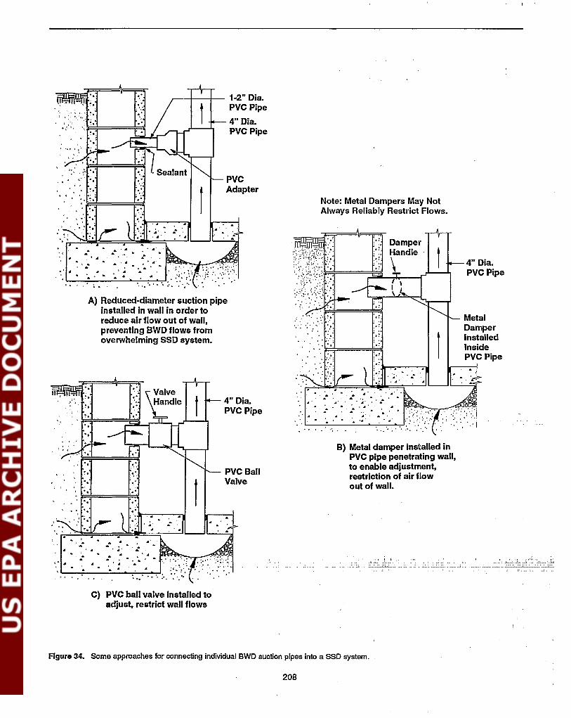
., Damper.,Handle:.:'\ 4" Dia.: :'.
PVC Pipe
.: Metal=.:" Damper: ..
f.: Installed:.;"
Inside.: PVC Pipe
.
B) Metal damper installed inPVC pipe penetrating wall,to enable adjustment,restriction of air flowout of wall.
.... ~.. ,;:.... . ... : . '. ~" .: .
Note: Metal Dampers May NotAlways Reliably Restl'ict Flows.
.' ..
.. -' '.' ... ' '.''.': ',.:': :!;..
~~~i,~i::r!=~~W;""'--r'1...-""l..~:.. : :.", .
PVCAdapter
4" Dia.PVC Pipe
..' .
,---f--l-- 1-2" Dia.PVC Pipe
,,.~,
",
A} Reduced-diameter suction pipeInstalled in wall in order toreduce air flow out of wall,preventing BWD flows fromoverwhelming SSD system.
, .. • A'. .... ~ .. .. ... '.. .. ..- ,
" .' ....
, ..
.. ':~~':::====i=~, '., .' -, -.
.' ... . .. . : ,
.. .':..:.. ..... -. pr'!'~ .L-~~~'!'-'Pl
~ ......• .. ~.. <It
"'1..-,_.-::-'-:-.-,-=---"--:0=.-.:-:.......r.. :" ..
"
", :;
~..."..
"~. ' "",",.,
C) PVC ball valve Installed toadjust, restrict wall flows
Figuro 34. Some approaches for connecting individual BWD suction pipes into a SSD system.
208
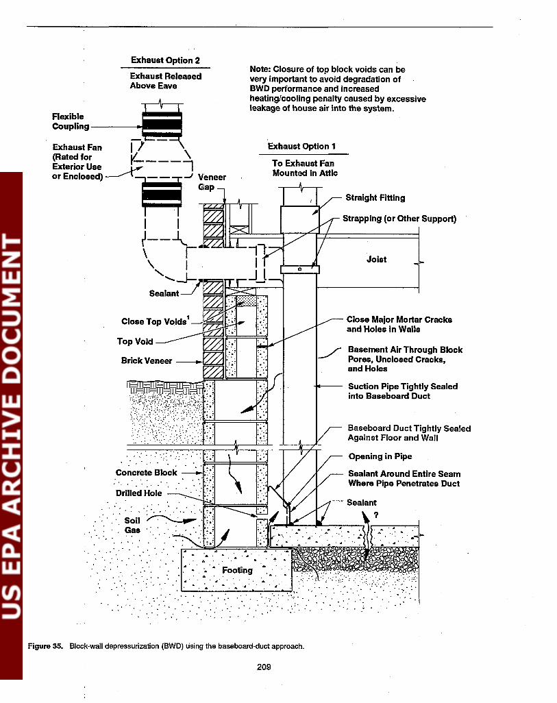
.' .. :. .
Joist
Baseboard Duct Tightly SealedAgainst Floor and Wall
Opening in Pipe
Sealant Around Entire SeamWhere Pipe Penetrates Duct
Suction Pipe Tightly Sealedinto Baseboard Duct
Basement Air Through BlockPores, Unclosed Cracks,and Holes
Close Major Mortar Cracksand Holes in Walls
Straight Fitting
Strapping (or Other Support)
o
To Exhaust FanMounted in Attic
Exhaust Option 1
Note: Closure of top block voids can bevery important to avoid degradation ofBWD performance and increasedheating/cooling penalty caused by excessiveleakage of house air into the system.
. .. .. ,. . ' ..;', ~
. ' ..... ' .
Exhaust Option 2
Exhaust ReleasedAbove Eave
Concrete Block~ ../.. .' ~ .'
Drilled Hole
: ,:.. ' ,'. : Soil~:"I'~':~.. ' Gas':' ... '.. ';.:
.....~;::..... ... ... •. .. .. ...•. f: ,;,\,;;i;;;!':~~~='::::;:t::::;i~=9::!::>==:~~ *~~~~llli. ..... . ... .....
" : .' . , .. ',. ~. . ~ ":' ', ..;', .....
Flexible ----1!!iCoupling-
Exhaust Fan iI-(Rated for V-- \Exterior Use~ ...,
or Enclosed) ~ -' :.~:~~~ee....,irh-...l\~"""'-
I I i
~--~ !\ r ....~ ~"'I.LJI. a....
\ I" ....... -.J--:l'ftj7;lU:..c..::;::.=j
Sealant
. ,,;. :
Figure 35. Block-wall depressurization (BWD) using the baseboard-duct approach.
209
proach-to drill holes around the perimeter and to seal thebaseboard duct onto the wall and slab-may be offset by theincreased effort required with the individual-pipe approach tomanifold together the large number of individual pipes thatmay be needed around the basement
Because of the nature of the baseboard duct installation, thisBWD variation is applicable only in basement houses.
Depressllrization vs. pressurizlltion. The discussion inSection 7 addresses the case where the block-wall treatmentsystems are operated in suction. Where block-wall treatmentis used in combination with SSD, operation in suction will bethe usual approach.
However, where block-wall treatment is used as a stand-alonemethod, the amount of air withdrawn from the basement bythe system may sometimes create sufficient basement depressurization to cause back-drafting of combustion appliances inthe basement. In such cases, the mitigator may wish to consider operation of the block-wall system to pressurize, ratherthan depressurize, the walls. Block-wall pressurization is discussed in Section 9.
TIle discussion in this section draws heavily from the detailedreview of available data on BWD systems, presented in Section 2.3.4.
7.1 Selection of the Number ofSuction Pipes7.1.1 Individual-Pipe Variation
Nllmber of sllction pipes per waU. With the individualpipe variation of BWD, each block wall that must be treatedwill probably require one or two suction pipes.
Suction drawn in the block cavities of one wall (e.g., the frontwall) will usually extend only weakly, if at all, around thecorners into the adjacent end walls, for two reasons. First, theflows from a wall are usually fairly high, because of theextensive leakage area inherent in block walls; for this reason,the suction and flow field inside a wall will not be able toextend very far. Second, the mason who laid the block duringconstruction could have applied the mortar and laid the blocksin a manner which inhibits the extension of the suction andflow field around the comer.
This S<'U11e concern exists when there is a discontinuity in onewall (i.e., a pair of corners in a wall which causes the wall tobe comprised of two parallel segments offset from eachother). In such cases, at least one suction pipe may be neededin each wall segment that is to be treated:
Because the block walls are so leaky, one often cannot relyupon a waIl cavity suction field extension test using a diagnostic vacuum cleaner (analogous to sub-slab suction fieldextension testing) to predict, prior to installation, when agiven wall will need more than one suction pipe. The high airflows from the wall will often overwhelm the vacuum cleaner,with the result that little apparent extension of the vacuum'ssuction field may be apparent, even in c~~ where only one
BWD suction pipe may turn out to be sufficient. As a rule ofthumb, in EPA's installations in Pennsylvania (ReS7, Sc88), asecond suction pipe was generally added whenever a wall waslonger than about 25 ft.
The need for a second pipe in a given wall will be greaterwhen that wall may be subject to particularly high air leakage.Features which could suggest high leakage include open topvoids which cannot be effectively closed, extenor brick veneer (creating an air gap as illustrated in Figure 5), and afireplace structure (which could conceal substantial leakageroutes that cannot be sealed).
Number ojwalls that must be treated. Having determinedthe number of suction pipes required for each wall that mustbe treated, the total number ofsuction pipes in a BWD systemwill then depend upon the number of walls requiring treatment. This issue is discussed more fully in Section 7.2.1 (seeSelection of the walls that must be treated).
When the BWD system is supplementing a SSD system, oneor two walls will usually be treated. At one to two pipes perwall, the total number ofsupplemental BWD pipes would thusbe one to four, most or all of which will usually be connectedto a nearby SSD pipe with a T fitting as in Figure 34.
When an in'dividual-pipe BWD system is installed as a standalone measure; all block walls which penetrate the slab mayneed to be treated. This would include the usual four perimeter walls, any discontinuities in the walls, any interior blockwalls and support structures, and, sometimes, the foundationwalls for a crawl-space wing that adjoins the basement. Astand~alone BWD system could thus have a total of four to tensuction pipes.
In a limited number of cases where one or two walls were theprimary radon entry routes into the house, stand-alone BWDsystems have reportedly been successful treating only thosewalls (Mes92). Thus, in best cases, one or two pipes haveoccasionally been sufficient in stand-alone systems.
When an individual-pipe BWD system is installed as a supplement to a SSD system, the number of SSD suction pipes willbe selected as discussed in Section 4.1. Usually, the number ofBWD pipes will then be selected as necessary to complementthe SSD system. In some cases, a tradeoff may be possible.The mitigator may choose to install an additional SSD pipe inan effort to prevent soil gas entry into a particular wall, ratherthan installing a BWD pipe in that wall, or vice-versa.
7.1.2 Baseboard Duct Variation
Vertical suction pipes. Usually, only one vertical suctionpipe penetrates the baseboard plenum, as illustrated in Figure35, if the plenum forms a largely continuous loop around thebasement perimeter. The baseboard is supposed to distributethe suction from this pipe to the walls around the entireperimeter.
If the baseboard duct cannot be continuous due to obstructionsor finish, and if the duct must be installed as two or moreisolated segments, then a suction pipe must penetrate each
210

segment. The ,suction pipes from the various isolated segments might be manifolded together, and directed to a singlefan. Or, the pipe from one or more of the isolated ductsegments might be directed to a second fan, as discussed inSections 7.4 and 7.6.
Even in cases where the baseboard duct is continuous, withoutisolated segments, it may sometimes be desirable to have asecond suction pipe penetrating the duct at a location remotefrom the frrst pipe. Because of the high flows expected in theduct, and the relatively small cross-section inside many commercially available pre-fabricated ducts, the suction loss inside the duct can be substantial. As a result, the suction insidethe duct at a point remote from a suction pipe may be quitelow (0.002 to 0.05 in. WG, or less). A second suction pipe,tapped into the duct on the opposite side of the basement fromthe frrst, could help increase the suction at the remote location, even if the second pipe is manifolded into the same fan asthe first. If the second pipe is connected to a second fan, theimprovement in suction would be greater.
Baseboard ducting. The preceding discussion concerningthe number ofsuction pipes has focused on the rigid PVC, PE,or ABS pipe that penetrates the baseboard duct and leads tothe fan (the vertical pipe labelled"Suction pipe" in Figure 35).However, the baseboard duct itself might be considered a"suction pipe," in the sense that it directs suction around thewall/floor joint.
Where there are no isolated segments of duct, the duct formsonly one "suction pipe." Isolated segments can be avoidedwhen the duct can form a continuous loop (an "0") or a nearlycontinuous loop (a "C," interrupted in only one location, e.g.,where there is a door or a fireplace structure in the basementwall). To avoid isolated segments, there would also have to beno isolated interior block walls/structures penetrating the slab,requiring a separate segment of duct.
Where isolated segments of duct 'are necessary, each segmentmight be considered a separate "suction pipe." As discussedpreviously, each such segment will also require a separatevertical PVC suction pipe.
7.2 Selection of Suction PipeLocation7.2. 1 Individual-Pipe Variation
Lateral position on the wall. If a single individual BWDsuction pipe is being installed into a wall, it would be generally logical to locate it near the horizontal center of the wall,
.midway between the two ends. However, if constraints (suchas basement ftnish) prevent it from being installed in thecenter, it should be acceptable to locate if off center. Likewise, if two suction pipes are being installed into a wall, theywould logically be placed about equidistant from each otherand from the ends of the wall, unless constraints dictateotherwise.
If one section of the wall seemed to contain higher radonconcentrations than the remainder of the wall, it would seemlogical to locate a suction pip~ in that section.
Where there is a discontinuity in a wall, one BWD suctionpipe would be installed on each side of the discontinuity, toensure that each wall segment would be treated. If there is afrreplace structure in a wall, potentially serving as a majorunclosable leakage source, a suction pipe in that wall might belocated near the frreplace structure.
If the BWD pipe is being installed as a supplement to a SSDsystem in a basement, the BWD pipe(s) in a given wall wouldnormally be installed immediately adjacent to a vertical SSDsuction pipe through the slab beside the wall, if possible, sothat the BWD pipe protruding horizontally out of the wall caneasily be T'd into the vertical SSD pipe.
Where possible, the exact location of a suction pipe would beselected to minimize the aesthetic impact (e.g., not in fmishedareas), and to minimize interference with house usage (e.g.,not blocking a usual traffic route).
Vertical position on the wall. In terms of the verticalpositioning of the BWD suction pipe on the wall, the suctionpipe should be located as near to the slab as possible, preferably in the first or second block above the slab. Placementclose to the basement slab should increase the possibility thatthe wall-cavity suction fteld will extend into the sub-slabregion, treating the wall/floor joint and other slab-relatedentry routes away from the wall. That is, it will maximize anySSD component that the BWD pipes might provide. In addition, location of the penetrations close to the slab should helpensure the best depressurization of the cavities in the footingregion, where most of the soil gas probably enters the voidnetwork.
Also, location of the individual BWD suction pipes near thebasement slab will reduce the height to which soil gas isdrawn up into the wall. This will potentially reduce theamount ofradon that might then be drawn into the house if thelow suctions being maintained in the voids by the BWDsystem were temporarily overwhelmed by homeowner orweather effects.
The BWD pipes use the wall cavities as a soil gas collector,drawing the gas up into the walls and out through the suctionpipes. But the suctions established inside the wall voids by thesystem are low, lower than the 0.01 to 0.15 in. WG measuredin the suction pipes. These low suctions are particularly .subject to being overwhelmed by the basement depressurizations that can be created by, e.g., changes in temperature andturning on exhaust fans such as in clothes driers. If the BWDpipes are high on the wall and are, in essence, fIlling thecavities with diluted soil gas, an overwhelming of the systemcould draw this soil gas into the house.
Sl!lection ojthe walls that must be treated-BWD as asupplement to SSD. In addition to the location of the pipesinstalled in a particular wall, another issue is which walls areselected to receive pipes.
Where an individual-pipe BWD component is being installedas a supplement to a SSD system, commonly only one or twoof the block walls are treated. The usual situation is that theSSD system is taking care of most of the slab-related entry
211

routes, and there are only one or two walls where the sub-slab radon into the house. In these apparently limited cases, it candepressurization is failing to adequately prevent soil gas entry be sufficient to treat only those specific walls (Mes92).into the wall cavities.
BWD components are usually added to SSD systems either: a)in cases where prior experience in similar houses (andperhapspre·rnitigation testing) suggests, prior to mitigation, that sucha component is needed; or b) in cases where an initial standalone SSD system has already been installed and has failed toachieve adequate radon reductions. Marginal or poor sub-slabcommunication, and very high radon concentrations in thesoil gas., are the conditions most likely to create a need for aBWD component.
In the former situation, where the possible need for thesupplemental BWD pipes is recognized prior to mitigation,the prior experience may suggest which walls could needtrentment. These could include, e.g., the wall beside an adjoining slab-on-grade garage, or the wall the deepest below gradein a walk-out basement. In some cases, selected pre-mitigation measurements (radon grab samples drawn from inside theblock cavities) might aid in the selection ofa wall to receive aBWD pipe. WaIls having pr~mitigation radon concentrationsgreater than some value would be selected for such directtreatment, because that wall thus appears to be a particularlyimportant entry route.
But there can be a problem with selecting walls based uponradon measurements in the cavities prior to mitigation. Theradon level in the wall is not necessarily a good indicator ofwhether the SSD system will adequately prevent entry of thatradon into the wall; the SSD system might take care of thatwall without a BWD component. Only in the unusual casewhere radon levels inside the wall are higher than those underthe slab, can one confidently conclude from such pre-mitigation measurements that there is an important source of radoninto that wall in addition to the sub-slab region. Where that isthe case. treatment of the sub-slab alone will probably notadequately treat that wall.
In the case where an initial SSD system is not doing the job,radon gmb sampling inside the wall cavities with the SSDsystem operating would indicate which walls are not beingadequately treated by SSD. These would be the walls selectedto receive BWD pipes.
Selection ofthe walls tlzat must be treated-BWD as astand-alone system. Where individual-pipe BWD is intended as a stand-alone mitigation option, it will sometimes benccess.'U)' to treat every block wall which penetrates the slab.This situation will arise when all of the walls are importantcntry routes. and where stand-alone BWD has been selectedrather than SSD, e.g., because of poor sub-slab communication. or because it is otherwise expected that SSD will notadequately treat the walls. In this situation, the need to treateach wall results because the high flows through the walls willreduce the extension of the suction and flow fields from onewall to the next, and because the suction field will not alwaysreliably tum the comers. .
In cases where all walls are important entry routes, it will benecessary to treat:
- Each of the four perimeter foundation walls. Even aperimeter wall that is largely above grade (such as theabove-grade wall in a walk-out basement) should generally be treated; it can still be serving as a conduit forsoil gas from the footing up into the basement, eventhough there is no soil in contact with the above-gradeportion of its exterior face.
- Each segment of each perimeter wall, in cases where adiscontinuity in the wall divides it into segments.
- Any interior block wall which penetrates the slab, e.g.,a load-bearing wall perpendicular to the front and rearwalls, dividing the basement into sections.
- Any interior block structure, such as a structure housing a fireplace in the basement, or supporting a frreplace on the floor above.
Where there is a slab-on-grade or crawl-space wing adjoiningthe basement, the block foundation walls associated with thatadjoining wing may also need to be treated, especially in caseswhere the void network in the walls for the adjoining wingdoes not link with the network in the basement walls.
Indoor vs. outdoor locations. In most cases in basementhouses, the individual BWD suction pipes are installed intothe wall from inside the basement, as illustrated in Figure 5.Indoor installation is generally simpler, at least when thebasement is not significantly fmished, and it minimizes thepiping visible from outdoors. Where the BWD pipes aresupplementing an interior SSD system, the BWD pipes willalways be indoors, so that they can easily be tied into the SSDpiping. The BWD pipes treating interior walls and structureswill necessarily always have to be indoors.
However, when a basement in heavily fmished (and when anySSD pipes are also installed from outdoors), the BWD pipesfor the perimeter foundation walls can be installed into theblocks from outdoors. Exterior installation would mean drilling into the block cores from outdoors rather than indoors. Itwould require excavating beside the exterior face of thebasement wall to expose the exterior face of the blocks at thelocation where the BWD pipe is to be installed. If the pipe isto penetrate the wall near the footing, this could mean anexcavation as deep as 5 to 8 ft. The individual exterior BWDpipes installed in this manner around the perimeter of thehouse could be extended vertically upward to near grade level,and manifolded together via a horizontal loop ofpiping buriedjust below grade level around the perimeter. Any exterior SSDpipes (penetrating horizontally through the foundation wallbelow slab level) could also be connected to this same pipingnetwork.
In other cases. stand-alone BWD will be selected because one Other considerations jor pipe location in basements.or two of the walls appear to be the primary entry route for the When individual BWD pipes are being installed from inside a
212

basement, some of the other considerations in selecting pipelocation will be similar to those discussed in Section 4.2.1regarding the location of interior SSD pipes. These· otherconsiderations include: location of the pipes in unfmished orinconspicuous areas where possible; location of the pipes inan effort to minimize interference with occupant traffic patterns (which should not usually be a problem) or with occupant usage of the space; location of the pipes to facilitatemanifolding of the multiple pipes together, in cases wherethey cannot be[tapped into an immediately adjacent SSD pipe;and location of the pipes away from any utility lines whichmay occasionally be inside the block cores (such as electricalconduits leading to electrical outlets in the block wall).
Consideratio~s for slabs on grades. Where individualBWD pipes are installed in a slab-on-grade house, they will beinstalled horizontally into the cores of the foundation stemwall from outdoors, near grade. In essentially all cases whereBWD pipes have been installed in a slab-on-grade house, theyhave been installed in conjunction with SSD pipes also beinginstalled horizontally through the foundation wall from outdoors. In such cases, it would appear logical to install theBWD pipes into the block cores just below the slab, at thesame level as· the SSD pipes. Such BWD pipes might beexpected to have the greatest benefit on foundalion stem wallswhich are largely below grade. In cases where the stem wallcomes above grade. because the slab is above grade, theamount of outdoor air drawn through the exterior face of theblock will probably be increased.
7.2.2 Baseboard Duct Variation
Vertical suction pipes. Where a single vertical PVC suctionpipe penetrates a continuous baseboard duct, this suction pipecan be located beside the foundation wall anywhere aroundthe basement perimeter. The location of this suction pipe canbe selected for convenient routing of the exhaust piping-i.e.,directly below a convenient route for an interior stack upthrough the living area above, or directly beside a convenientpoint for penetration through the band joist to an exteriorstack (e.g., at the rear of the house). It can be selected in anunfmished part of the basement.
Sometimes it is desirable to install a second (and maybe athird) suction pipe into a continuous baseboard duct, becausethe high flows from the walls can sometimes prevent thesuction field from one pipe from effectively extending throughthe duct around the entire perimeter. A second suction pipeshould be located approximately on the opposite side of thebasement from the first pipe. The exact location would beselected to avoid basement finish and other obstructions, andto facilitate the routing of the piping. If this second pipe is tobe manifolded together with the first, and both directed to asingle fan, the locations of the two pipes would be selected tofacilitate this manifolding. If the second pipe is to be routed toits own fan, its location would be selected to facilitate therouting of a second stack up through the house, or the routingof the piping through the band joist to a second exterior stack.
Where the baseboard ducting is interrupted, so that there aretwo or more isolated segments of ducting around the perimeter, there will have to be a vertical PVC suction pipe located
in .each of these isolated segments. Within the flexibilityprovided by the locations and extents of the segments, thesesuction pipes should be installed at locations in the segmentsthat facilitate manifolding the various pipes together, anddirecting them to one or two fans.
Baseboard ducting. Ideally, the baseboard ducting itself.should be installed over the wall/floor joint around the entirebasement perimeter, without interruption. In addition to beingthus installed on all four perimeter walls and around anydiscontinuities in these walls, it should also be installed onany interior block wall, and around any interior block structure (such as a frreplace structure), that penetrate the slab.
Complete coverage of the entire perimeter may not be necessary for adequate radon reduction, as long as there is asignificant segment ofducting along each block wall to ensurethat each wall receives some treatment. Among the obstructions that can cause interruptions in the ducting are: doorwaysthrough the block wall (e.g., in walk-out basements); frreplaces built into the wall; heavy interior finish or framing; andfurnaces, stairways, shower stalls, and other obstructions installed flush against (or very near to) the block wall.
The need for complete coverage of the perimeter by thebaseboard duct might be questioned. The individual-pipeBWD approach applies suction only to isolated points alongthe walls, not continuously around the perimeter. However,most testing of the baseboard approach to date has utilizednearly complete coverage. And, in the limited testing by EPAof very high-radon houses in Pennsylvania (Sc88), even withnearly complete coverage, these houses were not reliablyreduced below 4 pCi/L.
Many commercially installed baseboard duct BWD systemsare installed for the combined purpose of radon reduction andbasement water control (B188). Commercially available "baseboard ducting" has been on the market for basement watercontrol for many years, prior to the current concern aboutradon. Where the ducting has a water control as well as aradon control purpose, the need for ducting to be installed in acontiguous length may be mandatory, so that the collectedwater can flow through the duct, around the perimeter, to asump for discharge.
With interior block walls, where both faces of the wall areaccessible, installing the baseboard duct on just one facemight sometimes be sufficient. If the interior wall separates afmished portion of the basement from an unfinished area, theduct would conveniently be installed on the unfinishedside.
By the very nature of the system, the baseboard duct isinstalled over the wall/floor joint inside the basement. Thesuction on the wall-through holes drilled through the wall afew inches above the slab, enclosed within the duct-is thusapplied at the base of the wall. Applying the suction at thislocation: a) increases the potential that the BWD system willdevelop a suction field under the slab, creating a SSD component; b) increases the suction in the block cavities near thefooting, where much of the soil gas likely enters the voidnetwork; and c) reduces the height to which the system willdraw soil gas up into the wall, as discussed in Section 7.2.1.
213

Where the baseboard duct is also used for water drainage, andwhere a sump is thus also enclosed within the system, suctionon this sump increases the SSD component of the system.
7.3 Selection of Suction Pipe Typeand Diameter7.3.1 Individual-Pipe Variation
Type ojpiping. As with SSD and DTD systems~ the type ofpiping typicalIy used for individual-pipe BWD systems ,isrigid thin-walled or Schedule 40 PVC, PE, or ABS piping.
Pipe diameter-BlVD as a supplement to SSD. Theselection of the pipe diameter is influenced by the very highair flows that BWD pipes will draw out of the walls. In thelarge majority of cases, the substantial friction loss in thepiping, combined with the high flows, will result in quite lowsuctions in the block voids, even when the 90-watt tubular inline fans are employed.
In the most common case, where individual BWD pipes areinstalled as a supplement to a SSD system and are connectedto nearby vertical SSD suction pipes, reducing the diameter ofthe BWD pipe is one common option for restricting flows outof the walls. See Figure 34A, and the discussion'in Section7.5.1 regarding the need to restrict flows out of the walls incombined SSD+BWD systems. In the typical case illustratedin Figure 34A, the vertical SSD pipe is the usual 4 in.diameter, but the horizontal BWD pipe is 2 in. diameter.
However, as shown in Figures 34B and 34C, 4-in. piping canalso be used for the BWD leg in combined SSD+BWDsystems. Where 4-in. piping is used, a damper or valve iscommonly installed in the BWD pipe to restrict the flow fromthe wall.
Whichever of the approaches in Figure 34 is utilized, flowsfrom the walls are usually restricted adequately such that thereis no need to use piping larger than 4 in. for the remainder ofthe combined system. See Section 4.3.2 for discussion of theselection of pipe sizes for SSD systems.
Pipe diameter--BlVD as a stand-alone system. Whenindividual-pipe BWD is being used as a stand-alone methodas in Figure S, with no SSD component, restricting air flowfrom the walls is no longer an issue. For stand-alone systems,rodoo reduction performance will likely be improved if thewall flows are increased as necessary to achieve adequatesuction field distribution in, the void network. Thus, piping ofadequately large diameter should be selected.
EPA's limited experience with stand-alone BWD systemsindicates that, with a 9O-watt fan and 4-in. diameter individualsuction pipes in each wall, the flow in each pipe will typicallybe no more than about 50 cfm, sometimes less. At that flowrate, 4-in. piping can be used for the individual suction pipesinto the walls without suffering an unacceptable suction loss,especially since anyone suction pipe will probably extend nomore than 10 or 20 ft from the wall to a central trunk line(collector) running down the center of the basement. FromFigure 13, friction losses between the wall entry point and the
trunk line would be on the order of 0.05 in. WG or less underthese circumstances.
However, that central collector pipe will carry the combinedflow from all of the individual wall pipes, and can thus seeparticularly high flows. With 4-in. piping, the maximum flowthat would be generated by a 90-watt "270 cfm" tubular fan isabout 180 cfm, as discussed in Section 4.4.1. With 6-in.piping, flows as high as 200 cfm have been observed in BWDsystems.
At 180 cfm, the central collector pipe could sustain a frictionloss of about 0.75 in. WG down a 30- to 40-ft-long basementif the collector were simply a straight length of 4-in. piping(from Figure 13). ThIs loss would cause the fan to operateatadifferent point on its performance curve, significantly reduc-·ing the total system flows well below 180 cfm. As a result, thesuctions that would be being maintained in the walls woulddecrease significantly.
Thus, in the EPA installations, 6-in. diameter piping wasconsistently used for this high-flow central collector. With astraight 6-in. collector 30 to 40 ft long, the friction loss wouldbe only about 0.1 in. WG at 200 cfm. Accordingly, Figure 5shows a4-in. diameter wall suction pipe connecting to a 6-in.trunk line.
7.3.2 Baseboard Duct Variation
Vertical suction pipes. Commonly, the vertical suction pipethat penetrates the baseboard duct and extends up to the fan isPVC (or comparable) piping.
Some early research installations used sheet metal duetingextending up the basement wall for this purpose, in order toincrease the cross-section and thus reduce suction losses.However, such sheet metal ducting is more difficult to installand is difficult to seal effectively. It does not provide asufficient reduction in friction losses to compensate for thesecomplications. Thus, use ofPVC piping is now recommended.
Where a single vertical suction pipe is used to draw suction 01)
the baseboard duct at one location around the perimeter,experience suggests that flows in this pipe can be roughly 100cfm or more. (Exact flows will depend upon a variety ofvariables.) This flow is lower than the values that are sometimes seen in the trunk line of individual-pipe BWD installations (up to 200 cfm), because of the friction losses encountered inside the baseboard duct. At 100 cfm, 4-in. diameterpiping can probably be used, especially if the total piping runis only about 30 ft (e.g., extends relatively straight up from thebasement slab to the exhaust point at the root). In this case, thetotal suction loss would be on the order of 0.2 in. WG, anamount that could us~y be handled by a 90-watt fan.
Where a second or third suction pipe tap into the baseboardduct, 4-in. piping may still be sufficient, depending upon howthe piping is routed. If the piping connects directly to a secondfan, essentially identical to the frrst pipe, then 4-in. pipingcould again be adequate. If the piping from the second suctionpipe is going to be directed across the basement to manifoldinto the frrst fan, 4-in. piping might again be sufficient for the
214

roughly 20- to 40-ftpiping run across the basement, assumingagain a flow of about 100 cfm or less. But where the first andsecond pipes come together, the combined flow could becomesignificantly greater than 100 cfm. Thus, 6-in. piping could bewarranted downstream of the junction, including for the exhaust stack.
Because the high flows could sometimes warrant 6-in. diameter piping, Figure 35 shows all of the PVC piping as 6-in.piping.
Baseboard dueting. In most commercial BWD/baseboardduct installations, the base-board ducting consists of commercially available, pre-fabricated ducting composed of vinyl,ABS, or similarmaterial. This commercial ducting, which hasbeen marketed for years for basement water control purposes,is commonly sealed to the wall and slab using an epoxyadhesive. Figure 35 illustrates one version of such commercial ducting.
The commercial ducting shown in Figure 35 has a bottom thatcurves back toward the wall, and is cemented directly on topof the wall/floor joint. This configuration creates a vinylchannel inside the ducting, which can be helpful in channelling any water which enters the duct. Commercial channeldrains for water control would normally be considered forhouses which do not already have a perimeter channel (orcanal) drain in the form of a 1- to 2-in. wide wall/floor joint.The particular commercial drain shown in the figure would bea reasonable choice in cases where there is not a pre-existingperimeter canal.
However, when a baseboard duct system is being consideredfor radon mitigation, there may be cases where the baseboardapproach may be of interest in part because a perimeter canaldrain does already exist. In such cases, a commercial channeldrain having the cross-sectional configuration in Figure 35would cover the.canal, interfering with drainage into the canaland with extension of the baseboard duct suction field into thesub-slab region. Thus, where there is a pre-existing perimetercanal drain, OI)e may wish to use a commercial channel drainthat attaches to the slab a couple inches away from the wall, inorder to leave the canal open.
In some custom installations, the baseboard ducting has beenfabricated by the mitigator using sheet metal. 11le sheet metalduct would be attached to the wall and slab using masonryscrews and caulk. The metal duct can be fabricated. to createeither a rectangular or a triangular cross section when attachedto the wall. Fabrication of the ducting out of sheet metal hasthe advantage of enabling a much larger cross-sectional areainside the duct than is available with the relatively smallcommercial ducting, thus reducing friction losses. However,custom fabrication and installation of sheet metal ducting ismore difficult and time-consuming than is the use of thecommercially available ducting, and hence will usually bemuch more expensive. In addition, because it is larger and isnot pre-fabricated, the metal ducting will have a greateraesthetic impact.
Commercially available baseboard ducting is typically fairlysmall. It is commonly only 4 to 5 in. tall. As illustrated by the
example in Figure 35, it has a cross section that is not quiterectangular, creating an enclosure extending an average ofperhaps only 1 in. out from the wa11. Thus, when attached tothe slab and wa11, this ducting will have a cross sectiona1 areaof 4 to 5 in2 (equivalent to a round pipe having a diameter ofroughly 2.5 in.). Given the high flows that will come from the
. walls, the suction loss inside this duct will be substantial; theducting was designed to channel water and to be aesthetic, notto move air. The friction loss will significantly reduce thesuction that can be maintained in the duct, and the amount ofair that can be drawn out of the walls, unless one or moreadditional suction pipes are installed into the duct. However,since this low suction will be distributed around the entireperimeter by the ducting, and since the wa11/floor joint, amajor entry route, will be largely or entirely enclosed ·anddepressurized, a1beit to only a low level, these features mayhelp compensate for the low level of the suction.
Custom installations have utilized sheet metal ducts havingmuch larger cross sections, from 12 to 36 in2 (Sc88). The crosssectional area in these ducts would be equivalent to that in around pipe having a diameter of4 to 6.75 in., greatly reducingsuction loss compared to that in the commercial ducting.However, the larger ducts have a much greater aestheticimpact, as well as being more difficult to fabricate and install.And even with the larger baseboard ducting, the pressuresinside the ducting (with the system operated to pressurize thewall) were only 0.002 to 0.38 in. WG (and flows were 0.2 to96 cfm), depending upon proximity to a fan (Sc88, Fi91).
7.4 Selection of the Suction FanWith either the individual-pipe or the baseboard duct variations of the BWD approach, the high air flows expected fromthe walls will generally dictate that the fan be at least comparable to the 90-watt in-line tubular fans listed in Table 1.These fans can move up to 270 cfm at zero static pressure,although their practica1 maximum in BWD systems will probably be about 180 to 200+ cfm, depending upon the size ofpiping used. These fans will often be able to maintain adequate suctions at the wall suction hole, at the air flowsencountered and with the suction losses encountered in thepiping.
As discussed in Section 4.4, the 90-watt in-line tubular fans(Section 4.4.1) are generally recommended for stand-aloneSSD systems having good to poor sub-slab communication.Higher-suction blowers (Sections 4.4.2 and 4.4.3) can be anappropriate alternative when communication is margina1 topoor, and the smaller (50- to 70-watt) in-line tubular fans(Section 4.4.1) will sometimes be suitable when communication is good but flows are not excessively high.
When the SSD system is supplemented with a BWD component, the flows from the combined SSD+BWD system willtend to be higher than those from stand-alone SSD systems.This can be true despite the fact that steps have been taken torestrict air flows out of the walls, as illustrated in Figure 34.Because of these higher flows, the 50- to 70-watt tubular fanswill genera11y not be a good choice for such combined systems. Likewise, flows will very likely be too high for thehigh-suction/low-flow fans (Section 4.4.3). And flows will
215
, '

likely be high enough such that the radial blowers (Section4.4.2) would not be generating the higher suctions which isthe primary incentive for their use. Accordingly, the 90-watttubular fan will probably often be the logical choice for acombined SSD+BWD system.
With stand-alone BWD systems, total flows from the systems(when 9O-watt fans are used) are usually on the order of 100 to200 cfm, depending upon the pipe size. Suction in the systempiping immediately beside the walls is usually 0.1 to 0.4 in.WG or less, sometimes significantly less. Under these conditions, it is recommended that the fan always have a capabilityat 1c.'\St equal to that of the 90-watt in-line fans. In some cases,where the BWD system includes only a single fan, one of thehigh-flow lOO-watt fans listed in Table 1 (with 6-in. or even8-in. couplings) might be considered.
In some of EPA's research installations with the baseboardduct BWD variation, it has been found to be desirable to add asecond 90-watt fan, in order to maintain adequate suctions andflows in the duct around the entire perimeter. An additionalbenefit of the second fan was that where there were multipleisolated segments of baseboard ducting, it was sometimeseasier logistically to route the suction pipes from the segmentson one end ofthe house to a second fan, rather than attemptingto manifold all pipes to a single fan. This second benefit couldalso sometimes warrant a second fan in individual-pipe BWDinstallations, when it is not practical to run a single 6-in.conector pipe down the center of the basement to direct thecombined flow from all of the individual wall pipes to a singlefan. In any case, one or more of the suction pipes (from oneside of the house) would be directed to one of the fans, and theremaining suction pipes (from the other side) would be directed to the second fan.
7.5 Installation of Suction PipesInto the Block Walls7.5.1 Individual-Pipe Variation
A hole of the same diameter as the BWD suction pipe isprepared through one face ofa block at the location where theindividual pipe is to be installed. This hole would expose thecavity inside the particular block, and would not penetrate allthe way through to the other side of the wall. This hole wouldbe drilled through the inside face of the block wall, inside thebasement, in cases where the BWD pipes are to enter abasement wall from indoors. Or, it would be drilled throughthe outer face of the block, from outdoors, if the pipe is toenter a basement wall or a slab-on-grade foundation stem wallfrom outside the house.
The hole would be positioned on the selected block so that itpenetrated the face at the location ofa cavity. That is, it wouldnot at the location of one of the block's interior cross members. To judge the proper location, one must identify whetherthe blocks in that wall have two interior cavities, or three.Often, the top of some blocks will be exposed at some pointaround the basement, revealing how many cavities the blockscontain.
Commonly, a rotary hammer is used to prepare the hole intothe block, by drilling a series of l/2-in. holes in a circularpattern having the diameter of the BWD suction pipe. Becausethe block face over the cavity is thin, and because the concrete/aggregate mix used to fabricate the blocks is less densethan is solid concrete, drilling holes through the face of blockswith a rotary hammer is much simpler than is drilling suchholes through a 4-in. thick concrete slab, as discussed inSection 4.5.1. .
The BWD suction pipe is inserted horizontally, partway intothe block cavity. Mter this pipe is supported by connectioninto the remainder of the piping network (as illustrated inFigure 5 or 34), the gap between the block face and the pipe,around the pipe circumference, must be sealed. Gun-grade(non-flowable) polyurethane caulk should be worked into thegap to form a good seal. If this gap IS not sealed, air will leakthrough the gap, reducing the effectiveness of the BWDsyste"1. Because this gap will be immediately beside thesuction pipe, it will potentially have a greater impact than willother unsealed openings in the wall.
When individual BWD pipes are connected into a SSD system, it is usually necessary to restrict the air flows out of thewall, using a technique such as those illustrated in Figure 34.The reason for restricting the wall flow into the SSD+BWDsystem is that high flows from the BWD pipes would significantly reduce the suction that could be maintained in thesystem, including the SSD pipes. Thus, failure to restrict thewall pipes would significantly reduce the treatment of thesub-slab by the SSD system.
Of course, restricting the BWD pipes in this manner dramatically reduces the treatment of the walls. As discussed inSection 2.3.4, tests of such combined SSD+BWD systemshave commonly shown that the optimum approach in thesecases is to restrict the BWD flows, sacrificing some part of thewall treatment in order to maintain effective sub-slab treatment
One of the simplest, least expensive, and more widely utilizedmethods for restricting wall flow is to use smaller diameterpiping for the leg extenQing into the wall. Figure 34A illustrates this approach, for the case where 2-in. pipe has beenused for the wall and where the vertical SSD pipe is 4 in.diameter. For this configuration, 4-in. T fitting is installed intothe SSD riser adjacent to the wall hole, with the leg of the Tpointed horizontally toward the wall. A 4- to 2-in. adaptor atthe end of the T leg narrows down to accommodate the 2-in.pipe that then extends horizontally into the wall cavity. Because of the substantial suction loss in even such a shortlength of 2-in. piping, the use of the small-diameter pipingsignificantly reduces the flow out of the wall into the system.
Figure 34B shows the option of using 4-in. pipe for the wallleg, and of installing a damper in the leg to allow restriction offlows from the wall. Dampers are relatively inexpensive, andwould enable adjustment of wall flows after installation in aneffort to optimize system performance. However, some mitigators have reported that dampers are not always reliable(Kl92).
216

No attempt should be made to seal the wall/floor joint atlocations where the baseboard ducting will be installed overthe joint. Leaving the joint open will facilitate the extension ofthe ducting suction down into the sub-slab region, increasingany SSD component of the system. Where the baseboard doesnot cover the entire length of the wall/floor joint, and wherethat joint is a 1- to 2-in. wide perimeter channel drain, thechannel drain opening beneath the baseboard must be sealedin some appropriate manner at the point where the baseboardends, so that basement air is not drawn into the baseboard ductthrough the open perinleter channel drain beneath the end ofthe baseboard.
In other cases, the baseboard ducting might connect to thesump by a configuration other than that shown in Figure 36. Insuch other cases, it might sometimes be preferred for thesuction pipe to penetrate the sump cover, in a manner such asillustrated in Figure 33 and discussed in Section 5.5.2.
An installation such as the one in Figure 36 has a major SSDcomponent by virtue of the suction on the sump. This SSDcomponent can be more important than the BWD component.
An added concern is that when holes are drilled through theinterior face of the block wall near the slab, basements that didnot originally have a serious water problem may begin to haveone. Water flowing through the block cavities during wetperiods, which previously might have drained largely to thesub-sIal) region via the base of the wall, might now flow intothe baseboard ducting through the holes. To avoid claims thatthe mitigation system has negatively impacted the drainagefeatures of the house, it might sometimes be advisable toinstall a sump and sump pump system as an integral part of thebaseboard duct system, to handle any such drainage in caseswhere water problems might occur.
Baseboard ducting. Prior to the installation of the baseboard ducting, holes of about 1/2 in. diameter are drilled
. through the interior face of the blocks, into the cavities, at alllocations where the ducting is to be installed. These holeswould usually be in the frrst course of block above the slab,within 4 in. of the slab, so that the will be enclosed within thebaseboard ducting. These holes·pennit the suction from thedepressurization system to extend into the void network unifonnly around the perimeter. In EPA's testing of baseboardduct BWD systems (Sc88), as well as in commercial systems(E188), such holes have usually been drilled into every cavityof every block.
7.5.2 Baseboard Duct Variation
Alternatively, as illustrated in Figure 35, a hole could be cut inthe baseboard ducting to accommodate the suction pipe. Thepipe is installed vertically, almost flush against the foundationwall, fitting into the hole cut in the ducting. At the base of thevertical pipe, against the slab, a section of the pipe within theducting would be cut away, providing an opening between thesuction pipe and the interior of the baseboard ducting.
In many cases, commercial baseboard duct systems are installed for the combined purposes of basement water controland of radon reduction. The need for water control may oftenbe a factor in the decision to install a baseboard duct BWDsystem in the first place. Where water control is also anobjective, a sump and sump pump will commonly have to beretrofit into the house as part of the system, to handle thecollected water. (The need for water control and for a retrofit .sump will usually not exist in houses having a pre"existingperimeter channel (canal) drain.)
By this latter approach, the junction between the PVC suctionpipe and the baseboard ducting would then have to be sealedvery well, with gun-grade polyurethane caulk or other appropriate sealant The base of the vertical pipe, where it rests onthe slab, would have to be effectively sealed against the slabwith polyurethane caulk. Alternatively, an end cap could becemented onto the base of this pipe. And the seam betweenthe pipe and the baseboard duct must be sealed.
Unlike vertical SSD pipes, where the pipepenetration throughthe slab tends to anchor the pipe against lateral movementcaused by physical impact, the vertical suction pipe in baseboard duct BWD systems is resting on top of the slab, and hasonly the caulk bead at its base to prevent lateral movement.This pipe should be attached firmly to the wall using brackets,in order to reduce the risk that it will be jarred and the seals atits base broken.
Use of a PVC ball valve, as illustrated in Figure 34C, alsopennits adjustment of flows after installation, and offers thefurther advantage of being more reliable than the use of adamper. However, PVC valves are relatively expensive.
:
Vertical suction pipes-where a sump is present. Thepreceding disc!Jssion addresses the case where the baseboardduct does not connect to a sump. Where there is a sump, thevertical suction pipe can be installed in the capped sump,rather than as described above.
Vertical suction pipes-where no sump is present.Some manufacturers of channel drain market a speciallydesigned segment of baseboard ducting, designed to easilyaccommodate a vertical PVC suction pipe. Such a segmentwould be installed into the baseboard loop at the one or morelocations where a vertical PVC suction pipe is to be installedinto the baseboard ducting. The suction pipe would then be· Figure 36 illustrates an approach used by one vendor in casescemented into the fitting in this segment, providing an air-tight , where combined water control and radon mitigation are to beseal. Where such connection segments are available, this achieved with a baseboard duct system and a retrofit sumpwould be the preferred approach for connecting the suction (E188). In this configuration, a single PVC pipe serves both aspipe into the baseboard. the conduit for collected water from the baseboard ducting to
the sump, and also as the pipe by which suction is drawn onboth the baseboard ducting and the sump. To install this pipeand the new sump, of course, a section of the slab would haveto be removed and then restored after installation. The sumpmust be fitted with an air-tight cover, as discussed in Section5.5.2.
217

BaseboardDuct
Gasket
RetrofitSump Liner
Perforations inSide of Sump Liner,to Allow SuctionField to Extendinto Sub-Slab 'Regio'n '(ProvidingSSD Component)
~.-..
SoliGas
Opening in Suction Pipe,Inside Baseboard Duct
Soli Gas from SubSlab Region EnteringSuction Pipe ..I
Water from BaseboardDuct Entering Slimp .
. ,. .. ~~';;",,~ ;. ,. .. .
t ~ II> ,"'
., .
ConcreteBlock ~.'~. .:....~;;V;"":.·r~rl·~.r\ -,----.h-,.-JIJI-J
, I ~ '. • •
~ .., . ..
. ,
, . .
".,' ...... ,... . "',. "" ... ': ,-Drilled '.'.; ;Hole '. .' .' .. ',
,,' .. II- • • .", ,*,. ' ••t' .:,' ~". .... .... ." . ':.
S~lI :"~::~'~~':====:;~Gas·, " .•
,.:;:. ".' :. <: '~.;fl •• • • ~.. . ,, . '.". "'", .".. ." ..
to .... • , ....... •.. .. <.. .., ::. " ... ', ....... ., ~'.' '. : '...
l> ~~ .. ""::.,., "," .. " .. ' ~ ~ 0" <, .. •.. ' ., ... '..
, I ,"
Flguro 36. One spec/fie example of a baseboard duct BWD configuration with a major SSD component, for the case where a sump and sumppump are installed as part of the radon mitigation system. (Safe-Aire, Inc.)
The baseboard ducting must be attached to the slab and wall,fonning an air-tight seal over the wall holes and the wall/floorjoint. Where commercially available vinyl or ABS ducting isused, the ducting is usually bonded to the wall using epoxy orother adhesive. The surface of the wall and slab should becleaned and abraded first, to improve adhesion. If sheet metalducting were used, the metal ducting wouldbeanchored to thewall and slab with masonry screws, through flanges incorporated into the ducting for this purpose. The metal ductingwould be sealed against the wall and slab with a continuousbead of gun-grade polyurethane caulk between the flange andthe concrete. The masonry screws alone would not provide anadequate seal. When the slab contains irregularities, specialcare and additional caulking will be needed to ensure a goodseal.
Commercially available ducting is marketed in pre-fabricated5- to lO-ft lengths. Butt-joint fittings, having the samecross-sectional configuration as the ducting, are used (withsealant) to join lengths of straight ducting. Specialpre-fabricated sections of ducting ean sometimes be obtainedto turn inside or outside comers. Where these comer sectionsdo not form an integral piece, the mitered junction at thecomer must be sealed carefully, Where the ducting must beinterrupted, end-cap fittings are available to seal the open end.As indicated above, where the baseboard dueting is beingsealed over a perimeter channel drain, the gap between theopen drain and the base of the baseboard must be sealed atends.
218
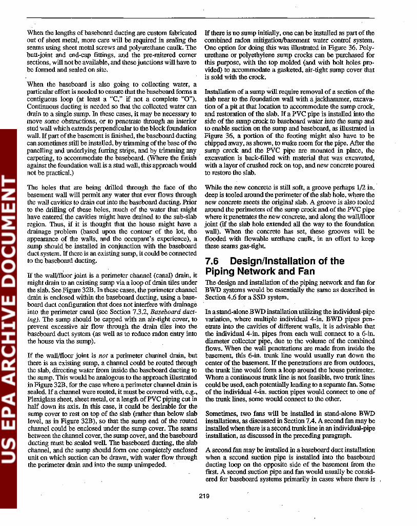
When the lengths of baseboard ducting are custom fabricatedout of sheet metal, more care will be required in sealing theseams using sheet metal screws and polyurethane caulk. Thebutt-joint and end-cap fittings, and the pre-mitered comersections, will not be available, and these junctions will have tobe formed and sealed on site.
When the baseboard is also going to collecting water, aparticular effort is needed to ensure that the baseboard forms acontiguous loop (at least a "C," if not a complete "0").Continuous ducting is needed so that the collected water candrain to a single sump. In these cases, it may be necessary tomove some obstructions, or to penetrate through an interiorstud wall which extends perpendicular to the block foundationwall. Ifpart of the basement is finished, the baseboard ductingcan sometimes still be installed, by trimming of the base of thepanelling and underlying furring strips, and by trimming anycarpeting, to accommodate the baseboard. (Where the fmishagainst the foundation wall is a stud wall, this approach wouldnot be practical.)
The holes that are being drilled through i1he face of thebasement wall will permit any water that ever flows throughthe wall cavities to drain out into the baseboard ducting. Priorto the drilling of these holes, much of the water that mighthave entered the cavities might have drained to the sub-slabregion. Thus, if it is thought that the house might have adrainage problem (based upon the contour of the lot, theappearance of the walls, and the occupant's experience), asump should be installed in conjunction with the baseboardduct system. If there is an existing sump, it could be connectedto the baseboard ducting.
If the walVfloor joint is a perimeter channel (canal) drain, itmight drain to an existing sump via a loop of drain tiles underthe slab. SeeFigure 32B. In these cases, the perimeter channeldrain is enclosed within the baseboard ducting, using a baseboard duct c<;mfiguration that does not interfere with drainageinto the perimeter canal (see Section 7.3.2, Baseboard ducting). The sump should be capped with an air-tight cover, toprevent excessive air flow through the drain tiles into thebaseboard duct system (as well as to reduce radon entry intothe house via the sump).
If the wall/floor joint is not a perimeter channel drain, butthere is an existing sump, a channel could be routed throughthe slab, directing water from inside the baseboard ducting tothe sump. This would be analogous to the approach illustratedin Figure 32B, for the case where a perimeter channel drain issealed. If a channel were routed, it must be covered with, e.g.,Plexiglass sheet, sheet metal, or a length ofPVC piping cut inhalf down its axis. In this case, it eQuId be desirable for thesump cover to rest on top of the slab (rather than below slablevel, as in Figure 32B), so that the sump end of the routedchannel could be enclosed under the sump cover. The seamsbetween the channel cover, the sump cover, and the baseboardducting must be sealed well. The baseboard ducting, the slabchannel, and the sump should form one completely enclosedunit on which suction can be drawn, with water flow throughthe perimeter drain and into the sump unimpeded.
If there is no sump initially, one can be installed as part of thecombined radon mitigation{basement water control system.One option for doing this was illustrated in Figure 36. Polyurethane or polyethylene sump crocks can be purchased forthis purpose, with the top molded (and with bolt holes provided) to accommodate a gasketed, air-tight sump cover thatis sold with the crock.
Installation of a sump will require removal of a section of theslab near to the foundation wall with a jackhammer, excavation of a pit at that location to accommodate the sump crock,and restoration of the slab. If a PVC pipe is installed into theside of the sump crock to baseboard water into the sump andto enable suction on the sump and baseboard, as illustrated inFigure 36, a portion of tb,e footing might also have to bechipped away, as shown, to make room for the pipe. After thesump crock and the PVC pipe are mounted in place, theexcavation is back-filled with material that was excavated,with a layer of crushed rock on top, and new concrete pouredto restore the slab.
While the new concrete is still soft, a groove perhaps 1/2 in..deep is tooled around the perimeter of the slab hole, where thenew concrete meets the original slab. A groove is also tooledaround the perimeters of the sump crock and of the PVC pipewhere it penetrates the new concrete, and along the wall/floorjoint (if the slab hole extended all the way to the foundationwall). When the concrete has set, these grooves will beflooded with flowable urethane caulk, in an effort to keepthese seams gas-tight.
7.6 Design/Installation of thePiping Network and FanThe design and installation of the piping network and fan forBWD systems would be essentially the same as described inSection 4.6 for a SSD system.
In a stand-alone BWD installation utilizing the individual-pipevariation, where multiple individual 4-in. BWD pipes penetrate into the cavities of different walls, it is advisable thatthe individual 4-in. pipes from each wall connect to a 6-in.diameter collector pipe, due to the volume of the combinedflows. When the wall penetrations are made from inside thebasement, this 6-in. trunk line would usually run down thecenter of the basement. If the penetrations are from outdoors,the trunk line would form a loop around the house perimeter.Where a continuous trunk line is not feasible, two trunk linescouldbe used, each potentially leading to a separate fan. Someof the individual 4-in. suction pipes would connect to one ofthe trunk lines, some would connect to the other.
Sometimes, two fans will be installed in stand-alone BWDinstallations, as discussed in Section 7.4. A second fan may beinstalled when there is a second trunk line in an individual-pipeinstallation, as discussed in the preceding paragraph.
A second fan may be installed in a baseboard duct installationwhen a second suction pipe is installed into the baseboardducting loop on the opposite side of the basement from thefIrSt. A second suction pipe and fan would usually be considered for baseboard systems primarily in cases where there is ,
219

no sump adding a major SSD component to the baseboardsystem.
When two fans nre used, each fan and exhaust system wouldbe installed as an independent unit, with all of the considerations discussed in Section 4.6 applying to each one.
Because of the large air flows drawn from the block walls bystand-alone BWD systems, the radon concentration in theexhaust is usually much lower than that observed from SSDsystems. This could impact decisions on design of the exhaustpiping.
TIle suction pipes leading to the fans will be 6 in. diameter insome cases, as discussed in Section 7.3. As indicated inSection 4.6.2, where a pipe penetrates the bandjoist (which issupported underneath by the foundation wall), at least 2 in. ofwood must always remain between the hole and both the topand the bottom of the joist. Thus, the 6-in. suction pipe couldbe installed through a 2- by lO-in. band joist, provided thehole is cut exactly in the center of the joist. A 6-in. pipe could .1Iot be installed through a 2- by 8-in. band joist. And a 6-in.pipe could never be installed through floor joists which arenot supported underneath. For such unsupported members,the rule is that the diameter of the hole must not be greaterthan one-third the height of the member; a 6-in. hole would bemore thrm one-third the height of a typical 2- by lO-in. joist(or even of a 2- by 12-in. joist).
7.7 Wall and Slab Sealing inConjunction with BWD SystemsSealing of major block wall openings can be crucial in theapplication of BWD systems. The block walls are inherentlyleaky, and significant amounts of air will leak into the BWDsystem regardless of the sealing effort that is undertaken.However, failure to close certain major opening (such as theopen voids in the top course of block) can result in suchexcessive air leakage that the ability to the BWD system totreat the wall can be compromised.
It is also recommended that major slab openings be sealed. Astand-alone BWD system can sometimes extend a weak suction field beneath the slab. Failure to close a wide wall/floorjoint could prevent any suction from reaching the sub-slabregion. Since BWD systems will not reliably treat entry routestoward the interior of the slab, the need to seal such interiorroutes in conjunction with stand-alone BWD systems will beincreased. With major slab-related entry routes, such as untrapped floor drains, sealing (or trapping) these major openings is generally good practice in any event, to reduce potentially significant soil gas entry if not aid in suction fieldextension. And finally, with some baseboard duct installations, sealing of sumps is an integral part of the installation.
7.7.1 Wall Openings
Operz voids in the wp course oj block. One of the mostcrucial openings in block walls to close in conjunction withBWD is the open voids in the top course of block in the wall,in cases where the wall is not constructed with a course ofsolid cap block on top.
These top voids are more accessible for closure in some casesthan in others, depending upon the construction features of theparticular house. Inability to close the open top voids will notalways render BWD completely inapplicable, but it can seriously detract from the performance of the system, and canmake indoor radon levels more subject to increases whenweather conditions or the. usage of depressurizing applianceschallenge the system. It may also increase the house heating!cooling penalty, and the risk of back-drafting combustionappliances in the basement. In addition, failure to close the topvoids enables the block wall void network to continue to serveas a chimney for soil gas flow up into the house, at thoselocations where the BWD system is unable to adequatelydepressurize the cavities.
Figures 37A and 37B illustrate two approaches for closing thetop voids, depending upon accessibility.
Where the dimensions of the block and of the sill plate aresuch that one to several inches of the open void are exposed,as in Figure 37A, there is sufficient accessibility such that thetop voids can be sealed from above with mortar or withexpandable closed--cell, one- or two-component urethane foam.To prevent the mortar or foam from dropping down into theblock cavities, some suitable support can be forced down intoeach individual void, if necessary, leaving a depth of about 2in. for the mortar or foam which is then applied above thesupport. Where codes prevent crumpled newspaper from being used as such a support, insulation material could be onesuitable alternative. A rapidly expanding, quick-setting foammight be applicable without any support underneath.
If several inches .of the void are exposed, mortar can beconsidered to close the top voids. Mortar may have a lowermaterials cost than foam, but will be much moretime-consuming to apply. When mortar is used, it is crucialthat the mortar be forced all the way to the far face of the voidunder the sill plate, to ensure that the entire void is closed. SeeFigure 37A.
When only an inch or two of the top void is exposed, there isnot sufficient room to accommodate a person's hand into thevoid. Mortar is thus no longer an option, because it could notbe reliably spread to the far face of the void under the sillplate. In these cases, expandable foams must be used.
Expandable foams are obtained in 12- to 24-oz. aerosol spraycans (for small jobs), or in compressed cylinders up to 16 lb.(likely required when an entire course of blocks is to besealed). Foams can be applied directly from the can, or can beinjected through a hand-held wand or nozzle connected to thecontainer with a hose. The wand or nozzle can be inserted intothe small opening accessible under the sill plate, injecting thefoam in a manner which will effectively seal the entire void.The foam should initially be directed toward the far face of thevoid, again to ensure that the entire void is sealed.
This sealing effort must be applied to every void in the topcourse of block.
In the majority of cases, the dimensions of the block and sillplate will be such that less than an inch of the top void will be
220

Siding
Sheathing
Wallboard
Floor
Floor J()ist
11/1-__-----+---- Band Joist
~-------11---Sill Plate
Sill Plate
Caulk
Brick VeneerSheathing
Floor Joist
~----+---Drilled Access .Hole ThroughBand Joist
Closure Plate
12 In.
C) One option for closing gapbetween exterior brick veneerand interior block and sheathing.
Foam toClose VeneerGap
Foam or Mortarto Close Void
Support for FoamlMortar if Needed
Caulk or F:oam
Top Void
; .Top Void
A) Closure of top voidwhen void is reasonably.accessible.
U'J4:;===f-- Sill Plate
....>: 121n.
... .
.= .~ ~ • '
.: .;: 8 In. :;.~.
B) One option for closureof top void when afraction of an inch ofthe void is exposed.
Figure 37. Some options for closing major wall openings at the top of block foundation walls, in conjunction with BWD systems.
221

exposed, if any of the void is exposed at all. In such cases, itwill be impractical or impossible to force support materialdown into the cavities. Without such supporting material, itcould be more difficult to get foam to effectively close the topvoids. since large amounts of foam might drop down into thecavities below. Where none of the void is exposed, there is anadditional complication, in that the cavity is not accessibleother than by drilling through the block face or sill plate.
Where at least a fraction of an inch of the void is exposed, afoam nozzle could be inserted into the void. If a rapidlyexpanding. quick-setting foam is used, it may successfullyseal the entire top void. despite the lack of any supportunderneath. Another option might be to drill a hole into eachcavity, through the face of the block just below the top of thewall; some type ofsupport for the foam could then be insertedthrough this hole.
If this ... is unsuccessful. efforts could focus on sealing thefraction-of-an-inch opening between the sill plate and thefoundation wall. as illustrated in Figure 37B. This approachseals that portion of the top void that is accessible, and reliesupon the sill plate to serve as at least a partial cap on theportion which is inaccessible. Expanding foam applied on topof the wall. beside the sill plate, is one material that might beused to seal this gap. Or. a small strip of wood might be sealedagainst the sill plate and the foundation wall using beads ofpolyurethane caulk.
Where none of the top void is visible, foam could be injectedinto each top cavity through a hole drilled in the face of theblock. If the foam did not expand rapidly enough to avoiddropping into the cavities below, one suggestion has been todrill a second hole below each injection hole, then insertingsome type of support through the lower hole. Alternatively,the seam between the sill plate and the foundation wall mightbe caulked with gun-grade polyurethane caulk, in an effort toimprove the ability of the sill plate to serve as a cap for the topvoids.
Reliance on the sill plate as a cap for the top voids, in themanner indicated in the preceding two paragraphs, is lesseffe·ctive than would be successful injection of foam into theblock cavities. TIle inaccessible outside seam between the sillplate and the block is left uncaulked, and the sill plate wouldthus be expected to be a leaky cap. However, use of the sillplate saves a lot of time and expense. It has seemed to besufficient in a few of the EPA study houses in Pennsylvaniawhere stnnd-nlone BWD systems were tested (He87, Sc88);however, in other cases, two fans were required and/or radonlevels were not reliably reduced below 4 pCi/L.
Firtplace structures. Fireplace structures incorporated intoblock walls offer the potential for large and inaccessibleopenings within the structure. For example, there may be asubstantial gap between the actual fireplace insert (and thenue) inside the structure, and the blocks which form the outerwalls of the structure. Such a gap could extend to above theb.'lSemcnt, serving as a thennaJ and air-flow bypass to theuppe.r levels of the house. Thus, even when the top voids inthe remainder of the block foundation wall itself can besealed, large amounts of air from the basement, the upstairs,
and outdoors could leak into the BWD system via this inaccessible opening.
There is no practical way to seal such openings within fIreplace structures. The frreplace/chimney structure would haveto be torn down and rebuilt. Where such a structure exists,additional BWD suction pipes near the structure, and perhapsincreased fan capacity, might be considered to compensate forthe expected leakage. Supplementing the BWD pipes withSSD should also be considered. The EPA study houses inPennsylvania in which stand-alone BWD systems gave thepoorest performance generally had frreplace structures (He87,Sc88).
Gap associated with brick velleer. In houses having exterior brick veneer, a gap occurs between the veneer and thesheathing and block behind the veneer. This gap is depicted inFigure 37C. This gap could sometimes serve as an importantsource of air leakage into the BWD system, with outside airand house air being drawn down through that gap (e.g., fromthe eaves where the veneer ends, or from house air leakagethrough the sheathing on the floors above).
In an effort to seal this gap, it would be necessary to drill intothe gap at intervals (probably through the band joist, asillustrated in Figure 37C), and to inject closed-cell urethanefoam through the drilled holes via a hose/nozzle from acompressed cylinder.
It is not clear from available data under what conditions it willbe cost-effective to try to seal the veneer gap in this manner.Reasonably good BWD performance has sometimes beenachieved even in brick-veneer houses where this gap was notclosed.
Major ami illtermediate holes through the block wall.Any major openings through the block wall must be sealed.Such major openings would include, for example, partiallymissing blocks in cases where there is some major penetrationhas been installed through the wall. Intermediate openingsshould also be sealed. These would include, e.g., modest gapsaround utility line penetrations, chinks in the blocks, andplaces where signifIcant amounts of mortar have fallen out ofmortar joints.
Block pores. While the pores in the blocks are small, theycover the entire face of the wall, and hence can add up to asubstantial leakage area. However, they are difficult andexpensive to seal, requiring that the entire face of the wall bepainted or coated. Tests have shown that the porosity ofblocks can vary by an order of magnitude, depending uponhow they were manufactured (Ru91). A variety of coatingscan reduce this porosity by 95% or more, including, e.g.,epoxy paints and cementitious block filler. With standardlatex paint, three coats were found to be needed in order toreduce air-flow through the wall by more than 95% (Ru91).
If the basement were unfinished and the walls thus readilyaccessible, the cost ofpainting the walls in a typical basementwas estimated to cost about $400-$1,000, depending upon thecoating used, including labor and materials. This would increase the cost ofa BWD installation by about 20-70%. Ifpart
222

or all of the basement were finished, and if finish thus had tobe removed and replaced as part of the coating effort, the costcould be significantly higher.
It is not clear under what conditions it is cost-effective to tryto seal the block pores, in view of the expense and potentialcomplications involved in coating the basement walls. In theEPA testing of stand-alone BWD systems in Pennsylvania, itwas not apparent that sealing of the block pores was necessaryin order to get adequate BWD performance, although nodefinitive tests were carried out in order to quantify thebenefits that such sealing would have provided. In only one ofthe EPA study houses, which had very porous cinder blockwalls, were the block pores sealed (by coating the entireinterior face of the walls with a waterproofing paint).
7.7.2 Slab Openings
Perimeter channel drains. With stand-alone BWD systems, proper closure of perimeter channel drains can be evenmore important than it is with SSD systems (see Section4.7.1). BWD systems will sometimes extend only a relativelyweak depressurization beneath the slab. A wide gap betweenthe slab and wall will permit so much air leakage into thesystem at that point that any extension of the wall suction fieldinto the sub-slab region will probably be elinlinated.
With the individual-pipe BWD approach, the pelimeter channel drain should be closed as discussed in Section 4.7.1.
With the baseboard duct BWD approach, which is the BWDapproach most likely to be selected when a perimeter channeldrain is present, the perimeter drain will be sealed by enclosure within the baseboard ducting. Any sump associated withthe perimeter channel drain will also be capped as part of theBWD installation, as discussed in Section 7.5.2 (see Baseboard ducting). The perimeter channel drain would not becaulked or mortared shut at locations where it was going to becovered by the baseboard ducting, since the open channelbeneath the baseboard could add a significant SSD componentto the system.
If a portion of the perimeter channel drain cannot be coveredwith baseboard ducting in a baseboard duct BWD installation,judgement will have to be utilized in determining how to sealthis uncovered segment. Often, if it cannot be covered by thebaseboard ducting, it may be too inaccessible for sealing. As aminimum, the opening in the slab will have to be sealedimmediately under the end of the ducting, so Ithat basement airwill not flow through this channel into the ducting. Uncoveredsections of the perimeter channel drain could be sealed usingthe techniques discussed in Section 4.7.1.
Wallljloorjoint (when not a perimeter channel drain).Where the wall/floor joint is covered by baseboard ducting, itshould always be left uncaulked, to increase the possible SSD
component that the baseboard duct BWD system might provide. However, uncovered sections of the wall/floor jointshould be caulked as discussed in Section 4.7.5, whenever it iswider than a hairline crack. This might be particularly important with stand-alone individual-pipe BWD systems, to helpthe wall suction extend beneath the slab.
Other major and intermediate holes through the slab.Other major holes through the slab, such as openings aroundbathtub plumbing, sections of missing slab, and other miscellaneous major openings should be sealed, as discussed inSection 4.7.2, to aid in the distribution of the BWD suctionfield to points under the slab remote from the walls. Likewise,intermediate slab openings, such as expansion joints andsmall slab holes (in addition to the wall/floor joint, discussedpreviously), should be sealed whenever accessible, as discussed in Section 4.7.5.
Untrapped floor drains. Untrapped floor drains should beaddressed as discussed in Section 4.7.3. Trapping these drainsmay aid in distribution of the weak BWD suction field beneath the slab, and will prevent continued soil gas entry intothe house through the drain.
Sumps. Where an existing sump with drain tiles is present ina basement,' a sump/DTD system will often be the ASDapproach selected for that house. Where a stand-alone BWDsystem is selected for a house with a sump, it will commonlybe because there is a perimeter channel drain draining tosub-slab drain tiles which empty into the sump. In such cases, .the baseboard duct BWD approach will often be selected, andthe sump will be enclosed as part of the BWD installation, asdiscussed in Section 7.5.2.
If for any reason a sump exists that is not being incorporatedinto the BWD system, that sump should be capped with anair-tight cover.
7.8 Gauges/Alarms and LabellingThe considerations discussed in Section4.8, concerning gauges/alarms and labelling for SSD systems, also apply to BWDsystems.
Because of the high air flows from the block walls, a pressuregauge on a stand-alone BWD system can register lowersuctions than gauges on SSD or DID systems. However, ifthe gauge is located near the fan, and if there is a significantpiping run associated with the BWD system, the gauge maystill provide a reasonably high reading. Due to potentiallyhigh suction losses common in the piping for stand-aloneBWD systems, resulting from the high flows, the fan willhave to maintain a fairly high suction in the piping immediately beside the fan in order to maintain a relatively lowsuction in individual pipes near their penetration into the wall,or in the baseboard ducting.
223


Section 8Design and Installation of Active
Sub-Membrane Depressurization Systems
Where the house is built over an earthen- or gravel-flooredclawl space, and where the clawl space is largely or entirelyaccessible, SMD is the applicable variation of the ASD technology. In effect, a "slab" of polyethylene sheeting is beinglaid over the exposed soil floor, and the region beneath this"slab" is being depressurized, analogous to SSD or DTD. SeeFigures 6 and 7.
Depressurization beneath a membrane over the crawl-spacefloor appears to be generally more effective at reducing radonconcentrntions. in the living area than is forced ventilation!depressurization of the entire crawl space, and distinctly moreeffective than are natural ventilation and forced ventilation!pressurization of the clawl space (fIe92). Ventilation of theentire crawl space is less expensive to install than is SMD,although the forced ventilation approaches probably involve agreater heating/cooling cost penalty, since more treated air islikely to be drawn or forced out of the living area.
Crawl-space ventilation approaches are apparently used inabout one-third of the commercial installations in crawl-space'houses, rather than SMD; sealing and barriers were used inanother one-third(H091). It issuspected that the large fractionof ventilation and sealing installations are most likely associated with: a) houses having adjoining basements, where aSSD or DTD system in the basement is providing most of thereductions, and where the clawl-space ventilation or sealing
.component is providing only a limited additional benefit; or b)low indoor radon levels, where crawl-space ventilation canprove sufficient.
Ventilation approaches are particularly applicable in caseswhere the crawl space is inaccessible. In these cases, SMD isnot an option; since reasonably good access to the crawl spaceis required in order to install the membrane.
Less mitigation research, and fewer commercial mitigationinstallations, have been completed in crawl-space houses,relative to basements and slabs on glade. Thus, less defmitiveguidance is possible for mitigation systems in crawl-spacehouses.
The discussion in this section addresses only SMD in clawlspaces having bare soil floors, or floors having gravel or aplastic vapor barrier over soil. Where the crawl space has apoured concrete slab or an unfmished concrete "wash" floor,it will not be necessary to install a polyethylene membraneover the floor. SSD beneath the existing concrete will be the
appropriate ASD technology, rather than SMD. The one exception might be crawl spaces with badly Clacked concretewash floors, in which case it may still be desirable to lay amembrane. To design and install SSD systems in such cases,see Section 4.
Where there is a basement or slab-on-grade wing adjoiningthe clawl space, that adjoining wing will often have to betreated with SSD or DID, in addition to (or instead of)clawl-space SMD treatment. For such treatment of the adjoining slabs, see Sections 4 through 6. Occasionally, whereclawl-spaces have block foundation walls, it might be necessary to supplement the SMD system with individual BWDpipes. For individual-pipe BWD supplements, see Section 7.
The discussion in this section draws heavily from the detailedreview of available data on SMD systems, presented in Section 2.3.5.
8.1 Selection of the Approach forDistributing Suction, and theNumber of Suction Pipes
8.1.1 Approach for Distributing Suction
Two approaches can be considered for distributing suctionbeneath the membrane of SMD systems.
- The mitigator can choose to insert one or more individual suction pipes through the membrane, in whichcase the SMD system wouldbe analogous to SSD. Thisapproach is referred to here as the "individual-pipe!SMD" approach. See Figure 6.
- Or, the mitigator can choose to install a length (orperhaps a matrix) of perforated piping beneath themembrane to aid in the distribution of the suction. Inthis case, the SMD system would be analogous toDID. This approach is referred to as the "sub-membranepiping!SMD" approach. See Figure 7.
Another option that has been considered, analogous to thesub-membrane piping/SMD approach, has been to lay a stripof porous matting beneath the membrane. The strip of mattingmight be viewed as analogous to a length ofperforated piping.
225

Some mitigators with significant experience using SMD systems routinely use sub-membrane perforated piping (An92,K(92). Others always use the individual-pipe approach, exceptperhaps in large or irregular crawl spaces (Bro92, How92,Sh92).
Potential advantages oj sub-membrane piping. Use ofsub-membrane perforated piping should aid in the distributionof the suction field beneath the membrane. Perforated piping,,,ould thus likely be most helpful when the crawl-space flooris a packed, impermeable soil with no imported gravel on top,suggesting marginal or poor sub-membrane communication.On the other hand, it would seem that individual suction pipes(with no sub-membrane perforated piping) should most likelybe adequate in cases where the crawl-space floor either consists of native gravel soil, or is covered with a layer ofimported gravel, suggesting good sub-membrane communication.
An additional potential benefit of sub-membrane piping istb.'lt, by distributing the suction over a wider area, it may bemore forgiving in cases where ruptures occur in the membrane. Ifa rupture occurs near an individual suction pipe, or aseam becomes unsealed, air short-circuiting into the individual pipe could dramatically reduce the already-limitedsuction field extension created by that pipe, degrading SMDperformance. But if such a rupture occurs near a portion ofsub-membrane perforated piping, the degradation would intuitively be expected to be less severe.
Guidance regarding tlte need jor sub-membrane piping. Individual-pipe/SMD seems to be consistently effectivein reducing living-area concentrations below 4 pCijL in crawlspaces up to about 1,500 to 2,000 fe. This has been the caseeven when: a) the crawl-space floor is a fairly tight soil, andsub-membrane communication would thus appear to be relatively poor; and b) the membrane has not been fully sealed.
Tile lise 01peiforated piping beneath the membrane is mostlikely to be Ivarranted when reductions below 2 pCilL arellt'eded. or when the crawl space is larger thani SOD to 2,000If. Sub-membrane piping may be beneficial even in smallerhouses, increasing radon reductions when sub-membrane communication is limited. Sub-membrane piping is least likely tobe needed when there is a layer of gravel on the floor.
Careful sealing of the membrane may increase the crawl spacesize that can conveniently be treated by individual-pipe/SMDsystems, and improve their performance. In addition, multipleindividual suction pipes may be a suitable substitute forperforated piping under the membrane.
To date, there has been no defmitive direct comparison ofindividual-pipe and sub-membrane piping SMD systemsback-to-back in a single house. Thus, it is not possible toquantify the benefits of using sub-membrane piping, or tospecify more precisely when it will be needed.
Results to date. Many SMD installations have used theindividual-pipe approach. The large majority of theindividual-pipe installations have been in houses where thecrawl-space floor appeared to be a packed, impermeable soil,
with no gravel. But despite the implicit poor submembranecommunication and the failure to use perforated piping, all butone of the EPA study houses having individual suction pipesand having crawl-space floor areas of 1,500 ff and less havebeen reduced below 4 pCi/L in the living area with only onesuction pipe. Only the two houses having floor areas of 2,000
.ff and greater (and no gravel) required a second suction pipeto get below 4 pCifL, or were not reduced below that level,despite complete sealing of the membrane in one of thehouses. This result would indicate that the individual-pipeapproach can work reasonably well in moderately sizedcrawl-space houses, even when the sub-membrane communication would appear to be marginal to poor.
On the other hand, none of the "pure" crawl-space houses inEPA's study-i.e., none of the houses having only a crawlspace with no adjoining wing of some other substructuretype-were reduced below 2 pCijL with individual-pipe/S:MDinstallations. Among the study houses, only those having anadjoining basement with an operating SSD system in· thebasement were reduced below 2 pCi/L when an individual-pipeSMD system was installed in the crawl-space wing. Thebasement SSD system was believed to be, or was demonstrated to be, largely responsible for the observed reductions.
By comparison, a number of "pure" crawl spaces withsub-membrane perforated piping have been reduced below 2 .pCi/L. This fact suggests that perhaps the use of perforatedpiping (or additional individual suction pipes through the
.membrane) might have helped performance in the houses withindividual-pipe systems. However, no definitive studies havebeen conducted to confrnn this suggestion or to quantify anybenefits that the perforated piping might have provided..
None of the individual-pipe installations in pure crawl-spacehouses involved complete sealing of the membrane among theEPA study houses cited above. Complete sealing of the membrane might have helped some of those systems achieve levelsbelow 2 pCi/L. Mitigators report achieving levels below 2pCi/L with fully sealed individual-pipe systems (How92,Sh92).
In contrast to individual-pipe/SMD systems, sub-membranepiping/SMD systems have consistently reduced living-areaconcentrations below 2 pCijL, even in houses as large as1,500 to 2,700 fe. This result has led to the conclusion statedearlier, that the use of perforated piping beneath the membrane is most likely to. be required when reductions below 2pCi/L are needed, or when the crawl space is larger than 1,500to 2,000 ft2. Careful sealing of the membrane may reduce thenumber of individual suction pipes required in large crawlspaces, and/or improve the performance of individual-pipesystems relative to sub-membrane piping systems.
Cost ojsub-membrane piping. There is a modest installation cost penalty associated with the perforated piping. Thepiping has a materials cost of about $0.30 to $0.40 per linearfoot, which would translate to perhaps $0.45· to $0.60/ftinstalled. Thus, installation of perforated piping beneath themembrane will add roughly $10 to $30 to the installation cost
. if the piping is laid as a single length down the center of the
226

crawl space, and roughly $40 to $100 if thepiping were laid ina loop around the perimeter.
These costs apply if the piping is simply laid on top of thefloor beneath the membrane, or is buried in loose gravel. If itis felt to be necessary to dig a trench for the piping in packedsoil, so that the piping does not create such a bulge in themembrane and is less subject to damage from foot traffic, theincrease in inlitallation cost caused by the sub-membranepiping would be greater.
8.1.2 Number of Suction Pipes
Individual-pipe/SMD approach. As discussed in Section8.1.1, one individual suction pipe through the membrane at acentral location has generally been sufficient to reduceliving-area concentrations below 4 pCi/L in crawl spaceshaving floor areas smaller than 1,500 to 2,000 ftz. This hasbeen true even in cases where sub-membrane communicationappeared to be marginal to poor, and even in cases where themembrane has not been fully sealed.
While one pipe has consistently seemed to be adequate inmoderately sized houses, the data base is fairly limited. Thestatement above is basedon data from only 12 EPA-sponsoredindividual-pipe installations in houses of 1,500 ff and lesswith no gravel on the floor, although the results are generallyconfirmed by mitigators who use the individual-pipe approach (How92, Sh92). The mitigator might be prepared toinstall one or more additional suction pipes in individual pipetSMD installations in crawl spaces with no gravel, even whenthe crawl space is smaller than 1,500 ftz, whenever the floorarea approaches that size.
In the EPA study houses, post-mitigation levels achieved inthe living area were 2 to 4 pCi/L, and pre-mitigation concentrations in the living area were almost always less than 20 to30 pCi/L. If the goal were to achieve less tharl 2 pCi/L, or ifthe pre-mitigation levels were particularly high, more suctionpipes through the membrane could be required.
The individual-pipe/SMD systems in the EPA study housesoften did not have the membranes fully sealed. As discussedin Section 8.Ll (see Results to date), careful sealing of themembrane ma,y reduce the number of pipes required for acrawl space of a given size. Sealing may also improve performance, enabling the individual-pipe system to achieve indoorlevels below 2 pCi/L.
Where there is native or imported gravel on the crawl-spacefloor, improving sub-membrane communication,.it is far morelikely that one individual suction pipe will provide betterreductions in large crawl spaces. Individual-pipe/SMD systems with sub-membrane gravel are analogous to SSD systems In basements having good sub-slab communication.Where there has been imported gravel, single suction pipeshave consistently reduced living-area levels below 2 pCi/L,although this particular set of conditions has been tested inonly two houses having small crawl spaces (about 300 ftz)adjoining bJisement wings that were also being treated withsump/DTD (Mes90a). Thus, the individual-pipe/SMD approacb has not received a fair test in crawl-space houses with
gravel floors, and it is impossible to provide definitive guidance regarding how large a crawl space might be treated witha single suction pipe when gravel is present.
The individual-pipe/SMD approach has been tested in two"pure" crawl-space houses having crawl-space floors of 2,000ftz and larger and having no gravel on the floor to improvecommunication. In neither of these houses was one suctionpipe sufficient to achieve living-area levels below 4 pCi/L(Py90). In one of these houses (DW29, with a floor area of2,000 ftz and with the membrane unsealed), two suction pipeswere required to reduce indoor levels to 3 pCi/L (from apre-mitigation level of 16 pCi/L). In the second house (DW27,with a floor area of 2,300 ftz and with the membrane fullysealed), two pipes were insufficient to reduce indoor levelsbelow 5 pCi./L(from a pre-mitigation level of 33 pCi/L).
Thus, when the individual-pipe/SMD approach is applied tohouses larger than 1,500 to 2,000 ftz with no gravel, at leasttwo suction pipes might be needed. Sometimes more than twopipes might be needed. Careful sealing of the membranemight reduce the number of individual pipes required, orimprove the radon reductions. At this time, more defmitiveguidance regarding the number of pipes in these cases is notpossible.
Where it is desired to install an individual-pipe system in alarge house with no gravel, the mitigatOl: might begin byinstalling one or two suction pipes. Any additional pipesmight then be added, guided by suction field measurements orsmoke visualization tests beneath the membrane, if the initialinstallation did not provide adequate radon reductions. Alternatively, a submembrane piping/SMD system might be installed at the outset.
In the two study houses having the highest pre-mitigationlevels (88 and 160 pCi/L), individual BWD pipes also had tobe added to supplement the individual-pipe/SMD system,treating the block foundation walls. This result could besuggesting that in cases where the source term is as high as itlikely was in these houses, the weak depressurization createdbeneath the membrane by individual-pipe/SMD systems maynot adequately prevent radon entry into the block cavities.
Sometimes a crawl space will be divided into sections, with afooting and even a load-bearing wall separating the sections.In this case, there would be a separate membrane coveringeach section, and each section can be viewed as a separatecrawl space. Each section would require at least one individual suction pipe, in accordance with the preceding discus-~a .
Sub-membrane piping/SMD approach.' Where a matrixof perforated piping is laid beneath the membrane, only onevertical PVC suction pipe is required. This single suction pipecan penetrate the membrane and connect to the sub-membranepiping at any convenient location. '
More than one suction pipe would be required only in caseswhere the sub-membrane piping consists of two or moreisolated segments, in which case a suction pipe would berequired for each segment. The sub-membrane piping will not
227

commonly be present in isolated segments, except in the casewhere the crawl space is divided into sections by footings andfoundation walls. In that case, each section of the crawl spacewould require its own membrane and its own sub-membranepiping system.
8.2 Selection of Suction PipeLocation8.2.1 Individual-PipelSMD Approach
Where a single individual suction pipe penetrates the membrane, the penetration is usually at some central location in thecrawl space. Where two individual suction pipes penetrate themembrane, one penetration is usually made at a centrallocalion in each half of the floor area. Where there are more thantwo pipes, the penetrations would logically be distributeduniformly around the cmwl space, unless sub-membrane suction field extension measurements with the first couple pipesoperating would suggest some other distribution.
Individual suction pipes should not penetrate the membraneimmediately beside any unsealed seams in the membrane. Tobe conservative, the pipes should not be located immediatelybeside sealed seams. Air short-circuiting into a pipe through anc.c'U'by sc.'U'n that is not scaled, or that inadvertently is notfully scaled, could dramatically reduce the extension fieldextension from that pipe. Such leakage would further reducesub-membrane depressurizations, which will usually be weakeven in the absence of unsealed seams. Accordingly, theindividual pipes should penetrate the membrane near thecenter of one of the membrane sheets, away from seamsbetween adjoining sheets and away from seams against perimeter foundation walls and any interior obstructions (such assupport pie.rs).
Where the foundation walls are hollow block, air can leak intothe sub-membrane region through the blocks. Accordingly,unless a specific objective is to treat the block walIs, individual S1\1]) pipes should generally not be immediately besidethe perimeter wall. Ifa suction pipe is ever placed near a wall,the membrane must be effectively sealed to the wall, regardless of whether the wall is block, poured concrete, or othermaterial (see Section 8.7).
Where the cmwl space is divided into isolated sections by afooting and/or foundation wall, the above criteria would beused to locate an individual suction pipe for each section.
8.2.2 Sub-Membrane PipinglSMDApproachVertical sllction pipe. The PVC suction pipe which penClrntes the membrane and connects to the sub-membraneperforated piping can tap into the perforated piping at anypoint along its length. Thus, the suction pipe can penetrate themembrane at any convenient location over the submembranepiping.
This location could be selected to simplify the routing of thepiping and the exhaust stack. For example, the suction pipecould be located near the point where the piping will penetrate
the foundation wall to an exterior stack, or at the point wherethe stack can conveniently extend up through the house for aninterior stack.
Where the sub-membrane piping is not in a continuous loop, itwould be logical to locate the suction pipe toward the middleof the perforated piping, if this is convenient. Especiallywhere corrugated flexible drain tile is used as the perforatedpiping, and where flow friction inside the perforated pipingcan thus be relatively high, application of the suction near themiddle of the piping should help achieve a more even suctionfield distribution beneath the membrane.
If there is a section of the membrane that could not be fullysealed or is otherwise expected to be fairly leaky, the suctionpipe should tap into the perforated piping remote from thatsection, if possible, to reduce the leakage of crawl-space airinto the system.
Sub-membrane perforated piping. The perforated pipingbeneath the membrane can also be considered as suctionpiping, helping to distribute the suction beneath the membrane. This perforated piping is laid on or trenched into thecmwl-space floor in some suitable matrix under the membrane. Different matrices have been used in different installations, with no defmitive.. study to defme which configurationmight be optimal under different circumstances.
Mitigators who use sub-membrane piping commonly install asingle, straight length of piping down the center of the crawlspace, parallel to the long dimension of the house (An92,Fit92, Kl92). This simple configuration generally appears toperform well. More complicated patterns are usually considered only when: a) the crawl space is divided into isolatedsegments, in which case a length of perforated piping isrequired in each segment; or b) the crawl space has a complicated floor plan, such as an L shape, in which case the lengthofperfomted piping should bend and extend down each leg oftheL.
When two adjoining crawl spaces are separated from oneanother by a footing, one length of sub-membrane piping willsometimes still be used to treat both segments (An92, KI92).In these cases, the perforated piping beneath the membrane inone crawl space will come up through the membrane, snakeover the footing, and then penetrate beneath the membrane inthe second crawl space. In these cases, the perforated pipingmight take the shape of a single long length (if the two crawlspaces are back-to-back), or a U (if the two crawl spaces areside by side). Where this approach is used for treating adjoining crawl spaces, the short section of flexible corrugatedpiping that snakes over the footing above the membranes, andjoins the sections of perfomted sub-membrane piping in thetwo crawl spaces, must not be perforated. Also, its penetrationthrough the membranes must be well sealed.
In some research installations, where the crawl space wasparticularly wide, two or more parallel lengths of piping havebeen used, each off center, rather than just one down thecenter. These parallel lengths were thim joined by a perpendicular segment near the center. Multiple lengths were used inthis manner, so that no point on the floor is more than 6 to 15
228

ft from a segment of piping, in an effort to ensure adequatesub-membrane depressurization everywhere. (See Section2.3.5b, Operation of central furnace fan, and Section 2.3.5c,Number of suction pipes.) This research study did not definewhether the multiple lengths were in fact required, or howwide the crawl space would have to be warrant using morethan one length.
If the suction field extended no more than 15 ft in eachdirection from a central length of perforated piping, thiswould suggest that any crawl space wider than 30 ft wouldrequire more than one length ofpiping. However, as discussedin Section 2.3.5c, suctions too low to be measured can extendmore than 15 ft from the suction point, even when the floor isan impermeable soil (Br92). Thus, especially if the membraneis well sealed, it may be possible to treat crawl spaces widerthan 30 ft with one length of piping.
In the most extensive case, one could envision a central lengthof piping, running from one end of the crawl space to theother, with perpendicular legs extending out at intervals in aneffort to ensure that no portion of the floor is more than a fewfeet from a segment of perforated piping.
In some research installations (Sc88, Fi90, Gi90), the perforated piping has formed a loop around the perimeter of thecrawl space, beside the foundation walls. In addition to treating the submembrane region, this configuration should provide the most effective treatment of the foundation walls.Where the walls are hollow block, they might be an importantsoil gas entry route into the crawl space and the living area. Inaddition, the soil near the foundation wall may be a particularly important radon source, due to pressure differentialsacross the wall created by wind effects.
Location of the SMD suction immediately beside the foundation walls is somewhat analogous to the recommendation thatSSD suction pipes be located near to the walls in basementhouses where sub-slab communication is marginal. It is alsoanalogous to the guidance that depressurization of completeinterior drain tile loops should often effectively treat basements having ptarginal sub-slab communication.
When the perforated piping is laid immediately beside thefoundation wall, it will be important that the membrane beattached to the wall with an effective and permanent seal..Otherwise, significant air leakage through the membrane/wallseam could overwhelm the SMD system, preventing suctionfrom distributing beneath the membrane or into the blockwall.
One possible concern with locating the piping around theperimeter is that, in wide crawl spaces, the central portion ofthe membrane might be left inadequately depressurized. Effective submembrane suction has been found in limited testing to extend perhaps no more than 6 to 15 ft tram the suctionpipe (see Section 2.3.5b, Operation of central furnace fan);central points may sometimes be more than 15 ft from theperimeter. However, as discussed in Section 2.3.5c (seeNumher of suction~, suctions below the measurement limitcan sometimes extend more than 15 ft. Also, as with SSD andDTD systems in basements, radon entry through the central
portion of the slab/membrane may be of less concern, so longas the membrane is providing a reasonable barrier at thecentral locations.
In summary, in many cases where sub-membrane piping isbeing used, a single straight length of piping down the middleof the crawl space will be sufficient. However, in some cases,more extensive matrices may be needed or preferred. Sincethere are not definitive data comparing alternative configurations under different conditions, the particular configurationfor a given installation will have to be selected by the individual mitigator, based upon experience and upon the considerations discussed above. One other consideration in selectingthe specific submembrane piping matrix is the desire to avoidobstructions, an to be out of the way of foot traffic in the crawlspace, if possible.
8.3 Selection of Suction Pipe Typeand Diameter '.8.3.1 Individual-PipelSMD Approach
As with the other ASD variations, the appropriate type ofsuction piping will be rigid Schedule 40 or lightweight PVC,PE, or ABS piping with compatible fittings.
The total flows in individual-pipe/SMD systems should depend upon whether the membrane is completely sealed, whetherthere is gravel on the floor,. and the number of suction pipes.
Limited results reported for individual-pipe systems wherethe membrane was sealed, there was no gravel, and there wasonly one suction pipe-i.e., for the expected lowest··flowcase-suggest flows in the range of 20 to 40 cfm with the90-watt in-line tubular fans (Os89a, Mes90a, How92). Insome cases, these flows represent the flows from the SMD legofa combined SSD+SMD system in houses where a basementadjoins the crawl space. At these flow rates, the system pipingwould have to be no larger than 4 in. diameter to avoid unduesuction losses in the piping. Segments of 3-in. piping mightnot create unacceptable suction losses at these flows, ifneededto facilitate an aesthetic installation. Refer to Figure 13 andSection 4.6.1.
Where the membrane is not completely sealed, flows fromindividual-pipe systems mightbe expected to be higher. Datafrom two houses with the membrane not fully sealed, with nogravel, and with only one suction pipe gave flows of 40 to 90cfm (Py90). Such flows would increase the need to using 4-in.piping, avoiding sections of 3-in. piping. Since this case alsoreflects the situation that could develop with the fully sealedmembrane discussed in the preceding paragraph, if sealsfailed or punctures occurred in the membrane over time.
Thus, the mitigator may be well served to consistently use4-in. piping in individual-pipe/SMD systems whenever possible, to account for possible higher flows in any particularinstallation. This could be desirable even when the membraneis sealed, there is no gravel, and there is only one suction pipe.Because the crawl-space piping will be out of sight, the use ofthe larger piping should generally not create any particular
229

difficulties, at least not for that portion of the piping which isinside the crawl space.
Where there is gravel on the crawl-space floor, the flows fromindividual-pipe/SMD systems would be expected to be somewhat higher, since the gravel would facilitate the flow of airfrom a larger area. In two relatively small crawl spaces (300ft2) with gravel floors, with the membrane completely sealedand with only one suction pipe, flows were 30 to 100 cfm withthe 90-watt fans (Mes90a). The higher flows could haveresulted from the possibility that the membrane seams in factmight not have been sealed as well as was thought. Althoughthe two houses cited here had poured concrete foundationwalls, higher flows might also be expected when gravel ispresent in houses having block foundations, since the gravelcould facilitate air being drawn into the system through theblock walls.
Thus, where there is gravel on the floor, 4-in. diameter pipingshould generally always be used to reduce the suction loss.Again, flows could be increased if the membrane were notcompletely sealed (or if seals broke), if more suction pipeswere used, or if the crawl space were larger, further underscoring the justification for using piping of at least 4 in.
Use of multiple suction pipes can also increase system flows.The highest flows reported for an individual-pipe/SMD system-over 100 cfm-were reported for one house having twosuction pipes, without the membrane being fully sealed, butwith no gravel (Py90). In this case, the second pipe addedabout 20 cfm to the total system flow, compared to the casewhere this same system was operated with only one pipe. Atflows this high, use of 4-in. piping throughout would beimportant.
8.3.2 Sub-Membrane Piping/SMDApproachVertical suction pipe. The vertical suction pipe which tapsinto the sub-membrane perforated piping and leads to the fanshould. be rigid lightweight or Schedule 40 PVC, PE, or ABS,as in the individual-pipe approach.
In houses having a single length ofperforated piping down thecenter of the crawl space, with the membrane completelysealed and with no gravel on the floor, typical system flowsappear to be 40 to 80 cfm with the 90-watt tubular fan (B091,Fil92, KI92). As would be expected, these flows are higherthan those from individual-pipe/SMD systems when there isno gravel on the floor. At these flows, the piping shouldgenerally be no smaller than 4 in. diameter, based on thefriction losses in Figure 13 and the discussion in Section 4.6.1.
Failure to seal the membrane would be ex.pected to increaseflows. In one house where two parallel lengths of perforatedpiping were installed, where the membrane was not sealed,and where there was no gravel on the floor, flows were 130cfm (Fi90). At flows this high, the piping should be no smallerthan 4 in. diameter. As discussed in Section 5.3, in connectionwith sump/DTD systems, larger (6-in. diameter) piping isprobably not warranted at these flows from the standpoint of
reducing friction loss. However, flow noise in the pipe couldstart to become of concern with 4-in. piping at these flows.
Placing the perforated piping in a loop around the perimetermight also be expected to increase flows, compared to acentral straight length. In one house where the piping wasaround the perimeter, with the membrane completely sealedand with no gravel on the floor, flows were 113 cfm (Sc88).Again, 4-in. piping would be appropriate.
Gravel on the crawl-space floor would be expected to increaseflows. Flows have been reported for three houses havinggravel on the floor (Fi90). All three represent high-flowconditions, in that, in addition to the presence of gravel, thesub-membrane piping was laid in a more extensive matrix,usually as a loop around the perimeter. In addition, the foundation walls were hollow block, increasing the possibility ofair flow from this source. The membranes were always sealedaround the perimeter, but were not always sealed at interiorseams. Under these conditions, total flows were 187 to over200 cfm with a 90-watt fan at full capacity. These flows arethe maximum that can be expected with the 90-watt fans,given flow restrictions created by the piping. The highestflows among these three were observed in the one househaving a complete liner that was completely sealed, with thepiping at an interior location (not a perimeter loop); this set ofconditions would be expected to provide the least leakage ofcrawl-space air into the system.
With the roughly 200 cfm flows observed in the systems ongravel floors, the friction loss figures from Figure 13 wouldsuggest that 6-in. piping could sometimes be desirable, toreduce both friction loss and flow noise. At that high flow in4-in. pipe, a large fraction of the fan suction capacity could beconsumed by virtue of the suction loss in the pipe (about 2 to3 in. WG total friction loss per 100 ft of pipe), thus providingreduced suction beneath the membrane. However, in practice,use of 4-in. piping when there is gravel on the floor maysimply make the fan operate at a different point on its performance curve, reducing flows and sub-membrane depressurizations. When there is gravel on the floor, reduced depressurizations may not represent a serious problem, especially if themembrane is well sealed.
In practice, the three sub-membrane piping/SMD systemswith gravel floors utilized 4-in. PVC suction piping (Fi90).All of them performed very well, reducing living-area concentrations below 2 pCijL, usually from pre-mitigation levelsof 15 pCi/L and higher, when the 90-watt fans were operatedat full capaCity. The good results with the 4-in. suction pipingin the gravel-floored crawl spaces could be due to the fact thatthe piping run was short, perhaps only 10 to 20 ft long, so thatthe total loss inthefVC piping may have been only about0.25 to 0.5 in. WG~a loss readily handled by the 90-watt .fans. Another contributing explanation could be that withsuch good sub-membrane communication and with the perforated piping to further aid in distributing the suction, littlesuction is required for such a SMD installation to performwell. Careful sealing of the membrane would be particularlyimportant in gravel-floor cases.
230

Sub-membrane perforated pzpmg.. Often, thesub-membrane perforated piping is the same 3- to 4-in. diameter flexible black corrugated piping commonly used for draintiles in the particular geographical area. This flexible piping issimple to getinto the crawl space, and is simple to lay. It isparticularly convenient when the matrix will involve bends,such as when the pipe is laid in a loop around the perimeter.
Another type of piping that has been used has been rigid 4-in.diameter perforated PVC, PE, or ABS piping. To resist crushing, Schedule40 piping might be preferred in this application.This rigid piping is most convenient when the matrix consistsof a straight length laid down the center of the crawl space,but, with the use of elbows and other fittings, the rigid pipecan be formed into any matrix configuration desired.
Both the flexible corrugated piping and rigid piping should befairly resistant to being permanently crushed by the weight ofa person on hands and knees, even if the piping is not trenchedinto the crawl-space floor. The lightweight rigid piping wouldbe the most·subject to damage, and might warrant beingtrenched into the floor if it is near a foot traffic route. Any ofthe piping could be subject to damage from heavy activities inthe crawl space~ e.g., from service personnel installing a newfurnace.
Piping larger than 4 in. diameter has never been used forsub-membrane perforated piping in SMD systems. This is truedespite the fact that the rough sides of the flexible corrugatedpiping result in a friction loss about 1.8 times that insmooth-walled pipe. When a straight length of piping is used,when the membrane is fully sealed, and when there is nogravel on the floor, good performance has been achievedwithout larger piping. In these cases, flows are generally lowenough (40 to 80 cfm), the length of piping short enough, andthe system sufficiently forgiving, such that larger piping is notneeded. .
In the more extreme case, where the piping forms a looparound the perimeter of a gravel-floored crawl space, flows inthe perforated piping can be on the order of 200 cfm at somelocations, and the piping can involve over 100 linear feet. Inthese cases, a significant suction loss could result through thisamount of 4-in. piping. However, the gravel which is contributing to these high flows is also providing excellentsub-membrane communication which makes high suctionsunnecessary, so long as the membrane is adt',quately sealed.The results show that, under these circumstances, very goodradon reductions can be achieved despite the presumably highsuction loss in the 4-in. piping. Moreover, the flows will notbe as high as 200 cfm at all locations in the piping.
8.4 Selection of the Suction FanIndividual-pipefSMD systems. With either theindividual-pipe or the sub-membrane piping SMD approaches,the air flows involved and the suctions desired will generallydictate that the fan be at least equivalent to the 90-watt in-line .tubular fans listed in Table 1 and discussed in Section 4.4.1.These fans can move up to 270 cfm at zero static pressure,although they are practically limited to about 180 to 200 cfm
when connected into 4-in. piping. Most of the SMD installations discussed previously have utilized such fans.
With the individual-pipe approach, the flows generated by the90-watt fans were 20 to.40 cfm when there was no gravel onthe floor (with suctions of over 1.5 in. WG in the piping), and30 to 100 cfm when there was gravel (with suctions of 1.0 toL5 in. WG).
Especially for the no-gravel case, the smaller 50-watt in-linetubular fans could handle the flows involved. In fact, theywould generate lower flows. In theory, these lower flowsshould be more than sufficient, considering the flows thatshould nominally be developed under the membrane basedupon fundamental principles. And, in fact, a few mitigatorsreport occasionally having reasonable success with thesesmaller fans in individual-pipe/SMD systems when the membrane is well sealed and when communication beneath themembrane is fairly good (Sh92).
However, in practice, the smaller fans are often not a goodchoice. The smaller fans would develop considerably lowersuctions than would the 90-watt fans (probably 0.25 to 0.75in. WG, rather than 1.0 to 1.5+ in. WG). This reduced suctionmight not be sufficient to distribute suction beneath the membrane when sub-membrane communication is poor. Also, inpractice, the smaller fans could have trouble handling thehigher flows that could develop over time, as ruptures occuror seals break. .
Thus; in view of the limited experience with SMD systems,and in view of the potential problems that could arise over thelong term from use of the smaller fans, it is recommended thatthe 90-watt in-line fans (or equivalent) be routinely used forindividual-pipe SMD systems until data become availabledemonstrating when smaller fans might be sufficient.
Where the membrane is fully sealed, .and especially wherethere is no gravel, the in-line radial blowers discussed inSection 4.4.2 could sometimes be a reasonable choice forindividual-pipe systems. At the flows involved-- 20 to 40 cfmwith no gravel, sometimes well below 100 cfm even withgravel-- the radial blowers would develop distinctly highersuctions than would the tubular fans (up to 2 to 3.5 in. WG,compared to 1.5 in. WG). ·These higher suctions could aid indistributing the suction field under the membrane.
The high-suction/low-flow fans discussed in Section 4.4.3 aregenerally not a reasonable choice for SMD systems. The veryhigh suctions are not required, and the flows that can bedeveloped (especially if membrane leaks develop over time)will be too high for some of the high-suction fan models.
Sub-membrane piping/SMD systems. With thesub-membrane piping/SMD approach, flows are sufficientlyhigh, even when no gravel is present, it is even more apparentthat the 90-watt tubular fans will generally be the best choice.Flows may be too high for the 50-watt tubular fans. And, sinceflows are consistently above 100 cfm with the 90-watt fans, .there would not seem to be an incentive to use a radial blowersince, at these flows, the suctions developed by the blowersare comparable to those developed by the tubular fans.
231

The flows of 100 to 200 cfm observed in these SMD systemswith 9Q-watt fans are too high for 50-watt tubular fans. Inpractice, of course, use of a 50-watt fan in such cases wouldresult in lower flows and lower membrane suctions. Whengravel is present on the floor and submembrane communication is thus very good, these lower flows and suctions may infact be sufficient. Some mitigators have occasionally used thesmaller fans with sub-membrane piping/SMD systems in smallcrawl spaces with fully sealed membranes, even when there isno gravel (An92).
However, experience is not sufficient to confirm that the50-watt fans will in fact often be adequate. Moreover, asruptures in the membrane and the membrane seals occur overtime, the flows may increase to the point that the small fanswill become overwhelmed and no longer effective. Accordingly, it is recommended that the 90-watt tubular fans alwaysbe used in submembrane piping/SMD systems, until an experience based is developed demonstrating when the smallerfans are acceptable.
With the 200+ cfm flows observed in the sub-membranepiping systems with gravel floors, one might even considerusing one of the larger, l()()..watt fans in such installations.
However, the sub-membrane piping systems in the severaltcst houses having gravel floors were extremely effective withthe 90-watt fans despite the high flows, reducing living-areaconcentrations below I to 2 pCi/L. Thus, even at the highflows, the 90-watt fans appear to be consistently distributingadequate suction through the perforated piping to effectivelytreat the house. Accordingly, the use of 100-watt fans in suchcases would not appear to be warranted unless indoor levelsbelow 1 pCi/L were required.
8.5 Installation of the Membraneand the Suction Pipes8.5.1 Installation of the Membrane
Selection of membrane material. In almost all reportedSMD installations, the membrane has consisted ofpolyethylene sheeting. Such sheeting is relatively easy to obtain in rollsof appropriate dimensions (10 to 20 ft wide by perhaps 120 ftlong), and is relatively convenient to worlc with.
Regular polyethylene sheeting as thin as 6 mil has sometimesbeen used, although regular 8- to IO-mil sheeting wouldprovide better puncture resistance. Rather than regular polyethylene. an increasing number of mitigators are usinghigh-density cross-laminated polyethylene. Thecross-laminated material has dramatically superior tensilestrength and puncture resistance. Unlike the regular polyethylene sheeting, which can be tom by hand even with athickness of 10 mil, the high-density cross-laminated materialcannot be tom by hand, even though its thickness may be onlyperhaps 4 mil. Due to its significantly increased punctureresistance, the cross-laminated polyethylene is recommendeddespite its higher cost.
1110 polyethylene sheeting that is used must be stabilized toresist UV radiation.
To provide additional protection against damage to the membrane, the polyethylene should be overlainby heavier materialalong expected traffic routes. Various materials have beenused for this purpose, including roofing felt, EPDM rubberized roofing membrane, and drainage mat.
Special precautions may be necessary in particular cases.Such cases could include walk-in crawl spaces, where theremay be foot traffic over the entire crawl space floor, or crawlspaces with very irregular floors (e.g., with sharp protrudingrocks). In such cases, special precautions could include theuse of even thicker cross-laminated material, or installation ofheavier material underneath the polyethylene, between thesheeting and the crawl-space floor.
In some cases, the crawl space will already have a plasticvapor barrier such as Visqueen laid over some portion of thefloor, for moisture purposes. Where this plastic is in goodcondition, mitigators sometimes straighten this existing plastic and incorporate it into the SMD membrane. However, it isrecommended that \heei~tingmoisture control membrane bereplaced with UV-resistant cross-laminatedpolyethylene sheeting for the SMD system.
Identification ofarea to be covered by the membrane.Where there is sufficient headroom throughout the crawlspace, the entire floor should always be covered by themembrane. Complete coverage should provide the best opportunity for depressurizing the soil everywhere, intercepting thesoil gas before it can enter the crawl space. Complete coverage should also reduce the leakage of crawl-space air into thesystem. This is particularly true when there is gravel on thefloor, since the gravel will facilitate air flow through theexposed gravel into the SMD system. If air leakage weresufficiently high due to incomplete coverage, this could notonly reduce system performance, but also increase the heating/cooling penalty (if treated air is drawn down from theliving area overhead), and perhaps also contribute· toback-drafting of combustion appliances in the crawl space.
Sometimes, a portion of a crawl space might be very difficultto access. For example, the crawl-space floor might be slopedsuch that one portion has less than I ft of headroom. Or, amajor obstruction such as a furnace and associated forced-airducting could prevent coverage of the floor directly under thefurnace.
As discussed in Section 2.3.5c (see Extent ofmembrane), verylimited results to date suggest that a Sl\ID system can sometimes still be effective even when some limited portion of thefloor is left uncovered. On the other hand, one mitigator(Kl92) reports that failure to provide complete coverage cansometimes reduce SMD performance so significantly that it isnecessary either: a) to excavate the inaccessible part of thecrawl space (to provide the headroom needed to enable complete coverage); or b) to supplement the Sl\ID system withsome other technique (such as a heat recovery ventilator in thehouse).
In summary, sufficient experience has not yet been obtainedto definitively demonstrate under what conditions differentamounts of floor can be left uncovered, and what the perfor-
232

mance, operating cost, or other penalties might be for such .incomplete co~erage. With the current data, the guidance isthat the mitigator should make a best effort to cover the entirecrawl-space floor. However, inability to cover the entire floorshould not lead the mitigator to conclude that SMD is not anoption for that house, especially in cases where the segment ofinaccessible floor is relatively limited and when there is notgravel on the floor.
Laying the membrane. Installation of a membrane willrequire that workers spend some time in the crawl space.Crawl spaces can contain molds and spores which can beirritating and unhealthful. Workers should be provided withappropriate respiratory protection.
The crawl-space floor must be cleared ofany movable objectsthat are being' stored in the crawl space. If possible, anyirregularities in the crawl space floor (such as embeddedrocks) should be cleared from the expected traffic paths (e.g.,the path between the crawl-space entrance door and the furnace or water heater), so that the m,embrane will be less likelyto be ruptured by subsequent traffic. If there is an existingvapor barrier which is to be replaced by the SMD membrane,the old plastic sheeting might be removed, Some mitigatorsleave the old vapor barrier in place, and simply install the newmembrane on top of it (An92).
The 10- to 20-ft wide sheeting should be rolled out over thefloor in a flat, smooth manner, with care by the installers toavoid ruptures in the membrane during installation. In somecases, rather than bringing the entire roll of polyethylene intothe crawl space, it may be more convenient to pre-cut thesheeting to the desired lengths outside, and bringing thepre-cut sheets mto the crawl space.
Adjoining sheets should be overlapped by at !east 12 in. atseams between the sheets. Where the sheets meet the perimeter foundation walls, they should be cut leaving about 12 in.excess sheeting, so that the sheeting can be extended a shortdistance up the walls. This will be necessary so that the sheetcan be attached to the walls as recommended. Even if perimeter sealing is not initially planned, it is advisable to leave the
,excess sheeting anyway, to permit subsequent perimeter seal-ing if it is later found to be desired.
Where the sheeting comes up against an interior obstructionsuch as a pier, it should be trimmed to fit around the obstruction, again leaving perhaps 12 in. excess to enable subsequentattachment to the sides of the obstruction. The sheets shouldbe laid and trimmed to fit relatively snugly all"ound the obstruction. The optimum width of sheeting to use (10 vs. 20 ft)will depend upon the dimensions, accessibility, and obstructions in a given crawl space.
Where there is a furnace or water heater in the crawl space, themembrane should not contact the hot part of the unit. If theunit rests upon a concrete pad, the membrane might be sealedagainst the pad. If a furnace rests, e.g., on hollow blocks, thefurnace can be temporarily jacked up so that the blocks can bemoved and the membrane can be extended uninterruptedunder the furnace; the blocks would then be replaced.
At particularly rough or sharp points on the floor, drainagemat, roofmg material, or some other heavy material might be 'placed beneath the membrane, to try to protect it from puncture. Similar heavy materials should be placed on top of themembrane as walkways along expected traffic routes, for thesame reason.
Seali~g the membrane-general The available data demonstrate that radon levels in the living area can often bereduced below 4 pCi/L even when the membrane is notcompletely sealed at the seams between the sheets, at theperimeter wall, and around interior obstructions. However,complete sealing is recommended whenever possible, for avariety of reasons:
- Increased indoor radon reductions expected' with agiven SMD systein, compared to those likely with thesame system if the membrane were not sealed;
- Fewer suction pipes required for individual-pipe/SMDsystems;
- Reduced heating/cooling penalty in the house, due toless treated house air drawn down into the crawl spacefrom the living area;
- Reduced contribution to possible backdrafting of combustion appliances in the crawl space Qr in an adjoiningbasement; and
- Increased likelihood that the membrane sheets willremain in place, and will not get shifted due to foottraffic over the years, opening gaps in the cover.
A disadvantage of sealing is that it will add to the installationtime and cost. Intuitively, sealing will be most critical forseams which are near individual suction pipes, or seamswhich run parallel to and immediately beside lengths ofsub-membrane perforated piping.
There are currently no definitive data demonstrating the impacts on performance if the membrane is not sealed undervarious circumstances. However, the limited available dataconfirm that better performance is achieved when the membrane is sealed (see Section 2.3.5c, Degree of membranesealing, and the discussion of individual-pipe/SMD systemsin Section 8.1). Moreover, the other potential benefits of 'sealing, listed above, appear compelling. As a result, it isrecommended that the membrane be completely sealed when-ever possible. '
Most mitigators who have substantial experience installingSMD systems indicate that they routinely seal the membranecompletely (An92, Bro92, Fit92, How92, K192, Sh92);
Where cross-laminated polyethylene has been used as themembrane, gun-grade polyurethane caulk is an extremelyeffective sealant. Where regular polyethylene sheeting hasbeen used, polyurethane caulk does not provide a good bond,and some other sealant must be used.
233

Sealing the membrane-seams between sheets. Seamsbetween adjoining sheets of membrane are usually sealed byapplying one or two continuous beads of sealant between thesheets, in the 12-in. strip where the sheets overlap. As indicated above, polyurethane caulk is a good sealant choice forthe recommended cross-laminatedpolyethylenes; various otherse.'\lants have been used for regular polyethylenes.
It can be difficult to achieve an air-tight seal. To help ensurethat the sealed seam is air-tight, some mitigators apply onevery liberal bead, using one tube of gun-grade polyurethanecaulk per 15 linear feet (Kl92). Other mitigators apply twopnra1Icl beads of sealant.
After the sealant is applied, the two sheets ofpolyethylene arepressed together. Some mitigators then tape the seams usingduct tape, to hold the sheets together while the sealant cures(K192). If the tape is not used, the sheets ofplastic can shift asthe workers complete the installation, causing the seal tobreak hefore the sealant cures.
Even if the mitigator decides not to seal all of the seamsbetween sheets throughout the crawl space, it is stronglyrecommended that the seams besealed for the sheet(s) throughwhich an individual SMD suction pipe penetrates, as well asany se.'U1lS which parallel a sub-membrane perforated pipe.High leakage rates through unsealed seams near the suctionpoint could seriously reduce the extension of the suction fieldto remote locations.
Sealing the membrane-perimeter foundation walls.To seal the membrane against the perimeter foundation walland any interior piers, one common approach is to simplyadhere the membrane to the wall with a bead of sealant Thisis the approach illustrated in Figures 6 and 7, and is thesimplest method for sealing the membrane against the wall.There would be no other structural support for the membraneagainst the wall, other than this bead of sealant. Based uponfield experience, a bead of polyurethane caulk can bondcross-laminated membranes to the foundation wall very securelyand durably, if the wall surface is reasonably flat and isproperly prepared. Some mitigators report such seals remaining intact in SMD systems for at least five years (K192).
By tIlis approach, the perimeter wall should frrst be wirebrushed at the height at which the caulk bead is to be applied(i.e., 6 to 12-in. above the crawl-space floor), to remove anydirt or other loose deposits.
TIle roughly 12 in. of excess sheeting that was left beside thefoundation wall would fien be folded at a 90' angle, at thejoint between the foundation and the crawl-space floor, andwouldbe extended straight up the wall. That is, the membranewould remain flat on the crawl-space floor right up to thewall, at which point it would then proceed straight upward,basically flat against the wall. See Figures 6 and 7. Some slackshould be left in the vertical section of plastic rising up thewan; this will help prevent stresses from being applied to thatseam by foot traffic in the crawl space, or by the SMD systemitself when the system fan is frrst turned on and the membraneis drawn down against the soil (Kl92).
The membrane should remain flat against fie floor right up tothe wall, rather than beginning to rise above the floor at somedistance from the wall. If some portion of fie membrane isbeing held suspended above the floor by the bead of caulk,then any weight applied to the suspended membrane bypersons or animals in the crawl space might cause the membrane to rip away from the wall at that location, or might causethe membrane itself to tear, destroying the seal.
A liberal bead of polyurethane caulk (or other sealant) wouldbe applied on the wall near the upper end of the membrane,and the membrane would be pressed tightly and smoothlyagainst this bead. Some mitigators report using as much asone tube of gun-grade polyurethane caulk per 10 linear feet,then taping the membrane against the wall using duct tape, tohold the plastic against the wall while the sealant cures(Kl92).
Where there are obstructions in the wall which extend towifiin 6 to 12 in. of the floor (e.g., a crawl-space access dooror a foundation vent), the membrane will need to be trimmedto pass beneath the obstruction. The caulk bead would likewise extend underneath the obstruction. Where the membraneturns a comer around the perimeter wall or around a pier, themembrane would need to be cut and tucked appropriately topermit a reasonably neat, sealed corner.
Current experience suggests fiat a bead of sealant will attachthe membrane to a flat (block or poured concrete) perimeterwall with a sufficiently secure and durable bond, without anyfurther steps to anchor the membrane against the wall. However, under some circumstances, mitigators find it desirable toattach the membrane to a wall using a 1- by 2-in. or 1- by 4-in.wooden furring strip nailed into the wall.
One circumstance where a furring strip can be necessary iswhen the foundation wall is irregular, e.g., when the wall isfieldstone. In this case, one approach would be to ftrmlyattach a furring strip to the wall using masonry nails. The endof the membrane would be caulked onto this strip, and asecond furring strip nailed into the frrst, sandwiching themembrane between the two. The gaps between the frrst furring strip and the irregular wall would then be sealed usingexpanding foam or caulk, as applicable (Kl92).
Another case where a furring strip can be used is when themembrane is extending all the way up the face of the wall, andis being attached to the band joist above the wall. This willsometimes be done when it is desired to try to increase thetreatment of a block wall, as discussed later. It might also bean option when the wall is irregular (e.g., fieldstone), as analternative to attaching the furring strip directly to the fieldstone. One approach that has been used in this case would beto caulk or cement the end of the membrane onto fie bandjoist around fie entire perimeter. The furring strip would thenbe placed on top of the caulked membrane and nailed into theband joist, sandwiching fie membrane between the furringstrip and the band joist. .
Most mitigators who use furring strips simply sandwich theend of the membrane between two pieces of wood, as with theapproaches described above. A more rigorous approach would
234

be to wrap the end of the membrane around a furring strip,then nailing this strip to the wall or to another piece of woodwith a layer of caulk in between. However, this more elaborate and time7consuming approach is probably not necessarywhen the membrane has been installed in a manner which willreduce the risk of the membrane being ripped out of thesandwich: that is, when the membrane rises flush against thewall with some slack, as discussed above, and especiallywhen the membrane is cross-laminated material.
In some early SMD installations, furring strips were used toattach the ends of the membrane directly to block or poured .concrete foundation walls, along with a bead ofcaulk betweenthe furring strip and the wall. This was done for increasedsecurity, rather than relying solely on the bead of caulk orother sealant to anchor the membrane against the wall. Theuse of furring strips in this manner, when the wall is relativelyflat, does not appear to be widely practicedat the present time,due to the success that has been demonstrated using caulkalone (as discussed above) and due to the cost and timepenalties involved in using a furring strip. The extreme case(where the membrane is wrapped around a furring strip) couldadd about $350 to the installation cost, relative to the simplest
. case (where the membrane is attached with a caulk bead),varying with the size of the crawl space (He91b, He91c).
Sealing the membrane-configurations to treat blockfoundation walls. In some cases where the foundation wallsare hollow blOCk, it is believed that the block wall may be animportant radon entry route into the crawl space and, fromthere, into the house. In these cases, one option would be toinstall an individual BWD suction pipe into the block walls,analogous to the approach shown in Figure 34 for basementSSD systems. However, some mitigators instead modify theinstallation of the membrane in an effort to increase thetreatment of the block wall by the SMD system.
Several options for increasing block wall treatment by theSMD system are illustrated in Figure 38.
Some mitigators try to increase the effective BWD componentby drilling a few holes through the face of the blocks belowthe point where the membrane is sealed against the wall, asshown in Figure 38A (Kl92). This should increase the flow ofair from the block cavities into the SMD system, thus increasing suction in the walls, although the suction field will befairly weak beneath the membrane at that point unless thesuction is being distributed by a perimeter loop ofsub-membrane perforated piping. Another approach, whichmay more positively treat the entire face of the wall and thetop voids, would be to extend the membrane all the way up theface of the wall, as shown in Figure 38B (Sh92). In this figure,the membrane is attached to the band joist by being sandwiched between the joist and a furring strip, in the mannerdiscussed previously. One difficulty in this approach is that
.there will always be some obstructions at some point alongthe wall-e.g., the access door and foundation vents-whichthe membrane will have to be contoured around.
Figure 38C illustrates an option used by one mitigator (An92)for distributing the suction around the perimeter, in an effortto increase the treatment of the walls. This option, analogous
to the baseboard duct BWD approach, would be an alternativeto installing a perimeter loop of sub-membrane piping as ameans for achieving strong suction at the perimeter. Thisoption is discussed further later.
Sealing the membrane-interior obstructions. Wherethere are interior support piers, the membrane can be sealedaround the piers in a manner similar to that discussed previously for sealing against the perimeter foundation wall.
Where there is a concrete pad in the crawl space supporting,e.g., a furnace or a water heater, the membrane should besealed to the edges of the pad with a bead of caulk or othersealant.
Role of the SMD membrane as a radon barrier. It isunderscored that the polyethylene being installed as describedabove is intended as an element ofa SMD system. That is, it isserving as a plastic "slab" which will enable potentiallyeffective depressurization of the crawl-space soil while reducing (but not eliminating) the amount of crawl-space air beingexhausted by the SMD system.
Without. operation of the SMD fan, this membrane shouldreduce (but not prevent) convective (pressure-driven) flow ofsoil gas up into the crawl space. Without the SMD fan tocreate depressurization beneath the membrane, the membranecannot be relied upon by itself to effectively block convectiveflow up from the soil. Despite efforts to carefully seal themembrane, there will undoubtedly be many leakage points.
In addition, polyethylene-although a very effective convective barrier, if it were air-tight-is only a moderate barrier toradon diffusion. As a result, radon trapped beneath the membrane could continue to diffuse into the crawl space.
Thus, installation of the membrane itself, as a stand-alone"sealing" step without the SMD component, would likely beof limited effectiveness, even if it is carefully sealed at allseams. Limited experience to date using crawl-space floorbarriers as a stand-alone mitigation approach has shown indoor radon reductions of only 0 to 30% (He92).
8.5.2 Installation of the Suction Pipes
Individual-pipe/SMD approach. A hole is cut in the membrane at the point where the suction pipe is to penetrate, of thesame diameter as the suction pipe. The suction pipe is insertedvertically down through this hole, and the membrane is sealedaround the pipe in an air-tight manner.
The vertical suction pipe must be supported in some manner,so that the open end of the pipe beneath the membrane is heldat least a couple inches above the crawl-space floor. If thepipe were to drop so that the open end were resting directly onthe soil, air flow into the pipe would be severely restricted,reducing the suction field distribution that could be maintained beneath the membrane. Analogous to the case withSSD systems (see Section 4.5.1, Mounting suction pipesthrough slab), the pipe can be supported by strapping orhangers overhead, or it can be supported, at the crawl-spacefloor under the membrane.
235

I'.' r~ ,," ·~ ;: '~ .. Membrane Sealed.....
Against Wall with~.' .•.~.Grade Level
\* : Bead of Caulk or~ ." ·, •Outdoor- .. Adhesive v Sealant..' ·.
I"S2' i Flooring
,1\ VNailII \.. "'""\
<~: l\- Furring\'. Strip
~ ~.
',' ;.", .
~:=~:~~:==:~.~.--- Membrane'.': : '.
:~. ~.
• ":.',', .. 0••
~ ~ ~: ','~; :
~;\ ~
.. ...
..: ','
B) Membrane extended upward to coverentire wall, sealed to band joist.
' .., ..
:;~Wm1..!J,:;::;:IT.J~!1.~~\)f::I,! ';',~
'iJ:fiC~f:l:~ .. . . . .. ~; ~ '.. .. '. . '.',. ......,',:' ..".. . .... . .... ~" ...'. .
..................~. ~.~.. , ..• • • I
• ,', A'" '~" ' " ••
.: '.' '.. 'A" '..
-Membrane
Suction Pipe
Membrane SealedAgainst Plywoodor Wall
.:
A) Holes drilled through inside faceof block at intervals. below thepoint at which the membrane issealed against the wall.
• ~t
".":r: ".: •
" ......~ ::" ..'~:; :~~t .:,~---~-+:~====:="'. • • .' ~ " ,. , :', Treated
, . • ..•..•'. .." PI d.. , .. 'I> , , :., " ywoa~ ..... ..'. .,." " '.. ..
" .:' ••. : '.' ~: : ,',~~ ':' ',. .• ' : ' Sealant Where, . .' • • .....'. '.' '. Suction Pipe
,',' ~:':',,".' ~, •.. '., : :.: Penetrates
~~~~~~rft=E~~-t-Staple Attaching~ Membrane to Plywood
Plywood SealedAgainst Wall withUrethane Caulk
C) Channel created around crawl-spaceperimeter using plywood; suctiondrawn on channel.
Agure 38. Some alternative approaches for increasing block wall treatment by a SMD system,
236
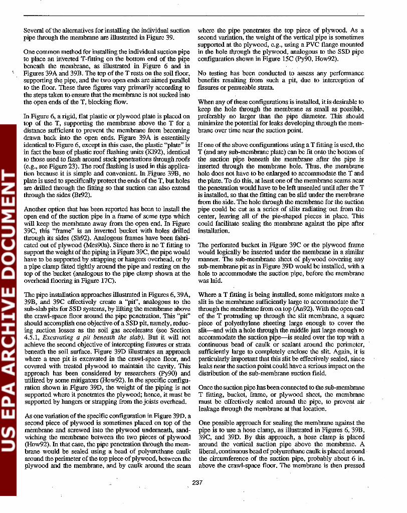
Several of the,alternatives for installing the individual suctionpipe through the membrane are illustrated in Figure 39.
One common method for installing the individual suction pipeto place an inverted T-fitting on the bottom end of the pipebeneath the membrane, as illustrated in Figure 6 and inFigures 39A and 39B. The top of the T rests on the soil floor,supporting the pipe, and the two open ends are aimed parallelto the floor. These three figures vary primarily according tothe steps taken to ensure that the membrane is not sucked intothe open ends of the T, blocking flow.
In Figure 6, a rigid, flat plastic or plywood plate is placed ontop of the T, supporting the membrane above the T for adistance sufficient to prevent the membrane from becomingdrawn back into the open ends. Figure 39A is essentiallyidentical to Figure 6, except in this case, the plastic "plate" isin fact the base of plastic roof flashing units (KI92), identicalto those used to flash around stack penetrations through roofs(e.g., see Figure 23). The roof flashing is used in this application because it is simple and convenient. In Figure 39B, noplate is used to specifically protect the ends of the T, but holesare drilled through the fitting so that suction can also extendthrough the sides (Br92).
Another option that has been reported has been to install theopen end of the suction pipe in a frame of some type whichwill keep the membrane away from the open end. In Figure39C, this "frame" is an inverted bucket with holes drilledthrough its sides (Sh92). Analogous frames have been fabricated oot of plywood (Mes90a). Since there is no T fitting tosupport the weight of the piping in Figure 39C, the pipe wouldhave to be supported by strapping or hangers overhead, or bya pipe clamp fitted tightly around the pipe and resting on thetop of the bucket (analogous to the pipe clamp shown at theoverhead flooring in Figure 17C).
The pipe installation approaches illustrated in Figures 6, 39A,39B, and 39C effectively create a "pit", analogous to thesub-slab pits for SSD systems, by lifting the membrane abovethe crawl-space floor around the pipe penetration. This "pit"should accomplish one objective of a SSD pit, namely, reducing suction losses as the soil gas accelerates (see Section4.5.1, Excavating a pit beneath the slab). But it will notachieve the second objective of intercepting fissures or stratabeneath the soil surface. Figure 39D illustrates an approachwhere a true pit is excavated in the crawl-space floor, andcovered with treated plywood to maintain the cavity. Thisapproach has been considered by researchers (Py90) andutilized by some mitigators (How92). In the specific configuration shown in Figure 39D, the weight of the piping is notsupported where it penetrates the plywood; hence, it must besupported by hangers or strapping from the joists overhead.
As one variation of the specific configuration in Figure 39D, asecond piece of plywood is sometimes placed on top of themembrane and screwed into the plywood underneath, sandwiching the membrane between the two pieces of plywood(How92). In that case, the pipe penetration t:Iuough the membrane would be sealed using a bead of polyurethane caulkaround the perimeter of the top piece ofplywood, between theplywood and. the membrane, and by caulk around the seam
where the pipe penetrates the top piece of plywood. Asasecond variation, the weight of the vertical pipe is sometimessupported at the plywood, e.g., using a PVC flange mountedin the hole th,rough the plywood, analogous to the SSD pipeconfiguration shown in Figure 15C (Py90, How92).
No testing has been conducted to assess any performancebenefits resulting from such a pit, due to interception offissures or permeable strata.
When any of these configurations is installed, it is desirable tokeep the hole through the membrane as small as possible,preferably no larger than the pipe diameter. This shouldminimize the potential for leaks developing through the membrane over time near the suction point.
Ifone of the above configurations using a T fitting is used, theT (and any sub-membrane plate) can be fit onto the bottom ofthe suction pipe beneath the membrane after the pipe isinserted through the membrane hole. Thus, the membranehole does not have to be enlarged to accommodate the T andthe plate. To do this, at least one of the membrane seams nearthe penetration would have to be left unsealed until after the Tis installed, so that the fitting can be slid under the membranefrom the side. The hole through the membrane for the suctionpipe could be cut as a series of slits radiating·out from thecenter, leaving all of the pie-shaped pieces in place. Thiscould facilitate sealing the membrane against the pipe afterinstallation.
The perforated bucket in Figure 39C or the plywood framewould logically be inserted under the membrane in a similarmanner. The sub-membrane sheet of plywood covering anysub-membrane pit as in Figure 39D would be installed, with ahole to accommodate the suction pipe, before the membranewas laid.
Where a T fitting is being installed, some mitigators make aslit in the membrane sufficiently large to accommodate the Tthrough the membrane from on top (An92). With the open endof the T protruding up through the slit membrane, a squarepiece of polyethylene sheeting large enough to cover theslit-and with a hole through the middle just large enough toaccommodate the suction pipe-is sealed over the top with acontinuous bead of caulk or sealant around the perimeter,sufficiently large to completely enclose the slit. Again, it isparticularly important that this slit be effectively sealed, sinceleaks near the suction point could have a serious impact on thedistribution of the sub-membrane suction field.
Once the suction pipe has been connected to the sub-membraneT fitting, bucket, frame, or plywood sheet, the membranemust be effectively sealed around the pipe, to prevent airleakage through the membrane at that location. .
One possible approach for sealing the membrane against thepipe is to use a hose clamp, as illustrated in Figures 6, 39B,39C, and 39D. By this approach, a hose clamp is placedaround the vertical suction pipe above the membrane. Aliberal, continuous beadofpolyurethane caulk is placed around·the circumference of the suction pipe, probably about 6 in.above the crawl-space floor. The membrane is then pressed
237

SuctionPfpe-----+l
~ . . '"
. Crawl Space Floor. ... ..
Plastic/RubberRoof Flashing
. (Commonly Usedto Flash AroundStack PenetrationsThrough Roofs)
A) Membrane sandwiched, sealed betweentwo roof flashing units; base offlashing prevents membrane frombeing sucked Into open ends ofT-f1ttlng
B) Perforations drilled in sides ofT-fitting, to prevent membranefrom blocking all air flow.
Suction Pipe(Supportedfrom Above) ---.of-
Inverted Bucket(or SpeciallyBuilt WoodenFlange) 0
jJ
Perforationsin Side ofBucket
. Note: A second piece of plywood issometimes placed on top of themembrane and.sc~e~ed into the bottompiece, sandwiching the membrane.
Suction Pipe(Supportedfrom Above)
TreatedPlywood
C) Inverted perforated bucket or woodenflange used to elevate membrane abovefloor and prevent membrane from beingsucked Into pipe Inlet.
D) Suction pit excavated in craWl-space floor.
F1suro 39. Some of the alternative approaches for installing individual SMD suction pipes through the membrane.
238

tightly against the sides of the suction pipe, compressing thecaulk bead, and clamped into place with the hose clamp.
Where the hole has been cut in a manner which leaves a seriesof pie-shaped· membrane segments radiating out from thecenter of the hole, as discussed above, these segments wouldbe pressed against the caulked side of the pipe and would bebound by the clamp. Any cuts that have been made in themembrane around the hole to enable insertion of a T-fitting orflange should be effectively closed by being pressed againstthe caulk and the side of the suction pipe by the hose clamp.
Where there is any doubt, additional caulk ma.y be placed atthe seam between the hose clamp, the membrane, and thesuction pipe to ensure that this penetration is air-tight. Airleakage at this location could significantly decrease what willalready be a relatively weak sub-membrane suction field.
Instead of a hose clamp, Figure 39A sandwiches the membrane between two roof flashing units. To seal this configuration, a liberal, continuous bead of polyurethane caulk wouldbe placed around the entire base of the unit above the membrane, between the flashing and the membrane, as indicatedon the figure. Likewise, the seam between the upper unit andthe suction pipe would be liberally caulked.
Where the approach in Figure 39D is supplemented by asecond plywood sheet above the membrane, a continuousbead of sealant is applied around the entire perimeter of theupper plywood, between the plywood and Ithe membrane(How92). A liberal bead of sealant is also applied around theseam between the upper sheet of plywood and the suctionpipe.
Except for the cases involving sheets of plywood covering asub-membrane pit, the other configurations just discussed allinvolve raising the membrane up several inches around thesuction pipe, as necessary to effectively clamp or otherwiseseal the membrane around the pipe. This will cause somedeformation of the membrane sheet through which the pipe ispenetrating. This deformation must not be sufficient to causecrawl-space soil to become exposed at the seam between thatsheet and the adjoining sheets. To avoid deformation of theadjoining sheets or undue stresses on the sealed seams, theseams between the penetrated sheet and the adjoining sheetsshould not be sealed until after pipe installation has beencompleted.
If a 12-in. overlap has been provided between sheets, thisshould often be sufficient to prevent the soil from becomingexposed at seams when the membrane is raised. However, tobe conservative, somewhat greater overlap might be providedfor the sheet through which the pipe will penetrate. Again tobe conservative, it would be desirable for the adjoining sheetsto overlap on top of sheet with the suction pipe, and.for theseams of those sheets to be sealed, even if the seams betweensheets are not being sealed elsewhere.
Figure 38C illustrates a unique suction pipe installation approach used by one mitigator (An92) in an effort to increasethe extension of the SMD suction to block foundation walls.This approach, analogous to the baseboard duct BWD ap-
proach, is an alternative to installing a perimeter loop ofsub-membrane perforated piping. In this approach, a slanted
. strip of treated plywood is sealed against the perimeter wallwith a bead of polyurethane caulk, creating a "baseboardduct" around the crawl-space perimeter. The SMD membraneextends up the plywood and is sealed against the wall justabove the top of the plywood. The suction pipe is sealed intothis baseboard channel at some convenient point around theperimeter. In addition to maximizing treatment of the wall,this approach should maximize treatment of the floor immediately beside the wall; radon entry will likely be highestthrough this section of floor, due to wind effects against theperimeter walls. However, because of the high flows likely tocome out of the walls, it is possible that suction will notextend well toward the center of the membrane.
Sub-membrane piping/SMD approach. The suction pipefor sub-membrane piping/SMD systems consists of two elements: the perforated piping laid beneath the membrane; andthe vertical PVC suction pipe which penetrates the membraneand connects to this perforated piping.
• Sub-membrane perforatedpiping. The perforated piping,which may be the flexible black corrugated piping, orrigid PVC piping, is laid on the crawl-space floor in theselected matrix, as discussed in Section 8.2.2.
Commonly, where the floor is bare soil, the perforatedpiping will be laid on top of the soil. Where the piping isbeing laid in the path of potential future foot traffic, atrench might be excavated. The trench could be filledwith gravel, and the piping embedded in the gravel. Suchtrenching would significantly increase the installationeffort, and is not often done. One mitigator who hastested SMD systems back-to-back in the same house,with the piping on top of the soil and also with the pipingin a trench, reports that installation of the piping in atrench appears to have no impact on radon reductionperformance (Kl92). .
Where the crawl-space floor is gravel, the perforatedpiping can be buried in the gravel relatively easily. However, where the floor is gravel, sub-membrane piping willbe less likely to be needed; the individual-pipe/SMDapproach will probably be adequate.
Where flexible perforated piping is used in a contiguouspattern with no branches (such as a straight length or afull or partial loop), it can easily be flexed into whateverpattern is desired. If a perpendicular branch were desired(to connect two parallel lengths of piping, or to extendlegs off the main trunk line), a flexible corrugated T-fittingcould be snap-fitted into the length of flexible piping. Ifarigid PVC T-fitting were used rather than a corrugatedfitting, the perforated piping could be connected to theends of the PVC T using screws and caulk, as discussedlater in connection with installation of the vertical suctionpipes.
In many cases where there are two parallel lengths ofperforated piping, it will be because there are two adjoining crawl spaces separated by a footing and/or wall. One
239

option is to connect these separate lengths using a lengthof non-perforated flexible corrugated piping that penetrates up through the membrane in one crawl space,snnkes over the interior footing, and then descends downthrough the membrane in the second crawl space. Depending on the configuration of the crawl spaces, eachend of this non-perforated connector could connect intothe middle of one of the parallel perforated lengths usinga corrugated T-fitting (so that the entire matrix takes onthe shape of an H). Alternatively, the non-perforatedconnector might connect the ends of the perforated segments, so that the matrix takes on a contiguous U shape.The penetration of the non-perforated piping through themembranes must be sealed well.
Where there are parallel lengths of piping, another alternative to linking these lengths beneath the membranewoald be to install a vertical PVC suction pipe throughthe membrane into each one, and linking these risers by apiping network in the crawl space above the membrane.
Where rigid perforated pipe is used for the sub-membranepiping, the sections of piping are joined by straight couplings, elbows, and T's as necessary to create the desiredmatrix. The fittings should be cemented onto the perforated piping to ensure the structural integrity of the matrixovertime.
When corrugated or rigid fittings are inserted into thesub-membrane piping network, in accordance with anumbe,r of the configurations just discussed, one questionis how well the joints should be sealed. If there is someleakage at the joint, but if the joint is beneath a well-sealedmembrane, it would seem that the leakage should not be amlijor problem. In assessing the need for joint sealing in agiven installation, the factors that should be consideredare the following:
- How big is the leak? If the gap at the joint is largeenough, the leakage at that point may become so severethat suction will not effectively extend to more remotepoints in the sub-membrane piping, and the system willtake on the characteristics of an individual-pipe/SMDsystem with an individual suction pipe penetrating themembrane at the leakage point.
- How far is the leak from the vertical suction pipe? Thenearer the leak is to the suction pipe, the greater theimpact of the leak can be.
- Does the leak reflect a structural weakness in the jointthat may result in the segments of sub-membrane piping becoming disconnected over time? Thesub-membrane piping network may be subjected tosome physical stresses due to foot traffic in the crawlspace. If the joint is sufficiently weak that the segmentsbecome disconnected over time, the remote segment ofpiping on the far side of the break could be cut off fromthe system.
The joints between flexible corrugated piping and corrugated snap-fittings are generally very tight, and may not
need to be cemented, screwed, or caulked together unlessthe piping is expected to come under particular physicalstresses. In this case, the concern is usually not one ofleakage around the joint as installed (as long as themembrane is carefully sealed), but rather, is one of the.joint becoming separated over time. Where rigid PVCfittings are being installed in a corrugated piping matrix,this joint will be very subject to becoming disconnectedunless it is fIrmly connected with screws or clamps andcaulk. Where rigid perforated piping is used for the entirematrix, the joints should all be cemented, because this iseasy to do, and because the rigid piping will not flex likethe corrugated material and thus may be more prone tohaving uncemented joints become disconnected as a result of physical stresses.
Where the perforated piping does not form a completeloop, so that there are open ends, the open ends should becapped. Capping the ends will help ensure that the suction is distributed evenly along the length of the piping. Ifan end is left open, most of the air flow into the pipingwill likely enter through the open end. Under this condition, the sub-membrane piping/SMD system will tend totake on the characteristics of an individual-pipe/SMDsystem with individual suction pipes at the locations ofthe open ends.
• Vertical suction pipes. A rigid non-perforated suctionpipe is installed into the sub-membrane perforated pipingnetwork at a convenient location. Installation of the suction pipe about in the middle of the perforated pipingwould help improve the uniformity of the sub-membranesuction field. However, unless there is an unusually longlength of sub-membrane piping, applying the suctionnear the middle is probably not critical.
One approach for connecting the vertical suction pipeinto the sub-membrane piping network is to use a rigidPVC, PE, or ABS T-fItting or 90' elbow, as illustrated inthe inset in Figure 7.
A leg of the T or the elbow is directed upward through ahole in the membrane. Depending upon how the membrane is subsequently to be sealed against the pipe, oneoption is to cut this hole through the membrane as a seriesof slits .radiating out from the center, leaving all of thepie-shaped pieces in place. See the discussion earlier inthis section under Individual-pipe/SMD approach. Thevertical suction pipe is cemented into the upward leg ofthe fItting.
The perforated piping must be fmoly connected to the TfItting or the elbow beneath the membrane, in a mannersuch that it will not become disconnected over time. Ifthis joint became disconnected over time, there could besignificant leakage of air into the vertical suction pipe,and the system would tend to behave more· like anindividual-pipe/SMD system with an individual suctionpipe at the location of the T.
"Ii
If flexible perforated piping has been used, and if a Tfitting is being installed in the middle of this piping, the
240

piping is severed as necessary to accommodate the T.Each severed end of the perforated piping is then connected to a side of the T using the techniques discussed inSection 6.5 (see Pipe installation using rigid T-fitting).Where 4-in. corrugated piping has been used, the pipingmay be forced inside of (or around the outside of) the4-in. T leg, and fmnly connected using screws or a hoseclamp, as appropriate, and urethane caulk. If 3-in. corrugated piping has been used, it should conveniently fitinside the leg of a 4-in. diameter T. .
If a rigid 90· elbow is being used instead of a T fitting, theelbow would be connected to the corrugated piping asdiscussed above, but at one end rather than in the middle.
If rigid perforated PVC piping has been used, this pipingis cemented into each open end of the T fitting (or into theelbow) beneath the membrane.
Other approaches for installing a rigid vertical suctionpipe into the middle of corrugated piping, rather thanusing a rigid T fitting, are discussed in Section 6.5 (seePipe installation directly into tiles without rigid T).
The membrane must be sealed tightly around the verticalpipe. This may be accomplished using a hose clamp, asillustrated in Figure 7. A procedure for using a hoseclamp for this purpose was discussed earlier in this section (see Individual-pipe/SMD approach). Other approaches can also be considered for accomplishing thissealing, such as sandwiching the membrane betweensealed roof flashing units (an adaptation of the approachillustrated in Figure 39A for the individual-pipe case).
If there are multiple segments of perforated piping whichhave not been connected beneath the membrane, a separate vertical suction pipe must be installed in each isolated segment. The resulting multiple risers will be connected by the piping network above the membrane, asdiscussed in Section 8.6.
8.6 Design/Installation of tlhePiping Network and FanThe design and installation of the above-membrane pipingnetwork and the fan, for SMD systems would be essentiallythe same as described in Section 4.6 for a SSD system.
Where multiple suction pipes penetrate the membrane, foreither SMD variation, these pipes·would be manifolded together, just as with SSD systems in basements. The pipingwould be hung from the floor joists under the living areaoverhead. Since the crawl space is not lived-in space, therewill usually be a lot of flexibility regarding the routing of thepiping through the crawl space. However, care should betaken that the piping not block expected traffic routes (e.g., formaintenance or subsequent replacement of a furnace located
. in the crawl space).
As with other ASD variations, the exhaust piping from SMDsystems may neatly be routed up through the living area of the
house to a fan mounted in the attic, as suggested in Figures 6and 7.
Where the exhaust stack is to be routed up the exterior of thehouse or through an adjoining slab-on-grade garage, it iscommon to direct the SMD piping out of the crawl spacethrough the band joist, just as in a basement.
For exterior stacks from systems in vented crawl spaces, somemitigators have occasionally taken the exhaust piping outthrough a foundation vent, if a vent existed at a convenientlocation. Using a vent would save the effort ofdrilling throughthe band joist and exterior finish. However, this can be abuilding code violation, if it reduces the net vent area for thecrawl space below the area required by code. For this reason,it is recommended that, in general, foundation vents not beused for piping penetrations through the wall.
When there is an indoor stack, the SMD fan will generally bein the attic. When there is an exterior stack (or a garage stack),the SMD fan should be outdoors (or in the garage). Locatingthe fan outdoors is particularly important when the crawlspace is unvented and is part of the conditioned space in thehouse, which will be the case, e.g., where the crawl spaceopens to an adjoining basement.
EPA's interim mitigation standards (EPA9lb) specify that thefans not be located in the crawl space, even if the crawl spaceis vented. The thermal stack flows will tend to draw thecrawl-space air up into the overhead living area. Thus, anyradon released in the crawl space due to leaks on the pressureside of a crawl-space fan could enter the living area.
In houses with vented crawl spaces, where the fan cannot belocated in the attic or in an adjoining garage, it can betempting to mount the fan in the crawl space to avoid theaesthetic impact of mounting the fan outdoors. It would seemthat, since the crawl space is vented, any radon released frompressure-side leaks should be diluted by the outdoor air thatwill infiltrate through the foundation vents. However, limitedtracer gas data show that, due to the dynamics of crawl-spacehouses, over one-half of any radon released by the fan in thecrawl space can flow up into the living area even when thecrawl space is being naturally ventilated (Na8S). As a result,to be conservative, the interim standards require that fans notbe in crawl spaces, despite the fact that occupants will notnormally be spending much time in the crawl space itself.
In Section 4.6.5 (see Requirement that fans be outside thelivable envelope of the house).. some precautions were discussed that an installer should consider if there were no choicebut to mount a fan in a basement in violation of the standards.One other precaution that was considered prior to the standards for fans mounted in crawl spaces is to enclose the fan,the fan couplings, and the pressure-side piping in a tightenclosure fabricated from sheetrock or insulation board (An92).A II2-in. hole is drilled in the pipe on the negative-pressureside of the fan, inside the enclosure, in an effort to slightlydepressurize the enclosure. The concept is that anypressure-side leaks inside the enclosure would be drawn backinto the fan intake, preventing their release into the crawlspace. Any such enclosure would· have to be tight but would
241

also have to enable ready access to the fan for maintenance.As emphasized in Section 4.6.5, there is no evidence that suchprecautions would compensate for the risks incurred if the fanwere mounted in the crawl space, and the precautions thuscould never be considered as a substitute for abiding by thestandards.
8.7 Sealing in Conjunction withSMD Systems8.7.1 Sealing the Membrane
The most important sealing in conjunction with the installation of SMD systems will be sealing of the membrane.
As discussed in Section 8.5.1 (see Sealing the membrane general), it is not possible to specify the precise conditionsunder which various sealing steps will be cost-effective, or toqunntify the benefits that will result. However, available datasuggest that better radon reduction performance will beachieved if the membrane is completely sealed, and a numberof other benefits would be expected as welL As a result, it isrecommended that the membrane be fully sealed wheneverpossible.
Complete sealing of the membrane includes: sealing the seamsbetween sheets; sealing the membrane against the perimeterfoundation wall; and sealing the membrane against any interior obstructions, such as support piers and concrete pads. Theprocedures for sealing these different membrane seams werediscussed in Section 8.5.1.
The most critical seams to seal would be: the seams betweensheets penetrated by individual suction pipes and adjoiningsheets; and seams running beside any sub-membrane perforated piping, including, for example, the seam between themembrane and the perimeter foundation wall in cases wherethe sub-membrane piping forms a loop around the perimeter.The seam between the membrane and the suction pipe, ofcourse, also must always be sealed well.
8.7.2 Sealing the Block Foundation Wall
Only very limited testing has been conducted to determine theimprovements in SMD performance that might be achievedby sealing major openings in the block foundation wall of acrawl space. Despite the lack of data, wall sealing mightintuitively be expected to be important in certain cases for tworeasons: '
- by analogy with basement houses. In basements, SSDappears least able to prevent radon entry into the wallcavities when sub-slab communication is marginal orpoor. When there is no gravel on the crawl-space floor,individual-pipe SMD systems might be expected tosimulate poor-communication SSD systems. This analogy would suggest that SMD systems with no gravelon the crawl-space floor may be failing to adequatelytreat wall-related entry.
- from experience in the two study houses having thehighest pre-mitigation radon levels in the living area
(88-160 pCi/L), ~here addition of a BWD component(supplementing the S:MD system) was necessary inorder to reduce concentrations below 4 pCi/L (Ni89,Py90). Both of these houses included other complica-
. tions which prevented the tests from clearly demonstrating the role of the BWD component and the conditions under which a BWD component will typically beneeded in other houses.
Open top voids, if present, would likely be the primaryopenings warranting closure. The procedures described inSection 7.7.1 and Figure 37 can be considered for closing thetop voids.
Figure 38B illustrates one approach for both sealing the entirewall and increasing block-wall treatment by the SMD system.
As with the membrane sealing, sealing of the block foundation wall (and/or adding a BWD component) are most likelyto be needed when the pre-mitigation concentrations are high,or when the desired post-mitigation concentration is lowerthan 4 pCi/L.
8.8 Gauges!Alarms and LabellingThe considerations discussed in Section4.8, concerning gauges/alarms and labelling for SSD systems, also apply to SMDsystems.
As discussed in Section 4.8.1, the gauge/alarm must be located where it will be readily visible to the house occupant.But much of the SMD piping will be in the crawl space, wherethe house occupant may rarely go.
If the SMD exhaust piping rises up through the house via anindoor stack, a gauge or alarm could be mounted on the stackat some convenient location in the living area where it can beseen or heard. If the stack is rising through a closet in theliving area, which will commonly be the case, and if a gaugewere mounted in the closet with the pipe, rendering the gaugeless visible, the gauge might be supplemented by an audiblealarm.
Where the exhaust piping rises through an adjoining garage,the gauge/alarm can be located in the garage.
Where the exhaust piping rlses up outside the house, via anexterior stack, a pressure gauge could be mounted at someconvenient location in the living area. In this case, the indoorgauge would have to be connected to the piping in the crawlspace or outdoors, via a line that penetrates the shell of theliving envelope. The ammeter discussed in Section 4.8.1would be connected to the outdoor fan via the fan wiring.
Some pressure-activated alarms will not be applicable forSMD systems when the stack is outdoors, if they are designedfor direct mounting on the suction piping. Such direct mounting would require either that the alarm be mounted on thepiping in the crawl space, in which case it may be too remoteto be considered readily visible or audible to the occupants; orthat the alarm be mounted on the piping outdoors, which willnot be feasible if the alarm is not designed for outdoor use.
242

See the related discussion of pressure-activated alanns outdoors in Section 6.8.
As discussed in Sections 4.8.1 and 6.8, some mitigators reportthat, during cold weather, moisture can condense or freeze inthe narrow tubing that extends from indoor pressure gauges tosuction piping in unconditioned crawl spaces or outdoors.When this happens, the gauge will give erroneously lowreadings. Use of larger diameter tubing, insulation of theoutdoor tubing, and advice to the occupant are possible stepsto address this problem, as discussed in Section 6.8. Use of theammeter as the warning device would avoid this problem.
In accordance with the discussion in Section 4.8.1 (see Pressure gauges), pressure gauges (and pressure-activated alanns)must tap into the suction piping at a point near the pipepenetration through the membrane in the crawl space. If thegauge or alann taps in too close to the fan, it may seerelatively high suctions at the fan inlet even if there is a majorleak in the piping near the membrane, and even if thesub-membrane depressurizations have thus been dramaticallyreduced. This potential problem is especially acute withpressure-activated alanns, which are often pre-set by themanufacturer such that they are not triggered until suctionsdrop to extremely low levels (perhaps only 0.2 in. WG). Suchlow levels can exist near the fan even if there is a total breachin the piping near the membrane.
243


Section 9Consiiderations for Active
Soil Pressurization Systems
For any of the active soil depressurization systems discussedin Sections 4 through 8, the suction fan could nominally bereversed to blow outdoor air into the soil, rather than drawingsoil gas out. As discussed in Section 2.4,active soil pressurization in this manner has been found to be beneficial, relativeto soil depressurization, in cases where system flows werehigh. Active soil pressurization has been folind to sometimesbe beneficial in the following two situations:
1. With sub-slab systems, as an alternative to SSD, in caseswhere the underlying soil is highly permeable, includingwell-drained gravels and highly fissured shales or limestones. Such highly permeable soils would permit greaterthan normal amounts of outdoor air to flow down throughthe soil into a SSD system. In these cases, sub-slabpressurization could be an alternative to installing ahigher-flow fan or more suction pipes on the SSD system.
2. With block-wall systems, as an alternative to BWD, incas,es where depressurization of the leaky block wallswould draw enough air out of the basement to depressurize the basement. Such depressurization of the basementcould increase soil gas influx and cause back-drafting ofcombustion appliances.
One typical configuration for a sub-slab pressmization systemis shown in Figure 40.
In most respects, the considerations in designing and installing a sub-slab pressurization system or a block-wall pressurization system will be exactly the same as those described inSections 4 and 7 for the corresponding depressurization systems. The prin1ary difference between pressurization and depressurization designs will be that, with pressurization: a) thefan direction will be reversed; b) provisions will have to bemade to prevent outdoor dust and debris from blocking freeair flow through the piping; and c) the need for an exhauststack is eliminated, since the system is no longer discharginga high-radon 'exhaust gas.
The discussion in this section focuses on the design andinstallation differences resulting when a sub-slab or block-wallpressurization' system is being installed rather than a depressurization system. This discussion draws from the detailedreview of data from pressurization systems presented in Section 2.4.
9.1 Selection of the Number ofPressurization Pipes9.1.1 Sub-Slab Systems
The available data are limited from sub-slab pressurizationsystems in houses amenable to pressurization. But these dataprovide no solid evidence that the nmnber of pipes requiredfor pressurization would necessarily be different from the oneor two pipes required for SSD systems in houses amenable toSSD.
Information on sub-slab pressurization system configurationare available from six houses amenable to this approach(Tu87, Kn90). These installations included between one andfour pressurizationpipes. These houses were only moderate insize; their footprints generally ranged from 800 to 1,400 ff,with one being 1,800 ff. The number of pipes usually corresponded to one pipe per 400 to 700 ft2, although one house hadone pipe per 200 ff, and another house had one pipe per1,000+ ff. In half of these installations, this number of pipeswas able to reduce indoor levels to below 2 pCiIL frommoderately elevated pre-mitigation levels (15-30 pCi/L). Theother half, having more elevated pre-mitigation levels (30-141pCi/L), were reduced below 4 but not below 2 pCiIL.
The nmnber of square feet per pipe is relatively low for thesepressurization systems, compared to figures as high as 1,850to 2,700 ff per pipe with SSD systems in houses with goodcommunication. The values of 400 to 700 ff per pipe withthese pressurization systems are more comparable to thevalues of 350 to 750 ft2 per pipe encountered in SSD houseshaving marginal rather than good communication. And theresidual indoor radon levels achieved by sub-slab pressurization in these houses are no lower than those commonlyachieved by one or two SSD pipes in houses with goodcommunication.
These comparisons would make it appear that sub-slab pressurization systems may, on the average, require more pipesthrough the slab than will SSD systems. This would beintuitively reasonable. More pipes may be needed to ensureadequate sub-slab pressures and adequate air flow into the soilat all locations under high-flow conditions, than may beneeded to achieve sufficient depressurizations everywhereunder the lower-flow, more static conditions often characteristic of SSD.
245

Removable Cap,for Pit Cleanout '
Notes:1. Closure of major slab openings is
important.2. Fan may also be mounted at grade
outdoors.3. Air filter must be accessible for
changing or cleaning.4. Houses built on well-drained
gravel soils (suitable for sub-slab. pressurization) will not alwayshave sub-slab aggregate as shown.
~-- Insulation, toPrevent PipeSweating inHumidifiedBasements DuringCold Weather
I*--- Pressurization
Pipe
Strapping (orOther Support)
A-Collars,ConnectingMetal FilterHolder toPVC Piping
Sheet Metal AirFilter Holder
.,
.,
, , '
.. '-.:. ,',.. ~. . ~.: .~."
. , ~ . .. . ..~
, " ":
Outdoor
Air -- ~~TI~=~_---"::~Z2LJ=~_.-J
,". ~' ~ l ' .. • •. ,',
Screened AirIntake (AboveSnow/Leaf Line)
Slope HorizontalLeg Down TowardSub-Slab Hole
Optional pIping configuration,to facilitate removal ofdebris from pit.
..:'.:
Sub-Slab Air Forced 1
Up Through Unclosed Openings
Ope~ Hole :' : ':- : "(As Large As .Reasonably'Practical)
. .. " "
... ..' ...
..,. . ~...:..
~ . -. ..•..
. ''. *.:
.",: <~:: .:~=-<,.-,.,-,~-, ..:.,'~,-::""""",....;,~7-:.;.-:-:,~,,,,,,,....,..J;
,'. :"~ ... ~'... :., ..~ ... ' .~~
Figure 40. SUb-slab pressurization using one typical approach,
246

Another option with sub-slab pressurization, rather than adding pressurization pipes, might be to use a higher-capacityfan. For five ofthe six installations just cited (Tu87), the fanswere capable of generating flows of 50 to 200 cfm in the totalsystem, and pressures of 1.25 to 2.0 in. WG in lthe pipes nearthe slab, in the given houses. In the sixth installation (Kn90),the fan was a 90-watt tubular in-line fan of the type listed inTable 1.
It must be underscored that most of the sub-slab pressurization installations reported here are among the first such installations, and that no effort was made in the early work toreduce the number of pressurization pipes in these installations, or to optimize the number of pipes and the fan capacityfor general application. Therefore, it cannot be definitivelyconcluded from these results that sub-slab pressurization systems will in fact routinely require more pipes; Nor can anassessment be made of the extent to which the number ofpipes might be reduced by increasing fan capacity.
9.1.2 Block-Wall Systems
Only three block-wall pressurization systems have been reported (Sc88). One of these represented the individual-pipevariation (Figure 5), and two represented the baseboard ductvariation (Figure 35). In all three cases, the systems wereoperated with the same number of ventilation pipes (or thesame baseboard duct configuration) in both pressure andsuction, with comparable performance under both conditions.Thus, a block-wall pressurization system would be expectedto require the same number of pipes as a BWD system.
This conclusion is intuitively reasonable. Because of theleakiness of the block wall, BWD systems are high-flowsystems just as are block-wall pressurization systems. BothBWD and wall pressUrization thus probably have a significantventilation/dilution component in their mechanisms, and both .would thus be expected to require a comparable number ofpipes to distribute these flows.
9.2 Selection of .PressurizationPipe LocationIt is not apparent that the location of pressurization pipes (inhouses amenable to soil pressurization) should necessarily beany different from that for depressurization systems. Pipelocation for SSD suction pipes was discussed in Section 4.2;the location for individual BWD suction pipes and for baseboard ducts was discussed in Section 7.2.
With SSD systems in houses having good sub-slab communication, Section 4.2 indicates that the one or two SSD suctionpipes might be located just about anywhere convenient. Theflows in SSD systems are low enough such that, even ifa pipeis placed at one end of a house, the suction field can extendbeneath the entire slab. With sub-slab pressurization systemsin houses underlain be highly permeable soils, location of thepressurization pipe near one end intuitively might result inexcessive flows of air out through the soil near that end of thehouse. If that occurred, sufficient flows might not be established at the remote end of the house. Thus, in sub-slabpressurization systems having only one pressurization pipe, it
might be advisable to locate that pipe at a relatively centrallocation, although there are no data confmningthat this is infact required.
9.3 Selection of PressurizationPipe Type and DiameterThe type and diameter of piping that would be used forsub-slab and block-wall pressurization systems would be thesame as that for SSD and BWD systems, discussed in Sections4.3 and 7.3.
Even though the pressurization piping will now be handlingoutdoor air rather than radon-containing soil gas, it is stillnecessary to use rigid PVC, PE, or ABS piping. Flexibleducting and flexible clothes drier hose are still not acceptable,due to reduced durability, difficulty in achieving sufficientlygas-tight joints, and a tendency to sag, providing sites foraccumulation of condensate. Leakage or flow restriction resulting from any of·these problems with the flexible ductingwould reduce pressurization system flows, thus likely reducing performance.
The flows in a typical sub-slab pressurization system will tendto be higher than those ina typical SSD system, since thepressurization approach will be used only in cases wherehighly permeable native soil contributes to high flows. In thefive sub-slab pressurization systems for which flow data werereported, flows generally ranged from 35 to 200 cfm, averaging 100 cfm. This compares with the range of 20 to 100+ cfmfor SSD systems, averaging perhaps 50 cfm. .
From the discussions in Sections 4.3.2 and 4.6.1, it is clearthat, in sub-slab pressurization systems, it will always bedesirable to use piping of at least 4 in. diameter. Sub-slabpressurization flows will essentially always be too high topermit the use of 2-in. piping, sometimes considered inlow-flow SSD systems, and will often be too high for use of3-in. piping.
At the highest sub-slab pressurization flows (150 to 200 cfm),it could seem desirable to use 6-in. diameter piping, sincepressure losses in 4-in. piping would be about 1.5 to 2 in WGper 100 ft at those flows (see Figure 13). However, the limitedexperience with sub-slab pressurization systems has shownthat in houses where sub-slab pressurization is preferred overSSD, pressurization gives adequate performance with 4-in.piping. Thus, 6-in. piping, though it would probably be helpful in particularly high-flow installations, does not really seemto be necessary. Where a central trunk line down the length ofa basement connects to multiple pressurization pipes in thebasement, it might be desirable for the trunk line to be 6-in.piping.
Flows in a typical stand-alone block-wall pressurization system will likely be about the same as those in a typicalstand-alone BWD system; the leakiness of the walls shouldcreate about the same flows in both cases. Thus, the pipediameters for block-wall systems should be the same, regardless of whether the system is operating in suction or inpressure.
247
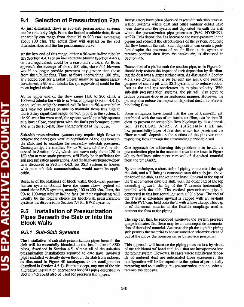
9.4 Selection of Pressurization FanAs just discussed, flows in sub-slab pressurization systemscan be relatively high. From the limited available data, flowsapparently can range from about 35 to 200 cfm, averagingabout 100 cfm. The actual flow will depend on the soilcharacteristics and the fan performance curve.
At the low end of this range, either a 90-watt in-line tubularfan (Section 4.4.1) or an in-line radial blower (Section 4.4.2),or their equivalent, could be a reasonable choice. As flowsapproach the avemge of about 100 cfm, the radial blowerswould no longer provide pressures any greater than thosefrom the tubular fans. Thus, at flows approaching 100 cfm,any added cost for a radial blower might be an unnecessaryinvestment; a 90-watt tubular fan (or equivalent) could be themore logical choice.
At the upper end of the flow range (150 to 200 cfm), al()().watt tubular fan with 6- or 8-in. couplings (Section 4.4.1),or equivalent, might be considered. In fact,.the 90-watt tubularfans may not always be able to maintain flows this high ifthere is any significant length of4-in. piping in the system. Ifthe 9O-watt fan were used, the system would possibly operateat a lower flow, consistent with the fan's performance curveand with tlle sub-slab flow characteristics of the house.
Sub-sL~b pressurization systems may require high flows toachieve the necessary ventilation/dilution of the gas beneaththe slab, and to maintain the necessary sub-slab pressures.Consequently, the smaller, 50- to 70-watt tubular fans discussed in Section 4.4.1, which can move only about 120 to160 cfm at zero static pressure, will likely be insufficient forsoU pressurization applications. And the high-suction/low-flowfans discussed in Section 4.4.3, for SSD systems in houseswith poor sub-slab communication, would never be applicable.
Because of the leakiness of block walls, block-wall pressurization systems should have the same flows typical ofsitand-alone BWD systems, namely, 100 to 200 cfm. Thus, the90- to lOO-watt tubular in-line fans (or their equivalent) willusually be the logical choice for block-wall pressurizationsystems, as discussed in Section 7.4 for BWD systems.
9.5 Installation of PressurizationPipes Beneath the Slab or Into theBlock Walls
9.5.1 Sub-Slab Systems
The installation of sub-slab pressurization pipes beneath theslab will be essentially identical to the installation of SSDpipes, described in Section 4.5. Almost all of the sub-slabpressuri.7.ation installations reported to date have involvedpipes installed vertically down through the slab from indoors,as illustrated in Figure 40 (analogous to the configumtiondescribed in Section 4.5.1). But in concept, anyone of the sixalternative installation approaches for SSD pipes described inSection 4.5 could also be used for pressurization pipes.
Investigators have often observed cases with sub-slab pressurization systems where dust and other outdoor debris havebeen drawn into the system and deposited beneath the slabwhere the pressurization pipe penetrates (Pr89, NYSE091,An92). This deposition has increased the back-pressure in thepiping and reduced the effectiveness of the system, reducingthe flow beneath the slab. Such deposition can create a problem despite the presence of an air filter in the system toremove outdoor dust from the intake air, as discussed inSection 9.6.
Excavation of a pit beneath the suction pipe, as in Figure 40,should help reduce the impact of such deposition by distributing the dust over a larger surface area. As discussed in Section4.5.1 (see Excavating a pit beneath the slab), one primarypurpose of such a pit with SSD systems is to reduce suctionloss as the soil gas accelerates up to pipe velocity. Withsub-slab pressurization systems, the pit will also serve toreduce pressure drop in an analogous manner. However, thepit may also reduce the impact of deposited dust and debris'inhindering flow.
Some mitigators have found that the use of a sub-slab pit,combined with the use of an intake air ftlter, can be insufficient to prevent unacceptable flow blockage by dust deposition (NYSE091, An92). A sufficiently thick andlow-permeability layer of fme dust which has penetrated theftlter can still deposit on the surface of the pit over time,restricting flow through the surrounding permeable soil.
One approach for addressing this problem is to install thepressurization pipe in the manner shown in the inset in Figure40, to facilitate subsequent removal of deposited materialfrom the pit (An92).
By this technique, a short stub of piping is mounted throughthe slab, and a T fitting is cemented onto this stub just abovethe top of the slab, as shown in the inset. One end of the top ofthe T is cemented onto the stub, with the other end of the topextending upward; the leg of the T extends horizontally,parallel with the slab. The vertical pressurization pipe isconnected to this horizontal leg with a 90' elbow. The end ofthe T that is extending upward is capped with an air-tight·flexible PVC cap, held onto the T with a hose clamp. This capis of the same material as the flexible couplings used toconnect the fans to the piping.
The cap can then be removed whenever the system pressuregauge indicates that there may "be an unacceptable accumulation ofdeposited material. Access to the pit through the pipingstub permits the material to be vacuumed or otherwise cleanedout of the pit by the homeowner or by service personnel.
This approach will increase the piping pressure loss by virtueof the additional 90' bend and the T that are incorporated intothe piping system. However, in cases where significant deposits of ambient dust are anticipated from experience, thisconfiguration will be far superior to the option of periodicallyremoving and re-installing the pressurization pipe in order toremove the deposits.
248

9.5.2 Block-Wall Systems
The installation of pressurization pipes into the block walls,and of baseboard ducting for wall pressurization systems, willbe identical to the installation of BWD piping, described inSections 7.5.1 and 7.5.2.
9.6 Design/Installation of PipingNetwork and FanMany of the considerations in designing and installing thepiping network and the fan for soil pressurization systems willbe similar to those for soil depressurizatioJl1 systems, discussed previously in Section 4.6. However, there will be someimportant differences.
These differences are illustrated in Figure 40 for a sub-slabpressurization system. Figure 40 is to be compared with theSSD diagram in Figure 1. While other sub-slab pressurizationconfigurations are possible, as discussed later, the one shownin Figure 40 is reasonably typical. Although figures forblock-wall pressurization systems are not shown here, schematics for block-wall pressurization installations would involve modifications to the BWD systems illustrated in Figures5 and 35, similar to the modifications made in Figure 1.
Pipe routing and installation between the pressurization points and the fan. The requirements for pipe routingand installation in both sub-slab andblock-wallpressurization .systems are very similar to those described for SSD systemsin Sections 4.6.2 and 4.6.3, and for BWD systems in Section7.6.
The horizontal piping runs must still be sloped downwardtoward the vertical piping into the slab or walls to allowcondensate drainage, and care must be taken to avoid lowpoints in the piping where condensed moisture can accumulate. With depressurization systems, the concern was primarily about condensation of soil gas moisture during coldweather, and about rainwater that enters Ithe stack. Withpressurization systems, the concern is primarily about condensation of humidity in the outdoor air during air conditioning season.
As with SSD and BWD systems, the piping joints must becarefully cemented. Even though the piping is handling outdoor air-and even though leaks on the pressure side of thefan would thus simply result in fresh air being blown into thehouse, which might seem innocuous-such pressure-side leakscould reduce the flows and pressures being delivered to thesoil (or into the block walls). They could also be suggesting aproblem with the physical integrity of the piping network.
Leaks on the suction side of the fan, if inside the house, wouldresult in house air being drawn into the system. In theory, thismight create depressurization within the house, and increasethe system heating/cooling penalty. More of the air beingblown beneath the slab (or into the walls) would be house airrather than outdoor air. However, much of the air being blownbeneath the slab (or into the walls) is likely flowing back intothe house, through cracks and other openings in the slab aridwalls. Thus, it is not clear whether such suction-side leaks
would really have any serious impact. Nevertheless, the mitigator is still advised to cement the suction-side joints carefully.
Some mitigators recommend insulation of all indoor piping(An92, Br92). Such insulation is shown in Figure 40. Thisinsulation will reduce "sweating" on the outside of the pipes,especially in humidified basements during cold weather, andhence will reduce or avoid water stains in finished areas. As asecondary benefit, it will also reduce condensation inside thepipe during hot weather.
Because of the high flows characteristic of pressurizationsystems, insulation ofthe piping will also serve to reduce flownoise. The average flow of 100 cfm observed in some sub-slabpressurizations systems to date corresponds to a flow velocityof 1150 ft/min in 4-in. piping, approaching the velocity rangeat which flow noise can start to become objectionable.
Needfor afilter on the air intake. One key difference inthe design of the piping network for soil pressurization systems is that an air filter is necessary to remove dust, pollen,and other debris from the incoming outdoor air. One possibleconfiguration for such an intake ftlter is shown in Figure 40.
This air filter is important for sub-slab pressurization systems,where deposited debris in the sub-slab pit has been found onsome occasions to increase system back pressure and reduceflows. The air filter may be less critical in block-wall pressurization systems (especially of the individual-pipe variation),since the void network into which the pressurization air isdischarging is so open that interference from dust depositionis intuitively less likely.
The recommended location for the filter is upstream of thefan, just as ftlters in forced-air heating systems are upstreamof the central furnace fan. This location will provide someprotection for the fan, as well as reducing deposition in thesub-slab pit. Upstream location of the filter in the figure ispossible because the figure shows the fan inside the house. Asdiscussed later, the fan can also be located outside the house;in that case, the ftlter will be downstream ofthe fan if the filteris indoors.
The filters are usually housed in sheet metal boxes, similar insomerespects to the sheetmetalhousings for ftlters in forced-airheating systems. At least one vendor markets a sheet metalftlter housing that could be installed in-line in the PVC piping,equipped with a gasketed door for access to the filter. This isthe type of filter holder illustrated in Figure 40. This sheetmetal box could be connected to the PVC piping using sheetmetal A-collars, as in the figure. With the A-collars properlyinstalled, and with the access door gasketed, the air leakagethrough joints associated with the ftlter housing should bereasonably limited. .-
The ftlter shown in Figure 40 is a type which is bent into theshape ofan inverted V. Pleated paper filters are recommended(An92, BI92). Pleated units have increased surface area andthus achieve better removals, have better dust-holding capacity (reducing frequency of replacement), and create less pres-
249

sure drop. These fIlters are more efficient than the fIlterstypically used in central fOICed-air furnace systems.
I
Some mitigators recommend against using washable wiremesh filte.rs, since these are less efficient (Br92). Others feelthat washable mters are satisfactory, since the ease of cleaning may encourage the occupants to clean the fIlters moreregularly than would be the case if they had to buy a newreplacement each time (An92).
Instead of the gasketed-door filter housings with V-filters, asshown in the figure, one could also consider the slotted fIlterhousing design common to many forced-air heating systems,where the mter slides into the slot. If such a housing wereused, a sheet metal cover for the slot should be included toreduce air leakage (An92).
Periodic replacement or cleaning of the fIlter is critical. Otherwise, the pressure drop across the filter will increase andflows will decrease. Also, dust may "break through" the fIlter,depositing in the fan (thus reducing fan performance) or in thesub-slab pit (also reducing flows). Even the pleated papermte.rs, which can go the longest between replacement, mustbe replaced about twice a year (An92).
For this reason, the filter must be located where .it can beeasily accessed by the house occupant for filter changing orcleaning. In the configumtion shown in Figure 40, the fIlterhousing is up between the overhead floor joists in the basement. The gasketed door in this case would likely be on thebottom of the housing, for easy access to the filter.
General considerations regarding fan location andexTzaust piping design. The primary difference betweenpressurization and depressurization systems, in terms of thepiping network and the fan, is associated with the fan and"exhaust" part of the system. Because the fan is blowing freshair beneath the slab or into the wall voids, there will be nohigh-rodon fan exhaust in pressurization systems, and all ofthe system piping will contain outdoor air. These facts impacttIle system design in two major ways:
- fIrSt, the fan can now be inside the living envelope, ifdesired, because there is no longer any risk thathigh-radon gases can leak out of the pressure side ofthe fan; and
- second, there is no longer any need for an exhaust stackup through the interior or the exterior of the house. The"exhaust"-actually, the fresh air intake--can be atgrade level.
Fan location and mounting-indoor fan. There arebnsica1ly two options for mounting the fan: indoors or outdoors. In both cases, of course, the fan is mounted with itsdirection reversed, relative to its direction for the depressurization systems, so that outdoor air is being blown beneath theslab (or into the block walls).
The fIrSt fan mounting option, shown in Figure 40, is to locatethe fan inside the house. In this case, the appearance of the airintake outside the house can be a screened air intake grille, as
shown in the fIgure. The 4-in. diameter intake piping wouldlikely penetrate the band joist (or some other convenientlocation on the side of the house), and the intake grille wouldbe mounted at the end of this pipe. This intake grille must bemounted at a suffIcient height on the side of the house suchthat it will not become blocked by snow or by accumulatedleaves or other debris.
As discussed above (see, Need for afilter on the air intake),the indoor fan should be mounted downstream of the intakeair filter, to provide some protection from the dust and debrisentrained with the outdoor air.
The indoor fan should be mounted vertically, as shown, sothat condensed moisture can drain down into the sub-slabregion (or into the block walls). As indicated previously, thethreat of condensation inside the pipe will be greatest duringhot, humid weather when the house is air conditioned.
As depicted in the figure, vertical mounting of the fan is mostconveniently done by installing it in the vertical pipe extending down into the slab. This is easy to do when there is onlyone pressurization pipe. If there were multiple pipes manifolded together, the fan must be mounted in the trunk lineupstream of the point at which the piping leading to thedifferent pressurization pipes splits off from the trunk. Location of the fan downstream of this split would result in the fandepressurizing the pipes upstream of the split.
If there were additional pressurization pipes beyond the oneshown in Figure 40, the horizontal trunk line leading to theother pipes would have to split off at a point in the verticalpipe below the fan. Even if the fan were placed as close aspossible to the basement ceiling, the horizontal trunk linewould be some distance below the floor joists. This willusually not be an acceptable location for the horizontal runacross the basement. Thus, where there are multiple pressurization pipes, one may wish to consider other options: mounting the fan outdoors, discussed later; or mounting the fanhorizontally with provisions for water drainage out of thehousing, an approach which could void the warranty on atleast one vendor's fans.
The soil pressurization fan should be mounted onto the systempiping with air-tight couplings, just as with depressurizationsystems. See Sections. 4.6.4 and 4.6.5. As discussed previolJ~ly in this section (see Pipe routing and installation between the pressurization points and the fan), the fact that thefan will be handling outdoor air rather than soil gas does noteliminate the need for the joints to be air-tight.
Fan location and mounting--outdoor fan. The secondfan mounting option is to mount the fan outdoors.
In this option, the portion of the system that. is outdoors couldlook very much like that shown in Figure 27 for the case ofSSD with an exterior ~tack, except that there would be nostac~ above the fan. In place of the air intake grille shown inFigure 40 on the side of the house, the piping would extendout through the side of the house; an upward-directed 90'elbow would be mounted on the outside end of this piping;and the fan would be mounted vertically on a stub of pipe
250

extending up from this elbow, oriented to blow outdoor airinto the piping.
Where an in-line duct fan is mounted beside the house in thismanner, a screen must be installed on the intake, for tworeasons. One reason is to prevent children and pets fromreaching into the fan blad~s. The other reason is to preventdebris from entering the fan. Intake grilles for this pUIpose aresold by some of the fan manufacturers.
When the fan is mounted outdoors, the air filter (which willusually be inside the house) will be on the pressure side of thefan, rather than on the fan inlet as in Figure 40. Thus, outdoorfans will not have the degree of protection from outdoor dustand pollen that will be possible for indoor fans mounteddownstream of the filter. The screens on the inlets to outdoorfans will not be effective at removing fine dust
One option that might be considered when the fan is mountedoutdoors is to mount the fan horizontally, directly on thehorizontal pipe where it penetrates the band joist. In this case,the fan would be mounted at the location where the screenedair intake grille is shown in Figure 40. Because the fan isoutdoors, and is at the same temperature as the surroundingoutdoor air, the threat of moisture condensation in the fanhousing is largely eliminated. Thus, this restriction on horizontal mounting would be avoided. However, entrainment ofrainwater could still result in some accumulation of waterinside the housing with horizontally mounted fans, and someprovision for drainage of this water out of the housing wouldbe necessary (see Section 4.6.5, Mounting exterior or garagefans). Horizontal mounting may void the warranty on somefans. .
9.7 Sealing in Conjunction withSoil Pressurization Systems·The slab and waIl sealing suggested in conjunction with SSDsystems (in Section 4.7) and with BWD systems (Section 7.7)are also appropriate for the analogous soil pressurizationsystems.
With soil depressurization systems, the sealing aids in thedistribution of the suction field beneath the slab. The sealingalso reduces the risk that soil gas will enter the house throughthe sealed entry route, in the event that the depressurization isnot fully effective for that route.
With soil pressurization systems, the sealing provides ananalogous benefit. Soil pressurization systems function in partby pressurizing the sub-slab (or waIl cavity) region, preventing soil radon from moving by convection into these regions.Sealing will aid in distributing the pressure field, thus improving pressurization system effectiveness.
Soil pressurization systems can also be viewed as functioningby creating relatively. high flows under the slab (or in thewalls). These high flows create the pressure field indicated inthe preceding paragraph, preventing convective soil gas flowtoward the foundation. Flows down into the soil can alsoovercome the diffusion of radon toward the foundation. Inaddition, the high flows can be viewed as ventilating thesub-slab or wall cavities, diluting any radon that does reachthe foundation. Since any radon that does reach the sub-slabwill likely be forced up into the house through slab cracks, thereductions in sub-slab radon levels must more than compensate for the increased flow of sub-slab gas into the house.
Accordingly, in addition to increasing sub-slab or wall cavitypressure, the sealing of slab and wall entry routes can also beviewed as aiding system performance by forcing more of theflow to be directed into the· soil rather than back into thehouse. Directing the flow away from the house can be viewedas helping ensure that the diffusive movement of radon toward the foundation is overwhelmed, and as increasing theextent to which the air ventilating the sub-slab is sweeping theradon away from the house rather than into the house. Sealingmay also reduce the extent to which other sub-slab "pollutants" (such as moisture, termiticides, and fungi) may beforced into the house by the system.
9.8 Gauges/Alarms and LabellingThe considerations discussed in Sections 4.8 and 7.8, concerning gauges/alarms and labelling for SSD and BWD systems, also apply to soil pressurization systems.
Ofcourse, for soilpressurization systems, any pressure gaugesor detectors installed on the system will be set to monitorelevated pressure rather than suction.
In sub-slab pressurization installations where back-pressurescan repeatedly build up over time due to deposition of dust inthe suction pit, a pressure gauge on the system piping (or apressure-actuated alarm) will alert the occupant when the pitmust be cleaned out for continued satisfactory system performance.
251


Section 10Considerations for Passive
Soil Delpressurization Systems
Passive soil depressurization systems eliminate the fan used inASD systems. Instead they rely upon natmal thennal andwind effects to create the desired depressurization. They mayalso depend ijl part on the "preSsme break" mechanism discussed in Section 2.5. Passive systems incorporate a fan-lessstack which usually rises up inside the house and through theroof, with suction being created by the natural thennal stackeffect in the house and by the flow ofwinds over the rootline.These naturally induced suctions are very low, compared tothe suctions that a fan could produce.
Because of these low suctions, and the potential variation inpassive perfonnanceas ambient temperatures and winds vary,the perfonnaJ;lce of passive systems has been unpredictable.Much of the reported testing of passive soil depressurizationinstallations has been in newly constructed houses, wheresteps were taken during construction in an effort to improvepassive perfQnnance. These steps included: good. sub-slabaggregate, to provide the best possJble communication; asub-slab network of perforated piping, to facilitate distribution of the weak suction field; and a relatively tight slab, toreduce the extent to which the weak suction field would befurther weakened by house air leakage into the system.
Passive soil depressurization systems should be consideredfor retrofit into existing houses only in cases where:
a. The required radon reductions are only moderate (nomore tlu!n about 30 to 70%).
b. The house appears potentially amenable to passive treatment, preferably including: good sub-slab aggregate; atight slab, to reduce air leakage into the system; a pouredconcrete foundatio~ wall, to miriimize air leakage fromthe walls; and a tight soil, to reduce air leakage throughthe soil. Existing sub-slab perforated drain tiles are potentially helpful but apparently not really necessary.
c. The mitigator or the. house occupant are prepared tomonitor system perfonnance for an extended period, todetennine whether the system is routinely overwhelmedunder certain weather or appliance usage conditions, andwill add a fan if needed.
d. There is astrong preference on the part of the mitigatororhomeowner for a passive system.
A given passive system would always provide greater radonreductions if it were activated with a fan.
Becausepassive systems generate such weak suctions and lowflows, they will be potentially applicable only to SSD systems, DID systems with the perforated piping inside thefootings (usually sump/DID systems), and SMD systemswith a completely sealed membrane. They will not likely everbe applicable to DID systems having exterior drain tiles,because the weak suction will likely not extend into thesub-slab region. Nor will they likely ever be applicable toBWD systems, because of the high flows required for suchsystems to be effective.
The discussion in this section focuses on the design/inst3llation differences that would result when a passive depressurization system is being installed rather than an active system.This discussion draws from the detailed review of the limiteddata from passive systems, presented in Section 2.5.
10.1 Selection of the Number ofSuction Pipes10.1.1 Passive SSD Systems
A passive SSD system will require more suction pipes than anactive SSD system to achieve a given radon reduction.
One to two passive SSD pipes were installed in seven basement houses in Maryland having reasonably good and uni.fonn sub-slab communication (Gi90), corresponding to onepipe per 700 to 1,100 ff. The one to two pipes yielded radonreductions ranging from zero to 90% in these houses. Thepost-mitigation radon concentrations averaged between 5 and8 pCi/L in all except one house, where they averaged about 2pCi/L. By comparison, when each of these systems wasactivatedby adding a fan, the radon reductions increased to 70to 99%, with residual radon levels ofabout 1 pCi/L and less inall houses.
This good perfonnance with the active SSD systems is consistent with that which would be expected when there is one pipeper 700-1,100 ft2 in houses having good sub-slab communication (see Section 4.1.1). Clearly, ifmost of these passive SSDsystems were to reduce levels even to 4 pCi/L, the passivesystems would have to be designed with more pipes, so thateach pipe only had to treat a smaller area. And to achieve thereductions obtained with the active systems (1 pCijL), the
253
added number of passive pipes could be substantial. It isdoubtful that with any practical number of suction pipes apassive SSD system could ever match the observed performance of the active systems in most of these houses.
There are no data to suggest whether a second passive suctionpipe connected into the perforated piping in a given house(e.g., on the opposite side of the basement from the first pipe)would have improved the passive performance.
In view of the limited amount of experience with passivesystems, it is not possible to specify more definitively howmany square feet should be treated by each passive SSD pipeto reliably obtain indoor levels below 4 pCi/L with passiveSSD systems.
All experience with passive DTD systems has involved asingle vertical suction pipe connecting to the sub-slab perforated piping, usually at a sump. These passive systems provided radon reductions of 20 to 75% in two existing houses(Gi90), and 9 to 90% (averaging 64 to 70%) in a number ofnewly constructed houses (Sau9Ia, Sau91b). (By comparison,activation of each of these installations by adding a fanincreased reductions to above 90%, reducing all of the housesto I pCi/L and less.)
Passive SMD Systems10.1.3
beneath the slab during construction. However. where a passive system is being considered for retrofit into an existinghouse that does not have sub-slab piping to begin with, thereis no clear incentive to justify the extensive effort that wouldbe required (including removal and restoration of part of theslab) to retrofit perforated piping.
In the house where the basement was not treated, which hadgravel on the small crawl-space noor, and where the furnacenue served as the passive stack. this passive SMD system wassufficient to reduce concentrations below 4 pCi/L (a reductionof 20 to 70%). In the other house. reductions were only 0 to30%, and levels remained significantly elevated. due to marginal and uneven communication beneath the basement slab(perhaps in addition to any inadequacies in the crawl-spacetreatment).
Passive SMD systems have been reported in two houses, eachof which had a basement adjoining the crawl space (Gi90). Inone of these cases, the passive SMD system was supplemented by a passive SSD system in the basement. In bothcases, the sub-membrane piping/SMD approach was used,with a length or loop of perforated piping placed beneath acompletely sealed memhrane. One vertical suction pipe connected to the sub-membrane piping.
Passive DTD Systems10.1.2
In counting the number of suction pipes in passive DIDsystems, one also has to consider the extent of the perforatedpiping beneath the slab. This perforated piping is a potentiallyimportant contributor in distributing the passive suction.
In the retrofit installations in the existing houses in Maryland(Gi90), the performance of the two passive sump/DID systems (20 to 70% reduction) was no better, on average, thanthat in the seven passive SSD installations (zero to 90%reduction). Some of the passive SSD systems gave betterperformance than did the sump/DTD systems.
Among the passive DTD installations in newly constructedhouses (Sau91a, Sau91b), the performance range (9 to 90%reduction) was the same as for the passive SSD retrofitinstallations (Gi90), but the average of the DID systems (64to 70%) was somewhat higher than the average of the SSDsystems (about 55%). This very limited data base may besuggesting that the sub-slab perforated piping was aidingsystem performance to some limited extent. On the otherhand, the somewhat better results with passive DTD in thenewly constructed houses-if real-may instead be resultingfrom improved slab sealing implemented during construction,rather than from the drain tiles.
In summary, the sub-slab perforated piping mayor may not bea contributor in improving the perfonnance of passive DTDsystems relative to passive SSD systems. Any performanceimprovements achieved with the perforated piping may beinfluenced by the extent and configuration of this pipingbeneath the slab, discussed in Section 10.2. Where a house isbeing built and where it is desired to increase the likelihoodthat a passive soil depressurization system will give adequateperformance, the builder may wish to install perforated piping
One mitigator also reports achieving reductions of about 60%or greater in crawl spaces with poured foundation walls usinga length of perforated piping beneath a completely sealedmembrane (KI92). In these cases, the passive stack simplypenetrated the band joist and terminated near grade.
These limited results do not permit definitive conclusionsregarding the number of suction pipes or the need forsub-membrane perforated piping in passive SMD systems.Among the questions that cannot be addressed from theselimited data are: the importance of the sub-membrane pipingunder various conditions (crawl-space size, block vs. pouredfoundation walls. gravel vs. no gravel on the floor); thenumber of suction pipes that might have been needed on thatsub-memhrane piping under these various conditions; and thenumber of suction pipes thai might have been needed had theindividual-pipe/SMD approach been used. Intuitively. it wouldseem that sub-membrane piping could he important for p,L'isive SMD systems, at least when there is no gravel on thefloor. Also, it is intuitively apparent that complete and carefulsealing of the memhrane will always be required to improvepassive SMD perfonnance and to reduce the number of suction pipes.
10.2 Selection of Suction PipeLocation10.2. 1 Passive SSD Systems
There are insufficient data to enahle definitive guidance regarding the optimum location for passive suction pipes. Intuitively, since the weak passive suction field may not be able toextend very far. il may be desirable 10 locale the suction
254

piping near the soil gas entry routes, such as the wall/floorjoint.
However, the pipes should not be located too near to theseroutes unless the routes can be sufficiently well sealed toavoid excessive air leakage into the passive system. Excessiveleakage of house air into a low-flow passive suction pipe froma nearby unsealed entry route could prevent the suction fieldproduced by that pipe from extending to other, more remoteentry routes.
under the slab. Intuitively, a perimeter loop of perforatedpiping might be expected to enable better passive treatment ofthe wall/floor joint than would a central length of piping,although there are no data to verify this intuition.
The preceding discussion, concerning the selection of thesub-slab piping configuration for a passive DTD system, isapplicable in practice only to new construction. In new construction, the piping can be laid in any desired configurationbefore the slab is poured.
With the seven passive SSD systems retrofit into existinghouses having good sub-slab communication (Gi90), some ofthe most effective systems had the one or two suction pipesnear the perimeter. However, some systems with centrallylocated pipes also gave generally similar performance. Thedata are far too limited to show any consistent differencebetween perimeter vs. central pipe location.
With the passive DID systems, a variety of sub-slab perforated piping matrices have been tested. Some installationshave involved perforated piping loops that extended aroundthe entire perimeter (Ta85, Ka89, Gi90, Sau91a, Sau91b).This configuration will commonly be present in existinghouses having sumps, and has been installed in some newlyconstructed houses to enable passive DID. Intuitively, aperimeter loop configuration should be the most effective atdistributing the suction near the major entry route (the wall/floor joint).
10.2.2 Passive DTD Systems
As discussed in Section 10.1.2, available data suggest thatperforated piping does not provide a sufficiently distinctimprovement in passive performance to warrant the extensiveeffort that would be required to retrofit sub-slab piping into anexisting house where it was not present to begin with. Inhouses having good sub-slab communication, passive SSDappears to perform roughly as well as passive DTD. In houseshaving marginal or poor sub-slab communication, passive soildepressurization should be eliminated as an option at theoutset. In reduced-communication houses, an active systemwould be the reasonable approach, rather than tearing out aportion of the slab to lay perforated piping and gravel in thehopes that a passive DID system might be adequate.
With passive DID systems, it appears that the vertical PVCsuction pipe (i.e., the passive stack) can be connected into theperforated piping at any convenient location. However, theconnection should be remote from any suspected source ofsubstantial air leakage into the system, since leaks near to thesuction pipe will have the greatest impact on suction fieldextension.
Where interior drain tiles empty into a sump, the suction pipemight be installed in the sump. However, as discussed inSection 5.2, it may be preferred to locate the stack remotefrom the sump, both to avoid increased leakage that mayoccur at the sump, and to simplify subsequent sump pumpmaintenance.
There is no experience with passive individual-pipe/SMDsystems to enable guidance on where individual suction pipe(s)should be placed. If there is gravel on the crawl-space floor,and if the membrane has been sealed everywhere (includingagainst the perimeter foundation wall), the pipe(s) can probably be located at either perimeter or central locations, as isapparently the case with passive SSD systems.
The limited experience with sub-membrane piping/SMD systems enables no guidance regarding whether a loop of perforated piping around the perimeter would be preferred over astraight length down the interior, or over some other configuration. As discussed for active SMD systems in Section 8.2.2(see Sub-membrane perforated piping), special piping configurations can be needed when the crawl space has an irregular cross section or when adjoining crawl spaces are isolatedfrom one another.
In some of the newly constructed houses that have beentested, the perforated piping may have been laid in as a singlelength extending for some distance down the center of the slab(Ka89, Sau91a, Sau91b).
The most extensive sub-slab piping network that has beenconsidered for passive DID systems was tested in early workin Canada (Vi79), and was incorporated into guidelines by theCentral Mortgage and Housing Corp. of Canada for newhousing built near uranium mining and processing sites. Asdiscussed in Reference EPA88a, this extensive matrix involved numerous parallel lengths of 4-in. diameter perforatedpiping extending down the length of the slab from end to end,capped at each end. The pipes were laid so that no pointbeneath the slab would be more than 1 to 2 ft away from apipe. The parallel lengths of piping were connected beneaththe slab by a 6-in. diameter manifold pipe which ran perpendicular to the parallel perforated pipes (i.e., from the front ofthe house to the rear) near the center of the slab. This manifoldwas connected to the passive stack which rose through thehouse. As discussed in Section 2.5, even this extensive pipingnetwork was unable to reliably maintain 18 study housesbelow 4 pCi/L year around in passive operation (Vi79).
In summary, the limited experience with these various sub-slabpiping network configurations do not permit any conclusionsregarding whether anyone of the configurations will commonly give better performance than the others. With recentexperience, it is now apparent that extensive networks areprobably not warranted, if there is a good aggregate layer
10.2.3 Passive SMD Systems
255

· _--- .. -_.- .- -_._......-- ~._ ,..".,.- .. ,.",-" ..,'~. ,.~ -
10.5.2 .Passive DTD Systems
10.5 Installation of Suction Pipes
Because passive flows are so low, only °a small sub-slab pitbeneath the SSD suction pipe should be adequate to reducesuction loss resulting from soil gas acceleration to pipe velocity. See Section 4.5.1, Excavating a pit beneath the slab.
In existing houses with interior drain tiles emptying into asump, passive DID suction pipes may be installed into thesub-siab perforatedpiping at a point remote from the sump. Insuch cases, the passive suction pipe(s) will be installed as
Passive SSp Systems10.5.1
The suction pipes for passive SSD. DTD, and SMD systemswould be installed in exactly the same manner as has beendescribed previously in Sections 4.5, 5.5, and 8.5, for thecorresponding active systems.
The stack must be inside the house if it is to take advantage ofthermal effects. Thus, passive suction pipes will almost always be installed in heated areas. One major exception will bepass~ve SMD systems, where the membrane penetrations willbe in a crawl space which may often be unheated. However,even in this case, the stack will rise through heated livingspace overhead, unless a decision is made to passively ventthrough the band joist for convenience (K192), foregoing thethermal contribution to the passive suction.
For SSD systems. the need for the stack to be indoors meansthat passive SSD pipes would likely be installed only vertically down through the slab indoors (see Section 4.5.1 or4.5.3), or horizontally through a foundation wall from insidethe basement (Section 4.5.5). Passive SSD pipes would neverbe installed horizontally through the foundation wall fromoutdoors (Section 4.5.4), and would preferably not be installed from inside an unheated garage (Section 4.5.6), unlessone were prepared to sacrifice the thermal contribution to thepassive suction.
challenges. If the passive system proves to be consistentlyinadequate, the system should be activated by adding a standard 50- or 90-watt in-line suction fan. Since the passive stackwill have been installed up through the house and through theroof, it should be relatively convenient to install an ASD fanin the section of the stack that passes through the attic.
Ifit is found to be necessary to add a fan to an initially passivesystem because the passive suction is occasionally overwhelmed, it is recommended that this fan then be operatedcontinuously. It shouldnot be suggested that the occupant turnthe fan on only under certain conditions (e.g., certain weatherconditions, or when certain exhaust fans are operating). Suchinstructions would require the occupant to be continually alertto the occasions when the fan should be turned on, and couldresult in the fan being left off. Another concern is that, onceinstalled in the stack, the fan will serve as.an obstruction toflow if it is not operated, thus potentially further reducing theperformance of the passive system.
The diameter of the passive suction pipe must be selected tominimize suction loss in the piping, since the naturally inducedpassive suctions are so low to begin with. Usually, 4-in.diameter piping has been used.
It must be underscored that such small fans cannot provideadequate suctions and flows to obtain the performance associated with active systems using the standard 50- to 9O-wattin-line tubular fans. The 6- to 10-watt fans can not be reliedupon to make a soil depressurization system function wellunless tlle passive system is largely adequate by itself-i.e.,unless only moderate reductions are needed, and unless thepassive system has demonstrated an ability to provide thosemoderate reductions without the booster fan except undercertain challenges. A typical ASD installation with a 9O-waltfan will always provide greater radon reductions more reliablythan will an installation with a 6- to to-watt fan.
10.3 Selection of Suction Pipe Typeand DiameterAs with active systems, the above-slab piping for passivesystems will be PVC, PE, or ABS. Perforated piping belowthe slab can be rigid perforated PVC, PE, or ABS, or can bethe flexible black corrugated material commonly used fordrain tiles.
Whenever a passive system is installed. the mitigator orhomeowner must be prepared to monitor the radon reductionperfonnanceover a wide rangeofconditions. to verify that thesystem is not consistently being overwhelmed by certain
10.4 Selection of a SupplementalSuction FanPassive soil depressurization systems. by defmition, shouldoperate without a fan. However, in some passive installationswhich are largely able to reduce indoor levels to 4 pCijL butwhich are occasionally overwhelmed (e.g•• when the centralfurnace fan comes on and depressurizes the basement). someinvestigators have reported (or suggested) that a small 6- to10-wattbooster fan in the passive piping might provide sufficient marginal increases in system flows and suctions tocompensate for the added challenge to the system (Ta85,Sau91b).
The very low suctions generate very low flows in the passivesystems. Reported flows have essentially always been lessthan 10 cfrn. and are commonly less than 1 cfm. At flows onthe order of 1cfm. suction losses in 4-in. piping would be onthe order of 0.0001 in. WG per 100 ft of piping (extrapolatingFigure 13). The stack will often rise straight up through thehouse with no horizontal runs and no elbows (or with veryfew); as a result. the equivalent length ofpiping may be onlyperhaps 15 to 30 ft. With this little piping and with the lowfriction loss per 100 ft, the total friction loss in the passive4-1n. piping network would be on the order of 1% of thep.1Ssive suction induced in the stack by thermal effects alone(ignoring the contribution from wind effects).
Thus, from the standpointof friction loss, there is genem1ly noincentive to use piping larger than 4 in.
256

Some success has been reported achieving moderate radonreductions with passive SMD systems venting at grade level,as discussed earlier (K192). However, in the discussion here, itwill be assumed that there will be a passive stack that extendsup through the house.
There must be a stack if the system is to take advantage ofthermal effects. Passive venting at grade level, with the passive exhaust pipe simply terminating outside the band joist,would lose most of the thermal stack effect and the rooflinewind .effects creating depressurization; only grade-level windeffects would remain. Thus, the passive depressurizationmechanism for system operation, which is already relativelyweak, would be further weakened, and the pressure breakmechanism would be the major remaining operative mechanism. See Section 2.5 for further discussion of the mechanisms.
As a result, the details regarding the design and installation ofthe passive piping network would generally be those in Sections 4.6.2, 4.6.3, and 4.6.4 which are applicable to theinterior stack case. The details in Section 4.6.5 for activeexterior and garage stacks would generally not apply.
10.6 Design/Installation of PipingNetworkSome of the guidance in Section 4.6 regarding the design andinstallation of the piping network and the fan for active soildepressurization systems also applies to passive systems.However, some of the guidance in Section 4.6 has to bemodified for passive systems, for several reasons: a) thepassive systems have no fan; b) the passive stack will usuallyneed to be installed to take advantage of the phenomena thatinduce natural suction; and c) passive flows are usually verylow.
Need for stack to rise through heated space. Mostimportantly, the passive stack must rise up inside the house ifthe system is to take advantage of the thermal stack effect.Higher temperatures in the heated living space, relative to theoutdoors, create this natural driving force, which will dependupon the height of the stack (Le., the number of stories in thehouse) and the temperature difference between indoors andoutdoors.
Passive SMD System~;10.5.3
Perforated piping would be installed beneath the membrane,and the vertieal suction pipe mounted in this piping, as discussed in Section 8.5.2 for active systems (see Sub-memlJranepiping/SMD qpproach). The membrane would be completelysealed over the crawl-space floor, as described in Section8.5.1.
There are only limited data on passive SMD systems. However, the limited results (along with intuition) suggest that thesub-membrane piping/SMD approach is probably the appropriate approach for passive systems, due to the low suctionsand flows developed by these systems, and due to the relatively poor communication that might beassumed beneath themembrane. The individual-pipe/SMD approach might best beconsidered only perhaps when there is gravel on the crawl-spacefloor to ensure good sub-membrane communication.
Alternatively, the passive suction pipe could be installed inthe sump, as discussed in Section 5.5.2.
In new houses, the T fitting would be installed into theperforated piping at the point at which the passive stack is torise up through the house, before the slab is poured. Becausethe perforated piping, would be completely exposed duringconstruction, this step would be much easier than describedfor the retrofit case in Section 5.5.1, where the T had to beinstalled through a hole in the slab. A vertical stub of PVC Thus, the passive exhaust piping will essentially always bepiping would be cemented into the upward-pointing leg of the designed in general accordance with the interior stack conT, long enough to extend above the top of the slab. The figuration illustrated in Figure 20, except that no fan would beperforated piping and the T would be embedded in the gravel ' included. The exterior and garage stack configurations conbed which would normally be present; and, especially if the sidered for active systems in Figure 21, where the exhaustsystem were intended from the outset to operate as a passive piping penetrates the band joist, and where the stack risessystem, polyethylene sheeting would be laid on top of the above the eave outside the house or in an unheated garage, aregravel, to reduce air leakage into the low-flow system. The generally not options for passive systems.slab would then be poured, with the vertical pipe stub protruding up through the new concrete. The suction pipe would thenbe cemented onto the end of the protruding pipe stub using astraight coupling. The weight of the vertical suction pipewould be borne by the T beneath the slab.
discussed in Section 5.5.1 for the case of interior drain tileloops.
In newly constructed houses, where perforated piping hasbeen installed beneath the slab specifically for radon reduction purposes, a PVC T fitting may be installed into theperforated piping to facilitate connection of the suction piperemote from the sump. The use of a T fitting in this manner isanalogous to the approach discussed in Section 5.5.1 forconnecting active suction pipes directly to interior drain tileloops in existing houses [see Interior tile loops - connectingthe remote suction pipe (direct approach)].
If there is gravel on the crawl-space floor, and if theindividual-pipe/SMD·approach is being considered, the individual suction pipes would be installed as discussed in Section8.5.2 (see Individual-pipe/SMD approach), and the membrane completely sealed.
Horizontal runs in the passive stack. Ideally, the passivestack would rise straight up through the house with no elbowsor horizontal runs, to reduce the equivalent length of pipingand to thus reduce friction losses. Since passive suctions areso low, it would seem desirable to minimize losses.
257
However, passive flows will always be low. Flows are oftenon the order of 1 cfm, and are rarely as great as 10 coo. Asdiscussed in Section 10.3, at 1 cfm, the friction losses will bevery low. on the order of 0.0001 in. WG per 100 ft of piping.This will commonly be very low relative to the naturallyinduced suctions, except during warm weather with no wind.
Because friction losses should be low, it is not mandatory thatthe passive slack rise straight up through the house from thepoint where it penetrates the slab. Within reason, elbows andhorizontal runs in heated space should be tolerable if necess.'U'Y. However, it would seem generally advisable to minimizesuch elbows and horizontal runs, and eliminate them if possible.
It should be noted that the thermal stack effect creating thepassive driving force depends on the net height ofthe stackand the temperature differential between indoors and outdoors. Adding horizontal runs inside heated space will notdecrease this driving force; it will only increase the frictionlosses due to the added length of piping. In fact, to the extentto which the horizontal run provides additional residence timein the stack which helps the stack gases come up to housetemperature, the horizontal run could even be beneficial.
Where horizontal runs are required in the passive piping, theyshould be made in heated space, such as a heated basement,rather than unheated space. This will contribute to bringingthe soil gas inside the pipe up to house temperature, and thusaid the system in achieving the theoretical maximum thermaldriving force for the given conditions of stack height andindoor/outdoor temperature differential.
A horizontal run in, e.g., an ullheated basement would not bede/rimellfal to the system. assuming that the basement is at atemperature higher than that of the soil under the house. In anunheated basement, the soil gas inside the piping would stillexperience some temperature rise, just not as much as if thebasement were heated.
Horizontal runs in unheated attics would create some limitedreduction in the thermal stack effect. That run would helpbring the soil gas down to attic temperature, causing thelimited column height in the attic to be at a lower temperatureduring cold weather. On the other hand, during the summer,when the attic would likely be warmer than the living spacebelow, this horizontal run in the attic would boost the stackeffect.
Needjor pipe insulation in unheated attics. Where thepassive stack passes through an attic, which in cold weatherwill be colder than the living space below, the segment of thestack in the attic might be insulated, to maintain the temperature of the gases inside the pipe. Maintaining stack gas temperature near house temperature during cold weather wouldhelp increase the thennal stack effect, and will help avoidmoisture freezing in the pipe.
One rationale for insulating the attic portion of the stack is thesame as that discussed previously for avoiding horizontal runsin the attic. If the temperature of the gases inside the atticpiping can be maintained near living-space temperature, the
several feet of stack in the attic will add to the total stackheight that is determining the driving force created by thethermal stack effect. If, on the other hand, the soil gas insidethe attic segment of the stack drops essentially to outdoortemperature, the stack segment in the attic will add nothing tothe driving force. But again, in the summer, the argumentwould be reversed, because the hot attic would then tend toboost the driving force if the stack were not insulated.
Passive stacks should always be insulated in the attic in coldclimates to reduce the risk that condensed moisture will freezeinside the stack, blocking the stack. Although the soil gasinside the pipe will be warmer with passive systems than inactive systems at the point where the stack penetrates into theattic (since it may have risen to indoor temperature during itsresidence time in the living-space piping), the gas in passivesystems will have a dramatically lower flow rate. Thus, thereis an increased chance that the gas will have dropped belowfreezing at the stack exit, and there will be much less momentum in the gas stream to prevent ice deposition.
Needfor cap at discharge point. As indicated in Section4.6.4 (see Caps all the exhaust stack), a cap is generally notneeded on the exhaust stacks from active systems. Any precipitation that enters the stack will be modest relative to thecondensed soil moisture that will be draining through thepiping anyway. And the velocity of the exhaust will reducethe risk of leaves or other light debris from entering the stack.
Passive stacks should also be able to handle any precipitationthat enters. However, because their exhaust velocity will bemuch lower than that from active stacks (on the order of 10 ft!min rather than perhaps 1,000 ft/min), the exhaust will be lessable to deflect light debris. If sufficient debris entered thestack, it could create a serious obstruction in a system thatmay have only a marginal flow to begin with. Accordingly, acap may be more important for a passive system.
A cap such as the one shown in Figure 26B, or such as one ofthe others discussed in Section 4.6.4, could be options. Ahardware cloth screen (l/4-in. mesh), as discussed in thatsection, could be a logical choice (Kl92). Alternatively, forpassive systems, caps can be considered which may modestlyincrease the passive suction, such as draft inducers (CI91).Since flows are so low, it is unlikely that any reasonable capdesign would create an undue pressure drop unless it becameplugged with ice during cold weather.
Provision for possible later addition of fan. Passivestacks, by definition, are installed without the fans discussedin Sections 4.4, 4.6.4, and 4.6.5. However, as discussed inSection 10.4, it may be necessary to add a fan at a later time, ifthe passive suction proves inadequate.
Thus, to the extent possible, the segment of passive stackthrough the attic should be installed in a manner to simplifysubsequent addition ofa fan. The stack should be located at apoint in the attic where there is sufficient headroom andworking space to permit subsequent fan installation and maintenance, and where the necessary electrical connections canconveniently be made. For there to be sufficient space for thefan itself, the stack would have to be at least 12 in. away from
258
existing walls, wooden members, or utility lines in the attic,and there would have to be at least 24 in. of vettical clearancein the stack. Other considerations in stack and fan location areindicated in Section 4.6.2 (see Routing considerations withattic piping runs).
Other guidance regarding piping installation. Much ofthe other guidance given in Sections 4.6.2 and 4.6.3 concerning the design and installation of the piping network for activesystems will also apply to passive soil depressurization sys,.tems.
For example, 'any horizontal piping runs should be slopeddownward toward the suction pipe in passive systems, toallow condensed moisture to drain, and low points in thepiping should be avoided or drained. The piping must beadequately supported, by hangars along horizontal runs, andwhere vertical piping penetrates a ceiling into the story above.Padding might still be inserted between the piping and anywooden members in passive systems, as is done to reducevibration noise in active systems; even though a fan is notbeing installed at the outset, one might be installed later.
Insulation of interior piping to reduce sweating during hot,hUmid weather will not be needed in passive systems, sincethe low gas flows inside the passive pipe will probablyapproach house temperature fairly quickly. Also, this insulation is not needed to help reduce system noise, since there isno fan. But this insulation might be considered subsequently,if a fan is added at a later time.
Use ofheatedflues as passive stack. The prior discussionhas all focused on the most common case, where the passivestack consists of PVC piping that has been installed upthrough the house. In a couple cases, investigators havereported using an existing furnace flue as the passive stack(Gi90).
Use'of a furnace flue offers two potential advantages. First, itavoids the time and cost involved in installing a separate stackup through the house; it uses a pre-existing stack. Second,when the furnace is operating, the hot flue gases significantlyincrease the draft up the stack and the passive suction. Wherethe furnace flue has been used, four-fold and gJreater increasesin flow rate (to as high as 30 cfm) and five- to ten-foldincreases in suction (to as high as 0.1 in. WG) have beenreported in passive suction pipes when the furnace was operating, compared to when it was not operating (Gi90).
Because of the high temperature of the flue, the PVC piping inthe radon mitigation system was connected to the flue using acustom designed length of sheet metal ducting, so that thePVC piping would not exceed its safe operating temperature.
Furnace flues should not be utilized as passive stacks withoutthe involvement of a qualified specialist in heating and airconditioning systems. The mitigator would have to ensure thatthe passive installation would not endanger the occupants,violate codes, or impact furnace performance or warranties.Extreme care would be required to ensure that the passivesystem did not result in improper drafting of the furnace.
10.7 Sealing in Conjunction withPassive Soil DepressurizationSystems
Because passive systems can draw only very low flows, anyleakage of house or crawl-space air into the systems couldsignificantly decrease the performance of what would likelybe only a marginal system even without the leakage. Withflows usually on the order of 1 cfm in the passive piping, andwith suctions typically only a few hundredths of an in. WG orless, air leakage through slab and membrane openings wouldfurther reduce what is already a weak sub-slab orsub-membrane suction and flow field.
Accordingly, the slab sealing steps described in Section 4.7for active systems become all the more important with passiveSSD and DID systems. Likewise, the membrane sealing stepsdescribed in Section 8.7 for active SMD systems become allthe more important with passive SMD systems.
10.8 Gauges/Alarms and LabellingThe very low suctions in passive systems (from below 0.01 in.WG to a maximum of0.1 in. WG) are at or below the low endof the range that can be reliably measured with the manometers and pressure gauges discussed in Section 4.8.1. Moresensitive devices would be required, such as the digital micromanometer used for sub-slab suction field measurements.These micromanometers Can cost $500 and more, a largefraction of the total cost for the system.
Moreover, the suctions in these systems are likely to be highlyvariable, varying as temperatures and winds change, and asappliances are operated in the house. Therefore, even if asufficiently sensitive. gauge were mounted on the passivestack, it might be expected to read below the desired range(and set off any alarm) for some part of the time.
As a result, it does not appear that a pressure gauge is a viableapproach for passive systems. The only option would appearto be sufficiently frequent radon measurements in the houseduring the year following installation, to conftrm that thesystem is not being overwhelmed by certain weather conditions or the operation of certain appliances (such as theforced-air furnace or a whole-house fan). This approach doesnot provide the assurance that is available with active systems,where gauges can give a reliable continuing indication ofperformance.
The passive systems should be labelled just as active systemsare (Section 4.8.2). Since there is no electrically powered fanwith passive systems, the electric fuse box or circuit breakerpanel would not necessarily be the most obvious location forthe centrally located label mentioned in Section 4.8.2. Also,there would be no electric switch that would have to belabelled, controlling power to the fan.
259


Section 11Post-Mitigation Diagnostic Test Procedures
for Soil Depressurization Systems
11.1 General11.1.1 Purposes of Post-MitigrationDiagnosticsThe purposes of diagnostic testing following the installationof a soil depressurization system are to:
a) confrrm that the system is operating properly; and
b) assess what corrective action is required, if the system isnot operating as desired.
Testing to confrrm that the system is operating properly will .always be conducted. Testing to determine necessary corrective action will usually be necessary only occasionally in mostareas ofthe country.
11.1.2 Diagnostic Tests that Can BeConsideredTo confrrm that the soil depressurization system is operatingproperly, mitigators will always: a) visually inspect the installation; b) measure suctions in the system piping; and c)conduct (or arrange for) short-term indoor radon measurements, and recommend independent long-term measurementsto the homeowner. Some mitigators also conduct (or arrangefor) long-term measurements directly. EPA's interim mitigation standards also require testing for backdrafting ofcombustion appliances (BPA91b).
Other post-mitigation diagnostics would usually be conductedonly if the testing above indicated that the system were notoperating properly. The most common additional testing whenthe system is· not operating as desired is measurement ofsub-slab suction field extension With the soil depressurizationsystem operating.
A more complete summary of the diagnostics that can beconsidered, and the cases under which they might be useful, isgiven below.
• Visual inspection. A visual inspection of the completedsystem, to confirm that all details have been completedproperly, should be a routine quality assurance step thatwould be completed for all installations.
• Suction (and possibly flow) in system piping. Asuction measurement in the system piping is a simple yetcrucial measurement that should always be made to verifythat the system is operating in the anticipated range. Thismeasurement can provide an immediate indication ofwhether certain problems have occurred during systeminstallation, whether there is a defect in the fan, or whethercertain complications (such as unacceptably high air leakage through slab openings) might exist This measurement can easily be made at the same time that a pressure' .gauge is being mounted on the system piping, and can benecessary to permit proper marking of the acceptablesystem operating range on the gauge to permit interpretation by the occupant.
If the suction measurement is being made using a micromanometer, this suction measurement can easily besupplemented with a system flow measurement, using a pitottube which comes as an attachment to the micromanometer. Flow data can be an important supplement to thesuction results, for assessing system performance. .
• Indoor radon measurements. An indoor radon measurement is the primary confirmation that the system isaccomplishing its objective. Radon measurements arenecessary to demonstrate that (he owner's/occupant'sradon exposure has been reduced as anticipated, and thatany warranty (that the system will reduce radon concentrations below a given level) is being met Thus, both theoccupant and the mitigator have a stake in ensuring thatthe measurement is completed properly.
EPA's interim mitigation standards (BPA91b) specifythat the mitigator must complete a short-term radon measurement within 30 days after the installation is completed, or must ensure that such a measurement is completed independently by the homeowner or by an independent :frrm. The mitigator should also recommend thatthe client conduct independent short- or long-term measurements at least once every two years.
In view of the iniproved measure ofexposure provided bya long-term measurement, the mitigator may wish to
.encourage a long-term measurement by providing theoccupant with alpha-track detectors for this purpose.
• Combustion appliance backdrajting. EPA's interimmitigation standards require that tests be conducted 1'01-
261

lowing installation of an ASD system, to detenninewhether the mitigation system may be contributing tobackdrafting of combustion appliances. Backdrafting ofclean-burning appliances such as furnaces and water heatCJ'S may not be apparent to the occupant, and could haveserious health consequences. Ifit is found that the systemis responsible for causing backdrafting, the mitigator isresponsible for seeing that the problem is corrected.
ASD systems are most likely to contribute to backdraftingin cases where the system has high flows, or where thebasement or house are particularly tight (i.e., have a lowleakage area and natural infIltration rate).
Ifpost-mitigation measurements suggest that backdraftingis occurring, the measurements should be repeated withthe mitigation system off, to confirm that it is indeed themitigation system causing the problem. Where backdrafting is found, the problem will often have existed prior tomitigation. Mitigators might consider backdrafting testsprior to mitigation to reveal any pre-existing problems, toavoid having to deal with this issue after mitigation.
• Suction field extension (with the mitigation systemoperating). In cases where the ASD system is not performing as well as expected, the most commonly utilizeddiagnostic test is a suction field extension measurementbeneath the slab, inside the block wall, or beneath thecrawl·space membrane, with the mitigation system oper·ating. This test will identify any areas of the slab, thewall, or the membrane which are not being adequatelydepressurized by the system, and will thus guide theinstallation of additional suction pipes.
In some cases, use of a chemical smoke stick to visualizeflow down into (or up out of) existing unsealed slabcracks can be used to provide a rapid, qualitative indicator of suction field distribution. However, the most definitive test would involve quantitative sub-slab suctionmeasurements with a micromanometerat drilled test holes.
• Radon grab sampling and "sniffing" (with the system operating). In certain cases where the system is notperfonning adequately, radon grab sampling or "sniffing" near or in potential entry routes might be conductedas a supplement to suction field extension testing. Grabsampling could identify those routes which stili exhibithigh levels, and hence which may still not be adequatelytreated. Such results could aid in selecting the locationsof additional suction pipes.
This diagnostic may prove to be useful in certain caseswhete suction field testing alone might not be expected toindicate where additional suction pipes (or perhaps additional sealing steps) may be needed. In particular, where aSSD, DID, or Sl\.ID system has been installed in houseshaving block foundation walls, suction field extensionmeasurements beneath the slab or membrane may notreveal that a particular wall still requires treatment. Evensuction measurements inside the block walls might notreveal this. since suction fields beneath slabs or membranes often will not create measurable suction fields
throughout a wall. However, radon grab sampling couldshow that one or more of the walls still contained distinctly elevated radon levels, indicating that the mitigation system was not intercepting the radon before itentered the walls.
In this case, more SSD or SIvID suction pipes near theelevated walls, or the addition of a BWD component tothe system, could be required. Or, perhaps particularopenings in the block wall could be shown by the grabsamples to be the primary remaining entry routes into thehouse, so that sealing of those wall-related entry routesmight adequately improve perfonnance.
• Smoke flow visualization tests to check for systemleaks. In addition to their potential utility in qualitativemeasurement of suction field extension to various openings in the slab, membrane, or wall, discussed above,smoke sticks could also be used to check for leaks in thelow-pressure and high-pressure portions of the systempiping.
Smoke flow into pipe seams on the suction side of the fancould reveal, e.g., if certain fittings were not adequatelysealed, or if the suction pipes were not adequately sealedwhere they penetrated the slab, possibly explaining thecause of high flows and low suctions in the system. Onthe pressure side of the fan, smoke flows away fromseams in exterior stacks fabricated of rain gutterdownspouting would reveal where exhaust gases are being released immediately beside the house, possibly contributing to exhaust re-entrainment.
• Tests to check for re-entrainment. In cases whereradon levels have not been reduced as expected andwhere other diagnostic tests fail to reveal the reason forthe inadequate perfonnance, the mitigator must considerthe possibility that radon is entering the house by somemechanism other than soil gas flow through the foundation. OQt'{ other~eyhanism coJ.1ld by re-entrainment ofthe ASD exhaust gas.
Where inspection suggests that re-entrainment might be apossible explanation, a variety of diagnostic tests couldbe considered. These could include chemical smoke visualization tests, to check for leaks in an exterior stackbeside the house, or temporary modification of the exhaust configuration in a manner that should significantlyreduce re-entrainment. Tracer gas tests could also beconsidered, probably using a HCFC or HFC refrigerant asthe tracer (see the discussion in Section 3.5.6). It is likelythat most mitigators would rarely, if ever, find it necessary to perform tracer gas testing.
• Well water radon analysis. In addition to exhaustre-entrainment, another mechanism by which radon mightbe entering the house (other than via soil gas flow throughthe foundation) would be as a component in the wellwater.
If suction field extension meas!ITements and radon grabsampling fail to suggest why ASD perfonnance is inad-
262

equate, a well water radon analysis might be conductedfollowing installation of the ASD system. This analysiswould enable determination of whether radon releasedinto the air from the well water might be responsible forsome significant fraction of the residual airborne concentrations. This diagnostic would be considered in houses isserved by a well which was not tested for radon prior tomitigation (see Section 3.5.2), in areas where elevatedwell water radon levels have sometimes been observed inthe past.
• Flux or gamma measurements. If suction field extension and grab radon measurements fail to suggest whyASO performance is inadequate; if the house is in an areawhere building materials have sometimes been found tobe a significant contributor to indoor airborne radonlevels; and if flux or gamma measurements were notmade prior to mitigation to assess the possible importance of building materials as a source (see Section3.5.3): then measurements might be conducted followinginstallation of the ASO system, to determine if the residual radon might in part be resulting from buildingmaterials.
The followitig subsections address specific procedures forconducting these diagnostics, along with discussion of howthe results of the diagnostic testing can be used to improveASO performance where necessary.
11.2 Procedures for the Vi!;ualInspectionA visual inspection of the ASO during and immediatelyfollowing installation should be a routine quality assurancestep for any mitigator. Any oversights during the installationprocess can be discovered at this time, and corrected prior totheir becoming apparent through elevated post-mitigation radon concentrations. Some of the problems that might beuncovered through the visual inspection might not have noticeably impacted the post-mitigation radon measurement, butcould still have had a long-term impact in the form ofreducedsystem performance and reduced system durability.
The checklist of items to be reviewed during the inspectionwill depend upon the particular ASD variation that has beeninstalled. Some of the key items to check include:
- Have the suction pipes been properly mounted into theslab, the sump, the block walls, and/or the membrane inaccordance with the system design, and have the penetrations been properly sealed?
- Has the system piping been propedy supported byhangars and strapping? Are all pipe fittings tightlycemented (including those associated with the exhauststack), and have the fan couplings been tightly clamped?
- Is the piping properly sloped, and have low points beenavoided (or fitted with a drain), to prevent accumulation of condensed moisture which could block airflow?
- Has the fan been mounted and wired properly? Is itrunning quietly? If it is not operating quietly, whatsteps need to be taken to reduce noise?
- Is the installation neat, and does it reflect good workmanship? Has the work area been cleaned and restoredadequately?
- Has a fIre break been installed in cases where thepiping penetrates a fIre wall into an adjoining garage?
- Does the fan exhaust discharge in a manner which willreduce re-entrainment?
- In crawl-space SMD systems, has the membrane beeninstalled and sealed properly?
- Have the slab, wall, and membrane openings whichwere identified for sealing, in fact been sealed properlyat all locations? .
- Has an appropriate gauge and/or alarm been installedoil the system piping? Has the gauge been properlymarked to· advise the occupant of the proper systemoperating range?
For some of the steps in this inspection---e.g., for assessingthe tightness of the pipe fittings, or the effectiveness of slabseals-a chemical smoke stick might be used, as discussed inSection 11.7, to assess whether air is being drawn into the pipejoint or down into the apparently sealed slab opening whenthe ASO system is operating.
11.3 Procedures for Suction (andFlow) Measurements in the SystemPiping
A quantitative measurement of the suction in the systempiping is always necessary, in order to confirm that the systemis indeed operating in the anticipated, typical range. Usually,this measurement will be made at the point where the gauge oralarm is to be mounted in the piping, and will be performed atthe time that the gauge or alarm is being installed. The resultsfrom this measurement will help the mitigator mark the system operating range on the gauge, and set the trigger value forthe alarm.
Operation at unexpectedly low suctions andhighflows.If the system is operating at unexpectedly low suctions andunexpectedly high flows, this could be suggesting that thereare leaks in the system piping. Or, it could be indicating largerthan expected amounts of air short-circuiting into the systemthrough leaks through openings in the slab or membrane.Thus, further smoke-stick or other diagnostics may be warranted to identify the source of these leaks, and further sealingsteps could be warranted.
What constitutes "unexpectedly low suction" will vary, depending upon the characteristics of the house and soil, theASD variation, the performance curve of the fan being used,and the distance of the measurement point from the fan (i.e.,
263

the amount of friction loss in the piping between the fan andthe measurement location). It is recommended that thesepiping suction measurements be made (and that any pressuregauge be located) reasonably near to the point at which thesuction pipe penetrates the slab, wall, or membrane, to provide the best measure of the suction actually being applied tothe soil. Making the measurement too close to the fan maysometimes give misleadingly high suction readings.
In typical SSD and DID systems with the 50- to 90-wattin-line tubular fans, suctions lower than roughly 0.25 to 0.5 in.WO near the slab penetration would usually be "low" inessentially any house. With 90-watt fans, and/or with tightsoils or reduced sub-slab communication, the suction mightgenerally be considered "low" if it fell below the upper end ofthat range. With 50-watt fans, and/or with highly permeablenative soils where flows can be expected to be high, thesuction might not be considered "low" until it fell toward thelower end of that range.
Of course, the actual value at which suctions start beingconsidered "unexpectedly low" in a given case will dependupon the particular house and geographical area. For example,pre-mitigation diagnostics orprior experience in an area mightsuggest that low flows should be expected in a particularhouse, and that a 90-watt fan would typically be expected togenemte over 1 in. WG in that house. Under those conditions,a suction below 1 in. WG might be considered "low" for thatfan in that house, and thus prompt further analysis.
With the in-line mdial blowers discussed in Section 4.4.2,"low" suction near the slab penetration in SSD and DIDsystems mightbe expected to be at the upper end ofthe 0.25 to0.5 in. WG range cited above for the tubular fans. With thehigh-suction/low-flow fans discussed in Section 4.4.3, "low"suction could be more than 1 in. WG.
There is less experience with SMD systems. However, sincethe flows are generally comparable to those in SSD systems(see Section 8.3), the range would be expected to be about thesame as that for SSD systems. That is, with the 90-watt fans,suctions much below roughly 0.25 to 0.5 in. WG near themembrane penetration might be considered "low." Again, theactual value at which suction would start being considered"low" would depend on a variety of house, geological, andsystem characteristics, as mentioned earlier.
With the high flows in BWD systems, suctions in BWDpiping near the wall penetration can be below 0.1 in. WG withthe gO-watt fans. As a result, quantification of"low" suctionsfor BWD systems is not possible.
Operation at unexpectedly high suctions andlow}lows.The preceding paragraphs address the case where the systemis opcmting at unexpectedly low suctions and unexpectedlyhigh flow. If, on the other hand, the system is opernting atunexpectedly high suction and unexpectedly low flow, thiscould be suggesting that the piping is blocked in some manner. Perhaps a SSD pipe was installed directly over a perimeter footing, if the pipe is located near the perimeter. Orperhaps the pipe has dropped down to the bottom of thesub-slab pit and is embedded in the soil there.
In houses with marginal or poor sub-slab communication,high suctions and low flows will be common. Thus, for asuction to be unexpectedly high, it will have to be near themaximum suction capability ofthe fan under communicationconditions which would lead one to expect that the fan shouldnot be near maximum suction.
Since high suctions will always be suction near the fan'smaximum capability, it could be necessary to make a flowmeasurement to supplement the suction measurement, to better distinguish whether the high suctions and low flows areoutside of what would be an expected range. Unless the househas poor sub-slab communication, flows below roughly 5 to10 cfin in a SSD pipe with a 90-watt fan could be suggestingsome blockage. However, even this is not a rigorous indicatorof blockage. Flows below 5 cfm have occasionally been seenin SSD systems with fair communication, with no pipe blockage, due to a combination of tight slab and tight soil whichreduces air leakage into the system.
Operation at low suctions and low flows. In some cases,low suctions and low flows might be found simultaneously ina particular installation. This result could be indicating thatthere is a defect ,in the fan, in the switch or speed controller inthe fan wiring, or in the wiring itself. It could also be suggesting that there is a leak in the system piping at some pointbetween the measurement location and the fan.
This type of result underscores the value of making flowmeasurements as, well as suction lIle~wements, during thesediagnostics. It should not be automatically assumed that, justbecause suctions are low, flows must be high.
Measurement procedures. Where a pressure gauge is being installed on the system, the piping suction measurementwill commonly be made using that manometer or gauge. See'Section 4.8.1, Pressure gauges. The gauge is leveled and/orzero adjusted, and flexible tubing from the appropriate tenninal of the device is inserted through a small hole drilled in theside of the piping for this purpose. The gap between the tubingand the hole through the piping'is made air-tight with a rubberseal around the tubing. The suction in the piping is then readdirectly from the gauge.
Where a pressure-activated alann is being mounted on thepiping, this alarm does not provide a quantitative measurement of suction. Hence, this measurement will have to bemade with a'separate device. If a micromanometer has beenobtained for sub-slab suction measurements, this device (setop the 0 to 2 in. WG scale) can conveniently be used to makethis measurement. Again, tubing from the micromanometerwould be inserted through the small hole in the side of thepipe, with the residual gap sealed by a rubber grommet.
Where a micromanometer is available, the flows in the pipingcan also be conveniently measured, using a pitot tube attachment that can be obtained with the micromanometer. The flowresults can provide important additional perspective regardinghow the system is operating, and are generally recommended.
264

11.4 Procedures for Indoor RadonMeasurements11.4.1 Initial Short-Term RadonMeasurementBecause the residual indoor radon concentration is the primary measure of the success of the system, EPA's interimmitigation standards (EPA91b) require that a short-term radonmeasurement be initiated no sooner than 24 hours after theinstallation of the system, and be completed within 30 daysafter installation. This measurement is intended to provide arapid indication of whether the mitigation system appears tobe operating properly.
According to the standards, the mitigator must either complete this short-term measurement directly, or must ensurethat the homeowner or a separate measurement finn completes the measurement independently. If the required measurement is made independently, the results must be providedto the mitigator for the mitigator's records. Even if the mitigator conducts the measurement directly, he/she should recommend that the homeowner have a measurement made independently.
The short-term measurement can be conducted using anyappropriate measurement device specified in EPA's radon/radon decay product measurement protocols, and must becompleted in accordance with these protocols (EPA92d,EPA93). These protocols require, among other things; that: a)house be closed during the measurement and fOf a period of atleast 12 hours prior, and b) that the measurement be made onthe lowest lived-in level of the house.
To be conservative, a mitigator might choose to make themeasurement in the lowest livable level (e.g., an unoccupiedbasement), if this level is below the lowest lived-in level.Radon concentrations commonly tend to be highest on thelowest level of the house.
Different mitigators employ different approachf'-s in completing this measurement. Many mitigators leave a charcoal detector with the pccupant, which the occupant is to deploy atthe appropriate time and then return to an independent laboratory for analysis after a 2- to 7-day exposure period. At leastone mitigator leaves an electret ion chamber with the occupant, which the occupant is to deploy at the designated timeand then ship back to the mitigator for reading after 2 to 7days' exposure.
More reliable deployment and retrieval of the measurementdevices would result if the mitigator handled these stepsdirectly. However, this would necessitate two additional visitsto the house (one each for deployment and for retrieval),which could be time-consuming if the house were located farfrom the mitigator's offices.
At least one mitigator reports completing the short-term measurement using a continuous monitor. The continuous monitoris deployed immediately after installation, and is retrieved andread after measurement period of 48 hours or longer. Ininterpreting the results, the first 24 hours of readings are
disregarded, since the measurement period is not supposed tobegin until 24 hours after system activation.
Alternatively, the mitigator could arrange to have the measurement completed by an independent measurement firm.While more expensive, this approach would ensure the homeowner that the measurement is independent of the mitigator.
11.4.2 Subsequent RadonMeasurementsFollowing the initial short-term measurement, any subsequentshort- or long-term measurements of the indoor radon levelsare the responsibility of the homeowner or occupant. According to EPA's draft mitigation standards, the mitigator shouldrecommend that the homeowner make a radon measurementat least once every 2 years.
Because a long-term measurement will provide a better measure of the occupant's radon exposure, the mitigator mightwish to encourage a long-term measurement by providing theoccupant with alpha-track detectors for this purpose. Thesedetectors could be deployed for 3 to 12 months. Locations forthe detectors would be selected with emphasis on the parts ofthe house where the occupants spend most time.
11.5 Procedures for CheckingCombustion Appliance BackdraftingEPA's interim radon mitigation standards require that a test bemade following installation of an ASD system, to determinewhether combustion appliances are backdrafting. Backdrafting would occur if the house were being depressurized to the'extent that suction in the house overcame the thermal effectsthat draw the products of combustion up the flues, causing thecombustion products (including some hazardous carbon monoxide) to flow into the house instead of up the flue..
. Backdrafting will probably not commonly be caused by ASDsystem$ with typical exhaust flows. Most often when backdrafting is encountered, the backdrafting problem will haveexisted prior to the installation of the mitigation system.However, once the system is installed, the system can worsenthe pre-existing problem, and the mitigator will have to address this issue in some manner. Thus, some mitigators maywish to include backdrafting measurements in thepre-mitigation diagnostics, so that the problem can be identified and discussed with the homeowner beforehand.
Combustion appliance backdrafting would be most likely tobe created by the ASD system in the following cases where:
- the depressurization system flows are particularly high,suggesting that significant amounts of air are beingdrawn out of the areas (such as the basement or furnaceroom) where combustion appliances are located. BWDsystems, which can have flows as high as 200 cfm,much of which has likely come from inside the house,thus offer a greater risk than would, for example, a SSDsystem exhausting 50 cfm.
265
- the basement or furnace room is particularly tight, sothat even a limited amount of exhausted air can createsome depressurization in the areas where the appliances are located. In some cases, such tight structuresmay have had only marginal draft to begin with, and aslight additional basement depressurization contributed by the ASD system might be sufficient to createbackdrafting.
The risk of backdrafting in a given house can be increased bya variety ofother factors associated with the design, construction, and operation of the house and flue system (Ang92,Fit92, Ne92). These other factors can reduce the draft in theflue prior to mitigation, making the system more subject tobackdmfting due to the incremental effects of the ASD system. In addition to the tightness of the basement or furnaceroom, these other factors include: improper connection of theflue to the combustion appliance; other problems in fluedesign or installation; partial blockage of the flue by debris;and other exhaust appliances in the house (in addition toASD) that can contribute to house depressurization. The riskofbackdrafting will also be greater when the flue temperatureis lOW, a condition that will exist when an appliance cycles onafter having been off for an extended period.
Backdrafting would not be a concern in cases where traditional natural-draft combustion appliances are not present.Such cases would include, e.g., houses having all-electricspace and water heating systems, or houses having advanced,high-efficiency, closed-combustion furnaces, water heaters,and flfCplaces. Also, the risk ofbackdrafting would be greatlyreduced with induced-draft appliances, which may have suctions of 0.06 in. WG or greater in the flue.
It is re-emphasized that if the following backdrafting tests areinitially conducted with the ASD system operating, and if thetests suggest a risk of backdrafting, the mitigator shouldrepeat the tests with the ASD system off, to assess the degreeto which the ASD system is responsible for (or is contributingto) the problem. .
11.5.1 Backdrafting Test Proceduresfor MitigatorsA variety of procedures have been identified to test forcombustion appliance backdrafting (CMHC88, NFGC88,ASHRAE89, TEC92). Many of these procedures can be conducted using equipment that many mitigators will have available (chemical smoke and a micromanometer).
EstablisTzing ('worst-case" conditions. All of the procedures involve initial steps to place the house under the conditions which have the greatest likelihood of creatingbackdrafting, to provide a worst-case scenario. These stepsgenerally include:
- Closing all windows and doors to the outdoors, toprevent draft air from being drawn in through openwindows and doors.
- Closing interior doors. If the combustion appliance isin a basement or furnace room, closing interior doors
will prevent the appliance from drawing draft air fromelsewhere in the house. This is important since a basement or furnace room will commonly be tighter thanother parts of the house.
- Turning on all exhaust fans, including, e.g., kitchen andbathroom exhaust fans, the clothes drier, any attic fan,and any whole-house exhaust fan. Sometimes the central furnace fan .in forced-air systems is operated aswell. Where the objective is to assess the effect of theASD system, the ASD fan would also be operating. It isnoted that operation of a whole-house exhaust fan withthe windows closed in contrary to the manner in whichsuch fans are normally operated; hence, the housemight be depressurized to an atypically great extent,and the backdrafting test thus might have an increasedtendency to give a false positive result.
- In some cases, turning off the combustion appliancesfor awhile, to allow the flue to cool, thus furtherreducing the initial draft .when the appliance is turnedback on.
Worst-case conditions are established for these tests becauseit is recognized that the conditions potentially causing backdrafting will be varying over time. Due to the potentiallylethal threat posed by carbon monoxide backdrafting into thehouse, it is considered wise to take the most conservativeapproach, which is to utilize the· most challenging set ofconditions.
Having established these worst-case conditions, the types ofmeasurements that are then performed depend upon the specific test procedure.
Simple smoke visualization test. One of the simplest tests(NFGC88) involves smoke visualization testing at the drafthood in the appliance flue with the combustion applianceoperating and the flue hot, and with all of the exhaust fansoperating. (Draft hoods are also referred to as down draftdiverters.) If the smoke flow is distinctly up into the hood andup the flue, a positive draft under these worst-case conditionsis qualitatively demonstrated, and backdrafting would notseem to be a problem.
Although this test is specifically designed for gas-fired appliances having draft hoods (draft diverters), a similar smokevisualization test could be envisioned at the barometric damperof oil-frred units, or near the combustion zones of frreplaces,wood stoves, kerosene heaters, etc. Consistent with the guid~
ance given in Sections 3.2 and 3.3.1, this document recommends that heatless chemical smoke be used, to avoid thethermal effects and fire hazard potentially associated with theuse of a match, cigarette, or punk stick as the smoke source.
Given the ease with which this test can be conducted, mitigators may often find it convenient to begin backdraft testingusing this approach. More extensive procedures, such as thosediscussed below, might then be considered if the results fromthis initial testing suggested that they are warranted.
266

More comprehensive procedures-house depressurization test. Two ofthe otherprocedures (CMHC88, TEC92)include more extensive testing, although still for the most partutilizing equipment that many mitigators will have available.
One of these procedures (CMHC88) begins with a paperscreening analysis to help assess whether the testing describedbelow is necessary.
The initial testing with these comprehensive procedures involves measurement of the pressure differential across thehouse shell, between the outdoors and the area where thecombustion equipment if located. Such pressure differentialmeasurements would be made as discussed in Section 3.5.4(see Procedure for pressure differential measurements acrossthe house shell), with care to avoid interference from windeffects. In one of these procedures (TEC92), these pressuremeasurements are to be made under three sets of conditions,to ensure that worst-case conditions are deftned: all exhaustfans operating, central forced-air air handler off; all exhaustfans plus the·air handler on; and exhaust fans off, only airhandler on. See the citations for further details.
According to these two procedures, the threat of backdraftingis assessed based upon the house depressurizations observedunder the worst-case conditions. For example, 0.012 in. WGdepressurization of the house relative to outdoors is .identifiedas the point at which one might become concerned aboutbackdrafting of fIreplaces having chimneys on the exterior ofthe house; 0.016 in. WG for oil-frred furnaces or boilers; and0.020 in. WG for gas-fIred furnaces. These values are lowerthan the suctions that would be expected in a well-designed,properly operating flue for each respective type applianceduring cold weather. By this approach, it is assumed that aslong as the measured depressurization in the house is less thanexpected draft suction in the flue, backdrafting should notoccur.
However, the house depressurization alone is not a sufftcientindicator of whether backdrafting might occur. The depressurization values just cited assume that the flue is drawingnormally during cold weather. If the flue is improperly installed or partially blocked, or if the weather is mild, thenatural draft can be lower than that assumed in identifyingthose values, and backdrafting could occur even if theworst-case house depressurization is less than 0.012 to 0.02in.WG.
More comprehensive procedures-smoke' visualizationtest. Accordingly, each of the procedures just cited (CMHC88,TEC92) include additional tests to assess the actual draft inthe flue under the worst-case conditions.
Both procedures include smoke visualization tests. In thesecases, the combustion appliances are all turned off to allowthe flue to cool. With exhaust fans operating, each appliance isthen turned on one at a time, with the flue being allowed tocool between appliance tests. Backdrafting is assessed forseveral minutes for each appliance, by chemical smoke testingat the draft hood, barometric damper, and/or combustionzone. The flame is also observed for signs of roll-out.
If these tests indicate that backdrafting/spillage occurs formore than 30 seconds (TEC92) to 1 or 2 minutes (CMHC88)after the appliance is turned on-i.e., if the flue. does not heatup sufftciently in that time to ensure proper draft-this resultsuggests a potential backdrafting problem.
More comprehensive procedures-direct suction measurements in flue. The smoke testing provides only aqualitative indication that flue gases are (or are not) in factmoving up the stack. Both of the cited procedures supplementthis smoke testing with quantitative measurements of the draftin the flue of traditional natural-draft appliances, with theexhaust fans operating. This test would provide the mostdeftnitive indication whether proper drafts are being maintained despite the worst-case conditions.
To make the measurements, a test hole would be drilled abouttwo feet downstream of the draft hood or barometric damper.The suction in the flue at that point (relative to the housewhere the appliance is located) can be' measured using asuitable pressure gauge. Pressure measurement devices (drafttesters) are manufactured speciftcally for the purpose of measuring drafts in hot flues, consistent with heating industrypractice. With proper taps, considering flue temperatures, thepressure gauges used for sub-slab pressure measurements canalso be adapted for this use.
The acceptable suction in the flue relative to the house willvary depending upon the outdoor temperature (CMHC88,TEC92). When the outdoor temperature is below 20 OF, thesuction in the flue (relative to the house) would be expected tobe about 0.020 in. WG or greater. But when the outdoortemperature is above 80 OF, a flue suction as low as 0.004 in.WG may be all that can be expected.
More comprehensive procedures-carbon monoxide(CO) measurements. The more comprehensive proceduresin References CMHC88 and TEC92 also include measurements for CO, in the house and in the flue. High levels in thehouse could be indicating that combustion products are entering the house, perhaps due to backdrafting. High levels in theflue could be indicating that the draft is insufftcient to drawadequate combustion air into the flame zone.
Carbon monoxide levels in the living area should generally bebelow 2 ppm (TEC92). These procedures recommend thatmaximum levels in the living area be limited to those specifted in EPA's Ambient Air Quality Standards (EPA87c): 9ppm CO averaged over an 8-hour period, and 35 ppm averaged over a I-hour period. Levels should never exceed 200ppm (TEC92). Carbon monoxide levels in the flue upstreamof the draft hood or barometric damper should be no greaterthan 100 ppm after 5 minutes of operation (TEC92).
Most mitigators will not have the equipment to make COmeasurements.
More comprehensive procedures-general comments.The more comprehensive procedures discussed in the preceding paragraphs (CMHC88, TEC92) have been designed primarily for professionals in the fteld of combustion systemevaluation. The procedures have been developed to enable an
267

extensive diagnosis of the combustion appliance and fluesystem. The diagnosis addresses a broad range of issues, e.g.,whether the flue is blocked or improperly connected, orwhether CO is entering the circulating house air through acrocked heat exchanger. Although very important, some ofthese issues extend beyond the immediate goal of the radonmitigator, which is to ensure that a mitigation system does notcreate or exacerbate a backdrafting situation.
On tltis basis, the question might be asked whether a mitigatordrawing from these more comprehensive test procedures mustin fact conduct all of the steps in these more comprehensiveprocedures, if these procedures are to be used. Or, on the otherhand, might it be sufficient to carry out only selected components of these extensive procedures? Definitive guidance onthis question is not possible at this time.
Simple measurement ojflue temperature. A simple testbased on flue temperatures has been identified for combustionsystems having draft hoods (ASHRAE89).
TIle objective of this procedure is to ensure that the draft in theflue is sufficiently great such that the amount of house airdrawn in through the draft hood to dilute the combustionproducts by at least 40%. This determination is made using asimple calculation based upon temperature measurements upstream and downstream of the draft hood, and in the house.
For this testing, all exhaust fans are turned on, and outdoordoors and windows are closed, as discussed previously (seeEstablishing "worst-case" conditions). The positioning ofinterior doors is not specified. The flue temperature measurements are usually done with the flue hot. The citation specifiesthat the testing be conducted when natural infiltration isexpected to be low, i.e., when the indoor-outdoor temperaturedifferential is no greater than 30 °F:t. and when the windvelocity is no more than 5 mph.
While the test is fairly simple, it requires temperature measurement equipment that many mitigators may not have.
11.5.2 Backup Backdrafting TestMethods for House OccupantsSeveral inexpensive devices are available that can be left inthe house to alert the occupants when backdrafting occurs.These devices detect either CO in the room, or the temperature near the draft hood.
These devices can be useful as a backup to the mitigatortesting options described in Section 11.5.1, alerting the occupants if potential problems arise at some point followinginstallation. However, they should not be considered as asubstitute for testing by the mitigator, for two reasons. First,the CO detection devices are generally triggered by COconcentmtions of 100 ppm and higher-a level higher thantlk'lt of concern in EPA regulations. Second, the devicesdepend upon monitoring and replacement by the occupant;failure of the occupant to inspect and replace the deviceswould render some of the devices useless.
Electronic carbon monoxide detectors. These monitorsoperate in a manner similar to smoke detectors, sounding anaudible alarm when CO levels exceed a given concentrationfor a given period of time. The higher the CO concentration,the more quickly the alarm sounds. The alarm would typicallysound after the detector had been exposed to 100 ppm forperhaps an hour or longer.
These devices can plug into a wall outlet. Underwriters Laboratories has recently approved the ftrst of these devices.Because they give all audible alarm and appear to require aminimum of occupant maintenance, these devices may be themost reliable (although most expensive) of the alternativebackup techniques for monitoring potential backdrafting, aslong as they are not disabled by the occupant.
Passive carbon monoxide detectors. Passive CO detectorscontain a CO-sensitive dot which changes color, from a lightcolor to gray or black (depending on concentration), whenexposed to CO. The rate of change depends upon the COconcentration; a concentration of 100 ppm would cause somecolor change in perhaps 15 to 45 minutes, while a concentration of 400 ppm may cause a response in 2 to 4 minutes.
The device would be mounted at a convenient location in thehouse. The occupants would have to monitor the color of thedevice. For this reason, the electronic devices, which attractthe occupant's attention with an audible signal, may be morereliable.
The detector is reusable for a period of time, returning to itsoriginal light color when the CO levels drop. However, thedot will ultimately remain dark or bleach out, and the detectorwill have to be replaced. The frequency of replacement maybe once every few months. Although these detectors arerelatively inexpensive (perhaps $3 to $4), it might be unrealistic to expect the average homeowner to regularly replace themover periods of years.
Passive temperature detectol·s. One passive temperaturedetector on the market uses a temperature-sensitive dot, and ismounted beside the flue just below the draft hood. When theflue is drafting properly, relatively co'ol house air is beingdrawn past the device and up into the draft hood. Under theseconditions, the device is at a low temperature, and it displaysa white dot. However, ifbackdrafting occurs, the flow throughthe hood will consistof hot combustion products flowing outof the flue into the house. Under these conditions, the' dot inthe device turns black.
As with the passive CO detector, the occupants would have tomonitor the device. This temperature-based device is notreusable, so that it would have to be replaced each time it was'exposed to high temperature.
11.5.3 Steps Required WhenBackdrafting Is ObservedIf combustion appliance backdrafting is observed after themitigation system is installed, the frrst step will generally beto repeat the backdrafting measurement with the ASD systemoff. A system-off test will identify the extent to which the
268

ASD system rimy be responsible for, or is contributing to, theproblem.
In cases where the ASD system is in fact responsible forcreating a backdrafting problem that did not exist before, onemight consider modifications to the system. If much of thehouse air being drawn into the system may be coming fromcertain identifiable unsealed openings in the slab or wall,sealing of those openings, ifpractical, might reduce house airflow into the system sufficiently to take care of the problem.Or, the ASD fan might be turned down to lower power,drawing less air out of the house (but possibly also reducingradon reduction performance).
However, even in the (probably infrequent) cases where theASD system is the sole source of the problem, modificationsto the ASD system might not be a reliable, permanent solution. The seals to reduce air flow out of the house may failover time. Or, the fan operating at reduced speed may beturned back up to full power at a later time by an occupantunaware of the backdrafting threat.
A further consideration is that, in the large m.ajority of caseswhere backdrafting is observed, the problem will be thatbackdrafting was occurring even before the ASD system wasinstalled, or else, that the draft was marginal prior to systeminstallation. In these cases, the mitigation system will only becontributing to a pre-existing condition, and no adjustments tothe ASD system 'could ever be a complete solution to theproblem. '
Thus, in most cases, the appropriate solution to backdraftingwill be some step (or combination of steps) to improve draft.Such steps CQuld include providing an outdoor source ofcombustion and draft air for the combustion appliance, sealing leaks in the cold-air return ducting, modifying or unblocking flues, etc. In many cases, such steps will be beyond theexpertise of a radon mitigator, and will require the services ofa professional building diagnostician or a heating, ventilating, and air conditioning contractor. Mitigators and homeowners who do not have expertise in these areas would bewell advised not to undertake these types of steps on theirown.
One step that is commonly taken to provide additional combustion and draft air consists of installing an opening throughthe house shell near the appliance, covered with a grille.Installing such an opening would be analogous to permanently opening a window. The opening should provide anentry route for fresh air to be drawn in to provide the needs ofthe appliance, reducing basement depressurization and increasing the natural inflltration rate. Installation of such anopening would create some increase in heating and coolingcosts.
However, even this apparently simple step is not alwaysstraightforward. If the opening were on the downwind side ofthe house, it is theoretically possible that rather than helpingalleviate the problem, the opening could exacerbate the problem, with the wind effects increasing ,basement depressurization. Or, if ducting is going to be installed to direct the airfrom the opening toward the location of the combustion
appliances, calculations could be necessary to ensure that theshell opening and the ducting are the correct size to providethe amount of makeup air needed. Other problems that couldresult from this step include problems with moisture andfreezing. These possible complications are the reason whysteps to correct backdrafting problems should be left to professionals in that field.
According to EPA's interim standards, a radon mitigator isonly responsible for correcting a"... backdrafting conditioncaused by the installed mitigation system . ..." (EPA91b).The mitigator is not responsible for correcting a pre-existingbackdrafting problem not caused by the system. However,once the mitigation system is installed, the mitigator maybecome involved with the problem, even if the system is notresponsible. Thus, in very cold climates where houses arecommonly built with low infiltration rates, or in tight housesin any climate, mitigators may wish to include backdraftingtests prior to mitigation, so that the issue can be faced beforemitigation is undertaken.
11.6 Procedures for Suction FieldExtension MeasurementsWhen an ASD system is not performing as well as expected,one reason will often (although not always) be that the systemis not adequately depressurizing the region that it is supposedto be depressurizing-i.e., the sub-slab, the block wall cavities, or the sub-membrane. Thus, the most valuable diagnostictest to conduct when ASD performance is inadequate is themeasurement of the suction field extension being maintainedwith the system operating.
Even when an ASD system appears to be perfonning satisfactorily during mild weather, quantitative suction field extension measurements (Section 11.6.2 below) may still be ofvalue, to suggest whether the system is maintaining sufficientdepressurization to prevent being overwhelmed during coldweather.
11.6.1 Qualitative Check withChemical SmokeOne simple approach for obtaining a quick, qualitative assessment of suctiop. field extension is to utilize chemical smoke tovisualize flow down into (or up through) existing unsealedopenings in the slab, wall, or membrane with the ASD systemoperating. Such openings could include, e.g., the wall/floorjoint around slabs, mortar joint cracks in block walls, orunsealed seams (if any) in the crawl-space membrane.
Slight flows through these openings can best be observedwhen only a small amount of smoke is released near theopening, using a flashlight to back-light the smoke. Smokeflows down into the opening would suggest that the ~ub-slab
(or wall cavity or sub-membrane) is being depressurized atthat location by the system. No flow down (or flow upward)would suggest that the depressurization is weak or non-existentat that location, or that the house is still depressurized relativeto the sub-slab.
269

During this testing, it would be advisable to challenge thesystem. to the extent possible. by turning on any exhaustapplinnces (such as the clothes drier and kitchen exhaust fan)that might be routinely depressurizing the house under normalliving conditions. If a central furnace fan is present in thebasement. it should be turned on. also.
If there are accessible openings to enable smoke-stick testingaround the entire slab (or wall or membrane), this test wouldgenerally indicate whether the sub-slab is being depressurizedeverywhere, or where the sub-slab is being depressurizedweakly or not at all. This information could help guide theplncement ofadditional suction pipes. Unfortunately, suitablee.:dsting openings may not be present or accessible at alllocations. limiting the ability of the smoke-stick approach tosurvey the entire slab. Smoke flows may be obscured by aircurrents in the room. And the approach will not provide aquantitative measure of the depressurization being achieved,limiting the ability to assess whether the depressurizationpresent at the time of measurement might likely be overwhelmed when faced with a challenge from weather or appliance usage.
11.6.2 Quantitative Measurement withMlcromanometerBecause of the limitations of the smoke-stick approach, it willgenerally be necessary to make quantitative suction measurements with a micromanometer whenever there is doubt aboutwhether the suction field is extending adequately.
Test holes would be drilled through the slab (or wall face ormembrane) to permit these suction measurements to be madeat specifically selected locations, to more reliably identify thelocations that are not being reached by the suction field. Suchnon·depressurized locations would be sites where additionalsuction pipes might be warranted.
111e procedure for this post-mitigation suction field diagnosticwill be very similar to that described in Section 3.3 forpre.mitigation diagnostics. The major difference is that thesuction field is now being established by the mitigation fanrather than by a vacuum cleaner.
• Equipment and materials required
- The equipment and materials needed for post-mitigationdiagnostics will be generally the same as those listed inSection 3.3.1 for pre-mitigation qualitative suction fielddiagnostics. However, since the suction field is nowbeing generated by the mitigation fan, the followingitems wi1lllot be needed:
The industrial vacijum cleaner.
Vacuum cleaner exhaust hose.
The 1.25-in. masonry drill bit, which was to drill theslab holeneeded to accommodate the vacuum cleanernozzle.
- The rotary hammer drill for drilling 1/4- to 1/2-in. testholes might not be needed, if suitable test holes alreadyexist as a result of earlier, pre-mitigation suction fieldextension testing. However, even ifpre-mitigation testing was conducted, the drill might still be needed.Addition.al hole~. might be required in different locations for the post-mitigation testing, and previous testholes that were mortared shut will need to be reopened.
- If a digital micromanometer is used to quantitativelymeasure depressurizations, this testing will providequantitative suction field extension data as discussed inSection 3.3.2. The Magnehelic® gauge and the vacuumcleaner speed controller, identified in Section 3.3.2, arenot necessary. The Magnehelic® gauge and the speedcontrollerwere needed to ensure that the vacuum cleanerwas operated to best simulate a mitigation fan; since anactual mitigation fan is being used for the post-mitigationtesting, this is no longer an issue.
• Test procedure
- The test procedure for the post-mitigation suction fieldtesting would be essentially the same as that describedin Section 3.3.1. However, the steps in Section 3.3.1associated with thevacuum cleaner would QO longer beapplicable:
The location for the vacuum cleaner suction holewould no longer have to be selected. Suction willnow be drawn at the mitigation suction pipe location.
The 1.25-in. hole through the slab for the vacuumnozzle no longer has to be drilled, nor the vacuummounted in the slab.
- The location for the 1/4- to 1/2-in. suction measurement test holes would be selected in a manner similarto that indicated in Section 3.3.1. Some additionaljudgement may be used in selecting locations, in aneffort to address regions where it is suspected· thesuction field is not reaching.
For suction measurements under slabs, thepost-mitigation testing would likely use the sametest holes used for any pre-mitigation diagnostics, ifconducted. More test hole sites might be selected tobetter defme the limits of the suction field extension. For houses having multiple slabs (e.g., a basement with an adjoining slab on grade), test holeswill likely have to be drilled in both slabs.
For suction measurements inside block wall cavities, one test hole should initi3ny be drilled into one' 'block cavity of each perimeter block wall and eachinterior load-bearing block wall. These test holesmight logically be near the center of each wall,toward the slab (since suction near the footings,when~ m!!ch,oft1Ie soil gas enters the void network,may be most important). .
270

For suction measurements beneath SMD membranes,test hole location would be selected in the samemanner as test holes for slabs.
- As with the pre-mitigation testing, the house would beplaced in the condition that will be used throughout thistesting. It is recommended that any commonly usedappliances which might tend to depressurize the housebe left running throughout the testing, so that the testresults will show the suction field extension underchallenging conditions.
- The sub~slab depressurization being maintained at thetest holes would be measured with the ASD systemoperating.
With. slab holes, the sample tube· from the micromanometer would be installed in the test hole asdescribed in Section 3.3.1.
With holes in block walls, the tubing would beinserted an inch or so into the caviity, and sealedwith rope caulk.
With membrane holes, a couple inches of the tubingshould be inserted through the membrane, and carefully sealed with duct tape. The open end of the tubebeneath the membrane must be horizontal (or beembedded in sub-membrane gravel), so that it is notpotentially plugged by being embedded in impermeable soil.
Record the observed range of readings on the micromanometer, and/or the average reading.
- If suction is not extending at all to some of the quadrants, the mitigator may wish to drill additional testholes closer to the suction pipe(s) and to repeat themeasurement steps above at these new holes, to identify how far the suction field is in fact extending.
- All holes that have been drilled through the slab orblock must be permanently closed with hydraulic cement or other nonshrinking cement after testing iscomplete. Holes through crawl-space membranes shouldbe closed, preferably by sealing a piece ofpolyethylenesheeting on top of the hole using urethane caulk (forcross-laminated polyethylenes) or other sealant (forregular polyethylenes).
• Interpretation ofresults
- If no depressurization can be measured in one or morelocations beneath the slab (or inside the wall, or beneath the membrane), or if, in fact, the sub-slab ispressurized relative to the house. the mitigator canconsider installing one or more additional suction pipesas necessary to treat these locations.
If the region not being adequately depressurized bythe initial system is relatively limited in size, it willlikely be cost-effective for the mitigator to proceed
immediately to install an additional suction pipe inthat region, without doing any further diagnosticsfIrSt.
If the region not being adequately depressurized bythe initial system is relatively large, the mitigatormay wish to conduct further suction field diagnostics in that region. using a vacuum cleaner to drawsuction in the region -- i.e., using the "pre-mitigation"diagnostics approach in Section 3.3.1 or 3.3.2, butlimiting the test holes to sites within the untreatedregion. These vacuum cleaner diagnostics couldhelp determine how many additional suction pipesshould be installed, and where they should be located within that region.
Alternatively, the mitigator might often find it morecost-effective to simply use best judgement in installing one or more additional suction pipes, without vacuum cleaner diagnostics. If those additionalpipes still did not reduce the indoor radon concentration to the desired level, the mitigator would thenhave to repeat the suction field extension measurements with the modified system operating, to identify any remaining portions of the slab (or wall ormembrane) still not being depressurized.
- If the suction field extension measurements are madeduring mild weather, it must be recognized that theincreased house depressurization that will exist duringcold weather will reduce the sub-slab depressurizationsobserved during the mild-weather measurements. Thus,if a house is not reduced below 4 pCi/L during mildweather, and if suction field extension measurementsshow some portion of the sub-slab not being depressurized during mild weather, the problem might be expected to become even worse during cold weather.
Even if the newly installed mitigation system seems to besatisfactorily reducing indoor radon levels during mild weather,the mitigator may wish to perform these quantitativepost-mitigation suction field extension measurements in houseswhere the sub-slab communication seems marginal. Suchmeasurements would be especially logical in marginal houseswhere pre-mitigation suction field measurements had beenmade, and where the test holes through the slab are thusalready existing. In these cases, post-mitigation suction fieldmeasurements would reveal whether sub-slab depressurizations during mild weather are marginal. Such marginal sub-slabdepressurizations could be overwhelmed by the increasedchallenge created by thermally induced house depressurization during cold weather.
As discussed in Section 3.3.2 and elsewhere, where thepost-mitigation suction field testing is made during mildweather and/or without exhaust appliances operating, themeasured sub-slab depressurizations should be great enoughto eompensate for the increased house depressurizations anticipated under the more challenging conditions. As stated inSection 3.3.2, the conservative goal would be to maintain thefollowing depressurizations everywhere under the slab: atleast 0.015 in. WG, if the measurements are made in mild
271

wemher with exhaust appliances operating; 0.025 to 0.035 in.WG, during mild weather without exhaust appliances operating; and 0.01 to 0.02 in. WG, during cold weather withoutexhaust appliances operating.
In prnctice, it appears that these figures are conservative, andthat ASD systems can often perform well even when sub-slabdepressurizations are less. Thus, lesser depressurizations mightsometimes be adequate. However, the mitigator must recognize that a system providing only marginal sub-slab depressurization during less challenging conditions may be overwhelmed during more challenging conditions.
11.7 Procedures for Radon GrabSampling and SniffingTIle procedures for post-mitigation radon grab sampling andsniffing will be the same as those described in Section 3.4 forpre-mitigation measurements. The primary difference is thatthe post-mitigation measurements will be performed with adifferent emphasis, for the purpose of determining why aninstalled system is not providing the desired radon reductions.
Sampling inside block waYs. Perhaps the best example ofhow radon grab sampling or sniffmg might be effectivelyutilized in post-mitigation diagnostics would be in basementor crawl-space houses with block foundation walls, where astand-alone SSD, DTD, or SMD system is not providingadequate radon reductions. If sub-slab (or sub-membrane)suction field extension measurements suggest that the entiresub-slab seems to be adequately depressurized, then the question would arise regarding whether the block walls mightcontinue to be radon sources despite the apparently effectiveslab treatment.
Samples would be drawn from inside selected block cavitiesin ench of the foundation walls with. the mitigation systemoperating, to determine if one or more walls have distinctlyelevated rodon levels. If elevated walls are found, this resultwould indicate that the system is not preventing soil gas entryinto that wall, and the wall is still a source. In such cases, aBWD component to treat the elevated walls might be added tothe initial system. Or, alternatively, additional SSD or SMDsuction pipes might be insta1led near these walls.
Sampling at unsealed openings. In general, grab sampling!sniffing at suspected soil gas entry routes can be used todetennine whether gas in those unsealed openings is high inradon, suggesting that that entry route is not being adequatelytreated. That is, high-radon soil gas is in that opening, presumably entering the house, rather than low-radon house airexiting through that opening. Any openings in the slab ofsufficient size to enable insertion of a grab sampling tubeshould have been sealed in conjunction with the installation ofthe ASD system. However, to the extent that such intermediate or large unsealed slab openings still exist, grab sampling inthose openings would suggest whether the suction field ispreventing radon entry there.
If the slab opening is, e.g., a crack which is too small for thesampling tube to be inserted, a sheet of plastic can be sealedover a length of the crack using duct tape, and the buildup of
radon beneath the plastic over a number of hours can bemeasured, to assess whether radon is entering through thecrack. The plastic sheet will hinder any convective flow ofsoil gas that might otherwise occur up through the crack, sothat this approach would be less reliable in revealing thepotential significance of the crack than would be suction fieldmeasurements beneath the slab at. the crack. However, theplastic-sheet approach may sometimes be qualitatively usefulin cases where it is not desired to drill test holes through theslab at the crack location.
Where SSD or DTD has been insta1led in a basement househaving poured concrete foundation walls, grab sampling inany unsealed wall openings (e.g., around utility penetrations)could indicate whether radon is continuing to enter throughtheseopenings. That is, it would indicate whether the SSP orDTD system were adequately treating the exterior face of theconcrete wall.
Sampling beneath the slab. Radon grab sampling or sniffing beneath slabs through test holes will probably not commonly be useful as apost-mitigation diagnostic method. However, it might be of practical value in certain cases.
A sub-slab radon grab sample could easily be drawn throughthe test hole during the post-mitigation suction field extensionmeasurements discussed in Section 11.6. However, the resultsfrom a grab sample will probably not be useful if the sub-slabis being effectively depressurized at that test hole. The sub-slabradon concentration will commonly be of only secondaryinterest as long as the ASD system is preventing the soil gasfrom entering the house at that location.
But where the sub-slab depressurization is only marginal or isnon-existent, the sub-slab radon grab sample might occasionally help determine the importance of adding a suction pipe totreat that untreated region of the slab. Higher sub-slab radonconcentrations could suggest increased importance in addinga suction pipe in that area, if there are entry routes nearbythrough which this sub-slab radon could enter the house. Notethat the radon entry potential is a function not only of thesub-slab radon level, but of the ability of that radon to enterthe house at that location (Tu90, Tu9la).
Where the house has a combined substructure-e.g., a basement having an adjoining slab-on-grade or crawl-spacewingand where only the basement is being directly treated (by aSSD or DID system), grab sampling could help determine theextent to which the untreated adjoining wing may be contributing to any residual indoor radon level. With the basementASD system operating, high radon levels under the adjoiningslab on grade, or at slab openings in the slab on grade, wouldsuggest that radon is continuing to enter the house via theadjoining slab. That is, the basement ASD system is notadequately intercepting the soil gas moving toward the adjoining slab. Likewise, high radon levels in the untreated crawlspace would suggest that the crawl space is continuing to be aradon source. In such cases, a SSD or SMD componenttreating the adjoining wing may have to be added to thebasement ASD system.
272
Sub-slab radon grab sampling after mitigation can also provide other information which may occasionally be of help indiagnosing a house. Very high post-mitigation sub-slab radonconcentrations can suggest a potentially increased diffusiveflux of radon into the house. With a very high concentrationgradient between the sub-slab and the house, radon coulddiffuse up through the open space in slab cracks and otheropenings, or ,even through unbroken concrete. Convectiveflow is normally the predominant mechanism by which radonenters a house; diffusion is generally expected to be a minorcontributor. However, in cases where sub-slab radon concentrations are very high, the diffusive component could becomeimportant, especially when the desired indoor levels are wellbelow 4 pCi/L.
A grab sample of radon in the suction piping would provide aqualitative indication of the sub-slab radon concentration. Thelevels in the piping will be diluted by indoor and outdoor airthat has been drawn into the system. If radon levels in thepiping are dramatically lower than sub-slab concentrations,this would be an indication that a significant amount ofleakage is occurring.
11.8 Procedures for ChemilcalSmoke Flow Visualization TestsGeneral procedures. The simple procedlID".-8 for chemicalsmoke testing are as described earlier in Sections 3.3.1 and11.6.1. A small amount of smoke is released near the seam oropening of interest. A flashlight back-lighting the smoke issometimes. helpful in detecting the smoke patterns. Smokemovement into the seam or opening means that: a) the opening is depressurized relative to the house; and!. b) the openingis not sealed, fIllowing house air to pass through it. Similarly,smoke movement away from the opening means that theopening is pressurized relative to the house, and that it is notsealed, with gas flowing through it into the house.
Chemical smoke is an: inert smoke-like, fine powder. It can beused with various types of dispensers, which release smallpuffs or a brief, continuous stream. Chemical smoke devicesare considered safer than are, e.g., burning punk sticks orcigarettes. In addition to the fire hazard, the smoke leavingpunk sticks and cigarettes tends to rise, since it is released athigh temperature. These thermal effects on the smoke canmask the sometimes subtle effects of the system-created airmovement that the smoke is intended to visualize.
Assessment ojopenings in joundation. Chemical smokecan be useful in a number of ways. It can be used aroundunsealed cracks, openings, and seams in slabs, block walls,and crawl-space membranes with ASD systems operating, todetermine whether the sub-slab, wall cavity, or sub-membranedepressurization is extending to those locations. Similarly,they can be used near sealed cracks, openings, and seams withthe ASD systems operating, to confirm whether in fact theyare effectively sealed (in which case there should be no airmovement into or out of these openings).
Smoke visualization can be used around potential entry routeswhich may not be being treated by the ASD system, to assesswhether some form of sealing or treatment of these potential
routes might be necessary. For example, smoke tests around afloor drain may help confmn whether or not it is effectivelytrapped. Smoke tests at a hole through the poured concretefoundation wall ofa basement with a SSD system could showwhether soil gas is entering the basement through that hole.
If smoke flow is not distinctly upward over a potential entryroute, this result does not necessarily prove that radon is notentering by convective flow through that opening. At very lowpressure differentials across the slab, the upward flow of soilgas may be too low to be detected by the smoke. However, thesmoke test is easy to perform, and is often worth conductingwhen initial ASD performance is inadequate,even though thesmoke cannot reveal very subtle flows.
Detection ojpiping leaks. Smoke visualization can be usedto determine whether all of the seams in the ASD systempiping have been sealed. If, e.g., a SSD suction pipe is notadequately sealed where it penetrates the slab, or if any fittingjoint in the PVC piping is not sealed on the suction side of thefan, smoke will be drawn into that joint. Unlike the smokeflows into or out of slab cracks, floor drains, etc., discussed inthe previous two paragraphs, where air movement may sometimes be subtle, the smoke flows into leaks in the ASD pipingwill usually be unambiguous, due to the relatively high suctions in the piping.
Similarly, smoke visualization can be used around joints inthe piping on the pressure side of the fan, to ensure thatexhaust gas is not leaking out at those joints. While thepressure-side piping will almost always be outside the livingarea (i.e., in the attic or out-doors), there will nevertheless beoccasions where the mitigator will be well advised to makecertain that there are no leaks there.
For example, pressure-side leaks in attic exhaust piping willbe particularly undesirable in attics where the central forced-airfurnace fan (and hence some cold-air return ducfing) is in theattic, a situation occasionally encountered. Pressure-side leaksin garage-mounted fans are generally undesirable, since thereis almost always a door and perhaps other openings betweenthe attached garage and the living area. With exterior stackshaving the fan at the bottom of the stack, radon leaking fromthe stack beside the house could potentially becomere-entrained through windows. This potential problem can beof particular concern when the exterior stack is fabricatedfrom sections of rain gutter downspouting, which is lessamenable to air-tight sealing at the joints.
Assessmentojbackdrajting. As discussed in Section 11.5.1,smoke visualization tests at the draft hood or barometricdamper, or at the air inlet to the combustion zone, is aconvenient and effective method for assessing whether acombustion appliance is drafting properly (and whether anASD system is impacting that draft).
11.9 Procedures to Test for ExhaustRe-EntrainmentIn some cases, an ASD system might not be providing adequate radon reductions, but the preceding post-mitigationdiagnostics might fail to reveal the cause of the problem.
273

Suction field extension testing might show the sub-slab, blockwall, or sub-membrane to be depressurized everywhere. Radon grab sampling might confmn that radon is not enteringthrough untreated block foundation walls. In such cases, theresidual radon present in the house may be entering throughsome mechanism other than soil gas flow through the slab andwalls.
One such additional mechanism could be re-entrainment ofthe ASD exhaust. Other mechanisms could include entry inwell water, and release for high-radium building materials,discussed in Inter sections.
If the ASD exhaust is being released above the eave, and is atleast 10 ft from openings in the house shell, re-entrainmentshould usually not be a significant problem. Under theseconditions, the appropriate frrst steps to take when the processof elimination suggests that re-entrainment may be occurringarc: a) a visual inspection, to confirm, e.g., that the discharge.is not near a window; and b) smoke stick tests, to confmn thatthere are no leaks in the piping on the pressure side of the fan.
If these steps failed to reveal a problem, and if re-entrainmentcontinued to be suspected, two other approaches might beconsidered. One would be to temporarily modify the exhaust,redirecting the exhaust so that it discharges at a location soremote that re-entrainment should be eliminated or at leastdramatically reduced. This might easily be done by clampingnon-perforated flexible corrugated piping to the end of thee.xisting stack, and routing that flexible piping to a remotepoint. If this step reduced indoor radon levels, it would be
evidence that the original exhaust configuration was resultingin re-entrainment.
Another possible approach would be to inject a tracer gas intothe exhaust piping, and then measuring for the tracer insidethe house. The general procedures associated with tracer gastesting have already been discussed, in Section 3.5.6. Asindicated in that earlier section, if tracer gas testing wereconsidered at all by a mitigator, it would most likely beconducted using a HFC refrigerant as the tracer, due to theavailability and ease of detection of these gases. As emphasized previously, due to concerns about stratospheric ozone,any such testing should be conducted using HFC refrigerants,rather than the CFCs or HCFCs.
11.10 Procedures fOIr Well WaterRadon AnalysisThe procedure for conducting radon analysis in well waterwas described in Section 3.5.2, in connection withpre-mitigation testing.
11.11 Procedures to Determine theSignificance of Building Materials asa Radon Source
The procedures for gamma measurements and surface fluxmeasurements, to help determine whether building materialsmight be a radon source, were described in Section 3.5.3, inconnection with pre-mitigation testing.
·274

Section 12Operation and Maintenance Requirementsfor Active Soil Depressurization Systems
Following the installation and the initial check-out of thesystem by the mitigator, the homeowner or occupant will beresponsible for subsequent routine operation and maintenanceof the system.
Ifoperating problems develop with the system, or ifnon-routinemaintenance is required, the owner/occupant must be in aposition to note the problem, and must ensure that any necessary repairs or maintenance are completed.
12.1 Instructions FollowingInstallationAs a minimum, the mitigator must provide sufficient infonnation about the system so that the owner/occupant can detectsubsequent operating problems, and can cont~ct a professional mitigator to make any necessary repairs. The mitigatorshould also indicate any routine maintenance that the owner/occupant will be required to perfonn. Depending upon themitigator's practices and the client's inclinations, the mitigator might also provide infonnation to enable the owner/occupant to undertake some initial, simple diagnostics prior tocalling the mitigator, should operating problems develop.
EPA's interim radon mitigation standards (EPA91b) specifythat the mitigator shall provide the client with the followinginfonnation, among other infonnation:
- A description of the system, at the centrally locatedlabel indicated in Section 4.8.2.
- The name and telephone number of the mitigator, orother person to contact should problems. develop withthe system.
- A statement indicating any required maintenance bythe owner/occupant.
- The method of interpreting the gauge or alarm whichmonitors system perfonnance, in accordance with Section 4.8.1. This would include the expected response ofthe monitor if a problem developed with the system.
- A recommendation that the house be rete,sted for radonat least once every 2 years.
In addition to these specifications in the interim standards,mitigators may wish to provide additional infonnation to aid
the owner/occupant in proper operation and maintenance ofthe system. The extent to which this additional infonnation isprovided will be detennined by the mitigator's practices andthe owner's inclinations. Among the additional infonnationthat EPA might ultimately require, based on the current draftof EPA's final Radon Mitigation Standards, are:
- Copies of contracts and mitigator warranties.
- The basic operating principles of the system.
- A description of the proper operating procedures ofanymechanical or electrical systems installed, includingmanufacturer's operation and maintenance instructionsand warranties.
- A list of appropriate actions for the owner/occupant totake if the system failure warning device indicatessystem degradation or failure.
12.2 Operating and MaintenanceRequirements12.2.1 System Fan
The major mechanical component of an ASD system is thesystem fan.
Routine maintenance. The primary routine maintenancefor the fan is periodic inspection of the warning device thathas been installed on the ASD system, to ensure that the fan iscontinuing to operate properly. In this regard, homeowners/occupants should be encouraged to routinely check the pressure gauge or pressure alarm on the system piping, or theammeter in the fan wiring (see Section 4.8.1).
The client should be given clear instructions on how to readand interpret the system warning device following installation.
If the system is equipped with a pressure gauge, the owner/occupant must confirm that system suction remains in theproper operating range, as marked on the gauge. Mounting thegauge in an area frequented by the occupant will help ensurethat such checking will be done. Supplementing the gaugewith a visual or auditory alarm would attract the occupant'sattention if the suction falls out of the acceptable rangebetween checks.
275

If the indicator device mounted on the system is an alarmonly, with no gauge, the occupant should be encouraged toroutinely check the indicator light confinning that the alarm isproperly activated.
TIle owner/occupant might also periodically listen to the fan,to ensure that it is operating. Some fans operate so quietly thatthe occupant may have to listen closely to confmn that it is infact operating.
The fact that the fan is operating does not mean that it isoperating properly. When electrolytic capacitors in the fancircuitry fail while the fan is operating, it is sometimes possible for the fan to continue operating for some time at greatlyreduced performance (Fi91). For these reasons, listening tothe fan cannot be a substitute for checking the suction gauge.Howeve.r, it may sometimes be a convenient supplement. Ifthe fan begins making growling noise, it could be an indication that the bearings are about to fail, which should alert theoccupant.
Ensuring that the fan is not disabled. In what might beconsidered a part of routine maintenance, the owner/occupantmust ensure that the fan is not turned off when it should beoperating, or inappropriately turned down below the powersetting established during installation.
Sometimes when the house will be left unoccupied for aperiod of time, the owners/occupants might wish to turn thefan off during their absence. If this were done, they mustensure that the fan is turned back on upon their return.
Also, owners/occupants sometimes choose to turn the fan offduring mild weather when windows are often open. However,this practice is discouraged. Experience has shown that thesystem will not always be turned back on every time thewindows are closed. Moreover, the open windows will notalways compensate for the ASD system being off. Thus, therecan be a resulting increase in indoor radon.
lfthe fan circuit is equipped with a voltage (speed) controller,the owner/occupant must ensure that this controller is notinndvertently turned down to a lower speed than that at whichit was set by the mitigator. Any reduction in power to the fanshould be accompanied by careful radon measurements toconfum that the reduced fan. speed does not result in unacceptable increases in indoor radon. In addition to potentiallyincr~1Sing indoor radon levels, operating the fan at too low aspeed could shorten fan life by increasing motor temperature,since the lower air flows may be insufficient to provide thenecessary motor cooling.
Fan. failure and repair. Periodic inspection of the systemwarning device, as discussed above, should alert the owner/occupant if the fan has failed. The owner/occupant is responsible for ensuring that the fan is repaired or replaced if it fails.
Commonly, repair or replacement will be accomplished bycontacting the mitigator who installed the system, or someother professional. This will be especially true when thesystem is under warranty. As specified in EPA's standards,the client must be advised following installation regarding
what response from the warning device indicates a problem.The client must also be provided with the name and telephonenumber of the mitigator, to facilitate contact when problemsarise.
As discussed in Section 2.3, the mitigation fans on manycommercial ASD installations have operated for a number ofyears without failure. However, these systems have not yetoperated for a sufficiently long period to enable a morequantitative estimate of the typical lifetime of these fans inthis application. A few fans have failed after only a year ortwo. The most common cause of fan failure appears to befailure of the electrolytic capacitor in the fan circuitry. Lessfrequently, bearing failure can be a cause.
Simple steps that the owner/occupant might fJlke priorto contacting mitigator. When the warning device indicatesthat system suction has dropped below the acceptable operating range, this will not always be the result of a problem withthe fan. In some cases, it may be due to problems with thesystem piping or foundation seals, as discussed in Section12.2.2. Also, the situation creating the problem can sometimesbe addressed by simple corrective action on the part of theowner/occupant.
Thus, mitigators may sometimes wish to provide the clientwith a listing of simple diagnostic tests that the owner/occupant can quickly perform to help identify the nature of theproblem, and, in simple cases, to correct it.
Steps that the owner/occupant might take when the suctionmoves outside the acceptable range could include the following. A mitigator evaluating the problem might initially takesimilar steps.
1. If the suction has dropped to zero, check the fan todetermine if it is not operating.
a. If it is not operating, has power been interrupted? Isthe switch in the fan circuit on? If the fan is simplyplugged into an outlet, is the plug still in the outlet?Try flipping the circuit breaker for the circuit that thefan is on.
276

to be operational for the duration of the repairs unlessa temporary replacement fan can be installed.
c. If the suction has dropped to zero and the fan seems tobe operating, there may be: condensation or ice blocking the tubing between the gauge and the suctionpiping; failure of the gauge; an intenuption iIi thepiping between the gauge and the fan; a blockage ofthe piping by ice or condensate; or failure of the fan.
The oWner/occupant should inspect to see if the tubing to the gauge appears blocked, to ensure that thesystem ,piping is intact, and to identify any potentialblockage of the piping. If no breaks 01' blockage arediscovered that the owner/occupant can repair, theowner/occupant should call the mitigator.
Smoke-stick testing might be perfonned in the holethrough the piping where the gauge is mounted to seeif there is any suction in the piping. If the smoke flowindicates that the piping is under suction despite thezero reading on the gauge, the gauge is malfunctioning or its tubing is blocked. If there is indeed nosuction, the fan might be removed and checked todetennine if the rotor is in fact turning.
2. If the suction has dropped below the acceptable range,but has not dropped to zero, the owner/occupant shoulddo the following.
a. If the fan circuit has been equipped with a voltage(speed) controller, check the controller to make surethat it has not inadvertently been changed to a lowersetting;
b. Check for leaks in the system piping or in slab/wall!membrane seals, as discussed in Section 12.2.2.
c. Check for potential blockage of the piping downstream of the fan by ice or condensed moisture, or onthe suction side of the fan between the fan and themeasurement location, as discussed in Section 12.2.2.
d. If the above steps do not reveal an apparent reason forthe decrease in suction, call the mitigator. One possibility may be that the fan capacitor has failed, causingthe fan to operate at reduced suction.
3. If the suction has increased significantly above its nonnalvalue, this, too, could be indicating a serious problemwith the system, although the problem probably is notcaused by the fan.
a. The owner/occupant should check the system pipingupstream ofthe fan (and upstream of the measurementlocation) for signs of possible blockage, as discussedin Section 12.2.2.
12.2.2 Piping Network, and Systemand Foundation SealsSeveral aspects of the piping network, and of the seals associ- 'ated with the system piping and the slab/wall/membrane, canalso contribute to reduced perfonnance of the ASD system.Part of the owner/occupant's operation and maintenance responsibility includes inspecting these features, and conducting (or arranging for) appropriate repairs as necessary.
Piping network (other than seals). Depending upon theclimate and the design of the piping network, sections of thepiping can sometimes become partially or completely blocked.This blockage can result in either: a decrease in systemsuction, if the blockage is on the pressure side of the fan, or onthe suction side between the fan and the measurement location; or an increase in measured suction, if the blockage is onthe suction side upstream of the measurement location. Ineither case, the blockage can dramatically reduce systemperfonnance.
Blockage on the pressure side of the fan, if it occurs, will mostcommonly result from accumulation of ice in exterior stacksduring cold weather. Moisture in the soil gas will condense inthe stacks. Since exterior stacks cannot practically be insulated (except by framing them in), this condensed moisturecan sometimes freeze along the interior walls of the stack inparticularly cold climates, despite the momentum of the exhaust gas and the consistently moderate temperature at whichthe soil gas will enter the stack. This ice can significantlydecrease the effective diameter of the pipe (increasing backpressure on the pressure side of the fan, thus decreasing thesuction on the suction side of the fan). In extreme cases, thestack might be frozen closed entirely.
In locales where ice will partially block the stack, this backpressure should considered in the design of the system, and inadvising the occupant regarding the suctions that might beexpected on the gauge during cold weather. Often, it appears,this partial blockage will reduce, but not be fatal to, theperfonnance of the system. If the stack freezes up completely,no good solution to this problem is apparent; occasionalapplication ofheat (e.g., hot water) to the exterior of the stac~
may be the only option. Clearly, indoor stacks would bepreferred in such climates, if stacks are required.
Blockage on the suction side of the fan can result from lowpoints in the hor;i.zontal piping where condensate can accumulate. If the suction gauge indicates increasing suctions, theowner/occupant should look for such potential low spotsupstream of the gauge. If low points exist and a drain tube hasbeen installed, the owner/occupant should check to ensurethat the tube is not plugged and that condensate is drainingfreely thfough the tube. If serious undrained low points arediscovered in horizontal piping runs, the mitigator should becontacted.
In some cases, increased suction (and reduced flow) mayresult not from any blockage of the piping, but from reductions in sub-slab communication, due to sub-slab moistureduring wet seasons. In the worst case, accumulation of waterin the sub-slab pit beneath SSD suction pipes could be respon-
277

sible for the increase in suction, especially if the open end ofthe pipe is low enough in the pit to be below water level.Flooding of drain tiles in DTD systems could produce thesame effect.
Blockage of a SSD suction pipe could also result if the pipedropped into the sub-slab pit, so that the open end was nowresting on the bottom of the pit. The piping should be inspected for evidence whether this has occurred.
System seals. If system seals on the suction side of the fanbreak over the years, this would result in an increase in systemflows (and a decrease in the measured suction). Such sealsinclude:
- filting joints in the piping network;
- t1lC seal around the suction pipe, where it penetrates theslab, wall, or membrane;
- traps in sump covers of sump/DTD systems, such asillustrated in Figures 33A and 33B;
- the seal between the sump cover and the slab in sump/DTD systems, and the seal between the cover and anypenetrations in addition to the trap; and
- the check valve in DTD/remote discharge systems, asillustrated in Figure 4.
If the owner/occupant observes a major reduction in systemsuction, he/she should inspect these seals, insofar as they arevisible, to see if there any major failures are visible. Are anyof the piping joints obviously loose? Is the caulk seal aroundthe SSD pipe penetration through the slab still intact? Is thetrap in the sump cover either full of water, or, if it is awaterless trap, is the weighted ring or ball seated properly?Where there is a significant leak in the system piping, such aleak can sometimes be detected by the hissing sound of airbeing drawn through the opening.
If visual inspection is ambiguous regarding whether some ofthese seals are in fact intact, and if the owner/occupant has achemical smoke device (or other smoke generator) available,a smoke flow visualization test would quickly indicate howwell the seals are maintained.
The owner/occupant would be well advised to periodicallycheck these seals visually, to ensure that they are remainingintact.
If ruptured seals are apparent from this inspection, or if thetrap in the sump cover is dry or not airtight, the owners/occupants may be aple to restore some of these seals themselves. In other cases, the owner/occupant may need to call themitigator.
FOllndation seals. If suctions in the ASD piping decreaseand flows increase, one other possible explanation could beshort-circuiting ofhouse or outdoorair into the system throughruptured seals in slab, wall, and membrane openings. Forexample, broken caulk seals at the wall/floor joint or the
perimeter channel drain could increase air leakage into abasement SSD system. Broken seals between the crawl-spacemembrane and the perimeter foundation wall could increaseair leakage into crawl-space SMD systems.
As with the system seals discussed previously, the owner/occupant should inspect these foundation seals if a significantdecrease in system suction is observed. In fact, the occupantwould be well advised to periodically check these seals visually in any event, to ensure that they are remaining intact. Achemical smoke test could supplement the visual inspection.
Ifan occupant has a smoke device available, he/she would bewell advised to also periodically check any other seals thatwere installed as part of the mitigation system, even if they donot necessarily directly impact the performance of the ASDsystem. For example, if a floor drain has been trapped with awaterless trap, the smoke stick could be used to confIrm thatthe trap is continuing to be effective, by demonstrating thatgas is not flowing up into the house through the drain.
If a water trap has been installed in a floor drain or sumpcover, water should routinely be added to the trap.
Summary. If the measured system suction moves outside therange specified on the gauge by the mitigator, and if theoWner/occupant cannot identify and correct the cause of theproblem using the steps outlined above, the owner/occupantshould contact the mitigator.
In some cases, the lTIeasured systdm suction may remain···within the indicated range, but may still change significantly(in one direction or the other) from the levels that it hashistorically been maintaining. In such cases, the owner/occupant would be well advised to follow the steps outlined above,to see if the cause of the change can be explained andcorrected. If the changes cannot be reversed, but if the suctions are still within the indicated range, the owner/occupantmay wish to conduct a follow-up radon measurement beforecontacting the mitigator, to see if the suction changes have infact degraded the system's radon reduction performance.
12.2.3 Follow-Up Indoor RadonMeasurementsEPA's interim Q1itigaiion standards (EPA91b) indicate thatthe mitigator should recommend that the homeowner re-testfor radon at least once every 2 years.
Testing even more frequently might be warranted if the owner/occupant observes any changes in the system the might implychanges in its performance, as indicated above. Significantchanges in climate or house operation, or remodelling of thehouse, could also warrant re-testing. .
While EPA's standards do not specify the type of measurement technique to be used for such follow-up testing, theowner/occupant will probably fmd it least expensive and mostconvenient to use either a charcoal detector or an alpha-trackdetector. These devices can be readily purchased locally,deployed by the owner/occupant, and mailed directly to alaboratory for analysis. Since the owner/occupant's concern
278

will commonly be one of the family's long-term exposure toradon, alpha-track detectors, deployed for 3 to 12 months,may be a logical selection. If the owner/occupant is trying toobtain a relatively quick measure of, for example, the impactof some observed change in system suctions, a charcoaldetector, deployed for perhaps 2 days, may be a better choiceto address that objective.
27!:j


Section 13Installation and Operating Costs
for Active SOlil Depressurization Systems
In estimating. the costs of ASD systems, it is necessary toconsider: a) the cost of installing the system at the outset; and .b) the cost each year of operating the system after installation.
General considerations regarding installation costs.Installation costs can vary significantly, depending upon avariety of factors.
Perhaps the most important factors are associated with thecharacteristics of the house. Important house characteristics
. include the substructure type, the nature of the sub-slab communication (in houses with slabs), the house size, the floorplan, and the. degree of interior fmish, among others. HousecharacteristicS can impact the costs of the ASD system bydetermining, among other things:
- the ASD variation selected;
- the number and location of suction pipes;
- the nature of the system fan;
- the routing of the piping network;
- the degree of foundation sealing required;
- the extent to which existing finish must be removed orrestored;
- the extent of pre- and post-mitig~tiondiagnostics required.
Other factors influencing installation costs are associated withthe practices of the individual mitigators. Different mitigatorsprovide different levels of services; for example, differentlevels of pre- and post-mitigation diagnostics, different warranties, and different qualities of finish on the system. Also,different mitigators have different labor, fringe benefit, andoverhead rates.
Because installation costs can vary so much between oneinstallation and the next, installation costs are presented in thisdocument as a range, incorporating the ranges of house characteristics and mitigator practices. The incremental impacts ofcertain key system design variables on installation costs, suchas adding suction pipes, are also shown.
In most cases, materials costs are only a small contributor tothe total installation cost. Commonly, labor costs constituteabout 70 to 80% of the total installed cost is SSD and DIDsystems (He91c). Materials costs will be a somewhat greaterportion of the total in SMD systems, due to the cost of themembrane material.
General considerations regarding operating costs. Operating costs for ASD systems include four elements: 1) thecost ofelectricity to operate the system fan; 2) the heating andcooling penalty resulting from treated house air being withdrawn and exhausted from the house during cold and hotweather; 3) the cost of system repairs and maintenance; and 4)the cost ofany periodic remeasurement of indoor radon levelsthat a homeowner may wish to conduct in order to ensure thatthe system is continuing to perform satisfactorily.
The operating cost for a particular house will depend upon avariety of factors. These include:
- The amount of electric power consumed by the fan.This will be determined by: the specific fan selected;and where that fan is operating on its performancecurve, since operation at less than maximum rated flowwill result in reduced power consumption.
- The impact of the system on the house ventilation rate.This will be determined by: the amount of house airexhausted by the system; and the impact of that exhauston· the house ventilation rate. Exhausting a certainamount of house air by the system will not necessarilyincrease ventilation rate by that amount; it may, in part,modify the ventilation pattern without changing theoverall rate.
- The local climate. An increase in the house ventilationrate induced by the ASD system will clearly have alesser heating and cooling penalty in a mild climatethan in a climate with very cold winters or very hot,humid summers.
- The efficiency of the heating and cooling system in thehouse.
- The local cost of electricity and fuel.
.Because operating costs can be influenced by so many variables in practice, the costs are shown as a broad range in this
281

document. The assumptions that were used in deriving thesecosts, and the ranges ofvariables covered for each variation ofthe ASD process, are shown in Table 5.
Situations could arise that would be outside the range of theindividual assumptions shown in the table. For example, ahigh-suction/low flow fan might be used that would have apower consumption higher than the range in the table. However, it is believed that the ranges of variables included inTable 5 result in operating cost ranges which reasonablyreflect the broad range of costs that will be encountered inpractice.
13.1 Sub-Slab DepressurizationCosts13.1.1 SSD Installation Costs
Relatively simple systems. In one defmitive study of SSDinstallation costs (He91b, He9Ic), five mitigators were askedto provide cost estimates for installing SSD systems in each ofseveral "baseline" houses, reflecting a range of house designvariables (basement vs. slab-on-grade substructure, fmishedvs. unfinished basement, one vs. two stories). In each house,the baseline SSD system was defmed by 12 system design
Tabto5. Assumptions Used in Estimating Annual Operating Costs for ASO Systems
Variable Range
Fan p<Jwsr consumption
Comments
- BWO
Fsn operation
- SSO, OTD, SMO 50-90 watts Includes cases of: 50-watt tubular fan operating at full power (maximum rated flow); 90-watt tubular fanoperating at reduced or full power; radial blower operating at reduced power.
75-180 Includes cases of: one 9O-watt tubular fan operating at full or somewhat reduced power; two 90-wattwatts fans operating near full power.
24 hrlday, Continuous operation assumed in all cases.365 daylyr
InctSflSf1 In hOUSf1 ventilation rate
5-80 cfm
• OTD/remole disch. 5-80 cfm
• SMD (vented crawl) 0-50 cfm
0-100 cfm
• SSO
- SUmplOTO
• BWD
• SMO (unvanted)
CNmste
Hast/ng system
Cocling system
Cost of electricity
COst ofnaturalgas
Based upon typical SSO exhaust flows of 20-100 cfm, assuming that, typically, 20-80% of the exhaustis treated house air (Ha89, Tu89, 8091, CI91, Fi91). Assumes that the house ventilation rate isincreased by an amount equal to the amount of house air exhausted, which may not be literally true.
10-120 cfm Based upon typical sumplDTO exhaust flows of 50-150 cfm, assuming that 20-80% of exhaust is houseair (same as SSO) when tiles are inside footings.
Based upon typical OTO/remote discharge exhaust flows of 50-150 cfm, assuming that 10-50% ofexhaust is house air (lower percentage than for SSO, since tiles are often outside footings).
50-320 cfm Based upon typical flows of 100-200 cfm in stand-alone BWO systems with 90-watt tubular fan,assuming that 50-80% of exhaust is house air (higher percentage than for SSO, since there arenumerous openings between walls and basement). Upper end of range assumes two fans.
Based upon typical SMO exhaust flows of 20-100 cfm (covering both individual-pipe and sub-membranepiping variations), assuming that: 0-100% of the exhaust air is drawn from crawl space (Ma89b, 8091,Rt92); and 25-50% of this crawl-space air is treated air drawn from the living area.
,"Based upon SMO exhaust flows of 20-100 cfm, assuming that 0-100% of the exhaust air is drawn fromthe crawl space, and that 100010 of this crawl-space air is treated air.
Los Angeles- Mild climate (Los Angeles) is 1698 heating FO-days and 565 cooling infiltration FO-days (She86).Minneapolis Extreme climate (Minneapolis) is 8034 heating FO-days and 1474 cooling FO-days.
Forced-air Furnace bums natural gas and is 70% efficient.furnace
Electric air Air conditioner coefficient of performance is 2.0.conditioner
$0.060-0.096 Covers range of costs around the U. S. in 1987,per kWh from Reference OOE87.
$4.54-6.75 Covers range of costs around U. S. (DOE87).per 1Q1 Btu
282

variables, including, e.g., the number and location of thesuction pipes, the exhaust configuration, the degree of slabsealing, the amount of pre-mitigation diagnostics, etc. Inaddition to the specification of these 12 system design variables, the effort to ensure consistency among the estimatesincluded specification of the assumed travel time to the jobsite, the system warranty, and the fact that applicable localbuilding codes were to be met.
The baseline system for each house type was selected torepresent what might be considered a relatively simple casefor that house. For example, each baseline system involvedonly one SSD suction pipe, a relatively simple piping run, andno slab sealing.
The five mitigators represented different major mitigationmarkets around the country, and a range of approaches to thedetailed practice of radon mitigation. They also represented arange of labor and overhead rates.
The estimated installation costs for these baseline (i.e., relatively straightforward) SSD systems ranged between about$800 and $1700 (in 1991 dollars). Again, this cost rangecovers a range of house characteristics and a range of mitigator practices and market conditions. For this reason, this rangeis felt to fairly well represent what a homeowner might expectto pay for a relatively simple, one-pipe SSD system installedby a commercial mitigator.
In a separate survey of 340 mitigators, the average cost of anSSD installation was reported to be $1,135 (H091). Thisbroader mitigator survey did not compile information on thehouse characteristics and the SSD system design characteristics on which the reported cost was based. However, it is clearthat this 340-mitigator average is quite consistent with therange of costs cited above.
More complicated systems. As emphasized previously, thebaseline cases in References He91b and He9lc represent, forthe mostpart, relatively straightforward cases. Complications,such as additional SSD suction pipes, more elaborate piping .runs, and more extensive sub-slab diagnostic testing, wouldserve to increase these baseline costs.
- Sealing the slab~ The additional cost of caulking aperimeter wal1/floor joint (when the joint is a narrowcrack) might be roughly $30 to $360, depending heavilyon slab size, and depending upon mitigator practices(e.g., degree of surface preparation). When the perimeterjoint is a channel drain which is to be sealed asillustrated in Figure 32a, the additional cost could beroughly $150 to $700. These figures assume that theperimeter joint is accessible, and do not include anyeffort to remove and restore fmish.
- Conducting pre-mitigation suction field extension diagnostics. In cases where a separate trip to the house ismade to conduct the diagnostics, this step could addroughly $170 to $240 to the installation cost. The costcould vary outside this range, depending upon thedistance of the house from the mitigator's offices, andupon the exact nature of the diagnostics performed.
The baseline cost estimates suggested that a reasonable installation cost range for relatively straightf01ward systems wouldbe perhaps $800-$1,700, when the system is installed by amitigator. From the discussion immediately above, it can beseen that, with more complicated systems, the upper end ofthe installation cost range could increase to perhaps $2,500or higher. Many mitigators will encounter some or all of thesecomplications on occasion.
The preceding discussion ofinstallation costs assumes that thesystem is installed by a professional mitigator. The use of amitigator is recommended, because a proficient mitigator willhave extensive experience with. how systems must be designed and installed in order to be effective in houses in thatarea. Homeowners should not undertake mitigation installations as a "do-it-yourself' project unless they have carefullyreviewed this manual and inspected installations in otherhouses similar to their own, and feel comfortably conversantwith the principles behind ASD systems. If a homeownerinstalled aSSD system on hisJher own, the installation costwould consist of the cost of materials: about $170-$480 forthe relatively straightforward system, somewhat higher formore complicated systems.
Fan electricity andhouse heating/coolingpenalty. Basedupon the assumptions indicated in Table 5, the fan electricityand house heating/cooling costs for SSD systems will oftenfall within the following ranges:
SSD Operating CostsAccordingly, each of the five mitigators participating in thatstudy were asked to estimate the incremental changes ,in thebaseline costs that would occur if various alterations weremade in the twelve baseline SSD design variables.
The impacts of the SSD design variables on the installationcosts are discussed at length in Reference He91c. For thepurposes here, it is sufficient to underscore that it number ofdesign variables can influence the baseline costs. Among theSSD design variables having the greatest impact on costsamong these five mitigators were:
13.1.2
Fan electricityHeating penalty (cold weather) Cooling penalty (hot weather)
$ 30-755-1752-45
$ 40-300 per year
- Adding SSD suction pipes. Each additional suctionpipe could add roughly $70 to $380 to the installationcost, depending upon factors such as the degree ofhouse f"mish, the configuration of the piping run, andthe practices of the mitigator.
This corresponds to about $3 to $25 per month in increasedutility bills, on average.
The lower extreme in this range assumes the least fan powerconsumption and the lowest cost of electricity in Table 5,combined with the lowest exhaust rate, the mildest climate, .
283

reliably be detected, each follow-up measurement should bemade at the same location in the house during the same timeofyear, and under the same house conditions, as the precedingfollow-up measurements.
Fan electricity and house heating/cooling penalty. Asindicated in Table 5, sump/DTD systems are assumed toincrease the house ventilation rate to a somewhat greaterextent than do SSD systems, thus increasing the heating!cooling penalty.
Using the same format as that in Section 13.1.2 for SSDsystems, the ranges of fan electricity and house heating!cooling costs for sump/DTD systems are estimated to be:
13.2 Sump/Drain-TileDepressurization Costs
13.2. 1 Sump/OTO Installation Costs
The study of ASD installation costs discussed in Section 13.1(He9lb, He91c) considered the incremental cost of installinga sump/DTD system rather than a SSD system.
The mitigators participating in that study estimated that installation of a sump/DTD system would cost about $16 to $50more than a SSD system, due to the need to install a coverover the sump. This estimate assumes a relatively simplesump cover. It also assumes that a submersible pump isalready present in the sump, so that the sump pump does nothave to be replaced as part of the system.
Therefore, within the accuracy of these cost estimates, theestimated installation cost for a baseline (relatively straightforward) sumplDTD system would be on the same order asthat for a baseline SSD system, i.e., $800-$1,700 when installed by a mitigator, as discussed in Section 13.1.1.
The installation cost for a sump/DTD system could be somewhat higher if a more elaborate cover is installed. If the sumpdoes not already have" a submersible sump pump, and if asubmersible pump must therefore be installed as part of thesump/DTD system, this would further increase the cost of thesump/DTD system by roughly $100-$200. In addition, anycomplications on top of the baseline system-e.g., additionalslab sealing-would increase the baseline sump/DTD cost,just as discussed for the S~D case.
Within the accuracy of these cost estimates, the cost increasesthat could result from more elaborate sump covers or sumppump replacement are felt to fall within the range of the costincreases that could result from the other complications thatmight arise. Accordingly, it is estimated that the upper end ofthe installation cost range for sump/DTD systems would beabout $2,500 or higher, as is the case for more complicatedSSD systems.
Sump/OTO Operating Costs13.2.2
and the lowest electricity and fuel costs. And conversely, theupper extreme assumes the combination of the maximum fanpower consumption, maximum exhaust rate, most extremeclimate, and highest electricity and fuel costs. Such combinations of best-case conditions on the one hand, or worst-caseconditions on the other, will probably not frequently occur inpractice. Thus, in most c~~, the actual costs of fan powerand heating/cooling will likely fall within a narrower rangethan that calculatedabove, probably within the range of$50 toS200.
System maintenance costs. In addition to the continuingfan electricity and house heating/cooling costs, SSD operatingcosts will also include some periodic maintenance expenses.l1\ese will likely include occasional repair or replacement oftJJe fan, and occasional repair of piping and foundation seals.
With the relatively limited duration over which most SSDsystems have been operating (generally 7 years or less), thereis not a long-term statistical data base defining the averagelifetime ofSSD fans, or the frequency ofrepairs required. Thecurrent assumption is that the average fan will have to bereplaced every 10 years, at a total cost of roughly $150 ormore each time, including the cost of the fan and of themitigator labor.
If t1Je fan failed during the manufacturer's warranty period,usually 1 to 3 years, there would be no charge for the repairedor replaced fan. If the fan failed during the mitigator's warnUlty period. there would be no charge for the labor.
If the fan could be repaired on-site, e.g., by replacing theelectrolytic capacitor in the fan circuitry, the cost wouldconsist of the mitigator's labor. While this could vary fromsite to site, it would probably be on the order of $50 (unless,again, the failure occurred during the mitigator's warrantyperiod).
These measurements should be made in a part of the housewhere the occupants spend a lot of time. Ifcertain members oft1Je family spend much time in the basement, the occupantmay wish to make simultaneous measurements in the basement and upstairs, which would increase the measurementcost. requiring two detectors each time instead ofonly one. Tomake sure that periodic follow-up measurements are comparoble, so that any degradation in system performance can most
If important seals rupture over the years (e.g., ~ue 1? houseshining over wet and dry seasons, or to phYSICal Impactsagainst the system piping), these seals can probably often berepaired by the occup:wt an no ~ig~cant ex~ns.e. If amitigator (or other servIce person) IS hired to do this Job, thecost would depend upon the extent of re-sealing required.
FollOW-lip radon measllrements. EPA recommends thatllJe mitigator suggest that occupants conduct follow-up indoorradon measurements at least once every 2 years followinginstallation. The occupant may wish to consider measurements on a more frequent interval. Assuming that the occupant uses a charcoal or alpha-track detector, the cost of eachmeasurement would probably be within the range of $10 to$40.
284

Fan electricityHeating penalty (cold weather) Cooling penalty (hot weather)
$ 30-7510-2505-70
$ 40-400 per year
rate as do SSD systems. Although the total exhaust rates fromDTD/remote discharge systems are higher, the fraction ofhouse air in these exhausts is assumed to be lower, since thetiles are commonly outside the footings.
This compares with the range $40 to $300 cited previously forSSD systems. The lower end of the range remains basicallythe same for sump/DTD as for SSD.because, at the very mildclimate assumed for the best-case condition, doubling theminimum house air exhaust rate from 5 to 10 cfm (see Table5) has very little impact on heating and cooling costs.
As discussed in Section 13.1.2, this full range is defined bythe best-case and worst-case combinations of conditions. Inpractice, the actual costs will likely fall within a narrowerrange, probably $50 to $250.
System maintenance costs, andfollow-up radon measurements. The costs for system maintenance and forfollow-up monitoring would be the same for sump/DTDsystems as for SSD systems, discussed in Section 13.1.2.
On this basis, the full range of annual operating costs for failelectricity and heating/cooling penalty is the same for DTD/remote discharge as for SSD, i.e., $40 to $300 per year. And inpractice, the actual costs will likely fall within the narrowerrange of perhaps $50 to $200 in most cases.
System maintenance costs, and follow-up radon measurements. The cost for system maintenance and for follow-onmonitoring should be roughly the same for DTD/remote discharge systems as for the other ASD systems discussed previously.
13.4 Block-Wall DepressurizationCosts .
13.4.1 BWD Installation Costs
Baseboard duct variation. Vendors of baseboard ductBWD systems (who have had experience instaIlirig similarsystems over the years for basement water control) indicatethat such systems can sometimes be installed for $2,000 to$2,500 (B188). These would presumably be the costs thatwould be obtained when the baseboard consists of plasticchannel drain which is attached using epoxy adhesive, andwhen the basement is not highJy finished and does not presentunusual complications. If the basement is heavily finished,costs would be expected to be higher, due to the added costsof, e.g.: trimming the wall and floor finish to expose the wall/floor joint and accommodate the baseboard duct (and refinishing afterwards); penetrating finished stud walls which runperpendicular to the block wall; and removing and replacing
13.3.2 DTD/Remote DischargeOperating CostsFan electricitY and house heating/cooling.penalty. Asindicated in. Table 5, DTD/remote discharge systems arebeing assumed to cause the same increase in house ventilation
For the purposes of this analysis, it is assumed that theinstallation cost of a stand-alone DTD/remote discharge system will generally not extend much above the baseline values.Unless SSD suction pipes have to be added into the system, itis thought to be less likely that the system will becomesufficiently complicated to increase the cost to $2,500 orhigher, as was estimated for complicated SSD and sump/DTDsystems. Complications might arise with DTD/remote discharge systems, such as the need to seal the slab or to excavateto a greater depth to reach the drain tiles. However, it isbelieved that in many cases the added costs resulting fromthese complications will not be sufficient to increase the costsdramatically above the baseline range.
Experience with stand-alone BWD systems is much more13.3 Drain-Tile Depressurization/ limited than is experience with the other ASD variations, soRemote Discharge Costs that estimates of likely installation costs are more uncertain.
13.3. 1 DTD/Remote Dischar~,e Individual-pipe variation. In basement houses that areInstallation Costs relatively amenable to stand-alone individual-pipe BWD sys-
tems-i.e., where the basement is unfinished and the wallsBased upon limited experience with DTD/remote discharge thus readily accessible, and where the major wall openingssystems, it is estimated that the typical instaJlation costs of (especially the top block voids) are reasonably accessible forthese systems will likely be in the same range as that for· closure-EPA's research experience (Sc88) suggests that arelatively straightforwardSSD systems, i.e., $81()0-$1,7oo when homeowner might e~pect topay roughly $1,500 to $2,500 toinstalled by a mitigator. This assumes that the cost of install- have the system installed by a .mitigator. This cost range ising a SSD pipe beneath the slab will be generally comparable greater than that indicated earlier for relatively stmightforto that of excavating the drain tile and!Ol' the drain tile ward SSD systems, because of: a) the increased number ofdischarge line outside the house for the D'ID/remote dis- suction pipes that will likely be needed (at least one per wall 'charge system. The effort required for this excavation will, of for the BWD system, compared to one total for. the SSDcourse, depend upon the depth of the tiles at the point of system); and b) the increased wall sealing effort that may beexcavation. required.'
If the basement were partially finished, complicating both theinstallation of pipes and the sealing of the walls, or if themajor wall openings were otherwise less accessible for closure, then the installation costs could be even higher (e,g.,$3,000 or more).
285

On this basis, as indicated in Table 5, it is estimated that asingle 90-watt fan could increase the house ventilation rate by50 to 160 cfm. If a second fan is needed, as discussed inSections 7.4 and 7.6, the increase in house ventilation ratecould be 100 to 320 cfm.
various obstructions that block access to the walls. COS(Smight also increase if the baseboard system is also expected to'fulfil a water drainage function, and ifa sump and sump pumpneed to be installed in conjunction with the system. Thus, insome cases, baseboard duct systems might be expected to costmore than $2,500 (e.g., $3,000 or more).
Fan electricity and house heating/cooling penalty. Astand-alone BWD system with a single 90-watt tubular fancan commonly have flows in the range of 100 to 200 cfm,higher than the range for either SSD or even DID systems.Because the block walls are so leaky, it might be assumed thata relath>ely high fraction of this exhaust (50 to 80%) is treatedhouse air drawn from inside the house, although there are notdefinitive tracer gas measurements to confmn that this is infact the casco
Because of the high flows from stand-alone BWD systems,only the high-flow 90-watt tubular fans are considered for thiscost estimate. Also, it is assumed that the fan will be operatingcloser to its maximum flow rate (and hence maximum powerconsumption) that would be the case in SSD systems. Thus,the assumed power consumption in Table 5 is 75 to 90 wattsfor one fan, and 150 to 180 watts for two.
With a single fan, the range of annual costs for fan electricityand for house heating/cooling, calculated using the assumptions in Table 5, would be:
The baseline S:MD system for each house was selected torepresent the simplest case for that house. For example, thebaseline systems were individual-pipe systems, with the membrane not sealed anywhere.
Again, estimates were obtained from each of five mitigatorsfor these baseline S:MD systems, as discussed in Section13.1.1. These mitigators represented a wide range of differentpractices and markets around the U. S., and a range of laborand overhead rates.
The estimated installation cost for the baseline (i.e., relativelystraightforward) S:MD systems of the individual-pipe configuration in a crawl-space house with the membrane unsealedranged between roughly $1,000 and $1,900 (in 1991 dollars).These costs are some~hathigher than those cited earlier forSSD, due to the labor and materials costs involved in installing a membrane over the crawl-space floor. The quality of themembrane material (i.e., the use of the more expensivecross-laminated polyethylene rather than regular polyethylene) will have an important impact on installation cost.
Relatively simple systems. The study of ASD installationcosts discussed for SSD systems in Section 13.1.1 (He91b,He91c) also considered the costs of SMD systems incrawl-space houses.
13.5 Sub-MembraneDepressurization Costs13.5.1 SMD Installation Costs
In this study, the "baseline" crawl-space houses addressedtwo house design variables (small vs. large crawl spaces andone vs. two stories). In each house, the baseline S:MD systemwas defined by 13 system design variables. These systemdesign variables defined, e.g., the method of distributingsuction beneath the membrane (individual-pipe vs.sub-membrane piping approach), the exhaust configuration,and the degree of membrane sealing.
BWD Operating Costs13.4.2
Fan electricityHeating penalty (cold weather) Cooling penalty (hot weather)
$ 40-7520-35010-90
$ 70-500 per year
As indicated, this cost range covers a range of house characteristics and a range of mitigation practices and market conditions. For this reason, this range is felt to fairly well representwhat a homeowner might expect to pay for a simple,individual-pipe S:MD system without sealing of the membrane.
This represents about $6 to $40 per month, on average. Inpractice, observed costs would likely fall within a narrowerrange of perhaps $100 to $400.
If two fans were used, the costs for fan ele,ctricity and for thehc.'\ting/cooling penalty would double.
System maintenance costs, and follow-up radon measurements. The costs for system maintenance and forfollow-up radon monitoring would be about the same forBWD systems as for the other ASD variations, as discussedpreviously. The one exception would be that, if the BWDsystem had two fans, the costs for fan repair or replacementwould presumably double.
As discussed in Section 8.5.1 (see Sealing the membrane general), it is generally recommended that the membrane becompletely sealed. From the analysis in Reference He91b, thecost estimated by the mitigators for sealing the membraneeverywhere using beads of caulk or other sealant ranged from$50 to $330, depending heavily on the size of the crawl space.As discussed in Section 8.1.1 (see Cost of sub-membranepiping), the addition of perforated piping beneath the membrane might be expected to add another $10 to $100 to theinstallation.
With the additional cost of the recommended membranesealing, and including the option of installing sub-membranepiping, the previous statement reg~d~g S:MD installation.
286

Some of these steps, such as additional individual suctionpipes, should· not cause the installation cost to exceed the$2,500 upper value of the range cited above. Other of.thesesteps might result in total costs.above $2,~00. Accordi~gl~,
while it is expected that installation costs WIll often be WIthinthe range of $1,000 to $2,500, installation costs could increase above $2S00for some more complicated systems.
The costs indicated above assume that the system is installedby a professional mitigator. As discussed in Section 13.1.1,the use of a mitigator is recommended. If a homeownerinstalled a SMD on his/her own, the installation cost wouldconsist of the cost of materials, about $200-$650, dependingupon the size of the crawl space, the quality of the membranematerial used, and other variables.
cost can be modified as follows: The estimated installationcost for typical SMD systems of either the individual-pipe orsub-membranepiping configuration, with the membranefullysealed, is generally in the range of$1,000 to $2S00.
More complicated systems. Various complications mightarise which could increase the cost of installing a SMDsystem. Some of these factors which could increase costscould be: additional individual suction pipes through themembrane; additional finish around the exhaust piping upthrough the house; large or complex crawl spaces;. moreelaborate efforts to attach the membrane to the penmeterwalls, using a furring strip (usually not necessary); or 'higher-quality membrane materials. In extreme cases, somemitigators have reported excavation of parts of a crawl. space,when there is initially insufficient headroom to proVIde theaccess needed to install and seal the membrane everywhere.
This represents about $2 to $20. per month~ 0!1 average. Inpractice, observed costs would likely fall wlthm a narrowerrange ofperhaps $30 to $150.
If the crawl space is unvented, and if it is open to the livingarea, then 100% of the air extracted from the crawl space. bythe SMD system will be conditioned house air, rather than Just25 to 50%. With this assumption, the range of annual fanelectricity and heating/cooling costs for SMD systems inunvented crawl spaces would be as follows:
This represents about $2 to $30 per month, on average. Inpractice, observed costs would likely fall within a narrowerrange of perhaps $50 to $250.
It should be noted that, when an unvented crawl space existswhich opens to the livable area as in this situation, it will oftenbe a crawl space opening to an adjoining basement. In sU~h
cases there will commonly also be a SSD or DID system mthe b~ement, supplementing the SMD system in the crawlspace. In evaluating the total operating cost of the combinedASD system, the operating cost of the SSD or DID component would also have to be considered.
System maintenance costs. One element ofsystem maintenance costs will be periodic repair or replacement of the SMDfan. The costs for fan repair/replacement in SMD systemsshould be about the same as for SSD systems, discussed inSection 13.1.2:
, $ 30-750-2400-60
$ 30-375 per year
Fan electricityHeating penalty (cold weather) Cooling penalty (hot weather)
SMD Operating Costs13.5.2
Fan electricity an house heating/cooling penalty. Theimpact of the SMD system on the house heating ~d ?oolingcosts will depend upon: a) whether the crawl space IS Isolatedfrom the living area and vented; or b) whether it is open to theliving area and is not vented, in which case it would beconditioned space. Table 5 lists both situations.
If the crawl space is vented, it is assumed for these calculations that 25 to 50% of the crawl-space air that is exhausted bythe SMD system is conditioned air that was drawn into thecrawl space from the living area. This is a relatively ~bitrary
assumption, since there are no tracerg~ da~confir!1ung wh~t
this percentage will typically be. On thIS basIS, t~e lllcrease 111
the house ventilation rate is calculated assllmmg that 0 to100% of the exhaust air is drawn from the crawl space (which
'has been shown by limited tracer gas data), and that 25 to 50%of this is conditioned air. See,Table 5.
With this assumption, and with the other assumptions.in Table5, the range of annual fan electricity and h~ating/coolingcostsfor SMD systems in vented crawl spaces IS ~,s follows:
. Fan electricityHeating penalty (cold weather) Cooling penalty (hot weather)
$ 30-750-1200-30
- roughly $150 or more for each complete replacementof the fan, potentially required once every 10 years, ifthe replacement is not covered by warranty.
- perhaps $50, if the fan can be repair.ed on sit~ b.y the, mitigator (e.g,~ by replacing a capacItor), agam if notcovered by warranty.
With SMD systems, there may be another major maintenancecost: periodic repair or replacement of th~ membrane. Thereare insufficient historical data to determme how frequently'this may have to be done, or the extent of the job that will berequired.
Where the problem consists of a limited number of rupturescaused by, e.g., traffic in the crawl space by the occupant orby service personnel, the ruptures may sometimes be repairedby the homeowner. Perhaps duct tape or other sealant to,coverthe ruptures may be sufficient, or perhaps some section of themembrane may have to be replaced. If a mitigator is called tomake these repairs, and if a couple hours of labor are required(plus perhaps some membrane material), the cost of theserepairs to the homeowner might be expected to be on the orderof $50-$150.
$ 30-2:25 per year
287
Soil Pressurization Operating
However, in some cases, it may be possible that essentiallythe entire membrane may have to be replaced. Extensivedamage to membranes by rodents over relatively briefperiodshave been reported by one mitigator (Wi91). In addition, themembrane may also ultimately deteriorate over the years dueto UV radiation, extended wear and tear, and other agingphenomena. It cannot be estimated at this time how frequentlysuch complete replacements of the membrane may be necessary. Removal of the old membrane and installation of a newmembrane by a mitigator might be expected to cost a homeowner on the order of $250-$1,100, or perhaps even more,depending upon the extent of membrane sealing required, thesize of the crawl space, and the quality of membrane materialused.
Follow-up radon measurements. The costs of follow-upindoor radon measurements with SMD systems would be thesame as that discussed previously for other ASD variations,namely, $10-$40 forench measurement (assuming charcoal oralpha-track detectors), with at least one measurement made at1e.:"\St once every 2 years.
13.6 Active Soil PressurizationCosts13.6.1 Soil Pressurization InstallationCostsActive soil pressurization installations will differ from thecorresponding ASD approach (i.e., from SSD or BWD) inseveral ways which can influence installation cost First, noexhaust stack will be required for pressurization systems,which should reduce the installation cost by roughly $50-$325compared to the corresponding depressurization system. However, these cost savings may be partially offset by the need toinstall an air filter in the inlet air piping (see Figure 40), and ascreened air intake.
In summary, a pressurization system might cost somewhatless to install than would the corresponding depressurizationsystem, at 1e.:'lSt in the prevailing case where an exhaust stackis required for the depressurization system. However, due tothe limited experience with pressurization systems, it shouldbe assumed that the installation cost of a sub-slab pressurization system will be generally in the range indicated in Section13.1 for a SSD system (i.e., $800-$1,700 for relatively straightforward systems installedby a mitigator, up to $2,500 or morefor more complicated systems).
Likewise, the installation cost for a block-wall pressurizationsystem should beassumed to be generally in the same range asindicated inSection 13.4 for BWD systems (Le., $1,500-$2,500for relatively straightforward systems, up to $3,000 or morefor more complic.'\ted systems).
13.6.2CostsFan electricity and house heating/cooling penalty. Active sub-slab pressurization systems will be installed whereflows beneath the slab are relatively high. However, there are
no defmitive data to suggest that the increased soil flows willcause a sub-slab pressurization system to increase the ventilation mte of the house any more or less than would a SSDsystem. Likewise, a block-wall pressurization system wouldbe expected to impact house ventilation rate in about the samemanner as would a corresponding BWD system.
As a result, there is currently no basis for expecting that thefan electricity or the house heating/cooling penalty for pressurization systems would be significantly different from thoseindicated earlier for the corresponding depressurization systems. Thus, the electricity. plus heating/cooling penalty forsub-slab pressurization sy<;tems would be expected to be inthe range of $40-$300 per year. Costs for block-wall pressurization systems would be in the range of $70-$500 per year forsingle-fan systems (or double that for two-fan systems).
System maintenance costs. In addition to the fan and sealmaintenance requirements discussed previously for activedepressurization systems, active soil pressurization systemswill experience some costs associated with cleaning/replacement of the filter in the air inlet, and possibly with removingdeposited dust from the pit beneath the slab. See Section9.5.1..
Within the accuracy of these maintenance cost estimates, it isassumed that the homeowner personally takes care of thismaintenance unique to the pressurization system. It is assumed that the costs involved with replacement air ftlters issmall. Thus, the maintenance costs for active soil pressurization systems are assumed to be about the same as for thecorresponding depressurization systems. .
Follow-up radon measurements. The costs of follow-upindoor radon measurements with active soil pressurizationsystems would be the same as discussed previously for depressurization systems. .
,
13.7 Passive Soil DepressurizationCosts13.7.1 Passive Soil DepressurizationInstallation CostsThe following discussion assumes that the passive system isretrofit into an existing house in exactly the same manner asan active system wouldbe installed. That is, there would be noadditional effort to improve the distribution of the passivesuction field by retrofitting improved sub-slab aggregate orsub-slab perforated drain tiles beyond what existed originally.As discussed in Section 10, without such efforts (or perhapseven with such efforts), passive systems will perfonn muchless effectively than will an active system. Efforts to retrofitsub-slab aggregate or drain tiles into existing houses would, ofcourse, dramatically increase the system costs.
Passive soil depressurization installations will differ from thecorresponding ASD systems in several ways which can influence installation cost.
- No fan will be required for passive systems, so that thematerial cost for the fan and the cost for installing and
288

wiring the fan will be eliminated. This could reduce theinstallation cost by perhaps $200-$250.
- The system stack will have to rise up inside the house;an exterior stack (or elimination of the stack) is not anoption. Where a mitigator would be installing an interior stack anyway, even if the system were to be active,the requirement that the passive stack be indoors represents no additional installation cost. But where themitigator would otherwise prefer to install an exteriorstack, and where there are no provisions (such as anexisting utility chase) to simplify installation of aninterior stack, the requirement for an interior stackcould increase costs by over $100 (He91b).
- If additional passive SSD suction pipes must be installed through the slab to get adequate performancefrom the passive system, installation costs would increase by $70-$380 per pipe added, as indicated inSection n.1.1.
Based upon the above points, it is not possible to make ageneral statement regarding whether a passive system will beless or more expensive to install than an active system. Insome cases passive systems may be less expensive; in othercases they may be of comparable cost or more expensive. Butin all cases, they will be significantly less effective in reducing indoor radon levels.
13.7.2 Passive Soil DepressurizationOperating CostsFan electricity and house heating/coolingpenalty. Passive soil depressurization systems will avoid the need forelectricity to operate a system fan (assuming that a supplemental fan does not turn out to be requiTed, as discussed inSection 10). On this basis, the $30 to $75 per year included inprior sections for the electricity to run the fan would beeliminated altogether. .
The house heating/cooling penalty would also be reduceddramatically. Whereas the active SSD, DID, and SMD sys-
tems are estimated to exhaust up to 120 cfm ofconditioned airfrom the house, passive systems may exhaust only a few cfmtotal. Thus, the total heating/cooling penalty might be on theorder of only perhaps $5-$10 per year.
But again, it is emphasized that this dramatic reduction inelectricity plus heating/cooling cost-from $40-$300 peryearwith an active system to $5-$10 with a passive system-isachieved only through a dramatic reduction in system performance.
System maintenance costs. With passive systems, the needfor periodic repair or replacement of the fan would be eliminated.
However, the need to maintain system·and foundation sealsmay become even more important with passive systems. Atthe low flows involved, short-circuiting of house air into thesystem could have a significant effect on the extension of thealready-weak suction fields.
Follow-up radon measurements. The need for follow-upradon measurements would be increased with passive systems.
In addition to the normal follow-up measurements at leastonce every 2 years, recommended by EPA for active systems,persons installing passive systems must be prepared to makefrequent measurements over the f"rrst year of operation. Thesemeasurements would be intended to identify the combinationsof weather conditions and appliance operating conditionsunder which the passive system is likely to be overwhelmed,so that a supplemental fan can be installed and activated asneeded.
13.8 Summary of ASO Installationand Operating CostsThe ASD installation and operating costs described previously in this section are summarized in Table 6.
289

Table 6. Summary of Installation and Operating Costs for ASD and Related Systems
Installation Costs(by Mitigator)
MitigationSystem
ssO
SUmptOTD
OTDII'9motadischarge
ewe
SMO
Acllvepl'9ssur·Izatlon
Passivedepl'9SSo
urlzalloo
SimpleSystem
$800·$1,700
$800·$1,700
$800-$1,700
$1,500·$2,500
$1,000-$2,500
Comparable tooorl'9spondingdepl'9ssurizationtechnology.
May be less ormOl'9 expensivethan corresponding activesystems2•
ComplicatedSystem
to $2,500+
to $2,500+
to $1,700+
to $3,000+
to $2,500+
Comparableto depress.technology.
May be less ormore expensivethan activesystems.
Fan Elect.+Heat/Cool(per year)
$40-$300(full range);$50-$200(more typical)
$40-$400(full range);$50-$250(more typical)
$40-$300(full range);$50-$200(more typical)
$70-$500(full range,if one fan);$100-$400(more typical).Double if twofans.
$30-$225(full range,ventedCS1);($30-$150typical).
$30-$375(full range,unvented 1);$50-250(more typical).
Comparableto depress.technology.
$0 for fanelectricity(assuming nosupplementalfan required).$5-$10 forheat/coolingpenalty2.
Operating Costs
SystemMaintenance
Repairfan (-$50)or replace (-$150)every '10 years.Repair seals.
As above.
As above.
As above (if onefan). Double fancosts if two fans.
Repair/replace fanevery 10 years, asabove. Repairmembrane ($50$150) or replace($250-$1,100) atunknown intervals.
As above forsse and BWD.
Fan repairlreplacement unnecessary.Seal repair of increased importance.
Follow-upMonitoring
At least onceevery 2 years@$10-$40.
As above.
As above.
As above.
As above.
As above.
Increasedmonitoringduring firstyear tounderstandwhen system ,overwhelmed.
1 Venled cmwf spaces contain foundation vents permitting ventilation of the crawl space by outdoor air; the crawl space is considerednon·conditloned space,isolated from the living area. Unventedcrawl spaces are not ventilated by outdoor air, and are considered conditionedspace; they may be open to livable space (such as adjoining basements).
I Assumes that no major effort is undertaken with passive systems to retrofit perforated piping or aggregate beneath the slabs of existinghouses. Such retrofit steps would dramatically increase the installation cost of passive systems. Note that any reductions in installation andoperallng costs for passive systems are achieved at the expense of a major degradation in radon reductions.
290

Section 14References
An92Anderson, J. W., Quality Conservation, Spokane, WA,personal communication, March 1992.
Ang92Angell, W. J., Midwest Universities Radon Consortium,University ofMinnesota, Minneapolis,:MN, personal communication, March 31,1992.
Ar82Arix Corp., "Planning and Design for a Radiation Reduction Demonstration Project, Butte, Montana," Report tothe Montana Department of Health and EnvironmentalSciences, Appendix C, January 1982.
ASHRAE88American Society of Heating, Refrigerating andAir-Conditioning Engineers, Inc., "1988 ASHRAE Handbook: Equipment," pp. 3.2-3.3, Atlanta, GA, 1988.
. ASHRAE89American Society of Heating, Refrigerating andAir-Conditioning Engineers, Inc., "Ventilation for Acceptable Indoor Air Quality: Positive Combustion AirSupply," ASHRAE Stanilllrd 62-1989, Appendix B, Atlanta, GA, 1989.
ASTM83·American Society for Testing and Materials, "StandardTest Method for Determining Air Leakage Rate by TracerDilution," ASTM E 741-83, Philadelphia, PA, 1983.
ASTM87American Society for Testing and Materials, "StandardTest Method for Determining Air Leakage Rate by FanPressurization," ASTM E 779-87, Philadelphia, PA, 1987.
Ba92Bainbridge, R. S., Aarden Testing, Sarasota, FL, personalcommunication, February 4, 1992..
Bar90Bartholomew, J. C., Quality Conservation, Spokane, WA,personal communication, May 23, 1990.
Be84Becker, A. P., and T. M. Lachajczyk, "Evaluation ofWaterborne Radon Impact on Indoor Air Quality andAssessment of Control Options," EPA-600n-84-093(NTIS PB84-246404), September 1984.
Bo91Bohac, D. L., L. S. Shen, T. S. Dunsworth, and C. J.Damm, ''Radon Mitigation Energy Cost Penalty ResearchProject," report prepared by the Minnesota Building Re-.search Center, University of Minnesota, September 15,1991.
Br89Brennan, T. M., M. R. Watson, C. E. Kneeland, J. P.Reese, and W. Evans, "Pressurizing Beneath Slabs inNew York State," presented at The 1989 Annual AARSTNational Conference, sponsored by the American Association of Radon Scientists and Technologists, Bethesda,MD, September 1989.
Br91aBrennan, T. M., M. E. Clarkin, M. C. Osborne, and W. P.Brodhead, ''Evaluation of Radon Resistant New Construction Techniques," in Proceedings: The 1990 International Symposium on Radon and Radon Reduction Tech- .nology. Volume 2, EPA-600/9-91-026b (NTISPB91-234450), pp. 8-1 through 8-13, July 1991.
Br91bBrennan, T. M., "Interpreting the Vacuum Suction Test,"in Proceedings: The 1990 International Symposium onRadon and Radon Reduction Technology. Volume 3,EPA-600/9-91-026c (NTIS PB91-234468), pp. 5-15through 5-20, July 1991.
Br92Brennan, T. M., Camroden Associates, Inc., Oriskany,NY, personal communication, March 26, 1992.
Bro90Brodhead, W. P., WPB Enterprises, Inc., Riegelsville,PA, personal communication, April 26, 1990.
Bro92Brodhead, W. P., WPBEnterprises, Inc., Riegelsville,PA, personal communication, March 11, 1992.
Bru83Bruno, R. C., "Sources of Indoor Radon in Houses: AReview," Journal of the Air Poll. Control Assoc.,33(2):105-109, 1983.
Ca60Carrier Air Conditioning Company, "Carrier System Design Manual: Part 2 - Air Distribution," Syracuse, NY,1960.
291
C~l ,Clarkin, M. E., T. M. Brennan, and D. Fazikas, "ALaboratory Test of the Effects of Various Rain Caps onSub-Slab Depressurization Systems," inProceedings: The1991 International Symposium on Radon and Radon Redlletion Technology. Volume 3, EPA-600/9-91-037c (NTISPB92-115377),pp.P4-31 throughP4-41,November 1991.
CMHC88Canadian Mortgage and Housing Corp., "Procedure forDetermining the Safety of Residential Chimneys," inChimney Safety Tests User's Manual (Second Edition),Ottawa, Ontario, January 1988.
Cr91Craig, A. B., K. W. Leovic, D. B. Harris, and B. E. Pyle,"Rndon Diagnostics and Mitigation in Two Public Schoolsin Nashville, Tennessee," in Proceedings: The 1990 International Symposium on Radon and Radon ReductionTechnology. Volume 2, EPA-600/9-91-026b (NTISPB91-234450), pp. 9-15 through 9-33, July 1991.
Cr92aCraig, A. B., U. S. Environmental Protection Agency,Research Triangle Park, NC, personal communication,January 1992.
Cr92bCraig, A. B., D. B. Harris, and K. W. Leovic, "RadonPrevention in Construction of Schools and Other LargeBuildings-Status of EPA's Program," in Proceedings:The 1992 International Symposium on Radon and RadonReductioll Technology. Volume 2, EPA-600/R-93-083b(NTIS PB93-196202), pp. 10-151 through 10-171, May1993.
Cra91Crawshaw, D. A., and G. K. Crawshaw, "Mitigation bySub-Slab Depressurization Under Structures Founded onRelatively Impermeable Sand," in Proceedings: The 1991International Symposium on Radon and Radon ReductionTechnology. Volume 3, EPA-600/9-91-037c (NTISPB92-115377), pp. P4-15 through P4-30, November 1991.
Cu92Cummings, J. B., J. J. Tooley, Jr., andN. Moyer, ''RadonPressure Differential Project, Phase 1. Florida Radon Research Program," EPA-600-R-92-008 (NTISPB92-148519), January 1992.
DeP91DcPierro, N., T. Key, andJ. Moon, ''The Effectiveness ofRadon Reduction in New Jersey," in Proceedings: The1990 International Symposium on Radon and Radon Reduction Technology. Volume 2,EPA-600/9-91-026b (NTISPB91-234450), pp. 7-83 through 7-99, July 1991.
Di86Dietz. R. N., R. W. Goodrich, E. A. Cote, and R. F.Wieser, "Detailed Description and Performance of a Pas-
292
sive Perfluorocarbon Tracer System for Building Ventilation and Air Exchange Measurements," in Measured AirLeakage ofBuildings, ASTM Special Technical Publication 904, H. R. Trechsel and P. L. Lagus, Eds., AmericanSociety for Testing and Materials, pp. 203-264, August1986.
DOE87U. S. Department ofEnergy, Energy Information Administration.., "Household Energy Consumption and Expenditures 1987. Part I: National Data," p. 81, Washington, D.C., 1987.
Du90Dudney" C. S., L. M. Hubbard, T. G. Matthews, R. H.Socolow, A. R. Hawthorne, K. J. Gadsby, D. T. Harrje, D.L. Bohac, and D. L. Wilson. "Investigation of RadonEntry and Effectiveness of Mitigation Measures in SevenHouses in New Jersey," EPA-600/7-90-016 (NTISDE89016676). August 1990.
Du91Dudney, C. S., D. L. Wilson, R. J. Saultz, and T. G.Matthews, "One-Year Follow-Up Study of Performanceof Radon Mitigation Systems Installed in Tennessee Valley Houses," in Proceedings: The 1990 International.Symposium on Rad01i and Radon Reduction Technology.Volume 2, EPA-600/9-91-026b (NTIS PB91-234450), pp.7-59 through 7-71, July 1991.
EI88Ellison, H., Safe-Aire, Inc., Canton, IL, personal communication, September 1988.
EPA87a .. .U. S. Environmental Protection Agency, "Radon Reduction in New Construction: An Interim Guide,"C>PA-87-009,August1987.
EPA87bU. S. Environmental Protection Agency, "Radon Reference Manual," EPA-520/1-87/20 (NTIS PB88-196654),September 1987.
EPA87cU. S. Environmental Protection Agency, "National Primary and Secondary Ambient Air Quality Standards,"Code ofFederalRegulations, Title40, Part 50, as amended,July 1, 1987.
EPA88aHenschel, D. B., "Radon Reduction Techniques for Detached Houses: Technical Guidance (Second Editi0Il),"EPN625/5-87/019 (NTIS PB88-184908), January 1985.
EPA88bU. S. Environmental Protection Agency, "Reducing Ra- .don in Structures: Manual (Second Edition)," studentmanual utilized in EPA's radon mitigation training course,September 1988.

EPA89aMosley, R. B., and D. B. Henschel, "Application ofRadon Reduction Methods (Revised)," EPN625/5-88/024 (NTIS PB89-205975), April 1989.
EPA89bU. S. Environmental Protection Agency, "Radon Reduction Techniques in Schools: Interim Technical Guidance,"EPA-520/1~89-020 (NTIS PB90-160086), October 1989.
EPA89cU. S. Environmental Protection Agency, "Radon Technology for Mitigators: Exercises and Supplemental Material," supplement to the student manual utilized in EPA'sradon mitigation training course, 1989.
EPA91aClarkin, M. E., and T. M. Brennan, "Radon-ResistantConstruction Techniques for New Residential Construction: Technical Guidance," EPA/625/2-91/032, February1991.
EPA91bU. S. Environmental Protection Agency, ''Radon Contractor Proficiency Program Interim Radon Mitigation Standards," December 15, 1991.
EPA92aU. S. Environmental Protection Agency, "A Citizen'sGuide to Radon (Second Edition)," EPA 402-K92-00l,May 1992.
EPA92bU. S. Environmental Protection Agency, ''Technical Support Document for the 1992 Citizen's Guide to Radon,"EPA 400-R-92-011 (NTIS PB92-218395), May 1992.
EPA92cU. S. Environmental Protection Agency, "Consumer'sGuide to Radon Reduction," EPA 402-K92-003, August1992.
EPA92dU. S. Environmental Protection Agency, "Indoor Radonand Radon Decay Product Measurement Device Protocols," EPA 402-R-92-004 (NTIS PB92-206176), July1992.
EPA93U. S. Environmental Protection Agency, "Protocols forRadon and Radon Decay Product Measurements inHomes," EPA 402-R-92-003, June 1993.
Er84Ericson, S.-O., H. Schmied, and B. Clavensjo, "ModifiedTechnology in New Construction, and Cost EffectiveRemedial Action in Existing Structures, to Prevent Infiltration of Soil Gas Carrying Radon," Radiation Protec-tion Dosimetry, 7:223-226, 1984. .
Fe92Femto-Tech, Inc., "Instruction Manual: Model RS410FRadon Survey Instrument," Carlisle, OH, 1992.
Fi89Findlay, W.O., A. Robertson, and A. G. Scott, "Testingof Indoor Radon Reduction Techniques in Central OhioHouses: Phase 1 (Winter 1987-88)," EPA-600/8-89-071(NTIS PB89-219984), July 1989.
Fi90Findlay, W.O., A. Robertson, and A. G. Scott, "Testingof Indoor Radon Reduction Techniques in Central OhioHouses: Phase 2 (Winter 1988-1989)," EPA-600/8-90-050(NTIS PB90-222704), May 1990.
Fi91Findlay, W.O., A. Robertson, and A. G. Scott, "Follow-UpDurability Measurements and Mitigation Perfonnance
. Improvement Tests in 38 Eastern Pennsylvania HousesHaving Indoor Radon Reduction Systems," EPA-600/8-91-010 (NTIS PB91-171389), March 1991.
Fis92Fisher, E. J., Office of Radiation Programs, U. S. Environmental Protection Agency, Washington, D. C., personal communication, January 9,1992.
Fit92Fitzgerald, J., Jim Fitzgerald Contracting,. Minneapolis,MN, personal communication, July 22,1992.
Fo89Fowler, C. S., A. D. Williamson, B. E. Pyle, F. E. BelzerIII, D. C. Sanchez, and T. Brennan, "Sub-Slab Depressurization Demonstration in Polk County, Florida,Slab-on-Grade Houses," in Proceedings: The 1988 Symposium on Radon and RadonReduction Technology. Vol-
. ume 1, EPA-600/9-89-006a (NTIS PB89-167480), pp.7-65 through 7-78, March 1989.
Fo90Fowler, C. S., A. D. Williamson, B. E. Pyle, F. E. Belzer,and R. N. Coker, "Engineering Design Criteria forSub-Slab Depressurization Systems in Low-PermeabilitySoils," EPA-600/8-90-063 (NTIS PB90-257767), August1990.
Fo92Fowler, C. S., A. D. Williamson, B. E. Pyle, F. E. Belzer,and R. N. Coker, ''Radon Mitigation Studies: South Central Florida Demonstration," EPA-600/R-92-207 (NTISPB93-122299), October 1992.
Fu91Funnan, R. A., and D. E. Hintenlang, "Sub-Slab PressureField Extension Studies on Four Test Slabs Typical ofFlorida Construction," in Proceedings: The 1990 International Symposium on Radon and Radon Reduction Technology. Volume 2, EPA-600/9-91-026b (NTISPB91-234450),pp. 8-29 through 8-43, July 1991.
293

Ga92Gadgil, A. J., Y. C. Bonnefous, and W. J. Fisk, "RelativeEffectiveness of Sub-Slab Pressurization and Depressurization Systems for Indoor Radon Mitigation: Studieswith an Experimentally Verified Numerical Model," inProceedings: The 1992 International Symposium on Radon and Radon Reduction Technology. Volume 1,EPA-600/R-93-083a (NTIS PB93-196194), pp. 6-23through 6-39, May 1993.
Gad89Gadsby, K. J., L. M. Hubbard, D. T. Harrje, and D. C.Sanchez, "Rapid Diagnostics: Subslab and WaIl Depressurization Systems for Control of Indoor Radon," in Proceedings: The 1988 Symposium on Radon and RadonReduction Technology. Volume 2, EPA-600/9-89-Q06b(NTIS PB89-167498), pp. 3-69 through 3-85, March 1989.
Gad91Gadsby, K. J., and D. T. Harrje, "Assessment Protocols:Durability of Performance of a Home Radon ReductionSystem - Sub-Slab Depressurization Systems," EPN625/6·91JQ32, April 1991.
Gad92Gadsby, K. J., Princeton University, Princeton, NJ, personal communication, March 20, 1992.
Gi90Gilroy, D. G., and W. M. Kaschak, "Testing of IndoorRadon Reduction Techniques in 19 Maryland Houses,"EPA-600/8-90-056 (NTIS PB90-244393), June 1990.
Ha89Harrje, D. T., L. M. Hubbard, K. J. Gadsby, B. Bolker,and D. L. Bohac, ''The Effect of Radon Mitigation Systems on Ventilation in Buildings," ASHRAE Transactions, 95 (part 1):107-113, 1989.
Ha91Harrje, D. T., K. J. Gadsby, and D. C. Sanchez, ''LongTenn Durability and Performance of Radon MitigationSubslab Depressurization Systems," in Proceedings: The1990 International Symposium on Radon and Radon RedlictionTechnology. Volllme3,EPA-600/9-91-Q26c(NTISPB91-234468), pp. 7-15 through 7-32, July 1991.
HeS7Henschel, D. B., and A. G. Scott, "Testing of IndoorRndon Reduction Techniques in Eastern Pennsylvania:An Updnte," in Indoor Radon II: Proceedings of theSecond APCA International Specialty Conference on Indoor Radon, APCA Publication SP-60, pp. 146-159,Cherry Hill, NJ, April 1987.
He89Henschel, D. B., and A. G. Scott, "Some Results from theDemonstration of Indoor Radon Reduction Measures inBlock Basement Houses," Environment International,15(1-6):265-270, 1989.
294
He91aHenschel, D. B., A. G. Scott, A. Robertson, and W. O.Findlay, "Evaluation of Sub-Slab Ventilation for IndoorRadon Reduction in Slab-on-Grade Houses," in Proceedings: The 1990 International Symposium on Radon andRadon Reduction Technology. Volume 2, EPA-600/9-91-026b (NTIS PB91-234450), pp. 7-1 through 7-18,July 1991.
He91bHenschel, D. B., "Cost Analysis of Soil DepressurizationTechniques for Indoor Radon Reduction," Indoor Air,1(3):337-351, 1991.
He91cHenschel, D. B., "Parametric Analysis of the Installationand Operating Costs of Active Soil Depressurization Systems for Residential Radon Mitigation," EPA-600/8-91-200 (NTIS PB92-116037), October 1991.
He91dHenschel, D. B., and A. G. Scott, "Causes of ElevatedPost-MitigationRadon Concentrations in BasementHousesHaving Extremely High Pre-Mitigation Levels," in Proceedings: The 1991 International Symposium on Radonand Radon Reduction Technology. Volume 1, EPA-600/9-91-037a (NTIS PB92-115351), pp. 4-3 through 4-19,November 1991.
He92Henschel, D. B., "IndoorRadon Reduction in Crawl-SpaceHouses: A Review of Alternative Approaches," IndoorAir, 2(4):272-287, 1992. '
Hi92Hintenlang, D. B., University ofFlorida, Gainesville, FL,personal communication, January 23,1992.
H091Hoornbeek, J., and J. Lago, "Private Sector Radon Mitigation Survey," in Proceedings: The 1990 InternationalSymposium on Radon and Radon Reduction Technology.Volume 3, EPA-600/9-91-026c (NTIS PB91-234468), pp.4-17 through 4-30, July 1991.
How92Howell, T., Radon R,eduction ~d Testing, Atlanta, GA,personal communication, February 5,1992.
Hu89Hubbard, L. M., B. Bolker, R. H. Socolow, D. Dickerhoff,and R. B. Mosley, "Radon Dynamics in a House HeatedAlternately by Forced Air and by Electric Resistance," inProceedings: The 1988 Symposium on Radon and RadonReduction Techfl:9(Pgy. Volume 1, EPA-600/9-89-006a(NTIS PB89-167480), pp. 6-1 through 6-14, March 1989.
ll..90ILMASTI Electronics, Ltd., "llmaRadon meter is theinstrument for measurements of radon gas concentrations," Vantaa, Finland, 1990.

J091Jones, D. L., Radon Reduction and Testing, Atlanta, GA,personal communication, March 1991.
Ka89Kaschak, W. M., D. G. Gilroy, R. H. Tracey, and D. B.Henschel, "Assessment of the Effectiveness ofRadon-Resistant Features in New House Construction,"in Proceedings: The 1988 Symposium on Radon andRadon Reduction Technology. Volume 2, EPA-60019-89-006b (NTIS PB89-167498), pp.4-91 through 4-103,March 1989.
KI89Kladder, D. 'L., Colorado Vintage Companies, Inc., Colorado Springs, CO, personal communication, June 1, 1989.
KI92Kladder, D. L., and .S. R. Jelinek, Colorado VintageCompanies, Inc., Colorado Springs, CO, personal communication,March 30, 1992.
Kn90Kneeland, C. E., J. P. Reese, and M. R. Watson, "Diagnostic and Mitigation Techniques Used in Radon FieldWorkshops," Paper No. 90-89.8, 83rd Annual Meeting ofthe Air & Waste Management Association, Pittsburgh,PA, June 1990.
Ma88Matthews, T. G., C. S. Dudney, D. L. Wilson, R. J. Saultz,P. K. TerKonda, and R. B. Gammage, personal communication, September 1988.
Ma89aMatthews, T. G., D. L. Wilson, P. K. TerKonda, R. J.Saultz, G. Goolsby, S. E. Burns, and J. W. Haas, "RadonDiagnostics: Subslab Communication and PermeabilityMeasurements," inProceedings: The 1988 Symposium onRadon and Radon Reduction Technology. Volume 1,EPA-600/9,.89-006a (NTIS PB89-167480), pp. 6-45through 6-66, March 1989.
Ma89bMatthews, T. G., D. L. Wilson, R. J. Saultz, and C. S.Dudney, personal communication, May 1989.
Me92Menetrez, M. Y., U. S. Environmental Protection Agency,Research Triangle Park, NC, personal communication,March 1992.
Mes90aMessing, M., "Testing of Indoor Radon Reduction Techniques in Basement Houses Having Adjoining Wings,"EPA-600/8-90-076 (NTIS PB91-125831), November1990.
Mes90bMessing, M., Infiltec Radon Control, Inc., Falls Church,VA, personal communication, Apri125-26, 1990.
Mes90cMessing, M., Infiltec Radon Control, Inc., Falls Church,VA, personal communication regarding follow-upalpha-track measurements in Maryland study houses, November 21,1990..
Mes91Messing, M., Inftltec Radon Control, Inc., Falls Church,VA, personal communication, February 14, 1991.
Mes92Messing, M., Infiltec Radon Control, Inc., Falls Church,VA, personal communication, March 31, 1992.
Mi87Michaels, L. D., T. Brennan, A. Viner, A. Mattes,
·and W. Turner, "Development and Demonstrationof Indoor Radon Reduction Measures for 10 Homesin ·Clinton, New Jersey," EPA-600/8-87-027 (NTISPB87-215356)! July 1987.
Na85 .Nazaroff, W. W., and S. M. Doyle, "Radon Entry intoHouses Having a Crawl Space," Health Physics,48(3):265-281, 1985. .
Ne92Nelson, G., The Energy Conservatory, Minneapolis, MN,personal communication, July 30, 1992.
NFGC88National Fuel Gas Code, ''Recommended Procedures forSafety Inspection of an Existing Appliance Installation,"Appendix. H, p. 2223.1-98,1988.
Ni85Nitschke, 1. A., G. W. Traynor, J. B. Wadach, M. E.Clarkin, and W. A. Clarke, "Indoor Air Quality, Infiltration and Ventilation in Residential Buildings," Report85-10, New York State Energy Research and Development Authority, Albany, NY, March 1985.
Ni89Nitschke, 1. A., "Radon Reduction and Radon Resistant Construction Demonstrations in New York,"EPA-600/8-89-001 (NTIS PB89-151476), January1989.
NYSE091 .New York State Energy Office, "Radon: A DiagnosticField Guide for Professionals," Albany, NY, 1991.
Os89aOsborne, M C., "Resolving the Radon Problem in Clinton,New Jersey, Houses," Environment International,15:281-287, 1989.
Os89bOsborne, M. C., D. G. Moore, Jr., R. E. Southerlan, T. M.Brennan, and B. E. Pyle, "Radon Reduction in CrawlSpace House," J. Environ. Engineering, 115(3):574-589,1989.
295

Pe90Pelican Environmental Corp., "Pelican S-3 Blower andPelican HPLF System," Framingham, MA, 1990.
Pr87Prill. R. J•• B. H. Turk, W. J. Fisk, D. T. Grimsmd, B. A.Mood, and R. G. Sextro, ''Radon and Remedial Action inSpokane River Valley Homes. Volume 2: Appendices toLBL-23430.tt LBL-24638, Lawrence Berkeley Laboratory. Berkeley. CA, December 1987.
Pr89Prill, R. J.• W. J. Fisk. ~d B. H. Turk. "Monitoring andEvaluation ofRadon Mitigation Systems Overa Two-YearPeriod." in Proceedings: The 1988 Symposium on Radonand Radon Reduction Technology. Volume 1, EPA-600/9·89·006a (NTIS PB89-167480), pp. 7-93 through 7-109,March 1989.
Py90Pyle. B. E•• and A. D. Williamson, "Radon MitigationStudies: Nashville Demonstration," EPA-600/8-90-061(NTIS PB90-257791). July 1990.
Py91Pyle. B. E.• and K. W. Leavic, "A Comparison of RadonMitigation Options for Crawl-Space School Buildings,"in Proceedings: The 1991 International Symposium onRadon and Radon Reduction Technology. Volume 2,EPA-600/9·91-037b (NTIS PB92-115369), pp. 10-73through 10-84. November 1991.
Py92 .Pyle. B. E., Southern Research Institute, Birmingham,AL. personal communication. April 14, 1992.
Ra92RadonAway. Inc., "Catalog: Fans and More for RadonProfessionals." Andover. MA, 1992.
Ro90Robertson. A. American ATCON. Inc.• Toronto. Ontario,personal communication regarding April 1989-90 annualalpha-track detector measurements in radon mitigationstudy houses in Ohio, September 1990.
R~91
Roessler. C. E •• R. Morato. D. E. IDntenlang. and R. A.Furman. personal communication. 1991.
Ru91Ruppersberger. J. S., "The Use of Coatings and BlockSpecification to Reduce Radon Inflow Through BlockBasement Walls." in Proceedlngs: The 1990 International Symposium on Radon and Radon Reduction TechIloloCY. Volume 2, EPA-600/9-91-026b (NTISPB91·234450). pp. 8-51 through 8-59. July 1991.
SaMSachs, H. M.• and T. L. Hernandez. "Residential RadonControl by Subslab Ventilation," presented at the 77th
296
Annual Meeting oCthe Air Pollution Control Association,San Francisco, CA, June 24-:29, 1984.
Sau89Saum, D. W., and M. Messing, "Guaranteed RadonRemediation Through Simplified Diagnostics," in Proceedings ofthe Radon Diagnostics Workshop, April 13-14,1987, EPA-600/9-89-057 (NTIS PB89-207898), June1989.
Sau91aSaum, D. W, and M. C. Osborne, "Radon Mitigation Performance of Passive Stacks in ResidentialNew Construction;' in Proceedings: The 1990 International Symposium on Radon and Radon ReductionTechnology. Volume 2, EPA-600/9-91-026b (NTISPB91-234450), pp. 8-15 through 8-28, July 1991.
Sau91bSaum, D. W., "Mini Fan for SSD Radon Mitigation inNew Construction," in Proceedings: The 1991 International Symposium on Radon and Radon Reduction Technology. Volume 2, EPA-600/9-91-037b (NTISPB92-115369), pp. 8-45 through 8-55, November 1991.
Sau92Saum, D. W., Infiltec, Falls Church, VA, personal communication, May 20, 1992.
Sc88Scott, A. G., A Robertson, and W. O. Findlay, "Installation and Testing of Indoor Radon Reduction Techniquesin 40 Eastern Pennsylvania Houses," EPA-600/8-88-002(NTIS PB88-156617), January 1988.
Sc89Scott, A. G., and A Robertson, "Follow-Up Alpha-TrackMonitoring in 40 Eastern Pennsylvania Houses with Indoor Radon Reduction Systems (Winter 1988-89),"EPA-600/8-89-083 (NTIS PB9()-134172), October 1989.
Sc90aScott, A G., American ATCON, Inc., Wilmington, DE,personal communication, August 1990.
Sc90bScott, A G., and A Robertson, ''Follow-Up AnnualAlpha-Track Monitoring in 40 Eastern PennsylvaniaHouses with Indoor Radon Reduction Systems (December 1988-December 1989)," EPA-600/8-90-081 (NTISPB91-127779), November 1990.
Sc92Scott, A. G., American ATCON, Inc., Wilmington, DE,personal communication, November 24, 1992.
Sh90Shearer, D. J., Professional House Doctors, Inc., DesMoines, lA, personal communication, April 25, 1990.
Sh91Shearer, D. J., Professional House Doctors, Inc., DesMoines, lA, personal communication, Febt:Uary 15, 1991.
Sh92Shearer, D. J., Professional House Doctors, Inc., DesMoines, lA, personal communication, February 6, 1992.
She80Sherman, M. H., and D. T. Grimsrud, "Measurement ofInfiltration Using Fan Pressurization and Weather Data,"in Proceedings ofFirst Air Infiltration Centre Conferenceon Air Infiltration Instrumentation and Measuring Techniques, pp. 277-322, Air Infiltration Centre, Berkshire,UK,1980.
She86Sherman, M. H., "Infiltration Degree Days: A Statistic forQuantifying Infiltration-RelatedClimate,"ASHRAE Transactions, 92 (Part 2A):161-181, 1986.
Si91Simon, R. E, R. F. Simon Company, Inc., Barto, PA,personal communication, April 4, 1991.
St90Staley, T. L., Radon Screening Service, Inc., Englewood,CO, personal communication, April 25, 1990.
Str91Strom, D. J., W. D. Ulicny, J. B. Mallon, Jr., and R. W.Benchoff, "A Cost-Effectiveness Comparison ofPrivate-Sector Radon Remediation with Traditional Radiation Protection Activities:' in Proceedings: The 1990InternationalSymposium on Radon and Radon ReductionTechnology. Volume 2, EPA-600/9-91-026b (NTISPB91-234450), pp. 7-73 through 7-82, July 1991.
Ta8STappan, J. T., "Radon Mitigation Remedial Action Demonstration at the Watras Residence:' report to Philadel-phia Electric Co. by Arix Corp., June 1985. .
TEC87The Energy Conservatory, "Minneapolis Blower DoorOperation Manual, Model 3:' Minneapolis, rv1N, 1987.
TEC92The Energy Conservatory, "Combustion Safety Test Procedure," Minneapolis, MN, 1992.
Tu87Turk, B. H., R. J. Prill, W. J. Fisk, D. T. Grimsrud, B. A.Moed, and R. G. Sextro, ''Radon and Remedial Action inSpokane River Valley Homes. Volume 1: ExperimentalDesign and Data Analysis:' LBL-23430, Lawrence Berkeley Laboratory, Berkeley, CA, December 1987.
297
Tu88aTurk, B. H., J. Harrison, R. G. Sextro, L. M. Hubbard, K.J. Gadsby, T. G. Matthews, C. S. Dudney, and D. C,.Sanchez, "Evaluation of Radon Reduction Techniques inFourteen Basement Houses: Preliminary Results:' PaperNo. 88-107.2, 81st Annual Meeting of the Air PollutionControl Association, Dallas, TX, 1988.
Tu88bTurk, B. H., J. Harrison, R. J. Prill, and R. G. Sextro,"Preliminary Diagnostic Procedures for Radon Control,"EPA-600/8-8~-084(NTIS PB88-225115), June 1988.
Tu89Turk, B. H., J. Harrison, and R. G. Sextro, "Performanceof Radon Control Systems:' LBL-27520, Lawrence Berkeley Laboratory, Berkeley, CA, June 1989.
Tu90.Turk, B. H., J. Harrison, R. J. Prill, and R. G. Sextro,"Developing Soil Gas and 222Rn Entry Potentials for Substructure Surfaces and Assessing 222Rn Control Diagnostic Techniques:' Health Physics, 59:405-419, 1990.
Tu91aTurk, B. H., J. Harrison, R. J. Prill, andR. G. Sextro, "SoilGas and Radon Entry Potentials for Substructure Surfaces:' in Proceedings: The 1990 International Symposium on Radon and Radon Reduction Technology. Volume 2, EPA-600/9-91-026b (NTIS PB91-234450), pp.5-33 through 5-51, July 1991.
Tu91bTurk, B. R., D. Grumm, Y. Li, S. D. Schery, and D. B.Henschel, "Soil Gas and Radon Entry Potentials forSlab-on-Grade Houses:' in Proceedings: The 1991 International Symposium on Radon and Radon ReductionTechnology. Volume 1, EPA-600/9-91-037a (NTISPB92-115351), pp. 5-53 through 5-67, November 1991.
Tu91cTurk, B. H., Mountain West Technical Associates, SantaFe, NM,personal communication, April 3, 1991.
Tu92Turk, B. H., Mountain West Technical Associates, SantaFe, NM, personal communication, March 31,1992.
Vi79Vivyurka, A., "Assessment of Subfloor Ventilation Systems," presented at the Workshop on Radon and RadonDaughters in Urban Communities Associated with Uranium Mining and Processing, Bancroft, Ontario, March12-14, 1979.
We90West, D., Insul-Tech, Inc., Westerville, OH, personalcommunication, April 25, 1990.

Wi90Wiggers, K. D., American Radon Services, Ltd., Ames,fA, personal communication, October 1990.
Wi91Wiggers, K. D., American Radon Services, Ltd., Ames,lA, personal communication, September 1991.
298
Wi92Wiggers, K. D., American Radon Services, Ltd., Ames,lA, personal communication, December 1992.
Zu92Zucchino, A. P., RadonAway, Inc., Andover, MA, personal communication, December 11, 1992.

Section 15Sources of Information
The first point of contact for infonnation concerning indoorradon and radon reductionmeasures should be the appropriatestate agency. Table 7 lists the appropriate agency to contactfor each of the states.
If further infonnation is desired, additional assistance andcontacts can be provided by the EPA Regional Office for theregion that includes your state. Table 8 lists the address andtelephone number of the radiation staff for each of EPA's 10regional offices. The table also includes the appropriate regional office to contact for each state.
299

Table 7. Radon Contacts for Individual States
Alab.maRadiological Health BranchAlabama Department of Public Health434 Monroe St, Room 510Montgomery, AL 36130·1701(205) 261-53151·800·582·1866 (In state)
AI.sklfAlaska Department of Health and Social Services .DMsion of Public HealthP. O. BoxHJuneau, AK 99811·0610(907) 465-3019
ArizonaArizona Radiation Regulatory Agency4814 South 40th StreetPhoonlx, AZ 85040(602) 255·4845
Arkansll$Division of Radiation Control and Emergency ManagementArkansas Department of Health4815 Markham StreetUtile Rock, AR 72205·3867(501) 661·2301
C.flfomlaCalifornia Department of Health services601 North 7th Streetsacramento, CA 94234-7320(916) 324-2208
ColoradoRadiation Control DivisionColorado Department of Health4210 East 11th AvenueDenver. CO 80220(303) 331·8480
Connoct/cutRadon ProgramConnectIcut Department of Health services150 Washington StreetHartford, CT 06106-4474(203) 566-3122
(HI.waroDivision of Public HealthDelaware Bureau of Environmental HealthP. O. Box 637Dover. DE 19901(302) 739-3787 or -38391·800·554·4636 (In state)
Dlstrlct of Columbl.DC Department of Consumer and Regulatory Affairs614 H Street, NW, Room 1014Washington, DC 20001(202) 727·7218
Florid.Offioe of Radiation Contro,1Rorida Department of Health and Rehabilitative Services1317 Winewood BoulevardTaUahassee, FL 32399·0700(904) 488-15251·800·543·8279 (consumer Inquiries only)
GeorgiaGeorgia Department of Human ResourcesEnvironmental Protection Division878 Peachtree Street, Room 100Atlanta, GA 30309(404) 894-66441-800-745-0037 (in state)
GuamGuam Environmental Protection AgencyIT and E. Harmon Plaza 0-107130 Rojas StreetHarmon, Guam 96911(671) 646-8863
HawaiiEnvironmental Protection and Health Services DivisionHawaii Department of Health591 Ala Moana BoulevardHonolulu, HI 96813-2498(808) 586-4700
IdahoBureau of Preventative MedicineIdaho Department of Health and Welfare450 West State StreetBoise, 10 83720(208) 334-6584
IllinoisIllinois Department of Nuclear Safety1301 Knotts StreetSpringfield, IL 62703(217) 786-71261-800-325-12.45 (in state)
IndianaRadiological Health SectionIndiana State Board of Health1330 West Michigan StreetP. O. Box 1964 .Indianapolis, IN 46206-1964(317) 633-01501-800-272-9723 (in state)
IowaBureau of Radiological HealthIowa Department of Public HealthLucas State Office BuildingDes Moines, IA 50319-0075(515) 281·77811-800-383-5992 (in state)
Kansas .Radiation Control ProgramEnvironmental Health ServicesKansas Department of Health and Environment6th floor, Mills Building109 SW 9th StreetTopeka, KS 66612(913) 296-1560
KentuckyRadiation Control BranchDivision of Community SafetyDepartment of Health Services275 East Main StreetFrankfort, KY 40621(502) 564-3700
300
(continued)

Table 7. (Continued)
LouisianaRadiation Protection DivisionLouisiana Department of Environmental QualityP. O. Box 14690Baton Rouge, LA 70898-4690(504) 925-4518
MaineDivision of Health EngineeringMaine Department of Human ServicesState House, Station 10Augusta, ME 04333(207) 289-5692
MarylandCenter for Radiological HealthMaryland Department of the Environment2500 Broening HighwayBaltimore, MD 21224(301) 631-33001-800-872-3666 (in state)
MassachusettsRadiation Control ProgramMassachusetts Department of Public Health150 Tremont Street, 11 th floorBoston, MA 02111(617) 727-6214
MichiganDivision of Radiological HealthBureau of Environmental and Occupational HealthMichigan Department of Public Health3423 Logan/Martin Luther King, Jr. Blvd.P. O. Box 30195Lansing, MI48909(517) 335-8190
MinnesotaIndoor Air Quality UnitMinnesota Department of Health925 Delaware Street, SEMinneapolis, MN 55459-0040(612) 627-50121-800-798-9050 (in state)
MississippiDivision of Radiological HealthMississippi Department of HealthP. O. Box 1700Jackson, MS 39215-1700(601) 354-66571-800-626-7739 (in state)
MissouriBureau of Radiological HealthMissouri Department of Health1730 E. ElmP. O. Box 570Jefferson City, MO 65102(314) 751-60831-800-669-7236 (in state)
MontanaOccupational·Health BureauMontana Department of Health and Environmental SciencesCogswell Bui!ding A113Helena, MT 59620(406) 444-3671
NebraskaDivision of Radiological HealthNebraska Department of Health301 Centennial Mall, SouthP. O. Box 95007Lincoln, NE 68509(402) 471-21681-800-334-9491 (in state)
NevadaRadiological Health SectionNevada Department of Human Resources505 East King Street, Room 203Carson City, NV 89710(702) 687-5394
New HampshireBureau of Radiological HealthNew Hampshire Division of Public Health ServicesHealth and Welfare BuildingSix Hazen Drive.concord, NH 03301-6527·(603) 271-4674
New JerseyBureau of Environmental RadiationNew Jersey Department of Environmental Protection and EnergyCN-415Trenton, NJ 08625-0145(609) 987-63891-800-648-0394 (in state)
New MexicoRadiation Licensing and Registration SectionNew Mexico Environmental Improvement Division1190 S1. Francis DriveSanta Fe, NM 87503(505) 827-2948
New YorkBureau of Environmental Radiation ProtectionNew York State Health DepartmentTwo University PlaceAlbany, NY 12202(518) 458-64611-800-458-1158 (in state)
North CarolinaRadiation Protection DivisionNorth Carolina Department of Environment, Health and NaturalResourcesP. O. Box 27687Raleigh, NC 27611-7687(919) 571-4141
North DakotaDivision of Environmental EngineeringNorth Dakota Department of Health1200 Missouri Avenue, Room 304P. O. Box 5520Bismarck, ND 58502-5520(701) 224-2348
OhioRadiological Health ProgramOhio Department of Health246 North High StreetP. O. Box 118Columbus, OH 43266-0118(614) 644-27271-800-523-4439 (in state)
(continued)
301

T_blo 7. (Continued)
OklahomaRadation Protection DivisionOklahoma State Department of HealthP. O. Box 53551Oklahoma City, OK 73152(405) 271·5221
OregonHealth DivisionOregon Department of Human Resources1400 S.W. 5th AvenuePortland, OR 97201(503) 229·5797
PennsylvaniaBureau of Radiation ProtectionPennsylvania Department of Environmental Resources200 North Third StreetP. 0, Box 2063Harrisburg, PA 17120(717) 787·2163 or ·24801-800·237·2366 (In state)
Puerto RicoPuerto Rico Radiological Health DivisionG.P.O. Call Box 70184Rio Plerdras, PR 00936(809) 767-3563
Rhod.lsllllldDivision of OCCupational Health and RadiationRhode Island Department of Health205 Cannon BuildingDavis StreetProvidence, RI 02908(401) 277·2438
South CsrollnaBureau of Radiological HealthSouth Carolina Department of Health and Environmental Control2600 Bull StreetColumbia. SC 29201(80s) 734·4700 or ·46311·800-768·0362 (In state)
South DakotaDivision of Environmental RegulationSouth Dakota Department of Water and Natural ResourcesJoe Foss BUilding, Room 217523 E. CapitolPierre, SO 57501·3181(605) 773-3153
r.nnutltltlDivision of Air Pollution ControlBureau of Environmental HealthTennessee Department of Environment and ConservationCustoms House, 4th ncor701 BroadwayNashville, TN 37243·1531(615) 741-46341·800·232-1139 (In stale)
TexasBureau of Radiation ControlTexas Department of Health1100 West 49th StreetAustin, TX 78756-3189(512) 835-7000
UtahBureau of Radiation ControlUtah State Department of Health288 North, 1460 WestP. O. Box 16690Salt Lake City, UT 84116-0690·(801) 538-6734
VermontOccupational and Radiological Health DivisionVermont Department of Health10 Baldwin StreetMontpelier, VT 05602(802) 828-2886
VirginiaBureau of Radiological HealthDepartment of Health1500 E. Main Street, Room 104AP. O. Box 2448, Main Street StationRichmond, VA 23218(804) 786-59321-800-468-0138 (in state)
WashingtonOffice of Radiation ProtectionWashington Department of HealthAirDustriai Building 5, LE-13Olympia, WA 98504(206) 586-33031-800-323-9727 (in state)
West VirginiaRadiological Health ProgramIndustrial Hygiene DivisionWest Virginia Department of Health15111th AvenueSouth Charleston, WV 25303(304) 348-3426 or -34271-800-922-1255 (in state)
WisconsinDivision of HealthRadiation Protection UnitWisconsin Department of Health and Social ServicesP. O. Box 309Madison, WI 53701-0309(608) 267-4795
WyomingEnvironmental HealthWyoming Department of Health and Social ServicesHathway BUilding, 4th FloorCheyenne, WY 82002-0710(307) 777-6015
302

Table 8. Badiation Contacts for EPA Regional Offices
Address and Telephone
Region 1U. S. Environmental Protection AgencyJohn F. Kennedy Federal Buil,dingBoston, MA 02203(617) 565-4502
Region 22AWM:RADU. S. Environmental Protection AgencyJacob K. Javits'Federal Building ,26 Federal PlazaNew York, NY 10278(212) 264-4110
Region 33AT12U. S. Environmental Protection Agency841 Chestnut Building
, Philadelphia, PA 19107(215) 597-8320
Region 4 ,U. S. Environmental Protection Agency345 CourtlandStreet, N.E.Atlanta, GA 30365(404) 347-3907
Region 5AT-18JU. S. Environmental Protection Agency77 West Jackson Blvd.Chicago, IL 60604-3590(312) 886-6175
Region 66T-ETU. S. Environmental Protection Agency1445 Ross Avenue, Suite 1200Dallas, TX 75202-2733(214) 655-7223
Region 7U. S. Environmental Protection Agency726 Minnesota AvenueKansas City, KS 66101(913) 551-7020
Region 88AT-RPU. S. Environmental Protecti9n Agency999 18th Street, Suite 500Denver, CO 80202-2405(303) 293-1709
Region 9'A-1-1U. S. Environmental Protection Agency75 Hawthorne StreetSan Francisco, CA 94105(415) 744-1045
Region 10AT-082U. S. Environmental Protection Agency1200 Sixth AvenueSeattle, WA 98101(206) 553-7299
States in EPA Region
Connecticut, Maine,Massachusetts, New Hampshire,Rhode Island, Vermont
New JerseY,New York, PuertoRico, Virgin Islands
Delaware, District of Columbia,Maryland, Pennsylvania,Virginia, West Virginia
Alabama, Florida, Georgia,Kentucky, Mississippi, NorthCarolina, South Carolina,Tennessee
Illinois, Indiana, Michigan,Minnesota, Ohio, Wisconsin
Arkansas, Louisiana, NewMexico, Oklahoma, Texas
Iowa, Kansas, Missouri,Nebraska
Colorado, Montana, NorthDakota, South Dakota, Utah,Wyoming
American Samoa, Arizona,California, Guam, Hawaii,Nevada
Alaska, Idaho, Oregon,Washington
Correspondence should be addressed to the EPA Radiation Program Manager at each address indicated.
303
(continued)

Table 8. (Continued)
EPA Region EPA Region
Alabama 4 Missouri 7
Alaska 10 Montana 8
Arizona 9 Nebraska 7
Arkansas 6 Nevada 9
Califomia 9 New Hampshire
Colorado 8 New Jersey 2
Connecticut New Mexico 6
Delaware 3 New York 2
'I ,,:
District of Columbia 3 North Carolina 4
Rorida 4 North Dakota 8
Georgia 4 Ohio 5
HawaH 9 Oklahoma 6
Idaho 10 Oregon 10
Illinois 5 Pennsylvania 3
Indiana 5 Rhode Island
Iowa 7 South Carolina 4
Kansas 7 South Dakota 8
Kentucky 4 Tennessee 4
Louisiana 6 Texas 6
Maine Utah 8
Maryland 3 Vermont
Massachusetts Virginia 3
Michigan 5 Washington 10
Minnesota 5 West Virginia 3
Mississippi 4 Wisconsin 5
Wyoming 8
* u.s. GOVERNMENT PRINTING OFAC.E: 1994 - 5 5 0 -() 0 1 18.0.385
304