Radio-Craft 1947 01.pdf
148
LAPO A De Forest Anniversary Number' 40 Years of the Vacuum Tube ká ADIO- ELECTRONICS IN ALL ITS PHASES
-
Upload
khangminh22 -
Category
Documents
-
view
0 -
download
0
Transcript of Radio-Craft 1947 01.pdf

LAPO A
De Forest Anniversary Number'
40 Years of the Vacuum Tube
ká
ADIO- ELECTRONICS IN ALL ITS PHASES
Another first! Greatest contin-
uous frequency
coverage of any
communications
receiver- from
540 kc to 110 Mc
This is the long- awaited Hallicrafters SX -42, a truly great communications receiver. The tremendous frequency range of the SX -42, greater than ever belole available in a receiver of this type, is made possible by the develop- ment of a new "split-stator" tuning system and the use of dual intermediate frequency transformers. Packed with advance features that every ham and every other radio enthusiast desires, the SX -42 clearly lives up to the Hallicrafters ideal of "the radio man's radio."
From now on watch Hallicraflers - the name that's remembered by the veteran, preferred by the radio ama- teur. See your distributor for demonstration of the SX -42 and for colorful literature describing this great set in complete technical detail.
$25000 Amateur Net
Adjustable Bose
for "eye- angle" tuning No. B -42 áZ50 Io.e.A.stp....et
Because of the pre- cise engineering that must be done on the SX-42 and because the parts supply has not been con- tinuous, top produr. lion peaks have not yet been reached. In the immediate future deliveries will necessarily run behind the demand. but the SX-42 is definitely w orth wailing tor.
hallicrafters RADIO rut uuAtrus CO .. IACILLlIC1 ot cSOla AHD 11.1(110141C wuVUrNr, CHICAGO IC u. S :.
ear Hallicrafters joins the entire radio industry in
VIP congratulations to Lee De Forest ... without whose ingenuity
and inventiveness such advanced communications equipment
as the Hallicrafters SX -42 would have been impossible.
SINCERELY, A N D A L L T H E
J, \ HALLICRAFTERS

KIT 1 I send you Soldering Equip ment and Radio Parts ; show
you how to do Radio soldering; how to mount and connect Radio parts; give you practical experience.
KIT 2 Early in my
hood
course I ,- 3 tamw
you how to build this N. R. I.
in
Tester with parts I , send. ]t soon helps y _ / You fix neighbor -
Radios and _...._......... _t,.. .....
Se
earn EXTRA money , ' are time. Technician
A ín Spare Time
...,
tA cry P by Le
__
KIT 3 You get parts to
build Radio Circuits; then test them; see how r.
they work; learn how to design special circuits; how to locate and repair circuit defects.
with BIG KITS of RADIO PARTS I send you
Ì You get parts to build KÌ4 this Vacuum Tube Power Pack; make changes which give you experience with packs of many kinds; learn to correct power pack troubles.
APPROVED far training
under
G.I.BI LL
Do you want a good -pay job in the fast-growing Radio Industry -or your own Radio Shop? Mail the Coupon for a Sample Lesson and my 64 -page book. "How to Be a Success in Radio-Tole- ' ,ion, Electronics," both FREE. See how I
will train you at home -how you get prac- tical Rad,o experience building. testing Radio circuits with BIC KITS OF )'ARTS I send! Many Beginners Soon Make Extra Money
in Spare Time Whits Learning The day you enroll I start sending EXTRA
MONEY JOB SHEETS that show how to make EXTRA money fixing neighbor? Radios in spare time while still learning! It's proba- bly easier to get started now than ever before, because the Radio Repair Business is booming. Trained Radio Technicians also find profitable opportunities in Police, Aviation. Marine Radio, Broadcasting, Radio Manufacturing. Public Address work. Think of even opportunities as Television, FM, and Electronic devices become available to the public! Send for FREE books now!
Find Out What NRI Can Do For You Mail Coupon for Sample Lesson and my FREE 64 -page book. Read the
details about my Course; lettera from men I trained; see how quickly, easily you can get started. No obligation! Just MAIL COUPON NOW in envelope or paste on penny postal. J. E. SMITH. President, Dept. 7AX, National Radio In. titule, fionccr Home Study Radio School, Washington 9, D.C. Our 33rd Year of Training Men for Success in Rodio
MT 5 Building this A. M. Signal Genera-
tor gives you more valu- able experience. It pro- vides amplitude- modulated signals for many tests and experiments.
KIT Ó You build this Superheterodyne
Receiver which brings in local and distant
stations -and gives you more ex- perience to help you
win suc- cess in Radio.
I
I I 1
1 1
MR. J. E. SMITH, President, Dept. 7AX National Radio Institute Washington 9, D.C.
Mail me FREE. Sample Lesson and 64- Page book about how to win success in Radio -Television. Electronics. (No sales- man will call. Please write plainly.)
My Course Includes Training in
TELEVISION ELECTRONICS FREQUENCY MODULATION
RADIO -CRAFT for JANUARY, 1947
I Name
Address
City State (Please include Post Office zone number)
Age
`mm, Approved for Training under GI Bill
-a

dC7E.70C3E o.. 0:e l/ i/ere.oae
2
N. U. AUTO RADIO VIBRATORS ARE BUILT FOR ENDURANCE!
1. Welded pole pieces for life- time adjustment accuracy. 2. Snug fitting synthetic sponge insulauon for quiet operation. 3. Spot -welding of fingers, in contact against each other and the center reed, reduces voltage drop in center reed assembly. 4. Vibration proof adjustment by
. means of double -screw stack. 6. Pressure plate on top of stack keeps stack tight under tension over wide ranges of temperature. 6. Extra flexible roped wire leads eliminate strain and weakening. 7. Metal can, spun at bottom, seals vibrator against dust and dirt. it Plated piac acsure m.n.mox contact resistance.
9. Face of center reed weight is surface -ground to improve mag- netic coupling. 10. Center reed uniformly stressed to prevent breakage. 11. Specially tempered reed and side contact arms. 12. Corrosion resistant silver - plated side contact arms. 13. Precision ground bakelite spacers for structural and dimen- sional stability. 14. Steel ring, molded into shock mount, centers and holds vibra- tor upright when can is sealed. 1S. Neoprene wafer in hermeti- cally sealed vibrators effectively se.atsaihraror agnt mecpher :e pressure changes and moisture.
PS
Typical Synchronous Vibrator Construction
NEU' LINE COVERS 97% OF ALL VIBRATOR REPLACEMENTS
UNIVIBE -the complete 8 -model vibra- tor line- covers the replacement needs of over 2500 auto radio models! Pro- vides quick, easy replacement of worn out vibrators in 182 makes of auto radios, as old as 1936!
Think of it -97% service coverage with only 8 fast- moving numbers -every one a repeat profit producer!
Yes, Univibe is right at the top in quality. Well known "balanced reso- nance" design, of extra heavy duty con- struction, means 33% longer vibrator lije by actual test.
Here is another money -making radio parts line for National Union dealers.
For immediate delivery order Univibes today from your N.U. Distributor.
NATIONAL UNION RADIO CORPORATION, NEWARK 2, N.J.
1907 -1947
NATIONAL UNION RADIOS, TUBES AND PARTS
Receiving Tubes Transmitting Tubes Special Purpose Tubes Cathode Roy Tubes Radio Sets Phototubes
Ponel lamps Flashlight Bulbs Ballasts Volume Controls Condensers Batteries Auto Vibroors
RADIO -CRAFT for JANUARY, 1947

e COMWlS "LL:-?"M_ . ... - 'f[Sl4ian
Afterr,.. -
What's your biggest headache when servicing radios? Identifying parts? W'h PHOTOFACT FOLDERS it's easy to locate and identify any item you want to find. Just look at the Complete Parts List . .. a list that's keyed to clear chassis photographs and a full page, easy -to -read schematic diagram. For instance, the capacitor listing alone gives complete data on capacity, volt- age rating, function, replacement types - , , even includes installation notes.
No service problem can stump you when you use PHOTOFACT FOLDERS. They result from the actual examination of the receiver involved, and are not copied from the manufac- turer's service data or from looking at his schematics. They tell you everything you need to know about any set manu- *Trade Mark Reg.
gUR
9
t;
CAPACITORS, Capacity Ve bee elves In the rating column an Id Ibfd. fer Electrolytic and Paper Capacitors, bnd Iñ tumid. let Mica and Ceramic Capelles.
/LACEMENT DATA
JU1wG !'
CAP. VOLT
40- 20
;c2
.01 004
..100 150 400 400
.400
TRUETONE MALLORY PMT Pk, PART No.
.500256 .
502158 ..502157 502151. ¢02150
FP306
17429 SP428 TP421 TP407
SOUR PART W
p7-401.20-130
8-0-2 S-005
8-0.004
factured since January 1, 1946 -even to the restringing of dial cords. They do this by means of pictures, full -page schematics, original technical notes that help you work faster, more accu- rately...easily increase the number of jobs you can do in a week by fifty percent.
PHOTOFACT FOLDERS are sold in sets of 40, each set covering new radios, phonographs, record changers, intercom- munication systems, recorders and power amplifiers within a short time after they reach the market. Their cost is only $1.50 a set, including membership in the Howard W. Sams Institute. No other radio service compares with PHOTOFACT FOLDERS in completeness, accuracy or timeliness. Use the coupon. Mail it to your nearest radio parts supply house.
In Each PHOTOFACT
FOLDER You Get - 1. A cabinet view of the receiver to help you establish identity and control functions. 2. A top view of chassis and speaker to identify com- ponent parts and alignment points. 3. A bottom view of chassis and /or accessories. 4. A com- plete list giving keyed reference to all parts, alignment and schematic diagram. 5. A com- plete, full -page schematic diagram. 6. Stage gain measurements listed on the schematic diagram. 7. A complete voltage and resistance analysis chart for rapid check of operational values. 8. Complete alignment instructions on the receiver consistent with the keyed alignment points indicated on photographs. 9. Dial cord diagram and restringing instructions. 10. Com- plete disassembly instructions where required.
SPRAGUE PMT No.
AEROVOX PART No.
EIr24 MUD
TC-2 TC-15 TC-11 TC-24
484-.2 484 -.05 484 -.01 484 -.004
CORNELL. DU'ILIER PART No.
UP3515
DT4P2 aT4S5 1754.51 Dr604
IDENOFIGTION COORS AND
INSTALLATION NOTis
*Filter . Lfae ..Ioolatia8 Line Filter Par. .Plata1
-'AU410 Coupllag
PUBLICATION DATES: SE No. 9 December 19 sat No. 10 December 29
NI
Cut this out and MAIL IT TO YOUR DISTRIBUTOR. If you do not know his name and address, send it directly to Howard W. Sams & Co., Inc., 2924 East Washington Street, Indianapolis 6, Indiana, and we will see that your near- est distributor gets it. In Canada- write to A. C. SIMMONDS & SONS, 301 King Street East, Toronto, Ontario. Canadian Price $1.75.
PLEASE PRINT
EJSend Set No.10 J Send Set No.9 (Circle one or more of following) Send Set No. 8, 7, 6, 5, 4, 3, 2, 1 (at $1.50 a set)
Send me a DeLuze Binder (at $3.39) My (check) (money order) (cash) for
is enclosed. (If you send cash, be sure to use registered mail)
Name
Address
City lone State
Company Name
My Distributor's Name
City
HOWARDWSams&CO.,lNc. RADIO PHOTOFACT SERVI In Canada -write to A. C. SIMMONDS S SONS, 301 King Strati East, Toronto, Ontario
RADIO -CRAFT for JANUARY, 1947 3

-thanks Dr. me Forest
N
Here in glass and metal is the control This is the electron tube ... the heart, the
of the world's greatest force ... the soul, the brain of every electronic device.
electron. Here is man's eye to see through We thank you, Dr. De Forest, for your
solids and beyond horizons ... to make invention of nearly a half century ago
audible to his ear sounds he otherwise which is the genesis of the TUNG -SOL
could not hear ... his voice, to make Electron Tube of today that serves
himself heard around the world ... his every domestic, industrial and marine
mastery of time, temperatures and motion. requirement.
T U N G - S O L L A M P W O R K S I N C . , N E W A R K 4 , N E W J E R S E Y
Sales Offices: Atlanta Chicago Dallas Denver Detroit Los Angeles New York Also Manufacturers of Miniature Incandescent Lamps, All -Glass Sealed Beam Headlight Lamps and Current Intermittors
4 RADIO -CRAFT for JANUARY, 1947

1J1? G OII "22 "Wade/1i W)-s,'ce" tome - dam Ihe houme
All who have heard the new Motorolas agree -their exquisite styling is
reflected in their gorgeous tone. They live up to the promise of their appear-
ance with performance that matches their beauty. There is a Motorola Radio
for every room of every home -each of them "furniture styled" to har-
monize with the most distinctive tastes in interior decorating.
When you first set eyes on them you'll find that here, at last, are radios
designed to fulfill the function of vOttE
fine furniture -and when you listen G0 ̀
p E N
to them you'll agree that Motorola
beauty is more than skin deep. Look,
listen, compare -you too will choose A. tÁ
Motorola. IF
.
. F
GALVIN MANUFACTURING CORPORATION, CHICAGO 51 RADIO -CRAFT for JANUARY. 1947 5

Series ZOO
BUILT IN TWO PARTS
*. Two basic parts -a coil assembly and a contact assembly -comprise
this simple, yet versatile relay. The coil assembly consists of the coil and field piece. The contact assembly con- sists of switch blades, armature, return spring, and mounting bracket. The coil and contact assembly are easily aligned by two locator pins on the back end of the contact assembly which fit into two holes on the coil assembly. They are then rigidly held together with the two screws and lock washers. Assembly takes only a few seconds and requires no adjustment on factory built units.
A. C. Coil Assemblies available for 6 v., 12 v., 24 v., 115 v. D. C. Coil Assemblies available for 6 v., 12 v., 24 v., 12 v., 110 v.
Series 200 Reo
Contact Assemblies Single pole dcuble throw Double pole dc uble throw
7e^Jo Contact Assemblies - Mwe CoN Assemblies
It has always been Guardian's aim throughout the years, to make the best radio relays that enterprise, skill and re- search could produce. The Series 200 Guardian Relay is such a product. With its interchangeable coil and contact assembly feature, it is one of the truly great innovations that radio
amateurs and service men have long needed and wanted. It exemplifies the progress Guardian has made in the in- terest of low -cost, high efficiency, radio relays.
Series R -100 H. F. Relay
See your Jobber Write for Bulletin 200
GUARDIAN
(Listed Above)
We salute you Dr. Lee de Forest,
on the 40th Anniversary
of the invention of your vacuum tube.
1907-1947
ELECTRIC 1641 -A W. WALNUT STREET CHICAGO 12, ILLINOIS
A COMPLETE LIME OF RELAYS SERVERS AMERICAS! INDUSTRY
6 RADIO -CRAFT for JANUARY, 1947

i
SYLVAXIA XEWS RADIO SERVICE EDITION
IAN. Prepared by SYLVANIA ELECTRIC PRODUCTS INC., Emporium, Pa. 1917
"CARRY THE TUBES THAT BUILD GOODWILL" 15
THEME OF SYLVANIA TUBE QUALITY STORY
SYLYAN 5GE
VICE
by
- FRANK FAX
Carrying the complete line of Sylvania receiving tubes is one of the best ways to build goodwill for your business.
You can be sure of this because of the public's recognition of Sylvania's high quality. Extensive national advertising has helped promote this recognition - and acceptance. QUALITY CONTROL backs up this story of Sylvania quality.
Before Sylvania tubes can be shipped to your distributor, they must first pass a series of stiff tests conducted by an efficient Quality Control Department. Only those tubes that are proved to be electrically and mechanically perfect ever reach you.
Sylvania makes its own tube parts - over forty-five million a month. Even the fine tungsten wire filaments for Sylvania tubes are Sylvania -made to safeguard the quality of this vital tube element.
As a result, Sylvania can keep a close check on every tube - from raw mate- rials straight through to the finished product.
Remember the story of Sylvania qual- ity! It is one reason why carrying Syl- vania tubes means you will receive a lot extra in the way of goodwill.
SEE YOUR SYLVANIA DISTRIBUTOR
For full information on the complete line of Sylvania receiving tubes-and the long list of valuable business and tech- nical aids for you - call on your local distributor.
petit of the Emporium. Pa .
Tuoe None, where pleasant surrounm.iy, help keep employees tuned to quality workmanship.
Ouohty pr.... lock -In tube, and tï e 'tiny °T
tube of proximity f, . -- -
Completed tubes ore being "oged" to stabilize charocteristics. Then they get continWlmia tests.
3r `.ó- ,r
SYLVANIA r ELECTRIC Emporium. Pct.
MAKERS OF RADIO TUBES. CATHODE RAY TUBES: ELECTRONIC DEVICES. FLUORESCENT LAMPS. I IXTURES, WIRING DEVICES ELECTRIC LIGHT BULBS
RADIO -CRAFT for JANUARY, 1947 7

THE TRUSTY TRIO FOR te..á1* ,)e g s
'6<N. Ny! : " "'?. ci' c:;
.a:
Severe operating conditions are a "push- over" for Turner Dynamic mikes. Their accurate pickup and smooth natural response to voice and music is not affected by climate or temperature. Built - in ruggedness enables them to stand up and deliver under abuse that renders an ordinary micro- phone useless. Typical of Turner Quality are Models 99, 999, and U9S. Professionals both in appearance and performance they will give added efficiency to your operations. Find out more about these Turner Dynamics.
MODEL 99 DYNAMIC Used by broadcast stations, large city police departments, and specified as standard equipment by internation- ally known manufacturers. Will not blast from close speaking. Case fits any standard microphone stand and adjustable saddle gives semi- or non - directional operation. Response is flat within *5db from 40 -9000 cycles. Level: 52db below 1 volt /dyne /sq. cm. at high impedance. Gun metal type finish. Complete with 20 ft. removable cable set in a choice of 30-50 ohms, 200
ohms, 500 ohms, or high impedance.
MODEL 999 "1 21" DYNAMIC Same style and finish as Model 99. Equipped with Balanced Line features for critical applications and professional results under all conditions. Has voice coil and transformer leads insulated from ground and microphone case. Line is balanced to the ground. Re- sponse is flat within *5db from 40-
9000 cycles. Level: 52db below 1 volt/ dyne /sq. cm. at high impedance. Com- plete with 20 ft. balanced line low capacity removable cable set with 3 -pin polarized locking connection in a
choice of standard impedances.
Write for complete literature describing all Turner Microphones for public address, recording, call system, amateur and commercial broadcast, andspecial applications.
8
MODEL U9S DYNAMIC Four Impedances a' Your Fingertips
Whatever impedance you need- 50 ohms, 200 ohms, 500 ohms or high impedance - you can get it quickly and easily with the turn of the switch on Turner U9S. This flexible unit handles toughest jobs. Same precision engineering and rug- ged construction as Model 999 with built -in multi -impedance trans - former. Response is flat within *5db from 40 -9000 cycles. Level: 52db be- low 1 volt /dyne /sq. cm. at high impedance. Complete with 20 ft. removable cable set.
THE TURNER COMPANY 902 17th Street N. E. Cedar Rapids, Iowa
BY TURNER Licensed underU.S. patents of the American Telephone and Tele-
graph Company, and Western Electric Company, Incorporated.
RADIO -CRAFT for JANUARY. I947

rt
NOW SPRAYBERRY RADIO TRAINING
8 GIVES YOU
BIG KITS OF RADIO EQUIPMENT WITH
COMPLETE 6 TUBE ,,, ;:öó: , RECEIVER
4
YOU DO EXPERIMENTS,
CONSTRUCTION,
TROUBLE - SHOOTING I'll show you how to perform over 175 instructive Ex- periments-how to build countless Radio Circuits. You'll learn a new, fast way to test Rodio Sets with- out mfg. Equipment.
I give you a ene, moving.coil type -. Meter Instrument an Jewel Bear-
ings -with parts for a complete Analyzer Circuit Continuity Tester. You learn how to check and correct Receiver defects with professional accuracy and speed.
You'll gel valuable experience and practico building this Sig- nal Generator and multi -purpose IJ.. Tester. Makes a breeze out of fixing Radios and you don't have to spend money on outside, ready -mode equipment.
Soldering, wiring, connecting
a Radio parts . building circuits
-, with your own hands -you can't .;.. beat this method of learning. When
you construct this Rectifier and Fil- ter, Resistor and Condenser Tester,
. -.w. etc.. You get a really practical slant on Radio that leads to o money -making future.
i) ,s fb: ^L-
®. _. `. 4 N* jl4
4"',
4' HERE'S THE LATEST, SIMPLEST WAY TO TRAIN at HOME for a GOOD LIVING in RADIO -ELECTRONICS & TELEVISION
I train your mind by puffing you to work with your Rands on a big 6 -Tube Superheterodyne Receiver. And, believe me, when you get busy with real Rodio Parts -8 big Kits of them - you really LEARN Rodio and learn it RIGHT! You get the practical stuff you need to he maul in Rodio, and that's what it takes to make money. You don't hove to worry about what to do with these 8 Kits of
Parts. Step by step, I show you how to build circuits, test, experiment, trouble- shoot. And you don't need any previous experience. The Sproyberry Course starts right at the beginning of Radio! You can't get lost Simplified lessons, coupled
SEND FOR THESE FREE BOOKS "How fo Read Rodio Diagrams and Symbols
Here's a valuable and wonderfully com- plete new book which explains in simple English how to read and understand any Radio Set Diagram. Includes translation of all Radio symbols. Seed for this vol- ume at once! It's free! Along with it, I will send you another Big Free book describing in detail my Radio -Elec- tronic Training.
S
I
with real "Shop "'practice, -mail every subj plain and easy to understand and remember.
A BUSINESS OF YOUR OWN .. s,
OR A GOOD RADIO JOB Saes after you begin Sprayberry Training, I'll send you my sensational BUSINESS BUILDERS. You'll, find out how to get and do neighborhood Radio' repair jobs for nice profits and rich experience while looming. This sort of work can easily pave the way for a Radio Service business of your own. But with Sprayberry Training, you're not limited. You con swing into any one of the swiftly expand- ing branches of Radio -Electronics INCLUDING Radio, Television, FM, Radar, Industrial Elec- Iranics. Be wise) Decide now to become a fully qualified RADIO -ELECTRONICIAN. Get full details about my Training at once! Mall coupon below for, my 2 big FREE Books.
wws:emmmiatrtetoy SPRAYBERRY ACADEMY OF RADIO f. L. Sprayberry, President, Room 2017, Pueblo, Colorado Please rush my FREE copies of "How to MAKE MONEY in 'RADIO;
'ELECTRONICS and TELEVISION,' and "HOW to READ RADIO DIA' ,GRAMS and SYMBOLS.
Name - I I
Address ,
City _.. State
r II IM111111110 - (Mail in envelope or paste on penny postcard)
tt/
9

JANUARY1947
Special d
40th Annívers
est Issue Vacuum Tube
Ediforiaf: de Forest - Father of (od Cj:: by Hugo Gernsback 17
Radio -Electronics Monthly Reviev
DE FOREST AND T:i1.E. AUDIO.N How the Audion Was Inv rèd .. Birth of the Audion.... How Audions Were Buil . f .. Three Anecdotes of th ! Audion'; Ed D
De Forest and the Na y
An Early Radiophone.... .. ... First Radio Association........... First Phone Broadcast Rodio Inventions of Lee d
hit...,..'., Forest.). I ... . s
E. I. Co. Sold First Audions... . .
De Forest the Inventor - De Forest Patents Motion Picture Engineers Honor Dr
To the Father of Radio
. by Lee de Forest by Frank E. Butler
.8))\ Gerald F. J. Tyne
by George H. Clark
bÿ Hugo Gernsback by Frank E. Butler
.by Fred Shundman .by Hugo Gernsback
by H. Winfield Secor
RADIO AND TELEVISION
RADIO CRAFT
AND POPULAR ELECTRONICS I
Inccrocr,t nR
SHORT WAVE CRAFT TELEVISION NEWS
RADIO S TELFVISION
114 HUGO GERNSBACK Ediror'nChi8T
19 22 27 31 32 36 37 38 41 45 46 50 51 52
Building a Televiser by Roy Freeland 60
Transmission with Light by Richard H. Milburn 62
Replacing the Rectifier 64
The Cinematic Analyzer, Port II - Construction and Adjustment of the Analyzer by E. Aisberg 65
Medium Power Transmitter by R. L. Parmenter, W11XF 67
The Scope -A Repair Tool by S. Prensky and J. Jacobsen 68
Simple Electronic Organ by Harold Conroy 70
Antenna Principles, Part II - Multi-Element,Long-line and Rhombic Antennos by I. Queen, W2OUX. 72
Television for Today, Port VIII - Video Amplifier Fidelity Considerations by Milton S. Kiver 81
Multitester Plus V. T. V. M. by J. Simrin 83
Radio Data Sheet 343 (Zenith Radio Models 811032, 811033, 8H050, 811052, 811061) 84
Trainee Five Radio by Edwin Bohr 86
Cabinet Refinishing by H. A. Nickerson 87
A Simple Metronome by Dr. Angelo Montani 88
Test Holder for Crystal Grinding by I. B. Robbins 88
Clip-On Radio Tester - by Homer L. Davidson 103
DEPARTMENTS Sound Engineering - No. 26 Conducted by A'. C. Shaney 89
Transatlantic News by Major Ralph Hollows 90
World -Wide Station List Edited by Elmer R. Fuller 92
Technotes 105,109 New Radio- Electt'onic Devices 106 The Question Box 112
Try This One - - 108 Communications - _.. 140
Radio -Electronic Circuits....__ .............._ 110 Book Reviews 143
FRED SHUNAMAN Managing Editor
M. HARVEY GERNSBACK Consulting Editor
ROBERT F. SCOTT, W2PWG Technical Editor
I. QUEEN, W2OUX Editorial Associate
ELMER FULLER Shortwave Editor
ANGIE PASCALE Production Manager
G. ALIQUO Circulation Manager
JOHN J. LAMSON Advertising Director
ALFRED STERN Promotion Monger
ON THE COVER:
Our cover this month shows Dr. de Forest and the radio tube which re -e
volutionized a century.
RADCRAFT PUBLICATIONS. INC. Hugo Gernsback, President, M. Harvey Gernsback, Vice President, G. Aliquo, Secretary.
Contents Copyright, 1947, by Radcaft Publications, Inc. Text and illustrations must not be reproduced without permission of Copyright owners.
RADCRAFT PUBLICATIONS, INC. PUBLICATION OFFICE 29 Worthington Street, Springfield 3, Mass. EDITORIAL AND ADVERTISING OFFICES 25 West
Broadway, New York 7, N. Y. Telephone REctor 2 -9690.
BRANCH ADVERTISING OFFICES: Chicago: 308 W. Washington Street, Suite 1413, Chicago 6, III. Tel. Randolph 7363. Cleveland: Burdette Phillips, Manager,
405 Erie Manager, 8606 SouthvH Hill St.,
Ohio. Tel. Los Angeles l4, Calif, Tel. Tucker 17 3olStannFr Francisco: Ralph W.uHarker,
Bldg., Detroit, Market St., Sane Francisco h 4, Calif.
Harker.
Garfield 2481.
RADIO -CRAFT, January 1947, Volume XVIII, No. 4. Published Monthly on 28th of month preceding date of issue. Allow one month for change of address.
When ordering a change, please furnish an address stencil impression from a recent wrapper. All communications about subscriptions should be addressed to
the Circulation Manager, Radio -Craft, 25 West Broadway, New York 7, N. Y.
SUBSCRIPTION RATES: United States and possessions, Mexico, Central and South American countries, $2.50 a year; 14.00 for two years; $6.00 for three years.
foorn members of year;
e Armed Forces in years; US.. or thhose
for addressed by A IP.O. orf
$3.25 Entered at PostOOffice, Springfield, Mass., as second class
Special matter
under the Act of March 3, 1879.
F.P.O. O
FOREIGN AGENTS: Great Britain: Atlas Publishing and Distributing Co., Ltd., 18 Bride Lane, Fleet St., London E.C.4. Australia: McGill's Agency, 179 Elizabeth
Street, Melbourne. France: Brentano's, 37 Avenue de l'Opera, Paris 2e. Holland: Technisch Bureau Van Bacrle Bemelmans & Co.; Heemsteedsche Dreef 124,
,
Heemstede. Greece: International Book & News Agency, 17 Amerikis Street, Athens. So. Africa: Central News Agency, Ltd. 369 Smith Street. Durban, Natal.
Universal Book Agency, 70 Harrison Street, Johannesburg. Middle East: Steimatzky Middle East Agency, Jaffa Road, Jerusalem. India: Magazines Distributors,
5 Bombay Mutual Annexe, Gunbow Street, Fort, Bombay 1.
itt 10
`R
ti

P - o 0 ßP
N
O y
O , N 4 ~
v?" o
PFCFREN( L\ EiV1NG
N0 PREVIOUS RADIO
OR ELECTRICAL
EXPERIENCE NECESSARY
WITH THE HELP OF A EIGHT Big Kits of Actual "Learn -by- Doing" Radio
Parts and Assemblies with which you make 133 fascinat- ing SHOP METHOD EXPERIMENTS in your own home!
Imagine building 7 different Radio Receivers that operate!
B A 16 mm Home Movie Projector and Twelve Reels of "Learn -by- Seeing" Home Movie Films ... for picture=
clear, fast understanding of Radio Fundamentals!
C Modern, -well-illustrated, Loose-leaf Les- sons, prepared in clear, simple, understand-
able language ... to guide you throughout your training! .
DeForest's Training, Inc. provides every major home study aid to help you learn Radio-Electronics rapidly and thor- oughly ... to give you the experience and confidence needed for a responsible, Good - Pay Job, or to Start a Business of Your Own! Here is a REAL opportunity ,field for YOU
when you are a trained Radio- Electronics mañ! Just think of the tremendously exciting future ahead of FM Radio, Aviation and Broadcast Radio, Sound Motion Picture Equip-. ment, Servicing and Sales of Radio Equipment, etc. Put yourself in this picture ... See how you can benefit from a PRACTICAL training in this fascinating work! Think, too, of the coming possi- bilities ahead of Radar, Facsimile and Television. Send TODAY for the interesting, opportunity - revealing book, "Victory for You!' See how others
Rprobably no more talented or ambitious than you, ave advanced in earning power after
this training ... how YOU can do it too l Mail the coupon NOW!
ßeCe` :1ybe +° ,Ie< e ec d
Ure Aieoi`I
od`o.F é Je sec
ò g°0 5:,,t; ' ll9r et :
. be- dy° 'p ele 7.r- e 9. t.; +
A i e+l°dy e Qi< O 5
th <
.7
1e MM MOVIE
PROJECTOR
YOU USE "LEARN -BY- SEEING"
MOVIES
VETERANS! Big things are happen- ing at DeFor t'.T Train- Big, Inc. for ratxaral See how you an prepare yourself WITHOUT COST for a GOOD JOB or a BUSINESS OF YOUR OWN in the cyst
e,,5 ES lva Mag SOK
THEN GET THE HELP OF OUR EFFECTIVE
EMPLOYMENT
SERVICE
Wa
4 .
$
.0-41'..040
ß
F °. 0 1 p NG G st--( vs,-ce- ,
V- 01
`XQ E
DEFOREST'S TRAINING, INC. INCLUDES INSTRUCTION IN MOTION PICTURE SOUND EQUIPMENT, FM RADIO AND TELEVISION ... RESIDENTIAL TRAIN-
. ING IN OUR MODERN CHICAGO LAB- ORATORIES ALSO AVAILABLE -ASK US FOR INFORMATION!
DeFOREST'S TRAINING, INC. CHICAGO 14, ILLINOIS
RADIO -CRAFT for JANUARY, 1947
E. B. DEVRY, President DeFOREST'S TRAINING. INC. 2535 -41 North Ashland Ave., Dept. RC-D1 Chicago 14, Illinois, U.S.A. .- Send FREE "VICTORY FOR YOU!" BOOK, showing how I may' make my start in Radio Electronics.
Name Age I Address Apt. r City _Zone,State
If under I6, check here .O If a discharged Veteran of for special information. World War Ib check here. I
II

Three big stores, each carrying
tremendous stocks, are ready to
serve you with tools, replace-
ment parts, test equipment, sets
or anything else you need. Wire,
write or telephone if you can't
visit one of our you'll find our trained
visit with us y to you.
staff of tremendous help Y
SERVICE Mail orders are shipped the same
n't day they are received.
YÓu don't
have to wait when you buy
Newark. On special inquiries, we
give you full information, prices
and delivery dates promptly.
Newark will give you service that
will help you serve your customers
better.
No matter what your public ad-
dress needs may be, Newark has
the outfit that will do the knowb'
for you. All the
standard makes are carried in de-
pendable Delivery iis ewt ̀ fork and t
packable Chicago we maintain our own 1
delivery system .. for out -of- 1
town customers we ship orders ii
the same day they are received.
All our stores are staffed by ',
trained men who know public
needs and can help you
select the outfit that will best
serve your purpose. If your needs
4
are unusual, they know how i
make up special combinations to l,
satisfy them efficiently. n of our 1
If you can, visit
stores phoneaortteleg telegraph and ou
us, writea , will be answered your inqui ry has promptly
Newarfully. has theNewark 'know the stock ,
.-nn help you. how', Newark
With Newark's kits and parts you
can easily build radio receivers,
amplifiers, and
exciting radio and elec- transmitters,
other
tronics devices.
Make a good radio receiver
for yourself or a fine record
player with automatic changer at
tremendous savings. You can con-
struct these and many other radio
and electronics devices easily.
Our men know how to make them
and will gladly show you if you
can visit one of our stores -or
will explain clearly by mail.
. -^e C:f[
FOR GOOD BUYS AND A GOOD TIME
VISIT OUR BIG BARGAIN COUNTERS
These big bargain counters in all our stores.
are loaded down with special items available
in quantities foo small to advertise. Marvelous
war -time sets, new small gadgets you can have
fun with . . all sorts of new
parts and special things you'll want fo see. Come in, look around
and ask all the questions you
wish. Come in often you'll have
e wonderful time. N.Y.C. Stores: 118 W. 45th St. & 212
WRITE FOR OUR BIG BARGAIN BULLETIN
LISTING THE LATEST AVAILABLE EQUIPMENT
Magazines are printed months before you read
'them, stocks change, new things are developed and made, so we give you the very latest news
about the very newest things in radio and
electronics in our Big Bargain
Bulletin. Send for your copy to- day and know all about the latest equipment first. When writing
address Dept. F-3
NEW YORK te SOW 554 si
In rr19, II 1
CHICAGO 373 118/Mw ft tllul /, IIL
12
Warehouse: 242 W. 55th St. N.Y. 19
RADIO -CRAFT for JANUARY, 1947
1

Grasp the NEW OPPORTUNITIES ih
RADIO ELECTRONICS AND
MODERN RADIO EQUIPMENT FOR YOU TO USE AND KEEP
The very essence of National Shop Method Home Training is EXPERIENCE. You get actual experience by working with modem Radio and Elettroni, eeuipment- eullding many types of circuits. You may build e floe, long Offence MODERN SUPERHET- ERODYNE, signal generator, miniature radio transmitter, audio oscillator, etc. - many other standard aotual Operating pieces of equipment- conduct cathode ray and other experiments. This practical work advance. with your training -YOU LEARN BY 00INGl
Modern Radio-FM Broadcast and Reception - Television - Industrial Electronics; Power, Control, Communications - new equipment and methods demand new technical ability and experience. Keep up to date with the latest.
Shop Method Home Training By a Real Established Resident School with its own FM Studios, Shops and
Laboratories. TRAIN WITH ADVANCED
TECHNIQUE The good lobe In Radio Electronic.
now go to the men who are equipped t0 handle them. It takes training and ex- perience. National Schools. ono of the oldest and largest trade schools in the country, make. it possible for you to get thle training right in your 009 home IN YOUR SPARE TIME.
National maintains modem resident training Studios, Shope and Labora- tories where instructors and engineers are working Constantly to Improve training methods. SHOP METHOD HOME TRAINING Is a logical egten- aion of this practical system.
A FRED lesson that .bows you how practical and systematic this new train- ing method Is will be sent you without obligation. You may keep and use this lesson to prove to yourself just how practioal National Training really is.
Get one of the many NEW JOBS that demand new techniques and meth- ode in Modem Radio. Get your abate of the NEW BUSINESS that servicing the new sets and equipment demands. Experts agree that Radio, Television and Electronics proeent opportunities
APPROVED FOR T RAIN t NO
UNDER 01 BILL
See What National Training Has Done For These Men
National Shop Method Home Training wins good job., in- dependence and security. Tako the word of National men who have established recorde In their favorite Radio. Televi- sion, or other branches of Electronics
From O. H. Ivey, Washington D. C., comes th endorsement: I believe National offers the best course to be had
. , Keep Up the good work."
Here's a etato- ment from R. R Wright Black- foot, Idaho: "Duo to my training at National I wan selected to in- struct in the laboratory work of Navy and Marines."
4` ww
Clifford Hannah. Portage La Prai- rie. Manitoba, Canada, writes: "My training has brought results as I'm in line for
another raise thanks to Na- tionsl'senoouragemontand thorough training."
Joseph Michel. Jr., Granite City. Illinois, write.:
I sin enthused with National training. I em now earning $225 a month as radio operator and technician and $20 a week more in my shop at home,
710 ìSr
Read what other enthusiastic student. baro written about National Training in the big 90 pago book we will send you.
RADIO -CRAFT for JANUARY, 1947
much greater than ever before! Radio Is expanding with far- reach-
ing improvements in reception. No one knows yet how great the Tolovi,ion market will Do, Electronics will touch almost every walk of alto -in industry and In the home.
TURN YOUR INTEREST IN RADIO INTO A CAREER THAT WILL ASSURE YOU SUCCESS AND SECURITY.
FIND OUT WHAT NATIONAL TRAININO CAN DO FOR YOU Where do you stand today in mod-
em industrial progress? What does the future hold for your You owe it to yourself to investigate this opportu- nity. With National Training YOU GET AHEAD FAST -you may step into a good position or eon a busi- ness of your own. with little capital, even before you complete your National Course.
F11 yourself for a career of inde- pendence. good earning,, success and security in one of the fastest growing fields in industry. For full information. just Bend your name and address on the coupon and mall It TODAY.
Get This Book FREE
This big book presents the facts about the field of Eleo- tronles and your opportunities in it together with full Infor- mation about the advanced Na- tionel Training, Read it and make up your own mind test National Training will equip you for a greet future. No salesman will call on you from National. The book is FREE with your sample lesson. Clip and mall the Coupon TODAY!
NATIONAL SCHOOLS LOS ANGELES 37, CALIFORNIA EST. 1905
MAIL OPPORTUNITY COUPON FOR QUICK ACTION National Schools. Dent I -RC (Mail in envelope or pasta 4000 South Figueroa Street, Los Angeles 37, California OD penny post Card)
Mall me FREE the two books mentionod In your ad Including a (ample lesson of your course. I understand no salesman will call on me. 1
NAME
i ADDRESS -
CITY Include your gone number
Check here if veteran of World War II
AGE
STATE
13

2
Andy Guide
SPRAGUE EL \
SELF-MOUNTING MIDGET
CAPACITORS (Can Type)
Easier to install... Tops for Dependability Time is money in radio servicing. Save it- -make more
of it -by using Sprague dyne EL can 'type dry electro-
lytic capacitors for every possible replacement use.
They're small enough to fit anywhere. They're absóilute
tops in dependability. And you can mount them in a
jiffy, either by direct chassis mounting or by means of
their convenient twist prongs. Both hakelite and metal
washers are supplied with each unit.
Ask for Sprague Type EL Capacitors by name!
SPRAGUE PRODUCTS CO., NORTH ADAMS, MASS.
J
SINGLE SECTION
CatalOg No.
Mid. Vollase DC wonting
Dimensions
0
EL-13 EL-111 EL-121 E L-142 EL-112 EL-152 E L-122 E L-SO EL-55 EL-31 EL-51 EL-14 EL-12 EL-30 EL-42 EL-6 EL-203 EL-33 EL-53 EL-123 EL-5 EL-125 EL-10 EL-20 EL-80 EL-1 EL-15 EL-2 EL-3 EL-4 EL-11S
3000 1000 7000
40 100 600
100 150 500 30 50 40
20 30 40 CO
15 30 50
125
50 125
10
20 0 10 15 20 30 40
10
IO
15 15
25 2S 25 25
SO
SO
150 150
200
750 250 250 250 300 300 300 30 150 350
W 400 450
450 450
525
134 I 134
I 134
134
I
I( !f
34
!f 34
34 34
34
34
K ><
4 M
1
3
3
1 2
2 234 2 2 7
2 234 2
7 234 2 234 2 2
SS
31
34
31
DUAL SECTION
EL-242 EL-250 EL-221 EL-231 EL-230 EL-24 EL-35 EL-25 EL-26 EL-101 E L-120 EL-245 E3.21 EL-2S3 EL-22 EL-23 EL-32 EL-254 EL-214 EL-210 EL-151 EL-220 EL-240
40-40 50-50 20-20 301S 3030 4020 50-30 5050 60-60 1010 20-20 40-40 10 III I5-IS 20-20 5u30 30-20 I525 80010
1010 1540 20-20 40-40
25
SO
150 150 150 ISO IO 150 150
750 20 250 300 300 30025 30-30 350
450
450 450
1
34
M
2
2i
7 2
7 2 2
1
2 2
2 2 2 3 3
31.
=i 3 1
TRIPLE SECTION
EL-325 EL-335 EL-113 EL-320 EL-224 EL-340 EL-321 EL-222 E L-324 EL-332 EL-43 EL-343 EL-351 EL-352 EL-355 EL-315 EL-354 EL-331 EL-334 EL-314 EL-316 EL-333 EL-341 EL-102 EL-153 EL-326 EL-212 EL-323 EL-311 EL-342 EL-322 EL-310 EL-344 EL-362 EL-363 EL-364 EL-345 EL-202 EL-312 EL-353 EL-205 L-350 EL-330 EL--360 EL-215
20-20-20 303030 103030 202020 402020 4010-40 302010 23.2020 301020 303020 30-40-25 403020 50-30-100 0-5010 10153S 10-1S-30 402020 151520 303020 10 20.30 100.1010 2023.20 40-1520 101020 151020 15-15-20 701020 30-20-20 10 1010 1515 40 202020 101010 151510 2041510 101020 1520-20 10d0.10 1010 20 102020 15.15-20 .
201520 202020 303070 151510 15515
25
50
150 150 ISO 150
150306 150015025 15015025 150 I5025 150-15025 10-1025 15015025 15410 25
250 250 250
20-250'25 20-250 25
20-20.350 300
30-30'25 300'30025 350-350-25 350035015 3503500.15 350350-25 3035015
40 4000.40-25 4004045
150
/54300030 15030-25 450-35020 150450.25 450-450-25 45045025 4504500. 25 45045025 10-40 25 45045024 40-40300 450-450-350
1
I 34
34
I
2
2 2 2 2 1
2
r 2 2 2 2 2 231 2 2 3 2 231 3
s.
31
34
34
!S
4
QUADRUPLE SECTION
E L-434 E L-443 EL-452 EL-422 EL-412 EL-432 EL-415 EL-442 EL-410 EL-420 EL-4Z1 EL-423 EL-425 EL-431 EL-424
30-30-30.40 40-40-3020 50-50-50-20 40201020 10101020 40-402020 2010510 20202F20 10101010 20202020 201515-20 20-15-20-20 20203030 1010-1020 40341020
150-150-150.25 150.150-150-25 150.150150-25 20020120025 3000.300030025 35030-30020 350P350-35025 40.40-40025
450 450
450350-33025 450-4502525 450-15030030 450450-43025 450-45045025
I K 134 134 I34 034 174
134 154 134 134 135 I34 I34 134 134
2 2 2 2 2 3 2, 23.13
2 3 2 2 3 2 3
J O B B I N G D I S T R I B U T I N G O R G A N I Z A T I O N F O R P R O D U C T S O F T H E S P R A G U E ELECTRIC COMPANY
RADIO -CRAFT for JANUARY, 1947 14
f ,11Er4,fi
/ 1) 4 IMC
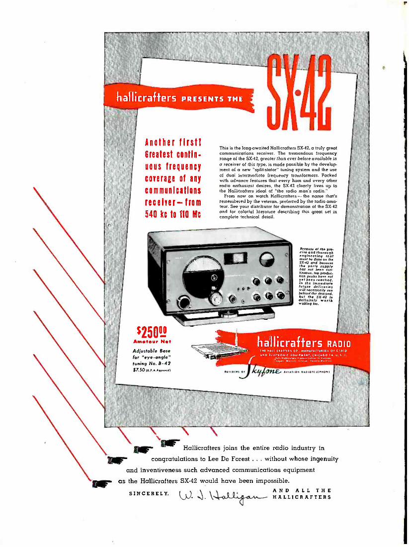
AND WE SALUTE YOU, DR. deFOREST,
THE REAL FATHER OF MODERN RADIO.. Send postcard for catalog of
new measuring and communica
Lion equipment, kits, parts.
OVER 35-YEARS O F R A D I O E N G I N E E R I N G A C H I E V E M E N T
`l % V 9,l4 4 4 4 a e.g. V l Ìfii/i 1249 MAIN STREET
RADIO -CRAFT for JANUARY, '1947 H A R T F O R D 3 C O N N E C T I C U T
IS

THE AMERICAN TELEVISION LABORATORIES INC.
1ZAQ5 Aide [f'1 4znoanein9
The Construction and Installation of the de Forest
Radio and Television Laboratory in our new North
Television Center Bldg. at 5050 Broadway, Chicago
Here, Dr. de Forest will devote his entire time to development and re-
search on behalf of the radio and television industry.
The five thousand student veterans, now enrolled in our Television School,
are inspired and encouraged by his presence. The new student groups that
enter each week look forward to the time when they, too, will become
proficient members of the great and still growing electronic, industry that
Dr. de Forest created with his invention of the vacuum tube. o
Dr. de Forest, at the age of 73, continues to pioneer. His present work is
destined to bring him new honors and add to his already overwhelming
achievements.
Thus, we salute Dr. de Forest, not only as a distinguished scientist and
- inventor but also as a man who has personally demonstrated the oppor-
tunity of reward for scientific enterprise offered by our American way
of life.
U. A. SANABRIA, President AMERICAN TELEVISION LABORATORIES, INC.
VETERAN TRAINING DIVISION AND RESEARCH LABORATORY
MANUFACTURING DIVISION AND EXECUTIVE OFFICES ,
5050 Broadway Chicago 40 525 Plymouth Court Chicago S
16 RADIO -CRAFT for JANUARY, 1947

l
DEFOREST - FATHER OF RADIO
By Hugo Gernsback.
T HE year 1947 marks the 40th anniversary of the radio vacuum tube -Dr. Lee de Forest's three -ele- ment audion, the first grid radio tube. While de Forest invented other audions before 1907, these did not contain the all- important and vital grid. His ap- plication for patent of this tube is dated Januar 29, 1907, hence we can safely say that this date mar the birth of modern radio.
And what a milestone it proved to be in the hi radio! Imagine for a moment that the audioá been invented: We would have no electronics, n no broadcasting, no ocean phone, ho talking mo tures, no amplifiers, no television, no klystrons, trons that made possible fission and atomic ene its bombs, no guided radio weapons -and hun . other radio wonders, plus myriads of new ones t. It will always remain a vivid fact which we never forget: de Forest gave us these priceless g gifts that changed our lives, our habits, that ann ed distances, that made the spoken word .and through all space on this planet a reality, which i will unite humanity as nothing has ever done be Verily -to. paraphrase Winston Churchill : " IN THE HISTORY OF THE WORLD HAS BEEN OWED, BY SO MANY, TO ONE
Tile callous always will parrot the ha "If he hadn't invented the vacuum to would have." Maybe so-but it was d first -and how, under what heartbre disappointments!
De Forest never was a "lucky" in bled accidentally upon an epoch - for instance Dr. Roentgen's discov he literally "sweated it out."
This, too, was seemingly preor. parsonage of a poor Iowa minis steeped in such virtues as reverence, and thrift. All this was augmented mother, too, was the daughter of a
Reared under the lash of severe di and denial in the parsonage, the young a searing hunger for the better things of staid dream was to better his condition. Fortin was gifted not only with a never- to -be- satisfied cui ity, but with an imagination of heroic dimensions.
Thus we later find young Lee, against the wishe- bís family, who wanted him to go to a theological se nary, enrolled at Yale University. After the first semester one of the professors gave lecture which was to change the entire course of de Forest's life. The lecture was on the electromagnetic
wave theory with a demonstration of Heinrich Hertz's experiments. This caused a veritable flare -up in the young student who made this entry in his notebook: "I shall learn all about the atom ... shall guess its shape ... shall postulate. its causes and attractions .. . and I SHALL INVENT THE REASON FOR IT." A bombastic promise -but it was more than fulfilled. It has been my great pleasure to have known Lee de Forest since 1906 -over forty years. I have come to
1wow him very well, and I have had many opportuni- ties to study him at close quarters over the years. I have
y of not
dios, pic-
yclo-
been fortunate to have known Edison, Tesla, and other inventors equally will, and therefore believe myself qualified to judge the outstanding qualities of such men.
One cannot be long in de Forest's company before realizing that among his greatest characteristics is his inherent His unusu the in give plet sta for not
odesty. He speaks in measured, quiet phrases. Ily deep -set eyes proclaim the man of- science,
tigable worker, the type of man who never a quest in search of light and truth. His com=
regard of his attire, his frugal living, his con - preoccupied air, points to his tireless toil and zest
v worlds to conquer. Indeed at.73, he has as yet nd time to begin his autobiography.
a = so many men of the genius type, de Forest has er disregard for money. Finances have never a thing to him, except as a means to new scien- nquests, for research and for his inventions. fts- inanci.l transactions bore him to distraction -and un-
hilat fortvnatly for him the world has seen fit to take ad- usié' v tage of this: a pittance tor his vacuum tube, his re-
n invention, his radiophone (broadcasting), as zens of. his more than two hundred inventions. history's great inventors have been paid so
r epoch- making patents. Harassed by patent him and oountersuits which he had to
ring in turn a . irist others, the little money that was given him soon v ished. Once, because he was so rash
s to tell a Federal .urt that with his radiophone a man ohid soon be able t. talk across the ocean, the Father
'Radio almost went to jail! If not for the pleas of a á+ attorney, de Foi st would have been imprisoned his ttemerity' in. pre.icting modern broadcasting!
asy to the great inventor. The was no exception. It was an
dogged plodding against seem - ntainous difficulties. There are
o worked with him and who cer- ith his Welsbach gas flame audion
ough literally thousands of separate battled himself to the three -element
pite of all this evidence, there are even arrow- minded intolerants who say:
"0 Forest, he just stuck a grid into the Flem- valve!" This is like saying: "The Wright brothers
because they stuck a propeller on an old kite."
timé'' -generati me. ", = *ell as
Few o iggardly uits agains
EVER MUCH'
AN." eyed cliché:
.somebody else orest who did' it,
king obstacles a,
entor who just,4u eking inventi as iy of the X -rallo; ined. Born. into the er he was literally discipline, humility I' the fact that his
ng ever came n of the audio frustration, in
thgly insuperable, mo too many witnesses w tified how he started
inister. and step by step, th ipline, poverty,: experiments, final
oy developed;. His con
y.
grid audion..In t day jealon
o all these soul -trying tribulations discourage Lee orest? Not in the least. His mind is as clear as ever
73, his ideas as young as of yore, his curiosity keener han ever. The other day he and I discussed certain new
aspects of a technical problem in television. For the first time during a two -hour conversation his deep -sunk eyes flashed and sparkled! His alert mind was stalking an idea once more!
This augurs well for his future: Let all of us -the entire radio -electronic fraternity -congratulate Dr. Lee de Forest on the 40th anniversary of his famed audion. Then let us wish him continuous good health, a long life, and many new laurels.
And, may I add, let the radio industry reward him financially for the staggering debt it owes the Father of Radio, which it can never hope to fully repay him.

RADIO-CRAFT foi JANUARY, 194-7

AUDION WAS INVENTED
N THE summer of 1900, I was working under the light of a Welsbach gas burn- er in my hall bedroom in Chicago, ex- perimenting with my so- called "Spon- der," an anti -coherer for the recep-
tion of electrical waves for use in wireless teleg- raphy. One night I noticed that whenever the little spark from my transmitter coil was put in operation the light from the Welsbach burner dimmed. When my transmitter key was lifted, the normal light of the burner was restored. Thus I was able to trans- late into light variations the signals from my key. I was amazed and highly elated 'by this unexpected phenomenon, and for several weeks played with it, believing that I had accidentally discovered that in- candescent gases were affected by Hertzian waves, and that here I had discovered an absolutely new principle which might be of the utmost value as a detector for wireless telegraphy. This illusion per- sisted until my assistant and I put the spark coil in a closet and closed the wooden door ; thereupon the fluctuations of the gas burner were no longer ob- served. This proved conclusively that the effect ob- served was not due to the electrical waves from the spark, but to the sound waves therefrom. I had mere- ly hit upon a new type of sensitive flame.
I was intensely disappointed by this outcome, but I was positive that there must be, nevertheless, some change in the conductivity of incandescent gases re- sulting from the passage therethrough of high -fre- quency electrical-waves, and I determined to inves- tigate further and prove that my original concep- tion had a basis in the physics of gases.
Early Flame Detectors It was not until 1903, when 1 was working in a
small laboratory at 11 Thames Street, ,in lower Manhattan, that I had leisure and opportunity to resume my work in this direction. There I used a Bunsen burner, locating within the flame two plat- inum electrodes, one of which was connected through the telephone receiver to a dry battery, and thence to the other platinum electrode. I enriched the flame with sodium, or common salt.
I then found that when the electrodes were prop- ,
erly located in the gas flame the signals from my spark transmitter were distinctly audible in the telephone receiver. I made countless experiments with this phenomenon ; and to prove definitely that the effect was not acoustic but electrical, I con- nected one of the flame electrodes to my antenna, the other to the ground, and actually obtained wire- less signals from ships in New York harbor. RADIO -CRAFT for JANUARY, 1947
Realizing that a gas -flame detector would be wholly unsuited for practical wireless work, I thought of other means for heating the gases. I tried a small electric arc -which was altogether too noisy to be of any use. After several futile attempts to build such a device myself, I persuaded Mr. McCandless, a manufacturer of miniature incandes- cent lamps, to build for me a tube containing a platinum plate and carbon filament. The plate was connected to the positive side of the dry battery ; the negative terminal to the filament. In series was a telephone receiver. This device was not the Flem- ing valve. It has always been quite impossible for me to understand the confused idea, in the minds of some otherwise keen thinkers, that the audion dif- fered from the Fleming valve merely by the inser- tion of a third electrode therein. Without the use of the B- battery the valve would be nothing but a rectifier with one too many electrodes. The employ- ment of the local battery in the plate, circuit is just as necessary an element to the success of the device as is the grid itself. At the time I was working on the two -element audion with B- battery, I had never heard of the Fleming valve. My approach to this perfected device was by an entirely different series of events, and began with the gas -flame detector. Vacuum -Tube Detectors
This device was a genuine relay, in which the local energy of the plate battery supplying the cur- rent through the remaining gas in the tube was con- trolled by pulsations of the incoming high- frequency waves, which were picked up on an antenna con- nected to the plate electrode, the filament -being con- nected to the ground. This was the same arrange- ment I had previously used with the gas flame de- tector. At that time I had requested McCandjess not - to exhaust the tube to any high degree of vacuum, because I then thought that the presence of gas was an essential element. This diode detector, as stated above, was intrinsically very much more than a simple rectifier of high- frequency current. The addi- tion of the plate battery made a very great differ- ence in the intensity of the signals received, for I was employing the high- frequency energy, not to actuate my telephone diaphragm, as Fleming had done, but to control very much larger quantities of energy from the local battery.
I argued that the above arrangement was imper- fect because it permitted part of the high- frequency energy to pass to earth through the telephone and B- battery circuit, instead of concentrating it upon the ions between the plate arid filament. To avoid this difficulty and still improve the sensitivity of the

Welsbach gas mantle, starting point of the series of experiments which led
detector, I wrapped a piece of tin foil around the outside of the cylindrical- shaped gas envelope, and connected this third electrode to the antenna or to one terminal of the high- frequency device. I then realized that the efficiency could be still further en- hanced if this third electrode were introduced with- in the envelope. I induced McCandless to construct another "audion," as I then called it. This last device contained two plates with a filament located between them, and, as before, a considerable amount of gas in the envelope. This detector showed further dis- tinct improvement over its predecessors.
The Grid Audion It occurred to me that the third, or control, elec-
trode should be located more efficiently, between plate and the filament. Obviously, this third elec- trode so located should not be a solid plate. Conse- quently I supplied McCandless with a small plate of platinum, perforated by a great number of small holes. This arrangement performed much better than anything preceding it, but in order to simplify and cheapen the construction I decided that the in- terposed third electrode would be better in the form of a grid, a simple piece of wire bent back and forth, located as close to the filament as possible.
At this time I was using a 6 -volt filament ener- gized from a dry or storage battery, which I called the A- battery; the plate battery I called the B -bat- tery- terminology which has persisted to this day.
As the various experiments and improvements
20
to the audion.
outlined took place during the period 1903 to 1906 and later, I applied for successive patents. At that time the Patent Office was not glutted as it is today, and my applications were related to an en-
: tirely new art, so that the Office issued my patents within only a few weeks or few months after filing.
Early in 1907 I conceived the idea that this remarkable wire- less telegraph detector, the three - element, or grid, audion -which had already covered itself with glory in the minds of the hams and wireless telegraph operators -might also be useful as an amp- lifier of audio -frequency or tele- phonic currents. I had made some experiments in this direction, and took out a patent containing very broad claims on the device as an amplifier of currents without limi- tation of the frequency thereof. This patent, No. 841,387, granted January 15, 1907, has since been acclaimed as one of the most valu- able patents ever issued by the United States Patent Office. The same, of course can be truthfully said about the patent on the grid electrode, No. 879,532, filed January 29, 1907.
In the summer of 1906 I presented a paper be- fore the American Institute of Electrical Engineers describing the audion, but only as a diode using the B- battery. I had not then applied for a patent on the grid, or control -electrode, type, and therefore I made only veiled reference in this paper to it. The grid patent was filed on January 29, 1907.
Early Types of Audions The first audions were of cylindrical form ; later,
in 1907 or 1908, McCandless suggested that it would be easier for him to construct the device in the spherical form. In the first audion the grid and plate electrodes were both brought out near the base ; but in 1907 the plate and grid electrodes were brought out through the top of the tube. To distin- guish readily between the two, I used a red sleeving over the lead to the plate, and a green sleeving over the grid wire -"green for grid," to be easily re- membered by the operator.
In my first experiments on the audion as an am- plifier for telephonic currents I added a third, or C- battery as I called it, in series with the control electrode. Although, unfortunately, I did not specify the polarity of this C- battery, the circuit diagram of the amplifier patent shows it with its negative ter- minal connected to the control electrode. This was the way I always employed it; but due to this un- fortunate omission from my. specification, Fritz Lowenstein was able, a few years later, to obtain a
very valuable patent covering the negative bias of
RADIO -CRAFT for JANUARY, 1947'

the grid. He was, however, by no means the first to apply this negative bias to the control electrode. Later Audion Improvements
From 1906 to 1910 I made countless improve- ments or changes in the form of the audion, such as the substitution of tantalum and then tungsten for the carbon filament; the use of nickel for plate and grid instead of platinum ; the double filament so ar- ranged that if one burned out the second one could be readily connected, thus doubling the life of the detector. As early as 1907 McCandless began to pump my tubes to the same vacuum he employed in his miniature incandescent lamps. Naturally some of the tubes contained more gas than did others, and we found that a very small amount of gas made the device a more sensitive detector than those of higher vacuum. When used as a detector of wireless signals, the lack -of- linearity characteristic was of course of no importance -maximum sensitivity was what we all were after. But so long as only an "in- candescent lamp vacuum" was employed, it was impossible to use more than 22 or 30 volts in the B- battery without producing the "blue arc" which at once rendered the device extremely insensitive.
My patents show types of audions employing two, three, or more grids, as well as the "double audion" having one plate and grid on either side of the double filament. The latter arrangement developed into a beautiful oscillator, the first push -pull type in electronic history.
It was not until the summer of 1912 that I actual- ly succeeded in developing the audion and its accom- panying circuits into a genuine amplifier of tele- phonic currents. Seeking to make this amplifier more efficient and able to handle larger power, I besought McCandless to exhaust the tubes to the highest pos- sible degree, to permit the use of more plate volt- age. But the best that he could do still restricted this voltage to about 45. Thereupon I took some of his tubes to a manufacturer of X -ray tubes in San Fran- cisco, who re- exhausted these to the best of his abil- ity, using mercury vapor diffusion pumps. (McCandless had used only mechanical pumps.) With these re- exhausted tubes I was able to use as high as a 220 -volt plate battery, without causing the "blue arc." Three of these high- vacuum audions
ANT
e
connected in cascade gave amazing audio -amplifier effects, so that using as my input source a. telegra- phone wire on which music or speech had been re- corded, and as my output device a loudspeaker of the 1912 vintage, I was able to hear the reproduction of voice and music over a distance of 100 feet or more in the open air. Thus it is evident that the approach to the radio, or amplifier, tube possessing an extremely high vacuum was merely a gradual, and perfectly obvious, result of the growing require- ment for more power from the amplifier or the oscil- lator. More power demanded higher voltages, and it was obvious that higher voltages would necessi- tate higher degrees of vacuum. I never considered for a moment that there was any invention involved in the gradual evolution of the audion from a gas- eous, or low -vacuum, to a high- vacuum device.
At this point in the development of the audion am- plifier I was requested by my good friend John Stone to bring my demonstration apparatus from Palo Alto, California, to show to the engineers of the telephone company in the Western Electric labora- tory in New York. From that point on, the further development and refinement of the audion amplifier to its present degree of ultra -perfection is well - known electronic history, and requires no résumé here.
Regeneration and Oscillation During those epoch- marking experiments in Palo
Alto, in the summer of 1912, I accidentally hit upon the feed -back circuit, which made of the audion am- plifier an oscillator of currents of any frequency. Thereafter began the intensive development of the "oscillion," as I then called it, in larger and larger sizes and degrees of power, until in 1915 I was em- ploying a 25 -watt power tube for broadcasting from my Highbridge, Bronx, laboratory steel tower. Si- multaneously, the Western Electric engineers were developing the oscillator along very similar lines to a point where they were able, utilizing a battery of one hundred or more of these tubes, to transmit the human voice across the Atlantic without wires -a feat the prediction of which by myself, just two years previously, had been considered a ridiculous improbability, had almost resulted in my incarcera- tion in Atlanta Penitentiary!
A"' Evolution of the audion. Even the earliest flame detectors incorporated the B battery, as shown in the left-hand figure (Patent No. 867,878). The circuit at center (Patent No. 836,070) k essentially the same, with a heated filament in a kw-vacuum tube taking the place of the Bun- sen burner flame. Thus the B battery was also a feature of the earliest two - element audions. In the circuit at right (Patent No. 841,387) wp see the separation of r.f. and local circuits, as well as the C battery (credit for the invention of which 'was lost to de Forest because polarity _ markings were omitted from the patent drawing). Obviously the whole series of heat detectors were thermionic relays, not simple rectifiers. RADIO -CRAFT for JANUARY 1947
gab

BIRTH OF THE AUDION
HEN I first became associated with Dr. Lee de Forest in 1904, the dependable communica- tion range of wireless was less than 100 miles. At that time he was driven by two ambitions - to increase the sending distance and to discov-
er a better detector -with thé greater stress on the lat- ter. He reasoned that improved detector sensitivity would automatically increase the transmission range. None of the then current coherers, magnetic and electrolytic de- tectors did ever satisfy the rigid requirements and hopes of de Forest.
At this time k disaster (which upon closer analysis was not a disaster but a real blessing in disguise) oc- curred to de Forest. A court decision, in favor of Mar- coni, strictly enjoined him "to forever desist from the manufacture, sale or operation of any system of wireless telegraph."
Penniless, but not discouraged nor beaten, he rented a small, inexpensive space in the Parker Building, then located at the corner of Fourth Avenue and 19th Street, New York City. Here he started his renewed search for a "better wireless detector." Watches, clothing, and keepsakes were pawned. His brother Charles made razor strops with a special "lick -dob" on them for sharpening, the blade, which I demonstrated and sold in Hageman's drug store window across from the old Grand Central Station as new experiments began and our hopes rose.
Ultimately the audion was invented as a result of brilliant reasoning by de Forest. Up to this time all known methods of reception depended upon or were derived from the three natural elements of water, earth, and air, notably metal filings, electrolytic fluids, and iron magnets. The possibility of using fire -the fourth and only remaining natural element -was at first un- noted, but the fluttering of a Welsbach gas flame in the
RADIO -CRAFT for JANUARY, 1947

13y Frank E. Butler
A first -hand account
written b y an assistant of de Forest throughout the hard years which immediately pre- ceded the most revolutionary in- vention in all the history of radio.
presence of a spark gap was the miraculous and meager clue flashed by Fate to the keen mind which saw in it the path to his great discovery. His clue was the possi- bility that heated gas molecules might be sensitive to high- frequency electric waves. Such a theory was at least a new creative thought -not a copy or a follow -up of anyone else's idea. But, how to use it and with what? That was the real problem to solve. "Can heat hear ?" was the first crude question! How was heat or gas or both to be fondled, handled, and nursed into a p actical application ?
As a result of de Forest's earlier preliminary tests, the fact was firmly established in his mind that the proper and only successful detector should operate upon the principle of relay ac- tion. According to this revolutionary idea some kind of automatic trigger device should control the local energy from a boost- er battery (from which the name "B- battery" is derived.) Activated by the incoming signals it would thus re- create the audible sound of the original transmitted signal. The plan was simple.
Assuming that a circuit were used in which the an- tenna impulses passed through a "gap of flame" to earth in the path of which there was inserted a telephone receiver -and provided there was even a breath of signal coming in over that route -why would it not be possible to boost or rejuvenate this feeble electrical impulse, to amplify it into audibil- ity by the use of an elec- trical booster of dry cells -B- battery in embryo. With the inception of that
idea the famous and very esential B- Battery came into being, marking the first revolutionary advance in wire- less since its beginning -a step as important to radio and electronics as was Franklin's discovery of electricity during an electrical storm by means of kite and key.
Dr. de Forest believed that if two bodies adapted for use as electrodes in a wireless receiving circuit be slightly separated, the space between them could be neutralized sufficiently to enable them to act as a detector of elec- trical oscillations. Provided that the intervening gap be put into a condition of molecular activity by the action of heat such a condition of ionic activity would cause what otherwise would be a nonsensitive device to become sensitive to electrical wave influences. His first impres- sion was that this could be accomplished in free air, and so it first was done.. There was no intention at the start to enclose the heating medium in a container of any kind, much less the thought of a vacuum.
Imbued with this revolutionary theory of using heat it was logical for de Forest to think of an open flame that would be small, concentrated, and adjustable. He selected for his experiments an open flame as generated in the common Bunsen gas burner universally used in research work.
Several standards of various types and designs for holding or suspending the necessary electrodes were made, equipped with binding posts on top to admit the ends of the wires. They were made so as to raise or lower the height of the extended terminals which later were placed in or adjacent to the open flame. A low -power transmitter was located on the other side of the room. In this case, the distance between the sending and . the receiving points was of no consequence -the ability to receive something in the nature of a signal meant everything.
De Forest's basic problem reduced to its simplest form was threefold: What kind of heat to use? What kind , of electrodes to employ? By what process could neutralization of gap be best obtained? He did not
FRANK E. BUTLER was born in Monroeville, Ohio, only a few
miles from the birthplace of Thom- as A. Edison. Like Edison, he start- ed his career as telegraph oper- ator from the same location and at the same age of 15 years. On June 10th, 1904, he resigned as train dispatcher on the New York Central to become associated with Dr. Lee de Forest in the young art of wireless telegraphy, and for many years afterwards acted as his chief assistant. In 1908 he organized The American Wireless Institute, the first school in the world to teach wireless engineer- ing. Many present -day radio ex- ecutives and engineers are among his graduates, and he points out that from the ruins of this pioneer school was started, in 1911, the forerunner of the RCA Institute. Mr. Butler designed numerous early radio circuits; was sales manager of. I tube com- panies, among them Archetron, Volutron, Arcturus and ken -Red. He is known among acoustical engineers as an inventor in this and the moving, picture field. Is a current writer for several tech- nical publications and the author of books dealing with the progress of wireless, radio and electronics.
RADIO -CRAFT for JANUARY, 1947

realize that the answer to these three questions would spell -radio tube! His original idea of a flame augment- ed by the B- battery, and his ultimate development of the three- element tube with its filament, plate, and grid, are identical in theory and operation- differing only in degree -an undying tribute to the .brilliant genius of Lee de Forest.
In his initial Bunsen burner tests a live flame stood between and divided two electrodes with no physical means of contact (such as a wire or other metallic medium). The heat of the gas created the "phantom medium" over which the signal might flow. De Forest chose to call this phenomenon, ionic action, though he might as well have called it electronic action.
The illustrations show 'explicitly and clearly the line of reasoning de Forest followed from one test to the next, even though they do not include all the many experiments that were tried, only to be discarded later as being impractical or not applicable. Those shown here constitute only the major steps. They do not represent, in the slightest, the complete research and intense analysis of de Forest as he progressed methodically and confidently with his experiments. So thorough and extensive were his tests that he applied for patents - not one but twelve! The first five covered his experi- ments with an open gas flame.
Had de Forest been interested in copying any pre- vious experiments of others, as is so often unjustly and untruthfully claimed by those who were not there, he naturally would have started his research with the bulb first, but it is significant that the sequence of his patent applications shows how unerringly he pursued the path of investigating heat as the only avenue to lead him to his goal -a path which scientifically could not have been traveled to success in any other way. This is a highly important historical fact.
In the first experiment (Fig. 1)- a common Bunsen burner was lighted and adjusted to an intense blue flame. The metal frame itself formed one of the two terminals or electrodes, thus being a part of the elec- trical circuit. The standard holding the second electrode was moved so that its projecting wire entered the area of the flame near the center. Obviously the electrode which was placed in the flame was of relatively higher temperature than the standard itself which formed, the other electrode. Thus was formed a local receiving cir- cuit possessing a certain asymmetric electrical con- .
ductivity
on-
ductivity which permitted the current from a few No. 6
dry cells to pass from the relatively cool burner stand to the more highly heated one. (Current in 1906 always traveled from positive to negative.) Fortunately the adjustment of the terminal wire in the flame during the first trial was perfect -quite by accident- other- wise no signal could have been heard. But there was no mistake about this! The signals were very weak, yes - but nevertheless they were real reproduced signals sent across the room.
This initial test brought out two important results: First it proved that heat was effective in detecting
wireless waves. Second it witnessed the birth of the B- battery -the importance of which cannot be empha- sized too much, because without this simple adjunct our present -day radio and electronics would not be possible.
The second test (Fig. 2) was prompted by a query which in itself seemed trivial, yet it was fraught with great possibilities, as later test proved.
"If one electrode in a flame produced such promising results -what will happen if two terminals be im- mersed in the flame,-and are different spots in the flame more sensitive than others ?"
Then another test (Fig. 3) suggested itself. Instead of using two plain points of wires as terminals, why not employ "blinkers" or reflectors at the end of terminals, and deflect or concentrate the "ions" across the flame. Another test consisted of two wings -first plain flat pieces of metal, then perforated ones.
It was observed that the extreme outer edge or envelope of a flame appeared to be the most sensitive spot and there was a difference in signal strength be- tween a cool wire just approaching or touching the flame and when, a moment later, that terminal tip became red hot. It was also noted that varying the voltage of the B- battery produced a marked difference in results. Every disclosure was startling in effect and heightened the curiosity and anxiety of de Forest to probe even deeper into this fascinating research.
The next test (Fig. 4) was a radical departure from the previous ones and illustrate the wide range of the inventor's imagination. This consisted of a trqugh -like electrode suspended horizontally above the flame. Vari- ous crystals of potassium, halogen sodium salts, etc., were placed in the trough, and when heated would emit different gasses or rarefied heated air. Parallel to this
RADIO -CRAFT for JANUARY, 1947

¿: r.. ' '
trough and above it was suspended a straight wire of the same length, this being the second electrode. The idea of using salts was to improve the sensitivity of the gap by further increasing its molecular activity. This was perhaps de Forest's inception of a "rarefied area" such as only an evacuated medium could produce -a radio tube in embryo.
Then followed the introduction (Fig. 5) of four term- inals in flame arrangements. This time the ends of the electrodes were made with rings of slightly different circumference so that each terminal could snugly en- circle the flame, one ring on top of the other and each leading to a different part of the circuit. This test again shows de Forest's original idea of keeping the high - frequency current path distinct and free from that of the local telephone current -the idea of separating the high- frequency from the audio circuits. It was in this experiment that de Forest obtained his first vague idea that the influence of high- frequency impulses could be impressed to better advantage on the conducting medium by means of a third electrode (the "grid ").
It now seemed that de Forest was running into a log -jam among so many results -each of which pre- sented its own set of baffling problems. The situation was bewildering -the search too intense. Anything might or could happen to precipitate a crack -up. It was this latter specter that haunted de Forest, for although he had learned a great deal about the action of heat and its relative importance to wire- less detection, yet once again it was a whiff of air that turned the tide against him just as it was a whiff of air that feebly fluttered the Welsbach burn- er that originally inspired him. He had observed that the slightest draft of air could blow the flame out of its delicate adjustment- thereby altering the action and rendering the reception unstable. This observation sent de Forest into despondency as it convinced him that no matter how successful his flame tests might be-or whatever type electrodes he might use -its practical use, as for instance on shipboard, was impossible. At last -the realization that the dead end of a street had been reached.
The instability of an open flame and its suscepti- bility to drafts then caused him to shift to another type of heat- producing medium in an attempt to find the necessary steadiness. There seemed nothing quite so handy, practical or promising as a lighted incandescent electric lamp.
The first thing to be decided was the voltage and the number and kinds of electrodes to use. It was de Forest's intention to follow the series of bulb tests along the same sequence as was done with the flame. It would take longer, but at least give the benefit of comparisons. A Christmas tree lamp with its small candelabra base and low voltage was considered the '
most advantageous type. This style of lamp was obtain- able locally from a manufacturer named McCandless Incandescent Lamp Co. However, making up only two or three samples of electric lamps which possibly would burn out after only a few moments' trial presented a real fi- nancial problem. It required unusual skill on the part of McCandless to construct the various electrodes and then to evacuate the tube with a hand pump before sealing. Sample after sample was discarded and yards of glass tubing sacrificed before the first crude specimen (Fig. 6) was produced. Then followed bulb after bulb, made along the same lines as the previous flame -tests. Each pro- duced varying degrees of good or bad results-represent- ing a maze of baffling problems. Then followed a test with a tube in a horizontal position (Fig. 7) designed with a small cup on the bottom which held a portion of mercury.
The next test, using two wings (Fig. 8) is especially significant. It is not only the original amplifier, but it also introduced for the first time the use of a "bias C- battery" clearly shown in the patent drawing with
RADIO -CRAFT for JANUARY. 1947

its negative plate leading to the oontrol electrode -un- assailable direct evidence that the idea of "negative grid bias" positively was originated by de Forest (though it later meant a fortune to those concerns controlling the Lowenstein patents).
With this idea fresh in mind de Forest next tried a tube having only one wing and filament. He pasted a strip of tin foil on the . outside of the tube (Fig. 9) which he used as one electrode -but this produced no favorable result. A safety razor blade was lying within reach. Preoccupied with many thoughts de Forest care- fully cut the tinfoil -round and round -into a long spiral piece like a spring, without changing its location where it was pasted. This simple act had the effect of making a coil of fiat metal instead of a flat plate -two quite different and distinct things electrically. This was hooked up and tried. The result was startling. Hopes rose. This also was the time a 6 -volt storage battery with adjustable resistance was used for fila- ment supply. Likewise the amount of B- voltage was set at 221/2 volts with a potentiometer for varying its potential -two items that remained standard in future radio circuits for many years afterward.
Experiments were continued with a wire instead of a tin -foil spiral. De Forest figured he had too much wire wound around the tube, which luckily was a sturdy one, able to withstand the series of additional tests. Signal strength continued to increase as he kept con- stantly snipping small pieces of the coil to reduce its length.
Finally when only about 11/2 inch remained of the original coil -not even enough to completely encircle the glass -he obtained his greatest results, and he stopped there. Feverishly he took this small length of
wire and with a pair of long -nosed pliers bent it into a flat zig -zag shape having the over -all dimensions of the flat % -inch wing. This was taken over to McCandless. Dramatic and intense moments followed.
"It is my impression," said de Forest, "that if we take this zig -zag wire and place it on the inside where it will be closer to the hot filament and the cold wing we'll notice a decided improvement. In fact I believe the closer we group the three elements the more effec- tively they will operate."
At this point de Forest sketched the idea he had in mind. Here again was shown the third or C- battery in the input circuit. This indispensable C- battery, like its big brother B- battery were both discovered and used before their famous sister the grid came into existence!
Several sets of tubes were made with the elements in different locations. Each was carefully tried. One of these was made with the zig -zag wire interposed between the filament and the wing. By a streak of for- tune this was the last one to be tested.
Disconnecting the previous tube, de Forest reached for the remaining specimen that was still resting in the old shoe box filled with cotton batting in which it was brought from the McCandless shop.
In that unforgettable moment, de Forest gently held this remaining tube in his hand as if he had a pre- monition of what promise it had in store for him -and mankind. When all was in readiness again, he called across the- room saying:
"O.K., Frank! Let's have some signals!" Immediately I started sending the familiar "Dash -dot-
dot"-of the letter D with the same monotonous action I had been accustomed to for years, with no special thought that this was an exceptional occasion. Two or
three D's had been made when my
28
Fig. 10-End of de Forest's long search for the better defector --the original grid eudion.
senses were jarred by the wild, almost frantic yell from de For- est saying:
"That's it, Frank! My God, you ought to hear those signals! I never heard such perfect D's before -Here take these phones quick and let me send it to you."
He dashed toward the trans- mitter- passing me as I rushed for his headphones where I too listened in amazement at the quality and strength of signals.
At last de Forest's dream had come true. That moment saw the birth of the "three- element vacu- um tube" (Fig. 10). Our "better detector" had become a reality.
The life of that pioneer tube was scarcely three minutes before it burned out. In that short and glorious life -span it had accom- plished what none of the human race had ever seen or heard sinoe creation. It was the first mes- senger from Cosmos chronicling the harnessing of the electron. Its sound, though weak, was strong enough in its message to echo throughout all future ages. Its infant range was merely the length of a dingy room -a far cry from that of its offspring to- day which girdles the earth and reaches into the infinite space of the planets.
RADIO -CRAFT for JANUARY, 1947
1
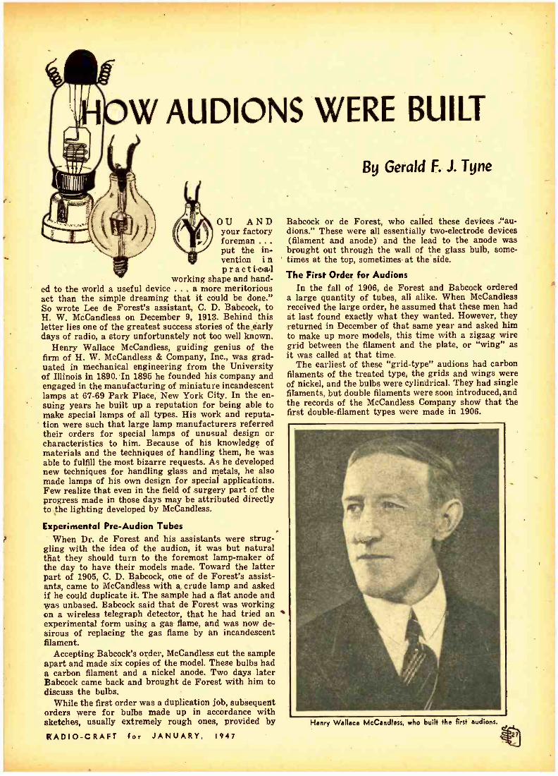
W AUDIONS WERE BUILT
0U AND your factory foreman .
put the in- vention i n praeti.aa.1
working shape and hand- ed to the world a useful device ... a more meritorious act than the simple dreaming that it could be done." So wrote Lee de Forest's assistant, C. D. Babcock, to H. W. McCandless on December 9, 1913. Behind this letter lies one of the greatest success stories of the early days of radio, a story unfortunately not too well known.
Henry Wallace McCandless, guiding genius of the firm of H. W. McCandless & Company, Inc., was grad- uated in mechanical engineering from the University of Illinois in 1890.In 1895 he founded his company and engaged in the manufacturing of miniature incandescent lamps at 67 -69 Park Place, New York City. In the en- suing years he built up a reputation for being able to make special lamps of all types. His work and reputa- tion were such that large lamp manufacturers referred their orders for special lamps of unusual design or characteristics to him. Because of his knowledge of materials and the techniques of handling them, he was able to fulfill the most bizarre requests. As he developed new techniques for handling glass and metals, he also made lamps of his own design for special applications. Few realize that even in the field of surgery part of the progress made in those days may be attributed directly to the lighting developed by McCandless.
Experimental Pre -Audion Tubes When Dr. de Forest and his assistants were strug-
gling with the idea of the audion, it was but natural that they should turn to the foremost lamp -maker of the day to have their models made. Toward the latter part of 1905, C. D. Babcock, one of de Forest's assist- ants, came to McCandless with a, crude lamp and asked if he could duplicate it. The sample had a flat anode and was unbased. Babcock said that de Forest was working on a wireless telegraph detector, that he had tried an experimental form using a gas flame, and was now de- sirous of replacing the gas flame by An incandescent filament.
Accepting Babcock's order, McCandless cut the sample apart and made six copies of the model. These bulbs had a carbon filament and a nickel anode. Two days later Babcock came back and brought de Forest with him to discuss the bulbs.
While the first order was a duplication job, subsequent orders were for bulbs made up in accordance with sketches, usually extremely rough ones, provided by
RADIO -CRAFT for JANUARY, 1947
By Gerald F. J. Tyne
Babcock or de Forest, who called these devices "au- dions." These were all essentially two -electrode devices (filament and anode) and the lead to the anode was brought out through the wall of the glass bulb, some- times at the top, sometimes at the side.
The First Order for Audions In the fall of 1906, de Forest and Babcock ordered
a large quantity of tubes, all alike. When McCandless received the large order, he assumed that these men had at last found exactly what they wanted. However, they returned in December of that same year and asked him to make up more models, this time with a zigzag wire grid between the filament and the plate, or "wing" as it was called at that time.
The earliest of these "grid- type" audions had carbon filaments of the treated type, the grids and wings were of nickel, and the bulbs were cylindrical. They had single filaments, but double filaments were soon introduced, and the records of the McCandless Company show that the first double -filament types were made in 1906.
Henry Wallace McCandless, who built +he firs+ audions.

Early double -filament, double -grid and double -plate audion, now owned by Louis G. Pacent..
The first double -element type (plate and grid on each side of the filament) was made in April 1909, but the single- element type contin- ued to be made for some years there- after. These double -element tubes were known as "double audions," and were sold by de Forest at a higher price than the single -element type. A number of these double audions are shown in the attached photographs.
Contributions by McCandless
It was evident to McCandless that these men were experimenting and as usual he drew on his wealth of knowledge to make suggestions as to
how the tubes might better be made. The earliest tubes had all the ele- ments mounted on a single stem, al- though the leads for the grid or wing, and sometimes for both, came through the side of the bulb instead of through the "press."
McCandless and his shop superin- tendent, Jacob C. Grogan, felt that the audion would not become a com- mercial product until the tubes were designed with the grid and wing on one stem, and the filament on an- other. The purpose of this was, first, to keep the leads separate and, sec- ond, to save the loss of audions due to burning out of wire filaments dur- ing exhaust. With the double -ended
assembly it was easy to cut off the stem of the bulb, splice on a new neck and seal in a new filament and stem, thus saving the bulb.
While this development work was going on, McCandless was working on another project. For a long time he had wanted to make a satisfactory incandescent lamp to operate at two volts, so that it could be used on a single storage cell. The character- istics of the available carbon fila- ments would not permit this, with the filament diameters available. The filament had to be so short that only the center part glowed, the tempera- ture of the end portions being re- duced by conduction of heat through the supports.
Improvements in Filaments In 1906 a friend brought from
Germany one of the newly -developed tantalum - filament, 110 -volt incan- descent lamps, which were then little known in the United States. Mc- Candless broke open this lamp, and using approximately 1/55 of the length of the 110 -volt filament, made up a two -volt lamp which was suc- cessful. He then tried to obtain addi- tional tantalum wire from Siemens & Halske, with the understanding that it was for use in lamps operating at less than ten volts filament. Al- though he made some progress in the early stages, negotiation was never successful because of patent difficul- ties. He did manage, by working through the Association of Lamp Manufacturers, to get limited amounts of this wire from the Gen- eral Electric Company.
McCandless decided to try tanta- lum- filaments insthe audion. It was a
Three evolutionary steps. Left is 1908 audion. center a 1910, and right a 1912 type. Courtesy G. F. J. Tvnc
RADIO -CRAFT for JANUARY, 1947

good inspiration, since . it improved the electrical characteristics con- siderably, but it had its disadvan- tages. It was not stable in position. When heated it would not remain in a plane, but would twist around to such an extent sometimes as to touch the other elements. The important thing was that it could be made to operate at four volts. Carbon fila- ments required at least six volts for satisfactory operation.
About this time tungsten filaments came into the picture, and McCand- less, ever on the lookout for methods of improving the quality of the au- dions he made, tried them. The tung- sten filament of that day proved to be little better than carbon and far inferior to tantalum.
The suggestion was made -by whom McCandless does not remem- ber -that a tungsten filament be used because of its rigidity, but that it be wrapped with tantalum to get good emission. Always open to sug- gestions, McCandless tried this ex- pedient. It was successful. The com- bination was as good electrically as pure tantalum and as good mechan- ically as the carbon filament.
Soon after the first tubes were made for de Forest, in 1905-1906, a young man came to McCandless and wanted to buy some audions. Mc- Candless consulted de Forest who told him: "Sure. Sell them to him." This McCandless did, and the word spread, so that more and more tubes were sold on an over -the- counter basis.
One of these customers, who first came to buy shortly after McCand- less had introduced the tantalum - wrapped tungsten filament, was Dr. Walter G. Hudson, an enthusiastic amateur, then chief chemist for du Pont. McCandless showed him the audions with the tantalum- wrapped filament and told him that the wrapping was an extremely tedious and time -consuming operation. Hud- son bought so%ne of the tubes, and after he had used them carne back to McCandless and said:
"I have an idea. Let me try it, and if it works I'll patent it and go fifty - ilfty with you if it proves saleable."
Hudson's plan was to grind the tantalum to powder, make a paste of the powder by adding a binder, and applying the paste to the loop of the tungsten filament. Hudson provided the paste and the audions made in this manner were very satisfactory. In fact the "Hudson filament" type soon became the "standard" audion.
During these years of development work on the audion, McCandless was not focusing his attention on mate- rials alone. He Was also experiment -
RADIO- CRAFT for JANUARY,
ing with the shape of the tube and the positioning of the elements therein. Better Pumping Equipment
The early audions were made with the vacuum ordinarily obtained in the incandescent lamp of that day. When McCandless began to manufac- ture miniature lamps, he used an ex- haust pump of the "Packard" type. Later he added so many improve- ments to this that it became known as the "McCandless pump." At that time no pressure gauge was used on the pumping equipment. To deter- mine when the proper vacuum was attained the mercury valve which checked the back -rush of air into the pump was watched. The tubes were pumped until practically no bubbles appeared at that point. The bulbs were checked for leaks with a high - tension spark -coil device, commonly used by incandescent lamp manufac- turers for that purpose.
De Forest kept demanding higher and higher vacua -in the audion. Later, for higher vacua, the tubes were baked in an oven to a very high temperature while still on the pump. In some cases the bulbs were heated, by the direct application of a Bunsen flame, almost to the collapsing point. This was done to expel all the gas occluded in the glass bulb.
A few years later, in August 1910, McCandless replaced his pumping equipment with two rotary pumps of the Gaede type (not the Gaede molec-
Courteeu R. MeV. Weston, F.R.P.S. A 1907 audion, once owned by J. A. Fleming.
Courteau G. F. J. Tyne
Left -An early de Forest "Singer Type" audion. Note the metal base. Right -An Ultraudion with Hudson filament mounted in an adapter to permit operation in candelabra socket.
I947

r
Courtesy Clark Historical Libra'', Very early type of three- electrode audion, made in 1907 and 1908.
Reconstruction of the 1907 appearance of the building at 67-69 Park Place, New York City, where the first Audion was made by McCandless.
ular pump). A third such pump was added in February 1911. De Forest continued to demand higher vacua in the audion and sometimes returned the bulbs for re- evacuation, com- plaining of a lack of "sensitiveness." Grogan insisted that the lack of sensitiveness was caused by pumping the tube to too high a vacuum. This was particularly the case while de Forest was on the West Coast with the Federal Telegraph Company, where he was trying, in 1912, to make the audion function as an amplifier.
Detector vs. Amplifier Here is a confusion of the terms
"sensitivity" and "output." In the case in question de Forest, on the West Coast, was trying to get high output by operating at high anode voltage. The tubes would not give output, hence he said they were not "sensitive." What he meant was that "
he could not get the desired ampli- fication at high power levels because of ionization of the residual gas. The gaseous tubes advocated by Grogan and operated at low anode voltage would detect lower voltages but would not give high power output.
McCandless made a number of au- dions for the Federal Telegraph Company while de Forest was with them.
In the fall of 1912 de Forest came east with a view to interesting the telephone company in the amplifying properties of the audion, for its use as a telephone repeater. After he had demonstrated the device, de Forest left the apparatus with the engineers of the Western Electric Company, and gave them permission to pur- chase additional bulbs from McCand- less for their experiments. McCand- less made for them two types of bulbs. The first was a tantalum-fila- ment double audion, and the second a single audion, but having larger ele- ments and a larger bulb, with a long- er, higher- voltage filament of tanta- lum. These tubes are shown in the photographs. The larger elements were used at the suggestion of Grogan.
Some time prior to 1912 the Mar- coni Company took official cognizance of McCandless' work on the audion. Mr. R. W. Sammis, then chief en- gineer of the Marconi Company, in a preliminary telephone conversation offered to give McCandless the job of making Fleming valves for his company, provided he would stop making audions for de Forest. Sam - mis later wrote McCandless a letter transmitting to him a copy of the Fleming patent ánd stating that it covered the audion 'and in fact any
RADIO -CRAFT for JANUARY, 1947

PIPP.7^',r.-,_..-*.
type of rectifying vacuum detector. McCandless consulted an attorney, Charles McCandless (not a relative, however), and they studied the Fleming valve patent. Meantime, aft- er the telephone conversation, but be- fore the letter from Sammis, Mc- Candless became very much con- cerned over the situation and wrote de Forest about it. De Forest replied, on March 2, 1912, giving a list of the patents covering the various embodi- ments of the audion, and assuring McCandless that he was fully pro- tected. McCandless obtained copies of all the patents, and after due con- sideration decided to continue the manufacture of audions.
Sales to the general public were negligible after 1913. De Forest started to make tubes himself at his High Bridge plant and "bootleg" manufacturers started up. McCand- less never advertised' or solicited trade in audions. He continued to make special bulbs for de Forest or any other customer who came to him with a problem which was a chal- lenge to his genius. Be sold his busi- ness to the Westinghouse Company in 1914 and entered their employ as
Courtesy G. F. J. Tyne
A 1916 tube, last of the screw-based audions. It was made at de Forest's Highbridge plant.
DE FOREST AUDION
manager of the Westinghouse Spe- cial Lamps Division.
To this day the concluding para- graphs of Babcock's letter written about that time must bring back a stirring flood of memories to Mc- Candless :
The Tribute from Babcock "The mechanical and electrical de-
velopment of the device from those crude designs of mine to the perfect instrument of the present day should and does stand as a monument to the skill, patience and technical knowl- edge of your Mr. Grogan. Particular- ly valuable was his disclosure to de Forest that the audion should not be exhausted to a vacuum known as 'hard,' but rather should be 'soft,' that single fact took the device from the ranks of failures and put it in the category of successes.
"Facts are stubborn things, and the above are some of the stubborn - est in the history of this instrument. The great pity is that the thing never became more generally used so that you could reap the reward due you for the part you and your staff played in its development."
í9o7^ -I 947 Three Anecdotes of the Audion's Early Days
How the Grid was Named During the early experiments with
the first crude handmade radio tubes it was the custom of Dr. de Forest to give directions to his assistants somewhat in the following manner:
"Here . hook this to that -and that to this. Bring this wire over to that post and move this over there."
In the rapidly shifting tests it was at times, difficult to differentiate be- tween what was "this, that or the other thing," so one day, in a state of ex- asperation, an assistant impulsively asked:
"Doc, why don't you name some of these parts so we'll know what you're talking about and what we are doing?"
"All right," snapped de Forest in re- ply. "You know what the filament is and which is the 'wing' (now known as 'plate') so we'll call this other jig- ger -the GRID, -because that's what it looks like -a roaster grid." Then, quickly adding, as if it were equally important:
" .. and remember this ... in fact make a sign and paste it on the wall: REMEMBER, GREEN TO GRID and Red to Wing."
To this day that order has never been countermanded and we find that in every country in the world where elec-
RADIO -CRAFT for JANUARY,
tronic circuits are planned or used the "lead to grid" is always specified in the color code as--- GREEN!
De Forest's Nickel ,
One day as Frank Butlerwasentering the open door of Dr. de Forest's labora- tory in the Parker Building he hesitated at the entrance and saw no one inside. Just as he was about to step forward across the threshold a slight sound came from behind the door and he heard the voice of de Forest unconsciously mut- tering to himself these words:
"Humph! I don't know whether to get a sandwich with this nickel or to buy a pad of writing paper...." -
In an instant the two were facing each other and the sudden, unexpected meeting took de Forest so by surprise that he dropped the precious coin so it rolled underneath the nearby empty shipping boxes which constituted the workbench. This placed the inventor in the predicament of not knowing which to do first -retrieve the coin or greet Butler who was then returning from an out -of -town visit.
This is but a sidelight upon the im- poverished conditions under which Dr. de Forest was often compelled to exist in those early days.
1947
Navy and the Audion A short time after the first few audi-
ons were made, Dr. de Forest took his original mahogany receiver cabinet with the "peep window" in front, together with a seven -plate Witherbee storage battery to the Navy Department in Washington hoping to interest them in his new discovery. The story of how "they entirely missed the boat" is a classic example of many similar in- cidents ascribed to dumb officialdom.
The several officers rendered an unfa- vorable decision based upon six counts:
1. The device can in no way be of service to the department either on land or sea.
2. The device is found impractical. 3. It is undesirable on shipboard be-
cause the motion of the ship at sea would permit the battery fluid to escape from the vent holes of the battery, splashing the acid on and ruining the deck of the wireless room.
4. The price of $30.00 is excessively high in comparison with a good crystal detector.
5. The device is short lived and bulbs would have to be replenished too often.
6. It is regarded as unreliable and unwanted because it is too new. It is untried. It is not Standard Equipment.

i r.
r
.
.: s-rrfíá. ..
AND THE NAVY
E FORE
R. LEE DE FOREST and the wireless com- pànies bearing his name have been associated with the United States Navy's wireless com-
munication, system since its early days, and in the opinion of the writer have had more direct and indirect in- fluence on the development of the Navy's wireless than has any other person or company up to the begin- ning of the recent war.
One honor is not his, however - that of first introducing the U. S. Navy to wireless communication. That is reserved for Guglielmo Mar- coni, wlio came to the United States in the fall of 1899 to report the In- ternational Yacht Races by wireless. The Navy Department appointed several officers to observe and report on this work, and the first wireless message in the Navy's history was sent by Lieutenant Blish, U.S.N., on September 30, 1899, from the Mar- coni- equipped observation vessel, the
S.S. Ponce, via the Lighthouse Serv- ice Station at the Highlands of Nave - sink, N. J., first U.S. shore station.
Four years later, however, de For- est came into the picture, submitting to the Navy one of his sets for com- petitive test against those of Slaby- Arco, Braun, Rochefort, and Ducre- tet. The Slaby -Arco set worked 70 miles from shore to ship, de Forest's only 42; the others made no record worth mentioning. On the basis of distance attained, the contract went to the German concern.
De Forest Equipment Better As a matter of fact, de Forest's
set was in some ways far superior to that of the Germans, although this was not recognized by the Navy au- thorities at the time. Two of the fea- tures which he submitted were later adopted as standard: (1) the use of alternating current as a power source instead of the interrupted di- rect current used by Slaby; and (2) the use of a self -restoring detector
Courtesy Gerald F. J. Tinto Lt. Weaver using thé de Forest radio Telephone aboard the U. S. flagship Connecticut.
32
By George H. Clark
with telephonic indicator, as opposed to the Slaby coherer. The Navy con- sidered the use of the coherer, with its tape register, essential for .the relatively untrained Naval operators of that time. The' message could be read off slowly from the tape at any time after its receipt if the operator were not sufficiently trained to copy it directly from the buzzing sound of the decoherer. Also -an important factor in those days when operators were few -a bell could be switched into the circuit instead of the record- er, to call the operator if he were away from the set or if messages came in during his sleeping hours.
The advantages of the alternator which became painfully obvious aft- er Navy men had spent weary hours cleaning the mercury- turbine interrupter of the Slaby system, were not appreciated (or rather foreseen) in the early experiments.
One of the early tests of de Forest sets was held between the Naval Academy at Annapolis and the Wash- ington Navy Yard, and during the work the Secretary of the Navy visited the former site on an official inspection. The Secretary suffered a slight accident at the time - some sources say he tripped over a wire, another that the horses drawing his carriage ran away; but at any rate the de Forest operator, Harry Mac Horton, sent a little story on the event to de Forest in Washington. -
The latter, even then publicity -con- scious, rushed up the narrow street to the Navy Yard gate, and tele- phoned the news to the Navy De- partment, whence it was sent to the local newspapers. Thus the "first press story" by wireless was in the Navy's realm, using de Forest ap- paratus. Nor was it the last!
The Slaby system soon became antiquated, and in time American manufacturers were given orders for sets. Thus such well -known inventors as Fessenden, John Stoné Stone, and (by no means least) de Forest began equipping Navy ships and stations. As early as 1906, there were 12 de Forest spark sets in use by the Navy.
RADIO -CRAFT for JANUARY. 1947

t
.. .
.. . . . . - . i^ .
x ''
GEORGE H. CLARK is one of the earliest of radio pio-
neers. He was the first radio- man to be graduated from the Massachusetts Institute of Tech- nology (In 1903). Joining the Stone Telegraph and Telephone Co., he remained till 1908, when he became the Navy's "Sub - inspector of Wireless Telegraph Stations." He remained with the Navy till after World War I, when he joined the Marconi Wireless Telegraph Co., re- maining with it and its suc- cessor, RCA, till his retirement from active Work In 1946.
From the time he started with the Navy, Clark's work led him to value the importance of the written record. First setting up specifications f o r apparatus, then installing a system of type numbers for equipment, he was drawn more and more toward "a bookish career" till he be- came the official historian of RCA and the semi -official his- torian of radio in the United States. His collection of records amounted to more than one hundred volumes when he left the Navy, and has been sup- plemented since then by pur- chase and gift. Therefore his article is based on something considerably more solid than recollection, and as such, has more than usuel authority.
, Three of these, the 25 -kw shore sta- tions installed in the Caribbean and at Puerto Rico, made spectacular rec- ords, the last -named being able to communicate directly with the de Forest commercial station at Man- hattan Beach, N. Y., a distance of 1,600 miles. This was of course (as we used to say in those days) "at night, in the winter time," but it was a record nevertheless. The U.S.S. West Virginia, equipped with a de Forest set, while en route to the Canal Zone with President Theodore Roosevelt on board carried on wire- less communication with ships off Key West, about 1,050 miles away. These were remarkable feats for the time and the apparatus. Nor were these isolated cases; they were re- peated many times.
Much of the success of the de For- est spark transmitters was due to three things: his appreciation of good grounding (at Key' West his ground plate was deeply laid, in water, but the water happened to be a man -made lake, with coral between it and the ocean; not until a hole was broken through to the latter did the station begin its record -breaking work) ; his use of a very large pri-
. mary condenser and a short spark, thus lessening the resistance of the latter and making for more sustained oscillations; the fairly loose coupling obtained, due to the large primary condenser, between primary and sec- ondary circuits, even with a direct - coupled set. In addition, the large RADIO -CRAFT for 'JANUARY,
condenser gave him multiple dis- charges and hence a spark note more easily readable over static and over the lower tones of sets such as those of Slaby.
This was the peak of de Forest's success with spark sets. He soon was surpassed in technical ways by Stone's loose -coupled sets, with strict- ly uniwave transmission, and by the giant Fessenden set installed at the Navy's first high -power station, NAA, at Arlington, Va., with its 500 -cycle supply and. a rotary syn- chronous gap. Navy Vacuum -tube Equipment
De Forest, however, was merely biding his time to go forward to greater successes by a different means. His first crude experiments with a vacuum tube, first as a detec- tor, then as an amplifier, and finally as an oscillator, in time lifted radio to a new era, and his little nickel grid proved to be the electrical lever which would move the radio world. There was a gap between the spark era, with its use of trains of waves, and the later vacuum -tube era, this gap being filled for. a time by the continuous -wave Poulsen arc system as developed by the Federal Tele- graph Company. Even this interme- diate method owed much of its suc- cess to de Forest adjuncts. In time, also, the are passed out of the pic- ture, and the vacuum tube reigned supreme in all fields of radio. Leav- ing out all matters of controversy, broadly speaking it was de Forest's
1947
invention of vacuum -tube control by means of a grid that caused the vacuum tube to become the uni- versal tool for radio in transmitting, - receiving, and amplifying.
De Forest's first contact with the Navy along these lines was before he had brought forward the grid, however. He made his first Government sale of vacuum tubes in 1906, to the United States Navy, in the form of a complete receiving set fitted with audion detectors, with candelabra base. These were, however, of the two -element type, with plate and filament only. These, as well as the three - element forms which soon followed, bore the name "audion," however.
In 1907 he came closer to the final goal, in that he introduced wireless telephony to the Navy, and with it the three - element audion.. In Novem-
ber of that year the famous voyage of "Fighting Bob" Evans' fleet around the world took place. De For- est interested the Navy in having a wireless telephone installed on the
Courtesy Gerald F. J. Tyne
De Forest "Singer Type" tube used by Navy.

rr-
Courtesy Gerald F. J. Tyno The Type H was a I50 -watt transmitting tube.
bridge of the principal vessels in the squadron, so that officer could speak with officer without an operator -in- termediary. This idea, which was technically and strategically correct, failed, for several reasons. First, the standard wireless telegraph set and the new telephone could not operate simultaneously, duplex -diplex opera- tion not having been provided nor indeed thought of. Second, the "new- fangled" installation required a tech- nical man to keep it in operation, and in those days such men were opera- tors, not officers. Other difficulties were present, as might be expected in a pioneer installation, so that the idea did not work as well as its de- viser had hoped, yet many good re- sults were obtained with it. One of
these was the "broadcasting" of phonograph records by then Chief Electrician H. J. Meneratti from the U.S.S. Ohio to her sister ships, dur- ing many nights of the world voyage. This story alone is most interesting, but space does not permit further description.
Not long after this world cruise, de Forest presented the audion to the Navy's attention for use as a detec- tor, and little by little it became more desired; sales became more frequent. An official accounting made for later court proceedings lists a sale of 1,000 single plate and grid audions at $2.50 each, sold on contract dated January 12, 1914; 500 oxide filament tubes, at $12.50, on October 5, 1916; 1,000 ultraudion and amplifying tubes, double plate and grid, at $4.00; on September 25, 1917. These were not the first, nor the last, nor the total of the sales, but are mentioned to give a general idea of usage and price.
There was, unfortunately, one bone of contention between "Doc" - as de Forest is called lovingly by his friends -and the Government from the beginning; he contended that "a little gas in the tube was a good thing," whereas the Navy said it was not. Both were right! De Forest was in some ways an amateur at heart, and sold his first tubes to amateurs. These eager lads wanted the greatest sensitiveness possible, and were per- fectly willing to juggle filament cur- rent and plate voltage to obtain it. That such tube conditions did not make for, stability bothered them not at all. But it did bother the Navy; each tube had to have the same con- stants as its elate, so that if a tube burned out during reception of an important message a second could be switched in and used immediately without readjustment. The contro-
ftUDION DETECTOR. FROM DE FOREST WIRELESS TELE Co i CON.Gt KEY WEST 9 -14-06 1882
Two of the early pre -grid de
versy ended with the Navy specify- ing such a standard tube, which de Forest either could not or would not make, and so he lost what might have been a very profitable business dur- ing World War L It was appreciated by those in charge that Dr. de For- est had brought audions into the world and to the Navy Department, and that it would have been only right to reward him in the form of orders; but Navy efficiency of course came first. Audion Amplifiers
All of the foregoing refers to the use of the audion as a detector for reception of spark signals. Next in line was de Forest's offer of the audion as an amplifier, destined to become an indispensable element in radio operation. For years previous,
'. various forms of amplifiers, all of the carbon -microphone type, had been tested by the Navy. Not one had proved worth adopting. On Novem- ber 25, 1912, all this was changed. On this date de Forest sent to the Navy for test a "breadboard" model of a three -stage audion amplifier, the result of his experimentation at the laboratory of the Federal Telegraph Company, Palo Alto, Calif. This was brought to the Arlington station, NAA, by Charles Logwood, Dr de Forest's assistant, and others. Chiefs W. A. Eaton and J. W. Scanlon, and the author, tested it for distance, and also for degree of amplification. Stations hitherto unheard at NAA, especially some on the West Coast, came in readably, even in the day- time. Technical measurements showed an amplification of 4 for the first stage (in terms of "audibility ") and a value of 10 for two stages. The third stage "squealed" so that it could not be used. This model, al- though crude, showed so much prom- ise that de Forest was encouraged to develop it into practical form, and during the ensuing years many pur- chases were made. In December, 1913, the Radio Telegraph and Tele- phone Company, one of de Forest's companies, quoted $475 for an ampli- fier, and that same month a requisi- tion was made by the Navy for ten amplifiers with four relays and bells and two loud- speaking horns. (The relays were of the Weston galvanom- eter type, and the bells showed that de Forest had at last caught up with Slaby's coherer and bell of 1903!)
The third development of de For- est which came into later major adoption by the U. S. Navy was his oscillating audion, particularly when associated with a receiver and used for heterodyne reception. The his-
Courtesy Clark Historical Library tory of this is indeed involved. Forest audions, each with two plates and filament. The Navy first became interested
RADIO -CRAFT for JANUARY, 1947

in heterodyne reception during 1912, when the 100 -kw Fessenden spark set at Arlington and a 30 -kw Poulsen are temporarily installed at the same station by C. F. Elwell were being given a long- distance test by recep- tion on the U.S.S. Salem. The spark set, of course, developed discontinu- ous waves; the arc was a continuous - wave generator. The Fessenden com- pany installed on the ship the first heterodyne receiving system known to the Navy. It was used to compare the distant spark and arc sets.
The Oscillating Detector Up to that time the arc had been
copied by means of a rotary ticker, a fine wire pressing on a rotating drum. Such signals were rustling, "shushy." Spark signals, however, when received on an electrolytic or crystal detector, gave a clear, musical sound, especially when the sending station was powered by a 500 -cycle alternator, as was the case at NAA. But with the heterodyne method of reception, all was reversed ; the spark signals lost their musical nature, while those from the arc became musical indeed, and with the added advantage that the note could be varied at will by the receiving opera- tor to suit his own ear. To this may be added the fact that the hetero- dyne signals from the 30 -kw arc were heard much farther than any signals from the giant 100 -kw spark.
But all was not perfect, despite these advantages. Heterodyning was performed, on the Salem, by mixing the incoming signals with continuous waves produced by a local oscillator. This latter was a small arc, though not so very small, at that! Moreover, the arc was highly temperamental, and worked only when it wanted to, as the writer well remembers. With the Navy's insistance on dependabil- ity and uninterrupted communica- tion, such a device was not usable, even though desirable. What, then, could be substituted for the arc as a generator of c.w.?
As of course everyone knows to- day, the answer was "an oscillating audion." But, due to reasons which will not be discussed here, no one had at that time brought such a device to the Bureau for test. The writer had heard of such a means, through records shown to him by a company then making teste at Arlington, and he at once made his own tests. He used home -wound feed -back coils, and even went so far as to coin a name for these: "tickler coils " -be- cause they "tickled the audion and made it oscillate." But since no com- mercial form seemed to be available
for such use, the Navy's work was experimental only.
In April, 1914, the de Forest com- pany wrote to the Navy, stating that it was about to display a new form of receiver at an exhibition spon- sored by the Bureau of Standards, and asking that a representative of the Navy Department be present. "This includes the use of the audion as a detector of undamped oscilla- tions,". the letter said. This was enough to cause immediate and thor- ough inspection, and it was found that these receivers fitted exactly the Navy's desire for c.w. reception. It was also said that these receivers "did not include feed -back coils, hence did not violate existing pat- ents." A number of sets were at once purchased from de Forest, and these so- called "Ultraudion" receivers -in which, it was learned later, feedback action did exist, though in a form of capacity coupling -made it pos- sible for the Navy to make fullest use of its arc transmitters, and in a short time to provide a world -wide chain of radio communication.
Had some other company brought to the Navy's attention a coil- coupled form of feedback, the writer can say that as far as he was concerned he would certainly have tested it and recommended its adoption; but no one did. That de Forest, who was al- ready recognized as the father of the audion and of the amplifier, should now have brought a third feature of the little tube into play, by using it
-as an oscillator and thereby making heterodyne reception practicable, seemed but another logical develop- ment of this versatile inventor.
Audion Transmitting Tubes But there was yet another offering
which he had to make to the U. S. Navy and to the world. That was the
development of the tiny receiving tubes into larger and larger ones, generators of electric waves which in time became the source of high -fre- quency power for all forms of trans- mitters. De Forest sold sets of this nature to the Government, particu- larly for airplane use, but the flood of business arising from the war led to the advent of many other manu- facturers, and de Forest by no means reaped a rich reward for what was later proven to have been legally his offspring.
Of the later work of de Forest in pioneer broadcasting, of his untiring efforts along other lines such as mo- tion pictures, television, diathermy, ànd the like, this article does not treat. His invention of grid control of the vacuum tube was the tiny forerunner of a new era of radio communication, replacing other too ponderous types of continuous -wave production by smaller, more control- lable devices, in the form of small and large vacuum tubes. He was first to produce a successful type of ampli- fier, long the goal of inventors. His success in setting úp persistent os- cillations by means of the vacuum tube made the heterodyne reception of radio telegraphy possible, and later these tubes, enlarged, supplied the other end of the chain by becom- ing the creative part of the distant transmitters themselves. On the basis of successful achievement alone, Dr. "Aladdin" de Forest, as he- should have been called, deserves a world's praise in these electronic days, and he in turn undoubtedly will admit that much of his success in those earlier years was due to the pressure of the needs of the United States Navy.
The foregoing represents the author's memories of his personal experiences, and is not intended to refer in any way to the poible viewpoint of any other person or organizssation.
Courtesy Gerald F. J. Tyne
Two Type 20's and one VT -21, a tube used by the Government during the first World War.
RADIO -CRAFT for JANUARY, 1947

AN EARLY
HE MODERN reader has difficulty in fully appreci- ating the impact of some of de Forest's earlier dis- coveries on the technical world of the time. So ob-
vious are their effects today that it is difficult indeed to realize that they were by no means so to the wireless authorities of the 1900's.
Readers can get a fair idea of how the radiophone was looked upon in those days from the following article, reproduced verbatim from MODERN ELECTRLCS, August, 1908:
The new art of wireless telephony has advanced to such a stage that the U. S. Navy has lately equipped 32 war vessels with complete sets. This point alone is a guarantee of the prac- ticability of the wireless telephone, as it is a well known fact that the gov- ernment does not adopt any apparatus until its utility has been proven.
The sets were sold under a contract to hold unbroken communication up to a distance of five miles regardless of fogs or atmospheric disturbances. This distance, however, has been doubled several times, and the latest records
Fig. 2 -A photograph of de Forest at one of the instruments described in this article.
show that a distance of 26 miles has been covered, the messages being picked up by the receiving end of a wireless telegraph set which no doubt could have been farther extended by the use of the special telephone receiv- ing sets as employed with the telephone.
The fleet which sailed around the Horn to the Pacific was equipped with complete sets. Admiral Evans could keep in constant communication with any of the ships -directing the move- ments of the whole fleet from one point
1 which may sound the death knell of the old wig -wag system of signal- ing used for an in- definite period by the navy.
The naval at- tachés are partic- ularly proud of the fact that the U. S. navy is the only one in the world utilizing this means of communi- cation but already foreign ambassa- dors are negotiat- ing with the mak- ers for like sets.
In operation the wireless telephone is very simple, and depends on the same principle as telegraphy, that is, the generation of Hertzian waves that pass through space 186,000 miles per second. While the principle is the same, yet the ac- tual working is vastly different, Fig. 4- Close -up of receiving apparatus and tuning equipment.
36 RADIO-
as was soon realized by the nu- merous investigators who took up the subject with the introduction of wire- less telegraphy. In telegraphy the transformer or transforming device is supplied by alternating current with periodic break or direct current with mechanical break. In either case the emitted wave is periodic. This, however, would not answer for wireless teleph- ony, as the break would destroy all properties of speech.
The problem now was to provide some means for generation of a contin -. uous wave current and impress there- on the modulations of the human voice which would possess the same qualities when caught at the distant receiving end and reproduce the spoken words.
The generation of such waves was made possible by the use of Duddell's arrangement, which is identical with the wireless telephone of the day with the addition of a few changes.
The circuits of the de Forest sending and receiving ends as shown in the May issue are repeated here for sake of clearness.
The transmitting set consists of an ordinary arc lamp (oscillator) burned in the flame of an alcohol lamp from a 220 -volt circuit, which sets up oscilla- tions. The latter flow through the con- denser and primary of transformer, ex- citing the secondary, which has one terminal leading to the ground through a telephone transmitter, and aerial wire.
It can now be understood that the wave current in flowing through the transmitter to the ground and aerial wire will be changed to the same pro- portion as the voice which falls against the diaphragm of the transmitter. A certain portion of this wave is caught by the antenna of the receiving end, which flows through the primary of a transformer set to the same wave length; passing the secondary, it flows
CRAFT for JANUARY, 1947

through the capacity condensers to the "Audion "; here it produces a like ehange in the ionized gases which changes the current from a local bat- tery flowing through a telephone re- ceiver, resulting in the spoken words increased in sound to a large extent.
Here we have the complete de For- est system, which of course required a considerable amount of ingenuity and work on the part of Dr. de Forest to bring the apparatus to its present stage of perfection.
In the June issue of this magazine was described a "Flame Audion" which works on the same theory as the one employed in wireless telephony. The "Audion" used by de Forest is an ordi- nary incandescent lamp with a platinum grid and wing sealed in a lamp bulb, as shown in the diagram. The "Flame Audion" has the platinum contacts in- serted in the flame impregnated with certain salts.
In Fig. 3 is shown a set designed for portable use, and is packed ready for transportation. [It was not possible tD reproduce this figure. Editor].
With this set communication can be established in a short while, as portable and easily handled aerial arrangements are being provided for this purpose.
To the left is the transmitter, con- sisting of the high tension coil placed in case with telephone transmitter mounted on an arc lamp in the back. The telegraph key and a device known as the "chopper," which resembles the ordinary buzzer, are shown in the front. The "chopper" is inserted in the aerial wire, and when the key is pressed oper- ates the wireless telegraph apparatus, for calling, etc.
The complete receiving set is shown in Fig. 4. Here we have the "pancake" syntonizer on top, adjustable condenser, tuning arrangement, and reserve "au- dion" for use in emergency.
In Fig. 2 is shown Dr. de Forest at the instrument, the audion is seen be- tween his hands.
CHOKE
SOURCE OF CURRENT
ANT.
COND.
OSC. TRANS
PILOT LAMP
AMICRO-PHONE TRANSMITTER
ILL(ANt
TRANS.
-1 GROUND
COND.
TELEPHONE RECEIVER
GRID _ WING (PLATE)
BAT T. FOR
TELEPHONE
STORAGE BAT T. FOR LAMP (TUBE)
FIRST RADIO ASSOCIATION By Hugo Gernsback
SOME TIME during the early fall of 1908, when wireless was boom- ing, the writer became convinced that it was necessary to band to-
gether the wireless amateurs into a national body. Accordingly, he set out to launch an association. The chief rea- son at that time was to organize a na- tional body to ward off adverse legisla- tion against the wireless amateur.
In those heydays there was no radio law. Anyone who had a transmitter just helped himself to whatever wavelength he took a fancy. Obviously, such a con- dition could not continue for long, and
Fig. 1- Transmitter and receiver schematics.
These were typical of early de Forest equip-
ment. Oscillator symbol represents a carbon
aro in its pot. The telephone receiver shows
strong influences from the 75-ohm line type,
indeed often used with radios of that period.
RADIO -CRAFT for JANUARY,
association. Late in October, 1908, Dr. de Forest accepted. The other founders, all well -known radio personages, were John S. Stone of radio fame, who be- came Vice President; William Mayer, Jr., author of one of the first radio en- gineering books, was Secretary; the writer was Chairman and Business Manager.
The league finally was organized in November, 1908. The first announce- ment of the new body "The Wireless Association of America" appeared in the writer's publication MODERN ELEC- TRICS, in the January, 1909, issue,
MODERN RLECTRICS
wring ,ÂsSDrittÍtDri D Amprirtt
lactóPr 11}e Auspima IIf "4íDbern Merida" Raub Q Mason
, Da. L0 on Foysar - President yomrS. Stows Vice.R°sident
&many Hopo Cuneua - CTni,mnn a Bminea Manager
The Wireless Anociation of America btu bet founded with the sok object of furthering the intermit of winless tel- egraphy .i-4 ea-option, in America. We are now on the threshold of the
wireless era, a,al
d just beginning to b
44" ry es ,t wan Some- ' lock the wall of
barred knowledge in M woo daring hat lays beyond Om all, u yn covered Witt a done lies -
However, young America, up to the pra,io. Is wide awake as anal.
Foreign wireless experts, Invariably exclaim In
rder when view-
ing in the "Wireless
Contest" of this magazine They canna grasp the Ida that boYs op- erate wireless stn ° ru yam
folly every day In the )ar under SII dition,, but they are all of Mr
eivided opinion that Young America lady the rest of the world wirelmly.
Even Dr. fee de Forms, Amelia'. foremost wirekss authority, confessed
in t
m;: country should be in young
possession of such well constructed and
well raged winless do ̀s, which u only another proof .hat the clear headed ÿn m mf this country
ll bench of elatrial ninon
So far America has lead in the roe.
and next thing
o er, tvvfoll o .
In the art ne
even) dart hint at the wonders tow cane
daring the next deader stile to-
day The boy experimenting In an
y be w. authority tomorrow However. not even the cleverest knew.
opportunity of lmakingayathhemsellies known to he world, and It Is right here that we are confronted with a mystery so !r unsolved. Out of 100 per cent of young' wireless ppee ten, 90 per
extremely '1vhy this avoid be su is a ystery .
As stated before the new \vireless Arsb dation s sole aim is to lusher the Inter-
ests of experimental
this wireless telegraphy
Headed b yAmerki s foremost wire
{ea men, Is not money- making In- stitution. There
and e lribn. benhip fees. d ro n
tiaras required 10 become m e
There are two conditions
s
ro he ,
nensi. I member of Asso- ciation be on ae
d
°Tndn g s.a
- -
ranon eimn for seior for re- miring beam.
The Association furnithes a member. hip bunco as pee our illustration. This
button is sold at actual cost and will be
mailed to a stamps checks).
member 'receipt or IS
Thi button is made of bronze, triple s0en-platd. The flashes from the w releu pole e laid in In hard red enamel, which nukes the button quite distinctive. The button furthermore has
the fasten
usual screw back to buttonhole. Dv lettering it.
if h laid in in black hard enamel. Sire mealy se est.
On n of the heavy plating it will last for years and h guaranteed not
to 'brassy." Its diameter is 3/4 inch. This la a
nine beget than usual. the propose be- ing to stir the button aft that it
Tn be readily seen iron a distance. . reason is obvious. Suppose you
are wireless experimenter d you live i n fairly large 11 you see a rager with the Association but- ton, you. of course, would not be back- ward talking to the w and in this
lavimanner boom acquainted with those ng a common object in mind. which
is the successful development of 'Seim.
ns The Association furthermore when
to inventors
o1 ou et eapiaienand app
the w owns appliances and
apparatus, If Ne wwan are cap- able to marten
information cric wt
and Mien.
Sucra inlonnallon sad advice will be body free
Somebody chou abe ford that Wireless Clubs should
while le lis in
terms, and es. le this ton is Pela.
ban in in larger
towns row is fusa-
. smaller owns wnee at enta any two or men maims maims experiment. e
an be louve
Most arperimenters would rather spend mony
'
oing and enlarging their winla in ii. n as of
contributing lees to maintain clubs or meeting rooms. etc
The Board t D us es
this As. of sociation ally
ra t
lion o v and owner of a sta. lion apply for membership n me Al. socLation by y submitting his name, decent location, instruments used. etc,
nte business manager.
no charge or
what connected with this.
Each nl las recorded all
e
bin member
be classified by town an d State.
After February 1st, are
members at liberty quire from me Asso-
ciation other their locality brshdQ
Sunn information l be fo am jumped return envelope s forward -
ed if stamped
Too the Askaùlion r quids. ly as possible it is necessary that pros- pective members make their application
r and wean t delay. o
once, a eligible fan spoliation
sheen d state par 'nnlarata, f "111-m,
Full rum bourn: State: age; system
and apparatus used: full description 1
The above above is a reproduction from the January, 1909, issue of MODERN ELECTRICS. Illustration
in the center is the first radio association insignia: a lapel button of that time.
already there were rumbles that Con- gress intended to do something about it.
Everyone feared that the amateur might be put off the air entirely. It was the writer's thought that if a national body of amateurs existed, they could make their voice felt in Washington, which indeed they did when the first radio law was enacted in 1912.
To give the proposed association a solid standing the writer, in October, 1908, wrote a number of letters to well known radio personalities. Even in these early days Dr. Lee de Forest was easily the outstanding radio figure in this country. For that reason the writer pro- posed to de Forest to become the first president of the first national wireless
1947
which was on the newsstands in Decem- ber, 1908. This was the first national radio association anywhere in the world.
By the end of 1912, the Association had some 14,000 members scattered all over the country and each member was given a lapel button to wear.
The Association also printed a book with the names and addresses of the members. Its title was: The Wireless Bluebook; it also was the first radio association membership book in print.
It is significant that Dr. Lee de Forest, who has so many firsts attached to his name should also have been the first President of the first Wireless As- sociation.
(Continued on page 40)
3T

FIRST PHONE BROADCAST
HE INVENTION of the three -element vacuum tube by Dr. Lee de Forest in 1906 -7 met with foggy and apathetic recognition in- stead of being welcomed with open arms and appre-
ciated by the electrical industry and the government.
The U. S. Navy Department flatly rejected the first audion tube receiver as being impractical and unreliable. A storage battery, officials said, was sub- ject to constant recharge with subse- quent possibility of losing part of an incoming message; battery fluid might spill during action at sea, thus ruining
By Frank E. Butler
Forest's idle dreams of a new wireless world -and all this happened 12 years before the Radio Corporation of Amer- ica was thought of.
In a word there was no place nor persons to turn to for counsel, en- couragement, or assistance.
De Forest, far from discouraged, loomed up at the lab w!th a changed mental attitude, fresh for another round, and indicated that the fight was not over. His first suggestion was to chuck the wireless receiver under the table. He was through with it for awhile. He announced that his new idea was to develop a wireless telephone, and explained that this thought had
The author. Frank Butler, stands in front of the equipment which made the first broadcast.
the deck of the operator's cabin. Be- sides, it was too high in initial price and the renewal cost of bulbs, compared to the low cost and reliability of de- tectors then in use.
The Western Union and Postal Tele- graph Companies, likewise the Bell Telephone System, frowned upon the idea. Long distance telephony, though greatly desired, was then unborn be- cause mechanical relays were insuffi- cient for the assigned task of boosting. Western Electric was concerned only in making instruments for the tele- phone company. George Westinghouse was interested in manufacturing air - brakes for railroad trains; Thomas Edi- son and the Victor Talking Machine Company in turning out phonographs. The General Electric Company special- ized in motors, dynamos, and other small electrical parts. None of them were professionally interested in de
ae
been in his mind for some time while he was busy with other matters.
Fortunately, the Parker Building in New York City, had both 110 and 220 volts d.c. It was this latter voltage de Forest chose for experiment with a "singing arc." Among his first tests he found that the standard wireless tele- graph transmission circuit was not adaptable to the arc principle, there- fore the entire circuit had to be re- vamped and tested before it could func- tion as a generator of the continuous, undamped, high- frequency waves which were required. Many experiments were conducted to determine the correct method of surrounding the arc with a gaseous atmosphere and the proper kinds of electrodes to employ. An alcohol lamp was decided upon to supply the re- quired gas from denatured fumes within a chimney made of thin fire -clay through which two electrodes extended.
These were located above or within the hot alcohol flame, in a chimney area about 11i- inches in diameter. The chimney was open at the top and the strong, obnoxious odors emanating from the lamp were almost unbearable.
It should be borne in mind that the audion first was produced as a recep- tion device. At the time of the wireless telephone tests de Forest was unaware of the oscillating qualities of the tube and its capacity to act as a transmit- ter.
Finally all was in readiness for the initial test of talking across the room. A discarded shipping box salvaged from a rug concern on a lower floor provided the workbench upon which rested our hopes, represented by a breadboard hookup of a jumbled mess of tubular cardboard boxes mounted with wires, an upright standard or rod holding a Blake carbon -button telephone trans- mitter, an alcohol lamp with chimney, and other apparatus. On the opposite side of the room the one and only audion receiver, "Old Grand -dad" -which had been retrieved from underneath the table- rested majestically on the draft- ing board, the only piece of real furni- ture in the lab. The distance of this historic test was less than ten feet.
Dr. de Forest, coatless and in a seri- ous mood, stood before the transmitter, breathing the foul fumes of burnt al- cohol, carefully changing from one ad- justment to the other as he spoke into the microphone, drawling monotonously:
"One, two, three, four -Can you hear me ?"
On the other side of the room, with headphone pressed tightly to my ear I listened, as I too changed tuning ad- justments. In my uncovered ear I could easily hear de Forest's voice, but the headphone on the other ear was unre- sponsive. Just then a connecting wire broke from its hurriedly twisted, joint and fell at de Forest's feet. Stooping to pick .it up, his face accidentally touched the metal frame of the tele- phone transmitter. He jerked away and exclaimed:
"That's hot! No wonder the thing won't work. Now, I know what's wrong -those granules in that carbon button are packed tpgether. The phone circuit is shorted!"
He picked up a screwdriver and as he resumed his singsong monologue, he struck the metal frame with the handle, saying:
"One, two " -bang.! The blow instant- ly dislodged the carbon impaction and permitted the word "three" to go through his jumble of wires and leap the intervening ,gap of space between
RADIO -CRAFT for JANUARY, 1947
1

Pilot Lamp Condenser S,ww,
Cf " .r.A 0148 )..Ç!
Choke Ca7
?10YoNs D. C.
Choke
Rheostat
Coil
A
Solenoid Plunger
hh TO
r;nq.Carbon -Copper
Akoho/Reserro'r
Pt
lnder Lome
ANTENNA
T TO
T TUNER
Listening Key Switch
Nnvophonê
Not Wire
Norse iv E _ Key
Qlh Chgoper
Animater E Dry Cells
TRA NSNtT TER CONNECTIONS
DEFOREST RADIO TELEPHONE SYSTEM
Radio Telephone CaNY U.S.A.
Schematic of de Forest radiophone, the commercial version of the original transmitter.
ns, the "three" being clearly audible in the headphone on my left ear.
Space conquered by wireless teleph- ony!
At that moment, in the early summer of 1907, radio broadcasting was born!
In the dazzling light of current achievements it is far more difficult to recapture the immediate simplicity and importance of this occasion than to rhapsodize on its measureless portents. Commonplace ideas today - worldwide radio communication, talking pictures, radio, and electronics -all were un- born. The problem then was to transmit the voice only a matter of inches.
"Let's rig up an antenna from that 30 -foot flagpole on the roof and send this stuff out over the air," said de Forest. "Guess we'd better try it with music, though. We'll save our words and let any listener guess who's doing it."
I was sent out to find a second -hand talking machine and returned shortly with a used phonograph and a single record -one side of which was "The Anvil Chorus" from II Trovatore.
The Brooklyn Navy Yard was about four miles away. Just inside its Sands Street entrance stood a 150 -foot pole, surmounted by a crossarm from which Dung a dozen aerial wires leading into a one -room wireless shack at its base. This shack housed the Yard's first wire- less telegraph station, which was equipped with a Slaby -Arco outfit of German design.
At the time this wireless telephone test was being made by Dr. de Forest, three Navy operators were on duty at this station -G: S. Davis, George F. Smith, and Arthur F. Wallis. Young Davis was on watch at that historic moment. With headphones on his ears he was vainly trying to intercept and copy a wireless message from a ship at sea. The signals were coming in very faintly. Nervously he fidgeted about as he sat on the edge of his chair, leaning forward and straining to hear the scarcely audible signals which were badly chewed up by rifts of uncontrol-
lable static. The other two stood near- by, unable to give any assistance. Final- ly, with patience exhausted, Davis ex- claimed:
"I wish there'd be something else on the air besides that damned static -!"
His wish was granted sooner than he expected, for at that moment the whispering, spasmodic dots and dashes were unceremoniously interrupted by mysterious sounds that were unmistak- ingly those of a "blacksmith hammer- ing blows on his anvil with a sledge." Davis turned pale. He thought for a wild moment that his receiver was haunted, he, later explained. Before he could utter a word, strains of music followed -a continuing portion of "The Anvil Chorus" record now being repro- duced by de Forest in the Parker Build- ing.
Disbelieving his senses, Davis was both scared and dumbfounded. No wireless operator had ever before heard musical sounds come through head- phones. Frantically he called to his companions:
"Hey, fellers! Listen! Come here quick! Music, yeah, music-plain !Come quick -it's angels I guess."
"Aw you're nutty, Davis," exclaimed Wallis. "Here, gimme those phones." He snatched the headpiece from Davis's head. "Let me listen to whatever you're talking about!"
"God! You're right!" exclaimed Wal- lis, his tone of ridicule changing to one of amazement as he listened intently. "I never heard of anything like that be- fore. Of course it's music -but it can't be 'angels, because how'd they be play- ing the 'Anvil Chorus' in Heaven, and that's surely what that music is. Here Smith -you listen! What do you think ?"
Smith had been impatiently standing by, anxioukly awaiting the. chance to hear. He adjusted the phones to his ears just in time to hear the last few notes of music, and then a man's voice broke in and said:
"One" - boom - "Two" - boom - "Three" - boom - "Four" - boom - as de Forest wielded the screwdriver against the Blake transmitter between words to dislodge its granules of fused carbon. Smith, startled because he mis- took the thumping "booms" for some- thing else, took off the headphones and said to Davis and Wallis excitedly:
"I heard something too, but it wasn't angels singing or blacksmith's pound- ing. What I heard was gunfire. It sounded like an admiral's salute, only there weren't that many shots. All I heard was four. I know -I heard a man count 'em just before each shot."
The three operators, impressed with the uncanniness of hearing mysterious
Courtesy Clark Historical Library Early de Forest radiophone equipment, type B arc transmitter and audion receiver.
RADIO -CRAFT for JANUARY, 1947

Photo reproduced from MODERN ELECraIcs, Oct. 1908 is8uo. This "Aerophone Tower" was erected by de Forest's Radio Telephone Co. in 1908, on the Terminal Building, 42nd Street and Park Avenue, New York City. Intended for use in telephone communication with ships, it was 125 feet high and supported an antenne of eight phosphor - bronze wires, which ran from the top of the mast down to the edge of the building's roof.
More important than this is the fact that the Father of Radio clearly saw the great future of radio, even at that early date, and was willing to lend his name to radio amateurism then. Dr. de Forest proved himself a most staunch friend of the amateur, because it was he also who, in those pioneering days, set aside many of his Audions which were sold to the wireless amateurs.
The following description of the Wireless Association of America was written by radio historian Clinton de Soto, in his book Two Hundred Meters and Down, the Story of Amateur Radio, published by the A.R.R.L.
"The Wireless Association of Amer- ica was a child of Hugo Gernsback, pub- lisher of MODERN ELECTRICS. After the first few months of its existence, Gerns- back announced a membership totalling 3200. By November, 1910, he claimed that this number had jumped to 10,000.
[-)
FIRST RADIO ASSOCIATION (Continued from page 37)
It was easy to recruit members for such an organization ; there were no dues and no obligations. Youthful electrical ex- perimenters signed up in swarms, at- tracted by the famous names in the honorary membership group and the ease of becoming a member. The mem- bership represented a fairly accurate index of national interest in radio, al- though not, of course, of the number of active transmitters. Even so, the num- ber of worthwhile amateur stations on the air had, according to conservative observers, increased from perhaps one hundred and fifty in 1905 to five or six hundred. The number of small spark coils in use was several times that figure.
"In early 1910 the first Wireless Blue Book of the Association appeared dated 1909. It listed ninety U.S. amateur sta- tions who were members of the Associa- tion together with the call letters used, approximate wavelength in meters, and
RADIO
music and voices coming through space by wireless, telephoned to New York newspapers and told of their experi- ence. Stories were published around which reporters wove mystery as to through whom, where, and how such a new kind of wireless had come into being. As a result of this publicity the Literary Digest wanted a special story of the invention. A reporter and photog- rapher called for particulars. De For- est gave them the details and they pre- pared to take a photograph of all the apparatus, including the original audion and its seven -plate Witherbee storage battery as well as the recently as- sembled wireless telephone transmitter which was now encased in a mahogany cabinet on top of which was the alcohol lamp. At the moment when all was in readiness for the camera shot I came in the door, just as the reporter said:
"I think if one of you men stood in front of these instruments it would be more appropriate and descriptive of what it is."
"Go ahead, Frank," said de Forest promptly, "You stand up in front of them -you've got your coat on."
Doubtless he did not realize at the time the tremendous historic importance that photograph would one day assume, else he instead would justly and right- fully have stepped up in my place even though he was coatless. As it was, that picture - herewith reproduced - ap- peared in the June 15, 1907, issue of the Literary Digest. A few months aft- erward a disastrous fire destroyed the Parker Building, completely consuming all of de Forest's possessions, including his priceless records, and all the orig- inal audions and wireless telephone ap- paratus. Thus this picture represents the only physical evidence in existence of that basic equipment from whence grew radio broadcasting and all forms of electronic speech.
the spark length of the induction coil. Stations were listed in the following states: Massachusetts, New York, New Jersey, North Carolina, Missouri, Cali- fornia, Texas, Rhode Island, Oregon, Illinois, Ohio, Pennsylvania, Connecti- cut, Florida, Indiana, West Virginia, Montana, Washington, Minnesota, Wis- consin and Maine. Wavelengths ranged from 32 to 950 meters. The average spark gaps were from 1/2 to 3 inches. Two stations had the exceptional length of 10 and 14 inches, respectively.
"The second Blue Book appeared June 1, 1910. Meanwhile the number of copies of MODERN ELECTRICS printed had increased from the initial 2000 to 30,000. The Wireless Association of America continued to send out more and more gaudy membership certificates, and the cumulative numbers on the membership rolls mounted higher and higher."
CRAFT for JANUARY, 1947
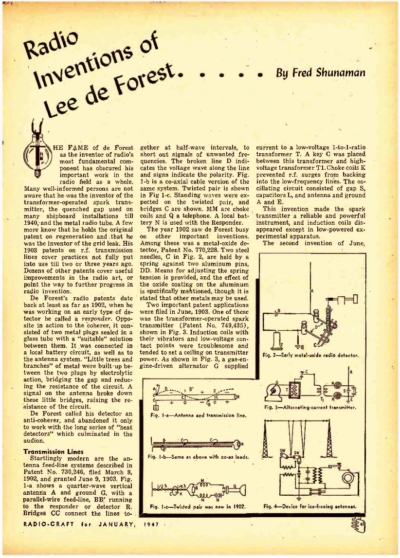
VSNo of
Le
orest.
ede HE FAME of de Forest
as the inventor of radio's most fundamental com- ponent has obscured his important work in the radio field as a whole.
Many well- informed persons are not aware that he was the inventor of the transformer -operated spark trans- mitter, the quenched gap used on many shipboard installations till 1940,-and the metal radio tube. A few more know that he holds the original patent on regeneration and that he was the inventor of the grid leak. His 1903 patents on r.f. transmission lines cover practices not fully put into use till two or three years ago. Dozens of other patents cover useful improvements in the radio art, or point the way to further progress in radio invention.
De Forest's radio patents date back at least as far as 1902, when he was working on an early type of de- tector he called a responder. Oppo- site in action to the èoherer, it con- sisted of two metal plugs sealed in a glass tube with a "suitable" solution between them. It was connected in a local battery circuit, as well as to the antenna system. "Little trees and branches" of metal were built-up be- tween the two plugs by electrolytic action, bridging the gap and reduc- ing the resistance of the circuit. A signal on the antenna broke down these little bridges, raising the re- sistance of the circuit.
De Forest called his detector an anti -coherer, and abandoned it only . to work with the long series of "heat detectors" which culminated in the audion.
Transmission Lines Startlingly modern are the an-
tenna feed -line systems described in Patent No. 730,246, filed March 8, 1902, and granted June 9, 1903. Fig. 1 -a shows a quarter -wave vertical antenna A and ground G, with a parallel -wire feed -line, BB' running to the responder or detector R. Bridges CC connect the lines to-
RADIO -CRAFT for JANUARY
By Fred Shunaman
gether at half -wave intervals, to short out signals of unwanted fre- quencies. The broken line D indi- cates the voltage wave along the line and signs indicate the polarity. Fig. 1 -b is a co -axial cable version of the same system. Twisted pair is shown in Fig 1-c. Standing waves were ex- pected on the twisted pair, and bridges C are shown. MM are choke coils and Q a telephone. A local bat- tery N is used with the Responder.
The year 1902 saw de Forest busy on other important inventions. Among these was a metal -oxide de- tector, Patent No. 770,228. Two steel needles, C in Fig. 2, are held by a spring against two aluminum pins, DD. Means for adjusting the spring tension is provided, and the effect of the oxide coating on the aluminum is .speéifically mehtioned, though it is stated that other metals may be used.
Two important patent applications were filed in June, 1903. One of these was the transformer- operated spark transmitter (Patent No. 749,435), shown in Fig. 3. Induction coils with their vibrators and low- voltage con- tact points were troublesome and tended to set a ceiling on transmitter power. As shown in Fig. 3, a gas -en- gine- driven alternator G supplied
current to a low- voltage 1 -to -1 -ratio transformer T. A key C was placed between this transformer and high - voltage transformer T1.Choke coils K prevented r.f. surges from backing into the low- frequency lines. The os- cillating circuit consisted of gap S, capacitors L, and antenna and ground A and E.
This invention made the spark transmitter a reliable and powerful instrument, and induction coils dis- appeared except in low- powered ex- perimental apparatus.
The second invention of June,
-h " B' 2 + , --- o _- - o
cl -.._ _ '(c - pR + o -Cs 0 +
Fig. I -a- Antenne and transmission line.
R
Fig. I- b-Same as above with co -ax leads.
1/2 h
C N ouj rillll M N
Fig. 1 -c- Twisted pair was new in 1902.
I 9 4 7
C
Fig. 2 -Early metal -oxide radio detector.
s -3 T5 E
Fig. 3-Alternating-current transmitter.
Fig. 4-Device for ice- freeing antennas.
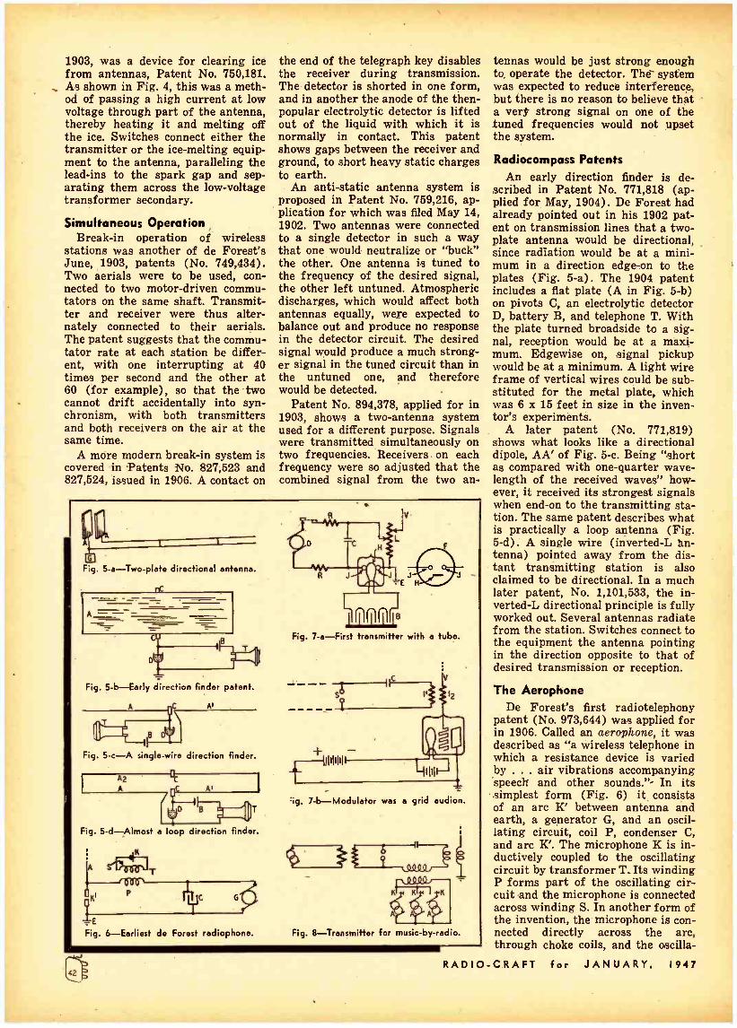
1903, was a device for clearing ice from antennas, Patent No. 750,181. As shown in Fig. 4, this was a meth- od of passing a high current at low voltage through part of the antenna, thereby heating it and melting off the ice. Switches connect either the transmitter or the ice -melting equip- ment to the antenna, paralleling the lead -ins to the spark gap and sep- arating them across the low- voltage transformer secondary.
Simultaneous Operation Break -in operation of wireless
stations was another of de Forest's June, 1903, patents (No. 749,434). Two aerials were to be used, con- nected to two motor- driven commu- tators on the same shaft. Transmit- ter and receiver were thus alter- nately connected to their aerials. The patent suggests that the commu- tator rate at each station be differ- ent, with one interrupting at 40 times per second and the other at 60 (for example), so that the two cannot drift accidentally into syn- chronism, with both transmitters and both receivers on the air at the same time.
A more modern break -in system is covered in Patents No. 827,523 and 827,524, issued in 1906. A contact on
the end of the telegraph key disables the receiver during transmission. The detector is shorted in one form, and in another the anode of the then - popular electrolytic detector is lifted out of the liquid with which it is normally in contact. This patent shows gags between the receiver and ground, to short heavy static charges to earth.
An anti -static antenna system is proposed in Patent No. 759,216, ap- plication for which was filed May 14, 1902. Two antennas were connected to a single detector in such a way that one would neutralize or "buck" the other. One antenna is tuned to the frequency of the desired signal, the other left untuned. Atmospheric discharges, which would affect both antennas equally, were expected to balance out and produce no response in the detector circuit. The desired signal would produce a much strong- er signal in the tuned circuit than in the untuned one, and therefore would be detected.
Patent No. 894,378, applied for in 1903, shows a two- antenna system used for a different purpose. Signals were transmitted simultaneously on two frequencies. Receivers on each frequency were so adjusted that the combined signal from the two an-
11
Fig. 5- a- Two -plate directional antenna.
Fig. 5 -b -Early direction finder patent.
A
C Div
Fig. 5 -c -A single -wire direction finder.
kilD
Fig. 5- d- Almost a loop direction finder.
-E Fig. 6- Earliest de Forest radiophone.
Fig. 7.a -First transmitter with a tube.
----I sY
11111111
v
r
IIII
'ig. 7- b- Modulator was a grid audion.
Q 1V QQ
,,
K
A .
Fig. 8- Transmitter for music -by- radio.
tennas would be just strong enough to operate the detector. The' system was expected to reduce interference, but there is no reason to believe that a vers strong signal on one of the tuned frequencies would not upset the system.
Radiocompass Patents An early direction finder is de-
scribed in Patent No. 771,818 (ap- plied for May, 1904). De Forest had already pointed out in his 1902 pat- ent on transmission lines that a two - plate antenna would be directional, since radiation would be at a mini- mum in a direction edge -on to the plates (Fig. 5 -a). The 1904 patent includes a flat plate (A in Fig. 5 -b) on pivots C, an electrolytic detector D, battery B, and telephone T. With the plate turned broadside to a sig- nal, reception would be at a maxi- mum. Edgewise on, .signal pickup would be at a minimum. A light wire frame of vertical wires could be sub- stituted for the metal plate, which was 6 x 15 feet in size in the inven- tor's experiments.
A later patent (No. 771,819) shows what looks like a directional dipole, AA' of Fig. 5 -c. Being "short as compared with one -quarter wave- length of the received waves" how- ever, it received its strongest signals when end -on to the transmitting sta- tion. The same patent describes what is practically a loop antenna (Fig. 5 -d). A single wire (inverted -L án- tenna) pointed away from the dis- tant transmitting station is also claimed to be directional. In a much later patent, No. 1,101,533, the in- verted-L directional principle is fully worked out. Several antennas radiate from the station. Switches connect to the equipment the antenna pointing in the direction opposite to that of desired transmission or reception.
The Aerophone De Forest's first radiotelephony
patent (No. 973,644) was applied for in 1906. Called an aerophone, it was described as "a wireless telephone in which a resistance device is varied by ... air vibrations accompanying speech and other sounds. " - In its
simplest form (Fig. 6) it consists of an arc K' between antenna and earth, a generator G, and an oscil- lating circuit, coil P, condenser C, and arc K'. The microphone K is in- ductively coupled to the oscillating circuit by transformer T. Its winding P forms part of the oscillating cir- cuit and the microphone is connected across winding S. In another form of the invention, the microphone is con- nected directly across the arc, through choke coils, and the oscilla-
RADIO -CRAFT for JANUARY, 1947

tor and antenna circuits are tuned. A number- of patents (Nos. 850;
917, 913,718, and 995,339) describe improved arc circuits. Patent No. 926,937 shows two arcs connected in parallel to the same antenna. Patent No. 926,936 is an arc transmitter modulated by a low -power spark gap placed either in the d.c. or the oscil- lating circuit. Other modulated -arc circuits are shown in Patent No. 913,718.
The Grid Audion The modern vacuum tube first ap-
peared as part of a radiophone cir- cuit in 1907. Application for the fundamental patent on the grid au- dion was filed on the 29th of January. On the .same day an application was made for a patent on a space tele- graph or telephone using that tube, as well as earlier types of audions. Patent No. 943,969 (Fig. 7 -a) de- scribes a transmitter which uses a two -plate audion as a discharge tube instead of an arc. Apparently the tube acted as a relaxation oscillator. D is a generator, K a key, RR resis- tors, C a condenser, L an inductor, and V and E the antenna and earth. The audion contains two plates J and a heater H, supplied with current from battery B. Fig. 7 -b has an arc S, an oscillation transformer Il and 12, and a three -element audion in the antenna circuit as modulator. The extremely naive hookup shows how little was then known of the audion.
An oscillating resistor was de- scribed in Patent No. 979,277. This was a conductor with a negative tem- perature coefficient, and was installed in place of the arc in an oscillating circuit. The description of this de- vice is somewhat reminiscent of the "talking ceramic" heralded a year or so ago.
Music By Rodio Another 1907 invention, on which
the patent (No. 1,025,908) was not granted till 1912, proposed to trans- mit music by wireless and described an electrical musical instrument. Fig. 8 shows the circuit, a conven- tional arc transmitter. It is modu- lated by low- powered alternators A, which supply current at frequencies corresponding to notes in the musical scale. Three of these modulators ap- pear in the figure. Keys K may be manipulated like those of a piano keyboard or an organ manual. De Forest's interest in radio musical de- vices continued. A circuit with an
- audion oscillator was invented in 1915 (Patent No. 1,543,900).
Later he invented the Pianorad, an instrument with a multiplicity of tubes and speakers.
RADIO -CRAFT for JANUARY.
a
I
I l' Fig. 9-This 1907 three -tube heterodyne
receiver had the first stage shielded.
T 0! Il
Fig. 10-A magnetic modulator circuit.
i..i.o 4sv B 'E
Fig. II-Section of quenched spark gap.
CHOKE COIL
o
Boo
-T° Fig. 12 -The first regenerative circuit.
C R
VIII
Fig. I3- Audion receiver with grid leak.
A receiver -amplifier invented in 1907 contains many modern features. Covered by Patent No. 995,126 (is- sued in 1911) it consisted of two grid audions and a discharge tube, which súpplied local oscillations (Fig. 9). The first stage, mounted in a metal box, is possibly the first shielded receiver. The output, accord- ing to the patent, modulated the con- tinuous oscillations from the two - plate discharge tube (relaxation os- cillator). The modulated output was further modulated by a third tube, in the plate circuit of which a tele- phone was connected.
A magnetic modulation system was another of the inventions of the prolific year 1907. A form in which the magnet coils DD are placed across the gap of a secondary arc in the antenna circuit is shown in Fig. 10. T is the microphone. The other letters indicate the same parts as in other figures. Patent 1,006,635, is- sued in 1911, covers the invention. Several other patents on systems with magnetic modulators were taken out by de Forest.
Patent No. 1,171,598 (Fig.. 11), application for which was made in 1910, covers the quenched gap, with the specially shaped plates and the fiber washers used till spark was out- lawed in 1940.
The regenerative receiver is de- scribed in Patent No. 1,170,881, for which the application was filed
1947
March 12, 1914. As shown in its simplest form in Fig. 12, it could be published today as a simple one -tube ultraudion circuit for the beginner, though it is doubtful if modern tubes would work without the grid leak.
Increased selectivity as well as sensitivity is claimed in the patent. "If the potential in the circuit of battery B and the current in the cir- cuit of filament F are so relatively adjusted that the grid circuit is just ready to be set into oscillation, we find that said circuit is highly re- sponsive to received impulses the group frequency of which is that at which the circuit tends to oscillate, but not sensitive to group frequen- cies materially differing from the natural period of the grid circuit," says de Forest in describing the action of his "Ultraudion." Use of the detector in an oscillating state was specified, and a drawing of the same circuit as a radio -frequency amplifier appears in the same patent.
The oscillating grid audion is re- ferred to casually in No. 1,170,881, but it was not until September 1914, that an application was made for a patent on an oscillating audion as a transmitter. This patent, No. 1,201; 270, is especially interesting because it covers the grid leak. "A high and preferably noninductide resistance" between the grid and filament, says de Forest, increases the energy of the oscillations generated enormous-

ly. "For example, from the order of a microwatt to that of tens or hun- dreds of watts. I have discovered that a still further increase in oscil- lation energy is obtained if a small capacity is connected in parallel to the resistance." The circuit appears in Fig. 13, complete with resistor R and capacitor C, which actually is a throttle condenser controlling feed- back.
Special Tube Types Metal tubes were patented by de
Forest in 1916 and 1917. The earlier patent, No. 1,201,271, proposed a double -walled tube, with a layer of "a suitable liquid, such as mercury" between the walls to overcome the porosity of metals to gases. Patent 1,230,874 shows a single- walled tube, the envelope of which is used as the anode. Metal tubes, the patents stated, could stand rough handling in shipment and use, and would permit greater power outputs than glass tubes.
A multiple -grid tube, with each grid performing its own specialized function, was described in Patent No. 1,311,264, applied for September 4, 1915. It had two inner grids, two outer grids, and two plates. See Fig. 14. Each pair of elements is connect- ed in parallel, and in a modern schematic would be -shown as a single element. The inner grid, or grids, is part of the ultraudion oscillating cir- cuit. The outer pair is in the micro- phone circuit. The present system of suppressor modulation is approxi- mately the same as this one.
Another circuit (Fig. 15) de- scribed in the same patent, has a pair of intermeshing coplanar grids rem- iniscent of those in the Wunderlich tube. The secondary of the micro- phone transformer is not center - tapped, however, and the supposed action is not quite clear. A number
A POEM BY DR. DE FOREST Although de Forest has written poems at intervals ever since his college days, the poetic side of his many - faceted character has always been overshadowed by his scientific accomplishments. The following poem indi- cates that he might have succeeded as poet if he had
not decided to become an inventor.
California Twilight I love a pine tree outlined on the night,
Behind it spread a drapery of light,
The moonbeam's weaving witchery's delight,
Mysterious, mysterious!
I love the glimmer of a mountain stream
When twilight's glow has faded to a dream
In pools where stars descending seem
Pendulous, pendulous!
I love the shadows of the spectral hill
Across the canyon when the night is chill,
And silence seals the river singing still,
Melodious, melodious!
-LEE DE FOREST
of other shown in
interesting the patent.
Finally, the artistic side of de For- est's nature comes to light in a pat- ent (1,720,544), issued in 1929. It "has for its object the provision of a radio receiving apparatus which is
circuits are
or may be at the same time orna- mental," and is nothing less than a radio table lamp (Fig. 16). The standard houses the speaker, and the tuning in- ductance (actual- ly a loop) is wound round the lower part of the lampshade.
Only a small fraction' of de Forest's 200 or more patents can be described in this story of some of his lesser known contribu- tions to the im- provement of communication between human beings.
Improved spark transmit- ters, secrecy de- vices, .special an- tenna - counter- poise systems,
tuning devices strangely like the modern "butterfly" are a few of the other ideas he brought forth. Radio components also received much atten- tion from him. His work on loud- speakers is described elsewhere in this issue.
After 1920, de Forest turned more and more to talking pictures and tele- vision, turning out a steady flow of inventions even to the present day. Indeed, he reported to the conven- tion of the Television Broadcasters' Association, October, 1946: "I am carrying on a few experiments in connection with television inven- tions, which I expect to finish .
within the next two or three years."
Fig. 16-An ornamental receiver is the ob- ject of this table -lamp -radio patent.-
111111
Fig. 14- Multiple -grid tube transmitter.
Fig. IS- Variation of the above circuit.
RADIO -CRAFT for JANUARY, 1947

E. I. Co. Sold First Audions
AY back in 1907, when Dr. Lee de Forest was experi- menting with his first three -element audion, the Electro Importing Com- pany, which had been start-.
ed by the writer in 1904, was going full blast, supplying wireless appa- ratus and instruments to early experi- menters and amateurs.
The first catalogs of the E.I.Co.- in their wireless sections -dealt prin- cipally with coherers. It was not un- til the year 1906 that the writer brought out the Auto -Coherer, which was illustrated on page 25 of the Electro Importing Company's Catalog No. 3.
Previous to that we had been sell- ing the coherer and decoherer instru- ment, but as it could not receive sig- nals over distances of more than a few miles, the Auto -Coherer was brought out. This Auto -Coherer was sold for many years by the E.I.Co. It was used in connection with a tele- phone receiver, rheostat and battery
-and brought in signals over fair dis- tances.
It was not until 1908 in its Catalog No. 5 that the E.I.Co. featured its first crystal detector, in which car - borundum, molybdenum, or silicon could be used.
In the same catalog was also fea- tured an electrolytic detector which was invented by the writer. The orig- inal electrolytic type of detector had been invented by Dr. Fessenden, but it required a battery for its operation. I eliminated the battery by making a primary battery out of the detector itself. I used a carbon cup which held the acid; then the fine Wollaston wire became the other element of the bat- tery. Thus was combined, for the first time, a battery and a detector all in a simple instnument.
Thus things stood until the year 1911 when we brought out E.I.Co. Catalog No. 10, in which was fea- tured for the first time de Forest's audion. Wireless had now arrived in earnest!
The E.I.Co. when it announced the audion on page 93b of Catalog No. 10, made history in that it was the first time that Lee de Forest's audion was sold commercially to_the public. The page showing the historic advertisement of the audion is repro- duced here.
RADIO -CRAFT for JANUARY,
For several years the audion was advertised in E.I.Co. catalogs and in MODERN ELECTRIC$, the writer's former magazine -the first radio magazine in print up to that time.
What I did not know until recent years, however, was the fact that the Electro Importing Company not only sold the first audion to the public, that is, to radio experimenters and ama-
By Hugo Gernsback
one of Dr. de Forest's patent suits. It appears that the following firms
were users of audions. First, of course, de Forest himself and -his various companies. It should be noted that the de Forest concerns did not sell audions in the years between 1909 and the end of 1913, but used them in various wireless telegraph and tele- phone sets which they sold complete.
flab
THE " ELECTRO'( AUDION. After long deliberation, we here -
with. present -the best audion manu- factured to -day in the United States. Of all the detectors in use; none present the accumulation of advantages offered by the Audionn; the "Electro" model being designed from the result of long and extend; ed experiments. While the crystal types of detector present many ad -' vantages, they have the' one great defect of not holding their adjust- ment, especially ón receiving from a nearby station.' The Audion, not only ranks as the highest in sensi. tiveness, but possesses' that much sought for characteristic, stability of adjustment. Loud signals do not affect the adjustment, and, on the contrary, seem to improve the sensitiveness. When receiving .from loud or nearby stations, the light will be noticed to flicker in the bulb, and the signals can thus be read without the use of a telephone receiver, this feature being found in - no other detector. Signals received by the Audion are extremely loud, and most stations in the vicinity of the receiving station may be heard with the phones three feet or more from the operator's ears.
The 'Electro" Audion, consists of a vacuum bulb containing two filaments of tantalum, connected in series with a lead taken off at the connecting point of both filaments. One filament is used at a time, and at the exhausting of one filament, the other may be resorted to. This gives double the life which is obtainable from other audions. The filaments are used on 4 volts, which may be obtained from storage battery or dry cells: The bulb also contains a wire which is bent in a zig -zag form, and called the "grid." A small sheet of nickel foil is also contained in the bulb. It is behind the grid and the metal foil. Under normal'conditions, the current from a 30-35 volt battery connected with a telephone receiver has:great difficulty in passing through the heated vacuum space. However, on reception of the wave trains, the current from the battery passes through the vacuum and produces an audible sound in the receiver. The audion is the most suited detector for wireless telephony. owing to its faithful reproduction of every wave. The 30$5 volts required for the telephone receiver circuit, may be obtained from 0 To T flash light batteries. Inasmuch as the current used is practically zero, a set of these cells will last for a long time. The ap-, paratus is connected- as shown in the diagram. In this instance a loose -coupler is shown, giving the set the maximum degree of selectivity. The rotary rheostat 'is also used, our No. 5000, which is very suitable for this purpose in regulating the filament current. The flash lamp dry cells are also shown connected in series with the telephone receiver. Here it might be stated that the audion will give excellent results on low-voltage telephone receivers, though, of course, the better the receivers the further the range.
Full instructions given with each instrument. Size of base, 534 in:. x 31 in., Height, 31/2 in. Weight, 1/4 lb.
No. 8200. The "Electro" Audion as described and illustrated $4.00 . ;ßy -mail extra, shipped in heavy wooden box 045
8200
The first Audion advertisement appeared in Catalog 10 of the
teurs, but that is also sold by far the largest quantity of audions between the years 1911 -1913, of any company in the world. The following figures, which were taken from records of the McCandless Incandescent Lamp Com- pany, makers of the first audions, are most interesting. They were used in
1947
E.I.Co., New York, 1911.
As far as is known none of these sets were sold direct to the pub' lic, but to services such as the Navy, etc.
The Electro Importing Company marketed its first audion in June, 1911. During that year the company
(Continued on page 49)

..
DE FOREST THE INVENTOR By H. Winfield Secor
OME of the most interest- ing patents granted to Dr. Lee de Forest were not in the field of radio. These less well -known inventions cover such diverse fields, as
diathermy, talking pictures, photo -elec- tric devices, range finders, television apparatus and airplane instruments. Cautery Device
One of the early de Forest medical patents disclosed an idea for a high fre- quency cautery device. Patent No. 874,- 178 was,issued on it Dec. 17, 1907. An oscillating or singing arc R (Fig. 1) was the exciter for the cautery elec- trode. A tuned circuit comprising a condenser C and an inductance I, is shunted across the arc A; this induct- ance may be the primary coil of the air - core transformer used to transfer the high- frequency current to the cautery electrode E. E' is the ground electrode. Frequencies of 500 to 1,000 kc are sug- gested.
Dr. de Forest has experimented con- siderably in the shortwave diathermy field. His patent No. 2,126,541 provides a unique design . for such apparatus. The output or treatment electrodes are excited by vacuum -tube oscillators 0 -0 in a circuit tunable from 3 to 13 meters.
A coiled Lecher wire system L is used; this gives the advantages of the dis- tributed capacity and inductance of the Lecher system and at the same time greatly reduces the dimensions of the apparatus. See Fig. 2.
Tube -less Amplifier A tube -less amplifier of the dynamic
type is the unusual device covered in patent No. 1,134,594, dated Apr. 6, 1915. A series of magnetic windings A, B, C, on iron cores are placed in close proxim- ity to a revolving metal disc, similar to the arrangement in a homopolar dynamo. (See Fig. 3.) The signals to be amplified are passed through the sev- eral coil windings in progressive order, and as the inventor states, "there is thus provided a means of dynamically amplifying minute current impulses, imparting thereto new energy from a local source . . . without moving con- tacts, microphonic or otherwise ... and without ohmic resistance or resistance - altering devices." A unique invention, to say the least, and worth study by all electrical and radio students.
Telegraphone Magnetic wire recorders engaged the
attention of de Forest at an early date.
Two patents involving the use of such devices are No. 1,375,447, Apr. 19, 1921 .
and No. 1,177,848, Apr. 4, 1916. The first patent describes means for repro- ducing sounds from magnetic sound records (steel wire recorders). The sec- ond covers the procedure for magneti- cally recording the amplified pulsating current thus produced. The originating wire recorder A may have its steel wire magnetized by sound waves (electric voice currents) in the usual manner. This device permits one to make a dup- licate copy B of a telegraphone record. See Fig. 4.
Subterranean Signalling System Transmitting and receiving high fre-
quency signals through the earth is pro- poséd in patent No. 1,424,805 (Aug. 8, 1922). The transmitter and receiver are connected to earth through buried metal plates separated quite a distance. The earthed circuit is preferably tuned to the generator frequency by suitable tun- ing means. Advantage claimed is the freedom from atmospheric disturbances.
Pneumatic Telephone The transmission and reception of
speech or other sounds, such as tele-
CE. Fig. I -A high- frequency su gery patent.
Fig. 2 -A special circuit for diathermy.
Fig. 3- Dynamic amplifier without tubes.
1111 1111
Fig. 4 -Means for reproducing magnetic -wire sound records.
Fig. 5-A pneumatic telephone for communication on trains.
RADIO- CRAFT for JANUARY. 1947

graph signals, over the air -brake pipe line extending along a train of standard railroad cars, is described in patent No. 1,515,152, Nov. 11, 1924. See Fig. 5. Magnetically controlled air pulsators (A and B) are used to impress the sound vibrations upon the air column in the pipe line C (the air brake and signal lines).
Stations are called by means of in- terrupters D (noise producers). When the engineer or conductor hears a buzz - saw note in the receiver, he knows that he should listen for a message.
The sound-waves induced in the air line are picked up by the magnetic pul- sators, the vibrating air column causing a diaphragm to vibrate and in turn in- duce, electric currents of corresponding frequency in coils placed behind the diaphragm. These voice currents may be amplified, and are connected to a standard type telephone receiver E or loudspeaker. Microphones are marked G.
Thermionic Phono Pickup Electric pickups for phonographs
have become very popular in recent years. De Forest received an interesting patent -No. 1,554,561 -date Sept. 22, 1925 -for a phono pickup operating on the thermionic principle. The sound vi- brations picked up by the needle A in contact with the phonograph record are transmitted to a grid member B sealed into an evacuated glass chamber, as shown in Fig. 6. A heated filament with- in the tube supplies an ionized field; vibrations of the grid cause correspond- ing modulation of the current in the circuit connected to the electrodes of the tube. The output of the thermionic pickup may be connected to a vacuum tube amplifier and any desired amplifi- cation of the sound readily obtained.
The pickup is strongly reminiscent of the Vibrotron, a 1946 tube based on much the same principles.
Diffraction Microphone A novel diffraction microphone in-
vented by de Forest Aug. 27, 1929, is described in patent No. 1,726,289. In this device a beam of light is flashed onto a photocell. A polished mirror A is interposed in the path of the beam of. light; this mirror is electrically heated. (See Fig. 7). It was found that sound waves striking the heated layers of air in proximity to the mirror caused changes in their diffracting powers and consequent variations or diffraction in the beam of light. In turn these varia- tions in the beam of light are recorded by the photocell B, connected in a tele- phone or modulator circuit; the pulsa- tions in the voice are thus reproduced in the circuit controlled by the photocell.
Gaseous Microphone A noise -free microphone of the gase-
ous type forms the subject of patent No. 1,834,051 -dated Dec. 1, 1931. The microphone is built into a glass and metal cylinder A, fitted with a flexible gas -tight diaphragm D at one end. See Fig. 8. An electrically heated cathode C
RADIO -CRAFT for JANUARY, 1947
is mounted a short distance behind the flexible metal diaphragm. Voice (air) waves striking the diaphragm cause variations in the ionized field between it and the heated cathode, causing fluctua- tions in the current in the main tele- phone circuit connected to the micro- phone. The chamber may be. exhausted to a high degree and a slight amount of gas admitted.
Loudspeakers De Forest was much interested in
loudspeakers. A diaphragmless loudspeaker is de-
scribed in patent No. 1,641,664 -Sept. 6, 1927. As Fig. 9 shows, two spirally wound strips, insulated from each other, are connected to the output of an amplifier or other voice current supply. The cathode strip A is heated to provide an ionized field between the two spiral conductors. B is the anode; C is the heating current source. When this field is modulated by the voice current, the surrounding air has sound waves set up in it, in the manner of the speaking arc. The cathode spiral strip may be made of fine woven wire, loaded with certain oxides of the rare earths to intensify the electronic emission.
Other patents on loudspeakers in- clude No. 1,560,502 -a means of. vibrat- ing a curved loudspeaker member. The actuating device or motor for driving a loudspeaker is the subject of patent No. 1,718,337. A novel cone speaker is illustrated and described in patent No. 1,554,794. Another diaphragm -less type
speaker is described in patent No. 1,486,866. A sealed inflated elastic body has wires wound around its exterior surface, which causes it to contract and expand 'n accordance with the fluctua- tions of the voice current impressed on the microphone M. See Fig. 10.
A table -lamp speaker appears in patent No. 1,452,827 -Apr. 24, .1923, and a cylinder type speaker in patent No. 1,736,035 -Nov. 19, 1929.
A novel speaker mechanism designed for controlling the escape of com- pressed air in accordance with the un- dulations of the voice current applied to it, is described in patent No. 1,766,612 - June 24, 1930. This speaker is intended for use where powerful sound waves are to be reproduced. The voice coil moves longitudinally in the field of a strong electromagnet, and causes slots in a valve to open and close in propor- tion to the fluctuating strength of the voice current. See Fig. 11.
Compressed air is admitted through pipe A which passes clear through the center core of the magnet. The magnet is excited by direct current. A brass dome B is threaded onto the upper end of the magnet core. This dome has slits C cut into it, through which compressed air from the tube A can pass, whenever the sliding sleeve D is moved up and down by the voice coil and uncovers the slits.
A corrugated diaphragm E supports the moving voice coil G and the valve sleeve. The compressed air liberated through the slits is in direct proportion
B'
Fig. 6 -This phonograph pickup works on the thermionic principle.
O B
Fig. 7 -A microphone which employs a vibrating mirror and photocell.
,,, (00000`
Fig. 8-A gaseous -tube microphone with vibrating anode- diaphragm.

to the strength of the varying voice cur- rent, . thus creating powerful sound waves in the horn attached to the air - valve chamber.
A combination cone and horn speaker is described by de Forest in patent No. 1,785,377 -Dec. 16, 1930. See Fig. 12. This combination has been found to re- produce the broad band of voice fre- quencies more satisfactorily than either speaker alone. Another similar type speaker of large proportions, for use where a great volume of sound is de- sired is covered by patent No. 1,853,850.
Thermophone A loudspeaker of the diaphragm-less
type, operating on the hot -wire or ther-
11141
Fig. 9 -A loudspeaker which works on air.
Fig. 10- Another intere fing loudspeaker.
BRASS HORN
G_
...,_. ;1i AV % iï? k'ibòlAì.D.II MOVING D2D.h`A`QiL-i
... ... COIL! ...-.
IRON CORE'
mophone principle, was invented by de Forest Feb. 17, 1925. See his patent No. 1,526,778 and Fig. 13.
A fine wire W is concentrated in an insulating disc D (or at the focus of a parabolic reflector in one form), fitted with a perforated cover through which the sound -emerges.
The heating effect of undulating voice currents causes the fine wire to expand and contract. These rapid thermal changes are communicated to the ad- jacent air envelope and set up sound waves therein.
One of the advantages of the thermal type speaker is the faithful reproduc- tion of sound. The principle involved is worthy of further study by our engi- neers intent upon high -fidelity music and speech reproduction.
An unusual scientific principle is in- volved in a loudspeaker (or micro- phone) covered by patent No. 1,738,988. It utilizes variations in the capillary boundary between two liquids of differ- ing densities. See Fig. 14.
With mercury and dilute acid, for example, placed in a capillary tube, a meniscus or semi -globular surface forms between them. If a varying (voice) current is applied to such a tube through suitable electrodes making con- tact with the acid A and the mercury,
Fig. I2-- Combined horn and cone speaker.
MAGNET COIL. t
.
CHANNEL- ) o
11 & \ \ \ \ \ \ \ \ \ \` \ \CI\
4rA s\ NIN , ,N,N.s\NtN..k;
-
Fig. I1- Air -blast "very loud" speaker. Fig. 13- Another heat-operated speaker.
B, the current will cause the contact surface or meniscus, C, between the two liquids to rise and fall within the tube. This action in turn will create sound waves in the acoustic horn chamber shown in the picture. This is the loud- speaker action.
When used as a microphone the re- verse action occurs ... the sound waves strike the liquids in the capillary tube and cause the meniscus to rise and fall. If an electric current is connected to the tube terminals, variations correspond- ing to the voice fluctuations in this cur- rent will be created (in the external cir- cuit). A loudspeaker connected in this circuit will reproduce the sounds origi- nating at the capillary microphone.
Talking Pictures Dr. de Forest performed a great deal
of research on devices to improve the early talking pictures. An early patent, No. 1,482,119, Jan. 29, 1924 -describes a method for recording the picture and the voice record on the same film sim- ultaneously. An early arrangement used an arc for recording the voice pat- terns on the film. Some more stable form of glow discharge was desirable, and one of de Forest's designs - for a glow tube that could be modulated by the voice current, is covered in patents No. 1,806,746, May 26, 1931, and No. 1,873,558, Aug. 23, 1932. See Figs. 15 and 16. The glow or corona A was con- centrated at one end of the tube and was of high intensity. The voice cur- rent, when super- imposed on the elec- trodes B and C of the glow tube, caused the intensity to vary.
Binaural recording and reproduction of sound is interestingly described in patent No. 1,769,907 of July 1, 1930. This has to do with speakers placed in different parts of the theater, each speaker reproducing certain frequencies and thus giving a third -dimension sound effect.
Photo - Electric Cell An improved photocell was devised
and patented by de Forest, July 30, 1929 (Patent No. 1,722,280). See Fig. 17. The light -sensitive cell A is made in a flattened lenticular shape so that the electrodes within the cell will be located only a short distance from the film B on which the sound track is impressed. A steady source of light projects a beam of light through the film sound track
.
upon the photo-cell.
Television One of the earliest televisionpatents
of de Forest, No. 2,003,680 was issued June 4, 1935. It describes a television receiving and projecting method for scanning a strip of specially prepared film and electrically etching pictures thereon. Patent 2,026,872, issued in 1936, describes a means of producing a large size television image. The re- ceived image is recorded on specially treated film and may be later projected onto a screen by the usual projector. Sound is reproduced by a sound track recorded on the picture film at the same
RADIO -CRAFT for JANUARY, 1947

Fig. 14-A unique loudspeaker principle.
time the picture signals are recorded. An ingenious metho for recording or etching the picture images on the coated film by an electrostatic discharge is described. The discharge is modulated by the received television signals. A following patent covers further develop- ments of this idea and includes means for synchronizing the received images with the accompanying sound signals.
An idea for stereoscopic television is covered by patent 2,163,749. Radial scanning is one of the features here proposed. A cathode beam radial scan- ning system appears in patent 2,241,809 issued May 13, 1941. The cathode beam
is deflected back and forth by a rotat- ing switching device; thus the beam traverses a non -repeating pattern on the screen.
Television Sign A television sign is described in pat-
ent No. 2,049,763 dated August 4, 1936. In the future we shall undoubtedly see many signs of this type along our high- ways. It is operated by remote control from a television station. A salient fea- ture of this television sign is that prac- tically any picture can be reproduced on its face, either in silhouette or halftone effect. The glow lamps on the surface of the sign are controlled by a switch directed by television signals, which may be picked up by a television re- ceiver located near the sign. These signs may be operated out in the open country and a number of signs can be controlled at the same time from one transmitter.
Fig. 17 -A photocell for sound recording.
The patent describes the preferred form of the high -voltage glow tubes and the switching mechanism. In one
GLOW DISCHARGE TUBE
IUUU 1111111111
Fig. 15 -Sound movie glow- discharge lamp.
Fig. 16- Another talking -picture lamp.
suggested form the sign might contain a hundred rows of glow tubes, with a hundred tubes in each row. Ten thou- sand glow tubes would be used in this case and thus a very good reproduction of the image realized. High voltage is fed to each glow tube as the commuta- tor switch makes the proper connection, in accordance with the television signal directing it.
Many of the above inventions were not followed up, for one reason or an- other. They offer challenging opportu- nities for the engineer or experimenter today. Certain speakers, for instance, were not practical when 90 volts of B battery was a standard power supply but might be quite usable now that 450 or even 900 volts can be obtained if desired. These patents are worth study.
E.I.CO. SOLD FIRST AUDIONS (Continued from page 45)
sold 93 audions. In 1912 it sold 165 auctions and in 1913 it sold 211, a total of 459. It should be noted that this com- pares rather well with all the de Forest companies combined, which from 1909 until the end of 1913 bought a total of 1,300 audions from McCáhdless.
The next runner -up in point of early purchase of audions was the Manhattan Electric Supply Company, which start- ed with a single audion, bought from McCandless in September, 1911. But the Manhattan Electric Supply Company bought only 10 audions in 1911 -1912.
The next fairly large user, second in point of sales to the public, was the J. H. Bunnell Company of New York. This company, however, did not start selling audions until January, 1912. During 1912 -1913 they sold a total of 384 au- dions against the E.I.Co.'s 469.
The third concern to sell audions to the public was Wallace & Company. They did not start, however, until February, 1912; during 1912 -1913 they sold a total of 280 audions.
A few other wireless supply'com- panies also sold audions to the public, but their sales did not come anywhere near the totals cited above.
Of passing interest also is the fact
RADIO -CRAFT for JANUARY.
that Western Electric Company -who did not sell the tubes to the public, but used them for experimental purposes -during the same years bought 45 audions from the McCandless Company. The Marconi Wireless Telegraph Com- pany of America, which during the year 1909 -1913 bought a total of 74 audions, was in the same class. None of these were sold to the public.
For the record, it might also be noted that the E.I.Co. did not make much profit on their audion sales. They paid between $1.50 and $2.00 per audion tube to the McCandless Company and sold it to the experimenters and amateurs for $4.00. This price was, of course, not just for the audion itself. The E.I.Co. mounted it on a substantial wooden base with five binding posts and socket; then it had to be wired, too. At such a price, little profit was realized.
The reader may be interested in the following taken from a forthcoming book by Mr. Gerald F. J. Tyne, Mc- Candless and the Audion:
"The Electro Importing Company was the child of Hugo Gernsback, now publisher of RADIO -CRAFT, founder of MODERN ELECTRICS, ELECTRICAL EX- PERIMENTER, RADIO NEWS, SHORT-
1947
WAVE CRAFT, and similar publications,. and entrepreneur extraordinary. Gerns- back sold great quantities of wireless apparatus in the period 1908 -1915, mostly on a mail order basis. Many am- ateurs of that day (including the writer) considered the E.I.Co. catalog as a second Bible. McCandless -made [de Forest] tubes were sold by the E.I.Co. under the "name of the 'Electro Audion.'
"The 'Electro Audion' first appeared in the E.I.Co. Catalog No. 10 for the year 1911 on page 93b and was first ad- vertised by them in MODERN ELECTRICS for July, 1911, on page 272. The last appearance of the 'Electro Audion' in the E.I.Co. Catalog was on page 11 of the 1913 issue.... In this connection the following statement made in this advertisement is worthy of note:
" 'When receiving from loud or near- by stations, the light will be noticed to flicker in the bulb, and the signals can be read without the use of a telephone receiver, this feature being found in no other detector.'
"The E.I.Co. went out of business about 1920 and Gernsback thereafter devoted his talents almost exclusively to publishing."
49

-DE FOREST PATENTS 1902 - 1946
The most important de Forest patents have been described in two articles else-
where in this issue. Dozens of other inventions would have been well worthy of mention had space been available. The following list, with dates of patents and a brief description of the main features of each invention (not necessarily the
patent title) may be interesting to many readers.
716,000, Dec. 16, 1902, Apparatus for Space Communications 716,203, Dec. 16, 1902, Wireless Telegraphy 716,334, Dec. 16, 1902, Method of Communicating Through Space 720,568, Feb. 17, 1903, Space Telegraphy 730,246, June 9, 1903, Space Telegraphy 730,247, June 9, 1903, Wireless Telegraphy 730,819, June 9, 1903, Wireless Signalling 748,597, Jan. 5, 1904, Wireless Signalling Device 749,131, Jan. 5. 1904, Wireless Signalling Apparatus 749,178, Jan. 12, 1904, Wireless Signalling Apparatus 749,371, Jan. 12, 1904, Wireless Telegraph Receiver 749,372, Jan. 12, 1904, Art of Wireless Telegraphy 749,434, Jan. 12, 1904, Wireless Signalling Apparatus
749,435, Jan. 12, 1904, Wireless Telegraphy Generating Set 749,436, Jan. 12, 1904, Wireless Telegraph Range Finder 750,180, Jan. 19. 1904, Spark Production Control Method 750,181, Jan. 19, 1904, Device for Cleaning Ice from Antenna 758,517, Apr. 26, 1904, Art of Wireless Telegraphy 759,216, May 3, 1904, Wireless Signalling Apparatus 770,228, Sept. 13, 1904. Receiver for Space Signalling 770,229, Sept. 13, 1904, Wireless Signalling Apparatus 771,818, Oct. II, 1904, Wireless Signalling Apparatus 771,819, Oct. 11, 1904, Wireless Signalling Apparatus 771,820, Oct. II, 1904, Protecting High Frequency Apparatus 772,878, Oct. 18, 1904, Magnetic Detector
772,879, Oct. 18, 1904, Art of Duplex Wireless Telegraphy 806,966, Dec. 12, 1905, Wireless Telegraph System 822,936, June 12, 1906, Wireless Telegraph System 823,902, June 12, 1906, Static Valve for Wireless Systems 824,003, June 19, 1906, Wireless Telegraph System 824 637, June 26, 1906, Oscillation Responsive Device 824,638, June 26, 1906, Oscillation Responsive Device
827,523, July 31, 1906, Wireless Telegraph System 827,534, July 31, 1906, Wireless Telegraph System 833,034, Oct. 9, 1906, Aerophone 836,015, Nov. 13, 1906, Aerophone 836,070, Nov. 13, 1906, Oscillation Responsive Device 836,071, Nov. 13, 1906, Oscillation Responsive Device 836,072, Nov. 13, 1906, Aerophone 837,901, Dec. 4, 1906, Wireless Telegraphy 841,386 Jan. 15, 1907, Wireless Telegraphy 841,387, Jan. 15, 1907, Device for Amplifying Feeble Curreets 850,917, Apr. 23, 1907, Space Telegraphy 852,381, Apr. 30, 1907, Wireless Telegraph Receiving System 867,876, Oct. 8, 1907, Oscillation Responsive Device
867,877, Oct. 8, 1907, Art of Detecting Oscillations 867,878, Oct. 8, 1907, Oscillation Detector 874,178, Dee. 17, 1907, Cautery 876,165, Jan. 7, 1908, Wireless Telegraph Sending System 877,069, Jan. 21, 1908, Magnetic Detector 879,532, Feb. 18, 1908, Space Telegraphy 894,317, July 28, 1908, Electrolytic Detector Electrode 894,318, July 28, 1908, Aerophone 894,378, July 28, 1908, Wireless Signalling Apparatus 913,718, Mar. 2, 1909, Space Telegraphy 926,933, July 6, 1909, Wireless Telegraphy 926,934, July 6, 1909, Wireless Telegraph Tuning Device
926,935, July 6, 1909, Wireless Telegraph Transmitter 926,936, July 6, 1909, Space Telegraphy 926,937, July 6, 1909, Space Telephony 943,969, Dec. 21, 1909, Space Telegraphy 966,539, Aug. 9, 1910, Transmitting Apparatus 973,644, Oct. 25, 1910, Aerophone 979,275, Dec. 20, 1910, Oscillation Responsive Device 979.276, Dec. 20, 1910, Space Telegraphy 979,277, Dec. 20, 1910, High Frequency Oscillator 995,126, June 13, 1911, Amplifier for Feeble Electric Currents 995,339, June 13, 1911, Space Telegraphy
1,006,635, Oct. 24, 1911, Space Telephony 1,006,636, Oct. 24, 1911, Space Telephony 1,025,908, May 7, 1912, Wireless Music Transmitter 1,042,205, Oct. 22, 1912, Duplex Wireless Transmission System 1,101,533, June 30, 1914, Wireless Telegraphy 1,123,118, Dec. 29, 1914, Signalling System 1,123,119, Dec. 29, 1914. Wireless Communication Secrecy System 1,123,120, Dec. 29, 1914, Space Communications Arc Mechanism 1,125,496, Jan. 19, 1915, Wireless Telephone Transmitter 1,134,593, Apr. 6, 1915, Electromagnetic Radiation Receiver 1,134,594, Apr. 6, 1915, Increasing Strength of Electric Currents 1,170,881, Feb. 8, 1916, Wireless Receiving System 1,170,882, Feb. 8, 1916, Telephone System Automatic Switch 1,171,598, Feb. 15, 1916, Radiotone Wireless Telegraph Spark Gap 1,177,848, Apr. 4, 1916, Method of Recording Fluctuating Currents 1,183,802, May 16, 1916, Range Teller 1,183,803, May 16, 1916, Wireless Telephone System 1,190,869, July 11, 1916, Quench Spark Discharger 1,201,270, Oct. 17, 1916, Oscillating Current Generator 1,201,271, Oct. 17, 1916, Oscillating Audion 1,201.272. Oct. 17. 1916, Telegraph and Telephone Receiving System 1,201,213, Oct. 17, f916, Oscillation Generator 1 214,283, Jan. 30, 1917, Wireless Telegraphy 1,221,033, Apr. 3, 1917, Wireless Telegraph Signalling System 1,221,034, Apr. 3, 1917, Oscillating Current Generator 1,2211035, Apr. 3, 1917, Wire or Radio Communications Apparatus 1,230,874, June 26, 1917, Metallic Audion 1,299,356. Apr. I, 1919, Radio Communication Apparatus 1,309,753, July 15, 1919, Vibrations Transducer 1,311,264, July 29, 1919, Oscillation Generator 1,314,250, Aug. 26, 1919, Current Pulse Reproducer and Amplifier 1,314,251, Aug. 26, 1919, Radiotelephony 1,314,252, Aug. 26, 1919, Oscillation Generator 1,314,253. Aug. 26, 1919, Wire or Radio Communication Apparatus 1,329,758, Feb. 3, 1920, Oscillating Current Generator 1,348,157, Aug. 3, 1920, Amplifier for Pulsating Electric Currents 1,348,213, Aug. 3, 1920, Radiotelephone System
14,959, Reissued Oct. 19, 1920, Wireless Telephone System 1,365,157, Jan. II, 1921, Apparatus for Telegraphy or Telephony 1,365,237, Jan. II, 1921, Endless Film Arrangement 1,375,447, Apr. 19, 1921, Means for Amplifying Currents 1,377,405, May 10, 1921, Audion Circuit 1,397,575, Nov. 22, 1921, Selective Audion Amplifier 1,417,662, May 30, 1922, Radio Signalling System 1,424,805, Aug, 8, 1922, Subterranean Signalling System 1,437,498, Dec. 5, 1922, Oscillion
1907 Forty Years of Electronics 1947
RADIO -CRAFT for JANUARY, 1947

1,442,426, Jan. 16, 1923, Sound Controlled Light Variations 1,442,682, Jan. 16, 1923, Endless Sound Record and Mechanism
15,540, Reissued Feb. 13, 1923, Changing Motion to Electricity 1,446,246, Feb. 20, 1923, Recording and Reproducing Sound 1,446,247, Feb. 20, 1923, Light Controlling Means 1,452,827, Apr. 24, 1923, Telephone Device 1,466,701, Sept. 4, 1923, Light Variation Current Control 1,478,029, Dec. 18, 1923, Radio Receiving System 1,482,119, Jan. 29, 1924, Recording and Reproducing Sound 1,486,866, Mar. 18, 1924, Sound Producer 1,489,314, Apr. 8, 1924, Recording Sound 1,507,016, Sept. 2, 1924, Radio Signalling System 1,507,017, Sept. 2, 1924, Wireless Telegraph and Telephone 1,515,152, Nov. 11, 1924, Communication System for Trains 1,526,778, Feb. 17, 1925, Thermophone 1,543,990, June 30, 1925, Producing Musical Notes Electrically 1,552,914, Sept. 8, 1925, Telephone Device 1,554,561, Sept. 22, 1925, Sound Reproducing Mechanism I,5S4,594, Sept. 22, 1925, Loud Speaking Device 1,554,795, Sept. 22, 1925, Radio Signalling System 1,560,502, Nov. 3, 1925, Sound Reproducing Device 1,561,596, Nov. 17, 1925, Indicating Device for Fluid Tanks Des. 69,443, Feb. 16, 1926, Loud Speaker 1,629,152, May 17, 1927, Slot Cleaner for Motion Picture Machines 1,641,664, Sept. 6, 1927, Electrical Sound Reproducing Apparatus 1,642,363, Sept. 13, 1927, Telephone Device 1,653,155, Dec. 20, 1927, Talking Moving Picture Equipment 1,659,909, Fob. 21, 1928, Film Protecting Arrangement 1,659,910, Feb. 21, 1928, Slot Cleaner for Phonofilm Attachments 1,680,207, Aug. 7, 1928, Radio Signalling System 1,683,451, Sept. 4, 1928, Recording and Reproducing Sound 1,687,364, Oct. 9, 1928, Radio Transmitting System 1,693,071, Nov. 27, 1928, Sound Recording Device for Movie Cameras 1,693,072, Nóv. 27, 1928, Shielding for Detector and Amplifier 1,695,414, Dec. 18, 1928, Talking Moving Picture Machine 1,695,415, Dec. 18, 1928, Talking Motion Picture Record 1,701,911, Feb. 12, 1929, Acoustic Apparatus 1,710,922, Apr. 30, 1929, Motion Picture Screen 1,716,033, June 4, 1929, Producing Talking Motion Picture Films 1,718,337, June 25, 1929, Loud Speaker Motor 1,720,544, July 9, 1929, Radio Receiving Apparatus 1,722,280, July 30, 1929, Photo Electric Cell 1,726,289, Aug. 27, 1929, Diffraction Microphone 1,736,035, Nov. 19, 1929, Sound Reproducing Device
1,738,988, Dec. 10, 1929, Sound Actuated and Producing Device 1,740,577, Dec. 24, 1929, Wireless Telegraph and Telephone System 1,761,619, June 3, 1930, Sound and Picture Recording Camera 1,764,938, June 17, 1930, Producing Talking Motion Picture Films 1,766,612, June 24, 1930, Sound Reproducing Device 1,769,907, July I, 1930, Binaural Recording and Reproducing Sound 1,769,908, July I, 1930, Recording and Reproducing Sound 1,769,909, July I, 1930, Talking Picture Exciting Lamp Switch 1,777,037, Sept. 30, 1930, Binaural Recording Sound 1,777,828, Oct. 7, 1930, Sound Picture Photography 1,785,377, Dec. 16, 1930, Loud Speaker 1,795,936, Mar. 10, 1931, Sound Reproducer 1,802,595, Apr. 28, 1931, Automatic Photographic Sound Reproducer 1,806,744, May 26, 1931, Talking Picture Machine Drive Mechanism 1,806,745, May 26, 1931, Sound Producing Device 1,806,746, May 26, 1931, Luminous Discharge Device
18,108, Reissued June 23, 1931, Obliterating Parts of Talking Film 1,812,687, June 30, 1931, Sound Chamber and Set Frame 1,827,283, Oct. 13, 1931, Sound Reproducer 1034,051. Dec. 1, 1931, Microphone 1,843,972, Feb. 9, 1932, Talking Motion Picture Apparatus 1,853,850, Apr. 12, 1932, Sound Reproducing Device 1,859,435, May 24, 1932, Sound -on -Film Phonograph 1,866,090, July 5, 1932, Sound Reproducing Device 1,873,558, Aug. 23, 1932, Gaseous Discharge Device 1.885,900, Nov. I, 1932, Talking Motion Picture Attachment 1,888,910, Nov. 22, 1932, Synchronization in Talkie Photography 1,894,024, Jan. 10, 1933, Photographic Sound Reproduction 1,897,363, Feb. 14, 1933, Luminous Discharge Device 1,929,626, Oct. 10, 1933, Soundproofing Picture Camera 1,944,929, Jan. 30, 1934, Gaseous Discharge Device 1,992,201, Feb. 26, 1935, Apparatus for Reproducing Sound -on -Film 2,003,680, June 4, 1935, Television Reception and Projection 2,026,872, Jan. 7, 1936, Television Receiving Method and Apparatus 2,045,570, June 30, 1936, Synchronizing Televised Images 2,049,763, Aug. 4, 1936, Television Sign 2,052,133, Aug. 25, 1936, Television Apparatus 2064,593, Dec. 15, 1936, Apparatus for Reproducing Sound on -Film 2,122,456, July 5, 1938, Television System and Method 2,126,541, Aug. 9, 1938, High Frequency Oscillating System 2,163,749, June 27, 1939, Radial Scanning Television System 2,241,809, May 13, 1941, Radial Scanning with Cathode Beam 2,391,554, Dec. 25, 1945, Aircraft Speed and Course Indicator 2,410,868, Nov. 12, 1946, Means and Method for Altitude Determination
Motion Picture Engineers Honor Dr. de Forest
Dr. de Forest with +lie scroll which was presented to him on the occa- sion of his seventy -third birthday last August. The illuminated address was presented by the Society of Motion Picture Engineers in honor of the inventor of the fundamental audion and other developments
important to the progress of sound motion pictures.
RADIO -CRAFT for JANUARY, 1947
lT,1'iptgli; lrt0YLt111147.64i.EIgi0it,ó:v.
Zvtl aliafifkmott, i*_',-vr.tCSRfe:t ..
RS1EYPfl}iesT.'-
original arehet which occulted in the u tveu eutiw, of the :Audion,n 3- electrode oacuum tube, detained to become a baste clonent In the du- rloa,ncntoutelephonic cmrnunicatio rnd it und
the und n ti n piCWre; .o;:ru. art.. .
a demonetnn.on'btttonn 1921 -792, orn aúdhnd prof ll,ntoprnphinp n uuri ,óle -d ,.city pound ree- esdonmotion picture film ,diliri,tp the Photios, 1.0111.1.1,
and u method ofreyn,bnring the pholosln.phic cound record i, ,:undtronio,n whit n motion p,chrre hp , -a tIl Bono of the Phonofilm proyector which inrorpomtrb the (lane Cihnlufide tell and o Radii-atnoe :>zlbion
lifier;ix.nranoaxiwiw,,nn.rxwvcnecrIrt.nr,..-xxx,..rnssex t -ru n readapt und remits trot rftt,rte nhich ronde .r:. poe.,b e 9,e Grist p Flic al wt.,. tp of to iml oo.u,d
IlóTiun pictunm in the 1 i voit and Rialto i WNrto in rw Sloth on Siff rkt 1S.1P:3.ams rubonp,enate in ,nnnY {theatcn thrnup t the .uurid. sc . ,- ..:_.n.-m-v -r,
E'! erer.-.onhce ant, hio piruwra n uicion venom,* \\ nduelvy un deactibnt inn posy, t brtrtr membrro" thie Soc ici vin(Thts &')' oc, creaprzedhethe-
R.wentntiu,, of thinSctntlof4chieuemcnt by.the So- cirtl,ofMotion PirtLLrc Enoinrrro in thin Ci entirth. id eor ut theSucctsssi i Itttrvbrtìon of Sound Motion Picttl MP. ,:..,x.., ,.fro.r:v+r,,...._.r.,,- ,.....ran....,...,,..
JWyi]:VE liX thvPoordá:low Soar-exist aThdiva Plch,t c pnpinter, , ..a..,....
rÉn=

-,- . ---_-
TO THE FATHER OF RADIO
Tributes _ to Dr. de Forest by Leading Figures_ in Radio
From Major General J. O. Mauborgne, U. S. A., Retired Engineer, soldier, artist, inventor; chief Signal Of- ficer United States Army, 1937-1941; technical adviser to United States delegations at several international communications conferences; radio pioneer, inventor of numerous radio devices; author of "Practical Uses of the Wavemeter in Wireless Telegraphy"
and brochures on radio and cryptanalysis.
How fitting that the January issue of RADIO-CRAFT is devoted almost entirely to a tribute to Dr. Lee de Forest, com- memorating the fortieth anhiversary of the invention of the vacuum tube with the control grid.
Since it was my good fortune to have been a reader of Modern Electrics in those early days, I take moré than usual interest in the tribute to Dr. de Forest, whom I have known since his art- revis- ing basic invention of the grid, which gave us the detector, oscillator, and am- plifier, and established the foundation of all later work in electronics.
Let me raise my voice in the mighty shout which issues through your tech- nical journal in praise of and congrat- ulations to the Grand Old Man of Wire- less, not only because he will live for- ever in the earth's Hall of Fame, but because he is -and always has been -a real American. May he live to be a hun- dred, knowing that he has achieved the greatest success a scientist can hope for.
-73- From Major General Harry C. Ingles Chief Signal Officer, United States Army; former deputy commander, European Theater of Operations;
former chief of staff, Caribbean Defense Command; former director Army Signal School, Fort Monmouth.
It is a privilege to participate in RADIO- CRAFT's symposium honoring Dr. Lee de Forest and commemorating the fortieth anniversary of his invention of the grid vacuum tube.
With this invention, electrons were first brought under control and the foundations of the electronics industry were laid. The development of that in- dustry, with its startling advances and its limitless horizons, has been one of our era's most important achievements.
Engineers of the U. S. Army Signal Corps yield to no other group in their admiration and respect for Dr. de For- est, and for his pre- eminent contribu- tions to the science of communications.
-73- From Admiral J. R. Redman Director of Naval Communications; member of Joint and Combined Communications Boards, Board of War Communications, State Department special com- mittee on communications; vice -president in charge
of engineering, Western Union Telegraph Co..
(Telegram) -I take great pleasure in joining with the many throughout the world in paying tribute to the achieve- ments of Dr Lee de Forest. We stand at the threshold of an electronic era, the effect of which on human life can scarcely be envisioned. For his great achievement in successfully developing the vacuum tube, we owe a debt to Dr. de Forest that cannot be repaid.
-73- From Brigadier General David Sarnoff President and director, Radio Corporation of Americo; chairman of the board of director of the National Broadcasting Co.; brigadier general Signal Corps Reserve, U. S. Army; member of the executive committee, Institute of Radio Engineers; member of the Industry Advisory Committee of the United States Defense Communications Board; Cross of Honor of the Legion of Honor, 1940.
In two of America's great farm states, two boys grew up, one destined to cre- ate electric light an the other destined to shed enlightenment on , the world through an electronic lamp. Thomas A. Edison, born at Milan, O., invented the incandescent light, and Lee de Forest, born at Council Bluffs, Ia., invented the audion. Both of these American men of science put the invisible electron to work for the benefit of mankind.
While Edison's Centennial will be ob-
served this year, de Forest will be cele- brating the fortieth anniversary of his invention of the audion, or grid, vacuum tube. The fame of both men and the value of their. contribution to science and society grows greater with time.
De Forest's audion, with its stream of electrons within a vacuum, forever chal- lenging research, has been the key to
many major advances in science and industry. The electron tube is a beacon of progress in the vast field of electron- ics that extends throughout radio and into many other fields such as communi- cations, the motion picture, and the phonograph.
De Forest's great contribution to electronics helps modern science to en- circle the globe by radio and to echo back from the moon by radar. -73- From the Federal Communications Commission Charles R. Denny, radio lawyer, chairman, ECC; formerly general counsel, FCC; special assistant to the Attorney General; attorney, Department of
Justice.
It is highly fitting that a grateful na- tion should take this opportunity to pay tribute to Dr. Lee de Forest. It is be- cause of genius such as his that Amer- ica has become pre- eminent in the field of electronics. Everywhere on this planet where electronics is ushering in a new era of accelerated human prog- ress, men and women gladly acknow- ledge their debt of gratitude to this distinguished American scientist.
RADIO -CRAFT for JANUARY, 1947

Labors are being lightened, culture is more abundant, pleasure is multiplied, new horizons are opened, all phases of civilization are enhanced because of his achievement.
The Federal Communications Com- mission considers it a privilege to send its felicitations to the inventor of the modern vacuum tube on the .fortieth anniversary of that revolutionary event.
-73- From Dr. E. F. W. Alexanderson Consulting engineer, General Electric Co; former chief engineer, Radio Corporation of America; inventor of the Alexanderson alternator, multiple - tuned antenne and numerous other inventions in radio, television, electric ship propulsion, power transmission, and amplidyne control; past president, Institute of Radio Engineers; member Sigma Xi; Royal Swedish Academy of Science; decorated by. King Gustav V of Sweden with Order of North Star,
When we look back upon the history of_ invention and industry, we find it extremely rare that one single inven- tion has materially changed the course of events. The inventions of gunpowder and the printing press were among those exceptions. The electrical industry, the automobile, and the airplane, on the other hand, grew out of the conscious- ness of the scientific world without any definite starting point. There was radio and even radiotelephony before de For- est invented the vacuum tube with the control grid, but radio, as then known, was destined to become a small indus- try of limited usefulness. This was all changed by de Forest. With one inven- tion, he opened up the electronics indus- try, which has already outgrown radio and is now on the way to become a vital factor in the power field for such pur- poses as power transmission, ship pro- pulsion and railroads, and also for in- dustrial processes of heating and for production of materials such as alumi- num and magnesium.
As an appreciation of de Forest's con - tribution, it may be said that'he opened the gate which flooded the world with electronics. -73- From Dr. W. R. G. Baker Vice -president, Electronics Department, General Electric Co.; former vice -president in charge of
engineering and manufacturing, Radio Corporation of America; president -elect, Institute of Radio
RADIO -CRAFT for JANUARY,
Engineers; director, National Electrical Manufac- turers Association; chairman, Radio Technical Plan- ning Board; chairman, National Television Systems
Committee.
I was glad to learn that an anniver- sary number of RADIO -CRAFT would be devoted to honoring Dr. Lee de Forest, for it gives me the opportunity of adding my good wishes to those of his many friends in America..
To those of us who have had the priv- ilege of knowing Dr. de Forest, we find his life of achievement a great source of encouragement and strength.
I am happy to join in this tribute to Dr. Lee de Forest for his untiring serv- ice these many years.
-73- From W. J. Barkley Executive vice- president, Collins Radio Co.; for- merly general manager, de Forest Radio Company, Jersey City, N. J.; general manager Wireless Spe- cialty Co., one of the earliest manufacturers of
radio equipment.
It was my pleasure to have been as- sociated with Dr. de Forest for several years. Knowing that he had more to do with the progress of modern radio than any other man, as demonstrated by his invention of the audion, it was also my pleasure to be able to help coin the phrase, 'The Father of Radio, while as- sociated with him. His invention of the audion vacuum tube was the greatest development of modern times and will remain the foundation of all electronics in the years to come.
I take this opportunity of expressing to Dr. de Forest my heartiest congratu- lations and wishes for many more years of happiness in watching the develop- ment of electronics as the result of his outstanding work.
-73- From Dr. O. E. Buckley R h scientist; President (Former director of research) Bell Telephone Laboratories; member,
Sigma Xi.
Hindsight is always easier than fore- sight, and it is now apparent that the advances being made in electron physics
1947
during the turn of the century, as evi -. denced by the identification and meas- urement of the electron, were so funda- mental that the electron amplifier was inevitable in our time. Yet no one could quite see it then. It remained for de For- est, with the incentive and intuition of the inventor, to provide the all- import- ant grid as the control element. By this one act of producing a device which would truly amplify, de Forest, more than any other one man, precipitated our great modern developments in radio and allied fields.
Representing, as I do, the laboratory to which de Forest brought his audion and where it was developed into the serviceable high vacuum tube, I join the current tribute to this great inven- tor with particular significance and pleasure.
-73- From Dr. W. D. Coolidge Physical chemist, famous as the inventor of the Coolidge X -ray tube and of the ductile tungsten electric -lamp filament; head of Hanford division, Research Laboratory, General Electric Co.; vice - president and director of research of General Elec-
tric from 1940 to 1944.
The work of Dr. Lee de Forest has had so profound and so far -reaching an influence on our daily lives that it is al- ready difficult to see how we ever got along without grid -controlled vacuum tubes. He is eminently deserving of the satisfaction which he must feel in see- ing the universal appreciation, ex:, pressed in terms of use, which his de- vice has received.
-73- From Prof. Frank E. Canavaciol Consultant in electrical communications; Associate Professor of Electrical Communications, Brooklyn Polytechnic Institute,- during the war, director of
h and deveopment, Universal Electronic Laboratories, New York City.
It is indeed with pleasure that I join with you and with all engineers and scientists in paying our respects to Dr. Lee de Forest on the eve of the fortieth anniversary of his invention of the grid - controlled vacuum tube.

e Many citizens of Brooklyn, and some of our staff at the Polytechnic, recall the occasion when Dr. de Forest first demonstrated his audion before a gath- ering at the Brooklyn Institute of Arts and Sciences. In fact, our Dr. Samuel Sheldon, then Professor of Electrical Engineering and Physics at the Poly- technic, was also chairman of the Phy- sics and Electrical Engineering group at the Brooklyn Institute. We are happy that Dr. Sheldon prevailed on Dr. de Forest to inaugurate the Electronic Age in Brooklyn.
May I also take this occasion to con- gratulate Mr. John V. L. Hogan, who assisted Dr. de Forest on that his- torical occasion.
We can never repay our debt to Dr. .de Forest. His guerdon can be only our best wishes and affection. May he live long and enjoy the realization of the service his accomplishments have pro- vided for mankind.
-73- From Dr. J. H. Dellinger
Physicist; chief of Radio Section National Bureau of Standards, since 1918; chief of Interservice Radio Propagation Laboratory; chairman Radio Technical Committee for Aeronautics. Former chief engineer, Federal Radio Commission (1928 -29). Delegate or technical adviser to numerous international radio conferences. Author of several radio books and many
shorter treatises.
Through all these years I have been one of the admirers of Dr. Lee de For- est's ingenuity and perseverance. Radio is a great debtor to this pioneer.
. -73- From William Dubilier Famous as the inventor of the mica condenser which bears his name; holder of more than 300 patents in the field of radio. X -ray, and medical apparatus and submarine detection equipment.
Author on many radio subjects.
It is most fitting that RADIO -CRAFT, one of the pioneers, is arranging the celebration of the fortieth anniversary of the greatest scientific development contributed to civilization.
Few people realize how the so- called vacuum tube has helpfully changed our mode of life and contributed toward the development and happiness of man. It has revolutionized communication -the real foundation of peace; for were it possible for all people to easily com- municate with each other and exchange
sa
viewpoints, there never would be wars. It has brought to all homes the finest music, up -to- the- minute news, current events, discussions, and other educa- tional means not previously possible. The newspapers, for the first time, have a competitor. Truly, it is the founda- tion for one -world government. It has changed almost every useful electrical device. -
Dr. Lee de Forest, as a pioneer, has valuably contributed and opened the door to these blessings. His name is to- day, and for many years will be, re- membered. -73- From Walter Evans Vice -president Westinghouse Electric Corporation; vice -president and general manager, Westinghouse
Radio Stations, Inc.
The gigantic world -wide radio broad- casting, communications, and electronics industries are undoubtedly the greatest tribute which can be paid to Dr. Lee de Forest for his brilliant invention of the three -element audion tube. The sig- nificance of these industries to nations and to individuals stands as a living monument to Dr. de Forest's pioneering efforts.
Because this invention has been s6 basic to the activities of our .people at the Westinghouse radio stations. and the industrial electronics and home receiver divisions, I join with them in sending our special appreciation and good wishes to Dr. de Forest for his vital contribu- tion to the radio -electronics industry.
We, in turn, join all the men and women of Westinghouse in expressing our personal gratitude to Dr. de Forest for the individual benefits and pleasures made possible by his great invention.
-73- From Dr. W. L. Everitt Engineer, physicist, former chairman FCC; head of the electrical engineering department, University of Illinois- wartime director Operational R h
Staff, office of the Chief Signal Officer, U. S. Army; ex- president Institute of Radio Engineers; member Sigma Xi; author of technical works, including "Com- munication Engineering," and (editor) "Funda-
mentals of Radio."
It is seldom that great pioneers are able to see, within their own lifetime, the development of , a great industry
founded upon their contributions. By now there can be no doubt that in a short list of the great forward advances in technology made by man, the devel- opment of means for controlling the flow of current in a vacuum tube, which was made by Dr. de Forest, must be listed prominently. To Dr. Lee de Forest, the world of the future as well as that of the present owes a great debt.
-73- From Dr. Alfred N. Goldsmith Engineer, editor, and author. Former chairman of the board of construction engineers, National Broad-
casting Co.; director of research, chief broadcast engineer vice -president, and general engineer, Radio Corporation of America. Now editor of Proceedings of the Institute of Radio Engineers; chairman of the sections on radio and motion pictures, American Standards Association; vice-
chairman, Radio Technical Planning Board.
It is occasionally the good fortune of a man to create a device which opens practically unlimited vistas of accom- plishment to his fellow workers, and which benefits civilization to a major extent. Dr. Lee de Forest, in producing the three -element electron tube, thus provided a powerful stimulus to his co- workers-an instrument of amazing po- tentialities to the fields of electrical, communications, and electronic en- gineering, and a source of untold bene- fits to the world at large.
It is difficult, even now, to appraise fully the amazing scope and value of the electron tube. It may well require dec- ades or centuries fully to explore its capabilities.
But in the meantime historians, usual- ly given to recording the day -by -day wrangles of governments and their rep- resentatives, might well turn aside to the more wholesome task of honoring such men as Dr. de Forest who con- structively create the bases of our civil- ization rather than the elements of its destruction. -73- From William J. Halligan President, The Hallicrafters Co.; senior vice presi- dent, Army Signal Association; president, The Signal
League; chairman Amateur Radio Committee of the Radio i Manufacturers Association.
RADIO -CRAFT for JANUARY, 1947

I had the pleasure of assisting in the celebration of Dr. Lee de Forest's sev- enty -third birthday on August 26. Fit- tingly enough, this birthday party was held in Chicago, where he began the experiments which resulted in the au- dion tube, one of the greatest inventions of all history.
Those of us in the radio industry owe him a tremendous debt, as do all in the allied electronics industries. It is a great privilege to participate in this issue of RADm- CRAFT, which you have arranged in tribute to Dr. de Forest and his many achievements.
-73- From R. V. L. Hartley Famous as the Inventor of the fundamental Hartley circuit. General communications engineer and theoretical research worker, at one time in charge of all wire -transmission h for Bell Telephone Co. At present theoretical consultant, Bell Telephone Laboratories. in which capacity he was instrumental in developing applications of servo mechanisms to
radar and fire control during the last war.
We might try to evaluate the signifi- cance of Dr. de Forest's invention of the three -element vacuum tube by vis- ualizing how things would be now if the invention had not been made. This, how- ever, would be as vain as trying to pre- dict the future. But we can picture with certainty many things which would not now be. Merely to catalog these would amply justify the conclusion that when Dr. de Forest added the grid to his tube he also added another dimension to the electric arts. -73- From R. A. Heising Radio and patent engineer; best known as inventor of the Noising modulation circuit for radiophone transmitters; radio research engineer, Western Elec- tric Co., 1914 to 1925, Bell Telephone Laboratories,
to 1944; past president, Institute of Radio Engi. nears; designer and developer of ship -to- shore, trans.
atlantic, and other radiophone circuits.
It is comforting to see the contem- poraries of Dr. Lee de Forest of the days of the invention of the audion ris- ing to pay tribute to that great inven- tor. They indeed understand the differ- ence between the world before and after that important happening. While most of the world takes his contributions RADIO -CRAFT for JANUARY,
along with liberty, free speech, and the ballot, as though they were natural phenomena instead of things worked or fought for, his friends of the early days are groping to find words to express to him their appreciation. May suitable words be uttered while his ears still hear, and stimulate him in work and health for years to come.
-73- From John V. L. Hogan Consulting engineer, pioneer of high -fidelity broad- casting president Interstate Broadcasting Co. (WQXR); special assistant to the director, Office of Scientific Research and Development; past president, Institute of Radio Engineers; inventor of many radio and facsimile devices; author of "Outline of Radio" and shorter works; formerly assistant to de Forest
and to Peter Cooper Hewitt.
My pleasure in giving Lee de Forest maximum credit and recognition for his constructive work in radio is increased by the fact that, while I was his chief (and only!) laboratory assistant dur- ing the winter of 1906 -07, I attended the birth of the very first grid audion. Having seen the conception and nativity of that little glass baby, I nursed it through its earliest life, and made its first characteristic curves. I am happy that Dr. de Forest is still with us, and I want to congratulate him again, in this fortieth year, on his invention of the grid audion.
From I. J. Kaar Manager Receiver Division, Electronics Department, General Electric Co.; chairman, Institute of Radio Engineers Committee on Television; chairman Radio Manufacturers Association Committee on Television
Receivers.
I doubt if anyone alive today can possibly visualize the magnitude and the effect upon humanity of Dr. de For- est's invention of forty years ago. The accomplishment and the things which have been built upon it are almost be- yond comprehension. It is a privilege indeed to do homage to the Grand Old Man of Radio.
-73- From Charles F. Kettering Engineer, manufacturer, inventor, and educator. general manager R h Laboratories Division and
1947
vice -president and director of General Motors Co.; inventor of automatic starting lighting and ignition
systems; chairman National Inventors Council.
Perhaps the most important date in the history of electronics is December 31, 1906, when a young experimenter named Lee de Forest inserted a third electrode in the form of a grid between the cathode and anode of a vacuum tube. The spectacular growth of electronics to an enormous industry employing over a million workers and benefiting untold millions of people in all parts of the world may be said to have begun on that date. Dr. de Forest's invention of the triode tube not only solved certain prob- lems of itself, it also acted as a stimulus to the efforts of hundreds of later inven- tors who devoted their lives to improv- ing it and adapting it to an ever -in- creasing number of uses. Even today the full extent of its utility and value has only been scratched. This ability to il- luminate the path ahead is one of the characteristics of a truly great inven- tion. To say that the three -element tube possesses this characteristic to a degree unique among modern inventions is the enormous tribute we must pay to Dr. de Forest. -73- From Dr. Irving Langmuir Chemist; inventor of the condensation high -vacuum pump which made "hard" radio tubes possible; worked in the development of gas -filled tungsten lamps, electron discharge apparatus, molecular
films, submarine detectors, and other projects; asso- ciate research director, General Electric Co.; past president, Institute of Radio Engineers, American Association for the Advancement of Science, Amer-
ican Chemical Society; member Sigma Xi.
Lee de Forest in discovering that an electric current in a vacuum tube can be controlled by means of an interposed grid, laid the foundation for an exten- sion of man's senses -an increase in speed and in sensitivity of many mil - lionfold. The revolution has been as great in its way as that which may now be envisioned in other fields through our new control of nuclear power.
-73- From George Lewis Assistant vice -president, International Telephone and Telegraph Corporation and Federal Telephone and Radio Corporation; radio officer at New York Navy

Yard, 1915, and radio officer, design division Bureau of Steam Engineering (later Bureau of
Engineering) U. S. Navy, Washington.
I recall one of the many valuable con- tributions of Dr. de Forest to the ad- vancement of the then infantile vacuum tube art in 1917, when I was chairman of the Vacuum Tube Committee for the Navy. This committee, probably the first official vacuum tube committee in the world, was set up when America en- tered World War I.
There were few vacuum tubes in the world then, but the Navy had experi- mented with them since 1913. The tubes, due to imperfect vacuum, had unreliable sensitivity and would glow with a bluish light- operatdrs learned to pluck a tube to vibrate the wing (plate) and achieve "t' v-ilight zone blue" for greater sen- sitivity.
Dr. de Forest met with the committee and set up uniform tests for vacuum tubes. It was due primarily to his coun- sel, backed by his knowledge in the field which he himself had opened and was tirelessly exploring, that the Navy was able to take steps which not only in- creased the efficiency of their communi- cations at the time but led eventually to their present high development in electronics.
-73- ,
From Dr. Frederick B. Llewellyn Res h engineer and Inventor; president, Institute of Radio Engineers, 1946; consulting engineer, Bell Telephone Laboratories; International authority on the design of vacuum tubes used for communication and electronic control purposes; inventor of ultra- high-frequency oscillator tubes and designer of
stabilised oscillating circuits.
Great things are often simple ones as well. The introduction of a grid of wires between the cathode and anode of a two- element vacuum tube is simple in itself, but the consequences have been breath -taking in their effect. The grid changed the tube from a nonlinear cir- cuit element into a device capable of ac- curate control of power. Alone and un- controlled power is useless and may be actually harmful, while, in contrast, controlled power is the foundation of technical civilization. The grid turned the vacuum tube into the versatile con- trol device that has brought about tech-
nical advances previously inconceivable. To the man who first introduced this
simple but far -reaching change in the vacuum tube, to Dr. Lee de Forest, on this occasion of the fortieth anniversary of the audion, I am delighted to pay tribute. _73_ From Donald McNicol Editor, engineer and author. Past president (1926) Institute of Radio Engineers. Radioman since 1900. Author of "American Telegraph Practice ", standard test on telegraphy. At present technical consultant. "Telegraph and Telephone Age" and general con-
sultant in the communications field. His latest book, "Radio's Conquest of Space ", has just been
published.
During the years when de Forest was busy fashioning the first audions, he struggled, often alone, with limited funds and with little encouragement. It is of interest to note some of the out- standing scientists who were de Forest's contemporaries in 1907 when the audion was about to emerge from the labora- tory and when he was 34 years of age: M. I. Pupin was 49; Nikola Tesla, 50; Elihu Thomson, 54; Oliver Lodge, 56; J. A. Fleming and A. H. K. Slaby, 58; H. von Helmholtz, 57; H. A. Rowland, 59; Alexander Graham Bell, Thomas A. Edison, and E. J. Houston, 60. Marconi was 33, and John Stone, 38. The elec- trical achievements of these scientists will be recounted and written about thousands of years from now, as has been true of the work of the ancient philosophers.
For radio needs the audion at first was not perfect. It arrived- somewhat after the manner of the stork's deliver- ies -well endowed with the vigor to howl lustily. But the call that soon went out to pacify the howler and suppress the howls launched inquiries which spawned the scores of inventions that prepared the way for the electronic age.
When Lee de Forest saw the possibili- ties of making an electron relay out of an ordinary incandescent electric light bulb by adding two more elements, he may have foreseen what tremendous and awe -inspiring developments would follow. His energies then were concen- tratedupon a new and better method of controlling the flow of an electric cur- rent. The realization of the method he
'visualized was revolutionary in itself. His success in this objective unlocked the secret which made possible an en- tirely new age, a skyrocketing of the liv- ing standards of the whole human race, and vast, ever -expanding new industries.
His brilliant achievements are re- corded in history and will forevermore serve as an inspiration to scientists and engineers the world over.
-73- From I. F. Mouromtseff Transmission tube research engineer; assistant to manager, Westinghouse Electronics Engineering De.
partment.
Beyond any doubt, de Forest's audion began a new era of radio -electronics and, through many subsequent develop- ments, also became the heart of indus- trial electronics. Its value as amplifier of the most minute currents and volt- ages in an unheard -of proportion was appreciated not only by the radio re- ceiver designers but also by the tele- phone companies and resulted in long - distance wire telegraphy and long -dis- tance telephony.
But its greatest worth lay in the possi- bility of generating, in simple circuits, currents from the lowest audio to the highest radio frequencies measured in millions of cycles per second. With modulation applied to the grid of the audion, radiotelephony became an ac- complished fact. With unprecedented ease it solved all problems on which many experimenters had been working
-73- with no appreciable success in their en- deavor to realize radiotelephony by means of the Poulsen arc or high-fre- quency rotating alternators.
As in every great invention or dis- covery, there is in de Forest's epochal invention an element of inspiration or revelation (frequently called "act of sub- conscious mind "). This is not the re- sult of painful logical thinking and cut - and -try practice, but a sudden message from Mother Nature flashing through the mind of the inventor. Logical work and scientific analysis usually come later in elaborating the details and ex- plaining the observed facts. In de' For- est's case the inspiration was the idea of interposing a grid between the cath- ode and anode of a tube; this made the whole difference between "to be" and "not to be." In all truth, Dr. de Forest is entitled to the honorary degree of "Father of Radio -Electronics."
RADIO -CRAFT for JANUARY, 1947
From L. K. Marshall President, Raytheon Manufacturing Co.; Trustee,
Tufts College.

r
From E. A. Nicholas President, Farnsworth Television and Radio Corpo- ration; former vice -president and member of the advisory board, Radio Corporation of America.
In a year in which we have witnessed a flash of light across the world, repre- senting perhaps the ultimate application of science to destruction, it is most fit- ting that we pay honor to one who has done so much for the constructive prog- ress of science.
The harnessing of the electron has proved one of the mightiest forces in the advancement of human welfare. For Dr. de Forest's leadership, his inspira- tion and his magnificent contributions to science, we are deeply grateful.
On this anniversary of the birthday of the three -element vacuum tube, we join in wishing for him many happy re- turns of the day.
-73- From Louis G. Pacent Consulting engineer; president, Pacent Engineering Corporation; pioneer manufacturer of radio parts and equipment; formerly consulting engineer on talking- picture sound equipment, Warner Brothers Pictures. designing for them the first all- power- operated motion- picture sound equipment. Author of a number of books and papers on radio subjects.
On this occasion of the fortieth an- niversary of the invention of the elec- tron tube by Dr Lee de Forest, I join with the many friends and admirers of this great genius in paying homage.
I recall my first meeting with Dr. de Forest at his laboratory in the Metropolitan Life Building shortly aft- er his tube was announced to the world, and although he saw clearly its many uses, his achievement- was- borne with- out self -glory. Since that time, I had the good fortune of seeing a good deal of him, and discussing early radio prob- lems. From these meetings I acquired a great amount of radio sense. In 1917 he spoke at the Pratt Institute Engi- neering Alumni dinner, and made many predictions which have come to pass.
It is therefore proper and fitting that on this occasion we honor a great man, whose achievements and accomplish- ments are outstanding in furthering the progress of not only the radio art but also humanity at large.
RADIO -CRAFT for JANUARY
From J. R. Poppele President, Television Broadcasters Association., vice - president, chief engineer and supervisor of pro- gramming, Bamberger Broadcasting Service; pioneer broadcaster (chief engineer of WOR since its
opening). Dr. de Forest is perhaps the fore-
most exponent of the electronic art. His developments have made possible not only advancement of wireless telegraphy and wireless telephony, but radio broad- casting and`the newest communication medium of all -television.
The development of his vacuum tube made possible the first organized at- tempt to fly the Atlantic. It was the de- velopment of his vacuum tube that made possible transoceanic transmission of photographs.
Today everyone's life is touched by the magic of electronics, which em- ploys the fundamental tube developed by Dr. Lee de Forest: persons at sea depend upon radio for safety; persons hard of hearing have been aided im- measurably by electronic hearing aids; people undergoing operations are more
pertain of recovery through use of the electronic knife and electronic diather- my; the farmer in the fields owes much of his knowledge of modern world af- fairs to radio the airplane is guided by radio; the wholesale merchant counts packages coming down belt lines by means of the electronic eye.
And now, thanks to Dr. Lee de For- est's pioneering, the greatest entertain- ment on Broadway and Hollywood will be brought to everyone's home through the great magic of television. We salute Dr. de Forest -a great inventor and a warm, human individual. -73- From Horaden Pratt Communications engineer; vice- president, chief engineer, and director, Mackay Radio Corp.; vice. president and director, Federal Telephone and Radio Corp.; chairman of the Radio Technical Planning Board, 1946; chairman of Panel 8 (Radio
Communications) of the Radio Technical Planning Board past president, Institute of Radio Engineers; committees on radio engineering standards; mem-
ber, Sigma Xi. (Continued' on page 129)
Resolution tilibercao, the science-of electronics owes a deep
debt of gratitude to the fertile mind of Dr. Lee de For- est and his epoch- making three -element vacuum tube, and
IERfjereag, the acknowledged "Father of Radio," from his invention of the "grid" in 1907 to the present day, has continued his rich contributions to the expand- ing electronic art, and
: fjereag, Dr. de Forest has played an impor- tant rôle in television progress as a natural sequence to his pioneering in sound motion pictures,
flríjertfore, a 3t i t olutb that the television art and industry, expressing itself through the Tele- vision Broadcasters' Association, Inc., record its affec- tionate greetings to the "Father of Radio" on the occasion of the Fortieth Anniversary of the "Audion," and
ßße 3t jfurtbtr itegofbeb that this Association hereby paye its warmest respects and deepest gratitude to this great scientist and inventor whose unending pioneering has helped bring about the realization of television and its immense possibilities toward Uniting All People.
By Order of the Board of Directors
(SEAL) 94, President Secretary- Treasurer
Dated this 31st day of October in the year 1946.
1947

, SIpN ELEVI
. ost T o e postwar Low-Cost Is Her ces its as n oun reach
arcn Laboratories an within the
Rose low cost television With
VISION rsr and
serviceme "' la" for bringing only
$2.Ot i
p Brim more for
of amateurs, can $100 or
this plan yr Ca by following the simple instructions included In
THE PLAN: Amateurs, experimenters, servicemen now have access to the secrets of post -war television. As a result of a long period of development Vision Labs now brings you complete and detailed plans for the construction of a five or seven inch television -FM receiver incorporating the very latest design features. Also, there is a detailed parts list arranged to
show you how you may substitute easily obtain- able components for those which may be diffi- cult to obtain.
THE COST: The design of this receiver requires nothing that is not Immediately avail- able. No waiting for delivery! The cost is ridicu- lously low! The plans show you how an expertly engineered set may be constructed at a cost
between $40.00 and $60.00! Vision Labs can assist you In obtaining needed parts at the lowest possible cost.
TIME: This design is so simple and straight- forward (yet sound and efficient) that only a
few days of spare time work is required for the construction of this modern television receiver. Alignment of the set requires no special equip- ment and can be carried out in a few minutes
our booklet.
ATTENTION: Servicemen Realizing the tremendous need for Inexpensive and practical test equipment for servicing tele- vision receivers, Vision Lobs has also prepared a booklet showing complete details for the con- struction of a flexible and efficient Sweep Gen- erator. This unit is a must for the service bench and can be made for the cost of about 1 /10th that of any unit commercially available. Ne
waiting for delivery! Just a few hours of your spare time required to build!
EACH TELEVISION RECEIVER BOOKLET CONTAINS: Schematic diagrams, detailed sketches, photographs and many pages of tech- nical and practical information not only on how to build a 5 - 7 inch television receiver but on modern television receiver practice. Each booklet is clearly printed and in an attractive binder.
EACH SWEEP GENERATOR BOOKLET CONTAINS: Schematic diagrams, detailed sketches, photographs and complete detailed in- formation on how to build a visual alignment sweep generator, covering from 6 - 100 mc with variable band width from 100 kc - 10 mc.
VISION RESEARCH LABORATORIES P.O. Box p52, Kew Gardens 15, N. Y.
Enclosed is $
No. of Copies Television Receiver Booklet
(check or money order) for:
No. of Copies @ $2.00 ea. Sweep Generator Booklet
Name._
@ $2.00 ea.
Address
58
Store...
RADIO -CRAFT for JANUARY, 19 47

We//s components ONE OR TEN THOUSAND
MAY SOLVE A MAJOR P: R OB L E M FOR Y 0 81 '
We have one Bof the world's largest relay stocks -about a million. ndreds of types and sizes of Ke leading makes are represented. Send for our Spe- cial ltelay Catalog.
VOLU ME CONTROLS ore than one production
line is moving because of our ability to make delivery of vol- ume controls. Sizes range from 100 ohms to 5 megohms. List sent upon request.
ONDENSERS
Micas, silver micas, tubulars, electrolytics, oil filled trans- mitting types, trimmers and paddérs are all available in quantity. Send us your require- ments.
ECTIFIERS
Heavy duty Mallory magne- sium- copper sulphide and B/L selenium rectifiers attractively priced. Like all Wells compo- nents they are fully guaranteed. What are your needs? I0r,
RESISTORS
Fix d, variable, wire wound, pre ion -hundreds of values and r stings.
WELLS 7 SALES, INC
r
-1
4717 W. MADISON ST., CHICAGO 44, ILL.
Immediate Delivery from One of America's Great Stocks of Guaranteed Parts Manufacturers, laboratories, radio stations, tele- phone companies, distributors and dealers are finding Wells to be an immediate source of hun- dreds of scarce items. In many categories, our in- ventory is adequate for production runs. Guaran- teed quality and lower than market prices repre- sent highly attractive values. We invite you to con- sult us on any electronic procurement problem.
WELLS AMATEUR RADIO DIVISION Just Arrived! Modulation Transformers
Built by R.C.A. to exacting standards, this high power modulation transformer will handle a kilo- watt class B. The primary is rated at 550 audio watts and matches any class B tube such as an 810, 805, 203, 211, 813, 828, 75T, etc.
Impedance ratio- primary to secondary #1 - 1:1 primary to secondary #2 - 25:1 pri(nary to secondary #2 Tap -625:1
We have priced this fine transformer at less than half of what you would normally expect to pay - only $24.95. F.O.B. Chicago. Also Amertran 2 K.V.A. plate supply 6200 volt C.T. power trans - formers at only $34.95, F.O.B. Chicago. All fully guaranteed. -
You will find hundreds of similar values in our new Amateur Radio Catalog H -200. Send for your copy today.
Wells Sales Inc., 4717 -Y West Madison St., Chicago 44, Ill.
Please ship R C A Modulation Transformers at $24.95 each for which check (or M.O.) for $ is 'enclosed.
Please send information on the following items:
Name
Address
City Zone State
1
J
RADIO -CRAFT for JANUARY, 1947 59

By ROY FREELAND
BUILDING A TELEVISER An Experimental Receiver which Has Given Good Results
THIS IS NOT an ordinary con- struction article. Neither is a tele- vision receiver an ordinary radio Set. Much detailed information
given in stories on simpler sets will be
Photo. A-Complete sight- end -sound receiver.
omitted, for the simple reason that a technician capable of constructing the set does not need it, and the person who does need it would not be successful in constructing a televises. The article will be divided in three parts, the first a de- scription of the picture receiver; the second containing the sound portion and the third telling how to align the set and get it into operation.
The televiser appears in Photo A. The complete schematic diagram of the
VI.V3,V4.VS.V6= 6AC7
TRANSPOSED LEADS TO ANTENNA
711
VI
MIXER
8
receiver including parts values is shown in Fig. 1. A 6AC7 tube (V1) is used as the mixer tube with an overall gain of approximate unity. The input cir- cuit of the mixer stage has a band pass of 6 me when adjusted properly. The tuned link- circuit helps give this broad response. Selector switch S2 enables one of three preset channels to be switched into the circuit.
The h.f. oscillator is a shunt- induc- tance tuned, modified Hartley circuit using a 6J5 tube (V2). The small vari- able capacitor C7 enable3 vernier tun- ing of the oscillator frequency. The fre- quency can be varied approximately 1 me with this capacitor. _
The video and sound signals are separated in i.f. transformer T1 which has two secondary windings. Windings L15 and L17 are self- resonant at 12.75 me while winding L16 is tuned to 8.25 me by capacitor C13. Five 'video i.f. stages are used, giving a gain of ap- proximately 10,000. Where the receiver is located only a mile or so from the television transmitter, such a large amount of gain is notrequired and two stages may be omitted. However, where reception is to be from a transmitter, located 25 to 50 miles away, five stages are necessary. The gain per stage is low, due to the heavy loading (small
TI-,-- Re-- 11
C82 )
I 1.16 1¡13 TOISOTNDLT2
I 15, 17 9I IST VIDEOIE I
1 a I V31 R61
R5;
\ CONTRAST CONTROL
2 SECTION DOUBLE \ POLE 3 POS. SW. \t7 P.SEE TEXT \ H.F.OSC.
LI -`L LII
60
442 v2 6J5
C7 Cw
!'R28 LI
R7 ^C12
RH
RIO
r. C22 I
CI4
CI8 1 2ND VIDEO IE
17 LI9 i V4
(
LI8 L20RI4 I
C
16
RI2
C15
19
shunt resistor values) required to ob- tain the necessary band width. Trans- formers T2, T3, and T4 incorporate re- jector circuits to prevent sound i.f. signals from getting into the picture.
The video second detector uses one half of the double -diode 6H6 (VS). The detector is connected for positive out- put since only one video amplifier stage is used. The video amplifier stage will give 180 -degree phase reversal of the signal, and thus apply a picture signal of the correct polarity to the grid of the picture tube. The video amplifier stage has a constant bandpass up to 4.6 mc. This wide response is obtained by placing inductances (peaking coils) L34, L35, L36, and L37 in the amplifier circuit to counteract tube and circuit capacitances.
Direct d.c. restoration is used in the amplifier stage to keep the black level on the picture tube constant. The pic- ture tube grid is connected directly to the plate of the video amplifier tube V9, thus having its bias controlled by the average plate current of the amplifier tube. The plate current of V9 is in turn controlled by the bias developed across grid resistor R40 by the flow of grid current on positive video signal peaks. The bias will adjust itself due to the RC time constant of C51 and R40
T3* T4! KC26 3RD VIDEO I.E r _ 533,
1 25IL22 L i V5
, 32 L25
9 I ® L24 L26R24 I
RI3
F-76.3 3V.FILS
âV.FIL.5BP4 PIX TUBE
VI6
5U4--G
CH.I
TC36
CH2
TC37
t ` CH3 jC39
-rao%-T
*-1,C35
+300V.
C.38 R27
Fig. 1 -The set u es 17 tubes (including rectifiers) plus the 5 -inch cathode -ray tube. Slight modifications make it possible to use a
RADIO -CRAFT for JANUARY, 1947

so that the black level is constant and does not vary with the a.c. picture con- tent.
The second half of the 6H6 tube V8 is used as a clipper and separates the synchronizing pulses from the video signal. The clipper circuit is connected so that its output is negative (current flows on the alternation when the ground end of L31 is positive). From V8 the pulses go to the 6N7 tube V10, a double- triode tube, which acts as synchronizing pulse amplifier and sec- ond clipper. The pulses in the output of the second clipper are negative and are applied to the separating circuits consisting of integrating circuit R54- R55-C60-C61 and differentiating circuit R71 -C70. The negative horizontal syn- chronizing pulse is applied directly to the horizontal sweep oscillator V14. The negative vertical pulse is fed to ampli- fier V11 where it is reversed in direc- tion and then applied to the vertical sweep oscillator V12.
The two sweep oscillators V12 and V14 use type 6N7 tubes. The vertical oscillator is a standard blocking oscil- lator circuit and has a frequency of 60 cps. The horizontal oscillator V14 cir- cuit is of the multivibrator type and the oscillator frequency is 15,750 cycles. Both oscillators have "hold" controls (R56 and R76) for varying the oscilla- tor frequency slightly. The output of
5114 VIDEO I.F.
V7 6AC7
15 ¡- L27 L28 ¡
R311
p R32i
I o 1
L-7 L29
R I I
,C43 .14445 I
each oscillator is fed to a balanced amplifier (V13 and V15) using a type 6F8 tube which is connected to the re- spective deflection plates. The ampli- tude of the voltage output of the verti- cal amplifier may be adjusted by height control R60, and of the horizontal am- plifier by width control R86. This allows proper ad- justment of the raster size.
A type 5BP4 cathode - ray tube with white screen a n d electrostatic deflection and focusing is used for the picture tube. This tube was chosen to keep expense down and the circuit as simple as possible. Normally the picture on this size tube is rather small, but by in- creasing the amplitude of the deflec- tion voltages the picture can be en- larged until the corners of the raster disappear and the center portion of the picture is comparable in size to that on a 7 -inch tube. Since most of the action takes place in the center of the picture, loss of the corners will not be noticed by the viewer. If a still larger picture is desired, a 7 -inch tube has been introduced recently, which can be
substituted for the 5BP4 with some circuit changes. The 5 -inch tube oper- ates with approximately 1700 volts on the second anode while the 7 -inch tube will require 4000 volts. Any tube larger than the 7 -inch type will necessitate changing the deflection circuits as well
Photo B-The television receiver, FM section and FM power supply.
as the power supply. Three power supplies are used in the
receiver. The high -voltage power supply delivers 1700 volts at about 1 ma for the picture tube. A second supply de- livers 300 volts to all the low- voltage circuits of the receiver except the FM sound unit. The sound unit is supplied from the third power supply which de- livers 250 volts.
The sound portion of the receiver is a straightforward FM receiver circuit. The output of the mixer stage is coupled
(Continued on page 118) PIX
VIB5BP4 VIDEO DET.t CLIPPER
-Td r - V86H6 L31 L31
0.35 a R361
R34 !
C49
VIOEO AIP.
v9fiAG7 L36
37
9 3 1
u I I
fi % 4 L35 C51
8 R39
L34
R40
vio cr, i7 SYNC.A
R VI16SN7 MPC R50 C58 2
6.3V IC53
f R44 BRIGHTNESS
CONTROL
R45
4
R54 0.55 I C64
C60 C61 C62".
VI26N7VERT. OSC.
R5
VERT.HOLD R56 CONTROL
4
6
1
VI36F8 G VERT. DEFL. AMR 6
C66 5
6 8
C67
R66 3
HEIGHT R612 CONT.
C63 58
TB
879+1100VDC E. 2.5V
4 I R90
VI
R
R92
R101 C80
R94
R95
R96
R98
R97 C81
R99 R100
VI46N7HORIZ.OSC. V15 3 6 lE-
675 R73 l l. 5 1. C73 HORIZ.HOLD
CONT.
R89 R87
HORIZ . DEFL. AMP.'
6F8-G
WIDTH CONT.
1C76
R81
R82
C78
R68
C77 IE-
R83
R84
R85
7 -inch tube with this equipment. No e well that 1700 volts is dangerous to life! Its smart fo be safe when dealing with high voltage!
RADIO -CRAFT for JANUARY, 1947 61

By RICHARD H. MILBURN
TRANSMISSION WITH LIGHT A Shórt -Range Light -Beam Transmitter and Receiver
A F EW years ago the author be- came interested in light-beam communication. Various ex- perimental setups were put to-
gether until a practical system was evolved. It worked very well, especially considering that it was built almost en- tirely from the contents of a wartime Junk box. In fact, the total expenditure was 40 cents for á neon tube purchased at a local hardware.store. Many of the tubes had seen better days, while the stubby leads and battered casings of most of the small parts were evidence of considerable use elsewhere, Using parts of such uncertain past shows at least that the system will work even though circuit gonstants are not opti- mum.
Basically, a sound -on- light -beam sys- tem consists of three parts: A light source which can be intensity -modu- lated by sound waves, an optical system to carry the light from the transmitter to the receiver, and a pickup unit to convert the modulated light back into sound. In discussing the apparatus each part will be taken separately: First the receiver, then the transmitter, and last the optical system which connects the other two.
THE RECEIVING EQUIPMENT The receiver converts modulated
light into sound. A photoelectric cell, with suitable voltage supply and ampli- fier, was the obvious choice for a de- modulator. An RCA -918, polarized at about 80 volts d.c., was used. Similar gas cells, such as the RCA -868, would also work, provided the manufacturer's specifications concerning operating con- ditions were followed. A 2- megohm load resistor and a 0.1 -µf blocking con- denser are used with the cell, the latter to keep d.c. from the grid of the first amplifier tube.
Almost any microphone amplifier
918 SHIEL.Tq... 6SJ7 -.I ,400V.
y 500K
40014 2MEG
o o--`O PLUG JACK
2MEG
with sufficient gain could be used to build up the output of the cell. In this case a small 4 -stage resistance -coupled amplifier was built and found to be satisfactory. It was desired to use the amplifier for other purposes, só the 918 was mounted in a separate housing (see photos) along with its load resis- tor and blocking condenser. This hous- ing is connected to the amplifier by two detachable shielded cables. One of these ends in an Amphenol'connector to fit the microphone input terminal of the amplifier. The other terminates in a phone plug which carries the polar- izing voltage to the cell from a jack on the amplifier chassis.
The grid of the next tube, a 6J5, is run from a simple circuit which mixes the inputs from the 6SJ7 and from a connector for a phonograph attachment. Two tone controls are associated with the 6J5. The treble attenuator simply shunts the plate to ground. The bass control is in series with the coupling condenser to the next stage.
A 6C5 triode is used as a phase in- verter for the push -pull output stage, a pair of 6L6's operated in Class A. A separate 10 -inch speaker is connected to the amplifier chassis with a 4 -prong plug.
The power supply is of standard de- sign and furnishes 250 volts at about
Receiver is at left-transmitter at right., Behind is photocell housing and optical system.
The first stage of the receiver ampli- fier shown in Fig. 1 is built around a 6SJ7. The circuit is designed to supply considerable gain. Hum may therefore occur, requiring installation of a shield around the tube socket %and associated components. The grid resistor is par- ticularly sensitive to stray pick -up. To prevent motorboating, the plate and screen supply is decoupled with a 50,- 000 -ohm resistor and a 16 -pf condenser.
6J5 SMEG
125 ma to the 6L6's. A voltage divider is connected, to supply 80 volts for the photoelectric cell. This is adequately filtered by a 40 -pf condenser.
The mechanical layout is also straightforward, as may be seen in the illustrations. Some care must be taken in the location and shielding of the 6SJ7 stage, but beyond that the ar- rangement is not critical. Even on the small aluminum chassis used there was
6C5 6L6 (TWO) ,,CABLE SPKR
.1 400V.
16
45 .1 50K
400V. 25V. 1.7K
.02 .0 400K S0K
s
SW.i 117 V.AC
200
low.
251( 20 40J.
10K 40 2W.
2W. T15oV. I 400V.
250K
BI+
Fig. I- Receiver can be a standard audio amplifier. Photocell is a separate unit, so the amplifier can be used for other purposes, thus saving the expense of special
equipment or any tie -up of apparatus already on hand.
62
OH\
Tri 15/450V. /Z.. T . T I5 /450V. T
RADIO -CRAFT for JANUARY, 1947 .
5T4

ample space for mounting components. The housing for the photoelectric cell
is composed of two old tube -shield cans. A hole was cut in the side of the top can. In this was soldered a smaller cylinder containing a 1 -inch magnify- ing lens to focus all the entering light upon the cathode of the 918. This upper shield fits tightly down upon the sock- et assembly. In this latter a 4 -prong Amphenol socket is clamped between the bottoms of the two rings which originally fastened the shield cans to a
For high intensities a carbon arc may be used.
All these methods have the disadvan- tage of expense. It was found that an ordinary neon lamp, in spite of its low brightness, could be used as a suitable modulated light source for short -range communication. A GE NE -30 was chosen because its anode consists of a small metal cup, % -inch in diameter, while its cathode is a helix of wire spaced closely around the anode. When the tube is operating correctly the bot-
Under -chassis view of the two main units and a disassembled view of the photocell section.
chassis. The top shield slips over one of these rings while the other ring is clamped in the second can, which has been shortened to form the base and to guard the socket connections. The division is plainly seen in the photos. A wooden foot is screwed on the base to support the unit. Several sheets of paper glued over the large hole in the top of the upper can, together with a
57 .02/400V.
250
2 MEG
tom of the cup is covered with a bright orange glow which may be projected with little difficulty.
THE TRANSMITTER AMPLIFIER The neon lamp is excited by a 3 -stage
amplifier (Fig. 2) of ordinary design. The output section consists of a 2B6 operating into a 5,000 -ohm load. The second triode only of this direct -coupled
56 .02/400V.
50K
2B6 .5/400V. 1:3
II
NEON NE-30
tery, while in the latter the battery should, be disconnected.
For convenience, the neon tube is separate from the amplifier. Its socket is screwed to an adjustable mount which slides back and forth behind a fl- inch lens of about 12 -inch focal length. Both lens and neon mount are fastened to an adjustable mount which can be set for different elevations of the light beam.
DETAILS OF OPERATION Little need be said about operating
the system. One should be careful to see that the spot of light at the receiver is focussed as small and as bright as possible by adjusting the neon tube be- hind its lens. The lens in the photocell housing should also be positioned for maximum volume. It will probably be found necessary to juggle the receiver and transmitter volume controls, and perhaps also the neon lamp voltage di- vider, to obtain best results. In general, the receiver gain should be as high as is consistent with a reasonably low noise level. (The amount of noise may vary greatly with the circumstances - daylight causes a distinct hiss; a.c. lighting, a strong hum.) When working properly the neon bulb should have a nearly constant light output, with changes in intensity just barely visible if at all. Sharp flickering may be due either to amplifier distortion or to an improper setting of the neon tube's voltage control.
The maximum range of this system is limited to the distance at which the input to the photoelectric cell from the neon bulb is above the gen-
illir eral noise level. For this reason it is well to reduce internal hum tò a mini- mum and also to shield the cell from all extraneous light.
Perhaps the greatest limitation is due to the
117V.AC
250V.
5K
INPUT
v 5Z3 10H
Fig. 2 -The transmitter. Output tube was half a 286, but any power triode or pentode can be used.
thick over -all coat of black paint, ef- fectively keep stray light from the photoelectric cell.
THE TRANSMITTER CIRCUIT There are several methods by which
one can intensity -modulate a beam of light. Commercial systems seem to favor the use of light gates with which the output from a source of constant brightness is varied in intensity by ex- ternal means. In some of these, light is passed through apertures of a size which may be varied at audio frequen- cies. Besides this arrangement there are various other mechanical and electro- dynamical methods of modulation. Sound -operated light gates are entirely practicable. It is also possible to use a Kerr cell, an electrical device which polarizes light to a degree controlled by the input voltage.
On the other hand, one may readily modulate the source of light itself. Spe- cial discharge tubes have been made to supply a bright, easily modulated light.
RADIO -CRAFT for JANUARY,
n T 15/450V. T
tube was used and another type of out- put triode or pentode tube would no doubt work as well or better. Effective- ly in parallel with this resistor is the primary of a 3 -to -1 audio transformer. A 0.5 -µf condenser is used to block the heavy d.c. plate current from the trans- former primary winding. The GE NE- 30 is in series with the secondary and the supply of about 150 volts d.c. The value is not critical. In any case, this potential must be high enough that at no time the gas discharge is completely stopped by large negative swings in the modulating voltage; otherwise there will be considerable distortion. The d.c. was obtained from an adjustable volt- age divider across the amplifier B sup- ply. An 8 -pf electrolytic condenser by- passes the a.f. to ground.
The remainder of the transmitter consists of two ordinary voltage ampli- fiers and a simple power supply. Input is from a carbon microphone or a phono- graph pickup. In the former case 6 volts d.c. is supplied by an external bat-
1947
5V.
relatively large diameter of the glow on the neon
tube anode. As a result, the quarter - inch spot of light is rapidly magnified by the lens; so much so, in fact, that at ranges greater than a few feet the spot is much larger than the aperture to the photo- electric cell! A compound lens sys- tem to focus the beam to a point at any desired distance would greatly in- crease the range.
The whole purpose of the optical system is to concentrate the maximum amount of light from the neon tube anode, the object, onto the cathode of the photo- electric cell. We may assume that most of the light entering the aper- ture on the cell housing will impinge upon the plate of the 918. Our object, then, is to secure the largest possible intensity of illumination at the re- ceiver.
INCREASING THE RANGE It can be shown mathematically that
for a transmitter lens whose diameter is small compared with its focal length,
(Continued on page 139)
63

REPLACING THE RECTIFIER New Selenium Unit Makes Substitution Easy
THE newly -developed selenium rec- tifiers may prove to be a boon to radio manufacturers and service- men who handle three -way porta-
bles and small a.c: d.c. sets. These stacks are designed primarily to replace 117Z6, 117Z3 and 0Y4 tubes but are equally useful in replacing many other types of rectifier tubes when the 100- - milliampere current rating is not ex- ceeded.
I I7Z6 /117Z3 8+
El FIL. S
-DC T T T 8
Fig. 1- Easily -rep eceeble type of rectifier.
- The Federal model 403D -2625 illus- trated consists of five circular plates, 1% inch in diameter, mounted in a stack 9/16 inch thick. Servicemen will find this useful in converting small bat- tery radios to a.c. -d.c. or three -way op- eration with very little trouble. Its small size makes it possible to find a place for it on almost every radio chassis without drilling socket holes or using outboard power packs.
The rectifier stack has two distinct poles, positive and negative, correspond- ing to the plate and cathode of the
vacuum tube, and can be inserted into the circuit as such. The positive side, denoted by a red dot on the lug, is equivalent to the cathode, while the negative side functions as the plate. Soldering the stack into the set in this manner constitutes the entire replace- ment operation unless the filament of the tube was linked to other parts of the circuit, in which case a resistor is used to replace the rectifier tube filament.
Installation of the selenium rectifier is very simple as indicated in photos A and B. The set shown is a typical three -powered portable using a 117Z6 rectifier. The filament is not inter- locked with any other component in the set (see Fig. 1). Therefore it is only necessary to insert the stack into the circuit along till lines outlined in the previous paragraph. Solder the positive side on pin 4 (cathode), the negative side on pin 5 (plate), and the installa- tion is over.
IOOMA SELENIUM RECT.
mv. AC-DC
FIL.
8+
8- Fig. 2- Selenium rec iffier in place of I17Z6.
Only four tools are required to per- form the entire seven -minute operation
-a soldering iron, screw driver, socket wrench, and a pair of long -nose pliers. First the chassis is withdrawn from the cabinet and the tube is removed from the socket. Extension leads are then soldered on the rectifier stack. It is recommended that the positive lead be connected with red wire to distin- guish it from the negative lead, which is usually yellow or black. (Photo A)
Whenever possible the stack should be installed underneath the chassis. However, in this case, as is the case with many portables, though the stack is only 11/a -inch in diameter, it did not fit underneath the chassis and was in- serted from above in the space former- ly occupied by the tube. In this latter case some type of protective covering must be provided.
The leads from the stack are drawn through the center of the tube socket and soldered to the appropriate pins, the red lead on pin 4 and the yellow one on pin 5. The set is then turned on. If the rectifier has been installed correctly, it should start operating immediately, Photo B. Finally a protective covering, which is supplied with the rectifier, is placed around the stack and tightened to the chassis via a screw and nut. Chassis is then put back in Cabinet and the job is done.
After installation of the rectifier check the filament voltage. If it is too high for normal tube operation, insert a 27-ohm resistor in the line just be- fore the rectifier to bring the operat- ing voltage of the filament back to normal. The altered circuit is shown in Fig. 2.
64
Fig. 3 -Pilot lamp end 35Z5 offer problems.
If the selenium rectifier is used to replace the rectifier tube of a set using a 35Z5, the replacement problem is slightly more complex. Fig. 3 shows a typical receiver power supply using a 35Z5. We know that if the rectifier tube is removed, a voltage- dropping re- sistor must be inserted in the filament line to compensate for the resistance of the 35Z5 filament. The 35Z6 draws 35 volts at .15 ampere. We know that this is equivalent to a 220 -ohm resistor.
Photo A -First step in replacement- inserting rectifier leads in former tube socket. (Continued on page 96)
RADIO -CRAFT for JANUARY. 1947

By E. AISBERG
THE CINEMATIC ANALYZER Part II - Construction and Adjustment of the Analyzer
THE first advice to the would -be constructor of the cinematic ana- lyzer is: Don't attempt to con- struct it- unless you already have
the cathode -ray oscilloscope which con- stitutes an indispensable part of it; unless you already have had plenty of experience in building measuring ap- paratus. Construction of the analyzer and putting it into operation require technical knowledge and skill usually lacked by the newcomer to the field.
Now that -to avoid all misconception -we have placed you on your guard, remember that in the preceding article we explained the principles of the cine- matic analyzer and brought to light its great advantages. We also noted its purpose and theory in a general fashion, without giving the complete schematic.
The schematic diagram is given in Fig. 1. It does not include the oscillo- scope, which may be any model in which the sweep can be effected equally well by a saw -tooth time base or by the sinusoidal voltage from the line.
In the left part of the schematic, sur- rounded by the square in broken lines, is the assembly which permits the use of the analyzer as a.panoramic receiver. This part of the apparatus may be omit- ted, without thereby abandoning its use for panoramic reception. It is nec- essary merely to connect to the input marked R.F. the plate of the converter tube of any radio receiver, as ex- plained in the preceding article. In this case the analyzer becomes a panoramic adapter.
THE PANORAMIC RECEIVER Examining the hookup of this op-
tional part of the apparatus, we note
r---r------ 6K8 _ uL, 6K7
IsK 'Trie LI
1
that it is the classic frequency- changer circuit with a 6K8 triode -hexode. The antenna and oscillator coils are the same as those employed on any super- heterodyne, provided it has an inter- mediate frequency of 460 kc. (This falls midway between the two popular Ameri- can intermediate frequencies, 455 and 465 kc, and coils for either of these will be satisfactory in practically all cases. Editor.)
Note at all times that it is NOT ad- visable to use coils of high quality. It is necessary that the tuned circuit pass a frequency band 100 kc wide. On the short waves, most coils are suf- ficiently broad to pass such a band without notable at- tenuation at the extremities. How- ever, it may be necessary to broad- en the tuning of medium -wave coils with resistors in the order of 10,000 to 60,000 ohms.
The coil- condenser circuit connected in the plate circuit of the 6K8 should be tuned to 460 kc and should also have a pass -band of 100 kc. An i.f. winding with its trimmer may be used. Even though the coil may be of poor quality, it is best to broaden it with a resistor in the order of 20,000 ohms.
To check the functioning of this part
of the assembly, it is sufficient to con- nect its output to the i.f. input of a receiver, of which the i.f. should be tuned to 460 kc.
WIDE -BAND AMPLIFIER The first stage of the analyzer proper
is equipped with a 6K7 variable -mu pentode tuned to 460 kc, and having a
Rear view of the French Analyzer and its accompanying oscilloscope
pass -band of 100 kc. The sensitivity of this tube is controlled with a 10,000 - ohm potentiometer inserted in the cath- ode circuit. The output transformer is broadened with 20,000 -ohm resistors across both windings. The resistor across the secondary is a potentiometer with scale calibrated from 1 to 100. Its
(Continued on following page)
20K P2
6K7 6K7 s oú i l 6H6
Mud
50K 51 0
RF
B+J L3
20uuf
. `j Nut
- b B+
FBED.WOBBLE i
I
1f 1
= -J 500.4
6.3V. PROD
B+
Cl4see text
L6 L7
r 117",0 Z4
B+2201C F;50-
2 r B+ B+ - I
A.F.
3. 50YUf
500 Fig. I- Complete diagram of the analyzer. The 6K8 section is optional, and may be replaced by the mixer section of any standard superheterodyne. C14 and CI5 are selected to tune the coil to 877 k. The cinematic analyzer output is connected to a standard oscilloscope.
16
T-5o0v.-- FM
RADIO -CRAFT for JANUARY, 1947
877KC t 50KC
65

taper should be linear. By applying to the grid of the following tube a greater or lesser part of the voltage across the secondary, this potentiometer serves to measure gain, as was explained in the preceding article. The two posts marked R.F. permit the application of signals to the input of this stage. For convenient testing of various signals from the re- ceiver under examination, a shielded co- axial cable is used. The inner conductor is connected to the "hot" post and the shielded to the grounded one. The cable may be two or three feet long. It should be a very low- capacity type. A con-
offers no remarkable peculiarity, the oscillator is distinguished by the fact that it is frequency- modulated over a range of ± 50 kc, at a rate of 60 cycles per second.
This frequency modulation is -as we have already stated -accomplished with the aid of an inductance variator. To this effect, the tuned winding of the oscillator grid circuit is divided in two parts, of which one, including approxi- mately one -third the number of turns, carries in its magnetic field a short - circuited turn attached to the end of a magnetic vibrator.
Panel view of analyzer and the oscilloscope with which it is used.
denser of about 2 µµf is connected in series with the inside conductor, close to the tip of the test prod. Such a con- denser may be made by twisting to- gether two pieces of insulated No. 24 wire for a length of three -quarters of an inch. At the free end of the low - capacity condenser, the inside conductor terminates in a test prod.
FREQUENCY CHANGER The signals amplified by the 6K? are
applied to the control grid of a 6K8. The oscillator section of this tube is tuned to 877 kc. If the rest of the stage
Various methods of construct- ing such a vibrator suggest themselves to the ingenious technician. Leav- ing him complete latitude as to his choice, we limit ourselves to giving several practical suggestions.
In the first place, one could use - with slight modifications - an existing vibrator of the kind used in automobile radios.
But it is probably easier to use the driving unit of an old electromag- netic 16udspeaker. Its windings carry the rectified current from one -half the secondary of the power -supply trans- former, as indicated in the schematic.
Finally, a technician with a knack for small mechanical jobs can construct a vibrator according to the design given in Fig. 2. The magnetic core is com- posed of four laminations stacked on each other, each lamination about 1/32 inch thick. The two exterior laminations do not extend to the end of the pole pieces (see figure), thus concentrating
66
the lines of force in the gap. The mag- net is excited by the two windings in series, each containing 250 turns of No. 28 enamel wire.
The vibrating reed is a thin blade of steel. The armature of soft iron is sim- ply a rectangle tinplate cut from an old tin can and bent around the reed. Watch that this armature is not placed in the exact center of the gap, but a little forward of it. (See profile view of Fig. 2). Finally, the short -circuited turn is made of a piece of heavy copper wire soldered or brazed to the top of the armature.
The equipment is assembled with the aid of three machine screws which se- cure the laminations and reed on a sheet of bakelite. The tuned winding is also fixed on this support, as are two pairs of lugs, one pair of which connects to the winding, the other to the field coils of the electromagnet.
If the vibrator is to function cor- rectly, it is necessary that the natural frequency of the reed be very close to 60 cycles per 'second, but not exactly'to this value. A good practical value is between 62 and 65 cycles. Under these conditions, variations in the exciting current have no influence on the ampli- tude of oscillation. The 'natural fre- quency of the reed may be varied by modifying the weight of the soft -iron armature, or by moving it slightly one way or the other along the reed.
SELECTIVE AMPLIFIER At the output of the frequency-
changer tube, we find signals whose frequency is equal to 877 - 460 = 417 kc, frequency-modulated with a ± 50 -kc -deviation. These signals are ampli- fied in the two stages equipped with 6K7's. The three transformers tuned to 417 kc must be extremely selective - their pass -band should not exceed 6 kc. Transformers of high quality and loose
(Continued on page 116)
Fig. 2, left- Dimensions, Bernhardt vibrator described last month. Below -The under -chassis view may be useful to constructors as a
reference; though layout conforms fo the French components used.
RADIO -CRAFT for JANUARY, 1947
ti

By R. L. PARMENTER, W1JXF
MEDIUM POWER TRANSMITTER Construction and Adjustment Are Fully Described IS there one of. us, who after having
shown and demonstrated our outfit to admiring friends and relatives, will overlook the opportunity to say
proudly (and justifiably), "Yes, I built it myself."
With this in mind, we offer this trans- mitter which presents advantages to both beginner and oldtimer. It is eco- nomical, it uses readily available tubes and parts and is a representative type of master oscillator, power amplifier transmitter, presenting the same prob- lems that will be found in more complex outfits.
The transmitter consists of two stages, a 6L6 crystal -controlled, grid - plate oscillator which drives an ampli- fier stage using a. 3C24 or HK -24G in class -C. This latter tube is a war sur- plus item customarily used for very high frequencies and is readily avail- able for approximately $2.00. This little bottle really puts out an amazing amount of r.f. energy considering its small physical size, even with only 600 volts on the plate. Its ratings at a plate potential of 1000 volts are: plate cur- rent 72 ma, grid current 15 ma. The grid bias voltage is 80 volts. Its power output is in the neighborhood of 47 watts assuming a plate efficiency of somewhat better than 60 percent. A combination of grid -leak bias and bat- tery or safety bias is employed in this stage. A value of 5000 ohms was used for the grid leak, since this alone will provide a bias value of minus 75 volts. A small 45 -volt B- battery is used in addition to provide more than enough to bias beyond cutoff. With no excita- tion (i.e. with key up) no plate current will flow in the amplifier stage.
The question might arise at this time .
as to why a beam tetrode or pentode was not used in the final stage to eliminate the necessity for neutralization. There are several answers among which are; the tube can handle a wide range of plate potentials, thus simplifying the power supply problem. The beginner will have the opportunity to learn the neutralizing procedure which although not a necessity, should still be con - sidered a step not to be omitted in the education of a ham. The power output of the final will give a very satisfactory account of itself. Lastly the tube is a bargain at the prevailing price. If they are to be used this tube may be used most effectively on v.h.f. as well as on the lower frequencies since it is espe- cially designed for low loss. Although the inter -electrode capacities of this tube are somewhat lower than is de-
RADIO- CRAFT for JANUARY,
sirable for lower frequencies neutraliza- tion was accomplished with no difficulty.
The oscillator was limited to a straight grid -plate type for simplicity: For the beginner and even for the average ham, perhaps it is easier to just change crystals and coils and be fairly sure that the transmitter is on the frequency desired rather than be in doubt about the harmonic being used. Later on the oscillator stage can be changed to a Tri -tet circuit, thus pro- viding a wider range of frequencies with the same number of crystals.
The actual construction of this trans- mitter presents no great problem to the
6L6/ 6L6-G
XTAL
PILOT
average builder. Keeping in mind the fact that machine tools are not too available to the beginner and are not in most workshops, we have used wooden construction throughout. While this does not present quite the professional appearance that a metal chassis would, it does make for a neat job if care is taken in cutting and making joints. As far as operation is concerned it is just as efficient as metal if due regard is given to neatness and care in wiring.
Two blocks of 1 -inch pine 3 x 61/2 inches long are used for the ends. The back is cut to 131/2 inches from the
(Continued on page 133)
SEE TEXT
LI
R.F.
2.5 MH 50N 2W.
60MA
SEE TEXT RE: L4,L5,CN
R.FA
.01 6000L IOW.
J2n
350- b 6 4009 C
B+ B 45.V.-
50
-1(--11- C2 .005 .005 CN
.1i mi looov
ó i j V0J3
+.V BHSSS. 500-15009.
L2°o
ó
G I^I00uuf C2°75uuf
The circuit diagram. Constants of all coils ere given in the text.
Photo A -Top View of the transmitter. Closed-circuit jacks permit
1947 use of one meter only.
67

;BO. PRENSKY & J. JACOBSEN
THE 'SCOPE -A REPAIR TOOL
WHEN the serviceman picks a set and says, "Now, let's see what's wrong with this baby" - what a wonderful
thing it would be if he literally could "see what's wrong." Who hasn't dreamed of being a technical Superman with X -ray vision -able to spot obscure troubles like that slightly leaky cou- pling condenser -just by taking a quick look? Fanciful as the dream may be, we can make an effective approach to- ward it with the cathode -ray oscillo- scope.
There are many servicemen who scoff at this exceedingly versatile instrument as being excessively complex and ex- pensive- holding that a simple multi - meter can give many of the indicatións obtainable with the oscilloscope. This shortsighted attitude results only in false economy. The saving of time alone, when the oscilloscope is used for cer- tain troubles where its direct approach cuts clean across deviously roundabout methods, makes it a tool of paramount importance to the efficient technician. In addition, the oscilloscope will supply visual information about the signal that would usually remain a closed book to the repairman using only a voltmeter and his ears as indicators.
As a representative example, let us check a superheterodyne with the typi- cal "All- American" five -tube line -up, illustrated in Fig. 1. The tests are shown in consecutive order in the Table of Test Connections and Wave Patterns, and the screen pattern to look for in each case appears with the table. Since previous RAnlo -CRArr articles have covered the fundamentals' of operation'
The two instru- ments above are capable of checking most types of radio and electronic equipment more quickly and effec- tively than any apparatus the radio- man has used up to the present time.
of the oscilloscope, we will start here directly with the receiver power supply. Connections are made as in the Table of
6 OKC ' 600KC-455KC-4550KL- 455KC-40n, ' 090X
- I2SK7-GT 12SQ7 GT 50L6-GT
MIXER I.F.AMP. DETfJCC-A.f. 02E OUTPUT
3 M A 8 3 02 470yn ,.Z.
LOOP
I2SA7-GT
x.002 i
o i EX7.ANLCONN.
¡CAP. COUPLING l WOUND IN
COIL
1V.AC-DC .05 ~ 2 3 7 2 7 2 7
?GT e12507GT
®SW -04 ' 35Z5GT 125A7
68
Fig. I- Standard sma I radio (Emerson 501 series) used for explaining test procedures.
Test Connections and Wave Patterns. The first three tests determine the
condition of various sections of the power supply: First, the power trans- former action of alternating- current receivers in furnishing high -voltage 60 -cycle a.c. is shown in test No. 1
as indicated in the table; then the pul- sating d.c. furnished by the rectifier in test No. 2, and then the filtered output of the power supply sections in test No. 3.
In viewing the pulsating d.c. (test No. 2) it will be recalled that the signal reaches the cathode -ray deflecting plates through an internal coupling con- denser (0.25 pf), which blocks the steady d.c. voltage, and thus allows the oscilloscope to indicate only the pulsa- tions (a.c. component) of the rectified d.c., also called the ripple voltage. This a.c. component, or ripple voltage, will have a smaller value than the original a.c. from the transformer. To use the ripple voltage as a reference value, the
1: Keillor; Oscilloscope for Trainees, July 1945, RADIO-CRAFT.
2: Prensky, The Oscilloscope, April 1946, RADIO -
CRArF.
RADIO -CRAFT for JANUARY, 1947

oscilloscope gain is turned up until the pattern conveniently fills the screen.
When the pattern of the filtered d.c. is next investigated (test No. 3), the ripple voltage should come down to a practically negligible value. Experience will soon make it easy to determine when the hum is negligibly low from the observed pattern, checked by the audible evidence from the loudspeaker It is a good plan to get experience by first checking a power supply known to be in excellent condition. Thus, sources of hum, such as an open (or dried -out) filter condenser, are quickly located. (It should be noted that a tunable hum
which does not originate in the power supply proper would not show up here, but would be caught later at the place it actually occurs.)
QUICK CHECK METHOD The procedure can be considerably
simplified and speeded up by the prac- tice of using a quick check point to in- dicate the general operating picture of an entire section and then moving on to a new section. Whenever such a quick check point indicates possible faulty operation, it is then followed up by a more detailed series of tests. This meth- od is rapid and reduces the complete table of sixteen points (and two ad-
vanced optional tests) to only five test points,which give the first indication for the d.c., a.f., i.f., oscillator, and r.f. sec- tions of the set. The general testing plan is that of working backward with in- jected signals, jumping from place to place as we select the significant test points of each of the five sections, and then retracing the steps in a more de- tailed manner in any particular section where faulty operation is suspected.
The quick check point for the power - supply section is obviously test No. 3. If proper operation is indicated here, we proceed to the next quick check point, in the a.f. section.
(Continued on page 136)
Pattern I
TABLE OF TEST CONNECTIONS AND WAVE PATTERNS
Pattern 2 Pattern 3 Pattern 4 Patterns 5, 6, 7 Patterns 8, 9
INDICATION DESIRED -
SCOPE CONNECTIONS TO SET
SCOPE ADJUSTMENT
PATTERN TO BE OBTAINED INTERPRETATION
Power Supply Section Test I
60 -cycle a.c. input to rec. tifiers
Vert. terminals to 35Z5 plate (pin 5), and chassis
Vert. gain turned up to fill screen with 2 complete cycles
60 -cycle wave with 30 -cy- ele sweep. (Pattern I)
A.c; input from power transformer to rectifier; also used as reference.
Test 2 Half -wave rectified d.c. rip- ple (unfiltered d.c.)
Vert. term. to 35Z5 cathode (pin 8), and chassis
Observe, then readjust to fill screen with 2 complete cycles
Rectified d.c. ripple. Same 30 -cycle sweep. (Pattern 2)
A.c. component of 3525 rectifier action; also used as reference
Quick Check Point Test 3
Filtered d.c. (after filter) Vert. term. to B -F [at 50L6 screen, (pin 40)], and chassis
No change Filtered d.c. ripple. Same 30 -cycle sweep (Pattern 3)
Negligible filtered d.c. rip - ple, for entire power supply section
A.F. Amplifier Section Test 4
Output transformer opera- tion
Scope across voice coil; e.f. gen. signal through 0.05µf blocking condenser to 50L6 plate (pin 3), and chassis
Advance set volume control to operating position and turn up gen. signal for read- able pattern on scope
3 complete cycles of 400- cycle wave (Pattern 4)
Output transformer func- tioning O.K.
Test 5
Output tube (50L6) opera- tion
Scope unchanged; a.f. gen. signal (high side) shifted to grid of 50L6 (pin 5)
Scope unchanged; a.f. sig- nel shifted to plate of 12SQ7 (pin 6)
No change
No change
I -stage audio -amplified 400 -cycle wave (Pattern 5)
1 -stage amplified 400 -cycle through coupling C (Pattern (;)
Attenuation by tone control (Pattern 7)
I -stag e audio -amplified 400 -cycle wave (Pattern 8)
Amplification by 50L6 set - isfactory
Coupling condenser fune- Honing O.K.
Tone control functioning O. K.
Amplification by 12SQ7 triode satisfactory
Test 6 Coupling Condenser from 12SQ7 plate to 50L6
Test 7
Tone control, if present Scope and a.f. gen. un- changed
Same- Vary tone control
Quick Check Point Test 8
Voltage amplification of 1st dedio tube (12SQ7 tri- ode)
Scope unchanged; e.f. gen. high side shifted to grid of 12SQ7 (pin 2)
Reduce a.f. gen. signal if necessary
Test 9
Over -all e.f. section, from diode load resistor to voice coil
Scope across voice coil; a.f. (400- cycle) gen. sig- nel through blocking con- denser (0.05), to high end of vol. control
Adjust weak a.f. signal to show 3 complete waves, reset vol. control as in nor- mal operation
2 -stage amplified 400 -cycle signal through coupling condenser (Pattern 9)
Satisfactory operation of entire a.f. portion
RADIO -CRAFT for JANUARY. 1947 69

By HAROLD CONROY
SIMPLE ELECTRONIC ORGAN A Worthwhile Instrument for the Serious Experimenter
RILE glancing over the May, 1942, issue RADIO- CRAFT I came upon an ar- ticle by W. K. Allan entitled
"Build Your Own Experimental Elec- tronic Organ." The idea clicked and re- sulted in an extensive program of ex- periment and research into patents, to find a system which would be both prac- tical and economical, yet versatile enough to produce a variety of tone colors with a variable wave envelope.
1174.7
repeated ad infinitum. Vacuum -tube- transformer oscillators, in the author's experience, are .fairly stable, and they generate notes of reasonably good tone quality. However, to generate the 61 tones (or 96 with pedals and complete harmonic coupling) necessary for the range of an organ, we must have 61 vacuum tubes and 61 audio transform- ers, which represent quite an outlay for the tone- producing mechanism alone much more than the average en-
ID244 SI 1E8 5 1 1396.9 1480. IC568. 1661.2 1.760. B59 1864.7 I1855 2093.
C438 554.4
0440' 622.3 987.8
C 49
1046.5
D 15 0416 146.8 146.8 155.6 174.6
II 8 12
98. 03.8 A10
IBI8.5 123.5
C 37 523.3
C 25 261.6
C 13
130.8
Cl 65.4
The complete oscillator system. Top row of tubes are half- 6N7's, others neon -tube oscillators.
The result was the construction of the instrument described here. While it is superficially similar . to Mr. Allan's organ, it nevertheless has a great many features borrowed from each of several other electronic musical instruments, notably the Hammond, Ñovachord, and one developed by N. Langer, together with a few innovations which are be- lieved to be original.
R2 30K
RI MEG 2
A Fig. 1 -A
G .001
8 neon -tube relaxation oscillator.
A musical tone may be produced . electronically in many different ways.
All these employ either the electron - tube oscillator or some mechanical de- vice such as a tuning fork, reed, stretched string, or rotating tone wheel. It was decided to stick to purely elec- tronic means of tone generation and control.
Audio oscillators use one of two (basic principles of operation. The convention- al vacuum -tube -transformer type de- pends on feeding back some of the plate - circuit oscillations through an audio transformer to the grid circuit, where they are amplified; and the process is
70
thusiast would care to spend. The other audio oscillator useful for
electronic music is known as a neop bulb relaxation type. It operates as fol- lows (see Fig. 1) : A d.c. potential is applied to terminals A and B, so that current flows through Rl and gradually charges capacitor C. The neon ionizes and becomes a conductor only when the potential across C builds up to a cer- tain definite value, about 90 volts. At that point the neon bulb suddenly dis- charges C, through R2, bringing the potential of C down to a very low value, at which the neon no longer conducts. The capacitor begins to recharge, and the 'process repeats itself once more. The frequency generated is approxi- mately proportional to the voltage ap- plied at AB and inversely proportional to the values of C and Rl. R2 af- fects the frequency but slightly; its purpose is to control the harmonic con- tent and to prevent a harsh tone from being developed.
The cost of a typical relaxation os- cillator is, of course, far less than one of the vacuum -tube -transformer type, its tone is richer in harmonics; and there are no tube filaments to light. But it suffers from a very serious disad- vantage. Slight changes in the supply voltage or in the spacing of the elec- trodes in the neon bulb have a marked effect on the pitch; it is next. to impos-
sible to keep an isolated neon oscillator in tune.
It would seem desirable to turn this instability into a useful asset. The author has found this can be done by stabilizing each set (all C's, all Cs's, etc.) with a master oscillator of the transformer type tuned to a harmonic of the set (group of oscillators in har- monic relation), thus securing both in -. expensiveness and stability. This is pos- sible because of the tendency of the relaxation oscillators to lock in at some simple ratio of the controlling frequency of the master oscillator, the action be- ing analogous to that of a multivibra- tor. Twelve master oscillators are tuned to the notes in the highest octave of the keyboard, with each producing the synchronizing voltage for the four or five relaxation oscillators of the set, as shown in Fig. 2. It was found that when the master oscillator is in operation, each relaxation oscillator will oscillate only at a note which is an integral num- ber of octaves lower than the master oscillator (or occasionally at a fifth be- tween octaves, since fifths are also in very close harmonic relationship).
The particular octave at which an individual relaxation oscillator will work, given a fixed master frequency, depends on the choice of circuit con- stants for that relaxation oscillator. Therefore the procedure for tuning a typical set such as that shown in Fig. 2 is:
1. Adjust the master oscillator to a note which is near what the highest note in the set will eventually be. This is done by removing laminations in the core of the audio transformer and by adjusting the variable mica trimmer C5. In the case of the C set, for ex- ample, the master oscillator is tuned to note C61, the highest note in the key- board, which has a frequency of 2,093 cycles per second.
2. Adjust each of the neon oscillators of the set in turn, starting with that for note C49, an octave lower (1,046.5 cycles) by varying the trimming ca- pacitor for that oscillator until it locks in at the right octave. It may also be necessary to vary the value of R5 and to exchange neon bulbs to get a particu- lar neon oscillator to work at the note desired.
The condenser and resistor values are approximate only. Much dependston the particular neon tubes in a given circuit. Thus experimenting with condenser and resistor values and changing neon tubes
'is required to get the desired results. For the same reason, as well as the
impossibility of reproducing in RADIO-
RADIO -CRAFT for JANUARY, 1947

CRAFT the enormous diagram that would be required, circuit constants of only the C set are given, from which resistor and condenser values for the other sets can be intelligently inferred.
(3) After the relaxation oscillators have been adjusted, the master oscilla- tor probably will have changed slightly in pitch and should be retuned perfect- ly by means of the variable resistor marked TUNING. If the system is operating correctly, all the neon oscilla- tors in the set will remain in synchro- nization with the master and all will be tuned by that control. This arrange- ment makes it necessary to tune only the twelve notes in the top octave be- fore each use; the complete keyboard is then automatically tuned.
These tuning processes may be ac- complished with the aid of a calibrated audio oscillator, but if one has any sort of musical ear, better results will be obtained by using the method employed by professional piano tuners -counting beats between intervals.* It is of high- est importance-to have the voltage of the B- supply determined before tuning is commenced, because any change in volt- age has a profound effect on pitch. The author found three heavy -duty 45 -volt B- batteries connected in series to be the most satisfactory as a constant -voltage supply.
ENVELOPE CONTROL If only organ effects were desired,
the system described so far would be quite sufficient for the framework of the instrument. However, it is possible (as in the Novaehord) to control corn - pletely the wave envelope of the audio tone, to vary the speed with which the notes build up and die away in such a manner as to be able to imitate success- fully a plucked harp or guitar string, chimes or violin, and to produce new and very beautiful effects. The instru- ment has provision for controlling the "attack" and "decay," in the form of an electron -tube keying circuit to link each oscillator to the amplifier, as shown in Fig. 3.
Since the key contacts are normally open, Cl becomes charged through R1 and R3 to a high value, and this places the grid of the keying tube at a high negative potential relative to the cathode, and thus prevents any signal from getting through the tube to the amplifier. When the key is depressed, however, Cl discharges through the variable attack control R2 at a rate de- termined by the value of its resistance, and the grid is gradually brought back up above cut -off. The intensity of the tone therefore increases from zero to full at a rate which may be made al- most instantaneous if R2 is made small enough. When the pressure on the key is released, Cl is gradually recharged through Rl at a rate determined by the setting of the decay control R3, and the tone slowly dies away to nothing. With
Readers who are more familiar with elec- tronics and music may be interested in some material on tuning a musical instrument. Stand- ard works are: William Braid White, Piano Tuning and Allied Arts, fourth edition, 1948. John Redfield, Music, Science and Art.
RADIO -CRAFT for JANUARY,
the right mixture of harmonics (dis- cussed later), a very short attack, and a very long decay, for example, one can produce a tone which sounds exactly like a plucked guitar string. A very long at- tack could simulate a violin or perhaps a musical saw, depending on the har- monics.
The keyboard was that of a discard- ed piano. A contact made from a small bent strip of sheet metal was fitted un- derneath the front of each key so that it would complete the circuit by touch- ing the bus. This proved satisfactory except for the key clicks which occurred every time the circuit was opened. The clicks were finally eliminated by cover- ing the bus with several strips of graphite- impregnated cloth made by rubbing the cloth with a soft lead pen- cil. The resistance contacts proved to have a high enough conductivity to dis- charge the bias -storing capacitors as originally planned, and in addition had the effect of making the note slightly louder when its key was pressed more heavily, thus making it possible to ac- centuate the melody note at will. This effect is highly desirable, for it at least partly eliminates the necessity of hav- ing two manuals, one for melody and a softer one for accompaniment.
THE COUPLERS .
To add other tones to the fundamen- tal note, the instrument must have har- monic couplers. It is practically in- dispensable, if one desires any variety of tone color, to be able to mix funda- mental, sub -fundamental, second har- monic, and third har- monic, corresponding to the 8', 16', 4' and 2 2/3' organ stops, respective- ly. For example, when C25 is depressed, these notes would be C13, C25, C37, and G44. The coupling action is ac- complished by having four 61 -pole single- RESISTANCE COVE
throw switches, one for each component to be added, as shown in Fig.
Fig. 3-Half 4 and the photo. Each consists of a wooden cylinder, 1 inch in diameter and about 2 feet long,.with two rows of 61 brushes each, one row on each side of the cylinder. A control mounted on the front of the console ro- tates the cylinder enough to bring a set of contacts mounted on it into such a position that they connect each brush in one row with the one opposite in the
10.20 MEG
0 OSC.THRU
COUPLERS CSEE FIG.4)
CI
other row. In view of the great amount of labor involved in constructing these couplers, the author strongly advises anyone interested in the project to make a serious attempt to procure them sec-
.00005 OUTPUT
V2 6N7 1 AUDIO FREQ. TT NS.WITH R3 150K - PART OF CORE REMOVED
C5 .00025 MICA TRMti l
j..00025 MICA TRIMMER 10K TUNING
.00 Rd
R5
.002 R4
.001 I I R5
A05 .001
1R4 R5
R4
.001 3R6
4001 i10UTPUT C42 .1046.5/v
. 001 OUTPUT
C31.523.3rv,
.00025 OUTPUT
C 25.261.6 ry -1
. 00025 OUTPUT
C13.130.8rv,
.DÓ05 OUTPUT
1H CI.65.4nr
-! 2oK 135V. BATT.
V R4=30Ka.R5=200Ka,R8250Ka L
Fig. 2- Typical set of harmonic oscillators.
ondhand (and a standard organ man- ual as well) rather than construct them himself.
In addition to the main contact un- TO PLATES OF OTHER KEYING TUBES
OUTPUT TRANS.
II TO AMPUFIER
.00I
- 1/2 SPRING 6N7
RED BUS
DECAY CONTROL
350V.DC
R2 I MEG ATTACK CONTROL
6N7's are used in the 61 keying circuits.
derneath the front of each key, as pre- viously mentioned, there must be a four -into-one contact on the back of the upper surface of each key to provide for feeding the harmonics selected by the couplers into the keying control for that particular key. This contact is made by mounting four spring -wires above the
(Continued on page 113)
-12t6lltaltC1E 4
One of the four hand -made couplers used in the organ. It is a 61 -pole, single -throw switch.
1947 71

By I. QUEEN
ANTENNA PRINCIPLES Part .11 - Multi- Element, Long -Line and Rhombic Antennas
THE half -wave dipole antenna the basis for practically all oter types. As used hère, the term "half- wave" refers to an electrical
half -wave, not the physical length. It is the distance which a wave can travel in empty space in the time required for half of a complete cycle. In space, a half -wave is conveniently calculated from the equation:
X (meters) 300
2 2 me
where 300 is the velocity (in millions of meters) of light and radio waves. The velocity of a wave is less along a solid conductor than it is in space, and along a conductor of large diameter or cross - section, it is less than on a thin wire. In many cases the actual physical length must be found by experiment. The veloc- ity of propagation along coaxial cables is. often. specified by the manufacturer. Inserting this information into the above equation (instead of 300) the physical half -wave may be determined.
Courtesy Engineering Eleetroniee and drew Co.
Two types of co -axial antennas. The two illus- trated resonate at approximately 2 meters.
the An-
n
The length of an antenna made of No. 12 or 14 wire will be approximately 95 percent of that indicated above. Typical antenna lengths are listed below:
Freq. (mc.) Half -wave (ft.) 3.5 133 7.0 67
14.0 33.5 28.0 16.6 60.0 7.7
144.0 3.2
MULTI -ELEMENT ARRAYS The simple dipole can be improved
upon by using elements in combination so that each adds to the effectiveness of the others. In combining elements they must be driven in proper phase so that
FEEDERS
Fig. I -A simple array. the Lary -H antenna.
power is strengthened in the desired direction and weakened or cancelled out in other directions. As a result the same power fed into the array will give a tremendous increase in sensitivity in a given direction, and at the same time will cut down interference caused by radiating power where it is not needed. Conversely, as a receiving antenna, sen- sitivity is decreased from directions from which no signals are desired. If the entire array can be made to rotate. any direction may be chosen as the on of maximum sensitivity.
A common array is shown in Fig. 1
This illustrates the principles of phas. ing each antenna so that radiation . is strengthened in the desired direction and cancelled out in others. It consist, of four half -wave antennae, two of them forming a straight line a half wave- length above the other pair. The feeders may (or may not) be of the resonant type. Polarity signs are drawn for a particular instant of time. It is evident from the figure that they are fed in phase, that is, current (shown by ar- rows) in each flows in the same di- rection at every instant. This pair acts just like a single antenna twice as long as the usual dipole, and therefore gives and receives a stronger signal at right angles to its length.
Since the upper antenna is an elec- trical half -wavelength above the lower
wire the polarity along the feeder is reversed, but since the feeder is also transposed, the polarity at correspond- ing points is the same as that along the lower wire. As a consequence, radiation is greatly increased (a power gain of about four) broadside or at right angles to the plans of the antenna, that is, in and out of the page. On the other hand, waves traveling up or down are can- celled out. Assume, for example, that the lower wire radiates a positive wave at a particular instant. It reaches the upper wire just in time to combine with the negative wave which the latter transmits at that time. The two cancel completely. This antenna array is an example of a driven system, that is, one in which each element is supplied with power from the feeder system.
Power may be strengthened in desired directions by elements which are not connected to the feeders. These elements are known as parasitic. They are de- signed to pick up power from the actual driven or radiating element, and to transmit it in the proper phase so that, the resulting wave is either weaker or stronger, as desired. In the first case, the element is a reflector and is placed behind the radiator. In the second case, the element is a director, built in front of the radiator.
Parasitic elements . are much more
REFLECTOR
e V °Hi
a
°DIRECTOR ! i , 0
TO OTHER 3 ELEMENTS
RADIATOR
1
INSULATING MATERIAL
I
4:1
i
Fig. 2- Construction of six -element antenna.
convenient to construct both from the standpoint of physical design and feed- ing problems. If the distance between elements and the length of the parasitic elements can be adjusted, optimum re- sults may be obtained by actual experi- ment.
In general, the reflector is longer (Continued on page 121)
RADIO -CRAFT for JANUARY. 1947

Our fondest greet- ings end heartfelt thanks to
If
Father of Radio" on the occasion of this fortieth anni- versary of his epoch . making
Audion.
SUPREME - /output)
Desk TRANSMITTER
over Ide$lfe by the Transmitter. Embodies 6-Bond,
?0, 40 an moteur
ban majority of
the Al( 100 Watt the
Most
amateur slam 18h0
meterdsfsmro5wequen tly amateurs.
Designed ces
27.Ihe bo d of has 'hehrtevery first ions AM and1 e 11 15,
is te 455eónánc2'9s ass 9ned f f Frequen°ifered to the
by tubonds. tun
tibia throughout megacycle Purp Modulation
the oscilla slug-tuned
buffer doubler stages
which ath of h0
Type TUBE es the problem which are oscillator
followed d 1
C7 Function MENT
m °f working athr ugh
I--6.15
1 &4 C7
1616
Read VariableceFreq
Frequency
R01 Crystal Osh laior or
meter Buffer olor meter
or
16(66 15 m meter
Doubler
40
? 80721 Fool tier
Doubler 1--61.5 Class AB Plifer
2-g 6A Peech for p rlolar,
I
Amplifier
hV getifie Rectifiers
ó
Rectifier 5114Gy
loRec fl1 -6X5cT
Bias Rectifier Rtfler L VR 150
I Audi Voltage
Regulator ° Oscillator
Frequency Range: Output
Power:
Method of Modulation,
Modulation Copob ilitiesi
Input Audio
Source:
Audio Frequency
Moise Level,
Audio Frequency Distortion:
S Frequency Control
Elements: UPRFME TRANSMITTER 280 NINTH
AVENUE
severe ORI14 foblishing and further 'he ere OR ^d rFurth r
enhances the pleasures
h ghly office sehen
Plu9go sein° f °a
bond se era
of easily
cpil for Fron/ pone
en, °^ oll bands,f the simple the particular and !n
Ca ^llator
Select rl Controls: Oscillator
D
t1 typest f eT erol0band Place Powere/' Band Sel
Modul. an Dial;
Final Amplifier °^.
Metering: P Switch; Emission SSwitch
5 l e
Dia'. Current. A Plate Current; elector Swic
nl p Phone PA Grid Current;
Modulator de °' Bonds--I0, ERIST Plate
t00 watts o C , CW and Frequency 80 meters
M AM--High ^evel Class
A8;
quencY Modulation
AM---/00% FM--100% Mf00 ̂/,
ce Tube Mottolotion
His
60 Impedance
8 Crysolo or
Ivarlable Irom
.075 AM--0-208,
200 DYnomic Microphone.
ID8 100 to
6000 cps
7500 cps
s5pg below / Uon
M M
IOpmd en75
° Yc kilocycles)
modulation
or 100 wotl o ufPul
St bilized Variable
crystal pogt,onsY Oscillator
or two
CORPORATION
RK Nov
YO 1, N. Y.
kc.l
Level
And here are sorn mofe details
Dimensions; '
.
long; 113 2948..
18%8 deep. wide;
Power Source: 110 -
cycles. v 50/60
Power C °^ 325 wat/ssump_
we1ght:ol25m6 t e t
Comes co PI
only
9et ms required
ewe key,
on the air" ° crystals. and
f^expensis
wo derful
valu - ° 0 eat
i
tubes andcoildi ̂ 9

eddaReviilon
Instructor demonstrat- ing rare Schmitt Op-
tical System, used in big picture, projection type, television receivers. This famous television school's location in the heart of the television industry, helps it to get such scarce scientific equipment. At N.Y.T.I. of N.J. all types of television receiv- ers are available for student study.
To stimulate its radio and television training programs, this famous resident radio
and television school is offering men inter-
ested in television this unusual opportunity.
IF you are unable to leave home to go to a resident school, N.Y.T.I. of N.J. can supply you with parts to build a television chassis in your own home. You will be supplied with the same instructions and direc-
tions with which the school's resident students are equipped, when they
reach the stage in their training that calls for television set construction. If you already have a sound radio background, with experience in build- ing radio receivers, you will be surprised to find how much you can
learn about television by building this set. N.Y.T.I. of N.J. is one of America's leading resident schools for men
seeking dependable, thorough, up- to- the -minute training in the various fields of radio and television.
The schooling offered by N.Y.T.I. of N.J. is particularly useful to those who recognize the high -earning possibilities of technical training in radio and television and are willing to tackle the class and laboratory work offered, regardless of their previous education.
No high -school diplomas are needed for entrance. But N.Y.T.I. of N.J. requires that a student be earnest, sincere, and radio- minded. Stu-
dents without proper mathematical backgrounds are taught the radio and
You can build a direct viewing television chassis similar to the one pictured above, either in your own home or in the magni- ficently equipped shops and laboratories of this famous television
74
school, located square in the HEART of Americas television manufacturing' and broadcasting industry. Mail the coupon at the right to get full details.
RADIO -CRAFT for JANUARY, 1947

SetylítiaYourOwniyome,/ television mathematics they need. Several students with only grammar school educations have successfully com- pleted advanced technical television courses.
A considerable number of out -of -state students attend the school because of its excellent, practical type of radio and television courses, so difficult to get anywhere else in the world today. Living quarters are obtainable by single students.
You Put Into Practice Everything You Learn
Students at N.Y.T.I. of N.J. particularly like the way the school puts into practice what it teaches. You may actually build a 17 -tube television chassis. You also help build as many as 7 radio receivers of different types, a total of 75 electronic educational devices. Class study, and laboratory study, in the proper combination, increase in- terest -and your hands get as smart as your head.
A 17 -tube, experimental, television chassis may be built by all resident students of television, and may be kept as their own property, if they so choose.
Located in the Heart of the Electronic Industry
The New York Technical Institute of New Jersey is in Newark, N. J., just across the river from New York City (only 20 minutes from Broadway by subway or train). The school is located in the heart of America's great radio and electronics industry. Such leading television, radio and electronics manufacturers as R.C.A.,Western Electric, Du Mont, Federal and Edison are nearby. This means that the school offers numerous advantages, as it is in touch with the most recent developments in radio and television.
Highly qualified television and radio instructors are here in abundance. Equipment is easier to get. Television students are offered exceptional advantages in this great electronic center.
MAIL THE COUPON TO GET FULL
INFORMATION ... FREE
The school issues a special Bulletin which illustrates and describes its truly exceptional facilities and equip- ment. This Bulletin also describes classes that may be attended, housing conditions, costs, hours, etc. If you are interested in Television -you will want to read this Bulle- tin. You can have it free, merely by mailing the coupon at right.
The school will also be happy to send you complete in- formation about the television kits and directions which are now available to you if you desire to build your own television chassis at home.
Just fill out the coupon at right and mail it NOW to: New York Technical Institute of New Jersey, Dept. 41, 158 Market StreepNewark, N. J.
RADIO -CRAFT for JANUARY, 1947
Instructor demonstrating theory of light in connection with study of optical systems used in projection type television receivers. This is just another one of the pieces of equipment which the New York Technical Institute of N.J. has available for resident student instruction.
Big picture television (16° x 20 4") in the flesh at N.Y.T.I. of N.J. When it comes to tele- vision receivers, N.Y. - T.I. of N.J. has it! All types of television re- ceivers are available for student use and instruc- don at the school.
Standard laboratory type test pattern used for determining picture perfection in all types of television transmitters and receivers. (You can see it at N.Y.T.I. of N.J.)
New York Technical Institute of New Jersey, Dept. 41, 158 Market Street, Newark, New Jersey
Check here if you wish to receive the Special FREE Bulletin describ- ing the resident school of the New York Technical Institute of New Jersey located in Newark, N. J.- including its facilities, equipment, courses offered, costs, hours, etc.
Check here if you wish complete information about building a tele- vision chassis in your own home.
Check here if you are a War Veteran.
Name .Age
Address
7
Zone City, (if any) State ................._...._...._ -
we
75
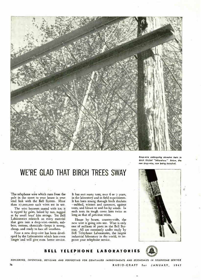
WE'RE GLAD THAT BIRCH TREES SWAY
The telephone wire which runs from the pole in the street to your house is your vital link with the Bell System. More than 17,000,000 such wires are in use.
The wire becomes coated with ice; it is ripped by gales, baked by sun, tugged at by small boys' kite strings. Yet Bell Laboratories research on every material that goes into a drop -wire -metals, rub- bers, cottons, chemicals -keeps it strong, cheap, and ready to face all weathers.
Now a new drop -wire has been devel- oped by the Laboratories which lasts even longer and will give even better service.
It has met many tests, over 6 or 7 years, in the laboratory and in field experiments. It has been strung through birch thickets -rubbed, winters and summers, against trees, and blown to and fro by winds. In such tests its tough cover lasts twice as long as that of previous wires.
House by house, country-wide, the new wire is going into use. Wire is only one of millions of parts in the Bell Sys- tem: All are constantly under study by Bell Telephone Laboratories, the largest industrial laboratory in the world, to im- prove your telephone service.
Drop -wire undergoing abrasion tests In birch thicket "laboratory." Below, the new drop -wire, now being installed.
BELL TELEPHONE LABORATORIES
EXPLORING, INVENTING, DEVISING AND PERFECTING FOR CONTINUED IMPROVEMENTS AND ECONOMIES IN TELEPHONE SERVICE
76 RADIO -CRAFT for JANUARY, 1947

Model 2450
ELECTRONIC
TESTER
ELECTRONIC VOLT-
OHM---. M A --
MFD
St rr `/iat TS n+YC rncMA
OrÈ ti
..r
AP:Gt
1 -
l' l íl ---. (' ;.1 t {;'a - 25'i
. 'j!?--..{ 1,
a¡
RXG J / \\
Ì . " H'°
-
'-1 - ) RI t n c S
pli';
` ^-°x tGJ Ms
--
1:
,t-is- C
F
-----.. C
There's never been a tester like this! Here's a tester with dual voltage regulation of the
power supply DC output (positive and negative), with
line variation from 90 to 130 volts. That means cali-
bration that stays "on the nose "! That means broader
service from a tester that looks as good as the vastly
improved service it provides. And, together with its
many other new features -including our Hi- Precision
Resistor which outmodes older types -it means higher
performance levels wherever a tester is needed. Detailed
catalog sheets on request.
42 RANGES: DC and AC. Volts: 0- 2.5- 10 -50. 250 -500- 1000. DC MILLIAMPS: 0.0.1- 1.0 -10 -50 -250 -1000. OHMS: 0- 1000- 10,000- 100,000. MEGOHMS: 0 -1- 10- 100 -1000. CAPACITY IN MFD: 0- .005- .05 -.S 550.
LOAD IMPEDANCE: 51 megohms on DC Volts. CIRCUIT LOADING: Low frequencies. Circuit loading equal to 8 megohms shunted by 35 mmfd. High frequency circuit loading equal to 8 megohms shunted by S mmfd.
t Triplet ELECTRICAL INSTRUMENT CO. BLUFFTON, OHIO
RADIO -CRAFT for JANUARY. 1947 77

We salute you Dr. Lee de
on the 40th Anniversary
of the Invention of your vacuum tube.
1907 -1947
78
NC-S-40D
Beauty goes deep in the NC- 2 -40D. Deep inside the
chassis parts of watchlike precision are assembled
with painstaking care. Carefully designed mechanisms
enable the controls to respond to your slightest
touch. Thorough shielding helps circuits to develop
the fine performance, stable operation and uniform
response that you expect of a National receiver. We
invite you to study the photographs above. They
are pictures of quality.
NATIONAL COMPANY, INC., MALDEN, MASS.
RADIO -CRAFT for JANUARY. 1947
US OFF
jiE pRES5 ,//\
0:010 p0 SAfFt
pN
WHAT THIS GREAT BOOK CONTAINS Radio Materials
Radio Abbreviations
Radio Circuits
Power Formulas
Radio Receiving Tubes
Reactance & Energy
Losses
Radio Transformers
Radio Amplifiers
Radio Receivers
Sound Systems &
M Devices ale&Me n
Radio Symbols result 044001
Radio Resistance & Insul- ation (wire tables, etc.)
Capacitors & Capicitance
Coils & Coil Winding / Resonance & Coupling \ iii //4 Power Supply - 11 yylll
A.C. or D.C. \ Power Supply -..
Batteries
Oscillators &- Antennas j
A Brand New, Valuable Reference Book for Men Working in Radio or Electronics This is the book that radio men everywhere have been waiting for. No matter what work you do in radio, this reference handbook will prove mighty valuable since it contains exactly the informa- tion you need You can refer to it easily right on the job. It should help you get jobs done quicker and better -it will save you valu- able time. I'm so sure that you wouldn't part with this book for many times its cost that I'm willing to send it to you for a 7 day FREE examination.
7 DAYS' FREE EXAMINATION You can't expect to carry all the necessary information you need on a job in your head. But with this book at your side you will be able to make quick calculations that will help to show the boss that you certainly know plenty about radio construction, design, installation and operation. As you look through the pages of this valuable Radio Handbook you can easily see how the tables, charts, diagrams and information can help you get more money for your services. So I want you to examine this fine book at ABSOLUTELY NO COST TO YOU before you make up your mind whether or not you want it.
A PRACTICAL REFERENCE BOOK-NOT A TEXT BOOK You won't need to "study" this book -it is not a textbook. Every subject is indexed and condensed. It is full of valuable tables that will help you in your daily work. When you are "on a spot" just turn to the quick reference index, look up the subject you want and you'll find it thoroughly explained with helpful / diagrams and tables. You lose no time. You waste no effort. The book is a day -by-day helper to you and will j be of value to you on every job you undertake. It was written by competent, experienced, practical radio engineers and instructors. Every diagram has been fully
tested in the great Coyne Electrical Shops. Every table $ is scientifically correct.
SEND NO MONEY SEE THIS BOOK FREE
I am not asking you to send any money -not a single penny. I am so sure this is the book you want and need that I will send it to you to examine for 7 days FREE. Then you look it over and you decide. If it isn't all I claim, then send it back and you owe nothing. If you are convinced that this book is worth many times its cost, then send $3.25 at the end of 7 days and the book is yours. Send the coupon now, while it is before you!
SEE OTHER COYNE BOOKS IN COUPON
i
I
I I
I
I
I
I
I
B. W, Cooke, Director, COYNE ELECTRICAL SCHOOL, Dept 17 -T11
500 S. Paulina Street, Chicago 12, Illinois 'O Send me the COYNE RADIOMAN'S HANDBOOK for 7 days' FREE examination. After 7 days I'll either return the book and owe nothing or I'll send you a check or money order for $2.75.
IHere are other Coyne Books -l'U send any or all on same 7 day Free Examination Offer.
O Coyne Applied Practical Electricity -7 volume set; a complete library on everything electrical in easy to understand form. $19.76 cash or $21.00 on time -$3.00 after 7 days and $3.00 per month - 1 year FREE Consultation Service and Technical Bulletins.
Coyne Electrical & Radio Trouble Shooting Manual -612 Pages, over 600 wiring diagrams, hookups. Radio, P.A. systems, radio testing, refrigeration, motors and controls. $8.00 cash -$8.95 on time -$3.00 after 7 days and $3.00 monthly -1 year Technical Bulletins Free. El Coyne Electrician's Handbook -400 pages: data, diagrams, circuits, installation, wiring methods, etc. $2.75 after 7 days.
Coyne Electronics for Radiomen & ,Electricians -over 400 Pages: clearly explains all types electronic tubes. hundreds of dia- grams, etc. $3.75 after 7 days' examination -1 year Free Technical B w let i n:+.
I O Electrical & Radio Dictionary and Data Book -3300 electrical and radio, radar, electronic and atomic energy terms, 800 pages. Ivest pocket size. $1.00 after 7 days. Name Age Address
Town Zone State Where Employed?
O If you prefer to pay postman cash price indicated above when boob.. sail, neck here. same 7 day examination and money -back swarsntee of satisfaction
COYNE ELECTRICAL SCHOOL
500 SOUTH PAULINA ST. DEPT. 17 -T6 CHICAGO, ILL.
RADIO -CRAFT for JANUARY, 1947 d
79
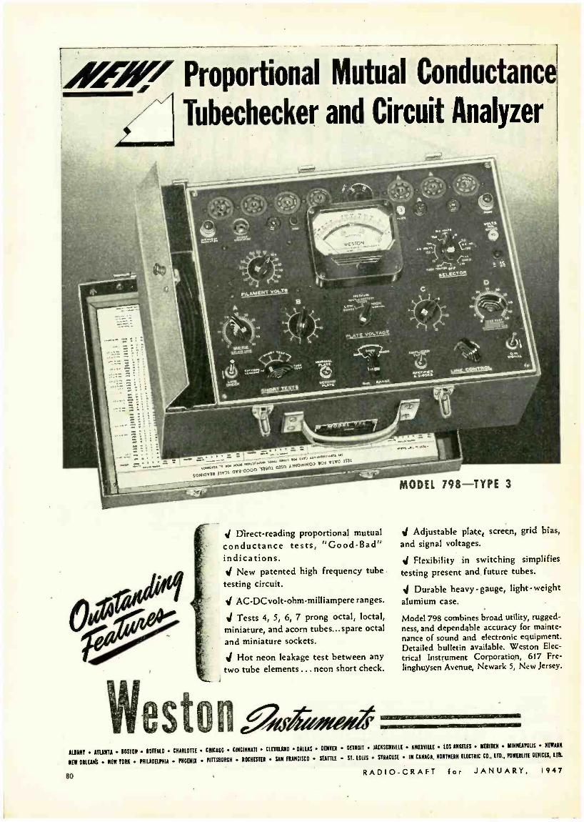
A47' Proportional Mutual Conductance
Tubechecker and Circuit Analyzer
;.,uw A1NOW 0'.w.I1VU'SSìI S 1Mr °r°.°°°° SAyfIA
MODEL 798 -TYPE 3
J Direct- reading proportional mutual
conductance tests, "Good -Bad" indications.
New patented high frequency tube
testing circuit.
J AC- DCvolt -ohm -milliampere ranges.
Tests 4, 5, 6, 7 prong octal, loctal,
miniature, and acorn tubes...spare octal
and miniature sockets.
J Hot neon leakage test between any
two tube elements.. . neon short check.
J Adjustable plate, screen, grid bias,
and signal voltages.
d Flexibility in switching simplifies
testing present and future tubes.
d Durable heavy - gauge, light- weight
alumium case.
Model 798 combines broad utility, rugged-
ness, and dependable accuracy for mainte-
nance of sound and electronic equipment. Detailed bulletin available. Weston Elec-
trical Instrument Corporation, 617 Fre-
Iinghuysen Avenue, Newark 5, New Jersey.
Wes a,s,.,,,o.. ALBANY ATUNTA BOSTON BUFTALO CHARLOTTE CHICAGO CINCINNATI CLEYELAND DALLAS DENVER DETROIT JACKSONVILLE KNOXVILLE LOS ANGELES MERIDEN MINNEAPOLIS HEWARN
NEW ORLEANS NEW YORK PHILADELPHIA PHOBIA PITTSBURGH ROCHESTER SAN FRANCISCO SEATTLE ST. LOUIS SYRACUSE IN CANADA, NORTHERN ELECTRIC CO., LTD.. POWEALILE DEVICES, LTD.
80 RADIO -CRAFT for JANUARY, 1947

TELEVISION FOR TODAY
By MILTON S. KIVER
Part VIII Video Amplifier Fidelity Considerations THE VIDEO amplifiers of the tele-
vision circuit are analagous to the a.f. amplifiers of the sound receiver. The rectified signal at
the output of the second detector is too weak to adequately drive the cathode -ray tube and produce maxi- mum contrast. Hence, the need for video amplifiers. The number is governed by the polarity of the rectified video voltage (as previously described) plus the strength of the detector output.
The requirements for video ampli- fiers must include uniform response from 10 cycles to 9.5 me (approximate- ly) and a phase shift which is either
the shunting capacities at the higher video frequencies. To this is added either a series or shunt peaking coil (sometimes both) to further maintain the response level to the highest video frequency desired. An illustration of each is shown in Figs. 1 -b and 1-c. The values of RL and L, with shunt peaking, are given by
R,. = 1
ohms 2nf C,
(1)
and L = 1 C, RL' henries (2) where C, = total stunting capacitance
f = highest video frequency to be amplified by stage.
Series peaking, because it divides Cs into two components, permits us to ob-
ally of the addition of the filter, R. CF, as shown in Fig's. 1 -b and 1 -c. At the middle and upper range of fre- quencies, CF effectively bypasses RF and the resistor is without effect. At low frequencies, CF combines with RF to increase the load offered to the signal and thus maintain a constant gain. Further, CF, in conjunction with RL, compensates 'to a great extent for the phase shift introduced by and R. To accomplish this, we set CFRL equal to C<Rg. Here, then, is the controlling de- sign equation for the low- frequency compensation. The calculations com- mence with equations (1), (2) or (3), (4) and finish with CFRL = CaRr. Typi- cal values of RF and CF are 5,000 ohms and 8 µf, respectively. Other methods of
Fiq. I -a -The re isfance- coupled amplifier.
Fig. I -b-The same, with shunt peaking added.
Fig. I-c-Same, wi h a series -pea ing circuit.
zero or else proportional to frequency. The importance of phase shift will be discussed presently; the frequency re- sponse requirement, however, should be self- evident from what has already been given. The video signal contains these frequencies and for the reproduc- tion of full detail they must reach the cathode -ray tube.
The form of the video amplifiers has already been fully discussed in many places (see references at end of ar- ticle) and no extended discussion is needed here. Briefly, an ordinary R -C amplifier (Fig. 1-a) is taken as the basis. The plate load resistor is de- creased torelatively low values (1500- 10,000 ohms) to minimize the effect of RADIO -CRAFT for JANUARY,
Courtcry Shur -Antenna- Mount, Inc. Dipole television antenna with reflector which
tain a higher gain. The governing equations in this instance are:
0.5 L =
(2Jrf)' C, 1.5
RL = (4) 2,tf C,
where C, = C, -- C: (shown in Fig.1 -c), Not only is the extension at the high-
er frequencies important, but the re- sponse characteristic must be rolled down to the vicinity of 10 cycles in or- der to prevent distortion of the slow changing background shading. Low - frequency compensation consists gener-
(3)
10
steps up gain and discriminates against echoes.
approach are available but good results are obtained with the preceding data. Fig. 2 is the response characteristic of a video amplifier having the values shown.
PHASE DISTORTION The effect of phase distortion upon a
video signal (and consequently the im- age) is not as readily apparent as fre- quency distortion. Sound receivers are seldom troubled with phase distortion because our ears are largely insensi- tive to it. The visual effect is marked.
Phase distortion occurs whenever the phase relationships between the various
(Continued on following page)
FLAT FROM I00 TO I,000,000 CYMES IOMC
Fig. 2 -Video amplifier circuit and response curve. Response is flet over broken po Lion.
1947 81.

portions of a complex wave are altered as the wave passes through a network. Of particular interest is the phase - versus- frequency characteristic of the resistance- coupled amplifier. The graph of a typical amplifier is shown in Fig. 3. It indicates quite clearly that the phase shift of such a circuit -as far as tele- vision application is concerned -is cen- tered chiefly at the low and high fre- quency ends of the characteristic. Throughout the middle range of fre- quencies the phase shift is zero, which means that the video signals pass through without being affected.
Phase shift at the lower frequencies is due to the coupling condenser, C of Fig. 1. When an alternating voltage ap-
90q 10 Fu --
49
<
0
ô W
u° v '
90° .
frequencies the phase shift is practi- cally 90 degrees.
The effect of the foregoing phase shifting characteristic upon a complex wave is evident. The lower frequencies, in passing through the network, would have their relative positions altered and with this, the shape of the resultant wave itself. A simple example will read- ily demonstrate this. Assume that the incoming wave has the form shown in Fig. 6 -a. Upon analysis the wave can be shown to contain a fundamental in com- bination with its third harmonic, say 60 and 180 cycles (6 -b). After passage through the R-C network, their relative relationship may have changed to the extent shown in Fig. 6 -c. Combining
1MC I MC
tion between phase shift and time delay. Suppose that a video voltage is applied to a group of video amplifiers and fur- ther, that frequencies of 40 and 90 cycles are present in this wave. Since the lower frequency voltage will receive the greater phase shift, the 40 -cycle wave may be shifted 45 degrees to pos- sibly 10 degrees for the 90 -cycle voltage. At the output of the network, the two frequencies will no longer possess the same relationship to each other as they had at the input. A simple calculation will indicate what the difference is.
A 40 -cycle wave requires 1/40 of a second to complete a full cycle of 360 degrees. Proportionally, then, it will re- quire 1/320 of a second for only 45 de- grees. 1/320 of a second is approximate- ly 0.003 sec. Hence, there will be this time difference between a maximum oc- curring at the input to the next tube and that occurring at the output of the pre- ceding tube. The appearance of one will lag behind the other by 0.003 seconds.
The 90 -cycle wave has a 10 degree phase shift. One cycle of a 90 -cycle wave requires 1/90 of a second. 10 degrees would require only 1/3240 of a second, or approximately 0.0003 seconds.
At the cathode =ray tube, the electron beam moves across a 12 -inch screen a distance of one inch from left to right in approximately 0.000,007 second. This time interval is extremely short and if waves are shifted as computed above, the visual result is a displacement of elements. The smearing is always from left to right, this being in the direction of motion of the electron beam. Smaller
Fig. 3 -Phase shift in video amplifier. Shift is negligible over the center of the spectrum.
pears across Ra. (See Fig. 4), it is, at the same time, impressed across the series combination of C° and R,. The division of the voltage between C° and R, will be directly proportional to their respective impedances. As we lower the frequency of the applied voltage, X, rises rapidly in value, reducing the ef- fective voltage at R,.
The phase angle between the voltage across Rc and the voltage across R, will also be found to be a function of frequency. When the frequency is suffi- ciently high to make X, insignificant with respect to R, (say in the ratio of 1:10), then ER/. and Eno are essen- tially in phase. But with a decrease in frequency, we find an increase both in the ratio of X, to R, and the phase difference between ERL and ERG. Graph- ically we have the situation shown in Fig. 5. This is the familiar impedance graph, with the resistance (R,) plotted along the abscissa and the reactance (X,) laid off along the ordinate axis. The angle, designated as 8, represents the phase difference between the cur- rent in the series branch C, and R, and the applied voltage or ERL. It also is the angle between ERr, and ERG since the current through R, and the voltage across it are in phase. R, remains con- stant, but X, changes inversely with frequency. The plot in Fig. 5 illustrates that as we lower the frequency X, in- creases and with it O. For the very low
82
these two voltages now would produce the complex wave of 6 -d, little resem- bling the original wave. While an in- stance where the phase shift was made excessively large was chosen, yet over several amplifiers, such results may actually be obtained.
At the high- frequency end of the response characteristic (Fig. 3), we see that the phase shift again becomes ap- preciable. The reason now is due, not to
v 8+
E Rl
Fig. 4 -Cause of low- frequency phase shift.
C but to CT, the capacitances that act in shunt with the grid resistor. CT com- prises the output capacitance of the preceding tube, the input capacitance of the following tube, and the stray wiring capacitance that is ever present. From the equivalent schematic, Fig. '7, we see that as the frequency increases, CT be- comes increasingly important as a
shunting path for the signal reaching R,. More of the current is diverted from R, and soon it becomes wholly capacitive with a resultant phase of 90 degrees.
VISUAL RESULTS
To explain the visual results of phase distortion, let us examine the correla-
RADIO
xC4
1 IC 3 i zC2 VERY
Rg \f( RELATIVELY HIGH)
Fig. 5- Phase -angle shift at high frequency.
objects and fine detail become fuzzy or even tend to blend into each other, pre- senting an indistinct outline. Phase dis- tortion will cause an incoming image with a perfectly white background to reproduce as a greyish hue, or even black. The reason for this can be ex- perimentally determined by the reader himself. Take any complex wave (such as we would find representing a white video element) and break it down into its components. If any of these com- ponents are then shifted in phasé, the resulting complex wave will have am- plitudes at each point which vary from those previously possessed. But, in a television _receiver, a change in ampli- tude results in a change of, intensity or hue at the screen. Thus, it becomes evi- dent that any change from a perfectly white spot could only result in some- thing which has less white, or more grey or even black, depending upon the change in phase of the different com- ponents of the complex wave.
(Continued on page 131)
-CRAFT for JANUARY, 1947

By j. SiMRiN
MU LIlIE STE R
PLUS V.TSVIIM.
THE WRITER has for many years used a volt- ohm -milliammeter of home construction which original- ly had an analyzer unit built in
it, but which he found of very little use in servicing modern radios. Having also a separate Electronic Voltmeter built from an article taken from RADIO -CRAFT some three years ago (see "A Simplified Electronic Voltmeter" by Harold Davis, RADIO-CRAFr, Jan.-Feb., 1943) it was decided to rebuild the original instru- ment, and by doing without the analyzer section, incorporate the electronic volt- meter in its place.
The completed instrument is an effi- cient, compact job, built on an alumi- num panel only seven inches square. Either instrument can be used inde- pendent of the other by turning one switch. It is housed in a wooden case, measuring 10 x 10 x 3 inches, leaving a space at the top for the test leads and a compartment at the right for small tools. There are no special or home. constructed switches; each is a stand- ard article which may be purchased at almost any parts supply house. Sw2, which is a 3 -pole six -gang switch, se- lects the use of the tester. Left posi- tion is volts, center mils and right elec- tronic voltmeter, or e.v.m. In this posi- tion the meter is switched into the e.v.m. circuit and the A and B batteries turned on at the same time. It should, of course, not be left in this position when the e.v.m. is not in use, as the batteries would be needlessly drained. The A bat- tery is an ordinary flashlight cell and the B is a 45-volt midget type with snap -on terminals.
Jacks 1 and 2 are used for volts and mils, 1 and 3 resistance high range, 1 and 4 resistance low range, with Swl set for low ohms. Swl is a d.p.d.t. and has the left position off so that the midget neon lamp may be used with- out the meter by plugging the test leads into jacks 2 and 6. The neon lamp will light when the line plug is being used and Sw8 thrown in, serving also as a warning that high voltage is being used. Sw8 permits the line plug to re- main inserted in a wall receptacle at all times and can be turned on only when desired.
Values of the milliammeter shunts are not given as they will depend on the ranges desired and the internal resist- ance of the meter being used. A sep- arate set of resistors was used for the RADIO -CRAFT for JANUARY,
The instrument shown here is as effective as many larger and more expensive units.
a.c. ranges and are approximately 10 percent lower in value than the cor- responding d.c. resistors. To save space all shunts and series resistors were mounted on Sw3, which is a 2 -gang 11- point switch.
Condensers up to .0.1 µf can be tested for capacity through jacks 1 and 6. Sw5 is turned to a.c., Sw3 set to a range that will show full scale or nearly so, with the test leads shorted when line Sw8 is on. Sw2 must be set for volts of course, as the line voltage is being read for this test. The tap on Sw3 marked Line Con- trol is merely a fixed resistor in series with a small volume control and switch (Sw9) which is used to short jacks 1 and 6 and then allows the line voltage to be adjusted to full scale reading on the meter. Electro- lytics and paper condensers over 0.1 µf can then be checked for capac- ity through jacks 1 and 4. The a.c. voltmeter can be used as an output indicator through jacks 1 and 5; a 02 condenser is in series with J5 to block any d.c. pres- ent.
A novel and sim- ple method of de- termining very low resistances for lo- cating shorted turns in coils, etc., is used. Sw6, a push- button type, is wired across the 4,000 ohm resistor in the ohmmeter circuit and is normally open. With the meter set for low ohms and
1947'
test leads in jacks 1 and 4 connected to a low- ohmage resistor or coil winding, depressing Sw6 will short out the 4,000 - ohm resistor and allow a greater cur- rent to flow. The resistance under test is a shunt across the meter, and values up to about 6 ohms may be safely tested this way. Even a small fraction of an ohm will show an appreciable reading. The pushbutton should be released
(Continued on page 138)
---- r____ VIII -íf
' ZERO ADJ. 1E4
SV47 IMEG IN TEST PROBE
SW2 GANGED
Fpe o-
Eqe o-
.2K 13
2
BMEG I
1,8 MEG
IOOK
IOOK
1
1
I VM SECTION
SWS DC ó r
OFF ON LQA q e 3
aSW.I
L ISHUNTn FOR MA IIMA
oIOM 1?50MA 4I00MA
500MA
I AMR
SW,3 l SERIES AFOR DC V.
1
1 o0v 14 1 } 50V. 50K
j 100100e Q 5 0
00
JI J2 J3 BULB TEST
J4 4.5 Ilql
.:.02
° U1 J5 J6
4K IK
0SW9 ON LINE CONTROL SVL-8
EON K
D. ADJ.
OR EXTRA LOA
KV_t_1AE' 0
25K T5K
LINE C N 02 L -
Ku Ac
250V.ACC
50uACC
IOV.AC 14
SERIES A FOR ACV.
v ! S11L8.
FUSA E 117VAC
Considering the number of circuits, construction is fairly simple.
83
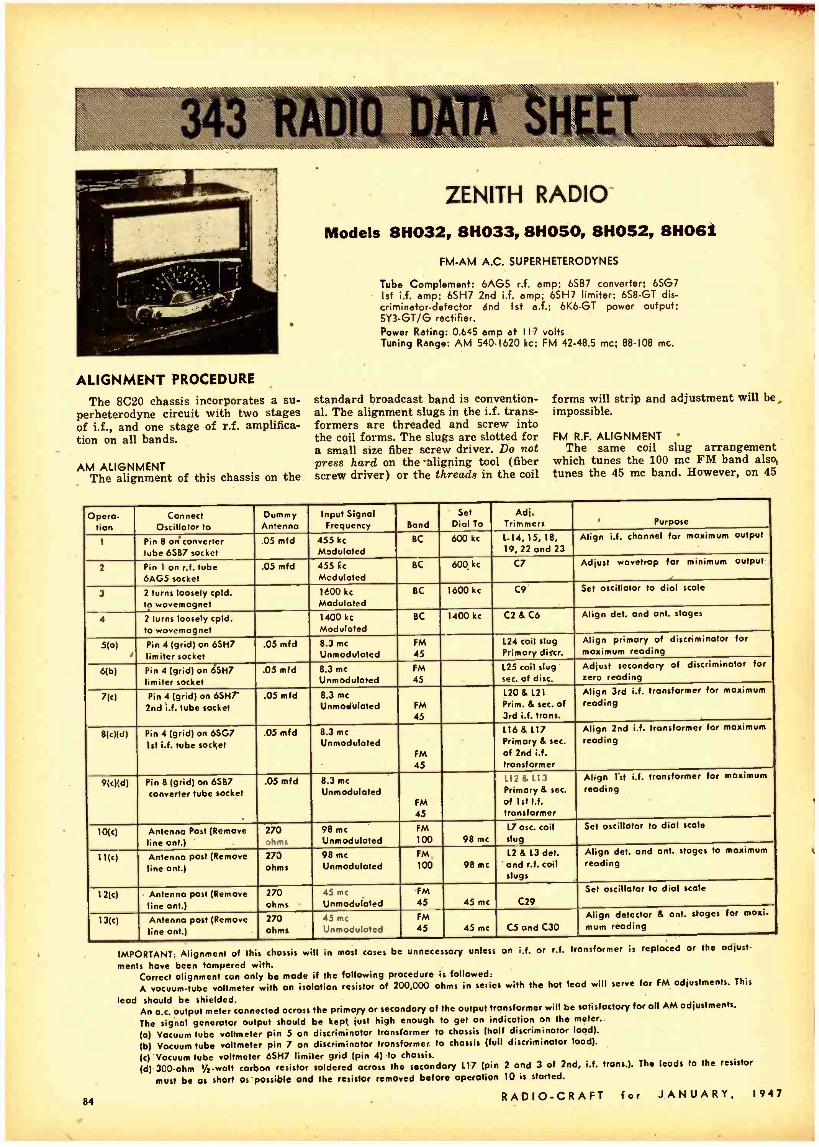
--r""11,1111
ALIGNMENT PROCEDURE
The 8C20 chassis incorporates a su- perheterodyne circuit with two stages of i.f., and one stage of r.f. amplifica- tion on all bands.
AM ALIGNMENT The alignment of this chassis on the
ZENITH RADIO
Models 8H032, 8H033, 8H050, 8H052, 8H061
FM-AM A.C. SUPERHETERODYNES
Tube Complement: 6AG5 r.f. amp; 6587 converter; 6567 Ist i.f. amp; 6SH7 2nd i.f. amp; 6SH7 limiter; 6S8 -GT dis- criminator- detector and Ist a.f.; 6K6 -GT power output; 5Y3 -GT /G rectifier. Power Rating: 0.645 amp at 117 volts Tuning Range: AM 540 -1620 kc; FM 42 -48.5 mc; 88 -108 mc.
standard broadcast band is convention- al. The alignment slugs in the i.f. trans- formers are threaded and screw into the coil forms. The slugs are slotted for a small size fiber screw driver. Do not press hard on the 'aligning tool (fiber screw driver) or the threads in the coil
forms will strip and adjustment will be impossible.
FM R.F. ALIGNMENT The same coil slug arrangement
which tunes the 100 mc FM band also tunes the 45 mc band. However, on 45
Opera. lion
Connect Oscillator to
Dummy Antenna
Input Signal Frequency Band
Set Dial To
Adj. Trimmers Purpose
1 Pin 8 oti converter tube 6567 socket
.05 mfd 455 kc
Modulated BC 600 kc 1 -14, 15, 18,
19, 22 and 23 Align i.f. channel for maximum output
2 Pin 1 on r.f. tube 6AG5 socket
.05 mfd 455 kc
Modulated BC 600. kc C7 Adjust wavetrap for minimum output
3 2 turns loosely cpld. t? wovemagnet
1600 kc
Modulated BC 1600 kc C9 Set oscillator to dial stole
4 2 turns loosely cpld. to wovemagnet
1400 kc
Modulated BC 1400 kc C2 & C6 Align del. and ant. stages
5(o) '
Pin 4 (grid) on 6SH7 limiter socket
.05 mid 8.3 mc
Unmodulated FM 45
124 coil slug Primary discr.
Align primary of discriminator for maximum reading
6(b) Pin 4 (grid) on 6SH7 limiter socket
.05 mfd 8.3 mc
Unmoduloted FM 45
125 coil slug sec. of disc.
Adjust secondary of discriminator for zero reading
7(c) Pin 4 (grid) on 6SHr 2nd i.f, tube socket
.05 mfd 8.3 me
Unmoduloted FM 45
L20 & L21
Prim. & sec. of 3rd i.f. trans.
Align 3rd i.f. transformer for maximum reading
8(c)(d) Pin 4 (grid) on 6507 1st i.f. tube socket
.05 mfd 8.3 mc Unmodulated
FM 45
116 & 117 Primary & sec.
of 2nd i.f. transformer
Align 2nd i.f. transformer for maximum
reading
9(c)(d) Pin 8 (grid) on 6587 converter tube socket
.05 mfd 8.3 mc Unmoduloted
FM 45
112 & 113 Primary & sec.
of 1st i.f. transformer
Align list i.f. transformer for maximum reading
10(c) Antenna Post (Remove line ant.)
270 ohms
98 mc
Unmoduloted FM 100 98 mc
L7 osc. coil slug
Set oscillator to dial scale
11(c) Antenna post (Remove line ant.)
273 ohms
98 mc
Unmoduloted FM 100 98 mc
L2 & L3 det. and r.f. coil slugs
Align det. and ant. stages to maximum
reading
12(c) Antenna post (Remove line ant.)
270 ohms
45 mc
Unmodulated FM 45 45 mc C29
Set oscillator to dial scale
13(c) Antenna post (Remove line ant.)
270 ohms
45 mc
Unmodulated FM 45 45 mc C5 and C30
Align detector & ant. stages for maxi -
mum reading
84
IMPORTANT: Alignment of this chassis will in most cases be unnecessary unless an i.f. or r.f. transformer is replaced or the adjust-
ments hove been tampered with. Correct alignment can only be made if the following procedure is followed: A vacuum -tube voltmeter with an isolation resistor of 200,000 ohms in series with the hot lead will serve for FM adjustments. This
lead should be shielded. An a.c. output meter connected across the primary or secondary of the output transformer will be satisfactory for oll AM adjustments.
The signal generator output should be kept just high enough to get an indication on the meter.
(o) Vacuum tube voltmeter pin 5 on discriminator transformer to chassis (half discriminator load).
(b) Vacuum tube voltmeter pin 7 on discriminator transformer to chassis (full discriminator load).
(c) Vacuum tube voltmeter 6SH7 limiter grid (pin 4) to chassis.
(d) 300 -ohm 1/2 -watt carbon resistor soldered across the secondary 117 (pin 2 and 3 of 2nd, i.f. trans.). The leads to the resistor
must be os short os possible and the resistor removed before operation 10 is started.
RADIO -CRAFT for JANUARY. 1947

me the band switch connects trimmer condensers in parallel and padding wires in series with the 100 me coils. The tuning slugs are attached to threaded shafts and the slugs are varied in the field of the coils by turning the shafts clockwise or counter- clockwise After adjustments the shafts must be secured with a drop of speaker cement. This will prevent changes due to vibra- tion or tampering.
FM I.F. ALIGNMENT The same type of tuning slugs for
aligning the AM i.f. amplifier are used for the FM i.f.'s. Observe the same precautions when making adjustments. The second 8.3 me i.f. stage is over - coupled. Overcoupling gives a wide band pass with good sensitivity. When an
L5XAT600KC : X AT 96 MC
LOOP LI
(5.5X AT 600 KC 4.2 X AT 98 MC
overcoupled stage is aligned with an unmodulated signal, the stage must be loaded. A 300 -ohm carbon resistor soldered across the secondary of the second i.f. transformer provides a satis- factory load for this circuit. The resis- tor leads must be kept short to reduce the distributed capacity of the circuit.
When aligning a loaded stage, it will be found that considerable signal from the generator will be required, and that it will tune broadly. THE LOAD RE- SISTOR MUST BE REMOVED AFT- ER ALIGNMENT.
If the signal generator used does not have sufficient output to overcome the temporary loss caused by the load re- sistor, the load resistance may be in- creased or the signal fed into the pre- ceding stage.
X FROM600T0455K 4.6X AT 4SSKC 5X FROM 98T08.3M 6X AT 8.3MC
FM DISCRIMINATOR ALIGNMENT When the secondary of the discrim-
inator is aligned (operation 6) use sufficient signal input to get a good positive and negative indication before setting the slug for zero reading. A center zero indicating meter is recom- mended for this adjustment, but is not absolutely necessary. Reversing the leads of a non -zero center meter, or ob- serving closely when this meter starts to go to the left (negative) of zero will give the same results.
Alignment of FM receivers is a spe- cial job and calls for knowledge of their characteristics. Articles on FM servic- ing were printed in RAnio- CRAFT, March 1946 and March 1944.
8.2 X FROM 455KC TI 400 nr
27XAT8.3MC
A5uf 6SB7 6SG7 GT 6SH7 r1? 6SH7
2ND I.F. 150 LIMITER 1.2V. .L,OOluf
CONVERTER 1ST I.F. 1
-1.6V -1.6V.
{I32V. ti C 30 110V.
- IIN . Illmlt 0
6S8-GT DISCRIM. DET. IST AUDIO
-1.2y i u 220K
475 252N
IST I.F.&3MC
TI-
12 L13 ar
I
.02uf
FM C& GA
90
It 2 20
A FM ANT COIL
OOluf
L4
&C.DET. - COIL
&8KJ 4'100
L p Oa 6.
iju f LB 850
L3
255
2ND LE 8.3MC
T? L16 L 1
-0r
150 60V.
3RD LF.8,3MC
73
20 L21 JC 41i
g r.bñ
0 0
6
ye1
B,C.OSC.
9n
114 L15 (.. 455KC ?
"64. `x 118 LI9
---- 455K l
68K f1 ,00IUf 0168K 1 2.2K =22K
9
.. 1500 14
'
rL25
y Lza ^11
O
r
f
1 ó ó
L22 L2
455KC
AI
150 47K 220K
L8 4-to 6K6-GT fOUTPUT
40uf 410K
.02 u 245\(
r 210V.
I
SMEG
DISCRIM. I.F.
8.3 MC
220K
470K
T.0541 NOTE:CONDENSERSIN uMf UNLESS NOTED CI GANGED
3RD I.F. TRANS. 2ND I.F. TRANS. IST iF TRANS. L \1.21_. 117 LI63 LIS, 1 L13
e FM
L7 FM
L22 L9
SY' GT
ODISC.I.F. 8.3MC
ON-OFF SW. WITH VOLUME CONTROL
IB LI4
TRANS
C9 OSC.1oo KC C6 DU. 1400 KC TUNING AND BAND SW. SHAFT C2 ANT. 1400 KC - NOTE:C7 =WAVE TRAP 455KC
TUBE AND TRIMMER LAYOUT, TOP VIEW OF CHASSIS,FROM FRONT, WITH RIGHT END, .
L2 ANL FM e--96 MC
6587 475
6SG7 Aluf /V
029 0SC.FM 45MC
C30 OET. FM 45 MC
CS ANT. FM 45MC
RADIO -CRAFT for JANUARY, I$47
322V.
700a HOT-2 SPKR FIELD
00' T 40uí
50 yel sl
LO BASS OPEN
47K .003uf
TREBLE CLOSED . bl si
T T ALTO OPEN BASS
5Y3-GT
.004u1
VOICE OPEN
BARE
41K
h -1b'ib yeslr7
NORMAOPEN
TO(JE SW.
OPEN
TO ANT.TERM.STRIP FM CONN,
LB í
blk .
- la redblk
SW ON V.C. Z.005uf
117 VAC 70 W.
85

T Ai EE FIVE RADIO
This Simple, Experience -Tested Set Is Easy to Build
DURING the war it was common practice for a student to con- struct a prcctical and useful radio to familiarize himself with
wiring practice, mounting of parts, soldering, .alignment, and to generally broaden his knowledge and put his "book learning" to use. These radios were usu- ally t.r.f.'s or superhets employing not more than five tubes. This is such a set and is not unlike the common a.c: d.c. radio.
The superhet circuit used has a 6K8 converter, a 6SK7 i.f. amplifier, a 6SQ7 detector and first audio a 25A6 audio output and finally a 35Z6 rectifier. (A 25Z6 can be used.) It is conventional in every respect with no tricky circuits.
Drilling and punching the chassis is the first step. Tools needed are: a good "egg- beater" type drill, an assortment of small twist drills, a circle- cutter or
chassis punch for tube sockets, and mis- cellaneous items as a pocket knife, center punch, hammer, and others.
Probably the most difficult job is the cutting of the opening in the chassis for mounting the speaker, but this may be done easily enough if an electric grinder is handy, as the opening may simply be ground away. If this is not possible a
hacksaw or coarse file may be used. After drilling is finished the tube
sockets, tuning condenser, i.f. trans- formers, output transformer, choke, and volume control are mounted. De- tails of the dial drive are given in Fig. 2.
Due to the possibility of puncturing the speaker cone, the speaker should be mounted last or a piece of cardboard taped to the speaker for protection. Filament wiring should be first, this identifies connections on the tube bases easily as
25A6, PM MSPKR
II OUTPUT TRANS
VOL.CONT. 5 MEG
117 V. AC /DC SW.ON V.C. BO
® 1 LINE CORD
6507 6K6 65K7 25A6
CONDENSERS ARE 200 OA MORE, UNLESS NOTED. "C" 8 7 2 7 2. 7 2
The circuit is almost a composite model of prewar standard five -tube a.c: d.c. receivers.
450n CHOKE
000x 20-
T í50V T
35Z6'
The chassis layout, also follows standard practise. Alignment problems
are considerably simplified by using the cut -plate condense}. Layout of parts under the chassis can be seen in this photograph.
86 RADIO -CRAFT for JANUARY, 1947
the filaments on all five tubes are num- bers 2 and 7. It is also advisable to ground the No. 1 pin on each socket.
As a result we have con - venientground connections. Cathodes and grids are next in order of wir- ing and should be soldered in with care. All suppressors should be tied to the cath- odes. After the cathode a n d grid connec- tions have been double checked, screen grids and plates are connected last. Don't rush, wire slowly!
Having completed all wiring and thoroughly checked each connection, the set is ready for its first try -out. After it has warmed up, a very low hum should be heard in the speaker with volume control set at maximum. If the i.f. transformers are new they have been peaked at 456 kc and some sort of signal should be heard.
If no signal generator is available, a fairly good job can be done by ear. Tune in a weak station and align the oscillator and antenna -coil trimmers for maximum
(Continued on page 120)
DIAL PULLEY DIAL CABLE
BUSHIN PANEL
G !
.25"SHAFT A side view of the sim- ple tuning mechanism.
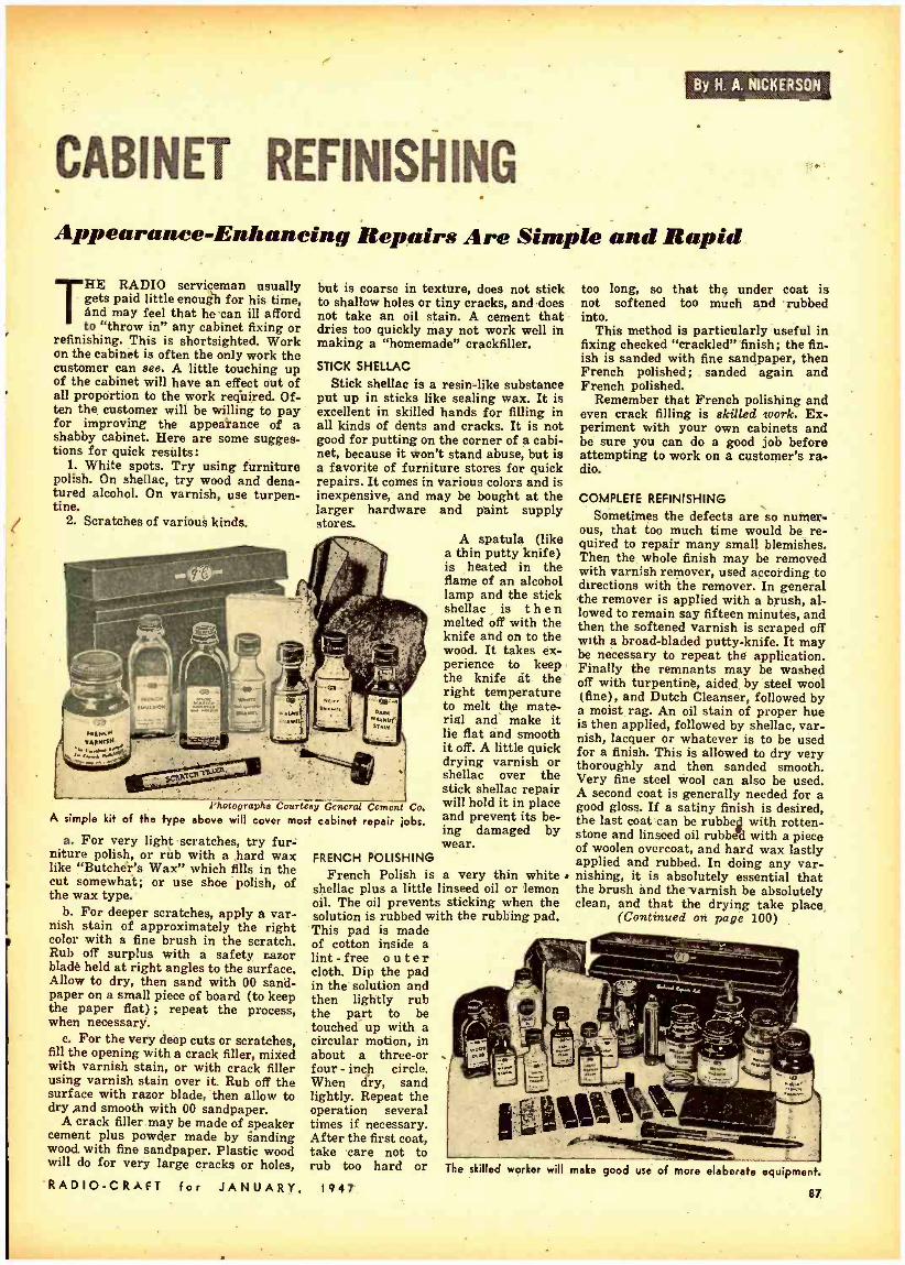
.as._..
REAM
By N. A. NtCKERSON;;
Appearanee- Enleaneing Repairs A re Simple and Rapid THE RADIO serviceman usually
gets paid little enough for his time, and may feel that he "can ill afford to "throw in" any cabinet fixing or
refinishing. This is shortsighted. Work on the cabinet is often the only work the customer can see. A little touching up of the cabinet will have an effect out of all proportion to the work required. Of- ten the customer will be willing to pay for improving the appearance of a shabby cabinet. Here are some sugges- tions for quick results:
1. White spots. Try using furniture polish. On shellac, try wood and dena- tured alcohol. On varnish, use turpen- tine.
2. Scratches of various kinds.
but is coarse in texture, does not stick to shallow holes or tiny cracks, and does not take an oil stain. A cement that dries too quickly may not work well in making a "homemade" crackfiller.
STICK SHELLAC
Stick shellac is a resin -like substance put up in sticks like sealing wax. It is excellent in skilled hands for filling in all kinds of dents and cracks. It is not good for putting on the corner of a cabi- net, because it won't stand abuse, but is a favorite of furniture stores for quick repairs. It comes in various colors and is inexpensive, and may be bought at the larger hardware and paint supply stores.
Photographs Courtesy General Cement Co. A simple kit of the type above will cover most cabinet repair jobs.
a. For very light scratches, try fur- niture polish, or rub with a hard wax like "Butcher's Wax" which fills in the cut somewhat; or use shoe polish, of the wax type.
b. For deeper scratches, apply a var- nish stain of approximately the right color with a fine brush in the scratch. Rub off surplus with a safety razor blade held at right angles to the surface. Allow to dry, then sand with 00 sand- paper on a small piece of board (to keep the paper flat) ; repeat the process, when necessary.
c. For the very deep cuts or scratches, fill the opening with a crack filler, mixed with varnish stain, or with crack filler using varnish stain over it. Rub off the surface with razor blade, then allow to dry and smooth with 00 sandpaper.
A crack filler may be made of speaker cement plus powder made by sanding wood with fine sandpaper. Plastic wood will do for very large cracks or holes,
"RADIO -CRAFT for JANUARY,
A spatula (like a thin putty knife) is heated in the flame of an alcohol lamp and the stick shellac is then melted off with the knife and on to the wood. It takes ex- perience to keep the knife at the right temperature to melt the mate- rial and make it lie flat and smooth it off. A little quick drying varnish or shellac over the stick shellac repair will hold it in place and prevent its be- ing damaged by wear.
FRENCH POLISHING French Polish is a very thin white .
shellac plus a little linseed oil or lemon oil. The oil prevents sticking when the solution is rubbed with the rubbing pad. This pad is made of cotton inside a lint - free outer cloth. Dip the pad in the solution and then lightly rub the part to be touched" up with a circular motion, in about a three -or four - inch circle. When dry, sand lightly. Repeat the operation several times if necessary. After the first coat, take care not to rub too hard or
1947
too long, so that the under coat is not softened too much and rubbed into.
This method is particularly useful in fixing checked "crackled" finish; the fin- ish is sanded with fine sandpaper, then French polished; sanded again and French polished.
Remember that French polishing and even crack filling is skilled work. Ex- periment with your own cabinets and be sure you can do a good job before attempting to work on a customer's ra- dio.
COMPLETE REFINISHING Sometimes the defects are so numer-
ous, that too much time would be re- quired to repair many small blemishes. Then the whole finish may be removed with varnish remover, used according to directions with the remover. In general the remover is applied with a brush, al- lowed to remain say fifteen minutes, and then the softened varnish is scraped off with a broad -bladed putty- knife. It may be necessary to repeat the application. Finally the remnants may be washed off with turpentine, aided by steel wool (fine), and Dutch Cleanser, followed by a moist rag. An oil stain of proper hue is then applied, followed by shellac, var. nish, lacquer or whatever is to be used for a finish. This is allowed to dry very thoroughly and then sanded smooth. Very fine steel wool can also be used. A second coat is generally needed for a good gloss. If a satiny finish is desired, the last coat can be rubbed with rotten - stone and linseed oil rubbe with a piece of woolen overcoat, and hard wax lastly applied and rubbed. In doing any var- nishing, it is absolutely essential that the brush and the-varnish be absolutely clean, and that the drying take place,
(Continued on page 100)
The skilled worker will make good use of more elaborate equipment
87

A SIMPLE METRONOME ALITTLE more than a year ago
RADIO -CRAFT started the idea of an electronic metronome. Since then, two firms put on the market an elec- tronic- metronome. The metronome is much more of a gadget than an instru- ment. The radio engineer could humor- ously consider it as the oldest ( ?) mechanical generator of synchronizing pulses.
Provided the rate of repetition of the "click" is kept with a constancy, let us say; within 1 /25th of a second, the con- traption is perfectly acceptable. To achieve such a modest result as far as accuracy is concerned, it seems that we should not bother with vacuum -tube or thyratron circuits; in fact, the end would barely justify the means. A simple and elegant solution of the elec- tric metronome can be obtained by the modification of the basic circuit of Fig. 1.
ARMATURE.
POLE PIECE II : COIL' CONDENSE
TINE
Fig. I -The fundamental time -delay circuit.
The large condenser positioned across the relay coil charges up to the d.c. voltage applied to the power wires. By the time the condenser is charged, a current of increasing intensity starts to flow through the relay coil, attract- ing the armature and therefore dis- connecting the entire system from the power supply. The condenser now dis- charges through the coil and when the charge is partially reduced, the arma- ture is pulled up by the spring so that the entire cycle may repeat over again in rhythmic succession.
s The "tempo" range of the metronome is between 40 and 208 clicks per min- ute. To obtain this variation we can in- troduce into the circuit a variable re- sistance which will discharge the con- denser according to different time con- stants (Fig. 2).
T
SPRING
Fg. 2- Variable resistor controls the tempo.
When the coil becomes sufficiently energized, the upper contact discon- nects and the lower contact is made. The variable resistor is now in parallel
86
with the condenser and the coil, and by varying its value we have a means of discharging the condenser more or less rapidly. This modifies the rate of repeti- tion of the clicks of the relay: the faster the condenser is discharged, the more clicks are beaten out per minute.
A further simplification of the metro- nome is offered by itself at this point. The slamming of the armature against the pole piece produces a loud enough noise which sounds very much similar to the one which is produced by the escape- ment of the classic winding metronome. This noise can be emphasized by mount- ing the relay on a thin panel of dry wood. A loudspeaker is not necessary. A second noise that must be eliminated is sometimes heard when the armature is pulled up by the spring against the upper contact. This damping can be achieved by' reducing the spring ten- sion and by cementing some rubber lay- ers between the contact holders in such a way that the contact actually takes place at a low speed.
Of course, instead of the noise of the relay, a chime or bell may be regularly hit each time the armature swings in one direction. With an additional pair of contacts, a light may be flashed at the same time.
The complete circuit is presented in Fig. 3. The relay we used is manufac- tured by the Allied Control Company (Number 806 D 42) for 110 volts d.c. and has a resistance of 2500 ohms. The
By DR. ANGELO MONTANI
The metronome is a fopn of time -delay relay.
compression type spring has been weak- ened by clipping the top turn. The con- denser values may be found different from the ones suggested, because of
Fig. 3 -Complete circuit of simple metronome.
the various leakages of different con- densers. The value of 320 of should en- able calibration between 40 and 100 clicks per second. By keeping in the circuit only 160 µf, calibration will be possible between 90 and 208 clicks. The 160 Id condensers are made up by paralleling two cartridges, each 40 + 40 µf, working voltage, 150.
The contacts must be kept clean, be- cause if they are not, their resistance cannot be equal for each time, and therefore the constancy of the rate of repetition may deteriorate.
TEST HOLDER FOR CRYSTAL GRINDING ANY transmitting radio amateur who
grinds his own crystals will appre- ciate this test holder as a time saver. With it a crystal in process can be quickly tested for frequency.
Saw off the cylinder portion of a tube base (old style, large size) until just the bottom is left. Face this down on a stone until perfectly flat. Remove the solder from the two prongs to be used. Drill a small hole into the edge of the bakelite opposite one prong and thread for a small bolt. Then solder a very fine wire from this bolt into the prong.
Cement a disk of thin cardboard to the top of the tube base and punch a tiny hole just over the remaining prong.
Next saw out two circular plates from heavy, extremely flat -surfaced brass. Solder a fine wire to the bottom face of one plate, run it through the hole in the cardboard and solder into the remaining prong. Additional cement should be used to hold this plate onto
RADIO
-the cardboard. The crystal is placed on this bottom plate and the second plate laid on it. Then a flexible but reasonably strong spring is clamped under the little side bolt and bent to press firmly but lightly onto this top plate.
SPRING METAL CLIP
BOTTOM PLATE `,,N`,`.7.
iF..............., ; MACHINE SCREW '
TOP PLATE
CRYSTAL
THIN CARDBOARD
BOTTOM OF TUBE BASE WITH PINS
Be sure and flatten the surface of each plate that contacts the crystal on a fine and perfectly flat new emery or oil stone. With this holder it is neces- sary only to remove the top plate, slip in the crystal and reset the plate. Aft- er a few adjustments of plate pressure this makes a rapid and sure crystal tester. -L.B.B.
-CRAFT for JANUARY, 1947

SOUND ENGINEERING -N This department is conducted for the benefit of all RADIO -CRAFT readers. All design, engineering, or theoretical questions of general interest on PA installation, sound equipment, and audio amplifier design will be answered in this section. No circuit diagrams can be supplied by mail, all answers being printed in order of their receipt.
(Note: when questions refer to circuit diagrams published in past issues of technical literature, the original, or a copy of the circuit should be supplied in order to facilitate reply.)
QUALITY IMPROVEMENT
The Question . . . .
My brother and I, liking classical music, and having only a Majestic com- bination radio phonograph, Model 181, decided to build an amplifier and use it until good amplifiers were again on the market.
We saw an amplifier described and pictured in a radio magazine (fiot RADIO -CRAFT) . We built it, but couldn't get full expansion at all settings of the input control. The overall tone was not good, and the high notes didn't sound real, whether bass or treble boost was turned on or off.
A serviceman friend tested the set and got 5.7 volts on the filament, and 300 volts on the plates of the ;tubes. He said that the power transformer should have a filament winding (6.3 volts) of at least 2.9 amps. We had a used power transformer but wanted to get your advice before, obtaining a new one. Would you suggest using the power transformer shown in the diagram or a different rated one. Everything else is as the diagram shows except the driver -A Stancor 1 to 1; 3 to 1 and 6 to 1, the latter of which we are using. We have a Shure Crystal Pickup and a Jensen PM 12 -inch 12 -watt speaker.
We are sending the schematic diagram along (Fig. 1) and would appreciate suggestions of what you would do if you were building the set.
If, after getting your advice, and we can't get the set working, is there any place we can send it to, be checked and serviced?
Thank you for any advice or time you may be able to give us, I am
ALFRED Ross, Freeburg, Illinois
The Answer . . . . Full expansion can be obtained only
with adequate input into the 6C5 ex- pander amplifier. Expansion takes place when a voltage is developed across the cathode resistor of the 6H6, and this will not occur if the volume control in the expander circuit is turned down. The best way to adjust the input con- trol for maximum expansion is to turn it all the way up and then gradually increase the input volume control (grid circuit of 6SK7) until the desired out- put level is attained.
Unrealistic reproduction of the higher frequencies may be caused by one or more of the following reasons:
A. Overload distortion of the input stage.
B. Overloaded driver stage. C. Poor frequency response in driver
500K .1/400V. / MASTER., I MEG
GAM 6N71 8Kn
.1/200%
EXPANDER CONTROL 500K
6H6
2001L
33K
MSS 500K
DRIVER TRANS GLASS "B" 5.25:1
12K RATIO
5V., 3A.
IpOK .2K 7t8 _400V .01/4
TOOK
25 251 270K ' 175N 25 251E .25VT IVE IW. T25k
VI =óC5 Fig. I- Amplifier referred to above. Tubes marked VI are 6C5's.
RADIO -CRAFT for JANUARY, 1947
24 8
700V.C.1:.70MA
ó.3V.,2.5 A. A
4-6
TO Ba PM SPKR
ä00k 117 VA
`.. 80
Conducted by A. C. SHANEY
26 or output transformer.
D. Excessive - distortion in output stage caused by poor regulation of power supply.
As you can surmise, Mr. Ross, the cir- cuit that you selected is not the best type for an amplifier of the kind you want. In the first place, a ClassrB am- plifier necessitates carefully coordinated design and if any one of the circuit elements are not correct, substantial distortion is introduced. While the total 6.3 -volt heater current of the amplifier is 2.9 amps., any good transformer rated at 21 amps. should be adequate. If, however, the voltage actually drops down to 5.7 volts, it is a sure sign that the transformer has very poor regula- tion. This will contribute substantially to the distortion in the output stage, as one of the prime requisites of a Class -B Amplifier is excellent regulation, both in the power supply and the driver stage. I believe, too, that you have in- adequate driving power, and if I were to build this amplifier at all, I would use a 6N7 as a driver, connecting both plates and grids in parallel, with a 900 - ohm '/c -watt cathode resistor bypassed by at least a 25 -sf 25 -volt, electrolytic .
condenser. To improve regulation, a mercury -vapor rectifier tube should be used. Condenser input should not be employed in the filter circuit.
You might save yourself a good deal of time, trouble and money, if you con- structed a standard Class -A amplifier instead of the type you now have. I can't suggest any place that you might send the amplifier to have it checked, but possibly some RADIO -CRAFT sub- scriber in your locality, who is capable of helping you, might contact you.
SCRATCH ELIMINATION The Question . . . .
Several months ago I purchased a record changer and found out that it could not be hooked up to my radio due to the age of the set. I was told that when my radio was built they used mag- netic pickups. In searching for an am- plifier, a friend of mine who is a "ham" operator told me that he knew of a unit that I could purchase at a reason- able price and convert it to an amplifier.
He then tore everything out leaving the 27 driving 2 45's in push -pull, then he added a 57 as an input stage, driving the 27 and 45's.
Now this amplifier works very well except for one thing; there is a good deal of needle scratch in the background. I do not know much about this sort of a hookup except what I have picked up in the last several months while work- ing with this amplifier. Now I would
(Continued on. page 132)
89

EFORE the war television transmissions were conduct-
ed in three Euro- pean countries, France, Germany
and Britain. The French service was largely experimental. It covered a very small part of the country and such re- ceivers as were in use belonged mainly to those more interested in the technical than in the entertainment aspect of the art. In Germany the position was much the same, in that there was a restricted service and few privately -owned receiv- ing sets. Like most other departments of applied science, German television was organized by the Nazis mainly on a propaganda basis. There was no at- tempt to make reception a popular hob- by. Demonstrations at exhibitions and so on aimed at showing that German technicians were not lagging behind those of other countries. It is hardly surprising that prewar television in France and Germany made little ap- peal, if any, to the ordinary man and woman. In neither country was there any attempt to popularize it.
In Britain the position was very dif- ferent. A regular service of high- defini- tion television (405 lines, 50 frames per ,second interlaced) was started by the BBC in the summer of 1936, with pro- grammes of three to four hours every day. There were many who predicted a colossal boom in television receivers. For some years before these transmis- sions started television had received more publicity hi the press than any- thing in the history of newspapers. Crowds had flocked to any and every television demonstration. Television was one of the common topics of conversa- tion. But there wasn't any boom then and there has not been one since. Nor does there seem to be any likelihood of ,a rush to buy television receivers, now that they are becoming available again.
The BBC's London television station serves nearly one -third of our popula- tion, but the outside estimate for the number of televisors in private owner- ship in 1939 was a mere 20,000. Nor had our public been badly oversold by advertising. Video receivers, giving a small picture, could be bought in 1938 for as little as $125. A receiver produc- ing a 10- by 8 -inch image, also provid- ing sound reception on the broadcast band and on the short waves, could be had for between $250 and $400. Tele-
90
TRANSATLANTIC NEWS From our European Correspondent, Major Ralph Hallows visors are just coming on to the market again and prices will range from about $175 for an instrument providing a 5- by 4 -inch picture and sound on the broadcast band to $400 for one with a 10- by 8 -inch image and sound reception on all frequencies used for broadcasting. Some will cost more than this; but I doubt whether the price of the most elaborate, containing a 15 -inch cathode - ray tube, covering 20 megacycles to 150
kilocycles on sound and incorporating a phonograph with automatic record changer, will run to much over $1,200. Will there be any rush to buy such tele- vision receivers this winter? I wish I could believe there would; but I just can't.
Television has had every chance of making good in Britain: all the free publicity and ballyhoo that any sales- man could pray for; a three -year's con- tinuous service before the war and the service in full swing again for the past six months; programs unsponsored and free from all publicity matter; most important of all, a public definitely in- terested in television and eager to have it. Why, then, is television not going ahead here?
The reason is that the cathode -ray
RADIO TERM ILLUSTRATED
Suggested by: M. Koainaki,
Brooklyn, N. Y. Amplitude
tube does not provide the television that the ordinary man and woman want. They don't like the small picture; they want a screen about as big as that used for home movies. As RADIO -CRAFT right- ly suggested in its September editorial, the cathode -ray tube and scanning sys- tems don't give the answer that the public wants. I can't think that the cost matters that much in these days of high wages and deferred payments. Offer the public real television, not just something showing what it might be, and they will go for it. But until the needed basic invention comes along my
own view is that manufacturers would be wise to soft-pedal cathode -ray tube television.
V.H.F. DIVERSITY TRANSMISSION You may remember that I gave some
account a short time ago of a v.h.f. am- plitude- modulated system of diversity transmission developed for the use of our police autos. The basis of the method is that messages are sent simultaneously by three transmitters using different carrier frequencies. The receiver has wide -band r.f. circuits which pull in all of them and the strongest at any instant automatically captures the detector stage. The result is that there is no flutter or fading, even when an auto is moving rapidly through a district where there are hills, high buildings and other screening ob- jects. A diversity system on similar lines is now being developed for the use of aircraft flying on inland routes. It is likely to be employed in a variety of ways, such as indication of positions, issuing of storm, fog and other bad weather warnings, and the marshalling of aircraft wishing to land at aero- dromes. Trials so far made show that diversity transmission is a more reliable method of maintaining v.h.f. speech be- tween ground and aircraft than any other yet known.
AIRCRAFT RADIO Talking of aircraft radio recalls a
conversation that I had the other day with the pilot of a big passenger ma- chine. He was all in favor of radio and radar as aids to navigation and safe landings, but was beginning to think that it was being rather overdone in large planes. His own "kite ", he told me, had no less than seventeen different antennas! The reason for such a fan- tastic array is that at present each country operates its own special naviga- tional and landing systems. An airplane which makes transatlantic and other international trips has to carry the equipment needed to deal with several of them. Hence the forest of antennas and a needlessly heavy and bulky radio and radar outfit. An international corn- mission now meeting in the United States will try to tidy things up a bit by standardization of equipment in all countries. May they be successful, for if every country continues to develop air navigational aids on its own lines there will soon be no room in long - distance aircraft for either cargo or passengers!
TOWARDS SIMPLICITY What has struck me very much lately
about the radar gear of aircraft is the tendency to get right away from the wartime presentation of navigational data on the screens of cathode -ray
(Continued on page 128)
RADIO -CRAFT for. JANUARY, 1947

.NOW AVAILABLE FOR IMMEDIATE SHIPMENT! Please place your order with your regular radio parts jobber. If your local jobber cannot supply you, kindly write for a list of jobbers in your state who do distribute our instruments or send your order directly to us.
Ile i?eeu %'?2!aldee
SIGNAL TRACER Simple to operate . . . because signal intensity readings are indicated directly on the meter!
The Model CA -11 comes housed in e beautiful hand -rubbed wooden cab- inet. Complete with Probe, test leads and .... Net price
%le
Essentially "Signal Tracing" means following the signal in a radio receiver and using the signal itself as a basis of measurement and as a means of locating the cause of trouble. In the CA -11 the Detector Probe is used to follow the signal from the antenna to the speaker -with relative signal intensity readings available on the scale of the meter which is calibrated to permit constant comparison of signal intensity as the probe is moved to follow the signal through the various stages.
8
15
Features: * SIMPLE TO OPERATE - only 1 connecting cable -
NO TUNING CONTROLS. * HIGHLY SENSITIVE - uses an improved Vacuum Tube
Voltmeter circuit. * Tube and resistor- capacity network are built into tho
Detector Probe. * COMPLETELY PORTABLE - weighs 5 lbs. and meas.
ures 5" x 6" x 7 ". * Comparative Signal Intensity readings are indicated
directly on the meter as the Detector Probe is moved to follow the Signal from Antenna to Speaker.
* Provision is made for insertion of phones.
7leal diodes 450 TUBE TESTER
SPEEDY OPERATION assured by newly designed ro- tary selector switch which re- places the usual snap, toggle,
or lever action switches.
Specifications: Tests all tubes up to 117 Volts including 4, 5, 6, 7, 7L, Oc- tale, Loctals, Bantam Junior, Peanut, Television, Magic Eye, Hearing Aid, Thyratrons, Single Ended, Floating Fila- ment, Mercury Vapor Recti- fiers, etc. Also Pilot Lights. Tests by the well -established emission method for tube qual- icy, directly read on the scale of the meter. Tests shorts and leakages up to 3 Megohms in all tubes. Tests individual sections such as diodes, triodes, pentodes, etc., in multi -purpose tubes. New type line voltage adjuster. NOISE TEST: Tip jacks on front panel for plugging in either phones or external am- plifier will detect microphonic tubes or noise due to faulty elements and loose internal Connections. Works on 90 to I 2 5 Volts 60 Cycles A.C.
The model 450 comes complete with all operating. instructions. Size 13 "x12 "x6' .
Net weight 8 lbs. sP 9 5 U
Our Net Price.__.. is \ >.
The Au, Model 670P SUPER -METER
A Combination Volt -Ohm Milliammeter plus Capacity Reactance Inductance and Decibel Measurements.
Spoeifeatlonse
D,
.C. VOLTS: O
to 7.5/15/75/150/750 / A.C. VOLTS: 0 to 15/30/150/300/1.500 / 3,000 Volts. OUTPUT VOLTS: 0 to 15/30/150/300/ 1.500/3,000 Volts. D.C. CURRENT: 0 to 1.5/15/150 Mo. 0 to
0 to 500/100,000 ohms; 0 to 10 Megohms. CAPACITY: .001 to .2 M /d., .1 to 4 Mfd. R(Quality
test 700 Ito í27.0000s Ohms, 13.000 Ohms to 3 Megohms.
INDUCTANCE: 1.75 to 70 Henries; 35 to 8.000 Henries. +30 to +58. DECIBELS: -10 to +18: +10 to +38:
Added Feature: The Model 670P includes a special GOOD -BAD scale for checking the quality of electrolytic con- densers at a test potential of 150 volts.
The Model 670P is housed in a hand -rubbed, portable oak cabi- net complete with cover, test leads and all operating i n - atructions.
411
$35.75
SUPERIOR INSTRUMENTS CO. Dept. RC 227 FULTON ST., NEW YORK 7, N. Y.
RADIO -CRAFT Por JANUARY, 1947 91

A Salut to Dr. Lee de Forest
Heartiest congratulations
on the 40th Anniversary of
your historic invention - the 3- element Audion.
OO HM04E
INSULATED COMPOSITION
RESISTORS
Resistance
Here is a new composition resistor -tiny but exceptionally rugged. Not only. Color coded, but individually marked for quick identification. Little Devils are sealed and insulated by molded plastic. They dissipate beat rapidly, have a low noise level and low voltage coefficient, are light, com- pact, and easy to install. Millions of these units have proved their value in critical war equipment. Available from stock in Standard RMA val- ues from 10 ohms to 22 megabit's. Tolerance ± 10 %.
Available only front Obmite Distributers
Send Now for Bulletin No. 127
OHMITE MFG. CO. 4894 Flournoy Street Chicago 44,Iltinoi9
Ve Re94t wít% ...
011llMll7IE RHEOSTATS
RESISTORS TAP SWITCHES
92
WORLD -WIDE STATION LIST
Edited by Elmer R. Fuller
MERRY CHRISTMAS and Happy New Year! And we hope that you got that new receiver you were wishing
for! We didn't wish for anything here and were not disappointed. Well, here we are starting another new year with yours truly, and hoping to make good again this year. To start off with, I'll give you a little advance dope on what will be in the February issue. We are going to stick our necks out by using a different time system than in the past. This will be based on the twenty -four hour clock like Greenwich time, but will be given in Eastern Standard Time. Thus, midnight will be 0000, noon will be 1200, 6 p.m. will be 1800 and so on. This will eliminate any confusion as to a.m. and p.m. We hope it will be adopted by all of our readers. After you see and I, a it, we would like to have your com- ments on it.
Starting soon after the turn of the new year, we will have something spe- cial for our regular observers. This will be announced through the mails to each one. This is the time to apply for your Observers Listening Post certificates as new ones will be mailed about the end of January. If you wish an appointment for 1947, drop me a letter and tell me of your intentions. The address again, is Elmer R. Fuller, Short Wave Editor, Radio- Craft, 25 West Broadway, New York, 7, N. Y.
JCKW is now heard on 7.220 mega- cycles from 1100 (11 a.m.) to 2130 (9.30 p.m.) hours EST. It is located in Palestine, and is usually heard relaying the BBC programs. The news in Eng- lish is given at 0700, 1400, and 2000 hours (7 a.m.; 2 and 8 p.m.) and the "Radio Newsreel" at 1800 hours, This information was sent to us by Bill Dug- gan who is our observer from Goshen
N. Y. At the present time Bill is aboard the S -S Cape Elizabeth on a voyage to the Near East, India, and Ceylon. The report came to us from Keamari, India. Many thanks, Bill.
Paris, France is now being heard daily on 9.550 and 11.845 megacycles at 0900 to 0930 in English, 0930 to 1000 hours in French; 1000 to 1030 hours with a variety program, and 1030 to 1045 hours in English to the Pacific. Re- ports are requested and may be sent to French Radio; 14 East 53rd Street, New York, 22, N. Y. KU5Q on Guam is now using the following frequencies: 7.645, 9.140, 9.280, 9.330, 9.670, 13.360, 15.920, 17.820, and 18.050 megacycles. FG8AA in Point -a -Pitre Guadeloupe, is being heard on the west coast on 5.960 megacycles from 1130 to 1245 hours. ZRH in Johannesburg, South Africa, is being heard on 6.029 megacycles from 2345 to 0130 hours. On Saturdays only, VLC9 is heard on 17.840 megacycles from 2010 to 2030 hours, EST. ZAA in Albania is heard on 7.850 with the news in English at 1600 hours EST. Beirut, Lebanon is heard on 8.110 megacycles from 1345 to 1505 hours EST.
A station in Scotland has been heard testing on 14.380 megacycles several times. They also shift their frequency from 14.300 to 14.500 megacycles. HSPP in Bangkok, Siam, is being heard on the west coast on 5.990 megacycles from 0600 to 0930 hours EST.
A letter was received recently from a reader in New Zealand who would like to correspond with dx'ers in this part of the world. So if you wish to cor- respond with him, drop your Shortwave Editor a card, and I will forward his address to you. I am sure that you will be well paid for your time. Well, until next month, 73! All schedules in EasternStandard Time
FrA. Station Location and SeheBule Free. Station Location and Schedule
9.958 HCJB
10.000 WWV
10.000 XOOL
10.220 PSH
10.400 YPSA
10.420 VLN
10.450
10.510 KUIG
1Ó78Ó SDB20
11.040 CSWO
11.090
11.115 MCM
11.145 WCBN
11.595 VRR4
11.616 COK 11.640 PYZ
11.630 11.645
QUITO. ECUADOR: afternoons and evenings.
WASHINGTON, D.C.: U. S Bureau of Standards; frequency. time and musical pitch: broadcasts continu- ously day and night
FOOCHOW. CHINA: 6 to 9 am; 11:30 pm to 1 am.
RIO DE JANEIRO. BRAZIL; eve - ninge.
SAN SALVADOR, EL SALVADOR; heard evenings.
SYDNEY. AUSTRALIA; around 12:15 em.
MOSCOW. U.S.S.R.: midnight to 2 em: 9:30 to 10 em.
GUAM: hoard calling NBC .around 5:30 pm.
NAIROBI. KENYA: 9 em. STOCKHOLM, SWEDEN: 3:15 to 6
11.550 XTPA CANTON, CHINA: 7 to 9:15 am. 11.680 CMCY HAVANA. CUBA: afternoons and
evenings. 11.680 GRG' LONDON; ENGLAND; Far East beam.
7 to 9 em; Northwest Peclae beam, 7 to 9:30 em.
11.690 XGRS SHANGHAI, CHINA: 10:15 em to 11:30 em.
11.696 HP5A PANAMA CITY, PANAMA; 7 am to 11 pm.
11.700 GVW LONDON, ENGLAND: Southwest Pacific beam. 1 to 5 em; Indian beam. 11 pm to 1 am; South Afri- can beam, 10:30 am to 4 pm; Near East beam. 1 to 4 pm.
11.705 SBP STOCKHOLM. SWEDEN: 8 to 9 Pm: 1:43 t0 2:15 am; 6 to 7 am.
11.705 CXA19 MONTEVIDEO; URUGUAY; 8 to 9
11.705 CBFY VERCHERES. CANADA: 10 am to 11 am.
11.710 WLWS2 CINCINNATI, OHIO; 4:45 pm to' 1 m.
11.710 WLWK CINCINNATI. OHIO: European beam. 7:30 em to 4:30 pm.
11.710 VLG3 MELBOURNE. AUSTRALIA; 1 W 1:45 em.
11.715 HE15 BERNE, SWITZERLAND: 6:30 to 8 pm except Saturday..
11.718 CR7BH MARQUIS. MOZAMBIQUE. 11.718 KIEV. U.S.S.R.: North Amerlean
beam. 6:20 to 0:15 pm. 11.720 ' PRLB RIO DE JANEIRO. BRAZIL: hoard at
5 am. 11.720 CKRX WINNIPEG, CANADA.
LISBON. PORTUGAL; Brazilian beam. 12:30 to 3 pm: 4 t.o 6 pm.
PONTA DEL DADA. AZORES: S to 4 pm.
LUXEMBOURG; heard with Army Hour York.
NEW YORK CITY; European beam, I to 5:45 pm.
JAMAICA. BRITISH WEST INDIES: heard at 10 em.
HAVANA. CUBA: 11 am to 11 pm. MANILA, PHILIPPINES; 8 :30 to 7:15
em; evenings. MOSCOW. U.S.S.R.; 7:30 to 10 pm. BRUSSELS, BELGIUM; evenings about 1 :50 pm.
RADIO -CRAFT
(Continued on page 94)
for JANUARY, 1947

CBS PHOTO CELE VISION -Lt51"/' (Quoting - Television Broadcasters Association)
Here's Your Opportunity to "Get In on the Ground Floor" and Prepare for Great Opportunities Ahead
NOW -For the First Time, CREI Offers A Complete, Streamlined Home Study Course in
PRACTICAL TELEVISION ENGINEERING Here is the basic, practical type of engineering training that will qualify you for a "key" job in the expanding Television industry. Sooner or later you must face Tele- vision-as a problem, or as an opportunity. You can't rest on your past radio experience. But, you can use it
as a firm foundation upon which you can add greater knowledge and ability with the help of this new CREI home study course. It costs you nothing but a few min- utes' time to get complete details. Write at once for FREE DETAILS of the Television Engineering Course.
CAPITOL RADIO ENGINEERING INSTITUTE 16th and Park Road, N. W. Dept. RC -1,
JUST OFF THE PRESS! MAIL COUPON for Complete Free
Details and Outline of Course If you have had professional or amateur radio experience and want to prepare for opportunities In. TELEVISION, let us prove to you we have the training you need to qualify. To help us Intelligently answer Your Inquiry- PLEASE STATE BRIEFLY YOUR BACK- GROUND OF EXPERIENCE. EDUCATION AND PRESENT POSI- TION.
Washington 10, D. C.
CAPITOL RADIO ENGINEERING INSTITUTE RC -1 16th and Park Road, N. W.. Washington IO. D. C. Please send me complete details describing the now CREI homo study course in Practical Television Engineering. I am attaching a brief resume of my experience, education and present position.
Name
Street
City p
Zone State
COURSE pPPRACTICAL TELEV SION ENGINEERING I am entitled to training under the G. I. Bill.
a Member of NATIONAL HOME STUDY COUNCIL -NATIONAL COUNCIL of TECHNICAL SCHOOLS -and TELEVISION BROADCASTERS ASSN. RADIO -CRAFT for JANUARY, 1947

THE MASTERS CHO /CE!
SUPREME MODEL 504B
TUBE AND SET TESTER
.-. -..-+a-!° . ,
Any craftsman distinguishes him - by the appearance of his tools and equipment. For 19 years SUPREME equipment has identi- fied thousands'ofsuccessful radio service engineers. SUPREME equipped repair shops distin- guish themselves for their pro- fessional appearance, dependa- bility, and profitable operation.
One among the complete group of SUPREME radio testers h the Model 504B Tube and Set Tester.
METER- large 4 -inch square -face me. ter, 500 microampere. SPEED- push-button operated. FLEXIBLE- simple, yet Universal Floating Filaments feature insures against o bsolese nce.
SIMPLICITY -roll chart carries full data for tube setting. No roaming test leads when using multimeter -only push a button.
SPECIFICATIONS DC VOLTS - 1000 Ohms per volt: 0.5.25
100.250- 500 -1000 -2500. AC VOLTS - 0. 5.10 -50- 250.1000. OUTPUT VOLTS. 0.5.10.50. 250.1000. OHMMETER. 0.200 -7000. 20.000 Ohms
0 -2.20 Megohms Condenser Cheek:
Eleclrolytics checked on, English reading Scale at rated voltages of 25.50. 100.200
250. 300.450 volts. Battery Test:
Check dry portable "A" and "B" bat- teries under load.
SUPREME INSTRUMENTS CORP.
GREENWOOD, MISS.
U. S. A.
"SUPREME BY
COMPARISON"
See the complete SUPREME line. Write for new SUPREME catalogue
No. 446.
94
WORLD -WIDE STATION LIST (Continued from page 92)
Free. Station Location and Schedule
11.720 OTC LEOPOLDVILLE, BELGIAN CON- GO: 5:30 to 7:30 am.
11.725 JVW3 TOKYO, JAPAN; heard at 1 pm. 11.730 KGEI SAN FRANCISCO. CALIF.; South-
west Pacific beam, 1 to 4:45 pto. 11.730 WRUW BOSTON. MASS.: European beam, 1
to ' pm; Caribbean beam, 5:15 to 5:45 pm.
11.730 KGEX SAN FRANCISCO, CALIF.; 2 to 4:45 am; 5 to 11
11.730 WRUL BOSTON, MASS.; 5:30 to 6 Dm; 0:30 pm to 1 am.
11.730 GVV LONDON, ENGLAND; Far East beans, 12 to 4:45 am.
11.740 COCY HAVANA, CUBA; afternoons. 11.740 CE1174 SANTIAGO, CHILE: 7 am to 11:30
pm. 11.740 HVJ VATICAN CITY; noon to 1 pm. II.750 GOD LONDON, ENGLAND; South African
boom, 12:30 to 3 am; 10:90 am to 4 pm; {Vest African beam, 1 to 3 am; South American beam, 4:15 to 10:15 pm; Central American beam. 4:15 to O pm; 1dediterranean beam, 1 to 4 am; G to 10 am: 10:30 a
to 2:30 pm; North African bean 2 to 4 am; 6 to 10 am; 10:30 aus to 4 pm
11.76D VLGIO MELBOURNE, AUSTRALIA; 2:30 to 6:30 to 8 am; 8:30 to 9 am.
11.765 ALGIERS: G ans to noon 11.770 KCBA SAN FRANCISCO. CALIF. South
American beam, 11 pm to 1 am; 5
to 10:45 pm; Oriental beam, 1 to 4:4.5 pm.
11.770 VLA4 MELBOURNE. AUSTRALIA: 2 to 8 :15 ant.
11.780 HPSG PANAMA CITY PANAMA; day- times and evenings.
11.780 MOSCOW, U.S.S.R.; 9 to 10 am. 11.780 01X3 LAHTI. FINLAND: 230 to 8 m;
G to 7 em: 8:15 to 8:45 am; 1 to 5 pm: 5:45 to 6:]5 Dm; 8:15 to 8:30 pm.
11.785 BRUSSELS. BELGIUM; 5:30 to 6 p : 8 to 8:15 pm.
BOSTON. MASS.: I1 am to 5 pm. SAN FRANCISCO. CALIF.: Philip-
pine beam, midnight to 3:45 ant; Routh American beam. 5 to 11:45 pm
11.800 TOKYO. JAPAN: 9 to 10 am. 11.810 CINCINNATI. OHIO:,F9ropecn beam;
6 to 7:45 m: 1 to 5:45 Dm. 11.810 _ COLOMBO, CEYLON: 5 es to noon.
West LONDON. ENGLAND: t African boam, 3 to 4 Dm: New Zealand beam, 1 to 5 am; Australian beam, 1 to 5 am.
NEW YORK CITY; European beam, 8 to 10:30 cm.
NEW YORK CITY; European beam. 10:15 am to 4:30 Dm; South Amer- ican beam. 5 to II pm.
11.830 MOSCOW. U.S.S.R-; 10 pm to 2 am: G to S am; it to 11 :30 am; oto pm.
11.835 CXA19 MONTEVIDEO. URUGUAY; 8 am to 10 pm.
11.835 ALGIERS; 12:30 to 3 a.n; noon to 8 pm.
11.835 PRAGUE, CZECHOSLOVAKIA: 12:30 to 4:30 pm.
11.840 CWQ LONDON. ENGLAND. 11.840 VLG4 MELBOURNE, AUSTRALIA: mid.
night to 12:45 11.840 SHEPPARTON. AUSTRALIA; Tahiti
beam 1 to 1:40 am. 11.845 PARIS, FRANCE; 8 to 9:45 pm; 10
to 10:45 pm: 11 to 11:45 pm; night to 3 inn; nano to 5 Dm; 5:30 to 7:30 pm.
11.847 WGEA SC Eu- ropean beam.
NEW YORK: Eu. Bean bee . G em to 3:45, pm:
Brazilian beans. 4 to 10:30 Dm. SHANGHAI, CHINA: A to 9 am. SINGAPORE, MALAYA; 8 to 9:30
nm RANGOON. BURMA; 10 pm to 1 am:
2:15 10 3 am: 8:30 to 10 NEW YORK CITY; South American
. beam. 0'30 to 11 pm. NEW YORK CITY: 4:30 to 5:30 pm. MOSCOW, U.S.S.R.; 0:20 to 7:30
Pm. ROSARIO, ARGENTINA; heard at
730 pm. MOSCOW. U.S.S.R.; 6:45 to 8 am;
030 to 7.30 nm. SAN FRANCISCO. CALIF.: 2 to 9
NEW YORK CITY; European beam, 1:15 to 4'45 pm.
TOKYO. JAPAN: 0:45 am to 12:30 OM.
CHU , CHINA; Allied Forces In the Far East. 7 to 8 Dm; Asla,
1 Australia. New Zealand beam. 5 to 5:30 am: East Russia beam, 5:30 to 0 am: beam. 6 to 6:30 am.
MONTEVIDEO, URUGUAY: 3:30 to 9 pm.
LONDON. ENGLAND; North Amer- ican beam, 5 to 7 am: Far East beam, 11 m to 4 am: Middle East beam. 12:15 to ^_din pm.
MEXICO CITY, MEXICO; heard eve- nings.
BERNE. SWITZERLAND; 4:30 to 5:15 inn.
BRAZZAVILLE. FRENCH EQUA- TORIAL AFRICA; 11 am to 8:20 inn.
11.995 LISBON. PORTUGAL; 8 to 10 am. 12.000 SANTIAGO, CHILE: late afternoons. 12.070 LISBON, PORTUGAL; heard 1:30 to
3 pm.
(Continued on page 101)
11.790 WRUL 11.790 KNBA
121 WLWLI
201 GSN
11.826 WCRC
11.830 WCRC
VLC7
11.847 XMHA 11.855
11.860
11.870 WNBI
11.070. WOOC 11.876
11.880 LRR
11.885
II.890 KWIX
11.893 WNRI
11.897 JVU3
11.900 XGOY
11.900 CXAIO
11.930 GVX
11.950
11.960 HEK4
11.970 F21
CS CEx180 CSW
Resco Sound Systems
o Better Quality No Lower Prices
READY TO HOOK UP
MODEL PA -1 A completely assem-
bled system, ready to
hook up and use! Practical for use
in office, plant, out- doors, etc. Don't miss
this value!
You Get: High Fidelity 14- Watt Amplifier 12" PM Speaker Crystal Microphone Wall Baffle 25 Ft. Speaker Cable and Connectors
Completely Assembled
De Luxe Portable System
MODEL PA -2 A complete portable system which includes
w high fidelity amplifier;
crystal " PM speakers; Y
phone; de luxe carrying case; 25 ft. of speaker noble and connectors.
$75 Complete
,¢ Re4e4 Value Seoofi
RCA OUTDOOR SPEAKER Designed and Engineered by RCA for
on the U. 5. Nosy for use
ionwarships Magnet Weight -7 lbs. Rated voltage -30 watts. Voice Coil -8 ohms im- pedance, complete with output transformer for multiple 'use.
Each
Other Sound Systems Also Avail- able ... Write for. Full Details. Ap / tafr_
7TH AND ARCH STREETS, PHILA. 6, PENNA. Rancher. 5133 Markel St. and 3145 N. Broad SI. In Pb11s.
Also In Wilmington, Del., Easton, Pa., Allentown, Pa., Camden, N.).
RADIO -CRAFT for JANUARY, 1947

OPPPIRPOIMIPPIPPPIPPORIMPIMMTIP
t
WIRE WOUND VOLTAGE
DIVIDER RESISTER l01) watt tapped of 3,000, 10,500, 10,523, 10,546, 11,296 ohms. With mounting clips Price, New eo 65e
Wire Wound Adjustable DIVIDER RESISTER
100 -Watt, 5,000 Ohms Price, New Ea. 85e
DL SELENIUM RECTIFIER
TYPE 23151 Used for eonrertlng (J0 V. AC to 110-
135 V. DC at 75 amp. Voltage out is con.
Dolled by condenser across output. By
connecting these unite In parallel, any
current output desired may be obtained.
She 3'A "s244 "sPa ". Price, New $1.25
PEI03 -A DYNAMOTOR UNIT... BRAND NEW Use to power your field or mobile transmitter. Input -6 V. DC. 21 Amps; 12 V. DC. 11 Amps. Output -500 V. DC. 160 MA. Filtered output, HiCurrent relay switches, and overload protect switches self contained in unit. Shipped in original overseas moisture -proof container. Wt. of unit 53 lbs.
Price, Brand New Ea. $13.95
SPECIALS ... ALL NEW MERCHANDISE Lo loss Amphenol Tube Sockets. 4, 5, 6 and 7 prong, 15e eo.; Octal, 17'/2c eo.; Acorn, 35c eo.
FILTER CONDENSERS -METAL CASED MFD. W. V. MFCR. TYPE 1.000 15 V. C. D. WP 1,000 25 V. C. D. WP
2 600 V. Aerovox 011 4 1,000 V. C. D. T-100400 8 1.000 V. C.D. TJH-10080-1
10 1.000 V. Solar 011 2 2.500 V. W E. Oil 1 3.000 V. Industrial 011 1 4.000 V. C.D. TJH-400100 3 9.000 V. Sprague 011 1 5.000 V. Aerovox Oil 2 5.000 V. C. D. Oil 2 6.000 V. C. D. 011 1 10.000 V. Aerovox Oil
DIAMETER
2 11/2- 3%'
PRICE 42c ea. 49c ea. 75e ea.
$1.39 ea. $195 ea. 14 75 ea. $1.25 ea. $2 75 ea. $4 75 ea. $5.75 ea. $5.75 ea.
95c ea. $1875 ea. $21.50 ea.
TRANSMITTING FEED -THRII INSULATOR
Heovy porceloin with metal collar for fastening. Size II" long, 31/4" dio. collar.
Price, New.. co., $1.50
Western Electric OIL- FILLED
TRANSMITTING CAPACITOR
2 mfd. 2,500 Volts. Size I' /2 "xl 11.16" x43.4 ".
Price, New,
co., $1.25
WILLARD 211. STORAGE CELL Ideal for portable 'radios and replace- ment of dry cell installations. Shipped dry. BB -54 -A Is exact replacement for G. E. portables size 4'53 "x541." Price, new. $3.60 each
CELL ILLUSTRATED
AT RIGHT
CERAMIC COIL FORMS LENGTI$ NO. GROOVES
5 34 3rh' 19 3v' 45 9W' 60
PRICE 5c
35c 25c 50C
Size 245" x 21/2"x Va".
ucb Pr,ee, new, $1.95
ANTENNA SWITCHES Double pole double throw. Size 8"x4 "x 2 ".
Price, New $1.95 ea. Same as Illustrated except SPST. site 8 "x4 "x2 ".
Price, New $1.00 ea.
4
AN -30 -B ANTENNA Used on alkie- talkles and other portable radio equipment. Brass zinc plated. Length 134b collapsed, 105" extended. 9 sections. Screw base. Ceramic insulated base for mounting AN. Price, New. $2,95 Ea. 29.B on vehicle or other object
Price. New...50e Ea.
. : 130 W. New York St. Indianapolis 4, Ind.
RADIO -CRAFT for JANUARY, 1947 95
INN

f.o.b. Detroit $6475 NET
Mobile . . . . /Hating
TRANSMITTER - RECEIVER for Amateurs Experimenters Radio Students Schools Three large packing cases full of equipment includes: Two complete transmitters and two complete receivers covering
the 2 to 8 megacycle and 235 megacycle bands. Also complete inter -corn unit with three remote control stations, cable, connec-
tors, extra head sets and push -to -talk microphones, all equipped with latest type dynamic units.
Also included: Dual voltage, completely filtered 12 volt dyna-
motor, antenna resonator, extra antennas, 15 spare tubes in addi-
tion to those included with set, spare parts, mounting brackets,
hardware, blueprints, instructions, etc. NET $64.75 F.O.B. Detroit, 25"x, deposit on C.O.D. orders. (Orders from Michigan add 3%
Sales Tax.)
HOOVER INDUSTRIES 9701 Bryden Avenue, Detroit 4, Mich.
REPLACING THE RECTIFIER (Continued from pag.o 64)
This resistor dissipates a little more than 6 watts so should be rated at 10 watts to allow a reasonable safety factor and cool operation.
Voltage for the pilot lamp may be obtained by any one of four methods. In Fig. 4 we have three alternate methods of lighting the pilot lamp: a,
96
Photo B- Rectifier in place with one side of the protective cover mounted beside it.
RADIO -C.RAFT for JANUARY, 1941
a 117 -volt pilot may be connected di rectly across the a.c. line; b, a single No. 47 bulb may be connected in series with an 800 -ohm 15 -watt resistor across the line. If two lamps are used, they are connected in series with a 775 - ohm resistor across the line, c.
s b c
LINE I 1 I
I I
I4_1 117V. 1 14
Bt
BULB
800 I
775
IK
13- 5 -lOw.
Fig. 4 -How pilot -lamp voltage is obtained.
As an alternate, when the available space does not permit mounting large pilot lamp dropping resistors, the meth- od shown in Fig. 5 may be used. Here, the filament dropping resistor is re- duced to 200 ohms and a 20 -ohm 1 -watt resistor connected in the plate side of the a.c. line. A No. 47 lamp is connected across the resistor.
Two of these rectifier stacks may be connected into a compact voltage doubler power supply to provide bias for high power amplifiers and trans- mitters or B -plus voltages for a large receiver or a small transmitter.
(Continued on page 98)
1

114775147.7" ,
MICROWAVE PARTS AND EQUIPMENT
TUBE SPECIAL Tubs Typs Approx. List Your Cost 811P1 $15.00 $3.95 8FP7 - 27.00 8.35 51.IP1 20.00 4.95 5BP4 27.00 6.95 6CP1 45.00 4.95 SCP7 48.00 6.00 5FP4 4.95 SEPT 32.00 4.25 5JP2 48.00 13.60 837 2.80 1.50. 872A 7.50 . 3.50 703A 22.50 7.60 241B -W11 85.00 50.00
8610 155.00 955.00
Sockets for 5CP1: 3BP1. and similar types f RELAYS
DPDT l0a contacta, 116v/60 cps coil. Allied $1.59 SPST 5a. ac; 115v cent. 115v/60 cps 1.25
MAGNETRONS ! 1
Westinghouse type 2J32 (JAN.) just released. This is the first large lot of MAGNETRONS to flow into the civilian market I The 2.132 is designed for 10 cm.
Ratedp r at 800 tion.
kw peak pulse power. C o m - plete informa- tion supplied. Brand new, packed in in-
, dividual pro- tective cartons.
SPDT contacts; coil rated 115v /600 1.39 DPDT 115v /60c. cont. rating 5a Oa 50v
W. E. Co. 1.69 DPST Telephone type; 2p. 1 cl; 1 open:
cont. rating, 5a @ 60v, coil rating 8.5 ma (lal 12K ohms) 1000 vac 1.05
DPDT Steatite Insulated Leach Relay 10 amp. silvered contacts 1.95
WESTON MICROAMMETER
Weston 0-20 microammeter. 54mv scale 0.20 Model 801. Brand. $4.50 new! 1
New Arc -5 Superhet Receivers Tubes (included) 3- 12SKI: 1 -12K8; 1- 12SR7; 1 - 12A6. Range: 190 -650 Kc; Power: 24 -28 VDC. Remote control unit and Dynamotor and tubes . $32.50
ARC -5 Transmitters: 25 watts CW; 15 watts phone. Tubes: 2-1622: 1-1629; 1 -1626: 1 crystal. Range (Specify frequency desired): 5 -.8 Me; .8-1.8 Mc; 1.3 -2.1 Mc; 4 -5.3 Mc; 5.3-7 Mc; 7 -9.1 Mc Power; 24 -28 VDC. Remote control. Rack and $32,50 plugs. Less dynamotor Modulator unit; (with tubes) 1 -1625:
S12.130 1- V10150: 1 -12.15 Transmitter- Dynamotor extra, new 516.00
PULSE AMPLIFIER Signal Corps type BC409. Designed for -
116 volts, AC 60 cycle s. Component parts worth several times the price of this unit. Slightly used. Following are a few of the items that make up the unit. 1- 804TL, (Eimac) 8-2 mfd. 4,000 W.E. GE Pyranol condensers. 1 -8200 volt. 160 MA power transformer. 1- Variac 6 amps. General Radio type CU 200. 1 -5 -volt, 26 Amp fil, transformer (for
804 TL.) 1 -2.5 volt, 10 Amp, fil. transformer 6000v
insulation. 1 -1 mfd. 1,000 volt. GE Pyranol. $59,50 1 -2 mfd. 1,000 volt, GE Pyranol.
The 2382 is listed at $200. OUR PRICE $26.50 3J31's just received. One cm- magne-
tron listed at $96.00. OUR PRICE $20.00 KLYSTRON oscillator tubes 2K26/
728ab, designed for 3 cm. operation. New. Packed individually. Listed at $38.00, reduced to $ 7.75
30 me oscillator- amplifier with 2 6ACT's Uses 723 a/b. Waveguide input, xtal detector. With 6AC7's 610.00 With 6AC7's and 728 a/b 16.50
Thermistor Beads (D- 170396), for use with UHF and Micro-Wave Equip- ment (list CQ $3.00).
In separate sealed containers (o) .95
3 CM WAVE GUIDE SECTIONS Silver Plated Directional Couplers with
a 20 DB drop with: A. Straight wave guide section 6" @ $3.95 B. 15° bend in wave guide 16' 5.90
4.75 C. 30° bend in wave guide 10 long D. 90° bend in wave guide 15' long
also 90° bend in coupler E. Six -inch section silver plated wave
guide with 90° twist F. 21 foot silver-plated with 90°
bend (2' radius) G. 160° bend, with 90° twist 8%
radius with pressurizing ripple and coax coupler
H. Straight section 2% ft. long, with choke coupling
6.50
2.95
6.50
3.95
4.90
' OIL FILLED CONDENSERS 500 mf 200 ado ..51.95 15 mf 300 vdc ....6 1-95
2000 mf 50 vdo .. 2.00 1 mf 1000 ade .... .90 4000 mf 30 vdc .. 2.25 2 mf 1000 ode .... 1.10
1 mf 800 vdc .. .25 1 mf 1500 vdc .:. 1.20 2 mf 800 vdc .. .30 4 mf 1500 ado .. 4 mf 300 ado .. .85 2 mt 000 ac/100 .95 4 rot 400 vdc .. .55 1 mf 2000 vdc .... 1.00 1 mf 600 vdo .. .35 2 mf 4000 vdc ... 5.95 2 nit 600 vdo .. .40 1-.1 mf 7000 vdc.. 4-95 8 mf 600 vdc pyr .65 .75 mf 20,000 vdc 2200 4 mf 600 vdc pyr .70 G.E. Pyranol .06 6 mf 600 vde pyr .95 mf vdo 36,000
10 mf 600 vdo pyr 1.49 (List 625.00) ... 6.95
O.B. Pyranol 23F40 1 mf-5000v List j27 $5.95 C.D TC-50010 Ind 6000v (Ilet 630) 4-50 G.E. 14F191 .1 mf 10.000v (list E37) 6.75
Sangamo Mico Condensers F8L 0003 mfd 8000V list
$29.00 $2.75 F3L 0015 mfd 8000V list
$31.00 - - 4.00 Solar type SX .0016 mf 3000V list $9.95 .75 Sangamo G-4 .004 mf 20kv list $110.00 25.50 Sangamo G -9 .006 mf 10kv list $87.50.. 19,50
SELSYN MOTORS ideal for remote control, or for antenna
rotation $7.75
RA -58 -A Hi- Voltage Power Supply Ideal for breakdown insulation testing. or as a source of power, for a pulse transmitter. This unit supplies continuously variable voltages between 500 and 15.eou colts DC at 85 ma. A voltage Doubler circuit using two 705a rectifiers and two 1 tuf condensers Is ern -
nloyed. RMS ripply voltage at maximum power le 6%. THIS UNIT OPERATES FROM 115 v /60c Variable voltage Is obtained by means of a Varloc In the Sloe 1s 21 "x17
circuit of tdeep.
high Ne
voltage wightan a '/ et
1 6 314 lbs. This unit Bells for the low price of
NEW POWER SUPPLY for l
L3t -18 freq. meter. Output: 290 v, at 20 ma: 13 v. at 600 ma. Input: 105 -125v. at 60 Na: 200 ma; 27.6 W. type 84 rectifier tube; shock mounted. Complete pith Input and output cables tube In- $1 $14.75
NEW USN NAVY MODEL RAN -1 SHIP RECEIVER
$69.95 15 kc to 600 ke. 6 -tuba receiver with: AVC -Band pass filter -Audio filter - Nolse limiter -Precision
-tuning with a Vernier dial - Voltage regulated power supply. with three tubes, for 60 cycle. 115 volts. Can be battery operated. Complete with spare parts box weighing 73 lbs.. sparo tubes and
0-20 Computer Ampnaer.lnat.nttaini'ng 8- JAN6SN7 amplifier tubes. 1-6x5 GT.
containing 5neon glow
mps, completely wired amplifier circuit with many compoilenta.
rem This fine
guns.Thise designed sells for 'voltage 'Power ' Supply' 'for' Á7J /ArC -7Ó.a using 3 -0x5 CT's. and 1.0000. omplete with n chokes, I parer transformer. and niter condensen. ....$6. SO
AMERTRAN PLATE TRANSFORMER! 115 v- 60 cycle primary. 6200 voit -et -700 mil socondary. Sine 11"x14'x10". $39.95 6119. 700 M. A. CHOKES $7.95. Can be used with Amortise Transformers. 14 WAVE RECTIFICA- TION ll5v- 60c/3200z 150 mile- MADE BY KENYON $9.95
CHOKES 12hy -12 hy ® 160 ma., 16 amp. rat-
ing, each price - $4.25 15 by @ 165 ma -200 ohms DCR made
by Jefferson. Price 2.00 59 by Gt? 100 ma 850 ohms DCR made
by Jefferson. Price 2.00 2.6 hy © 800 ma stud and terminals
at bottom 5.00
AUDIO TRANSFORMERS Modulation xfmr: typical for 211's
cl.. ASOW $1.25 Modulation xfmr: 807 to pr. 807's 1.35 Modulation xfmr: pr. 811's to 818 5.00 Input xfmr: single button to grid. 20:1 1.00 Audio output transformer Split pri. 160.0
OHMS each side. Secondary imped- ance 86 ohms center -tapped -6:1 ratio. 100 watts output- $7.50
Line to Voice coil transformer. Pri 600 ohms Sec 6 ohms. 1200 Test volt . 1.75
Ohmite Wire Wound Rheostats Model Ti 250 ohms 25 Watt .98 Model H 125 ohms 26 Watt .98 Model J 1800 ohms 60 Watt 1.25 Model K 9000 ohms 100 Watt 1.95 Model L 100 ohms 160 Watt 2.25 Model L 250 ohms 160 Watt 2.25 Model N 22 ohms 250- Watt 3.00 Model P 1200 ohms 226 Watt 2.75 Other ratings in stock in ohmite Clarostat and Dejar. Inquire.
I -F Crystal filter for BC -312, BC- 342. Resonant at 470 kc. Crystal included.
$6.95
All merchand Ise guaranteed. Mall orders promptly filled. All prices F.O.B. New York City. Send Money Order or Check. Shipping charges sent C.O.D.
COMMUNICATIONS EQUIPMENT CO.
131 -C LIBERTY ST., NEW YORK CITY 7, N. Y.
W1.1 4 -7658
Cardwell Split-Stator typo PK -200- OD. 200 -90 most per section. Special Hl -Volt with Y spacing $9.25 Johnson type 500D35. 500 -35 mat. .08' spacing. (Llated at 11.75) $4.75
SPECIAL ITEMS 62 ohm co-ax types, RG -8/U, RG -9/U,
RG -88/0 @ .06 per ft. minimum order $1.50 Tube shields for 2AP1 (and others of the
same size) 1.25 Transmitting key ; 200 watt .79 Hook -up wire, stranded. 100 ft. .95 Mycalex strips, '/a' xis "x14% , ea .20
12 for $1.00. Minimum order .60 Hand generator type GN -45B. Output:
6v- 3a /600v -.14a, rated speed 60 cps 6.95 Antenna loading coil, heavy duty, with
six (6) variable taps. 6 %" longx4%4 " 2.95 829 socket, ceramic .95 Visor for 6" 'scopes .75 Broadcast band push- button tuning units.
Inductive, capacitive types 2.98 Matched pair precision resistors, 6.83
megs. 3.00 Swinging Chokes: 2.5 hy 875 ma;
10 by ® 75 ma 3.95 SILVER BUTTON MICA CONDENSERS
stud. mtg. (Erie /Centralab.) 176 -180- 1ß8C246- 885- 860 -865 !mad 400 vdc, each $ .OS Iota of 100 450 lots of 1000 37.50
minimum order $1.00 HANDSETS -WHILE THEY LAST! -
Famous TS -19 .push- to-talk handset with 50 -ohm mike and 200 -ohm phone. 1 each PL-66 and PL-68. Selling brand .
new for 5.95
RADIO -CRAFT for JANUARY, 1947

E L E C T I Ñ Î E Q U JPME
I
Concord has them! Radio & Electronic Parts, Supplies and Equipment of every kind, for every need ... long -awaited, hardto -get items ...new merchandise, just received.., Hundreds of barflalns. , .10 stock NOW for Immediate Shipment front CHICAGO or ATLANTA. Listed below, are just a few of Concord's Money - Making Values In Top - Quality, Standard -Make Parts and Equipment. CHECK these offerings now - or write us your needs.
ALNICO V 5'P. M. SPEAKER New Alnico V magnet provides maximum der -. formance with minimum weight. Normal wattage 8 peak wattage 41§,
á pi`h 27 /16'.e$1.9ú 587009
3 Mfd.4000 Volt Hi- Voltage Condenser Large 3 mid., 4000 v, DC. condenser, her. metically sealed ln an aluminum con. Site 653168
WELLS -GARDNER BC -348 -N Com- munications Receiver- 6 Bands -200 -500 KC. and 115 MC. to 18 MC. in 5 Bands. 2 stages RF., 3 stages IF., Beat Frequency Oscillator, Crystal IF. Filter. Manual or Automatic A.V.C. Complete with tubes and 24 V.D.C. input dynamotor power supply. supplied with complete Instructions d dia- grams for converting to 110 V.A.C. 60 53.95 cycle operation. BC -348 -N . , . . $
CARBON THROAT MICROPHONE
Will work into any 200 ohm impedance input circuit, Has adjustable strap to fit any neck. Ideal for ultra high fre- quency mobile work for hams. Supplied with stmp. IO' cord and 6 plug. 587060.. 49
Supreme Model 543B 1000 O.P.V.
A Sensitive Meter Has pin Sack terminals, and ín-
0/6/60/600 D. C. M. A.,, 0/15/160/600%3000 V A. C. and D.C., 0/2000/200,000 ohms. This meter is con- venient to carry. Weighs 28 oze. Uses full size 3' meter with a rugged, accurate 1.6f. A. movement. All resistance ranges are operated by batteries furnished with the unit. Bakelite case. Size: 67 /8'x21 /16'x21 /8'. Shpg.wt.2 lbs. $15.57 C21745 . ,
D.C. MILLIAM- METERS
2S$' flange mounting type. Black dull fin- ish bakelite Mtg.Iidwe. included -Large, clearly legi- ble dial calibrations. Either 584122- E-2o M.A. D.C. or 584116 -0 -300 Special
D.C. . $3.23 SAVE ON VALUES .LIKE THESE
A POPULAR HAM TUBE AT A REAL LOW PRICE 9003 VHF Midget Super Cpnerol
RF95° Pentode Tuba .
HEAVY DUTY LINE FILTER Soler Ellm- O -Stnt. Com-
pletely shielded. Type s1 .731 e7 ENIO6. 583218 Each
NEUTRALIZING TOOL KIT 12 tools Telescope into S units Composed of alligator side wrench - 6' insulated driver -metal nib, 6/16' and ST' not wrench, y, ins. square nut wrench, 1T' hex metal aide wrench, 21.5' ins. driver with metal nib, y4' hex slotted insulated wrench driver, 6/16' hex ins, nut wrench. 5' and 6' ins.
, 49 rier. 586547 .
WIRE STRIPPER St rips instantly! Fastens to bench or other support. Wire
stripped to any length. Strips wire up
p 12MM diam. Each 9Oy
s7 D AERIAL VIRE
Contains / of moat, 100 foot coils. f 585133 , , . . Each s7
CRESCENT AUTOMATIC RECORD CHANGER
Simple, single control, plays ten 12' or twelve 10' records nutomotically. Rejects any record desired, or its optional playing of records manually. Only three moving parts while changing. Fast.,, changes records in 6 seconds. Has self-starting. 78 RPM. 110 volt GO cycle ACS heavy duty motor. Finished in two -tone brown with attractive plastic trim. Requires only 654' head room and fits any cabinet with 124'x 1651 changer area. $1
D. /] 5 C22503. SPECIAL . s-! O TUNER UNIT TU -1O -B. Continuous fre- quency range from 10 MC. to 12.5 MC. VFO oscil- lator tuning
c ction, buffer, coupling, capacitors and choke, and buffer output matching tapped coil and condenser. Site 1635 le. x 735 h. x $2 95 6W deep. A54132. SPECIAL a
LAFAYETTE RADIO CORPORATION CHICAGO 7 ATLANTA 3
901 W. Jackson Blvd. 265 Peachtree Street
98
T -17 -B 200 Ohm Carbon Mike, Lightweight. with press -to talk button. Built in filter to suppress carbon hiss. 6 rubber covered enhle and PL -68 3- circuit plug supplied. 587062 . 22 Midget Volume Control - I Meg. ohm Standnrd 0.4 'Bushing, Y.'din.Shaft. 'lang,withapiit 35° spline for pushon knob. C8154 STANCOR Universal Output Transformer Type A3856. Primary for all single or push -pull pintes. Secondary adjustable from 1 to 30 ohms, Two -inch mounting centers. 4 watts at 85 mils. sl 32 C1675. SPECIAL .
Mail the Coupon Below Now! for New Concord Bulletin of Radio Parts and Elec- tronic Equipment. See 8 giant -site pages pncked with Radio Needs - Condensers, Meters. Controls,
Switches, Relays, Tools, Players nod Changers-new and
items -scores of bargains. MAIL COUPON NOW!
Concord Radio Corporation 901 W. Jackson Boulevard, Dept. RC -17 Chicago 7, Illinois Please rush my FREE COPY of the new Concord Bulletin of Radio Parts.
Name
Address
I City State
REPLACING THE RECTIFIER (Continued from page 96)
Using the circuit shown in Fig. 6, the voltage doubler will supply 285 volts at 20 ma and the voltage drops off to 255 volts when the load current reaches the maximum d.c. output of 100 ma.
N°41 BULB
LINE w7 IOO MA SELENIUM RECT.
FILAMENTS 00
6 1 W. S-IOW. 8-
Fig. 5- Another pilot lamp connection method.
T h r e e operational improvements have been achieved with the installation of this rectifier. In the first place'since rectification is now immediate the set operates as soon as it is turned on in contrast to the filament warm -up period
8+
tt .L- SELENIUM RECT. 40-" +WAD
1® l7AC TAI
5 PL STACKS fT 450vß +
Fig. 6 -The rectifier as a voltage doubler.
wait previously required. Secondly in view of the low internal impedance and high efficiency of the stack, the ambient temperature of the set is reduced by 36° F meaning increased battery life. Finally the long life of the selenium rectifier means that rectifier troubles have been reduced to a minimum.
RADAR BEATS WEATHER Ground -controlled approach, a radar
system of landing planes, is credited by the Navy with making possible a trans- continental all- weather airway.
The Naval Air Transport Service has been flying a daily schedule between Patuxent, Md., and San Francisco for five months; with no flight cancelled be- cause of unfavorable weather.
It is the further claim of the N. A. T. S. that no flight into Patuxent from anywhere has been canceled because of weather conditions there and that its flights to that base are dispatched "re- gardless of weather." This record is attributed to no superior flying skill on the part of Navy pilots, but to the fact that the N. A. T. S. is an all -out believer in and user of the radar "ground -con- trolled approach" (GCA) system of guiding aircraft down out of the skies to weather- obscured runways.
The C.A.A., according to the re- port, has already commenced instal- lation of "experimental" GCA in- stallations to supplement and serve as a check on their Instrument Landing System, equipment in which the C.A.A. had a long- standing and heavy invest- ment -and to which many C.A.A. offi- cials consequently feel they are com- mitted. Work already is under way on the installation of a complete GCA sys- tem at La Guardia Field in New York.
RADIO CRAFT for JANUARY, 1947
1

RADIO -CRAFT LIBRARY SERIES
5 New Books Just Out! Each of the books in this new series is crammed full of meaty modern material for immediate, practical application. The books are all set in modern easy -to-read type, carefully printed and well illustrated. 64 pages, durable, flexible cover in colorful modern design. Price 50c each post paid.
No. 29
HANDY KINKS AND SHORT CUTS. A compilation of practical expedients "
and methods of overcoming difficulties encountered by every radio man, sug-
gested by readers of RADIO -CRAFT. Here are kinks on antennas, kinks on
servicing, kinks for the shop, kinks on power supplies, etc.- arranged by sec-
tions for easy reference, and illustrated.
No. 30
UNUSUAL PATENTED CIRCUITS 1944 -1946. A digest of electronic patents, many the result of wartime research, valuable both to the experimenter and
to anyone in the electronic field. Divided into five sections: Control Circuits; Power Supplies; Detectors and Amplifiers; Miscellaneous and Foreign' Patents. Simplified circuit diagrams illustrate the text.
No. 32
ADVANCED SERVICE TECHNIQUE. An up -to -date collection of information on specialized phases of servicing, appealing definitely to the advanced service-
man rather than the beginner. This book is not intended as a course in advanced
servicing, but strictly a diversified library of ideas, methods, and procedures not .
likely to be found in other textbooks designed for the professional serviceman.
No. 36
RADIO TEST INSTRUMENTS. Every radio man can use this latest book on
building test equipment. The book places more emphasis on the practical side
of constructing testers than on classroom theories. Among the instruments described are signal tracers; capacity meters, portable and bench multicheckers, signal generators, tube checkers and electronic voltmeters.
No. 38
HOW TO BUILD RADIO RECEIVERS. Here is a book for the set builder. 18
modern receivers are described -a sufficient variety to appeal to practically every radio fan. The selection includes the following types: Short -wave, broad- cast, v. h. f., portable, ac-operated, a.c: d.c. and miniature. Complete coil winding information is given where necessary.
CUT OUT COUPON AND MAIL
RADCRAFT PUBLICATIONS d ALL 5 BOOKS 25 West Broadway No. 29 New York 7, N. Y. Gentlemen: Kindly send me the volumes of No. 30
your RADIO -CRAFT LIBRARY (50c each, No. 32 postpaid) which I have checked by number to the right. I enclose my remittance totaling No. 36
$ No. 38
Name
Address 5 additional titles reedy early In 1947. Watch for announce- ments in RADIOCRAFT.
RADIO -CRAFT for JANUARY, 1947 99

5 DC and 4 AC voltage ranges from 0 to 3000 V.
Three current ranges. Four resistance ranges.
Resistances 1/20 ohm to 20 megohms. Low ohm
scale is low drain back -up type. First ten divi- sions 1/20 ohm each.
AC volts 25 cycles to 1 megacycle. No exter-
nal source of power required. Battery and rec-
tifier replaceable without soldering iron. Matched -pair multiplier resistors accurate to 1 %. 41/2" meter.
The E.M.C. Volometer*
(trade name)
MODEL 101 B (above) $20.95
Portable $24.95 Model 101 A $17.50 Same as above with 3" meters. Portable $21.50
CABINET REFINISHING (Continued from page 87)
in a dust -free atmosphere, or at least in a place where there is no movement to stir up dust.
Since the average radio man can usually employ himself more profitably at radio repair than as a woodworker, he may find it advisable to make an arrangement with a local furniture man or cabinet maker to handle any extensive cabinet refinishing job. One radioman submits an estimate for a complete cabinet refinishing job as part of the' repair work in all cases where the cabinet is worn or shabby. He makes a slight profit on each job, which is done by a local cabinet maker, and benefits greatly by the enhanced reputation which his "looks- like -new" cabinets give him.
METAL OR PLASTIC CABINETS
The methods shown above are for wood cabinets, but may be used for metal and plastic -type cabinets. If crack filler does not "stick" when ap- plied, it may be fitted into the crack or opening and allowed to dry, then re- moved and cemented back in again, us- ing a cement for glass or bakelite, rather than ordinary cement. Ordinary putty will often prove excellent in re- pairing cracks in bakelite cabinets, but the joint will show more or .less and it is difficult to paint over the joint without leaving the paint raised above the sur- rounding bakelite surface.
For repairing broken cabinets, an ex- cellent waterproof glue, made by mixing powder with cold water, is available un- der the name Weldwood. For plastic cabinets, special cements designed for the particular material must often be used. Many of these dry very quickly, so it is advisable that one person apply the cement while another has the clamps ready for quick use. These clamps are a necessity, as it is important that the surfaces be pressed firmly together to bond properly. A visit to any second- hand store that sells carpenters' tools should produce an old style wood clamp large enough for most cabinets.
Complete kits, containing shellac sticks, light and dark oil stain, metal shading lacquer, furniture polish and scratch remover, are available from large radio supply houses. For small jobs, the radioman will find one of these a great help to touch 'em up and tdke 'em out!
HI- VOLTAGE FROM SPACE Sun -spot activity which last spring
played havoc with radio communication circuits throughout the world, produced some queer effects on wired circuits as well. Line communication systems were disturbed by the severe magnetic fields which induced unwanted currents in the lines. Eight hundred volts were induced on one telegraph line which normally carries 160 volts. The results: garbled messages or complete stoppage of the service.
100 RADIO CRAFT for JANUARY, 1947
For further information about this and other models, write us direct. For a conclusive demon-
stration, see your regular jobber.
ELECTRONIC MEASUREMENTS CORP.
114 Liberty St. New York 6, N. Y.
.",111111111111111101111nINellllllllnllllllllllla,IlleOlallll
1907 -1947 We honor you, Or. Lee de Forest on the occasion of the 40th Anniversary of your vacuum tube, the historic audion.
SERVICE CÌur quidiny ìbolcy For nearly 20 years, Radio Parts Company has used as
a watchword- SERVICE. We have felt and still feel that a company will grow and prosper according to the measure of service it provides for its customers.
During the past war years, we did our level best to serve all equally in furnishing hard -to -get radio parts. We are proud of our record of seeing that radio service men, ama- teurs and others received the parts essential to their work.
In the coming years, we pledge ourselves to continue serving the radio industry to the best of our ability. You can count on Radio Parta Company in the future, as in the past, for dependable parts at all times.
WRITE TODAY FOR OUR LATEST POST WAR CATALOG.
RADIO PARTS COMPANY 612 W. Randolph St., Dept, C, Chicago, Illinois

WORLD -WIDE STATION LIST (Continued front page 94)
Freq. Station Location and Schedule
12.080 PST RIO DE JANEIRO. BRAZIL; 6 to 7
0m. 12.080 MOSCOW. U.S.S.R.: 8 to 11 am. 12.095 GRF LONDON, ENGLAND: Near East
beam, 1 to 2:15 am; noon to 250 pm: Italian beam. 1 to 5 am; G to 10 am: 10..30 a ni to 4:15 pm.
12.110 HI3X CIUDAD TRUJILLO. DOMINICAN REPUBLIC; noon to 2:30 pm. o to 10:30 pm.
12.175 MOSCOW, U.S.S.R.: 0:45 to 7:45 am; 8:30 to 10:30 am; noon to 1 pm; 7 pm to 1 am.
12.190 LSN3 BUENOS AIRES. ARGENTINA; 6:15 pm.
12.210 VIENNA. AUSTRIA; afternoons nt 4:30 pro.
12.250 WXFD ALASKA; 8 pm to midnight. 12.255 KUSQ GUAM; 7 pro to midnight 12.265 MOSCOW. U.S.S.R.: 4 to 5:30 pm:
8 to 0:30 pro; 10 pm to 6 am; 7 am to 1 pm.
12.265 .TFI REYKJAVIK, ICELAND; 8 to 9 am; 3 to 6:30 Dm.
12.270 HAVANA. CUBA; evenfnga. 12.445 Hal/ QUITO. ECUADOR: afternoons and
evenings. 13.000 HOD QUITO ECUADOR: 2:45 to 3:30 am. 13.050 WNRI NEW YORK CITY; European beam,
G am to G pm. 13.050 KCBR SAN FRANCISCO. CALIF.; Oriental
beam. 10 :15 nm to I n 14.560 WNRX NEW YORK CITY; European beam,
O am to 3:45 pm. 15.000 WWV WASHINGTON, D.C.; U. S. Bureau
of Standards: frequency, time and musical pitch; broadcasts continu -
sIv day nod night. 15.105 TOKYO. JAPAN: heard at 7:70 pm. 15.110 OWO LONDON, ENGLAND: west African
borin. 1 to 4 prn: Par Fast beam, 1 to 8:30 nm; Southwestern Pacific beam. 1 to 5 am: Northwestern Nettle beam. I to 10:15 am.
15.110 HCJB QUITO. ECUADOR; mornings and aft - 5.
15.120 HVJ VATICAN CITY: 8:30 to 9:30 am. 15.130 KGEI SAN FRANC:SCO. CALIF.; 5 to 7:95
pm 8 nm to midnight. 15.130 WLWSI CINCINNATI. 01110;'6:45 am to 4:80
nm 15.130 WRUW BOSTON, MASS.: European beam, G
to 9'45 am. 15.140 GSF LONDON. ENGLAND; West African
beam. :0 to 4:15 pm: Indian beam. 12:30 to 4 am; 5 to 10:15
m. 15.150 WRCA H5 YORK CITY; 9 am to 4:30 Dm;
5 to G:4á pm. SANA CALIFORNIA: 4 to 11 am. SAN FRANCISCO. CALIF.; AL Orientai
beam. 9 to 11:45 pm. 15.155 SST STOCKHOLM, EDEN; G to 7 am SWEDEN:
10 to 1:13 Dm: Sundays, 2:95 o
15.160 TOKYO. JA
AA heard 7.30 pm. 15.170 WA GU ATEMA LA CITY. GUA TEM ALA;
daytime lENG ENGLAND: 15.180 GSO LONDON, CLAND :
American beam,
4 to 10 am; Central ar East
beam. 4 to 5 tn: Near lìast beam. 12:30 to 5 atm: 6 to 10 am: 10:30 am to 30 pm.
15.190 CKCX MONTREAL, CANADA; European beam. 7 am to 3
15.100 WLWSI
CNKANN, TURKEY: out to 8 nm. 15.200 WLW31 CINCINNATI, OHIO: South American
beam. 5 to 7:15 Tm. 15.200 VLA6 MELBOURNE, AUSTRALIA; 3:30 to
8 am; 8:30 to 0: p0 am; 4:15 to G:30 pm: 9 to 11 pm.
15.200 WOOC NEW YORK CITY; European beam, G am to 3:15 pm.
15.210 KGEX SAN FRANCISCO. CALIF.; mhilfp nine beam. 5 1:45 am.
15.210 WBOS BOSTON. :NABS..: European opean prom, 6 to l 4 5:15 pro.
15.220 CHIA MONTREAL. CANADA. 15.225 1T t3 TOKYO JAPAN; 55 to pm. 15.230 VLG6 MELBOtRNE, USTRALIA; 9 11
pm 15.230 WLWL2 CINCINNATI, OHIO; North 12:45
beam. 0 to 75 am; 8 am to 12:45 pm; 1 to U.S pR.
15.230 MOSCOW, U.S. S.R.: to 8: o 9:15 to 9:30 am; Il am to
1:30 pm. 15.240 KNBX SAN FRANCISCO. CALIF.; Oriental
beam. AT to 8:45 nm. 15.250 WLWK CINCINNATI, OHIO; South Amer-
IN beam. 5 l0 7:15 pm. 15.250 WLWRI CINCINNATI. OHIO: North African
beam. 7:30 am ro 3 pm. 15.260 GSI LONDON, ENGLAND; South African
beam. 10K0 am to 2 pm. 15.270 WCBX NEW YORK CITY; European pram,
6 nm to ELE pm. 15.270 KCBR LOS ANGELES, CALIF.; Oriental tl
boom, 4 to 10 vtn; 10:15 Dm to 1 am.
WNRE NEW YORK CITY; European beam: 7'30 am to 4:15 pm.
15.290 WRUL BOSTON. MASS.; 5 to 10:30 am. 15.290 KWIX SAN FRANCISCO. CALIF.; 5:30 to
8:15 pm. 15.290 VUO3 DELHI, INDIA: 7 to 8 am. 15.300 GWR LONDON. ENGLAND; Near East
beam, 5 to 6 am; South American beam, 3 to 5:45 pin; 511dd10 East beam. 12:30 to 1:45 am.
15.31D GOP LONDON, ENGLAND: North Amer- ican beam, 4:15 pm to 7:45 Dm; 0 to 8:15 run; Australian beam, 1 to 5 am; New Zealand beam, 1 to 5
15.315 HERS BERNE, SWITZERLAND; Mondays, 3 to 3:30 am.
15.320 MOSCOW; U.S.S.R.; 5 to 11:30 am. (Continued on page 102)
RADIO- CRAFT. for JANUARY,
15.150 KCBA 15.150 KNBX
15.280
MOBILÈt'RAD 0:lÚNITS
GEOPHYSICAL SURVEY
i
cr,
MUNICIPAL SIGNAL STANDBe.?
`3 1 , 1
1 . , .. >»
40CoRtUe. POWER
PORTABLE, STANDBY
OR STATIONARY for
Electronics Uses
Onan Electric Plants are completely self- contained, dependable power units built in a wide range of sizes and stand- ard voltages. ) Lightweight, one or two -cylinder, air - cooled models offer the maximum in portability for many applications. Port- able A.C. models -350 to 3,000 watts; portable D.C. models -600 to 5,000 watts.
Although widely used for intermit- tent service as standby units, Onan two, four, and six- cylinder water -cooled plants are built for continuous heavy - duty operation ... stationary or mobile. A.C. models -3 KW to 35 KW; D. C. models -3.5 KW to 10 KW.
WRITE FOR FOLDER
ONAN Electrk Plants ore avo3able in many sizes and models. ALTERNATING CURRENT: 350 to 35,000 watts In
all standard voltages and frequencies. DIRECT CURRENT. 600 to 10,000 watts, 115 and 230 volts. BATTERY CHARGERS 500 to 3,500 watts; 6, 12, 24 and 32 volts.
D. W. ONAN & SONS INC. 2179 Royalston Aye. MInneapolll 5, Minn.
11 ̂̀ 4 .'.. .
ptROOVGtS
1947 101

,.
3 MAKES 90 OUT OF 100 RADIO
1l` J..TROUBLES Easy to Repair! Complete, Easy Instructions for Repairing Common Troubles in Practically Every Model and Make of Radio in Use Today
Eliminates Needless Testing - Enables You to Repair Two Radios in the Time
Ordinarily Required for One
PAYS FOR ITSELF ON THE FIRST JOB ! What's wrong with the radio you want to repair? A defec-
tive transformer? Wiring insulation trouble? A faulty capacitor or resistor? Don't guess I Don't waste time in needless, tedious testing! Just look up that particular make and model in Ghirardï a famous RADIO TROUBLESHOOT- ER'S HANDBOOK. Nine times out of ten, this big book will tell you exactly what is wrong -and exactly how to repair it. You don't have to be an expert to use the. HANDBOOK- and there's no better way of getting in- valuable practical service training. Over 400 pages are chock -full of this factual Case History repair data on over 4,800 receivers, auto radios and record changers of 202 different manufacturers- practically every radio set in use today 1 Over 300 additional pages contain hundreds of re- pair charts, tube charts, data on tuning alignment, trans- former troubles, tube and parts substitution data, color codes -all designed to help you repair any radio ever made EASIER, BETTER and FASTER. Ideal for either busy service shops or for beginners. Only $6 complete - on our 5 -Day Money -back Guarantee basis,
Ghirardes RADIO TROUBLESHOOTER'S HAND- BOOK (above) is the ideal book to have on hand for training new helpers, repairing either cheap or expensive sets quickly and profitably, eliminating needless test time and equipment -and MAKING MORE MONEY.
TELLS WHAT TO DO EXACTLY
HOW TO DO IT As valuable to a radio
man as a recipe book is to a cook!
repair
$5
ALL THE SCIENCE OF RADIO- ti
ELECTRONIC SERVICING CIAN BOOK
LEARN AT HOME .,. without an Instructor Alfred A. Ghirardi's MODERN RADIO SERVICING
-' gives you a COMPLETE, MODERN EDUCATION in truly professional radio -electronic service methods of the kind that will be your "Open, sesame!" to the big -money op- portunities that only well- trained servicemen are in a posi- tion to grasp. It is a complete, scientific servicing course from A to Z. You'll be surprised how easily understandable it makes every phase of the work even if you have had no previous service training. And, if you are already in the business, you'll be pleased to learn how this big 1300 -page book will serve as a "refresher" course. Not only will it help you handle repair jobs quicker, better and more profitably, but it also will give you the necessary basic training to equip you for profitable industrial electronic work. Specifically written and designed for home study. 1800 pages: 706 clear illustrations. 720 Self -Test Review Questions make it easy for you to check your progress every step of the way. Fully indexed. Only $5 on our famous 6 -Day Money -back Guarantee.
MONEY -BACK GUARANTEE MURRAY HILL BOOKS, INC., Dept. RC-17, 232 Madison Ave., New York 16, N. Y.
f7 Diddled find $ for books checked: or R send 6 C.O.D. (U.S.A. only) for this amount plus postage. I mar return the books for refund within 5 days if not fully satisfied.
RADIO TROUBLESHOOTERS HANDBOOK $5 ($5.50 foreign) MODERN RADIO SERVICING $5 ($5.50 foreign) 1 MONEY -SAVING COMBINATION OFFER: Both of the 5
ENDORSED BY EXPERTS EVERYWHERE
From beginning to end, MODERN RADIO SERVICING brings you the kind of modern professional "Know How" that will pay big dividends for years to come: Gives complete data on test instrumente and their use, pre- liminary trouble checks, scientific cir- cuit analysis and trouble -shooting, parts repair and substitution, how to start and operate a successful service business and hundreds of other sub- jects.
s
above big books, only $9.50 ($10.50 foreign)
Name
Address
City & DIL Na Muts
102
I
SPECIAL 11 OFFER Let RADIO TROUBLE- SHOOTER'S HANDBOOK save you time on common radio service .jobs! Let MODERN RADIO SERVIC- ING train you for complete professional, electronic work. Get BOTH BIG BOOKS at the special price of only $9.50 for the two- Send cou-
pon today!
IWORLD -WIDE STATION LIST (Continued front page 101)
Fret. Stollen
15.325 I LP2 15.330 WGEO
15.340 KNBI
15.340 15.550 WRUA
15.350 15.375 GRE 15.405 PZXS
15.450 ORD
15.505 CMAS 15.875 HE04
15.595 FZI
15.620 VARO 15.810 LSL3
15.920 KU5G 17.445 NW
17.527 F21
17.700 GVP
17.715 ORA
17.730 GVG
17.750 WRUW
17.760 KWID
17.765 17.770 OTC
17.780 WNBI
17.780 KNBA
17.790 OSO
17.800 WLWO
17.500 KRHO
17.800 01X5
17.810 GEN
17.820 CKNO
17.830 WCBN
17.830 VUDIO 17.845
17.850 KCBF
17.870 OPP
17.955 WLWLI
18.025 GRG
18.080 CVO
18.135 PMC
18.160 WNRA
21.470 GBH
21.530 GBJ
21.550 GST 21.640 GRZ
21.710 ßV8
G8G GSK
21.750 25.750 26.100
26.400 GSR 26.550 OSS
Leentìon and Schedule
TOKYO. JAPAN; 11:,5 pm to 4 am. SCHENECTADY, NEW YORK; Eu-
ropean beam. 8 to 4:30 pm. SAN FRANCISCO. CALIF. South
American beam, 5 to 11:.45 pm; Oriental beam, 2 to 4:45 pm.
MOSCOW U.S.S.R.; 5:30 to 9:90 am. BOSTON, MASS.: European beam, 0
am to 4:15 pm. PARIS, FRANCE 8 to 8 am. LONDON. ENGLAND. P1 AMARIBO. SURINAM; 12:30 to
LONDON. ENGLAND: African beam. 10:30 em to 2:30 pm.
HAVANA. CUBA: 6:95 to 7:30 pm. BERNE. SWITZERLAND; 2:15 to 2:50 Dm.
BRAZZAVILLE. FRENCH EQUA- TORIAL AFRICA: 4:45 to 8 am.
JAMAICA, BRITISH WEST INDIES. BUENOS AIRES, ARGENTINA:
hoard mornings. GUAM: 7 pm to midnight, VATICAN CITY; Wednesdays and
Saturdays, 8:45 to 9:15 are. BRAZZAVILLE, FRENCH EQUA-
TORIAL AFRICA: midnight to 2:30 4:45 to 7:95 am: 11 to 5 pm.
LONDON. ENGLAND: Middle East beam, 1 to 5 am; 0 to 10 am; 10:30 am to 12:15 Dm.
LONDON. ENGLAND: Now Zealand and Australian beam. 2:30 to 5 am.
LONDON, ENGLAND; Near East beam, 9 are to nom; Central Amer- ican beam- noon to 4 pm; 8 to 8:30 am: Far East beam. 2 to 6 am: In- dien beam- 2 to 5 am; Southwest Pacific beam- 2 to 5 am.
BOSTON, MASS.: Central American beam, 6:30 to 8:15 pm; European beam, 9 am to 12:95 pm.
SAN FRANCISCO. CALIF.: South American beam 5 to 7:90 pm. PARIS. FRANCE; 9 to 8 am. LEOPOLDVILLE. BELGIAN CONGO:
6 to 9:30 am; 11:90 am to 12:15
NEW YORK CITY: South American beam, 6 to 0:15 pm: European beam 7:80 am to 1 Dm.
SAN FRANCISCO. CALIF.; South Pacific, beam. 2 to 9:95 pm. LONDON. ENGLAND; New Zealand
beam. 2:30 to 5 em. CINCINNATI. OHIO- South Amer-
ican beam, 5 to 6:45 pm; Eu- ropean beam. 7:30 em to 2:30 pm. HONOLULU. HAWAII; Philippine beam, 4 to 11:30 am.
LAHTI. FINLAND: 8 am to 12:30 pm.
LONDON, ENGLAND South African beam. 1 to 4 am; Indian beam, I to 10:15 pm; West African beam. 2 to 4 am.
MONTREAL CANADA; European beam 7 am to 2 pm.
NEW FORK CITY: European beam, DELHI, INDIA; 5m to 7 am. BRUSSELS. BELGIUM: 6 to 7 am;
11 am to noon. LOS ANGELES, CALIF.: South
American beam 5 to 10:45 pm. LONDON. ENGLAND: Northwest Patine beam, 1 to 6 am: 6 to 8:15 am: South African beam, 10:30 am to 12:45 Dm CINCINNATI. OHIO; European beam,
8 am to 12:45 pm. LONDON. ENGLAND: South Afri- can beam. 5 to 9 am; 10 am to
12:15 pm: West African beam, 5 to 9 am: 10 am to 2:30 Dm.
LONDON. ENGLAND- North Amer- ican beam. 8 am to 6:45 pm: South
BATAAVIAr. beam.
.NETHERLANDS pm.
IN- DIES: 11:80 pm to 9:30 am. NEW YORK CITY; European beam.
6 am to 1:30 pm. LONDON ENGLAND: South African
beam, 5 to 10:15 am; Near East beam, 6 to 10:15 am; West Afri- can beam. 5 to 10:15 am.
LONDON.. ENGLAND: Indian beam, 6 to 8:15 am.
LONDON, ENGLAND. LONDON. ENGLAND; Central Amer- ican beam 8:30 to 10:15 am. LONDON.
beam, South Amer-
ican beam. 6 to 10:15 am. LONDON, ENGLAND. LONDON. ENGLAND. LONDON, ENGLAND South AM- an beam, 6:15 to 10:15 am; Wait
African beam. 6:15 to 10:15 em. LONDON, ENGLAND. LONDON. ENGLAND.
HAMS WORK AT RADIO Amateur radio operators employed at
the Kearny (N. J.) Works of the West- ern Electric Co. have recently conducted an informal census. The Kearnygram, published by W.E., lists 143 hams and their calls. They would like to know how this compares with the number of amateurs in other communications and electronics companies.
RADIO -CRAFT for JANUARY, 1947
.xl.aliÌ

CLIP -ON RADIO TESTER By HOMER L DAVIDSON
THE little clip -on tester described here
is ideal for the radio beginner or serv- icemen. This small unit was built around a low- priced war surplus meter now found on the market. It is a Weston unit meter with a basic 0 -1 ma meter move- ment.
Original feature of the tester is the clip, which is of the kind used to keep papers together. A heavy battery or photograph film clip would work as well or better. The clip is bolted to the bottom of the aluminum chassis of the tester and can be attached to the chassis of a set being checked, so the meter faces up toward the serviceman. Then he goes ahead with one probe to check the receiver.
It is best to use wirewound precision multiplier resistors for greater ac- curacy, although carbon resistors can be used. This meter has only two ranges, 0 to 100 and 0 to 500 volts d.c.
A s.p.s.t. toggle switch is used to switch one side of the voltmeter to ground or chassis as shown in Fig. 1.
IOOK
500K
5. P. S.1. 100V. 500
CHASSIS . S.P.Oi.
PHONE JACKS (INSULATED,
- - DC VOLTAGE ' +
Fig. I- Tester is a one- or two -lead device.
This switching method allows voltages to be measured from chassis to various
' positive voltage positions by flipping a switch. If the chassis is not the common negative connection the switch is thrown to the "off" position. Then two test leads are plugged into the common and other voltage phone plug, throwing switch 2 in the desired voltage range.
I'LL TRAIN YOU FOR
RADIO1LECTRONICS
ALFRED A. GHIRARDI the man who has started thousands on successful careers by making Radio - Electronics easy to learn.
in a few short weeks
FOR ONLY $5 COMPLETE
NO PREVIOUS TRAINING NEEDED...
LEARN AS FAST AS YOU CAN READ This single, fully -illustrated, 972,page RADIO PHYS-
ICS COURSE book is a miracle of modern Radio -Elec- tronic training -by an author who is famous through- out the world for making basic Radio -Electronics easy to learn. Actually, it is the equivalent of 36 complete courses in one. If broken into "course" form and sent in lesson style, you'd regard it as a bargain at $50 or more. Instead, you buy it complete in book form for only $5-and you progress as fast as you can read. Many students have completed it within a few weeks.
COMPLETE- PRACTICAL -EASY TO LEARN
RADIO PHYSICS COURSE starts at the very begin- ning -with Basic Electricity. Then it guides you step by step through the entire field of RADIO- ELECTRONICS- TELEVISION to the latest, most modern developments. Nothing is omitted. Nothing is condensed. Everything is clearly and thoroughly explained. "I have read quite a few texts on Radio -Electronics," writes C. W. Redish of Astoria, Oregon. "Now, after reading RADIO PHYSICS COURSE, I can see that I wasted my time on the other ones!" Gerard Champagne of Montreal says that Ghirardi's RADIO PHYSICS COURSE at only $5 -
explained things to him far better than, a course for which he paid $1501
Ask any successful Radio- Electronic man about RADIO PHYSICS COURSE. He'll know the book - because he probably got his start from it himself!
THIS ONE BIG 3% LB. BOOK DOES THE TRICK . , the same book that is more widely used for home study, by more Signal Corps,
Navy, and civilian schools than any other book or course of its kind!
No matter what phase of ELECTRONICS - RADIO- TELEVISION work you plan to enter, a knowledge of basic fundamentals is absolutely essential. Ghirardi's world -famous RADIO PHYSICS COURSE gives exactly what you need -at a price you can afford to pay I Sound. Speech,
Music, Electron Theory, Current. Circuits, Resistance, Measuring Instruments, Vacuum Tubes, De- tector & Amplifier Tube Action ;
Main feature of the instrument is smallness.
The small chassis measures 3 by 6 inches and is cut from a thin sheet of aluminum. To fasten the clip -on tester to the chassis a large battery clip was secured and bolted onto the chassis with two 6 -24 bolts. Later the clip shown in the photo was adopted as an improve- ment.
To operate the tester simply clip it (Continued on following Osage)
RADIO -CRAFT for JANUARY,
Superheta ; Amplifiers, Auto and Aircraft Radio; P.A. Systems ; Sound Pictures and Television are but a few of the subjects covered. No previous electronic training is necessary to enable you to understand every word.
WE GUARANTEE YOU'LL LIKE IT! Remember! RADIO PHYSICS COURSE) has
given more beginners their start in this fascinat- ing field than any other book or course ever published. Send coupon today! Read the book for 5 full days. Then. if not more than satisfied.
return it - and we'll refund EVERY CENT of your money without Question! LEARN ALL ABOUT
ELECTROLYTIC
CAPACITORS'
Want to know how to pick the right
capacitor for a job? The advantages and applications
of the different types at both high' and low frequencies and voltages? How they are made? Their use an a-c or pulsating d-c Ambient conditions, etc.? How to make measurements, tests, emergency repairs? Then send for Alexander M. Georgiev's "THE ELECTROLYTIC CAPACITOR" - the first book of its kind giving com- plete, modern data on this vital, wide- ly used component. Fully illustrated. $8 (8.26 foreign). -
USE COUPON TO ORDER
HAVE A LOOK!,You be the judge! MURRAY HILL BOOKS, INC., Dept. RC-17, 232 Madison Ave., New York 16, N. Y.
mvi $5 foreign)
hc000k,
Enclosed dis big 972-page ADIO PHYSICS CS COIIBSE
O soo C.O. D- (fa U.S.A. only) for this amount plus postage. If not more than satisfied. it Is
full Nat'l may return
the book within 6 days of receipt [a full rdund of my money- and no ouestim, asked.
23 enci LYTICCAPACITTO)R.foscopy d C.O.D.(IISA.
only) for -this amount plus postage.
Address
City & Diet No. . ntstc
5 -DAY MONEY -BACK GUARANTEE 1947 103
o
.4
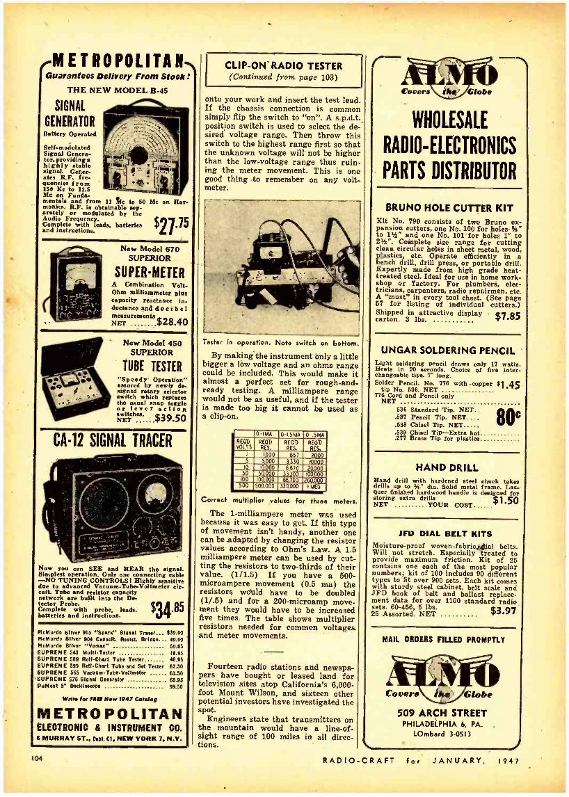
METROPOLITAN Guarantees Delivery From Stook:
THE NEW MODEL B -45
SIGNAL
GENERATOR Battery Operated
Self -modulated Signal Genera- tor, providing a highly stable signal. Gener- ates R.F. fre- quencies from 150 Kc to 12.5 Mc on Funda- mentals and from 11 tic to SO Mc on Har- monics. R.F. is obtainable sep- arately or modulated by the Audio Frequency. Complete with leads, batteries and instructions. $2735
New Model 670 SUPERIOR
SUPER -METER A Combination Volt - Ohm milliammeter plus capacity reactance in- ductance and d e c i b e l measurements NET $28.40
New Model 450 SUPERIOR
TUBE TESTER "Speedy Operation" assured by newly de- signed rotary selector switch which replaces the usual snap toggle or lever action
NNET $39.50
CA -12 SIGNAL TRACER
Now you can SEE and HEAR the signal. Simplest operation. Only one connecting cable -NO TUNING CONTROLS! Highly sensitive due to advanced Vacuum -Tube -Voltmeter cir- cuit. Tube and resistor capacity network are built into the De-
Complete with probe, leads, 8C l batteries and instructions. $34 McMurdo Silver 905 "Spars" 8Ional Tracer 639.90 McMurdo Silver 904 Capaelt Resist. Bridge... 49.90 McMurdo Sliver "llamas" 59.85 SUPREME 543 Muitl- Tester 18.95 SUPREME 589 Roll -Chart Tube Tester 48.95 SUPREME 599 Roll -Chart Tube and Set Tester 62.50 SUPREME 565 Vacuum- TubeValtmeter 63.50 SUPREME 576 Signal Generator 68.95 DuMont 5" Oscilloscope 99.50
Writ. for FREI Now 1947 Catalog
METROPOLITAN ELECTRONIC & INSTRUMENT CO. 6 MURRAY ST., Dept. CI, NEW YORK 7, N.Y.
104
CLIP -ON -RADIO TESTER (Continued from page 103)
onto your work and insert the test lead. If the chassis connection is common simply flip the switch to "on ". A s.p.d.t.. position switch is used to select the de- sired voltage range. Then throw this switch to the highest range first so that the unknown voltage will not be higher than the low- voltage range thus ruin- ing the meter movement. This is one good thing to remember on any volt- meter.
Tester in operation. Note switch on bottom.
By making the instrument only a little bigger . a low voltage and an ohms range could be included. This would make it almost a perfect set for rough -and- ready testing. A milliampere range would not be as useful, and if the tester is made too big it cannot be used as a clip -on.
0IMA 0.1.5MA 0-.SMA RE® VOLTS
RE® RES.
REOb RES.
RE00 RES.
I 1000 667 2000 5 5000 3.330 10000
IO 10000 6670 20000 50 50,000 33.300 100000
100
-WI- [00.000 66.700 200.000
500,000 330000 1 MEG
Correct multiplier velues for three meters.
The 1- milliampere meter was used because it was easy to get. If this type of movement isn't handy, another one can be adapted by changing the resistor values according to Ohm's Law. A 1.5 milliampere meter can be used by cut- ting the resistors to two- thirds of their value. (1/1.5) If you have a 500 - microampere movement (0.6 ma) the resistors would have to be doubled (1/.5) and for a 200 -microamp move- ment they would have to be increased five times. The table shows multiplier resistors needed for common voltage& and meter movements.
Fourteen radio stations and newspa- pers have bought or leased land for television sites atop California's 6,000 - foot Mount Wilson, and sixteen other potential investors have investigated the spot.
Engineers state that transmitters on the mountain would have a line -of- sight range of 100 miles in all direc- tions.
Covers Globe
WHOLESALE
RADIO- ELECTRONICS
PARTS DISTRIBUTOR
BRUNO HOLE CUTTER KIT Kit No. 790 consists of two Bruno ex- pansion cutters, one No. 100 for holes - %" to Ph" and one No. 101 for holes 1" to 2W'. Complete size range for cutting clean circular holes in sheet metal, wood, plastics, etc. Operate efficiently in a bench drill, drill press, or portable drill. Expertly made from high grade heat - treated steel. Ideal for use in home work- shop or factory. For plumbers, elec- tricians, carpenters, radio repairmen, etc. A "must" in every tool chest. (See page 67 for listing of individual cutters.) Shipped in attractive display $7,85 carton. 3 lbs.
UNGAR SOLDERING PENCIL Light soldering pencil draws only 17 watts. Heats in 90 seconds. Choice of five inter- changeable tips. 7' long. Solder Pencil. No. 776 with - copper 31.45
tip No. 636. NET 776 Cord and Pencil only
NET 636 Standard Tip. NET..
80C .587 Pencil Tip. NET.... .638 Chisel Tip. NET .689 Chisel Tip -Extra hot .277 Brass Tip for plastics
HAND DRILL Hand drill with hardened steel chuck takes drills up to IA" dia. Solid metal frame. Lac- quer finished hardwood handle is designed for storing extra drills NET YOUR COST $1.50
JFD DIAL BELT KITS Moisture -proof woven- fabric,4`ial belts. Will not stretch. Especially treated to provide maximum friction. Kit of 25 contains one each of the most popular numbers; kit of 100 includes 90 different types to fit over 900 sets. Each kit comes with sturdy steel cabinet, belt scale and JFD book of belt and ballast replace- ment data for over 1100 standard radio sets. 60 -956, 5 lbs. 3,97 25 Assorted. NET
MAIL ORDERS FILLED PROMPTLY
Covers Íhe Globe
509 ARCH STREET PHILADELPHIA 6, PA.
LOmbard 3 -0513
RADIO -CRAFT for JANUARY, 1947

TECHNOTES
. RECORD CHANGER NOTES One of the chief difficulties in ser-
vicing automatic record changers is in making adjustments on the under side of he mechanism.
I have overcome this problem by sus- pending the changer from the ceiling by means of wires and springs, as illus- trated. This -method speeds the work considerably.
I have a radio with the entire r.f. section badly damaged. The a.f. section is in good shape and I keep this set close at hand and use it fo- checking the per- formance of the pick -up.
M. W. HATLEY, Shawnee, Oklahoma
. PHILCO 505 A frequent complaint on this model
is fading accompanied by distortion. This trouble was found to be caused by the 1- megohm resistor in the grid re- turn circuit of the 75 tube. This resistor changes value after the set has been in operation for a short time. Replacement with a good resistor of the required value will cure the trouble.
CLAUDE M. PREw New London, N. H.
PHILCO 42 -1006 The complaint was distortion and
hum. When the antenna was removed from the set, the hum disappeared. I soon found that the speaker field was supplied by one -half of the 50Y6 recti- fier. Filtering for the field is supplied by a 15 -ohm resistor in series with a 10 -µf, 150 -volt condenser. This con- denser had shorted and burned out the resistor so that there was no "short" indication from cathode to ground. The open filter circuit was not evident in the absence of voice coil excitation because of the low voltage.
WALTER WESTERGREEN, Muskegon, Michigan
....GEE72 Frequently these sets are brought in
with the complaint that the volume is low and unaffected by the volume con- trol. The trouble is usually caused by a burned out 6H6.
The output transformer on this model opens frequently resulting in a "dead" set. When a 6F6-G is used, the trouble is spotted readily by the red -hot screen grid.
CHARLES MCCLESKEY, Baton Rouge, La.
PHILCO 42 -350 This model often develops an inter-
mittent which results in slight loss in volume. The screen bypass of the sec- ond i.f, stage is often the cause of this trouble. Oddly enough, this condition is not always detected by tapping the condenser. Replacement is recommend- ed in all questionable cases.
MCCLESKEY RADIO CO., Baton Rouge, La.
HARRISON HAS IT! - COMPACT roaßye _ POWER PACK V e0` For hills moro than the cost. of ono set of regular dry batteries,
you can obtain a new, modern, vibrator pack that will save you space, weight, and moneyl Ruggedly made for Navy radio equip- ment, this pack gives excellent service under tho roughest field
coedit lai,.
Only 13A "x3 % "s4" high (6%" high with battory)I Weighs 3 lb. 10 or., complete with battorY. Deliver: 135 volta at 20 ma. In continuous Military duty or 30 ma, or moro, In Intermittent Amateur service: 67% volts at 8 ma; 1.5 filament or 6.3 heater, bias. and microphone toilages.
.0
76203 tot
Portable Receivers Transmitters
Walkie Talkies
Remote Controls Test Equipment V111101"'"--
This efficient pack works on any 6 Volt DC sourco, and has such desirable design features co neon voltage regulator, complete filtering, re-
Nmote load start relay. etc. Brand new In sealed avy Inspected cartons, fully guaranteed. One of the malt sensational HSS values over offered!
Complete Vibrator Pack, lees only battery (use It on four flashlight cells or your ear $3.95 battery, etc.)
ART -13 COLLINS AUTOTUNE
TRANSMITTERS
Completo Power Pack including clip-in Willard storage battery. Unbreakable plastic Non -Spill Case (oven if turned upside- downi) Shipped bone-dry, folly charged. ready to put into Im- mediate service, or to store for years. Can give several hours of continuous operation at full rated load and then be Recharged for only a few pennies by any % ampere charger or our special Vickie charger $5.50
Sparo Storage Battery $2.75
BATTERY CHARGER. Noise- less. Selenium rectifier type. to trickle charge these or any other small batteries at .2 Ampere. Á0 Volt $3.45
Hero's the most desirable transmitter for Amateur and Commercial service' available In surplus today -the fam- ous airborne ART -181 Frequency motor type VFO-- Adiustablo fully automatic tuning with remote control provision-Mal controlled calibrator -8l3 final. modulated by 811's -2 to 18.1 Ma (Adaptable to efficiently cover 10 meter band)- antenna tuning network and automatic relay -easily converted into a FB Ham Phono -CW transmitter with modern commercial features. See the complete articles in Novem- ber CQ and December Radio News. Brand new, In sealed containers. The latest improved production 47A. Less tubes and power supply
(With complete set of tubes. $144.50)
$12450
BC -406 RECEIVER $}9.95 (BC -406 -A 16 Tubes. with motor-$29.75)
These are the good meal Completo with tubes and con- version instructions. Ask the ham who got one from. Us! See our previous ads.
TELESCOPING ANTENNA Signal Corps AN20 -C. Sturdy. lightweight, brass antenna extende to 12' 30", telescopes to 15 Inches. yes" diameter. Weighs only 3174 FB for mobile. or rotary beam element.. WQ
$1.95 each Six at
OIL FILLED CONDENSERS Standard makes, new guaranteed, all at prices that will save you moneY. IlSS 2 Mfd, 1000 Volt Round, upright caso mounts In %" hole. $2.34 POUR for
Rectangular, upright cues, with ceramic terminal In sulators:
4 MFD, 600 VOLT 10
8 1000 " 4 1500 3 4000 1 " 5000 "
THREE fer $1.98 TWO for 2.47 TWO for 3.88 TWO for 3.98
4.95 2.45
3E29(829B) TUBES New, perfect, Gov't $4.79 accepted
(3C24/VT204) An FR triode for 24G TUBES VHF. 90 Watt rated Class C out- put. 6.3 Volt, 3 amp filament. Small bulb. Made by H & K. Gov't. inspected. fully guaranteed! Regular amateur not price was 19.00, reduced to $ 4C) $6.00. Harrison selle them for only
I r The last tieso wo offered these popular tubes, 1 orders and reorders carne in so heavy. we had to
ration them. But this time, we think we have
I plenty -SO order as many as you want- spares- presents, etc.!
RADIO -CRAFT for JANUARY, 1947
H recharging facilities are unavailable we can simply these packs with clip-in Willard 6 volt lead -nine Primary batteries. 25 watt hour capacity. Unlimited elicit life. (Can store for years! Excellent for export.) 1Te "1314 "x214 ". on 1 Y 21
Ices! Complete pack with ounces! Primary $5.75
batteries
REPLACEMENT PRIMARY BATTERIES. T bee o bat- teries aro also a lino source of 6 Volte DC for many other applications. 95c Each
Export packed calo of twenty 514.75
KW MODULATION TRANSFORMER Here's an FB MS value in a hard -to -get item) 11CA commercial quality construction. Conservatively rated at 550 WsUe of audio will modulate up to a kilowatt Onal.
Primary matches any Class B modulators UP to 10.000 ohm plate to plato. Impedance ratio 1:1. Secondary carries 450 ma. Tertiary winding to modulate screens or suppressers carries 80 ma. -
Mycalex terminal board taint three adjustable pro- tective flash -o'er gene insures against breakdowns. Open frame ounting. Actual weight 38% lbs. $24.75 91/2"971/2- 7%. high
ANTENNA TUNING UNIT Signal Corps BC -939 -A IHalllcraftor AT -81
Will efficiently couple up to KW transmitter to any short or long wire antenna working against ground. Full range of 1.5 to 18 tic.
You've seen these sold as surplus at $79.50. Harrison sells them NOW, brand new, complete with RF meter. cabinet, and bath plug-in vacuum tonden- $29.95 Sers, for only
COAXIAL CABLE Savo moncyl See our previous ado, for all types!
RG 58/U. 55 ehme. An efficient. light- weight trans- mission lino (.195" OD) for Amateur. FM. and Tele- vision antennae. Also use as high quality, inexpensive crystal mike or pick -up cable, List price. $18.50 HSS SPECIAL -100 feet for $3.95
TRANSMITTERS Still the best buy in e modorn, post -war rigs Cense.ve- tive output rating of 75 Watts Phone. 100 Watts CW. The price of $405 brings you a FB stable VFO. full coverage of 10, 15, 20, 40. and 80 bands. one dial tun- ing. band -switching, and everything to go on the air but key, microphone, and antenna. Add it up yourself and you'll see why the Temco 75 -GA is gaining such popularity!
And to step up your power later. Just slip It into the 500 GA Amplifier and you will haro a complete, well engineered 750 Watt Output transmitter.
Order your 75 -GA from Harrison. to -days
* ALL STANDARD LINES We are Factory Authorized Distributors
for the top quality m nufncturere and we now have In stock lots sore new, latest improved production Ham m marl Visit our stores today. for everything you need. We promise you fresh clean material -quicker -at the lowest current .prices -and above all. our sincere desire to bo of friendly, helpful service.
MAIL ORDERS? c e rt a i nly! Just list everything you want (items in this ad, or
any ad, magazine, or catalog) and include remittance.
V/y
/73 de
.t?L 7yá27i1on, W2AVA
ARR. .RRISON RADIO CORPORATION: '-) 9 WEST BROADWAY. ' NÈW YORK CITY 7 .e
PÑONE- eArriey 7,484 EXPORT Met HARRISORAO' 1
LJAMAIGA, BRANCH -171 31 Hillside Ava.- REpublic 9- 4102],'
105

y
SOMETHING NEW IN
TEST EQUIPMENT!
THE FEILER TS-3
SIGNAL TRACING
"STETHOSCOPE"
Save Time.. . Earn More
on Every Radio Repair lob! GETS TO THE HEART OF RADIO TROUBLE IN A FLASH! There's nothing lílte the FEILER STETHOSCOPE for sav- ing service time-solves the toughest re- pair problem in minutes. To isolate and locate trouble, you just "listen in" on or
look at" the signal as it progresses through the circuit. Traces trouble at First Grid, B.F., I.F., Audio: testa parts; locates causes of mistracking, intermittence, dis- tortion, etc. Features: 1" dia. aluminum probe with 3 ft. cable; full 6" PM Speaker; R.F. vacuum tube voltmeter circuit pro- vision for visual indication of R.F. volt- ages; Output meter provision; Headphone oonneotion. In handsome brown -finished steel case with carrying handle; 8 "x11% "x 6 ": wt.. 10% lbs. Operates on 106 -126 volts,. 60-60 cycles A.C. A professional in- strument for the Service Engineer who wants the best at a moderate price. Com- plete with valuable Radio Service Guide.
MODEL TS -3 Signs/ Tracing STETHOSCOPE for A.C. opera- tion. Complete with 2 -1T4 (or 1L4); I-6K6 (er 6F6), and I -6X5 tubes. $3
ONLY
IMMEDIATE DELIVERY! Place your order with your regular parts lubber. If he can't supply you. write for name of nearest local Jobber stocking the TEILER STETHOSCOPE -or send your order to m direct.
FEILER ENGINEERING CO.. Dept. 2 -A7 803 Milwaukee Asa., Chicago 22. Illinois O Ship me one TS -3 STETHOSCOPE.
$ enclosed. O Send me FREE descriptive literature. O Send name of local Jobber stocking TS -3.
Name
Address
City Zone .... State
RADIO ELECTROIIIC DYKES
ADVANCED VOLTOHMYST Radio Corp. of America
Camden, N. J.
The new type WV-75A. meter employs a newly -developed diode probe for measuring very high frequency voltages in addition to the refinements of the Voltohmyst Type 196A. It is useful for FM, television and other high fre- quency measurements.
The probe contains a full -wave recti- fier which makes it possible to read both positive and negative voltage peaks at high frequencies. Céaxial cable is used between the probe and meter.
When used for FM and television testing, the meter can make all measure- ments in radio receivers up to 1,000 volts, from the primary of the power transformers to the output transformer or voice coil of the speaker. It is also
used for checking d.c. measurements di- rectly at the grid, plate, screen, or cath- ode terminal, as well as bias -cell volt- ages and a.f.c., a.v.c., and FM discrim- inator voltages.
When used as an ohmmeter, the one scale works for all ranges with no zero resetting necessary. It has six scales for d.c. resistance readings, covering the ranges 0 to 1,000 ohms to 0 to 1,000 megohms. The internal voltage source used for resistance measurements is three volts.
The meter case weighs nine pounds and measures 9% inches high, 6% inches wide, and 6% inches deep. - RADIO -CRAFT
ELECTRONIC SWITCH General Electric Co. Schenectady, N. Y.
The new Type YE -9 electronic switch will show simultaneously for compari- son, two or more independent signals on the screen of a single cathode -ray tube oscilloscope. Mechanical vibrations, sound, light, and other quantities trans- ferable into electrical functions may be compared. By using two Type YE -9 electronic switches in cascade, three in- dependent circuits can be studied simul- taneously. It may also be used with any oscilloscope with a horizontal sweep
vo tage and available connections to the plate of the cathode -ray tube.
Operating on any sweep frequency of from 10 to 12,000 c.p.s., continuously variable, the switch has an amplifier frequency response of 4 c.p.s. to 450 kc (flat within 3 db). Its input voltage is 110 -125, 60 -60 cycles, and its maximum signal input is 260 -volt r.m.s.- RADIO- CRAFT
SOUND PRESSURE METER Massa Laboratories, Inc.
Cleveland, Ohio The Model GA -1002 sound pressure
measurement system is a precision elec- tro- acoustic instrument for making ab- solute sound pressure measurements over the entire audible and early super- sonic frequency range to about 40 kc.
The complete system includes a
Model M -101 standard microphone, a shock -mounted preamplifier with 15 feet of cable, and an auxiliary ampli- fier complete with dry batteries. A built -in calibrating circuit permits set- ting the gain to produce an output of exactly 1 millivolt per dyne /cm' sound pressure, so that a conventional elec- tronic voltmeter can be employed for the direct reading of sound pressure. A wide dynamic range permits measure- ments from less than 1 dyne /cm' to 20,000 dynes /cm° (160 db level) without distortion.- RADIo-CRAFT
RADIO -CRAFT for JANUARY, 1947

TUBE TESTERS Sylvania Electric Prods., Inc.
New York 18, N.Y. The new instruments, a counter type
139 and a portable type 140, provide accurate tube testing facility for shop, spot testing in the home, industrial elec- tronic applications, automobile and mo- bile radio equipments. Accurate checks of receiving type tubes used in broad- cast receivers, FM, television, industrial electronic controls, record players and photoelectric devices may be made un-
Prepare NOW for a Better Job in
RADIO ENGINEERING
der dynamic conditions and without damage to tubes.
Extra sockets and switch contacts are included for modernization as new types of tubes are developed. Test for shorts may be made without danger of grid -filament çontacts due to electro- static attraction in battery type tubes where spacing between these elements is close. Provision is also made for noise testing.
Both instruments are supplied for 105-125 volts, 50 -60 cycle a.c. operation and are rated at 20 watts. Controls are readily accessible and all markings, in- cluding those on the 41/2-inch meter face are easily read.- RADIO -CRAFT
GRID AND PLATE CAPS Eitel- McCullough, Inc.
San Bruno, Calif. Eimac HR heat dissipating connec-
tors are used to make electrical con- nections to the plate and grid terminals of Eimac and other vacuum tubes, and,
ADD TECHNICAL TRAINING TO
YOUR PRACTICAL EXPERIENCE. CLEVELAND INSTITUTE COURSES OFFER COM- PLETE TECHNICAL TRAINING RANGING FROM LOW -LEVEL TO COLLEGE -LEVEL.
A. Master+ Course in Radio Communication. Covers fundamentals of Radio and includes complete preparation for FCC Commercial License Examinations.
B. Advanced Course in Radio Communication Engineering. A college -level Radio Engineering Course.
C. Specialized Television Engineering. Including post -war Television Techniques.
All Courses Include The Remarkable Workbooks of Instructional Aids, prepared by the instructing staff of Cleveland Institute.
Choose the course best suited to your needs -Start with the section you are qualified to enter -Use the economical CIRE "Pay -As- You -Go Plan."
You may enroll for individual sections for highly specialized training. Study any one or more of the following sections if you do not require a complete course-
5. Advanced Radio Telephony for the Broad- cast Operator.
6. Audio and Radio Components and Sys- tems (Design of Receiver and Transmit. ter Equipment).
1. Mathematics of Radio
2. Fundamentals of DC and AC Theory.
3. Essentials of Radio Communication.
4. Communication Networks.
Write for descriptive folder No obligation
CLEVELAND INSTITUTE OF RADIO ELECTRONICS CONTRACTORS TO THE CANADIAN BROADCASTING CORPORATION
Successors to
SMITH PRACTICAL RADIO INSTITUTE Founded 1934
SILSON RADIO SCHOOL Founded 1939
RC -I TERMINAL TOWER, CLEVELAND 13, OHIO Approved for Veteran Training Under "G -1 Bill of Rights"
(MAIL THIS COUPON) Cleveland Institute of Radio Electronics, RC -I. Terminal Tower, Cleveland 13. Ohio.
Gentlemen: Please send Information about your home study courses in Radio Electronics.
NAME
ADDRESS operating O mfg. Q - CAA O Arany -Navy
CITY
ZONE STATE
I desire training in I have had esperlenco in broadcasting iJ servicing 0
at the same time, provide efficient heat transfer from the tube element and glass seal to the air. They aid materially in keeping seal temperatures at safe values. The connectors are machined from solid durai rod, and are supplied with the necessary machine screws. - RADIO -CRAFT
RADIO -CRAFT for JANUARY,
SAME -DAY SHIPMENT ON Se OF ALL MAIL ORDERS. tools of nearly all redo publishers. If you dons loo price. send deposit and well ship C.O.O.
FOP CATALOG TO EDITORS AND ENGINEERS, ltd. 110SHenwood Road Santa Barbara, California
STROBO -LIGHT Kluge Electronics Co.
Los Angeles, Calif. The new a.c.- operated portable Stro-
bo -Light uses a K -60 bulb which has a light intensity rating approximately 100 times that of sunlight. This bulb will take approximately 10,000 pictures. -RADIO -CRAFT
1947
amateur 12 other I am
High School Grad. Collego Degree
Check hero for Veteran Enrollment Informatlm
IN THE MIDDLE -WEST IT'S
Radio Specialties Company RADIO AND ELECTRONIC EQUIPMENT
DETROIT 4, MICHIGAN, 456 CHARLOTTE PHONE: TEMPLE 2 -0800
TRY US WE PROBABLY HAVE WHAT YOU WANT IF NOT WE'LL GET IT.
I07/

. . . ... ,7,^-a.lrP.,R,.
SUBSTITUTION GADGET I find Mr. Cox's Serviceman's com-
pass, page 780 of the August issue, too cumbersome for use on midget re- ceivers: A quicker and easier way in
Ifeud 30 WATT Deluxe PORTABLE P.A. SYSTEM
Here's a preview of ALLIED Sound for 1947 in this smoothly -styled, brilliantly engineered 30 Watt De Luxe Portable System. New stabilized inverse feedback circuit delivers high output, usable right up to its peak. Flexible operation is pro- vided by two microphone and one phono channels, each with separate control. Has bass -treble tone control. Amplifier and speakers are safety -fused. Amplifier gain on microphone is 128 db; on phono, 80 db. Frequency response: 50- 10,000 CPS. System covers up to 4,000 persons, or up to 20,000 square feet.
Complets 30 Watt System includes: 30. Watt De Luxe Amplifier with tubes; 2 -12' Safused Dynamic Speakers, with 30 -ft. cables and plugs; 1- Cardax Unidirec- tional Microphone with floor stand and 20 -ft. cord and plug. Complete in hand some luggage -type split portable carry- ing case, 22 x20 x 15'. Carrying wt., 60 lbs. For 110 volts, 60 cycles A.C. (Less phono top and volume level meter which are optional.) Complete System (approximate price) Ont Egg5ó
For Everything in Radio and
Sound
See your ALLIED Cat- slog No. 111 for the world's largest and most complete stocks of quality radio and sound equipment -at today's lowest prices! Count on ALLIED for fast service, expert h elp. If you haven't a copy of Catalog No. l 11- send for it now -it's FREE for the asking.
ALLIER RADIO ALLIED RADIO CORP. 533 W. Jackson Blvd., Dept., 2.A.7, Chicago., III, Ship 30 -Watt Portable System described above. S enclosed. Send full details on ALLIED Sound. OSend FREE Radio Catalog No. Ill. Name
: Address
City Zone State
IOe
PROD DOODLE FANNSTOCK CLIPS
TESI PROD TEST
to solder a Fahnestock clip on each end of a piece of twisted light cord. Cut one of the wires shorter than the other so that the clips cannot touch. Tin the opposite ends to serve as test prods. Resistors, condensers, coils, etc. are fastened to the clips.
If you have test prods, double clips may be fastened to a 1 x 2 -inch piece of bakelite, plastic or Masonite. The upper clips are used to 'connect to the spare parts, the lower ones connect to the test prods.
HELEN M. DOUGLAS, WÖLGY, Commerce, Texas
CHASSIS SUPPORTS When experimenting with or servicing
small radio sets, unshielded coils and tubes are often damaged when the chassis is inverted on the work bench. To prevent this trouble, mount a "C"
clamp on each corner of the chassis. When the chassis is inverted, it rests on the screws of the clamps.
RICHARD C. SZUMILO, West Hazelton, Penna.
TEST LEAD SAVER I have often been irritated to find
that my test leads have been broken at the point where they enter the" prods or plug.
To prevent this from recurring, I se- )
> WIRE n '1/4. SPRINGS
lected four dial springs. The outside diameter should fit snugly into the open ends of the prods and plugs. Place two springs on each wire. The springs are forced down into the open end of the tips and held in place with a few drops of cement. The springs will prevent the test leads from breaking at these points.
WALTER M. BOWLAN, Prince Edward Island
RADIO
TUBE REPLACEMENT On page 658 -of the May issue, there
is a description of a method of replacing Sparton 183's with 45's. This method calls for series connection of the fila. ments to operate from the five -volt filament winding. When the filament: are connected in this manner, hum will result from the varying a.c, across the bias resistor.
This may be corrected by using only half of the filament winding and con.
Munn-CRAFT wants original kinks from its readers, and will award a one year subscription for each one pub- lished. To be accepted, ideas must be new and useful Send your pet short- cut or new idea to RAatoCaApr today!
necting a 20- to 60 -ohm center -tapped resistor across the paralleled filaments of the 45's. The biasing resistor is con-
o° C.T.
o o 750` 2.5V TO 45%
IN PARALLEL
nected between the center -tap and ground. When the filaments are con- nected in this manner, no hum is present.
ALLIN W. JACKSON, Edmonton, Canada
(Note: 2A5's may be used with the filaments connected in series without causing hum. Editor)
NOVEL PANEL LAMP A very neat panel lamp for illumi-
nating the dials on a receiver or trans- mitter may be made from the cap of a
20.50
PANEL
RUBBER GROMMET RED UPSTICK CAP
(PLASTIC)
BULB
HOLE CUT TO EMIT LIGHT
POINTER
DIAL KNOB
discarded p astic lipstick tube. A hole is drilled in the panel to take a rubber grommet whose outside diameter is large enough to fit snugly into the open end of the lipstick cap. A hole or slot is cut in the cap so that it will cast a ray of light on the dial.
HARRY KUNDRAT, Garwood, N. J.
JANUARY, 1947 -CRAFT for
1

TECH NOTES (Continued from page 105)
TRUETONE D2630 The complaint on the first three of
these new sets was poor reception. The trouble has been traced to a shorted primary on the output i.f. transformer. In all cases, the remedy has been to re- place the mica in the trimmer condenser.
JACK C. WHITE, Starkville, Miss.
. HUM CURE Recently I was called in to service a
new receiver that developed a severe hum during the early mornings and late at night. All filters and tubes checked OK. A line voltage check was made and it was found that the voltage often reaches 135 volts. A Clarostat Auto- matic Regulator was installed.
G. SAMOFSKY, Brooklyn, N. Y.
RADIO -CRAFT wants Technotes de- scribing common troubles of well - known receivers or telling bow rare or difficult problems were solved. A six - month subscription will be awarded for each unillustrated and a one -year subscription for each illustrated Tech - note published.
. SEALING TRIMMERS To prevent customers from tighten-
ing the "loose screws" on trimmers and padder condensers, melt a bit of .
rosin with a hot soldering iron and allow it to run down on the head of the adjust- ment screw. The rosin will cool and hold the screw in place.
H. T. BROWN, Jacksonville, Fla.
(Note: Nail polish or Duco cement can be used for the same purpose. It is also useful in sealing the condensers in automobile and portable radios.-Edi- tor)
.. CRYSTAL DIODES When the still critical diode tubes,
1H5, 75, 12Q7, etc., need replacing, use the new crystal diode, 1N23, as a- substi- tute for the diode section. Connect it in series with the wire removed from the diode plate connection and the cathode. Polarity should be observed. If the triode section is also bad, rewire socket and use straight triode tube.
A. G. SANDERS, Miami, Fla.
(While the crystal mentioned might give good service in many cases, it would seem that the 1N34 would be much more suitable for use as a diode detector for strong signals. Editor)
. . G.E. TESTERS TC3 AND TC3P When checking for shorts, in tubes
having a high plate -to- cathode capacity, these testers will indicate a short in al- most every case. This is particularly noticeable with pentode and tetrode out- put tubes. This condition is normal
RADIO -CRAFT for JANUARY,
GET YOUR
FCC Commercial
Radio Operators'
It's Easy If You Follow Our Plan
Thousands of new jobs are opening up- FM, TELEVISION, MOBILE COMMUNI- CATION SYSTEMS, are only a few of the
new radio fields which require licensed opera- tors.
FREE BOOKLET Tells you the Government require- ments for all classes of commercial
operator licenses. Tells where to apply for and take the ex- aminations, examining offices, scope of knowledge required,
extracts from FCC Rules and Regulations, extracts from FCC Study Guide and' Refer- ence Materiel, approved way to prepare for FCC examinations, positive method of check- ing your knowledge before taking the examinations.
Edition Limited -Mail Coupon Before Supply Is Exhausted
CLEVELAND INSTITUTE OF RADIO ELECTRONICS CONTRACTORS TO THE CANADIAN BROADCASTING CORPORATION
Successors to
NILSON RADIO SCHOOL SMITH PRACTICAL RADIO INSTITUTE Founded 1939 Founded 1934
RC -I TERMINAL TOWER, CLEVELAND 13, OHIO Approved for Veteran Training Under "G -I Bill of Rights"
MAIL- THIS COUPON CLEVELAND INSTITUTE OF RADIO ELECTRONICS RC-I TERMINAL TOWER, Cleveland 13, Ohio
Gentlemen: Please send your FREE Booklet, "How To Pasa FCC License Examinations." (Note: This Booklet does not cover examinations for Amateur License)
NAME I have had experience in broadcast-
ing servicing operating
mfg. CAA Army -Navy
CITY STATE .... amateur other
Check license desired:
Radiotelephone 1st. Class 2nd Clam
Radiotelegraph 1st Class 2nd Class
ADDRESS
I now hold these licenses
I am a High School Grad. College
Grad. with degree
If a War Veteran, check bere
with this model tester. (Can any of the readers tell us how a true short can be detected with this model tester? - Editor)
JOHN FINDARLE, Modesto, Calif.
. . OSCILLATOR COILS Most defective oscillator coils may be
rewound by hand satisfactorily enough to eliminate re- alignment. Count the turns as they are removed. Note the di- rection of the winding and location of taps, . if any. Replace the windings, duplicating the original coil as closely as possible. Slight variations in wire size and type of wiring have little effect on tuning.
I 9 4 7
A. G. SANDERS, Miami, Fla.
SILVERTONE R -1181 The complaint on this receiver is in-
termittent crackling and frying. This is often due to the .003 -of, 1500 -volt, con- denser connected between the plates of the 5Y3. This condenser develops inter- nal arcing after a period of service and should be replaced with a new unit.
B. S. NORKUS, Stratford, Cont.-
. ATWATER KENT 55C When aligning the belt -ganged con-
densers on this model, be sure to clean the supporting bearing of each rotor with carbon tetrachloride. The brass tension spring on each rotor should also be checked for tightness.
CLAUD M. PREw, New London, N. H.
109

It's NEW, it's BIG, it's COMPLETE. It's Lafayette's latest, greatest catalog brimming with EVERYTHING that you want in Radio and Electronics. Radiomen and servicers, hams and dealers, hobbyists and experimenters -this is the book for YOU. Mail Coupon!
Pages are crammed with standard , items as well as all new develop-
ments. They're in stock - they're ieady for super -speed delvery - they're priced for super -economy. If radio's your hobby, if radio's your business - if you're mild about it or wild about it -this is THE book!
ITs YOURS FRE E
i:,Iv,. si : ,k..:. .: .
,d,j:,iy ::t> , ; % .l
'`: Xi ? q ji , , - yi{,r-T; - ";,,. - '
10 Dee JA
*gavot aAC Y Y!. ti- 1 -
10DSiw A+jye'
H te
ae b
big MO ..."4.1 tei
RUSH 7er' return
TA. .
NAM
1 'molts
....... COUPON ON PENNY POST CARD
.pHETA.1
IIO
to. SIMPLE INTERCOM
Here is a diagram showing how an amplifier may be converted to an inter - communicator. The sub -station and master speakers are equipped with 500 - ohm line -to- voice -coil transformers. The amplifier is fitted with an output trans- former to match a 500 -ohm line and a
INPUT .,. , ,r,r OUTPUT
SUB STATION SPKR MASTER SPKR
RING LISTEN TALK Note - Switch connections are incorrectly drawn; reverse connections to "talk" switch
contacts. line -to -grid transformer is used in the input.
A two -pole three -position switch is used to switch the connections to Talk, Listen and Ring positions. In the "talk" position, the master speaker is connected to the input circuit and the remote speaker is connected to the output of the amplifier. These connections are re- versed when the switch is thrown to Listen. When the switch is in Ring position, the remote speaker is con- nected to the output of the amplifier. Feedback for ringing is supplied by connecting the amplifier output to the input circuit.
All leads leading to the switch should be carefully shielded to prevent uninten- tional audio feedback. The switch and the terminals for connecting the speak- ers and amplifier circuits may be con- structed in a small metal box placed close to the amplifier.
DON RUSSELL, Toronto, Canada
V.H.F. OSCILLATOR With very low power and no antenna,
this 112- to 300 -mc parallel -line oscil- lator makes an ideal signal generator for testing v.h.f. receivers.
The oscillator uses parallel -line tuners in the plate -grid and cathode circuits. The plate -grid inductors con-
HY615
E-1148 $SHORTING SLIDER
AOI MICA 6D r
IOK SW
0-SOMA
B+IOOK 8-
I
SHORTING SLIDER
100
e. 3y,
s'st of two pieces of 5/16 inch brass tubing, 12 inches long, spaced 1 inch center -to- center. They are mounted above the chassis with standoff insula- tors which permit the shortest connec- tions to the plate and grid caps of the
t)
tube. The tubes are joined together at the B -plus end with a piece of No. 14 wire.
The cathode inductors are made of the same material, seven inches long, mount- ed below the chassis. One of the filament leads is threaded through the tubes and the other is connected to ground through the inductor. The open ends are con- nected with a piece of No. 14 wire.
The oscillator frequency is determined by the position of the shorting bar on the plate -grid inductors. The shorting bar on the cathode inductor is varied for maximum output and best stability at the desired frequency. The normal plate current is from 10 to 12 ma.
The oscillator may be either plate or
RADIO -CaAer wekomes new and orig- inal radio or electronic circuits. Hook- ups which show no advance on or advantages over previously published circuits are not interesting to us. Send in your latest hook-ups- RADIO -CRAFT will extend a one-year subscription for each one accepted. Pencil diagrams -with short descriptions of the cir- cuit -will be acceptable, but must be clearly drawn on a good -sized sheet.
grid modulated if desired. Output may be taken from the oscillator with a hair -pin loop coupled closely to the B- plus end of the plate -grid inductor. The loop may be connected to an antenna or to the tuned grid circuit of an amplifier stage.
P. F. EGERTON, JR. Toronto, Canada
(Note: The oscillator may be shielded to prevent uncalibrated v.h.f. receivers from being tuned to one of its har- monics. The signal generator does not require modulation when it is being used to align and calibrate regenerative and superregenerative receivers. Editor)
SIMPLE POWER SUPPLY This is an interesting a.c: power sup-
ply that uses a power transformer from an automobile radio. The unit will sup- ply up to 250 volts of well -filtered d.c. at 75 ma and 6.3 volts for tube filaments.
The center- tapped secondary winding is used as an auto -transformer with the a.c. line connected between one end and the center tap. The rectifier plates are connected across the entire winding in the conventional manner. The OZ4 -G was selected for the rectifier because of its small size and the cold cathode which does not require heater voltage. A brute - force filter section provides ample filter- ing action. A 25,000 -ohm semi -variable resistor is connected across the output of the unit so that the voltage can be lowered when necessary.
Filament voltage is taken from the primary winding. The center tap, if any, should be grounded.
This unit is connected directly to the RADIO -CRAFT for JANUARY, 1947
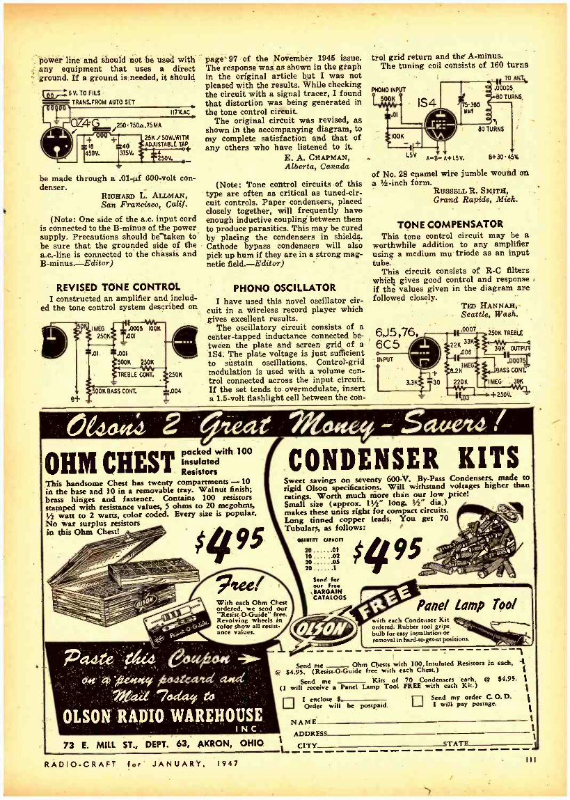
.poWër line and should not be used with any equipment that uses a direct ground. If a ground is needed, it should
6V. TO FILS
TRANS.FROM AUTO SET
1171LAC
QZ4G /250-750a,75MA
-I- -Fi IB 40 ADJUSTABLE TA+
450V. 175V. t 14 ° T250V.
be made through a .01 -µf 600 -volt con- denser.
RICHARD L. ALLMAN, San Francisco, Calif.
(Note: One side of the a.c. input cord is connected to the B -minus of the power supply. Precautions should be taken to be sure that the grounded side of the a.c. -line is connected to the chassis and B-minus.-Editor)
REVISED TONE CONTROL I constructed an amplifier and includ-
ed the tone control system described on
8+
IMEG .0005 I00K
250K I.001
.01 .001
500K 250K
TREBLE CONT. 250K
OOK BASS CONT.
' 004
2
page 97 of the November 1945 issue. The response was as shown in the graph in the original article but I was not pleased with the results. While checking the circuit with a signal tracer, I found that distortion was being generated in the tone control circuit.
The original circuit was revised, as shown in the accompanying diagram, to my complete satisfaction and that of any others who have listened to it.
E. A. CHAPMAN, Alberta, Canada
(Note: Tone control circuits of this type are often as critical as tuned -cir- cuit controls. Paper condensers, placed closely together, will frequently have enough inductive coupling between them to produce parasitics. This may be cured by placing the condensers in shields. Cathode bypass condensers will also pick up hum if they are in a strong mag- netic field. Editor)
PHONO OSCILLATOR I have used this novel oscillator cir-
cuit in a wireless record player which gives excellent results.
The oscillatory circuit consists of a center -tapped inductance connected be- tween the plate and screen grid of a 1S4. The plate voltage is just sufficient to sustain oscillations. Control -grid modulation is used with a volume con- trol connected across the input circuit. If the set tends to overmodulate, insert a 1.5 -volt flashlight cell between the con-
trol grid return and the A- minus. The tuning coil consists of 160 turns
1 Tf TOA .00005
80 TURNS. PHONO INPUT
500K e
01
1S4
100K
1I
L5V A-B- A+ LS V.
BO TURNS
8 +30.45V,
of No. 28 enamel wire jumble wound on a / -inch form.
RUSSELL R. SMITH, Grand Rapids, Mich.
TONE COMPENSATOR This tone control circuit may be a
worthwhile addition to any amplifier using a medium mu triode as an input tube.
This circuit consists of R -C filters which gives good control and response if the values given in the diagram are followed closely.
6J5,76, 6C5 o INPUT
1
Tm HANNAH, Seattle, Wash.
t I .0007
22K 33K
.006
I MEG 6.2K
220K 3.3K
t 30
250K TREBLE
39K OUTPUT
.00075
BASS CANT.
IMEG 39K
+250V.
OHM CREST packed with 100 Insulated Resistors
This handsome Chest has twenty compartments -10 in the base and 10 in a removable tray. Walnut finish; brass hinges and fastener. Contains 100 resistors stamped with resistance values, 5 ohms to 20 megohms, 1/2 watt to 2 watts, color coded. Every size is popular. No war surplus resistors in this Ohm Chest! }
CONDENSER KITS Sweet savings on seventy 600-V. By -Pass Condensers, made to rigid Olson specifications. Will withstand voltages higher than ratings. Worth much more than our low price! Small size (approx. 11" long, ÿ2" dia.) makes these units right for compact circuits. Long tinned copper leads. You get 70 Tubulars, as follows: $495 QUANTITY CAPACITY
20 01 10 02 20 O5 20 1
With each Ohm Chest ordered, we send our 'Resist -O- Guide' free.
Revolving wheels in color show all resist- ance values.
Send for our Free BARGAIN CATALOGS
$4 95 .,
. iu +M tx, Lo s<,,.?ià/%t s Tt ..
.see+efì _'`7 ;i le
__.yo--
`iY Ölt with each Condenser Kit ordered. Rubber tool grips bulb for easy installation or removal in hard -to- get -at positions.
Send me Ohm Chests with 100 Insulated Resistors in each, a 6-e $4.95. (Resist -O -Guide free with each Chest.)
Send me - - Kits of 70 Condensers each. ,Q $4.95. 1 - (I will receive a Panel Lamp Tool FREE with each Kit.)
I enclose S
Order will be postpaid. Send my order C. O. D. I will pay postage.
NAME ADDRESS
73 E. MILL ST., DEPT. 63, AKRON, OHIO CITY
RADIO -CRAFT for JANUARY, 1947
STATE

EXPANDER- COMPRESSOR r The a.f. section of my radio uses two 6C5's in cascade, transformer - coupled to push -pull 6L6's. Kindly show me how a simple expander -compressor may be added to tho circuit. -J.B., New York, N. Y.
A. Here is a circuit showing how the unit may be added to the a.f. system in your receiver. A 6SK7 control tube is inserted between the two 6C5's. The output of the first 6C5 is also coupled to the grid circuit of the 6SJ7 expander - amplifier. This tube is coupled to a 6H6 rectifier. The output of the 6H6 appears across a 1- megohm center -tapped poten- tiometer. One side of the resistor is positive with respect to ground and the other is negative. The position of the slider determines the degree of expan- sion or compression.
BATTERY INTERCOM 'f I would like a diagram of a bat- tery-powered intercommunicator using a 1S5 and a 1S4. 4 -inch PM speakers are to be used for two -way communica- tion between the master and three re- mote stations. - J. A., New York. N.Y.
A. The intercommunicator circuit you requested is shown. Each speaker func- tions eithér as a microphone or speaker. The two tubes should give ample gain and volume.
asvenr.m¡t-e.ï ..
o inmummnnuuunnnmmmnlllmll mmlmunnln nm m ommuti m i n umi nnmummntnmiu m t uialin n iiimuunimmun
The Question Box is again undertaking to answer a limited number of questions. Queries will be answered by mail
and those of general interest will be printed in the mega- _ tine. A fee of 50c will be charged for simple questions re-
quiring no schematics. Write for estimate on such ques-
lions as may require diagrams or considerable research.
IIIIIIII IIIIIIIIIIiilllllllllllllllllll IIIAIIIIIIIIIIII15.
] INTRUDER 1 have been seeking a diagram of
a capacity -operated intruder alarm. This unit is to be operated from 117- volt a.c. lines with low current drain while in operation,. It is to be used to protect two windows in our home. Is it
ALARM should be placed in a small grounded metal box just inside the windows to prevent using long capacity leads which would present a difficult shielding prob- lem and reduce the sensitivity.
The capacity wire or screen may be
STD. S.P.D.T 6V. AC RELAY COIL
6.3V. RY-2
I.A 2501145W. á
6ÒÓ0o
CSE05 esw 600V.
25 600V.
RVI L1 :STD 6SA7 TYPE OSC. COIL AS USED FOR
CI ó 175KCI.F,
I.áI RY- 1.5Kit COIL TO OPERATE AT 5MA DC
ALARM BELL OR OTHER SIG.
BATT. TO OPERATE ALARM SIG. GND SIDE OF AC-7
1I7V. AC
TO AS MANY
MORE UNITS i. AS DESIRED
CI:PAPER; C2, C3= 10- 100uuf
NOTE Ä: GROUNDED SHIELD,ETC.ON INSIDE OF WINDOW IN FRONT
OF CAPACITY WIRE TO DECREASE SENSITIVITY OF UNIT FROM INSIDE OF ROOM.
NOTCB: CAPACITY WIRE, TOWARD OUTSIDE OF WINDOW, ETC.
2 UNITS SHOWN. AS MANY AS DESIRED CAN BE ADDED.
possible to place the wires in such a neanncr that the alarm will be set off when anyone approaches from outside the house to within a few feet of the windows yet permit the windows to be approached from the inside without triggering the alarm ?- J.O.H,, San Diego, Calif.
A. Here is a diagram of a capacity - operated relay. The tube and relay unit
placed toward the outer edge of the window and a grounded shield placed about six inches from the wire on the side toward the room. This will reduce the , sensitivity from this side. Each location presents its own problem' and it will be necessary to do some experi- menting for the best possible results. Each of the protective units uses about two watts of current during the time that it is in operation.
6SK7 FROM IST AUDIO
IOV.
IMEG
5 -
4000 20K
450
25K
20 9+ 25V. 250V.
6C5
6SJ7 .05/400V.
IMEG
TO GRID OF 6L6/
1B+ _ t TO GRID OF 610
C.T. POT.
IMEG
- 201 25V.
500
8 +250V.
6H6
10 MEG
1S5 .01 1S4 TUBE TO V.C.TRANS.
GAIN 23K, r CONT. PRI.
LOCAL SPKR B
4' PM
A BAT T.
PUSH TO TALK
k D.P.D.T. SW.?
TALK..-.LISTEN
Above- Two -tube battery intercommuni- cator with master and 3 remote stations.
Left -Expander - compressor. Transformer may be omitted for single-ended stage.
625V. ^lSW. lppp;l1- B BATT.
REMOTE STATIONS 4 "PM
\ JJ
112 RADIO -CRAFT for JANUARY, 1947

%.14.
EVERYTHING
Congratulations to Dr. Lee de the 40th anniversary of the
IN RADIO, ELECTRONIC, AND
Forest on audion.
COMMUNICATIONS SUPPLIES
JAN
M1'(1'L 829B/3E29 TUBE
AND SHIELDED ALUMI.
L -! -- InUby -Des' condensers eBoth
for the price of the tube
socket. 6.95 ri- Our Price 3
ANTENNA CHANGEOVER RELAY for
all bands - Isolantil0 T.P.D.T.5'l nth
of contact surface... -" RELAY.
ANTENNA CHANG DG 13FRDPDT- Leech Typo 1357. y -.mounted an low loss
of spacing ..52.60 akelite ...... ...... .. .. .
TAL precision AT Cut mount- KC X lder...... ...54.96
mount-
ed In standard h^
10 ASSORTED TRANSMITTING brand
CONDENSERS All wellknoAwssortmenl
Voltage. ..51 ant designed high your price ... .......
20% Deposit with order. Balance
100 TS TUBE y to 600 Mc a pair well
This VT-127A/100 hi to 600 MC; pair
will
able of 1x11 aut0ut u Plate late
ells-
on
- niode capable
Class C Teleg7raphY; Grid CurFac-
2 ÓOi Ve IPlaite Current 200 nma; Grid 6V ;.Amp take a
ma; Filament Current 10 a; Special $3.25
for -I5. . .51.2 SOCKET for above tubo... ..2 for 1 .26
HEAT RADIATING CAPS for VT 127............
Special MYICROY S
J I FULL WAVE
RECTIFIER Perfect for
Use your DG WO-
cation from an AC +' relays Only reauiros
5oura e Rectifier for In-
3"x!z°to 3Ó0Vn@s40 ma oxtput4.B0
put up $ ß9 or 5 for $
CW3 RECEIVER GW3 RECEIVER aircraft monitoring) 1100 1 ter free. receiver (ytal `
KG to 16.600) IIOV. 60 cr.
controlled superb ACt power suliOló; the following 6cy; with BaO furnished In any Cocus can be 3500.6100 KC; 5600.10.000
groups: 0.16.500 complete with add. set of
tubes 9400.16.5 c less xtal $
tubes and one rot a1 calls
.........56.b0 G,E. PY RANOL 2mfd 4000 Teter 23FQ 4.26
G.E. PY RAN OL 4m1d 2000 -.
22166 CD DYKAN OL2mfd
Volt..-'"' cj 5
A volts OX FILTER CORDS. 6.. ..500
No. 476 -0.130 Volt AC _ ...54.96 W3 Meter, special ..... N.Y.C.
All Pr ces F.O.B. our arehouse
RA RADIO SUPPLY IAG 160 Greenwich St., New York 6, N. Y.
PLATE
TRANSFORMER 6200 Volt C1-700 Mils, 110 Volts. Cycles tape
K V mart' Y2
AMERTRAN Pt' of DCon-
Any Part U. 5-
$39.95 TRANSFORMER MODULATION lass C
x to 300 V14000 Ohms-- rY for screen of
loads o^ No. 2 Id designed will match
Secondary P<nt or
TZ4l Tetrode or or TndO Tubes. Comb
NI, 809, and circuit diagram ÿ6 factory spocifl
<etlon...
luded) .. .. CLASS B TRANSFORMER
CLASS Class B
W.E ORNER h for above Trans -
Perfect) match Pull to ,5395
gprads.
Iormer ...... Write for
Dur latest
12 -RC.
Ihr
Ili l
back of each key in such a position that they will all make contact with a small rectangle of sheet copper on the key. Obviously they should be adjusted so that the copper touches them slightly before the front contact presses on the graphite- treated cloth covering the front bus. See Fig. 4 for a section of the coupling system.
To better understand the operation of the coupler system, let us take a single note and trace it backward front the key. If, for example, middle C is depressed and only the coupling switch for the fundamental is on, with the oth- ers off, the second spring -wire mounted above the back of that key connects the C26 keying circuit -and consequently the amplifier and loudspeaker -with the neon oscillator generating 261.6 cycles or note C25. As a result of depressing the key, therefore, a single note, C25, is heard in the speaker. If now, in addi- tion to the fundamental, another cou- pler, say the second harmonic, is turned to the on position, neon oscillator C37 (an octave higher), generating 523.3 cycles, will be connected through the second harmonic coupler and subse- quently through the third spring -wire contact on key C25 to the same keying circuit. As a result, both middle C and the C above middle C will be heard, even though only the key for Middle C be depressed. The same applies in the case of the two remaining coupling
RADIO -CRAFT for JANUARY,
SIMPLE ELECTRONIC ORGAN (Continued from page 71)
switches (sub -fundamental and the third harmonic) where the added notes would be C13 and G44, respectively. With this arrangement one can set the instrument so that it will produce any one of the four harmonics separately, or any of them in combination. For convenience the controls which turn the
couplers are constructed to work like standard organ tablet stops. It might be helpful to those who are accustomed to organ nomenclature to give the fun- damental, sub- fundamental, second and third harmonics names of stops which they most resemble: Diapason 8', Bour- don 16', Flute 4', and Nazard 2 2/3'.
Other tonal effects may be obtained by shunting the output transformer with different sizes of capacitors, to filter out more or less of the original
(Continued on page 116)
OSCILLATORS
r
i rrs, SUB
` v-v, FUNDAMENTAL
N°1
a,o,o,or YCOUPLER
mninstAr. res. o,o,o, ,or o,o,o,t
TO COUPLERS
(G-SECTIONS)
á Td d -COUPLER N°2 4 ó J d
COUPLER N °3 d
COUPLER N°4 T I %CC SECTIONS ONLY.
-
j
r'34L C13 13L C25 Il3.l C37 I:7í3:, r
49KEYS
FROM C I
7SEYING CIRCUIT JATTACK CONTROL AMPLIFIER SPKR
Fig. 4- Section of the four couplers, showing four of the 61 poles (C sections) on each.
OUTPUT TRANS
RESISTANCE BUS
KEYING CIRCUITS
< FROM C61 KEYING CIRCUIT
1947 113

COLOR TELEVISION with present black- and -white receivers was declared possible as a result of a new electronic color television system, RCA engineers announced at a demonstration October 30 last.
A new color slide television camera produces signals from 35 mm Koda- ehrome slides. The picture on the slide is transmitted in natural colors when a light beam from a kinescope is focused through the slide and separated into
COLOR TILM SCANNING UNIT
SCANNINO CATNORtRAT
V.[
LENS LtR
INLm SIMULTANEOUS COLOR PICTURE
PROJECTION
COLOR wt MIRROR.
-Toc' -.
CHARNEL.
Ra
component colors by a system of mir rors and photo - electric cells.
Each of the three transmitted images -red, blue and green -is of the same number of lines, that is, 626; also of the same horizontal scanning rate and the same picture repetition rate of 30 per second as in present commercial television broadcasting.
The receiving set is equipped with
OMIIIIIIUMEEMililliiii RADIO I
I
E
--1
iimammmitmommummnm inummimumsummumniminni nmummunItems Interesting
-ELECTRONICS
three 3 -inch kinescopes, which separate- ly receive the signals representing red, blue and green. This trio of kinescopes is called a Trinoscope. From it the three color images are optically pro-. jected into a brilliant composite pic- ture which appears on a 15 x 20 -inch screen in natural color, free from any flicker, color fringes or break -up. By this new advance in television, simul-
\taneous color transmission, instead of sequential transmission, color by color, is achieved.
Since the electrical characteristics and all of the standards of the green image - including the synchronizing pulses -are identical to those of the present black- and -white standards, any broadcasts from color stations using the electronic simultaneous system can be received clearly on black -and -white receivers by the addition of the easily installed radio -frequency converter. No modifications whatever are required in- side the set.
This converter will enable present - day television sets to receive color pro- grams and reproduce them in black - and- white, even when transmitted on ultra -high frequencies. Thus, existing receivers will not be made obsolete by the introduction of color at some fu- ture date. On the conetary, their use-
fulness will be ex-
114
Full -color television receiver with its three cathode-ray tubes.
tended. For exam- ple, if a football game is broadcast by a color trans- mitter, the owner of a black - and - white receiver can see it in black -and- white. Even the oldest television sets can be adapted to tune in the color pictures in black - and- white.
Electronic color television sets will be able to receive the broadcasts of black -and - white stations. Further -' more, when elec- tronic color tele- vision is estab- lished as a broad- casting service, the black- and -white re- ceivers will be able to reproduce the color broadcasts in monochrome. En- gineers explained that this cannot be done with any known system of mechanical color.
MOST RECENT PATENT of Dr. Lee de Forest was granted on November 12, 1946. The patent, No. 2,410,868, de- scribes a means and method for deter- mining the altitude of an aircraft above the terrain below..
An extremely brief signal is radiated from the plane, at the same time ren- dering conductive a tube whose plate current commences to charge a con- dense y. The reflected signal from the terrai below stops the charging proc- ess. A means of measuring the charge which has accumulated in the interval is provided, the measure of charge be- ing read directly in distance units.
A special strongly -damped spark cir- cuit is used for sending out the pulses, which are so short that the instrument may be used to measure distances as small as ten meters.
DR. W. R. G. BAKER, vice- president of General Electric in charge of electron- ics, is the new president of the Insti- tute of Radio Engineers. Dr. Baker is particularly well -known in the fields of FM and television. He is Director of the Engineering Department of the Radio Manufacturers Association; member of the Board of Governors of the National Electrical Manufacturers; chairman of the Electronics Committee of the American Institute of Electrical Engineers, and has held such other prominent positions as chairman of the National Television Systems Commit- tee of the television industry, and first chairman of the electronics industry's Radio Technical Planning Board. He succeeds Dr. Frederick B. Llewellyn, of Bell Telephone Laboratories.
Dr. Baker, elected in November, will take office before the I.R.E. convention and Engineering Show, which will be held respectively in the Hotel Commo- dore and Grand Central Palace, New York City, March 3 to 6.
UNIVERSAL DX RECORD appears to have been set by Grote Reber of Wheaton, Illinois, who described his re- ception to a recent meeting of the Chi- cago Section of the Institute of Radio Engineers. The dx described is radia- tion from the Andromeda Nebula, some 800,000 liglít -years away, or 5 x 10" miles!
A highly directional antenna is used to scan the sky, the output feeding into a tuned- radio -frequency receiver. The noise thus received can best be de- scribed by calling it a hiss. Many meas- urements have been made at 160 mc., and measurements are now under way at 480 mc. Various theories have been advanced as to the cause of this static, but none has satisfactorily explained all the observed phenomena.
RADIO -CRAFT for JANUARY, 1947

IVI O N la 11 1..'Y' R E II I -EWnnnnmimnmmnnmummu:mnmmnmimunm2
to the Technician nunnmmnmiummmiummnummnnmmmmmnmmummmnmmumummnn
CATHODE -RAY TUBES are to be used in broadcast and shortwave radio receivers, General Electric has just an- nounced. The tube is a tuning indicator of new design, and will be especially useful in FM receivers. It will also be useful to radio amateurs and service- men as its construction and method of presentation makes it particularly adaptable for service as a null -indicator in bridge circuits and test equipment.
Features of G -E cathode -ray tuning indicator
In the new electron -ray tube patterns appear on a fluorescent screen located near the end of the glass bulb. This screen differs considerably from that in indicator type electron -ray tubes used in AM receivers in the past. The 6AL7- GT employs a translucent screen, or target, consisting of a transparent disc on which the fluorescent material is deposited. The fluorescent pattern can be viewed through the screen.
The translucent -type screen enables all other tube electrodes such as heater, cathode, deflecting plates, etc., to be be- hind the target and out of sight. In previous indicator -type electron - ray tubes it has been necessary to locate cathode and deflecting plates in front of the screen, making it necessary to mask out the center of the target. '
The tube's three deflection electrodes are adjacent to the cathode and the cathode -deflection -electrode- assembly is separated from the target by the space - charge grid. These electrodes can effec- tively control the position of the elec- tron beam on the target because the velocity of the electron is low between the cathode and space- charge grid.
By controlling the bias of the space - charge grid the target current and pat- tern brightness can be affected. Six volts negative grid bias is sufficient to black the pattern out completely if the target voltage is less than 315 volts d.c. "On tune" is indicated when two halves of a pattern which appear on the screen at the end of the tubes are aligned. Deviation from the proper tun- ing condition on one side of resonance will raise one edge of the pattern and deviation on the other side of the reson- ance will lower the pattern edge.
RADIO -CRAFT for JANUARY,
SHORTWAVE RADIO RECORDS were shattered November 24 last, when a six -meter signal was sent from West Hartford, Connecticut, across the ocean to England. Never before have such short waves been used in two -way trans- oceanic communication.
Climaxing several months of advance preparation and tests, at 11.16 a.m. E.S.T. November 24th the 60 -mega- cycle transmission of Station W1HDQ, owned and operated by Edward P. Til- ton, was intercepted by English am- ateur station G6BY, Hilton O'Heffer= nan of South Devon, and a few moments later confirmed by G6DH, D. W. Heightman of Essex.
The three men participating, leaders of a group in each country, have been closely watching the performance of these undeveloped channels. Checking their data with predictions of the Na- tional Bureau of Standards in Wash- ington, with which amateurs are co- operating in propagation tests, they found some months ago that the late Fall of 1946 promised the most favor- able conditions of any recent year, and so arranged a comprehensive series of test schedules. On the morning of the twenty- fourth the English stations re- ported hearing American frequency - modulation broadcast stations in the 40,000 -kilocycle range stronger . than ever before and the three amateurs predicted -correctly -that a signal as high as 50,000 kilocycles could be trans- mitted across the ocean.
THREE HUNDRED MILLION VOLTS is the expected output of a new synchrotron under construction at the University of Michigan, joint re- ports from the Navy and the University reveal. The new nucleus smasher is ex- pected to produce energy approaching that of cosmic rays.
The Michigan synchrotron, expected to be completed early in 1947, differs from others as its electron path is the shape of a race track, not circular. Its designers, Professors H. R. Crane and David M. Dennison, believe the "race track" will have definite advantages when machines with capacities of one billion electron volts are constructed.
Portions of the race track, which will be about 28 feet around, can be seen between the four sections of the magnet which will set up magnetic fields to guide the electrons in their path. The tall, cylindrical part of the synchrotron at the left is the electron gun which will give the electrons an initial "kick" f 600,000 volts to start them on their trip . around the race track. The squir- rel cage looking device at the right is a resonant cavity similar to that used in a Klystron. It is built up out of %- inch aluminum rods, rather than of sheet metal, purely for convenience in construction. The cavity is frequency modulated, the frequency going from 34.5 to 39 megacycles and back, 20 times per second, or once for each burst of 300,000,000 -volt electrons that comes out of the synchrotron. The electrons pass through the center of the cavity on each lap around the race track, re- ceiving the electric kick which increases their energy. A given electron passes through about 450,000 times in being brought up to 300,000,000 volts.
Other synchrotrons are being built at the Massachusetts Institute of Tech- nology, the University of California, and at the General Electric Co.
Model shows size of the five -ton synchrotron by comparison with the Linen figure at right.
1947 IIS

Our =` Honors ~ to
DR. de FOREST
$5,00 for 10 Output Transformers
10 Given FREE
$5.00 Amplifier using 2 -7C5, 7F7, 7Y4
1 Given FREE
$4.00 150 mill. Chokes
1 Given FREE
$2.00 96" Aerial
1 Given FREE
$1.00 Tube No. 6SQ7
1 Given FREE
$1.00 Tube No. 6K7
1 Given FREE
$1.00 Tube No. 6D6
1 Given FREE
$1.00 Tube No. 75
1 Given FREE
$1.00 Filament Transformer 21/2 Volt 10 Amp.
1 Given FREE
$1'00 100 Resistors 2 watt
$1.00 for 4 High Frequency Filters
We pay shipping costs
Thousands of parts and tubes in stock. Write us your needs.
Send check, money order or merely en- close currency (at your risk).
RADIO CENTER
5834 West Warren Ave. Phone TYler 7 -2720 and 7 -5878
DETROIT 10, MICHIGAN
116
SIMPLE ELECTRONIC ORGAN (Continued front page 113)
harmonics present. For example, no ca- pacitance across tdlie transformer pro - duces a brilliant ' 'string" tone; some capacitance, a more mellow "diapason" effect; and a large capacitor (2µf), a clear "flute" tone. Three of these four capacities are shunted across it by means of tablet -stop switches so that any desired degree of filtering may be obtained. Volume control is accom- plished by three more tablet stops which switch in more or less resistance be- tween the grid and cathode of the ampli- fier's input tube. A "swell" pedal for producing smooth crescendos is merely a foot -actuated potentiometer connected at the same point in the amplifier.
The tubes used in these circuits - both master oscillators and keying con- trols -may be practically any triode. The author used 6N7's because they consist of two triodes in the same en- velope and consequently only half as many tubes are necessary, 6 for oscilla- tors and 31 for keying controls, making a total of 37, exclusive of those in the amplifier and the rectifier -type power supply called for in Fig. 3.
It should again be emphasized that values of resistance and capacitance given in the diagrams are only approxi- mate, and experiment with other val- ues probably will be necessary exactly to duplicate the effects described.
I THE CINEMATIC ANALYZER (Continued from page 66)
coupling are therefore used, with wind- ings of Litzendraht wire on powdered - iron cores. The circuit itself has, no peculiarities worth mentioning, and is in all respects a straight i.f. amplifier.
SOME SPECIAL POINTS The voltages from the output of the
selective amplifier are applied to the I.F. posts, where, by means of a shield- ed low- capacity coaxial cable they are applied to the vertical deflection plates of the oscilloscope.
However, in certain cases it is worth while to apply to these plates a detected signal. In these cases, the connections to the oscilloscope are still the I.F. posts. But the signals are detected by the 6H6 double- diode. The switch S2 is thrown to the downward position, closing the filament circuit of the 6H6. In its other position, the 6H6 heater circuit is broken and the secondary of the last 417 -kc transformer is placed across the I.F. terminals.
When studying the audio end of a receiver, the signals brought out from it should be applied to the A.F. posts provided for that purpose.
Note also that when the analyzer is not used for panoramic reception, switch S1 permits cutting off the high- voltage supply from the stage used for that purpose.
Finally, for the study of receiver i.f.'s, and especially for making reso-
RADIO
xnnnnmmmummmmnnnnmmmnnunmmmimmnunmmtonmmammnnunw
Surplus - New
Navy Oax =Sonar Units
Partially Assembled
Each unit consists of the following:
1-4" Jensen PM4S Speaker If
1 -Power Transformer, 115 volt 60 cycle input, output 315 -0 -315 volts at 70 MA, 6.3 volts center tapped at 3.5 ampere, 5 volt at 3 am- pere
1- Single variable condenser, 312 MMF with clock wise increase characteristics
1 -Input Transformer 1- Output Transformer 1 Crowe 4" Dial 1- Notional Vernier Drive 1 -I RC Attenuator, 100,000
impedance 3 DB per step to 57 DB, Type B -31 P
9 -Octal Sockets 2 -2" Skirted knobs 3
1 -DPST Toggle Switch g.
1 -3 deck, 2 pole, 5 position reach wafer switch.
i 1-Fuse post
Also a large quantify of assorted rosis- = tors, mica condensers, bathtub condens-
ers, potentiometer, connectors, etc.
The unit was designed fo use I,6SJ7; 1,65N76T; I,6U66T; I- 5Y36T; I,UR- 150/30
Tr-
Tubes are not supplied.
ONLY F.O.B. N.Y.
50
MARITIME SWITCHBOARD
316 CANAL STREET NEW YORK 13, N. Y.
nnnuninnnnumninuonunnnummwnummnnumnnwnnnnwmnnnnnnnumuunnm
CRAFT for JANUARY, 1947

1907 -1947 We honor you, Dr. Lee de Forest on the occasion of the 40th anniversary of your vacuum tube, the historic audion.
Transmitter and re- ceiver has been widely used on the 199MC band- Just released from the Government. as surplus. Shipping weight 100 les. Your price less tubes and power
14.95 Iran. tl former.. -P
Meters 0 -.5 MA. Western Electric 4' round' case zero center $3.95 Lip Mike with head band $ .95 Meters 0 -1 MA. Westinghouse 2" round case $2.95 Meters 0-1 amp. R.F. Westinghouse 2" round case $2.95 Coaxial cable -RG. 54 A /U -58 OHM per ft .06
TUBES 6J4 $1.50 616 $ .95 955 -9004 $ 65 Sockets for Acron tubes $ .19 VR 160 voltage regulators $ .49
Condenser oil filled. hermetically sealed, 8.5.8.5 M.F.D.. 1000 V.D.C.. c ruble to 4.25 RFD.. 2000 V.D.C., 5y4' long, 2- wide, 5' high 53.95 A wonderful coil which be ed on blab fee - .'ugcy aluminum can. 30MC. I.F. transformer. /4014..
Mica capecitator .002 M.F.D.. 3000 V.D.C. 5 .89
nance curves, the frequency- modulated 877 -kc signal which is generated in the analyzer is brought out from the FM posts by means of a flexible shielded ri. cable, to the end of which is at- tached a small metal box containing a 50,000 -ohm potentiometer to permit regulation of the signal amplitude.
The power supply offers no problems. The high voltage may be rectified with a 5Z4 or any similar tube.
ADJUSTING THE ANALYZER When the assembly is completed,
check all connections carefully. It is then possible to go on to the adjustment, which requires an r.f. signal generator.
The I.F. posts are connected to the vertical deflexion input of an oscillator whose sweep is set at 60 cycles. The 6H6 is switched to the nonfunctioning position, as is the panoramic reception section. Applying a signal of 460 kc to the R.F. posts we should see a vertical image on the screen of the oscilloscope. The trimmers of the three lást i.f. transformers of the analyzer are ad- justed to give an image of maximum height. Then, with the controls of the oscilloscope, the image is brought to the center of th'e screen.
The frequency of the generator should now be varied, going down as far as 410 and up as far as 510 kc. The image on the cathode -ray tube screen should then be displaced to the left and' right ex- tremities of the screen, respectively. If they do not reach these points, the 877 -kc oscillator is being frequency -
(Continued on page 127)
1912 -1947 We have beeh honored by having had the privilege of serving the radio electronic field for 35 years.
S01522- 100 -156 MC. receiver and transmitter. Transmitter output 8 -9 watts. voice amplitude modulated on any one of our crystal controlled frequencies. Receiver Is readily switched to either one of the 4 present crystal -control channels. Tubes used: 2 -832; 3 -12A6: 1 -606: 2 -OSSI :
1.12750T; 1 -1208; 1 -9002; 3 -9003: 1- 12A1170T: 3- 12S07. Price new-- compioto as shown $59.95. Price used -complete as shown $39.95.
SELSYN MOTORS The Ideal way of Indicating the position tc., rotary
° °fie iß:2 $3.95 st uctionss for
110 .A.C.°n pens- for
BLEEDERS 75M. OHM -200 watt $ .49 2600 OHM -100 watt adj. $ .49
20% deposit on all C.O.D. orders.
HERSHEL RADIO COMPANY
5249 GRAND RIVER DETROIT 8, MICH.
Dynamotor P o w o r Supply- Inputs 6 or 12 V. output 500 UDC at 160 MA
cmounted on box with
ircuit breakers, re- laya, interference dl- ter and two 10 foot cables. Army surplus a $9.95 wclg lB4hlpthg Ibc
TRANSFORMERS 6.3V. -6 amps. 110 V.A.C. -60 cycle $1.49 Thordarson 8 HY 150 M Choke $ .95 12 HY 25 M Choke I .39 Thordarson Swing Choke 2 -7 HY, 56 -550 MA. In original box $7.95 Thordarson SHY, 175M choke. In original box $1.49
CONDENSERS 100 M.M.F.D. variable A.P.C. type silver
plated .59 30 M.M.F.D. variable A.P.C. type silver plated .25 12 M.M.F.D. variable 1/e" shaft .30 Johnson neutralizing condenser for 260 TH .96 12 M.M.F.D. vacuum condenser- 20,000 VDC 3.95 Filament Transformer 9.7V -.5 amps.; 6.3V- 4 amps.. 6.3V -4.5 amps., pri. 110V 25 or 60 Cu'. $1.95
Tuning unit R.C. 375. Each unit has 8 double spaced unit card. approximately 65 M.M.F.D. tolls, SW chokes, national velvet dials and assorted mica con- denser 2500 WCDC, over $50.00 In parts. ..$3.75
aj etechznie Iiflaza.tu4 'Lft2 - - da.,te G'alaloy. schaols Gold 1'aGo4alaau'es
Our respectful congratulations to
GET OUR SPECIAL CATALOG OF ELECTRONIC INSTRUMENTS SELECTED FOR SUITABILITY IN SCHOOLS AND LABORATORIES
-ALSO - 60 -PAGE EXPERIMENTAL MANUAL
FOR ELECTRONIC DEMONSTRATION
To help you get fhe most out of your class- room Demonstrations, these practical direc- tions are illustrated in complete detail. Avail- able to school pur- chasers of test equip- ment at no extra cosf.
Send for Demonstra- tion Experimental Man - ual-RD. Enclose $2.00, which is refunded when
SOL D. PRENSKY any
ch test ased.
equipment is pur
Write for FREE CATALOG of Selected'Elec- tronic Equipment, showing Multi- meters, Signal Generators, Oscilloscopes. Sound Amplifier Sys - tema and Kits for radio and television seta.
BY
Dr. Lee de Forest and his Audion
NEW "TRANSVISION" TELEVISION KIT
(Illustrated In our catalog) Complete Kit for 7' Pic- ture and FM Sound-Ex- cellently engineered for practical assembly. In- cludes special antenna. tubes and all necessary data.
TRANSVISION TELEVISION KIT. $149.50 completo with tubes (Delivery In 10 eks. Send 25% for C.O.D. orders.)
BASIC MICROAMMETER AND GALVANOMETER
Used as rero- eenter galva- nometer. 100.0.100 us.
Also can be used as mi. oros Inmeo,, 0 -200 us.
(Meter need not be opened at all) Sensitive dual movement Westinghouse meter. ruggedly made for aircraft. each movement 200 ua. and independ- ent. Two white -on -black scales furnished for pasting either one on outside of glus. Makes a fine foundation unit for a multimeter.
.Westinghouse Dual Micro- ammeter -WD $6.50 (Send SI If wanted C.O.D.)
RADIOLAB PUBLISHING & SUPPLY CO. 652 Montgomery Street Brooklyn 25, N. Y.
RADIO -CRAFT for JANUARY 1947. 117

GENERAL TRANSMITTERS These unite manufactured war by General amateur can afford. comploto with dynamotor. connector book, which sold mlttcr; hero Kc. and will modification. Instruction is also included. inches. Total the lowest price COMPLETE
ELECTRIC 150 -WATT ... NOW ONLY $44.50
for tho Army Alr Forces during the Electric are now available at a price every
They ro the same brand new transmitter, seven plug -In tuning unite, antenna tuning unit,
plugs, cables. all toboe. and instruction for as high as $175.00 last year. These trans-
n frequency range Of 200-500 Et and 1500- 12.000 operate on the 10 and 20-meter bends with slight
booklet for conversion to 110V. 60 -Cyclo Transmitter dimensions are 211/2 x 23 r 9%
shipping weight 250 lbs. Obtain yours NOW for at which this model has over been sold
$44.50
' fñ'ls . M Ig7 'ITS
1 r 7:0-,..
. a.7 -I.'. - ._.. - - _
- 'J , , - ' ' --
a
- _
- - - - -- - -- .
i ,} at, -
- ' .
qra e
- I , ew 0 ..-
- t:3:;! - -
. - .
General Electric RI-1248 IS -Tube TranamItterRecelver Famous amous Collins Autotune Transmitter
This is the well known unit used in Army and Navy planes that features automatic motor tun - ing of any of 11 front -panel preselected 9uencies up to 18,100 Ke, as well as manual tun - ing at any time. The transmitter Operates on voice, CW, and MCW on all frequencies. This beautifully designed unit uses an 813 final, and push -pull $11'e as modulator, measures 231Fax19 t/s
power Ell, and weighs 70 lbs. Estimated average output -$185.00.
150 Watts. Price including dynamotor -$185.00. Write for literature describing any units you wish more information on.
''''01 alp ; ., - (
,`... 1 : , ';, 4
- 4 i r, e 4' ,f L t
I! 1 :r _T
X11 a f' f
r ;sf 1 - jQ."'
- 'S.- ..: r -i' at- --
TERRIFIC POWER (20 Watts) on any 2 instantly selected, easily pre-adjusted frequencies from 435 to 500 Megacycle$. Transmitter
S lopes Including Western Electric 31e A se anal. Re elver uses 0 bee 1 windi 955 fie first detector and ecll-
later, and s3 -7n7's fie IF's, with 4 lug -tuned 40 MC. IF trans. formers, plus a 7x7. 7E0's, and 7FT's. In addition unit cont.. 8 relays dceegned w operate any son of external caulnmcnt when actuated D iv12 signal from similar set elsewhere. Orig.. malty designed for 12yV operation, tower pply is of Included using anyycslupplyfor
apable of áóóV DC at t135ama. The ideal AC,
for telephone s In taxicab, for an kind of remote trot aoPsupplied fir
running drone airplanes. ransmiter and the
gems poked for name rho Rrceive transmitter m Tenor code r voice, d for using ore receiver a dither n
etcher r
oM t M n Pee an the almost
elver hell or e 1a FM capable of Dotter Las than almost of the commercial
engineering sae o
tila raer, Largely a útt of the re engmce oge and tllatoua kmaectio Toyed in constructing the rter
15 tubes. mYour ioei $2Ó
sections. less If
in In hats cartons
z on more. If desired formarine o mobile e, me dynamotor. which will
rk t12doro24L VDC and supply I1 for the set, i. to $15.00
BENDIX SCR -522 Very High Frequency Voice Transmitter -Re- ceiver -100 -to-156 MC. THIS JOB WAS GOOD ENOUGH FOR THE JOINT COM- MAND TO MAKE IT STANDARD EQUIP- MENT IN EVERYTHING THAT FLEW EVEN THOUGH EACH SET COST THE GOVT. $2500.00. Crystal Controlled and Am- plitude Modulated -High Transmitter Output and 3 Microvolt Receiver Sensitivity gave good communication up to 180 miles at high alti- tildes. Receiver has 10 tubes and transmitter 7 tubes, including x. Furnished complete or e
AND 2-832's.
with 17 tubes AND POWER SUPPLY for 12 or 24 volts, also remote control boxes and cable con- nectors. We include complete diagrams and in- structions for the simple conversion of the 522 to full 110-Volt, 60-Cycle operation. Your cost $44.50
Six Band Communications Receiver
Featuring continuous coverage from 1600 Kc to 18,000 Re on a direct reading dial with the finest vernier drive to be found on any radio at any price -extreme sensitivity with a high de- gone of stability- Crystal pen and phasing control -BFO- antenna compensation -transit receive relay -standard 6 volt tubes. Contains a plate supply dynamotor in compartment within the handsome black crackle finish cabinet, the removal of which leaves plenty of room for in-
supply new
of a 110,, 60 or 25 cycle These new receivers, which make any civilian communications receiver priced under $200.00 look cheap and shabby by comparison, are only $44.60. Power supply kit for conversion to 110V, 60 Cycle. is only $8.60 additional.
14 Tubes UHF Superheterodyne Receiver
This beautifully constructed receiver was destined espo- dally for Signal Corps communication service. and 1s
one rho finest anal most sanalllvo sots ever tortured. [ram
tuned rter this sill ta.
two tuned RF stages. tuned tx diode c oscillator. >1vL aloe tuned LP. etegos. diode detector, tuning eye. and a two -stago amplifier mat ill drive a sneaker or Phones. The frequency range is 159 -210 men. ][ is
e elmplo otter to operate on other bailie by making tub s include In the tuning cover. A comp
with art r-
tubts la Included with each receiver gh-v wigs sup diagram d vets list. rho high-voltage power supply deliver. 160 uliemperee. and la well 9ltored by a heavy -d'tty choke and three 7 Mfd. oll -filled con- aboutr$ This buy of a lifetime cost rho government
oo °: A purchase
and equipment
will never again bo Olo to Durcbeao fine equipment at such a fro- modals saving) Only $39.05.
BUFFALO RADIO SUPPLY 219 -221 Genesee St, Dept. 1C Buffalo 3, N. Y.
through °T1 and a coaxial line to the sound unit. The unit consists of a two - stage i.f. amplifier, limiter and dis- criminator. Only one stage of limiting is used but has been found adequate. No audio amplifier is included since most present day broadcast receivers contain a phonograph input connection to which the output of the discriminator can be connected, thus saving the addi- tional equipment required for an audio amplifier.
Photo B shows the complete television receiver. The large chassis contains the mixer, h.f. oscillator, all video circuits, the sweep circuits, the high -voltage
BUILDING A TELEVISER (Continued from page 61)
power supply, and one low- voltage pow- er supply. The small chassis in the mid- dle contains the FM sound unit. The power supply for this unit is built on the chassis to the right in Photo B. The chassis measure 161i x 141/2 x 2%; 71/2 x 7 x 21/2 ;'and 6x81/2x11/2 inches.
Six controls are mounted on the
Photo C, below -Rear view of set, especially showing tube mount. Photo D, right -Top view, layout coded to agree with parts list.
118
front of the main chassis. These are from left to right in the photos: focus control R97, power switch SW (rotary type), contrast control R3, brightness control R44, channel switch, and os- cillator tuning control C7.
Two jacks are mounted on the front of the sound unit (center, Photo B). The jack on the left is for audio output while the coaxial connector on the right is for the i.f. signal input from the main
V2 VI TI T2
V3 V4 T3 VI2
RADIO -CRAFT for JANUARY, 1947

MOST - OFTEN- NEEDED
We salute Dr. Lee de Forest, a pioneer and leader in radio.
Covering 1946, 1942, 1941, 1940, 1939, I Price each $2.00 J Each manual contains between 192 and 240 pages.
Service radios faster, better, easier, save money and time, use these r most-often-needed diagram manuals to get ahead in radio servicing. Clearly printed circuits, parta lists, alignment data, service hints are the facts you need to improve your servicing ability. Save hours each day, every day, let these six volumes furnish diagrams for 80% of all seta you will service.
see Your Radio Jobber or. Send Coupon.
Supreme Publications PUBLISHFRS'OF *RADIO BOOKS, MANUALS, AND DIAGRAMS
9 8. KEDZIE AVE. chassis. The power input plug is mount- ed on the rear of the sound chassis. The power plug and cord are shown con- nected to the terminal strip on the end of the sound unit power supply.
The 5BP4 picture tube is mounted above the main chassis in a metal shield constructed of light sheet iron, which Serves to keep stray magnetic fields from affecting the picture. Four rub- ber grommets at each end of- the shield support the tube and prevent it from touching the metal. The shield is 132 inches long and measures 5% inches in diameter at the large end and 2 inches at the small end. The shield sup- port (Photo C) is a U- shaped bracket 10 inches high.
The parts should be laid out and mounted on the various chassis before wiring is begin. The best schedule for wiring is to wire the power supplies first, then the sweep circuits for the picture tube, and last the video and sound circuits of the receiver. Each cir- cuit should be checked as far as pos- sible for operation after wiring is com- pleted.
A layout of parts on the main chassis can be seen in Photo D. Parts are mounted as close as possible to insure the shortest leads when wiring. This is especially true in the r.f. portion of the receiver. The power supply components are to the rear of the main chassis with the positioning controls R90 and R91 located on the rear of the chassis since they are seldom used (Photo C). Con-
(Continued one following page)
CHICAGO 12, ILL.
1 1926 -1938 This volume $2.50
NO RISK TRIAL ORDER COUPON SUPREME PUBLICATIONS, 9 S. Kedzle Ave., Chicago 12, ILL.
Ship the following manuals: (Money back guaranteed) G 1946 1942 D 1941 Q 1940 0 1939 L Price each volume only $2.00, postpaid J
I am enclosing $ send postpaid.
O Send C.O.D. I am enclosing $ deposit.
Name:
Address:
ti I 9
Q 1926.1938 I L. $2.50 J
Look at Our Specials Army Aircraft
Receivers BC -946 -B
Broadcast band from 520 to 1500 K. tube complement: 3- I2SK7, 1- 128117, 1 -12A8. 1 -12KB; can be used with 24 V dynamotor SW- plying A & B power; can be con- verted to AC or DC or 32 volt Sets: 9 litages of IF wed, Uses 8 gang condenser. $12.95 Each W Complete with tubes and schematic.
Signal Corps Receivers tubes; 3.125K?. 1-12SR7. 1-12A6.
-12Kß 190-550 Kc (specify free. mired) 3 -8mc: power 28 VDC. mid. y Western Elea. etc. Slap. wt. 19 be. Original cwt $99.2 . Complete vlth tubes, whole receive at cost of
used 06.75 uyoouronly. cot each
'Ir
at Lower
- -
e . G r ,
I
;'';, ,. ,
© Q a y, S v I
To put V ; original Ship. Your Lots
Prices!
Dynamotor DM -32A
match receiver; 28VDC: output
cost $88.95. wt, 5 lbs $4.95
Cost ea. of 10 ea. 3,95
. -...,
_ (:'
+" ,1
-.
V- -'
-- .,
in. 250
HICKOK 2)4" 0 -150 Volt AC Voltmeter ouch $2.49 lots of 10 $22.50
Signal Corps Radio Receiver BC -857 -B 2 tube set- 1- 128Q7; 1 -12C8; original price $18.76; ship. wt. 5 lbs. Your COST (less tubes) .. $3.95.
31/2" G. E. AUTOMATIC TIME METER 60 cycle 110 volts. This limo meter consists of a cyclometer driven by teiechron synchronous motor. Carmel to an electric circuit: it will, measure and indicate the number . of hours, tenth, of hour, or minute, that the circuit In uso. Ship. set. 6 lbs. list $17.00 YOUR COST
SUPREME FOUNDATION METER 40 Micro Amps. 20.000 ohms per volt. 41/4 square. Manufactured by Supreme Instruments Corp. $8.95
plus shipping chargea DEPT D - BARROW SALES, INC. _
59 W. HUBBARD ST., CHICAGO 10, ILL. Telephone: SUperior 5575
RADIO -CRAFT for JANUARY, 1947 1 19

LIBERTY'S TRIBUTE TO DR. LEE DE FOREST
"He has made radio entertainment avail- able to millions -his research launched an industry."
RADIO PARTS and
EQUIPMENT SIGNAL CORPS JACK BOX
BC -1366
Cast aluminum box held together by II banana plugs; 2 jacks, single and I double circuit, po- tentiometer, and double deck hand switch. Single unit 59c. Lots of 10 45c. Lots of 100 38c.
SIGNAL CORPS RADIO RECEIVER
BC -946.6
Broadcast band from 520 to 1500 Kc, tube complement: 3.12SK7, I.12SR7, 112A6, I -12K8; can be used with 24V dynamotor supplying A and B power; can be converted to AC or DC or 32 Volt sets; 3 stages of I. F. used. Uses 3 gang condenser. Complete with tubes and schematic. $16.95
RECORD CHANGERS Detrola -late model $16.50 net Crescent -late model $17.50 net
RAG1O KITS 6 Tube "Super Het ".. $14.95 5 Tube "Super -Het" ACDC...$12.95 Special 5 Tube "Super Het" with Slide Rule Dial $19.95
OIL FILLED CAPACITORS 2 mfd -1000 V $1.60 4 mfd -1000 V $2.20 8 mfd -1500 V $2.80 8 mfd -600 V. , $1.90 2 mfd -1500 V. $2.20
VOLUME CONTROLS 50 ohm 10M ohm 200M ohm
100 ohm 20M ohm I meg 700 ohm 40M ohm 2 meg
1000 ohm 50M ohm 25 meg ohm 5000 ohm 100M ohm Your cost 25c ea. Duals -your cost 35c each. 100M -100, meg ohm 100 meg -15 ohm 25% Deposit with order, Minimum order $2.00.
LIBERTY SALES CO., INC.
115 WEST BROADWAY NEW YORK 13, N. Y.
120
fS
BUILDING A TELEVISER
(Continued from page 119)
trois R90 and R91 as well as focus con- trol R97 are insulated from the chassis because they are at a high potential above ground. When wiring the high - voltage power supply, precautions should be taken to adequately insulate all wiring to insure against short cir- cuits in the receiver (and also against possible fatal shock to the builder!).
The sweep circuit oscillators and amplifiers together with the synchro- nizing circuits are located on the right side of the main chassis as shown in Fig. 10. The height and width controls R60 and R86 as well as the horizontal and vertical bold controls R76 and R56 are mounted on the rear of the chassis (Photo C).
When wiring the r.f, portion of the receiver, attention should be given to short leads and good grounds. This is particularly important in the mixer and h.f. oscillator stages since these circuits operate at comparatively high fre- quencies. If oscillator leads are not kept short, difficulty will be found in getting the oscillator to tune above 90 mc. It was found that with certain'air- ing conditions even a straight piece of wire 2 inches long had too much induc- tance to enable the oscillator to be tuned to 90 mc.
The second part of this article, which will ap- pear In an early issue, will describe the con- struction of a complete FM television sound re- ceiver, with all data necessary for winding the r.f. coils and 1.f. transformers. A complete parta list will ho published in that installment.
TRAINEE FIVE RADIO (Continued from page 86)
volume and correct position on the dial. As the tuning condenser is of the cut - plate type, made especially for a broad- cast -band superheterodyne, there is no padder to adjust and very good tracking is achieved. As a final warning, common sense must be used. Long plate or grid leads will result in oscillation and much grief.
Amateurs may attain the number of 250,000 in the near future, predicts' John Reinartz, head of RCA's amateur activities. Captain Reinartz attributes the increase in operators to the fact that many returning servicemen became versed in.electronics during the war and an equally large number were engaged in radio and radar manufacturing jobs.
NEW CATHODE-RAY TUBES 5CP1'° In original sealed cartons. S7.95 each. 12 pin eleh; lther°wwise,
Soc eacwhen ew bought with el shields` each;
plated, 85c each.
Include shipping poainge in your money order. 5CP1- O -lbs.: shield, 3.1b°. New 954, 055. 050 and 057 Acorn tubes In original cartons,
n r89e each, postpaid in U. S. tc réeNGItebargain
OHMEYER ENGINEERING LABS. Fairview Blvd. Dopt. K Hempstead. N. Y.
'?HARD-TO-GET PARTSN POWERFUL ALL -PURPOSE INDUCTION
MOTOR IDEAL FOR EXPERIMENTERS -101 USES
Sturdily constructed to precision standards. this self -starting shaded pole A.C. Induction motor Is pow- erful enough fora number of u
iSom othese are: Automatic Tim- Ina Devices. Current Interrupters, Electric Fans. Electric Chimes Window Displays. Photocell Control Devices. Electric Vibrators. Small Grinders. Bullen and Polishers, Miniature Pumps. Mechanical Mp
ei, s "en a app h
lions. Consumes about 15 watts of
power and hen °Bgeared" do 3.000
siurdY unit will constantly with 200 Ibe. dead
ate weioht-THAT'S POWERII
loaded
he Dimensions onient
moá tl by
studs :dIn by
IaarVas deep¢; by 3 /10. diameter.
mounting in elf.ellgning 11
retaining hearings. Designed 2 r 10 -20 voles. 50-00 cycles. A.C. only. Bhp. WW
ITEM NO. 147 5 9 2 YOUR PRICE
$ .p2 7
ULTRA MAGNET LIFTS MORE THAN 20 TIMES
ITS OWN WEIGHT LITTLE GIANT MAGNET
Lifts S lbs. ily. Weighs 4 z. Made of ALNICO m new high.agnetle steel. Complete with keener. World' most powerful magnet tot ile experimenter dhbbyiswl find hundreds of excellent u n for tide high sunlit, permanent
us en
Measures 13/4° S I V' Shin. Vt. lbs.
ITEM NO. 159 $1.50 YOUR PRICE
THE MAGIC ELECTRIC WELDER /tea Is one of the most compact. prwetl- cal welders m have over seen. BRAZES. SOLDERS, CUTS ALL METALS. A N Y O N E CAN OPERATE IT- Repairs steel,
n
et brass, copper. bronze.
etc. Complete with power metallic
unit. Omaattach-
men.. DC 1Fr hobhv'lttt professional. COM-
LETE SAFETY to a.- d. No /ernes with this o tfit SET COMES COM-
PLETE-nothing °y
NEW OUTFIT. one
Lo buy. instructions with
each set. ITEM NO. 158 $19.95 YOUR PRICE
AMAZING BLACK LIGHT!! Powerful 250.Watt Ultra -Violet Source
The beau and most tical Source of Itr.. violet light ht for ttalnmelnexperimental M all fluores- cent substances brilliantly luml-
No transformers of any kind needed. Fite Y standard lamp socket. Brings out beau- tiful opalescent nues in y fleas types of terile. Swell for
parties. etc.: to amateur r unique lighting effects.
Bulb only. Shp. Wt. 2 lbs.
$1.95
1))
ITEM NO. 87 YOUR PRICE
WESTERN ELECTRIC BREAST MIKE Thin Is a fine light- weight air-
craft carbon microphone. It weighs only
ike Imco with breastplate mounting and has 2-way swivel- ing adjustment
any des] that be
Thera are 2 straps; goes and neck. the Otte,
and around
cheat woven
Straps tom
inapped on and off quickly by an
ngg]ecnTious n ngement.
adopted for` home broadcasting or private communication systems.
or dismounting breastplate. IL can be Used as desk mike.
Coin Comes with 0 -foot cord and hard and plug. Finished In anerardited plate, n rustable. Shipping Weight 2 lbs. ITEM 152 YOUR PRICE $1.49
WATTHOUR METER Completely overhauled nd reedy for Immediate . rvice. Designed for regulnr 110 - volt. 00 cycle 2 -wre i A.C. circuit Simple to install: 2 wires from the line and 2 wires to the load. Sturd- 119
fO nsttructed In heavy
metal cane. 81fa high. OW wide, s- deep. Wetting- house. G. E. Ft. ayne.
055mo o other available make Shp. Wt. 14 tbs.
ITEM NO. 33 $5.95 YOUR PRICE
HUDSON SPECIALTIES CO. 40 West Broadway, Dept RC -I47. New York 7, N. Y.
I have Circled below te nun of the learns l'in ordering. My full remittance
numbers of shipping
` a harge.i Is enclosed (NO C.Ó.D.
ORDERS UNLESS ACCOMPANIED WITH A DEPOSIT.) OR
ircdl. deposit
order C.O.D. for balance.lONO C.O.D. my
ORDER DE SHI'PPINGS CHARGES
.00. BE SURE TO IN-
Circle ]tom No. lased: 147 159 ° Lae 87 152 32
Nome
Address
City State
Please Print Clearly
RADIO -CRAFT for JANUARY, 1947

:; ,
...r rS +FtrT? ' .
CRYSTALS MTD "AT" CUT NEW GTD 85c @;
4 for $3 6250 to 8750 (6mtr) 6797 to 6803 (11mtr) 7000 to 7925 (40. 20, 10mtr.) 8335 to 9000 (6mtr)
ACTIVE OSC'S GTD DC -9 STD I000KC -!- lacy $5.95 DC -15A STD200KC 10 cy 5.95 100KC STD 7.20
"TA That's A Buy
Cathode Ray Trans( Prt 115V /60ey: Seo I000VCP 045ma & 795/360V/.08ma, 5V /3A. 5V /8A!. 6.3V/1A.
6.8V/0.3A & 3ßP1 tubo & socket 57.50 Llttolfuse 250ma /3A0 ILP.237' 48 for LOO
Cond r kit oty silver micas; 50 for $2.00 1
Roslo or kit 100BT1/2&1tV: 50 to 2 mogohms 2.50 Cant of kit AB]; 50 to 2 meg: 10 for 2.50 Korn an 1000KC Hummer. op 6 -8V (19) .97 Cored IImticaily sealed Transformer l'rf 50/
80 cy 105- 125 &80V; Sec 1000VCT&300 /110 ma 6.3V/5A, 5V /3A, 6.3V/.65A, 6.3V /.OSA, G 3V/1.25A & Two cased W scaled 10 By 110ma chokes Sc Two Condors 3mfd/ 83 VAC 1000WVDC Pyranol & RX60 & socket 9.00
Rays eon cased 840VCT /110ma. 630VCT /21ma, 6V 3A, 5V /3A, 6.9V/1A, 8.3V/.6A, 115V/60 Pr & Two l0lly /1I0ma H'sealed. chokes & oll Condors 2 /2.5mfd &3mfd /600WVDC oll 5.95
Thermador Cased SC Rated Coot 3800VCT/ 6í1W /2.7 Amps, Primary 200. 210, 220. 230, 240, 940; 50 /6Dess ($365) "TAB" SPECIAL 45.00
Collins caged 6ßy /1.2Amp /12500WV 16.00 Amphenol octal socket. mica 13 SBTN 22 for 1.50 Cinch Loctal sockets with saddle 21 for 1.50 Amphenol Moglnal sockets 49SSIIL .39 Condor OE Pyranol 15mfd /33OVAC /1000WVDC 2.75 Condor GE Pyranol 30mfd /G60VAC (3 unite) 8.10 Condor Watghso 2mfd /12500WVDC ($210) 25.00 Condor Wstghse lmfd /25000WVDC ($395) 75.00
NEW NAVY DYNA- MOTORS EICOR DC GTD overseas packed. AN lnep 111-eff. CONT. duty. Input I2V /4A or 24V/2A, output 500V/ 50ma: Input 12V /8A or 29V/4A output 275V 110 ma & 12V/3A. Either UNIT $1.95 or both unite (2) & filter $3.49. Witt. 9 IDS., 784" L z 2?k' H tie W. Adaptable to 6V opera- tion. Alnico Field.
RCA BOB JAN-CRC New OL'd Pli 7.5V Comp. Piste 1500V /200 Watts
red 100 Watts output each ((UHF" (List
2 for 55.00 "TAW( $2.751k:55.00
GE& VST 807 51.350: 2 for 2.50 82913/3E20 & socket . 4.50
rt GE&AY 955 05e; 2 for 1.25 RCA 950 & Socket 1.25 957 958A & Socket ea 1.25 805 /003 & Socket 50. 2 for 11.00 GE448A /2C40LIghthouso (511) 6.95 GE845 & Sockets $7.50, 2 for 14.00 NU 2V30 /10500V Rect. (53.00) .75 RCA OAC7 Boxed
e w a for 3.00
R 2C20 UUF (LP55)1.95 OAKS boxed 51.2560:.2 for ,. 2.00 BAGS boxed 75e(0: 2 for 1.30 3A4 new (LP52.50) .65 9000 II.P81.00) 70e 2 for 1.25
WESTON MODEL 796 Portable Insulation tooter and megger NEW NAVY ter- mination. Tests Insulation and resistance up to 200 meg- ohms toot potential 350 to 500 rdc Resistance 0- 20.200 megohms .5 and 5 megohms center scale. 4" so. 50 micro- amp mtr. less batteries, test leads and carmin, case (LP $100) $16.95 with carrying case $24.75: Parts for 500V -AC supply $9.
IF YOU DONT SEE IT -WRITE FOR IT Crystals 1N21, 22, 23, 25 OTD 4 for $1.50 Condor oil 20 mrd /600WVDC (1.2- 9- 5 -8mtd) 1.50 LS -3 Perm Meg 6' hey duty Spkrs (LN) 4.95
$2 Min. order FOB N.Y.C. Add Postage all orders and 25% deposit. W Hltohall 3 -3557. Send for catalog 300. Specialists In International Export. School, College & Industrial trade. Money Back Guarantee.
872A New & socket. Two for $5.75 VRI50 Now (LP $3.20) .85 ®. 2 for 1.50 581'1 or 513P4 New & socket 9.95 5CP1 & socket $7.50: 3ßP1 & socket 3.95 6SN7 new ($1.80) .80 ®; 2 for 1.45 615 now (LP $1.851 65 ®: 2 for 1.20 OVO new (LP $1.50) 83®; 2 for 1.60 6C4 new (LP $1.80) 75 ®; 2 for - 1.40 2X2 new (LP $3.20) $1; 2 for 1.80 3D21/631 -P1 STItOROTIOON (LP $6) 4.50 WE703A tubo UUIIF /1000mc'e (LP $40) 5.95 WE307A IIF Pentode (LP $19) 5.95 \í}309A RF Pentode WE717A Door Knob tubo new ($7.00) 1.95 1625 New boom (5'807) .78c: 2 for 1.50 RCA -30 (LP 91.35) 65c ®; 2 for 1.10 RCA -1E70 (LP $3.20) $1.50 ®; 2 for 2.50 RCA -614 UURF ($550) 2.49 605/6U5 RAY eye tubes (LP $1,80) 2 for 1.00 9002 New boxed RCA (LP $2.50) 2 for 1.10 OE 1041/RK60 new 101V I3. V. Rest ($2.751 1.95 11X215 Raytheon new PTV 500V /15Amp
(LP $241 7.95 0E Vacuum Condit- 50mmfd /16000V 3.95 New TRY Vibrator pack and &Battery, Manual 9.95
Ray tBoon 866A filament tranefOr mer 115V 60c pri, 2.5Vet 11A Seo and Two new RCA 866A tubes .$5.90 With Millen ceps and sockets $7.00 Raytheon Trtms- former only $3.25
Combination Two 872A's KENYON TNSF, SOCKETS New gtd $12 00
"TAB" DEPT. RC1, 6A CHURCH ST., NEW YORK 6, N.Y., U.S.A. "TAB"
than the radiator (which is an electrical half -wave) and the director is shorter. A difference of about 5 percent in each case is found to give maximum effects.
The length of a parasitic element varies somewhat with its distance from the radiator, and the radiation resis- tance decreases as this distance becomes shorter. It is usual to build a reflector a quarter wavelength behind the radi- ator and to place .a director at about .1 wavelength in front of it, thus form- ing a three -element beam. By rotating the assembly, the beam may be pointed in any direction.
A commercially -designed 146 me ar- ray is shown in Fig. 2. This antenna is made to be assembled as a six -element beam antenna. The figure shows only one bay, comprising one radiator, re- flector and director. The other three corresponding elements are located at the other end of the horizontal support. The radiators are fed in phase from a coaxial cable which is led up the vertical pipe and through each arm of the horizontal support. Since the two bays are fed in phase, they must be separated by a half -wavelength.
Each element is made of half -inch aluminum tubing, sealed with spherical tins on the ends and rigidly supported to withstand wind and ice. This is im- portant if wobbly signals are to be avoided. The mast can be made ro- tatable, usually a requirement for ama- teur and listener use.
ANTENNA PRINCIPLES (Continued from page 72)
trated in Fig. 3. The horizontal plane pattern shows distance vs. angle from the forward direction of the array. The pattern shows that the signal level say 10 miles from the array in the forward (0- degree angle) direction can be received at half this distance, only within a restricted angle of 64 degrees. Outside this angle, the signal strength is greatly reduced. With this
array, a 10 -watt transmitter gives the same output in the favored direction as does 60 watts with a non -directional radiator.
The simple dipole can be greatly im- proved and certain of its disadvantages overcome by using specially designed antennas derived from it.
The J antenna shown in Fig. 4 is a popular one among amateurs. It con- sists of a dipole connected to a lower matching section. This section may be considered to be another half -wave bent
(Continued on following page)
P =HALF POWER ANGLE 64° ABOVE CALIBRATION DEGREES
The high ' power -gain obtained from the six -element beam antenna is illus- Fig. 3 -The complete antenna of Fig.
RADIO -CRAFT for JANUARY, 1947
2 with a
Courtesy Workshop Aesociatca, Inc.
radiation pattern showing its directivity.
121

LEEDS CAN ALWAYS BE RELIED
ON FOR EXCELLENT VALUE AND SERVICE
ARMY RADIO PHONES
They're Signal less dynamic band, connecting special
s f
I I
perfect and were O.K.'d by Corps inspectors. For battery -
phone or recordings, etc. Complete hand mike, 2 earphones, head-
cord set and special $345 cord set. A real . .... ONLY
GYRO
Used motor,
CONDENSERS 10
2 1
2 AU
0.1
-21/2 VOLT STABILIZER
,. ; r
-- ----J on 1000 -1b. bomb. Complete with
relay -gyro $5.00
1dfd 600v DC 81.51 Mfd 2000v DC 2.25 Mfd 5000v DC 4.95 Mfd 1000v DC .95 Mfd 1500v DC 3.49 Mfd 7500v DC 1.50
C.E. 4" SQUARE METERS. Bakelite cane; 100.0.100 microampe. Illuminated Dial. Very special - $5.50
COAXIAL CABLE. 52 ohm; 100 ft.... $5.00 68 -74 me RF oscillator with tube ...... .50
CPI CATHODEsRAY TUBE; new, in sealed carton 82.95 14 -prong low loss socket for above .50
CRYSTALS 40 & 80 meter bonds mounted in holder 1.00
Complete stock on hand of
NATIONAL CO. Products TRIPLETT Instruments and Panel Meters If not rated 25% with order, balance C.O.D. AU prices F.O.B. our warehouse New York.
No order under $2.00 We ship to any part of the globe
LEEDS RADIO CO. 75 Vesey St., Dept. J -2
COrtland 7 -2612 New York City 7
122
ANTENNA PRINCIPLES (Continued from page 121)
to form two parallel conductors. As de- scribed in the previous article, voltage loops appear at each end of a half -wave section and a voltage node appears at the .center. Therefore, high -voltage points are obtained at the upper ends of the matching section and practically zero voltage at the lower or closed end. Consequently, the radiator (upper part
T MATCHING SECTION
I
Fig. 4 -The "J" antenna is employed widely.
of the antenna) can be connected di- rectly to one end of the matching sec- tion. Actually, of course, the entire antenna, consisting of radiator and matching section is made of one piece of heavy aluminum or brass tubing, or of two parallel conductors connected at their bottom end.
Since the voltage is high at the upper ends of the matching section these points are at high impedance, while the impedance at the bottom of the J is
EXTENSION OF INNER COAX
CONDUCTOR ),/4
SLEEVE AND OUTER COAX ARE CONNECTED HERE
INSULATOR BETWEEN
EVE AND UPPER SECTION
LARGE DIAMETER METAL SLEEVE
TER COAX NDUCTOR
INNER COAX CONDUCTOR
Fig. 5-Construction of the co -axial antenna.
almost zero. This means that the entire antenna can be directly grounded or connected to a grounded mast, thus eliminating insulation and mounting problems. Also, since the impedance in- creases gradually from the closed end
of the matching section (bottom of the J) it is evidentl possible to find any desired impedance somewhere along the section. This may be done by experi- ment.
The feeders must be attached at those points where the ratio of maximum to minimum voltage along the feeders is as small as possible. It may be de- termined by use of a vacuum -tube volt- meter or an r.f. ammeter moved along the lines. When the voltmeter or am- meter shows as nearly as possible a constant value all the way down the feeder lines, the impedance is correctly matched, and maximum output is being obtained.
COAXIAL ANTENNA The two conductors of the J matching
section are not actually balanced be- cause one connects to a dipole and the other is left open. Under these circum- stances the two currents cannot be ex- actly equal in each conductor. Because of this, there is some radiation from the matching section as well as the dipole, and the reaction between them distorts the doughnut pattern and may cause power to be radiated upwards. This is undesirable where local coverage is im- portant, as in police radio and general amateur work. .
The coaxial antenna, designed to eliminate much of this difficulty, is shown in Fig. 5. It is a combination of coaxial feeder and a dipole antenna. The inner conductor of the feeder is ex-
Fig. 6 -High- frequency ground -plane antenna.
The rods are changed to change frequency.
RADIO -CRAFT for JANUARY, 1947

L
tended by a quarter -wave and this be- comes the upper half of the dipole radi- ator. The outer coaxial conductor is connected to a large diameter sleeve which becomes the lower half of the dipole. The sleeve (like the upper por- tion) must be a quarter -wave long elec- trically. Because of its wide diameter, however, its length is generally much less than this physically, and must be de- termined by experiment or calculation.
In this antenna, fields due to the 7I 2
B00 OR 650A FEEDERS
Z
Fig. 7 -A wide -band 3- element folded dipole.
feeders cannot react upon the radiator sections due to the grounded shield of the coaxial cable. In addition, the two feeder currents are balanced, one feed- ing the upper conductor and the other feeding the sleeve. As a result, there is practically no high -angle radiation from this antenna and it is an efficient type.
GROUND PLANE ANTENNA High -angle radiation of power can
also take place from the earth. This can be eliminated by cancelling out all downward radiation so that none can be
TUBES
RELAYS CHOKES RESISTORS RECEIVERS CAPACITORS TRANSMITTERS TRANSFORMERS
0 We know you have been waiting patiently for your copy of the SURPLUS catalog. Now here it is. available to YOU! Packed with the latest electronic components and equipment at prices a FRACTION OF THE ORIGINAL COST. All equipment strictly BRAND NEW and UNCONDITIONALLY GUARANTEED.
Are you on our mailing .list? Send a postcard for your FREE Copy! .
UHF PRESELECTOR For the UHF GANG!
The Highest Gain Preselector Made! STOP DREAMING HERE IT IS! The most efficiently designed unit of Its type which has ever been made available to the amateur. Complete with 3- GL446A tube t, spare parts, cables and sturdy wood carrying case. Original cost $275. 112 aä0 Your cast All units Brand New.
FREQUENCY RANGE: 175 Mc. to '220 Mc. Easily adapted tò cover the following bands: 224 Mc; 144 Mc; 54 Mc; 28 Mc.
Fig. 8-A commercial ype wide -band antenna.
reflected upwards. A ground plane right below the antenna can be introduced for this purpose. Fig. 6 shows such an an- tenna. Electrically, it is a quarter -wave vertical radiator mounted on an in- sulator and fed by the inner coaxial conductor. The outer conductor feeds the ground plane, which is made of either four or six spokes or radials which are mounted on a metal plate. Although these radials do not make a closed plane, the effect at the very high frequencies is practically the same.
A/2 A/2
A B t
Fig. 9- Simple full -wave end -fire "array."
When designed properly, the radia- tion pattern is circular (or non- direc- tional) in the horizontal plane, thus assuring a more efficient use of the radi- ated power. Downward radiation is prevented, and therefore no reflection upwards is present. This antenna is
RADIO -CRAFT for JANUARY,
FEATURES Extremely high gain. Two grounded -grid lighthouse stages. Tuned cathode and plate circuits. R.F. circuits individually shielded with silver -plated brass. Disk type vernier trimmers. National velvet vernier dials.
saíPs.==- .4D/O, INC
30 MUNSON ST.. Dept. R -1
PORT WASHINGTON. N. Y.
500 FORMULAS TO SUCCESS MANY million dollar firme started
with single formula. for which have
they lebig s- trued
price. testeed
formulas, recipes and p for making things Il at th`rldic-
llere is low ur opportunity to start a
capital and with undreamed of profita 1n prospect.
with undreamed n also use these
formulas Canonn s to home
hem bonne. cut O
you can t them to use In your workshop to cut sta as much as Co
000 W,,. Quit paying out many dollars in profit. tom manufacturers. wholesalers. same dealers. when vou
thing yourself for a few make
It's Instruction..
roll follow our
66 PAGES, 3200 WORDS IN TEXT Send for SOO FORMULAS AND RECIPES" to- day. Enclose 250. that's 1 You ont be asked for another cent now or later. Sold on money back a anise.
NATIONAL PLANS COMPANY P. O. 60% 26 R, STATION N. New York 23. N. Y.
GENERAL UTILITY CHEST Radio Parts - Hardware - Tools, Etc.
End opening-2 drawers 2" deep x 81/2" x 151/2" 100 compartments. Every shop needs several of these well constructed plywood chests shipped ex- press C.O.D. S/C cost $27.50.
Rush order today special price, $5.45 TERRY JAY
550 Arlington Place. Chicago 14. Illinois
Zeal ;Vote E'Eectzic ?2git For numerous control oppliccoiono wch a burglar alarm, .m duurial calely control..
with automatic chico or bell eo e el
person, In end olfce, for AC: Compre. rah robe. $1 i.95 and boaNn SPOT fete,
N Al
ADSON' RADIO CO. ill FULTON ST., NEW YORE 7, N. Y. wsr n(Ma K
easy to construct and install because it needs only one solid support,'which may be combined with the coaxial feeder.
1947
Most antenna systems tune sharply because of their basically high Q. In
(Continued on following page)
123

Length 1oyty in.. width 4
1 a IÌ¢¢n g19Y Poíwiñdsnt
DR. LEE
DEFOREST We salute you on this
40th Anniversary
of The Vacuum Tube
The Most Efficient Auto Radio Tuning Cable- Servicing Machine in Use Today!
1 SWEDGES SHAFTING TO PREVENT UNRAVELLING. 2. CUTS SHAFTING TO EXACT LENGTH 3. REPLACES OLD FITTINGS ON NEW SHAFTING '4. CASING GROOVE MAKES CUTTING EASY
J. F. II. NI \\1 Fli I I liI\t. I1I,. 1111 11. 11%1111 III \ 1'h\\ ll. IYF 1.1 \. \. 1.
A LABORATORY QUALITY OSCILLOSCOPE
For the Service Man .. .
Portable, sturdy, compact -the CRO -5A is an ideal unit for rapid, accurate, high quality service work. Check the utility and features which you have always wanted in the instrument on your bench.
For better laboratory and production testing ... For routine Service work... For studying any variable .which may be translated into electrical potentials by means òf associated apparatus... Designed with tubes for maximum am- plification with minimum noise ... Exceptionally stable trace even under adverse power line variations... Frequency response -essentially flat from 20 cycles to 350 KC ... Completely self -contained ....
Write to General Electric Company, Electronics Department SRC -6407, Syracuse 1, New York.
GENERAL 124
CROrRA
ELECTRIC 177 -es
ANTENNA PRINCIPLES (Continued from page 123)
other words, their reactance is much greater than their resistance when they are tuned off their resonant frequency. This works out well if only one fre- quency is to be worked either with c.w. or with amplitude -modulated phone. For F.M. and television, the situation is changed and the technical require- ments are much different. The antenna must be designed to have a more uni- form response for reception or trans- mission of the wide -range signals.
The simplest wide -band antenna is one which is constructed of relatively large- diameter tubing. Electrically, this has the effect of reducing the Q. Still better results are obtained through the use of two or more conductors to form a single antenna system. A common an- tenna for this purpose is the folded dipole made of aluminum or copper tubing (Fig. 7). The figure shows three elements, but any number may be used. The distance between elements should be very small, a few inches at most, so that they are effectively in parallel at the frequency of operation.
Another great advantage of the fold- ed dipole is the increase of impedance which is obtained at the point of feed.
Il
Fig. l0- Transmission from long -line enferma.
For two elements the impedance is 300 ohms and for three it is 650 ohms. These are values often used for transmission lines, therefore connection may be made directly to the antenna.
Commercial types of wide -band an- tenna systems are now beginning to appear on many roofs. Fig. 8 shows one type known as the "Di- fan " *. It uses five elements extending in several di- rections and fed by one transmission line. It is designed to be effective over the television band or the FM band and gives a uniform response over a wide range of frequencies. The antenna elements are made of aluminum alloy and, lie in a horizontal plane.
The Andrew Co.
RADIO -CRAFT for JANUARY. 1947
I

rtfri-iPpir
LONG -LINE ANTENNA The multi- element types of antennas
show that improvement can result by using more than one element. It is< also possible to secure better directivity by using a longer single element than the basic dipole itself. However, the phase between elements must be considered.
Let two half -wave elements (Fig. 9) be connected directly to each other. If the free end of A is negative as marked, the other end of it must be positive at the same instant. Also, if the inner end of B is positive, its free end must be negative. Then electrons move from the two open ends towards the center of the long antenna. The fields radiated by such out-of -phase currents are equal and opposite. No signal can be received at right angles to such an antenna.
C
Fig. Il-The Y -an approach fo the rhombic.
See Fig. 10. P represents a station at right angles to the antenna and Q is another station making an angle with the full -wave antenna. As shown in the above discussion P will hear nothing because the fields from each half of the antenna are equal and opposite at this point. If Q is located at such a point that it is half a wavelength further from b than it is from a, this station will hear a loud signal from the trans- mitter. At a given .instant, assume that a positive wave is radiated from a and a negative from b (since the currents at these points are out of phase). When the wave from b-reaches point e (half a wavelength distant) a negative wave is being radiated from a. Note what happens. There are two negative waves moving at once towards station Q and they reach it at the very same time. Evidently, maximum radiation is in this direction and there is none towards P. It is found that the angle a is about 60 °. The same reasoning shows that another station Q' will also receive a strong signal. Further, if the antenna is still longer, say two wavelengths, there will be four lobes, that is, foyr distinct directions of maximum radia- tion. In general, there is an added lobe for each half -wave. Note that the radia- tion in Fig. 10 takes place at an angle e all around the antenna. The actual solid three -dimensional pattern is made by
(Continued on following page)
RADIO -CRAFT for JANUARY,
i
CONGRATULATIONS DR. DE FOREST without your pioneering work this amplifier would not have been possible.
THE SECRET'S OUT!
The Ne , cad sned4C14144
ACA -100DC AMPLIFIER 9s Remy ton yeliiJefy¡
DESIGNED BY A. C. SHANEY
A revolutionary development in amplifiers cleverly.' designed t defy obsolescence and amazing in its peìformance. New circuits, new materials and new processes ore actuafy combined in this one amplifier to produce the most satisfying musical amplifier the world has ever known. If you are one of those discrimi -'. noting persons for whom nothing less than the best iss
a disappointment, you ore one for whom the AC7C 100DC was designed. Send for technical literature.
Broadway, New York 13, N. Y. A. C. Shoney's FM -AM AMPLIFIER MANUAL is still available at 25c
I1011,111111111
Now in full production on
to serve you better faster Our new plant has been specially designed for the manufacture of Electrolytic Capacitors. Newest production techniques, closer, more rigid control, air conditioning for batter quality and employee work- ing conditions and finest materiels . all are features which insure you of the highest product standards. Illinois' Capacitors have been used by leading concerns of the nation for over 12 years. They have an unsurpassed reputation for lightweight,
compact construction combined with rug- gedness for long life.
Your copy of our futon catalog is ready for you. Writs few it today.
ILLINOIS CONDENSER CO. 1616 NORTH THROOP STREET CHICAGO 22, ILL.
2vety LIQCttOn[c Neeid
FOR THE- . RADIO SERVICE MAN AMATEUR STUDENT EXPERIMENTER
D INDUSTRIAL WRITE FOR ILLUSTRATED PRICE LIST
tRAB1REE' WHOLESALE RADIO
DALLAS 2608 ROSS AVE. TEXAS
1947
Choose the CANNON BAL HEADSET
You Like Best
Sei iti Ì! Ily Heavy mag- nets greatly n-
emee their em iiy
C. F. CANNON COMPANY SPRINGWATER, N. Y.
Rugged construction. Inside or outside ter- minals. Sensitive, Clear tone. Depend- able quality. Headset Headquarters guaran- tees satisfaction. Write for folder R -1.
125

A eady SALESKIT
FOR RADIO SERVICEMEN A real saleshelp exclusively for Radio Servicemen
. the Jensen Phonograph Needle Saleskit is just the thing for demonstrating fine needles. What's more, Jensen needles augment your work, assure full, clear tone of the instruments you repair, make all records sound better.
Colorful, convenient, compact ... the Sales - kit slips easily into your pocket. Take it on service calls. It contains 3 Jensen Concert Needles retailing at $1 each and 3 Jensen Genuine Sapphire Needles at $2.50 each.
Available NOW at your jobber. WRITE TO- DAY for complete details and our better than - - usual discount to servicemen.
0 i'
JENSEN INDUSTRIES, INC. 327 SOUTH WOOD STREET CHICAGO 12 ILLINOIS
The Quality
RADIO KIT available at a Record Breaking
Low Price sensationally reduced below O.P.A. ceiling
price
MODEL S -5P Improved Superhet- erodyne circuit, built -in loop anten- na, PM A l n i c o speaker, streamlined airplane dial, wide tuning range, 650Kc- 1600 kc, 5 tubes (including rectifier 116V-AC-DC 12SK7 IF) 12SA7 convert- er. 12SQ7 Det. and 1st audio 60L6GT
36Z5GT rectifier, brown bakelite output and cabinet:
Complete Kit less tubes Tubes available (prices on
request) Also Available Phono Kits
Model RP -3
Radio Phono Kit Model RP -S5
Portable Radio Phono Kit Model RP -S5P
Portable Battery Kif Model PB -4
Record Changer Kit Model RC -3
$10.95
19.95 34.95
31.95
15.95
39.95 (ALL KITS SUPPLIED LESS WIRE & SOLDER)
Writo for Descriptive Catalog M
RADIO KITS COMPANY 120 CEDAR STREET NEW YORK. N. Y.
126
Radolek's big Free Profit Guide Catalog and Profit Bulletin supplements keep you abreast of the rapidly changing radio situation. Buying from Radolek means greater values, better service and more profits. Make Radolek your buying headquarters.
Large Stocks Fast Service
RADIO PARTS
SOUND SYSTEMS
FREE CATALOG
RADOLEK CO.. Dept. C -113 601 W. Randolph St.. Chicago 6. III. Please send your FREE Profit Golds Catalog.
Name
Address ....... _ -._
SAVE AT RADOLEK
ANTENNA PRINCIPLES (Continued from page 125)
the lines DQ and DQ' swinging corn - pletely around the antenna.
The several lobes which are associ- ated with long wires are generally dis- advantageous. More often better effici- ency results when only a single lobe is radiated or if the antenna is made non - directional altogether. Undesired lobe patterns may be eliminated in two ways: either they may be combined so that some are cancelled and others are strengthened; or the effects of the out - of -phase antenna currents may be eliminated.
V AND RHOMBIC ANTENNA The first method requires the use of
two long -wire antennas which make up a V shape. While this type of antenna is not as popular among amateurs or listeners, it will be briefly described. Its chief disadvantage is the large area which is required. In addition, its con- struction is generally far beyond the abilities of the average operator.
Fig. 11 shows what happens when two full -wave conductors are joined to form a V. Radiation along the directions A and B is strengthened so that a strong signal will be heard by stations located along these lines. The radiation along C and D is cancelled.
700,1 ^ IRON CORE WIDE BAND TRANS.
00RES
70a
Fig. I 2-The rhombic antenna is good at high frequencies where its size us not excessive.
A combination of two V antennas makes a rhombic antenna. The rhombic is also directional along A and B (Fig. 11). This antenna can be made unidirectional by closing its far end with a non -inductive resistor. When properly matched (about 700 ohms is required) the standing waves along the antenna are eliminated and communi- cation can be carried on only in the di- rection A. The resistor must be capable of dissipating half of the power fed into the antenna. See Fig. 12.
FM? NEVER HEARD OF IT! FM is not as well known as many
radiomen suppose, a survey completed last month by American Magazine in- di ates. Forty percent of the persons queried did not know the exact meaning of the term when asked about it. On the other hand, more than forty percent considered FM a necessity in their, next radios. Sixteen percent did not consider FM essential and three percent did not answer.
RADIO -CRAFT for JANUARY, 1947-

F
r
'(S JUST ARIVED!
A 1MI BOOK HERÏ01E SHOOED 0111'
ELECTRONICS FOR BEGINNERS
By MERLE DUSTON
Here's a new non -technical manual on the theory, practice and how to build electronic devices. A practical, under- standable, helpful book written by a recognized author- ity in this field.
ONLY PER COPY
For Sale by RADIO -CRAFT Dealers in Principal Cities Or Sent Postpaid on Receipt of 50 Cents in Stamps, Post Office Money Order or Check
MERLE DUSTON
& ASSOCIATES 8907 KERCHEVAL AVE.
DETROIT 14, MICHIGAN
NOW IN STOCK!
Size: 151/2.7.3
The Famous SIMPSON model 260 VOLT -OHM -M ILLI AM METER
for Radio and Teleyision Servicing
(20,000 ohms per volt D.C.) ACDC volts. 0 -5000 DC Milliamperes: 10. 100. 500 DC Microamperes: 100 Decibels: -IO to +52 db. Ohms: 0 -20 megohres Complete With test leads.
NET PRICE- 538.95 Also, SIMPSON model 215
(5000 SEND FOR FREE
volt) $32.50
Please Send 25o%o Deposit with C.O.D. Man Orden.
SCENIC RADIO 63 Park PI. Dept. F, New York 7, IS.
PERMEABILITY TUNING For Broadcast Band Superhets. One compact tracked
unit, Including hookup diagrams and Instructions. Sample 54.00 Postpaid
(Standard discounts order)
SPECIAL OFFER - I Pair High 0 456 ke Iron Core I.F. TRANSFORMERS 53.50
MAGNA -METAL PRODUCTS 70 E. 45 ST. NEW YORK 17. N.Y.
RADIO SERVICEMEN: SPECIALS SELENIUM RECTIFIER - Replaces 11720. etc 50.99 SAPPHIRE PHONO NEEDLE (10,000 Playa, .99 DIAL CORD KIT-00 Ft. Ass'td & O Springs .99 KNOB KIT -20 Aaa'ta Screw & Spring. .99 RESISTOR KIT -100 Ass'td 1/3 to 1 Watt... 1.95 BY PASS COND. KIT -35 Aeo'td .005 to .1.N 1.95 SPEAKER GRILLE CLOT-8 Aea'td 0 ̂50^ 9 ANT. & OSCIL. or ANT. IS RF. COIL SETS .09 SPEAKERS -4^ or S. PM. ALNICO S 1.59 TUBE SHIELDS or FP. COND. MTG. PLATES .04 RADIOS -S TUBE SUPER 47 MODEL
NATIONALLY e
KNOWN for Bargain
16.95 ,gain Bulletin
RADIO DISTRIBUTING CO., Pasadena 18, Cal.
NEW RADIO -CRAFT
LIBRARY 50c BOOKS: JUST OUT!
SEE PAGE 99.
RADIO -CRAFT for JANUARY,
THE CINEMATIC ANALYZER (Continued from page 117)
modulated more than 50 kc. In this case it is necessary to increase slightly the distance between the oscillating. short- circuited turn and the oscillator wind- ing. On the other hand, if the displace- ment is too great, so the 410- and 510 -kc images are beyond the edge of the screen, the frequency -modulation swing is too small, and the turn must be brought nearer the winding. It is, of course, understood that the constructor has made absolutely certain that the local oscillator circuit is exactly on 877 kc.
As the image is moved from -right to left on the screen by varying the fre- quency of the signal generator, its height should not diminish excessively at the two extremes. If there is such a diminution, the transformer tuned to 460 kc has not a large enough pass - band. The coupling between its two windings should be increased, and the two 20,000 -ohm resistances across these windings reduced to about 10,000 ohms each.
The last step is to try the instrument as a panoramic receiver by attaching it to an antenna. Images of all trans- missions less than 50 kc from the fre- quency to which the first section is tuned should be seen on the cathode -ray tube screen.
Our first article covered the principal applications of the cinematic analyzer clearly enough to render further ex- planations unnecessary. We limit our. selves to pointing out that the oscillo- scope sweep should be sinusoidal for measurements in the r.f. and i.f. por- tions of the receiver, including the analysis of resonance curves. Sinusoidal sweep is also used for panoramic re- ception.
On the other hand, when cinematic analysis is used to investigate the audio end of a receiver, linear sweep is substituted, with the time base of the oscilloscope synchronized with the modulating frequency of the generator.
The use of flexible r.f. test leads and prods is extremely practical. Rapid an- alysis of a receiver is then effected' by simply touching with the test prods the points from which it is desired to bring out a signal, or into which a frequency - modulated signal is to be injected from the analyzer itself.
We hope that the two articles which we have devoted to cinematic analysis will sgrve to spread this new method among American servicemen, and to aid them in working easier and faster. Further, we are quite certain, that once having mastered the new technique, they will make improvements that we, the technicians of the old continent, will be happy to adopt and possibly refine in our turn.
Let us add that the idea of the cinematic analyzer is due to our friend Robert Aschen, to whom our thanks are hereby tendered.
1947
41.1011,14. I
04.0 tw+Tioloi
ß Leading the field in the ler production of quality sound equipment, Newcomb onnounces o new 30 -watt phonogroph omplifier Its remarkable performance, its flexi- bility, make it the onswer to the amplifier needs
of the most critical For wired music, as a moni- toring or playback omplifier for broadcast or recording studio, or in the home as a deluxe phonograph amplifier, the KXP -30 is unequalled. Freedom from hum; duol- octing, distortion -free individual tone controls; extended flat frequency response from 20 to 20,000 cycles ...these and other exclusive Newcomb features combine to
make this the logical amplifier for the quality - minded buyer. Not merely os good as the others, but better than all others.
w07# AUDIO PRODUCTS CO.
MANUFACTURERS
DEPT. C. 2815 S. 31ILL STRUT LOS ANGELES 7,CALIFORNIA
We salute you Dr. Lee de Forest.
on the 40th Anniversary
of the Invention of your
vacuum tube.
TAYLOR TUBES, INC. 2312 -18 Wobansia Avenue CHICAGO 47, ILLINOIS
Manufacturers of
CUSTOM BUILT TRANSMITTING
VACUUM TUBES
127

THERE'S A WORLD OF PROFIT IN HANDLING
Talk -A -Phone The World's Most Complete Line
of Inter -Communication Interested in bigger profits, easier sales, faster turnovers? Then look into what Talk -A -Phone has to offer. You never
saw a better business- getting, profit - yielding proposition. Talk -A -Phone is tops in value -in the very latest in- ter- communication advancements. "Has Everything ". Backed by National adver- tising. Out in front in demand.
ASK YOUR JOBBER Cut yourself in on a world of profit by handling the world's most complete line of intercom- munication. Catalog listing is unit for every re-. quirement upon request. Address Dept. A D
Talk -A -Phone Co. 1512 S.' Pulaski Road Chicago 23, I11.
r1Q R H A D O The Modern
GAS TORCH I Way of Soldering
Ideal for hard and soft soldering. Will heat quickly; solder will flow freely and smoothly. No compressed air required. Nothing to pump. Self-adjust- ing. Safe. Economical. Can be used for annealing small parts and bending metal parts. Generates a heat of 1700° Fahrenheit. Simply connect to any illuminating gas jet with a rubber hose and operate. Tornado Torch No. 119 comes with three (3) tips, (l ,4 ", s/* ", %" blast.) The Tornado Gas Torch No. 119, complete with three tips, is $2.95. See your dealer or order direct. Send check or money order -postpaid.
ROBCO CORPORATION, 'DEPT. B, 202 E. 44TH STREET, NEW YORK 17, N. Y.
Come to the famous
COYNE TRAINING SHOPS whereyotilearn bydoing"
BARGAIN SPECIAL
T Fr?
OR RADIO - ELECTRONICS
IN A FEW WEEKS
Prepare For A Good Job Now With A Lifetime Future!
Trained Radio -Electronics men needed now. They will be needed too in the rs to come. Don't be caught apping. Get a Radio training now and be ready. Learn by Doing. Free employment service for life after graduation. Many earn while learning. If you are short of money, ask about my Student Finance Plan. Now added Training in Electric Re- frigeration. We are also equipped to train those who
menrwiith physical disabilities whetther due ltotwearfor other causes. Fill in and mail coupon for details. SEND COUPON FOR FULL DETAILS
B. W. COOKE. Dir.. Radio -Electronics Div. COYNE ELECTRICAL SCHOOL 500 S. Pauline St., Dept.17 -8H, Chicago 12, III.
Emp Free loyment oymentk and Student
about accee Pla
Part- Time
Send G. I. Bulletin D Physical Disability
NAME AGE
ADDRESS
CITY ,mac STATE
128
8000 OHM IMPEDENCE HEAD SET
Built on hearing aid princi- ple. Ear fitting rubber cush- ions attached to receivers shut out outside noise. Cora fortoble, light metal band easily shapes to contour of head. 6 -foot cord. Supplied complete as shown. Cost to make many times the price we ask. Every one brand new in original cartons. No. 17A420. Special each . $295
Order from this ad. Include postage.
WRITE FOR CATALOG Everything in Radio and Electronics in the new BA Catalog. Write if you ore not already on our list.
BURSTEIN -APPLEBEE CO. 1012 McGee, Kansas City 6, Mo.
TRANSATLANTIC NEWS I (Continued from page 90)
tubes. "Breaks" on the,time base trace of a cathode -ray tube are all very well as indicators when instruments have to be mass -produced under war conditions. But the peace -time pilot and navigator want something neater and clearer than that. And they are getting it. Dials and pointers are taking the., places of the time base trace and the "break." One system, the Decca, uses a hyperbolic lattice produced by a master station and "slaves" by means of un- modulated c.w. on very low frequencies in the neighborhood of 100 kilocycles. On one small panel the navigator sees two sets of numbers, which change con- tinuously, like those of a revolution counter. These show him from moment to moment the co- ordinates which give him his position on a special map. In the latest equipment another small panel contains a graduated dial with a pointer and three sets of easy -to -read figures. The pointer shows the exact deviation right or left from the proper track. One set of the figures indicates the miles at the moment between the aircraft and its destination; the second indicates the ground speed and the third shows the number of minutes early or late on scheduled time.
One disadvantage of simplifying the visible parts of almost any kind of electrical apparatus is that it can be done only at the expense of making the unseen works inside the cabinet more complicated -a fact not always appreciated by the user of a broadcast radio with its few controls. The simpli- fication of aircraft radar indicators is having the same effect and must lead to an increase in apparatus size and weight. That is probably well worth while if it means that pilot and naviga- tor obtain instant ,clear indications which require no working out. Nor will size or weight be of great importance if the present international commission can succeed in reducing the types of equipment that must be carried to rea- sonable numbers.
TRIBUTE TO DE FOREST
There are few names in radio better known over here than that of Dr. Lee de Forest, "the man who put the grid into the radio tube." Humanity owes him a big debt, if it were only for the fact that his invention made possible the broadcasting services, which have dons so much to brighten the lives of human beings all over the world. Those who were either unborn or still in their cradles in the days when broadcasting began cannot possibly realize the dif- ference that it has made to life, for to them it is unthinkable that news and entertainment should not have been al- ways available for the mere turning of a switch. The origin of every benefit that we have from radio today can be traced back to that fortunate moment when Lee de Forest was inspired with the idea of a control grid.
RADIO CRAFT for JANUARY, 1947
1

The development of the radio tube from its primitive form to its modern make -up is not, of course, the work of one man only. Its original begetter was undoubtedly Thomas A. Edison who in his "Edison Effect" invented thisone- way street for electrons long before its time. Sir, Ambrose Fleming realized the
possibilities of Edison's discovery for radio purposes and re- invented it long after as the Fleming diode, which could detect or rectify but nothing more. De Forest, by introducing the control grid, gave us a tube able not only to detect, but also to amplify and to oscil- late. But for his invention radio teleph- ony could never have made great advances. Later Hull and Round ex- perimented in their own particular ways, and from their labors emerged a practical screen -grid tetrode. From that point progress led naturally to the pentode and the multi -grid tubes of today.
TO THE FATHER OF RADIO (Continued from page 57)
For many years, Dr. Lee de Forest was recognized as the inventor who laid the foundation of modern electrical com- munication, making possible all of its accomplishments.
But now it is clear that he really es- tablished the cornerstone for a new civ- ilization which touches every phase of life. Without his vacuum tube, we would not have radar, guided missiles, the practical proceeds of nuclear fission, in- dustrial electronic applications, and many other _things to which must be added - developments of the future as yet unforeseeable in their extent. This is a most fitting occasion to honor Lee de Forest.
-73- From Dr. A. Hoyt Taylor Chief consultant for electronics Naval Research Laboratory; Inventor of balanced ground -wire sys- tem, pioneer of radar development; author of numerous papers on radio subjects from 1902;
ex- president, Institute of Radio Engineers.
Since I am completing a half century in radio this fall, I can almost be classed with the old -timers, although not with the real old- timers like de Forest, Mar- riott, and Dr. G. W. Pierce.
Like all the other old- timers I have great admiration for de Forest, the man and his work. He has always been a man of amazing ingenuity and versatility. Perhaps not everyone knows that he has a gift for pungent expression as well. At a meeting in Washington in 1928, I believe about the time I took over the
(Continued on following page)
RADIO -CRAFT for JANUARY,
QUAM ta -awe SPEAKERS
QUAM -NICHOLS COMPANY Builders of Quality Speakers since' 1923
33rd PLACE AT COTTAGE GROVE CHICAGO 16, ILLINOIS
NE PERMEABILITY
VHF -FM TUNING UNIT Noted for its High "Q" and freedom from acoustical feed -back (howling) BO common with condenser tuned circuits. Complete FM unit incorporates all parts including tubo on a small metal frame. This is for mounting on a radio chassis where it will PcCUPY 2'x 3' end extend 2" above and 21/2' below. It tunes 88.108 MC tho new FM -100 commercial band. The shaft rotates 315 °. Only four connections are needed to complete wiring. A special circuit provides an oscil- lator mixer with a sensitivity below 20 uvfm using a standard metal tubo. Many FM -45 adapter, or re- ceivers can be changed with this unit to the new FM-100 band-or build your own FM receiver. The design has been worked out to eliminate erratic be- havior so common in VHF when ordinary parta are used. It can also be adapted to other frequencies. Introductory price $6.50 (less tube) pesipad.
Eat. 1922 J -M -P Mfg. Co. ORDER To -DA" MILWAUKEE 10, WIS.
Order from LAKE! You'll Make No Mistake!
RADIO Cabinets & Parts NOW Available!
Postwar
2 Post
RECORD- CHANGER
With luxurious brown leatherette portable can 16" L x 16" W x 10" D. Latest electronic de- velopments make this modern record -changer the finest on the market today Changer -$1B.51í Cabinet for sam- -$8.95
Alae blank table canlnata ló. walnut veneer l/ in the following xe oe in 'de. (Note: 7* has center peakeragrill.)n
r1 - e4" L x Sty' H x A" D 51.95 r2 -10t/" L x 6/a H v 5" D $2.75 r3 -134' I. a 7a/ H a 61/4" D $3.25 r7 -10 %e I. r 7' N x at/f- D $2.60
speaker Opening In center of front Id. All typos of radio cabinets and parts are available at Lake's lower prices. A lame stork is listed In our catalog.
SERVICEMEN -RETAILERS loin our customer list today.
Write today for our new 16 -Doge Illustrated catalog NR.I 16. It's free. Got on our mailing list.
Dept C
LAKE RADIO SALES CO. 615 W. Randolph Street. Chicago 6, III.
1947
THE YEAR'S BIGGEST OFFER
10 Ib. Radio Parts Assortment
A "find" for the radio serviceman. Hundreds of valuable radio parta, including coils, resistors, trimmer condcneere. lugs, transformera, switches, hardware, etc. Only , $1.95
Write for radio parte circular
RANDOLPH RADIO STORES 609 W. Randolph St. Chicago 6, DL
PARTIAL CON- TENTS
Electronic Tubes Thyratron Control AutomaticTiming Tho Ignitron Welding Controls High Frequencies Maintenance and Trouble Shooting
. and hundreds of others.
ELECTRONICS is Your Next Step up,in Position snd Money
Coyne's ELECTRONICS contains 400 concise. easy -to -road pages of practical information, for better pay -big lobs -in this advanced electrical Gold. G i v e s working knowledge . teaches you to select. Install, maintain electronic apparatus. Expert electricians now In electronics say: "The most help- ful, practical book on the market."
ELECTRONICS" PROVES ITS -
1 7DAYS FREE a
Electronics" ororn
almple, down - omex, principles clearly explained. late developments covered. Solid,
facts a profusely Illustrated with hundreds r hundreds _et h a
di photos. See for rot if -try It for '7 days FREE.
Publishing naó °°:ón COYNE ELECTRICAL SCHOOL Dept. 17 -TI, 500 S. Pauline St., Chicago 12. Illinois
FILL OUT AND MAIL COUPON. .NOW:
i
Educational Rook publishing Division COYNE ELECTRICAL SCHOOL. 500 5. Paulina St.. Dept. 17 -T3 Chicago 12. Illinois
RADIOMEN Send me your ANT) ELECTRICIANS f ELECTRONICS trial. I D
Onot 100% tln0C0 I'll return book and we v0(010g.
therwise. i'il send 53.75 -which Includes ono veal of free technical bulletin.. NAME ACE
ADDRESS TOWN ZONE. STATE
OCCUPATION f you Same 7-0.Y trial
the nCOe .0-, and m °ney-bekginrantce 1
129

$2995 COMPLETE 115 VOLTS
50 -60 CYCLES
NW taster, easier servicing by "listening in" with PRECISION ELECTRONICS
SIGNAL TRACER Real versatility! The "number one" instrument in
any Service Man's equipment. Probe with Poly- styrene tip (operates on frequencies up fo 300MC), top quality parts throughout and exclusive engineering features. Outstanding "on - the -job" superiority!
Checks signal stage by stage in R.F.. I.F., and Audio sections. Speeds location of intermittents, opens, shorts, hums and noisy circuits with set bot or cold -coils condensers, transformers, resistors, speakers, tubes! See your Jobber or write for descriptive literature. (Please address Dept. C).
V.C\S\ß\A TC.CïILQti\c.S,\K 164\- 643 M.1 RUWA-X. 0.VTCHU
CACAGOt 22 "--t-"40\S
For Examining My New 7 Volume Set on
ELECTRICITY HERE'S a valuable book of 160 Electrical and Radio Wiring diagrams with charts and instructions. Practical Informa- tion you need towinsetortty d promotion. It's yours FREE mere! for examining my 7- Volumo Set on Applied Prac- tice! Electricity on 7 day's free Mel. This 7- Volume Set COVERS EVERYTHING ELECTRICAL from HOUSE WIRING to ADVANCED AC -DC MOTORS and EQUIP- MENT. Thousands of diagrams and photos ... written so both "beginners ' and "old- timere" can emily understand-
1-DAY'S FREE TRIAL v to tend y Rhs
pp y set en b1 dl
the FREE of 150 FREE
Prints which !ul also
keep you
to kce as my gift regardless of whether or not you return the 7 -book .et. (No/talesman wil l ed1. ) Offer Limited -Send Coupon Nowt
NOT AN ORDER - JUST A REQUEST TO SEE BOOKS
EL W. cows, Dir.CoyneEtectricatSchool Det. 17 -T2, SOD e: PAUUNA STREET, CHICAGO 12, ILLINOIS
p. Send e book of 160 Shop 14Ìnó which a FREE ft to, e ro- mend
turns tthe7 of In r not
and keeeeprt 160 Shop Pria. boot end gift
month lii2211;ralnothing I send th within shp iedo of
{19.76. One year FREE Cpmultatlou Service and Technical Bal - latine ln hided. NAME__ A_^a
ADDRESS
TOWN Zone-- STATE-
Ne Chock rice
you want on deli el r, SSaame 7-da
the e°Oram,oe-
bon and Money -Back Guarantee.
Guaranteed Factory Rebuilt Radio
VIBRATORS - $1.00 ea. 6 Volt Non -Synchronous Vibrators
$1.00 ea. 6 Volt Synchronous, 12, 32, and
1 1 0 volt Vibrators $1.25 ea. Defective parts replaced.
48 HOUR SERVICE' For the :cry prompt service enclose remit-
tance and return postage. We rebuild any make or hind of radio vibrator. C.O.D. or- ders accepted. Send your sick vibrators to-
BEST VIBRATOR CO., Box 5802 -Z CLEVELAND I. OHIO
130
HIGHBRIDGE'S BEST BUY! BRAND NEW ARMY MINE DETECTORS!
Portable: Will Detect ME- TALLIC and NON- METAL- LIC objects; Very Sensi- tive; using 965 Tube in de- tecting head; two tube am- plifier using two 1N5gt; headset; or microphone; also 150 micro meter; Power supply; 3 -45v.; one 6 -v.; or 2 3 -v, batteries. Complete with instr. Leas bat- teries; packed in original cases; ahpg. wgt. 108 lbs.
FOB. From N.Y, Special
$1 750 Send order to
HIGHBRIDGE R. T. & A. SER. CO. 340 CANAL ST.. NEW YORK 13. N. Y.
110 VOLT 60 CYCLE
A -C MOTOR GENERATOR UNITS TWO BRAND NEW COMPLETE LIMITS COST NAVY 9750
roui COST
Amazing valuci You get two separate units Will opernto as two a -c motors or as an n -c generator. Precision built with ball bearings, polluted aluminum housings. Operate small grinders fans, polishing heads, etc. Students. schools mn use to experiment with fascinating a -c phenomena. Gen- erate a -c electricity. operate as rotary convertor. ern - chronoue motor -generator. use as photo shifter. variable transformer. etc. Fred with each order -manual of In- teresting experiments and full instructions. Send money order, personal check. currency. or will send C.O.D. Order today or send card for moro details. LECO ENGINEERING CO.. Box 908-RC-I. Lincoln, Nebr.
Fire alarm for hotels will use the regu- lar hotel room radio,. according to an American radio manufacturer.
RADIO-
TO THE FATHER OF RADIO (Continued from page 129)
presidency of the Institute of Radio En- gineers-at any rate, at the same time that the Medal of Honor was presented to Dr. Pierce -Dr. de Forest sat acrov from me at the speakers' table at the dinner preceding the meeting. I shall never forget the speech that de Forest made on television in which he referred to early television as having been "bora with only one pink eye through whick it didn't see very clearly."
I haven't seen the Grand Old Man of American Radio for a good many years but I have had correspondence with him which shows that he is still green at the top and still full of ingenuity and new ideas,
-?3- From Dr. Vladimir K. Zworykin Research engineer, inventor and author; associate research director, RCA Laboratories; (previously director of electronic research, RCA); leading au- thority on television techniques; author of works oe television and technical subjects, co- author of "Electron Optics and the Electron Microscope "; inventor of the iconosco e, basic instrument of television transmission, and other television devices;
. member, Sigma Xi.
There is a notable gap between the discovery of the essential principles of television in the years from 1875 to 1884 and the witnessing of the first television picture. American, British. French, and German inventors strug- gled in vain against the apparently in- superable obstacle that the signal cur- rents generated in their television pick- up devices were too weak to control adequately the brightness of the light source in the receiver. De Forest's in- vention of the audion tube, in 1906, turned the dream of television into a reality.
More than that, the discovery of the ability of the audion to generate harmonic oscillations (1912) freed tele- vision from its dependence on wire or cable connection and ushered in televi- sion broadcasting on radio channels. In the words of the inventor himself:
"The fatal difficulty of insufficiently powerful reaction was overcome by a little three -electrode tube invented by the writer in 1906, and called by him the ' audion.' This revolutionary device, used as an amplifier, strengthened by astronomical ratios the ears of radio and the eyes of television, and made pos- sible the clear reception over great distances, which we have today."
Apart from his other contributions to the art, th& invention of the audion places Dr. de Forest in the forefront of television pioneers.
CRAFT for JANUARY, 1947
I
1

TELEVISION FOR TODAY (Continued from page 82)
Phase distortion may be eliminated if the phase shift is zel1 or if a propor- tional amount of delay is introduced
t.I
Two Popular New Additions to the Famous 5,.r
G -C Line ! ¿
G -C De Luxe "SPEEDEX" Wire Stripper Kit
Handiest tool in the shop -the ganseen Speeder Wire
Stripper complete with 7 Inter hangeable blades for
with stripping any, elan wire from No. 8 to No. 30. Nut
up In attractive permanent steel box. Ave w
Automatic or Regular Strippers.
No. 7µ.K Automatic List Pries $17.Ó
Fig. 6 -How changing the phase of a distort- ing wave can affect the resultant waveform.
Send For Latest G -C
Catalog No.147
for each frequency. Thus, a phase delay of 30 degrees at 45 cycles is equivalent to 60 degrees at 90 cycles. The first pro- duces a time delay of approximately
i=-gm Es
RL *a Fig. 7- Equivalent circuit, h.f. amplifier.
G -C PHONO TURNTABLE SERVICE STAND
This quickly adjustable phono service stand supports turntable
at any convenient angle. Top bse mechanism
worked on ee. itely saves time and prevents
damage to parts. Rugged-all steel -low cost.
No. 3205 List Price $6.65
GENERAL CEMENT MF
0.002 seconds, the same as 60 degrees at 90 cycles. The result is that all of the picture elements are shifted in equal amount. Correction may be achieved by positioning the picture.
REFERENCES
Everest, F. A., Wide -Band Television Amplifiers, ELECTRONICS, Vol. 11, Janu- ary, 1938. McQuay, Jordan, Video Amplifiers, RADIO -CRAFT, June, 1946. Kiver, M. S., Television Simplified, D. Van Nostrand Co., 1946. Preisman, Albert, Notes on Video Am- plifier Design, R.C.A. REVIEw, Vol. 2, April 1938. Wheeler, H. A., Wideband Amplifiers for Television, PROC. I.R.E., July (1939).
Radio advertising by medical men will be initiated for the first time in the United States by the California Medical Association, which has voted to spend $70,000 annually in radio to answer ex- ponents of government health insurance plans.
WAR SURPLUS CENTRALAB -3000 VDC, 50 mmfa, type 850
silver Ceramic Condenser 10 for S1.39 SPRAGUE -Metal- encased, oil Impregnated.
tabular condensera. 600 VDC .1 mfd. 25 for $2.19 loo for 58.49 CRYSTALS-Sylvania typo 1N21, high fre-
quency, plug -ils receiving (makes a fine meter ractiller) v -2 for, 98e.
JACKS- Signal Corps type 3K34A, short phono Jack 10 for 98c
MICANfOLDS -.01 mfd, 400 Volt, molded-in- hakelite,
25 for $1.09 100 for 53.98 IRC RESISTORS-10,000 ohm, 10 Watt, type
AH, cement Coated. 25 for $2.19 100 for $8.49
Write for circular listing many other outstanding values. SPECIAL DIS- COUNTS on quantities, Shipping extra.
ERIE SUPPLY CO. 88 Exchange St. Rochester, N. Y.
RADIO -CRAFT for JANUARY,
-BRAND NEW! GUARANTEED
Dykanol Capacitors 10 Mfd. -600 Volts DCW..98c .1 Mfd. -3000 Volts DCW..69c .1 Mfd. -7500 Volts DCW.2.95
Tube Bargains! 6AK5, Special .
1.50 6AC7 75c 2X2/879 95c 2051 1.25 Midget Variables Ceramic Insulation, fop
quality! 100 Mmfd. 88c 35 Mmfd. 69c
Fixed Bleeder Resistors 50,000 ohms, 100 watts, IRC 10,000 ohms, 120 watts, Sprague
Phone Plug & Jack Extension Cable Standard phone plug and jack, 66 inch rubber covered kinkless cable. Ideal for head- phone extensions, speaker cable, patch cords, etc. 69c
WARRANTY -Every item we sell Is fully guaranteed, regardless of Its low price.
If unable to visit our store, send us - your mall orders with 254/. deposit
Remit In full all orders under $5.00. Prices are F.O.B. New York.
ROCKFORD, áLL!N
69c 39c
-WIRELESS PHONO OSCILLATOR - NO LICENSE REQUIRED
Transmits recordings (roen phono pickup or voice from mike to radio without use of wires up to 500 ft. Neatly designed. Complete kit less tubes $3.49 Above kit assembled and tested 4.49
Tubos for above kit (12SA7. 3525) 2.49 IMMEDIATE DELIVERY
CONSTANT ELECTRIC, Dept. C 112 Cornelia Street Brooklyn 21, N. Y.
1947
THE STAR TESTER MODEL M 11
All rruirumentr ;hipped cons. plato with bat. seriar, test leads and innructionr for Oro. Net Privo
26.95
FEATURING A large 45'. 400 microampere meter for sauna of readings on all ranges.
27 separato' ranges for measurement¢. 1000 ohm per volt sensitivity AC and DC. A metal crackle finish cabinet for ruggednegg Ce
use under all working conditions.
DESIGN DATA 5 AC Voltage Ranges
O to 10/50/250/500/1000 Vola 5 DC Voltage Ranges
O to 10/50/250/1000 Volts 5 Output Meter Ranges
O to 10/50/250/500/1000 Volta 4 DC Current Ranges
O to 1/10 /100 /1000 MA 3 Resistance Ranges
O to 5,000 /500,000 ohms O to 5 Mcgohms
5 Decibel Ranges -10 to +14, +4 to +28, +18 to -{-42. + 24 to +48, +30 to +54 DB
STAR MEASUREMENTS CO. 442 E. 166th Street New York 56, N. Y.
NEWTRRADIO sl pa
ONLY clap 15.1 C mplete READY TO PLAY shown with It contained phone for är sic' casrt- v p at se.
Ha patent-
ed fixed CRYSTAL -SLIDE TUN- ING DIAL! NO TUBES. BAT. TERIES OR ELECTRIC PLUG - IN REQUIRED. USUALLY RE- CEIVES LOCAL BROADCASTS without outside aerial wires.
GUARANTEED TO WORK
cording to lneWctione. Can ac-
cording used In homes^ fees. hotels. cabins. In bed after hours.
9
hor s. etc. d
send cr post-PAW de °ery` (DEAL GIFT POR CHILDREN OR ADULTS ALIKEI Get your PA -KETTE RADIO NOW for real enloymenL O'orelgn orders 55.00 U.S. Cash.) Pa -Katie Electric Co., Dept. RC -I, Kearney, Nebra&Su
131

elo
7 DAYS' FREE EXAMINATION
sic o
COMPLETE
Por ,,91/70
MECHANICS
PAY ONLY $1 A MO.
AUDELS AUTO GUIDE explains in detail with illustrations and diagrams for better service the whole subject of auto mechanics: Basic principles- Construction- Operation- Service- Repair. Handy Sine, Easily understood. NEW FLUID DRIVE HYDRAULIC SHIFT AND DIESEL ENGINES FULLY COVERED. Over 1700 pages - 1540 illustrations showing inside views of mod- ern cars, trucks and buses with instructions for service lobs. This standard book saves time, money and worry for operators and mechanics. Step up your own skill with the facts and figures or your trade. Audels hfccbanlp Guides contain Prac- tical Inside Trade Information to a bandy form. Fullyillustrated and. Easy to Understand. Highly Endorsed. Check the book you want for 7 days' Free Examination.
Bend No Money. Nothing to pay postman.
- -- CUT HERE - --emu MAIL ORDER AUDEL, Publishers,49 W.23 St.. 'Tr YORK
3O, H Y. masse me po. d eci etc EXAMINATION Iagbooks mall $d
In below.
on 1 decide keep them I to mall $l Inn Days en
each each oku bend and further Ilrl monthly eN earn Ìl1 have paid prlta. Otlrerwisa, I wtlÌratum Nam.
AUTOMOBILE GUIDE, 1700 Pages . REFRIGERATION & Air Conditioning, 12U;Pgs. 4: OIL BURNER GUIDE 384 Pages 1 POWER PLANT ENGINEERSGuede,1500 Pages. 4: PUMPS, Hydraulics & Ai r Compressors,1658 Pgs. 4, WELDERS GUIDE 400 Pages 1, BLUE PRINT READING, 416 Pages , . 2: SHEET METAL WORKERS Handy Book 388 Pgs. 1: SHEET METAL PATTERN LAYOUTS, 1100 Pgs. 4: AIRCRAFT WORKER 240 Pages . 11 MATHEMATICS & CALCULATIONS, 700 Pgs 2: MACHINISTS Handy Book 1600 Pages . . 41 MECHANICAL Dictionary, 968 Pages 4; DIESEL ENGINE MANUAL, 400 Pages 2, MARINE ENGINEERS Handy Book, 1280 Pages 44 SHIPFITTERS Handy Book 272 Pagan 1, MECHANICAL DRAWING COURSE, 160 Pages 1, MECHANICAL DRAWING & DESIGN, 480 Pgs: 21 MILLWRIGHTS & Mechanics Guide, 1200 Pgsi 4, CARPENTERS & Builders Guides (4 vols.) . 6, PLUMBERS & Steamfitters Guides (4 Vols.) . 61 MASONS & Builders Guides(4 vols.) .. MASTER PAINTER & DECORATOR, 30 Pgs: 21 GARDENERS & GROWERS GUIDES (4 Vols.) 61 ENGINEERS and Mechanics Guides
Nos. 1, 2 3 4, 5, 6, 7 and B complete 12a Answers on Practical ENGINEERING 11 ENGINEERS R. FIREMANS EXAMINATIONS 1: ELECTRICIANS EXAMINATIONS, 250 Pages, 1. WIRING DIAGRAMS 210 Pa es L ELECTRICAL DICTIONARY 9000 Terms 2: ELECTRICAL POWER CALCIILAT IONS, 425 Pgs: 2. HANDY BOOK OF ELECTRICITY, 1340 Pages 4. RADIOMANS GUIDE 914 Pages 4. ELECTRONIC DEVICES, Pages 2 ELECTRIC LIBRARY, 12 val., 7000 Pgs.. 51.50 vol.
Name
Addross-
Occupation
Employed by
132
SOUND ENGINEERING (Continued from page 89)
like to know if this scratch can be elim- inated, or is the amplifier too old to be used with the new high -impedance pick- up on my present changer unit.
DERBIN S. BLO88ER, Mechanicsburg, Penn.
The Answer ... . The easiest, but not the best way, of
eliminating or reducing scratch in your particular amplifier would probably be to shunt some of the high frequencies out of the circuit by bypassing some high -impedance grid circuit with a suit- able condenser and series variable re- sistor. The fallacy of cutting high fre- quencies in an attempt to suppress scratch is, of course, obvious. When the upper audio spectrum is affected, it al- ters the higher harmonics of any tone. Some so- called scratch filters eliminate, or greatly attenuate, all frequencies above 3,000 cycles. While it is true that the ear may be conditioned to such reproduction, unconditioned listeners would immediately notice the limited range of the system. To really eliminate scratch, some kind of circuit must be utilized which will differentiate scratch from music. Such circuits have been commercially developed, but they can- not be incorporated into any amplifier.
I therefore suggest that you either select records which have minimum scratch, or try a variety of phono needles, or sacrifice some of the high frequencies by using a standard "tone control" to eliminate the disturbing characteristics of scratch. If you are interested in the theoretical aspects of scratch filter design, you might refer to an article by that name ip RADIO- CRAlir, February, 1940, page 472.
o GOLD MINE of SURPLUS PARTS
for RADIO REPAIRMEN AMATEURS AND EXPERIMENTERS
12 lbs. of RADIO PARTS ai11$2.00
Relays - Condensers - Resistors Transformers - Coils - Hardware
Wire, etc., etc.
Send 2.00 cash. M.O., or check today! (Pay small express charges on receipt.) Write for Radio
Parts Catalog.
ELECTRONIC PARTS, Inc. 622 W. Randolph St. Dept. CI Chicago 6, 111.
/Rake eNrradudo. ice emcinn inyi RADIO
ELECTRICAL EXPERIMENTS n WAR SURPLUS EXPERIMENTAL KIT
50 -Piece Genuine New War Surplus Electronic Apparatus. Super -bargain - worth $25. In- cludes headphone, capacitors. potentiometers. +q resistors. fuses. sockets. wire switches. - fa 1l'A etc. Build hundreds fascinating circuits. (l' 2_ Learn electronics. 50-piece kit with eons- s ,e =(7 piste inaIructionl, and plans for home ] laboratory. yts9 Z.*1 Send only 44.99'todey. or will ship C.C.D. V -Sr LECO ENGINEERING CO.. Box 931 -C4. Lincoln. Nebr.
RADIO -CRAFT
POSTPAID
SERVICE- MEN'S
LED oNE SPECIALS TUBES: Perfect condition. but not in sealed cartons. Guaranteed no days. t 27. 40. 50 0F6- .29; s 24, 42. 17. 89. 0A7. 0D0. 6K0.n 0X7 .39 Brand R.C.A. 21X.200 tubos in sealed ir. tons (detector @ amplifier) 8 fer 1.00 RADIOMAN'S HARDWARE TREASURE. Over 1000 amid. screws. nuts, ashen. lugs. etc.
PLUS handy 3Ów Compartment cardboard °kit
.59 Victor Power Transformer for model.: R-32. 45, 52 or 75. Unshielded 5.95 BARGAIN ASSORTMENT KITS t 1 -R.F., Antenna @ OW. coils. 10 asstd. .9B #2-Speaker Cones: 12 asstd. 4^ to j2'
oueided 1A fno -edge (magnetic incl.). Leas
2.00 a 3- BAKELITE MICA CONDENSERS: 50 asstd. .00005 to .2mfd, 200- 000WV. Clearly marked 2.95 ad- Tubular By-Pan Condensers: GO 555W. .0005 to .25mfd. 200- 000WV. 8tadsee brands 2.49 a5- Electrolytes; 10 asstd. meludlne multi section, paper @ can S0 -Dial Steles: 25 55th, airplane @ slide- 1.25
?71e (acetate @ glees asstd.
. 2.95 -Escutcheon Plates; 25 airplane, 511de -rule and full vision types 2.95 28- Knobs: 2S etd. wood Sr bakellte. includ- ing setscrew A push -on type. 1.00 LO -Water Sockets: 12 W. 4 to 7 prong .25 am lti- tapped. Dividers:
nwattagesa includedtan.. 1.98 a I I°lu -Shield Cane; 15 asstd. for coils. tube., transformers. etc. 1.00 s 12 -Mica Pedda» @ Trimmers: 15 asald Incl. multiple @ commie base types .69 a 14- Potentiometers @ Controls: iÓ Pend. Min -wound @ comp. Less switches 1.49
20 EXPERIaMENTAL. TUBES. nil A base tt s d: mes. est Ires 1.00'
SURPLUS BARGAINS SÉLStN MOTORS (5231F3)) Used fn ales as ^ s tra metter @ follower 0 45V. 0Cycles. 2y x6 ̂ . Per pair (shpg. wt. 3 lbs) 3.95 Shunt Wound Reversible Motor: 1/40 H. P lyI. Bl1 a e BR G t du. ä X
Black cidasshi Ty Long 3.45 Oen'I Electric 27V. DC, 145 145 RPM. .65 amp 14 /lo.; 11",4 ". wt. 1 lb. 1.49 EARPHONE HEAD /ANDS (DArmy H5 -33) Leather covered frame. adj. forks. With PL -54 plug and 16" double phone cord .39 PLSO plug L. 13" tipped double phone rd .19 J1(.26 8 t. jack (for PL-54). Bakelite shell . .25 eleecctronnslperrcchargerC5. ntrrol.71110VÓ° Used
cycle. Contains: power trans.. 7 condensers
Ica and olnm 7 resistors. sociaall' sockets plus other ponenb worth many timos the price. Black 3' IpLtelide-in s10 Bx44'8%3 Less tube. 1.49 POWER RHEOSTATS all with knobs and mug. h POp10. ß 5 os
W8 tt O. 152 50. 37
alum. shell: ohms .59 50 tb_l5. 50, 100 or 500 ohms .98
1201 ohms 25a ohm-50 ire -w and. slider j. em Istor .29 SHUNTS.MULTIPLIERS. 1% precision. wire-
wound. 5 840. 1740, 2500. S33Ó0.13400. 78ÓÓ.
Weston o1 e@ Precision Resiston, on commie .35
form. Ohmage.: 135K, 164.5E. 226.8K. 50K. 500K. 800K or 3 megohms. 12 for 1.50 Frequency
anpOpperatiion. 30 ill Manual (Navy) gm; Theory 8
11SV. PANEL LIGHT ASSEMBLY. 1" amber Jewel, D.C. bay. baso. Gun motel finish: O D.1
Neon Glow Lamps Otto above nimbly) 110V, 1/2 CABLE
LL clear bulb. Double cant bay. caeo .29 CABLE CONNECTORS. chromed le (for cable
up to 49" O.D.): chassis mtg. female. O.D. Ideal elm for radio and P.A. work. Set .Z9
2" with glass
Case and adj
Housing screw.
dam. COmPlete .39
Weston a 301 meter glass and frame. 3" O.D. .89
ALNICO MAGNETS
.15
.49
a SI-Bar. 81/2"s "ale" .39
Bar In shorter acme, per inch .12 a2 -Fan I i l% eye' hIch .. .95 y3 -Heavy A bar. 2i "a1%3^.5í1á" thick .99 54- Face %/ ^5 high .39 a 5- Polished; racé Vs Tri 10"5%13 high 35 ell- POUenea ear. 9//18a ^x icy" 2ó'ior 1.00 g7 -Face ½5½")'54, h 6th .10
aso VS-ALNICO V, horseshoe, poles %y" u: 1r/" .75
L9-- AINICO V. horseshoe. 9/10" poles s0.: ,ee
. 4 AtS
tee N.H.C. RECORDINGS. Eseh bins 2 complete 15 min. contains
of the Arm " dramatic program. ith mimic. Over 60 different titles euh as: Time Raue Out. Day For Illatnry On The Bear. etc. 33 1/3 RPDM 5 ASSSTTD. RECORDS (10
DWFtRENT PROGRAMSI
1.49 Prompt Service en All Speaker and
Phono Pickup Repairs MinimumOrder 52.010 -20% Deposit
on WRITE
Add entt towage e
MAKERS OF CONES AND FIELD COILS 65.67 DEY STREET. NEW YORK 7, N.Y.
WORTH 2- 0284 -5
12,000 SO FT OF RADIO PARTS
for JANUARY, 1947

HELLO! CHECK THESE "GET ACQUAINTED" VALUES!
SPEAKERS
15" P.M. 1 o1. ALNICO 5 MAGNET $139
6 for $8.00
6' PM I o . Alnico 5 Magnet $1.98 0' PM 2.15 oz. Alnico 5 Magnet 2.79 8' PM 20 o Slug $4.95 IY PM20 oz Slug 8.95
VOLUME CONTROLS
1/2 MEG with switch and 2" shalt 75c
6 for $4.25
Kit of 10 assorted controls, without switch $1.96
WIRE
Approslm tely 400 ft. of Wire in assorted colore and gaup s, solid and stranded In 2 to 4 $ 99 feet tonal s, per pkg.
2 pkgs. for $1.90 I
No. 20 shielded wire, stranded. per ft. $ .03 2 conduct r mike-cable. per ft. .06 Radio arado spaghetti, lc It., No. 20 solid ush
back la ft.
CABINETS IPORTABLE PHONOGRAPH CASE two-toned
Leatherette finish, Dimensions 15 %" L x l % "W x 8 "H $9.95
Portable Automatic Phonograph Record- Changer
$ 14.95 Case
TRANSFORMERS I10 MIL POWER TRANSFORMER 600 V.
6.3V © 3 Amp. C.T., 5V (4) $2.95 3 Amp.
3 for $8.00
50 Mil Power 500V, 03V @ 2 Amp. 5V Q 2 Amp $1.95 90 MII Power 500V, 6.3V @ 3.5Amp.5v @ 3 Amp. 9.25 120 Mil Power 500V. 6.3V @ 5 Amp. 5V @
4 Amp. 4.25 50L6 Output .59 6V6 Output 8 Watt Universal Output 1.29
2 Post V.M. Record Changer $17 95 3 for $52.00
CONDENSERS TUBULAR PAPER CONDENSERS
All 600 Volt teat PRICE PERI PRICE PER
MFD. EACH 100 MFD. EACH 100 .01 .08 $6.50 .001 .08 $6.50 .02 .08 8.50 .002 .08 6.50 .05 .10 8.00 .005 .08 6.50 .1 .12 9.00 .006 .08 6.50 .25 .17 13.50 .5 .26 22.50
"ILLINOIS" ELECTROLYTICS MED. VDC. PRICE MFO. VDC. PRICE
10 25v .25 50 150e .50 100 25v .55 8 4500 .38 12 50e .38 10 450e .43 16 150v .35 16 450v .55 20 150e .38 20 450e .60 24 150v .38 40 4500 .88 30 150v .40 100 15e .49
DUALS 16 -10 150v .58 50.30 150v .70 20 -20 150e .65 8 -8 450v .65 30.30 150v .70 10 -10 - 450v .70 40.20 150v .70 20.20 -20 150v .99
Mica Condensers. All alms 8c each 10°!, discount on all electrolytics If
purchased In lots of 20 or more
RESISTORS t l s
watt, all sizes 2e / watt. all sizes 3e I watt, all sizes 4e
5 watt wire -wound 18o IO watt wire-wound 20e 25 watt wire -wound 30o
Resistor kit containing 100 Insulated resistors in popular sizes of 1/3. 1/2, I and 2 watt $1.95
'All items subject to prior sale 20% with order, balonce C.O.D. We prepay express on $50.00 orders In U.S.A.
ELECTRONIC PARTS, Inc., Dept. Cl 622 W. Randolph St. Chicago 6, W.
RADIO -CRAFT for JANUARY,
MEDIUM POWER TRANSMITTER
(Continued from page 67)
same material. The front panel and the top are Masonite measuring 3 x 141/2 and 7 x 141/2 respectively. Small brads are used to fasten the top and front to the side members. If a metal chassis is preferred, a standard 8 x 17 x 2 inch plated or crackle- finished chassis may be used.
Socket holes are drilled for the tubes, coils and crystal. The location of the surface- mounted components is shown on Photo A. A five -prong socket is used with the older type of crystal holders. The newer type holders will fit into an octal socket. Holes are drilled in the front wall of the chassis for pilot lamp, tuning condensers and current -metering jacks. A jack, mounted on the rear wall near the 6L6 socket, serves both as a jack for metering the oscillator current and for keying the oscillator. A cen- trally- located five -prong socket is used for the input leads for the filament and oscillator voltages and common ground connection. The positive high -voltage lead for the power amplifier may be con- nected at this socket if the voltage does not exceed 600 volts. A separate feed - through should be used to prevent in- sulation breakdown and short circuits if higher voltages are used. Two color - coded binding posts, red and black, are mounted to provide connections for an external bias supply.
The oscillator plate voltage is sup- plied from a power supply capable of delivering 350 to 400 volts at 100 ma. This voltage is dropped to the correct value for the screen grid by bleeder resistors connected across the high -volt- age supply.
Capacity coupling is used between the oscillator and-the plate -neutralized am- plifier. Series feed is used in the plate circuits of both stages. (If a metal chassis is used, the condensers should be carefully insulated from the chassis and ground. Insulated shaft couplings and well insulated knobs should be em- ployed on the tuning and neutralizing condensers to prevent the operator from receiving a severe shock or possible in- jury.) The neutralizing condenser, CN, mounted above the chassis on a ceramic stand -off insulator, is located close to
RADIO TERM ILLUSTRATED
1947
"Transmission Loss"
o
FEDERATED YUU STARTED
torn little as Ono oó
For Servicemen starting a radio repair business -Federated has a plan to smooth fhe way! Backed by our huge stocks of radio and electronic components, and our many years of experience In filling the needs of the radio serviceman, we can help You, because
WE KNOW WHAT YOU NEED
A special department In our organise.' fion, staffed with special personnel quali- fied by long actual experience in radio service work, will help you get started. Test equipment, tubes, replacement parts, tools. manuals. EVERYTHING you will need. fo set you up in a profitable radio repair business, all Included In our plan! For Interesting details:
WRITE DEPARTMENT 274.
elderáted Purchaser ...nro ., RADIO- ELECTRONIC
°..t -SOUND EQUIPMENT B0 PARK rl. «f F. N. Y.
Phuu. n 11 -5.2000
QÚ1c"-' Quq Limn.
D
F.M. and Television Signal Generator Converted Western Elec- tric SIGNAL GENERA- TOR for F.M. and TELE- VISION. 54 -106 Mc. In- dividually calibrated. Well constructed, will maintain calibration. Brand new Duco finish. Inquire about additional frequency ranges.
WHILE THEY LAST
ALUMINUM CASES for SCOPES, MOBILE RIGS POWER SUPPLIES and many other uses. With punched front panels and chassis. Size 12 x 14 x 21 inches. Well ventilated. With 2 handles. Brand new Duco finish.
$34.50
ONLY $7.50 Heavy duty shock -mount base assembly for above cases, only $1.50.
A 14 -prong cathode ray tube Socket assembly with provision for angular adjustment of tube, also has springs to maintain position with front panel. Only $1.95.
All above Is war surplus In good condition. All prices F.O.B. this address.
Full remittance with all orders.
Last three items all for $9.95. IMMEDIATE DELIVERY
ALGERADIO ELECTRONICS CO. Dcp't C 147 278 E. Columbia St.. HEMPSTEAD. N. Y.
133

mio W E5T RADIOS
at Greater -Than -Ever VALUES BIG, PONEIFU
WORLD - RANGING CHASSIS with F M 4 Frequonry Modulation)
3 WAVE BANDS
6
SEPARATE CHASSIS or COMPLETE CONSOLES AVAILABLE
SEND FOR
FREE CATALOG
The SYMPHONY GRAND AM -FM RADIO -PHONOGRAPH A magnificent radio console and mu- sical instrument that Is completely new -from the ground up. Big. pow- erful Series 16 Chassis brings is long wave, short wave, and advanced FM reception. Automatic record-
phonograph and scores of NEW post -war features including TRI -MAGNADYNE COIL SYSTEM
a sensational, exclusive MID- WEST feature fully described In our new 1947 catalog. Also, other console and table models with Series 16 I7 and 8 Chassis, and portable AC/DC Battery Table Radios.
BUY DIRECT FROM FACTORY and SAVE! loti IN GütrsoW AtM'MAI
SEND YOUR NAME ANO ADDRESS ON - It POSTCARD',
MIDWEST RADIO CORPORATION, DepI.38 -B. 909 Broadway, Cincinnati 2, Ohio.
Please tend me your new FREE Catalog.
Name
Sheet
City Zone Shahs J
RADIO PARTS ASSORTMENT Hundreds of valuable and useful radio parte. Transformer=, terminale. coils, condensers.
oecutcheone, wire, etc.. etc.
+ «- All brand new war surplus.
10 Ms. $1.69
U.S. SIGNAL CORPS 2 -WAY TALKING SYSTEM
Made by Western -Electric for army tanks. Now you can use them for offices, garages, farms, baby's room to kitchen, etc. Just plug into AC, consists of one master unit and 1
speaker- receiver unit,. $34.50 Complete -ready to operate. BC -812, 842 I.F. crystal transformer, resonant at 470 KC. Replace that 1st. I.F. with this unit and separate those crowded $6.49 ham bands. Double button mike to grid trans. $ .59 mdde for Wectern -Electric. Kit of 10 asst. RF coils- $1.98 a real buy Power trans., 860 -0 -860, 60 mils, $2.15 6.8V. ®2A, 5V.@2A. Flush mounting. HS-80 Hearing aid type headphone with plug and matching trans. $1.98 closeout
$2.98 A superior headset. Broadcast band converter for NC -100, BC-348, state model receiver Interlock switch for doors, protection against hi- voltage.
REMIT 25% WITH ALL C.O.D
HS-16 Noise proof headset.
BC-812, 342, $15.00
$1.89
THOR ELECTRONICS 5051 N. CLARK ST., CHICAGO, ILL.
134
MEDIUM POWER TRANSMITTER (Continued from page 133)
the amplifier grid pin. This condenser is made by removing plates from a small Cardwell Trim -Air condenser so that one rotor and one stator plate re- main. Double spacing is used between these plates. A commercial neutralizing condenser may be used if its minimum capacity is 1.5 µµf, or less, with suffi- cient spacing to withstand a voltage equal to the sum of the plate and grid bias voltages.
A 100 -µµf receiving type condenser is used to tune the oscillator plate tank circuit. The amplifier plate tuning con- denser shown in Photo B has a split stator with 75 µµf per section. The sec- tions may be connected in parallel for 80 -meter operation but this value is too large for efficient operation on the high- er frequencies. A single- section 75-µµf condenser will work effectively on the three lower- frequency amateur bands. The breakdown voltage rating should be equal to at least twice the plate voltage.
Power for the transmitter may be obtained from any supply capable of delivering between 500 and 1500 volts with a 150- to 200 -milliampere load. The filaments are supplied by a trans- former delivering 6.3 volts at 4 amperes or more. If the transformer has a five or six- ampere rating, this will help to stabilize the filament voltage against drops in line voltage and on long fila- ment leads. If the supply is in the order of 600 volts, a dropping resistor may be used to drop the voltage to 350 or 400 volts for the oscillator.
At this installation, we had a power supply that delivered 650 volts at 200 ma from the filter with choke input and 850 volts with condenser input. The lower voltage is used while making tun- ing adjustments. The input choke is shorted with a switch for normal opera- tion. When the high -voltage supply ex- ceeds 600 volts, it is advisable to use a separate supply for the oscillator.
TUNING ADJUSTMENTS Initial tests should be emade on 80
meters since the broader tuning on this band makes adjustments easier. The power supplies are connected to the transmitter and coils and crystal for the 80 -meter band plugged into the proper sockets. A 150- to 200 -ma meter is plugged into the jack in the cathode cir- cuit of the 6L6. The plate voltage is applied to the oscillator ONLY. The tuning condenser is rotated slowly and adjusted for minimum current on the meter. If the stage does not oscillate readily or follow rapid keying, its plate circuit should be detuned slightly to the minimum capacity side of the cath- ode current dip, The meter is removed and placed in the grid circuit jack of the amplifier and a key inserted in the oscillator jack. With the key closed and no plate voltage on thi amplifier, the tuning condenser of the latter is rotated through its range. At resonance, a dip in grid current will be noted, indicating that the amplifier is not neutralized. The neutralizing condenser' is adjusted in small steps until the plate condenser can be rotated throughout its range without causing the grid current to fluctuate. With the neutralizing con- denier set at this point, the amplifier is neutralized. If no meter is available, a flashlight bulb soldered to a loop of wire slightly larger than the diameter of the coils, and fastened to a dowel, may be used as a neutralizing indicator. This coil is coupled closely to the amplifier plate coil and the neutralizing con- denser adjusted to the point where the lamp does not glow at any setting of the amplifier tank condenser.
With the amplifier neutralized, the meter is moved to the amplifier plate jack and voltage applied. When the key is depressed, the amplifier plate current will rise to a high value when the plate circuit is out of resonance. While key- ing intermittently, the amplifier tank
Phofo B- Under -chassis view of transmitter, showing layout. Large condenser k plate Tuner.
RADIO -CRAFT for JANUARY, 1947
e,
1

WAR SURPLUS SALES
RADIO-ELECTRICAL-ELECTRONIC EQUIPMENT - PARTS - SUPPLIES PHILCO TANK ANTENNA -all aluminum copper weld ; dark grey finish; 12 feet long, in8 sections; weight 1011.; base 5/16" dia. tip h". Very special WESTERN ELECTRIC or SYL- VANIA 1 -N -21; 1 -N -23 Crystals, 35c each 3 for CRYSTALS 5000 KC complete in holders
2" METER, bakelite case, 1 mil do WESTON-2" Meter. Model 508 metal case 1r mil. DC GE 2" Meter, Model 8 DW 44 bakelite case; 0 to 1 anip. RF ..., STANDARD RACK CABINETS heavy gauge steel, gray crackle finish ; panel opening 19" wide, 27" high SUPERIOR 2 KVA Power Stets; input 115 volt AC, 50.60 cycle single phase, r output voltage range 0 -185 volt; maximum rated output current 15 amp available over entire range of output volt- age ; weight approx 20 lbs. SUPERIOR 2 KVA 8r KW pow- er stets, 2 in tandem, each 115 volt AC single phase. Same as the above but twice the' input and output voltage ZENITH -BENDIX or RAWLINS Frequency Meters 125 to 20.000 kc BC 221 with original crystals ; com- plete with spare tubes and calibra- tion book, each one tested, guar- anteed
$ .98
1.00 1.95 2.25 2.50 2.50
12.95
29.50
54.50
54.50 Many other Interesting items
Prompt Delivery. 25% deposit required on each order
Shipped F.O.B. New York- Minlmum Order $2.00
MICHAEL STAHL, INC. 39 RCJ VESEY ST.
Tel. COrtland 7 -5980 New York 7, N. Y.
DE LUXE BINDER Preserve/out 1Lí1,1// IBIVAFT BACK ISSUES
ptrawnfl
DROTECT your beck issues In this new beautiful De Luxe Binder, taller -modo to fit 8 issues of
RADIO - CRAFT. Start now to keep your magazines clean. fresh-looking for 'natant reference -Ineteed of lying around bettor - skelter, torn, dog -eared and soiled . . . very likely loot. This De Luxe binder is attractive enough to dress up your living room library shelves. Well -constructed, finished In simulated Morocco leather, rich russet brown with gold embossed lettering -and design on front and back. P. x 12%. with 1%' back. No punching of magazines necessary. Just slip your RADIO -CRAFT magazines through a metal strap built Into the binder. In a Jiffy they aro in place and everlastingly protected.
5 -DAY FREE TRIAL The De Luxe Binder Is guaranteed to more than satisfy. If not, return within 5 days and your money will be cheerfully refunded. Sent postpaid In U.S. on receipt of 61.50. (Canadian and Foreign 51.75.)
RADIO -CRAFT 25 West Broadway, New York, 7, N. Y.
RADIO -CRAFT for JANUARY,
t
1
circuit is adjusted for minimum current, which will be from 10 to 26 ma depend- ing on the plate voltage.
A low- impedance antenna may be coupled directly to the link ,winding on the output coil. An antenna coupler should be used with other antennas to provide more efficient matching. The coupler shown on the. schematic is de- signed for operation on the 80 -meter band and is used to couple a single -wire antenna feeder to the transmitter. The tuned coil, L6, consists of 28 turns of No. 18 bell wire closely wound on a 3- inch form, A 3 -turn link, L4, is wound over one end and has leads long enough to reach to the transmitter output ter- minals. The larger coil is tuned by a 75- to 100 -µ1,.f condenser. Coils for other bands may be wound using between 10 and 15 percent more turns than the amplifier coil if the diameters and tun ing condensers are equal. End -linked manufactured plug- in,coils may be pur- chased for each -band.
When tuning the coupler to load the antenna, it is very desirable to have an antenna current meter (r,f. thermo- couple ammeter). If one is not avail- able, ordinary light bulbs clipped be tween the coupler and the feeder may be used to indicate the relative values of current drawn by the antenna by the brightness of the bulbs. Do not attempt to load the 'antenna too heavily. If the loading is held down to manufacturer's ratings, better performance will be ob- tained and tubes will last much longer.
COIL DATA
80 Meters L1 -27 turns spaced to 1% inch L2-25 turns spaced to 1l, inch LS-8 turns
40 Meters L1 -16 turns spaced to 1% inch L2-15 turns spaced to 1% inch L8-8 turns
20 Meters LI -12 turns spaced to 1% inch L2-9 turns spaced 4o 1% inch L8-2 turns
All coils are wound on 1% inch forms with No. 16 enameled wire. L8 is wound around, or close to the lower end of the L2.
Light is being need in a new system of relaying television programs. A cath- ode -ray tube is used to transmit the tele- vision- modulated light beam, and a photocell to turn it back to electric im- pulses for retransmission.
A FREE BOOK Develop your personal, creative power! Awaken the silent, sleeping forces in your own conscious. ness. Become Master of your own life Push aside all obstacles with a new energy you have overlooked. 'The Rosicrucians know how, and
will help you apply the greatest of all powers in man's control. Create health and abundance for yourself. Write for Free book, "'he Mastery of " Life." It tells how you may receive these teach- ings for study and use, It means the dawn of a new day for you. , . Address: Scribe W.N.T.
The ROSICRUCIANS SAN JOSH (AMORC) CALIFORNIA
1947
RTS RADIO TUBE SERVICE CO.
1945 70th St. Brooklyn 4, N.Y.
Let RTS reprocess
your dead RABID AND TELEVISION TUBES
NEW Scientific Process e REACTIVATES THORIUM
CONNECTS OPEN FILAMENTS
CLEARS SHORTS and
MICROPHONICS
MINIMUM ORDER 6 TUBES SEND NO CASH
C.O.D. ONLY EA.
30 -DAY GUARANTEE Every tube fully tested in
checkers and sets for playing
Send itemized list with order Make sure glass, base & prongs are intact .. . flashed, exploded or open cathodes REJECTED and NOT RE- TURNED.
New tubes, amplifiers, wire recorders, radios,
and
all electronic equipment.
Machines used for reprocessing Radio Tubes are available. WRITE FOR DETAILS.
This Month's SPECIALS
At Greenwich Sales
U. S. ARMY SIGNAL CORPS CODE TRAIN- ING SET AN /CSC -T1. Will operate from 6, 12, 24, 116 VDC or 115, 230 VAC 60 Cy. Phones. speaker or blinker operation. Suitable for group or individual training. BRAND NEW Complete with í19.O0 tubes and compact carrying ease
TWO WAY INTERCOM SET. 115 VAC 60 Cy. Beautiful compact case, substation black crackle cabinet. Volume control. switches, pilot lamp, 3 tube amplifier. Shipped complete, one master station, one substation, 100 ft. wire, tubes. Ready to plug in and operate. Ideal for home, office or industrial. Additional stations easily added. 433 00 Guaranteed,
SEND FOR BI- MONTHLY BULLETIN CR
25% deposit reouired on all orders. Prompt delivery assured.
GREENWICH SALES CO. 59 Cortlandt St. - WHitehall 3 -3052
New York City 7, N. Y.
135

C ea
1907 -1947 We honor you. Dr. Lee de Forest on.the occasion of the 40th Anniversary of your vacuum tube, the his- toric audlon.
In New Jersey .. .
D D it's VARIETY
SUPERIOR Model CA -12
FEATURING Simple Operation... only one connecting cable... No tuning Con -.
trols. A new Superior Instrument Product. Complete with Probe, Test Leads, Batteries and Instructions.
SUPERIOR
Model 670
SUPER- METER A Combination Volt -Ohm Milliammeter plus Capac- ity Reactance Inductance and Decibel Measurements, Complete with test leads and instructions $28.40
Radio Kits by "EASY BUILT" MODEL NO. 28
Battery operated, easy tuning, attractive wood finish cabinet. Complete with Tube, Coll, Bat tery. Headphone, Hard- ware and Baso.
List Price. $M1.98
¡..
SPECIAL $3.33
No. 2 KIT. AC -DC. Electric Battery Kit with Cabinet complete with Tube, Special Variable Condenser, Earphones, Resistors, Hardware and Special Fittings, Completely Wired Tube Socket. Diagram on Mounting Base -Ready Cut and Drilled. $5.01 each Kit No. 1 $2.13 Kit No. IX $2.13
Federal Teleco Selenium Rectifier Replaces Rectifier Tube $1.09 each
6 or more 99c each
BARGAINS! 100 ASSORTED BYPASS CONDENSERS
10- .001 -600V. 10- .02 -600V. 15-.00 2-6 0 0 V. 10-.0 5-6 0 0 V 10-.005-600V. 10-.1-600V. 15 -.006 --600 V. 10- .5 -200V. 10- .01 -600V. Value $11.00
Special -$6.95 Write Dept CI for our FLYER. 20% De- posit with order required. Please odd sufficient postage. Eases will be refunded.
`r/azietei ELECTRIC CO., Inc.
601 Broad St., Newark 2, N. J.
136
THE 'SCOPE -A REPAIR TOOL
(Continued from page 69)
A.F. SECTION The quick check point for this section
is test No. 9 in the table. When a 400 -cycle a.f. signal from the signal
Fig. 2 -Two distortion patterns often viewed.
generator is fed into the set as indicated in the table, satisfactory (or unsatis- factory) operation of the entire audio system is determined. The presence of distortion will easily be recognized by á flattening or peaking of the sine wave, and a little experience will readily establish the amount of gain that can be used without introducing noticeable distortion. If satisfactory operation is not sufficiently definite at this point, we retrace our steps to pick up possible causes of trouble. In the case of in- sufficient audio output from the set, the obvious possible offenders such as the audio tubes and the output transformer are suspect. In the case of distorted output from the set, we look for con- ditions that might cause improper bias, such as improper biasing resistor, open bypass condensers for the bias resistor, leaky coupling condensers or improper functioning of the tone control. Common distortion patterns are shown in Fig. 2. Each of the above conditions can be lo- cated at its source by starting from the output transformer and moving back- ward by detailed steps as shown below.
DETAILED TROUBLE LOCATION
Test No. 4 checks output transformer operation; test No. 6 shifts the injected signal to the grid of the 50L6 power tube. The audio output shown on the oscilloscope, with all other controls left unchanged,should be noticeably greater. Gain may be measured either by high - resistance voltmeter or calibrated os- cilloscope screen. For Test No. 6, we check the coupling condenser from the 12SQ7 plate to the power tube grid. Watch here for distortion introduced by a slightly leaky coupling condenser. At this point, if a tone control is present, its operation can readily be checked by Test No. 7. (Although the illustration given here does not use a variable tone control, a modified form of fixed audio filtering is provided by the first audio plate bypàss condenser, 0.001 sf. In this case, the effect of the audio filtering can be determined, if suspected, both by ear and oscilloscope indication by.open- ing this bypass circuit). When a vari- able tone control is present its effect can be investigated easily, paying special attention to its effect on the filtering of both low and high passages.
/is
PORTABLE VOICE AND CODE RADIO
RECEIVER -TRANSMITTER Self- Contained 200 KC Calibrated Crystal
BC -659 -A Is a combined transmitter and receiver de- signed for portable or vehicular operation. The fre- quency range of both transmitter and receiver is contlnuoue from 3700 to 5800 kilocycles: all stages gang tuned by anti beck lash worm gear dial mechanising. The BC -054 -A 1s 18" wide, 19" high, and 91" deep. \s eight 94% pounds. Power required for Receiver- 1.5, 45, and 90 volts D.C. Power required for Transmitter -11. 6. 51. 89 volts D.C. and 500 volts D.C. at 160 ma. Operates from Dynamotor PE- 103 -A.
Balance of stock being closed CM out at this low price (as is)... / .J41 (Complete with case less LL
dynamotor) One -third deposit with order, balance C.O.D., F.O.B. shlppin8 point- For chock with order. Ihlpple1 charges prepaid,
D. & H. DISTRIBUTING CO., INC. a Mnm ri°¡ PARTS DIVISIONI Mow 2µ
1907.1947 w a.nn, raw p,. t.. . Fon eoc .de Ann...nary or Fou. 1,841.11.11, 'Nee. the htenria wdlen. o
INCREASE YOUR INCOME -Doing ELECTRIC WIRING- APPLIANCE &MOTOR REPAIRING
New, modern theory gives you better knowledge of electricity in fewer hours of study -gives you better chance for success whether doing electric wiring, servicing or repairing electrical apparatus.
APPUANCE & MOTOR REPAIRING Start immediately I No burdensome studying necessary. Repair vacuum cleaner by simply fol- lowing easy step -by -step procedure given on cleaner work sheet. Same method used for wash- ers, irons, toasters, motors, etc.
Complete training only $2.95. NO EXTRAS!
DON'T WAITI satdefi ed hias tr ainin g daytosd,
e etuIt r n not
and your money will be refunded. Same trial period applies to Bash or C.O. D. orders. Wo pay postago on orders accompanied by cash.
check. or M.O.
Sunbury Engineering Works, Pox 129, Dept. D, Sunbury, Pa
ELECTRONIC VOLT- OHMMETER
$»85 POSTPAID
110 VOLTS AC 20 RANGES 0/5/10/50 /100 /500 /1000 /5000 volts DC and AC. 0- 1,000.000.005 ohms in sir ar lapping ranges. Sensitivity: over DIILLION OHMS por VOLT on 5 volt range.
Complete kit Includes 11 component porta. tubes. punched and deified chassis and beautifully enameled panel. welly assembled and .wired.
Special alldebaok circuit developed during by eel ntlet et the Califomla Institute f TechnoloRya tinos
clog a necessity
to aria nexibluty wb8e c e, iY 11m.
Instrument n sity of
individually los ana e
m . Facts
mehes is Individually Calibrated. Dial acute over nine Inches long:
In addition to performing the usual volt -ohm function.. this instrument canut measures these voltages: SUPER- HET GRID. BIAS CELLS withoAFC. frectingg tGRID e lccircuit.S b
AT lessures
the exact leakage resistance of INSULATION. TUBES. CONDENSERS. It can be used with a signal generator for SIGNAL TRACING.
STERLING ELECTRONIC COMPANY 166 N. Sierra Bonita Ave.. Dent. 2. Pasnd.e, 4. Calif.
RADIO -CRAFT . fir J NUARY, 1947
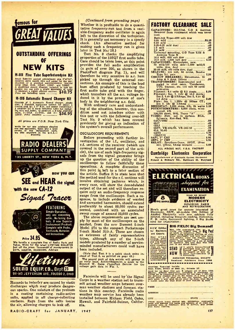
mous for
GREAT yqUfJ
OUTSTANDING OFFERINGS
OF
NEW KITS H -101 Five Tube Superheterodyne Kit Small Bakelite cabinet approximate sire 9"x5x6 ", complete parts except wire and solder for the con- struction of a standard superheterodyne receiver using 50L8, 8525. 128A7. 128(17. and 12ßK7. A simplified circuit diagram included in this kit enables any one with a slight knowledge of radio to construct a highly efficient, receiver. $ 1 0.75 Price not including tubes T
H -105 Automatic Record Changer Kit Consists of 1 Automatic Record changer, singlo most; 1 Portable leatherette cabinet for above; 1 Crystal.pick up: 1 5' P.M. end output transformer: 1 complete kit of parts including tubes but exclud- ing wire and solder, to construct s 8 -tubo amplifier using i -SOLB, 1 -3525. and 1- 36.95 12ßQ7. Price complete
AU prices are F.O.B. New York City.
Write for our new eateleeue showing new test equipment, tubes and luge variety of new replacement parts. We ship anywhere In the U.S.A. -
promptly.
RADIO DEALERS _SUPPLY COMPANY-
135 LIBERTY ST., NEW YORK 6, N.Y.
SEE and HEAR the signal.
with the new (A -12
5694tae 7:deep
h ¡4.34.85
FEATURING Simple Operation... only one connecting cable... No tuning Con- trols. A new Superior Instrument Product. Complete with Probe, Test beads. Batteries and Instructions.
We handle a complete line of Radio Parts and Tubes. Write for the latest LIFETIME BULLETIN lust off the press. Thousands of money -savers In parts, supplies, equipment. Address
SCUM) EQUIP. CO., Dept.í 911 -913 JEFFERSON AVE.,TOLEDO2,OH10
Hazards to industry are caused by static discharges which may produce danger- ous sparks. One solution of the problem is a coating containing radio- active salts, applied to all charge -collecting surfaces. Rays from the salts ionize the air, allowing charges to leak off.
RADIO -CRAFT for JANUARY,
(Continued from preceding page) Whether it is profitable to do a quanti- tative frequency -run test from a vari- able- frequency audio oscillator is again left to the discretion of the technician. It is generally not necessary in a speedy check. (An alternative method for making such a frequency run is given later in Test No: 18.)
Test No. 8 checks the amplifying properties of the 12SQ7 first audio tube. Care should be taken here, as this point provides the full audio amplification (a gain of over 300, as shown in the PhotoFact diagram Fig. 1), and will therefore be very sensitive to a.c. hum picked up through the external con- nections. An example of this is the loud hum effect produced by touching the first audio tube grid with the finger, which transfers all the a.c. voltage in- duced in it by the presence of one's body in the neighboring a.c. field.
With ordinary care and understand- ing of the situation, however, this con- dition need not interfere either with this test or with the following over -all Test No. 9 which has been covered previously for giving an indication of the system's overall performance.
OSCILLOSCOPE REQUIREMENTS Before proceeding with further in-
vestigation of the i.f., oscillator; and r.f. sections of the receiver (which are covered in the second part of the arti- cle), the use of such high -frequency sig- nals from the signal generator brings up the question of the ability of the oscilloscope to follow faithfully these operations. A complete discussion of this point is left to a later section of the article. Suffice it to state here that the method used for the r.f. sections will involve obtaining patterns which, in every case, will show the demodulated output of the set and will therefore re- quire only an audio -frequency response range from the oscilloscope. Such, a re- sponse, to include evidence of wanted and unwanted harmonics, should extend preferably to about 50,000 cycles per second, combined with an associated sweep range of around 20,000 cycles.
The above requirements are met am- ply by most of the oscilloscopes on the market, from the new Dumont 5-inch Model 274 to the compact Pocketscope 2 -inch Mode! S10 -A. These are chosen as extremes of fairly representative types, although any of the 3 -inch models produced by a number of service - minded manufacturers could well have been included.
(Note that Test 9 is a quick check point in- stead of Test 8, as printed on page 69.)
The second part of this article will appear in an early issue. Acknowledgment is made to the Howard W. Same PhotoFact Service for the voltage gain data in Fig. 1.
Facsimile will be used by 'the Signal Corps in a weather station net to trans- mit actual weather maps between over- seas weather stations and forecast sta- tions in this country. Facsimile radio weather map service has already been installed between Hickam Field, Oahu, Hawaii, and Fairfield- Suisun, Califor- nia.
1947
FACTORY CLEARANCE SALE CAPACITORS: Oil -filled. C -D & Aerovox.
Removed from equipment which was never used. Bath -tub Type -600 volt dew 0.06 mfd 50.19 0.60 mfd .33 0.26 -0.26 mfd dual .49 1.0 mid .39 2.0 mfd .49 Universal mounting. C-D Type TJH &
Aerovox Type N 10.0 mfd, 600 volt dew .98 10.0 mfd. 1,000 volt dew 1.60
CAPACITORS: Electrolytic. new. 20 mfd/160 volts dew -1,000 mfd /5
volta, dew. dual .49 20 -60 mfd, 400 volte dew, dual .59
SELSYNS: 116 volt. 60 cycles, Bendix Type I -1, pair 7.60
CIRCUIT BREAKERS: Heinemann. 16 Amp & 5 Amp, 115vac 98
TRANSFORMERS: Impregnated and sealed in steel cases. Thordarson. UTC, Stancor, etc. 116 volt 60 cycle primaries.
Filament: 6.4 volts ca 8.6 Amps 1.89 Filament: Sec. 1, 2.6v t l 10.0 Amps;
Sec 2. 6.4v @ 6.6Amps. Sec 8, 6.4v Q 1.0 Amy 8.49
Plate: Sec 1, 1,280v (41 262ma CT; See 2. 18v t 1.0Amp 6.95
RHEOSTAT: 8.000 ohms. 5%. 26 watts 1.59 POTENTIOMETERS: 6.000 ohms, wire -
wound, 6% .29 100,000 ohms. 10 %. Taper "A" .29
TUBES: New. not in cartons. RCA Sylvania, Ken -Rad, WE.
6AC7/1852 .99 6s37 .49 6SL7 .69 6SN7, VR- 106/80, Vit- 160/30 .69 6L6, 6L6G .84
6X5GT /C 1.76 2AP1, 2" CRT 9 95 5HP4. 5" CRT 6.95 RELAY: Struthers -Dunn, SPDT. 18vac
coil, 116vac, BAmp contacts 2.00
ALL PRICES NET. F.O.B. FACTORY
Cambridge Electronics Corporation Manufacturers of Electronic Control Equipment
Pulaski & McHenry Sts.. Baltimore 23. Maryland
ELECTRI CAL BOOKS ,siuppnd frrz
EXAMINATION SEND NO MONET
MODERN ELECTRICITY INCLUDING RADIO
AND REFRIGERATION Here's great news for anyone interested iii Electricity. NEW, up- to-date 19th Edition of Applied Eleçtriclty with new subjects fully covered. including blueprint reading, electronics. F. M. radio, fluorescent lighting, 8 Big Books send for examination:
NEW Edition for Beginners and Experts
Over 3 7 0 0
Illustrations and 134 tabls in t com- plete electrical work w k have published.
m t diesel plants. power stations.
llned rreasr understanding.
BIG FIELD! Big Demand! Men l who understand cl
81 Patr
all kinds orffyIndustriesprat- tinily g. /!
r knowledge.nand depends
know this subject make
and money. Lean.
hoally with these new. interesting oks. Send coupon for set of hooka
on you to getl ahead
how will help
SEND
NOW
A year's consulting privileges
flow given en-
gineers 1l buyers Of this fa-
Emous of
lectricity. AMERICAN TECHNICAL SOCIETY
Vocational Publishers Since 1898
American Technical Society. Dept. E128. Drexel at 58th Si., Chicago 37.
EdLton. Applied uF.licity including a 1Dth
chargea i Olnnly on the books. If Iyear. ish I will
may return
them. m Itnill0 end
82.000owe r so nothing.
u 83.00 a month until the total price Of only 834.80 IE paid.
NAME
ADDRESS
CITY STATE
Plesso attach letter Mating age. occupation, ployeMa-
bueinesspeddies. n s reference. and
In address
service. at
also pleurae give borne address.
137

MULTITESTER V.T.V.M. (Continued from page 83)
otherwise the entire current, about four or five ma, will pass through the meter and might damage it.
The e.v.m. section, shown in dotted lines on the diagram, and for which due credit is given Mr. Davis, is an excel- lent instrument and constructed almost exactly as described in his article. The only change is an additional switch in the B battery lead (section F on Sw2)'
else there would be a continuous drain on the battery. It has its own test leads -a few feet of shielded microphone cable with a 1- megohm resistor in the probe end was more stable and elim- inated a good deal of the hand capacity which was present with ordinary leads. In addition to the many uses suggested by Mr. Davis, the e.v.m. is an efficient instrument for testing crystal pickups
i \
Please send me FREE copy of your 1947 \ Catalog. I understand It has thousand, of lama \ Illuatreled. described end priced and will be a
great help to me In my search. for "hard-to- find" radio equipment.
Name
Address
City
t \ RADIONIC EQUIPMENT CO. \ 170 Nassau St.. Dept. 101. New York 7. N. Y.
Stete
EASY TO LEARN CODE It is easy to learn or Increase speed with an Inetructagraph Code Teacher. Affords the quickest and most prac- tical method yet developed. For be-
nera or advanced students. Available tapes from beginner's alphabet to typical messages on all subjects. Speed range 5 to 90 WPM. Always ready -no QRM.
ENDORSED BT.THOUSANDS!
itrll°aesehae of neapr liteaytkestl plc oper- ator-Instructor and enables e ne to learn and master code without fur - ther assistance. Thousands of successful operator. hava
Write 1 todday fo rode" convenient
the rental ° d`toPurchase
System. ln
HUMS
.T' NM ca..-
.aasa tan
All this equipment came from the fool and test -prod compartments. Everything want back, fool
INSTRUCTOGRAPH COMPANY 4701 Sheridan Rd.. Dept. RC. Chicago 40. Ill.
The BUY of a LIFETIME U.S.SICNAL 5 Meter ONLY
CORPS eter \_ SHORT WAVE XMTRS.
(72.2 Mc)
XMTR and Tube Only
349
Lesa mike. Batteries and Antenna
One 11/2 volt dry cell and 571/2 volts of B operates it. Just attach dl -pote. key or mike. connect the bat- teries ind it's ready to use. Signal Corps spec wired with silvered wire. mica condensers. and preci- sion resistor.. Highly stable circuit with Lo -Loss ail. vend Inductance. (Adjustable padder.) Schematic sup- plied Converts to walkie.alklo and Ham bands. weighs lees than pound. Shipped by express only. No C.O.D..., No Panel Post. A uerinee at only 53.49. Postal or express money Order or certified Check.
NEWARK SURPLUS MATERIALS CO. 324 Plane St.. Dent. C. Newark 2. N.J.
SEND STAMP FOR GIANT CATALOG!
YOUR ELECTRIC DRILL Has 100 Other Uses
when used with K -lag attachments METAL SAWING SHEARING
RIVETING ATTACHMENTS Ask your Hardware dealer or write for Illustrated circular
K -JAX, 2600 Canton St., Dallas, Texas
139
This underchassis view of Hie combination faster shows how the vacuum tube h mounted.
RADIO -CRAFT for JANUARY. 1941

-by connecting pickup leads of a sus- pected crystal and playing a record, a ,good crystal will show an appreciable reading on the meter. This is a good practical test before yanking out the crystal and then afterward deciding that the trouble is elsewhere. The re- versing switch (Sw4) operates with either instrument, as does the a.c: d.c. switch.
There was still room on the panel for another gadget so a test socket for pilot bulbs was installed in the upper left - hand corner. It saves the time and trouble of using a pair of test leads.
i TRANSMISSION WITH LIGHT I
(Continued from page 63)
the light intensity at the receiver varies directly as the square of the radius of this lens and inversely as the square of the distance between it and the receiver -assuming that the object, the neon tube anode, has been carefully focussed so that a sharp image appears at the photocell. Hence doubling the distance between the units will produce a 75 per- cent reduction in light input to the re- ceiver, with consequent loss in volume. However, one can compensate for this effect by using a larger lens at the photocell, since a 2 -inch lens will pass four times as much light as a 1 -inch lens.
In the system described, using 4 -inch and 1 -inch lenses at the transmitter and receiver respectively, good repro- duction was obtained at a distance of 16 feet. Had a 4 -inch instead of a 1 -inch lens been used ahead of the photoelec- tric cell, this range would have been greatly increased.
Insofar as the average experimenter is concerned, the immediate practical uses of a light -beam system are almost nil. Yet these efforts are definitely profitable. Besides the pleasure in- volved, and the fact that two very pass- able amplifiers are built, one has to tangle with some interesting problems of amplifier design and applied optics, with a few bits of photoelectric theory on the side.
T9 u D r
Can supply you with all types of Radios, Radio parte, Electrical parts and accessories.
PREPAID ASSORTMENTS GUARANTEED FIRST QUALITY
100 1/3 Watt Resistors All Insulated 52.98 100 v Watt Resistors All Insulated 3.98 100 1 Watt Resistors All Insulated 4.45 50 200 Volt Panel condensers
lel 2.48
50 Mica Condenser 2.98 20- Dry Electrolytic Filter Condensers 6.75 10 25 ft. Rolls Hookue Wire- A,nt'd colors 1.98 10 Volume and Tone Controls -4ío switches 1.98
100 ft. Spaghetti and VIn into .98 10 Coils I.F., R.F. Ant. and Ore 2.98 20
Auto to Suppreesson Ceramic Rand 6wltchce..
2.98 30 Electrical Devices. Plug., 721.3.
Rases. Fuses. etc 5.00 SEND FOR TRUTONE COMPLETE RADIO AND
ELECTRICAL LIST Term. 25 deposi[ uired with order. Balance
C.O.D. Merchandise sent prepaid lf full re- mittance accompanies order.
TRUTONE PRODUCTS CO. 303 W. 42nd St. Dept. C New Volk 18. N. Y.
Automatic Combinations -NOW! The New Arnold Shure Auto- matic Wired Record Player Ready For Immediate Delivery I
The Shure automatic rec- ord player connects easily to any radio. Its feather- weight crystal pickup and quiet, smooth changer ac- tion assure high quality playing of ten 12" rec- ords or twelve 10" rec- ords. Every one of your customers can now own a fine automatrc combina- tion at a remarkably low cost.
Shure players are shipped complete with A.C. cord and shielded cable -only 2 wires to connect and it's ready to play.
Your price only $21.92 net F.O.B. CHICAGO. ILLINOIS
OPA Retail Price 531.30 Zone I
OPA Rotall Price 33.87 Zone
Orden aro now hemp accepted for Immediate delivery-410 waiting. Terms: 2% check with order. Or 25% deposit. balance express C.O.D.
PHONO AMPLIFIERS I -Tube Phono. Amplifier I-Tube Phono. Amplifier
t- Alnico (5) ;" Alnico (5)
Alnico (5)
4.50 M
PM SPEAKERS PM Speaker $1.39 ta. PM Speaker 1.49 w PM Speaker 1.99 40.
TUBULAR ELECTROLYTICS 100-MFD 25 V $ .Y. ea- IO-MFD-450 V.....3 .29 ea. 10-MFD- 50 V .22 ea. I6MFD450 V .39 ea. 20-MFD-150 V..... .22 ea. 10.10-MFO450 V .59 aa. 30-MFD-I50 V .29 es 20.20-MFD-150 V... .29 ma.
40-MFD150 V .39 ea. 30-20-MF0-150 V ... .3C 4i 50-MFD-150 V .45 ea. 40-30.M FD-I50 V... .45 4a. 8-MFD-150 V .25 ea. 50-30-MFDI50 V... .59 4a.
HOLLANDER RADIO SUPPLY CO. 549 West Randolph Street Chicago 6, Illinois
MORE SMASH BUYS at National Radio Distributors NOW! IMMEDIATE DELIVERY!
THE NEW AND IMPROVED NATIONAL RADIO KITS. The Original and .still the Finest. Ml parts brand new, No War Weary Surplus. All parte per- fectly matched and mounted on chassis for easy wiring. Pmvertul Alnico P. M. speaker d beau- tiful Plastic Cabinet with Dutt- Proof back furnished with all Kite. Bulls -In loop antenna, and Illuminated Airplane dial. Pull Instructions. MODEL N.R. 7-6 -TUBE 105 -125r. A.C. /D.C.
SUPS RD};F} RODYNE. Uses 12SA7. 12SKT, 12SQ7. 5014 and 3525 WPCs 511.95
Kit of 5 Matched Tubes 4.95 MODEL N.R. 5-5 TUBE TWO BAND A.C. /D.C
SUPERHETERODYNE. as aboco. Fro. Mange 550- 1600 K.C. and 5.5-18 Mega cycles 313.95
Klt of 5 Matched Tubes 4.95 MODEL N.R. 6-6 -TUBE A.C. /D.C. SUPER-
HETERODYNE. Uses 12517. 12SÁ7. 12SQ7, 351.13, and 3525 Tubes $13.75
MODEL N.R. 1-4 TUBE A.C./D.C. T.R.F. Uses 12SKT, 12537, 501.8 and 3525 Tubes. Highly recommended for Students, Schools Hospitals and Institutions $10.95
Kit of 4 Matched Tubes 3.95
MODEL P. R. 7- PORT A- B LE RADIOPHONO- GRAPH COMBINATION KIT Powerful 5 -Tubo Superhet-
erodyne Radio, with Self - Contained l o o p Antenna
d Alnico speaker. Self -Starting Phono -Motor, and Feather- Weight Crys- tal Pick -up arm, 9 Turn - Table. -
Luxurlous leatherette cor cred carrying cant $27.50
KIT OF Matched Tubas 5 4.95
Manufacturer., lebben, Caperton! Write for quantity prices. White Plastic Cabinets available far Radio Kits, $100 haddlla
ale C.O.D. At least 25% with order. WO
will WRITE FOR OUR COMPLETE CATALOO. IT'S FREE.
National Radio Distributors 899 r Southern Blvd., New York 59, N. Y.
RADIO -CRAFT for JANUARY, 1947
FOR SALE Wire. 12,000 ft. Gov't RCU / -6, Radio Fre- quency, Low Loss Cable, copper wire, shielded about 52 ohms, 1000' coils on wood reel, $.07 per ft., if cut 100' lengths, 4.09 ft.
Lyell Hardware Co. BOX 5 ROCHESTER. N. Y.
Jlllllllllllllllllllllllllillilllllllllllllllllllllllllllllll! IIIIIIIIIIIIIIiIIIIIIIIIIIIIIIIIIIIIIIIIIIIIVIIII
_ AMATEURS AND EXPERIMENTERS P.
Hundreds of radio and electrical parta in- eludes -1 Throat Mike... Resistors ...=-= Sub Assemblies . . Contact Points .. Condensers . Insulators ... Coila .. Socket ... etc., etc., etc.
PRICE ONLY $2.00 EACH KIT
SHIPPING WEIGHT IO LBS. TERMS CASH WITH ORDER F.O.D. CHICAGO. nL'
GEORGE BROOKS & ASSOCIATES 220 SOUTH HAI.STEO STREET CHICAGO 6. ILLINOIS
PEN -OSCIL -LITE Extremely convenient test oscillator for all radie servicing: allgnmcut Small o Self
Ó0e megacyclees u.n.f. Output cycles audio
ta 125 over
iLow in cost Vsed by Signal Corrs Write for nformation.
GENERAL TEST EQUIPMENT 38 Argyle Ave. Buffalo 9, N. Y
CORRECTION Formula and text do not agree in the
formula at the head of the second column, page 17 of the December is- sue. In the text, v is used to represent velocity of sound, but by error an x is used in the formula. The caption on Photo D is also in error, and should read "... fixed light and moving scale."
139

HOLIDAY GIFTS SPECIALLY PRICED
I KITCHEN FLUORESCENT UNITS t
Uses 2 -15 or 2 -20 Watt Lamps AC or DC Lamps 80c each U/L Approv- parta
a4.5Ú
Pluge right into your fixture
VIN MIXER RECORD CHANGER MAGUIRE 2 -POST CHANGER DETROLA RECORD CHANGER
ft ABTATIC L70 -A
F
SHURE GLIDER CURVED ARM CRYSTAL PICKUPS
516.50 $15.25 $15.95
t e
t t
I
52.15 10 at $1.95
PHONO AMPLIFIER 3 Tube ACDC
Completely Wired Volume and tone controls .. $2.95
Phono. Amp. Kit with 5" Spk. & tubes $7.95 Less tubes or spk $5.95 Uses 12S97. 50L6. 35Z5. Above kit wired $8.50
100 Asst Insulated Resistors $1.75 t 15 Asst. BY -PASS Cond. All 600 X .89 T 25 Asst. Mica Cond. Color Coded .89
f PL -55 Mike Plugs with lock nuts .15 Open circuit Jacks .12 Alliance phono motors and turn -tables 8.75
i RISCO RECORD PLAYER
c
Easily attaches to any r ad I o.
Heavy duty mo- tor. Walnut fin- ish. High otrt put.
$9.95 with built In amplifier and tubos ...$15.95
We Specialize in Mail -Order Accounts T 25% Required on C.O.D. Orders -Free Catalog CI
RISCO SALES CO. WHOLESALE DISTRIBUTORS t
f 22 Warren St. Now York 7, N. Y.
I
t
OPPORTVNlTy AD-LETS Advertisements in this section cost 20 cents a word for each insertion. Name, address and initials must be Included at tha
a born rate. Cash should accom-
pany all classified advertisements unless placed by an accredited advertising agency. No advertisement for less thon ten words accepted. Ten percent dis- count six Issues. twenty percent for twelve iesuex. Objectionable or misleading advertisements not Sc'
eeptod. Advertisements for February, 1947, issue must reach be not later than December 29. 1946. Radlo-Craft 25 W. B'way New York 7. N. Y.
BARGAINS: TUBES. PARTS. ETC. SEND FOR LIST. Joe T. Morrow, O'olfe City, Texas. ARMY SURPLUS. NEVER USED J -37 KEYS ON J -97 Bakelite Base. 89c ea. postpaid. The Gateway Co., P. 0. Box 926, Brockton, Mass. CORRESPONDENCE COURSES AND SELF- INSTRUC- Uon books slightly used Sold. Rented. Exchanged All subject.. Satisfaction guaranteed. Cash paid for used courses. Complete information and 100 -pago Uluslnted bargain catalog Free! Write-'3' elaon Co., Dept. 39, Chi- cago 5. Ill. "DRA\VINO- CARTOONLNG MANUAL," 31 LESSONS, 600 Illustrations, complete $1.00. Howard Sales. 6749 Clyde SL, Forest Bills. N.Y.C. WHY FLUNK FCC EXAMS/ GET THESE SIMULATED multiple- clmice FCC practice exams. Five for $1.00. Five different exam! each for Elements 2. 3, 4, 5 and 6. State elements wanted. Dale's of Denver. 510 15th Street. Den- ver, Colorado. ELECTRICAL SUPPLIES? EQUIPMENT. AMAZING Value. New 110 volt, sixty cyclo Ball Bearing precision motora. Operate grinders, fans, etc. Cost government $48.75. Sent express prepaid. Only $3.69. Loco Engineer- ing Company, 908 -IBC -1. Lincoln, Nebraska. SIGNAL TRACER: SAVE $17.45. EM CLOSING RHDI'. Will sell brand new Sacco Modal Slap AC -DC for $27.50. Cost me $94.95. Send check. money order or C.O.D. to M. H. B. Hoffman, 4112 Gallatin Street. Ilyallarine, Maryland. WE REPAIR ALL TYPES OF ELECTRICAL INSTRU- mente, tubo checkers and analyzers. Haaeiton Instrument Co. (Electric Meter Laboratory), 190 Liberty Street, New York. N. Y. Telephone- BArclay 7 -9230. MAGAZINES (BACK DATED1- FOREIGN. DOMESTIC, arts. Books, booklets, subscriptions. pin-ups. etc. Cata- log 100 (refunded). Cicerone's, 863 First Ave., New York 17. N. Y. AMATEUR RADIO LICENSES. COMPLETE CODE and theory preparation for passing amateur radio ex- -minatione. Home study and resident courses. American Radio Institute, 101 West 63rd Street. Now York City. Soo our ad on page 199.
FREE WHOLESALE BULLETIN. TUBES. PARTS. Bargain prices. Henshaw Radio Supply, 3313 Delaran City. Kansas City. Kansas. WANTED COPIES OF' "MODERN ÉLFCTRICS" AND "Electrical Experimenter." State price. Box GT. % Radio - Craft,
140
COMMUNICATIONS AN ATHENIAN VIEW ON
Dear Editor: I read carefully your article "Why
No Postwar Radios" in the August issue. My present letter will not deal with the difficulties of production but will indicate some drawbacks inherent in even the best American prewar sets.
First is the quality of musical repro- duction. Even the best American re- ceivers compare unfavorably with good European sets. European listeners are accustomed to high -quality musical tone and do not tolerate anything that does not satisfy them acousticajly.
Degenerative feedback was widely used in good European sets as far back as 1938. I still remember how surprised I was when I compared two superhets of the same make, one with degenera- tive feedback and the other without. The difference in musical reproduction was very pronounced indeed. Now I see, from data available, that not one of the
"GI IS SMALL MAN Dear Editor:
I have just been reading your Com- munications column in the September issue. It seems to me that too much griping is being done about the raw deal which the GI is getting after doing his duty for his country.
I am a GI myself and proud of the fact -but it isn't going to do any good to any of us GI's to complain because every civilian who hasn't seen service doesn't turn a flip -flop for us. Thou- sands of men who have seen service are back in civilian life trying to make a living. These men are strong, healthy and young and are able to make a de- cent living. The man who did not see service is not the youthful, healthy man
POSTWAR RADIOS 1946 American sets available here in- corporates this design! I cannot under- stand how one can expect good-perform- ance without degenerative feedback and some means to boost the bass, especially in sets with small cabinets and speakers.
Another drawback is the poor per- formance on the medium -wave band. This may be attributed to the character- istics of American tubes and the inter- mediate frequency of 450 to 470 kc? With an i.f. of 128 to 175 kc we have better sensitivity and selectivity, in my opinion.
The latest models imported from the United States have not made a very favorable impression on the public here. Besides, their cost is prohibitive. They are sold at an average price of $100, which represents two to three times the monthly average salary of an employee.
G. C. STAVRIDES Athena, Greece
IN BUSINESS WORLD" the GI is and is not able to go at the work the same. Those GI's who were left disabled are being taken care of by the government and are learning some trade which will enable them to make a living.
As for the RFC, the GI is getting the same old shaft again that is true, but then the average GI is only a small man in the business world. The big man has always got the break and he always will, GI or no GI.
We fought for our country on the battle fields -now let's fight for it at the polls, if we are not satisfied with the deal' we get. How about it?
MAURICE S. HUDON Bradenton, Florida
RADIO -CRAFT for JANUARY, 1947

1
IS SERVICE FIELD SUPER -SUPER- SATURATED?
Dear Editor: Today, in this and other cities, it is
common parlance to say "there is a radio man on every corner." That is pretty close to the truth. Three causes can abe summed up into three reasons for the situation: 1. Old- timers in the radio -service field, who are still at it, or have come back into the radio service field after discharge from war service. 2. Those service men who have gained their knowledge while in the service of their country. 3. Those who have been, and are being ground out by the mail order radio institutions.
By way of contrast, we have in this city one principal and only telephone company, whose phone service extends into about three -quarters or more of the homes, and into all business places
',throughout the city. These phones need servicing from time to time, and are ready for service 24 hours of the day.
A house radio may be in service any - wheres from a few minutes to several hours daily. The entire number of tele- phone installations in this city, com- prising about 18,000 phones, are main- tained and serviced by eight or nine men employed by the telephone com- pany for this purpose. The moral is obvious: if it takes but eight or nine telephone service men to maintain in service this large number of local tele= phones, then by what standard in num- bers can we say that the number of radio service men are sufficient: or that the radio service field is saturated, super -saturated, or even super- super- saturated. From my own observation, I would say that the last -named situa- tion is that now prevailing in the radio service field.
NAZI TUBE REPLACEMENT
Dear Editor: I have not noticed any article in
your magazine describing successful substitution of our standard tubes in place of the tubes in the Nazi sets the boys are bringing over. I would like to contribute an item on this subject.
The set I worked on had all the tubes blown, it was a battery portable, Nora radio, using the following tubes, DCH11, DF11, DAF11, DL11.
After tracing out the tube pin connec- tions, I removed the large bakelite sock - eta, substituted a bakelite disc with a midget socket installed in the center, in
A. J. GALLAGHER
Erie, Penna
place of each one. I then rewired the sockets as follows:
DCH11 -1R5, DF11 -1T4, DAF11 -1S6, DL11 -1S4. The screen grid connection on the 1R5 was omitted.
The set worked fine, and the tubes did not require any shielding, although aligning was necessary, as the set has a regenerative i.f. circuit. The tone quality was good, indicating that the output transformer matched the 1S4 output tube very well. Perhaps this may help someone tackle a similar job.
WILLIAM BERGEN,
Saskatoon, Canada
SERVICEMAN'S ASSOCIATION IN PALESTINE
Dear Editor: The radio technicians of Palestine
founded an association in 1939 to pro- mote radio service in the country. In the course of time we have acquired the confidence of the broad public as well as that of the respective authorities. At present, our association has some 30 members, all of whom are well -known technicians, most of them owners of workshops and some dealers.at the same time.
You may be interested to learn that we have introduced consulting hours for the public, giving our clients advice free of charge regarding the purchase and the sale of radio sets, the use of same. At the same time we provided them with the opportunity of discussing all questions concerning their radio sets. '
A Palestinian radio serviceman must be able to:
1. Repair radio sets of all types, no matter whether they are of American, Europe or Transcontinental make;
2. Carry out work without help of diagrams, without accurate spare -parts (the latter owing to war -time shortage)
and in the past also without facsimile tube -types (especially European tubes). We had to replace European tubes by American tubes, change sockets, change heater voltages (from 4 volts to 6.3), etc.
We are now in possession of an im- port license enabling us to order new test equipment for which we are in dire need. Thus, we have immediately ordered the necessary instruments for our members (such as oscilloscopes, signal generators, meters and com- bination- units). There is a large mar- ket for American radio sets and all sorts of radio merchandise in this coun- try and we are anxiously awaiting the time when your production will again be in full swing.
We shall be pleased to establish con- tact between Ameriéan radio service- men's associations and our institution and would be thankful for any assist- ance or suggestions along these lines.
RADIO TECHNICIANS ASSOCIATION OF PALESTINE
W. Goldstein, Sec'ÿ; Tel -Aviv, Palestine
1907 -1947 W. wnw r.n On Ire as rams. an a. aces* r as 40e Awnl......, r raw ..s.a as. an. pn-r..Wlen
OSCILLOSCOPE FOUNDATION SIT
5 INCH
Consisting of Case, Chassis, two shelves (right & left), tube shield and
bracket,front panel, screen w i n d o w frame, han- dle, plastic window sock- et, with 5CP1 Cathode Ray tube- . Special ....
895
2x2 Tube $1.00 Socket for 2x2 Tube .25 H.V. Condenser .5 Mfd 2000 V 1.95 KIT, without Cathode Ray tube 11.95 5CP1 Cathode Ray tube only 7.40 Tube shield and bracket only 1.98
Highbridge Radio - Television. pnd Appliance Co.
340 CANAL STREET NEW YORK 13, N. Y.
Check Pin Connections & Tube Data Instantly!
Two new and amazingly handy slide rules tell you at once the location and nature of pin con - nections. filament voltage. filament current. and uses for 176 radio tubes. Radio or electronic engi- neers, servicemen, students can't afford to be without these pocket -sized time -savers. SEND $1.00 IN CASH OR MONEY ORDER TODAY and receive both prepaid by return mail. Your money back if not satisfied.
AT YOUR DEALERS
HARRY LANGSAM'. 12 S. 12M Street. Phila. 7. Pa. Cl I enclose 81.00. Please send both Radio Tube
Pin Data Rules. Name Address City sate
THORDARSON 6.3 Volt Filament
TRANSFORMERS I I5 V., 50/60 Cy. Pri- mary, 6.3 Volts at IO
Amps. Sec. Leads brought out en as engraved bakelite panel -WL 5 lbs. Stse 3 it Sir S inches. With mounting bracket.. Suitable for filament supply, battery charges. A" supplies. pinball machines. bell- ringers. toys, etc.
3 to erto-no less than 3 sold PRICE $1.50 $1.25 Lots of 12. each
AUDIO SALES CO. II WARREN ST. NEW YORK 7. N. Y.
Do you n BINDING POSTS?
Th. XL PUSH POST with Its Spring Action . Cannon Contact and mach moññaetiou. Manufactured in All Aluminum Tine M at 12a h.,
Aluminum Body. Bakelite Top Typo Si at 1sc each. T o.. C NP. ALL. BRASS- STAIN- LESS STEEL SPRING PIN. PROVEN
OIV : 2!a éeaach. TEST u NON-
CORROSIVE and Dealer. Littoral
Discounts
X. L. RADIO LABORATORIES 420 West Chicago Ave.. Chicago 10. III.
RADIO -CRAFT for JANUARY, 1947 141

Q FAMOUS NAMES
HAMMARLUND SP400 -X SUPER PRO This la the new mortel which covers continuous rango in 5 steps from .59 to 30 meg. $347.25 Complete with Speaker
HAMMARLUND HQ129 -X Frequencies cover .59 to Si mcg. in 0$173.25 steps. Complete with Speaker.
NATIONAL RECEIVERS 1330 STA, completo with Prover Supply, Speaker and Colle 11.7 -40; 3.5 -7.3; 7.0 -14.4, 14.0- 3051C). Additional coils $306.70 available
NC 2.400 Complete with Speaker
NC 46 Complete with Speaker
$241.44
$107.40
Federal Selenium Rectifiers
6to49 99Ea.
1to6S109Ea.
Quotations on larger quantities gladly furnished.
for: CONSOLE RADIOS *AC -DC PORTABLES *VIBRATOR POWER SUPPLIES *INTERCOM POWER SUPPLIES
*REPLACES 29 TYPES RECT.
TUBES
FEATURES REPLACE TUBE and SOCKET; REQUIRE LESS
SPACE: FACILITATE SMALLER CABINET
DESIGN; PROLONG LIFE OF SET; GIVE
IMMEDIATE RECTIFICATION
Schematic Application with every order.
TALK -A -PHONE LP -110 SUPER SELECTIVE SYSTEMS
The LP -110 System Is medo up excluelrely of
Master Stations. With this system any station call any other elation in the system and in
can a number of two -way conversations mn
ho carried on at one time. You can begin with 2 Masters and add up to a total of 10 in the LP -110 System.
Each Master $26.50
Milo has complete stocks of nationally known
IRC. AEROVOX. B & W, NEWCOMB, THOR-
DARSON, MEISSNER, TUNGSOL, WESTON,
SUPREME, NATIONAL, SNC TRANSFORM-
ERS, etc.
¡f'not rated. fO % with ordcr.balanceC.O.D. Oopt. C
Radio- aaLd G.LCCt.üYYIGG.l C1lYL/2-.
200 Greenwich St., N. Y. 7, N. Y. BEekman 3- 2980 -1
Export Div.: WESTERN INTERNATIONAL 168 Washington St., N.Y. 6, N.Y.
142
Adson Radio Bass & Weber Co., Inc.
Algeradio Electronics Co. Allied Radio Corporation
Henry H. Tepliti Advertising Almo Radio Co.
E. L. Brown Co. American Technical Society
Reincke- Ellis- Younggreen & Finn American Television Institute
Turner Advertising Agency Amplifier Corporation of America
Sternfield. Godley, Inc. Arrow Sales, Inc.
Sender Rodkin Adv. Agency Andel Publishers
Grant & Wadsworth Audio Sales Company
Bass & Weber Co., Inc. Bell Telephone Labs
N. W. Ayer & Son Best Vibrator Company Brooks & Assoc., George
The Schram Advertising Company Buffalo Radio Supply
International Advertising Ag. Burstein -Applebee Co.
Frank E. Whalen Adv. Co. Cambridge Electronics Corp. C. F. Cannon Co.
M. J. Werner Adv. Capitol Radio Engineering Institute 93
Henry J. Kaufman & Associates Cleveland Institute of Radio Electronics .. 107. 109
Kenneth Kolpein Communications Equipment Co.
Borough Advertising Co. Concord Radio Corp.
E. H. Brown Advertising Ag. Constant Electric Coyne Electrical School
Phil Gordon Advertising Agency Coyne Electrical School
McJunkin Advertising Agency Crabtree Wholesale Radio DeForest's Training Institute
Lauesen 8 Solomon Duston and Associates. Merle D. & H. Distributing Co. Editors and Engineers, Ltd. Electro Impulse Labs. Electronic Measurements Corp.
J. L. Purnies & Assoc. Electronic Parts, Inc.
Campbell & Reynolds Erie Supply Company Esse Radio Co.
Gary A. Ruben Federated Purchaser
Bergman -Jarrett Company Feiler Engineering Company
George Brodsky, Advertising Galvin Manufacturing Company
Gourfain -Cobb Advertising Agency General Cement Manufacturing Company
Turner Advertising Agency General Electric Company
Maxon, Inc. Generai Test Equipment Company
Suzanne Hayman Greenwich Sales Company
Bass & Weber Co., Inc. Guardian Electric Manufacturing Co.
Kennedy & Co. Hallicrafter Company Inside Front Cover
Burton Browne, Inc. Harrison Radio Company 105
Altomari Advertising Agency Hershel Radio Co.
Hugh Allen Advertising
Hi hbridge Radio -Television & Appliance Co. 130, 141
Burke & Wayburne Advertising Agency Hollander Radio Supply Co. 139
Turner Advertising Agency Hoover Industries
Hyatt Eby Hudson Specialties Illinois Condenser Company
Roy D. Zeff & Associates Instructograph Company
Turner Advertising Agency Jensen Industries, Inc.
Allan D. Parsons Advertising J. F. D. Manufacturing Company
Bergman -Jarrett Company J. M. P. Manufacturing Co. K -Jan Lafayette Radio Co.
Rehs Advertising Agency Lake Radio Sales Co.
Sender Rodkin Adv. Agency
- INDEX TO ADVERTISERS 123
133 108
104
137
16
125
119
132
141
76
130 139
118
128
137 125
97
98
131
79, 129, 130
128
125 11
127 136 107 143 100
132, 133
131
95
133
106
5
131
124
139
135
6
117
96
120 125
138
126
124
129 138 110
129
Langsam, Harry 141 Leco Engineering Co. 130. 132
Buchanan -Thomas Advertising Leeds Radio Company 122
Bass & Weber Co., Inc. Leotone Radio Corp. 132
Altornari Advertising Agency Liberty Sales Company 120
Sternfield -Godley, Inc. Lifetime Sound Equipment Co. 137
The Miller Agency Co. Lyell Hardware Company r 139 McGraw -Hill Book Company 143 McMurdo Silver Company, Inc. 15
Edward Owen & Co. Magna Metal Products 127
Equity Adv. Agency Mallory & Co., Inc., P.R Inside Back Cover
Aitkin -Kynett Company Maritime Switchboard 116 Metropolitan Electronic & Instrument Co. 104
Bass & Weber Co., Inc. Midwest Radio Co. 134
Savage & Talley Milo Radio & Electronics Corp. 142
Burke and Wayburn Advertising Co. Murray Hill Books, Inc.
Harry P. Bridge Advertising National Company, Inc.
Graydon Smith & Co. National Plans Co. National Radio Distributors
Burke & Wayburne Advertising Agency National Radio Institute
Van Sent, Dugdale & Co. National Schools 13
The Mayers Co. National Union Radio Corp. 2
Hutchins Advertising Co. New York Technical Institute of N. J. 74, 75
Schwab & Beatty, Inc.
Newark Electric Co. Inc. 12 The Charles Brunelle Co.
Nelvark Surplus Materials Co. 138 Wm. N. Scheer Advertising Agency
Newcomb Audio Products Company 127 Stevens Hell Advertising
Niagara Radio Supply 113 Burke and Wayburne Advertising Agency
Ohmeyer Engineering Labs. Ohmite Mfg. Co.
Fensholt Co. Olson Radio Warehouse III
Jessop Advertising Co. Onan & Sons, D. W. Inc. 101
Graves and Associates Opportunity Adlets 140 Pa.Kette Radio Co. 131
Arrow Advertising Agency Phelps Publishing Co. ` 142 Precision Electronics, Ins. 130
Campbell & Reynolds Quam Nichols 129
Triangle Advertising Agency Inc.
102, 103
78
123 139
I.
120 92
RADIO SCHOOL DIRECTORY (Spe page 144)
American Radio Institute. Sternfield -Godley, Inc.
Candler System Co. Rand -Ries Adv., Inc.
Commercial Radio Institute Electronics Institute, Inc.
Chester Miller Gotham Radio Institute
Halpern Advertising Agency Lincoln Engineering School
Buchanan- Thomas Adv. Melville Radio Institute
1 Seidell Adv. RCA Institutes Tri -State College
Clem J. Steigmeyer Adv United Radio Television Western Radio Television Institute Y.M.C.A.
Radcraft Publications 99, 135 Radio Corporation of America Back Cover
J. Walter Thompson Co. Radio Center 116 Radio Dealers Supply Co. 137 Radio Distributing Co. 127 Radio Electric Service Co. 94
David Zibman Adv. Radio Kits Co. 126
Hamburger Agency Radio Parts Co. 100
Sydney S. Lovitt Advertising,
PRODUCTION in u "'u`"' in our plant includes the typesetting, presswork,
f binding and mailing and shipping of your t RADIO -CRAFT
Congratulations to the Publisher as he salutes DR. LEE DE FOREST its this issue
PHELPS PUBLISHING COMPANY, Springfield, Massachusetts f
RADIO -CRAFT for JANUARY, 1947
1
'I

r
Radiolab Publishing Co. 117 Bass & Weber Co. Inc.
Radio Specialties Co, . 107 Radio Tube Service Co.. Inc. 135 Redionic Equipment Co. 138
Bass & Weber Co., Inc. Radolek Company 126
Turner Co. Randolph Radio 129 Risco Sales Co. 140
Diener & Dorskind Robco Corporation 128
Freiwald- Coleman Advertising Rosicruciens, The 135
Richard Jorgensen Sams Howard W., & Co., Inc. 3
Aitken -Kynett Co. Scenic Radio & Electronics Co. 127 Sprague Products Co. 14
Harry P. Bridge Co. Sprayberry Academy of Radio 9
Harry P. Bridge Co. Stahl, Michael 135
Bess & Weber Co., Inc. Star Measurements Co. 131
Altorari Advertising Agency, Inc. Sterling Electronic Co. 136 Sunbury Engineering Works 136 Su rior Instruments 91
Bass & Weber Advertising Agency Supreme Instruments Corp. 94
O'Callaghan. Advertising Agehcy Supreme Publications 119
Henry H. Teplitt Advertising Supreme Transmitter Corp. 73 Surplus Radio, Inc. 123
Bass & Weber Co.. Inc. Sylvania Electric Products. Inc. 7
Newell -Emmet Co. "TAB" Technical Apparatus Builders ---- 121
Bass & Weber Co., Inc. Talk -A -Phone 128
Dwight M. Blish Advertising Taylor Tubes, Inc. 127
Turner Advertising Agency Terminal Radio Co. - '131
Regent Adv. Agency Terry, Jay 123 Thor Electronics 134
Paul J. Basinger Advertising Triplett Electrical Instrument Co. 77
Western Ade. Ag. Trutone Products Co. 139
Julius ',J. Rowen Company Tung -Sol Lamp Works. Inc. 4
E. M. Freystadt Associates, Inc. Turner Co. B
W. D. Lyon Co. Variety Electric Co. 136
Bass & Weber Co., Inc. Vision Research Laboratories 58
Abner Robins Advertising Wells Sales, Inc. 59
Turner Advertising Agency Weston Electrical Instrument Co. Bo
G. M. Basford Co. XL. Radio Laboratories 141
BOOK REVIEWS' RADIO'S CONQUEST OF SPACE, The Experimental Rise in Radio Communi- cation, by Donald McNicol (past presi- dent, The Institute of Radio Engineers). Published by Murray Hill Books, Inc. Stiff cloth covers, 51/2 x 81/2 inches, 374 pages. Price $4.00.
Here is radio history on the march - written by an engineer who grew up with it. The author is to be congratulat- ed on the complete manner in which he has covered the field of radio invention and inventors. In this book one has an opportunity to learn something about the real background of radio invention. What were some of the early experi- ments that led to the invention of the vacuum tube detector and amplifier . . .
and who were the investigators? Mr. McNicol tells all this -for the
first time in many instances, as this "background" is frequently omitted by writers. His historical record of names, places and inventions is surprisingly detailed and shows that a prodigious amount of research was performed in the preparation of this work,
A refreshing feature of the book is that the author does not hesitate to ex- press an opinion on some of the impor- tant inventions; some unusually inter- esting "sidelights" on the claims and opinions of inventors are included.
The copious section on the Fleming valve and the de Forest audion comes at a happy moment, when the fortieth an- niversary of de Forest's invention of the three -electrode tube is being celebrated. A complete index by names as well as by inventions is included in the book. H.W.S.
a z -
Suggeeted by: Rueeeil Simpson, Lansdale, Pa.
RADIO -CRAFT for JANUARY, 194,
NOW -A REALLY HIGH-POWERED - Radio Engineering
Library
xorm
as tia !oxo' han
NOTE: The Library comprises a selection of boob culled from leading Mc- Graw -Hill publications In the ra- dio field.
especially selected by radio specialists of Mc- Craw- Hill publications
to give most complete, dependable coverage of feed needed by all whose fields are grounded on radio fundamentals
available at is special price and terms
THESE books cover circuit phenomena, tube the ory, networks. measurements, and other sub-
jects -give specialised treatments of all fields of practical design and application. They are books of recognized position in the literature -books you will 'refer to and be referred to often. If you are a %practical designer, researcher or engineer in any field based on radio, you want these books for the help they give in hundreds of problems throughout the whole field of radio engineering. b VOLUMES, 3319 PAGES, 2289 ILLUSTRATIONS 1. Eastman's FUNDAMENTALS OF VACUUM TUBES 2. Termini's RADIO ENGINEERING B.- Everitt's COMMUNICATION -ENGINEERING 4. Hund's HIGH FREQUENCY MEASUREMENTS 5. Henney's RADIO ENGINEERING HANDBOOK io day eraminetlon. Frey te s. Special prltt unAar Nls offer less then books EouEnt eepaatety. Add Ne.. standard to your library ow; PAy small monthly Ubt.tlmCnt., while you use the book..
10 DAYS' FREE EXAMINATION -SEND COUPON
McGraw -Hill Book Co., $30 W. 42nd St, New York 18
ay6end me ][adio Ehgtneerine Library. e ]s.. for '10 -
°s,3 so p1 l ftiwon o .1. m dt 4 áö
vols..
age . eb is paid', Dboota itmuaie: OGrrt to si- nt:i remittance
Adores.
city .od Stat.
Company
Po.tues - RC S-47
'SURPLUS SPECIALS Western Electric dry disc rectifier replaces rectifier tube. In portable radios. 150v 60ma 3" cathode ray radar scopes 115v. 400 cps brand new $25.00 RCA beat frequency oscillator. 30- 15.000 cps, model 154 $40.00 Lending Meter, with two 200 mitsampe movement.. 314" dia. $5.00 5e cathode ray tuba 5BP1 $7.50 6 volt filament transformer 85e 6 volt power transformer 81.50 4 mid 600WV round an. oil filled 60. .05 mfd 1500 WV, oil filled I5e .001 silver micas 15 for $1.00 .01 mica and .0175 mica. 1200 WV 15e AC. DC 2 band 5 tube radio. 5" speaker. beautiful two tone bekellte cabinet, OPA retail 236.00, net $24.95
ELECTRO IMPULSE LABS. Shrewsbury, N.J.
ile
An error in Radio Data Sheet 340 on page 35 of the October issue shows the control grids of the lower pair of 6K6's connected to the high -voltage bus. The high- voltage lead from the speaker socket is connected to the screens of the right -hand pair of 6K6's -and to nothing else in the set. To correct the drawing, the hih- voltage bus connection to the control grids should be made to the speaker socket high -voltage lead.
We thank Mr. Horace M. -Love, Jr., of Pittsburgh for' this correction.
143
W
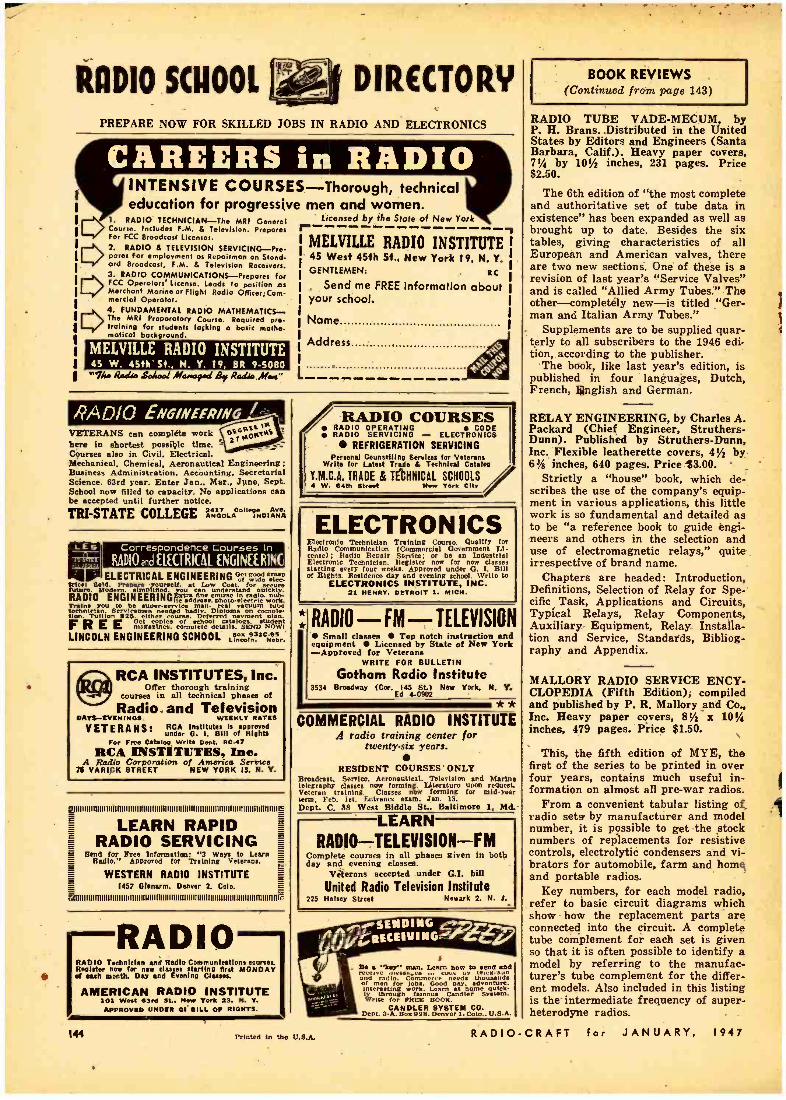
Correspondence Courses In
RADIO rails' £L£CTRI(AL £NGIN££RING
RaDIO .SCHOOL DIRECTORY PREPARE NOW FOR SKILLED JOBS IN RADIO AND ELECTRONICS
INTENSIVE COURSES -Thorough, technical education for progressive men and women.
licensed by the State of New York
MELVILLE RADIO INSTITUTE,
1. RADIO TECHNICIAN -The MRI General Course. Includes F.M. & Television. Prepares For FCC Broadcast Licenses.
E> 2. RADIO & TELEVISION SERVICING --Pre pores for employment as Repairman on Stand ord Broadcast, F.M. & Television Receivers. 3. RADIO COMMUNICATIONS -Prepares for
E> FCC Operators' License. Leads to position os Merchant Marine or flight Radio ORcor; Com 'nerds!! Operator. 4. FUNDAMENTAL RADIO MATHEMATICS-. The MRI Preparatory Course. Required pre training for students laçking o basic mathe- maticol background.
MELVILLE RADIO INSTITUTE 45 W. 45th St., N. T. 19, BR 9.5080
45 West 45th St., New York 19, N. Y. GENTLEMEN: RC
Send me FREE Information about your school.
Name
Address
"Ilea Rad& Soloed Maawyad By Radio 'r M L
VETERANS can complete work bere in shortest possible time. Courses also in Civil, Electrical. Mechanical, Chemical, Aeronautical Engineering: Business Administration, Accounting, Secretarial Science. 63rd year. Enter Jan., Mar., June, Sept. School now filled to capacity. No applications can be accepted until further notice.
TRI -STATE COLLEGE ANGOLA "I
ELECTRICAL ENGINEERING oStw; ;;p"^ Viral
Mode Prepare yourself, at
n understand for
ulcklv.. RADIO ENGINEERING S can
1" a1e ' ui man. nhol vacuum tube t clins an.
Servicemen be sape r.e m reel v tube
needed Orf Dlplomas0 mvle- o,m. Tuition a23. either e as " cas Alen.
magazines. complete details. SEND SNOW, FREE LINCOLN ENGINEERING SCHOOL On°op931arshr
RCA INSTITUTES, Inc. Offer thorough training
courses in all technical phases of
Radio. and Television DAYS -EVENINGS WEEKLY RATES
VETERANS: RCA Institutes 1s approved under G. I. 13111 of Rlghta
For Free Catalog Write Dent. RC-47
RCA INSTITUTES, Inc. A Radio Corporation of America Screws
75 VARICK STREET NEW YORK 13, N. Y.
JIIIIIIIIRIIIIIIIIINIIIIIIIIIIIIIIIIIIIIIIIIIIIIIIIIIIIIIIIIIIIIIIIIIIIIIIIIIIIIIIIIIIIIIII
LEARN RAPID RADIO SERVICING
E Send for Free Information: "3 Ways to Learn ° Radio." Approved for Training Veterans.
WESTERN RADIO INSTITUTE 1457 Glenerm. Denver 2, Colo.
u l l l l l l f ll l l t lt l l l l l l l l l l lt l l l l l 1111111111 I I I I I I I I I I I I I I I I I I I I I I I I I I I I I I I I I I I I I I I I I I I I I I I I I I I II I T
RADIO
RADIO COURSES RADIO OPERATING CODE RADIO SERVICING - ELECTRONICS
REFRIGERATION SERVICING Personal Counselling Services for Veterans
Write for Latest Trade & Technical Catalog
Y.M.C.A. TRADE & TECHNICAL SCHOOLS o W. 64th Street New York city
ELECTRON ICS Electronic Technician Training Course. Qualify for Radio Communication (Commercial Govomment Li- cense): Radio Repair Service: or be an Industrial Electronic Technician. Register now for new classes starting every four week.. Approved under O. 7. Blil of Rights. Residence day and evening school. Write to
ELECTRONICS INSTITUTE, INC. 21 HENRY. DETROIT I. MICH.
* RADIO - FM - TELEVISION Small classes Top notch instruction and
equipment Licensed by State of New York -Approved for Veterans
WRITE FOR BULLETIN
Gotham Radio Institute 3534 Broadway (Cor. 145 St) New York. N. Y.
Ed 4 -0902 ** COMMERCIAL RADIO INSTITUTE
A radio training center for twenty -six years.
RESIDENT COURSES' ONLY Broadcast, Service, Aeronautical. Television and Marino telegraphy classes new forming. Literature upon request. Veteran training. Classes now forming for mid -year term. Feb. let. Entrance exam. Jan. 13.
Dept. C. 38 West Biddle St.. Baltimore I, Md.
LEARN RADIO -TELEVISION -FM
Complete courses in all phases given in both day and evening classes.
Veterans accepted under G.I. bill
United Radio Television Institute 225 Halsey Street Newark 2. N. J.
RADIO Teehnitlan and Radio Communications course.. Register now for new classes starting first MONDAY
to et each month. Day and Evening Classes.
AMERICAN RADIO INSTITUTE 101 West ó3r. SL. New York 23. N. Y. APPROVED UNDER DI BILL OF RIGHTS.
144 Printed In the U.S.A.
Bo e kit' man. Learn how to send and
and radio. Commerce`n eeds tlhousands
Interesting lobs. ork. Learn at homeoaulrk
ly through famous Candler System. Write for FREE BOOR.
CANDLER SYSTEM CO. Dept. 3.A. Box928. Denver 1. Colo., U.S.A.
BOOK REVIEWS (Continued from page 143)
RADIO TUBE VADE- MECUM, by P. H. Brans.. Distributed in the United States by Editors and Engineers (Santa Barbara, Calif.). Heavy paper covers, 7% by 10% inches, 231 pages. Price $2.50.
The 6th edition of "the most complete and authoritative set of tube data in existence" has been expanded as well as brought up to date. Besides the six tables, giving characteristics of all European and American valves, there are two new sections. One of these is a revision of last year's "Service Valves" and is called "Allied Army Tubes." The other-completely new -is titled "Ger- man and Italian Army Tubes."
Supplements are to be supplied quar- terly to all subscribers to the 1946 edi- tion, according to the publisher.
The book, like last year's edition, is published in four languages, Dutch, French, L}nglish and German.
RELAY ENGINEERING, by Charles A. Packard (Chief Engineer, Struthers - Dunn). Published by Struthers -Dunn, Inc. Flexible leatherette covers, 4% by 6% inches, 640 pages. Price $3.00.
Strictly a "house" book, which de- scribes the use of the company's equip- ment in various applications, this little work is so fundamental and detailed as to be "a reference book to guide engi- neers and others in the selection and use of electromagnetic relays," quite irrespective of brand name.
Chapters are headed : Introduction, Definitions, Selection of Relay for Spe- cific Task, Applications and Circuits, Typical Relays, Relay Components, Auxiliary Equipment, Relay Installa- tion and Service, Standards, Bibliog- raphy and Appendix.
MALLORY RADIO SERVICE ENCY- CLOPEDIA (Fifth Edition), compiled and published by P. R. Mallory and Co., Inc. Heavy paper covers, 81/2 x 10% inches, 479 pages. Price $1.50.
This, the fifth edition of MYE, the first of the series to be printed in over four years, contains much useful in- formation on almost all pre -war radios.
From a convenient tabular listing of radio sets' by manufacturer and model number, it is possible to get the stock numbers of replacements for resistive controls, electrolytic condensers and vi- brators for automobile, farm and home and portable radios.
Key numbers, for each model radio, refer to basic circuit diagrams which show how the replacement parts are connected into the circuit. A complete tube complement for each set is given so that it is often possible to identify a model by referring to the manufac- turer's tube complement for the differ- ent models. Also included in this listing is the intermediate frequency of super- heterodyne radios.
RADIO -CRAFT for JANUARY, 1947

Mallory Offers 12 Clutch Type Controls for Use in Auto Receivers
MALLORY offers the widest range of resistance values in clutch type controls to fit every need. Four different values are available
in the Universal Midget line (100M ohms, 250M ohms, 500M ohms, L 1 megohm), and eight values in popular combinations of overall and tap resistances in our Tapped Midget line.
Add these to the Plug -In Shafts you see at the right, and you can re- place original controls in any auto set you name -not merely replace them but duplicate them mechanically and electrically. Get the complete story from your Mallory distributor.
You Expect More..: and Get More...
from Mallory
NO WOBBLE -this ring prevents it
All Mallory Plug-In Shafts are made with a small ring as shown above. That's why they can't wobble or work loose -why they fit as securely as a fixed shaft.
i
INSIST ON MALLORY -THE
COMPLETE
CONTROL
LINE
44;2
--°*,= í v=t1
1
,..._ s f P. R. MALLORY B CO..Inc.
MALLORY VIBRATORS . . VIBRAPACKS *... CAPACITORS ... VOLUME
CONTROLS ... SWITCHES ... RESISTORS ... FILTERS
... RECTIFIERS ... POWER SUPPLIES. ALSO MALLORY
DRY BATTERIES, THE ORIGINAL MERCURY BATTERIES. *Rep. U. S. Pat. Off.
APPROVED PRECISION PRODUCTS P. R. MALLORY & CO., Inc., INDIANAPOLIS 6, INDIANA

RCA Laboratorks- Center of Radio and Electronic Research
RCA Laboratories at Princeton, N. J., are far more than one of the most modern and best -equipped laboratories ever built. It is
a community of scientists, research men and technicians -each a top man in his field -each working with the other-contribut- ing wherever and whenever his specialized knowledge will help.
It is a "university of ideas" -where vi- sions are graduated as practical realities... where human wants arc fulfilled through the creation of new products and processes, new services and markets.
It is a birthplace of scientific, industrial and social progress for the entire nation.
oVicirolo T. M. Peg. U. S. Pot. 041
It is the reason why anything bearing the letters "RCA" -from a radio tube to your television receiver of tomorrow --is one of the finest instruments of its kind that science has yet achieved.
For just as RCA Victor television re- ceivers, radios, or Victrola* radio- phono- graphs are stamped .by the RCA emblem, so do the products themselves bear a stamp of experience and research that gives RCA pre- eminence in radio and electronics.
Radio Corporation of America, RCA Building, Radio City, New York 20. Listen to The RCA Show, Sundays, 2:00 P. M., Eastern Time, over the NBC network.
PIONEERING
Scientists and research men who work in RCA Laboratories made many vital contributions in help- ing to win the war through appli- cation of radio, electronic, radar and television techniques. Their skills now are devoted to peace- time applications of these sciences.
At RCA Laboratories the elec- tron microscope, radar, all -elec- tronic television (featuring the pro- jection system for the home) and many other new instruments of radio, including hundreds of new electron tubes, were developed to improve and to extend the serv- ices of radio around the world.
RADIO CORPORATION of AMER /CA