British Kinematography (1947) - Internet Archive
288
-
Upload
khangminh22 -
Category
Documents
-
view
12 -
download
0
Transcript of British Kinematography (1947) - Internet Archive


Scanned from the collection of
Frank Wylie
Coordinated by the
Media History Digital Library
www.mediahistoryproject.org
Funded by a donation from
University of St Andrews
Library & Centre for Film Studies


Digitized by the Internet Archive
in 2013
http://archive.org/details/britishkig1011brit


right Field Reference UbranTMam Branch
.
THE JOURNAL OF THE
BRITISH KINEMATOGRAPH SOCIETY
Vol. 10. No. I. JANUARY and FEBRUARY, 1947
Presidential Address
FIVE-YEAR PLAN OF PROGRESSOF THE
BRITISH KINEMATOGRAPH SOCIETY
At the meeting of the Society, held on 15th January, 1947, the President, Mr. I. D.
Wratten, F.R.P.S. (Fellow) read the following document prepared by the Council.
The paper which followed, " Fundamentals of Latent Image Formation," by Dr. W.F. Berg, will be printed in a later issue.
IN view of the new Constitution of the Society, now legalised after two years'
work, the Council has decided that the present is an opportune time for the
preparation of a plan for. future progress extending over the next five years. Withthis object, it instructed the various Committees of the Society to submit detailed
proposals which are here correlated for the information of interested parties.
1. MembershipThe status of a Society is no higher than that of its principal membership. Under
the terms of the new Constitution, the Council is required to restrict the Corporate
Membership to persons of technical eminence and good standing in the industry.
Election to the Corporate Membership will, therefore, be a jealously guarded
privilege. The Associateship, on the other hand, is open to any technician who has
been engaged for two years in the industry.
In the field of film production it is the aim of the Membership Committee to^
secure as a Corporate Member every technician whose name appears on the credit
titles of British films. Other sections of the industry are already well represented
in the Society.
Members have henceforth the opportunity of qualifying for a still higher status,
that of the Fellowship. The first fifteen Fellows were in accordance with the
Constitution recently elected by the Membership of the Society. A proposal which it
is felt will establish the status of the British technician and at the same time increase
still further the national spirit of British production is that all technicians so quali-
fied should be encouraged to use the initials F.B.K.S. on credit titles.
2. Lecture ProgrammeIn none of its many fields of activity has the work of the Society shown a greater
increase than in the number of meetings arranged. Including the main Society papers,
Divisional meetings and those of the two provincial sections, no fewer than forty-
two papers have been arranged during the 1946-47 session, in addition to six
meetings arranged jointly with the Association of Cine-Technicians, which latter
are to be repeated at a number of studios, making an estimated total of no fewer than
sixty-six meetings during the session. This compares with eleven meetings only
during the 1938-39 session. The Council submits that this forms a valuable part
of the educational work of the Society.
mo*

Of the forty-two meetings above mentioned, two are to be held jointly with the
Royal Photographic Society, and one with the Television Society.
It may, however, be necessary, as a temporary measure, to restrict the number ofmeetings in view of the work involved in increased frequency of publication of the
Journal. Papers from students may be invited.
It may fairly be said that the status of the Society is such that any technician
is honoured by an invitation to lecture to the Society. The time has arrived whenthe practice of other learned Societies is to be adopted, of inviting the submissionof papers early in the year.
3. Technical
The work of various technical committees of the Society was of considerable
importance in the years before the war. Immediately post-war conditions made it
possible for members to devote their time to such work, a number of technical
committees were appointed.
Two such committees have already made detailed reports, which are underconsideration by the British Standards Institution, relating to length of reel, leaders
and runouts for 35mm. and 16mm. films respectively.
Other technical activities concerning which committees exist, or which are underpreliminary investigation, include :
(a) Film Mutilation. (/) Practical Aspects of Sound Record-(b) Technical Data Books. ing.
(c) Home Office Regulations. (g) Camera and Sound Report Sheets.
(d) Test Films. (h) Distribution of 16mm. Films.
(e) Studio Set Construction. ( i)
16mm. Projector Requirements.
Much of the work of the above committees will, of course, lead to the prepara-
tion of British standards. The Society works closely with the British Standards
Institution and is strongly represented on all its committees dealing with kinema-tography.
4. Educational
The educational work of the Society must play a prominent part in its future
development. The educational activities should cover the following fields :
(a) Studio. (d) Kinematograph Sub-Standard.
(b) Laboratory. (e) Engineering.
(c) Theatre.
The educational work may be divided into two sections : (a) Laboratory an
generalised instruction which will be centralised in London, and (b) Training o
projectionists which must necessarily be decentralised.
(a) One of the most successful activities of the Society is the two-year course in
kinematography organised at the Polytechnic, Regent Street. The present course
is limited to an intake of twelve students per annum. The Society would give
sympathetic consideration to the views of the Industry relating to an increase of
intake.
Proposals have already been discussed for the extension of this course to a third
year, the additional period consisting mainly of practical work in a studio set apart
for the purpose. When this can be done more practical work will be introduced into
the first two years.
This, however, will involve the provision of additional plant, which in its tun
will demand increased accommodation.Another important aspect of the Society's educational work is the provision o)
educational courses for persons already engaged in the industry. Two courses ir
particular, " Sensitometry and Laboratory Practice," and " Fundamentals o
Sound Recording," each of which lasts twelve weeks, have for a number of year

fc'right Field Reference Library
Main Branch .V|±
been well attended. There is, however, room for a very large increase in the numberand scope of such courses, and it is envisaged that such courses might be organised
in six or eight subjects. While it would be desirable for such courses to be cen-
tralised at the Polytechnic, Regent Street, it is appreciated that neither staff,
accommodation nor equipment is adequate, and it may be necessary, therefore,
either to enlist the co-operation of other Polytechnics or to organise such courses
in other places, preferably studios. Manufacturers might offer co-operation.
It is proposed that syllabuses of such courses should be prepared at an early
date in co-operation with the British Film Producers' Association and the Associa-
tion of Cine-Technicians.
(b) The Society has for the past two years been studying the problem of providing
technical education for projectionists, theatre engineers, etc. The recently con-
cluded national agreement between the Cinematograph Exhibitors' Association and
the National Association of Theatrical and Kine. Employees provides for training
of probationers over a two-year period. The Society is anxious that its services
should be used to the full in the preparation of syllabuses (a dratt syllabus already
exists which has been approved by interested trade organisations), and to provide
graded instruction on which national certificates might be issued.
It must be emphasised that in the matter of education above all others, it is the
aim of the Society to be of maximum service to the industry, and for this reason it
seeks the closest association with all interested bodies, with a view to makingeducational courses of an essentially practical nature. To this end, the appointment
of an Education Officer has been suggested.
5. Library
In the recent inauguration of a Library of technical books, the Council feels that
a long outstanding want has been met, to the benefit of the membership and of the
industry as a whole.
The aim of the Library Committee is to make the Society's Library a unique
collection of publications pertaining to kinematography.
The Library should aim to include :
(a) Books under the following headings, in all cases relating to kinemato-
graphy
:
i. History. 4. Associated Sciences.
2. Reference. 5. Cultural.
3. Technical.
(b) All standards specifications relating to kinematography.
(c) All known periodicals, Home and Overseas, relating to kinematography.
(d) Patent Office abstracts.
(e) Publications of trade firms.
(/) Film scripts.
Close collaboration with the Foreign Relations Committee is desirable in order
>to obtain knowledge of books published abroad.
The catalogue of the Library should be published annually and all accessions
should be printed regularly in the Journal.
6. Journal
The Society's Journal has previously been published quarterly, with the addition
^of the occasional issue of proceedings of the various Divisions. The increase above- referred to in the number of papers presented to the Society, its Divisions andbranches, makes it imperative that more frequent publication be effected. Further-
more it is realised that to many Members and Associates outside the region coveredby the London headquarters and the two provincial sections, the Journal represents
almost the only benefit of membership.Monthly publication of the Journal has, therefore, been an important aim which is
about to achieve fruition. It has been decided that the Journal should appear bi-
monthly from January, 1947, and monthly from July, 1947.
Property of U. S.
4+ 775-

It will be appreciated that the decision to publish monthly issues has given the
Council considerable anxiety in view of the financial and organisational difficulties
involved, since it is agreed that the Journal must at all costs be maintained at the
highest possible standard in order that it may attain the status equal to that enjoyed
by organs of other learned societies.
Among other objects of the Journal Committee are the publication of papers as
early as possible after presentation;
publication of reports of all technical com-mittees ; the reprinting of selected papers from overseas publications, e.g., the
Journal of the Society ofMotion Picture Engineers, La Technique Cinematographique,
Kinotechnik when republished, etc., and on the circulation side, the receipt of the
Journal by every technician employed in the industry, every kinema theatre,
colleges and universities, leading technical libraries, etc.
7. Theatre Division
The Theatre Division comprises theatre engineers, projectionists, manufacturers,
etc., and its work covers every aspect of the kinema. Valuable papers have recently
been presented on the subject of auditorium design, while the Divisional programmefor the current session comprises six lectures having as their theme the need for
co-ordinated design of projection equipment.
The Division was instrumental in the formation of various committees on 35mm,Release Print Make-Up, Film Mutilation, Home Office Regulations, Test Films,
etc. It has also fathered the two provincial sections and has urged the develop-
ment of these into branches and the formation of other branches. In the sphere of
education, it is keenly interested in the training of projectionists.
8. Sub-Standard Division
The chief field of the Sub-Standard Division is, of course, the 16mm. film and its
growing ramifications. The teething troubles of this standard in its new fields of
use are being studied by four technical sub-committees, while the five lectures
in the Divisional programme this session relate to the same aspect.
The membership of the Division naturally includes many technicians not directly
engaged in the Film Industry but making regular use of kinematography for
industrial, educational, technical and scientific purposes.
9. Film Production Division
Of all branches of the industry, film production has been the least represented in
the membership of the Society. The formation of the Film Production Division
has done much to remedy this state of affairs. As above mentioned, the Division
aims to include within its membership every technician whose name appears on the
credit titles of British films, and also to secure recognition on credit titles for Fellows.
The Division has also been active in pressing the need for increased educational
facilities for persons already engaged in the industry.
A feature of the current session has been the co-operation of the Division withj
the Association of Cine-Technicians, and it is hoped in the future that co-opera-
tion in the technical sphere, both with this Union and with other studio Unions,;
may be furthered. . The Division has recommended to the Council that a Joint
Standing Committee be set up to deal with such co-operation.
The Division is also actively engaged in a number of technical matters as out-
lined above.
10. Branches
There exists in the provinces a very healthy demand for the establishment of
localised activities of the Society. Theatre Division sections have been established
in Manchester and Newcastle-on-Tyne, both of which have during the past andcurrent sessions organised excellent lecture programmes ; these sections are not
yet branches of the Society but merely sections of the Division. At the sugges-

ion of the Theatre Division the Council has in view the establishment of branches
>f the Society in the following centres :
Birmingham, Cardiff, Leeds, Manchester, Newcastle, Glasgow, and Belfast.
The Society also has growing memberships in Australia and India, and it is
doped in the near future to establish branches in both countries and also in other
ountries of the Empire, e.g., South Africa. The establishment of branches must,
kowever, await an extension of the central organisation of the Society.
. Foreign Relations
A Committee was appointed at the beginning of 1946 to ". . . contact and
xchange information with individuals, firms and societies in foreign countries,"
nd with power to arrange representation of the Society in such countries and to
rlect the exchange of Journals. Valuable contacts have been established with the
allowing countries: Czechoslovakia, France, Hungary, Russia, Spain, Swedennd Switzerland. The Committee is watching developments in other countries,
nd in particular is ready to resume relations with technical bodies in ex-enemyountries.
An important aim of the Committee is to encourage the adoption of British
standards in all foreign countries, with which object the Society strongly supports
le British Standards Institution in its efforts towards international standardisation.
; The Committee has done much to facilitate the inclusion of foreign periodicals
1 the Society's Library.
2. Co-operation with Other Bodies
In addition to the bodies above-mentioned, co-operation in some form or other
as during the past year taken place with the Kinematograph Renters' Society, the
ncorporated Association of Kinematograph Manufacturers Ltd., the Central
Jfficeof Information, the Ministry of Labour, the Ministry of Education, and the
oard of Trade.
THE JOURNALrHE more frequent publication of the Journal has long been an aim of the
Society. The increased number of papers arranged by the Papers Com-littee, the Divisions and the provincial sections, and the growing demands onpace of news of the Society and of other matters of technical interest, make an
arly increase in space imperative.
Increased frequency of publication was until recently prohibited by the papersstrictions. These restrictions are however now eased, and the Journal Com-littee is happy to announce that during the present year the Society's Journal
'ill become a monthly publication.
In view of the organisational problems involved, it has been decided not to
istitute monthly issue at the moment. As from the present issue, the Journal
'ill appear bi-monthly, and from July next it will be published monthly.At the same time, the increasing circulation of the Journal has made it possible
> reduce the cost to subscribers. The price per issue is now reduced to 3s.
Is. 2d. post free). The subscription rate for the present year (nine issues) is
7s. , and for a full year 36s., in both cases including postage.
Fellows, Members and Associates will continue to receive the Journal free of
large. The special rate of subscription to Students will for the moment remain: 10s., since the Council feels that the Journal is of especial value to Students.
It will be of interest to members to know that the Journal enjoys a very wideverseas circulation. Copies are sent to practically every part of the British
mpire, and to the following countries : Algiers, Argentina, Austria, Batavia,
elgium, Czechoslovakia, Egypt, Finland, France, Holland, Italy, Norway,alestine, Portugal, Spain, Sweden, Switzerland, the U.S.A., and the U.S.S.R.

D.C. VERSUS A.C. AS PROJECTION ILLUMINAN1Read to the B.K.S. Theatre Division on \7th March, 1946.
I. DIRECT CURRENTR. E. Pulman (Fellow)*
XCE upon a time, the A.C. carbon arc was used only as an emergency standbo to D.C. carbon arcs. Housed in a scissors or straight burner were white
flame carbons of up to 22 millimetres in diameter. Everything about their operatic
was uncertain, to say the least. From this ugly chrysalis has emerged the beautifi
butterfly that we know today as the modern A.C. high-intensity carbon arc
Special copper-coated carbons of less than half the diameter but loaded to the samcurrent are now housed in modern projector arc lamps fitted with relatively fas
optical systems and highly efficient automatic feeds.
The A.C. carbon arc light source in its present form is nothing new, howeveiIn 1935 the author had the opportunity of studying the use of this source in Francand at that time it was widely used on the Continent. As a result of investigation
a test installation at a kinema was carried out early in 1936 and has been runninj
satisfactorily ever since, a matter often years. In this installation the arc lamp wafed with alternating current at 150 cycles to eliminate the noticeable beat fron
which most A.C. arc lamps suffered at that time and which has now been overcomeThis beat originated of course from the difference between the 50-cycle suppl]
and the 48-cycle picture frequency.
Misconception seems to exist in several directions and the main purpose of thi:
short paper is to present the author's conclusions regarding the merits and demerit
of this A.C. source as compared with an equivalent D.C. source of the Supre:
type.
Screen Illumination
The only standards of screen illumination available are those suggested by th<
Society of Motion Picture Engineers of America, the latest revision of which state;
that screen brightness in the centre of the screen should be between 9 and 14 foot
lamberts. The normal type of screen in use may be said to average around 70 pei
cent reflectivity, which means that the light incident upon the screen must be be
tween 13 and 20 foot-candles measured at the centre. Since we are more used t(
talking of averages, and allowing a normal 70 per cent side to centre distribution
this means that an average of between 10.4 and 16.0 foot-candles is required.
Some years ago the author had reason to experiment with these suggests
standards and apart from technical and aesthetic considerations, experience and visu2
observation confirmed them to be of great value, although as a personal opinion th
author would prefer to limit the maximum to 18 foot-candles centre or 14.4 average
The next point to be considered is that of picture size. The three peak width
of picture to be found in this country are 19 ft., 21 ft. and 24 ft. respective!}
To illuminate these peak sizes so that the desired centre brightness of 9 foot-lamben
is obtained demands the use of projectors capable of delivering 2,725, 3,320 an
4,350 lumens to the screen.
Light OutputXow let us consider the A.C. high-intensity carbon arc light source under tr
most favourable conditions. Although authorities differ slightly, as they alwa>
will, it is generally agreed in this country that the lumen output of this sounused in a properly designed projector arc lamp is around 2,150 lumens, allowir
for the loss introduced by the rotating shutter embodied in the film-mechanisri
This figure should be supported by the information that it stands for matched optic
systems at/ 2.1 and an 8mm. standard electrode at 26 arc volts and 90 amperes.
* Gaumont-British Picture Corporation, Ltd.

It will immediately be seen that this lumen output of 2,150 is quite inadequate for
the three picture sizes given previously. In point of fact, the maximum picture
width which can be illuminated to the required minimum is 17 ft. It would seemtherefore that one has to decide to limit the use to picture widths of under 17 ft.
or accept a screen illumination which is less than the suggested minimum standard.
If we insist in illuminating the three sizes given previously, i.e., 19 ft., 21 ft. and
24 ft. in width, then we shall have average illumination figures of 8.2, 6.7 and 5.1
foot-candles, or 80 per cent, 65 per cent and 49 per cent of the suggested minimumstandard. These figures moreover represent the most favourable conditions,
whereas most kinemas have optical systems working at about/ 2.6, and the/ 2.1
system would transmit about 50 per cent more light.
Having disposed of the A.C. light source in terms of available illumination, let
us consider a comparative D.C. source. A 7mm. high-intensity copper-coated
electrode of the Suprex type loaded to 45 amperes will give the equivalent of 2,150lumens with matched optical systems at/ 2.1. Therefore the same conclusions
regarding available screen illumination can be arrived at in regard to this source andthe A.C. source. This type of D.C. source is capable of greater light output since
the current rating is not at its maximum for this electrode. Its light output can be
pushed up to 4,000 lumens with a / 2.1 system and 4,400 with a / 1.9 system,
enabling adequate illumination to be obtained for picture widths up to 24 ft. underideal conditions.
Electrical Efficiency
Electrical efficiency is of very great importance, for upon its degree depends the
annual amount to be paid out for consumpton of electrical energy. The A.C.source is fed with electrical energy through the medium of a single-phase trans-
former and the secondary wattage for the source examined here will equal 26 X 90or 2,340 watts. Suppose we again take the most favourable conditions and grant
an efficiency of 95 per cent which gives an input wattage of 2,463 or roughly 2J units
per hour. The author's own opinion is that an electrical efficiency of anything
above 87 per cent at a power factor of 0.7 is unlikely to be realised. If an arbitrary
figure of 1.1 pence per unit is taken, then the cost of electrical consumption per year
will be roughly £34 for 3,000 running hours.
This figure compares very favourably with those of £71 for the D.C. equivalent
run from an 80-volt motor-generator set or £59 for the same source but fed fromthe more efficient rectifier at the same line voltage. However, the tendency for
some years past has been to eliminate the wasteful ballast resistance and improveoverall efficiency from the 30 per cent and 35 per cent in the above cases to up to
70 per cent, and under these conditions the annual cost of electrical consumptiondrops to £31. This leads to the conclusion that the A.C. source or equivalent D.C.source will cost practically the same to run as far as electrical consumption is con-
cerned, provided that modern conversion equipment is being considered, and a
comparison is not being made between the efficient transformer and inefficient
conversion equipment of high line voltage and using ballast resistances.
Electrode ConsumptionElectrode or carbon consumption must also be considered, and in the case of the
A.C. source under examination the burning conditions of 26 volts and 90 amperesgive a burning rate of 5.4 in. per hour for each of the two electrodes. The equivalent
D.C. source has positive electrode consumption of 7.7 in. per hour and a negative
electrode consumption of 3.7 in. per hour. The annual cost, allowing for normalwastage in both cases, would be around £180 for the A.C. source (8mm. 26 volts,
90 amperes) and around £190 for the equivalent D.C. source (7mm. and 6mm.,
34 volts, 45 amp res).
It can therefore be concluded that the A.C. source has no considerable advan-

tage over the equivalent D.C. source as far as cost of electrode consumption is con-cerned.
Installation CostIf the A.C. source had any advantage over the equivalent D.C. source, that
advantage lay in the initial cost of the equipment and the simplicity and low cost ofinstallation. The A.C. source needed merely a single-phase transformer and thesimple wiring associated therewith, whereas, until recently, high-efficiency rectifiers
were very much more costly and their wiring more complicated and therefore moreexpensive.
We are now able to obtain single-phase rectifiers, still admittedly more costly
than transformers, but capable of being located in the projection-room and withsimilarly simplified wiring. So vanishes the only advantage of the A.C. arc lamp.
SummaryThe author submits as his case the conclusion that the A.C. source has no
advantage over the equivalent D.C. source as far as electrical and electrode con-sumption are concerned, its use is limited to the smaller kinema if adequate screen
illumination is to be obtained, it lacks the flexibility of the D.C. source, has opera-tional difficulties that are not encountered with D.C. Its only advantage is that of
initial cost and this, in the author's opinion, is outweighed by the advantages to begained by the use of D.C. carbon arcs as projection illuminants.
II. ALTERNATING CURRENT
W. Stanley-Aldrich (Member)*
WHILE I agree in principle with what Mr. Pulman has had to say on the
matter of screen lighting generally, nevertheless I have to contest a point
:
the relegation of the A.C. equipment to the smaller type of kinema. I agree that -
certain limitations tie the A.C. arc to a restricted screen area, though the limitations
are imposed only by virtue of the fact that the larger kinema has not yet been catered
for by the provision of larger scale equipment.
Screen Brightness
At the present time a really efficiently designed A.C. arc lamp can produce 8,000
lumens of light. This figure is immediately reduced to 4,000 lumens through the
interposing of the projector mechanism shutter blades. If we make a further re-
duction to allow for the beat factor and general losses through the projector
mechanism we get a total output of approximately 3,000 lumens. We must assumea lens aperture of the order of/ 2.1, to give a fair comparison between A.C. andD.C.
In this respect I would quote an authentic test under conditions of a pre-war
installation of A.C. equipment. The results of the this test were :
Picture width—22 ft.
Current—85 amps.
Pressure at arc—26 volts.
Average screen illumination with shutter running—8.5 foot-candles.
As I remember this was assessed from seven readings taken across the screen.
The running cost in current was 2.4 units, or an overall electrical efficiency of
about 90 per cent.
Now, 8.5 foot-candles on that 22-ft. screen was a very satisfying illumination and
was ample for that kinema at that time (and as far as I know is still sufficient) for in
* Strong Electric Corporation (Great Britain) Ltd.

those days one of our very large kinema circuits was quite content to reach anaverage of 6 foot-candles screen illumination. The present-day trend towards
higher screen illumination is no doubt prompted by the density of colour prints andalso in no small measure through the inability of the exhibitor to get a more efficient
screen or screen dressing.
Running Costs
As regards the comparison of running costs of D.C. against A.C., it must be
admitted that today, with the introduction of the later types of rectifier of high
efficiency, there is not so great a margin of saving to be claimed for the A.C. equip-
ment as was the case before the war, when so much more or less obsolescent equip-
ment was in use. Nevertheless there is still a good margin of difference and a con-
siderable amount of this type of obsolescent equipment is unfortunately still in use.
It therefore rests with the particular exhibitor to decide whether he will instal
the cheaper A.C. supply gear as against the rather more expensive D.C. supply-
gear. If the exhibitor decides that A.C. shall be his selection, then it is for himwisely to consider the type of A.C. equipment he is going to use.
Precision of EquipmentThis brings me to the most vital aspect of A.C. arc lamps, an aspect which applies
regardless of the make of the equipment, or the design of the gear. It is essen-
tial that the A.C. equipment be built to a closer precision than is actually necessary
with the D.C. equipment. The crater formed on the front carbon of an A.C. arc
lamp is smaller in area than that formed on the positive carbon of a D.C. lamp (all
other conditions being equal or proportionate for our purpose). It will be seen
therefore that constancy of centre is more important in the A.C. lamp than it wouldbe in D.C. practice, as the variations of carbon centre will have a greater effect onthe smaller A.C. crater area.
This means that all driving parts of the burner mechanism—all support rods,
lead screws and guide rods, etc., must be turned and gauged to the very closest
tolerance, as any fault in this machining will result in very greatly magnified varia-
tions when the mechanical movement is transmitted to the arc centre. Anotherimportant factor to be considered is the constancy of feed. It is absolutely essential
that the motor control of an A.C. arc be designed specifically for the operation of
an A.C. kinema projection arc lamp, the circuit an actual integral part of the arc
circuit, each so closely related that the slightest change in the character of either
will have an immediate effect on the other. By this means the feeding of the arc
lamp can be almost perfect, the motor circuit acting as the nerve centre and main-taining the precise arc gap required for good operation and taking care of varying
characteristics of current supply and carbon trim.
War-time Installations
Before the war it was a rule not to install an A.C. equipment unless it compriseda total equipment, that is A.C. arc lamps together with their attendant and matchedinductors or transformers. When war came and exhibitors found themselves un-able to replace vital parts of their supply equipment, it was felt that a temporaryrelief would be found in allowing the operation of any type of arc lamp on A.C.rather than close down a centre of public entertainment. This resulted in the whole-sale application of A.C, in many cases to the most unsuitable situations.
In a great many instances the arcs in question were manually controlled, dueto the inability of the users to get A.C. motor drives of any sort. These latter cases
were of course the worst, as A.C. cannot be controlled by hand feed operation.
Imagine the arc gap closed to its limit and then let it burn away to its maximumgap. On the screen results under such conditions I will not dwell, but on the effects
on the inductor, from my personal experience and to my not inconsiderable cost, I
can. An inductor rated to operate at 80 amperes 25 volts, characteristics which

10
are perfectly normal under average conditions, found itself loaded to 120 ampereswhen the gap was closed, yet would naturally receive no benefit from the fact that
only 60 amperes were being drawn from it when the arc had burned to its maximumgap-
Stroboscopic Beat
Screen " beat " is a condition which is peculiar to A.C. screen illumination andis set up through the phasing of the cycles of the current supply with the shutter
blades of the projector mechanism ; its results vary with different types of
shutter blades and with varying projector speeds. The effects, whilst they are
discernible to the expert, are not discernible to the public eye. The almost total
elimination of these effects is attained where a correctly designed and consist-
ently fed lamp enables the arc to maintain a constantly incandescent state of crater.
This beat has no eyestrain effect on the audience. I make this statement with the
authority of ten years' close experience. The public is still unaware what puts the
light on the screen and much less aware of the electrical composition of the light.
In summing up, I believe that today there are some seven hundred kinemas in
Great Britain using the A.C. system. Of this number I have personal knowledge of
the full satisfaction of some three hundred kinema exhibitors and I am sure that
their satisfaction is not born entirely of ignorance of modern equipment trends or
their responsibility towards their patrons.
DISCUSSION
Mr. C. G. Heys Hallett : Mr. Pulmantook 90 amps. A.C. as giving the same light
as 45 amps. D.C., giving a ratio of 2:1;
actually it is more accurate to take the
ratio of 2:15. Under those conditions
we made the carbon costs of A.C. about66 per cent higher, whereas Mr. Pulmangave them almost equal.
Mr. Stanley-Aid ich referred to the
screen beat, and I think dismissed it
rather lightly. The beat varies consider-
ably, and the reason is that it is extremely
sensitive to focus.
Dr. F. S. Hawkins : I believe it is
necessary for stable running of an A.C.arc that the power factor should be from.2 to .4—a very low figure. Are any steps
being taken to correct this low powerfactor ?
Secondly, is the actual light sourcethat you use under optimum conditions
the crater or the luminous gas in be-tween ? We have in our laboratories
taken slow-motion films of the ordinaryA.C. arc. run from a 50-cycle inductor,
taken at 3,000 frames per second. Thatdoes show quite clearly that the luminousgas in between is of a great brightness,
as compared with the other parts of the
arc. We have also observed that the
beat is bad when you are only picking
up the light effectively during half a
cycle. You can observe in the film that
the two craters are only bright in alternate
half-cycles, whereas the luminous sourcecomes up to full brightness each half-
cycle.
Mr. Stanley-Aldrich : I have know-ledge of only one type of equipmentand no steps are taken outside the trans-
former to provide power factor correc-
tion. Our works readings show a verylow power factor, of the order of .1, onno load, but about .75 or .76 on load.
Mr. S. A. Stevens : If you take a
D.C. arc and gradually increase the per-
centage ripple the flame gradually gives
more light as the ripple increases.
Mr. C. G. Heys Hallett : The fact
that the light comes from a gas and notfrom a solid is easily calculated, becauseas the size of a sphere is reduced the ratio
t
of volume to surface area increases
enormously, and the rate of cooling of aj
large object like the end of a carbon is
so slow that it would not possibly vary
at the rate of 50 cycles.
Mr. C. H. Champion : In a demon-;stration we made by colour film it wasquite easy to see the tail flames disappear,,
and then the gaseous ball, finally leaving
the active surface as giving the most light

II
THE DESIGN OF STUDIO LIGHTING FITTINGS*. S. Hawkins, Ph.D., A.R.I.C. (Member) and W. R. Stevens, B.Sc,
A.M.I.E.E., F.I.E.S.
Read to the B.K.S. Film Production Division on 1st May, 1946.
rHIS paper deals with the principles of design of kinema studio lighting fittings,
rather than a detailed description of particular units. It has been found con-
lenient to divide the subject matter into three main parts, namely, light, heat and
bund.
. LIGHT. I.I Light Sources
The light sources most widely used in kinema studios at present are tungsten
lament (incandescent) lamps for black-and-white film, and high intensity arcs
h>r colour film. Some colour film, particularly 16mm. stock, is designed to be
Imposed to incandescent lamp light, but generally the high illumination required
[an only conveniently be obtained with high-powered arcs. Fortunately the
I.I. arc gives light of a colour resembling daylightf and is therefore, a convenient
::>urce for colour film which may be exposed outdoors or in the studio.
i The H.I. arc is also used occasionally for black-and-white film work where a
articular high-light effect is required, such as sun streaming through windows,
ut the high sensitivity of modern panchromatic stock makes the incandescent
;imp sufficiently powerful and more convenient than the arc.
This paper will not deal with the use of high pressure electric discharge lamps,
jince although they may eventually have a profound effect on studio lighting, they are
lot in general use at present. 1
We are concerned with the size, shape and brightness of the light sources avail-
ble : these details are summarised in Table I for the sources in most general use
i studios. It will be seen that H.I. arcs are considerably more bright than
icandescent lamps.
The light distribution of these sources is also a matter of importance. Figs, i andshow light distributions for an incandescent and a H.I. arc respectively, and it is
vident that while the incandescent lamp gives half its light output forward of the
lament and half backward, the H.I. arc gives practically all its light forward of the
rater. Analysing the arc lamp distribution in more detail we find that of the total
ght output 70 per cent is given in the region + 60 degrees from the axis of symmetrynormal to the plane of the crater). Any light collecting system tends to growapidly in size in order to pick up flux beyond these angles. Figf 3 illustrates this
oint : the lens AB picks up 68 per cent of the total light emitted by the crater,
nd the lens CD, rather more than 3 times the diameter of AB, picks up 94 per cent,
"hus for an increase in lens diameter to 3 times (involving an area increased 9mes) the gain in light collected is only 26 per cent. This does not mean that a
esigner is unwise to attempt to use the light emitted at large angles to the optical
xis, but that he will have difficulty in doing so without producing a rather cumber-)me and expensive fitting.
A similar argument can be applied to the design of fittings for the incandescent
imp : the effort to pick up more and more flux becomes more and more expensive,
ith the added complication that we must attempt to use both forward and back-
ard light to get a highly efficient fitting. This is generally achieved in one of twoays :
(a) If a lens is the main optical component, a backing mirror is used to collect
the backward light.
* Communication from the staff of the Research Laboratories of the General Electricompany, Ltd., Wembley, England.
" Daylight " is very variable in colour—more so than most people realise—but a 150mp H.I. arc gives a colour resembling that of a sunny day at noon.

12
(b) If a mirror behind the lamp is the main component the forward light is allowi
to contribute directly to the light distributed by the fitting.
1.2 Light Distribution
We shall not discuss here special effects devices* but the " Illuminator" which
i
the basis of all studio lighting, and the broadside, scoop, and similar diffusing units
The optical design of the broadside unit is simple. It consists of a vitreous enameor other durable white surface which diffuses the light falling on it, and this diffused
light plus the direct lamp light is available for the general lighting of large areas.
The shape of the reflecting surface is not critical ; the light distribution of the
fitting is determined almost entirely by the shape of the front opening of the
reflector and the position of the light source relative to that opening. Thus in
Fig. 4 the reflector surfaces A and B will give substantially the same result wit
TABLE I
TYPICAL LIGHT SOURCES
Type of Source Size, mm. Effective Brightness, Fil. TypeCandles per sq. cm.
|
Incandescent Height Width
5 KW
2KW
500 W
32
23
4°_
24
1,000
to
2,000
6 Bar Flat grid
8 Bar Flat grid
J 4 6 Bar Flat grid
H.I. Arc Effective Diam.
150 Amp. 12.5mm.
120 Amp. 1 1 mm.
65 Amp. 6.5mm.
50,000
to
70,000
Carbon Size
Positive 1 6mm.Negative 1 imm.
diameter
Positive 13.6mm.diameter
Negative 1 0.0mmdiameter
Positive 9mm.diameter
Negative 7mm.diameter
the filament at F and the front aperture remaining unchanged. Polar curves
these two are shown in Fig. 5.
If specular reflectors, such as silvered glass or polished metal, are used the re
flector shape controls the light distributions, and this is also true with semi-diffu
sing surfaces such as matted aluminium ; but broadsides are generally made iii tin
vitreous enamel or similar material.
The optical problems associated with the " Illuminator " are more interesting
and it will be well to discuss the subject in some detail, particularly as all air c
mystery seems to have grown round the design of prismatic glassware most generall
used.
* For example, those with a " Magic Lantern " optical system which are able to produclight patches of well defined and controllable shape.

13
The first thing which the designer must know is the light distribution required
from his fitting. It is difficult to get, from British studios at least, a clear statement
•of requirements. Fortunately for the last few years good quality lenses have beenavailable and the instruction to the designer has usually been to " get a distribution
like that "—" that " being identical with the existing lens. Up to a point this is
40° ISO 160° I70°I80°I70° 160° 150° 140°
I3d
I2d
V vNN
j/^/yfy<^\\S^ ^XT~7^AnS^\
110° ^tOnScVVx^
oo°
90°
80C
^^4-_U5|JJ ito
70°
60°
50° w\Y\v\>Cl40° 30° 20° 10° 0° IO° 20° 30° 40°
:ig. I . Light distribution in vertical plane from5 KW bi-post incandescent projector lamp.
(Arbitrary units of intensity.)
140° 150° 160° 170° !80° 170° 160° 150° I40°
//y. y\\130°
/^/yK^CZ^1 ^trr\>Cx\120°
IIO° ^+a70\Xv\\
IOO°
90°
80°
70° X^^^l
!§§^i~f§|LM ] 1 110
JJ/i
60°
iO
\W x//
130°
120*
no*
ioo°
90"
80°
70°
60°
50*
40 30° 20° IO° 0° 10° 20° 30° 40°
Fig. 2. Light distribution in vertical plane
from a 150 amp. high intensity arc lamp.
(Arbitrary units of intensity.)
satisfactory. But on questioning studio technicians onefinds a wide diversity of opinion : some think the
existing units will not spread the light sufficiently,
others think the " spotted down " condition not suffi-
ciently concentrated. Some think the light patch pro-
duced has too hard an edge ; some regard it as too soft
.
Some engineers quibble at the slightest variation in
illumination in the light patch, forgetting that in the
studio they cover the lens with diffusers so dense as to
obliterate almost every trace of the original distribu-
tion. It may be that the existing light distribution is
all that is required, and evidently it must be fairly goodDr films would not be made with the facility which is
now common. The important thing is, however, that
cameramen and other studio technicians should make,from time to time, a critical survey of their require-
ments and then discuss with designers any modification
to light distribution which they think desirable.
If we can dispose of the idea that there is nothing
setter than what exists already, and if we can achieve
.active co-operation between users and designers in
this country we may well make valuable progress.
The design at present taken as standard gives a patch
3f light on a surface 10 ft. from the fitting which canbe varied broadly speaking from about 8 ft. diameterto 2 ft. diameter. The lens diameter has been stan-
dardised by the British Film Producers' Association
as shown in Table II. Focusing is obtained by changinglamp position relative to the lens.
Fig. 3. Effect of lens
size on pick-up oflight

TABLE II
LENS DIAMETERS FOR KINEMA STUDIO ILLUMINATORS
Lamp Rating Lens Diameter
Incandescent 500 watts 6 in.
Incandescent 2 KW 10 in.
*Incandescent 5 KW 14 in.
H.I. Arc 65 amps Sin.
*H.I. Arc 120 amps 14 m.H.I. Arc 150 amps 20 in.
* These lenses are of the same diameter but different prism formations.
1.3 Optical System for Illuminator Lens
It is not necessary in this paper to discuss detailed points in design of a prismatic
plate lens. There are two main problems :
(a) Design of prisms.
(b) Diffusion on back of lens.
/•'
A/
I
LIGHT1 SOURCE
1
\
\\V^
140° 150° 160° 170° IBO° 170° 160° 150° 140°
/ —--T~^L NA\ \/\\130°
3^sJV)\^\\
120°
IIO°
100
90°
8d
70°
60°
50°
\S ^^rv^W/
130
120°
110°
IOO°
90°
80
70°
60'
SO"
40 30 20 IO O IO 20 30 40
Fig. 4. Optically equivalent
diffusing fittings
Fig. 5. Polar curves of diffusing fittings
Fig. 6 shows the main task which the lens must perform. If P is a section of
correctly designed plate and A and B the extreme positions of the source then ray
Aa must spread to the required amount whilst rays Bb must have only a smal
divergence. Each of these rays is, of course, associated with a small cone of light
depending on the source size and its distance from the lens as shown in the lower
half of the diagram. If the lens is designed to have its best performance with the
source at A—that is to have a perfectly uniform distribution—then it is found that
with the source at B the light is not sufficiently concentrated. If the lens is designed
to give maximum concentration with the source at B, the spread position will be
found to show a dark centre. The art of the designer is to get a satisfactory
compromise between the performances at these extreme positions.
Let us suppose that we have a lens designed correctly for source position A,
that is to give a uniform wide-spread beam. This can be done by obeying a simple
mathematical formula.** British Patent No. 470,432.

From such a lens we shall get light rays such as Aa, Aa 2 and Ax (the straight
through position) in Fig. 7. If now we move the source towards B}the rays shown
will gradually contract, and it will be found that at a source position between Aand B, such as C, the ray Cc1
will cross over the axis while rayCc2 is still divergent.
By the time the source reaches B giving a ray Bb1which is parallel to the axis,
the ray Bb 2will diverge. The straight through rays from A, C, and B at all times
fall in the centre of the beam produced by the lens. The best concentrating position
for the source will be where rays such as Ccx diverge as much on one side of the axis
as do rays Cc2 on the other side. This process of crossing over produces an effect
which is apparent to some extent in all lenses of this type, that in some positions
intermediate between spot and full spread, the light distribution is not uniform.
As the beam is spotted down rays such as Ccxreach the centre of the beam and give
a bright core rather before the rays from the edge prisms (such as Cc2 )reach the
centre. While these " edge " rays are closing in the others are crossing over the
centre and making it bright. The result is a bright beam core with a lower level of
brightness surrounding it.
Action of ideal lens plate
The first compromise which the designer will make is to improve the performancein the " spot " position at the expense, of course, of the wide spread position. Thisis done by making rays such as Bbx less divergent, so that the spot can be madesmaller, and affects the spread beam by making rays Ax slightly more divergent.
As a result the spread beam will tend to have a dark centre and bright edge ; but[this is not bad for with a little cunning it is possible to " pack " the light towards[the edge of the light patch (in the spread position) in such a way as to give a com-paratively hard edge.
From now on the process of design becomes too involved to describe easily, oriindeed to matter for the purpose of this discussion. The designer will examine theifan of light produced by each prism for a variety of lamp positions. The sumeffect of all fans in producing a beam must be examined, and small modificationsimust be made to achieve a good compromise. The process is tedious and involves
iirtistry of design of a high order ; nevertheless it can be done with satisfactory results.
Having decided on the angles of the working faces (which may be flat or curved)

16
of his prisms, the designer must now set out the back faces. In Fig. 8 the workingfaces of one prism are shown as heavy lines and the back face dotted. Incorrectly
placed back faces can give rise to the emission of light in unwanted directions vary-
ing from rays emerging almost parallel to the lens face, to rays along the optical
axis of the system. A spill ring cuts-off the most widely divergent light, but in somelenses the back faces are blackened with good effect. The disadvantage of this
method is the cost involved.
Finally a certain amount of diffusion must be incorporated on the lens, usually
on the flat surface. Diffusion is not a means of overcoming bad design but a neces-
sary optical device. Because the lens consists of a series of discrete steps andbecause (in an incandescent lamp) the source is not a uniformly bright disc, there
will inevitably be some lack of smoothness in the beam of light. The diffusion
must iron out these irregularities with a minimum of effect on the general beamdistribution. Various patterns have been tried and that most favoured at the
Fig. 7. Rays through lens plate
present is a series of raised knobs on the plate, obtained by forming depressions in
the mould from which the glass is made. The exact surface finish of these diffusing
knobs is important. Variations difficult to detect by inspection of the lens will
produce marked variations in lens performance.
The manufacture of the lenses is a subject in itself and it must
suffice to say here that the accuracy of making, must be high. Anerror of i degree in prism angle in a few prisms may completely
spoil the light distribution.
This account of a lens design has been illustrated by reference
to a flat lens ; but a flat surface is not essential to the design.
A curved face although it has no outstanding advantages gives an-
other degree of freedom to the designer, and is used by some
lens makers.
With all lens units for incandescent lamps it is customary to
provide a backing mirror, spherical in shape, with the lamp at the
Fig. 8. Prism for- centre# The mirror should be so arranged that the images of the
fa^eThea^.^ck vertical limbs of the filament mesh with the actual limbs as shown
faces, dotted in Fig. 9.

17
1.4 Mirror System Illuminators
Mirror systems have gone out of fashion although they are capable of giving
results comparable with lenses. One objection to them is that they lead to less
convenient mechanical designs than plate lens systems, but another reason for their
falling into disrepute may be that early experiments in studios were made with para-
bolic mirrors. These, which give good concentrated beams, are inherently un-
suitable for spread distributions. Suitable mirrors can be made, however, and a
simple ellipsoid form gives very nearly what is required. In Fig. 10 if the source
is at the focus A of the ellipsoidal reflector, light after reflection will converge to a
point P (the second focus) after" which it diverges to form a spread beam. If the
lamp is now moved back into the reflector rays such as Bx and By become morenearly parallel to the axis {xb
r yb2) and a concentrated beam is obtained. It will be
noticed that, since in the spot position the lamp is moved into the reflector, morelight flux is used in the concentrated beam than in the spread, whereas the con-
verse is true with lens plate systems. This type of mirror arrangement gives, onthe whole, a better performance in the concentrating condition than the spread
condition but if correctly designed it can give good results over the whole range of
distributions and may eventually return to favour.
Fig. 9. Adjustment of spherical backing mirror (a) Well adjusted (b) Badly adjusted
This account of lens and mirror design is necessarily brief : it is only intended to
show how such designs are tackled and something of their possibilities. Theauthors would like to emphasise once again how important it is that the film
industry asks if it wants something new. The machinery is ready through the
British Kinematograph Society and the British Film. Producers' Association, andequipment designers are anxious to co-operate. Let us be sure to remember;;his in the future.
\l HEATHaving designed a suitable lens we have to house it in a robust, easy to handle
itting. For convenience the fitting must be relatively small and light even though.he energy which it has to dissipate is considerable. We must therefore dispose of
.he heat, at the same time keeping the body reasonably cool in an efficient way.In the following discussion the principles involved in doing this will be illustrated
)y reference to lens plate illuminators, although the same principles will apply to
)ther types of fittings.

IS
2.1 Disposal of Heat
The principal method of removing heat from a fitting is by convection and,
therefore, the principal point of design is to obtain a good through draught, as free
as possible from obstruction, bearing in mind that apertures in the fitting must be
louvred to prevent a direct view of the lamp.
If an aperture of good size can be provided at top and bottom of the fitting th(
hot air surrounding the lamp will sweep up and out, and the maximum rate of heat
removal will be obtained. Fig. 1 1 (a) is a photograph of a fitting interior showing
heat streams rising, using an efficient louvre system top and bottom. In Fig. n (b)
a baffle plate has be^n inserted at the top and it will be seen that the hot air sweeps
round and down in large eddies, transferring heat to the side of the fitting. Ex-periments show that cutting holes in the sides of the fittings helps very little in main-taining a smooth flow of hot air : a more important reason for cutting such holes
is to reduce the weight of the body.
It must be remembered that openings are required at the top and bottom of the
Fig. 10. Rays from specular ellipsoidal reflector
fitting whatever its attitude, so that to allow for tilting downwards it is necessary to
have openings in the back of the fitting.
The disposal of heat is complicated in incandescent lamp fittings by the fact that
the backing mirror tends to obstruct the convection stream and form a pocket of hotair. The temperature of this air pocket may be so great as to soften the glass of the bulb,which then blows a bubble of glass. Some studios find this so serious a trouble that
they remove the backing mirrors in spite of the reduction in light output which results.
In ventilating an H.I. arc lamp it is useful to arrange that the clean air enteringthe fitting sweeps up past the back surface of the refractor plate. This helps t®
keep the refractor plate both cool and clean.
2.2 Temperature of HousingRemoving the heat by efficient convection is only a part of the problem of keeping
the body (particularly the control handles) and working parts cool. The most

11)
effective way of doing this is to prevent the heat from reaching the parts in question,
that is, by preventing direct radiation from the light source from reaching them.
This can be done by making the fitting into a double walled enclosure. In arc lampunits it is usual to lag the space between these walls with heat insulating material.
In incandescent units no such lagging is used (since the heat produced by the lamp is
relatively small) but it is effective to have the inner (facing) walls polished and the
outer wall (facing the open air) painted. The wall facing the lamp must also be
painted black to reduce stray light. This double wall construction is shown in
Fig. 13 and it is interesting to note that the temperature of the hottest part of the
sloping surface near the top of the unit is 60 degrees C. (ambient temperature 25degrees C). If the double wall is replaced by a single skin painted black and screwed
up to the casting, this temperature rises to 85 degrees C.
In the fitting shown in Fig. 13 the lead screw driving the focusing mechanismis also shielded from direct radiation by being enclosed in a metal tube. This pre-
vents binding due to overheating and obviates the need for frequent greasing.
Fig- I I. Schlieren photograph of air streams in studio illuminator
(b) Baffled ventilating system
(a) Efficient ventilating system
The construction conventionally used for incandescent lamp fittings consists of
an aluminium alloy casting, suitably re-
lieved to reduce weight, and filled in with
sheet metal. This construction lends it-
self admirably to the double-wall re-
quirement as does another with a pressed
aluminium body looking almost iden-
tical to that shown in Fig. 13. It is in-
teresting to note, however, that one fit-
ting now on the market is a completebreak-away from this design. The fitting
is made of U-shaped bent metal pieces
on the principle shown in Fig. 12. This
;design leads to a very light weight fit-
ting, but it gets much hotter than the
more normal design. It is novel and it
will be interesting to know whether the
saving in weight proves, with use in the
studios, to be worth the sacrifice of
coolness.
^unF>g. 12. Principle of sheet metal
design : Section

20
3. SOUNDThe first two sections of this paper have dealt principally with the desirable
properties of an illuminator, namely, with the light output, and its direction andcontrol. This section has for its subject matter the reduction and elimination of
an undesirable feature, namely, the noise which may accompany the operation of a
lighting unit. The term " noise " is used to describe any unwanted sound emana-ting from a lighting fitting, whether it be a note of definite frequency, or a soundhaving the mixture of frequencies which is usually recognised as a noise.
3.1 Noises arising from Thermal Effects
Noise from studio lighting units may be caused by disturbances of a mechanical
Fig. 13. Illuminator showing double wall construction
or an electrical nature. Mechanical noises can arise from thermal expansion or
contraction of the parts of the fitting which change in temperature on switching
on or off. They manifest themselves as sudden cracks or ticks when the fitting is
warming up or cooling down, and if the sound waves they generate are studied with
/the aid of a microphone, amplifier and cathode-ray oscilloscope it can readily be
seen that although they are of brief duration they have considerable amplitude
—
the noise is loud while it lasts. Such noises may occur in both arc and incandescent
fittings unless care is taken to ensure that there is no relative movement between the
various components during thermal expansion or contraction, and that there are no
flat, or nearly flat sheets of metal that can exhibit the " oil-can " effect, i.e., jump

21
with a loud click from one position to another like the bottom of an oil-can when it
is pressed.
3.2 Noises Arising from Mechanical Effects
Mechanical noises may also arise from moving parts, such as the feed mechanismof an arc lamp. Rotation of the positive carbon and steady feeding of both positive
and negative are essential conditions for the quiet and stable operation of the larger
high intensity arcs and these movements are obtained from a small electric motorwhich drives and rotates the carbons through suitable reduction gearing. Quietness
of operation can be secured by the use of well cut, well fitted gearing, and fibre
gears have been recommended. It is also desirable to keep the rotational speed of
Ithe motor as low as is practical, and to use adequate sound insulation in the mountingof the motor and gearing on the frame of the arc lamp. In the absence of such
sound insulation the metal components of the arc lamp act as sounding boards
and amplify considerably the noise arising from the motor and gearing. This point
is illustrated in Fig. 14, which shows photographs of traces obtained by assessing
the noise with the microphone-amplifier cathode ray oscillograph equipment. Thefirst trace shows the noise emanating from a motor and gearbox solidly bolted to
the frame of an arc lamp ; in the second trace there is a record of the same motor andgearbox running under precisely the same conditions except that in this case the
motor and gearbox are acoustically insulated from the lamp frame.
A further reduction of the amount of noise escaping from the lamp house can be
obtained by the use of pads or blankets of sound absorbing material placed in appro-
priate positions so that they will absorb sound incident upon them, but will not in-
Fig. 14. Noise from motor and gearbox of arc lamp feed, (a) Motor solidly bolted to
arc lamp frame, (b) Motor acoustically insulated from arc lamp frame
[terfere unduly with other functions of the lamp house such as the ventilation and
cooling2.
Illuminators using incandescent lamps have no parts which move when the lamp
is switched on and so are free from this source of noise.
3.3 Noises of Electrical Origin
The fundamental phenomena which give rise to noise of electrical origin are twoin number. The first of these is the flow of electric currents, which is always ac-
companied by mechanical forces. For example, any two parallel cables in whichcurrent is flowing in the same direction will attract each other ; if the current flows
in opposite directions—and this is the usual case—then repulsion will occur, and
the magnitude of the forces will depend upon the magnitude of the current, the
distance between the conductors and their length. Thus in the case of two parallel
cables the force between them is given by :
F = 2Hhlr
where F = Force between the cables.
h>h = The currents carried by the two conductors
/ = Length of the conductors
r = Distance between the conductors
The second is that no practical D.C. generator will generate a perfectly steady
voltage and so there will not be a perfectly steady flow of current unless steps are

taken to remove the effect of the ripple voltage. Indeed all practical forms ofD.C. generators are actually rectifiers of A.C. ; the D.C. dynamo is an A.C.generator fitted with a rectifying commutator, and other sources of direct current,
such as the mercury arc rectifier, do not generate current but convert alternating
current produced elsewhere to direct current. It is a well known fact that the rawoutput from any form of rectifier still contains A.C. components which if they are
not removed will give rise to vibratory mechanical forces in the apparatus whichcarries the current, and if there is anything free to vibrate in the apparatus as a result
of the application of these forces then an objectionable noise will arise. Commutatorripple differs only in degree, not in nature, from the ripples produced bv equip-
ment conventionally recognised as rectifiers and can cause vibratory forces to act
upon the components carrying current in exactly the same way.
3.4 Production and Silencing of Electrical Noises
Although such vibratory forces act upon illuminating equipment as a result of
commutator ripple in the supply, noise will not arise unless parts of the illuminator
are free to move. The forces involved are small and so it follows that if the parts
are held in position by normal methods of fastening, it is very unlikely that any noise
will be generated.
In illuminators using incandescent lamps there is no difficulty in securing the
various components against the small forces arising from the commutator ripple,
and no noise is found, in practice, to arise from this source.
It is, however, not possible to tie down an arc flame, and moreover, the volumeof the flame depends upon the current flowing through it. The arc flame will
therefore be influenced by two effects, namely the attraction and repulsion exercised
by neighbouring parts of the circuit, and the change in volume of the flame. Con-sequently it acts as a quite sensitive generator of sound when fed with currents
that are not quite steady, and a commutator ripple of quite small amplitude can beheard to an objectionable degree. It is therefore necessary to design D.C. generators
for supplying studio equipment to give the minimum ripple voltage, and oneBritish studio generates with a ripple of 0.2 in 230 volts. Even this small ripple
however, may be audible ; indeed Duddell 3 claims that under favourable con-
ditions a current ripple of 1 1,000 amps, r.m.s. can be heard, and to remove it filter
circuits must be used. These circuits are best discussed after reference has beenmade to the use of rectifiers.
It has been the custom in this country for the studios to obtain their D.C.supplies either by generation or by conversion of A.C. with the aid of a motor,
generator or other form of rotary machinery. Recently, however, interest has been
shown in the use of mercury rectifiers, notably of the pumpless steel tank type.
It is claimed in a recent publication by L.A. Umansky 4 that rectifiers have a better
efficiency than the motor generator when not fully loaded. .They give, however, an
output voltage which has a ripple much larger than that given by a dynamo, and so
their use is conditional upon the fitting of an effective filter circuit. The filters pro-
posed for this purpose are of the well known types ; for example one form emplovs a
series ofresonant circuits tuned to the fundamental ripple frequency and its harmonics.
Each circuit consists of a condenser in series with a choke, and they are con-
nected in parallel with each other across the rectifier output terminals, therebv
providing a low impedance path for the A.C. components of the rectifier output.
A multiphase arrangement of rectifier and main transformer is preferred for this
purpose as by this means, the lowest frequency which has to be filtered out may be
300 or 600 cycles per second, and such higher frequencies require a smaller andless expensive filter than would be necessary for the removal of a low frequencv
ripple, such as one of 50 cycles.
For the removal of commutator ripple, low pass filters have been recommendedby Miller"'. In this type an inductance is placed in series with the load and a con-

23
denser across it, and the latter provides a low impedance path for all the A.C.components having a frequency above the critical frequency, which is determined
by the correct choice of the inductance and capacity.
3.5 Noise Inherent in the Carbon ArcThe sources of noise which have so far been considered all arise from causes
external to the arc itself, and would be absent if an arc was powered by a goodsecondary battery and actuated by completely noiseless feed mechanism.The arc itself may however serve as a generator of sound, as was first demon-
strated by Duddell in 1900. 3 He showed that if a circuit having suitable inductance
and capacity were connected in parallel with some forms of arc then oscillations were
set up which caused the arc to emit an audible note. The conditions under whichthis occurs are however special to the experiment and are unlikely to be found in the
lighting circuits of a studio.
Many other forms of noise are emitted spontaneously by an arc when it is in-
correctly run, e.g., under overload conditions. MacGregor Morris6 has shown howlow intensity arcs will hum and hiss as the current density is increased, and high
intensity arcs also emit a characteristic sound if too much current is forced through
them, or if the electrodes are brought too close together. But it can readily be
shown, by listening to an arc in a quiet room, that neither a high intensity arc nor
mmd e f
Fig. 15. Noise from single negative arc at various currents, (a) 45 amps., (b) 65 amps., (c) 90amps.,(d) 1 05 amps., (e) 120 amps., (/") ! 50 amps.
a low intensity arc is perfectly silent, even when it is set to burn under the mostfavourable conditions.
The following series of oscillograms (Fig. 15) illustrate this point. They were takenwith the same microphone amplifier-oscillograph equipment used for the previousexperiments and the traces record the noise produced by H.I. arcs of increasingcurrent burnt at their normal rating.
These oscillograms show quite clearly that the smallest H.I. arc (the 45 amp. arc)
makes very little noise, but there is an increase with current, steadily at first, butquite rapidly between 65 and 90 amps, and then again steadily with current up to
150 amps., the highest current at which measurements have been taken at thepresent time.
The noise has been variously described as a frying or bubbling noise and thereferences in the literature show that it is well known, and that its origin is ascribedto the negative electrode. 7 Some support for this view can be drawn from a studyof the oscillograms in Fig. 15 for it is in the region of 65-90 amps, that there is adistinct change in the composition of the negative flame. It is within the limits ofthis range of currents that the central white tongue appears and becomes so sharply

24
defined. It is also within these current limits that the noise increases comparatively
rapidly. In view of these observations it seemed to us worth-while trying the ex-
periment of setting up an H.I. arc with two negatives, so that although the current
through the positive remains at its usual value the current through each negative
is only half of that carried by an arc with a single negative.
3.6 Reduction of Noise Inherent in large H.I. Arcs
The experiment was tried and it was indeed found to be the case that the double
negative arc was quieter than the single negative. The oscillograms for a 120 amp.
arc are shown in Fig. 16, and for a 150 amp. arc in Fig. 17 and in each case the
result is the same, the amplitude of the trace given by the double negative arc is
appreciably less than that given by the single negative arrangement, a result that
is fully confirmed by listening to the two forms of arc under quiet conditions. It
was soon found out however that the reduction in noise obtained by using a double
negative was not entirely due to the division of the current between two negatives,
for if this were the only factor the noise reduction should be independent of the
position of the negatives relative to the positive and to each other. This is not so
:
the amount of noise made by the double negative arc depends to a certain extent
upon the position in which the negatives are placed, the setting shown in Fig. 18 (a)
Wmi*r*:\ -v>
A A* A A A
^0^0^Fig. 16. Noise from 120 amp. arcs,
(a) Single negative arc. (b) Double nega-
tive arc with 50 cycle timing wave.
Fig- 17. Noise from 150 amp. arcs, (a)
Single negative arc. (fc>) Double negative
giving the quietest burning ; other positions, such as Fig. 18 (b) are not quite so
silent although appreciably quieter than the single negative arc. On the other
hand if the negatives are arranged as shown in Fig. 18 (c) the arc is almost as noisy
as the single negative arrangement*
3.7 Power Absorbed by Double Negative ArcWhile these experiments on the noise of the double negative arc were being made
another feature of this form of arc began to attract attention, and that was its com-paratively low arc voltage. H.I. arcs of 120-150 amps, current when burnt with a
single negative have a voltage drop across the arc of 60-65 volts, and it is usual to
connect them to the 115 volt mains of the studio in series with a ballast resistance.
This absorbs the unwanted volts and as a consequence liberates a good deal of the
energy supplied to the lamp circuit as heat. The 150 amp. lamp wastes about
8 KW in this manner. The double negative arc, however, has an arc voltage of
only 45-50 volts and is sufficiently stable for two of these arcs to be run in series ona 115 volt main. This makes it possible for two double negative lamps to replace
one single negative lamp of the same amperage and its attendant ballast resistance,
* All these measurements of noise were made when the arc was burning without its
housing ; they represent the full noise of the arc without any reduction that may arise fromthe sound absorbing properties of the housing.

25
and so produce twice as much light without drawing any more power from the
power-house. There is, as a result of the series connection, a larger proportion
of the power usefully expended in the arcs generating light, and only a small pro-
portion used in the ballast resistance, generating heat without light. The exact
proportions are shown in Table III.
TABLE III
EFFICIENCY OF ARCS
Single negative arc, one lamp with ballast resistance
Current 150 amps. Arc voltage 65 volts. Line Voltage 115 volts.
Kilowatts in arc, producing light ...... 9.75Kilowatts in ballast generating only heat .... 7.5
Total Kilowatts . . 17.25
Double negative arc, two lamps with ballast resistance in series
Current 1 50 amps. Arc Voltage 49 volts. Line Voltage 57.5 volts per lampKilowatts in arcs, producing light ...... 14.7
Kilowatts in ballast, generating only heat .... 2.55
Total Kilowatts . . 17.25
Although, as the above table
shows, the amount of ballast
resistance is small it has a very
important function, for the
stability of the twin negative
arc, whether two arc lampsare burnt in series or not, de-
pends upon its correct usage.
It is essential that each nega-
tive carbon should have its
own ballast resistance. Theschematic diagram, Fig. 19,
shows that every negative in
each lamp is connected to oneterminal of its resistance, the
other ends of the appropriate
pairs of resistances are connec-
ted to each other and to either
the negative main, or the posi-
tive terminal of the other lamp.
In actual practice these con-
nections are made by meansof plugs and sockets whichpermit two lamps to be run in
series, or, in special circum-stances, one lamp with an ap-
propriate ballast resistance.
Another feature of the lampswhich helps to secure arc stab-
Fig. 18. Effect of different arrangements ofnegatives on noise produced by the arc(a) Minimum noise. (b) Medium noise.
(c) Maximum noise
ility as well as cooling is the ventilation system. The air flows in through anopening of generous dimensions in the base of the lamp and is directed by baffles

26
forward in the direction of the refractor. It sweeps over the surface of the latter
thereby ensuring its cleanliness and freedom from arc fume and then leaves throughthe louvres in the top of the lamp.
The remainder of the bottom of the lamp house is more or less airtight. Suchan arrangement permits of the steady flow of a considerable volume of air throughthe lamp house, thereby securing adequate scavenging and cooling without dis-
turbing the arc flame by involving it in a draught.
3.8 Source of the Reduction in Arc Voltage
Measurements indicate that there is no difference in the light output of corres-
ponding single and double negative arcs, although the voltage drop across thelatter arc is about 15 volts less than the former. It is believed that the reason for
this increased efficiency arises from a reduction in the power dissipated in the arc
flame outside the positive crater when two negatives are used, without any changein the power used inside the positive crater for the production of light. It is
apparently necessary to position the negatives so that the negative flames coverthe opening of the positive crater in an even manner, and when this is done, a lower
ARC LAMP N° I
r—^SSS5SS3
ARC LAMP N° 2
rirt
r-SSSSSSSS,1
3 POSITIONSELECTOR SWITCH
BOTH
rWN°<
> k *N°2
*^^v^wv
MAINSFig. 19. Schematic diagram of connections for two double negative arc lamps in series, or either
lamp and a ballast resistance
arc voltage results. If for any reason, such as misplacement of the negatives, the
arc voltage rises, the stability of the arc is reduced and at any voltage greatly in excess
of 50 volts, movement and flicker of the flame becomes perceptible. This effect,
which in some ways is the reverse of what is found in the single negative arc, is to
be the subject of further study.
3.9 Conclusion
The form of high intensity arc described in the later paragraphs of this paper
resulted from experiments on the noise inherent in the operation of carbon arcs,
and it has consequently first been developed for a use where freedom from noise is
of great importance, namely in the studio. Its possibilities in other directions have
yet to be explored.
BIBLIOGRAPHYi %
Stevens, J. Brit. Kine. Soc, 1938, Vol. I., p. 158.
Davits, Trans. Ilium. Eng. Soc. (London) (to be published).
Francis and Stevens, Trans. I.E.E. (to be published).

27
Research Council Ctte., J. Soc. M.P.E., 1941, 36, p. 559.Duddell, J.I.E.E., 1900, 30, p. 232.
Umansky, J. Soc. M.P.E., 1945, 45, p. 414.
Miller, J. Soc. M.P.E., 1943, 41, p. 367.
MacGregor Morris, Trans. III. Eng. Soc, 1940, V, p. 123.
Joy, Lozier and Zavesky, J. Soc. M.P.E., 1939, 33, p. 374.
DISCUSSION
Mr. L. Isaacs : Concerning the angle
of carbons, did you try having thempointing up instead of down ?
Dr. Hawkins : Yes, we tried that,
and found that pointing downwardgives the best results, although a similar
upward pointing arrangement is a close
runner-up.Mr. H. Waxman : Is the arc steadier
than the single negative arc ?
Dr. Hawkins : When run underproper conditions we believe we canget better stability.
A Visitor : Dr. Hawkins has told us
why the arc voltage in a double negative
arc is lower. How is the light outputaffected ?
Dr. Hawkins : Provided the other
conditions are the same, the light output
is unaffected for the same current andthe same positive.
Mr. R. H. Cricks : Some years ago I
carried out some experiments on the
magnetic control of high-intensity arcs.
I found that by correct adjustment of the
field, it was possible to work at a lowerarc voltage and consequently a higher
efficiency, and possibly less noise. Haveyou tried any experiments in that
direction ?
Dr. Hawkins : We have not done a
long series of experiments. One hesitates
to dogmatise on the effect of magneticcontrol, but it appears that it has a small
effect on the arc voltage of this lamp.A Visitor : I should like Dr. Hawkins
to enlarge on why the negative tip shouldbe the controlling factor in the causingof noises in the arc.
Dr. Hawkins : American studies
showed that the hot spot at the tip of the
negative was a source of noise, and that
by changing the composition of the
negative they could reduce that noise.
Our observations confirm that. Fromthe oscillograms you will see that the
noise grows quite rapidly in the region of
70 to 90 amps—a time when the com-position of the negative flame is changing.At lower currents the negative flame is
less compressed, as the current rises
you get a more rigid flame;you get an
inner tongue which is characteristic of
the higher currents.
Mr. L. Isaacs : In regard to the
practical working of the lamp, whatwould happen if you had two dissimilar
carbons, with a different burning rate ?
Dr. Hawkins : We have always keptto a nominally identical pair, and the
arrangement seems to be self compen-satory, if a negative is slow-burning the
arc gap will tend to shorten, the current
through that negative will tend to rise,
and that will make it burn more quickly.
Mr. H. Waxman : Has any thoughtever been given to constructing a lampwith a diffusing medium constructed as
an integral part of the lamp ?
Mr. Stevens : We have given thoughtto it, but we are a little afraid to do it.
It was one of those things I referred to
when I said we are hoping for moreco-operation from the studios.
Mr. C Hillyer : In the design of the
lamp, did the designer keep an eye onthe maximum weight that it is practicable
for us to use ?
Mr. Stevens : Nobody who has spent
any time in the studio can fail to knowthe importance of keeping the weightdown. Our mechanical side have en-
deavoured to do that as far as they can, andI think have made a fairly good job of it.
Mr. A. G. Penny : Looking at these
illuminators, it strikes me that they seemto be designed for burning in the hori-
zontal position ; but most of them are
used at an angle. Why not design themfor the conditions under which they are
normally to be used ?
Mr. Stevens : We have tried to makesure that they will function in anyposition : in particular, we have pro-
vided ventilation for burning at any angle.
Mr. H. Waxman : Does the H.I.
arc open with the frontal door, or
like the 5 kw. ? A problem in trimmingthe arc is that they are invariably set
up above the stage, with an angle of 45 ^,
and they always have to be lined up again.
Dr. Hawkins : It is an interesting
suggestion. You have doors on bothsides to facilitate re-trimming.

28
COLOUR TELEVISIONJ. E. B. Jacob, B.Sc, A.M.I.E.E.. (Member)* L C. Jesty, B.Sc.
M.I.E.E., (Member)* R. B. Mackenzie, B.Sc, A.M.I.E.E.,* and A. E.
Sarson, B.Sc, A. Inst. P., (Member)*
Read to a joint meeting of the Television Society and the British KinematographSociety on May 3rd, 1946.
RECENT papers and discussions regarding the future of Television 1 indicate
the desirability of a clear understanding of the issues which are important in
relation to colour television.
All the systems of colour reproduction so far evolved are based on the splitting
up of the colours in the subject into two, or preferably three, suitable primary
colours. Experience in the photographic field has shown that three colours are
essential to obtain satisfactory results, and the two-colour process has now dis
appeared, except for advertisements, cheap magazine illustrations, etc., which do no
claim to give true colour reproduction.
The Additive Principle
Early attempts at colour photography and kinematography were made by taking
simultaneous or successive photographs, through red, green and blue filters, so
chosen that they " added up "to white when due allowance for the colour sensitivity
characteristic of the photographic emulsion had been made. In the case of still
photographs, the print was made by printing on white paper in suitable colours
(using " minus " red, " minus " blue, and "minus " green dyes or inks) from the
three negatives obtained (e.g., the Carbro process). 2
In the case of kinematography, either the three negatives were taken at once,
each through its appropriate colour filter, and then projected simultaneousl
through similar filters, the pictures being superposed optically on the projectio
screen ; or alternatively the separate photographs of the film were taken at an in
creased speed through a revolving three-colour filter in front of the camera lens
so that successive exposures were made through each filter in turn, and projecte
similarly. In the latter case persistence of vision allowed the three separate colou
pictures to appear as one correctly coloured picture. 3
All these early attempts at a solution to the problem suffered from one commonfault—lack of registration of the colours, producing colour fringes round the image.
In the examples cited above, the separate processing and final superposition of each
colour primary introduced errors due to film shrinkage, parallax, optical distortion,
etc., and the final difficulty of accurate superposition. The case of the film running
at increased speed gave a further type of colour fringing on moving objects, wherethe successive colour primaries were slightly displaced in the direction of motion,
due to the motion of the object between each frame of the film. As will be seen
later, both types of colour fringe give rise to difficulty when considering methods'of colour television, but it should be noted that the latter type can be reduced to an
unnoticeable level by increasing the speed sufficiently.
It was not until the advent of the self-coloured film, requiring no special optical
mechanical devices for taking and reproducing, and obviating the registration of
the three separated colour images, that colour processes began to gain popularity.
Two basic methods of self-coloured photographic film have been evolved.
One is -the colour mosaic method, available commercially as ihe Finlay process,
Dufaycolor, etc. The other is the integral tri-pack method, depending on the use
of special dye-coupler developers, and available commercially as Kodachrome,Agfacolor, etc. In the former a three-colour mosaic of very fine texture is super-
posed on the photographic emulsion, which is suitably matched in colour sensitivity
* Research Laboratories of The General Electric Company, Limited, Wembley, England.

29
to the three basic colours in the filter matrix. The texture of the filter is made fine
enough to give no noticeable loss of definition. The photograph is developed as
a negative, reversed or printed to a positive, and viewed as a transparency through
the colour mosaic—or projected, in the case of kinema film. The filter matrix is
a fixture with regard to the emulsion behind it when taking and viewing, so that
there is no colour fringing effect, either due to inaccuracies of superposition, or to
movement of the subject in the case of motion pictures.
The Subtractive Principle
In the integral tri-pack method of colour reproduction the sensitive film is
usually made up in the form of a sandwich of colour filters and colour-sensitive
emulsion layers. The film is exposed in the normal way, then developed, reversed,
and at a suitable point in the processing, the three layers of emulsion are dyedwith special dye-couplers and the silver bleached out. This leaves a transparency
in colour suitable for viewing or projection.
This method has the advantage over the mosaic method, of greater transparency
and freedom from graininess. The mosaic method is, however, more easily pro-
cessed, requiring only normal dark-room facilities. Both methods give excellent
colour rendering and demonstrate the great improvement which the addition of
: colour brings to the reproduced picture.
It appears, therefore, from an examination of the development of the coloured
photograph and printing techniques, that the following conclusions can be arrived at
:
(i) A three-colour system is essential for satisfactory results.
(2) Superposition methods can give rise to objectionable colour fringes of twotypes : (a) those produced by inaccurate registration of the separate colour
images when superimposed ; and (b) those produced by movement of the
object between each separate colour frame, in the special case of the kinemato-graph quoted above.
(3) Self-coloured methods, in which the colour is recorded on the negative andreproduced in the final positive without any physical separation of the three-
colour pictures contained in the photographic material, do not suffer from either
of the colour fringing defects described in (2)
.
The Application of Colour to Television
Examination of the literature available shows that all the systems of colour
television proposed have a parallel in one or other of the colour reproduction
systems discussed above.
Television systems, as such, fall broadly into two classes : (a) those dependenton scanning and persistence of vision, and (b) those using a direct link between each
picture point in the transmitted and received picture, such as banks of photo-cells
in the transmitter linked one for one to banks of lamps in the receiver. The only
successful commercial television systems so far evolved are of the first type, and it
is interesting to note that all the colour television systems so far demonstrated (by
Baird,4 Bell Telephone, 5 and Columbia 6) are also of this type.
If method (b) above were available for television transmission, then the intro-
duction of colour would be a straightforward step, involving treble the number of
channels required for a black-and-white picture, each picture point being repro-
duced by three separate colour channels (see Fig. 1). But such a television system
has so far proved impracticable due to cost and complexity of the equipment.Coming to the methods employing some form of scanning therefore, it will be
seen at once that it is not possible to obtain the equivalent of the photographic self-
coloured picture, and that the picture is therefore liable to suffer from colour fringes
in one form or another, unless a suitable scanning sequence can be found. This is
because of the finite time which must elapse between the reproduction of onecolour and the next, and the problem is to reduce this time to such an extent that
persistence of vision gives the required impression of simultaneity in the colours to
avoid colour fringing.

30
Difficulty of Simultaneous Reproduction
It has been proposed to use three separate channels, one for each colour, withseparate camera and receiving cathode-ray tube. It has also been proposed to useseparate cameras and or cathode-ray tubes (beams) for each colour component,switching them sequentially on a common channel. 7 Such systems would be a
compromise between the two methods (a) and (b) above. In this case the difficulty
would be to. obtain accurate simultaneous registration of the three colour primarypictures in the transmitting cameras and in the receiving tubes.
This brings out a further reason why method (a) has so far proved the only success-
ful one both for black-and-white and colour. Electronic cameras and cathode-ray
tubes, which are necessary for transmitting and receiving the picture, depend onthe scanning of an electron beam, and as workers with cathode-ray oscillographs
will readily agree, it is possible to obtain a very high order of relative accuracywith these devices, but absolute accuracy is of a much lower order. When used for
television purposes therefore, they give very accurate relative positioning of the
adjacent picture points and lines, and it is for this reason that the electronic methodshave proved superior to mechanical scanners. Local variations in magnification of
the reproduced picture occur, due to non-linearity of deflection, slight pin-cushion
or barrel distortion etc., but do not appear critical, even for local displacements of
several picture points in magnitude. They would be critical, however, if separate
pictures had to be superposed from three receiving tubes (e.g., by optical projec-
tion as shown in Fig. 2), and at the present stage of the art it is suggested that anymethod in which the picture is analysed in more than one camera and synthesised
by more than one cathode-ray beam or screen is ruled out of consideration.
Colour Scanning
It would appear, therefore, that if colour television is possible in the immediatefuture (i.e., without carrying out a major research on any new methods of tele-
vision recently invented), it must be based on straightforward scanning methodsusing a single camera and receiver tube in conjunction with suitable colour filters
—
either fixed or synchronously driven. With this convention the following alterna-
tive methods of scanning the complete picture are available :
(1) Scanning each picture point successively in the three primary colours 8 (Fig. 4)
.
(2) Scanning each picture line successively in the three primary colours 9 (Fig. 5).
(3) Scanning each picture frame successively in the thiee primary colours 10 (Fig. 6).
Interlacing can be used as found advantageous, and theoretically the same applies
to the choice between moving and fixed colour separation filters. Practically,
however, it would not appear possible to move the colour filters synchronously at
higher frequency than the frame frequency (method 3—see Fig. 3).
If the picture is to be capable of being viewed direct on the face of the cathode-
ray tube without the aid of any auxiliary devices such as mirror drums, etc., then
the use of fixed filters, of a mosaic or " reseau " type 8 in either method 1 or 2, is
ruled out because of the difficulty of accurate registration between the picture onthe C.R.T. screen and the required filter mosaic. For reasons stated above, method1 also suffers from a colour " aperture distortion " due to the scanning spot being
of the same order of size as the mosaic elements.
A further factor which must be taken into consideration is that storage in the
camera appears to be essential, in order to get adequate light sensitivity, even for
black-and-white reproduction. Storage has to be for a number of lines for reason-
able sensitivity, and if moving colour filters are to be used, method 3 is the only
one which will allow the transmitter mosaic to store a reasonable amount of
informatr n in one colour at a time.
It would appear, therefore, that unless some accurate method of registration of a
colour mosaic can be contrived, both in the transmitting and receiving tubes, 11 then
method 3 is the only possible solution.

American Systems
The Columbia Broadcasting System seem to have come to this conclusion in
America. Their papers 6 deal exclusively with this type of system and go very
thoroughly into the effect of the various combinations of colour sequence and inter-
lace on such things as flicker and colour fringing in the image.
Of the combinations of scanning sequence examined by Columbia, the one they
found most satisfactory is their System 3, with 120 colour fields/sec, 40 colour
frames/sec, 60 frames/sec, and 20 colour pictures/sec, interlaced 2/1 (see Fig. 7).
They show that this should be reasonably free from flicker and colour fringing
defects, up to highlight brightnesses of 2 foot-lamberts. Various observers who have
reported on the picture quality to the writer, state that colour fringing was either
not present in the demonstrations, because of the choice of slow-moving subject-
matter, or was noticeable but tolerable in view of the great improvement given to
the picture by the addition of colour.
Experimental Colour Apparatus
An experimental equipment employ-ing this principle has been developed,
in order to obtain preliminary appraisal
of the relative importance of the para-
meters involved. * In order to reduce
it to the bare essentials necessary for
colour reproduction, the transmitter'
receiver link was omitted. A cathode-
ray tube film scanner, constructed to run1 6mm. film at various frame frequen-
| cies, in conjunction with suitable line
and frame time base generators, wasused to generate the picture signals. Asa further simplification, the picture re-
producing tube was scanned from the
same time base generators as the scan-
ning tube (using separate output stages
for each).
To obtain colour analysis, special
films were prepared by rotating a red/
green/blue sequential filter disc in front
ofthe lens of a 1 6mm. camera. This gave
a three-colour separation film (such
as was used in the earliest experiments
with colour kinematography), the suc-
cessive monochrome frames of the film
containing the red, green and blue in-
formation in the pictures, respectively.
To reconstitute the colour picture, a similar rotating colour filter disc was revolved
synchronously in front of the screen of a white-fluorescing cathode-ray tube. Sofar, the equipment has only been run at 25 frames per second, 405-line sequential
scanning, giving 8J complete colour pictures per second (see Fig. 6). Thisresulted in intense colour flicker and fringing, but in spite of this, the presentation
of the picture in full colour confirmed the improvement which this gives to picture
quality. The next step is to increase the scanning frequency, and then observeif the colour fringing is objectionable.
In the reproduction of monochrome television pictures, three parameters haveto be controlled to obtain good tone reproduction : signal amplitude ; backgroundor " black level "
; and gamma, or the relation between brightness ratios in the
* First demonstrated at the Physical Society's Exhibition, January, 1946.
Fig. 8. 16mm. Film Scanner

32
a. o : 11t <x oO CL ^~- O c*-> O OJ i hO^o "
JJ ; c-2
of
sepa
nnectedtransm
<X0
C
S0)
oc
E_2
REEN
ers
co
from
u
cai3 ^v
IVING
SC
olour
filt
channel
5
co
-oc
UJ *-» H oU ^ <u t-
O-o O a a: >-•
Uic'CQC O O. — rvl
I*o-
?&?111C O H
£ c §
g c fcSoy£° §
O O k.— u (i
SJ£J
** £ § *» o * c
_ t> C 4> <y «- £S "° o 5 fc c b
2 * iJ °\ \ \ \ \ * \ \ \ \W* \\W\\\\\\\\\\\\\
H Cc
Is> c«">2o
o3
oU
co
• —U3
o

33
vO
M ^C '
t+- •MB
cc
l/l <tf
o u
-M L.
0) 3Z o
oU -.
/fil l
ij.l MIL
li
%
— >
i\\
LLLJ
1
\
k
n- " "^
\I 1 ! ! I ! !
\ ' 'Mill!!
I 'MM!!J I I till!l
'' MM!
i l IMill!I 1 1M I 1 I 1
1 1 !1 1 1 1 1
tillMl!!!
!*».
I I I I
1
\Li )
nrvn\\
iJ ^ i i
c v. c: <u
P ° 3 viiO c *J ^~
'i ° - 0J
g " -.s~
2 •s E """" -5-
5 Eo> °
ii <l> b E -cO S; 3 ^ U
o i ~ <*iv CO
4) . CL
- «> O O 3
u £ <U ~ .—
3<*-§ ..sy « it «
i
o. >. i- v.
c s s L„, o
EU"> >^ C6* VJ
•*.«/> U O. O"
• <L>
; c6 .o -E
fcc'SI1§«S
i: o c -c -T"
2 1 S 8 3
^-*-><L> (U
o ^ c ^ c
E-5£ |§
-1||E
— 9J »- <U
S. s
. • ° >
§2^-2
•§^S.Eii ^5

34
original and the reproduction. In a colour system, these three quantities have to
be controlled for each of the primary colours, resulting in 9 controls for a three-
colour system. The selection of the appropriate control in synchronism with th<
transmission of the successive colours was effected by means of a mechanical-
optical switch* (see Fig. 9). This consisted of a synchronously rotated disc,
with 3 sets of 3 slots, operating in conjunction with 9 lamps and 3 photo-cells;
the intensity of the light for the 9 lamps was individually adjusted to regulate the
light passing from them to the photo-cells, which were in turn arranged to control
the three parameters listed above. The slots in the interceptor disc were arranged
so that the light from only one lamp from each group of three was operative on the
3 photo-cells at any instant. So far
only 7 controls have been brought^—
^
- into operation, 3 each for signal am-plitude and black level adjustment,
and one controlling the over-all
gamma direct.
Colour Fringing
It is of interest to make a rough
calculation of the magnitude of the
colour fringes produced by such a
system. Suppose a white object is
moving across a black backgroundand the reproduced picture is 10 in.
(250mm.) wide. Suppose, further,
that the white object takes about 4seconds to move the width of the
screen, i.e., travels at about 60mm.second on the screen. Then it will
move Jmm. (about one line width
on a 400 line picture) between each
colour field and if an observer allows
his eye to follow the moving object,
he will see that the leading and trail-
ing edges have two colour fringes of
this width.
A demonstration to show the mag-'
nitude of colour fringing consisted ofa disc containing red, green, and blue
filters in sequence, which was rotated
at a suitable speed within a light beam. Due to persistence of vision, the resultant light
appeared white, but any rapid movement in the beam caused colour fringing, due to
the stroboscopic effect of the continually changing colours ; in particular, the rotation ofa wheel of white card caused the spokes to appear coloured, while the rim remained white.
Conclusion
Summing up, it appears that until further fundamental developments are made,there is only one method of scanning a colour television picture which is practicable,
in the light of present published knowledge and experience, bearing in mind the
need for the use of electronic scanners at transmitter and receiver. The basic prin-
ciple of this method is to scan each picture frame successively in each of the three
primary colours. This method is likely to suffer from colour fringing on fast-
moving objects, but this price may be worth paying for the addition of colour.
It is desirable to replace the colour filter disc or drum, rotating in front of the
Fig. 9 Schematic Diagram of Colour Control System
Pat. Appn. Xo. 11858/45, G. E. G. and A. E. Sarson.

35
cathode-ray tube in the receiver, with some more compact, preferably electronic,
device, for producing the necessary colour scanning sequence. This may impose
certain limitations on the scanning sequences available. The commercial solution
of these problems must be achieved if colour is to be ready for inclusion in an
improved television system.
Fig. 10. Colour Control Disc and Main Drive to Film Scanner. Left, Variable Gearing for Frame Fre-
quency Control ; in centre, Differential Gear for Phasing Adjustment, driven by small Motor
REFERENCES
i. B. J. Edwards, " A Survey of the Problem of Post-War Television " (Paperread to the Radio Section, I.E.E., 23/2/44).Donald G. Fink, " Television Broadcasting Practice in America, 1927-44
"
(Paper read to the Radio Section, I.E.E., 24 1 45)." Colour Television " (Discussion—Radio Section, I.E.E., 13/3/45, openedby L. C. Jesty).
2. D. A. Spencer, " Colour Photographv in Practice," Isaac Pitman & Sons, Ltd.,
1938.
3. A. B. Klein, " Colour Cinematography," Chapman and Hall, 1939.
4. J. L. Baird, Nature, Aug. 18, 1928, pp. 232-4. Television, Vol. I, No. 7,'
pp. 20-21 ; Aug., 1928, pp. 9-10 ; Oct., 1928, pp. 4, 26-31. Wireless World,Feb. 17, 1938, p. 148 ; Aug. 17, 1939 ; Feb., 1943, p. 41. Electrician, Jan. 1,
1943, p. 41. J. Television Society, Vol. 3, No. 6, pp. 171-174.
5. Bell Telephone Labs. : H. E. Ives, " Television in Colour," Bell Lab. Rec,Vol. 7, pp. 439-444, July, 1929-
6. Columbia Broadcasting System : P. C. Goldmark, J. N. Dyer, E. R. Piore and
J. M. Hollywood, " Colour Television," Part I, Proc. I.R.E., April, 1942,Vol. 30, pp. 162-182. P. C. Goldmark, E. R. Piore, J. M. Hollywood, T. H.Chambers and J. J. Reeves, " Colour Television," Part II, Proc. I.R.E.,
Sept., 1943, pp. 465-478. Magazine Life, Sept. 22, 1941.
7. A. T. and T. and J. E. Pollack, Pat. No. 318,565. G.E.C. and L. C. Jesty,
Pat. No. 424,093, B. T. H. Pat. No. 424,743. Loewe and K. Schlesinger,
Pat. No. 426,138. Scophony and A. H. Rosenthal, Pat. No. 514,776. J. L.
Baird, Pat. No. 562,168.8. Westinghouse and V. K. Zworykin, Pat. No. 255,057.9. K.B. and C. N. Smythe, Pat. No 508,037. J. L. Baird, Pat. No. 562,344.[o Baird Television and J. L. Baird, Pat No. 473,323. Baird Television and
J. L. Baird, Pat. No. 508,039. C.B.S., U.S. Pat. No. 2,304,081. C.B.S., U.S.Pat. No. 2,339,256.
[i. G.E.C. and L. C. Jesty, Pat. No. 443,896.

36
DISCUSSION
Mr. T. M. C. Lance : A great manypeople may feel that we are trying to
run before we walk. But television is
going to be enormously aided by the
introduction of colour—far more than
the kinema. One of the problems is that
of tone range, which is limited partly
by the mechanism of the television cir-
cuits, and a^o by the noise level in the
transmission. In this case colour is a
tremendous asset.
Mr. W. Stevens : Mr. Jesty suggested
three methods whereby we could get
colour rendering, but there may be a
fourth. It is possible to obtain colouration
in Cellophane by means of two pieces of
Polaroid. If we could possibly affect
the Cellophane by electrical means wemight have a means of changing colour
electrically, and by putting Polaroid in
front of the cathode-ray tube we mayhave another method of getting ourcolour without rotating discs. Possibly
a Kerr cell, with the property of rotating
polarised light, might be used.
Mr. G. Parr : It has already beendone. A friend of mine has been doingwork on Cellophane from the birefringent
point of view, and was telling me aboutthis. He showed me a patent in whichthe principle of birefringence was usedfor colour television.
The Author : In reply I entirely agree
on the value of adding colour to the
picture. If you go from 400 line tele-
vision picture to 800 or 1,000 lines youwill have an improved television picture,
but if you add colour you introduce a
new dimension.With regard to Mr. Stevens' remark,
I should like to mention that there are
many alternative schemes which havebeen put forward, for controlling colour
electrically. Whilst at the moment wecan only see the possibilities of the se-
quential scanning method, in five years
a revolutionary system may be developed.
Mr. A. G. D. West : What standards
are the Americans using ?
The Author : Columbia is using 20complete colour pictures per second,
40 complete colour sequences persecond, with a brightness of z\ foot-
lamberts ; the number of lines is 380.The picture is free from flicker, and there
is no objectionable colour fringing. Bysuch dodges as following the object withthe camera, it should be possible to avoidrapid movement and so avoid colourfringing.
Mr. Bounds : The colour fringing
appears to be due to the subject movingin the same direction as the colourscanning lines. Possibly the fringing
could be reduced by scanning alternate
groups of three in opposite directions.
The Author : Scanning in oppositedirections to reduce fringing I do notthink would help ; it might even hinder,
in much the same way as we have dis-
covered that if you scan coloured film
you can sometimes get very much worsecolour fringing, because you are bunchingthe scans together in groups. If youscan three in a group one way, and thenthree in a group the other way, the gapsbetween successive groups are increased.
Instead of having a series of regular
colour fringes you would get probablythree smaller ones, then one very big
one, which might be more apparent.
With regard to contrast control, I
believe the speaker was trying to suggest
that if we control contrast in the trans-
mitted signal, we can gain on signal/noise
as against random interference. Thereis considerable argument on this point,
in relation to high versus low gammapictures. It is a case of balancing onething against another, as the uniformity
of brightness in the camera and in the
receiver screen have to be of a muchhigher order. We have found that if youuse a low gamma transmission system,
you have to achieve a much moreuniform screen sensitivity, both in the
camera and the cathode-rav tube screen.
AMERICAN STANDARDS SPECIFICATIONSThe following single sheet standards Z38. 3.3-1946 35mm. Slide film Pro-
were developed by the A.S.A. Committeeon Standardisation in the field of
Photography, sponsored by the Optical
Society of America.Z38.1.47-1946 35mm. Film Magazines
for Still Picture Cameras,Dimensions for.
Z38. 7. 17-1946
Z38.7.9-1946
jection Rolls,
tions for.
Reels for
Microfilm.Microfilm
Specifica-
Processed
Readers.
Specifications for.

37
PROJECTION SCREEN EFFICIENCYJ. L. Stableford (Member)*
Read by Mr. R. Pulman (Fellow) to the B.K.S. Theatre Division on 19th May, 1946.
PROJECTION screen efficiency, in my opinion, means getting the best results
out of any combination of apparatus or equipment available at a given moment.I am going to talk mainly about the matt white projection screen, whether it be the
so-called rubber or the metal type, although much of what follows will be applicable
to any type of screen
By far the greater number of theatres in this country, or throughout the world
for that matter, are of such a shape that they call for a matt white screen. This
type of screen, being nearly a perfect diffuser, reflects light in all directions within
a hemisphere. Since the audience is disposed within a flat ellipse, this is very
wasteful. Nevertheless, the matt white screen can give a very pleasing picture,
when all factors are in first-class condition.
Effect of Bad AtmosphereUnder conditions of stress during the war, much equipment has been allowed to
get into very poor condition. For example, the heater bank might be completely
corroded and so, in order to avoid the resulting complaints of draughts of cold air,
the fresh air intake is shut right down. Again, owing to the serious shortage of
fuel, some theatres have made a practice of shutting down heating systems at
about 7 o'clock in the evening. Under either of these conditions, the atmosphere in
the theatre becomes excessively contaminated.
This has two effects : the first is the absorption and scattering of the incident ray
from the projector. Expert opinion is that under the worst conditions, this loss is as
high as 40 or 50 per cent. The second effect is the attack upon the screen by an
atmosphere supercharged with tar vapour. The active contaminating agent fromcigarette smoking is tar, as the amount of nicotine in the smoke is infinitesimal.
The very nature of the screen surface causes it to act as a magnificent absorber.
The attack is in its most insidious form, that is to say, vaporised. This is several
times"more penetrating than a wet application of similar concentration.
Under conditions of considerable neglect, the screen can discolour to the extent
of absorbing 40 per cent or more of the incident ray, aggravated by a considerable
shift to the red in the spectral response.
Light Losses
Some interesting calculations will show how badly the presented picture will
fare with only these two factors being considered.
We will take a projector, as a unit, producing 2,500 lumens forward of the lens.
Firstly, there is a loss of 5 to 10 per cent from the porthole glass, depending uponits quality—say 7\ per cent. This leaves 2,312 lumens. Assume a 20 per cent loss
by atmospheric absorption through an inefficient plenum or ventilating systemand we have a balance of 1,850 lumens. Assume a loss of 30 per cent (not by anymeans unusual) caused by a dirty screen, we then have a balance of 1,295 lumensleaving the screen. The sorry tale does not end here, however, as the patrons will
still suffer a second loss by atmospheric absorption and scattering of the reflected
ray. Those at the rear of the theatre will lose 20 per cent, those at the front,
perhaps 3 or 4 per cent. One can take the average at 10 per cent ; 10 per cent from
1,295 leaves us with 1,166 lumens. And we started with 2,500 lumens !
Effect of Perforations
Dealing with the provision of a reflecting surface in the form of a screen, im-mediately there is a light loss of 7 per cent from the sound perforations, althoughthe smallness of this loss might surprise some people who are fond of making the
* Stableford Screens Ltd.

38
statement that one of the solutions of avoiding light loss is to go back to the old
solid screen.
Of the i oo pe r cent incident ray, the screen is therefore giving back 93 per cent, less
the reflection factor. The reflection factor is normally taken as 70 per cent in a brandnew screen, but if manufactured with high quality materials, this can be as high
as 80 per cent. We have therefore a loss varying between 20 per cent and 30 per
cent for the reflection factor—say 25 per cent, making the net return from the screen
69.75 Per cent °f tne incident ray. This, of course, with a brand new screen or anefficiently resurfaced one.
Standard of Reflectivity
Let us see if we can do anything basically to improve the light from the screen.
The physical standards of reflection of a diffusing white reflecting plane surface are
based, in scientific circles, upon magnesium oxide. Under most elaborate laboratorv
conditions, it is possible to obtain a reflection factor of 98 per cent of the incident
ray. To obtain this, however, it is necessary to burn magnesium ribbon and allow
the oxide smoke to collect upon a polished silver surface to a depth of 2mm.The slightest breath of air will scatter the prepared reflector in all directions and
to make such a surface usuable as a projection screen, the particles will have to be
bound by a medium. Xow, any medium, however waterclear, will degrade quite
considerably the reflecting power of the pigment. Under conditions called for in
a matt white screen, in the light of present knowledge, there is very little chance of
avoiding a light loss through the binder of 10 to 15 per cent.
Causes of Screen Contamination
Many users have no sufficiently clear idea of the processes which bring about
screen contamination. We will ignore the mechanical factors of dirt and dust anddeal with the main problem, that is to say, discolouration from a smoky atmosphere.
To make a practical test for yourselves, just hold a lighted cigarette in your fingers
so that the smoke percolates upwards through them for two or three minutes. Youwill find that your fingers will be stained yellow. If you try to wash the stain off
you will find that soap and water will have very little effect upon it.
Now consider the concentration of smoke in a theatre. Your own living roommight be 15 ft. X 18 ft. In this area, with the normal seat concentration of a
theatre you would have 30 or 40 seats. Allow for a capacity density of 40 per cent
from 12 noon to 11 o'clock at night ; also, realise that most of these people are
smoking for a large proportion of the time, and I think you can appreciate the inevit-
able effect.
Plastic Screens
The Americans have done some experimental work in the newer types of plastics
for screens and my own people have also been doing a lot of work in this direction.
I say " newer " types of plastics because it does not seem to be appreciated generally
that the existing matt white screen is made of nitro-cellulose, which is the motherof all plastics. The newer plastics have certain attractions from the point of view
of standing rougher handling, but, once installed, this attraction, of course, ceases
to exist.
What we are interested in is the staining from tobacco smoke and it is an unfor-
tunate fact that general experimental work to date indicates that the newer plastic
material will absorb tobacco stain and hold it as tenaciously as the nitro-cellulose
screen.
Summing up the screen end of film projection, it is clear that, if in the present
state of the art, a manufacturer provides the theatre with a screen, the surface of
which has a reflection efficiency ranging between 70 and 80 per cent, the remainder
of the story is largely up to the theatre.
The Screen an Expendable Item
The writer feels that it is insufficiently appreciated in this country that the screen
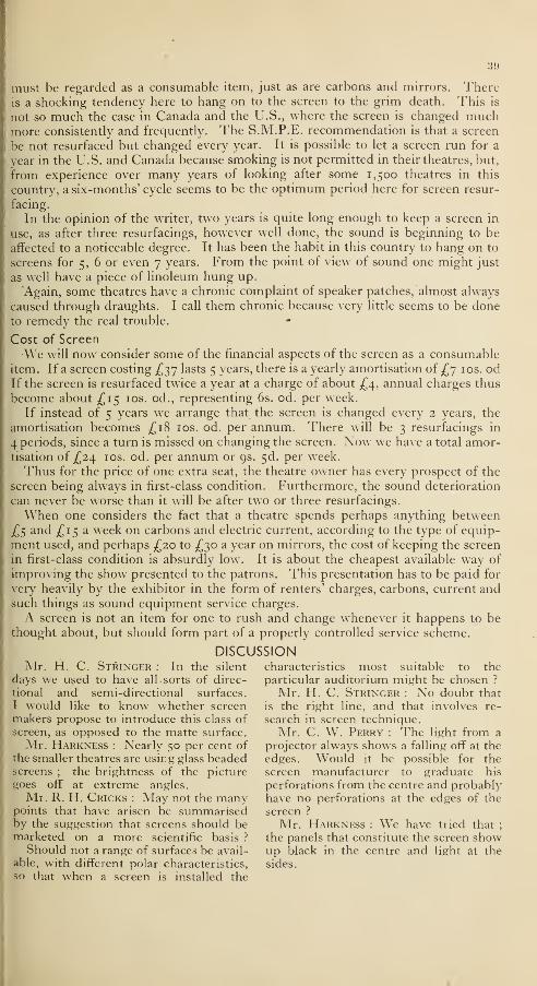
39
must be regarded as a consumable item, just as are carbons and mirrors. Thereis a shocking tendency here to hang on to the screen to the grim death. This is
not so much the case in Canada and the U.S., where the screen is changed muchmore consistently and frequently. The S.M.P.E. recommendation is that a screen
be not resurfaced but changed every year. It is possible to let a screen run for a
year in the U.S. and Canada because smoking is not permitted in their theatres, but,
from experience over many years of looking after some 1,500 theatres in this
country, a six-months' cycle seems to be the optimum period here for screen resur-
facing.
In the opinion of the writer, two years is quite long enough to keep a screen in
use, as after three resurfacings, however well done, the sound is beginning to be
affected to a noticeable degree. It has been the habit in this country to hang on to
screens for 5, 6 or even 7 years. From the point of view of sound one might just
as well have a piece of linoleum hung up.
Again, some theatres have a chronic complaint of speaker patches, almost always
caused through draughts. I call them chronic because very little seems to be done
to remedy the real trouble.
Cost of Screen
We will now consider some of the financial aspects of the screen as a consumableitem. If a screen costing £37 lasts 5 years, there is a yearly amortisation of £7 10s. odIf the screen is resurfaced twice a year at a charge of about £4, annual charges thus
become about £15 10s. od., representing 6s. od. per week.
If instead of 5 years we arrange that the screen is changed every 2 years, the
amortisation becomes £18 10s. od. per annum. There will be 3 resurfacings in
4 periods, since a turn is missed on changing the screen. Now we have a total amor-tisation of £24. 10s. od. per annum or 9s. 5d. per week.
Thus for the price of one extra seat, the theatre owner has every prospect of the
screen being always in first-class condition. Furthermore, the sound deterioration
can never be worse than it will be after two or three resurfacings.
When one considers the fact that a theatre spends perhaps anything between
£5 and £15 a week on carbons and electric current, according to the type of equip-
ment used, and perhaps £20 to £30 a year on mirrors, the cost of keeping the screen
in first-class condition is absurdly low. It is about the cheapest available way of
improving the show presented to the patrons. This presentation has to be paid for
very heavily by the exhibitor in the form of renters' charges, carbons, current andsuch things as sound equipment service charges.
A screen is not an item for one to rush and change whenever it happens to bethought about, but should form part of a properly controlled service scheme.
DISCUSSIONMr. H. C. Stringer : In the silent characteristics most suitable to the
days we used to have all -sorts of direc- particular auditorium might be chosen ?
tional and semi-directional surfaces. Mr. H. C. Stringer : No doubt that
I would like to know whether screen is the right line, and that involves re-
makers propose to introduce this class of search in screen technique,screen, as opposed to the matte surface. Mr. C. W. Perry : The light from a
Mr. Harkness : Nearly 50 per cent of projector always shows a falling off at thethe smaller theatres are using glass beaded edges. Would it be possible for thescreens ; the brightness of the picture screen manufacturer to graduate his
goes off at extreme angles. perforations from the centre and probablyMr. R. H. Cricks : May not the many have no perforations at the edges of the
points that have arisen be summarised screen ?
by the suggestion that screens should be Mr. Harkness : We have tried that;
marketed on a more scientific basis ? the panels that constitute the screen showShould not a range of surfaces be avail- up black in the centre and light at the
able, with different polar characteristics, sides,
so that when a screen is installed the

40
TECHNICAL ABSTRACTSCertain of the following abstracts are reprinted by courtesy of Messrs. Kodak Ltd.
Most of the periodicals abstracted may be seen in the Society's Library.
RECOVERY OF SILVER FROM PHOTOGRAPHIC FIXING BATHS ANDOTHER SOURCES.
R. Fusco, Chimica e industria, 24, 1942, pp. 356-358 ; Chem. Zentralblatt , Part II,
1943, P- 598.
Referring to the comprehensive work of R. Stratta on silver recovery from exhaustedfixing baths, the author describes a new method of treating precipitated silver sulphide
with concentrated sulphuric acid by the wet method : Ag 2S + 2H2SO4 -» Ag 2S04 -f-
4SO2 + 4H2O. Silver sulphate is precipitated with Water, and purified by solution in
ammonium hydroxide, filtering the impurities, and precipitation with sulphuric acid.
The yield is 96 per cent. Further amounts are obtained from the mother liquor bytreatment with copper. The very pure sulphate obtained readily yields other silver
salts through the oxide or carbonate. The method is also suitable for recovery of
silver from silver iodide which precipitates in the preparation of certain quaternaryammonium bases : 2R4N -f Ag 2 + H 2 -» 2R4N.OH + 2AgI, where, moreover,the iodine can also be easily recovered : 2AgI -f 2H 2S0 4 — Ag2S0 4 + S0 2 + I2 -f 2H 20.(Translation of the German abstract.) W.R.E.
BRIGHT LIGHT SOURCES.J. N. Aldington, Trans. Illuminating Engineering Soc, 10, January, 1945, pp. 1-22.
A survey is made of tungsten light sources other than household and car lamps. Thegeneral characteristics of tungsten filaments operating in a vacuum or in a gas are
dealt with first, and then the detailed characteristics of lamps having single and doublewound helices, multi-filament lamps and symmetrical sources. R.B.M.
DETERIORATION OF LENSES IN THE TROPICS.Colonial Cinema, 3, March, 1945, PP- 20-23.
A letter from the Kodak Ltd. Research Laboratories is printed describing the deterior-
ation of lenses and giving advice as to its prevention by dessication of the air, airing,
cleaning, avoiding of temperature changes. (Corrosion ; stiffness of movements;
cement " starting "; mould hyphae.) R.S.S.
NEW METHOD FOR INTENSIFYING THE LATENT IMAGE.F. W. H. Mueller and J. E. Bates, J. Phot. Soc. Amer., 10, No. 9, November, 1944,
pp. 586-591, 704.The vapours of some organic acids, such as formic, acetic and propionic, exert an
intensifying effect upon the latent image, but if applied before exposure, desensitisation
is produced. Volatile weak inorganic acids, such as sulphurous acid, have a similar
effect. When the acids are dissolved in non-polar solvents, such as benzene, similar
effects are obtained. Low and medium-speed emulsions are less responsive than high-
speed emulsions, which show speed increases of 200 to 300 per cent with no more than a
very slight increase in fog. This method of intensification does not noticeably increase
the graininess. The extent of speed increase decreases with the age of the film, and fog
is increased with age. When the treated film is held in free air until the acid evaporates,
the. increase in speed is retained for two weeks prior to development. After 12 to 18
months, films are usually unsatisfactory for latent-image intensification. Minutequantities of water vapour are necessary to the process but aqueous solutions of the
acids cause desensitisation. Higher temperatures, reduced pressures, increased con-centration, and circulation of the vapour reduce the time of treatment. The possible
influence of this treatment on other phenomena, such as low and high-intensity reci-
procity-law failure, the Herschel effect, etc., has not been investigated. G.T.E.
TEST FOR EXHAUSTION OF FIXING BATHS.Photographe, 1943, p. 40 ; Photo cinema, 24, 1943, p. 43 ; Chem. Zentralblatt, 114,
Part I, 1943, pp. 2472.To 20 cc. of the fixing bath to be tested are added 3 to 4 drops of a 10 per cent potas-
sium iodide solution. If permanent turbidity occurs, the bath is exhausted. (Transla-
tion of the German abstract.) T.HJ.

41
ITHE SCIENTIST IN WARTIME—II.
E. Appleton, Engineer, 63, November, 30, 1945, pp. 432-433.A high-speed camera developed at the Road Research Laboratory, Harmondsworth,
: Middlesex, enables 59 photographs to be taken at frequencies higher than 100,000 per
« second on stationary film. The camera contains 59 lenses which are exposed by a shutter
disc containing a number of slots. The shutter disc is driven at high speed. (A sub-
sidiary shutter isolates a single revolution of the main shutter disc.—Abstractor.)
E.D.E.
\ PHOTOGRAPHIC RECORDING OF CATHODE-RAY TUBE SCREEN TRACESR. J. Hercock, R. G. Hopkinson, W. F. Berg, and W. Nethercot, Phot. J., Vol. 86B,
1 No. 6, November-December, 1946.
A series of papers on the recording of cathode-ray traces discusses (1) the requirements
of emulsions and developers, (2) fluorescent screen materials, (3) reciprocity failure
- and pre- and post-exposure, and (4) the photographing of high-speed traces.
R fT C' AN IMPROVED FILM DRIVE FILTER MECHANISM., C. C. Davies, J. Soc. Mot. Pic. Eng., Vol. 46, No. 6, June, 1946, p. 454.
Two types of damped compliance film drive are described, having single and doublejockey arms respectively. Electrical equivalent circuits are given together with per-
Iformance details, and an interesting comparison made with an equivalent damped
1 inertia drive. A new design of sprocket is mentioned in which wider teeth minimise> cross-over effect. N.L.
A SIMPLIFIED ALL-PURPOSE FILM RECORDING MACHINE.G. R. Crane and H. A. Manley,^. Soc. Mot. Pic. Eng.
fVol. 46, No. 6, June, 1946, p. 465.
This Western Electric camera incorporates the recently developed double-arm film
drive and the film chamber layout is simple and straightforward. It can be adapted1 for 16mm. film by means of interchangeable sprocket and roller assembly. The driving> motor is enclosed within the camera, and a separate compartment houses the unit-
mounted light valve, optic, and lamp assembly. N.L.
A SIMPLIFIED RECORDING TRANSMISSION SYSTEM.F. L. Hopper and R. C. Moody, J. Soc. Mot. Pic. Eng., Vol. 47, No. 2, August 1946,
p. 132.
The Western Electrical RA-1253 portable recording amplifier and power pack is des-
scribed. A straight 3 -stage amplifying circuit is employed with a new type of peaklimiter using a voltage regulator tube. A noise reduction circuit with the usual controls
is included, and details of performance are given. N.L.
SYNCHRONISATION TECHNIQUE.W. A. Pozner, J. Soc. Mot. Pic. Eng., Vol. 47, No. 3, September, 1946, p. 191.
A survey of early methods of producing foreign language versions of feature films,
including the mechanical methods used in Germany, is given. The various stages in
the process evolved by M.G.M. International Films Corporation are described, inclu-
ding the projection equipment used, and notes on matching acoustic conditions to
visual impressions. N.L.
DUBBING AND POST-SYNCHRONISATION STUDIOS.W. A. Mueller,^. Soc. Mot. Pic. Eng., Vol. 47, No. 3, September, 1946, p. 230.
The studios built by Warner Bros, to fulfil wartime requirements of foreign languagedubbing are described with particular reference to layout and acoustic treatment.
Post-war uses include recording of location scenes to guide track, which is now beingwidely employed in feature production. N.L.
RUSSIAN STEREOSCOPIC FILMS.J. Polyak, Red Fleet, 10th October, 1946 ; S. Ivanov, Pravda, 4th October, 1946 ;
Moskovoski Bolshevik, 19th October, 1946. (Abstracted in the Foreign Office publica-
tion Film News from the Soviet Press.)
Shortly before the war a system of stereoscopy was developed which did not require
any special apparatus to be used by the spectator, and in 1941 it was decided to set up a
special studio for the production of films. An improved stereoscopic screen made of
glass (?) has been prepared measuring 9 square metres, and a number of films are in
production. No stereoscopic films can at the moment be seen. R.H.C.

42
LECTURES ON OPTICS
TN response to requests from the B.K.S. and members of the industry, the Polytech-^ nic, Regent Street, is organising a third refresher course to follow those being held at
present on " Sensitometry and Laboratory Praciice "and" The Fundamentals of SoundRecording." The subject asked for is " Optics " and the lecturer is Malcolm V. HoareB.Sc. The course is intended for those engaged in all branches of the film industrywho use lenses or other optical equipment and find that an understanding of the behaviour of light would help them in their work.The course will consist of 10 lectures to be held on Monday evenings from 6-8 p.m.
at the Polytechnic, commencing on Monday, 14th April. The fee for the course will
be £1 and students should enrol at the Polytechnic on or before that date.
Outline Syllabus
14th April Light and the Spectrum. Units of light measurement.21st April Recording of colour in monochrome. Filters.
28th April Pola screens. Exposure meters. Measurements of light.
5th May Basic laws of optics. Image formation.
1 2th May Lens systems and focusing.
19th May Perspective. Factors affecting the length of an image.26th May No lecture.
2nd June Depth of field and depth of focus in theory and practice.
9th June Errors of lens systems. Coated lenses.
1 6th June Basic types of lens systems. Lens testing.
23rd June Optical systems used in film industry.
J
BOOK REVIEWS
PHOTOELECTRIC CELLS by A.Sommer {Methuen's Monographs on
Physical Subjects). Methuen, 5s. net.
100 pages, 27 Figs.
There is no question as to Dr.Sommer's ability and qualification to
write a monograph on photo-cells, as
he has been engaged on their develop-
ment at Cinema-Television for manyyears. This is an excellent book andsummarises the theory and practical
points on cells in a very readable manner.After the historical introduction, the
theory of photo-electric emission is ex-
plained with the minimum of mathe-matical expressions, followed by a long
chapter on the manufacture and pro-
perties of photo-cathodes. The chapter
on matching light sources and cathodes,
i.e., choosing a cell, is of interest to every
user of these universally (but often
wrongly) used electronic devices.
The comparison between the gas-filled
cell and the vacuum cell is also of parti-
cular interest, as is the comparison be-
tween the multiplier cell and the plain
cell. The final chapter on the applica-
tions can only summarise the principal
points, but there is a table giving the
types recommended for various applica-
tions, and the reader is referred to other
books dealing with this aspect morefully.
The kinematograph engineer who takes
more than a passing interest in the elec-
tronic gadget on which his livelihood
depends should make a point of buyingthis book at the very reasonable price of
5s. G. Parr.
SOCIOLOGY OF FILM bv J. P.Mayer. Faber and Faber, Ltd. 328pages. 15s.
J. P. Mayer has written here a philo-
sophical treatise both ambitious anderud te. It consequently follows that
there is a challenge on every page, andenough material for a brains trust to dis-
agree over for an inordinate number of
sessions.
It is, indeed, the author's search for
esoteric motives for things that can beexplained far more simply that is the factor
likely to provoke most opposition. " Whydo millions go to the picture house ?
"
he asks in his first paragraph, and quotespsychologists as answering that ourmodern populus seeks escape from the
dreariness and mechanisation of ourrationalised lives. But one might equally
ask, " Why reading ? " " Why music ?"
" Why the arts ? " " Why a deck chair onthe beach ? " Is not the short answerthis : " Because we enjoy it "
?
He quotes appreciatively anotherauthor as saying : " The Elizabethans

13
were trained listeners ; where we rely
on the eye and the printed book, they
relied in the ear. . ." He finds this to
be a consequence of " the modernrationalised structure of our lives
"
Surely the superficial reason might be
the right one : that the great art form
of the kinema happened to be invented
in the 19th century and not in the time
of Shakespeare. What our entertainment
is to be in any generation is surely for-
tuitous. In broadcasting, for instance,
the transmission of sound was invented
first. Consequently, people becametrained listeners before they becametrained watchers of television. Theprocess was reversed in kinematography,
not for any profound philosophical
reason, but simply because it so happenedthat invention occurred in that order.
. The author describes in his preface
how he set out to study kinema. Buttruly to understand so vast a subject,
as to understand a foreign people, oneshould live with it and them. Certainly
this book is, as all good books should be,
a challenge to controversy, but many of its
conclusions will find many dissenters.
J. C. Warbis.
ACOUSTICS FOR ARCHITECTS.E. R. Richardson, B.A., Ph.D., D.Sc.
(88 pages, 29 Figs. *j\ X 5 in.).
Edward Arnold & Co. 5s.
Some twelve years ago Dr. Richardsonpublished his Introduction to Acoustics
of Buildings and it is upon this work that
the present book is based. The author
deals with the general principles of
reverberation, resonance, and the be-
haviour of sound waves. He outlines
the various methods of applying acoustic
correction to existing buildings, and gives
general hints on the acoustic design of
auditoria. Some of the author's sug-
gestions for best listening conditions
are not altogether in accord with modernthought ; for instance, he states that the
difference of the lengths of the possible
paths by which sound can reach anauditor from the source should notexceed 70 feet ; some modern authorities
have reduced this figure to 45 feet in
the case of kinema auditoria, with a
possible further restriction where stereo-
phonic sound is employed.The author, however, seeks to give a
general statement of the fundamentalacoustic principles, devoid of mathe-matical complexity, and consequentlythe book will be found useful to architects
and others who have neither time norinclination to make a close analysis of
this complex subject. L. Knopp.
DEFECTIVE COLOUR VISION ININDUSTRY. Report by a Committee
of the Colour Group of the Physical
Society. Taylor and Francis, Ltd.
2s. dd.
A special Committee of the Physical
Society Colour Group was appointedin February 1942 with the following
Terms of Reference :
" To obtain as complete information
as possible as to the technique and pro-
cesses in which deficiencies of colour
vision are a handicap, to report on exist-
ing methods of testing such deficiencies
in Industry and in Schools, and to makerecommendations regarding the improve-ment and co-ordination of these tests."
A report by this committee has nowbeen published which merits careful
study by those concerned with problems of
colour perception at the many stages in the
production of motion pictures in colour,
which begin in the research laboratory of
the manufacturer and end in the pro-
jected picture.
Eight per cent of the male population
have defective colour vision but less than
one per cent of women are deficient.
Defic encies in colour sensation are
divided into three categories :
(1) Those who possess no colour dis-
crimination, known as Mono-chromats. These are extremelyrare.
(2) Those with reduced colour dis-
crimination who can match all
colours with two radiations, knownas Dichromats.
(3) Those who require three radiations
for matching all colours but makematches markedly differing fromthe normal. Known as AnomalousTrichromats.
Groups 2 and 3 are each sub-divided
into three sub-types. There are three
times as many Anomalous Trichromatsas Dichromats, the latter being some twoper cent of males.
The so-called confusion colours of
the colour-blind are green, yellow, orange,
red, brown, pink, etc. The mostcommonly confused colours are red fromyellow, and yellow from green—especially
in the absence of any brightness differ-
ence. Other colours which tend to be
confused are blue-green, grey and purple.
Usually the defect does not lead to much

44
difficulty in distinguishing green fromblue-green, blue-green from blue, yellowfrom grey, or grey from blue.
Since persons with defective vision
confuse certain colours with one anotherall tests used for the detection of defi-
ciency are based upon this phenomenon.The Committee recommend as reliable
the well-known Confusion Chart Testsfor most industries and trades. Thesetests are composed of a series of cards onwhich are printed backgrounds of
coloured spots the sizes of which are
carefully chosen, and interspersed amongthese background spots are figures,
letters, or other shapes, also made of
coloured spots of suitable size. Thesemust be recognised in order to pass the
test.
The existence of a small proportion of
colour deficients in audiences is a matterof no consequence since the appearanceof a colour picture which is acceptable
to normal vision will closely, if notexactly, resemble the appearance of the
world with which the colour deficient
is familiar. A dichromat would, how-ever, probably not perceive the closer
approximation to truth of the rendering
of a three-colour process to that of a
two-colour process.
The report makes no mention of the
motion picture industry, and the fact
that no evidence was obtained as to the
proportion of operatives concerned withcolour, nor of any tests at present applied,
seems an unfortunate omission. Para-
graph 6 under Section B (Industry)
briefly refers to " Photographic In-
dustries." It is stated that " In photo-
graphic colour processes firms reportthat they deem special tests to be un-necessary, as the number of workersconcerned is very small, and colour-weak subjects automatically avoid this
work." The reviewer takes strong ob-jection to this statement. Indeed,tests should be regarded as absolutely
essential for the following engaged in
colour film production :
Studio.—Cameramen ; Directors ; Artdirectors ; Editors ; Cutters ; Artists,
model-makers, painters, costumiers;
Make-up artists ; Title designers anddraughtsmen ; Still photographers.
Laboratory.—Graders ; Sensitometriccontrol and testing ; Cutters ; Optica]
Printers ; Foremen developers andprinters ; Viewers in projection depart-
ment ; Title camera operator.
It would seem highly desirable that
the B.K.S. should afford facilities for a
test and this would best be carried outby means of, say, the Ishihara confusion
charts (9th British Edition), it beingadvisable that the examinations shouldbe made by someone competent to drawdependable conclusions from the appli-
cants' replies.
The report is the work of some of the
outstanding authorities on colour vision
in Britain, and the committee membersmust be congratulated on having madean important contribution to the exten-
sive literature of defective colour vision.
It is to be noted that the work wasaccomplished in London during the warand the Colour Group of the Physical
Society have just cause for pride in this
achievement. A. Cornwell-Clyne
PERSONAL NEWS OF MEMBERSMembers are urged to keep their felloiv members conversant zvith their activities through the
medium of the Journal.
D. G. Daggett has joined British
Tricolour Ltd. where he is working oncoloured cartoons.
T. S. Lyndon-Haynes is Assistant
Director at Ealing Studios.
Flight-Lieutenant Miller is under-
going a specialised course in photography
and kinematography at No. 1 R.A.F.
School of Photography.C. W. Perry has retired from the
Ship Carbon Company.Jack Ramsden has just returned to
this country after a survey of India and
the Middle East on behalf of British
Movietonews Ltd.
C. F. Trippe, since 1927 manager of
sound reproducer sales to B.T.H., has
retired.
Eric Williams of Ealing Studios has
just returned from a visit to Palestine.
R. Gillespie Williams is Vice-
President of the Delicolor Corporation,
an American company formed to com-mercialise his new stage lighting system.
EDWARD GODALDied 3rd December, 1946
Mr. Godal entered the film industry in 1916,
and two years later became interested in the
old-established British and Colonial Kinemato-
graph Co., of which he later became chairman
and managing director. More recently he had
been managing director of British Fine Arts
Pictures Ltd., and of Mobile Cinema Services,
Ltd., and had been keenly interested in the
nearly completed Glenbuck Studios, Surbiton.

45
THE COUNCILSpecial Meeting of 30th October, 1946
Present : Messrs. I. D. Wratten {President), W. M. Harcourt {Vice-President),
E. Oram {Hon. Secretary*), P. H. Bastie {Hon. Treasurer), C. Cabirol, R. B. Hartley,L. Knopp, A. W. Watkins, A. G. D. West {Past President), W. Buckstone {representing
Sub-Standard Division), B. Honri {representing Film Production Division), and R. H.Cricks {Secretary).
Fellowship.—Messrs. George Burgess and A. H. C. Rouse were appointed scrutineers
in the ballot for the first fifteen Fellows.
Five-year Plan.—Proposals for a five-year plan of progress were received from thefollowing committees :
Theatre Division.
Sub-Standard Division.
Film Production Division.
Education Committee.Library Committee.Foreign Relations Committee.Journal Committee.
Consideration was given to the requirements of staff and finance, and also to an im-proved system of accountancy. It was agreed that the Secretary should collate thevarious proposals which should be further considered in detail by the Council.
Meeting of 6th November, 1946
Present : Messrs. I. D. Wratten {President), P. H. Bastie {Hon. Treasurer), R. B.Hartley, L. Knopp, A. W. Watkins, A. G. D. West {Past President), C. H. Bell {repre-
senting Theatre Division), B. Honri {representing Film Production Division), and R. H.Cricks {Secretary).
Five-year Plan.—Detailed consideration of proposals for a five-year plan of progresswas remitted to a special meeting of the Executive Committee.
Fellowship.—It was decided that the names of those Members elected to the Fellow-ship should be announced at the general meeting of November 13th.
Library.—Mr. Hartley reported that as a result of his recent circular letter a numberof books and donations had been received for the Library. Thanks were conveyedto Mr. Bohm for a book-plate which he had presented.
Film Mutilation Committee.—The President briefly reported the meetings of the FilmMutilation Committee held on the 1st and 23rd October.Data Book.—The President reported negotiations for the production of a data book.
The following committee was appointed to advise on the subject : Messrs. Wratten,West, Knopp, and Honri.
Branches.—At the request of the Theatre Division Committee, brief consideration
was given to the constitution, territory and membership of branches.
Membership Qualifications.— It was agreed to instruct the Membership Committeeto prepare regulations on the qualifications needed for Membership and Associateship.
Sub-standard Film Division.— It was reported that the Committee of the Sub-standard Film Division had appointed a sub-committee on " 16mm. Projection," underthe chairmanship of Mr. H. S. Hind, and that the sub-committee, on " Film Distribu-
tion," under the chairmanship of Mr. W. Buckstone, had been re-formed.
Test Films.—In response to representations from the Sub-standard Film Division, it
was reported that the British Standards Institution had obtained 35mm. test films
from America, and it was hoped that 16mm. copies of these films could be made in this
country.
It was agreed to ask a sub-committee appointed by the Theatre Division Committeeto submit recommendations regarding the requirements of sound test films
Leaders and Run-outs.—Representations frcm the Sub-standard Film Division werereceived, urging that publication of standards for leaders and run-outs should beexpedited.
Co-operation with Trade Unions.— It was agreed that co-operation similar to that
existing with the Association of Cine-technicians should be offered to other Unions shouldthey so request.
Journal.—Further consideration was given to the proposal that monthly publication
of the Journal be instituted.

40
Meeting of 4th December, 1946
Present : Messrs. I. D. Wratten {President), W. M. Harcourt {Vice-President),
E. Oram {Hon. Secretary), P. H. Bastie {Hon. Treasurer), C. Cabirol, C. H. Champion,R. B. Hartley, L. Knopp, S. B. Swingler, A. W. Watkins, A. G. D. West {Past President),
C. H. Bell {representing Theatre Division), W. Buckstone {representing Sub-standardDivision), B. Honri {representing Film Production Division), and R. H. Cricks {Secretary).
Co-operation zcith Trade Unions.—Major Bell reported that he had discussed withMr. T. O'Brien, Secretary of the National Association of Theatrical and Kine. Em-ployees, proposals for co-operation with the B.K.S.
Journal.—The proposal of the Executive Committe, that the Journal be publishedbi-monthly from January, 1947, and monthly from July, was agreed unanimously.The Journal Committee was asked to submit an estimate of cost.
Five-year Plan.—The five-year plan submitted by the Executive Committee wasconsidered in detail.
Papers Committee.—It was agreed that the Papers Committee should be re-elected
at the January meeting of the Council and should forthwith meet to plan the lecture
session for the 1947-48 session. It was proposed that when the Journal was publishedmonthly, notices of meetings might be sent with the Journal.
Technical Committees.—The work of the various technical sub-committees of the
Divisions was briefly surveyed.
Educational.—Mr. West reported that, as Chairman of the Education Committee,he and the Secretary were shortly attending a meeting at the British Film Producers'
Association to consider closer co-operation in the provision of educational facilities.
Branches.—The recommendation of the Executive Committee that the Constitution
Committee should prepare a draft constitution for Branches of the Society was accepted.
Film Mutilation Committee.—The President reported that an interim report of film
mutilation had been prepared, for submission to the C.E.A. and the K.R.S.Foreign Relations.—The Vice-president reported that he had contacted the President
of the Association Frangaise des Ingenieurs et Techniciens du Cinema, who would welcomeco-operation with the Society.
EXECUTIVE COMMITTEE
Meeting of November 6th, 1946
Present : Messrs. I. D. Wratten {President), P. H. Bastie {Hon. Treasure)), R. H.Cricks {Secretary).
Membership.—The following were elected :
Anthony Squire (Member), Anglo-Scottish Pictures, Ltd.
Edward Taylor (Associate), Star Cinema, Blackburn.
John Errol Rankin McDougall (Associate), Associated Screen Studios, Montreal,
Canada.Cyril Ronald George Kirk (Member), Mole-Richardson (England), Ltd.
Leonard John Hewins (Member), Mole-Richardson (England), Ltd.
Basil Tolson Wedmore (Member), Western Electric Co., Ltd.
Allan Alexander Hall (Student), Pathe Pictures, Ltd.
John A. S. Turner (Associate), Pathe Pictures, Ltd.
F. Sellman (Member), Radiant Films, Ltd.
Sidney George Rider (Associate), Merton Park Studios.
Hal Mason (Member), Ealing Studios, Ltd.
Horace George Mason (Member), Hastings-Hodgkins, Ltd.
Dennis Vivian Sumpter (Member), G.B.-Kalee, Ltd., Cardiff.
Peter Noel Bishop (Student), Ultra Radio.
Howard Colin Jones (Student), Polytechnic, Regent Street.
William E. Kelly (Student), Polytechnic, Regent Street.
James Black Sloan (Associate), G.H.W. "Productions, Ltd.
Frank Daniel Walter (Associate), M.G.M. British Studios.
Hector Vincent Williams (Associate), M.G.M. British Studios.
Edward Harold Viveash (Associate), Crown Film Unit.
Derrick Edmund Timmins (Associate), Gaumont British News.Thomas Edward Francis Cadman (Member), G.B. Instructional, Ltd.
Jack Browning Saunders (Member), Unifilm Studio, Ltd.

47
Frank Trevor Jones (Associate), General Electric Co., Ltd.
[William John Hart (Student), Polytechnic, Regent Street.
>Krishna Gopal (Associate), Bombay.Robert Graham Bell (Associate), G.B.-Kalee, Ltd. (Glasgow).
Robert Thomas Trumble (Associate), Gainsborough Pictures (1925), Ltd.
.William Frederick Girdlestone (Associate), General Film Distributors, Ltd.
Gordon Salmons (Student), Radio Mechanic, R.E.M.E. (formerly Clifton Cinema,Birmingham).
Arthur Paul Fletcher (Associate),
Derek James Pounder (Student), Polytechnic, Regent Street.
Arthur Frederick Kershaw (Associate), Jones Bros., Ltd., Blackpool.
Rex Eisenstadt Ensleigh (Student), Concord Productions, Ltd.
John Blyth (Associate), The Playhouse, Perth.
Lovat Halket Cave-Chinn (Member), British Paramount News.The following Associates were transferred to Membership :
James Walker Budge, Scottish Electric, Ltd.
Sidney Robert Deards, Picturedrome, Bedford.
Bertram Sinkinson, English Electric Co., Ltd.
Charles Thomas Parkhouse, Kay Carlton Hill Studios.• Percival George Smith, Regal Cinema, Torquay.Allan Terence Sinclair, RCA Photophone, Ltd.
The following Student was transferred to Associateship :
Anthony Frank Hinds, Exclusive Films.
The following resignation was accepted with regret :
F. W. Hirst (Associate).
Deaths.—The deaths of the following were recorded with regret
! J. Hutchins (Member).R. Ingram (Associate).
|E. Lauste (Member).
Special Meeting of 20th November, 1946
Present : Messrs. I. D. Wratten {President), P. H. Bastie {Hon. Treasurer), R. HCricks {Secretary).
Journal.—The desirability of monthly publication of the Journal was fully agreed. It
was suggested to recommend to the Council that bi-monthly publication be instituted
from January, 1947 and monthly publication from July. Other activities of the Society
1 should, if necessary, be reduced to a minimum to make such publication possible.
Five-year Plan.—Draft of a five-year plan of progress was agreed for submission to
the Council.
Branches.—It was agreed to recommend to the Council that the Constitution Com-mittee should be asked to prepare a draft constitution for Branches.
Awards.—Mr. Wratten reported that a member of the Council who wished to remainanonymous had offered to present a gold medal for the best paper read to the Society,
1 or published in the Journal during Mr. Wratten's term of office.
Meeting of 4th December, 1946
Present : Messrs. I. D. Wratten {President), W. M. Harcourt {Vice-President),
P. H. Bastie {Hon. Treasurer), R. H. Cricks {Secretary*).
Elections.—The following were elected with effect from July, 1946 :
Raymond Albert Mustow (Associate), Mole-Richardson (England), Ltd.
Desmond Cockburn Dickinson (Member), D. & P. Studios.
Norman Alfred Prouting (Student), Polytechnic, Regent Street.
Frank Charles Littlejohns (Associate), Technicolor, Ltd.
John Lennox Kincaid Hall (Associate), Technicolor, Ltd.George Hirehouse Newton (Associate), Technicolor, Ltd.
John Alfred Clark (Associate), Denham Laboratories.
The following were elected with effect from January, 1947 :
Cyril Jack Phillips (Member), Pathe Pictures, Ltd.
John Francis Gooding (Associate), Universal Car Co., Ltd.Albert John Graham (Associate), Cinetechnic, Ltd.Richard A. Smith (Member), Merton Park Studios.
John Denton (Associate), Princes Theatre, North Shields.

48
Albert Charles Hammond (Associate), Merton Park Studios.
Guy Spencer Baker (Member), Paramount Pictures Theatre Circuit.
Frederick Edwin Bowles (Associate), Ernest F. Moy, Ltd.Miss Elfra Lorraine Prideaux (Associate), Religious Films, Ltd.
John Charles George Speller (Member), Ealing Studios, Ltd.Harold Herbert Hooper (Associate), Film Producers' Guild.Darrel Charles Catling (Member), G.B. Instructional, Ltd.Charles Edwin Perry (Member), Odeon Theatres, Ltd.Leslie Horace Edwin Dunk (Associate), Pathe Pictures, Ltd.
John Gordon Doncaster (Associate), Kay Film Printing Co., Ltd.Colin Bell (Associate), G.B. Instructional Films Ltd.
Leonard Reginald Joffre Johnson (Member), Cinema-Television, Ltd.Transfers.—The following Associates were transferred to Membership :
Eugene Hague, Technicolor, Ltd.
Adolph Iredell Morgan, Ministry of Supply.
Donald William Aldous, Walden Films, Ltd.
Gordon Alexander D. Rennte, Pathe Pictures, Ltd.
Harry Smith, Ilford, Ltd.
Resignations.—The resignation of Mrs. Powell was accepted with regret.
Fellowship.—The names of Fellows elected at the meeting of the 13th Xovembewere noted. (See p. 721 of the October-December Journal).
JOURNAL OF THE BRITISH KINEMATOGRAPH SOCIETYCopies of most of the back issues of the Journal and of Divisional Proceeding
are available, price 5s. 3d. post free, or 15s. per volume (four issues).
PROCEEDINGS OF THE BRITISH KINEMATOGRAPH SOCIETYPrior to the inauguration of the Journal, papers read to the Society were re
printed in 8. K.S. Proceedings. Nearly complete sets"(l 93 I to 1936) are available
price 10s.
STABLEFORDSCREENS LTD.
WE make metal, flat OUR screen re-surfacing
white, rear, projection, service covers Great
roll-up and amateur Britain from Aberdeen
screens. toLand'sEnd.
1 MiliiMM. STREET. i.OMIOV. W.I I
PHONE PARK 7682

Wright Field Reference Library
Main Branch
THE JOURNAL OF THE
BRITISH (CINEMATOGRAPH SOCIETY
Vol. 10. No. 2. MARCH and APRIL, 1947
LECTURE PROGRAMME, 1947/8
The Papers Committee is arranging the programme of meetings for the
1947/1948 session, and is open to consider proposals from Members who maybe prepared to read a paper at either the Society or Divisional meetings.
The proposal should be accompanied by a synopsis giving sufficient detail
to enable the Committee to determine whether the paper is suitable for inclusion
in the forthcoming session. The proposals should reach the office of the Society
not later than 25th April, 1947.
Information for the guidance of authors in the preparation and submission
of papers is obtainable from the Secretary on request.
Attention may, however, be drawn to the Committee's decision that
Society Meetings will be of a higher scientific and technical character than
hitherto, and that Divisional meetings will be of a more popular and demonstrativenature.
L KNOPP,Acting Chairman, Papers Committee.
PHYSICAL SOCIETY EXHIBITION
This exhibition, which is being held this year in the Department of Physics,
Imperial College, South Kensington, on the 9th, 10th, Nth, and 12th of April,
usually attracts a large number of visitors.
The B.K.S. is arranging an exhibit showing some examples of motion picture
equipment as used for scientific research. In addition some examples fromresearch films are being shown on the screen. The Physical Society has provided
us with the Small Lecture Theatre for this display and members of the B.K.S.
and their friends have loaned the special equipment which is to be shown.
Our Society is performing one of its proper functions in sponsoring this
exhibit, and as a result we can expect an increased interest in the use of the
motion picture among research workers.
There is a need for volunteers to assist and in particular we require memberswho can spare a little time during the period of the exhibit, and are able to
discuss the possibilities of the motion picture with visitors. A rota of B.K.S.
members who can attend during the four days is being prepared by the Secretary
and those able to help should get in touch with him as soon as possible.
The B.K.S. has only a small number of tickets and these will be available to
helpers.
W. BUCKSTONE.
Members are requested to note change of telephone number to
GERrard M54/5 (2lines).
Property of ITsTl
-f2 * 7
' 7 <T

58
AUDITORIUM REQUIREMENTS IN SOUNDFILM PRESENTATION
The Theatre Division Committee appointed two Sub-committees to prepare reportson the requirements of auditorium design, from the aspects of picture projection andsound reproduction respectively.
I.—PICTURE PROJECTIONR. E. Pulman (Fellow),* J. L. Stableford (Member).t
and H. P. Woods (Member).i
Read by I. D. Wratten, F.R.P.S. (Fellow), to the British Kinematograph Society
on March \3th, 1946, and by Mr. Pulman to the Newcastle-on-Tyne Section of tht
Theatre Division on January 7th, 1947.
THE presentation of kinematograph sound films in auditoria has beenmade possible by the use of scientific phenomena which can be perceived
by the senses of sight and hearing.
It would be reasonable to suppose that those concerned in the design of
auditoria would have given due consideration to the physiological requirements
of the eye and ear mechanisms so that both might receive the intelligence
conveyed to them by sound films in conditions of reasonable comfort, but,
unfortunately, such procedure does not seem to have been the rule in the past.
It would be difficult, and perhaps unfair, to attempt to apportion the blamefor this lack of consideration, for kinema architects and engineers are not
physiologists, and if their past endeavours have not appealed to those learned
in physiology, then perhaps the latter might have been expected to tell themwhy. It may be that the physiologists are not at all certain what minimumstandards are desirable.
This paper deals only with the effect of sound films on the organ of sight,
and the authors must therefore confine themselves to the problems of genera-
tion and transmission of light in so far as this is used for the projection of
kinematograph films. They wish to emphasise, however, that in the absence
of acknowledged physiological standards for such work they do not seek to set
up such standards, but merely to review suggestions made in this and other
countries, and to relate these to the performance limits of kinema projection
equipment.
Standardising Screen Brightness
The fact that a committee of the British Standards Institution, dealing with
one of the most important aspects affecting this subject, i.e., desirable limits
of kinema screen brightness, has resumed deliberations interrupted by the
outbreak of war, might be advanced as an argument that the authors are
premature in putting forward this paper, and that consideration should be
deferred until some authoritative standard of screen brightness is available.
But their reply is that, first, it may be some considerable time before a B.S.I,
standard can be set up, if we appreciate the difficulties involved which were
quoted by E. Oram in an address to this Society on the occasion of the
inauguration of our Theatre Division 1; secondly, despite the probability that
kinema building and re-building, apart from special cases, may continue to be
prohibited for two years or even longer, it is undoubtedly the case that much
* G.B. Picture Corporation, Ltd.
f Stableford Screens, Ltd.
t Ship Carbon Co. of Great Britain, Ltd.

Wright Field Reference Library
Main Branch
59
design work is in hand ; thirdly, it is believed that, in many kinema theatres,
existing very poor physiological viewing conditions could be improved in
greater or lesser degree if more information were made available to those
concerned ; and, lastly, it is thought that sufficient information is available
and can be summarised to indicate, even within broad limits, the conclusions
likely to be arrived at by the B.S.I. Screen Brightness Committee on that
particular problem.
Six Essentials
The authors submit that in the design of kinema auditoria, the architect andthe engineer (and the work of both is of equal importance) should have regard
to six main points so as to ensure :
1. Clear vision of the entire picture area from every seat.
2. Minimum distortion of the picture image both in projection and in viewing.
3. Auditorium dimensions suited to practicable picture area.
4. Provision of adequate and consistent screen illumination with proper dis-
tribution over the picture area.
5. Carefully arranged surroundings to the picture area.
6. Correct choice of screen.
I. CLEAR VISION OF PICTURE AREAThe first item, that of clear vision of the picture area from every seat, may
appear at first glance to be too obvious to be worth mentioning ; nevertheless,
it is surprising to find in some of the most modern super-kinemas that the seat
spacing arrangements are such that a full view of the picture area is restricted
by the heads and shoulders of those sitting immediately in front. This is
a matter for the architect, though his possible solution of more steeply rakingthe seating may well be negatived by the engineer's requirements in connectionwith the angle of projection (to be dealt with later), so that some compromisemay be necessary. But this question of clear vision is one which deserves close
attention, since the goodwill of kinema patrons may be adversely affected.
The authors feel that insufficient attention has been paid to the properplanning of seating. If the seats are scientifically staggered it will enable theramp angles to be reduced by nearly one-half, and yet still give unhinderedviewing for each patron. This has more important advantages than would at
first appear. Obviously, it eases the constructional problems, but moreimportantly, it can be of great help to the sound engineers.
Volume of Auditorium
Although this paper is not intended to deal with the latter aspect, it mayperhaps be permitted to make an observation which is relevant to projection
problems. Acoustic engineers are constantly dealing with the problem of
reverberation, and excessive cubic capacity makes it difficult to keep this
within acceptable limits.
The ideal to aim at is thought to be approximately 120 to 130 cubic feet
per seat. A steep ramp and a high dome will increase the cubic capacitymuch above this figure, so that with a shallower ramp, the architect is enabledto keep the height, and thus the cubic capacity of his auditorium, very muchreduced.
To be perfect, it would be necessary to stagger each seat directly in relation
to its position, but this is quite unnecessary, and group staggering for variousparts of the auditorium can be arranged without great difficulty.
One objection to staggered seats is the serrated gangway which would beproduced, of which the Authorities may disapprove. It should not be difficult,
however, to attach to the flanking seats a tubular iron member which would

60
have the effect of keeping the gangway a straight line.
If the scientific aspect of staggered seating is taken to its conclusion, it will
be found that in many cases the auditorium floor could have a negative rampfor the first rows of seats, thus again reducing the high ramp and cubic capacityproblems.
2. MINIMUM DISTORTION OF IMAGE
The second item, that of providing for minimum distortion of the picture
image, both in projection and viewing, requires the projection enclosure to becentrally disposed to the screen in both horizontal and vertical planes, with
the projector mechanisms mounted accordingly. Assuming, as is usual,
a strictly perpendicular screen surface, a line joining the centre of the film
mechanism gate and the centre of the screen should be at right angles to both,
or, as it is usually termed, the projection angle should be zero degrees.
This, given correct projector working conditions, provides distortionless
projection of the image, but is an ideal which is impossible in practice, since
two projectors at least are required, and additionally it is usually necessary
ACTUAL HORIZONTALDIMENSIONS OF PICTURE
l— 25V—
J
Fig. I. Effect of Projection Rake, illustrating " out-of'-focus"
and'
' keystone'
' effects.
to site the projection enclosure well above a line drawn at right angles to the
screen centre. The projection angle in the vertical plane then becomes
negative, but distortion from this source is reasonably slight and hardly
discernible up to about 12 degrees ; however, with an increasing negative
angle above this figure, distortion rapidly becomes intolerable. Such a
projected image as viewed on the screen is never a rectangle, but a trapezoid,
and if the projection angle in the horizontal plane is other than zero the shape
changes to a trapesium, introducing distortion in two planes.
Even if the Licensing Authority would permit the siting of the projection
enclosure under and to the front of the circle, thus providing both a zero
projection angle and better facilities for improved rake of seating, this would
not necessarily be a satisfactory solution, because, contrary to general belief,
the distance from projector to screen can be too short, involving the use of
projection lenses of very short focal length, which has certain technical
disadvantages. The authors suggest that the length of the projection beam,
or throw, should be not less than 4.7 times the picture width.
Projection Rake
The authors would like to offer a basis of discussion on projection without

61
rake. It is not popular, perhaps chiefly because its practical difficulties havenot been solved.
To produce a flat rake, almost inevitably it means that the projection
enclosure must be at the back of the stalls and the ray just clear of the bottombalcony. This produces two drawbacks : firstly, it interferes with the dis-
position of the entrance hall or foyer, and secondly, the light ray suffers morethan ever from absorption and reflection by smoky atmosphere. The former
is a problem for the architect to solve, and the latter might be eliminated
largely by trunking carried from the balcony, enclosing the ray and slightly
pressurised. So that the apparent height of the balcony is not reduced this
trunking could be of transparent material, such as Perspex. We know this
type of projection has been tried in a number of kinemas and has not provedpopular, but only because the above drawbacks have not been dealt with.
One possibility would give a projection enclosure and rewind room underthe balcony level and in order to give side entrances to the stalls, the rectifier
room, battery room, and rest room could be placed on a second floor of a self-
contained suite.
In a kinema with an admittedly high rake of 25 degrees and a picture
24 feet in width, the top is focusing 7 feet in front of the bottom of the picture.
With a more normal rake of 15 degrees this distance is 5 feet. With no rake
the picture would focus all in the same plane. With 2 degrees or 3 degrees
positive rake the displacement would be only 9 inches.
3. AUDITORIUM DIMENSIONS IN RELATION TO SCREEN*
The third requirement, that auditorium dimensions should be suited to
the practicable picture area, is very important from the physiological angle.
There must, of necessity, be some relationship between the picture area and the
maximum and minimum distances from the screen to the viewer. If this
distance is too great for a given picture area, the viewer will find difficulty in
observing detail ; if the distance is too short the eye is unable to focus on its
retina the full picture area, and physical movement of the eye may be required
to follow the movement of the screen characters. The bad effects on both eyeand brain in such conditions are well summarised by Dr. D. T. Harris in anaddress to this Society 2
.
While not putting forward any recommended minimum distance betweenscreen and viewer, Dr. Harris suggested that the maximum distance should be6.0 times the picture width, and this figure is only a little in excess of the
figures of 5.2 to 5.8 recommended by the Society of Motion Picture Engineersof America. For the minimum distance the S.M.P.E. suggests a factor of 1.0
as the relationship between picture width and distance of the nearest seat, andthis figure fits in very well with a requirement imposed by the London CountyCouncil and other licensing authorities, and designed to prevent eyestrain
arising from too close a proximity to the screen. Taking the more favourableof the suggested maximum distance factors, 5.2, a viewing angle of about 11
degrees solid angle from the most distant seats results, while the solid viewingingle from the nearest seat, accepting the factor of 1.0, is found to be aboutU degrees.
From a study of vision threshold and the visual angle for binocular vision,
:hese figures allow for comfortable viewing conditions.
Viewing Angle
This conclusion, however, is for seats on the centre line of the screen or
iiibtending an angle of not more than 1 degrees. Outside this angle distortions apparent and is at a maximum at the extreme ends of the front row of seats.
)r. Harris suggests that seats in these positions should subtend an angle of

62
not more than 30 degrees with the centre line of the screen, and that the widthof the rear row of seats be not more than six times the picture width, but hestipulates that the 30 degree maximum should be used only with good illumina-
tion and a good diffusing screen. (Fig. 2.)
Theoretically, the ratios which have been suggested would seem to imposeno limitation on auditorium size, but this is not the case, as will be seen by anexamination of the fourth requirement calling for the provision of consistent
and adequate screen illumination with proper distribution over the picture
area.
4. ADEQUATE PICTURE ILLUMINATION
At the present time the normal source of illumination for standard kinemato-graph projection is the carbon arc. This source of light has a wide range of
NEAREST SEATNOT LESSTHANW FEET N
THROW NOTLESS THAN47"A' FEET
PICTURE WIDTH"A
- FEET
FARTHESTSEAT NOTLESS THAN52V FEET
Fig. 2. Optimum Proportions of Auditorium.
intensities, making it suitable for the satisfactory illumination of most sizes
of kinema screens met in common practice. The size and type of arc used
governs the ultimate luminous output of the projector, which in turn limits
the size of the screen which can be adequately illuminated.
The light on the aperture, and ultimately on the screen, depends on twofactors :
(a) The intrinsic brilliancy of the crater.
(b) The physical size of the crater.
The intrinsic brilliancy of the crater depends on the type and composition
of the carbon used, and also on the current density, the latter being of great
importance if the arc is to give its best results. All carbon electrodes for arc
lamps are designed to be burned between specified maximum and minimumamperages. The variation in light output between these ratings, particularly

63
n the case of high-intensity carbons, is quite pronounced, and when arcs are
run below their minimum ratings, the light output has usually become very
poor in quality as well as quantity.
In the graph of Fig. 3, showing the variation in total light output of anSmm. H.I. arc lamp, it can be seen that at the minimum amperage of 56 the
total screen light is approximately 75 per cent, of the light obtained at the
naximum current of 65 amperes. Because of this fact it is usually necessary
:o burn arcs at or near their maximum rating to obtain a satisfactory illumina-
:ion of large screens.
.ight Distribution
In the case of H.I. arcs the brilliancy varies across the positive crater and is
isually at its highest value near the centre. This variation in brilliancy has
some effect on the distribution of light across the screen and in general pro-
luces greater illumination at the centre of the picture.
With low-intensity arcs the brilliancy is practically uniform over the crater,
producing a flatter screen distribution. However, with all arc lamps the
listribution of screen
llumination is governed
o quite a large extent by;he position of the arc with
espect to the focus of the
optical system of the lamp.
:Several factors govern
;he light output of the pro-
ector, the main ones being
he angle of collection of
he optical system of the
ire lamp, and the optical
peeds of the projection
ens and the arc lamp)ptical system.
ti m.m. HI.POS
10,000 _
9.000
8,000
7000
6,000
s.ooo 1
Fig. 3.
60AMPERES
Light Output of H.I. Arc Lamp using 8 mm.Positive Carbon.
"ypes of Arcs 55
The types of carbonLrcs in general use fall
nto the following mainategories :
(a) Low Intensity.
(b) High Intensity at medium amperages.
(c) Small H.I. at high current densities.
(d) Rotating H.I. arcs not copper coated.
(e) Alternating current arcs.
The table indicates the luminous output of some typical arc light sources,
howing the brilliancies of the craters with the total luminous output fromhe arc. The luminous output of the complete projector is much less than the
otal output from the arc itself. This is due to the fact that the collecting
ystem of the arc lamp does not pick up all the light from the arc, and several
dditional losses occur.
It should be noted that the figures quoted in the preceding table are thosebtained regularly in general practice and are not the maxima which can beeached. Research and development are already producing brilliancies of
higher order, to enable greater light output to be obtained from the carbonre lamp.

64
Incident and Reflected Light
Consistent illumination needs only short reference as it is easily obtainable
by the use of modern projector arc lamps, using proper carbon combinationsunder correct electrical conditions. The provision of adequate illumination
is, however, quite another matter. Until such time as the B.S.I, committeereaches conclusions, it is suggested that we should adhere to the S.M.P.E.standard of brightness and endeavour to obtain at least the minimum laid
down under this.^
The latest revision of the S.M.P.E. standard requires that the picture should
have a centre brightness of between 9 and 14 foot-lamberts. Screen illumina-
tion is more generally detailed in foot-candles, covering a measure of the
incident light, and unless the difference is clearly understood confusion arises.
The foot-lambert, equalling one lumen emitted per square foot, makesallowance for the reflection factor of the screen surface. If this be accepted as
averaging 70%, then a foot-candle or incident ray reading taken at the centre
of the screen should give between 13 minimum and 20 maximum, as comparedwith the aforementioned figures.
Positive Negative Amps Volts Lamp
LB.Candles/mm 2 Total
FluxLumens
Crater
dia.Mean Max.
13mm. L.I.
Ilmm. HI.
cc.
8mm.SUPREX
13.6mm.HI.
8mm.
9mm. LI.
8mm. HI.
7mm. III.
11mm. HI.
A.C.
35
85
65
140
90
50
36
40
68
27
90°
Angular
90°
Angular
Horizontal
45°
Angular
Horizontal
180
260
430
615
340
190
350
690
800
380
39,700
210,000
180,000
650,000
150,000
8.5mm.
7.5mm.
7.1mm.
11.5mm.
5.0mm.
Auditorium Proportions
We are now in a position to specify what this standard means to the
architect. To obtain the minimum recommended brightness when using
equipment giving the maximum light output now possible, the engineer mustnot be called upon to illuminate a picture size in excess of 24 feet in width.
This figure permits the use of previously suggested factors to determine certain
desirable maxima and minima :
(a) using the factor of 5.2, the distance from the screen of the farthest seat mustnot be more than 125 feet
;
(b) using the factor of 1.0, the distance from the screen of the nearest seat mustnot be less than 24 feet ; and
(c) using the factor of 4.7, the throw must not be less than 110 feet.
In the past, the engineer was generally faced with a completed set of plans
as his first introduction to the job. On these plans the seating was alreadydisposed, and if the kinema was to be a large one, the engineer then had the
unenviable task of compromising between the correct size of picture to suit

65
the auditorium characteristics and one suitable to the amount of light availableto produce a satisfactory picture brightness.
RELATIVEPERCENTAGEIOO
SO
Screen Size
A survey carried out on a representative group of kinemas in this countryand compared with a similar survey made in the U.S.A., revealed that pictureareas here are roughly 40 per cent, larger than those in the U.S.A., whichinevitably means that they are only about 60 per cent, as bright. It is to behoped that the days are happily past when exhibitors insisted on larger andlarger picture areas, with an utter disregard to the limitations of illuminatingthem, and then assumed a hurt expression when they found their large pictures
to be dull and uninteresting, while their less expansively minded competitorshad bright and sparkling picture presentation.
Reference may well be made here to Magnascopic picture presentation.This is acceptable as a
medium for the impres-
sive presentation of cer-
tain trailers or special
short items, but the fact
that the average Magnas-scopic picture has a
brightness factor only 50percent, of normal speaksfor itself.
Eyestrain Regulations
Before leaving Item 4,
it is necessary to refer
to the existing eyestrain
regulations. In 1920 a
Joint Committee of theI.E.S. and others inves-
tigated the matter at
some length. Their sub-sequent findings wereadopted by the leading
Licensing Authorities andare well known to kinemaarchitects. The sugges-
tions contained in thereport were designed to
provide that persons
seated at the extremes of horizontal visual angle should not have to turn their
heads more than 65 degrees from normal to take in the farthest vertical
boundary of the picture, and similarly, that persons seated at the extremesof vertical vision angle should not have to elevate their heads more than 35degrees from normal to take in the farthest horizontal boundary of the picture.
To sum up on the question of picture size and screen illumination, if ex-
hibitors demand auditoria of such dimensions and seating capacities as to
make necessary the provision of picture areas in excess of 420 square feet, or
demand out-of-proportion picture sizes from the showmanship or publicity
angles, then such pictures cannot be adequately illuminated at present noruntil such time as technical progress results in the provision of equipmentsgiving greater lumen outputs. Fig. 7 illustrates how a reasonable increase
in picture width can result in a doubling of picture area.
8o
70
eo
so
AO
30
30
IO
12 14- 16 16 20 22 24 26 26
PICTURE WIDTH IN FEET30
Fig- 4. Relation of Screen Sizes in Great Britain andUnited States.

66
5. PICTURE SURROUNDThe fifth item is one of securing properly arranged surroundings to the
picture and takes into consideration both the stage and that part of theauditorium within the audience's visual angle.
Proscenium versus Picture
In many kinemas, even of recent design, it is found that an illusion of small—too small—picture size is caused by the disproportionately large, prosceniumopening. In this connection it is hoped that architects will design the pro-scenium, if such be needed at all, round the picture size as required byauditorium dimensions and seating layout, rather than attempt to create animpressive proscenium opening, the very size of which makes it impossibleto fill it proportionately without making the picture unnecessarily large, to theultimate detriment of screen illumination.
Fig. 8 shows how with two exactly similar size pictures, one will appear tobe much larger than the other.
SCREEN
5. Minimum Lateral
Viewing Angle.
SCREEN
Fig. 6. Maximum Vertical
Viewing Angle.
Avoidance of Glare
A most important aim is the avoidance of glare spots which cause distrac-
tion, for glare causes discomfort to the eye which in prolonged exposureproduces fatigue, and in its most intense forms may cause injury to the eye.
It is seldom that glare spots in kinemas are such as to cause disability glare,
but cases of discomfort glare are quite frequent.
Excessive glare lowers visual acuity, and when consideration is given to
illuminated screen surrounds it should be remembered that a lowering of
visual acuity wT
ill be experienced if the surroundings are at any time of a
brightness greater than that of the picture.
Clocks and Exit Signs
The most usual offender where glare is considered is undoubtedly the clock
or clocks which are nearly always placed at the sides of the proscenium arch.

67
These are generally illuminated to such a degree as to constitute a very serious
menace, or conversely are so dimly lit as to make it practically impossible to
tell the time. The question of clock positioning has always presented difficul-
ties, and although in several cases they have been located well to the sides of
the auditorium, this causes them to be seen by the corner of the eye, which is
particularly sensitive to a small lighted object, for this part of the eye is better
adapted to night vision than the fovea. The fact that the solid visual angle
for one eye is over 90 degrees in the horizontal plane makes it nearly impossible
to position the clock outside the normal visual angle unless it be placed behind
the audience. This has been done in several cases, but the danger here is
that the audience will remain entirely unaware of the clock's existence.
It would seem that the solution lies in linking the clock lighting circuit to
the trailer dimmer controlling the screen curtain lighting. This would havethe effect of giving a brightly lit clock face only when there is no picture being
projected on the screen, and comparatively few of the audience want to knowthe time in the course of a picture presentation.
Exit Doors
Another, and similar, type of glare spot is to be found in kinemas so designed
as to make the provision of
exit doors necessary at the
sides of the proscenium, for
these doors must have well
illuminated exit box signs.
In quite a few kinemas the
maintained lighting fittings
have been badly positioned
and create glare spots. Toinstance a particular case, a
certain kinema has gangwaylighting carried out fromfittings placed under the
seat standards, and the un-
fortunately placed patron
has a string of red lights in
his visual field which closely
resemble the warning lights
used at night over road con-
struction works.
Glare, even in its mildest
form, must be avoided.
There have even beenexamples where, due to the simultaneous opening of two doors, a shaft of
brilliant sunshine has been projected on to the screen during picture presenta-
tion or has caused an intermittent glare spot to appear on the walls near the
proscenium.
Re-reflection of Picture
Re-reflection of the picture is another great source of unconscious annoyance
to patrons. The offending surface need not necessarily be specular in nature,
such as the glass panels in a badly positioned lighting fitting, but can be light
decorative features, stage floors, orchestra well coverings, organs, etc., which
will all re-reflect the picture under certain conditions. Such a distraction is
doubly irritating owing to the image movement which is constantly taking
place, making itself felt even if the re-reflection be weak or nearly out of the
visual angle.
r
867SQFT
C~
"
">
+3ZS&.FT
^
^ J
2.4- FT.
3+ FT,
Fig. 7. Relation between Picture Width and Area.

68
Avoidance of Stray Light
Light sources at the proscenium surround should not be directly visible
if at all possible, for indirect illumination is much to be preferred. Somearchitects and engineers seem to be under the erroneous impression that as long
as light sources are directly shielded from the audience, stray light can beallowed to reach the screen without any detrimental effect to picture presenta-
tion, and through this belief many presentations have been spoilt as far as
picture contrast is concerned. If a kinema is lit as it is normally when picture
presentation is in progress and observation is made from the centre of the
screen, it will often be found that several relatively bright light sources are
directly visible. Steps should be taken to ensure that directional baffles are
provided to mask any such stray light from falling upon the screen.
6. THE SCREENHaving obtained a certain quantity of light, covering a certain area at the
position of the screen, the proper distribution of this light through reflection
and refraction has to be considered. There are several types of screen material
available, all having different distribution curves and reflection factors,
which can be suited to certain shaped auditoria, and a very brief summary of
these would not be out of place.
The glass-beaded screen, by refracting the reflected ray, can increase the
Fig. 8. Effect of Proscenium in dwarfing Picture.
apparent brightness by several hundred per cent. Unfortunately, this
greatly increased brightness is only available over an arc of about 25 degrees,
with a very high central node. Outside this arc, the apparent brightness of
the picture falls off considerably. One further aggravation is that the glass
screen is a high refractor. In other words, it throws the picture back into
the projection room and starves the patrons in the stalls.
The silver screen has approximately the same angle of response as a glass-
beaded screen, but in this case acts as a true reflector and throws the picture,
with great brilliance, into the front of the stalls, and, governed by the pro-jection rake, starves the patrons in the circle.
Under conditions found in a modern kinema, where at least 90 degrees
horizontal arc of response from the screen is required, it becomes clear whythe matt white diffusing screen, which spreads the picture it receives every-
where, is, up to now. the one mainly used.
Improving Screen Efficiency
The disadvantage of the flat white screen is that it throws the picture outover a complete hemisphere. Since the audience is disposed within an arc of
about 00 degrees in the horizontal axis and about 30 degrees in the vertical

69
axis, it is clear that this type of screen is throwing most of its picture into
areas where it is of no use. The actual ratio of the area of an ellipse, enclosing
the audience as aforementioned, and a hemisphere is 5 : 1. In other words, the
screen is yielding to the paying audience a picture only 20 per cent, as bright
as its total yield.
There have been attempts, usually by lenticulated screens, to overcome this
great waste. The only successful ones have cost a great deal of money, butthe ordinary kinema has not such an acute need as would justify so large anoutlay. Much experimental work has gone on to produce a screen having all
the desirable characteristics, but which is, at the same time, within reasonable
distance of the cost of the existing type of screen. There are signs of somedegree of success in this direction.
The perforation of a screen sometimes comes in for criticism. However,anything up to a width or diameter of 1/16 in. is unlikely to be seen, as the
resolving power of the eye may be taken as one part in 3,438. This makes the
limiting distance at which such perforation is visible as 18 ft.
Screen Discoloration
An ever present problem of kinema owners is discoloration of the screen.
a b * c
Fig. 9. Reflectivity Characteristics of Screen Surfaces :] (a) Matte, (b) Silver, (c) Beaded.
This is caused partially by the surface dust, but very much in the main bytar contamination through smoking 3
.
The authors venture the view that this contamination is approximately
a function of the number of admissions at the box office, multiplied by the
cleanliness ratio of the kinema.The modern plenum system can keep the latter down to a low figure, but
where it is deficient or the extract is taken, in the main, from over the stage,
the cleanliness ratio can become very high indeed. It is also an unfortunate
fact that there are still kinemas being built with radiators and hot water pipes
immediately below the screen, and this can have dire results.
This prevalence of extracts over the stage is probably the result of somearchitectural textbooks advocating such a scheme, perhaps because it is
highly convenient from a structural and design point of view. If somearchitects were to take a trip up into the flies of a kinema which has been openseveral years and has been extracting over the stage, and they made contact
with the borders and legs and other stage drapes, then they would descend in
such a state as could only be compared with the proverbial sweep. If a portion
of the extract must be taken over the stage (if a stage is being used) as required
by the Authorities, surely it could be drawn off without making the stage
drapes and screen filthy 4.

70
Frequently, there are complaints of dark patches appearing on the screen.Almost without exception, these are caused by draughts passing through thescreen. Architects should pay particular attention to the prevention of
draughts in horn chamber doors and to the acoustic blanket at the back of
the screen.
Illuminated Screen Surround
As to possible trends in the future the authors would hesitate to makeprophecies, but as one controversial offering, they would suggest the so-called" illuminated surround." In their view, this is most unfortunately named,tending to suggest contrast as does a hard black line, whereas a real aim of
the scheme is a diffused falling off of the picture into the auditorium.There is no doubt that experimental kinemas of this type will be built, and
may be a success. What might be considered here is whether in such cir-
cumstances the existing 5,000 kinemas can be converted to such a scheme of
projection if the need arose. It is thought that a fairly inexpensive scheme of
contoured surfaces merging the screen with the auditorium could be producedwhich would still enable the stage to be used as a stage if necessary. Theessential effect of these is, of course, the suppression of the proscenium arch.
Most of the work on the optical side of schemes such as this has been doneby using additional light of various hues made to blend with the edge of thepicture. The authors feel that this bears the criticism of introducing moreequipment to buy and maintain. It would be an advantage if the extra light
could be obtained from the existing projector through a modification of
frame size.
It is suggested that a better description of this type of scheme is " widevision " or " full vision " picture.
Value of Presentation
In conclusion, those whose business takes them into many kinemas up anddown the country know exactly what a vast gulf separates the kinema wheremotion picture presentation is clear and sparkling from its counterpart wherepresentation is marred by obstructions, glare spots, and a dull picture. Thekinema public may not be aware of the causes lying behind presentation of
the latter kind nor of the considerable work and careful planning that results
in presentation of the former kind, and have to suffer or go elsewhere
—
a step they are increasingly taking.
REFERENCES
1. E. Oram : " Standardisation and the Kinema." /. Brit. Kine. Soc, Vol. 7, No. 4,
October, 1944, p. 137.
2. D. T. Harris :" The Physiological Aspect of Motion Pictures." J. Brit. Kine Soc,
Vol. 2, No. 1, January, 1939, p. 24.
3. J. L. Stableford : " Projection Screen Efficiency." /. Brit. Kine. Soc, Vol. 10,
No. 1, January, 1947, p. 37.
4. L. W. J. Henton : " Heating and Ventilating of Kinemas." /. Brit. Kine. Soc,Vol. 7, No. 3, July, 1944, p. 92.
BIBLIOGRAPHY" Public Lighting." J. F. Colquhoun. " A Symposium on Illumination."" Lighting for Safety, Health and Welfare." H. C. Weston. " A Symposium on
Illumination."- Modern Factory Lighting." B.E.D.A. & E.L.M.A." Physiology qi Radiation." Ernst Weber." An Introduction to Appl ed Optics." L. C. Martin." Motion Picture Projectioin." J. R. Cameron.
i.

71
" Auditorium Design and Its Relation to Motion Picture Projection." /. Soc. Mot. Pic.
Eng,, 1038, Vol. 30.
. How Visual Angles Affect Image Size." Better Theatres, October 18, 1941." Regulations CD950." Middlesex County Council, 1935.11 Regulations and Rules 3004A." London County Council, 1934." Principles of Optics." Hardy and Perrin. McGraw, Hill Book Co., No. 1932, p. 190.
J. Soc. Mot. Pic. Eng., 1942, Vol. 38, p. 219.
/. Soc. Mot. Pic. Eng., 1939, Vol. 32, May, p. 485.
H. Frieser and H. Scharffenberg. Kinotechnik, August, 1939 (English extract, PhotoTechnique 2, No. 3, p. 46, March, 1940. McGraw, Hill, N.Y.).
Mr. A. G. D. Westthat it is possible to increase the apparent
contrast of the picture by a slight illumina-
tion around the screen. Is there any truth
in this ?
Mr. J. L. Stableford : It is bound upwith the physiology of viewing. The maineffect of the picture is taken in through
foveal vision, and you are taking in the re-
mainder of the picture through macularvision. If this is subject to a sharp contrast,
one is not able to get as sensitive an impres-
sion of the picture.
Mr. R. H. Cricks : A point which should
be borne in mind, both in connection with
the proposed screen surround lit by stray
light, and in regard to reflection from the
side walls of the auditorium, is that the eye
becomes very sensitive to flicker at the sides
of the retina.
Mr. I. D. Wratten : The increase in
angle is so slight that the flicker aspect does
not come into it at all. I have seen similar
surrounds in America ; the idea is that the
surround is controlled by some means so
that a change in the hue of the surround is
controlled by a change in the picture.
Mr. Rexham : Is it correct that if smokingwere discontinued in kinemas, the average
illumination would be raised by 40% or
50% ?
Mr. R. Pulman : I think it might be
reasonably correct. It depends entirely
on the heating and ventilating system of
the kinema.
Mr. I. D. Wratten : In the UnitedStates, the quality of the picture on the
screen is superior to that in Great Britain.
There seems to be little question that the" No smoking " rule has something to dowith it. Another thing is the question of
screen size. Apparently for some years in
this country there has been a desire to get
bigger screens with the same amount of
illumination, and the result has been to makefor poor picture presentation, and in the endactually to affect the print itself. The
1
average print made in this country has a
DISCUSSION.
It has been stated slightly lower overall density than a com"parative print in the States.
Mr. R. H. Cricks : Little notice seems to
be taken of the very considerable picture
distortion due to viewing off-centre. Is that
problem insuperable ?
Mr. J. L. Stableford : There is no doubtthat a commercial kinema can be built whereviewing distortion is negligible. The only
point is that the kinema is probably going to
have a picture size of 18 ft., and is going to
seat 1,000 people. You come up against the
trouble that a 1,000-seater kinema is not
a paying proposition.
Mr. E. Oram : Manufacturers of equip-
ment must pay more attention to their lens
fitting. The requirements are that the lens
shall be close to the film gate, and on British
equipment you cannot increase the size of
the lens near the film gate. In a large
theatre with a long throw you get a smaller
aperture lens just when you want a larger
aperture.
A Visitor : I was interested in your
factor of 4.7, the ratio between the screen
width and the minimum throw. What is
the reason for that figure ?
Mr. R. Pulman : You will find that that
factor of 4.7 will give a lens focus which is
somewhere about 4 ins. focal length. If the
lens focus is about 2 ins. or 2£ ins., it is very
difficult to get anything approaching the
flatness of field that we require in the corners
of the screen.
Mr. A. H. C. Rouse : Have any experi-
ments been made with luminescent screens,
making use of the light invisible to the eye ?
Mr. H. P. Woods : If you examine the
spectrum curve of an arc lamp you would
find that the ultra-violet energy would not
be more than 10%.Mr. H. J. O'Dell : From what has been
said, it is obvious that we need a simple
portable instrument for measuring screen
illumination. There are many good types
of foot-candle meters available, but the
authors recommended that we should check
the foot-lamberts. I would be glad to have

72
their views on the availability of suitable this problem is to get a comparator type of
instruments. instrument, in which a given standard of
Mr. J. L. Stableford : There are several brightness is applied with a given standard
instruments we can use ; but they give of spectral response, and your screen should
arbitrary readings. Any photometer read- be measured at regular intervals against
ing should be based on the curve of the this comparator,
human eye. The only way one can approach
II.—ACOUSTICS
L. Audigier (Member),* A. P. Castellain, a.c.g.i., d.i.c. (Member)^W. F. Garling (Member),! and L. Knopp, Ph.D., m.Sc, M.i.Mar.E. (Fellow).
§
Read by Mr. Knopp to the British Kinematograph Society on September I Ith, 1946,
and by Mr. J. Dobson (Member) to the Newcastle-on-Tyne section of the Theatre
Division on February 4, 1947.
WITHIN recent years architectural acoustics has become a subject of
increasing importance, and in submitting the following fundamentalrequirements for acoustical conditions in kinema auditoria the authorshave not been unmindful of other requirements which are of major im-portance, such as, for instance, the satisfactory projection of the picture, butnone of the recommendations will be found to be incompatible with or pre-
judicial to these other considerations.
The authors have also borne in mind future developments in sound motionpicture engineering. The installation of more modern reproducer equipment,or the introduction of stereophonic sound, will not of itself materially alter
these fundamental requirements, but rather make their satisfaction moreimperative.
I. ACOUSTIC REQUIREMENTS
A kinema may be said to possess good listening conditions when :
—
1. The components of complex sound maintain their proper relationship ;
2. Successive sounds in fast-moving speech or music are clear and distinct;
3. The sound loudness is adequate in all parts of the auditorium :
4. There is an " intimacyr?
or " presence " between the focal interest of the
projected picture and the source of sound;
5. There is freedom from extraneous noise.
These conditions cannot be realised in auditoria where the following acoustic
defects are present :
—
(a) Unsatisfactory reflection effects, which will alter the amplitude of fundamentalsand absorb or distort the partials of complex sound, resulting in low in-
telligibility of speech, poor quality of music, and sometimes will produceobjectionable echoes.
(b) Unsatisfactory reverberation time, which, if too short, will produce " life-less
sound " and if too long, will reduce intelligibility.
(c) Uneven distribution of sound throughout the seating area, producing concentra-
tion in some places and paucity in others.
(//) Excessive auditorium noise level, arising either internally or externally, anddestroying good sound reception by interference.
In addition to the foregoing, poor acoustic transmission characteristics canarise from defects in the picture screen.
f Sound Equipment Ltd. § Technical Adviser, Cinematograph Exhibitors' Association* British Acoustic Films Ltd. i RCA Photophone Ltd.

73
Reverberation Time
The reverberation time of an enclosed space is the interval of time betweenthe stopping of a source of sound and the moment when the subsequentreverberation dies away to inaudibility, or, more specifically, the time takenfor the sound to decay 60 decibels. Reverberation time is ordinarily a functionof the size of the enclosed space and the quantity and nature of the absorbentmaterial within it. The total length of the path of a sound-wave within theenclosed space is co-related to the internal dimensions, and the absorptionqualities of the wall surfaces become a factor, because upon them dependsthe amount of energy extracted from the sound waves as they strike thevarious surfaces.
In music the slow decay of sound is not a serious objection, and in somecases may even be desired, especially when succeeding sounds are harmonious :
it improves the sonority and impressiveness of slow stately music, but it
introduces a blurring effect to rapidly moving staccato passages. In speecha limited amount of reverberation has a beneficial effect, but when excessive
it causes confusion and low intelligibility.
Reverberation time below optimum is undesirable. It imparts an unnaturalquality to the sound and involves the radiation of an excessive quantity of
sound energy from the speaker units.
Because of the impor-tance of reverberation
time, Knudsen instituted
a method of quantitative
measurement by articula-
tion tests which afforded
a ready means of ascer-
taining the intelligibility
of speech under variousconditions. The generalresults of his investiga-
tions showed that if thereverberation time of aparticular auditoriumwas 4.8 seconds, the sylla-
bic articulation is 65 percent., and the hearingconditions were unsatisfactory ; at 3 seconds reverberation period the
syllabic articulation improved to 75 per cent., but such conditions werebarely satisfactory even to an attentive listener ; with 1.8 seconds reverbera-tion time or less, the syllabic articulation increased to 85 per cent, or more,at which sound conditions for speech might be considered satisfactory.
Sabine, Watson and Iyifshitz's independent investigations show that themaximum reverberation times (a) with l/3rd audience and {b) with themaximum audience should not exceed those shown in Fig. I, where thereverberation times are based upon the cubic capacity of the auditoria.
Frequency Response
Investigation shows that it is not desirable to provide a uniform reverbera-tion time throughout the full frequency range ; in auditoria in which theacoustic conditions are considered good, the reverberation time is invariablygreater at the lower frequencies. The recommendations of the ResearchCouncil of the Academy of Motion Picture Arts and Sciences for the optimumreverberation period at frequencies from 50 to 1,000 cycles are given in Fig. 2.
Mason and Moir have published curves of optimum reverberation time ata mean frequency of 500 cycles per second, shown in Fig. 3. This curve hasbeen amplified by another, shown in Fig. 4, which indicates the variation of
so
• &2^2o^*-
lC fe
r/\ ^J^»MJS
Fig. I.
VOLUME >N CUBIC FEET w lOO OOO <£
Curve of Maximum Reverberation at full and at
one-third Audience.

71
ro
• o
OF
...
in |
»fl
1"
7 1
f"~"
U111
if'
n
.
.^--i"
—
k
+- *a*T——' t
-"*"-!
2o i^^^rii^^d^^2S „
__
"sggj XT- T" 1
[ il~
1 1i
i! I'll
1
O.000
VO'.UV t
aooo •M
Fig. 2. Optimum Reverberation Time at various frequencies. (Academy of Motion Picture
Arts and Sciences.)
|1 1
s^^"^^
_^^-J,—-——
;
_4-—-—"
!
1 !
VOLUME IN CUBIC Fcc.Ti . 10.0005
Fig. 3. Optimum Reverberation Time at 500 cycles. (Mason & Moir.)
H\At- 4 v\* g '«
^,MA»Oki * M« i«
WMW^^.^ ss ^-i
1
'
" ^^^^~*"^»^
^^~
IK 50C 030 »0c *0C9
Fig. 4. Variation of Reverberation Time for various Frequencies.
reverberation time at frequencies between 100 and 5,000 cycles per second.The variation is expressed as a percentage of the reverberation period at thebasic frequency of 500 cycles. A comparison with the earlier research of
McNair is also shown.It is the opinion of the authors that reverberation times closely approximat-
ing those shown in Figs. 2-4 should satisfactorily meet one of the primaryconditions for good listening.
Intimacy of Speech
The optimum reverberation times for speech and music are not the same,but as the intelligibility of the former is generally regarded as being the moreimportant, the reverberation times recommended favour the speechrequirements.

75
" Intimacy "or " pre-
sence " will benefit fromthis recommendation.Good "intimacy " shouldgive the impression to all
members of the audiencethat the sound is emana-ting from the characters
on the screen. This is
primarily achieved by the
reception of direct rather
than reflected sound.
Closely associated withthe reverberation-volumerelationship is the ratio
between volume and seat-
ing capacity. For goodacoustic conditions the
volume of the auditoriumper seat of audienceshould lie between the
maximum and minimumcurves given in Fig. 6.
If a greater volume perseat than that recommended bytion is likely to occur ; and if
unnatural quality.
Fig. 5. Absorption at various Frequencies.
the curve be adopted, excessive reverbera-
a lesser volume, the sound will have an
Reflection Effects
When a sound wave strikes a wall or other object its energy is dissipated in
three ways: it is partially reflected, transmitted and absorbed. In the case of
surfaces large in comparison with the wave-length of the sound, the reflection
is analogous to the reflection of light ; and the angle of incidence of the sound
is equal to the angle of reflection. The relative amounts of acoustic energy
reflected and absorbed by a material vary not only with the angle of incidence
and with the frequency of the sound, but also with the nature and quantity of
the material itself. Whilst it is possible only to double the sound energy at any
one point due to a single reflection, the decreased level or cancellation effect
can be infinite, and thus any absorption at a point of reflection will tend to
decrease both the additive and subtractive components of sound, and thus
minimize anv modifications of the characteristics of the direct sound.
The choice of the building materials ot
the walls and ceilings and the natureof the
furnishings have a large influence upon
the acoustic conditions in the auditorium.
The absorption coefficients of building
materials vary greatly, and as will be seen
in Fig. 7, each material has widely dif-
ferent absorption coefficients at different
frequencies. Judicious choice of materials
used is therefore necessary if the compo-
nents of complex sound are to maintain
their proper relationship. The materials
selected should possess a smooth absorp-
Fig. 6. Ratios of cubic feet volume per tion characteristic and Particularly with
seat (maxima and minima.) adequate absorptivity throughout the
X
j
s
<
-
D(J m m
SE ATtts
" 1.
G C
)M>*U»AC
L fa
ITY
• —
B
2.0<

76
owei frequencies. Materials recently developed are of such varied design andconstruction that it is possible to obtain the proper sound absorption charac-teristics in almost any type of auditorium, and thereby obtain the desiredacoustic effects.
Sound Waves in the Auditorium
The unsatisfactory shape or size of an auditorium, and the focusing effect
of wrongly shaped reflecting surfaces, produce echoes and objectionableconcentrations of sound which are the basis of many of the major acousticdefects in present day. auditoria.
In Fig. 8 are shown the successive stages of the progress of a sound wavein a sectional model of a badly shaped auditorium. It will be seen in (1) thatthe initial sound wave is closely followed by another of almost equal intensitvdue to the reflection from the horn-chamber. In the subsequent views are
Fig 7.
Absorption Characteristics ofVarious Materials.
K. Thatchboard covered with paper,hangers and canvas. (McNair.)
1. 2 in. of bare Thatchboard (Bureauof Standards.)
Z. Acoustic Rock Wool 4 in. thickbehind wire net and muslin.(Knudsen.)Thatchboard covered with p«r-forated metal. (Building ResearchStation.)
Eelgrass Quilt 3-ply scrim covered(Sabine.)
Eelgrass Quilt 3-ply 2 layers 1$ in.
from wall and Canvas Cover I in.distant.
AcousticCelotex BB type. (Sabine.)
| in. double Insulite with t in Airspace. (Building Research Station.)I in. Nashkote asbestos felt fabricpainted AX finish. (McNair.)1 in. Hair felt li in. from waHMcNair.)i in. Masonite fibre board on2 in. x I in. studs at 12 in. c/c
.
(Sabine.)
7/16 in. Celotex standard boardon 4 in. x 2 in. studs. (Sabine.)
J in. Lino. (Building ResearchStation.)
2 in.Wood (Pine). (Behm.)Marble. (Behm.)
D.
FggqUENCV
shown the almost complete absence of direct sound in the rear stalls due to thebad design of the balcony front and the excessive balcony rake ; and the soundreflections from the roof dome and the rear wall of the balcony concentratingin the balcony area.
To obviate long path echoes in an auditorium the nature of the wall andceiling surfaces should be such as to absorb the sound falling upon them, or
preferably, the shape and position of the surfaces relative to the source of the
sound should be such as thoroughly to diffuse the reflected sound.
A very high proportion of the sound reaching the ears of the audience shouldcome by direct path, or by paths differing at most by 45 feet from the direct
path, i.e., the maximum time interval between the reception of the direct andindirect sound wave is 1 25th seconds. It is possible that this permissible
difference of sound path length will have to be rigidly enforced, and possibly
reduced, for such future sound developments as stereophonic sound, where the
apparent sound source has to move across and even off the screen.

Auditorium Noise Level
The exclusion of noise arising from without and the reduction of extraneousnoise arising within the auditorium are important factors. Not infrequentlykinemas are situated in busy main streets and street noise is a cause of com-plaint. Investigation has shown that the equivalent loudness of outdoor noise
can vary between 70 phons in a local shopping road to 100 phons in a mainroad carrying heavy motorised traffic. These values represent the loudnessat the kerb-side, and, although there is a progressive diminution in intensity
as the distance from the sound source increases, reflection of noises from oneside of a street to the other enhances the general loudness and promotes its
continuity. This increase in loudness may under some circumstances reach5 phons.
Noise from street sources can be introduced into the auditorium through
Fig. 8.
Successive Reflections of SoundWave in badly shaped
Auditorium.
jei\
three differentchannels, viz., by direct path through cracks around doors, byflexur.al movement of walls and floors which vibrate as diaphragms and readilytransmit low and medium frequencies, and by vibrations set up within thewhole structure which transmit the higher frequencies.The reduction of street noise by direct path is most satisfactorily attained
by insulating the auditorium by means of entrance lobbies with close fitting
doors, ;and by avoiding any exits which open directly from the auditoriumon to the street.
The quantity of noise transmitted by flexural movement and vibrations is
largely a function of the kind of material employed in the structure ; and themass or weight is a reasonable guide to the insulation properties of the material.Fig. 9 indicates this relationship between weight of structure and soundreduction, and generally speaking, the relationship is such that each time theweight per Unit area of the material is doubled the insulation value increases

78
by the same amount. Consequently the reduction of street noise within anauditorium is dependent upon the solidity of the structure.
A double ceiling may be considered essential, and in cases where the outsidenoise is likely to be serious a double wall structure should be considered.
Objectionable extraneous noise is frequently introduced into auditoria fromthe use of worn or badly balanced machinery within the kinema, or the employ-ment of electrical equipment which has not been designed specifically for quietoperation. In addition to the direct noise arising from machinery, attentionshould also be directed to the reduction of vibration. Again, selection anddesign is of importance, but, in addition, the proper installation of the equip-ment and the provision of some form of isolator or absorber are necessary if
the transmission of noise is to be prevented. The proper maintenance and theearly replacement of worn parts of machinery are essential.
Noises from Projection RoomMachinery and mechanical equipment most closely situated to the audi-
torium is that in the projection room, and very frequently the audience sitting
in close proximity can hear not only the objectionable " whirr " of the pro-jector mechanisms but also the careless handling of spool boxes, change-over
63
MJtu(O
UUJ 43
Oz
hU3G u
'
a
\
da
isu
f.
4T
ia10
a
Fn
Ti
r
)
u
<.£
fV
oDO
c
2 /
1 +'V * »v
-'iV
u
u
Poumos Weight p=a SuP=e?iCM_ ^oot
Fig. 9 Reduction of Sound Loudness in relation to Weight of Structure.
devices and the like. The design and construction of the projection roomshould be such that neither air-borne nor structure-borne noise will betransmitted into the auditorium. It is also recommended that the ceilings
and walls of the projection room be covered with fireproof acoustic material
to reduce the noise level in the projection room to a value not exceeding40 phons.
Noise Originating in Auditorium
It is, of course, desirable that there shall be no intruding noise entering the
auditorium, but it would be a matter of considerable difficulty to render all
such noise completely inaudible. It is therefore recommended as a minimumrequirement that all such extraneous noise shall be reduced to a level at whichit will not normally be a source of annoyance. This level should not exceed
a loudness of 35 phons in any part of the auditorium.
The audience itself can be the source of objectionable noise, arising from the
movement of seats and the traffic along gangways. The latter should be
covered with thick felt and carpet, and where this is not possible, the use of

7!)
quiet, resilient floor covering material is recommended. This should not berestricted to the gangways, but should also be used on the floor in the seating
area.
Where tip-up seats are used, it is necessary that the stops be well rubbered,
and that the chair be so designed as to be as quiet as possible when the seat is
being either raised or lowered.
Another common source of noise originating within the auditorium is the
use of ill-designed lighting fittings which resonate or rattle.
The Screen
The kinema screen performs two functions : firstly to be opaque to and a
good reflector of light, and secondly to transmit sound from the speakers, for
which purpose the screen is perforated. The transmission of sound, particu-
larly that of the higher frequency range, is considerably affected by the
presence of the screen and the area of its perforations, which comprise only
8 per cent, of the total area when the screen is new.
When a screen is resurfaced the thickness of the screen is invariably in-
creased and the area of the perforations reduced, with a consequential adverse
effect upon the sound trans-
mitted, which cannot be cor-
rected by the frequencyresponse characteristics of the
reproducer equipment. It is
therefore recommended that
resurfacing treatment should
not be resorted to more thantwice, after which the screen
should be renewed. Indeed,
where a high standard is re-
quired the screen should bereplaced after its first resurfac-
ing.
70
«o
SO
*40
1
SEPTUMG C&PO.CITV
Watts output in relation to Seating Capacity.
2. POWER REQUIREMENTS
The acoustical energy neces-
sary for satisfactory soundreproduction varies with the F 'g- [0.
volume of the auditorium.
This energy can be determined only empirically, and its value is most
conveniently expressed in terms of electrical watts of amplifier output.
The curve shown in Fig. 10 is the mean of several that have been prepared byvarious authorities, and it is the opinion of the authors that adherence to this
curve will provide adequate volume of sound reproduction for speech, music
or for special sound effects. The curve is based upon the assumption that
a modern two-way speaker system is installed.
3. OPTIMUM ACOUSTICAL DESIGN
For the purpose of the following proposals it is assumed that the reproducer
equipment to be installed is free from intermodulation, that it has a satis-
factory frequency response, that it possesses the ability to reproduce transients,
and that it is capable of providing adequate sound volume throughout the
whole of the seating area. A consideration in connection with the reproducer
design, however, which has a fundamental bearing upon the design of the
ideal auditorium is the maximum angle of satisfactory distribution for which
the modern speaker system can be designed. In the paper presented to this

8(1
Society earlier in the year* a maximum subtended angle of 30° from the centre
of the screen to the extreme outside front stall seats is mentioned, and con-
sequently it is assumed that the reproducer is designed for this distribution
angle.
Recommended design ofAuditorium.
Fig. 12. Reflection Panels for Rear Seats.
Proportions of Auditorium
In determining the general dimensions of the auditorium having regard to
the shape and area of the site available, an endeavour should be made to
restrict the width of the auditorium to between 50 and 70 per cent, of its
length. vSite conditions do not ordinarily affect ceiling heights, and the
authors recommend that this height should not exceed 40 per cent, of the
length of the auditorium when a balcony is required, and should not exceed:{() per cent, of the length in a kiuema having a single floor.
Auditorium Requirements in Sound Film Presentation, Part I,,
by R. E. Pulman, J. L. Stableford, and H. P. Woods, March, 1946.

SI
The suggested general design based upon acoustic principles is shown in
Fig., -11. It has accommodation for 1,200 to 1,500 persons, which is- theaverage size of kinema likely to be built in the future.
The width of the auditorium at the screen is 22 J per cent, of the length,
increasing to. 37 per cent, at the front stalls, with a maximum width at therear balcony of 70 per cent, of the length. This shape. of floor plan providesnon-parallel wall surfaces which avoid objectionable cross-reflections of sound,and provides a basic shape which readily accommodates a side wall designwhich can further assist the proper diffusion of sound. In cases where it is notpracticable to use convex side wall surfaces as shown in the illustration, othermeans should be adopted. These may consist of non-parallel and sloping,
rectilinear sections which will thoroughly diffuse the sound. These sections
should be so positioned in respect of the sound source as to reflect the soundinto the sides rather than into the seating area.
No Proscenium
The screen opening is splayed into the side walls to maintain a sound energyflow parallel to them, and it is important that these splays do not reinforce
the sound source. Consequently their surfaces should be well broker! up.Pillars, panels, decorative lighting arrangements or other reliefs can be used to
achieve this if desired, but it is not recommended that such arrangements takethe form of a proscenium, which is a legacy of the legitimate theatre, andserves no useful purpose in a kinema unless stage shows are also given. Wherethis is necessary, however, care should be exercised to ensure that the pro-scenium does not interrupt the flow of sound energy from the speaker systeminto the auditorium.
A large portion of the rear of the auditorium is occupied by the balcony. It
will be seen from Fig. 11 that the distance from the screen to the rear of thebalcony is greater than to the rear stalls, and the balcony overhang has beenkept to a minimum to ensure an adequacy of sound in the rear stalls.
Rear Walls
Some, authorities recommend the upper portion of the rear walls being set
at an angle, as showm in Fig. 12, to form directional reflectors : where these
are fitted, the surfaces should be highly finished and non-absorbent so thatthey function with the highest efficiency, particularly throughout the upperfrequency range. On the other hand, however, cases have been reported of
objectionable concentration of sound in the rear seating area, and the destruc-
tion of ," intimacy " or " presence ", due to the sound appearing to come frombehind and above the listener instead -of from the' screen. It is the opinion of
the authors that such reflecting panels should be avoided. If the level of theunderside of the balcony is kept at a sufficient height so as not to obstruct thedirect path of the sound, there should be satisfactory listening conditions, in
the rear stalls seats, and the rear wall treatment can therefore be arranged to
diffuse rather than to concentrate the sound into a given area.
The shape and treatment of the rear walls of both the stalls and balcony are
important features in auditorium design. Unbroken wall surfaces causeundesirable reflections into certain portions of the seating area. These reflec-
tions can be sufficiently delayed in time and can attain sufficient magnitudeto be clearly audible as echoes. Concave rear wall construction, which is'
a very common feature of present day kinemas, due no doubt to the fact thatit follows the natural arc of the seating, is particularly Objectionable. It hasa focusing effect of the reflected sound, adversely affects sound quality, andnot infrequently is the source of echoes.

B2
Whatever form the rear walls may take, it should be such that it uniformlydiffuses the sound falling upon it. Convex surfaces provide the highest degreeof sound dispersion : such shapes are likely to cause a slight wastage of floorarea towards the sides, but it is possible to provide modified convex types of
rear walls that will conserve seating area and at the same time eliminate thefocal objections inherent in the concave design. The ceiling should be steppeddown towards the screen somewhat on the lines indicated. This shape of
ceiling has several advantages, but where decorative ceiling lighting is desired,
it may be convenient to reverse the serrations or to arrange the steps of theceiling in a convex fashion. No objection would be raised to such alternativearrangements providing care be exercised to ensure that sound is not reflected
back on to the screen.
Ceiling and Balcony
Under no circumstances should domes or concave types of ceiling construc-tion or decoration be used. These invariably focus sound into certain portionsof the seating area. The ceiling should not be parallel with the floor, either in
the longitudinal or transverse direction.
The front of the balcony should be as narrow as possible and sloped forwardin a vee-shape, or well rounded ; in both cases it is advisable to break up thesurface with vertical corrugations.
Any remaining surfaces facing the screen such as the vertical partitions
behind the rear gangway, and the front of the projection room near the portholes, should similarly be broken up.
In order to reduce the angle of coverage required by the speaker system andthus reduce the total quantity of sound energy reflected into the seating area,
it is recommended that the gangways at both the stalls and balcony levels beplaced against the side walls.
Horn Chamber
Thought should be given to the means to be adopted for absorbing the soundradiated from the back of the loud speaker system, and sound that may bereflected from the walls of the horn chamber. The reverberation period of the
horn chamber should be negligible. The horn chamber should be properly
designed and aligned with the splays previously mentioned. The walls shouldbe built to prevent the structural transmission of sound, and they should bewell treated with suitable acoustic material so as thoroughly to damp andabsorb sound of all frequencies.
It is the opinion of the authors that in an auditorium specially designed for
film presentation a stage as such is not desirable, and a dummy stage is ananachronism. Where, however, it is considered necessary to provide a stage,
it is particularly important that the flooring be strongly reinforced, and that
its upper surface be covered with acoustically absorbent material so that it
does not become a source of low frequency resonant effects.
Furnishings
The question of furnishings has a material effect upon the sound quality.
Gangways and aisles should invariably be carpeted, and heavily underfelted.
The chairs should be well upholstered, particularly the backs. If sufficient
attention is paid to these matters, the numbers of persons present in the
auditorium should not have a marked effect on the acoustic characteristics, at
least between one-third and full audience. It is most desirable that the
acoustic conditions in the auditorium remain uniform, and every endeavourshould be made to minimize changes due to variation in the number of the
audience.

83
4. CONCLUSIONIn presenting this design, the authors are of the opinion that little or no
acoustic treatment of wall surfaces will be required and all objectionable soundreflections will be obviated by proper diffusion. In kinemas seating less than1,000 persons this should always be accomplished ; in larger auditoria seating
between 1,000 and 1,500 it should be possible if these recommendations are
carried out ; but in the largest theatres the application of some acoustic
material on the wall surfaces may be necessary. When this is required, it
should be provided in the form of strips or panels of limited area, which should
be spaced asymmetrically about the side walls.
Concentrated areas of acoustic material are to be avoided. Although leading
to the same final reverberation time, the initial decay processes are dissimilar,
and it is these initial stages of the decay period that are important for super-
lative sound conditions.
It appears that it is during the first few milliseconds of the reception of
a sound that the human ear assesses its direction of approach and frequencyresponse ; and thus, whilst a satisfactory overall reverberation time is essential
for good listening conditions and for intelligibility of speech, the initial
frequency characteristics of the decay period are of equal, if not greater,
mportance.
DISCUSSION.
Mr. J. L. Stableford : What is going to
happen to the tabs, and drapes if noproscenium is provided ?
Mr. L. Audigier : They are not necessary
to the modern kinema, and should be
dispensed with.
Mr. J. L. Stableford : I doubt whether
the exhibitor will agree to lose the decorative
effect of a proscenium.
A Member : A convex back wall might
detract from the appearance of the audi-
torium, and furthermore would probably
add to the cost of construction.
Mr. A. P. Castellain : The convex wall
might assist in providing space for lobbies
and offices, and upstairs for the projection
room.
A Member : Would not the auditorium
be acoustically more satisfactory if a reverse
rake were given to the stalls floor level ?
Mr. L. Knopp : It would be objectionable,
not from the point of view of sound, but
from the point of view of the comfort of the
patron. The seat may, of course, be raked
back to provide a satisfactory viewing angle,
but in this case seating capacity will be
considerably reduced.
Mr. S. T. Perry : My experience has beenthat most of the older theatres, with several
circles, had better acoustics than the modernkinema auditorium.
Mr. R. H. Cricks : How was the illustra-
tion of the sound waves in auditoria (Fig. 8)
produced ?
Mr. L. Knopp : It was produced in a
ripple-tank by means of models.
INDUSTRIALISTS' REPORTS ON GERMANYA revised list of intelligence reports on
German industry (some of which marked *
were summarised in a recent issue of the
Journal) is now obtainable from H.M.Stationery Office, price 6d. The following
will be of interest to members (prices
include postage) :
CIOS XXVI^6 : Stereophonic SoundRecording System (Is. Id.).
BIOS 207 :" Magnetophon " of A.E.G.
(Is. Id.).
CIOS XXVI-61 : Film Production andMethods, Agfa Film-Fabrik Plant,
Wolfen (Is. Id.).
CIOS XXX-15 : Agfa Film Factory,
Wolfen (2s. 7d.).
CIOS XXX-17 : I.G. Farbenindustrie,
Agfa Subsidiary, Wolfen (7d.).
BIOS 262 : German Photographic Film
Base Industry (6s. 9d.).
BIOS 397 : Agfacolor (2s. 2d.).
FIAT 528 : Light Sensitive Reproduc-
tion Materials (7s. 9d.).
FIAT 721 : Agfacolor Negative/Positive
Method (3s. 2d.).
FIAT 802 : The Arriflex 35mm. Motion
Picture Camera (Is. 7d.).
There is also a large number of reports
dealing with chemical and metallurgical
products, and with many aspects of the
engineering, electrical and optical in-
dustries.

81
THE PREPARATION OF A FILM
Harold Huth, b.Sc. (Member).*
Summary of address delivered to the B.KS. Film Production Division on
February 27th, 1 946.
MR. HUTH commenced his account of production at the .stage where aprovisional .script had been agreed—not, he emphasised, the final script.
The script was agreed by a conference at which the director, the art director,
lighting director, and other interested parties were present.
It was essential that the art director should know exactly how a scene wasto be played ; he could then design his set wit;h the maximum of economy, notbuilding any parts of the set that would not come within the camera angle, or
would be in darkness. Every camera angle must be planned in advance. Theart director would
:
first make a sketch of the scene, and would then preparea
;
groimd plan from which subsequent work could proceed.
One of the principal things in arranging shots was, what was going to be thereaction on the artists .? Most artists were prepared to move to a chalk-line—others were not so amenable. A certain elasticity in planning must therefore
be allowed.
Planning the Action
When the plans } of half-£-dozen sets were ready, a meeting was held,
attended by the producer, director, cameramen, editor, if possible the cameraoperator, and occasionally the man who was to be in charge of the construction
of the set. Mr. Huth's niethod of conveying and recording his ideas—not, hestressed, the only one—was to make thumbnail sketches of what the artists
would look like on the set. Occasionally an artist would make sketches of the
more important scenes. ,
Mr. Huth explained his method in detail in connection with the set of a
public-house. He first showed the art director's drawing,, then sketched the
ground-plan, and demonstrated how the positions and movements of the
characters were illustrated. In the particular scene he described, a character
started an altercation with the barmaid, struck the tray of drinks from her
hand, and in the middle of his frenzy, dropped dead. Mr. Huth followed in
detail the movement of the barmaid from the bar to a table where the
character was seated, her movement across the scene followed by the man,and his movement to the place of his fall.
The speaker advocated the use of a moving camera rather than of cutting
to close-ups, which, he maintained, spoilt the continuity; .there was no reason
why people should not appear in close-ups as the camera moved. The move-ment of the camera as it trucked diagonally across the, set was drawn in,.
Mr. Huth explaining that he worked out the angle of the lens by means of.
a celluloid scale on which were marked the angles of lenses of various foci.
Estimating the Footage
Having detailed the action, the next step was to time it. The methodadopted was to mime the action- several times, and time it with a stop-watch.
He stressed the importance of accurate timing of each shot ; in a picture there
would be hundreds of set-ups, &nd the slightest error could result in excessive
footage being shot. He estimated that in his films, 80 per cent, of material
reached the screen exactly as planned, and most of the remaining 20 per cent.
* Gainsborough Pictures (1928) Ltd.

85
underwent only trivial cliltnge»,fon the fl$or. , The result was that little Surplus
footage was shot. The more detailed the shooting plan, the more accurate
would be the time schedule.
The final script was produced only after all this planning had been com-pleted. The dialogue might have to be slightly altered to suit the action.
Ultimately the agreed shooting plan was passed round to the various
departments.
.,Mr. Huth expressed the opinion that detailed planning of this nature "was
becoming absolutely essential to production. Without it, the cost of a picture
went up enormously—and a picture was not better for time that was wasted.
The principal cause of waste, concluded Mr. Huth, was lack of planning.
SCENE 76. SET-UP I. M.C.U. Landlord talking to customer seated
at table in foreground. At end of Landlord's speech he takes glasses
from table and moves to bar, CAM following on track to C.2 cross
Perkins and include Pani. Landlord exits CAM R. (We should be able
to see Grice between Pam and Perkins.) We track with Pam to C.3as Perkins goes round on outside of counter and Pam follows up inside
framing eventually with Pam R of CAM. Perkins L of CAM and Gricecentre.
One of three Action Diagrams illustrating part of the Public House Scene from the film fof all Evil," together with the Director's Description of the Action.
The Root

86
A HEAT RESISTING AND HEAT ABSORBINGGLASS
Communication from Chance Bros. & Co., Ltd.
ANY normal source emitting light emits at the same time a much greater
proportion of its energy in the form of invisible radiation which, while notcontributing to the visual effect, is absorbed by and therefore heats up anybody on which it falls. The light itself when absorbed gives rise to heatingand there is therefore a natural limitation of the efficiency of a heat absorberof this type. Any glass which absorbs heat must necessarily become hot andglass on heating is liable to fracture ; it becomes essential therefore, that sucha filter must have heat resisting properties as well as that in general it must beof low thermal expansion. A further requirement is that the glass whichabsorbs the invisible part of the spectrum shall not change the colour of thelight to any appreciable extent.
As the result of a long series of experimental investigations a glass has nowbeen produced on an unusual type of base which combines the required
properties to a remarkable degree. It is virtually colourless, i.e., it does notabsorb or change the colour of any light falling on it, and it absorbs almostcompletely all the invisible infra-red portions of the spectrum which causeheating, without any disadvantage as regards the visible. This glass is knownas Chance ON19.The physical properties of the glass are indicated in the following table :
Light-Heat Transmission (for 2848° K.)
Thickness Light Heat
mm. 0/ 0/
0.5 91.3 39
1.0 90.3 23
1.5 89 19
2.0 88 14
3.0 87 8.5
4.0 85 6.5
5.0 83 5.5
6.0 81 4.5
66.5
2.5
59xl0- 7
550° C.
Other properties which may be of interest to computers are
Refractive index ... ... ... 1 . 505v-value
Specific Gravity ...
Thermal ExpansionAnnealing Temperature ...
Durability : The durability is good, as no visible attack hasbeen observed on long exposure to a damp, warm atmos-phere.
Methods of Using the Glass
Since this glass has almost complete absorption of the infra-red it necessarilygets very hot in use and in spite of its low expansion serious strains can be set
up, particularly when the radiation does not fall uniformly on the glass. In

87
a projection system the heat absorbing filter must be placed somewherebetween the lamp and the film. If placed close to the lamp it will get very
hot and will need greater cooling than if at a greater distance from the lamp;
on the other hand, if it is closer to the film it is likely that the heat will be
concentrated on the centre and the outer edges will be relatively cool, whichagain leads to breakage. Also, any minor defects in the glass, such as small
bubbles, may appear on the projected picture if the glass is close to the film.
The best place, therefore, is somewhere near the condenser lens and preferably
on the lamp side of the condensers in order that the condensers themselves
shall be subjected only to cool light. In this case some form of forced cooling
is probably necessary, but in such cases as those where forced cooling cannotbe applied the glass filter should be put on the inside of the condenser. In
either case a small gap should be left between the glass and the condenser.
It is frequently an advantage to cut the glass into strips as this minimises the
stresses due to uneven heating, but in such cases care must be taken that the
edges are smooth and the glass must not be mounted so tightly that it is
fractured from this cause.
Owing to the particular and peculiar nature of the glass used for ChanceON19, it is impossible for it to be moulded or provided in other shapes thanthe flat glass indicated above.
BOOK REVIEWS.
TWENTY YEARS OF BRITISH FILM,by Michael Balcon, Ernest Lindgren,
Forsyth Hardy, and Roger Manvell. The
Falcon Press. Price 10s. 6d.
Here are the beginnings of what might
have been a very significant volume on the
subject of British Film. Unfortunately, in
its literary content, it goes so far and no
farther. It divides itself sharply into four
compartments. By way of introduction,
Michael Balcon sounds a wise and timely
warning for the future of the British
quality film.
Ernest Lindgren writes on the early
feature film, and is responsible for anextremely interesting analytical exercise
concerning the early Quota period. Hementions quickly seventy-two film titles, all
outstanding in their time and all well
remembered. Twenty-six of these are
associated with Michael Balcon and twelve
with Sir Alexander Korda. Directorial
credits constantly recurring are Hitchcock,
Asquith, Forde, Saville and Wilcox. Is it
that the period is now sufficiently in retro-
spect for the sterling service rendered
British Films by this small group of pro-
ducers and directors to be at last fully
recognised and acknowledged ?
Forsyth Hardy's chapter on the British
documentary film traces quickly the begin-
ning, growth and acceptance of this sig-
nificant aspect of production without whichthe British Film would be incomplete.
Lastly, Roger Manvell, whose literary
efforts on behalf of the industry are becom-ing prodigous, summarises the situation
during the war years and brings the reader
up to date ; at the same time adding another
word of warning for the future.
The whole is more than adequately
seasoned by a remarkable series of stills
covering production from " Blackmail"
(1929) to " Painted Boats " (1945), in-
cidentally proving that out of the welter of
inferior product between 1929 and 1939 the
British quality film emerged and commandsnostalgic remembrance.A volume to recommend as a spring board
for students of the British kinema, as well as
to authors and lecturers whose memoriesrequire a quick and easy prompt. Never-
theless, there remains the regret that the
literary content of this well produced bookwas not more fully developed.
John Croydon.
CLASSIFICATION, APPRAISAL ANDGRADING OF SCIENTIFIC FILMS.Scientific Film Association. 18 pages.
Price 2s. 6d.
This publication sets out in detail a
system of recording information aboutmotion pictures of a scientific character.
There is evidence that considerable thought
has been given to this and it is to be hopedthat such a system will be generally adopted
throughout the world, to facilitate the use

iS
and interchange of scientific films.
The compilers have left very little roomfor criticism, but it is possible that the
terms " Interiors" and " Exteriors " could
give a more exact meaning than the ex-
pressions " in Studio " and " on Location "
which are used in the text. Also as analternative to ** time lapse " we prefer" Single picture photography " rather than
the words " Stop Motion photography.*'
In practice the assessment of photographicand sound quality may present some diffi-
culties. It is sometimes difficult to give
correct answers without checking back to
the original and there will be times whenthis check is not possible. This decision
should obviously be given by a properly
qualified film technician.
If the principle of " appraising " films is
accepted an; interesting point arises in con-
nection with scientific films. Such films
usually go through more than one phase
—
a period of usefulness—a period of decay
—
and sometimes a period of historical value.
Some provision seems desirable to record the
need for subsequent appraisals to decide if
films are out-dated, or only of historical
interest. In some cases the subsequent" appraisal " may indicate the need to scrap
the film in its entirety.
This publication outlines a sincere effort
to establish some order in the use and dis-
tribution of scientific films, and for that
reason it should be studied by those
who are engaged in making, distributing
or using scientific films. W. BUCKSTONE.
ADDRESSIXG THE PUBLIC, by P. J.Walker (Acoustical Manufacturing Co.,
Ltd. 3 6).
This hand-book on public address work is
intended mainly as a practical guide to those
entering this field who already have a moder-ate knowledge of electrical theory. Thefunctions and capabilities of amplifiers andaccessories are explained without probinginto the underlying theory, and many opera-
tional hints are given.
Chapters dealing with installation andoperation on various types of location, bothinterior and exterior, will be of particular
interest to mobile kinema operators, but the
120 v. line system of load matching (used onlarge P.A. installations) will be unfamiliar to
technicians who are used to the fixed-
impedance line system used in film work.X. Leeyer-.
SAIL'RE AND MY CINE CAMERA.by Oliver G. Pike. Focal Press. Price\os. 6d. 226 pages of text. Index 2pp.Table of contents.
This is a companion volume to Nattire andMy Camera, a book by Mr. Pike that dealt
with the same kinds of subject, but for the
still photographers.
The high standard of the first book is
continued in the second and gives the re-
viewer as much pleasure both in the review-
ing and in subsequent readings. Mr. Pike
has a free and direct style that brings himand his charming sitters right to the reader's
chair. Love you not Nature ? Enjoy then
the samples of Mr. Pike's art for the sake of
their intrinsic beauty. Chapter 6 is to be
taken to heart by all novices in this patience-
testing business, the examples of script,
commentary and shooting list show how these
things should be done, and the extracts fromfilms make one wish that the films could be
reviewed at the local picture palace in a sort
of repertory programme from time to time :
news-reel theatres might like to use this
idea.
Beauty and art are wedded here and the
stars are unspoiled ; not concerned with
camera angles and make-up. This is a book
to treasure and read and then re-read.
L. J. Hibbert.
LE LIVRE D'OR DU CINEMA FRAX-CAIS. 1946. Edited by Marc Pascal.
Agence d'Information Cinegraphique, Paris.
In this year book, two-score members of
the French film trade between them paint
a comprehensive picture of the industry, andof its development during and in spite of the
Occupation. The bulk of the material is
devoted to films, and is illustrated by a large
number of excellently reproduced stills.
Chief practical interest of this section is its
indication of the wide field covered byFrench production, and its frequent novelty
of outlook.
The principal interest for the technician
is an article by A. -P. Richard, in which he
surveys the technical facilities in material,
equipment, sound and colour available to
the French producer. R. H. Cricks.

89
FELLOWSHIP COMMITTEE
THE first meeting of the Fellowship Committee was held on February13th, 1947, at the Waldorf Hotel, and was followed by an informal dinner.
Unfortunately two of the fifteen elected Fellows were absent : Mr. W. M.Harcourt was in the United States, and Mr. C. H. Champion was otherwiseengaged in connection with the fuel crisis. Two Members who had materially
assisted in the formulation of the Fellowship proposals had been invited to
join the Committee : Messrs. R. T. Dealey and Rex B. Hartley.
The Committee feels that it is expressing the wish of the Membership in
ensuring that the Fellowship shall be an exclusive distinction, conferred onlyupon outstanding technicians. The Honorary Fellowship is an even higheraward.The Committee is to meet at regular intervals, and as soon as its proposals
have been finally agreed, and have been approved by the Society's solicitor,
they will be made available to the Membership.
The first meeting of the Fellowship Committee : Left to right (seated) : Messrs.
E. Oram, I. D. Wratten, A. G. D. West, and P. H. Bastie. (Standing) : Messrs.
Rex B. Hartley (a co-opted member), L Knopp, R. H. Cricks, G. 8. Harrison,
P. G. A .H. Voigt, G. Parr, A. W. Watkins, C. Cabirol, W. Buckstone, andR. E. Pulman.
AMERICAN STANDARDSAmong recent accessions to the Society's
library is a set of 26 standards on kinemato-graphy, issued by the American StandardsAssociation, and compiled by the S.M.P.E.They include dimensional standards for
35 mm., 16 mm., and 8 mm. film, mechanical
components, projection room standards,
screens and screen brightness, test films,
and methods of making tests.
The standards are not available for
borrowing.

90
TECHNICAL ABSTRACTS
Certain of the following abstracts are reprinted by courtesy of Messrs. Kodak Ltd.
Most of the periodicals abstracted may be seen in the Society's Library.
HIGH-SPEED KINEMATOGRAPHY.K. C. Johansen, /. Inst. Mech. Eng., Vol. 152, September, 1945, pp. 224-22 5.
A general review of high-speed kinematography is given, with brief descriptions of the
Yinten, Zeiss-Ikon and Kodak high-speed cameras. S. C.G.
A HIGH-SPEED CINEMATOGRAPH CAMERA.P. S. Henry, /. Sci. Instruments, Vol. 21, August, 1944, pp. 135-141.
The camera described takes 120 pictures on 35mm. film, at a rate of 1,500 per sec, 1>\
using a combination of a rotating drum and a series of sparks. S.C.G.
HARNESSING TIME AND MOTION BY MEANS OF HIGH-SPEED PHOTOGRAPHYFOR INDUSTRIAL RESEARCH.
II. D. McLarty, Iron and Steel Engineer, Vol. 21, December, 1944, pp. 70-73.
An account and a discussion are given of the use of a high-speed camera capable of
exposing from 900 to 3,200 frames per second. Problems are presented in pure research,
and in the practical fields of visual education, sales and promotion ; engineering studies
made with this camera on the design, operation, and performance of machine tools andvarious mechanical devices are described. E.P.W.
THE RAW STOCK SCHEME.Colonial Cinema, Vol. 3, December, 1945, pp. 76-79.
A description is given of the scheme under which the Colonial Film Unit sends 16mm. film
stock to colonial officers equipped with suitable apparatus. The use of the film is left to the
local film-making committees which can, if desired, submit scripts to the unit before shooting.
All exposed film is returned to Britain for processing and editing. Mention is made of workon the deterioration of film in the tropics, carried out in collaboration with Kodak Ltd.
It is intended to increase the use of colour film. G.A.J.
TELEVISION AND THE KINEMA.G. Parr, Phot. J., Vol. 85b, September-October, 1945, pp. 94-96.
The methods of presentation and production of kinema and television programmes are
compared. It is stated that if the quality of television is improved, television in the homemight be considered a complement to, rather than a competitor of, the kinema. The use of
film in the production of television programmes is considered to be uneconomical, except as
a recording medium. The use of television in the kinema is restricted at present by technical
difficulties in obtaining adequate screen brightness. Recent attempts at increasing screen
brightness include the use of a Schmidt optical system producing a highlight brightness
of 5-ft. lamberts on a directional screen (cf. Soc. Mot. Pict. Engnrs. standard of 7 to 14-
ft. lamberts), two methods using electron scanning, and one using mechanical scanning, all
of which may employ a high-intensity light source. Screen brightness values for these
methods are not quoted. In the discussion the author stated that the definition of a tele-
vision picture of 600 lines was comparable with that of the 16mm. cine system. J.L.T.
VARIATION OF CONTRAST WITH WAVELENGTH.E. P. Davey, Phot. J., Vol. 85b, November-December, 1945, pp. 127-128.
The variation of contrast of a photographic plate with wavelength is due to strong
absorption by the silver halide between 250-310m^t, which restricts the light action to
a region near the emulsion surface, thus resulting in a fairly low contrast. Above 310m/x,
absorption decreases with increasing wavelength, which allows greater penetration of the
light, and hence a higher contrast. This variation in absorption results also in less scattering,
and so in higher resolution at the lower wavelengths. The addition of suitable absorbing
substances to the emulsion can increase the absorption at the higher wavelengths without
materially affecting that at the lower wavelengths, so giving rise to a more uniform contrast
through an extended wavelength range.

91
WIDE-RANGE LOUDSPEAKER DEVELOPMENTS.H. F. Olson and J. Preston, /. Soc. Mot. Pic. Eng., Vol. 47, No. 4, October, 1946, p. 327.
In the course of developing a new dual loudspeaker of wide frequency response, a numberof alternative arrangements and designs were tested. Performance details are given of
several of these and also of the final design. A major difficulty in some designs is phase
displacement between the outputs of the two radiators near the cross-over frequency, andthe final design minimises this by using two separately driven cones placed congruently
one inside the other. N.L.
FACTORS GOVERNING THE FREQUENCY RESPONSE OF A VARIABLE-AREAFILM RECORDING CHANNEL.
M. Rettinger and K. Singer, /. Soc. Mot. Pic. Eng., Vol. 47, No. 4, October, 1946, p. 299.
Due to the scale distortion effect, electronic limiters used in sound transmission systems
tend to modify the frequency response as well as the gain. The paper examines the desirable
characteristics for the system required under various conditions of use and after deducing
the total equalisation required apportions the amounts to be applied at suitable stages in
the system.
The frequency characteristics and timing circuit of the compressor are dealt with in somedetail and a series of studio tests described. N.L.
LA SOURCE HOMOGENE.G. Lechesne, La Technique Cinematographique, No. 32, 28th November, 1946.
The author criticises normal methods of sound reproduction in auditoria, stating that
the directional properties of loudspeakers give rise to reverberation patterns which are
a major drawback. Suggested designs for non-directional loudspeakers include a corner
horn, a folded horn, and an arrangement using reflection from a solid kinema screen. N.L.
RCA MARKETS NEW RECORDING GEAR.Kine. Weekly, December 19, 1946, p. 300.
Newly developed 35mm. and 16mm. recording channels (including a single-film news-reel
recorder) are described. The tracks may be either standard duplex or Class B push-pull.
A re-recording system comprises two combined picture and sound heads, interlocked with
a number of sound heads. R.H.C.
WESTERN ELECTRICS PORTABLE 35mm. IOOmil RECORDER.Kine. Weekly, December 19, 1946, p. 301.
A portable recording channel embodies a sealed magnetic light valve, and can be readily
converted to 16mm. recording. The conversion necessitates merely the substitution of the
film feed mechanism and a movement of a switch to change the equalisation. R.H.C.
HOW THE " WATERLITE " 16mm. DIRECT RECORDER OPERATES.D. W. Aldous, Kine. Weekly, December 19, 1946.
A glow-lamp 16mm. recorder embodies a fluid flywheel smoothing device, and can bequickly converted to play-back or re-recording. Recording can be performed on positive.,
negative or reversal stock, the last being preferred-. R.H.C.
CHARACTERISTICS AND APPLICATIONS OF CONCENTRATED-ARC LAMPS.W. D. Buckingham and C. R. Deibert, /. Soc. Mot. Pic. Eng., November, 1946, p. 376.
The concentrated-arc lamp is an arc lamp provided with permanent electrodes whichare sealed into an argon-filled glass envelope. The light source is a sharply defined luminousdisc on the end of a specially prepared zirconium oxide cathode. The radiation has a graybody distribution with the superimposed atomic spectra of zirconium and argon. In the
various sizes of lamps now made the light-emitting spot ranges from 40 to 100 candles
per sq. mm. in brightness and from 0.003 to 0.06 in. in diameter.
Small-sized lamps furnish a close approach to a point source and have application in
optical testing and demonstrating. Medium-sized lamps make increased detail rendition
and depth of focus possible in microscopy and the photographic enlarger. Large-sized
lamps are applicable in the field of projection. Authors' Abstract.

H2
THE COUNCIL
Meeting of January 8th, 1947Present : Messrs. I. D. Wratten {President), E. Oram (Hon. Secretary), R. B. Hartley,
L. Knopp, S. B. Swingler, A. W. Watkins, A. G. D. West (Past President), W. Buckstone(representing Sub-standard Division), B. Honri (representing Film Production Division),
and R. H. Cricks (Secretary).
Educational.—In response to a request from a Student, it was agreed to ask the EducationCommittee to prepare a scheme for the award of a two-year scholarship, tenable at the
Polytechnic, Regent Street.
Mr. West reported that he and the Secretary were attending a meeting the following dayat the British Film Producers' Association, when the formation of an Education Council for
the Industry was to be discussed by representatives of employers' organisations and trade
unions. It was agreed that, while the Society would be happy to co-operate in any proposedCouncil, it was not prepared to lessen its educational activities.
Five-year Plan.—Mr. Wratten reported that the Five-year Plan of Progress of the
Society he would present as his Presidential Address.
Journal.—Arrangements for a change of printer (due to the present firm being unable to
undertake a monthly issue) were reported. The President gave the assurance that no change
of title or cover, as was contemplated, would take effect without the approval of Council.
In order to raise the standard of published Divisional papers, the recommendation of the
Journal Committee that Divisions be asked to appoint Advisory Representatives wasconfirmed.
Film Mutilation.—It was reported that an interim report of the Film Mutilation Com-mittee was being circulated.
Papers Committee.—Under Standing Orders, the following were due to resign from the
Papers Committee : Messrs. E. Oram, A. W. Watkins, and A. G. Penny. The following
were appointed in their places : Messrs. E. D. Eyles, B. Honri, and L. C. Jesty.
Branch Constitution.—The Constitution Committee was re-appointed for the purpose of
preparing a constitution for Branches of the Society, the members being : Messrs. A. G. D.
West (Chairman), C. H. Champion, E. Oram, and I. D. Wratten.Fellowship Committee.—It was agreed that the Fellowship Committee should meet on
February 13th, and that the meeting should be followed by an informal dinner.
Meeting of February 5th, 1947Present : Messrs. I. D. Wratten (President), P. H. Bastie (Hon. Treasurer), C. Cabirol,
C. H. Champion, R. B. Hartley, A. G. D. West (Past President), C. H. Bell (representing
Theatre Division), W. Buckstone (representing Sub-standard Division), and R. H. Cricks
(Secretary).
Patron Membership.—The following committee was appointed to deal with the Patron
Membership : Messrs. Oram, Hartley, and Knopp.Educational.—Meetings of a committee to prepare a constitution for an Educational
Council for the Film Industry were reported. The B.K.S. had been in the position only of
an observer.
Fellowship Committee.—Arrangements for the meeting of February 13th were confirmed.
It was agreed to invite Messrs. R. T. Dealey and R. B. Hartley.
Papers Committee.—In the absence abroad of Mr. Harcourt, it was agreed to ask Mr. Knoppto act as chairman of the Papers Committee, and to call an early meeting.
Library.—It was reported that Mr. G. A. Jackson had offered to attend the Library on
Monday evenings, and had accordingly been co-opted to the Library Committee. TheCommittee had suggested that each Division should appoint a representative. It was also
reported that arrangements had been made for the library of the Television Society to be
installed on the Society's premises.
Foreign Relations.—In accordance with a recommendation from the Foreign Relations
Committee, the desirability of adopting the metric system in all equipment was agreed.
It was decided to communicate this view to the British Standards Institution and to the
Decimal Society.
Branches.—A meeting of the Constitution Committee was arranged for the purpose of
preparing a constitution for branches of the Society.
Fellowship'and Membership Certificate.—Draft certificate was considered, but a decision
as to its adoption was deferred.
S< real Brightness. It \\;is reported that the Theatre Division Committee had approved
a draft standard for " Screen Brightness for Projection of 35 mm. Film.*' It was agreed to

93
confirm this approval to the B.S.I.
Physical Society Exhibition.—It was reported that the Physical Society had offered
accommodation for the period of their exhibition in April, and it was proposed that technical
exhibits be displayed, and at intervals a programme of scientific films should be shown.
Participation of the B.K.S. in the exhibition had accordingly been confirmed.
Technical History.—A proposal from the British Film Institute, that a technical history
of the Industry should be prepared, was supported.
Film Strips.—A request from the Ministry of Education that film strips used at meetings
of the Society should be placed in the care of the Ministry was agreed.
EXECUTIVE COMMITTEEMeeting of January 8th, 1947
Present : Messrs. I. D. Wratten (President), E. Oram (Hon. Secretary), and R. II. Cricks
(Secretary).
Elections.—The following were elected :
John Hamburgh (Member), R.A.F. Cinema Corporation.
Cecil Leonard Overnell Cattermoul (Member), Cecil Cattermoul, Ltd.
John Peter Wells, O.B.E. (Associate), Technicolor, Ltd.
Geoffrey Gulliver (Associate), Granada Theatres, Ltd.
Maurice Maxwell Dawe (Associate), Dawe Bros., Ltd., Newcastle-on-Tyne.
Rudall Charles Victor Hayward (Member), Director-Cameraman, New Zealand.
Robert Benjamin Paine (Member), Ernest F. Moy, Ltd.
David Leslie Werschker (Associate), Technicolor, Ltd.
John Palmer Sayer (Associate), Catlin's Mobile Cinemas, Ltd.
Terence Kelly (Member), African Theatres, Ltd.
George William Stanwix (Associate), Kodak, Ltd.
Christopher Herbert Towle (Student), British Pictorial Productions, Ltd.
John Athol Burnett (Associate), Film Section, Admiralty.
Baron Victor Aingworth (Associate), Gainsborough Pictures (1928), Ltd.
Alfred Robert Witcomb (Member), Gainsborough Pictures (1928), Ltd.
Thomas Earle Knight (Associate), Pinewood Studios.
Reginald Stephen Ernest Thorpe (Member), Odeon Theatres, Ltd., Glasgow.
Richard Henry Bomback (Member), Pathe Pictures, Ltd.
Owen Franklin Albright Gollings (Associate), Film Section, Admiralty.
Transfers.—The following Associates were transferred to Membership :
James Neil, Photographer-Director, Glasgow.
Lionel Banes, Ealing Studios, Ltd.
Resignations.—The resignations of the following were regretfully accepted : Messrs.
H. R. Shilling and H. de A. Donisthorpe.Death.—The death of Mr. Edward Godal was noted with regret.
Accountancy.—Details of an improved system of accountancy were approved.
Staff and Equipment.—An increase of staff, and purchase of the necessary equipment,
were authorised.
Meeting of February 5th, 1947Present : Messrs. I. D. Wratten (President), P. H. Bastie (Hon. Treasurer), and R. H.
Cricks (Secretary).
Elections.—The following were elected :
Herbert Kenneth Paul (Member), Herbert Paul (Photos), Ltd.
Gilbert Murray (Associate), British Tricolour, Ltd.
Gilbert Oswell Simpson (Associate), Palladium Cinema, Patricroft, Manchester.
Eric Thomas Merry (Student), Polytechnic, Regent Street.
Kenneth Courtney Wiles (Associate), Bushey Films, Ltd.
Helen Rosemary Dunt (Member), Pathe Pictures, Ltd.
Stefan Severin Fraenkel (Associate), formerly Technicolor, Ltd.
Robert Harold Arthur Staniforth (Associate), E.T.T. College, Coventry.
Alan James Blay (Associate), British Lion Films, Ltd.
Cyril Henry Page (Associate), British National Films, Ltd.
Alistair Fraser Ross (Student), Polytechnic, Regent Street.
Frederick Archibald Young (Member), M.G.M. British Studios.
John William Herbert Kemsley (Associate), Religious Films, Ltd.
Gaston Ludwig George Charpentier (Member), G.B.I. Imperial Studios.

04
Henry George Barker (Member), Denham Laboratories, Ltd.Ernest Maurice Askew (Associate), Imperial Studios, Elstree.
ALBERT Howard Anstis (Member), Ross, Ltd.
KENNETH Allerton Cameron (Member), Crown Studios.
Transfers.—The following Associates were transferred to Membership :
Alexander Strasser, Realist Film Unit.
Herbert Stuart Hampson, Co-operative Wholesale Society, Manchester.
Accountancy.—The appointment of Mr. J. Foster as auditor was agreed.
Czech Film Week.—An invitation from the British Film Institute to guarantee part of the
cost of a Czech film week was considered, but it was felt that this did not fall within the
constitution of the Society.
PERSONAL NEWS of MEMBERSMembers are urged to keep their fellow members conversant with their activities through the mediumof the Journal.
F. E. Bowles has started business on his David M. Robson has resigned from the
own account as an engineering draughtsman. Victor Animatograph Corporation.
C. Cabirol is now in the United States. W. Stanley-Aldrich has started a
C H. Champion has been seriously ill factory in this country for the manufactureBaynham Honri has been appointed of Strong arc lamps,
studio manager at Ealing Studios. R. Watkins-Pitchford has returned
Alan Newing has recently paid a visit to from a visit to South Africa.
Scandinavia to investigate the market for F. Watts has joined M.G.M., in charge
British kinema equipment. of their forthcoming news-reel.
Geoffrey Parr has acted as consultant Eric Williams is shortly leaving for an
on a film on electronics, prepared by extended stay in Australia.
Ediswan.
BRITISH KINEMATOGRAPH SOCIETYMembership of the Society is divided into three Grades : Student, Associate,
and Member.
ENTRANCE FEES AND SUBSCRIPTIONSGrade Entrance Fee Annual Subscription
Student 5
Associate 110 110Member 2 2 2 2
The subscription of persons joining after June 30th of any year is halved for that year.
Members, Associates and Students are entitled to attend meetings. Only Members are
entitled to hold office or to vote.
The Journal is supplied free of charge to Members and Associates ; Journal subscription to
Students 10s. per annum (otherwise 15s. per annum).
Proposal Form obtainable on application to the Secretary
JOURNAL OF THE BRITISH KINEMATOGRAPH SOCIETYCopies of most of the back issues of the Journal are available, price 5s. 3d.
post free, or 15s. per volume (four issues).
PROCEEDINGS OF THE BRITISH KINEMATOGRAPH SOCIETYPrior to the inauguration of the Journal, papers read to the Society were
reprinted in B.K.S. Proceedings. Nearly complete sets (1931 to 1936) are
available, price 10s.
DIVISIONAL PROCEEDINGSThe following Proceedings of Divisions of the Society have been published,
price 5s. 3d. each post free :
Theatre Division, 1944-5 Film Production Division, 1945-6
Sub-standard Film Division, 1944-5 Theatre Division, 1945-6

Wright Field Reference Library
«*.«,,. Main Branch
THE JOURNAL OF THE
BRITISH KINEMATOGRAPH SOCIETY
Vol. 10. No. 3. MAY and JUNE, 1947
BRITISH
KINEMATVGMPHYThe Journal of the British Cinematograph Society
As previously announced, the Society's journal will, from the July issue,
be published monthly. A long outstanding aim is thus achieved, which will
be to the benefit especially of those members who live outside the area of the
London headquarters and the two provincial sections, and to whom the Journal
is therefore the principal advantage of membership. This greater frequency
of publication will enable reports of meetings to appear earlier than has been
possible of recent years.
The proposals of the Journal Committee embrace more than an increase
in frequency of publication. It has during the past year become apparent that
there is a wide demand for the journal from manufacturing firms catering for
the industry, technical and scientific libraries, Government departments, and
many persons and bodies, chiefly overseas, who for various reasons are not
members of the Society. The circulation of the journal has, in fact, quintupled
over pre-war figures.
The Journal Committee is anxious to encourage this external circulation,
holding the view that it may play a valuable part in extending the work of the
Society.
Coincident with the inauguration of monthly publication, certain changes
in policy will take effect. While the more frequent publication will enable the
proceedings of the Society to be more fully reported than at present, the journal
will cease to be devoted exclusively to such proceedings, but will also carry tech-
nical papers contributed to the journal, but not delivered to the Society. TheJournal Committee will at all times be glad to consider publication of papers
which, while of general interest, are not suited for delivery at a meeting,
e.g., papers of a mathematical nature.
The widening of scope of the Journal demands a broader title. As from the
July issue, the title will be altered to BRITISH KINEMATOGRAPHYA new design of cover will appear, indicative of the progressive outlook
of the Society, without sacrifice of the dignity which characterises the present
cover.
It is confidently expected that the new publication will play a valuable part
in promoting the advancement of kinematograph technology.
NOTICE TO LIBRARIANSIn view of the change in title, it has been decided that the present volume,
Volume 10, shall contain only three issues, of which the present is the last.
Future volumes will contain six monthly issues, the July, 1947, issue com-mencing Volume 1 1.

106
MOTION PICTURES IN THE OPERATINGTHEATRE
W. Buckstone (Fellow)*
Read to the B.KS. Sub-Standard Film Division on May 22nd, 1946
IMPROVEMENTS in photographic materials, cameras and lighting equip-
ment have each in turn contributed to a simplification of the job of makingmotion picture records of surgeons at work in the operating theatre.
It was during the ten years between 1929 and 1939 that the greatest advanceswere made in the production and use of surgical films. The major problem in
these early days was to provide enough light from portable equipmentsufficiently clean in design and small in bulk to be introduced into the
operating theatre.
Lighting EquipmentA suitable type of lamp manufactured by Zeiss consisted of a 24 inch mirror
which projected an intense beam of light from a 500 watt electric lamp. Meanswere provided to focus the beam and when properly adjusted it gave evenillumination over an area of four square feet, sufficiently large for all shots of
the operative field. In addition to the Zeiss searchlight, two floor stands wereused, each with two 500 watt lamps in reflectors, placed one on either side of
the camera to give a general flat lighting, with the Zeiss lamp at one side of
the camera to give some degree of modelling.
The introduction of the Photoflood lamp allowed us to modify our lighting
equipment, and after some experiments we decided to dispense with the Zeiss
searchlight and standardise on four No. 1 Photoflood lamps in Kodaflectors.
Later, we developed a series-parallel control switch for the Photoflood lampswhich allowed the camera to be focused and positioned without the heat andglare of full Photoflood lighting.
Camera EquipmentAt the start it was necessary to use a 35 mm. camera, as the orthochromatic
film available for 16 mm. cameras was too slow. My first twelve medical films
were shot with a 35 mm. Pathe camera, loaded with panchromatic negative.
To prevent the tripod legs slipping on the hard floor of the operating theatre
a tripod base was used consisting of three strips of wood which formed atriangle and held the tripod legs securely. This tripod base was fitted with" domes of silence," which made it easy to move the camera about.
The Pathe Camera was fitted with an iris on the mask box and use was madeof this to open and close sequences. This camera was also fitted with a sliding
lens panel for quick change of lenses. A 45 mm. lens was used for long shots
and a 75 mm. lens for close-ups.
This made a rather bulky outfit to introduce into an operating theatre. Theintroduction of 16 mm. panchromatic film allowed us to make some tests witha 16 mm. camera. These tests were so successful that the Pathe 35 mm.camera was discarded in favour of a Model B Cine-Kodak which was held in
the hand.Generally two cameras were used in the theatre so that one could be reloaded
by an assistant whilst the other was in use.
Camera TechniqueVisual focusing was not possible with the Model B Cine-Kodak nor with the
Medical Department, Kodak, Ltd.
,

107
later Model K, and therefore, all lens settings had to be by scale. It is
difficult for a photographer to measure the distance between hiscameraandthesterile field of an operation. A sterile measuring rod can be used or a lengthof the sterile catgut used for sutures can be attached to the camera for measur-ing short distances. In practice, however, we found that sufficiently accurateestimates could be made by an assistant standing at the side of the camera andable to judge the distance from a broadside view. The area included whenusing the one-inch lens at a distance of two feet is approximately 9 in. x 7 in.,
and it has been found that this size of field covers most surgical shots.
There are times, however, when it is necessary to obtain very close-up shotsand to secure these, two changes in technique are required. Firstly,. a lens of
longer focus has to be used as the one-inch lens does not allow sufficient spacebetween camera and subject to accommodate the surgeon's hands and lighting
equipment, and, secondly, a visual focusing camera must be used to ensurecritical focus and correct position. The demand for very close-up shots
became insistent, and in 1931 we had no camera suitable for the work. This,
of course, was before the Cine-Kodak Special was introduced.
To overcome this difficulty I took the problem to the late Arthur S. Newman,who designed a reflex focusing system for the hand-cranked 16 mm. Model ACine-Kodak. This modified camera was very easy to use, pressure on aplunger bringing the reflex image into view. I can recollect two difficult jobs
that would have been impossible but for Arthur Newman's reflex focusing.
One of these was the photography of the vocal cords of a cat and the other
occasion was when we had to show repair work on the crowm of a tooth as anultra close-up.
When the Cine-Kodak Special was introduced in 1933 we realised that at
last we had a camera completely equipped to handle all our medical problems.
Camera Stand
We had always been aware of the movement on the screen due to a hand-held camera, but experiments with tripods were not satisfactory as the splayedlegs occupied far too much of the limited space around the operating table.
In addition to the surgeon there are assistant surgeons, the theatre sister withher trolleys, the anaesthetist with his apparatus, nurses, etc., also one has tobe very careful when moving about to avoid touching any of these people or
their equipment, as all are surgically clean and must not be contaminated.Our solution of the tripod problem was to design a pillar type stand which
was adjustable for height ; the table to which the camera was attached wasoffset from the pillar, allowing a full 360 degrees tilt and panoram.
Experiments in Editing
By 1937 we felt that we had solved our difficulties regarding cameras andlighting, and this allowed us to devote more time to the picture. I find whenreviewing our medical films taken in the early thirties that they appear tobe theatrical, and this is probably due to concentrating on the story insteadof the action.
Deciding that this treatment of a medical film was quite wrong, I experi-
mented in editing a few films. As a result, I learnt that it was necessary to
reduce the ordinary routine picture material in a film to short linking shots;
in some cases I even found it an advantage to omit picture material of routine
jobs and use a title to maintain continuity. It must be remembered thatmembers of the medical profession are busy people and they appreciate mostthe films which show the variations from normal surgical technique in full
detail and at the same time reduce the ordinary routine shots to a minimumlength.
Another lesson learnt was the futility of including complicated formulae in

108
a film. It is a clever person who can memorise formulae and retain the memorywhilst viewing the following picture material.
Two Types of Films
Motion pictures of surgical operations fall in two separate groups. InGroup 1 we have motion pictures for general medical exhibition and in these
the operation is photographed in detail—from positioning the patient to thefinal dressing and removal of the patient. In some cases the pictureVill beextended at the start to cover premedication and anaesthesia, and at the endto show post-operative treatment. It is, of course, necessary to use the samepatient and surgical team for all general shots, but close-up detail shots canbe photographed on other patients, so long as the condition, aspect andsurroundings match in with the adjacent shots. In this way it is possible,
when necessary, to use patients most suitable for any part of the operation.
In Group 2 we have the motion pictures prepared to demonstrate variations
and development in operative technique for exhibition to specialists. In this
group it is usual to omit all action that is normal and generally accepted andto concentrate in full detail on the new material. In all surgical motionpictures individual shots should run for at least eight seconds, start just prior
to the commencement of the movement and continue until the movement is
completed.
Camera position
The preferable camera position is usually next to the surgeon as this provides
the best teaching film—
" As the surgeon sees it," a view over the surgeon's
left shoulder will generally be best. The right shoulder position should, of
course, be used with a left-handed surgeon so that the movement of the scalpel
can be photographed with the minimum obstruction from the surgeon's hands.
The first shot should include some anatomical landmarks to locate the
position of the patient in relation to the camera, and any change in angle
should be preceded by a shot including a landmark to re-orientate the patient
to the camera. Avoid any disturbing factor in the background and do notus 2 white towels ; use green, blue, or red, preference being in this order.
Speed of MovementSurgical motion pictures are usually photographed at distances of two to
three feet and the enlargement when projected results in an apparent increase
in the speed of movement. The surgeon should be restrained from workingquickly, particularly during the important stages of the operation.
Selection of Film
The best film for black-and-white results is fast, reversal panchromatic film.
A fast film may give more " grain " than a slower material, but will allow thelens to be stopped down, and so secure greater depth of focus. In practice the
advantage in grain size when using a slower film is more than counterbalancedby the slight unsharpness due to slight error in estimates of camera distance,
the effect of which is more pronounced owing to the necessarily larger aperture
called for by the slower film.
One hears arguments against reversal film on the ground that it is difficult
to obtain a number of copies. This is a fallacy, and even if it were true, it
would not apply to a surgical film as it is seldom that a number of copies are
required. The idea that editing is difficult when using reversal film is also
incorrect as it is just as easy to edit a duplicate as it is to edit a contact print.
Identification of Shots
Generally a motion picture of a surgical operation is photographed in

109
correct sequence and it is only necessary to delete unwanted sections. In such
cases the only identification required is a number or letter on each film carton
to ensure that the separate rolls are assembled in correct order. For moreinvolved work, where individual sections need identification, a letter should
be allocated to each separate roll of film and a number should be photographedat the start of each sequence needing identification. Numbers can be written
on a card, or printed numbers such as date pads or cloakroom tickets can
be used.
A record of the scene taken under each identification should be kept on the
outside of the carton or on a separate sheet.
Sound CommentaryWe experimented with sound for surgical films at a very early stage. The
method used was to photograph the operation in the usual way allowing
sufficient picture material to accommodate the commentary. The com-mentary was subsequently recorded on a standard twelve-inch disc and as
we were only concerned with speech it was possible to use a fine-cut recording
which gave us about nine minutes of speech on one side of a 12 in. disc. As wewere not concerned with lip synchronisation, but only hand movements, it waspossible to use quite a loose coupling between picture and sound.At the recording session, in which the surgeon's voice was used, the projector
speed was maintained at a constant rate with a stroboscope disc on the sprocket
shaft of the projector. Our plan was to evolve a scheme whereby the sound for
the medical film could be provided by a normal home reproducer, and weactually used an acoustic gramophone for the first demonstration to a medicalaudience.
The first 16 mm. medical film with recorded commentary was shown at theRoval Society of Medicine, in London, by the Medical Department of Kodak,Ltd., on June 27th, 1929. The sound was recorded by H.M.V.To synchronise the acoustic gramophone at the side of the screen with the
16 mm. projector at the back of the hall, we first adjusted the disc speed to
78 revolutions per minute by timing it over a minute with a stop-watch.The stop-watch was then placed on a rotating table which was driven from theeight-picture sprocket shaft of the projector, and geared to make one revolu-
tion for each 120 revolutions of the sprocket shaft. In action the hand of thestop-watch moved clockwise to make one revolution in a minute whilst therotating table driven from the sprocket shaft moved the watch in an anti-
clockwise direction. If the second hand of the watch remained stationary
synchronism was effective, whilst if it moved backwards or forwards it meantthat the projector was too slow or too fast. Correct synchronism could alwaysbe regained by bringing the watch hand back to the zero position.
The idea of using sound with films of surgical subjects was abandoned,however, as subjects of this type are shown to varied audiences: sometimes to
students, sometimes to general practitioners, and sometimes to specialists.
It was found impossible to combine in one commentary the informationrequired for these different conditions without making it too prosy, and in
addition we had to face the fact that surgical operations are subject to con-tinual improvement in detail. It is easy to insert an alternative picture
sequence in a silent film, but to modify part of a spoken commentary either
on disc or film is an expensive job.
Sectionalising Films
In the early 'thirties we evolved a useful method of presenting a surgical
film. We happened to receive a request to film an operation for showing at
a meeting on the following evening. The picture material presented nodifficulty, but it was impossible to prepare captions in the short time available.

110
Our solution of this difficulty was to break up the film into episodes, inserting
a short length of opaque film between the sections.
The film was then used by the lecturer as he would normally use lanternslides ; as each section of film ended the projector would stop whilst thelecturer spoke, until, when he was ready for it the projector showed the nextepisode of the subject. We named these short lengths of film " animatedlantern slides," and it is an interesting fact that at a recent meeting to discuss
the use of 16 mm. film in medical teaching just such a method as we had plannedand used twelve years earlier was put forward as the most effective way to use16 mm. silent films for teaching.
Titles and Credits
When a surgical film has to be shown without a lecturer, titles are necessary.
These titles should be explicit and each one should only deal with one state-
ment. The long title which covers the various happenings in a length of film
long before they happen is worse than useless. A multiplicity of titles may bebad motion picture technique, but it is certainly a good practice to adopt whennecessary in a film which is designed to teach.
Whilst on this matter of titles I should like to make another point. In the
U.S.A. the practice has been established to submit all surgical films to the
American College of Surgeons for approval and a special title is issued for
use with each approved film. We used our influence to avoid a similar systemin this country as we felt that a motion picture was a medium for expression in
the same way as the written word, and if articles and books by medical menwere not subject to approval by medical organisations there was no case for
putting motion pictures under this form of control.
It is, however, necessary for someone to accept responsibility for the ideas
propounded in a medical film and wre have always insisted on a credit title
giving the name of the medical man responsible for the production, and the
place where the film was made. Occasionally a medical man will object to this
because he thinks it savours of advertising ; when it is pointed out that his
name is always printed at the head of any article he may publish and that a
motion picture is but another form of publication, this opposition vanishes.
Factual TreatmentThe treatment of a subject in its film form is also of interest, and here a
distinction must be made between the teaching film and the propagandafilm. The theatrical treatment with fades, flash-backs, dissolves, etc., is
definitely wrong in a medical film. A teaching film to be effective for adults,
must be factual and free from theatrical tricks or fanciful treatment.
There are three ways in which surgical technique can be portrayed. It canbe shown in direct photography or if parts are difficult of access, it can beshown by means of models, with or without the surgeon's hands. For extremeconditions where even models fail use can be made of the animator's art to
demonstrate details.
The Use of ColourThis brings us to a consideration of the value of colour in surgical films.
There are some who favour the use of colour for each and every medical film
and there is a lot to be said for this point of view. It allows the photographerto use only one sensitive material in the operating theatre.
For exposing Kodachrome Type A film, Photoflood lamps must be used.
The fall-off in intensity and quality when a Photoflood lamp is used at a
voltage below that marked on the lamp must be borne in mind. For example,a fifteen per cent, reduction in voltage results in nearly a fifty per cent.

Ill
reduction in light intensity, and it also cuts the blue end of the spectrum,giving a red cast to all the colours.
Hospital RoutineNow for the future. I believe the 1 6 mm. motion picture will be of increasing
value to teachers of surgery. I also believe that complete films of operationswill only be used in special cases and that for general use we shall find theshort episode film to be of the greatest value to the student.
I visualise the establishment of a routine in hospitals and associated
departments whereby anyone who encounters an unusual condition sufficiently
interesting to show a colleague will call in the hospital photographic depart-
ment to make a visual record. ' This record will be kept in the film library of
the hospital where it will be indexed and cross-indexed in every possible way.These library shots will accumulate year by year and within a short time it
will be possible for a tutor in surgery to assemble all the material he requires
for his lectures from the accumulation of short episode films in the hospital
library.
I also think we may soon see stereoscopic motion pictures used in the medicalschool, when the third dimension is required for the complete demonstration.If this necessitates, as it probably, will, the use of accessories for viewing,
I think the students will willingly use them to secure the additional teaching
value of the stereoscopic motion picture.
The paper was illustrated by sequences from the following films :
Amputation of the Breast. ) by courtesy of the
Blood Transfusion. / Kodak Medical Department,
Gastrectomy (by courtesy of Robert Maingot, Esq.)
DISCUSSION
Mr. Cabirol : What is the proportion of noise made by the camera or the operator
colour film in medical research ? interfere with the surgeon ?
The Author : I should say it would be The Author : The camera is always wiped
50%. Black-and-white film is sometimes over before you go into the theatre. Thesuitable for other subjects— orthopaedic sister will usually give you a duster which
subjects, for instance. has been wrung out in disinfectant. I have
Mr. Cook : What focal length lens do you on occasion been compelled to " wash up "
use with a hand-held camera ? before going into the theatre, but generally
The Author : One inch. it suffices to wear a gown, mask, and over-
Mr. Cook : With a parallax corrected shoes. Camera noise does not give muchview-finder ? trouble.
The Author: No. Instead of checking Mr. H. S. Hind : Are any special pre-
your view-finder, you check your subject. cautions required to reduce the heat from
If you determine the distance apart of the the lights ?
camera axis and the view-finder axis, you The Author : I have been told by
can make the necessary correction when several surgeons that cases that had been
centring the subject in the finder. photographed seemed to heal quicker.
Mr. Ross : What light intensity is used Mr. N. Leevers : You have referred to
for Kodachrome " A " ? the tendency for close-up views of an
The Author : The light consists of four operation to appear hurried when shown
No. 1 Photofloods : two lamps in reflectors full screen size. Have you tried the use of
being above the patient and two alongside slow-motion ?
the camera. Those four lamps are about The Author : We have tried the experi-
3 ft. 6 in. from the operative field with the ment—we have run up to 24 frames on
lens set at//2.8. occasion. But the best solution is to ask
Mr. T. W. Osborn : Is any attempt made the surgeon to be deliberate ; it tends to
to make the camera sterile ? Does the slight improve the teaching value.

112
RECIPROCITY FAILURE ANDCONTROL
SENSITOMETRIC
G. S. Moore, M.Sc, F.R.P.S. (Member)*
Read to the british Kinematograph Society on 13th November, 1946.
OENSITOMETRIC control was introduced into the motion picture^ industry following the advent of the sound picture, and the need for
more exact control in the exposure and processing of motion picture films.
The Eastman type IIB sensitometer, which was made available to the industry
in 1931, soon became the standard motion picture laboratory sensitometer in
both America and Great Britain, and has made an important contribution to
the improvement in sound and picture quality.
When Ilford Ltd. introduced their Fine Grain Release Positive, 5BW, at
the beginning of 1946, it was pointed out that its characteristics relative to
Eastman 1302 would be different when determined by means of the Eastmantype IIB sensitometer, compared with the relative characteristics of the films
when used on the printer. On the printer they were a much closer matchin speed and contrast than indicated
by tests made on the IIB sensitometer.
It was explained that this resulted fromtesting the materials on a time-scale
sensitometer, whereas on the printer
the emulsions were exposed to a range
of intensities for a constant time andthat the differences in behaviour of the
two films were due to differences in the
extent to which they showed " recipro-
city failure." However, these differ-
ences caused a good deal of confusion
in a number of laboratories and it wassuggestedthat apaperon thereciprocity
failureshownbyphotographicemulsionsand its importance insensitometric con-
Fig. I. Hurter & Driffield Sector Wheel, trol would be of interest to the society
The Characteristic CurveA plot of density against the logarithm of the exposure is invariably used
to represent the response of the photographic material and the resulting curveis known as the " characteristic curve " of the material. It has long beenknown, however, that the response depends to a great extent on the con-
ditions of exposure and development, and that the resulting " characteristic
curve " will not represent the behaviour of the material in practice unless theconditions of test correspond in all essential details with those occurring in
practical usage.
The essential requirements for obtaining the " characteristic curve " of
a photographic material are :
(1) A sensitometer consisting of a light source of known intensity and spectral
composition and a means of modulating the exposure so as to produce
a series of known exposures on the photographic material.
(2) Standardised conditions of development.
(3) An instrument, known as a densitometer, for measuring the densities producedas a result of this exposure and development.
•Ilford, Ltd.

113
The Light SourceSince photographic materials differ in their colour sensitivity the spectral
quality of the light source is obviously important. The quality of light fromtungsten lamps may be specified by means of their colour temperature, andsunlight is reproduced in the laboratory by the combination of a tungsten lamprun at a colour temperature of 2360° K. and the well-known Davis-Gibsonfilter which gives light approximating in quality to mean noon sunlight at
Washington. This is the only light source which has been internationally
standardised for photographic use. In the Eastman IIB sensitometer twolight sources are used : a tungsten lamp run at 2360° K. screened witha Wratten 79 filter to raise its colour temperature to 5400° K., a close approxi-mation to international sunlight, and giving an intensity of 0.75 metre candles
;
and a tungsten lamp run at 2600° K. screened with a Wratten 78B filter to
Fig. 1. Partially sectioned front elevation of Eastman Sensitometer, Type IIB. : L, Lamp : F, Filter :
M, Inclined Mirror : EP, Exposure Plane : S, Shutter : D, Exposure Drum : SM, Synchronous Motor.
raise the colour temperature to 300C° K. to approximate to the colour tem-perature of lamps used for printing positive film and in sound recording, andgiving an intensity of 27 metre candles.
Exposure Modulators—Time and Intensity Scales
Exposure being defined as the product of the intensity of the illumination
on the photographic material and the time for which it is allowed to act,
raises the question which of these factors is to be varied in giving the series of
test exposures necessary to determine the characteristic curve of the material
under test. A series of exposures in which the intensity factor is varied is
referred to as an " intensity-scale " and one in which the time factor is varied as
a " time-scale."
An example of an intensity-scale modulator is the so-called " neutral"

114
FINE GRAIN POSITIVE
INTENSITY SCALE EXPOSURESFOR 2SECS,i J/50 SEC.
density wedge, and an example of a time-scale modulator is the well-knownHurter and Driffield sector wheel, Fig. 1, consisting of nine angular openings,
each double the size of the preceding one, so that when it is rotated at uniformspeed the material receives nine different times of exposure in ratios of 1, 2,
4, 8, etc., to a constant intensity of light. We must here distinguish betweenintermittent and non-intermittent time-scale exposures, since the photographiceffect of a series of flashes is not in general the same as a continuous exposureequal in time to the sum of the intermittent exposures. Since to-day it is
relatively easy to rotate the sector wheel slowly at uniform speed and to
arrange a shutter so that the material is only exposed for one revolution of the
sector wheel, all modern time-scale sensitometers are non-intermittent.
The Eastman type IIB sensitometer is a time-scale instrument, the typeIIB referring to a non-intermittent time-scale, Fig. 2. In this sensitometerthe exposure modulator consists of a series of 21 apertures, increasing in ratios
of \/2, cut in a cylindrical shutter which is rotated at constant speed close
to the exposure plane by means of a
synchronous motor. The material thusreceives a series of exposures at con-
stant intensity, increasing in log. timeincrements of 0.15 from approximately1/200 sec. to 5 sees, when [operated
on a 50 cycle supply.
Reciprocity LawIt would be immaterial whether we
used a time-scale or an intensity-scale
provided a certain amount of light
energyalways producedthe samephoto-graphic effect, no matter whether it
were obtained with a weak intensity of
light acting for a long time or with a
higherintensity of lightfor acorrespond-ingly shorter time, which is the assump-tion of the so-called "reciprocity law."
According to this law, equal values of
light energy, measured by the product of
intensity and time, falling on a photo-
graphic emulsion will always produce
equal densities regardless of the absolute level of intensity at which the exposures are
made. In general, photographic materials do not obey this law and their
failure to do so is known as " reciprocity failure."
Fig. 3. Intensity-scale exposures for 2 sees,
and I /50th sec, Fine-grain Positive.
Reciprocity Failure of Fine Grain Positive Emulsions
An example of reciprocity failure is shown in Fig. 3, which shows the results
of giving two strips of a Fine Grain Positive film the same series of exposures,
both being intensity-scale, the only difference being that curve A was obtained
with an exposure time of 2 seconds and curve B with an exposure time of
1/50 second, with the intensity levels correspondingly increased. If there
had been no reciprocity failure the curves would, of course, be superimposed,but it will be noted that the longer time of exposure is more efficient in pro-
ducing density. For instance, an exposure of 10 metre candle seconds produces
a density of 1 .93 if it consists of 5 metre candles acting for 2 seconds, and only
a density of 1.5 if it consists of 500 metre candles acting for 1/50 second.
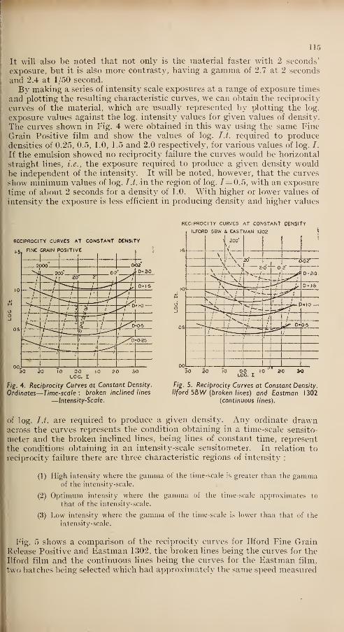
115
It will also be noted that not only is the material faster with 2 seconds'
exposure, but it is also more contrasty, having a gamma of 2.7 at 2 seconds
and 2.4 at 1/50 second.
By making a series of intensity scale exposures at a range of exposure times
and plotting the resulting characteristic curves, we can obtain the reciprocity
curves of the material, which are usually represented by plotting the log.
exposure values against the log. intensity values for given values of density.
The curves shown in Fig. 4 were obtained in this way using the same Fine
Grain Positive film and show the values of log. I.t. required to producedensities of 0.25, 0.5, 1.0, 1.5 and 2.0 respectively, for various values of log. I.
If the emulsion showed no reciprocity failure the curves would be horizontal
straight lines, i.e., the exposure required to produce a given density wouldbe independent of the intensity. It will be noted, however, that the curves
show minimum values of log. I.t. in the region of log. 7=0.5, with an exposure
time of about 2 seconds for a density of 1.0. With higher or lower values of
intensity the exposure is less efficient in producing density and higher values
RECIPROCITY CURVES AT CONSTANT OENSlTY
ILfORD 5BW & EASTMAN 1302 \
RECIPROCITY CURVES At CONSTANT DENSITY
. StFINE GRAIN POSITIVE
Fig. 4. Reciprocity Curves at Constant Density.
Ordinates—Time-scale : broken inclined lines
—Intensity-Scale.
\ 200
\
1
\ <\ 1
\\
•' \ 20
"
o-or"
\2 d -
.
D-20%' ' "S* .Jf^l
1-0\ *"""--ii. t _ ; > D-J-5
**- **TX i
^S^,v--^- _
^s_ /•
0-5/ -x
S- _ *r o- 0-5/~"""--" "^
00 -j) J—
'
10 OO 1-0
LOG. I
Fig. 5. Reciprocity Curves at Constant Density.1 1ford SBW (broken lines) and Eastman 1302
(continuous lines).
of log. /./. are required to produce a given density. Any ordinate drawnacross the curves represents the condition obtaining in a time-scale sensito-
meter and the broken inclined lines, being lines of constant time, represent
the conditions obtaining in an intensity-scale sensitometer. In relation to
reciprocity failure there are three characteristic regions of intensity :
(1) High intensity where the gamma of the time-scale is greater than the gammaof the intensity-scale.
(2) Optimum intensity where the gamma of the time-scale approximates to
that of the intensity-scale.
(3) Low intensity where the gamma of the time-scale is lower than that of the
intensity-scale.
Fig. 5 shows a comparison of the reciprocity curves for Ilford Fine GrainRelease Positive and Eastman 1302, the broken lines being the curves for theIlford film and the continuous lines being the curves for the Eastman film,
two batches being selected which had approximately the same speed measured

116
at a density= 1.0 when exposed to an intensity-scale for 1/50 second. It will
be noted that the curves are remarkably different, the Ilford film showing anoptimum intensity at about log. 7=1.5 corresponding to a time of exposureof about 1/5 second for a density of 1.0, whereas the Eastman film shows anoptimum intensity at about log. 7= 0.5 corresponding to an exposure time ofabout 2 seconds for a density of 1 .0. Over the range of intensities correspond-ing to times of exposure of 1/50 second to 20 seconds for a density of 1.0 theIlford film shows less reciprocity failure than the Eastman film, but its
reciprocity failure becomes much greater than for the Eastman film for
lower values of intensity.
Since the Eastman IIB sensitometer, when used for exposing positive filmgives a log. 7= 1.43, we should expect the two films to show greater differencesin speed and contrast when exposed to a time-scale under these conditions thanwhen exposed to an intensity-scale for a 1/50 second. This is illustrated inFigs. 6 and 7. When exposed to a time-scale under the conditions obtaining
40
LFORD
TIME S
5BW L
:ale A
EASTMj
r LOG.]
\N 1302
I * 1 -43
20
>-
12
zQ l//'ILF 3RD5BV 1
1-0
LOG. E.
4*0
ILFORD
INTENSI
5BW &
TY SCA
EASTMAN 1 302
L£ 1/ 50 SEC.
3r0
>
ILFORD 5BWy/
II i
If1302
Mz
a2-0
l.O
00, C0 •r 2.
J
Fig. 6. Characteristic Curves of SBW and 1302.
Time-scale at log I = 1.43 (//B Sensitometer).
Fig. 7. Characteristic Curves of SBW and 1302.
Intensity-scale at I 50 sec. (Printer).
on the IIB sensitometer it will be seen that the Ilford film, in addition to being
slower than 1302, has a lower gamma, whereas to an intensity-scale exposureat 1/50 second the two films have the same speed at a density of 1.0, the Ilford
film having a slightly higher gamma. When positive film is exposed througha negative on a printer it is exposed to a range of intensities for a constant timeof the order of 1/100 second, which is sufficiently close to a 1/50 second for the
intensity-scale exposure at 1/50 second to be a close approximation to the
characteristics of the films when exposed on a printer.
All photographic emulsions show reciprocity failure and the reciprocity
characteristic varies greatly with different emulsions. The exposure intensity
at which maximum efficiency occurs is usually about that value for which a
medium density is produced in from 1/10 second to 10 seconds, but may be as
short as 1/50 second for some fast negative emulsions.

r
117
Sensitometric Control in the Motion Picture Laboratory
Motion picture films are exposed, in the picture camera or on the printer,
to a range of intensities for a constant time, of the order of 1/50—1/200 second,
although in some variable density sound recording cameras the moving ribbons
of the light valve cause a variation in time and not in intensity at exposure
times of the order of 1/20,000 second. If we are to obtain the " characteristic
curve " of the material which is really characteristic of the material in practice
we have seen that the test exposures must be made under the same conditions
as regards intensity and time as those in practical usage. The difficulties in
producing intensity-scale sensitometers to operate at the required short
exposure times are firstly the much higher intensities of light required, since
there is an enormous waste of light in producing a wide range of intensities,
and secondly, in providing a means of modulating the intensity over a sufficient
range without altering the quality of the light. So-called neutral density
wedges cannot readily be made so non-selective that they do not require
elaborate calibration with the type of photographic material with whichthey are to be used, and intensity-scale sensitometers are in consequence muchmore difficult to specify and calibrate than time-scale sensitometers. Thelatter type of sensitometer is easy to specify and can be constructed withgreat precision, and offers considerable advantages for sensitometric control.
The purpose of using sensitometric control in the motion picture laboratory
is to enable material to be exposed and processed so that a definite desired
result may be achieved. This involves developer bath control for which,although chemical analysis and pTL measurements are a valuable aid in
establishing replenishment rates, the final check on developer activity shouldstill be by means of a sensitometric strip ; development of material to a givencontrol gamma ; and determination of the speed of different batches of
material so that due allowance can be made for batch variation.
For developer bath control a time-scale sensitometer offers no disadvantages.
The required degree of development of a given type of material may also
be specified by exposures made on a time-scale sensitometer where thetype of exposure is rigidly specified as with the Eastman IIB sensitometer.
Different manufacturers' materials may, however, require to be developedto different IIB control gammas to achieve the same degree of contrast in^
practice. Again, while the difference in speed between different batches of
the same type of material of one manufacturer may be adequately determinedby means of a IIB sensitometer, since the reciprocity failure differences
between different batches is relatively small, it cannot be relied upon to give
accurate information on the relative speed of different makers' products whenused in practice. This would be especially the case if a IIB sensitometer wereused to compare the speed of different materials required to be exposed at themuch higher intensity level used in sound recording. Provided these limita-
tions are realised the IIB sensitometer has much to recommend it as a standardinstrument for sensitometric control.
One interesting development which some laboratories have been using is
what is generally referred to as a " print-through gamma " strip. In theDenham Laboratories this consists of a wedge of three or four steps and aportrait, the whole occupying the 35 mm. picture frame, made on duplicating
negative film by means of an optical printer. Three frames of this strip are
attached at the beginning of the negative and printed at a given light change,and are used to control print quality, the IIB sensitometer being used for bathcontrol.
In this paper an attempt has been made to indicate the nature of reciprocity
failure shown by photographic emulsions and to discuss its implications in the

118
sensitometric control in the motion picture laboratory. There will of necessity
be many points of sensitometric control with which it has not been possible
to deal and it is hoped that these will be raised in the discussion.
DISCUSSION
Mr. L. II. Bacon : Is the reciprocity
failure greater with fine-grain stock than
with ordinary stock ?
The Author : It depends on what
materials you are comparing. The re-
ciprocity failure of some fast negative
materials is quite as great as for fine grain
positive.
Mr. II. Waxman : Does the inability of
a photographic emulsion to integrate a
series of exposures give a less density than
a continuous one ?
The Author : The intermittency effect
is another aspect of reciprocity failure.
Whether an intermittent exposure gives
a greater or less density than a continuous
one depends on the intensity level, and the
frequency of the flash.
A Visitor : Is it to be expected, as a
result of reciprocity failure, there will be
a non-linear volume characteristic in the
Western Electric light valve?
The Author : No. Although the
characteristic curve of the sound negative,
obtained at the relatively low intensity
time-scale conditions of the IIB sensito-
meter, will in general be different from its
characteristics in the sound recording
camera, the IIB control gamma is only used
to obtain a given contrast which has pre-
viously been shown to give the desired
result.
Mr. R. H. Cricks : Does the colour of the
light affect reciprocity failure ? I have in
mind the difference in colour of light of a
resistance controlled printer light.
The Author : No ; the colour of the
light has no effect on the amount of re-
ciprocity failure shown by photographic
emulsions.
Mr. Felt : You mentioned that there
had been difficulties over the use of the IIB
sensitometer with these particular emulsions,
and I take it the difficulty is that having
assessed the capability of an emulsion with
that particular sensitometer, it is found in
practice that on the printer you do not get
the results you- expect. Would it not be
possible for the manufacturers to quote
some factor for their emulsion which would
enable you to relate the figures taken on the
IIB sensitometer, so that they would agree
with what is found on the printer
Mr. I. D. Wratten : When Kodak pro-
duced 1302 material it gave the laboratories
a development control gamma guide. If
another manufacturer introduces a material
matched with the Kodak product in terms
of the printer, obviously situations arise
when with similar gamma values obtained
with the IIB sensitometer the two materials
may show differences in quality. I agree
with Mr. Moore that this method fails to
take account of differences in reciprocity
failure between the two material-.
The AUTHOR : As regards the second
part of the question, manufacturers recom-
mend an appropriate development control
gamma. For the Eastman film the IIBcontrol gamma is in the region of 2.6 or 2.8,
and for the Ilford film about 2.3 to 2.6. Asregards the speed factor, it is not possible to
recommend the density of a given step on
account of the differences in the degree of
development obtained in various labora-
tories. Wr
e could, however, say that for
a density of 1.0 with 1302, the density with
the Ilford film should be 0.1 to 0.15 lower
for matched prints.
Mr. M. V. Hoare : On the question of
exposing strips on the IIB, the usual
practice with fine grain stocks is to give twoexposures : would there be any serious
consequence in leaving the 78B filter out,
and getting the higher intensity at the lower
colour temperature ?
The Author : I do not see any advantagein giving two exposures since you can get
adequate exposure on 5BW or 1302 on the
IIB with the filter with one exposure.
While there will be no intermittency effect
between these two exposures, it is difficult
for the operator to remember whether he
has given one or more exposures, and this
method is therefore liable to lead to errors.
Mr. Dibley : Is there any recommenda-tion on this point, because at Denham weare having to give four exposures on 1302
material.
Mr. J. W. W. Smith : The recommenda-tion I have made is that the IIB sensito-
meter should be set up and operated exactly
as for ordinary positive, but instead of
using, say, the tenth step as the control, youtake the fourteenth step and so obtain the
necessary four times increase in exposure
for Fine Grain Release Positive. Thus, you
do not have to disturb the instrument other
than perhaps to cut notches in the mask to
indicate the new position.
Mr. I. D. Wratten : I quite agree with
that view.

119
SOME SPECIAL PHOTOGRAPHIC EFFECTSHarry Waxman (Member) *
Read to the B.KS. Film Production Division on October 23rd, 1946.
THE subject of special photographic effects as a whole being too vast andcomplex to cover within the limits of one evening's discussion, I propose
to-night to deal specifically with three or four effects we have been recentlv
called upon to do.
In special photographic effect work one is more often than not faced witha problem the solution of which is purely mechanical and not photographic.I use the term " mechanical " in a broad sense to differentiate from thepurely photographic.
Planning an Effect
For example, the opening sequence in the recently completed Two Cities'
production " School for Secrets " called for shots of an aircraft flying abovethe clouds. The aircraft gradually loses height until it sinks into the cloudsand when completely lost from view it collides with a mountain peak andcrashes in flames.
During the preliminary production meetings the treatment was decidedupon, such as that the actual collision with the mountain peak should not beshown, as this would destroy much of the dramatic effect. The viewpointfrom which the scene should be photographed was likewise decided upon as
being seen from another aircraft flying alongside—this being about the onlvlogical viewpoint from which such action could be seen. Also it was felt thatthe introduction of any camera movement that such a camera position wouldnaturally give would also heighten the effect of realism.
After the collision and subsequent explosion it was decided that the "cameraplane "should then go down into and through the clouds and there below wouldbe seen the mountain peaks and the burning wreckage. This simple deviceenabled us to make a break at this point in the shooting of the scene and thetwo halves of the completed scene which we shall see later were, in fact, shotsix weeks apart.
Camera EquipmentFrom the foregoing it will be seen that there were no real photographic
problems to overcome. The flying camera view-point was simply solved byshooting this sequence with a hand-held camera, so that the operator couldintroduce the required amount of movement.A 400ft. model " Q" Eyemo was used for this purpose because it was
capable of being run at 48 frames per second, which had been found byprevious experience to be just sufficient to " iron out " any too violent cameramovement. A 24 mm. lens stopped down to //2.8 with Super XX stockcompleted the photographic combination. Incidentally, this method wasused to photograph almost all of the flying model shots in this productionand in the R.A.F. film " Journey Together," from which I hope to show youa complete sequence later.
Our real problem, of course, was the production of the clouds. As we werein effect going to do a tracking shot we first had to decide whether we shouldproduce a large area of static cloud and track the camera and aircraft over it,
or have a fairly static set-up and move the clouds past the camera. Wedecided upon the latter method as being the more practical and controllable.
* Camera Department, Two Cities Films Ltd., Denham Studios

12(1
Forming the CloudsThe various methods of producing cloud backgrounds such as B.P. photo-
graphic backings, projected clouds, etc., are too well known to need descrip-
tion, but it will be evident that none of these methods would be of any use to
us as we wanted not only a background of clouds, but a foreground and middledistance too. In other words, it had to be solid " clouds into which ouraircraft could actually fly.
My associate, John Howell, and myself solved this problem after a small
scale test was made, based on some experiments we had made together whilst
in the R.A.F.We knew that when solid carbon dioxide (CG 2 ), which is commercially sold
as " Dricold," is placed in water, a white heavier-than-air vapour is producedwhich always naturally travels in the same direction—downwards. All wehad to do was produce it in sufficient quantity and control it.
Mechanical Construction
A large sloping ramp (Fig. 1), measuring 18 ft. x 24 ft., was mountedon a central transverse pivot. This pivot was incorporated to allow us to
arrive easily at the required angle of tilt, after which the ramp was locked off.
®-
i
©
LJ\ fr" ;>
—
Fig. I . Diagram of ramp.
(I ) Generating Tanks. (2) Top
of ramp boxed in. (3) Water
Pipe. (4) Ramp 18ft. x 14ft..
surface smooth and waterproof.
(5) Trough. (6) Drain Trough.
(7) Transverse Pivot. A to 8.
Direction ofshort camera track
(By courtesy of The Cinc-Tcch-nician).
Across the full width of the ramp at the top, metal tanks measuring
6 ft. x 1 ft. x 6 ins. deep were placed, each tank containing about 4 ins. of
water and being fittedjwith heating units. Each tank was also fitted with
a hinged wooden lid which opened right back into the horizontal position.
" Dricold " was broken up into small pieces and loaded on to the lids of the
tanks so that it could be tipped into the water across the full width of the
ramp when the water reached the required temperature. We found that
130° F. gave us the best results.
Being only 1.5 times the weight of air the vapour is very easily disturbed,
>o that there was a limit to how far we could tilt the ramp before the "clouds"'
lost their formation. As. however, they were required to travel faster than
this limited tilt would allow, the top surface of the ramp was made smooth
and waterproof and cold water was run down across the full width. Our
clouds were now resting on a moving surface of cold water to which they seemed
to adhere whilst being carried forward with a minimum of disturbance.
A trough running up the full length of the ramp was provided to allow sufficient
depth of cloud for the model aircraft completely to sink into.
The camera which tracked alone; the direction indicated by the dotted line

121
in Fig. 1 was tilted to " level " the shot up and the aircraft was run alonghorizontal wires in the usual way so that it gradually entered the clouds.
Wooden baffles, of various lengths, heights, and angles, were placed here andthere on the ramp to bounce the clouds up where necessary.
The camera, of course, over-shot the far edge of the ramp on to a whitebacking on which was projected a sky in the conventional manner, using
three cloud glasses moving at slightly different speeds. No great difficulty
was experienced in blending .this into the " solid " foreground clouds.
Fig. 2 is an enlargement from this actual shot of the aircraft flying overthe clouds and as it is about to disappear into the clouds.
Crashing an Aircraft
Another shot that was called for was of a Halifax aircraft crashing on to
a town after it had impacted a barrage balloon cable. The preceding shots
were to show the reactions of people in the streets looking up at this low-flying
aircraft and then running for shelter as they realise it is crashing.
Therefore it was obvious that the actual shot of the crash should have humanbeings in it. Fortunately the director wanted this shot to show the aircraft
crashing behind some buildings, which made our task easy.
Fig. 2.
Aircraft just about to
enter Clouds.
(By courtesy of The Cine-Technician).
For the sake of economy a real skyline was photographed. A full size
foreground was then built with a small perspective portion on the lot at thestudio, on which the artists played their action. The only important detail
here was that the small amount of perspective background should come abovethe heads of the moving figures to facilitate the matting out. The skyportion of the same set-up carried the aircraft (Fig. 3). It was necessaryto shoot this set-up in two sections because of the different camera speedsrequired and also because of the shadow cast by the model aircraft. Thesethree negatives were finally combined in the projection printer by methodssuch as have been described by T. W. Howard. Fig. 4 shows a frame fromthe final combined print.
Filming Radar Masts
Another shot which at first presented an interesting mechanical problemwas a descriptive shot that was required of a radar installation. The shotwas required to show first a complete radar tower set-up with the base of
a transmitting tower in the foreground and four receiving towers in thedistant background. The camera was then required to pan round until it
held only the base of the foreground transmitting tower. Then it had to

122
track slowly up this tower beyond the top until it held sea and sky, pan roundon to the sea and sky only, with a distant ship, hold this set-up for a few
seconds, then pan quickly back to a close-up of one of the distant receiving
towers and travel quickly down this to the ground. This shot was obviously
a model shot as the towers in question were 360 ft. and 240 ft. high respectively
and were some quarter of a mile or more apart. It was decided firstly to shoot
it on location, as it was realised that it would not be possible to do justice to
the extensive sea and sky background necessary under studio conditions.
Half-inch scale models were made up in metal, which gave us a transmitting
tower 15 ft. high and four receivers 10 ft. high. Our problem was how to
manipulate the camera. A camera crane was unsuitable for two reasons.
Firstly it was almost impossible to get one up to the location which had beenselected, this being the top of the cliffs overlooking St. Margaret's Bay, andsecondly, the speed of the pan back on to the receiving tower was too fast
for a camera crane to cope with.
Camera Lift
On simple analysis the camera movement was broken up as follows :
(1) a pan to the right and subsequently back again; (2) a vertical track of
at least 18 ft. and subsequently quickly down again ; and (3) whilst the
Fig. 3. Enlargement from preliminary test o/
Aircraft and foreground Set-piece.
Fig. 4. Enlargement from final CombinedPrint.
camera was in the top position it had to track horizontally some 50-60 feet
to be in position for picking up the close-up of one of the distant receiving
towers on the return pan right to left.
We solved this problem as follows. A builder's hoist such as is often seen
on construction jobs was used as a camera lift. Incidentally, it was, of course,
a new one purchased especially for this shot. Manipulation of this hoist wasmanual, assisted with counterweights, and proved most satisfactory—as youwill be able to judge later when we run a complete " take." With the cameramounted on a " free " head, this combination gave us our required vertical
track and the horizontal pan. The tracking of the camera was eliminated
by tracking the models into position whilst the camera was on the sea andsky portion of the shot. Fig. 5 shows the camera in the foreground for thebeginning of the shot. The lower half of the transmitting tower and the
distant left hand receiving tower are clearly shown standing on their respective
bogies, which are on rails which run out of picture on the right. Fig. 6 is
a more detailed view of the camera lift.
Shooting Down a Junkers
The shooting down of a Ju. 88 as seen from behind the pilot of a Beaufighter

123
night fighter raised another interesting problem. This obviously was a
straightforward B.P. shot ; our problem was, of course, to produce the B.P.
plate. Firstly, we had to see the Ju. 88 flying steadily ahead. Tracer bullets
then had to be shown as coming from the foreground aircraft, in which wasthe camera, the engine of the Ju. 88 then burst into flames and it side-slipped
out of view.
This plate was produced in stages. Stage 1 was of the Ju. 88 flying along
over clouds, which again were produced with the aid of C0 2 . At a suitable
time a detonator concealed in the port engine was fired by remote control.
This gave us the initial explosion and subsequent fire. As this model wasfully motorised and carried correctly pitched propellors, we found that noexternal influence was necessary to give the flames the correct amount of
"flutter."
We now had to add the ten lines of tracer bullets all converging on the
port engine.
Fig. 5. View of Radar Tower Set-up. Fig. 6. The Camera Hoist used to film
Radar Towers.
Tracer and Smoke-puffThe section of the shot that has so far been described was now developed
and printed, and at the point where the tracer bullets were wanted to hit
(that is just before the detonator was fired) a frame was punched out of the
positive and a pin-hole carefully made through the port engine nacelle. Thispunched frame was fitted into the camera gate. The camera was set up ona rostrum pointing downwards. Some 40 or 50 feet away a point was markednear the studio floor that exactly coincided with the pinhole in the punchedframe. Behind the camera and slightly below the lens—to maintain thecorrect relative viewpoint—-a length of 4 in. x2 in. timber about 12 feet long
was fixed in a horizontal position. On this batten were marked the relative
positions of the ten machine guns with which the Beaufighter was fitted.
From each of these positions in turn a thin piano wire was run down to themarked point near the studio floor. Down these wires was then run a series
of small trollies, each carrying a 4J-volt flashlamp bulb. Then with the stage
in complete darkness these were photographed at a camera speed of about6 or 7 frames per second. After each run the camera was rewound and therunning wire moved over to the next position. Thus the ten tracer lines werebuilt up.

124
The next essential detail of realism that was required was the puff of smokefrom the engine immediately preceding the flames. This puff of smoke, it
will be noted, is in fact left behind by the Ju. 88 which is travelling forward,and as our Beaufighter from which we are shooting is following on its tail,
this puff of smoke will rush towards us and momentarily black out our picture
as it flashes past us. To produce this part of the shot a large white flat
was placed in a horizontal position with the camera shooting straight down onto it. With the same punched frame in the camera gate a small hole wasmade in this flat to coincide with the pinhole previously mentioned. The flat
was illuminated to a sufficiently high level to give us a maximum negativedensity. A smoke bomb was then fired through the hole in the flat and theback smoke was guided upwards by baffles towards the camera, which wasrun at about 8 pictures per second.
These three negatives—the plane, the tracer bullets, and the puff of smoke—
-
were combined in the optical printer, providing the B.P. plate for projecting
in front of the Beaufighter cockpit.
Counting the final exposure when actually shooting the B.P. set-up, this
shot necessitated 13 exposures in the camera alone.
Bombing Berlin
Finally, to show you how the use of special photographic effects can heighten
the dramatic intensity of a film I would like to show you an extract from the
R.A.F. film, " Journey Together." The sequence that I am going to showyou is of a large bomber raid on Berlin as seen from one particular Lancaster
aircraft taking part. During the raid this aircraft is attacked by a night
fighter. The Lancaster is hit and crashes in the sea on its way home to base.
It sinks and the crew just manage to get away in their dinghy as it sinks.
This sequence was done entirely in the studio, but, unfortunately, timedoes not permit me to go into all the details of production. However, I shall
be only too pleased to answer any relevant questions after the showing.
The paper was illustrated by the projection of sequences from the films" School for Secrets " and "Journey Together."
DISCUSSION
Mr. Franks : For the ground shots of On the screen I think you will agree it looks
Berlin, with the bombs exploding, were as though the aircraft was going up andlibrary shots used ? down.The Author: Yes; they were actually Mr CuLL . lf the fuse iage was on the
T
10^by^M
theTT°P
era!^
na56C
1
tl0n°fJ5f bottom of the tank, how did you get it
R.A.F. Film Unit. We used them as B.P.t0 ti ?
J fe
plates. The Lancaster sequences were shot'
on the stage, on a real Lancaster fuselage. The Author : The final shot is a model
Flt.-Lieut. Miller : Were the dinghy shot>used as a B -p
- PIate -A model was
shots done in the studio ?used
>measuring about 6 ft. wing span
;it
The Author : Yes ; that was all done in was sunk in the tank and shot on a mgh"
the studio tank at Pinewood. The tank sPeed camera. Two things you cannot
measured some 60 ft. square, and in the contro1 are sinoke and water? y°u m
l
middle was about 13 ft. deep. A production variably have to shoot them at high speed,
trick we used to add to the effect of realism and thls was shot at 148 frames per second
was not to use a static camera. The aircraft The sPlash was intensified by the use of
was a real fuselage, and was sitting on the compressed air lines, which produced the
bottom of the lank. The way we made itwhite foam.
appear to heave was by moving the sky Mr. R. 11. Cricks : Does Mr. Waxmanbacking and the camera, which were both work to any fixed ratio for camera speed in
mounted on rafts floating on the water. relation to the scale of the model ? Mat he-

125
matics would suggest that the ratio should
be the square root of the scale.
The Author : We have never started off
with any fixed ratio, because I believe there
can be no relationship between the two, as
camera speed depends upon the action andthe ease with which the models, etc., can
be manipulated. For example, the modelLancaster aircraft used in the " JourneyTogether " sequence you have just seen wasexactly the same in every case. Yet the
flying shots were photographed at 48 pic-
tures per second, and the sinking shot at
148 pictures per second. This was because,
as I have already explained, we had water
to contend with, and water, like smoke andflames, cannot be slowed down in miniature
so you have to run the camera speed up to
meet it.
A Visitor : Would the use of colour
allow a similar perfection in model work ?
The Author : Yes ; I can see no great
problem in using colour. A problem in
shooting colour model shots is in getting a
camera to run at high speed. Technicolor,
I believe, have experimented with a high-
speed three-colour camera, but colour shots
are more satisfactorily and easily doneusing Monopak and standard high-speed
camera equipment.
A Visitor : In a model shot is there anyeffective means of reducing the size of
water drops ?
The Author : No ; that is a problem,
because it is almost impossible to get
miniature spray, as the individual drops of
water are quite normal and consequently
are out of all proportion to the model. In
the crashing Lancaster sequence there is
a short shot of the aircraft skimming along
the water like a speedboat. We first tried
to achieve this by actually racing the modelthrough the water with the camera lashed
to it by mechanical means. We had to
abandon this method because the spray
created was completely out of scale to the
model. The way we finally did that shot
was with a static camera and a static modeland the water and spray were blown past it
by ten high pressure air lines working at
about 40 lbs. per square inch, thus atomising
the water.
Mr. T. S. Lyndon-Haynes : With the
shot of the tracer entering the fuselage whichunlike the one in the Ju. 88 was a lateral
shot, was the same method employed ?
The Author : No ; that was almost the
real thing. We set the camera up inside the
fuselage, and we had a machine gun 12ft.
away, firing real tracer bullets. An interest-
ing point about that Lancaster sequenceis that there is not more than one static
shot in the whole of the sequence. Theaircraft fuselage, which weighed about 5
tons, was mounted on an elaborate andcarefully planned pivot arrangement, so
that the whole thing could tilt both ways,and the camera, even when it was almost
inside it, was always mounted quite in-
dependently of the fuselage. For other
shots, where the camera had to be mountedinside the fuselage, we used a free bowl headmounting. One shot was actually done as
a tracking shot inside the aircraft, a tiny
dolly being mounted on rails along the
inside of the fuselage.
A Visitor : Can Mr. Waxman tell us
whether experiments have been made to get
rid of the hot-spot on the B.P. screen?
The Author : Unfortunately, you are
conscious of the hot-spot in one or two shots
but this is not due to lack of experiment, as
one always endeavours to eliminate this
trouble, invariably with considerable success.
The fault in this case is due to the fact that
we were forced by lack of studio space to use
a 35 mm. lens in shooting the plate, whichemphasises the falling off in the corners.
One should never shoot a B.P. plate with
anything less than a 50 mm. lens.
Mr. A. Critoph : How did the aircraft
go down with the engine alight ?
The Author : That was very simply
done. The basic shot of the burning city
below was a real shot, taken over a Germancity. All we had to do was to put in some-thing going down. We put a long curved
rail in the studio along the path where wewanted the German aircraft to fall ; a piece
of wood was soaked in petrol, set alight, andwhilst running down the curved rail wasphotographed in a completely dark studio.
Then the shot was double printed.
COLOUR TEMPERATURE CONVERSION FILTER
A new type of filter glass provides a pre-
cise means of increasing apparent colour
temperature. Colour difference betweena light source so modified and a Planckianradiator at the higher colour temperaturecan hardly be distinguished, even by anexperienced observer ; for example, a piece
1.6 mm. thick will convert a source at2250° K. to 2870° K.Type OB9 is supplied in unpolished rolled
sheet form and to a guaranteedfj,
co-
efficient. The usual thickness is 5-6 mm.Sizes up to 8 in. square can usually be
provided by Messrs. Chance Bros., Ltd.

126
PHYSICAL SOCIETY'S EXHIBITION^HE participation of the Society in the annual exhibition of the Physical*~ Society, held at the Imperial College of Science, Kensington, from April
9th to 12th, took the form of the hourly projection of a reel of 16 mm. film,
made up of sequences from a number of scientific subjects, and the display
of the various specialised apparatus used for producing these films. Theprojector was stopped between the separate sections, and a descriptive
commentary was delivered by means of a gramophone record.
The sections of film shown comprised the following subjects :
1. Investigation into the Accommodation of the Human Eye (by courtesy of Messrs. K. B.
Morris and H. E. B. Grimshaw, Kodak Research Laboratories). The behaviour of the pupil
after a bright light has been switched off is photographed in visual darkness by means of
infra-red radiation and infra-red sensitive film.
2. Slow-motion photography of Dischargefrom Fuel Jet (by courtesy of Mr. W. Buckstone,
Kodak, Ltd.) A camera was belt-driven from the fuel pump shaft with a ratio betweenpulleys of 30 :31; the picture is a combination of parts of thirty successive cycles, whichsynthesise into one complete cycle, producing stroboscopically an apparent 30-times
reduction of speed.
3. Slow-motion Picture of Carbon Arcs (by courtesy of Dr. F. S. Hawkins, G.E.C. Research
Laboratories). The film shows an A.C. high-intensity arc, and the striking of a 150-amp.
double-negative D.C. studio arc, both slowed down about 200 times.
4. Surgical Operation under the Microscope (by courtesy of Mr. T. E. Cawthorne andMr. E. Gwynne-Evans, the apparatus made by Mr. E. Mackie). The film shows the set-up
for filming the operation of the removal of the Eustachian canal, and sections of the film ;
the surgeon is seen operating with the aid of a microscope.
5. Accelerated Motion of a Biological Preparation (by courtesy of Mr. R. McYitie Weston).
The film, taken through the microscope with the aid of time-lapse equipment, shows the
white cells of the blood moving through masses of stationary red cells.
6. Kine-radiograph ofHuman Joints (by courtesy of Dr. A. E. Barclay, Nuffield Institute
for Medical Research). The film shows the recording of X-ray images of moving joints.
7. Super-slow-motion of a Splash (by courtesy of Messrs. G. A. Jones and J. Hadland,
Kodak Research Laboratories). The formation of a series of splashes produced by drops
falling into a liquid is shown at about 200 times slower than normal.
8. Diagrammatic Instructional Films (by courtesy of Mr. Max J. Kaufmann, Dance-Kaufmann Cycle Films, Ltd.). Moving diagrams of the action of a D.C. generator, a
Cyclotron, the reflection of a radial wave, and a conductor cutting a magnetic field, are
intended to be used as endless loops.
9. Films in Aircraft Research (by courtesy of Mr. D. S. Bancroft, Miles Aircraft, Ltd.).
The film illustrates the study of the take-off of aircraft by means of two cameras, the
behaviour of the aircraft being computed by triangulation.
In all cases except Nos. 2,3, and 6 the apparatus used for the production of
the films was exhibited. In addition, three other pieces of equipment weredisplayed : a device, shown by courtesy of Miles Aircraft, Ltd., for makingphotographic records of the instruments of aircraft undergoing test ; apparatusfor the recording of traces on a cathode-ray oscillograph ; and a kine-broncho-
scope, consisting of a 16 mm. camera attached to a bronchoscope.
The arrangements for the exhibition were entrusted to a committee com-prising Messrs. W. Buckstone (chairman of the Sub-standard Film Division),
George A. Jones (who was responsible for the editing of the film and writing
the commentary), and H. S. Hind, who lent a Bell & Howell projector for the
period of the exhibition. Duplicates of the original films were made by Messrs.
Kodak, Ltd. The commentary was spoken by Mr. Frank Phillips, B.B.C.
announcer, and recorded bv Mr. Norman Leevers.

127
TECHNICAL ABSTRACTSMost of the periodicals here abstracted may be seen in the Society's Library,
A COLOUR PROCESS WHICH MAY RIVAL TECHNICOLOR.R. H. Cricks, Kine. Weekly, December 19th, 1946, p. 272.
A survey of the Agfacolor process is followed by consideration of its problems. A close
degree of control is required in processing ; the negative has to be colour-graded before
printing, and no fewer than 30 filters of each of the three primary colours, and 30 neutral-
density filters, are required in printing. Positive processing is complicated by the require-
ment of a silver sound track. A satisfactory duping process has not yet been perfected.
A TTTfTOR '^ A R*^TR APTAGFACOLOR AND ITS FUTURE IN THIS COUNTRY.T. H. Williamson, The Cinema, January 1st, 1947, p. 461.
While all stock manufacturers have investigated the Agfacolor process for the professional
market, no material is yet available. The possibility of economising in processing by the use
of a dye sound-track is suggested, which would necessitate the use in the kinema of antimony-caesium photo-cells. R. H. C.
BRITISH TRICOLOUR PROCESS.R. H. Cricks, Kine. Weekly, April 3rd, 1947, p. xix.
Subjects are photographed either on three separation negatives (a special bipack-and-one
camera having been built for the purpose) or on a single negative with consecutive frames
exposed through different colour filters and run at 72 frames per second. A stripping process
is also described. The printing method envisaged consists in printing the blue record
negative upon a positive emulsion containing a yellow former, re-coating with an emulsion
containing a magenta former and exposing through the green record, and again re-coating
with an emulsion containing a cyan former which is printed from the red record ; all three
layers are colour-developed simultaneously. The positive method at present in use differs
from this in that each layer is processed before the next is applied. The films projected are
described as of high quality. Author's Abstract.
PIONEER RECORDING CHANNEL.R. H. Cricks, Kine. Weekly, April 3rd, 1947, p. xxA complete recording channel produced by Pioneer Films comprises a Capco camera
mounted on a self-contained console, disc recorder, mixer console, and amplifying unit. Anexperimental development is recording by means of a cathode-ray tube.
MAGNETIC SOUND RECORDING.Author's Abstract.
/. Soc. Mot. Pic. Eng., January, 1947.
The first article, by S. J. Begun, of the Brush Development Company, mentions Poulsen
as the originator, in 1898, of magnetic sound recording ; as early as 1917 suggestions were
made to use magnetic sound recordings in conjunction with a complementary picture film.
The Brush Company in 1939 brought out a magnetic paper tape recorder, the paper tape
being coated with a magnetic powder. It is stated that with a tape speed of 7.5 in. per
second a response up to about 5,000 c.p. s. can be obtained, with a signal to noise ratio better
than 60 db. It is suggested that a 35 mm. perforated magnetic tape could be introduced
into standard recording practice. War time developments by the Brush Company include
the development of a ductile non-magnetic, non-ferrous wire, which is plated with a thin
layer of a highly magnetic nickel-cobalt alloy.
The second article, by Marvin Cameras of the Armour Research Foundation, deals with
magnetic sound for motion pictures. The advantages and disadvantages of optical recording
versus magnetic recording are enumerated and experiments are described in which acetate
or nitrate film stock was Used, coated to a thickness of half-mil with a magnetic material.
Push-pull and stereophonic records are also possible by using two tracks at the same time.
Further experiments are mentioned of coating 35 mm., 16 mm. and 8 mm. picture films
with a magnetic material. On the 35 mm. film, instead of using the usual photographic
sound track, a 100 mil magnetic coating is provided. Similar suggestions are made for
16 mm. film (80 mil coating on the non-perforated side of the film). Synchronisation of the
sound record with the picture record is made by driving the sound recording and picture
cameras with synchronous motors which, when up, to speed, operate relays which put
a scratch or dab of paint on each film, thus providing synchronising marks.
The frequency response of magnetic sound records thus obtained is mentioned as being
lat from 50 to 12,000 c.p.s. within ±3 db.

128
The third article, by K. J. Tinkham and J. S. Boyers of Magnecord, Inc., concerns a
magnetic wire recorder which has an extremely accurate wire feed arrangement and abouta mile of wire must pass through the machine before a total slippage of the order of one foot
is encountered. The authors suggest the use of a motor of the interlock type for employingthe apparatus in conjunction with film work. The speed of the wire is 4 feet per second
and the best wire to use has been found to be of stainless steel having a diameter of 0.004 in.
The frequency range claimed is from 10 c.p.s. to 30,000 c.p.s. in the recording, whilst the
playback head gives a rising frequency response of 6 db per octave from a low frequency
to approximately 1,000 c.p.s. The high end of the frequency range begins to fall off at
approximately 5,000 c.p.s. and at 12,000 c.p.s. it is about 15 db down from the level at
1,000 c.p.s.
The fourth article, by II. A. Howell, of the Indiana Steel Products Co., describes the use
of coated paper tape for magnetic sound recording and, contrary to the Germans, who havebeen using red Magnetite (gamma phase Fe 2 3) exclusively, the article describes investiga-
tions concerning other coating materials, especially a magnetic powder known as " Ilyflux"
with which, with a tape speed of 8 inches per second, a good frequency response up to about
6,000 c.p.s, has been obtained. A special paper for use as a base has been found having
advantages over plastic ribbons, especially as it can be easily handled, edited and repaired
whilst the paper can be perforated in the same way as any ordinary 35 mm. film. O.K.K.
SCREEN ILLUMINATION WITH CARBON ARC MOTION PICTURE PROJECTIONSYSTEMS.
R. J. Zavesky, C. J. Gertiser, W. W. Lozier, /. Soc. Mot. Pic. Eng., 1947^8, 73.
The screen illuminations given by low intensity and high intensity arc projection systems
are tabulated. Typical figures for screen lumens range from 2,500 lumens given by low
intensity at 32 amperes to 21,500 lumens given by a 13.6 mm. rotated high intensity positive
at 170 amperes. These values are for projectors with no film in the gate, no shutter
running, no porthole glass and no heat filter.
The central screen illuminations in ft. candles, assuming a shutter transmission of 50%and a porthole glass of 90% transmission, but with no heat filter or film in the machine,
are plotted against screen width. They are also recalculated as screen brightnesses for
a screen having a 75% reflection factor, and it is shown that by choice of a suitable projec-
tion system, screens of 10-39 ft. width can be illuminated to the level of brightness of
10 db* foot-lamberts recommended by the American Standards Association. F. S. H.
IS THE PROSCENIUM NECESSARY IN MODERN KINEMAS?R. H. Cricks, Ideal Kinema, October, 1946, p. xix.
While the proscenium arch is considered undesirable from the point of view of sound
distribution, there are four reasons calling for its retention : as a framework to the projected
picture, as an ornamental feature during intervals, as a means of concealing tabs and drapes,
and in connection with stage presentations. Alternative methods of meeting these require-
ments are considered. Author's Abstract.
MALTESE CROSS WITH COMPENSATED ACCELERATION.La Cinematographic Francaise, October 5, 1946, p. xx.
A description of the intermittent motion device of the Radion projector shows it to
comprise an orthodox Maltese cross system, but with the cam driven by means of a slipper-
block on the eccentrically disposed flywheel shaft, and so accelerated during the shift period
of the cross. The acceleration is at its maximum at the point where the striker pin leaves
the cross slot. A 50 per cent, increase in screen illumination is claimed. R.H.C.
COLOUR TELEVISION CONTROVERSY.RCA Review, Vol. VII, No. 4, December, 1946; Electronic Industries, December, 1946;
Broadcasting, December 23rd, 1946, p. 17 ; D. G. Fink, Electronics, January, 1947.
During the F.C.C. hearing of the C.B.S. petition for the initiation of colour television
transmissions, the RCA have launched an alternative system. This uses simultaneous as
against the C.B.S. sequential scanning of the primary colours. The main advantage claimed,
is that existing monochrome receivers can continue to be used. By means of a simple tuning" converter " they would receive the " green channel " only as a monochrome picture. To
receive a colour picture it is necessary to superpose and accurately register the three primary
pictures, which limits the system to the use of three projection tubes and associated lenses.
A very complicated triple-gun cathode ray tube has been proposed—but not yet apparently
made—by Du Mont. The pros and cons of the RCA and C.B.S. claims are discussed in
detail in the last of the above references. L.C.J.

129
BOOK REVIEWS
H1ST0R1QUE ET DEVELOPPEMENTDE LA TECHNIQUE CINEMATO-GRAPHIQUE, by Jean Vivie. Editions
B.P.I., 79, Av. des Champs- Elysees.Paris, 8e. 137 +XXXIII pp., 680 jr.
The present work is the first of a series of
12 volumes covering all technical aspects of
kinematography. Their author is head of
the School of Kinematography in Paris, andit is to be expected therefore that they
should be in the nature of text-books. Thepresent volume is in fact more than a
history—it is an introduction to the wholeof the science of kinematography.
In discussing the origins ofkinematographythe author distinguishes between animatedprojection, and " chronophotography." Thefirst with some justification he credits to
Emile Reynaud, whose " optical theatre"
(a Praxinoscope embodying an endless bandof perforated film) was based upon a patent
of 1888. Under the second heading, credit
is very fairly assigned to many inventors,
notably Marey, Edison, and the Lumierebrothers, the sole fault—to English eyes
—
being the scanty credit paid to WilliamFriese-Greene : is our faith in the priority
of the British inventor merely an illusion
carefully fostered by the film trade historian,
the late Will Day ?
At a later stage, too, Vivie's views of the
British industry are not complimentary :
" L'industrie cinematographique anglaise
ne se developpa guere ; a cote de l'agence
creee par la Societe L. Gaumont en 1908
.... on ne peut guere citer que le nomde l'inventeur et industriel Vinten, fabricant
de cameras, projecteurs, et materiel de
laboratoire." The late W. Vinten did not
as a matter of fact commence his ownbusiness until 1911 ; a number of still
existing firms were manufacturing on quite
a large scale long before that time.
Having very briefly continued the story
of the trade up to 1914, the author turns to
sound and colour, both of which subjects are
dealt with far too cursorily. In three pagesthe history of the cartoon film is covered,
from Reynaud to Disney. Trick work—the
scientific film—the sub-standard film—all
receive too brief mention.
A valuable feature of the book is the
several chronological tables, and the lists of
patents. The volume concludes with 32pages of interesting historical illustrations.
Jean Vivie's book may be regarded as the
most authoritative work yet published onthe technical development of kinemato-
graphy. If equally comprehensive researches
were undertaken in this country and in
America (much of the material is indicatedby Vivie) and the results of the three com-bined, we should have virtually the complet e
and authentic history of the birth of ourindustry. R. H. CRICKS.
TELEVISION RECEIVING EQUIP-MENT, by W. T. Cocking, M.I.E.E.
This little book should fill the need for
a compact source of information on tele-
vision receiving apparatus. It is not
intended for the pure beginner, but is
written to give an extension of knowledge to
radio engineers into the realm of cathode ray
tube scanning circuits and wide band re-
ceivers and the other features peculiar to
the application.
To those who are not in the radio industry
it may be mentioned that W. T. Cocking is
the Editor of the Wireless Engineer and hasfor many years contributed extremely prac-
tical articles to the Wireless World, both onradio and television, and the present book is
based in general on a selection of the con-
tributions which he made to cover tele-
vision subjects.
The introduction to the principles of
television is very short and the book gets
directly to its subject in a manner com-pletely free from side issues. Under the
different chapter headings are given various
variations of the special circuits required for
television receiving purposes, and the bookincludes information and circuit diagramstogether with half-tone blocks. Most of the
diagrams include values of all componentsto enable the reader to construct those heis interested in.
To cover the construction of a television
receiver Mr. Cocking has also included in the
book the circuits of a superheterodyne
receiver with an alternative straight vision
receiver which can be used within 10 miles
of Alexandra Palace and a double deflecting
magnetic time-base and power supply unit
suitable for commercial cathode ray tubes.
The instructions are such that the reader
having followed the circuits and the informa-
tion given should then be able to adjust andline up a set so as to receive pictures of goodresolution and general satisfaction.
The book ends with two chapters onfaults and their remedies and television
servicing, which, although short, is very
much to the point. The diagrams are all
drawn with admirable clarity and in all

130
cases actual values of components are
stated.
While being a useful reference book.
keeping closely to its subject, it could act
as a very useful guide to the home con-
structor anxious to receive the high quality
programmes once more available fromAlexandra Palace. T. M. C. Lance.
ELECTROPHYSIOLOGICAL ANALYSIS OFCOLOUR RECEPTION
THE various solutions of the problemof colour photography are based uponthe facts of colour mixture, which can
be analysed and applied wholly without the
need for any hypotheses as to the nature andfunctioning of the visual receptor apparatus,so that strictly speaking, the study of the
physiological aspects of the phenomena of
colour vision is altogether outside the region
with which photography is concerned.
Nevertheless, familiarity with the literature
of colour photography inevitably arouses
interest in the classical theories of colour
vision.
Nearly one hundred and fifty years ago(in 1801) that astonishingly versatile
Somerset physician, Dr. Thomas Young,F.R.S., who has been called the founder of
physiological optics, propounded the hypo-thesis that colour perception depends on the
presence in the retina of three kinds of nervefibres, which respond respectively to red,
green and violet light. Since Young,innumerable workers have accumulatedindirect evidence to support his hypothesis,
but experimental proof of the existence of
the hypothetical receptors has only recently
been obtained by Professor Ragnar Granit,
Director of the Xobel Institute of Neuro-physiology, The Royal Caroline Institute.
Stockholm.
In the fourteenth Thomas Young Oration,
delivered on 29th June, 1945, before the
Physical Society, Granit described the
extremely beautiful investigation which hasso completely endorsed the soundness of
Young's scientific imagination.
Granit's methods are based on the work' of
the eminent British physiologist, Professor
Adrian, who first demonstrated that all
sense organs respond to stimulation bydischarging electrical impulses through their
associated nerve fibres, variations in stimulus
intensity producing variations in frequencyof an impulse of constant size in an indivi-
dual nerve fibre. Granit developed a special
micro-electrode technique for isolation of
individual fibres (a task of immensedifficulty) the electrical responses to the
stimulus being amplified and led to a loud-
speaker. Measurements were made of the
absolute threshold to spectral light of
various wave lengths throughout the
trum. It was found that cone receptors
in the retina of the snake, cat, guinea-pig,
frog, etc., possess spectral sensitivities
grouped in three main bands 600
—
580 mfi, 540—520 w/x. and 470^50 m/4,
The sensitivity curve of a single receptor is
usually narrow with a maximum in one of
these three regions. The reason why re-
ceptors respond selectively to radiant energy
is unknown. Probably no two receptors
respond to identical wave-length ranges,
but sensitivity is in the main confined to
three regions. Why the message of one
receptor should ultimately be projected in
consciousness as redness and of another as
greenness remains utterly mysterious.
Granit has been unable to discriminate
between the signals from different receptors,
though there may be differences too fine to
be detected by his present apparatus, but
presumably the current in either case is
connected to a different type of responder at
the cortical end of the circuit.
The three main classes of receptor Granit
calls " modulators " and a unit having a
much broader wavelength sensitivity bandwhich he calls a " dominator
,?he believes
is a composite receptor composed of in-
dividual modulators of the three types. Thewider response curves of the classical tri-
chromatic theory are assumed to represent
average curves for the large number of red,
green, and blue modulators in the most
sensitive part of the retina, viz., the foveal
area.
Wright's curves for the red sensation in
the central fovea had suggested its probable
composite nature and Granit's proof of the
existence of a yellow modulator with a
maximum at oSOm/j. has enabled him to
construct a combined curve (red modulator
plus yellow modulator) which closely
corresponds with the earlier curve.
Thus Granit has provided at last objective
evidence in support of the actual existence
of a visual trichromatic mechanism and thus
substantiated the past speculations of
physicists, physiologists and psychologist-.
This is an immensely important achieve-
ment.
A. Cornwell-ClyneGRANIT, RAGNAR.—The Electrophysio-
logical Analysis of the Fundamental
Problem of Colour Reception. Pro.
Physical Society, Vol. LVII, p. 447, 1945.

131
THE COUNCILMeeting of March 5th, 1947
Present : Messrs. I. D. Wratten {President), Rex B. Hartley, L. Knopp, S. B. Swingler,
A. W. Watkins, A. G. D. West (Past President), C. H. Bell (representing Theatre Division),
W. Buckstone (representing Sub-standard Division), B. Honri (representing Film ProductionDivision), and R. H. Cricks (Secretary).
Election of Council.—The Officers of the Society placed their resignations in the hands of
the Council, but were unanimously asked to continue in office. It was noted that Messrs.
Champion and Swingler were due to retire ; the position of Mr. A. G. D. West was dependentupon the re-election of Mr. Wratten to the Presidency. The Divisional representatives
also retired.
Divisional Committees.—The composition of Divisional Committees was agreed as follows :
Chairman
Appointed byExecutiveuntil 1948
Appointed byCouncil
until 1949Elected
until 1948 ' To retire
TheatreDivision
S. B. Swingler C. H. ChampionR. PulmanH. C. Stringer
W. F. GarlingS. T. PerryJ. I,. Stableford
C. H. Bell
D- KnoppA. Xewing
R. J. EnglerF. H. Sheridan-
ShawS. A. Stevens
Sub-StandardDivision
H. S. Hind C. CabirolN. L,eevers
W. BuckstoneS. Schofield
D. F. CantlayD. Ward
H. E. Dance(G. H. Sewell
previouslyresigned)
Film Production-Division
A. W. Watkins C. E. CrowhurstW. M. HarcourtRex B. Hartley
F. G. GunnH. HarrisT. Howard(L. Thornburn
offers his
resignation)
B. HonriT. S. L,yndon-
Havnes(E. Williams'
resignationconveyed bvMr. Hartley)
G. BlattnerF. J. CoxJ. J. CroydonH. Huth
Attendance at Committees.—The President was authorised to appoint a deputy for anymember of a committee leaving London for any length of time.
Papers Committee.—Preliminary proposals for the 1947/8 lecture programme were
considered.
A.C.T. Meetings.—It was agreed that if further joint meetings were held with the A.C.T.,
their arrangement should be in the hands of the Film Production Division.
Training of Projectionists.— It was reported that the C.E.A. and N.A.T.K.E. had agreed
that the Society should be the educational authority responsible for the examination andcertification of projectionists.
Adoption of Metric System.—Correspondence with the B.S.I, and the Decimal Association
was reported, relative to the recommendation of the Foreign Relations Committee that the
adoption of the metric system be furthered.
Theatre Division.—It was reported that the Theatre Division Committee had not
accepted the recommendation of the Council that an Hon. Secretary be appointed.
Film Mutilation.—It was reported that, in accordance with the recommendations of the
Film Mutilation Committee, the C.E.A. proposed inviting the Society to prepare a booklet
on the care of film, for circulation to projectionists, and that the K.R.S. had appointed
a Committee of Print Managers.
Meeting of April 2nd, 1947
Election of Council.—Tentative list of nominations was submitted. Mr. A. W. Watkins
had been nominated as Vice-President, but did not wish to stand for election.
Qualificationsfor Membership.—Draft modification to By-law 3, relating to qualifications
for Membership, was provisionally approved.
Constitution of Branches.—Following consideration of a draft constitution for Branches
of the Society, decisions were deferred until a subsequent meeting.
Journal.—Alternative designs for a new cover for the Journal were considered, and a
decision taken to adopt one of the designs. Change of title to British Kinematography was
agreed.
It was reported that publication of the March/April issue had been delayed by lack of
blocks.

132
Papers Committee. It was reported that the A.C.T. was anxious to arrange further joint
meetings, and was agreeable to these being held with the Film Production Division.
Education ( 'ommittee.— Minutes of a meeting of the Education Committee were submitted,from which it appeared that the Committee was anxious regarding the position of the
Society in regard to the proposed British Film Industry Joint Training and ApprenticeshipCouncil.
Library.—It was agreed that the Divisions should be asked to appoint Library represen-
tatives, each to attend the library one evening a month.Brussels Film Festival. -Mr. Baynham Ilonri was appointed to represent the Society
on a C.O.I, committee to select short films for inclusion in the Brussels Film Festival.
EXECUTIVE COMMITTEE
Meeting of March 5th, 1947
Present : Messrs. I. D. Wratten (President), R. II. Cricks (Secretary), Miss Barlow(Assistant Secretary).
Elections.—The following were elected :
Ernest William Stimson (Member), Kay West End Laboratories, Ltd.
Roy Nelson Jones (Student), Regent Street Polytechnic.
Adrian Henry Cooper (Student), Regent Street Polytechnic.
Roy Frank George Scott (Member), G.B.-Kalee, Ltd.
Leslie Ronald Long (Associate), G.B.-Kalee, Ltd.
Frederick W'ells Corden (Associate), Denham Laboratories, Ltd.
Eric Sydney Morden (Associate), Sound-Services, Ltd.
William Thomas George Bush (Associate), George Humphries & Co., Ltd.
Louis H. Lavelly (Member), G.-B. Instructional.
Albert James Betts (Associate), Odeon Theatre, Rcdhill.
Cecil A. Hill (Associate), Mobile Film Co.
Leonard Lawrence Ellis (Associate), Leonard Ellis (Sub-Standard) Films, Ltd.
Stanley George Gale (Student), G.F.D., Ltd.
Leslie Maskell (Member), Pathe B.I.F.
Albert Claude Batchelor (Member), I). & P. Studios, Ltd.
Meeting of April 2nd, 1947
Present : Messrs. I. D. Wratten (President). W'. M. Harcourt (Vice-President), E. Oram(Hon. Secretary), P. H. Bastie (Hon. Treasurer), R. H. Cricks (Secretary), Miss S. M. Barlow
(Assistant Secretary).
Elections.—The following were elected :
Eric Blake (Associate), Bradford Civic Playhouse.
Frederick Humphrey Green (Associate), RCA Photophone, Ltd.
Bernard Thomas Druce (Member), Leevers, Rich & Co.
Arthur Challinor (Associate), G.B.-Kalee, Ltd.
William Charles Greatbatch (Associate), Denham Laboratories, Ltd.
George Vernon Summersgill (Associate), Palace Cinema, Droylsden, Manchester.
John Charles Jordan (Associate), G.B.-Kalee, Ltd.
Lewis Stanley Ray (Associate), Alliance Films, Ltd.
Mis. Marjorie Owens (Associate), Southall Studios.
Edwin Francis Bradley (Member), Metro-Goldwyn-Mayer Pictures, Ltd.
John Alan Guy Dacombe (Student), Southall Film Studios.
Dr. S. B. Seth (Associate), Amalgamated Dental Co., Ltd.
William Charles Grant (Associate), Geo. Humphries & Co., Ltd.
THOMAS O'Sullivan (Associate), National Studios.
Cyril Arthur George Cambridge (Associate), M.G.M. Pictures, Ltd.
Transfers.—The following Associate was transferred to Membership :
Charles Patrick Sunderland, British Movietonews, Ltd.
Staff.—An increase of staff was reported.

1S.3
ELECTION OF COUNCILThe first Ordinary Meeting of the newly
constituted British Kinematograph Society
was held on May 14th, 1947, at the Gaumont-British Small Theatre, Wardour Street, W.l.
The President, Mr. I. D. Wratten, was in
the Chair.
A report of the past year's work was read
by the Hon. Secretary, Mr. E. Oram, and the
accounts were presented by the Hon.
Treasurer, Mr. P. H. Bastie.
The scrutineers in the election of twoMembers of Council announced that Mr.
Charles H. Champion and Mr. BaynhamHonri had been elected. (Mr. B. Honri
represents the Film Production Division in
addition to being an ordinary Member of
Council.) The officers were unopposed.
The meeting will be more fully reported
in the next issue.
DIVISIONAL COMMITTEESThe following have been elected to the
Committee of the Theatre Division : Messrs.
F. H. Sheridan-Shaw, S. A. Stevens and
J. A. Walters.
Four members have been elected to the
Committee of the Film Production Division :
Messrs. F. Young, F. J. Cox, H. Waxman
THEVery generous response has come from the
few to my appeals for books for the Library.
But too few have responded, and I therefore
make this appeal to each of you to support
the Library by the contribution of a book.
The Library is made up of the following :
1. History
2. Reference
3. Technical
4. Associated Sciences
5. Cultural
A list of titles which it is desired to pro-
cure has been compiled, and may be obtained
on request. I would greatly appreciate every
assistance from those who would donate
books.
Space on our bookshelves has been placed
and G. Burgess.
Messrs. H. E. Dance and G. H. Sewell
have been re-elected to the Sub-standard
Division Committee. During Mr. Sewell's
absence in P^ast Africa, Mr. F. V. Heathhas been nominated by the President as his
deputy.
LIBRARYat the disposal of the Television Society to
house their library temporarily wheremembers can use it for reference. It mustbe understood these books cannot be
borrowed.
The hours of the library are as follows :
Daily, 9.30 a.m. to 5.30 p.m. ; Mondays,9.30 a.m. to 8 p.m. ; closed Saturdays.
Readers are entitled to borrow two booksfor a duration of fourteen days. Postal
borrowing is not yet possible.
Periodicals, not only of England but other
countries, are received regularly and are in
the Library for reference. Suggestions frommembers will be welcomed ; our object is
to create a Library fitting with the aims of
the Society.
Rex B. Hartley,Chairman, Library Committee.
PERSONAL NEWS OF MEMBERSMembers are urged to keep their fellow members conversant with their activities through the
medium of the Journal.
A. P. Castellain is recovering from a
severe operation.
C. H. Champion is also making a goodrecovery from a major operation.
John Croydon has been appointed by
J. Arthur Rank to be in charge of HighburyStudios, where second-feature films are to
be produced.
J. Hadland has joined the Kodakresearch staff.
J. C. Jordan has been appointed in
charge of the purchasing department of the
new M.G.M. Studios, Elstree.
T. S. Lyndon-Haynes is now production
manager at Southall Studios.
Matt Raymond has rejoined M.G.M. in
the 16 mm. department.
A. H. Ross, founder of the Film Depart-
ment of S. H. Benson, Ltd., has resigned to
undertake factual and visual research, bothhome and overseas ; he will work in con-
junction with the Film Producers' Guild,
Ltd.
R. H. A. Staniforth is making a 16 mm.record of the foundation year of his teachers'
training college : he has been elected a
member of the Council for Visual Education.

131
INDEX TO VOLUME 10(Three issues only)
TITLE INDEXAcousticsAmerican Standards Specifications -
Auditorium Requirements in Sound-film PresentationBook Reviews ...... 42,
Colour Television ......Colour Temperature Conversion Filter ...Council, The 45,
D.C. versus A.C. as Projection llluminant
Design of Studio Lighting Fittings - - - -
Divisional Committees- .....Election of Council ......Electrophysiological Analysis of Colour Reception -
Executive Committee ..... 46,
Fellowship Committee------Five-year Plan of Progress .....Heat-resisting and Heat-absorbing Glass -
Journal, TheLibrary, The .......Motion Pictures in the Operating TheatreOptics, Lectures onPersonal News of Members - - - -44,Physical Society Exhibition
Picture Projection
Preparation of a Film
Projection Screen Efficiency ....Reciprocity Failure and Sensitometric Control-Some Special Photographic Effects ...Technical Abstracts 40,
7236
58
87. 129
28
125
92. 131
6
II
133
133
130
93. 132
89
1
86
5, 105
133
106
4294. 133
57. 126
588437
112
119
90, 127
INDEX TOAUTHORS
Audigier, L. - - 72
Buckstone, W. - 106
Castellain, A. P. - 72Cornwell-Clyne, A. 130
Garling, W. F. - 72
Hawkins, F. S. - II
Huth, H. 84
Jacob, J. E. B. - 28
Jesty, L. C. - - 28
Knopp, L. - - 72
Mackenzie, R. B. - 28
Moore, G. S. - - 112
Pulman, R. E. - 6, 58
Sarson, A. E. - - 28
Stableford, J. L. - 37, 58
Stanley-Aldrich, W. 8
Stevens, W. R. - II
Waxman, H - 119
Woods, H. P. - 5d
WESTON E SCREEN c
In Matt (plastic finish reinforced with cotton), Beaded
and Metal Types—for 35mm. or 16mm. Projection
" Let our long experience of making IS}0Q0
screens oil over the world HELP YOU "
Manufacturers
ANDREW SMITH HARKNESS, Ltd.
96-100 Kensal Road
London , W . I
Phone : LADbroke 1276-7


Wright Field Reference Library
<:w .. Main Branch
BRITISH
KINEMATOCHAPHYThe Journal of the British Hlnetwatograph Society
VOLUME ELEVEN, NoTi. JULY, 1947
Third Arthur S. Newman Memorial Lecture.
BRITISH INFLUENCE IN THE TECHNICALDEVELOPMENT OF KINEMATOGRAPHY
R. Howard Cricks, F.B.K.S., RR.P.S.*
Read by Mr. Baynham Honri to a joint meeting of the Royal Photographic Society and
the British Kinematograph Society on December 14th, 1946, and by M. jean Vivie to
the Association Francaise des Ingenieurs et Techniciens du Cinema on April 18th, 1947.
THIS paper makes no claim to be an impartial record of the invention anddevelopment of the kinematographic industry. It aims merely at a por-
trayal of the part played in the technical development of the Industry byBritish technicians, and without any undue patriotic bias it ma}' fairly be said
that this part compares favourably with that of any other country.
I. INVENTIONAlthough our eminent film trade historian, the late Will Da}r
, F.R.P.S.,
F.R.S.A., has traced the birth of kinematography to drawings dating from
25,000 B.C., portraying the movement of a trotting bear, it would be morereasonable to date its scientific beginnings from researches into persistence of
vision.
Analysis of MotionWhile Leonardo da Vinci, Newton, and many others had some knowledge
of the subject, the first systematic researches seem to have been made byDr. P. M. Roget, who in a paper before the Royal Society in 1824 described
many aspects of the subject and originated what was to become for morejthan half a century an essential of most attempts to analyse or synthesise
movement—the rotating shutter with a narrow slit.
A converging line of discovery was the invention of photography. Of the
many attempts made to capture in permanent form the image on the screen
of the camera obscura, the names of Tom Wedgewood and Fox Talbot rank
pre-eminent.
An outstanding example of the application of photography to the study of
motion was the recording by Eadweard Muybridge, an English photographer
working in San Francisco, of the movements of a trotting horse. One of the
original prints of this historic series of photographs was presented by the
B.K.S. to the Science Museum, South Kensington. Muybridge succeeded in
* Technical Editor, Ideal Kinema.

projecting his pictures by the classical apparatus of a glass disc revolving
behind a high-speed slit shutter.
Optical CompensationAccording to our historian above quoted, true kinematography begins with
the patent of William Friese-Greene, of 1889. But earlier than this there is
a strangely interrupted story of Louis-Aime-Auguste Leprince, an Alsatian
working in London, whose equipment so far as we know never attained anyclose resemblance to modern equipment ; according to his patent No. 423
of 1888 it employed a battery of 16 lenses and two films, although it has beenreported that he produced a single -lens camera. In 1890 Leprince set out ona visit to France and at Lyons descended from the train and was never seen
again.
At what stage then can wTe assert that kinematography was born ? A num-ber of inventors had modified the slit shutter principle by the addition of
optical components. Reynaud in France projected films by means of the
Praxinoscope, a device employing a mirror drum, in 1888, and in 1894 Jenkins
in America patented the lens-drum principle which we have so often seen since.
But it would be fair to suggest that kinematography commenced with the use
of strip film moved intermittently, with a shutter which cut off the light during
the period of movement. The sole reason for fixing this datum line is that it
was apparatus of this type that first proved itself capable of commercially
successful results, and has with rare exceptions been used ever since.
Patent Priority
On this basis Friese-Greene's patent No. 10,131 of 1889 may, so far as the
claiming clauses are concerned, be justly described as the original invention
of kinematography, since it claimed apparatus embodying these essentials.
It is not unfair to suggest that Friese-Greene, when he prepared this
specification, had little idea of the requirements of kinematography. But that
his claims were not, as has been so often asserted, confined to this patent
specification is evident from the camera which the author is able to show bycourtesy of Mr. S. J. Cox, of Dufay-Chromex (Figs. 3 and 4). It is dated
1890, and provides for two separate wide films with intermittent motions,
presumably for the purpose of producing either coloured or stereoscopic films.
However, those of use who knew Friese-Greene can well believe the accounts of
his contemporaries : that he never produced commercially acceptable
apparatus.
Other names have been brought forward to dispute Friese-Greene's priority:
Robert W. Paul, Birt Acres, Marey, Demeney, the Lumiere Brothers,
Skladanowsky, and the ubiquitous Thomas Alva Edison.
British Inventors
Robert W. Paul played a quite important part in the early development of
the film. His first apparatus was of course merely a copy of Edison's Kineto-
scope, a peep-hole machine employing continuously running film and a slit
shutter ; but as a result of his being compelled by the with holding of supplies
of Edison films to his customers to develop a camera, he designed both a
camera and a projector, both with intermittent motions, and he producedConsiderable quantities of films. It is probable that for a couple of years he
was the largest producer of films in the world, not excluding Edison andLumiere.
Paul has been frequently credited with the invention of the Maltese cross,
but there seems no question that this principle was in fact well known in manybranches of engineering, and was used in the construction of animated slides.

Wright Field Reference Library
busst*. Main Branch
such as the Choreutoscope. Paul's first projector apparently dispensed with
a friction gate, employing intermittently driven sprockets above and below the
aperture. Fig. 1 illustrates a machine described in his Patent No. 4686 of 1896.
In 1895 Birt Acres patented a camera employing a crude form of the modernclamping gate with a spring film feed. Although he cannot claim patent
priority, he was undoubtedly the originator of certain apparatus, and one of
the earliest workers. Birt Acres was also responsible for the first sub-standard
camera, having produced a camera using film described as half the standard
width.
French Pioneers
Marey was making films of a scientific nature as early as 1887. But his
equipment was incapable of producing accurate registration of the picture, andthe film could not therefore be projected without being re-registered. Iveon
Gaumont has recorded that, in conjunction with Demeney, an assistant of
Fig. I Robert W. Paul's Projector and Intermittent Motion Device
Marey's, he demonstrated in 1896 a projector embodying an intermittentmotion obtained by means of a cam. (Demeney's patent No. 24,457 of 1893describes a method of obtaining an intermittent motion by mounting thetake-up bobbin eccentrically.) This was later replaced by a Maltese cross.
Colonel Bromhead states that in 1895 exhibitions were given on a Demeneyprojector in a hall in Regent Street. A modification of the above-mentionedpatent led to the invention of the dog motion.
In the same month that Paul demonstrated his Theatrograph at theFinsbury Technical College, the association of the Polytechnic, Regent Street,
with kinematography began with a programme of films presented by Iyouis
IyUmiere. Patriotic Frenchmen hail the Lumiere brothers as the inventors of
kinematography ; they undoubtedly played an important part in its early
development, notably by the invention of the famous Lumiere claw movement,and almost certainly in the manufacture of sensitised stock ; but there is noevidence that they anticipated Demeney. However, the important part

played by the Lumieres in popularising the new science must not be under-estimated.
Edison's Film GaugeIt is recorded of Edison that his earlier machines employed the classical
principle of a continuously running film and slit shutter, and furthermore that
he always refused to attempt the manufacture of a projector, holding that
a peep-hole device would prove more profitable. On the other hand, to himbelongs the credit of originating the present 35 mm. film standard—or shouldone rather say, to his English assistant, W. Kennedy Dickson ?
The fact is that for half a century men's minds had been working on the
problem of kinematography, and it so happened that in the years 1895 and1896 half-a-dozen inventors hit on substantially the same solution. ArthurPereira states that Lumiere, Skladanowsky, and Jenkins all projected their
first films in public within three months of each other, at the end of 1895.
Lumiere's show was at Lyons, Jenkins's at the World's Fair at Philadelphia,
and Skladanowsky's at the Winter Garden, Berlin.
The Invention of Celluloid
One other vital contribution to
the science of kinematographymust be mentioned—the inven-
tion of celluloid. A number of
claimants have arisen. Will Daysupported the claims of AlexanderParkes of Birmingham, but claims
have been put forward for manyother workers. Friese-Greenemadehis own celluloid in 1889. Thereseems little doubt that Eastmanwas the first to market celluloid
film for kinematographic pur-
poses, but it has been claimed
that it was first produced by the
Blair Company (of which the
author's father was sales
manager). Whether Blair ac-
tually preceded Eastman is opento doubt.
British Pioneers
Although he could lay claim to no part in the basic invention of kinemato-graphy, it was at a quite early date that a man who has left his mark upon themechanical development of the industry enters the picture : Arthur S.
Newman, the beloved " little man," whose memory we honour to-day. Of evenmore lasting value was Newman's contribution to the standardisation of films
and apparatus, to which reference will be made later.
Only slightly later was Ernest F. Moy, like Paul an electrical engineer whoturned his attention to the developing industry. WT
ith Percy H. Bastie, to-dayHonorary Treasurer of one of our Societies, he developed a type of camerawhich for many years held the field—the so-called English type of camera withmagazines placed one above the other inside the camera-case. In premiseswhich they still occupy to-day, the firm made also projectors, printers, anddeveloping gear, and on their roof made a number of films ; a catalogue of
1898 lists no fewer than 47.
Yet another name that should be mentioned is that of James Williamson,
ZfUmie-re
Fig. 2. EarlyC
C 3Film Gauges
.
c
c
Edison
3
C JPresttvich 3
*— - •— 2sinc D
c JDe7neny 3
«
—
— , £0« *• — >
D

who with his four sons still, of course, outstanding in the Industry-represented probably the first " vertically integrated combine ", since his
activities embraced the manufacture of equipment, film production andprocessing, and distribution.
II. THE FIRST DECADEBy the end of the century the film was in process of becoming an industry.
Already a number of studios were in operation : Cecil Hepworth's at Walton-on-Thames*, Paul's at Southgate, Williamson's and G. A. Smith's at Brighton,Mottershaw's at Sheffield, and others. While we have all heard of Edison's" black Maria," it appears that very shortly after, a similar studio, rotatable
to catch the sunlight, was built in the Adelphi.By the early 1900's there was a number of firms producing films of varying
degrees of merit. The foremost was, perhaps, that of Cecil M. Hepworth;
even in those days Will Barker performed prodigies of rush work in the news-reel field besides producing theatrical films ; while Cricks and Sharp (later
Cricks and Martin, the Martin being, of course, J. H. Martin now of Merton),and the Clarendon Film Co., of which L. J. Hibbert, now principal of thePolytechnic School of Photography, was a member of the technical staff,
were both active.
In 1903 Cecil Hepworth built the first covered studio in the country, lit byarc lamps.
In this period, too, films first acquired titles. The author's father used to
claim having originated the master title, the introduction of which met withconsiderable opposition from his customers, who objected to paying 4d. a foot
for something that did not move.
III. MECHANICSIn a general sense, the outstanding development of the mechanical side of
the Industry has been the ever more stringent standard of accuracy.
Newman's accuracy was the accuracy of the craftsman, not of the measuringmachine, and for many years the quality of his work stood pre-eminent.
One essential feature of modern studio and optical equipment must beaccredited to him—the pilot-pin, without which Technicolor would be im-possible and the modern optical printer useless.
But Newman rendered a still greater service to our Industry. He was thefirst to appreciate the need for standards. It was largely as a result of his
persistence that the Kinematograph Manufacturers' Association formed whatwas probably the first Standards Committee in the history of our Industry.The K.M.A. Standards Committee was the true ancestor of the CinematographIndustry Division of the British Standards Institution.
Continuous Processing Plant
Cecil Hepworth at his Walton-on-Thames plant early realised the in-
efficiency of the rack-and-tank system of development. In 1898 he built the
first continuous processing machine ; this employed long horizontal tanks,
but as we all recall, his engineer, H. V. Lawley, later replaced this principle
by the system of long vertical tubes.
In 1912 one of Newman's employees, imbued with Newman's standard of
accuracy, left to start his own business. That business to-day is W. VintenLimited, and there is probably no British firm which has left a greater markupon the mechanical progress of our Industry.
One of Vinten's first jobs after 1918 was the design and installation of
automatic processing plant, again the prototype of apparatus which is to befound throughout the world. His printing machine with its patented method
The Jubilee of this studio was celebrated on June 27, 1947.

of light-control, is admirably suited to the requirements of British
laboratories.
Yinten also followed Newman's example in his keenness for standardisation
and co-ordination and, like Newman, was one of the original founders of onen\ our two Societies.
IV. PRODUCTION TECHNIQUEThere is little doubt that most of the technique used in film production owes
its origin to British technicians. As early as 1891) Paul's studio was providedwith a camera trolley, and with its aid trucking and zoom shots were made,even though as late as 11)12 or 1913 the static camera was generally preferred.
I). \V. Griffith is commonly credited with the invention of the close-up;yet
in 1898 Paul was featuring this device.
Special Effects
Trick films are as old as the film itself. In 1897 G. A. Smith, later the
inventor of Kinemacolor, took out a patent on double-exposure. Most of the
early British comedies depended for their humour on the risible effects of
stop-action, reversal, slow action, fast action, double-exposure, and so forth.
Model shots were, of course, very popular, and even in the early days the
desirability of high speed photography of such shots was appreciated,
although the capabilities of cameras were very limited. The author recalls
a film of about 1910 entitled prophetically " The Pirates of 1920," in whichmodel aeroplane and airship shots were inter-cut with full-scale shots.
It has often been said that British production led the world prior to the
first World War. The proof is to be found in the large number of studios
functioning in 1913, of which no fewer than 27 have been listed.
V. PHOTOGRAPHYThe cameraman, the sound recordist, and the laboratory worker owe a vast
debt to the small band of scientists who have perfected the modern film stock
and standardised its processing. First must be mentioned the names of
Hurter and Driffield, whose researches form the basis of the whole of the
science ofsensitometry.
It is noteworthy that the first eight names of whom one thinks in connection
with photographic progress are all British. First comes the name of Wratten,in the persons of the grandfather and father of the B.K.S. President ; theywere the first to develop colour sensitising dyes. Their work in the Kodakorganisation has been continued by Dr. Shepherd and Dr. Mees. In the
Ilford organisation their opposite numbers are the late Drs. Renwick andOlaf Bloch. In the basic study of photographic phenomena Professors Mottand Gurney are pre-eminent.
Studio llluminants
Improvements in film stocks have led to corresponding developments in
light sources. The Westminster arc was used in studios throughout the world.
The recent developments in discharge lighting owe their origin to the mercuryvapour tube developed by Cooper-Hewitt—commonly used in the early daysfor general lighting, when its high ultra-violet content made it particularly
actinic to the ortho stocks of those days.
Optics
A tradition that dies very hard is that German optics lead the world.
Whatever truth there may have been in this idea a quarter of a century ago,
of recent years it has been quite unfounded. To-day, British lenses are
unquestionably superior to the products of any other country, as is demon-

strated by the fact that practically every film, British or American, is photo-graphed with British lenses.
It is worth recalling too that the idea of " coating " or " blooming " lenses
to avoid reflection losses was first discovered by chance by Dennis Taylor, of
Taylor, Taylor & Hobson, who was responsible for working out the theoryof the process.
VI. COLOURIt is generally held that all systems of colour kinematography are based
upon the researches of Ducos du Hauron. As early as 1861, however, Clerk
Maxwell had demonstrated a three-colour additive process of photography.Friese-Greene was obviously aware of this work when he built the cameraof Fig. 3. It is fitted with two lenses, and runs two films with provision for
filters. In 1898 he demonstrated a camera alternatively fitted with a lens
divided into three sectors, or a rotary shutter—the prototype of innumerablecolour systems of a later date.
Additive Processes
The first commercially successful colour system in the world was, of course,
Kinemacolor, a system based on the patents of George A. Smith, which owedmuch to the work of Moy, New .i. an, Vinten and William Engelke of Wrench'sin providing special equipment. Kinemacolor, of course, ran uncolouredfilm, the colours being obtained by red and green sectors on the projector.
Friese-Greene himself around the time of the 1914-18 war was working ona system in which alternate frames of the film were tinted ; the author recalls
seeing him turning a camera at the Cricks & Martin studios. Kinemacolorwere financially ruined as a result of patent litigation with Friese-Greene. Hisson Claude, whom many of us knew so well, carried on with his experiments in
which the author co-operated. By courtesy of Mr. A. E. Ellis of PathePictures, the author is able to show a length of his work, which in those dayswe thought quite an outstanding achievement.
(The section of film here projected showed very faint colours and bad colour
pulsation, due no doubt to fading of the dyes.)
To list the innumerable additive processes which have had their origin in
this country would be futile. Zoechrome, Raycol, and Trucolor are but three
of them. All were based upon the same principles as Friese-Greene's, butnone showed much promise of success.
The one outstanding exception to the foregoing remarks is, of course,
Dufaycolor. Although of French origin, the process was made practicable
by researches carried out in this country, in which Major A. Cornwell-Clyneplayed an important part.
Subtractive Processes
In the production of subtractive processes, which it appears will henceforthhold the field, this country cannot claim any outstanding contribution. TheMulticolour or Polychromide process developed in the 1920's by AaronHamburger no doubt contributed indirectly to the success of other subtractivesystems. It is worth recalling that the Gasparcolor process, although in-
vented by a Hungarian chemist, was developed in this country.
VII. SOUNDIt is a matter of history that the first talking picture ever produced resulted
from the marrying by Kennedy Dickson of Edison's phonograph and thenewly-invented moving picture. For many years attempts were periodically
made to produce " talkies " with the aid of the gramophone record. It is
worthy of comment that Eugene Lauste who worked with Edison, and his son

Emit, whose recent death we mourn, were associated with Leon Gaumont,whose Chronophone svstein was run by Colonel Bromhead at the LondonHippodrome during 1908 and 1909.
But the outstanding system of that time, at least in this country, wasCinephone, made under the joint patents of William Jeapes and Will Barker
;
in this system, synchronism between gramophone and the hand-driven pro-
jector was effected by means of a dial photographed on the film, the hand of
which had to be kept in step with a similar dial driven by the projector. Capt.
Barker states that during 1908 to 1910 no fewer than 483 kinemas wereequipped with this system, and three studios were occupied in providingprogrammes.Two other workers of the same period were Donisthorpe and Thomassin.
The former employed mechanical coupling between gramophone and pro-
jector. The Thomassin Animatophone the author recalls running at a muchlater period ; in this, synchronism was maintained by an electric connection
from the gramophone to a dial in the projection room.
Recording on Film
The origin of the sound film, as distinct from the film with accompanyingsound on discs, is generally attributed to Eugene Lauste. But four years
before his patent, the principle of oscillographic recording was very fully set
out bv William Duddell (whose name is of course associated with oscillographs)
in British patent No. 24,546 of 1902.
Nevertheless, Lauste's patent No. 18,057 of 1906 is a remarkable essay onthe requirements of sound-on-film recording. The essentials of the process
were clearly set out and the possibility of recording either by means of a glow-
lamp (variable density) or a vibrating shutter or mirror (variable width)
was discussed.
Electronic Amplification
But the problem wrhich confronted all other inventors remained : how wasthe sound to be magnified to be heard by a large audience ? The possibilities
of electronic amplification consequent upon the discovery by Sir AmbroseFleming of the thermionic valve, altered the whole situation.
An early worker in the field of electronics was Lee de Forest, an American,whose researches resulted in the grid being added to Fleming's diode. At anearly date he carried out research on film recording, most of it in this country.
In 1925, at the Wembley Exhibition, thousands of spectators strained their
ears to understand the sound accompanying some films of several British
comedians. As we shall shortly have an opportunity of hearing, reproductionof the films on more modern equipment shows that the quality of recording
was extremely good—it was the reproduction that failed to reach the samestandard.
Fig. 3. William Friese-Greene's Camera (1890)
Fig. 4. Mechanism of Friese-
Greene's Camera

The system employed was that of variable-density sound and picture onone negative—an unhappy compromise that did injustice to both cameramanand recordist. Arthur Pereira, who had much to do with the technical
development of the process, recalls that sometimes the glow lamp would die,
and the picture would be photographed without the accompanying sound.
The company later became British Talking Pictures.
(An early De Forest Phonofilm was projected, the sound showing a surprisingly
high quality.)
About the same time, two Danish inventors, A. Petersen and A. Poulsen,
were working on the same problems. They employed a separate sound film
the whole width of which between perforations w7as occupied by the soundmodulations. They brought their system to this country, where Dr. O. K.Kolb, of the Gaumont Company, perfected it, creating the system known as
British Acoustic.
Nevertheless, it is only fair to say that as far as the general public wasconcerned it is the developments which reached us from America in the late
twenties which put sound on the map;
progress since those early days hasbeen a matter of competition between technicians in all countries, in which it
may fairly be claimed that the British technician has held his own.One name that should be mentioned in this connection is that of Capt.
Round. At a time when noiseless recording was seemingly tied up by com-prehensive patents, he devised a method of producing a noiseless track, whichwas operated in a number of studios. He was also a pioneer of the moving-coilmicrophone and of the dry-damped oscillograph.
VIII. CONCLUSIONIt would be quite impossible in one paper even to mention the many
engineers, photographers and other technicians whose work has contributedto the growing supremacy of British films. Equally, it would be unfair to
suggest that the technician should receive all, or even a major portion, of thecredit, much of which must go to those whose contributions are of an artistic
nature.
Nevertheless, the British technician must take his share of the credit in theincreasing frequency wTith which one hears the remark, " I always prefer
British films."
AcknowledgmentsIn conclusion, the author must express his thanks for the assistance given
him in the preparation and presentation of this paper.
Fig. 5. Studio of Cricks and Martin, Ltd., Waddon New Road, Croydon (circa 1910)
«pog
TT
a rry*
V
- '$V

Ill
Thanks are first due to Mr. Baynham Honri, who has not only read thepaper on behalf of the author, but has assisted materially in the preparationof it, and in the provision of slides. The author is also grateful to Mr. A. E.ElUs, of Pathe Pictures, for the loan of the Friese-Greene colour film ; to
Mr. S. K. Wilson, of Soundcraft, Ltd., for the loan of the de Forest film ; to
Mr. S. J. Cox for the loan of the early Friese-Greene camera ; to Mr. P. H.Bastie for the early Moy projector ; and to Miss Rachael Low, of the British
Film Institute, for having made available the MS. of the forthcomingpublication, The First Ten Years of British Cinema.The author's appreciation must also be expressed for the information pro-
vided by the following, which has assisted in assuring the authenticity of the
paper :
Capt. W. Barker ; Mr. P. II. Bastie ; Mr. E. E. Blake ; Col. A: C. Bromhead ;
Mr. W. BrcKSTONE ; Mr. W. M. IIarcourt ; Mr. CECIL Hf,PWORTH ; Mr. L. J. HlBBERT :
Dr. (). *K. Kolb ; Mr. E. Lindgren ; Mr. A. Pereira ; Mr. C. M. Williamson; and
Mr. I. D. Wratten.BIBLIOGRAPHY
Living Pictures, by II. V. Hopwood (1899).
Prefatory brochure to the unpublished work, 25,000 Years to Trap a Shadow, by W. E. P.
'Day, F. R.P.S., F.R.S.A.
LTnvention du Cinema, by Georges Sadoul.
Historique et Peveloppement de la Technique Cine'malographique, by Jean Vivie.
Notice Retrospective sur les Etablissements Gaumont, 1895-1929, by Leon Gaumont.The First Ten Years of British Cinema, to be published by the British Film Institute.
Proceedings of the British Kinematograph Society, Nos. 21 and 38.
Colour Cinematography, by A. B. Klein (A. Cornwell-Clyne).
See also a number of papers in the /. Soc. Mot. Pic. Eng., notablv Jan. 1930, Jan. 1931,
Julv 1931, Oct. 1931, Dec. 1933, and Mar. 1935.
EARLY EXPERIENCESTo mark the Fiftieth Anniversary year of the first public film shows a number
of veterans gave short talks on their experiences, following the paper by Mr.R. H. Cricks.
Mr. G. QUARMBY : My only claim to fameis that I was one of the earliest British film
stars, although I did not know it until after-
wards. I was born in a village in Yorkshire
towards the end of the last century and in
that village was a firm of photographers whomade money by making postcards. Theyopened up in Paris, London, and New York,
and when Lumiere's pictures came along
Bamforth's thought there might be some-
thing in it and got them to Yorkshire. Theygot the whole village to act as supers.
One of my earliest appearances was whenI was fetched out of school and sent to the
top of a hill with a toboggan. They used to
attract one or two famous people from
London and they made use of the mill people:
everybody liked the films, it meant a shorter
working day.
Mr. W. BUCKSTONE : I did not enter ihe
motion picture business until 1909, but I
had made two earlier attempts. The first
occasion was in 1903, when Mr. J. McDowellwas showing moving pictures at the Palace
Theatre. This was before the days of title-,
Mr. P. H. Bastie : I suppose I am one of
the oldest kinematograph veterans in the
room ; my experience goes back over 50
years. In later years, with my late friend,
Ernest F. Moy, I formed the CinematographCompany, and we made all the mechanism :
cameras, perforators, printers, developing
gear and all other details required.
We put a studio on the roof of the workswhere we made short films. In those days
50 ft. was the standard length of a film. Wewrote little plays and rehearsed them to a
stop watch, because if we were too slow welost the finish and if we were too quick wehad a long blank at the end.
We made a number of topical films, suchas M r. ( iladst one's funeral. One of the mostinteresting was made after the relief of
Mafeking. We took the film back to the
works, printed and developed it, took it
down to the Empire Music Hall, where it
was shown the same night. That must be
.one of the earliest occasions of a topical
subject being shown the same day at a
music hall.

II
and somebody had to put a lantern slide on
the screen before each film was shown ; T
was allowed to do this while the lanternist
was on holiday.
The second occasion was about two years
later, when a syndicate was formed to makea motion picture of a wrestling match be-
tween Hackenschmidt and Madrali ; I was
one of fifty who worked for hours to instal
the lighting equipment at Olympia. Every-
thing was ready to time, and the matchstarted, but within 21 seconds of the start,
one of the wrestlers was lying on his back
with a broken arm. The cameraman had
not taken any of the preliminaries in order
to save his film for the actual match !
In 1909 I met Will G. Barker, who wanted
somebody to instal the electrical plant in his
new premises in Soho Square. That waswhen I met Mr. Bastie, who with Mr. Moysupplied most of the equipment. When the
work was finished, Mr. Barker asked me if
I would like to stay in the picture business.
Among the pictures we made was one of
General Booth's funeral. W7
e had a camera-
man posted on the route, and as the cortege
came into sight, to the strains of the DeadMarch, he got more and more depressed, andcranked the camera slower and slower as
the procession went by. You must not have
a temperament if you are taking motion
pictures.
The same cameraman later photographed
the finish of the Derby. It was a close finish
and he became very excited. I leave you to
imagine how the finish of the race appeared
on the screen !
W hen " Sixty Years a Queen " was being
made at Ealing, the property man hadcharge of the guns outside Delhi, whichconsisted of rolls of linoleum, painted to look
like guns. As they had to be fired, the
property man made up paper bags filled with
gunpowder, with a fuse attached, and loaded
the guns. He went off for a drink, andshortly after his return someone said :
" Have you loaded the guns ? " He loaded
them again, and went off for another drink.
The guns were loaded half-a-dozen times,
and you can imagine what the noise was like
when the battle started.
In another picture we made in the Samuel-son studios, reconstructing the events whichled up to the first European war, we wantedguns in a great hurry ; I spotted some drain-
pipes : we broke off two or three lengths,
poked them through some convenient
bushes, put in bags of gunpowder with fuses,
and fired them. They were very effective,
and we got away with the deception by
referring to them in the title as " maskedartillery."
Mr. Bert Bernard prefaced his remarksby showing a slide announcing an inter-
national prize fight in America in March,1897. He said : A film was taken of the
fight and we got to know about it andcabled for a price and ordered a copy,
whatever the length. We exhibited it in
various places, however, and in Sheffield it
was engaged to be shown several times.
Seven years later there was a law case, the
first in the industry, on the word "bioscope"
The above slide was produced in the lawcourts in 1905 and it won the case.
Mr. Baynham Honri : I do not claim to
be a veteran, but have taken a close interes.
in the trade since about 1909, when the" Lion's Head Brand " trade mark of
Cricks and Martin was as well known as
M.G.M.'s Lion is now. That was the begin-
ning of the " middle period " of film produc-
tion, 1910-1920, when most of the big films
originated from Italy (such as " Cabiria,"" Maciste," and " Quo Vadis ") ; but quite
a number were made in England by several
of the twenty-seven British Studios men-tioned by Mr. Cricks. Some of these films
were milestones of progress at the time, andI refer particularly to Will Barker's " JaneShore " and " Sixty Years a Queen," to
Hepworth's " Barnaby Rudge " and "DavidGarrick," to Clarendon's " Old St. Pauls
"
and " Under the Red Robe," B. & C.'s
'Battle of Waterloo," and several other
spectacular costume films. Clarendon were
noted for remarkable model shots,
especially in " Old St. Pauls."
One of the pictures we saw this evening
was a Pathe " Big Ben " comedy, probably
made at the Alexandra Palace Studio (close
to where the BBC's Television Studio is nowlocated), where George Pearson later onmade a number of remarkable pictures,
one of which was " Heroes of the Mine," for
which exteriors were taken in and around a
real mine—a big step forward in actuality
thus being attained. George Pearson wasresponsible for the original introduction of
back-lighting effects in the studio, when he
made a successful series of blood-curdling
melodramas at the old Gaumont glasshouse
studio at Shepherd's Bush, the first being" Ultus—the Man from the Dead."
Sporting films were well to the fore in
early British Studio schedules, Cricks andMartin making " A Sporting Chance," andBarker " A Ride for a Bride " and " By the
Shortest of Heads," and Hepworth " TheSecond String " and other racing pictures.

12
Several companies made single reel pic-
tures, comedy and dramatic, in which the
same characters featured week by week.
Clarendon's highly patriotic " Lt. Daring "
films were matched by the rival B. & C.
Company's " Lt. Rose." And almost as
familiar as the exploits of these gallant flag-
lieutenants was the Folly Film Company'sweekly comic reel (made in a boat house at
Eel Pie Island, Twickenham) featuring" Pimple." Other comedy series were madeup in Yorkshire by Bamforth (featuring" Scotty "). The Pimple films frequently
had to help out their footage—especially
when the weather was bad !—with long
dialogue sub-titles putting over wisecracks
in the manner which later became familiar
in American films.
At the end of the period, the original
London Film Company started up at
St. Margarets, and made many first class
productions, the most memorable of which
were " The House of Temperley," " ThePrisoner of Zenda," and " Rupert of
Hentzau."I have mentioned a few films made in this
country prior to 1914 which I rememberwith pleasure, and which should, I think, go
on record as showing that America did not
always set the pace.
Mr. W. J. Sadler : My first introduction
to the film business was in 1911, but myfirst memory was as a youngster at Worm-wood Scrubs at a fair when you wereinvited to " come up, come up, and see the
films," by a man shouting at the top andbeating a drum ; you climbed the steps andpaid the entrance fee, then went down themand sat on the grass.
I worked for Vinten for a number of years.
I remember the Kinemacolor projector;
two firms manufactured it, Moy's andYinten's ; it ran 32 pictures a second, andhad the dog beater movement. The colour
was additive, red and green filters being
carried in a shutter which revolved at half
speed. Colour was excellent except for
fringing. A later machine was a convertedSimplex, the double movement being
obtained by two striker pins.
Some of the earlier films were printed bygas mantle, the printer turned his machineas well as operating the gas mantle back-wards and forwards to get his density of
light, so you may imagine what it must haveinvolved in labour.
In the early days, Vinten designed a pro-
jector which was never put on the marketbecause it was quite ahead of its time. Mr.Yinten incorporated the sprocket into the
magazine to act as a trap and totally
enclosed the mechanism ; I believe onlyone was manufactured.
Mr. Cricks mentioned Lauste. I actually
heard Lauste's sound, but the difficulty wasto get the sound loud enough for people to
hear. A peculiarity was that it was a double-
width film, on one side was the picture andon the other was sound, very similar to
that exhibited by British Acoustic. I also
had occasion to visit the de Forest studios at
Clapham and saw some of the earlier soundpictures being photographed there.
In regard to developing machines, I never
knew what our friend Hepworth used andwas intrigued to learn that it was a long flat
tank. The earliest ones I know were those
built for Topical Budget, in the same formas now.
Mr. R. Hayward : I have just arrived
from New Zealand and I esteem it a great
honour to be able to speak amongst the
veterans of the film business here.
I left this country as a child in 1905 with
a combination known as " West's Pictures
and the Brescians." We were amongst the
first to screen films with the electric arc
lamp as an illuminant, throughout Australia
and New Zealand. We had the agency for
Urban projectors, and films were screened
together with a musical programme.After three tours the company split up
and its members settled in New Zealand :
my father and my uncle established a
theatre chain. This later developed into the
Fuller-Hayward Theatre Circuit of whichmy uncle, Henry Hayward, was the
president, and always a strong supporter of
British films. Many of the films mentionedhere to-night were screened in New Zealand.
I particularly remember " Rob Roy " andthe " Pimple " comedies with the titles
written in doggerel.
I started in the exhibition business turn-
ing the bottom spool in the days before take-
ups were reliable. In those days we used
spools made of the 3-ply bottoms of cane
chairs, and this probably led to the fact that
in New Zealand to-day we use 3-ply
2,000 ft. spools for touring the films, a
method that has proved most satisfactory
as the film gets knocked about much less
with this system.
At an early age I went into the film pro-
duction business, studying under Australians
and Americans at a time when an Australian
company brought over Wilfred Lucas andhis wife, Bess Meridith, to make a series of
Australian " Westerns." A number of these
films were screened here.
In 1920 I returned to New Zealand andstarted making pictures on my own account.

L3
I specialised in historical outdoor dramasdealing with the Maori War and pioneering
period, rather like American " Westerns."
For the last five years I have been with
the New Zealand Government National FilmUnit making documentaries and news-reels.
Up to the outbreak of war we had no
studios or laboratories to speak of, and wedid everything ourselves from the writing of
the script to the finished production. Nowwe have a studio with modern equipment.
The Government is turning cut a weeklynewsreel and numerous documentaries.
In connection with the exhibition in-
dustry in New Zealand, we have a numberof fine theatres and our equipment is fairly
modern.We have one thing probably unique in the
British Empire, that is theatres that showBritish films exclusively.
With regard to stories of old film produc-
tion, there is one story which stands out in
my mind. I was making a picture about1925 and wanted some pictures of the old
artillery so I advertised and managed to get
a team of gentlemen who had been with the
Royal Artillery and who were prepared to
operate the guns. We borrowed three old
guns which had a breech of the unrepeatingscrew type, the shells we had made to fire
out of them had a fuse on them and it wasimpossible to shut the breech properly andin the middle of the battle one of the gunsfired at both ends and set fire to the
gunner's whiskers and somebody swampedhim with a canvas bucket of water.
I hope to send a complete report of Mr.
Cricks's paper to New Zealand and to take
back some of the fine sentiments I haveheard here to-night.
ASSOCIATION FRANCAISE des INGENIEURSet TECHNICIENS du CINEMA
The paper on " British Influence in
the Technical Development of Kinemato-graphy " was read to the French technical
society by its secretary, M. Jean Vivie.
Following the paper, a discussion took
place, during which ft was suggested that
Friese-Greene's camera of 1890 was not
intended for recording stereoscopic or two-
colour pairs of images, but that it embodiedthe principle earlier adopted by the French
engineer, LePrince, of the successive
exposure of images on each of two films, the
films moving alternately. It was pointed
out that the two cams visible in the photo-
graph were arranged in suitable relation for
such successive exposures.
At a subsequent meeting of the Associa-
tion, the film prepared by the B.K.S. for
the Physical Society Exhibition was pro-
jected. This film has already been shownat the Brussels Film Festival.
PHYSICAL SOCIETY ACOUSTICS GROUPThe Acoustics Group of the Physical
Society was formed in February, 1947, to
provide an opportunity for the very varied
types of workers engaged on acoustical
problems to meet and discuss the scientific
and technical implications of their work.
It is hcped to arrange for some six meetings
per year, including at least one special
summer meeting which will take the formof a symposium covering a particular aspect
of acoustical investigation ; reprints of
papers will be circulated to the memberswhen available, and it is hoped to arrange
for research panels on special topics.
The Group operates under the authority
of the Council of the Physical Society.
Membership is open both to members of the
Society and also to non-members. Annualsubscription to B.K.S. members is 5s.
The committee invites members to submit
papers for reading at meetings of the Group
and requests that any member who is pre-
paring a paper dealing with acoustics, for
publication by or reading before any other
Society or Institution, should inform the
committee of the Group of his intention with
regard to the paper. The committee maythen be able to obtain reprints of the paper
and may also make special arrangements for
members of the Group to attend the reading
of the paper, or alternatively the author maybe invited to give a separate reading of the
paper to the Group.
Information with regard to papers should
be sent to the Joint Secretaries of the
Acoustics Group, Messrs. W. A. Allen and
A. T. Pickles, The Physical Society, 1 Low-
ther Gardens, Prince Consort Road, S.W.7.

II
FILMS IN AIRCRAFT MANUFACTURE ANDTESTING
J. C. Thackeray *
Read to the B.K.S. Sub-standard Film Division on September 25th, 946.
TT is probably true to say that the 16 mm. film has only been used in the•*- aircraft industry to any great extent during the past eight years. Strange to
relate in many cases it was first used in the industry purely by accident.
The still photographer of an aircraft firm is asked to take a picture of a fast
low flying 'plane at close range, and it is suggested that he borrows the kine
camera belonging to the Managing Director, and that one of the frames shouldbe enlarged.
From these crude beginnings many firms have built up film units doingevery conceivable form of technical work, and I may add that the work donehas proved of enormous value during the war, and is still doing so in peace.
It was very quickly realised that it was possible to capture both fast andslow movement with the help of the kine camera, and with this end in mindproblems of every kind involving movement were brought to the unit for ananswer. One thing I have learnt in dealing with technicians is that, becauseI am able to use lenses with apertures of J 11.5 they are under the fixed im-pression that it is possible at any time of the day or night to shoot movingobjects, even though you are unable to see your hand in front of your face.
Study of Aircraft PerformanceA valuable application of kinematography is in the study of aircraft per-
formance in take-off and landing. As shown in the drawing, two cameras are
used, separated by a known distance. Around each camera is a number of
posts at 5° intervals, each bearing a large number indicating its angle. Thecameras are trained upon the aircraft, photographing also these figures, whichindicate the orientation of the aircraft. Simultaneously flashing lamps arephotographed on the two films in order to permit of synchronism.
It is possible by simple triangulation to calculate the length of take-off, and,as shown in' the sketch, the rate of climb.
Records are always kept of the initial first flight of a new 'plane, and some-times quite startling results are captured
;you will see afterwards a 'plane
crashing on one of these I ights. It is also customary nowadays for air-to-air
shots to be included in the flying record of the new aircraft.
Recording Instrument Dials
As aircraft flew faster and faster the degree of accuracy called for in theinstruments and controls became more exacting ; this was connected againwith a further increase in the number of instruments and controls fitted to anaircraft, particularly with the large four-engined type. It became increasingly
* Miles Aircraft, Ltd.
Fig. I . Triangulation Method of examining Aircraft Take-off by means^ of two Cameras.

1..
difficult for a test pilot to give his undivided attention to the terrifying array
of gadgets. This is where the kine camera proved of enormous value.
In order to provide records of the array of dials, a light-tight box was made
to fit over the instrument panel, and to carry the camera and lights. Whenthe pilot presses a button, the lights are switched on and the camera exposes
one frame. The type of record obtained is shown in Fig. 3.
Wind-tunnel Records
The wind-tunnel plays a very big part in the life of an aircraft factory, and
photography in this connection has proved indispensable. It is interesting to
note that the modern design for a wind-tunnel includes special provision in the
tunnel of photographic lighting suitable for both still and kine work. The" flow " over an aircraft is watched through the inspection panels and from
the behaviour of small pieces of wool stuck all over the various surfaces of the
model the aerodynamic expert is able to assess the potential flying qualities
of any given prototype aircraft. Smoke is also used for watching the " flow"
over a model, and I shall be showing you some high speed kine shots taken in
a smoke wind-tunnel.
The wool tuft technique is employed on the full size aircraft, and in early
days it was customary for a pilot to study the behaviour of these tufts whilst
-k '% <%«>'
i m frJ tV- ^9 > .
; ;
> -
4
t
1 r.
•ii:ii^ L J.g&lFig. 2. Film of Aircraft Touch-down, showing
Angular Marking Posts.
Fig. 3. Enlargement of Frame of Aircraft
Instrument Panel.
flying the " plane" ; nowadays he is relieved of this responsibility, and byfixing a camera in the aircraft a complete record at any given time is obtained.
Training and Publicity
The 16 mm. film has played a big part in the training of work-people andtechnicians in their own particular sphere, and I firmly believe that it will play
an even bigger part in the years to come. We have made films showing ouremployees the good work they have done—and some of the bad work—and the
reactions have always been satisfactory. I think the presentation of the subject
is of paramount importance in this type of film, and a great deal of latitude is
allowed the cameraman in the way he tackles the subject and gets it over to his
works audience.
Advertising, of course, can be a major side of a film unit, and a certain
number of the staff can be allocated to carrying out this work, and nothing else.
Here the approach is quite different. The object of the film is to try to sell theproduct, and I must confess that the professional company can probably doa better job of this work than the unit contained within the firm. The film
unit does, however, have one great advantage inasmuch as they are able to
arrange and plan their shooting on the spot, and are in constant daily touchwith the project itself.
The paper was illustrated by a number of films, including a publicity film in
Kodachrome.

It)
PROVINCIAL SECTIONSThe Provincial Sections of the Theatre Division have been very active during the
past session. A number of meetings have been held in each centre, and have beenwell attended.
Steps are now proceeding for the formation of these Sections into Branches of the
Society.
MANCHESTER SECTIONTNDER the chairmanship of Mr. C. H. Tuckett, a series of monthly
*^ meetings has been held in the theatre of the Manchester GeographicalSociety, to whom the Society is grateful. The secretary is Mr. A. Wigley.
Electronics and the KinemaThe session opened with a meeting on September 10th, 1946, when Mr.
Geoffrey Parr, A.M.I.H.K., P.B.K.S., delivered a paper which covered thesame ground as the three papers which he had previously delivered to theTheatre Division in London. 1 An interesting discussion ensued.
A VISITOR : Would the lecturer explainthe action of light on a selenium cell ?
The Author : There are two kinds of
selenium cell. The original cell in which a
thin layer of selenium was spread betweentwo contacts, altered its resistance whenlight fell on it, and thus altered the value of
current flowing through it. It is importantto note that this cell did not generate a volt-
age, nor produce free electrons.
In the later form of cell, the so-called" Barrier Layer " cell, a film of selenium is
coated on to a metallic backing and the
light passes through a metal film deposited
on the front surface of the selenium.
Electrons are liberated from the surface
of the selenium in contact with the metal
film (the barrier layer), and flow through the
metal to the outside circuit. The advantageof these cells is the comparatively heavyemission obtainable, which enables them to
be used directly connected to a meter, butthey are difficult to use with valve ampli-
fication on account of their low resistance.
A Member : What was the origin of the
thoriated tungsten filament in valves?The Author : In 1924 the valve fila-
ments were made of pure tungsten, whichhad the advantage of having a high melting
point. The temperature could therefore beraised to nearly white heat to give the
maximum emission of electrons. A short
time after it was discovered, more or less
accidentally, that tungsten contaminatedwith a trace of thorium (and pure uncon-taminated tungsten is the exception rather
than the rule) was capable of giving a greater
DISCUSSION
emission at a temperature very little abovered-heat. We know from later measure-
ments that the work function of thoriated
tungsten is 3.35 as against 4.5 of tungsten,
which means that the emission is increased
due to the molecules of thorium deposited
on the surface of the tungsten. A good
account of the properties of tungsten fila-
ments is given by Koller in his book," Physics of Electron Tubes."
A Visitor : Referring back to the photo-
cell, would it not be of advantage to use
a gas-filled cell ?
The Author : The gas-filled cell is
certainly more sensitive than the vacuumcell, because of the increased number of
.electrons produced by collision with the gas
molecules. There is a certain risk in using
it, however, as if the anode voltage is in-
creased to give the maximum sensitivity the
ceil is liable to produce a permanent dis-
charge between anode and cathode. This
makes it behave like a gas-discharge diode
and ruins the cell. The other disadvantage
is that the frequency response is poor and
falls to about 60% at 8,000 c/s under someconditions.
Mr. C. II. Tuckett : Can we have someinformation on the type of barrier-layer cell
which has a high voltage output ?
The Author : This cell is really a collec-
tion of units connected in series, and is madeby Evans Electroselenium, Ltd. It was
shown at the Physical Society's Exhibition
at the beginning of this year, and is intended
to overcome the disadvantage of the low
lesistance selenium cell.
The Cathode-ray TubeOn October 8th, a paper on the eathode-ray tube was given by Mr. Jeff. C.
Evans. The paper traced the development of the tube from the thermionic

17
diode, the formation of the beam of electrons by means of the Wehnelt tube
or grid, and the focusing of the beam on the fluorescent screen by means of
electro-static or electro-magnetic fields. The method of deflection of the
beam was discussed, and the formation of images.
The paper was followed by a discussion.
The Principles of Television
The paper by Mr. Evans led up to a paper on the subject of television, de-
livered by Mr. T. M. C. Lance on November 12th, 1946 ; the paper had beenpreviously read to the Theatre Division in London. 2 The meeting wasexceptionally well attended.
Fluorescent Lighting
On December 3rd, a paper on fluorescent lighting was, in the absence
in the United States of Mr. A. G. Penny, read by Mr. W. A. R. Stoyle,
B.Sc, A.M.LE.E. The paper will be reported in a later issue of British
Kinematography
.
Projection Optics
On January 7th, 1947, a paper on the optics of the projector was delivered byMr. D. F. Burnett, M.A. Mr. Burnett discussed the optical system which pro-
jected a beam of light upon the screen, and the system whereby an image wassuperimposed on this beam. The various imperfections inherent in suchsystems were discussed, and the methods taken to minimise them wereindicated.
Uses, Care and Maintenance of Low-tension Batteries
A paper on storage batteries as used in the kinema was delivered by Mr.
J. D. Wright, B.Eng., on February 11th. This paper also will be reported in
a later issue.
Kinema Engineering Efficiency
The paper previously delivered by Mr. H. E. Whitney, A.M.LE.E.
,
A.M.I.H.V.E., to the Theatre Division 3 was presented by him to the
Manchester Section on March 11th, 1947.
Auditorium Requirements in Sound-film Presentation
The lecture season closed with the delivery, on April 8th and May 13th, of
the two papers on auditorium design prepared by sub-committees of theTheatre Division and delivered at Society meetings. 4 The first, on picture
presentation, was read by Mr. R. Pulman, F. B.K.S., and the second, onacoustics, by Mr. W. F. Garling, M.B.K.S., both part authors of the respective
papers.
REFERENCES1. Proc. B.K.S. Theatre Division, 1945/6, pp. 1, 6, and 17.
2. Proc. B.K.S. Theatre Division, 1945/6, p. 22.
3. Proc. B.K.S. Theatre Division, 1944/5, p. 19.
4. /. Brit. Kine. Soc, Vol. 10, No. 2, Mar./Apr., 1947, pp. 58, 72.
NEWCASTLE-ON-TYNE SECTIONT^HE chairman of the Newcastle-on-Tyne Section is Mr. R. E. Greene,-*- M.Inst. R.E., and the secretary Mr. Edward Turner. Their meetings areheld in the Neville Hall, Neville Street, Newcastle-on-Tyne.
The Principles of Amplifiers and Amplification
The first meeting of the session was held on October 1st, 1946, when a paperwas delivered by Mr. George Dobson on the subject of amplification Thepaper will be summarised in a later issue of British Kinematography
.
Unit Specialisation in Kinema EquipmentAt the meeting held on November 5th, the paper delivered by Mr. S. B.

18
Swingler to the Theatre Division (to be printed in a subsequent issue
this Journal) was read by Mr. C. E. Pern
.
Fluorescent Lighting
On December 10th, the paper on fluorescent lighting delivered the previous
week to the Manchester Section by Mr. W. A. R. Stoyle, B.Sc, A.M.I.E.E.,
was repeated. This also will be reported in a later issue.
Auditorium Requirements : I.—Projection
The first of the two papers on auditorium design prepared by sub-
committees of the Theatre Division, and read at meetings of the Society, wasdelivered on January 7th, 1947, by Mr. R. Pulman. The following discussion
ensued.DISCUSSION
Mr. Wilson : Regarding illuminated
screen borders, we are used to seeing the
borders illuminated, but the picture ter-
minating in a defined black surround.
Mr. Pulman : While the ordinary picture
with the black surround is normal, it will
be most desirable to introduce a means of
dissolving a picture at the edge.
Mr. Wilson : Light other than that on
the screen is very distracting. As exit
boxes have to be clearly seen, will this workagainst the engineers as far as placing
illumination ?
Mr. Pulman : As exit boxes are generally
at the side of the auditorium they do not
affect screen illumination, and architects
should not design audit oria where such
distraction will exist.
Mr. Lewis : Some theatres have exit
boxes placed each side of the proscenium
arch, can anything be done with this ?
Mr. Pulman : Exits within visual angle
are a distraction, but unfortunately there is
little that can be done about it. It is just
another example of lack of co-operation with
the architect during design. The B.K.S. is
offering technical advice so that an architect
cannot later say " nobody told me."Mr. Wilson : Can you advise us as to
the best height of screen from stage ?
Mr. Pulman : You are bound by the
eye-strain regulations. It depends upon the
distance of front stalls seating from the
screen as shown on the slides.
Mr. Watson : Can you tell us briefly
what a lenticulated screen is?
Mr. Pulman : It has small lenses instead
of balls as in the glass beaded screen. Theyare arranged to be directional down to the
seats where required and do not send rays
into the roof. I have seen a Technicolor film
on a lenticulated screen and was really
amazed with the marked difference.
Mr. Watson : What arrangements can
be made for cleaning this type of screen ?
Mr. Pulman : Glass beaded screens can
be washed if this is done very carefully, but
I would not like to do the job.
Auditorium Requirements : II.—Acoustics
The second of the above papers, on the subject of acoustics 2, was, in the
unavoidable absence of Mr. Iv . Knopp, who had been expected, read byMr. George Dobson on February 4th. It was followed by a discussion.
DISCUSSIONMr. WILSON : In some kinemas the rear
of the stalls frequently has glass partitions
as draught excluders. Is this detrimental
to sound reproduction ?
Mr. Dobson : Yes ; it is definitely
detrimental.
Mr. Wilson : On one slide you showed aninverse curved wall ; could you amplify the
reasons for having such a wall ?
Mr. Dobson : Sound is akin to light andthe incident angle of reflection from such
a wall is such as to diffuse the sound navesaway from the audience.
Mr. WILSON : What are the tests for
reverberation—or are these trade secrets ?
Mr. Dobson : At one time a spark gapand microphone were used, but a more re-
liable method is to work this from the
architect's plans.
Mr. Wilson : In one kinema I know there
can be heard waves of hum which can be
detected at several points down the audi-
torium—with silent patches in between.
Mr. Dobson : This is due to the 100 cycle
hum from an energised speaker field being
reflected back from the rear wall—the
return wave being 180 degrees out of phase
with the original.

Luncheon arranged by the Newcastle-on-Tyne Section on May 6th, 1947
Back row (left to right) : Messrs. Fraser, Turner (Hon. Secretary), Brown, Dobson, Stuart, Fade,
Nicholson, Wilson, Eadie, Watson, Phillips, and Lewis.
Front Row (left to right) : Mesdames Fraser, Turner, Greene, Mr. Greene (Chairman), MesdamesStuart, Nicholson and Wilson.
Has
Uses, Care and Maintenance of Low-tension Batteries
The paper on storage batteries by Mr. J. D. Wright, B.Eng., previously
delivered to the Manchester Section, was read on March 4th. The report will
appear in a later issue.
Heating and Ventilating EquipmentA paper by Mr. Iy . W. J. Henton, A.M.I.H.V.R. 3
,previously delivered to the
Society, was read by Mr. J. T. Leake, M.I.H.V.E., on April 8th. A discussion
followed.
DISCUSSIONMr. Wilson: On the question of fuel, pumps are always used. If the pump breaks
down what are the dangers ?
Mr. Leake : Referring to the brochure of
a particular make of pump, you will notice
it has an automatically operated by-pass.
This removes any danger in the event of a
breakdown. Where this by-pass is not anautomatic feature, hand-operated by-pass
valves should be fitted.
Mr. Watson : There surely would be nodanger because the ordinary convection
flow will be operating.
Mr. Leake : Poor results would be
noticed, but there would be no danger if
the fire is damped.
why is it coal or coke is always used ?
oil been tried ?
Mr. Leake : Yes ; as a matter of fact
we have put a plant in a particular place
recently. Oil is much dearer than solid fuel,
but you get twice the calorific value from it
compared with coal. Costs are much greater.
Mr. Wilson : Has gas any advantages ?
Mr. Leake : Gas is also dearer than solid
fuel, and as far as I am aware has not beenused in kinemas in this district. The extra
cost may be cancelled out by dispensing
with the services of a boiler attendant.
Mr. Wilson : In the ordinary system
Problems of 16 mm. Projection
At the meeting of May 6th, a symposium arranged by Mr. H. S. Hind,A.M.I.E.E., M.B.K.S., A.R.P.S., on sub-standard projection, was read byMr. G. Dobson. The paper was originally presented to the Sub-standardDivision, and will be reported in a later issue.
The meeting was followed by an informal luncheon at the Queen's Cafe,
Newcastle-on-Tyne.
Discussion MeetingThe season closed on June 3rd, 1947, by a meeting devoted to general
technical discussion, and to consideration of the lecture programme for the1947/48 session.
REFERENCES1. /. Brit. Kine. Soc, Vol. 10. No. 2. Mar./Apr., 1947, p. 58.
2. /. Bril. Kine. Soc, Vol. 10, No. 2, Mar./Apr., 1947, p. 72.
3. /. Brit. Knic. Soc, Vol. 7, No. 3, Julv/Sept., 1944, p. 92.

20
TECHNICAL ABSTRACTSCertain of the following abstracts are reprinted by courtesy of Messrs. Kodak Ltd.
Most of the periodicals abstracted may be seen in the Society's Library.
PROPOSED FRENCH STANDARDS IN SENSITOMETRY.M. Roulleau, Sri. Ind. Phot., Vol. (2)13. March-April, 1942, pp. 49-00.
Comprehensive standards are proposed for nearly all black-and-white sensitised materials
with specific details and tolerances for every stage in the testing. The testing procedures
generally agree with the American Standards Association tests for photographic speed, butthe criterion for locating the speed point differs from the A.S.A. system. For most emulsions,
this criterion is the log E value at the intersection of the two tangents to the toe of the
characteristic curve having a slope of 0.2 gamma and 0.4 gamma. Sensitised materials onboth transparent and non-transparent supports are classified as : (1) rapid negative
(amateur) ; (2) slow negative (motion picture); (3) reversible ; and (4) positive. Each
group has its own testing procedure and criteria- for speed, contrast, and other properties.
Arbitrary limits in spectral sensitivity aie set up for determining the type of sensitivity andspectral range of a given emulsion. Two means of expressing the speed are proposed :
a value of the sensitivity and a " factor of exposure," evaluated in phot-seconds and lux-
seconds (metre-candle-seconds), respectively. R. S. B.
INTENSIVE EXHAUSTION OF MOTION-PICTURE DEVELOPER BATHS.R. Martinez, Ion, Vol. 5, No. 46, May, 1945, pp. 327-331.
Gamma-time curves showing th°: progress of photographic development have the formcharacteristic of first-order reactions with parameters changing progressively upon ex-
haustion, in accordance with the decreasing development rate. In the continuous-machine
processing of motfon-picture film, the use of developers to the point of extreme degrees of
exhaustion is not usually permissible because the time of development would be too long.
Because of the form of the development characteristic, a higher over-all development rate
can be obtained for a given degree of developer exhaustion (utilisation) if a counter-flow
system is used so that development is begun in the comparatively exhausted bath andcompleted in the comparatively fresh bath. This was treated graphically for a two-tank
system. With positive film, the area oi film treated with a given volume of developer can be
increased greatly ; in the case of negative film, only 30 per cent. C. E. 1.
COURSE OF DEVELOPMENT AT DIFFERENT pR. II. A STUDY OF METOL-HYDROQUINONE DEVELOPER.
E. R. Elvegard, Z.wiss. Phot., Vol. 42, No. 4-7, 1943, pp. 65-80.
The author studied the kinetics of development by solutions containing different pro
portions of metol and hydroquinone, and at different pH values. The data confirm the
author's formula for density as a function of time of development and exposure (Ibid.,
Vol. 42, 1943, p. 1). The time of development required to reach a given gamma value is
determined by two factors : the induction period and the rate of increase of gamma beyondit. The dependence of these two factors on the p¥L and composition of the developing
solution is discussed. With the formula tested (containing 1 gm. potassium bromide per
litre), the confluence point of the family of characteristic curves moves upwards and towards
higher log E values as the pH increases up to 10 ; beyond 10, the point moves towards
lower log E values. The rate of increase of gamma increases at first with pH, but passes
through a maximum around ^>H = 10, and is often smaller at pH = \2.5 than at 8.5, par-
ticularly if the developer contains little hydroquinone. The author suggests that a con-
nection exists between the sudden changes observed in the neighbourhood of pH = \0 and
the onset of hydrolysis of the silver bromide. T. H. J.
ROENTGEN KINEMATOGRAPHY AS A ROUTINE METHOD.B. S. Holmgren, Ada radiologica, Vol. 26, No. 3 1945, pp. 286-292.
The advantages of modern roentgen kinematography in the form of the indirect methodare discussed. Emphasis is laid on the value of the routine use of the method for the study
of deglutition and the esophagus and also in connection with arteriography and venography.
Author's Abstract.
THE PHOTOMETRY AND COLORIMETRY OF ELECTRIC DISCHARGE LAMPS.G. T. Winch, Light and Lighting, Vol. 39, March, 1946, pp. 41-43.
The speaker described some improvements in a photo-electric colorimeter in which the

21
light from the lamp under test is dispersed into a spectrum which is suitably masked to give,
in combination with a photo-electric cell, not only the colours of the source in C.T.E. units,
but also the number of lumens and the relative luminosities in eight agreed wavelengthbands. After discussing the period of stabilisation of discharge lamps after switching on,
he remarked that although the lumens output decreases during the first 100 hours of life,
there is no indication of any change in colour. Dealing with the apparent colour temperature
of fluorescent lamps he stated that the daylight type were almost black body, but that the
warm-white type were not so. R. B. M.
THE SCOPHONY HIGH-SPEED CAMERA.Scophony, Ltd., Phot. J., Vol. 86b, March-April, 1946, pp. 42^6.The Scophony High-Speed Camera described takes 49 pictures at a time on a strip o f
standard 35 mm. film at the rate of 10,000 pictures a second. The film is supported on a
uniformly rotating drum and the image stabilised thereon by reflection from a prism
concentric with and rigidly attached to the drum. The optical, mechanical and electrical
problems connected with the design are discussed. Author's Abstract.
A NEW 16 mm. PROFESSIONAL CAMERA.F. F. Baker, /. Soc. Mot. Pic. Eng., Feb., 1947, p. 157.
The Mitchell 16 mm. camera is a miniature replica of the 35 mm. model. It has a
register-pin movement, 175° shutter opening with hand dissolve, 4-lens turret with slide-
over focusing, and 400 ft. magazines. Double-perforated film has to be used. R. H. C.
ESSENTIAL REQUIREMENTS OF SOUND TRANSDUCTION.R. H. Cricks, Ideal Kinema, Vol. 12, 1946, April 11, p. xxi ; May 16, p. xix
; June 13,
p. xix; July 11, p. xix.
The general principles and methods of recording sound on film are reviewed, and the
relative merits of the various types of sound track, variable density and variable area, are
mentioned, particularly in relation to the photographic material. The sound films at
present available in this country resolve 50 to 90 lines per millimetre, but it is expected that
film resolving up to 150 lines per millimetre will be obtainable in the future. An essential
in the recording and reproduction of sound, is that the film shall move past the scanning
point at a uniform velocity. This necessitates accurate combination of momentum, resilience,
and friction in the recording camera and projector. Suitable design of the optical system is
important, particularly to give uniform illumination over the scanning slit, the EastmanKodak toroidal lens being most satisfactory from the author's point of view. G. W. S.
TONE CONTROL FOR RE-RECORDING.C. O. Slyfield, /. Soc. Mot. Pic. Eng., Dec, 1946, p. 453.
When mixing dialogue with music or other background sounds, the volume level of the
latter may be faded down during dialogue sections, and restored to norrnal, with accurate
timing by the use of a simple control track.
The control track includes sections of constant note track cut in to synchronise with
dialogue sequences, and the output of the tone control play-off is used to control the gain
of an amplifier inserted in the lines from music and effects play-off heads. N. L.
AN IMPROVED 200-MIL PUSH-PULL DENSITY MODULATOR.T. G. Frayne, T. B. Cunningham, and V. Pagliarulo, /. Soc. Mot. Pic. Eng., Dec, 1946.
p. 494.
The modulator include^ a newly developed light valve having three ribbons, of whichthe centre one only carries the signal, the outer ones providing the noise reduction
control. The images of the two slits so formed are aligned by the use of an inverter prism
in one light beam and a compensator in the other.
The design of the light valve is described together with its associated optics, and per-
formance data given together with a mathematical analysis of the operation for both three
-
ribbon and four-ribbon types. N. L.
A NEW7 SELSYN INTERLOCK SELECTION SYSTEM.D. J. Bloomberg and W. O. Watson, /. Soc. Mot. Pic. Eng., Dec, 1946, p. 469.
In order to avoid the cumbersome patch plug and cable system normally used in selecting
and setting up Selsyn systems, a new type of multi-way switch was developed. By rotary
movement, the switch selects one of five positions without contacting any intermediate
position, the contacts being closed after selection by axial movement of the knob. N. L.

22
THE COUNCILMeeting of May 7th, 1947
Present : Messrs. I. I). Wratten (President), W. M. Harcourt {Vice- President), C. Cabirol,R. B. Hartley, L. Knopp, A. G. D. West {Past President), C. H. Bell {representing TheatreDivision), and R. H. Cricks (Secretary).
Annual Accounts.—Accounts for the year 1946 were submitted ; it was reported that theHoard of Trade required separate accounts for the half-year prior to incorporation of theSociety. The accounts were approved for submission to the Ordinary Meeting.
Election of Council.—Messrs. N. Leevers and A. H. C. Rouse were appointed scrutineers.
Qualifications for Membership.—It was reported that the Society's Solicitor had preparedrevised wording for By-law 3. It was agreed to communicate the amendment to themembership.
Fellowship.—Draft nomination form for candidates for the Fellowship was approved.Provincial Sections.—In accordance with recommendations of the Theatre Division
Committee, the following Sub-Committee was empowered to examine the draft Branchconstitution, and to submit it to the Secretaries of the Provincial Sections : Messrs. Pulman,Stringer, Swingler, and Bell. It was agreed that the Secretary should travel to Newcastle-on-Tyne and Manchester and submit the constitution to the respective committees.
Education Committee.—It was agreed that proposals concerning the award of a scholarship
tenable in the two-year course at the Polytechnic should be considered at the next meetingof the Council.
Mr. f. Benson.—It was agreed that a letter of appreciation for his past services to theSociety be sent to Mr. J. Benson on the occasion of his relinquishing his non-technical
activities in favour of technical work on the Ideal Kinema.Brussels Film Festival.—Mr. Baynham Honri reported a meeting of a committee of the
CO. I., when short films had been selected for exhibition at the Brussels Film Festival.
Publicity.—Mr. Harcourt reported that he was having notice boards prepared for display
at Denham Studios, Denham Laboratories, and Pinewood Studios, to carry notices of
B.K.S. meetings.
Meeting of June 4th, 1947Present : Messrs. I. D. Wratten (President), W. M. Harcourt (Vice-President), E. Oram
(Hon. Secretary), C. Cabirol, R. B. Hartley, B. Honri,* L. Knopp, A. W. Watkins, A. G. D.West (Past President), R. Pulman (representing Theatre Division), H. S. Hind (representing
Sub-standard Division), and R. H. Cricks (Secretary).
Film Production Division Representative.—A request from the Film Production Division
Committee was agreed, that in view of the election as an Ordinary Member of Council of
Mr. Honri an additional representative of the Division should be elected.
Committees.—A* number of Committees were re-appointed (see inside back cover).
Fellowship.—Following upon approval of the nomination form for the Fellowship, it wasagreed that the material should be re-arranged in a form suitable for inclusion in the
constitution.
Branch Constitution.—Meetings of the Provincial Sections Sub-committee were reported,
one of which had been attended by the secretaries of the Newcastle-on-Tyne and ManchesterSections. Draft constitution of branches had been considered.
History of British Film.—Proposals for the compilation of a technical history of the
British film industry were considered, but were not approved.
Education Committee.—The sum of £50 per annum for two years was placed at the disposal
of the Education Committee for the award of scholarships.
Membership Committee.—A recommendation that, in view of the necessity to restrict
attendances at meetings, Members and Associates should be issued with a limited number of
admission tickets for meetings was approved.
Film Mutilation Committee.—It was reported that the K.R.S. Print Managers' Committeehad proposed that a number of brochures be issued to projectionists, rather than a single
book, as previously proposed.
Theatre Division.—Reporting a meeting of the Theatre Division Committee, Mr. Pulmanwas thanked for his outstanding services to the Division.
National Illumination Committee.—Messrs. F. G. Gunn and S. B. Swingler were appointed
to represent the Society on the National Illumination Committee.
* Mr. Honri, in addition to being an Ordinary Member of
Council, also represents the Film Production Division.

23
EXECUTIVE COMMITTEEMeeting of May 7th, 1947
Present: Messrs. I. D. Wratten {President), W. M. Harcourt (Vice-President), R. ,H.
Cricks (Secretary), Miss S. M. Barlow (Assistant Secretary).
Elections.—The following were elected :
Arthur Pereira, F.R.P.S. (Member), Kinematographer.
A. R. Pichumany Ayyar (Member), National Picture Corporation, Ltd., India.
George Morris (Associate), Cinex, Ltd.
Terence Pearson Hunter (Associate), Warner Bros.' Studios.
Eric Albert Richard Herron (Member), British Lion Studio Co., Ltd.
John Thomas Allan Haveron (Associate), Hippodrome, Shildon, Co. Durham.John Marshall Gill (Member), RCA Photophone, Ltd.
Leslie Godfrey Keith Stanley (Associate), R.A.F.
Alexander Russell Borland, M.A. (Member), British Instructional Films, Ltd.
James Benson (Member), Technical Journalist, Ideal Kinema.Leonard William Wagstaffe (Associate), British Lion Studios.
John Albert Clifford Drury (Associate), British Lion Studios.
Ernest Henry John Runkel (Associate), British Lion Studios.
Cyril George Grace (Member), Pathe Pictures.
Edward Smith Morris (Member), Polytechnic Films, Ltd.
Major William de Lane Lea, C.G. (Member), Lingua-Synchrone, Ltd., and ByronPictures, Ltd.
Frederick Ernest Baldwick (Member), Manchester News Theatre.
H. S. Rathmill (Associate), Moston Imperial Palace, Manchester.
George Alfred Nightingale (Associate), Cinetechnic, Ltd.
Marcus James Broadway (Associate), B.M. Productions, Ltd.
William Ernest Green (Associate), Studio Film Laboratories.
Frederick Maurice Kear (Member), Pathe Equipment, Ltd.
Raymond Nutton (Associate), Pavilion, Newcastle-on-Tyne.Robert Ritson (Member), M.G.M. Studios.
Transfers.—The following Associates were transferred to Membership :
Digamber Chatterjee, Associated Pictures, Ltd., Calcutta.
Ronald Norman Haig, Technicolor, Ltd.
Ronald Edward Jeffery, Central Picture Theatres (Lincoln), Ltd., Leeds.
Subscriptions.—It was agreed that Members, Associates, or Students voluntarily joining
the Forces now that hostilities have ceased should not be excused their subscriptions.
Sub-Standard Division Committee.—Pending Mr. G. II. Sewell's absence abroad, Mr.
F. V. Heath was nominated as his Deputy.
Meeting of June 4th, 1947Present: Messrs. W. M. Harcourt (Vice-President), E. Oram (Hon. Secretary), R. H.
Cricks (Secretary), Miss S. M. Barlow (Assistant Secretary^).
Elections.—The following were elected :
Norman Sydney Giles (Student), Kay Film Printing Co., Ltd.
Sambhu Singh (Member), Motion Picture Engineer, India.
James William Hissey (Member), G.B. Film Library.
Vaclom Vich (Member), British Lion.
Irene Wilson (Member), Pathe Pictures, Ltd.
Roland Henry Kemp (Associate), S. Presbury & Co., Ltd.
Donald James Ramsey (Associate), Studio Film Laboratories, Ltd.
Jack Ryder Greenwood (Associate), Technique Film Productions.
Stanley William Simmons (Associate), Dekko Cameras, Ltd.
David Blythe Foster (Member), Delanium, Ltd.
Harold Morton. Spencer (Member), Palace & Derby Castle Co., Ltd., Douglas, I.o.M.
Derek William Blackwell (Associate), Cinetechnic, Ltd.
Kenneth James Lowrey (Student), RCA Photophone, Ltd.Robert Alfred Allman (Associate), Warner Bros. & First National Productions, Ltd.
Transfer.—The following was transferred from Associateship to Membership :
Stanley Clinton.Death.—The death of Mr. William McInally was noted with regret.
Resignations.—The resignations of the following were accepted with regret :
Arthur Henry Page. James Greenoff.

24
Non-Enrolment in the Society.-- It was reported that the undermentioned had failed to
complete the necessary transfer form in compliance with Article 12 and their names weretherefore erased from the Register :
Members : Messrs. K. M. Chirgwin, J. W. "Cotter, J. H. Dawson, M. Gray, H. Grynszpan,R, Harris, R. J. Horton, D. A. Huish, B. Lotto, J. Mitchell, A. B. Richmond,
J. Rix, W. Spencer, F. J. Standerwick, R. L. Standerwick, J. II. A. Whitehouse,J. Whitnall.
Associates : Messrs. C. W. Alstin, K. C. Barker, II. Cartwright, D, Clifford, T. K.
Cowley, A. Davis, W. C. Emery, N. C. Evans, L. G. Farnell, R. W. Hards, M. K.Hankinson, F. Herman, H. P. Hess, J. Hood, E. Humphriss, G. J. Johnston,P. L. Kendrick, B. Knott. J. J. Lawrence, A. II. Luff, C. Mepham, J. D. Milling-ton, N. H. Pearce, J. L. Philip, G. A. Price, A. E. Rossiter, C. H. Schofield,L. Slow, B. H. Stephens, V. 0. Stubbs, A. D. Surrey, C. R. Tasto, F. J. Taylor,W. Tigg, J. L. Y. Woodiwiss, T. Wynne.
ORDINARY MEETINGThe first Ordinary Meeting of the incorporated Society was held on May 14th, 1947, at
Film House, Wardour Street, W.l. The President, Mr. I. D. Wratten, was in the chair.
MinutesThe minutes of the Annual General Meeting of April 10th, 1946, and of the Special General
Meeting of July 26th, 1946, were read by the Hon. Secretary, Mr. E. Oram, and were agreed,
Hon. Secretary's ReportThe Hon. Secretary, Mr. E. Oram, submitted his report as follows :
Membership.—As I have previously pointed out in my reports, it is to a large extent the
ordinary membership which is the measure of success of a Society such as ours. Appreciating
this, our Membership Committee has been strengthened and has been doing good work in
enrolling members of the type which the Society requires. It is rather invidious to refer to
any particular member of the Committee, but I feel I must stress once again the valuable
work which Mr. Rex Hartley has contributed and which is reflected in the following figures :
Members : total 448. Increase over 1946—131.Associates : total 386. Increase over 1946—45.
Students : total 67. Increase over 1946—18.
These figures show a net increase of 194 and the total of the present membership is 901.
These figures-relate to December 31st last, since wrhen, of course, we have received a numberof new members.
Education.—One of the first objects for which the Society is established is to encourage
and further the scientific and technical aspects of British kinematography and to encourage
the study of kinematography in all its branches. The Council have therefore always felt
they have justification for expending the major portion of their energy and expenditure
on educational programmes which, of course, include our monthly meetings.
Discussions have taken place in co-operation with the Cinematograph Exhibitors'
Association, and the Society is also represented at discussions on the British Film Industry
Apprenticeship and Training Council.
The two-year Course at the Polytechnic has been maintained and it is interesting to note
that in the present term 83% of the students are ex-Service men.General Meetings.—The general meetings of the Society are a definite contribution to our
educational programme, and-as it will be appreciated by reference to the 1946 47 provisional
programme supplied to all members, we have carried through an unprecedented number of
lectures and maintained a high standard. Every endeavour has been made to cover all
activities of the Society in the 31 meetings held in London and the 9 in Manchester and 8
in Newcastle. These meetings have included joint meetings with the Royal Photographic-
Society and the Association of Cine-Technicians, as well as the Television Society.
Divisions.—As will be seen by reference to the lecture programmes, the three Divisions,
namely Theatre Division, Sub-Standard Division, and Film Production Division, haveincreased their activities and considerably strengthened their interests. A great deal of
attention has been given and must be given by the Council to the development of these
Divisions. Similarly, consideration is being given to the consolidation and expansion of the
Provincial Branches, having regard to the extent to which these are interested in the
Divisions, particularly the Theatre Division and Sub-Standard Division.

25
Fellowship.—In accordance with our new Constitution 15 Fellows were elected by ballot
of the Members, and these elected Fellows have constituted a Committee to prepare regula-
tions for the subsequent conferment of the Fellowship and Hon. Fellowship. After muchdeliberation the final proposals are nearing completion.
Patron Members.—It gives me much pleasure to record again our appreciation of our
Patron Members' generous support. All our original Patron Members have continued their
subscriptions, and in addition we have had a steady increase in membership.
I am confident that now that we have a definite programme and policy of education and
advancement of the Society we can look forward to still further support in this direction.
Standardisation.—Although work has been resumed in connection with the British
Standards Institution, progress has not been as rapid as I would have wished, due to the
heavy load on the British Standards Institution organisation after the return to peace.
A great deal of work has been done in reviewing existing standards and proposed Americanstandards, and as a result a number of publications should shortly be forthcoming.
The Committee dealing with Screen Brightness has given a considerable amount of time
to this subject, and the Institution has published an interim recommendation.
Library.—As Members know, the Library is now open every day, and each Mondayevening until 8 p.m. A useful and valuable collection has been compiled, but we are still
looking forward to receiving contributions of technical books, journals, etc.
Journal.—You will I am sure all agree that the high standard of our publication has been
maintained and will be glad to know that schemes have been approved for more frequent
publication, to start in July next.
Hon. Treasurer's ReportThe Hon. Treasurer, Mr. P. H. Bastie, submitted the accounts for the year 1946, which
he explained were, in accordance with- the requirements of the Board of Trade, shown in
two sections, the first half those of the unregistered Society and the second half after the
adoption of the new constitution.
For the first period, subscriptions totalled £468 7s. 8d., and for the second period
£599 5s. 6d., altogether an increase of £443 Os. 5d. over the previous year. Entrance fees,
at £149 12s. 6d. and £221 10s. respectively, were £24 12s. 6d. higher than the previous year.
Patron members' subscriptions, at £590 17s. and £257 3s. for the respective half-years \^ere
nearly double the figures of the previous year.
Expenditure had also much increased, and for the first half-year1
the accounts showeda surplus of £60 6s. 3d., while for the second half-year there was a deficit of £94 14s.
On the proposal of Mr. C. E. W. Crowhurst, seconded by Mr. F. Bush, the adoption of the
Hon. Secretary's and Hon. Treasurer's reports and accounts was carried unanimously.
Annual Election
The President reported that the four officers of the Society had been re-elected unopposed.He also reported that Messrs. Norman Leevers and A. H. C. Rouse had been appointedscrutineers in the election of Council members, and called upon them to make their report.
Mr. Leevers reported that Messrs. C. H. Champion and Baynham Honri had received the
highest number of votes. The President declared them duly elected.
Appointment of AuditorOn the proposal of Mr. C. W. Perry, the appointment of Mr. J. Foster, Incorporated
Accountant, as Auditor was agreed unanimoulsy.
Votes of ThanksThe President moved votes of thanks to the scrutineers ; to the G.B. Picture Corporation
for the use of the theatre, and to Mr. J. S. Abbott and his staff for their services ; to the
Patron Members ; to the Trade Press for reports of meetings ; to the Journal advertisers;
and to all members who served on committees. The motions were carried by acclamation.
The President also expressed his appreciation of the services of the staff of the Society.
On the proposal of Mr. G. Parr, a vote of thanks to the Officers and Council was carried.
Physical Society ExhibitionMajor C. H. Bell referred to the Society's exhibit at the Physical Society Exhibition.
Although this did not fall within the year under discussion he moved a vote of thanks to
Mr. W. Buckstone for his services; this was carried by acclamation. Mr. Buckstone asked,that the names of Messrs. Norman Leevers, George A. Jones, and H. S. Hind be coupledwith this motion.
Reports oj the Annual General Meetings oj the three Divisions are unavoidably held over

2(5
CARRIAGE OF FILMS OIn June, L946, the .Ministry of Transport
circulated draft By-law 18 of the LondonPassenger Transport Board, which wouldhave had t lie effect of prohibiting the carriage
of films, whet Iter inflammable or non-
inflammable, on the Board's railways.
Representations were made by this Society,
the Royal Photographic Society, and the
Scientific Film Association, asking for
exemption from this regulation of non-
inflammable films.
As a result of these representations, the
wording of the By-law has now been
modified, the relevant portion now reading
N LONDON VEHICLESas follow - :
" No person shall take into, or place in or
upon, or cause to be taken into or placed in
or upon any lift or vehicle, or elsewhere
upon the Railway .... any cinemato-
graph film .... Provided that nothing in
this By-law shall apply to ... . sub-
standard film (16 mm. wide or less) formed
on a cellulose acetate base, that is, so-called' safety,' ' slow-burning.* or similar types .
.'"
The Society has accepted this revised
wording, which it should be noted still
prohibits the carriage of inflammable films
upon the Board's vehicles.
PERSONAL NEWS of MEMBERSMembers are urged to keep their fellow members conversant with their activities through the medium
of the Journal.
S. A. COOK Ins joined R. |\ Pullin, Ltd..—-——-—---—-———^—
—
optical manufacturers.
1). J. Edwards, of Pye Radio, has been
responsible for the research work connected
with the recent demonstration at the Nettle-
fold Studios of a television monitoring system.
(i. S. Moore is now technical manager of
Ilford, Ltd., film sales, in place of
—
J. W. \V. Smith, who has been transferred
to the photo-engraving section.
WILLIAM MACINALLY
Died May 16th, 1947
A Scot, Mr. Macinally was a very able
engineer, holding both electrical and mechani-
cal qualifications. He was for seventeen years
chief engineer to Associated British Cinemas,
Ltd.
AND * HtP
***k ANO <
,f #m
TRANSRADIO LTD 16 the highway beaconsfield m bucks

Wright Field Reference Library-
Main Branch
37
BRITISH
KINEMATOGHAPHYThe Journal of the British Hlnematograph Society
VOLUME ELEVEN, No. 2. AUGUST, 1947
THE CARBON ARC: ITS CHARACTERISTICSAND PROPERTIES.
F. S. Hawkins, Ph.D., A.R.I.C. (Member)*
Read to the British Kinematograph Society on October 9th, 1946
'"pHE formation of an electric arc between two pieces of well burnt charcoal-- was one of the earliest discoveries in the field of electrical research, for it wasin 1809 that Sir Humphrey Davy, with the aid of a new and powerful battery,
was able to demonstrate the phenomenon to the audience at a lecture in the
Royal Institution. Most people credit him with the discovery of the electric
arc, although there are prior claimants who have some grounds for claiming to
have made the discovery during the previous five years. 1 Many people at
that time were generating electric sparks, there is perhaps some doubt as to
when these sparks first became arcs, but there is no doubt that we owe the
first clear description and demonstration of the carbon arc to Sir HumphreyDavy.
In view of the early date of its discovery, it would be reasonable to supposethat the carbon arc would have been the subject of many researches, and that
by now there would exist a considerable amount of knowledge concerning boththe fundamentals and details of its operation. Such a supposition is correct
;
many researches have been made and much is known, but, nevertheless, it mustbe stressed that much still remains to be discovered about the complexphenomena that occur in even the simpler types of arc, such as one in whichboth positive and negative consist of a solid rod of pure carbon.
Many methods of investigation, chemical, electrical and physical, havebeen used to reveal the main characteristics of an arc, and each has added to
our knowledge of the arc's operation. Some of the salient facts that have beenrevealed by these experiments can be demonstrated by a study of the striking
of an arc and of the conditions required for its maintenance.
2. Striking and Maintaining an ArcIt is a well known fact that if two carbons are separated by a small air gap
and are suitably connected to an electric supply, nothing happens when thesupply is switched on, no arc is established. It can therefore be concluded that
the presence of a potential gradient between the two carbons is in itself in-
sufficient to start an arc. On the other hand, if the arc is established b}r the
* Research Laboratories of the General Electric Company, Limited, Wembley, England.

38
usual method of allowing the carbons to touch, and then separating them bya small distance, the current can be completely interrupted for a period of
time, but provided that the interruption is of brief duration, not longer thanabout 1.25 seconds, the arc is re-formed and continues to burn as if nothing hadhappened as soon as the circuit is restored and the potential gradient is
re-established. The essential difference is that the carbons and the arc gapare now hot and so the conclusion may be drawn that an arc can be established
when the electrodes and gap are hot as soon as an adequate potential gradient
comes into existence. If, however, they are not at an elevated temperature,
then no arc results when the circuit is switched on.
This may be demonstrated experimentally by striking an arc, and as soon as
it is established, switching it off, at first for short periods of only a fraction of
a second's duration, and then for longer and longer periods, until finally the
time is reached when the interval has been long enough for appreciable cooling
to have occurred, and then restoring the circuit no longer restrikes the arc.
A convenient circuit for demonstrating this effect is shown in Fig. 1 ; the
arc circuit is opened by a high speed contactor which remains closed until
the push button controlling it is pressed.
3. The Functions of each Electrode
The above experiment shows that the arc is formed instantly if the current
is switched on when both the electrodes and the arc gap are hot, but does not
Fig. 2. Circuit for Transference of Arc
to Cold Electrode
QUICK ACTINGCHANGEOVERSWITCH
Fig. I. Circuit for Demonstration ofDe-ionisation time of Carbon Arc
show whether it is necessary to
have both electrodes hot, or
whether the arc is formed if only
•one of the carbons is sufficiently
heated. It can be shown in thefollowing way that it is necessary only to have the negative hot. An arc
lamp having three electrodes, two horizontal and one vertical, is connected as
shown in Fig. 2. It is supplied with direct current through a ballast resistance,
a reversing switch is fitted to make the vertical electrode either positive or
negative at will, and a quick acting single pole changeover switch enables
either of the horizontal electrodes to be connected to the other side of thesupply. The arc is struck between one of the horizontal electrodes and the
vertical electrode, and by means of the changeover switch the potential is
removed from the hot horizontal electrode and applied to the other horizontal
electrode, which is cold.
If the horizontal electrodes are made positive, then it is found that operationof the changeover switch causes the arc to be transferred from the hot electrode
to the cold electrode with ease, it is interrupted for a fraction of a second as
the switch operates, but re-establishes itself as soon as the volts are appliedto the cold electrode. If, however, the horizontal electrodes are made negative,

39
the operation of the changeover switch does not cause the arc to transfer to
the cold electrode, it causes only extinction of the arc.
4. High-speed Film of the Striking of an Arc
This experiment suggests that an early and essential step in the striking of
an arc is the formation of a hot spot on the end of the negative.
A high speed film has been taken of the striking of an arc, and the details
it shows support this view. The film is one of a double negative studio arc 2
being struck by an automatic striker in which a striking carbon connected to
the positive side of the supply normally rests against only one of the negatives.
On switching on, it is pulled away from the negative by an electromagnet,
and initiates an arc between the side of the negative and the striker carbon.
As the latter is pulled farther and farther away from the negative, the discharge
transfers itself to the positive carbon and at the same time runs along to the
tip of the negative, forming a hot spot in the usual place. The film shows that
from now onward, this hot spot is stable, the arc stream steadily emanatesfrom it, although it wanders about all over the face of the positive. Quite
soon after the first negative hot spot has been established, in fact as soon as the
arc stream, in its wanderings over the face of the positive, touches the other
negative, the second negative hot spot forms, and remains stable. Finally
the arc spreads over the whole of the face of the positive and becomes fully
established.
These experiments demonstrate that the initiation of the arc cannot occur
until the negative is made sufficiently hot, in fact, it can be shown that the
function of the hot negative is to act as' a thermionic emitter of electrons,
just like the filament of a valve.
5. Striking the Arc by lonisation
There is another method of striking the arc which throws light upon its
mechanism, for it does not require either the negative or the positive to beheated as in the previous experiments. This is to strike the arc by ionising
the gases in the gap between the electrodes. A convenient method of
accomplishing this ionisation is to pass the flame of another arc, powered byan entirely independent supply, across the gap between two carbons ; if a
suitable supply has been switched on to these carbons an arc is immediatelyestablished between them. It can be shown that such a momentary passage
of the igniting arc across the electrodes of the main arc does not raise their
temperature by passing it through the main arc without the power beingswitched on to the latter. The main arc electrodes are not even red hotimmediately after this has been done, but if it is done when the power is
switched on then the potential gradient between the main electrodes causes
the positive ions in the flame of the igniter arc to travel to the main negative
and raise the temperature of its surface by bombarding it until thermionic
emission is established and the main arc strikes.
6. The Constitution of the Arc
Experiments such as these lead to the picture of an arc divided in three
parts : the negative tip, the arc stream, and the positive crater, each withits own separate function. That of the negative tip is to be heated to a hightemperature and emit thermionically a stream of electrons. These are causedby the potential gradient to travel towards the positive ; they collide withthe gas molecules in the arc stream and ionise them, splitting them into
positive ions and more electrons. The positive ions travel towards the
negative, and when they reach it they bombard it and so maintain it at a

40
temperature high enough to keep up its thermionic emission. The electrons
travel towards the positive and bombard it with the liberation of a com-paratively large amount of energy. What happens as a result of their
bombardment depends upon the material from which the anode is made.
7. The Operation of the Anode
If the anode is a solid stick of carbon its temperature will be raised to the
volatilisation point of carbon, approximately 3,800° K., thereby forming the
familiar highly incandescent crater of the low-intensity arc. If it is metal it
will probably be heated to its melting point, an effect which is made use of
in arc welding processes. If, however, the anode is made of something that
can absorb the energy liberated without substantial rise in temperature, it
will remain cool. An example of such a material is an aqueous solution of anychemical, e.g., caustic soda, sulphuric acid, calcium chloride, which has a
sufficiently low electrical resistance to allow the arc current to flow readily
through it. An arc can be struck and maintained between a negative carbon
and such a solution in exactly the same way as between a negative and positive
carbon, as can be demonstrated by the apparatus shown in Fig. 3. It consists
of a porcelain dish containing the
solution, a metal plate placed flat
upon the bottom of the dish and a rod
of carbon connected to the plate andprojecting from the solution. Therod, plate, and solution are connectedto the positive side of the supply, the
negative side is connected to a carbonrod in an insulated holder which canbe held in the experimenter's hand.An arc can then be struck betweenthe negative carbon and the solution
by dipping it into the liquid and withdrawing it a few millimetres fromits surface. .
If, however, the polarity is reversed, it is impossible to strike anarc between the liquid and the carbon rod, the liquid does not act as a
thermionic emitter, but a normal arc can be struck between the pillar of
carbon projecting from the liquid and the electrode held in the hand, for the
arc forms a normal thermionically emitting hot spot on its surface.
Fig. 3. Diagram for Using an AqueousSolution as Anode
8. Anodes for Illuminating Arcs
Experiments such as these show that the anode of an arc of this type canbe made of a large variety of materials, and it is the anode that is of great
practical interest in illuminating arcs, for it is the effective light source.
For this reason it is made of a refractory material which can be raised to a
high temperature and so act as an emitter of light. In the case of the low-
intensity arc the refractory material is a stick of carbon, which is raised by the
energy liberated at the anode to its sublimation temperature of approximately.'J, 800' K. The high-intensity arc is more complicated, for in this case the
positive carbon has a large core containing a high percentage of rare earth
compounds. The latter are volatilised by the heat generated at the anodeand a comparatively deep crater is formed. The negative is arranged so that
the arc stream emanating from its tip hinders the escape of vapour from the
positive crater, the vapours contained in the crater by this process are heatedto an extremely high temperature and constitute a bright and highly luminouslight source,

41
9. Energy dissipated in the Arc
The emission of a large amount of light from the positive crater of these
arcs suggests that a large proportion of the energy absorbed by the arc will
be dissipated here. Many experiments have been made during the last 40years by different workers to ascertain how much of the energy input is
dissipated at the positive crater, and how much in other parts of the arc.
It has proved difficult to obtain reliable results, but the more recent measure-ments have shown fairly close agreement. The following values for a 150ampere 11.25 kW. H.I. arc may be taken as typical :
From positive carbon to front of positive crater ... ... ... 5.25 kWFrom front of crater, through flames to negative tip ... ... ... 4.5 kWNegative lip to negative carbon ... ... ... ... ... ... 1.5 kW
Total 11.25 kW
Figures such as these suggest that the amount of energy dissipated may bean important factor in determining the nature of the phenomena occurring
in the various parts of the arc, although there must be other factors such as
the chemical composition of the carbons which have a very large influence
on the behaviour of the arc. For example, a high intensity arc will be a veryindifferent light source if the rare earth compounds in the core are replaced
by others which do not form a luminous vapour. Given, however, carbonsof normal composition, the parallelism traced in the previous paragraphsof this paper between energy expenditure and emission of light suggests that
the positive crater happens to be the light source because the bulk of the
energy is released there, and not only because it happens to be of positive
polarity. If this is the case, and if we can by a suitable experiment separate
the polarity from the energy dissipation, then we can show which of these
two phenomena is the controlling factor in the formation of a crater and the
emission of light from this crater.
In order that the effect of polarity alone can be isolated it is necessary to
burn an arc in which the two carbons are of the same composition, so that
differences in composition will not produce a misleading effect, and in whichthe energy dissipation at each electrode is the same.
10. The A.C. ArcThe A.C. arc between, for example, coppered cerium-cored carbons comes
near to fulfilling these conditions, in that the carbons are the same, -and the
average energy dissipated at each electrode is the same, although the in-
stantaneous values of the rate of energy dissipation will not be expected to
be the same for both positive and negative polarity. Nevertheless, this arc
was thought worthy of study in spite of this departure from the rigid require-
ments, to see whether it gave a clue to the effect of polarity.
Three high-speed films were taken at about 3,000 frames per second of suchan arc, one film being fully exposed, so that the details of the carbons and the
less bright portions of the arc could be observed, the others being taken withshorter exposures, thereby revealing the detail of the brighter portions of
the arc. These films show that a bright flame of luminous vapour is formedbetween the electrodes, rising to a maximum and then falling once every half
cycle, irrespective of which carbon is positive. A selection of prints of single
frames of film from one cycle is given in Figs. 4a, b, c, d, e, f. In Fig. 4a
the luminous flame is at the peak of its intensity, in 4b it has decreased in size
and intensity as the arc current falls off, Fig. 4c was taken after the arc hadpassed through its minimum luminosity and illustrates a point that is quite
striking^when[the[_film is projected, namely the bulging of the flame below the

42
•d e f
Fig. 4. Frames from High-Speed Film of A.C. Arc (3,000 frames per second)
electrodes at the beginning of each half-cycle before it develops fully abovethem. In Fig. 4d the volume of the flame has increased, and in 4e it reaches
a maximum, falling off again in 4/. Figs. 4e and/ correspond to 4# and b,
but show the appearance of the arc after the lapse of half a cycle.
The first film also shows that the tail of this flame changes its direction every
half cycle, its position depends upon the polarity of the electrodes (see Fig. 4#,
b and e, f) ; by analogy with the direct current arc one would expect it to
point away from the negative. The second film shows one interesting feature
and that is a bright tongue of flame which arises from each electrode, whetherpositive or negative, every half cycle (see Fig. 5a). These tongues of flame
appear to correspond to the overspill from the crater of the positive of a D.C.
arc and suggest that the comparatively shallow crater of the A.C. arc contains
luminous gases similar to those contained in the deeper D.C. positive crater.
This is what would be expected from the positive electrode in any given cycle
of the A.C. arc, but it can be seen from this film that it also occurs at the
negative electrode ; for instead of only one carbon showing a bright tongue
of flame, both show it during each half cycle. There is a difference betweenthe two tongues in that the negative tongue constricts when the peak current
is flowing in a manner reminiscent of the constriction of the negative flame
of a D.C. arc that first appears as the current is raised to about 80 amps.It is difficult to illustrate this point by the reproduction of single frames
of film ; some indication is given by Fig. 5b, in which the left-hand side flame
is constricted. The effect is clearly visible when the moving film is projected,
but can best be seen by direct vision of the arc with the aid of a stroboscope
to arrest the motion of the arc flames.
The third section of the film is exposed to show only the brightest portions
of the arc ; it shows quite clearly the simultaneous appearance of the bright
tongues of flame at both electrodes, it also shows that they are of quite similar

43
Fig. 5. Frames from High-Speed Film of A.C. Arc showing Negative Flame
in luminosity, but differ somewhat in size, the positive being the larger
(Fig. 5c).
II. Possible relation between Crater Formation and Energy Dissipation
These experiments suggest, but do not prove, that the formation and shapeof a crater is largely dependant upon the energy expended at the surface of
the crater, more dependant upon energy than upon polarity. Other experi-
ments have been made in which carbons have been burnt both as positives
and as negatives, and if the current passed through them when they are burntas negatives is about six or seven times as great as when they are burnt as
positives, very similar craters are formed. Examples are shown in Figs. 6
and 7. In Fig. 6 the carbon was burnt as a positive at 12-13 amperes, as
a negative after copper plating, at 85-90 amperes, the silhouettes show the
outlines of the tip and crater to be very similar. Similarly, in Fig. 7 thecarbon was burnt as a positive at 200 amperes, as a negative without a coppercoat at 1,200 amperes, and again the crater dimensions are similar. In eachcase the left hand side photograph was taken after the carbon had been burntas a positive.
Fig. 6. Carbon burnt first as Positive
at 12/13 amps (left) and subsequentlyas Negative at 85/90 amps
Fig. 7. Carbon burnt first as
Positive at 200 amps and subse-
quently as Negative at 1 ,200 amps
Such experiments, while they suggest that crater formation depends uponenergy dissipation rather than polarity, are not in themselves sufficient toestablish the fact. Much more experimental work is required, particularlyon the measurement of the energy released in the various part of the arc andits relation to arc current, before it can be shown with any degree of exactness

ii
what relationship there is between these two quantities ; at present there areonly a few pointers which suggest that the energy dissipation and not thepolarity is the controlling factor.
REFERENCESGh tptei 19-261. Hatha Ayrton. The Electric .lr<
.
2. Stevens & Hawkins. /. Brit. Kine. Soc. No. 1. Ian. Feb
DISCUSSION
1947. page LI. Vol. 10
Mr. R. II. Cricks : A number of years
ago I made some experiments on magnetic
control of arcs and found it was possible
to increase the efficiency of an arc bydepressing the flames into the crater.
Have you done any work on this subject ?
The Author : Magnetic control is a
subject for a lecture in itself, but it can be
said that the primary function of the
magnet is to twist the arc stream to anappropriate angle. It has been well
established that if you can burn II. I.
carbons and choose the angle for the negative
so that you get the optimum compression
of the vapours in the positive crater
purely by the setting of the negative angle,
then it is difficult to secure improvementby the use of a magnet. But it is jmt
always possible so to set the negative, for
instance, optical reasons may prevent it
being done. What you can do under those
circumstances is to put the negative at a
different angle, and then magnetically
bend the negative stream so that it enters
the positive stream at the optimum angle.
Mr. S. A. Stevens : What happenswhen you replace the negative of the
ordinary H.I. arc with a negative that also
has a cerium loading? Why is there such
a difference in voltage as one gradually
changes a DX\ arc into an A.C. arc ?
If you take a D.C. arc with a voltage of
about 40, and then superimpose A.C.
upon it, the arc voltage steadily falls.
The Author : Dealing with the second
point first, as it seems you have done the
experiments, when the arc voltage is
gradually lowered by the A.C do youat the same time get a corresponding
decrease in the depth of positive crater ?
It is usually thought that much of the
reduced arc voltage in the A.C. arc comesfrom a reduction in crater depth.
With regard to the first point, of putting
a negative in place of the positive, whathappens is complicated by the fact that
it is extremely difficult with the core of
positive composition to keep the negative
hot-spot stable ; it wanders about.
Mr. W. DOLBEAR : Do you favour auto-
matic striking ?
The Author : With proper automaticstriking there is no danger of throwing
chips off the positive, as occurs in someforms of hand striking.
Mr. A. P. Castei.i.ain : Could Dr.
Hawkins give us some information as to
how he assesses the energy in the various
parts of the arc ?
The Author : The basic method is to
insert a probe in the arc. and with a knowncurrent flowing in the arc, measure the
voltage between the probe and the positive-
electrode, under circumstances where the
probe causes a minimum disturbance ni
the arc.
Mr. Cann : May I ask Dr. Hawkinswhether an increased illumination would
be gained by using different rare earths ?
The Author : In 1924 experiments
were carried out in these laboratories with
all the elements in the periodic table.
There are none better than those used at
present.
Mr. F. G. C.unn : Could you briefly
review the advantage of using a double
negative, 150 ampere arc lamp ?
The Author : They are two-fold. If
you replace the single negative by two
negatives, each of which carries half the
current, then the bubbling and frying
noise is reduced, and the arc voltage changes
from 65 to 48 or 49 v. As a result of this
fall in voltage, you can run two of these
lamps in series on the 115 v. studio supply.
Mr. F. G. GUNN : Do you reduce the
amount of energy dissipated from the
positive crater ?
The Author : No, the drop in energy
comes from a reduction in the arc length.
Mr. J. New : Is there any limit to the
number of negatives you could introduce ?
The Author : We have tried three,
but we found it difficult to effect any
further gain.
Mr. vS. A. Stevens : I take it it is quite
unnecessary to use two negatives with any
advantage in a projection type of arc ?
The Author : That depends on what
size of positive the kinema projectionist
wants to use. There is nothing to be
gained by using two negatives on small
diameter positives. On the other hand,
if you come to the 13.6 mm. positive
carbons, then quite an appreciable saving
in power can be made.

VISIT TO G.E.C. RESEARCH LABORATORIESA/fKMBKRvS of the B.K.S. visited the G.E.C. Research Laboratories,*-** Wembley, on October 9th, 1946, and made a stimulating three-hours
tour of the enormous building. A paper on research work in connection witharc lamps was read by F. S. Hawkins, Ph.D., A.R.I.C., reported on anotherpage.
The first department visited was one where all restrictions on lighting andpower consumption seemed to be defied : the section where specimens of all
types of lamps undergo life tests. Among the hundreds of types of lamps, oneparticular novelty was of especial interest : a high-pressure mercury lampwhich was burnt horizontally, the discharge being deflected off the glass bulbby means of a magnet.An intermediate stage between the designing of a new lamp and its pro-
duction in quantity is pre-production development. For this purpose special
workshops are set aside, which were engaged on numerous types of lamps.Another feature of the laboratories which must be of great practical value is
the locating of several small workshops at convenient points, where small
mechanical jobs can be carried out at short notice.
Wire-drawing Dies
The G.E.C, owing to war conditions, was responsible for the creation of
a new industry in this country : the manufacture of diamond dies, used for
drawing fine wires, and previously manufactured chiefly in Holland. In this
department, which is staffed almost exclusively by girls, the diamond is first
ground on four faces ; a deft-fingered girl then mounts the diamond in ajeweller's lathe, and with a diamond chip centres it, just as a turner mightcentre a steel rod. From this centre a tiny steel needle coated with diamonddust drills a hole half-way through the stone, on a multi-spindle machine in
which every few seconds the drill is automatically withdrawn and sharpenedon a small grinding wheel. The diamond is then reversed and the opposite face
countersunk to meet the drilled hole ; finally it is mounted in a steel die-
holder.
Some idea of the delicacy of this work may be gained if it is mentioned that
the smallest standard size of hole is .0004 ins ; in use the die wears larger,
and the hole is then lapped out to the next size.
Testing Projection CarbonsOf chief interest to the projectionists among the visitors was the laboratory
where the projection carbons are tested. Two types of apparatus are used, onone of which a Peerless arc was mounted, the light from which was thrown upona projector gate, which formed the aperture of an integrating sphere, the
photo-cell in which was connected to mirror galvanometers, enabling a constant
reading of light output to be taken over a twenty-minute run.

46
On the adjacent stand was a Ross arc, upon which measurements of light
distribution over the screen were being made. The light was focused uponthe gate of a specially modified projector head, whose lens projected the beamupon a framework carrying nine photo-cells. Another device demonstratedenabled the brightness distribution over a positive crater to be read in the formof a curve on the screen of a cathode-ray tube ; the image of the crater wasscanned and the output of the photo-cell fed to the Y plates of the tube, theX plates being connected to a time base. In this way curves showing thebrightness distribution in slices of the crater are produced photographically.
Radar Research
Next, the visitors toured the laboratories devoted to the development of
cathode-ray tubes. Tubes of all sizes, from a tiny 1 J in. tube used for instru-
ment work, to a 12 in. television tube, were explained in detail. One particular
6 in. tube had been specially developed for the R.A.F. for use in Radar, its
function being to reproduce the terrain underneath the aircraft in the formof a map. An experimental Skiatron tube was also shown.By means of three-stage mercury pumps, the pressure in finished tubes is
brought down to the order of 10~~ 7 cm. of mercury, and for research purposesa demountable system is used, in which the electron gun under test may bemounted in a tube sealed only by a ground-glass surface and oil, and exhaustedwithin a few minutes.
Time did not permit of a lengthy visit to the valve laboratories. However,the visitors saw the laboratory in which the Magnetron—the valve that madecentimetric radar possible—was developed ; here at one time five hundredsuch valves were being turned out weekly. One laboratory is concerned solely
with ultra-short wave research. In an interesting experiment a tube contain-
ing mercury vapour was held close by a generator of such waves of 10 cm.wavelength, and the glow produced in the tube was seen to have black bars at
10 cm. intervals, illustrating the formation of standing waves.
Illumination MeasurementsIn the illumination section a particularly interesting piece of newly-
developed apparatus was an instrument for measuring brightness levels of
a scene. The image is scanned by means of a high-speed disc, and the light
falls upon a photo-cell which produces a brightness curve upon the screen of
a cathode-ray tube. The instrument, which is a development in a moresensitive form of the apparatus for measuring the brightness distribution of
the carbon-arc crater, could be adapted for use as a precision exposure metermerely by calibrating the screen to suit the particular emulsion.
Two devices were used to test prismatic lenses, such as are used for studio
lamps. In a profile projector the section of the lens was magnified aboutfifteen times for exact measurement. In another device, a narrow beam of
light was moved across the section of the lens, and the accuracy with whichthe lens produced a parallel beam could be studied minutely.
In an adjoining room was a remarkable display of fluorescent signs, whosebrilliant colours were produced by the " black light " of ultra-violet mercurylamps. As soon as lighting restrictions are lifted, the striking and beautiful
effects so produced will undoubtedly find a wide use in the kinema.This completed the tour of the Laboratories ; the visitors next repaired to
the staff canteen, and after tea retraced their way along the lengthy corridors
to the kinema laboratory where a particularly interesting paper was delivered
by Dr. Hawkins, describing certain fundamental research into the nature
of the carbon arc. The lecture was concluded by a demonstration to the
audience of the light and noise of an enormous 1,200 amp. searchlight arc,
which was burning as a negative the same carbon which previously had runas a positive at two hundred amps.

UNIT SPECIALISATION IN KINEMAEQUIPMENT
S. . B. Harrison-Swingler (Member)*
Summary of Paper read to the B.K.S. Theatre Division on Sept. 22, 1946
THERE are now approximately 5,000 kinemas in this country, a large
number of which seem to have been equipped without proper regard to the
all-important question of obtaining the highest standard of results, economyof operating costs, and maintenance of efficiency. The last is of considerable
importance.
The modern projection room demands the highest degree of co-ordination
of all its equipment, and unless all items are carefully selected for unified
operation, the best results are unattainable. One weak link in the chain will
prevent perfect screen presentation, and lower the standard of efficiency.
Haphazard Choice of EquipmentOften the ordering of projector arc conversion apparatus, whether it be
rectifier or motor-generator, was placed in the hands of a contractor whosupplied what was thought to be adequate for the equipment which it hadto feed. The variation in arc currents used, from low intensity at 25 amperesup to high intensity at 140 amperes, has resulted in arc conversion gear in
many cases being totally unsuitable, inefficient and under- or over-loaded.
From the arc lamps available, one was chosen not because of its suitability
for a theatre's requirements or its combination with other projection apparatus,
but largely due to the selling effort of the equipment company's representative.
The projectors were in some cases even of different manufacture, and the
objective lens invariably was acquired without full knowledge of its optical
characteristics or efficiency in relation to the arc mirror or arc collecting
medium. Largely, it is to be feared that, in those days, its / value waswrapped in mystery.
The screen itself was very rarely considered in relationship to the remainderof the projection technique.
It is obvious that with such a haphazard combination as described in the
foregoing, maximum efficiency is not obtained. Furthermore, there is, as
is well knowm, a gradual deterioration in screen illumination which is pro-
gressive, as mirrors, condensers and screen surface became affected.
Specialised design in Lighting ApparatusWhile some manufacturers have produced a range of equipment needed
completely to equip a projection room, not one has published specific informa-
tion as to the technical data of each individual unit or what results can beobtained on the screen in actual illumination. Nor have any recommendationsbeen made that optimum results can only be obtained by using any one of
their components in conjunction with others of certain known characteristics.
To give specific instances, the maximum light emitted by a given carboncombination is attained when it is operated at the highest amperage withoutthe core or shell breaking down.. Somewhere within its rating, certainly
nearer the higher value, is the optimum operating condition, having dueregard to crater brilliancy and economical performance. How then can the
carbon manufacturer produce carbon combinations that will be adequate for
a wide range of electrical and operational requirements ?
There are many types of apparatus for supplying current for arcs, but so far,
of all those manufactured, only one, to my knowledge, has been exclusively
* Engineering Controller. Odeon Theatres Ltd

48
designed to give the utmost efficiency at a predetermined arc voltage andamperage to suit a particular type of lantern. Here again, if the rectifier
manufacturers had specific data available, they could produce apparatus that
would give optimum conditions at its most economical running cost.
Standardisation of EquipmentObviously, if one equipment supplier were to plan all the components,
each and every item would become an integral part, wide limits would beavoided, therefore efficiency must be increased. Equally if published datawere available of all major components upon the market, an experienced
theatre engineer could plan the projection apparatus as a whole, for maximumefficiency.
The recent world conflict has proved beyond question that scientific research
has advanced phenomenally in a short period and the opportunity nowbecomes available to consider what steps may be taken towards the unifica-
tion of equipment.Firstly, establish at once a minimum standard of screen brightness.*
Secondly, determine screen widths on a scientific basis in accordance with auditoria
size and maximum seating range.
Thirdly, when the first and second recommendations have been established, the
equipment suppliers should produce electrical and picture projection apparatus in
units and ranges that could be classified according to the output in lumen-.
If these points were achieved, a theatre needing equipment to illuminate
a screen of given size to the required standard would acquire from the range
equipment which would be capable of producing this, with the knowledgethat each and every item would be a harmonious combination of mechanicaland optical apparatus, with an efficiency of the highest order.
Accuracy in Screen Illumination
The progressive deterioration of optical components and loss of reflectivity
of the screen surface is considerable. It is imperative that this loss should be
minimised by replacing or re-surfacing the screen and renewing the mirrors
when the light, as- the patron sees it, deteriorates. This should be a regular
routine service item ; the alternative of increasing current to the carbons
hould not be considered.
As the eye cannot easily detect a difference of up to 12 h% increase or decrease
in light, it becomes necessary to have tests made with an accurate measuringdevice, so that immediately the screen illumination drops below 20% of its
original intensity, steps be taken to bring the light back to its original level.
Such measuring device should record the screen illumination as the patron
sees it and it should also have a response that would bear a reasonably close
relationship to that of the human eye.
This paper has served merely as an introduction to the problems to be
discussed in subsequent technical papers, to be delivered during the forth-
coming session by manufacturers of the respective projection room requisites.
In course of these papers, each manufacturer will enlarge upon the require-
ments of his own equipment, needed to adapt it to unified working with other
components.DISCUSSION
Mr. 1 1. ('. Stringer : The seating capacil v Mr. Perkins : A standard of sound level
of the majority of the kinemas in the is needed as much as a standard oi screen
United States is nothing like ours. They brightness.
build kinemas with 400 or f>!>:> seats, and Mr. W. I'". GARLING : It is easier to
obviously their screen si/.e is smaller. That obtain the right level of brightness thanis why they seem to have a better standard the right standard of sound level as this is
of screen brightness than we have. changing almost continuously.
* Since this paper was delivered, a draft British Standard has been circulated, specifying a
brightness of 10 f^ foot lamberts.

49
ARC LAMP CONVERSION EQUIPMENTJ. C Milne, A.M.I.E.E., M.Amer.I.E.E.*
Read to the B.K.S. Theatre Division on November 17, 1946
npHE methods used in the kinema for converting alternating to direct-- current have varied very considerably during the course of years,
from the early motor-generator sets to mercury-arc rectifiers, hot-cathoderectifiers and metal rectifiers.
Motor Generators
Nearly all kinemas until the 1930's were provided with motor-generatorsets, one set being provided to give the D.C. supply for both arc lamps, spot-
lights, etc. This generator set was arranged to have an output voltage of
100/110 volts and a ballast resistance was provided in each arc lamp or spot-
lamp circuit to drop this voltage to 30/40 volts, for supply to the carbon arc
itself.
In an endeavour to reduce the losses and increase the efficiency of theconversion equipment, the Electric Construction Company produced a numberof compound wound motor-generator sets which were designed to have ano-load output of 100 volts, and a full load output of 40 volts, so that the use
of ballast resistances could be avoided. A separate generator had to beemployed for each arc, but the actual power consumption was reduced to
half of what it was in the case of an orthodox installation
Mercury-Arc Rectifiers
The mercury-arc rectifier completely superseded the use of the motor-generator on A.C. mains, except in isolated cases, owing to the fact that it hasa higher efficiency, is static, and requires little maintenance. It does notrequire foundations, and generally is far more adaptable for this type of duty.
Ballast resistances were still employed to provide the necessary characteristics
and arc stability, and the overall efficiency was low. In many instances, tworectifiers were arranged to run in parallel so that adequate stand-by equipmentwas available.
The majority of kinemas to-day are fitted with this type of equipment.It consists of three major parts :
—
(a) A mains transformer.
(b) A rectifier bulb.
(c) A smoothing choke.
The alternating current from the supply is fed into the primary of a trans-
former, also fitted with various auxiliary windings for excitation of the
rectifier bulb and for supplying power to the cooling fan, etc. The mercuryarc rectifier bulb consists essentially of an evacuated glass chamber which is
fabricated with special arms in which are situated graphite anodes, while at
the base of the bulb is a pool of mercury, see Fig. 1 . The anodes are made of
pure graphite, and are connected through tungsten .rods sealed in the glass
chamber to form vacuum-tight joints and to allow the current to flow. It
operates by virtue of the fact that the mercury emits electrons whichconstitute a current flow in one direction only ; thus each anode will carry
current only while it is positive, and when it is negative the anode will be extin-
guished as no current can flow through the bulb in the reverse direction. The
*Chief Rectifier Engineer, Electric Construction Co., Ltd.,Wolverhampton.

50
output is smoothed by a cathode smoothing choke to reduce the ripple andeliminate any hum which might be apparent in the arc. The rectifier bulb is
generally provided with small excitation and starting electrodes which maintainionisation of the mercury when current is not being taken from the mainanodes, so that the bulb is always ready for instantaneous use.
Many mercury arc rectifiers have been operating for 10 and 20 years, witha life of well over 50,000 hours. They are extremely robust and once installed
give very prolonged satisfactory service.
Hot-Cathode Rectifiers
In place of mercury arc rectifier bulbs, hot-cathode rectifier bulbs have beenutilised, chiefly in smaller kinemas, owing to their low capital cost. Valveshave been practically unobtainable in war time, and as they only have astrictly limited life it has been necessary in the majority of cases to convertthe hot cathode rectifier equipments in use to either mercury arc or metalrectifier sets.
These valves are very similar in many respects to ordinary radio valves.
The filament provides the thermionic electronic emission necessary for theoperation of the valve, and this filament deteriorates with use and, therefore,
manufacturers will not guarantee more than 1,000 hours life from this typeof valve. Valves are each arranged for single-phase, half-wave rectification,
a number of separate valves being employed for 3- or 6-phase rectification,
three valves in the case of the .'i-phase equipment and six valves in the case
of a 6-phase equipment.
Development of Arc LampsDuring the last ten years there has been very considerable progress in the
design of the carbon arc projection lamp which has helped considerably to
increase both the efficiency of the lamp itself and the efficiency of theconversion.
In the early days arc lamps were for hand operation ; to ensure stable
operation and to maintain the arc satisfactorily for some minutes before it
was necessary to re-adjust, a D.C. supply voltage of 100 to 110 was selected,
dropped to 40 volts by means of a ballast resistance, this providing a verystable form of supply, but very inefficient. The actual electrical consumptionof the arc would be, for instance, 60 amperes at 40 volts, i.e., 2.4 kW., andthe output from the rectifier would be 6.6 kW., which, assuming an efficiency
of 80% for the rectifier, gives a total of 8.25 kW. input to the rectifier, anoverall efficiency of 29%.The next development was the auto-feed arc, where the carbons were fed
by a small electric motor connected across the arc, and fed in the carbons at
a pre-determined and adjustable rate, so that the arc gap was maintained at
a constant value. Therefore, we now have a carbon arc consuming 60 amperesat 40 volts, where \he voltage and current are maintained by automaticmechanism, this arc being essentially stable in itself since it is continuously
adjusted by the motor. Therefore, it is not necessary to have such a high
no-load voltage, and rectifiers with an output of 80 volts to 90 volts wereconsidered satisfactory for this purpose, ballast resistances again being
used to reduce the voltage to that required by the arc.
Choke ControlThe next step in the trend of development was to improve the efficiency
of conversion and eliminate the losses in the ballast resistances. This led
to the use of individual rectifiers for individual arcs. The reason for this
will be obvious as the problem is further considered,

Fig. I . Circuit of Twin-bulb 3-phase
Choke-controlled Rectifier for supplying
two Arcs. A—Start contactors ; 8
—
Chokes ; C
—
Running-in Resistances andContactors ; D
—
Main Transformers.
Fig. 2. Nevelector " Single-phase
Rectifier.
For the satisfactory operation of the arc itself, it is essential that therectifier ontput should be provided with a tapering voltage characteristic,
similar to that produced by a rectifier with the ballast resistance, and to dothis, suitable chokes are connected in the A.C. supply mains so that as thecurrent from the rectifier is increased, the voltage drop across these A.C.
chokes increases and the necessary taper characteristics are provided. Thereis a considerable saving in efficiency, as ballast resistances are no longer
necessary. As each rectifier has a taper characteristic, it is not possible to
use one rectifier to give the necessary characteristics for several arcs, since
very severe interference would be caused during the change-over, which is
so undesirable. Thus for operating two arc lamps, it is necessary to providetwo rectifiers each having a suitable output for each arc, the two rectifiers
being carefully matched to ensure that the light from each arc is the same.This type of equipment is produced both in the metal and in the mercury-arc types, either of which is highly satisfactory, giving an overall efficiency of
50 to 70% depending entirely upon the individual construction and arc
characteristics.
The main disadvantage of this type of equipment is that by adding chokesin the A.C. side of the equipment, the power factor is reduced, approximatelyproportionately to the amount of inductance added, and power factor im-provement condensers are necessary to ensure that the power factor does notfall below .8. Adjustment of the arc voltage and current is provided for
by means of tappings on the transformer or chokes, these tappings being
adjusted by links or tapping switches

Rectifiers of this type ate normally mounted remote from the operatingbox and provided with suitable contactors so that remote operating can beobtained by push buttons from the projector head. A suitable remotecontrolled push-button station complete with voltmeter and ammeter is
provided on each arc lamp, these control stations being arranged with three
push buttons : "start," " run " and " stop." In the " start " position the
output of the rectifier is reduced to a pre-determined amount for running-in purposes. This can be done either by means of tappings on the chokeor by means of a small resistance which is connected in the output of the
rectifier, the latter method being more usual owing to its simplicity, and as
the running-in resistances are only in circuit during starting purposes, its
losses are of small consequence. (Fig. 1).
High Efficiency Rectifiers
A popular type of equipment is a twin-bulb mercury arc rectifier set whereeach bulb is provided with six anode arms, only three anode arms on eachbulb being utilised for each arc. In the case of trouble being experiencedwith either half of the equipment, the second three arms on either bulb canbe utilised for the other arc, so that the two arcs can run from one bulb if
necessary. Thus stand-by equipment is provided and comes into operationmerely by changing over a small single-pole switch. There is no intercon-
nection between arcs and there is no need for the projectionist to take anyspecial precautions during the changeover.
With this type of equipment the chief projectionist can set the arc voltage
-
and arc current at which he requires the arcs to run, and then by means of
the push-buttons on the projector these characteristics are immediatelyobtainable, so that the actual arc current and voltage is not subject to
adjustment by unauthorised persons.
A similar type of equipment to the above is produced by the Hewittic
Company and is called their " Econotrol " unit. This consists of a single or
two bulb rectifier equipment employing anode chokes in the manner de-
scribed above. In the two bulb equipment two or three arm bulbs are
provided and in the case of trouble in one bulb a change-over switch can beswitched over to switch both arcs on to one bulb, but it is essential for the
projectionist to make a very quick change-over when using one bulb, as
otherwise there will be interference between the two arcs. Switches for the
control of arc voltage and current are arranged for mounting in the projection
box, no contactors being provided for remote control.
High Reactance Type EquipmentA further development from the above is high-reactance transformers
where, instead of using chokes to give the necessary output characteristics,
the transformer itself is designed to give these characteristics by virtue of
its inductance, and the arrangement of its primary and secondary coils.
Many of these equipments have been supplied and have been very successful
in operation, the elimination of the chokes, of course, increasing the efficiency
still further and simplifying the equipment considerably.
Post-War DevelopmentsThere have been very appreciable post-war developments in kinema arc
rectifiers. Single-phase types for use in operating boxes include the" Nevelector," produced by the Nevelin Electric Company (Fig. 2), and the" Uni-Arc " produced by the Hewittic Company.Each equipment is a single-phase mercury-arc rectifier provided with the
necessary A.C. chokes to give the output the characteristics required, andthe necessary smoothing filters to smooth out the single-phase 100-cycle

53
ripple which is prominent on single-phase equipments. These equipmentsare entirely self-contained, and are provided with two tapping switches
giving in all 12 variations of arc current and voltage, from 25 to 65 amperes.Meters are provided on the front of the equipment for indicating the outputto the arc. The efficiency is from 60 to 70% under normal operatingconditions.
One rectifier is required for each arc and for each spot lantern, so that in anormal projecting box with two arc lamps and one lantern, three of these
units would be required, although two could be used, providing the operator
planned his programme beforehand. As it is intended that these equipmentsshould be connected from phase to neutral across the 3-phase supply andthat they should be mounted in the operating box, there is some difficulty
with regard to various regulations, since in some areas it is not permissible to
have 230 volts in the box, while in other cases there is no objection. Atthe present time the Home Office are considering modifying these regulations
so that a higher voltage can be arranged in the operating box, in which case
there would be no objection from this source.
Owing to the fact that a single-phase supply is used, the power factor is
about .5 and to increase this to .8, power factor correction will be required
New Twin-Arc EquipmentAn entirely new step in conversion equipment comprises a special 3/6-
phase rectifier having one transformer and one rectifier bulb only, the rectifier
transformer being provided with a dual output for supplying two arcs fromone bulb without any interference whatever between the two arc supplies.
This eliminates the use of chokes altogether, considerably simplifies the
equipment, reduces the weight and dimensions very appreciably, and provides
the operator with all he requires.
It is primarily intended that this should be situated out of the operating
box and its control should normally be by means of push-buttons situated
on the projector. Assuming, however, that the Home Office regulations
will be modified as mentioned above, there is no objection at all to the
equipment being in the operating box (Fig. 3).
Push-button stations are arranged on the projector head and have pushbuttons giving " start," " stop " and " run " positions, also voltmeter andammeter indicating the arc consumption. Tapping switches are providedon the rectifier giving 16 positions of voltage and current output. Theefficiency of this equipment is from 60 to 70% and the power factor .7 to
.8 under normal working conditions without any power factor correction.
Metal Rectifiers
Metal rectifiers of the selenium-iron type are produced by the Westing-
house Company and by the Electric Construction Company. The standard
equipment normally consists of two 3-phase rectifier units mounted in the
one cubicle, forced ventilated, and arranged with the necessary chokes andcondensers to provide the voltage characteristic required by kinema arcs.
They are suitable for remote operation or for mounting in the projection box.
The equipment is provided with contactors for remote operation, and control
boxes giving " start," " stop " and " run " positions.
Metal rectifiers are manufactured in the form of metal plates, each plate
being capable of rectifying up to a maximum of about 12 amperes per plate
at a voltage of approximately 12 volts. These rectifier plates are connected
in series and parallel as required, depending upon the voltage and current of
the arc lamp.Metal rectifier equipments give an efficiency from 60 to 75% when new,
but this efficiency drops off as the equipment ages, so that in a matter of

Fig. 3. E.C.C. "Ecwe//te" High-
efficiency type 3-phase Rectifier for
supplying two Arcs and Lantern. ShowingContactors for Remote Control and Pre-
selector Arc Volt and Current Switch.
Fig. 4. Westinghouse Twin-Arc MetalRectifier, with Resonance Control.
two years the efficiency will have dropped by approximately 10%. Tappingsare provided to compensate for this ageing by all manufacturers and thetappings are provided also to vary the output to suit individual arc conditions.
It is the considered opinion of the author's company, as manufacturersof both mercury-arc and metal type rectifiers for kinema use, that mercuryarc rectifiers are superior and give better service than metal rectifiers for
kinema arc projection purposes. The ageing of metal rectifiers is quite
appreciable, and the average life is considerably less than that of the mercuryarc rectifier. In addition, the output from the metal rectifier equipmentfalls off from time to time and requires compensation by means of the adjustingtappings.
Opinions are often expressed that the rectifier with the maximum efficiency
should be utilised for projection purposes. However, having obtained anefficiency of 65%, which with a normal 60 amperes arc represents a con-sumption of 3.7 kW per arc, the saving in power costs by increasing this
efficiency even a further 5% or 10% is only a matter of a few hundred watts.
Actually, having reached the efficiencies that we have to-day of 60% to
70%, a much more important requirement is the question of reliability andflexibility of operation.
Location of Rectifier
The next important point, is the question of whether the rectifier equip-
ment should be situated in the operating box or whether it should be situated

out of the operating box and remotely controlled. The single-phase rectifier
is arranged especially for fitting in the projection box at the side of the pro-
jection lamp, and this, of course, leads to some saving in initial cost, as noremote contactors or push buttons are required. Although there is no serious
objection to this, the author suggests, after discussions with many pro-
jectionists and projection engineers, that as much equipment as possible should
be eliminated from the operating box, and that the operation of the projection
equipment should be made as simple and reliable as possible.
Thirdly, there is the question of single or 3-phase equipments. From the
point of view of economy and reduced fundamental ripple, it has in the past
been the tendency of all rectifier manufacturers to manufacture 3 or 6-phase
rectifier equipments unless only a single-phase supply was available. Thereis a tendency now to use the small single-phase equipments, one for each arc,
as this provides flexibility. Here, of course, the claim for single-phase is
that it makes the equipment smaller and more economical to produce, while
if the ripple is satisfactorily smoothed there is no detriment in using single-
phase rectification for this purpose. The multi-phase rectifier has, however,obvious advantages.
AcknowledgmentsIn conclusion the author must thank the Electric Construction Company
for the facilities granted in preparing this paper, and the many colleagues
who have assisted.
In an endeavour to make this paper unbiased the author took the oppor-
tunity of communicating with other manufacturers, and thanks are due to
the Hewittic Electric Co., and the Nevelin Electric Co., for their co-operation
in providing information with regard to their specialised products for arc
conversion equipment.DISCUSSION
Mr. A. NEWING : A point omitted is the quite satisfactory. On the sets that are
economics of the situation of the rectifier, being made to supply arcs for studios, the
whether in or out of the box. The average ripple has to be as low as .05%.cost of installing a rectifier or a motor Mr. S. A. Stevens : Mr. Milne has
generator set outside the box would be invited me to add to what he has said in
about £150. regard to the metal rectifier.
Mr. J. Sturgeon : If the equipment is At the outbreak of war. my Companyin the box, you are taking your lightest had been working for some years on the
current over the longest run ; this calls selenium-iron rectifier, and had developed
for a lighter cable and reduces the costs this to a stage where we had overcome
of switchgear in the box. ageing and de-formation, and instead of
The Author : The A.C. input on the working at 12 volts per element, it can
single-phase types is very much more than now work at 42 volts peak on each ele-
that on the 3-phase types. Therefore, the ment ; so, for the usual arc conditions, a
costs of cabling and installation of the 3- or hexaphase-bridge can be made up with
single-phase types are very similar, and I only two elements in each arm ot the
doubt very much whether there is any bridge and each element only drops about
appreciable difference in the cost of 1 volt. The total voltage drop is of the
installation of either type. order of about 5 volts, so that the efficiency
Dr. F. S. Hawkins : Could Mr. Milne of a 40 volt rectifier is of the order of about
tell us a little more about the smoothing 90%, and allowing for the losses in trans-
used ? We have recently been interested former and ballast, it is possible to have an
in the supply of arcs to film studios. overall efficiency of more than 75%.THE Author : In film studios the ripple Choke ballast and individual rectifiers
content required is in no way comparable were first used with metal rectifiers andto that for a kinema arc ; the trouble in. not with mercury bulb rectifiers. I quite
the studio is microphonic pick-up. On a agree with the disadvantages of using
kinema rectifier, the ripple is smoothed out straightforward choke ballasting with anyin the neighbourhood of 10% it is normally type of rectifier, in that you get a low

56
power factor. At a very early date, chokeballast of metal rectifiers was dropped,
and a more developed form of ballast, a
resonant filter, was adopted, and gave a
power factor of about 0.9.
1 also agree that three-phase is greatly
to be preferred to single-phase. Withthree-phase hexaphase the ripple, without
any smoothing, is about 6%, and you do
not have to use any smoothing.
With regard to tapping switches versus
contactors, the ideal is to get away from
both. The current should not be adjusted
while the show is running. Some engineers
want to pre-set the value of the running
current and to know that the staff cannot
change it. Against that, some people do
want to put rectifiers into the box, andwant to regulate the current while the showis running. We rectifier manufacturers
have got to meet that demand, and my ownCompany have in course of development a
rectifier for mounting in the box, for
BOOKBR1 TIS1I JOU RNAL PRO TOGRA PHIC
. ILJtfANAC, 1947. 444 pp. f32 gravure.
Henrv Greenwood & Co., Ltd. Price As.
{doth 5s.).
A little belated, but none the less welcome,
the B.J. Almanac contains its usual store-
house of information concerning photo-
graphv and sub-standard kinematography.
A particularly valuable paper on emulsion
sensitivity provides the cameraman with a
useful guide to the practical aspects of
sensitometry. Two papers on pictorial
photography contain points equally applic-
able to kine-photography, as does an article
On medical photography (although the
author specifically excludes kinemato-
graphy).
Although the section devoted to sub-
standard work is all too brief, it nevertheless
contains much useful data. The manypages of tables are as usual invaluable to
any technician. R. II. Cricks.
regulating the current, during the show, andwithout tapping switches or contactors.
We do it by a continuously variable ad-
justment. We consider it should be three-
phase as far as the rectifier is concerned,
even if there is only a single-phase supply
in the projection box.
A Member : Is it possible for igniter
control to be used to improve the control of
mercury-vapour rectifiers and increase
efficiency ?
THE AUTHOR : Yes. doing away fromigniter control, which in any case would be
uneconomic for conversion equipment,many have toyed with the idea of using
grid control, which is exactly the same in
principle as igniter control. The trouble
is, the more voltage control you have the
worse the ripple gets. Therefore, from that
point of view there is no economy, because
the ripple is so high and the smoothing is so
large. The capital cost would be high,
power factor bad, and the efficiency low.
UNITED NATIONSSCIENTIFIC ORGANISATIONRepresentatives of organisations from all
over the world interested in the production
of scientific films are to meet this autumn in
Paris or ('amies to discuss the setting up of
a World Federation of Scientific Film
Associations.
This decision has been taken after con-
sultation in Paris between members of the
Scientific Film Association, the Institut de
Cinematographic Scientifique and UNESCO.
REVIEWSINFORMATION FILM YEAR BOOK-
1947. The Albyn Press, 17o pages,
10s. Qd.
The publishers of this book have followed
the well-tried plan of division of the
contents into two broad sections : a
reference section preceded by a series of
signed contributions. It would be invidious
to single out any of these contributions for
individual mention ; it is perhaps sufficient
to say that there are twelve in all and that
they are all authoritative, by well-known
experts, and cover a wide variety of aspects.
To many the book will be primarily
useful for reference purposes and it might
have been better to have devoted a little
more space to these sections where so
often only the bare details are set out.
Under present conditions, the directory
sections cannot expect to be complete and
in some cases information was not supplied
by the firms or organisations concerned.
However, the book remains a valuable
reference guide. Denis Ward
THE LIBRARYThe response to the appeal for books for
the Reference Library has resulted in a
generous donation of 79 books from Major
A. Cornwell-Clvne, M.B.E., M.B.K.S.,
F.R.P.S.
The books cover every aspect of colour
and include two written by the donor :
" Colour Cinematography," and " Colour
Music—the Art of Fight."

57
POLYTECHNIC KINEMATOGRAPHY COURSESr"PHE two-year course in kinematography, organised in conjunction with*- the Society at the Regent vStreet Polytechnic, has had a successful
year.
Six students have left after completing the course, of whom two are ex-
Service, the other four being liable to call-up. The examinations showedthat academically these students were perhaps a little below the standardof some previous years. However, the lead taken by them in studentactivities, and their keenness in practical work, suggests that they will
prove useful recruits to the Industry.
Ex-Service Classes
The twelve students who started the course last September have done a
very useful year's work, and indicate that the ex-Service man makes anadmirable student. The examinations show, however, that in some cases
the interruption in their education is an academic handicap ; this is largely
offset by their greater experience, which is of great assistance in practical
work. One student has left, and the remaining eleven are engaged at presentin shooting films to scenarios prepared by themselves.
The selection of twelve students to start this September proved difficult.
From a large number of applicants, 27 came up before the Selection Boardon June 18th. The twelve selected applicants are all ex-Service, and shouldcontinue the tradition of providing the Industry with suitable men, equippedwith an adequate technical foundation. M. V. H.
Evening Classes
As in past years, three series of evening classes will be held at the Poly-technic during the coming scholastic year. The lecturer is Mr. MalcolmV. Hoare, B.Sc, M.B.K.S.
SENSITOMETRY AND LABORATORY PRACTICEA course of 12 lectures designed to enable laboratory workers to understand
the basic principles underlying processing, and studio workers to appreciate
the requirements of the photographic process and secure the fullest co-
operation from the laboratory.
Mondays at 6 p.m. commencing 22nd September, 1947.
1. The photographic process and its variables.
2. Plotting the H. and D. curve.
3. Information derived from the H. and D. curve.
4. Sensitometers. Production of test strips.
5. Gamma and contrast. Densitometers. Developing strips.
6. Emulsion speeds. Exposure and exposure meters.
7. Control of negative gamma and positive density. Stock testing.
8. Printers and their sensitometric control. Cinex strips.
9. Product gamma. Duping.10. Control of sound, variable area. Duping and dubbing.
11. Control of sound, variable density. Duping and dubbing.
12. Developing machines. Solutions and replenishment and general laboratory practice.
Fee-£1Enrolments may be made at the Polytechnic 15th, 16th, and 17th Sept . from 6.0 p.m.
SOUND-FILM RECORDING AND REPRODUCTIONA course of twelve lectures, designed for all who are concerned with the
recording and reproduction of sound on film.
Commencing January, 1948.
PHOTOGRAPHIC OPTICS FOR THE FILM INDUSTRYA course of lectures intended for those engaged in all branches of the
film Industry who use lenses or other optical equipment.Commencing April, 1948.

58
TECHNICAL ABSTRACTSMost of the periodicals here abstracted may be seen in the Society's Library
COLOUR STIMULUS AND COLOUR SENSATION.P. J. Bouma and A. A. Kruithof, Philips Technical Review, Vol. 9, No. 1, p. 2.
The differences between the two conceptions, " colour sensation " and " colour stimulus"
are discussed. Colour stimulus is the subject of trichromatic measurements, the results
of which can be expressed in terms of dominant wave-length, chromatic purity, andluminosity. Colour sensation is purely subjective, and is influenced by many secondaryfactors.
'
K. H. C.'
THE SOUNDMANG. R. Groves,/. Soc. Mot. Pic. Eng., Mar., 1947, p. 220.
The paper deals with the work of the sound recording engineer from the creative rather
than the technical aspect, showing how progress in technique has accompanied improve-ments in the functional qualities of the various tools employed on the floor. N. L.
POSTWAR TEST EQUIPMENT FOR THEATRE SERVICING.E. Stanko and P. V. Smith. /. Soc. Mot. Pic. Eng., Dec, 1946, p. 457.
Wartime advances in ruggedness and portability are incorpoiated in the sound reproducer
test kit described. It includes new multi-purpose instruments such as the battery-driven
VoltOhmyst and the Triatic tester. The latter incorporates a capacity bridge and also
a compact high gain amplifier which should be a valuable tool in signal tracing as it applies
a negligible load to circuits under test. N. L.
CORRECTIVE NETWORKS.F. L. Hopper,/. Soc. Mot. Pic. Eng., Mar., 1947, p. 2f>3.
The use of corrective networks in re-recording is briefly dealt with and the performance
requirements set out. A suitable design is described giving wide control of gain or loss
at various spot frequencies which may be selected, and data for calculating the circuit
constants is given. N. L.
NEW METHODS OF RADIO PRODUCTION.J. A. Sargrove, J. Brit. L R. E., Jan.-Eeb., 1947.
The paper describes a new method of spraying metal on to moulded plastic plates to
form complete electronic circuits, the metal deposit forming all circuit elements such as
condenser plates, coil turns and wiring in metallic continuity. Apart from the value of this
technique in mass production of simple circuits such as utility radio sets, it would seemto have many possible applications where large numbers of circuits to very accurate
tolerances are required. N. L.
NEW METHOD OF PRODUCING ASPHERJCAL OPTICAL SURFACES.H. Rinia and P. M. van Alphen, Tech. Cinematographique, May 1, 1947, p. 951.
In a heated aspherical mould a 10% or 20% solution of gelatine is placed, and upon it
a flat or spherical glass surface. The mould is cooled, and the gelatine in solidifying
adheres strongly to the glass, while contracting to about 10% of its thickness. Different
curvatures may be obtained from the same mould by varying the composition of the
gelatine solution. The most important application of the method is in producing cor-
recting lenses for Schmidt optical systems. R. H. C.
KINEMATOGRAPHY IN RELIEF.Technique Cine, May 29, 1947, p. 1022.
In the Relief- Lyon-Erance system of stereoscopic projection, right- and left-hand views
are vertically compressed in the camera into the space of a single normal frame, and are
projected, the right view in the upper half of the screen and the left view below. Each
patron is provided with an individual viewing device, which corrects the proportions of
the frames and superimposes them. Adjustments are necessary to allow for viewing
distortion. R. H. C.

5ft
THE COUNCILMeeting of 2nd July, 1947
Present : Messrs. I. D. Wratten (President), W. M. Harcourt (Vice-President), RexB. Hartley, B. Honri, Leslie Knopp, A. W. Watkins, A. G. D. West (Past- President),
H. S. Hind (representing the Sub-Standard Division), and R. H. Clicks (Secretary).
Rates of Subscription.—It was decided to increase by 10s. 6d. the Fellowship, Membershipand Associateship subscription rates, but that Students' subscription and their special
subscription rates to the Journal should remain as heretofore.
Papers Committee.—Progress on the 1947/8 lecture programme was reported, with
certain alterations in the original proposals.
Journal.—It was reported that there were hopes that the cost of production might be
reduced and it was decided to continue with the present arrangements for printing the
Journal until the end of the year.
Education Committee.—-As a result of the meeting of the Polytechnic Advisory Com-mittee meeting of the 25th June, when twelve ex-service candidates were chosen from27 applicants for the two-year course, it was agreed that there was no occasion for the
award of a scholarship.
Training and Apprenticeship Council.—It was suggested that some months might elapse
before the commencement of the scheme.
Branch Constitution.—As the Provincial Sections were unable to arrange Committeemeetings during June, the Secretary announced his intention to attend meetings in
Newcastle-on-Tyne and Manchester towards the end of July.
Sound Film Projectors.—Mr. Oram was appointed as the Society's representative onthe B.S.I. Committee.
Proposed Equipment Division.—It was decided to submit to the next Council meeting
suggestions for the proposed formation of an Equipment Division.
Theatre Division.—The Council expressed pleasure that the training scheme for pro-
jectionists had been approved by the C.E.A. Council.
Home OJfice Regulations.—Recommendations of the Theatre Division Committee onthe study of draft Home Office Regulations were considered. A Committee was appointed,
the members of which should it was agreed, represent the Society on the C.E.A. Technical
Committee.
Joint Meetings with the A.C.T.—It was reported that five joint meetings had been
provisionally arranged.
EXECUTIVE COMMITTEEMeeting of 2nd July, 1947
Present : Messrs. I. D. Wratten (President), W. M. Harcourt (Vice-President), R. II.
Cricks (Secretary), Miss S. M. Barlow (Assistant Secretary).
Elections.—The following were elected :
—
Frank Hill (Member), Wool Textile Employers' Council.
Joseph William Davies (Associate), Astoria Cinema, Forest Hill, S.E.23.
John William Stuart Moore Sudds (Associate), Golden Memories, Ltd., Margate, Kent.
Dorian Stanley Lloyd (Member), Chas. H. Champion & Co., Ltd.
Owen Hope Greet (Associate), Pathe Pictures Educational Dept.
Thomas Hugill Waterworth (Associate), M.G.M. Film Studios.
Stanley Albert Herbert (Associate), Kine-Technic Services, Ltd.
Transfers.—The following Associates were, transferred to Membership :
—
Harold George Hoar, RCA. Photophone, Ltd.
Charles Albert Evemy, Warner Bros, and First National Pictures.
Terence Pearson Hunter, Warner Bros, and First National Pictures.
Margaret Cardin, Margaret Cardin Cutting Rooms.The following was transferred from Student to Associateship :—
Walter Lassally, Alliance Film Studios, Ltd.
THEATRE DIVISIONThe retiring chairman of the Theatre Division, Mr. C. II. Champion, was unfortunately
absent through illness from the annual general meeting of the Division, held on May 18th,
1947, Mr, S. B, Swingler, formerly deputy chairman, and newly elected chairman, officiated

60
Chairman's ReportMr. Swingler, reporting on the year's work of the Division, said :
The Theatre Division Committee have during the past 12 months been actively engagedin dealing with many items, details of which you have already noticed in the reports
appearing in the Journal.
. The Theatre Division membership now totals over 340—this being a large increase since
the lasl Annual General Meeting. I must now draw your attention to the fact that the
Theatre Division does not now have the largest membership ; the Film Production Division
now have the record.
Film Mutilation.— It was at your Committee's instigation that the Film Mutilation
Committee of the B.K.S. was set up and we believe that this is the first time that any really
serious effort has been made to deal with this difficult problem. Representatives from all
Brandies of the Industry are represented on the Committee dealing with this.
Papers Sub-Committee.—The Papers Sub-Committee arranged quite successful Theatre
Division Meetings in the 1946-1947 season and I take this opportunity of expressing on yourbehalf appreciation to the Committee and the authors of the Papers, which have been so well
received, and I am sure that the programme for 1947-1948 will be as successful in every way.Library.— \ would draw your attention to the Library which now functions. A con-
siderable number of books are available for the use of members.Bra nches.—The branches at Newcastle-on-Tyne and Manchester are continuing with their
lecture programmes in a satisfactory manner. The Committee are meeting the Secretaries
of both Branches on Thursday next, May 21st, with a view to ensuring closer liaison with
London activities, after which it is certain that they will make substantial progress.
Journal.—The Journal, which is having its title changed to " British Kinematography,"will be a monthly issue commencing from July. This will keep all members fully informed
of the activities of the Divisions.
I am sure I am voicing your approval in passing thanks to all Committees who have
assisted during the year and will welcome all the new Committee members.I should like to pay tribute to the retiring Chairman, Mr. Charles Champion, who has
devoted a large amount of time to the Division and on your behalf I would ask the Secretary
to convey to him your appreciation, with good wishes for a speedy recovery from his illne ss.
I cannot conclude without thanking the G.B. Picture Corporation for the continued loan
of the Theatre—also Mr. Abbott, together with his staff and by no means least, those ladies
who so adequately look after us with refreshments.
Election of Committee MembersAnnouncing the names of the newly appointed or non-retiring members of the Committee,
Mr. Swingler reported that Messrs. P. W. Alston and R. Scott had been appointed scrutineers
in the election ; they declared that Messrs. S. A. Stevens, F. H. Sheridaw-Shaw, and
J. A. Walters had been elected.
On the proposal of Mr. H. J. O'Dell, a vote of thanks was accorded to the retiring chairmanand committee.
SUB-STANDARD FILM DIVISIONMr. W. Buckstone, F.B.K.S., retiring chairman of the Sub-standard Film Division^
made the following report at the annual general meeting of the Division, held at the
Wellcome Foundation on May 28th, 1947 :
During the past year your Division has made considerable progress. A most satisfactory
yardstick with which to measure our progress is the membership figure for the Division.
At the last Annual General Meeting the membership stood at seventy-four; to-day the
Division has 170 members, an increase during the year of nearly 100.
Meetings.—Five meetings have been held and all have been well attended. Membersand guests have contributed to the discussions and the independent thoughts, which found
expression, indicate the acute interest of members in all aspects of sub-standard.
The meetings have been held at the Wellcome Foundation and I wish to express our deep
gratitude to the Director, by whom we are permitted to make use of one of the finest andbest equipped lecture theatres in London. 1 would also like to thank Miss Anthony whose
unfailing kindness is highly appreciated by all who refer to her on our Society's business.
The provision of refreshments at meetings has been considered, but the present difficulties
in obtaining supplies has caused us to defer this matter for the time being.
Five- Year Plan.—-Your committee prepared a plan to cover the expansion of the

61
Division over the next few years, and this was embodied in the Five-year Plan announcedby the President of the Society
Physical Society Exhibition.—Arising out of a suggestion made at a meeting of the
Division Committee, the Council arranged to provide a display of research films and" taking equipment " for the Physical Society Exhibition, which took place at the Depart-
ment of Physics, Imperial College, Kensington, from April 9th to the 12th. The B.K.S.
exhibit was well attended, and subsequently the Council decided to continue this association
with the Physical Society and provide a display for the next exhibition.
Committees.—Members of the Division have served on various Committees and expressed
the viewpoint of Sub-standard film users.
Election of Committee.—Following his report, Mr. Buckstone stated that Messrs. II. F.
Dance and G. II. Sewell had been re-elected to the Committee. Mr. II. S. Hind had been
appointed chairman.
Votes of thanks were moved from the chair to the Wellcome Foundation ; to Miss FAnthony and her staff, for their assistance at meetings ; and to the lecturers.
FILM PRODUCTION DIVISIONAt the annual general meeting of the Film Production Division, the chairman, Mr. A. W.
Watkins, A.M.I.E.F., F.B.K.S., F.R.P.S., reported that the membership of the Division
had increased to no less than 347. Four meetings of the Division had been held during the
session. Keen interest had been taken in the joint meetings with the Association of Cine-
Technicians, the arrangement of which would in future be entrusted to the Division.
Recommendations had been made for the standardisation of sound and camera report
sheets, and other technical matters were under consideration.
On the chairman's proposal, Messrs. D. Forrester and S. Course were appointed scrutineers
in the election of committee members, which the chairman explained had not yet taken place.
On the proposal of Mr. D. Forrester, a vote of thanks was carried by acclamation to the
chairman and members of the Committee.
Election of CommitteeOn May 16th, 1947, the scrutineers reported that the following had been elected to the
committee : Messrs. F. Young, F. J. Cox, II. Waxman, and G. Burgess.
Council RepresentativeIn view of the fact that Mr. Baynham Honri, the representative on the Council of the
Division, was also elected as an Ordinary Member of Council, the election of another
representative was authorised by the Council.
In response to a request for nominations, one member only, Mr. Ceorge E. Burgess
received the necessary five nominations, and he was therefore declared duly elected.
THE ROYAL BETROTHALThe Society joined in the universal pleasure concerning the Royal Betrothal and the
following telegram was despatched to Princess Elizabeth on the 11th July :—
The President and Council of the British Kinematograph Society send their respectful
congratulations upon the occasion of your betrothal.
The following reply was received from Buckingham Palace :
" The President, The British Kinematograph Society.
" Please convey the Princess Elizabeth's sincere thanks to all who joined in your kind
message on the announcement of Her Royal Highnesses engagement." Lady-in -Waiting."
PERSONAL NEWS of MEMBERSMembers are urged to keep their fellow members conversant with their activities through the medium
of the Journal.
James Benson received a letter of work for the Kine Weekly to devote
appreciation from the ^President for his himself exclusively to technical journalism
unfailing assistance to the Society, on the for its associated publications,
occasion of his relinquishing his general [Continued overleaf

of G.E.C., has
R.A.F. joined
A2
P. D. Collins, formerly
on his release from the
Cinema Television Ltd.
George Gunn is at present at the
Technicolor Laboratories in Hollywood;
he has recently been awarded the Fellow-
ship of the R.P.S.
('ecu. Hepworth was unable to be
present on the occasion of the jubilee
celebration of Xettlefold Studios, which heopened in 1897.
George H. Sewell has returned fromEast Africa, where he has been directing
films for the Colonial Film Unit ; heexpects to be returning to Africa shortly.
E. P. Williams has recently returned fromAustralia, where he has been supervising
production for Ealing Studios.
APPRECIATION FROM NEW ZEALANDA tribute of mure than special interest
comes from New Zealand which expresses
the desire of the Dominions for the further-
ance of the exports of British Equipment.Mr. (.. F. J. Alward. the equipment
manager of Messrs. Gaumont-Kalee, of
Wanganui, >uggests that improved service
in British equipment would secure masteryover competition from other countries at
present supplying Australia and NewZealand with both projection and soundequipment.
Designs from British manufacturers
have considerably improved, observes Mr.
Alward, and if reliability is obtained as
well as service, the next few years will see
a great change in the kinematographindustrv.
RATES OF SUBSCRIPTIONThe Council hereby gives notice that the rates of subscription of Associates,
Members and Fellows will, as from January 1st, 1948, be increased in each case
by 10s. 6d. per annum. The subscription rate for Students remains unchanged.
A
sz<g.e.
Product
FOR SOUND SERVICEuse
EXCITER LAMPSThe uniformity of construction which characterisesOsram Exciter Lamps eliminates any troubles onrefocusing which occurs when replacing lamps.
Due to their robust construction, they can alwaysbe relied upon to provide the maximum light out-
put during the life ot the lamp under arduousconditions. Suitable types are available for moststandard sound equipment.
Made in England
Advt. ofThe General Electric Co.. Ltd., Magnet House, Kingsway, London. W.C.2

Oct. 8
Nov. 12
Dec. 3
Dec. 17
Jan. 14
BRITISH
KINEMATOGHAPHYThe Journal of the British Hlnematograph Society
VOLUME ELEVEN, No. 3. SEPTEMBER, 1947
PROVISIONAL LECTURE PROGRAMME, 1947-48
Society Meetings" The Law of Copyright and the Film," by ARTHUR KRESTIN, LLB." Controlling the Elon-Hydroquinone Developer," by G. I. P. LEVENSON,
Ph.D., B.Sc.
ANNUAL DINNERPresidential Address, by I. D. WRATTEN, F.B.K.S., F.R.P.S.
Newman Memorial Lecture : Joint Meeting with Royal Photographic Society : " TheOrigin and Development of the Matte Shot Process," by W. PERCYDAY.
Feb. II "Some Thoughts on Metals in Kinema and Related Equipment," by A.B. EVEREST, Ph.D., F.I.M., and F. HUDSON, F.I.M.
Mar. 10 " Phase Modulation Principles applied to Sound Recording," by J. A. SAR-GROVE, M.Brit.l.R.E., A.M.I.E.E., D. A. BALL, A.M.Brit.l.R.E., and NORMANLEEVERS, B.Sc, A.C.G.I., M.B.K.S.
Apr. 14 " Colour Vision and the Film Industry," by W. D. WRIGHT, A.R.C.S., D.Sc.
Society meetings are held at the Gaumont-British Theatre, Film House, Wardour Street, W. I
,
commencing at 7.15 p.m. Light refreshments are served from 6.45 p.m.
Theatre Division Meetings
Sept. 28 " Problems of Distribution and Maintenance of Release Prints," by A. E.
ELLIS, M.B.K.S.Nov. 23 " Fundamentals of Colour," by W. D. WRIGHT, A.R.C.S., D.Sc.
Jan. 25 " From Silent to Sound," by B. G. ANSTRUTHER, M.B.K.S.Mar. 21 " Safety Requirements in the Kinema," by A. F. STEEL, A.M.I.E.E.
Apr. 18 Discussion Meeting.Theatre Division meetings are held on Sunday mornings at the Gaumont-British Theatre, Film
House, Wardour Street, W.I, commencing at 1 1 a.m. Light refreshments are served from 10.45 a.m.
Sub-Standard Film Division Meetings
Discussion Meeting."The Film in Colonial Development," by GEORGE PEARSON, Hon. F.R.P.S.
" Reversal Processing," by HEER ir. VERKINDEREN." Light Efficiency of Projectors," by W. BUCKSTONE, F.B.K.S.
Demonstrations of New Equipment.Joint Meeting with R.P.S. Kinematograph Section (to be held at 16 Princes Gate, S.W.7) :
" Exposure Technique for Reversal Materials," by J. DUNN.Sub-Standard Film Division meetings (with the exception of the lastmentioned) are held in the
theatre of the Wellcome Foundation, Euston Road, N.W.I, commencing at 7.15 p.m.
Film Production Division MeetingsNov. 5 " Television Production in contrast to Film Production," by PHILIP H.
DORTE, O.B.E., A.M.I.E.E.
Jan. 7 " Power Supply for Studios," by F. S. HAWKINS, Ph.D., A.R.I.C., M.B.K.S.
Mar. 3 " Processing of Colour Films," by W. M. HARCOURT, F.B.K.S., F.R.P.S.
May 8 Visit to Studio and Demonstrations of Equipment.F/7m Production Division meetings (with the exception of the lastmentioned) are held at the
Gaumont-British Theatre, Film House, Wardour Street, W.I, commencing at 7.15 p.m. Light
refreshments are served from 6.45 p.m.
Oct. 1
Nov. 26Dec. 10Feb. 4Apr. 7
Apr. 23

Oct. 7
Nov. 4Dec. 2
Jan. 6
Feb. 3
Mar. 2
Apr. 6
May 4
74
Manchester Section MeetingsThe Manufacture of Motion Picture Film," by A. E. AMOR, F.R.P.S.
Arc Lamp Conversion Equipment," by J. C. MILNE, A.M.I.E.E., M.Amer.I.E.EElectronics in Industry," by J. BAGGS. A.I.E.E., M.S. IT.Light and Colour in Stage Presentation," by P. CORRY.Optical Equipment for Projection," by A. HOWARD ANSTIS, M.B.K.S.Light Production from the Carbon Arc," by H. P. WOODS, B.Sc, A.lnst.P.,
M.B.K.S.Projection Equipment," by R. ROBERTSON, B.Sc, M.I.M.E.Planning the Projection Room," by C. H. BELL, O.B.E., M.B.K.S.
Meetings of the Manchester Section are held in the theatre of the Manchester Geographica.Society, 16 St. Mary's Parsonage, Manchester, commencing at 10.30 a.m.
Hon. Secretary, Manchester Section : ALBERT WIGLEY, 15, Broadway, Walkden,Lanes.
Newcastle-on-Tyne Section MeetingsOct. 7 •• Some Special Purpose Arcs," by C. G. HEYS HALLETT, M.A., M.B.K.S.,
A.I.P.E.
Nov. 4 " A Treatise on Kinema Arc Lamp Reflectors," by A. BROWN, M.B.K.S.,A.R.P.S.
Dec. 2 " Arc Lamp Conversion Equipment," by J. C. MILNE, A.M.I.E.E., M.Amer.I.E.E.
Jan. 6 " The Cathode Ray Tube," by G. PARR, M.I.E.E., F.K.B.S.
Feb. 3 " The Film in relation to Television," by MARCUS F. COOPER, M.B.K.S.Mar. 2 " Optical Equipment for Projection," by A. HOWARD ANSTIS, M.B.K.S.April 6 " Kinema Engineering Efficiency," by H. E. WHITNEY, A.M.I.E.E., A.M.I.H.V.E.,
M.B.K.S.May 4 " Projection Equipment," by R. ROBERTSON, B.Sc, M.I.M.E.
June I " Planning the Projection Room," by C. H. BELL, O.B.E., M.B.K.S.
June 8 Discussion Meeting.Meetings of the Newcastle-on-Tyne Section are held in the Neville Hall, Neville Street, Newcastle-
on-Tyne, I, commencing at 10.30 a.m.
Hon. Secretary, Newcastle-on-Tyne Section : EDWARD TURNER, 30, Ettrick Grove,Sunderland, Co. Durham.
Joint Meetings with the Association of Cinemaand Allied Technicians
Oct. 22 " Set Construction Methods," by JOHN GOW.Jan. 28 " The Production of a Documentary Film," by JOHN GRIERSON.Feb. 25 "Design and Use of the Miniature in Motion Pictures," by JOHN BRYAN.Mar. 24 " Editorial Importance in Film Production," Author to be announced.April 28 Title to be announced.
Joint Meetings with the A.C.T. are held at the Gaumont-British Theatre, Film House, WardourStreet, W. I , commencing at 7. 1 5 p.m. Light refreshments are served from 6.45 p.m.
NOTIFICATION OF MEETINGSThe programme cards formerly issued, giving the entire lecture programme for the session,
will no longer be published. Members should therefore keep the above programme available
for reference.
In view of the monthly publication of the Journal, the postcards which were formerlydistributed will also be discontinued. Instead, a programme card will be enclosed monthlywith British Kinematography.
ADMISSION TO MEETINGSThe admission of non-members to meetings will in future be by invitation card only, which
must be signed by a Member or Associate. An invitation will be found attached to the monthlyprogramme card, which may be completed and handed to any interested non-member. Additional cards may be obtained on application to the Secretary, from whom non-members also
may obtain invitations.

Wright Field Reference Library
Main Branch
75
FUNDAMENTALS OF LATENT IMAGE THEORYW. F. Berg, D.Sc, F.lnst.P., F.R.P.S.
*
Read to the British Kinematograph Society on January 15, 1947.
THREE years ago Professor N. F. Mott lectured to this Society on thesubject of latent image theory 1
. He is the co-originator of the modernconcepts of latent image theory based on crystal physics, and he was using
the language of the modern theoretical physicist. The present paper is
meant to continue along the same lines and to deal in particular with themore peculiarly photographic end of the story.
Since the publication of the original paper by Gurney and Mott 2, advances
have been made in several directions. Some of these were concerned withthe basic theory which was confirmed all round ; others established fresh
ground, obtaining results which are quite independent of any theory, al-
though all fitting in well within its general framework. On the whole wecan say that the Gurney-Mott theory has been an outstanding success, andhas formed the basis for most of the fundamental photographic work donesince its publication. More than that, it has acted as a very strong stimulus
to research, and it may fairly be said that it fulfils all the requirements of
a good theory.
Nature of the Problem
The so-called photographic emulsion is not an emulsion in the true meaningof the word, but a dispersion of small crystals of silver halides—mostlysilver bromide—suspended in gelatine. It has been postulated for a longtime that the light-sensitive unit in a photographic emulsion is the individual
grain : we will here be entirely concerned with the behaviour of the single
grain. L,atent image theory sets out to give a description as complete as
possible of the processes leading to the formation of the latent image in thegrain. It is impossible, of course, to investigate the actual grain, if onlybecause it is so small. There are 109 to 10 12 of these grains, i.e., up to abillion (British), in each square centimetre of a piece of photographic material.
Each grain on the average thus weighs one billionth of a gram. Thesegrains, however, are large on the atomic scale. It is well known that all
crystals are built up from continuously repeating elementary units—in this
case, the silver and halogen ions. Of these the photographic grain contains
109 to 10 10 ion pairs.
In photographic research we thus always deal with the behaviour of
millions of grains acting together and try to reach conclusions concerningthe behaviour of the single grains. It is this step which provides the greatest
difficulty in the interpretation of photographic data ; very often we mustbe in doubt. A curve may represent a progressive change occurring in
many grains simultaneously, and thus be characteristic of the behaviour of
the single grain. On the other hand, the curve may be characteristic of the
way in which the various grains in an emulsion react one after the other,
and may thus be quite unsuitable to be interpreted in terms of the behaviourof the individual grain. It is fortunate, in this connection, that in the
density we have a very useful measure of the number of grains, since for anyone emulsion those two quantities are almost exactly proportional to oneanother 3
.
Exposure to light causes these grains to blacken by the reaction :
AgBr+light=Ag+Br.Compared with the exposures normally given in a photo-
graphic camera very large amounts of light indeed are necessary to cause
* Research Laboratory, Kodak Limited, Harrow

76
this visible blackening, known as printing out, and consisting in the decom-position of the grains into silver and bromine according to the equation.It has been assumed for a long time that the very much smaller exposuresproducing a latent image have the same result., i.e., the production* of asmall amount of silver in or on the photographic grains. If these grains are
treated with a developer, they will be quickly and completely reduced to
silver, whereas unexposed grains are reduced but slowly.
Only a few to a few hundred silver atoms are necessary to form a latent
image in a grain. The amount of silver formed in an emulsion duringexposure is so small that it has escaped all methods of detection except thatof development. To illustrate how small an amount of silver we have to
deal with, the following figures will be useful.
The value of the film required to provide one gram of latent image silver,
based on the price of positive stock, comes to £50,000,000. Alternatively,
the kinema industry in this country, consuming some 100 million feet of
film in a few months, utilizes an amount of latent image silver of the order
of one grain.
All these figures demonstrate well the difficulties of research work on thelatent image. The subject somehow seems to lack a firm foundation, andall approaches are of an indirect nature. Almost all conclusions have to bedrawn from photographic evidence, i.e., from experiments involving de-
velopment. A large amount of painstaking work has to be done before anydefinite conclusions can be drawn, and even then it often happens that
later work contradicts previous conclusions. The work presented here,
however, is felt to have stood the tests of time, and we can feel fairly con-
fident that its essential features will not have to be altered.
Gurney-Mott Mechanism
Let us remind ourselves briefly of the Gurney-Mott picture of latent image
formation. This is based on two well-known experiences obtained on large
crystals of the silver halides. These crystals conduct electricity by virtue
of the fact that some of the Ag+ions making up the crystal struc-
ture are loose and thus able to wan-der under the influence of an electric
field. They are said to exhibit "ionic
conductivity." Ionic conductivity
like all ionic processes dependsstrongly on temperature.
Under the influence of light an
additional conductivity is found.
This is due to electrons being re-
leased from the bromine ions andthen able to move across the crystal
under the influence of an electric
field. This " photo-conductivity"
does not depend on temperature, a
fact which is characteristic of an
electronic mechanism of conduction.
The two facts were coupled with
a well-known photographic experi-
ence, viz., that certain impurities
are necessary to make photo-
graphic emulsions sensitive. These
as concentration or sensi-
image collects, like water vapour
Fig. I. The Gurney-Mott picture of latent imageformation. The large triangles represent a photo-
graphic grain at four stages, (I ) before, (2) during,
(3) and (4) after exposure. O are the mobilesilver ions, — the electrons, lililll the sensitivity
speck, and the latent image silver.
mpurities havetivity specks on
long
whichbeenthe latent
regarded

77
EXPOSURE LEADING TO SPECK BELOW CRITICAL SIZE FURTHER EXPOSURE: SPECK ABOVE CRITICAL SIZE
Fig. 2. A speck of silver of critical size is necessary to act as a latent image speck.
condensing on dust particles in the formation of fog. We now think that
these specks act by trapping electrons released by light, thus becomingnegatively charged. In this way, an electric field is set up and attracts the
positive ions. It is seen that in this way, both components of silver atomsjean move through a crystal, i.e., the electron and the ion, and that silver
collects on the sensitivity specks (Fig. 1). It is this which constitutes the
latent image.
There is a good deal of evidence supporting the view that the latent imageconsists in a strictly localized change on the grain ; in other words, that the
silver is concentrated in one or a few specks as is visualized by the Gurney-Mott mechanism. Thus, for example, development always begins at a fewisolated points. Further evidence is produced by the electron micrographpictures of photographic grains. The developed grain consists of a tangled
;mass of narrow threads of silver looking for all the world like a ball of steel
wool 4. The impression is created that the developed silver is squirted from
'the body of the grain like icing sugar from a gun at isolated points, whichlare interpreted as the latent image specks.
We may thus summarize the basic picture of latent image formation as
follows :—The latent image on a grain is a small speck of metallic silver which
is concentrated on the grain surface because of the existence of the
concentration speck. The latent image speck must be of a certain
minimum critical size before it can induce the rapid developmentcharacteristic for a grain carrying a latent image. (See Fig. 2.)
Reciprocity Law Failure
The Gurney-Mott mechanism accounted for some of the most puzzling
eatures of the photographic process. Amongst these is the so-called re-
:iprocity law failure. This is illustrated by Fig. 3 which shows sensitometric
:urves obtained for the same actual exposure (E—I't) brought about by/arying the exposure time (t) and intensity (/) so as to keep the product (Pt)
constant. It is seen that there is an optimum intensity or time, and on both
iiides of this the speed of a photographic material falls off. Reciprocity
jaw failure is plotted in various ways, one of which is used most frequently;
t is known as the " reciprocity curve." Fig. 3 also shows both how the
o-called reciprocity curve is obtained from the characteristic curves of a
motographic material and the way it is plotted. The log exposure (I't)
Necessary to obtain a constant density is plotted against the log intensity
I). Gurney and Mott 2 accounted for both low- and high-intensity failure

78
by considering that the electronic process is fast, and the ionic process
relatively sluggish.
At low intensities of light the process of latent image formation is ineffi-
cient, since a very small speck of silver is unstable and liable to decompose.Thus the silver can recombine with the bromine atoms, formed as the result
of exposure to light. Silver, therefore, has to be released at a sufficient
rate to form a stable speck in a reasonably short time ; the lower the in-
tensity of light the less the probability of a stable speck being formed in a
grain, and the less therefore the photographic efficiency of light 6.
At high intensities the sensitivity speck is charged rapidly, and anyfurther electrons are repelled until the more sluggish ions have moved up.
In this way latent image formation is impeded and one might wonder whathappens to the repelled electrons. It was this consideration that led up to
one of the lines of research to be reported on here. There are two possible
fates for the repelled electrons : they may be forced to recombine with the
bromine atoms from which they came, or they may contrive to form latent
image elsewhere in or on the grain. Luppo-Cramer 6 and others 7 have showna long time ago that latent image is formed inside the grain as well as on its
surface, and has furthermore suggested that the distribution of the latent
image as between the interior and the surface of the grain, depends on the
intensity of the exposing light ; in other words that it is connected withreciprocity law failure.
Latent-Image Distribution
In recent years there has been considerable interest in latent-image dis-
tribution. During the war, over 30 papers have been published on this
subject in Belgium8; other recent contributions originate from the Kodak
Research Laboratories 7.
Basically, latent-image distribution is investigated by applying three types
of solution. The surface image is developed in a " surface developer,"
which is one containing no solvent for the silver halide, and is thus considered
Fig. 3. The derivation of the reciprocity failure curve. Intensity scale characteristic curves for the
same exposure Ixt, but a range of times are plotted on the left. A line of constant density, here
0.5, is drawn through the curves. The log exposures necessary to produce this density are then
plotted again the log I of the exposure.

7<J
to respond only to latent-image specks situated on the grain surface. Thesecond solution is a bleacher which destroys the surface latent image withoutaffecting the internal. Bleaching time and concentration are altered until
the surface image is just destroyed. The third solution is an internal de-
veloper applied after the bleach bath. Various types of internal developerare available. The most convenient one is an ordinary MQ developer con-taining a sufficient concentration of a silver halide solvent such as hypo.The amount of silver halide solvent is adjusted so that the internal latent
image specks are reached within a reasonable time ; too high a concentration
would cause the emulsion grains to dissolve before they had a chance to
develop. Other methods of internal development make use of the fact thatsilver iodide is less soluble than silver bromide ; on treating an emulsionwith iodide ions the grains break up and the developer can reach the internal
image.
Physical development after fixation is another method of internal de-
velopment, but is not to be trusted implicitly, since a latent image for achemical developer is not necessarily one for a physical developer, if onlysince heavier exposures are always necessary with physical development.Finally, the internal image may be developed by treating the emulsion witha silver halide solvent first, and an ordinary developer afterwards, reacting
to the latent image laid bare. In this way, the distribution of the latent
image throughout the grains can be investigated.
Using these methods, it is found that a sharp distinction can be obtainedbetween surface and internal image. Furthermore, the distribution of the
internal image has been studied ; this can usefully be sub-divided into a
sub-surface and a deep internal image8. The sub-surface image is obtained
with exposures of the same order of magnitude as those causing the surface
image. The deep internal image is much slower than either, and therefore
does not play an appreciable part for exposures in which we are normallyinterested.
Of all the results obtained on latent image distribution, we will select
but two of the more important aspects—the Herschel effect and reciprocity
failure.
Herschel Effect
The Herschel effect is defined as the destruction by red light of latent
image produced in any known manner. Very heavy exposures as comparedwith those producing the latent image are required for its destruction, the
basic mechanism of which is well accounted for by the Gurney-Mott theory.
The red light is absorbed by the latent-image silver specks, which in con-
sequence emit and thus lose an electron. The remaining speck is positively
charged and as a result, loses a positive silver ion ; thus a complete silver
atom is lost for each quantum of light absorbed.
There are two possible fates for the silver so lost from the latent imagespecks. If any halogen atoms remain from the original exposure, the
silver and halogen can react to form silver halide—a process described as
recombination. This is unlikely, however, since the Herschel effect canoccur a long time after the original exposure when bromine atoms are pre-
sumably no longer available. It must be assumed, therefore, that the
Herschel effect consists in a dispersion of the silver. If latent-image silver
specks occur both on the surface and in the interior of the grains, absorption
of light may shift the silver from the surface to the interior or other parts
of the surface, or f.om the interior to other parts of the interior or to the
surface. The last case was proved to exist by the following experiment :
—
A blue-sensitive material was heavily exposed and the surface image

so
then bleached away. On further exposure a new surface image was formed,and in this formation a new spectral sensitivity peak occurred in the red dueto the absorption of light by the internal latent image which is therebyshifted to the surface9
. (See Fig. 4.)
Reciprocity Failure for the Internal ImageKig. 5 shows a typical case of reciprocity failure for the surface and internal
image, and also for that developed in an ordinary MQ developer, whichalways contains some silver halide solvent in the form of sodium sulphite.
The surface image shows high-intensity reciprocity failure for exposure times
and intensities at which the internal image shows low-intensity failure. Inother words, the latent image is preferentially formed on the surface at lowintensities of light and tends to form in the interior of the grains to anincreasing extent the higher the intensity.
in mj
Fig 4 Spectral sensitivity curves of an originally blue-sensitive material, which has been heavily
pre-exposed and then bleached so as to destroy the surface latent image.
This finding, which was obtained on a large number of emulsions, and with
various types of internal development, is of great practical and theoretical
importance. According to its composition, a commercial developer will
react more or less strongly to the internal image, although the surface image
as a rule is more important. It is clear that misleading results have often
been obtained when latent-image distribution was not considered. This
applies in particular to statements on reciprocity failure of any given emul-
sion which should be made always in conjunction with the developer used.
The knowledge of reciprocity failure of a given emulsion is of importance
when considering this emulsion to be used under abnormal conditions, for
example for high speed recording when the exposure times are very brief
and the intensity is high 10. In certain instances, it may pay to use an
internal developer, although here of course one would not consider bleaching
away the surface image first : the developer used would be a total developer,
i.e., one containing a silver halide solvent so as to react to both the surface
and the internal images.
Latent Image Dispersity.
Hopes of achieving in practice higher photographic speeds by using the
internal developer for high intensity exposures were not, however, in general

81
uOCt
3-0
z
//(d- O 5 RBOV£ FOG////w^N^ / / / /
K^C / / /kJ ^^^j SURFACE.. /w /Sx^* A>o COMMERCIAL.
w J^->K /
*7 i*00*^ L*"*^ / INTE.RNRL
7F/g. 5. Reciprocity failure curves for the surface and the internal latent image and for that de-
veloped by a commercial M.Q. developer.
fulfilled. We now believe that we understand why this should be so ; to
explain the fact, we have to consider how a latent-image speck is built up 11.
This is most easily seen on considering a curve in which the density is plotted
against the time of exposure (not the log exposure time as is common sensi-
tometric practice). Almost all photographic materials produce a curvewith a toe (Fig. 6). The significance of this result, is that during the early
stages of exposure something accumulates which allows the density to growat an increasing rate as exposure progresses. This something we have termedthe " sub-image " which is short for " sub-developable latent image."The presence of this sub-image can be demonstrated in other ways. If
two exposures are added then as a rule the resulting density is larger thanthe sum of the densities produced by the individual exposures. The addi-
tional density is proof of the existence of sub-image produced by the first
exposure and brought to completion by the second exposure. In anyparticular instance, the amount of sub-image must be defined and deter-
mined in conjunction with the development treatment : it is quite possible
for sub-image for one treatment to behave as a full image for another.
The concept of the sub-
image has been found very use- r~
ful and its formation has beenstudied under various con-
ditions. Thus the ratio of the
sub-image to the full latent
image has been investigated for
various intensities of light.
This has been made possible byapplying the process of latent
image intensification : the sub-
image present in an emulsioncan be built up to the full
image by a post-exposure
at a sufficiently low in-
tensity. At this low inten-
sity, the light forms butlittle new latent image,
i.e., little fog, because of theFig. 6. Typical density-exposure time (note : not log t)
curve.

82
oLOG I—
Fig. 7. Reciprocity failure curves for a material pre-exposed at I /25th sec. and control (*' normal").The pre-exposure has caused the curve to flatten out at the low-intensity end.
low-intensity reciprocity failure. The light does, however, continueto build up the sub-image specks until they are sufficiently large to form alatent image. This is demonstrated in Fig. 7 in which reciprocity curvesare drawn for a material which has received a brief pre-exposure at l/25th
of a second. This pre-exposure produces a supply of sub-image grains, andit is seen that the emulsion in consequence loses its low-intensity failure,
i.e., the latent image is now formed at full efficiency whatever the intensity
of light. One concludes that low-intensity failure is confined to the stage
of sub-image formation, and does not occur in the second stage of completionof the latent image.We can, therefore, regard a low-intensity post-exposure as a method of
" developing " the sub-image and may apply this method of developmentto exposures of widely different intensities. The result is shown in Fig. 8,
*— LOGt
Fig. 8. Reciprocity failure curves of a material with and without (" normal ") uniform post-
exposure of long duration. The post-exposure has " developed " the sub-image ; in consequence,
high-intensity failure has disappeared.

Fig. 9. The best prints obtainable from sections I, of an under-exposed aerial negative, 2, the samenegative post-exposed for 30 minutes, 3, the same negative uranium-intensified after processing,
and 4, the negative both post-exposed and uranium intensified. The result represents a total speedincrease of about ten times.
again in the form of a reciprocity diagram, and indicates that a constant
post-exposure reveals increasing amounts of sub-image as the intensity of the
first exposure goes up.
This result is of great significance. Reciprocity failure at high intensities
is eliminated and is thus shown to be confined to the second stage in the
formation of the latent image. Sub-image formation seems to be moreefficient the higher the intensity of light. The increasing preponderance of
sub-image as the intensity increases indicates that, on the whole, latent imagespecks due to high intensities are smaller than those formed at low intensities
of light. In consequence, the high-intensity image develops more slowly
than one of the same final density obtained at low intensities of light.
In order to get full speed for an exposure of short duration to high-intensity
light, full development is necessary ; latent image intensification is another
way of achieving the same end, often more efficiently. Under extremeconditions one may have to utilise this somewhat inconvenient process.
A striking example of what can be achieved is shown in Fig. 9, in which a
speed increase of about 10 times is obtained by post-exposure and uraniumintensification.
To sum up, we have found that the Gurney-Mott theory accounts for manyphotographic experiences. At high intensities of light the latent-image
specks have difficulty in growing at the rate at which electrons, and therefore,
silver atoms, are released in the grains by the absorption of light. In con-
sequence, the latent image forms in a more highly dispersed form. Thelatent-image specks tend to be smaller, and some of them are found in the
interior of the grains. The concept of the sub-image is introduced. Re-
ciprocity failure at low intensities is due to inefficiency in the sub-image

84
stage ; the second stage is fully efficient. A pre-exposure at high intensitycan therefore eliminate low-intensity failure. The ratio of sub-image tofull image increases with the intensity of light. Low-intensity post-exposure is a method of developing this sub-image. High-intensity reci-
procity failure can be eliminated by a post-exposure at low intensity and is
therefore confined to the second stage of latent-image formation.
REFERENCES1. Mott, /. Brit. Kine. Soc, 7, 1, 5 (194+).
2. GURNEY & Mott, Proc. Roy. Soc—A. 164, 151 (1938).
3. TRIVELLI, /. Frank Inst.. 241, 1, (1946).
4. Hall & ScHOEN, /. Opt. Soc. Amer., 31, 281 (1941).
5. Webb & Evans, Phot. /., 83, 188 (1940).
6. Luppo-Cramer, Phot. Cm., 72, 1, (1936).
7. See e.g., Berg, Mvrriage, Stevens, Phot. J.. 81, 413 (1941).
S. In preparation, Phot. J.9. DEBOT, Bull. Soc. Roy. Sri., Liege, p. 675 (1941).
10. Berg, Phot. J., 86B, 154 (1946).
11. Burt :>n & Berg, Phot. J., 83B, 1 (1946).
DISCUSSION
Mr. G. S. Moore : There may be a possi-
bility of using latensification technique in
sound recording, where exposures of the
order of l/20,000th second are usual.
From the work that has been done on the
internal and external latent image, havethere emerged any possibilities of using
better developers than our present devel-
opers for improving speed of kine. negatives
or sound recording films ?
The Author : With variable area soundfilm, at any rate, the main requirement is to
get sufficient contrast and resolution ; onewould not have thought that speed was a
major consideration. A post-exposure is
liable to decrease the contrast rather thanincrease it.
Regarding the question of using internal
development for increasing speed, tests havebeen made at various times, and havealways been disappointing. It looks as
though by far the best hope is to find a
developer which works well with small latent
image specks. In the developer known as
RAF pyro-metol, we have one that does just
that, and often gives considerably higher
effective speeds.
Mr. B. C. Sewell : Would you get a par-
ticularly fine-grain image with pyro-metoldeveloper ?
The Author : Pyro-metol tends to give
rather a grainy image. It is a very energetic
developer, which seems to have an almostexplosive action on the grains, thus makingthem larger than would an ordinary
developer.
Mr. L. Isaacs : What type of developer
would be a surface developer ?
The Author : All commercial developers
are a fairly close approximation to a surface
developer, but to get a perfect one sulphite
must not be used as a preservative because
of its solvent action, but carbonate is satis-
factory. Glycin carbonate, and also a
catechol formula, are satisfactory surface
developers.
Mr. L. Isaacs : What developer wouldyou recommend for use with long exposures
and low intensity ?
The Author : One would give a pre-
exposure at a fairly high intensity of light.
If really long camera-exposure times are in
question, one would then get quite an
appreciable increase in speed. The pre-
flash exposure time should be of the order of
l/25th second, but not much shorter. This
causes a sub-image to be formed. If the
exposure time is much shorter, one also gets
an internal image which counteracts the
effect of the sub-image on the surface.
Using an exposure time of l/25th second,
then, the intensity should be so adjusted as
to obtain a fog level of not more than 0.2 or
0.3 on development in Kodak formu'a
D76 or D16. Doing this, one can reckon to
get a speed increase of two or three times if
the camera-exposure time is of the order of
two or three minutes. It does not matter
what colour of light is used for the pre-
flaslrng as long as it produces a sufficient
density in the time stated.
Mr. G. S. Moore : A simple rule to
remember this fogging technique for in-
creasing speed is : if your camera-exposure
is going to be of long duration, you give
a short pre-exposure : if your camera ex-
posure is going to be short, of the order of
l/25th second or less, you give a long fogging

S.1
exposure after the camera exposure. Theshort exposure always comes first, whetherit is the camera exposure or the fogging
exposure.
Mr. W. Buckstone : There must bea considerable difference in time betweenthe, pre- or post-exposure and the mainexposure ?
The Author : Yes, the difference mustbe of the order of 1,000 or 10,000 to one.
Mr. W. Buckstone : Friese-Greene useda clear sector in the shutter, which gave apre-exposure to the colour exposure ; this
was in 1911.
The Author : A similar practice is
carried out in certain laboratories, wherea brief flash exposure is given before pro-
cessing. The effect of this is more to
influence the shape of the characteristic
curve than to give an actual increase of
speed, although the speed does in fact go up.
In this way the threshold exposure is
decreased.
A Visitor : Some years ago mercuryintensification was advised.
^The Author : It is somewhat unreliable,
for reasons which are not fully understood.
If a material is treated with mercuryvapour, either before or after exposure, it is
found that reciprocity failure can beeliminated both at high and low intensities.
Mercury treatment, therefore, behaves very
much like an exposure to light. The effects
are said to evaporate after some time, there-fore its significance is largely theoretical.
Mr. F. Bush : In some process shots,after an exposure on one part of the framearea, a delay is inevitable of two or threeweeks before you can complete the exposure.As a result of hand tests, we find we canmatch densities fairly well. Then the filmgoes to the laboratory, and is developed,perhaps after two or three hours, and wefind that the process has gone awry. Youhave got a built-up of the latent image onthe more recent exposure, but it is difficult
to assess its extent.
The Author : Most modern fast emul-sions are liable to latent image growth.No-one appears to have studied this
property in detail, to the extent of com-paring different emulsions. Nothing butpractical experience with a given materialwould help to deal with this problem.
Mr. F. Bush : In what time would the
limit of the build-up be reached ?
The Author : The process is probablyan exponential one, which means that thebiggest build-up occurs in the first fewhours. It would perhaps be practicable to
hold up processing for 24 hours, assumingthat the build-up had practically stoppedafter that time.
With a view to discussing the transference
of the existing provincial sections of the
Theatre Division to the status of branches,
the Secretary attended meetings of the
Newcastle-on-Tyne and Manchester Com-mittees on July 23rd and 24th respectively.
By courtesy of the local branch of the
Cinematograph Exhibitors' Association,
meetings of the Newcastle-on-Tyne Com-mittee are held in the Association's commit-tee room in Grainger Street. The chair wastaken by Mr. R. E. Greene, M.Brit. I.R.E.
;
the secretary is Mr. E. Turner, and other
members of the Committee present were :
Messrs. A. Brown, A.R.P.S., W. Carr, R. E.
Eadie, A. B. Stuart, and L. A. Wilson ; Mr.
G. Dobson was unfortunately absent.
The meeting of the Manchester Committeewas held in the offices of Messrs. G. B.-
Kalee, Ltd. In the absence of the chairmanof the Section, Mr. A. Tuckett, the chair wastaken by Mr. J. F. Kinniburgh ; the sec-
retary of the Section is Mr. A. Wigley, andthe committee consists of Messrs. F. G.
Donaldson, L. H. Mould, and S. Wilson.
A draft branch constitution, prepared bythe Provincial Sections Sub-committee of
PROVINCIAL SECTIONSthe Theatre Division, under the chairman-
ship of Mr. R. R. E. Pulman (Fellow) wassubmitted to each Committee. Both Com-mittees accepted the constitution in prin-
ciple, subject to reservations concerning the
financial aspects. The views expressed bythe Committees have since been accepted bythe Executive Committee.
In both cases, details were submitted of
the lecture programme for the coming
session, arranged by the respective sec-
retaries in conjunction with Mr. Pulman(see Page 74).
In the case of the Manchester Section, the
proposal that occasional meetings should be
arranged in Liverpool was favourably con-
sidered. Arrangements were also discussed
for the reporting at greater length of meet-
ings in British Kinematography.
Visual Education Digest, published
by British Instructional Films, Ltd.,
contains a summary of the Government's
scheme to promote the use and develop-
ment of the kinema in the classroom and
introduces a wide range of educational
subjects for exploration.

86
MOTION PICTURE LABORATORY PRACTICEAND OPTICAL PRINTING
W. M. Harcourt, F.B.K.S., F.R.P.S.* & T. Howard, M.B.K.S., F.R.P.S.t
Summary of papers read to a joint meeting of the British Kinematograph Society
and the Association of Cine-Technicians, on October 16, 1946.
THE first joint meeting held with the Association of Cine-Technicians
was opened by Mr. W. M. Harcourt, who read the paper previouslydelivered to the Society 1
, in which he had dealt with fine-grain stocks,
chemical analysis, developments in Agfacolor and Anscocolor, and in printing
and developing plant, and had also described two new densitometers.
Mr. Howard then presented his paper, which embraced the matter of
a paper which he had previously delivered to the Society 2 on the design
and operation of optical printers, together with some comments on thesensitometric aspects of optical printing.
The use of lavender stock, he said, had been almost entirely superseded byfine-grain duping positive and duping negative. The master print must becarefully graded, with a maximum density of 1.75 and a minimum of .60.
The master print must be developed to a gamma of 1.2 or 1.3, and the dupingnegative to a gamma of .6 or .7. The product gamma should thus be less
than unity.
The speaker described the many special effects which could be producedon the optical printer ; wipes, dissolves, split-screen shots, montage se-
quences, etc., The adding of clouds was quite a frequent requirement.
Another field of application of the optical printer was the superimposition
of cartoon figures upon scenes containing human figures. Such work called
for an accuracy of registration of the order of .001 in. for black-and-whitework, or in Technicolor, with its three negatives, of .0001 in. Mr. Howardconcluded his paper by a description of the travelling matte process, first
used in " The Thief of Bagdad."
DISCUSSION
Mr. C. J. Phillips : In America I special characteristics in the joins in these
attended a demonstration of Elon and huge reels of stock, bearing in mind the
Hydroquinone determination by means of great strain ?
the pH meter That is considerably Mr> W< m . Harcourt: They have aquicker than chemical analysis and I battery of nine developing machines run-think it is a method that should become at a d of 240 feet mmute . Inwidely used in this country order t0 strengthen the joins made on aMr. W. M. Harcourt : It is a develop-
Be]1 & Howdl splicer) a piece of ce„ .
merit of the determination of Elon and phane-backed adhesive tape is wrapped.Hydroquinone by using a pYL meter in This is squeezed tight in a press and whereconjunction with potentiometnc titration. the machines have sprockets, the tape is
I do not believe it is any quicker but a sprocket-punched at the same time,liner end point is obtained. We hope to TT
have such an instrument at Denham in a Mr - w - Lassally : Can Mr. Howard
short space of time. teil us why before and after a dissolve
Mr. N. Potter : Could Mr. Harcourt there 1S often a distinct jump in quality ?
tell me how many developing machines Mr. T. Howard : In American films, the
were used in America to accompany the optical dupe is run through for the length
high-speed printers, and the speed at which of the film. I think it is the exception
the developing machines run? Are there today to find optical films that " kick."
* Denham Laboratories Ltd. f M.G.M. British Studios Ltd.
1J. Brit. Kiiie. Soc, Vol. 8, No. 3, Oct. /Dec. 1945, p. 73.
*J. Brit. Kinc. Sue, Vol. 5, No. 3, July, 1942, p. 77.

87
CURRENT PROCESSES OF COLOURKINEMATOGRAPHY
Jack H. Coote, M.B.K.S., F.R.P.S.*
Summary of paper read to a joint meeting of the British Kinematograph Society
and the Association of Cine-Technicians on November 20, 1946.
THE paper which he had formerly delivered to the Society 1 formed thebasis of a lecture and demonstration given by Mr. J. Coote to the
second joint meeting with the Association of Cine-Technicians. In this
paper, the author had discussed the Dufaycolor, Technicolor, Agfacolor,
Anscocolor and British Tricolour processes. On the present occasion he gavefurther details of the Anscocolor process.
A special soft gradation taking material was now available, intended for
printing on to a high contrast release material. A new duping material hadalso been introduced ; all these films were processed by reversal. In order
to maintain colour brilliance in the final print, a new masking method hadbeen developed, employing a low gamma monochromatic mask, which wasoptically printed from the colour original.
Mr. Coote also gave further details of the Cinecolor and Magnacolor systems;
the latter, he said, was soon to be replaced by another two-colour process,
Trucolor. Cinecolor was known to be a part metallic-toning, part dye-toning,
process, based upon the use of duplitised positive stock, and Magnacolor wasprobably very similar. Trucolor, the speaker suggested, probably compriseda material having two emulsion layers coated on one side of the base, the
outer emulsion containing a substantive blue-green coupler, and the inner
one an orange-red colour former. 2
The speaker suggested that the situation in regard to two-colour printing
should interest the laboratories in this country, since it would obviously bemore satisfactory for this country to import duplicate negatives than prints.
The paper was illustrated by sequences from the following films :
" What is Colour? " (16 mm. Technicolor) by courtesy of I.C.I." English Village " (35 mm. Technicolor shot in Monopak) by courtesy
of Barrel Catling, M.B.K.S." Hands full of Power " (16 mm. Kodachrome) by courtesy of United Motion
Pictures, Ltd." Sports Parade in Moscow " (35 mm. Agfacolor)." Enchanted Forest " (Cinecolor)." Unusual Occupations " (Magnacolor).
DISCUSSION
Mr. Grey : Has Mr. Coote any observa- Mr. C. J. Phillips : I have actually
tions to make in regard to temperature seen three-colour Cinecolor in America,
. , • -> and it was extremely good. I was assuredcontrol in processing?
, , ^ ,< ? , . t1 & that the cost would be about four timesThe Author : It is much more critical that f black-and-white,
in colour than in black-and-white. In the Mr. Small : Could Mr. Coote tell us
case of Agfacolor, baths have to be worked whether, when correcting filters are in-
at a fairly low temperature because of the troduced during processing of colour
risk of frilling, and the temperature must films, the judgment is that of the operator,
not exceed 65° F. the cameraman, or a colour meter ?
* British Tricolour Processes, Ltd.
1 Proc. B.K.S. Film Prod. DivisBn. 1945/6, p. 15.
2It is now known that the first Trucolor prints to reach this country, are in fact coated on both
sides of the base.

88
The Author : In passing a print, the
cameraman and director and the laboratory
technicians will all be involved in deciding
upon a satisfactory print. The difficulty
after that will be to maintain a similar
rendition in all subsequent prints ; for
this the laboratory staffs must obviously
be responsible.
A Visitor : Can you clear up the patent
situation? Are there any restrictions?
The Author : I do not really know. I
understand that a number of patents are
held by a Swiss Company, and the situa-
tion is by no means as straightforward as
was thought.
BOOK REVIEW
THEATRE TELEVISION. RADIOCORPORATION OF AMERICA.This booklet is a publication of R C A
covering the plans on which they were
working in 1945. It starts by describing in
a very general manner the various items of
equipment which are required to provide a
television programme to the theatre, such
as studio cameras and outside broadcast
units. This is followed by a description
of the big-screen television projector em-ploying the Schmidt 30-inch mirror systemwhich was installed for a period in the
New Yorker Theatre.
A large section of the book is then taken
up with a very elementary introduction to
electronics and simple circuits. This
is then followed by a very simple intro-
duction to the principles of the Iconoscope
camera and the Kinescope projection tube.
All this central section is very elementary
to the radio and television engineer, but
is purposely written in a manner whichmakes an extraordinarily good introduction
to those who are not versed in these newtechniques. This is because the book is
written primarily for theatre owners andtechnicians and it sets out to provide the
theatre industrv with some of the basic
facts about theatre television. Thosemembers of the Society who wish to knowthese facts are recommended to borrowthis book and read it through, rememberingthat it was written with an optimistic pen.
The last chapter is particularly inter-
esting as it predicts the mode of operation
of the theatre television-projector andincludes 11 photographs showing the forms
of distortion which can be expected bymis-adjustment of the controls of the
receiver.
The reader must bear in mind that the
impression is created that all this equip-
ment is available and is a complete going
concern in America, particularly as twoappendices have been added which supply
an imposing list of television stations for
which application has been made in
America, only a few of which are, of course,
working at the present time.
Finally, there is a section on first aid" to enable every projectionist to give
adequate first aid and thereby prevent loss
of life," which is rather a peculiar inclu-
sion in a technical book. One would havethought that adequate precautions could
have been taken in the design of this type
of equipment to make this last chapter
unnecessary. T. M. C. Lance.
16mm. TEST FILMS
The Society has received, by arrangementwith the Society of Motion Picture Engineers
and the British Standards Institution, speci-
mens of the following American 16 mm.test films :
Snake Track Test Film(Field Type).
Snake Track Test Film
(Laboratory Type).
No. 2 Multifrequency Test
Film.
Z52.7-1946
Z52.7 1946
Z22.44-1946
Z22.43-1946
Z52.10-1944'
Z22.42-1946
No.Film,
No.Film.
No.
Film
3 3,000-cycle Test
4 Buzz Track Test
5a 7,000-cycle Test
Z22.42-1946 No. 5b 5,000-cycle Test
Film.
Z22.45-1946 400-cycle Test Film.
Travel Ghost.
Z52.6
A glass test plate Z22.53-1946, for testing
the resolving power of lenses* has also beenreceived. (Those items marked * are
illustrated in the Proceedings of the Sub-
standard Division, 1944 45, p. 19). Mostof the relevant American standards may be
seen in the Society's Library.
The above are available for inspection byintending purchasers. Orders may be
placed through the British StandardsInstitution.

89
THE PRINCIPLES OF AMPLIFIERS ANDAMPLIFICATION
George Dobson, M.B.K.S.*
Summary of paper read to the &.K.S. Newcastle-on-Tyne Section on
October I, 1946.
MR. DOBSON commenced his paper by outlining the requirements of anamplifier, chief of which was that the output power must be pro-
portional to the input voltage in every way, and at all frequencies. Anydeviation would produce two types of distortion, amplitude or harmonicdistortion, and frequency distortion, the latter being due to the amplifier
gain not being the same at all points of the frequency spectrum. Anothertype of distortion, phase distortion, was not of great importance in audio-
frequency work.The power output needed would depend on the size of hall and the type of
speakers employed. It had been suggested by the S.M.P.E. of America, that
one acoustic watt should be delivered to every 1000 square feet of floor space.
Average values for loud-speaker efficiencies were 25% when horn loaded and5% when used in conjunction with a flat baffle.
Amplifier performance depended largely on the functioning of the valves.
Three parameters or characteristics of the valve were dependent largely uponthe geometrical construction of the valve : 1— the amplification factor, or
ratio between the anode voltage and grid voltage creating it ; if the ampli-
fication factor were /x and the grid voltage Vg , the anode voltage would be
[j,Vg ;2.—the mutual conductance, or the ratio between the valve current
and the grid voltage wrhich produced it ; and 3.—the dynamic plate resistance
or internal impedance of the valve.
To obtain maximum power with limited distortion, the external load
impedance of a valve must bear a definite ratio to the internal impedance;
for a triode the ratio was 2, for a pentode 5. Regarding the valve as a
generator, Mr. Dobson gave some mathematical illustrations which de-
monstrated that the potential developed across a load depended upon the
relation of the load to the internal impedance of the valve.
The speaker next explained the principle of resistance-capacity valve
coupling. Referring to the equivalent circuit of Fig. 1, in which the valve
developed an e.m.f. of fiVg across the internal impedance Ra and the parallel
resistances Rl and Rg (the effect of the condenser C could be neglected at
middle frequencies) the speaker explained that the current in the circuit
would be
—
V<VgIa=
Ra~{- Re
RlRs
where— Re=Rl+Rs
and the voltage across Re=Ia xRe
flVgXRe
The stage gain
Ra~\-Re
llVgXRe llRe
Vg(Ra+Re) Ra+R6
*fcRCA Photophone Ltd.

90
The effect of the condenser C must be taken into account at the higher
and lower frequencies.
The speaker next turned to transformer coupling, of which Fig. 2 was the
equivalent circuit. The external load impedance was due to the resistance
and inductance of the transformer primary winding (for simple calculations,
its resistance could be neglected). The alternating current flowing in the
anode circuit was
—
ILVr
where Z=V&*+(?ir/L)'-<U <s/Ra*+Xi*
l=<S/Ra*+X*
The voltage developed across the transformer primary was
—
^ _IJiVgXXL
The voltage at the grid of the following valve would be equal to the product
of this voltage and the turns ratio of the transformer.
Primary \ndoct*nc£L
Fig. I. Equivalent Circuit of Valve. Fig. 2. Equivalent Circuit of Transformer Coupling.
The speaker next turned to consideration of push-pull circuits, and ex-
plained the phase inversion circuit. With such circuits, he said, it waspossible to develop more than twice the output power of a single valve. Thedemand for still greater power led to the introduction of the American 6L6and its British counterpart KT66 beam tetrode valves, and by operating
these under Class A or Class AB conditions, it was possible to obtain large
output currents at moderate cost.
Finally, the speaker dealt with the matching of the loud-speaker to the
output stage of the amplifier. In Fig. 3 he showed a 6L6 valve delivering
10 watts into a 4,000 ohm load, the anode voltage being 300 volts, screen
volts, 200, grid bias 12 volts.
The anode current was 50 m.a. and screen current 4 m.a. under these
conditions. It was required to find the value of the resistance Rk in order
to develop the required grid bias voltage, and also the turns ratio of the
output transformer if the load speaker resistance were given as 15 ohms.The bias voltage was equal to the value of the resistance Rk multiplied
by the current flowing through it, which would be the sum of the anode and

9]
screen currents, or Ia+L. Hence :
Total current=54 m.a.
Bias voltage = i?*x.054 amp.
12
Rk= =220 ohms..054
If the 6L6 delivered 10 watts into a load of 4000 ohms, the voltage across
the transformer primary would be
—
£/>=V10x4000=200 volts.
As the 10 watts were also delivered to the loud-speaker of 15 ohms, therequired voltage across the speaker would be
—
£,= ^10x15= 12.1 volts.
»
Therefore the turns ratio of the transformer was
—
Ep 200= =16.5
Es 12.1
HT +
Louo Spe*ke(? I5ohms
Fig. 3. Loud-speaker Matching.
DISCUSSION
Mr. Fraser : Does acoustic watts
indicate actual output, and what is the
difference between electrical and acoustical
watts ?
The Author : The term acoustic watt
indicates the rate at which power or sound
is being delivered by the loud-speaker
units. Basically there is no difference
between the two units—they can both be
expressed in fundamental units of ergs per
second. The difference lies in the method of
production or absorption of the power.
Mr. Watson : In the case of Class A
push-pull, there seems to be little difference
when operating this stage with one valve
removed. What would be the effect in a
loud-speaker if one valve were removed in
a Class B push-pull stage ?
The Author : I agree that there is
little apparent difference when one valve
is removed in a Class A push-pull stage.
With regard to Class B, however, the
removal of the one valve would result in a
great deal of harmonic distortion and the
loud-speaker cone would appear to be verjp
much out of centre.

02
TECHNICAL ABSTRACTSMost of the periodicals here abstracted may be seen in the Society's Library.
SENSITOMETRIC CONTROL OF THE DUPING PROCESS.J. P. Weiss, /. Soc. Mot. Pic. Eng., Dec, 1946, p. 443.
'
With normal sensitometric procedures the process of making duplicate negatives can-
not be followed in detail sensitometrically as the conditions under which the sensitometric
exposures are made differ from those for the picture, head and tail effect being particularly
serious. The author describes a form of " print-through " chart which has been used
successfully to follow the duping process sensitometrically. M. V. H.
AN IMPROVED METHOD FOR THE DETERMINATION OF HYDROQUINONEAND METOL.
Baumbach, /. Soc Mot. Pic. Eng., Nov., 1946.
The developing agents are extracted by two portions of methyl acetate from the sample
saturated with potassium bromide at a pH of 8.0—8.5. The metol is determined bypotentiometric titration against N/10 Hce. Subsequently, the sum of the metol andhydroquinone is determined by titration with iodine in the same sample. Greater con-
venience is claimed and superior accuracy in the case of low ^H developers containing
little metol. M. V. H.
APPLICATION OF METHYL ETHYL KETONE TO THE ANALYSIS OFDEVELOPERS FOR ELON AND HYDROQUINONE.
Vaughan C. Shaner and Mary R. Sparks. /. Soc. Mot. Pic. Eng., Nov., 1946, p. 409.
The method of determination of metol and hydroquinone described by Baumbach(see abstract above), was adapted for the U-tube extractor. Alternative extracting solvents
were tried and tests showed methyl ethyl ketone to be superior to methyl acetate. Tests
using this solvent show that the method is suitable for routine analyses of production
developers. M. V. H.
UNDERWATER PHOTOGRAPHY. PRINCIPLES AND PRACTICE.Marcel Draby, Sciences et Ind. Phot., Jan., 1947.
After a brief general survey of the problems of underwater photography, the choice of
angle of lens and construction of a water-tight camera housing, with joints for controls,
is discussed in some detail. Examples are given of the camera housings for a " Leica"
and a " Verascope," and of the submersible lamps constructed at the Laboratories du
Centre d'Etudes de la Marne. M. V. H.
RAPID TEST FOR FERRICYANIDE BLEACH EXHAUSTION.L. E. Varden and E. G. Seary, /. Soc. Mot. Pic. Eng., Dec, 1946. p. 450.
A ferricyanide bleach is sensitive to changes in concentration of ferrocyanide. Thedetermination of ferrocyanide in a diluted sample is made by converting it to ferric ferro-
cyanide (" Prussian Blue ") which is determined on a Kodak " Argentometer." M. V. H.
A PROCESSING CONTROL SENSITOMETER.G. A. Johnson, /. Soc. Mot. Pic. Eng., December, 1946. p. 474.
An intensity scale sensitometer manufactured by Messrs. Eastman Kodak, Ltd. is
described. The exposure is modulated in 21 steps of increment \/2by means of a step
wedge. The lamp is a 10 v. 7.5.A exciter lamp operated at about 6.5A and two set-ups
are provided, one suitable for positive type material and the other for negative. Char-
acteristic curves of all types of materials are given. M. V. H.
STUDIO PRODUCTION WITH TWO-COLOUR BIPACK MOTION PICTURE FILM.J. W. Boyle and B. Berg, /. Soc. Mot. Pic. Eng., February, 1947, p. 111.
Modification of the Mitchell camera for bi-pack involves re-setting lenses and focusingglass, and modification of the pressure plate. Identical perforations must be used for
registration in all operations. A key light of 500 foot-candles is used at a lens apertureof //2.8, with coated lenses. The requirements of make-up and colour selection are
discussed. R. H. C.
DE LUXE FILM RECORDING MACHINE.L E. Collins; /. Soc. Mot. Pic. Eng., February, 1947, p. 148.
The RCA Type PR-31 recording camera is designed to fulfil all the requirements metwith in a " main studio channel " installation. A " folded " optical system is adopted,

93
having provision for several alternative types of area track, also the density system maybe used. Provision is made for adding photo-cell monitoring.
Modifications to the film chamber include the use of spring loaded jockey rollers to
maintain film contact with the recording drum, while slating and punching accessories
may be permanently installed. N. L.
A NEW BLOOPING DEVICE.George Lewin, /. Soc. Mot. Pic. Eng., April, 1947, p. 343.
This paper describes a method of automatically silencing the splices on work prints
used for re-recording. Holes are punched in the picture area of the sound track by me;.ns
of a convenient foot-operated punch, at a fixed distance from each splice. These holes
then serve to operate a switch in the re-recording head so that the sound output is momen-tarily cut off, while the splice is passing the scanning beam. Author's Abstract.
IMPROVED ENGINEERING DESIGNS EOR STAGE DOORS, TRANSPARENCYSCREENS, AND WATER TANK -BULK-HEADS.
A. C. Zoulis, /. Soc. Mot. Pic. Eng., April, 1947, p. 348.
This paper describes three innovations in studio stage construction : (1) Vertical -lift
Stage Separation Doors. These doors eliminate the hinged type formerly used, which
required so much valuable stage space. Ease of operation and good sound insulation have
been obtained between adjacent stages. (2) A Movable 50-foot Transparency Screen.
A screen has been suspended from a monorail system for storage outside the stage. It
can be readily rolled into position in the space normally occupied by the vertical lift doors
to permit large screen transparency shots to be made between connecting stages. (3)
A Vertical-Lift Disappearing Bulk-head for a Stage Water Tank. A hydraulically lifted
bulk-head has been designed which permits a large sound stage to be quickly converted
into a 7 ft. deep tank. Author's Abstract.
FREQUENCY ALLOCATION.Paul J. Larson, J. Soc. Mot. Pic. Eng., March, 1947.
The S.M.P.E. strongly opposed the F.C.C. reallocation of the frequency bands originally
reserved in 1945 for theatre television, to other services. In this statement they put
forward claims for parity of importance of the needs of theatre television with other non-
government demands within the frequency band 1,000—13,000 megacycles. Channe's
will be required in the near future within this band for television distribution to groups of
kinemas for inter-city relays, and for television pick-up circuits. T. M. C. L.
BRITISH AND AMERICAN STANDARDSTwo British standards specifications of specifications on the same subject have
photographic interest have recently been been recently issued under Nos. Z38.7.9
—
published : 1946 and Z38.7.17—1946.)B.S.1383 : 1947. Photo-electric Exposure American Specifications.—The following
Meters.—This standard covers photo- American standards have been recently
electric exposure meters which integrate issued :
the light from the subject. It prescribes Z38.2.1—1946. Method for determining
the scales to be employed and the markings photographic speed and speed number,
for those scales ; it specifies the effective Z38.2.4—1946. Method for determining
range for the pointer and the standard of spectral-sensitivity indexes and group
accuracy to be attained, together with a numbers for photographic emulsions,
limit of time of response and limits for Z38.4.3—1947. Distance scales marked in
errors due to fatigue, to tilting, or to feet for focusing camera lenses,
change of temperature. Recommenda- Work is proceeding by A.S.A. Committees
tions are made upon methods of calibra- on standardising sensitometric practice
tion and upon acceptance angle. and procedure. A number of American
B.S.1371 : 1947. Microfilm Readers, specifications covering a wide range of
and Reels.—This standard covers 35 mm. photographic chemicals have been circu-
and 16 mm. microfilm, microfilm readers, lated for ballot.
and reels for processed microfilm. Guid- A trial specification, No. Z38.7.18,
ance is given on the arrangement of images relates to lantern slides 5 in. x 4 in. and
and the sequence of pages. (American 2f in. x2f in. in size.

94
EXECUTIVE COMMITTEE
Meeting of August 6, 1947.
Present : Messrs. I. D. Wratten (President), W. M. Harcocrt (Vice-President),
P. H. Bastie (Hon. Treasurer) and R. H. Cricks (Secretary).
Elections.—The following were elected:
—
Herbert John Morgan (Associate), Granada Theatre, Aylesbury.
Otto Heller (Member), Teddington Studios.
Richard Charles Welch (Student), Radiant Films, Ltd.
George Patrick (Associate), Gauinont Palace, Middlesbrough.
Transfers.—The following Associates were transferred to Membership :
—
Percy Newsum, Odeon Theatres, Ltd., Manchester.
Joseph William Davies, Astoria Cinema, Forest Hill.
Reinstatement.—The following was reinstated as a Member :
—
James Whitnall, Paignton.
Death.—The death of Raymond Nutton- was noted with regret.
Fellowship.—Approval by the Society's Solicitor of draft regulations for the con-
ferment of the Fellowship was noted. Arrangements were made for a meeting of the
Fellowship Committee.
Provincial Sections.—The agreement of the Committees of the Newcastle-on-Tyne
and Manchester Sections to the draft Branch constitution was reported, ex-
ception being taken, however, to the financial provisions. Alternative proposals
were made for submission to the Committees.
Home Office Regulations.— A number of Sub-committees was appointed to con-
sider various sections of draft Home Office regulations. The view was strongly ex-
pressed that the purpose of the Society must be to assist the Industry and the
Authorities.
Membership Certificates.—Arrangements were approved for the printing of certi-
ficates of Fellowship, Membership, and Associateship. In view of the heavy cost,
it"*was agreed that a charge should be made for them.
National Illumination Committee.—It was agreed .to ask the Illuminating Engineering
Society to keep the Society au fait with the work of this Committee on kinema andstudio illumination.
PERSONAL NEWS of MEMBERSMembers are urged to keep their fellow members conversant with their activities through the mediumof the Journal.
E. Richard Eadie has celebrated the General Manager to the Eastman Kodakfortieth anniversary of his wedding by Company.presenting a cheque for £5 5s. to the funds Norman Parkinson is recovering from anof the Newcastle-on-Tyne Section. internal operation.
W.Kelly on successful termination ofj. A . Walters has been appointed
the Polytechnic two-year course, has Mana of the General Electric Company '
ssecured a temporary appointment with Carbon Depar tment.Dennam Laboratories pending his return
to Australia. K. C. Wiles, of Leevers Rich & Co., is
Donald McMaster, F.R.P.S., and past shortly leaving for Vancouver to take up
Deputy Chairman of Kodak, Ltd., London, a technical position.
has returned to New York to take up his Julian Wintle, after a protractednew post as Vice-President and Assistant illness, is directing for A.K.C.

Wright Fielrf Reference LibraryMam Branch
105
BRITISH
KINEMATOCBAPHYThe Journal of the British hlnematocjrdph Society
VOLUME ELEVEN, No. 4. OCTOBER, 1947
THE FELLOWSHIPThe Council is happy to announce that it has accepted the recommendations
of the Fellowship Committee, arrived at after many protracted meetings, for the
conferment of the Fellowship. The regulations set out overleaf, which have been
approved by the Society's Solicitor, Mr. H. Barrs Davies, have been confirmed.
By ballot of the membership, the following 15 Members were on November13th, 1946, elected as the original Fellows :
Messrs.
I. D. Wratten P. G. A. H. Voigt
A. G. D. West G. Parr
R. H. Cricks L. KnoppW. M. Harcourt G. B. Harrison
P. H. Bastie W. BuckstoneC. H. Champion J. C. Cabirol
E. Oram R. R. E. PulmanA. W. Watkins
These 15 Fellows have constituted the Fellowship Committee which has
prepared the new regulations. At their latest meeting, held on September 10th,
1947, the regulations were formally recommended for confirmation to the
Council.
In accordance with these regulations, the Committee is empowered to recom-
mend for the Fellowship, without further enquiry, any of those Members whowere nominated in the initial ballot, but were not elected. Under standing
orders prepared by the Committee, elections are required to be by secret ballot,
and two dissentients disqualify an applicant. The necessary degree of unanimity
was secured only in the case of one Member, Mr. Rex B. Hartley, whose services
to the Industry and to the Society the Council is pleased to recognise by confer-
ment of the Fellowship.
The Council has also accepted the recommendation that the Honorary
Fellowship be conferred upon the following in recognition of their invaluable
services to the Industry :
Messrs. P. H. Bastie (Hon. Treasurer),
A. G. D. West, M.A., B.Sc, F.R.P.S. (Past President).
The Council further announces that nominations or applications for the
conferment of the Fellowship may be submitted on forms shortly to be obtainable
from the Secretary. Completed forms must be received not later than March
1st, 1948, if they are to be considered during the coming year. The attention
of intending nominators or applicants is drawn to the need for strict adherence
to the regulations, and to the standing orders, as set out on the nomination form.

108
REGULATIONS FOR CONFERMENT OF FELLOWSHIP1. The Fellowship may be conferred upon any person not under 35 years of age, who,
save in the exercise of the special discretion of the Council, shall for a period of not less thanfive years have been a Corporate Member of the Society (Active Membership in the unregistered
Society to count in the qualifying period) and who shall comply with the following requirements '
(i) He shall either
—
(a) in the opinion of the Council have reached a position of distinction
and eminence in, or by research and invention have materially advanced,the science or art of kinematography or subjects pertaining thereto ; or
(b) be recommended to the Council by not less than five CorporateMembers as a person who has reached a position of eminence in the science
or art of kinematography or subjects pertaining thereto.
(ii) He shall have delivered to the Society to the satisfaction of the Councila thesis, lecture, or demonstration upon the subject in which he has
gained eminence, or upon which he has conducted research.
2. Any person who was duly nominated for the initial ballot for the election of Fellows
may be elected without further enquiry into his qualifications.
3. Except in special circumstances, not more than five Members shall be admitted to
the Fellowship in any one year.
4. Nominations to the Fellowship shall be considered by the Fellowship Committeewhich shall be appointed annually by the Council from among the Fellows and HonoraryFellows, and shall submit its recommendations to the Council for ratification.
5. A Fellow shall pay an annual subscription of Three and a half Guineas.
NOTIFICATION OF MEETINGSMembers are reminded that the programme cards formerly issued, giving the
entire lecture programme for the session, will no longer be published. Thelecture programme which was included in the September issue should therefore
be kept available for reference.
This and future issues of British Kinematography will contain programme cards
which are being used as substitutes for the former postcards, now discontinued.
Non-members desiring to attend meetings in future can only do so by the
presentation of an invitation card which must be signed by a Member or an
Associate. An invitation will be found attached to the monthly programme card,
which may be completed and handed to any interested non-member. Additional
cards may be obtained on application to the Secretary, from whom non-membersmay also obtain invitations.
B.K.S. DINNERThe Social Committee has regretfully decided that, owing to the recently
imposed restrictions, the Dinner and Dance provisionally arranged for December3rd. must be postponed.
It is hoped that it may be held at a later date, as soon as conditions permit.

Wright Field Reference LibraryMain Branch
107
COLOUR MODIFIED COMPACT SOURCE LAMPSFOR FILM AND TELEVISION
H. K. Bourne, M.Sc, M.I.E.E., F.R.P.S.* and E. J. G. Beeson*
Read to a joint meeting of the Royal Photographic Society with the british Kinemato-graph Society, on 25th March, 1947.
THE film industry is perhaps the largest consumer of high power lampsdue to its special requirements. Tungsten filament lamps, in sizes
up to 10 kW. and mounted in spotlights or open reflectors, are used extensively
in film studios for black-and-white film production. The advent of colour
photography resulted in a requirement for illumination levels of 750 ft.-
candles upwards, levels which can only be provided over a large area by highintensity carbon arcs rated at 40 to 150 A. mounted in " broads " and " spots."
Studio lighting engineers have realised for some years that high pressure
mercury vapour lamps offered possibilities, but two reasons have preventedtheir adoption. The colour rendering given by the earlier lamps was notsufficiently good for colour photography, and the delay in obtaining full light
output has in the past made them unsuitable for use in studio and kinemaconditions. Recently these two difficulties have been overcome, with theresult that the aspect has changed, and it is probable that the new instant
starting colour modified compact source lamp will play an important part
in the future in the film industry.
Construction of Compact Source Lamps
The compact source, or type ME lamp, consists essentially of an approxi-
mately spherical quartz bulb containing near its centre two tungsten electrodes
spaced a few millimetres apart between which the arc operates'. Thecurrent-carrying molybdenum foil seals may emerge either diametrically
opposite to one another, as in the double ended lamp shown in Fig. 1, or
from one side of the bulb as in Fig. 2. The diameter of the bulb increases
as the wattage increases, so that the surface area is sufficient to prevent the
temperature of the quartz exceeding about 700° C. The bulb contains afilling of a starting gas and a globule of mercury or of mercury-cadmium,which evaporates completely during normal operation of the lamp andexerts a vapour pressure of 10 to 40 atmospheres in the bulb. 2
The electrodes consist of blocks of tungsten with ends chamfered to give
minimum obscuration of the arc. Lamps intended for A.C. operation havesymmetrical electrodes, but in D.C. lamps the anode must be made larger
than the cathode owing to the greater heat dissipation at the formerelectrode.
The largest practical lamps made at present take a current of 150-A andare rated at 10 kW. Experimental 20 kW. lamps have also been made.
Electrical Characteristics
The voltage drop in the lamp is generally 65 to 80v. and the lamps will
operate from a 100-1 15v. supply. A 5 kW. lamp takes a current of 75 A.
with a total power consumption from a 115v. supply of 8.65 kW. This
may be compared with the arc in an MR.65 studio spotlight consuming65 A. at 58v., where the power in the arc is 3.8 kW. and that from the supplyis 7.5 kW.When a cold lamp is first switched on, the voltage drop across it is only
about 15v. so that the starting current will be considerably higher than the
* Research Laboratory, British Thomson-Houston Co., Ltd.

i
Fig. 2. Experimental 5 kW. single-ended Compact Source Lamp.
Fig. I. Experimental 10 kW.double-ended Compact Source
Lamp.
normal running current. The starting current maybe limited by an extra starting resistance.
It will be appreciated that in the compact sourcelamp, the light is produced by the arc itself, while in
the carbon arc it is emitted chiefly from the positive
carbon crater. The length of the arc in a type MElamp varies from 6 mm. in a 1000 W. lamp to
11 mm. in a 10 kW. lamp, while its width is generally
somewhat less than its length. Curves of brightness
distribution over the arc of a 5 kW. lamp are shownin Fig. 5. Data on the source size of compact source
lamps are given in Table I. Extremely high values
of brightness, far exceeding those obtainable fromcarbon arcs, have been obtained from experimentalcompact source lamps 3
.
Spectral Energy Distribution
Light is produced by a discharge in gas as a result of transitions of excited
atoms from one excited state to another at a lower energy level. Eachtransition produces radiation of a certain wavelength, and the nature of the
gas and the operating conditions can be chosen so that the radiated lines lie
in the visible spectrum, and the discharge is an efficient light generator.
The chief 'lines in the spectrum of a discharge in mercury vapour at a
high pressure lie at wavelengths of 5770/90A (yellow), 5461A (green), 4359and 4047A (blue) and 3650A (ultra-violet). A small amount of continuum
TABLE I.
Data on Compact Source Lamps
J.amp rating W. 250 500 1000 2500 5000 10000
Lamp voltage Y. 60—75 60—75 60—75 65—80 65—80 65—80Lamp current approx. A. ... 4 8 15 37 75 150
Arc length mm. 3.75 5 6 7 10 10
Effective arc width mm. 1.5 2 2.5 5 7.5 8.5
Bulb diameter mm. 51* 65* 45 65 85 120
Overall consumption from
U5v. D.C. supply \V. 460 920 1725 4260 8650 17300
Diameter of outer ijlass jacket

109
is also present, the amount of which increases with increasing wattage loadingper unit length of arc column. Owing to the low red content in the radiation,
the colour rendering particularly of red objects illuminated by the lamp is
distorted seriously. The red content rises as the loading increases, but evenat the highest loadings the deficiency is still marked and the colour rendering
of a normal mercury lamp is unsatisfactory for colour photography.The colour of the discharge from mercury vapour may be improved by
introducing cadmium into the lamp 4. Certain other metals may also be used
but the strong red line from a discharge in cadmium vapour at 6438A improvesthe red content considerably, while the additional blue-green line at 5086Afills in a wide gap between the blue and the green mercury lines. Othermetals have also been tried but the best practical results are obtained withcadmium.The luminous efficiency of the discharge in cadmium vapour is high at the
higher pressure and the high current density in compact source lamps of
several kilowatts rating, and so the introduction of cadmium improves thecolour without appreciable loss of efficiency.
The colour of the radiation from a lamp is often measured by subdividingthe spectrum into a number of bands and measuring the light output or
energy in each of these 5. In sources giving a continuous spectrum the
colour may conveniently be specified in terms of colour temperature, but this
method may not be used with sources giving a discontinuous spectrum.Figures in Table II show that the red content of a 5 kW. mercury cadmiumcompact source lamp is 11% as compared with 6% for a normal mercurylamp of the same rating, with a loss in efficiency of only some 5%.The distribution of energy in the spectrum of 5 kW. mercury and mercury
cadmium compact source lamps may be compared by the diagrams in Figs.
3 and 4. Practical tests have proved that high power mercury-cadmiumlamps will give a good rendering with various colour photographic processes.
Although the efficiency of production of short wavelength ultra-violet
energy is low at the high operating pressure in a compact source lamp, never-
theless the total output is considerable from high power lamps. Precautions
must therefore be taken to protect personnel, and lamps should never beoperated with the doors of the lamp housing open.
Delay TimeThe liquid mercury in the lamp evaporates completely under normal
TABLE II.
Red Content of Light Sources
Expressed by measuring amount of light transmitted by No. 25 Wratten filter.
Light Source
LuminousEfficiency
L. per W.% Red
Sunlight
200 W. general service tungsten filament lamp.
High intensity carbon arc
400 W. type MA high pressure mercury vapour lampDitto. with cadmium ...
>> >> )> >> >>
125 W. type MB quartz h.p. mercury vapour lamp1000 W. type MD/H watercooled lamp250 W. type ME compact source lamp5000 W. „ „ „5000 W. „ „ „ with cadmium
13.6
31
45
3023
4062.5
4552
50
15
25
15
1
4
5.5
2
4
3
5.5
11.5

Ill)
operating conditions and within 5 to 10 minutes exerts a pressure of between10 and 40 atmospheres in the bulb. When a lamp has been operatingnormally and the arc is extinguished the arc will not ignite again immediatelyas the re-ignition voltage in the de-ionised vapour is many thousands of volts.
The lamp must cool down until the pressure falls sufficiently to enable thearc to re-ignite.
Obviously these delays, while of little importance in some applications,cannot be tolerated in film studios or kinemas, but fortunately they can beavoided in two ways 6
. In the first method, the lamp is mounted in a glass
walled oven containing heaters above and below the bulb to maintain thetemperature at its normal value of about 700° C. even though the arc is
extinguished. Light may be obtained immediately by applying a highvoltage impulse of about 15 kV. between an auxiliary electrode and theadjacent cathode. This impulse, which is produced by the discharge of
condensers through the primary of a step-up transformer, ignites first theauxiliary and then the main arc.
In an alternative method of arc ignition, avoiding the need for an auxiliary
electrode, a high voltage impulse of 30 to 50 kV. is applied directly across
the main electrodes of the lamp. When the arc has ignited, the heaters in
the oven are disconnected automatically to prevent overheating of the lampArc l«ntt>i 10mmlamp oper»tinf it 67 Sv, 7)7 a
j
1
1
| ]
c
-—
1
1
• o
.1
Wavelength I
Fig. 3. Energy Distribution of 5 kW. mercury vapour Compact Source Lamp.
With this method of operation the only delay remaining is the initial warmingup period of 15 minutes at the beginning of each day, after which full light
output can be obtained immediately at any time. The power used in the
heating oven for a 5 kW. lamp is approximately 2 kW. The photograph in
Fig. 6 shows an experimental arrangement of this type fitted in an MR. 90housing. The impulse starting unit is contained in the box underneath the
housing.
Another method of operation utilises the principle of " simmering"'
After the lamp has warmed up, the current in it is reduced to about 15%of its full load value and the shutter is closed. The casing also contains
a heating spiral surrounding the lamp, and the total dissipation in this heater
and in the lamp is sufficient to maintain the bulb at the normal operating
temperature with the lamp simmering. When the light is required the
lamp power is increased to full load, and the shutter is opened simultane-
ously. The heating spiral is connected in series with the lamp to form the
simmering resistance ; in this way the heat dissipated in the simmeringresistance helps to maintain the temperature of the bulb.
An experimental simmering unit is shown in Fig. 7. The shutter actuating
mechanism is linked mechanically with the simmering resistance short

Ill
circuiting switch. The power consumption in the simmering condition is
approximately 1.5 kW. in this unit, which operates from 115v. D.C.Either of these methods may be used, but a third possibility is to combine
the principle of simmering with the high voltage impulse method of arcre-ignition.
Operating Position
When a lamp is tilted, convection currents carry the arc flame vertically
upwards which may cause overheating of the bulb where it impinges on thequartz, leading to premature failure of the lamp. The difficulty may beavoided by dispersing the arc flame before it touches the quartz. By applyinga suitable magnetic field, the arc flame can be deflected downwards against
the action of the convection currents whatever the angle of tilt of the lamp,to enable the lamp to be operated in any position. For upward tilt, a magneticfield must be brought into action to disperse the arc flame. In a doubleended lamp a magnetic field is required for either upward or downward tilt.
The magnetic field is generally produced by a solenoid connected in series
with the lamp. This may have a movable iron core by which the field inten-
sity may be varied in accordance with the burning position of the lamp.
Arc length 10-0 m tn
L«T.p operant »t 76 Sv, C6-0A
4 :
[ | | |
IIII Ji| y HQsUOurj*
Wavelenfth X
Fig. 4. Energy Distribution of 5 kW. mercury-cadmium vapour Compact Source Lamp.
The position of the core is moved by the action of gravity when the lamp is
tilted so that operation is automatic. A device of this type may be seenfitted to the unit in Fig. 7.
Stroboscopic Effect
When a discharge lamp is operated on A.C., the current falls periodicallyto zero and the light output thus fluctuates in accordance with the change incurrent. This cyclic fluctuation in light intensity can cause difficulties
when the lamps are used for photographic applications. With a 50 c.p.s.
supply variations in exposure occur with exposure times shorter than 1/50sec. In kinephotography or kine-projection, stroboscopic effects will beproduced which cause fluctuations in screen intensity unless the supplyfrequency synchronises with the frame frequency.
In film applications stroboscopic effects may be avoided by operating thelamps on D.C. and the reduced overall efficiency in this case must be accepted .
Constancy of Light Output
A sudden reduction in supply voltage of 1% will reduce the light output

Ump opent>n| vrrtiully on D C
Fig. 6. Studio Spotlight fitted with 5 kW. Compact Source Lampand instant start Circuit.
Fig. 5. Brightness Distribution in the Arc
of a 5 kW. Compact Source Lamp.
from a mercury cadmium lamp by about 3.4°,but will have very little
effect on the colour of the radiation. The spot produced by a compactsource lamp in a spotlight is perfectly steady and clean cut.
Complete life test data for high power compact source lamps operating
under service conditions are not yet available, but it is expected that lives of
some hundreds of hours should be obtained. The light output in this class
of lamp at the end of its normal life is generally about 75% of its initial
value.
Cleanliness
With the arc hermetically sealed in the quartz envelope, the compactsource lamp is perfectly clean in operation, and produces no smoke, fumes or
dust. The maintenance of units for cleaning is consequently reduced andthe haze of smoke, which sometimes envelops studios in which a number of
arcs are operating, is avoided entirely.
Fire risk is less and the absence of fumes reduces the load on the air con-
ditioning plant.
Safety Precautions
The application of compact source lamps may necessitate the adoption of
certain safety precautions which have not so far been required in film studios.
Presumably housings fitted with high voltage impulse circuits for restriking
will have to be earthed.
It will be necessary to ensure that the doors of a housing cannot beopened when a lamp is operating or the circuit is alive, both to protect
personnel from the ultra-violet radiation from a bare lamp, and to safeguardagainst the possibility of an explosion of the bulb. Such explosions are
extremely rare, but if they do occur they are extremely violent, so that lampsshould never be operated except in an enclosure. Lenses have occasionally
been broken by a lamp bursting, and it is therefore a wise precaution to place
a wire netting screen over the condenser to prevent pieces of glass falling fromoverhead spots if such an event does occur.

DimmingNormally, a high pressure mer-
cury vapour lamp cannot bedimmed satisfactorily over a widerange without causing unstableoperation. When the current is
reduced the light output dropsimmediately, but owing to thereduction in lamp wattage, thetemperature of the bulb falls andsome of the mercury condenses,
causing a reduction in lamp volt-
age and a further fall in lampwattage.
It should, however, be possible
to design a lamp unit which can fig. 7
be dimmed satisfactorily over a
wide range of light intensities
by providing a heater around the lamp to maintain the temperature of thebulb at all values of current.
Arrangement of Simmering Oven for Compact Source
Lamp in Spotlight.
Heating
A quartz high pressure mercury vapour lamp radiates only about 11%of its input energy as light. Some 15% appears as infra-red radiation, as
compared with 60 to 70% from a tungsten filament lamp of equal wattage,so that the heating of objects illuminated by the discharge lamp is much less.
Comparative tests of the temperature rise of the human skin when illu-
minated by compact source lamps, carbon arcs, and tungsten filament
lamps shows that for a temperature rise in the skin of approximately 2° C,for example, the relative levels of illumination with these three forms of
illumination are 1320, 2640 and 5280 fC. respectively. The reduction in
heating is a factor of considerable significance in film studios owing to the
high levels of illumination of around 1000 fC, and one which will help to
improve the conditions for the artists 9.
Actinic Value
Due to the high output of radiation in the blue region, the mercury vapourlamp is very effective as a photographic light source, particularly with blue-
sensitive and orthochromatic emulsions. lu Comparative figures in TableIII show the relative actinic efficiencies of compact source and tungstenfilament lamps with various emulsions.
Applications of Compact Source Lamps : (a) Film Studios
The first practical tests with colour modified compact source lamps werecarried out in conjunction with F. V. Hauser and Messrs. Technicolor, Iytd.
Tests at Denham Studios in May, 1945, in which colour charts were photo-
graphed in Technicolor, proved that a good colour rendering could be obtainedwith illumination from a 5 kW. mercury cadmium lamp. Tests were con-
tinued on a larger scale in November, 1945, when a small set was illuminated
first with seven 5 kW. mercury-cadmium compact source lamps in con-
verted MR. 65 spotlight housings, and then with the same number of 65 amp.H.I. carbon arcs6
. A Technicolor film made under the two types of illumina-

114
tion showed that there was little to choose between them as regards colour
rendering.
Sections of these tests were projected showing excellent colour rendering.
Recent tests with Kodachrome, Dufaycolour and x\nscocolor, show that
mercury cadmium lamps can give excellent results with these materials.
These experiments have established that the compact source mercury-cadmiumlamp is already a useful source for film studio illumination, and several
studios in this country are now installing a relatively large number of lampsto gain experience in film production.
(b) Television Studios
The general principles of television studio lighting are similar to those in
film studios, except for a few important differences. So far, tungsten fila-
ment spotlights have been used generally in Great Britain, but satisfactory
results with water cooled mercurv vapour lamps have been reported from the
U.S.A.The combination of camera and mercury cadmium lamp enables a good
match to be obtained and gives an improved rendering of colours into mono-chrome. The advantages of the discharge lamp as regards heating havealready been described and artists performing under the discharge lampunits invariably comment on the " coldness " of the light.
Practical tests were first made in this country with the mercury-cadmiumcompact source lamp at the B.B.C. Television Station at Alexandra Palace,
where a set was lighted with five 5 kW. lamps mounted in converted MR. 90
housings.
(c) Film Projection
Compact source lamps can obviously be applied for film projection as a
replacement for either the carbon arc or the incandescent lamp.
Experiments made some years ago in B.T.H. 35 mm. projectors with 2\kW. compact source lamps have been attended with considerable success.
Technicolor films have been projected with this lamp and with a carbon arc
before an audience who found it difficult to differentiate between the twosources as regards colour rendering. In kinema projectors, it will be necessary
to use the principle of simmering, and to keep a spare lamp heated con-
tinuously, in order to protect completely against possible delays. Theproblem of applying these lamps to large projectors for kinemas is largely
one of economics.The compact source lamp is likely to be used at first in smaller projectors,
either portable 35 mm. equipments previously fitted with incandescent
TABLE III.
Relative Photographic Effectiveness of Compact Source andTungsten Filament Projector Lamps.
Relative photographic speed.
Photographic Material1
For equal visual For equal total
illumination power consumption
Panchromatic film 1.1 2.2
Orthochromatic film 1.7 3.3
Positive film 4.4 8.5
Bromide paper 0.0 13.7
Gaslight paper :o 8.3

115
lamps, or in 16 mm. projectors. Tests made with a 750 W. compact sourcelamp in a 16 mm. projector have enabled a flux of 1000 L,. to be directedon to the screen, as compared with approximately 300 L,. for a tungsten lampof equal power.
(d) Film Printing
Another important application of the compact source lamp in the film
industry, is as a source for film printing 11. A number of printing machines
have been fitted with the 250 w. compact source lamp, with the result thatthe printing speed has been increased considerably, and that slow emulsionscan be printed without sacrifice of printing speed. As the light output of
the lamp cannot be varied over wide limits, the lamp is suitable for thosemachines fitted with aperture control of exposure.
Acknowledgments
The authors wish to acknowledge with thanks the help given by their
colleagues in the Research Laboratory of the B.T.H. Co. They also wish to
thank Mr. F. V. Hauser of Denham and Pinewood Studios ; Messrs. Hewittand Double ; Mr. W. Norris, of Archibald Nettlefold Studios ; and Messrs.
Macnamara, D. R. Campbell, and other B.B.C. engineers for their valuableassistance, and for providing facilities for carrying out the practical tests.
Finally, thanks are also due to Mr. L,. J. Davies, Director of Research of theB.T.H. Company, for permission to publish the paper.
BIBLIOGRAPHY1. V. J. Francis, G. H. Wilson. " Air Cooled High Brightness Mercury Vapour Lamps
and their Applications to Projection." Trans. I.E.S. (London), 4, 59 (April,
1939).
2. H. K. Bourne. " Characteristics of Electric Discharge Lamps for Projection."
B.K.S. Jour., 4, 15 (Jan., 1941).
3. [. N. Aldington. " Bright Light Sources, Pt. II—-The Electric Discharge Lamp."Trans. I.E.S. (London), 11, 11 (Feb., 1946).
4. II. Warren. "Modern Light Production." B.T.H. Research Laboratory PaperNo. 112.
5. L. J. Davies, H. R. Ruff, W. J. Scott. " Fluorescent Lamps." J.I.E.E., 89, Pt. II,
447, (Oct., 1942).
6. H. K. Bourne. " A New Discharge Projection Lamp for Studio Lighting." B.T.H.Activities, 19, (March, 1947).
7. V. J. Francis, W. R. Stevens. " The High Pressure Mercury Vapour Discharge andits Applications." Paper to I.E.E., 23rd January, 1946. To be published.
8. R. Maxted, J. N. Hull. " Circuits for Discharge Lamps." Trans. I.E.S. (London),
10, 199 (Oct., 1945).
9. N. L. Harris, H. J. A. Turner. " Electric Discharge Lamps and their Applications
to Photography." Phot. Jour., 78, 401 (June, 1938).
10. H. K. Bourne. " Photographic Properties of Mercurv Vapour Electric Discharge
Lamps." Phot. Jour., 83, 135 (April, 1943).
11. H. K. Bourne. " A Compact Source Projection Lamp." /. Set. Instr., 22, 107
(June, 1945).
DISCUSSIONMr. J. P. J. Chapman : Is it likely that Mr. S. Double : There must be an
a lamp can be produced which can be earthing lead to these units and it must be
worked on 3-phase A.C. to obviate the cost so arranged that unless the earthing con-
of having expensive D.C. conversion nection is connected it is impossible to
equipment ? strike up the lamp. A switch must enable
Mr. Bourne : Lamps operating from the condensers to be discharged.
3-phase A.C. have been made experi- Mr. Bourne : It is not necessary to use
mentally, but they are rather complicated. earthing on standard studio lighting fittings,

lie.
because they use only IH) volts. Bui if
l here are to be fittings with an impulse of
some thousands of volts, a shock from a
lamp when on the rails might prove
dangerous. The question as to whetherearthing will be essential is being in-
vestigated.
Mr. R. II. Cricks : I his the lampproved sufficiently stable for sound print-
ing, and can it be dimmed for picture
printing ?
Mi. Bourne : I do not think the lampIlls been tried for picture printing. It is
not normally capable of being dimmed. I
do not think the lamps have been tried for
sound printing, but they are quite stable.
Mr. L. Y. Chilton : Is it possible,because
of the greater efficiency of these lamps over
incandescent lamps, to use finer grain andtherefore slower stock?
Mr. BOURNE : Certainly, these lamps are
enabling fine grain emulsions to be printed
without any sacrifice in printing speed.
Mr. I\ Y. HAUSER : I expect this lampwill have a very big effect on motion
-
picture photography, particularly for
colour. Tests have proved that the mercurycadmium lamp is equally suitable for colour
photography as is the arc lamp.
Mr. W. NORRIS : It is possible to run a
lamp lor as long as 7 hours, switching onand off, and get the same lumens output
at any stage. The arc lamp has been used
within 2 ft. of the microphone and there
has been no trouble with noise. Theweight of the complete unit is much less
than that of an arc and it is easy to keep
clean.
Mr. I'. CRITOPH : lias the lamp been
demonstrated in a kinema?Mr. BOURNE: Demonstrations have
been given in a small kinema in 35 mm.projection, and about equal light outpul
or a little more from the mercury lampthan from the carbon arc lor equal power,
has been obtained.
Mr. S. Double : Is there any serious
risk of an explosion with the lamp ?
Mr. Bourne : It is necessary to wain
people against the possibility of an ex-
plosion, because of the high pressure. Whena bulb explodes with 20 atmospheresinside, it is like a small bomb and the quartz
is red-hot. Explosions are very rare ; but
if the control gear broke down and someone operated it incorrectly a lamp might
explode. Compact source lamps should
be operated inside a protective housing.
BOOKKINEMA TOGRAPH YFAR BOOK,
1947. Kinematograph Publications, Ltd.
•20s.
The reputation of the KinematographYear Hook as an invaluable guide to the
film industry is well maintained in the 1947issue, just published.
The 000 pages contain data of a general
and technical nature, of value to all branchesol the trade. There is the usual reviewol trade developments last year; bio-
graphies of leading personalities; studio
facts and figures, labour and technical
developments; a directory of kinemas ;
and overseas markets.
Mr. Norman Hart, C.E.A. solicitor,
contributes an article on the legal outlookand the summaries of the various Actsgoverning the trade are most helpful. Thefinancial section gives the directorate,
capital and share price record of leading
companies.In view of expansion of 1(> mm. markets,
the section giving names of renters andexhibitors should prove most valuable.
J.C.W
THE PRESENTATION OF FILMS.16 pages, price 2s. 3d. post free ; FILMPRODUCTION, 14 pages, price 2s. 3d.
REVIEWSpost free; WOMEN TALKING,29pages,price 3s. 3d. post free ;
published by the
Kinematograph Section of the Royal Photo-graphic Society of Great Britain, 16,
Prince's Gate, SAY .1.
These three interesting brochures con-
tain useful information on kinematographynot usually found in text books.
THE PRESENTATION OF FILMSprovides a comprehensive survey of the
essentials for non-theatrical projection,
itemising the observances required bysafety regulations.
The provision of adequate seating ac-
commodation, ventilation, illumination,
sound and projection, occupy a consider-
able portion of the booklet and advice is
given on licensing and the care of films
and the projector.
FILM PRODUCTION is mostly con-
cerned with organisation and personneof film societies, the preparation o\' script
and the importance of editing and titling.
WOMEN TALKING. This brochureis a report of a symposium by womentechnicians on their part in film production.Script writing, continuity and art direction
are discussed from the woman's point of
view.

THE PRODUCTION OF CARTOON FILMSDavid Hand*
Read to the British Kinematograph Society on March 12th, 1947.
THIS paper is divided into two sections : the first an account of thestudios and their organisation
; secondly, the development of a cartoonsequence from the original story idea, through production routine, to itsinclusion in a finished film.
The administrative department is closely related to every stage of pro-duction. The functions of this department include, among other things, theprovision of equipment and materials. It must designate the type of storyand budget the overall cost of the picture along with separate budgets foreach of the many production operations. It assumes the responsibility ofwatching weekly costs of the various departments so that it can uncoverany production weaknesses evidenced by over-expenditures. It is alsoconcerned with the recruitment of staff, and in particular the attracting ofartists who are likely to develop an ability for the work.
The Development of the CartoonNo written script is prepared for a cartoon film. The script is always in
graphic form—many drawings which describe the action, arranged in sequence,and continually revised, until the complete idea is finally approved forproduction. As an average, an individual drawing corresponds to about 8 ft.
of film, although sometimes it may be necessary to draw half-a-dozen picturesfor ten feet of film, while on the other hand, a single picture may sometimescover 20 ft. or 30 ft.
Each story board consists of about 60 drawings, and a complete cartoonmight comprise three or four boards.The usual method of developing a story is to assign a basic idea to two
artists, who stimulate each other in developing their " gags," until a singlesequence is eventually completed.When the whole story is finally approved, it is handed to the director.
He is the co-ordinator of all the departments, and is responsible from theinception of the story until the picture is finally screened.
*G-B Animation Ltd.
Fig. I. Part of Picture Board, on which the story of a Cartoonis presented in the form of Sketches.
feS^ >t
%
^f5f-,<

Tempo TKOSOCTION 19 U-
Look"'
K.TT
0- /NT
^1
so\
vim <-\u. Kittj/" 'PIT) tHTfcpS
CUMJ F^Tftrts,
« KlTT
Per c ^,p , v , hi e&Ai UJnat10
KK' ItH UP
^ ^
W'7f'T^«>*'"vS
55s
) &6)
F/g. 2. Sect/on of Work Sheet. The figures
represent feet of Film.
MOO 'mOlUKCI SCEN -fOOTAO]
AN .,» CREDIT JptCKUP DATE INI. rHtCKEli SHIlV]
102 /6 2-ic
CMAHAC
r'SEf I
CO •animaiobI cm»b< CTED COANIMATOO TED E.X-ANIMATO CHARACTER EFX-ANIH CHARACTER
UN T CHECKER UHITI HECKEB UNIT CHEC«E« UNIT CHECKER
,n TACt|CBtDIT DEADLINE roo.AMJC.EDIl DEADLINE FOOTAGElCREDI DEADLINE FOOTACElCREDIT DEAOUNE
SCENE STNOPSIS
ArOCoCo —'BEAR /"MK£S C^PAB
SPECIAL CAMERA INSTRUCTIONS
/COA/
A
[START J
ACTION DIAL EXTRA - 3 ^r i 1 EXTRA CAMEOA INSTRUCTIONS
" ol -n i\f !A / A HTasrr-5—
-
*Ai'
'
>i i
/ »
i
(' Cn \ii
sf irvZ^X
—
if16
Jill 1 -,?flft
t L>
/ « i/M W/ A/vl> ?0f Zo
/ |fr/ |r
1/ T
/ 1 ~i>-
".
gffC*T*:*.T&
/ C4VTi
ll—/ -M^e* <
y
( "CVCo|
—Lj
—A V
Fig. 3. A typical Exposure Sheet.
Before the story goes to the director it may be pre-scored. Dialogue mustalways be pre-scored, and in this case a chart is prepared for the director,
which shows frame by frame timing of vowels, consonants, inflections, andmodulations of the voice. Music need not be pre-scored, and it is possible
to complete a picture without any music having been composed, thanks to
the mechanical means used for timing and synchronising the music. Amusical production, which must synchronise with the cartoon action, e.g.,
dancing, should be pre-scored.
Musical SequenceThe director must at that time decide the tempo of the picture. The
setting of the tempo is done by an understanding of music and treatment.
The music beat must fit the picture tempo, whether it be, say, two beats to
the second (known as " Two twelves," since there are 24 frames to the
second), three to a second, with a beat every eight frames, or otherwise.
Generally, a picture will start in slow tempo and increase speed towards the
end.
Having decided the tempo, the director times every foot of action through-
out the film. He has for this purpose a work-sheet : a chart into which is
written a description of the action for each foot of film. The chart is divided
into squares, which in the case of 2/12 timing, will each represent twelveframes. Each square is numbered, and these numbers are given to the
composer of the music, who numbers each bar of music to correspond.
Next, the director makes out an exposure sheet, which is the "bible" for the
animator and everybody else concerned with the picture. On this are lines
which allow for the indicating of the individual drawings ; each line re-
^ \ fFig. 4. Model Sheet to&showing features of H&tCartoon Character.
4 %J
<\Si
r&m

J** A
x I
7
Fig. 5. Progress of an Individual Drawing.Drawing inked in and painted.
Lay-out sketch ; Drawing ready for Film Test ; and
presents l/24th second, or one frame of film. Columns show the " cell
level "—the position of a particular celluloid in photographing. On this
chart, each drawing is numbered, and in exposure the camera operator placesthe drawings where the animator has numbered them. Drawings areregistered on all drawing-boards, and on the camera, by means of holesfitting on standard pegs.
Lay-out TechniqueThe lay-out man starts with thumb-nail sketches, which he subsequently
draws to full size. Consecutive lay-out action sketches will show the positionsof the characters in various portions of the scene. The normal " field " of
the camera is 10 in. by 1\ in. ; while shooting, the camera may be movedcloser to the drawing, so restricting the area of the " field."
The director delivers the lay-out and exposure sheet to the animator, whowill create the movements of the characters. The length of time which it
would take a single animator to produce a complete film would be too long,
and so a group of animators must be employed. One director can supplyone or two lay-out men and about five animators, and this therefore, is thebasis for the total number of artists in a production unit.
These five animators would tend to produce five different types of char-
acters. To prevent this, model sheets are prepared, showing a characterin various positions, and showing also the exact relation of the head and body,the placement of the eyes, and other features. The great art of the animatoris not simply to be able to draw the character correctly, nor even to be able
to make him move, but to make him live.
The animator makes the extreme drawings of the action, and his assistant
and " in-betweeners " make the break-down drawings. Each animatormakes an average of one in five of the key drawings. For each key drawingthe animator makes a chart showing the spacing between successive drawings.
AnimationAt this stage, the individual drawings are filmed and projected as a test.
The negative itself is projected, often in the form of a loop. The animator
t Background sketch, showing the full Camera Field
t smaller Field after tracking up.
Fig. 7. Finished background drawing.
5*4 Pu*U &~exo

Fig. 8. An idea gets cnanged in course of development.
may revise his animation as many as five or six times before the scene is
finally approved by the director.
A scries of test films, showing the successive modifications, some almost
imperceptible, was projected.
Another type of animator is the effects animator, who makes splashes of
water, puffs of smoke, and similar effects.
When the test film has been finally approved, the drawings are passed to
the inking and painting departments, first passing through a checking de-
partment to be sure that the drawings are in proper level (a drawing must bekept at a constant celluloid level, to avoid changes in colour saturation).
The colour of the character must be decided ; the colouring must for instance,
be changed between sunlight and moonlight.
Pre-camera WorkThe girls in the inking department trace the drawings upon transparent
celluloid sheets, '005 in. thick. The background is of course, drawn only
once, and the only opaque section of the celluloid is the character. After
the background has been rendered and the celluloids have been inked andpainted, the complete set moves into the camera department.
Although the drawings are to be photographed in Technicolor, a single-
film camera with appropriate colour filters is used ; three frames are exposedon each drawing. Light is provided by spotlights ; a glass frame holds the
celluloids flat against the background.
Sound Sequence
Sound sequences must be recorded, checked, and approved : for this thedirector is responsible. When the picture tests are completed, the dialogue
track is run with the test. At this stage the director calls in the musician;
he sees the test reel, he has the work sheets describing the action. He makesa rough composition for the picture, always in the tempo that has been de-
cided upon. A piano track may be made and run in synchronism. Even-tually, the score is approved, and is then orchestrated
Recording of Tracks
In recording the final track, the conductor wears 'phones on which hehears the pre-determined beat, so assuring perfect synchronism betweenpicture and sound.
The process of dubbing requires great care. There are the dialogue track,
Fig. 9. Frames from the finished Film.
-r
-

Fig. 10. The Animation Camera.
vocal track, two or three effects tracks, and often two music tracks—-an
average of five or six tracks, all of which must be properly balanced. Thepicture may be run twelve or fifteen times before the track is recorded, each
time with a slightly different balance of the component tracks.
DISCUSSION
A Visitor : Can Mr. Hand describe the
Disney Multiplane camera ?
The Author : The Disney Multiplane
camera is about 18 or 20ft. high ; between
the camera and the background plane are
several planes, each capable of movingindividually. Each plane consists of a
plate-glass with registering pegs, and its
own lighting system.
Mr. F. Rodker : How are special
effects, such as water and rain produced ?
The Author : Water effects can be
created in two ways : either by orthodox
animation, or the character to be reflected
can be photographed in a mirror through
a distorting glass. Rain is usually pro-
duced by superimposing " live action"
on the scene, although it may actually be
animated.
Mr. Wills : How is the effect produced
of living persons moving among cartoon
characters ?
The Author : There are two methods
of combining cartoon characters with live
actors. In one system, the cartoon may be
made first, and the live actors added by
projecting the cartoon as a back-projection
shot while the actors are photographed in
the foreground. A more complicated
method is the double-printing process :
the animator takes a rough tracing of the
previously photographed live actor's
then animates his drawings to
the live action ; the finished
then double-printed through
mattes.
action, andfit in with
films are
appropriate
Fig. 12. Recording Score.
(V.
-©f-Vfb* <m mvm ^
11'-/•
73
»JfJ p74-
•' »W J Lmf-^-
nnofi T?iS.//v<7 //v fiTcn
— r = rrzf :

122
VISUAL METHODS OF EDUCATIONH. E. Dance, A.M.I.C.E., M.B.K.S.*
Summary of paper read at a joint meeting of the Royal Photographic Society with
the British Kinematographic Society, on the 21st January, 1947. Reprints have
been sent to members of the Sub-standard Film Division, and are available free ofcharge on request.
IN his introductory remarks, Mr. Dance classified his subject under three-*- headings, first, direct observation ; second, personal communication, in
relation to speech and teaching aids ; and third, remote communicationssuch as printing, kinema, wireless, television, etc.
The first group fell outside the present discussion. Visual methods in the
second group were used by the teacher to assist in the conveyance of ideas withgreater precision and attraction. This was the group on which the present
discussion was to be concentrated.
In the third group the material was designed for an average audienceof such material. Only in the case of printed matter was reference at all
easy ; footage numbering of film would facilitate reference.
Classroom aids could be specified under the following headings :
1. Specimens. 8. Standard Slides.
2. Models. 9. Miniature Slides.
3. Books and print. 10. Film Strips.
4. Episcope. 11. Kinematograph film
5. Display panels. 12. Special apparatus.
6. Charts and Diagrams. 13. Visual units.
7. Chalkboard.
The standard lantern slide best served the purpose for the display of still
photographs, but was costly, involving postage and packing, and circulation
was limited. It was likely to be displaced to a certain extent by film strips.
Children should be encouraged to look at a film or film strips in the same wayin which they referred to the books in the school library.
Negatives of film strips could be reproduced at low cost and high speed.
A set of 40 pictures could be delivered to a school at prices ranging between7s. 6d. and 12s. 6d., and the material could be left in the school after use.
Pictures, however, were costly and the original film strip containing 40pictures might cost £200.The mere fact that there were 40 pictures or so in a film strip would mean
that the teacher might find himself showing a sequence which he did not want,
but cutting and mounting as slides could solve the problem. The filing of film
strips presented certain difficulties which would be regulated by the teacher.
The projector with a long throw was of little use to a teacher in the class
room ; what was required was a projector of short throw, under one's hand.The picture should not be projected in full darkness nor on to a white screen,
but under conditions in which one could work as a teacher. The teacher
should be able to see the children and vice versa, but some control of lighting
was essential both from an educational and photographic standpoint.
In the discussion which followed, Mr. Calvert pointed out that Mr. Dancehad not mentioned in detail the individual costs for teachers who madetheir own material. Double frame film strip cost 4Jd. per picture for the
negative and 1 Jd. for the print, so that each picture cost 6d. A group of
teachers sharing the cost per picture would reduce the price to 2d.
* Ministry of Education

123
DEMONSTRATIONS OF NEW EQUIPMENTAt the meeting of the Film Production Division, held on the 23rd Apr/7, 1947, a number
of manufacturers demonstrated newly developed equipment.
THE BRITISH TRICOLOUR CAMERAJack H. Coote, M.B.K.S., F.R.P.S.*
THE British Tricolour camera is designed to produce standard 3-colour
separation negatives for printing by the British Tricolour process, thoughother subtractive printing processes could be used satisfactorily.
The camera is of the " bipack and one " type, having two exposure planes
at right angles, exposing a single film at one plane and a bipack at the other.
A prism block, incorporating a partial reflecting surface at 45 degrees to the
lens axis, provides the two light paths. The reflecting surface is metallised
with gold to give the correct ratio of reflected to transmitted light for properbalance of exposure at
the two film planes.
The green record is ex-
posed on a single film
by transmitted light,
the blue and red re-
cords are exposed byreflected light on the
front and back films
respectively of the bi-
pack.
Two of the latest
type Vinten move-ments are used in the
camera. The bipackgate may be swungaway from its operat-
ing position thus mak-ing loading easier andavoiding the use of a
hinged lens panel.
The three rolls of
film stock are housedin two separate maga-zines, instead of a
single magazine con-
taining all three. Theuse of two magazinesallows the camera to
be loaded without re-
moval from its blimp.
One magazine serves
the single-film side of the camera which is loaded in the normal way, while the
bipack is threaded through the camera from the opposite side, both films being
housed in the second magazine.The Mitchell viewfinder is coupled to the lens for automatic correction of
focus and parallax. Selsyn type focusing, if required, operates both lens.andviewfinder together.
A range of driving motors permits the camera to be used in conjunction with
the usual sound system drives, including a " wild " motor, Western Electric
220 v. interlock, Western Electric 12 v. D.C. interlock, RCA and B.A. 220 v.
ynchronous.* British Tricolour Processes, Ltd.

124
The optical system was designed by Mr. C.
includes five special //2 lenses of 25, .'Jo, f>0, 7,'
DISCUSSION
G. Wynne, of Wray Ltd., and>, and LOO nuns, focal length.
Mr. A. W. Watkins : Is the cameracompletely quiet, or have you designed a
blimp for it ? Would it not have been anadded advantage to have had a selsyn drive
for the focus rather than hand focusing ?
The Author : The camera is reasonably
quiet, by comparison with three-film
cameras, thanks to the Vinten movementsused. A blimp is in hand.
1 would add that the camera was madealmost single-handed in a very small
workshop by Mr. Gilbert Murray.
VISATONE LIGHT PORTABLE SOUND RECORDERD. Forrester, M.B.K.S.* and R. Firth
ALTHOUGH its size and weight are extremely low, the performance of
this equipment is comparable with that of much bulkier equipment.A fluid fly-wheel and carefully matched mechanical filter provide a smooth
transmission of the film past the recording beam and ensure a clean " wow-free " result. An illuminated footage counter, which is re-set by a knob at
the left of the case, registers the amount of film which has been used. A markerlight is provided to give a synchronisation mark. •
The driving motor has been especially designed to operate either froma 12 volt accumulator or an 8 volt 3-phase A.C. circuit.
When operating from an accumulator the speed is governed to very fine
limits and an alternating current is generated which can be used for inter-
locking with the picture camera. H.T. is produced by a vibrator very
efficiently filtered.
The Optical Modulation Unit is very small in size ; adjustments have beenreduced to a minimum. Modulation can be observed through a microscope
and a self-closing aperture in the door.
The Recorder weighs 50 lbs. and measures 12 in. x 10] in. x 10J in.
DISCUSSION
You did not mention of the commentary, and noise reductionMr. 11. Wentzelthe noise reduction system employed.
Mr. Forrester : Generally you are
modulating at the order of 110% ; in
consequence any noise reduction system is
merely adding to the size of the equipment.
Mosl tracks are re-recorded for the purpose
can be introduced at that stage.
Mr. Baber : How do you measure wowand flutter ?
Mr. Firth : It is below any audible
level. We have not measured it, because
we have not found it worth measuring.
* Films and Equipments, Ltd.

FOUR-WAY SYNCHRONISER AND CUTTING TABLED. Forrester, M.B.K.S.*
AFEATURE of the new model synchroniser is that a viewing light is
incorporated in the base ; the centre portions of the sprockets are of
Perspex, through which the light reaches the film, and which gives the cutter
a firm surface on which to mark his films. The principle has been foundparticularly useful for a 16 mm. synchroniser, on which there is only one rowof teeth.
The cutting table, formerly made of steel, is now constructed of duralumintube. Again, Perspex is used for the lighting system, which employs a
fluorescent tube. Provision is made for linen bags for the film.
DISCUSSION
Mr. N. Leevers : Does the fluorescent
lighting conform to regulations ?
The Author : Yes, it is completelyenclosed with a double thickness of glass,
and meets Home Office regulations.
A Visitor : Is Perspex also agreeable
to the Home Office views ?
The Author : So far we have not
obtained any reaction on that point. Ourown tests show that, while Perspex in
swarf form is very inflammable, in its
sheet form it is nothing like so inflammableas the material used on the top of it. It
has been installed in four or five studios,
and has so far met with approval.
Mr. A. W. Watkins : Has the syn-
chroniser a brake on each channel, or on
the first one only ?
The Author : On the master only.
Mr. A. W. Watkins : Do you consider
that better from the cutting point of view,
or is it better to have each one separately
controlled ?
The Author : The point is rather a
difficult one. It has become an accepted
practice that the first sprocket is the guide
track, therefore it would appear to be
reasonable to brake the first track only.
There would be no difficulty in making anyone of the others brake.
We have just produced another syn-
chroniser which gives a picture track on the
first, plus six 17.5 mm. sound tracks.
LIGHT MODEL ROLLING CAMERA HEADR. B. Paine, M.B.K.S.t
THE Moy Light Model Rolling Camera Head was originally -designed to
take the Technicolor " wild " camera for use on location and _.travelogue
work. It has subsequently been adapted for the Tricolour camera and for
black-and-white cameras.The camera platform and quadrant is supported by rollers fixed to front and
rear lateral shafts, ball-bearing mounted in the main base. The rollers also
provide the lateral guide to the platform. Internal rollers fixed to the mainbase provide the steady guide for the platform. The rear lateral shaft carries
two pinions, meshing with the geared quadrant and is fitted to a reduction
worm box to form thetilt drive. The main baseis fitted by means of aspecial ball race to a fixed
worm wheel which is in
turn mounted to thetripod or velocitator
head. A worm mountedin the main base mesheswith this worm wheel to
provide the panningdrive.
Balanced handwheelsof large diameter are pro-
vided for both pan and
Films and Equipments, Ltd.
f Ernest F. Moy, Ltd.

126
tilt. A 2-speed gear box giving 2.7-1 speed up or normal speed can be fitted tothe tilt if desired. Both pan and tilt drive can be disengaged to allow free move-ment and a telescopic handle is provided. Brakes are fitted to both pan andtilt. Two spirit levels are fitted to the main base. The positive and negativetilt is 30°, but a camera wedge is provided in order to obtain an additional25° both ways. A camera adapter plate is provided for fitting the camera.The head is designed to carry 150 lbs. The weight of the head is 54 lbs.,
of the wedge 11J lbs., and the weight of the adapter plate is 10 lbs.
ACMIOLA EDITING MACHINED. T. Myers*
THREE different types of Acmiola are made : the first type provides an8 in. projected picture, while the others are fitted with a viewing lens,
one with and the other without take-off and take-up. The screen of the modelshown can be removed, enabling a larger picture to be projected—-up to
3 ft. in a darkened room. The lamp is 60 watts only, and there is no danger of
fire ; the optical system comprises a spherical mirror.
The machine can be run forwardsor backwards, at synchronous speedor at variable speed. The amplifier
and sound equipment are the samein all three models.
DISCUSSIONMr. A. W. Watkins : Is the viewer
interchangeable with the type of local
viewing ?
The Author : No, we have not got the
ordinary viewing lens. But we have this
advantage : as before, we can open the
gate to mark the film. The mirror boxsystem is very robust. Adjustment is
provided for focussing for change of
distance.
A Visitor : What means have you for
keeping the picture in rack ?
The Author : We have a racking device
at the side.
JOINING PRESS
D. T. Myers*
A FEATURE of the joining press is that it is adaptable to either 35 mmor 16 mm., by means of retractable pins. The machine may be supplied
with either negative or positive guide pins ; in the case of the 16 mm. pins,
allowance is made for longitudinal shrinkage, while in the case of 35 mm.,allowance is made only for lateral shrinkage. A heater is incorporated ; this
and the viewing lamp comply with all regulations.
The benches at the sides of the table can be adjusted to suit either vertical
or horizontal winders. The machine is made throughout to the highest
standards of precision, the cutting blades for instance being ground to
within .0002 in.
DISCUSSIONMr. W. Bland : Do you find much call
lor the combined machine?The Author : Yes, there is quite a lot
of 16mm. work being done. We are
also making a straight negative and a
straight positive joiner, and we also makediagonal joiners which suit also IT.onun.
for sound.
* Acmade, Ltd.

127
TECHNICAL ABSTRACTSMost of the periodicals abstracted may be seen in the Society's Library.
MOTION PICTURES ON OPERATION CROSS-ROADS.R. J. Cunningham, /. Soc. Mot. Pic. Eng., June, 1947, p. 554.
A brief description of the kinematograph equipment provided for the filming of the
Bikini atom bomb tests indicates that a wide use was made of electronic control. R.H.C.
PROPOSALS FOR 16mm. AND 8mm. SPROCKET STANDARDS.J. S. Chandler, D. F. Lyman, and L. R. Martin, /. Soc. Mot. Pic. Eng., June, 1947, p. 483.
Proposed dimensions for 16mm. and 8mm. feed and hold-back sprocket, make allowance
for specified maxima of shrinkage and provide that slippage of the film, when its pitch
differs from that of the sprocket, shall be in the opposite direction to the direction of travel.
Recommended radii of bending of the film on engagement with and disengagement fromthe sprocket are proposed. Reference is also made to the side guiding of the film.
R.H.C.
HISTORICAL DEVELOPMENT OF SOUND FILMS.E. I. Sponable, /. Soc. Mot. Pic. Eng., April, 1947, p. 275.
This paper deals with the early efforts and achievements of many pioneers in photo-
graphic recording, whose contributions form the basis of systems now in use.
Concise notes cover each stage of development and while these are primarily in chrono-
logical order, they fall naturally under seven sub-headings :
1. Early developments.
2. The work of Case and De Forest.
3. Commercialisation of Fox-Movietone.4. Foreign Progress.
5. Western Electric.
6. RCA.7. Miscellaneous Systems.
The author disclaims the intention of giving a truly balanced treatment of this wide
field, but through his association with the work of T. W. Case is able to portray the de-
velopment of the glow tube system in some detail, and by including the progress of com-mercial exploitation in relation to purely technical results he has given a vivid picture of
pioneer sound development prior to 1930. N.L.
SOME SPECIAL PROBLEMS OF POST-SYNCHRONISATiON MIXING.T. Lawrence, /. Soc. Mot. Pic. Eng., April, 1947, p. 317.
Post-synchronisation has developed from a rough-and-ready means of fitting dialogues
to silent shots or faulty sound shots into a highly organised means of translating films into
foreign languages. In recreating the original atmosphere of the film the mixer pays
particular attention to acoustics in microphone setting up ; examples of this are quoted.
N.L.
LE NOUVEAU MICROPHONE CARDIOIDE LMT 3639 A.
E. R. Francois, Tech. Cine. No. 47, June, 1947, p. 1081.
Dealing first with the theoretical derivation of the ideal cardiod microphone from the
combination of a pressure element with velocity element, the paper deals with practical
examples of each in turn, showing how their individual performances depart from the ideal
characteristic, particularly at the extremes of the audio spectrum.
It is shown that slight departures from the ideal polar diagram in the case of the pressure
element may be compensated by equalisation of the velocity element, and that by careful
juxtaposition phase errors may be minimised, giving good polar response and linearity
over a wide range of frequencies..
N.L.
THE CONCENTRATED ARC-LAMP AS A SOURCE OF MODULATEDRADIATION.
W. D. Buckingham and C. R. Deibert, /. Soc. Mot. Pic. Eng., April, 1947, p. 324.
In the concentrated arc-lamp, radiation occurs from the molten zirconium cathode
and also from the glow region between the electrodes. The former radiation is visibly

128
stronger bul cannot be satisfactorily modulated at high audio frequencies, while the hitler
provides a useful source of modulated light, particularly in the smaller sizes of lamp,Radiation from the two regions differs greatly in spectral distribution thus providing aneffective means of controlling the modulation characteristic.
Spectral characteristics and performance data are given for several types of lamp andsuitable modulating circuits described. N.L.
THE COUNCILMeeting of September 10th, 1947
i'ic;m, : Mjooro. 1. l). w.v.Ac.i (P.csidcit), VV. M. Ilarcourt {Vice-President), I'. li.
Bastie (Hon. Treasurer), C. Cabirol, C. H. Champion, Rex Hartley, B. Honri, Les'ie Knopp,A. \V. Wat kins, II. S. Hind (Representing Sub-Standard Division), G. E. Burgess (Represent-
ing Film Production Division) and R. II. Cricks (Secretary).
Film Production Division.—The President we'eomed Mr. George Burgess, the n.'.v'v
elected representative of the Film Production Division.
Finance Committee.— It was reported that the accounts and financial situation ha I
been studied together with the best means of ensuring the future security of the SocietyThe work of the Finance Committee is continuing.
Fellowship Committee.—-The Council ratified the recommendations of the Committeeto confer the Fellowship upon Mr. Rex Hartlev and the Hon. Fellowship upon Messrs.
P. II. Bastie and A. G. D. West.
Constitution.—-It was reported that draft constitutions of the Divisions and Brancheswere in the hands of Mr. Barns Davis (Solicitor), for consideration.
Papers Committee.—The lecture programme for the coming session was surveyed.
Membership Certificates.—It was reported that certificates of Fellowship, Membershipand Associateship would be shortly ready. It was agreed that they should be distributed
as the 1948 subscriptions were received, and that no charge should be made.Proposed Equipment Division.—-A memorandum from Mr. H. Bastie, Jnr., was considered
suggesting the formation of an Equipment Division. It was decided that the formation
of such a Division would not be advantageous to the Society at the present time.
Sub-Standard Film Division.—-The following Committee was appointed to handle the
Society's participation in the 1948 Physical Society's Exhibition : Messrs. W. H. Ilarcourt
(Chairman), W. Buckstone, H. S. Hind, George Jones, H. C. Stringer and S. B. Swingler.
Mr. Knopp agreed to give assistance where necessary.
EXECUTIVE COMMITTEEMeeting of 5th September, 1947
Present : Messrs. I. D. Wratten (President), E. Oram (Hon. Secretary), Miss S. M. Barlow
(Assistant Secretary).
Elections.—The following were elected :—John Charles Milne (Member), Electric Construction Co.
Frank Alexander Beake (Associate), Ilford, Ltd.
Archibald Fleming (Member), Kelburn Cinema, Renfrewshire.
Jeffrey Mendelsohn (Student).
Richard Walter Lowden (Member), Royal Aircraft Establishment, Farnborough.
Edgar Brandt, B.Sc. (Associate), Scientific and Documentary Films.
Francis William King (Associate), Film Producers Guild.
Dennis Frederick Billings (Associate), Malvern Picture House.
Wm. Henry Pendleton (Associate), Assistant Cameraman Trainee.
Alec. John Appleby (Associate), Ilford, Ltd.
William Vincent De'Wan (Member), Gaumont British Pictures.
Arthur Thomas Bale (Member), British Thomson-Houston.
VlLNIS ZUZE (Associate), Kinematograph Engineer.
Sidney Leslie Carpenter (Member), Paduoc House, Wembley.
Pramathesh Chandra Barua, B.Sc. (Member), Film Director, India.
Robert Robertson, B.Sc. (Member), A. Kershaw & Sons, Ltd., Leeds.
Transfers.—The following were transferred from Students to Associateship :
—
Gerald Denis Grimsdell, Mullard Wireless Services, W.l.
Albert Louis Burton, G.B. Screen Service, W.l.
Donald Garside Daggett, British Tricolour Processes, Ltd.
(Continued on page 130)

129
(rtotl (<nomaamoH4- • • •
OF DUPLICATING QUALITY
T?OR duplicates which compare favourably with the
original, a natural choice isc Kodak' Fine Grain
Panchromatic Duplicating Negative Film, Type 1203,
lsed as a companion toc Kodak ' Fine Grain Duplicating
5ositive Film, Type 1365.
The extremely line grain and high resolving power
>f these two films give them important places in the
amily of c Kodak ' Films, favourites of the industry for
nore than fifty years.
1ADE IN GREAT BRITAIN BY KODAK Ltd

130
{Continued from page 128)
The following were transferred from Associateship to Membership :
—
Colin Martin Williamson. Williamson Manufacturing Co., Ltd., N.W.10.Charles Fer, Cinex, Ltd., W.C.2.
Robert McVitie Weston, S.I.M.P.L., Ltd., S.E.I.
JAMES ALEXANDER McDonald. Mole Richardson (England), Ltd.. N.W.10.Hans WETZEL, G.B. Instructional Films, Ltd., Herts.
Francis Julian Wintle, Guild House, W.C.2.
John A. S. TURNER, Lathe Picture-.
Robert Graham Bell. (LB. Kalee. Ltd.. Glasgow.
Reinstatement. -The following was reinstated in the Associateship :
—
M. K. Hankinson, Merlin Film Co., Ltd.. W.(M.Resignation. Owing to his having severed his connection with the film industry, the
following resignation was accepted with regret :
—
G. Almond.
STANDARDISATION OF PICTURE AND SOUNDNEGATIVE REPORTS
The desirability of standardising picture
and sound negative reports has for long
been recognised, and a year ago a Com-mittee was appointed by the Film Produc-
tion Division to consider the matter.
A committee of the British Film Pro-
ducers' Association has been able to devise
and recommend standard forms for both
picture and sound negative reports on the
lines laid down by the above-mentioned
committee. Before doing so, it consulted
the Film Laboratory Association and
examined many of the different styles nowin use. It has attempted to embody the
best points of each in its final design.
These standard forms were put into use
simultaneously at all B.F.P.A. member-studios as from the 1st September.
The forms as finally designed have no
revolutionary features. Takes are enu-
merated vertically with a bold " P'*
against those it is desired to print. Thefootage reading at the end of each take and
the footage used are noted in special
columns, these two figures being self-
checking. It is recommended that a
separate sheet be used for each complete
magazine, although this may not be
necessary when small lengths of negative
are being used up, or on such occasion^ as
music recorded sessions.
A small stock summary is provided at the
foot for the use of any studios that do not
employ separate forms for stock record
purposes. The forms are in quintuplicate.
the sheets being distributed to the labora
tory, cutting rooms, production offices,
accounts department or stores, and cameradepartment.
Specimen sets of forms can be obtained
on application to the B.F.P.A., 17, WaterlooPlace. S.W.I.
THE GERMAN FILMINSTITUTE
The German Film Institute, situated in
Hamburg (states Sight and Sound) nowprovides offices for the Broadcasts andTeaching Aids Sub-Section of the EducationBranch of the British Control Commissionfor Germany, which has undertaken the
task of reorganisation for the production
and distribution of teaching aids.
A special organisation composed of
education authorities of the Lander in the
British Zone has been inaugurated to
undertake the work of purchase and print-
ing of films and the distribution of apparatus
PERSONAL NEWS of MEMBERSMembers are urged to keep their fellow members conversant with, their activities through the mediumof the Journal.
Ken Cameron, of the Crown Film
Unit, has been seconded to the CanadianFilm Board, and will be in Quebec for a
few month-.1". MlDGLEY, formerly of Midgley &
llarmer. is also in Canada, having estab-
lished the Steelmaster Company, 950 S.W.
Marine Drive. Vancouver, for the production
of mechanical and electrical equipment :
he offer- his assistance to any memberswho may visit Canada.
iky Sciiofielu has >tarted business
on hi- own account in 16 mm. production
and consultative work, specialising in
medical subjects.
T. G. Stanford, who has been engagedin the production of Service films, hopes to
be demobilised in November.
Eric Williams, probably one of the
most travelled people in the film industry.
is again in this country : he reports anincreased interest in Australia in British
films and equipment.
E. P. Williams, of G.B., is recovering
from a protracted illness due to pneumonia.

BSB?*i141
BRITISH
KINEMATOCHAPHYThe Journal of the British hinematogrdph Society
VOLUME ELEVEN, No. 5. NOVEMBER, 1947
MEMBERSHIP CERTIFICATES
Ql
THE
BRITISH KINEMATOGRAPH SOCIETY
Z/JitJr iMio cetfi/ii hmi
k Is eieciea a ~^|
#1 ember ^of Me <~>ocielu.
<~)ectetati/
35,̂ ate
Certificates of Fellowship, Membership and Associateship will be available
shortly for distribution. Those for the Fellowship are in red, for the Membershipin dark blue, and for the Associateship in light blue.
In order to facilitate office work, preparation of the Certificates will beput in hand on receipt of the 1948 subscriptions.

142
THE ANSCO COLOR PROCESSE. A. Wilhford*
Read to the British Kinematograph Society on April 9, 1947
ANSCO COLOR is an integral subtractive colour process using the methodJ-\^ of dye coupling for the production of dye images in a multilayer material.
Colourless colour-forming components are incorporated in the emulsion layers.
The important property of the colour formers in the Ansco Color process is thatthey are of a molecular structure which renders them non-diffusing. Hence,they remain immobilised in their respective emulsion layers and do not bleed
into adjoining layers.
Fig. 1 shows the layer arrangement of Ansco Color Film. The film base,
which can be either cellulose nitrate or acetate, carries a colloidal silver anti-
halation laver followed bv the red-sensitive emulsion laver. This emulsion
BLUE SENSITIVE LAYER
YELLOW FILTER LAYER
GREEN SENSITIVE LAYER
RED SENSITIVE LAYER
ANT I HALO LAYER
BASE
Section of Ansco Color Film.
layer also contains a colourless dye-forming component which, upon develop-
ment in a suitable colour developer, develops an image in colour complementaryto the colour sensitivity of the layer. In the case of the red-sensitive emulsionlayer, the colour is blue-green or cyan. For reasons of simplicity, this layei
is usually referred to as the " cyan " layer.
The green-sensitive middle layer contains a colour former which, upondevelopment, produces a magenta image, therefore called " magenta " layer.
A yellow filter layer, coated on top of the magenta layer, absorbs all blue light,
which would normally affect also the cyan and magenta layers and, therefore,
has to be filtered out in order to obtain the desired separation of colour in these
layers. The top emulsion layer is blue-sensitive only, and the non-diffusing
colour former in this layer develops to a yellow image. This layer will be re-
ferred to as the " yellow " layer.
The colour formers in all three layers have been carefully selected so that
they develop to a cyan, magenta and yellow colour respectively, in one colour
developing step. This greatly simplifies the processing of the film and makesit possible to have the complete processing and finishing done by the consumer.Thus far. this general description of Ansco Color also applies to Agfacolor. 1
In other words, both processes are based on the same fundamental patents,
which cover methods for preventing the diffusion of the colour formers or
components. The further research and development which is always necessary
to bring patents to fruition in the form of marketable products was carried on
* Vice-president, General Aniline & Film Corporation

143
by Ansco independently after the separation from Agfa before the war.Therefore, Ansco Color films and processing methods are considerably different
from those marketed as Agfacolor. Part of this is due to the difference in theconsumer demand of the American market as opposed to the European, andpart to the different approach of the American research and developmentscientists.
The fundamental principles of both processes are applicable to a great
variety of colour products, such as Ansco Color Printon and Ansco Color Paper.Ansco Color Film of the reversible types for exposure by daylight and tungstenlight has been in use for some time in the form of 16 mm., 35 mm. cartridges,
roll and sheet film. These latter materials are being manufactured for useprimarily for direct projection or viewing, and, therefore, have gradationcharacteristics which make them particularly well suited for this purpose.
Requirements of Film Industry
These same films, however, have not been found suitable for the motionpicture industry, where the requirements are essentially different. The mostimportant requirement for an original colour transparency suitable for 35 mm.motion pictures is that it lends itself to the printing of first and second genera-
tion duplicates with a minimum loss in colour brilliance and fidelity.
The demands of the professional motion picture industry on the photographicmanufacturer are the most exacting of any in photography where any appreci-
able quantity of materials is involved. A variety of films is necessary to meetthe various studio and laboratory specifications. The manufacturer of
photographic films is directly concerned with the following important phasesof making a feature picture :
(1) Photography of the original scene.
(2) Process photography involving intermediate duplicates or masters for including
the special effects, such as photomontages, lap dissolves, fades, wipes andbackground projection ; also, provision for protecting the original film which
represents the only tangible assets of the producers' investment is madeduring this phase.
(3) Printing of the releases.
(4) Processing ; and
(5) Sound Reproduction.
I. PHOTOGRAPHYThe film which has been designed for the photography of the original scene
is a soft-gradation reversible film which is designated as Ansco Color Type 735.
The primary consideration leading to the selection of a reversible film instead
of a negative, as is used in the Agfacolor process, was the advantage of finer
grain which an original reversible film offers. This becomes apparent only
when it is necessary to make intermediate duplicates, a practice which was not
used to any extent in the production of Agfacolor feature pictures, but one
which is most important to the American market where approximately forty
per cent, of the average feature consists of special effects and where release
in other countries is planned.
Fundamentally, Ansco Color Type 735 is quite similar to the other AnscoColor Films and the layer arrangement is the same as shown in Fig. 1 . It differs
from the regular sheet, 16 mm. and roll films primarily in that the gradation
of Type 735 is considerably softer and the colour balance is purposely slightly
off-neutral.
Fig. 2 shows a comparison of the H and D curves of Ansco Color Type 735
and the regular Ansco Color Daylight Film Type 235. This new material is
designed to provide a film for exposure in the camera which is ideally suited for

X\\
\
ANSCC COLOR F 1 LM «. _
\^TYPE 235
\\ ANSCO COLOR
CAMERA FILM __
s.TYPE 735
\\ \\
VN,>V
*--0: v
Fig. 2. Characteristics of Soft Gradation Type 735 andDaylight Type 235 Films.
colour reproduction which results when the
the toe region.
The film has an Exposure Index Xumbergeneral type of studio and exterior lighting
processes for photographing colour motion
printing, but is not intendedfor direct projection. Inother words, its use shouldparallel the use of theoriginal negative in black-
and-white motion pictures.
For optimum print re-
sults, it is desirable that theoriginal be slightly under-exposed or somewhatheavier in density than is
the usual practice when ex-
posing a transparency for
screen projection. Thereason for preferring a
heavy original is to main-tain as much of the exposureas possible on the straight
line portion of the H and Dcurve and avoid inaccurate
exposure falls predominantly in
of 8 and is used with the sameas is in current use with other
pictLires.
II. OPTICALS OR INTERMEDIATE DUPLICATESThe next stage in the making of a motion picture after a satisfactory
original has been obtained and properly cut and edited is the preparation of
intermediate duplicates by optical printing, during which stage the special
effects are included. It is generally known that in colour reproduction eachprinting step results in a noticeable degradation in quality of colour reproduc-
tion due to the inherent characteristics of the image dyes. For this reason, it is
desirable to reduce the number of printing operations in colour photography to
a minimum. Where possible, it is desirable to print directly from the original,
and this was practised in the Agfacolor process by including as many special
effects as possible either directly in the camera or dLiring the release printing
operation. Typical of the latter are the pseudo-wipes which were obtained in
Agfacolor prints by having a bar in the printer, which, actuated by notches,
passed across the film, beginning a few feet before and ending a few feet after
a splice, giving the illusion of an optical wipe. Chemical treatment of the
original was also used to produce fades.
In order to provide protection against loss of the original, the Agfacolor
method required three good takes of each scene. The number of takes madein Hollywood to obtain one which is acceptable to the director will indicate
what additional expense the requirement of three satisfactory takes wouldinvolve.
Such methods are equally applicable to Ansco Color, but are not satisfactory
for the American market, and three methods of making true opticals have beenworked out. This requirement was the main consideration in the selection of
a reversible film for camera use.
Duplication by Optical Printing
The first method consists of straightforward optical printing of the AnscoColor original on to Ansco Color Type 132 Duplicating Film. This duplicating
stock is also a reversible film of soft gradation, but of slower speed and finer

grain, and requires approxi-
mately two to four timesthe light needed for black-
and-white positive fine-
grain stock. A duplicate is
obtained which is substan-
tially equal in contrast to
the camera original. Thisfirst generation duplicate
can then be interspliced
with the original where the
special effects are to beincluded.
There will be some loss of
colour brilliance in the
scenes prepared by this
method. However, the loss
is probably not serious
enough to preclude its use
SPECIAL BASE
MASKING FILM
GAMMA = .UO
Fig. 3. Characteristics of Ma:king Film.
for lap dissolves, fades and other special effects, especially if the subject of these
special effects is of such a nature that a very critical judgment of colour
rendition is not possible, and if the numbers of such effects are held to a
minimum. However, this method is not recommended for full length inter-
mediate duplicates because of the loss in quality of colour reproduction whichwill result.
Masking CorrectionThe second method, and the one which is most likely to find general
acceptance, is the use of a black-and-white mask in register with the original
for colour correction when printing the intermediate duplicate. This methodutilises the same duplicating film Type 132 as described for the first method,except it is developed slightly longer in each developer for higher contrast.
A special low-shrink, panchromatic, black-and-white film has been developedfor masking in connection with the Ansco Color process. The characteristics
of this material are such that the required masking densities are obtained, withthe least amount of critical control. For this reason, the gamma infinity of
the material is adjusted to the masking requirements (Fig. 3). In order to
ensure good registration of the mask, precision optical equipment is necessary
as well as control of humidity and other conditions which affect the shrinkage
characteristics of themasking film. Withproper control of these
factors good registra-
tion is obtained.
Exposure of themask is made with ayellow filter if normalcolour correction is
desired. However, a
great deal of control
is available in thechoice of the filter for
this exposure, de-
pending on the typeof scene being printed;
for example : if a scene
Fig. 4. Production of Release
Prints by the Colour Separa-
tion Method.
1 SEPARATION NEGATIVES H SEPARATION POSITIVES 1
'PI
OPTICAL
PRINTER
m=r^ L
G B 1
iQi ^B^jfl
Wi-H aH*,i ]jgL COLOR JHtt^flm^OR 1 G 1 NA L^^| BaS
^L COLOR PF INT jj
&V 1 OPTICAL 1
1 PRINTER 1
STEPPRINTER ^^H
with m^MREGISTER Pireg

\jANSCO COLOR
PRINTING FILM
TYPE 73J
Fig. 5. Characteristics of Prnting Film, Type 732.
is predominantly green amore desirable effect maybe obtained by making themask with a magenta filter.
Flexibility and control of thecolour obtained is possiblebythis means. The black-and-white mask is then run in
contact with the original,
and the masked intermedi-ate duplicate containingat the same time all of theeffects, is printed. There is
then obtained a conformedmaster which when printedwill show little or no loss
in colour brilliance. Thismasked master will also be
balanced from scene to scene in regard to printing light and filter, and canbe contact printed with standard continuous or step printers without thenecessity for light changes or special provision for filter changes between scenes.
Any number of such masters can be made for export release printing.
Since the original is not essential for release printing it can be stored in a safe
place to provide insurance against loss.
Colour Separation MethodA third method for producing intermediate duplicates in the Ansco Color
process was described in a paper by Harsh and Friedman 2. This method
utilises for separation negatives a black-and-white film which has the uniqueproperty of giving equal gradation for exposures by blue, green and red light.
The purpose here is to expose as consecutive frames on the same strip of film,
the red, green and blue separations, so that the problem of registration is
minimised even though the film shrinks with age.
The steps of this procedure are shown in Fig. 4. This method has the dis-
advantage that a special skip-frame release printer is required or, if separate
separation positives are made, the release printing will be somewhat slow.
It has the advantage, however, that good permanent records of the colour
original are obtained, and there is no need for masking to retain good colour
reproduction in making the intermediate duplicates. It is an optional methodfor those who would prefer the additional investment in equipment in order to
obtain the advantages offered.
III. RELEASE PRINTINGThe release printing stock for the Ansco Color process is Ansco Color Printing
Film, Type 732. This film is also of the reversible type, and while fundament-ally similar to the other Ansco Color reversible films, it is characterised bya relatively low speed, very fine grain and special sensitisation for printing.
This printing stock can be developed to a high maximum density to obtain
optimum colour brilliance.
Fig. 5 shows a typical H and D curve for this film. A wedge spectogram of
Ansco Color Printing Film (Fig. 6) shows relatively sharp sensitivity peaks in
the green and red regions with a partial gap between these peaks. Goodseparation of the peaks of sensitivity is very essential in a printing film in order
to obtain faithful colour reproduction.
Most motion picture printers which are suitable for printing fine grain black-
and-white positive stock can be readily adapted to print Ansco Color Type 723

147
stock. If not already available, the following features should be provided ona printer to make it suitable :
(1) A light source which operates at a colour temperature of approximately 3,000° K.(2) A means for inserting printer filters into the light path quickly and conveniently.
(3) A condenser lens system for the light source in order to concentrate the light atthe aperture. (Ansco Color Printing Film, with the printing filters in place, will
require two to four times the light needed for printing black-and-white positive finegrain stock.) (4) It is a good practice to provide an air blast or fan as a means ofdissipating the heat from the lamphouse, in order to avoid damage to the filters and film.
Using a regular black-and-white printer with the modifications justdescribed, the printing of the Ansco Color original on to Ansco Color PrintingFilm requires the insertion of filters to balance the colour quality of the lightsource. A standard series of Ansco Color compensating filters, in varyingdensities of yellow, magenta and cyan, are available for this purpose. Con-siderable control of the colour balance of the release print is possible by theselection of these printing filters.
36 A0 44 A3 64 68
Fig. 6. Wedge Spectogram of Printing Film, Type 732.
IV. PROCESSING
The machine processing of Ansco Color has been previously described. 3
It is a straightforward reversal process requiring approximately 85 minutes,and all of the Ansco Color motion picture films which I have described canbe processed in the same solutions, with only a slight variation in the develop-ing times as shown in the table.
Developing Times of Ansco Color Films
First
DeveloperColour
Developer
Type 735 Camera Film 9 minutes 11 minutes
Type 132 Duplicating Film (without mask) 8 minutes 9 minutes
Type 132 Duplicating Film (with mask) 10 minutes 18 minutes
Type 732 Printing Film 10 minutes 18 minutes
The processing of Agfacolor negative-positive Films, of course, avoids thefirst developing step. However, the times are not necessarily much shorter
due to the special processing required for the sound track on positive film.
The processing time for Agfacolor negative, as published, was 56 minutes, andfor Agfacolor positive approximately 75 minutes.

148
The Ansco Color processing procedure has the advantage of including a
hardening step, thereby eliminating much of the danger of reticulation whichexisted with the Agfacolor processing procedure. Agfacolor had the advantagethat with only one developer the control of solutions was somewhat easier.
V. SOUND REPRODUCTIONSince the release printing stock for Ansco Color is a reversible film, a
positive black-and-white track is required for printing. The ideal way to
obtain the black-and-white positive would be a direct positive recording.
However, equipment to record to a direct positive i^ not generally available,
and the following method has been found almost equally satisfactory and i<
the one recommended.The recording head of the sound equipment is moved so that the negative
recording is obtained on the opposite side of the film. This negative is then
printed on to black-and-white positive stock, which will then have the soundtrack in the proper position for printing directly on to Ansco Color Type 732
Printing Film in the conventional manner.
Blue-sensitive Photo-cell
Dye tracks, especially those obtained by the dye coupling method, havea relatively low absorption in the infra-red region. Therefore, the conventional
infra-red-sensitive photo-cell, in theatre reproducing equipment, for example,the RCA Type 868, is not too well suited for these dye tracks, and a loss in
volume amounting to approximately 6 db is encountered. This loss in volume,while serious, still comes within the range where adjustment can be made byfader setting on most 35 mm. projection equipment.
Fortunately, within the last few years the development of blue-sensitive
photo-cells has progressed, and cells are available to-day which are ideally
suited for dye tracks and will play normal silver tracks with approximatelythe same volume, so that interchange of cells is not required. These photo-
cells are available from the Radio Corporation of America, designated as the
1P-37, and from Continental as the CE-91.No special treatment method in processing to make Ansco Color prints
suitable for the red sensitive photo-cells is now recommended, since it is
believed that the eventual use of the blue-sensitive photo-cell is the ideal
solution to the*problem of dye tracks. However, if it proves impracticable to
introduce the blue-sensitive cells into the theatres along with the release of
Ansco Color feature pictures, methods of preferentially treating the track area
will be made available. Such methods usually slow up the speed of processing
of the printing stock and are not desirable if they can be avoided.
The Agfacolor method, using a positive film for release printing, has the
advantage that the normally used black-and-white negative sound recording
can be used. The multiple variable area track was commonly used in Germanyby Klangfilm. The Agfacolor track of dye plus silver was obtained duringprocessing by applying a viscous bleach in the picture area only. This opera-
tion slows up the processing procedure to such an extent that most of theprocessing machines in Germany ran at a very slow speed such as fifteen
feet per minute.
Possibilities of Negative-Positive Method
In describing the reversible films which Ansco has now marketed for motionpicture use, I do not infer that the negative-positive method has been definitely
abandoned. In the present state of the art the Ansco films are more adaptableto meet the specifications of the industry, particular!v in regard to providing

L49
satisfactory intermediate duplicates, than the Agfacolor negative-positivemethod as it was used in Germany. In the future, it appears probable thata combination of reversible and negative and positive films will be utilised
to give the combined advantages of both methods.In any case, the motion picture industry can look forward to integral tri-
pack colour films which they can process and print in their own laboratories
with a minimum of special equipment, and which utilise techniques that canbe readily mastered by personnel already skilled in the production of black-and-white motion pictures. I believe we can all look forward to continuedadvances in colour photography, and the day when all motion pictures will
be in colour is no longer in the far distant future.
REFERENCES1. J. Brit. Kine. Soc. July/Sept., 1946. p. 90.
2. S.M.P.E. paper. (Not yet published)
3. /. Soc. Mot. Pic. Eng. Nov., 1945, p. 313.
4. /. Soc. Mot. Pic. Eng. May. 1946, p. 387.
DISCUSSIONMr. F. G. Ginn : Did I understand you
to say that for making release prints, youcould use either a coloured master copy or a
black-and-white successive-frame copy ?
The Author : Yes;you could use either.
Mr. Gunn : Which is the preferred
method?The Author : We feel that the multi-
layer film used throughout is perhaps the
preferred method. The separation process
takes quite a lot of film, and special equip-
ment. The use of a dupe negative which
can be printed on a high-speed continuous
printer, where the corrections are made in
the dupe negative, is much more desirable.
Mr. F. Rodker : How does the cost
compare with other colour systems ?
The Author : I would not like to makecomparisons. In the United States we are
selling camera film on nitrate base for
12 cents a foot ; we are selling duplicating
film on nitrate base at 6 cents a foot, andthe printing film at 5J cents. The pro-
cessing costs will vary, but there are firms
who are handling the processing at about
2 or 2£ cents a foot.
Mr. I. D. Wratten : I should havethought that the costs of lighting, in viewof the Weston reading of 8, and the colour
temperature requirements, would be quite
high.
The Author : We hope to have a Westonreading of 12 to 20. Our latest amateurfilm has a reading of 10.
Mr. F. Bush : When is the stock likely
to be available for the production of feature
pictures ?
The Author : That depends upon howsoon we can build the plant. Ansco Color
Film goes through the coating machine five
times, so the same machine that will give
a million feet of black-and-white film will
only give 200,000 feet of colour film.
Mr. Gunn : I take it the professional
camera film is made for two colour
temperatures ?
The Author : Our daylight stock is madeto work at 5,200° K. It is the desire of
every producer to eliminate arc lamps anduse incandescents. The amount of heat for
the ergs of light energy on the set make it
desirable to use carbon lighting unless there
is some other form of light of that colour
temperature which will give less heat.
Mr. Cherman : Is reduction printing
from 35 mm. for 16 mm. release feasible ?
The Author : Yes ; it is very simple.
Mr. «B. C. Sewell : Is the signal-to-noise
ratio as high with the dye track as with a
silver track?
The Author : It is apparently equal
with the IP-37 tube.
Mr. Gunn : Would rushes be in colour or
black-and-white ? Is it expensive or
inexpedient to give coloured rush prints?
The Author : I think colour is desirable.
Alternatively, we can make coloured prints
in 24 hours from the time the film is de-
livered to us. The expense is not very high.
Mr. B. C. Sewell : Is the camera film
lower in contrast ?
The Author : Yes, much lower in
contrast ; and it has a bluish tinge.
Mr. Gunn : The cutter has to start
assembling and editing ; he needs something
more than the camera film.
The Author : As a practical method wewould make rush prints on reversible stock.
Mr. J. Coote : Could Mr. Williford tell
us whether he controls processing sensito-
metrically or chemically ?
The Author : It is controlled by chemical
analysis, as well as sensitometrically.

THE PLASTER SHOPJ. H. Grogan*
Read to the b.K.S. Film Production Division on Feb. 26, 1947
HISTORY proves that plastering is one of the oldest crafts, and the skill
of the plasterer has played an important part in bringing about the
measure of comfort and beauty we enjoy today. There is hardly a building
of historical value anywhere in the world for which we do not owe somethingto the plasterer, who played an important part in bringing to fruition the
original plans and designs.
It is recorded that the first time plaster casts were used to make morerealistic stage settings, was for the production of " Romeo and Juliet
"
in 1860 at the Lyceum Theatre. Frequently since then, plaster has beenused in the theatre for making stage props and moulds for reproducing papier
mache casts, but it was not until the advent of the film industry that plaster-
ing really came into its own as a medium for securing the desired effect in
sets.
Application of Plaster
The reason for its wide use is due to the fact, that any conceivable effect,
stone, brick, tile, rock or weathered timber, can be perfectly reproduced.
Columns, cornices, dadoes, architraves, skirtings, panelling, ornamentalpicture frames, statues, in fact anything from the splendour of the baronial
hall down to a table ornament, a mountain to a coal mine, a thatched farmcottage to the eggs in the hen-run, can be reproduced to perfection in the
plaster shop.
If a director wants a vase that will break at the slightest touch yet looks
perfectly solid, the plasterer makes it. If a building has to collapse, the
plasterer makes the bricks, using a mixture of cork and plaster which is light,
and remains solidly in position until it is required to collapse.
Plaster casts can be made strong enough to walk, run, jump on, or whenrequired, to break at the lightest touch. The uses to which plaster can beput in a film studio are limitless. For miniature sets, the plasterer is onceagain called on to reproduce in miniature the bleakness of mountainouscountry with its gushing waters, moving glaciers, the trees and woods in the
Fig. I. A Mould for casting Brickwork. Fig. 2. A Section of Brickwork.
D . <S P, Studios, Ltd.

F/g.3.
A Mouldfor a
Fluted
Column
lower reaches, barns, houses and villages that dot the landscape, and eventhe people. To secure the trick effects in miniature needed to make a filmrealistic, plaster is used to great effect.
Plaster in Process Shots
A favourite trick process is the hanging miniature. The miniature, if
it is a ceiling piece, is made up to scale and in perspective, is moulded, usingone of the methods I will describe later, reproduced in one piece and hung infront of the camera, so that the camera matches it up perfectly with the full-
size set.
Miniatures are often used to create the effect of distance, the miniaturebeing placed near the camera and sighted so that it joins up perfectly withthe action taking place in the background. A good example of this type ofshot can be seen in " Caesar and Cleopatra," when the soldiers and peopleare gathered in the court-yard at the end of a magnificent colonnade. Thecolonnade was, of course, in miniature.
Moulding a Brick Wall
How are all these various effects and reproductions achieved ? Beforedescribing the more complicated reproductions, the production of thosesolid looking streets of brick built houses, etc., should be described.
First, a plaster model is made, on which the joints of the brick work aremarked out ; when the plaster is properly set the bricks are rubbed up with awire brush to secure the desired degree of weather effect. The model is
painted with three coats of shellac, dusted with french chalk to harden thesurface, and then greased with a mixture of tallow and paraffin or linseedoil. The model is then ready for moulding.Canvas and timber are prepared for reinforcing the mould. The " first-
ings " is brushed over the face of the mould and then splashed on to give therequired J in. thickness, after which the first layer of canvas is stretched overthe " firstings " and brushed in with " seconds." Canvas and timber are thenpasted with plaster, placed into position and lightly splashed to give addedthickness and strength. When properly set the mould is given three coatsof shellac, french chalked, greased and it is ready to cast the bricks for theset (Fig. 1).
The bricks are termed " skin casts "—that is to say, they are not reinforcedwith timber. When the cast is taken off the mould, it should be approxi-mately J in. to f in. thick (Fig. 2). These casts are then taken to the set andnailed to a batten frame, the joints stopped with plaster so that the wholearea is one continual surface of brickwork, which when painted cannot bedistinguished from the real thing.
Stonework, rocks, cliffs, mountains are all done in the same way, the onlydifference being, of course, the shape and texture of the original model."

Fig. 4. A Group of finished Columns.
Fig. 5. Moulding a Fluted Column,are being plastered in position.
Canvas and Be
When there is action on them, they are not cast but modelled on a solid
wood frame on the set.
Paving stones, cobbles and kerbstones are all made in the same way,except for the fact, that the casts are made thicker to stand up to the wear.
Fluted ColumnsThe fluted column is the most difficult of plaster shop jobs. The principle
of turning an ordinary column mould is used in turning the bed into whichthe flutes are fitted. The columns shown in Fig. 4 were made at Denhamfor the film " Fame is the Spur," and were 3 ft. 6 in. in diameter and 22 ft.
long.
First, zinc template is cut to the vertical profile of the column, but betweenthe base and the necking, the template is so cut that it will form a bed for the
flutes, which are approximately 2 in. to 2J in. thick. The template is nailed
to a board, which is to be mounted on pivots in line with the centre of the
column, so that when the template is turned it will run plaster to the required
radius for the bed.
The next step is to make a heavy frame, with ribs and laths to form the
approximate shape of the bed. To the end timbers are fixed the pivots
on which the template turns. Plaster is gauged, and by means of the tem-plate the bed is cast to the form of the outer diameter of the column. Theflutes are moulded in plaster ; to each flute is added a ground corresponding
in depth to the extra radius allowed on the template.
The flutes are fitted in pairs in the bed, channels being cut in the bed for
ropes to tie the flutes to the cast column. The mould is greased, and is thenready for casting (Fig. 3).
Canvas and battens are prepared to reinforce the cast. Plaster is gauged,the " firstings " is pasted over the mould and then splashed on to give the
required J in. thickness. Then the first layer of canvas is applied ; battens
used to reinforce the edges are placed in position. The second layer of
canvas is next placed in position (Fig. 5) and also brushed in with plaster andwhen this is complete the other four battens are placed in position, pastedwith plaster and covered with canvas. Strips of canvas cut to fit round the
column are next soaked in plaster and placed rope fashion round the cast.
When the cast is set, the ends of the rope which run under the flutes are
tied across the top of the cast, and the whole taken out of the bed. Whenthe cast is right out and turned so that it is safe to untie the ropes without'fear of the flutes falling off, the ropes are untied and the flutes replaced
into the bed.

Fig. 6. A Clay Model for
Gelatine Moulding. Fig. 7. Gelatine Mould and a Cast.
Gelatine Mould Making
The gelatine mould is used where enriched cornices, panels, plaques, are
undercut to an extent where a plaster mould would break off at the edges.
The model (Fig. 6) is made in clay, smoothed over with paraffin or tur-
pentine. A case is cast over the clay, heavily reinforced to stand the pressure
of the gelatine when being poured. Funnels are fixed for pouring in thegelatine and small air holes are made to allow the air to escape when the
gelatine is poured in. The case is then given three coats of shellac andgreased.
The model is also greased, the case is placed back over the model, funnels
placed in position and the gelatine poured in. After the gelatine has cooled
—this takes from six to ten hours—the case is taken off, dried out withfrench chalk and the gelatine removed from the model and placed in the case.
The grease is washed off the face of the gelatine, which is thoroughlydried and given a good brushing over with a mild, warm alum solution.
This is allowed to rest for three or four hours, given another brush with warmalum solution, and allowed to stand for a further nine or ten hours before it
is greased ready for reproducing casts (Fig. 7).
Waste Moulding
A process known as waste moulding is used where a model is heavily
enriched and only one reproduction is necessary, or a perfect reproduction
needed.
The clay figure is given a very light sprinkling of turpentine or paraffin.
Plaster is splashed on to the model with the hand, a brush not being used as
it would damage the face of the clay. Irons are cut for reinforcing the
mould. When the plaster is set the clay is taken away from the mould in
pieces. Having got the face of the mould perfectly clean, it is ready to havethe cast filled in in the orthodox manner.When the cast is set the whole job—cast and mould—is turned on end,
the irons in the mould are carefully chopped off and the mould is chipped
away from the cast with a chisel.
Piece Moulding
A piece mould is used where a model which is undercut has to be mouldedand reproduced more than once, and it is essential that none of the detail
or character is lost. In this case, a gelatine mould will not suffice because
a certain amount of detail is lost. A waste mould is obviously no use,
because more than one reproduction is required.

L54
A piece mould is made in such a way that each piece of the model which is
undercut is moulded separately, each piece of the mould being independentyet reliant on the other pieces which fit to it. No two piece moulds are
alike and no two men make a piece mould exactly the same.
Template Moulding
To run an ordinary straight plain mould, a zinc template is cut, whichgives a plaster mould from which to cast.
Fig. 8 shows the method used to turn a vase or baluster. A box is madeup in the same way as for the column. The template is fixed on a spindle,
which is continually turned whilst canvas and plaster are added until the
mould is complete.
The model is then moulded in halves. When two are cast they are tied
together, and wadded down the joints, with canvas soaked in plaster, on the
inside.
DISCUSSION
Mr. W. Howell : Is there any way of
hardening the surface of cobblestones andpaving, to avoid the clouds of dust ?
The Author : Dextrine is used for
hardening plaster. Cobblestones are madewith sand and cement, reinforced with
expanded metal.
Mr. A. H. Ross : Is papier mache ever
used in place of plaster ?
The Author : Papier mache is not, I
think, used for mouldings. But I haveheard of paper moulds being taken fromfurniture, to be reproduced in plaster,
to avoid damaging carved furniture.
Mr. Thomas : If you are taking a mouldof a valuable piece of furniture, you can
use tissue paper and clay : you back the
clay with plaster, and you have a perfect
mould.
3R--2,sfmmtFig. 8. Template Moulding.
COMITE INTERNATIONAL DE TELEVISIONA meeting of television technical authori-
ties of various countries took place at
Cannes from September 20th to the 23rd,1!>47. as part of the Comite Internationalpour la Diffusion Artistique, Litteraire et
Scientifique par la Cinema. The British
representative at this Conference was Mr.A. G. D. West. Past-President, who also
represented the Societv.
Various papers were presented on tech-
nical subjects of common interest to tele-
vision and kinema. These were concernedwith international exchange of television
programmes, technical standards, television
;i^ an aid to the kinema. the kinema'scontribution to television, and the de-
velopment of large screen television for thekinema.
The opportunity was taken to form aComite International de Television (C.I.T.)
with Monsieur R. Barthelemy (France),
Dr. A. Castellani (Italy), Professor F.
Fischer (Switzerland), and Mr. A. G. D.
West (Great Britain), as Founder Members.It is hoped that the work of this Comite
will be augmented by the addition of
further representative members and by the
holding of regular meetings.
B.S.R.A. JOURNALThe quarterly publication of the British
Sound Recording Association, before the
war circulated in duplicated form, nowappears under the title of Sound Recording.
The Hon. Editor is Donald W. Aldous,
F.R.S.A., MTnst.E., M.B.K.S.The first issue, dated Summer, 1947,
includes several valuable technical papers,
together with reports on the progress of
the Societv.

155
FLUORESCENT LIGHTINGW. A. R. Stoyle, B.Sc, A.M.I.E.E.*
Read to meetings of the B.K.S. at Manchester, on the 3rd December, 1946, and at
Newcastle-on-Tyne, on I Oth December, 1946.
BEFORE 1930 the illuminating engineer, contending only with metalfilament lamps, could flatter himself that he knew almost everything
concerning electric lamps and their application to lighting.
In a filament lamp only about 8% of the energy is radiated as visible light,
the remaining 92% being radiated as heat The colour of the light froma filament lamp is predominantly red, and extremely deficient in blue.
The production of light by the discharge of electricity through certain
gases is an extremely complex process. The electric discharge lamp can beconsidered primarily as an envelope containing a gas such as neon or mercuryvapour, into the ends of which are sealed two electrodes ; a suitable voltageapplied across these electrodes so excites the gas atoms that multiplecollisions take place.
These collisions are so violent that some of the electrons are displaced fromtheir normal orbits and move rapidly towards the positive electrode, colliding
with other atoms on the way and resulting in still further electrons beingdisplaced. This process is cumulative and if some impedance is not placedin circuit with the lamp, the electron flow will build up to a catastrophic value.
Many of these displaced electrons recombine with atoms which have lost
one or more electrons. It is in this process of recombination that energy is
radiated, in the form of radiant heat, as ultra-violet or as visible light.
Discontinuous Spectrum
Unlike a heated metal filament, which emits a continuous spectrum, the
radiation from an electric discharge is discontinuous. Only certain wave-lengths (or colours) are emitted, each separate gas radiating different colours
or combination thereof.
An electric discharge through neon gas results in the type of radiation
shown in Fig. 1 and that from sodium vapour is shown in Fig. 2. The visible
light from neon is predominantly red and that from sodium predominantlyyellow, limiting their application to general lighting.
Neon, sodium vapour and mercury vapour—particularly the two latter
—
have a high luminous efficiency when compared with metal filament lamps,
efficiencies of 50 to 70 lumens per watt being possible with some mercury andsodium vapour lamps.The most flexible gas from the point of view of the lamp engineer is mercury
vapour, whose characteristic radiation when operated at about atmospheric
pressure, is given in Fig. 3. With the exception of a low red content, the
majority of other spectral colours are radiated strongly and the colour
distortion is materially less than with either neon or sodium lamps.
As regards light production in the earlier forms of discharge lamps, muchof the invisible ultra-violet energy was completely lost, being absorbed in the
glass bulb of the lamp. More recently, however, use has been made of
fluorescent powders which when activated by ultra-violet radiation themselves
emit visible radiation. It is this principle which is used in the fluorescent
lamp, the tubular bulb being internally coated with special fluorescent
powders. Variation of the mixture of fluorescent powders enables an almost
infinite number of colours to be produced.Fluorescent lamps of the type described can be divided into two main
categories known as hot cathode and cold cathode.
* General Electric Co., Ltd.

yrfCltN&T.I IN ANCHBOM UNIT.-,
Fig. I. Spectrum of Neon.
2.000 4.000 fcOOO 8000 10.000 H.000 i*.000 ifeOOO
Fig. 2. Spectrum of Sodium.
Ik.*000 MOO 8000 10000 17.000 h)
Fig. 3. Spectrum of H/g
Pressure Mercury.
Hot Cathode Fluorescent Lamps
The particular advantage of the hot cathode lamp is that it can be operated
from ordinary mains voltages. Ordinarily voltages of 200 to 250 are in-
sufficient to start a discharge through a tube, say, 4 ft. to 5 ft. long ; butby a combination of thermionically coated electrodes providing an active
electron emission and a high voltage impulse, striking is made possible ona relatively low voltage, and once the discharge has been initiated, ordinary
mains voltages are quite sufficient to maintain the arc.
A schematic diagram of the lamp and electrode construction is shown in
Fig. 4. Plates connected to each electrode act as anodes at each half-cycle of
the alternating voltage.
Commercially made lamps of this type are supplied in two ratings, viz., a
5 ft. 80 Watt lamp and a 4 ft. 40 Watt lamp. Initial efficiencies of from 40to 50 lumens per Watt are possible and the lamps are available in two colours,
daylight and warm white.
The normal type of circuit used with hot cathode lamps is shown in Fig. 5,
consisting fundamentally of a choke coil to limit the current through the
lamp and a special starting switch S.I., which consists of a small heliumdischarge tube containing one or two bi-metallic strips connected in parallel
with the lamp. The mains voltage is insufficient to start the main discharge
in the lamp, but the discharge in the helium gas of the glow starting switch
heats the bi-metallic strips which bend over and make contact. The circuit
is completed through the lamp electrodes, the electrodes are raised to in-
candescence, and the mercury vapour is ionised. As the starter contacts are
now short circuited the bi-metallic strips cool and the contacts open. Thisbreaking of the circuit gives rise to a high voltage surge (caused by the collapse
of the magnetic field in the choke coil) which, combined with the excitation of
the gas, is sufficient to start the discharge from end to end of the fluorescent
lamp.The other components of the circuit illustrated in Fig. 6 are a small radio-
interference suppression capacitor C.l and the normal power factor correction
capacitor C.2.
The introduction of the necessary inductance in the circuit in order to limit
the lamp current results in a low power factor of about 0.45, but this can bebrought up to about 0.85 by the addition of a suitable capacitor.
Light Fluctuation
One characteristic of all types of electric lamp is that, on alternating current,
they have a non-uniform light output as the light drops almost to zero witheach half cycle, causing a periodic flicker. In such cases the difficulty can beovercome by arranging some " overlap " of" the light from two or more lampsoperated from separate phases of the A.C. supply or by use of the two-lampcircuit in which one lamp is operated in series with a choke coil and the other
in series with a choke coil and capacitor, this arrangement resulting in the
current, and the light output in the two circuits, being 120° out of phase. Thiscircuit has the additional advantage that, as one branch of the circuit hasa 60° lagging power factor and the other a 60° leading one, unity power factor
is achieved.

157
Operated under normal burning conditions the average life of this type of
hot cathode lamp is of the order of 2,500 to 3,000 hours.
Hot cathode fluorescent lamps, although designed for use on alternating
current, can be operated on direct current but with some reduction in life andlight maintenance and a considerable reduction in overall economy. A stabil-
ising resistance in series with the lamp ensures that the wattage loss in theresistance will be at least equal to that consumed by the lamp, thereby reducingthe overall efficiency of the circuit to about 50% of that on alternating current.
Because the mercury gradually drifts towards the cathode, the polarity of thesupply must be changed at periodic intervals.
One other method of operation is the use of relatively high frequencysupplies of 250 cycles upwards. This enables a simple semi-resonant circuit
to be used, the values of inductance and capacity being chosen to causeresonance at starting, the voltage across the lamp builds up to a sufficient
magnitude to start the lamp. Operation on high frequency supplies also
enables much smaller and lighter auxiliary gear to be used and flicker is
more or less eliminated. The need for a starting switch is also eliminated.
Cold Cathode Lamps
Cold cathode electric discharge lamps are constructed with solid or semi-
solid uncoated electrodes, starting being effected by the application of
STARTING SWITCH SI
OVERALL LENGTH60 INS.
FLUORESCENT COATING
100 il RESISTANCE
-J |—/AAA, j
^§ IN
ARC LENGTH
LENGTH OF LIGHT
SOURCEMAINS SWITCH S3
Fig. 4. Construction of Cold Cathode Discharge Lamp. Fig. 5. Circuit for Discharge Lamp.
relatively high voltages. The actual operating voltage is also relatively large
so that step-up transformers are necessary. The use of these voltages naturally
necessitates special safety precautions. No starting switches are needed andprovided that a sufficiently high voltage is available, very long lengths of
tube can be operated from a single transformer.
Cold cathode lamps are slightly less efficient than hot cathode, but havea longer average life, which is an important factor where maintenanceproblems, such as difficulty of access, exist.
The use of three lamps in series affords a convenient means of mixingdifferent coloured tubes and enables many different lighting effects to becarried out.
DISCUSSION
Mr. Wilson : What is the comparative
efficiency and candle power per watt ?
The Author : Efficiency of the tungsten
filament lamp is 12 lumens per watt. TheH.T. discharge type is 30 lumens per watt
and the L.T. type is 40 lumens per watt.
Mr. Fraser : On re-striking, does the
lamp operate at the same voltage as that at
which it is extinguished ?
The Author : The striking voltage is
slightly higher than the extinguishing
voltage.
Visitor : Is the efficiency of the lampconstant ?
The Author : There is a drop in efficiency
in the first 100 hours but after this period
the drop in efficiency is very slow.

168
DEMONSTRATIONS OF NEW SUB-STANDARDEQUIPMENT
At the meeting of the B.K.S. Sub-standard Division on the 28th May, 1947, newapparatus was demonstrated by a number of manufacturers.
The demonstrations were preceded by the projection of the 16mm. film, prepared
on behalf of the Society by Messrs. W. A. Buckstone, F.B.K.S., and G. A. Jones,
A.R.I. C, M.A., F.R.P.S., for the Physical Society Exhibition, held on April 8, 9 and
10, 1947. The film consisted of the following sequences :
1. Infra-red film of the accommodation of the pupil to darkness (Kodak, Ltd.).
2. Slow-motion (stroboscope) photography of discharge from a Fuel Jet (Mr.
W. A. Buckstone).
3. Slow-motion films of Carbon Arcs (G.E.C. Laboratories).
4. Microscopic film of Surgical Operation (Messrs. T. E. Cawthorne, F.R.C.S.,
and E. Gwynne-Evans, M.B., B.S.—apparatus made by Mr. E. Mackie,
F.R.M.S., A.R.P.S.).
5. Time-lapse film of the Movement of Blood Cells (Mr. R. McVitie Weston,
M.A., M.B.K.S.).
6. Kine-radiograph of Human Joints (Nuffield Institute for Medical Research).
7. Slow-motion film of a Splash (Kodak Research Laboratories).
8. Diagrammatic instructional films (Mr. Max J. Kaufmann, M.B.K.S.).
9. Take-off of Aircraft, and the recording of Aircraft Dials (Miles Aircraft, Ltd.)
B.T.-H 16 mm. FILM PROJECTOR, TYPE 301
M. E. Clayton*
THE BTH 16 mm. projector shown in Fig. 1 is the first post war 16 mm.projector of British design. Its excellent all-round performance is
combined with an exceptional degree of simplicity and portability.
A high level of screen illumination is obtained by the use of either a 500 Wattor 750 Watt lamp with a high efficiency optical system, the lamp and lamphouse being force-draught cooled. Exceptional picture steadiness and com-plete freedom from flicker have been achieved by the unique design of theintermittent mechanism. Film threading is the simplest yet devised. Thereare only two sprockets, the sound sprocket being co-axial with the sound drum.The projector is built on the unit principle so that major parts such as the
intermittent mechanism and the amplifier can be removed and replaced in
a matter of seconds ; this feature together with the extensive use of grease-
packed ball bearings and single point lubrication for the intermittent
mechanism, makes for the greatest simplicity in servicing.
The soundhead incorporates a differential friction drive to the sound drumand a scanning slit only .0004 in. wide. These features ensure a very steadyand clear reproduction of sound. The 10 Watt amplifier uses miniature valves,
and feeds a 12 in. P.M. speaker, mounted in its own carrying case, which formsan effective baffle when the projector is in use.
The spool arms are built-in and are capable of handling 2,000 feet of film.
The instantaneous tilt adjustment can be seen under the front of the pro-
jector. All controls for the amplifier and projector are grouped on the sameside of the machine. Just below the feed spool can be seen the combined feed
and take-up sprocket, also the gear speed change' lever for silent film pro-
jection.
Electrically interlocked switches are provided whereby it is impossible
* British Thomson-Houston Co.. Ltd.

to Switch the projector lamp on before the motor and blower are running.The complete equipment is housed in two carrying cases, one containing
the projector, and the other the speaker, 50 feet of speaker cable, and a sparespool. The mains transformer is also housed in this case for transportation.
Dimensions and weights are as follows :
Projector carrying case
Speaker carrying case ...
Weight of projector unit only
Weight of projector unit in case
Weight of speaker and mainsunit in case ... ... 50 1b.
23 in. X8f in.xm in.
231 in . X 8f irl. X 15 in.
39"lb.
58 lb.'
THE VICTOR PROJECTORH. T. O. Culliford*
COMPLETE protection against film
damage is one of the- features of the
Victor Animatophone 16 mm. sound-on-film projector. A trip device is incor-
porated at every point where emergencymight arise. Damage to film perforations
is entirely prevented by the use of pawlswhich spring over the film to engage the
holes, and the picture shift is relatively slow.
The swing-out lens mount permits of easy cleaning of the film channeland aperture. Side guidance of the film in the gate is effected by an offset
loop, which ensures the film flowing naturally to one side of the gate, andthus prevents picture weave.The motor-driven fan forces the draft in a spiral path around the lamp
and between the multiple walls of the lamphouse, ensuring a long lamp life
and allowing the most powerful lamps to be used with perfect safety.
No prisms are employed in the sound optical system. Variable voltage
control of the photo-cell assures high efficiency and long cell life.
The power rewind is fast, positive and convenient and does not necessitate
the changing of reel positions before rewinding.
A minimum number of controls are employed, all of which are well marked,accurate and positive in action.
The projector is designed to operate on 110 volts A.C., and a step-downtransformer is provided to suit any mains voltage.
* Victor Animatograph Corporation (London) Ltd.

THE"DEBRIE 16" PROFESSIONAL
G. A. Nightingale*
THE "Debrie 16 " projector is anopen professional machine designed
for operation on A.C. from 220/250volts.
The 750 watt projection lamp is
also used as an exciter for the soundhead. The intermittent mechanism
gives a 60° movement with a minimum of film wear. Drive is by means of asplit-phase motor, and is geared throughout, making spring belts or chainsunnecessary.
The film is thoroughly smoothed before scanning by an adjustable three-
roller assembly, and flutterless reproduction is ensured by a sprung com-pensator interposed between the take-up sprocket and the sound drum.The sound drum itself can be removed instantaneously for cleaning, therebyexposing the prism. Sound scanning is carried out by a compensatedoptical unit, and the width of the scanning beam is .0005 in. L,arge diameter(16 tooth) sprockets are used, obviating jockey rollers.
Lubrication is fully automatic, oil being pumped from the lower to theupper chamber, from which it is fed visibly to the mechanism and gears,
and returned to the sump.The amplifier has an output approaching 30 watts, and two tone controls
are provided, bass attenuation and treble boost. Telephone type jacks are
provided, one for mic/gram. input and the other for monitor speaker input.
The main speaker is a 12 in. p.m. type, efficiently baffled, and the speakercase is designed to reduce cabinet resonances to a minimum.The machine is finished in matt chrome and black crackle enamel, and is
supplied in two substantial carrying cases. A fully adjustable duralumintripod is also available. This has a pan-tilt action and can be locked in
any position. * Cinetechnic Ltd.
CARPENTER PROJECTORS. L. Carpenter, M.B.K.S.*
ONE of the many novel features of this projector is the left-hand threading
;
mechanically this has several advantages : the claw motion is close to
the main panel, ensuring rigidity, while the sound track is on the outside, thus
permitting direct scanning. The drive is by means of two high-speed"=* synchronous motors,
one driving the mainmechanism and the
other a small blower;
the latter is also usedfor rewinding. Theprojector has soundand sil mt speeds.
The pull-down ratio
of one to five leads
to less wear on thefilm. A triple clawassists in passing dam-aged film. Spool armscarry 2,000 ft. of film.
* Carpenter & Richardson,
Ltd.

161
The lamp-house accommodates 110 v. lamps of up to 1,000 watts. Coatedlenses assure maximum screen brightness.
The amplifier gives an undistorted output of 25 watts. Tone control gives
attenuation of bass and treble. Microphone and pick-up jacks are provided.
VISIBLE EDGE NUMBERING MACHINER. B. Paine, M.B.K.S.*
THE Moy 16 mm. Visible Edge Numbering Machine is an adaptationof the standard machine. In the past, 16 mm. equipment has seemed
to be of much too flimsy a character ; too much attention has been paid to
the building of equipment suitable for the amateur. This growing andimportant section of the industry deserves equally as good equipment as its
standard counterpart. In this machine an attempt has been made to provide it.
The movement of the film is continuous, i.e., non-intermittent. Numberingis carried out by a revolving numbering head rotating at the same speed as
the 40 toothed driving sprocket—1 revolution of the sprocket being 1 foot
of film. Inking is obtained by a capillary feed wick on to an inking roller.
The cap provided should be placed over the wick immediately the actual
process of numbering is completed to prevent the wick hardening, owing to
the rapid drying of the ink ; for this purpose the inking chamber can be slid
sideways clear of the inking roller.
The numbering stamp is easily removable from the numbering head ; at theend of each day's working this is removed and washed out to prevent clogging.
The film is numbered on the inside edge between the perforations on theemulsion side.- The size and type of character can be varied within reason to
suit individual requirements ; the usual head consists of a total of 6 letters
and numbers. The stamp changes once in each revolution automatically.
A gear driven brush is provided together with a cleaning roller, and the com-plete cycle is :
1. Brush the stamp.
2. Clean the stamp.3. Ink.
4. Number the film.
After numbering, the film passes
over a number of drying rollers in
order that the ink may dry before
taking up.
^waf0m0
The machine will accommodate up to 2,000 feet and runs at a speed of
50 ft./min. Motors can be supplied to suit any voltage either A.C. or D.C.
A central oiling point feeds oil to the gears and spindle in the main head.
* Ernest F. Moy, Ltd.

162
Negative as well as positive film can be used, the ink being dense enough toprint through if required. The supply coupling is by " Niphan " plugsuitable to take metallic flexible tubing, and a built-in switch is provided.The general finish is a high quality black enamel, brass parts being chromium
plated and polished.
HORIZONTAL REWIND UNITR. B. Paine, M.B.IGS.*
THE earlier remarks regarding equipment have been to the fore in designing
this horizontal rewind unit. The result is a robust piece of equipmentcapable of withstanding a considerable amount of rough usage.
The winding table is of cast aluminium, well ribbed for stiffness, the topface being turned to a smooth finish. The steel spindle carrying the table
runs in a self-lubricating bearing and both spindle and table are supportedon a special ball race. The drive is by bevel gears of 2|-to-l ratio. A re-
tractable centre is withdrawn by means of the lever situated near the windinghandle enabling the reel of film to be slid off the table. Standard bobbins canbe used if desired. Oiling points are provided where necessary. A springloaded arm ensures even winding of the film.
The unwind table is of similar construction, but is provided with an adjust-
able friction disc to prevent over-running. The main castings of both units
are in iron. It is preferable that these units be mounted underneath the workbench, with the tables standing just clear of the top face, and for this purposethe tables are easily removable from their spindles. They can alternatively
be mounted on top of the work bench. Both units will accommodate 1,600feet of film. . .
INTELINC TRANSFORMER FOR 16 mm. PROJECTORSR. A. Smithf
FOR use with sub-standard 16 mm. kinemaprojectors, Intelinc supply an illuminated
Perspex voltage selector providing instantane-
ous control of screen brightness duringprojection.
There is a shaded lamp for commentaries,and inspection and repair of film, also anaccurately calibrated, floodlit voltmeter, whichpermits a continuous check on correct operating
voltage—of first importance to a bright picture
and good sound.
The apparatus is designated Type D.A. 8/1
for use on 190-250 v. A.C. mains.. Its rating is
1,000-1,250 watts.
Ernest F. Moy, Ltd. f Intelinc Ltd.

163
TECHNICAL ABSTRACTSCertain of the following abstracts are reprinted by courtesy of Messrs. Kodak Ltd.
Most of the periodicals abstracted may be seen in the Society's Library.
METHOD FOR SHARP FOCUSING.
G. Korff, Z. Instrumentenkunde, 63, April, 1943, pp. 121-125.
A special test object is suggested for use in focusing a camera under conditions where
depth of field is important. Two parallel-line objects are mounted some distance apart andin such a manner that the bars of one chart correspond to the spaces in the other chart.
It is stated that the position of correct focus is then obtained when the image of the test
object shows a doubling of the number of lines. G. C. H.
MULTIPLANE SETS FOR FILMING WITH MODELS.
G. A. Gauld, Movie Makers, 20, October, December, 1945, pp. 385, 400-402, 491, 498-500 ;
21, February, April, June, 1946, pp. 62-63, 82-84, 146, 154, 224, 232, 234-236.
The article is the first of an authoritative series of articles published on this relatively newmotion-picture technique used chiefly in making Disney cartoons. Part 1 . This article gives
general information about the building of model sets wherein the models are made in different
sizes and placed in different planes relative to the camera lens, but so scaled as to give
correct relationship to each other in the picture. It is noted that when filming is complete,
the scene, including the models, appears to have greater depth and naturalness than would
otherwise be obtained. Detailed information is given on the determination of object size
and the technique of building model sets. Part 2. This article continues with information
on the model set building, following one idea through in fairly complete detail. A table is
given showing field sizes obtained with supplementary lenses of varying dioptre ratings.
Part 3. This chapter discusses the relationship of the parts of the set to what the observer
sees, and tells how to attain the maximum naturalness in the illusion. Included are formulae
and perspective details. Part 4. This article provides a number of graphs giving a scale
of planes on which models should be constructed, and also the scale of distances of objects
from the camera. Part 5. This article includes final details on the design, construction, anduse of miniature multiplane sets for use in filming small models. All five articles are
adequately illustrated with drawings, graphs, tables, and formulae. H. B, T.
PROJECTION BY PIN POINT.
U.S. Camera, 9, No. 5, June, 1946, pp. 25, 51.
The article is an account of a comparison made between a concentrated (zirconium) arc
and the conventional tungsten lamp, in both an 8 mm. motion-picture projector and a
2-inch by 2-inch slide projector. For lamps of comparable wattage, the arc produced higher
screen illumination, better contrast and definition, one hundred times longer lamp life, less
heating, and was more rugged. With a proper optical system, larger screen images can be
obtained with the arc. These new lamps are not usable in present projectors, different
lamphouses and optics being required. The cost and weight of the power unit is one present
disadvantage. J. W. _McF.
FREQUENCY RESPONSE OF MAGNETIC RECORDINGS.
Otto Kornei, Electronics, August, 1947, p. 124.
The article in reality describes the frequency response of the reproduction of a magnetic
record. In reproduction for very low wave lengths a rising frequency characteristic of
18 db per octave is mentioned, but when the wave length is of the medium audio frequency
range a slope of 6 db per octave is obtained. The frequency response, however, does not
correspond exactly to the 6 db slope at the upper end of the audio frequency range, but
various factors and their influences are discussed, the most important of these factors being
the demagnetization, the penetration and the gap effect.
The demagnetization effect depends entirely on the physical shape of the magnets and
increases with rising frequencies. The penetration effect depends on the thickness of the
material and lower frequencies have a deeper penetration than higher frequencies. The gap

164
effect is the loss due to the finite width of the magnetic gap in comparison with the wave-length ; this effect is similar to the slit loss in photographic recording.
The author then compares homogeneous magnetic media with powdered magneticmaterial on tape and pomes to the conclusion that for a given frequency response the
magnetic tape can be run with roughly half the speed required for the wire. The reproducing
level from magnetic tape is inherently low, but this difference can be compensated by using
a correspondingly wider recording tjack. 0. K. K.
RECENT DEVELOPMENTS OF SUPER-HIGH-INTENSITY CARBON-ARC LAMP.-.
M. A. Hankins. /. Soc. Mot. Pic. Eng., 1947, p. 97.
A trim consisting of a 16 mm. positive and a copper-coated negative 17/32 inches dia-
meter, burning at 225 amperes, 75 arc volts gave high intrinsic brilliancy (700 candles/
sq. mm. maximum), uniform brightness of a comparatively large area of the crater face,
and steadiness of burning.
For process projection, the lamp designed to take this trim is fitted with a watercooled
positive head. The positive feed is controlled by a photronic cell ; the negative feed keeps
the arc length correct when burning and strikes the arc. A resistance grid enables the arc
to be run at currents of 150, 180, 200, 225 amperes.
For studio lighting the same trim is burnt in a lamp fitted with a 24 in. diameter Fresnel-
type refractor. The luminous flux from this lamp is approximately double that of the
150 ampere studio spotlight. F. S. H.
G.K.-21 PROJECTOR.R. H. Cricks, Ideal Kinema, Feb., 1947, p. 19.
A streamlined appearance characterises a self-contained unit, features of which are the
parallel opening gate ; built-in change-over system and carbon dioxide fire prevention
system; 16 in. arc mirror, giving an over-all aperture of //1.8 ; and totally enclosed
easily accessible wiring connections. Author's Abstract.
B.T.-H. SUPA PROJECTOR.Ideal Kinema, March, 1947, p. 23, April, 1947, p. 19, Oct., 1947, p. 25.
Features of the new* B.T.-H. projection unit are the massive mute head, built integrally
with the sound head, the latter with eddy-current smoothing ; completely automatic arc ;
built-in change-over device; optical system with//!.85 aperture. The amplifier is con-
tained within the stand of one unit, and the arc control circuits inside the other. R. H. C.
THE PROJECTION LIFE OF 16 mm. FILM.
C. F. Vilbrandt, /. Soc. Mot. Pic. Eng., June, 1947, p. 521.
The relationship between tension on the film at the sprockets and wear of the film are
considered for both drive and hold-back sprockets. The paper shows that film wear is muchgreater on drive than on hold back sprockets with the same film tension. The conclusions
reached are supported by laboratory tests. H. S. H.
EFFECT OF TIME ELEMENT IN TELEVISION PROGRAM OPERATIONS.
Harry R. Lubcke, /. Soc. Mot. Pic. Eng., June, 1947.
This paper probably breaks new ground in that it is one of the first non-electronic papers
on television operation. It deals with the essential difference between the film and television
studio and although the paper is short it describes the " preset " principle developed by the
Don Lee Television Studio in Hollywood.The author's first point is that a great deal is accomplished in the smooth performance of
a television programme by having a well written script. Next it is important to arrange
the studio sets so that continual and rapid movement of cameras, microphones and essential
lighting can be carried out during the performance. Finally he emphasises the necessity for
a trained engineering and production crew, each member of which knows his part to
perfection and unselfishly co-operates with his crew mates. All this is essential to maintain
the principle that once the television programme has started the show must go on to the
end. There is no time for re-takes and recriminations and no breaks for anyone—production
staff, camera crews, floormen or engineering staff. T. M. C. L.

165
THE COUNCILMeeting of 8th October, 1947
Present : Messrs. I. D. Wratten (President), E. Oram (Hon. Secretary), P. H. Bastie(Hon. Treasurer), C. H. Champion, B. Honri, L. Knopp, A. W. Watkins, A. G. D. West(Past President), R. Pulman (representing Theatre Division), H. S. Hind (representingSub-Standard Division), G. Burgess (representing Film Production Division), R. H. Cricks(Secretary).
Branch and Divisional Constitutions.—Draft constitutions of Branches and Divisions,as approved by the Society's solicitor were submitted. It was agreed that the TheatreDivision should further consider the formation of Branches and fix a minimum membership.
Foreign Relations Committee.—Where currency restrictions prevented remittancesfrom would-be subscribers, it was decided to forward a number of Journals abroad free
of charge. The formation of foreign branches at the present time was not approved.Mr. West reported that he had represented the Society at the Press Conference in con-
nection with the Cannes Film Festival and that a Comite* International de Television hadbeen formed.
Film Mutilation Committee.—Mr. Knopp reported that he was convening a meetingbetween the K.R.S. and the C.E.A. and that agreement had been reached between theseauthorities for the production of brochures.
Home Office Regulations.—It was decided that the Society should offer its services to theHome Office as an impartial adviser.
Sub-Standard Division.—It was decided to convene an early meeting of the Committeeset up to consider the programme for the Physical Society Exhibition.
EXECUTIVE COMMITTEEMeeting of 8th October, 1947
Present : Messrs. I. D. Wratten (President), E. Oram (Hon. Secretary), P. H. Bastie(Hon. Treasurer) and R. H. Cricks (Secretary).
Elections.—The following were elected :
—
William Smith McInally (Member), Associated British Cinemas, Ltd.
John Henry Jordan (Student).
Edward Clayton (Member), Middlesex Cinemas, Ltd., Middlesex.
Alexander Charlozinski (Student), Regent Street Polytechnic, W.l.George William Ashton (Student), Regent Street Polytechnic, W.l.Norman Arthur Kerridge (Associate), Associated British Cinemas, Ltd.
Donald Ian Dalgleish (Student), Regent Street Polytechnic, W.l.
John Meredith Haybittle (Student), Regent Street Polytechnic, W.l.William Edward Johnson (Student), Regent Street Polytechnic, W.l.Karl Herbert Carter (Member), Alliance Studios, Chiswick.
Kenneth Edmund de Warrenne Waller (Student), Twickenham Studios.
Transfers.—The following were transferred from Associates to Corporate Members :
—
Arthur William Smith, Wray (Optical Works), Ltd.
Edward Gardiner, Odeon Theatre, Henley-on-Thames.Leslie Stuart Baker, Army Kinema Corporation, North Circular Road, N.W.10Henry Cyril Brockwell, Grown Film Unit.
Walter Ralph Dolbear, British Lion Studios.
Alfred John Pauley, D. & P. Studios, Ltd.
Walter Ernest Saunders, Ilford, Ltd.
Howard Thomas, Pathe Pictures, Ltd.
Cyril Worthington Botham, G.B. Equipment, Ltd.
Ronald David Hallett, D. & J. Peters, Ltd., Hatton Wall, E.C.I.
William Stephen Dalby, Ealing Studios, Ltd., W.5.
Jack Stanley Gregory, Odeon Theatre, Leicester Square, W.C.2.
Albert Charles Hammond, Merton Park Studios, S.W.19.
BRITISH KINEMATOGRAPH SOCIETYMembership or Associateship of the Society is open to technicians engaged in all branches of
the industry.
Proposal form on application from the Secretary

\m
BRITISH STANDARDSThe following British standard specifica-
tions have been issued. Coptes are obtain-
able, price 2s. each (No. J 384. 4-.) post free,
from the British Standards Institution,
28, Victoria Street, S.W.I.
B.S. 1112:1947—Sizes, of Photographic
Paper.—Sizes and tolerances for photo-
graphic paper, from 5x7 cm. to 20 ins. x24 ins., are specified.
5.5.1359 : 1947—Photographic Conver-
sion Tables.—Comprises 15 tables of con-
version factors between English and metric
units, and conversion tables between Centi-
grade and Fahrenheit.
£.5.1380 : 1947—Speed and Exposure-
index of Photographic Negative Material.—Specifies method of measurement of photo-
graphic speed, based upon the point on the
log E axis of the curve at which the gradient
is 0.3 times the average gradient for anexposure range of 1.50, of which E is the
minimum exposure. Arithmetic andlogarithmic speed indices are derived fromthe speed, the latter being measured in
degrees.
B.6M384 : 1947—Measurement of Photo-
graphic Transmission Density.—The term" British Standard Diffuse Density "
is
defined as the density determined under the
geometric conditions provided by any oneof three methods described : the integrating-
sphere method, the opal-glass method, andthe contact-printing method.
#.5\1404 : 1947
—
Screen Brightness forthe projection .of 35 /;/;//. Film.—Specifies
a screen brightness between 8 and 16 foot-
lamberts. A lengthy appendix describes
the experimental work which led to the fix-
ing of this standard. Black-and-white andTechnicolor films, each about 400 ft. in
length, were projected at various screen
brightnesses, and comments were elicited
under the following headings :
1. Visibility of grain.
2. Appearance of flicker.
3. Incidence of glare.
4. Specific comments on individual
subjects.
5. General quality of projection.
The findings under Nos. 1, 2 and 5 were
plotted in the form of curves, from which it
appeared that optimum results wereobtained at the following brightnesses :
Black-and-white : Min. 12 ; Max. 24.
Technicolor : Min. 7 ; Max. 14.
The choice of a figure between these
values, weighted on the low side to avoid
running into difficulties with grain in black-
and-white, finally led to the recommendation
given. It is emphasised that if the possibility"I using a denser print is considered, theupper limit may well be extended withadvantageous result>. but while a brightnessin excess of 30 foot-lamberts can only beachieved in certain special theatres withequipment available at present, it did notseem necessary to investigate this aspect ofthe problem.
BOOK REVIEWWORKING FOR THE FILMS. Edited
by Osioall Blakeston. Focal Press, 204pp.105. 6d.
Nineteen star personalities of the film
industry have come forward to tell thereader what they do to produce the finished
article. They each tell their story in their
own words—how much goes in to producea picture.
The public, which is always of an enquir-ing nature, will appreciate this opportunitvof reading the story
—" of working for the
Films and all it entails." A most interesting
\'ade Mccum of the Film Industry.I venture to prophesy " Working for the
Films '"will find many admirers in the
motion picture studios who will value suchfirst hand information.
Rex B. Hartley.
PERSONAL NEWS of MEMBERSMembers are urged to keep their fellow members
conversant with their activities through the mediumof the Journal.
G. R. Bell, formerly of G. B. Kalee.Ltd., has left the film industry to take up a
position with an aluminium company in
Montreal.
Frank Bush of Technicolor, Ltd., shortly
going to Hollywood on a visit, hopes to
be back in this country by Christmas.
A. Cavalcanti has been elected a
Fellow of the Royal Society of Arts.
T. E. Eastaff has resigned from OdeonTheatres, Ltd.
C E. Fielding has been appointed Chief
Engineer to Associated British Cinemas,in place of the late W. Maclnally.
B. Happ£ of Technicolor, Ltd., has left
on a visit to the Technicolor MotionPicture Corporation, Hollywood.
Rex B. Hartley, recently elected
F.B.K.S., has been further honoured bvelection as a Fellow of the Royal Societyof Arts.
A. G. D. West has sailed for the U.S.A.where he is to deliver a paper, and to
represent the B.K.S., at the Society of
Motion Picture Engineers' Convention.

£%*&»
THE JOURNAL OF THE
BRITISH KINEMATOGRAPH SOCIETY
19 4 7
Volumes 10 and 1
1
the latter of which is entitled
BRITISH
KINEMATOCBAPHYINDEX TO VOLUME 10
(Three issues only)
TITLE INDEXAcoustics 72American Standards Specifications .... 36Auditorium Requirements in Sound-film Presentation 58Book Reviews 42, 87, 129Colour Television 28Colour Temperature Conversion Filter - - - 125Council, The 45,92,131D.C. versus A.C. as Projection llluminant - - 6Design of Studio Lighting Fittings - II
Divisional Committees 133Election of Council 133
Electrophysiological Analysis of Colour Reception - 130Executive Committee - - 46,93,132
89I
86- 5, 105
133
106
4244,94, 133
- 57, 126
588437
112
119
40,90, 127
Fellowship Committee - - - -
Five-year Plan of ProgressHeat-resisting and Heat-absorbing Glass -
Journal, TheLibrary, TheMotion Pictures in the Operating TheatreOptics, Lectures onPersonal News of Members -
Physical Society Exhibition
Picture Projection ....Preparation of a Film ....Projection Screen Efficiency -
Reciprocity Failure and Sensitometric ControlSome Special Photographic Effects -
Technical Abstracts ....
INDEX TOAUTHORS
Audigier, L. - - 72
Buckstone, W. - 106
Castellain, A. P. - 72Cornwell-Clyne, A. 130
Garling, W. F. - 72
Hawkins, F. S. - II
Huth, H. 84
Jacob, J. E. B. - 28Jesty, L. C. - - 28
Knopp, L. 72
Mackenzie, R. B. - 28Moore, G. S. - - 112
Pulman, R. E. - 6, 58
Sarson, A. E. - 28Stableford, J. L. - 37, 58Stanley-Aldrich, W. 8Stevens, W. R. - II
Waxman, H. - - 119
Woods, H. P. - 58
INDEX TO VOLUME II
TITLE INDEX
Acmiola Editing Machine 126
American Standards ------ 93
Amplifiers and Amplification, Principles of - - 17
Ansco Color Process 142
Arc Lamp Conversion Equipment - 49
Auditorium Requirements in Sound Film Presentation 17, 18
Book Reviews 56,88, 116, 166
INDEX TOAUTHORS
Beeson, E. J. G.
Berg, W. F. -
Bourne, H. K.
107
75
107

6, 17, 18
TITLE INDEX—continued
British Influence in the Technical Development of
Kinematography ------British Tricolour Camera -
British Standards 93,
B.S.R.A. JournalB.T.H. Film ProjectorCarbon Arc, The ------Carbon Arc Lamps, Recent Developments in -
Carpenter Projector ------Carriage of Films on London Vehicles -
Cartoon Films, The Production of -
Cathode Ray Tube ------Colour Kinematography, Current Processes of
Comite International de Television - - -
Compact Source Lamps for Film and Television -
Council, The ... - 22, 59, 128,
Debrie " 16 " Professional ProjectorDemonstration of New EquipmentDemonstration of New Sub-Standard Equipment -
Electronics and the Kinema - - - - -
Executive Committee - - - 22,59,94,128,Fellowship, The __.--.Films in Aircraft Manufacture anJ TestingFilms in Relation to TelevisionFilm Production Division
Fluorescent Lighting ... -
Four-Way Synchroniser and Cutting TableG.E.C, Research Laboratories, Visit to
German Film Institute------Heating and Ventilating EquipmentHorizontal Rewind Unit -
Intelinc Transformer for 16mm. Projectors
Joining Press -------Kinema Engineering Efficiency - - - -
Latent Image Theory, Fundamentals of -
Lecture Programme, 1947-48
Library, The -------Light Model Rolling Camera HeadLow Tension Batteries, Uses, Care, Maintenance of -
Manchester Section ------Membership Certificates - - - - -
Motion Picture Laboratory Practices and Optical
Printing -------Newcastle-on-Tyne Section - - - - -
Ordinary Meeting ------Personal News of Members - - 26,61,94,130,Physical Society Acoustics GroupPlaster Shop, ThePolytechnic Kinematograph CoursesProjection Optics ------Provincial Sections ------Rates of Subscription ------Royal Betrothal, TheStandardisation of Negative ReportsSub-Standard Film Division ------Technical Abstracts - - - 20,58,92,127,Television, Principles of
Theatre Division-------Victor Projector ------Visible Edge Numbering MachineVisatone Light Portable Sound RecorderVisual Methods of Education - - - -
United Nations Scientific Organisation
Unit Specialisation in Kinema Equipment16mm. Processing ------16mm. Production, Problems of -
16mm. Test Films ------
INDEX TO
1
AUTHORS--continued
123 Carpenter, S. L 160166 203
154Chapman, J. P. J. - 198
158 Clayton, M. E. - 15337
188Coote, J. H. - - 87 123
160 Cooper, M. F. - 177
26 Cricks. R. H. .1
117
16
87 Dance, H. E. - 122
154 Davey, H. - 199
107 Dobson, G. - . 89165, 202
160
123 Evans, J. C. - - 16
158
165,
16
202Firth, R. - 124
105 Forrester, D. 124, 125
56
14
177
61
155
125
45130
19
162
162
126
17
7573204125
17, 19
16
141
8617
24166, 204
13
150
5717
16, 856261
130
60163, 201
17
59159
161
124
122
5617, 47
124
19, 198
88
Grogan, J. H.
Hand, D.
Harcourt, W. M. -
Harrison-Swingler, S. B. -
Hawkins, F. S.
Henton, L. W. J. -
Heys-Hallett, C. G.
Knopp, L.
Lance, T. M. C. -
Milne, J. C. -
Myers, D. T.
Nightingale, G. A.
150
117
86
47
37
19
188
18
17
49
126
160
Parr, G. 16
Penny, A. G.- 17
Pulman, R. - 17
Paine, R. B. 125, 161, 162
Schofield, S. 198
Smith, R. A. 162
Stoyle, W. A. R. - 18, 155
Swingler, S. B. 18
Thackerary, J. C. - 14
Ward, D. - 142, 199
Williford, E. A. - 142
Wright, J. D. 17, 19
THE BRITISH KINEMATOGRAPH SOCIETYDEAN HOUSE, 2, DEAN STREET, LONDON, W.I
GERrard 1154/5

Wright Field Reference Li
Main Branch
BRITISH
KINEMATOGRAPHYThe Journal of the British Hinematograph Society
VOLUME ELEVEN, No. 6. DECEMBER, 1947
THE FILM IN RELATION TO TELEVISIONMarcus Cooper, M.B.K.S.*
Read to a joint meeting of the British Kinematograph Society and the Television
Society on February 12th, 1947.
WE who belong to the B.K.S. or the Television Society are vitally in-
terested in the manner in which television and motion pictures will
get on together. We want to know whether they will each go their inde-
pendent ways, whether they will marry and live happily ever afterwards,
or whether as they seem to be doing at present, they will just go on living in
sin.
RADIO LINK
MICROPHONELOUD
SPEAKER
TRANSMISSION LINE
RECORDER -TRANSDUCER
Fig. I. Elements of a Sound Transmission System.
No one at the moment can give the answer to such questions, and it is
certainly not the purpose of this paper to do so.
I. MOTION PICTURE COMMUNICATION SYSTEMSIn order to see how television fits into what one may term Motion Picture
Communication Systems, there are one or two elementary conceptions which
i are helpful.
For example, there is a rather loose analogy with sound transmission
systems (Fig. 1.) In the latter, we have an acoustic pick-up device whichwe call a microphone, and also an amplifier system. The resulting alter-
nating current is sent via a line or radio link either directly to reproducing
equipment, or to the intermediary of a recording machine. In the latter
case, after a time interval the record itself may be played, and the resulting
signal passed once more to a transmission line. The recording process cmthus be regarded as delayed transmission.
Equally, it should be possible to regard television and films as part andparcel of motion picture communication systems. Unfortunately, when we
* Marcus Cooper, Ltd.

attempt to do this, the electrical transmission process becomes mingled with
the photographic one, and each seems to have restricted applications.
When we attempt to express such systems in the form of block diagrams,
the comparison is also unsatisfactory.
TELEVISIONCAMERA
RADIO LINK
COAXIAL CABLE
TELEVISIONRECEIVER
RECORDER -TRANSDUCER
Fig. 2. Elements of a Motion Picture Transmission System.
Returning now to motion picture systems, on the pick-up side, the ordinary
kinematograph camera has been used as the first stage in a television system.
This has now given way to the purely electronic camera.
On the pick-up side of films, we are at present using only the ordinary
photographic process.
As far as reproduction is concerned, television uses the fluorescent screen
of a cathode ray tube for both direct viewing or projection, or electrically
modulates a light beam as in the Scophony system. Ordinarily, of course,
motion picture film also modulates a light beam, although not electrically.
Analogous thinking can sometimes be misleading, but it is interesting to
draw out " the shape of Motion Picture Communication Systems to come,"based on an analogy with sound. 1 (Fig. 2.)
Such a layout for Motion Picture Communication Systems is unlikely to
be workable for another five to ten years, and it may be much longer still
before the very practical kinematograph camera is replaced entirely.
Nevertheless, as the television system simplifies, and approaches morenearly the photographic process in the matter of picture quality, one cannot
help feeling that such a layout is the ultimate logical basis.
Fig. 3. Effect of Lens Aperfjre on Definition.
Fig. 4. Contrast Sensibility of the
Eye (Konig and Brodhun).
TOTAL NUMBER OF THOUSANDS OF LINES
IN FRAME 0-600'HIOH. fOOT LA MBERTS

11'.)
Basic Properties of a Picture Pick-up Device
The three basic properties of any picture pick-up device are :
1. Resolution.
2. Sensitivity.
3. Contrast discrimination.
Resolution is something that is in everyone's mind as far as picture trans-
mission is concerned. Sensitivity is obviously important but can often bemet in practice by increasing illumination and lens apertures. Contrast dis-
crimination is, however, all too often overlooked and is obviously a necessaryparameter in the expression of overall picture quality. Clearly, a large
number of lines to the inch is of little use if the contrast discrimination is
zero.
The Criterion of Picture Quality
Whenever the relationship of films to television is discussed, almost in-
variably the question of relative picture quality arises.
How good has a television picture got to be before it is up to 35 mm. film
standard ? Is the present television service giving a picture as good as
16 mm. films can give ?
Effective Number of Lines
Let us first consider the question of the effective number of lines attainable
in the two media under discussion.
The first point of interest is the lens. One hears so much about the loss
of definition of a lens when it is worked at small aperture, that it is profitable
to see just what this means in terms of number of lines.
Taking a 35 mm. kinematograph camera, let us suppose that we haveavailable a theoretically perfect thin lens whose definition is limited only
by diffraction phenomena. Such a lens can produce image detail whosestructure is expressed in lines per inch by the formula 2
:
0.48
N=F. A
where iV= the number of lines per inch,
i^aperture ratio of lens,
A= longest wavelength of light forming the image.
For a 35 mm. film frame which is 0.6 inches in height, we can introduce the
factor of 0.6 into the above formula and obtain the expression for the total
number of lines. The curve of Fig. 3 has been worked out for red light,
taking the wavelength as 0.000026 inches.
It is clear from this curve that if we work our lens at the small aperture
of //32, the image structure will be comparable with that of a 600-line tele-
vision system. For the larger aperture, however, the diffraction effect is
hardly a factor. For a lens operating under optimum conditions, the re-
solution may be as high as two thousand lines per inch.
Resolution of Film Stock
Let us now look at the limits of resolution of our film stock. (Table I.)
If we accept the figures given by A. Cox 3 in his book " Optics," Super XX is
capable of resolving 1400 lines per inch, Plus X, 1750 and Panatomic X, 2150.
Multiplying these figures by the frame height tells us the total number of
lines given in the two right-hand columns.
In view of the excellent definition of present-day motion pictures, and
by comparison with television reproduction, it is at first remarkable that these
figures are no higher.
To sum up, the limiting resolution of the photographic process to the
practical cameraman is the emulsion itself, and in this connection, the 35 mm.

180
film frame has the equivalent of about 1000 lines in the vertical direction
on an emulsion such as Plus X.I have, unfortunately, no data to hand as to the loss in resolution due to
printing.
As far as the picture you see in the kinema is concerned, there is an increase
of definition brought about by the ability of the eye to store up and integrate
a number of frames.
The emulsion grains, unlike the lines of a television image, are randomlydistributed and occur in different positions on successive frames. Thus,fine detail tends to re-form as one adds together in the eye the results of twoor more pictures. It is, I think, this which in part accounts for the fact thatwhen we try to enlarge a frame from a first-class kinematograph negative,
we are disappointed with the result as compared with the projected motionpicture.
Finally, in this attempt numerically to compare television quality with thatof film, there is the fact that we do not obtain a full 405-line picture on ourtelevision screen. (Neither, by the way, have I ever seen a television picture
on any privately owned set that compares in quality with that obtained onthe closed circuit monitors at Alexandra Palace.)
First of all there is the interval between the successive frames of a tele-
vision image during which some of the lines are lost. This interval corre-
TABLE I.
Resolution of Film Stock.
FilmStock
Lines
per
inch
Total Num 3er of Lines
35 mm. 16 mm.
Super XX 1400 840 396
Plus X 1750 1050 495
Panatomic X 2150 1290 610
sponds to ten lines, leaving a maximum of 192.5 active lines per frame, or
385 active lines per complete interlaced picture 5.
Effective Vertical Resolution of Television Image
Imagine now that the picture to be transmitted is a horizontal stripe
pattern consisting of alternate black-and-white stripes. The scanning spot
has appreciable width and if its size approaches that of the picture pattern
it is just as likely that the scanning spot will fall half-way between two stripes
as exactly on one of them 4.
In the very unlucky case of the scanning spot being the width of one of
these stripes, and also equally overlapping two of them, the resulting picture
would be an intermediate grey tone devoid of detail.
Of course, this is an extreme case, since in practice a picture consists of a
scattered distribution of different degrees of light and shade. There will,
however, be many instances in a typical picture where this effect occurs, andthe question is, what is the average effect of this on the whole picture in
terms of reducing the effective number of scanning lines ?

181
An investigation into this matter by Engstrom 7 based on practical ex-perience, indicated that no more than 64% of the picture elements are, onthe average, correctly reproduced in the scanning process.
If this is so, we must multiply our 385 active lines by a reduction factorof 0.64. This gives present B.B.C. television an effective number of lines
of only 246, and helps to explain the superiority of photographic emulsionswhich, as we have seen, ordinarily cannot resolve more than about 1,000lines in a 35 mm. frame.
Picture Contrast
From the foregoing remarks it is clear that we must accept the givennumber of lines of a television system with certain reservations as far aspicture goodness is concerned.
Nor does the number of lines of a picture tell us anything about contrast.Clearly a picture of a thousand lines is of poor quality if its contrast range is
very low.
It has been stated that the contrast obtainable in present-day television
is of the order of 12 : 1, and that that attainable by a well-graded motionpicture is about 50 :
u
It is known 10 that at a given illumination level (say of the order of 10 ft.
candles) the eye can perceive a contrast ratio of 500 : 1. It is also known 9
that at this illumination level the eye can distinguish between two shades of
TABLE II.
Criterion of Picture Goodness in Terms of ability of Eye todistinguish shades of grey and also the picture resolution.
Brightness Perceivable Effective
Medium Range Steps Lines Goodness
405 Line Television 12 : 1 105 246 6.7 x 10 6
35 mm. Film (Plus X) .
.
50 : 1 165 1050 180 xlO 6
16 mm. Film .i
50 : 1 165 495 41xl0 6
Note.—" Goodness " is taken as Product of Square of No. of Lines
multiplied by No. of Steps.
grey whose reflection coefficients differ by a ratio of no more than 1.018.
This being so, it can easily be calculated that the eye is capable of distinguish-
ing something between 300 and 400 different tones of grey at such anillumination level.
This contrast sensibility of the eye is depicted in Fig. 4, the abscissae of
which are marked in foot-lamberts, and the ordinates in contrast sensibility.
Contrast sensibility is expressed as the ratio of the sum of the least per-
ceivable increase in brightness and the original brightness level, to the actual
increment.
Expressed mathematically :
—
dBContrast Sensibility=
B YdBwhere B-\-dB is the stimulus which can just be distinguished from B.
L,et us assume that the highlights of a typical kinema screen picture reflect
back to us ten foot-lamberts, and that at that particular adaptation, the eye

DIRECT VISION
fig. 5. Sensibility of the Eye to detect different shades of Grey.
can perceive a contrast range of 500 : 1. Then according to the researches
of Konig and Brodhun, 9 the eye will be able to distinguish between two shadesof brightness which have a ratio of no more than 1.06 at the lower level of
illumination, and between two shades of brightness whose ratio is no morethan 1.018 at the higher illumination level.
If we assume that the average value for this range of illumination is 1.024,
then it can be calculated that for the above conditions the eye can perceive
165 different shades.
With a television picture of equal brightness, the eye could be expected to
distinguish no more than 105. As the highlights of most home television
sets are of a lower brightness level than 10 foot-lamberts, this figure is on thegenerous side.
These results are depicted in the accompanying Fig. 5.
Limitations of Television Image
You will have seen, therefore, that present-day 405 line television is
suffering from certain severe limitations as compared with kinematographfilm.
These limitations are :
—
(i) Smaller number of picture elements,
(ii) Smaller contrast range.
One of the points I have endeavoured to make is that the contrast rangeis just as important in conveying information in picture form as the numberof picture elements. One should therefore be justified in calculating the
potential number of steps perceivable by the eye in a motion picture com-munication system, and then expressing the goodness of a picture as the
product of the maximum number of grey shades and the square of the
number lines. (Table II.)
Set out in this way, it would seem as if television has still a long way to gobefore it reaches the standard of its photographic brother.
II. THE FILM IN THE TELEVISION STUDIOHaving compared the picture capabilities available by direct television
and by direct film processes, we are now in a position to see how each canhelp the other.
Clearly, it should be possible to televise ordinary motion pictures withnegligible quality loss, and there is no doubt that even if this ideal is not at
present being attained, it is only a matter of time before the necessary
improvements are effected.
Plays in Television
If it is the purpose in a television play to duplicate the art of the theatre,
then one can say right away that the film medium is redundant. However,as we all know, the legitimate stage has to confine itself within very definite
barriers :
—

1S3
(a) Its number of sets is strictly limited.
(b) It can rarely afford sets purely for atmospheric purposes.
(c) The sets themselves are limited in size and nature.
(d) The tempo of the action is limited by entrances and exits, and the time takento change costumes.
(e) Faking is difficult.
(f) An atmosphere of realism is hard to achieve.
Television, being a new medium, is unlikely willingly to submit to theserestrictions and it will want to exploit every known technical trick to achieveits effects. In the television play, therefore, we find the film used for :
—
-
(a) Atmospheric shots.
(b) Exterior action.
(c) Special effects, e.g., "the body that falls from the fourth floor window."(d) Continuity sequences which permit change of set.
As to the future, it is likely that the film will be used for back projection(if it has not already been so used) and for trick sequences where the sameartist plays two parts simultaneously.
News Items
The next important use of the film in television concerns news items.
Clearly one of the great attractions of television is its immediacy. Never-theless, it is seldom convenient for the mass of viewers to look in at the timewhen important events take place. The simultaneous shooting of a topical
event, both by direct television and with the motion picture camera, is there-
fore likely to be increasingly carried out.
In doing so, television has two important advantages over the news reel
in the kinema. Firstly, of course, it is no longer necessary for a large numberof prints to be made, and arrangements effected for their distribution to
numerous kinemas. All this takes time and tends to increase the period
between the actual event and its appearance on the screen.
Secondly, as far as the television film machine is concerned, it can runnegative film, and by switching in a phase reversing unit, can convert the
result into a positive picture.
Illustration of Talks
A lesser known use of the film in the television studio is for the illustration
of talks. As an example, I was able last year to have made a number of
animated diagrams dealing with atomic structure and atomic energy, to beused in the same way as lantern slides for the Faraday Lecture. A monthor so ago, the lecturer, Dr. T. E. Allibone, gave a similar talk from AlexandraPalace, using the same film. At a given cue, the lecturer was faded out andreplaced by the film, this occurring some ten or twelve times during the talk.
The technique proved surprisingly attractive and it relieved the lecturer
from the strain of being televised over a considerable period of time.
The Film as a Programme Item
An important part which the film can play in the television studio, is that
of a self-contained programme item. Such usage has many attractions, andnothing would please viewers more than to sit at home and let their favourite
film-star entertain them. It is inevitable, however, that financial problemsmust be solved before this is an everyday occurrence, as it is unreasonable
to expect film producers who have spent large sums of money on their pro-
ductions, to hand them over to the television authorities for the comparativelysmall amount that the latter can afford to pay.

184
As far as the magazine type of film is concerned, this is of course a muchcheaper type of production, and there may in the future be an increasing
supply of such films for television.
Apart from representing an attractive programme item, the film also serves
as a standby, should for any reason the advertised programme have to becancelled at the last minute.
As an instance of the use of a film as a complete programme in television
must be mentioned the B.B.C.'s Television Demonstration Film. In the
present state of television it is not economic to radiate a live programme in
the morning. Nevertheless it is apparent that many people visit dealers'
shops at this time of day and wish to inspect a television set. As film people
know full well, there is nothing more depressing than a blank screen, and it
was therefore decided, both in the interests of television progress and of the
dealers themselves, to have made a film playing for about an hour, whichcould be radiated regularly every morning.
The B.B.C. film, " Television is Here Again," was projected.
The future use of films specially prepared for television programmes dependsmainly on economics. Where there is a nation-wide system of television
stations, and the distances are large, as for example in the U.S.A., it mayprove cheaper to distribute programmes in film form rather than incur the
very heavy cost of co-axial cables and repeater stations.
Considerable thought has been given to this subject, both in this countryand in America 8
. Over here, the Television Service has already prepared a
number of interest films on an economic basis. It has achieved this byshooting exact footages to a well-planned script, by dispensing with all
positive prints, projecting the negative with the help of a phase reversing
unit, and by using a live commentator instead of recorded sound.
Recording the Televised Image
The film is likely to be used in the future for recording television programmesat the same time as they are radiated. This would permit repeat perform-ances from the same station, or performances from more distant provincial
stations.
Before this becomes an actuality, however, certain problems have to besolved. Due to the low inertia of television systems, it is possible for suc-
cessive frames to appear on the screen with only a very small time interval
for the picture change.
The ordinary motion picture, however, usually takes about as long to
move its film as it allows for the exposure. That is to say, running at the
rate of 24 frames per second, and with a shutter opening of 180 degrees,
an exposure of l/48th of a second is given, and a further l/48th of a secondis required, during which the next frame moves into position.
The interlaced television image is displayed at the rate of 50 frames persecond. As only ten lines are lost during a frame change, the time interval
between successive frames is of the order of one thousandth of a second.
It is, of course, possible now to film the television screen, but due to the
limitations already outlined, the recorded picture omits one set of interlacing
and thus exposes only 50% of the effective number of lines.
However, it is clearly very important for a television service to be able to
record its picture, and it is likely that the problem may be solved in thefuture.
Such a facility would obviate the necessity for the film unit to be present
on location when news items are being televised.

185
III. TELEVISION AS AN AID TO THE MOTION PICTURE INDUSTRY
So far we have discussed how the film can be of assistance to the television
studio. Let us now look at some of the ways in which television may be
able to come to the aid of the film industry.
I must, however, warn you that this is necessarily a dream of the future,
because the film industry is unlikely to make substantial use of this newmedium until the picture quality attainable is at least equal to that given
by the ordinary photographic process. Although we are promised 1,000
line television within the next few years, we have still to convince ourselves
that in addition to resolution, the television image will have the contrast
ratio and fidelity of reproduction which delights the cameraman and satisfies
the audience.
Television in the Studio
Nevertheless, if we grant that one day the television picture will equal
that of the film, then the picture making side of a studio may tend to re-
semble in principle that of the sound recording side.
On the floor our present cameras may be replaced by television cameraswhich transmit the picture to a monitor room where the director can see andhear the action on a screen while rehearsing or taking, and to a picture re-
cording room where the television image is photographed by special motionpicture cameras.Such a set-up is attractive from many angles. On the floor the television
camera provides a light, silent camera. Its sensitivity to light will by this
time greatly exceed that of the photographic emulsion. It will thus be able
to work at lower levels of illumination, and possibly also, by stopping downits lenses, have a greater depth of focus.
In the monitor room, the director will have the advantage of being able to
judge this scene as it will finally appear on the screen. He will no longer bemisled by the stereoscopic effect of his own eyes, nor will he be uncertain as
to what is being cut by the frame line. Also, the contrast of the picture will
be to some extent under his control for special dramatic effects. It is possible,
too, that many tracking shots will be done by means of an electronic " zoom "
which could also be under his control in such a monitor room.When rehearsals indicate that the scene is ready to be shot, the picture
recording room will spring to life. Here special forms of motion picture
cameras will operate under dry, dust-free conditions. It is possible that the
television image will be so presented, and the camera synchronised, that anintermittent is unnecessary. Standby camera units will be available, so that
in the event of one failing another can be switched in. This should also
solve the " short end " problem since, as one camera is approaching the endof a roll of film, another can be started up, overlapping the action.
Transmission from the Film Studio
When the film studio is thus equipped, it may also have facilities for passing
its television signal direct to a transmitter, thereby permitting kinemas,
which by this time will be wired for television, to give a "live" show. It
seems unlikely that this will apply to plays for the reasons that we havealready given, but variety acts and such like could very well be radiated.
From all this the broad principle seems to emerge which may govern the
nature of our entertainment in the future. Plays, whether they be tragedies
or comedies, require the canvas and polish of the motion picture film that
we know at present. It is unlikely that audiences of the future will be sati-
fied with less. Musical items and variety acts are more straight-forward,

1S6
and usually arrive at the studio fully rehearsed. It is likely then that this
style of entertainment may be directly televised to kinemas.As far as newsreels are concerned, national events such as the Derby will
no doubt be televised to the kinemas while they are in progress. Meanwhile,the picture recording room at the studio will photograph them, so that theywill be radiated again to kinemas the same evening.
If these things are to come about, one may well wonder as to the future
relationship of the home television set to the public kinema, for by this timethe entertainment value of home television should be of a high order.
The Future of the KinemaBut man is a gregarious animal. He likes to share his entertainment with
his fellow creatures. The television set at his fireside is grand in one way
,
but it will never have the glamour of the evening visit to the kinemas.The psychological aspect of method of payment also plays its part. Tele-
vision in the home is paid for by the viewer as an annual licence fee. Hetherefore switches on his set for items which do not particularly interest him,
either to get his money's worth or to entertain his neighbours. A visit to
the kinema, particularly if one takes the family, means dipping into the
pocket, and one is therefore more careful to ensure that the nature of the
entertainment is geared to one's own tastes. In consequence one tends to
remember a kinema show with affection.
We who live in this cosmopolitan capital hardly realise the esteem in whicha well-run suburban or provincial kinema is held by its patrons.
All such factors must be taken into account in endeavouring to forecast
the lines along which our entertainment will develop, and my own opinion
is that the kinema theatre will continue to exist because it satisfies an im-
portant social need of the world at large.
REFERENCES1. Rose, A. " A Unified Approach to the
Performance of Photographic Film,
Television Pick-up Tubes and the
Human Eve." /. Soc. Mot. Pic. Eng,October, 1946.
2. Miller, C. W. Principles of Photographic
Reproduction. Macmillan, 1942.
3. Cox, A. Optics. Focal Press, 1943.
4. Fink, D. G. Principles of Television
Engineering. McGraw Hill, 1940.
5. B. B.C. Annual, 1936.
6. West, A. I). G. " Television in the
Kinema." /. Brit. Kine. Soc. Janu-
ary, 1946.
Engstrom, E. \V. " A Study of Tele-
vision Image Characteristics." Proc.
J.R.E., December, 1933, and April,
1935.
Cooper, W. " Film Production as
Viewed by a Motion Picture Pro-
ducer." J. Soc. Mot. Pic. Eng.,
August, 1944.
Konig. and Brodhun. Reported in
Optical Measuring Instruments. L. C.
Martin, p. 200. Blackie, 1924.
10. Harris, D. T. " Physiological Aspects
of Motion Pictures." /. Brit. Nine.
Soc, January, 1939.
8.
9.
DISCUSSIONMr. F. G. GUNN : A point 1 have found
slightly objectionable is that the lighting is
so flat that one could see right down the
singer's throat. Is that really necessary ?
The Author : I am not qualified to
speak on the technical side of lighting. Butit is a general principle, when you have got
a number of camera set-ups any of whichmay be switched in, you have to use flat
lighting. The problems are otherwise almost
insoluble, to have perfect lighting whichwill satisfy all three cameras.
Mr. C. J. Phillips : One of the chief
snags in viewing films other than cartoon
films is that the television picture will not
hold the amount of contrast available, with
the result that you get black-and-white.
But when it is entirely acceptable, it is
possible that all plays might be filmed before
they are televised. It seems to me that to
get a polished play production, it might be
necessary to go entirely to film as an inter-
mediate stage.
The Author : I tried to make that point

187
—that when we have a number of stages or
the distance between them is great, it maybe that we shall go to film.
Mr. J. New : Your suggestion of the
future about films being made in the studio
by a television camera needs thought, be-
cause of Mr. Gunn's point about lighting.
Television does seem flat and terribly un-
interesting in camera angles.
The Author : When television is put
into the film studio, it will be in the handsof film cameramen, who will give results
every bit as good as they have been getting
via the direct photographic process. Therewould be no point in using more than one
camera at a time, so the cameramen wouldhave full scope.
A Visitor : Is there any great difference
in the rendering of colours in monochromeas far as television is concerned, as comparedwith the panchromatic film ?
The Author : I have raised that point
with the B.B.C. engineers, and they tell methat the present-day Emitron is fairly
parallel with pan. stock in spectral sensi-
tivity. In the old days they used to take
a curve of the spectral sensitivity every few
hours, and adjust make-up and lighting to
comply with the requirements of that curve,
but now it is very much improved.
Mr. F. G. Gunn : On the few occasions
I have seen television they have mixed, andto one who has studied film conventions
that seems to suggest a lapse of time, or a
change to a different location. Is there anydifficulty about getting a direct cut from
one camera to another ?
The Author : Cutting was introduced
into television after the service re-started.
It is not always successful—if they miss the
cue you get a blank frame coming between
the two cameras, which is a little discon-
certing.
Mr. Whitworth : The facilities available
to the television stations at the moment are
not in any relationship to the facilities
available to the film industry.
Mr. T. S. Lyndon-Haynes : We whohave watched them, realise they are upagainst tremendous difficulties. They havetwo stages ; often they are building a set onone stage while another set is being televised.
Mr. .Lee : May I offer a word of re-
assurance about the obsolescence of the
405-line scanning ? The manufacturers are
quite determined that any improvementthey put out must not make the old sets
obsolete ; the programme that is beingtelevised will for many years have to go outon two different frequencies.
Mr. Levy : On the subject of future
developments and television in the kinema,is it not conceivable that as the quality of
the television picture improves, eventually
the film will be transmitted from one central
station to a circuit of kinemas ? If so, wouldnot that finish the job in the projection
box ?
Mr. I. D. Wratten : That is rather at
the back of my mind. There are consider-
able economic difficulties, in the cost of
laying land lines.
Mr. H. L. Bohm : I suggested to the
B.B.C. before the war that 16 mm. film
could be used for direct transmission. Is it
not true that a tremendous amount of
money could be saved by using 16 mm. film
if the quality were satisfactory ?
The Author : The matter is purely one
of economics—there is no technical reason
why one should not scan a 16 mm. picture.
But at the moment there is a vast library of
material in 35 mm., which does not exist in
16 mm., and I think that probably influenced
the B.B.C. in deciding on 35 mm.Mr. R. H. Cricks : Might it not have been
a factor that the 35 mm. Mechau continuous
projectors were available ?
The Author : Yes ; no doubt that wasa factor.
A MEMBERMr. The Teng Hoei, a cameraman from
Batavia, has been paying a visit of survey
of the film industry of this country, and
desires, through the medium of British
Kinematography, to express his appre-
ciation to those various members with whomhe has been in contact, and who have given
him assistance.
Among the members he especially wishes
to mention are the following : R. H.
Bomback (Pathe), C. Cattermoul, A.
Challinor (G.B.-Kalee), G. J. Craig (Kodak),
C. A. Evemy (Warner Bros.), D. Forrester
(Films & Equipments). W. Harcourt
FROM JAVA(Denham Laboratories), Rex B. Hartley
and Dr. F. S. Hawkins (G.E.C.), B. Honri
(Ealing Studios), L. Knopp (C.E.A.),
C, F. Parkins (Studio Film Laboratories),
P. Sunderland (British Movietonews), A.
A. Waters (United Motion Pictures), L.
T. White (George Humphries), and I.
D. Wratten (Kodak).
Mr. The's studio in Batavia, in which
full-length features were produced, wasburnt out by the Japanese, and all his
equipment removed. He has now left
for Paris, Brussels and Amsterdam, and is
shortly flying back to Batavia.

INK
RECENT DEVELOPMENTS IN CARBONARC LAMPS
C G. Heys Hallett, M.A., A.I.P.E., M.B.K.S.*
Read to the British Kinematograph Society on May 14, 1947, and to the Newcastle-
on-Tyne Section on OctoberJ, 1947
THE object of this paper is a consideration of the potentialities of the
illuminating arc. It must first be made quite clear that we are
investigating the increase in light output which can be expected, without
giving any consideration to whether it would be worth the trouble or be of
any practical or commercial use.
I. THE MASTER CURVEFig. 1 shows the relation between current and peak brightness for a typical
high-intensity arc. It will be noted that, though the rate of increase dimin-
ishes, the light continues to increase with the current. At higher currents
the arc becomes very unstable and noisy and it is this factor which sets the
limit to the current at which it can be used.
/'
1/
1
TYPICAL HI CARBON
lb MM POSITIVE
O 5 K10 ' >0
BR
2SOAMPS4
/'
TNE
5
175 AMPS/ 1J- c
C
/ A
* vE— -*»
Fig. I. Relation between Current
and Crater Brightness for a typical
H.I. Carbon.
Fig. 2. Characteristic Curves for
set of three H.I. Positives designed to
run at different Currents. Tangent
point to common Tangent shows
Current of maximum efficiency for
each Carbon.
It is possible to design a carbon which will run satisfactorily at higher
currents and Fig. 2 shows the characteristics of a group of three carbons, all
of the same diameter and designed as a series to run at three different
currents. It will be seen that the curves cross one another owing to the
variation of efficiency with current. The curve A is for a carbon in commonuse, Carbon B can be used in a few lamps, but Carbon C is beyond the capacity
of all except the lamp which will be described later.
All these characteristic curves are tangents to the curve which is showndotted, and which may be called the Master Curve. The points at whichthese characteristic curves touch this Master Curve indicate the currents of
maximum efficiency for each type of carbon. It can, therefore, be used to'
predict the potentialities of any particular intermediate carbon yet to bedesigned.
Before proceeding to the next stage, it is convenient to convert the scale
from current to current densitv by dividing by the cross sectional area
(Fig. 3).* Morgan Crucible Co., Ltd.

L89
Extrapolation of Curve
The question arises as to whether this Master Curve represents the limit
of light output for a given current. I believe this curve to be very close
indeed to the maximum. Many carbons are in existence which fail to reach
this Master Curve, but I have seen no evidence that any carbon has crossed
it. Unless some revolutionary discovery is made, similar to that whichpreceded the change from low- to high-intensity carbons, it appears to
represent the limit of possibility
.
For the present the possibilities of climbing along the curve have to bestudied, and the question of crossing it left to the future.
Fig. 3 shows the range over which this Master Curve has so far beenexplored. The characteristic curves of the three carbons shown in Fig. 2
are shown for comparison. It will be seen that the curve is still rising at the
limit plotted, and no evidence has yet been found to indicate that consider-
able extrapolation is not possible.
If. CARBON CONTACTSClimbing up the Master Curve involves considerable increase in current
density, which is already very close to the limit of the lamp mechanisms
I
\ !
./'
-"'
&R
C/
TL
£
S
/Vt^nsi/'
r
c
1
oI
*-v£5>4! £SJ$MET EJ£_
a
a«/>
i 10ij
z
uI-<
<
c
A sjfa
2 S
ZaCD
RELATION BETWEEN PROTRUSION
AND BURNING RATE OR
CRATER DIAMETER
16 MM POSITIVE AT 150 AMPS
I
current oensity amps/so mm PROTRUSION INCHES
Fig 3 The full Range over which the Fig. 4. Variation of Burning Rate and Crater
Master Curve has been explored. Arrows Diameter with Protrusion of 16 mm. H.I. Positive
indicate Tangent Points of Carbons A, 6, at 150 amps,
and C for Fig. 2.
available and also to that of the copper coating on the carbon. Consequently,
the first major problem encountered is the development of a contact system
which will enable uncoppered carbons to be handled without trouble at
currents several times those normally employed.
The requirements of the contact system cover a wider field than is at
first appreciated.
Carbon Protrusion
The protrusion of the positive carbon is a point of major importance,
because it is intimately connected with the burning rate of the carbon,
Research with extremelv small protrusions has shown that a considerable
reduction of burning rate without loss of light can be obtained by this means.
The magnitude of this economy is shown in Fig. 4, from which it will be
seen that well designed contacts enable the burning rate to be reduced to
half that normally obtained.

190
Current Transmission
The electrical resistance of the shell of the carbon is considerable, and the
temperature gradient which it can withstand without cracking is strictly
limited ; if the current is not evenly distributed round the circumference
of the carbon, if it tends to flow in streaks, the gradient may be sufficient
to cause longitudinal splitting of the shell. This is particularly liable to
occur in the gaps between contacts. Uneven distribution of current will
also have an effect in the crater, and will cause it to burn away faster on oneside than the other.
If sparking is allowed to occur at the contact faces the point at whichcurrent flows into the carbon will be liable to frequent and sudden changesin position, which will have a serious effect on the steadiness of the arc.
The conveyance of the current into the contacts is a point requiring careful
consideration, because, at the current densities involved, asbestos insulated
copper flexibles, which give enough trouble at normal currents, fail entirely.
Mechanical and Thermal Problems
The mechanical properties of the contact system are also of great import-ance. Both positive and negative carbons must be located with a high
degree of accuracy ; the resistance to motion provided by the contacts mustnot be excessive ; contacts should be easy to dismount for cleaning, pre-
ferably without disturbing any connections ; replacement should be simple
and not costly.
If any springs are used to apply the contact pressure, they must beeffectively shielded from heat, both radiant and conducted.
The thermal problems are, perhaps, the most important. The contacts
must be capable of extracting large amounts of heat from the carbon anddisposing of it without detriment to themselves. Some heat will be generatedin the contacts, hence they must be able to dispose of more heat than theyreceive from the carbon.
Requirements of Contacts
The requirements may, therefore, be summarised as follows :
—
1. Capable of working with short carbon protrusion.
2. Capable of carrying a heavy current and distributing it uniformly round the
carbon.
3. Able to extract and dispose of large amounts of heat.
4. Reliable connections to main conductors.
5. Accurate location.
6. Low friction.
7. Simplicity and ease of dismantling.
None of the usual forms of contact holds any promise of being capable of
modification to meet these needs.
The ability to dispose of large amounts of heat disqualifies all types in
which the junction between the contact and mechanism is inferior to thatbetween contact and carbon. The employment of alloys capable of with-standing high temperatures makes the situation worse instead of better,
because their high electrical resistance and low thermal conductivity increase
the amount of heat.
It was decided that the ultimate disposal of the heat must be to water.The provision of a water supply is not, in practice, an inconvenience, becausethe projector, which has to handle the greatly increased amount of light,
also needs this medium, and a simple but efficient self-contained coolingsystem is silent in operation and less costly than alternative methods.
Form of Contact Jaws
Intimacy of contact between the contacts and the jacket can only be

191
ELECTRICALCONNECTION
obtained by a wedge form, but care must be taken to prevent the wedgesbecoming self-jamming as the carbon is fed forward. The angle required is
large—57°—and a single wedge of this shape would be very unstable andt hediameter of the jacket would be excessive ; it would also be exceedinglydifficult to machine.The wedge could be rectangular, the back serrated so as to provide a series
of wedges, but this would make manufacture almost impossible. Serratedcircular contacts would be easy to make, but the width of the slots betweenthe segments would have to be so great in order to allow them to be inserted
and removed, that the distribution of current round the carbon would notbe adequate. This serious defect can, however, be overcome by making thesei rations in the form of a helix or, in other words, a screw thread, so that the
segments of the jaw can be screwed in and out ; the width of the gaps canthen be reduced to that given by the thinnest practicable saw.
The helix thus assumes a form resembling a buttress thread. This cir-
cular or helical form has an apparent defect which, in practice, is found to
be quite unimportant ; in the circular form the mating surfaces becomeconical and can, therefore, be in perfect contact only when the carbondiameter is exactly correct. That this consideration is not important in
practice has been demonstrated.
Carbon Surface
The carbon, however, must also
contribute its share to the solution
of the problem. Its surface mustbe perfectly regular and smooth,because any irregularity will causelocal concentration of current whichwill not only destroy the surface of
the contact, but will also affect thedistribution of current and, there-
fore, the crater formation, and mayalso cause the shell to crack.
In practice, this involves centre-
less grinding of the carbons—a simple
and efficient process, which prc#duces carbons to a high degree of accuracy well within the tolerance of
the contacts.
Positive HeadFig. 5 shows a sectional elevation of the contact assembly. The serrated
jaws are £ in. long for currents up to about 300 amps, and 1J in. up to 1200
amps. The diameter of the buttress thread is |- in. for carbons up to 11 mm.diameter. These jaws are urged against the wedge faces by means of a spring
and spring cup which, being enclosed within the water jacket, remain quite cold.
The contact head is bolted to the mechanism by three bolts. Ports in the
head register with water ports in the mechanism, and are rendered water-
tight by rubber rings, while the current is conveyed across the surface against
which the head is bolted. The water is conveyed from the terminal blocks
to the contact heads by copper pipes J in. diameter, which also fulfil the very
important duty of conveying the current, thus providing conductors whichare entirely free from trouble.
Fig. 6 shows the heads installed in a -lamp and with burnt carbons in
position. The run of the waterpipes, which also convey the current, can beclearly seen. The whole of the flat casting to which the positive head is
bolted is water cooled to act as a radiation shield to keep the heat awayfrom the mechanism.
WATLPOUTLET
Fig. 5. Part Sectional Diagram ofMorganiteH.D. Contact.

Fig. 6. Morganite H.D. Fig. 7. Showing Method of dismountin
Contacts as mounted in Jaws in Mole-Richardson Type M.R. 125
Mole-Richardson Type M.R. Lamp. Positive Jaws removed and n1250 Lamp. tained in Tool. Negative jaws parti
extracted.
Water Circulation
Fig. 7 shows the positive jaws entirely removed and the key inserted in the
negative jaws which are partly unscrewed. This illustrates the method bywhich the only renewable part of the contact system is removed and replaced
without disturbing any connections, either electrical or water.
It is customary to pass the water through the positive and negative contact
heads in series. Copper pipes are used to convey the current from the ter-
minal blocks to the heads, and about a foot or so of rubber hose is used to
convey the water from the positive head to the negative. The heat carried
away in the water from both positive and negative contact heads, and also
from the heat shield, represents less than 20% of the arc watts, and canreadily be handled by a water flow of 2 to 3 pints per minute. The extremelimits of these contact heads have not yet been determined, but the headshave been successfully employed at current densities up to 10 amps, per
sq. mm.
Life of Jaws
It is too early to make definite statements as to the life of these contacts,
but it may be said that no head has yet had to be replaced in this or anyother lamp, and the failure of jaws is entirely due to deterioration of thesurface in contact with the carbon ; no case of deterioration of the screwthread has yet been observed. It can be definitely stated that the cost of
replacement jaws is unlikely to exceed 2J% of the cost of the carbons burned,which is very small compared with the reduction in burning rate of the
carbons which, as shown in Fig. 4, may be of the order of 50%.Some of the test carbons from which the curve of Fig. 4 was derived, are
shown in Fig. 8. The clean cut contact line is clearly visible.
III. CARBON CONTROLWe will now turn to the problems connected with the control of high power
arcs. That the relatively simple methods, which have sufficed in the past,
will not do so in the future is illustrated by Fig. 9, which shows the relation
between burning rate and time for a normal arc. It will be seen that theburning rate varies continuously from the moment of striking the arc until
it has been burning for 18 minutes.
Burning Rate
It is customary to measure the length of carbon burned in a given time,
to use that value to calculate the amount which would be burned in one hour,

1)3
and to call that the burning rate. The curve shows the importance of thetime over which the test is taken. During the first 10 minutes, the averagerate is 4.9 in. per hour, as compared with the steady rate of 9.3 in. per hourfrom the 18th minute onwards.
The curve for a negative carbon is shown on the right of Fig. 9, and it
will be seen that its curvature is in the opposite sense to that of the positive.
Control Requirements
The ratio of the burning rates of the positive and negative carbons starts
at 1 : 1, and exceeds 3 : 1 after 20 minutes, so it is apparent that a single feed
motor with a fixed gear ratio is not sufficiently accurate for heavy duty arcs.
The requirements of the control system for high power arcs can be derived
from a study of first principles. An arc lamp can only give correct per-
formance if the following requirements are met :
1. The light source (the positive crater) must he maintained at the focal point
of the optical system.
2, The negative carbon must be controlled so that the arc voltage is maintainedat the correct value. .
Positive Feed Control
The positive feed must be automatically regulated so as to maintain the
crater in a fixed position with an accuracy dependent on the focal length of
l^2
25
Carbon consumption (inches!
/
//
/
//
/
/ NEGA IVE
5 c 6 1 5 2
OPTION (inches)
Fig. 8. Illustration of undamaged Die Skin
of Carbon. Photograph of some Carbonsused for Protrusion Tests for Fig. 6 showingFormation. Note clear cut Line markingposition of end of Jaws and undamagedDie Skin on Carbons.
Fig. 9. Relation between Carbon Consump-tion and Time for unused 16mm. Positive
and I I mm. Negative at 150 amps, showingchange of Burning Rate during early stages.
the optical system. In modern arcs it may be stated that a movement of
0.1 mm. either side of the mean is the maximum which should be tolerated.
In practice, therefore, a device is required which will accelerate or retard
the positive feed according to the position of the crater. This can, of
course, be achieved by means of a photo-electric cell, but the circuit andoptical arrangements are complicated and very expensive.
The Automatic Focus Control shown in Fig. 10 was developed to fill the
need for a simple but effective instrument. It will be seen that it consists
of two bi-metal strips ; one strip, which carries the moving contact, is
mounted on the free end of the other. A small magnet is fitted to provide
a quick make-and-break.A rise in ambient temperature will affect both strips equally ; the instru-
ment is, in fact, insensitive to changes in ambient temperature up to 80° C.
The instrument functions solely on the difference in temperature of the twostrips. An image of the arc is thrown on to these strips by means of a lens
made of a type of glass which also passes infra-red radiation.

Fig. 10. MorgtAuto Focus Coi
mounted on NRichardson /
1250 Lamp.
Operation of Thermostat
Fig. 11 shows the distribution of radiant energy, as measured with a
thermopile, along the longitudinal axis of the are. It will be seen that there
is a marked peak immediately in front of the crater, and it is this peak whichis utilised to cause the carbon to move until the temperature of the two strips
is equal, which will be in the position shown in the left hand diagram to Fig. 12.
If the image is moved so that the peak of the curve lies between the twostrips, as in the right hand diagram, strip A will receive more heat than strip B,
and the contacts will be firmly made. But if the gap adjustment is moveduntil the contacts just break, this excess of heat on strip A will be com-pensated for, the sensitivity will be greatly increased, and the instrumentwill continue to maintain the carbon in this position.
The size of the arc image may be regulated by varying the focal length
of the lens ; normally, the gap width is adjusted for use with a magnification
of about 2J, and when thus installed, the instrument can maintain the crater
with an accuracy of ^0.10 mm.
Negative Feed Control of Mole-Richardson Type M.R. 1250 Lamp
The negative feed is provided with a separate motor which is controlled bya bridge circuit in which the arc and the ballast resistance form two legs.
The negative feed motor operates so as to balance the arc voltage against the
volt drop in part of the ballast resistance. With constant current, the arc
voltage will, therefore, be maintained constant, but should the current fall
the feed will shorten the arc until the arc voltage is correct for that current.
x\s the motor is connected in a bridge circuit it will, of course, run in either
direction, according to whether the arc is too short or too long. This feature
obviously provides automatic striking as well, because when the switch is
zo$5<
[CARBON fcCARBON ^CARBON
(1
Fig. I I . Distribution of RadiantEnergy along Axis of Positive
Carbon in a typical High-Intensity Arc.
Fig. 12. Position in which Crater is retained
by Morganite Auto Focus Control (left) whenContacts are adjusted cold and (right)
correctly adjusted when Lamp is burning.

Fig. 13. Focus Control fitted to B.T.-H. Types H. and K. and SUPA Arc Lamps.
made, the motor will close the arc at full speed until the carbons touch, andwhen current starts to flow the arc voltage will be far too low and the feed
motor will automatically reverse until the arc has been opened out to correct
length. The same negative carbon, 11 mm. diameter, is used at all currents.
Two new arc lamps employ this automatic focus control. Fig. 10 showsthe instrument mounted on the door of the Mole-Richardson type M.R. 1250,
while Fig. 13 shows the method of mounting employed in the B.T.H. lamps.
The' lens and mirror are mounted on the far side of the bracket carrying the
front guide for the positive carbon, while the instrument itself is housed in
the casting fixed inside the lamphouse just to the right of the door.
Mechanical Details of Feed
The MR 1250 lamp employs their well-known carbon feed system, comprisinga scroll plate driving feed wheels mounted in a carriage. The scroll plate andfeed wheel carriage are driven by two separate motors, and the feed rate
depends on the difference between their speeds, and, thus, can be adjusted
over a very wide range, from zero upwards.A tapped resistance is put in series with the armature of the motor which
drives the scroll plate. Each of the three tappings is connected to a three-
position selector switch, which also controls the circuits of the contactors
in the ballast resistance. The tappings are adjusted to give motor speedsslightly below the burning rate of the three carbons. Part of this resistance
is shorted by the automatic focus control so as to accelerate the motor to
slightly more than the burning rate.
The motor which controls the rotation runs at approximately the samespeed at all currents, and is fitted with a variable resistance so that its speedcan be regulated as a fine adjustment for the carbon feed rate. The threa
carbons in question have a maximum burning rate of approximately 40inches per hour, but by changing the tapping of the resistances the lampcan be made to feed at any speed between zero and well over 100 inches
per hour.
All that has to be done to alter the current is to change the positive carbon,
move the selector switch to a new position and make the contactor switch.
The arc will then strike automatically and maintain itself with accuracy.
(By courtesy of Mole- Richardson (England), Ltd., their Type M.R. 1250lamp, embodying the above described developments, was demonstrated.)
IV. PERFORMANCE OF ARCThe performance of this arc lamp is well illustrated by the charts obtained
with a specially developed recorder. Charts taken with the MR. 250 lampare shown in Fig. 14.
The black trace is made by an Einthoven galvanometer recording thelight, while the three white traces recording current, arc volts and line volts

!
Fig. 14. Two charts MustPerformance of Mole-Richi
type M.R. 1250. Showing,
relative Performance at
Currents and Time to c
Carbons and Current. B
Constancy of Light OutptCrater of Positive durii
automatic Run of 13 minu
respectively, were made by d'Arsonval type galvanometers. A fourth
galvanometer, which was not in use, remained at zero. The vertical whitelines are timing marks at 10 second intervals, starting automatically on the
completion of the arc circuit. The black patches at the upper part of the
chart are made by a relay in parallel with the automatic focus control, andrecord the periods during which its contacts were made and broken.
The trace at the top of each chart records the crater in the following
manner. A lens throws an image of the crater on to a cylindrical lens andthence on to the film which is wrapped round a drum, whose axis is parallel
to the axis of the positive carbon. The film, therefore, gives a continuous
record of the exact position of the end of the carbon nearest to the lens
system. A magnification of 3 to 1 is employed, so that the accuracy of the
automatic focus control can be measured with precision.
Record of PerformanceThis trace also gives a very searching record of the performance and crater
formation of the carbon. If the crater has a perfectly even edge, normalto the axis of the carbon, the trace will be a straight line. If the edge of the
crater is plane but at an angle to the axis, the resultant trace will, with a
rotating carbon, be sinusoidal, and any deviation from this form will be anindication that the crater edge is imperfect.
The lower chart shows the behaviour during automatic striking, andindicates that shooting could safely commence within 20 seconds of striking.
After 5 minutes the camera commenced to run intermittently and to record
5 second periods at 1 minute intervals and shows that the lamp continued to
run automatically with a high degree of steadiness.
Rapid Re-trimmingThe upper chart shows the performance whilst all three of the carbons,
illustrated in Fig. 2, were burned in succession. The camera ran continuously
and the chart shows that the time taken to change the positive and restrike
was 22 seconds, which may be regarded as normal. When trimming the
lamp, the positive carbons were positioned by eye only, and the chart showsthat, in the second test, the carbon was placed 2 mm. short of the correct
position. This was sufficient to affect the light adversely, but the automaticfocus control operated after 1 1 seconds and had corrected the position of the
crater within 28 seconds of the arc being struck. In the third test, the carbon

107
was placed 1 mm. too far forward, but the high burning rate at the momentof striking soon corrected this.
As the optical system is specified by the customer and is not part of the
lamp, it is not possible to state a value for the light output, but reference
to Fig. 2 will show that, as a light source, this fully automatic arc can safely
claim to be the most powerful standard model available to the industry.
DISCUSSION
Mr. r. G. GUNN : Is this an English Mole-
Richardson development ?
The Author : Definitely. It is based on
the design of a lamp which has been in use in
Hollywood for a fair amount of time. Butin Hollywood the maximum is- 220 amp>.It lias been modified by the water-cooled
contacts and the automatic focus control,
which are developments added by Mole-Richardson (England), Ltd.
Mr. W. Bland : In view of the fact that
you got with other carbons curves that fell
below the Master Curve, do you take it that
you have reached the ultimate in carbons
—
that no other carbon in future can go abovethat curve ?
The AUTHOR : That is my personal belief.
That curve is based on the highest light
measurements taken, either in my ownlaboratory -or in published literature any-where. To the best of my belief it has neverbeen passed, and many of the sm aller
carbons do not reach the curve, possiblyadue
to their having a greater surface are in
relation to cross-sectional area.
Mr. R. H. Cricks : I noticed that the
curves of brightness, if they had beenlogarithmic, would have been straight lines
;
has that any significance ? To what do youattribute the curvature of the burning rate
curves with time ?
The Author : It is entirely due to the
formation of the carbon. I did a series of
tests on the shape of the tip of a negative
carbon, and found that under normal con-
ditions, there was no such thing as a final
shape of the negative tip. It started off bybeing bulbous, and then tended to spindle
to concave lines, and then returned to
convex lines. Although the swing of the
pendulum became less after H hours, the
carbon had not made up its mind. Thepositive carbon was, of course, a new carbon
,
with no crater, and the carbon had to
excavate its own crater, and then the out-
side walls of the crater had to taper down to
reduce the size of the carbon to its final
diameter. It is those changes in the shapeof the carbons which cause the burningrate to vary.
Mr. F. G. Gunn : Do you think the
brightnesses attained by these arrangementsare likely to be exceeded by other forms of
illuminant, such as H.P. mercury ?
The Author : I should regard it as im-
possible for any discharge enclosed in a
transparent envelope to exceed what can be
done with a free arc in open air. I say that
in quite an academic sense, because we all
know that the incandescent lamp displaced
the arc, not on the grounds of economy, but
of convenience.
Mr. F. G. Gunn : I am not sure I under-
stood your remark regarding the peakycurve in connection with the carbon control.
Is that the actual distribution of heat
around the crater ?
The Author : I can answer you best bytelling you how the curve was obtained. Weput a spectacle lens about 18 ins. from the
arc, and we put a thermopile at a consider-
able distance. We slid the thermopile
through the image of the arc, and plotted
the galvanometer readings. It is a dis-
tribution of energy on the centre line of the
carbon through the arc.
PURCHASE TAX ONIt is the decision of H.M. Customs and
Excise that purchase tax on projection
lamps shall now be the same as for other
lamps with tungsten filaments, i.e., taxable
up to, and including 250 watts, instead of
up to and including 750 watts.
PROJECTOR LAMPSThe rate of purchase tax on tungsten
filament lamps was increased under the
recent special Budget from 33 l/3rd to
50% of the wholesale value. The current
rate of purchase tax, where applicable, onprojector lamps is therefore chargeable to
list price.

M
ids
PROBLEMS OF 16mm. PRODUCTIONSummary of Papers read to the B.KS. Sub-Standard Film Division on
November 27th, 1947
COLOUR PROBLEMS
J. P. J. Chapman, M.B.K.S., A.R.P.S.
R. CHAPMAN spoke of the difficulties he had encountered whenusing regular Kodachrome. The reflection of light from water and
highly polished surfaces caused false colour rendering, and in certain cases,
particularly when using telephoto lenses, a fogged effect, due to U.V. scatter
in the lenses. It might be said that haze filters could be employed, but Mr.
Chapman's experience was that this appeared to upset the richness of the
colours and produced other out-of-balance effects. These troubles did not
occur between latitude 32° North and 32° South (depending on local con-
ditions) , and it was possible to avoid them by employing Kodachrome Type Afilm which in daylight, with the appropriate filter, gave truer and richer
colour rendering.
Mr. Chapman recommended employing Kodachrome Type A exclusively,
for both exterior and interior work, and referred to the use of booster light
sources with appropriate filters. He described a method of matching,consisting of placing a colour card in a box, half of which was illuminated bydaylight, the other half being lit by filtered tungsten light. A resistance
was incorporated in the circuit to enable the colour temperature of the
tungsten light to be raised or lowered until a reasonable visible colour matchwas obtained. Many effects could be produced by the use of filters, bothon the camera and in combination with lights. When filters other than the
standard type A filter were used on the camera, re-determination of the
exposure could be made by taking a reading through the filter.
Mr. Chapman referred to the problem of duplicating Kodachrome andhoped that the principles of the new Kodacolor process would be adoptedto kine. film in due course.
PROBLEMS OF EXPOSURE DETERMINATIONStanley Schofield, M.B.K.S., F.R.P.S., F.R.S.A.
Mr. Schofield reviewed various methods available for determining exposure,
dealing particularly with the failings of each method, problems of mixedlighting and subjects having a tone range greater than that which can berecorded.
There were dangers in following too closely the readings of an ordinary
exposure meter and judgment had to be exercised in interpreting the results.
For example, a black suit could easily be rendered grey if direct exposuremeter readings were followed blindly. A white object in such circumstances
would also be rendered grey.
When working in colour Mr. Schofield had found that exposure limits
were narrow and restricted to plus or minus half a stop if a fair rendering
was to be obtained. Allowance had to be made if the stock was more thansix months old, but he had made use of Kodachrome that was considerably
out-dated by up to four or five years and found it still usable by making anallowance of only one stop. For colour work, Mr. Schofield recommendedthe use of a highlight meter such as the Smethurst. This was ideal for
measuring front and top lighting. The desirability of modelling should
not be overlooked and to secure good modelling effects, side and backlighting were important.

199
Problems of lighting arose when shooting in large areas such as were en-
countered in factories, and portable backgrounds were a big asset in suchcases. When such backgrounds were used a Weston type of meter could besuccessfully employed.
PROCESSING PROBLEMSHubert Davey, M.B.K.S.
Mr. Davey pointed out that any film unit producing directly on 16 mm.had the choice of two systems, namely, reversal and negative-positive. Hedid not wish to enter into the pros and cons of these, but had the following
points to make.As far as reversal was concerned, he found that even in black-and-white,
processing varied to a considerable extent ; one set of results might . bereasonably clean and bright and the next flat and dirty. It was desirable in
black-and-white and essential in colour to send the whole of the exposedfilm to be processed in the same bath, but this led to the difficulty that the
director was unable to see his rushes until after the whole film was photo-graphed. Considerable delay to production occurred as a result of this, butthere was also further delay due to the time taken at the processing station.
Quality had deteriorated since the war and he wanted a return to pre-warstandards of cleanliness and quality.
In negative-positive working, one might obtain good negatives, but the
positives were frequently poor, with bad grading and excessive grain. Again,
he had experienced delays and wished to see a marked improvement in
laboratory services. He summed up by stating that what was required was aservice for 16 mm. professionals that would process reversal or negative film
to 35 mm. technical standards with something approaching 35 mm. speed,
which would print reversal or negative film equally well and quickly andwhich would print master copies with optical effects and make marriedprints. Finally he entered a plea that the 16 mm. producer should not betreated as an amateur.
EDITING PROBLEMSDenis Ward, Ph.D., M.B.K.S.-
Dr. Ward referred to the lack of equipment available for the 16 mm.editor. Although 16 mm. film was now definitely being used for professional
production, we were in a transitional phase during which 16 mm. equipmentand facilities were neither wholly amateur nor yet fully professional. All
the facilities to be found in 35 mm. editing were needed in the 16 mm. cutting
room, but not necessarily reduced in size from 35 mm. equipment in the
ratio of 16/35.
A 16 mm. editing machine of Moviola type had been made, and he wantedsuch a machine readily available giving a reasonably sized picture withforward and reverse motion, rapid start and stop, which could be hand-turnedas well as run at the standard speed of 24 frames per second, and which,
further, should be quiet in operation, and with a picture and sound linked
firmly together. He wanted good firmly made rewinds with standard shafts,
and instanced how some winders will take all makes of reel and some will not.
He referred to the need for standardisation of reels as regards size, centre
cores and holes, and mentioned that the B.K.S. had recommendations in
hand.Dr. Ward wanted to see improved splicers available which would make a
narrow, dry, straight splice easily. Many were quite unsuitable, especially
* Times Film Co., Ltd.

J<MI
those which were copies of .'>."} mm. splicers. He wished to see a film cementthat would really stick firmly, especially for use with Kodachrome film, andwould like to see this marketed and not have to make it up himself. Heparticularly wished to see the edge numbering of film introduced, and did notwish to do this himself. He wanted optical printing of good quality for usewith colour, and if this meant special emulsions, they should be provided.He looked forward eagerly to the day when the manufacturers would cater
for the 16 mm. user in a fully professional fashion.
DISCUSSIONMr. 15. Honri : If one of these gentlemen
were commissioned to produce a film, to beshot on 16 mm., say of an open-air subject,
could we have some idea of the comparative:osts of the two methods, reversal andnegative positive, or taking on 35 mm. andreducing to 16 mm., and also a comparisonas to whether the sound would be taken on35 mm. or direct on 16 mm.
Mr. II. DAVEY : It is very largely a
question of budget. If you are on a propo-
sition which can stand the expense, there is
a gain in photographing on 35 mm. and re-
ducing to 16 mm. But again it is dependentupon the laboratory services. Roughlyspeaking, stock costs five times as much to
shoot in 35 mm. as in 16 mm. If you havenot got a 35 mm. cameraman you canprobably hire one complete with camera from
£25 to £30 a week upwards. Lighting will
probably cost considerably more. I do not
like to commit myself on the relative
advantages of recording in 35 mm. as
direct recording is vastly improved uponagainst direct 16 mm. recording ; 16 mm.a year or two ago.
Dr. Ward : Without wishing to appearto promote disunity, I do not quite share
Mr. Davey's gloom about the laboratories.
I am convinced that if one wants a picture
for 16 mm. distribution, one should producein 16 mm. My company, backed by a chain
of 35 mm. theatres, could well have decided
to use 35 mm., but the type of film we knewwe were going to have to make was 16 mm.,and with our eyes open we decided to pro-
duce in 16 mm. There is a colossal gain in
the cost of colour. As for sound, my ownopinion is that it is better to use direct
16 mm. sound for direct 16 mm. productions.
Mr. II. S. Hind : The manufacturers haveadvised us not to go into colour yet, so that
if we do and get into trouble, we should
blame ourselves, not the manufacturers.
Mr. J. HADLAND : We have heard that
16 mm. production is inclined to be un-
reliable. Is it not a fact that in America,
certain productions are photographed in
16 mm. Monopak— I do not know whetherit is Kodachrome or Kodacolor.
Mr. I. I). WRATTEN : A number of pic-
tures have been " blown-up " to 35 mm.Technicolor from 16 mm. Kodachrome, andwhile the quality level is inevitably inferior
to 35 mm. Technicolor prints from subjects
produced by the 35 mm. three-strip film
camera method, remarkably good results
have been obtained.
On the general subject of 16 mm. Koda-chrome, you will appreciate that Kodak,Ltd., does not recommend its use at the
present time for commercial production in
this country. Loth the film and the colour
processing are in the initial stages of develop-
ment, and we have a considerable amount of
leeway to make up before we can effer
similar facilities to those which exist in the
U.S.A. We are, of course, aware of the
commercial users' requirements, and within
the restricted limitations imposed by the
aftermath of war, we are doing our l>e-t
to meet some of these requirements. Theposition, especially with regard to the avail-
ability of 16 mm. Kodachrome raw stock in
sufficient quantities and facilities for a rapi
duplicating service, is not likely to improvwith great rapidity, however.
Mr. J. P. Chapman : As a user solely of
colour, I am fully satisfied with Kodachrome.I recently shot 750 ft. in Switzerland, using
Rochester and Harrow stock : I am fully
confident of the processing. When those
two lots of film came back, it was impossible
to tell which was Rochester and which wasHarrow. Provided it is kept at a constant
temperature I have never had trouble, but
you must be careful to thaw it out slowly,
otherwise you will get static.
Mr. N. LEEVERS : One important con-
tributory factor is the human element. Weall know the laboratories, half-way through
the war, lost many skilled men.Mr. R. II. Cricks : May I ask Mr. Davey
and others who have grumbled about 16 mm.processing whether they have tackled the
matter scientifically : for instance, In-
putting gamma strips on their negatives,
and using them ?
Mr. Davey : I must confess I have not
thought of doing so.

201
TECHNICAL ABSTRACTSMost of the periodicals here abstracted may be seen in the Society's Library
ALUMINIUM AND CHROMIUM AS GELATINE HARDENERS.II. L. Baumbach and H. E. Gausman, /. Soc. Mot. Pic. Eng., July, 1946, p. 22.
The chemistry of the hardening of gelatine by aluminium and chromium is discussed in
some detail, together with the effects of other probable fixing bath ingredients. Thepractical consequences of desirable fixing bath formulae and control procedure are assessed,
and in particular, the chromium bath is shown to have advantages in rendering washing
more complete, though requiring greater care in operation. M. V. H.
LIGHTING AND EXPOSURE CONTROL IN COLOR KINEMATOGRAPHV.Ralph A. Woolsey, /. Soc. Mot. Pic. Eng., June, 1947, p. 548.
The author describes an exposure meter and calculator of the familiar photc-electric
type, whose novelty consists in the provision of three interchangeable light collectors, a
hemisphere of diffusing material used to determine exposure, a flat diffusing disc used to
measure incident light, and a mask pierced with holes used to measure reflected light.
A detailed example is given of the method of use of the device in lighting a set within close
limits, showing the purpose of the scales. M. V. H.
THE SOUND SPECTROGRAPH.W. Koenig, H. V. Dunn and L. Y. Ray, Jour. Acous. Sot. Amer., July, 1940.
The sound spectrograph is a wave analyser which produces a permanent visual i*ecord
showing the distribution of energy in both frequency and time. One model is described
and some of the problems encountered in the design discussed. Examples of sound spectra
are included. (Based on Bell System Technical Journal abstract.) M. V. H.
A HIGH-QUALITY RECORDING POWER AMPLIFIER.Kurt Singer, /. Soc. Mot. Pic. Eng., June, 1947, p. 560.
Designed to fulfil modern requirements in film recording, disc recording and monitoring
work, this RCA amplifier employs push-pull throughout and substantial negative feedback.
Detailed figures on performance are given and a new type mounting for use in relay racks
is described. N. L.
ELECTRONIC EIRE AND GAS LIGHT EFFECT.E. Nye, /. Soc. Mot. Pic. Eng., April, 1947, p. 353.
A small gas flame is used as a primary source of flicker, the light falling on a photocell,
which is connected to the control electrode of a thyratron relay valve. This controls the
A.C. supply to one or more small projector bulbs, producing a brighter replica of the
original flicker which may be used in light fittings or fire-places on a studio set. N. L.
SCREEN ILLUMINATION MEASURING DATA.Inter Projectionist, July, 1947, p. 5.
It is considered that for the assessment of screen illumination, it is sufficient to take five
foot-candle readings, respectively top left, centre of left and right edges, bottom right,
and centre. R. H. C.
DETERMINING THE SHAPE OF THE IMAGE SURFACE IN 16mm. PROJECTION.F. H. Kolb, A. C. Robertson, and R. H. Talbot, /. Soc. Mot. Pic. Eng., June, 1947, p. 569.
P'or the determination of the curvature of image in projection, a 30 in. screen was con-
structed having a number of adjustable rods, upon the ends of which focus charts embodiedin a special test film were projected, the rods being so adjusted as to bring each test imageinto sharp focus. Curvature of the field amounted to as much as 20 in. on a 30 in. screen.
R. II. C.
PROPERTIES OF THERMISTORS—THERMALLY SENSITIVE RESISTORS.]. A. Becker, C. B. Green and G. L. Pearson, Bell System Technical Journal, Jan., 1947,
p. 170.
In this comprehensive survey a full discussion of the theory underlying the use of semi-
conductors in circuit elements, which vary their resistance with temperature, is followed

by a discussion of their applications. The large negative temperature coefficient (—4°
per ° C.) is explained and the existence of a region of negative dynamic resistance. Theapplications described include the use of these elements as temperature compensators,automatic gain controls, volume expanders and compressors and voltage regulators.
M. V. II.
THE COUNCILMeeting of No/ember 12, 1947
Present : Messrs. I. I). YVratten (President), W. M. Harcourt (Vice-President, F. Oram(Hon. Secretary). P. II. Bastie {Hon. Treasurer), C. Cabirol. R. B. Hartley, B. Honri. A.
\Y. Watkins, R. Pulman (Representing Theatre Division), H. S. Hind (Representing Sub-
Standard Film Division), G. Burgess (Representing Film Production Division), and R.
II. Cricks (Secretary).
S.M.P.F. Convention.—A letter from Mr. A. G. D. We>t (Past-President), stated that
he had read two papers to the S.M.P.E. Convention in America, and had had a favourable
discussion with the S.M.P.E. President. A cable if congratulation was sent to Mr. West.
Finance Committee.—It was agreed that the financial position, having regard primarily
to monthly publication of British Kinematography, should be studied by the Finance
Committee.British Kinematography.—Arrangements were reported for the binding of the 1947
issues of British Kinematography, and thanks were expressed to Messrs. Kodak for pre-
senting advertising space.
Certificates of Membership.—It was reported that the preparation of certificates was in
hand.
Physical Society Exhibition.—A meeting was reported of the Committee appointed to
organise the Society's exhibit : the Committee was authorised to proceed with its proposal.^.
*l Library Committee.—The Committee was authorised to proceed with the preparation
of a duplicated catalogue of the Library.
"i B.SJ. Glossary Committee.—Meetings were reported of the Sub-Committee appointed
to consider words used in the kinema.
B.SJ. Electrical Committee.— In response to a request for represents tives, Mr. L. Knepp,chairman of the Committee, was authorised to co-opt suitable members.
Foreign Relations Committee.—Contacts with a number of overseas technical bodies
were reported.
Branch Constitution.—Proposals of the Theatre Division Provincial Sections Sub-Com-mittee were confirmed, for modifications to the draft constitution of Branches, for the
establishment of Branches, and for minimum membership of Branches.
Film Production Division.—Consideration was deferred of a proposal that the Film
Production Division should be empowered to handle television matters.
Publicity for Meetings.—Proposals for increased publicity of meetings were considered.
British Film Academy.—The President was asked to write to Mr. David Lean, chairman
of the newly-formed British Film Academy, offering technical co-operation.
Food Parcels from New Zealand.—It was reported that New Zealand exhibitors had
very kindly offered to send food parcels to B.K.S. members.
EXECUTIVE COMMITTEEMeeting of November 12, 1947
Present : Messrs. I. D. Wratten (President), W. M. Harcourt (Vice-President}, E. Oram(Hon. Secretary), P. II. Bastie (Hon. Treasurer). R. II. Cricks (Secretary) and Miss S. M.
Barlow (Assistant Secreta
Membership.—The follow ng were elected :
—
Gordon Harry Barney (Member), Fortiphone, Ltd.
Harry Parker Walker (Member), I.C.I.. Ltd.
George Edward Cox (Associate), Simplex-Ampro, Ltd.
Donald Barter Browning (Student), Polytechnic, Regent Street.
Stewart Calderwood Hamilton (Member). Gaumont-British Picture Corporation, Ltd.

203
Hans Kuhn (Associate), Army Kinema Corporation, Palestine.
Stanley Kennedy (Member), Rex Cinema, Gateshead.
The Teng Hoei (Memoer), Java Industrial Films.
Robin F. W. Guard (Student), University College, London.Gwyneth Parker (Associate), Rotha Films.
Stephen Chudleigh Minchin (Student), Denham Studios.
Alfred Andrew Keating (Associate), Gainsborough Studios.
Kdward McCormack (Associate), Roxy Cinema, Carnforth, Lanes.
John F. Tellam (Member), British Film Institute.
David Cumming Cousland (Member), Two Cities Films, Ltd.
Harold Godart Brown (Associate), National Film Library.
Transfers.-—The following Associates were transferred to Corporate Membership :
—
Yousufali Abdulla Fazalbhoy, Bombay.Hoshung Mandiwall, Royal Dental Hospital.
Louis Bernard Kallett Happe, Technicolor, Ltd,
Charles Tyle Gibbk, Kodak, Ltd.
Thomas Earle Masee Knight, D. & P. Studios.
Norman Arthur Kerridge, Associated British Cinemas, Ltd.
Resignations.—The following resignations were regretfully accepted :
—
Alistair K. Philip (Student).
Edward William Gillard (Associate).
The membership of the following was terminated :—R. J. Horton (Member).
British Kinematography.—The increased cost of the printing of British Kinematographywas considered.
B.S.i. ACTIVITIES
The position of work before the Cine-
matograph Technical Committees of the
British Standards Institution was con-
sidered at a meeting of the ProgrammeCommittee, held on October 30 last. Aconsiderable amount of new work was
proposed.
Committee CME'2—Motion Picture
Films.—Review of B.S. 677, Motion Picture
Films, is in hand : information on Ameri-
can proposals for modification of the
35mm. negative stock standard is awaited
before circulating a revised draft.
Committee CME/3—Standard Release
Print Reels.—A draft standard for 35mm.Motion Picture Release Prints (in 2,000ft.
lengths) is ready, but a reply is awaited
from the S.M.P.E. concerning proposals
made^by the Committee, that the Americanstandard should be modified in regard to
the leader, to assist printing of 16mm. as
well as 35mm. films.
Committee CME/4— Electrical Equip-
ment.—This committee is being reconsti-
tuted, and the following work has beenassigned to it : Ripple content in studio
supplies ; dimmers ; secondary lighting
for kinemas ; Exit and No Exit boxes;
stage electrical equipment ; A.C. in-
ductors for arc lamps ; rating of rectifiers;
arc resistors ; feeder controls for carbon
arcs ; and projection motors.
Committee CME/5—Projector Equip-
ment.—The need for specifying a standard
method of measuring gate temperature is to
be considered, in view of the requirements
of the draft Home Office regulations.
Committee CME/Q—Inflammability of
Films.—The desirability of securing HomeOffice recognition of the existing standard
is to be considered.
Committee CME/1— Glossary of Kine-matograph Terms.—-A number of Sub-committees had been appointed, each to
consider words in one section of the industry.
Good progress was reported.
Committee CME/S— Tests for Pro-
jectors.—Recommendations are awaitedfrom the Incorporated Association of
Kinematograph Manufacturers.
Committee CME/9—Exciter Lamps.—The desirability of specifying a maximumpermissible sag of the filament was con-
sidered, but in view of practical difficulties
a decision was deferred.
Committee CME/10—Frequency Char-
acteristics in Recording and Reproduction.—It was agreed to study existing Americanstandards with a view to their adoption.
Committee CME/ll—Screen Bright-
ness.—B.S. 1404, Screen Brightness for the
Projection of 35mm. Film, has been pub-lished. Work is to be started on a standard
method of determination of brightness.

204
Committee CMEj12— Transformers forCinema Operation.—No work at present.
Committee CME/IS—16mm. Projectionand Sound Equipment.—Standards oftest films are being finalised, and thepossibility of making them in this countryis being considered.
Committee CME/15—'Cinema Seating.—The proposed standard for cinema seats
appeared to be held up by the difficulty
of floor rake.
Committee CME/16—Cinema Lenses.—Draft standard for lenses for 35mm.projectors is nearing completion, and workis to be commenced on a similar standardfor 16mm. Reports are awaited from thePhotographic Committees on methods of
determining resolving power, uniformityof illumination, and light transmission.
In course of the meeting of the Pro-gramme Committee, it was visited by Mr.
J. W. McNair, of the American StandardsAssociation, who was on a brief visit to
this country to further co-operation be-tween the two bodies. Several points of
mutual interest were discussed.
Edit edby OswellBlakeston
WORKING FOR THE FILMS contains all theadvice which can be honestly given on films as a
career in the personal stories and frank opinions ofscript writer Roger Burford : director David Lean :
documentary director J. B. Holmes : film actor EricPortman : agent Al Parker : producer A. Caval-canti : art director David Rawnsley : cameramanFrederick Young : documentary cameraman W.Suschiczky : newsree/ cameraman H. W. Bishop :
still cameraman Edward Woods : sound man JohnS. Dennis : film editor Sidney Cole.
From dealers, booksellers, or the publishers
FOCAL PRESS, 31 FITZROY SQ., LONDON, W.I
THE LIBRARYA catalogue of the Society's Library is
now available, price Is., post free Is. 3d.The completion of this catalogue makes
it possible to inaugurate postal borrowingof books, and full details of the arrange-ments made will be found in the catalogue.
S.M.P.E. JournalThe Hon. Librarian is anxious to make
up a complete set of the fournal of the
Society of Motion Picture Engineers fromits inception, together with a duplicate set
from Vol. 28 (1937) in order to permit of
the later volumes being available for
borrowing.
The following issues are missing from the
Library:
Vol. 15 and earlier (1930 and before)
„ 20 No. 6, June, 1933
„ 21 No. 6, December, 1933
„ 23 No. 5, November, 1934
„ 25 Nos. 1, 2, 3, 4, 5, July, August,September, October and November, 1935
„ 37 Nos. 2, 5, August, November, 1941
„ 40 No. 4, April, 1943
„ 41 Nos. 4, 6, October, December, 1943
„ 42 No. 1, January, 1944
„ 46 Nos. 1, 3, January, March, 1946The co-operation of members in securing
these missing issues will be appreciated
by the Library Committee.
A number of bound volumes from 1937(less those listed above) are available for
borrowing.
ILLUMINATING ENGINEERSSOCIETY
The Illuminating Engineers Society is
holding two meetings at the Lighting
Services Bureau, 2, Savoy Hill, London,W.C.2, during the next few months. Thefirst of these is on January 13th, when a
paper, " High Speed Photography/' byDr. J. W. Mitchell, will be read. On April
13th, two papers referring to Film Studio
Lighting, the first jointly by Dr. F. S.
Hawkins, and Mr. W. P. Stevens, and the
second by Mr. F. V. Hauser, will be read.
Both meetings begin at 6 p.m.—B.K.S.
members are cordially invited to attend.
PERSONAL NEWS of MEMBERSH. S. Hind of Sound Services, Ltd., has
been elected a Fellow of the Royal Society
of Arts.
K. S. Pike, student at Regent Street
Polytechnic, has been called to H.M. Forces.
G. Sewell, of Colonial Film Unit, has
returned to South Africa, and is not ex-
pected back in this countrv until the end of
May, 1948.
7 4 I ^