RAC Product Design Prof. Sanjeev Jain & Bhupinder Godara ...
31
RAC Product Design Prof. Sanjeev Jain & Bhupinder Godara Department of Mechanical Engineering Indian Institute of Technology, Delhi Lecture - 06 Refrigeration cycle and components Today, we will move from what we did last time to a little more in depth on refrigeration and air conditioning. So, in the absence of taking you around in a factory showing you design components. I am going to take you as close as possible virtually. So, I will show you what those components are like and what products look like. So, there will be a fair amount of videos in today’s class. (Refer Slide Time: 00:44) Now, before we start let us also remember the second law of thermodynamics. And if you look at another way of saying it is impossible to construct a device; that operating in a cycle has no effect other than transfer of heat from a cooler to a warmer body. So, what this means really is that when we build a system we will have to invest a work; which means energy. We need energy to be able to pump heat from a low temperature area or a body to a higher temperature body.
-
Upload
khangminh22 -
Category
Documents
-
view
0 -
download
0
Transcript of RAC Product Design Prof. Sanjeev Jain & Bhupinder Godara ...

RAC Product DesignProf. Sanjeev Jain & Bhupinder GodaraDepartment of Mechanical Engineering
Indian Institute of Technology, Delhi
Lecture - 06Refrigeration cycle and components
Today, we will move from what we did last time to a little more in depth on refrigeration
and air conditioning. So, in the absence of taking you around in a factory showing you
design components. I am going to take you as close as possible virtually. So, I will show
you what those components are like and what products look like. So, there will be a fair
amount of videos in today’s class.
(Refer Slide Time: 00:44)
Now, before we start let us also remember the second law of thermodynamics. And if
you look at another way of saying it is impossible to construct a device; that operating in
a cycle has no effect other than transfer of heat from a cooler to a warmer body. So, what
this means really is that when we build a system we will have to invest a work; which
means energy. We need energy to be able to pump heat from a low temperature area or a
body to a higher temperature body.

(Refer Slide Time: 01:17)
What are the building blocks that we need in a refrigeration air conditioning system, we
looked at compressors, heat exchangers, expansion devices, refrigerant, and some control
some means of regulating temperature and some means of ensuring the components
operate safe.
(Refer Slide Time: 01:32)
Another way to look at all these components is inside a refrigeration cycle. So, if you
look at this diagram, you can see some zones. So, there is a light yellow zone which
implies this is all superheated vapour.

Then we have zone which is inside this region which is a 2 phase zone. So, it is a
combination of liquid and vapor. This is where condensation evaporation takes place, and
this is actually the sweet spot. So, the closest we can get to a Carnot cycle for transfer of
heat. At the condensing temperature and the evaporating temperature is inside this zone
of 2 phases coexisting. If you look at the compressor it operates in a vapour, it is
compressing vapour straight of the refrigerant. They attempt with all the controls and
components that we select is to have the compressor always operate compressing vapor.
Student: hm.
Then we take go to the condenser, and inside the condenser we have d super heating and
in the next slide we are going to look at that on a pressure enthalpy diagram, but d super
heating followed by condensation followed by sub cooling. After that we get to an
expansion device and there are different types of expansion devices that we will discuss
today. From the expansion device where we have sub cooled liquid enter the expansion
device we have a 2 phase mixture, which is at low temperature low pressure that goes to
the evaporator. Following that we have some super heating inside the evaporator and
then we go back to the compressor, the compression happens. So, it will always help to
remember this basic concept no matter whether you are designing an conditioner or a
refrigerator this basic principle will always come in handy.
(Refer Slide Time: 03:29)

Then we have a look at refrigerant properties and refrigerant properties on a pressure
enthalpy diagram that is conventionally used to analyze systems.
So, we have enthalpy on the x axis and pressure on the y axis. The pressure is normally
plotted on a logarithmic scale. And then the intent is to make use of the 2 phase region of
a refrigerant. So, we will attempt to find a substance which will have good performance
at the condensing temperature that we are targeting and the evaporating temperature that
we are targeting. On this pressure enthalpy diagram if we plot constant temperature lines,
this is what they will look like. And the intent here is to be able to appreciate what
happens in the conventional refrigeration cycle.
So, again as I said before we have superheated vapour on the right, we have sub cooled
liquid on the left, and then we have a mixture within the curve.
(Refer Slide Time: 04:27)
Now, let us look at what happens to the different parts of the refrigeration cycle in the
evaporator condenser compressor and expansion valve. So, let us begin with the
evaporator; that is a place where we are targeting to remove heat. So we in attempting to
pump heat from a low temperature area to a higher temperature area so, it has essentially
2 parts the one is the evaporation part of the refrigerant and then there is a small part
which is super heating. Now this superheat may happen in the evaporator and a part of it
may happen in the suction line that connects the evaporator to the compressor. It would

gain heat from the environment and they could also be impacts due to the pressure drop
and side lines.
So, once we have superheated the refrigerant, we will look at the next step of
compressing it and we have a step of compressing refrigerant which is in vapour form. It
will reach a point where it is in a superheated state and it is at a higher pressure. This
pressure we are targeting is a pressure corresponding to which the saturation temperature
of the refrigerant is higher than the ambient air temperature, to which we want to reject
heat in the condenser. Let us take an example of an outdoor air temperature of 35 degree
centigrade. We would like to target saturation temperature of the refrigerant anywhere
between 45 and 55 degrees centigrade depending on our energy efficiency target. Next is
the 2 phase phenomenon happens inside the condenser, but before that happens we have
d superheating.
So, a certain part of the condenser is dedicated to d superheating discharge gas that
comes from the compressor. And this is not intentional we would not want to do d
superheating because it is not the best way to transfer heat, there is a temperature drop
happening; where as you are targeting to be as efficient as possible by following the
Carnot cycle. Where there is heat rejection at constant temperature heat gain at constant
temperature, but for practical systems we need to address vapour compression, and if you
are compressing vapour we will have superheated discharge gas that needs to be cooled
before we can get to condensation. After that we have condensation and followed by that
is sub cooling.
So, as you could see these are the constant temperature lines. So, as we move to the left
we have a drop in temperature, and we would attempt sub cooling. Now the sub cooling
if you are not targeting very high performance 3 to 4 degrees is enough, because all we
are trying to do is make sure refrigerant getting into the expansion device is liquid, it
does not have bubbles in it, it does not have any vapor content. When we look at
designing high efficiency system then there is another benefit that you will see. That is
that is best explained once you looked at the throttling process.
So, the next process is expansion, where sub cooled liquid expands to low pressure in
the evaporator, corresponding to which there is a low saturation temperature. And now I

will come back to the early point of making that if we attempt increasing the sub cooling
we are increasing the net refrigeration effect that will be available in the cycle.
So, the more we go to the left the more refrigeration effect is available to us for the same
compression factor. And that allows us to get higher efficiencies also it allows us to get
higher cooling performance from the same system. To get this benefit we need to invest
in one component, and would anyone of you like to guess what that component is. Look
at it another way where is it we are attempting to sub cool the refrigerant in the
condenser right? Because that is where we are rejecting heat and sub cooling means you
want to get closer to the ambient air temperature.
So, if we invest in the condenser we will be able to get a higher sub cooling, which
means a lower temperature leaving the condenser and entering the expansion valve, and
that increases the refrigeration effect. So, when you are analyzing this part just remember
that this compression work remains the same. The more we move to the left the more
refrigeration effect we will get. And then someone might as well say that why not try and
get right to this point. The cost involved in getting to our temperature which is close to
ambient would become huge.
As we try and approach 35 our investment and the heat exchanger is going to be less and
less effective so, there is an optimum it is a tradeoff between cost and performance that
we will accept. So, today 46 degrees the condenser outlet temperature for a standard
trading condition is acceptable. If the condensing temperature was 55 you would accept
that as a good system; however, if you wanted to go to higher efficiencies we would do 2
things, we would lower the condensing temperature.
So, the compressor work is dependent on these 2 parameters, one is the saturated suction
temperature or the evaporating temperature and there is a pressure corresponding to that
on this chart. So, these 2 points are clearly determining the work done by the compressor.
So, if you want to target a higher efficiency we would attempt to lower this, is that
clearly making sense? Now to do that; one opportunity is to lower this pressure itself and
this pressure and temperature are correlated in the condenser because of saturation
conditions. So, if we increase the size of the condenser we can do both, lower the
condensing temperature as well as increase the sub cooling; depending on what

temperature we are targeting inside the room we will need a delta t between the space to
be cooled.
So, if it is air we are cooling then there has to be a delta t between air and the evaporated
temperature. So, let us talk about comfort, 25 degrees is or temperature we target for
comfort. Inside the evaporator we would have refrigerant temperature between 7 and 9 if
you making a choice between 7 and 9 you can clearly see that if you could operate at 9
you would reduce the compression work. So, this line would move up and the delta t
would come down. So, the closer these 2 lines are the less is the compressor work
required. Then there is another aspect to remember that during expansion we are not
recovering any work.
Potentially we could expand refrigerant inside a turbine and recover some work, but the
amount of work is. So, small that it does not make sense and for reasons of space and
cost it is standard practice not to go in for that recovery.
So, what we do is simply use a throttling device and we want to talk about different types
of throttling devices today. So, essentially all the cooling that is happening is because of
investing energy to drive the compressor, which is pumping refrigerant from the low
temperature which is corresponding to the evaporating temperature and pumping it to a
level which is equivalent to the pressure corresponding to the condensing temperature.
So, anyone has questions at this point I will be surprised if there are no questions.
Student: why do we need that the refrigerant should be in liquid state in the expansion
device in the expansion device.
Right.
Student: why it should be?
Because if we were to have any traces of vapor, then the flow rate through the expansion
device would come down sharply, it is like if you have water flowing and if you had
some bubbles in it, air bubbles in it then the flow rate cannot be the same because a
certain part of the flow diameter is occupied by vapor. So, the mass flow rate that you
will have through the device will come down. And essentially it finally, comes down to a
cost question. So, you have selected an expansion device for a certain flow rate.

Now, if we select a larger expansion device we could allow for both liquid and vapor to
flow through, but then the cost would have gone up. The second part is about stability, an
expansion valve the stability depends on pure liquid entering the expansion valve and in
there the throttling process that happens. Moment you have bubbles in it and there is a
phenomenon called hunting. So, the entire system does not operate in a steady state there
will be surges. So, there will be a lot of refrigerant flow and then it will reduce so those 2
things would happen but great and thanks for asking that question.
So any other questions? What other thing is that I have oversimplified the system when I
talk about just 4 elements, but as we go further in the course we will look at more and
more components. For example, you need to remember that there is a filter dryer that is
there before the expansion valve. Now a function of a filter dryer is to prevent any
contamination reach the expansion valve because you talk about throttling.
And when we look at expansion valves you see that there are small orifices through
which refrigerant needs to flow. If there is any contamination like dirt from the system
deposit there, we will have a choked system, we will have loss of performance or
sometimes even you know break down in the system. Now this refrigeration cycle that
we have just discussed is very generic. You could apply this for air conditioning,
refrigeration, anywhere because remember we not put any values right. Now if we go to
the next slide then we can look at something typical of R 22 inside an air conditioning
system.

(Refer Slide Time: 14:25)
So, this chart has actual properties so the lines that we talked about the constant
temperature lines are all here. So, here there is a variation happening from 40 onwards
and then the constant temperature lines flow down here has dotted lines. So, as you can
see this requires even more focus and attention, but it has all the properties. So, constant
entropy lines are all these. So, these are constant entropy lines here then there is
something to do with vapor quality. So, we have lines here representing right from 0.1, 1
to 0.9 lines of constant vapor quality.
And on this if we super impose the cycle in a conventional air conditioning system, then
we can get the real numbers for a typical standard design condition. So, if you look at
evaporating temperature it will be 7.2 degree centigrade. You know comfort a
conditioner 7.2 is a standard evaporating temperature. Then we would have super heat
which would vary from 8 to 12. So, that we can see the line going past the saturation
curve and then we have compression.
So, compression from 7.2 to 54.4 our pressure is corresponding to that and the discharge
temperature would be somewhere in the vicinity of 100 degree centigrade. So, we have
refrigerant pumped from 7.2 so there will be a pressure corresponding to that in absolute
terms in psi if we talk about it will be 83 psi. Or if you look at the SI system then we
could pick it up from here, but I am more familiar using the psi because of the gauge’s
availability and everything else so when we design systems that is what we use. And it is

pumped to a value of 314 so that is what is happening inside the compressor for an air
conditioning hard way to do air conditioning system.
And then we have condensation, so heat transfer in the condenser which consists of d
super heating and condensation and sub cooling. And we get to this point where we have
liquid, sub cooled liquid in expanded inside or throttling device could be capillary could
be expansion valve. And this gives us an assessment of typical parameters that are there
for a R 22 air conditioning system.
(Refer Slide Time: 17:25)
So, today we will look at a little bit on the history of air conditioning. Now the comfort
units sent today all of us are so familiar with we flick a button, and air conditioning
comes on has taken almost a century of complex engineering, and looking at combining
components to make available what we are considering so much as a done deal today.
The first innovation around energy around air conditioning happened about 100 years
back. It has its root in China where someone looked at a fan and used it for producing
comfort. Then the first modern day a conditioner was invented by Willis Carrier, and he
founded the company Carrier Air Conditioning. And I have had the privilege of working
for the Indian entity carrier India when I was in product development and engineering.
So, I had an opportunity to work there have first-hand glimpse into what the processes
are like what it is to develop a product with an carrier. When carrier looked at designing
an air conditioner he was driven by the same thing that we talked about in the last class a

certain need and the need was taking care of paper while printing. So, there was a need
for humidity control, and there was no knowledge base that he could draw upon as to
how he could solve that problem of humidity control in a printing press.
So, he set out to do experiments and create a wealth of information about what we today
refer to as psychometric charts. The relationship between humidity and temperature how
much of humidity air can hold and at what stage, a water begins to separate out of air at
the saturation point. So, he did a lot of experiments, and he solved that printing press
issue by devising a coil in which there was water, chilled water and that was used to
remove moisture. So, that is how the first air conditioning idea was translated into reality.
And it addressed a need the need was not comfort it was for men managing a process and
printing.
(Refer Slide Time: 19:51)
In 1931 then a variant of what is today an air conditioner was created. And that was
when he founded a company a Carrier Air Conditioning. You can see here a picture of
carrier proudly next to his invention. And today air conditioning has grown from a luxury
to a necessity; most of us would not feel if there was no air conditioning in this room.
Hospitals depend on air conditioning, a lot of process controls depend on air
conditioning.

So, today we do not really have to get into identifying air conditioning as a human need
it already is a given that air conditioning is required. It is also considered as one of the
most growing sectors in terms of industry.
(Refer Slide Time: 20:50)
Now what all does a system consist of; so, if you look at a very, very simple schematic of
an air conditioning system it would have a compressor, it would have a means of
rejecting heat to the environment which is condenser; that will consist of a heat exchange
surface, and it will include an air moving device like a fan which is driven by motor.
So, the more we began to look at the complexity around components we can see that a
compressor will need a motor. And this compressor that we see in this picture is a
hermetically sealed compressor. So, I am going to take you through different types of
compressors in a while, but a hermetically sealed compressor means you have to have
the means of transferring electrical power within a hermetically sealed shell. And for that
you need a terminal, which will hold refrigerant inside, but will allow electric current to
pass through and withstand the different temperatures that the unit will be encountering
during it is operation.
Then we need to have inlet and outlet a means of isolating vibrations. So, the moment we
learn to look at just one component the compressor there is a whole amount of
engineering that goes into it. And there are several companies that have mastered the
manufacturing processes that go for making compressors of different types.

So, when you today consider translating a need, a human need to a product you actually
have that available to you. So, design then becomes more around applying the
compressor right instead of having to recreate or redesign the whole thing from scratch.
And then we of course, need to be innovative about how we apply the compressor what
are the conditions under which we will be able to utilize it for its maximum of efficiency
for addressing it, for reliable operation and all the working conditions that; we will
encounter and feel and all that. So, you look at compressor we can look at the condenser,
there again what amount of heat exchange surface area. So, we design it for a particular
temperature and we talk plastering a little bit around the variation that happens in real
life.
So, we will have temperatures going down to 30 degrees or even lower at night, and
going to 46 during the day. So, what does it take to have that heat exchange surface ice
for a variety of conditions that we have. And what would come to your mind I mean;
what is the first fundamental thermodynamic equation that comes to your mind. We need
to transfer a certain amount of heat so what are we likely to consider using how are the
factors related, anyone?
Student: (Refer Time: 23:20).
Yeah. So, if I use this Q, Q is the heat to be rejected and that would be a heat transfer
rate, because we are going to remove heat continuously.
(Refer Slide Time: 23:32)

So, we someone said overall heat transfer coefficient and in the area and then the delta T.
Now this is what I was talking about, we would have a design delta T and for purposes of
beginning we could say that; let us assume this is 20 degrees centigrade. And then we
will have a delta T that will vary depending on the load, because this Q is not a constant
value. It could be maximum for if you are taking care of a comfort application, or let us
even consider this room it is comfort plus variation in number of students. When we
began we had about 20 students and now we have crossed 60 perhaps.
So, what happened to the rate of heat transfer that is required by the air conditioner; it is
undergone change. So, this delta T will not be a constant it will be varying when this
comes down the same heat transfer area will lead to a lower temperature difference to be
able to transfer the same amount of heat. So, just one complexity as to how you begin to
connect theory with the components are you going to look at. And most of the times
simple equations will not suffice you will end up, making a simulation program having
representative performance values of different components and connecting them
together, proving them and then you will be in a position to create something that
represents an annual performance rating.
(Refer Slide Time: 25:07)
Then we look at some internals of a window air conditioner.
So, if you open up if we remove the window air conditioner from it is wrapper then most
of us would have seen something like this. And we need to look at different components.

So, on the right on my right which would also be your right, here we have a blower
housing. Now this blower housing here is made of steel, but it could be made of plastic
or any material the whole function here is to seal the air that is taken from the room, go
over a air moving device which is a blower; a forward curved blower and then it goes
back into the room after passing over a heat exchanger the evaporator coil. Then we have
a mount which is basically protecting the motor. So, there is one motor which drives the
condenser fan as well as the blower in a window air conditioner. So, there is some
protection required from rain and dust and all that.
So, there is a protective motor bound then we have a compressor that ideally should
isolate vibrations. So, the trend today in all residential appliances for cost and noise is to
go for rotary compressors. So, what you see here is a rotary compressor it is mounted on
some rubber mounts, and those rubber mounts will isolate vibrations being transferred to
the chassis. Then we have the heat exchangers so what you see in the condenser there is a
similar heat exchanger also in the evaporator, but it is covered by the housing.
So, when we design our heat exchanger a cold heat exchanger we need to look at several
parameters. So, one of them is fin density, how many fins per inch? And as one of the
commonly used parameters we could not defines manufacturing and tolerances at the
components of supplier end. It also has to do with the dust levels that are there in a
certain area of operation. In dusty environments or higher fin density could mean to
clogging, to lower fin density means you are going to waste power in the fan they will
not be good heat transfer or good contact between air and the heat exchange surface. And
then we need to also take decisions about how to make the flow and be managed
optimally inside the condenser.
So, do we have a single circuit going from top to bottom passing through all the tubes, or
we divided into 2 or 3 or more. So, that comes out of an analysis of the optimum heat
transfer coefficient and pressure drop. So, there is a penalty which is pressure drop, if we
have just one circuit we will have a high pressure drop. And therefore, we will lose some
of the power of the compressor and just overcoming that; and that will have a penalty on
energy efficiency. At the same time, we will have increase heat transfer because of higher
flow rates. So, when I am talking to you continue to be aware of the involved factors and
how we will at a later stage in this course itself start optimizing, again to look at what to
do 2 circuits 3 circuits, and what pressure drops, what performance parameters are now

to simulate the whole thing to be able to look at different variants by doing few
experiments.
(Refer Slide Time: 28:21)
So, we have looked at these components and the thing that is missing now is controls.
So, we design something for comfort and what happens is when the temperature is
attained. We need to either regulate it slow down the capacity switch it off switch it on
again. So, it is an integral component of an air conditioner. For reliability we need to take
care of situations when the condenser is clogged. Pressures go high; the compressor can
fail.
So, to prevent that from happening we need have some sensors. So, in larger systems
where the compressor cost is very high, we would look at monitoring the discharge gas
temperature. You could look at monitoring the pressures the discharge pressure, they
could have devices that cut off power to the compressor when the pressure reaches a
certain value a certain preset value.
So, those are safety cutouts that enable reliable operation. In addition to that in modern
day advanced air conditioning systems we are able to modulate the speed of
compressors. So, controls come in there to allow for modulation of the compressor speed
modulation of the expansion devices. So, that they work together in a coordinated way
and allow for adjustments in cooling capacity, maximizing the potential for energy
efficiency.

(Refer Slide Time: 29:43)
Now, we will take a little bit deep dive into the different types of compressors. Now
while I am taking you through all of this. The whole idea is for you to be able to design
an air conditioner you need to be familiar with the components that going to design of an
air conditioner. Otherwise you will have a need that the means to meet that need will not
be in your hand.
So today I am familiarizing you with different components that are already there. And
you need not be overwhelmed by the complexity of these components, but aspire to
understand how they perform and how you could select them. My strength actually is in
systems engineering. So, if you today ask me to design a compressor I probably will
have to depend on some other company or a group of professionals to do that, because I
never had the need to get into the design details of a compressor.
But what I did master was the ability to choose the right compressor for the right
application. When there is a need which is going to go down to minus 10 degrees
centigrade, it would require a different compressor. If I just comfort it would require a
different compressor, if it is a defense application it would require a compressor that can
handle a higher ambient.
So, coming back to components compressors and we classify compressors in different
ways. So, one of the classic the first classification is whether it is an open compressor or
semi hermetic compressors or hermetic compressor. So, the names are self-explanatory,

what we mean by hermetic is there is no shaft seal required. So, the motor and the
compressor are together inside a shell that is airtight. And the electric wires go through
of your sight terminal, which is made up of special material that allows electric current to
pass, but again there is no threat of any leakage. In an open compressor we have the
compression device independent of the motor.
So, there is an electric motor that is coupled through a shaft through whatever
mechanism it could be a fan belt or whatever, but it is distinct and different and can be
replaced independent of the compressor. A semi hermetic is in between, the motor and
the compressor are sealed, but they not hermetically sealed. There is a gasket and there
are bolts that hold the gasket together.
So, when maintenance is required one could remove that; it is almost like an automobile
engine you can remove the head and have access to the compression chamber change
valves, so the same thing you can do in a semi hermetic compressor. So, when the
capacities go high and you do not want to waste the components inside a compressor
then you look at a semi hermetic. When you have major concerns about refrigerant
leakage and it operating fault free without attending on a regular basis then you look at a
hermetic compressor.
Open compressors are not finding major use now, because of the issues concerning
refrigerant leakage and environmental issues because of damage to the ozone layer and
global warming.
(Refer Slide Time: 32:50)
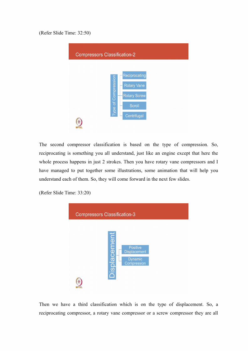
The second compressor classification is based on the type of compression. So,
reciprocating is something you all understand, just like an engine except that here the
whole process happens in just 2 strokes. Then you have rotary vane compressors and I
have managed to put together some illustrations, some animation that will help you
understand each of them. So, they will come forward in the next few slides.
(Refer Slide Time: 33:20)
Then we have a third classification which is on the type of displacement. So, a
reciprocating compressor, a rotary vane compressor or a screw compressor they are all

positive displacement. Whereas, a centrifugal compressor is a dynamic compression
device so there is no physical displacement happening there.
(Refer Slide Time: 33:43)
Now, let us first look at a reciprocating compressor. So, we have the downward stroke
where refrigerant and blue color comes it is a low temperature, low pressure and we
throw it out, there is a valve the suction valve, the discharge valve and then the
component inside consists of a wristband connecting rod crankshaft.
(Refer Slide Time: 33:54)

Pretty much stuff you may have already you know studied and been familiar with. And
now you can have a single cylinder compressor or you could have multiple cylinders,
you could have them inline, you could have them in a V shape.
(Refer Slide Time: 34:11)
And all those opportunities are there just like in automobile engines the same thing
happens in compressors, the higher the size the more the opportunity to reduce
vibrations, and improve energy efficiency by playing around with the different layouts.
Now, we look at rotary vane compressor and you would you do not perhaps; have this in
your mind that why do we need a rotary vane compressor. When we already have been
familiar with the recip compressor and the main thing is cost. The other difference
between a rotary and a recip compressor is how the compressor motor is cooled. And we
can get into those things, but first let us look at this animation. So, here compression
happens over 2 revolutions.

(Refer Slide Time: 34:50)
There is again a piston and there is circular motion there is a vane, which is moving up
and down. The vane separates the high pressure and the low pressure refrigerant. And we
will in a while look at what happens. So, you need just one valve first of all you do not
need a suction value just need one discharge valve, and then the refrigerant leaves. The
other thing to notice is that it will consist of steps of taking the entire refrigerant fill a
certain area and then gradually compress it while the other part of the chamber is being
filled with low pressure and low temperature refrigerant.
(Refer Slide Time: 35:33)
So, you can see this go down slowly and here the discharge side, one on the left the
refrigerant is getting compressed and the pressure is reducing on the right hand side
which draws a refrigerant from the evaporator. So, as we move we can see the space on
the left getting smaller and therefore, the pressure going up; until it is almost negligible
and the entire refrigerant is forced out, and a new set of you can say refrigerant
molecules are there to again get compressed. So, this whole thing will continue, and
every 2 revolutions we would have moved refrigerant from the suction side into the
discharge. So, in this next revolution the entire pink area will just diminish and the entire
refrigerant will escape through the discharge port.
So, the motor heat was not actually adding to any load on the refrigeration system, the
evaporator and the refrigerant is spread. So, if you look at the refrigeration cycle there is
no heat that is being added in the evaporation side. It is all being rejected to the
condenser directly; for that reason, rotary compressors are also at a higher risk of failure
when operating in high ambient temperatures, because the thresholds for motor winding
temperatures are common across compressors.
So, you have a class f insulation motor that can take temperatures up to 130 degrees
centigrade. Then that can be used interchangeably across compressors with the
compressor. That exposes the motor winding to a high temperature is likely to cause
issues. Whereas, you know scroll compressor the refrigerant from the evaporator first
passes over the motor cooling it, taking up a lot of heat.
So, it is an inefficient way of transferring heat to the low temperature refrigerant, but
then it also leads to reliability. So, these are the tradeoffs that you need to be aware of
when we looking at ordinary of technologies. Reciprocating compressors, like scroll
compressors also have the same benefit the motor is in the cold refrigerant area.

(Refer Slide Time: 37:58)
So now let us look at the inside of a screw compressor. Now any of you is interested in
these animations they are all available on YouTube, like you just need to be selective
about where they are and which ones to use, and then you will find them abundantly
available.
(Refer Slide Time: 38:04)
(Refer Slide Time: 38:19)

So, here we see a certain area of the casing which is open. And that is where the
equivalent of suction happens. So, we are drawing refrigerant into the compressor in a
recipe, and there is a small animation on the right hand side which is just showing that.
(Refer Slide Time: 38:50)
And then once it is inside that shell then the screw compressor consists of a male screw
and a female screw. And the 2 together displays positively the refrigerant that has got
trapped between the casing; so, it is pushed into the discharge area.

(Refer Slide Time: 39:02)
Does that make some sense? I will give you some glimpse of what happens in different
types of compressors. There is one more, we talked about positive displacement. All this
while we have been looking at positive displacement compressors, what is the other
type?
Student: dynamic.
Dynamic and when you say dynamic, how do you relate to dynamic? You creating
pressure through whatever means, but without directly reducing the volume in a confined
space. So, so here we were forcing the refrigerant to be confined; whereas, in a dynamic
compression we would not do that we would make use of some dynamic forces like
centrifugal force so it should be look at one of those also.

(Refer Slide Time: 40:02)
So, here we have our centrifugal compressor, and in a centrifugal compressor there are
key components consist of an impeller, there are veins and there is a volume casing. So,
what we do inside a centrifugal compressor is we use the impeller to impart high velocity
to the refrigerant gas.
(Refer Slide Time: 40:21)
Now, this refrigerant at high velocity by itself is not refrigerant at high pressure. So, we
need some means of translating this kinetic energy into pressure, static pressure and that
is done by expanding it.

(Refer Slide Time: 40:31)
So, allowing for an area in the volume where the gas expands and gain static. So, the
kinetic energy gets translated into static; so we get static pressure.
(Refer Slide Time: 40:53)
So, here we can see the impeller, and all the impeller is doing is throwing the refrigerant
centrifugal out.

(Refer Slide Time: 41:06)
So, low velocity refrigerant entering in the center and being thrown red will be readily
outside.
(Refer Slide Time: 41:27)
And then we have a diffuser, so the primary function of the diffuser is to contain this
kinetic energy and gradually allow for expansion. So, that we have high pressure
refrigerant available at the outlet of the centrifugal compressor. And then we need a
means of capacity regulation.

(Refer Slide Time: 41:50)
(Refer Slide Time: 41:57)
So, to regulate capacity we use something like a blocking device at the inlet of the
centrifugal compressor. So, those guide vanes would close partially in response to need
so our capacity changes.
So, here you can see them you know gradually closed, when part load capacity is
required and open fully when you need.

(Refer Slide Time: 42:20)
Now, since this is not such an efficient way of controlling capacity now inverter drives
are used so you regulate the speed of the compressor also.
(Refer Slide Time: 42:33)
And that again needs to, but if you use a combination of both then we can address both
flow rate and head. So, when we want to keep a certain head then vanes would be used
and when we want to reduce the pressure and flow together, then we would lower the
speed using an inverter drive.