QUICK START GUIDE GUIDE DE DÉMARRAGE RAPIDE SCHNELLSTARTANLEITUNG GUIDA INTRODUTTIVA GUÍA BREVE DE...
10
QUICK START GUIDE GUIDE DE DÉMARRAGE RAPIDE SCHNELLSTARTANLEITUNG GUIDA INTRODUTTIVA GUÍA BREVE DE INICIO КРАТКОЕ РУКОВОДСТВО TM LIQUID CPU COOLING UPGRADE KIT 46221 Landing Parkway • Fremont • California • 94538 • USA © 2013 Corsair Components, Inc. All Rights Reserved. The Corsair logo is a registered trademark, and Hydro Series are trademarks of Corsair in the United States and/or other countries. All other names and products are trademarks and property of their respective owners. Printed in China. Document Number: 49-000182 rev AB FORUM: forum.corsair.com TWITTER: twitter.com/corsairmemory H55 PAGE: corsair.com/h55 EMAIL: [email protected] FACEBOOK: facebook.com/corsairmemory BLOG: corsair.com/blog/ USA and CANADA: (800) 205-7657 | INTERNATIONAL: (510) 657-8747 | FAX: (510) 657-8748 corsair.com
-
Upload
independent -
Category
Documents
-
view
3 -
download
0
Transcript of QUICK START GUIDE GUIDE DE DÉMARRAGE RAPIDE SCHNELLSTARTANLEITUNG GUIDA INTRODUTTIVA GUÍA BREVE DE...

QUICK START GUIDEGUIDE DE DÉMARRAGE RAPIDE
SCHNELLSTARTANLEITUNG
GUIDA INTRODUTTIVA
GUÍA BREVE DE INICIO
КРАТКОЕ РУКОВОДСТВО
TM
LIQUID CPU COOLING UPGRADE KIT46221 Landing Parkway • Fremont • California • 94538 • USA
© 2013 Corsair Components, Inc. All Rights Reserved. The Corsair logo is a registered trademark, and Hydro Series are trademarks of Corsair in the United States and/or other countries. All other names and products are trademarks and property of their respective owners. Printed in China.
Document Number: 49-000182 rev AB
FORUM: forum.corsair.comTWITTER: twitter.com/corsairmemory H55 PAGE: corsair.com/h55
EMAIL: [email protected]: facebook.com/corsairmemory
BLOG: corsair.com/blog/
USA and CANADA: (800) 205-7657 | INTERNATIONAL: (510) 657-8747 | FAX: (510) 657-8748
corsair.com
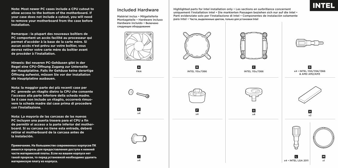
Note: Most newer PC cases include a CPU cutout to allow access to the bottom of the motherboard. If your case does not include a cutout, you will need to remove your motherboard from the case before installation.
Remarque : la plupart des nouveaux boîtiers de PC comportent un accès facilité au processeur qui permet d'accéder à la base de la carte mère. Si aucun accès n'est prévu sur votre boîtier, vous devrez retirer votre carte mère du boîtier avant de procéder à l'installation.
Hinweis: Bei neueren PC-Gehäusen gibt in der Regel eine CPU-Ö�nung Zugang zur Unterseite der Hauptplatine. Falls Ihr Gehäuse keine derartige Ö�nung aufweist, müssen Sie vor der Installation die Hauptplatine ausbauen.
Nota: la maggior parte dei più recenti case per PC prevede un ritaglio dietro la CPU che consente l'accesso alla parte inferiore della scheda madre. Se il case non include un ritaglio, occorrerà rimuo-vere la scheda madre dal case prima di procedere con l'installazione.
Nota: La mayoría de las carcasas de las nuevas PC incluyen una puerta trasera para el CPU a fin de permitir el acceso a la parte inferior del mother-board. Si su carcasa no tiene esta entrada, deberá retirar el motherboard de la carcasa antes de la instalación.
Примечание. На большинстве современных корпусов ПК имеется прорезь для предоставления доступа к нижней части материнской платы. Если на вашем корпусе нет такой прорези, то перед установкой необходимо удалить материнскую плату из корпуса.
Included HardwareMatériel inclus • Mitgelieferte Montageteile • Hardware incluso Hardware incluido • Включено следующее оборудование
Highlighted parts for Intel installation only • Les sections en surbrillance concernent uniquement l'installation Intel • Die markierten Passagen beziehen sich nur auf die Intel • Parti evidenziate solo per l'installazione di Intel • Componentes de instalación solamente para Intel • Части, выделенные цветом, только для установки Intel
x4I
x2H
x4
E
FAN
A
INTEL 115x/1366
B
INTEL 115x/1366
C
x4
F
x4 • INTEL 1155/1156/1366& AMD AM2/AM3
D
x4G
x4 • INTEL LGA 2011
L
x1
M
AMD AM2/AM3
J
AMD AM2/AM3
K
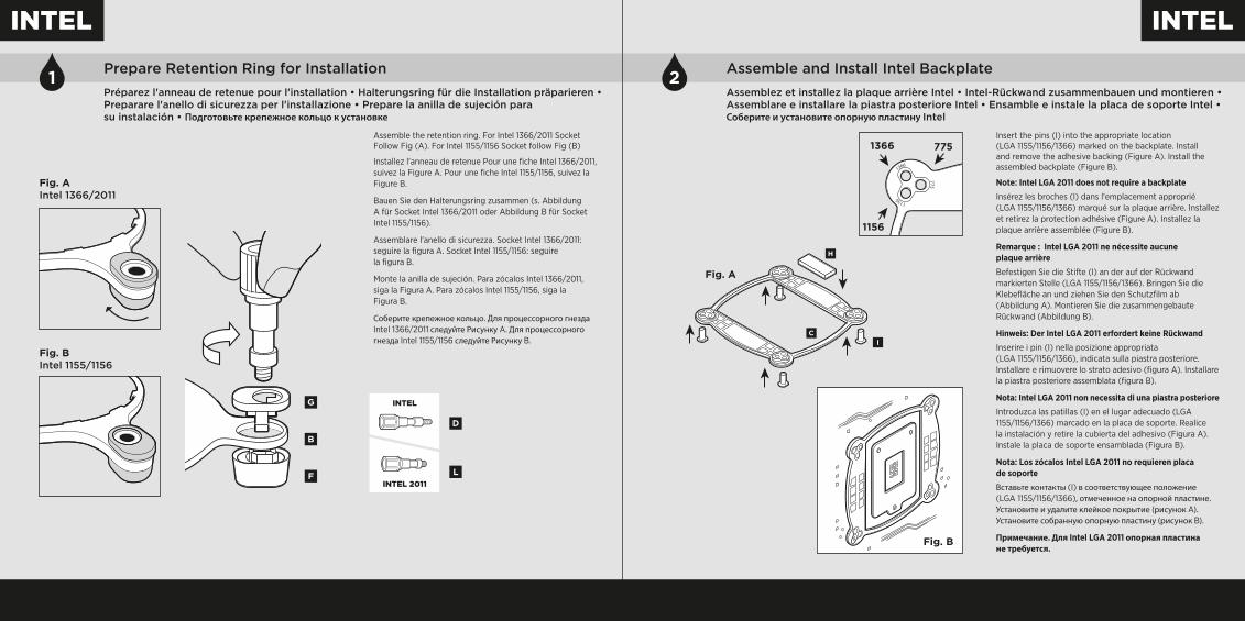
1 Prepare Retention Ring for InstallationPréparez l'anneau de retenue pour l'installation • Halterungsring für die Installation präparieren • Preparare l'anello di sicurezza per l'installazione • Prepare la anilla de sujeción para su instalación • Подготовьте крепежное кольцо к установке
2 Assemble and Install Intel BackplateAssemblez et installez la plaque arrière Intel • Intel-Rückwand zusammenbauen und montieren • Assemblare e installare la piastra posteriore Intel • Ensamble e instale la placa de soporte Intel • Соберите и установите опорную пластину Intel
Assemble the retention ring. For Intel 1366/2011 Socket Follow Fig (A). For Intel 1155/1156 Socket follow Fig (B)
Installez l'anneau de retenue Pour une fiche Intel 1366/2011, suivez la Figure A. Pour une fiche Intel 1155/1156, suivez la Figure B.
Bauen Sie den Halterungsring zusammen (s. Abbildung A für Socket Intel 1366/2011 oder Abbildung B für Socket Intel 1155/1156).
Assemblare l'anello di sicurezza. Socket Intel 1366/2011: seguire la figura A. Socket Intel 1155/1156: seguire la figura B.
Monte la anilla de sujeción. Para zócalos Intel 1366/2011, siga la Figura A. Para zócalos Intel 1155/1156, siga la Figura B.
Соберите крепежное кольцо. Для процессорного гнезда Intel 1366/2011 следуйте Рисунку A. Для процессорного гнезда Intel 1155/1156 следуйте Рисунку B.
Insert the pins (I) into the appropriate location (LGA 1155/1156/1366) marked on the backplate. Install and remove the adhesive backing (Figure A). Install the assembled backplate (Figure B).
Note: Intel LGA 2011 does not require a backplate
Insérez les broches (I) dans l'emplacement approprié (LGA 1155/1156/1366) marqué sur la plaque arrière. Installez et retirez la protection adhésive (Figure A). Installez la plaque arrière assemblée (Figure B).
Remarque : Intel LGA 2011 ne nécessite aucune plaque arrière
Befestigen Sie die Stifte (I) an der auf der Rückwand markierten Stelle (LGA 1155/1156/1366). Bringen Sie die Klebefläche an und ziehen Sie den Schutzfilm ab (Abbildung A). Montieren Sie die zusammengebaute Rückwand (Abbildung B).
Hinweis: Der Intel LGA 2011 erfordert keine Rückwand
Inserire i pin (I) nella posizione appropriata (LGA 1155/1156/1366), indicata sulla piastra posteriore. Installare e rimuovere lo strato adesivo (figura A). Installare la piastra posteriore assemblata (figura B).
Nota: Intel LGA 2011 non necessita di una piastra posteriore
Introduzca las patillas (I) en el lugar adecuado (LGA 1155/1156/1366) marcado en la placa de soporte. Realice la instalación y retire la cubierta del adhesivo (Figura A). Instale la placa de soporte ensamblada (Figura B).
Nota: Los zócalos Intel LGA 2011 no requieren placa de soporte
Вставьте контакты (I) в соответствующее положение (LGA 1155/1156/1366), отмеченное на опорной пластине. Установите и удалите клейкое покрытие (рисунок A). Установите собранную опорную пластину (рисунок B).
Примечание. Для Intel LGA 2011 опорная пластина не требуется.
F
B
G
Fig. A Intel 1366/2011
Fig. B Intel 1155/1156
D
LINTEL 2011
INTEL
Fig. B
1366 775
1156
1366
1156
775
I
Fig. A
C
H

3 Install Assembled Intel Retention Ring and Clip onto Pump Head Installez l'anneau de retenue et le clip sur la tête de pompe • Intel-Halterungsring und -clip auf dem Pumpenkopf montieren • Installare il fermo e l'anello di sicurezza Intel assemblato sulla testina della pompa • Instale la anilla de sujeción Intel ensamblada y la abrazadera en el cabezal de bombeo • Установите собранное крепежное кольцо Intel и зажим на верхнюю часть корпуса насоса
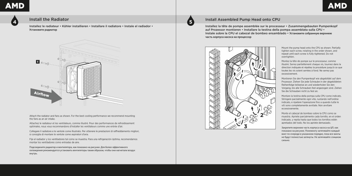
4 Install the RadiatorInstallez le radiateur • Kühler installieren • Installare il radiatore • Instale el radiador • Установите радиатор
Install the assembled retention ring and retention clip onto pump head.
Installez l'anneau de retenue et le clip sur la tête de pompe.
Montieren Sie den zusammengebauten Halterungsring und -clip auf dem Pumpenkopf.
Installare il fermo e l'anello di sicurezza assemblato sulla testina della pompa.
Instale la anilla de sujeción ensamblada y la abrazadera de retención en el cabezal de bombeo.
Установите собранное крепежное кольцо и крепежный зажим на верхнюю часть корпуса насоса.
Attach the radiator and fans as shown. For the best cooling performance we recommend mounting the fans as an air intake.
Attachez le radiateur et les ventilateurs, comme illustré. Pour des performances de refroidissement optimales, nous vous recommandons d'installer les ventilateurs comme une entrée d'air.
Collegare il radiatore e le ventole come illustrato. Per ottenere le prestazioni di ra�reddamento migliori, si consiglia di montare le ventole come aspiratori d'aria.
Fije el radiador y los ventiladores tal como se muestra. Para una refrigeración óptima, recomendamos montar los ventiladores como entradas de aire.
Подсоедините радиатор и вентилятора, как показано на рисунке. Для более эффективного охлаждения рекомендуется установить вентиляторы таким образом, чтобы они нагнетали воздух внутрь.
M
E
Airflow

5 Install Assembled Pump Head onto CPU Installez la tête de pompe assemblée sur le processeur • Zusammengebauten Pumpenkopf auf Prozessor montieren • Installare la testina della pompa assemblata sulla CPU •Instale sobre la CPU el cabezal de bombeo ensamblado • Установите собранную верхнюю часть корпуса насоса на процессор
6 Connect Power to Fan and Pump
Reliez les ventilateurs et la pompe à l'alimentation • Lüfter und Pumpe anschließen • Collegare ventole e pompa all'alimentazione • Conecte la alimentación de los ventiladores y la bomba • Подключение питания вентиляторов и насоса
Mount the pump head onto the CPU as shown. Partially tighten each screw, rotating in the order shown, and repeat until each screw is fully tightened. Do not overtighten.
Montez la tête de pompe sur le processeur, comme illustré. Serrez partiellement chaque vis, tournez dans la direction indiquée et répétez la procédure jusqu'à ce que toutes les vis soient serrées à fond. Ne serrez pas excessivement.
Montieren Sie den Pumpenkopf wie abgebildet auf dem Prozessor. Ziehen Sie jede Schraube in der abgebildeten Reihenfolge teilweise an und wiederholen Sie den Vorgang, bis alle Schrauben fest angezogen sind. Ziehen Sie die Schrauben nicht zu fest an.
Montare la testina della pompa sulla CPU come indicato. Stringere parzialmente ogni vite, ruotando nell'ordine indicato, e ripetere l'operazione fino a quando tutte le viti sono completamente avvitate. Non avvitare eccessivamente.
Monte el cabezal de bombeo sobre la CPU como se muestra. Apriete parcialmente cada tornillo, en el orden indicado, y repita hasta que todos los tornillos estén apretados del todo. No los apriete demasiado.
Закрепите верхнюю часть корпуса насоса на ЦП, как показано на рисунке. Понемногу затягивайте каждый винт по очереди в указанном порядке, пока все винты не будут полностью затянуты. Не затягивайте слишком сильно.
Connect the pump power connector to any available 3-pin or 4-pin fan header on the motherboard.
Branchez le fil d'alimentation de la pompe à une fiche à trois ou quatre broches libre sur la carte mère.
Verbinden Sie den Stecker der Pumpe mit einem beliebigen, freien drei- oder vierpoligen Lüfteranschluss auf der Hauptplatine.
Collegare il connettore di alimentazione della pompa a qualsiasi header per ventola a 3 o 4 pin disponibile sulla scheda madre.
Enchufe el conector de alimentación de la bomba a uno de los cabezales de ventilador de 3 ó 4 patillas de la placa base.
Разъем питания насоса подключите к любому из имеющихся на материнской плате 3-контактных или 4-контактных разъемов питания вентилятора.
4-PIN 3-PIN

Included HardwareHighlighted parts for AMD installation only • Les sections en surbrillance concernent uniquement l'installation AMD • Die markierten Passagen beziehen sich nur auf die AMD • Parti evidenziate solo per l'installazione di AMD • Componentes de instalación solamente para AMD • Части, выделенные цветом, только для установки AMD 1 Prepare Retention Ring for Installation
Préparez l'anneau de retenue pour l'installation • Halterungsring für die Installation präparieren • Preparare l'anello di sicurezza per l'installazione • Prepare la anilla de sujeción para su instalación • Подготовьте крепежное кольцо к установке
Assemble the retention ring. For AMD AM2/AM3 Socket follow Figure A.
Installez l'anneau de retenue Pour une fiche AM2/AM3 AMD, suivez la Figure A.
Bauen Sie den Halterungsring zusammen (s. Abbildung A für Socket AMD AM2/AM3).
Assemblare l'anello di sicurezza. Socket AMD AM2/AM3: seguire la figura A.
Monte la anilla de sujeción. Para zócalos AMD AM2/AM3, consulte la Figura A.
Соберите крепежное кольцо. Для процессорного гнезда AMD AM2/AM3 следуйте Рисунку A.
F
B
G
Fig. A AMD AM2/AM3
D
INTEL/AMD
x4I
x2H
x4
E
FAN
A
INTEL 115x/1366
B
INTEL 115x/1366
C
x4
F
x4 • INTEL 1155/1156/1366& AMD AM2/AM3
D
x4G
x4 • INTEL LGA 2011
L
x1
M
AMD AM2/AM3
J
AMD AM2/AM3
K

3Install Assembled AMD Retention Ring and Clip onto Pump Head
Installez l'anneau de retenue et le clip AMD sur la tête de pompe • AMD-Halterungsring und -clip auf dem Pumpenkopf montieren • Installare il fermo e l'anello di sicurezza AMD assemblato sulla testina della pompa • Instale la anilla de sujeción AMD ensamblada y la abrazadera en el cabezal de bombeo • Установите собранное крепежное кольцо AMD и зажим на верхнюю часть корпуса насоса
Install the assembled retention ring and retention clip onto pump head.
Installez l'anneau et le clip de retenue assemblés sur la tête de pompe.
Montieren Sie den zusammengebauten Halterungsring und -clip auf dem Pumpenkopf.
Installare il fermo e l'anello di sicurezza assemblato sulla testina della pompa.
Instale la anilla de sujeción ensamblada y la abrazadera de retención en el cabezal de bombeo.
Установите собранное крепежное кольцо и крепежный зажим на верхнюю часть корпуса насоса.
2 Assemble and Install AMD BackplateAssemblez et installez la plaque arrière AMD • AMD-Rückwand zusammenbauen und montieren • Assemblare e installare la piastra posteriore AMD • Ensamble e instale la placa de soporte AMD • Соберите и установите опорную пластину AMD
Insert the pins (I) into the AMD mounting backplate. Install and remove the adhesive backing (Figure A). Install the assembled backplate (Figure B).
Note: The stock AMD mounting bracket may need to be removed before the AMD backplate can be installed.
Insérez les broches (I) dans la plaque arrière de montage AMD. Installez et retirez la protection adhésive (Figure A). Installez la plaque arrière assemblée (Figure B).
Remarque : Il est possible que le support de fixation AMD doive être retiré avant d'installer la plaque arrière AMD.
Befestigen Sie die Stifte (I) an der AMD-Rückwand. Bringen Sie die Klebefläche an und ziehen Sie den Schutzfilm ab (Abbildung A). Montieren Sie die zusammengebaute Rückwand (Abbildung B).
Hinweis: Die AMD-Montagehalterungen müssen u. U. entfernt werden, bevor die AMD-Rückwand installiert werden kann.
Inserire i pin (I) nella piastra posteriore di montaggio AMD. Installare e rimuovere lo strato adesivo (figura A). Installare la piastra posteriore assemblata (figura B).
Nota: potrebbe essere necessario rimuovere la sta�a di montaggio AMD prima di installare la piastra posteriore AMD.
Introduzca las patillas (I) en la placa de montaje AMD. Realice la instalación y retire la cubierta del adhesivo (Figura A). Instale la placa de soporte ensamblada (Figura B).
Nota: Puede que sea necesario retirar el soporte de montaje AMD de serie antes de poder instalar la placa de montaje AMD.
Вставьте контакты (I) в опорную пластину AMD. Установите и удалите клейкое покрытие (рисунок A). Установите собранную опорную пластину (рисунок B).
Примечание. Возможно, вам придется удалить стандартный монтажный кронштейн AMD перед установкой опорной платины AMD.
I
HK
Fig. A
Fig. B
M
4 5 Install Assembled Pump Head onto CPU
Installez la tête de pompe assemblée sur le processeur • Zusammengebauten Pumpenkopf auf Prozessor montieren • Installare la testina della pompa assemblata sulla CPU •Instale sobre la CPU el cabezal de bombeo ensamblado • Установите собранную верхнюю часть корпуса насоса на процессор
Install the RadiatorInstallez le radiateur • Kühler installieren • Installare il radiatore • Instale el radiador • Установите радиатор
Attach the radiator and fans as shown. For the best cooling performance we recommend mounting the fans as an air intake.
Attachez le radiateur et les ventilateurs, comme illustré. Pour des performances de refroidissement optimales, nous vous recommandons d'installer les ventilateurs comme une entrée d'air.
Collegare il radiatore e le ventole come illustrato. Per ottenere le prestazioni di ra�reddamento migliori, si consiglia di montare le ventole come aspiratori d'aria.
Fije el radiador y los ventiladores tal como se muestra. Para una refrigeración óptima, recomendamos montar los ventiladores como entradas de aire.
Подсоедините радиатор и вентилятора, как показано на рисунке. Для более эффективного охлаждения рекомендуется установить вентиляторы таким образом, чтобы они нагнетали воздух внутрь.
Mount the pump head onto the CPU as shown. Partially tighten each screw, rotating in the order shown, and repeat until each screw is fully tightened. Do not overtighten.
Montez la tête de pompe sur le processeur, comme illustré. Serrez partiellement chaque vis, tournez dans la direction indiquée et répétez la procédure jusqu'à ce que toutes les vis soient serrées à fond. Ne serrez pas excessivement.
Montieren Sie den Pumpenkopf wie abgebildet auf dem Prozessor. Ziehen Sie jede Schraube in der abgebildeten Reihenfolge teilweise an und wiederholen Sie den Vorgang, bis alle Schrauben fest angezogen sind. Ziehen Sie die Schrauben nicht zu fest an.
Montare la testina della pompa sulla CPU come indicato. Stringere parzialmente ogni vite, ruotando nell'ordine indicato, e ripetere l'operazione fino a quando tutte le viti sono completamente avvitate. Non avvitare eccessivamente.
Monte el cabezal de bombeo sobre la CPU como se muestra. Apriete parcialmente cada tornillo, en el orden indicado, y repita hasta que todos los tornillos estén apretados del todo. No los apriete demasiado.
Закрепите верхнюю часть корпуса насоса на ЦП, как показано на рисунке. Понемногу затягивайте каждый винт по очереди в указанном порядке, пока все винты не будут полностью затянуты. Не затягивайте слишком сильно.
E
Airflow

1. How do I know the direction of the air flow of the fan? In arrow located on the side of the fan indicates the direction of air flow.
2. Can I reuse the pre-applied thermal paste on the H55 for a re-installation? Re-installation of the H55 cooler will require you clean off the pre-applied thermal paste and apply an aftermarket paste.
3. Where can I purchase additional Radiator screw for push/pull Configuration? Additional screws can be purchase from www.corsair.com
4. Do I mount the radiator hose up or down? For optimized cooling, Corsair recommends the radiator is mounted hose down.
1. Comment savoir dans quelle direction le flux d'air du ventilateur se déplace ? Une flèche située sur le côté du ventilateur indique la direction du flux.
2. Est-il possible de réutiliser la pâte thermique pré-appliquée sur le H55 en vue d'e�ectuer une nouvelle installation ? Pour réinstaller le dissipateur thermique H55, il vous faudra d'abord nettoyer la pâte thermique pré-appliquée pour la remplacer par une autre pâte neuve.
3. Où peut-on se procurer des vis de radiateurs supplémentaires pour la configuration « Push-Pull » ? Vous pouvez acheter ces vis sur le site Web www.corsair.com
4. Lors de l'installation du radiateur, le tuyau doit-il être placé en haut ou en bas ? Pour un refroidissement optimal, Corsair recommande que le tuyau soit placé vers le bas.
1. Wie erkenne ich die Richtung des Luftstroms, der durch den Lüfter erzeugt wird? Die Richtung des Luftstroms wird durch einen Pfeil auf der Seite des Lüfters signalisiert.
2. Kann ich die auf dem H55 aufgetragene Wärmeleitpaste bei einer Neuinstallation wiederverwenden? Bei der Neuinstallation des H55-Kühlsystems muss die aufgetragene Wärmeleitpaste entfernt und eine neue Paste aufgetragen werden.
3. Wo kann ich zusätzliche Kühlerschrauben für eine „Push-Pull-Konfiguration“ erwerben? Zusätzliche Schrauben können Sie auf www.corsair.com erwerben.
4. Wird der Kühler mit der Leitung nach oben oder nach unten montiert? Um ein optimales Kühlergebnis zu erreichen, empfiehlt Corsair, den Kühler mit der Leitung nach unten zu montieren.
FAQ6 Connect Power to Fan and PumpReliez les ventilateurs et la pompe à l'alimentation • Lüfter und Pumpe anschließen • Collegare ventole e pompa all'alimentazione • Conecte la alimentación de los ventiladores y la bomba • Подключение питания вентиляторов и насоса
Connect pump power connector to any available 3-pin or 4-pin fan on the motherboard.
Branchez le fil d'alimentation de la pompe à une fiche à trois ou quatre broches libre sur la carte mère.
Verbinden Sie den Stecker der Pumpe mit einem beliebigen, freien drei- oder vierpoligen Lüfteranschluss auf der Hauptplatine.
Collegare il connettore di alimentazione della pompa a qualsiasi header per ventola a 3 o 4 pin disponibile sulla scheda madre.
Enchufe el conector de alimentación de la bomba a uno de los cabezales de ventilador de 3 ó 4 patillas de la placa base.
Разъем питания насоса подключите к любому из имеющихся на материнской плате 3-контактных или 4-контактных разъемов питания вентилятора.
4-PIN 3-PIN

Thank you for purchasing Corsair Hydro Series H55 Liquid CPU Cooling Upgrade Kit.This Quick Start Guide will help you install the H55. Please visit: corsair.com/h55 to download a detailed user guide or to obtain technical support.
Merci d'avoir acheté le dissipateur à liquide pour processeur Hydro Series H55 de Corsair.Le guide de démarrage rapide vous aidera à installer le H55. Rendez-vous sur corsair.com/h55 pour télécharger un guide d'utilisation complet ou pour obtenir de l'assistance technique.
Vielen Dank, dass Sie sich für den Corsair Flüssigkühlsystem-Upgrade-Kit Hydro Series H55.Die Schnellstartanleitung führt Sie durch die Installation des H55. Auf corsair.com/h55 können Sie ein umfassendes Benutzerhandbuch herunterladen und technischen Support erhalten.
Grazie per aver acquistato il sistema di ra�reddamento a liquido per CPU Corsair Hydro Series H55.La guida introduttiva illustrerà l'installazione di H55. Visitare corsair.com/h55 per scaricare la guida utente completa o per ottenere supporto tecnico.
Gracias por adquirir el sistema de enfriamiento líquido de máximo rendimiento Hydro Series H55 de Corsair.Esta guía rápida del usuario le ayudará a instalar el H55. Si desea descargar una guía del usuario detallada o solicitar asistencia técnica, visite www.corsair.com/h55
Благодарим за приобретение высокопроизводительной системы охлаждения процессора Corsair Hydro Series H55.Краткое руководство по установке системы охлаждения H55 поможет вам в установке. Загрузить подробное руководство пользователя и получить техническую поддержку можно на веб-сайте www.corsair.com/h55
1. How do I know the direction of the air flow of the fan? In arrow located on the side of the fan indicates the direction of air flow.
2. Can I reuse the pre-applied thermal paste on the H55 for a re-installation? Re-installation of the H55 cooler will require you clean off the pre-applied thermal paste and apply an aftermarket paste.
3. Where can I purchase additional Radiator screw for push/pull Configuration? Additional screws can be purchase from www.corsair.com
4. Do I mount the radiator hose up or down? For optimized cooling, Corsair recommends the radiator is mounted hose down.
1. Comment savoir dans quelle direction le flux d'air du ventilateur se déplace ? Une flèche située sur le côté du ventilateur indique la direction du flux.
2. Est-il possible de réutiliser la pâte thermique pré-appliquée sur le H55 en vue d'e�ectuer une nouvelle installation ? Pour réinstaller le dissipateur thermique H55, il vous faudra d'abord nettoyer la pâte thermique pré-appliquée pour la remplacer par une autre pâte neuve.
3. Où peut-on se procurer des vis de radiateurs supplémentaires pour la configuration « Push-Pull » ? Vous pouvez acheter ces vis sur le site Web www.corsair.com
4. Lors de l'installation du radiateur, le tuyau doit-il être placé en haut ou en bas ? Pour un refroidissement optimal, Corsair recommande que le tuyau soit placé vers le bas.
1. Wie erkenne ich die Richtung des Luftstroms, der durch den Lüfter erzeugt wird? Die Richtung des Luftstroms wird durch einen Pfeil auf der Seite des Lüfters signalisiert.
2. Kann ich die auf dem H55 aufgetragene Wärmeleitpaste bei einer Neuinstallation wiederverwenden? Bei der Neuinstallation des H55-Kühlsystems muss die aufgetragene Wärmeleitpaste entfernt und eine neue Paste aufgetragen werden.
3. Wo kann ich zusätzliche Kühlerschrauben für eine „Push-Pull-Konfiguration“ erwerben? Zusätzliche Schrauben können Sie auf www.corsair.com erwerben.
4. Wird der Kühler mit der Leitung nach oben oder nach unten montiert? Um ein optimales Kühlergebnis zu erreichen, empfiehlt Corsair, den Kühler mit der Leitung nach unten zu montieren.
1. Come si determina la direzione del flusso d'aria della ventola? La freccia situata sulla parte laterale della ventola indica la direzione del flusso d'aria.
2. È possibile riutilizzare la pasta termoconduttiva preapplicata sull'H55 per una seconda installazione? Per reinstallare il dissipatore di calore H55 è necessario rimuovere la pasta termoconduttiva preapplicata e applicarne una nuova da acquistarsi sul libero mercato.
3. Dove si può acquistare una vite aggiuntiva con configurazione "push-pull" per il radiatore? È possibile acquistare viti aggiuntive sul sito www.corsair.com.
4. Il radiatore va montato con il manicotto rivolto verso l'alto o verso il basso? Per un raffreddamento ottimale, Corsair consiglia di montare il radiatore con il manicotto rivolto verso il basso.
1. ¿Cómo puedo saber el sentido en que circula el aire del ventilador? En el lateral del ventilador hay una flecha que indica el sentido del flujo de aire.
2. ¿Puedo reutilizar la pasta térmica que venía aplicada en el H55 para volver a instalar el refrigerador? Para volver a instalar el refrigerador H55 es preciso limpiar a fondo la pasta térmica que venía aplicada de fábrica y aplicar una capa de pasta nueva, adquirida a tal efecto.
3. ¿Dónde puedo comprar un tornillo adicional de Radiador para configurarlo en modo push/pull (empuje/extracción)? Se pueden comprar tornillos adicionales en www.corsair.com
4. ¿Debo montar el radiador con el tubo hacia arriba o hacia abajo? Para una refrigeración óptima, Corsair recomienda montar el radiador con el tubo hacia abajo.
1. Как определить направление воздушного потока вентилятора? Стрелка на боковой части вентилятора обозначает направление воздушного потока.
2. Можно ли повторно использовать нанесенную термопасту для переустановки H55? Переустановка системы охлаждения H55 требует удаления остатков нанесенной термопасты и нанесения новой термопасты.
3. Где можно приобрести дополнительный винт для радиатора приточно-вытяжной конфигурации? Дополнительные винты можно приобрести на сайте www.corsair.com
4. Должен ли шланг радиатора быть направлен вверх или вниз? Для оптимального охлаждения Corsair рекомендует устанавливать радиатор шлангом вниз.