Qualification of Electronic Components for a Radiation ...
57
I-1 Qualification of Electronic Components for a Radiation Environment: When Standards do not exist - High Energy Physics S. Uznanski, R.G. Alia, M. Brugger, P. Moreira, B. Todd European Organization for Nuclear Research, CERN CH-1211, Genève 23, Switzerland 1 Introduction ............................................................................................................................. 4 1.1 Detector design in the 1990’s ........................................................................................... 4 1.2 Accelerator sector from the 2000’s .................................................................................. 5 2 Approach to Radiation Hardness Assurance in the accelerator environment ......................... 8 2.1 System availability vs. development cost ........................................................................ 8 2.2 Radiation impact on the accelerator performance ............................................................ 8 2.3 Overview of the LHC layout and mixed-field radiation environment ............................. 9 2.4 Impact of radiation environment on system design and operation................................. 10 2.4.1 Radiation level estimation....................................................................................... 10 2.4.2 Observed failure rates ............................................................................................. 11 2.5 Applicability of RHA methods and qualification standards to the accelerator systems 12 3 Component/System radiation characterization at different radiation test facilities .............. 14 3.1 Testing challenges and requirements ............................................................................. 14 3.2 Overview of relevant radiation sources and particle types ............................................ 14 3.3 Component vs. system characterization ......................................................................... 15 3.4 Overview of facilities used for component qualification ............................................... 16 3.4.1 SEE test facilities .................................................................................................... 16 3.4.2 TID and DD test facilities ....................................................................................... 18 3.4.3 Mixed-field large volume SEE, TID and DD tests at CHARM ............................. 18 4 Design case 1: A distributed accelerator system based on COTS ........................................ 23 4.1 Introduction .................................................................................................................... 23 4.2 Design requirements and constraints.............................................................................. 25 4.3 Design flow for radiation-tolerance based on testing..................................................... 26 4.3.1 Overview of the design flow ................................................................................... 26 4.3.2 Component criticality vs. testing strategy............................................................... 27 4.3.3 Radiation characterization tests and component screening .................................... 29 4.3.4 Procurement and lot acceptance tests ..................................................................... 30 4.3.5 System radiation qualification ................................................................................ 31 4.3.5.1 TID and DD system test results ....................................................................... 32 4.3.5.2 SEE system test results .................................................................................... 34 4.3.5.3 Impact of system failure modes on the LHC machine .................................... 34 4.4 Feedback from first months of operation ....................................................................... 35 5 Design case 2: A detector Rad-Hard communication link based on an ASIC...................... 36 5.1 ASIC design activity at CERN ....................................................................................... 36 5.2 Introduction to the GigaBit Transceiver (GBT) project ................................................. 37 5.3 CERN ASIC design flow for radiation hardness ........................................................... 39 5.4 Choice of technology for the GBT project ..................................................................... 41 5.5 Functional design and applied SEE mitigation techniques ............................................ 41 5.5.1 Synthesized standard cells, State Machines ............................................................ 42 5.5.2 Full-custom analogue and high-speed circuits cells ............................................... 43
-
Upload
khangminh22 -
Category
Documents
-
view
0 -
download
0
Transcript of Qualification of Electronic Components for a Radiation ...
I-1
Qualification of Electronic Components for a Radiation Environment: When Standards do not exist - High Energy Physics
S. Uznanski, R.G. Alia, M. Brugger, P. Moreira, B. Todd European Organization for Nuclear Research,
CERN CH-1211, Genève 23, Switzerland 1 Introduction ............................................................................................................................. 4
1.1 Detector design in the 1990’s ........................................................................................... 4 1.2 Accelerator sector from the 2000’s .................................................................................. 5
2 Approach to Radiation Hardness Assurance in the accelerator environment ......................... 8 2.1 System availability vs. development cost ........................................................................ 8 2.2 Radiation impact on the accelerator performance ............................................................ 8 2.3 Overview of the LHC layout and mixed-field radiation environment ............................. 9 2.4 Impact of radiation environment on system design and operation ................................. 10
2.4.1 Radiation level estimation....................................................................................... 10 2.4.2 Observed failure rates ............................................................................................. 11
2.5 Applicability of RHA methods and qualification standards to the accelerator systems 12 3 Component/System radiation characterization at different radiation test facilities .............. 14
3.1 Testing challenges and requirements ............................................................................. 14 3.2 Overview of relevant radiation sources and particle types ............................................ 14 3.3 Component vs. system characterization ......................................................................... 15 3.4 Overview of facilities used for component qualification ............................................... 16
3.4.1 SEE test facilities .................................................................................................... 16 3.4.2 TID and DD test facilities ....................................................................................... 18 3.4.3 Mixed-field large volume SEE, TID and DD tests at CHARM ............................. 18
4 Design case 1: A distributed accelerator system based on COTS ........................................ 23 4.1 Introduction .................................................................................................................... 23 4.2 Design requirements and constraints .............................................................................. 25 4.3 Design flow for radiation-tolerance based on testing ..................................................... 26
4.3.1 Overview of the design flow ................................................................................... 26 4.3.2 Component criticality vs. testing strategy ............................................................... 27 4.3.3 Radiation characterization tests and component screening .................................... 29 4.3.4 Procurement and lot acceptance tests ..................................................................... 30 4.3.5 System radiation qualification ................................................................................ 31
4.3.5.1 TID and DD system test results ....................................................................... 32
4.3.5.2 SEE system test results .................................................................................... 34
4.3.5.3 Impact of system failure modes on the LHC machine .................................... 34
4.4 Feedback from first months of operation ....................................................................... 35 5 Design case 2: A detector Rad-Hard communication link based on an ASIC. ..................... 36
5.1 ASIC design activity at CERN ....................................................................................... 36 5.2 Introduction to the GigaBit Transceiver (GBT) project ................................................. 37 5.3 CERN ASIC design flow for radiation hardness ........................................................... 39 5.4 Choice of technology for the GBT project ..................................................................... 41 5.5 Functional design and applied SEE mitigation techniques ............................................ 41
5.5.1 Synthesized standard cells, State Machines ............................................................ 42 5.5.2 Full-custom analogue and high-speed circuits cells ............................................... 43
I-2
5.5.3 High-speed digital circuits and configuration registers .......................................... 43 5.5.4 Protection of payload using Forward Error Correction .......................................... 44
5.6 Prototype evaluation ....................................................................................................... 45 5.6.1 X-ray irradiation at CERN ...................................................................................... 45 5.6.2 Heavy-ion irradiation at Louvain-La-Nauve .......................................................... 46 5.6.3 Qualification results and discussion ........................................................................ 48
5.7 Future work on the GBT project .................................................................................... 48 6 How the CERN design flows can be transferred to a design of space systems .................... 50
6.1 RHA flow for a low cost satellite projects ..................................................................... 50 6.2 Extreme environment technology qualification for deep space missions ...................... 51
7 Conclusions ........................................................................................................................... 52 8 Bibliography ......................................................................................................................... 53 9 Acronyms .............................................................................................................................. 56
I-3
Abstract
The radiation environment inside particle accelerators varies significantly depending on location: in certain places it can be comparable to avionic or LEO orbit applications while in others it can differ significantly. In addition, the failure criticality also varies significantly. Thus, the testing standards used for space are not directly applicable. This short course will describe a practical approach to component qualification, system tests and the radiation hardness assurance used to design electronics at CERN. The talk will provide examples of two different design cases: 1) an LHC accelerator control system and 2) a highly redundant LHC detector system.
I-4
1 Introduction
1.1 Detector design in the 1990’s
At the European Organization for Nuclear Research (CERN), particle accelerators are used to accelerate protons and ions to high energies and are being collided either in the detectors or against a fixed target. During the design of the Large Hadron Collider (LHC), it was thought that the future central part of the detectors (trackers) would need to sustain certain levels of radiation. At the beginning, these radiation levels were defined as a Total Ionizing Dose (TID) and Displacement Damage (DD) requirements were predicted to a certain extent using Monte-Carlo codes. Historically, in order to fulfil these radiation requirements, military semiconductor manufacturing processes were considered. A first process was evaluated in 1991. This Radiation-Hardening-By-Process (RHBP) approach had certain disadvantages: it was costly and these were niche processes in dedicated foundries which were facing yield problems. Process variability was high, making radiation hardness inconstant between devices. After one of CERN’s designs for ALICE detector faced a yield problem, and knowing that recent technologies were getting intrinsically better TID performance, the experiments decided to continue with commercial processes using Radiation-Hardening-By-Design (RHBD) techniques. A general statement at that time was that Single Event Effects (SEE) should be covered at the design level and it was thought that SEEs were not a considerable threat to detector designs unlike in space where highly energetic heavy ions were present. At that time, the Nuclear and Space Radiation Effects Conference (NSREC) community was publishing broadly about SEEs, which triggered the first discussions at CERN but it did not gain a lot of attention as the general focus was rather on detectors design, disregarding SEE’s impact on operation. Moreover, the future High Energy Hadron (HEH) fluence was not known making it difficult to perform sound estimations. Systems outside of the detector’s inner tracker were thought not to be exposed to significant levels of radiation. In the late 90’s, a pre-qualification of a commercial 0.25 µm CMOS process for TID and DD performance was carried out, including threshold voltage shifts and leakage currents on multiple reference designs. This work was used for multiple future designs of Application Specific Integrated Circuits (ASIC) for detector use. The first RHBD designs were implemented for ATLAS strip detector chips. At the same time, work started on estimating SEE error rates in the detector environment. There were no methods specifying how to perform such estimations. In addition, the LHC was under construction and its future radiation environment was not known. First efforts simulated the environment and particle spectra, then, these spectra were used to perform the first Monte-Carlo simulations of particle interactions with silicon leading to SEEs. In 1998 [1], the first models started to be developed. In this work the measured or taken from the literature SEU heavy ion cross-sections were used to estimate the SEU proton cross-section. The method proved to be sufficiently accurate for initial estimations, which showed that SEUs were likely to cause malfunctions in the electronics systems. The work continued and resulted in a subsequent publication by Huhtinen et al. in 2000 [2], which presented in detail the complex hadron accelerator environment and proposed a methodology to estimate error rates in this environment. An explicit generation and transport of secondary particles from nuclear interaction, based on Monte-Carlo simulations based on FLUKA, was used. This allowed to make a forecast of the error rates in LHC for electronics components for which Heavy Ion tests results were available.
I-5
As this was done, the detectors were already under construction, their design was on-going and first prototyp chips were available. Outside of the inner tracker, little emphasis was devoted to radiation effects, and commercial components were often used. Nevertheless, these estimations triggered discussions and ultimately led to the creation of the Radiation Hardness Assurance Working Group. By the end of 1999, two Radiation Hardness Assurance (RHA) methodologies were proposed at CERN: one by the ATLAS collaboration [3] and one by CMS [4]. The ATLAS approach to RHA was based on simulation of radiation environments with applied safety factors on the simulated values (up to factor of 120). This approach was based on standard test methods derived for DOD (DD) [5] or ESA (TID and SEE) [6] [7] test methods which were supposed to be applied to the selection of electronic components required by each ATLAS sub-system. Component procurement was performed in four steps:
selection of component types, pre-selection and radiation characterization tests, production lot qualification, component purchase.
This test method was not adopted for the design as it appeared too late in the design process and required a significant design overhead due to large safety margins. There was no manpower nor experience in radiation testing at CERN to be able to follow the RHA flow which would require numerous steps; halting the design, designing radiation test equipment for individual components, performing qualifications and data analyses, writing test reports and completing a component database including traceability of component and manufacturer. The CMS approach differed from that proposed by ATLAS. The CMS technical coordination considered that the design was too advanced for a full component qualification. The approach was rather a test plan and guidelines that proposed to use existing proton test facilities at 230MeV and 60MeV to evaluate component responses to DD, TID and SEE simultaneously. It was based on the assumption of the effectiveness of mono-energetic proton beams described in [1] and proposed component or full board tests embedding mostly Commercial-Off-The-Shelf (COTS) components. As a function of results the failure rates could be estimated and re-design of most sensitive systems could be targeted as a function of priorities. As both the Paul Scherer Institute (PSI) in Switzerland and the Université Catholique de Leuven (UCL) were parts of the CMS collaboration, radiation tests were often performed at irradiation facilities in these Institutes – for which preferential access conditions were granted.
1.2 Accelerator sector from the 2000’s
While the discussion on the radiation tolerance of detector design was on-going, questions were raised concerning the radiation effects in the LHC accelerator systems. A first LHC Radiation Workshop took place in 2001 [8] and it was made an annual event. As the levels were supposed to be significantly lower than those in detectors, equipment groups were facing design challenges and there was a lack of radiation effects expertise in the accelerator sector, this forum for discussion did not result in development of a proper RHA approach for the machine sector. Initial radiation qualification of multiple electronic systems was performed with 60 MeV protons at the UCL giving information prior to construction of the LHC machine but, what as would become clear later during the operation of the LHC, these tests were not sufficient, due to too low energy and fluences to which electronics was tested.
I-6
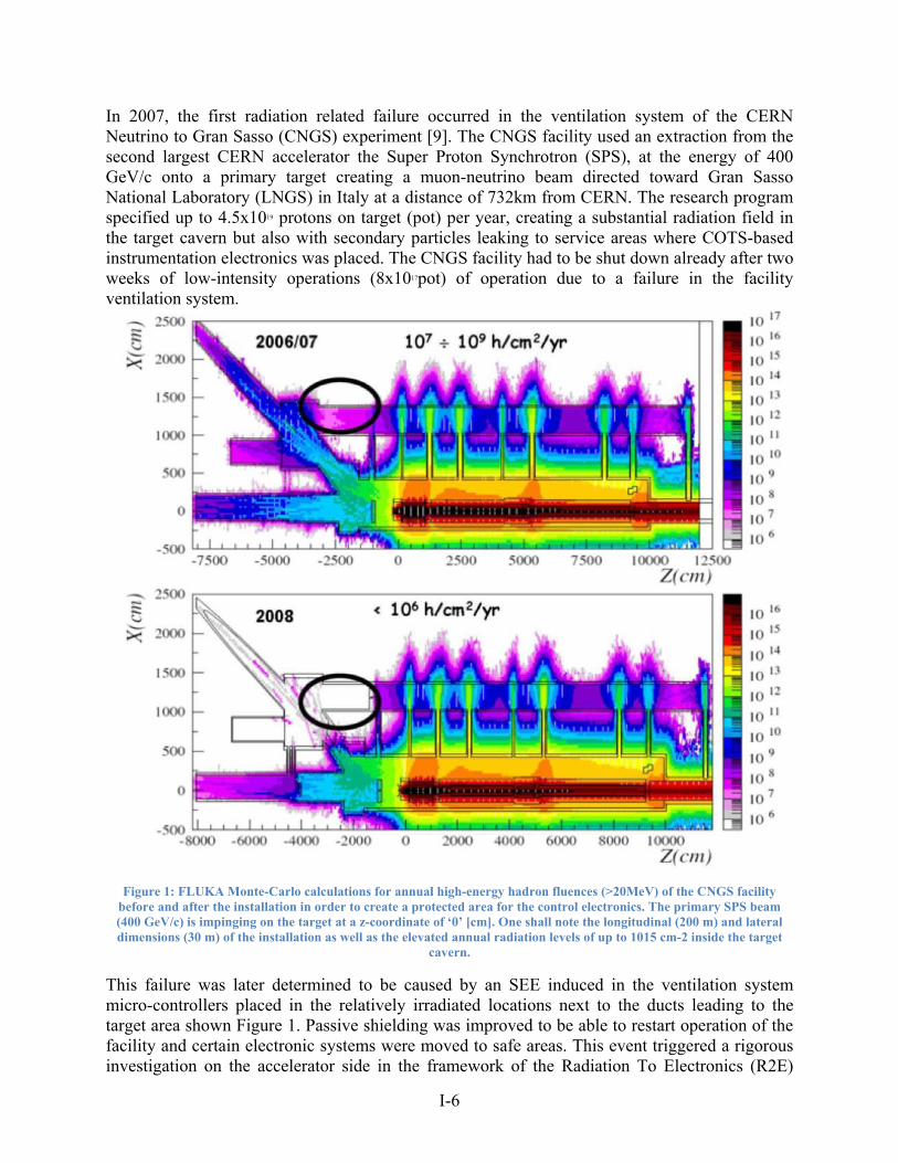
In 2007, the first radiation related failure occurred in the ventilation system of the CERN Neutrino to Gran Sasso (CNGS) experiment [9]. The CNGS facility used an extraction from the second largest CERN accelerator the Super Proton Synchrotron (SPS), at the energy of 400 GeV/c onto a primary target creating a muon-neutrino beam directed toward Gran Sasso National Laboratory (LNGS) in Italy at a distance of 732km from CERN. The research program specified up to 4.5x10¹⁹ protons on target (pot) per year, creating a substantial radiation field in the target cavern but also with secondary particles leaking to service areas where COTS-based instrumentation electronics was placed. The CNGS facility had to be shut down already after two weeks of low-intensity operations (8x10¹⁷pot) of operation due to a failure in the facility ventilation system.
Figure 1: FLUKA Monte-Carlo calculations for annual high-energy hadron fluences (>20MeV) of the CNGS facility before and after the installation in order to create a protected area for the control electronics. The primary SPS beam (400 GeV/c) is impinging on the target at a z-coordinate of ‘0’ [cm]. One shall note the longitudinal (200 m) and lateral dimensions (30 m) of the installation as well as the elevated annual radiation levels of up to 1015 cm-2 inside the target
cavern.
This failure was later determined to be caused by an SEE induced in the ventilation system micro-controllers placed in the relatively irradiated locations next to the ducts leading to the target area shown Figure 1. Passive shielding was improved to be able to restart operation of the facility and certain electronic systems were moved to safe areas. This event triggered a rigorous investigation on the accelerator side in the framework of the Radiation To Electronics (R2E)
I-7
project. The R2E project’s main goal is to assist accelerator operations in optimizing the availability of beam by failure analysis and radiation level monitoring as well as assist equipment groups in the design of reliable accelerator systems. The R2E activity can be presented in three main areas:
Shielding optimization reducing the radiation in a given location Relocation of equipment to the location with lower radiation levels Design and qualification of radiation tolerant or radiation hardened electronic systems.
I-8
2 Approach to Radiation Hardness Assurance in the accelerator environment
CERN’s accelerators, including the LHC, are complex machines composed of tens of systems including power converters to power magnets, machine protection equipment, radio frequency, cryogenics, vacuum, interlocks, beam instrumentation, beam injection/dump and many others. Some of these systems are composed of hundreds or thousands of individual sub-systems and millions of single components. This complexity of design causes reliability problems due to mechanical, electrical, electronic hardware equipment failures as well as those related to software or human error. Radiation-induced failures are one of multiple causes of the unavailability of CERN’s machines for physics.
2.1 System availability vs. development cost
The LHC cycle is composed of several stage: 1) preparation of the machine for injection, 2) injection of beams, 3) ramp up in energy from the injection 450GeV energy to 7TeV, 4) nominally 10h long stable beams stage at a collision energy when particle collisions are delivered in the detectors, 5) ramp down and preparation for the new injection. One definition of availability of the LHC is the percentage of time the machine is in stable beams. Each failure of a system resulting in beam dump leads directly to so-called turnaround time of at least 2h 15m which consists in ramping down, preparing for a new injection, injecting, ramping up before the next stable beams are reached. This is an optimum case, assuming no dedicated repair time. The overall increase system reliability and availability for accelerator operations has a certain development cost. It is practically impossible to eliminate all failures in such a complex system as the LHC nevertheless CERN’s goal is to maximize the time in stable beams phase of the LHC. This requires a continuous work on decreasing the failure mode probability (occurrence) and decreasing the time to repair. Nevertheless, a certain failure rate, even destructive for a system, is acceptable and an intervention in the LHC tunnel is possible in order to replace faulty equipment.
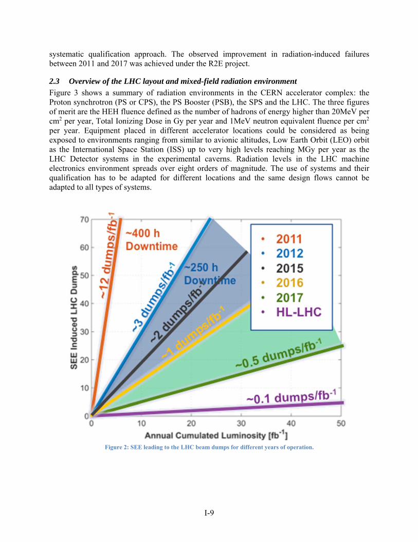
2.2 Radiation impact on the accelerator performance
A large part of CERN’s accelerator control systems were not explicitly designed to be radiation hardened or radiation tolerant but are still exposed to a certain level of radiation depending on their location. When the LHC machine started its main phase of operation in 2011, a certain number of beam dumps were caused by radiation related problems. Figure 2 shows the evolution of SEE induced LHC beam dumps for different years of operation. In 2011, there were over 10 beam dumps related to radiation effects per delivered inverse femtobarn (fb-1) which is a unit proportional to the number of proton collisions in the detector and therefore used as figure of merit of the accelerator performance. These 10 beam dumps per fb-1 resulted in a total around 400h of lost physics. Certain equipment relocation campaigns and additional shielding of equipment decreased this number to around two per fb-1 in 2012. Work continued during the so-called Long Shutdown 1 (LS1) which took place in 2013-2014; additional relocation, shielding and new system upgrades resulted in improvements in 2015 and 2016. Further improvement now requires the redesign of multiple systems to increase their radiation tolerance for the High-Luminosity LHC (HL-LHC) to be achieved in 2025. This process has led to development of qualification methods and guidelines presented in this short course. The initial relatively high failure rate was caused by two main factors: the lack of knowledge concerning machine radiation levels before the LHC started its operation and absence of a
I-9
systematic qualification approach. The observed improvement in radiation-induced failures between 2011 and 2017 was achieved under the R2E project.
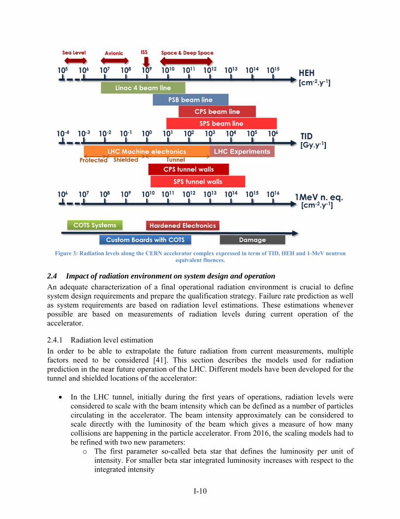
2.3 Overview of the LHC layout and mixed-field radiation environment
Figure 3 shows a summary of radiation environments in the CERN accelerator complex: the Proton synchrotron (PS or CPS), the PS Booster (PSB), the SPS and the LHC. The three figures of merit are the HEH fluence defined as the number of hadrons of energy higher than 20MeV per cm2 per year, Total Ionizing Dose in Gy per year and 1MeV neutron equivalent fluence per cm2 per year. Equipment placed in different accelerator locations could be considered as being exposed to environments ranging from similar to avionic altitudes, Low Earth Orbit (LEO) orbit as the International Space Station (ISS) up to very high levels reaching MGy per year as the LHC Detector systems in the experimental caverns. Radiation levels in the LHC machine electronics environment spreads over eight orders of magnitude. The use of systems and their qualification has to be adapted for different locations and the same design flows cannot be adapted to all types of systems.
Figure 2: SEE leading to the LHC beam dumps for different years of operation.
I-10
Figure 3: Radiation levels along the CERN accelerator complex expressed in term of TID, HEH and 1-MeV neutron
equivalent fluences.
2.4 Impact of radiation environment on system design and operation
An adequate characterization of a final operational radiation environment is crucial to define system design requirements and prepare the qualification strategy. Failure rate prediction as well as system requirements are based on radiation level estimations. These estimations whenever possible are based on measurements of radiation levels during current operation of the accelerator.
2.4.1 Radiation level estimation
In order to be able to extrapolate the future radiation from current measurements, multiple factors need to be considered [41]. This section describes the models used for radiation prediction in the near future operation of the LHC. Different models have been developed for the tunnel and shielded locations of the accelerator:
In the LHC tunnel, initially during the first years of operations, radiation levels were considered to scale with the beam intensity which can be defined as a number of particles circulating in the accelerator. The beam intensity approximately can be considered to scale directly with the luminosity of the beam which gives a measure of how many collisions are happening in the particle accelerator. From 2016, the scaling models had to be refined with two new parameters:
o The first parameter so-called beta star that defines the luminosity per unit of intensity. For smaller beta star integrated luminosity increases with respect to the integrated intensity
I-11
o The second parameter is the bunch crossing angle: with which the luminosity increases per unit of intensity.
In the lightly shielded areas (RRs) in the LHC insertion points 1 and 5, radiation levels scale up with the luminosity and the collimator settings that are placed on each side of the insertion point to decrease the radiation levels downstream from the detector. In 2016, the collimator settings changed which impacted the radiation levels during the 2016 run. The observed increase of radiation levels was form 5 to 10 times higher than predicted due to tighter settings. In the insertion point 7, the radiation levels are mainly impacted by primary collimation system settings that is relatively stable but will change after the LHC Long Shutdown 3 (LS3) in 2025 for High-Luminosity LHC (HL-LHC)
The radiation levels in the heavily shielded LHC locations (UJ and UA) purely scale up with luminosity.
The estimation of average radiation levels also considers the residual gas pressure in the beam pipe that cannot be reliably measured as the pressure is lower than the designed pressure measurement threshold of 10-12 bar. This uncertainty has a direct impact on the uncertainty of the radiation level estimations.
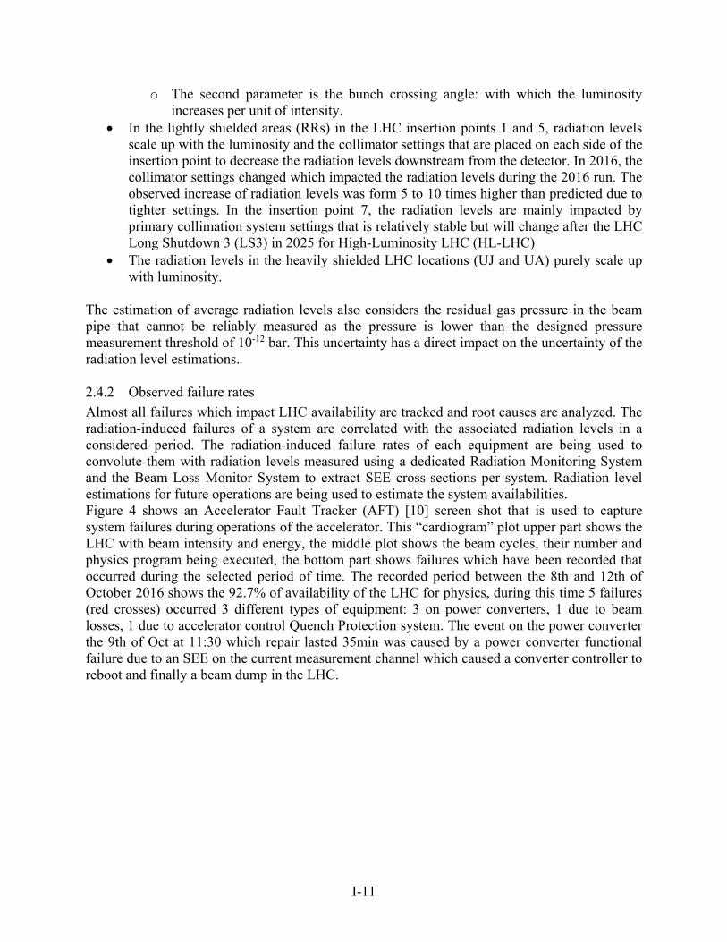
2.4.2 Observed failure rates
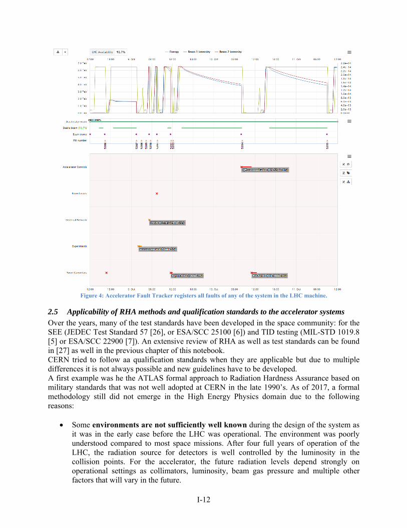
Almost all failures which impact LHC availability are tracked and root causes are analyzed. The radiation-induced failures of a system are correlated with the associated radiation levels in a considered period. The radiation-induced failure rates of each equipment are being used to convolute them with radiation levels measured using a dedicated Radiation Monitoring System and the Beam Loss Monitor System to extract SEE cross-sections per system. Radiation level estimations for future operations are being used to estimate the system availabilities. Figure 4 shows an Accelerator Fault Tracker (AFT) [10] screen shot that is used to capture system failures during operations of the accelerator. This “cardiogram” plot upper part shows the LHC with beam intensity and energy, the middle plot shows the beam cycles, their number and physics program being executed, the bottom part shows failures which have been recorded that occurred during the selected period of time. The recorded period between the 8th and 12th of October 2016 shows the 92.7% of availability of the LHC for physics, during this time 5 failures (red crosses) occurred 3 different types of equipment: 3 on power converters, 1 due to beam losses, 1 due to accelerator control Quench Protection system. The event on the power converter the 9th of Oct at 11:30 which repair lasted 35min was caused by a power converter functional failure due to an SEE on the current measurement channel which caused a converter controller to reboot and finally a beam dump in the LHC.
I-12
Figure 4: Accelerator Fault Tracker registers all faults of any of the system in the LHC machine.
2.5 Applicability of RHA methods and qualification standards to the accelerator systems
Over the years, many of the test standards have been developed in the space community: for the SEE (JEDEC Test Standard 57 [26], or ESA/SCC 25100 [6]) and TID testing (MIL-STD 1019.8 [5] or ESA/SCC 22900 [7]). An extensive review of RHA as well as test standards can be found in [27] as well in the previous chapter of this notebook. CERN tried to follow aa qualification standards when they are applicable but due to multiple differences it is not always possible and new guidelines have to be developed. A first example was he the ATLAS formal approach to Radiation Hardness Assurance based on military standards that was not well adopted at CERN in the late 1990’s. As of 2017, a formal methodology still did not emerge in the High Energy Physics domain due to the following reasons:
Some environments are not sufficiently well known during the design of the system as it was in the early case before the LHC was operational. The environment was poorly understood compared to most space missions. After four full years of operation of the LHC, the radiation source for detectors is well controlled by the luminosity in the collision points. For the accelerator, the future radiation levels depend strongly on operational settings as collimators, luminosity, beam gas pressure and multiple other factors that will vary in the future.
I-13
Strict requirements for system radiation tolerance cannot be defined. In addition, knowing that accelerator systems are designed and used typically for 30 to 40 years, the operational settings will change multiple times during the lifetime of most of systems. These future operational scenarios are often not known during the design phase of systems. There is a mutual dependency between the availability of systems and the operations.
It is difficult to define common system requirements due to accelerator system complexity, system variety and system criticality.
Wide range of particle energies with annual fluences ranging from near ground effects to extreme harsh environments, which makes it difficult to apply same standards especially for the accelerator system design and detectors.
The complex radiation field at CERN composed of light hadrons but unlike space, no heavy ions; Having a high neutron spectra ranging from very low thermal energies to extremely high energies.
Wide and open collaborations including a variety of scientific institutions and companies develop systems for example in the case of detectors. A majority of partners comes from academia which is a very low formalized environment with often no experience in radiation testing. Collaborations can be composed of hundreds of institutions in different countries. Multiple universities might design multiple sub-systems across many countries that make it difficult to apply the same design practices. These collaborations need time to learn and develop a working culture. These collaborations evolve dynamically as new institutions join development teams.
All these reasons make it difficult to standardize the design flow and qualification procedures. Nevertheless, a great amount of effort has been made to propose certain guidelines, share data and knowledge across the system equipment groups as well as external collaborations.
I-14
3 Component/System radiation characterization at different radiation test facilities
3.1 Testing challenges and requirements
As analyzed in detail in the first part of this short course, CERN electronics is facing quite a unique type of radiation environment both in terms of composition of mixed-field radiation and in terms of energy spectrum. Some locations can be directly comparable to certain space environments and some are hugely different. Most equipment is exposed mainly to light hadrons (protons, neutrons, and pions). With this respect all radiation qualification with such hadrons is relevant to CERN application. There are some unique challenges that need to be faced during a component or a system design. With a mass produced systems in thousands and high system availability for the accelerator, the target system function cross-sections are extremely low, often lower than 10×-13 cm2. To achieve such SEE cross-sections, it is needed to test tens to hundreds of components in order to reach the target fluence before inducing a significant TID degradation. The LHC particle spectra range from thermal energies to extremely high energies in tens of GeV which makes testing challenging as there are no commercial facilities with such high particle energies. On top of this, detector is exposed to very high accumulated doses, especially equipment in the inner part of detectors ranging towards 10MGy.
3.2 Overview of relevant radiation sources and particle types
There is a wide selection of radiation facilities that can be used for radiation qualification. This section mentions those that are actively used by the CERN community to perform qualification of components. Relevant radiation facilities use the following particles:
Hadrons of energies from tens of MeV to tens of GeV, which are dominant particles in the accelerator mixed field.
Heavy-ions that allow measurement of the SEE cross-section as a function of Linear Energy Transfer (LET) which can easily be extrapolated to the particle LETs of the accelerator environment.
Co-60 gamma source for standard TID radiation testing X-ray machines that allow to accumulate doses ranging up to MGy at high dose rates
used mostly for detector designs 14MeV neutrons for displacement damage tests for neutron-sensitive components as
optical or analogue circuits. Thermal neutrons are used occasionally as certain LHC locations are exposed to
substantial thermal neutron fluences.
Available and certified test facilities for space applications are well characterized, are widely used by the space community, and offer good dosimetry and suitable irradiation conditions. Nevertheless, there are certain limitations when performing component qualification for CERN:
Proton test facilities do not offer sufficiently high energies. The maximum energy is available at TRIUMF and is equal to 500MeV while the particle energies in the LHC environment can range up to tens of GeV. For certain components the containing high-Z materials this might be problematic as the SEE cross-section does not saturate at the energy of 500MeV [11] [12].
Irradiation of a large number of components requires a long irradiation test time.
I-15
Most of the facilities used for space qualification offer a collimated beam to couple of cm2 which makes irradiation of multiple components at once difficult.
Extrapolation to operating conditions at CERN requires intensive computations and modeling to assess the cross-section as a function of energy and requires confidence in environment characterization.
Practical impossibility to test full boards or full systems.
To overcome these limitations, several test facilities were built at CERN whose main purpose is to offer equipment groups the ability to test in representative conditions as well as irradiate full equipment in large volumes, perform complete system tests and irradiate substantial number of components in parallel. Nevertheless, even the new facilities have certain limitations that force equipment groups to use external help for certain types of qualification:
There is a lack of dedicated DD test facility. There is a throughput problem, so certain test campaigns are subcontracted to external
companies to gain in time.
3.3 Component vs. system characterization
As shown in Figure 3 there are three main types of systems at CERN that can be used in the radiation environment:
COTS systems are either systems designed at CERN and manufactured by external partners or commercially acquired systems, for example some types of power converter. Neither design nor component procurement is supposed to take into account radiation effects, nevertheless system radiation response and failure rate in most cases needs to be evaluated to assess the impact on system availability.
Custom systems based on COTS components are already in more radiation exposed areas and radiation effects are taken into account during design phase. Depending on complexity and criticality system and operational environment, radiation hardness assurance may require only system radiation qualification or a complete screening of COTS components during design phase. One of such system design will be presented in the Design Case 1.
Hardened Electronics is mostly limited to equipment very close to the beam or collision points as the detectors in which the radiation levels are very often orders of magnitude higher than that found elsewhere in the machine. The approach to testing and qualification of all these three cases needs to be adapted. One of such system design will be presented in the Design Case 2.
COTS systems require a top-down system level radiation qualification. Such an approach relies on the availability of a suitable radiation facility in which: 1) system tests directly cover the operational functional scenarios used in a final application and 2) system tests can be performed in the same or nearly the same radiation environment, which makes it easier to understand and extrapolate test results. An obvious drawback of direct system tests without prior component radiation characterization is the much lower observability of component failures on a system level that will impose constraints on the Design of Experiment (DoE) and implementation of test points. These COTS system qualification can be treated as the “black box” qualification in which the system intended function available on its interfaces and implemented test pints can be
I-16
verified, nevertheless neither the internal implementation nor component composition is assumed known. The use of COTS system is excluded from locations highly exposed to radiation and to system low criticality for physics program. The case of custom systems based on COTS components will require a joint top-down system qualification that is complemented by additional component tests that depend on component criticality, complexity of its response to radiation field and its susceptibility to dose rate effects. A key difficulty lies in choosing the most adapted component radiation test and how to relate system with the component test results. On one hand, the system qualification has a considerably lower cost and requires a much shorter beam time with respect to the current state-of-the-art RHA device-level approaches Hardened electronics requires a completely different approach, from careful technology radiation-response evaluation to dedicated ASIC design and radiation qualification on a single component level in adapted radiation facilities.
3.4 Overview of facilities used for component qualification
To cover all these testing scenarios multiple different radiation facilities need to be used. This section does not describe in detail the facilities but reviews which facilities are used for qualification both at CERN and externally and gives their advantages and drawbacks.
3.4.1 SEE test facilities
There are two main particle types used by CERN for the SEE component qualification: protons and heavy-ions (occasionally also neutrons). A proton facility is used for a typical case of COTS component testing and screening. The main facility used by CERN is PSI that is close and its availability for component testing for CERN is quite high in the range of 15 weekends of around 50h of beam time (around 750h of beam per year). The main advantages are that the facility is easily accessible and well characterized as it is the ESA certified facility. It allows to test both SEE and TID that extrapolate well to most of the accelerator environments. The irradiation takes place in the air which makes the COTS component use very easy. One limitation is a low event statistics for low cross-section effects as for example the SEL so it is difficult to exclude certain failure modes in the destined proton radiation environment. Second limitation is a relatively low energy of the beam (230MeV) with respect to the final particle energies in the LHC. In the past, some components were irradiated at TRIUMF thanks to the scientific beam time program up to 500MeV which allow a better characterization of component cross-section at saturation. A heavy-ion facility allows to characterize components the event cross-section with much higher LET values than that can be extrapolated to a proton environment:
the destructive SEE LET threshold value (LETth) value is higher than 40 MeV×cm2/mg, the component will be immune in a mixed-field hadron environment of LHC. The value of 40 MeV×cm2/mg is a maximum LET value of a secondary product that can be produced by an incident proton on an integrated circuit considering the real composition metallization layers in the chip [12].
the LETth value is higher than 15-20 but lower than 40 MeV×cm2/mg, it is potentially unsafe to use this component and further investigations need to be done to analyze the composition of metallization layers to assess the presence of heavy fragments such as tungsten. The bottom limit of 15-20 MeV×cm2/mg was chosen to guarantee the immunity of component to SEE induced by secondary ions from Silicon recoils.
I-17
the LETth value is lower than 15 MeV×cm2/mg, then the component is sensitive to environment and its failure rate needs to be carefully assessed.
I-18
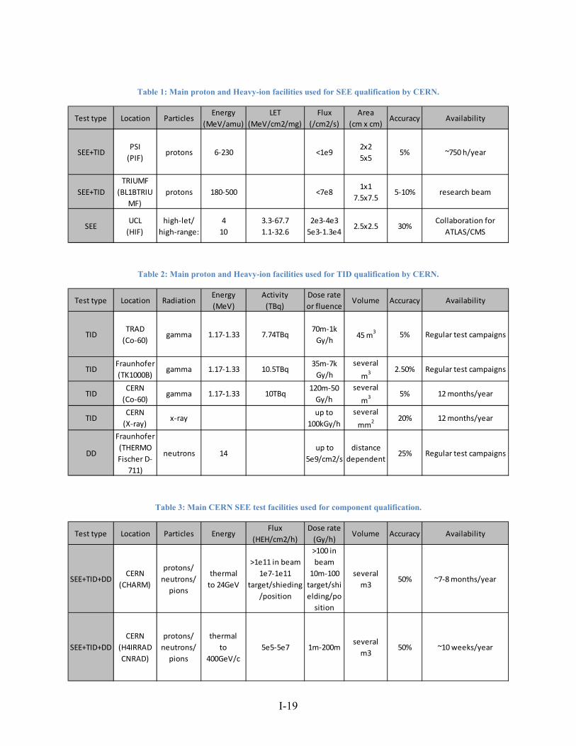
Table 1 shows main proton and heavy-ion facilities used for component qualification, their characteristics and particle types and availability for CERN to perform irradiations.
3.4.2 TID and DD test facilities
The radiation cumulative effects are tested with gamma (TID) and neutrons (DD) facilities. For lower accumulated TID a standard Co-60 gamma source is used and the test facility depends on the availability of the facility and timeline of the project. There is no dedicated DD test zone with 14MeV neutrons at CERN so such tests are subcontracted to external facilities. A dedicated 50kV X-ray machine is used to accumulate large target doses for detector system qualification. It is assembled with a semi-automatic wafer prober for device centering, a cooling element with a controller to set the temperature from cryogenic temperatures to 1000C and a CCD camera. The available dose rates are up 15 Mrad(Si)/h with a diameters of the X-ray beam around 3-4mm for high dose rates. Such tests are available for dedicated ASICs designed at CERN and manufactured by external companies. CERN receives silicon wafers or silicon components without packaging which makes it much easier to solder directly on the dedicated test Printed Circuit Board (PCB). These the X-ray tests need a directly exposed silicon die.
3.4.3 Mixed-field large volume SEE, TID and DD tests at CHARM
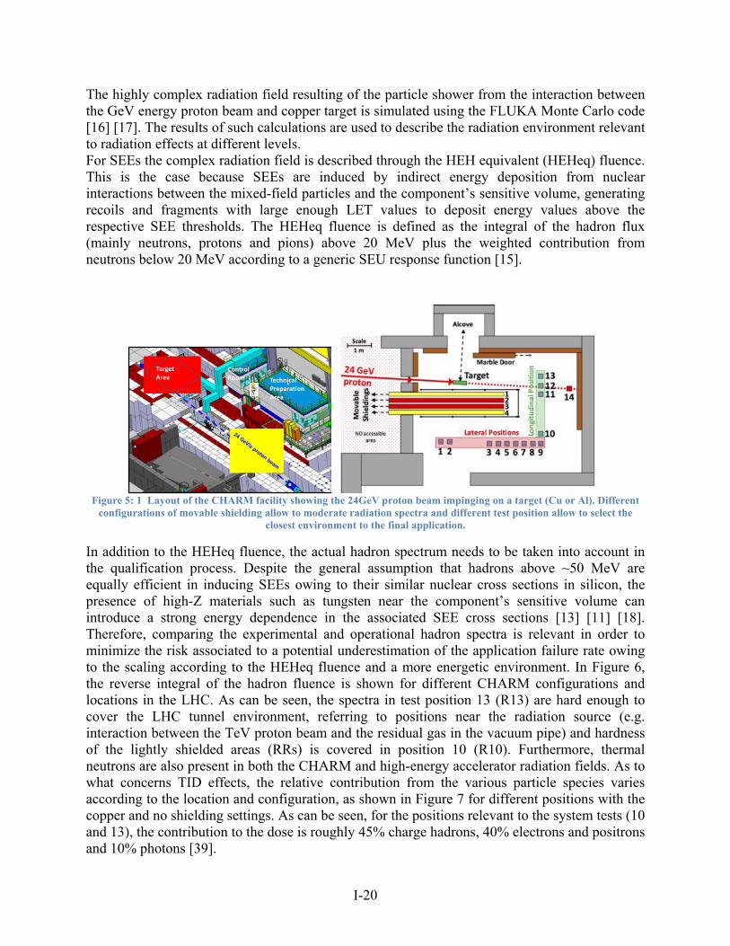
There are several test zones and test facilities used for radiation qualification of components or systems. These facilities were built emulate different accelerator environments. Test zones H4IRRAD and CNGS decommissioned during the Long Shutdown 1 (LS1) and a new facility Cern High-energy AcceleratoR test facility (CHARM) offering much higher beam availability and beam intensity replaced previous facilities. More information about H4IRRAD and CNGS can be found in [9]. CHARM is a radiation test facility at CERN used to qualify components and systems mainly for LHC accelerator equipment applications [13] [14]. The radiation field is generated through the interaction of a 24 GeV/c proton beam extracted from the PS with a 50 cm metallic target. The corresponding mixed-field environment resembles that present in the vicinity of a high-energy accelerator [15] and can be adapted to the application conditions by selecting different test configuration. The latter depends on the selection of the target material (aluminum or copper), test location and movable shielding consisting of four 20 cm thick concrete (yellow) and iron (red) blocks, as illustrated in Figure 5. The test facility is particularly suitable for full system testing owing to the very large irradiation volume available, as well as the relatively homogeneous and penetrating characteristic of the field over distances relevant for equipment testing (i.e. several m3). The facility is operated in such a way that setups are changed on a weekly basis, corresponding to an average integrated proton-on-target intensity of 1016 which yields a maximum weekly TID and HEH equivalent fluence (defined below) of roughly 500 Gy and 1012 HEH per cm2 respectively.
I-19
Table 1: Main proton and Heavy-ion facilities used for SEE qualification by CERN.
Table 2: Main proton and Heavy-ion facilities used for TID qualification by CERN.
Table 3: Main CERN SEE test facilities used for component qualification.
Test type Location ParticlesEnergy
(MeV/amu)
LET
(MeV/cm2/mg)
Flux
(/cm2/s)
Area
(cm x cm)Accuracy Availability
SEE+TIDPSI
(PIF)protons 6‐230 <1e9
2x2
5x55% ~750 h/year
SEE+TID
TRIUMF
(BL1BTRIU
MF)
protons 180‐500 <7e81x1
7.5x7.55‐10% research beam
SEEUCL
(HIF)
high‐let/
high‐range:
4
10
3.3‐67.7
1.1‐32.6
2e3‐4e3
5e3‐1.3e42.5x2.5 30%
Collaboration for
ATLAS/CMS
Test type Location RadiationEnergy
(MeV)
Activity
(TBq)
Dose rate
or fluenceVolume Accuracy Availability
TIDTRAD
(Co‐60)gamma 1.17‐1.33 7.74TBq
70m‐1k
Gy/h45 m
3 5% Regular test campaigns
TIDFraunhofer
(TK1000B)gamma 1.17‐1.33 10.5TBq
35m‐7k
Gy/h
several
m3 2.50% Regular test campaigns
TIDCERN
(Co‐60)gamma 1.17‐1.33 10TBq
120m‐50
Gy/h
several
m3 5% 12 months/year
TIDCERN
(X‐ray)x‐ray
up to
100kGy/h
several
mm2 20% 12 months/year
DD
Fraunhofer
(THERMO
Fischer D‐
711)
neutrons 14up to
5e9/cm2/s
distance
dependent25% Regular test campaigns
Test type Location Particles EnergyFlux
(HEH/cm2/h)
Dose rate
(Gy/h)Volume Accuracy Availability
SEE+TID+DDCERN
(CHARM)
protons/
neutrons/
pions
thermal
to 24GeV
>1e11 in beam
1e7‐1e11
target/shieding
/position
>100 in
beam
10m‐100
target/shi
elding/po
sition
several
m350% ~7‐8 months/year
SEE+TID+DD
CERN
(H4IRRAD
CNRAD)
protons/
neutrons/
pions
thermal
to
400GeV/c
5e5‐5e7 1m‐200mseveral
m350% ~10 weeks/year
I-20
The highly complex radiation field resulting of the particle shower from the interaction between the GeV energy proton beam and copper target is simulated using the FLUKA Monte Carlo code [16] [17]. The results of such calculations are used to describe the radiation environment relevant to radiation effects at different levels. For SEEs the complex radiation field is described through the HEH equivalent (HEHeq) fluence. This is the case because SEEs are induced by indirect energy deposition from nuclear interactions between the mixed-field particles and the component’s sensitive volume, generating recoils and fragments with large enough LET values to deposit energy values above the respective SEE thresholds. The HEHeq fluence is defined as the integral of the hadron flux (mainly neutrons, protons and pions) above 20 MeV plus the weighted contribution from neutrons below 20 MeV according to a generic SEU response function [15].
Figure 5: 1 Layout of the CHARM facility showing the 24GeV proton beam impinging on a target (Cu or Al). Different
configurations of movable shielding allow to moderate radiation spectra and different test position allow to select the closest environment to the final application.
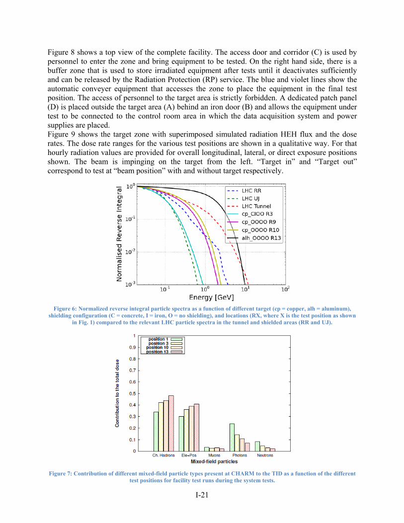
In addition to the HEHeq fluence, the actual hadron spectrum needs to be taken into account in the qualification process. Despite the general assumption that hadrons above ~50 MeV are equally efficient in inducing SEEs owing to their similar nuclear cross sections in silicon, the presence of high-Z materials such as tungsten near the component’s sensitive volume can introduce a strong energy dependence in the associated SEE cross sections [13] [11] [18]. Therefore, comparing the experimental and operational hadron spectra is relevant in order to minimize the risk associated to a potential underestimation of the application failure rate owing to the scaling according to the HEHeq fluence and a more energetic environment. In Figure 6, the reverse integral of the hadron fluence is shown for different CHARM configurations and locations in the LHC. As can be seen, the spectra in test position 13 (R13) are hard enough to cover the LHC tunnel environment, referring to positions near the radiation source (e.g. interaction between the TeV proton beam and the residual gas in the vacuum pipe) and hardness of the lightly shielded areas (RRs) is covered in position 10 (R10). Furthermore, thermal neutrons are also present in both the CHARM and high-energy accelerator radiation fields. As to what concerns TID effects, the relative contribution from the various particle species varies according to the location and configuration, as shown in Figure 7 for different positions with the copper and no shielding settings. As can be seen, for the positions relevant to the system tests (10 and 13), the contribution to the dose is roughly 45% charge hadrons, 40% electrons and positrons and 10% photons [39].
Control Room
TargetArea Technical
PreparationArea
I-21
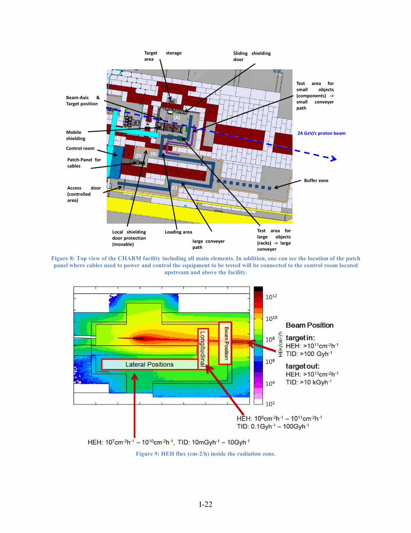
Figure 8 shows a top view of the complete facility. The access door and corridor (C) is used by personnel to enter the zone and bring equipment to be tested. On the right hand side, there is a buffer zone that is used to store irradiated equipment after tests until it deactivates sufficiently and can be released by the Radiation Protection (RP) service. The blue and violet lines show the automatic conveyer equipment that accesses the zone to place the equipment in the final test position. The access of personnel to the target area is strictly forbidden. A dedicated patch panel (D) is placed outside the target area (A) behind an iron door (B) and allows the equipment under test to be connected to the control room area in which the data acquisition system and power supplies are placed. Figure 9 shows the target zone with superimposed simulated radiation HEH flux and the dose rates. The dose rate ranges for the various test positions are shown in a qualitative way. For that hourly radiation values are provided for overall longitudinal, lateral, or direct exposure positions shown. The beam is impinging on the target from the left. “Target in” and “Target out” correspond to test at “beam position” with and without target respectively.
Figure 6: Normalized reverse integral particle spectra as a function of different target (cp = copper, alh = aluminum),
shielding configuration (C = concrete, I = iron, O = no shielding), and locations (RX, where X is the test position as shown in Fig. 1) compared to the relevant LHC particle spectra in the tunnel and shielded areas (RR and UJ).
Figure 7: Contribution of different mixed-field particle types present at CHARM to the TID as a function of the different
test positions for facility test runs during the system tests.
I-22
Figure 8: Top view of the CHARM facility including all main elements. In addition, one can see the location of the patch panel where cables used to power and control the equipment to be tested will be connected to the control room located
upstream and above the facility.
Figure 9: HEH flux (cm-2/h) inside the radiation zone.
Beam‐Axis &Target position
Mobileshielding
Patch‐Panel forcables
Access door(controlledarea)
Local shieldingdoor protection(movable)
Loading area Test area forlarge objects(racks) ‐> largeconveyer
Test area forsmall objects(components) ‐>small conveyerpath
Sliding shieldingdoor
Target storagearea
large conveyerpath
Buffer zone
(A)
(B)
(C)
(D)
Control room
24 GeV/c proton beam
I-23
4 Design case 1: A distributed accelerator system based on COTS
4.1 Introduction
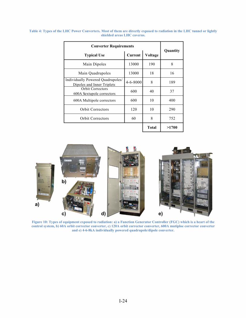
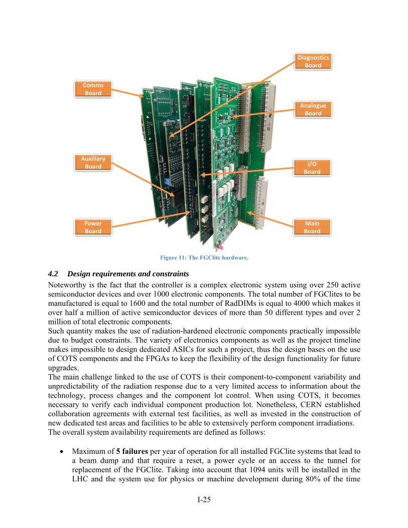
The Large Hadron Collider is a complex machine composed of multiple systems that allow to inject the beam, control its trajectory and parameters, increase its energy and finally extract. To be able to do it there are tens of electronics control, machine protection, safety and beam instrumentation systems. One of the biggest distributed systems in the accelerator are power converters that supply the current to the LHC magnets to finally precisely control the beam trajectory and its optics. Table 4 and Figure 10 show the LHC power converter equipment. Over 1100 converters are exposed to ionizing radiation and placed directly in the LHC tunnel or in lightly shielded LHC caverns. This requires a certain level of radiation tolerance to guarantee the system availability for the LHC operations. This section will present a new radiation-tolerant power converter control system named Function Generator Controller lite (FGClite) that was designed to replace currently installed the FGC2. Figure 11 shows the hardware of the FGClite which consists of seven electronic boards:
Communication Board embeds a Fieldbus real-time communication at 2.5 Mbps with the CERN’s Control Centre (CCC) as well as all critical digital functions for the power converter low level control implemented in two ProASIC-3 FPGAs from Microsemi.
Auxiliary Board embeds all diagnostic functions as digital identification of boards, temperature readings, radiation monitor and communication with up to 60 Radiation-tolerant Diagnostic Interface Modules (RadDIMs).
On-boards RadDIM is a diagnostic boards allowing to spy on the controller power supplies and 24 other digital diagnostic signals.
Analogue Board embeds three redundant temperature compensated 24-bit high-precision ADCs and a fast 16-bit DAC for analogue measurements and reference signal generation.
Input/Output Board that embeds all drivers for all digital and analogue signals connecting to outside world. This board delivers as well current loops for machine protection interlock systems.
Main Board as a passive boards that assures a highly redundant connectivity to all other boards and the power converter through a dedicated backplane.
I-24
Table 4: Types of the LHC Power Converters. Most of them are directly exposed to radiation in the LHC tunnel or lightly shielded areas LHC caverns.
Figure 10: Types of equipment exposed to radiation: a) a Function Generator Controller (FGC) which is a heart of the control system, b) 60A orbit corrector converter, c) 120A orbit corrector converter, 600A mutiploe corrector converter
and e) 4-6-8kA individually powered quadrupole/dipole converter.
Individually Powered Quadrupoles/Dipoles and Inner Triplets
4-6-8000 8 189
Orbit Correctors600A Sextupole correctors
600 40 37
600A Multipole correctors 600 10 400
Orbit Correctors 120 10 290
Orbit Correctors 60 8 752
Main Quadrupoles 13000 18 16
Total >1700
Converter Requirements
Typical Use Current VoltageQuantity
Main Dipoles 13000 190 8
I-25
Figure 11: The FGClite hardware.
4.2 Design requirements and constraints
Noteworthy is the fact that the controller is a complex electronic system using over 250 active semiconductor devices and over 1000 electronic components. The total number of FGClites to be manufactured is equal to 1600 and the total number of RadDIMs is equal to 4000 which makes it over half a million of active semiconductor devices of more than 50 different types and over 2 million of total electronic components. Such quantity makes the use of radiation-hardened electronic components practically impossible due to budget constraints. The variety of electronics components as well as the project timeline makes impossible to design dedicated ASICs for such a project, thus the design bases on the use of COTS components and the FPGAs to keep the flexibility of the design functionality for future upgrades. The main challenge linked to the use of COTS is their component-to-component variability and unpredictability of the radiation response due to a very limited access to information about the technology, process changes and the component lot control. When using COTS, it becomes necessary to verify each individual component production lot. Nonetheless, CERN established collaboration agreements with external test facilities, as well as invested in the construction of new dedicated test areas and facilities to be able to extensively perform component irradiations. The overall system availability requirements are defined as follows:
Maximum of 5 failures per year of operation for all installed FGClite systems that lead to a beam dump and that require a reset, a power cycle or an access to the tunnel for replacement of the FGClite. Taking into account that 1094 units will be installed in the LHC and the system use for physics or machine development during 80% of the time
I-26
during the year, it yields an overall Mean Time To Failure (MTTF) of more than 1.5Mdevh.
The radiation requirements for the FGClite are defined as follows:
Maximum of 2.5 radiation induced failures per year of operation for all installed FGClite systems (50% of total failures) that lead to a beam dump of LHC in nominal conditions. An SEE cross-section of the FGClite is required to be lower to 5×10-13 cm2.
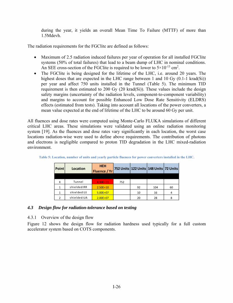
The FGClite is being designed for the lifetime of the LHC, i.e. around 20 years. The highest doses that are expected in the LHC range between 1 and 10 Gy (0.1-1 krad(Si)) per year and affect 750 units installed in the Tunnel (Table 5). The minimum TID requirement is then estimated to 200 Gy (20 krad(Si)). These values include the design safety margins (uncertainty of the radiation levels, component-to-component variability) and margins to account for possible Enhanced Low Dose Rate Sensitivity (ELDRS) effects (estimated from tests). Taking into account all locations of the power converters, a mean value expected at the end of lifetime of the LHC to be around 60 Gy per unit.
All fluences and dose rates were computed using Monte-Carlo FLUKA simulations of different critical LHC areas. These simulations were validated using an online radiation monitoring system [19]. As the fluences and dose rates vary significantly in each location, the worst case locations radiation-wise were used to define above requirements. The contribution of photons and electrons is negligible compared to proton TID degradation in the LHC mixed-radiation environment.
Table 5: Location, number of units and yearly particle fluences for power converters installed in the LHC.
4.3 Design flow for radiation-tolerance based on testing
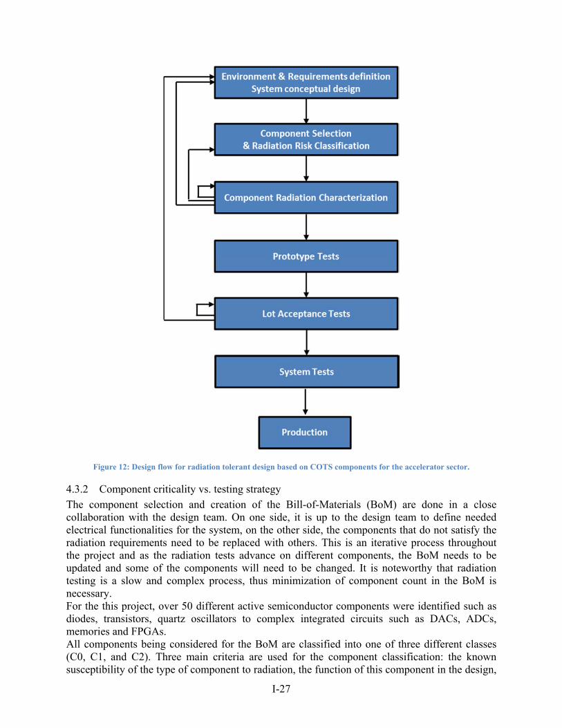
4.3.1 Overview of the design flow
Figure 12 shows the design flow for radiation hardness used typically for a full custom accelerator system based on COTS components.
Point LocationHEH
Fluence / Yr752 Units 122 Units 148 Units 72 Units
X Tunnel 4.00E+11 752
1 shielded:RR 2.50E+10 92 104 60
1 shielded:UJ 5.00E+07 10 16 4
2 shielded:UA 2.00E+07 20 28 8
I-27
Figure 12: Design flow for radiation tolerant design based on COTS components for the accelerator sector.
4.3.2 Component criticality vs. testing strategy
The component selection and creation of the Bill-of-Materials (BoM) are done in a close collaboration with the design team. On one side, it is up to the design team to define needed electrical functionalities for the system, on the other side, the components that do not satisfy the radiation requirements need to be replaced with others. This is an iterative process throughout the project and as the radiation tests advance on different components, the BoM needs to be updated and some of the components will need to be changed. It is noteworthy that radiation testing is a slow and complex process, thus minimization of component count in the BoM is necessary. For the this project, over 50 different active semiconductor components were identified such as diodes, transistors, quartz oscillators to complex integrated circuits such as DACs, ADCs, memories and FPGAs. All components being considered for the BoM are classified into one of three different classes (C0, C1, and C2). Three main criteria are used for the component classification: the known susceptibility of the type of component to radiation, the function of this component in the design,
I-28
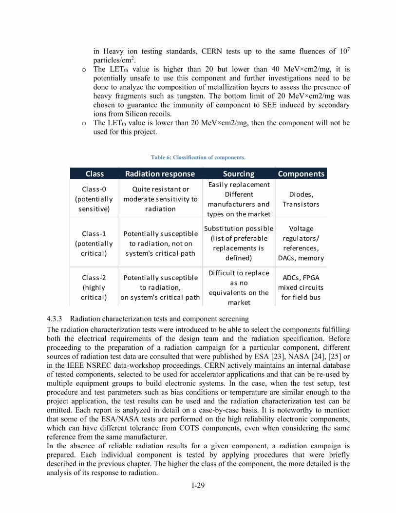
i.e. the impact of its failure on the system reliability, and the ability to find COTS alternatives for the type of component. A more detailed description of the classes with examples of components are shown in Table 6 while Table 7 presents the testing procedures applied to each of the classes.
Class-0 (C0) components are the ones considered as generally resistant in the relevant radiation environment, with different COTS alternatives existing on the market. These components are not used for any critical function in the design. C0 components are tested in a mixed-field radiation environment at CERN, equivalent to LHC tunnel conditions, thus giving a direct indication of the device’s performance in the final application. These tests can be done using a dedicated test setup for component testing or at the electronic board level with components implemented in a system, carrying out their intended function during the tests. The drawback of these tests was the limited beam availability and very long irradiation time due to the relatively low fluences that could be obtained in CNRAD and H4IRRAD test zones [20]. A new mixed field facility CHARM was built to be able to overcome these limitations [21].
Class-1 (C1) components are considered as potentially susceptible to radiation but are not used on the system’s critical path. They are to be irradiated with 230 MeV mono-energetic protons at the PSI radiation facility to measure their susceptibility to SEE and TID. In the LHC tunnel, particle energies reach up to several tens of GeV, a level which cannot be reached at PSI. For many components, the SEE proton cross-sections already saturates for energies in the range of tens of MeV but not for all of them. Moreover, the proton cross-section saturates at different energies for different effects. Typically, the cross-section can increase until GeV energies for effects such as Single Event Latch-up (SEL) [22]. In this work, a safety factor of 3 is applied to account for the high energies not possible to test at PSI. The value of this safety factor is currently under investigation and first results are discussed in ref. [22]. The mixed-field tests are optional at the radiation characterization stage as mono-energetic protons tests allow to assess SEE and TID response of a component in a much shorter time. Only in some cases, an additional test is performed with mixed-field radiation, to complement the results from PSI in case a component fails around the limit of the radiation requirements.
Class-2 (C2) components are considered radiation sensitive and in addition are used on the system’s critical path. They are to be tested in exactly the same way as the C1 components and in addition, a heavy-ion radiation campaign is performed in order to better assess their destructive SEE cross-section (as Single Event Latch-up, Single Event Gate Rupture or Single Event Burnout) and the respective risk in the LHC radiation environment. As all C2 components are highly critical to the project design, their SEL cross-section is the biggest concern while the other SEEs such as Single Event Functional Interrupts (SEFIs) or Single Event Upsets (SEUs) will be mitigated on the design level using Error Correcting Codes (ECC), Triple Modular Redundancy (TMR) or other adapted mitigation methods. The heavy-ion tests give the qualitative information about the destructive SEE mostly used for SEL qualification of C2 components. It is considered that if:
o The SEE LET threshold value (LETth) value is higher than 40 MeV×cm2/mg, the component will be immune to SEE in a mixed-field proton/pion environment of LHC. The value of 40 MeV×cm2/mg is a maximum LET value of a secondary product that can be produced by an incident proton on an integrated circuit considering the real composition metallization layers in the chip [12]. Typically as
I-29
in Heavy ion testing standards, CERN tests up to the same fluences of 107 particles/cm2.
o The LETth value is higher than 20 but lower than 40 MeV×cm2/mg, it is potentially unsafe to use this component and further investigations need to be done to analyze the composition of metallization layers to assess the presence of heavy fragments such as tungsten. The bottom limit of 20 MeV×cm2/mg was chosen to guarantee the immunity of component to SEE induced by secondary ions from Silicon recoils.
o The LETth value is lower than 20 MeV×cm2/mg, then the component will not be used for this project.
Table 6: Classification of components.
4.3.3 Radiation characterization tests and component screening
The radiation characterization tests were introduced to be able to select the components fulfilling both the electrical requirements of the design team and the radiation specification. Before proceeding to the preparation of a radiation campaign for a particular component, different sources of radiation test data are consulted that were published by ESA [23], NASA [24], [25] or in the IEEE NSREC data-workshop proceedings. CERN actively maintains an internal database of tested components, selected to be used for accelerator applications and that can be re-used by multiple equipment groups to build electronic systems. In the case, when the test setup, test procedure and test parameters such as bias conditions or temperature are similar enough to the project application, the test results can be used and the radiation characterization test can be omitted. Each report is analyzed in detail on a case-by-case basis. It is noteworthy to mention that some of the ESA/NASA tests are performed on the high reliability electronic components, which can have different tolerance from COTS components, even when considering the same reference from the same manufacturer. In the absence of reliable radiation results for a given component, a radiation campaign is prepared. Each individual component is tested by applying procedures that were briefly described in the previous chapter. The higher the class of the component, the more detailed is the analysis of its response to radiation.
Class Radiation response Sourcing Components
Class‐0
(potentially sensitive)
Quite resistant or moderate sensitivity to
radiation
Easily replacement
Different manufacturers and types on the market
Diodes,
Transistors
Class‐1
(potentially critical)
Potentially susceptible to radiation, not on system's critical path
Substitution possible (l ist of preferable replacements is
defined)
Voltage regulators/
references, DACs, memory
Class‐2
(highly critical)
Potentially susceptible to radiation,
on system's critical path
Difficult to replace as no
equivalents on the market
ADCs, FPGAmixed circuits for field bus
I-30
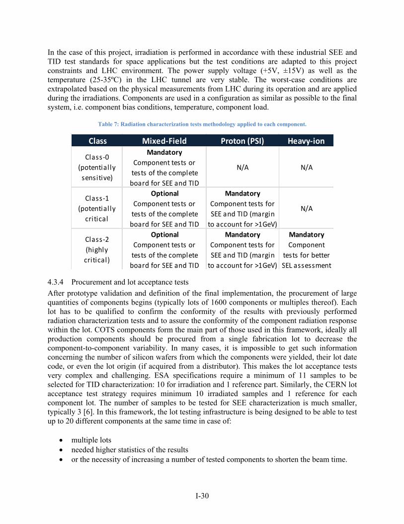
In the case of this project, irradiation is performed in accordance with these industrial SEE and TID test standards for space applications but the test conditions are adapted to this project constraints and LHC environment. The power supply voltage (+5V, ±15V) as well as the temperature (25-35ºC) in the LHC tunnel are very stable. The worst-case conditions are extrapolated based on the physical measurements from LHC during its operation and are applied during the irradiations. Components are used in a configuration as similar as possible to the final system, i.e. component bias conditions, temperature, component load.
Table 7: Radiation characterization tests methodology applied to each component.
4.3.4 Procurement and lot acceptance tests
After prototype validation and definition of the final implementation, the procurement of large quantities of components begins (typically lots of 1600 components or multiples thereof). Each lot has to be qualified to confirm the conformity of the results with previously performed radiation characterization tests and to assure the conformity of the component radiation response within the lot. COTS components form the main part of those used in this framework, ideally all production components should be procured from a single fabrication lot to decrease the component-to-component variability. In many cases, it is impossible to get such information concerning the number of silicon wafers from which the components were yielded, their lot date code, or even the lot origin (if acquired from a distributor). This makes the lot acceptance tests very complex and challenging. ESA specifications require a minimum of 11 samples to be selected for TID characterization: 10 for irradiation and 1 reference part. Similarly, the CERN lot acceptance test strategy requires minimum 10 irradiated samples and 1 reference for each component lot. The number of samples to be tested for SEE characterization is much smaller, typically 3 [6]. In this framework, the lot testing infrastructure is being designed to be able to test up to 20 different components at the same time in case of:
multiple lots needed higher statistics of the results or the necessity of increasing a number of tested components to shorten the beam time.
Class Mixed‐Field Proton (PSI) Heavy‐ion
Class‐0
(potential ly sensitive)
Mandatory
Component tests ortests of the complete board for SEE and TID
N/A N/A
Class‐1
(potential ly critical
Optional
Component tests ortests of the complete board for SEE and TID
Mandatory
Component tests for SEE and TID (margin to account for >1GeV)
N/A
Class‐2
(highly critical)
Optional
Component tests ortests of the complete board for SEE and TID
Mandatory
Component tests for SEE and TID (margin to account for >1GeV)
Mandatory
Component tests for better SEL assessment
I-31
All components are to be irradiated up to 300 Gy of Total Ionizing Dose and to fluences 1×10¹² particles per cm2. If a C0 component does not pass this test, another equivalent component will be purchased and lot acceptance tests will be performed. If a C1 component does not pass the lot acceptance tests, its equivalent will be chosen from a special list of preferred replacements for C1 components prepared in advance during the BoM creation. As shown in Fig. 2, C2 components are highly critical for the design and in case of lot non-conformity, the project’s conceptual design will have to be revised. For all C2 components, it is of the utmost priority to decrease the probability of lot problems. As an example of the C2 component, a very specific high-precision delta-sigma Analogue to Digital Converters (ADCs) from Texas Instruments were selected for the project (ADS1271/ADS1272). Interestingly, both components were manufactured using the same BiCMOS process in the same foundry but one exhibits a high SEL cross-section (ADS1271) while the second one (ADS1281) does not show any SEL up to very high LET values. These results were closely analyzed with the manufacturer and were tracked back to the use of specific depth of the epitaxial layer in both components.
4.3.5 System radiation qualification
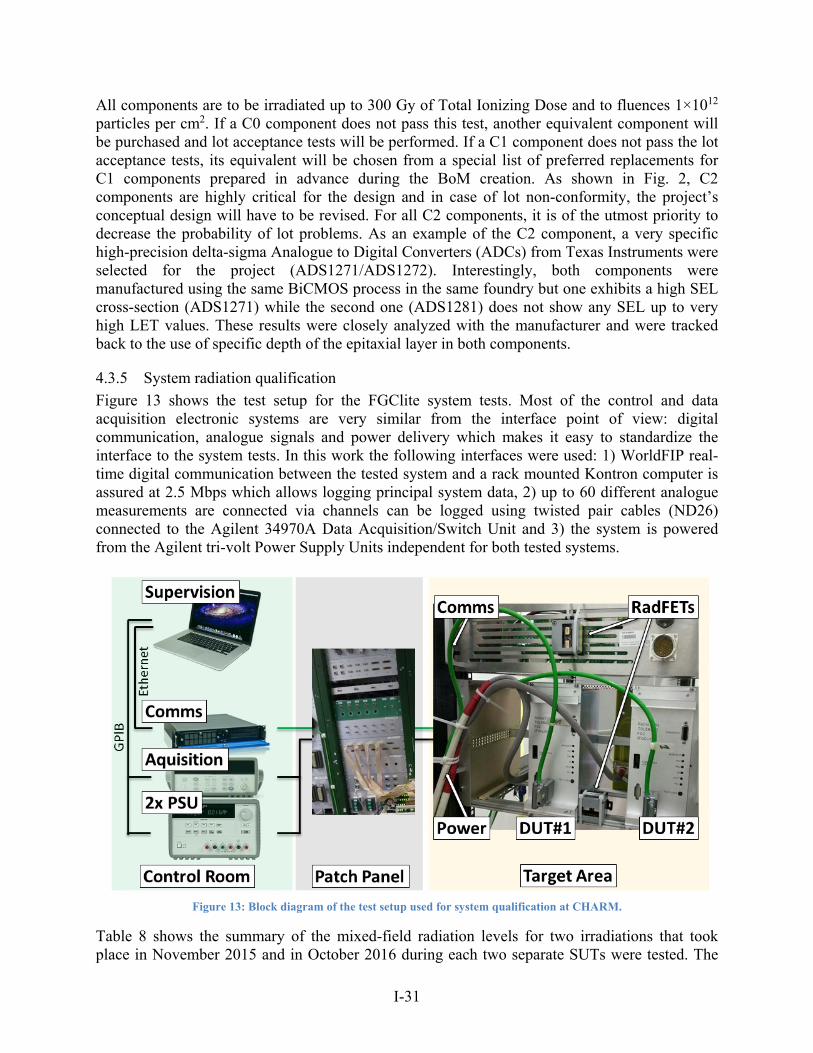
Figure 13 shows the test setup for the FGClite system tests. Most of the control and data acquisition electronic systems are very similar from the interface point of view: digital communication, analogue signals and power delivery which makes it easy to standardize the interface to the system tests. In this work the following interfaces were used: 1) WorldFIP real-time digital communication between the tested system and a rack mounted Kontron computer is assured at 2.5 Mbps which allows logging principal system data, 2) up to 60 different analogue measurements are connected via channels can be logged using twisted pair cables (ND26) connected to the Agilent 34970A Data Acquisition/Switch Unit and 3) the system is powered from the Agilent tri-volt Power Supply Units independent for both tested systems.
Figure 13: Block diagram of the test setup used for system qualification at CHARM.
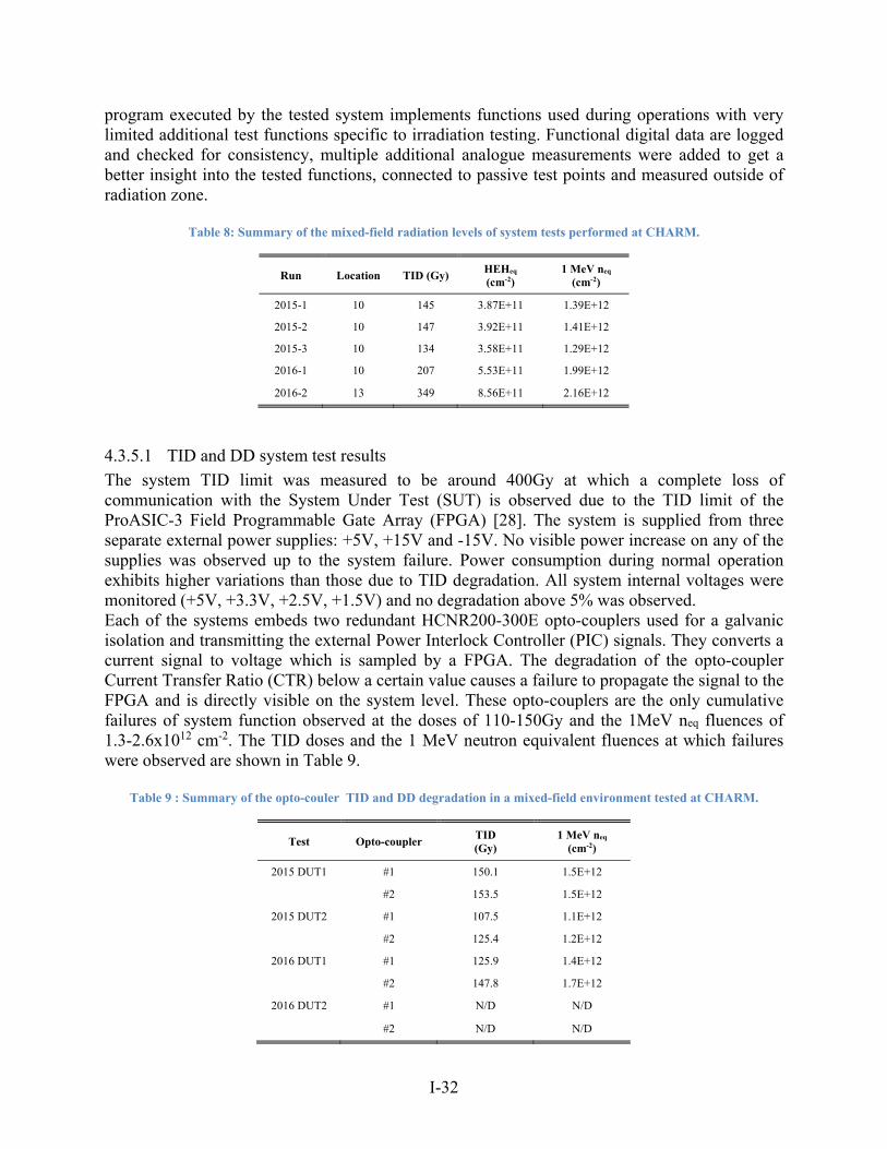
Table 8 shows the summary of the mixed-field radiation levels for two irradiations that took place in November 2015 and in October 2016 during each two separate SUTs were tested. The
I-32
program executed by the tested system implements functions used during operations with very limited additional test functions specific to irradiation testing. Functional digital data are logged and checked for consistency, multiple additional analogue measurements were added to get a better insight into the tested functions, connected to passive test points and measured outside of radiation zone.
Table 8: Summary of the mixed-field radiation levels of system tests performed at CHARM.
Run Location TID (Gy) HEHeq
(cm-2) 1 MeV neq
(cm-2)
2015-1 10 145 3.87E+11 1.39E+12
2015-2 10 147 3.92E+11 1.41E+12
2015-3 10 134 3.58E+11 1.29E+12
2016-1 10 207 5.53E+11 1.99E+12
2016-2 13 349 8.56E+11 2.16E+12
4.3.5.1 TID and DD system test results
The system TID limit was measured to be around 400Gy at which a complete loss of communication with the System Under Test (SUT) is observed due to the TID limit of the ProASIC-3 Field Programmable Gate Array (FPGA) [28]. The system is supplied from three separate external power supplies: +5V, +15V and -15V. No visible power increase on any of the supplies was observed up to the system failure. Power consumption during normal operation exhibits higher variations than those due to TID degradation. All system internal voltages were monitored (+5V, +3.3V, +2.5V, +1.5V) and no degradation above 5% was observed. Each of the systems embeds two redundant HCNR200-300E opto-couplers used for a galvanic isolation and transmitting the external Power Interlock Controller (PIC) signals. They converts a current signal to voltage which is sampled by a FPGA. The degradation of the opto-coupler Current Transfer Ratio (CTR) below a certain value causes a failure to propagate the signal to the FPGA and is directly visible on the system level. These opto-couplers are the only cumulative failures of system function observed at the doses of 110-150Gy and the 1MeV neq fluences of 1.3-2.6x1012 cm-2. The TID doses and the 1 MeV neutron equivalent fluences at which failures were observed are shown in Table 9.
Table 9 : Summary of the opto-couler TID and DD degradation in a mixed-field environment tested at CHARM.
Test Opto-coupler TID (Gy)
1 MeV neq (cm-2)
2015 DUT1 #1 150.1 1.5E+12
#2 153.5 1.5E+12
2015 DUT2 #1 107.5 1.1E+12
#2 125.4 1.2E+12
2016 DUT1 #1 125.9 1.4E+12
#2 147.8 1.7E+12
2016 DUT2 #1 N/D N/D
#2 N/D N/D
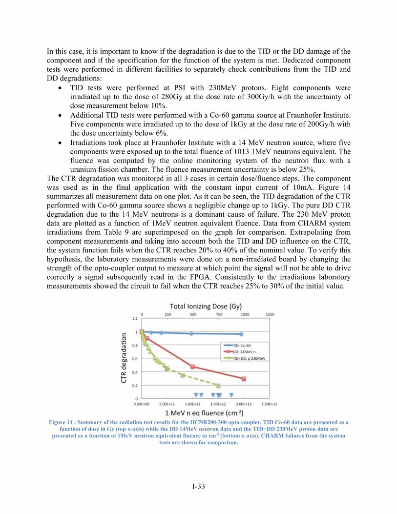
I-33
In this case, it is important to know if the degradation is due to the TID or the DD damage of the component and if the specification for the function of the system is met. Dedicated component tests were performed in different facilities to separately check contributions from the TID and DD degradations:
TID tests were performed at PSI with 230MeV protons. Eight components were irradiated up to the dose of 280Gy at the dose rate of 300Gy/h with the uncertainty of dose measurement below 10%.
Additional TID tests were performed with a Co-60 gamma source at Fraunhofer Institute. Five components were irradiated up to the dose of 1kGy at the dose rate of 200Gy/h with the dose uncertainty below 6%.
Irradiations took place at Fraunhofer Institute with a 14 MeV neutron source, where five components were exposed up to the total fluence of 1013 1MeV neutrons equivalent. The fluence was computed by the online monitoring system of the neutron flux with a uranium fission chamber. The fluence measurement uncertainty is below 25%.
The CTR degradation was monitored in all 3 cases in certain dose/fluence steps. The component was used as in the final application with the constant input current of 10mA. Figure 14 summarizes all measurement data on one plot. As it can be seen, the TID degradation of the CTR performed with Co-60 gamma source shows a negligible change up to 1kGy. The pure DD CTR degradation due to the 14 MeV neutrons is a dominant cause of failure. The 230 MeV proton data are plotted as a function of 1MeV neutron equivalent fluence. Data from CHARM system irradiations from Table 9 are superimposed on the graph for comparison. Extrapolating from component measurements and taking into account both the TID and DD influence on the CTR, the system function fails when the CTR reaches 20% to 40% of the nominal value. To verify this hypothesis, the laboratory measurements were done on a non-irradiated board by changing the strength of the opto-coupler output to measure at which point the signal will not be able to drive correctly a signal subsequently read in the FPGA. Consistently to the irradiations laboratory measurements showed the circuit to fail when the CTR reaches 25% to 30% of the initial value.
Figure 14 : Summary of the radiation test results for the HCNR200-300 opto-coupler. TID Co-60 data are presented as a
function of dose in Gy (top x-axis) while the DD 14MeV neutron data and the TID+DD 230MeV proton data are presented as a function of 1MeV neutron equivalent fluence in cm-2 (bottom x-axis). CHARM failures from the system
tests are shown for comparison.
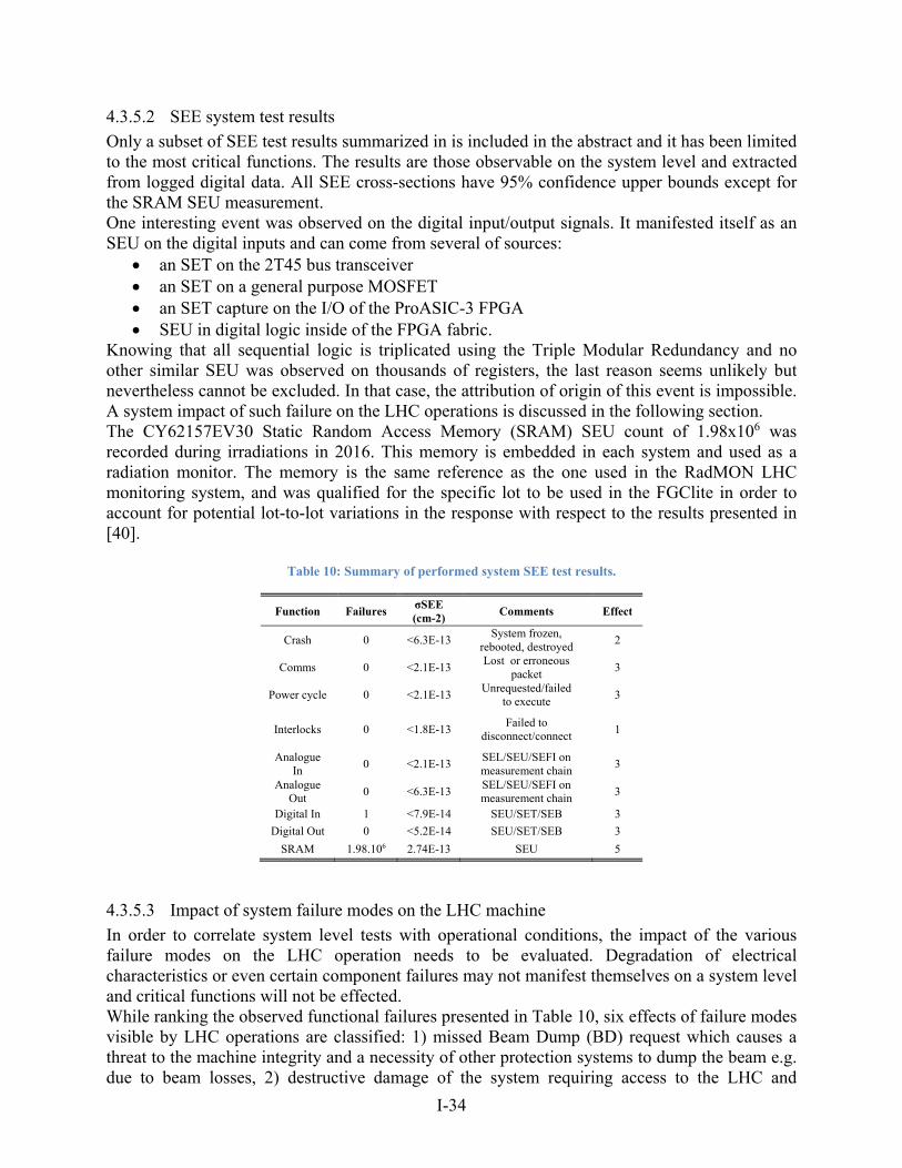
I-34
4.3.5.2 SEE system test results
Only a subset of SEE test results summarized in is included in the abstract and it has been limited to the most critical functions. The results are those observable on the system level and extracted from logged digital data. All SEE cross-sections have 95% confidence upper bounds except for the SRAM SEU measurement. One interesting event was observed on the digital input/output signals. It manifested itself as an SEU on the digital inputs and can come from several of sources:
an SET on the 2T45 bus transceiver an SET on a general purpose MOSFET an SET capture on the I/O of the ProASIC-3 FPGA SEU in digital logic inside of the FPGA fabric.
Knowing that all sequential logic is triplicated using the Triple Modular Redundancy and no other similar SEU was observed on thousands of registers, the last reason seems unlikely but nevertheless cannot be excluded. In that case, the attribution of origin of this event is impossible. A system impact of such failure on the LHC operations is discussed in the following section. The CY62157EV30 Static Random Access Memory (SRAM) SEU count of 1.98x10⁶ was recorded during irradiations in 2016. This memory is embedded in each system and used as a radiation monitor. The memory is the same reference as the one used in the RadMON LHC monitoring system, and was qualified for the specific lot to be used in the FGClite in order to account for potential lot-to-lot variations in the response with respect to the results presented in [40].
Table 10: Summary of performed system SEE test results.
Function Failures σSEE (cm-2)
Comments Effect
Crash 0 <6.3E-13 System frozen,
rebooted, destroyed 2
Comms 0 <2.1E-13 Lost or erroneous
packet 3
Power cycle 0 <2.1E-13 Unrequested/failed
to execute 3
Interlocks 0 <1.8E-13 Failed to
disconnect/connect 1
Analogue In
0 <2.1E-13 SEL/SEU/SEFI on measurement chain
3
Analogue Out
0 <6.3E-13 SEL/SEU/SEFI on measurement chain
3
Digital In 1 <7.9E-14 SEU/SET/SEB 3
Digital Out 0 <5.2E-14 SEU/SET/SEB 3
SRAM 1.98.106 2.74E-13 SEU 5
4.3.5.3 Impact of system failure modes on the LHC machine
In order to correlate system level tests with operational conditions, the impact of the various failure modes on the LHC operation needs to be evaluated. Degradation of electrical characteristics or even certain component failures may not manifest themselves on a system level and critical functions will not be effected. While ranking the observed functional failures presented in Table 10, six effects of failure modes visible by LHC operations are classified: 1) missed Beam Dump (BD) request which causes a threat to the machine integrity and a necessity of other protection systems to dump the beam e.g. due to beam losses, 2) destructive damage of the system requiring access to the LHC and
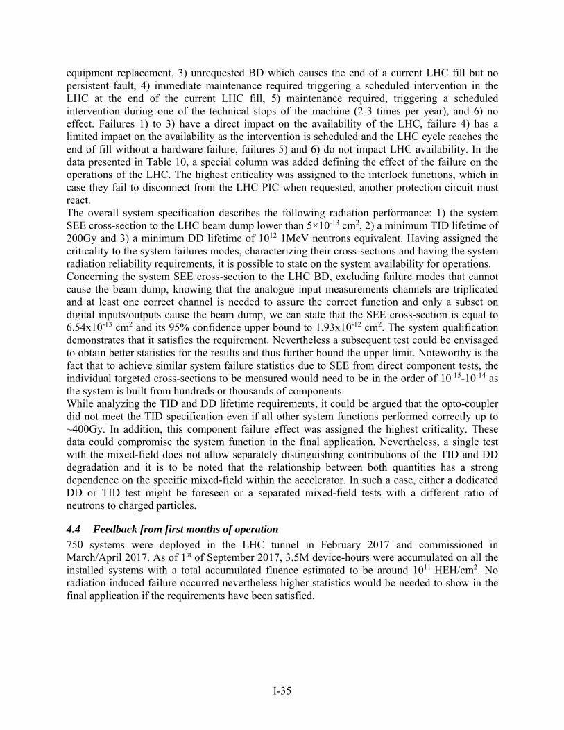
I-35
equipment replacement, 3) unrequested BD which causes the end of a current LHC fill but no persistent fault, 4) immediate maintenance required triggering a scheduled intervention in the LHC at the end of the current LHC fill, 5) maintenance required, triggering a scheduled intervention during one of the technical stops of the machine (2-3 times per year), and 6) no effect. Failures 1) to 3) have a direct impact on the availability of the LHC, failure 4) has a limited impact on the availability as the intervention is scheduled and the LHC cycle reaches the end of fill without a hardware failure, failures 5) and 6) do not impact LHC availability. In the data presented in Table 10, a special column was added defining the effect of the failure on the operations of the LHC. The highest criticality was assigned to the interlock functions, which in case they fail to disconnect from the LHC PIC when requested, another protection circuit must react. The overall system specification describes the following radiation performance: 1) the system SEE cross-section to the LHC beam dump lower than 5×10-13 cm2, 2) a minimum TID lifetime of 200Gy and 3) a minimum DD lifetime of 1012 1MeV neutrons equivalent. Having assigned the criticality to the system failures modes, characterizing their cross-sections and having the system radiation reliability requirements, it is possible to state on the system availability for operations. Concerning the system SEE cross-section to the LHC BD, excluding failure modes that cannot cause the beam dump, knowing that the analogue input measurements channels are triplicated and at least one correct channel is needed to assure the correct function and only a subset on digital inputs/outputs cause the beam dump, we can state that the SEE cross-section is equal to 6.54x10⁻¹³ cm2 and its 95% confidence upper bound to 1.93x10⁻¹² cm2. The system qualification demonstrates that it satisfies the requirement. Nevertheless a subsequent test could be envisaged to obtain better statistics for the results and thus further bound the upper limit. Noteworthy is the fact that to achieve similar system failure statistics due to SEE from direct component tests, the individual targeted cross-sections to be measured would need to be in the order of 10-15-10-14 as the system is built from hundreds or thousands of components. While analyzing the TID and DD lifetime requirements, it could be argued that the opto-coupler did not meet the TID specification even if all other system functions performed correctly up to ~400Gy. In addition, this component failure effect was assigned the highest criticality. These data could compromise the system function in the final application. Nevertheless, a single test with the mixed-field does not allow separately distinguishing contributions of the TID and DD degradation and it is to be noted that the relationship between both quantities has a strong dependence on the specific mixed-field within the accelerator. In such a case, either a dedicated DD or TID test might be foreseen or a separated mixed-field tests with a different ratio of neutrons to charged particles.
4.4 Feedback from first months of operation
750 systems were deployed in the LHC tunnel in February 2017 and commissioned in March/April 2017. As of 1st of September 2017, 3.5M device-hours were accumulated on all the installed systems with a total accumulated fluence estimated to be around 1011 HEH/cm2. No radiation induced failure occurred nevertheless higher statistics would be needed to show in the final application if the requirements have been satisfied.
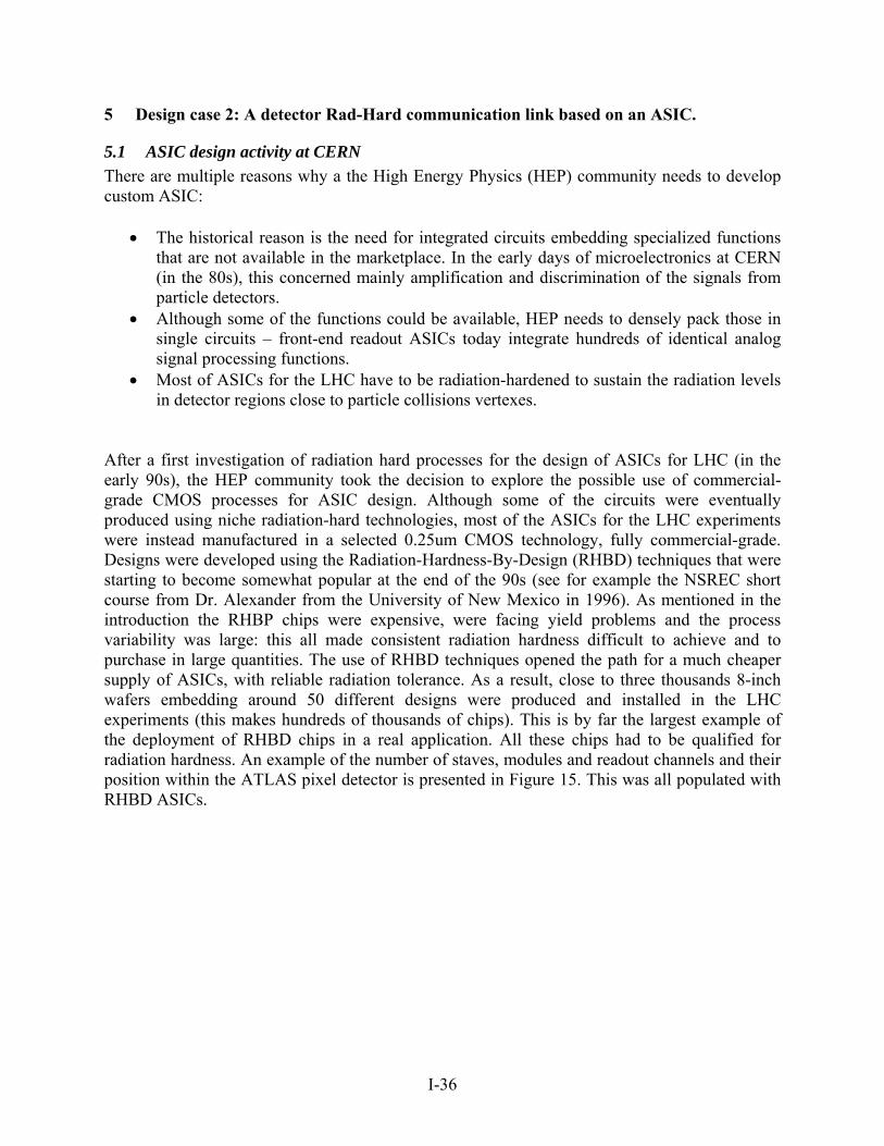
I-36
5 Design case 2: A detector Rad-Hard communication link based on an ASIC.
5.1 ASIC design activity at CERN
There are multiple reasons why a the High Energy Physics (HEP) community needs to develop custom ASIC:
The historical reason is the need for integrated circuits embedding specialized functions that are not available in the marketplace. In the early days of microelectronics at CERN (in the 80s), this concerned mainly amplification and discrimination of the signals from particle detectors.
Although some of the functions could be available, HEP needs to densely pack those in single circuits – front-end readout ASICs today integrate hundreds of identical analog signal processing functions.
Most of ASICs for the LHC have to be radiation-hardened to sustain the radiation levels in detector regions close to particle collisions vertexes.
After a first investigation of radiation hard processes for the design of ASICs for LHC (in the early 90s), the HEP community took the decision to explore the possible use of commercial-grade CMOS processes for ASIC design. Although some of the circuits were eventually produced using niche radiation-hard technologies, most of the ASICs for the LHC experiments were instead manufactured in a selected 0.25um CMOS technology, fully commercial-grade. Designs were developed using the Radiation-Hardness-By-Design (RHBD) techniques that were starting to become somewhat popular at the end of the 90s (see for example the NSREC short course from Dr. Alexander from the University of New Mexico in 1996). As mentioned in the introduction the RHBP chips were expensive, were facing yield problems and the process variability was large: this all made consistent radiation hardness difficult to achieve and to purchase in large quantities. The use of RHBD techniques opened the path for a much cheaper supply of ASICs, with reliable radiation tolerance. As a result, close to three thousands 8-inch wafers embedding around 50 different designs were produced and installed in the LHC experiments (this makes hundreds of thousands of chips). This is by far the largest example of the deployment of RHBD chips in a real application. All these chips had to be qualified for radiation hardness. An example of the number of staves, modules and readout channels and their position within the ATLAS pixel detector is presented in Figure 15. This was all populated with RHBD ASICs.
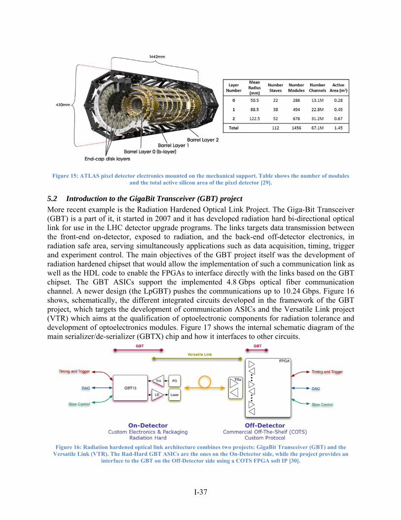
I-37
Figure 15: ATLAS pixel detector electronics mounted on the mechanical support. Table shows the number of modules
and the total active silicon area of the pixel detector [29].
5.2 Introduction to the GigaBit Transceiver (GBT) project
More recent example is the Radiation Hardened Optical Link Project. The Giga-Bit Transceiver (GBT) is a part of it, it started in 2007 and it has developed radiation hard bi-directional optical link for use in the LHC detector upgrade programs. The links targets data transmission between the front-end on-detector, exposed to radiation, and the back-end off-detector electronics, in radiation safe area, serving simultaneously applications such as data acquisition, timing, trigger and experiment control. The main objectives of the GBT project itself was the development of radiation hardened chipset that would allow the implementation of such a communication link as well as the HDL code to enable the FPGAs to interface directly with the links based on the GBT chipset. The GBT ASICs support the implemented 4.8 Gbps optical fiber communication channel. A newer design (the LpGBT) pushes the communications up to 10.24 Gbps. Figure 16 shows, schematically, the different integrated circuits developed in the framework of the GBT project, which targets the development of communication ASICs and the Versatile Link project (VTR) which aims at the qualification of optoelectronic components for radiation tolerance and development of optoelectronics modules. Figure 17 shows the internal schematic diagram of the main serializer/de-serializer (GBTX) chip and how it interfaces to other circuits.
Figure 16: Radiation hardened optical link architecture combines two projects: GigaBit Transceiver (GBT) and the
Versatile Link (VTR). The Rad-Hard GBT ASICs are the ones on the On-Detector side, while the project provides an interface to the GBT on the Off-Detector side using a COTS FPGA soft IP [30].
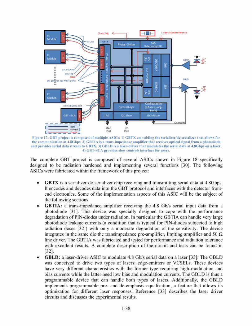
I-38
Figure 17: GBT project is composed of multiple ASICs: 1) GBTX embedding the serializer/de-serializer that allows for the communication at 4.8Gbps, 2) GBTIA is a trans-impedance amplifier that receives optical signal from a photodiode
and provides serial data stream to GBTX, 3) GBLD is a laser-driver that modulates the serial data at 4.8Gbps on a laser, 4) GBT-SCA provides slow controls interface for users.
The complete GBT project is composed of several ASICs shown in Figure 18 specifically designed to be radiation hardened and implementing several functions [30]. The following ASICs were fabricated within the framework of this project:
GBTX is a serializer-de-serializer chip receiving and transmitting serial data at 4.8Gbps. It encodes and decodes data into the GBT protocol and interfaces with the detector front-end electronics. Some of the implementation aspects of this ASIC will be the subject of the following sections.
GBTIA: a trans-impedance amplifier receiving the 4.8 Gb/s serial input data from a photodiode [31]. This device was specially designed to cope with the performance degradation of PIN-diodes under radiation. In particular the GBTIA can handle very large photodiode leakage currents (a condition that is typical for PIN-diodes subjected to high radiation doses [32]) with only a moderate degradation of the sensitivity. The device integrates in the same die the transimpedance pre-amplifier, limiting amplifier and 50 Ω line driver. The GBTIA was fabricated and tested for performance and radiation tolerance with excellent results. A complete description of the circuit and tests can be found in [32].
GBLD: a laser-driver ASIC to modulate 4.8 Gb/s serial data on a laser [33]. The GBLD was conceived to drive two types of lasers: edge-emitters or VCSELs. These devices have very different characteristics with the former type requiring high modulation and bias currents while the latter need low bias and modulation currents. The GBLD is thus a programmable device that can handle both types of lasers. Additionally, the GBLD implements programmable pre- and de-emphasis equalization, a feature that allows its optimization for different laser responses. Reference [33] describes the laser driver circuits and discusses the experimental results.
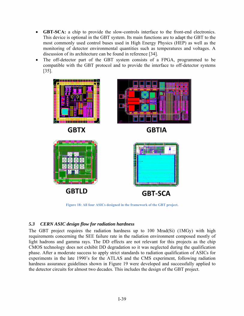
I-39
GBT-SCA: a chip to provide the slow-controls interface to the front-end electronics. This device is optional in the GBT system. Its main functions are to adapt the GBT to the most commonly used control buses used in High Energy Physics (HEP) as well as the monitoring of detector environmental quantities such as temperatures and voltages. A discussion of its architecture can be found in reference [34].
The off-detector part of the GBT system consists of a FPGA, programmed to be compatible with the GBT protocol and to provide the interface to off-detector systems [35].
Figure 18: All four ASICs designed in the framework of the GBT project.
5.3 CERN ASIC design flow for radiation hardness
The GBT project requires the radiation hardness up to 100 Mrad(Si) (1MGy) with high requirements concerning the SEE failure rate in the radiation environment composed mostly of light hadrons and gamma rays. The DD effects are not relevant for this projects as the chip CMOS technology does not exhibit DD degradation so it was neglected during the qualification phase. After a moderate success to apply strict standards to radiation qualification of ASICs for experiments in the late 1990’s for the ATLAS and the CMS experiment, following radiation hardness assurance guidelines shown in Figure 19 were developed and successfully applied to the detector circuits for almost two decades. This includes the design of the GBT project.
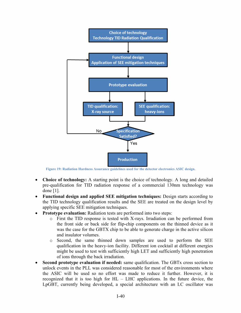
I-40
Figure 19: Radiation Hardness Assurance guidelines used for the detector electronics ASIC design.
Choice of technology: A starting point is the choice of technology. A long and detailed pre-qualification for TID radiation response of a commercial 130nm technology was done [1].
Functional design and applied SEE mitigation techniques: Design starts according to the TID technology qualification results and the SEE are treated on the design level by applying specific SEE mitigation techniques.
Prototype evaluation: Radiation tests are performed into two steps: o First the TID response is tested with X-rays. Irradiation can be performed from
the front side or back side for flip-chip components on the thinned device as it was the case for the GBTX chip to be able to generate charge in the active silicon and insulator volumes.
o Second, the same thinned down samples are used to perform the SEE qualification in the heavy-ion facility. Different ion cocktail at different energies might be used to test with sufficiently high LET and sufficiently high penetration of ions through the back irradiation.
Second prototype evaluation if needed: same qualification. The GBTx cross section to unlock events in the PLL was considered reasonable for most of the environments where the ASIC will be used so no effort was made to reduce it further. However, it is recognized that it is too high for HL – LHC applications. In the future device, the LpGBT, currently being developed, a special architecture with an LC oscillator was
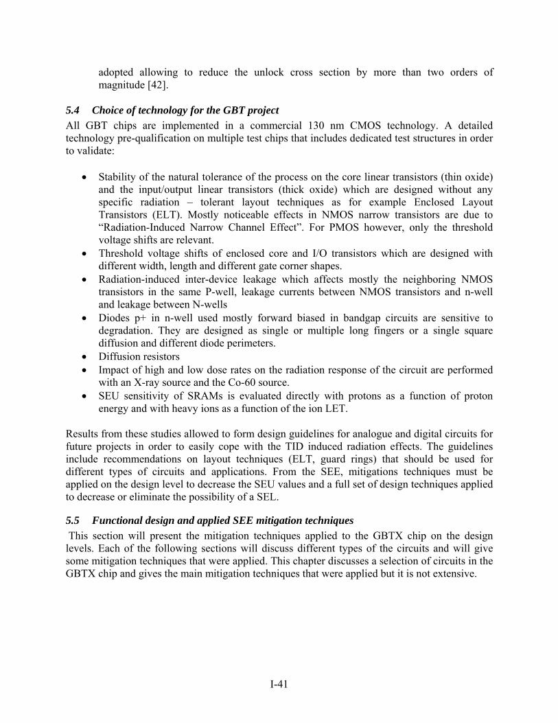
I-41
adopted allowing to reduce the unlock cross section by more than two orders of magnitude [42].
5.4 Choice of technology for the GBT project
All GBT chips are implemented in a commercial 130 nm CMOS technology. A detailed technology pre-qualification on multiple test chips that includes dedicated test structures in order to validate:
Stability of the natural tolerance of the process on the core linear transistors (thin oxide) and the input/output linear transistors (thick oxide) which are designed without any specific radiation – tolerant layout techniques as for example Enclosed Layout Transistors (ELT). Mostly noticeable effects in NMOS narrow transistors are due to “Radiation-Induced Narrow Channel Effect”. For PMOS however, only the threshold voltage shifts are relevant.
Threshold voltage shifts of enclosed core and I/O transistors which are designed with different width, length and different gate corner shapes.
Radiation-induced inter-device leakage which affects mostly the neighboring NMOS transistors in the same P-well, leakage currents between NMOS transistors and n-well and leakage between N-wells
Diodes p+ in n-well used mostly forward biased in bandgap circuits are sensitive to degradation. They are designed as single or multiple long fingers or a single square diffusion and different diode perimeters.
Diffusion resistors Impact of high and low dose rates on the radiation response of the circuit are performed
with an X-ray source and the Co-60 source. SEU sensitivity of SRAMs is evaluated directly with protons as a function of proton
energy and with heavy ions as a function of the ion LET.
Results from these studies allowed to form design guidelines for analogue and digital circuits for future projects in order to easily cope with the TID induced radiation effects. The guidelines include recommendations on layout techniques (ELT, guard rings) that should be used for different types of circuits and applications. From the SEE, mitigations techniques must be applied on the design level to decrease the SEU values and a full set of design techniques applied to decrease or eliminate the possibility of a SEL.
5.5 Functional design and applied SEE mitigation techniques
This section will present the mitigation techniques applied to the GBTX chip on the design levels. Each of the following sections will discuss different types of the circuits and will give some mitigation techniques that were applied. This chapter discusses a selection of circuits in the GBTX chip and gives the main mitigation techniques that were applied but it is not extensive.
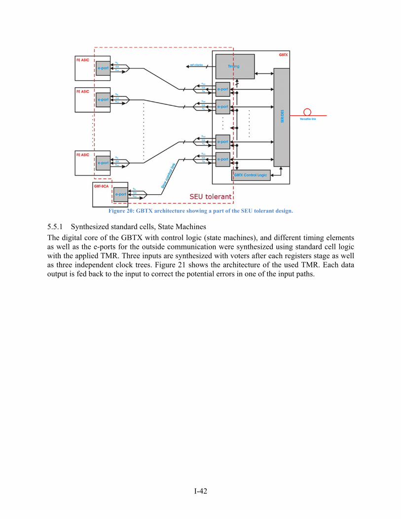
I-42
Figure 20: GBTX architecture showing a part of the SEU tolerant design.
5.5.1 Synthesized standard cells, State Machines
The digital core of the GBTX with control logic (state machines), and different timing elements as well as the e-ports for the outside communication were synthesized using standard cell logic with the applied TMR. Three inputs are synthesized with voters after each registers stage as well as three independent clock trees. Figure 21 shows the architecture of the used TMR. Each data output is fed back to the input to correct the potential errors in one of the input paths.
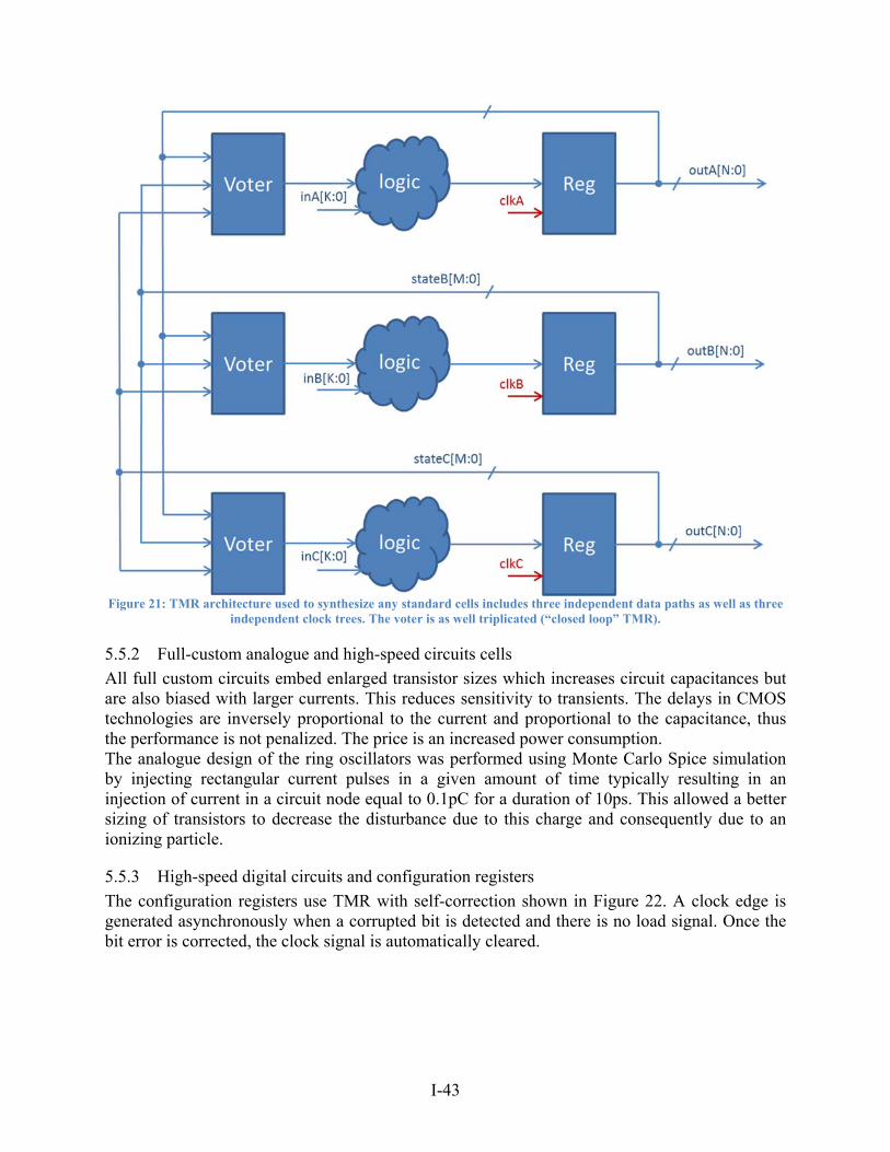
I-43
Figure 21: TMR architecture used to synthesize any standard cells includes three independent data paths as well as three
independent clock trees. The voter is as well triplicated (“closed loop” TMR).
5.5.2 Full-custom analogue and high-speed circuits cells
All full custom circuits embed enlarged transistor sizes which increases circuit capacitances but are also biased with larger currents. This reduces sensitivity to transients. The delays in CMOS technologies are inversely proportional to the current and proportional to the capacitance, thus the performance is not penalized. The price is an increased power consumption. The analogue design of the ring oscillators was performed using Monte Carlo Spice simulation by injecting rectangular current pulses in a given amount of time typically resulting in an injection of current in a circuit node equal to 0.1pC for a duration of 10ps. This allowed a better sizing of transistors to decrease the disturbance due to this charge and consequently due to an ionizing particle.
5.5.3 High-speed digital circuits and configuration registers
The configuration registers use TMR with self-correction shown in Figure 22. A clock edge is generated asynchronously when a corrupted bit is detected and there is no load signal. Once the bit error is corrected, the clock signal is automatically cleared.
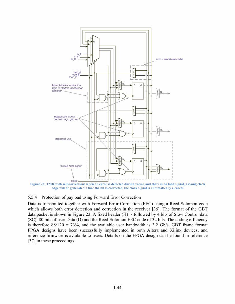
I-44
Figure 22: TMR with self-correction: when an error is detected during voting and there is no load signal, a rising clock
edge will be generated. Once the bit is corrected, the clock signal is automatically cleared.
5.5.4 Protection of payload using Forward Error Correction
Data is transmitted together with Forward Error Correction (FEC) using a Reed-Solomon code which allows both error detection and correction in the receiver [36]. The format of the GBT data packet is shown in Figure 23. A fixed header (H) is followed by 4 bits of Slow Control data (SC), 80 bits of user Data (D) and the Reed-Solomon FEC code of 32 bits. The coding efficiency is therefore 88/120 = 73%, and the available user bandwidth is 3.2 Gb/s. GBT frame format FPGA designs have been successfully implemented in both Altera and Xilinx devices, and reference firmware is available to users. Details on the FPGA design can be found in reference [37] in these proceedings.
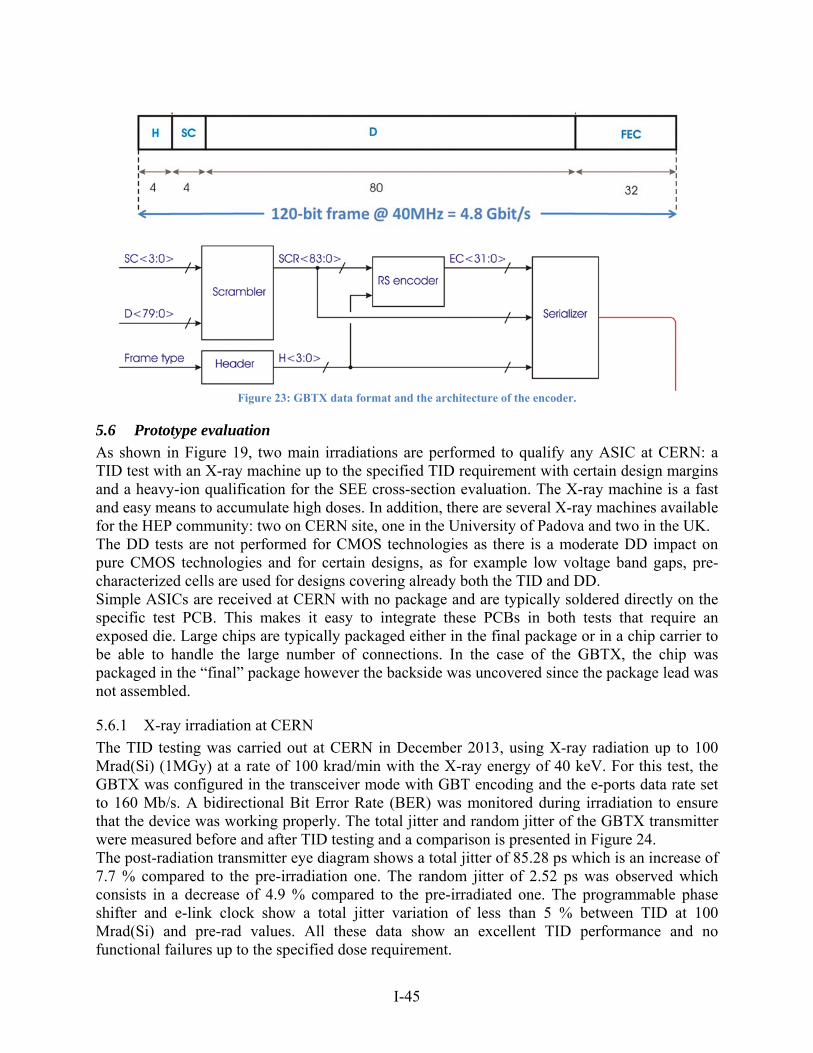
I-45
Figure 23: GBTX data format and the architecture of the encoder.
5.6 Prototype evaluation
As shown in Figure 19, two main irradiations are performed to qualify any ASIC at CERN: a TID test with an X-ray machine up to the specified TID requirement with certain design margins and a heavy-ion qualification for the SEE cross-section evaluation. The X-ray machine is a fast and easy means to accumulate high doses. In addition, there are several X-ray machines available for the HEP community: two on CERN site, one in the University of Padova and two in the UK. The DD tests are not performed for CMOS technologies as there is a moderate DD impact on pure CMOS technologies and for certain designs, as for example low voltage band gaps, pre-characterized cells are used for designs covering already both the TID and DD. Simple ASICs are received at CERN with no package and are typically soldered directly on the specific test PCB. This makes it easy to integrate these PCBs in both tests that require an exposed die. Large chips are typically packaged either in the final package or in a chip carrier to be able to handle the large number of connections. In the case of the GBTX, the chip was packaged in the “final” package however the backside was uncovered since the package lead was not assembled.
5.6.1 X-ray irradiation at CERN
The TID testing was carried out at CERN in December 2013, using X-ray radiation up to 100 Mrad(Si) (1MGy) at a rate of 100 krad/min with the X-ray energy of 40 keV. For this test, the GBTX was configured in the transceiver mode with GBT encoding and the e-ports data rate set to 160 Mb/s. A bidirectional Bit Error Rate (BER) was monitored during irradiation to ensure that the device was working properly. The total jitter and random jitter of the GBTX transmitter were measured before and after TID testing and a comparison is presented in Figure 24. The post-radiation transmitter eye diagram shows a total jitter of 85.28 ps which is an increase of 7.7 % compared to the pre-irradiation one. The random jitter of 2.52 ps was observed which consists in a decrease of 4.9 % compared to the pre-irradiated one. The programmable phase shifter and e-link clock show a total jitter variation of less than 5 % between TID at 100 Mrad(Si) and pre-rad values. All these data show an excellent TID performance and no functional failures up to the specified dose requirement.
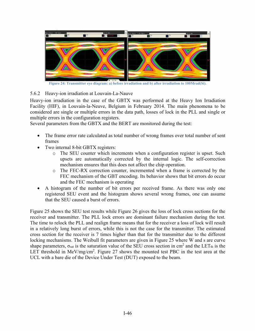
I-46
Figure 24: Transmitter eye diagram: a) before irradiation and b) after irradiation to 100Mrad(Si).
5.6.2 Heavy-ion irradiation at Louvain-La-Nauve
Heavy-ion irradiation in the case of the GBTX was performed at the Heavy Ion Irradiation Facility (HIF), in Louvain-la-Neuve, Belgium in February 2014. The main phenomena to be considered are single or multiple errors in the data path, losses of lock in the PLL and single or multiple errors in the configuration registers. Several parameters from the GBTX and the BERT are monitored during the test:
The frame error rate calculated as total number of wrong frames over total number of sent frames
Two internal 8-bit GBTX registers: o The SEU counter which increments when a configuration register is upset. Such
upsets are automatically corrected by the internal logic. The self-correction mechanism ensures that this does not affect the chip operation.
o The FEC-RX correction counter, incremented when a frame is corrected by the FEC mechanism of the GBT encoding. Its behavior shows that bit errors do occur and the FEC mechanism is operating
A histogram of the number of bit errors per received frame. As there was only one registered SEU event and the histogram shows several wrong frames, one can assume that the SEU caused a burst of errors.
Figure 25 shows the SEU test results while Figure 26 gives the loss of lock cross sections for the receiver and transmitter. The PLL lock errors are dominant failure mechanism during the test. The time to relock the PLL and realign frame means that for the receiver a loss of lock will result in a relatively long burst of errors, while this is not the case for the transmitter. The estimated cross section for the receiver is 7 times higher than that for the transmitter due to the different locking mechanisms. The Weibull fit parameters are given in Figure 25 where W and s are curve shape parameters, σsat is the saturation value of the SEU cross section in cm2 and the LETth is the LET threshold in MeV/mg/cm2. Figure 27 shows the mounted test PBC in the test area at the UCL with a bare die of the Device Under Test (DUT) exposed to the beam.
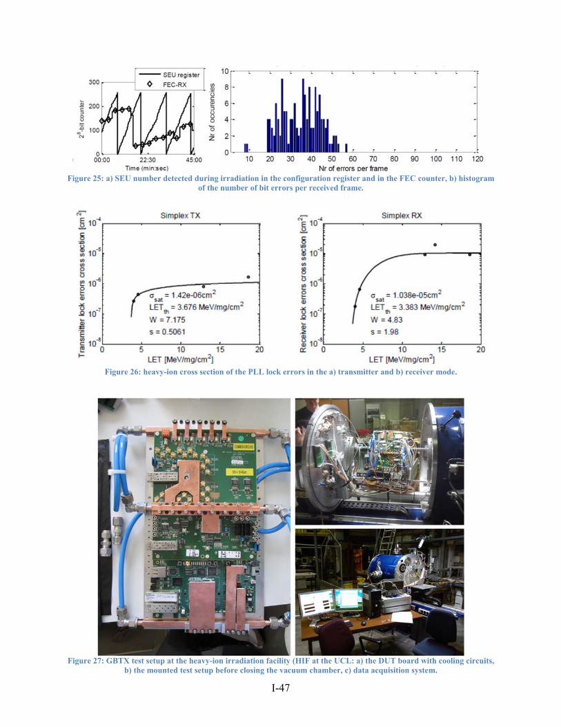
I-47
Figure 25: a) SEU number detected during irradiation in the configuration register and in the FEC counter, b) histogram
of the number of bit errors per received frame.
Figure 26: heavy-ion cross section of the PLL lock errors in the a) transmitter and b) receiver mode.
Figure 27: GBTX test setup at the heavy-ion irradiation facility (HIF at the UCL: a) the DUT board with cooling circuits,
b) the mounted test setup before closing the vacuum chamber, c) data acquisition system.
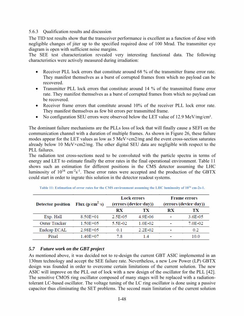
I-48
5.6.3 Qualification results and discussion
The TID test results show that the transceiver performance is excellent as a function of dose with negligible changes of jiter up to the specified required dose of 100 Mrad. The transmitter eye diagram is open with sufficient noise margins. The SEE test characterization revealed very interesting functional data. The following characteristics were actively measured during irradiation:
Receiver PLL lock errors that constitute around 68 % of the transmitter frame error rate. They manifest themselves as a burst of corrupted frames from which no payload can be recovered.
Transmitter PLL lock errors that constitute around 14 % of the transmitted frame error rate. They manifest themselves as a burst of corrupted frames from which no payload can be recovered.
Receiver frame errors that constitute around 10% of the receiver PLL lock error rate. They manifest themselves as few bit errors per transmitted frame.
No configuration SEU errors were observed below the LET value of 12.9 MeV/mg/cm².
The dominant failure mechanisms are the PLLs loss of lock that will finally cause a SEFI on the communication channel with a duration of multiple frames. As shown in Figure 26, these failure modes appear for the LET values as low as 5 MeV×cm2/mg and the event cross-section saturates already below 10 MeV×cm2/mg. The other digital SEU data are negligible with respect to the PLL failures. The radiation test cross-sections need to be convoluted with the particle spectra in terms of energy and LET to estimate finally the error rates in the final operational environment. Table 11 shows such an estimation for different positions in the CMS detector assuming the LHC luminosity of 1034 cm-2s-1. These error rates were accepted and the production of the GBTX could start in order to ingrate this solution in the detector readout systems.
Table 11: Estimation of error rates for the CMS environment assuming the LHC luminosity of 1034 cm-2s-1.
5.7 Future work on the GBT project
As mentioned above, it was decided not to re-design the current GBT ASIC implemented in an 130nm technology and accept the SEE failure rate. Nevertheless, a new Low Power (LP) GBTX design was founded in order to overcome certain limitations of the current solution. The new ASIC will improve on the PLL out of lock with a new design of the oscillator for the PLL [42]. The sensitive CMOS ring oscillator composed of many stages will be replaced with a radiation-tolerant LC-based oscillator. The voltage tuning of the LC ring oscillator is done using a passive capacitor thus eliminating the SET problems. The second main limitation of the current solution
I-49
was its power consumption especially due to the oversizing of transistors. This limitation will be overcome mostly by porting the current design to the new 65nm CMOS technology and the optimization of the circuit architecture.
I-50
6 How the CERN design flows can be transferred to a design of space systems
At CERN, three different types of systems are used that are exposed to certain levels of mixed radiation field: COTS systems that are placed either in radiation safe locations or with relatively low radiation, Custom systems based on COTS that are developed mostly for the accelerator sector and dedicated radiation hardened ASICs placed closely to the beam interaction points where radiation levels reach extreme levels. Both design cases presented are very different in terms of system requirements as well as radiation harness which has led to two different design and qualification guidelines presented in previous chapters. This section presents a discussion on how applicable these guidelines would be a space system and if certain convergences can be found.
6.1 RHA flow for a low cost satellite projects
The custom system based on COTS component as seen in previous chapters are exposed to radiation levels that can directly be compared to certain space missions as for example LEO orbit. A great overview of TID and SEE hardness assurance for small satellites (SmallSats) was presented during the NSREC 2017 short course [43, 44]. As presented, the SmallSat missions face new challenges and their priorities are different than a standard satellite:
Extremely short development time mostly driven by the primary payload schedule. A delay in development of the secondary payload satellite leads to a miss of the launch.
Relatively small budget practically limiting the designs to only COTS components, small development teams of often unexperienced engineers.
Higher risk acceptance mostly due to both previous points as well as using new technologies, components and innovative designs.
The primary payload imposes the final orbit to the SmallSat and it might happen that the the final orbit is not known to the secondary user during their design phase.
Short mission lifetime for SmallSats yields lower TID and DD requirements that are less of a concern compared to the SEE.
While analyzing these challenges and limitations of SmallSat missions, it seems that the accelerator systems face similar challenges. The development time ranges from 1 to 5 years. Systems must be manufactured in thousands of units which limits component use to COTS due to budget constraints. Even if the top level LHC machine requirements show a high reliability and availability requirements, accelerator systems are able to accept a higher risk as the system is accessible for potential repairs and replacements. The risk is bound mostly by the failure rate and the criticality of the system. Many mitigation techniques are implemented directly in the system by having higher margins on parameter drifts due to the TID, mitigating SEEs using the design techniques, applying fail safe mechanisms and masking in both hardware, programmable logic as well as in software. Due to two main constraints: the schedule and the cost, the testing and qualification needs certain prioritization by dividing components in different classes or even avoiding component radiation characterization tests in favor of the full board or system testing. Such tests have their obvious limitations due to a reduced observability of events on the board/system level but allow to test in final application conditions.
I-51
6.2 Extreme environment technology qualification for deep space missions
The CERN’s detector electronics is exposed to a very harsh environment. The work on detectors leads to understanding of new failure mechanisms of active semiconductors exposed to ultra-high levels of TID even above the 100Mrads(Si) [45] that have not yet been fully studied as there is no direct need for electronics exposed to such high levels. Nevertheless, new space missions aim at much harsher environments ranging to 10’s to 100’s of Mrads(Si) of the TID requirement for example for JUICE Jovian missions coming mostly form trapped electrons in the Jovian radiation belts [46]. The component irradiations and functional validation for such missions might use the design flow presented in Figure 19. New evidence of high-energy electron induced SUEs were studied in [47] and their impact on JUICE mission that presents a challenging radiation environment due to intense high-energy electron flux in the trapped radiation belts. In addition, the technology pre-qualification step with multiple of test vehicles in commercial technologies are designed at CERN, irradiated and used for design of future ASICs for detectors. This approach has been proven for multiple years and multiple projects at CERN and might be interesting to be used for space applications for certain design offices and semiconductor companies.
I-52
7 Conclusions
Traditional RHA used for space applications are conservative due to test dosimetry and measured effect uncertainties, system design margins amd environment simulation uncertainties that lead to overestimating the requirements. At the same time CERN accelerator and detector applications sometimes cannot follow the same guidelines due to the specificity of the final application environment or the design challenges. This work focused on discussion on CERN system/component design constraints, on specific characteristics of the environment and guidelines that are applied to different types of systems. Finally, two design cases were presented: a distributed accelerator system based on COTS components exposed to the accelerator mixed radiation and a radiation hardened communication ASIC developed for the readout of data from detector systems exposed to very harsh annual doses and fluences of light hadrons. Some final thoughts were presented if the CERN’s qualification methods and design guidelines overlap with current and future needs in the space community in which a huge number of SmallSat missions are being developed and are constrained mostly by development cost and scheduled with more relaxed radiation hardness constraints.
I-53
8 Bibliography
[1] F. Faccio and et al., "Total dose and single event effects (SEE) in a 0.25−μm CMOS technology," in 4th Workshop on Electronics for LHC Experiments, Rome, 1998.
[2] M. Huhtinen and F. Faccio, "Computational method to estimate Single Event Upset rates in an accelerator environment," Nuclear Instruments and Methods in Physics Research Section A, vol. 450, no. 1, pp. 155-172, 2000.
[3] M. Dentan, "Revision 2 of the ATLAS policy on Radiation Tolerant Electronics," in Second meeting of the ATLAS Radiation Hardness Assurance Working Group, CERN, 1999.
[4] F. Faccio, "A global radiation test plan for CMS electronics in HCAL, Muons and Experimental Hall," CERN, 1999.
[5] D. o. Defense, "Test Method Standard, Microcircuits, MIL-STD-883-D/E," 1991. [6] E. S. Agency, "Single Event Effects Test Method and Guidelines, ESCC Basic
Specification N. 25100," 2014. [7] E. S. Agency, "Total Dose Steady-State Irradiation Test Method, ESCC Basic
Specification No. 22900," 2010. [8] C. Paris, "1st LHC Radiation Workshop," CERN, 2001. [Online]. Available:
https://indico.cern.ch/event/426916/. [9] M. Brugger, R. Alia, S. Danzeca, R. Denz, J. Mekki, P. Oser, P. Peronnard, J. P. D. C.
Saraiva, G. Spiezia and Y. T. S. Uznanski, "Radiation Effects, Calculation Methods and Radiation Test Challenges in Accelerator Mixed Particle and Energy Environments," in NSREC short course Notebook, Paris, 2014, pp. II-1-96.
[10] CERN, "Accelerator Fault Tracker," CERN, 2017. [Online]. Available: https://aft.cern.ch/.
[11] S. Uznanski, R. G. Alia, E. Blackmore, M. Brugger, R. Gaillard, J. Mekki, B. Todd, M. Trinczek and A. V. Villanueva, "The Effect of Proton Energy on SEU Cross Section of a 16 Mbit TFT PMOS SRAM with DRAM Capacitors," IEEE Transactions on Nuclear Science, vol. 61, no. 6, pp. 3074-3079, 2014.
[12] J. R. Schwank, M. R. Shaneyfelt, J. Baggio, P. E. Dodd, J. A. Felix, V. Ferlet-Cavrois, P. Paillet, D. Lambert, F. W. Sexton, G. L. Hash and E. Blackmore, "Effects of particle energy on proton-induced single-event latchup," IEEE Transactions on Nuclear Science, vol. 52, no. 6, pp. 2622-2629, 2005.
[13] R. G. Alia, M. Brugger, S. Danzeca, V. Ferlet-Cavrois, C. Frost, R. Gaillard, J. Mekki, F. Saigné, A. Thornton, S. Uznanski and F. Wrobel, "SEL Hardness Assurance in a Mixed Radiation Field," IEEE Transactions on Nuclear Science, vol. 62, no. 6, 2015.
[14] J. Mekki and et al., "CHARM: A Mixed Field Facility at CERN for Radiation Tests in Ground, Atmospheric, Space and Accelerator Representative Environments," IEEE Transactions on Nuclear Science, vol. 62, no. 6, 2015.
[15] K. Roeed, M. Brugger, D. Kramer, P. Peronnard, C. Pignard, G. Spiezia and a. A. Thornton, "Method for measuring mixed field radiation levels relevant for SEEs at the LHC," IEEE Transactions on Nuclear Science, vol. 59, no. 4, pp. 1040-1047, 2012.
[16] e. a. A. Ferrari, "FLUKA, a multi-particle transport code CERN"," CERN-2005-10-2005, INFN/TC-05/11, SLAC-R-773, 2005.
[17] T. Bohlen, F. Cerutti, M. Chin, A. Fass, A. Ferrari, P. Ortega, A. Mairani, P. Sala, G. Smirnov and V. Vlachoudis, "The FLUKA code: developments and challenges for high energy and medical applications," Nuclear Data Sheets, vol. 120, pp. 211-214, 2014.
[18] R. G. Alia, E. W. Blackmore, M. Brugger, S. Danzeca, V. Ferlet-Cavrois, R. Gaillard, J. Mekki, C. Poivey, K. Roed, F. Saigne, G. Spiezia, M. Trinczek, S. Uznanski and a. F.
I-54
Wrobel, "SEL cross section energy dependence impact on the high energy accelerator failure rate," IEEE Transactions on Nuclear Science, vol. 61, no. 6, pp. 2936-2944, 2014.
[19] K. Roed, V. Boccone, M. Brugger, A. Ferrari, D. Kramer, E. Lebbos, R. Losito, A. Mereghetti, G. Spiezia and R. Versaci, "FLUKA simulations for SEE studies of critical LHC underground areas," IEEE Trans. Nucl. Sci., vol. 58, no. 3, pp. 932-938, 2011.
[20] B. Biskup, M. Brugger, M. Calviani, I. Efthymiopoulos and R. Kwee, "Design and Operation of the H4IRRAD Mixed-Field Test Area at CERN," Progress in Nuclear Science and Technology, vol. 4, pp. 218-222, 2014.
[21] E. Lebbos, M. Brugger, M. Calviani, L. Gatignon, M. Glaser and M. Moll, "East Area irradiation test facility: preliminary FLUKA calculations," CERN, 2011. [Online]. Available: http://cds.cern.ch/record/1385034/files.
[22] R. G. Alıa, M. Brugger, S. Danzeca, V. Ferlet-Cavrois, C. Poivey, K. Røed, F. Saigne, G. Spiezia, S. Uznanski and F. Wrobel, "SEE Measurements and Simulations using mono-energetic GeV-energy hadron beams," IEEE Trans. Nucl. Sci., vol. 60, no. 6, pp. 4142-4149, 2013.
[23] ESA, "ESA radiation reports," ESA, 2010. [Online]. Available: https://escies.org/labreport/radiationList.
[24] NASA-GSFC, "GCFC Radiation Data Base," NASA-GSFC, 2013. [Online]. Available: http://radhome.gsfc.nasa.gov/radhome/RadDataBase/RadDataBase.html.
[25] NASA-JPL, "Radiation effects data base," NASA-JPL, 2013. [Online]. Available: http://radnet.jpl.nasa.gov.
[26] J. Standard, "Test Procedures for the Measurement of Single Event Effects in Semiconductor Devices from Heavy Ion Irradiation," JEDEC, 1996.
[27] D. M. Fleetwood and H. A. Eisen, "Total-dose radiation hardness assurance," IEEE Trans. Nucl. Sci, vol. 50, no. 3, pp. 552-564, 2003.
[28] G. Spiezia, P. Peronnard, A. Masi, M. Brugger, M. Brucoli, S. Danzeca, R. G. Alia, R. Losito, J. Mekki, P. Oser, R. Gaillard and L. Dusseau, "A New RadMon Version for the LHC and its Injection Lines," IEEE Trans. Nucl. Sci., vol. 61, no. 6, pp. 3424-3431, 2014.
[29] G. Aad and et al., "ATLAS pixel detector electronics and sensors," JINST, 2008. [30] P. Moreira, R. Ballabriga, S. Baron, S. Bonacini, O. Cobanoglu, F. Faccio, T. Fedorov,
R. Francisco, P. Gui, P. Hartin, K. Kloukinas, X. Llopart, A. Marchioro, C. Paillard, N. Pinilla, K. Wyllie and B. Yu, "The GBT Project," in Topical Workshop on Electronics for Particle Physics, Prague, 2007.
[31] M. Menouni and et al., "a 5 Gbit/s radiationhard optical receiver for the SLHC upgrades," in Topical Workshop on Electronics for Particle Physics, Paris, 2009.
[32] J. Troska and et al., "The GBTIA, a 5 Gbit/s radiationhard optical receiver for the SLHC upgrades," in Topical Workshop on Electronics for Particle Physics, Paris, 2009.
[33] G. Mazza and et al., "A 5 Gb/s Radiation Tolerant Laser Driver in 0.13 um CMOS technology," in Topical Workshop on Electronics for Particle Physics, Paris, 2009.
[34] A. Gabrielli and et al., "The GBT-SCA, a radiation tolerant ASIC for detector control applications in SLHCB experiments," in Topical Workshop on Electronics for Particle Physics, Paris, 2009.
[35] A. Pacheco and e. al, "Single-Event Upsets in Photoreceivers for Multi-Gb/s Data Transmission," Nuclear Science, IEEE Transactions on, vol. 56, no. 4, pp. 1978-1986, 2009.
I-55
[36] G. Papotti and et al., "An Error-Correcting Line Code for a HEP Rad-Hard Multi-GigaBit Optical Link," in Proceedings of the 12th Workshop on Electronics for LHC and Future Experiments, Valencia, 2006.
[37] F. Marin and et al., "Implementing the GBT data transmission protocol in FPGAs," in Topical Workshop on Electronics for Particle Physics, Paris, 2009.
[38] M. Huhtinen and F. Faccio, "Computational method to estimate Single Event Upset rates in an accelerator environment," Nuclear Instruments and Methods in Physics Research, vol. A 450, pp. 155-172, 2000.
[39] M. Marzo, S. Bonaldo, M. Brugger, S. Danzeca, R. Garcia Alia, A. Infantino, A. Thornton, “RadFET dose response in the CHARM mixed-field: FLUKA MC simulations,” EPJ Nuclear Sci. Technol., Volume 3, 2017, Jul 2017.
[40] S. Danzeca, G. Spiezia, M. Brugger, L. Dusseau, G. Foucard, R. Garcia Alia, P. Mala, A. Masi, P. Peronnard, J. Soltes, A. Thornton, L. Viererbl, “Qualification and Characterization of SRAM Memories Used as Radiation Sensors in the LHC,” IEEE Trans. Nucl. Sci. Vol. 61, No. 6, pp. 3458-3465, Dec. 2014
[41] R. GarcíaAlía, M. Brugger, F. Cerutti, S. Danzeca, A. Ferrari, S. Gilardoni, Y. Kadi, M. Kastriotou, A. Lechner, C. Martinella, O. Stein, Y. Thurel, A. Tsinganis, S. Uznanski, “LHC and HL-LHC: Present and Future Radiation Environment in the High-Luminosity Collision Points and RHA Implications,” presented at the NSREC 2017, New Orleans, LA, USA.
[42] J. Prinzie, J. Christiansen, P. Moreira, M. Steyaert, P. Leroux, “Comparison of a 65 nm CMOS Ring- and LC-Oscillator Based PLL in Terms of TID and SEU Sensitivity,” IEEE Trans. Nucl. Sci., Vol. 64, No. 1, Jan 2017.
[43] C. Poivey, “Total Ionizing and Non-Ionising Dose Radiation Hardness Assurance,” 2017 NSREC short course notes, New Orleans, LA, USA.
[44] R. Ladbury, “Strategies for SEE Hardness Assurance – From Buy-It-And-Fly-It to Bullet Proof,” 2017 NSREC short course notes, New Orleans, LA, USA.
[45] F. Faccio, G. Borghello, E. Lerario, D. M. Fleetwood, R. D. Schrimpf, H. Gong, E. X. Zhang, P. Wang, S. Michelis, S. Gerardin, A. Paccagnella, S. Bonaldo, “Influence of LDD spacers and H+ transport on the total-ionizing-dose response of 65 nm MOSFETs irradiated to ultra-high doses,” presented at the NSREC 2017, New Orleans, LA, USA.
[46] JUICE team, “JUICE Environment Specification”, ESTEC, European Space Agency, 2015.
[47] Maris Tali, Rubén García Alía, Markus Brugger, Veronique Ferlet-Cavrois, Roberto Corsini, Wilfrid Farabolini, Ali Mohammadzadeh, Giovanni Santin, and Ari Virtanen, “High-Energy Electron-Induced SEUs and Jovian Environment Impact,” IEEE Trans. Nucl. Sci., Vol.: 64, Issue: 8 pp: 2016 – 2022, 2017.
I-56
9 Acronyms
AFT Accelerator Fault Tracker ASIC Application Specific Integrated Circuit BD Beam Dump BER Bit Error Rate BOM Bill Of Materials CCC CERN's Control Centre CERN European Organization for Nuclear Research CHARM CERN High-energy AcceleratoR test facility CNGS CERN Neutrino to Gran Sasso COTS Commercial Of The Shelf CPS Proton Synchrotron CTR Current Transfer Ratio DD Displacement Damage DOE Design of Experiment DUT Device Under Test ELDRS Enhanced Lowe Dose Rate Sensitivity ELT Enclosed Layout Transistor FEC Forward Error Correction FGC Function Generator Controller GBT Gigabit Transceiver HEH High Energy Hadron HEP High Energy Physics HL-LHC High Luminosity LHC ISS International Space Station LEO Low Earth Orbit LET Linear Energy Transfer LHC Large Hadron Collider LNGS Gran Sasso National Laboratory LS1 Long Shutdown 1 MTTF Mean Time To Failure NSREC Nuclear and Space Radiation Effects Conference PCB Printed Circuit Board PIC Power Interlock Controller PLL Phase Locked Loop PS Proton Synchrotron R2E Radiation-2-Electronics RHA Radiation Hardness Assurance RHBD Radiation Hardening By Design RHBP Radiation Hardening By Process SEE Single Event Effects SEFI Single Event Functional Interrupt SEL Single Event Latch-up SEU Single Event Upset SPS Super Proton Synchrotron SRAM Static Random Access Memory SUT System Under Test TID Total Ionizing Dose
I-57
TMR Triple Modular Redundancy VTR Versatile Link