
Purely numerical compensation for microscope objective phase curvature in digital holographic...
10
Purely numerical compensation for microscope objective phase curvature in digital holographic microscopy: influence of digital phase mask position Frédéric Montfort, Florian Charrière, and Tristan Colomb Ecole Polytechnique Fédérale de Lausanne (EPFL), Institut d’Optique Appliquée, CH-1015 Lausanne, Switzerland Etienne Cuche Lyncée Tec SA, PSE-A, CH-1005 Lausanne, Switzerland Pierre Marquet Centre de Neurosciences Psychiatriques, Département de Psychiatrie DP-CHUV, Site de Cery, 1008 Prilly-Lausanne, Switzerland Christian Depeursinge Ecole Polytechnique Fédérale de Lausanne (EPFL), Institut d’Optique Appliquée, CH-1015 Lausanne, Switzerland Received March 17, 2006; revised June 1, 2006; accepted June 3, 2006; posted June 8, 2006 (Doc. ID 69123) Introducing a microscope objective in an interferometric setup induces a phase curvature on the resulting wavefront. In digital holography, the compensation of this curvature is often done by introducing an identical curvature in the reference arm and the hologram is then processed using a plane wave in the reconstruction. This physical compensation can be avoided, and several numerical methods exist to retrieve phase contrast images in which the microscope curvature is compensated. Usually, a digital array of complex numbers is in- troduced in the reconstruction process to perform this curvature correction. Different corrections are discussed in terms of their influence on the reconstructed image size and location in space. The results are presented according to two different expressions of the Fresnel transform, the single Fourier transform and convolution approaches, used to propagate the reconstructed wavefront from the hologram plane to the final image plane. © 2006 Optical Society of America OCIS codes: 090.1000, 090.1760, 100.3010, 110.0180. 1. INTRODUCTION Because of the limited sampling capacity of the electronic camera compared with the one of photosensitive materi- als such as photographic plates, the spatial resolution of reconstructed images in digital holography was formerly limited compared with classical holography. Different ap- proaches exist to achieve microscopic imaging with digital holography. One can, for example, use spherical diverging waves for the hologram recording, which allows a numeri- cal enlargement of the object during the reconstruction process, without any image-forming lens, as described in Chap. 5 of Ref. 1. By the introduction of a microscope ob- jective (MO), Cuche et al. 2 have demonstrated that digital holographic microscopy (DHM) allows one to reconstruct, with a lateral resolution below micrometers, the optical topography of specimens with a nanometric accuracy. Nevertheless, the introduction of a MO increases the com- plexity of the reconstruction process. Indeed, the MO in- troduces a phase curvature to the object wave that should be compensated perfectly to perform accurate measure- ment and imaging of the phase delay induced by the specimen. There are two different main possibilities to compensate for this phase curvature, either physically by introducing the same curvature in the reference wave or digitally as presented in Refs. 2–6. The physical compensation, in standard interference microscopy like the Linnik configuration (see, for ex- ample, Chap. 20 in Ref. 7), is done experimentally by in- serting the same MO in the reference arm, at equal dis- tance from the exit of the interferometer. The curvature of the object wave is then compensated by the reference wavefront during interference. Nevertheless, this method requires a precise alignment of all the optical elements. Moreover, each modification in the object arm needs to be precisely reproduced in the reference arm. In the present paper, we call digital phase mask (DPM) a complex numbers array, by which the reconstructed wavefront is multiplied during the hologram processing. Digitally, the definition and the position of the DPMs used to compensate the phase curvature can be different. Fer- raro et al. make the compensation in the image plane by subtracting the reconstructed phase of a hologram ac- 2944 J. Opt. Soc. Am. A/Vol. 23, No. 11/November 2006 Montfort et al. 1084-7529/06/112944-10/$15.00 © 2006 Optical Society of America
-
Upload
independent -
Category
Documents
-
view
3 -
download
0
Transcript of Purely numerical compensation for microscope objective phase curvature in digital holographic...
1BcarlphwcpCjhwtNptbm
2944 J. Opt. Soc. Am. A/Vol. 23, No. 11 /November 2006 Montfort et al.
Purely numerical compensation for microscopeobjective phase curvature in digital
holographic microscopy: influence of digital phasemask position
Frédéric Montfort, Florian Charrière, and Tristan Colomb
Ecole Polytechnique Fédérale de Lausanne (EPFL), Institut d’Optique Appliquée, CH-1015 Lausanne, Switzerland
Etienne Cuche
Lyncée Tec SA, PSE-A, CH-1005 Lausanne, Switzerland
Pierre Marquet
Centre de Neurosciences Psychiatriques, Département de Psychiatrie DP-CHUV, Site de Cery,1008 Prilly-Lausanne, Switzerland
Christian Depeursinge
Ecole Polytechnique Fédérale de Lausanne (EPFL), Institut d’Optique Appliquée, CH-1015 Lausanne, Switzerland
Received March 17, 2006; revised June 1, 2006; accepted June 3, 2006; posted June 8, 2006 (Doc. ID 69123)
Introducing a microscope objective in an interferometric setup induces a phase curvature on the resultingwavefront. In digital holography, the compensation of this curvature is often done by introducing an identicalcurvature in the reference arm and the hologram is then processed using a plane wave in the reconstruction.This physical compensation can be avoided, and several numerical methods exist to retrieve phase contrastimages in which the microscope curvature is compensated. Usually, a digital array of complex numbers is in-troduced in the reconstruction process to perform this curvature correction. Different corrections are discussedin terms of their influence on the reconstructed image size and location in space. The results are presentedaccording to two different expressions of the Fresnel transform, the single Fourier transform and convolutionapproaches, used to propagate the reconstructed wavefront from the hologram plane to the final image plane.© 2006 Optical Society of America
OCIS codes: 090.1000, 090.1760, 100.3010, 110.0180.
scid
masttwrMp
awDtrs
. INTRODUCTIONecause of the limited sampling capacity of the electronicamera compared with the one of photosensitive materi-ls such as photographic plates, the spatial resolution ofeconstructed images in digital holography was formerlyimited compared with classical holography. Different ap-roaches exist to achieve microscopic imaging with digitalolography. One can, for example, use spherical divergingaves for the hologram recording, which allows a numeri-
al enlargement of the object during the reconstructionrocess, without any image-forming lens, as described inhap. 5 of Ref. 1. By the introduction of a microscope ob-
ective (MO), Cuche et al.2 have demonstrated that digitalolographic microscopy (DHM) allows one to reconstruct,ith a lateral resolution below micrometers, the optical
opography of specimens with a nanometric accuracy.evertheless, the introduction of a MO increases the com-lexity of the reconstruction process. Indeed, the MO in-roduces a phase curvature to the object wave that shoulde compensated perfectly to perform accurate measure-ent and imaging of the phase delay induced by the
1084-7529/06/112944-10/$15.00 © 2
pecimen. There are two different main possibilities toompensate for this phase curvature, either physically byntroducing the same curvature in the reference wave origitally as presented in Refs. 2–6.The physical compensation, in standard interferenceicroscopy like the Linnik configuration (see, for ex-
mple, Chap. 20 in Ref. 7), is done experimentally by in-erting the same MO in the reference arm, at equal dis-ance from the exit of the interferometer. The curvature ofhe object wave is then compensated by the referenceavefront during interference. Nevertheless, this method
equires a precise alignment of all the optical elements.oreover, each modification in the object arm needs to be
recisely reproduced in the reference arm.In the present paper, we call digital phase mask (DPM)complex numbers array, by which the reconstructed
avefront is multiplied during the hologram processing.igitally, the definition and the position of the DPMs used
o compensate the phase curvature can be different. Fer-aro et al. make the compensation in the image plane byubtracting the reconstructed phase of a hologram ac-
006 Optical Society of America
qccp(pmspisytca(
2ADcloTgwogt
wa
vdta=fialpamf
wtFf
U
ta
1Tc
Iaf
igttb
2Tu
IFphtipp
BTsioiwcpp
Montfort et al. Vol. 23, No. 11 /November 2006 /J. Opt. Soc. Am. A 2945
uired without a specimen.3 Cuche et al. define a numeri-al quadratic curvature model2 that could be automati-ally computed in the image plane.4 Finally, two recentapers show that the compensation for the MO curvatureand for phase aberrations) can be done in the hologramlane by using a reference hologram5 or polynomial DPModels (standard or Zernike) computed automatically.6 In
pite of the numerous phase retrieval techniques pro-osed in the literature, no systematic study of the behav-or of the phase images obtained through these recon-truction methods has, to our knowledge, been performedet. In this paper, we present analytically the influence ofhe DPMs’ position (hologram or image plane) in the re-onstruction process, in particular in terms of positionnd size of the reconstructed specimen region of interestROI).
. BASES OF DIGITAL HOLOGRAPHY. Principle and Reconstructionigital holography allows one to retrieve the original
omplex wavefront from an amplitude image, called a ho-ogram, recorded on an electronic camera such as a CCDr complementary metal-oxide semiconductor camera.his hologram is created by the interference, in off-axiseometry, between two coherent waves: on one side theave of interest, called object wave O, coming from the
bject, and on the other a reference wave R. In the holo-ram plane, the two-dimensional recorded intensity dis-ribution IH�x ,y� can be written8 as
IH�x,y� = �O + R�2 = �O�2 + �R�2 + RO* + R*O, �1�
here R*O and RO* are the interference terms with R*
nd O* denoting the complex conjugate of the two waves.After hologram apodization9 and spatial filtering,10 the
irtual interference term R*O (the same procedure can beone with the real interference term RO*) is multiplied inhe hologram plane by a DPM �H,5 which should be ide-lly equal to R, to reproduce the original wavefront �H
RR*O=�HR*O in the hologram plane. Once the wave-ront �H has been retrieved, it has to be propagated to themage plane to have a focused image. This propagation of
monochromatic reconstructed wavefront �H at wave-ength �=2� /k from the hologram plane to the imagelane over a distance d is done in the Fresnelpproximation,1–6,9–11 which allows one to implement nu-erically the propagation by simple fast Fourier trans-
orms (FFTs), as will be pointed out further:
�I�x,y� =exp�ikd�
i�d �� �H��,��
�exp�i�
�d��� − x�2 + �� − y�2��d�d�, �2�
here �I is the corresponding wavefront propagated tohe image plane. Let us define the two-dimensionalresnel transform (FT) of parameter �=�d of a given
unction f�x ,y� as
F��f�x,y�� =1
�2 �� f��,��
�exp�i�
�d��� − x�2 + �� − y�2��d�d�. �3�
sing this definition, Eq. (2) can be written as
�I�x,y� = − i exp�ikd�F�d��H�x,y��. �4�
This analytical expression of propagation can be digi-ized by using two different formulations: the single FTnd the convolution formulations.
. Single Fourier-Transform Formulationhe propagation in the Fresnel approximation [Eq. (4)]an be written using a single FT:
�I�x,y� =exp�ikd�
i�dexpi
�
�d�x2 + y2��
�FT��H��,��expi�
�d��2 + �2��� . �5�
n its discrete formulation, the low time-consuming FFTlgorithm can be employed.2 In the following text, thisormulation will be referred to as FT formulation.
In this case the sampling step of the propagated images not the same as the initial one. If the initial image isiven by Npts�Npts points with a sampling step T��T�,he image propagated over a distance d is sampled withhe same number of points but with a sampling step giveny
Tx =�d
NptsT�
, Ty =�d
NptsT�
. �6�
. Convolution Formulationhe Fresnel propagation given by Eq. (4) can be writtensing a convolution formulation:
�I�x,y� =exp�ikd�
i�d��H�x,y�� � expi
�
�d�x2 + y2�� . �7�
ts discrete form is a little more time-consuming than theT formulation when computed.1,12 The convolution ex-ression of the propagation in the Fresnel approximationas the same sampling step before and after the propaga-ion. Thus if the image in the hologram plane is sampledn Npts�Npts points with a sampling step T��T�, theropagated image is sampled with the same number ofoints and a sampling step �Tx�Ty�= �T��T��.
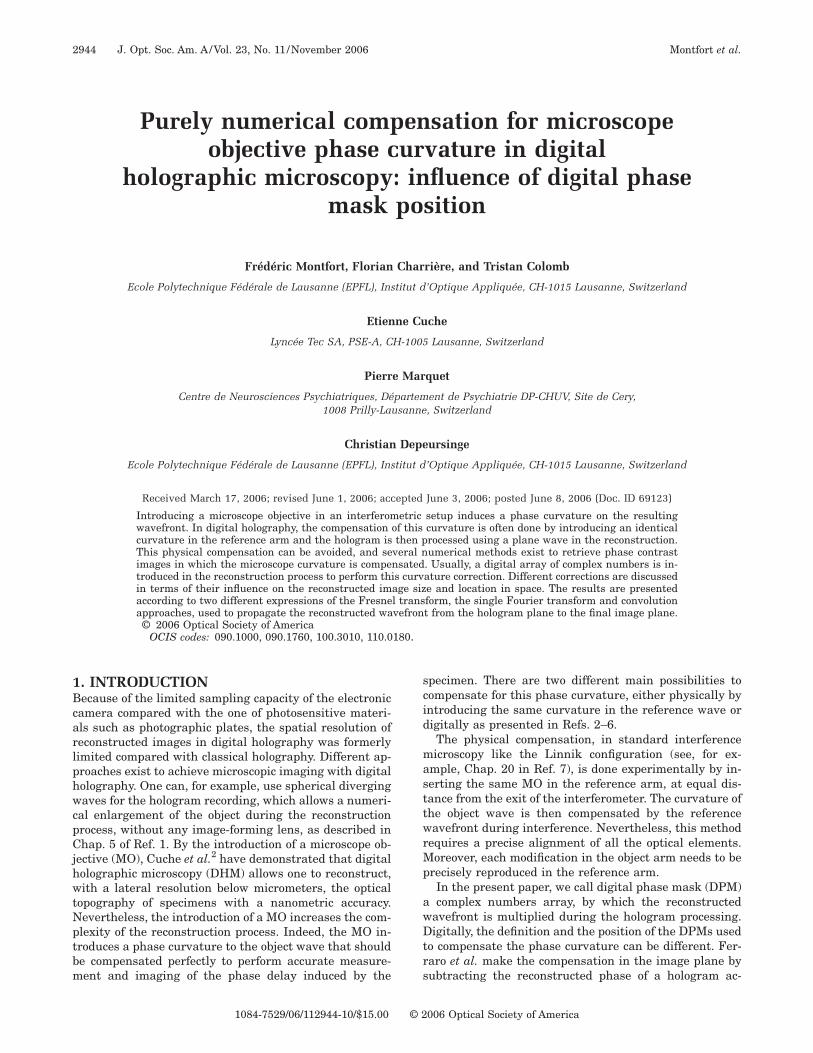
. Microscope Objective Introductionhe introduction of a MO in the object arm opens the pos-ibility of imaging at the submicrometer scale. As shownn Fig. 1, the optical arrangement in the object arm is thatf an ordinary single-lens system producing a magnifiedmage of the specimen in an image plane. In comparisonith classical microscopy, the difference is that the CCD
amera is not in the image plane but is in the hologramlane that is located between the MO and the imagelane, at a distance d from the image. This situation can
btf
ooatcsp�a
3ILcotiad
s
wbp
wf
cotpt
wttsbt
Lsflatp
teipo
T
Iw
FCos
2946 J. Opt. Soc. Am. A/Vol. 23, No. 11 /November 2006 Montfort et al.
e considered to be equivalent to a holographic configura-ion without a MO with an object wave emerging directlyrom the image and not from the object itself.
The MO produces a curvature of the wavefront in thebject arm. This deformation affects only the phase of thebject wave and does not disturb amplitude contrast im-ging. However, to perform an accurate measurement ofhe phase delay induced by the specimen only, the phaseurvature induced by the MO must be perfectly compen-ated. This compensation can be done in the hologramlane by a DPM �H and/or in the image plane by a DPMI. Therefore we can write the corrected wavefront gener-lly as
I�x,y� = − �Ii exp�ikd�F�d��H�H�x,y��. �8�
. HOLOGRAM RECONSTRUCTION: THEDEAL CASEet us first express analytically the reconstruction pro-ess that exactly reproduces the image resulting from thebject through the MO, as it would be performed on an op-ical bench, without any scaling or lateral or axial shift-ng. This ideal case formulation will serve as a gauge im-ge for comparison with the images obtained by theifferent digital reconstruction methods.The hologram is multiplied by an ideal DPM �id
H corre-ponding to a replica of the reference wave:
�idH = �id
HR*O = RR*O = O, �9�
here the reference wave amplitude has been assumed toe equal to one. The propagation over a distance did ex-ressed using Eq. (4) is given by
�idI = − i exp�ikdid�F�did
��idH�, �10�
=− i exp�ikdid�F�did�O�, �11�
here �idI corresponds to the exact initial object wave-
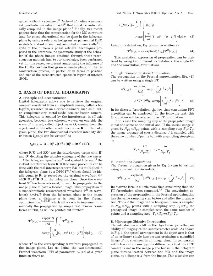
ront.In a general approach, we can consider an off-axis mi-
roscopy setup (angle between the propagation directionf the reference and object waves), in which the curva-ures of the reference and object waves at the hologramlane are different (Fig. 2). Let us define the centers ofhe spherical reference and object waves as
ig. 1. Standard configuration in holographic microscopy: TheCD defining the hologram plane is placed in front of the imagebtained though the microscope objective (MO). d is the recon-truction distance.
SR = �SRx,SRy,�hr2 − SRx
2 − SRy2 �1/2�, �12�
SO = �0,0,ho�, �13�
here hr and ho are, respectively, the distances betweenhe source points of the reference and object waves andhe recombining location of the two beams. Note that theource point of the spherical object wave is located at theack focal plane of the MO. The reference wavefront inhe hologram plane is thus given by8
R�x,y� = exp�i�
�hr��x − SRx�2 + �y − SRy�2�� . �14�
et us now define a blank object wave O0 (without apecimen in the transmission configuration and with aat surface in the reflection configuration).4 Because wessumed that only phase curvature is induced by the MO,he wavefront of the blank object wave at the hologramlane is
O0�x,y� = expi�
�ho�x2 + y2�� . �15�
To recover the phase delay induced by the object only,he phase curvature induced by both the MO and the ref-rence beam curvatures can be compensated by multiply-ng �id
I by a second DPM �idI introduced in the image
lane. The latter is determined by the complex conjugatef the blank wave O0 propagated to the image plane:
�idI = �F�did
��id,0H � *, �16�
=�F�did�O0� *. �17�
he corrected wavefront idI becomes
idI = �id
I �idI , �18�
=�F�did�O0� *F�did
�O�. �19�
nserting Eqs. (14) and (15), Eqs. (17) and (18) can beritten as
Fig. 2. Schema of the used notations.
�t
oPodtp
4DTplMhutdnlp
ALip
ofih
Pi
Tcf
Tc(
virceca
Ts
w
Fi
Ft(o
Montfort et al. Vol. 23, No. 11 /November 2006 /J. Opt. Soc. Am. A 2947
�idI �x,y� = exp− i
�
��ho + did��x2 + y2�� , �20�
idI �x,y� = − i exp�ikdid�
�exp− i�
��ho + did��x2 + y2��F�did
��idH�. �21�
idI logically corresponds to the spherical wavefront cen-ered in SO at a distance ho+did from the image plane.
This general development expresses the retrieval of thebject wavefront, in which the MO curvature is corrected.otentially this approach may also be used for correctionf optical aberrations of the holographic setup,4 but theevelopment will be restricted to the case without aberra-ions, focusing on the effect of the phase curvature com-ensation.
. PHASE CURVATURE COMPENSATIONURING NUMERICAL RECONSTRUCTION
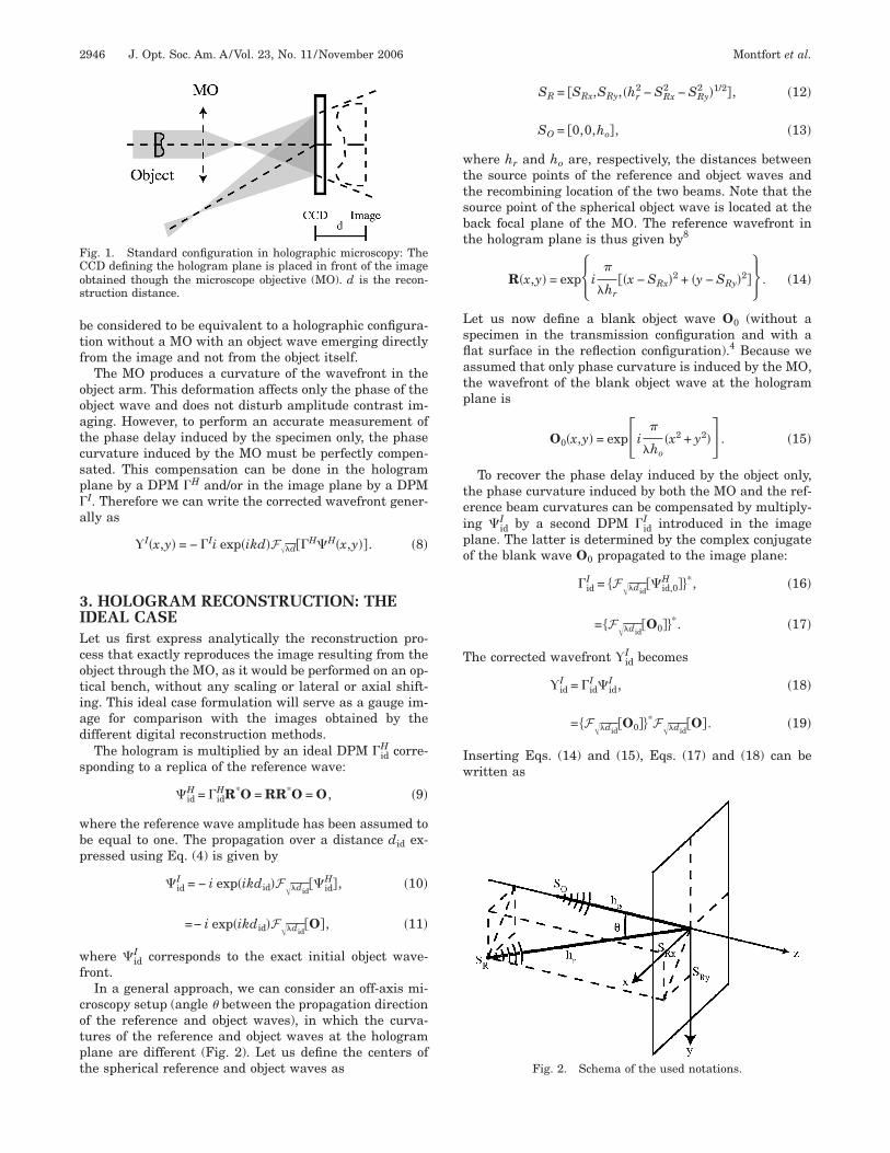
o illustrate the different reconstruction approaches andropagation formulations, a hologram of a quartz micro-ens recorded in a transmission DHM setup with a 20�
O (numerical aperature of 0.5) is used. This microlensas a diameter of 240 �m and a height of 21.15 �m. Fig-res 3(a)–3(c) present the raw phase reconstruction, thewo-dimensional unwrapped phase image, and its three-imensional representation, respectively. The differentotations for the approaches are done with a subscript
etter: no letter, general; i, image plane; h, hologramlane; and m, mixed.
. General Approachet us develop the general approach in which a DPM is
ntroduced both in the hologram plane and in the imagelane. The application of this general approach is devel-
ig. 3. (a) Phase reconstruction of the microlens recorded in aransmission DHM setup (diameter 240 �m, height 21.15 �m),b) two-dimensional unwrap of (a), (c) perspective representationf (b).
ped in detail and illustrated with examples in Ref. 6. Werst apply a DPM �H to the interference term R*O in theologram plane,
�H = �HR*O. �22�
ropagating the resulting wave over a distance d to themage plane yields �I;
�I = − i exp�ikd�F�d��H�, �23�
=− i exp�ikd�F�d��HR*O�. �24�
hen a second DPM �I is applied in the image plane toompensate for the curvature of the propagated wave-ront. The corrected wavefront I is thus given by
I = �I�I, �25�
=− i exp�ikd��IF�d��HR*O�. �26�
o determine the effects of �H on the propagation, we willompare I with id
I obtained in the ideal case [see Eqs.19) and (21)].
The DPM applied in the image plane for the phase cur-ature compensation will of course depend on the DPMntroduced in the hologram plane. We defined the digitaleference wave using the same notation as in the idealase in Eqs. (14) and (12). In this way we can define a gen-ral DPM in the hologram plane. As it is supposed to be aurvature correction term, it is defined as the conjugate ofspherical wave centered in SD:
�H = exp�− i�
�hd��x − SDx�2 + �y − SDy�2�� , �27�
SD = �SDx,SDy,�hd2 − SDx
2 − SDy2 �1/2�. �28�
he DPM �I in the image plane that compensates the re-ulting propagated wavefront is then given by
�I�x,y� = exp�− i���SDx − SRx�2 + �SDy − SRy�2�
��hd − hr��
� exp�i�
��h + d/M�� 1
M2x − h�SRx
hr−
SDx
hd��2
+1
M2y − h�SRy
hr−
SDy
hd��2��
� exp�− i�
��h0 + d/M�� 1
M2x − d�SRx
hr−
SDx
hd��2
+1
M2y − d�SRy
hr−
SDy
hd��2�� , �29�
here M and h are defined as
h =hdhr
hd − hr, M =
h − d
h. �30�
inally, the phase curvature-corrected wavefront in themage plane I is given by
w=ia
wptbpoos
a
w(
BIpRtct
aDmpT
T
T
Fpar
2948 J. Opt. Soc. Am. A/Vol. 23, No. 11 /November 2006 Montfort et al.
I�x,y� = �I�x,y��I�x,y�
= − i exp�ikd�1
MF�d/M�x�,y��
�exp�− i�
��h + d/M�� 1
M2x − h�SRx
hr−
SDx
hd��2
+1
M2y − h�SRy
hr−
SDy
hd��2��
= expik�d −d
M�� 1
Mid
H�x�,y��, �31�
here x�=�x−d�SRx�hr − SDx�hd ��M and y��y−d�SR4�hr − SD4�hd ��M . The propagation direction
s no longer parallel to the optical axis, but is given by thengle :
sin =SRx
2 + SRy2
hr−
SDx2 + SDy
2
hd. �32�
By analyzing the image plane DPM given by Eq. (29),e can find that the first term is a phase constant of noarticular interest and can be suppressed. The seconderm is compensating for the phase deformation inducedy the reference wave and the DPM in the hologramlane. Finally the third term is the correction term of thebject wavefront curvature. The final image I is a replicaf the ideal case image scaled by a factor M and laterallyhifted.
We note that one can retrieve the results of the idealpproach by setting �H=R:
�H = R ⇒ SD = SR, hd = hr ⇒ limhd→
h = hr, M = 1,
hich gives the well-known results of Eqs. (10), (20), and21):
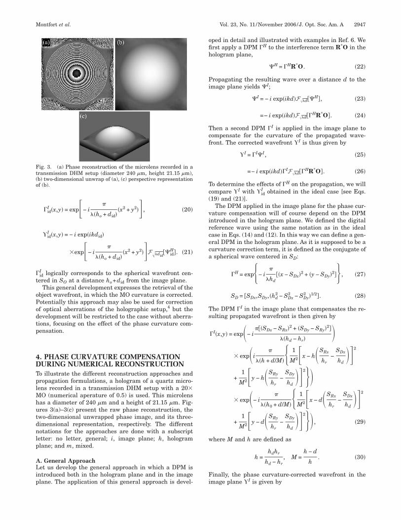
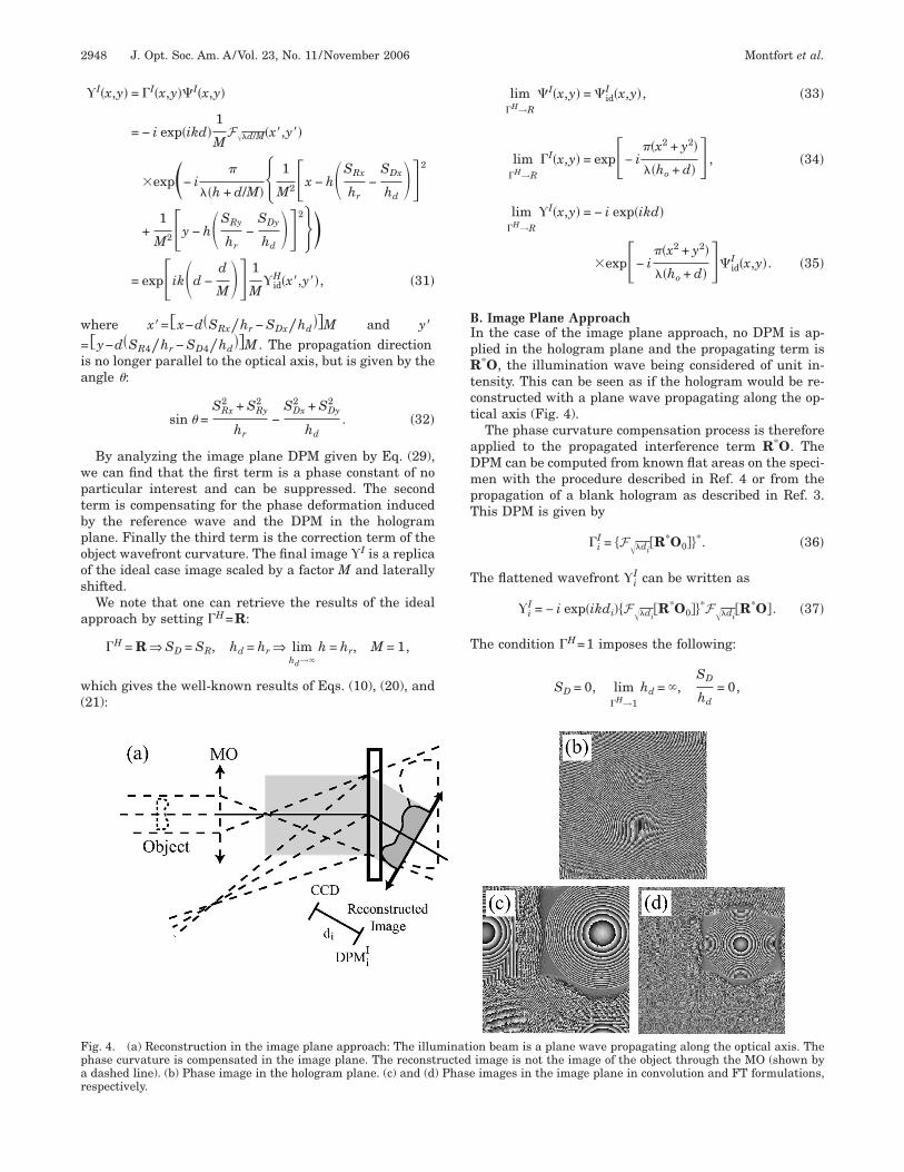
ig. 4. (a) Reconstruction in the image plane approach: The illuhase curvature is compensated in the image plane. The reconstdashed line). (b) Phase image in the hologram plane. (c) and (d)
espectively.
lim�H→R
�I�x,y� = �idI �x,y�, �33�
lim�H→R
�I�x,y� = exp− i��x2 + y2�
��ho + d� � , �34�
lim�H→R
I�x,y� = − i exp�ikd�
�exp− i��x2 + y2�
��ho + d� ��idI �x,y�. �35�
. Image Plane Approachn the case of the image plane approach, no DPM is ap-lied in the hologram plane and the propagating term is*O, the illumination wave being considered of unit in-
ensity. This can be seen as if the hologram would be re-onstructed with a plane wave propagating along the op-ical axis (Fig. 4).
The phase curvature compensation process is thereforepplied to the propagated interference term R*O. ThePM can be computed from known flat areas on the speci-en with the procedure described in Ref. 4 or from the
ropagation of a blank hologram as described in Ref. 3.his DPM is given by
�iI = �F�di
�R*O0� *. �36�
he flattened wavefront iI can be written as
iI = − i exp�ikdi��F�di
�R*O0� *F�di�R*O�. �37�
he condition �H=1 imposes the following:
SD = 0, lim�H→1
hd = ,SD
hd= 0,
on beam is a plane wave propagating along the optical axis. Theimage is not the image of the object through the MO (shown byimages in the image plane in convolution and FT formulations,
minatiructedPhase
Iprw
pctdctca
sapo
Ttotstt
Ttspintc
mstw
CIidhTdp
Bpw
Td
Tpttrant
appc
tsw
Tthmpp
Montfort et al. Vol. 23, No. 11 /November 2006 /J. Opt. Soc. Am. A 2949
⇒ limhd→
h = hr, limhd→
M =hr − d
hr= Mi.
ntroducing these results in Eqs. (29) and (31), we can ex-ress the DPM �i
I that expresses the phase curvature cor-ection leading to the expression of the corrected imageavefront i
I:
�iI�x,y� = lim
�H→1
�I�x,y� = exp�i�
��hr + di/Mi� 1
Mi2 �x − SRx�2
+1
Mi2 �y − SRy�2��exp�− i
�
��h0 + di/Mi� 1
Mi2
��x −di
hrSRx�2
+1
Mi2�y −
di
hrSRy�2�� , �38�
iI�x,y� = lim
�H→1
I�x,y� = − i expik�di −di
M���
1
Miid
I �x −di
hrSRx
Mi,
y −di
hrSRx
Mi� . �39�
Equation (39) shows that the correction in the imagelane approach also introduces a resizing of the image inomparison with the ideal case. The scale factor is a func-ion of the reference beam curvature hr. This scaling isue to the fact that, compared with the ideal solution, theorrection of the reference curvature is not performed inhe hologram plane as it is when the hologram is pro-essed with exactly the same reference wave used duringcquisition.In the image plane approach, the image is also laterally
hifted in space, as mentioned in the general approachnd shown in Fig. 4. The shift is due to the fact that theropagation direction is modified by an angle from theptical axis of the object beam. is given by
sin =SRx
2 + SRy2
hr. �40�
his inclination of the propagation direction arises fromhe fact that the illumination wave propagates along theptical axis, which is precisely inclined of an angle fromhe correct reference wave. This induced error corre-ponds to a tilt of the wavefront that is not corrected inhe hologram plane and induced this propagation devia-ion. The lateral shift is thus given by
Lshift =di
hr�SRx
2 + SRy2 �1/2 = di sin . �41�
his shift is not convenient for the numerical propaga-ion. Indeed, the image is no longer centered in the recon-truction window. In a convolution formulation of theropagation (see subsection 5.B), this results in a tailedmage [Fig. 4(c)]. In the case of the FT formulation, it mayot be a problem if the sampling step is small enough sohat the field of view of the window is large enough toover the off-axis propagating wavefront [Fig. 4(d)]. The
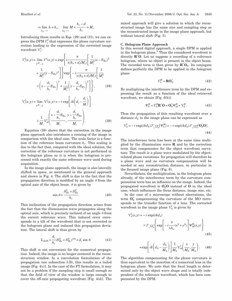
ixed approach will give a solution in which the recon-tructed image has the same size and sampling step ashe reconstructed image in the image plane approach, butithout lateral shift (Fig. 5).
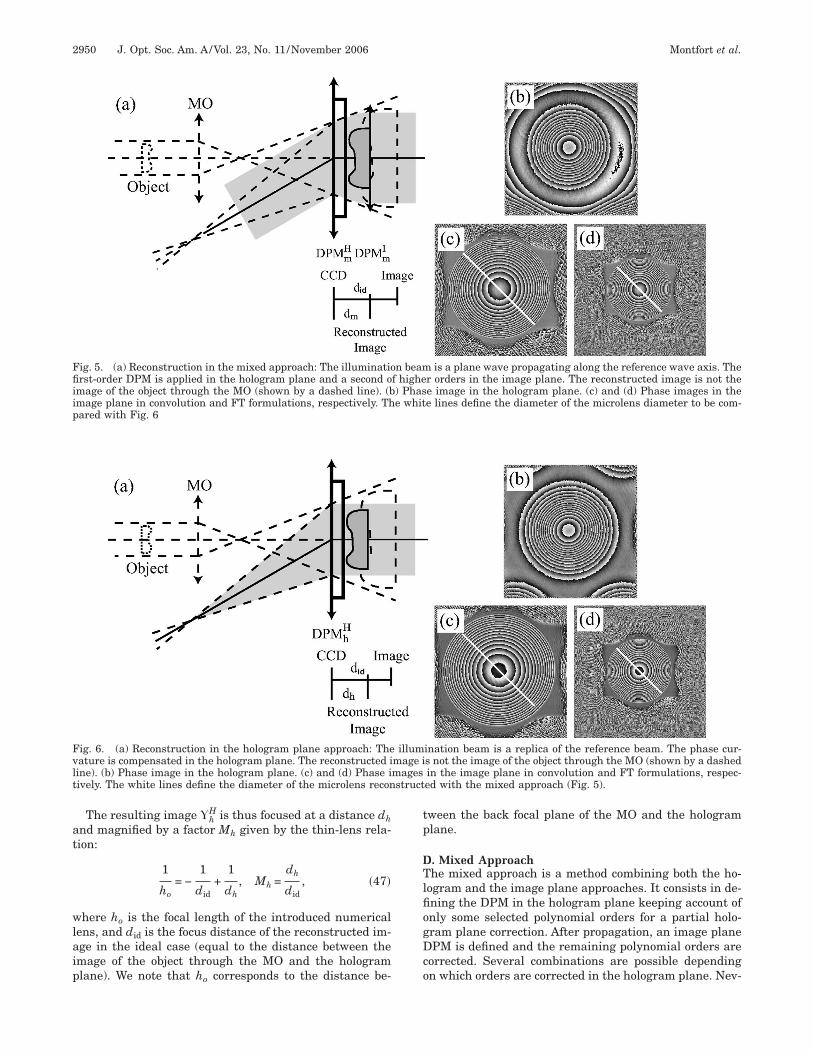
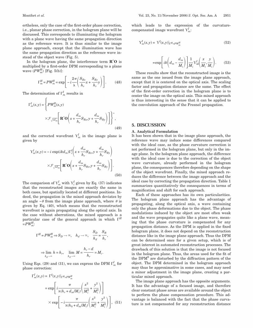
. Hologram Plane Approachn this second digital approach, a single DPM is appliedn the hologram plane.5 Thus the considered wavefront isirectly R*O. Let us suppose a recording of a referenceologram, where no object is present in the object beam.he recorded term is then given by R*O0. Its conjugateefines perfectly the DPM to be applied in the hologramlane:
�hH = RO0
* . �42�
y multiplying the interference term by the DPM and ex-ressing the result as a function of the ideal retrievedavefront, we obtain [Fig. 6(b)]:
�hH = �h
HR*O = O0*�id
H = hH. �43�
hus the propagation of this resulting wavefront over aistance dh to the image plane can be expressed as
hI = − i exp�ikdh�F�dh
��hH� = − i exp�ikdh�F�dh
�O0*O�.
�44�
he interference term has been at the same time multi-lied by the illumination wave R and by the correctionerm that compensates for the object wavefront curva-ure. The result is a plane wave modulated by the object-elated phase variations. Its propagation will therefore be
plane wave and no curvature compensation will beeeded at any reconstruction distance, in particular inhe focused image plane (Fig. 6).
Nevertheless, the multiplication, in the hologram planelready, of the interference term by the curvature com-ensation term has an influence on the image. Indeed, theropagated wavefront is O0
*O instead of O in the idealase, which influences the focus distance, image size, etc.
In the case of a microscope without aberrations, theerm O0
* compensating the curvature of the MO corre-ponds to the transfer function of a lens. The correctedavefront in the image plane h
I is given by
hI �x,y� = − i exp�ikdh�
�F�dh�exp− i�
�ho�x2 + y2���id
H�x,y���45�
=expik�dh −dh
Mh�� 1
Mhid
I � x
Mh,
y
Mh� . �46�
he algorithm compensating for the phase curvature ishus equivalent to the insertion of a numerical lens in theologram plane. We note that the focal length is deter-ined only by the object wave shape and is totally inde-
endent of the reference wavefront, which has been com-ensated by the DPM.
at
wlaip
tp
DTlfiogDco
Ffiiip
Fvlt
2950 J. Opt. Soc. Am. A/Vol. 23, No. 11 /November 2006 Montfort et al.
The resulting image hH is thus focused at a distance dh
nd magnified by a factor Mh given by the thin-lens rela-ion:
1
ho= −
1
did+
1
dh, Mh =
dh
did, �47�
here ho is the focal length of the introduced numericalens, and did is the focus distance of the reconstructed im-ge in the ideal case (equal to the distance between themage of the object through the MO and the hologramlane). We note that h corresponds to the distance be-
ig. 5. (a) Reconstruction in the mixed approach: The illuminatiorst-order DPM is applied in the hologram plane and a second o
mage of the object through the MO (shown by a dashed line). (bmage plane in convolution and FT formulations, respectively. Thared with Fig. 6
ig. 6. (a) Reconstruction in the hologram plane approach: Theature is compensated in the hologram plane. The reconstructed iine). (b) Phase image in the hologram plane. (c) and (d) Phase iively. The white lines define the diameter of the microlens recon
o
ween the back focal plane of the MO and the hologramlane.
. Mixed Approachhe mixed approach is a method combining both the ho-
ogram and the image plane approaches. It consists in de-ning the DPM in the hologram plane keeping account ofnly some selected polynomial orders for a partial holo-ram plane correction. After propagation, an image planePM is defined and the remaining polynomial orders are
orrected. Several combinations are possible dependingn which orders are corrected in the hologram plane. Nev-
is a plane wave propagating along the reference wave axis. Ther orders in the image plane. The reconstructed image is not thee image in the hologram plane. (c) and (d) Phase images in thee lines define the diameter of the microlens diameter to be com-
ination beam is a replica of the reference beam. The phase cur-s not the image of the object through the MO (shown by a dashedin the image plane in convolution and FT formulations, respec-ed with the mixed approach (Fig. 5).
n beamf highe) Phase whit
illummage imagesstruct
eidwapts
mw
T
ag
Ttbdagwtp=
Up
wc
sefocit
5AIrwnawwpodism
Tpomaiphdcgditomat
Ictvt
Montfort et al. Vol. 23, No. 11 /November 2006 /J. Opt. Soc. Am. A 2951
rtheless, only the case of the first-order phase correction,.e., planar phase correction, in the hologram plane will beiscussed. This corresponds to illuminating the hologramith a plane wave having the same propagation directions the reference wave. It is thus similar to the imagelane approach, except that the illumination wave hashe same propagation direction as the reference wave in-tead of the object wave (Fig. 5).
In the hologram plane, the interference term R*O isultiplied by a first-order DPM corresponding to a planeave �PWm
H� [Fig. 5(b)]:
�mH = PWm
H = exp− i2�
��SRx
hrx +
SRy
hry�� . �48�
he determination of �mI results in
�mI �x,y� = �PWm
H�x,y�
�F�dmR*O�x +dm
hrSRx,y +
dm
hrSRy���*
,
�49�
nd the corrected wavefront mI in the image plane is
iven by
mI �x,y� = − i exp�ikdm��i
I�x +dm
hrSRx,y +
dm
hrSRy�
�F�dmR*O�x +dm
hrSRx,y +
dm
hrSRy�� .
�50�
he comparison of mI with i
I given by Eq. (37) indicateshat the reconstructed images are exactly the same inoth cases, but spatially located at different positions. In-eed, the propagation in the mixed approach deviates byn angle − from the image plane approach, where isiven by Eq. (40), which means that the reconstructedavefront is again propagating along the optical axis. In
he case without aberrations, the mixed approach is aarticular case of the general approach in which �H
PWmH:
�H = PWmH ⇒ SD → , hd → ,
SD
hd=
SR
hr,
⇒ limhd→
h = hr, limhd→
M =hr − d
hr= Mi.
sing Eqs. (29) and (31), we can express the DPM �mI for
hase correction:
�mI �x,y� = ��I�x,y���H=PWm
H
= expi�
��hr + dm/Mi�� x2
Mi2 +
y2
Mi2��
� exp− i� � x2
2 +y2
2�� , �51�
��h0 + dm/Mi� Mi Mihich leads to the expression of the curvature-ompensated image wavefront m
I :
mI �x,y� = �I�x,y���H=PWm
H �52�
=expik�dm −dm
Mi�� 1
Miid
I � x
Mi,
y
Mi� . �53�
These results show that the reconstructed image is theame as the one issued from the image plane approach,xcept that it is centered on the optical axis. The scalingactor and propagation distance are the same. The effectf the first-order correction in the hologram plane is toenter the image on the optical axis. This mixed approachs thus interesting in the sense that it can be applied tohe convolution approach of the Fresnel propagation.
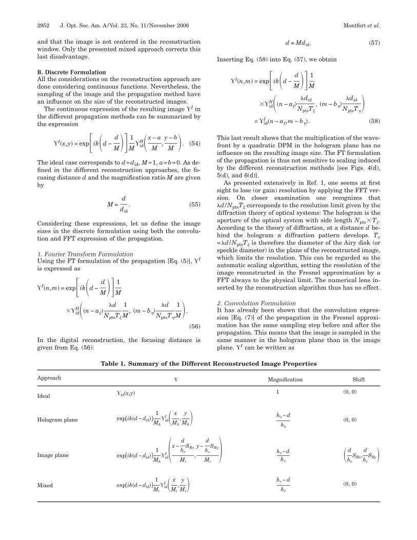
. DISCUSSION. Analytical Formulation
t has been shown that in the image plane approach, theeference wave may induce some differences comparedith the ideal case, as the phase curvature correction isot performed in the hologram plane, but only in the im-ge plane. In the hologram plane approach, the differenceith the ideal case is due to the correction of the objectave curvature, already performed in the hologramlane, the consequences therefore depending on the shapef the object wavefront. Finally, the mixed approach re-uces the difference between the image approach and thedeal case by correcting the propagation direction. Table 1ummarizes quantitatively the consequences in terms ofagnification and shift for each approach.Each of these approaches has its own particularities.
he hologram plane approach has the advantage ofropagating, along the optical axis, a wave containingnly the phase deformations due to the object. The phaseodulations induced by the object are most often weak
nd the wave propagates quite like a plane wave, mean-ng that the phase curvature is compensated for anyropagation distance. As the DPM is applied in the fixedologram plane, it does not depend on the reconstructionistance like in the image plane approach. Thus the DPMan be determined once for a given setup, which is ofreat interest in automated reconstruction processes. Therawback of this solution is that the image is not focusedn the hologram plane. Thus, the areas used for the fit ofhe DPM6 are disturbed by the diffraction pattern of thebject. The DPM determined in the hologram approachay thus be approximative in some cases, and may needminor adjustment in the image plane, creating a par-
icular mixed approach.The image plane approach has the opposite arguments.
t has the advantage of a focused image, and thereforelear constant phase areas are available around the objecto perform the phase compensation procedure. This ad-antage is balanced with the fact that the phase curva-ure is not compensated for any reconstruction distance
awl
BAdsa
tt
Tficb
Cst
1Ui
Ig
I
Tfiob5
ss�daAh=swaiFs
2Ismpsp
A
I
H
I
M
2952 J. Opt. Soc. Am. A/Vol. 23, No. 11 /November 2006 Montfort et al.
nd that the image is not centered in the reconstructionindow. Only the presented mixed approach corrects this
ast disadvantage.
. Discrete Formulationll the considerations on the reconstruction approach areone considering continuous functions. Nevertheless, theampling of the image and the propagation method haven influence on the size of the reconstructed images.The continuous expression of the resulting image I in
he different propagation methods can be summarized byhe expression
I�x,y� = expik�d −d
M�� 1
Mid
H�x − a
M,y − b
M � . �54�
he ideal case corresponds to d=did, M=1, a=b=0. As de-ned in the different reconstruction approaches, the fo-using distance d and the magnification ratio M are giveny
M =d
did. �55�
onsidering these expressions, let us define the imageizes in the discrete formulation using both the convolu-ion and FFT expression of the propagation.
. Fourier Transform Formulationsing the FT formulation of the propagation [Eq. (5)], I
s expressed as
I�n,m� = expik�d −d
M�� 1
M
�idH��n − a��
�d
NptsT�
1
M, �m − b��
�d
NptsT�
1
M� .
�56�
n the digital reconstruction, the focusing distance isiven from Eq. (56):
Table 1. Summary of the Differe
pproach
deal id�x,y�
ologram plane exp�ik�d − did��1
Mhid
I � x
Mh,
y
Mh�
mage plane exp�ik�d − did��1
Mhid
I �x −d
hrSRx
Mi,
y −
ixed exp�ik�d − did��1
Miid
I � x
Mi,
y
Mi�
d = Mdid. �57�
nserting Eq. (58) into Eq. (57), we obtain
I�n,m� = expik�d −d
M�� 1
M
�idH��n − a��
�did
NptsT�
, �m − b���did
NptsT��
= idI �n − a�,m − b��. �58�
his last result shows that the multiplication of the wave-ront by a quadratic DPM in the hologram plane has nonfluence on the resulting image size. The FT formulationf the propagation is thus not sensitive to scaling inducedy the different reconstruction methods [see Figs. 4(d),(d), and 6(d)].As presented extensively in Ref. 1, one seems at first
ight to lose (or gain) resolution by applying the FFT ver-ion. On closer examination one recognizes thatd /NptsT� corresponds to the resolution limit given by theiffraction theory of optical systems: The hologram is theperture of the optical system with side length Npts�T�.ccording to the theory of diffraction, at a distance d be-ind the hologram a diffraction pattern develops. Tx�d /NptsT� is therefore the diameter of the Airy disk (orpeckle diameter) in the plane of the reconstructed image,hich limits the resolution. This can be regarded as theutomatic scaling algorithm, setting the resolution of themage reconstructed in the Fresnel approximation by aFT always to the physical limit. The numerical lens in-erted by the reconstruction algorithm thus has no effect.
. Convolution Formulationt has already been shown that the convolution expres-ion [Eq. (7)] of the propagation in the Fresnel approxi-ation has the same sampling step before and after the
ropagation. This means that the image is sampled in theame manner in the hologram plane than in the imagelane. I can be written as
econstructed Image Properties
Magnification Shift
1 (0, 0)
ho − d
ho
(0, 0)
� hr−dhr
� d
hrSRx,
d
hrSRy�
hr − d
hr
(0, 0)
nt R
d
hrSRy
Mi
wscacimfaeHl
6Iaircubatoathflss
iatau
AT1
f
R
1
1
1
Montfort et al. Vol. 23, No. 11 /November 2006 /J. Opt. Soc. Am. A 2953
I�n,m� = expik�d −d
M�� 1
Mid
H� �n − a��T�
M,�m − b��T�
M � ,
�59�
hich means that the size of the images is magnified theame way as in the continuous domain. Figure 6(c) is re-onstructed using the hologram plane approach. The im-ge has the same size as the hologram. Figure 5(c) is re-onstructed using the mixed approach. The size of themages of Figs. 5(c) and 5(d) is not the same because the
agnification factor with respect to the ideal case is dif-erent. Reconstruction of holograms by the convolutionpproach results indeed in images with more or fewer pix-ls per unit length than those reconstructed by the FFT.owever, because of the physical limits, the image reso-
ution does not change.
. CONCLUSIONn digital holography, the access to numerical data allowsn easy compensation of the nondesired phase curvaturesn the reconstructed images. Nevertheless, procedures areequired to determine the correction to be applied. The re-orded data, corresponding to the interference term R*O,sually do not allow the retrieval of the original image,ut only a scaled replica displaced both laterally and axi-lly. The reconstructed image can therefore be consideredo be an image of the object through a system, composedf a MO and an additional numerical lens, that can benalytically characterized to get the exact properties ofhe complete holographic microscope. In this paper, weave presented for the first time to our knowledge the in-uence of the phase masks’ position involved in the recon-truction process, in particular in terms of position andize of the reconstructed specimen ROI.
We hope that this study on the reconstruction methods,n conjunction with the remarks on the reconstructed im-ge sampling regarding the FT or convolution formula-ion, will clarify the relations subtended between thevailable hologram processing techniques, facilitating the
ser’s choice for each specific application of DHM.CKNOWLEDGMENThis work was funded through research grants 205320-03885/1 from the Swiss National Science Foundation.The e-mail address for F. Montfort is
EFERENCES1. U. Schnars and W. P. O. Jüptner, “Digital recording and
numerical reconstruction of holograms,” Meas. Sci. Technol.13, R85–R101 (2002).
2. E. Cuche, P. Marquet, and C. Depeursinge, “Simultaneousamplitude-contrast and quantitative phase-contrastmicroscopy by numerical reconstruction of Fresnel off-axisholograms,” Appl. Opt. 38, 6994–7001 (1999).
3. P. Ferraro, S. D. Nicola, A. Finizio, G. Coppola, S. Grilli, C.Magro, and G. Pierattini, “Compensation of the inherentwave front curvature in digital holographic coherentmicroscopy for quantitative phase-contrast imaging,” Appl.Opt. 42, 1938–1946 (2003).
4. T. Colomb, E. Cuche, F. Charrière, J. Kühn, N. Aspert, F.Montfort, P. Marquet, and C. Depeursinge, “Automaticprocedure for aberration compensation in digitalholographic microscopy and applications to specimen shapecompensation,” Appl. Opt. 45, 851–863 (2006).
5. T. Colomb, J. Kühn, F. Charrière, C. Depeursinge, P.Marquet, and N. Aspert, “Total aberrations compensationin digital holographic microscopy with a referenceconjugated hologram,” Opt. Express 14, 4300–4306 (2006).
6. T. Colomb, F. Montfort, J. Kühn, N. Aspert, E. Cuche, A.Marian, F. Charrière, S. Bourquin, P. Marquet, and C.Depeursinge, “Numerical parametric lens for shifting,magnification, and complete aberration compensation indigital holographic microscopy,” J. Opt. Soc. Am. A 23(2006) (to be published).
7. D. Malacara, ed., Optical Shop Testing, Wiley Series inPure and Applied Optics (Wiley, 1992).
8. J. W. Goodman, Introduction to Fourier Optics (McGraw-Hill, 1968).
9. E. Cuche, P. Marquet, and C. Depeursinge, “Apertureapodization using cubic spline interpolation: application indigital holographic microscopy,” Opt. Commun. 182, 59–69(2000).
0. E. Cuche, P. Marquet, and C. Depeursinge, “Spatialfiltering for zero-order and twin-image elimination indigital off-axis holography,” Appl. Opt. 39, 4070–4075(2000).
1. J. W. Goodman and R. W. Lawrence, “Digital imageformation from electronically detected holograms,” Appl.Phys. Lett. 11, 77–79 (1967).
2. T. H. Demetrakopoulos and R. Mittra, “Digital and opticalreconstruction of images from suboptical diffraction
patterns,” Appl. Opt. 13, 665–670 (1974).