Pulsed Power Amplifier Solutions - - BONN Elektronik GmbH
28
Gerald Puchbauer BONN Elektronik GmbH Pulsed Power Amplifier Solutions
-
Upload
khangminh22 -
Category
Documents
-
view
4 -
download
0
Transcript of Pulsed Power Amplifier Solutions - - BONN Elektronik GmbH

Gerald Puchbauer
BONN Elektronik GmbH
Pulsed Power
Amplifier Solutions

RF Pulsed Power Amplifier SolutionsJanuary 2022
2
BONN Elektronik GmbH

RF Pulsed Power Amplifier SolutionsJanuary 2022
3
Broadband RF Power Amplifiers

RF Pulsed Power Amplifier SolutionsJanuary 2022
4
BSA Series BLWA Series BLMA Series BPA
Solid State Amplifiers Solid State Amplifiers Solid State Amplifiers Pulsed Solid State Amplifiers
4 kHz ... 1000 MHz
1 W ... 20 kW
1 ... 1000 (4000) MHz
1 W ... 40 kW
100 MHz ... 40 GHz
0.1 W ... 2 kW
300 MHz ... 10 GHz
25 W pk ... 20 kW pk
Narrow Band Amplifiers TWAL Series TWAP Series
Solid State Amplifiers TWT Amplifiers Pulsed TWT Amplifiers
800 ... 2700 MHz
10 W ... 600 W
1 GHz ... 50 GHz
20 W ... 1 kW
1 ... 18 GHz
1.5 ... 50 kW pk
Broadband RF Power Amplifiers
RF Pulsed Power Amplifier SolutionsJanuary 2022
5
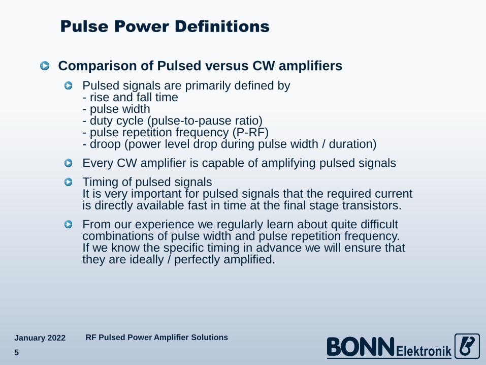
Comparison of Pulsed versus CW amplifiers
Pulsed signals are primarily defined by- rise and fall time- pulse width- duty cycle (pulse-to-pause ratio)- pulse repetition frequency (P-RF)- droop (power level drop during pulse width / duration)
Every CW amplifier is capable of amplifying pulsed signals
Timing of pulsed signals It is very important for pulsed signals that the required current is directly available fast in time at the final stage transistors.
From our experience we regularly learn about quite difficult combinations of pulse width and pulse repetition frequency. If we know the specific timing in advance we will ensure that they are ideally / perfectly amplified.
Pulse Power Definitions

RF Pulsed Power Amplifier SolutionsJanuary 2022
6
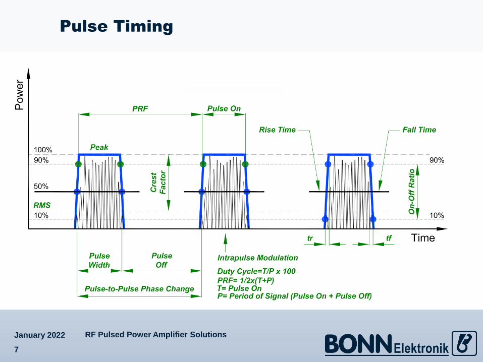
Pulse Elements
RF Pulsed Power Amplifier SolutionsJanuary 2022
7
Pulse Timing

RF Pulsed Power Amplifier SolutionsJanuary 2022
8
Pulse Modulator

RF Pulsed Power Amplifier SolutionsJanuary 2022
9
Power Amplifier Pulse Response
BSA 0040-250 800 ps 2 ns 5 ns
– Input Pulse from Signal Generator
– Pulse Response at Amplifier Output

RF Pulsed Power Amplifier SolutionsJanuary 2022
10
Power Amplifier Pulse Response
BSA 0040-250 20 ns
– Input Pulse from Signal Generator
– Pulse Response at Amplifier Output

RF Pulsed Power Amplifier SolutionsJanuary 2022
11
Solid state BPA series pulsed amplifiersup to approximately 10 kW pk
300 … 4000 MHz For wideband ranges no dedicated pulsed transistors are available. Therefore, using CW transistors the optimization for pulsed operation is not that ideal. However, power supplies and cooling can be reduced accordingly. Specifically at higher output levels this still is important.1 … 10 GHz For narrow bands, dedicated pulsed transistors are allowing cost effective designs at significantly higher output power levels compared to CW transistors.Typical duty cycle of pulsed power solid state designs is 10%Typical pulse width is 100 µs
Pulsed travelling wave tube amplifiers TWAP series1 … 18 GHz up to 30 kW pk
Significantly higher output power levels than standard CW tubesTypical duty cycle of travelling wave tube designs is 1 … 6%Standard pulse width is 50 µs; optional for some tubes 100 µs
Pulsed Power Testing

RF Pulsed Power Amplifier SolutionsJanuary 2022
12
Automotive Radar Pulse TestingGM GMW 3097S1.2 … 1.4 GHz, 600 V/m at 0.75 m and 1 % Duty
Ford EMC-CS-2009.11.2 … 1.4 GHz and 2.7 … 3.1 GHz, 300 or 600 V/m at 1 m and 1% Duty
FCA (Fiat Chrysler) CS.00540.8 … 2.7 GHz, 50 V/m at 1 m and 1% Duty
VOLVO 515-00031.15 … 1.45 GHz, 600 V/m and 10% Duty2.6 … 3.2 GHz, 5.2 … 5.9 GHz and 8.2 … 12.4 GHz, 200 V/m at 1 m and 10% Duty
Autonomous DrivingPreliminary8.5 … 10.5 GHz, 600 V/m at 1 m and 50% Duty15.7 … 17.7 GHz, 600 V/m at 1 m and 50 % Duty
Aerospace RTCA/DO-160Section 20.0: Radio Frequency Susceptibility (Radiated and Conducted), Category R0.4 … 8 GHz, 150 V/m at 1 m and 4% Duty
MIL TestingMIL 461x, RS1032 MHz … 18 GHz, 200 V/m at 1 m and 50% Duty
Popular Pulsed Power Test Standards

RF Pulsed Power Amplifier SolutionsJanuary 2022
13
Requirements
Example: VW TL 810 00 (2018-03)
RF Pulsed Power Amplifier SolutionsJanuary 2022
14
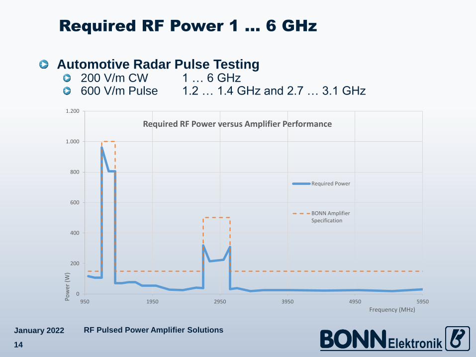
Automotive Radar Pulse Testing200 V/m CW 1 … 6 GHz600 V/m Pulse 1.2 … 1.4 GHz and 2.7 … 3.1 GHz
Required RF Power 1 … 6 GHz
0
200
400
600
800
1.000
1.200
950 1950 2950 3950 4950 5950Po
wer
(W
)
Frequency (MHz)
Required RF Power versus Amplifier Performance
Required Power
BONN AmplifierSpecification
RF Pulsed Power Amplifier SolutionsJanuary 2022
15
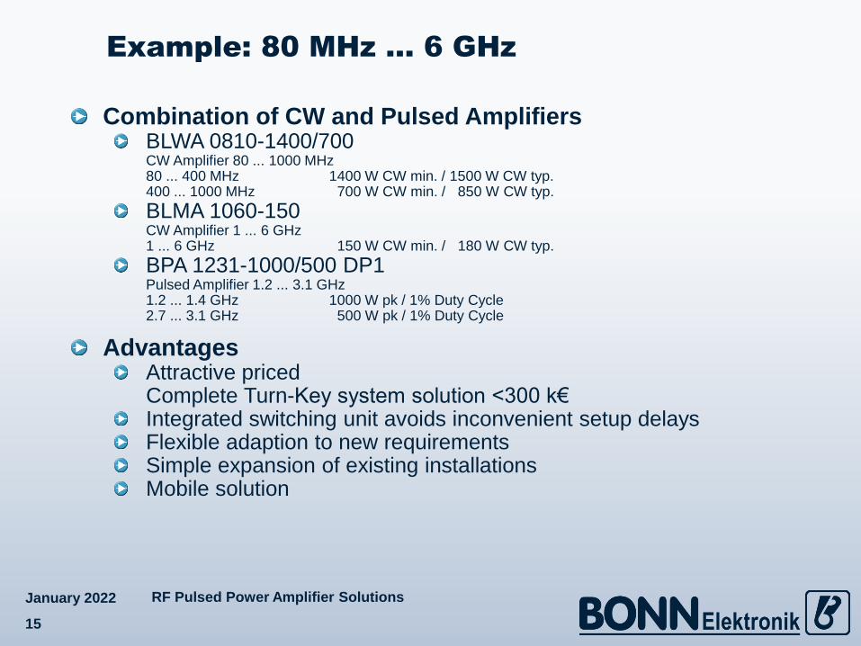
Combination of CW and Pulsed AmplifiersBLWA 0810-1400/700CW Amplifier 80 ... 1000 MHz 80 ... 400 MHz 1400 W CW min. / 1500 W CW typ.400 ... 1000 MHz 700 W CW min. / 850 W CW typ.
BLMA 1060-150CW Amplifier 1 ... 6 GHz 1 ... 6 GHz 150 W CW min. / 180 W CW typ.
BPA 1231-1000/500 DP1Pulsed Amplifier 1.2 ... 3.1 GHz1.2 ... 1.4 GHz 1000 W pk / 1% Duty Cycle2.7 ... 3.1 GHz 500 W pk / 1% Duty Cycle
AdvantagesAttractive pricedComplete Turn-Key system solution <300 k€Integrated switching unit avoids inconvenient setup delaysFlexible adaption to new requirementsSimple expansion of existing installationsMobile solution
Example: 80 MHz … 6 GHz

RF Pulsed Power Amplifier SolutionsJanuary 2022
16
System Block Diagram
RF Pulsed Power Amplifier SolutionsJanuary 2022
17
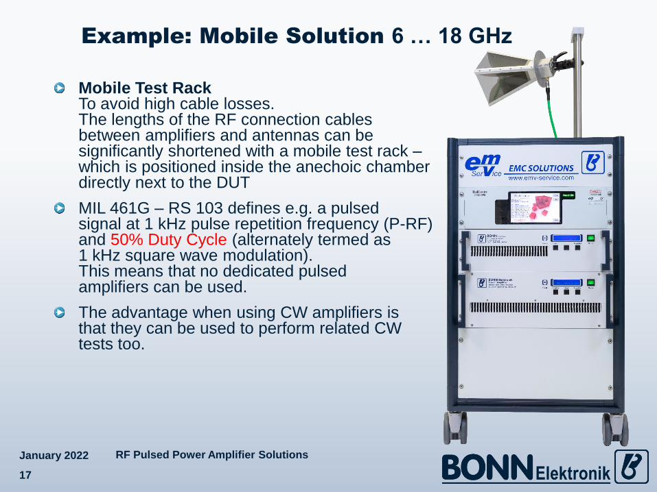
Mobile Test Rack To avoid high cable losses. The lengths of the RF connection cables between amplifiers and antennas can be significantly shortened with a mobile test rack –which is positioned inside the anechoic chamber directly next to the DUT
MIL 461G – RS 103 defines e.g. a pulsedsignal at 1 kHz pulse repetition frequency (P-RF)and 50% Duty Cycle (alternately termed as1 kHz square wave modulation). This means that no dedicated pulsed amplifiers can be used.
The advantage when using CW amplifiers is that they can be used to perform related CW tests too.
Example: Mobile Solution 6 … 18 GHz

RF Pulsed Power Amplifier SolutionsJanuary 2022
18
Requirements for different Platforms
Example: MIL 461G – RS 103

RF Pulsed Power Amplifier SolutionsJanuary 2022
19
Example MIL 461G – RS 103 AircraftAircraft (external / safety) 200 V/m CW Ground Army 50 V/m CW
RF Power Requirements 6 … 18 GHz
0
50
100
150
200
250
300
350
6000 8000 10000 12000 14000 16000 18000
Po
wer
(W
)
Frequency (MHz)
Required RF Power versus Amplifier Performance
Required Power
BONN Amplifier Specification
0
5
10
15
20
25
6000 8000 10000 12000 14000 16000 18000
Po
wer
(W
)
Frequency (MHz)
Required RF Power versus Amplifier Performance
Required Power
BONN Amplifier Specification

RF Pulsed Power Amplifier SolutionsJanuary 2022
20
For 50 V/m according to MIL 461G – RS 103 Ground Armywe e.g. can offer following amplifiers:
BLMA 6018-20Solid State Power Amplifier6 ... 18 GHz 20 W CW min. / 22 W CW typ.
For 200 V/m according to MIL 461G – RS 103 Aircraft (external / safety)we e.g. can offer following amplifiers:
TWAL 0618-300Travelling Wave Tube Amplifier6 ... 18 GHz 300 W CW min. / 320 W CW typ.
BLMA 6018-200Solid State Power Amplifier6 ... 18 GHz 200 W CW min. / 220 W CW typ.
AdvantagesAttractive priced mobile solutionFlexible adaption to new requirementsSimple expansion of existing installations
Example: MIL 461G – RS 103

RF Pulsed Power Amplifier SolutionsJanuary 2022
21
High test frequencies (18 … 40 GHz )and exceptional high field strengthAerospace RTCA DO160MIL Tests MIL-STD 461, RS103
High cable losses at very high frequenciesAt very high frequencies, the cable loss increases extremely and the use of flexible waveguides is not always ideal
Split-Mount configurationHere the power amplifier is split into a RF unit and separate power supply and control unit
power supply and control unit are conventionally integrated into 19“ cabinets and are installed into a mobile rack
This makes the RF units of the power amplifiers much more compact and lightweight
Tripod mountingThese compact RF units can be mounted on tripods and the antennas are mounted directly – without any waveguides or cables – to the amplifier output (see example)
Example: Split-Mount 18 … 40 GHz

RF Pulsed Power Amplifier SolutionsJanuary 2022
22
Example: Split-Mount 18 … 40 GHz

RF Pulsed Power Amplifier SolutionsJanuary 2022
23
CW E-Field Probe Method (Dual Mode)Peak RMS forward power is the reference parameter for characterization of the field using peak envelope power (PEP) sensors or a spectrum analyser (not recommended by some standards). Characterization at the required field strengths is performed in CW mode.
If the CW E-Field probe is not capable of measuring the final field levels required, or if a pulsed-only amplifier is used, then it is acceptable to calibrate at a lower CW level using CW power sensors plus CW amplifier and scale up the forward power levels with a PEP sensor accordingly to the corresponding target E-Field during actual testing.
Calibration of Pulsed Fields (GMW 3097)

RF Pulsed Power Amplifier SolutionsJanuary 2022
24
Pulsed E-Field Probe MethodE-Field probes capable of direct measurement of a pulsed field Please note: This method is not (yet?) recommended by some standards...Possible solutions
Amplifier Research, AR PL7004Pulsed E-Field Probe, 0.8 … 3.6 GHz, 80 … 800 V/mEMC Test Design LLC, PI-3PIsotropic Pulsed Electric Field Probe, 0.1 … 18 GHz, 70 … 1400 V/mNEC Pulsed Power E-Field Test System
Antenna MethodThis method may be applicable when using either CW or pulsed power amplifiersPeak RMS forward power is used as reference parameter for characterization of the field using peak envelope power (PEP) sensors or a spectrum analyzer (not recommended by some standards)
Calibration of Pulsed Fields (GMW 3097)

RF Pulsed Power Amplifier SolutionsJanuary 2022
25
Pulsed Power Capability

RF Pulsed Power Amplifier SolutionsJanuary 2022
26
Pulsed Power Capability – BPA

RF Pulsed Power Amplifier SolutionsJanuary 2022
27
Pulsed Power Capability – TWAP
RF Pulsed Power Amplifier SolutionsJanuary 2022
28
The Power you need
for many Applications