
PSV61V2500E3 FG110 Shop Manual.book - PrecisionUSA
81
A Few Words About Safety SERVICE INFORMATION The service and repair information contained in this manual is intended for use by qualified, professional technicians. Attempting service or repairs without the proper training, tools, and equipment could cause injury to you and/or others. It could also damage this Honda product or create an unsafe condition. This manual describes the proper methods and procedures for performing service, maintenance, and repairs. Some procedures require the use of special tools. Any person who intends to use a replacement part, service procedure, or a tool that is not recommended by Honda must determine the risks to his or her personal safety and the safe operation of this product. If you need to replace a part, use Honda Genuine parts with the correct part number or an equivalent part. We strongly recommend that you do not use replacement parts of inferior quality. For Your Customer’s Safety Proper service and maintenance are essential to the customer’s safety and the reliability of this product. Any error or oversight while servicing this product can result in faulty operation, damage to the product, or injury to others. For Your Safety Because this manual is intended for the professional service technician, we do not provide warnings about many basic shop safety practices (Hot parts-wear gloves, for example). If you have not received shop safety training or do not feel confident about your knowledge of safe servicing practice, we recommend that you do not attempt to perform the procedures described in this manual. Some of the most important general service safety precautions are given below. However, we cannot warn you of every conceivable hazard that can arise in performing service and repair procedures. Only you can decide whether or not you should perform a given task. Important Safety Precautions Make sure you have a clear understanding of all basic shop safety practices and that you are wearing appropriate clothing and using safety equipment. When performing any service task, be especially careful of the following: • Read all of the instructions before you begin, and make sure you have the tools, the replacement or repair parts, and the skills required to perform the tasks safely and completely. • Protect your eyes by using proper safety glasses, goggles, or face shields anytime you hammer, drill, grind, or work around pressurized air, pressurized liquids, springs or other stored-energy components. If there is any doubt, put on eye protection. • Use other protective wear when necessary, for example gloves or safety shoes. Handling hot or sharp parts can cause severe burns or cuts. Before you grab something that looks like it can hurt you, stop and put on gloves. • Protect yourself and others whenever you have engine-power equipment up in the air. Anytime you lift this product with a hoist, make sure that the hoist hook is securely attached to the product. Make sure the engine is off before you begin any servicing procedures, unless the instruction tells you to do otherwise. This will help eliminate several potential hazards: • Carbon monoxide poisoning from engine exhaust. Be sure there is adequate ventilation whenever you run the engine. • Burns from hot parts. Let the engine and exhaust system cool before working in those areas. • Injury from moving parts. If the instruction tells you to run the engine, be sure your hands, fingers and clothing are out of the way. Gasoline vapors and hydrogen gasses from battery are explosive. To reduce the possibility of a fire or explosion, be careful when working around gasoline or batteries. • Use only a nonflammable solvent, not gasoline, to clean parts. • Never store gasoline in an open container. • Keep all cigarettes, sparks, and flames away from the battery and all fuel-related parts. WARNING Improper service or repairs can create an unsafe condition that can cause your customer or others to be seriously hurt or killed. Follow the procedures and precautions in this manual and other service materials carefully. WARNING Failure to properly follow instructions and precautions can cause you to be seriously hurt or killed. Follow the procedures and precautions in this manual carefully.
-
Upload
khangminh22 -
Category
Documents
-
view
1 -
download
0
Transcript of PSV61V2500E3 FG110 Shop Manual.book - PrecisionUSA

A Few Words About Safety
SERVICE INFORMATIONThe service and repair information contained in this manual is intended for use by qualified, professional technicians. Attemptingservice or repairs without the proper training, tools, and equipment could cause injury to you and/or others. It could also damage thisHonda product or create an unsafe condition.
This manual describes the proper methods and procedures for performing service, maintenance, and repairs. Some proceduresrequire the use of special tools. Any person who intends to use a replacement part, service procedure, or a tool that is notrecommended by Honda must determine the risks to his or her personal safety and the safe operation of this product.
If you need to replace a part, use Honda Genuine parts with the correct part number or an equivalent part. We strongly recommendthat you do not use replacement parts of inferior quality.
For Your Customer’s SafetyProper service and maintenance are essential to the customer’s safety and the reliability of this product. Any error or oversight whileservicing this product can result in faulty operation, damage to the product, or injury to others.
For Your SafetyBecause this manual is intended for the professional service technician, we do not provide warnings about many basic shop safetypractices (Hot parts-wear gloves, for example). If you have not received shop safety training or do not feel confident about yourknowledge of safe servicing practice, we recommend that you do not attempt to perform the procedures described in this manual.
Some of the most important general service safety precautions are given below. However, we cannot warn you of every conceivablehazard that can arise in performing service and repair procedures. Only you can decide whether or not you should perform a giventask.
Important Safety PrecautionsMake sure you have a clear understanding of all basic shop safety practices and that you are wearing appropriate clothing and usingsafety equipment. When performing any service task, be especially careful of the following:
• Read all of the instructions before you begin, and make sure you have the tools, the replacement or repair parts, and the skillsrequired to perform the tasks safely and completely.
• Protect your eyes by using proper safety glasses, goggles, or face shields anytime you hammer, drill, grind, or work aroundpressurized air, pressurized liquids, springs or other stored-energy components. If there is any doubt, put on eye protection.
• Use other protective wear when necessary, for example gloves or safety shoes. Handling hot or sharp parts can cause severeburns or cuts. Before you grab something that looks like it can hurt you, stop and put on gloves.
• Protect yourself and others whenever you have engine-power equipment up in the air. Anytime you lift this product with a hoist,make sure that the hoist hook is securely attached to the product.
Make sure the engine is off before you begin any servicing procedures, unless the instruction tells you to do otherwise. This will helpeliminate several potential hazards:
• Carbon monoxide poisoning from engine exhaust. Be sure there is adequate ventilation whenever you run the engine. • Burns from hot parts. Let the engine and exhaust system cool before working in those areas. • Injury from moving parts. If the instruction tells you to run the engine, be sure your hands, fingers and clothing are out of the way.
Gasoline vapors and hydrogen gasses from battery are explosive. To reduce the possibility of a fire or explosion, be careful whenworking around gasoline or batteries.
• Use only a nonflammable solvent, not gasoline, to clean parts. • Never store gasoline in an open container. • Keep all cigarettes, sparks, and flames away from the battery and all fuel-related parts.
WARNINGImproper service or repairs can create an unsafe condition that can cause your customer or others to be seriously hurt or killed.
Follow the procedures and precautions in this manual and other service materials carefully.
WARNINGFailure to properly follow instructions and precautions can cause you to be seriously hurt or killed.
Follow the procedures and precautions in this manual carefully.

Date of Issue: February, 2005© American Honda Motor Co., Inc.
INTRODUCTIONThis manual covers service and repair procedures for all Honda FG110 Mini-Tillers and incorporates supplement Z.
All information contained in this manual is based on the latest product information available at the time of printing. We reserve the right to make changes at any time without notice.
No part of this publication may be reproduced, stored in a retrieval system, or transmitted, in any form by any means, electronic, mechanical, photocopying, recording, or otherwise, without prior written permission of the publisher. This includes text, figures, and tables.
As you read this manual, you will find information that is
preceded by a symbol. The purpose of this message is to help prevent damage to the tiller, other property, or the environment.
SAFETY MESSAGES
Your safety, and the safety of others, is very important. To help you make informed decisions, we have provided safety messages and other safety information throughout this manual. Of course, it is not practical or possible to warn you about all the hazards associated with servicing this tiller. You must use your own good judgement.
You will find important safety information in a variety of forms, including:
• Safety Labels – on the tiller.
• Safety Messages – preceded by a safety alert symbol and one of three signal words: DANGER, WARNING, or CAUTION.
These signal words mean:
You WILL be KILLED orSERIOUSLY HURT if you don’tfollow instructions.
You CAN be KILLED orSERIOUSLY HURT if you don’tfollow instructions.
You CAN be HURT if you don’tfollow instructions.
• Instructions – how to service this tiller correctly and safely.
American Honda Motor Co., Inc.Service Communications Department
NOTICE
DANGER
WARNING
CAUTION
CONTENTS
SPECIFICATIONS 1
SERVICE INFORMATION 2
MAINTENANCE 3
AIR CLEANER/CARBURETOR 4
RECOIL STARTER/STARTER PULLEY/FUEL TANK 5
TOP COVER/MUFFLER 6
IGNITION COIL/CLUTCH SHOE/FLYWHEEL 7
CAM PULLEY/CYLINDER HEAD COVER/LOWER CRANKCASE 8
CRANKSHAFT/PISTON/CYLINDER BLOCK/VALVES 9
HANDLEBAR/TINES/FENDER 10
TRANSMISSION/OUTER CLUTCH 11
INDEX 12
Revised: October 2014© American Honda Motor Co., Inc.

Date of Issue: February, 2005© American Honda Motor Co., Inc.

FG110
Date of Issue: February, 2005© American Honda Motor Co., Inc. 1-1
1. SPECIFICATIONS
1. SPECIFICATIONS
• DIMENSIONS, WEIGHTS, AND CAPACITIES
• POWER TRANSMITTING SYSTEM
1. SPECIFICATIONS . . . . . . . . . . . . . . . . . . . . . . . 1-1 2. WIRING DIAGRAM . . . . . . . . . . . . . . . . . . . . . . 1-3
Model FG110 FG110K1
Description code FAAA FAAA
Overall length 1,038 mm (40.8 in)
Overall width 365 mm (14.4 in)
Overall height 1,000 mm (39.4 in)
Weight
Dry (without wheels) 13.0 kg (28.8 lbs) 11.3 kg (24.9 lbs)
Dry (with wheels) 13.9 kg (30.6 lbs) 12.2 kg (26.8 lbs)
Wet (with wheels) 14.5 kg (31.9 lbs) 12.6 kg (27.8 lbs)
Minimum ground clearance 47 mm (1.9 in)
Tilling width 230 mm (9 in)
Tilling depth 203 mm (8 in)
Tine number 4 (6 teeth per tine)
Type Worm gear
Engine-to-tine shaft ratio 34:1 (engine at 6,200 rpm: tine shaft 182 rpm)
ClutchType Internal expanding shoe
Engagement 4,200 ± 200 rpm
Reduction case greaseCapacity 63 g min (2.2 oz min, 70 cc min)
Type NLGI #2 general purpose grease
Revised: October 2014© American Honda Motor Co., Inc.

Date of Issue: February, 20051-2 © American Honda Motor Co., Inc.
FG110
• ENGINE
Engine model GX25
Description code GCAAM
Engine type 4-stroke, overhead cam, single cylinder, forced air cooled
Displacement 25 cm³ (1.5 cu in)
Bore x stroke 35 x 26 mm (1.4 x 1.0 in)
Compression ratio 8.0:1
Fuel consumption* 340 g/kWh (250 g/HPh, 0.559 lb/HPh)
Cooling system Forced air
Ignition system Transistorized magneto ignition
Ignition timing 30° B.T.D.C. (Fixed)
Spark plug CMR5H (NGK)
Carburetor Diaphragm type
Air cleaner Semi-dry type
Lubrication system Oil mist
Oil capacity 80 cc (2.7 US oz, 2.8 Imp oz)
Recommended operating ambient temperature -5°C ~ 40°C (23°F ~ 104°F)
Starting system Recoil starter
Stopping system Ignition primary circuit ground
Fuel used Unleaded gasoline with a pump octane number 86 or higher
Fuel tank capacity 0.55 L (0.15 US gal, 0.12 Imp gal) (pre-2010 year)
0.53 L (0.14 US gal, 0.12 Imp gal) (low-perm, horizontal type)(Serial # GCART-1161188 and later)
0.54 L (0.14 US gal, 0.12 Imp gal) (low perm. vertical type)(Serial # GCART-1159428 and later)
0.58 L (0.15 US gal)
PTO shaft rotation Counterclockwise (from PTO shaft side)
*Actual fuel consumption will vary, depending on engine load conditions.
Revised: October 2014© American Honda Motor Co., Inc.

Date of Issue: February, 2005© American Honda Motor Co., Inc. 1-3
FG110
2. WIRING DIAGRAM
GROUND
IGNITION SWITCH
GROUNDGROUND
SPARK PLUG
IGNITION COIL
BLACKBLACK
GREEN

Date of Issue: February, 20051-4 © American Honda Motor Co., Inc.
FG110
NOTES

FG110
Date of Issue: February, 2005© American Honda Motor Co., Inc. 2-1
2. SERVICE INFORMATION
1. SERVICE RULES
• Use genuine Honda parts or their exact equivalent. Lower quality parts can damage the tiller or reduce its performance.
• Install new gaskets, O-rings, and seals during reassembly.
• This tiller uses metric fasteners and SAE (non-metric) fasteners. Metric bolts, nuts, and screws are not interchangeable with non-metric fasteners. The use of incorrect tools and fasteners may damage the tiller.
• When tightening nuts and bolts, begin with the larger-diameter or inner bolts, and tighten diagonally to the specified torque values, unless a particular tightening sequence is specified.
• When tightening self-tapping screws, be especially careful to avoid cross-threading or overtightening.
• Clean parts in nonflammable solvent after disassembly.
• Lubricate sliding surfaces before reassembly.
• After reassembly, check parts installation and operation.
2. SYMBOLS USED IN THIS MANUAL
As you read this manual, you may find the following symbols with the instructions.
1. SERVICE RULES . . . . . . . . . . . . . . . . . . . . . . . . 2-1 5. TORQUE VALUES . . . . . . . . . . . . . . . . . . . . . . . 2-4
2. SYMBOLS USED IN THIS MANUAL. . . . . . . . . 2-1 6. TOOLS . . . . . . . . . . . . . . . . . . . . . . . . . . . . . . . . 2-5
3. SERIAL NUMBER LOCATIONS . . . . . . . . . . . . 2-2 7. ENGINE TROUBLESHOOTING. . . . . . . . . . . . . 2-6
4. SERVICE SPECIFICATIONS . . . . . . . . . . . . . . . 2-3
A special tool is required to perform the procedure.
(commercially available)
Commercially available tools are distinguished by the words (commercially available). They are not available through the American Honda Parts Department. Most commercially available tools shown in this shop manual can be ordered through the Tool and Equipment program by calling (888) 424-6857. Refer to the Tool and Equipment program catalogue for a complete tool listing.
Apply grease
Apply oil
O x O (O) Indicates the diameter, length, and quantity of metric flange bolts used.
P. O-OIndicates the reference page. When viewing on-screen, click the reference to go to the referenced page.

Date of Issue: February, 20052-2 © American Honda Motor Co., Inc.
FG110
3. SERIAL NUMBER LOCATIONS
The engine serial number is located on the cylinder block near the carburetor. Refer to the engine serial number when ordering parts and when making technical inquiries.
The frame serial number is located on the right hand side of the fender.
FRAME SERIAL NUMBER
ENGINESERIALNUMBER

Date of Issue: February, 2005© American Honda Motor Co., Inc. 2-3
FG110
4. SERVICE SPECIFICATIONS
Part Item Standard Service Limit
Engine
Idle speed 3,100 ± 200 rpm ——————————
Cylinder compression 0.90 - 1.10 Mpa (9.2 - 11.2 kgf/cm2, 131 - 159 psi) at 2,000 rpm
——————————
Cylinder Cylinder I.D. 35.000 - 35.015 mm (1.378 - 1.379 in) 35.100 mm (1.3819 in)
PistonSkirt O.D.Piston-to-cylinder clearancePiston pin bore I.D.
34.970 - 34.990 mm (1.377 - 1.378 in)0.010 - 0.045 mm (0.0004 - 0.0018 in)8.010 - 8.026 mm (0.3154 - 0.3160 in)
34.900 mm (1.3740 in)0.120 mm (0.0047 in)8.060 mm (0.3173 in)
Piston pinPin O.D.Piston pin-to-piston bore clearance
7.994 - 8.000 mm (0.3147 - 0.3150 in)0.010 - 0.032 mm (0.0004 - 0.0013 in)
7.950 mm (0.3130 in)0.070 mm (0.0028 in)
Piston ringsRing width: top/secondRing side clearance: top/secondRing end gap: top/second
0.970 - 0.990 mm (0.0382 - 0.0390 in)0.015 - 0.056 mm (0.0006 - 0.0022 in)0.10 - 0.25 mm (0.004 - 0.010 in)
0.920 mm (0.0362 in)0.120 mm (0.0047 in)0.60 mm (0.024 in)
Connecting rod Small end I.D. 7.978 - 7.989 mm (0.3141 - 0.3145 in) ——————————
Valves
Valve clearance (cold): INEX
Stem OD: INEX
Guide ID: IN/EXStem-to-guide clearance: IN
EXValve spring free length
0.08 ± 0.02 mm0.11 ± 0.02 mm3.470 - 3.485 mm (0.1366 - 0.1372 in)3.435 - 3.450 mm (0.1352 - 0.1358 in)3.500 - 3.518 mm (0.1378 - 0.1385 in)0.015 - 0.048 mm (0.0006 - 0.0019 in)0.050 - 0.083 mm (0.0020 - 0.0033 in)20.66 mm (0.8134 in)
————————————————————3.400 mm (0.1399 in)3.380 mm (0.1331 in)3.560 mm (0.1402 in)0.098 mm (0.0039 in)0.120 mm (0.0047 in)20.00 mm (0.7874 in)
Cam pulleyCam heightCam pulley I.D.Cam pulley shaft O.D.
22.097 mm (0.8700 in)4.020 - 4.050 mm (0.1583 - 0.1595 in)3.990 - 4.000 mm (0.1571 - 0.1575 in)
21.797 mm (0.8581 in)4.100 mm (0.1614 in)3.950 mm (0.1555 in)
Cylinder block Block I.D. (Cam pulley bearing) 4.000 - 4.018 mm (0.1575 - 0.1582 in) 4.050 mm (0.1594 in)
Carburetor Main jet #34 ——————————
Spark plug Gap 0.6 - 0.7 mm (0.024 - 0.028 in) ——————————
Ignition coilResistance: Primary coil
Secondary coilFlywheel air gap
0.75 - 0.92 Ω6.1 - 9.3 kΩ0.3 - 0.5 mm (0.012 - 0.020 in)
——————————————————————————————
Clutch Lining thickness 2.0 mm (0.08 in) 1.0 mm (0.04 in)

Date of Issue: February, 20052-4 © American Honda Motor Co., Inc.
FG110
5. TORQUE VALUES
Use standard torque values for fasteners that are not listed above.
(CT) Indicates a self-tapping bolt.
Standard Torque Values
SPECIAL FASTENERSTHREAD DIAMETER
(mm)
TORQUE
N•m kg-m ft-lb
Lower crankcaseM5 (CT) 6.4 0.7 5.1
Fan cover
Oil outlet valve plate M4 3.0 0.3 2.2
Ignition coil M4 3.9 0.4 2.9
Recoil starter pulley M6 6.4 0.7 5.1
Flywheel M7 14.7 1.49 10.8
Valve adjusting lock nut M5 4.9 0.5 3.6
Spark plug M10 11.8 1.2 8.7
Transmission M6 (CT) 10 1.0 7.2
Transmission grease fill 1/4” 7.5 0.8 5.5
Throttle M3 0.7 0.07 0.52
Engine switch ground M5 4.2 0.4 3.1
STANDARD FASTENERS THREAD DIAMETERTORQUE
N•m kg-m ft-lb
Screw3 mm 1.0 0.1 0.7
4 mm 2.1 0.2 1.4
Flange bolt and nut
4 mm 3.4 0.3 2.2
5 mm 5.4 0.6 4.3
6 mm 9.8 1.0 7.2
CT flange bolt5 mm 5.9 0.6 4.3
6 mm 12 1.2 8.7

Date of Issue: February, 2005© American Honda Motor Co., Inc. 2-5
FG110
6. TOOLS
a. SPECIAL
ITEM TOOL NAME TOOL NUMBER APPLICATION
Piston base 07VPF-ZM3010BPiston pin removal/installation
Push rod 07VPF-ZM3020A
Guide 07VPF-ZM3030A Piston pin installation
Rocker arm replacement tool 070PF-Z0HA100 Rocker arm removal/installation
Revised: March, 2015© American Honda Motor Co., Inc.

Date of Issue: February, 20052-6 © American Honda Motor Co., Inc.
FG110
7. ENGINE TROUBLESHOOTING
a. GENERAL SYMPTOMS AND PROBABLE CAUSES
Engine does not start or is hard to start.
CARBURETOR NEEDLE VALVE AREA contains stale gasoline, or no fuel reaches the carburetor.
Drain old fuel. Check and clean (P. 4-2)
SPARK PLUG WIRE disconnected, or no spark at plug.
FUEL TANK TUBE clogged.
FUEL FILTER clogged.
CARBURETOR problem.
IGNITION COIL air gap incorrect.
IGNITION COIL faulty.
SPARK PLUG faulty.
Engine lacks power. SPARK PLUG faulty.
AIR CLEANER clogged.
VALVE CLEARANCE incorrect.
Inspect (P. 2-11)
Inspect (P. 3-9)
Inspect (P. 3-9)
Readjust (P. 3-8)Disassemble/clean (P. 4-3)
Readjust (P. 7-3)
Inspect (P. 7-2)
Inspect (P. 3-5)
Inspect (P. 3-5)
Clean (P. 3-4)
Readjust (P. 3-7)
Disassemble (P. 9-1)Inspect (P. 9-6)
CYLINDER, PISTON, PISTON RINGS, or CAM PULLEY worn
Engine does not rev sufficiently. CARBURETOR problem.
IGNITION COIL faulty.
SPARK PLUG faulty.
Readjust (P. 3-8)Disassemble/clean (P. 4-3)
Inspect (P. 7-2)
Inspect (P. 3-5)
TRANSMISSION binding. Check for jammed tines or debris wrapped in the tines.

Date of Issue: February, 2005© American Honda Motor Co., Inc. 2-7
FG110
Poor performance at high speed. CARBURETOR clogged.
SPARK PLUG faulty.
AIR CLEANER clogged.
Inspect (P. 3-5)
Clean (P. 3-4)
Poor performance at low speed. CARBURETOR clogged.
AIR CLEANER clogged.
SPARK PLUG faulty.
Readjust (P. 3-8)Disassemble/clean (P. 4-3)
Clean (P. 3-4)
Inspect (P. 3-5)
Readjust (P. 3-7)VALVE CLEARANCE incorrect
Readjust (P. 3-8)Disassemble/clean (P. 4-3)
Readjust (P. 3-7)VALVE CLEARANCE incorrect.
Inspect (P. 9-8)Replace (P. 8-2)
CAM PULLEY worn.

Date of Issue: February, 20052-8 © American Honda Motor Co., Inc.
FG110
b. HARD STARTING
Check the fuel level. Refuel.No fuel in the tank
Check whether fuel is reaching the carburetor by pressing the priming bulb.
Remove the spark plug and check for wet or fouled electrode.
Install the spark plug on the plug cap and ground the electrode. Pull the recoil starter and check for sparks (P. 2-11).
Install a compression gauge in the plug hole. Pull the recoil starter several times to check the cylinder compression (P. 2-11).
Install the spark plug and start the engine according to the starting procedure.
• Check for correct valve clearance (P. 3-7).
• Check for defective valves (P. 9-5).• Check for worn piston, piston rings,
or cylinder (P. 9-6).
• Check for blockage of the fuel line or filter (P. 3-9).
• Check for line blockage and for stiff carburetor diaphragm or worn valve (P. 4-3).
Disassemble the carburetor and check for blockage of the nozzle, etc. (P. 4-3).
• Replace the spark plug with a new one and check for spark.
• Check for leaking current caused by damaged high tension cord insulation.
• Check the ignition coil (P. 7-2).
Check to see whether excessive carbon has accumulated in the combustion chamber.
Reaching the carburetor
Wet
Good spark
Adequate cylinder compression
Sufficient fuel
Not reaching the carburetor
Dry
No spark or weak spark
High cylinder compression
Low cylinder compression

Date of Issue: February, 2005© American Honda Motor Co., Inc. 2-9
FG110
c. POOR PERFORMANCE AT LOW SPEED
Check the air filter (P. 3-3). Clean the air filter. Replace if necessary (P. 3-4).
Clogged
Remove the spark plug and check for cracks, carbon on the electrodes, and spark plug gap (P. 3-5).
Inspect the fuel tube for kinking, pinching, and cracks. Inspect the carburetor for loose installation and air leaks around the carburetor insulator.
Check the fuel filter (P. 3-9).
Check inside the carburetor for abnormalities such as hard or stiff diaphragms (P. 4-3).
Measure the cylinder compression (P. 2-11).
Start the engine according to the starting procedure.
Adjust the plug gap; replace if chipped, cracked, or fouled (P. 3-5).
• Straighten the fuel tube if it is bent or pinched. Replace if necessary (P. 3-9).
• If the carburetor is loose, replace the gaskets and tighten the nuts securely.
• Check the carburetor shroud for damage and proper installation (P. 8-6).
Clean the fuel filter. Replace if necessary (P. 3-9).
Replace the faulty parts (P. 4-3).
• Check the valve clearance (P. 3-7).• Check for excessive carbon in the
combustion chamber(P. 9-10).• Check for worn piston, piston rings,
cam pulley, or cylinder (P. 9-6).
Abnormal
Abnormal
Abnormal
Abnormal
Clogged
Not clogged
Not clogged
Normal
Normal
Normal
Normal
Check for a plugged spark arrester. Clean and replace as necessary (P. 3-6).
Plugged
Normal

Date of Issue: February, 20052-10 © American Honda Motor Co., Inc.
FG110
d. POOR PERFORMANCE AT HIGH SPEED
Check the air filter (P. 3-3). Clean the air filter. Replace if necessary (P. 3-3).
Clogged
Remove the spark plug and check for cracks, carbon on the electrodes, and spark plug gap (P. 3-5).
Inspect the fuel tube for kinking, pinching, and cracks. Inspect the carburetor for loose installation and air leaks around the carburetor insulator.
Check inside the carburetor for abnormalities such as hard or stiff diaphragms (P. 4-3).
Check for a plugged spark arrester.
Start the engine according to the starting procedure.
Adjust the plug gap; replace if chipped, cracked, or fouled (P. 3-5).
• Straighten the fuel tube if it is bent or pinched. Replace if necessary (P. 3-9).
• If the carburetor is loose, tighten the nuts securely.
• Check the carburetor insulator for damage and proper installation (P. 8-6).
Replace the faulty parts (P. 4-3).
Clean and replace as necessary (P. 3-6).
Abnormal
Abnormal
Abnormal
Plugged
Not clogged
Normal
Normal
Normal
Normal

Date of Issue: February, 2005© American Honda Motor Co., Inc. 2-11
FG110
e. SPARK TEST
1. Drain the fuel tank or take out the fuel filter from the fuel tank and drain the gasoline by pressing the carburetor primer bulb.
2. Remove the spark plug.
Unburned gasoline can ignite if it is left in the cylinder. Pull the recoil starter several times to release the unburned gasoline from the cylinder before testing. Do not touch the flywheel fins when pulling the recoil starter.
3. Install the removed spark plug on the spark plug cap.
4. Ground the negative (–) electrode of the spark plug to the engine block.
5. Pull the recoil starter to check for sparks.
f. COMPRESSION TEST
1. Drain the fuel tank.
2. Drain the gasoline by pressing the carburetor primer bulb.
3. Remove the spark plug cap and spark plug, and install a compression gauge in the spark plug hole.
4. Open the throttle wide open and make sure the choke is open.
5. Pull the recoil starter several times with force and measure the cylinder compression. Do not touch the flywheel when pulling the recoil starter.
WARNINGGasoline is highly flammable and explosive. If ignited, gasoline can burn you severely.Before testing the spark plug:• Be sure there is no spilled fuel near the engine.• Place the spark plug away from the spark plug hole.
Cylinder compression @ 2,000 rpm*
0.9~1.1 MPa (9.2~11.2 kgf/cm²,131~159 psi)
* Decompressor mechanism engaged
COMPRESSION GAUGE(Commercially available)
SPARK PLUG
Date of Issue: February, 20052-12 © American Honda Motor Co., Inc.
FG110
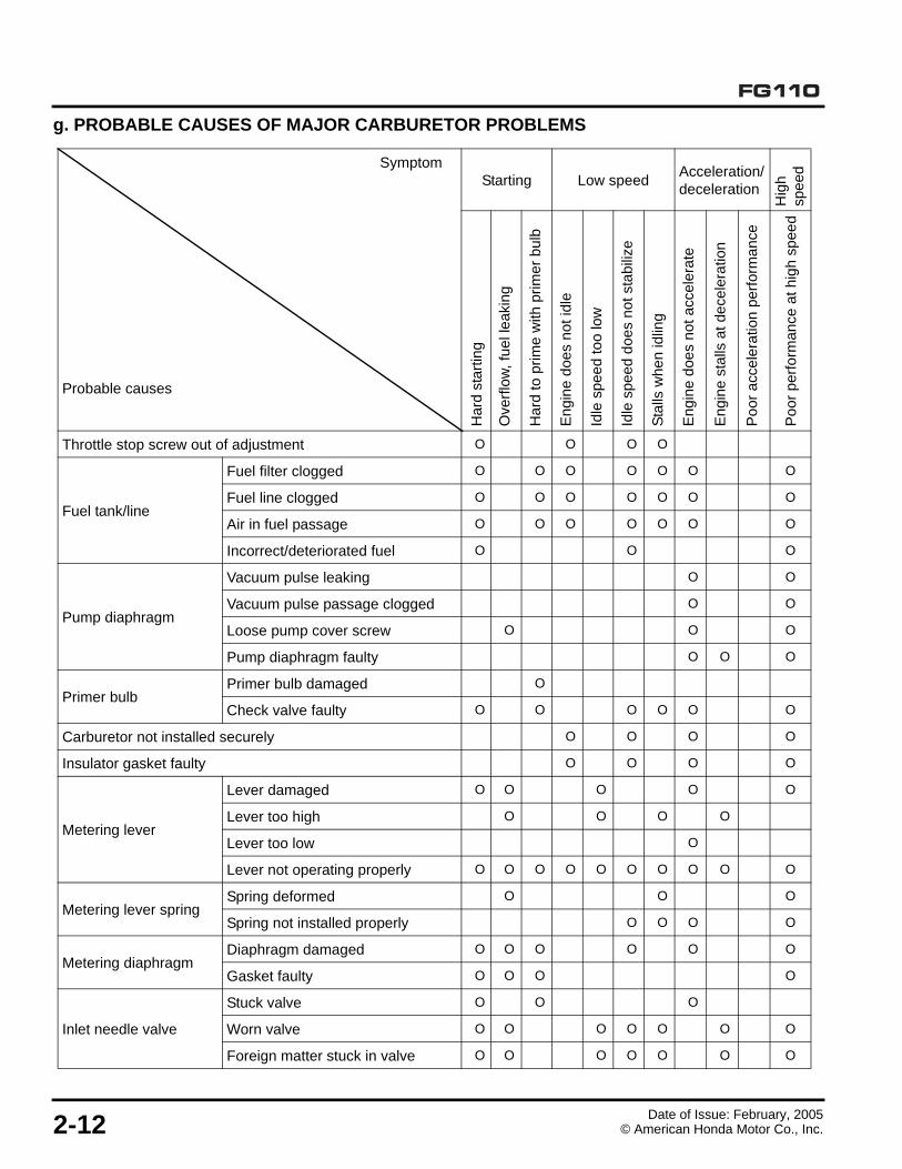
g. PROBABLE CAUSES OF MAJOR CARBURETOR PROBLEMS
SymptomStarting Low speed
Acceleration/deceleration
Hig
h sp
ee
d
Probable causes
Har
d st
artin
g
Ove
rflo
w,
fuel
leak
ing
Har
d to
prim
e w
ith p
rimer
bul
b
En
gin
e d
oes
no
t id
le
Idle
sp
eed
too
low
Idle
spe
ed d
oes
not s
tabi
lize
Sta
lls w
hen
idlin
g
En
gin
e d
oes
no
t acc
ele
rate
Eng
ine
stal
ls a
t de
cele
ratio
n
Po
or a
cce
lera
tion
perf
orm
an
ce
Po
or p
erfo
rma
nce
at h
igh
sp
eed
Throttle stop screw out of adjustment O O O O
Fuel tank/line
Fuel filter clogged O O O O O O O
Fuel line clogged O O O O O O O
Air in fuel passage O O O O O O O
Incorrect/deteriorated fuel O O O
Pump diaphragm
Vacuum pulse leaking O O
Vacuum pulse passage clogged O O
Loose pump cover screw O O O
Pump diaphragm faulty O O O
Primer bulbPrimer bulb damaged O
Check valve faulty O O O O O O
Carburetor not installed securely O O O O
Insulator gasket faulty O O O O
Metering lever
Lever damaged O O O O O
Lever too high O O O O
Lever too low O
Lever not operating properly O O O O O O O O O O
Metering lever springSpring deformed O O O
Spring not installed properly O O O O
Metering diaphragmDiaphragm damaged O O O O O O
Gasket faulty O O O O
Inlet needle valve
Stuck valve O O O
Worn valve O O O O O O O
Foreign matter stuck in valve O O O O O O O

FG110
Date of Issue: February, 2005© American Honda Motor Co., Inc. 3-1
3. MAINTENANCE
1. MAINTENANCE SCHEDULE
(1) Service more frequently when used in dusty areas.
(2) These items should be serviced by your servicing dealer, unless you have the proper tools and are mechanically proficient. Refer to the Honda shop manual for service procedures.
(3) Log hours of operation to determine proper maintenance intervals.
1. MAINTENANCE SCHEDULE. . . . . . . . . . . . . . . 3-1 7. COOLING FIN INSPECTION . . . . . . . . . . . . . . . 3-8
2. ENGINE OIL . . . . . . . . . . . . . . . . . . . . . . . . . . . . 3-2 8. THROTTLE CABLE INSPECTION . . . . . . . . . . 3-8
3. AIR FILTER . . . . . . . . . . . . . . . . . . . . . . . . . . . . 3-3 9. CARBURETOR ADJUSTMENT . . . . . . . . . . . . . 3-8
4. SPARK PLUG SERVICE . . . . . . . . . . . . . . . . . . 3-5 10. THROTTLE CABLE ADJUSTMENT . . . . . . . . . 3-8
5. SPARK ARRESTER (OPTIONAL PART) . . . . . 3-6 11. FUEL SYSTEM CLEANING . . . . . . . . . . . . . . . . 3-9
6. VALVE CLEARANCE ADJUSTMENT . . . . . . . . 3-7 12. TRANSMISSION LUBRICATION . . . . . . . . . . . 3-10
REGULAR SERVICE PERIOD (3)
ITEM Perform at every indicated month or operating hour interval, whichever comes first.
Before each use
First month
or 10 hrs
Every month
or25 hrs
Every 3 months
or25 hrs
Every 6 months
or50 hrs
Every years
or100 hrs
Every 2 years
or300 hrs
Refer to page
number
Engine oilCheck O
3-2Change O O
Air filterCheck O
3-3Clean O (1)
Spark plugCheck O
3-5Replace O
Throttle cable Check O 3-8
Cooling fins Check O O 3-8
Spark arrester(optional part)
Clean O 3-6
Fuel tank Clean O3-9
Fuel filter Check O
Clutch shoes Check O (2) 7-5
Idle speed Check-Adjust O (2) 3-8
Valve clearance Check-Adjust O (2) 3-7
Combustion chamber Clean After every 300 hours (2) 9-10
Nuts and boltsCheck(Retighten if necessary)
O —
Transmission grease Check O 3-10
Fuel tubes Check O (2) 3-9

Date of Issue: February, 20053-2 © American Honda Motor Co., Inc.
FG110
2. ENGINE OIL
Level Check
Check the engine oil level before each use, or every 10 hours if operated continuously. Rest the tiller on a level surface, with the engine stopped and in an upright position.
1. Tip the tiller on its carry handlebar as shown.
2. Remove the oil filler cap/dipstick and wipe it clean.
3. Insert and remove the dipstick without screwing it into the filler opening. Check the oil level shown on the dipstick.
4. If the oil level is low, fill to the edge of the oil filler hole with the recommended oil (see P. 3-3). To avoid over-filling or under-filling, be sure the engine is in a level position, as shown.
NOTICERunning the engine with too little or too much oil can cause engine damage.
5. Screw in the oil filler cap/dipstick securely.
Oil Change
Drain the used oil while the engine is warm. Warm oil drains quickly and completely.
1. Place a suitable container below the engine to catch the used oil.
2. Remove the oil filler cap/dipstick.
3. Tip the tiller to drain the used oil through the oil filler opening. Allow the used oil to drain completely.
Please dispose of used motor oil in a manner that is compatible with the environment. We suggest you take used oil in a sealed container to your local recycling center or service station for reclamation. Do not throw it in the trash, pour it on the ground or down a drain.
4. With the engine resting on the carrying handlebar on a level surface, fill to the edge of the oil filler hole with the recommended oil (see P. 3-3). Do not overfill.
5. Screw in the filler cap/dipstick securely.
Engine oil capacity 80 cc (2.7 US oz, 2.8 Imp oz)
Recommended operating ambient temperature
-5°C ~ 40°C (23°F ~ 104°F)
OIL FILLERHOLE
OIL FILLERCAP/DIPSTICK
CARRYING HANDLEBAR
OIL LEVEL

Date of Issue: February, 2005© American Honda Motor Co., Inc. 3-3
FG110
Engine Oil Recommendations
Oil is a major factor affecting performance and service life. Use 4-stroke automotive detergent oil.
SAE 10W-30 is recommended for general use. Other viscosities shown in the chart may be used when the average temperature in your area is within the recommended ranges.
The SAE oil viscosity and service category are in the API label on the oil container. Honda recommends that you use API service category SJ (or later) oil.
3. AIR FILTER
Check
1. Move the choke lever to the CLOSED () position to prevent dirt from entering the engine.
2. Squeeze together the air cleaner upper tab at the top of the air cleaner cover to release it from its catch, then flip the cover down to remove it.
3. Check the air filter to be sure it is clean and in good condition.
4. If the air filter is dirty, clean it as described under Air Filter Cleaning (see P. 3-4). Replace the air filter if it is damaged.
NOTICEOperating the engine without an air filter, or with a damaged air filter, will allow dirt to enter the engine, causing rapid engine wear. This type of damage is not covered by the Distributor’s Limited Warranty.
5. Align the air filter with the air cleaner base as shown. Reinstall the air filter by locating the three air cleaner base pegs into the three air filter holes. Slide the air filter over the pegs until it is flush with the air cleaner base.
NOTICEAn improperly installed air filter will allow dirt to enter the engine, causing rapid engine wear. Make sure the air filter is properly installed and flush with the air cleaner base before installing the air cleaner cover.
6. Reinstall the air cleaner cover by hooking the two lower tabs on the bottom of the cover and snapping the upper tab into place.
UPPER TAB
AIR CLEANER BASECHOKE LEVER
LOWER TABS
FILTER
AIR CLEANER COVER
FILTER

Date of Issue: February, 20053-4 © American Honda Motor Co., Inc.
FG110
Air Filter Cleaning
A dirty air filter restricts air flow to the carburetor, reducing engine performance. If you operate the engine in very dusty areas, clean the air filter after each refueling.
We recommend using Honda Air Filter Oil, which is available from any authorized Honda dealer.
1. Remove the foam air filter from the filter base (see P. 3-3).
2. Clean the air filter in warm soapy water, rinse, and allow it to dry thoroughly. Or, clean in nonflammable solvent and allow it to dry.
3. Place the filter in a resealable plastic bag and pour about 1 oz. (1/4 of a bottle) of Honda Air Filter Oil into the bag. Seal the bag closed and knead the bag for one minute or longer until the oil is completely distributed into the foam filter. Squeeze excess oil from the filter.
4. Remove the filter from the bag.We recommend using latex gloves when removing the oiled foam air filter from the bag.
NOTICEOperating the engine with a dry air filter will allow dust to enter causing engine damage. The air filter must be oiled after cleaning.
5. Wipe dirt from the air cleaner base and cover using a moist rag. Be careful to prevent dirt from entering the carburetor.
6. Reinstall the air filter and air filter cover (see P. 3-3).
Honda Air
Filter O
il
1. CLEAN IN WARMSOAPY WATER.
3. SOAK IN Honda AIR FILTER OIL
4. SQUEEZE OUT EXCESS OIL.
2. RINSE THOROUGHLY, AND DRY COMPLETELY.
Revised: October 2014 (PSV61V2500E3)© American Honda Motor Co., Inc.

Date of Issue: February, 2005© American Honda Motor Co., Inc. 3-5
FG110
4. SPARK PLUG SERVICE
NOTICEAn incorrect spark plug can cause engine damage.
If the engine has been running, it will be very hot. Allow the engine to cool before proceeding.
1. Loosen the captive 5 mm hex bolt with a 4 mm Allen wrench, then remove the fan cover.
2. Disconnect the spark plug cap, and remove any dirt from around the spark plug area.
3. Remove the spark plug with a 5/8-inch spark plug wrench.
4. Inspect the spark plug. Replace it if the electrodes are worn, or if the insulator is cracked, chipped, or fouled.
5. Measure the spark plug electrode gap with a suitable gauge.
6. Correct the gap, if necessary, by carefully bending the side electrode.
7. Make sure the sealing washer is attached and install the spark plug carefully, by hand, to avoid cross-threading.
8. After the spark plug seats, tighten with a 5/8-inch spark plug wrench to compress the washer.
If reinstalling the used spark plug, tighten 1/8 ~ 1/4 turn after the spark plug seats.
If installing a new spark plug, tighten 1/2 turn after the spark plug seats.
NOTICEA loose spark plug can overheat and damage the engine. Overtightening the spark plug can damage the threads in the cylinder head.
9. Attach the spark plug cap.
10.Install the fan cover and tighten the 5 mm hex bolt securely.
Recommended spark plugs NGK – CM5H or CMR5H
Spark plug gap 0.60 ~ 0.70 mm (0.024 ~ 0.028 in)
SPARK PLUGSPARK PLUG CAP
SEALINGWASHER
0.60 ~ 0.70 mm(0.024 ~ 0.028 in)
SIDEELECTRODE
5 mm HEX BOLT
FAN COVER

Date of Issue: February, 20053-6 © American Honda Motor Co., Inc.
FG110
5. SPARK ARRESTER (optional part)
The spark arrester must be serviced every 100 hours to keep it functioning as designed.
If the engine has been running, the muffler will be very hot. Allow the muffler to cool before servicing the spark arrester.
1. Loosen the captive 5 mm hex bolt, then remove the fan cover.
2. Remove the 3 x 6 mm self-tapping screw from the spark arrester, and remove the spark arrester from the muffler.
3. Use a brush to remove carbon deposits from the spark arrester screen. Be careful to avoid damaging the screen.
The spark arrester must be free of breaks and holes. Replace the spark arrester if it is damaged.
4. Install the spark arrester in the reverse order of removal.
5. Install the fan cover and tighten the captive 5 mm hex bolt securely.
3 x 6 mm SELF-TAPPING SCREW
SPARK ARRESTER
MUFFLER
SPARK ARRESTER SCREEN

Date of Issue: February, 2005© American Honda Motor Co., Inc. 3-7
FG110
6. VALVE CLEARANCE ADJUSTMENT
Valve clearance inspection and adjustment must be performed with the engine cold.
1. Remove the 5 x 12 mm hex bolt and remove the top cover.
2. Remove the two 5 x 12 mm hex bolts from the head cover.
Engine oil can leak out when removing the head cover. Catch the leaking oil with a suitable material and wipe up the area immediately.
3. Set the piston at top dead center of the compression
stroke by aligning the “ “ mark on the cam pulley with the cylinder head center.
4. Insert a feeler gauge between the rocker arm and valve to measure the valve clearance.
5. If adjustment is necessary:
a. Loosen the adjusting screw lock nut and turn the adjusting screw right or left.
b. Hold the adjusting screw with the tappet adjusting wrench and tighten the lock nut to the specification.
Torque: 4.9 N•m (0.5 kgf•m, 3.9 lbf•ft)
c. Recheck the valve clearance.
Standard valve clearance
IN 0.08 ± 0.02 mm
EX 0.11 ± 0.02 mm
5 x 12 mm HEX BOLT
TOP COVER
5 x 12 mm HEX BOLT (2)HEAD COVER
ENGINE ASSEMBLY
ALIGNMENT MARK
CYLINDER HEAD CENTER
ADJUSTING SCREW
ADJUSTING SCREW LOCK NUT
FEELER GAUGE
To increase valve clearance, screw out. To decrease valve clearance, screw in.

Date of Issue: February, 20053-8 © American Honda Motor Co., Inc.
FG110
7. COOLING FIN INSPECTION
Inspect the engine cooling fins. You should clean out any dirt and debris if air is obstructed from flowing across the cooling fins.
1. Loosen the 5 mm hex bolt, then remove the fan cover.
2. Remove all dirt and debris from the cooling fins.
3. Install the fan cover, and tighten the 5 mm hex bolt securely.
8. THROTTLE CABLE INSPECTION
Verify that the throttle trigger operates smoothly, releases properly, and the throttle cable is undamaged. If there is visible damage, or if the throttle lever does not operate smoothly or release properly, repair as needed.
Check the free play at the end of the throttle lever.
Throttle Lever Free play: 5 ~ 8 mm (3/16 ~ 5/16 inch)
If adjustment is needed, use the Throttle Cable Adjustment procedure below.
9. CARBURETOR ADJUSTMENT
A tachometer is required to adjust the idle speed.
1. Start the engine outdoors, and allow it to warm up to normal operating temperature.
2. Turn the throttle stop screw to obtain a stable idle, below the speed at which the tiller tines begin to turn.
Standard Idle Speed: 3,100 ± 200 rpm
3. Verify that the throttle lever free play is 5 ~ 8 mm (3/16 ~ 5/16 inch). If adjustment is needed, use the Throttle Cable Adjustment procedure below.
10. THROTTLE CABLE ADJUSTMENT
1. Loosen the lock nuts with a 10 mm wrench, and move the adjuster in or out as required.
2. Tighten the lock nuts and recheck throttle lever free play.
Throttle lever free play 5 ~ 8 mm (3/16 ~ 5/16 inch)
COOLING FINS
THROTTLE LEVER
5~ 8 mm(3/16 ~ 5/16 in)
THROTTLE STOPSCREW
LOCKNUTS
ADJUSTER
CHOKE LEVER

Date of Issue: February, 2005© American Honda Motor Co., Inc. 3-9
FG110
11. FUEL SYSTEM CLEANING
1. Remove the fuel tank cap.
2. Tip the tiller as shown and empty the fuel tank into an approved gasoline container. Use a funnel to avoid spilling gasoline.
3. Pull the fuel filter out through the fuel filler neck by hooking the black fuel supply tube with a piece of wire, such as a partly straightened paper clip.
4. Inspect the fuel filter. If the fuel filter is dirty, wash it with nonflammable solvent. Be careful to avoid damaging the filter.
5. Replace the filter if it is damaged or excessively dirty.
6. Rinse sediment from the fuel tank with nonflammable solvent.
7. Insert the fuel filter in the fuel tank, and install the fuel tank cap.
WARNINGGasoline is highly flammable and explosive.
You can be burned or seriously injured when handling fuel.
Keep heat, sparks, and flame away when refueling.
Handle fuel only outdoors.
Wipe up spills immediately.
FUEL FILTER
WIRE
FUEL SUPPLY TUBE (BLACK)
FUEL FILTER

Date of Issue: February, 20053-10 © American Honda Motor Co., Inc.
FG110
12. TRANSMISSION LUBRICATION
1. Place the tiller on the left side as shown.
2. Remove the lock pin from the right side tine shaft by turning it up [a] and pulling it out [b] as shown.
3. Wear heavy gloves and remove both right side tines. If the tines are difficult to remove, rinse the tine shaft with water and detergent to remove dirt from between the tines and shaft. Do not use a hammer to remove the tines, or you might distort the tine hub and make it difficult to remove the tines.
4. Remove the air vent screw and fill hole screw from the transmission case.
5. Fill the transmission by using a grease gun or grease applicator at the fill hole screw opening. Push the gun or applicator against the opening so as to seal the nozzle of the gun or applicator against the casting embossment. Apply grease until grease begins to come out of the top air vent hole.
6. Reinstall the air vent screw and fill hole screw.
7. Clean the tine shaft and place a few drops of oil on the tine shaft before installing the tines.
8. Wear heavy gloves and reinstall the tines in the reverse order of removal.
9. Install the lock pin through the round side of the tine shaft hole, then turn it over to lock it in place.
Grease NLGI #2 general purpose
(b)
(a)
FILL HOLE SCREW OPENING
AIR VENT SCREW OPENING
LOCK PIN
RIGHT OUTER TINE (D)
RIGHT INNER TINE (C)
GREASE GUN

FG110
Date of Issue: February, 2005© American Honda Motor Co., Inc. 4-1
4. AIR CLEANER/CARBURETOR
1. AIR CLEANER REMOVAL/INSTALLATION
NOTICEIf these parts are left out, dirt will enter the intake system and damage the engine.
1. AIR CLEANER REMOVAL/INSTALLATION . . . 4-1 2. CARBURETOR REMOVAL/INSTALLATION . . . 4-2
AIR CLEANER HOUSING
REASSEMBLY:Before installation, clean inside the case with compressed air
BREATHER TUBE
REASSEMBLY:Before installing the breather tube, check for deterioration or damage. Replace if necessary.
SHORT END
LONG ENDTO AIR CLEANER BASE
TO CYLINDER BLOCK
AIR CLEANER ELEMENT
CLEANING: (P. 3-3)
5 mm FLANGE NUT (2)
OIL TRAP PLATE
AIR CLEANER COVER

Date of Issue: February, 20054-2 © American Honda Motor Co., Inc.
FG110
2. CARBURETOR REMOVAL/INSTALLATION
Before removal, completely drain the carburetor.
NOTICEIf these parts are left out, dirt will enter the intake system, damaging the engine.
1. Remove the top cover (P. 6-1).
2. Remove the air cleaner (P. 4-1).
WARNINGGasoline is highly flammable and explosive.
You can be burned or seriously injured when handling fuel.
Keep heat, sparks, and flame away when refueling.
Handle fuel only outdoors.
Wipe up spills immediately.
14.8 x 2.4 mm O-RING
TUBE CLIP
CARBURETOR ASSEMBLY
DISASSEMBLY/REASSEMBLY: (P. 4-3).ADJUSTMENT: (P. 3-8), (P. 4-5).
CARBURETOR GASKET
Do not reuse.

Date of Issue: February, 2005© American Honda Motor Co., Inc. 4-3
FG110
3. CARBURETOR DISASSEMBLY/REASSEMBLY
Clean the outside of the carburetor before disassembly.
WARNINGGasoline is highly flammable and explosive.
You can be burned or seriously injured when handling fuel.
Keep heat, sparks, and flame away when refueling.
Handle fuel only outdoors.
Wipe up spills immediately.
MAIN JET
REASSEMBLY:
Clean thoroughly with compressed air before installation. Replace the main jet if it is corroded.MAIN JET NUMBER: #34
O-RING
CARBURETOR BODY
REASSEMBLY:Blow compressed air through the main jet passage to clean the passage before installing the carburetor body.
THROTTLE STOP SCREW
ADJUSTMENT: (P. 3-8)
SWIVEL
SCREW (2)
THROTTLE BODY
SPRING RETAINING RING
PUMP SPRING
PUMP GASKET
Do not reuse.
PUMP DIAPHRAGM
REASSEMBLY:Replace the pump diaphragm if it is deteriorated or damaged.
INLET SCREEN
REASSEMBLY:Remove dust and other foreign material from the screen before installation.
FUEL RETURN TUBE INSTALLATION PIPE
FUEL INLET FILTER

Date of Issue: February, 20054-4 © American Honda Motor Co., Inc.
FG110Carburetor Adjustment
INLET NEEDLE VALVE
REASSEMBLY:
Check for worn valve seat, valve, or weak spring before installation.
VALVE SEAT
VALVE
REPLACE OK
METERING LEVER PIN SCREW
METERING LEVER
ADJUSTMENT: (P. 4-5)
BULB COVER SCREW (4)
REASSEMBLY: After assembly, check for any sign of fuel leakage.
METERING LEVER PINPRIMER BULB COVER
METERING LEVER SPRING
PUMP BODY
REASSEMBLY:Wash the passage with nonflammable solvent to remove dust and other foreign material before installation. Do not clean by blowing air.
PRIMER BULB
REASSEMBLY: Replace the primer bulb if it is deteriorated or damaged.
AIR PURGE BODY
METERING DIAPHRAGM
REASSEMBLY:Replace the metering diaphragm if it is deteriorated, stiff, or damaged.
METERING DIAPHRAGM GASKET
Do not reuse.
CHECK VALVE

Date of Issue: February, 2005© American Honda Motor Co., Inc. 4-5
FG110
4. CARBURETOR ADJUSTMENT
1. Install the metering body spring, inlet needle valve, metering lever, metering lever pin, and the metering lever pin screw on the pump body (P. 4-4).
2. Measure the gap between the metering lever surface and the pump body surface.
3. If the measurement is outside the specification, adjust by bending the metering lever.
Specification 1.18 ~ 1.50 mm (0.046 ~ 0.059 in)
METERING LEVER PUMP BODY
1.18 ~ 1.50 mm(0.046 ~ 0.059 in)

Date of Issue: February, 20054-6 © American Honda Motor Co., Inc.
FG110
NOTES

FG110
Date of Issue: February, 2005© American Honda Motor Co., Inc. 5-1
5. RECOIL STARTER/STARTERPULLEY/FUEL TANK
1. RECOIL STARTER
a. REMOVAL/INSTALLATION
1. RECOIL STARTER. . . . . . . . . . . . . . . . . . . . . . . 5-1 3. FUEL TANK REMOVAL/INSTALLATION . . . . . 5-6
2. STARTER PULLEY . . . . . . . . . . . . . . . . . . . . . . 5-5
RECOIL STARTER ASSEMBLY
5 x 16 mm SOCKET BOLT (3)

Date of Issue: February, 20055-2 © American Honda Motor Co., Inc.
FG110
b. DISASSEMBLY
• Wear gloves and eye protection.
• During disassembly, take care not to allow the return spring to come out.
RECOIL STARTER ROPE
REASSEMBLY:Check the rope for fraying or wearing before installation.
SWING ARM COLLAR
SET SCREW
SWING ARM
RECOIL STARTER REEL
RECOIL STARTER HANDLERECOIL STARTER SPRING
DISASSEMBLY:Take care not to allow the recoil starter spring to pop out. Wear gloves during operation.REASSEMBLY: (P. 5-3)
RECOIL STARTER CASE

Date of Issue: February, 2005© American Honda Motor Co., Inc. 5-3
FG110
c. REASSEMBLY
• Wear gloves and eye protection.
• During assembly, take care not to allow the return spring to come out.
1. Insert the hook on the outer side of the spring into the groove inside the starter reel.
2. Carefully wind the recoil starter spring inside the starter reel.
3. Pass the starter rope through the starter reel and tie the rope so that it can be untied easily by pulling it as shown.
4. Wind the starter rope around the recoil starter reel in the direction of the arrow.
5. Install the starter reel on the starter case so that the spring inner hook is hook to the case tab.
6. Hold the starter case and rotate the starter reel three turns in the direction of the arrow for preliminary winding.
HOOK
RECOIL STARTER SPRING
RECOIL STARTER REEL
GROOVE
HOOK
RECOIL STARTER REEL
RECOIL STARTER ROPE
SLIPKNOT
RECOIL STARTER REEL
TAB

Date of Issue: February, 20055-4 © American Honda Motor Co., Inc.
FG110
7. Pass the starter rope end through the case and pull it outwards.
8. Pass the starter rope through the starter handle and tie the rope so that it can be untied easily by pulling it as shown.
9. Secure the starter reel with the set screw. Make sure to align the projection of the swing arm collar and swing arm.
10.Pull the starter handle several times to make sure the swing arm operates properly.
STARTER CASE HOLE
SLIPKNOT
SET SCREW
PROJECTION
SWING ARMSWING ARMCOLLAR

Date of Issue: February, 2005© American Honda Motor Co., Inc. 5-5
FG110
2. STARTER PULLEY
a. DISASSEMBLY
1. Remove the engine top cover (P. 6-1).
2. Remove the recoil starter (P. 5-1).
3. Remove the ignition coil (P. 7-3).
4. Remove the fan cover (P. 7-4).
5. Remove the clutch assembly (P. 7-4).
6. Hold the recoil starter pulley with a driver or equivalent tool and loosen the flywheel with a 10 mm wrench.
b. REASSEMBLY
1. Hold the recoil starter pulley with a driver or equivalent tool and tighten the flywheel to the specified torque.
TORQUE: 6.4 N•m (0.7 kg-m, 5.1 lb-ft)
2. Install the clutch assembly, fan cover, and ignition coil.
3. Adjust the ignition coil air gap (P. 7-3).
4. Install the recoil starter and engine cover.
ENGINE ASSEMBLY
RECOIL STARTER PULLEY
DRIVER10 mm WRENCH
DRIVER TORQUE WRENCH(Commercially available)

Date of Issue: February, 20055-6 © American Honda Motor Co., Inc.
FG110
3. FUEL TANK REMOVAL/INSTALLATION
Before removal, completely drain the fuel tank and fuel line.
Loosen the fuel tank cap and release the pressure from the tank before operation.
WARNINGGasoline is highly flammable and explosive.
You can be burned or seriously injured when handling fuel.
• Keep heat, sparks, and flame away when refueling.• Handle fuel only outdoors.• Wipe up spills immediately.
CUTAWAY VIEW OF A LOW-PERMEABILITY FUEL TANK (See page 2-2 for serial number locations)
If a low-permeability fuel tank gets a cut 1mm or more deep, exchange it.
OUTSIDE
WHITE
OFF-WHITE
WHITE
1 mm
87 ~ 93 mm (3.4 ~ 3.7 in
FUEL TUBEFUEL RETURN TUBE
MATING SURFACES
100 ~ 106 mm (3.9 ~ 4.2 in
FUEL TUBE
REASSEMBLY:Inspect for cracks or deterioration before installation and replace if necessary.Verify that the tube is not kinked in the tank.
FUEL FILTER
CLEANING: (P. 3-9)
TUBE CLIP (2)
FUEL RETURN TUBE
FUEL TANK CAP
RECOIL STARTER ASSEMBLY
5 X 16 MM SOCKET BOLT (3)
FUEL TANK
Fuel capacity:See Note 1CLEANING: (P. 3-9)REASSEMBLY:Wash with solvent to remove any sediment, and dry thoroughly before starting
FUEL TUBE GROMMET
INSTALLATION:Insert the fuel tube and fuel return tube into the grommet to the dimensions shown. Note that engine failure can result if the dimensions do not conform to the specifications shown. Take care not to damage the grommet surface where it contacts the tank. Replace the grommet if it is damaged.
Note 1:Fuel tank capacity (See page 2-2 for serial number locations):
Pre-2010 year:0.55 (0.15 US gal, 0.12 Imp gal)
Low-perm horizontal type:0.53 (0.14 US gal, 0.12 Imp gal)
Low-perm vertical type:0.54 (0.14 US gal, 0.12 Imp gal)
Revised: October 2014© American Honda Motor Co., Inc.

FG110
Date of Issue: February, 2005© American Honda Motor Co., Inc. 6-1
6. TOP COVER/MUFFLER
1. TOP COVER
a. REMOVAL
1. Loosen the 5 mm captive cover bolt.
2. Slide the cover off the engine.
b. INSTALLATION
1. Slide the cover onto the engine.
2. Tighten the 5 mm captive cover bolt.
1. TOP COVER. . . . . . . . . . . . . . . . . . . . . . . . . . . . 6-1 2. MUFFLER . . . . . . . . . . . . . . . . . . . . . . . . . . . . . . 6-2
TOP COVER 5 mm COVER BOLT

Date of Issue: February, 20056-2 © American Honda Motor Co., Inc.
FG110
2. MUFFLER
a. REMOVAL
1. Remove the two 5 mm self-locking nuts.
2. Remove the 5 x 10 mm socket bolt from the air exhaust guide.
3. Remove the muffler and air exhaust guide from the engine.
4. Separate the muffler from the air exhaust guide.
b. INSTALLATION
1. Remove any carbon deposits from the muffler.
2. Use a plastic hammer to install the muffler and air exhaust guide on the two studs.
Do not tap on the muffler seal flange or you will damage it. If the seal flange is dented or damaged, replace the muffler.
3. Install the two 5 mm self-locking nuts on the studs.
4. Install the 5 x 10 mm socket bolt through the air exhaust guide.
5. Check the muffler exhaust port for damage.
CAUTIONThe engine and muffler become very hot during operation and they remain hot for a while after operation. Be sure that the engine is cold before muffler removal/installation.
5 mm SELF-LOCKING NUT (2)
5 x 10 mm SOCKET BOLT
AIR EXHAUST GUIDE
MUFFLER SEAL FLANGE

FG110
Date of Issue: February, 2005© American Honda Motor Co., Inc. 7-1
7. IGNITION COIL/CLUTCHSHOE/FLYWHEEL
1. IGNITION COIL
a. ASSEMBLY/DISASSEMBLY
1. IGNITION COIL . . . . . . . . . . . . . . . . . . . . . . . . . 7-1 3. FLYWHEEL. . . . . . . . . . . . . . . . . . . . . . . . . . . . . 7-6
2. CLUTCH ASSEMBLY . . . . . . . . . . . . . . . . . . . . 7-4
IGNITION COIL
INSPECTION: P. 7-3ADJUSTMENT: P. 7-3
4 x 14 mm SOCKET BOLT (2)
3.9 N•m (0.4 kg-m, 2.9 lb-ft)

Date of Issue: February, 20057-2 © American Honda Motor Co., Inc.
FG110
b. INSPECTION
• PRIMARY RESISTANCE
1. Attach one lead of the tester to the engine stop switch wire and the other tester lead to the iron core.
2. Measure the primary resistance of the ignition coil.
• SECONDARY RESISTANCE
1. Attach one lead of the tester to the terminal inside the spark plug cap and the other tester lead to the iron core.
2. Measure the secondary resistance of the ignition coil.
Resistance 0.75 ~ 0.92 Ω
Resistance 6.1 ~ 9.3 kΩ

Date of Issue: February, 2005© American Honda Motor Co., Inc. 7-3
FG110
c. AIR GAP ADJUSTMENT
Adjustment is required only when the ignition coil or the flywheel has been removed.
1. Loosen the ignition coil’s two 4 x 14 mm hex bolts.
2. Rotate the flywheel to align the magnets with the ignition coil.
3. Insert a feeler gauge between the ignition coil and the magnets on the flywheel.
4. Push the ignition coil firmly toward the flywheel and tighten the bolts.
5. Adjust the clearance at the magnetic part of the flywheel.
6. Adjust the gaps at both the right and left sides of the ignition coil simultaneously so they are equal.
Clearance 0.3 ~ 0.5 mm (0.012 ~ 0.020 in)
FEELER GAUGE
MAGNETS
0.3 ~ 0.5 mm (0.012 ~ 0.020 in)
0.3 ~ 0.5 mm (0.012 ~ 0.020 in)

Date of Issue: February, 20057-4 © American Honda Motor Co., Inc.
FG110
2. CLUTCH ASSEMBLY
FLYWHEEL
DISASSEMBLY: P. 7-6REASSEMBLY: P. 7-6Take care not to break or bend the fins during disassembly or reassembly
7 mm FLANGE NUT
14.7 N•m (1.49 kgf•m, 10.7 lbf•ft)
5 x 20 mm SOCKET BOLT (3)
6.4 N•m (0.7 kgf•m, 4.6 lbf•ft)
FAN COVER
CLUTCH ASSEMBLY
CLUTCH SIDE
FLYWHEEL SIDE
6 x 15 mm CLUTCH WASHER (2)
6 mm CLUTCH BOLT (2)
9.8 N•m (1.0 kgf•m, 7.2 lbf•ft)
WAVE WASHER (2)

Date of Issue: February, 2005© American Honda Motor Co., Inc. 7-5
FG110
NOTICETo avoid damage to the flywheel fan blades, position the strap wrench fulcrum at the flywheel magnetic parts.
a. CLUTCH DISASSEMBLY:
1. Hold the flywheel with a commercially available strap wrench.
2. Remove the two clutch bolts.
3. Remove the clutch assembly.
b. CLUTCH REASSEMBLY:
1. Install the clutch assembly so that the mark is visible,
as shown.
2. Set the clutch washer between the clutch assembly and the flywheel.
3. Hold the flywheel with a commercially available strap wrench.
4. Install the two clutch bolts and tighten to the specified torque.
TORQUE: 9.8 N•m (1.0 kgf•m, 7.2 lbf•ft)
c. CLUTCH INSPECTION
Measure the thickness at the center of the clutch lining.
Standard Service limit
2.0 mm (0.08 in) 1.0 mm (0.04 in)
“ ” MARK
ROTATINGDIRECTION
STRAP WRENCH(Commercially available)
FULCRUM
MAGNETS

Date of Issue: February, 20057-6 © American Honda Motor Co., Inc.
FG110
3. FLYWHEEL
a. DISASSEMBLY
NOTICETo avoid damage to the flywheel fan blades, position the strap wrench fulcrum at the flywheel magnetic parts.
1. Hold the flywheel with a commercially available strap wrench.
2. Remove the 7 mm flange nut from the flywheel.
NOTICEDo not remove the flywheel by tapping it with a hammer or you might damage the flywheel
3. Remove the flywheel using a commercially available flywheel puller.
b. REASSEMBLY
1. Clean the tapered portion of the crankshaft of dirt, oil, grease, and other foreign material.
2. Install the flywheel, making sure the flywheel key is properly set in the crankshaft groove.
3. Hold the flywheel with a commercially available strap wrench. Position the fulcrum at the flywheel magnets.
4. Install the 7 mm flange nut to the specified torque.
TORQUE: 14.7 N•m (1.49 kgf•m, 10.7 lbf•ft)
STRAP WRENCH(Commercially available)
MAGNETS
FLYWHEEL PULLER(Commercially available)
STRAP WRENCH(Commercially available)
FULCRUM

FG110
Date of Issue: February, 2005© American Honda Motor Co., Inc. 8-1
8. CAM PULLEY/CYLINDER HEADCOVER/LOWER CRANKCASE
1. CAM PULLEY/CYLINDER HEAD COVER
a. DISASSEMBLY/REASSEMBLY
1. CAM PULLEY/CYLINDER HEAD COVER . . . . 8-1 2. LOWER CRANKCASE. . . . . . . . . . . . . . . . . . . . 8-4
1. Remove the top cover (P. 6-1).
2. Remove the recoil starter (P. 5-1).
3. Remove the fuel tank (P. 5-6).
5 x 12 mm SOCKET BOLT (2)
BREATHER FILTER
HEAD COVER SEAL
HEAD COVER
4 x 12 mm SELF-TAPPING SCREW (2)
HEAD COVER GROMMET
HEAD INNER COVER
INSPECTION: P. 8-3
CAM PULLEY SHAFT
CAM PULLEY
TIMING BELT
INSTALLATION: Check that the belt is not worn or cracked and do not bend or twist the belt.

Date of Issue: February, 20058-2 © American Honda Motor Co., Inc.
FG110
b. CAM PULLEY REMOVAL
1. Remove the spark plug.
2. Remove the head cover.
3. Set the piston at top dead center (TDC) of the compression stroke.
When the piston is at TDC of the compression stroke, the
flywheel alignment mark “ “ will align with the fan cover bolt hole. Also, the cam pulley alignment marks will be positioned as shown.
4. Push the cam pulley shaft out from the valve spring side using a pin approximately 2 mm in diameter.
5. Remove the timing belt from the cam pulley.
6. Remove the cam pulley.
c. CAM PULLEY INSTALLATION
Install the cam pulley and timing belt in the reverse order of removal.
ALIGNMENTMARK
HEAD COVER MATING SURFACE
CAM PULLEY SHAFT
CAM PULLEY ALIGNMENT MARKSTIMING BELT
FAN COVER BOLT HOLE
FLYWHEEL
CAM PULLEY SHAFT
CAM PULLEY
TIMING BELT
Date of Issue: February, 2005© American Honda Motor Co., Inc. 8-3
FG110
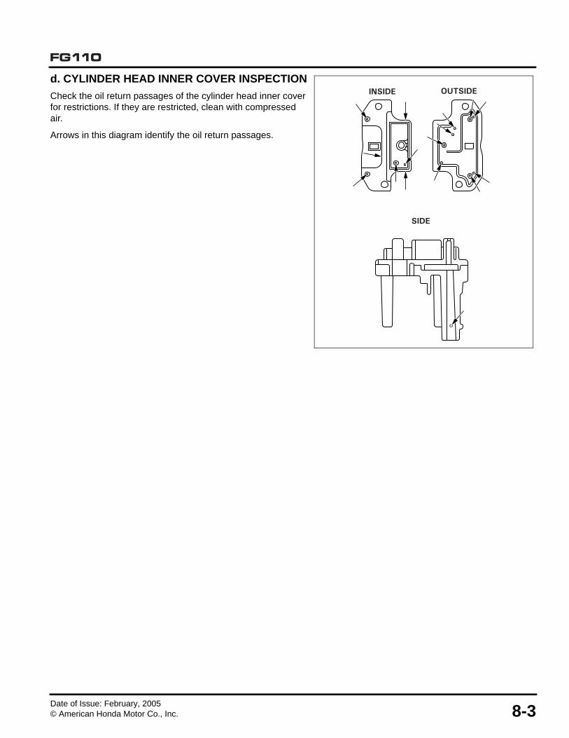
d. CYLINDER HEAD INNER COVER INSPECTION
Check the oil return passages of the cylinder head inner cover for restrictions. If they are restricted, clean with compressed air.
Arrows in this diagram identify the oil return passages.
INSIDE
SIDE
OUTSIDE

Date of Issue: February, 20058-4 © American Honda Motor Co., Inc.
FG110
2. LOWER CRANKCASE
a. DISASSEMBLY/REASSEMBLY
1. Drain the engine oil (P. 3-2).
2. Remove the air cleaner case assembly (P. 4-1).
3. Remove the carburetor (P. 4-2).
4. Remove the recoil starter and fuel tank (P. 5-6).
5. Remove the muffler (P. 6-2).
6. Remove the recoil starter pulley (P. 5-5).
7. Remove the flywheel (P. 7-6).
OIL OUTLET VALVE PLATE
INSTALLATION:Install the valve aligning the chamfer and projections.
CHAMFER
PROJECTIONS
12.3 x 2.4 mm O-RING 5 x 16 mm SOCKET BOLT (3)
SHROUD
REASSEMBLY:Clean the socket bolt threads and apply liquid sealant (Loctite® 648) to the threads.
4 x 8 mm SCREWS (2)
REASSEMBLY:Clean the threads and apply liquid sealant (Loctite® 201) to the threads.3.0 N•m (0.3 kgf•m, 2.2 lbf•ft)
OIL TUBE
D13.0 TUBE CLIP (2)
3 x 5 mm SCREW
5 x 30 mm SOCKET BOLTS (4)
6.4 N•m (0.7 kgf•m, 5.1 lbf•ft)
5 x 20 mm SOCKET BOLTS (2)
6.4 N•m (0.7 kgf•m, 5.1 lbf•ft)
LOWER CRANKCASE
OIL FILLER CAP GASKET
OIL FILLER CAP
STOPPER PLATE
OIL OUTLET VALVE

Date of Issue: February, 2005© American Honda Motor Co., Inc. 8-5
FG110
b. LOWER CRANKCASE REMOVAL
1. Remove the two 5 x 20 mm socket bolts and the four 5 x 30 mm socket bolts.
2. Remove the oil tube (P. 8-4).
3. Insert a screwdriver or equivalent tool into the recess as shown, and remove the lower crankcase from the cylinder block.
c. OIL OUTLET VALVE DISASSEMBLY
1. Remove the two 4 x 8 mm screws and oil outlet valve assembly.
2. Remove the 3 x 5 mm screw, stopper plate, oil outlet valve, and oil outlet valve plate.
3. Check the oil outlet valve and stopper plate for contamination and foreign material.
RECESS
5 x 20 mm SOCKET BOLTS (2)
5 x 30 mm SOCKET BOLTS (4)
4 x 8 mm SCREW (2)
LOWER CRANKCASE
OIL OUTLET VALVE ASSEMBLY
OIL OUTLET VALVE
OIL OUTLET VALVE PLATE
CUTOUTS
STOPPER PLATE3 x 5 mm SCREW

Date of Issue: February, 20058-6 © American Honda Motor Co., Inc.
FG110
d. LOWER CRANKCASE INSTALLATION
1. Clean the mating surfaces of the cylinder block and the lower crankcase using a degreasing cleaning agent and clean shop towel.
2. Apply a bead [φ1.0 ~ 1.5 mm (φ0.04 ~ 0.06 in)] of liquid gasket (Hondabond 4, ThreeBond® #1216, 1216E, or equivalent) to the lower crankcase surface that mates with the cylinder block.
3. Install the lower crankcase on the cylinder block. Assemble within 3 minutes after applying the liquid gasket.
4. Loosely tighten each of the two 5 x 20 mm and the four 5 x 30 mm socket bolts.
5. Tighten the socket bolts in the numbered sequence shown in the diagram.
TORQUE: 6.4 N•m (0.7 kgf•m, 5.1 lbf•ft)
6. Wait approximately 60 minutes after assembly before filling with oil and starting the engine.
e. SHROUD REASSEMBLY
1. Set the two 5 x 53 mm bolts into the shroud.
2. Make sure the bolt heads are fully inserted into the cutouts in the shroud.
3. Attach the shroud to the cylinder block using three 5 x 16 mm socket bolts.
3
4
1
26
5
Liquid gasket application area
LOWER CRANKCASE
5 x 53 mm SOCKET BOLTS (2)
SHROUD
5 x 16 mm SOCKET BOLTS (3)

FG110
Date of Issue: February, 2005© American Honda Motor Co., Inc. 9-1
9. CRANKSHAFT/PISTON/CYLINDERBLOCK/VALVES
1. CRANKSHAFT/PISTON
a. DISASSEMBLY/REASSEMBLY
Remove the lower crankcase (P. 8-4).
1. CRANKSHAFT/PISTON. . . . . . . . . . . . . . . . . . . 9-1 2. CYLINDER BLOCK/ROCKER ARMS/VALVES . 9-5
SECOND RING(BLACK CIRCUMFERENCE)
OIL RINGS(COMBINATIONRINGS)
SIDE RAILSPACERSIDE RAIL
10 mm(0.4 in)
120¡
120¡120¡
TOP RING(WHITE CIRCUMFERENCE)
CARBURETOR SIDE
TOP RING
SECOND RING
OIL RINGS
MARK
10 x 20 x 5 mm OIL SEAL12 x 24 x 5 mm
OIL SEAL
PISTON
INSPECTION: (P. 9-2)REASSEMBLY: (P. 9-2)
Install with the mark on the piston head facing the carburetor side.
CRANKSHAFT
REASSEMBLY: (P. 9-4)
PISTON PIN
DISASSEMBLY: (P. 9-2)REASSEMBLY: (P. 9-4) INSPECTION: (P. 9-2)
SECOND RING
OIL RINGS (COMBINATION RINGS
TOP RING
“ • ” MARK
INSPECTION: (P. 9-2)REASSEMBLY:
• Install the second ring with the “ • “ mark facing up.
• Do not interchange the top ring and the second ring.
• After assembly, check for smooth movement of the piston ring.
• Stagger the piston ring end gaps 120° apart. Do not align with the piston end.
• Space the side rail end gaps at least 10 mm (0.4 in) apart. Coat the oil ring with oil after assembly.
10 mm (0.04 in)
PISTON RING

Date of Issue: February, 20059-2 © American Honda Motor Co., Inc.
FG110
b. PISTON PIN
DISASSEMBLY
1. Insert the push rod special tool into the piston pin with the crankshaft timing gear upward, as shown.
TOOL:Push rod 07VPF-ZM3020A
2. Set the cutout part of the piston base special tool in the clearance between the connecting rod and the piston as shown.
• Be sure that the connecting rod small end is securely set in the cutout of the piston base special tool.
3. Remove the piston pin from the connecting rod using a hydraulic press.
TOOLS:Piston base 07VPF-ZM3010BPush rod 07VPF-ZM3020A
REASSEMBLY
1. Slide the piston pin over the push rod special tool and install the guide special tool.
TOOLS:Push rod 07VPF-ZM3020AGuide 07VPF-ZM3030A
PUSH ROD07VPF-ZM3020A
TIMING GEAR
PUSH ROD07VPF-ZM3020A
PISTON PIN
CONNECTING ROD
CUTOUTPISTON
CLEARANCE
PISTON BASE07VPF-ZM3010B
PUSH ROD07VPF-ZM3020A
GUIDE07VPF-ZM3030A
PISTON PIN

Date of Issue: February, 2005© American Honda Motor Co., Inc. 9-3
FG110
2. Set the piston over the connecting rod so that the
crankshaft oil slinger is on the right side with the “ “ mark on the piston head pointing toward you, as shown.
3. Apply oil to the piston pin and assemble the piston pin with the special tools attached, as shown.
With the timing gear up, align the piston pin hole with the connecting rod hole and insert the special tool guide into the piston pin hole.
4. Set the cutout part of the piston base special tool in the clearance between the connecting rod and the piston, as shown.
Be sure that the connecting rod small end is securely set in the cutout of the piston base special tool.
5. Press-fit the piston pin into the connecting rod using a hydraulic press.
Press in the piston pin until the piston pin is flush with the piston recess.
6. Remove the special tools from the piston pin.
TOOLS:Piston base 07VPF-ZM3010BPush rod 07VPF-ZM3020AGuide 07VPF-ZM3030A
7. After assembling the piston pin, set the connecting rod at the center of the piston. Be sure that the gap from the piston pin end to the piston end is equal at the right and left sides.
8. If the right and left gaps are not equal, raise or lower the piston pin as needed.
GAP GAPCENTER
PISTONPIN
PISTON
CONNECTING ROD
CONNECTING ROD
PUSH ROD07VPF-ZM3020A
“ ” MARK
OIL SLINGER
PISTON PIN
CUTOUTS
TIMING GEAR
GUIDE07VPF-ZM3030A
PISTON PIN BASE07VPF-ZM3010B

Date of Issue: February, 20059-4 © American Honda Motor Co., Inc.
FG110
c. CRANKSHAFT REASSEMBLY
1. Install the timing belt on the crankshaft timing gear. Pay attention to the direction of the letters on the timing belt, as shown in the diagram.
Replace a worn or cracked timing belt. Do not bend or twist the timing belt.
2. Install the crankshaft in the cylinder block.
3. Apply a bead of liquid gasket to the cylinder block, specifically to the mating surface of the crankcase cover.
4. Install the crankcase cover on the cylinder block (P. 8-6).
5. Install the cam pulley and timing belt in the cylinder block (P. 8-2).
d. 10 x 20 x 5 mm OIL SEAL ASSEMBLY
1. Set the oil seal on the crankshaft.
2. Install by aligning the oil seal projection with the groove in the cylinder block.
3. Install the lower crankcase (P. 8-6).
CYLINDERBLOCK
CAM PULLEY
TIMING BELT
PISTON
CRANKSHAFT
10 x 20 x 5 mmOIL SEAL
CRANKSHAFT
PROJECTION
GROOVECYLINDERBLOCK

Date of Issue: February, 2005© American Honda Motor Co., Inc. 9-5
FG110
2. CYLINDER BLOCK/ROCKER ARMS/VALVESa. DISASSEMBLY/REASSEMBLY1. Remove the head cover and cam pulley (P. 8-2).2. Remove the lower crankcase (P. 8-5).3. Remove the crankshaft (P. 9-1).
SPARK PLUG
INTAKE VALVE LIFTER
VALVE SPRING (2)
VALVE STEM SEAL(Intake valve only)
(Whole surface)
EXHAUST VALVE LIFTER
VALVE SPRING RETAINER (2)
(Sliding surface)INTAKE
INSTALLATION:Do not interchange with the exhaust valve.
11.8 N·m (1.2 kgf·m, 8.7 lbf·ft)
INTAKE VALVE ROCKER ARM
EXHAUST VALVE ROCKER ARM
ADJUSTING SCREW (2)
ADJUSTING SCREW LOCK NUT (2)
4.9 N·m (0.50 kgf·m, 3.6 lbf·ft)
Do not remove the valve spring retainers while the lower crankcase is installed, or the valves will drop into the cylinder.
REMOVAL:Push down and slide the retainer to the side, so the valve stem slips through the hole at the slide of the retainer.
Viewed from clutch side.
REMOVAL/INSTALLATION:(P. 9-11)
Do not interchange with the exhaust valve rocker arm.
Do not reuse after removing.
(Sliding surface)
INSTALLATION:Do not interchange with the intake valve.Before installation, remove the carbon deposits and inspect the valve.
EXHAUST VALVE
Do not reuse after removing.
REMOVAL/INSTALLATION:(P. 9-11)
Do not interchange with the exhaust valve rocker arm.
Do not reuse after removing.
Viewed from recoil starter side.
REMOVAL/INSTALLATION:(P. 9-11)
Do not interchange with the intake valve rocker arm.
Do not reuse after removing.
Viewed from recoil starter side.
REMOVAL/INSTALLATION:(P. 9-11)
Do not interchange with the intake valve rocker arm.
Do not reuse after removing.
Viewed from clutch side.
Revised: March, 2015© American Honda Motor Co., Inc.

Date of Issue: February, 20059-6 © American Honda Motor Co., Inc.
FG110
b. INSPECTION
• CYLINDER SLEEVE I.D.
Measure and record the cylinder I.D. at three levels in both the “X” axis (perpendicular to the crankshaft) and the “Y” axis (parallel to the crankshaft). Take the maximum reading to determine cylinder wear and taper.
• PISTON SKIRT O.D.
Measure and record the piston O.D. at a point 10 mm (0.39 in) from the bottom of the skirt and 90° to the piston pin bore.
• PISTON-TO-CYLINDER CLEARANCE
• PISTON RING WIDTH
• PISTON RING SIDE CLEARANCE
When any piston ring exceeds the service limit, replace all the piston rings as a set.
Standard Service limit
35.000 ~ 35.015 mm(1.378 ~ 1.379 in)
35.100 mm(1.3819 in)
Standard Service limit
34.970 ~ 34.990 mm(1.377 ~ 1.378 in)
34.900 mm(1.374 in)
Standard Service limit
0.010 ~ 0.045 mm(0.0004 ~ 0.0018 in)
0.120 mm(0.0047 in)
Standard Service limit
Top/Second0.970 ~ 0.990 mm
(0.0382 ~ 0.0390 in)0.920 mm(0.0362 in)
Standard Service limit
Top/Second0.015 ~ 0.056 mm
(0.0006 ~ 0.0022 in)0.120 mm(0.0047 in)
10 mm (0.39 in)
90¡
X
Y

Date of Issue: February, 2005© American Honda Motor Co., Inc. 9-7
FG110
• PISTON RING END GAP
Put the piston ring in the cylinder and then use the piston crown to push the ring down. This will make the piston ring horizontal so the ring end gap can be measured.
Because the combination oil rings are used on this model, always replace the piston rings as a set.
• PISTON PIN O.D.
• PISTON PIN BORE I.D.
• PISTON PIN-TO-PISTON PIN BORE CLEARANCE
• CONNECTING ROD SMALL END I.D.
Standard Service limit
Top/Second0.10 ~ 0.25 mm
(0.004 ~ 0.010 in)0.60 mm(0.024 in)
Standard Service limit
7.994 ~ 8.000 mm(0.3147 ~ 0.3150 in)
7.950 mm(0.3130 in)
Standard Service limit
8.010~ 8.026 mm(0.3154 ~ 0.3160 in)
8.060 mm(0.3173 in)
Standard Service limit
0.010 ~ 0.032 mm(0.0004 ~ 0.0013 in)
0.070 mm(0.0028 in)
Standard Service limit
7.978 ~ 7.989 mm(0.3141 ~ 0.3145 in)
Replace if exceeding the standard value.

Date of Issue: February, 20059-8 © American Honda Motor Co., Inc.
FG110
• CAM HEIGHT
Replace the cam if the cam height is lower than the service limit.
• CAM PULLEY SHAFT O.D.
• CAM PULLEY I.D.
• VALVE SPRING FREE LENGTH
Measure the free length of the valve spring.
Replace the springs if they are shorter than the service limit.
Standard Service limit
22.097 mm (0.8700 in) 21.797 mm (0.8581 in)
Standard Service limit
3.990 ~ 4.000 mm(0.1571 ~ 0.1575 in)
3.950 mm(0.1555 in)
Standard Service limit
4.020 ~ 4.050 mm(0.1583 ~ 0.1595 in)
4.100 mm(0.1614 in)
Standard Service limit
20.66 mm (0.8134 in) 20.00 mm (0.7874 in)

Date of Issue: February, 2005© American Honda Motor Co., Inc. 9-9
FG110
• VALVE FACE/STEM O.D.
1. Inspect each valve for pitting or wear irregularities.
2. Inspect each valve stem for bending or abnormal stem wear.
3. Replace the valve, if necessary.
4. Measure and record each valve O.D. Replace the valves if their O.D. is smaller than the service limit.
• VALVE GUIDE I.D.
1. Measure and record each valve guide I.D.
2. Replace the cylinder block if the measurement exceeds the service limit.
• VALVE STEM-TO-GUIDE CLEARANCE
For each valve stem, subtract the O.D. from the corresponding guide I.D. to obtain the valve stem-to-guide clearance.
Valve Standard Service limit
IN3.470 ~ 3.485 mm
(0.1366 ~ 0.1372 in)3.400 mm(0.1339 in)
EX3.435 ~ 3.450 mm
(0.1352 ~ 0.1358 in)3.380 mm(0.1331 in)
Standard Service limit
3.500 ~ 3.518 mm(0.1378 ~ 0.1385 in)
3.560 mm(0.1402 in)
Valve Standard Service limit
IN0.015 ~ 0.048 mm
(0.0006 ~ 0.0019 in)0.098 mm(0.0039 in)
EX0.050 ~ 0.083 mm
(0.0020 ~ 0.0033 in)0.120 mm(0.0047 in)
VALVE FACE

Date of Issue: February, 20059-10 © American Honda Motor Co., Inc.
FG110
c. COMBUSTION CHAMBER CLEANING
1. Prepare a cylinder of thick paper or equivalent material with a diameter large enough to fit against the inner wall of the cylinder.
2. Insert the thick paper into the cylinder to protect the cylinder wall during combustion chamber cleaning.
3. Attach a commercially available combustion chamber cleaning brush to an electric drill and clean the combustion chamber.
Do not press the cleaning brush with force against the combustion chamber.
ELECTRIC DRILL
Thick paper or equivalent.
CLEANING BRUSH(commercially available)

Date of Issue: February, 2005© American Honda Motor Co., Inc. 9-11
FG110
d. ROCKER ARM/VALVE LIFTER REMOVAL/INSTALLATION
REMOVAL
1. Remove the adjusting screw lock nuts [1] and remove the adjusting screws [2] from the rocker arms [3].
Remove the cam pulley (P. 8-2).
2. Tighten the holder bolt [1] of the special tool fully as shown.
Set the special tool on the cylinder head over the rocker arm and valve lifter that you are going to take apart, and tighten the bolt (5 mm) [3] to the cylinder head cover installation boss [4] by hand.
Do not tighten the bolt (5 mm) using a wrench.
3. Tighten the push rod [1] of the special tool by hand until the tip of the push rod comes to the center of the valve lifter shaft [2]. Move the special tool left and right and check that it can be moved slightly.
4. Using a 14 mm wrench [1], tighten the push rod [2] until the shaft of the valve lifter goes out from the rocker arm [3].
Loosen the push rod and remove the bolt (5 mm) [4], and then remove the special tool.
The valve lifters and rocker arms cannot be reused after they are pressed apart. Always replace with new parts.
TOOL:Rocker arm replacement tool [2] 070PF-Z0HA100
[3]
[2]
[1]
[1]
[2]
[4]
[3]
It should be able to move slightly in this direction.(Or the cylinder head cover installation boss will be damaged)
[1]
[2]
[1]
[2]
[3]
[4]
Revised: March, 2015© American Honda Motor Co., Inc.

Date of Issue: February, 20059-12 © American Honda Motor Co., Inc.
FG110
INSTALLATION
1. Install the new valve lifter [1] on the cylinder head and bring the valve lifter in contact with the installation guide rib [2] of the cylinder head.
Push the new rocker arm [3] into the shaft of the valve lifter by hand while holding the valve lifter in the position and holding the rocker arm against the installation guide rib [4] of the cylinder head.
• Check the valve lifter for inlet side and exhaust side before installation. Do not interchange them.
• Check the rocker arm for "IN" or "EX" marks before installation. Do not interchange them.
2. Set the projection [1] of the valve lifter [2] in contact with the installation guide rib [3] of the cylinder head.
Set the rocker arm [4] in contact with the installation guide rib [5] of the cylinder head.
Check that the projection on the valve lifter and the rocker arm are in contact with the installation guide rib of the cylinder head.
EXHAUST VALVE ROCKER ARM
INTAKE VALVE ROCKER ARM
INTAKEVALVE LIFTER
EXHAUSTVALVE LIFTER
Viewed from the flywheel side:
Viewing cylinder head right down:
[1]
[2]
[3]
[4]
[1]
[4]
[5]
[2]
[3]
Revised: March, 2015© American Honda Motor Co., Inc.

Date of Issue: February, 2005© American Honda Motor Co., Inc. 9-13
FG110
3. Install the holder bolt [1] of the special tool in the direction as shown.
Install the adapter [3] on the tip of the push rod [4] that is set on the special tool.
Install the special tool on the cylinder head so that the bolt (5 mm) [5] sets in the center of the long hole in the special tool as shown.
Tighten the bolt (5 mm) against the cylinder head cover mounting boss by hand.
• Set the bolt (5 mm) in the center of the long hole.
• Do not tighten the bolt (5 mm) using a wrench.
4. Bring the projection on the valve lifter [1] and the rocker arm [2] to come in contact with the cylinder head positioning ribs [3].
Bring the clearance A [4] and B [5] to be equal by moving the valve lifter and rocker arm right and left.
While holding the valve lifter and rocker arm in the position, tighten the holder bolt [6] by hand until it contacts the valve lifter. Tighten the push rod [7] by hand until the adapter [8] contacts the rocker arm.
After installing the special tool, check that the bolt (5 mm) [9] is in the center of the long hole [10] in the tool.
NOTICEThe cylinder head cover mounting boss can be damaged by tightening the push rod with the bolt (5 mm) not in the center but on either side in the long hole. Be sure that the bolt is in the center of the long hole securely.
5. Using a 14 mm wrench [1], tighten the push rod [2] until the rocker arm [3] comes to the cylinder head cover installation part. [4]
TOOL:Rocker arm replacement tool [2] 070PF-Z0HA100
[1]
[2]
[4]
[3]
[5]
[1]
[2]
[3]
[6]
[8]
[10]
[3]
[9]
[4] [5][7]
[4][1]
[2]
[2]
[3]
[3]
Revised: March, 2015© American Honda Motor Co., Inc.

Date of Issue: February, 20059-14 © American Honda Motor Co., Inc.
FG110
6. Loosen the push rod [1] and tighten the holder bolt [2] by hand until the valve lifter [3] contacts the cylinder head cover mounting boss [4]. Be sure that the bolt (5 mm) [5] is in the center of the long hole in the special tool.
NOTICEThe cylinder head cover mounting boss can be damaged by tighten the push rod with the bolt (5 mm) not in the center but on either side in the long hole. Be sure that the bolt is in the center of the long hole securely.
7. Using a 14 mm wrench, retighten the push rod [1] until the adapter [2] comes to the shaft of the valve lifter [3]. Loosen the push rod and remove the bolt (5 mm) [4], and then remove the special tool.
8. Measure the clearance between the rocker arm and the cylinder head, and make sure if the clearance are within the specification.
If the clearance is over the specification, the rocker arm is not correctly installed to the valve lifter. Install the special tool again, and tighten the push rod until the rocker arm is completely pressed onto the shaft of the valve lifter.
9. Inject the oil as shown. Lift the lifter by finger and release the lifter, and make sure it operates by the lifter’s weight.
Install the adjusting screws and the adjusting screw lock nuts to the rocker arms.
Install the cam pulley (P. 8-2).
Adjust the valve clearance (P. 3-7).
Rocker arm and cylinder head clearance:0.15 – 0.65 mm (0.006 – 0.026 in)
[1]
[4]
Loosen Tighten
[2]
[5]
[3]
[1]
[4]
[3]
[2]
Tighten
0.15 mm - 0.65 mm (0.006 - 0.026 in)
Revised: March, 2015© American Honda Motor Co., Inc.

FG110
Date of Issue: February, 2005© American Honda Motor Co., Inc. 10-1
10. HANDLEBAR/TINES/FENDER
1. HANDLEBAR ASSEMBLY
1. HANDLEBAR ASSEMBLY . . . . . . . . . . . . . . . 10-1 3. TINES . . . . . . . . . . . . . . . . . . . . . . . . . . . . . . . . 10-2
2. ENGINE STOP SWITCH INSPECTION . . . . . . 10-2 4. FENDER/WHEELS . . . . . . . . . . . . . . . . . . . . . . 10-4
THROTTLE CABLE
ENGINE STOP SWITCH CABLE
5 x 12 mm SCREW-WASHER
ENGINE STOP SWITCH THROTTLE LEVER
ASSEMBLY
3 x 12 mm PAN SCREW
3 mm SPRING WASHER
3 mm PLAIN WASHER HANDLE GRIP (2)
UPPER HANDLE PIPE
HANDLE JOINT GRIP (2)
FRAME JOINT WASHER (6)
CABLE TIES (2)
HANDLE HOLDER BOLT (2)
3 x 160 mm HEX BOLT (2)
6 mm NYLON LOCK NUT (2)
LOWER HANDLE PIPEK1 model has a 1 piece lower handle pipe.
REINSTALLATION:Adjust the throttle lever free play after assembly. (P. 3-8)
FRAME JOINT WASHER (4)
Revised: October 2014© American Honda Motor Co., Inc.

Date of Issue: February, 200510-2 © American Honda Motor Co., Inc.
FG110
2. ENGINE STOP SWITCH INSPECTION
Check for continuity between the engine stop switch wires. There should be continuity when the switch is in the OFF position.There should be no continuity when the switch is in the ON position.
3. TINES
a. DISASSEMBLY/REASSEMBLY
RIGHT OUTER TINE
RIGHT INNER TINE
LEFT INNER TINE
LEFT OUTER TINE
LOCK PIN (2)

Date of Issue: February, 2005© American Honda Motor Co., Inc. 10-3
FG110
b. TINE REMOVAL
1. Remove the left and right tine shaft lock pins and pull them out.
2. Clean the tine shaft ends and remove the tines.
c. TINE INSTALLATION
1. Clean the tine shaft and tine hubs of any foreign material.
The tines should easily slide onto the tine shaft in the order shown in the diagram above. Do not force the tines onto the shaft.
2. Install the lock pins through the tine shaft round side hole (a), then rotate the pin (b) to lock the pin in place.
d. NARROW CULTIVATING
1. Remove the two outer tines by pulling the lock pins out of the holes in the end of the tine shaft.
2. Slide the outside tine set off the tine shaft.
3. Secure the inner set of tines onto the tine shaft by placing the lock pins in the inside set of lock pin holes.
(a)
(b)

Date of Issue: February, 200510-4 © American Honda Motor Co., Inc.
FG110
4. FENDER/WHEELS
ASSEMBLY/DISASSEMBLY
FG110
12.7 mm PUSH NUT (2)
WHEEL (2)
WHEEL BAR
DRAG BAR13 x 27 x 1 mm THRUST WASHER (2)
LOCK PIN
6.35 mm LOCK PIN
FRONT FENDER REAR FENDER
6 x 45 mm FLANGE BOLT (4)
4.8 x 9.8 mm RIVET (2)

Date of Issue: February, 2005© American Honda Motor Co., Inc. 10-5
FG110
FG110K1
9.53 mm PUSH NUT (2)
WHEEL (2)
DRAG BAR
LOCK PIN
6 x 177.5 mm HEX BOLT (2)
FENDER COLLAR (4)
6 mm NYLOCK NUT (2)
FENDER
6.35 mm LOCK PIN
LINCHPIN
WHEEL BAR
WHEEL SHAFT
TORQUE: 10 N•m (7 ft•lb)Torque must not crush frame joint washers or lower handle pipe.
Revised: October 2014© American Honda Motor Co., Inc.

Date of Issue: February, 200510-6 © American Honda Motor Co., Inc.
FG110
WHEEL BAR (K1 models only)
The wheel bar assembly can be attached to the drag bar in two ways.
When in the storage position, the unit can be stored upright. It can also be transported over smooth ground or pavement.
When in the transport position, the unit can be transported over rough ground. This position also prevents the tines from dragging against grass or other vegetation.
INSTALLATION:Install linchpin with the clip over the top of the drag bar.
LINCHPIN
Revised: October 2014© American Honda Motor Co., Inc.

FG110
Date of Issue: February, 2005© American Honda Motor Co., Inc. 11-1
11. TRANSMISSION/OUTER CLUTCH
1. TRANSMISSION COMPONENTS
1. TRANSMISSION COMPONENTS . . . . . . . . . . 11-1 3. REASSEMBLY . . . . . . . . . . . . . . . . . . . . . . . . . 11-3
2. DISASSEMBLY . . . . . . . . . . . . . . . . . . . . . . . . 11-2
OUTER CLUTCH
NOTICEIf you try to remove the outer clutch without disassembling the transmission, the driveshaft bushing will be damaged.
RADIAL BALL BEARING
DRIVE GEAR
10 x 24 mm WASHER
DRIVESHAFT BUSHING
TINE SHAFT
RADIAL BALL BEARING (2)
LEFT TRANSMISSION CASE
17 x 40 x 8 mm OIL SEAL (2)
GRASS GUARD (2)
DRIVEN GEARRIGHT TRANSMISSION CASE
6 x 23 mm FLANGE BOLT (11)
1/4-20 x 1/2 SELF-TAPPING SCREW (2)
REASSEMBLY:Press into the transmission case until it seats against the ledge.
REASSEMBLY:Use a press to center the driven gear over the splines on the tine shaft.

Date of Issue: February, 200511-2 © American Honda Motor Co., Inc.
FG110
2. DISASSEMBLY
a. REMOVE THE GRASS GUARDS
Remove the grass guard(s) only if you need to replace the oil seal(s).
1. Using pliers or similar tools, pry one grass guard off the transmission housing, as shown in the diagram.
2. Using the same technique, pry the grass guard from the other side of the transmission.
b. SEPARATE THE TRANSMISSION HALVES
1. Remove the eleven 6 x 23 mm flange bolts.
2. Place a screwdriver or similar tool in each of the two recesses between the transmission halves.
3. Pry the transmission halves apart.
c. REMOVE THE OUTER CLUTCH
1. Remove the driveshaft from the transmission.
2. Hold the worm gear firmly in one hand.
3. Loosen and remove the outer clutch from the worm gear assembly.
4. Slide the driveshaft bushing, washer, and bearings off the worm gear.
d. REMOVE THE TINE SHAFT
1. Slide the tine shaft out of the transmission case.
2. Use a press to remove the driven gear from the tine shaft.
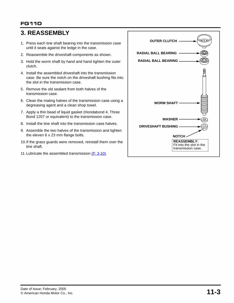
Date of Issue: February, 2005© American Honda Motor Co., Inc. 11-3
FG110
3. REASSEMBLY
1. Press each tine shaft bearing into the transmission case until it seats against the ledge in the case.
2. Reassemble the driveshaft components as shown.
3. Hold the worm shaft by hand and hand tighten the outer clutch.
4. Install the assembled driveshaft into the transmission case. Be sure the notch on the driveshaft bushing fits into the slot in the transmission case.
5. Remove the old sealant from both halves of the transmission case.
6. Clean the mating halves of the transmission case using a degreasing agent and a clean shop towel.
7. Apply a thin bead of liquid gasket (Hondabond 4, Three Bond 1207 or equivalent) to the transmission case.
8. Install the tine shaft into the transmission case halves.
9. Assemble the two halves of the transmission and tighten the eleven 6 x 23 mm flange bolts.
10.If the grass guards were removed, reinstall them over the tine shaft.
11.Lubricate the assembled transmission (P. 3-10).
OUTER CLUTCH
RADIAL BALL BEARING
RADIAL BALL BEARING
WORM SHAFT
WASHER
DRIVESHAFT BUSHING
NOTCH
REASSEMBLY:Fit into the slot in the transmission case.

Date of Issue: February, 200511-4 © American Honda Motor Co., Inc.
FG110

Date of Issue: February, 2005© American Honda Motor Co., Inc. 12-1
FG110 12. INDEX
AAdjustment
Air gap . . . . . . . . . . . . . . . . . . . . . . . . . . . . . . . . . . . . . 7-3Carburetor . . . . . . . . . . . . . . . . . . . . . . . . . . . . . . . . . . 4-5
Air cleaner . . . . . . . . . . . . . . . . . . . . . . . . . . . . . . . . . . . 4-1Air filter . . . . . . . . . . . . . . . . . . . . . . . . . . . . . . . . . . . . . . 4-1
Cleaning . . . . . . . . . . . . . . . . . . . . . . . . . . . . . . . . . . . 3-4Inspection . . . . . . . . . . . . . . . . . . . . . . . . . . . . . . . . . . 3-3
Air gap adjustment . . . . . . . . . . . . . . . . . . . . . . . . . . . . . 7-3
BBreather tube . . . . . . . . . . . . . . . . . . . . . . . . . . . . . . . . . 4-1
CCam height . . . . . . . . . . . . . . . . . . . . . . . . . . . . . . . . . . . 9-8Cam pulley I.D. . . . . . . . . . . . . . . . . . . . . . . . . . . . . . . . . 9-8Cam pulley Installation/Removal . . . . . . . . . . . . . . . . . . 8-2Cam pulley shaft O.D. . . . . . . . . . . . . . . . . . . . . . . . . . . 9-8Capacities . . . . . . . . . . . . . . . . . . . . . . . . . . . . . . . . . . . 1-1Carburetor . . . . . . . . . . . . . . . . . . . . . . . . . . . . . . . . . . . 4-2Carburetor adjustment . . . . . . . . . . . . . . . . . . . . . . . . . . 3-8Cleaning brush . . . . . . . . . . . . . . . . . . . . . . . . . . . . . . . 9-10Clutch . . . . . . . . . . . . . . . . . . . . . . . . . . . . . . . . . . . . . . 11-2Clutch Assembly/Disassembly . . . . . . . . . . . . . . . . . . . . 7-5Combustion chamber cleaning . . . . . . . . . . . . . . . . . . . 9-10Connecting rod small end I.D. . . . . . . . . . . . . . . . . . . . . 9-7Cooling fin inspection . . . . . . . . . . . . . . . . . . . . . . . . . . . 3-6Crankshaft reassembly . . . . . . . . . . . . . . . . . . . . . . . . . 9-4Cylinder head cover . . . . . . . . . . . . . . . . . . . . . . . . . . . . 8-1Cylinder head inner cover . . . . . . . . . . . . . . . . . . . . . . . 8-3Cylinder sleeve I.D. . . . . . . . . . . . . . . . . . . . . . . . . . . . . 9-6
DDimensions . . . . . . . . . . . . . . . . . . . . . . . . . . . . . . . . . . 1-1Displacement . . . . . . . . . . . . . . . . . . . . . . . . . . . . . . . . . 1-2Drive gear . . . . . . . . . . . . . . . . . . . . . . . . . . . . . . . . . . . 11-1Driveshaft . . . . . . . . . . . . . . . . . . . . . . . . . . . . . . . . . . . 11-2
EEngine
Oil change . . . . . . . . . . . . . . . . . . . . . . . . . . . . . . . . . . 3-2Oil recommendations . . . . . . . . . . . . . . . . . . . . . . . . . 3-3Specifications . . . . . . . . . . . . . . . . . . . . . . . . . . . . . . . 1-2Stop switch inspection . . . . . . . . . . . . . . . . . . . . . . . . 10-2
FFan blades . . . . . . . . . . . . . . . . . . . . . . . . . . . . . . . . . . . 7-6Fender Installation/Removal . . . . . . . . . . . . . . . . . . . . 10-4Flywheel Assembly/Disassembly . . . . . . . . . . . . . . . . . . 7-6Fuel . . . . . . . . . . . . . . . . . . . . . . . . . . . . . . . . . . . . . . . . 1-2Fuel filter . . . . . . . . . . . . . . . . . . . . . . . . . . . . . . . . . . . . 5-6Fuel return tube . . . . . . . . . . . . . . . . . . . . . . . . . . . . . . . 5-6Fuel tank Installation/Removal . . . . . . . . . . . . . . . . . . . . 5-6
GGear . . . . . . . . . . . . . . . . . . . . . . . . . . . . . . . . . . . . . . . 11-1Grass guard . . . . . . . . . . . . . . . . . . . . . . . . . . . . . . . . . 11-2Grease . . . . . . . . . . . . . . . . . . . . . . . . . . . . . . . . . . . . . 3-10
HHandlebar . . . . . . . . . . . . . . . . . . . . . . . . . . . . . . . . . . . 10-1
IIdle speed adjustment . . . . . . . . . . . . . . . . . . . . . . . . . . 3-8Ignition coil
Assembly/Disassembly . . . . . . . . . . . . . . . . . . . . . . . . 7-1Inspection . . . . . . . . . . . . . . . . . . . . . . . . . . . . . . . . . . 7-2
LLower crankcase
Disassembly/Reassembly . . . . . . . . . . . . . . . . . . . . . . 8-4Installation . . . . . . . . . . . . . . . . . . . . . . . . . . . . . . . . . . 8-6Removal . . . . . . . . . . . . . . . . . . . . . . . . . . . . . . . . . . . 8-5
Lubrication . . . . . . . . . . . . . . . . . . . . . . . . . . . . . . . . . . 3-10
MMaintenance
Air filter . . . . . . . . . . . . . . . . . . . . . . . . . . . . . . . . . . . . 3-3Cooling fins . . . . . . . . . . . . . . . . . . . . . . . . . . . . . . . . . 3-6Fuel system . . . . . . . . . . . . . . . . . . . . . . . . . . . . . . . . . 3-9Idle speed . . . . . . . . . . . . . . . . . . . . . . . . . . . . . . . . . . 3-1Schedule . . . . . . . . . . . . . . . . . . . . . . . . . . . . . . . . . . . 3-1Spark arrester . . . . . . . . . . . . . . . . . . . . . . . . . . . . . . . 3-6Spark plug . . . . . . . . . . . . . . . . . . . . . . . . . . . . . . . . . . 3-5Throttle cable . . . . . . . . . . . . . . . . . . . . . . . . . . . . . . . . 3-8Transmission . . . . . . . . . . . . . . . . . . . . . . . . . . . . . . . 3-10
Metering diaphragm . . . . . . . . . . . . . . . . . . . . . . . . . . . . 4-4Metering lever . . . . . . . . . . . . . . . . . . . . . . . . . . . . . . . . . 4-4Muffler . . . . . . . . . . . . . . . . . . . . . . . . . . . . . . . . . . . . . . 6-2
NNarrow cultivating . . . . . . . . . . . . . . . . . . . . . . . . . . . . . 10-3
OOil
Change . . . . . . . . . . . . . . . . . . . . . . . . . . . . . . . . . . . . 3-2Recommendations . . . . . . . . . . . . . . . . . . . . . . . . . . . . 3-3
Outer clutch . . . . . . . . . . . . . . . . . . . . . . . . . . . . . . . . . 11-2
PPiston Assembly/Disassembly . . . . . . . . . . . . . . . . . . . . 9-1Piston pin . . . . . . . . . . . . . . . . . . . . . . . . . . . . . . . . . . . . 9-2Piston pin bore I.D. . . . . . . . . . . . . . . . . . . . . . . . . . . . . . 9-7Piston pin O.D. . . . . . . . . . . . . . . . . . . . . . . . . . . . . . . . . 9-7Piston pin-to-piston pin bore clearance . . . . . . . . . . . . . 9-7Piston ring
End gap . . . . . . . . . . . . . . . . . . . . . . . . . . . . . . . . . . . . 9-7Side clearance . . . . . . . . . . . . . . . . . . . . . . . . . . . . . . . 9-6Width . . . . . . . . . . . . . . . . . . . . . . . . . . . . . . . . . . . . . . 9-6
Piston skirt O.D. . . . . . . . . . . . . . . . . . . . . . . . . . . . . . . . 9-6Piston-to-cylinder clearance . . . . . . . . . . . . . . . . . . . . . . 9-6Primer bulb . . . . . . . . . . . . . . . . . . . . . . . . . . . . . . . . . . . 4-4Pump diaphragm . . . . . . . . . . . . . . . . . . . . . . . . . . . . . . 4-3
RRecoil starter . . . . . . . . . . . . . . . . . . . . . . . . . . . . . . . . . 5-1
Disassembly . . . . . . . . . . . . . . . . . . . . . . . . . . . . . . . . 5-2Pulley . . . . . . . . . . . . . . . . . . . . . . . . . . . . . . . . . . . . . . 5-5

Date of Issue: February, 200512-2 © American Honda Motor Co., Inc.
FG110
Reassembly . . . . . . . . . . . . . . . . . . . . . . . . . . . . . . . . 5-3Removal/Installation . . . . . . . . . . . . . . . . . . . . . . . . . . 5-1Starter rope replacement . . . . . . . . . . . . . . . . . . . . . . 6-2
Resistance . . . . . . . . . . . . . . . . . . . . . . . . . . . . . . . . . . . 7-2Rocker arm removal/installation . . . . . . . . . . . . . . . . . . 9-11
SSafety messages . . . . . . . . . . . . . . . . . . . . . . . . . . . . . . 1-1Serial numbers . . . . . . . . . . . . . . . . . . . . . . . . . . . . . . . . 2-2Service rules . . . . . . . . . . . . . . . . . . . . . . . . . . . . . . . . . 2-1Service specifications . . . . . . . . . . . . . . . . . . . . . . . . . . . 2-3Shroud . . . . . . . . . . . . . . . . . . . . . . . . . . . . . . . . . . . . . . 8-6Spark arrester service . . . . . . . . . . . . . . . . . . . . . . . . . . 3-6Spark plug service . . . . . . . . . . . . . . . . . . . . . . . . . . . . . 3-5Special tools . . . . . . . . . . . . . . . . . . . . . . . . . . . . . . . . . . 2-5Specifications
Dimensions . . . . . . . . . . . . . . . . . . . . . . . . . . . . . . . . . 1-1Engine . . . . . . . . . . . . . . . . . . . . . . . . . . . . . . . . . . . . . 1-2Service . . . . . . . . . . . . . . . . . . . . . . . . . . . . . . . . . . . . 2-3
Starter reel . . . . . . . . . . . . . . . . . . . . . . . . . . . . . . . . . . . 5-3Symbols . . . . . . . . . . . . . . . . . . . . . . . . . . . . . . . . . . . . . 2-1
TThrottle lever cable inspection . . . . . . . . . . . . . . . . . . . . 3-8Throttle stop screw . . . . . . . . . . . . . . . . . . . . . . . . . . . . . 4-3Tine shaft . . . . . . . . . . . . . . . . . . . . . . . . . . . . . . . . . . . 11-1Tines Installation/Removal . . . . . . . . . . . . . . . . . . . . . . 10-2Tools, special . . . . . . . . . . . . . . . . . . . . . . . . . . . . . . . . . 2-5Top cover . . . . . . . . . . . . . . . . . . . . . . . . . . . . . . . . . . . . 6-1Torque values . . . . . . . . . . . . . . . . . . . . . . . . . . . . . . . . 2-4Transmission . . . . . . . . . . . . . . . . . . . . . . . . . . . .3-10, 11-1
VValve face/stem O.D. . . . . . . . . . . . . . . . . . . . . . . . . . . . 9-9Valve guide I.D. . . . . . . . . . . . . . . . . . . . . . . . . . . . . . . . 9-9Valve seat . . . . . . . . . . . . . . . . . . . . . . . . . . . . . . . . . . . 4-4Valve spring free length . . . . . . . . . . . . . . . . . . . . . . . . . 9-8Valve stem-to-guide clearance . . . . . . . . . . . . . . . . . . . . 9-9
WWeight . . . . . . . . . . . . . . . . . . . . . . . . . . . . . . . . . . . . . . 1-1Wheel Installation/Removal . . . . . . . . . . . . . . . . .10-4, 10-5