ProQuest Dissertations - UCL Discovery
245
Computer Aided Analysis of Mechanically Fastened Composite Laminates by Surachate Chutima A Dissertation submitted for the degree of Doctor of Philosophy in the Faculty of Engineering, University of London Department of Mechanical Engineering University College London May 1996
-
Upload
khangminh22 -
Category
Documents
-
view
0 -
download
0
Transcript of ProQuest Dissertations - UCL Discovery

Computer Aided Analysis of Mechanically
Fastened Composite Laminates
by
Surachate Chutima
A Dissertation submitted for the degree of Doctor of Philosophy
in the Faculty of Engineering, University of London
Department of Mechanical Engineering
University College London
May 1996

ProQuest Number: 10055408
All rights reserved
INFORMATION TO ALL USERS The quality of this reproduction is dependent upon the quality of the copy submitted.
In the unlikely event that the author did not send a complete manuscript and there are missing pages, these will be noted. Also, if material had to be removed,
a note will indicate the deletion.
uest.
ProQuest 10055408
Published by ProQuest LLC(2016). Copyright of the Dissertation is held by the Author.
All rights reserved.This work is protected against unauthorized copying under Title 17, United States Code.
Microform Edition © ProQuest LLC.
ProQuest LLC 789 East Eisenhower Parkway
P.O. Box 1346 Ann Arbor, Ml 48106-1346

ABSTRACT
The procedures adopted in the design of mechanically fastened joints
between polymer based composite laminates have evolved from the results of a
number of experimental investigations as well as some simplified analytical
simulations. However, the universal apphcability of experimental data is limited,
since the type of material, the lamina stacking sequence and the geometric
configuration of a joint can vary widely in practice. Similarly there are
shortcomings in using an analytical approach to evaluate the stress distribution
and joint strength since certain modelling constraints are required to minimize
the complexity of the assessment. However, recent advances in modelling
techniques have enabled more realistic constraints to be applied, thereby,
ensuring greater confidence in the design of this type of joint.
In this study general finite element models are proposed for two
dimensional and three dimensional analysis of mechanically fastened composite
laminates joined in a double lap fashion. In a two dimensional analysis, the
material properties of the fibre and matrix were used, in conjunction with
classical laminate theory, to compute the ply properties and, subsequently, the
laminate properties, for a variety of ply lay-ups and orientations. These results
were then used for each discrete element in the model representing the complete
laminate. Finite element analysis was applied to the composite laminate
connected in a double lap configuration with a single pin fastening; this was
subsequently extended to assess the performance of multi-fastened joints.
From this preliminary investigation three dimensional models were
constructed to accurately determine the effect of in-plane loading in the vicinity

of the bolt-laminate contact zone and the interlaminar stresses between adjacent
phes in the composite laminate. As in the two dimensional analysis the material
properties for each element were computed from the ply material properties in
combination with the ply orientation. The laminate properties were subsequently
formulated from layering of these elements. Bending and clamping effects as well
as interlaminar shear and through thickness stresses were examined using these
models.
The results obtained for a range of parametric constraints, viz.; the
laminate properties, fastener configuration and interfacial friction, showed good
agreement with previously published experimental work. This study confirmed
that a design methodology may be developed for mechanically fastened
composite laminates utilising commercially available computer code together
with appropriate modelling techniques, which must incorporate a full three
dimensional stress analysis.

TO MY FAMILY
and THE MEMORY OF MY PARENT
CHATCHAVAN CHUTIMA

ACKNOWLEDGMENTS
I would like to express my gratitude to my supervisor, Dr. Alvin P. Blackie,
for his supervision, enthusiasm, encouragement and valuable suggestions
throughout this research.
I also gratefully acknowledge the financial support provided by the Thai
Government during the period of my studies. The cooperation fi-om the Thai
Government Students’ Office is also acknowledged.
A special thanks to my wife, Cattaleeya, my daughter, Chutinan and my son,
Vajarah for their support, love, encouragement and patience.
I am also indebted to my parents, Chatchavan and Pensri, and my brothers
for their love and kindness.
Finally, thanks to the staff of the Department of Mechanical Engineering,
University College London, especially the computer system manager, Mr. Mark
nine and Mr. Joe Fletcher for their help.

CONTENTS
TITLE PAGE 1
ABSTRACT 2
ACKNOWLEDGMENTS 5
TABLE OF CONTENTS 6
LIST OF TABLES 10
LIST OF FIGURES 11
NOTATION 19
CHAPTER 1. INTRODUCTION 22
1.1 OBSERVATIONS 22
1.2 STATEMENT OF THE PROBLEM 25
1.3 THE OBJECTIVES OF THIS STUDY 26
1.4 SCOPE AND LIMITATIONS 26
1.5 ORGANIZATION OF THE THESIS 27
CHAPTER 2. LITERATURE REVIEW 30
2.1 INTRODUCTION 30
2.2 EXPERIMENTAL EXAMINATIONS OF MECHANICALLY
FASTENED COMPOSITE JOINTS 30
2.2.1 INFLUENCE OF MATERIAL PROPERTIES ON JOINT
STRENGTH 31
2.2.2 EFFECTS OF FASTENER CONFIGURATION 34
2.2.3 CONSEQUENCES OF JOINT GEOMETRY 37
2.2.4 MULTI-FASTENED JOINTS 43
2.3 ANALYTICAL INVESTIGATIONS OF MECHANICALLY

FASTENED COMPOSITE JOINTS 46
2.3.1 CLASSICAL ANALYSIS 46
2.3.2 NUMERICAL ANALYSIS 50
CHAPTER 3. THEORETICAL ANALYSIS OF COMPOSITE
LAMINATES 62
3.1 INTRODUCTION 62
3.2 MECHANICS OF COMPOSITE MATERIALS 62
3.2.1 UNIDIRECTIONAL LAMINA 63
3.2.2 STRESS-STRAIN RELATION 65
3.2.3 ELASTIC BEHAVIOUR OF MULTIDIRECTIONAL
LAMINATES 73
3.3 FINITE ELEMENT FOR CONTACT MECHANICS 79
CHAPTER 4. TWO-DIMENSIONAL SINGLE FASTENER MODEL 86
4.1 INTRODUCTION 86
4.2 MODEL 87
4.3 RESULTS AND DISCUSSION 90
4.3.1 ACCURACY OF THE MODELLING TECHNIQUES 91
4.3.2 CONFIDENCE IN THE MODELLING TECHNIQUES 91
4.3.3 COMPARATIVE ASSESSMENT OF LAMINATES
A, B AND C 94
4.4 CONCLUDING REMARKS 95
4.4.1 ACCURACY AND RELIABILITY 96
4.4.2 EFFECTS OF PIN RIGIDITY AND FRICTION 96
4.4.3 EFFECTS OF LAMINATE PROPERTIES 97

CHAPTER 5. TWO-DIMENSIONAL MULTI-FASTENER MODEL 109
5.1 INTRODUCTION 109
5.2 METHOD OF ASSESSMENT 110
5.2.1 RIGID FASTENERS 110
5.2.2 ELASTO-PLASTIC FASTENERS 112
5.3 RESULTS AND DISCUSSION 115
5.3.1 RESULTS FOR MULTI-FASTENED COMPOSITE
LAMINATES JOINED BY RIGID PINS 115
5.3.2 RESULTS FOR MULTI-FASTENED COMPOSITE
LAMINATE OUTER LAP JOINED TO A RIGID
INNER LAP 117
5.4 CONCLUDING REMARKS 122
5.4.1 EFFECT OF FRICTION AT THE INTERFACE 122
5.4.2 EFFECT OF NUMBER OF PINS 122'
5.4.3 EFFECT OF NUMBER OF ROWS AND PATTERNS 123
5.4.4 EFFECT OF PITCH DISTANCE, ROW SPACING
AND EDGE DISTANCE 124
CHAPTER 6. THREE-DIMENSIONAL SINGLE FASTENER
MODEL 143
6.1 INTRODUCTION 143
6.2 METHOD OF ASSESSMENT 144
6.2.1 SINGLE LAMINATE MODEL 144
6.2.2 DOUBLE LAMINATE MODEL 149
6.3 RESULTS AND DISCUSSION 154

6.3.1 COMPARATIVE ASSESSMENT 154
6.3.2 DOUBLE LAMINATE MODEL RESULTS 155
6.4 CONCLUDING REMARKS 173
CHAPTER 7. CONCLUSIONS AND SUGGESTIONS FOR
FURTHER RESEARCH 212
7.1 CONCLUSIONS 212
7.1.1 CHAPTER 2 212
7.1.2 CHAPTER 3 213
7.1.3 CHAPTER 4 214
7.1.4 CHAPTER 5 214
7.1.5 CHAPTER 6 216
7.2 ACHIEVEMENTS OF THIS WORK 216
7.3 SUGGESTIONS FOR FURTHER WORK 217
7.3.1 MODELLING TECHNIQUES 217'
7.3.2 MATERIAL AND FASTENER PARAMETERS 218
7.3.3 FAILURE CRITERIA AND STRENGTH PREDICTION 219
REFERENCES 220
APPENDIX
APPENDIX A: MACROMECHANICAL FAILURE THEORIES 235

10
LIST OF TABLES
Table Title Page
4.1 Material properties of T300/914C graphite/epoxy (Eriksson 1986),
titanium pin and ri gid pin 8 8
5.1 Material properties of two-dimensional multi-fastened model
(Griffin Jr., 1994) 111
5.2 Comparison of load transferred by each pin in a multi-fastened
composite laminate 116
6.1 Material properties for GRP (Marshall et al., 1989) and bolt
(Chen et al., 1995) 145
6.2 Material properties for CFRP (Smith et al., 1986) and bolt
(Chen et al., 1995) 147
6.3 Material strengths of the GRP laminate (Chen et al., 1995) 150
6.4 Laminate ply orientations 151

11
LIST OF FIGURES
Figure Title Page
1.1 Designs of mechanically fastened joints 29
1.2 Failure modes of double lap composite joints 29
3.1 Stress component in a unidirectional lamina referred to loading
and material axes 84
3.2 Laminate geometry 84
3.3 In-plane, bending, and twisting loads applied on a laminate 85
3.4 Normal and shear forces at the contacting node 85
4.1 Physical model of laminate A under tensile load (Eriksson 1986) 99
4.2 Typical finite element model of laminate A 99
4.3 Experimental model for laminate D (Eriksson 1986) 100
4.4 Two dimensional finite element model of laminate D 100
4.5 Comparison of normalized axial stress 101
4.6 Results for the maximum principal stress at distance Ao from
the hole centre 101
4.7 Normalized maximum principal stress of nodes on hole boundary 102
4.8. Effect of pin rigidity and coefficient of friction on axial strain
of laminate D 102
4.9. Analytical comparison of stresses for laminate A. at (a) hole
boundary; (b), (c) and (d) at the critical distance, Ao 103
4.10 Analytical comparison of stresses for laminate B. at (a) hole
boundary; (b), (c) and (d) at the critical distance, Ao 104

12
Figure Title Page
4.11 Analytical comparison of stresses for laminate C. at (a) hole
boundary; (b), (c) and (d) at the critical distance, Ao 105
4.12 Comparison of normalized axial stress versus normalized distance
for (a) laminate A; (b) laminate B; (c) laminate C and (d) laminate
A, B and C 106
4.13 Comparison of (a) radial stress ; (b) tangential stress and (c) shear
stress on the hole boundary for laminate A, B and C 107
4.14 Comparison of (a) radial stress at Ac; (b) tangential stress at A q and
(c) shear stress at A q for laminate A, B and C 108
5.1 Geometric configuration of composite laminate and steel plate 126
5.2 Finite element model representing a composite laminate joined to
outer lap steel plates 126
5.3 Configuration for two-dimensional multi-fastened joints using
a deformable pin 127
5.4 Geometric configuration for a double row multi-fastened laminate
of infinite width 128
5.5 Typical model for composite plate fastened with elastic pins 128
5.6 Contact stress on the hole boundary of a seven pin double lap joint 129
5.7 Normalized radial stress on the hole boundary for a single row
multi-fastener with pitch distance (a) Ad and (b) 2>d 130
5.8 Normalized radial stress for double row, 5 pin joint configurations
(a) pattern A, pitch 4d, (b) pattern B, pitch Ad, (c) pattern A,
pitch 3d and (d) pattern B, pitch 3d 131

13
Figure Title Page
5.9 Normalized tangential stress for double row, 5 pin joint
configurations (a) pattern A, pitch Ad, (b) pattern B, pitch Ad,
(c) pattern A, pitch 3d and (d) pattern B, pitch 3d 132
5.10 Normalized shear stress for double row, 5 pin joint configurations
(a) pattern A, pitch Ad, (b) pattern B, pitch Ad, (c) pattern A,
pitch 3d and (d) pattern B, pitch 3d 133
5.11 Contour plot of Von Mises stress on the deformed model for the
double row 5 pin configuration 134
5.12 Normalized radial stress for double row, 7 pin joint configurations
(a) pattern A, pitch Ad, (b) pattern B, pitch Ad, (c) pattern A,
pitch 3d and (d) pattern B, pitch 3d 135
5.13 Normalized tangential stress for double row, 7 pin joint configurations
(a) pattern A, pitch Ad, (b) pattern B, pitch Ad, (c) pattern A,
pitch 3d and (d) pattern B, pitch 3d 136
5.14 Normalized shear stress for double row, 7 pin joint configurations
(a) pattern A, pitch Ad, (b) pattern B, pitch Ad, (c) pattern A,
pitch 3(f and (d) pattern B, pitch 3(f 137
5.15 Contour of Von Mises stress on the deformed model for the
double row 5 pin configuration 138
5.16 Percentage of load transfer for single row joints compared with a
single pin configuration 139
5.17 Percentage of load transfer for double row joints compared with a
single pin configuration (a) 5 pin and (b) 7 pin 139

14
Figure Title Page
5.18 Effect of variable pitch distance and row spacing on load
transferred to inboard and outboard rows (constant e = 2d) 140
5.19 Effect of variable pitch distance and edge distance on load
transferred to inboard and outboard rows (constant s = Id) 140
5.20 Comparison of radial stress/gross tensile stress at the hole
boundary for different pin diameters 141
5.21 Stress distribution across net tension area on the inboard row 142
5.22 Effect of pin diameter on load transferred to inboard and outboard rows 142
6.1 An experimental configuration of GRP (04/904)s joint, after
Marshall et al. (1989) 176
6.2 Finite element model of thick GRP laminate 176
6.3 An experimental configuration of a CFRP laminate, (45/0/-45/90)s
joint after Smith et al. (1986) 177
6.4 Finite element model for CFRP laminate of (45/0/-45/90)s 177
6.5 Physical model of a single bolt composite laminate joint arranged
in a double lap fashion 178
6.6 Lay-up designation of composite laminate used in this investigation 179
6.7a. Finite element model of double lap joint 180
6.7b. Detail of finite element model at the bolt-laminate interface 181
6.8 Comparison of axial strain (point a) on the bearing plane for
GRP (O4/9 O4) with Marshall et al. (1989) 182
6.9 Relation between load and strain at point a and b for CFRP
(45/0/-45/90)s compared with Smith et al. (1986) 182

15
Figure Title Page
6.10 The effect of laminate stacking sequence on the normalized radial
stress distribution of the outer lap 183
6.11 The effect of laminate stacking sequence on the normalized radial
stress distribution of the inner lap 184
6.12 The effect of laminate stacking sequence on the normalized shear
stress distribution of the outer lap 185
6.13 The effect of laminate stacking sequence on the normalized shear
stress distribution of the inner lap 186
6.14 Percentage of load transferred through the bolt for different
stacking sequences 187
6.15 The effect of laminate width and edge distance on normalized
radial stress 188
6.16 Normalized radial contact stress through the thickness of the
outer lap laminate without bolt tightening torque 189
6.17 The effect of laminate width and edge distance on the normalized
interlaminar shear stress 190
6.18 The effect of laminate width and edge distance on normalized
tensile stress on the net tension plane 191
6.19a. Normalized radial contact stress on the hole boundary in the
through thickness direction of the inner lap(i, ii and iii), for a
range of bolt tightening torques 192

16
Figure Title Page
6.19b. Normalized radial contact stress on the hole boundary in the
through thickness direction of the outer lap (i, ii and iii), for a
range of bolt tightening torques 193
6.20a. Normalized interlaminar shear stress on the hole boundary in the
through thickness direction of the inner lap for a range of bolt
tightening torques 194
6.20b. Normalized interlaminar shear stress on the hole boundary in the
through thickness direction of the outer lap for a range of bolt
tightening torques 195
6.21 The effect of bolt tightening torque on the through thickness
stress of the inner lap and outer lap laminate 196
6.22a Normalized tensile stress along the net tension plane of the inner
lap for a range of bolt tightening torques (0 to 8 Nm) 197
6.22b Normalized tensile stress along the net tension plane of the outer
lap for a range of bolt tightening torques (0 to 8 Nm) 198
6.23 The effect of joint geometry on the maximum radial contact
stress for the inner lap and outer lap having the bolt tightening
torques of 4 Nm and 8 Nm 199
6.24 The effect of joint geometry on the maximum inter laminar shear
stress for the inner lap and outer lap having the bolt tightening
torques of 4 Nm and 8 Nm 200

17
Figure Title Page
6.25 The effect of joint geometry on the maximum tensile stress for the
inner lap and outer lap having the bolt tightening torques of 4 Nm
and 8 Nm 201
6.26 Deformed shape in the z-direction for (a) without bolt tightening,
(b) 4 Nm and (c) 8 Nm tightening torque;
laminate width = 6d: edge distance = 6d 202
6.27 Deformed shape in the z-direction for (a) without bolt tightening,
(b) 4 Nm and (c) 8 Nm tightening torque;
laminate width = 4d: edge distance = 6d 203
6.28 Deformed shape in the z-direction for (a) without bolt tightening,
(b) 4 Nm and (c) 8 Nm tightening torque;
laminate width = 3d: edge distance = 6d 204
6.29 Relative displacement in the z-direction at the free end of the
outer lap compared with displacement of centreline 205
6.30 The effect of clamping pressure on the percentage of load
transferred via the bolt 206
6.31 The effect of edge distance on the ply failure index for the elements
at the interface between the inner lap and the outer lap, having a
range of bolt tightening torques (constant width of 6d) 201
6.32 The effect of edge distance on the ply failure index for the elements
at the interface between the inner lap and the outer lap, having a
range of bolt tightening torques (constant width of 4d) 208

18
Figure Title Page
6.33 The effect of edge distance on the ply failure index for the
elements at the interface between the inner lap and the outer
lap, having a range of bolt tightening torques (constant width
of 3d) 209
6.34 Onset of delamination for the elements of the inner and the outer lap
on the hole boundary (w=6d: e=6d) 210
6.35 Failure index for elements on the hole boundary of the outer lap
at the laminate plate interface (w=6d: e=6d: bolt tightening
torque 4 Nm) 211
A.l Schematic failure surface for maximum stress 236
A.2 Schematic failure surface for maximum strain 237
A.3 Failure envelope of Azzi-Tsai-Hill theory 238
A.4 Comparison of the failure envelope of the most often used
failure theories 241

19
NOTATION
Symbol Description
[A] extensional stiffness matrix for the laminate
[B] coupling stiffness matrix for the laminate
C stiffness component
[D] bending stiffness matrix for the laminate
d hole diameter
dbo bolt diameter
E modulus of elasticity
e distance from the centre of the hole to the edge i
F force
F components of the strength tensor
G in-plane shear modulus
h distance from the mid plane
[K] structure stiffness matrix
k torque coefficient
M moment resultant per unit width
N force resultant per unit width
n total number of layers in the laminate
Pw clamping pressure
Q reduced stiffness component
[R] structural load matrix

20
Symbol
R
r ,0
S
S
[T]
T
w
%, y, z
Y
z
P
Y
[5]
[A80]
ô
£
0
K
Symbol
Description
interlaminar shear strength
Polar coordinates
compliance component
laminate in-plane shear strength
translation matrix
bolt tightening torque
laminate thickness
displacement vector
laminate strip width
outside diameter of the washer
laminate longitudinal strength
Cartesian coordinates
laminate compressive strength
distance from the midplane in the thickness direction
prescribed tolerance stress magnitude
shear strain
nodal displacement matrix
incremental displacement matrix
displacement component
normal strain
angular position
curvature component
Description

21
X clearance ratio
|i static coefficient of friction
V Poisson's ratio
o normal stress component
X shear stress component
SUBSCRIPT
1, 2, 3 material principal directions
C compressive
f fibre
k layer number in the laminate
Lc, Lt longitudinal compressive and tensile, respectively
m matrix (resin)
s shear
T tension
Tc, Tt Transverse compressive and tensile, respectively
V lamina volume
X , y, z global direction
SUPERSCRIPT
0 initial position
n increment number

22
CHAPTER 1
INTRODUCTION
1.1 OBSERVATIONS
The utilization of composite materials for a variety of structural purposes
has increased with astonishing speed in the last few decades and consequently
joining techniques between two or more structural components has become one
of the major concerns in research and development as well as design.
Conventional mechanical fastening methods have been utilized, although the use
of adhesive technology is now quite widespread. Despite the advantages offered
by adhesive bonding, mechanically fastened joints are essential to enable a
convenient means of assembly, for the replacement of structural parts or to
implement dismantling of sections where regular inspection and or repair is
required. The common types of joint design used in mechanical fastening of
composites are shown in Figure 1.1.
One of the basic functions of mechanically fastened joints is to transfer
loads from one structural component to another via the fasteners. The joint
strength is dependent on the contact stress distribution developed at the fastener-
hole interface. The generalized design methodology for the joining of ductile
materials, such as steel, is incapable of providing rational guidelines for the
anisotropic and heterogeneous characteristics of a composite material, since in
this case a comprehensive stress analysis is required. The most successful and

23
reliable way to determine the strength of mechanically fastened composite
laminates is by full scale experimental examination. However, the ability to tailor
laminate properties to match a specific design requirement would be extremely
expensive and time consuming using this method. This has encouraged
investigators to conduct research concerned specifically with the stress analysis
and strength prediction of mechanically fastened composite joints.
The detailed stress or strain distributions in the proximity of a loaded bolt
in a composite material can be determined by means of a complex variable
formulation (Oplinger and Gandhi 1974), fracture mechanics (Eisenmann 1976)
or numerical analysis (Waszczak and Cruse 1971). Most of the analytical
investigations of mechanically fastened composite structures are aimed at
providing precise stress resultants to enable strength prediction which may then
be incorporated in rational design methodologies. Since strength prediction by'
fracture mechanics methods requires considerable experimental investigation,
this presents severe limitation on its application. Furthermore, due to the
complexities of the problem, which involves many influential factors, for
example: laminate type, ply orientation, stacking sequence and joint
configuration, the analytical procedures in predicting joint strength are frequently
semi-empirical. For these reasons numerical analysis may be considered as the
most appropriate technique to handle these complexities.
The significant influence of joint geometry (e.g., the bolt diameters,
laminate width, edge distance and thickness) on the strength and the failure mode

24
of single bolted joints has been reported by Hart-Smith (1980). Figure 1.2 shows
a variety of failure modes that can occur in single fastened double lap composite
laminates. Smith (1985) demonstrated that the damage mechanism in composite
laminates was extremely complex and essentially distinct from that occurring in
metals, though failure modes are similar.
Effective design of mechanically fastened composite joints requires reliable
and accurate methods to predict the joint strength. Procedures for determination
of strength and the resultant failure mechanism can be considered from either a
microscopic or macroscopic point of view. Moreover, it is known that failure
patterns for composite joints are more difficult to establish than for joints
between isotropic materials because they are more susceptible to the joint
variables, such as fastener configuration, joint geometry and material complexity
(Curtis, 1993).
The methods for predicting joint strength fall into essentially three
categories based on the following: fracture mechanics, damage mechanics or
failure criteria. The method based on fracture mechanics requires
determination of the energy necessary for development of a single crack.
This is not strictly feasible since a single crack can not characterise the
complex damage zone in a composite joint. The damage mechanics method
covers all the techniques based on the identification of a particular failure
mode and the subsequent effort to model such behaviour (Kortschot, 1990).
Since this approach relies on predictive models of the physical behaviour.

25
rather than mathematical formulations, this demands micromechanical detail
that is very costly and difficult to incorporate in strength prediction models
for composite joints. For this reason, most of the design procedures use
simple, approximate, failure theories, or, a two-parameter model, to predict
strength.
1.2 STATEMENT OF THE PROBLEM
Analytical and numerical techniques based on a two-dimensional
approach have been used extensively for performing stress analysis or for
investigating the strength and fracture of mechanically fastened composite
joints. However, previous analytical strength prediction methods, which are
mostly based on semi-empirical procedures, have provided conservative
estimates when compared with results from experimental investigations'
(Poon 1986).
This is due to the fact that in conventional analytical procedures the
following assumptions are made, giving less than optimum design: a cosine
pressure distribution at the interface, rigid pin contact and smooth surface
contact. Moreover, the benefits that may be obtained by suitable selection of
the stacking sequence in a composite laminate, to control the magnitude of
the through thickness and interlaminar shear stresses, has not been fully
realised using two-dimensional modelling. Consequently, an adequate stress
investigation procedure, which includes a full contact stress analysis, based

26
on a more realistic three-dimension model, may offer considerable
advantages.
1.3 THE OBJECTIVES OF THIS STUDY
The main objective of this study is to conduct a more comprehensive stress
evaluation of mechanically fastened composite laminates, subjected to in-plane
loading, than has previously been reported. Effects of a range of parametric
constraints, viz; the laminate properties, fastener configuration and interfacial
friction, on the stress distribution within the laminate will also be quantified.
Subsequently, the results obtained from this analysis will be used to determine
the resultant ply stress and thereby ascertain the onset and location of ply failure
and delamination within the laminate. Rational design guidelines for mechanically
fastened composite laminates joined in a double lap fashion are also considered. '
1.4 SCOPE AND LIMITATIONS
In this analysis commercially available finite element code is utilized to
ensure the general applicability of the modelling technique employed. Initially,
two-dimensional models, for a single and multi fastened composite laminates
joined in double lap configuration, were constructed. The orthotropic shell
element has been used in Representative Volume Element (RVE) modelling
(Wood, 1994). Gap elements have been utilised to model the contact condition
at the fastener-hole interface. A double lap joint configuration, having a perfect

27
fit pin with circumferential friction at the bolt-hole interface, has been
considered.
However, this technique is incapable of evaluating the interlaminar normal
and shear stresses, thus a three-dimensional model was developed for a more
extensive assessment of the local stress distribution and to determine the onset of
failure in the laminate. A replica model of a double lap joint composite laminate,
connected by a perfect fit bolt, having layered elements equal to individual ply
thickness, was investigated. Friction at the hole boundary between the bolt and
laminate, in the circumferential direction, as well as the friction at the laminate
plate interface in the loading direction was considered.
The novel analytical aspects of the modelling technique adopted are: three-
dimensional modelling based on a layerwise theory that enables evaluation of the'
global stiffness matrix on a ply-by-ply basis; utilization of gap elements to model
the contact condition at the joint interfaces; the ability to incorporate bolt
tightening torque in the model; and finally, failure analysis which includes an
assessment of the interlaminar normal and shear stresses.
1.5 ORGANIZATION OF THE THESIS
The material in this thesis is organized in the following sequence. A review
of the relevant literature is given in chapter two. This includes both previously
published experimental and analytical studies concerned with mechanically

28
fastened composite laminates and incorporates topics relating the effect of joint
geometry: width (for single fastener), pitch distance (for multi-fastener), edge
distance, as well as laminate material properties, stacking sequences, washer size
and bolt tightening torque, on the stress distribution and joint strength.
Laminate theory relevant to this analysis is discussed in chapter three. The
following chapter includes a description of the two-dimensional modelling
exercise adopted for a single fastened, double lap, composite laminate joint. The
results and conclusions for this particular model are given in the final section of
this chapter. Chapter five includes a similar analysis applied to the problem of
multi-row pinned joints and the results and conclusion for this configuration are
included in the final part of this chapter. Design guidelines for multi-fastened
composite laminates, based on the optimum load transferred, are also provided.
Chapter six contains a description of the three-dimensional model for a
single bolt, double lap, composite laminate joint and includes validation of the
modelling technique and a comprehensive stress investigation. Failure initiation
for a specific joint geometry has also been considered. Results and discussion of
this work is presented in the last part of this chapter. The final chapter contains
the conclusions of this entire study and includes a comparison of the results
obtained in the two-dimensional and three-dimensional modelling exercise as
well as considerations for further work.

29
single lap butt lap
offset lap double lap
Figure 1.1 Designs of mechanically fastened joints
TensileFailure
UShearoutFailure
fTCleavageFailure
O
BearingFailure
WBolt Pull Through
Figure 1.2 Failure modes of double lap composite joints

30
CHAPTER 2
LITERATURE REVIEW
2.1 INTRODUCTION
In this chapter previously published state-of-the-art experimental and
analytical investigations are surveyed. The review is drawn from the range of
general classical experimental examinations as well as the advanced three-
dimensional analysis of mechanically fastened joints. The following chapter is
divided into two sections on this basis: experimental and analytical investigations
of mechanically fastened composite joints.
2.2 EXPERIMENTAL EXAMINATIONS OF MECHANICALLY
FASTENED COMPOSITE JOINTS
Most of the information provided in design guidance notes for
mechanically fastened composite laminates has been obtained from experimental
investigations of specific laminate constructions. One of the earliest
investigations was undertaken by Lehman and Hawley (1969) to evaluate the
performance of CFRP joints for aircraft structures. The empirical methods
derived from this and other similar studies has required a tremendous effort in
testing and inspection. More recently, major effort has been expended on
developing analytical based design methods that can handle the complex analysis
associated with modelling the behaviour of mechanically fastened joints.

31
However, as a consequence of the numerous variables involved analytical
approaches are in the early state of evolution and comparison with experimental
results is needed to validate the methodology used.
The variables that have a significant influence on joint strength can be
categorized into three major groups: material properties, fastener configurations
and joint geometry. The following review presents the results of published
experimental work on these topics.
2.2.1 INFLUENCE OF MATERIAL PROPERTIES ON JOINT
STRENGTH
Carbon, glass, boron or Kevlar are the commonly used reinforcing fibres
embedded in a resin matrix to form a layer of a prepeg. The fibres may be
arranged either unidirectional or in two principal orthogonal directions, as in
woven roving, or as randomly chopped short strands. Laminates are produced
from stacking the layers of prepegs, usually in a specific sequence or lay-up. The
elastic properties of fibrous composite laminates depends strongly on this
stacking sequence, as well as the fibre volume fraction, orientation and on the
properties of both the fibre and resin within the plies.
32
Fibre stacking sequence
The plies of a laminate can be stacked in more than one combination for
any given thickness to provide various laminates having particular mechanical
properties. Pagano and Pipes (1971) confirmed that the interlaminar stresses in
the vicinity of an unloaded hole, for laminates loaded in tension, are influenced
by the stacking sequence of the piles.
The effects of stacking sequence on the strength of mechanically fastened
composite laminates has been examined by many investigators. Matthews et al.
(1976) investigated riveted joints and found that the bearing strength of a
90° and ±45° lay-up was significantly lower than that for a 0° and ±45° lay-up.
CoUings (1977) has concluded from work on 0° and ±45° CFRP laminates"
joined by a single bolt, that the bearing strengths were significantly lower for
stacking sequences having 0° piles grouped together. The tensile strengths were
slightly different, but the measured shear strengths were approximately the same
for laminates having the same composition but different stacking sequences.
Quinn and Matthews (1977) have examined pin-loaded joints in GFRP
laminates and showed that rearrangement of the stacking sequence can lower the
bearing strength by 30%, compared with the maximum bearing strength that can
be achieved.

33
Garbo and Ogonowski (1981) and Ramkumar and Tossavainen (1984)
have shown that the bearing strength under the tensile loading decreases when
the percentage of adjacent plies, having the same fibre orientation, is increased.
Fibre orientation
CoUings (1977) concluded that for bolted joints between CFRP laminates
optimal bearing strength was achieved when the percentage of 0° plies is in the
range of 55% to 80%, balanced by ±45°plies to reduce the stress concentration
at the loaded hole. For optimum tensile strength the ratio of 0° to 45° piles
was 2:1, while an equal percentage of both plies was required for optimum shear
strength.
Ramkumar and Tossavainen (1984) tested AS 1/3501-6 graphite/epoxy and
found that under tensile loads gross tensile strength, gross tensile failure strain
and bearing strength increased when the percentage of ±45° plies was increased
from 40% to 60%. The failure mode changed in this optimal range from a shear
out mode to a local bearing failure mode. In compression tests the failure strain
increased with an increase in percentage of ±45° plies, but gross compressive
strength and bearing strength decreased. The local bearing failure mode was
found to be independent of the lay-up sequence.
For glass fibre/epoxy laminates Kretsis and Matthews (1985) showed that
0°/±45° laminates gave better bearing strengths than other lay-ups investigated.

34
Marshall et al. (1989) considered the bearing strength in (0°/90°)s and
(90°/0°)s glass reinforced polyester laminates and concluded that those with
outer layers having 90° orientations fail at higher applied stresses.
Recently, Hamada et al. (1995) demonstrated that for a quasi-isotropic
carbon-epoxy laminate having plies of 0° orientation on the outer surfaces and
alternate 90° and ±45° plies in the centre provided the highest bearing strength.
2.2.2 EFFECTS OF FASTENER CONFIGURATION
The term fastener configuration as used here refers to the type of fastener,
clamping pressure, washer size, bolt friction and tolerance between the hole and
fastener. Bolt fasteners are of major interest since they are suitable for high load
transfer applications, they are easy to install and may be used to control the
clamping pressure. Pin fasteners are often considered as a type of bolt with zero
clamping pressure for the purposes of comparison.
Effect of tightening torque
The beneficial effect of a lateral pressure or bolt pre-load on joint strength
has been widely reported. Stockdal and Matthews (1976) concluded that the
strength of a glass epoxy was dramatically increased when the clamping pressure
is increased.

35
The remarkable influence of bolt tightening on joint strength was
demonstrated in the work of Crews (1981). In this study the bearing strength
increased by approximately a factor of two when the tightening torque was
applied to a value recommended for structural applications.
Godwin et al. (1982) also reached the same conclusion for bolted
composite laminates and showed that the joint strength was increased with
increasing bolt torque.
Hodgkinson (1985) demonstrated the significance of a bolt tightness factor
for both single lap and double lap KFRP joints.
Eriksson (1990) reported that a tightening torque of 5.4 Nm increased the
joint strength by a factor of 1.5 times that obtained from finger tightening a'
fastener on a specimen of the same configuration. Moreover, it was shown that
for a specimen clamped to a torque of 0.6 Nm the maximum bearing strength
was obtained in a laminate having the largest proportion of plies oriented in ±45°
direction.
Cooper and Turvey (1995) demonstrated that the critical laminate width
and edge distance, normalized with respect to the hole diameter {wid and eld) for
mechanically fastened pultruded GRP was dependent on the bolt clamping
torque.

36
These finding reference the earlier work of CoUings (1977 and 1982) and
Garbo and Ogonowski (1981) which reports that the degree of lateral constraint
was the most important factor governing joint strength and recommended a
clamping pressure of 22 MN/m^ to develop full strength.
Effect of washer size
Stockdale and Matthews (1976) found that failure load in a
mechanicaUy fastened laminate to be proportional to the ratio of the outer
and inner diameters of the washer when the clamping pressure was maintain
at a constant level.
Godwin and Matthews (1980) noted that the degree of clamping pressure
was determined by the washer size and demonstrated that the joint strength of a
CFRP laminate increased when washers were used. Later, Godwin et al. (1982)
showed that replacing the washer by a GRP plate produced insignificant changes
in failure loads.
Abd-El-Naby and Hollaway (1993a.) showed the behaviour of the bolted
joint of a pultruded glass/epoxy depends on the size of the clamping area and the
washer material.

37
Effect of bolt friction and tolerance
In reality both friction and clearance exist at the interface between the
laminate and the fastener. However, only analytical investigations have been
conducted to determine the effect of variable friction between the fastener and
the hole interfacial surface area. Three conditions may occur in defining the bolt
and hole tolerances: clearance fit, perfect fit and interference fit. Cole et al.
(1982) recommended that only clearance fit (-0.000 to +0.004 inch) fasteners
should be considered in joining composite laminates.
Stockdale and Matthews (1976) compared results obtained from standard
washers and interference fit washers and showed that the joint strengths were
almost the same, the only difference being in the behaviour of the load-
displacement curve on initial loading. Nevertheless, it was considered important'
to ensure that the washer is a close fit to the bolt. Godwin et al. (1982) has
suggested that an oversize hole would reduce the strength of the joint.
2.2.3 CONSEQUENCES OF JOINT GEOMETRY
The joint geometry describes the type of joint, joint thickness, laminate
width and end distance. A number of authors have investigated the dependency
of joint strength on these variables. The following section presents a review of
the literature especially concerned with these parameters.

38
Effect of joint configurations
Most mechanically fastened composite materials are constructed using a
lap joint configuration. Smith et al. (1986) considered two types of joint design:
single lap and double lap configurations. The results from this study showed that
for a single lap joint the additional complication of an applied bending moment
causes a reduction in joint strength. Conservatively, it was recommended that a
safety factor of 1.25 should be applied to the strength of single lap joints when
compared with double lap joints of the same laminate.
Hart-Smith (1980 and 1987) reached the same conclusion showing that
double lap joints give higher strengths than single lap joints, which suffer as a
consequence of the eccentric nature of loading. It was proposed that in design a
reduction of 20% must be applied to the strength of double lap joints to obtain
the equivalent strength for a single lap joint.
In the experimental analysis of Ramkumar and Tossavainen (1984)
single lap joints gave gross tensile bearing loads 17-20% lower than double
lap joints.
Hodgkinson (1985) concluded that for KFRP laminates double lap joints
produced higher joint strengths than single lap joints for the same laminate
material.

39
Influence of joint thickness
To determine the role of joint thickness on strength, the results from
various studies should be normalized for effective comparison. CoUings (1977)
used this approach and normalized the thickness to an equivalent laminate
containing 60% of fibre, by volume, but considered this technique as unsuitable
when the fibre volume fraction is low.
Garbo and Ogonowski (1981) showed the effect of laminate thickness on
bearing strength of a graphite/epoxy laminate. The results from both tension and
compression tests showed an increase in bearing strength when the laminate
thickness was increased.
For single lap joints, Ramkumar and Tossavainen (1984) showed that the'
strength of a 60-ply laminate was lower than a 20-ply laminate, by approximately
five percent.
Godwin et al. (1982) demonstrated that decreasing the ratio between the
bolt diameter to laminate thickness {dbJt) resulted in an increase in bearing
strength.
ColUngs (1982) produced the same result for pin loaded holes, however, in
a later work (1985) the author suggested the use of a d^Jt ratio greater than 1.5
to avoid fastener failure.

40
Effect of laminate width
In the studies concerned with the effect of laminate width on joint strength,
most investigators have attempted to correlate the dimensionless ratio of strip
width to hole diameter (w/d) with joint strength for single lap and double lap
joints. A minimum wId ratio is required to achieve full strength according to
Matthews et al. (1976), CoUings (1977), Garbo and Ogonowski (1981) and
Ramkumar and Tossavainen (1984). Smith (1985), Smith et al. (1986) and Hart-
Smith (1987) have also shown that the laminate width exerts a considerable
influence on joint strength, particularly in a single fastened joint.
In an experimental investigation using CFRP laminates of 0°±45°,
Matthews et al. (1976) suggested a minimum value for wId of 4 to develop full
bearing strength.
CoUings (1977) recommended a wid ratio of 8 for CFRP with ±45° lay-ups
and a wid ratio of 5 for pseudo-isotropic lay-ups to achieve full bearing strength.
It was found that the 0°/90° laminates were more sensitive to a change in wJd
than ±45° laminates.
Garbo and Ogonowski (1981) have shown that for a AS/350-6 graphite-
epoxy an increase in hole diameter caused a reduction in bearing strength and
gross joint failure strain over the stress range investigated.

41
Hayer and Liu (1983) showed that the stress concentration, which was
based on the nominal bearing stress, was increased when the wid ratio was
increased.
Ramkumar and Tossavainen (1984) investigated over 318 statically tested
coupons of AS 1/3501-6, graphite-epoxy, in both single lap and double lap joint
configurations. The results indicated that for a wid ratio over 6 the bearing
strength remained relatively constant. For a wid ratio below 4 the failure mode
occurred as a net section failure across the hole while for ratios greater than 4,
the failure mode was primarily shear-out for 50/40/10 laminates having a 0°, ±45°
and 90° lay-up. In contrast failure of 30/60/10 laminates was predominantly via a
bearing mode. The effects of hole diameter on joint strength for both single lap
and double lap configurations were found to be similar.
Smith (1985) conducted an experimental study to investigate the strength
of a range of quasi-isotropic CFRP bolted double lap joints. The results showed
that the bearing strength of the laminate was sensitive to the laminate width. In
contrast. Smith and Pascoe (1985) demonstrated that for a cross ply laminate
(0°/90°)2s the bearing strength was unaffected by the laminate width. A similar
conclusion was made in the later work by Smith et al. (1986) for single lap joints
using cross ply laminates.
Hart-Smith (1987) derived empirical expression for multi-fastened joints
based on the experimental results obtained from testing a single pin fastened

42
elastic-isotropic material. An interesting observation in this work was the
reported incidence of non-uniform bearing stresses through the laminate
thickness.
Effect of end distance
The joint strength and failure mode are also influenced by the magnitude of
the end distance (e) between the hole centre and the edge of the laminate. To
promote bearing failure and avoid net tension failure modes it is considered
desirable to adopt a minimum value for the e/d ratio.
CoUings (1977 and 1987) has proposed a relationship between end
distance to diameter ratio and bearing strength for different CFRP laminates. A
minimum e/d ratio of 5 was required to develop full bearing strength for all ±45°'
CFRP lay-ups, whereas a minimum e/d ratio of 3 was preferred for a pseudo
isotropic lay-up.
Pradhakaran (1982) showed in a quantitative assessment that the maximum
shear stress decreased as a result of increasing the end distance on a quasi
isotropic and unidirectional glass-epoxy laminate.
Ramkumar and Tossavainen (1984) found that for a AS 1/3501-6
graphite/epoxy unidirectional prepeg material, the bearing strength of all lay-ups
increased with e/d ratio, up to a value of 4 or 5.

43
Hyer and Liu reported comparable results with those obtained by
Pradhakaran (1982) using quasi-isotropic (Hyer and Liu, 1984) and orthotropic
(Hyer and Liu, 1985) glass-epoxy laminates.
Kretsis and Matthews (1985) concluded that the minimum eld ratios
required for full bearing strength were dependent on bolt diameter, joints with
large bolt diameters requiring lower eid values.
Smith (1985) showed that for a double lap quasi-isotropic CFRP laminate
the end distance has negligible effect on the bearing strength. On the contrary.
Smith and Pascoe (1985) have shown that failure of (0°/90°)2s laminates to be
sensitive to the joint end distance. The identical conclusion has been shown for
single lap cross ply laminates in the later work of Smith et al. (1986).
Hart-Smith (1987) have also provided information on the influence of end
distance on the modes of failure in composite laminates.
2.2.4 MULTI-FASTENED JOINTS
Some experimental examinations of multi-fastened composite laminates
have been performed to determine the effect of fastener arrays and joint
geometry on the resultant strength of the joint.

44
Oplinger (1978) reported a remarkable increase in the gross section
strength for glass/epoxy laminates of ±45° lay-ups, fastened using three pins in a
single row compared with a single pin joint. A similar comparison for 0°/90° lay
up showed only slightly higher strengths in the multi-fastened configuration.
Agarwal (1980) has shown that for multi-fastened bolted joints the net
section failure increased slightly (5 to 10 percent) by increasing the number of
fastener rows.
Tests undertaken on multi-bolt glass-reinforced plastic (GRP) joints by
Godwin et al. (1982) showed that two bolts in a row perpendicular to the
loading direction resulted in higher failure strengths than two bolts aligned with
the loading direction. For a single row of bolts a pitch value of 2.5d and an eld
ratio of 5 were given as the necessary requirements to achieve optimum joint'
strength; in this particular case a tensile failure mode predominated. For the case
of bearing mode failures they reported an optimum pitch distance of five or six
times the pin/bolt diameter. A similar value was proposed by Hart-Smith (1980)
in joints containing CFRP laminates.
Using photoelasticity on a joint having two pins aligned with the loading
direction, Hyer and Liu (1983) showed that the inboard hole sustains the higher
tensile stress concentration factor compared with the outboard hole.

45
Hodgkinson (1985) suggested that the ratio of pitch to bolt diameter
should be greater than, or equal to, four for Kevlar reinforced plastic, joined in
double lap fashion with bolts aligned with the loading direction. For bolts in a
line perpendicular to the loading direction, pid ratios greater than or equal to 6
were recommended.
An experimental investigation of multiple-fastener arrays in a composite
laminate was also conducted by Herrera-Franco and Cloud (1986). In this study
high-sensitivity Moire interferometry was used on glass-reinforced epoxy plates
with two pins in tandem, two pins in a row and a 3-hole pattern. In the case of
two pins in tandem, subjected to tensile loads, the results showed that the
maximum tensile strain at the edge of the inboard hole was 2.9 times larger than
the maximum tensile strain at the edge of the outboard hole.
In a complimentary study, Cohen et al. (1989) conducted an experimental
investigation on thick IM7G graphite fibre laminate joints and showed that the
percentage of plies of a specific orientation, pin diameter, row spacing and pitch
distance, can substantially alter the failure mode of a multi-fastened composite
laminate. Increasing the percentage of ±45° plies for a multi-fastened joint raised
the joint strength of thick Hercules IM7G graphite fibre laminate by a
considerable margin.

46
Zimmerman (1991) determined the stress concentration factors in GFRP
multi-bolt joints and showed that there was considerable interaction between
various stress components in the vicinity of the hole boundary.
Abd-El-Naby and Hollaway (1993b.) reported experimental results for
pultruded GRP fastened using two bolts in series and showed that failure
occurred in bearing and tensile modes at loads double that of a single-bolt
specimen.
2.3 ANALYTICAL INVESTIGATIONS OF MECHANICALLY
FASTENED COMPOSITE JOINTS
The analytical method used in this study is based on mathematical models
which employ a certain type of approximations to represent the physical*
problem. These models can be examined using either classical analysis
techniques, based on two-dimensional anisotropic theory of elasticity, as given
by Lekhnitskii (1968), or modem numerical analysis such as the finite element
and boundary element methods.
2.3.1 CLASSICAL ANALYSIS
A classical work which accounts for the effect of friction on the behaviour
of pin jointed composites was given by Oplinger and Gandhi (1974) by using
continuum mechanics, based on complex variables, including Hoffman's specified

47
distortion failure criterion. A prescribed cosine displacement of the contact
boundary was assumed at the interface representing friction between the pin and
laminate. The effect of tolerance was also considered in this work. As non-linear
shear behaviour was not incorporated in the analysis, considerable discrepancy
was noted in comparing the analytical results for the shear failure mode with
those obtained experimentally.
Eisenmann (1976) has successfully predicted the strength of bolted joints
based on an analysis incorporating a fracture mechanics approach. The principal
of this method is to calculate a characteristic dimension, based on the laminate
tensile strength and Mode I fracture toughness, which defines the damage zone
around the hole boundary. This characteristic is the same, in principal, as the
concept employed in the earlier work of Whitney and Nuismer (1974).
Unfortunately, this method requires extensive experimental testing and
consequently presents severe limitation in its practical application.
De Jong (1977) presented a superposition solution to simplify an
approximate expression for the stress distribution on the hole boundary in a pin
loaded orthotropic plate of infinite width. The normal stresses were calculated
from displacements of the loaded section on the hole boundary. In subsequent
work pin friction was incorporated in the analysis which was applied to both
infinite (De Jong, 1982) and finite (De Jong, 1987) width anisotropic plates. This
work showed that the contact stress on the bearing plane was reduced as the
numerical value of the friction coefficient increased.

48
Agrawal (1980) showed that the assumed cosine pressure distribution for
pin loaded laminates was related to the experimental contact pressure. Changing
the pattern of the contact stress was shown to exert a considerable effect on the
predicted bearing strength using the average stress failure criterion. However,
this method is regard as unsuitable for non-linear elastic materials.
Garbo and Ogonowski (1981) used the first term of the cosine series for
the contact stress and the superposition technique, employed by De Jong (1977),
to investigate the strength of mechanically fastened composite lap joints. The
analytical procedure was subsequently implemented in a computer program
called BJSFM (Bolted Joint Stress Field Model). This program also enables the
strength for the first ply failure to be determined using the Tsai-Hill, Hoffman,
Tsai-Wu, maximum stress and maximum strain failure criterion.
A similar program, ‘A4EJ’, was developed by Hart-Smith (1981) based on
semi-empirical bolted joint analysis. The assumed load transfer through the
mechanical fasteners was defined in terms of the relative displacement between
the fastener and the laminate.
More recently, Hayer and Klang (1984), using a complex variable, found
that the stress distribution on the hole boundary of a finite width laminate plate
was significantly affected by: the laminate properties, interfacial friction and the
bolt-hole clearance. This work was extended to the more complicated problem
of a joint containing an elastic pin. The results showed that increasing the

49
interfacial friction tended to decrease the maximum radial stress on the bearing
plane (0 = 0°) and the maximum circumferential stress occurred near the end of
the contact zone (i.e. values of 0 between 75° and 85°). Nevertheless, this
method was limited to the analysis of a two dimensional problem.
Mangalgiri (1984) studied the interfacial contact condition in an infinite
orthotropic laminate loaded by perfect fit rigid pin using the inverse technique.
The investigation demonstrated that the contact angle between the pin and plate
was a non-linear function of the load. This technique was subsequently modified
for the same contact problem to incorporate in-plane loading in any given
directions, with respect to the bearing plane (Mangalgiri and Dattaguru 1986).
Smith et al. (1986) predicted the bearing strength of double-lap joints
subjected to net-tension loading by evaluating the stress distribution along the
net-tension plane using a point stress criterion. Reasonably good agreement was
obtained with the earlier reported results of Smith (1985).
Wilson and Tsujimoto (1986) also used the point stress hypothesis to
predict the strength and failure mode of mechanically fastened composite
laminates, in conjunction with a customized failure criteria. In this study a cosine
contact stress distribution was assumed at the interface and it was concluded that
a reasonably accurate result was achieved for a range of plate widths ranging
from Id to M.

50
Smith et al. (1987) used a simple three-dimensional analytical approach to
model the clamping pressure in a bolted composite laminate joint. The clamping
pressure was shown to improve the bearing strength by a greater amount than
the extra load transferred due to friction. However the lack of suitable experimental
data to support this work limited the applicability of this semi-eripirical method.
2.3.2 NUMERICAL ANALYSIS
The advantages of utilizing closed-form solutions in the analysis of contact
problems of this type are their accuracy and computational efficiency. However,
there is a major disadvantage: solutions become increasingly more complicated
when fewer assumptions are considered in the model (Jurf and Vinson, 1990).
Despite this, the suitability of using a numerical method to evaluate the complex
behaviour of mechanically fastened composite laminates is well recognized.
The boundary element method has been less often applied to this problem
compared with finite element method since the features of this technique can not
be as readily applied to interfacial analysis.
However, this method has been utilized in several cases. Zhang and Ueng
(1984) used a complex stress function, which satisfies the displacement boundary
condition at the hole interface, to obtain an analytical solution of the local
contact stress for a pin-loaded hole in an orthotropic laminate. A more efficient
boundary element method was utilized by Mahayerin and Sikarskin (1986) in the

51
analysis of mechanically fastened composite structures. More recently, Lin and
Lin (1993) using a two-dimensional boundary element method, in conjunction
with Yamada-Sun (1978) failure criterion, predicted the strength of uniform
loaded bolted joints between orthotropic plates.
Finite element analysis provides a more appropriate method of modelling the
interfacial contact and there are several exanples of its application. Waszczak and
Cruse (1971) predicted the local strength of a mechanically fastened joint between
composite laminates using a two-dimensional finite element method. A cosine-
distributed contact pressure was assumed for a rigid pin, although fiiction was not
considered in this analysis. The maximum stress criterion, the maximum strain
criterion and the Tsai-Hill distortional failure criterion was used to predict the joint
strength which resulted in a value 50% lower than that obtained experimentally. A
subsequent investigation by Waszczak and Cruse (1973) used the first term of cosine
distribution of the normal stress to represent the bolt load, in conjunction with a
superposition technique, to estimate the finite plate stresses but on this occasion did
not evaluate the joint strength.
In an early attempt to model the non-linear behaviour of a composite
laminate Humphris (1978) used a finite element model that recalculated the
effective stiffness matrix of each element as individual plies failed. The Tsai-Hill
failure criterion was used to predict the strength of the laminate at successive
load increments and at the time represented a novel approach to the failure
analysis of fibre reinforced composites.

52
Wilkinson et al. (1981) used a method based on an incremental load
procedure in conjunction with the application of a stress-strain transformation
matrix to study the effect of friction between a rigid fastener and an orthotropic
plate. Rowlands et al. (1982) continued this work and applied a similar analysis
to the problem of multi-bolted laminates. In this study the contact area was
found to be dependent on the pin tolerance and subsequently was considered as a
superior method of analysis compared with that obtained using the cosine
pressure assumption. Later, Rahman et al. (1991) adopted the Tsai-Hill, Tsai-Wu
and Cowin failure criteria to predict the ultimate strength of multifastened wood
members. In this study failure initiation as opposed to the failure strength was
predicted at 10 to 25% of the ultimate structural strength of the material.
An alternative method of predicting joint strength was employed by Wilson
and Pipes (1981) using the point stress hypothesis, in association with a
maximum stress criterion, to predict the shear-out strength in a composite
laminate. The analysis was undertaken using SAP V finite element code and
showed that for wid ratios > 5.25 shear-out failure was the predominant failure
mode for all the values of eld ratios investigated.
Chang et al. (1982) used the Yamada-Sun failure criterion together with
the characteristic length, initially introduced by Waddoups et al. (1971), to
determine the joint strength in a composite laminate. This method was extended
by Chang et al. (1984a) to investigate the strength of a multi-pin joint which was

53
subsequently implemented in a finite element program (BOLT) for the design of
this type of joint configuration (Chang et al. 1984b).
In the classical work of Matthews et al. (1982) a three-dimensional analysis
was performed on a smooth pin laminate model, using twenty node hybrid iso
parametric elements, which was solved using an iterative loading technique. The
results for three clamping cases showed the important contribution of the
through thickness, direct and shear stresses in determining the behaviour of the
joint.
Tsiang and Mandell (1985) used a polynomial failure criteria (Tsai-Hill,
Azzi-Tsai and Hoffman) to examine the failure initiation index for in-plane tensile
loaded double lap joints. Two cases were examined for glass and graphite fibre-
reinforced epoxy laminates and included either ffictionless conditions, or, with'
infinite friction and no sliding at the fastener interface. The same assumptions
were analysed in the work by Conti (1986) and Serabian and Oplinger (1987)
which were concerned with evaluating the stress distribution in the vicinity of the
hole boundary. Generally good agreement was obtained in comparisons between
these results and experimental observations.
Crews and Naik (1986) employed the inverse iteration technique with the
NASTRAN finite element code to model the displacement constraint at the pin-
plate interface. The result obtained from tensile loading showed the combined
effect of bearing and bypass loads may be correlated with the damage developed

54
on the net tension plane. Conversely, compressive bypass loads were shown to
reduce the bearing strength and promote bearing failure in the laminate.
Eriksson (1986) investigated the contact stress in composite laminates
using the ASKA code, based on a transformation matrix method (a routine in the
general purpose FE computer program from SAAB-SCANIA AB and IKOSS
GmbH). In this study the effects of the elastic properties of the laminate,
clearance, friction, and loading as well as bolt stiffness, on the stress distribution
at the hole boundary were considered. This study concluded that the most
important influence on the peak stresses was due to interfacial friction and bolt
clearance, while pin elasticity was considered to exert only a minor role.
The effect of contact friction between a pin and a graphite and epoxy
laminate on the resulting stress distribution in the vicinity of the hole boundary,
was also considered by Tsujimoto and Wilson (1986). A two dimensional elasto-
plastic finite element analysis was used, with the simplifying assumption of a
rigid pin. A non-linear ply-by-ply failure analysis was undertaken using the
average stress and Hill yield criterion. Varying the friction coefficient was
reported to have a significant effect on the failure mode. The results obtained
from this study were in good agreement with those obtained experimentally, with
the best correlation established for the model containing a rigid frictionless pin.
Chang and Chang (1987) determined the strength of a pin jointed
composite laminate using a progressive modelling technique, although this

55
evaluation was limited to only net-tension and shear-out failure mechanism, since
the model is incapable of incorporating an assessment of through thickness
stresses.
Hyer et al. (1987) examined the influence of pin elasticity, clearance and
friction at the interface on the stress distribution in a double lap joint containing a
pin fastening. The principal conclusion of this work was that pin elasticity was
found to have an insignificant effect on the stress distribution on the hole
boundary.
This work was re-examined by Yogeswaran and Reddy (1988) where a
mixed variational Lagrangian multiplier method was employed in a finite element
model. In this case a dynamic and a static friction coefficient was introduced in
the model as part of the contact analysis. Despite the differences in the analytical'
technique the results from this work compared well with that of Hyer et al.
(1984).
In the work of Marshall et al. (1989), twenty node orthotropic elements
were utilised to model a double lap joint composite structure. A displacement
boundary condition was employed in considering four clamping conditions for a
carbon-fibre-reinforced epoxy (CFRP) and glass-reinforced polyester laminate
(GRP). Variations in the normal interfacial stress, generated under the washer
area, were identified. Quantitative comparisons with experimental work on
bearing failures in pin-loaded laminates showed good agreement with these

56
results. An interesting observation in this study was that the contact angle at the
pin-laminate interface was found to change through the laminate thickness which
was taken to be indicative of nonuniform elastic deformation of the pin.
Jurf and Vinson (1990) used a two dimensional finite element technique,
similar to that adopted by Crews et al. (1981) to study failure of bolted joints
between Kevlar/epoxy and graphite/epoxy laminates. The predicted joint strength
was found to be consistent with the values obtained in a corresponding
experimental investigation.
In an attempt to significantly reduce the computational time involved in
solving bolt-laminate contact problems Murthy et al. (1990) utilized a condensed
stiffness matrix of the joint together with an iteration technique. This technique
was subsequently utilized by Murthy et al. (1991) in conjunction with the'
Yamada-Sun failure criteria to predict the strength of a joint constructed from
anisotropic graphite/epoxy laminates.
Lessard (1991) employed the technique of progressive damage modelling
to investigate the failure mechanisms in the pinned jointed CFRP. A rigid pin was
modelled using a radial displacement method. The influence of joint geometry,
ply lay-up sequence and fibre-matrix composition on the failure mode of the joint
was investigated. Unfortunately, the results of this work have limited
applicability in joint design since only a small number of joint geometries were
studied.

57
Serabian (1991) carried out a three-dimensional non-linear finite element
investigation on a pin loaded laminate and showed that the stress distribution
was changed as the load applied through a perfect fit pin was increased. The
contact angle also changed with the applied load attaining a maximum value of
80°. Although an in-plane load was applied to the joint out-of-plane deflections
were reported, which was also confirmed by Serabian and Anastasi (1991). A
point of interest to note was that the radial contact stress on the outer surface of
the laminate appeared to be higher than at the mid-plane position.
Graham et al. (1994) demonstrated the effect of bolt clamp-up pressure
and washer friction on the magnitude and distribution of global in-plane strain for
a CFRP quasi-isotropic laminate. It was concluded that the joint strength was
increased by pre-loading the bolt since a high proportion of the applied load was
transferred directly from the plate through the washer to the fastener.
Three-dimensional finite element analysis of a bolted joint between a CFRP
laminate and a rigid fixture was undertaken by Benchekchou and White (1995)
using (a) cheese-headed bolts and (b) countersunk bolts. The results from this
analysis showed good agreement with the experimental work conducted in the
same investigation. It was concluded that the results from the stress analysis may
be used to predict the fatigue initiation site in XAS/914 CFRP laminates.
Chen and Lee (1995) investigated the effects of friction, stacking sequence
and bolt head profile on the stress distribution in vicinity of the hole boundary of

58
a composite laminate. A three-dimensional finite element technique was used to
predict the strength of a bolted composite joint based on an incremental
restricted variational principal (the transformation matrix of three-dimensional
contact kinematics) and the Ye delamination criterion (Ye, 1988). The results
were shown to be compatible with the experimental data conducted in the same
study.
An identical technique was utilized by Chen et al. (1995) for bolt fastened
composite laminates. In general, the results obtained compared favourably with
experimental works of Smith et al. (1986) and Marshall et al. (1989). However,
the friction at the laminate plate interface and the washer-plate interface was not
considered.
Lessard and Mahmood (1995) used a two-dimensional finite element*
model to investigate damage propagation in pin jointed graphite/epoxy laminates.
Despite the assumption of a perfect fit rigid pin the results showed a good
correlation with the earlier experimental work of Lessard et al. (1992)
Ramakrishna et al. (1995) investigated the behaviour of pultruded
sandwich composite laminates connected by a single pre-loaded bolt. Radial load
was applied to the hole boundary to simulate two-dimensional pin contact. The
characteristic distance in conjunction with the Yamada-Sun failure criteria was
used to determine the joint strength. The laminate having the pultrusion direction

59
normal to the longitudinal axis, with an optimum wjd ratio of 7, gave the highest
strength, which was consistent with the results obtained experimentally.
An alternative approach was conducted by Schulz et al. (1995) using a
finite element code to model the tensile failure mode in bolted laminate joints. In
this analysis a fracture mechanics approach was adopted, based on the maximum
circumferential stress failure criterion (Erdogan and Sih, 1963), applied to a
pseudo flaw size. Although a cosine contact stress distribution was assumed in
this modelling exercise, the accuracy of this solution was considered to be
compatible with the result obtained by Hart-Smith (1977) and Chang et al.
(1982).
The work undertaken on composite joints with a single fastener has tended
to concentrate on evaluating the contact stress on the hole boundary as well as '
the joint strength. However, in the case of multifastened joints the principal
concern has been an assessment of the load distribution. In these studies, such as
in the early work of Wang and Han (1988), specific two-dimensional finite
element procedures have been developed to investigate the load transferred to
the fastener.
Fan and Qiu (1993) incorporated friction and fitting tolerances in their
model of a multi-fastened joint in an attempt to produce a more realistic solution
for a multi-fastened composite laminates. The analysis included a Faber
expansion in conjunction with the assumption of a cosine contact stress between

60
the laminate and a rigid pin. The conclusions of this work were somewhat
unsatisfactory since the modelling technique was not validated and the many
assumption adopted limited the applicability of this work.
Oakeshott and Matthews (1994) have modelled the load distribution of
multi-fastened joints using a finite element method. In contrast to the model
developed by Wang and Han (1988), this model allowed bending to be included
in the analysis. However, the effect of friction and clearance at the fastener-
composite interface was neglected.
This was partly addressed in the work by Rahman (1994) which included
contact friction analysis of multi-fastened composite laminates. The effect of
varying the in-plane geometry, bolt clearance, bolt friction, relative motion and
load ratios between adjacent bolts, were incorporated in a two-dimensional stress'
analysis of a double-bolted model.
The work of Abd-El-Naby et al. (1991) was specifically concerned with
the effects of friction on the load distribution in multi-fastened joints and showed
that for a two-pinned composite joint interfacial friction has an insignificant
effect in changing the load distribution on the pins.
Cohen et aL (1995) used single-fastener test data, in conjunction with finite
element analysis and the average stress criterion, to predict the strength of a multi
fastened joint. In this analysis the ABAQUS finite element code was utilized and a

61
rigid pin joint was assumed. The predicted joint strength was shown to be within 1%
of the results obtained experimentally. However, predicting failure initiation, using
the average stress criterion, was not nearly as accurate.
Griffin et al. (1995) investigated the stress distribution and load transfer in
multi-fastened composite joints. A two dimensional finite element model was
used to represent a composite plate joined to steel outer laps by a number of
rigid, frictionless, pins in a double lap fashion. This analysis showed that the load
transferred by each pin was in good agreement with the experimentally
determined values conducted by Cohen et al. (1989).
The extended interior penalty method was employed by Kim and Kim
(1995) to model the contact pressure in multi-pin composite laminates joined to
a rigid fixture. For a quasi-isotropic laminates joined by two, perfect fit, rigid
pins in tandem, the results showed that the percentage of load transferred via the
inboard pin was 63.4% for a frictionless case and 64.2% when a friction
coefficient of 0.2 was adopted.
A review of the literature reveals that a considerable amount of effort has
been expended in attempts to obtain a satisfactory analytical procedure for
investigating the behaviour of mechanically fastened composite joints. A more
reliable, accurate, and widely applicable technique is still challenging researchers
in this field. The current study is an attempt to address some of these
shortcomings.

62
CHAPTER 3
THEORETICAL ANALYSIS OF COMPOSITE LAMINATES
3.1 INTRODUCTION
This chapter provides the theoretical background for the investigation of
mechanically fastened composite laminates. An understanding of the theory given
here is necessary to successfully model the physical characteristics and behaviour
under load of a composite laminate joint. Two major topics are involved in the
analysis: the mechanics of composite materials and finite element analysis for
contact mechanics.
3.2 MECHANICS OF COMPOSITE MATERIALS
Two techniques were used to construct the laminate properties in this
study: representative volume element (RVE), and replica (layerwise) modelling
techniques, the advantages and limitations of these techniques have been
discussed elsewhere (Wood, 1994). In the REV technique unidirectional ply
properties are used to constmct the laminate properties by employing laminate
plate theory. From any defined stacking sequence the compliance of the laminate
may be derived. The laminate properties are then assigned to the element
representing the laminate in the model. The two dimensional laminate properties
are different from three-dimensional laminate properties in that the properties in
relation to z-direction are not considered in the former case.

63
For the layerwise technique the unidirectional ply properties are also
utilized, however, these properties are applied directly to each elemental layer
representing specific lamina orientation. Local element constituents are then
transformed to a global coordinate system and assembled to form the laminate
properties.
3.2.1 UNIDIRECTIONAL LAMINA
Chamis (1974) has reviewed approaches to the micromechanical behaviour
of a composite lamina. One of these approaches involved a simplification of the
firbre-matrix interactions in the unidirectional lamina (Holister and Thomas,
1966) where the basic assumptions are as follows:
1. Fibres are perfectly aligned and uniformly distributed throughout the
matrix.
2. Perfect bonding exists between fibres and matrix.
3. The matrix is free of voids.
4. Applied loads are either parallel to or normal to the fibre direction.
5. The lamina is initially in a stress-free state (i.e., no residual stresses are
present).
6. Both fibres and matrix behave as linearly elastic materials.

64
The stress of unidirectional lamina can be calculated using the theoretical
micromechanic behaviour of a lamina, material properties of fibre and matrix and
the percent of fibre content, as given by Jones (1975):
a, = csiv, + a„v„ (3.1)
where Gj is average tensile stress in the composite, G and G are fibre and
matrix stresses, respectively, v^andv^^ are fibre and matrix volume,
respectively. Dividing both sides of equation (3.1) by longitudinal strain of
composite, the longitudinal modulus for the composite, Ep can be written as
El = EfV^ + E ^ ( l - v ^ ) (3.2)
where E and E^ are the elastic moduli for fibre and matrix, respectively. Equation
(3.2) is called the rule of mixture. This equation shows that the composite
longitudinal modulus is an intermediate value between the fibre and matrix moduli.
The major Poisson’s ratio, V12, transverse modulus. Eg, minor Poisson's
ratio, V21 and shear modulus are given as:
V12 = VfVf +
EfV„ + E „v,
E , (3.3)V. =
P GfG„CJi, =
GfVm + G„Vf
where G12 is in-plane shear modulus.

65
Since in the manufacturing process none of the assumption made is
completely valid, these equation provide only approximate values for the elastic
properties of a continuous fibre 0° lamina. Chamis and Sendeckyj (1968) showed
that the value of Ei and predicted by the above equation agree well with the
experimentally determined values, whereas, E2 and G12 are lower than the results
obtained from experimental investigations.
3.2.2 STRESS-STRAIN RELATION
The relation between stress and strain in general continuum is given by
generalized Hook’s law as follows (Daniel and Ishai, 1994):
G ll ^1111 ^ 1 1 2 2 ^ 1 1 3 3 ^ 1 1 2 3 ^ 1 1 3 1 ^ 1 1 1 2 ^ 1 1 3 2 ^ 1 1 1 3 ^ 1 1 2 1 Ê 11
^ 2 2 (-2211 (-2 2 2 2 (-2 2 3 3 (-2 2 2 3 (-2231 (-2 2 1 2 (-2 2 3 2 (-2 2 1 3 (-2221 ^ 2 2
^ 3 311 (-3 3 2 2 (-3333 (-3 3 2 3 (-3331 ^ 3 3 1 2 ^ 3 3 3 2 ^ 3 3 1 3 (-3321 £ 3 3
% (-2311 (-2 3 2 2 (-2333 (-2 3 2 3 (-2331 (-2 3 1 2 (-2 3 3 2 (-2 3 1 3 (-2 3 2 1 ^23
= (-3111 (-3 1 2 2 (-3133 (-3123 (-3131 (-3 1 1 2 (-3 1 3 2 ^ 3 1 1 3 (-3121 E 31 ( 3 . 3 )
G 12 (-1211 (-1 2 2 2 (-1233 (-1223 (-1231 (-1 2 1 2 (-1232 (-1213 (-1221 £ i 2
% 2 (-3211 (-3 2 2 2 (-3233 (-3 2 2 3 (-3231 (-3 2 1 2 (-3 2 3 2 (-3 2 1 3 (-3221 E 32
(?13 (-1311 (-1 3 2 2 (-1333 (-1323 (-1331 (-1 3 1 2 (-1 3 3 2 (-1313 (-1321 E l3
Æ - -(-2 1 1 1 (-2 1 2 2 (-2133 (-2 1 2 3 (-2131 (-2 1 1 2 (-2 1 3 2 (-2 1 1 3 ( -2 1 2 1 - - ^ 2 1 -
and

66
E l l ^111 S i 122 S i 133 S i 123 S 113 S 1112 S l l 3 2 S 1113 S 1121 (^11
E %2 S 221 S 2222 S 2233 S 2223 S 223 S 2212 S 2232 S 2213 S 222I ^ 2 2
E 33 ^331 S 3322 S 3333 S 3323 S 333 S 3312 S 3332 S 3313 S 3321 G 33
E 23 ^231 ^ 2322 S 2333 S 2323 S 233 S 2312 S 2332 S 2313 S 232I ^ 2 3
E 31 = ^311 S 3 122 S 3 133 S 3 123 S 313 S 3112 S 3132 S 3 I I 3 S 312I ^ 3 1
E i 2 S 12I S 1222 S 1233 S 1223 S l2 3 S 1212 S l2 3 2 S 1213 S 1221 G 12
E 32 S 321 S 3222 S 3233 S 3223 S 323 S 3212 S 3232 S 3213 S 322I ^ 3 2
E i 3 ^131 S 1322 S 1333 S i 323 S l3 3 S i3 1 2 S l3 3 2 S l3 1 3 S l3 2 1 ^ 1 3
- E 2 1 . - S 2 II S 2122 S 2133 S 2123 S 213 S 2 II2 S 2132 S 2 II3 S 212I - - (^ 2 1 -
(3.4)
where a.j and e-j are stress and strain components, respectively (where i, j =
1,2,3), Ciju and S,y„ are stiffness components and compliance components,
respectively (where i,j, k, I = 1,2,3). Clearly, the compliance matrix is the
inverse of the stiffness matrix ] •
Using a contracted notation for stress, strain, stiffness and compliance
tensors in mechanics of composites for example:
£ ;; —
28,
( 3 . 5 )
= 1, 2, 3
in conjunction with the symmetric stiffness and compliance matrices. The state of
stress (or strain) at a point can be described by six components of stress (or

67
strain), and the stress-strain equations. (3.3) and (3.4) are expressed in terms of
21 independent stiffness (or compliance) constants.
However, in the case of an orthotropic material the number of independent
elastic constants is reduced to nine, as various stiffness and compliance terms are
inter-related. For the specially orthotropic material having a reference coordinate
system along principal planes of material symmetry the stress-strain relation can
be written as
(^1 ' C n C i 2 C l 3 0 0 0 E l "
(^2 C ,2 ^ 2 2 C 2 3 0 0 0 E z
(^3 ("23 C 3 3 0 0 0 E 3
1:31 0 0 0 C 4 4 0 0 Y31
^ 2 3 0 0 0 0 C 5 5 0 Y23
t l 2 _ . 0 0 0 0 0 C 6 6 . - Y i 3 -
(3.6)
and
El S i i S i z S l 3
Ez S i z ^ 2 2 ^ 2 3
E3 S l 3 ^23 S33
Y31 0 0 0
Yz3 0 0 0
Y iz - .0 0 0
>44
'55
'66 J
'31
'23
L 12.
(3.7)

68
For thin laminates loaded in the plane of the laminate, the composite
laminate can be considered to be under a condition of plane stress with all stress
components in the out-of-plane direction (3-direction) being zero, i.e..
X23 - 0
Ti3 - 0
(3.8)
Thus, the in-plane stress-strain relationship for an orthotropic layer under
plane stress can be expressed in term of only four independent elastic parameters.
The orthotropic stress-strain relation (equation 3.6) reduce to
C n C 1 2 C n
Gz C 1 2 ("2 2 C %3
0 C i 3 ("23 C33
0 0 0 0
0 0 0 0
t l 2 _ -0 0 0
'44
'55
'66 J
El “
Ez
E3
Ybi
Y23
- Y 1 2 -
(3.9)
which can be written as
(?1
(?2=
_ t l 2 _
Qn Qi2 0 0
0 0 Q «J
Qi2 Q22
'1
'2
-Ti2
(3.10)

69
where reduced stiffnesses Qÿ are
Qÿ = C , . — ' (i.y = 1 ,2 ,6 )'33
and equation (3.7) can be written as
(3.11)
E l
£ 2 =
- 7 i 2 -
Su S., 0
12 ^22 ^
0 0 ’66
Go
Ltl2.
(3.12)
where [S] is the compliance matrix.
Relation between Mathematical and Engineering Constants
The stress-strain relationship in equation (3.7) can be expressed in terms of
engineering constant as follows:
C3
7 2 3
731
■7 i2 .
1 V21 V31El "E , ■E3
1 ^ 3 2
El Ez E3
Vl3 1
El Ez E3
0 0 0
0 0 0
0 0
0 0 0
1
'23
0
0 0
1G 13
0 0'12 J
'23
'31
CL13)

70
However, in a case of a thin, unidirectional, lamina a state of plane stress may be
applied. The reduced stiffness and compliance component in equation (3.10) and
(3.12) can be expressed in terms of the engineering constants as follows:
1
and
= % = - 1
G.2
Qn = l-VizVj,
(3.14)
Q = - ^(3.15)
« _ ' '12^2 ' '21^1Q i2 — I-V12V21 l-V,2Vji
Q« = G i2
Thus, this clearly shows that in considering the in-plane stress-strain
relationship, four independent constants are needed to characterize the
unidirectional lamina, such as the four reduced stiffnesses Qn, Q22, Q12 and Qee;
or four compliances Sn, S22, S12 and Seel or four engineering constants Ei, E2,
Gi2 and V12 (V21 is equal to V12 as the compliance matrix is symmetric).

71
Transformation of Stress and Strain
In the case where the lamina principal axes (1, 2) do not coincide with the
in-plane loading or global axes (x, y), as shown in Figure 3.1, the stress and
strain components referred to the principal material axes (1,2) can be expressed
in terms of those referred to the loading axes (x, y) by the following
transformation relationship:
Cl
* 2 = [T]
-' 1 2-
(3.16)
and
Ei
£ 2 = [T]
1 1
(3.17)
where the transformation matrix [T] is given by
[T] =
m
n '
n 2mn
m^ - 2mn
mn - mn m^ - n^
(3.18)
and m = cos0, n = sin0. The angle 0 is measured counterclockwise from the x-
axis to the 1-axis. The laws of stress and strain transformation are independent of
material properties, i.e., they are same for isotropic or anisotropic materials.

72
The transformation matrix for the stress-strain relationship is needed to
transform the stress-strain equation (3.10 and 3.12) from the principal material
axis to the arbitary axis x and y for more practical propose. The stress-strain
relationship expressed in arbitary axis x and y is,
L ' x y .
e.
e,
J^xy.
(3.19)
From the transformation equation (3.16) the relationship between the transformed
stiffress [Q]xo>» in the abitary direction, and the principal stifiSiess [Q]u is,
Q:. Q . 2Q„ Qn Q.2 0
Q . Qjry 2Q„ = [T-'l Q i2 Q22 0
.Q» Q , 2Q ». 0 0 2Q «.
[T] (3.20)
which given the transformed reduced stiffnesses as a function of the principal
lamina stiffnesses: .
Q « = 4- 2m^n^Qi2 +
Qyy = n ^Qii + +2m^n^Qi2 + W n^Q ^ô
= m^n^Q^^ +m ^n^Q 22 +(m '^ -f-n"^)Qi2 66
= m^nQji - mn^Q22 + (mn^ - m^n)Qj2 + 2(mn^ - m^n)Q
= mn^Qu -m ^nQ 22 4-(m^n- mn^)Q 2 -l-2(m^n-mn^)Q
(3.21)
=m^n^Qii -l-m^n^Q22-2m^n^Qi2-(m^ -n^)^Q66

73
Direct inversion the stress-strain equation (3.19) given
£v _y
S i x y .
S„ s , s,
^ y x ^ y y ^ ys
.S. s,
(3.22)
which lead to the transformed compliances as a function of the principal lamina
compliances:
S„ = + n' S22 +2m^n^Sj2 + m' n'^S^g. 2 _ 2 <
= n"*Sii -l-m''S22 +2m^n^Si2 +m^n^Sgg
= m^n^Sji 4-m^n^S22 +(m^ + n" )Si2 -m^n^S^^
= 2m^nS„ -2mn^S22 + 2(mn -m^n)Sj2 +(mn^ -m^n)Sgg
= 2mn^Sii -2m^nS22 +2(m^n- mn^)Si2 + (m^n- mn^)S 66
=4m^n^Sii +4m^n^S22 -8m^n^Si2 4-(m -n^)^S 66
(3.23)
3.2.3 ELASTIC BEHAVIOUR OF MULTIDIRECTIONAL
LAMINATES
A laminate is constructed by stacking a number of laminas in the thickness
direction. The overall behaviour of the laminate is a function of the geometry,
material properties and stacking sequence of the individual lamina. Classical
laminate theory predicts the behaviour of the laminate based on the following
basic assumptions:

74
1. Each lamina is quasi-homogeneous, orthotropic and behaves in a linearly
elastic manner.
2. The laminate is thin and wide (wide » thickness).
3. The deformations are infinitesimal compared with the thickness.
4. A perfect interlaminar bond exists between the various layers.
5. Linear strain distribution through the thickness.
6. Displacements are continuous through the thickness.
7. Normal distances from the middle surface remain constant.
Figure 3.2 shows the geometry of a laminate which consists of n laminas.
The geometric midplane of the laminate contains the x and y axis, and the z axis
defines the thickness direction. The total thickness of the laminate is t, and the
thickness of the j* layer is tj (j=l,2,3,....,n-l,n) where n is the total number of
layers.
Stress-Strain Relationship of a Layer within a Laminate
Following assumption 5, laminate strains are linearly related to the distance
from the midplane as,
e.— + zy y y
.y x y . .yl>.
(3.24)
where: e®, e° = midplane normal strain in the laminate

75
= midplane shear strain in the laminate
Kx, Ky = bending curvature in the laminate
Kt = twisting curvature in the laminate
z = distance from the midplane in the thickness direction
Consider an individual layer A: in a multidirectional laminate having a
midplane at a distance Zk from the laminate reference plane, the stress-strain
reaction referred to the material axes are
*1 Qii Qi2 0 El
(?2 = Qi2 Q22 0 £2
tl2_ k .0 0 0 .6 6 . k -Yi2 -
(3.25)
and transformed into the global laminate system
y
— jçy - k
Q„ Q;, Q .
Q,x Q„ Q y .
Q« Q , Q . J
e .
e ,
k .Y *.
(3.26)
substitute equation (3.24), gives
0, Q= Q . Q„ < Q» Q . Q» K,
c . = Q . Q„ Q . < + 2 Q . Qx S
k Qv Q ._ k . y % . k_Q. Q . k
(3.27)

76
Equations (3.24) and (3.27) show that the strain varies linearly through the
thickness. In contrast, the stress does not since the discontinuous variation of the
transformed stiffness matrix [Q]x.y from layer to layer. The average stresses in
each layer are determined by knowing the reference plane strain [e°]x,y and
curvatures [k]xj, of the laminate, the location of the midplane layer zi, and the
transformed stiffness matrix [Q]xo-
The applied force and moment on a laminate, as shown in Figure 3.3, are
related to the midplane strain and curvature by the following expression (Daniel
and Ishai, 1994):
force-deformation relationship are
N.N.y
-N,-
■^XX ^ xy ^ xs
A. yx ^yy A
A „
Bx.
Byx B ^
B„ B^ B= ,
(3.28)
and the moment-deformation relationship are
M.y
Bxx B^ B„
Byx B B^
B« B^ B = j yly}
+
Dxx D„
L ^ x y ,
(3.29)
where: Nx = normal force resultant in the %-direction (per unit width)

77
= normal force resultant in the j-direction (per unit width)
NjQ, = shear force resultant (per unit width)
Mx = bending moment resultant in the jz-plane (per unit width)
My = bending moment resultant in the %z-plane (per unit width)
Mxy = twisting moment resultant (per unit width)
[A] = extensional stiffness matrix for the laminate, relating in-plane
loads to in-plane strain(N/m)
[B] = coupling stiffness matrix for the laminate, relating in-plane load
to curvatures and moments to in-plane strain (N)
[D] = bending stiffness matrix for the laminate, relating moments to
curvatures (N-m)
The elements in [A], [B] and [D] matrices are calculated from
n
nB , = - ^ l Q . y ( h ^ - h L ) (3.30)
k=l
n
k=l
where: n = total number of laminas in the laminate
= element in the [Q] matrix of the lamina

78
hjfe.i = distance from the mid plane to the top of the lamina
hjfc = distance from the mid plane to the bottom of the lamina
and f, j = x ,y or s.
The elements of stifhiess matrix [A], [B] and [D] are functions of the elastic
properties of each lamina and their location with respect to the midplane of laminate.
In the RVE modelling technique the material properties in the principal
direction for each lamina are calculated from equation (3.2) and (3.3). The
stiffness (or compliance) matrix of each element in the layer are transformed
from local material coordinates into the global structure coordinate system using
equation (3.21) (or (3.23)). From the position and thickness of each ply, the
laminate stiffness matrices [A], [B] and [D] are calculated by using equation
(3.30). The laminate engineering properties, referred to global coordinate
system, are obtained by the inverse combination of equation (3.28) and (3.29).
All the elements in the laminate model have the same value as these properties
For the layerwise modelling technique, unidirectional lamina properties are
calculated using equation (3.2) and (3.3). However, the engineering properties are
determined by transformation from the local material coordinate system to the global
coordinate system, using equation (3.21) (or (3.23)), and integrated to form global
stifiSiess matrix by the finite element method. Clearly, the dimensions of the stiffness
matrix using this modelling technique are dependent on the number of layers,
thickness of elements in the layer and the number of elements per layer.

79
In some cases, the elastic properties of the unidirectional lamina are
determined experimentally instead of using equation (3.2) and (3.3) so as to
avoid errors that arise from variations in material properties as a consequence of
the manufacturing process.
3.3 FINITE ELEMENT FOR CONTACT MECHANICS
The finite element method has become more widely used recently in the
analysis of composite material problems involving mechanical fastened joints,
since this offers certain advantages over the other methods. The structure or
component is modelled by a finite number of discrete elements. Groups of these
elements are called meshes in which elements are connected to the contiguous
elements at nodal points. The structure stiffness matrix [K] which represents the
stiffness of the overall structure can then determined from the material'
properties. The forces that act on the body can be analysed from the basic finite
element equation (Cook, 1989)
[K][5 ] = [/?] (3.31)
where [5] are the nodal displacements and [R] =N
Mare the loads on the
structure. For the contact problems between a bolt and plate, equation (3.31) is
non-linear because the stiffness matrix [K] is a function of deformation.

80
An iteration technique has been used by several authors in the analysis of
bolt loaded composite plates that incorporate frictional effects. Since friction
contact problems involve severe geometric non-linearity at the interacting
surfaces, three separate iterations are required to obtain a numerical solution.
The iterations developed by Wilkinson et al. (1981) are as follows:
1. Determination of the total contact area at each load step,
2. Determination of the non-sliding portion of contact area (due to friction)
at each load step, and
3. Selection of incremental load steps to reach a specified load level.
The original finite element stress analysis of equation (3.31) can be
reformulated through the iteration as follows,
[KO][A&^MARO];
(3.32)
where the total external load [R] is given by
[/?]—[A/? ]+[A/? ]-i— i-[A/?‘ h— [-[A/?”] (3.33)

81
and the total nodal displacements vector [5] under the full load is given by the
sum of the incremental displacements [AÔ'l, i.e.
[ô]=[AÔ0]+[AÔ^]+....+[AÔ‘l+--+[A5«] (3.34)
Structural stiffness [K"] is based on the final deformed geometry of the (n-1)
load level.
Initial displacements [A5 ] are obtained from the first part of equations
(3.34) using the initial stiffness [K^] and loading [A/? ]. Contact conditions are
then implemented. Contact of a node is established whenever it numerically
penetrates or touches the surface of the bolt. Numerical iteration using the finite
element method is repeated at every load increment of equation (3.34) to
guarantee that no nodes lie inside the bolt and until no bolt surface is contacted.
The change in boundary conditions are therefore reflected completely in the final
displacements for each loading step.
The contact boundary conditions for slip and non-slip nodes in each step
can be determined by computing the normal and shear stresses for the contacting
nodes. Stick or slip of each of these contacting nodes can then be resolved
according to the following criteria. If,
(3-35)

82
a node continues to slide at this level, where |i is coefficient of friction
and are the normal and shear stresses, in terms of the local polar coordinates,
as illustrated in Figure. 3.4.
If,
O^HG,|-|x^|<p (3.36)
where p is a prescribed tolerance stress magnitude, having a value in the range of
7-35 kPa (Rahman, 1993), then this node becomes fixed to the bolt at current
displacement. If,
||xa,|-|x^|<P (3.37)
the available friction force Fj is significantly greater than the actual shear forces
and the node becomes fixed to the bolt surface. However, this node is fixed to
an interpolated position on the bolt surface between the tangential component of
the displacement for this node, corresponding to the current and immediately
previous load levels. The interpolation formula for the displacement used for
this situation is,
Uq = (1 - a)uQ^ + aul (3.38)

83
where i represents the load iteration, Uq is the displacement tangential to the
contacting surface of the load iteration, and
a = i— r i — Ï (3.39)m l - K I
For relatively small load increments, any node in which new contact is
made on the bolt surface slides before it becomes fixed. Once a node does
become fixed, it remains at that position on the bolt throughout all subsequent
structural loading.
In this study, the commercial available finite element code I DEAS 1.3
MS. has been used. The subroutine for gap element was utilized to calculate the
contact condition. The concept of incremental loading is similar to the method,
described above, however, instead of the prescribed load required by Wilkinson
et al. (1981) a prediction of the initial contact point is needed.
For all the finite element models used in this investigation the validity of
the elements used was tested by undertaking a patch test (Cook, 1995) to ensure
that the discretization error was reduced as the mesh was refined. The
convergence test was satisfied using the 7? error estimator method which
evaluates the error in the computed stresses using a strain energy balance. The
optimum mesh refinement for each model was achieved using this procedure.

8 4
a.
'xy
X.
Figure 3.1 Stress component in a unidirectional lamina referred to loading and
material axes
1st lamina
MIDPLANE
+z
N-l/th lamina
nth lamina
Figure 3.2 Laminate geometry

85
►
Figure 3.3 In-plane, bending, and twisting loads applied on a laminate
condition
slidingcondition
:F =! «
Centre of ' /bolt 7
plate
bolt/
Figure 3.4 Normal and shear forces at the contacting node

86
CHAPTER 4
TWO-DIMENSIONAL SINGLE FASTENER MODEL
4.1 INTRODUCTION
In the development of a three-dimensional model for a single fastened
double lap joint, two-dimensional modelling was investigated to evaluate the
reliability of the analytical technique by comparing the results with the
previously published experimental data. Provided a suitable correlation could be
established this would assure the applicability of the modelling procedure and
provide firm support for the further investigation. For the two-dimensional
analysis a model consisting of a single fastened composite laminate joined in the
double lap fashion was examined. Details of the model as well as the results and
conclusions obtained from the analysis are given in the following section.
The methodology employed to assess the contact stress distribution
between the mechanical fastener and the composite laminate involved carrying
out two different analytical procedures for verification purposes. Firstly, the
accuracy of the commercial computational code used in the investigation was
confirmed by comparing the results with those derived from an alternative
computational code. Secondly, the confidence of the modeUing technique
employed in this investigation was assessed by comparing the results of this
analysis with the experimental results and data available in the literature.

87
4.2. MODEL
Eriksson (1986) used two-dimensional models of a composite laminate
conforming with the T300/914C graphite/epoxy, laminate types A, B and C
having material properties given in Table 4.1. In the present study, for
comparison purposes, the same model was analysed using the commercial finite
element analysis code I DEAS Master Series 1.3c for all three laminate types.
The model incorporated a deformable pin and no clearance between the
pin and the composite laminate. The effect of friction at the contact interface
was examined using a friction coefficient of 0.0 and 0.3.
Figure 4.1 shows the physical model of T300/914C graphite/epoxy
laminate. The finite element model with meshes generated using 4-node
quadrilateral shell elements for the composite laminate is given in Figure 4.2.
Adjacent nodes along the hole boundary subtend an angle of 5° at the centre of
the bolt. For the elasto-plastic pin (titanium) 3-node triangular elements were
applied where the angular separation between adjacent nodes along the hole
boundary was the same as that used for the composite laminate. The interface of
coincident nodes between the laminate plate and pin along the anticipated
contact length on the hole boundary (i.e. along the second quadrant) was
modelled using node to node type gap elements.

A tensile force of 2 kN was applied at the one end of the plate and the
centre of the pin was restrained in all directions. Symmetry permits analysis of
only half of the physical laminate model, as shown in Figure 4.2. In the case of
laminate A joined to an elasto-plastic pin, the finite element model has a total
523 elements consisting of 468 four-node quadrilateral elements, 36 three-node
triangular elements and 19 node to node type gap element.
Using this model, the case of a rigid pin, having an interfacial friction
coefficient of 0.3, was also considered to compare the accuracy of I-DEAS MS
1.3c with an alternative finite element computational code, ABAQUS 5.2. In this
case, the model developed using I-DEAS MS 1.3c. incorporated gap elements
of node to ground type at the interface between the rigid pin and the laminate,
whereas, in the model developed using ABAQUS 5.2 a rigid interface line was
employed to simulate the contact boundary.
Table 4.1 Material properties of T300/914C graphite/epoxy (Eriksson 1986),
titanium pin and rigid pin
Percentage of piles in
direction 07907±45°
Ex
(GPa)
Ey
(GPa)
Gxy
(GPa)
Vxy
laminate A: 25/25/50 51.4 51.4 19.3 0.33
laminate B: 69/06/25 102 24.2 111 0.44
laminate C: 06/69/25 24.2 102 112 0 .1 0
laminate D: 20/60/20 40.6 91.4 9.6 0 .1 0
titanium pin 110 110 0.29
rigid pin OC OC OC

89
Eriksson (1986) reported both experimental and analytical results for a
second model, of the type shown in Figure 4.3, conforming to laminate type D,
having a different stacking sequence (20/60/20 percentage ply distribution) and
properties, as shown in Table 4.1. A similar model was also constructed in this
study, applying 4-node quadrilateral elements to represent the composite
laminate. Adjacent nodes along the hole boundary subtended an angle of 5° at
the centre of the bolt, as described in the previous model. A smooth rigid pin
and an elasto-plastic (titanium) pin having a perfect fit were studied. A model of
titanium pin was constructed using 3-node triangular element.
The finite element model, presented in Figure 4.4, was loaded in
compression using an applied load of 3.0 kN at the end of the plate furthest from
the pin. In this model, a total of 577 elements were employed and included 522
four-node quadrilateral elements for laminate D, 36 three-node triangular
elements for titanium pin and 19 node to node type gap elements, joining
coincident nodes of laminate D and the titanium pin.
Using the I-DEAS MS 1.3c code, node to node type gap elements, with
the following coefficients of friction: 0.0, 0.01, 0.05, 0.1 and 0.3, were used to
model the contact between coincident nodes of the laminate and the deformable
pin along the third quadrant of the hole boundary. In the analysis using a rigid
pin, the gap elements of node to ground type were used to connect the nodes
along the third quadrant of the laminate plate. Symmetric boundary conditions
comparable with the previous model was also applied.

90
4.3 RESULTS AND DISCUSSION
For comparative assessment stresses were normalized according to the
following definitions. Contact stresses were normalized by the average bearing
stress, (7b
load transferred on a specific hole------------------ T T t -------------------
where d denotes the hole diameter and t is the laminate thickness. The shear
stresses along the shear-out plane were normalized by the average shear stress,
applied/oad ,
where, e is the distance from the centre of the hole to the edge of the plate. The
axial stresses along the bearing plane were normalized by the gross tensile stress.
^ applied load (4 3 )w x t
where w is the plate width. For the case of the maximum principal stresses, these
were also normalized using the nominal far field stress, as given in equation
(4.3).

91
4.3.1 ACCURACY OF THE MODELLING TECHNIQUES
The results of the analysis using I-DEAS MS 1.3c and ABAQUS 5.2 finite
element code are shown in Figures 4.5, 4.6 and 4.7, which show the normalized
axial stress, normalized maximum principal stress at (a) the critical distance (Ao)
and at (b) the hole interface, respectively. In both cases, involving a smooth rigid
pin and friction, the results obtained using I DEAS MS 1.3c and ABAQUS 5.2,
shown in Figure 4.5 and 4.6, are almost identical. For the nodes in contact,
shown in Figure 4.7, a small difference was recorded. This may be attributed to
the different interfacial element used in ABAQUS 5.2 compared with the gap
element utilized in I-DEAS MS 1.3c which affects the deformation geometry.
Clearly, there is very little difference between the two solutions; the main
advantages of using I DEAS MS 1.3c as opposed to ABAQUS 5.2 is that
associated with the ease in which post-processing may be carried out.
4.3.2 CONFIDENCE IN THE MODELLING TECHNIQUES
The results of this investigation were compared with those obtained in the
analytical and experimental examination undertaken by Eriksson (1986); the
results of this comparison are summerised below.
Experimental and analytical results obtained by Eriksson for laminate D
are compared with the results obtained in this study, in Figure 4.8. These results

92
show the normalized axial strain , where is the far field strain, along
the bearing plane plotted against the normalized distance from the hole interface.
Generally, good agreement is found for an elastic pin with a friction
coefficient equal to 0.3. The results also show that effect of increasing friction in
reducing the axial strain at the pin-composite laminate interface. The results for
the rigid and elastic pin are comparable with the exception of the case involving
a high friction coefficient of 0.3. This arises from the higher contact area for
rigid pin in conjunction with a high circumferential friction force producing a
significantly lower axial contact pressure. It is noticeable that the rigid pin
assumption employed by many investigators is applicable for this particular
contact problem, provided the friction coefficient at the interface is less than a
value of 0 .2 .
In addition to the comparison given above for laminate D, analytical data
taken from Eriksson (1986) for laminate A, B and C are compared with the
results obtained in this study, as shown in Figure 4.9, 4.10 and 4.11. In all of
these figures the variation in the normalized radial stress at the hole boundary of
the laminate is plotted against angular position, with respect to the centre of the
pin. For comparison purposes the normalized radial, tangential and shear
stresses at the critical distance Ao, equivalent to 1.26 mm. from the hole
boundary, as a function of angular position are also given.

93
The results obtained for the normalized radial stress at the hole boundary
and the normalized radial and tangential stress at the distance Ao for laminate A,
using an elastic pin without friction, compare favourably with the results
obtained from Erikssson (1986) which employed a friction coefficient of 0.3. In
contrast, using the same friction coefficient of 0.3 in this analysis shows that the
stress are consistently lower than those obtained by Eriksson (1986) for angular
positions between zero and seventy-five degrees, with respect to the positive x-
direction. However, the converse applies to the normalized shear stresses at the
distance Aq. Furthermore, it is interesting to note that the maximum shear stress
was not given by Eriksson (1986), since only the first quadrant was examined. In
the present study the maximum shear stress for laminate A was recorded in the
second quadrant, as shown in Figure 4.8 (d).
Comparison of the various stress components in laminate A at the distance
Ao shows that the maximum normalized tangential stress (corresponding to zero
normalized shear and radial stresses) occurred at an angular position of 85
degrees, with respect to the positive x-direction. This is also the case for
laminate B and C as shown in Figure 4.10 and 4.11. This is in agreement with
previously published work (Hyer and Klang 1984) showing that the maximum
tangential stress occurs at the end of the contact zone, i.e. when 0 = 85 degrees.
In general, the trend in the normalized stress values for laminate B and C are
compatible with the work of Eriksson (1986).
94
The normalized axial stress along the bearing plane for laminates A, B and
C is shown in Figure 4.12. The results show good agreement with Eriksson's
work (1986) except at normahzed distances less than, approximately, 0.1 (i.e.
half the critical distance) where the stresses are lower. The results of the current
work show that the axial stress peaks at a normalized distance equivalent to 0.1.
For comparison purposes the normalized axial stress as a function of normalized
distance for all three laminates is shown in Figure 4.12 (d). At any distance from
the hole boundary the axial stress on the bearing plane of laminate B is greater
than the corresponding axial stresses in either laminate A or C.
4.3.3 COMPARATIVE ASSESSMENT OF LAMINATES A, B AND C
The normalized radial, tangential and shear stresses at angular position
between 0 and 180 degrees at, (a) the hole boundary, (b) the critical'
distance, for laminates A, B and C is given in Figure 4.13 and 4.14,
respectively. The variation in the normalized tangential and radial stresses
are similar at both the hole boundary and the critical distance, although the
magnitude is greater at the hole boundary compared with the critical
distance. The shear stress distribution is somewhat different, exhibiting a
minimum value at an angular position of 60 degrees at the hole boundary,
compared with a maximum value at an angular position of 130 degrees at the
critical distance.

95
At the hole boundary the tangential stress is a maximum at an angular
position of 80 degrees, whereas, the radial and shear stress components exhibit
intermediate values. At the critical distance and the same angular position these
stresses diminish to zero while the tangential stress maintains a maximum value,
although of a reduced magnitude compared with the stress at the hole boundary.
The tangential and shear stresses for each laminate are similar at any
specific angular position, at either the hole boundary or the critical distance,
however, the radial stress distribution is different for each laminate. The
maximum radial stress on the hole boundary occurs at angular positions of
50, 25 and 75 degrees from the positive x-direction for laminates A, B and
C, respectively, whereas, at the critical distance the maximum stress
corresponds to an angular position of 0 and 55 degrees, as shown Figure
4.14 (a). The angular variation in peak stress for each laminate is attributed
to the different fibre content in the principal direction of the laminate, as
identified in Table 4.1
4.4 CONCLUDING REMARKS
Comparison of the results obtained in this study, for a single pin fastened
joint, with previously published work has validated the finite element code
together with the modelling technique. Furthermore, it may be concluded that
the stresses imposed on the laminate are influenced by some specific parameters
concerned with the modelling of the joint interface.

96
4.4.1 ACCURACY AND RELIABILITY
Though different interfacial elements were utilized in the finite element
model using I-DEAS MS 1.3c and ABAQUS 5.2 code, the resulting analytical
solutions for a pin loaded laminate joint compared favourably. I DEAS MS 1.3c
was adopted for subsequent investigations since it provides special features for
post processing. The results obtained from the model incorporating a
deformable pin were shown to be compatible with previously published
experimental and analytical data given by Eriksson (1986), thus further verifying
the modelling technique employed.
4.4.2 EFFECTS OF PIN RIGIDITY AND FRICTION
In the analysis of a pin jointed laminate, most investigators have assumed a
rigid pin and/or a smooth pin-laminate interface. Figure 4.8 shows that these
assumptions produce a conservative result. The rigid pin assumption gives
higher axial contact stresses compared with a smooth deformable pin because of
the reduced contact area. The reduction in the axial contact stress is significant
when friction is introduced at the pin interface; a higher friction coefficient
lowers the contact stress.
Obviously, the principal effect of friction is to reduce the contact stress on
the bearing plane, thereby, increasing the frictional force in the circumferential
direction and, as a result of the equilibrium conditions, the hoop stress

97
decreases. The identical effect was demonstrated in the analytical works by de
Jong (1982) and Hyer et al (1987). Also in this study, it was shown that the
maximum circumferential stress occurs at the end of the contact zone which
corroborates earlier work done on similar laminate models (Hyer and Klang
1984).
4.4.3 EFFECTS OF LAMINATE PROPERTIES
The ply orientation has a considerable influence on the stress distribution
in the composite laminate. Figure 4.13 shows that (a) the radial stresses, (b)
tangential stresses and (c) shear stresses, on the hole boundary for three types of
laminates A, B and C. Clearly, laminate A, having quasi-isotropic material
properties, has a lower maximum radial stress compared with laminates B and C,
which have orthotropic properties. This is due to the higher percentage of plies
aligned in the 45° direction that cause a more uniform stress distribution with in
the laminate. The maximum radial stress occurs in the 45° direction in case of
laminate A, the 25° direction for laminate B and the 75° direction for laminate
C. The mode of failure of a composite laminate is strongly dependent on the
angular position of this specific stress component. Laminate B has fewer piles in
the 90° direction and exhibits the lowest tangential stress. In contrast. Figure
4.13(b) shows that laminate C, with the largest number of fibres in the direction
perpendicular to the applied load, exhibits the largest tangential stress. The same
conclusion can be made in assessing the variation in radial stresses, tangential
stresses and shear stresses at the critical distance, A , as shown in Figure 4.14.

98
The resultant element stresses obtained in the analysis, in conjunction with
a suitable failure criterion, will enable ply failure indices to be derived for each of
the laminates considered in this study. The procedure to achieve the failure index
is given in Chapter 6.

99
net teosnop plane
Bearing plane
net tenstion plane
L = 4dW = 4dd = 6.0 mmao = 8.52 mm
T = 2.0 kN
Figure 4.1 Physical model of laminate A under tensile load (Eriksson 1986)
Figure 4.2 Typical finite element model of laminate A

1 0 0
L = 171 mm W = 36 mm d = 6.0 mm C = 3.0 kN
Bearing planeC
T30G/914C : 0 /90/445/-45 (20/60/20 % )
Figure 4.3 Experimental model for laminate D (Eriksson 1986)
Figure 4.4 Two dimensional finite element model of laminate D

1 0 1
ABAQUS ABAQUS I-DEAS I-DEAS
bO
0.6 1.2 1.4 1.60.2normalized distance form hole boundary (x/d)
0.4
Figure 4.5 Comparison of normalized axial stress
o 2.5
2
1.5
1CL
ABAQUS ABAQUS I-DEAS I-DEAS p. = 0.0 p = 0.3 p = 0 .0 p = 0.3
0.5
0g 150 1800 50 100
angular displacement (deg)
Figure 4.6 Results for the maximum principal stress at distance Ao from the hole centre

1 0 2
eu
ABAQUS ABAQUS I-DEAS I-DEAS ^ = 0 .0 | i = 0.3 |I=0.0 |I=0.3
2 -2 3 100angular displacement (deg)
150 180
Figure 4.7 Normalized maximum principal stress of nodes on hole boundary
8X experimcnul
(Eriksson 1986)7 Model
analytical (Eriksson 1986)Bearing plane
elastic pinp.= o.o
5
elastic pin p. = 0.3
4rigid pin p. = 0.0
rigid pin p. = 0.2
rigid pin p. = 0.32
10 0.5 2 2.5 31 1.5
n o r m a liz e d d is t a n c e x /dFigure 4.8 Effect of pin rigidity and coefficient of friction on axial strain
of laminate D

(a) (b)
Eriksson (86)
I
0 50 100 150angular position (deg)
(c)
200
Eriksson (86)
ii = 0.0
I? 0.2
0.1
0(0 .1)
Eriksson (86)
H = 0.0
g(0.2)
(0.4)100 150 200
angular position (deg)
(d) s
0 50 100 150angular position (deg)
0.6Eriksson [86]
0.4
p. = 0.0
-o (0.2)
I (0.4)
g (0.6)
(0.8)
50 100angular position (deg)
150 200
Figure 4.9 Analytical comparison of stresses for laminate A at (a) hole boundary, (b), (c) and (d) at the critical distance, Ao

1.4
1.2
10.8
0.6
0.4
0.2
0-0.2
(a) Comparison of radial stress versus angularposition on hole boundary for Laminate B
Eriksson (1986)present studyA
0 50 100 150angular position (deg)
200
0.8
(c) Comparison of ungential stress versus angular position at A ,for Laminate B
-0.2
Erikssc«(1986) present study
(b) Con^arison of radial stress versus angulaposition at A , for Laminate B
Eriksson (1986) present study
50 100 150angular position (deg)
200
(d) Comparison of shear stress versus angular position at A , for Laminate B
50 100 150angular position (deg)
200
Eriksson (1986) present study
0 50 100 150angular position (deg)
200
Figure 4.10 Analytical comparison of stresses for laminate B at (a) hole boundary, (b), (c) and (d) at the critical distance, Ao

(a) Comparison of radial stress versus angularposition on hole boundary for Laminate C
(b) Comparison o f radial stress versus angularposition at A , for Laminate C
1.41.2
1
0.8
0.60.40.2
0
-0.2
-0.4
Eriksson (1986) present study
20050 100 150angular position (deg)
(c) Comparison of tangential stress versus angular position at A ,for Laminate C
0.8
0.6
0.4
0.2
0
-0.2
-0.4
Eriksson (1986)present study
7 ^
200) 50 100 150angular position (deg)
(d) Comparison of shear stress versus angular position at A , for Lamirtatc C
0.7Eriksson (1986)
present study0.6
0.5i 0.4t%•3 0.3
0.2
-0.1150 2000 50 100
angular position (deg)
0.3
< 0.2
8
(0 . 1)
I (0.2)
(0.3)50 100 150 200angular posititm (deg)
Figure 4.11 Analytical comparison of stresses for laminate C at (a) hole boundary, (b), (c) and (d) at the critical distance, Ao

(a) Comparison of axial stress along bearing planeversus distance from hole boundary for Laminate A
(b) Comparison of axial stress abng bearing planeversus distance from hole boundary for Laminate B
Er&woo (t986) pracn auty
I 2
00 0.2 0.6 0.80.4 1
normalized distance x/d
(c) Comparison of axial stress along bearing plane versus distance Aom hole boundary for Laminate C
EnkMoo (1986) piaennudy
2.5
0.5
0 0.2 0.6 0.8 10.4
6
I &iiiuD (1986) ptaos aiOy
ri 3
I 2I.00 0.2 0.4 0.6 0.8 1
normalized distance x/d
(d) Comparison of axial stress along bearing plane versus distance from hole boundary for laminate A, B and C
3.5
I2.5
I1.5
sI 0.5
0 02 0.4 0.6 0.8 1
g
normalized distance x/d normalized distance x/d
Figure 4.12 Comparison of normalized axial stress versus normalized distance for (a) laminate A, (b) laminate B, (c) laminate C and (d) laminate A, B and C

a. Comparison of radial stress versus angular positionon hole boundary for laminate A 3 and C
b. Comparison o f tangential stress versus angular positionon hole boundary for laminate A , B and C
i 0.6L.iniialB A
0.4
- 0.20 50 150 200100
1 jm im ig A Laimmle B 1 jm im le C
Ig
I 0.5
-0.50 50 100 150 200
angular position (deg)c. Comparison of shear stress versus angular position
on hole boundary for laminate A, B and C
angular position (deg)
0.4
0.3
i 0.2 §
Ip -0.1 Lanmak A Limimie B Lunmtie C
- 0.20 50 100 150 200
angular position (deg)
Figure 4.13 Comparison of (a) radial stress, (b) tangential stress and (c) shear stress on the hole boundary for laminate A, B and C

a. Conçarison of radial stress versus angular posiùcnat Ao for laminate A, B and C
b. Conparison of tangential stress vasus angular position at Ao for laminate A, B and C
0.6
£ 0.4g
I 0-2
-0.2
-0.4 0 50 150 200100
0.2
-0.2500 100 150 200
angular position (deg) angular position (deg)
c. Comparison of shear stress versus angular position at Ao for laminate A, B and C
0.2-3 Lammle A LAnintie B T C
Ig
I"8I -0.2
-0.3 I 100 1angular position (deg)
150 200
g
Figure 4.14 Comparison of (a) radial stress at Ao, (b) tangential stress at Aq and (c) shear stress at Aq for laminate A, B and C

109
CHAPTER 5
TWO-DIMENSIONAL MULTI-FASTENER MODEL
5.1 INTRODUCTION
Although considerable work has been undertaken in the analysis of
single bolt fastened laminates, in many practical applications multi-fasteners
are commonly utilized. One of the major problems concerned with this type
of joint is the load transferred by each specific fastener. Wang and Han
(1988), Fan and Qui (1993) and Oakeshott and Matthews (1994) have
addressed this problem and investigated analytically the load distribution
occurring in multi-fastened joints. However the localized contact stress
distribution was not considered in any of these previous studies.
This chapter describes a general two dimensional finite element model
which was used to determine the local stress distribution at the pin/hole
interface and the load transferred on each pin in multi-fastened composite
plates. Pin elasticity and interfacial friction are taken into account. A multi
fastened double lap joint consisting of two elastic plates and a composite
laminate joined by rigid pins as well as a composite laminate joined to a rigid
fixture were also examined.

110
5.2 METHOD OF ASSESSMENT
Two models of a double lap joint were constructed in this analysis, the first
consisted of two high modulus elastic plates connected to an inner lap composite
laminate by several rigid fasteners (Rowlands et al. 1982 and Griffin et al. 1994),
thereby, confining the deformation to the inner lap plate. A second model,
consisting of a joint between an inner lap composite laminate and a rigid fixture
connected by a series of elastic pins, providing zero relative displacement
between the centre of the fastener and the outer lap, was also analysed. Either
rigid elements (Kim and Kim 1995) or deformable elements were employed to
model the fasteners. In this respect, considering elastic fasteners in the model
offers an advantage in that they provide a more realistic contact stress
distribution at the interface.
5.2.1 RIGID FASTENERS
For comparison purposes, the geometric configuration of a double row 7
pin multi-fastened double lap joint, in a double lap fashion as utilized by Griffin
et al. (1994) was adopted in this study. The length of the CFRP and steel plates
was 260.35 mm., with widths of 190.5 mm. and 202.4 mm., respectively. These
plates were connected using rigid pins of 19.05 mm. diameter with centre
distances on the same row (pitch distance) of 47.625 mm. The edge distance and
row spacing were 44.45 mm. and 38.1 mm., respectively, as shown in Figure 5.1.
The mode of loading and identification number assigned to each hole in the

I l l
laminate are also shown in this figure. The row closest to the end of the plate
being referred to as the outboard row and the row furthest from the end as the
inboard row.
The material properties chosen for the model of a composite laminate and
elastic plates were similar to those used in the experimental work conducted by
Griffin et al. (1994) and are given in Table 5.1. The composite plate (laminate E)
and the steel plate were modelled with 4-node quadrilateral shell elements. The
finite element model for the multi-row cases employed a lower number of
elements on each hole boundary than the single pin models due to the restriction
on the number of gap elements that can be incorporated in the analysis. In these
meshes an element on hole boundary subtended an angle of 11.25° at the pin
centre. The rigid pins were constructed having the same number of nodes along
the hole boundary as the laminate.
Table 5.1 Material properties of two-dimensional multi-fastened model (Griffin
Jr., 1994)
Material plies and orientation E,
(GPa)
Ey
(GPa)
Gxy
(GPa)
Vxy
IM7G/3501-6
Laminate E
{[(±15)3/902/0/(±45/0)5/903]6
/ ( ± 1 5 ) 3 } t
86.05 48.06 21.03 0.191
Steel plate 206.84 206.84 80.15 0.30

112
Using the I-DEAS MS 1.3c code, gap elements were used to model the
contact between coincident nodes of the plates and the rigid pins, in the first
and fourth quadrant for the pin/composite laminate interface and in the
second and third quadrant for pin/steel plate interface; the tolerance of the
pins was disregarded. Gap elements that modelled the interaction between
the rigid pin and composite plate were defined using the local coordinates of
each pin. In this analysis, the friction coefficient at the interface was chosen
as either 0.0 or 0.3. Symmetry permits analysis of only half of the physical
joint, as shown in Figure 5.2.
A model of multi-fastened composite laminate inner lap joined to steel
plate outer laps by rigid pins was also constructed, having a line of symmetry
along the mid-plane of the physical model. The 7 pin model consisted of 3278
elements, which included 3218 four-node quadrilateral shell elements, 2098
elements for the steel plate and 1120 elements for laminate E and 60 of the node
to node type gap elements.
5.2.2 ELASTO-PLASTIC FASTENERS
A model of a multi-fastener composite plate using laminate D with titanium
pins, having material properties given in Table 4.1, was used to investigate the
effect of the joint geometry on the stress distribution and load transferred to the
laminate. A multi-pin fastening between a rigid fixture and a composite laminate
was examined as it represents the extreme case for load transfer to the laminate

113
via the inboard fasteners (Chang and Scott 1984a.). Models containing a single
row of either 2, 3, or 4 pins, as shown in Figure 5.3, were constructed for
analysis, each pin having the same diameter, d. A constant edge distance of Id
was adopted with two pitch distances: 3>d and Ad, corresponding to side
distances of 1.5d and Id, respectively. The latter dimensions were adopted to
provide an equivalent stress on the net section area of the plate while maintaining
average bearing, shear and far field stresses for each configuration.
The double row configurations were also constructed incorporating 5 and
7 pins in two patterns A and B, as shown in Figure 5.3. Pattern A has the greater
number of pins on the inboard row while pattern B has the greater number on the
outboard row. The row spacing used in this configuration was 2>d with the same
edge distance used for the single row joint {2d)\ pitch distances of 2>d and Ad
were investigated. For all the multi-fastener configurations, tensile forces were
applied at the end furthest from the hole and the pin centres were fully
constrained. Only half of the model width was analysed since symmetric
boundary conditions applied along the centre line of the joint.
A model to study the effects of pitch distance, row spacing, end
distance and pin diameter on the percentage of load transferred via the
inboard and outboard rows for a joint of infinite width was also constructed.
The condition of an infinite width, quasi isotropic, laminate was utilized to
exclude the influence of free edge effects. The material properties of the
composite plate (laminate D), having an overall length of 69.85 mm., and the

114
titanium pins used as fasteners are identical to the previous model. A
constant hole diameter of 6.35 mm. was used in this model while the pitch
distance was varied between 3d and 14d, the row spacing between Id and 4d
and the edge distance between Id and 3d, The effect of the bolt diameter on
the stress distribution in the joint was investigated by varying the diameter
between 5 mm. and 16 mm. whilst maintaining a constant pitch distance, row
spacing and edge distance of 38.10 mm., 19.05 mm. and 12.70 mm.,
respectively. These values were considered to be close to the optimum values
derived from the previous analysis for a single fastener model having pin
diameter of 6.35 mm. The geometric configuration of the laminate
considered in this study is shown in Figure 5.4.
The rigid outer lap model was constructed using 4-node quadrilateral shell
elements for the laminate plate, while the deformable pins were represented by 3-
node triangular shell elements. An angle of 11.25 degrees was subtended at the
centre of the hole by adjacent nodes along the hole boundary, as used in all the
two-dimensional finite element models of the multi-fastened composite laminate.
Gap elements, having a friction coefficient equal to 0.3, were used to connect
coincident nodes between the composite plate and the pins. A plate of infinite
width allowed symmetric boundary conditions to be applied along the centre Hne
of the pins parallel to the load direction. A uniform tensile load was applied at
the edge furthest from the inboard row. A typical finite element model is shown
in Figure 5.5.

115
5.3 RESULTS
The radial contact stress on each hole was normalized for comparative
assessment of the results using the nominal bearing stress which is given by
equation (4.1).
5.3.1 RESULTS FOR MULTI-FASTENED COMPOSITE LAMINATES
JOINED BY RIGID PINS
The results obtained in this study for the percentage of load transferred to each
pin in a multi-fastened double lap joint, consisting of two steel outer laps joined by
either three or seven rigid pins to an inner lap corrposite laminate, are given in Table
5.2. The load transferred to each pin was calculated by numerically intergrating the
load-direction conponents of the contact stresses obtained from the gap elements.
The results show that, for a conposite inner lap, the load transferred is highest on the
outer most hole on the outboard row (hole 1 for the case of 3 pin and hole 3 for the
case of 7 pin configuration). For the 3 pin configuration, the load transferred to the
pin on the outboard row (hole 1) is 41.3% higher than the load transferred to the pin
on the inboard row (hole 2). It can be seen that the 7 pin configuration exhibits the
more uniform load transferred.
The results obtained for the frictionless condition compare well, for both
the three and seven pin configurations, with the earlier work of Griffin et al.
(1994) on which this model was based. The introduction of interfacial friction

116
between the pin and composite plate is shown to have a negligible effect on the
load transferred to each pin.
The variation in the normalized radial stress at the hole boundary for the
seven pin double lap joint is given in Figure 5.6. These results show that when
friction is incorporated in the model there is a reduction in the stress on the
bearing plane but negligible effect on the maximum stress on the inboard row,
whereas, the maximum stress decreases at both holes on the outboard row.
Although the peak stresses are symmetric about the bearing plane for both the
inboard and outboard rows the maximum stress for holes 2 and 4 on the
outboard row occurs at ±45 degrees with respect to the loading direction. The
observed changes in location of the peak stress, arising from considering friction
at the fastener interface, will clearly have a consequential effect on the failure
mode of the joint.
Table 5.2 Comparison of load transferred by each pin in a multi-fastened
composite laminate
hole 1 (%)
hole 2 (%)
hole 3 (%)
hole 4 (%)
Model r 2* 5‘ r 2* 5* I- 2* 3* r 2* r
3H jj,=0.0 38 41 41.4 32 31 29.3 - - - - - -
3Hp=0.3 - - 42.1 - - 29 - - - - - -
7H p=0.0 15 15 15.1 12 10 9.6 16 18 17.8 15 15 15
7H p=0.3 - - 15.2 - - 9.4 - - 18 - - 14.9
1 and 2 Experimental and analytical results after Griffin et al. (1994)
3* Results obtained in this study

117
5.3.2 RESULTS FOR MULTI-FASTENED COMPOSITE LAMINATE
OUTER LAP JOINED TO A RIGID INNER LAP
For purposes of comparison the results for the normalized radial stress on
the hole boundary in the single row multi-fastened joint are shown in Figure 5.7.
The four-pin single row, with a pitch of 4d, exhibits the highest normalized radial
stress at the interface of the hole nearest the side of the plate, i.e. the outer most
hole (hole 1), which is slightly higher than that recorded for the 3d pitch
configuration. This is reflected in the nonuniform distribution of load transferred
across the joint and demonstrates that the results obtained for single pin joints
cannot be extrapolated to cases involving multi-pin fastenings.
The results obtained for double row multi-fasteners containing 5 pins are
shown in Figure 5.8, 5.9, 5.10 and 5.11. Figure 5.8 compares the normalized
radial stress on the hole boundary for pattern A and B with pitch distances of 3d
and 4d. For both patterns and pitch, the maximum radial stress occurs at the
outer most hole on the inboard row (hole 1, hi).
Figure 5.9 shows the normalized hoop stress on the hole boundary to be
zero at an angular position of 0° (i.e. localized bearing plane) but then
dramatically increase to a peak value at an angular position of 90°(i.e. localized
tension plane). This stress then decreases to a minimum value at an angular
position of 180°. The maximum tangential stress occurs in the joint configuration
with the largest pitch distance (4d).

1 1 8
The normalized shear stress component, shows in Figure 5.10, exhibits
maximum and minimum values at angular positions of ±45° which diminishes to
about zero at angular positions of ±90°. A second peak is obtained, although
lower in magnitude, at an angular position of 135°.
In all these cases an asymmetric stress distribution about the bearing plane
may be observed with hole 1 pattern B - 4d pitch, showing the highest recorded
stress.
The Von Mises stress is shown for the double row 5 pin configuration on
the deformation model in Figure 5.11. From this stress distribution it is apparent
that the often used assumption of equivalent load transfer on each pin is
erroneous. The stress contour plot and the deformation associated with each
hole indicates that a high proportion of the load is transferred via the inboard
pins and, in particular, the outer most pin of the outer lap plate. The percentage
of load transfer via each pin is referred to in a later section.
The results obtained for the double row, 7 pin joint configurations are
shown in Figure 5.12, 5.13, 5.14 and 5.15. The maximum normalized radial
stress (Figure 5.12) is recorded on the inboard row at the outer most hole (hole
1) for pattern B, with a pitch of Ad. This is consistent with the observation made
in the case of the 5 pin joint.

119
The variation in the radial stress, tangential stress (Figure 5.13) and shear
stress (Figure 5.14) along the hole boundary, for all the configurations
investigated corresponds with the stress distributions observed for the 5 pin
multi-fastened joint, although the peak stresses in this case are greater.
Figure 5.15 shows that significant deformation occurs in the 7 pin joint
configuration, particularly around the hole closest to the side of the plate on the
inboard row. As in the case of 5 pin joint the highest load is transferred via the
inboard pins, as shown by the Von Mises stress contour plot.
The load transferred in a multi-fastened joint having a single row is shown
in Figure 5.16. It may be observed that the load transferred is slightly higher
when the number of pins is increased from 3 to 4. The load transfer for a double
row fasteners is shown in Figure. 5.17. For these joints the range in stress levels
between the maximum normalized radial stress on each hole in the same model
increases with the number of pins and the load transferred to the outmost hole
appears proportional to the number of pins used. It is also apparent from these
results, which further confirms earlier analysis of multi-fastened composite joints
using rigid pins, that for the outer lap plate the percentage of load transferred is
more significant on the outer most pin on the inboard row.
For an infinite width composite laminate connected to a rigid fixture the
effect of varying the row spacing, and edge distance on the percentage of load
transferred to the inboard and outboard rows, for various values of pitch

120
distance, is shown in Figure 5.18 and Figure 5.19, respectively. These results
show that the variation in load transfer as a function of pitch distance is the same
for all the row spacings investigated and that the higher row spacing (as a
function of pin diameter) gives a more uniform load distribution across both the
inboard and outboard rows.
It is also evident from Figure 5.18 and Figure 5.19 that, for all row spacing
and edge distances shown, the load transfer is almost unaffected when the pitch
distance exceeds, approximately, six times the pin diameter. Varying the edge
distance between one and three times the pin diameter, as shown in Figure 5.19,
produced a more uniform transfer of the load for both the inboard and outboard
rows, although very little change was observed for edge distances greater than
2d, where d is the hole diameter. •
For perfect fit pins the change in radial contact stress, normalized with
respect to the gross tensile stress (equation 4.3), at the pin-hole interface is
shown in Figure 5.20 for a range of pin diameters. In the case of the inboard row
(Figure 5.20a) the angular position of the maximum stress, with respect to the
pin centre, increases from 30 degrees for the smallest pin diameter (5 mm) to 40
degrees for pin diameters of 8 mm and above. It is apparent that this stress
rapidly decays once the maximum value is attained, with the exception of the
larger pins diameters (13 mm and 16 mm). The angular position of the maximum
radial contact stress on the outboard row, as shown in Figure 5.20b, exhibits a
trend similar to that observed for the inboard row, however, the magnitude of

121
the normalized stress is considerably lower. Once the maximum stress has been
reached, unlike the trend observed on the inboard row, there is a gradual
reduction with increasing contact angle; for the larger pin diameters the stress
only drops significantly when the contact angle exceeds 90 degrees. This is to be
expected since the hoop stress is also comparatively low resulting in lower slip at
the interface and prolonged contact.
The normalized stress on the net tension plane (local stress divided by the
gross tensile stress) is shown in Figure 5.21 for a range of pin diameters. This
value is clearly important since it is likely to determine the functionality of the
joint (since only tensile loading has been considered here). These results show
that the stress at the pin-hole interface systematically decreases as the pin
diameter increases in the range of 5 mm to 8 mm. However, this represents the
limit in pin diameter for this joint configuration since a further increase to 16 mm
raises the interfacial stress as a consequence of the increasing influence of the net
tension stress.
The effect of increasing the pin diameter on the load transferred on both
the inboard and outboard rows is shown in Figure 5.22. A more uniform load
distribution across the joint is observed for the smallest pin diameter, with
increasing asymmetric loading occurring as the pin diameter is increased. This
result cannot be considered in isolation since the optimum joint geometry is
dependent on several other parameters, particularly the net tension stress at the
hole boundary, as shown earlier.

122
5.4 CONCLUDING REMARKS
From the results given in the previous section, the following conclusions
may be made concerning some of the specific geometric parameters of a multi
fastened joint.
5.4.1 EFFECT OF FRICTION AT THE INTERFACE
Interfacial friction appears to exert a negligible effect on the percentage of
load transferred in a multi-fastened double lap joint, consisting of two high
modulus elastic plates and a composite laminate inner lap, connected by either
three or seven, perfect fit, rigid pins. However, friction does significantly effect
the normalized radial contact stress on the bearing plane, in some cases reducing
the value by approximately 50%.
5.4.2 EFFECT OF NUMBER OF PINS
The normalized radial stress distribution for a single row multi-fastened
joint, as shown in Figure 5.7, was observed to increase at the hole nearest the
side of the plate (hole I) as a result of increasing the number of pins. However,
the variation in the maximum normalized radial stress on each hole on the same
model is hmited to a narrow range. This leads to the conclusion that for the
single row array, increasing the number of pins will slightly increase the load

123
transferred at hole 1 relative to the single pin joint, as measured by the
percentage of load transferred, shown in Figure 5.16. The load transfer for
double row fasteners is shown in Figure 5.17. For these joints the range in stress
levels between the maximum normalized radial stress on each hole in the same
model increases with the number of pins and the load transferred to the
outermost hole on the outer lap plate appears proportional to the number of pins
used.
5.4.3 EFFECT OF NUMBER OF ROWS AND PATTERNS
The results obtained in Figure 5.16 show that although the loads are not
uniformly distributed through all the pins in the single row multi-fastened joint,
the variation is low resulting in a slightly higher load transferred at the outmost
hole (hole 1) compared with that obtained in a single pin joint. For the double
row configurations the results are somewhat different exhibiting reductions up to
40% of load transferred by a single pin (pattern B with a 5 pin array and Ad
pitch). These results also show that increasing the number of rows in the joint
has a considerable effect on the load distribution, and for the cases studied,
significantly increasing the load transferred via the outer most hole.
Comparing the results obtained for the double row joint configuration,
conforming to either pattern A or B, shows that, for a pitch distance of 3d,
pattern A gives the better load distribution, for both 5 pin and 7 pin
configurations. Increasing the pitch distance to Ad considerably improved the

124
load distribution, particularly for pattern B. The implication is that for both 5 and
7 pin configurations there is greater potential for improving the joint
performance of pattern B compared with A. It may be concluded that in
mechanically fastened joints between a composite laminate and rigid fixture,
pattern B is the preferred configuration since it gives a more uniform stress
distribution across the joint.
5.4.4 EFFECT OF PITCH DISTANCE, ROW SPACING AND EDGE
DISTANCE
Single row multi-fastened composite laminates with a pitch distance of Ad
exhibit slightly higher normalized radial stresses compared with similar joint
configurations with lower pitch distances. However, as the hole interspacing is
reduced closer attention must be given to the influence of the stress distribution
from the neighbouring holes and the reduced net section area. The results of 5
and 7 pin double row multi-fastened joint configurations, conforming to either
pattern A or B, indicate that when the value of pitch distance is increased from
l)d to Ad the joint performance is improved. For the infinite width multi-fastened
double lap joint, consisting of a composite laminate inner lap fastened to rigid
outer lap plate the more suitable pitch distance was found to be approximately
six times the pin diameter, although some maginal benefit may be gained by
increasing this parameter. The preferred row spacing and edge distance was
found to be twice the pin diameter, provided that uniform transfer of load for
both rows is the design objective.

125
Since tensile failure represents the catastrophic failure mode for composite
laminates it is important to consider the magnitude of the net tension stress.
Thus, having chosen the optimum pitch and edge distances the most suitable pin
diameter can be selected by considering both the peak net tension stress at the
hole boundary, with a view to minimising this value, and the percentage of load
transferred to the inboard and outboard rows of the joint. From the results of the
latter model it is clear that 8 mm diameter pins give the lowest normalized tensile
stress at the hole boundary these also give an acceptable load distribution across
the joint. An optimum pin diameter of 8 mm may be considered suitable for this
paticular type of joint.

1 2 6
Load
95.25S te e l
47.625 S
m
47.625C o m p o s i te 101.203
Loaddim ensions in mm.
Figure 5.1 Geometric configuration of composite laminate and steel plate
Figure 5.2 Finite element model representing a composite laminate joined to steel
plates outer lap

e
4 .......... .......... 4 ^ -
©
A -r
W.
W.
.... ©pitch, p
:....©. . . f f i . ----------------------------
w .
pattern 6 1A ® %
L.4________________
pattern © .....B © p
L n . _______________
pattern ©A %
©L._.cL_______________
pattern ®B © %
...... .........................—
L_
w .
d = 3.175 mm.e = 2dP = 3d, 4ds = 3dWi = 3d, 4dW2= 6d, 8dW3= 9d, 12d
12d, 16dL1 = 16dL2= 20d
y
Figure 5.3 Configuration for two-dimensional multi-fastened joints using deformable pin

1 2 8
symv y
L o a d
sym
Figure 5.4 Geometric configuration for double row multi-fastened laminate of
infinite width
1 r
Figure 5.5 Typical model for composite plate fastened with elastic pins

normalized radial stress
ILnOn
Ixr>I§
I
Is,
I1-Ϋ2:13
O
8I
Oo.Sq
(Dm
normalized radial stressO I—‘ S ) U )
normalized radial stress
■o
8s
1 °
I
oo8i
1 °
II
normalized radial stressO H-* w w
o ■O
o8IO OQÎ Ito
6Zl

(a) (b)
IHhl
2Hhl
(/)c/3g 0.6C/3
-a0.4
3Hhl
3Hh3
1 4Hhl
4Hh3
§
(0.2)
(0.4)(200) ( 100)
angular position (deg)100 200
IHhl
2Hhl
3Hhl
3Hh3
1 4Hhl
T3N 0.2 4Hh3
Oc
(0.2)
(200) (100)
angular position (deg)100 2 0 0
o
Figure 5.7 Normalized radial stress on the hole boundary for a single row multi-fastener with pitch distance (a) 4d and (b) 3d

(a)1.5
hlA
h3A
h5A
[200) (100) 100 200
(b)1.5
1I 0.5
I °
hlB
h3B- h5B
h j
---------1—,200)
angular position (deg)( 100) 0 100
angular position (deg)200
(d)1.5 1.5
hlA hlB
h3A h3B*o •aT3h5A h5B
[200) (100) 100 200 [200) (100) 100 200angular position (deg) angular position (deg)
Figure 5.8 Normalized radial stress for double row, 5 pin joint configurations (a) pattern A, pitch 4d, (b) pattern B, pitch 4d, (c) pattern A,
pitch 3d and (d) pattern B, pitch 3d

(a) (b)
hi A2.5
h3A
h5A
OJ
-0.5 200-IC O 100•200angular position (d%)
(c)
hlA
h3A
h5A
0.5
c
-0.5 200-200 -100 0 100
hlB% 2.5 -
h3B
1& 1.5i•o 1
h5B
0.5 -
c
100 200-200 -100angular position (deg)
(d)
angular position (deg)
hlB
h3B! h5B
•o03
c
-0.5 100 200-200 -100angular position (deg)
Figure 5.9 Normalized tangential stress for double row, 5 pin joint configurations (a) pattern A, pitch Ad, (b) pattern B, pitch Ad,
(c) pattern A, pitch 3d and (d) pattern B, pitch 3d

(a) (b)
hlA
h3A
§ hSA
II - a s
c
-1.5-200 -100 0 100 200
angular position (deg)
(c)
angular position (deg)
hlA
h3A
h5A
-1.5-200 -100 0 100 200
hlB
h3BI“ 05
c -0.5I
h5B
-1.5-200 -100 1000 200
angular position (deg)
(d)
angular position (deg)
hlB
h3B
h5B
I - a s -
g
-1.5-200 -100 1000 200
Figure 5.10 Normalized shear stress for double row, 5 pin joint configurations (a) pattern A, pitch 4d, (b) pattern B, pitch 4d,
(c) pattern A, pitch 3d and (d) pattern B, pitch 3d

2 rows, 5 pins, pattern A, 4d pitch 2 rows, 5 pins, pattern B, 4d pitch
2 rows, 5 pins, pattern A, 3d pitch 2 rows, 5 pins, pattern B, 3d pitch
U I 1 1 1 1/ T / I ^ N ^>S^\\\\u^ '■>1 r Δ r n t >1^;
r r i - r r e r r I T I'
!-i-i-i-:
, I r r f - r r i t->: to r r r r r i? r rr r r :
Figure 5.11 Contour plot of Von Mises stress on the deformed model for the double row 5 pin configuration

(a) (b)
hlA
h3A
11
h5AOi
h7A
§(200) (100) 100
angular position (deg)200
(c)
hlA
h3A
h5A
h7A
(100) 100
angular position (deg)
200
IP)
hlB
h3B
1 h5B0 51 h7B
§(100) 100
angular position (deg)200
(d)
hlB
h3B
1 h5B0.5
h7B
(200) (100) 200100
angular position (deg)
U)Ln
Figure 5.12 Normalized radial stress for double row, 7 pin joint configurations (a), pattern A, pitch 4rf,
(b). pattern B, pitch Ad, (c). pattern A, pitch M and (d). pattern B, pitch 2>d

(a) (b)
hlA
h3Aah5A
•\h7A
2000-200 -100 100
angular position (deg)
(c)
hlA2.5
h3A
00 1.5 h5A
•\ h7A0.5
-0.5200100-200 -100 0
angular position (deg)
hlB
h3B•ah5B
h7BOJ
-0.5200-200 -100 1000
angular position (deg)
(d)
hlB
h3B•ah5B
h7BOJ
-03200-200 -100 1000
Wo\
angular position (deg)
Figure 5.13 Normalized tangential stress for double row, 7 pin joint configurations (a), pattern A, pitch 4d,
(b). pattern B, pitch 4d, (c). pattern A, pitch 2>d and (d). pattern B, pitch ?»d

(a) (b)
hlA hlB
h3Bh3A0.5
h5A h5BX)
h7A h7B-0.5-0.5
8-1J5-1.5
100-200 0 200100 200 -100-200 0-100
angular position (deg)
(c)angular position (deg)
(d)
hlA hlBI 'Ü 0.5I.
h3Bh3A
h5Bh5AT3
h7Bh7A-0.5
8-1.5-1.5
100
angular position (deg)-200 -100 200-200 -100 100
angular position (deg)200
W
Figure 5.14 Normalized shear stress for double row, 7 pin joint configurations (a), pattern A, pitch 4d,
(b). pattern B, pitch 4d, (c). pattern A, pitch 3d and (d). pattern B, pitch 3d

2 row s, 7 pins, pattern A, 4d pitch 2 row s, 7 pins, pattern B, 4d pitch
f + 4-4 + + + f +K-r
2 rows, 7 pins, pattern A, 3d pitch
- * 4 4 4 4 * 4 4 4
i:
2 rows, 7 pins, pattern B, 3d pitch
» ^ ♦ 4 4 4 4 *♦ + + ♦ ♦ 4 4 4 . 4 ^ 4 4 * ^4 4 4 . . . 4 4 4 4 0 . 4 >t f 4 4 4 4 4 4 \ 4 4 44 t 4 4 4 4 J 4 4 4 4 4 4 » .
4 4 4 4 V 4 ,
W00
Figure 5.15 Contour plot of Von Mises stress on the deformed model for the double row 7 pin configuration

1 3 9
4Hh3
4d 3dpin number and pattern
Figure 5.16 Percentage of load transfer for single row joints compared with a
single pin configuration
(a) (b)160
5HB4d-B-
5HB3d140
5HA4d-0-
5HA3d
401 3 5 7
1607HB4d
-B-7HB3d140
7HA4d-o-
7HA3d
% 120
100
1 3 5 7pin Number pin Number
Figure 5.17 Percentage of load transfer for double row joints compared with a
single pin configuration (a) 5 pin and (b) 7 pin

140
^ 90 2 § 80
70
60
S 50(4-1
& 4 0
# 3 0
I 20
sym
□
row spacing
2d inb
3d inb
4d inb
2d out— O- -
3d out
4d out- -D -
0 2 4 6 8 10 12 14 16p itc h d is ta n c e , x d (m m )
Figure 5.18 Effect of variable pitch distance and row spacing on load
transferred to in board and outboard rows (constant e = 2d)
> 90 2§ 80
'a 70
I■so
60 -
50 -
& 4 0
§ 30ÜA 20
sym
J I L
edge distanceId inb
2d inbo—
3d inb
Id out— O - —
2d out—♦" -
3d out- o -
0 2 4 6 8 10 12 14 16p itc h d is ta n c e , x d (m m )
Figure 5.19 Effect of variable pitch distance and edge distance on load
transferred to in board and outboard rows (constant e = 2d)

(a) inboard (b) outboard
O
4p in d ia . (m m )
36.35
2
1
0- 0-
10 20 40 60 80 100 120 140
4p in d ia . (m m )
36.35
2
1
0
10 20 40 60 80 100 120 140
contact angle (deg) contact angle (deg)
Figure 5.20 Comparison o f radial stress/gross tensile stress at the hole boundary for different pin diameters

142
net tension plane pm dia.
5 mm
6.35 mm
8 mm
10 mm
13 mm
16 mm
(10) 0 10 distance from centre line
Figure 5.21 Stress distribution across net tension area on the inboard row
inboard
outboard
sym
sym _
B 3 0D.
pin diameter (mm)
Figure 5.22 Effect of pin diameter on load transferred to inboard and outboard
rows

143
CHAPTER 6
THREE-DIMENSIONAL SINGLE FASTENER MODEL
6.1 INTRODUCTION
Though the results obtained from the investigation using two-dimensional
modelling, as described in the preceding chapter, showed reasonably good
agreement with previously published experimental investigations this does,
however, present certain limitations in the applicability of the analysis. The
principal assumption in two dimensional modelling was that only in-plane
deformation, without transverse shear and normal stresses, is considered,
therefore, an accurate assessment of the true stress resultant is impossible.
Consequently, suitable prediction of failure initiation, joint strength and failure
mode, are also limited.
This chapter describes the validation procedure utilised for the three-
dimensional modelling technique adopted in this study, by comparing the results
with previously published experimental work of Marshall et al. (1989) and Smith
et al. (1986). The subsequent modelling techniques were then used in the
modelling of a single bolted composite laminate joint connected in a double lap
configuration. The investigation was concerned especially with the effects of
laminate stacking sequence, joint geometry (width, row spacing and end
distance) and clamping pressure, on the stress distribution around the fastener
and the percentage of load transferred through the joint. Ply failure indices were

144
calculated from the resultant ply stress and these were used to indicate the effect
of joint geometry and clamping pressiu'e on specific ply failure. Finally, the
minimum load required to initiate first ply failure was determined.
6.2 METHOD OF ASSESSMENT
Mathematically there is a very straightforward development from two-
dimensional shell elements to solid elements. The formulation of a three-
dimensional element is a simple extension of that proposed for the two-
dimensional case. However, the application of three-dimensional finite element
analysis is more difficult. These difficulties arise from the complexity of
constructing the three-dimensional finite element model, which results in a large
matrix of equations that requires significantly more computer resource, and
display capability for visualizing the results (Knight, 1993). Although the
modelling is a difficult process, the technique is the only practical numerical
approach that can be used to evaluate the effects of the interlaminar shear and
through thickness stresses occurring in mechanically fastened composite
laminates.
6.2.1 SINGLE LAMINATE MODEL
Many of the previous experimental investigations into the performance of
double lap single-bolted joints have been specifically concerned with the
behaviour of the composite inner lap, for example Marshall et al. (1989),

145
Hamada et al. (1995) and Cooper and Turvey (1995). This enabled finite element
simulations to be performed by considering only a single laminate in contact with
the bolt.
In the current study two models were developed to validate the three-
dimensional modelling techniques; both consisted of a double lap composite
laminate joint connected using a single bolt fastening. In the first model a thick
GRP (O4/9 O4) laminate joined by an aluminum bolt (6061-Tl) was considered, as
proposed in the work by Marshall et al. (1989). The second model consisted of
an eight ply thin quasi-isotropic CFRP laminate connected using a steel bolt,
after Smith et al. (1986). Table 6.1 shows the mechanical properties of the
materials used in this investigation. Figure 6.1 shows a representation of the
physical model investigated by Marshall et al. (1989).
Table 6.1 Material properties for GRP (Marshall et al., 1989) and bolt (Chen et
al., 1995)
Material
properties
El
GPa
E2
GPa
E3
GPa
Gi2
GPa
G23
GPa
G31
GPa
V12 V23 V31
GRP 31.8 10.2 7.14 2.14 2.14 2.14 .328 .199 .045
6061-T6 68.3 68.3 68.3 25.7 25.7 25.7 .33 .33 .33
Before undertaking the finite element analysis the findings of the cited
experimental work were examined in order to anticipate the requirements of the

146
finite element model. Clearly, for the model represented in Figure 6.1 only the
laminate-bolt contact needs to be considered and, using the symmetric plane of
the joint, only a quarter of the physical model was employed in the numerical
analysis. The resultant finite element model used in this study is shown in Figure
6.2.
The model consists of 480 eight-node brick elements, 32 six-node wedge
elements and 27 node-to-node type gap elements, representing the laminate
plate, a perfect fit bolt and interfacial boundary, respectively. In this model two
layers of elements were used: one layer consisting of four plies of 0° orientation
and the other of four plies oriented at 90°, with respect to the loading direction.
The element material properties were calculated from the properties of each of
the plies and the stacking sequence, using classical laminate plate theory, as
described in Chapter 3. Adjacent nodes along the hole boundary subtended an
angle of 11.25° at the centre of the hole. Node-to-node type gap elements
connected coincident nodes on the bolt-laminate interface, in the first quadrant.
An interfacial friction coefficient of 0.2 was used.
In addition, the effect of bolt clearance was investigated using the same
model. A clearance ratio, X , as defined by Hayer and Klang (1984), equivalent
to 0.2% was used, where:
X = (6.1)

147
and d is the hole diameter, dbo is the bolt diameter.
The boundary conditions were selected as follows: for the first plane of
symmetry, parallel to the ;ty-plane and at half the laminate thickness, for the
second plane of symmetry, parallel to the %z-plane and coincident with the
centreline of the hole. Nodes along the edge of the laminate furthest from the
hole centre were considered as having a fixed displacement. A line loading range
from 0 to 2.5 kN was applied at the centre of the bolt in the positive x direction,
parallel to the longitudinal axis of the composite laminate.
The second model, consisting of an 8-ply thin quasi-isotropic CFRP (45/0/-
45/90)s laminate joined by a A ISI4130 bolt, having the material properties given
in Table 6.2, was constructed for comparison with the work undertaken by Smith
et al. (1986). The physical representation of this model is shown in Figure 6.3.
Table 6.2 Material properties for CFRP (Smith et al., 1986) and bolt (Chen et
al., 1995)
Material
properties
El
GPa
El
GPa
Eg
GPa
Gi2
GPa
Gi3
GPa
Ggi
GPa
Vi2 V23 V31
CFRP 150 9.5 9.5 3.5 3.5 3.5 .263 .253 .0167
A ISI4130 200 200 200 75.8 75.8 75.8 .32 .32 .32

148
In this model a CFRP laminate, 60 mm in length, 40 mm width and 2 mm
thickness having a 5 mm diameter hole, and 10 mm washer, was subjected to a
tensile load. The clamping pressure applied to the washer was equivalent to a
bolt tightening torque of 5.6 Nm. Analysis of the experimental investigation
indicated that only a finite element model representing the composite laminate
inner lap was necessary for a suitable comparison to be achieved. This reduced
the complexity of the model since only two deformable bodies in contact are
needed. Gap elements were used to join coincident nodes on the laminate-bolt
surface corresponding to the first quadrant on the circumference of the hole
boundary. A perfect fit bolt was assumed in the subsequent analysis.
The planes of symmetry utihzed in this analysis corresponded to an x i
plane, along the centreline of the hole, in conjunction with an xy plane, at half of
the laminate thickness. A quarter of the physical model was required for the
three-dimensional finite element investigation which incorporated a total of 686
elements: 636 eight-node brick elements, 24 six-node wedge elements and 26
node-to-node gap elements. Elements along the hole boundary subtended an
angle of 7.5° at the hole centre. Layers of elements corresponding to half the
laminate thickness were used in the model. Global laminate plate properties were
determined using classical laminate plate theory, as described in Chapter 3. A
coefficient of friction at the laminate-bolt interface of 0.0 and 0.2 was adopted in
this study.

149
Compressive forces ranging from 0 to 5 kN were applied to centre of the
bolt in the positive x direction, parallel to the longitudinal axis of the composite
laminate. A clamping pressure equivalent to a bolt tightening torque of 5.6 Nm
was applied to the nodal points of the plate under the washer. The nodes at the
end of the laminate furthest from the bolt were ground, simulating rigid clamping
at this point. A corresponding finite element model is presented in Figure 6.4.
6.2.2 DOUBLE LAMINATE MODEL
The benefit of a double lap mechanically fastened joint is not only that this
configuration minimizes the bending of the joint due to non-coplanar loading, but
also that a fraction of the load can be transferred from the inner lap directly to
the outer lap, through interfacial friction at the laminate contact surface (bypass
load). The latter effect arises as a consequence of bolt pre-load, which increases
the normal compressive force between the plates and thereby increases the
frictional force. Accordingly, the contact stress at the hole boundary, due to the
load transferred via the bolt, is reduced.
This investigation was concerned with the stress distribution in a double
lap joint consisting of an inner lap GRP laminate, having the material properties
given in Table 6.1, fastened to an outer lap of the same material by a perfect fit
aluminum bolt. A tensile load was applied at the end of composite outer lap
furthest from the bolt, while the end of the inner lap was fixed. The lateral
constraint, as represented by the bolt tightening torque, T, was applied to the

150
laminate in the form of a clamping pressure exerted by the washer, and is
given by Stewart (1965):
(6.2)
where k is the torque coefficient equal to 0.2, dt,o is the bolt diameter and Wa is
the outside diameter of the washer, which in the current study was taken as equal
to 2dbo‘ A typical physical model for a single bolt composite laminate joined in a
double lap fashion, as described is shown in Figure 6.5.
The effects of laminate stacking sequence, joint geometry and clamping
pressure on the stress distribution in the joint were evaluated, as well as the
effects of interfacial friction at the contact surface. The ply failure index and the
onset of delamination were derived using the Azzi-Tsai-Hill theory (Azzi and
Tsai, 1965) and Hashin-Rotem (1974), respectively. The first ply failure load was
also determined based on the strength in the principal directions of the GRP
laminate, as given in Table 6.3.
Table 6.3 Material strengths of the GRP laminate (Chen et al., 1995)
Properties X
MPa
Y
MPa
S
MPa
R
MPa
Estimated value 60 60 60 60
X and Y are the laminate strengt 1 in the principal cirection (
S is the in-plane shear strength
R is the interlamina shear strength

151
A GRP laminate outer lap, having a total thickness (r) of 6 mm, and an
inner lap having a total thickness of 12 mm and with the stacking sequences
given in Table 6.4, were adopted to examine the effect of ply orientation on the
stress distribution in the vicinity of the hole boundary. Figure 6.6 shows the ply
designation of the laminate used in this study. An in-plane force having a
magnitude of 1 kN was applied to the extremities of each laminate, as shown in
Figure 6.5. Analysis was undertaken, in the first instance, using a coefficient of
fiiction at the contact interfaces of 0.2 and without any lateral constraint. The
geometric configuration of the laminates was the same for each stacking
sequence, having a width and edge distance equivalent to 6d.
Table 6.4 Laminate ply orientations
Designation ply orientation
seq. A ( 0 /4 5 /- 4 5 /9 0 ) s
seq. B (45/90/0/-45),
seq. C (0/90/45/-45),
seq.D (O2/9 O2).
seq. E (9 O2/O2),
seq. F unidirectional (Og)
The quasi-isotropic laminate, ( 0 /4 5 /- 4 5 /9 0 ) s , was subsequently utilized to
evaluate the influence of joint geometry on various parameters. A constant hole

152
diameter, d, of 6.35 mm was used, while the laminate width (w) was varied
between 3d and 6d and the edge distance between 2d and 6d.
The effect of bolt tightening was also examined using this model. The bolt
tightening torque was varied from 0 to 8 Nm and was represented by a uniform
clamping pressure applied directly to an annulus representing the washer contact
area on the outer layer of the laminate. An in-plane tensile load was applied at
the ends of the outer lap, furthest from the fastening.
In the analysis fixed boundary conditions in the y- and z- directions were
specified for nodes on the loaded edge, permitting displacement only in the x-
direction. Symmetric boundary conditions were selected coincident with the xz-
plane along the longitudinal centreline of the bolt and the %y-plane through the
mid-plane of the double lap configuration. Further, fixed displacement boundary
conditions were applied to the nodes at the end of the inner lap furthest from the
hole.
A typical finite element model as used in this investigation is shown in
Figure 6.7(a) and details of the model around the fastener is given in Figure
6.7(b). For this configuration, having a width and edge distance of 6d, the model
includes 1248 eight-node linear solid elements, representing a single outer lap
and half thickness of the inner lap; each element having a thickness equal to the
ply thickness. Thus, the eight ply laminate was represented by eight layers of
elements aligned so that the specified material properties were consistent with

153
the ply orientation. The aluminum bolts were modelled using six-node linear
solid elements, having the material properties as given in Table 6.1. The bolt
nodes were constructed initially to be coincident with the laminate nodes along
the hole boundary, representing a perfect fit bolt. A total of 204 six-node solid
element were used to represent the bolt.
Node to node type gap elements were used to model the contact between
coincident nodes of: the inner lap and the bolt in the first quadrant, the outer lap
and the bolt in the second quadrant and the inner lap and outer lap contact
surface. The gap elements included 202 elements between the bolt-laminate
interface and 77 elements between coincident nodes of both laminates. Interfacial
friction at the hole boundary between the bolt and the composite inner and outer
laps was considered only in the circumferential direction, while friction at the
laminate planar contact surfaces was confined to the loading direction. A
coefficient of friction equal to 0.2 was adopted.
Loading was applied to the model in two steps: firstly, the clamping
pressure was applied and the stiffness matrix and deformed nodal displacements
computed. These values were subsequently used in the second step, the
application of a 1 kN tensile in-plane load at the end of the outer lap furthest
from the joint.
This model was also utilized to determine the onset and location of failure
in the laminate for a fixed joint geometry and bolt pre-load, having a width and

154
edge distance of 6d and a clamping pressure equivalent to the bolt tightening
torque of 4 Nm.
6.3 RESULTS AND DISCUSSION
The results obtained from the three-dimensional finite element analysis are
given in the following section:
6.3.1 COMPARATIVE ASSESSMENT
Figure 6.8 shows the results obtained in this study for the load-axial strain
relationship at a point on the bearing plane 10 mm from the edge of the thick
GRP, (04/904)5, laminate (as shown in Figure 6.1) compared with the
experimental results reported by Marshall et al. (1989). The result for both cases,
a perfect fit bolt and a bolt with a clearance ratio of 0.2%, show generally good
agreement.
It is interesting to note that the results obtained by Marshall et al. (1989)
show a non-linear load-strain relationship at very low applied loads. This may be
attributed either to the influence of the bolt-hole tolerance or to the non-linear
properties of the GRP. However, the numerical results shows that this may be
due to the bolt clearance, since the data for this condition is closer to the slope of
the experimental data than the slope of the curve representing the perfect fit bolt
condition.

155
The strain values at points a and b on the bearing plane (Figure 6.3) obtained
from the analysis of the CFRP, having a stacking sequence (45/0/-45/0)s, are shown
in Figure 6.9. The results indicate that the effect of considering interfacial friction
is to marginally reduce the strain at these locations, for any given value of load.
It should be noted that in the analytical examination a tensile strain was recorded
at these locations even in the absence of an applied tensile load. This was wholly
attributed to the clamping pressure exerted on an annulus of the laminate beneath
the washer and accounts for the marginal difference in these results, at low load,
compared with the experimental data (Smith et al., 1986).
Clearly, these results illustrate that although the laminate properties in this
analysis were computed using classical laminate theory (Jones, 1975) reasonably
good agreement was achieved with previously published work (Marshall et al.,
1989 and Smith et al., 1986). This correlation provided the confidence to use the
three-dimensional modelling technique as part of a further investigation into a
more realistic analysis of joint behaviour.
6.3.2 DOUBLE LAMINATE MODEL RESULTS
In order to obtain a ply-by-ply failure index, the -Hill-Tsai expression (Azzi
and Tsai, 1965) having the following form was used:
^ - w 4 4 - ‘

156
where, G- = stress in the principal direction (1 and 2), X and Y are the laminate
strengths in the principal direction 1 and 2, respectively and S is the laminata
shear strength. For the onset of delamination the following expression applies
(Hashin and Rotem, 1974):
when Gg > 0
G_3
V y
y - Vl 2 3
y= 1 (6.2a)
when Gg < 0
y— \2 / — \2'lj3
y
T_23
y= 1 (6.2b)
where 3 denotes the thickness direction and R is the interlaminar shear strength.
The effect of ply orientation
The effect of the ply orientation on the radial contact stress at the hole
boundary at various positions through the thickness, of both the outer and inner
lap laminate, is shown in Figure 6.10 and Figure 6.11, respectively. In almost all
of the stacking sequences investigated, with the exception of the seq. B and seq.
E laminates, the maximum radial contact stress for the outer lap was recorded on
the bearing plane at the laminate interface. As the angular position increases.

157
with respect to the bearing plane, the radial contact stress decreases continuously
at this location and becomes zero at the end of the contact zone (approximately
85° in all stacking sequences). Beyond this point the radial stress becomes tensile
and peaks at position on the hole boundary coincident with the net tension plane.
The results for the seq. B are somewhat different, attaining a maximum value on
the hole boundary at an angular position of 30°, which diminishes to zero at the
end of the contact zone.
In contrast the orthotropic laminate of seq. E, (902/02)s, exhibits the
maximum radial contact stress at the bearing plane between layers 5A and 6A,
where the fibres are aligned with the loading direction (load carrying fibres).
These results suggest that the peak radial contact stress only occurs at the
laminate plate interface on the bearing plane of the outer lap when the fibre
orientation of the outer ply of the laminate corresponds with the loading
direction.
The maximum radial contact stress for the inner lap (Figure 6.11) occurs
on the bearing plane at the laminate interface for aU the stacking sequences
investigated. Unlike the outer lap, the maximum radial stress for the cross ply
laminate of seq. E also occurs at this location. However, for this laminate the
contact stress does not decreases continuously around the contact interface but
peaks at an angular position of about 60°, before diminishing to zero at larger
angular positions. It is apparent that the magnitude of the maximum radial
contact stress for each stacking sequence on the inner lap is considerably higher

158
than the value on the outer lap. This is considered to be the effect of bolt bending
caused by the peeling moment on the outer lap.
It is recognised that the radial contact stress is the predominant stress
component contributing to the failure of the joint. Although prediction of the
laminate strength was not performed in this particular analysis the magnitude of
the radial contact stress for the cross-ply laminates {seq. E and seq. D) indicates
that a fibre orientation of 90° on the outer layer would improve the joint
strength. This is in agreement with an observation made in an experimental
examination conducted by Marshall et al. (1989) using an identical material.
Quinn and Matthews (1977) also showed that for GFRP 0°, ±45° and 90°
laminates, with a stacking sequence having a 90° ply at, or near, the surface
produced a higher strength than any other configuration.
The effect of laminate stacking sequence on the inter-lamina shear stress
distribution on the hole boundary of the outer lap and the inner lap is shown in
Figure 6.12 and 6.13, respectively. The maximum shear stress for both the outer
lap and inner lap of the seq. B, the cross ply laminate {seq. D and seq. E) and the
unidirectional laminate {seq. F) was recorded at the laminate plate interface.
However, the maximum inter-lamina shear stress for the quasi-isotropic laminate
of seq. A and seq. C was recorded at the interface between the two plies
designated as 6 and 7 for seq. A and 5 and 6 for seq. C, for both the outer and
inner lap. This peak stress occurs at a lamina interface where there is a 90°
difference in orientation between adjacent plies. For all the ply orientations

159
studied, the maximum inter-lamina shear stress occurs at a similar angular
position on the hole boundary and peaks at approximately 45°, with respect to
the positive %-direction. However, the magnitude of the peak stress at any given
interface for the seq. A and seq. B laminates is somewhat different. In the case of
the seq. A the interlaminar shear stress is higher compared with the other lay-ups
for low and intermediate angular positions (<60°), whereas for seq. B the shear
stress exhibits significantly higher values at all angular positions around the hole
boundary.
The percentage of load transferred via the bolt for each stacking sequence
is shown in Figure 6.14. These results show that the lowest value was recorded
for seq. 5 , which also exhibits the lowest maximum radial contact stress and
highest maximum shear stress of all the lay-up examined. In contrast, the
unidirectional laminate seq. F, which was shown to have the highest radial
contact stress and lowest interlaminar shear stress, exhibits the highest
percentage of load transferred via the bolt. The different in the percentage of
load transferred via the bolt for each of the laminates shown is considered to be
the consequence of different degrees of bending of the outer lap, which increases
the normal contact force at the laminate plate interface. Thus, it may be inferred
that for seq. F there is limited contact at the laminate plate interface.
The quasi-isotropic laminate, seq. A (0/45/-45/90)s, was chosen for the
second phase of this study which was concerned with determining the effects of
friction and bolt pre-load on the stress distribution around the bolt interface and

160
failure of the laminates. This particular lay-up was chosen since it exhibited
extremely high radial contact stresses compared to all of the other stacking
sequences investigated.
The effect of laminate width, edge distance and clamping pressure
The effect of varying the joint geometry on the maximum normalised radial
contact stress at the laminate plate interface, recorded by the application of an in
plane load to a quasi-isotropic inner lap and outer lap laminate with interfacial
friction at the contact surfaces, is shown in Figure 6.15. The effect of varying the
edge distance, as a function of hole diameter (d) between 2d and Ad, shown in
Figure 6.15a and 6.15b for the inner lap and outer lap, respectively, was to
marginally increase the maximum radial contact stress at the laminate plate
interface for all the laminate widths examined. However, a further increase in
edge distance to 6d showed no significant effect on the contact stress. In
contrast, the results obtained for the outer lap showed that increasing the
laminate width, as a function of hole diameter, for a range in edge distances from
Id to 6d (Figure 6.15b) caused a continuous increase in the maximum radial
contact stress. However, the opposite effect was observed at the top surface of
the outer lap, where increasing the laminate width from 2d to 6d lowered the
radial contact stress on the bearing plane, as shown in Figure 6.16. This figure
presents the variation in radial contact stress at the hole boundary and through
the outer lap thickness for these laminates.

161
Thus, the stress gradient through the outer lap thickness, on the bearing
plane or close to it on the hole boundary, increases as the laminate width is
increased. This is considered to arise from the excessive longitudinal bending
sustained by the narrow laminate (w=3d) in comparison with a laminate of
greater width (w=6d), which has a tendency to reduce the radial contact stress on
the bearing plane at the laminate plate interface.
The effect of joint geometry on the maximum interlaminar shear stress
which was recorded between layers 6A-7A for the outer lap and layers 6B-7B
for the inner lap, at an angular position of 45° to the bearing plane, is shown in
Figure 6.17a and 6.17b, respectively. The maximum interlaminar shear stress is
reduced as a result of increasing the end distance from 2d to 4dy for both the
inner lap and the outer lap. A further increase in edge distance to 6d has no
effect on the maximum interlaminar shear stress. From these results it is clear
that the interlaminar shear stress is greatest for outer lap having the smallest
width, whereas the minimum value occurs in the inner lap having the largest
width. Increasing the width of the outer lap has a very litde effect on interlaminar
shear stress at low edge distances, whereas, the converse applies in the case of
the inner lap.
Figure 6.18a and 6.18b shows the normalized tensile stress at the laminate
plate interface on the net tension plane for the inner and outer lap laminates,
respectively. For a range of laminate widths, between 3d and 6<i, increasing the
edge distance from 2d to 4d caused a reduction in the tensile stress for both the

162
inner lap and the outer lap. Increasing the edge distance beyond Ad has a
negligible effect on the magnitude of the tensile stress. Clearly, increasing the
width of the laminate lowers the net tensile stress on the net tension plane and
for a given laminate width the inner lap sustains a greater tensile stress compared
with the outer lap.
In summary, although a slightly higher radial stress was found for the
laminate with an edge distance equivalent to Ad compared with 2d, the results
obtained for the variation in interlaminar shear and tensile stress indicate that a
minimum edge distance of Ad is preferred for this type of lap joint. As a tensile
failure mode in the laminate is induced by high stresses on the net tension plane
an edge distance of 6d may be considered to be the most suitable since this give
the minimum tensile stress values.
The effect of bolt pre-load on the stress distribution in a laminate having a
width and edge distance of 6d, was examined by applying a uniform lateral
pressure on an annulus representing the washer contact area on the top surface
of the laminate. The pressure applied was equivalent to a bolt tightening torque
of 4 Nm and 8 Nm. The normalised radial contact stress distribution on the
laminate surface and at each ply interface on the bolt-hole boundary, for both the
inner lap and the outer lap, is given in Figure 6.19a and 6.19b, respectively.
These results show that the maximum radial contact stress occurs on the bearing
plane at the laminate plate interface for both the inner lap and the outer lap, and

163
corresponds with the observation made for the same case without the pre-
loading the bolt.
However, it is quite apparent that pre-loading the bolt, by applying a
tightening torque of 4 Nm, dramatically reduces the maximum radial stress on
the bearing plane at the laminate plate interface of the inner lap. In contrast, the
maximum radial stress at the same location for the outer lap is increased. In the
case of the outer lap it interesting to note that on the top surface of the laminate
the radial stress on the bearing plane is considerably higher than that obtained in
the joint with no bolt pre-load. Comparing the radial stress variation on the hole
boundary for both laminates shows that the stress decreases continuously with
angular position at the surface of the inner lap, whereas, the stress remains
constant on the top surface of the outer lap. In the latter case the radial stress
peaks near an angular position of 90° with respect to the positive x-direction. '
The high radial stress at this position arises from the increased contact pressure
between the laminate and the bolt as a consequence of the clamping pressure
exerted by the washer, causing the hole boundary to deform in the radial
direction. This effect is more pronounced in the case of highest clamping
pressure, as shown in Figure 6.19b (iii), which clearly, shows that the maximum
radial stress occurs at the angular position of 90° on the top surface. In this
particular case the maximum radial stress at the laminate plate interface is
significantly lower as a consequence of the high radial stress on the opposite
surface.

164
These results indicate that it is essential to examine the stress distribution
for both the inner lap and the outer lap to assess the full impact of bolt tightening
on joint performance.
For the range of the bolt tightening torques investigated, the maximum
interlaminar shear stress on the hole boundary was recorded at the interface
between layers 6 and 7, at an angular position of 45°, with respect to the positive
%-direction, for both the inner and outer lap laminates, as shown in Figure 6.20.
It is interesting to note that there is a difference in orientation of 90° between
adjacent plies at this position. Increasing the bolt tightening torque results in a
reduction in the maximum interlaminar shear stress for both the inner lap and
outer lap laminates. This is to be expected since the bolt pre-load acts to increase
the interfacial pressure between adjacent plies.
Figure 6.21 shows the through thickness stress as a function of the angular
position for both the outer lap (6.21a and 6.21b) and the inner lap (6.21c and
6.2Id) laminates for bolt tightening torques of 4 Nm and 8 Nm. In all the cases
for the outer lap the through thickness stress decreases from the top surface of
the laminate towards the centre (layer 4A-5A) and exhibits a peak value on the
bearing plane. This stress diminishes around the hole boundary reaching a
minimum at an angular position of approximately 15° and, thereafter, increases
marginally up to an angular position of approximately 90°. The variation in
through thickness stresses from the centre of the laminate (layer 5A-6A) towards
the joint interface exhibits minimum values at angular positions of 30° before

165
increasing continuously up to angular positions of 180°. At this location it is
noticeable that the through thickness stress on the laminate plate interface is
higher than at the other ply interfaces. This is consistent with the effect produced
by bending of the outer lap which causes an additional compressive stress in the
through thickness direction at this location on the hole boundary.
The through thickness stress for the inner lap (Figure 6.21c and 6.21d)
shows a gradual reduction in magnitude from the laminate plate interface to the
mid-plane position. The stress variation around the hole boundary for the four
plies nearest to the laminate plate interface is consistent with that observed for
the corresponding position in the outer lap. However, there appears to be
negligible change in the interlaminar normal stress from layer 4B towards the
mid-plane of the laminate at all angular positions.
The results obtained for the variation in the tensile stress along the net
tension plane as a consequence of changing the clamping pressure over a range
equivalent to a bolt tightening torque of 0 to 8 Nm, are given in Figure 6.22.
These results show that the maximum tensile stress on the inner lap (Figure
6.22a.) at the laminate plate interface is significantly reduced as the tightening
torque is increased. This is also the case at all other interfaces considered for the
inner lap, however, the magnitude of the reduction is different and dependent on
the position of the interface with respect to the laminate surface. This may be
explained as the result of the through thickness stress contributing an additional
compressive component to the tensile stress. The higher the through thickness

166
stress at the interface between the plies, the greater the reduction in the
maximum tensile stress.
The clamping pressure on the outer lap, as shown in Figure 6.22b, exerts a
significant effect on the maximum tensile stress recorded at the top surface of the
laminate and results in a high compressive component on the hole boundary. In
contrast, the maximum tensile stress at the laminate plate interface exhibits an
increase in magnitude with increasing tightening torque. This is considered to be
the effect of the bolt pre-load causing longitudinal bending of the laminate as the
clamping pressure was applied.
The effect of joint geometry on the maximum radial contact stress for the
inner lap and outer lap, with bolt tightening torques of 4 Nm and 8 Nm, is
summarized in Figure 6.23. With the exception of the result for the outer lap"
having tightening torque of 8 Nm, these results are comparable with those
obtained for the same joint with no bolt pre-load (Figure 6.15). The maximum
radial contact stress occurs on the bearing plane at the laminate plate interface
and marginally increases as the edge distance is increased from 2d to Ad. This
stress remains relatively constant for an increase in edge distance from Ad to 6d.
In the case of the outer lap subjected to the higher bolt tightening torque of 8
Nm, an increase in edge distance results in only a minor reduction in the
maximum radial stress, as shown in Figure 6.23d.

167
Figure 6.24 presents the effect of joint geometry on the maximum inter
laminar shear stress for the inner lap and outer lap, having bolt tightening torques
of 4 Nm and 8 Nm. For the entire range of the geometries considered, increasing
the edge distance from 2d to 4d reduced the maximum inter laminar shear stress.
A further increase in the edge distance from 4d to 6d produced an insignificant
change in the magnitude of this stress. The edge distance and laminate width had
no effect on changing either the angular position of the maximum stress, relative
to the bearing plane, or the interlaminar position on the hole boundary. Figure
6.24 also shows that for intermediate and high edge distances the maximum
shear stress is reduced as the laminate width is increased.
The effect of joint geometry on the maximum tensile stress for the inner lap
and outer lap subjected to bolt tightening torques of 4 Nm and 8 Nm, is shown in
Figure 6.25. The trend in these results is comparable to that observed in Figure'
6.24 for the maximum interlaminar shear stress.
Although not presented here the through thickness stress distribution for
the inner lap and the outer lap were almost insensitive to changes in the joint
geometry and only marginal changes in magnitude were recorded.
A quantitative evaluation of the deformation produced as a consequence of
bolt clamping and in-plane loading of the composite outer lap, at the laminate
plate interface, is shown in Figures 6.26 to 6.28. The displacement in the z-
direction at specific longitudinal positions across the plate width has been

168
recorded. For all the examples shown a constant edge distance equivalent to 6d
was adopted and the laminate width varied from 6<i, Ad and 2>d, as shown in
Figure 6.26, 6.27 and 6.28, respectively. For each specific laminate width a bolt
tightening torque of 0 ,4 Nm and 8 Nm was investigated. These results show that
the maximum out-of-plane displacement was recorded when no clamping
pressure was applied to the laminate. In this case considerable deformation was
recorded in the +z direction in the vicinity of the hole boundary due to excessive
bending of the bolt as a result of the applied load.
Applying a clamping pressure, equivalent to a tightening torque of 8 Nm,
significantly reduced the deformation, especially near the washer and reversed
the out-of-plane deflection from a positive to a negative displacement. In
addition transverse bending of the laminate was also recorded. Increasing the
tightening torque to 8 Nm caused greater deformation of the laminate than that
sustained for the lower torque value. Clearly, for a constant clamping pressure
the deformation in the z-direction was more significant for the narrower laminate
and confirms an earlier hypothesis concerning the observation of the higher stress
gradient in the through thickness direction for this joint configuration.
The displacement due to bending in the z-direction at the free edge of the
outer lap, relative to the centreline of the laminate, is shown in Figure 6.29. For
the narrow outer lap, having a laminate width of 3d, transverse bending causes
displacement in a negative direction, with respect to the centre line of the plate.

169
whereas, displacement of the wider laminates is in the opposite sense; i.e.
causing further separation of the laminate plate interface.
The effect of joint geometry on the percentage of load transferred via the
bolt as a function of clamping pressure, is shown in Figure 6.30. As anticipated,
the results for the double lap single bolt fastened joint clearly indicate that
increasing the bolt tightening torque substantially reduces the percentage of load
transferred via the bolt. Varying the edge distance (2d~6d) and laminate width
(3d-6d) has an insignificant effect on the percentage of load transferred.
As the percentage of load transferred via the bolt is approximately inversely
linearly proportional to the clamping pressure this demonstrates that the effectiveness
of the joint may be readily established from an assessment of the bolt pre-load.
However, the influence of the bolt pre-load on the magnitude of the various stress
components in the vicinity of the bolt-hole interface, such as the radial contact stress
and tensile stress, should also be considered for optimum joint design.
The ply failure and delamination indices were investigated using the stress
resultant in conjunction with the failure (Azzi and T sa i, 1965) and delamination
criterion (Hashin and Rotem, 1974) described earlier. The element stresses, as
opposed to the average contact stresses, were used to calculate the failure
indices based on the strength of GRP, as shown in Table 6.3.

170
Since the delamination index, as used by Hashin and Rotem (1974), is
determined from the element stresses this may only be used as an indication of
failure within each lamina and not the delamination at the ply interface, which is
more common mode of failure. The other limitation of this analysis is that linear
elastic behaviour through the thickness is assumed and hence the derived shear
stress is only a first approximation to the actual value. This clearly restricts the
application of this failure criterion in determining the onset of delamination and
the results presented in the current study should be viewed with some scepticism.
The failure indices for elements on the hole boundary, representing the
surface plies at the laminate plate interface for both the inner lap and outer lap,
are shown in Figure 6.31 to 6.33. This surface was selected since stress analysis
indicated that failure of the laminate could be initiated at this site. The effect of
joint geometry on a single bolted double lap composite joint without bolt
tightening and with tightening torques of 4 and 8 Nm, for both the inner lap and
outer lap, are also shown in these figures.
In all the cases the peak failure index was recorded in the element adjacent
to the bearing plane (element 1) or in the element adjacent to the net tension
plane (element 6). For the inner lap laminate (a. b. and c. in Figure 6.31 to 6.33),
the effect of bolt pre-load was to lower the failure indices at all the elements on
the hole boundary. Increasing the edge distance results in an increase in the
failure index of the element adjacent to the bearing plane whilst the failure index
for the element having a mid-point at an angular position of 97.5° (element

171
position 6), with respect to the bearing plane, was decreased. This result is
consistent with the influence of joint geometry on the maximum radial contact
stress and maximum tensile stress of the inner lap, as given earlier.
The effect of increasing the clamping pressure on the outer lap laminate (d.
e. and f. in Figure 6.31 to 6.33) was to lower the failure index of the element
adjacent to the bearing plane. However, the opposite effect was observed for the
element located at an angular position of 97.5°; increasing the edge distance was
found to raise the maximum ply failure index at the site adjacent to the bearing
plane for all clamping pressures applied but the peak index value for element 6
was reduced.
For elements adjacent to the bearing plane and net tension plane the
change in the ply failure index as a consequence of changing the laminate width, '
for all the clamping pressures applied, conforms with the results obtained for the
variation in the maximum radial contact stress and maximum tensile stress for the
outer lap. This observation confirms that this stress parameter may be used as a
first approximation in determining the location of the failure initiation site within
the laminate.
Finally, it can be seen from Figure 6.31 to 6.33 that an increase in bolt
tightening torque reduces the number of elements on the hole boundary having
ply failure indices exceeding unity. In terms of joint performance, this confirms
the benefit afforded by preloading the fasteners.

172
Figure 6.34 shows the onset of delamination for the elements on the hole
boundary of the inner and outer lap at the laminate plate interface. In this
example a laminate having a width and edge distance of 6d was subjected to an
in-plane tensile load of 1 kN and a range of bolt tightening torques was
considered. The results obtained for the inner lap with no bolt pre-load showed
that the onset of delamination was most likely to occur at the element adjacent to
the bearing plane, with the index falling to zero further around the interface. Pre-
loading the bolt reduced the delamination index for the element adjacent to the
bearing plane which remained almost constant, at a low value, around the
interface. For the outer lap, shown in Figure 6.34b, the effect of increasing the
bolt tightening torque was to increase the onset of delamination index for the
element adjacent to the bearing plane.
Although not presented here, the variation in the delamination indicies on
the hole boundary, for both the inner lap and outer lap, exhibits identical
characteristics for the entire range of joint geometries and clamping pressures
investigated. The relatively low magnitude of this index indicates that ply failure,
as opposed to delamination, is the predominant failure mechanism for this
particular double lap configuration.
The comparative assessment of the ply failure indicies on the hole
boundary presented in these figures fails to account for the load shedding that
occurs as a consequence of failure initiation at any given site on the hole
boundary. A more suitable evaluation of the failure initiation site can be

173
undertaken by examining the load case when the failure index for any given
element exceeds unity.
A series of trial loads were undertaken to determine the minimum value to
initiate first ply failure of the laminate. In this instance a double lap laminate
having a width and edge distance of 6d fastened with a 4 Nm bolt tightening
torque was used. Figure 6.35 shows the resultant ply failure index for a range of
in-plane loads from 0.6 to 0.7 kN. Clearly, a tensile in-plane load of 0.65 kN was
sufficient to cause failure of the outer lap at an element position adjacent to the
net tension plane. Therefore, it may be concluded that a tensile failure mode
predominates for this specific joint configuration, despite the outer lap having a
large width to diameter ratio.
A means of reducing the likelihood of a catastopic tensile failure on the'
outer lap would be to increase the laminate width. This demonstrates the
overriding influence of this parameter upon the ply failure index on the net
tension plane (as observed earlier in evaluating the effect of joint geometry on
the failure index). In contrast. Figure 6.35 reveals that a bearing failure mode is
the controlling failure criterion for the inner lap.
6.4 CONCLUDING REMARKS
The results obtained in this study, using the laminate properties computed
from classical laminate theory (Jones, 1975), show good agreement with

174
previously published work (Marshall et al., 1989 and Smith et al., 1986) and,
thereby, validated the modelling technique adopted in the three-dimensional finite
element investigation. However, to predict the laminate failure mode and
evaluate the joint strength a full three-dimensional stress investigation, using ply-
by-ply properties (layerwise), as shown in the previous section is required.
Three dimensional stress analysis for a range of different laminates forming
the inner and outer lap of a mechanically fastened joint, connected by a single
bolt without pre-loading, has shown that the maximum radial contact and
interlaminar shear stresses occur on the hole boundary of the inner lap at the
laminate plate interface. This has been attributed to the effect of bolt bending and
interfacial friction at the laminate contact surface and the bolt-laminate interface.
The location of the peak radial stress on the hole boundary was shown to be
coincident with the bearing plane. For a quasi-isotropic laminate the magnitude
of this stress was found to be higher than any of other laminate lay-ups
considered in this investigation. The peak radial stress for the outer lap was also
shown to occur on the bearing plane for all laminates except the ( 4 5 /9 0 /0 / - 4 5 ) s
lay-up {seq. B) which displayed a peak value at a angular position of 3 0 ° , with
respect to the bearing plane.
The peak interlaminar shear stress on the laminate plate interface of the
inner lap and outer lap occurred at an angular position of 45°, with respect to the
bearing plane, for all the laminates investigated. For the quasi-isotropic laminate

175
the maximum shear stress was recorded at the interface between layer 6B and
7B.
The effect of increasing the bolt tightening torque, up to a maximum value
of 8 Nm, on the radial contact and interlaminar stresses for the quasi-isotropic
laminate was to lower the peak stress at the laminate plate interface, with the
exception of the through thickness stress, which shows the converse effect.
Although only an in-plane tensile load was applied to the joint significant
out-of-plane displacements were recorded on the outer lap due to bending of the
fastener. Applying bolt pre-load reduced the magnitude of these displacements.
However, preloading the fasteners was shown to cause small transverse
deflections in the laminate.
The laminate width and edge distance was shown to influence the ply and
delamination failure indices and the results suggest that the laminate width
should be maximized, consistent with an appraisal of the net tension stress. The
optimum edge distance on the other hand was considered to be equivalent to
four times the bolt diameter. Comparison of the ply and interlaminar failure
indices indicated that ply failure was the predominant failure mode for the quasi
isotropic laminate and that first ply failure would occur at an angular position
close to 90°, with respect to the bearing plane, on the hole boundary. The first
ply failure load for the joint configuration examined in this study was 0.65 kN.

\ l 6
10 mmloading
\ loading
»o^ oi
|9 0 À>
•ç\©»16 6.'!
s.t0>

177
a#-45'
CFRPlaminate loading
clamping I H-t Iloading
clamping L J*——►-
loadingwasher
a = l.05db = l.65dd = 5 mme := 4dL = 60 mmt = 1 mmw = Sdw = 2d
Figure 6 .3 An experimental configuration of a CFRP laminate, (4 5 /0 /-4 5 /9 0 )s
joint after Smith et al. (1 9 8 6 )
Figure 6 .4 Finite element model for CFRP laminate of (4 5 /0 /-4 5 /9 0 )s

\
%
t1

top surfacelA
3A4A5A6A7A8A o Binterface#» 8B7B
4B3B2BIB
mid plane
Figure 6.6, Lay-up designation of composite laminate used in this investigation

\%07^
%
\I
vD

oP.
,\512\®9 # ^ ^ °
i^ S ÛAL'9 '
f

182
5
4
Oh 3
21<L>c/3g
1
0
Marshall et al. (89) perfect fit A = 0.2%
OK
0 500 1,000 1,500 2,000 2,500 3,000 3,500strain, E *(10^)
Figure 6.8 Comparison of axial strain (point a) on the bearing plane for
GRP (O4/9 O4) with Marshall et al. (1989)
’5o
g
10a (Smith et al. 86) b (Smith et al. 86) a (|I= 0.2)
8 b(jl= 0.2) a(p,= 0.0) b(|I=0.0)
4 €L.
2
00 1,000 2,000 3,000 4,000 5,000
strain, 8* (10' )
Figure 6.9 Relation between load and strain at point a and b for CFRP
(45/0/-45/90)s compared with Smith et al. (1986)

a) seq A b) seq B c) seq C
2.52.52.5
0.5
-0.5■0.5-0.5 150 200 100 150 200100100 150 200«ngular position (deg) angular position ( d ^ angular position (deg)
d) seq D e) seq E OseqF
2.52.52.5
0.50.5,
-0.5-0.5-0.5 150 200100 150 200 100150 200100
laminate interface
7A -8A
6A -7A
5A -6A
4A -5A
3A -4A— #—2A -3A— o------
1A-2A
Top surface— —
00w
angular position (deg) angular position (deg) angular position (deg)
Figure 6.10 The effect of laminate stacking sequence on the normalized radial stress distribution of the outer lap

a) seq A b) seq B c) seqC
150 200 150100 150 200 100 100 200•nguUr pwition (deg) angular poainoo (deg) angular poainoo (deg)
d ) s e q D e ) s e q E f ) s e q F
I
20050 100angular poainoo (deg)
150
IIe
50 100 150angular poaidoo (deg)
200
1
50 100 150angular poaidon (deg)
200
laminate interface
7B-8B
6B-7B
5B-6B
4B-5B
3B-4B— # —
2B-3B
1B-2B
Mid plane —0—
Figure 6.11 The effect of laminate stacking sequence on the normalized radial stress distribution of the inner lap

a) seq A b) seq B c) seq C2.52.5 2.5
1.5
0.50.5 ^ 0.5
-0.5 -0.5
150 200 100 150 200 200100 100 150■nguUr position (deg) anguUr position (deg) angular position (deg)
d) seq D e) seqE f)seqF2.5 2.5 2.5
1.5
-0.5-0.5
150100 150 200 100 200 100 150 200
laminate interface
7A-8A
6A-7A
5A-6A
4A-5A
3A-4A— #—2A-3A— o— 1A-2A
Top surface —0—
00
angular position (deg) angular position (deg) angular position (deg)
Figure 6.12 The effect of laminate stacking sequence on the normalized shear stress distribution of the outer lap

a) seq A b) seq B c) seq C
2.5
I0.5
-0.5
20050 100ingular potitioD (deg)
150
d ) s e q D
III 0.5
□
-0.5
150 20050 100angular positioD (deg)
e ) s e q E2.52.5
1.5
I 0-5
-0.5-0.5
50 100 150angular position (deg)
20050 100 150 200angular position (deg)
2.5
150 20050 100angular position (deg)
f ) s e q F2.5
-0.5
50 100 150angular position (deg)
200
laminate interface
7B-8B
6B-7B
5B-6B
4B-5B
3B-4B— #—2B-3B
— o------
1B-2B
Mid plane—e—
ooo
Figure 6.13 The effect of laminate stacking sequence on the normalized shear stress distribution of the inner lap

0 100
W)3
1- 99.95ë
99.9
o
99.85
gH<U^ 99.8
00>-a
s ta c k in g s e q u e n c eFigure 6.14 Percentage of load transferred through the bolt for different stacking sequences

a) inner lapposition-0 deg on the interface
sC/]
11
5
w=3d: w=4d: w=6d
4.5
4
3.5
3
2.5
2
1.561 2 3 4 5 7
b) outer lapposition-0 deg on the interface
4.5
w=3d: w=4d: w=6d
3.5
2.5
edge distance (*d) (mm)edge distance (*d) (mm)
Figure 6.15 Effect o f laminate width and edge distance on normalized radial stress
0000

a) outer lap, w=3d b) outer 1^, w=4d c) outer lap, w=6d
2.5
-0.5 50 too 150 angular position (deg)
200
2.5
1Î
-0.5 50 100 150angular position (deg)
200
2.5
II
-0.5 50 100angular position (deg)
150 200
laminate interface
7A-8A
6A-7A
5A-6A
4A-5A
3A-4A— #—2A-3A— o-----
1A-2A
Top surface—0—
ooVO
Figure 6.16 Normalized radial contact stress through the thickness of the outer lap laminate without bolt tightening torque

a) inner lapposition-45 deg between 6B-7B
b) outer lapposition-45 deg between 6A-7A
1.45
w=3d: w=4d: w=6d -O’
1.4
c/3I 1.35 •S
1.3
•a
1.2
1.15
edge distance (*d) (mm)
1.45
w=3d: w=4d: w=6d
oc1.2
1.15
edge distance (*d) (mm)
o
Figure 6.17 The effect o f laminate width and edge distance on normalized interlaminar shear stress

a)inner lapposition-90 deg at the interface
sc/3
ÎT3
I
4
w=3d: w=4d: w=6d
3.5
3
2.5
262 3 4 5 71
b) outer lapposition-90 deg at the interface
edge distance (*d) (mm)
w=3d: w=4d: w=6d
3.5
ixi
Ig
2.5
edge distance (*d) (mm)
VO
Figure 6.18 The effect o f laminate width and edge distance on the normalized tensile stress on the net tension plane

i) no clamping 11) clamping torque 4 Nm 111) clamping torque 8 Nm
ÏiI
50 100 150tngulir position (deg)
200
g
I
50 100ingulsr position (deg)
150 200
.91I
50 100 150angular position (deg)
200
laminate interface
7B-8B
6B-7B
5B-6B
4B-5B
3B-4B— # —
2B-3B— o —
1B-2B
Mid plane—0—
VON)
Figure 6.19a. Normalized radial contact stress on the hole boundary in the through thickness direction of the inner lap(i, ii and iii), for a rangeof bolt tightening torques

i) no clam ping ii) clam ping torque 4 Nm iii) clam ping torque 8 Nm
I1I
150 20050 100ingular position (deg)
Ii
150 20050 100angular position (deg)
I1
50 100angular position (deg)
150 200
laminate interface
7A-8A
6A-7A
5A-6A
4A-5A
3A-4A—#—2A-3A
— o —
1A-2A
Top surface —0—
Figure 6.19b. Normalized radial contact stress on the hole boundary in the through thickness direction of the outer lap, (i, ii and iii) for a rangeof bolt tightening torques

i) no clam ping ii) clam ping lorquc 4 Nm iii) clam ping torque 8 Nm
" 0.5
-0.5
50 100 150tngultr position (deg)
200
l i
I1
-0.5-0.5
50 100 150 200ingular position (deg)
50 100ingular position (deg)
150 200
laminate interface
7B-8B
6B-7B
5B-6B
4B-5B
3B-4B— # —
2B-3B— o—
1B-2B
Mid plane— —
VO
Figure 6.20a. Normalized interlaminar shear stress on the hole boundary in the through thickness direction of the inner lap for a rangeof bolt tightening torques

i) no clam ping ii) clamping torque 4 Nm iii) clam ping torque 8 Nm
1.51.5
II1§
-0.5-0.5
50 100 150 200angular position (deg)
50 100 150angular position (deg)
200
I 0.51
-0.5
50 100 150angular position (deg)
200
laminate interface
7A-8A
6A-7A
5A-6A
4A-5A
3A-4A— #—2A-3A— o —
1A-2A
Top surface—e—
Ut
Figure 6.20b. Normalized interlaminar shear stress on the hole boundary in the through thickness direction of the outer lap for a rangeof bolt tightening torques
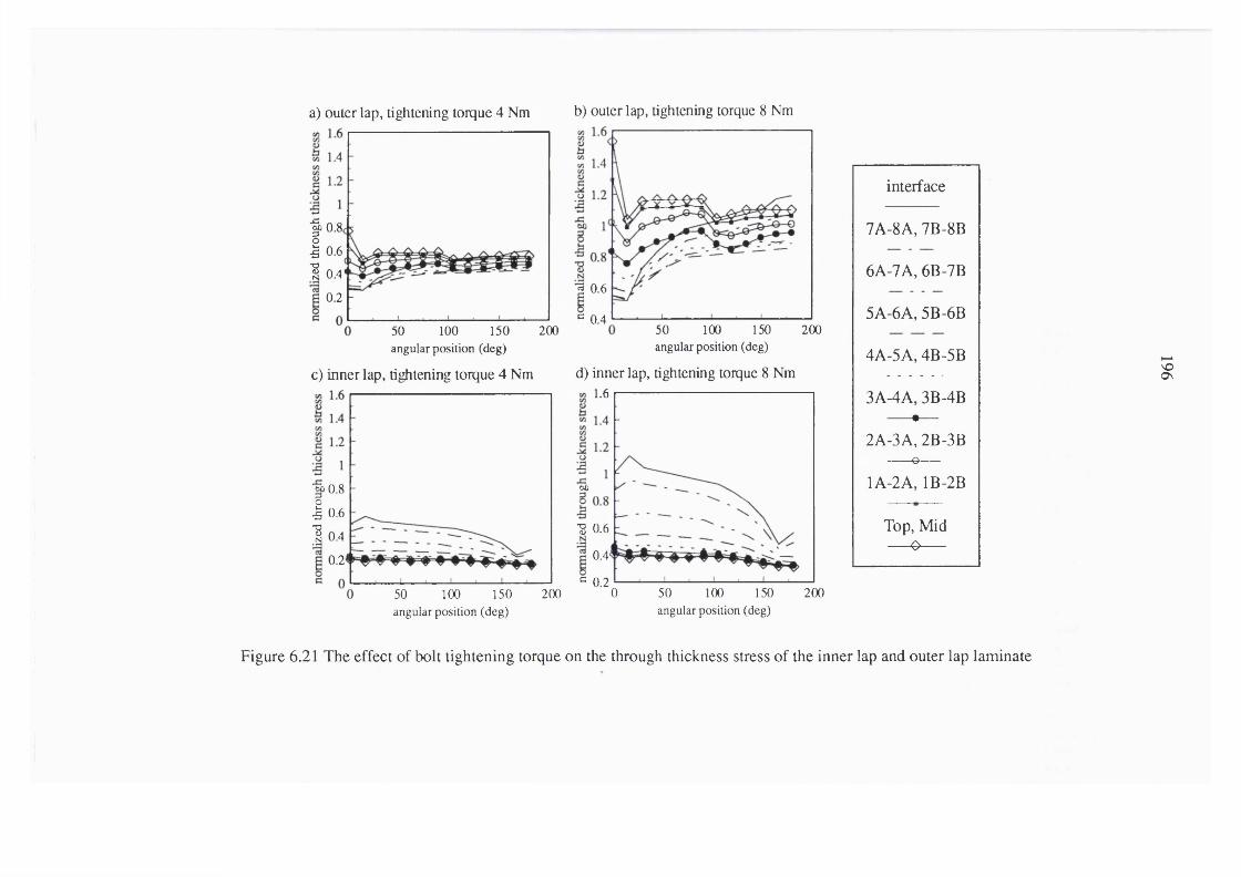
a) outer lap, tightening torque 4 Nm b) outer lap, tightening torque 8 Nm
|)0.8< I 0.61 0.4
2 0.60.2^ 0.4
50 100 150angular position (deg)
20050 100angular position (deg)
150 200
c) inner lap, tightening torque 4 Nm d) inner lap, tightening torque 8 Nm
%0.8 I 0.61 0.4
0.2-
50 100angular position (deg)
150 200
1.6
0£
•g 0.60.4
0.2150 2000 50 100
interface
7A-8A, 7B-8B
6A-7A, 6B-7B
5A-6A, 5B-6B
4A-5A, 4B-5B
3A-4A, 3B-4B #—
2A-3A, 2B-3B G -- - - - -
1A-2A, 1B-2B
Top, Mid— O----
VO0\
angular position (deg)
Figure 6.21 The effect of bolt tightening torque on the through thickness stress of the inner lap and outer lap laminate

i) no clamping ii) clamping torque 4 Nm iii) clamping torque 8 Nm
Ia■8
20distance firom hole boundary (mm)
1
III
distance from hole boundary (mm)
ÎI
20distance front hole boundary (mm)
laminate interface
7B-8B
6B-7B
5B-6B
4B-5B
3B-4B
2B-3B— o—
1B-2B
Mid plane—^ —
VO
Figure 6.22a Normalized tensile stress along the net tension plane of the inner lap for a range of bolt tightening torques (0 to 8 Nm)

i) no clam ping ii) clam ping torque 4 Nm iii) clam ping to rque 8 Nm
-g
20distance from hole boundary (mm)
G
distance from hole boundary (mm)
Ji
■8Ig
20distance from hole boundary (mm)
laminate interface
7A-8A
6A-7A
5A-6A
4A-5A
3A-4A— #—2A-3A— 0—
1A-2A
Top surface—0—
VO00
Figure 6.22b Normalized tensile stress along the net tension plane of the outer lap for a range of bolt tightening torques (0 to 8 Nm)

a) inner lap, clamp 4 Nm position-0 deg on the interface
2.7 w=3d w=4d w=6d
2.6.2 2.5
2.4
2.22.1
edge distance
c) outer lap, clamp 4 Nm position-0 deg cm the interface
3.2
w=3d w=4d w=6d%
^ 2.9
O— - ' — ^ ^
2.4
edge distance
b) inner lap, clam p 8 N mposition-0 deg on the interface
1.4
w=3d w=4dw=6d
•I 0.9
0.7
0.6edge distance
d) outer lap, clamp 8 Nm position-90 deg on top surface
32w=3d w=4d w=6d
.2 2.9
2.62.5
2.4
edge distance
Figure 6.23 The effect of joint geometry on the maximum radial contact stress for the inner lap and outer lap having the bolt tightening torques of4 Nm and 8 Nm

a) inner lap, clamp 4 Nmposition-45 deg between layer 5B-6B
1.2w=3d w=4dw=6d
I0.9
— -X— o
0.8edge distance
c) outer lap, clamp 4 Nm positian-45 deg between layer 5A-6A
w=3d w=4dw=6d
ë 0.7
0.6
^O— * - — “O0.5
0.4
edge distance
b) inner lap, clamp 8 Nm position-45 deg between layer 5B-6B
w=3d w=4d w=6d
— OI0.9A
0.8edge distance
d) outer lap, clamp 8 Nm position-45 deg between layer 5A-6A
0.8
I ^r x ^
O— - - — -O8^ 0.6II w=3d w=4d w=6d
0.4
edge distance
to
Figure 6.24 The effect of joint geometry on the maximum inter laminar shear stress for the inner lap and outer lap having the bolt tighteningtorques of 4 Nm and 8 Nm

a) inner lap, clamp 4 Nm b) inner lap, clamp 8 Nm4.5
w=3d w = 4dw =6d
3.5-
o — - - — o
2.5
edge distance
c) outer lap, clamp 4 Nm
w=3d w =4dw =6d
I
----------- X
O----------
edge distance
4.5
' ----------f 3.5
w=3d w=4d w=6d
2.5
edge distance
d) outer lap, clamp 8 Nm
w=3d w =4dw =6d
2.5
N
I ------------X
edge distance
g
Figure 6.25 The effect of joint geometry on the maximum tensile stress for the inner lap and outer lap having the bolt tightening torques of4 Nm and 8 Nm

202
a) without bolt tightening0.2
line 1 line 2 line 3 line 4 line 5 line 60.15
0.1
0.05
-O -0.05 100 120distance from loaded end (mm)
b) 4 Nm bolt tightening torque0.2
line 1 line 2 Une 3 line 4 line 5 line 60.15
-a0.1
0.05
100 120distance from loaded end (mm)
c) 8 Nm bolt tightening torque0.2
line 1 line 2 line 3 line 4 line 5 line 6c 0.15•g
0.1.sT3N
0.05
a-O -0.05 120100
distance from loaded end (mm)
w = 6 d : e = 6 d ( o u t e r la p a t t h e la m i n a t e p la t e in t e r f a c e )
Figure 6.26 Deformed shape in the z-direction for (a) without bolt tightening, (b) 4 Nmand (c) 8 Nm tightening torque; laminate width = 6d: edge distance = 6d

203
a) without bolt tightening0.25
line 1 line 2 line 3 line 4 line 50.2
0.15
0.1
0.05
-O -0.05 100 120distance from loaded end (mm)
b) 4 Nm bolt tightening torque'a 0.2Ic 0.15•SI 0-1Nc 0.05
-o
line 1 line 2 line 3 line 4 line 5
-O -0.05 100 12040 60 80
distance from loaded end (mm)
c) 8 Nm bolt tightening torque'a 0.2Ic 0.15 •§
0.1 1c 0.05
i .
line 1 line 2 line 3 line 4 Hne 5
-0.05 100 120distance from loaded end (mm)
w = 4 d : e = 6 d ( o u t e r la p a t t h e la m i n a t e p la t e in t e r f a c e )
Figure 6.27 Deformed shape in the z-direction for (a) without bolt tightening, (b) 4 Nmand (c) 8 Nm tightening torque; laminate width = 4d: edge distance = 6d

204
a) without bolt tightening0.25
line 1 line 2 line 3 line 40.2•a 0.15
V 0.1
0.05
- c -0.05 100 120distance from loaded end (mm)
b) 4 Nm bolt tightening torque0.2
line 1 line 2 line 3 line 4C 0.15
0.1
0.05
-O -0.05 120100distance from loaded end (mm)
c) 8 Nm bolt tightening torque0.2
line 1 line 2 line 3 line 4
- 7 ^ : :C 0.15•S
0.1NC 0.05
t3 -0.05 120100distance from loaded end (mm)
w = 3 d : e = 6 d ( o u t e r la p a t t h e l a m in a t e p la t e in t e r f a c e )
Figure 6.28 Deformed shape in the z-direction for (a) without bolt tightening, (b) 4 Nmand (c) 8 Nm tightening torque; laminate width = 3d: edge distance = 6d

I§(ü*&
<Ü
I
0 . 0 0 4
0 . 0 0 3 -
B 0 . 0 0 2
width=3d clamp 4 Nm
width=3d clamp 8 Nm
width=4d clamp 4 Nm
—<3width=4d
clamp 8 Nm
width=6d clamp 4 Nm
B
widthclamp 8 Nm
line 1 line 2
-3 0 . 0 0 1 -
5 1 0 1 5 2 0d i s t a n c e f r o m c e n t r e l i n e ( m m )
S
Figure 6.29 Relative displacement in the z-direction at the free end of the outer lap compared with displacement at the centreline

a) edge distance=2d b) edge distance=4d c) edge distance=6d105105
w=3d: vM d; w^=6dw=3d; w=4d: w=6d
8
1Üa
8I
10bolt tightening torque (Nm)
105
w=3d: w=4d; w^=6d
oo
g
bolt tightening torque (Nm)
Figure 6.30 The effect of clamping pressure on the percentage of load transferred via the bolt

a) w=6d:e=2d inner lap
10
b) w=6d:e=4dinner lap
.1 6
0
wiilKmUbakti|hUoin| 4 Nm bofc lightang Urque• eI Nm bok lonfie
0
d) w=6d:e=2d outer lap
o
2 4 6 8 10 12 14element position
10without hok ti unmi 4 Nm bcà tightmingi Nm bdt uA^bi ta ue
8
6
4
2
0
element positione) w=6d:e=4douter lap
10without bo^ghtnng 4 Nm bcft tig^ ng tor<fic
B Nm bok bg^mg tonpe8
6
4
2
10without bcfctightaing 4 Nm bok tightmmg tmque
8
6
4
2
00 2 4 6 8 10 12 14
c) w=6d:e=6dinner lap
10without bok tightmmg 4 Nm bok lig tmhg tonpe
8
6
4a
2
0
element positionf) w=6d:e=6douter lap
.1
I-È
10without bdi tighten ng 4 Nm bdt tightmk% lonye
B Nm bok ti^^Bg torque8
4
2
00 2 4 6 8 10 12 14
element position element position element position
toS
Figure 6.31 The effect of edge distance on the ply failure index for the elements at the interface between the inner lap and the outer lap,having a range of bolt tightening torques (constant width of 6d)

a) w=4d:e=2dinner lap
b) w=4d;e=4dinner lap
10wilhau bcÉ U|huiB| 4 Nm bok U|tilaii| ut<)uc
8 Nm bok ddum m g lor^ie
8
6
4
2
0
element positiond) w=4d;e=2d
10vitfKMi b o k ti^ io a k it 4 Nm b c k tig b u n a t ter^^e
Nm bok ua)uc
8
6
4
2
0
element positione) w=4d:e=4d
outer lap outer lap10
•ilhaul bok Ughun mg 4 Nm bok lighum ng lorigie
8
6
4o.
2
00 2 4 6 8 10 12 14
10bckli^UBiBg 4 Nm boktightaiing UF(|ue
8
6
4
2
0
c) w=4d:e=6dinner lap
10wiihaui b o k ti^ io iB g 4 Nm bok lig h to in g to r^ e
Nm bok üA u m b g u r^ ic
8
6
4
2
0
element positionf) w=4d:e=6douter lap
10 I—widMut b o k ti^ ta iin g 4 Nm b o k ti^ to in g U rt^e • 0 Nm bok t i d ^ m g un^ ie
8
6
4D.
2
0
element position element position element position
Ooo
Figure 6.32 The effect of edge distance on the ply failure index for the elements at the interface between the inner lap and the outer lap,having a range of bolt tightening torque (constant width of Ad)

a) w=3d:e=2dinner lap
b) w=3d:e=4dinner lap
10without bok tighiAng 4 Nm bafeiifhunng urque
8
6
4
2
0
element positiond) w=3d:e=2d
10wiibaui bcÉiiÿtaiBg 4 Nm bofcugbtCDiaguvtyic
Nm bok ü ^m g uique
8
6
4
2
0
element position
outer lap outer lap10
without bok ti^toiBg 4 Nm b(k lights)Bg lortyic
8 Nm bok tid ^m g lonyje
8
6
4a
2
0 2 4 6 8 10 12 14
10without bok ti#)UBBg 4 Nm bok tightmmg urquc
8Nm bokuA^mgtmque
8
6
4
2
c) w=3d;e=6dinner lap
10boh lights) Bg 4 Nm bok lights) ngKT^ie
Nm bok tid^simg tor^c
8
6
4
2
0
element positionf) w=3d:e=6douter lap
1
■i
10without bok ti^isiing 4 Nm bokiightonmg ton^e
8
4
2
00 2 4 6 8 10 12 14
element position element position element position
to
Figure 6.33 The effect of edge distance on the ply failure index for the elements at the interface between the inner lap and the outer lap,having a range of bolt tightening torques (constant width of 3<i)

a) inner lap b) outer lap0.30.3
without bolt tightening 4 Nm bok tightening torque
8 Nm bok tightening torque
0.250.25
0.20.2
0.150.15
0.10.1
0.050.05
element position
without bok tightening 4 Nm bok tightening torque
8 Nm bok tightening torque<j> e
fo
-e 0-0-^ 0. ; o.o -o- o -o © ^ of O- o
# -i # 4" # # é • é0 4 6 8 10
element position12 14
toO
Figure 6.34 Onset of delamination for the elements of the inner lap and the outer lap on the hole boundary (w=6d: e=6d)

X'O.s
iS
1 .4
1 .2 -
1 - °■. '
0 .8 _
0 .6 _ " '''\ ''■ V:!é
0 .4
0 .2
0
- \
.. , . 1 . . . 1
outer lap.6 kN
inner lap.65 kN
outer lap.65 kN
inner lap.7 kN
outer lap.7 kN
0 2 4 6 8 1 0e l e m e n t p o s i t i o n
w = 6 d : e = 6 d : t ig h t e n in g to r q u e 4 N m
inner lap .6 kN
K)
Figure 6.35 Failure index for elements on the hole boundary of the outer lap at the laminate plate interface (w=6d: e=6d: bolt tightening torque 4 Nm)

212
CHAPTER 7
CONCLUSIONS AND SUGGESTIONS
FOR FURTHER RESEARCH
In this chapter a summary of each of the previous chapters is provided.
This is followed by a brief overall appraisal of the results and an assessment of
the relevance of this work to the current understanding of the behaviour of
mechanically fastened composite laminates. Finally, suggestions are made for
extending the current work.
7.1 CONCLUSIONS
7.1.1 CHAPTER 2
This chapter presented a literature review of the current developments in
both experimental and analytical investigations of the stress distribution and
failure analysis of mechanically fastened joints. Experimental examinations
concerned with assessing the effect of joint geometry, material composition and
fastener configuration on the joint strength and failure mode were discussed.
In the case of the analytical studies it is apparent that many researchers
have attempted to use the boundary element method as well as the finite element
method, as a means of evaluating the stress distribution around the fasteners and,
thereby, the joint strength. However, in the application of the boundary element
method, the requirement to prescribe the contact condition at the joint interface

213
limits the suitability for this type of problem. The finite element method,
however, utilises numerical techniques to solve the interfacial contact condition
and consequently has been shown to be the most appropriate method to date in
the analysis of mechanically fastened composite laminates.
The accuracy of the results obtained from a finite element analysis of this
problem are dependent on the assumptions made in the modelling process. To
achieve a more realistic model, the contact conditions at the interface should be
solved analytically using an incremental loading scheme. Moreover, the layerwise
technique for modelling the laminate should be utilised so that the effects of the
interlaminar normal and shear stresses may be incorporated. These additional
features will not only increase the complexity of the modelling process but will
normally increase the time required to construct the model, as well as to perform
the analysis and post-processing of the results.
7.1.2 CHAPTERS
In this chapter the theoretical aspects concerning the laminate plate theory
and the contact mechanism concept in the analysis of mechanically fastened
joints was presented. Layerwise modelling was considered more suitable for
three-dimensional modelling than the RVE modelling technique since
interlaminar shear and through thickness stresses can be directly evaluated for
each lay-up. However, this technique requires considerable time in model
construction, carrying out the analysis and then post-processing the results.

214
7.1.3 CHAPTER 4
The results obtained from two-dimensional finite element modelling of a
single pin, double lap, composite laminate joint subjected to an in-plane load was
described in this chapter. The modelling technique was verified by comparing the
results obtained for a specific joint configuration with those given in previously
published studies.
The influence of interfacial friction, pin elasticity and the laminate
properties on the stress distribution at the hole boundary were assessed. The
combined effect of interfacial friction and pin elasticity, which have not been
previously assessed, were considered to have a significant influence on the joint
performance. This is confirmed by the results which showed that an increase in
the fnction coefficient lowered the radial contact stress, thereby, reducing the pin
deformation and increasing the pin-laminate contact area. Moreover, the angular
position of the peak radial, interlaminar shear and through thickness stresses was
shown to be dependent on the stacking sequence of the laminate.
7.1.4 CHAPTERS
In this chapter a two-dimensional multi-fastener model of a double lap joint
was presented. The special features of this model enabled a realistic evaluation of
the load transfer via each fastener to be derived from the local contact pressure
distribution. These results indicate that for the specific joint configurations

215
considered the outermost hole on the inboard row of the inner lap was subjected
to the highest load transfer.
The non-uniform transfer of load through the fasteners demonstrates that
results obtained in the analysis of single fastened joints can not be extrapolated to
multi-fastened configurations, since the stress distribution is affected by the
proximity and location of adjacent fasteners.
7.1.5 CHAPTER 6
Two types of three-dimensional model were given in chapter 6 in which;
(a) a representative volume element (RVE) technique was used in the modelling
of an inner lap laminate in contact with a single bolt and (b) replica (layerwise)
modelling was utilized to construct models for both the inner and outer lap
laminates in a double lap joint.
The modelling technique was validated by comparing the analytical results
with previously published work. The effect produced by varying bolt pre-load
and tolerance demonstrated that good correlation may be obtained between
analytical and experimental results when the model includes most of the physical
attributes of the joint.
Although good agreement was obtained using the RVE procedure, the
layerwise technique was employed in the subsequent analysis since this allows

216
consideration of the interlaminar stress and, thereby, enables failure analysis of
the joint to be carried out.
The proportion of load transferred due to the interfacial friction at the
laminate plate interface and the out-of-plane deformation that occurs under load,
highlights the importance of three-dimensional modelling for this type of joint.
Bolt pre-load showed a considerable influence on the stress distribution on the
hole boundary and the load transferred by the bolt. For the case without bolt pre-
loading the maximum radial contact stress was recorded on the inner lap,
whereas, for a bolt tightening torque of 4 Nm and 8 Nm the maximum radial
contact stress occurred in the outer lap. Despite the contrary practice these
results demonstrate that it is essential to perform a comprehensive stress analysis
on both the inner and outer lap of the joint when undertaking three-dimensional
modelling.
7.2 ACHIEVEMENTS OF THIS WORK
This thesis outlines the application of three-dimensional finite element
modelling in studying the stress and strain produced during loading of
mechanically fastened composite laminates. An original model of a double lap
single bolted joint, consisting of an inner lap and outer lap laminate joined by an
elastic bolt, was constructed. The model incorporated the analysis of the
interlaminar shear and through thickness stresses imposed on the laminate by the
apphcation of bolt pre-load and an applied tensile load. A realistic contact stress

217
distribution at the joint interfaces was modelled which included the effect of
friction at the bolt-hole interface as well as at the laminate plate interface.
Comprehensive stress analysis of the laminates showed the influential effect
of stacking sequence, joint geometry and bolt pre-load on the stress distribution
in the vicinity of the fastener. This analytical work is the first study to
demonstrate out-of-plane bending of the outer lap as function of bolt pre-load
and laminate width. Finally, on the basis of examining a variety of joint
geometries design guidelines were proposed for this particular double lap joint
configuration.
7.3 SUGGESTIONS FOR FURTHER WORK
As a result of this study, the following recommendations are made to
extend the work presented here.
7.3.1 MODELLING TECHNIQUES
In this study the bolt pre-load was applied directly on the surface nodes
corresponding to the washer contact area. This assumption is violated when the
laminate deforms out-of-plane in the z-direction. A more accurate result could be
obtained by modelling the washer as an individual elastic body and subsequently
carrying out the contact analysis at the washer-laminate interface. However, this
proposal increases the complexity of the model and may cause a non-

218
convergence in the numerical iteration loop when the frictional contact analysis is
undertaken.
In predicting laminate failure the average stress on an element was used in
the appropriate failure criteria. Clearly, the finer the mesh, especially in vicinity
of the hole boundary, the more accurate is the prediction of the initiation site.
This is, however, dependent on the number of contact elements that can be
incorporated in the finite element simulation. Further work should be undertaken
to investigate the optimum mesh size to give the appropriate resolution for
investigating failure initiation.
7.3.2 MATERIAL AND FASTENER PARAMETERS
The application of different laminate stacking sequences and or material
combinations under various clamping conditions should be investigated. The
effect of bolt elasticity and tolerance should also be considered as bolt bending
influences the radial contact stress distribution through the laminate thickness.
The effect of washer size is another parameter to study since this governs the
through thickness stress. Moreover, a three-dimensional analysis of a multi
fastened joint should be examined since this is more appropriate to practical
applications. This assessment is considered essential to enhance joint
performance and to evolve a more useful design methodology of composite
bolted joints.

219
7.3.3 FAILURE CRITERIA AND STRENGTH PREDICTION
This study Has shown that it is possible to predict the failure initiation for
this particular type of joint using existing failure criteria. Further development in
the procedures for predicting joint strength and failure mode are required. This
may be included into the analytical simulation by recalculating the stiffness of the
laminate immediately after an element has failed and adopting an iterative loading
procedure to check for subsequent element failure. The reliability of this type of
assessment must dependent on the accuracy of the damage mechanics model that
is used to recalculate the laminate stiffness near the damaged zone.

220
REFERENCES
ABAQUS Finite Element Computer program, Hibbitt, Karlsson, and Sorensen,
Inc., Providence, RI
Abd-EI-Naby, S. F. M., HoIIaway, L. and Gunn, M. (1991): “Load
distribution in two-pinned polymer composite joints”. Composite
Structures 6 (Ed. Marshall, I. H.), pp. 553
Abd-EI-Naby, S. F. M., and HoIIaway, L. (1993a.): “The experimental
behaviour of bolted joints in pultruded glass/polyester material. Part
1: Single-bolt joints”. Composites, Vol. 24, pp. 531-538
Abd-EI-Naby, S. F. M., and HoIIaway, L. (1993b.): “The experimental
behaviour of bolted joints in pultruded glass/polyester material. Part
2: Two-bolt joints”. Composites, Vol. 24, pp. 539-546
Agarwal, B. L. (1980): “Behaviour of multifastener bolted joints in composite
materials”, AIAA-80-0307
Azzi, V. D. and Tsai, S. W. (1965): “Anisotropic strength of composites.”,
Experimential Mechanics, Vol. 5, pp. 283-298
Bencheckchou, B and White, R. G. (1995a.): “Stress around fasteners in
conqx)site structures in flexure and effects on fatigue damage initiation
part 1: cheese-head bolts”. Composite Structures, VoL 33, pp. 95-108
Bencheckchou, B and White, R. G. (1995b.): “Stress around fasteners in
composite structures in flexure and effects on fatigue damage initiation
part 1: countersunk bolts”. Composite Structures, Vol. 33, pp. 109-119

221
Chamis, C. C. (1974): “Micromechanics strength theories”, Composite
Materials, Vol. 5, Fracture and Fatigue (Ed. Broutman, L. J.),
Academic Press, New York, pp. 93-115
Chamis, C. C. and Sendeckyj, G. P. (1968): “Critique on theories predicting
thermoelastic properties of fibrous composites”. Journal of
Composite Materials, Vol. 2, pp. 332-348
Chang, F. K. and Chang, K. Y. (1987): “Post-failure analysis of bolted
composite joints in tension or shear-out mode failure”. Journal of
Composite Materials, Vol. 21, pp. 809-833
Chang, F. K., Scott, R. A. and Springer, G. S. (1982): “Strength of
mechanically fastened composite joints”. Journal of Composite
Materials, Vol. 16, pp. 470-494
C hang, F. K., Scott, R. A. and Springer, G. S. (1984a.): “Failure of
composite laminates containing pin loaded holes - method of
solution”. Journal of Composite Materials, Vol. 18, pp. 255-278
Chang, F. K., Scott, R. A. and Springer, G. S. (1984b.): “Design of
composite laminates containing pin loaded holes”. Journal of
Composite Materials, Vol. 18, pp. 279-289
Chen, W. H. and Lee, S. S. (1995): “Numerical and experimental failure
analysis of composite laminates with bolted joints under bending
loads”. Journal of Composite Materials, Vol. 29, pp. 15-36
Chen, W. H., Lee, S. S. and Yeh, J. T. (1995): “Three-dimensonal contact
stress analysis of a composite laminate with bolted joint”. Composite
Structures, Vol. 30, pp. 287-297

222
Cohen, D., Norton, F.M. and Hodgson, M E . (1989): “Experimental
investigation of failure loads in thick composite joints”, Proceedings
of the Fourth Technical Conference of the American Society for
Composites, Blacksburg, VA, October, pp. 72-81
Cohen, D., Hayer, M. W., Shuart, M. J., Griffin, O. H., Prasad, C. and
Yalamanchili, S. R. (1995): “Failure criterion for thick multifastener
graphite-epoxy conposite joints”. Journal of Conposites Technology &
Research, VoL 17, pp. 237-248
Cole, R. T., Bateh, E. J. and Potter, J. (1982): “Fasteners for composite
structures”. Composites, Vol. 13, pp. 233-240
Collings, T. A. (1977): “The strength of bolted joints in multi-directional CFRP
laminates”, Composites,Vol. 8, pp. 43-55
Collings, T. A. (1982): “On the bearing strengths of CFRP laminates”.
Composites, Vol. 13, pp. 241-252
Collings, T. A. (1987): “Experimentally determined strength of mechanically
fastened joints”. Jointing fibre-reinforced plastics (Ed. Matthews, F.
L.), Elsevier, London
Conti, P. (1986): “Influence of geometric parameters on the stress distribution
around a pin-loaded hole in a composite laminate,” Composite
Science and Technology, Vol. 25, pp. 83-101
Cook, R. D., Malkus, D. S. and Plesha, M. E. (1989): “Concepts and
applications of finite element analysis”, Edition, John Wiley, New
York

223
Cooper, C. and Turvey, G. J. (1995): “Effects of joint geometry and bolt
torque on the structural performance of single bolt tension joints in
pultruded GRP sheet material” Composite Structures, Vol. 32, pp.
217-226
Crews, J. H., Jr. (1981): “Bolted bearing fatigue of a graphite/epoxy laminate”.
Joining of Composite Materials ASTM STP 749 (Ed. Kedward, K. T.),
American Society for Testing and Materials, pp. 131-144
Crews, J. H., J r. and Naik, R. A. (1986): “Combined bearing and bypass
loading on a graphite/epoxy laminate”. Composite Structures, Vol.
6, pp. 21-40
Curtis, P. T. (1993): “Theoretical prediction of failure mechanism and
strength”. Composite materials in maritime structures (Fundamental
aspect) (Ed. Shenoi, R. A., Wellicom, J. P.), Cambridge University
Press, Cambridge, Vol. 1., pp. 280-307
de Jong, T. (1977): “Stresses around pin-loaded holes in elastically orthotropic
or isotropic plates”. Journal of Composite Materials, Vol. 11, pp.
313-331
de Jong, T. (1982): “Stresses around pin-loaded holes in composite materials”,
in Mechanics of Composite Materials, Recent Advances, Pergamon
Press, pp. 339-348
de Jong, T. (1987): “On the calculation of stresses in pin-loaded anisotropic
plates”, TU Delft, Report LR-529, November
Daniel, I. M. and Ishai, O. (1994): “Engineering mechanics of Composite
Materials”, Oxford University Press, New York

224
Eisenmann, J. R. (1976): “Bolted joint static strength model for composite
materials”, NASA TM-X-3377, April, pp. 563-602
Eriksson, I. (1990): “On the bearing strength of bolted graphite/epoxy
laminates”. Journal of Composite Materials, Vol. 24, pp.1246-1269
Eriksson, L. I. (1986): “Contact stresses in bolted joints of composites
laminates”. Composite Structures, Vol. 6, pp. 57-75
Fan, W. and Qiu, C. (1993): “Load distribution of multi-fastener laminated
composite joints”. International Journal of Solids Structures, Vol.
30, p p .3010-3023
Garbo, S. P. and Ogonowski, J. M. (1981): “Effect of variances and
manufacturing tolerances on the design strength and life of mechanically
fastened conposite joints”, AFWAL-TR-81-3041, Air Force Wright
Aeronautical Laboratory, Dayton, OH, Vol. 1 & 2 & 3, April
Godwin, E. W. and Matthews, F. L. (1980): “A review of the strength of
joints in fibre reinforced plastics. Part I: Mechanically fastened
joints”. Composites, Vol. 11, pp. 155-160
Godwin, E. W., Matthews, F. L. and Kilty, P. L. (1982): “Strength of multi
bolt joints in GRP”, Composites, Vol. 13, pp. 268-272
Graham, U., Wisnom, M. R. and Webber, J. P. H. (1994): “A novel finite
element investigation of the effects of washer friction in composite plates
with bolted filled holes”. Composite Structures, Vol. 29, pp. 329-339
Griffin Jr., O.H., Hyer, M.W., Cohen, D., Shuart, M .J., Yalamanchili, S.R.
and Prasad, C.B. (1994): “Analysis of multifastener composite
joints”. Journal of Spacecraft and Rockets, Vol. 31, pp. 278-284

225
Hamada, H., Haruna, K. and Maekawa, Z.-I. (1995): “Effect of stacking
sequences on mechanically fastened joint strength in quasi-isotropic
carbon-epoxy laminates”, Journal of Composites Technology &
Research, Vol 17, pp. 249-259
Hart-Smith, L. J. (1977): “Bolted joints in graphite-epoxy composites”,
Douglas Aircraft Company, NASA Langley Contract Report, NASA
CR-144899, January
Hart-Smith, L. J. (1980): “Mechanically fastened joints for advanced
composites - Phenomenological considerations and simple analysis”.
Fibrous composites in structural design (Ed. Lenoe, E. M., Oplinger,
D. W. and Burke, J. J.), Plenum Press, New York
Hart-Smith, L. J. (1987): “Design and empirical analysis of bolted or riveted
joints”. Jointing fibre-reinforced plastics (Ed. Matthews, F. L.),
Elsevier, London
Hashin, Z. and Rotem, A. (1974): “A fatigue failure criterion for fibre
reinforced materials”. Journal of Composite Material, Vol. 7, pp.
448-504
H errera-F ranco , P. J . and Cloud, G. L. (1986): “Experimental Analysis
of Multiple-Hole Arrays of Composite Material Fasteners”,
Proceedings of the 1986 SEM Spring Conference on
Experimental Mechanics, New Orleans, Louisiana, June, pp.
621-629

226
Hodgkinson, J. M. (1985): “The strength of bolted joints in Kevlar RP, Proc.
Conf., Composite design for space application, 15-18, ESA SP-243,
European Space Agency, Noordwijk, Netherlands
Holister^ G. S. and Thomas, C. (1966): “Fibre reinforced materials”, Elsevier
Publishing Co., London
Humphris, N. P. (1978): “Migration of the point of maximum stress in a
laminate composite lug structure - A stepwise approach”.
Symposium: Jointing in Fibre Reinforced plastics. Imperial College,
London, September, pp. 79-86
Hyer, M. W. and Klang, E. C., (1984): “Contact stresses in pin loaded
orthotropic plates” Virginia Polytechnic and State University, VPI-
E-84-14, April
Hyer, M. W., Klang, E. C. and Cooper, D. C. (1987): “The effect of pin
elasticity, clearance and friction on the stresses in a pin-loaded
orthotropic plate”. Journal of Composite Materials, Vol. 21, pp.
190-206
Hyer, M. W. and Liu, D. (1983): “Photoelastic determination of stresses in
multiple-pin connectors”. Experimental Mechanics, Vol. 23, pp. 249-
256
Hyer, M. W. and Liu, D. (1984): “Stresses in a quasi isotropic pin-loaded
connectors using photoelasticity”. Experimental Mechanics, Vol. 23,
pp. 48-53

2 2 1
Hyer, M. W. and Liu, D. (1985): “Stresses in pin-loaded orthotropic plates:
Photoelastic results”. Journal of Composite Materials, Vol. 19, pp.
138-153
I DEAS Master Series 1.3c. (1993), 2000 Eastman Drive, Milford, OH 45150,
USA,
Jones, R. M. (1975): “Mechanics of composite materials”. Hemisphere Publ.
Co., New York
Jurf, R. A. and Vinson J. R. (1990): “Failure analysis of bolted joints in
composite laminates”. Composite Material: Testing and Design
(Ninth Volume), ASTM STP 1059 (Ed. Garbo, S. P.), American
Society for Testing and Materials, Philadelphia, pp. 165-190
Kretsis, G. and Matthews, F. L. (1985): “The strength of bolted joints in glass
fibre/epoxy laminates”. Composites, Vol. 16, pp.92-102
Kim, S.J. and Kim, J.H. (1995): “Finite element analysis of laminated
composite plates with multi-pin joints considering friction”.
Computer and Structures, Vol. 55, pp. 507-514
Knight, C. E., J r. (1993) “The finite element in mechanical design” PWS-
KENT Publishing Company, Boston, U. S. A.
Kortschot, M. T., Beaumont, P. W. R. (1990): “Damage mechanics of
composite materials: 1.-Measurement of damage and strength, 2.-A
damage based notched strength model”. Composite Science and
Technology, Vol. 39, pp. 289-326

228
Lehman, G. M. and Hawley, A. V. (1969): “Investigation of joints in advanced
fibrous composites for aircraft structures”, McDonnel-Douglas
Coporation, Contract F33615-67-C-1582, June
Lekhnitskii, S. G. (1968): “Anisotropic plates”, Translated from Russian by
Tsai, S. W. and Cheron, T., Gordon and Breach Science Publishing,
New York
Lessard, L. B. (1991): “Bearing failure of composite pinned joints using
progressive damage modeling”, ICCM/8, International Conference
on Composite Materials, Honolulu, HI, July 15-19, pp. 9E1-9E10
Lessard, L. B., Poon, C. and Fahr, A. (1992): “Composite pinned joint failure
modes under progressive damage”, ECCM-V Fifth European
Conference on Composite Materials and Exhibition, Bordeaux,
France, April 7-10
Lessard, L. B. and Mahmood, M. S. (1995): “Two-dimensional modeling of
composite pinned-joint failure”. Journal of Composite Materials,
Vol. 29, pp. 671-697
Lin, Chlen-Chang and Lin, Chuen-Horng (1993): “Stress and strength
analysis of composite joints using direct boundary element method”.
Composite Structures, Vol. 25, pp. 209-215
M ahayerin, E. and Sikarskin, D. L. (1986): “Boundary element study of
loaded hole in an orthotropic plate”. Journal of Composite Materials,
Vol. 20, pp. 375-389
Mallick, P. K. 1988: “Fiber-reinforced composites: materials, manufacturing
and design”, Marcel Dekker Inc., New York

229
Man gal g: ri, P. D. (1984): “Pin-loaded holes in large orthotropic plates” AIAA
Journal, Vol. 22, pp. 1478-1484
Mangalgiri, P. D. and Dattaguru, B. (1986): “A large orthotropic plate with
misfit ' pin under arbitrary oriented biaxial loading” Composite
Structures, Vol. 6, pp 271-281
Marshall, I. H., Arnold, W. S., Wood, J. and Mousley, R. F. (1989):
“Observations on bolted connections in composite structures”.
Composite Structures, Vol. 13, pp. 133-151
Matthews, F. L., Nixon, A. and W ant, G. R. (1976): “Bolting and riveting in
fibre reinforced plastics”. Proceedings of Reinforced Plastics
Congress, British Plastics Federation, Brighton, November
M urthy, A. V., Dattaguru, B., Narayana, H. V. L. and Rao, A. K. (1990):
“An improved iterative finite element solution for pin-joints”.
Computer and Structures, Vol. 36, pp. 1121-1128
M urthy, A. V., Dattaguru, B., Narayana, H. V. L. and Rao, A. K. (1991):
“Stress and strength analysis of pin joints in laminated anisotropic
plates”. Composite Structures, Vol. 19, pp. 299-312
Nahas, M. N. (1986): “Survey of failure and post-failure theories of laminated
fibre-reinforced composites”. Journal of Composites Technology &
Research”, Vol. 8, pp. 138-153
Oakeshott, J. L. and Matthews, F. L. (1994): “Determination of fastener load
distribution in double lap composite joints”, American Society of
Mechanical Engineers, PD-Vol. 64-2, Engineering Systems Design
and Analysis, Vol. 2, pp. 243-251

230
Oplinger, D. W. (1978): “On the structural behavior of mechanically fastened
joints in composite structures”, Conference Proceedings: Fibrous
Composites in Structure Design, San Diego, California, Nov. 14-17,
pp. 575-602
Oplinger, D. W. and Gandhi, K. R., (1974): “Analytical study of structural
performance in mechanically fastened fibre-reinforced plates”. Army
Synposium Proceedings: Solid Mechanics, 1974; The role of mechanics
in design-stmctural joints. Army Materials and Mechanics Research
Center, Report No AMMRC MS 74-8 (AD 786 543), pp. 211-242
Pagano, N. J. and Pipes, R. B. (1971): “The influence of stacking sequence on
laminate strength”. Journal of Composite Materials, VoL 5, pp. 50-62
Pipes, R. B. and Pagano N. J. (1970): “Interlamina stresses in composite
laminates under uniform axial extension”. Journal of Composite
Materials, Vol. 4, pp. 538-548
Poon, C. (1986): “Literature review on the design of mechanically fastened
joints”. National Aeronautical Establishment Canada, Aeronautical
Note NAE-AN-37, NCR No-25442, February
Pradhakaran, R. (1982): “Photoelastic investigation of bolted joints in
composite”. Composites, Vol. 13, pp. 253-256
Quinn, W. J . and Matthews, F, L. (1977): “The effect of stacking sequence on
the pin bearing strength in glass fibre reinforced plastic”. Journal of
Composite Materials, Vol. 11, pp. 139-145
231
Rahman, M. U., Chiang, Y. J. and Rowlands, R. E. (1991): “Stress and
failure analysis of double-bolted joints in douglas-fir and sitka
spruce”, Wood and Fiber Science, Vol. 23, pp. 567-589
Rahman, M. U. and Rowlands, R. E. (1993): “Finite element analysis of
multiple-bolted joints in orthotropic plates”. Computers and
Structures, Vol. 46, pp. 859-867
Ramakrishna, S., Hamada, H. and Nishiwaki, M. (1995): “Bolted joints of
pultruded sandwich composite laminates”, Composite Structures,
Vol. 32, pp. 227-235
Ramkumar, R. L. and Tossavainen, E. W. (1984): “Bolted joints in composite
structures: Design, analysis and verification task I test result- single
fastener joints”, AFWAL-TR-84-3047
Reddy, J. N. and Pandey, A. K. (1987): “A first-ply failure analysis of
composite laminates”. Computer and Structures, Vol. 25 pp. 371-393
Rowlands, R. E., Rahman, M. U., Wilkinson, T. L. and Ching, Y. I. (1982):
“Single- and multiple-bolted joints in orthotropic materials”.
Composites, Vol. 13, pp. 273-279
Sandhu, R. S. (1972): “A survey of failure theories of isotropic and anisotropic
materials”. Air Force Flight Dynamics Laboratory, Technical Report
AFFDL-TR-72-71, Wright Aeronautical Labs, Dayton, OH
Serabian, S. M. and Oplinger, D. W. (1987): “An experimental and finite element
investigation into the mechanical response of 0/90 pin-loaded laminates”.
Journal of Composite Materials, VoL 21, pp. 631-649

232
Serabian, S. M. and Anastas!, R. F. (1991): “Out-of-plane deflections of
metallic and composite pin-loaded coupons”. Experimental
Mechanics, March 1991, pp. 25-32
Serabian, S. M. (1991): “The effect of nonlinear interlaminar shear behavior on
the modeling accuracy of [(0/90)3,0]s and [(+45/-45)]3s pin-loaded
laminates”. Journal of Composite Technology & Research, Vol. 13,
pp. 236-248
Smith, P. A. (1985): “Aspects of the static and fatigue behaviour of composite
laminates, including bolted joints”, PhD Thesis, Cambridge
University Engineering Department, Cambridge, UK
Smith, P. A., Pascoe, K. S. (1985): “Behaviour of bolted joints in (0/90)ns
laminates, Cambridge University Engineering Department Technical
Report (CUED/C/MATS/TR.121), UK
Smith, P. A., Pascoe, K. S., Polak, C. and Stroud, D. O. (1986): “The
behaviour of single-lap bolted joints in CFRP laminates”. Composite
Structures, Vol. 6, pp. 41-55
Smith, P. A., Ashby, M. F. and Pascoe, K. S. (1987): “Modelling clamp-up
effects in composite bolted joints”. Journal of Composite Materials,
Vol. 21, pp. 878-897
Stewart, W. C. (1965): “Metals Engineering Design”, ASME Handbook
(Ed.Horger, O. J.), McGraw-Hill, New York
Stockdale, J. H. and Matthews, F. L. (1976): “The effect of clamping pressure
on bolt bearing loads in glass fibre reinforced plastics”. Composites,
Vol. 7, pp. 34-38

233
Tsai, W. S. (1965): “Strength characteristics of composite materials”, NACA
CR-224
Tsai, S. W. and Hahn, H. T. (1975): “Failure analysis of composite materials”,
Inelastic behaviour of composite materials (Ed. Herakovich, C. T.),
American Society of Mechanical Engineer, New York
Tsai, W. S. and Wu, E. M. (1971): “A general theory of strength of anisotropic
materials”. Journal of Composite Materials, Vol. 5, pp. 58-80
Tsieng, T. H. and Mandell, J . F. (1985): “Damage development in bolt bearing
of composite laminates”, AIAA Journal, Vol. 23(10), pp. 1570-1577
Tsujimoto, Y and Wilson, D. (1986): “Elasto-plastic failure analysis of bolted
joints”. Journal of Composite Materials, Vol 20, pp. 236-252
W addoups, M. E., Eisenmann, J. R. and Kaminski, B. E. (1971):
“Macoscopic fracture mechanics of advanced composite materials”.
Journal of Composite Materials, Vol. 5, pp. 446-455
Wang, S. and Han, Y. (1988): “Finite element analysis for load distribution of
multi-fastener joints”. Journal of Composite Materials, Vol. 22, pp.
124-135
Waszczak, J. P. and Cruse, T. A. (1971): “Failure mode of strength predictions
of anisotropic bolt bearing specimens”. Journal of Composite
Materials,Vol. 5, pp. 421-425
Waszczak, J. P. and Cruse, T. A. (1973): “A synthesis procedure for
mechanically fastened joints in advanced composite materials”,
AFML-TR-73-145, Vol. U, September, 1973.

234
Wilkinson, T. L., Rowlands, R. E. and Cook, R. D (1981): “An incremental
finite element determination of stresses around loaded holes in wood
plates”. Computers and Structures, Vol. 14, pp. 123-128
Wilson, D. W. and Pipes, R. B. (1981): “Analysis of shearout failure mode in
composite bolted joints”, Composite Structure 1 (Ed. Marshall,
I.H.), pp. 34
Wilson, D. W. and Tsujimoto, Y. (1986): “On Phenomenological failure
criteria for composite bolt joint analysis” Journal of Composite
Science and Technology” Vol. 26, pp. 283-305
Whitney, J. M. and Nuismer, R. J. (1974): “Stress fracture criteria for
laminated composites containing stress concentrations”. Journal of
Composite Materials, Vol. 8, pp. 253-265
Wood, J (1994): “Finite element analysis of composite structures”. Composite
Structures, Vol. 29, pp. 219-230
Yamada, S. E. and Sun, C. T. (1978): “Analysis of laminate strength and its
distribution”. Journal of Composite Materials, Vol. 12, pp. 275-284
Ye, L. (1988): “Role of matrix resin in delamination onset and growth in
composite laminates”. Composite Science & Technology, Vol. 33,
pp. 257-277
Yogeswaran, E. R. and Reddy, J. N. (1988): “A study of contact stresses in
pin loaded plates”. Computers and Structures, Vol. 30, pp. 1067-
1077.
Zimmerman, K. B. (1991): “Mechanical fastening of GFRP composites”,
AIAA J., Vol. 29, pp. 1009-1011

235
APPENDIX A
MACROMECHANICAL FAILURE THEORIES
Macromechanical failure theories for composites lamina have been
proposed by extending and adapting isotropic failure theories, such as maximum
normal stress (Rankine), maximum shear stress (Tresca), and maximum
distortional energy (Von Mises), to account for the anisotropy in stiffness and
strength of composite lamina. Sandhu (1972) and Nahas (1986) have surveyed
the literature on anisotropic failure theories, the latter containing a summary of
more than forty such theories.
All existing failure theories are based on a phenomenological design
criteria because of its simple and direct approach. It is often assumed that failure
criteria can be established and strength predicted for a composite lamina,
subjected to a combination of stresses, if the strength of the five loading modes
of a unidirectional lamina, i.e., longitudinal tension and compression, transverse
tension and compression and longitudinal shear, have been determined. Of all
failure theories available, the most frequently used failure criteria theories used in
predicting the strengths of composite lamina are presented below.

236
MAXIMUM STRESS FAILURE THEORY
According to the maximum stress failure theory, a ply is considered to
have failed when any stress in the principal material directions is equal to, or
greater than, the corresponding allowable strength. Thus, no failure will occur if:
-Yo < <%- S < T i 2 < 5
(A.l)
Where Oj and 02 are the normal principal stress components; X12 is the shear
stress component; X , X , and are the longitudinal compressive and tensile
strengths and transverse compressive and tensile strengths, respectively; S is in
plane shear strength. Failure surfaces for the maximum stress criterion are shown
schematically in Figure A.I.
i , « 2
« 1
Figure A.l Schematic failure surface for maximum stress
The maximum stress theory is more applicable for the brittle modes of
failure of the material, closer to transverse and longitudinal tension, and does not
take into account any stress interaction under a general biaxial state of stress.

237
MAXIMUM STRAIN FAILURE THEORY
Similar to the maximum stress failure theory, the maximum strain failure theory
is probably the most widely accepted lamina strength prediction theory and is
commonly used in the aerospace industry. Failure of a ply arises when any strain in
the principal material directions is equal to, or greater than, the allowable strain in
same direction. Failure is avoided if the following conditions are satisfied:
-Elc <£i <e <6n <e
Lt
Tt (A.2)
-Y, <Y i2<Y.
where 8 and y are the normal and shear strains respectively; subscripts Lc and
Lt denote the longitudinal compressive and tensile components, respectively; Tc
and Tt the transverse compressive and tensile components and s is the shear in
corresponding plane. The maximum strain failure theory is often preferred over
the maximum stress theory because the allowable strain data is usually more
accurate than the allowable stress data for certain types of material. The failure
surface is shown schematically in Figure A.2.
Figure A.2 Schematic failure surface for maximum strain

238
AZZI-TSAI-HILL FAILURE THEORY
Azzi and Tsai (1965) proposed this failure criterion after Hill's generalized
Von Mises isotropic yield failure criterion for anisotropic materials. The criterion
for unidirectional lamina states that failure occurs in an orthotropic lamina if and
when the following equality is satisfied,
XY ~
.2'12 (A.3)
where Gj and G2 are both tensile (positive) stresses. When c^and or Oj are
compressive (negative) stresses, the corresponding compressive strength are
used in this equation. Graphic representations of Azzi-Tsai-Hill theory in the
stress coordinate system or failure envelope for a general anisotropic lamina is
shown in Figure A.3, for various values of the x^2 ^S ratio.
increase x
Figure A.3 Failure envelope of Azzi-Tsai-Hill theory

239
The Azzi-Tsai-Hill failure theory is expressed in terms of a single criterion
instead of the three subcriteria required in the maximum stress and maximum
strain theories. The Azzi-Tsai-Hill theory allows for considerable interaction
between the stress components. One disadvantage, however, is that it does not
distinguish between tensile and compressive strengths. The strength parameters
in Eq. (A.3) must be specified according to the given state of stress.
HOFFMAN FAILURE THEORY
The Hoffman failure criterion is similar to the Azzi-Tsai-Hill criterion, but
accounts for different strengths in tension and compression. This failure criterion
is expressed as:
o f - 0 , 0 ;
X, X , Y.Y, X ,X '(A.4)
TSAI-WU FAILURE THEORY
The most general failure criterion for composite materials is the tensor
polynomial criterion given by Tsai (1965) and Tsai and Wu (1971). Failure in an
orthotropic lamina is predicted when the following equality is satisfied:

240
^ A + ^ 2 ^ 2 + 6'Ci2 + ^ 1 iOÎ
"^^22^ 66 12 ^^12^1^2 ~ (A.5)
Here, O- are the stress tensor components in the material principal coordinate
directions and F, and are the component of the strength tensors, such that:
t c '‘ I
(A.l)
where F ^ 2 is a strength interaction term between Oj and O2 which is determined
experimentally. All these components are referenced with respect to the principal
axes of the material. This equation assumes that there is no interaction between
shear stresses and normal stresses.
Since reliable experimental data are not always easy to obtain an
approximate range of F jj has been recommended by Tsai and Hahn (1975).
(A.8)
The lower limit of this equation is frequently used for F 2 in absence of
experimental data.

241
Typical comparison of the failure envelopes of five failure criterion theories
is shown in Figure A.4. All the stress tensors described here have been used for
special cases, which are a reduced form of the Tsai-Wu tensor polynomial theory
(Reddy and Pandey, 1987)
300Maximum stressMaximum strainA2Lzi-Tsai-HillHof&nan
Tsai-Wu
-3001500
Figure A.4 Comparison of the failure envelope of the most often used failure
theories
The failure theories previously given are representative and the most
widely used. The validity and applicability of a specific theory depends on the
convenience of application and agreement with the experimental results. Since
the failure mode depends on the material properties and loading condition, the
applicability of the various theories must also be related to the type of material
and failure mode.

242
For example, the maximum stress and maximum strain theories are more
applicable when brittle behaviour is predominant. Although the concept of these
theories is simple, they are not suitable for computational operation since there
are three subcriteria involved.
The interactive theories, such as Azzi-Tsai-Hill, Hoffman and Tsai-Wu
theories, are more applicable when ductile behaviour under shear or compression
loading is predominant. For the Tsai-Wu failure theory, a comprehensive
material characterization program is desirable to determine accurately the
numerous material parameters required.
ANALYTICAL STRENGTH PREDICTION
The failure criterion theories reviewed previously in this appendix only
apply to individual laminate layers, with the assumption that the lamina or ply
forming part of the laminate exhibits the same behaviour as a unidirectional
isolated ply. The stresses and strains in each lamina, that may be computed, are
transformed into stresses and strains in the principal material directions. These
results may be compared with the failure envelope produced by one of the
methods described above to determine which lamina has failed first.
If the laminate strength is considered as the initial failure of a single lamina
in either the fibre direction or in the direction perpendicular to the fibres, the
method is termed: first ply failure (FPF). On the other hand, if the strength is

243
considered after the structure has degraded to the point where it is no longer
capable of carrying additional load, the method is called last ply failure (LPF).
For the last ply failure approach, reduced stiffness and strains, determined
by either the total discount method, limited discount method or residuary
property method, are assign to the failed laminate. The stresses and strains of
remaining laminas are recalculated and then the process is repeated by comparing
the stress or strain with the appropriate failure envelope until the ultimate failure
of the laminate takes place.
In many composite laminates, first ply failure occurs just before ultimate
failure (Mallick, 1988), and this is considered as justification of the first ply
failure design approach. In other materials, the last ply failure approach may be
more suitable, since the first ply approach can be considered rather conservative.
If the laminate stresses are a ,, Oy and the transformations of laminae stress
of the n* ply are,
= a , cos^ 0 + Oy sin^ + 2x^ cos0, sin0^
= a , sin^ 0 cos^ 0 - 2x^ cos0* sin0^ (A.9)
"'S? = ( -0 , + CT J sin 0, COS0, + t „ (cos' 0„ - sin ' 0. )
when 0„ is the ply orientation of n* lamina. If the failure criterion is satisfied in a
ply of an element, the individual contribution, or failure indices, of each stress
component to the tensor polynomial are computed. For example, if the

244
contribution of the to the polynomial is larger than the contribution of the
other stress components, then it is assumed that failure in that ply is caused by
the tension or compression in the 1 direction depending on the sign of . The
failure indices can also be used to reduce the stiffness in post first ply failure
(FPF) analysis.