PROGRAMMING MANUAL FOR DIGITAL
124
PROGRAMMING MANUAL NEOS IS FIELD CONFIGURABLE AS HOTEL/OFFICE AS PER DIP SWITCH SETTING (Compatibility Upto ARM Split CPU Ver. 1.8)
-
Upload
khangminh22 -
Category
Documents
-
view
0 -
download
0
Transcript of PROGRAMMING MANUAL FOR DIGITAL
PROGRAMMING MANUAL
NEOS IS FIELD CONFIGURABLE AS HOTEL/OFFICE AS PER DIP SWITCH SETTING
(Compatibility Upto ARM Split CPU Ver. 1.8)
------------------------------------------------------------------------------------------------------------------------------------------------------------------
PROGRAMMING MANUAL Wednesday ,January 01, 2014 2
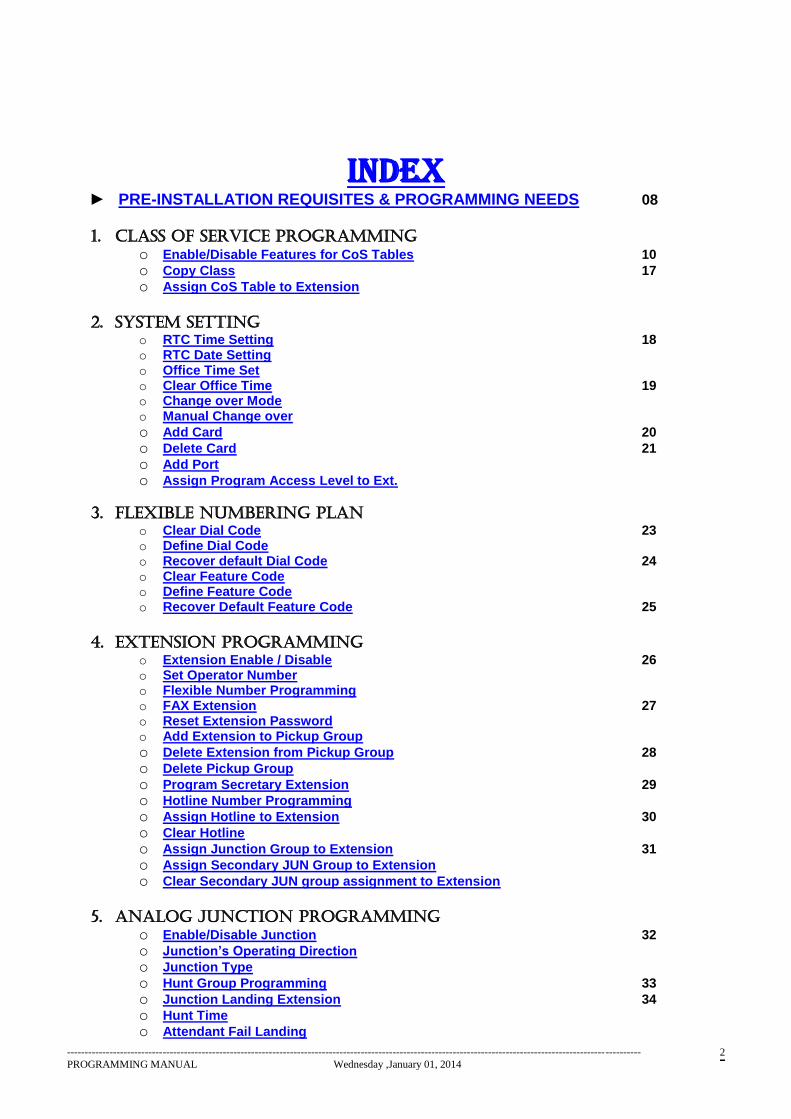
INDEX ► PRE-INSTALLATION REQUISITES & PROGRAMMING NEEDS 08
1. CLASS OF SERVICE PROGRAMMING
o Enable/Disable Features for CoS Tables 10 o Copy Class 17 o Assign CoS Table to Extension
2. SYSTEM SETTING
o RTC Time Setting 18 o RTC Date Setting o Office Time Set o Clear Office Time 19 o Change over Mode o Manual Change over
o Add Card 20 o Delete Card 21 o Add Port o Assign Program Access Level to Ext.
3. FLEXIBLE NUMBERING PLAN
o Clear Dial Code 23 o Define Dial Code o Recover default Dial Code 24 o Clear Feature Code o Define Feature Code o Recover Default Feature Code 25
4. EXTENSION PROGRAMMING
o Extension Enable / Disable 26 o Set Operator Number o Flexible Number Programming o FAX Extension 27 o Reset Extension Password o Add Extension to Pickup Group
o Delete Extension from Pickup Group 28 o Delete Pickup Group o Program Secretary Extension 29 o Hotline Number Programming o Assign Hotline to Extension 30 o Clear Hotline o Assign Junction Group to Extension 31 o Assign Secondary JUN Group to Extension o Clear Secondary JUN group assignment to Extension
5. ANALOG JUNCTION PROGRAMMING
o Enable/Disable Junction 32 o Junction’s Operating Direction o Junction Type o Hunt Group Programming 33 o Junction Landing Extension 34 o Hunt Time o Attendant Fail Landing

------------------------------------------------------------------------------------------------------------------------------------------------------------------
PROGRAMMING MANUAL Wednesday ,January 01, 2014 3
o Assign Private Junction Line 35 o Delete Private Junction Line o Service Provider Selection for # Centrex dialing 36 o Program Dummy dial Tone for Analog Junctions o Call Forward of Hunt Group o Call Wait on Hunt Group 37 o Program Junction Grouping o Clear JUN from JUN Group o Program Leased Line 38 o Program Centrex Line o Programmable Hunt Group Landing Pattern o STD / Local Junction Access Transperancy 39 o Programmable Paging Junction o Clear Paging Junction
6. CoS PREFIX TABLE PROGRAMMING o Set CoS Prefix Table 40 o Initialize default CoS Prefix Table 41
7. LEAST COST ROUTING
o Junction Service Provider 42 o Set LCR Prefix o Clear LCR Prefix 43 o Set LCR Code o Clear LCR Code o Program Centrex Table 44 o Clear Centrex Table o Program Modify Number Table o Clear Modify Number Table
8. AUTO ATTENDANT MESSAGE PROGRAMMING
o Message Time Zone Programming 45 o Welcome Message Table Programming
#
o Assign Message Table to Junction# 46
o Record Auto Attendant Messages/ User Music#
o Play Recorded Auto Attendant Messages#
o Erase Auto Attendant Messages# 47
o Assign user recorded Music o Select Language for Auto Attendant Voice Prompts
( # : Possible Only thro’ Telephone )
9. E1 JUNCTION PROGRAMMING
o E1 Channel Setting 48 o E1 Parameter Setting o E1 Landing Extension 49 o Programmable CLI Length for E1
10. BRI JUNCTION PROGRAMMING
o Channel Setting 50 o Landing Extension o BRI Junction Category
11. PRI JUNCTION PROGRAMMING
o Channel Setting 51 o Landing Extension o Define Network Clock Source 52 o PRI Junction Category o Program CRC o Calling Party Number Information 53
------------------------------------------------------------------------------------------------------------------------------------------------------------------
PROGRAMMING MANUAL Wednesday ,January 01, 2014 4
o Called Party Number Information
12. VOIP SIP Trunk o Programmable Logical Partitioning 54 o o
13. VOIP TIE JUNCTION o Tie Route Method 55 o Own PBX Code o Auto Route Selection o Tie Digit Timeout o Tie Leading Digit/Tie Route Table o Add / Strip Digit 56 o Min – Max Digits/Tie destination Number Length o IP Address of Card o Program Netmask o Program Gateway 57 o Program Debug Level o Load Default Tie Parameters o Reset Tie Card o Program Alternate Destination IPs In Routing Table o Clear Tie Route Table o Programmable Remote IP for SIP Extension Card o Programmable Input Gain for SIP Ext./ Trunk / Tie Card 58
14. VOIP JUNCTION o SIP JUN Enable/Disable 59 o Display SIP Trunk Name o SIP Line ID o Authentication ID for SIP Trunk o Authentication Password for SIP Trunk o SIP Trunk Mode o Proxy server Address for SIP Trunk 60 o Registration flag for SIP Trunk o Register Server Address for SIP Trunk o Out Bond Proxy Flag for SIP Trunk o Out Bond Proxy Server Address for SIP Trunk o Register Expiry Timer for SIP Trunk o Transport Protocol for SIP Trunk o DTMF Mode for SIP Trunk 61 o Enable Vocoder for SIP Trunk o Preferred Vocoder for SIP Trunk
15. CLI Based Routing o Set CLI Based Routing Table 62 o Clear CLI Based Routing Table o CLI Based Day / Night Landing (Enable / Disable)
16. MSN Based Routing
o Assign MSN Table to Junction 63 o Program MSN Number Length o Assign MSN No. to Port o Clear MSN No. for Port No. 64 o Clear MSN No. Table o Clear Pilot Number 65 o Program Pilot Number o MSN Day / Night landing (Enable / Disable) 66 o Program MSN CLI Display Number
------------------------------------------------------------------------------------------------------------------------------------------------------------------
PROGRAMMING MANUAL Wednesday ,January 01, 2014 5
17. GSM CARD INTERFACE
o Setting Base Station 67 o MIC Gain Setting o SPEAKER Gain Setting o SIDE TONE Setting o PRI Channel Allocation o IMEI number display selection 68
o GSM Version Compatibility Flag
o Programmable call proceed timeout for GSM
o Programmable Deliver timeout for GSM
18. GSM PRI Extension with MSN Compatibility o Set MSN Number Length to PRI 69 o Set MSN Junction to PRI Extension o Assign PRI Extension to MSN Table o Clear MSN Table o Clear assigned MSN Junction to PRI Extension
19. RESTRICTED & DENIED TABLE PROGRAMMING
o Restricted Table Programming 70 o Clear Restricted Table o Denied Table Programming 71 o Clear Denied Table
20. ABBREVIATED DIALING
o Abbreviated Table Programming 72 o Assign Departmental Abbreviated Table to Extension o Clear Abbreviated Tables 73 o Extended Abbreviated Number Programming (With ARM Split Ver. 0.4+ onwards only) o Clear Extended Abbreviated Number 74
21. METER SETTING & MISCELANEOUS
o Program Bill Start Time 75 o Initialize Bill Parameters o Program Call type o Program Call Record Serial Number 76
22. BILLING & SETTING COST TABLES
o Program PRPC Table 77 o Program Call Cost Table o Program STD/ISD Codes 78 o Program PRPC for Centrex Lines
23. BUDGETING
o Program FIX Budget 79 o Program Enhanced Budget o Clear Budget ( Only thro’ Hyper )
24. CLOSED USER GROUP
o Assign CUG Number to Extension 80 o CUG Call Enable (allow calling) o CUG Call Disable (disallow calling) 81
------------------------------------------------------------------------------------------------------------------------------------------------------------------
PROGRAMMING MANUAL Wednesday ,January 01, 2014 6
25. VOICE MAIL INTEGRATION
o Program Voicemail Port 82 o Program Voicemail Mode
26. SYNApps PC Console application
o Agent Interface Mode 83 o Reset Agent’s login Password
27. PROGRAMMING FOR THE ADMINISTRATOR
o Set Ring Repetition Pattern 84 o Program CTI/ HMS INTEGRATION/ SYNApps Application Ver. 1.8 onwards o Dial Plan (Not applicable for ARM Split CPU Ver. 1.1 onwards) 85 o CLI DUMMY DIGITS o CLI RING SETTING ( Before/After First Ring) 86 o Time-out for External Forwarded Call o Auto Attendant Ring Time-out o Time-out for JUN-JUN transferred Call 87 o COM1/COM2 Selection ( Only thro’ Telephone ) (Not applicable from Ver. 1.8 onwards) o ‘Transfered Call’ Recall Time Selection
o Waiting Tone & Transfer to OPR MSG during Auto Attendant 88 o Waiting Timeout during ATT after MSG o Programmable Billed Extension
o Set Dynamic STD Lock Timeout 89
o Set Dynamic CoS
o Programmmable Auto Callback on No Reply
28. PROGRAMMING FOR THE ADMINISTRATOR ( CONFIDENTIAL )
o Create Backup 90
o Recover Backup o Create Master Backup o Recover Master Backup o Change Program PW o Set Printer Password 91
29. PROGRAMMING FOR PRI Trace
o Printing L2 < - > L4 Packets 92 o Printing L1 < - > L2 Packets o Printing L2 status o PRI Trace o GSM Trace
30. HOTEL VERSION COMMANDS
o Floor-wise Room Service 93 o Single Digit Access for Hotel Rooms o Room to Room Barring 94 o Check-In o Check-out 95 o Temporary Check-in Check-out
o Dial Tone Message for Hotel Rooms
o Music Before Dial Tone Message (Not applicable for Office Version) 96
o Room to Room Calling - Groupwise
o Removal of Extension from Group
o Hotel Bill entry
o Room to room calling - Global 97
o Hotel Name Programming
o Clear Floor-wise Room Service Extensions
o Clear Single Digit Access codes
31. Miscellaneous Programming Through Hyper Terminal
o Setting Name of an Extension (Not Applicable for 256P NEOS) 98
------------------------------------------------------------------------------------------------------------------------------------------------------------------
PROGRAMMING MANUAL Wednesday ,January 01, 2014 7
o Clear Extension Name o Change Login Password for Hyper Terminal
► REMOTE PROGRAMMING
► Default Data 99
► Print Commands Through Hyper Terminal 109
► Quick Reference Guide 110
► ANNEXURE – FEATURE CODE 120
► ANNEXURE – DIAL CODE 121
► Port Details – Slotwise 122
► Connection details of cables used with NEOS 123
► PRI Status Indications 124
► Software Details
------------------------------------------------------------------------------------------------------------------------------------------------------------------
PROGRAMMING MANUAL Wednesday ,January 01, 2014 8
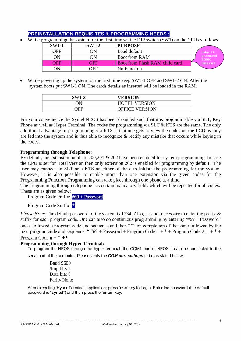
PREINSTALLATION REQUISITES & PROGRAMMING NEEDS :
While programming the system for the first time set the DIP switch (SW1) on the CPU as follows
SW1-1 SW1-2 PURPOSE
OFF ON Load default
ON ON Boot from RAM
OFF OFF Boot from Flash RAM child card
ON OFF No Function
While powering up the system for the first time keep SW1-1 OFF and SW1-2 ON. After the
system boots put SW1-1 ON. The cards details as inserted will be loaded in the RAM.
SW1-3 VERSION
ON HOTEL VERSION
OFF OFFICE VERSION
For your convenience the Syntel NEOS has been designed such that it is programmable via SLT, Key
Phone as well as Hyper Terminal. The codes for programming via SLT & KTS are the same. The only
additional advantage of programming via KTS is that one gets to view the codes on the LCD as they
are fed into the system and is thus able to recognize & rectify any mistake that occurs while keying in
the codes.
Programming through Telephone:
By default, the extension numbers 200,201 & 202 have been enabled for system programming. In case
the CPU is set for Hotel version then only extension 202 is enabled for programming by default. The
user may connect an SLT or a KTS on either of these to initiate the programming for the system.
However, it is also possible to enable more than one extension via the given codes for the
Programming Function. Programming can take place through one phone at a time.
The programming through telephone has certain mandatory fields which will be repeated for all codes.
These are as given below:
Program Code Prefix:: ##6699 ++ PPaasssswwoorrdd
Program Code Suffix: **
Please Note: The default password of the system is 1234. Also, it is not necessary to enter the prefix &
suffix for each program code. One can also do continuous programming by entering ‘#69 + Password”
once, followed a program code and sequence and then “*” on completion of the same followed by the
next program code and sequence. “ #69 + Password + Program Code 1 + * + Program Code 2….+ * +
Program Code n + * +* Programming through Hyper Terminal:
To program the NEOS through the hyper terminal, the COM1 port of NEOS has to be connected to the
serial port of the computer. Please verify the COM port settings to be as stated below :
Baud 9600
Stop bits 1
Data bits 8
Parity None
After executing ‘Hyper Terminal’ application; press ‘esc’ key to Login. Enter the password (the default password is “syntel”) and then press the ‘enter’ key.
Subject to
presence of
PGBK
flash card
------------------------------------------------------------------------------------------------------------------------------------------------------------------
PROGRAMMING MANUAL Wednesday ,January 01, 2014 9
There are basically three sets of commands, namely:
Display – Used to observe the set parameters for a particular feature
Set – Used to program/set the parameters for a particular extension/CO/system
Clear – Used to delete the parameters set for a particular feature
‘Display Help’ listes all the possible ‘Display Commands’. For getting the help for how to use he display
command, enter d <CMD> h
‘Set H’ listes all the available programmable commands which are possible through hyper terminal.
‘set <CMD> h’ displays the programmer the syntax of the specific ‘set’ command.
Similar for ‘Clear’ command as well.
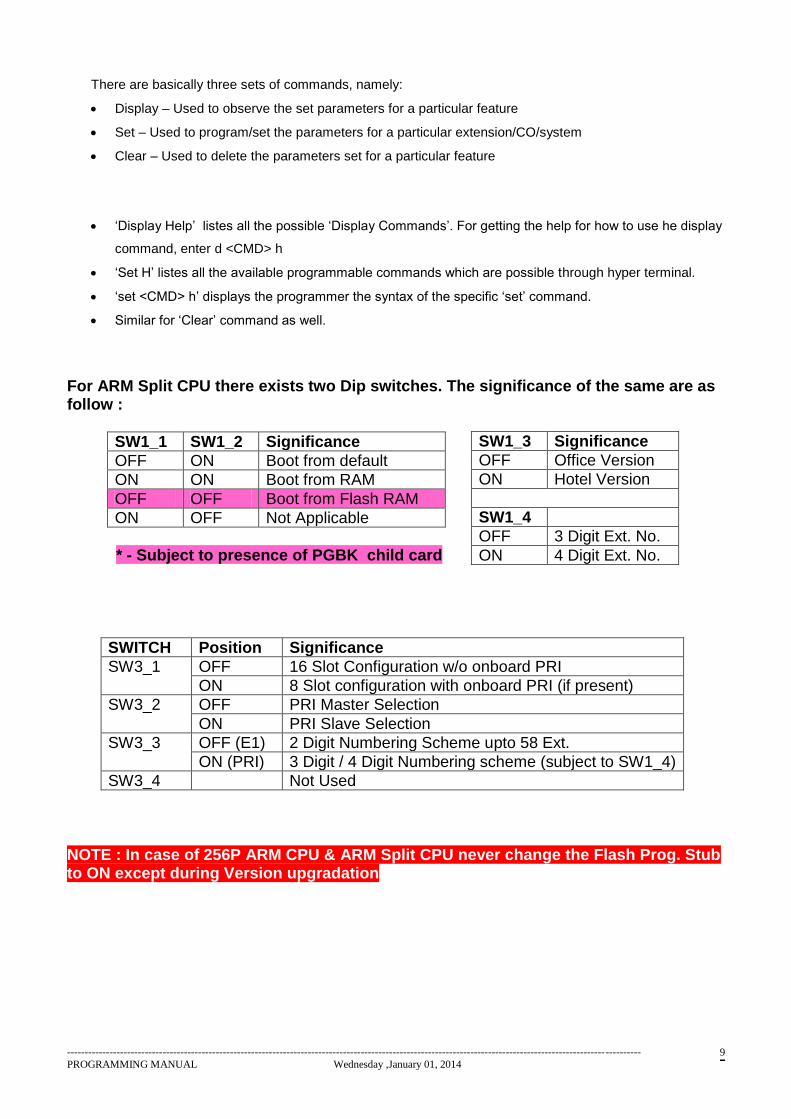
For ARM Split CPU there exists two Dip switches. The significance of the same are as follow :
SW1_1 SW1_2 Significance
OFF ON Boot from default
ON ON Boot from RAM
OFF OFF Boot from Flash RAM
ON OFF Not Applicable
* - Subject to presence of PGBK child card
SWITCH Position Significance
SW3_1 OFF 16 Slot Configuration w/o onboard PRI
ON 8 Slot configuration with onboard PRI (if present)
SW3_2 OFF PRI Master Selection
ON PRI Slave Selection
SW3_3 OFF (E1) 2 Digit Numbering Scheme upto 58 Ext.
ON (PRI) 3 Digit / 4 Digit Numbering scheme (subject to SW1_4)
SW3_4 Not Used
NOTE : In case of 256P ARM CPU & ARM Split CPU never change the Flash Prog. Stub to ON except during Version upgradation
SW1_3 Significance
OFF Office Version
ON Hotel Version
SW1_4
OFF 3 Digit Ext. No.
ON 4 Digit Ext. No.
------------------------------------------------------------------------------------------------------------------------------------------------------------------
PROGRAMMING MANUAL Wednesday ,January 01, 2014 10
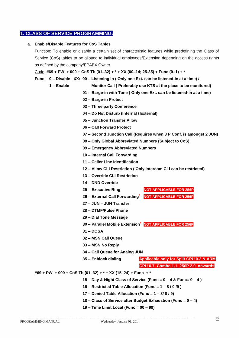
1. CLASS OF SERVICE PROGRAMMING:
a. Enable/Disable Features for CoS Tables
Function: To enable or disable a certain set of characteristic features while predefining the Class of
Service (CoS) tables to be allotted to individual employees/Extension depending on the access rights
as defined by the company/EPABX Owner.
Code: #69 + PW + 000 + CoS Tb (01–32) + * + XX (00–14; 25-35) + Func (0–1) + *
Func: 0 – Disable XX: 00 – Listening in ( Only one Ext. can be listened-in at a time) /
1 – Enable Monitor Call ( Preferably use KTS at the place to be monitored)
01 – Barge-in with Tone ( Only one Ext. can be listened-in at a time)
02 – Barge-in Protect
03 – Three party Conference
04 – Do Not Disturb (Internal / External)
05 – Junction Transfer Allow
06 – Call Forward Protect
07 – Second Junction Call (Requires when 3 P Conf. is amongst 2 JUN)
08 – Only Global Abbreviated Numbers (Subject to CoS)
09 – Emergency Abbreviated Numbers
10 – Internal Call Forwarding
11 – Caller Line Identification
12 – Allow CLI Restriction ( Only intercom CLI can be restricted)
13 – Override CLI Restriction
14 – DND Override
25 – Executive Ring NOT APPLICABLE FOR 256P
26 – External Call Forwarding# NOT APPLICABLE FOR 256P
27 – JUN – JUN Transfer
28 – DTMF/Pulse Phone
29 – Dial Tone Message
30 – Parallel Mobile Extension# NOT APPLICABLE FOR 256P
31 – DOSA
32 – MSN Call Queue
33 – MSN No Reply
34 – Call Queue for Analog JUN
35 – Enblock dialing Applicable only for Split CPU 0.3 & ARM
CPU 0.7, Combo 1.1, 256P 2.0 onwards
#69 + PW + 000 + CoS Tb (01–32) + * + XX (15–24) + Func + *
15 – Day & Night Class of Service (Func = 0 – 4 & Func= 0 – 4 )
16 – Restricted Table Allocation (Func = 1 – 8 / 0 /9 )
17 – Denied Table Allocation (Func = 1 – 8/ 0 / 9)
18 – Class of Service after Budget Exhaustion (Func = 0 – 4)
19 – Time Limit Local (Func = 00 – 99)
------------------------------------------------------------------------------------------------------------------------------------------------------------------
PROGRAMMING MANUAL Wednesday ,January 01, 2014 11
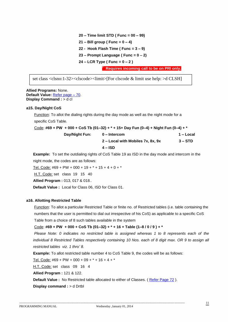
20 – Time limit STD ( Func = 00 – 99)
21 – Bill group ( Func = 0 – 4)
22 - Hook Flash Time ( Func = 3 – 9)
23 – Prompt Language ( Func = 0 – 2)
24 – LCR Type ( Func = 0 – 2 )
# -
Requires incoming call to be on PRI only.
Allied Programs: None. Default Value: Refer page – 70. Display Command : > d cl a15. Day/Night CoS
Function: To allot the dialing rights during the day mode as well as the night mode for a
specific CoS Table.
Code: #69 + PW + 000 + CoS Tb (01–32) + * + 15+ Day Fun (0–4) + Night Fun (0–4) + *
Day/Night Fun: 0 – Intercom 1 – Local
2 – Local with Mobiles 7x, 8x, 9x 3 – STD
4 – ISD
Example: To set the outdialing rights of CoS Table 19 as ISD in the day mode and intercom in the
night mode, the codes are as follows:
Tel. Code: #69 + PW + 000 + 19 + * + 15 + 4 + 0 + *
H.T. Code: set class 19 15 40
Allied Program : 013, 017 & 018..
Default Value : Local for Class 06, ISD for Class 01.
a16. Allotting Restricted Table
Function: To allot a particular Restricted Table or finite no. of Restricted tables (i.e. table containing the
numbers that the user is permitted to dial out irrespective of his CoS) as applicable to a specific CoS
Table from a choice of 8 such tables available in the system
Code: #69 + PW + 000 + CoS Tb (01–32) + * + 16 + Table (1–8 / 0 / 9 ) + *
Please Note: 0 indicates no restricted table is assigned whereas 1 to 8 represents each of the
individual 8 Restricted Tables respectively containing 10 Nos. each of 8 digit max. OR 9 to assign all
restricted tables viz. 1 thro’ 8.
Example: To allot restricted table number 4 to CoS Table 9, the codes will be as follows:
Tel. Code: #69 + PW + 000 + 09 + * + 16 + 4 + *
H.T. Code: set class 09 16 4
Allied Program : 121 & 122.
Default Value : No Restricted table allocated to either of Classes. ( Refer Page 72 ).
Display command : > d Drtbl
set class <clsno:1-32><clscode><limit>[For clscode & limit use help: >d CLSH]
------------------------------------------------------------------------------------------------------------------------------------------------------------------
PROGRAMMING MANUAL Wednesday ,January 01, 2014 12
a17. Allotting Denied Table:
Function: To allot a particular Denied Table or finite no. of denied tables (i.e. table containing the
numbers that the user is not permitted to dial out irrespective of his CoS) as applicable to a specific
CoS Table from a choice of 8 such tables available in the system
Code: #69 + PW + 000 + CoS Tb (01–32) + * + 17 + Table (1–8/ 0 / 9 ) + *
Please Note: 0 indicates no denied table is assigned whereas 1 to 8 represents each of the individual
8 Denied Tables respectively containing 10 Nos. each of 8 digits max. OR 9 to assign all denied table
viz. 1 thro’ 8.
Allied Program : 123 & 124.
Default Value : No Denied table allocated to either of Classes. ( Refer Page 73 )
Display command : > d Drtbl
NOTE: It is not recommended to allocate vacant Restricted/Denied Table to Class unnecessarily.
a18. Allotting CoS after Budget Exhaustion
Function: To define the applicable CoS in terms of outdialing rights for each CoS Table in event of the
defined user budget being exhausted
Code: #69 + PW + 000 + CoS Tb (01–32) + * + 18 + Func (0–4) + *
Func: 0 – Intercom 1 – Local
2 – Local with Mobiles ( 7x, 8x, 9x). 3 – STD
4 – ISD
Example: To set the outdialing rights to only local calls – after budget exhaustion – for CoS Table 30,
the codes are as follows:
Tel. Code: #69 + PW + 000 + 30 + * + 18 + 1
H.T. Code: set class 30 18 1
Allied Programs : 088
Default Value : 0 i.e. Intercom for all the classes.
Display Command : d cl
A19. Allotting Time Limit for Local Calls
Function: To define the Time Limit applicable for each CoS Table for all outgoing local calls
made by the users, wherein after the set time lapses the call is automatically cutoff
Code: #69 + PW + 000 + CoS Tb (01–32) + * + 19 + XX + *
XX: 00 – No Time Limit
01 – Cutoff in 1 minute
02 – Cutoff in 2 minutes
:: :::::::::::::::::::::::::::
99 – Cutoff in 99 minutes
------------------------------------------------------------------------------------------------------------------------------------------------------------------
PROGRAMMING MANUAL Wednesday ,January 01, 2014 13
Example: To set the STD time limit for CoS Table 3 as 5 minutes, the codes are as follows.
Tel. Code: #69 + PW + 000 + 03 + * + 20 + 05 + *
H.T. Code: set class 03 20 05
Please note that no warning tone is fed before call disconnection.
Only Local Landline calls are covered under this category.
Allied Program : None
Default Value : No Local Time Limit for either of Classes.
a20. Allotting Time Limit for STD Calls
Function: To define the Time Limit applicable for each CoS Table for all outgoing STD/ISD/95 calls
made by the users, wherein after the set time lapses the call is automatically cutoff
Code: #69 + PW + 000 + CoS Tb (01–32) + * + 20 + XX + *
XX: 00 – No Time Limit
01 – Cutoff in 1 minute
02 – Cutoff in 2 minutes
:: :::::::::::::::::::::::::
99 – Cutoff in 99 minutes
Local Mobile calls alongwith STD landline & STD mobile are covered under this category.
Allied Program : None
Default Value : No STD Time Limit for either of Classes.
a21. Allotting Bill Group
Function : To define different billing category for each CoS Table for all Outgoing Calls
Code : #69 + PW + 000 + CoS Tb (01–32) + * + 21 + X + *
X : Bill Group No. – 0-4
Example: To set the Charge Type 3 for CoS Table 25, the codes are as follows:
Tel. Code: #69 + PW + 000 + 25 + * + 21 + 3 + *
H.T. Code: set class 25 21 3
Please note that this is possible for Office Version as well as for Hotel Version.
Allied Program : 151.
Default Value : 0 for all Classes.
a22. Setting Hook Flash Time
Function : To define hook flash time for Extensions.
Code : # 69 + PW + 000 + CoS Tb (01–32) + * + 22 + Ext. Hook-flash digit + *
Ext. Hook-flash Digit : Digit (3-9) * 100 millisec.
Eg. 3 = 300 ms., 6 = 600 ms., 9 = 900 msec. Etc.
------------------------------------------------------------------------------------------------------------------------------------------------------------------
PROGRAMMING MANUAL Wednesday ,January 01, 2014 14
Example: To set the hook flash timing to 400 mille secs for CoS Table 12, the codes are as follows:
Tel. Code: #69 + PW + 000 + 12 + * + 22 + 4 + *
H.T. Code: set class 12 22 4
Allied Program : None
Default Value : 700 mSec. for all Classes.
a23. Setting Prompt Language
Function : To set language ( English/Hindi) for user voice-prompts
Code : # 69 + PW + 000 + CoS Tb (01–32) + * + 23 + Digit (0 – 2) + *
Digit : 0 – English 1 – Hindi 2 – No Prompts.
Example: To set the language for internal voice prompts as Hindi for CoS Table 5, the codes are as
follows:
Tel. Code: #69 + PW + 000 + 05 + * + 23 + 1 + *
H.T. Code: set class 05 23 1
Allied Program : None
Default Value : 0 i.e. English for all Classes.
a24. Setting LCR Type
Function : To set LCR type for extension.
Code : # 69 + PW + 000 + CoS Tb (01–32) + * + 24 + Digit + *
Digit : 0 = No LCR; 1 = LCR with Override 2 = Only LCR
Example: To set no LCR (type 0) for CoS Table 1, the codes are as follows:
Tel. Code: #69 + PW + 000 + 01 + * + 24 + 0 + *
H.T. Code: set class 01 24 0
Allied Program : 072, 157.
Default Value : 0, i.e. No LCR for all Classes.
a25. Setting Executive Ring NOT APPLICABLE FOR 256P and ARM 256 CPU
Function : To set Executive Ring for extension.
Code : # 69 + PW + 000 + CoS Tb (01–32) + * + 25 + Digit + *
Digit : 0 = Normal Ring; 1 = Executive Ring
Allied Program : None
Default Value : 0, i.e. Normal ring for all Classes.
------------------------------------------------------------------------------------------------------------------------------------------------------------------
PROGRAMMING MANUAL Wednesday ,January 01, 2014 15
a26. Setting External Call Forward NOT APPLICABLE FOR 256P
Function : To enable External Call forwarding feature for extension. For external calls to get
forwarded it is mandatory that I/C call has to be on PRI Line. It is not recommended to use analog
JUN for this feature.
Code : # 69 + PW + 000 + CoS Tb (01–32) + * + 26 + Digit + *
Digit : 0 = Disable; 1 = Enable
Allied Program : 000 – 27. User Features #510 & #511.
Default Value : 0.
a27. Setting JUN-JUN Transfer Rights
Function : To set unsupervised conference rights or JUN – JUN transfer rights for extension.
Code : # 69 + PW + 000 + CoS Tb (01–32) + * + 27 + Digit + *
Digit : 0 = Diable; 1 = Enable
Allied Program : None
Default Value : 0.
a28. Setting DTMF/Pulse Dialing for Extension
Function : To set dialing type for extension.
Code : # 69 + PW + 000 + CoS Tb (01–32) + * + 28 + Digit + *
Digit : 0 = Tone; 1 = Pulse
Allied Program : None
Default Value : 0, i.e. Tone Instruments for all Classes.
a29. Setting Dial Tone Message for Extension
Function : To set dial tone message for extension.
Code : # 69 + PW + 000 + CoS Tb (01–32) + * + 29 + Digit + * Digit : 0 = Off; 1 = On
Allied Program : None
Default Value : 0.
a30. Setting Mobile Parallel Ring for Extension NOT APPLICABLE FOR 256P
Function : To set Mobile Parallel ring for extension. This feature would redirect intercom calls as well to
predefined No. set. For external calls to be forwarded it is mandatory that I/C call has to be on PRI Line.
Code : # 69 + PW + 000 + CoS Tb (01–32) + * + 30 + Digit + *
Digit : 0 = Disable; 1 = Enable
Allied Program : 000-26, 000-27. Feature Code #511 & #512.
Default Value : 0.
------------------------------------------------------------------------------------------------------------------------------------------------------------------
PROGRAMMING MANUAL Wednesday ,January 01, 2014 16
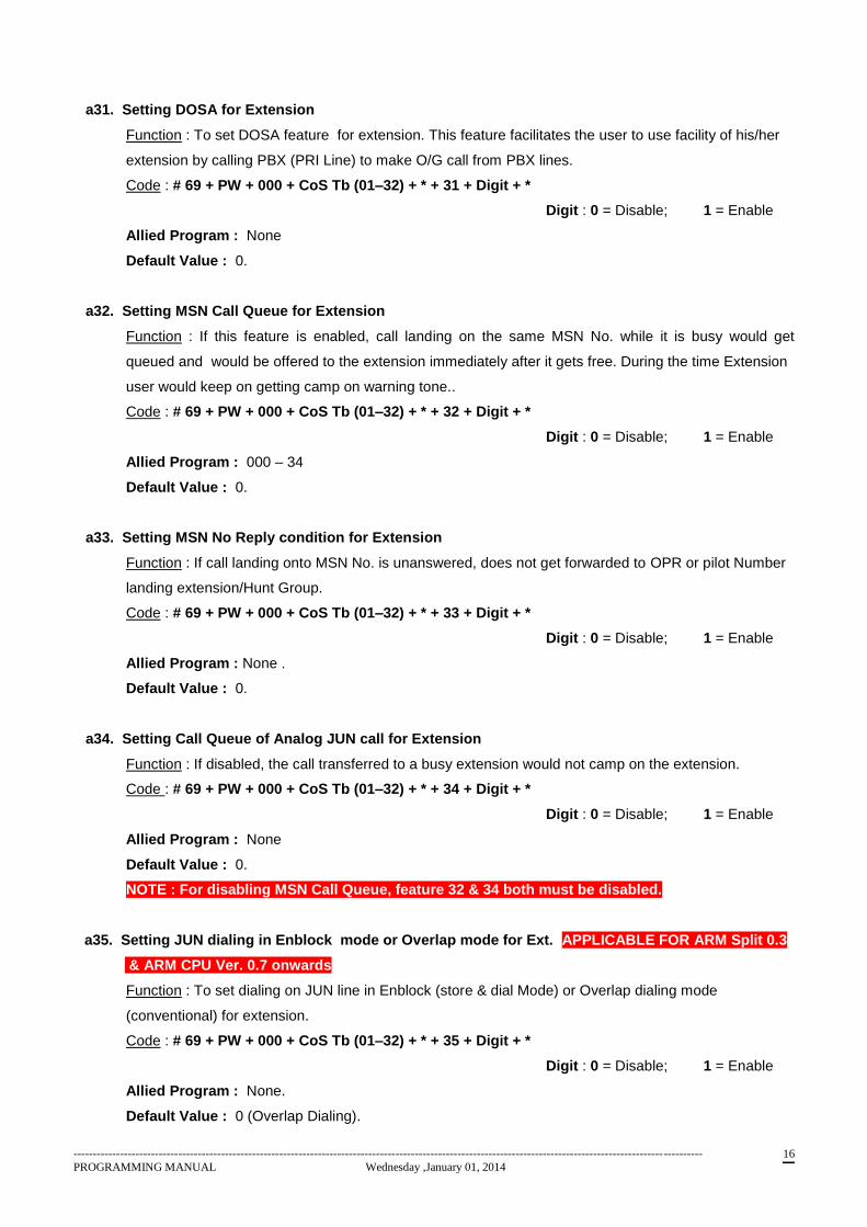
a31. Setting DOSA for Extension
Function : To set DOSA feature for extension. This feature facilitates the user to use facility of his/her
extension by calling PBX (PRI Line) to make O/G call from PBX lines.
Code : # 69 + PW + 000 + CoS Tb (01–32) + * + 31 + Digit + *
Digit : 0 = Disable; 1 = Enable
Allied Program : None
Default Value : 0.
a32. Setting MSN Call Queue for Extension
Function : If this feature is enabled, call landing on the same MSN No. while it is busy would get
queued and would be offered to the extension immediately after it gets free. During the time Extension
user would keep on getting camp on warning tone..
Code : # 69 + PW + 000 + CoS Tb (01–32) + * + 32 + Digit + *
Digit : 0 = Disable; 1 = Enable
Allied Program : 000 – 34
Default Value : 0.
a33. Setting MSN No Reply condition for Extension
Function : If call landing onto MSN No. is unanswered, does not get forwarded to OPR or pilot Number
landing extension/Hunt Group.
Code : # 69 + PW + 000 + CoS Tb (01–32) + * + 33 + Digit + *
Digit : 0 = Disable; 1 = Enable
Allied Program : None .
Default Value : 0.
a34. Setting Call Queue of Analog JUN call for Extension
Function : If disabled, the call transferred to a busy extension would not camp on the extension.
Code : # 69 + PW + 000 + CoS Tb (01–32) + * + 34 + Digit + *
Digit : 0 = Disable; 1 = Enable
Allied Program : None
Default Value : 0.
NOTE : For disabling MSN Call Queue, feature 32 & 34 both must be disabled.
a35. Setting JUN dialing in Enblock mode or Overlap mode for Ext. APPLICABLE FOR ARM Split 0.3
& ARM CPU Ver. 0.7 onwards
Function : To set dialing on JUN line in Enblock (store & dial Mode) or Overlap dialing mode
(conventional) for extension.
Code : # 69 + PW + 000 + CoS Tb (01–32) + * + 35 + Digit + *
Digit : 0 = Disable; 1 = Enable
Allied Program : None.
Default Value : 0 (Overlap Dialing).
------------------------------------------------------------------------------------------------------------------------------------------------------------------
PROGRAMMING MANUAL Wednesday ,January 01, 2014 17
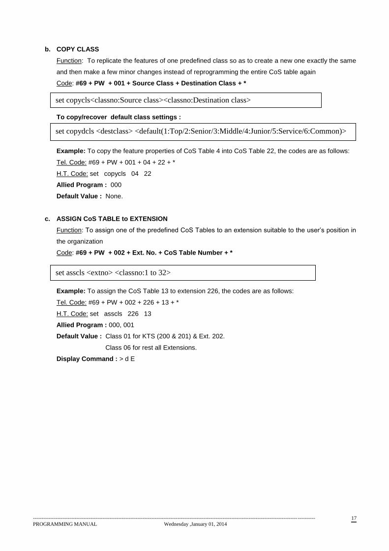
b. COPY CLASS
Function: To replicate the features of one predefined class so as to create a new one exactly the same
and then make a few minor changes instead of reprogramming the entire CoS table again
Code: #69 + PW + 001 + Source Class + Destination Class + *
To copy/recover default class settings :
Example: To copy the feature properties of CoS Table 4 into CoS Table 22, the codes are as follows:
Tel. Code: #69 + PW + 001 + 04 + 22 + *
H.T. Code: set copycls 04 22
Allied Program : 000
Default Value : None.
c. ASSIGN CoS TABLE to EXTENSION
Function: To assign one of the predefined CoS Tables to an extension suitable to the user’s position in
the organization
Code: #69 + PW + 002 + Ext. No. + CoS Table Number + *
Example: To assign the CoS Table 13 to extension 226, the codes are as follows:
Tel. Code: #69 + PW + 002 + 226 + 13 + *
H.T. Code: set asscls 226 13
Allied Program : 000, 001
Default Value : Class 01 for KTS (200 & 201) & Ext. 202.
Class 06 for rest all Extensions.
Display Command : > d E
set copycls<classno:Source class><classno:Destination class>
set asscls <extno> <classno:1 to 32>
set copydcls <destclass> <default(1:Top/2:Senior/3:Middle/4:Junior/5:Service/6:Common)>
------------------------------------------------------------------------------------------------------------------------------------------------------------------
PROGRAMMING MANUAL Wednesday ,January 01, 2014 18
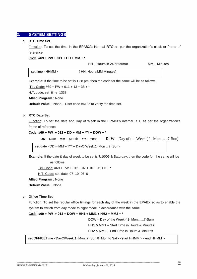
2. SYSTEM SETTINGS
a. RTC Time Set
Function: To set the time in the EPABX’s internal RTC as per the organization’s clock or frame of
reference
Code: #69 + PW + 011 + HH + MM + *
HH – Hours in 24 hr format MM – Minutes
Example: If the time to be set is 1.38 pm, then the code for the same will be as follows.
Tel. Code: #69 + PW + 011 + 13 + 38 + *
H.T. code: set time 1338
Allied Program : None
Default Value : None. User code #6135 to verify the time set.
b. RTC Date Set
Function: To set the date and Day of Week in the EPABX’s internal RTC as per the organization’s
frame of reference
Code: #69 + PW + 012 + DD + MM + YY + DOW + *
DD – Date MM – Month YY – Year DoW – Day of the Week ( 1- Mon.,….7-Sun)
Example: If the date & day of week to be set is 7/10/06 & Saturday, then the code for the same will be
as follows.
Tel. Code: #69 + PW + 012 + 07 + 10 + 06 + 6 + *
H.T. Code: set date 07 10 06 6
Allied Program : None
Default Value : None
c. Office Time Set
Function: To set the regular office timings for each day of the week in the EPABX so as to enable the
system to switch from day mode to night mode in accordance with the same
Code: #69 + PW + 013 + DOW + HH1 + MM1 + HH2 + MM2 + *
DOW – Day of the Week ( 1- Mon.,….7-Sun)
HH1 & MM1 – Start Time in Hours & Minutes
HH2 & MM2 – End Time in Hours & Minutes
set time <HHMM> ( HH: Hours,MM:Minutes)
set date <DD><MM><YY><DayOfWeek:1=Mon .. 7=Sun>
set OFFICETime <DayOfWeek:1=Mon..7=Sun 8=Mon to Sat> <start HHMM > <end HHMM >
------------------------------------------------------------------------------------------------------------------------------------------------------------------
PROGRAMMING MANUAL Wednesday ,January 01, 2014 19
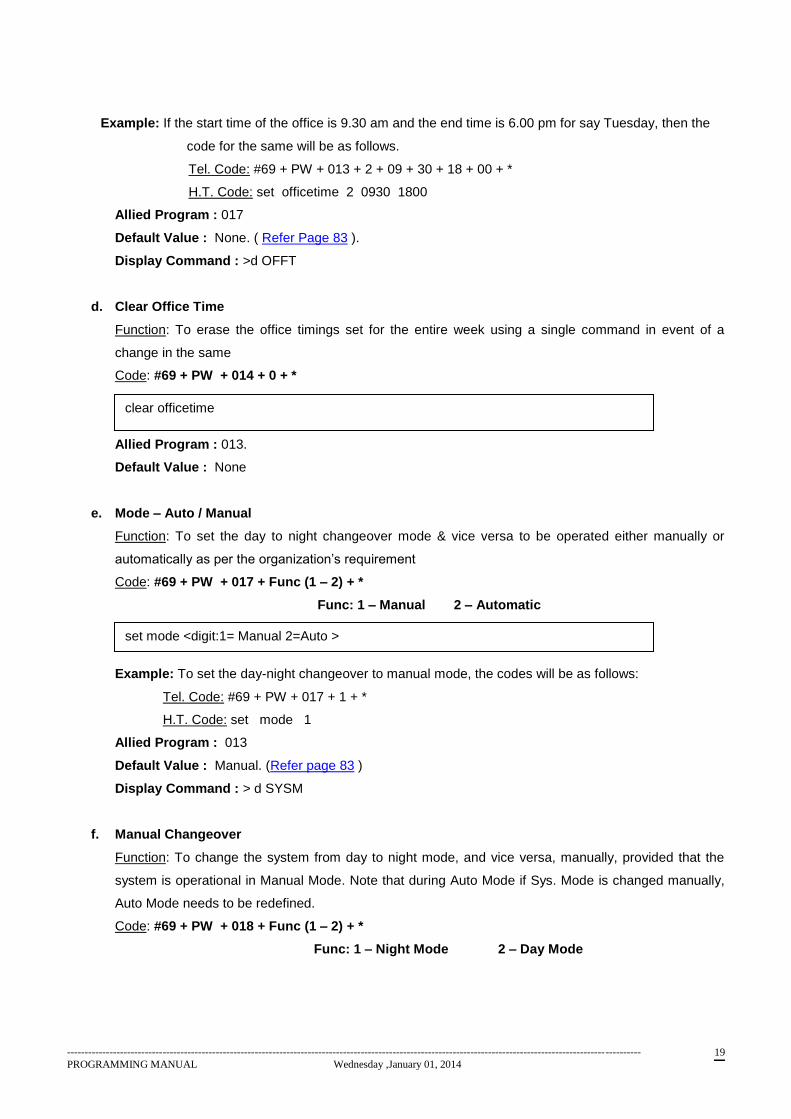
Example: If the start time of the office is 9.30 am and the end time is 6.00 pm for say Tuesday, then the
code for the same will be as follows.
Tel. Code: #69 + PW + 013 + 2 + 09 + 30 + 18 + 00 + *
H.T. Code: set officetime 2 0930 1800
Allied Program : 017
Default Value : None. ( Refer Page 83 ).
Display Command : >d OFFT
d. Clear Office Time
Function: To erase the office timings set for the entire week using a single command in event of a
change in the same
Code: #69 + PW + 014 + 0 + *
Allied Program : 013.
Default Value : None
e. Mode – Auto / Manual
Function: To set the day to night changeover mode & vice versa to be operated either manually or
automatically as per the organization’s requirement
Code: #69 + PW + 017 + Func (1 – 2) + *
Func: 1 – Manual 2 – Automatic
Example: To set the day-night changeover to manual mode, the codes will be as follows:
Tel. Code: #69 + PW + 017 + 1 + *
H.T. Code: set mode 1
Allied Program : 013
Default Value : Manual. (Refer page 83 )
Display Command : > d SYSM
f. Manual Changeover
Function: To change the system from day to night mode, and vice versa, manually, provided that the
system is operational in Manual Mode. Note that during Auto Mode if Sys. Mode is changed manually,
Auto Mode needs to be redefined.
Code: #69 + PW + 018 + Func (1 – 2) + *
Func: 1 – Night Mode 2 – Day Mode
clear officetime
set mode <digit:1= Manual 2=Auto >
------------------------------------------------------------------------------------------------------------------------------------------------------------------
PROGRAMMING MANUAL Wednesday ,January 01, 2014 20
Example: To change the system from night to day mode, the codes will be as follows:
Tel. Code: #69 + PW + 018 + 2 + *
H.T. Code: set daynight 2
Allied Program : 013, 017.
Default Value : Day Mode. (Refer page 83 )
Display Command : > d SYSM
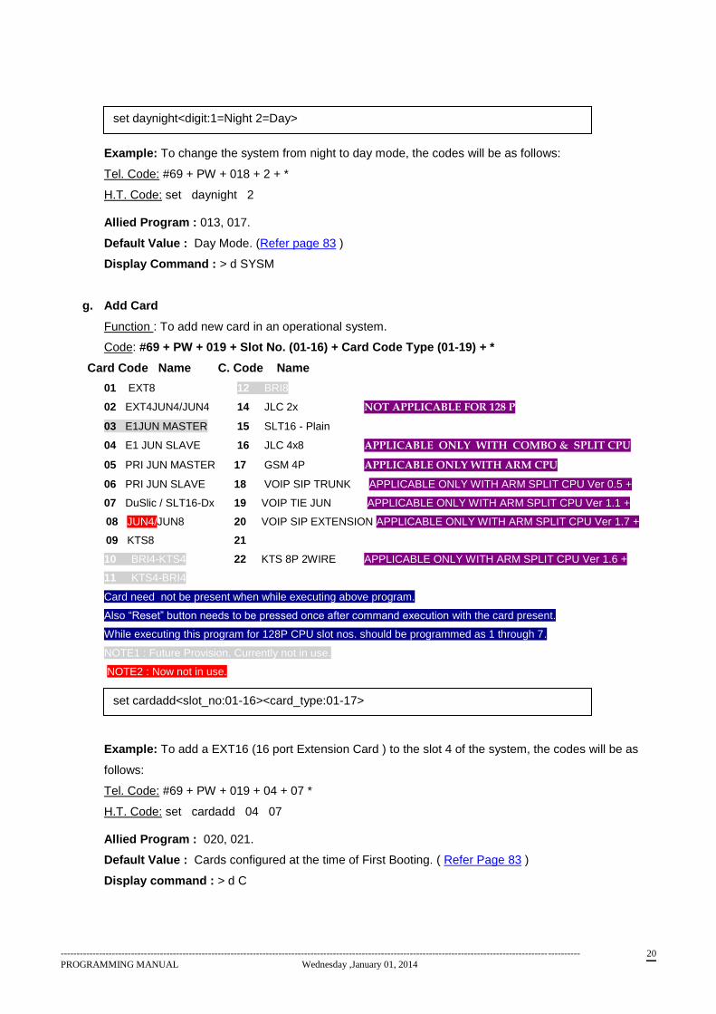
g. Add Card
Function : To add new card in an operational system.
Code: #69 + PW + 019 + Slot No. (01-16) + Card Code Type (01-19) + *
Card Code Name C. Code Name
01 EXT8 12 BRI8
02 EXT4JUN4/JUN4 14 JLC 2x NOT APPLICABLE FOR 128 P
03 E1JUN MASTER 15 SLT16 - Plain
04 E1 JUN SLAVE 16 JLC 4x8 APPLICABLE ONLY WITH COMBO & SPLIT CPU
05 PRI JUN MASTER 17 GSM 4P APPLICABLE ONLY WITH ARM CPU
06 PRI JUN SLAVE 18 VOIP SIP TRUNK APPLICABLE ONLY WITH ARM SPLIT CPU Ver 0.5 +
07 DuSlic / SLT16-Dx 19 VOIP TIE JUN APPLICABLE ONLY WITH ARM SPLIT CPU Ver 1.1 +
08 JUN4/JUN8 20 VOIP SIP EXTENSION APPLICABLE ONLY WITH ARM SPLIT CPU Ver 1.7 +
09 KTS8 21
10 BRI4-KTS4 22 KTS 8P 2WIRE APPLICABLE ONLY WITH ARM SPLIT CPU Ver 1.6 +
11 KTS4-BRI4
Card need not be present when while executing above program.
Also “Reset” button needs to be pressed once after command execution with the card present.
While executing this program for 128P CPU slot nos. should be programmed as 1 through 7.
NOTE1 : Future Provision. Currently not in use.
NOTE2 : Now not in use.
Example: To add a EXT16 (16 port Extension Card ) to the slot 4 of the system, the codes will be as
follows:
Tel. Code: #69 + PW + 019 + 04 + 07 *
H.T. Code: set cardadd 04 07
Allied Program : 020, 021.
Default Value : Cards configured at the time of First Booting. ( Refer Page 83 )
Display command : > d C
set cardadd<slot_no:01-16><card_type:01-17>
set daynight<digit:1=Night 2=Day>
------------------------------------------------------------------------------------------------------------------------------------------------------------------
PROGRAMMING MANUAL Wednesday ,January 01, 2014 21
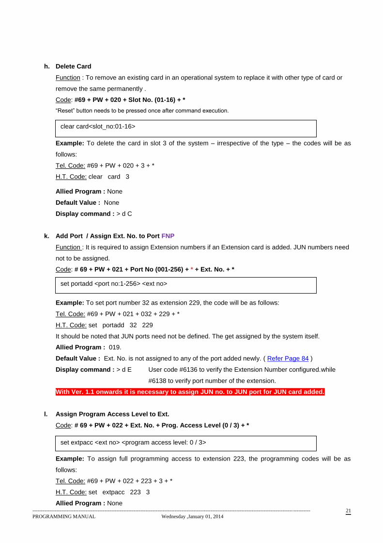
h. Delete Card
Function : To remove an existing card in an operational system to replace it with other type of card or
remove the same permanently .
Code: #69 + PW + 020 + Slot No. (01-16) + *
“Reset” button needs to be pressed once after command execution.
Example: To delete the card in slot 3 of the system – irrespective of the type – the codes will be as
follows:
Tel. Code: #69 + PW + 020 + 3 + *
H.T. Code: clear card 3
Allied Program : None
Default Value : None
Display command : > d C
k. Add Port / Assign Ext. No. to Port FNP
Function : It is required to assign Extension numbers if an Extension card is added. JUN numbers need
not to be assigned.
Code: # 69 + PW + 021 + Port No (001-256) + * + Ext. No. + *
Example: To set port number 32 as extension 229, the code will be as follows:
Tel. Code: #69 + PW + 021 + 032 + 229 + *
H.T. Code: set portadd 32 229
It should be noted that JUN ports need not be defined. The get assigned by the system itself.
Allied Program : 019.
Default Value : Ext. No. is not assigned to any of the port added newly. ( Refer Page 84 )
Display command : > d E User code #6136 to verify the Extension Number configured.while
#6138 to verify port number of the extension.
With Ver. 1.1 onwards it is necessary to assign JUN no. to JUN port for JUN card added.
l. Assign Program Access Level to Ext.
Code: # 69 + PW + 022 + Ext. No. + Prog. Access Level (0 / 3) + *
Example: To assign full programming access to extension 223, the programming codes will be as
follows:
Tel. Code: #69 + PW + 022 + 223 + 3 + *
H.T. Code: set extpacc 223 3
Allied Program : None
clear card<slot_no:01-16>
set portadd <port no:1-256> <ext no>
set extpacc <ext no> <program access level: 0 / 3>
------------------------------------------------------------------------------------------------------------------------------------------------------------------
PROGRAMMING MANUAL Wednesday ,January 01, 2014 22
Default Value : Ext. 200, 201 & 202 are set for Full Programming Access. Rest all are denied for
programming. However at a time, only one Extension can originate programming. In case of Hotel
Version, initially it’s possible to program only from Ext. 202. If room to room barring for Ext. 200 & 201 is
deactivated, programming can be availed from the said ext. as well.
Display command : > d E
------------------------------------------------------------------------------------------------------------------------------------------------------------------
PROGRAMMING MANUAL Wednesday ,January 01, 2014 23
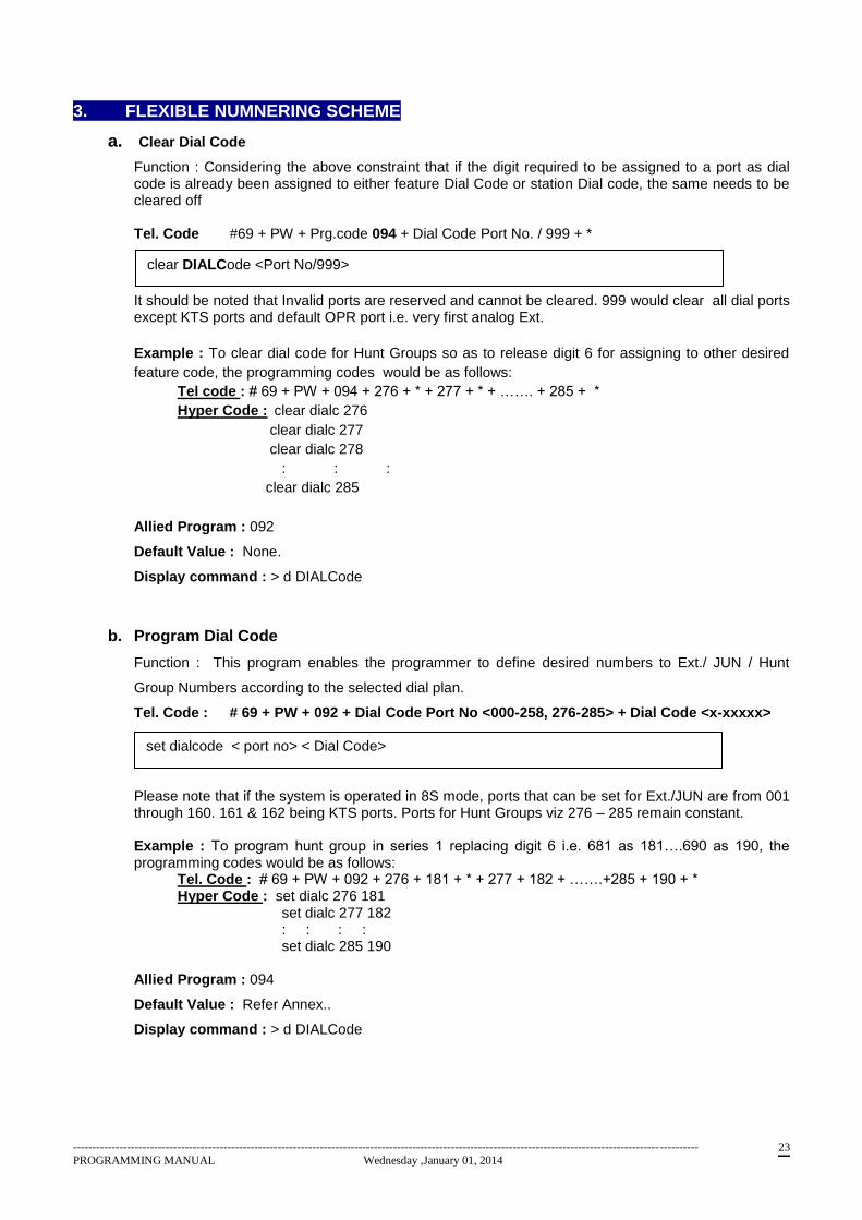
3. FLEXIBLE NUMNERING SCHEME
a. Clear Dial Code
Function : Considering the above constraint that if the digit required to be assigned to a port as dial code is already been assigned to either feature Dial Code or station Dial code, the same needs to be cleared off Tel. Code #69 + PW + Prg.code 094 + Dial Code Port No. / 999 + *
b. It should be noted that Invalid ports are reserved and cannot be cleared. 999 would clear all dial ports except KTS ports and default OPR port i.e. very first analog Ext.
Example : To clear dial code for Hunt Groups so as to release digit 6 for assigning to other desired
feature code, the programming codes would be as follows:
Tel code : # 69 + PW + 094 + 276 + * + 277 + * + ……. + 285 + *
Hyper Code : clear dialc 276
clear dialc 277
clear dialc 278
: : :
clear dialc 285
Allied Program : 092
Default Value : None.
Display command : > d DIALCode
b. Program Dial Code
Function : This program enables the programmer to define desired numbers to Ext./ JUN / Hunt
Group Numbers according to the selected dial plan.
Tel. Code : # 69 + PW + 092 + Dial Code Port No <000-258, 276-285> + Dial Code <x-xxxxx> Please note that if the system is operated in 8S mode, ports that can be set for Ext./JUN are from 001 through 160. 161 & 162 being KTS ports. Ports for Hunt Groups viz 276 – 285 remain constant. Example : To program hunt group in series 1 replacing digit 6 i.e. 681 as 181….690 as 190, the programming codes would be as follows: Tel. Code : # 69 + PW + 092 + 276 + 181 + * + 277 + 182 + …….+285 + 190 + * Hyper Code : set dialc 276 181 set dialc 277 182 : : : : set dialc 285 190 Allied Program : 094
Default Value : Refer Annex..
Display command : > d DIALCode
clear DIALCode <Port No/999>
set dialcode < port no> < Dial Code>
------------------------------------------------------------------------------------------------------------------------------------------------------------------
PROGRAMMING MANUAL Wednesday ,January 01, 2014 24
c. Restore Default Dial Code
Function : This program enables the programmer to recover the default settings of Dial Code which have been enabled at the time of first booting.
Tel. Code #69 +PW + 096 + 1234 + *
d. Clear Feature Code
Function : Considering the rules for redefining the feature code it might need to clear the already existing feature codes if conflicting with the desired ones, it needs to clear such ports first. Program for doing the same is as follow : Tel. Code : #69 + PW + Prg.code 095 + Feature Code Port No./999 + *
Note that Feature code at port No. 003 and 056 i.e. System Programming & Redial cannot be altered. 999 used to clear the all feature codes in one go, but would not reset port No. 003 & 056. Example : To clear STD JUN access code ‘8’ so as to make digit ‘8’ available for defing as other feature code or for extension numbering scheme, the programming code would be as follows : Tel. Code : # 69 + PW + 095 + 055 + * Hyper Code : clear featc 055
Allied Program : 094
Default Value : Enabled.
Display command : > d FEATCode
e. Program Feature Code
Function : It is possible to redefine the various features codes applicable at during the DIAL Phase. Program for doing so is as follows :
f. Tel. Code :. #69+1234 + 093 + Feature Code port no.(xxx) + Dial code<x-xxxxx>+ *
Example : To set STD JUN access code as 5, the programming code would be as follows :
Tel. code : # 69 + PW + 093 + 055 + 5 + *
Hyper code : set featc 055 5
Allied Program : 095
Default Value : Refer Annex..
Display command : > d FEATCode
set dialdef <1234>
clear FEATCode < Feature Port No /999>
set featcode <feature port no> <Dial code>
------------------------------------------------------------------------------------------------------------------------------------------------------------------
PROGRAMMING MANUAL Wednesday ,January 01, 2014 25
g. Recover Default Feature Code
Function : This program enables the programmer to recover the default settings of Dial Code which have been enabled at the time of first booting.
Tel. Code #69 +PW + 097 + 1234 + *
set featdef <1234>
------------------------------------------------------------------------------------------------------------------------------------------------------------------
PROGRAMMING MANUAL Wednesday ,January 01, 2014 26
4. Extension Programming
a. Enable/Disable Extension
Function: To activate/deactivate a particular extension port for regular functioning
Code: #69+ PW + 031+ Ext. No. + Func (0 – 1) + *
Func: 0 – Disable 1 – Enable
Example: To enable extension 229 for day to day use, the codes will be as follows:
Tel. Code: #69 + PW + 031 + 229 + 1 + *
H.T. Code: set enext 229 1
Allied Program : None
Default Value : Enabled.
Display command : > d E
b. Set Operator Number
Function: To define a particular extension as the Operator. It is recommended that an Ext. which is
member of a Hunt Group that has been defined as Landing Ext. should not be defined as Operator.
Code: #69 + PW + 032 + <Ext. No./ Hunt Group> + * ( 999 to cancel)
Example: To define extension number 249 as the Operator Extension, the codes will be as follows:
Tel. Code: #69 + PW + 032 + 249 + *
H.T. Code: set oprext 249
To remove Operator from the system use 999 as ‘Ext. No.’
Allied Program : 064, 058.
Default Value : Ext. 202 is default OPR.
Display command : > d SYSM
Note : A Hunt Group if defined as Operator, does not get camp-on if all extensions within the Hunt
Group are busy. However can be enabled for using Program 058. If KTS is one of the member, KTS
can not avail OPERATOR FEATURES on KTS.
c. Flexible Number Programming - FNP
Function: To customize the extension numbering scheme as per the user’s requirement
Code: #69 + PW + 033 + Old Ext. No. + * + New Ext. No. + *
New No. can be in the range 000-999., however it is recommended not to use 000-050 being
reserved for JUN access codes. Further in ‘9’ series, Ext. No. 900, 910 & 999 will not be allowed.
set enext <ext no> <digit:1=Enable 0=Disable>
set oprext <ext no/Hunt Group(681-690)>
set flex<extno_old><extno_new>
------------------------------------------------------------------------------------------------------------------------------------------------------------------
PROGRAMMING MANUAL Wednesday ,January 01, 2014 27
Example: To redefine extension number 236 as 680, the codes will be as follows:
Tel. Code: #69 + PW + 033 + 236 + * + 680 + *
H.T. Code: set flex 236 680
Allied Program : 047.
Default Value : 200 onwards up to no. of Ext. configured.
Display command : > d C User code #6136 to verify the Extension Number configured.
d. Fax Extension
Function: To define the extension/s as fax extension/s (max. 4) to enable the functioning of Auto Fax
Detection. It is necessary to define landing of the JUN as Auto Attendant.
Code: #69 + PW + 035 +Ext.No.1+ * +Ext.No.2+ * +Ext.No.3+ * +Ext.No.4+ * ( 999 to cancel)
Example: To set extension numbers 226, 239, 252, 291 as the four fax extensions, the codes will be as
follows:
Tel. Code: #69 + PW + 035 + 226 + * + 239 + * + 252 + * + 291 + *
H.T. Code: set faxext 226 239 252 291
Allied Program : 065 / 116.
Default Value : None
Display command : > d SYSM
e. Reset Extension Password
Function : To reset user password of an extension and set it as ‘1234’. It should be noted that
Password for Ext. assigned/programmed after card addition needs to be resetted mandatorily.
Code: #69 + PW + 036 + Ext. No. + *
Example: To reset the Password for Extension 241, the codes will be as follows:
Tel. Code: #69 + PW + 036 + 241 + *
H.T. Code: set resetexpw 241
Allied Program : None
Default Value : 1234 only for the entensions enabled at first Booting..
Display Command : None
f. Add Extension to Pickup Group
Function: To add a particular extension to a pickup group wherein that extension is thus enabled to
pickup (answer) any other extension ringing within that group. By default no pickup group exists.
Hence call pick-up feature would not function unless Pick-up groups are programmed.
It is suggested / recommended to enter KTS Ext. & Ext. 202 (default) at the end of the Pickup
group if part of the Pickup group.
Code: #69 + PW + 037 + Ext. No. 1 + * + Ext. No. 2 + * +……….
set faxext<extno><extno><extno><extno> (999 to clear all fax ext)
set resetexpw <extno>
------------------------------------------------------------------------------------------------------------------------------------------------------------------
PROGRAMMING MANUAL Wednesday ,January 01, 2014 28
Example: To create a group of extension 223, 249, 262 & 251, the codes will be as follows:
Tel. Code: #69 + PW + 037 + 223 + * + 249 + * + 262 + * + 251+ *
H.T.Code: set pickgrp 223 249
set pickgrp 223 262
set pickgrp 223 251
Allied Program : 038, 039
Default Value : No Pickup group exist.
Display command : > d PICK
g. Delete Extension from Pickup Group
Function: To delete a particular extension from an existing Pickup Group so that it is barred from
answering calls landing at any extension within that group using global call pickup feature.
Code: #69 + PW + 038 + Ext. No. + *
Example: With reference to the earlier example, to remove extension 262 from the Pickup Group
defined earlier, the codes will be as follows:
Tel. Code: #69 + PW + 038 + 262 + *
H.T. Code: clear pickext 262
Allied Program : 037
Default Value : None.
h. Delete Pickup Group
Function: To erase the existence of a Pickup Group altogether in event of restructuring or
reorganization within the company
Code: #69 + PW + 039 + Ext. No. + *
Please Note: Here any extension number from the said group can be entered which would release all
the Ext. contained with specified pickup group.
Example: With reference to the earlier example, to delete that particular group, the codes will be as
follows:
Tel. Code: #69 + PW + 039 + 249 + *
H.T. Code: clear pickgrp 249
Here, instead of 249, one can specify 223, 262 or 251 also.
Allied Program : 037, 038
Default Value : None
set PICKgrp<head ext><member ext>
clear pickext<extno>
clear pickgrp<extno>
------------------------------------------------------------------------------------------------------------------------------------------------------------------
PROGRAMMING MANUAL Wednesday ,January 01, 2014 29
i. Secretary Extension - FNP
Function: To define a particular extension as Secretary of another extension number, wherein the
former automatically gets the advantages assigned to a secretary. This is applicable only in case of
billing. i.e. Bill for the call originated by Secretary & then transferred to Boss would be charged to
Boss’s account (Ext.). Facilities for Boss’s Ext. does not get transferred to Secretary’s Ext. nor
calls for Boss’s Ext. get transferred automatically to Secretary’s Ext.
Code: #69 + PW + 154 + Boss Ext. No. + * + Secretary Ext. No. + *
Secretary ext no : valid Ext. Number as per numbering scheme (999 to cancel secretary ext )
Example: If the Boss’s extension number is 224 and his secretary’s is 229, then to set the latter as the
secretary extension, the codes are as follows:
Tel. Code: #69 + PW + 224 + * + 229 + *
H.T. Code: set secretary 224 229
Please note that one Extension can be assigned as secretary of multiple extensions.
Allied Program : 151, 152, 153.
Default Value : None. ( Refer Page 84)
Display command : > d E
j. Hotline Number Programming
Function: To define all the numbers to be stored in the system as Hotlines for ease in assignment to
any extension at any point of time
Code: #69 + PW + 040 + Hotline (01 – 16) + * + Number + *
Hotline 1 to 16 – Internal reference numbering for defined numbers
Number – The actual number (internal or external) to be defined as Hotline including Jun
Access Code. Selective Seizure code starting with #, in case of specific JUN line.
Example:
To set extension 229 as hotline to be referred to internally as 4
Tel. Code: #69 + PW + 040 + 04 + * + 229 + *
H.T. Code: set hotline 4 229
To set local P&T number 26876120 as hotline to be referred to internally as 9
Tel. Code: #69 + PW + 040 + 09 + * + 026876120 + *
H.T. Code: set hotline 9 026876120
To set an STD mobile number 9822500032 as hotline to be referred to internally as 2
Tel. Code: #69 + PW + 040 + 02 + * + 009822500032 + *
H.T. Code: set hotline 2 009822500032
To set an STD P&T number (say in Mumbai) 26876120 as hotline to be referred to internally as 10
Tel. Code: #69 + PW + 040 + 10 + * + 002226876120 + *
set secretary <boss extno> <secretary extno>
set hotline <hotlineno:1-16> <digits>

------------------------------------------------------------------------------------------------------------------------------------------------------------------
PROGRAMMING MANUAL Wednesday ,January 01, 2014 30
H.T. Code: set hotline 10 002226876120
Allied Program : 041 & 042
Default Value : None
Display command : > d HOT
k. Assign Hotline to Extension
Function: To assign one of the numbers set by the previous code as Hotline for a particular extension.
(Func. not used. Hence ‘don’t care’)
Code: #69 + PW + 041 + Ext. No. + Hotline (01 – 16) + Type (0 – 1) + 1 + *
Type: 0 – Immediate 1 – Delayed
Example: To assign the internal reference number 5 as an immediate hotline for extension 235, the
codes will be as follows:
Tel. Code: #69 + PW + 041 + 235 + 05 + 0 + 0 + *
H.T. Code: set exthotline 235 05 0 0
Allied Program : 040. User code #602 for Delayed Hotline.
Default Value : None ( Refer page 84).
Display command : > d E
l. Clear Hotline
Function: To clear the Hotline set for a particular Ext., whether it be for delayed or for immediate access
Code: #69 + PW + 042 + Ext. No. + *
Example: To clear the hotline set in the previous example, the code will be as follows:
Tel. Code: #69 + PW + 042 + 235 + *
Please note that the hyper terminal command clears all hotlines set for different extensions,
irrespective of the type. However, the hotline can also be cleared selectively by using the telephone
command.
Allied Program : 041.
Default Value : None
set exthotline<extno><hotlineno:01-16><digit:1=Del 0=Imm)>< 1= Dummy Entry>
clear hotline
------------------------------------------------------------------------------------------------------------------------------------------------------------------
PROGRAMMING MANUAL Wednesday ,January 01, 2014 31
m. Assign Junction Group to Extension
Function : Junction groups set using Program 073 can be allocated using this command. One
Extension can have only one group.
Code : #69 + PW + 075 + Group No. (01 – 16 ) + * + Ext. No. + * + Ext. No. + * + ….
By default, all Extensions are programmed for JUN Group No.. 1
Example : To group extensions 229, 304 & 510 say belonging to sales department as Junction Access
Group No. 3, the codes will be as follows :
Tel. Code : # 69 + PW + 075 + 03 + * + 229 + * + 304 + * + 510 + *
H. T. codes : set assjungrp 229 3
set assjungrp 304 3
set assjungrp 510 3
Allied Program : 073 & 074.
Default Value : 01.
Display command : > d E
m. Assign Secondary Junction Group to Extension
Function : Junction grouping set using Program 073 can be allocated as Secondary Junction group
wherein in case all the Junctions of the JUN group allocated using Prog. 073, are busy, Junctions
program using this program would get offered to the extension.
Tel. Code : #69 + PW + 098 + Group No. (01 – 16 ) + * + Ext. No. + * + Ext. No. + * + ….
By default, none of the Extensions are assigned with secondary JUN group.
Allied Program : 073 & 075.
Default Value : None
Display command : >d secj
n. Clear Secondary Junction Group to Extension
Function : This program features to clear the secondary JUN Group assigned to an extension. This
would restrict extension to access junctions only from the primary JUN Group assigned using Prog.
073.
Tel. Code : #69 + PW + 100 + ExtNo + *
Allied Program : 073 & 098.
Default Value : None
Display command : d SECJ
set assjgrp <groupno:1-16> <extno>
This feature can no be programmed through Hyper Terminal
This feature can no be programmed through Hyper Terminal
------------------------------------------------------------------------------------------------------------------------------------------------------------------
PROGRAMMING MANUAL Wednesday ,January 01, 2014 32
5. Analog Junction Programming
( JUN No. = 000-127 Selective Junction; JUN No. = 999 can be used to program all Junctions using
a single Command. JUN = 999 is not allowed for Prog. 083 and 067 )
a. Enable/Disable Junction
Function: To activate/deactivate a particular junction port for regular functioning
Code: #69 + PW + 061 + JUN No. + Func (0 – 1) + * + ……
Func: 0 – Disable
1 – Enable
Example: To enable junction number 003 & 004 to start functioning, the codes will be as follows:
Tel. Code: #69 + PW + 061 + 003 + 1 + * + 004 + 1 + *
H.T. Code: set junen 003 1
set junen 004 1
Allied Program : None
Default Value : Enabled
Display command : > d C
b. Junction’s Operating Direction
Function: To define whether the junction is meant to be only incoming or incoming & outgoing in terms
of operation
Code: #69 + PW + 062 + JUN No. + Direction (1 – 2) + * + …….
Direction: 1 – Only Incoming
2 – Both Ways
Example: To define junction number 010 as only incoming, the codes will be as follows:
Tel. Code: #69 + PW + 062 + 010 + 1 + *
H.T. Code: set jundir 010 1
Allied Program : 061
Default Value : Bothways. ( Refer Page 84)
Display command : > d J
c. Junction Type
Function : To define the various characteristics of the junction line like the signal type, type of metering,
type of CLI, etc
set junen <junno> <digit:0=Disable 1=Enable>
set jundir<junno><digit:1=I/C 2=Both>
------------------------------------------------------------------------------------------------------------------------------------------------------------------
PROGRAMMING MANUAL Wednesday ,January 01, 2014 33
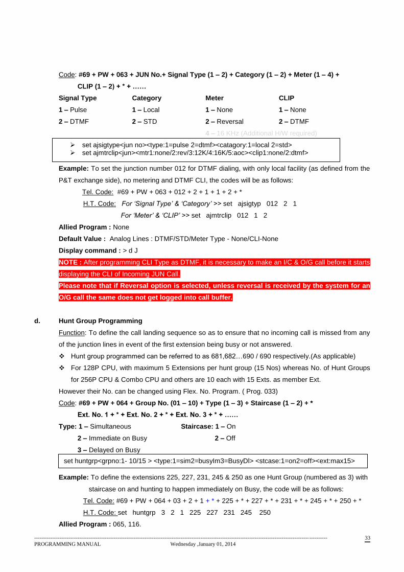
Code: #69 + PW + 063 + JUN No.+ Signal Type (1 – 2) + Category (1 – 2) + Meter (1 – 4) +
CLIP (1 – 2) + * + ……
Signal Type Category Meter CLIP
1 – Pulse 1 – Local 1 – None 1 – None
2 – DTMF 2 – STD 2 – Reversal 2 – DTMF
4 – 16 KHz (Additional H/W required)
Example: To set the junction number 012 for DTMF dialing, with only local facility (as defined from the
P&T exchange side), no metering and DTMF CLI, the codes will be as follows:
Tel. Code: #69 + PW + 063 + 012 + 2 + 1 + 1 + 2 + *
H.T. Code: For ‘Signal Type’ & ‘Category’ >> set ajsigtyp 012 2 1
For ‘Meter’ & ‘CLIP’ >> set ajmtrclip 012 1 2
Allied Program : None
Default Value : Analog Lines : DTMF/STD/Meter Type - None/CLI-None
Display command : > d J
NOTE : After programming CLI Type as DTMF, it is necessary to make an I/C & O/G call before it starts
displaying the CLI of Incoming JUN Call.
Please note that if Reversal option is selected, unless reversal is received by the system for an
O/G call the same does not get logged into call buffer.
d. Hunt Group Programming
Function: To define the call landing sequence so as to ensure that no incoming call is missed from any
of the junction lines in event of the first extension being busy or not answered.
Hunt group programmed can be referred to as 681,682…690 / 690 respectively.(As applicable)
For 128P CPU, with maximum 5 Extensions per hunt group (15 Nos) whereas No. of Hunt Groups
for 256P CPU & Combo CPU and others are 10 each with 15 Exts. as member Ext.
However their No. can be changed using Flex. No. Program. ( Prog. 033)
Code: #69 + PW + 064 + Group No. (01 – 10) + Type (1 – 3) + Staircase (1 – 2) + *
Ext. No. 1 + * + Ext. No. 2 + * + Ext. No. 3 + * + ……
Type: 1 – Simultaneous Staircase: 1 – On
2 – Immediate on Busy 2 – Off
3 – Delayed on Busy
Example: To define the extensions 225, 227, 231, 245 & 250 as one Hunt Group (numbered as 3) with
staircase on and hunting to happen immediately on Busy, the code will be as follows:
Tel. Code: #69 + PW + 064 + 03 + 2 + 1 + * + 225 + * + 227 + * + 231 + * + 245 + * + 250 + *
H.T. Code: set huntgrp 3 2 1 225 227 231 245 250
Allied Program : 065, 116.
set ajsigtype<jun no><type:1=pulse 2=dtmf><catagory:1=local 2=std> set ajmtrclip<jun><mtr1:none/2:rev/3:12K/4:16K/5:aoc><clip1:none/2:dtmf>
set huntgrp<grpno:1- 10/15 > <type:1=sim2=busyIm3=BusyDl> <stcase:1=on2=off><ext:max15>
------------------------------------------------------------------------------------------------------------------------------------------------------------------
PROGRAMMING MANUAL Wednesday ,January 01, 2014 34
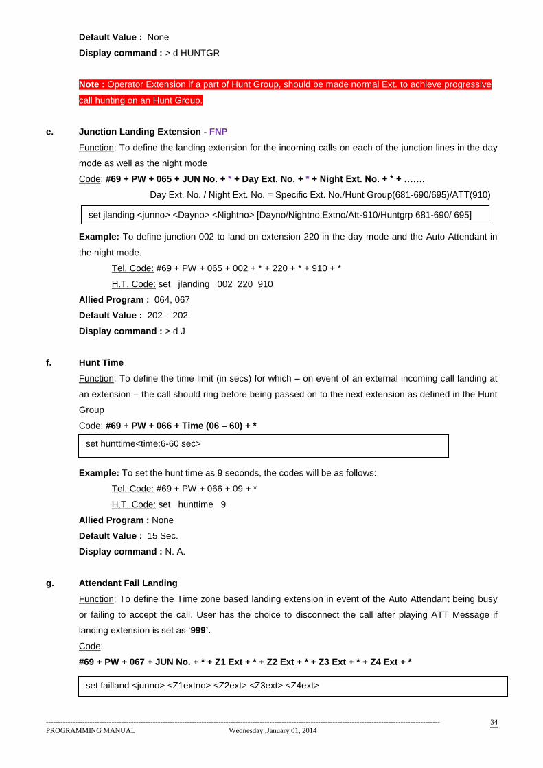
Default Value : None
Display command : > d HUNTGR
Note : Operator Extension if a part of Hunt Group, should be made normal Ext. to achieve progressive
call hunting on an Hunt Group.
e. Junction Landing Extension - FNP
Function: To define the landing extension for the incoming calls on each of the junction lines in the day
mode as well as the night mode
Code: #69 + PW + 065 + JUN No. + * + Day Ext. No. + * + Night Ext. No. + * + …….
Day Ext. No. / Night Ext. No. = Specific Ext. No./Hunt Group(681-690/695)/ATT(910)
Ext. No. = 681…690 indicates Hunt Groups 01 to 10
Example: To define junction 002 to land on extension 220 in the day mode and the Auto Attendant in
the night mode.
Tel. Code: #69 + PW + 065 + 002 + * + 220 + * + 910 + *
H.T. Code: set jlanding 002 220 910
Allied Program : 064, 067
Default Value : 202 – 202.
Display command : > d J
f. Hunt Time
Function: To define the time limit (in secs) for which – on event of an external incoming call landing at
an extension – the call should ring before being passed on to the next extension as defined in the Hunt
Group
Code: #69 + PW + 066 + Time (06 – 60) + *
Example: To set the hunt time as 9 seconds, the codes will be as follows:
Tel. Code: #69 + PW + 066 + 09 + *
H.T. Code: set hunttime 9
Allied Program : None
Default Value : 15 Sec.
Display command : N. A.
g. Attendant Fail Landing
Function: To define the Time zone based landing extension in event of the Auto Attendant being busy
or failing to accept the call. User has the choice to disconnect the call after playing ATT Message if
landing extension is set as ‘999’.
Code:
#69 + PW + 067 + JUN No. + * + Z1 Ext + * + Z2 Ext + * + Z3 Ext + * + Z4 Ext + *
set jlanding <junno> <Dayno> <Nightno> [Dayno/Nightno:Extno/Att-910/Huntgrp 681-690/ 695]
set hunttime<time:6-60 sec>
set failland <junno> <Z1extno> <Z2ext> <Z3ext> <Z4ext>
------------------------------------------------------------------------------------------------------------------------------------------------------------------
PROGRAMMING MANUAL Wednesday ,January 01, 2014 35
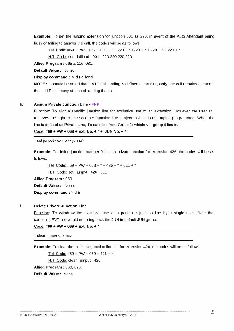
Example: To set the landing extension for junction 001 as 220, in event of the Auto Attendant being
busy or failing to answer the call, the codes will be as follows:
Tel. Code: #69 + PW + 067 + 001 + * + 220 + * +220 + * + 220 + * + 220 + *
H.T. Code: set failland 001 220 220 220 220
Allied Program : 065 & 116, 081.
Default Value : None.
Display command : > d Failland.
NOTE : It should be noted that it ATT Fail landing is defined as an Ext., only one call remains queued if
the said Ext. is busy at time of landing the call.
h. Assign Private Junction Line - FNP
Function: To allot a specific junction line for exclusive use of an extension. However the user still
reserves the right to access other Junction line subject to Junction Grouping programmed. When the
line is defined as Private Line, it’s cacelled from Group 1/ whichever group it lies in.
Code: #69 + PW + 068 + Ext. No. + * + JUN No. + *
Example: To define junction number 011 as a private junction for extension 426, the codes will be as
follows:
Tel. Code: #69 + PW + 068 + * + 426 + * + 011 + *
H.T. Code: set junpvt 426 011
Allied Program : 069.
Default Value : None.
Display command : > d E
i. Delete Private Junction Line
Function: To withdraw the exclusive use of a particular junction line by a single user. Note that
canceling PVT line would not bring back the JUN in default JUN group.
Code: #69 + PW + 069 + Ext. No. + *
Example: To clear the exclusive junction line set for extension 426, the codes will be as follows:
Tel. Code: #69 + PW + 069 + 426 + *
H.T. Code: clear junpvt 426
Allied Program : 068, 073.
Default Value : None
set junpvt <extno> <junno>
clear junpvt <extno>
------------------------------------------------------------------------------------------------------------------------------------------------------------------
PROGRAMMING MANUAL Wednesday ,January 01, 2014 36
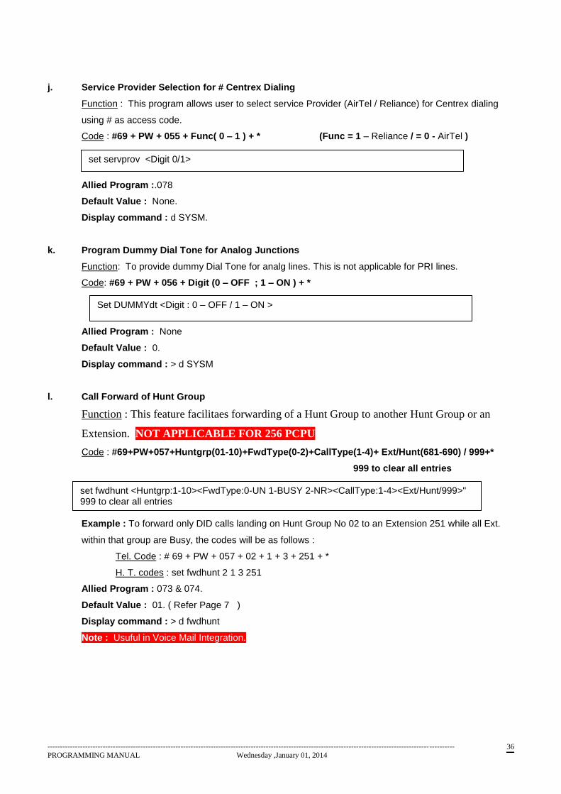
j. Service Provider Selection for # Centrex Dialing
Function : This program allows user to select service Provider (AirTel / Reliance) for Centrex dialing
using # as access code.
Code : #69 + PW + 055 + Func( 0 – 1 ) + * (Func = 1 – Reliance / = 0 - AirTel )
Allied Program :.078
Default Value : None.
Display command : d SYSM.
k. Program Dummy Dial Tone for Analog Junctions
Function: To provide dummy Dial Tone for analg lines. This is not applicable for PRI lines.
Code: #69 + PW + 056 + Digit (0 – OFF ; 1 – ON ) + *
Allied Program : None
Default Value : 0.
Display command : > d SYSM
l. Call Forward of Hunt Group
Function : This feature facilitaes forwarding of a Hunt Group to another Hunt Group or an
Extension. NOT APPLICABLE FOR 256 PCPU
Code : #69+PW+057+Huntgrp(01-10)+FwdType(0-2)+CallType(1-4)+ Ext/Hunt(681-690) / 999+*
999 to clear all entries
Example : To forward only DID calls landing on Hunt Group No 02 to an Extension 251 while all Ext.
within that group are Busy, the codes will be as follows :
Tel. Code : # 69 + PW + 057 + 02 + 1 + 3 + 251 + *
H. T. codes : set fwdhunt 2 1 3 251
Allied Program : 073 & 074.
Default Value : 01. ( Refer Page 7 )
Display command : > d fwdhunt
Note : Usuful in Voice Mail Integration.
set fwdhunt <Huntgrp:1-10><FwdType:0-UN 1-BUSY 2-NR><CallType:1-4><Ext/Hunt/999>" 999 to clear all entries
set servprov <Digit 0/1>
Set DUMMYdt <Digit : 0 – OFF / 1 – ON >
------------------------------------------------------------------------------------------------------------------------------------------------------------------
PROGRAMMING MANUAL Wednesday ,January 01, 2014 37
m. Call Wait on Hunt Group
Function : This feature facilitaes enabling / disabling call waiting feature onto member
extensions of an hunt group. Code : #69 + PW +058 + Digit (0-Disable / 1 – Enable) + *
Note : Useful for JUN landing defined on Hunt Group & need call camp-on while busy
n. Program JUN Grouping
Function : To group JUN lines into various 16 groups. One Junction can appear in multiple groups.
However Junction line if defined as Private, gets deleted from all the JUN Groups and remains
inaccessible until it is assigned to any group.
Code : #69 + PW + 073 + Group No.(01 - 16) + * + JUN No + * + JUN No + * ……………
Note : JUN No. = 999 puts all JUN in the group.
By default all junctions are contained in group no 01 hence erase all the contents in Group 01
before using the same.
Example : To add junction 003 , 005 & 019 to Group 2, the codes will be as follows :
Tel. Code : # 69 + PW + 073 + 02 + * + 003 + * + 005 + * + 019 + *
H. T. Code : set jungrp 2 003
set jungrp 2 005
set jungrp 2 019
Allied Program : 074,075.
Default Value : 01.
Display command : > d JUNGR
o. Clear Junction from JUN Group
Function : To release one or multiple junctions programmed in a group using Program 073.
Code : #69 + PW + 074 + Group No.(01 - 16) + * + JUN No + * + JUN No + * +…………
Note : JUN = 999 would release all Junctions from the specified group.
Example : To remove junction 003 from group 2 ( as assigned earlier), the codes will be as follows:
Tel. code ; # 69 + PW + 02 + * + 003 + *
H.T. Code : clear jungrp 2 003
Allied Program : 073.
Default Value : None
set jungrp <groupno:1-16><junno> (junno=999 will add all juns to group)
clear jungrp <groupno:1-16> <junno> (junno=999 clears entire group)
This feature can not be programmed through Hyper Terminal

------------------------------------------------------------------------------------------------------------------------------------------------------------------
PROGRAMMING MANUAL Wednesday ,January 01, 2014 38
p. Program Leased Line
Function : To remove the JUN line from ‘0’ or ‘8’ access. The line defined as leased line needs to be
accessed by selective seizure only.
Code : #69 + PW + 076 + JUN No. + Func( 0 – 1 ) + * (Func = 1 - Enable / = 0 - Disable )
Example : To set jun 003 as leased line, the codes will be as follow :
Tel. Code : # 69 + PW + 076 + 003 + 1 + *
H. T. Code : set jlease 003 1
Allied Program : 000 – 15.
Default Value : None.
Display command : >d JUNGR.
q. Program Centrex Line
Function : For dialing numbers outside Centrex environment user need to dial ‘0’ to access the P&T
line and make calls with outside world. For this purpose, user need to be assigned higher CoS than it’s
needed to dial the required number. If the line is defined as Centrex then the additional ‘0’ dialed after
accessing the line is absorbed and the digits are outpulsed on to P&T line.
Code : #69 + PW + 078 + JUN No. + Func( 0 – 1 ) + * (Func = 1 - Enable / = 0 - Disable )
Allied Program : 000 – 15, 164
Default Value : None.
Display command : > d J.
r. Program Hunt group Landing Pattern –
Available with ARM Split CPU Ver. 0.3 & ARM CPU Ver. 0.7 Combo CPU Ver. 1.1 while 256PCPU
Ver. 2.0 onwards
Function : For availing landing with in the huntgroup as Sequential or round robbin. If round robbin
option is selected, the I/C call landing on the specific Hunt Group would land on the next extension of
which the earlier call has landed, inspite of the prior extensions being free. Whereas the option
sequenctial would make the call land on the initial extensions. In this case the later extensions would
receive call only if all extensions prior to the extension are busy.
Code : #69 + PW + 217 + <Huntgrp no. 01-10>+<digit:0=Sequential/1=Round robbin> +*
Allied Program : 000 – 15, 164
Allied Program : 064, 065, 116
Default Value : None.
Display command : > d J.
set JLEASE<JUN No.> + <Digit 1/2>
set CENTREX<JUN No.> <Digit 0/1>
Set huntland <huntgrp no 01-10> <digit:0=sequential/1=Round robbin>
------------------------------------------------------------------------------------------------------------------------------------------------------------------
PROGRAMMING MANUAL Wednesday ,January 01, 2014 39
s. STD/ Local Junction Access Transparancy –
Available with ARM Split CPU Ver. 1.0 onwards
Function : In the existing NEOS versions, 0 dialing can access not only JUN lines defined as Local but
the lines defined as STD while all Local lines are busy. However this new feature enables the
programmer to restrict the user to access only those JUN lines defined as Local by dialing 0. By default
dialing 0 would access STD defined lines when all Local defined lines are busy.
Code : #69 + PW + 109 + Digit < 0 – OFF / 1 – ON > +*
Allied Program : 063, 000
Default Value : ON i.e. allowed to access STD lines by 0, while Local Lines are busy..
Display command : > d J.
t. Programmable Paging Junction
Available with ARM Split CPU Ver. 1.1 onwards
Function : This program facilitates the user to define the Junction connected with a Paging unit for
Paging facilty. By programming the JUN as Paging Junction,
Code : #69 + PW + 600 + JUN No. + *
Allied Program : None
Default Value : No paging JUN Exists.
Display command : > d Sysm.
u. Clear Paging Junction
Available with ARM Split CPU Ver. 1.1 onwards
Code : #69 + PW + 601 + JUN No. + *
Allied Program : 601
Default Value : N.A.
Display command : > d sysm.
set allowstd <Digit:1=on/ 0=off>
set pagejun <JUN No.>
clear pagejun < JUN No.>
------------------------------------------------------------------------------------------------------------------------------------------------------------------
PROGRAMMING MANUAL Wednesday ,January 01, 2014 40
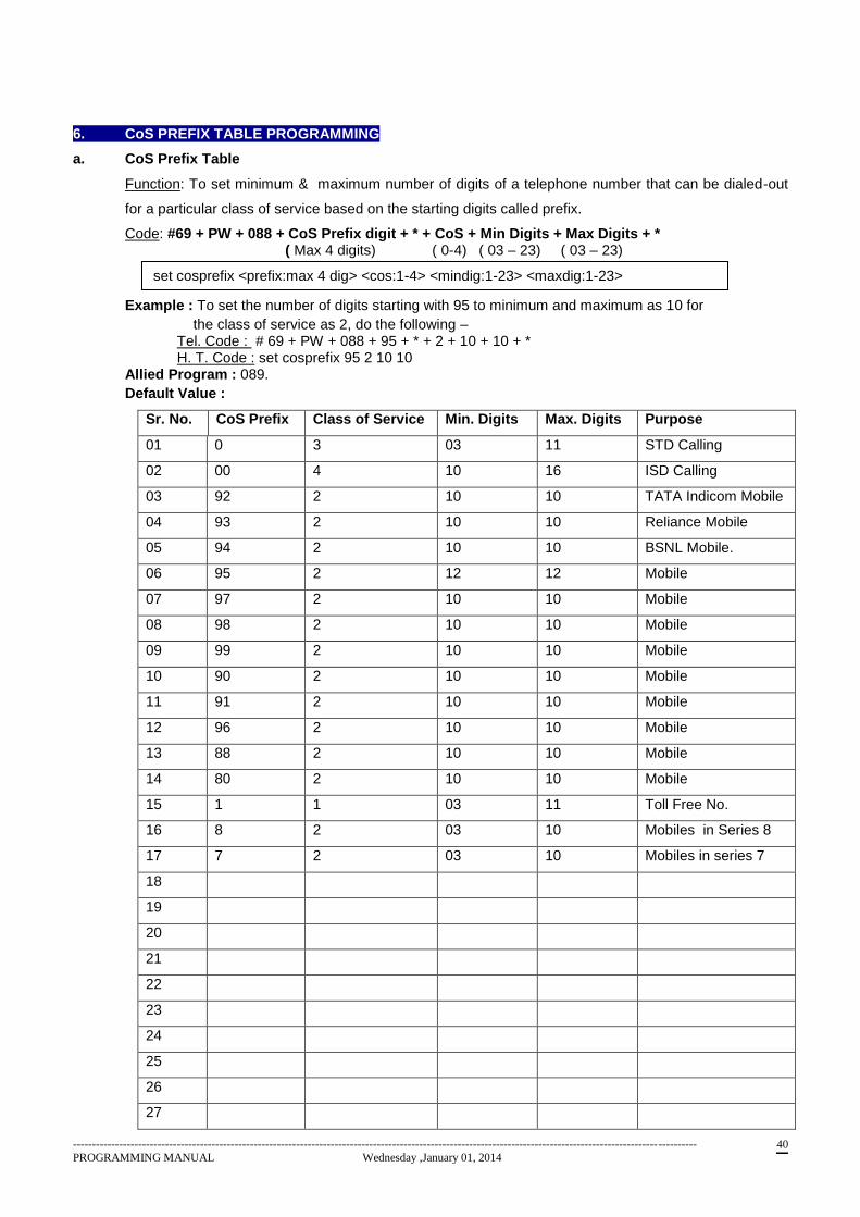
6. CoS PREFIX TABLE PROGRAMMING
a. CoS Prefix Table
Function: To set minimum & maximum number of digits of a telephone number that can be dialed-out
for a particular class of service based on the starting digits called prefix.
Code: #69 + PW + 088 + CoS Prefix digit + * + CoS + Min Digits + Max Digits + * ( Max 4 digits) ( 0-4) ( 03 – 23) ( 03 – 23)
Example : To set the number of digits starting with 95 to minimum and maximum as 10 for
the class of service as 2, do the following – Tel. Code : # 69 + PW + 088 + 95 + * + 2 + 10 + 10 + * H. T. Code : set cosprefix 95 2 10 10
Allied Program : 089.
Default Value :
Sr. No. CoS Prefix Class of Service Min. Digits Max. Digits Purpose
01 0 3 03 11 STD Calling
02 00 4 10 16 ISD Calling
03 92 2 10 10 TATA Indicom Mobile
04 93 2 10 10 Reliance Mobile
05 94 2 10 10 BSNL Mobile.
06 95 2 12 12 Mobile
07 97 2 10 10 Mobile
08 98 2 10 10 Mobile
09 99 2 10 10 Mobile
10 90 2 10 10 Mobile
11 91 2 10 10 Mobile
12 96 2 10 10 Mobile
13 88 2 10 10 Mobile
14 80 2 10 10 Mobile
15 1 1 03 11 Toll Free No.
16 8 2 03 10 Mobiles in Series 8
17 7 2 03 10 Mobiles in series 7
18
19
20
21
22
23
24
25
26
27
set cosprefix <prefix:max 4 dig> <cos:1-4> <mindig:1-23> <maxdig:1-23>
------------------------------------------------------------------------------------------------------------------------------------------------------------------
PROGRAMMING MANUAL Wednesday ,January 01, 2014 41
28
29
30
Display command : > d COSP
b. Initialize default CoS Prefix Table
Function: To load the default CoS Prefix table as indicated above.
Code: #69 + PW + 089 + 1234 + *
Allied Program : 088
Default Value : Refer program 088.
With Old veriosns there was a space for defining only 15 such CoS prefixes out of which 11-12
are default and can not be replaced. They can only be modified. Hence once all 15 entries are
fulfilled, system won’t accept further entries.
For this purpose it’s advised to reset all the entries and program only first digits such as 7,8,9 &
1 with required Min & Max digits.
clear COSPrefix
------------------------------------------------------------------------------------------------------------------------------------------------------------------
PROGRAMMING MANUAL Wednesday ,January 01, 2014 42
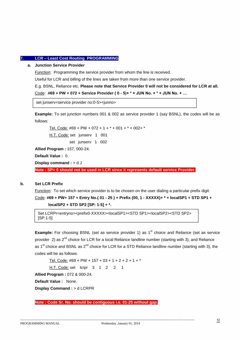
7. LCR – Least Cost Routing PROGRAMMING
a. Junction Service Provider
Function: Programming the service provider from whom the line is received.
Useful for LCR and billing of the lines are taken from more than one service provider.
E.g. BSNL, Reliance etc. Please note that Service Provider 0 will not be considered for LCR at all.
Code: #69 + PW + 072 + Service Provider ( 0 - 5)+ * + JUN No. + * + JUN No. + …
Example: To set junction numbers 001 & 002 as service provider 1 (say BSNL), the codes will be as
follows:
Tel. Code: #69 + PW + 072 + 1 + * + 001 + * + 002+ *
H.T. Code: set junserv 1 001
set junserv 1 002
Allied Program : 157, 000-24.
Default Value : 0.
Display command : > d J
Note : SP= 0 should not be used in LCR since it represents default service Provider.
b. Set LCR Prefix
Function: To set which service provider is to be chosen on the user dialing a particular prefix digit.
Code: #69 + PW+ 157 + Entry No.( 01 - 25 ) + Prefix (00, 1 - XXXXX)+ * + localSP1 + STD SP1 +
localSP2 + STD SP2 [SP: 1-5] + *.
Example: For choosing BSNL (set as service provider 1) as 1st choice and Reliance (set as service
provider 2) as 2nd
choice for LCR for a local Reliance landline number (starting with 3), and Reliance
as 1st choice and BSNL as 2
nd choice for LCR for a STD Reliance landline number (starting with 3), the
codes will be as follows:
Tel. Code: #69 + PW + 157 + 03 + 1 + 2 + 2 + 1 + *
H.T. Code: set lcrpr 3 1 2 2 1
Allied Program : 072 & 000-24.
Default Value : None.
Display Command : > d LCRPR
Note : Code Sr. No. should be contiguous i.e. 01-25 without gap.
set junserv<service provider no:0-5><junno>
Set LCRPr<entryno><prefix0-XXXXX><localSP1><STD SP1><localSP2><STD SP2> [SP:1-5]
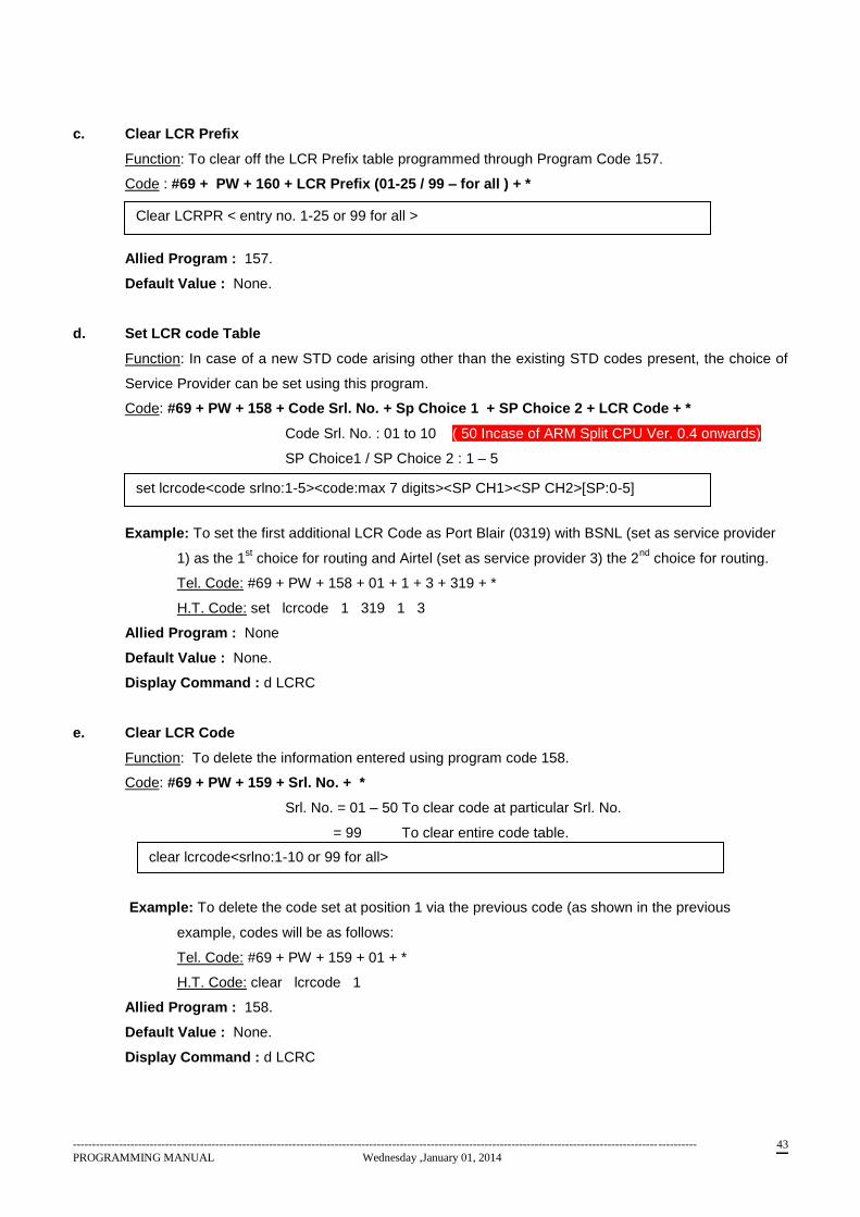
------------------------------------------------------------------------------------------------------------------------------------------------------------------
PROGRAMMING MANUAL Wednesday ,January 01, 2014 43
c. Clear LCR Prefix
Function: To clear off the LCR Prefix table programmed through Program Code 157.
Code : #69 + PW + 160 + LCR Prefix (01-25 / 99 – for all ) + *
Code: #69 + PW + 160 + Entry No. (01-25 or 99 for all ) + *
Allied Program : 157.
Default Value : None.
d. Set LCR code Table
Function: In case of a new STD code arising other than the existing STD codes present, the choice of
Service Provider can be set using this program.
Code: #69 + PW + 158 + Code Srl. No. + Sp Choice 1 + SP Choice 2 + LCR Code + *
Code Srl. No. : 01 to 10 ( 50 Incase of ARM Split CPU Ver. 0.4 onwards)
SP Choice1 / SP Choice 2 : 1 – 5
LCR Code : Max . 7 digits.
Example: To set the first additional LCR Code as Port Blair (0319) with BSNL (set as service provider
1) as the 1st choice for routing and Airtel (set as service provider 3) the 2
nd choice for routing.
Tel. Code: #69 + PW + 158 + 01 + 1 + 3 + 319 + *
H.T. Code: set lcrcode 1 319 1 3
Allied Program : None
Default Value : None.
Display Command : d LCRC
e. Clear LCR Code
Function: To delete the information entered using program code 158.
Code: #69 + PW + 159 + Srl. No. + *
Srl. No. = 01 – 50 To clear code at particular Srl. No.
= 99 To clear entire code table.
Example: To delete the code set at position 1 via the previous code (as shown in the previous
example, codes will be as follows:
Tel. Code: #69 + PW + 159 + 01 + *
H.T. Code: clear lcrcode 1
Allied Program : 158.
Default Value : None.
Display Command : d LCRC
set lcrcode<code srlno:1-5><code:max 7 digits><SP CH1><SP CH2>[SP:0-5]
clear lcrcode<srlno:1-10 or 99 for all>
Clear LCRPR < entry no. 1-25 or 99 for all >
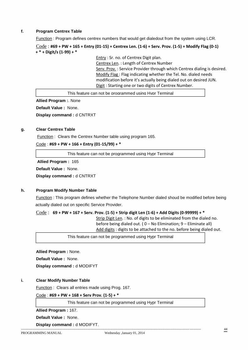
------------------------------------------------------------------------------------------------------------------------------------------------------------------
PROGRAMMING MANUAL Wednesday ,January 01, 2014 44
f. Program Centrex Table
Function : Program defines centrex numbers that would get dialedout from the system using LCR.
Code : #69 + PW + 165 + Entry (01-15) + Centrex Len. (1-6) + Serv. Prov. (1-5) + Modify Flag (0-1) + * + Digit/s (1-99) + * Entry : Sr. no. of Centrex Digit plan. Centrex Len. : Length of Centrex Number Serv. Prov. : Service Provider through which Centrex dialing is desired. Modify Flag : Flag indicating whether the Tel. No. dialed needs modification before it’s actually being dialed out on desired JUN.
Digit : Starting one or two digits of Centrex Number.
Allied Program :. None
Default Value : None.
Display command : d CNTRXT
g. Clear Centrex Table
Function : Clears the Centrex Number table using program 165.
Code : #69 + PW + 166 + Entry (01-15/99) + *
Allied Program : 165
Default Value : None.
Display command : d CNTRXT
h. Program Modify Number Table
Function : This program defines whether the Telephone Number dialed shoud be modified before being
actually dialed out on specific Service Provider.
Code : #69 + PW + 167 + Serv. Prov. (1-5) + Strip digit Len (1-6) + Add Digits (0-99999) + * Strip Digit Len. : No. of digits to be eliminated from the dialed no. before being dialed out. ( 0 – No Elimination; 9 – Eliminate all)
Add digits : digits to be attached to the no. before being dialed out.
Allied Program : None.
Default Value : None.
Display command : d MODIFYT
i. Clear Modify Number Table
Function : Clears all entries made using Prog. 167.
Code : #69 + PW + 168 + Serv Prov. (1-5) + *
Allied Program : 167.
Default Value : None.
Display command : d MODIFYT.
This feature can not be programmed using Hypr Terminal
This feature can not be programmed using Hypr Terminal
This feature can not be programmed using Hypr Terminal
This feature can not be programmed using Hypr Terminal
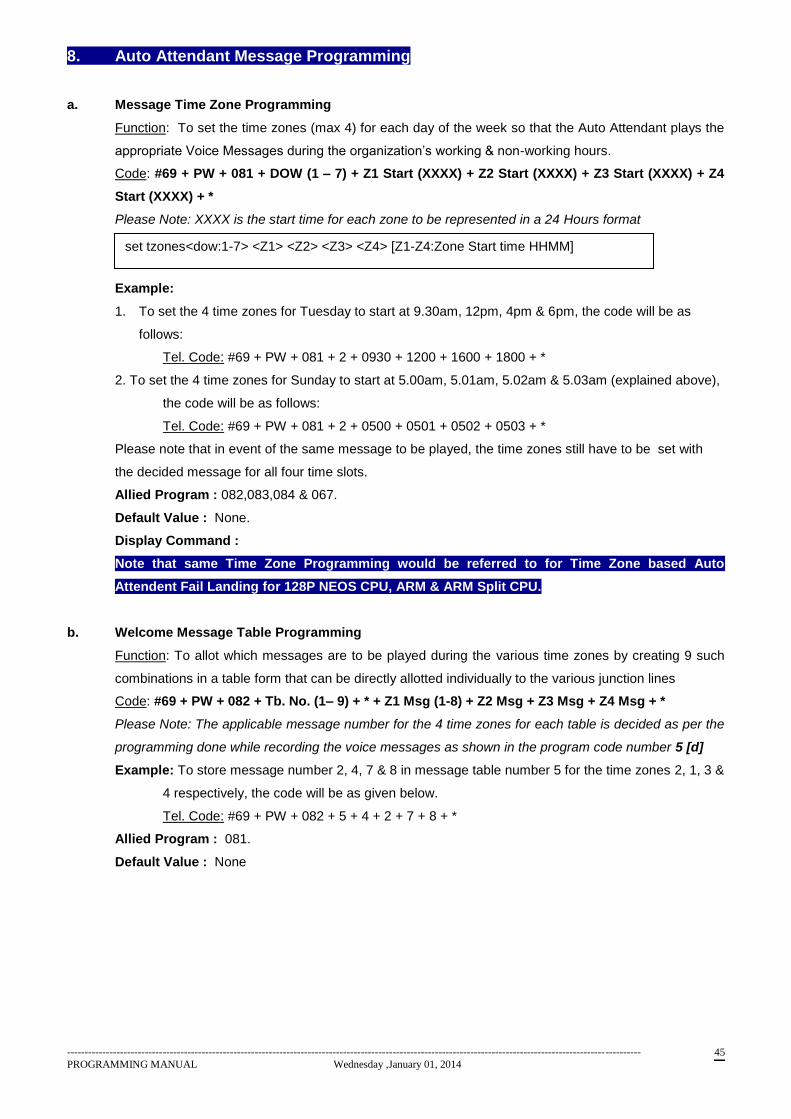
------------------------------------------------------------------------------------------------------------------------------------------------------------------
PROGRAMMING MANUAL Wednesday ,January 01, 2014 45
8. Auto Attendant Message Programming
a. Message Time Zone Programming
Function: To set the time zones (max 4) for each day of the week so that the Auto Attendant plays the
appropriate Voice Messages during the organization’s working & non-working hours.
Code: #69 + PW + 081 + DOW (1 – 7) + Z1 Start (XXXX) + Z2 Start (XXXX) + Z3 Start (XXXX) + Z4
Start (XXXX) + *
Please Note: XXXX is the start time for each zone to be represented in a 24 Hours format
Example:
1. To set the 4 time zones for Tuesday to start at 9.30am, 12pm, 4pm & 6pm, the code will be as
follows:
Tel. Code: #69 + PW + 081 + 2 + 0930 + 1200 + 1600 + 1800 + *
2. To set the 4 time zones for Sunday to start at 5.00am, 5.01am, 5.02am & 5.03am (explained above),
the code will be as follows:
Tel. Code: #69 + PW + 081 + 2 + 0500 + 0501 + 0502 + 0503 + *
Please note that in event of the same message to be played, the time zones still have to be set with
the decided message for all four time slots.
Allied Program : 082,083,084 & 067.
Default Value : None.
Display Command :
Note that same Time Zone Programming would be referred to for Time Zone based Auto
Attendent Fail Landing for 128P NEOS CPU, ARM & ARM Split CPU.
b. Welcome Message Table Programming
Function: To allot which messages are to be played during the various time zones by creating 9 such
combinations in a table form that can be directly allotted individually to the various junction lines
Code: #69 + PW + 082 + Tb. No. (1– 9) + * + Z1 Msg (1-8) + Z2 Msg + Z3 Msg + Z4 Msg + *
Please Note: The applicable message number for the 4 time zones for each table is decided as per the
programming done while recording the voice messages as shown in the program code number 5 [d]
Example: To store message number 2, 4, 7 & 8 in message table number 5 for the time zones 2, 1, 3 &
4 respectively, the code will be as given below.
Tel. Code: #69 + PW + 082 + 5 + 4 + 2 + 7 + 8 + *
Allied Program : 081.
Default Value : None
set tzones<dow:1-7> <Z1> <Z2> <Z3> <Z4> [Z1-Z4:Zone Start time HHMM]
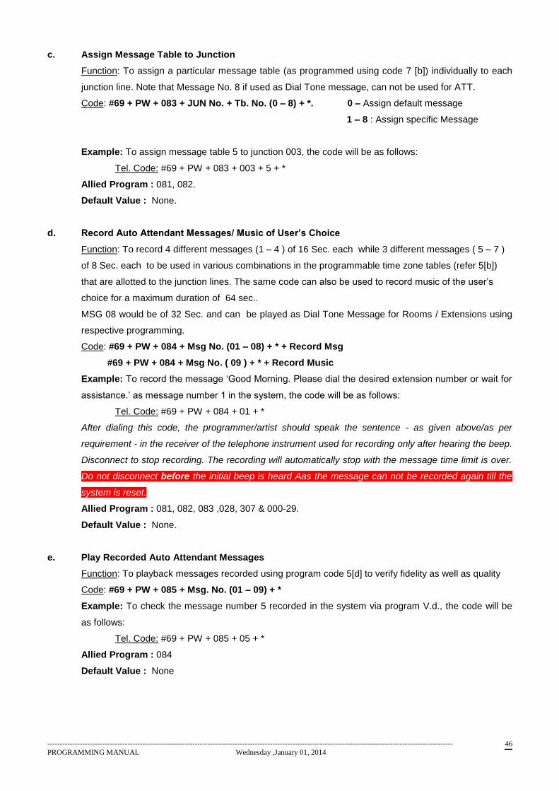
------------------------------------------------------------------------------------------------------------------------------------------------------------------
PROGRAMMING MANUAL Wednesday ,January 01, 2014 46
c. Assign Message Table to Junction
Function: To assign a particular message table (as programmed using code 7 [b]) individually to each
junction line. Note that Message No. 8 if used as Dial Tone message, can not be used for ATT.
Code: #69 + PW + 083 + JUN No. + Tb. No. (0 – 8) + *. 0 – Assign default message
1 – 8 : Assign specific Message
Example: To assign message table 5 to junction 003, the code will be as follows:
Tel. Code: #69 + PW + 083 + 003 + 5 + *
Allied Program : 081, 082.
Default Value : None.
d. Record Auto Attendant Messages/ Music of User’s Choice
Function: To record 4 different messages (1 – 4 ) of 16 Sec. each while 3 different messages ( 5 – 7 )
of 8 Sec. each to be used in various combinations in the programmable time zone tables (refer 5[b])
that are allotted to the junction lines. The same code can also be used to record music of the user’s
choice for a maximum duration of 64 sec..
MSG 08 would be of 32 Sec. and can be played as Dial Tone Message for Rooms / Extensions using
respective programming.
Code: #69 + PW + 084 + Msg No. (01 – 08) + * + Record Msg
#69 + PW + 084 + Msg No. ( 09 ) + * + Record Music
Example: To record the message ‘Good Morning. Please dial the desired extension number or wait for
assistance.’ as message number 1 in the system, the code will be as follows:
Tel. Code: #69 + PW + 084 + 01 + *
After dialing this code, the programmer/artist should speak the sentence - as given above/as per
requirement - in the receiver of the telephone instrument used for recording only after hearing the beep.
Disconnect to stop recording. The recording will automatically stop with the message time limit is over.
Do not disconnect before the initial beep is heard Aas the message can not be recorded again till the
system is reset.
Allied Program : 081, 082, 083 ,028, 307 & 000-29.
Default Value : None.
e. Play Recorded Auto Attendant Messages
Function: To playback messages recorded using program code 5[d] to verify fidelity as well as quality
Code: #69 + PW + 085 + Msg. No. (01 – 09) + *
Example: To check the message number 5 recorded in the system via program V.d., the code will be
as follows:
Tel. Code: #69 + PW + 085 + 05 + *
Allied Program : 084
Default Value : None
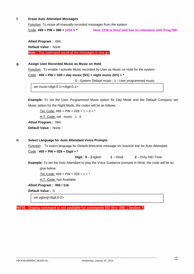
------------------------------------------------------------------------------------------------------------------------------------------------------------------
PROGRAMMING MANUAL Wednesday ,January 01, 2014 47
f. Erase Auto Attendant Messages
Function: To erase all manually recorded messages from the system
Code: #69 + PW + 086 + 1234 + * Here 1234 is fixed and has no relevance with Prog PW.
Allied Program : 084.
Default Value : None.
Note : This command would all the messages in one go.
g. Assign User Recorded Music as Music on Hold
Function : To enable / activate Music recorded by User as Music on Hold for the system.
Code : #69 + PW + 028 + day music (0/1) + night music (0/1) + *
0 - System Default music , 1 - User programmed music
Example: To set the User Programmed Music option for Day Mode and the Default Company set
Music option for the Night Mode, the codes will be as follows:
Tel. Code: #69 + PW + 028 + 1 + 0 + *
H.T. Code: set music 1 0
Allied Program : 084.
Default Value : None.
h. Select Language for Auto Attendant Voice Prompts
Function : To select language for Default Welcome message on Junction line for Auto Attendant.
Code : #69 + PW + 029 + Digit + *
Digit : 0 – English 1 – Hindi 2 – Only DID Tone.
Example: To set the Auto Attendant to play the Voice Guidance prompts in Hindi, the code will be as
give below:
Tel. Code: #69 + PW + 029 + 1 + *
H.T. Code: Not Available
Allied Program : 065 / 116.
Default Value : 0.
NOTE : Display command is not available for commands 082 thro’ 086. ( Section 7)
set music<digit:0-1><digit:0-1>
set vglang<digit:0-2>
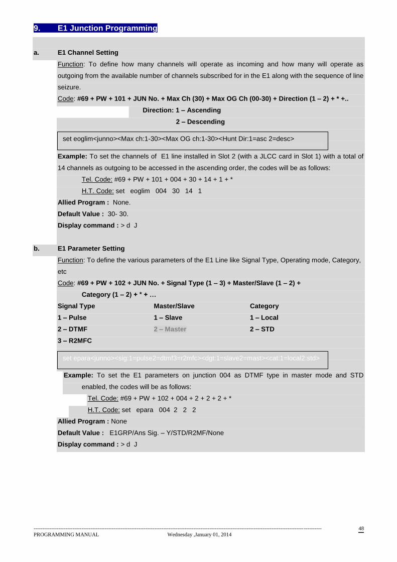
------------------------------------------------------------------------------------------------------------------------------------------------------------------
PROGRAMMING MANUAL Wednesday ,January 01, 2014 48
9. E1 Junction Programming
a. E1 Channel Setting
Function: To define how many channels will operate as incoming and how many will operate as
outgoing from the available number of channels subscribed for in the E1 along with the sequence of line
seizure.
Code: #69 + PW + 101 + JUN No. + Max Ch (30) + Max OG Ch (00-30) + Direction (1 – 2) + * +..
Direction: 1 – Ascending
2 – Descending
Example: To set the channels of E1 line installed in Slot 2 (with a JLCC card in Slot 1) with a total of
14 channels as outgoing to be accessed in the ascending order, the codes will be as follows:
Tel. Code: #69 + PW + 101 + 004 + 30 + 14 + 1 + *
H.T. Code: set eoglim 004 30 14 1
Allied Program : None.
Default Value : 30- 30.
Display command : > d J
b. E1 Parameter Setting
Function: To define the various parameters of the E1 Line like Signal Type, Operating mode, Category,
etc
Code: #69 + PW + 102 + JUN No. + Signal Type (1 – 3) + Master/Slave (1 – 2) +
Category (1 – 2) + * + …
Signal Type Master/Slave Category
1 – Pulse 1 – Slave 1 – Local
2 – DTMF 2 – Master 2 – STD
3 – R2MFC
Example: To set the E1 parameters on junction 004 as DTMF type in master mode and STD
enabled, the codes will be as follows:
Tel. Code: #69 + PW + 102 + 004 + 2 + 2 + 2 + *
H.T. Code: set epara 004 2 2 2
Allied Program : None
Default Value : E1GRP/Ans Sig. – Y/STD/R2MF/None
Display command : > d J
set eoglim<junno><Max ch:1-30><Max OG ch:1-30><Hunt Dir:1=asc 2=desc>
set epara<junno><sig:1=pulse2=dtmf3=r2mfc><dgt:1=slave2=mast><cat:1=local2:std>
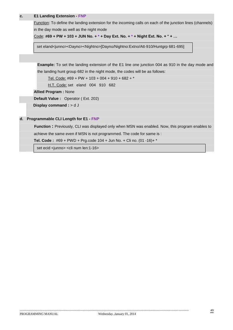
------------------------------------------------------------------------------------------------------------------------------------------------------------------
PROGRAMMING MANUAL Wednesday ,January 01, 2014 49
c. E1 Landing Extension - FNP
Function: To define the landing extension for the incoming calls on each of the junction lines (channels)
in the day mode as well as the night mode
Code: #69 + PW + 103 + JUN No. + * + Day Ext. No. + * + Night Ext. No. + * + …
Example: To set the landing extension of the E1 line one junction 004 as 910 in the day mode and
the landing hunt group 682 in the night mode, the codes will be as follows:
Tel. Code: #69 + PW + 103 + 004 + 910 + 682 + *
H.T. Code: set eland 004 910 682
Allied Program : None
Default Value : Operator ( Ext. 202)
Display command : > d J
d. Programmable CLI Length for E1 - FNP
Function : Previously, CLI was displayed only when MSN was enabled. Now, this program enables to
achieve the same even if MSN is not programmed. The code for same is :
Tel. Code : #69 + PWD + Prg.code 104 + Jun No. + Cli no. (01 -16)+ *
set eland<junno><Dayno><Nightno>[Dayno/Nightno:Extno/Att-910/Huntgrp 681-695]
set ecid <junno> <cli num len:1-16>
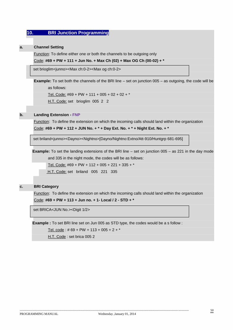
------------------------------------------------------------------------------------------------------------------------------------------------------------------
PROGRAMMING MANUAL Wednesday ,January 01, 2014 50
10. BRI Junction Programming
a. Channel Setting
Function: To define either one or both the channels to be outgoing only
Code: #69 + PW + 111 + Jun No. + Max Ch (02) + Max OG Ch (00-02) + *
Example: To set both the channels of the BRI line – set on junction 005 – as outgoing, the code will be
as follows:
Tel. Code: #69 + PW + 111 + 005 + 02 + 02 + *
H.T. Code: set brioglim 005 2 2
b. Landing Extension - FNP
Function: To define the extension on which the incoming calls should land within the organization
Code: #69 + PW + 112 + JUN No. + * + Day Ext. No. + * + Night Ext. No. + *
Example: To set the landing extensions of the BRI line – set on junction 005 – as 221 in the day mode
and 335 in the night mode, the codes will be as follows:
Tel. Code: #69 + PW + 112 + 005 + 221 + 335 + *
H.T. Code: set briland 005 221 335
c. BRI Category
Function: To define the extension on which the incoming calls should land within the organization
Code: #69 + PW + 113 + Jun no. + 1- Local / 2 - STD + *
Example : To set BRI line set on Jun 005 as STD type, the codes would be a s follow :
Tel. code : # 69 + PW + 113 + 005 + 2 + *
H.T. Code : set brica 005 2
set brioglim<junno><Max ch:0-2><Max og ch:0-2>
set briland<junno><Dayno><Nightno>[Dayno/Nightno:Extno/Att-910/Huntgrp 681-695]
set BRICA<JUN No.><Digit 1/2>
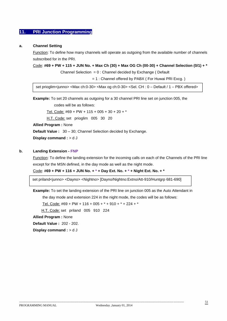
------------------------------------------------------------------------------------------------------------------------------------------------------------------
PROGRAMMING MANUAL Wednesday ,January 01, 2014 51
11. PRI Junction Programming
a. Channel Setting
Function: To define how many channels will operate as outgoing from the available number of channels
subscribed for in the PRI.
Code: #69 + PW + 115 + JUN No. + Max Ch (30) + Max OG Ch (00-30) + Channel Selection (0/1) + *
Channel Selection = 0 : Channel decided by Exchange ( Default
= 1 : Channel offered by PABX ( For Huwai PRI Excg. )
Example: To set 20 channels as outgoing for a 30 channel PRI line set on junction 005, the
codes will be as follows:
Tel. Code: #69 + PW + 115 + 005 + 30 + 20 + *
H.T. Code: set prioglim 005 30 20
Allied Program : None
Default Value : 30 – 30; Channel Selection decided by Exchange.
Display command : > d J
b. Landing Extension - FNP
Function: To define the landing extension for the incoming calls on each of the Channels of the PRI line
except for the MSN defined, in the day mode as well as the night mode.
Code: #69 + PW + 116 + JUN No. + * + Day Ext. No. + * + Night Ext. No. + *
Example: To set the landing extension of the PRI line on junction 005 as the Auto Attendant in
the day mode and extension 224 in the night mode, the codes will be as follows:
Tel. Code: #69 + PW + 116 + 005 + * + 910 + * + 224 + *
H.T. Code: set priland 005 910 224
Allied Program : None
Default Value : 202 - 202.
Display command : > d J
set prioglim<junno> <Max ch:0-30> <Max og ch:0-30> <Sel. CH : 0 – Default / 1 – PBX offered>
set priland<junno> <Dayno> <Nightno> [Dayno/Nightno:Extno/Att-910/Huntgrp 681-690]
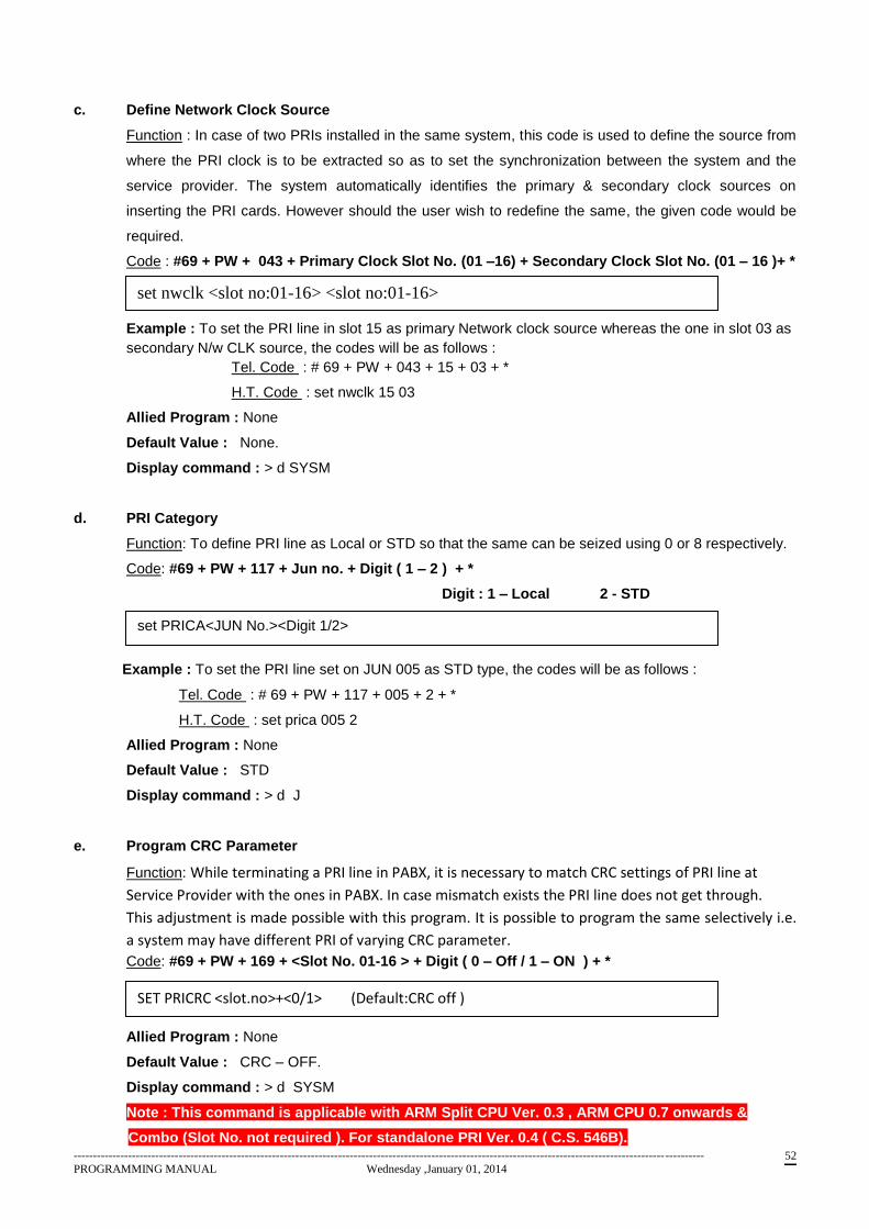
------------------------------------------------------------------------------------------------------------------------------------------------------------------
PROGRAMMING MANUAL Wednesday ,January 01, 2014 52
c. Define Network Clock Source
Function : In case of two PRIs installed in the same system, this code is used to define the source from
where the PRI clock is to be extracted so as to set the synchronization between the system and the
service provider. The system automatically identifies the primary & secondary clock sources on
inserting the PRI cards. However should the user wish to redefine the same, the given code would be
required.
Code : #69 + PW + 043 + Primary Clock Slot No. (01 –16) + Secondary Clock Slot No. (01 – 16 )+ *
Example : To set the PRI line in slot 15 as primary Network clock source whereas the one in slot 03 as
secondary N/w CLK source, the codes will be as follows :
Tel. Code : # 69 + PW + 043 + 15 + 03 + *
H.T. Code : set nwclk 15 03
Allied Program : None
Default Value : None.
Display command : > d SYSM
d. PRI Category
Function: To define PRI line as Local or STD so that the same can be seized using 0 or 8 respectively.
Code: #69 + PW + 117 + Jun no. + Digit ( 1 – 2 ) + *
Digit : 1 – Local 2 - STD
Example : To set the PRI line set on JUN 005 as STD type, the codes will be as follows :
Tel. Code : # 69 + PW + 117 + 005 + 2 + *
H.T. Code : set prica 005 2
Allied Program : None
Default Value : STD
Display command : > d J
e. Program CRC Parameter
Function: While terminating a PRI line in PABX, it is necessary to match CRC settings of PRI line at
Service Provider with the ones in PABX. In case mismatch exists the PRI line does not get through.
This adjustment is made possible with this program. It is possible to program the same selectively i.e.
a system may have different PRI of varying CRC parameter.
Code: #69 + PW + 169 + <Slot No. 01-16 > + Digit ( 0 – Off / 1 – ON ) + *
Allied Program : None
Default Value : CRC – OFF.
Display command : > d SYSM
Note : This command is applicable with ARM Split CPU Ver. 0.3 , ARM CPU 0.7 onwards &
Combo (Slot No. not required ). For standalone PRI Ver. 0.4 ( C.S. 546B).
set nwclk <slot no:01-16> <slot no:01-16>
set PRICA<JUN No.><Digit 1/2>
SET PRICRC <slot.no>+<0/1> (Default:CRC off )
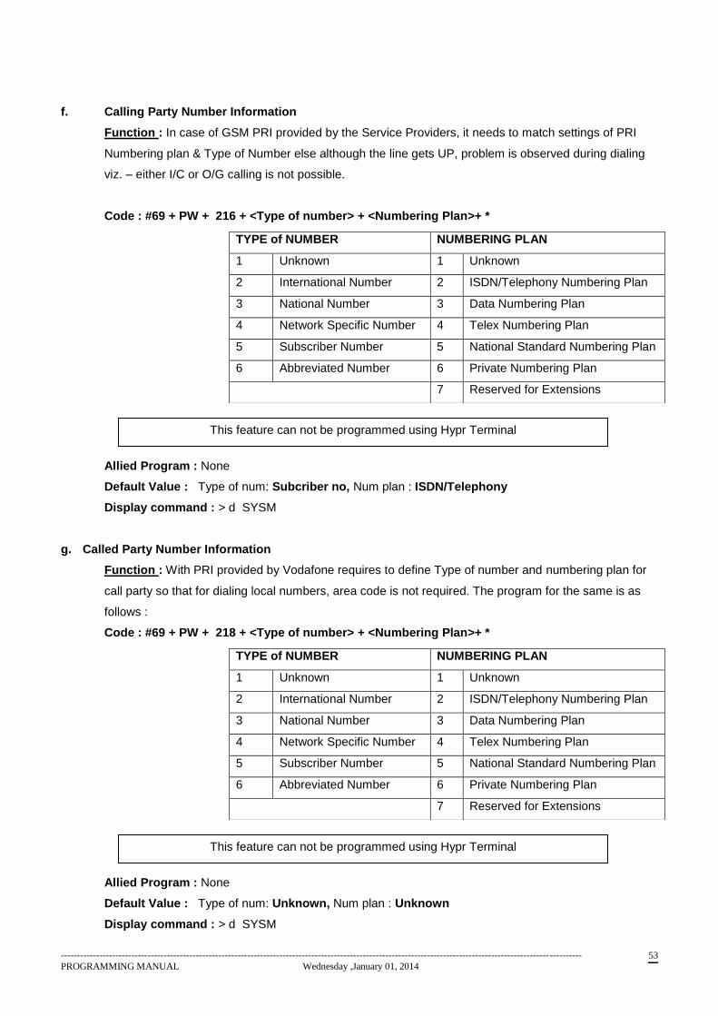
------------------------------------------------------------------------------------------------------------------------------------------------------------------
PROGRAMMING MANUAL Wednesday ,January 01, 2014 53
f. Calling Party Number Information
Function : In case of GSM PRI provided by the Service Providers, it needs to match settings of PRI
Numbering plan & Type of Number else although the line gets UP, problem is observed during dialing
viz. – either I/C or O/G calling is not possible.
Code : #69 + PW + 216 + <Type of number> + <Numbering Plan>+ *
Allied Program : None
Default Value : Type of num: Subcriber no, Num plan : ISDN/Telephony
Display command : > d SYSM
g. Called Party Number Information
Function : With PRI provided by Vodafone requires to define Type of number and numbering plan for
call party so that for dialing local numbers, area code is not required. The program for the same is as
follows :
Code : #69 + PW + 218 + <Type of number> + <Numbering Plan>+ *
Allied Program : None
Default Value : Type of num: Unknown, Num plan : Unknown
Display command : > d SYSM
TYPE of NUMBER NUMBERING PLAN
1 Unknown 1 Unknown
2 International Number 2 ISDN/Telephony Numbering Plan
3 National Number 3 Data Numbering Plan
4 Network Specific Number 4 Telex Numbering Plan
5 Subscriber Number 5 National Standard Numbering Plan
6 Abbreviated Number 6 Private Numbering Plan
7 Reserved for Extensions
This feature can not be programmed using Hypr Terminal
This feature can not be programmed using Hypr Terminal
------------------------------------------------------------------------------------------------------------------------------------------------------------------
PROGRAMMING MANUAL Wednesday ,January 01, 2014 54
12. VOIP SIP TRUNKING
A. Programmable Logical Partitioning
Tel. Code : #69+ PW + 091 + 1/0 + *
The status can be viewed using display command “d SYSM.”
set lgclprtn <Digit:0/1>
------------------------------------------------------------------------------------------------------------------------------------------------------------------
PROGRAMMING MANUAL Wednesday ,January 01, 2014 55
13 VOIP TIE JUNCTION NETWORKING
A. Tie Route Method
Function : Two or more NEOS exchanges can be interconnected using VOIP TIE JUN. If
numbering scheme of all the exchanges are same, it might create conflict while the call is routed
amongst the PBX. Hence each PBX can be distinguished by a code defined for each PBX. It’s
called as ‘Own PBX Code’. This enables the PBX user’s call to the specific Exchange inspite of
having same Ext. Numbering for interconnected PBXs.
Thus if extension numbers of the interconnected PBX are different then the method of inter-calling
is referred to as EXT. Num. method whereas if Ext. Nos. are same then as described above, the
alling pattern is referred to as PBX Code pattern.
The selection of the same accordingly can be done by the following program.
Tel. Code #69+ PW + 400 + <Method: 1-PBX code /0:Ext.Num > + * (Default Ext. Num)
B. Own PBX Code
Function : As described in the Tie Route method, if Ext. Nos. of interconnected PBXs are same
then each PBX would be assigned as code which indirectly functions as Route Code for the specific
PBX.
While dialing is made referring to this code, the call would be directed to the specified PBX.
Following is the program for defining code for such PBXs.
Tel. Code #69 + PW +401 + Own PBX code(10-99) + * (Default 0)
C. Auto Route Selection
Function : There are 2 possible ways to dial the outgoing call.
a. User can dial TIE access code and then user can dial other PBX Extension number. In this
case ARS mode will be OFF.
b. User can dial only Extension number and PBX can decide whether this is local extension call or
Tie Extension call and route accordingly. In this case, ARS mode will be ON.
Tel. Code #69+ PW + 402 + ARS: 1=On/0: Off + * (Default ON)
D. Tie Digit Timeout
Function : This program defines the time after which the call would get matured / placed on the
specified route. Dialing # after the dialing is over, would immediately route the call to desired
destination. Default value is 100 i.e. 10 Sec.
Tel. Code #69 + PW + 404 + Dig dial timeout <001 (100msec) - 100(10sec) > + *
E. Tie Leading digit / Tie Route Table
Function : This is main part for IP Networking programming. Here user can program leading digits
and destination IP of other PBX. User can program 16 different routes.
As a leading digit, User can program any series of other PBX. For example, if other PBX is having
extension numbers from 200 to 299, User will program leading digit as 2.
User can program maximum 4 Destination IP address for each route entry. Purpose of providing 4
IP addresses is that if first programmed IP Address is not reachable, PBX should dial code using 2nd
set troutmthd <Digit: 1=PBX code/ 0=Ext. numbering>
set pbxcode <code no 10-99>
set tiears <Digit:1=on/ 0=off >
set tiedigtme<time:1-100>
------------------------------------------------------------------------------------------------------------------------------------------------------------------
PROGRAMMING MANUAL Wednesday ,January 01, 2014 56
Destination IP Address and so on. Out of this 4 IP address, user will program 1st Destination IP
address in this command.
Tel. Code #69 + PW + 405 + Sr.no (01-16) + Leading dig (1-4 dig ) + * +1st element (Destination IP 1) +
* + 2nd
element + * + 3rd
element + * + 4th element + *
Default : Blank
F. Add / Strip Digit
Function : In case there is a requirement such that the number dialed by the user needs to be
modified before placing the same onto the Tie No.
Tel. Code #69 +PW + 406 + sr.no (01-16) + Add dig + * + sub dig cnt + *
G. Min – Max Digit / Tie Destination Number Length
Function ; We programmed leading digit in previous command. But, we have not programmed
extension number length of other PBX Extensions. So it is necessary for PBX to know the length of
other PBX Extension number. In this command, user can program Minimum and Maximum length of
other PBX Extension number. Please note that this command is connected with route defined in
previous command. I.e. User must enter route entry number for which this command needs to be
set.Using this command PBX will determine following things:
a. If dialed number is less than minimum digits required to route call, PBX will not route the call.
b. If dialed number is equal to maximum digits required to route call, PBX will immediately route
the call. PBX will not wait for inter digit timeout expiry.
c. If dialed number is greater than minimum digits required but less than maximum digits required
dialing the call, PBX will wait for inter digit timeout expiry and after that PBX will route the call.
Tel. Code #69 +PW + 407 + sr.no(01-16) + Min dig(01-22) + Max dig(01-22) + *
H. Program SIP TIE Card IP Address
Function ; This command will set IP Address of SIP card which is present in PBX system. Here
user must give slot number in which card is inserted. When this command will be entered, this
command will be sent to SIP TIE card present in that slot. After that Programming software will wait
for response. On receiving positive response, programming software will allow to execute next
command. If programming software will not receive response from SIP TIE card in 10 seconds, it
will discard this command and allow executing next command. This is applicable for all commands
in this section except SIP TIE card restart command.
Tel. Code #69 +PW + 410 + slot no + *+ IP Addr <1st element>+* <2nd>+ *+ <3rd> + *+<4th> + *
I. Program SIP TIE Card Netmask
Function :
Tel code : #69 + PW + 411 +slot no + * + Netmask <1st element> + * <2nd>+ * + <3rd> +
*+ <4th> + *
Default 255.255.255.0
set tieroutbl <Sr.no(1-16)> <Leading dig (max 4 dig)> <1st element (Destination
IP 1)> <2nd element> <3rd element> <4th element>
set tieaddsub <Sr.no (1-16)> <add digits (max 4 dig)> <sub digit(0-9) >
set tieminmax <Sr.no (1-16)> <Min dig(1-22) > <Max dig(1 -22)>
set SIPIPaddr <slot no> <1st element> <2nd Element> <3rd Element><4th Element>
set SIPNEtmask < slot no> <1st element> <2nd Element> <3rd
Element> <4th Element>
------------------------------------------------------------------------------------------------------------------------------------------------------------------
PROGRAMMING MANUAL Wednesday ,January 01, 2014 57
J. Program SIP TIE Card Gateway
Function :
Tel. Code #69 + PW + prg.code 412 +slot no + * +Gateway<1st element> +* + <2
nd > + *
+ <3rd
> + *+ <4th > + *
Default 10.25.10.111
K. Program SIP TIE Card debug Level
Function :
Tel code #69 + PW + 413 +slot no + * + <Debug level 0-7> + *
Default 0
L. Load Default Tie Parameters
Function : Tel. Code #69 + PW + 415 + <slot no> + *
M. Restart SIP Tie Card
Function : When all above parameters are configured, it is necessary to restart SIP TIE card.
Above set parameters will be effective only after restarting the card.
Tel. Code #69 + PW + 414+ <slot no> + *
N. Program Alternate destination IPs in Routing Table
Function : As discussed during Tie route table command, User can program up to 4 Destination
IPs. Using this command user can do that. Please note that this command is connected with route
defined in TIE route table command. I.e. User must enter route entry number for which this
command needs to be set.
Tel. Code #69 + PW + 416+ srno(01-16) + IP Add. (02-04) + * + <1st element> + *<2nd>
+ * + <3rd> + *+ <4th> + *
O. Clear Tie Route Table
Function : This program enables the user tp refresh / clear the contents of Tie route table. Tel Code #69 +PW + 409 +sr.no(01-16)/999 + *
P. Programmable Remote IP for SIP Extension Card
Function : Remote IP is required if you want to enable remote SIP extension. SIP
extension is called remote if it runs on internet i .e. On the cloud. This version
set SIPGAteway < slot no> <1st element> <2
nd Element> <3
rdElement> <4
th Element>
set SIPDEbug <solt no > <Debug Level 0-7>
set SIPDEF <Slot no.>
set SIPREStart <Slot no.>
set TIEDEStip <Sr.no 01-16> <IP Add.(2-4)> <1st Element> <2
Nd > <3
rd > <4
th Element>
clear tieroutbl <Sr.no(01-16)/999>
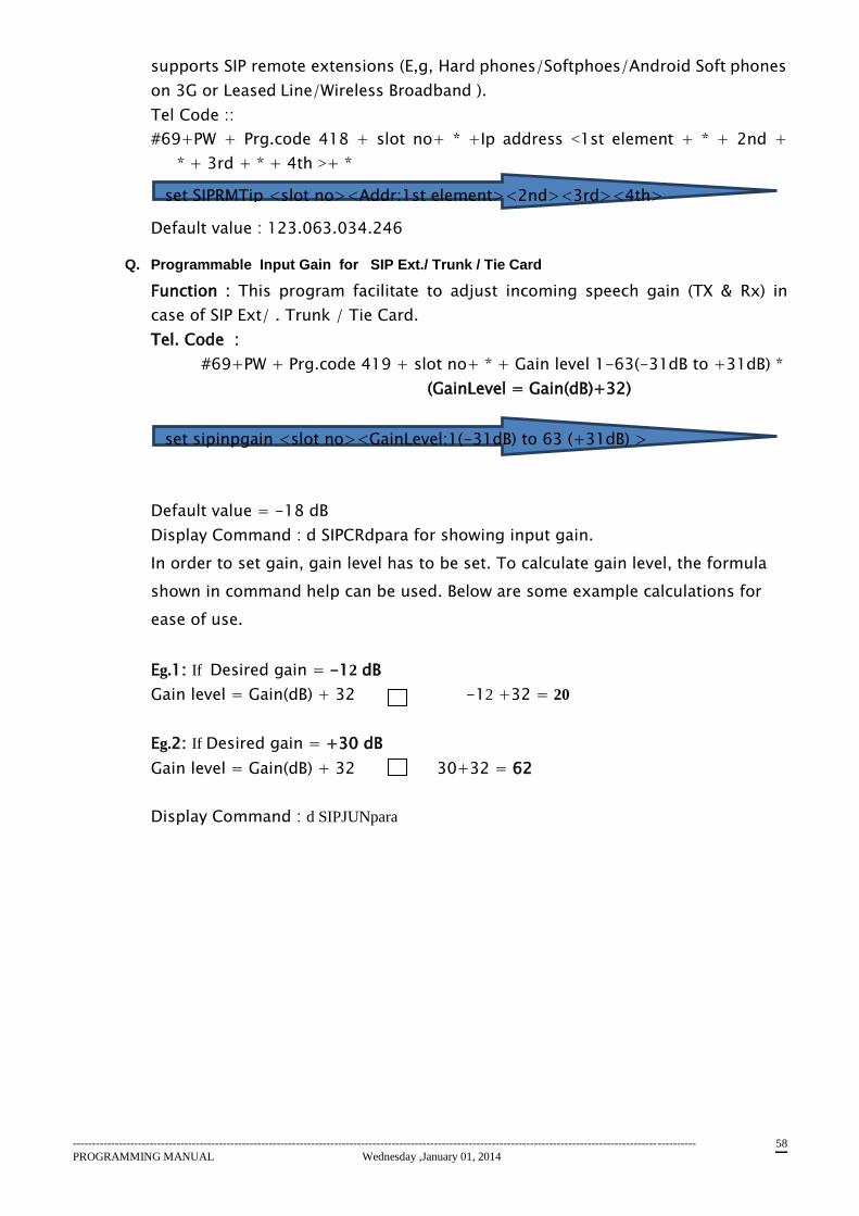
------------------------------------------------------------------------------------------------------------------------------------------------------------------
PROGRAMMING MANUAL Wednesday ,January 01, 2014 58
supports SIP remote extensions (E,g, Hard phones/Softphoes/Android Soft phones
on 3G or Leased Line/Wireless Broadband ).
Tel Code ::
#69+PW + Prg.code 418 + slot no+ * +Ip address <1st element + * + 2nd +
* + 3rd + * + 4th >+ *
Default value : 123.063.034.246
Q. Programmable Input Gain for SIP Ext./ Trunk / Tie Card
Function : This program facilitate to adjust incoming speech gain (TX & Rx) in
case of SIP Ext/ . Trunk / Tie Card.
Tel. Code :
#69+PW + Prg.code 419 + slot no+ * + Gain level 1-63(-31dB to +31dB) *
(GainLevel = Gain(dB)+32)
Default value = -18 dB
Display Command : d SIPCRdpara for showing input gain.
In order to set gain, gain level has to be set. To calculate gain level, the formula
shown in command help can be used. Below are some example calculations for
ease of use.
Eg.1: If Desired gain = -12 dB
Gain level = Gain(dB) + 32 -12 +32 = 20
Eg.2: If Desired gain = +30 dB
Gain level = Gain(dB) + 32 30+32 = 62
Display Command : d SIPJUNpara
set SIPRMTip <slot no><Addr:1st element><2nd><3rd><4th>
set sipinpgain <slot no><GainLevel:1(-31dB) to 63 (+31dB) >

------------------------------------------------------------------------------------------------------------------------------------------------------------------
PROGRAMMING MANUAL Wednesday ,January 01, 2014 59
14 VOIP TRUNK JUNCTION NETWORKING
Now NEOS has been featured to provide connectivity for SIP Junction. Establish VoIP calling using services provided by …… through LAN (IP). For this one SIP card needs to be installed in both the systems configured as VOIP TRUNK. This enables external calls over IP. The programming required for the same are as follows : Note that since execution of these commands require online response from the SIP Trunk card the programming for these features is possible only through Hyper commands ONLY. A. SIP JUN Enable / Disable
Function : Tel. Code N.A.
Default : Enable
B. Display SIP Trunk Name
Function : SIP Line name can be of alphanumeric type.
Tel. Code N.A.
Default : 111-126 for trunk 01-16.
C. SIP Line ID : SIP line ID of numeric type only.
Function :
Tel. Code N.A.
Default : 111-126 for trunk 01-16.
D. Authentication ID for SIP Line :
Function :
Tel. Code N.A.
Default : 111-126 for trunk 01-16.
E. Authentication Password for SIP Line
Function : Authentication password can be of alphanumeric type.
Tel. Code N.A.
Default : 111-126 for trunk 01-16.
F. SIP Trunk Mode
Function :
Tel. Code N.A.
set sipen <slot no.><Trunk No.01-16><Digit:1-Enable,0-Disable>
Set sipdisp <slot no.><Trunk No.01-16><Name: 01-16 characters>
Set sipid <slot no.><Trunk No.01-16><ID: 01-16 characters>
Set sipathid <slot no.><Trunk No.01-16><ID: 01-16 characters>
Set sipathpw <slot no.><Trunk No.01-16><PW: 01-16 characters>
Set siptmode <slot no.> <Digit: 1-Proxy,0-Peer to Peer>
------------------------------------------------------------------------------------------------------------------------------------------------------------------
PROGRAMMING MANUAL Wednesday ,January 01, 2014 60
Default: Peer to peer mode
G. Proxy Server Address for SIP Line :
Function ;
Tel. Code N.A.
Default: IP address: 10, 25, 10, 111 & Port No: 5060
H. Registration Flag for SIP Line :
Function :
Tel. Code N.A.
Default: Disable
I. Register Server Address for SIP Line :
Function :
Tel Code N.A.
Default: IP address: 10, 25, 10, 111 & Port No: 5060
J. Out Bond Proxy Flag for SIP Line :
Function:
Tel. Code N.A.
Default: Disable
K. Out bond proxy server address for SIP Line :
Function :
Tel code : N.A.
Default: IP address: 10, 25, 10, 111 & Port No: 5060
L. Register Expiry timer for SIP Line :
Function :
Tel. Code N.A.
Default 3600 Sec.
M. Transport Protocol for SIP Line :
Function :
Tel code N.A.
Set sipprxyadd<slot no.> <IP address> <Port no.: 0-65535>
Set sipregstr <slot no.> <Digit: 1- Enable, 0- Disable>
Set siprgaddr <slot no.> <IP address> <Port no.: 0-65535>
Set sipobprxy <slot no.> <Digit: 1- Enable, 0- Disable>
Set sipobaddr <slot no.> <IP address> <Port no.: 0-65535>
Set siprgexpry <slot no.> <Duration: 0-65535sec>
Set siptxproto <slot no.> <Type: 0-UDP, 1- TCP>
------------------------------------------------------------------------------------------------------------------------------------------------------------------
PROGRAMMING MANUAL Wednesday ,January 01, 2014 61
Default UDP Protocol
N. DTMF Mode for SIP Line :
Function :
Tel. Code N.A.
Default RTP Method
O. Enable Vocoder for SIP Line :
Function :
Tel. Code N.A.
Default Enable
P. Preferred Vocoder for SIP Line :
Function :
Tel. Code N.A.
Display commands
D SIPTRKpara : Displays SIP trunk line parameters:
D SIPPRXY : Displays SIP trunk proxy parameters:
D SIPVOcoder : Displays SIP trunk vocoder parameters:
Set sipdtmfmth <slot no.> <Method: 0-Audio, 1-RTP, 2-SIP Info>
Set sipvocoen <slot no.> <vocoder no. 0-4> <Digit: 1-Enable, 0 -Disable>
Set sipprfvoco <slot no.> <vocoder no. 0-4> <Preferred vocoder no.0-4>
0 - Vocoder G729
1 - Vocoder G711PCMU
2 - Vocoder G711 PCMA
3 - Vocoder G723
4 - Vocoder G72632
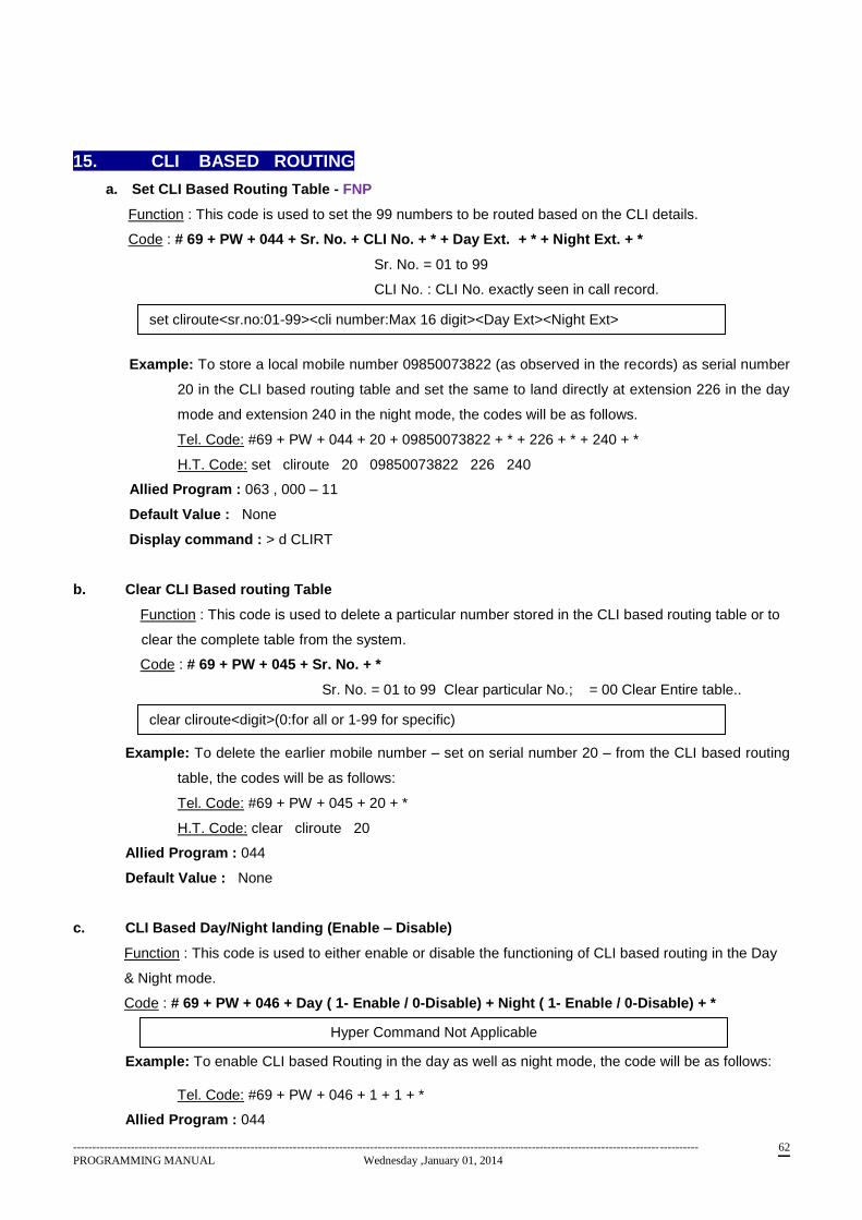
------------------------------------------------------------------------------------------------------------------------------------------------------------------
PROGRAMMING MANUAL Wednesday ,January 01, 2014 62
15. CLI BASED ROUTING
a. Set CLI Based Routing Table - FNP
Function : This code is used to set the 99 numbers to be routed based on the CLI details.
Code : # 69 + PW + 044 + Sr. No. + CLI No. + * + Day Ext. + * + Night Ext. + *
Sr. No. = 01 to 99
CLI No. : CLI No. exactly seen in call record.
Example: To store a local mobile number 09850073822 (as observed in the records) as serial number
20 in the CLI based routing table and set the same to land directly at extension 226 in the day
mode and extension 240 in the night mode, the codes will be as follows.
Tel. Code: #69 + PW + 044 + 20 + 09850073822 + * + 226 + * + 240 + *
H.T. Code: set cliroute 20 09850073822 226 240
Allied Program : 063 , 000 – 11
Default Value : None
Display command : > d CLIRT
b. Clear CLI Based routing Table
Function : This code is used to delete a particular number stored in the CLI based routing table or to
clear the complete table from the system.
Code : # 69 + PW + 045 + Sr. No. + *
Sr. No. = 01 to 99 Clear particular No.; = 00 Clear Entire table..
Example: To delete the earlier mobile number – set on serial number 20 – from the CLI based routing
table, the codes will be as follows:
Tel. Code: #69 + PW + 045 + 20 + *
H.T. Code: clear cliroute 20
Allied Program : 044
Default Value : None
c. CLI Based Day/Night landing (Enable – Disable)
Function : This code is used to either enable or disable the functioning of CLI based routing in the Day
& Night mode.
Code : # 69 + PW + 046 + Day ( 1- Enable / 0-Disable) + Night ( 1- Enable / 0-Disable) + *
Example: To enable CLI based Routing in the day as well as night mode, the code will be as follows:
Tel. Code: #69 + PW + 046 + 1 + 1 + *
Allied Program : 044
set cliroute<sr.no:01-99><cli number:Max 16 digit><Day Ext><Night Ext>
clear cliroute<digit>(0:for all or 1-99 for specific)
Hyper Command Not Applicable
------------------------------------------------------------------------------------------------------------------------------------------------------------------
PROGRAMMING MANUAL Wednesday ,January 01, 2014 63
Default Value : Enable.
16. MSN BASED ROUTING
For MSN No. programming follow programming sequence as
Prog. 201, 202, 207 & 203. All program data related to MSN can be viewed using command
> d msnt
Note : MSN Tables will be 1 – 3 for 256P CPU whereas 1 – 4 for Combo CPU, ARM CPU 0.7 and
ARM Split CPU 0.3 onwards.
a. Assign MSN Table to Junction
Function : This code is used to assign a particular MSN table to a PRI junction connected to the
system. Please note that more than one MSN table can be assigned to a particular PRI junction.
On the other hand, a provision for 4 separate tables has been made so as to cater to a system
with more than one PRI card.
Code : # 69 + PW + 201 + JUN No. (XXX) + MSN Table No. (1 – 4 ) + *
Example: To assign MSN table 1 to the PRI line on junction 005, the codes will be as follows:
Tel. Code: #69 + PW + 005 + 1 + *
H.T. Code: set msntbljun 005 1
Allied Program : None
Default Value : None.
b. Program MSN Number length
Function : This code allows the user to define the maximum length of the MSN number to be followed
by the system. Please note that this number cannot exceed 4 digits as the remaining digits belong to
the pilot number to be added as the prefix.
Code : # 69 + PW + 202 + MSN Tbl. No.(1 – 4) + MSN No. Length (X) + *
Example: To set the maximum length of the MSN numbers as 3 digits for MSN table number 1, the
codes will be as follows:
Tel. Code: #69 + PW + 202 + 1 + 3 + *
H.T. Code: set msnnolen 1 3
Allied Program : 201
Default Value : None.
c. Assign MSN No. to Port
Function : This code is used to define the MSN Table contents including the representing MSN
numbers for their respective ports on the extension side. Please note that the port number should not
be confused with the junction or extension number. Each slot in the system represents 16 ports counted
set msntbljun <junno><msn tbl no:1-4>
set msnnolen <msntbl no:1-4><msnno len:max.8>
------------------------------------------------------------------------------------------------------------------------------------------------------------------
PROGRAMMING MANUAL Wednesday ,January 01, 2014 64
from bottom to top, irrespective of the type of card physically used. Same program can be used to
assign MSN no. to Hunt groups. For port No. details please refer page 101..
Code : # 69 + PW + 203 + MSN Tbl. No. ( 1 – 4 ) + * + port no. (XXX) + MSN No.
( as per length programmed) + * + port no. + MSN no. + * + ….
Example: Going by the example stated above, let us assume that a 8 port JLCC is inserted in slot 1
and a 16 port LCC in slot 2. Then to assign the MSN number 223 to the first extension port on
the JLCC (this will be port 005) and MSN number 239 to the 2nd
port on the LCC16 card (this
will be port 018) for MSN Table 1, the codes will be as follows:
Tel. Code: #69 + PW + 203 + 1 + * + 005 + 223 + * + 018 + 239 + *
H.T. Code: set msnportno 1 005 223
set msnportno 2 018 239
Allied Program : 201, 202, 207
Default Value : None.
Note that for defining MSN on hunt group use port No. 131 to 145 to represent Hunt Groups 01 to 15
respectively.
d. Clear MSN No. for port
Function : This code is used to clear a particular MSN number – assigned to a port using the above
code – from a particular MSN Table.
Code : # 69 + PW + 204 + MSN Tbl. No. ( 1 – 4 ) + port no. (XXX) + *
Example: To clear the MSN number set for the port 018 (as per the previous example), the codes will
be as follows:
Tel. Code: #69 + PW + 204 + 1 + 018 + *
H.T. Code: clear msnport 1 018
Please note that if this command executed, MSN landing needs to be enabled using code #504 + 1 for
the specific ext.
Allied Program : 201, 203
Default Value : None
e. Clear MSN Number Table
Function : This code is used to clear a complete MSN Table – consisting of 100 MSN numbers – as
stored in the system.
Code : # 69 + PW + 205 + MSN Tbl. No. ( 1 – 4 ) + *
set msnportno <msntbl no:1-4> <port no:001-145> <msn no:as per msnno len>
clear msnport<msntbl no:1-4><port no:001-130/162/258>
clear msntbl<msntbl no:1-4>
------------------------------------------------------------------------------------------------------------------------------------------------------------------
PROGRAMMING MANUAL Wednesday ,January 01, 2014 65
Example: To clear the MSN Table 1 – as stored in the earlier examples – the codes will be as follows:
Tel. Code: #69 + PW + 205 + 1 + *
H.T. Code: clear msntbl 1
Please note that if this command executed, MSN landing needs to be enabled using code #504 + 1 for
all the extensions.
Allied Program : 201
Default Value : None
Note : After clearing MSN table due to any reasons, for MSN landing to happen it is required to execute
program 208 for the said MSN Table as well as execute feature code # 504 + 1 from extensions where
MSN landing is anticipated.
f. Clear Pilot Number
Function : As explained earlier, the Service Provider assigns a pilot number to each PRI/E1 user.
However, on changing the PRI/E1 Service Provider, the pilot number too is bound to change. Hence,
this code is used to clear the Pilot Number stored in the system earlier for a particular MSN Table.
Code : # 69 + PW + 206 + MSN Tbl. No. ( 1 – 4 ) + *
Example: To clear the Pilot Number stored for the MSN Table 2 (irrespective of what the actual digit
values), the codes will be as follows:
Tel. Code: #69 + PW + 206 + 2 + *
H.T. Code: clear pilotno 2
Allied Program : 201, 207
Default Value : None
g. Program pilot Number
Function : Each Service Provider assigns a separate Pilot Number for each PRI/E1 line. This code is
used to set the Pilot Number for each of the MSN Tables in accordance with the number of PRI/E1 lines
or MSN Tables assigned per line.
Code : # 69 + PW + 207 + MSN Tbl. No. ( 1 – 4 ) + * + digits… + *
Example: To set the Pilot Number for MSN Table 1 as 26904000 (where the last 3 digits will be
changed in accordance with the MSN Table programming), the codes will be as follows:
Tel. Code: #69 + PW + 207 + 1 + * + 26904000 + *
H.T. Code: set pilotno 1 26904000
Allied Program : 201
Default Value : None
Display Command : d MSNT
clear pilotno<msntbl no:1-4>
set pilotno <msntbl no:1-2><pilot no>
------------------------------------------------------------------------------------------------------------------------------------------------------------------
PROGRAMMING MANUAL Wednesday ,January 01, 2014 66
h. MSN Day/Night landing (Enable/Disable)
Function : Some organizations may want MSN based routing to be operational all the time whereas
others may wish for it to be operational only during office hours. This code is thus used to enable or
disable MSN based Routing for office & non-office hours in accordance with the user’s requirement.
This command along with user code #504+1 is required to be dialed if MSN Table is erased &
reprogrammed due to any mistake occurred.
Code : # 69 + PW + 208 + MSN Tbl. No. ( 1 – 4) + Day ( 1 / 0 ) + Night ( 1 / 0 ) + *
Note that this program is not possible through Hyper Command.
i. Program MSN CLI Display Number
Function : This program facilitate the user to choose the number to be displayed to called party when
O/G call made using PRI. Refer to user feature code # 506.
Code : # 69 + PW + 209 + MSN Tbl. No. ( 1 – 4 ) + * + Port No. (001-130) + CLI display port no.
(001 – 145) + *
Allied Program : 203, User feature #506.
Default Value : None
set MSNCLIdisp <msntbl no:1-4><port no : 1-130162/258> <clidisp:1-145/172/285>
------------------------------------------------------------------------------------------------------------------------------------------------------------------
PROGRAMMING MANUAL Wednesday ,January 01, 2014 67
17 GSM CARD INTERFACE
Following programs facilitates to program GSM Junctions available from GSM Card
a. Setting BASE Station :
Function : This code is used to define Base station where the PABX is installaed. This would enable
the used to dial Local Land line numbers without STD code for the city which is required to dial while
making a Local LL call from a mobile.This is useful for making Local calls using GSM SIM. The
code for the same through Telephone is as follow :
Tel. Code : # 69 + PW + 080 + Digits + * ( Digit : STD code of the base station of the GSM card)
Example : To define base station for a system installed in Delhi and using GSM trunk the code would
be as follows :
Tel. code : # 69 + PW + 080 + 011 + *
Allied Program : None Default Value : None
Display Command :
b. Setting MIC Gain :
Function : This program would enable to improve the TX of the speech on specific JUN. (Useful if user
complains that o/g speech is low).
Tel. code #69+1234+220+<JUN NO> + <GAIN> + * (Gain : 00-15)
Allied Program : None.
Default Value : 02
Display Command : d GSM
c. Setting Speaker Gain :
Function : This command would enable to improve the I/C gain of the speech on specific JUN. (Useful
if user complains that the speech from the called party is low i.e. incoming speech low).
Tel. Code. : #69+1234+221+<JUN NO> + <GAIN> + * (Gain : 00-99)
Allied Program : None
Default Value : 50
Display Command : d GSM
d. Setting Side Tone :
Function :
Tel. Code : #69 + 1234 + 222 + <JUN NO> + <side tone >
Allied Program : None.
Default Value : 00 .
Display command : > d GSM
set gsmspeaker <junno: 000-255> <speakergain : 00-99>
set gsmmic <junno: 000-255> <micgain : 00-15>
set gsmsdtone <junno: 000-255> <sidetone : 00-15>
Hyper Command Not Available
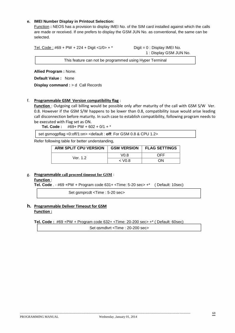
------------------------------------------------------------------------------------------------------------------------------------------------------------------
PROGRAMMING MANUAL Wednesday ,January 01, 2014 68
e. IMEI Number Display in Printout Selection:
Function : NEOS has a provision to display IMEI No. of the SIM card installed against which the calls
are made or received. If one prefers to display the GSM JUN No. as conventional, the same can be
selected.
Tel. Code ; #69 + PW + 224 + Digit <1/0> + * Digit = 0 : Display IMEI No.
1 : Display GSM JUN No.
Allied Program : None.
Default Value : None
Display command : > d Call Records
f. Programmable GSM Version compatibility flag : Function : Outgoing call billing would be possible only after maturity of the call with GSM S/W Ver. 0.8. However if the GSM S/W happens to be lower than 0.8, compatibility issue would arise leading call disconnection before maturity. In such case to establish compatibility, following program needs to be executed with Flag set as ON.
Tel. Code : #69+ PW + 602 + 0/1 + *
Refer following table for better understanding,
ARM SPLIT CPU VERSION GSM VERSION FLAG SETTINGS
Ver. 1.2 V0.8 OFF
< V0.8 ON
g. Programmable call proceed timeout for GSM : Function : Tel. Code . - #69 +PW + Program code 631+ <Time: 5-20 sec> +* ( Default: 10sec)
h. Programmable Deliver Timeout for GSM Function :
Tel. Code : #69 +PW + Program code 632+ <Time: 20-200 sec> +* ( Default: 60sec)
This feature can not be programmed using Hyper Terminal
set gsmogpflag <0:off/1:on> <default : off: For GSM 0.8 & CPU 1.2>
Set gsmprcdt <Time : 5-20 sec>
Set gsmdlvrt <Time : 20-200 sec>

------------------------------------------------------------------------------------------------------------------------------------------------------------------
PROGRAMMING MANUAL Wednesday ,January 01, 2014 69
18. GSM PRI EXTENSION WITH MSN COMPATIBILITY (Refer SUN41 for more details)
a. Set MSN No. length to PRI :
Function : This program enables to assign MSN No. lenth to the MSN Table assigned to the PRI
Junction.
Tel. Code : #69 + PW + 241 + MSN tbl No:1/2 + MSN no Length (MAX 10 Digits) + *
b. Set MSN Junction to PRI Extension
Function : This program enables to associate MSN Table with PRI Junction
Tel. Code : #69 + PW + 242 + MSN Tbl no:1/2 + Jun No + * + MSN No.(MAX 10 Digits) + *
c. Assign PRI Extension to MSN Table
Function : This program assigns PRI Ext. group to MSN Table.
Tel. Code : #69 + PW + 243 + Pri ext group no. + MSN Tbl No:1/2+ *
d. Clear MSN Table
Function : This command can be used to clear MSN Table
Tel. Code : #69 + PW + 244 + MSN Tble no : 1/2+ *
e. Clear assigned MSN Junction to PRI Extension
Function : This program clears assignment of MSN table associated with PRI Junction.
Tel. Code : #69 + PW + 245 + MSN Tble no : 1/2+ Jun No +*
f. Hyper display command d> pemsnt
------------------------------------------------------------------------------------------------------------------------------------------------------------------
PROGRAMMING MANUAL Wednesday ,January 01, 2014 70
19. Restricted & Denied Table Programming
a. Restricted Table Programming
Function: To program the set of numbers that the user wishes his employees to have access to for
outdialing, irrespective of their CoS. 8 such tables with a total of 10 numbers in each of 8 digit length
max. can be programmed
Code: #69 + PW + 121 + Tb. No. (1 – 8) + * + No. + * + No. +…..
Example: To add the following numbers to restricted table 1, the codes will be as follows:
(Numbers to be added >> 09850073822, 02225555956, 26876120, etc)
Tel. Code: #69 + PW + 121 + 1 + * + 09850073 + * + 02225555 + * + 26976120 + * + …..
H.T. Code: set resttbl 1 1 09850073
set resttbl 1 2 02225555
set resttbl 1 3 26976120
Please note that, if user has to be allowed to dial local Nos., the same also must be included in
Restricted Table.
Allied Program : 000–16.
Default Value : None.
Display command : > d RE
b. Clear Restricted Table
Function: To erase the numbers in a particular Restricted Table in order to feed new numbers
Code: #69 + PW + 122 + Tb. No. (1 – 8) + *
Example: To clear the contents of Restricted Table 2 from the system, the codes will be as follows:
Tel. Code: #69 + PW + 122 + 2 + *
H.T. Code: clear resttbl 2
Allied Program : 121
Default Value : None
set resttbl<tblno:1-8><entry no:1-10><digits>
clear resttbl<tblno:1-8>
------------------------------------------------------------------------------------------------------------------------------------------------------------------
PROGRAMMING MANUAL Wednesday ,January 01, 2014 71
c. Denied Table Programming
Function: To program the set of numbers that the user does not wish his employees to have access to
for outdialing, irrespective of his CoS. 8 such tables with a total of 10 numbers of 8 digit length max. in
each can be programmed
Code: #69 + PW + 123 + Tb. No. (1 – 8) + * + No. + * + No. +….
Example: To add the following numbers to denied table 4, the codes will be as follows:
(Numbers to be added >> 09850073822, 02225555956, 26876120, etc)
Tel. Code: #69 + PW + 123 + 4 + * + 09850073 + * + 02225555 + * + 26976120 + * + …..
H.T. Code: set denytbl 4 1 09850073
set denytbl 4 2 02225555
set denytbl 4 3 26976120
Allied Program : 000 – 17.
Default Value : None.
Display command : > d DE
d. Clear Denied Table
Function: To erase the numbers in a particular Denied Table in order to feed new numbers
Code: #69 + PW + 124 + Tb. No. (1 – 8) + *
Example: To clear the contents of Restricted Table 7 from the system, the codes will be as follows:
Tel. Code: #69 + PW + 124 + 7 + *
H.T. Code: clear denytbl 7
Allied Program : 123.
Default Value : None
set denytbl<tblno:1-10><entry no:1-10><digits>
clear denytbl<tblno:1-8>
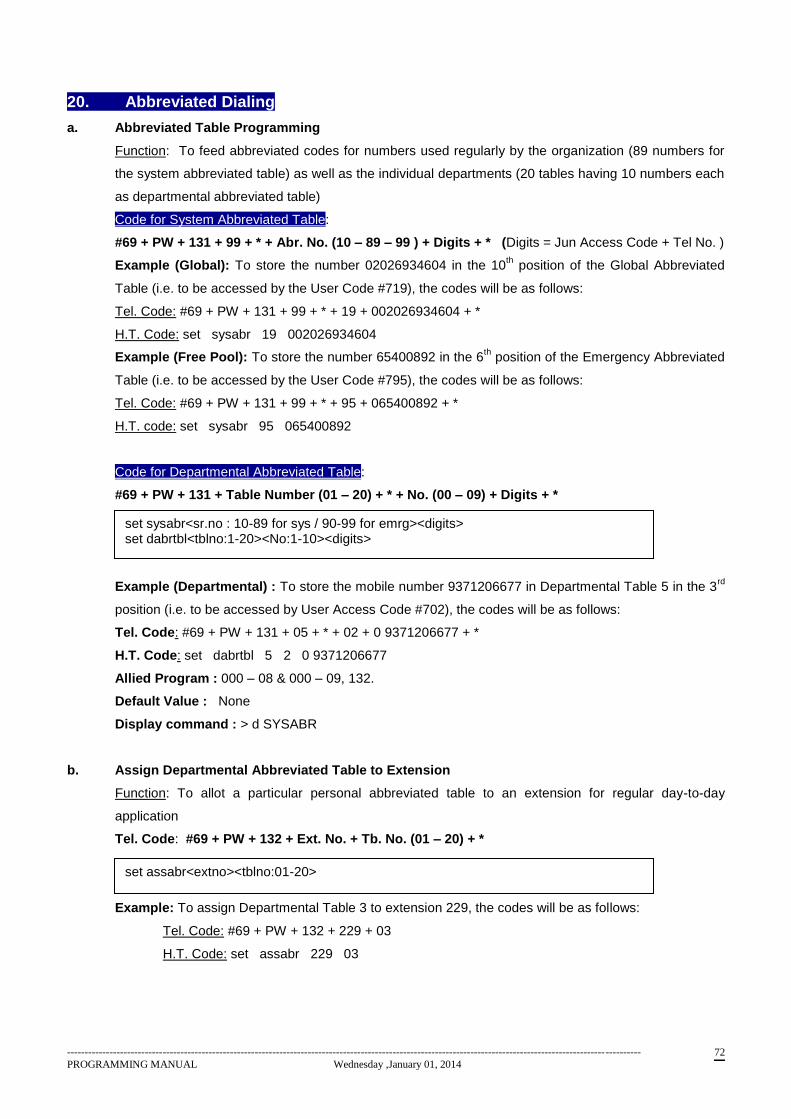
------------------------------------------------------------------------------------------------------------------------------------------------------------------
PROGRAMMING MANUAL Wednesday ,January 01, 2014 72
20. Abbreviated Dialing
a. Abbreviated Table Programming
Function: To feed abbreviated codes for numbers used regularly by the organization (89 numbers for
the system abbreviated table) as well as the individual departments (20 tables having 10 numbers each
as departmental abbreviated table)
Code for System Abbreviated Table:
#69 + PW + 131 + 99 + * + Abr. No. (10 – 89 – 99 ) + Digits + * (Digits = Jun Access Code + Tel No. )
Example (Global): To store the number 02026934604 in the 10th position of the Global Abbreviated
Table (i.e. to be accessed by the User Code #719), the codes will be as follows:
Tel. Code: #69 + PW + 131 + 99 + * + 19 + 002026934604 + *
H.T. Code: set sysabr 19 002026934604
Example (Free Pool): To store the number 65400892 in the 6th position of the Emergency Abbreviated
Table (i.e. to be accessed by the User Code #795), the codes will be as follows:
Tel. Code: #69 + PW + 131 + 99 + * + 95 + 065400892 + *
H.T. code: set sysabr 95 065400892
Code for Departmental Abbreviated Table:
#69 + PW + 131 + Table Number (01 – 20) + * + No. (00 – 09) + Digits + *
Example (Departmental) : To store the mobile number 9371206677 in Departmental Table 5 in the 3rd
position (i.e. to be accessed by User Access Code #702), the codes will be as follows:
Tel. Code: #69 + PW + 131 + 05 + * + 02 + 0 9371206677 + *
H.T. Code: set dabrtbl 5 2 0 9371206677
Allied Program : 000 – 08 & 000 – 09, 132.
Default Value : None
Display command : > d SYSABR
b. Assign Departmental Abbreviated Table to Extension
Function: To allot a particular personal abbreviated table to an extension for regular day-to-day
application
Tel. Code: #69 + PW + 132 + Ext. No. + Tb. No. (01 – 20) + *
Example: To assign Departmental Table 3 to extension 229, the codes will be as follows:
Tel. Code: #69 + PW + 132 + 229 + 03
H.T. Code: set assabr 229 03
set sysabr<sr.no : 10-89 for sys / 90-99 for emrg><digits> set dabrtbl<tblno:1-20><No:1-10><digits>
set assabr<extno><tblno:01-20>
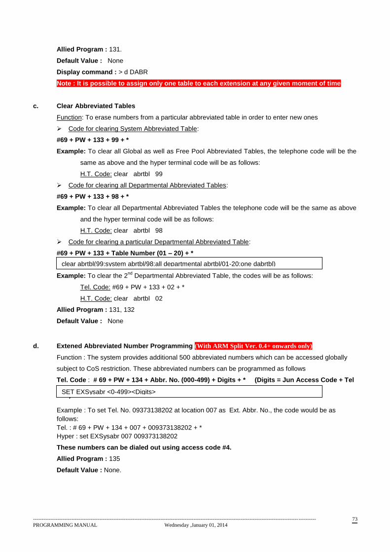
------------------------------------------------------------------------------------------------------------------------------------------------------------------
PROGRAMMING MANUAL Wednesday ,January 01, 2014 73
Allied Program : 131.
Default Value : None
Display command : > d DABR
Note : It is possible to assign only one table to each extension at any given moment of time
c. Clear Abbreviated Tables
Function: To erase numbers from a particular abbreviated table in order to enter new ones
Code for clearing System Abbreviated Table:
#69 + PW + 133 + 99 + *
Example: To clear all Global as well as Free Pool Abbreviated Tables, the telephone code will be the
same as above and the hyper terminal code will be as follows:
H.T. Code: clear abrtbl 99
Code for clearing all Departmental Abbreviated Tables:
#69 + PW + 133 + 98 + *
Example: To clear all Departmental Abbreviated Tables the telephone code will be the same as above
and the hyper terminal code will be as follows:
H.T. Code: clear abrtbl 98
Code for clearing a particular Departmental Abbreviated Table:
#69 + PW + 133 + Table Number (01 – 20) + *
Example: To clear the 2nd
Departmental Abbreviated Table, the codes will be as follows:
Tel. Code: #69 + PW + 133 + 02 + *
H.T. Code: clear abrtbl 02
Allied Program : 131, 132
Default Value : None
d. Extened Abbreviated Number Programming (With ARM Split Ver. 0.4+ onwards only)
Function : The system provides additional 500 abbreviated numbers which can be accessed globally
subject to CoS restriction. These abbreviated numbers can be programmed as follows
Tel. Code : # 69 + PW + 134 + Abbr. No. (000-499) + Digits + * (Digits = Jun Access Code + Tel
No. )
Example : To set Tel. No. 09373138202 at location 007 as Ext. Abbr. No., the code would be as
follows:
Tel. : # 69 + PW + 134 + 007 + 009373138202 + *
Hyper : set EXSysabr 007 009373138202
These numbers can be dialed out using access code #4.
Allied Program : 135
Default Value : None.
clear abrtbl(99:system abrtbl/98:all departmental abrtbl/01-20:one dabrtbl)
SET EXSysabr <0-499><Digits>
------------------------------------------------------------------------------------------------------------------------------------------------------------------
PROGRAMMING MANUAL Wednesday ,January 01, 2014 74
e. Clear Extended Abbreviated Numbers
Function : This program enables to erase Extended Abbr. Nos. programmed selectively or cumulatively.
Tel. Code : . : # 69 + PW + 135 + Ex. Abbr. Code (000-499) / 999 (for ALL) + *
Allied Program : 134
Default Value : None
Clear EXAbrtbl <0-499/999> (*999 for clearing complete table)
------------------------------------------------------------------------------------------------------------------------------------------------------------------
PROGRAMMING MANUAL Wednesday ,January 01, 2014 75
21. METER SETTINGS & MISCELANEOUS
a. Bill Start Time
Function: This code is used to set the Start Time for billing local as well as STD calls initiated via
the system, i.e. the system will start billing the outgoing call only after the set time has elapsed.
Please note that this programming is not possible via the hyper terminal.
Code: #69 + PW + 145 + Local Start Time + STD Start Time + *
( 00 – 99 Sec.) ( 00 – 99 Sec.)
Example: To set the Start Time for billing Local Calls as 20 secs and for STD calls as 5 secs, the code
will be as follows:
Tel. Code: #69 + PW + 145 + 20 + 05 + *
Allied Program : None
Default Value : None
Display command : > d SYSM
b. Initialize Bill Parameters
Function: This code is used to clear/initialize the parameters related to billing in the system so as to
start with fresh records. Please note that this programming is not possible via the hyper terminal.
Code: #69 + PW + 155 + Digit + *
Digit : 0 – Clear All
1 – Clear Day & Month Bill ( Both current & previous),
Call log serial No. & Call Print Serial No.
2 – Clear Budget
3 – Clear STD, CCT, PRPC Tables.
Example: To clear budget related parameters of the system, the code will be as follows:
Tel. Code: #69 + PW + 155 + 2 + *
c. Program Call type
Function : This code is used to program the type of calls that need to be logged in the system buffer.
Code: # 69 + PW + 156 + Digit + *
Digit: 0 – Log all calls
1 – Log Outgoing only.
set billtime<local start time:0-99><std start time:0-99>
set logtype<type:0= Log all calls 1=Log Outgoing only>
This feature can not be programmed using Hyper Terminal
------------------------------------------------------------------------------------------------------------------------------------------------------------------
PROGRAMMING MANUAL Wednesday ,January 01, 2014 76
Example: To log only outgoing calls in the system buffer, the codes will be as follows:
Tel. Code: #69 + PW + 156 + 1
H.T. Code: set logtype 1
d. Program Call Record Serial Number
Function: Set the serial number from where you wish to print the call log details.
Code: #69 + PW + 163 + XXXX + *
XXXX: 4 digit call record serial number ( 0000-9290)
Example: To start printing the call record in the buffer after the 200 mark, the codes will be as follows:
Tel. Code: #69 + PW + 163 + 0200 + *
H.T. Code: set crsrno 200
Please note that on line printing is possible only on Hyper Terminal and can not be directed to
Parallel port.
set crsrno<call record sr no:0-9290>
------------------------------------------------------------------------------------------------------------------------------------------------------------------
PROGRAMMING MANUAL Wednesday ,January 01, 2014 77
22. BILLING & SETTING COST TABLES
a. Program PRPC (Pulse Rate Pulse Change) Table
Function: This code is used to set the Pulse Rates & Pulse Charges (PRPC) applicable for the various
Service Providers available in the area. Please note that there is a provision to store upto 25 PRPC
tables. So, the user should try to define all the permutations & combinations possible of the pulse rates
& pulse charges individually.
Code: #69 + PW + 151+ PRPC Tb. No. + FPR + PR + * + FPC1 + PC1 + * + FPC2 + PC2 +--+* (Up
to FPC5 & PC5 i.e. Max Cust types (5))
PRPC Table No.: 01 to 25
FPR (First Pulse Rate): 0000 to 9999 (Rate in 0.1 sec) e.g. Enter 1800 for 180 sec FPR
PR (Pulse Rate): 0000 to 9999 (Rate in 0.1 sec)
FPC1 (Service Charge for Cust type 1): 0000 to 9999 (in Paise)
PC1 (Pulse Charge for Cust Type 1): 0000 to 9999 (in Paise)
Allied Program : 000 – 21.; 152 & 153.
Default Value : None
Display Command : > d PRPC
b. Program Call Cost Table (CCT)
Function: The various PRPC tables mentioned above now have to be coupled with the available
Service Providers - as per the charges applicable for the various time zones - to create the cost tables.
This code is used to define the same.
Code: #69 + PW + 152 + Service Pro. No. + CCT No +* Zone Start Time for Zone1 + PRPC Table
for Zone1 + *…..+ * (upto 4 time zones)
Service Pro No : 0 to 5
CCT ( Call Cost Table ) No : 01 to 16
Zone Start Time : HHMM
PRPC(Pulse Rate Pulse Charge) table no : 01 to 25
Allied Program : 151.
Default Value: None
Display Command : > d CCT
set fprpc<prpctbl:1-25><fpr:0-9999>[<Cust#1fpc:0-9999ps>...uptoCust#5] set prpc<prpc tbl:1-25><pr:0-9999>[<Cust#1pc:0-9999paise>...uptoCust#5]
set cct<sp.no:0-5><cct no:1-16>[<TZ1st.time:HHMM><prpc tblno:1-25>..upto4 TZ]
set dprpcloc<servpro:0-5><fpr:0-9999><pr:0-9999><fpc:0-9999><pc:0-9999> set dprpcstd<servpro:0-5><fpr:0-9999><pr:0-9999><fpc:0-9999><pc:0-9999> set dprpcisd<servpro:0-5><fpr:0-9999><pr:0-9999><fpc:0-9999><pc:0-9999>
------------------------------------------------------------------------------------------------------------------------------------------------------------------
PROGRAMMING MANUAL Wednesday ,January 01, 2014 78
c. Program STD/ISD Codes
Function: This code is used to assign the various Cost Tables to the codes applicable for the same so
that the system can bill the outgoing calls accordingly.
Code: #69 + PW + 153+ Code Sr. No+ Code Digits + * + CCT for SP0 +* + CCT for SP1 +* + -----+
CCT for Max Service Provider + * Code Sr. No. : 01 to 99
CCT ( Call cost Table ) for SP1 to SP5 : 01 to 16 each
Allied Program: 000–21; 151 & 152.
Default Value : None
Display Command : > d STD
Note : Code Sr. No. should be contiguous 01-99.
d. Program PRPC (Pulse Rate Pulse Change) Table for Centrex Lines
Function: This code is used to set the Pulse Rates & Pulse Charges (PRPC) for lines defined as
Centrex
Code: #69 + PW + 164 + FPR + PR + * + FPC1 + PC1 + *
FPR (First Pulse Rate): 0000 to 9999 (Rate in 0.1 sec) e.g. Enter 1800 for 180 sec FPR
PR (Pulse Rate): 0000 to 9999 (Rate in 0.1 sec)
FPC (Service Charge): 0000 to 9999 (in Paise)
PC (Pulse Charge): 0000 to 9999 (in Paise)
Allied Program : 078.
Default Value : None.
Display Command :
set std<code srl no:1-99><code><cct sp0><cct sp1>...<cct for sp5> ( CCT:1-16)
Programming this feature through Hyper Terminal not applicable.
------------------------------------------------------------------------------------------------------------------------------------------------------------------
PROGRAMMING MANUAL Wednesday ,January 01, 2014 79
23. BUDGETING
a. Program Fix Budget
Function: To set the outgoing call budget on a daily & monthly basis - for an extension or a junction line
- so as to ensure that the P&T bills for each do not exceed the set limits. After budget exhaustion, the
outdialign rights would be decided by the CoS set by feature code 18 in class programming, otherwise
O/G calls are barred on budget exhaustion.
Code: #69 + PW + 161 + Ext. No./JUN No. + Day Budget + Month Budget + *
Day Budget: 0000 to 9999
Month Budget: 000000 to 999999
Example : To program a day budget of Rs. 200 and a month budget of Rs. 1500 for extension 250
Tel. Code: #69 + PW + 161 + 250+ 0200 + 001500 + *
H.T. Code: set fixbudget 250 150 1500
Allied Program : 000–21; 151, 152 & 153.
Default Value : None : No Barring for Budget..
Display Command : > d BILL
b. Program Enhanced Budget
Function: To increase the day/month budget of a particular user in event of the cause being genuine.
The budget would get set to Fix budget (Day/Month) on next day/Month accordingly. While enhancing
the budget, consumed budget needs to be taken into account.
Code: #69 + PW + 162 + Ext. No./JUN No. + Enhanced Day Budget + Enhanced Month Budget + *
Enhanced Day Budget : 0000 to 9999
Enhanced Month Budget: 000000 to 999999
Example : To enhance a day budget of Rs. 300 and a month budget of Rs. 2000 for extension 250 Tel. Code: #69 + PW + 162 + 250+ 0300 + 002000 + * H.T. Code: set enhbudget 250 300 2000
Allied Program : 161.
Default Value : None : Infinite Budget. Equals Fix Budget if budget programmed..
Display Command : > d BILL
c. Clear Budget ( Only through Hyper)
set fixbudget<ext/jun no><day bud(Rs):0-9999 ><month bud(Rs):0-999999>
set enhbudget<ext/jun no><day bud(Rs):0-9999 ><month bud(Rs):0-999999>
Clear budget <extno/ junno>
------------------------------------------------------------------------------------------------------------------------------------------------------------------
PROGRAMMING MANUAL Wednesday ,January 01, 2014 80
24. CLOSED USER GROUP - CUG
The system allows the user to define Closed User Groups within the organization, wherein the control of
who is allowed to call whom can be defined by the authorities as per hierarchy & protocol followed in the
company
a. Assign CUG Number to Extension
Function: This program is for creating groups of extensions assigning it a CUG number. There is no
maximum limit on extensions that can be added in a group. However 16 such groups can be created.
Code: #69 + PW + 171 + CUG No. (01 – 16) + * + Ext. No. + * + Ext. No. + …
Example: To create 3 groups, of extension 200,201,202,203 in group 1, 300,301,302,303 in group 2
and 400,401,402,403 in group 3
From Tel: #69 + PW + 171 + 01 + * +200+*+201+*+202+*+203+* #69 + PW + 171 + 02 + * +300+*+301+*+302+*+303+* #69 + PW + 171 + 03 + * +400+*+401+*+402+*+403+* From HT: set cuggrp 200 01
set cuggrp 201 01 set cuggrp 202 01 set cuggrp 203 01 set cuggrp 300 02 set cuggrp 301 02 set cuggrp 302 02 set cuggrp 303 02 set cuggrp 400 03 set cuggrp 401 03 set cuggrp 402 03 set cuggrp 403 03
Allied Program : 172 & 173.
Default Value : None ( All Extensions in CUG Group 1
Display Command : > d E
b. CUG Call Enable (allow calling)
Function: This program is to allow calling from a group to other group(s) created above. It means that
extensions in the group can call extensions in the other group(s). By default all groups are allowed to
call each other. This command is useful to allow calling if it was earlier disallowed.
Code: #69 + PW + 172 + CUG No. (01 – 16) + * + CUG No. (01 – 16) + *…
set cuggrp<extno><cug table no:1-16>
set cugen<cug tbl no:1-16><cug tbl no:1-16>
------------------------------------------------------------------------------------------------------------------------------------------------------------------
PROGRAMMING MANUAL Wednesday ,January 01, 2014 81
Example: To allow group 1 to call 2 and 3; group 2 to call group 3 can be done using the following
program
Tel code: #69 + PW + 172 + 01 + * + 02 + * + 03 + *
#69 + PW + 172 + 02 + * + 03 + *
HT code: set cugen 01 02 set cugen 01 03
Allied Program : 171 & 173.
Default Value : None
Display Command : > d CUG
c. CUG Call Disable (disallow calling)
Function: This program is to disallow calling from a group to other group(s) created above. It means
that extensions in the group cannot call extensions in the other group(s). If it is required to disallow
calling amongst group members with in the group, calling with same group needs to be disabled.
Code: #69 + PW + 173 + CUG No. (01 – 16) + * + CUG No. (01 – 16) + *…
Example: To disallow group 3 to call 1 and 2
Tel code: #69 + PW + 173 + 03 + * + 01 + * + 02 + *
HT code: set cugdis 03 01
set cugdis 03 02
Display Command : > d CUG
set cugdis<cug tbl no:1-16><cug tbl no:1-16>
------------------------------------------------------------------------------------------------------------------------------------------------------------------
PROGRAMMING MANUAL Wednesday ,January 01, 2014 82
25. VOICEMAIL INTEGRATION
a. Program Extension as Voicemail Port
Function: This program defines an Extension as a voice mail port so that strings can be parsed through
this extension which is terminated into Voice Mail Port.
Code: #69 + PW + 053 + Ext. No. + Digit ( 0 – Disable / 1 – Enable ) + *…
Allied Program : 054, 057.
Default Value : None ( Refer Page )
Display Command : > d VMExt
b. Program Voicemail Mode
Function: This program selects the make of Voice Mail Unit connected amongst Synegtic or Voicegate
so that respective strings can be exchanged within Voice mail unit & PABX for Voicemail operation.
Code: #69 + PW + 054 + Digit ( 0 – Disable / 1 – VM1{Synegtic} / 2 – VM2{Voicegate} ) + *…
Allied Program : 053, 057.
Default Value : None
Display Command : > d SYSM (Refer Page
set voicemail <Ext No><Digit : 0 – Disable / 1 – Enable>
Programming this feature through Hyper Terminal not applicable.
------------------------------------------------------------------------------------------------------------------------------------------------------------------
PROGRAMMING MANUAL Wednesday ,January 01, 2014 83
26. SYNAPPS PC CONSOLE APPLICATION
a. Set Agent Interface Mode
Function : This program enables to set the mode of Agent’s Interface as Acknowledged or
unacknowledged.
Tel. Code : #69 + PW + Program code 528 + 1(ACK) or 0(UNACK) + *
At power ON, Agent Interface would be set as Unacknowledged by default. If switched to
Acknowledged, confirmation will be given in the form of tone (Confirmation/Error) within 5Seconds.
b. Reset Agent’s Login Password
Function : This feature enables the administrator to reset an agent’s password as default Password viz. 1234
Tel. Code : #69 + PW + Program Code 529 + Agent ID + *
------------------------------------------------------------------------------------------------------------------------------------------------------------------
PROGRAMMING MANUAL Wednesday ,January 01, 2014 84
27. PROGRAMMING FOR THE ADMINISTRATOR (CONFIDENTIAL)
a. Set Ring Repetition Pattern :
Function: The Ring repetition time can be programmed using following command.
Default value of Ring repetition time is 5 sec .You should increase as minimum as possible. e.g. For
“Innomedia MTA 3328-2Re” requires 7 sec ring repeat time .It works fine if we program the ring
repeat time = 7 sec . So one need not program/try 8 sec. Code : #69 + PW+ 077 + Digit + * . Digit: 5- 8
Allied Program : None.
Default Value : 5.
Display Command : Not available.
b. Program CTI/ HMS-PMS Integration - FNP
Function: This command sets the COM2 Port for CTI applications, i.e. on activating this command, the
strings required from the system to operate CTI (Responz Software), are sent to the COM2 Port which
in turn can be connected to the CTI Server. Third party HMS-PMS S/W can be integrated with NEOS
using the same program. NEOS has been made compatible to operate with IDS HMS S/W. Others also
can be made compatible by adjusting the strings accordingly by the developer.
Options 2 is for CTI operational with flexible numbering plan whereas option 4 is for SYNTEL HMS S/W
Integration with/ without flexible numbering plan. (ARM Split CPU Ver. 0.6 onwards only).
Code: # 69 + PW + 024 + CTI mode + *
Mode : 0 = CTI Disabled 1 = CTI mode for Non Flexi No. Plan 2 = CTI mode for Flexi. No. Plan 3 = HMS mode for Non Flexi. No. 4= HMS mode for Flexi No. Plan ( SYNTEL HMS requires this option exclusively ) 5 – PRI Trace 7 – SYNApps Applicable for Split CPU Ver. 1.8 onwards.
Allied Program : None. However COM port selection should be COM2.
Default Value : Disabled. However once enabled remains active inspite of System being switched
OFF/ON.
For “HMS Strings” details please contact Area Office / H. O., Pune
With introduction of this command henceforth it is not necessary to switch COM port
while using Hyper connectivity application and CTI (Responz) or HMS application using
Prog. 170.
Prog. 170 has been terminated from this version (1.8) onwards.
Programming this feature through Hyper Terminal not applicable.
set CTI Mode < digit > Digit = 0/1/2/3/4
------------------------------------------------------------------------------------------------------------------------------------------------------------------
PROGRAMMING MANUAL Wednesday ,January 01, 2014 85
c. Program DIAL Plan : NOT APLICABLE ARM SPLIT CPU Ver. 1.1 ONWARDS
Function: The dial plan for NEOS can now be programmed to start with any digit between 0 to 9; i.e.
extension numbers can be set as anything in the range 000 to 998 (unless programmed exclusively,
by default, flexible numbering would be from 100 to 799 only) with the exception of 900 & 910 (not
permitted). To ensure that this does not conflict with the single digit seizure of local, STD & Operator
lines (earlier set as 0, 1 & 9 respectively), the user is allowed to reprogram these access codes as well.
Code: #69 + PW+ 047 + Digit (0-9) + Dial Type (1-5) + * 1-EXT dialing 2- Local Jun seize 3- STD Jun seize 4- Operator dialing 5- Redial
Allied Program : None
Default Value : Digit 1-7 for Ext. Dialing. 0 for Local JUN Seize, * for STD JUN Seize, 9 for Operator
dialing & * for redial. ( Refer Page 89 ).
Display Command : > d DIALP
d. Program DUMMY CLI Digits
Function: It has been observed that some CLI Telephone Instruments require more than 3 digits to
display CLI. This program would add additional 0 in Ext. CLI No. so as to make the CLI of the desired
length. User can choose to prefix or suffix these additional 0, as per user’s choice. In case of CLI set
before / after ring, using program 049; it must be set accordingly depending on which of the part of CLI
is getting truncated while displaying on CLI Phone. For Panasonic CLI instruments this program is
mandatory for getting intercom CLI.
Code : #69 + PW+ 048 + Digit ( 0 - 5 ) + Digit (0- Suffix / 1- Prefix ) + *
Allied Program : 000–11
Default Value : 0..
Display Command : > d SYSM.
Set DIALPlan <Digit> (0-9) <Dial Type> (1-5) 1-EXT dialing 2- Local Jun seize 3- STD Jun seize 4- Operator dialing 5- Redial
Set CLIDUMmy <digit: 0-5><0- Suffix / 1-Prefix >
------------------------------------------------------------------------------------------------------------------------------------------------------------------
PROGRAMMING MANUAL Wednesday ,January 01, 2014 86
e. Program CLI BEFORE / AFTER Ring
Function: It has been observed that some telephone instruments acquire power from the line itself. In
such cases the instrument gets activated on first ring, then the CLI information is sent to get it
displayed. This setting is done as CLI before Ring or CLI after ring. By default CLI information is sent
with first ring referred to as before ring.
Code: #69 + PW+ 049 + Digit (0- Before Ring / 1- After Ring) + *
Allied Program : 000 – 11
Default Value : 0.
Display Command : N. A.
f. Program Time-out for External Forwarded Call
Function: To define the Time Limit applicable for all External Forwarded calls forwarded by the system,
wherein after the set time lapses the call is automatically cutoff.
Code: #69 + PW+ 050 + Digit (XX) + *
Digit XX = 01 – 99 Min.
Allied Program: 000 – 26
Default Value: 03 Min.
Display Command : > d EFWD; > d CL
g. Program No. of rings during Auto Attendant
Function: To define the No. of rings that should get extended in case the caller disconnects the call
after hearing Auto Attendant Message or during the message, wherein after the set time lapses the call
is automatically cutoff.
Code: #69 + PW+ 051 + Rings (05 – 30) + *
Allied Program : 065, 116, 067.
Default Value : 30 Rings.
Display Command : N. A.
Set clisend <0-Before Ring / 1- After Ring>
Programming this feature through Hyper Terminal not applicable.
Programming this feature through Hyper Terminal not applicable.
------------------------------------------------------------------------------------------------------------------------------------------------------------------
PROGRAMMING MANUAL Wednesday ,January 01, 2014 87
h. Program Time-out for JUN-JUN Transferred Call
Function : To define the Time Limit applicable for all JUN to JUN transferred calls , wherein after the set
time lapses the call is automatically cutoff.
Code : #69 + PW+ 052 + Digit ( XX ) + *
Digit XX = 01 – 99 Min.
Allied Program : 000–27
Default Value : 03 Min.
Display Command : N. A.
i. COM1 / COM2 Selection ( Valid Only thro’ Telephone)
NOT APPLICABLE FROM SPLIT CPU VER. 1.8 ONWARDS. Refer Prog. 024 )
Function : To use COM portin the System to work as COM1 / COM2 for required application.
COM1 selection would serve to use COM port for Hyper connectivity for Data Display &
system Programming.
COM 2 selection would serve to use COM port for CTI / HMS application as well as for Trace
required for any peculiar problem occurring with PRI. (This would be guided from H.O.)
Code : #69 + PW+ 170 + Digit ( X ) + *
Digit X = 0 – Hyper connectivity (COM1 selection) Default
= 1 – CTI/HMS Application (COM2 selection).
Allied Program : 024
Default Value : COM1.
Display Command : N. A.
j. ‘Transfered Call’ Recall Time Selection
Function : A call transferred by one Ext. to an another and if not attended in 15 Sec ( 5 rings), gets
transferred back to the Transferring Ext.
This program facilitates the user to program the said time varying from 15 Sec to 60 Sec. as per
requirement.
Tel. Code : #69 +PW +105 +<Time 15-60> + *
Allied Program : None
Default Value : 15 Sec.
Display Command : > d SYSM
Programming this feature through Hyper Terminal not applicable.
Programming this feature through Hyper Terminal not applicable.
set trfrecall<Time(sec):15-60>
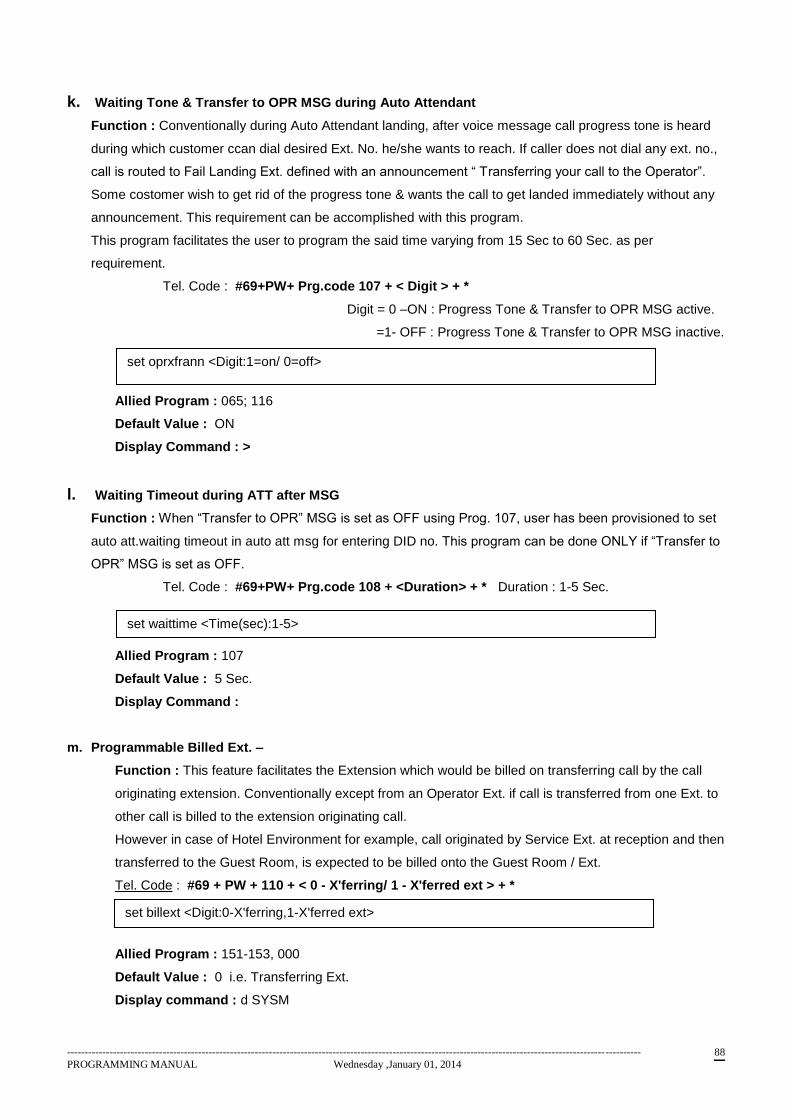
------------------------------------------------------------------------------------------------------------------------------------------------------------------
PROGRAMMING MANUAL Wednesday ,January 01, 2014 88
k. Waiting Tone & Transfer to OPR MSG during Auto Attendant
Function : Conventionally during Auto Attendant landing, after voice message call progress tone is heard
during which customer ccan dial desired Ext. No. he/she wants to reach. If caller does not dial any ext. no.,
call is routed to Fail Landing Ext. defined with an announcement “ Transferring your call to the Operator”.
Some costomer wish to get rid of the progress tone & wants the call to get landed immediately without any
announcement. This requirement can be accomplished with this program.
This program facilitates the user to program the said time varying from 15 Sec to 60 Sec. as per
requirement.
Tel. Code : #69+PW+ Prg.code 107 + < Digit > + *
Digit = 0 –ON : Progress Tone & Transfer to OPR MSG active.
=1- OFF : Progress Tone & Transfer to OPR MSG inactive.
Allied Program : 065; 116
Default Value : ON
Display Command : >
l. Waiting Timeout during ATT after MSG
Function : When “Transfer to OPR” MSG is set as OFF using Prog. 107, user has been provisioned to set
auto att.waiting timeout in auto att msg for entering DID no. This program can be done ONLY if “Transfer to
OPR” MSG is set as OFF.
Tel. Code : #69+PW+ Prg.code 108 + <Duration> + * Duration : 1-5 Sec.
Allied Program : 107
Default Value : 5 Sec.
Display Command :
m. Programmable Billed Ext. –
Function : This feature facilitates the Extension which would be billed on transferring call by the call
originating extension. Conventionally except from an Operator Ext. if call is transferred from one Ext. to
other call is billed to the extension originating call.
However in case of Hotel Environment for example, call originated by Service Ext. at reception and then
transferred to the Guest Room, is expected to be billed onto the Guest Room / Ext.
Tel. Code : #69 + PW + 110 + < 0 - X'ferring/ 1 - X'ferred ext > + *
Allied Program : 151-153, 000
Default Value : 0 i.e. Transferring Ext.
Display command : d SYSM
set oprxfrann <Digit:1=on/ 0=off>
set waittime <Time(sec):1-5>
set billext <Digit:0-X'ferring,1-X'ferred ext>
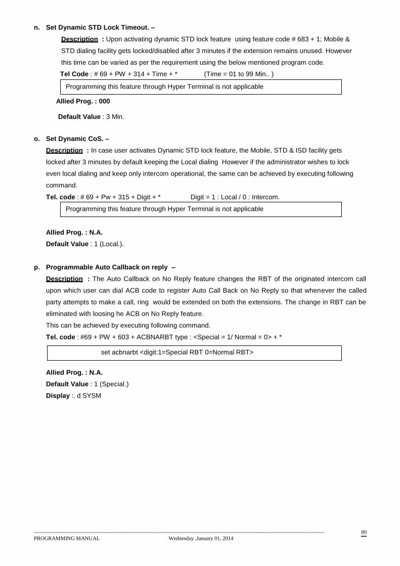
------------------------------------------------------------------------------------------------------------------------------------------------------------------
PROGRAMMING MANUAL Wednesday ,January 01, 2014 89
n. Set Dynamic STD Lock Timeout. –
Description : Upon activating dynamic STD lock feature using feature code # 683 + 1; Mobile &
STD dialing facility gets locked/disabled after 3 minutes if the extension remains unused. However
this time can be varied as per the requirement using the below mentioned program code.
Tel Code : # 69 + PW + 314 + Time + * (Time = 01 to 99 Min.. )
Allied Prog. : 000
Default Value : 3 Min.
o. Set Dynamic CoS. –
Description : In case user activates Dynamic STD lock feature, the Mobile, STD & ISD facility gets
locked after 3 minutes by default keeping the Local dialing However if the administrator wishes to lock
even local dialing and keep only intercom operational, the same can be achieved by executing following
command.
Tel. code : # 69 + Pw + 315 + Digit + * Digit = 1 : Local / 0 : Intercom.
Allied Prog. : N.A.
Default Value : 1 (Local.).
p. Programmable Auto Callback on reply –
Description : The Auto Callback on No Reply feature changes the RBT of the originated intercom call
upon which user can dial ACB code to register Auto Call Back on No Reply so that whenever the called
party attempts to make a call, ring would be extended on both the extensions. The change in RBT can be
eliminated with loosing he ACB on No Reply feature.
This can be achieved by executing following command.
Tel. code : #69 + PW + 603 + ACBNARBT type : <Special = 1/ Normal = 0> + *
Allied Prog. : N.A.
Default Value : 1 (Special.)
Display :. d SYSM
Programming this feature through Hyper Terminal is not applicable
set acbnarbt <digit:1=Special RBT 0=Normal RBT>
Programming this feature through Hyper Terminal is not applicable

------------------------------------------------------------------------------------------------------------------------------------------------------------------
PROGRAMMING MANUAL Wednesday ,January 01, 2014 90
28. PROGRAMMING FOR THE ADMINISTRATOR (CONFIDENTIAL)
a. Create Backup
Function: This code is used to create a backup of the entire System Programming on the flash card
except call record details and user defined voice messages & music. This flash card can then be used
in the future to directly reboot the system – in event of data corruption – thus saving a lot of time and
energy for the system programmer. Please note that this flash card has a provision to store two such
backups wherein the second one is addressed as Master Backup (mentioned later in the manual).
Code: #69 + PW + 026 + 0 + *
NOTE : Previously it was possible to create two different copies of Program Backup on PGBK child card with Prog. 026 and 181. With the new version (ARM Split 0.7), only one copy of backup would be possible to create. Program 181 and 182 are no more available. The backup can be created with Prog. 026 and can be recovered using prog. 027. However it is not mandatory to recover backup using Prog. 027. The backup can be recovered using DIP switch settings as described in the programming manual. For recovering backup change SW1-1 and SW1-2 position to OFF. Switch ON the system or reset the system. The backup created using prog. 026 would be automatically recovered into CPU RAM.
Note : Wait for approx. 30 sec. to get confirmation tone/program completion.
IMPORTANT : This program is possible only if PGBK child card is present on CPU
b. Recover Backup
Function: This code is used to recover the programming backup from the 1st level in the flash card (as
stored by the Create Backup command). This is used when the system needs to be rebooted with the
same programs that were set earlier in event of the system program being corrupted or washed out.
Code: #69 + PW + 027 + 0 + *
c. Create Master Backup ( Not Applicable )
d. Recover Master Backup ( Not Applicable )
e. Change Program PW
Function: This program is used to change the programming password of the system. Please note that
all passwords have to be in a 4-digit format.
Code: #69 + PW + 025 + chng level (3) + New PW + *
Programming this feature through Hyper Terminal not applicable.
set recbackup
set prpwchng<level><password:4-digits>
------------------------------------------------------------------------------------------------------------------------------------------------------------------
PROGRAMMING MANUAL Wednesday ,January 01, 2014 91
f. Set Printer Password
Function : This code is used to set the printer password. The factory set printer password is ‘1234’. The
The old password need not be known.
Code : #69 + PW + 030 + Printer PW + *
Note : For this program to get executed, one need not to know the current Printer PW.
Programming this feature through Hyper Terminal not applicable.
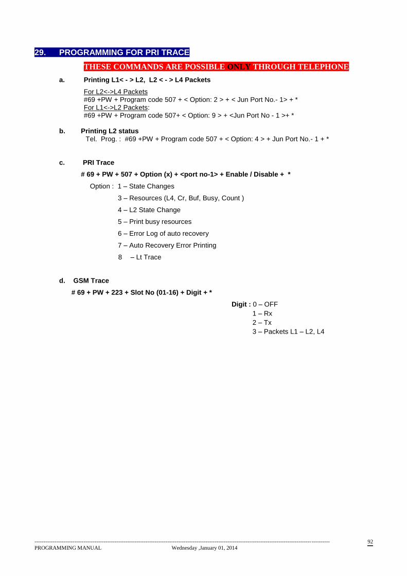
------------------------------------------------------------------------------------------------------------------------------------------------------------------
PROGRAMMING MANUAL Wednesday ,January 01, 2014 92
29. PROGRAMMING FOR PRI TRACE
THESE COMMANDS ARE POSSIBLE ONLY THROUGH TELEPHONE
a. Printing L1< - > L2, L2 < - > L4 Packets
For L2<->L4 Packets #69 +PW + Program code 507 + < Option: 2 > + < Jun Port No.- 1> + * For L1<->L2 Packets: #69 +PW + Program code 507+ < Option: 9 > + <Jun Port No - 1 >+ *
b. Printing L2 status
Tel. Prog. : #69 +PW + Program code 507 + < Option: 4 > + Jun Port No.- 1 + *
c. PRI Trace
# 69 + PW + 507 + Option (x) + <port no-1> + Enable / Disable + *
Option : 1 – State Changes
3 – Resources (L4, Cr, Buf, Busy, Count )
4 – L2 State Change
5 – Print busy resources
6 – Error Log of auto recovery
7 – Auto Recovery Error Printing
8 – Lt Trace
d. GSM Trace
# 69 + PW + 223 + Slot No (01-16) + Digit + *
Digit : 0 – OFF
1 – Rx
2 – Tx
3 – Packets L1 – L2, L4
------------------------------------------------------------------------------------------------------------------------------------------------------------------
PROGRAMMING MANUAL Wednesday ,January 01, 2014 93
30. HOTEL VERSION PROGRAMS a. Floor-wise Room Service
Function : Usually in any hotel, there is a different bell boy/steward allotted to each floor for serving the
guests on that floor. However, irrespective of the floor, the number for room service is always the same
(for NEOS this number is 1), although the answering extensions may be different. Thus, this feature is
used to define which numbers are to ring (floor wise) should a particular guest dial the ‘Room Service’
number. This feature is not applicable for Service Ext./ Ext. with room to room barring feature
disabled.
Code : #69 + PW + 301 + 1st FLOOR RS. Extno + * + 2nd FLOOR RS. Extno. + * + 3rd FLOOR RS.
Extno + * + ………….
Example: In a hotel if they want to set extension 234,245, 248,267,270,281,285 as room service extension on each floor (maximum of 7 floors) From Tel: #69 + PW + 301 + 234+*+245+*+248+*+267+*+270+*+281+*+285+* HT code: set roomserv 234 245 248 267 270 281 285
Allied Program : None
Default Value : None
Display Command : > d ROOMS
b. Single Digit Access for Hotel Rooms
Function : It is highly convenient for any guest to access all services by dialing single digit numbers as
defined in the hotel charts. Typically, the numbers assigned are like 2 for travel desk, 3 for restaurant, 4
for laundry, etc (this differs from hotel to hotel). Thus, this code helps the user set which single digit code
(from 2 to 7 only as 1 is predefined for room service) he would wish to assign to a particular department
extension. This feature is not applicable for Service Ext./ Ext. with room to room barring feature
disabled.
Code : #69 + PW + 302 + access digit(2-7) + extno. + * + access digit(2-7) +extno. + * +…………...
Example: To set extension 210 for travel desk with access digit as 2; 211 for restaurant with access digit
3; 212 for laundry with access digit 4; 213 for Bar with access digit 5; do the programming as
follows
From Tel.: #69 + PW + 302 + 2 + 210 + * + 3 + 211 + * + 4 + 212 + * + 5 + 213 + * + *
Code: set onedigacc 2 210
set onedigacc 3 211
set onedigacc 4 212
set onedigacc 5 213
Allied Program : None.
Default Value : None.
Display Command : > d ACCESSD
set roomserv<extno:max.7ext>
set onedigacc<digit:2-7><ext>
------------------------------------------------------------------------------------------------------------------------------------------------------------------
PROGRAMMING MANUAL Wednesday ,January 01, 2014 94
c. Room to Room Barring
Function : Many hotels do not prefer their guests calling other guests directly due to privacy reasons.
Hence, they wish to selectively choose/assign which room extensions can dial other room extension
numbers by using the given code. By default room to room calls are barred. The hotel management has
to define the extensions as non-guest room extensions.
Code : #69 + PW + 303 + extno. + 1-EN / 0-DIS + *
Example: To make extensions 200, 201, 202, 203, 204, 205 as non-guest room extensions do the
following program
From Tel : #69 + PW + 303 + 200 + 0 + * + 201 + 0 + * + 202 + 0+* + 203 + 0 +*+ 204 + 0+* + 205 + 0 + *
HT code: set roombarr 200 0
set roombarr 201 0
set roombarr 202 0
set roombarr 203 0
set roombarr 204 0
set roombarr 205 0
Allied Program : None.
Default Value : None.
Display Command : > d e
d. Check-In
Function : To check in a guest in a room. When a guest is checked in the room the out dialing facility
gets enabled.. It is not possible to check into a room that has already been checked in.
Code : #69 + PW + 304 + extno. + *
Example: To check in a guest in room no 205 (ensure that the room number and extension number are
the same) do the following program.
From Tel : #69 + PW + 304 + 205 + *
From HT : set checkin 205
Allied Program : 305, 306.
Default Value : None. All rooms (Ext.) are checked out with no call details on their account.
Display Command : > d CHECKI
NOTE that for check-in / Check-out feature the extension can be a service Ext. (R-R barring disabled)
set roombarr<ext><digit:0-1>
set checkin<extno>
------------------------------------------------------------------------------------------------------------------------------------------------------------------
PROGRAMMING MANUAL Wednesday ,January 01, 2014 95
e. Check-Out
Function: To check out a guest in a room on a permanent basis. When a guest is checked out, the out
dialing facility for that room gets disabled. The guest room telephone bill is printed at the check out
command. The print port can be defined as the serial or parallel port.
Code : #69 + PW + 305 + extno. + 0 - OP bill on hyper/ 1 - OP bill on Printer + *
Example: To checkout room number 205 and print the bill on parallel port do the following
Tel Code : #69 + PW + 305 + 205 + 1 + *
HT code : set checkout 205 1
Allied Program : 304.
Default Value : None.
f. Temporary Check-in/Check-out
Function : This feature is used to temporarily check in/out/in a guest who has already checked in the
room. This is done when the guest leaves the room for the day or for a while but has not checked out
(vacated) the room. When the guest is temporarily checked out the telephone bill is not printed. The out
dialing facility is locked but no other guest can be checked in the room. When the guest arrives back a
temporary check in is done to allow the out dialing.
Code : #69 + PW + 306 + extno. + 0 - temp check out / 1 - temp check in + *
Example: To temporarily checkout a guest from room 205 use the following program
From Tel : #69 + PW + 306 + 205 + 0 + *
HT code : set tempinout 205 0
Allied Program : 304.
Default Value : None.
g. Dial Tone for Hotel Rooms
Function : This feature is useful to replace the dial tone by a message that announces the internal
telephone directory or any other information the Hotel management wishes to convey to the guest rooms
when the guest lifts the telephone handset. The message is to be recorded using program 084, the
message number to be recorded is 8 and the message duration should not exceed 32 seconds. This
program is to replace the dial tone with the message or vice-versa. By default the dial tone is present.
Code : #69 + PW + 307 + 0 - OFF / 1 - ON + *
Example: To replace the dial tone by the message program as follows
From Tel : #69 + PW + 307 + 1 + *
Allied Program : 084, 303
Default Value : None.
set checkout<extno><digit:0=hyper / 1=printer>
set tempinout<extno><digit:0=checkout / 1=checkin>
Programming this feature through Hyper Terminal not applicable.

------------------------------------------------------------------------------------------------------------------------------------------------------------------
PROGRAMMING MANUAL Wednesday ,January 01, 2014 96
h. Programming Music on Hold prior to Dial Tone Message NOT APPLICABLE FOR OFFICE VERSION
Music is played for 2-3 sec before Dial Tone Message is heard by the guest. This program facilitates the
user to play the message without playing music before the DT message.
Tel. Code : #69 + PW + 106 + Digit ( 0 – disable / 1 – Enable) + *
Allied Program : 307.
Default Value : Enable.
i. Room to Room calling – Groupwise This program facilitates the guests occupying multiple rooms to communicate on their own without
operator’s intervention. This program can form groups of such rooms wherein Room to room dialing
would be possible. Paralally, these rooms can avail Hotel features such as single digit access codes,
which otherwise was not possible in previous versions.
The room would get deleted automatically from the existing group once it is check out. However at any
given movement of time the room can be attached with other group directly using any extension from the
new group as Header Ext. with program code 308.
By default there would be no group programmed. One Extension can be a part of a single group only.
Dialing within group can be availed by dialing # followed by the room No. ( Ext. No.)
Program for Creation of groups for calling within group Tel. Code #69+ PW + 308 + <Ext.No.> + * + <Ext.no> + * + ------ + *
j. Program for removal of extension within a group.
Tel. code : #69+ PW +<Prg.code309>+<Ext.No.>+*
k. Hotel Bill entry
Guest, during his/her stay in the hotel may use the chargeable services provided by the hotel such as
Food, Laundry or any other miscellaneous services. Charges of all these services along with Room Tariff,
Tax and Telephone Bill can be included in a Bill and can be printed as a Cumulative/consolidated Bill that
can be presented to the customer. These various charges except Tel Bill can be entered using this
program.
If there happens to be some changes to be made after the bill gets printed, system allows the operator to
re-enter all the entries and checkout the guest again. The information about the call details would be
preserved for the said room till the room does not get check-in. Also during that period if another room gets
check-out, the data would be lost.
Maximum amount That can be entered & total bill amount displayed cannot exceed Rs.99999.99. Last two
digits of the value entered would be considered as paise. Either entry (Digit 1-5) if not applicable can be
omitted.
TEL. Code: #69+ PW + 310 + <EXT.NO.> + * + <1: Room rent>+Amount (Rs xx-xxxxx.xx)+ * +
<2: Food> + Amount (Rs xx-xxxxx.xx) +* + <3: Laundry>+ Amount (Rs xx-xxxxx.xx) +* +
<4: Misc>+ Amount (Rs xx-xxxxx.xx) +* + <5: Tax>+ Amount (Rs xx-xxxxx.xx) +*
set playmusic <digit:0=off / 1=on>
set roomgrpext <extno :max15>
Clear roomgrpext <ext.no>
------------------------------------------------------------------------------------------------------------------------------------------------------------------
PROGRAMMING MANUAL Wednesday ,January 01, 2014 97
l. Room to Room Calling - Global
This facilitates room to room calling amongst all rooms but still enjoying the Hotel Features including single
digit access codes which otherwise was not possible for Service Ext. in previous versions. However for
room calling, # needs to be prefixed before room ext. is dialed. This feature can be enabled/disabled using
following program
TEL : #69 + PW + 311 + Digit 1/0> + *
m. Programming Name of Hotel
This program facilitates the user to program Name of the Hotel that should get printed in final bill to be
presented to the customer. The Hotel name can be of max. 40 characters length comprising of 4 words,
each not exceeding 16 characters.
This program is possible only through Hyper terminal. Applicable only for ARM Split CPU Ver. 0.6
onwards.
Tel. Code : Not Applciable
n. Clear Floorwise Room Service Extension :
With this program it is possible to erase/clear the floor-wise room service extensions defined using program
301. The programming code for the same is as follows :
Tel . Code : #69 +PW +Program code 312 + <Floor No: 1-7> + *
o. Clear single digit access code :
This program enables user to clear the single digit access codes defined using Prog 302. The code for the
same is as follows :
Tel. Code : #69 +PW +Program code 313 + <Digit: 2-7> + *
Set hotelbill <Ext.no> <Digit1-5> <Amount (Rs.xx-xxxxx.xx)>
set roomcall <Digit 0/1> ( Digit: 0-Disable, 1-Enable)
Set hotelname <word 1> <word 2> <word 3> <word 4> |<-------------------- Characters 1-40--------------------------->|
Clear roomserv <Floor No: 1-7>
Clear onedigacc <Digit: 2-7>
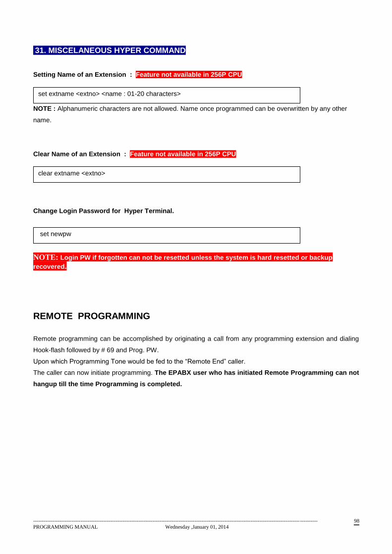
------------------------------------------------------------------------------------------------------------------------------------------------------------------
PROGRAMMING MANUAL Wednesday ,January 01, 2014 98
31. MISCELANEOUS HYPER COMMAND
Setting Name of an Extension : Feature not available in 256P CPU
NOTE : Alphanumeric characters are not allowed. Name once programmed can be overwritten by any other
name.
Clear Name of an Extension : Feature not available in 256P CPU
Change Login Password for Hyper Terminal.
NOTE: Login PW if forgotten can not be resetted unless the system is hard resetted or backup
recovered.
REMOTE PROGRAMMING
Remote programming can be accomplished by originating a call from any programming extension and dialing
Hook-flash followed by # 69 and Prog. PW.
Upon which Programming Tone would be fed to the “Remote End” caller.
The caller can now initiate programming. The EPABX user who has initiated Remote Programming can not
hangup till the time Programming is completed.
set extname <extno> <name : 01-20 characters>
set newpw
clear extname <extno>
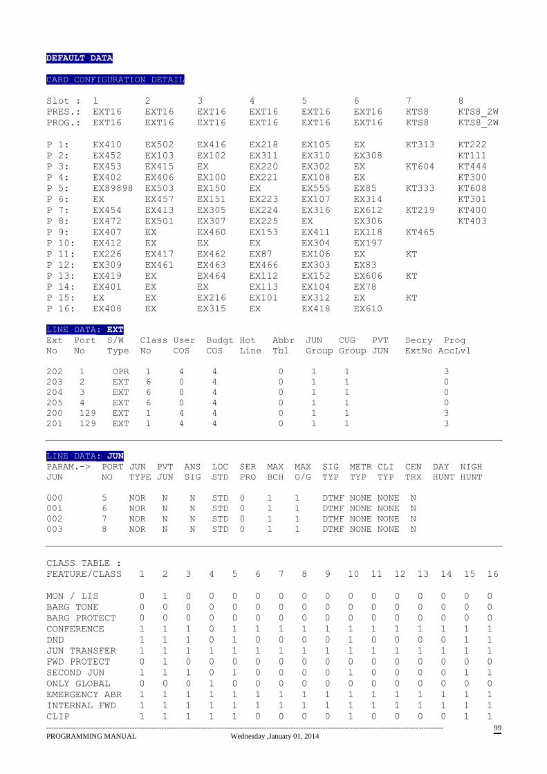
------------------------------------------------------------------------------------------------------------------------------------------------------------------
PROGRAMMING MANUAL Wednesday ,January 01, 2014 99
DEFAULT DATA
CARD CONFIGURATION DETAIL
Slot : 1 2 3 4 5 6 7 8
PRES.: EXT16 EXT16 EXT16 EXT16 EXT16 EXT16 KTS8 KTS8_2W
PROG.: EXT16 EXT16 EXT16 EXT16 EXT16 EXT16 KTS8 KTS8_2W
P 1: EX410 EX502 EX416 EX218 EX105 EX KT313 KT222
P 2: EX452 EX103 EX102 EX311 EX310 EX308 KT111
P 3: EX453 EX415 EX EX220 EX302 EX KT604 KT444
P 4: EX402 EX406 EX100 EX221 EX108 EX KT300
P 5: EX89898 EX503 EX150 EX EX555 EX85 KT333 KT608
P 6: EX EX457 EX151 EX223 EX107 EX314 KT301
P 7: EX454 EX413 EX305 EX224 EX316 EX612 KT219 KT400
P 8: EX472 EX501 EX307 EX225 EX EX306 KT403
P 9: EX407 EX EX460 EX153 EX411 EX118 KT465
P 10: EX412 EX EX EX EX304 EX197
P 11: EX226 EX417 EX462 EX87 EX106 EX KT
P 12: EX309 EX461 EX463 EX466 EX303 EX83
P 13: EX419 EX EX464 EX112 EX152 EX606 KT
P 14: EX401 EX EX EX113 EX104 EX78
P 15: EX EX EX216 EX101 EX312 EX KT
P 16: EX408 EX EX315 EX EX418 EX610
LINE DATA: EXT
Ext Port S/W Class User Budgt Hot Abbr JUN CUG PVT Secry Prog
No No Type No COS COS Line Tbl Group Group JUN ExtNo AccLvl
202 1 OPR 1 4 4 0 1 1 3
203 2 EXT 6 0 4 0 1 1 0
204 3 EXT 6 0 4 0 1 1 0
205 4 EXT 6 0 4 0 1 1 0
200 129 EXT 1 4 4 0 1 1 3
201 129 EXT 1 4 4 0 1 1 3
LINE DATA: JUN
PARAM.-> PORT JUN PVT ANS LOC SER MAX MAX SIG METR CLI CEN DAY NIGH
JUN NO TYPE JUN SIG STD PRO BCH O/G TYP TYP TYP TRX HUNT HUNT
000 5 NOR N N STD 0 1 1 DTMF NONE NONE N
001 6 NOR N N STD 0 1 1 DTMF NONE NONE N
002 7 NOR N N STD 0 1 1 DTMF NONE NONE N
003 8 NOR N N STD 0 1 1 DTMF NONE NONE N
CLASS TABLE :
FEATURE/CLASS 1 2 3 4 5 6 7 8 9 10 11 12 13 14 15 16
MON / LIS 0 1 0 0 0 0 0 0 0 0 0 0 0 0 0 0
BARG TONE 0 0 0 0 0 0 0 0 0 0 0 0 0 0 0 0
BARG PROTECT 0 0 0 0 0 0 0 0 0 0 0 0 0 0 0 0
CONFERENCE 1 1 1 0 1 1 1 1 1 1 1 1 1 1 1 1
DND 1 1 1 0 1 0 0 0 0 1 0 0 0 0 1 1
JUN TRANSFER 1 1 1 1 1 1 1 1 1 1 1 1 1 1 1 1
FWD PROTECT 0 1 0 0 0 0 0 0 0 0 0 0 0 0 0 0
SECOND JUN 1 1 1 0 1 0 0 0 0 1 0 0 0 0 1 1
ONLY GLOBAL 0 0 0 1 0 0 0 0 0 0 0 0 0 0 0 0
EMERGENCY ABR 1 1 1 1 1 1 1 1 1 1 1 1 1 1 1 1
INTERNAL FWD 1 1 1 1 1 1 1 1 1 1 1 1 1 1 1 1
CLIP 1 1 1 1 1 0 0 0 0 1 0 0 0 0 1 1
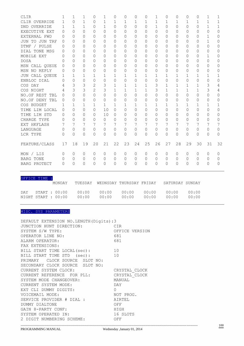
------------------------------------------------------------------------------------------------------------------------------------------------------------------
PROGRAMMING MANUAL Wednesday ,January 01, 2014 100
CLIR 1 1 1 0 1 0 0 0 0 1 0 0 0 0 1 1
CLIR OVERRIDE 1 0 1 0 1 1 1 1 1 1 1 1 1 1 1 1
DND OVERRIDE 1 1 1 0 1 0 0 0 0 1 0 0 0 0 1 1
EXECUTIVE EXT 0 0 0 0 0 0 0 0 0 0 0 0 0 0 0 0
EXTERNAL FWD 0 0 0 0 0 0 0 0 0 0 0 0 0 0 1 0
JUN TO JUN TRF 0 0 0 0 0 0 0 0 0 0 0 0 0 0 1 0
DTMF / PULSE 0 0 0 0 0 0 0 0 0 0 0 0 0 0 0 0
DIAL TONE MSG 0 0 0 0 0 0 0 0 0 0 0 0 0 0 0 0
MOBILE EXT 0 0 0 0 0 0 0 0 0 0 0 0 0 0 1 0
DOSA 0 0 0 0 0 0 0 0 0 0 0 0 0 0 0 0
MSN CALL QUEUE 0 0 0 0 0 0 0 0 0 0 0 0 0 0 0 0
MSN NO REPLY 0 0 0 0 0 0 0 0 0 0 0 0 0 0 0 0
JUN CALL QUEUE 1 1 1 1 1 1 1 1 1 1 1 1 1 1 1 1
ENBLOC DIAL 0 0 0 0 0 0 0 0 0 0 0 0 0 0 0 0
COS DAY 4 3 3 2 3 1 1 1 1 3 1 1 1 1 3 4
COS NIGHT 4 3 3 2 3 1 1 1 1 3 1 1 1 1 3 4
NO.OF REST TBL 0 0 0 0 0 0 0 0 0 0 0 0 0 0 0 0
NO.OF DENY TBL 0 0 0 0 0 0 0 0 0 0 0 0 0 0 0 0
COS BUDGET 1 1 1 1 1 1 1 1 1 1 1 1 1 1 1 1
TIME LIM LOCAL 0 0 0 0 10 0 0 0 0 0 0 0 0 0 0 0
TIME LIM STD 0 0 0 0 10 0 0 0 0 0 0 0 0 0 0 0
CHARGE TYPE 0 0 0 0 0 0 0 0 0 0 0 0 0 0 0 0
EXT HKFLASH 7 7 7 7 7 7 7 7 7 7 7 7 7 7 7 7
LANGUAGE 0 0 0 0 0 0 0 0 0 0 0 0 0 0 0 0
LCR TYPE 0 0 0 0 0 0 0 0 0 0 0 0 0 0 0 0
FEATURE/CLASS 17 18 19 20 21 22 23 24 25 26 27 28 29 30 31 32
MON / LIS 0 0 0 0 0 0 0 0 0 0 0 0 0 0 0 0
BARG TONE 0 0 0 0 0 0 0 0 0 0 0 0 0 0 0 0
BARG PROTECT 0 0 0 0 0 0 0 0 0 0 0 0 0 0 0 0
OFFICE TIME :
MONDAY TUESDAY WEDNSDAY THURSDAY FRIDAY SATURDAY SUNDAY
DAY START : 00:00 00:00 00:00 00:00 00:00 00:00 00:00
NIGHT START : 00:00 00:00 00:00 00:00 00:00 00:00 00:00
MISC. SYS PARAMETERS
DEFAULT EXTENSION NO.LENGTH(Digits):3
JUNCTION HUNT DIRECTION: CIR
SYSTEM S/W TYPE: OFFICE VERSION
OPERATOR LINE NO: 681
ALARM OPERATOR: 681
FAX EXTENSIONS:
BILL START TIME LOCAL(sec): 10
BILL START TIME STD (sec): 10
PRIMARY CLOCK SOURCE SLOT NO:
SECONDARY CLOCK SOURCE SLOT NO:
CURRENT SYSTEM CLOCK: CRYSTAL_CLOCK
CURRENT REFERENCE FOR PLL: CRYSTAL_CLOCK
SYSTEM MODE CHANGEOVER: MANUAL
CURRENT SYSTEM MODE: DAY
EXT CLI DUMMY DIGITS: 0
VOICEMAIL MODE: NOT PROG.
SERVICE PROVIDER # DIAL : AIRTEL
DUMMY DIALTONE OFF
GAIN 8-PARTY CONF: HIGH
SYSTEM OPERATED IN: 16 SLOTS
2 DIGIT NUMBERING SCHEME: OFF

------------------------------------------------------------------------------------------------------------------------------------------------------------------
PROGRAMMING MANUAL Wednesday ,January 01, 2014 101
PRI MASTER/SLAVE MODE: SLAVE
PRI TYPE OF NUMBER(CallingPty): SUBSCRIBER
PRI NUMBERING PLAN(CallingPty): ISDN/TELEPHONY
PRI TYPE OF NUMBER(CalledPty): UNKNOWN
PRI NUMBERING PLAN(CalledPty): UNKNOWN
LOGICAL PARTITION: ON
TRANSFER RECALL TIMEOUT(sec): 15
PAGING JUNCTION NO:
GSM JUN CALL PROCEED TIMEOUT(sec): 10
GSM JUN DELIVERED TIMEOUT(sec): 60
ACB NOANS RBT TYPE: SPECIAL RBT
>D EXTNAME
EXTNO EXTNAME EXTNO EXTNAME
LCR Prefix Table
Entry Prefix C H O I C E 1 C H O I C E 2
No. Digit SP.LOCAL SP.STD SP.LOCAL SP.STD
JUNCTION GROUPS
GROUP No : 1
000 001 002 003
GROUP No : 2
GROUP No : 3
GROUP No : 4
GROUP No : 5
GROUP No : 6
GROUP No : 7
GROUP No : 8
GROUP No : 9
GROUP No : 10
GROUP No : 11
GROUP No : 12
GROUP No : 13
GROUP No : 14
GROUP No : 15
GROUP No : 16
CLI BASED ROUTING TABLE
Sr. CLI NO DAY EXT NIGHT EXT Sr. CLI NO DAY EXT NIGHT EXT
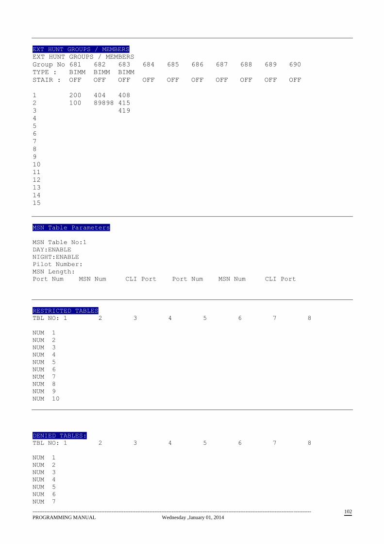
------------------------------------------------------------------------------------------------------------------------------------------------------------------
PROGRAMMING MANUAL Wednesday ,January 01, 2014 102
EXT HUNT GROUPS / MEMBERS
EXT HUNT GROUPS / MEMBERS
Group No 681 682 683 684 685 686 687 688 689 690
TYPE : BIMM BIMM BIMM
STAIR : OFF OFF OFF OFF OFF OFF OFF OFF OFF OFF
1 200 404 408
2 100 89898 415
3 419
4
5
6
7
8
9
10
11
12
13
14
15
MSN Table Parameters
MSN Table No:1
DAY:ENABLE
NIGHT:ENABLE
Pilot Number:
MSN Length:
Port Num MSN Num CLI Port Port Num MSN Num CLI Port
RESTRICTED TABLES
TBL NO: 1 2 3 4 5 6 7 8
NUM 1
NUM 2
NUM 3
NUM 4
NUM 5
NUM 6
NUM 7
NUM 8
NUM 9
NUM 10
DENIED TABLES:
TBL NO: 1 2 3 4 5 6 7 8
NUM 1
NUM 2
NUM 3
NUM 4
NUM 5
NUM 6
NUM 7
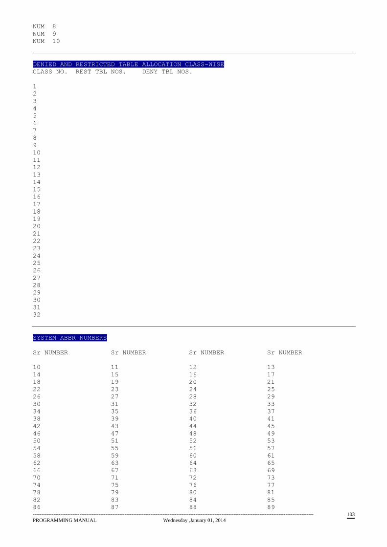
------------------------------------------------------------------------------------------------------------------------------------------------------------------
PROGRAMMING MANUAL Wednesday ,January 01, 2014 103
NUM 8
NUM 9
NUM 10
DENIED AND RESTRICTED TABLE ALLOCATION CLASS-WISE
CLASS NO. REST TBL NOS. DENY TBL NOS.
1
2
3
4
5
6
7
8
9
10
11
12
13
14
15
16
17
18
19
20
21
22
23
24
25
26
27
28
29
30
31
32
SYSTEM ABBR NUMBERS
Sr NUMBER Sr NUMBER Sr NUMBER Sr NUMBER
10 11 12 13
14 15 16 17
18 19 20 21
22 23 24 25
26 27 28 29
30 31 32 33
34 35 36 37
38 39 40 41
42 43 44 45
46 47 48 49
50 51 52 53
54 55 56 57
58 59 60 61
62 63 64 65
66 67 68 69
70 71 72 73
74 75 76 77
78 79 80 81
82 83 84 85
86 87 88 89
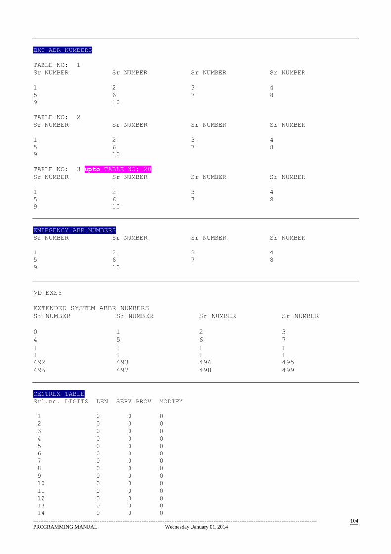
------------------------------------------------------------------------------------------------------------------------------------------------------------------
PROGRAMMING MANUAL Wednesday ,January 01, 2014 104
EXT ABR NUMBERS
TABLE NO: 1
Sr NUMBER Sr NUMBER Sr NUMBER Sr NUMBER
1 2 3 4
5 6 7 8
9 10
TABLE NO: 2
Sr NUMBER Sr NUMBER Sr NUMBER Sr NUMBER
1 2 3 4
5 6 7 8
9 10
TABLE NO: 3 upto TABLE NO: 20
Sr NUMBER Sr NUMBER Sr NUMBER Sr NUMBER
1 2 3 4
5 6 7 8
9 10
EMERGENCY ABR NUMBERS
Sr NUMBER Sr NUMBER Sr NUMBER Sr NUMBER
1 2 3 4
5 6 7 8
9 10
>D EXSY
EXTENDED SYSTEM ABBR NUMBERS
Sr NUMBER Sr NUMBER Sr NUMBER Sr NUMBER
0 1 2 3
4 5 6 7
: : : :
: : : :
492 493 494 495
496 497 498 499
CENTREX TABLE
Srl.no. DIGITS LEN SERV PROV MODIFY
1 0 0 0
2 0 0 0
3 0 0 0
4 0 0 0
5 0 0 0
6 0 0 0
7 0 0 0
8 0 0 0
9 0 0 0
10 0 0 0
11 0 0 0
12 0 0 0
13 0 0 0
14 0 0 0
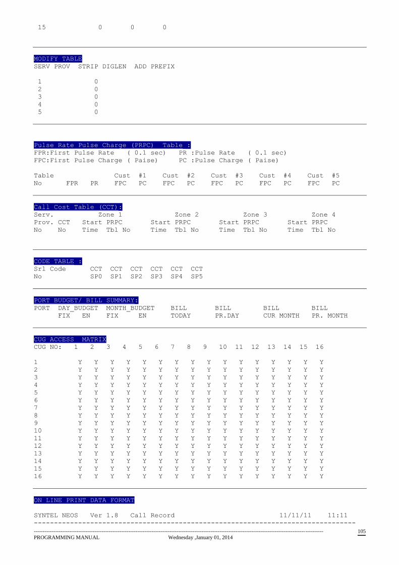
------------------------------------------------------------------------------------------------------------------------------------------------------------------
PROGRAMMING MANUAL Wednesday ,January 01, 2014 105
15 0 0 0
MODIFY TABLE
SERV PROV STRIP DIGLEN ADD PREFIX
1 0
2 0
3 0
4 0
5 0
Pulse Rate Pulse Charge (PRPC) Table :
FPR:First Pulse Rate ( 0.1 sec) PR :Pulse Rate ( 0.1 sec)
FPC:First Pulse Charge ( Paise) PC :Pulse Charge ( Paise)
Table Cust #1 Cust #2 Cust #3 Cust #4 Cust #5
No FPR PR FPC PC FPC PC FPC PC FPC PC FPC PC
Call Cost Table (CCT):
Serv. Zone 1 Zone 2 Zone 3 Zone 4
Prov. CCT Start PRPC Start PRPC Start PRPC Start PRPC
No No Time Tbl No Time Tbl No Time Tbl No Time Tbl No
CODE TABLE :
Srl Code CCT CCT CCT CCT CCT CCT
No SP0 SP1 SP2 SP3 SP4 SP5
PORT BUDGET/ BILL SUMMARY:
PORT DAY_BUDGET MONTH_BUDGET BILL BILL BILL BILL
FIX EN FIX EN TODAY PR.DAY CUR MONTH PR. MONTH
CUG ACCESS MATRIX
CUG NO: 1 2 3 4 5 6 7 8 9 10 11 12 13 14 15 16
1 Y Y Y Y Y Y Y Y Y Y Y Y Y Y Y Y
2 Y Y Y Y Y Y Y Y Y Y Y Y Y Y Y Y
3 Y Y Y Y Y Y Y Y Y Y Y Y Y Y Y Y
4 Y Y Y Y Y Y Y Y Y Y Y Y Y Y Y Y
5 Y Y Y Y Y Y Y Y Y Y Y Y Y Y Y Y
6 Y Y Y Y Y Y Y Y Y Y Y Y Y Y Y Y
7 Y Y Y Y Y Y Y Y Y Y Y Y Y Y Y Y
8 Y Y Y Y Y Y Y Y Y Y Y Y Y Y Y Y
9 Y Y Y Y Y Y Y Y Y Y Y Y Y Y Y Y
10 Y Y Y Y Y Y Y Y Y Y Y Y Y Y Y Y
11 Y Y Y Y Y Y Y Y Y Y Y Y Y Y Y Y
12 Y Y Y Y Y Y Y Y Y Y Y Y Y Y Y Y
13 Y Y Y Y Y Y Y Y Y Y Y Y Y Y Y Y
14 Y Y Y Y Y Y Y Y Y Y Y Y Y Y Y Y
15 Y Y Y Y Y Y Y Y Y Y Y Y Y Y Y Y
16 Y Y Y Y Y Y Y Y Y Y Y Y Y Y Y Y
ON LINE PRINT DATA FORMAT
SYNTEL NEOS Ver 1.8 Call Record 11/11/11 11:11
--------------------------------------------------------------------------------
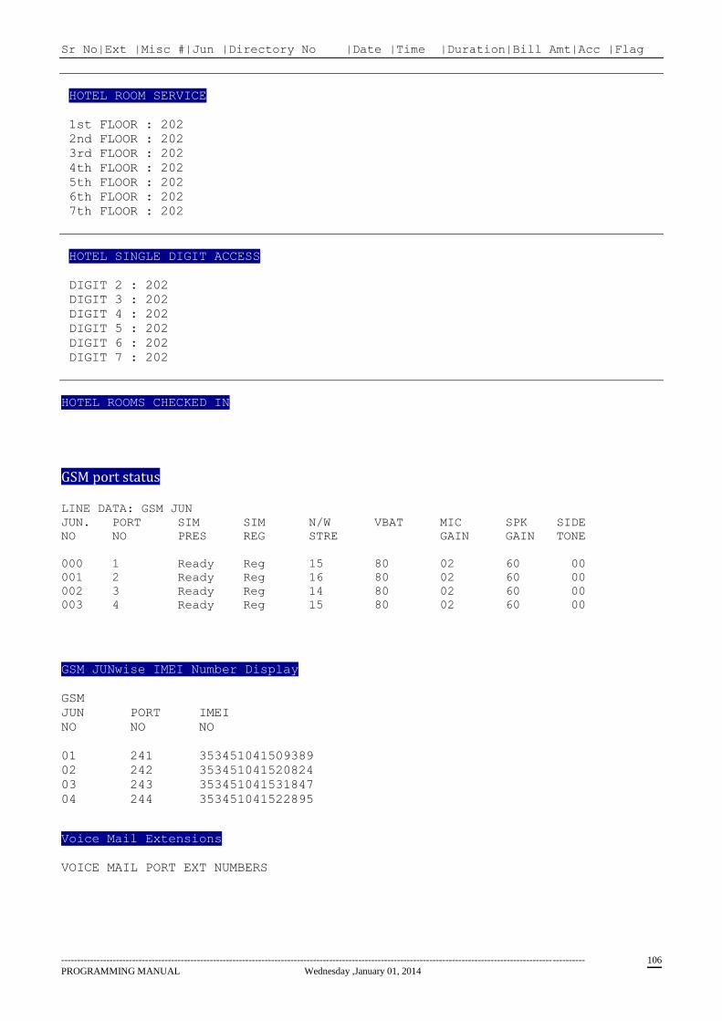
------------------------------------------------------------------------------------------------------------------------------------------------------------------
PROGRAMMING MANUAL Wednesday ,January 01, 2014 106
Sr No|Ext |Misc #|Jun |Directory No |Date |Time |Duration|Bill Amt|Acc |Flag
HOTEL ROOM SERVICE
1st FLOOR : 202
2nd FLOOR : 202
3rd FLOOR : 202
4th FLOOR : 202
5th FLOOR : 202
6th FLOOR : 202
7th FLOOR : 202
HOTEL SINGLE DIGIT ACCESS
DIGIT 2 : 202
DIGIT 3 : 202
DIGIT 4 : 202
DIGIT 5 : 202
DIGIT 6 : 202
DIGIT 7 : 202
HOTEL ROOMS CHECKED IN
GSM port status
LINE DATA: GSM JUN
JUN. PORT SIM SIM N/W VBAT MIC SPK SIDE
NO NO PRES REG STRE GAIN GAIN TONE
000 1 Ready Reg 15 80 02 60 00
001 2 Ready Reg 16 80 02 60 00
002 3 Ready Reg 14 80 02 60 00
003 4 Ready Reg 15 80 02 60 00
GSM JUNwise IMEI Number Display
GSM
JUN PORT IMEI
NO NO NO
01 241 353451041509389
02 242 353451041520824
03 243 353451041531847
04 244 353451041522895
Voice Mail Extensions
VOICE MAIL PORT EXT NUMBERS
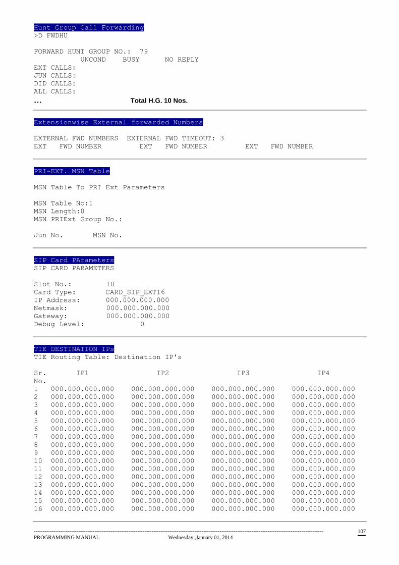
------------------------------------------------------------------------------------------------------------------------------------------------------------------
PROGRAMMING MANUAL Wednesday ,January 01, 2014 107
Hunt Group Call Forwarding
>D FWDHU
FORWARD HUNT GROUP NO.: 79
UNCOND BUSY NO REPLY
EXT CALLS:
JUN CALLS:
DID CALLS:
ALL CALLS:
… Total H.G. 10 Nos.
Extensionwise External forwarded Numbers
EXTERNAL FWD NUMBERS EXTERNAL FWD TIMEOUT: 3
EXT FWD NUMBER EXT FWD NUMBER EXT FWD NUMBER
PRI-EXT. MSN Table
MSN Table To PRI Ext Parameters
MSN Table No:1
MSN Length:0
MSN PRIExt Group No.:
Jun No. MSN No.
SIP Card PArameters
SIP CARD PARAMETERS
Slot No.: 10
Card Type: CARD_SIP_EXT16
IP Address: 000.000.000.000
Netmask: 000.000.000.000
Gateway: 000.000.000.000
Debug Level: 0
TIE DESTINATION IPs
TIE Routing Table: Destination IP's
Sr. IP1 IP2 IP3 IP4
No.
1 000.000.000.000 000.000.000.000 000.000.000.000 000.000.000.000
2 000.000.000.000 000.000.000.000 000.000.000.000 000.000.000.000
3 000.000.000.000 000.000.000.000 000.000.000.000 000.000.000.000
4 000.000.000.000 000.000.000.000 000.000.000.000 000.000.000.000
5 000.000.000.000 000.000.000.000 000.000.000.000 000.000.000.000
6 000.000.000.000 000.000.000.000 000.000.000.000 000.000.000.000
7 000.000.000.000 000.000.000.000 000.000.000.000 000.000.000.000
8 000.000.000.000 000.000.000.000 000.000.000.000 000.000.000.000
9 000.000.000.000 000.000.000.000 000.000.000.000 000.000.000.000
10 000.000.000.000 000.000.000.000 000.000.000.000 000.000.000.000
11 000.000.000.000 000.000.000.000 000.000.000.000 000.000.000.000
12 000.000.000.000 000.000.000.000 000.000.000.000 000.000.000.000
13 000.000.000.000 000.000.000.000 000.000.000.000 000.000.000.000
14 000.000.000.000 000.000.000.000 000.000.000.000 000.000.000.000
15 000.000.000.000 000.000.000.000 000.000.000.000 000.000.000.000
16 000.000.000.000 000.000.000.000 000.000.000.000 000.000.000.000
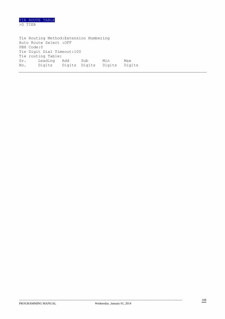
------------------------------------------------------------------------------------------------------------------------------------------------------------------
PROGRAMMING MANUAL Wednesday ,January 01, 2014 108
TIE ROUTE TABLE
>D TIER
Tie Routing Method:Extension Numbering
Auto Route Select :OFF
PBX Code:0
Tie Digit Dial Timeout:100
Tie routing Table:
Sr. Leading Add Sub Min Max
No. Digits Digits Digits Digits Digits
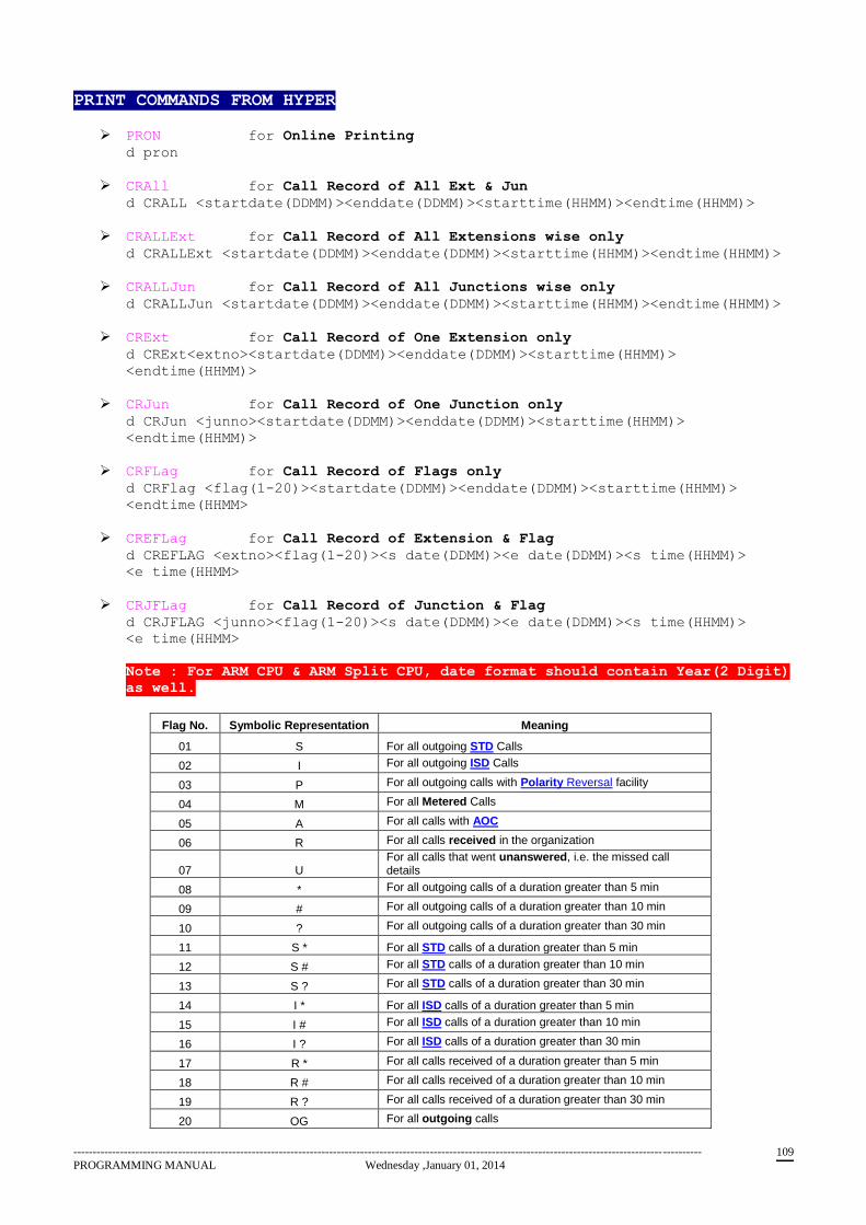
------------------------------------------------------------------------------------------------------------------------------------------------------------------
PROGRAMMING MANUAL Wednesday ,January 01, 2014 109
PRINT COMMANDS FROM HYPER
PRON for Online Printing
d pron
CRAll for Call Record of All Ext & Jun
d CRALL <startdate(DDMM)><enddate(DDMM)><starttime(HHMM)><endtime(HHMM)>
CRALLExt for Call Record of All Extensions wise only
d CRALLExt <startdate(DDMM)><enddate(DDMM)><starttime(HHMM)><endtime(HHMM)>
CRALLJun for Call Record of All Junctions wise only
d CRALLJun <startdate(DDMM)><enddate(DDMM)><starttime(HHMM)><endtime(HHMM)>
CRExt for Call Record of One Extension only
d CRExt<extno><startdate(DDMM)><enddate(DDMM)><starttime(HHMM)>
<endtime(HHMM)>
CRJun for Call Record of One Junction only
d CRJun <junno><startdate(DDMM)><enddate(DDMM)><starttime(HHMM)>
<endtime(HHMM)>
CRFLag for Call Record of Flags only
d CRFlag <flag(1-20)><startdate(DDMM)><enddate(DDMM)><starttime(HHMM)>
<endtime(HHMM>
CREFLag for Call Record of Extension & Flag
d CREFLAG <extno><flag(1-20)><s date(DDMM)><e date(DDMM)><s time(HHMM)>
<e time(HHMM>
CRJFLag for Call Record of Junction & Flag
d CRJFLAG <junno><flag(1-20)><s date(DDMM)><e date(DDMM)><s time(HHMM)>
<e time(HHMM>
Note : For ARM CPU & ARM Split CPU, date format should contain Year(2 Digit)
as well.
Flag No. Symbolic Representation Meaning
01 S For all outgoing STD Calls
02 I For all outgoing ISD Calls
03 P For all outgoing calls with Polarity Reversal facility
04 M For all Metered Calls
05 A For all calls with AOC
06 R For all calls received in the organization
07 U For all calls that went unanswered, i.e. the missed call details
08 * For all outgoing calls of a duration greater than 5 min
09 # For all outgoing calls of a duration greater than 10 min
10 ? For all outgoing calls of a duration greater than 30 min
11 S * For all STD calls of a duration greater than 5 min
12 S # For all STD calls of a duration greater than 10 min
13 S ? For all STD calls of a duration greater than 30 min
14 I * For all ISD calls of a duration greater than 5 min
15 I # For all ISD calls of a duration greater than 10 min
16 I ? For all ISD calls of a duration greater than 30 min
17 R * For all calls received of a duration greater than 5 min
18 R # For all calls received of a duration greater than 10 min
19 R ? For all calls received of a duration greater than 30 min
20 OG For all outgoing calls
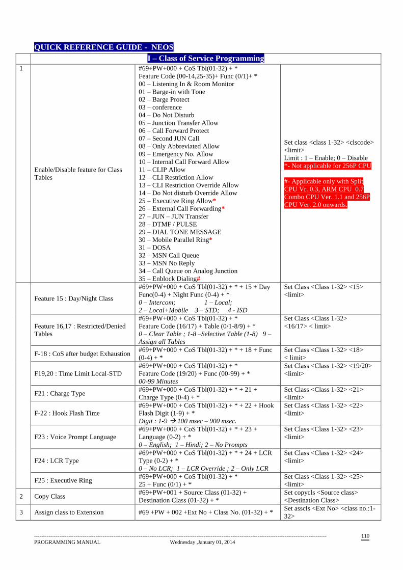
------------------------------------------------------------------------------------------------------------------------------------------------------------------
PROGRAMMING MANUAL Wednesday ,January 01, 2014 110
QUICK REFERENCE GUIDE - NEOS
I – Class of Service Programming
1
Enable/Disable feature for Class
Tables
#69+PW+000 + CoS Tbl(01-32) + *
Feature Code (00-14,25-35)+ Func (0/1)+ *
00 – Listening In & Room Monitor
01 – Barge-in with Tone
02 – Barge Protect
03 – conference
04 – Do Not Disturb
05 – Junction Transfer Allow
06 – Call Forward Protect
07 – Second JUN Call
08 – Only Abbreviated Allow
09 – Emergency No. Allow
10 – Internal Call Forward Allow
11 – CLIP Allow
12 – CLI Restriction Allow
13 – CLI Restriction Override Allow
14 – Do Not disturb Override Allow
25 – Executive Ring Allow*
26 – External Call Forwarding*
27 – JUN – JUN Transfer
28 – DTMF / PULSE
29 – DIAL TONE MESSAGE
30 – Mobile Parallel Ring*
31 – DOSA
32 – MSN Call Queue
33 – MSN No Reply
34 – Call Queue on Analog Junction
35 – Enblock Dialing#
Set class <class 1-32> <clscode>
<limit>
Limit : 1 – Enable; 0 – Disable
*- Not applicable for 256P CPU
#- Applicable only with Split
CPU Vr. 0.3, ARM CPU 0.7
Combo CPU Ver. 1.1 and 256P
CPU Ver. 2.0 onwards.
Feature 15 : Day/Night Class
#69+PW+000 + CoS Tbl(01-32) + * + 15 + Day
Func(0-4) + Night Func (0-4) + *
0 – Intercom; 1 – Local;
2 – Local+Mobile 3 – STD; 4 - ISD
Set Class <Class 1-32> <15>
<limit>
Feature 16,17 : Restricted/Denied
Tables
#69+PW+000 + CoS Tbl(01-32) + *
Feature Code (16/17) + Table (0/1-8/9) + *
0 – Clear Table ; 1-8 –Selective Table (1-8) 9 –
Assign all Tables
Set Class <Class 1-32>
<16/17> < limit>
F-18 : CoS after budget Exhaustion #69+PW+000 + CoS Tbl(01-32) + * + 18 + Func
(0-4) + *
Set Class <Class 1-32> <18>
< limit>
F19,20 : Time Limit Local-STD
#69+PW+000 + CoS Tbl(01-32) + *
Feature Code (19/20) + Func (00-99) + *
00-99 Minutes
Set Class <Class 1-32> <19/20>
<limit>
F21 : Charge Type #69+PW+000 + CoS Tbl(01-32) + * + 21 +
Charge Type (0-4) + *
Set Class <Class 1-32> <21>
<limit>
F-22 : Hook Flash Time
#69+PW+000 + CoS Tbl(01-32) + * + 22 + Hook
Flash Digit (1-9) + *
Digit : 1-9 100 msec – 900 msec.
Set Class <Class 1-32> <22>
<limit>
F23 : Voice Prompt Language
#69+PW+000 + CoS Tbl(01-32) + * + 23 +
Language (0-2) + *
0 – English; 1 – Hindi; 2 – No Prompts
Set Class <Class 1-32> <23>
<limit>
F24 : LCR Type
#69+PW+000 + CoS Tbl(01-32) + * + 24 + LCR
Type (0-2) + *
0 – No LCR; 1 – LCR Override ; 2 – Only LCR
Set Class <Class 1-32> <24>
<limit>
F25 : Executive Ring #69+PW+000 + CoS Tbl(01-32) + *
25 + Func (0/1) + *
Set Class <Class 1-32> <25>
<limit>
2 Copy Class #69+PW+001 + Source Class (01-32) +
Destination Class (01-32) + *
Set copycls <Source class>
<Destination Class>
3 Assign class to Extension #69 +PW + 002 +Ext No + Class No. (01-32) + * Set asscls <Ext No> <class no.:1-
32>
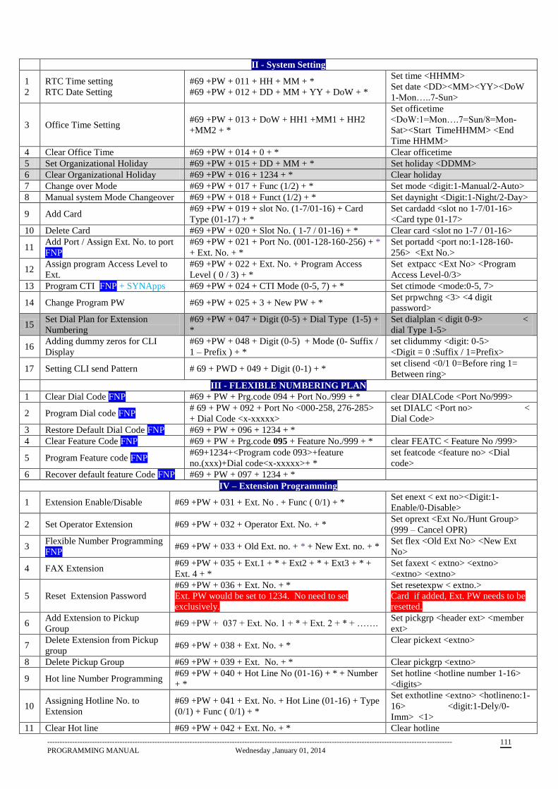
------------------------------------------------------------------------------------------------------------------------------------------------------------------
PROGRAMMING MANUAL Wednesday ,January 01, 2014 111
II - System Setting
1
2
RTC Time setting
RTC Date Setting
#69 +PW + 011 + HH + MM + *
#69 +PW + 012 + DD + MM + YY + DoW + *
Set time <HHMM>
Set date <DD><MM><YY><DoW
1-Mon…..7-Sun>
3 Office Time Setting #69 +PW + 013 + DoW + HH1 +MM1 + HH2
+MM2 + *
Set officetime
<DoW:1=Mon….7=Sun/8=Mon-
Sat><Start TimeHHMM> <End
Time HHMM>
4 Clear Office Time #69 +PW + 014 + 0 + * Clear officetime
5 Set Organizational Holiday #69 +PW + 015 + DD + MM + * Set holiday <DDMM>
6 Clear Organizational Holiday #69 +PW + 016 + 1234 + * Clear holiday
7 Change over Mode #69 +PW + 017 + Func (1/2) + * Set mode <digit:1-Manual/2-Auto>
8 Manual system Mode Changeover #69 +PW + 018 + Funct (1/2) + * Set daynight <Digit:1-Night/2-Day>
9 Add Card #69 +PW + 019 + slot No. (1-7/01-16) + Card
Type (01-17) + *
Set cardadd <slot no 1-7/01-16>
<Card type 01-17>
10 Delete Card #69 +PW + 020 + Slot No. ( 1-7 / 01-16) + * Clear card <slot no 1-7 / 01-16>
11 Add Port / Assign Ext. No. to port
FNP
#69 +PW + 021 + Port No. (001-128-160-256) + *
+ Ext. No. + *
Set portadd <port no:1-128-160-
256> <Ext No.>
12 Assign program Access Level to
Ext.
#69 +PW + 022 + Ext. No. + Program Access
Level ( 0 / 3) + *
Set extpacc <Ext No> <Program
Access Level-0/3>
13 Program CTI FNP + SYNApps #69 +PW + 024 + CTI Mode (0-5, 7) + * Set ctimode <mode:0-5, 7>
14 Change Program PW #69 +PW + 025 + 3 + New PW + * Set prpwchng <3> <4 digit
password>
15 Set Dial Plan for Extension
Numbering
#69 +PW + 047 + Digit (0-5) + Dial Type (1-5) +
*
Set dialplan < digit 0-9> <
dial Type 1-5>
16 Adding dummy zeros for CLI
Display
#69 +PW + 048 + Digit (0-5) + Mode (0- Suffix /
1 – Prefix ) + *
set clidummy <digit: 0-5>
<Digit = 0 :Suffix / 1=Prefix>
17 Setting CLI send Pattern # 69 + PWD + 049 + Digit (0-1) + * set clisend <0/1 0=Before ring 1=
Between ring>
III - FLEXIBLE NUMBERING PLAN
1 Clear Dial Code FNP #69 + PW + Prg.code 094 + Port No./999 + * clear DIALCode <Port No/999>
2 Program Dial code FNP # 69 + PW + 092 + Port No <000-258, 276-285>
+ Dial Code <x-xxxxx>
set DIALC <Port no> <
Dial Code>
3 Restore Default Dial Code FNP #69 + PW + 096 + 1234 + *
4 Clear Feature Code FNP #69 + PW + Prg.code 095 + Feature No./999 + * clear FEATC < Feature No /999>
5 Program Feature code FNP #69+1234+<Program code 093>+feature
no.(xxx)+Dial code<x-xxxxx>+ *
set featcode <feature no> <Dial
code>
6 Recover default feature Code FNP #69 + PW + 097 + 1234 + *
IV – Extension Programming
1 Extension Enable/Disable #69 +PW + 031 + Ext. No . + Func ( 0/1) + * Set enext < ext no><Digit:1-
Enable/0-Disable>
2 Set Operator Extension #69 +PW + 032 + Operator Ext. No. + * Set oprext <Ext No./Hunt Group>
(999 – Cancel OPR)
3 Flexible Number Programming
FNP #69 +PW + 033 + Old Ext. no. + * + New Ext. no. + *
Set flex <Old Ext No> <New Ext
No>
4 FAX Extension #69 +PW + 035 + Ext.1 + * + Ext2 + * + Ext3 + * +
Ext. 4 + *
Set faxext < extno> <extno>
<extno> <extno>
5 Reset Extension Password
#69 +PW + 036 + Ext. No. + *
Ext. PW would be set to 1234. No need to set
exclusively.
Set resetexpw < extno.>
Card if added, Ext. PW needs to be
resetted.
6 Add Extension to Pickup
Group #69 +PW + 037 + Ext. No. 1 + * + Ext. 2 + * + …….
Set pickgrp <header ext> <member
ext>
7 Delete Extension from Pickup
group #69 +PW + 038 + Ext. No. + *
Clear pickext <extno>
8 Delete Pickup Group #69 +PW + 039 + Ext. No. + * Clear pickgrp <extno>
9 Hot line Number Programming #69 +PW + 040 + Hot Line No (01-16) + * + Number
+ *
Set hotline <hotline number 1-16>
<digits>
10 Assigning Hotline No. to
Extension
#69 +PW + 041 + Ext. No. + Hot Line (01-16) + Type
(0/1) + Func ( 0/1) + *
Set exthotline <extno> <hotlineno:1-
16> <digit:1-Dely/0-
Imm> <1>
11 Clear Hot line #69 +PW + 042 + Ext. No. + * Clear hotline
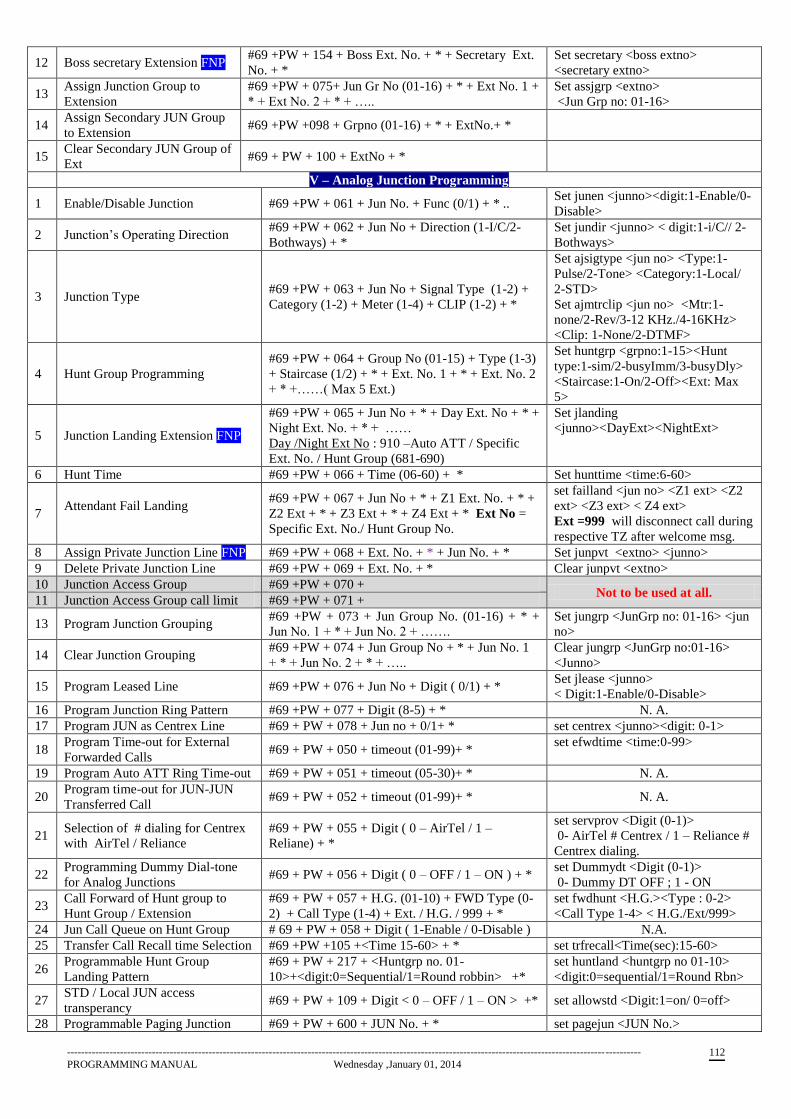
------------------------------------------------------------------------------------------------------------------------------------------------------------------
PROGRAMMING MANUAL Wednesday ,January 01, 2014 112
12 Boss secretary Extension FNP #69 +PW + 154 + Boss Ext. No. + * + Secretary Ext.
No. + *
Set secretary <boss extno>
<secretary extno>
13 Assign Junction Group to
Extension
#69 +PW + 075+ Jun Gr No (01-16) + * + Ext No. 1 +
* + Ext No. 2 + * + …..
Set assjgrp <extno>
<Jun Grp no: 01-16>
14 Assign Secondary JUN Group
to Extension #69 +PW +098 + Grpno (01-16) + * + ExtNo.+ *
15 Clear Secondary JUN Group of
Ext #69 + PW + 100 + ExtNo + *
V – Analog Junction Programming
1 Enable/Disable Junction #69 +PW + 061 + Jun No. + Func (0/1) + * .. Set junen <junno><digit:1-Enable/0-
Disable>
2 Junction’s Operating Direction #69 +PW + 062 + Jun No + Direction (1-I/C/2-
Bothways) + *
Set jundir <junno> < digit:1-i/C// 2-
Bothways>
3 Junction Type #69 +PW + 063 + Jun No + Signal Type (1-2) +
Category (1-2) + Meter (1-4) + CLIP (1-2) + *
Set ajsigtype <jun no> <Type:1-
Pulse/2-Tone> <Category:1-Local/
2-STD>
Set ajmtrclip <jun no> <Mtr:1-
none/2-Rev/3-12 KHz./4-16KHz>
<Clip: 1-None/2-DTMF>
4 Hunt Group Programming
#69 +PW + 064 + Group No (01-15) + Type (1-3)
+ Staircase (1/2) + * + Ext. No. 1 + * + Ext. No. 2
+ * +……( Max 5 Ext.)
Set huntgrp <grpno:1-15><Hunt
type:1-sim/2-busyImm/3-busyDly>
<Staircase:1-On/2-Off><Ext: Max
5>
5 Junction Landing Extension FNP
#69 +PW + 065 + Jun No + * + Day Ext. No + * +
Night Ext. No. + * + ……
Day /Night Ext No : 910 –Auto ATT / Specific
Ext. No. / Hunt Group (681-690)
Set jlanding
<junno><DayExt><NightExt>
6 Hunt Time #69 +PW + 066 + Time (06-60) + * Set hunttime <time:6-60>
7 Attendant Fail Landing
#69 +PW + 067 + Jun No + * + Z1 Ext. No. + * +
Z2 Ext + * + Z3 Ext + * + Z4 Ext + * Ext No =
Specific Ext. No./ Hunt Group No.
set failland <jun no> <Z1 ext> <Z2
ext> <Z3 ext> < Z4 ext>
Ext =999 will disconnect call during
respective TZ after welcome msg.
8 Assign Private Junction Line FNP #69 +PW + 068 + Ext. No. + * + Jun No. + * Set junpvt <extno> <junno>
9 Delete Private Junction Line #69 +PW + 069 + Ext. No. + * Clear junpvt <extno>
10 Junction Access Group #69 +PW + 070 + Not to be used at all.
11 Junction Access Group call limit #69 +PW + 071 +
13 Program Junction Grouping #69 +PW + 073 + Jun Group No. (01-16) + * +
Jun No. 1 + * + Jun No. 2 + …….
Set jungrp <JunGrp no: 01-16> <jun
no>
14 Clear Junction Grouping #69 +PW + 074 + Jun Group No + * + Jun No. 1
+ * + Jun No. 2 + * + …..
Clear jungrp <JunGrp no:01-16>
<Junno>
15 Program Leased Line #69 +PW + 076 + Jun No + Digit ( 0/1) + * Set jlease <junno>
< Digit:1-Enable/0-Disable>
16 Program Junction Ring Pattern #69 +PW + 077 + Digit (8-5) + * N. A.
17 Program JUN as Centrex Line #69 + PW + 078 + Jun no + 0/1+ * set centrex <junno><digit: 0-1>
18 Program Time-out for External
Forwarded Calls #69 + PW + 050 + timeout (01-99)+ *
set efwdtime <time:0-99>
19 Program Auto ATT Ring Time-out #69 + PW + 051 + timeout (05-30)+ * N. A.
20 Program time-out for JUN-JUN
Transferred Call #69 + PW + 052 + timeout (01-99)+ * N. A.
21 Selection of # dialing for Centrex
with AirTel / Reliance
#69 + PW + 055 + Digit ( 0 – AirTel / 1 –
Reliane) + *
set servprov <Digit (0-1)>
0- AirTel # Centrex / 1 – Reliance #
Centrex dialing.
22 Programming Dummy Dial-tone
for Analog Junctions #69 + PW + 056 + Digit ( 0 – OFF / 1 – ON ) + *
set Dummydt <Digit (0-1)>
0- Dummy DT OFF ; 1 - ON
23 Call Forward of Hunt group to
Hunt Group / Extension
#69 + PW + 057 + H.G. (01-10) + FWD Type (0-
2) + Call Type (1-4) + Ext. / H.G. / 999 + *
set fwdhunt <H.G.><Type : 0-2>
<Call Type 1-4> < H.G./Ext/999>
24 Jun Call Queue on Hunt Group # 69 + PW + 058 + Digit ( 1-Enable / 0-Disable ) N.A.
25 Transfer Call Recall time Selection #69 +PW +105 +<Time 15-60> + * set trfrecall<Time(sec):15-60>
26 Programmable Hunt Group
Landing Pattern
#69 + PW + 217 + <Huntgrp no. 01-
10>+<digit:0=Sequential/1=Round robbin> +*
set huntland <huntgrp no 01-10>
<digit:0=sequential/1=Round Rbn>
27 STD / Local JUN access
transperancy #69 + PW + 109 + Digit < 0 – OFF / 1 – ON > +* set allowstd <Digit:1=on/ 0=off>
28 Programmable Paging Junction #69 + PW + 600 + JUN No. + * set pagejun <JUN No.>
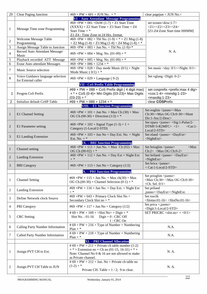
------------------------------------------------------------------------------------------------------------------------------------------------------------------
PROGRAMMING MANUAL Wednesday ,January 01, 2014 113
29 Clear Paging Junction #69 + PW + 601 + JUN No. + * clear pagejun < JUN No.>
VI – Auto Attendant Message Programming
1 Message Time zone Programming
#69 +PW + 081 +DoW (1-7) + Z1 Start Time
(XXXX) + Z2 Start Time + Z3 Start Time + Z4
Start Time + *
Z1-Z4 : Time Zone in 24 Hrs. format.
set tzones<dow:1-7>
<Z1><Z2><Z3><Z4>
[Z1-Z4:Zone Start time HHMM]
2 Welcome Message Table
Programming
#69 +PW + 082 + Tbl No. (1-9) + * + Z1 Msg (1-8)
+ Z2 Msg (1-8) + Z3 Msg (1-8) + Z4 Msg (1-8) + *
N. A.
3 Assign Message Table to Junction #69 +PW + 083 + Jun No. + Tbl No. (1-9)+*
4 Record Auto Attendant Message/
Music #69 +PW + 084 + Msg. No. (01-09) + *
5 Playback recorded ATT Message #69 +PW + 085 + Msg. No. (01-09) + *
6 Erase Auto attendant Messages #69 +PW + 086 + 1234 + *
7 Music Source selection #69 +PW + 028 + Day mode Music (0/1) + Night
Mode Music ( 0/1) + *
Set music <day: 0/1><Night: 0/1>
8 Voice Guidance language selection
for External caller #69 +PW + 029 + Language ( 0-2)
Set vglang <Digit: 0-2>
VII - CoS Prefix Table Programming
11 Progrm CoS Prefix #69 + PW + 088 + CoS Prefix digit ( 4 digit max) + * + CoS (0-4)+ Min Digits (03-23)+ Max Digits (03-23) + *
set cosprefix <prefix:max 4 dig> <cos:1-4> <mindig:1-23> <maxdig:1-23>
2 Initialize default CoSP Table #69 + PW + 089 + 1234 + * clear COSPrefix
VIII. – E1 Junction Programming
1 E1 Channel Setting #69 +PW + 101 + Jun No. + Max Ch (30) + Max
OG Ch (00-30) + Direction (1/2) + *
Set eoglim <junno><Max
Ch:30><Max OG Ch:0-30><Hunt
Dir:1-Asc/2-Desc>
2 E1 Parameter setting #69 +PW + 102 + Signal Type (1-3) + 1 +
Category (1-Local/2-STD)
Set epara <junno> <Sig:1-Pulse/2-
DTMF/3-R2MFC> <1> <Cat:1-
Local/2-STD>
3 E1 Landing Extension #69 +PW + 103 + Jun No + Day Ext. No. + Night
Ext. No. + *
Set eland <junno> <DayExt>
<NightExt>
IX. – BRI Junction Programming
1 Channel setting #69 +PW + 111 + Jun No. + Max Ch (02) + Max
OG Ch (00-02) + *
Set brioglim <junno> <Max
Ch:2> <Max OG Ch:0-2>
2 Landing Extension #69 +PW + 112 + Jun No. + Day Ext + Night Ext
+ *
Set briland <junno> <DayExt>
<NightExt>
3 BRI Category #69 +PW + 113 + Jun No + Category (1/2) Set brica <junno>
< Cat:1-Local/2-STD>
X. – PRI Junction Programming
1 Channel Setting #69 +PW + 115 + Jun No. + Max ch(30) + Max
OG Ch.(00-30) + Channel Selection (0-1) + *
Set prioglim <junno>
<Max Ch:30> <Max OG Ch:0-30>
<Ch. Sel. 0/1>
2 Landing Extension #69 +PW + 116 + Jun No. + Day Ext. + Night Ext
+ *
Set priland
,junno><DayExt><NightExt.
3 Define Network clock Source #69 +PW + 043 + Primary Clock Slot No +
Secondary Clock Slot no + *
Set nwclk
<Slotno:01-16> <SlotNo:01-16>
4 PRI Category #69 +PW + 117 + Jun No + Category (1/2) Set prica <,junno>
<Digit:1-Local/2-STD>
5 CRC Setting
# 69 + PW + 169 + <Slot No> + Digit + *
Slot No. : 01-16 Digit = 0 : CRC Off
1 : CRC On
SET PRICRC <slot.no> + <0/1>
6 Calling Party Number Information # 69 + PW + 216 + Type of Number + Numbering
Plan + * N.A.
7 Called Party Number Information # 69 + PW + 218 + Type of Number + Numbering
Plan + * N.A.
XI. – PRI Channel Allocation
1 Assign PVT CH to Ext.
# 69 + PW + 211 + Private ch table number (1-2)
+ * + Extension no + Ch no (01-15, 16-31) + * +
Note: Channel No 0 & 16 are not allowed to make
as Private channel.
N. A.
2 Assign PVT CH Table to JUN
# 69 + PW + 212 + Jun. No + Private ch table no
(1-2) + *
Private CH. Table = 1 / 2; 9 to clear. N. A.
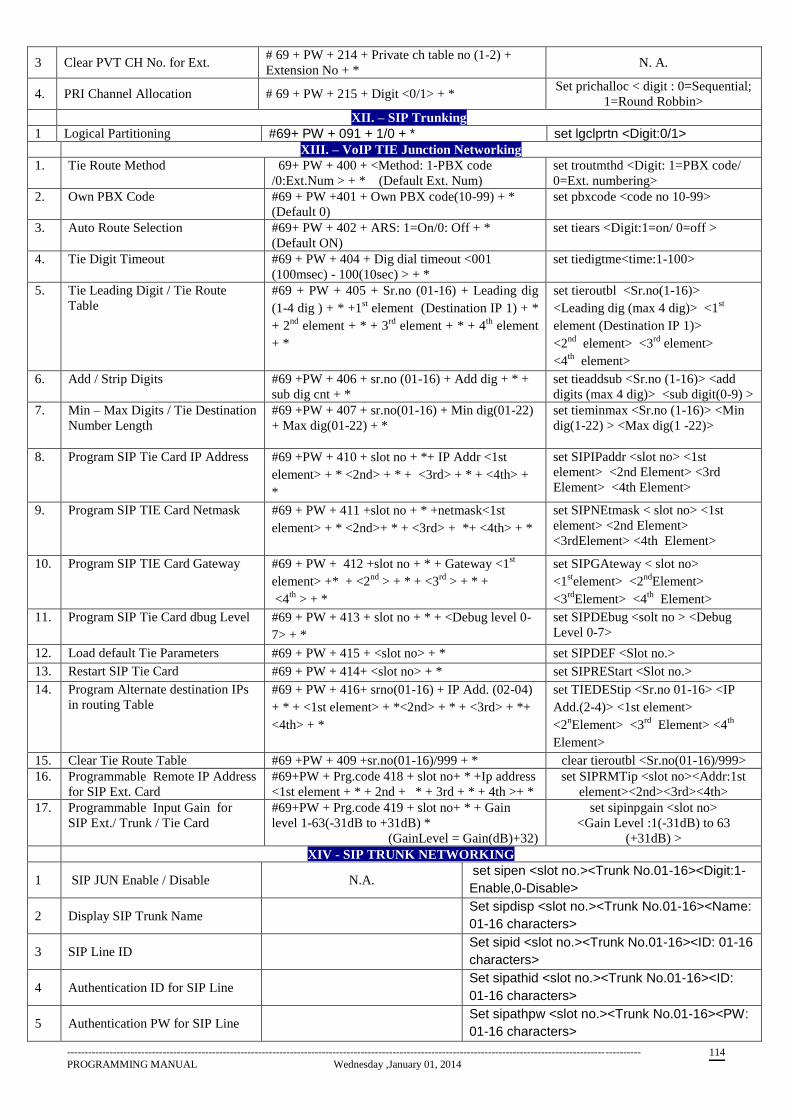
------------------------------------------------------------------------------------------------------------------------------------------------------------------
PROGRAMMING MANUAL Wednesday ,January 01, 2014 114
3 Clear PVT CH No. for Ext. # 69 + PW + 214 + Private ch table no (1-2) +
Extension No + * N. A.
4. PRI Channel Allocation # 69 + PW + 215 + Digit <0/1> + * Set prichalloc < digit : 0=Sequential;
1=Round Robbin>
XII. – SIP Trunking
1 Logical Partitioning #69+ PW + 091 + 1/0 + * set lgclprtn <Digit:0/1>
XIII. – VoIP TIE Junction Networking
1. Tie Route Method #69+ PW + 400 + <Method: 1-PBX code
/0:Ext.Num > + * (Default Ext. Num)
set troutmthd <Digit: 1=PBX code/
0=Ext. numbering>
2. Own PBX Code #69 + PW +401 + Own PBX code(10-99) + *
(Default 0)
set pbxcode <code no 10-99>
3. Auto Route Selection #69+ PW + 402 + ARS: 1=On/0: Off + *
(Default ON)
set tiears <Digit:1=on/ 0=off >
4. Tie Digit Timeout #69 + PW + 404 + Dig dial timeout <001
(100msec) - 100(10sec) > + *
set tiedigtme<time:1-100>
5. Tie Leading Digit / Tie Route
Table
#69 + PW + 405 + Sr.no (01-16) + Leading dig
(1-4 dig ) + * +1st element (Destination IP 1) + *
+ 2nd
element + * + 3rd
element + * + 4th
element
+ *
set tieroutbl <Sr.no(1-16)>
<Leading dig (max 4 dig)> <1st
element (Destination IP 1)>
<2nd
element> <3rd
element>
<4th
element>
6. Add / Strip Digits #69 +PW + 406 + sr.no (01-16) + Add dig + * +
sub dig cnt + *
set tieaddsub <Sr.no (1-16)> <add
digits (max 4 dig)> <sub digit(0-9) >
7. Min – Max Digits / Tie Destination
Number Length
#69 +PW + 407 + sr.no(01-16) + Min dig(01-22)
+ Max dig(01-22) + *
set tieminmax <Sr.no (1-16)> <Min
dig(1-22) > <Max dig(1 -22)>
8. Program SIP Tie Card IP Address #69 +PW + 410 + slot no + *+ IP Addr <1st
element> + * <2nd> + * + <3rd> + * + <4th> +
*
set SIPIPaddr <slot no> <1st
element> <2nd Element> <3rd
Element> <4th Element>
9. Program SIP TIE Card Netmask #69 + PW + 411 +slot no + * +netmask<1st
element> + * <2nd>+ * + <3rd> + *+ <4th> + *
set SIPNEtmask < slot no> <1st
element> <2nd Element>
<3rdElement> <4th Element>
10. Program SIP TIE Card Gateway #69 + PW + 412 +slot no + * + Gateway <1st
element> +* + <2nd
> + * + <3rd
> + * +
<4th
> + *
set SIPGAteway < slot no>
<1stelement> <2
ndElement>
<3rd
Element> <4th
Element>
11. Program SIP Tie Card dbug Level #69 + PW + 413 + slot no + * + <Debug level 0-
7> + *
set SIPDEbug <solt no > <Debug
Level 0-7>
12. Load default Tie Parameters #69 + PW + 415 + <slot no> + * set SIPDEF <Slot no.>
13. Restart SIP Tie Card #69 + PW + 414+ <slot no> + * set SIPREStart <Slot no.>
14. Program Alternate destination IPs
in routing Table
#69 + PW + 416+ srno(01-16) + IP Add. (02-04)
+ * + <1st element> + *<2nd> + * + <3rd> + *+
<4th> + *
set TIEDEStip <Sr.no 01-16> <IP
Add.(2-4)> <1st element>
<2nElement> <3
rd Element> <4
th
Element>
15. Clear Tie Route Table #69 +PW + 409 +sr.no(01-16)/999 + * clear tieroutbl <Sr.no(01-16)/999>
16. Programmable Remote IP Address
for SIP Ext. Card
#69+PW + Prg.code 418 + slot no+ * +Ip address
<1st element + * + 2nd + * + 3rd + * + 4th >+ *
set SIPRMTip <slot no><Addr:1st
element><2nd><3rd><4th>
17. Programmable Input Gain for
SIP Ext./ Trunk / Tie Card
#69+PW + Prg.code 419 + slot no+ * + Gain
level 1-63(-31dB to +31dB) *
(GainLevel = Gain(dB)+32)
set sipinpgain <slot no>
<Gain Level :1(-31dB) to 63
(+31dB) >
XIV - SIP TRUNK NETWORKING
1 SIP JUN Enable / Disable N.A. set sipen <slot no.><Trunk No.01-16><Digit:1-
Enable,0-Disable>
2 Display SIP Trunk Name Set sipdisp <slot no.><Trunk No.01-16><Name:
01-16 characters>
3 SIP Line ID Set sipid <slot no.><Trunk No.01-16><ID: 01-16
characters>
4 Authentication ID for SIP Line Set sipathid <slot no.><Trunk No.01-16><ID:
01-16 characters>
5 Authentication PW for SIP Line Set sipathpw <slot no.><Trunk No.01-16><PW:
01-16 characters>
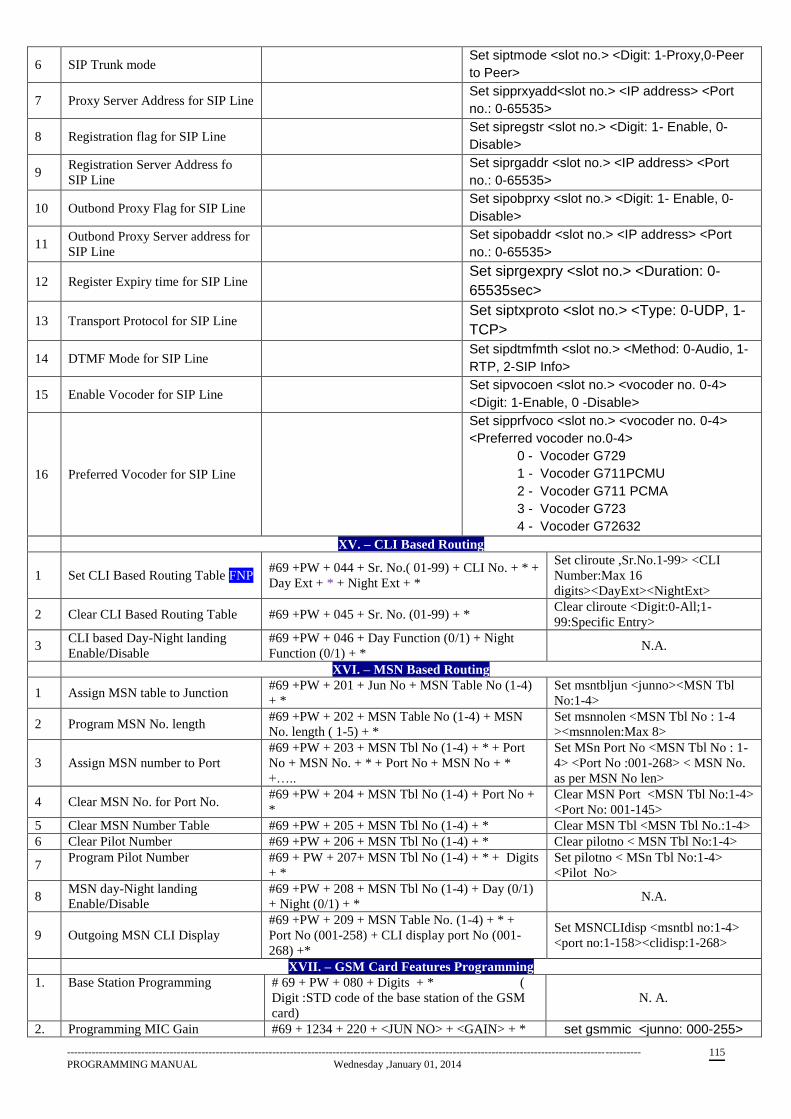
------------------------------------------------------------------------------------------------------------------------------------------------------------------
PROGRAMMING MANUAL Wednesday ,January 01, 2014 115
6 SIP Trunk mode Set siptmode <slot no.> <Digit: 1-Proxy,0-Peer
to Peer>
7 Proxy Server Address for SIP Line Set sipprxyadd<slot no.> <IP address> <Port
no.: 0-65535>
8 Registration flag for SIP Line Set sipregstr <slot no.> <Digit: 1- Enable, 0-
Disable>
9 Registration Server Address fo
SIP Line
Set siprgaddr <slot no.> <IP address> <Port
no.: 0-65535>
10 Outbond Proxy Flag for SIP Line Set sipobprxy <slot no.> <Digit: 1- Enable, 0-
Disable>
11 Outbond Proxy Server address for
SIP Line
Set sipobaddr <slot no.> <IP address> <Port
no.: 0-65535>
12 Register Expiry time for SIP Line Set siprgexpry <slot no.> <Duration: 0-
65535sec>
13 Transport Protocol for SIP Line Set siptxproto <slot no.> <Type: 0-UDP, 1-
TCP>
14 DTMF Mode for SIP Line Set sipdtmfmth <slot no.> <Method: 0-Audio, 1-
RTP, 2-SIP Info>
15 Enable Vocoder for SIP Line Set sipvocoen <slot no.> <vocoder no. 0-4>
<Digit: 1-Enable, 0 -Disable>
16 Preferred Vocoder for SIP Line
Set sipprfvoco <slot no.> <vocoder no. 0-4>
<Preferred vocoder no.0-4>
0 - Vocoder G729
1 - Vocoder G711PCMU
2 - Vocoder G711 PCMA
3 - Vocoder G723
4 - Vocoder G72632 XV. – CLI Based Routing
1 Set CLI Based Routing Table FNP #69 +PW + 044 + Sr. No.( 01-99) + CLI No. + * +
Day Ext + * + Night Ext + *
Set cliroute ,Sr.No.1-99> <CLI
Number:Max 16
digits><DayExt><NightExt>
2 Clear CLI Based Routing Table #69 +PW + 045 + Sr. No. (01-99) + * Clear cliroute <Digit:0-All;1-
99:Specific Entry>
3 CLI based Day-Night landing
Enable/Disable
#69 +PW + 046 + Day Function (0/1) + Night
Function (0/1) + * N.A.
XVI. – MSN Based Routing
1 Assign MSN table to Junction #69 +PW + 201 + Jun No + MSN Table No (1-4)
+ *
Set msntbljun <junno><MSN Tbl
No:1-4>
2 Program MSN No. length #69 +PW + 202 + MSN Table No (1-4) + MSN
No. length ( 1-5) + *
Set msnnolen <MSN Tbl No : 1-4
><msnnolen:Max 8>
3 Assign MSN number to Port
#69 +PW + 203 + MSN Tbl No (1-4) + * + Port
No + MSN No. + * + Port No + MSN No + *
+…..
Set MSn Port No <MSN Tbl No : 1-
4> <Port No :001-268> < MSN No.
as per MSN No len>
4 Clear MSN No. for Port No. #69 +PW + 204 + MSN Tbl No (1-4) + Port No +
*
Clear MSN Port <MSN Tbl No:1-4>
<Port No: 001-145>
5 Clear MSN Number Table #69 +PW + 205 + MSN Tbl No (1-4) + * Clear MSN Tbl <MSN Tbl No.:1-4>
6 Clear Pilot Number #69 +PW + 206 + MSN Tbl No (1-4) + * Clear pilotno < MSN Tbl No:1-4>
7 Program Pilot Number #69 + PW + 207+ MSN Tbl No (1-4) + * + Digits
+ *
Set pilotno < MSn Tbl No:1-4>
<Pilot No>
8 MSN day-Night landing
Enable/Disable
#69 +PW + 208 + MSN Tbl No (1-4) + Day (0/1)
+ Night (0/1) + * N.A.
9 Outgoing MSN CLI Display
#69 +PW + 209 + MSN Table No. (1-4) + * +
Port No (001-258) + CLI display port No (001-
268) +*
Set MSNCLIdisp <msntbl no:1-4>
<port no:1-158><clidisp:1-268>
XVII. – GSM Card Features Programming
1. Base Station Programming # 69 + PW + 080 + Digits + * (
Digit :STD code of the base station of the GSM
card)
N. A.
2. Programming MIC Gain #69 + 1234 + 220 + <JUN NO> + <GAIN> + * set gsmmic <junno: 000-255>
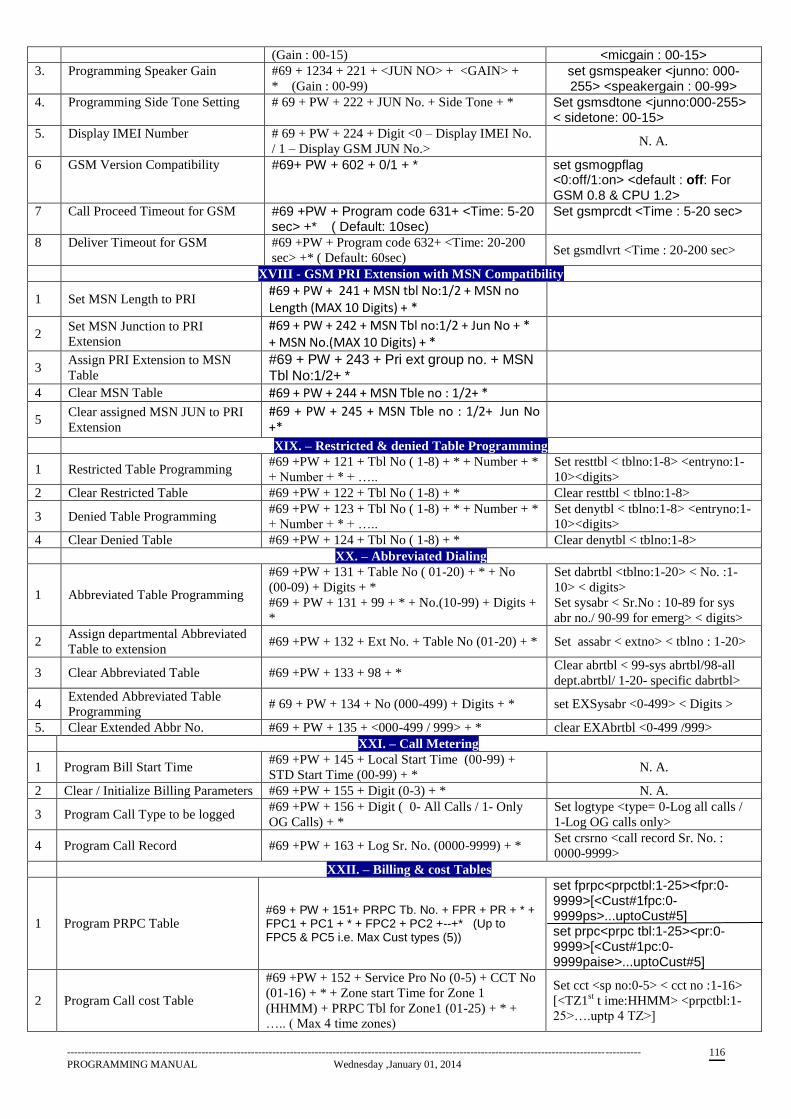
------------------------------------------------------------------------------------------------------------------------------------------------------------------
PROGRAMMING MANUAL Wednesday ,January 01, 2014 116
(Gain : 00-15) <micgain : 00-15>
3. Programming Speaker Gain #69 + 1234 + 221 + <JUN NO> + <GAIN> +
* (Gain : 00-99) set gsmspeaker <junno: 000-255> <speakergain : 00-99>
4. Programming Side Tone Setting # 69 + PW + 222 + JUN No. + Side Tone + * Set gsmsdtone <junno:000-255> < sidetone: 00-15>
5. Display IMEI Number # 69 + PW + 224 + Digit <0 – Display IMEI No.
/ 1 – Display GSM JUN No.> N. A.
6 GSM Version Compatibility #69+ PW + 602 + 0/1 + * set gsmogpflag <0:off/1:on> <default : off: For GSM 0.8 & CPU 1.2>
7 Call Proceed Timeout for GSM #69 +PW + Program code 631+ <Time: 5-20 sec> +* ( Default: 10sec)
Set gsmprcdt <Time : 5-20 sec>
8 Deliver Timeout for GSM #69 +PW + Program code 632+ <Time: 20-200
sec> +* ( Default: 60sec) Set gsmdlvrt <Time : 20-200 sec>
XVIII - GSM PRI Extension with MSN Compatibility
1 Set MSN Length to PRI #69 + PW + 241 + MSN tbl No:1/2 + MSN no Length (MAX 10 Digits) + *
2 Set MSN Junction to PRI
Extension
#69 + PW + 242 + MSN Tbl no:1/2 + Jun No + * + MSN No.(MAX 10 Digits) + *
3 Assign PRI Extension to MSN
Table
#69 + PW + 243 + Pri ext group no. + MSN Tbl No:1/2+ *
4 Clear MSN Table #69 + PW + 244 + MSN Tble no : 1/2+ *
5 Clear assigned MSN JUN to PRI
Extension
#69 + PW + 245 + MSN Tble no : 1/2+ Jun No +*
XIX. – Restricted & denied Table Programming
1 Restricted Table Programming #69 +PW + 121 + Tbl No ( 1-8) + * + Number + *
+ Number + * + …..
Set resttbl < tblno:1-8> <entryno:1-
10><digits>
2 Clear Restricted Table #69 +PW + 122 + Tbl No ( 1-8) + * Clear resttbl < tblno:1-8>
3 Denied Table Programming #69 +PW + 123 + Tbl No ( 1-8) + * + Number + *
+ Number + * + …..
Set denytbl < tblno:1-8> <entryno:1-
10><digits>
4 Clear Denied Table #69 +PW + 124 + Tbl No ( 1-8) + * Clear denytbl < tblno:1-8>
XX. – Abbreviated Dialing
1 Abbreviated Table Programming
#69 +PW + 131 + Table No ( 01-20) + * + No
(00-09) + Digits + *
#69 + PW + 131 + 99 + * + No.(10-99) + Digits +
*
Set dabrtbl <tblno:1-20> < No. :1-
10> < digits>
Set sysabr < Sr.No : 10-89 for sys
abr no./ 90-99 for emerg> < digits>
2 Assign departmental Abbreviated
Table to extension #69 +PW + 132 + Ext No. + Table No (01-20) + * Set assabr < extno> < tblno : 1-20>
3 Clear Abbreviated Table #69 +PW + 133 + 98 + * Clear abrtbl < 99-sys abrtbl/98-all
dept.abrtbl/ 1-20- specific dabrtbl>
4 Extended Abbreviated Table
Programming # 69 + PW + 134 + No (000-499) + Digits + * set EXSysabr <0-499> < Digits >
5. Clear Extended Abbr No. #69 + PW + 135 + <000-499 / 999> + * clear EXAbrtbl <0-499 /999>
XXI. – Call Metering
1 Program Bill Start Time #69 +PW + 145 + Local Start Time (00-99) +
STD Start Time (00-99) + * N. A.
2 Clear / Initialize Billing Parameters #69 +PW + 155 + Digit (0-3) + * N. A.
3 Program Call Type to be logged #69 +PW + 156 + Digit ( 0- All Calls / 1- Only
OG Calls) + *
Set logtype <type= 0-Log all calls /
1-Log OG calls only>
4 Program Call Record #69 +PW + 163 + Log Sr. No. (0000-9999) + * Set crsrno <call record Sr. No. :
0000-9999>
XXII. – Billing & cost Tables
1 Program PRPC Table #69 + PW + 151+ PRPC Tb. No. + FPR + PR + * + FPC1 + PC1 + * + FPC2 + PC2 +--+* (Up to FPC5 & PC5 i.e. Max Cust types (5))
set fprpc<prpctbl:1-25><fpr:0-9999>[<Cust#1fpc:0-9999ps>...uptoCust#5] set prpc<prpc tbl:1-25><pr:0-9999>[<Cust#1pc:0-9999paise>...uptoCust#5]
2 Program Call cost Table
#69 +PW + 152 + Service Pro No (0-5) + CCT No
(01-16) + * + Zone start Time for Zone 1
(HHMM) + PRPC Tbl for Zone1 (01-25) + * +
….. ( Max 4 time zones)
Set cct <sp no:0-5> < cct no :1-16>
[<TZ1st t ime:HHMM> <prpctbl:1-
25>….uptp 4 TZ>]
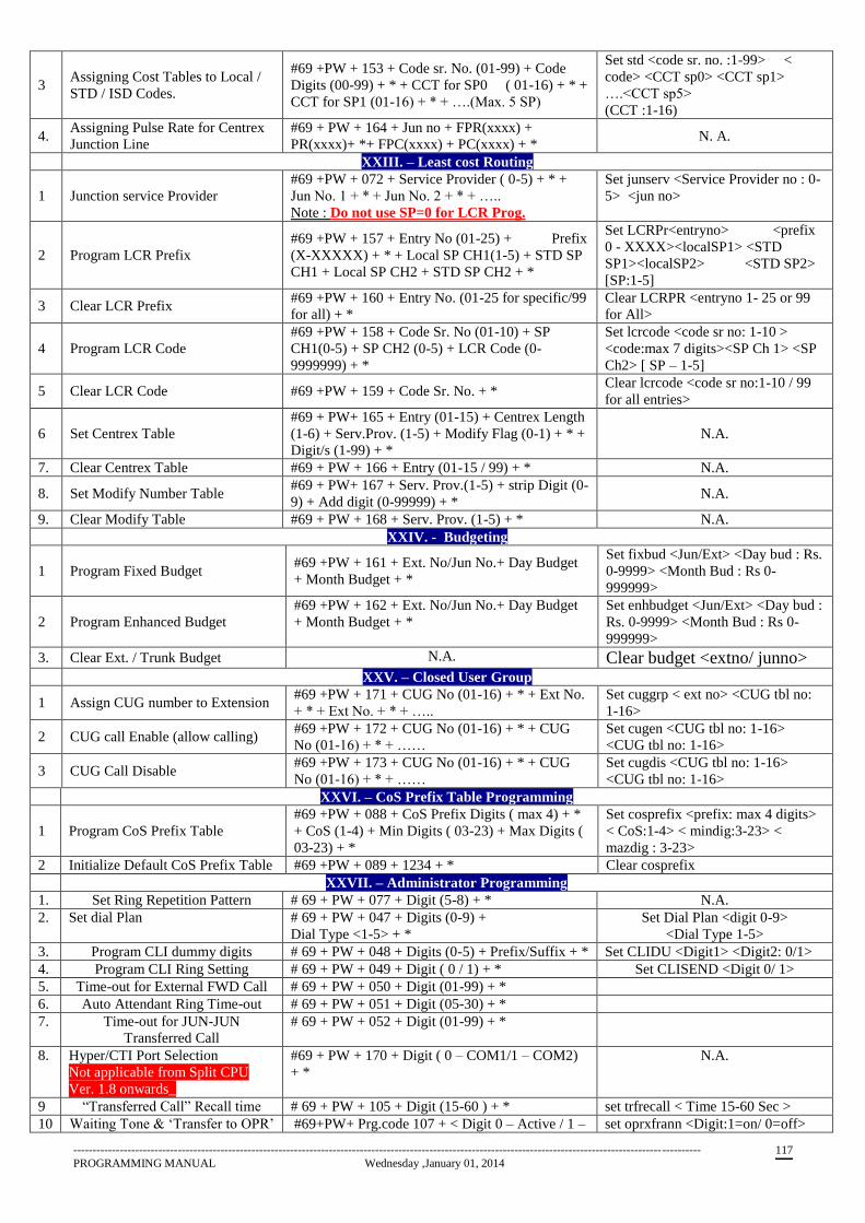
------------------------------------------------------------------------------------------------------------------------------------------------------------------
PROGRAMMING MANUAL Wednesday ,January 01, 2014 117
3 Assigning Cost Tables to Local /
STD / ISD Codes.
#69 +PW + 153 + Code sr. No. (01-99) + Code
Digits (00-99) + * + CCT for SP0 ( 01-16) + * +
CCT for SP1 (01-16) + * + ….(Max. 5 SP)
Set std <code sr. no. :1-99> <
code> <CCT sp0> <CCT sp1>
….<CCT sp5>
(CCT :1-16)
4. Assigning Pulse Rate for Centrex
Junction Line
#69 + PW + 164 + Jun no + FPR(xxxx) +
PR(xxxx)+ *+ FPC(xxxx) + PC(xxxx) + * N. A.
XXIII. – Least cost Routing
1 Junction service Provider
#69 +PW + 072 + Service Provider ( 0-5) + * +
Jun No. 1 + * + Jun No. 2 + * + …..
Note : Do not use SP=0 for LCR Prog.
Set junserv <Service Provider no : 0-
5> <jun no>
2 Program LCR Prefix
#69 +PW + 157 + Entry No (01-25) + Prefix
(X-XXXXX) + * + Local SP CH1(1-5) + STD SP
CH1 + Local SP CH2 + STD SP CH2 + *
Set LCRPr<entryno> <prefix
0 - XXXX><localSP1> <STD
SP1><localSP2> <STD SP2>
[SP:1-5]
3 Clear LCR Prefix #69 +PW + 160 + Entry No. (01-25 for specific/99
for all) + *
Clear LCRPR <entryno 1- 25 or 99
for All>
4 Program LCR Code
#69 +PW + 158 + Code Sr. No (01-10) + SP
CH1(0-5) + SP CH2 (0-5) + LCR Code (0-
9999999) + *
Set lcrcode <code sr no: 1-10 >
<code:max 7 digits><SP Ch 1> <SP
Ch2> [ SP – 1-5]
5 Clear LCR Code #69 +PW + 159 + Code Sr. No. + * Clear lcrcode <code sr no:1-10 / 99
for all entries>
6 Set Centrex Table
#69 + PW+ 165 + Entry (01-15) + Centrex Length
(1-6) + Serv.Prov. (1-5) + Modify Flag (0-1) + * +
Digit/s (1-99) + *
N.A.
7. Clear Centrex Table #69 + PW + 166 + Entry (01-15 / 99) + * N.A.
8. Set Modify Number Table #69 + PW+ 167 + Serv. Prov.(1-5) + strip Digit (0-
9) + Add digit (0-99999) + * N.A.
9. Clear Modify Table #69 + PW + 168 + Serv. Prov. (1-5) + * N.A.
XXIV. - Budgeting
1 Program Fixed Budget #69 +PW + 161 + Ext. No/Jun No.+ Day Budget
+ Month Budget + *
Set fixbud <Jun/Ext> <Day bud : Rs.
0-9999> <Month Bud : Rs 0-
999999>
2 Program Enhanced Budget
#69 +PW + 162 + Ext. No/Jun No.+ Day Budget
+ Month Budget + *
Set enhbudget <Jun/Ext> <Day bud :
Rs. 0-9999> <Month Bud : Rs 0-
999999>
3. Clear Ext. / Trunk Budget N.A. Clear budget <extno/ junno>
XXV. – Closed User Group
1 Assign CUG number to Extension #69 +PW + 171 + CUG No (01-16) + * + Ext No.
+ * + Ext No. + * + …..
Set cuggrp < ext no> <CUG tbl no:
1-16>
2 CUG call Enable (allow calling) #69 +PW + 172 + CUG No (01-16) + * + CUG
No (01-16) + * + ……
Set cugen <CUG tbl no: 1-16>
<CUG tbl no: 1-16>
3 CUG Call Disable #69 +PW + 173 + CUG No (01-16) + * + CUG
No (01-16) + * + ……
Set cugdis <CUG tbl no: 1-16>
<CUG tbl no: 1-16>
XXVI. – CoS Prefix Table Programming
1 Program CoS Prefix Table
#69 +PW + 088 + CoS Prefix Digits ( max 4) + *
+ CoS (1-4) + Min Digits ( 03-23) + Max Digits (
03-23) + *
Set cosprefix <prefix: max 4 digits>
< CoS:1-4> < mindig:3-23> <
mazdig : 3-23>
2 Initialize Default CoS Prefix Table #69 +PW + 089 + 1234 + * Clear cosprefix
XXVII. – Administrator Programming
1. Set Ring Repetition Pattern # 69 + PW + 077 + Digit (5-8) + * N.A.
2. Set dial Plan # 69 + PW + 047 + Digits (0-9) +
Dial Type <1-5> + *
Set Dial Plan <digit 0-9>
<Dial Type 1-5>
3. Program CLI dummy digits # 69 + PW + 048 + Digits (0-5) + Prefix/Suffix + * Set CLIDU <Digit1> <Digit2: 0/1>
4. Program CLI Ring Setting # 69 + PW + 049 + Digit ( 0 / 1) + * Set CLISEND <Digit 0/ 1>
5. Time-out for External FWD Call # 69 + PW + 050 + Digit (01-99) + *
6. Auto Attendant Ring Time-out # 69 + PW + 051 + Digit (05-30) + *
7. Time-out for JUN-JUN
Transferred Call
# 69 + PW + 052 + Digit (01-99) + *
8. Hyper/CTI Port Selection
Not applicable from Split CPU
Ver. 1.8 onwards_
#69 + PW + 170 + Digit ( 0 – COM1/1 – COM2)
+ *
N.A.
9 “Transferred Call” Recall time # 69 + PW + 105 + Digit (15-60 ) + * set trfrecall < Time 15-60 Sec >
10 Waiting Tone & ‘Transfer to OPR’ #69+PW+ Prg.code 107 + < Digit 0 – Active / 1 – set oprxfrann <Digit:1=on/ 0=off>
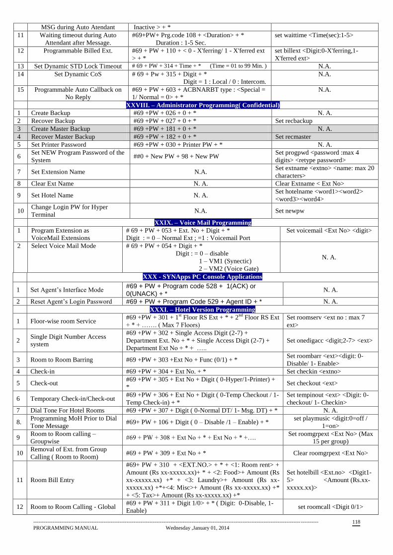
------------------------------------------------------------------------------------------------------------------------------------------------------------------
PROGRAMMING MANUAL Wednesday ,January 01, 2014 118
MSG during Auto Atendant Inactive > + *
11 Waiting timeout during Auto
Attendant after Message.
#69+PW+ Prg.code 108 + <Duration> + *
Duration : 1-5 Sec.
set waittime <Time(sec):1-5>
12 Programmable Billed Ext. #69 + PW + 110 + < 0 - X'ferring/ 1 - X'ferred ext
> + *
set billext <Digit:0-X'ferring,1-
X'ferred ext>
13 Set Dynamic STD Lock Timeout # 69 + PW + 314 + Time + * (Time = 01 to 99 Min. ) N.A.
14 Set Dynamic CoS # 69 + Pw + 315 + Digit + *
Digit = 1 : Local / 0 : Intercom.
N.A.
15 Programmable Auto Callback on
No Reply
#69 + PW + 603 + ACBNARBT type : <Special =
1/ Normal = 0> + *
N.A.
XXVIII. – Administrator Programming( Confidential)
1 Create Backup #69 +PW + 026 + 0 + * N. A.
2 Recover Backup #69 +PW + 027 + 0 + * Set recbackup
3 Create Master Backup #69 +PW + 181 + 0 + * N. A.
4 Recover Master Backup #69 +PW + 182 + 0 + * Set recmaster
5 Set Printer Password #69 +PW + 030 + Printer PW + * N. A.
6 Set NEW Program Password of the
System ##0 + New PW + 98 + New PW
Set progpwd <password :max 4
digits> <retype password>
7 Set Extension Name N.A. Set extname <extno> <name: max 20
characters>
8 Clear Ext Name N. A. Clear Extname < Ext No>
9 Set Hotel Name N. A. Set hotelname <word1><word2>
<word3><word4>
10 Change Login PW for Hyper
Terminal N.A. Set newpw
XXIX. – Voice Mail Programming
1 Program Extension as
VoiceMail Extensions
# 69 + PW + 053 + Ext. No + Digit + *
Digit : = 0 – Normal Ext ; =1 : Voicemail Port
Set voicemail <Ext No> <digit>
2 Select Voice Mail Mode # 69 + PW + 054 + Digit + *
Digit : = 0 – disable
1 – VM1 (Synectic)
2 – VM2 (Voice Gate)
N. A.
XXX - SYNApps PC Console Applications
1 Set Agent’s Interface Mode #69 + PW + Program code 528 + 1(ACK) or 0(UNACK) + *
N. A.
2 Reset Agent’s Login Password #69 + PW + Program Code 529 + Agent ID + * N. A.
XXXI. – Hotel Version Programming
1 Floor-wise room Service #69 +PW + 301 + 1
st Floor RS Ext + * + 2
nd Floor RS Ext
+ * + ……. ( Max 7 Floors)
Set roomserv <ext no : max 7
ext>
2 Single Digit Number Access
system
#69 +PW + 302 + Single Access Digit (2-7) +
Department Ext. No + * + Single Access Digit (2-7) +
Department Ext No + * + …..
Set onedigacc <digit;2-7> <ext>
3 Room to Room Barring #69 +PW + 303 +Ext No + Func (0/1) + * Set roombarr <ext><digit: 0-
Disable/ 1- Enable>
4 Check-in #69 +PW + 304 + Ext No. + * Set checkin <extno>
5 Check-out #69 +PW + 305 + Ext No + Digit ( 0-Hyper/1-Printer) +
* Set checkout <ext>
6 Temporary Check-in/Check-out #69 +PW + 306 + Ext No + Digit ( 0-Temp Checkout / 1-
Temp Check-in) + *
Set tempinout <ext> <Digit: 0-
checkout/ 1- Checkin>
7 Dial Tone For Hotel Rooms #69 +PW + 307 + Digit ( 0-Normal DT/ 1- Msg. DT) + * N. A.
8. Programming MoH Prior to Dial
Tone Message #69+ PW + 106 + Digit ( 0 – Disable /1 – Enable) + *
set playmusic <digit:0=off /
1=on>
9 Room to Room calling –
Groupwise #69 + PW + 308 + Ext No + * + Ext No + * +….
Set roomgrpext <Ext No> (Max
15 per group)
10 Removal of Ext. from Group
Calling ( Room to Room) #69 + PW + 309 + Ext No + * Clear roomgrpext <Ext No>
11 Room Bill Entry
#69+ PW + 310 + <EXT.NO.> + * + <1: Room rent> +
Amount (Rs xx-xxxxx.xx)+ * + <2: Food>+ Amount (Rs
xx-xxxxx.xx) +* + <3: Laundry>+ Amount (Rs xx-
xxxxx.xx) +*+<4: Misc>+ Amount (Rs xx-xxxxx.xx) +*
+ <5: Tax>+ Amount (Rs xx-xxxxx.xx) +*
Set hotelbill <Ext.no> <Digit1-
5> <Amount (Rs.xx-
xxxxx.xx)>
12 Room to Room Calling - Global #69 + PW + 311 + Digit 1/0> + * ( Digit: 0-Disable, 1-
Enable) set roomcall <Digit 0/1>
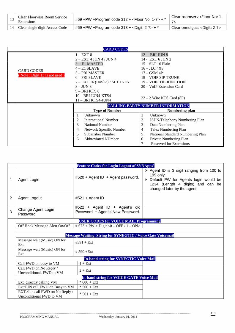
------------------------------------------------------------------------------------------------------------------------------------------------------------------
PROGRAMMING MANUAL Wednesday ,January 01, 2014 119
13 Clear Floorwise Room Service
Extensions #69 +PW +Program code 312 + <Floor No: 1-7> + *
Clear roomserv <Floor No: 1-7>
14 Clear single digit Access Code #69 +PW +Program code 313 + <Digit: 2-7> + * Clear onedigacc <Digit: 2-7>
CARD CODES
CARD CODES
( Note : Digit 13 is not used )
1 – EXT 8 12 – BRI JUN 8
2 – EXT 4 JUN 4 / JUN 4 14 - EXT 6 JUN 2
3 - E1 MASTER 15 – SLT 16 Plain
4 – E1 SLAVE 16 – JLC 4X8
5 – PRI MASTER 17 – GSM 4P
6 – PRI SLAVE 18 – VOIP SIP TRUNK
7 – EXT 16 (DuSlic) / SLT 16 Dx 19 – VOIP TIE JUNCTION
8 – JUN 8 20 – VoIP Extension Card
9 – BRI KTS 8
10 – BRI JUN4-KTS4
11 – BRI KTS4-JUN4 22 – 2 Wire KTS Card (8P)
CALLING PARTY NUMBER INFORMATION
TType of Number Numbering plan
1 Unknown 1 Unknown
2 International Number 2 ISDN/Telephony Numbering Plan
3 National Number 3 Data Numbering Plan
4 Network Specific Number 4 Telex Numbering Plan
5 Subscriber Number 5 National Standard Numbering Plan
6 Abbreviated NUmber 6 Private Numbering Plan
7 Reserved for Extensions
Feature Codes for Login Logout of SYNApps’
1 Agent Login #520 + Agent ID + Agent password.
Agent ID is 3 digit ranging from 100 to 199 only.
Default PW for Agents login would be 1234 (Length 4 digits) and can be changed later by the agent.
2 Agent Logout #521 + Agent ID
3 Change Agent Login Password
#522 + Agent ID + Agent’s old Password + Agent’s New Password.
USER CODES for VOICE MAIL Programming
Off Hook Message Alert On/Off # 673 + PW + Digit <0 – OFF / 1 – ON>
Message Waiting String for SYNEGTIC / Voice Gate Voicemail
Message wait (Music) ON for
Ext. #591 + Ext
Message wait (Music) ON for
Ext. # 590 +Ext
In-band string for SYNECTIC Voice Mail
Call FWD on busy to VM 1 + Ext
Call FWD on No Reply /
Unconditional. FWD to VM 2 + Ext
In-band string for VOICE GATE Voice Mail
Ext. directly calling VM * 600 + Ext
Ext/JUN call FWD on Busy to VM * 500 + Ext
EXT./Jun call FWD on No Reply /
Unconditional FWD to VM * 501 + Ext

------------------------------------------------------------------------------------------------------------------------------------------------------------------
PROGRAMMING MANUAL Wednesday ,January 01, 2014 120
ANNEXURE
FEATURE CODE
Ports No. specified for Feature Code are virtual ports and has no concern with the Port No. of the Extension generally referred to while programming MSN No. or Defining Ext. No. with Add Port Program.
Feat No.
Dial Code Description
Feat No.
Dial Code Description
000 #680 Change ext.password
030 #62 Other park pickup
001 #687 Change COS
031 #610 Unconditional forwarding
002 #677 Reset COS
032 #611 Forward on busy
003 #69 System programming
033 #612 Forward on no reply
004 #65 Printing commands
034 #671 Cancel internal forward
005 #607 DOSA class
035 #613 Budget bill announcement
006 #682 Set DND
036 #64 Pick any ext
007 #670 Set forward
037 #504 MSN landing
008 #602 Set hotline
038 #505 CLI landing
009 #603 Reset hotline
039 #600 Follow me
010 #683 Set Dynamic lock
040 #1 Pickup
011 #7 Dial abbreviated no.
041 0 Local jun seize
012 #502 CLIR
042 #4 Extended abbreviated dialling
013 #8 Selective jun seize
043 9 Operator dial
014 #2 Tie seize
044 #599 Reset port
015 #3 Selective tie seize
045 #506 Display MSNCLI
016 #674 Cancel ACB
046 #511 Set external forward
017 #685 Set self alarm
047 #510 Enable external forward
018 #686 Set others alarm
048 #673 Off hook msg
019 #675 Clear self alarm
049 #591 Enable voice mail waiting
020 #676 Clear others alarm
050 #590 Disable voice mail waiting
021 #501 Call monitoring
051 #512 Mobile ext
022 #615 Temporary walkin
052 #660 Invoke multiparty conference
023 #616 Long walkin
053 #661 Start multipaty conference
024 #617 Cancel walkin
054 #662 Delete multiparty conference
025 #614 Enable walkin
055 8 STD jun seize
026 #503 Room monitoring
056 * Redial
027 ##0 Set program password
057 #663 Port dial code announcement
028 #672 Set internal DND
058 #664 Feat dial code announcement
029 #63 Park pickup
Feature codes #69, ##0 & * can not be changed.
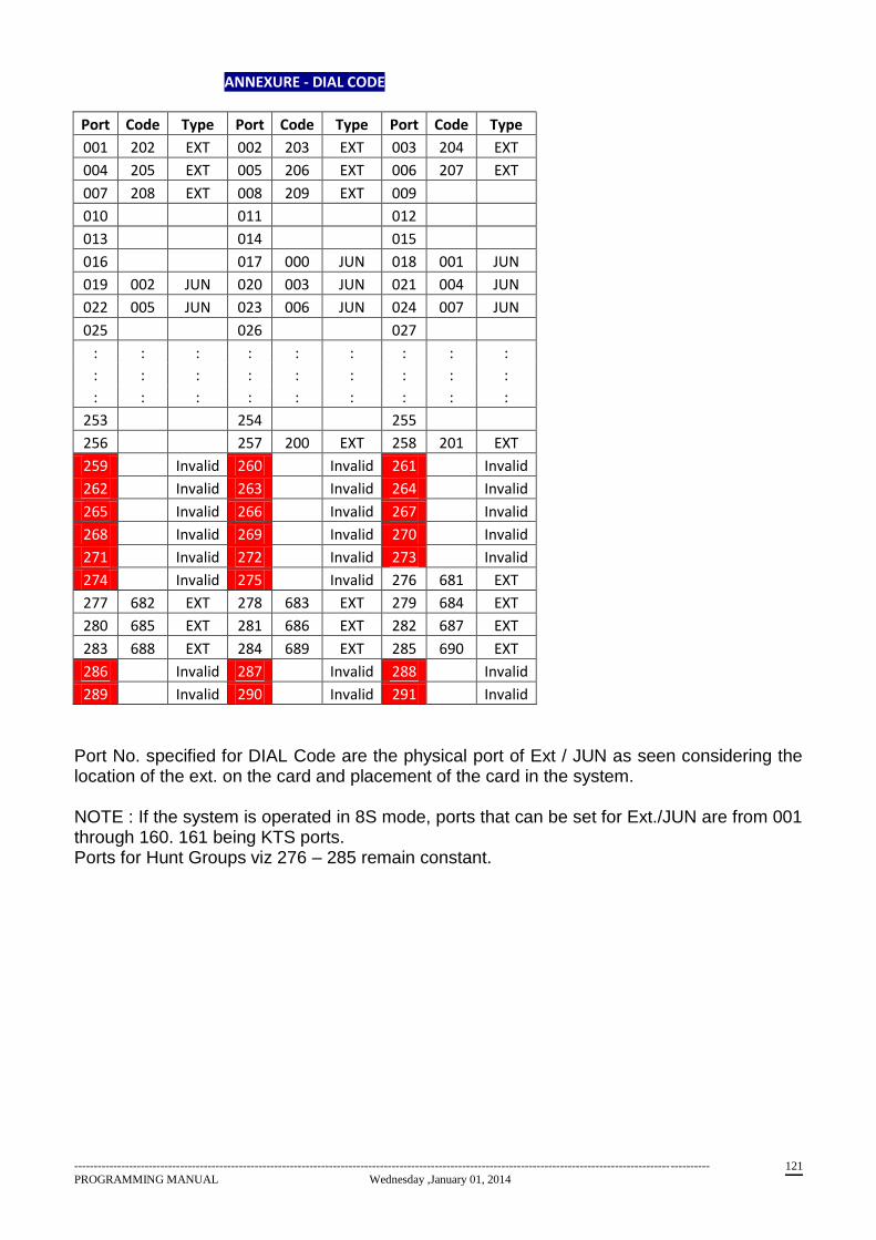
------------------------------------------------------------------------------------------------------------------------------------------------------------------
PROGRAMMING MANUAL Wednesday ,January 01, 2014 121
ANNEXURE - DIAL CODE
Port Code Type Port Code Type Port Code Type
001 202 EXT 002 203 EXT 003 204 EXT
004 205 EXT 005 206 EXT 006 207 EXT
007 208 EXT 008 209 EXT 009
010 011 012
013 014 015
016 017 000 JUN 018 001 JUN
019 002 JUN 020 003 JUN 021 004 JUN
022 005 JUN 023 006 JUN 024 007 JUN
025 026 027
: : : : : : : : :
: : : : : : : : :
: : : : : : : : :
253 254 255
256 257 200 EXT 258 201 EXT
259 Invalid 260 Invalid 261 Invalid
262 Invalid 263 Invalid 264 Invalid
265 Invalid 266 Invalid 267 Invalid
268 Invalid 269 Invalid 270 Invalid
271 Invalid 272 Invalid 273 Invalid
274 Invalid 275 Invalid 276 681 EXT
277 682 EXT 278 683 EXT 279 684 EXT
280 685 EXT 281 686 EXT 282 687 EXT
283 688 EXT 284 689 EXT 285 690 EXT
286 Invalid 287 Invalid 288 Invalid
289 Invalid 290 Invalid 291 Invalid
Port No. specified for DIAL Code are the physical port of Ext / JUN as seen considering the location of the ext. on the card and placement of the card in the system.
NOTE : If the system is operated in 8S mode, ports that can be set for Ext./JUN are from 001 through 160. 161 being KTS ports. Ports for Hunt Groups viz 276 – 285 remain constant.
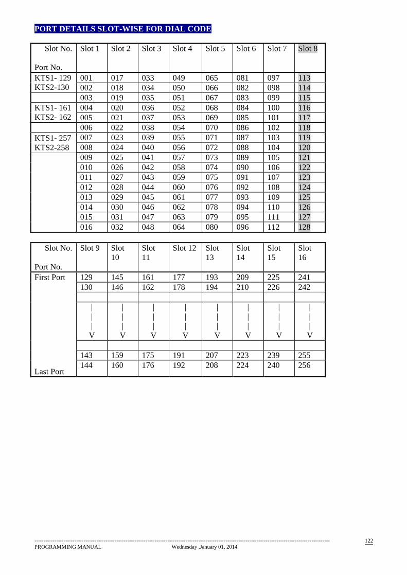
------------------------------------------------------------------------------------------------------------------------------------------------------------------
PROGRAMMING MANUAL Wednesday ,January 01, 2014 122
PORT DETAILS SLOT-WISE FOR DIAL CODE
Slot No.
Port No.
Slot 1 Slot 2 Slot 3 Slot 4 Slot 5 Slot 6 Slot 7 Slot 8
KTS1- 129
KTS2-130
001 017 033 049 065 081 097 113
002 018 034 050 066 082 098 114
003 019 035 051 067 083 099 115
KTS1- 161
KTS2- 162
004 020 036 052 068 084 100 116
005 021 037 053 069 085 101 117
KTS1- 257
KTS2-258
006 022 038 054 070 086 102 118
007 023 039 055 071 087 103 119
008 024 040 056 072 088 104 120
009 025 041 057 073 089 105 121
010 026 042 058 074 090 106 122
011 027 043 059 075 091 107 123
012 028 044 060 076 092 108 124
013 029 045 061 077 093 109 125
014 030 046 062 078 094 110 126
015 031 047 063 079 095 111 127
016 032 048 064 080 096 112 128
Slot No.
Port No.
Slot 9 Slot
10
Slot
11
Slot 12 Slot
13
Slot
14
Slot
15
Slot
16
First Port
Last Port
129 145 161 177 193 209 225 241
130 146 162 178 194 210 226 242
|
|
|
V
|
|
|
V
|
|
|
V
|
|
|
V
|
|
|
V
|
|
|
V
|
|
|
V
|
|
|
V
143 159 175 191 207 223 239 255
144 160 176 192 208 224 240 256

------------------------------------------------------------------------------------------------------------------------------------------------------------------
PROGRAMMING MANUAL Wednesday ,January 01, 2014 123
CONNECTION DETAILS OF CABLES USED WITH NEOS
JUMPER SETTINGS ON ISDN BRI + KTS card
Jumper Position of Jumper Configuration
J3 KTS side Ports of connector CN2: KTS ports
J3 BRI side Ports of connector CN2: BRI ports
J4 KTS side Ports of connector CN3: KTS ports
J4 BRI side Ports of connector CN3: BRI ports
The cable colour codes for JLCC, LCC 8 and LCC 16 are as under
Port number Colour code
1 Blue-White
2 Orange – White
3 Green- White
4 Brown - White
5 Gray-White
6 Blue-Red
7 Orange-Red
8 Green-Red
When connected to the card the Blue-White wires will be seen on the lower side of the card.
In case of the LCC 16 2 such cables are used. The lower connector caters to ports 1 to 8 and the upper
to ports 9 o 16.
SERIAL PORT CABLE : The serial port cable is configured as follows
9 PIN D TYPE
FEMALE – PC SIDE
9 PIN D TYPE MALE
– PBX SIDE
1,4, 6 SHORT
7,8 SHORT
2 3
3 2
5 5
9 NC
Serial port 1 is for programming the NEOS and connecting PMS software if required. Port 2 is for
connecting to CTI applications.
The cable length should not exceed 15 meters or 50 feet.
KEY TELEPHONE CABLE
The key telephone can be connected to the CPU as well as the Digital extension (ISDN) card. The
CPU to KTS cable is as follows
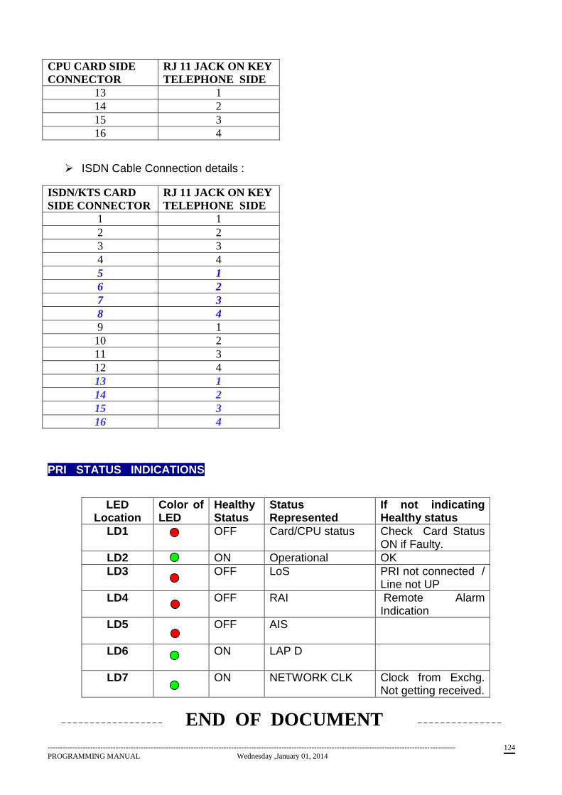
------------------------------------------------------------------------------------------------------------------------------------------------------------------
PROGRAMMING MANUAL Wednesday ,January 01, 2014 124
CPU CARD SIDE
CONNECTOR
RJ 11 JACK ON KEY
TELEPHONE SIDE
13 1
14 2
15 3
16 4
ISDN Cable Connection details :
ISDN/KTS CARD
SIDE CONNECTOR
RJ 11 JACK ON KEY
TELEPHONE SIDE
1 1
2 2
3 3
4 4
5 1
6 2
7 3
8 4
9 1
10 2
11 3
12 4
13 1
14 2
15 3
16 4
PRI STATUS INDICATIONS
LED Location
Color of LED
Healthy Status
Status Represented
If not indicating Healthy status
LD1 OFF Card/CPU status Check Card Status ON if Faulty.
LD2 ON Operational OK
LD3 OFF LoS PRI not connected / Line not UP
LD4 OFF RAI Remote Alarm Indication
LD5
OFF AIS
LD6
ON LAP D
LD7 ON NETWORK CLK Clock from Exchg. Not getting received.
------------------ END OF DOCUMENT ---------------