Airline Terminology And Abbreviations - The Professional ...
Upload
khangminh22Category
view
0download
0
ED 251 646
AUTHORTITLE
INSTITUTION
PUB DATENOTE
PUB TYPE
EDRS PRICEDESCRIPTORS
DOCUMENT RESUME
CE 040 233
Henderson, William Edward, Jr., Ed.Articulated, Performance-Based Instruction ObjectivesGuide for Machine Shop Technology.Greenville County School District, Greenville, S.C.;Greenville Technical Coll., S.C.Jun 84771p.; Prepared by the Occupational EducationArticulation Program Task Force Committee for MachineShop/Technology.Guides - Classroom Jse Guides (For Teachers) (052)
MF05/PC31 Plus Postage.Behavioral Objectives; Blueprints; Competency BasedEducation; Criterion Referenced Tests; CurriculumGuides; Employment Opportunities; High Schools; JobSkills; Learning Activities; Machine Repairers;*Machine Tool Operators; *Machine Tools; *Machinists;*Numerical Control; Performance Tests; PostsecondaryEducation; Secondary Education; *Trade and IndustrialEducation; Units of Study
ABSTRACTThis articulation guide contains 21 units of
instruction for two years of machine shop. The objectives of theprogram are to provide the student with the basic terminology andfundamental knowledge and skills in machining (year 1) and to teachhim/her to set up and operate machine tools and make or repair' metalparts, tools, and machines (year 2). Introductory materials includerecommended secondary and postsecondary programs. The nine units inyear 1 are entitled introduction, precision measuring instruments,work layout, benchwork, grinding, drill press, power saws, basicengine lathe work, and mill work. The twelve units in year 2 areentitled advanced blueprint reading, turret lathe, surface grinder,shaper, tool and cutter grinder, heat treatment, hydraulic press,computer numerically controlled machining, machining mathcalculations, machine shop projects, oxyacetylene cutting/welding andbrazing, and shielded metal arc welding. Each unit contains a unitoverview, prerequisites, standards, suggested instruction times, andtasks. A task sheet for each task details the performance objective,performance actions, performance standards, suggested instructiontime, resources, and related technical information. Additionalreferences include matrixes of occupational competencies, suggestedjob skills, and a list of equipment. Sample outcome-referenced andperformance tests are provided for most units. Appendixes includesample articulation agreements, and test directions. (YLB)
************************************************************************ Reproductions supplied by EDRS are the best that can be made ** from the original document. *
***********************************************************************
ARTICULATED, PERFORMANCE-BASED INSTRUCTION OBJECTIVES GUIDEFOR
MACHINE SHOP/TECHNOLOGY
DEVELOPMENT PERIODJULY, 1983 - JUNE, 1984
PREPARED BYOCCUPATIONAL EDUCATION ARTICULATION PROGRAM
TASK FORCE COMMITTEEFOR
MACHINE SHOP/TECHNOLOGYREPRESENTING
THE SCHOOL DISTRICT OF GREENVILLE COUNTYAND
GREENVILLE TECHNICAL COLLEGEGREENVILLE, SOUTH CAROLINA
PUBLICATION OFOCCUPATIONAL EDUCATION ARTICULATION PROGRAMOF THE SCHOOL DISTRICT OF GREENVILLE COUNTY
AND GREENVILLE TECHNICAL COLLEGE
U S DEPARTMENT OF EDUCATIONNATIONAL INSTITUTE OF EDUCATION
tUoiA)iolsAt s INFORMATIONCFNTFR eFFItr.
It, .h... etv,1,1, el 1 11
. I I JUNE, 1984EDITION I
"PERMISSION TO REPRODUC'E THISMATERIAL HAS BEEN GRANTED BY
TO THE EDUCATIONAL RESOURCESINFORMATION CENTER (ERIC)
ARTICULATED, PERFORMANCEAASED CURRICULUM GUIDE
THE-SCHOOL :1)1 STR G £EW LLE = tQ'JNrfY-
DR. J. FLOYD HALLSUPERINTENDENT
DR. NORMAN MULLINSASSOCIATE SUPERINTENDENT FOR EDUCATIONAL DEVELOPMET
MRS. DORIS CLANTONDIRECTOR, INSTRUCTIONAL SERVICES
MR. O. RICHARD COTHRAN, JR.CONSULTANT, VOCATIONAL EDUCATION
ARTICULATION GUIDE
THE SCHOOL DISTRICT GREENVILLEOF GRE'ENVILLE COUNTY
SCHOOL DISTR.; w 40
AND TECHNICAL COLLEGE
GREENVILLE, SOUTH CAROLINA
1934
COU..TY
Henderson, Wm. Edward, Jr., Ed. Articulated, Perfocmance-based InstructionOb ectives Guide for Machine Shop, Greenville, SC: OccupationalEducation Articulation Program of The School District of GreenvilleCounty and Greenville Technical College, 1984.
ACKNOWLEDGEMENT
The Articulated, Performance-based Instruction Objectives Guide forMachine Shop is the product of the work of the following instructor TaskForce Committee participants representing the secondary programs of TheSchool District of Greenville County and the post-secondary similarprogram at Greenville Technical College.
Donaldson Career CenterEnoree Career CenterFoothills Career Center .
Greenville Technical College
Melvin J. NestichRandy McWhorterGeorge Caldwell
Charlie Granger
The cooperation of the instructor participants and others representingThe School District of Greenville County, Greenville Technical College,and South Carolina State Department of Education, the South CarolinaState Board for Technical and Comprehensive Education, and local indus-tries is appreciated.
Typist Theresa EubanksProgram Secretary
Title of Program;
Program Coordinator:
Sponsoring Agencies:
ABSTRACT
Occupational Education Articulation Program
Wm. Edward Henderson Jr.
The School District of Greenville Countyand Greenville Technical Collegec/o P.O. Box 2848 - 301 Camperdown WayGreenville, SC 29602
Program DevelopmentPeriod: July 1, 1983 through June 30, 1984
PURPOSE:
METHOD:
To develop a continuous line of vocational training 1.n
similar Machine Shop programs so that students maycontinue their career / vocational education at the secondaryand post-secondary levels with -t loss of time or wasteof effort in repeating tasks th, have been masteredpreviously.
To provide a system where teachers can cooperate effec-tively in providing a continuous occupational developmentprogram where the level and type of training that leadsto entry-level employment skills will be clear to students,teachers, other educators, and potential employers.
Machine Shop instructor representatives from the threesecondary level career centers of The School District ofGreenville County and the post-secondary level MachineTechnology Department Head from Greenville TechnicalCollege were brought together in task force committeemeetings and workshops to ,survey very similar areas ofvocational training to identify possible overlaps or gapsas students continue machine shop training from thesecondary level to the post-secondary level. In addition,lateral articulation of machine shop programs at thesecondary level was promoted.
This Articulated, Performance-based Instruction ObjectivesGuide for Machine Shop, was developed by the Task ForceCommittee on Machine Shop to facilitate articulation.The Task Force Committee, by the task analysis process,identified the minimum essential competencies for thesecondary machine shop graduate to continue training at:he next higher level of education or for successful
ii
5
RESULTS:
initial entry into the labor market in the trade. Majorobjectives for competency were stated, performance toobtain the objectives were clarified, enabling actionswere identified and placed in sequential order, instructiontime was estimated, and performance standards werestated. Finally, outcome-referenced (criterion-referenced) measures of performance were developed as aguide in articulating (articulation).
As a result of the project development phase, theArticulated, Performance-based Instruction ObjectivesGuide for Machine Shop was developed. This articulationguide, however, is not a final product since it must befield trial tested and revised. Modifications andimprovements to the guide are expected since the processof education must be continually reviewed to ensure thatobjectives are valid and are being met as best they canbe met under given conditions.
Prior to development of this articulation guide, anArticulation Policies and Procedures Guide was developedto aid articulation activities and was used to directprogram and product (guide) development activities.
Workshop 3uides, developed and refined during an earlierphase of the program, were used to assist task forcecommittee participants in obtaining task analysis data,writing performance-based objectives, identifying perfor-mance actions to reach the objectives, stating performancestandards, and developing outcome-referenced tests.These how-to-do-it guides are usable at the instructionallevel as well as at the supervisory level.
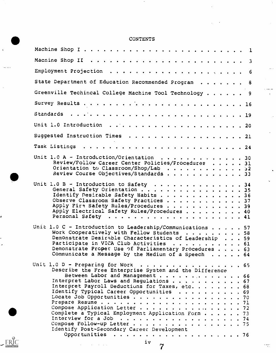
CONTENTS
Machine Shop I 1
Macnine Shop II 3
Employment Projection 6
State Department of Education Recommended Program 8
Greenville Techincal College Machine Tool Technology 9
Survey Results . 16
Standards 19
Unit 1.0 Introduction 20
Suggested Instruction Times 21
Task Listings 24
Unit 1.0 A - Introduction/Orientation 30Review/Follow Career Center Policies/Procedures 31Orientation to Classroom/Shop/LabReview Course Objectives/Standards 33
Unit 1.0 8 - Introduction to Safety 34General Safety Orientation 35Identify Desirable Safety Habits 36Observe Classroom Safety Practices 37Apply Firc! Safety Rules/Procedures 39Apply Electrical Safety Rules/Procedures 40Personal Safety 41
Unit 1.0 C - Introduction to Leadership/Communications 57Work Cooperatively with Fellow Students 58Demonstrate Desirrible Characteristics of Leadership . 59Participate in VICA Club Activities 61Demonstrate Proper Use of Parliamentary Procedures . 63Communicate a Message by the Medium of a Speech 64
Unit 1.0 D - Preparing for Work 65Describe the Free Enterprise System and the Difference
Between Labor and Management 66Interpret Labor Laws and Regulations 67Interpret Payroll Deductions for Taxes, etc 68Identify Typical Career Opportunities 69Locate Job Opportunities 70Prepare Resume 71Compose Application Letter 72Complete a Typical Employment Application Form 73Interview for a Job 74Compose Follow-up Letter 75Identify Post-Secondary Career Development
Opportunities 76
iv
Unit 1.0 E - Introduction to Desirable Job Learning; 77Describe Good Work Habits Important to Job Succlss .(78Exhibit Successful Job Performance CharacteristicsExhibit Desriable Work Attitudes
. IP 79
82Demonstrate Respect/Care for School Property 84
Unit 1.0 F - Basic Math Skills 85Basic Math - Fractions 86Basic Math - Decimals- 87Basic Math - Volumes 88Basic Math.- Areas 89The Metric System 90
Unit 1.0 G - Basic Measuring 93Measuring 94
Unit 1.0 H - Introductory Blueprint Reading 96Interpret Multiview Drawings. 97Determine Dimensions and Tolerances 98Interpret Pictorial Drawings 99
Unit 1.0 I - Write and Read Technical Information 100Write Technical Information Concerning Machining
Operations 101Read Technical Information Concerning Machining
Operations 102
Articulated Performanced-Based Description of Beachwork . 103
Wait 2.0 - Using Precision Measuring Instruments 104
Suggested Instruction Times 105
Task Listings 107
Care for Precision Instruments 110Layout WOrkpiece on Surface Plate 111Layout Workpiece with Combination Square 113Layout Workpiece with Hemaphrodite Calipers 115Measure Workpiece with 6 inch Pocket Scale 117Measure Workpiece with Tape Measure 118Measure Workpiece on Surface Plate 119Check Workpiece with Sine Bar 121Check Workpiece using Radius Fillet/Center Gages . . 122Measure Inside Diameters with Vernier Caliper 123Measure Workpiece with Depth Gages 124Measure Workpiece witt. Depth Micrometer 125Measure Workpiece with Dial Calipers 126Measure Workpiece with Gage Blocks 127Measure Workpiece with Vernier Height Gage 128Measure Workpiece with Inside Micrometer 129Measure Workpiece with Telescope awl Hole Gages 130Measure Workpiece with Thread Wires 131
Transfer Dimensions with Divider 132Measure Outside Diameter with Outside Calipers 133Measure Round Stock with Outside Micrometer 134Measure with inside Calipers 137Measure Threads Per Inch with Screw Pitch Gage 138Measure Screw Threads with Screw Thread Micrometer . . . 139Measure Optical Comparator 140Check Round Stock with Dial Indicator 141Snap Gages (OMITTED) 142Radius Gage 143
Unit 3.0 - Work Layout 1;14
Standards 145
Suggested Instruction Times .146
Task Listings 147
Scribe Workpieces 148Mark Locations with Prick Punch and Center Punch 149Locate Holes with Transfer Punches 130Layout Hole Spacing and Outside Dimensions 151Layout Angles 152Layout a Bolt Circle 153 1
Layout Compound Angles 154Layout Tangents 155
Unit 4.0 - Benchwork 156
Suggested Instruction Times 158
Task Listings 160
Inspect Workbench Area for Safe Working Environment . . 163Care for Hand Tools 165Bench File Workpiece 167Disassemble/Assemble Workpiece with Arbor Press 169Hand Broach an Internal Keyway 170Using Hand Hacksaw, Cut Given Material 172Cut Threads with Hand Tap 174Drill Holes with Portable Drill 176Grind Part with Hand Grinder 178Hand Hone Cutting Tools 179Hand Ream Holes . . . . . . . 180Remove Broken Drills and Taps 181Remove Damaged/Broken Studs/ Screws 183Cut Threads with Die 184File Test Workpiece for Hardness 186Remo7e Frozen or Seized Parts 187Identify Types of Fasteners 188Assemble and Fit Parts 189Identify and Properly Use Work-Holding Devices 190Identify and Properly Use Coolants and Cutting Compounds 191Properly Use Hand Tools for Assembly /Disassembly 192
Unit 5.0.- Basic Grinding 194
Suggested Instruction Times 195
Task Listings 196
Set-up Pedestal Grinder 198Inspect and Clean Pedestal Grinder 200Grind a Convex Radius 201Grind a Center Punch_ 202Sharpen a Chisel 203Sharpen Drill Bits by Hand 204Grind a General-Purpose Turning Tool Bit 206
Unit 6.0 - Operating Drill Press 208
Suggested Instruction Times 209
Task Listing 210
Inspect, Clean, and Lubricate Drill PressSet up Drill PressDrill Holes to SizeCounterbore Hole to SpecificationsCountersink Hole to SpecificationsReam Hole to Size . ............ 224Spotface to Specified Dimensions 226Mount Work on V-Blocks 228Tap Hole with Tapping Attachment 230
Unit 7.0 - Power Saws 231
Suggested Instruction Times 232
Task Listings 233
Clean and Lubricate Power Saws 235Cut and Weld Bandsaw Blade 237Replace Bandsaw Blade 239Saw Internal Contours with Bhndsaw 240Saw Scribed Line 242Select and Set Speeds and Feeds for Sawing Operations . . 243Make Straight and Angular Cuts with Power Saw 244Cut Material to Length with Power Hacksaw 245
Unit 8.0 - Basic Engine Lathe Work 247
Suggested Instruction Times 248
Task Listings 250
Inspect and Clean Engine Lathe 255Set up Engine Lathe for Turning Operations 258Align Lathe Centers Using Accurate Mesurement 261Mount Workpiece Between Centers 263Align Workpiece on Faceplate 265Align Workpiece in Four-Jaw Chuck 266:
vii 0
Make Roughing Cuts 267Make Finishing Cuts 269Turn a Workpiece to Dimensions 271Face a Workpiece to Dimensions 274Knurl a Workpiece 276Drill Holes with Lathe 278Ream Holes on the Lathe 280Bore Holes
Countersink Holes Using the Lathe
282
2 e
Counterbore Holes 284
Tap Holes 287Cut Grooves or Recess 289'Machine an External Chamfer 290\Machine an Internal Chamfer 291cPart Workpieces 292File Workpieces 293Polish Workpieces 295
Advanced Engine Lathe Work 296
Grind Workpiece with Tool Post Grinder 297Machine External Taper 299Machine Internal Taper 301Machine External Angle 303Machine Internal Angle 304Set-up Lathe for Threading Operations 305
Unit 9.0 - Basic and Advanced Mill Work
Suggested Instruction Times
Task Listings
309
310
312
Inspect and Clean a..Milling Machine . 315Identify Milling Machine Work Holding Devices/Functions 318Align Workpiece on Machine Table 320Align Mill Head to Table 322Align Milling Machine Attachment: 324Align Milling Machine FixtUres with Indicator 325Calculate Cutting Speeds/Feeds for Milling Machine
Work 326Face Mill - Workpiecc 328Perform Side Milling Operation 329Perform Angular Milling Operations . 330 mPerform'End Milling Operations 332Drill, Bore, and Ream Holes 333Perform Keyseating and T-slot Milling Operations. 335Cut Slots with Milling Machine 337
Advanced Mill Work 333
Perform Indexing OperationsPerform Graduating and Marking OperationsIdentify Types of Gears and their FuncitonsCalculate Pitch, Diameters, Working Depth and Clearances
for Machining GearsMill a Gear RackMachine a Spur Gear
viiil 1
339342343
345346347
LEARNING PROJECTS FIRST YEAR 349
SECOND YEAR 350
Suggested Instruction Times 352
Unit 10.0 - Advanced Blueprint Reading . . . . . 353
Suggested Indtruction Times 354
Task Listings 355
-Tnterpret Sectional Views 356Determine Metric Dimensions and Tolerances 357Interpret Auxillary Views 359Sketch Shop Drawings of Workpiece to be Machined 360Interpret Assembly Drawing 362
Unit 11.0 - Turret Lathe 363
Suggested Instruction TimesA 364
Task Listings 365
Identify Turret Lathe 366Clean and Lubricate Turret Lathe 367Identify Workholding Devices y 368Identify Chucking Operations on the Turret Lathe 369
,Identify Standard Tool Holding Devices . 370Select Cutting Speed and Feed 371Identify Coolants 372Additional Tasks for Turret Lathe 373
Unit 12.0 - Surface Grinder 375
Suggested Instruction Times 376
Task Listings , 377
Inspect and Clean a Surface 111111n.er 378Set-up Surface Grinder for Fl t - urface Operation . 380Grind Flat Surfaces 382Tasks Omitted from Surface Grinding Unit 385
Unit 13.0 - Shaper k' 386
Suggested Instruction Times 387
Task Listings 388
Inspect and Clean a Shaper 390Identify Types, Sizes, Construction, Specifications,
Nomenclature, and Ranges of Work for Shapers 391 6
Set-up Shaper for Machining Operations 392Make a Rough and Finished Horizontal Cut 395Shape Flat Surfaces ...... . ....... 397Shape Angular Surfaces r 398
Unit 14.0 - Tool and Cutter Grinder 399
Suggested Instruction Times 400
Task Listings 401
Inspect/Clean a Tool and Cutter Grinder 40kSet-up Tool and Cutter Grinder 403Grind Tools 404
Cylindrical Grinder Unit Omitted from Guide 405
Unit 15.0 - Heat Treatment 406
Suggested Instruction Times 407
Task Listings 408
Test Workpiece for Hardness . p 409Anneal Workpiece 411Harden and Temper a Workpiece 413Harden Given Small Tools 415
Unit 16.0 - The Hydraulic Press 416
Suggested Instruction Times 417
Task Listings 418
Lubricate Hydraulic Press 419Straighten Parts with Hydraulic Press 421Set-up, Remove, and Replace Parts 422
Unit 17.0 - Computer Numericall; Controlled Machining 424
Suggested Instruction Times 425
Standards 426
Task Listings 427
Identify the Controls and Operations of the EMCO COMPACT5 CNC Trainer 428
Identify Program System and Select G-Codes for MachineOperations 430
Plot CNC Drawing for Coordinates 432Calculate Coordinates for Dimensions of CNC Drawing . 434
Write Program for CNC MachineSet-up CNC Machine/ProgramMachine Workpiece with CNC Machine . .
Unit 18.0 - Machining Math Calculations
435437439
441
Suggested Instruction Times . . .. ......... . . . 442
Task Listings 443
Calculate Amount of Stock Required for Job 445Convert Revolutions Per Minute . . 446Calculate Depths and Widths of Slots and Grooves on
Special Setups 447Calculate Feeds and Speeds 448Calculate for Angular and Simple Indexing 449Calculate Gear Blank Specifications 451Calculate Sine-Bar Dimensions for Machine Shop 453Calculate Tap Drill Size with Formula 454Calculate Tapers for Machine Setup 455Calculate Tolerances/Allowances 457Convert Common Fractions to Decimal Fractions 458Convert Dimensions to Metric Size 459
LEARNING PROJECTS SECOND YEAR 460
Unit 19.0 - Machine Shop Projects/Live Work 4.61
Unit 20.0 - Oxyacetylene (OAW) Cutting/Welding and Bra-ing . . . 467
Optional Addendum Module 468
Prerequisites 469
Standards 470
Suggested Instruction Times 471
Task Listings 472
Oxyacetylene Cutting/Welding Terminology 474Oxyacetylene Cutting/Welding Safety 478Perform Soap and Water Test (Safety) 480Identifying Oxygen and Acetylene Gases and Cylinder
Handling 481Set-up Oxyacetylene Cutting/Welding Station 482Clean Oxyacetylene Cutting/Welding Tips 484Lighting the Torch 485Adjusting the Flame 486Oxyacetylene Cutting 487Preparing the Joint . ............ ... 489Carrying the Puddle (Fuse) 490Run a Bead with Filler Rod 492
Weld Open Butt Joint, All Positions 494Fillet Weld, Lap Joint, Al'. Positions 495Braze Metal 496Checklist for Weld 497
Unit 21.0 - Shielded Metal ARC Welding (SMAW)
Prerequisites
Suggested Instruction Times
Task Listings
498
499
500
.501
Introduction of ARC Welding 503Safety in ARC Welding 509Machines and Accessories 513Select Electrode 515Striking and Maintaining an ARC 516Chip Slag Using Chipping Hammer 518Run Short Beads, Flat Position 519Run Continuous Beads, Flat Position 520Prepare Joint 521Construct Open Butt Weld, All Positions 522Construct Lap Joint Weld, 3/8 Inch Equal Legs, Three
Passes 523Checklist for SMAW Welds 524
Proficiency Report 525
References 534
Additional References 538
Reference 1 DACUM Matrix for Machinist, SC 539
Reference 2 DACUM Matrix for NC Operator, Greenville, SC . . . 540
Reference 3 Suggested Skills 541
Reference 4 Survey Results 542
Reference 5 Recommeded Equipment 543
PREFACE
This Articulated, Performancebased Instruction Objectives Guide isased on the following ASSUMPTIONS:
1. The grouping of tasks is more conduclte to skill development invocational education.
2. Potential employers probably would prefer an employee well educatedin the basics with more detailed onthejob training provided bythe employer.
3. Among topics that should be included in vocational education are;safety, career opportunities, how to get and keep a job, and thejob attitudes that often are the key to employee success and jobretention.
4. A premise of the articulated, performancebased instruction guideis that it is absolutely essential `hat career/vocationaleducation/training be based on the kLowledges, skills, abilities,and personal characteristics that ara important to success on thelot, if the vocational program is ijoing to validly serve the needsof students and potential employers of the community.
5. Another premise in the articulated instruction guide is thatvocational education can no longer be developed according toprogram titles, be timebased, lack flexibility, or overlook basicfundamentals if instruction is to meet the needs of students andemployers and be of the highest quality.
6. Substantial research clearly indicates that instructionaltechnology and accountability demands are increasing the movementtoward the use of instructional systems.
The systems approach, a method of organizing the instructionalsituation, methods, media, materials, and equipment so that themaximum knowledge and skill development Elx be achieved, is promotedbecause it directs its attention toward teaching the observablebehaviors that the vocational student should possess at the termination of instruction.
The instructional program described in this articulated, performancebased instructional objectives guide has been assembled by instructortask force committee pa.rticipants: representing The SchoolDistrict of Greenville County and Greenville Technical College andit is based on the concept that the minimum tasks described shouldbe those identicied for successful entry level employment according
to local task analysis information, state-of-the-art literature,similar/related research/ publications, and the expertise of theinstructor participants.
7. The articulated instruction guide illustrates one wax the
curriculum max be organized. The example is not intended to imply,that there are not other ways to structure the curriculum.
The articulated instruction guide should be preceived as a vehicleto facilitate the development of alternate, detailed instructionalplans for the individual learner.
8. While the objectives in this guide typically have been arranged ina sequence from less to more difficult in performance or as theymight occur on the job, the sequence of tasks is not meant toindicate a required pattern.
9. The "suggested minimum instruction times" are included for planningpurposes and may be extended as required for the completion of taskobjectives. An underlying premise of the articulated instructionguide is that it is more desirable for the student to complete someobjectives and gain some employable skills rather than to beintroduced to a large number of tasks and not acquire any employableskills.
The actual amount of time required for each task ob ective ma vasaccording to the local program objectives, the individual needs ofthe learner, the instructor's experiences, and the trainingfacilities and materials available.
10. While it may become necessary to modify the vocational program fromthe articulated guide description, a lowering of the minimumstandards (competency level) recommended by industry should beavoided to ensure that the program graduate can demonstrate aminimum performance essential to employment success.
11. This articulation guide was drafted in a period of less than twelvemonths so that a product production deadline of twelve months mightbe met.
Because of a restricted development time frame, emphasis was placedon developing a sound and valid articulation guide which might berefined at a later date.
Greenville, SC W.E.H.
xi v
PREVIOUS ARTICULATION(Revised)
A 1975-1976 program of articulation between Greenville Technical Collegeand The School District of Greenville County articulated the similarpost-secondary Machine Tool Technology with the similar Machine Shopprograms at the secondary level by specifying post-secondary programtopics and standards in outline form.
The 1983-1984 Machine Shop/Machine Tool Technology articulation programdevelopment activities have revived and strengthened upon the previouslyestablished 1976 agreement. (Set Appendix A)
As part of the 1976 articulation agreement, Greenville Technical Collegeestablished a "tuition scholarship" in the Machine Tool Technologyprogram to be awarded to the most outstanding or worthy student fromeach of the four secondary Machine Shop Programs of The School Districtof Greenville County. Initially, the tuition scholarship will be forone quarter of tuition free study. Upon successfully completing thefirst quarter, the scholarship may be extended based upon review andapproval by the Machine Tool Technology instructor and Department Head.
According to the 1976 agreements, a graduate of a secondary Machine Shopprogram of The School District of Greenville County may be grantedexemption of a Machine Tool Technology course at Greenville TechnicalCollege according to; the recommendations of the former secondaryinstructor, the student's secondary level performance as represented bygrade achievement and a "Proficiency Report," and the individual'sperformance on "Placement Tests" administered by the Machine ToolTechnology Department, GTC. The procedures established in 1976 will becontinued, with slight modifications, in the current articulationprogram.
Every effort has been made to incorporate all previous articulationefforts between the secondary Machine Shop programs and GTC's MachineTool Technology program and to ensure that provisions are establishedand documented to encourage the fulfillment and continuation of1983-1984 articulation agreements.
"Machine Tool Technology Articulation" (Appendix D), OccupationalEducation Program Articulation Between Secondary Vocational EducationCenters and Greenville Technical College, Greenville, SC: GreenvilleTechnical College, 1976. (Included as Appendix A in thisArticulated, Performance-based Instruction Guide.
MACHINE SHOP
LEVEL: Secondary
TITLE: Machine Shop I
DESIGNATION: MACHINE SHOP I COMPUTER NUMBER: 759
DESCRIPTION: The introductory year of Machine Shop includes a study ofshop safety, shop operations, and career opportunitiesfor machinists. Student machinists learn the workingproperties of a variety of metals such as steel, castiron, aluminum, brass, and other materials used to makeparts for machines. The student learns how to readblueprints and specifications to determine the dimensionsof work and machining computations.
The student will learn to select and use semiprecisionand precision measuring instruments such as the micrometer,verniers, gageblocks, various gegen, rulers, dial indicators,and calipers. The student will learn to use introductorydrafting skills such as the alphabet of lines, tolerances;oneview and multiview drawings, auxilliary and sectionviews, and freehand drawing.
The machinist student will apply math skills involvingthe addition, subtraction, multiplication, and divisionof fractions and decimals as well as taper (per inch)calculations, speeds and feeds formulae and s. le elementarytrigonometry. The student will learn to plan and layoutwork using the surface plate, surface gage, layout dye,tri square, scribers, dividers, calipers, Vblocks, andangle plates in layouts.
The student will be introduced to benchwork focusing onbuilding machinist's skills in the use of vises, taps,dies, files, hammers, wrenches, hacksaws, the arborpress, and other hand operated tools.
The student will learn the use and care of grinders; thedrill presses; vertical and horizontal bandsaws; themilling machine; as well as the engine lathe for grinding,turning, facing, knurling, grooving, boring, taperturning, threading, and drilling.
OBJECTIVE: Machine Shop I is designed to provide the student withthe basic terminology as well as fundamental knowledgesand skills in machining. Upon completing the first yearof training, the machine shop student will be able toemploy mathematics to solve machine shop situations;interpret specifications, blueprints, and technicalinformation; identify, use, and maintain hand tools; use
and maintain machine shop equipment; layout machiningwork; and complete basic machining jobs using a varietyof machines or hand tools.
The student who has successfully completed Machine Shop Iwill be prepared for continued study in Machine Shop II.Upon mastering the competencies of the first year ofMachine Shop, the student may be qualified to enteremployment as a machine operator.
PROFICIENCY Machine Shop I competencies will be measured by writtenEVALUATION: outcome-referenced transfer and performance tests using
the minimum standards recommended by industry for entrylevel worker success.
Upon successfully completing the first.year of secondarymachine shop training, the student should be prepared to:read and use all standard measuring instruments associatedwith the machine shop; perform basic set-ups on lathes,mills, grinders, and drill presses including squaring,turning, and laying out work; process jobs to theircompletion; and demonstrate safety practices and Foodwork habits important in machining work.
Upon completing Machine Shop I, the student eiculd beable to perform the following:
- Turn outside diameters to shoulder and to +/-.001 inch tolerances
- Mount work between centers, and use collets andchucks
- Read micrometers and vernier scales- Grind tool bits and sharpening drill bits to
proper angles- Mill square and parallel to +/- .005 inch and
do simple indexing on dividing head- Contour saw stock to layout lines and cut off
to length- Drill, tap, and ream holes to industrial
tolerances- Cut threads, turn tapers, and bore holes to +/-
.005 inch tolerance
PREREQUISITES: None
Suggested Entry Grade Level: 11
RECOMMENDED Secondary level programs which might contribute to theSECONDARY optimum success of the machine shop student include;PREPARATION: prevocational education, industrial arts, general
mathematics, geometry, and mechanical drawing.
The machinist student should be able to add, subtract,divide, and multiply fractions and decimals. The studentshould be able to convert fractions to decimals andshould be able to perform accurate fractional linearmeasurements.
The machinist student should be able to comprehend themeaning of technically written instructions and followthe sequence of a set of directions.
Being mechanically inclined will help the studentmachinist in using the tools and machines required in thetrade and in understanding the often complex mechanismsthat must be repaired or constructed.
The prospective machinist should be able to work independently, concentrate on a job which sometimes may betedious and repetitious, and change from one task toanother as required.
REQUIRED INSTRUCTION HOURS:
System YearDivision
-,
ClassCredits 3
Hours 540
LEVEL: Secondary
TITLE: Machine Shop II
DESIGNATION: MACHINE SHOP II COMPUTER NUMBER: 760
DESCRIPTION: The second year of machine shop study emphasizes: Shopsafety; linear, angular, radii, vernier, xyz axis andquadrant measuring; bandsaw blade welding and annealing;use and care of the shaper; toolpost grinding; precisemilling head alignment procedures; lathe and mill projects;use of the drill press; grinders; tailstock offsettingformulas and tailstock alignment; basic metallurgy;inspection of machined parts; charts, graphs, records,production gages, and inspection devices; as well as useof the hydraulic press and heat treating.
The second year of machine shop includes a handsonintroduction to Computer Numerically Controlled (CNC)precision machining through the use of the ENCO Compact 5CNC trainer, similar in operation to production machinesbut designed for practical classroom learning experiencesin basic lathe and milling operations.
OBJECTIVES: The graduate of Machine Shop II will be able tosuccessfully set up and operate machine tools (such asthe lathe, milling machine, shaper, or grinder) and fitand assemble components to make or repair metal parts,tools, and machines.
The graduate will be prepared to interpret specifications,blueprints, eketches, or measurements to determinedimensions and tolerances of a piece to be machined; thesequence of operations and the tools, materials, andmachines required. The graduate will be able to measure,mark, and scribe dimensions and reference points tolayout stock for machining.
The Machine Shop graduate will be able to: verifyconformance of a workpiece of specifications by usingvarious precision measuring instruments; position andsecure a workpiece in a holding device and use hand toolssuch as files and wrenches to fit and assemble parts.The graduate will be ableto verify dimensions and.alignment using measuring instruments such as micrometers,gages, and calipers.
PROFICIENCY Competencies of the Machine Shop II student will beEVALUATION: measured by written outcome-referenced transfer and
performance type testing as well as simulated/actualperformance testing. The minimum competency standardsare those recommended by industry for entry level jobsucceas in machining and are described in this Articulated,Performance-based Instruction Guide for Machine Shop7secondary curriculum guide).
The secondary Machine Shop program graduate will be ableto use a safe and analytical problem solving approach inapplying fundamental machining theory to practicalsituations. The graduate will know where to seek tiachnicalinformation and other pertinent data when it is needed.
In addition to the skills outlined in Machine Shop I, thegraduate of the two year secondary program in machiningwill be competent to accomplish the following:
- Sharpen high speed steel tool bits and drills- Turn diameters to +/- .001- Accurately select speeds and feeds for the job,- Surface grind flats and angles to +/- .0005- Layout and inspect work with indicator height
gage, sine bar, and gage blocks to specifications- Mill radii, slots, and irregular shapes to
specifications- Drill, bore, ream, and tap to commercial
tolerances
4
22
PREREQUISITES:
- Set-up vises and locate work on rotary tables, mountwork on angle plate, sine bar, and chucks to tolerances+/- .001
Machine Shop I
Suggested Grade Level: 12
The Machine Shop I graduate shou_d have demonstrated aninterest in and aptitude for the study of advancedmachine shop including the necessary mathematical skills,an ability to concentrate on and complete a repetitiveand tedious task, as well as the fundamental skills andknowledges necessary to succeed in advanced machine shopstudy.
REQUIRED INSTRUCTION HOURS:
'system 'Year
Division ClassCredits 3
Hours 540
TOTAL REQUIRED INSTRUCTION HOURS FOR THE SECONDARYMACHINE SHOP PROGRAM:
Entail' 2-YearsDivision. ClassCredits 6
Hours 1,080
WORKING The machinist should be prepared to work with machineryCONDITIONS: and materials that may be oily or greasy, like to work
with tools and machines, and enjoy the challenge ofprecision work.
The machinist must be able to read, write, and understandtechnical words, instructions, and abbreviations. Themachinist should be able to interpret plans and blueprints,visualize objects, and be able to think ahead and planwork in a series of steps. The machinist should be ableto work alone and concentrate on precision work.
Physically, the machinist should have good vision, withcorrection if necessary, to be able to see fine details.Standing for periods of 2-4 hours at a time should beexpected. Work may require minutely accurate measurementswith small tools. Machine shop work typically requiresreaching, squatting, bending, and twisting.
Generally, modern machine shops are clean, well lightedand ventilated and many may be air-conditioned, especiallyin industries. Noise levels may occasionally
be high and the machinist may have to use hearing safetydevices.
'high speed machining equipment, sharp tools and metals,and heat equipment involve certain dangers. The machinistgenerally must wear safety glasses or face shields foreye or face protection and should wear appropriateclothing to prevent cuts or burns or getting caught ormangled in a machine.
EMPLOYMENT The South Carolina Employment Security Commission hasPROJECTION: projected a growth of approximately 20.6 percent to occur
in the machining trade in the Greenville-Spartanburg areain the five year period between 1980 and 1985. Thisgrowth represents an estimated expansion of about 60 jobsto occur between 1983 and 1985 when the total machinistemployed in the Greenville- Spartanburg area should bearound 1,170. This estimate, however, may not take intoaccount the number of machinists that may be practicingin related fields or as independent small businessmen.
Typical employment will be in factories or industrieswhich are growing substantially in Greenville County andsurrounding area.
Some employers may require the secondary level MachineShop graduate to enter an apprenticeship program whileother opportunities may exist for the graduates withadvanced skills to enter all-round machine work orspecialized work gaining additional skills on-the-job.
To successfully compete in a growing technologicalbusiness/industrial community, the high school graduateshould seriously consider the advantages of additionaleducational preparation at Greenville Technical Collegein Machine Technology, the Tool-and-Die option, or incomputer assisted machining (CAM) training. The machinistshould pursue related training in areas such as mathematicsand physics to prepare for high technology work that mayinvolve hydraulics, electronics, robotics and computerassisted machine-control systems, and newer metalwOrkingtechnologies.
1
South Carolina Occupational Projection, 1978-1985, Columbia, SC: SouthCarolina Employment Security Commission ?Research & AnalysisDepartment, p. 158, 1982.
The secondary Machine Shop program is designed to preparegraduates primarily as an entry-level apprentice
Machinist, D.O.T. 600.280-022
Other possible job areas include:
Grinder. Operator, D.O.T. 603.280-018Drill Press Operator, D.O.T. 606.682-014Milling Machine Operator, D.O.T. 605.685-030Lathe Operator, D.O.T. 604.685-026
Related occupations include: machine tool operators,production inspector, tool-and-die makers (with additionaltraining), setup workers, and instrument makers as wellas metal patternmakers, or even locksmiths.
e SECONDARY LEVELSTATE DEPARTMENT OF EDUCATION
RECOMMENDED PROGRAM
MACHINE SHOP
Machine Shop is a two year high school program typically involving3-hour instructional blocks for the 180 day school year of 1,080 hoursfor the two year program.
The machinist student learns to read and interpret technical information;select and use semi-precision and precision measuring and gaging toolssuch as the micrometer or surface, depth, or dial gages; selecting,using and maintaining hand tools; setting up, operating and maintainingmachines such as the drill press, cutoff saw, engine lathe, turretlathe, shaper, vertical and horizontal milling machines, surface grinder,and tool grinder. The machine shop student learns the proper selection,use and maintenance of cutting tools; identifying the properties ofmaterials, and how to plan and layout work. Occupational safety andemployability skills are integrated into the program! s
Suggested topics that Machine Shop should include are:
1. Safety2. Industrial processes3. Drawing and blueprint reading4. Materials (metals)5. Work planning and layout6. Math and measuring instruments7. Hacksaw8. Handsaw9. Benchwork
10. Engine lathe11. Drilling machine12. Shaper13. Milling machine14. Grinding machine15. Welding and heat treating
Outline of High School Credit Courses, Columbia, SC: SC StateDepartment of Education, pp. 135-136, 1980, (locally revised foraccuracy).
Defined Wnimum Program for South Carolina School Districts, Columbia,SC: SC Department of Education, 1980.
GREENVILLE TECHNICAL COLLEGEMACHINE TOOL TECHNOLOGY(Post-secondary Level)
The Machine Tool Technology Curriculum is designed to supply the studentswith the basic skills and necessary related information to enable themto develop into skilled machinists and tool makers. Graduates of theprogram may find employment in such positions as machinists, apprentice.tool and die makers, and tool designers. Upon completion of the firstyear of study, the student may graduate with a Machinist diploma orcontinue for a second year in Tool and Die Making. The two-year programawards an Associate in Applied Science Degree.
Required courses - Machine Tool Technology 75 credit hoursRequired courses - General Education 48 credit hoursMinimum requirements to graduate 123 credit hours
Suggested Sequence of Required Courses:
FIRST QUARTER
COURSENUMBER COURSE TITLE CLASS LAB CREDIT
MAT 112 Applied Mathematics I 5 0 5EGT 180 'Blueprint Reading & Sketching I 5 0 5MTT 111 Machine Shop Theory &
Practice I 3 12 7
13 12 17
SECOND QUARTER
MAT 122 Applied Mathematics II 5 0 5EGT 110 Mechanical Drafting I 2 3 3MTT 121 Machine Shop Theory &
Practice II 3 12 7
10 15 15
THIRD QUARTER
MAT 132 Applied Mathematics III 5 0 5EGT 151 Industrial Drafting II 5 0 5MTT 131 Machine Shop Theory &
Practice III 3 12 7ECO 100 Consumer Economics 3 0 3
16 12 20
FOURTH QUARTER
ENG 150 Introduction to Composition 4.5 0 4.5PSY 112 Industrial Human Relations 3 0 3MTT 141 Machine Shop Theory &
Practice IV 3 12 7MTT 113 Metals & Heat Treatment 4 0 4
14.5 12 18.5
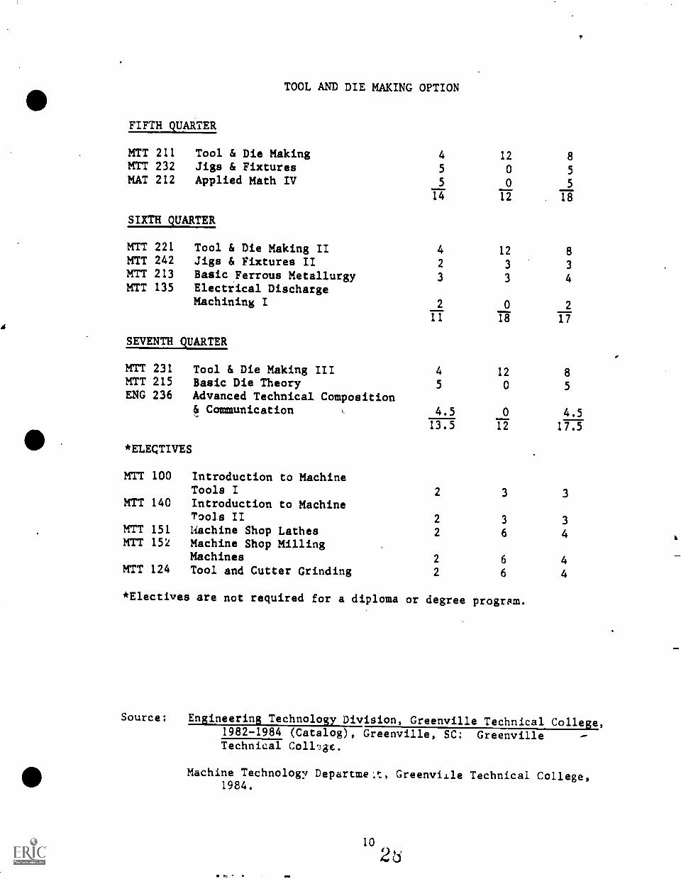
TOOL AND DIE MAKING OPTION
FIFTH QUARTER
MTT 211 Tool & Die Making 4 12 8MTT 232 Jigs & Fixtures 5 0 5MAT 212 Applied Math IV 5 0 5
14 12 . 18
SIXTH QUARTER
MTT 221 Tool & Die Making II 4 12 8MTT 242 Jigs & Fixtures II 2 3 3MTT 213 Basic Metallurgy 3 3 4.FerrousMTT 135 Electrical Discharge
Machining I 2 0 2
11 18 17
SEVENTH QUARTER
MTT 231 Tool & Die Making III 4 12 8MIT 215 Basic Die Theory 5 0 5ENG 236 Advanced Technical Composition
& Communication , 4.5 0 4.513.5 12 17.5
*ELECTIVES
MTT 100 Introduction to MachineTools I 2 3 3
MIT 140 Introduction to MachineTools II 2 3 3
MTT 151 Machine Shop Lathes 2 6 4MTT 152 Machine Shop Milling
Machines 2 6 4MTT 124 Tool and Cutter Grinding 2 6 4
*Electives are not required for a diploma or degree program.
Source: Engineering Technology Division, Greenville Technical College,1982-1984 (Catalog), Greenville, SC: GreenvilleTechnical Coll'.!gc.
Machine Technology Departme:t, Greenville Technical College,1984.
MAT 112 APPLIED MATHEMATICS I:
Included are operations with fractions, decimals, percentages, andformulas. Use of measurements and industrial applications are stressed.(5-0-5)
EGT 100 BLUEPRINT READING & SKETCHING I:
This is a study of basic blueprint reading and sketching. It includes adetailed study of layout, projection, and dimensioning. The studentcompleting this course should be able to make *etches of certaingeometric shapes and be atle to orthographically project these shapes.The student should be able to read and interpret most shop drawings.(5-0-5)
MTT 111 MACHINE SHOP THEORY & PRACTICE I:
The student will become familiar with the operation of the drillingmachine and the lath.a. A rigid indoctrination in the basic handling ofmachinist hand tools, precision measuring tools and basic machine tooloperational procedures will be given. The student will also learn howto sharpen drills and lathe cutting tools. Safety and good housekeepingwill be taught and stressed at all times. (3-12-7)
MAT 122 APPLIED MATHEMATICS II:
Continuation of elementary algebra through quadratic equations. Elementaryplane and solid geometry. Industry applications. Prerequisite: MAT112. (5-0-5)
EGT 110 MECHANICAL DRAFTING I:
An introduction to principles and practices of mechanical drafting,which includes a study of instrument drawings, technical lettering,geometrical constructions, orthographic projection of normal, inclined,oblique, and cylindrical surfaces, and principles for selection and useof size and location dimensions. (2-3-3)
MTT 121 MACHINE SHOP THEORY & PRACTICE II:
The student will increase his proficiency in the use of the lathe anddrilling machine operations, and have the basic knowledge of the surfacegrinder, milling machine and shaper operation. This course will alsoexpose the student to further experience with precision measuringinstruments, lathe accessories for basic internal and external latheoperations and setups. (3-12-7)
MAT 132 APPLIED MATHEMATICS III:
Algebra, trigonometry, geometry and industrial applications are presented.Prerequisite: MAT 122 or equivalent. (5-0-5)
EGT 151 INDUSTRIAL DRAFTING II:
A course of study designed to prepave students to complete multivieworthographic views of objects. Problems will be selected to includeauxiliary and section views. Dimensions and notes, limits and tolerances,screw threads and fasteners will be studied and related to preparationof working drawings. Prerequisite: EGT 110. (5-0-5)
MTT 131 MACHINE SHOP THEORY & PRACTICE III:
The student will be able to operate the surface grinder, milling machineand shaper to produce advanced projects. Also, he/ohe will be able tooperate the cylindrical grinder for external grinding operations andstudy internal grinding. Safety and good housekeeping will be stressedat all times. (3-12-7)
ECO 100 CONSUMER ECONOMICS:
Emphasizes the role of the consumer in our society. It includes consumerdecision making, money and marital happiness, money management, consumercredit, intelligent shopping, financing a home, transportation, healthservices, estate planning and consumer protection. (3-0-3)
ENG 150 INTRODUCTION TO COMPOSITION:
A study and application of the principles of grammar, mechanics, andrhetoric as preparation for business and technical writing. TI.e coursewill include writing correct and effective paragraphs and essays ofvarious types, including expository, narrative, and descriptive.(4.5-0-4.5)
PSY 112 INDUSTRIAL HUMAN RELATIONS:
Provides supervised experience and instruction designed to help thestudent recognize and develop the traits necessary for good relationswith fellow workers, supervisors, subordinates, customers and others.Through exercises involving awareness, self-concept and self-evaluation,role-playing, and group and individual problem solving, the course willhelp to develop improved interpersonal relationships. (3-0-3)
MTT 141 MACHINE SHOP THEORY & PRACTICE IV:
The student will be able to produce and complete projects using allbasic machine tools with a minimum of supervision. In this course,advanced work with basic machine tools, producing industrial styleprojects will be accomplished in the development of accuracy, speed,safety, workmanship, and skill. (3-12-7)
12
30)
MTT 133 METALS & HEAT TREATMENT:
The student will be able to select steel by its color codes and have anunderstanding of heat treatment terminology, procedures, and testing.The student will also study the elementary principles concerning metals,their production, composition, individual properties and uses. (4-0-4)
MTT 211 TOOL & DIE MAKING:
The student will be able to machine and construct to tolerance, simplecutting dies or tool gages to industrial style prints. This course willoffer the student the theory and practice of precision machining on alltool room equipment. Safety and good housekeeping will be stressed atall times. (4-12-8)
MTT 232 JIGS & FIXTURES:
The student will be able to design simple jig and fixtures to localindustrial standards'. This course of study will be of the theoryinvolved in 6esigning jigs and fixtures. By following industrialprocedures end tolerances, the student will design working drawings ofdrill jigs and milling fixtures. (5-0-5)
MAT 212 APPLIED MATH IV:
Course includes algebra, trigonometry, geometry and further industrial
411applications. Prerequisite: MAT 132 or equivalent. (5-0-5)
MTT 221 TOOL & DIE MAKING II:
The student will be able to machine and construct to tolerance, simplecutting dies or tool gages to industrial style prints. This course willoffer the student the theory and practice of precision machining on alltool room equipment. Safety and good housekeeping will be stressed atall times. (4-12-8)
MTT 242 JIGS & FIXTURES II:
The student will te able to design complex jigs or fixtures or constructa simple jig and fixture in the lab or meet local industrial standards.This course is a continuation of MTT 232, leading to more complexdesigns, or the construction of jigs and fixtures designed previously.(2-3-3)
MTT 213 BASIC FERROUS METALLURGY:
The student will know the basic fundamental of metallurgy and will beable to heat, treat, and test metals for various results desired. Thiscourse will present the general theory and practical application of thestructure, behavior and heat treatment of ferrous metals used in themanufacture of tools, dies, and other industrial products. (3-3-4)
MTT 135 ELECTRICAL DISCHkRGE MACHINING I:
The student will have an understanding of the types of machining opera-tions performed by electrical discharge machining and its application inmanufacturing. (2-0-2)
MTT 231 TOOL & DIE MAKING III:
The student, using his/her basic tool and die theory, will be able toconstruct more complex tooling with minimum assistance. Dies such ascutting, blanking, and piercing and/or advanced tooling will be con-structed and put into trial operation. Press safety will be emphasized.(4-12-8)
MTT 215 BASIC DIE THEORY:
The student will have knowledge of die components as they relate to thecomplete die. Essential facts of cutting and forming operations areexplained, and related to the manner in which the dies must function inorder to achieve the desired results. (5-0-5)
ENG 236 ADVANCED TECHNICAL COMPOSITION & COMMUNICATION:
Instruction in the theory and practice of planning and writing effectivebusiness and technical compositions. A research project reflectingacceptable writing styles and basic knowledge of the student's majorarea of study is required. Techniques, of oral communication and presenta-tions will be covered. Prerequisite: ENG 150 or ENG 101 and completionof first year of the student's major. (4.5-0-4.5)
MTT 100 INTRODUCTION TO MACHINE TOOLS I:
A course in the identification, use, capabilities and characteristics ofbasic machine tools in industry. Emphasis will be placed on basicmeasuring tools, machine setup, and demonstration of the drill press,engine lathe, milling machine, shaper, and grinder. Students will beintroduced to such operations as drilling, milling, turning, shaping,tapping, reaming, boring, and grinding. (2-3-3)
MTT 140 INTRODUCTION TO MACHINE TOOLS II:
The student will learn the limitation of machine tool operation. Thiscourse is a continuation of MTT 100, with the student operating thebasic machines. (2-3-3)
MTT 151 MACHINE SHOP LATHES:
The student will be able to operate the lathe and to produce projectscontaining the main features of lathe work. The student will be able tosetup and operate the lathe and work to close tolerances, grind lathecutting tools and use the correct speed and feed for material beingmachined. The student will be able to use all of the lathe attachments.(2-6-4)
MTT 152 MACHINE SHOP MILLING MACHINES:
The student will be able to operate the milling machine to produceprojects containing the main features of milling machine work. Thiscourse will cover the theory and practice of basic and advanced millingmachine operations. The student will use all types of cutters, setups,and be able to select the correct speed and feed for all types. (2-6-4)
MTT 124 TOOL AND CUTTER GRINDING:
The student will be able to resharpen the various cutting tools to suitvarious metals. This course will stress wheel safety and selection.The cutting tools to be ground will be general machine shop items suchas drills, lathe tools, bits, and end mills. (2-6-4)
SURVEY RESULTSSECONDARY .MACHINE SHOP LAB FACILITIES
(for articulation purposes)
A survey of the secondary Machine Shop program yielded the followinginformation concerning the manor types of machines, equipment, andmeasuring tools that are available for instruction.
For articulation purposes, the survey results indicates similar machineshop training equipmeut at the three secondary career centers.
The survey does not reflect the age or condition of the measuringinstruments or machines and, in some cases, the training equipment maybe deadlined or in need of repairs.
Greenville Technical College's Machine Technology program was omittedfrom the survey since the post-secondary program features equipmentsimilar or equivalent to that found in local industry, including NC/CNCtechnology. Equipment in the TEC Machine Technology program is updatedregularly through industrial donations, grants, and other activitiesthat have allowed the *program to become a resource center for machinetechnology training in the State and Nation.
. Gages and Measuring Equipment (larger)
m. wFmwUCg:s1:113C40004000,U
gQDi'0-Iitl
al-11
a)
4)id
00id
4-44.044/
Ca.
Go-No Go Ring GagesDial Bore GageDia; Depth GageCylindrical SquareOptical FlatGage Blocks x x xComparator
cal Comparator . _ x,OptBench CenterSine Bar x xSnap Gages
bxne.xVernier Height Gage x
"RiTaT7fficrometer
Machine Sho mentedestal Grinder
-tail Press x xxHorizontal Band Saw x xxVertical Band Saw x xPower Hacksaw
_
Engine Lathe x KMilling Machine x xx
.
Turret Lathe x x x
-.3haper w7oo1. i ..t.ter Grinder
rxx mx.
surface Grinder x xixC7lindrtaal Grinder
707i7-- XI >4
ies.. treatmen.t z...ul ment xl xi
Hvorau 1.. Press xi x:
...2.CNC .raiser : Zm ..., %..amoact 3 :::IT La tne :xt 4x
l'I
his sur7ey results page is acc=panled ay pagegag Lng tools.
16 34BEST COPY AVAILABLE
DEFINITIONSSURVEY OF TRAINING EQUIPMENT
GAGING TOOLS
DIAL BORE GAGE
DIAL DEPTH GAGE
CYLINDRICALSQUARE
CYLINDRICALPLUG GAGE
OPTICAL FLAT
GAGE BLOCKS
COMPARATOR
BENCH CENTER
SINE BAR
SNAP GAGES
VERNIER HEIGHTGAGE
tiLiGHT
MICROMETER
SURFACE PLATE
Used to check t1 bore of parts to .0001 accuracy,preset with a ring gage.
Used to check depth of holes, slots, and grooves,and recesses.
Used as meter against which other squares may bechecked.
Has "go" and "nogo" ends, used to check bore ofparts to .0001 accuracy.
Uses light waves to measure flatness, parallelism,and size.
Used to check measurements, set fixed gages,calibrate measuring tools, set comparators, inspectand perform other setups (.000001).
Used to inspect size of parts from a flat surface.
Used to check concentricity of machined parts.
Used to set up or inspect angular surfaces.
Used to check parts within certain limits of apredetermined, fixed dimension.
Used as a vertical caliper to scribe lines within.0001 inch in layout, to measure depth, and to gagea machined surface.
Used to set other measuring tools for inspection bycomparison, accurate to .00001 inch.
A reference plane for precision measurement; whenused with other gages, the surface plate becomes agage itself.
Some measuring instruments were omitted if they typically are standarditems in a machine shop classroom or if they may be classified asexpendable measuring tools.
p
SURVEY RESULTSCURRENT SECONDARY LEVEL USE OF MACHINE SHOP
CAREER CLUSTER PROJECT: 1972-1976
The three secondary career center machine shop programs of The SchoolDistrict of Greenville County were surveyed to determine the current useof the 1976 Career Cluster Project material. The Career Cluster Projectyielded audio-visual training aids as well as validated competencystatements.
The intent of the Career Cluster project was to promote a "region-widecoordination of vocational-technical training program in South CarolinaAppalachia." Through job related training objectives, the programintended to promote a smooth transition from secondary vocationaltraining to post-secondary technical training.
The secondary machine shop instructors participating in the articulationprogram reported the following use of the Career Cluster project materials.
CAREER CENTER (Secondary) YES NODonaldson xEnoreeFoothills
*To limited degree during1st year of training.
The primary reasons the instructors gave flr not using the CareerCluster Project material include; poor q lity of audio-visual materials,extensive bookkeeping requirements on instructor, and instructor'sfindings that students still had to be "shown" (taught) by the instructorin addition to being taught by the Career Cluster A/C materials (i.e.,The Lap Program in general did not improve. the learning situation andrequired more instructor time.).
The purpose of this survey was to identify the degree of use of theCareer Cluster Program materials and, as much as possible, to salvageobjectives and competency statements from the program.
I.
. ......
I
STANDARDS APPLICABLE TO MACHINE SHOP(Secondary Level)
Performance-based objectives assume that the workpiece or stockprovided for training is mild steel. The task objective willclarify the standards, specifications, and procedures when a metalstock other than mild steel is used. Other materials used fortraining include aluminum, plastic, etc.
This articulated guide is based on a three-hour per day trainingperiod. The time allocated for training is 1,080 hours for twoyears or 540 hours per year. No time is allocated for the busingof students between the parent high school and the career center,for coke breaks, or for other non-training activities.
Objectives and performance actions (enabling objectives) aredesigned on the assumption that instructional materials such asmetal stock and fully operational equipment accompanies by thetypical support accessories are available for training. If articu-lated training objectives cannot be met due to lack of trainingmaterials or equipment, the instructor should be informed by thestudent, the instructor should enter a note in the articulatedinstruction guide on the appropriate task objective page, andappropriate measures should be taken to correct the situation sothat, training objectives may be met.
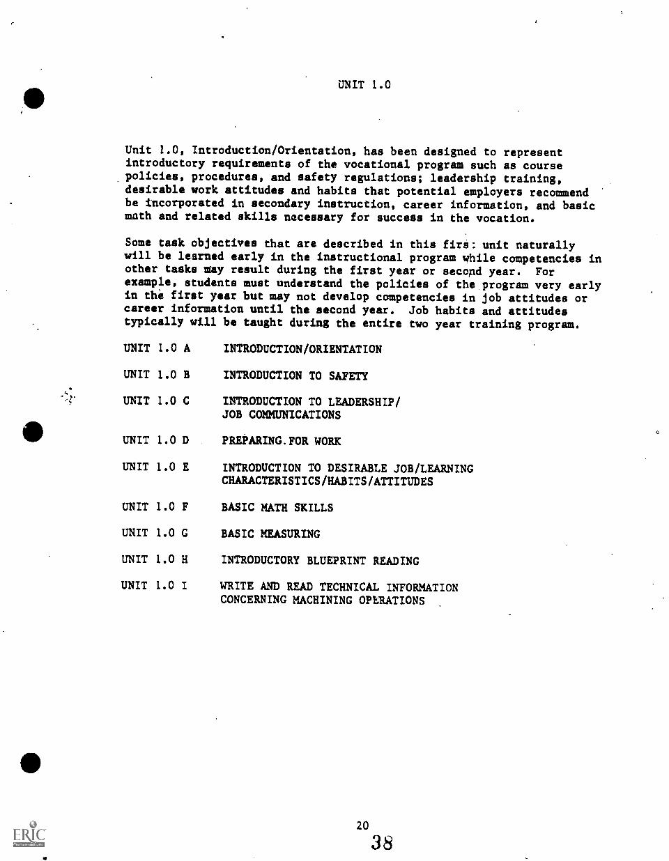
UNIT 1.0
Unit 1.0, Introduction/Orientation, has been designed to representintroductory requirements of the vocational program such as coursepolicies, procedures, and safety regulations; leadership training,desirable work attitudes and habits that potential employers recommendbe incorporated in secondary instruction, career information, and basicmath and related skills necessary for success in the vocation.
Some task objectives that are described in this firs: unit naturallywill be learned early in the instructional program while competencies inother tasks may result during the first year or second year. Forexample, students must understand the policies of the program very earlyin the first year but may not develop competencies in job attitudes orcareer information until the second year. Job habits and attitudestypically will be taught during the entire two year training program.
UNIT 1.0 A INTRODUCTION/ORIENTATION
UNIT 1.0 B INTRODUCTION TO SAFETY
UNIT 1.0 C INTRODUCTION TO LEADERSHIP/JOB COMMUNICATIONS
UNIT 1.0 D
UNIT 1.0 E
UNIT 1.0 F
UNIT 1.0 G
UNIT 1.0 H
UNIT 1.0 I
PREPARING.FOR WORK
INTRODUCTION TO DESIRABLE JOB/LEARNINGCHARACTERISTICS/HABITS/ATTITUDES
BASIC MATH SKILLS
BASIC MEASURING
INTRODUCTORY BLUEPRINT READING
WRITE AND READ TECHNICAL INFORMATIONCONCERNING MACHINING OPERATIONS
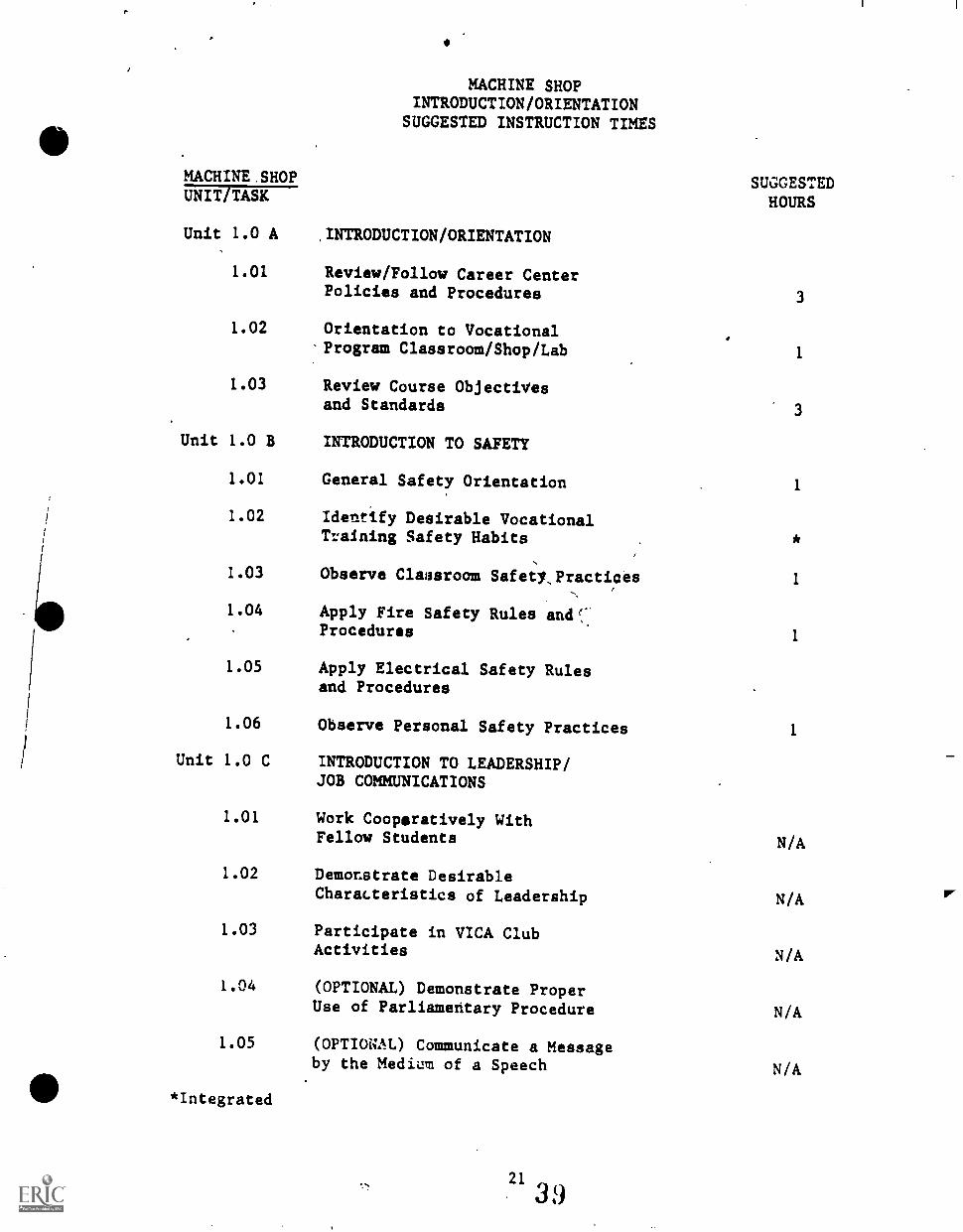
MACHINE SHOPINTRODUCTION/ORIENTATION
SUGGESTED INSTRUCTION TIMES
MACHINE.SHOP SUGGESTEDHOURSUNIT TASK
Unit 1.0 A
1.01
.INTRODUCTION/ORIENTATION
Review/Follow Career CenterPolicies and Procedures 3
1.02 Orientation to Vocational-Program Classroom/Shop/Lab 1
1.03 Review Course Objectivesand Standards
Unit 1.0 B INTRODUCTION TO SAFETY
1.01 General Safety Orientation 1
1.02 Identify Desirable VocationalTraining Safety Habits
1.03 Observe Classroom Safety,Practices 1
1.04 Apply Fire Safety Rules andProcedures
1
1.05 Apply Electrical Safety Rulesand Procedures
1.06 Observe Personal Safety Practices 1
Unit 1.0 C INTRODUCTION TO LEADERSHIP/JOB COMMUNICATIONS
1.01 Work Cooperatively WithFellow Students N/A
1.02 Demonstrate DesirableCharacteristics of Leadership N/A
1.03 Participate in VICA ClubActivities N/A
1.04 (OPTIONAL) Demonstrate ProperUse of Parliamentary Procedure N/A
1.05 (OPTIONAL) Communicate a Messageby the Medium of a Speech N/A
*Integrated
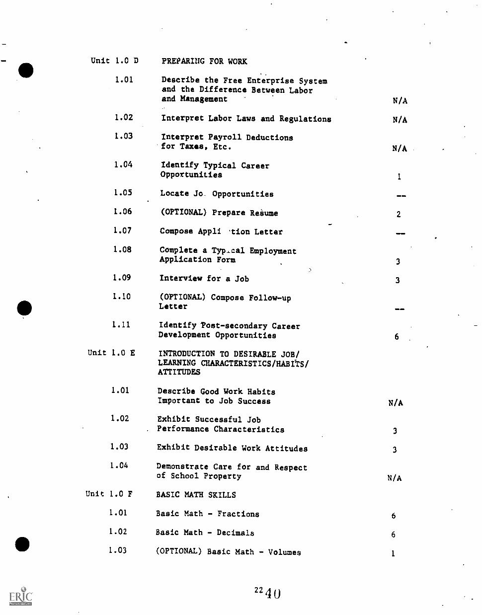
Unit 1.0 D PREPARING FOR WORK
1.01 Describe the Free Enterprise Systemand the Difference Between Laborand Management N/A
1.02 Interpret Labor Laws and Regulations N/A
1.03 Interpret Payroll Deductionsfor Taxes, Etc. N/A
1.04 Identify Typical CareerOpportunities 1
1.05 Locate Jo.. Opportunities NO 4MM
1.06 (OPTIONAL) Prepare Resume 2%N.
1.07 Compose Appli 'tion Letter
1.08 Complete a Typ.,cal EmploymentApplication Form 3
1.09 Interview for a Job 3
1.10 (OPTIONAL) Compose Follow-upLetter enema
1.11 Identify Post-secondary CareerDevelopment Opportunities 6
Unit 1.0 E INTRODUCTION TO DESIRABLE JOB/LEARNING CHARACTERISTICS/HABITS/ATTITUDES
1.01 Describe Good Work HabitsImportant to Job Success N/A
1.02 Exhibit Successful Job. Performance Characteristics 3
1.03 Exhibit Desirable Work Attitudes 3
1.04 Demonstrate Care for and Respectof School Property N/A
Unit 1.0 F BASIC MATH SKILLS
1.01 Basic Math - Fractions 6
1.02 Basic Math - Decimals 6
1.03 (OPTIONAL) Basic Math - Volumes 1
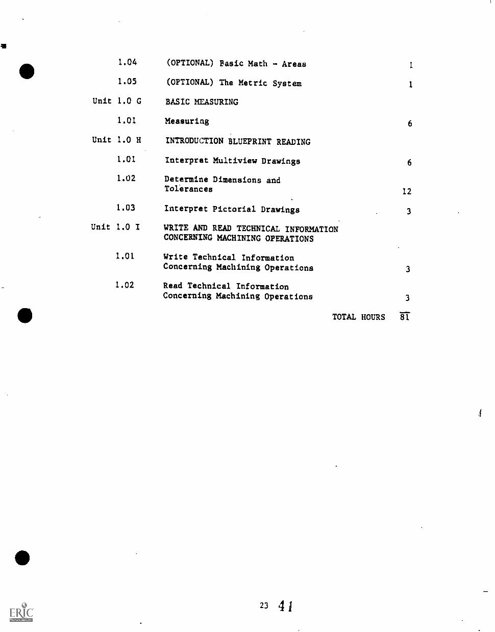
1.04
1.05
(OPTIONAL) Basic Math - Areas
(OPTIONAL) The Metric System
1
1
Unit 1.0 G BASIC MEASURING
1.01 Measuring 6
Unit 1.0 H INTRODUCTION BLUEPRINT READING
1.01 Interpret Multiview Drawings 6
1.02 Determine Dimensions andTolerances 12
1.03 Interpret Pictorial Drawings 3
Unit 1.0 I WRITE AND READ TECHNICAL INFORMATIONCONCERNING MACHINING OPERATIONS
1.01 Write Technical InformationConcerning Machining Operations 3
1.02 Read Technical InformationConcerning Machining Operations 3
TOTAL HOURS 81
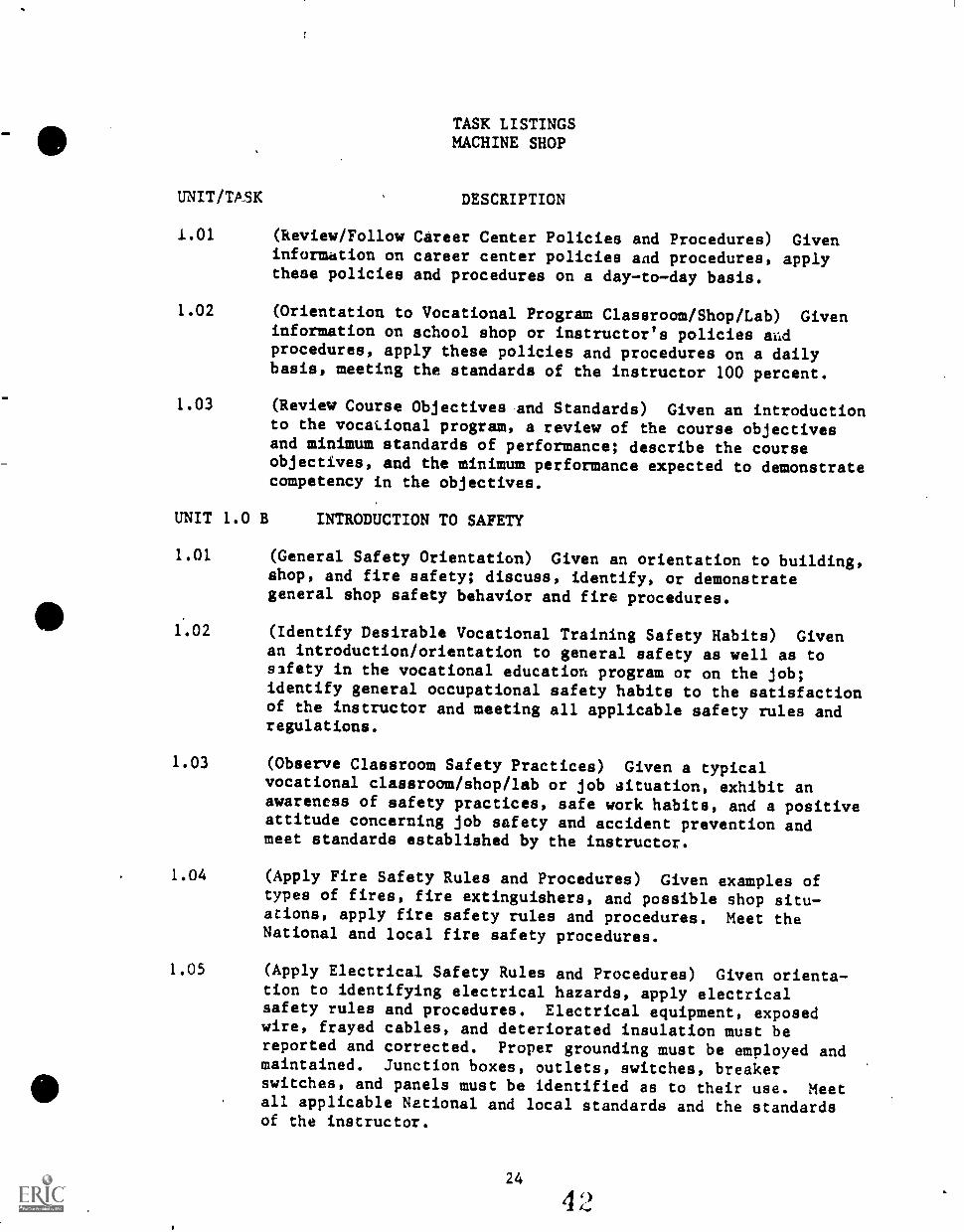
TASK LISTINGSMACHINE SHOP
UNIT/TASK DESCRIPTION
1.01 (Review/Follow Career Center Policies and Procedures) Giveninformation on career center policies and procedures, applythese policies and procedures on a daytoday basis.
1.02 (Orientation to Vocational Program Classroom/Shop/Lab) Giveninformation on school shop or instructor's policies aildprocedures, apply these policies and procedures on a dailybasis, meeting the standards of the instructor 100 percent.
1.03 (Review Course Objectives and Standards) Given an introductionto the vocational program, a review of the course objectivesand minimum standards of performance; describe the courseobjectives, and the minimum performance expected to demonstratecompetency in the objectives.
UNIT 1.0 B INTRODUCTION TO SAFETY
1.01 (General Safety Orientation) Given an orientation to building,shop, and fire safety; discuss, identify, or demonstrategeneral shop safety behavior and fire procedures.
1.02 (Identify Desirable Vocational Training Safety Habits) Givenan introduction/orientation to general safety as well as tosafety in the vocational education program or on the job;identify general occupational safety habits to the satisfactionof the instructor and meeting all applicable safety rules andregulations.
1.03 (Observe Classroom Safety Practices) Given a typicalvocational classroom/shop/lab or job aituation, exhibit anawareness of safety practices, safe work habits, and a positiveattitude concerning job safety and accident prevention andmeet standards established by the instructor.
1.04 (Apply Fire Safety Rules and Procedures) Given examples oftypes of fires, fire extinguishers, and possible shop situations, apply fire safety rules and procedures. Meet theNational and local fire safety procedures.
1.05 (Apply Electrical Safety Rules and Procedures) Given orientation to identifying electrical hazards, apply electricalsafety rules and procedures. Electrical equipment, exposedwire, frayed cables, and deteriorated insulation must bereported and corrected. Proper grounding must be employed andmaintained. Junction boxes, outlets, switches, breakerswitches, and panels must be identified as to their use. Meetall applicable National and local standards and the standardsof the instructor.
24
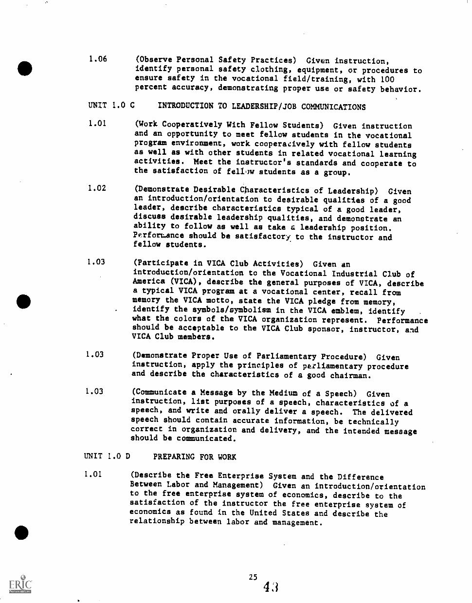
1.06 (Observe Personal Safety Practices) Given instruction,identify personal safety clothing, equipment, or procedures toensure safety in the vocational field/training, with 100percent accuracy, demonstrating proper use or safety behavior.
UNIT 1.0 C INTRODUCTION TO LEADERSHIP/JOB COMMUNICATIONS
1.01 (Work Cooperatively With Fellow Students) Given instructionand an opportunity to meet fellow students in the vocationalprogram environment, work cooperatively with fellow studentsas well as with other students in related vocational learningactivities. Meet the instructor's standards and cooperate tothe satisfaction of fellow students as a group.
1.02 (Demonstrate Desirable Characteristics of Leadership) Givenan introduction/orientation to desirable qualities of a goodleader, describe characteristics typical of a good leader,discuss desirable leadership qualities, and demonstrate anability to follow as well as take a leadership position.P.irfortance should be satisfactory to the instructor andfellow students.
1.03 (Participate in VICA Club Activities) Given anintroduction/orientation to the Vocational Industrial Club ofAmerica (VICA), describe the general purposes of VICA, describea typical VICA program at a vocational center, recall frommemory the VICA motto, state the VICA pledge from memory,identify the symbols/symbolism in the VICA emblem, identify .
what the colors of the VICA organization represent. Performanceshould be acceptable to the VICA Club sponsor, instructor, andVICA Club members.
1.03 (Demonstrate Proper Use of Parliamentary Procedure) Giveninstruction, apply the principles of parliamentary procedureand describe the characteristics of a good chairman.
1.03 (Communicate a Message by the Medium of a Speech) Giveninstruction, list purposes of a speech, characteristics of aspeech, and write and orally deliver a speech. The deliveredspeech should contain accurate information, be technicallycorrect in organization and delivery, and the intended messageshould be communicated.
UNIT 1.0 D PREPARING FOR WORK
1.01 (Describe the Free Enterprise System and the DifferenceBetween Labor and Management) Given an introduction/orientationto the free enterprise system of economics, describe to thesatisfaction of the instructor the free enterprise system ofeconomics as found in the United States and describe therelationship between labor and management.
1.02 (Interpret Labor Lac. and Regulation;) Given instruction,necessary references concerning labor laws and regulations;interpret typical labor laws and regulations. Performancemust meet the instructor's standards.
1.03 (Interpret Payroll Deductions for Taxes, etc.) Giveninstruction and sample forms concerning income tax and otherwithholdings; interpret the typical forms used in income taxand other withholdings to the satisfaction of the instructorand itemize typical payroll deductions that a worker encounters.Performance must be to the instructor's standards.
1.04 (Identify Typical Career Opportunities) Given instruction,data on the local business and industry, opportunities to
, study entry-level job opportunities; identify the majorcategories of potential employers in the local community (andthe key characteristics of each).
1.05 (Locate Job Opportunities) Given job placement informationsuch as newspaper ads and personal contacts, list a minimum often specific jobs in the community. One week will be allowedto complete the task.
1.06 (Prepare Resume) Given examples of suitable resume/personaldata sheets, prepare and type (or print at a minimum) apersonal resume on paper acceptable to the instructor with allerrors acceptable corrected.
1.07 (Compose Application Letter) Given a newspaper ad for a.job,compose a letter of application. The letter must be mailableand include the necessary personal information.
1.08 (Complete a Typical Employment Application Form) Given anemployment application form typical of the job, complete theform with all information accurate, neatly typed or printed inan aligned in the form blanks.
1.09 (Interview for a Job) Given instruction on how to interviewfor a job, a job interview checklist, and a mock job interview;complete a job interview to the satisfaction of the instructor.
1.10 (Compose Follow-up Letter) Given a case situation by theinstructor or from the textbook, compose and write a follow-upletter appropriate to the job application or interview situationand in mailable form. The finished letter must meet theinstructor's standards.
(Identify Post-secondary Career Development Opportunities)Given an orientation to similar post-secondary career develop-ment programs, primarily the similar vocational programs atGreenville Technical College but including continuing educationprograms as well, a report of skill competencies
developed during secondary training, and other information asneeded; identify post-secondary career development opportunities.
UNIT 1.0 E INTRODUCTION TO DESIRABLE JOB/LEARNINGCHARACTERISTICS/HABITS/ATTITUDES
1.01 (Describe Good Work Habits Important to Job Success) Givenintroduction/orientation to desirable work habits, as describedby potential employers or tradesmen, demonstrate desirable(good) work habits based nn information provided by theinstructor to represent the minimum standards expected bybusiness/industry (potential employers) for entry employmentSuccess.
1.02 (Exhibit Successful Job Performance Characteristics) Giveninstruction, demonstrate job performance characteristics thatare considered important to entry-level career success in thevocational field. A "Job Performance Rating Sheet" will beused to evaluate performance and all items must be rated"frequently" or above.
1.03 (Exhibit Desirable Work Attitudes) Given instruction,demonstrate work attitudes that the majority of potentialemployers prefer in an entry level worker. Performance willbe evaulated on a "Work Attitudes Score Catd" and a minimum of90 percent should be attained. Performance will be ratedthrough training and should improve to 100 percent by the endof the training period.
UNIT 1.0 F BASIC MATH SKILLS
1.01 (Basic Math - Fractions) Given a pretest or examples of theinstructor, conduct the following operations with fractions:
1. Change any fraction to a decimal number, and anyterminating decimal number to a fraction.
2. Arrange in order...unit and simple nonunit fractions.3. Write equivalent fractions in higher, lower, lowest
terms.4. Write improper fractions 1.3 whole or mixed numbers, and
mixed numbers as improper fractions.5. Multiply fractions and mixed numbers, expressing answers
in simplest form.6. Divide fractions and mixed numbers, expressing answers
in simplest form.7. Add and subtract unlike fractions, expressing answers
in simplest form.8. Add and subtract mixed numbers with unlike fractions,
expressing answers in simplest form.9. Use rational numbers to solve simple work problems.
1.02 (Basic Math Decimals) Given a pretest or examples by theinstructor, conduct the following decimal math operations:
1. Name the place value of digits in decimal numbers on upto nine digits before the decimal and six digits afterthe decimal.
2. Compare decimal numbers and arrange them in order.3. Write the numeral for any decimal number of up to four
decimal places.4. Round decimal numbers to any designated place value up to
thousandths.5. Add and subtract decimal numbers of up to six digits.6. Multiply decimal numbers by whole numbers or decimal
numbers.7. Divide a number by a threedigit decimal number.8. Multiply and divide decimal numbers by powers of ten, by
inspection.
1.03 (Basic Math Volumes) Given a pretest or examples by theinstructor, find the volme of any rectangular prism or cube.
1.04 (Basic Math Areas) Given a pretest or examples by theinstructor, find the area of the following types of figures:
a. Rectangle and squareb. Circle
1.05 (The Metric System) Given basic instruction in the metricsystem and conversion from United States Customary units tometric; read and convert specifications and dimensions from
. one system into the other system on teacher or text assignedproblems with 100 percent accuracy.
UNIT 1.0 G BASIC MEASURING
1.01 (Measuring) Given proper instructions, read a rule and useother measuring tools with the precision necessary to takemeasurements from drawings, and transpose them to exactworking lengths and angles.
UNIT 1.0 H INTRODUCTORY BLUEPRINT READING
1.01 (Interpret Multiview Drawings) Given a selection of multtviewblueprints or drawings (orthographic projections) completewith symbols, notations, dimensions, and tolerances, and thenecessary reference materials; interpret the multiview drawings.All symbols, notations, dimensions, and tolerances must beidentified. Side, top, and front wires must be identifiedfrom each drawing.
1.02 (Determine Dimensions and Tolerances) Given a selection ofmachine shop blueprints or drawings, and the necessary referenceand writing materials, determine the dimensions and tolerancesgiven on the drawings using dimensions lines,
28
4
centerlines, projection lines, and views. Correct dimensionsmust be determined in order to machine the parts. Tolerancesmust be identified with 100 percent accuracy.
1.03 (Interpret Pictorial Drawings) Given a selection of pictorialdrawings complete with symbols, notations, dimensions, andtolerances, and the necessary reference materials; interpretthe pictorial drawings. All symbols, notations, dimensions,and tolerances must be identified.
UNIT 1.0 I WRITE AND READ TECHNICAL INFO-AATION CONCERNINGMACHINING OPERATIONS
1.01 (Write Technical Information Concerning Machining Operations)Given instruction and an introduction to the secondary machineshop program and the terminology of the trade, write technicalreports/communications that convey the intended messages andthat can be read intelligently by another machinist student(or machinist). Student performance must be acceptable to theinstructor.
The written message may include notations, etc., made onworking drawings, specifications, technical instructions, ordescriptions of machining operations using the proper termi-nology. The message intended must be communicated to thereceiver.
While correct spelling and punctuation is desirable, emphasiswill be on effective and efficient communications of a technicalmessage.
1.02 (Read Technical Information Concerning Machining Operations)Given an introduction to the secondary machine shop programand the terminology used in the trade, read and interprettechnical literature or information concerning machiningoperations. Reading competency should be demonstrated by theability to read and interpret information from blueprints andspecifications, technical instructions, and manufacturer'smanuals on equipment. Student performance must be acceptableto the instructor.

e
UNIT 1.0 A
INTRODUCTION/ORIENTATION
30 46
UNIT 1.0 A INTRODUCTION/ORIENTATION
TASK 1.01 REVIEW/FOLLOW CAREER CENTER POLICIESAND PROCEDURES
PERFORMANCE OBJECTIVE:
Given information on career center policies and procedures, apply thesepolicies and procedures on a day-to-day basis.
PERFORMANCE ACTIONS:
1.0101
1.0102
1.0103
Review center policies and procedures.
Review philosophy of center and, The School Districtof Greenville County, and the South Carolina Departmentof Education.
Review relevant safety policies and procedures underunit concerning safety, and practice desired safetybehavior as outlined in relevant safety policies andprocedures.
PERFORMANCE STANDARDS:
- Using information and materials, supplies, review and applycareer center policies and procedures daily.
SUGGESTED INSTRUCTION TIME: 3 Hours
RELATED TECHNICAL INFORMATION:
- Career Center Student Handbook- High School Student Handbook
- Written Policies and Procedures of The School District ofGreenville County
- Policies and Procedures of the South Carolina State Departmentof Education
- "Authorization" and "release" forms (such as safety releases)
4931
UNIT 1.0 A INTRODUCTION/ORIENTATION
TASK 1.02 ORIENTATION TO VOCATIONAL PROGRAMCLASSROOM/SHOP/LAB
PERFORMANCE OBJECTIVE:
Given information on classroom/shop or instructor's policies and proce-dures, apply these policies and procedures on a daily basis, meeting thestandards of the instructor 100 percent.
PERFORMANCE ACTIONS:
1.0201 Review with instructor the shop policies and procer.dures.
1.0202 Apply, with 100 percent accuracy, the policies andprocedures of the vocational program, shop, orinstructor.
PERFORMANCE STANDARDS:
- Apply information/instruction given during orientation andthroughout training period to comply with all policies andprocedures of the shop (instructor) on a day-to-day basis.
- Standards of the State, School District, Career Center, andhigh school, and instructor apply.
SUGGESTED INSTRUCTION TIME: 1 Hour
RECOMMEND}D:
- Vocational education (shop) policies and procedures should bewritten and posted or distributed to students.
9
UNIT 1.0 A INTRODUCTION/ORIENTATION
TASK 1.U3 REVIEW COURSE OBJECTIVES AND STANDARDS
PERFORMANCE OBJECTIVE:
Given an introduction to the vocational program, a review of the courseobjectives and minimum standards of performance; describe the courseobjectives, and minimum performance expected Co demonstrate competencyin given objectives.
(NOTE: This task may be accomplished in general at the beginning ofthe first year and in detail over the two year trainingperiod.)
PERFORMANCE ACTIONS:
1.0301 Review each major objective of the vocationalprogram as outlined in this articulated, performance-based instruction objectives guide,
1.0302 Review the minimum performance standards of theobjectives.
Possible Alternate Actions:
Instructor may require idents to identify objectives andstandards at the initiation of each new unit of instruction.
PERFORMANCE STANDARDS:
- Using information provided, explain the objectives of thecourse and describe the minimum performance for each objective.
SUGGESTED INSTRUCTION TIME: 3 Hours
RECOMMENDATION:
- Course objectives, (Task Listing objectives) should be writtenand posted or distributed to students.
5133

UNIT 1.0 B
INTRODUCTION TO SAFETY
UNIT 1.0 B INTRODUCTION TO SAFETY
TASK 1.01 GENERAL SAFETY ORIENTATION
PERFORMANCE OBJECTIVE:
Given an orientation to building, shop, and fire safety; discuss,identify, or demonstrate general shop safety behavior and fire procedures.
PERFORMANCE ACTIONS:
1.0101 As applicable, discuss basic safety rules applicableto the training facility.
1.0102 Identify general shop safety rules.
1.0103 a. Review fire safety rules with the instructor.b. Identify fire safety equipment, exits, and
procedures in the shop and building area duringa fire.
PERFORMANCE STANDARDS:
- Follow basic safety rules and established shop safety practices.- Follow established fire safety practices and procedures.
SUGGESTED INSTRUCTION TIME: 1 Hour
UNIT 1.0 B INTRODUCTION TO SAFETY
TASK 1.02 IDENTIFY-DESIRABLE VOCATIONAL TRAININGSAFETY HABITS
PERFORMANCE OBJECTIVE:
Given an introduction/orientation to general safety as well as to safetyin the vocational education program or on the job; identify generaloccupational safety habits to the satisfaction of the instructor andmeet all applicable safety rules and regulations.
PERFORMANCE ACTIONS:
1.0201 Listen to all information provided by the instructoror others concerning safety in the career center,vocational program, and in live learning activities.
1.0202 Observe safety posters.
1.0261% Observe safety warning devices for hazardous materialsor work areas.
1.0204 Demonstrate correct safety practices going to andfrom the classroom/shop as well as in the classroomsituation.
1.0205 Describe the effect of accidents on the productiondollar, due to possible time loss.
1.0206 Observe learning situations or other situations forthe observation of safe situations as well asviolation of proper safety rules and regulations.
PERFORMANCE STANDARDS:
- To the standards of the instructor and standards applicable tothe classroom or school or in the vocational field, demonstratedesirable occupational safety habits.
- "Zero" accidents.- "Zero" safety violations.
SUGGESTED INSTRUCTION TIME: (Integrated training)
36
54
UNIT 1.0 B INTRODUCTION 10 SAFETY
TASK 1.03 OBSERVE CLASSROOM SAFETY PRACTICES
PERFORMANCE OBJECTIVE:
Given a typical vocational classroom /shop /lab or job situation, exhibitan awareness of safety practices, safe work habits, and a positiveattitude concerning job safety and accident prevention and meet standardsestablished by the instructor.
PERFORMANCE ACTIONS:
1.0301 Develop an awareness of vocational training/jobhazards and become more safety conscious.
1.0302 Develop a serious attitude toward the daily use ofsafety procedures.
1.0303 Prepare for safety before entering the training workarea.
1.0304 Prepare for safety at the work station.
1.0305
1.0306
Prepare for safety on existing the training workarea..
Demonstrate knowledge of general safety color codingin the training/job facility and on equipment andtools.
1.0307 Practice safe procedures/habits daily.
PERFORMANCE STANDARDS:
- "Zero-level" accident record in vocational program.- Instructor's standards based on recommended resources.- Applicablt. OSHA Standards.
SUGGESTED INSTRUCTION TIME: 1 Hour
POSSIBLE RESOURCES:
Current vocational program safety guide publication of The SchoolDistrict of Greenville County.
UNIT 1.0 B INTRODUCTION TO SAFETY
TASK 1.03 OBSERVE CLASSROOM SAFETY PRACTICES(Con't.)
POSSIBLE RESOURCES: (Con't.)
Jacobs, Clinton 0., and Howard J. Turner, Developing Shop Safety Skins,Athens, GA: American Association for Vocational InstructionalMaterials. (Approximately 80 pages of brief, visually clearsuggestions concerning a variety of shop safety situations. Goodstudent or resource manual.)
RECOMMENDED RESOURCES:
Safety Handbook, A Guide for Trade and Industrial Programs, ClemsonUniversity, SC: Vocational Education Media Center, 1968. (No.13/2/70, $2.25: Accompanying 31 Transparencies, No. 9/8/68,$5.75.) Available from Trades and Industries Division Supervisor,Office of Vocational Education, South Carolina State Department ofEducation or from the Vocational Education Media Center, ClemsonUniversity, SC.
4
Planning for Emergencies, Occupational Safety and Health Short CourseNumber Seven, Columbia, SC: SC State Board for Technical andComprehensive Education.
Notgrass, Troy, Safety Handbook for ICT, The University of Texas atAustin: Center for Occupational Curriculum Development, Divisionof Continuing Education, 1978.
Hoerner, Thomas A., and Mervin D. Bettis, Power Tool Safety and Operation,St. Paul, MI: Hobax Publications, 1977.
RELATED TECHNICAL INFORMATION:
- Regulations of individual center or vocational program.- Regulations of The School District of Greenville County.- Codes, lows, and ordinances.- Materials and equipment handbooks and manuals.- OSHA Regulations.
E.P.A. Regulations.
38 r
UNIT 1.0 B INTRODUCTION TO SAFETY
TASK 1.04 APPLY FIRE SAFETY RULES AND PROCEDURES
PERFORMANCE OBJECTIVE:
Given examples of types of fires, fire extinguishers, and possible shopsituations, apply fire safety rules and procedures. Meet National andlocal fire safety procedures.
PERFORMANCE ACTIONS:
1.0401 Identify and explain application for fire extin-guishers of the following types:
1.0402
1.0403
1.0404
1.0405
a. Formb. Carbon Dioxidec. Soda Acidd. Pump Tanke. Gas Cartridgef. Dry Chemicalg. Multi-purpose Dry Chemical
Describe procedures for operating selected fireextinguishers.
Identify potential causes of fire in the vocationalfield/shop and common methods for avoiding orpreventing fires.
Inspect shop/laboratory for conformity with firesafety rules and procedures.
Identify/explain relevant safety precautions appli-cable to vocational training activities.
PERFORMANCE STANDARDS:
- Apply applicable fire safety rules and procedures to thevocational program/training meeting all applicable standards,National, local, and instructor's.
SUGGESTED INSTRUCTION TIME: 1 Hour
UNIT 1.0 B INTRODUCTION TO SAFETY
TASK 1.05 APPLY ELECTRICAL SAFETY RULES ANDPROCEDURES
PERFORMANCE OBJECTIVE:
Given orientation to identifying electrical hazards, apply electricalsafety rules and procedures.. Electrical equipment with exposed wire,frayed cables, and deteriorated insulation must be reported and corrected.Proper grounding must be employed and maintained. Junction boxes,outlets, switches, breaker switches, and panels should be identified asto their use. Meet all applicable National and local standards and thestandards of the instructor.
PERFORMANCE ACTIONS:
1.0501
1.0502
1.0503
1.0504
1.0505
Explain importance of labeling circuit breakers.
Explain importance of proper grounding of machinesor equipment of electrically operated hand tools.
Demonstrated/explain methods for using flexibleextension cords, long cables, or drop lights.
Identify electrical hazards and explain safety rulespertaining the vocational field of training.
Identify approved locations for all electricalequipment and power sources in the shop or at thetraining field location.
1.0506 Interpret safety precautions for electricity in thevocational shop.
PERFORMANCE STANDARDS:
- Apply electrical safety rules and procedures for the vocationalshop/laboratory, including field training locations, on aday-to-day basis meeting all applicable National and localsafety rules and regulations as well as the standards of theinstructor.
SUGGESTED INSTRUCTION TIME: 1 Hour
(NOT: Specific safety procedures and recommendations pertaining to atool and equipment item may be included as a part of the taskdescription concerning the tool/equipment.)
OUNIT 1.0 B INTRODUCTION TO SAFETY
TASK 1.06 PERSONAL SAFETY
PERFORMANCE OBJECTIVE:
Given instruction, identify personal safety clothing, equipment, orprocedures to ensure safety in the vocational field/training, with 100percent accuracy, demonstrate proper use or safety behavior.
PERFORMANCE ACTIONS:
1.0601
1.0602
List and explain personal safety rules/procedures.
Identify appropriate protective clothing/equipment/etc.,used in the vocational field/training, possibly froma given list, sketch, or mock-up.
PERFORMANCE STANDARDS:,a
- Given a list,. sketch, or mock-up, identify with 100 percentaccuracy personal safety clothing, equipment, etc., used inthe vocational field.
SUGGESTED INSTRUCTION TIME: 1 Hour
RELATED TECHNICAL INFORMATION:
- Additional personal safety training will be integrated intooccupational task training.
Addend= to Safety Unit
STUDENT'S SAFETY PLEDGEAND
PARENT'S/GUARDIAN'S MANSSSIOS FOR OCCUPAZIONALTIAZNI=
, as part of vocational education =maniac,alniTe/operate potentially hazardicus occupational tools, machinery,.equipment, and mateciels typical of the vocational field: provided t'at thestudent pledges to follow all safety rules and regulations of the instructor/career center /The School District of Greenville County and provided that thestudent's parent or guardian grants permission for occupational training bysigning the release below.
TO. TEL STUDENT/
The vocational student vilI be given proper instruction, both in the use ofand correct safety procedures concerning occupational tools. machinery.equipment, and materials typical to the vocational field before beingallowed to use/operate them.
The student must assume responsibility for following safe practices andrules, and therefore the student is asked to subscribe to the followingsafety pledge.
STUDENT'S SAFETY ,PLEDGE,
I. °T (student) promise to follow all safety rules of thelastructor/Of.the shop,
L. °I promise never to use a tool, machine, piece of equipment.as material of the vocational program without first havingpermisaion from the instructor.
3. t will not as* permission to use a particular tool, macnine..or piece. of equipment unless : have been instructed in itsasap. and have. made 104 percent an the safety test for thattool. machine or equipment.
4. 'Pt will report any ..ocident or injury to the vocationalinstructor immediately.
S. w'r will report any potentially bazardioua situation to thevocational instructor immediately.'
Date Student's Signature
?ARE:WS/GUARDIAN'S ?EMISSION
't hereby give my consent to allow my son/daughter to use/operate alloccupational tools. &tablas', equipment, anki materials nec4ssarycarrying out the requirements of the, vocational program of training.'
Oats parent's /Guardian's Signature
'Parents are cordially invited to 7151t the snop to inspect tfte occupationaltools, macmines, and equipment and to 34* them :a operation.)
Addendum to Task 1.0 B
METAL CUT/OBT_UW_SAFETY_
1. Always wear safety glasses or a face shield when operating themetal cut/off saw.
2. Use the correct type of abrasive cut/off blade for the type ofmaterial to be cut.
3. Make adjustments to the saw only when the saw is off.
4. Aiways shut off the saw before removing the metal from the sawater you have made the cut.
5, Stand to one side of the saw when operating it and make sure othersare clear of the area before starting the saw.
6. Never operate the metal cut/off saw with fragile, non-reinforcedabrasive blades.
7. The suggested capacity of the saw if 4 inch shapes and 2 inchsolids.
8. Care should be exercised when holding materials against the fenceby hand. Wear gloves to guard against heat and keep hands awayfrom the blade.
9. When starting any abrasive cut/off saw, it is a good safety rule toallow the blade to operate at full speed for one minute beforestarting to cut.
10. Blades minimize in diameter as they are used. It is wise to savethe full size blades for cutting pipe and larger shapes whileconsuming the worn blades on smaller sections.
11. Use the- Cam/Clamp on the right or left of the fence. Avoid clampingagainst burrs.
12. When the Cam/Clamp is used:a. raise lever handle to an upright positionb. place material in position, firmly agains, fencec. slide tab forward, firmly against material, securely tighten
,Jthe "T" screwd. activate the Cam/Clamp by pulling the lever toward you
13. Pull blade into material firmly. Vary pressure when "loading"occurs.
14. The position of the material to be cut is important. Al-mys try tomaintain the minimum arc of contact between the blade and thematerial to be cut.
15. Always clean up when you are finished cutting metal and followprocedures for end of using machine.
Addendum to Task 1.0 B
LATHE SAFETY
1. Roll sleeves above elbows and remove or fasten any loose clothing.
2. Check to see that all guards are in place.
3 Be sure that all parts of the carriage will clear any rotating partduring full length of cut.
4. Remove chuck key or wrench immediately after using.
5. Set tool on horizontal center of (or slightly above) work to beturned.
6. Wear eye protection devices.
7. Place your hands on the controls or at your sides except whenfiling or polishing.
8. Keep hands away from chips.
9. Cuts that are close to chuck or against a shoulder are to befinished by hand feed.
10. Bring lathe to a complete stop before reversing.
11. Move tool holder and tool post out of way before filing or polishing.
12. BetweenCenters Turning Precautions:a. use lathe dog to drive workb. clamp tailstock securelyc. adjust the tailstock center, lubricate if necessaryd. regulate depth of cut according to size and type of metale. use tools that are properly grounded for the particular job
13. Chuck and Faceplate Turning Precautions:a. place a board under chuck when threading the chuck on or off
spindle, keep fingers clearb. secure work firmly in chuckc. remove chuck key or wrench immediately after using itd. counterbalance work on the faceplate if it is irregular in
shapee. turn chuck or faceplate by hand through one complete cycle to
make sure work is clearf. regulate depth of cut according to size and type of metalg. stand to one side of revolving faceplateh. stop power feed before tool reaches jaws of chuck
Addendum to Task 1.0 B
HEAT TREATING SAFETY
1. Heat treating involves metal heated to very high temperatures. Hotmetal must be handled with appropriate care and tools.
2. Wear goggles and proper protective clothing. gloves, and apron.
3. Never look at the flames in a furnace unless you are wearing tintedgoggles.*
4. Do not try to light a furnace until you have been instructed in itsoperations. Ask for instruction if you are not familiar withoperation.*
*Alternate heat treating metLoris may be employed where furnaces arenot available.
5. Be sure area is properly ventilated.
6. Do not use potassium cyanide as a case-hardening medium.
7. Do not stand over the quenching bath when immersing work.
Addendum to Task 1.0 B
-GRINDER SAFETY- V
1. Set tool rest 1/16 inch to 1/8 inch from wheel and spark tongue 1/4inch from wheel.
2. Dress wheel when necessary.
3. Check Last guards are place.
( . Stand to one side of wheel.
5. Hold work with your hands. Ask instructor for permission to grindsmall pieces.
6. Use the face of the wheel only.
7. Press material against wheel with just sufficient pressure to causesteady, even removal of metal.
8. Keep work in motion across face of wheel.
Addendum to Task 1.0 B
_BANDSAW SAFETY
1. The saw guide must be within one-half inch of the stock to be cutbefore power is turned on.
2. Do not allow fingers to come closer than 2 inches from the sawblade when cutting stock.
3. Do not permit hands to cross the saw line while operating thebandsaw.
4. Do nct stand on the right side of the bandsaw while it is beingused.
5. Cylindrical shock must not be cut on the bandsaw without the use ofV-blocks.
6. The guide must not be adjusted while the machine is in operation.
7. Do not cut stock unless it is supported against the downward thrustof the saw.
8. If the bandsaw blade should break while tne machine is in operation,immediately shut off the power, keeping clear of the saw, andnotify the instructor at once.
9. Do not reach around the bandeau blade to remove work.
10. Do not overcrowd the bandsaw.
11. Clean off the bandsaw and the floor around the bandsaw when throughusing the machine.
466%i
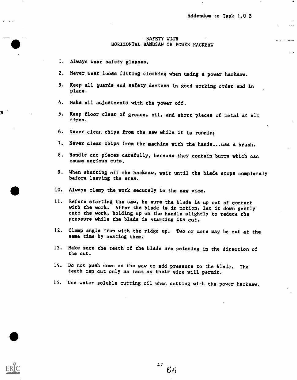
Addendum to Task 1.0 B
SAFETY WITHHORIZONTAL BANDSAW OR POWER HACKSAW
1. Always wear safety glasses.
2. Never wear loose fitting clothing when using a power hacksaw.
3. Keep all guards and safety devices in good working order and inplace.
4. Make all adjustments with the power off.
5. Keep floor clear of grease, oil, and short pieces of metal at alltimeb.
6. Never clean chips from the saw while it is runnini,
7. Never clean chips from the machine with the hands use a brush.
8. Handle cut pieces carefully, because they contain burrs which cancause serious cuts.
9. When shutting off the hacksaw, wait until the blade stops completelybefore leaving the area.
10. Always clamp the work securely in the saw vice.
11. Before starting the saw, be sure the blade is up out of contactwith the work. After the blade is in motion, let it down gentlyonto the work, holding up on the handle slightly to reduce thepressure while the blade is starting its cut.
12. Clamp angle iron with the ridge up. Two or more may be cut at thesame time by nesting them.
13. Make sure the teeth of the blade are pointing in the direction ofthe cut.
14. Do not push down on the saw to add pressure to the blade. Theteeth can cut only as fast as their size will permit.
15. Use water soluble cutting oil when cutting with the power hacksaw.
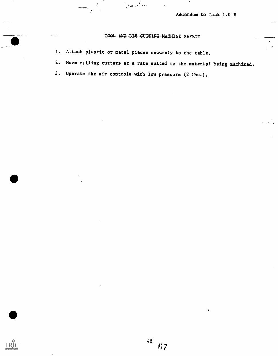
Addendum to Task 1.0 B
TOOL AND- DIE -CUTTING-MACHINE SAFETY
1. Attach plastic or metal pieces securely to the table.
2. Move milling cutters at a rate suited to the material being machined.
3. Operate the air controls with low pressure (2 lbs.).
48
6r
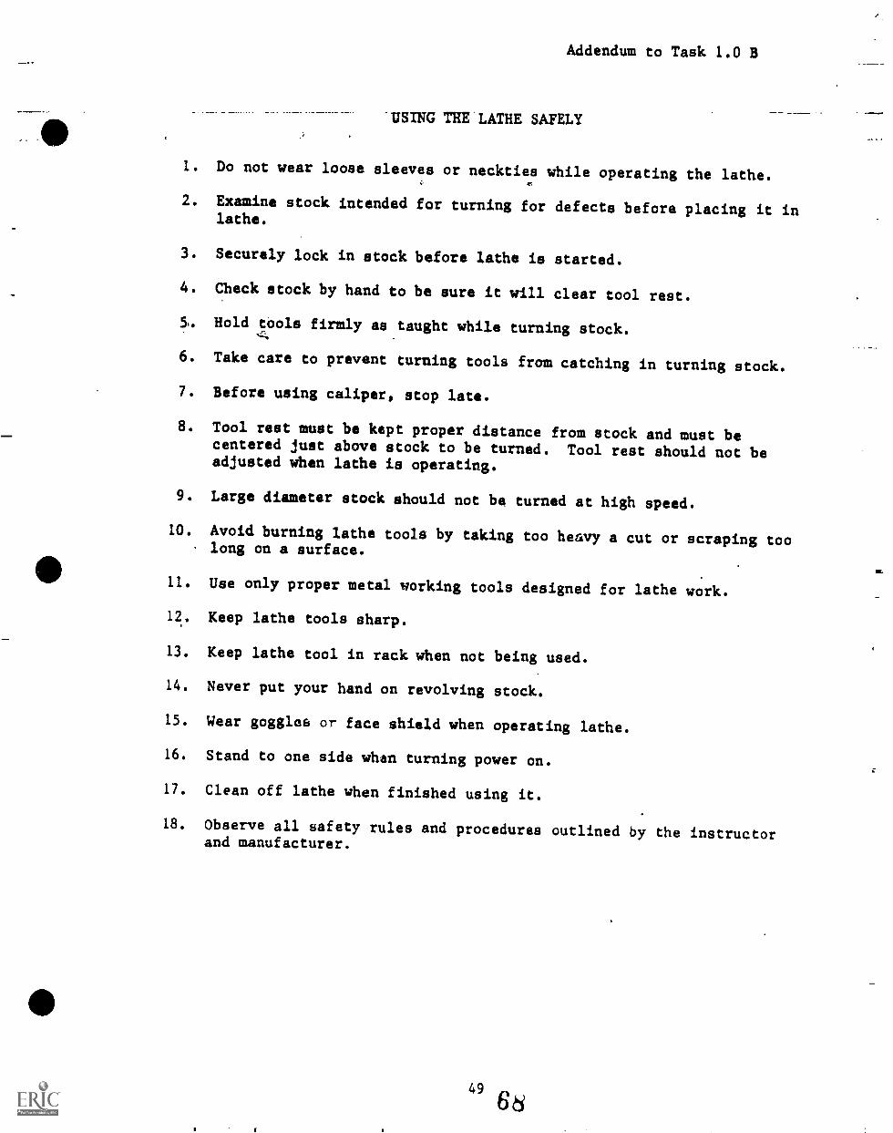
Addendum to Task 1.0 B
"USING THE 'LATHE SAFELY
1. Do not wear loose sleeves or neckties while operating the lathe.
2. Examine stock intended for turning for defects before placing it inlathe.
3. Securely lock in stock before lathe is started.
4. Check stock by hand to be sure it will clear tool rest.
5, Hold tools firmly as taught while turning stock.
6. Take care to prevent turning tools from catching in turning stock.
7. Before using caliper, stop late.
8. Tool rest must be kept proper distance from stock and must becentered just above stock to be turned. Tool rest should not beadjusted when lathe is operating.
9. Large diameter stock should not be turned at high speed.
10. Avoid burning lathe tools by taking too heavy a cut or scraping toolong on a surface.
11. Use only proper metal working tools designed for lathe work.
12. Keep lathe tools sharp.
13. Keep lathe tool in rack when not being used.
14. Never put your hand on revolving stock.
15. Wear goggles or face shield when operating lathe.
16. Stand to one side when turning power on.
17. Clean off lathe when finished using it.
18. Observe all safety rules and procedures outlined by the instructorand manufacturer.
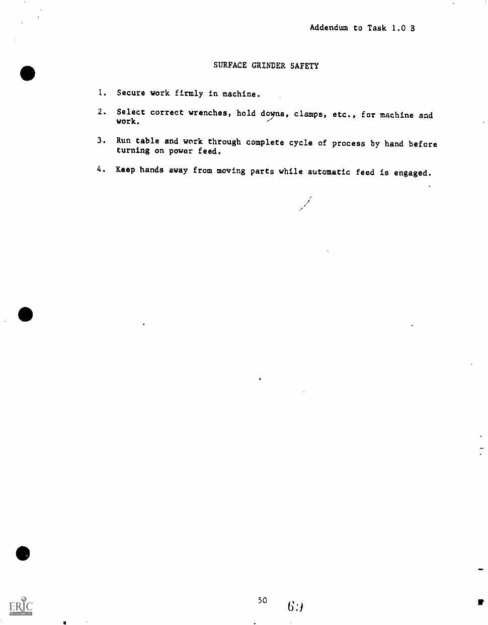
Addendum to Task 1.0 B
SURFACE GRINDER SAFETY
1. Secure work firmly in machine.
2. Select correct wrenches, hold doyns, clamps, etc., for machine andwork.
3. Run table and work through complete cycle of process by hand beforeturning on power feed.
4. Keep hands away from moving parts while automatic feed is engaged.
50:)
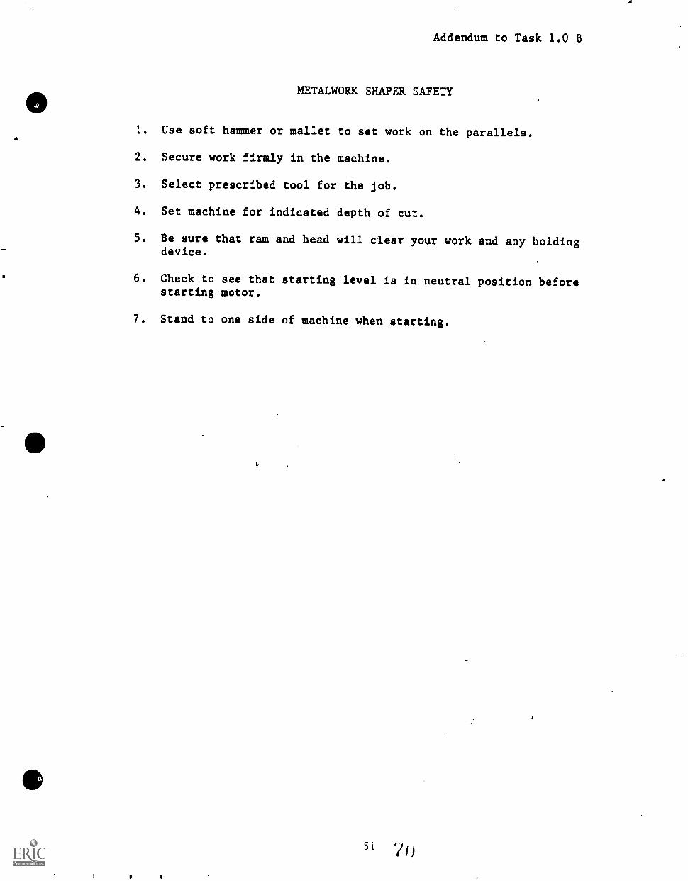
4
Addendum to Task 1.0 B
METALWORK SHAPER SAFETY
1. Use soft hammer or mallet to set work on the parallels.
2. Secure work firmly in the machine.
3. Select prescribed tool for the job.
4. Set machine for indicated depth of cut.
5. Be sure that ram and head will clear your work and any holdingdevice.
6. Check to see that starting level is in neutral position beforestarting motor.
7. Stand to one side of machine when starting.
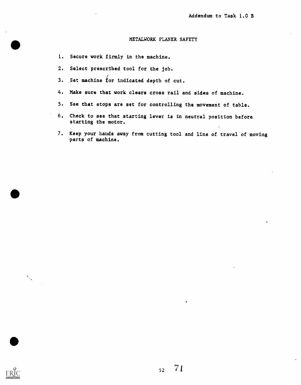
Addendum to Task 1.0 B
METALWORK PLANER SAFETY
1. Secure work firmly in the machine.
2. Select prescribed tool for the job.
3. _Set machine for indicated depth of cut.
4. Make sure that work clears cross rail and sides of machine.
5. See that stops are set for controlling the movement of table.
6. Check to see that starting lever is in neutral position beforestarting the motor.
7. Keep your hands away from cutting tool and line of travel of movingparts of machine.
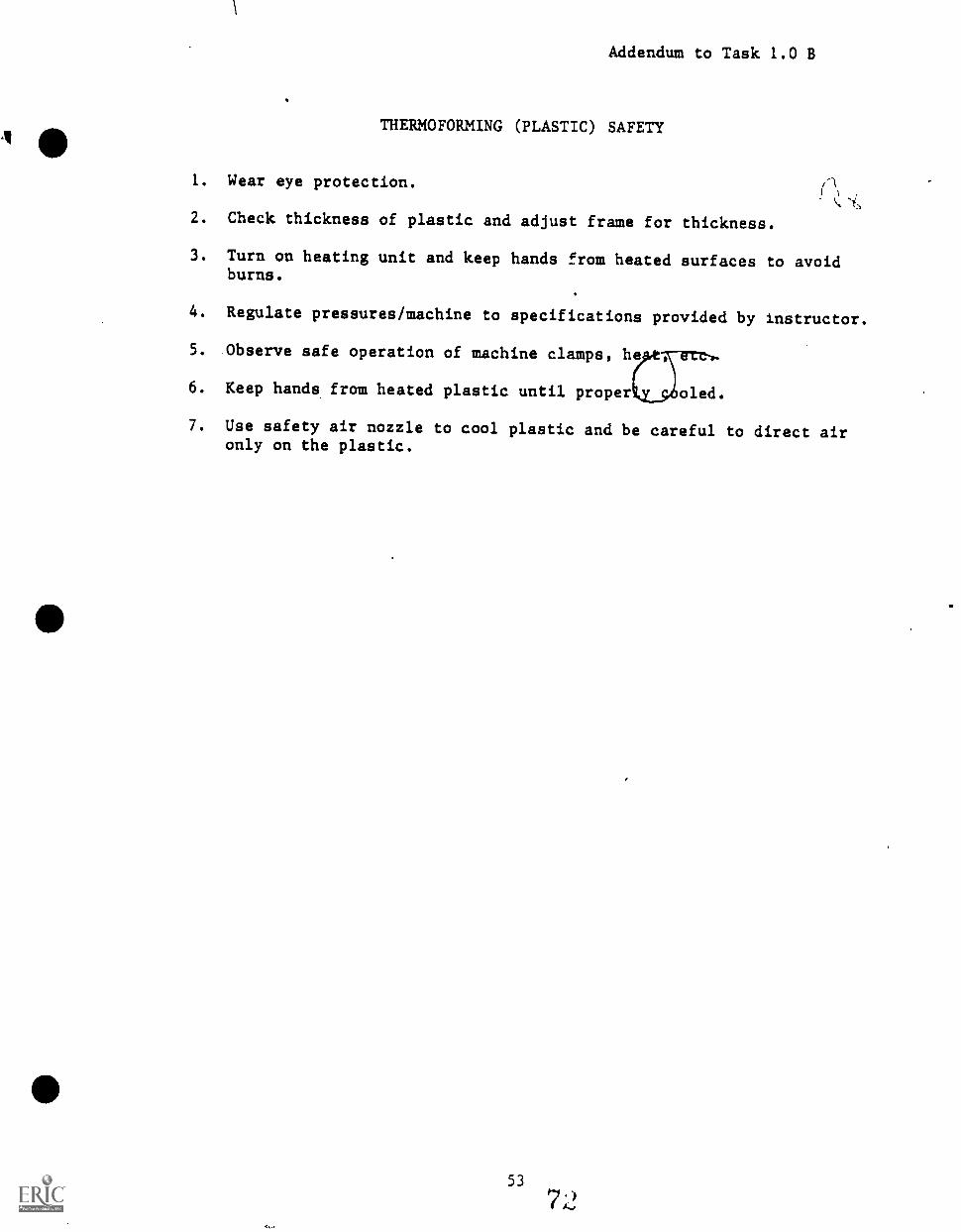
Addendum to Task 1.0 B
THERMOFORMING (PLASTIC) SAFETY
1. Wear eye protection.
2. Check thickness of plastic and adjust frame for thickness.
3. Turn on heating unit and keep hands from heated surfaces to avoidburns.
4. Regulate pressures/machine to specifications provided by instructor.
5. Observe safe operation of machine clamps, h
6. Keep hands from heated plastic until proper oled.
7. Use safety air nozzle to cool plastic and be careful to direct aironly on the plastic.
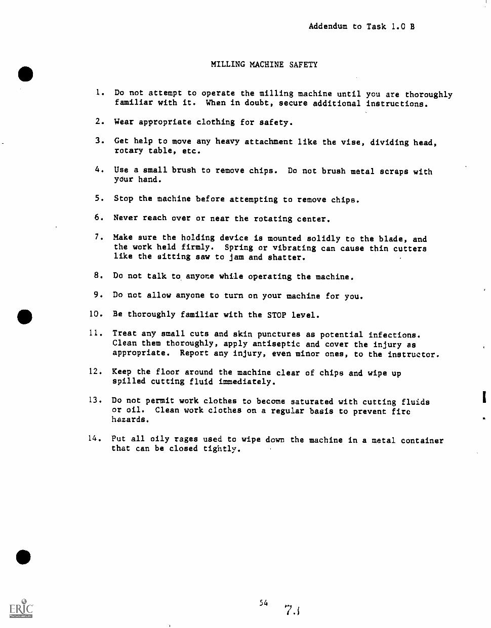
Addendum to Task 1.0 B
MILLING MACHINE SAFETY
1. Do not attempt to operate the milling machine until you are thoroughlyfamiliar with it. When in doubt, secure additional instructions.
2. Wear appropriate clothing for safety.
3. Get help to move any heavy attachment like the vise, dividing head,rotary table, etc.
4. Use a small brush to remove chips. Do not brush metal scraps withyour hand.
5. Stop the machine before attempting to remove chips.
6. Never reach over or near the rotating center.
7. Make sure the holding device is mounted solidly to the blade, andthe work held firmly. Spring or vibrating can cause thin cutterslike the sitting saw to jam and shatter.
8. Do not talk to. anyone while operating the machine.
9. Do not allow anyone to turn on your machine for you.
10. Be thoroughly familiar with the STOP level.
11. Treat any small cuts and skin punctures as potential infections.Clean them thoroughly, apply antiseptic and cover the injury asappropriate. Report any injury, even minor ones, to the instructor.
12. Keep the floor around the machine clear of chips and wipe upspilled cutting fluid immediately.
13. Do not permit work clothes to become saturated with cutting fluidsor oil. Clean work clothes on a regular basis to prevent firehazards.
14. Put all oily rages used to wipe down the machine in a metal containerthat can be closed tightly.
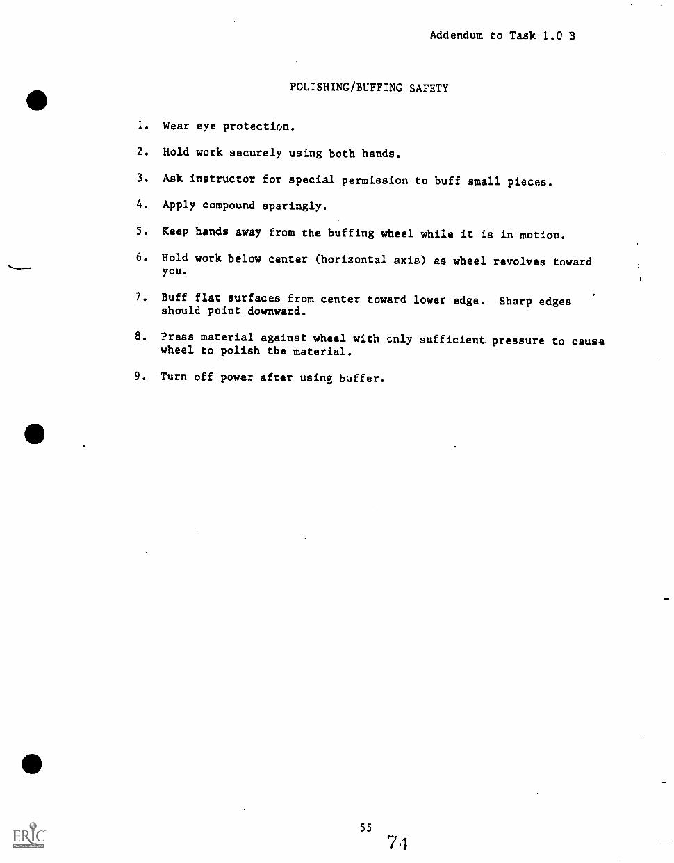
Addendum to Task 1.0 B
POLISHING/BUFFING SAFETY
1. Wear eye protection.
2. Hold work securely using both hands.
3. Ask instructor for special permission to buff small pieces.
4. Apply compound sparingly.
5. Keep hands away from the buffing wheel while it is in motion.
6. Hold work below center (horizontal axis) as wheel revolves towardyou.
7. Buff flat surfaces from center toward lower edge. Sharp edgesshould point downward.
8. Press material against wheel with only sufficient pressure to causewheel to polish the material.
9. Turn off power after using buffer.
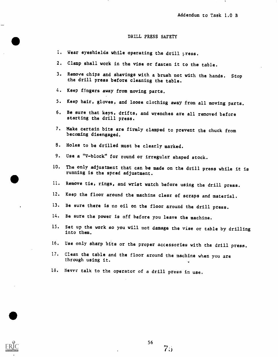
Addendum to Task 1.0 B
DRILL PRESS SAFETY
1. Wear eyeshields while operating the drill 1.ress.
2. Clamp shall work in the vise or fasten it to the table.
3. Remove chips and shavings with a brush not with the hands. Stopthe drill press before cleaning the table.
4. Keep fingers away from moving parts.
5. Keep hair, gloves, and loose clothing away from all moving parts.
6. Be sure that keys, drifts, and wrenches are all removed beforestarting the drill press.
7. Make certain bits are firmly clamped to prevent the chuck frombecoming disengaged.
8. Holes to be drilled must be clearly marked.
9. Use a "Vblock" for round or irregular shaped stock.
10. The only adjustment that can be made on the drill press while it isrunning is the speed adjustment.
11. Remove tie, rings, and wrist watch before using the drill press.
12. Keep the floor around the machine clear of scraps and material.
13. Be sure there is no oil on the floor around the drill press.
14. Be sure the power is off before you leave the machine.
15. Set up the work so you will not damage the vise or table by drillinginto them.
16. Use only sharp bits or the proper accessories with the drill press.
17. Clean the table and the floor around the machine when you arethrough using it.
18. Never talk to the operator of a drill press in use.
UNIT 1.0 C
INTRODUCTION TO LEADERSHIP/JOB COMMUNICATIONS
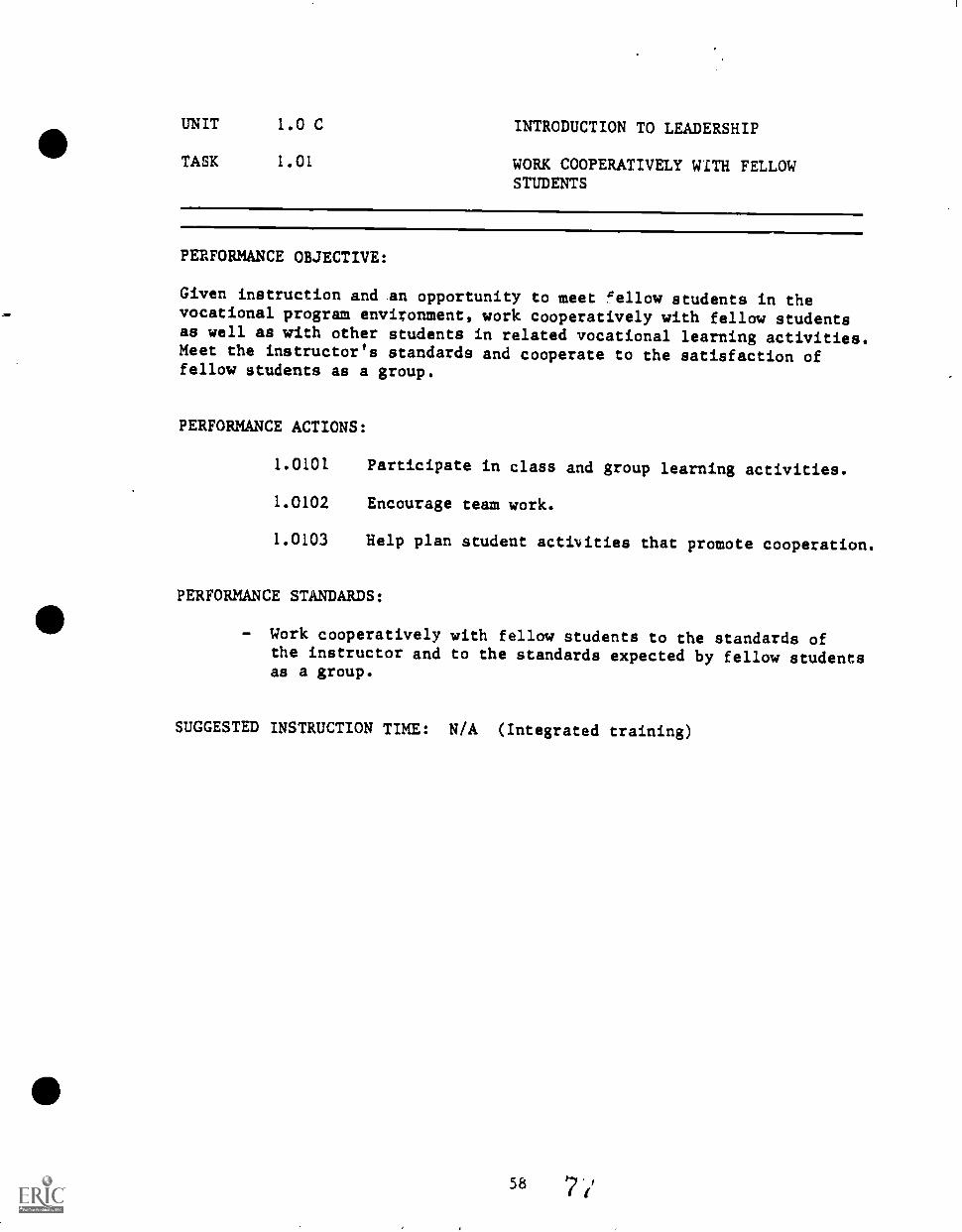
UNIT 1.0 C INTRODUCTION TO LEADERSHIP
TASK 1.01 WORK COOPERATIVELY WITH FELLOWSTUDENTS
PERFORMANCE OBJECTIVE:
Given instruction and an opportunity to meet "ellow students in thevocational program environment, work cooperatively with fellow studentsas well as with other students in related vocational learning activities.Meet the instructor's standards and cooperate to the satisfaction offellow students as a group.
PERFORMANCE ACTIONS:
1.0101 Participate in class and group learning activities.
1.0102 Encourage team work.
1.0103 Help plan student activities that promote cooperation.
PERFORMANCE STANDARDS:
- Work cooperatively with fellow students to the standards ofthe instructor and to the standards expected by fellow studentsas a group.
SUGGESTED INSTRUCTION TIME: N/A (Integrated training)
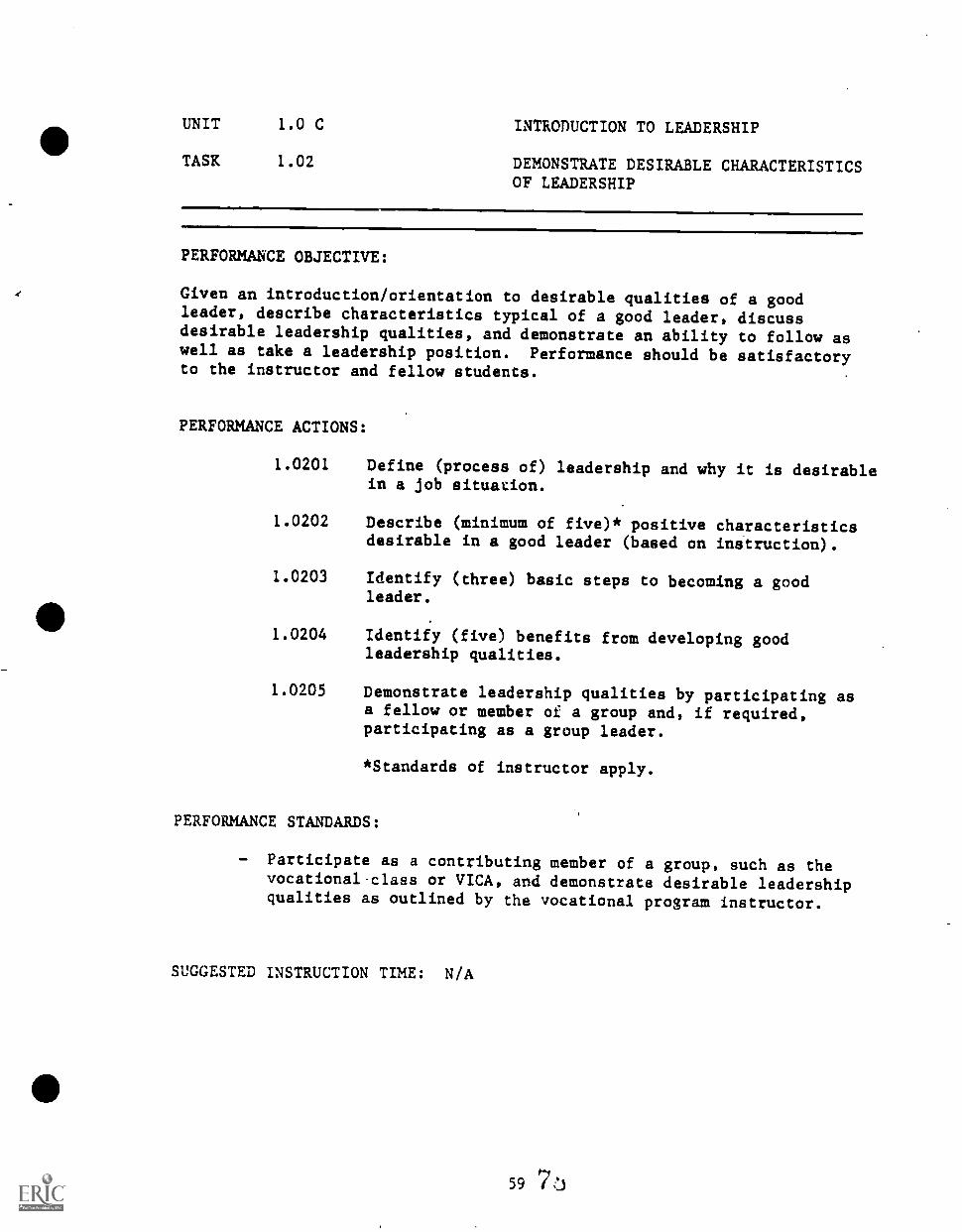
UNIT 1.0 C INTRODUCTION TO LEADERSHIP
TASK 1.02 DEMONSTRATE DESIRABLE CHARACTERISTICSOF LEADERSHIP
PERFORMANCE OBJECTIVE:
Given an introduction/orientation to desirable qualities of a goodleader, describe characteristics typical of a good leader, discussdesirable leadership qualities, and demonstrate an ability to follow aswell as take a leadership position. Performance should be satisfactoryto the instructor and fellow students.
PERFORMANCE ACTIONS:
1.0201 Define (process of) leadership and why it is desirablein a job situation.
1.0202 Describe (minimum of five)* positive characteristicsdesirable in a good leader (based on instruction).
1.0203 Identify (three) basic steps to becoming a goodleader.
1.0204 Identify (five) benefits from developing goodleadership qualities.
1.0205 Demonstrate leadership qualities by participating asa fellow or member of a group and, if required,participating as a group leader.
*Standards of instructor apply.
PERFORMANCE STANDARDS:
Participate as a contributing member of a group, such as thevocationalclass or VICA, and demonstrate desirable leadershipqualities as outlined by the vocational program instructor.
SUGGESTED INSTRUCTION TIME: N/A
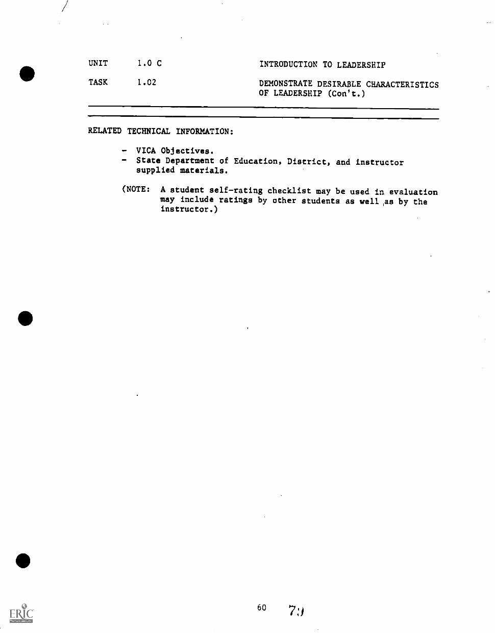
UNIT 1.0 C INTRODUCTION TO LEADERSHIP
TASK 1.02 DEMONSTRATE DESIRABLE CHARACTERISTICSOF LEADERSHIP (Con't.)
RELATED TECHNICAL INFORMATION:
- VICA Objectives.- State Department of Education, District, and instructor
supplied materials.
(NOTE: A student self-rating checklist may be used in evaluationmay include ratings by other students as well ,as by theinstructor.)
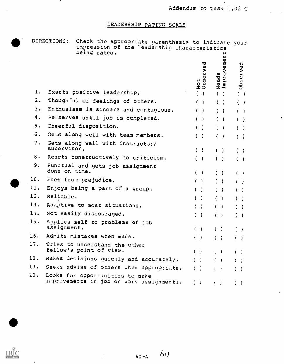
Addendum to Task 1.02 C
LEADERSHIP RATING SCALE
0. DIRECTIONS: Check the appropriate parenthesis to indicate yourimpression of the leadership ...haracteristicsbeing rated. .6)
o 64
4J (is)) va cn
o cu ez o z1-4 0
1.
2.
3..
Exerts positive leadership.
Thoughful of feelings of others.
Enthusiasm is sincere and contagious.
(
(
(
)
)
)
(
(
(
)
)
)
(
(
(
)
)
)
4. Perserves until job is completed. ( ) ( ) ( )
5. Cheerful disposition. ( ) ( ) ( )
6. Gets along well with team members. ( ) ( ) ( )
7. Gets along well with instructor/supervisor.
( ) ( ) ( )
8. Reacts constructively to criticism. ( ) ( ) ( )
9. Punctual and gets job assignmentdone on time. ( ) ( ) ( )
10. Free from prejudice. ( ) ( ) ( )
11. Enjoys being *a part of a group. ( ) ( ) ( )
12. Reliable. ( ) ( ) ( )
13. Adaptive to most situations. ( ) ( ) ( )
14. Not easily discouraged. ( ) ( ) ( )
15. Applies self to problems of jobassignment. ( ) ( ) ( )
16. Admits mistakes when made. ( ) ( ) ( )
17. Tries to understand the otherfellow's point of view. ( ) ) ( )
18. Makes decisions quickly and accurately. ( ) ( ) ( )
19. Seeks advise of others when appropriate. ( ) ( ) I
20. Looks for opportunities to makeimprovements in job or work assignments. ( ) ) ( )
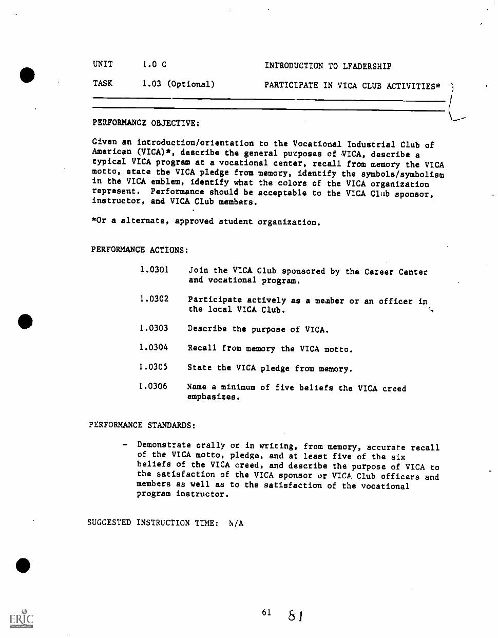
UNIT 1.0 C INTRODUCTION TO LEADERSHIP
TASK 1.03 (Optional) PARTICIPATE IN VICA CLUB ACTIVITIES* )
PERFORMANCE OBJECTIVE:
Given an introduction/orientation to the Vocational Industrial Club ofAmerican (VICA)*, describe the general purposes of VICA, describe atypical VICA program at a vocational center, recall from memory the VICAmotto, state the VICA pledge from memory, identify the symbols/symbolismin the VICA emblem, identify what the colors of the VICA organizationrepresent. Performance should be acceptable to the VICA Club sponsor,instructor, and VICA Club members.
*Or a alternate, approved student organization.
PERFORMANCE ACTIONS:
1.0301 Join the VICA Club sponsored by the Career Centerand vocational program.
1.0302 Participate actively as a member or an officer inthe local VICA Club.
1.0303 Describe the purpose of VICA.
1.0304 Recall from memory the VICA motto.
1.0305 State the VICA pledge from memory.
1.0306 Name a minimum of five beliefs the VICA creedemphasizes.
PERFORMANCE STANDARDS:
Demonstrate orally or in writing, from memory, accurate recallof the VICA motto, pledge, and at least five of the sixbeliefs of the VICA creed, and describe the purpose of VICA tothe satisfaction of the VICA sponsor or VICA. Club officers andmembers as well as to the satisfaction of the vocationalprogram instructor.
SUGGESTED INSTRUCTION TIME: N/A
UNIT 1.0 C
TASK 1.03 (Optional)
INTRODUCTION
PARTICIPATE(Can't.)
TO LEADERSHIP
IN VICA CLUB ACTIVITIES*
RELATED TEC ICAL INFORMATION:
VICA publicatIon(s)- emblem.- VICA motto, pledge,- Local VICA Club in
and creed.Career Center.
UNIT 1.0 C JOB COMMUNICATIONS,
TASK 1.04 (Optional) DEMONSTRATE PROPER USE OFPARLILMENTARY PROCEDURE
PERFORMANCE OBJECTIVE:
Given ins.uction, apply the principles of parliamentary procedure anddescribe the characteristics of a good chairman:.
PERFORMANCE ACTIONS:
1. Identify two basic principles upon which parliamentaryprocedure is based.
2. List two important characteristics of a "good" chairman.
3. Define or identify types of motions.
4. Describe /idenrif the order of business for a meetingconducted by pa- Imentary procedure.
5. Describet,.. .ify the characteristics of the kinds ofmotions used in conducting a typical meeting by parlia-mentary procedure.
6. Demonstrate ability to use parliamentary procedurecorrectly.
PERFORMANCE STANDARDS:
- Define parliamentary procedure and how it is used to contributeto a meeting, identify the characteristics of a good chairman,and used parliamentary procedures correctly meeting thestandards of the instructor.
SUGGESTED INSTRUCTION TIME: N/A
(NOTE: "This activity should be Imtegrated into VICA activitiesand objectives.")
RELATED TECHNICAL INFORMATION:
- Robert's Rules of Order.- VICA Club.- Public Speaking.
63
S A
1
UNIT 1.0 C
TASK 1.05 (Optional)
JOB COMMUNICATIONS
COMMUNICATE A MESSAGE BY THE MEDIUMOF A SPEECH
PERFORMANCE OBJECTIVE:
Given instruction, list purposes of a speech, characteristics of aspeech, and write and orally deliver a speech/ The delivered speechshould contain accurate information, be technically correct in organi-zation and delivery, and the intended messa;e should be communicated.
PERFORMANCE ACTIONS:
1. Identify three purposes for making a speech.
2. Write an outline for a proposed speech.
3. List at least five methods/ways to make a speecheffective/interesting.
4. Deliver a three to five minute speech that successfullycommunicates the intended message.
PER7ORMANCE STANDARDS:
- Successfully communicate intended message by a speech usingproper techniques and meeting instructor's (or VICA sponsor's)standards.
ALTERNATE STANDARD:
- Student is to describe verbally, task being performed, techni-ques used, etc., to the instructor's standards.
SUGGESTED INSTRUCTION TIME: N/A
(NOTE: "This acrvrity may be integrated into VICA activities andobjectiveA ')
RELATED TECHNICAL INFORMATION:
- VICA Club.- Communications.

tt
ft.
UNIT 1.0 D
PREPARING FOR WORK
65 8;i
UNIT 1.0 D PREPARING FOR WORK
TASK 1.0, DESCRIBE THE FREE ENTERPRISE SYSTEMAND THE DIFFERENCE BETWEEN LABOR ANDMANAGEMENT
PERFORMANCE OBJECTIVE:
Given an introduction/orientation to the free enterprise system ofeconomics, describe to the satisfaction of the instructor the freeenterprise system of economics as found in the United States and describethe relationship between labor and management.
PERFORMANCE ACTIONS:
1.0i01
1.0102
Read assignments in trade magazines or periodicals.
Listen to talks by representatives of labor andmanagement.
1.0103 Discuss the Free Enterprise System as represented bybusiness/industry in the United States.
1.0104 Discuss problems concerning employee management-trade union transactions.
PERFORMANC STANDARDS:
- To the satisfaction of the instructor describe the FreeEnterpri.se System of economics as represented by business/ -industry in the United States.
SUGGESTED INSTRUCTION TIME: N/A
RELATED TECHNICAL INFORMATION:
- Free Enterprise System of Economics.- Management and Labor Relationships.
66b:
UNIT 1.0 D PREPARING FOR WORK
TASK 1.02 INTERPRET LABOR LAWS AND REGULATIONS
PERFORMANCE OBJECTIVES:
Given instruction, necessary references concerning labor laws andregulations, interpret typical labor laws and regulations. Performancemust meet the instructor's standards.
PERFORMANCE ACTIONS:
1.0201 Identify and interpret the "Fair Labor StandardsAct."
1.0202
1.0203
1.0204
State the minimum wage for a worker.
State the typical minimum age for a worker.
Define overtime.
1.0205 Identify local or State laws that affect the worker.
PERFORMANCE STANDARDS:
- Interpret typical labor laws and regulations of the Federal,State, and local level that affect the worker.
- The instructor's standards must be met.
SUGGESTED INSTRUCTION TIME: N/A
67
U
-M
UNIT 1.0 D PREPARING FOR WORK
TASK 1.03 INTERPRET PAYROLL DEDUCTIONS FORTAXES, ETC.
PERFORMANCE OBJECTIVE:
Given instruction and sample forms concerning income tax and otherwithholdings, interpret the typical forms used in income tax and otherwithholdings .to the satisfaction of the instructor and itemize typicalpayroll deductions that worker encounters. Performance must be to theinstructor's standards.
PERFORMANCE ACTIONS:
1.0301 Obtain a social security card (if not acquiredalready). (Recommended]
1,0302 Identify the purposes of social security withholdingsfrom pay.
1.0303 Describe who is qualified for unemployment compensation.
1.0304 Describe who qualifies for workmen's compensation.
1.0305 Complete typical forms used for Federal Income TaxWithholdings.
1.0306 Interpret a typical Federal Income Tax Wage and TaxStatement form.
1.0307 Identify typical payroll deductions.
PERFORMANCE STANDARDS:
- Civen typical forms used for payroll deduction and reportingof income and other taxes, interpret payroll deductions andother statements on the forms.
- Performance must be to the instructor's standards.
SUGGESTED 1STRUCTION TIME: N/A
II I
6
UNIT 1.0 D PREPARING FOR WORK
TASK 1.04 IDENTIFY TYPICAL CAREER OPPORTUNITIES
PERFORMANCE OBJECTIVE:
Given instruction, data on the local business and industry, opportunitiesto study entry-level job opportunities; identify the major categories ofpotential employers in the local comaunity (and the key characteristicsof each).
PERFORMANCE ACTIONS:
"Performance actions may vary from career center to career center due tothe potential employers served and based on the emphasis of the individualvocational program."
PERFORMANCE STANDARDS:
- Identify typical types of entry-level jobs, in the localcommunity, and the major characteristics that distinguish thembased on given instruction, local market data, and studentobservation.
- Meet instructor's standards.
SUGGESTED INSTRUCTION TIME: 1 Hour
69
UNIT 1.0 D PREPARING FOR WORK
TASK 1.05 LOCATE JOB OPPORTUNITIES
PERFORMANCE OBJECTIVE:
Given job placement information such as newspaper ads and personalcontacts, list a minimum of ten specific jobs in the community. Oneweek will be allowed to complete the task.
PERFORMANCE ACTIONS:
1.0501 Identify job opportunity areas as related to training,skills, and interests.
1.0502 Contact (or list) various employment opportunitysources:
1.0503
a. Job placement office.b. Want ads.c. Employment Security.d. Other sources such as family, friends, school
officials, etc.
Estimate competition for job opportunities. (numberof other persons wanting same job) and target enoughjob opportunities to statistically qualify for oneopportunity.
PERFORMANCE STANDARDS:
- Student must list a minimum of ten specific jobs in thecommunity ad advertised in the newspaper or media or throughpersonal contacts.
- The jobs must be available currently.
SUGGESTED INSTRUCTION TIME: * (Integrated)
70
'JO
UNIT 1.0 D PREPARING FOR WORK
TASK 1.06 (Optional) PREPARE RESUME
PERFORMANCE OBJECTIVE:
Given examples of suitable resume/personal data sheets, prepare and type(or print at a minimum) a personal resume on paper acceptable to theinstructor with all errors acceptable corrected.
PERFORMANCE ACTIONS:
1.0601 Define the basic purpose of the resume.
1.0602 Outline the essential information a resume ofpersonal data sheet should contain:
a. Personal data such as name, address, telephone,age, physical descriptions, marital status,etc.
b. Job objective or skills offered.c. Training.d. Experience.e. Accomplishments, interests, etc.f. References.
1.0603 Prepare a resume that is acceptable to the instructor.
PERFORMANCE STANDARDS:
- Prepare resume/personal data sheets on paper and in a formacceptable to the instructor with all errors acceptablecorrected.
SUGGESTED INSTRUCTION TIME: 2 Hours
RELATED TECHNICAL INFORMATION:
- Job Seeking - How and Where, Columbia, SC: South CarolinaState Department of Education, 1981.
'
71
UNIT 1.0 D PREPARING FOR WORK
TASK 1.07 COMPOSE APPLICATION LETTER
PERFORMANCE OBJECTIVE:
Given a newspaper ad for a job, compose a letter of application. Theletter must be mailable and must include all necessary personal information.
PERFORMANCE ACTIONS:
1.0701 Assemble necessary information, supplies, andequipment.
1.0702 Compose a letter of application for a given businessposition. Include the necessary information.
1.0703 Proofread the letter, correcting all errors.
PERFORMANCE STANDARDS:
- Compose a letter of application for a position advertised inthe local newspaper and suitable for the skills and experienceof the student or for the hypothetical position described bythe instructor.
- Include necessary personal information and prepare the letterin mailable form.
SUGGESTED INSTRUCTION TIME: Optional
RELATED TECHNICAL INFORMATION:
- Job Seeking - How and Where, Columbia, SC: South CarolinaState Department of Education, 1981.
UNIT 1.0 D PREPARING FOR WORK
TASK 1.08 COMPLETE A TYPICAL EMPLOYMENTAPPLICATION FORM
PERFORMANCE OBJECTIVE:
Given an employment application form typical of the job, complete theform with all information accurate, neatly typed or printed in, andaligned in the form blanks.
PERFORMANCE ACTIONS:
1.0801 Assemble minimum necessary information:
a. Personal information such as nama, address, anddate of birth.
b. Data related to applicant such as socialsecurity number, etc.
c. Schooling or training information.d. Past employment record.e. References.
1.0802 Complete the application form following directionscarefully with neat, aligned entries.
1.0803 Proofread the completed form for errors or incompleteblanks.
PERFORMANCE STANDARDS:
- Complete an employment application form typical of the jobwith all information accurate, neatly printed or typed in andaligned in the form blanks to the instructor's standards.
SUGGESTED INSTRUUION 3 Hours
RELATED TECHNICAL INFORMATION:
- Job Seeking - How and Where, Columbia, SC: South CarolinaState Department of Education, 1981.
UNIT 1.0 D PREPARING FOR WORK
TASK 1.09 INTERVIEW FOR A JOB
PERFORMANCE OBJECTIVE:
Given instruction on how to interview for a job, a job interview check-list, and a mock job interview; complete a job interview to the satis-faction of the instructor.
PERFORMANCE ACTIONS:
1.0901 Prepare for the interview;
a. Prepare personal appearance.b. Prepare necessary information, references, or
other material for the interview.
1.0902 Arrive at the appropriate time and identify yourselfand your purpose or appointment.
1.0903 Giva a good impression in meeting the interviewer.
1.0904 Exchange essential information with the interviewerto reflect your job skills, training, and experienceas well as your personality. In addition, learnabout the job opportunity and employer.
PERFORMANCE STANDARDS:
- Complete a mock job interview to the satisfaction of theinstructor following suggested procedures.
SUGGESTED INSTRUCTION TIME: 3 Hours
9 I
UNIT 1.0 D PREPARING FOR WORK
TASK 1.10 (Optional) COMPOSE FOLLOW-UP LETTER
PERFORMANCE OBJECTIVE:
Given a case situation by the instructor or from the textbook, composeand write a follow-up letter appropriate to the job application orinterview situation and in mailable form. The finished letter must meetthe instructor's standards.
PERFORMANCE ACTIONS:
1.1001 Assemble necessary information, supplies, andequipment.
1.1002 Compose a follow-up letter, in mailable form, to agiven job application or interview situation.
1.1003 Proofread the letter, correcting all errors.
PERFORMANCE STANDARDS:
- Compose and write a follow-up letter appropriate in thejudgement of the instructor to a given job application orinterview situation and in mailable form.
SUGGESTED INSTRUCTION TIME: Optional
RELATED TECHNICAL INFORMATION:
- Job Seeking - How and Where, Columbia, SC: South CarolinaState Department of Education, 1981.
'
UNIT 1.0 D PREPARING FOR WORK
TASK 1.11 IDENTIFY POST-SECONDARY CAREERDEVELOPMENT OPPORTUNITIES
PERFORMANCE OBJECTIVE:
Given an orientation to similar post-secondary career developmentprograms, such as offered at Greenville Technical College, a report ofskill competencies developed during secondary training, and otherinformation as needed; identify post-secondarr.career developmentopportupities.
PERFORMANCE ACTIONS:
1.1101 Identify:
1.1102
1.1103
a. Need for additional training at the post-secondary level.
b. Benefits from additional training.
a. Identify post-secondary training programsavailable at GTC.
b. Identify how post-secondary (GTC) trainingdiffers from secondary training in relatedareas.
Visit GTC program of possible interest. Talk withinstructor, department head, or admissions counselorat GTC.
1.1104 Determine, with secondary and post-secondary personnelassistance, if exemption of post-secondary leveltraining is recommended.
1.1105 Accomplish the required steps to apply or test forexemptions (if applicable).
PERFORMANCE STAYDARDS:
- Identify post-secondary training opportunities, specificallyat GTC, to include:, Associate Degree or Diploma in area ofpossible career interest.
SUGGESTED INSTRUTION TIME: 6 Hours Approximat(.1v

UNIT 1.0 E
INTRODUCTION TO DESIRABLE JOB/LEARNINGCHARACTERISTICS/HABITS/ATTITUDES
UNIT 1.0 E INTRODUCTION TO DESIRABLEJOB/LEARNING CHARACTERISTICSHABITS/ATTITUDES
TASK 1.01 DESCRIBE GOOD WORK HABITS IMPORTANTTO JOB SUCCESS
PERFORMANCE OBJECTIVE:
Given introduction/orientation to desirable work habits, as described bypotential employers or tradesmen, demonstrate desirable (good) wo.:khabits (based on information provided by the iatzuctor) that representtypical standards expected by business/industry (potential employers)for entry employment success.
PERFORMANCE ACTIONS:
1.0101 Identify specific criteria for success in typicalentry level job categories.
1.0102 Participate in planning student's learning activities.
1.0103 Maintain i clean, well-organized learning situation(desk, lozker, work area, shop, etc.) which isconducive to effective learning.
1.0104 Objectively receive instructor or other: critique(correction, criticism, suggestions, etc.) oflearning or job performance (behavior) or product oractivity.
1.0105 Describe good work habits and how they are relatedto job success, stability, and advancement.
PERFORMANCE STANDARDS:
- Describe to the instructor's standards good work habits thatare important to job success, stability, and advancement.
SUGGESTED INSTRUCTION TIME: N/A
UNIT 1.0 E INTRODUCTION TO DESIRABLEJOB/LEARNING CHARACTERISTICS/HABITS/ATTITUDES
TASK 1.02 EXHIBIT SUCCESSFUL JOB PERFORMANCECHARACTERISTICS
PERFORMANCE OBJECTIVE:
Given instruction, demonstrate job performance characteristics that areconsidered important to entry-level career success in the vocationalfield. A "Job Performance Rating Sheet" will be used to evaluateperformance and all items must be rated "frequently" or above.
(NOTE: It is recommended in research findings that employer-recommended "job performance characteristics" and "workattitudes" be included as part of the vocational student'soverall training and that demonstrated performance in theseareas be included in the total evaluation of the student.)
PERFORMANCE ACTIONS:
1.0201 Review important work characteristics for thevocational field.
1.0202 Review the "Job Performance Rating Sheet" with theinstructor.
1.0203 Demonstrate those work characteristics that areconsidered important to success in the vocationalfield.
PERFORMANCE STANDARDS:
- Demonstrate by personal performance the work characteristicsthat are considered important.
- A "Rating Sheet" will be used to evaluate performance and allitems must be rated "frequently" (observed) or above.
SUGGESTED INSTRUCTION TIME: 3 Hours
Accompanied by addendum page (Rating Sheet)
Rating sheet may include the following categories:
- Accuracy of work.- Care of working space.- Care of equipment.
79

UNIT 1.0 E INTRODUCTION TO DESIRABLEJOB/LEARNING CHARACTERISTICS/HABITS/ATTITUDES
TASK 1.02 EXHIBIT SUCCESSFUL JOB PERFORMANCECHARACTERISTICS
Rating Sheet (Con't.):
- Speed- Use of working time- Initiative- Attendance- Attitude toward fellow workers- Attittde toward teacher- Observance of safety rules- Use of materials- Responsibility- Accident report- Personal appearance, cleanliness
80 1 iii)
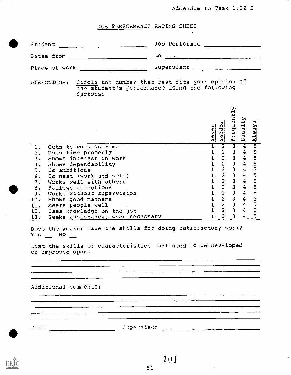
Student
Addendum to Task 1.02 E
JOB PF.RFORMANCE RATING SHEET
Job Performed
Dates from to
Place of work Supervisor
DIRECTIONS: Circle the number that best fits your opinion ofthe student's performance using tne followingfactors:
0--4 a)
03
301
ro
1. Gets to work on time 1 2 3 4 5
2. Uses time properly 1 2 3 4 5
3. Shows interest in work 1 2 3 4 5
4. Shows dependability 1 2 3 4 5
5. Is ambitious 1 2 3 4 5
6. Is neat (work and self) 1 2 3 4 5
7. Works well with others 1 2 3 4 5
8. Follows directions 1 2 3 4 5
9. Works without supervision 1 2 3 4 5
10. Shows good manners 1 2 3 4 5
11. Meets people well 1 2 3 4 5
12. Uses knowledge on the job 1 2 3 4 5
13. Seeks assistance, when necessary 1 2 3 4 5
Does the worker have the skills for doing satisfactory work?Yes No
List the skills or characteristics that need to be developedor improved upon:
Additional comments:
Supervisor
81
UNIT 1.0 E TNTRODUCTION TO DESIRABLEJOB/LEARNING CHARACTERISTICS/HABITS/ATTITUDES
TASK 1.03 EXHIBIT DESIRABLE WORK ATTITUDES
PERFORMANCE OBJECTIVE:
Given instruction, demonstrate work attitudes that the majority ofpotential employers prefer in an entry level worker, Performance willbe evaluated on a "Work Attitudes Score Sheet" and a minimum of 90percent should be attained. Performance will be rated throughouttraining and should improve to 100 percent by the end of the trainingperiod.*
PERFORMANCE ACTIONS:
1.0301 Review work attitudes considered important tosuccess in the vocational field.
1.0302 Review the "Work Attitudes Score Sheet."
1.0303 Demonstrate the type of work attitudes that potentialemployers in the local industry report as importantto job success.
PERFORMANCE STANDARDS:
- Demonstrate to 90 percent acceptable rating on a "Work AttitudesScore Sheet" to be completed by the instructor those workattitudes considered important by local potential employersfor entry-level joh success.
SUGGESTED INSTRUCTION TIME: 3 Hours
Accompanied by addendum page: (Work Attitudes Score Sheet)
(*NOU: It is recommended in research study findings that employer-recommended "job performance characteristics" and "workattitudes" be included as part of the vocational student'soverall training and that demonstrated performance in theseareas be included in the total evaluation of the student.)
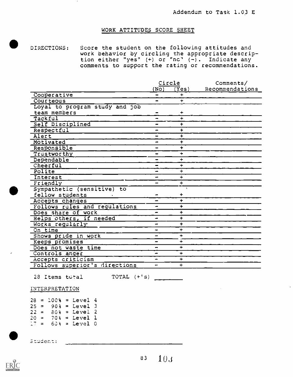
Addendum to Task 1.03 E
WORK ATTITUDES SCORE SHEET
III DIRECTIONS: Score the student on the following attitudes andwork behavior by circling the appropriate descrip-tion either "yes" (+) or "nc" (-) . Indicate anycomments to support the rating or recommendations.
Circle(No) (Yes)
CooperativeCourteousLoyal to program study and jobteam membersTackfulSelf Disciplined
Comments/Recommendations
Respectful - +
Alert +Motivated - +Responsible - +Trustworthy_ - +Dependable - +
Cheerful - +Polite - +Interest - +
Friendly - +
IIISympathetic (sensitive) tofellow students - +
Acce ts changes - +
Follows rules and regulations - +
Does share of work - +
Helps others, if needed - +
Works regularlr___ - +
On time - +
Shows pride in work - +
Keeps promises - +
Does not waste time AM/
Controls an erAccepts criticismFollows superior's directions
28 Items tc.:tal TOTAL (+'s)
INTERPRETATION
28 = 100% = Level 4
25 = 90% = Level 3
22 = 80% = Level 2
20 = 70% = Level 1
17 = 60% = Level 0
1.,83 MI
UNIT 1.0 E INTRODUCTION TO DESIRABLEJOB/LEARNING CHARACTERISTICS,HABITS/ATTITUDES
TASK 1.04 DEMONSTRATE RESPECT FOR AND CARE OFSCHOOL PROPERTY
PERFORMANCE OBJECTIVE:
Given a classroom, shop, or other instructional setting with access tofurniture, equipment, tools and materials, and given proper instruction;demonstrate a respect for and care of public property (trainingfacilities) and instructional materials to the standards established byThe School District of Greenville County, the career center, and theinstructor.
PERFORMANCE ACTIONS:
1.0401 Listen to information provi,:ed by the instructor andread given or posted materials concerning studentbehavior and care of property.
1.0402 Demonstrate respect for and care of public schoolproperty including:
a. Facilities (building, classroom).b. Furnishing (furniture).c. Equipment and tools.d. Instructural materials.
PERFORMANCE STANDARDS:
- Demonstrate respect for and care of school property as repre-sented by the classroom, shop, equipment, tools and materialsused in instruction.
- Performance must be to the standards of policies of the SchoolDistrict, the career center, and the instructor.
(NOTF: A willful disregard or disrespect (intentional damage ordestruction) of instructional facilities, equipment, ormaterials should be considered a most serious situation sincean employer typically would require payment for intendeddamages and might fire the employee or bring legal chargesagainst the employee for intentional damage to facilities,equipment, or materials.)
411SUGGESTED INSTRUCTION TIME: N/A Integrated during two-year training
period.
" 104

i
UNIT 1.0 F
BASIC MATH SKILLS
UNIT 1.0 F BASIC MATH SKILLS
TASK 1.01 BASIC MATH - FRACTIONS
PERFORMANCE OBJECTIVE:
Given a pretest or examples by the instructor, conduct the followingoperations with fractions:
1. Change any fraction to a decimal number, and anyterminating decimal number to a fraction.
2. Arrange in order...unit and simple nonunit fractions.3. Write equivalent fractions in higher, lower, and lowest
terms.4. Write improper fractions as whole or mixed numbers, and
mixed nuelbers as improper fractions.5. Multiply fractions and mixed numbers, expressiag answers
in simplest form.6. Divide fractions and mixed numbers, expressing answers in
simplest form.7. Add and subtract unlike fractions, expressing answers in
simplest form.8. Add and subtract mixed numbers with unlike fractions,
expressing answers iv simplest form.9. Use rational numbers to solve simple work problems.
PERFORMANCE ACTIONS:
Consult: Curriculum Guide for High School General Mathematics,Greenville, SC: The School District of Greenville County,1979.
PERFORMANCE STANDARDS:
- Student should be able to complete pretest in Math CurriculumGuide with '90 percent accuracy.
- Consult the Math Curriculum Guide for pretests, suggestedexercises, and refererces.
(NOTE: The level of this math skill is eighth grade, General Math I.)
SUGGESTED INSTRUCTION TIME: 6 Hours (Actual hours of instruction willbe determined by student': math skill as indicated by pretest. Remedialinstruction may be at initiation of skill development if required.)
86
1Ut)
UNIT 1.0 F BASIC MALI! SKILLS
TASK 1.02 BASIC MATH - DECIMALS
PERFORMANCE OBJECTIVE:
Given a pretest or examples by the instructor, conduct the followingdecimal math operations:
1. Name the place value of digits in decimal numbers of upto nine digits before the decimal and six digits afterthe decimal.
2. Compare decimal numbers and arrange them in order.3. Write the numeral for any decimal number.of up to four
decimal places.4. Round decimal numbers to any designated place value up to
thousandths.5. Add and subtract decimal numbers of up to six digits.6. Multiply decimal numbers by whole numbers or decimal
numbers'.
7. Divide a number by a three-digit decimal number.8. Multiply and divide decimal numbers by powers of ten, by
inspection.
411 PERFORMANCE ACTIONS:
Consult: Curriculum Guide for High School General Mathematics,Greenville, SC: The School District of Greenville County,1979.
PERFORMANCE STANDARDS:
- Student should be able co complete pretest in Math CurriculumGuide with 90 percent accuracy.Consulti Curriculum Guide for High School General Mathematics,
1979,'for pretests, suggested exercises, and references.
SUGGESTED INSTRUCTION TIME: 4, 6 Hours (Actual hours of instruct:Con willbe determined by the student's math skill as indicated by pretest.Remedial instruction may be at initiation of skill development ifrequired.)
(NOTE: The level of this math skill is eighth grade, General Math I.)
87
107
UNIT 1.0 F BASIC MATH SKILLS
TASK 1.03 BASIC MATH - VOLUMES
PERFORMANCE OBJECTIVE:
Given,a pretest or examples by the instructor, find the volume of anyrectangular prism or cube.
PERFORMANCE ACTIONS:
Consult: Curriculum Guide for High School General Mathematics,Greenville, SC: The School District of Greenville County,1979.
PERFORMANCE STANDARDS:
- Student should be able to complete pretest in Math CurriculumGuide with 90 percent accuracy.
- Consult: Math Curriculum Guide for pretests, suggestedexercises, and references.
SUGGESTED INSTRUCTION TIME: 1 Hour (Actual hdUrs of instruction willbe determined by the student's math skills as indicated by pretest.Remedial instruction may be at initiation of skill development ifrequired.)
(NOTE: The level of this math skill is eighth grade, General Math I.)
UNIT 1.0 F BASIC MATH SKILLS
TASK 1.04 BASIC MATH - AREAS
PERMAMANCE OBJECTIVE:
Given a pretest or examples by the instructor, find the area of thefollowing types of figures:
a. Rectangle and squareb. Cirr.lc
PERFORMANCE ACTIONS:
Consult: Curriculum Guide for High School General Mathematics,Greenville, SC: The School District of Greenville County,1979.
PERFORMANCE STANDARDS:
- Student should be able to complete pretest in Math CurriculumGuide with 90 percent accuracy.
- Consult the Math Curriculum Guide for pretests, suggestedexercises, and references.
SUGGESTED INSTRUCT/ON TIME: 1 Hour (Actual hours of instruction willbe determined by the student's math skill as indicated by pretest.Remedial instruction may be at initiation of skill development ifrequired.)
(NOTE: The level of this math skill is eighth grade, General Math I.)
89 1 0:)
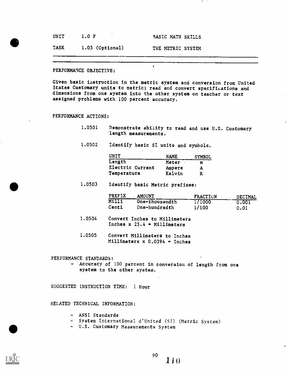
UNIT 1.0 F 3ASIC MATH SKILLS
TASK 1.05 (Optional) THE METRIC SYSTEM
PERFORMANCE OBJECTIVE:
Given basic icistruction in the metric system and conversion from UnitedStates Customary units to metric; read and convert specifications anddimensions from one system into the other system on teacher or textassigned problems with 100 percent accuracy.
PERFORMANCE ACTIONS:
1.0501 Demonstrate ability to read and use U.S. Customarylength measurements.
1.0502 Identify basic SI units and symbols.
UNIT NAME SYMBOLLength Meter mElectric Current Ampere ATemperature Kelvin K
1.0503 Identify basic Metric prefixes:
PREFIX AMOUNT FRACTIeN DECIMALMilli One-thousandth 1/1000 0.001Centi One-hundredth 1/100 0.01
1.0504 Convert Inches to MillimetersInches x 25.4 Millimeters
1.0505 Convert Millimeters to InchesMillimeters x 0.0394 Inches
PERFORMANCE STANDARDS:- Accuracy of 100 percent in conversion of length from one
system to the other system.
SUGGESTED INSTRUCTION TIME: 1 Hour
RELATED TECHNICAL INFORMATION:
- ANSI Standards- System International d'United (SI) (Metric System)- U.S. Customary Measurements System
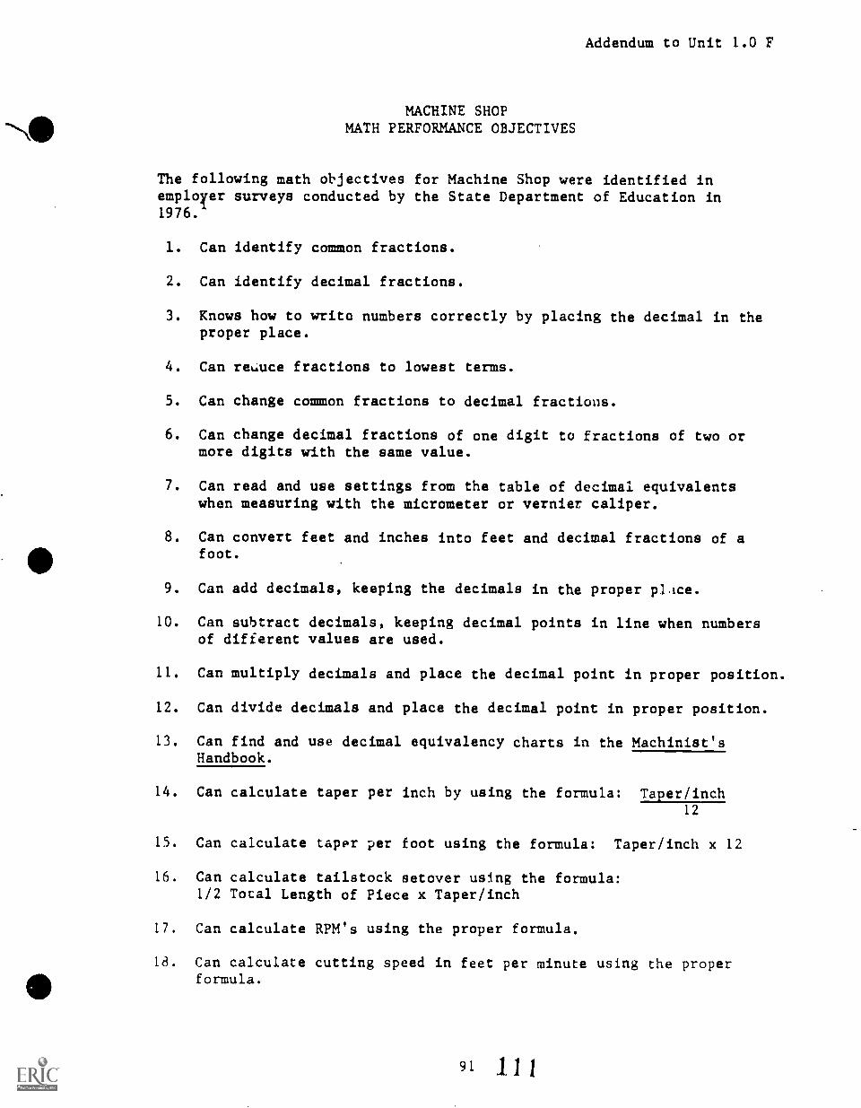
Addendum to Unit 1.0 F
MACHINE SHOPMATH PERFORMANCE OBJECTIVES
The following math objectives for Machine Shop were identified inemployer surveys conducted by the State Department of Education in1976.
1. Can identify common fractions.
2. Can identify decimal fractions.
3. Knows how to write numbers correctly by placing the decimal in theproper place.
4. Can reiuce fractions to lowest terms.
5. Can change common fractions to decimal fractions.
6. Can change decimal fractions of one digit to fractions of two ormore digits with the same value.
7. Can read and use settings from the table of decimal equivalentswhen measuring with the micrometer or vernier caliper.
8. Can convert feet and inches into feet and decimal fractions of afoot.
9. Can add decimals, keeping the decimals in the proper ',Lice.
10. Can subtract decimals, keeping decimal points in line when numbersof different values are used.
11. Can multiply decimals and place the decimal point in proper position.
12. Can divide decimals and place the decimal point in proper position.
13. Can find and use decimal equivalency charts in the Machinist'sHandbook.
14. Can calculate taper per inch by using the formula: Taper /inch12
15. Can calculate taper per foot using the formula: Taper/inch x 12
16. Can calculate tailstock setover using the formula:1/2 Total Length of Piece x Taper/inch
17. Can calculate RPM's using the proper formula.
18. Can calculate cutting speed in feet per minute using the properformula.
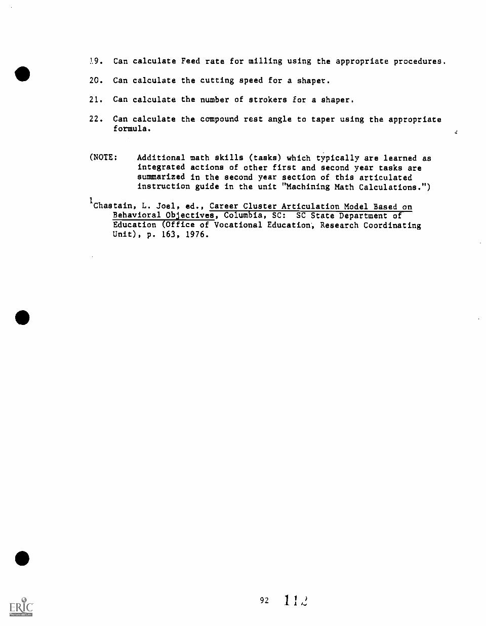
19. Can calculate Feed rate for milling using the appropriate procedures.
20. Can calculate the cutting speed for a shaper.
21. Can calculate the number of strokers for a shaper.
22. Can calculate the compound rest angle to taper using the appropriateformula.
(NOTE: Additional math skills (tasks) which typically are learned asintegrated actions of other first and second year tasks aresummarized in the second year section of this articulatedinstruction guide in the unit "Machining Math Calculations.")
1Chastain, L. Joel, ed., Career Cluster Articulation Model Based on
Behavioral Objectives, Columbia, SC: SC State Department ofEducation (Office of Vocational Education', Research CoordinatingUnit), p. 163, 1976.
UNIT 1.0 G
BASIC MEASURING
93 11i
UNIT 1.0 G BASIC MEASURING
TASK 1.01 MEASURING
PERFORMANCE OBJECTIVE:
Given proper instructions, read a rule and use other measuring toolswith the ptecision necessary to take measurements from drawings, andtranspose them to exact working lengths and angles.
PERFORMANCE ACTIONS:
1.0101
1.0102
1.0103
1.0104
Define measuring terms with 80 percent accuracy.
Accurately identify basic tools used in measuring.
Read a rule to the nearest feet, inches, andfractions of inches down to 1/16 inch.
Demonstrate ability to perform following measuringskills:
a. Measure objects to nearest sixteenth of an inchwhen given pictures of objects and a measuringinstrument.
b. Draw lines and objecti to specified dimensions.
PERFORMANCE STANDARDS:
- Demonstrate ability to measure to 1/16 inch and draw lines orobjects to specified dimensions (1/16 inch accuracy).
SUGGESTED INSTRUCTION TIME: 6 Hours
RELATED TECHNICAL INFORMATION:
- Graduations on rule: Halves, quarters, eights, sixteenths.- Rules: Tapes (steel or other), following rule, straight rule,
steel square.
94
114
UNIT 1.0 G BASIC MEASURING
TASK 1.01 MEASURINC (Con't.)
DEFINITIONS
MEASURING Setting of limits or bounds according to a pre-determinedstandard.
INCH Smallest whole unit of lineal meaaure typically used.
FOOT Unit of measure consisting of twelve equal parts calledinches.
FRACTION One or more equal parts of a whole. (i.e., 1/2 inch, 1/4inch, 3/8 inch, and 5/16 inch)
RULE Instrument graduated in whole units and fractions ofunits and used in measuring.
DIMENSIOr Number of full.units and fraction of units between twopoints.
UNIT 1.0 H
INTRODUCTORY BLUEPRINT READING - MACHINE SHOP
See the second year unit, Advanced Blueprint Reading in Machining, foradditional task objectives concerning blueprint reading.
96 1 Hi
UNIT 1.0 H INTRODUCTORY BLUEPRINT READING
TASK 1.01 INTERPRET MULTIVIEW DRAWINGS
PERFORMANCE OBJECTIVE:
Given a selection of multiview blueprints or drawings (orthographicprojections) complete with symbols, notations, dimensions, and toler-ances, and the necessary reference materials; interpret the multiviewdrawings. All symbols, notations, dimensions, and tdferances must beidentified. Side, top, and front views must be identified from eachdrawing.
PERFORMANCE ACTIONS:
1.0101 Define orthographic projection.
1.0102 Identify the six principal views in an orthographicprojection.
1.0103 Explain how several views can be used to define theshape of an object or part completely.
1.0104 Explain how to read lines and areas in a multiviewdrawing.
1.0105 Describe the procedure for interpreting a multiviewdrawing.
1.0106 Make freehand sketches or parts in side, top, andfront views using coordinate paper or plain paperwith drawing/drafting equipment.
PERFORMANCE STANDARDS:
- Interpret multiview (orthographic projections) with allsymbols, notations, dimensions, and tolerances identified andwith the side, top, and front views identified. Performancemust be to the standards established by the instructor.
SUGGESTED INSTRUCTION TIME: 6 Hours
RELATED TECHNICAL INFORMATION:
- Identify all parts of title block on blueprint.- Alphabet of Lines.
9' 11
UNIT 1.0 H INTRODUCTORY BLUEPRINT READING
TASK 1.02 DNERMINE DIMENSIONS AND TOLERANCES
PERFORMANCE OBJECTIVE:
Given a selection of machine shop blueprints or drawings, and thenecessary reference and writing materials; determine the dimensions andtolerances given on the drawings using dimension lines, centerlines,projection lines, and views. Correct dimensions must be determined inorder to machine the pairs. Tolerances be identified with 100percent accuracy.
PERFORMANCE ACTIONS:
1.0201
,1.0202
1.0203
1.0204
1.0205
Explain the purpose of dimensions and tolerances.
Explain how fractions and decimal dimensions andtolerances are indicated on a blueprint.
Describe the procedure to determine dimensions.
Explain why blueprints and drawings are drawn toscale.
Make freehand sketches and apply dimensions andtolerances to the sketches.
PERFORMANCE STANDARDS:
- Determine correct dimensions and tolerances from given machineshop blueprints and drawings accompanied by the necessaryreference materials, with an accuracy of 100 percent.
SUGGESTED INSTRUCTION TIME: 12 Hours
UNIT 1.0 H INTRODUCTORY BLUEPRINT READING
TASK 1.03 INTERPRET PICTORIAL DRAWINGS
PERFORMANCE OBJECTIVE:
Given a selection of pictorial drawings complete with symbols, notations,dimensions, and tolerances, and the necessary reference materials;interpret the pictorial drawings. All symbols, notations, dimensions,and tolerances must be identified.
PERFORMANCE ACTIONS:
1.0301 Identify the following types of pictorial drawings:
a. Isometricb. Obliquec. Perspective
1.0302 Explain the difference between pictorial drawings4 and orthographic projections.
1.0303 Describe the procedure for interpreting a pictorialdrawing.
1.0304 Make freehand sketches of parts in isometric,oblique, and perspective.
PERFORMANCE STANDARDS:
Interpret pictorial drawings identifying all symbols, notations,dimensions, and tolerances.
SUGGESTED INSTRUCTION TIME: 3 Hours
99 1 1 :)
UNIT 1.0 I
WKITE AND READ TECHNICAL INFORMATIONCONCERNING MACHINING OPERATIONS
The purpose of these tasks is to develop basic knowledges and skillsessential to success as a machinist.
Emphasis will be on effectively and efficiently sending and receivingtechnical rtssages concerning machining operations.
UNIT 1.0 I WRITE AND READ TECHNICAL INFORMATIONCONCERNING MACHINING OPERATIONS
TASK 1.01 WRITE TECHNICAL INFORMATIONCONCERNING MACHINING OPERATIONS
PERFORMANCE OBJECTIVE:
Given instruction and an introduction to the secondary machine shopprogram and the terminology of the trade, write technical reports/communications that convey the intended messages and that can be readintelligently by another machinist student (or machinist). Studentperformance must ba acceptable to the instructor.
The written message may include notations, etc., made on working drawings,specifications, technical instruction, or descriptions of machiningoperations Hsing the proper terminology. The message intended must becommunicated to the receiver.
While correct spelling and punctuation is desirable, emphasis will be oneffective and efficient communications of a technical message.
PERFORMANCE ACTIONS:
1.0101 Interpret technical terminology commonly used inmachining as identified by the instructor.
1.0102 Write technical notatio:is, instructions, and machiningdescriptions that communicate the intended messageto another machinist student, to the instructor, orto a machinist.
PERFORMANCE STANDARDS:
- Write technical information concerning machine operations,etc., that communicates the intended message.
- Instructor's standards apply.
SUGGESTED INSTRUCTION TIME: 3 Hours (Training integrated into all
RELATED TECHNICAL INFORMATION:
- Technical terminology of machine shop trade.
101 121
UNIT 1.0 I WRITE AND READ TECHNICAL INFORMATION.CONCERNING MACHINING OPERATIONS
TASK 1.02 READ TEr.INICAL INFORMATION CONCERNINGMACHINING OPERATIONS
PERFORMANCE OBJECTIVE:
Given an introduction to the secondary machine shop program and theterminology used in the trade, reed and interpret technical literatureor information concerning machining operations. Reading competencyshould be demonstrated by the ability to read and interpret informationfrom blueprints and specifications, technical instructions, and manu-facturer's manuals on equipment. Student performance must be acceptableto the instructor.
PERFORMANCE ACTIONS:
1.0201 Read and interpret common technical terms used inmachine shop work as identified by the instructor.
1.0202
(e.g., "set to zero," sine bar, tailstock, micro -inches, swivel, anneal, transitional fit,cylindricity, parallelism, concentricity, etc.)
Read and properly interpret a written set ofdirections or instructions of machine operationsthat was written by another student, the instructor,or a machinist.
PERFORMANCE STANDARDS:
- Read technical information concerning machining operations,correctly interpreting the common technical terms used, sothat message intended to be communicated is received.
- Instructor's standards apply.
SUGGESTED INSTRUCTION TIME: 3 Hours (Training integrated into allunits.)
RELATED TECHNICAL INFORMATION:
- Technical terminology of machine shop trade.
102 122
ARTICULATED, PERFORMANCE-BASED DESCRIPTIONOF
BENCHWORK
Benchwork - "Work placed on a bench or in a bench vise for operationsusually involving head tools."
For the purpose of this articulated, performance-based description,benchwork descriptions may be interpreted as including floorwork usingthe same tools as benchwork, although emphasis in tasks will be on workperformed at a bench.
BenchworkOperations - For the purpose of this performance/competency-based
description, benchwork operations are represented by:
1. Measuring2. Work Layout3. Assembly/Disassembly4. Chipping5. Sawing6. Drilling7. Reaming8. Tapping9. Threading10. Filing11. Fitting12. Scraping13. Polishing14. Grinding15. Inspection16. Testinii
FOR CONVENIENCE, BENCHWORK OPERATIONS ARE ORGANIZED IN THE FOLLOWINGUNITS:
1. Using Precision Measuring Instrument2. Work Layout3. Benchwork
UNIT 2.0
USING PRECISION MEASURING INSTRUMENTS
Measuring and gaging tools/instruments will be divided into two cate-gories: Semi-precision and precision measuring and gaging tools.
SEMI-PRECISION MEASURING AND GAGING TOOLS
Semi-precision measuring and gaging tools will be used to measuredirectly or transfer measurements from calipers to a measuriugscale to the nearest 1/64 inch.
Emphasis will be on gaining experience in adding and subtractingdimensions to determine wall thickness, depth's, accumulation oftolerance limits and tolerances for interchangeability purposes.
Tools may include:- 6 inch flexible scale- 12g inch combination set- tape rule dividers- inside calipers- outside calipers- rule depth gage- surface gage
PRECISION MEASURING AND GAGING TOOLS
Tools may include:- micrometers (6 inch outside, inside and depth)- 6 inch vernier calipers, vernier height gage- vernier bevel- protractor- gage: Telescoping, small hole, radius center, ocrewpitch- gage blocks- Sine bar- sine plate- planer gage- adjustable parallel- dial indicator
Emphasis, for example, will be on measuring directly or transferringmeasurements from gage to micrometer to within the nearest .001.
NOTE: Tasks in this unit have aen arranged in divisions ofsemi-precision and precision weasLring instruments and in ageneral sequence from Jimple to .e..mplex measuring tasks.
The order of tasks may be learned in a sequence different fromthat described in this guide. Skill development in some tasksmay emphasized the shill related to a specific machiningoperation some Ain aev,.!lopment tasks may be reserved for thesecor:d year of training.
104
121
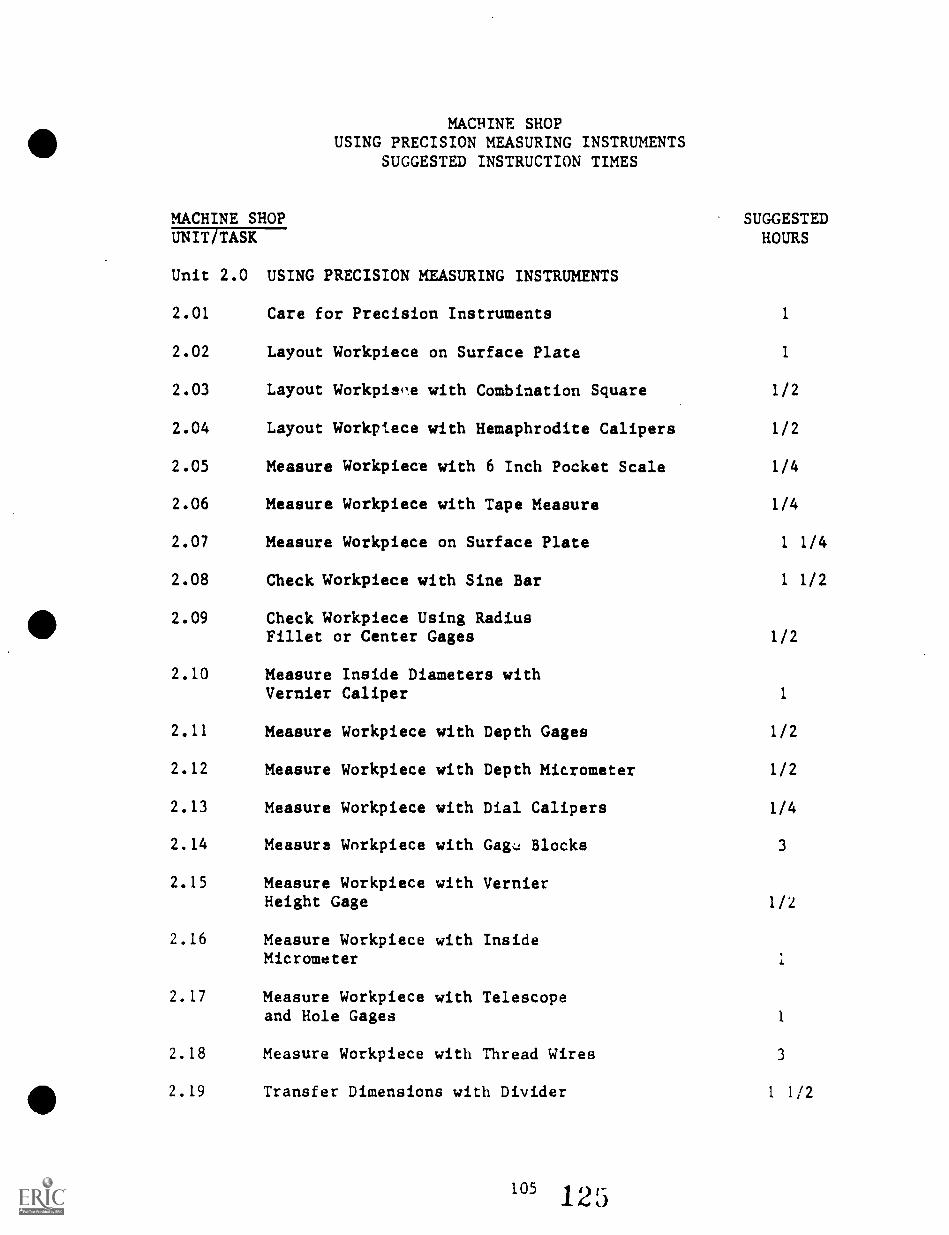
MACHINE SHOPUSING PRECISION MEASURING INSTRUMENTS
SUGGESTED INSTRUCTION TIMES
MACHINE SHOPUNIT/TASK
Unit 2.0 USING PRECISION MEASURING INSTRUMENTS
SUGGESTEDHOURS
2.01 Care for Precision Instruments 1
2.02 Layout Workpiece on Surface Plate 1
2.03 Layout Workpie'e with Combination Square 1/2
2.04 Layout Workpiece with Hemaphrodite Calipers 1/2
2.05 Measure Workpiece with 6 Inch Pocket Scale 1/4
2.06 Measure Workpiece with Tape Measure 1/4
2.07 Measure Workpiece on Surface Plate 1 1/4
2.08 Check Workpiece with Sine Bar 1 1/2
2.09 Check Workpiece Using RadiusFillet or Center Gages 1/2
2.10 Measure Inside Diameters withVernier Caliper 1
2.11 Measure Workpiece with Depth Gages 1/2
2.12 Measure Workpiece with Depth Micrometer 1/2
2.13 Measure Workpiece with Dial Calipers 1/4
2.14 Measure Workpiece with Gag:: Blocks 3
2.15 Measure Workpiece with VernierHeight Gage 1/2
2.16 Measure Workpiece with InsideMicrometer
2.17 Measure Workpiece with Telescopeand Hole Gages 1
2.18 Measure Workpiece with Thread Wires 3
2.19 Transfer Dimensions with Divider 1 1/2
2.20
2.21
Measure Outside Diameterwith Outside Calipers
Measure Round Stock withOutside Micrometer 1
2.22 Measure with Inside Caliper 1/2
2.23 Measure Threads Per Inch withScrew Pitch Gage 1/2
2.24 Measure Screw Threads withScrew Thread Micrometer 1/2
2.25 Describe Optical Comparator 1/2
2.26 Check Round Stock withDial Indicator 1/2
2.27 Snap Gages (Omitted) N/A
2.28 Radius Gage 1/2
106 12
TOTAL HOURS 13
TASK LISTINGSMACHINE SHOP
UNIT/TASK DESCRIPTION
Unit 2.0 USING PRECISION MEASURING INSTRUMENTS
2.01 (Care for Precision Instruments) Given precision machine shopmeasuring instruments, proper instruction and cleaningmaterials; clean and return to tool crib/box. Precisioninstruments must be free of rust and grease and stored properlyin the appropriate case/cabinet, according to the instructor'sprocedures.
2.02 (Layout Workpiece on Surface Plate) Given access to aworkpiece, blueprint, surface plate, angle plate, surfacegage, vernier height gage, scribe combination square set,scribe dividers, layout dye, files, prick punch, hammer;layout the workpiece. Location of positions must bn within+/- .001 inch for decimal dimensions, +/- 1/64 inch forfraction dimensions and 41- 30 minutes on angular dimensionsor within blueprint specifications.
2.03 (Layout Workpiece with Combination Square) Furnished with aworkpiece, blueprint, and layout instruments including thecombination square, scri"oer, files, layout dye, prick punch,center punch, and layout hammer; layout the workpiece usingthe combination square. Layout must be to a tolerance of +/-1/64 inch of blueprint specifications.
2.04 (Layout Workpiece with Hemaphrodite Calipers) Givenblueprint, hermaphrodite calipers, combination square andblade, prick punch, hammer, layout dye, and a round workpiece;describe a line paeallel to an edge of a workpiece and locatethe center of a workpiece to an accuracy of +/- 1/64 inch ormeet blueprint specifications.
2.05 (Measure Workpiece with 6 Inch Pocket Scale) Using givenpocket scale, blueprint, and workpiece; measure workpiecewithin a tolerance of +/- 1/64 inch.
2.06 (Measure Workpiece with Tape Measure) Measure given workpieceusing given tape rule and blueprint. Workpiece measurementsmust be within a tolerance of +/- 1/64 inch.
2.07 (Measure Workpiece on Surface Plate) Given a blueprint,workpiece, and measuring instruments to include gage blocks,height gage, dial indicator and stand V-blp,:ks, and surfaceplate; measure accuracy of the workpiece to a tolerance of +/-1/64 inch on fraction dimensions and +/- .001 on decimaldimensions or to blueprint specifications.
2.08 (Check Workpiece with Sine Bar) Given a blueprint,Machinery's Handbook, gage blocks, sine bar, surface plate,angle plate, clamps, dial indicator, and workpiece; alignworkpiece at an angle within +/- 1 minute of blueprint speci-fications.
2.09 (Check Workpiece Using Radius Fillet or Center Gages) Givenworkpieces and drawings, and gages; check workpiece forassigned measurements. Workpiece must fit gage so no lightshows between gage and workpiece.
2.10 (Measure Inside Diameters with Vernier Caliper) Furnishedwith a workpiece, blueprint, inside vernier caliper, files,workpiece; measure inside diameters of workpiece to a toleranceof +/- .001 inch.
2.11 (Measure Workpiece with Depth Gages) Supplied with rule depthgage, blueprint, and counterbored workpiece; measure workpiecewhich must meet blueprint specifications and a tolerance of+/- 1/64 inch with a rule depth and +/- .001 inch with avernier depth gage.
2.12 (Measure Workpiece with Depth Micrometer) Using furnisheddepth micrometer, interchangeable measuring rods, machinedworkpiece, blueprint; measure depth of slot to a tolerance of+/- .001 inch.
2.13 (Measure Workpiece with Dial Calipers) Given a machinedworkpiece, blueprint and dial caliper; measure the workpiecewithin a tolerance of +/- .001 inch.
2.14 (Measure Workpiece with Gage Blocks) Given blueprint, work-piece, gage blocks, height gage attachment, surface platecleaning solution and lint free tissue; measure workpiecewithin a tolerance of +/- .0001 inch at a temperature as closeto 70 degrees as practical.
2.15 (Measure Workpiece with Vernier Height Gage) Using a vernierheight gage, offset scriber, surface plate, blueprint, andworkpiece; measure work with height gage within a tolerance of+/- .001 inch.
2.16 (Measure Workpiece with Inside Micrometer) Using an insidemicrometer, extension rods, spacing collar, handle, steelrule, outside micrometer, standards, blueprint; measure insidediameter of a gi'ren workpiece, with +/- .001 inch.
2.17 (Measure Workpiece with Telescope and Hole Gages) Usingfurnished telescoping gages, small holes gages, micrometercaliper, micrometer standard, and blueprint; measure internaldimensions of workpiece which must be within +/- .001 inch ofblueprint specifications.
108
12
2.18 (Measure Workpiece with Thread Wires) Using thread measuringwires, micrometer calipers, Machinery's Handbook, blueprint,and furnished workpiece; measure workpiece within tolerance of+/- .001 inch or blueprint specifications.
2.19 (Transfer Dimensions with Divider) Given a divider, machinistscale, drawing, and workpiece and other materials needed;transfer dimensions of the drawing to the workpiece usingdividers and machinist's scale with an accuracy of +/- 1/64inch.
2.20 (Measure Outside Diameter with Outside Calipers) Given theoutside caliper, machinist's rule, drawing, and round work-piece; measure the outside diameter of the round workpiecewithin +/- 1/64 inch.
2.21 (Measure Round Stock with Outside Micrometer) Given anoutside micrometer, instruction concerning its operations, andround stock and flat. stock; measure the outside diameter ofround stock and the thickness of flat stock and the length offlat stock using the outside micrometer.
2.22 (Measure with Inside Caliper) Given an inside caliper,outside micrometer, workpiece of tubular stock, and requiredmaterials; measure the inside diameter of the tubular stockwithin +/- .002 inches of specifications.
2.23 (Measure Threads Per Inch with Screw Pitch Gage) Given ascrew pitch gage and screws or bolts with standard threads,measure the number of threads per inch of given screws orbolts with screw pitch gage.
2.24 (Measure Screw Threads with Screw Thread Micrometer) Given ascrew thread micrometer and screws to measure, measure thepitch diameter of screw threads within +/- .001 inches ofspecifications using the screw thread micrometer.
2.25 (Describe Optical Comparator) Given an orientation to theoptical comparator, describe the optical comparator andexplain how it is used for checking work.
2.26 (Check Round Stock with Dial Indicator) Given a dial indicatorand round stock, check the concentricity of the round stock towithin +/- .001 inches.
2.27 (Snap Gages [Omitted]) Because snap gaps such as GO/NO GOgages are used more in production work and are not readilyavailable in the training programs, they currently are omittedfrom secondary training.
2.28 (Radius Gage) Using a radius gage provided, measure convexand concave radii of given parts to the instructor's standards.
UNIT 2.0 USING PRECISION MEASURING INSTRUMENTS
TASK 2.01 CARE FOR PRECISION INSTRUMENTS
PERFORMANCE OBJECTIVE:
Given precision machine shop measuring instruments, proper instructionand cleaning materials;.clean and return to tool crib/box. Precisioninstruments must be free of rust and grease and stored properly in theappropriate case/cabinet,. according to the instructor's procedures.
PERFORMANCE ACTIONS:
2.0101
2.0102
2.0103
Check instruments for proper operation/damage.
Remove grease from instruments by applying anappropriate cleaning solution and wiping surfacesclean and dry.
Insure instrument is aligned and adjust instrumentfor proper setting for storage, given adjustmentinstruction.
2.0104 Store instrument in proper case/cabinet/locations.
PERFORMANCE STANDARDS:
- Care for precision instruments of the machine shop by cleaningand storing the instruments in the proper locations andaccording to instructor procedures.
- Instruments must be free of rust and stored properly.
SUGGESTED INSTRUCTION TIME: 1 Hour
RELATED TECHNICAL INFORMATION:
- Identify semi-precision and precision measuring instrumentswith an accuracy of 95 percent.
- Cleaning rust from tools if needed.- Lubrication of specific instrument.
110 13
UNIT 2.0 USING PRECISION MEASURING INSTRUMENTS
TASK 2.02 LAYOUT WORKPIECE ON SURFACE PLATE
PERFORMANCE OBJECTIVE:
Given access to a workpiece, blueprint, surface plate, angle plate,surface gage, vernier height gage, scribe, combination square set,scribe dividers, layout dye, files, prick punch, hammer; layout theworkpiece. Location of positions must be within +/ .001 inch fordecimal dimensions on angular dimensions or within blueprintspecifications.
PERFORMANCE ACTIONS:
2.0201
2.0202
2.0203
Remove all burrs on workpiece.
Clean workpiece and coat surface with dye.
Align workpiece:
a. Place angle plate carefully on surface plate.b. Align workpiece so that all dimensions can be
made from surface plate or reference point.c. Mount workpiece and clamp to angle plate (use a
straightedge of the workpiece as a base).
2.0204 Scribe a reference or base line on workpiece:
a. Use a straightedge on workpiece as base ifpossible.
b. Set vernier height gage to blueprintdimensions.
2.0205 Scribe lines in accordance with blueprintspecifications:
a. Set vernier height gage to required dimensions.b. Scribe all horizontal lines using protractor.c. Scribe angular lines using protractor.d. Scribe arcs and circles with scribe dividers.
2.0206 Assure scribed lines are within specified tolerances.
fr
UNIT 2.0 USING PRECISION MEASURING INSTRUMENTS
TASK 2.02 LAYOUT WORKPIECE ON SURFACE PLATE(Con't.)
PERFORMANCE STANDARDS:
Layout work on surface plate with positions within +/- .001inch, +/- 1/64 inch, +/- 30 minutes, or within blueprintspecifications.
SUGGESTED INSTRUCTION TIME: 1 Hour
112 132
UNIT 2.0 USING SEMI-PRECISION MEASURINGINSTRUMENTS
TASK 2.03 LAYOUT WORKPIECE WITH COMBINATIONSQUARE
PERFORMANCE OBJECTIVE:
Furnished with a workpiece, blueprint, and layout instruments includingthe combination square, scriber, files, layout dye, prick punch, centerpunch, and layout hammer; layout the workpiece using the combinationsquare. Layout, must be to a tolerance of +/- 1/64 inch or blueprintspecifications.
PERFORMANCE ACTIONS:
2.0301 Deburr and clean workpiece.
2.0302 Coat surface with layout dye.
2.0303 Select reference surface or edge oil workpiece:
a. Check blueprint for reference edge.b. Use finished surface for reference on workpiece.
2.0304 Scribe one end of workpiece:
2.0305
2.0306
2.0307
2.0308
a. Allow room for complete layout on workpiece.b. Scribe perpendicular to reference edge.
Scribe centerlines of arcs and holes.
Prick punch hole locations on centerlines.
Scribe arcs and holes, as necessary.
Check against blueprint specifiEations:
a. Approved workpiece.b. Correct layout by recoating workpiece with
layout dye and completely layout again untilall designated dimensions are within tolerancespecified.
PERFORMANCE STANDARDS:
- Layout workpiece with combination square to a tolerance of +/-1/64 inch or blueprint specifications.
113
133
UNIT 2.0 USING SEMI-PRECISION MEASURINGINSTRUMENTS
TASK 2.03 LAYOUT WORKPIECE WITH COMBINATIONSQUARE (Con't.)
SUGGESTED INSTRUCTION TIME: 1/2 Hour
EXPANSION OF TASK:
- Locate end mark center of both ends of a round bar of any sizefrom 1/4 inch to 6 inches using the center head of the com-bination set. Must be within +/- 1/32 inch of sdecifications.
114
UNIT 2.0 USING SEMI-PRECISION MEASURINGINSTRUMENTS
TASK 2.04 (Optioftl) LAYOUT WORKPIECE WITH HEMAPHRODITECALIPERS
PERFORMANCE OBJECTIVE:
Given blueprint, hermaphrodite calipers, combination square and blade,prick punch, hammer, layout dye, and a round workpiece; Scribe a lineparallel to an edge of a workpiece and locate the center of a workpieceto an accuracy of +/- 1/64 inch or meet blueprint specifications.
PERFORMANCE ACTIONS:
2.0401A Scribe line parallel to an edge (flat workpiece)
1. Clean and deburr workpiece.2. Set hermaphrodite calipers on designated
setting.a. Place hooked leg against end of square
blade.b. Adjust scriber leg to setting.c. Use fine adjustment for final setting.
3. Scribe line parallel to edge of workpiece.a. Coat workpiece with layout dye.b. Refer to blueprint for reference edge.c. Hold hooked leg against edge and move
calipers parallel to edge.d. Hold calipers perpendicular to edge when
scribing line.4. Check layout to see if layout lines meet
tolerance specifications.5. If line not within tolerance, repeat steps 2-4
until workpiece meets designated specifications.
2.0401B Locate center of round workpiece
1. Clean and deburr workpiece.2. Coat end of workpiece with layout dye.3. Set divider leg at required radius.
a. 'easure workpiece and set dividers atone-half diameter or workpiece - plus.
b, Place hooked leg on end of rule and adjustscribed leg to required radius.
4. Scribe arcs on end of workpiece.a. Use four arcs at 90 degrees apart on
workpiece.b. Hold calipers perpendicular to end of
workpiece.
115 13;)
UNIT 2.0 USING SEMI-PRECISION MEASURINGINSTRUMENTS
TASK 2.04 (Optional) LAYOUT WORKPIECE WITH HEMAPHRODITECALIPERS
PERFORMANCE ACTIONS (Con't.):
5. Mark center of workpiece in center of arcs withprick punch.
6. Check center location with rule.a. Approve workpiece.b. Redo steps 2-6 until workpiece meets
designated specifications.
PERFORMANCE STANDARDS:
- Layout work with.hemaphi)dite calipers by scribing a lineparallel to an edge of a workpiece and locate the center of aA:aund workpiece to an accuracy of +/- 1/64 inch or meetblueprint specifications.
SUGGESTED INSTRUCTION TIME: 1/2 Hour
RELATED TECHNICAL INFORMATION:
- Scribe angles and parallel, lines with the hermaphroditecalipers.
- Optional but similar to GTC's MS-3-5 Package.
116136
A'
UNIT 2.0 USING SEMI-PRECISION MEASURINGINSTRUMENTS
TASK 2.05 MEASURE WORKPIECE WITH 6 INCH POCKETSCALE
PERFORMANCE OBJECTIVE:
Using given pocket scale, blueprint, and workpiece; measure workpiecewithin a tolerance of +/- 1/64 inch.
PERFORMANCE ACTIONS:.
2.0501 Check blueprint for required dimension.
2.0502 Measure workpiece:
a. Select reference point.b. Use 1/64 inch graduated scale.c. Stand rule on edge to avoid parallel error.d. Avoid using end of rule because of possible
wear on rule.e. Use one inch mark as reference.f. Allow for this one inch in calculating measure-
ment.g. If measuring an end diameter, move rule until"
largest reading is obtained.h. Repeat measuring until two or more measurements
are within tolerance.
PERFORMANCE STANDARDS:
- Measure workpiece within a tolerance of +/- 1/64 inch usingthe 6 inch pocket scale.
SUGGESTED INSTRUCTION TIME: 1/4 Hour
RELATED TECHNICAL INFORMATION:
-.'Measuring using 1/64 inch scale.- Use .2 inch pocket scale.
117 13/
UNIT 2.0 USING SEMI-PRECISION MEASURINGINSTRUMENTS
TASK 2.06 MEASURE WORKPIECE WITH TAPE MEASURE
PERFORMANCE OBJECTIVE:
Measure given workpiece using given tape rule and blueprint. Workpiecemeasurements must be within a tolerance of +/- 1/64 inch.
PERFORMANCE ACTIONS:
2.0601 Measure workpiece:
a. Inside measurements add 2 inches for rule case,if applicable.
b. Butt hook against workpiece on insidemeasurement.
c. Hook rule over edge or workpiece on outsidemeasurements.
2.0602 Verify workpiece dimension as within/withoutspecified tolerance.
PERFORMANCE STANDARDS:
- Measure workpiece with tape measure within a tolerance of +/-1/64 inch.
SUGGESTED INSTRUCTION TIME: 1/4 Hour
118 138
UNIT 2.0 USING PRECISION MEASURING INSTRUMENTS
TASK 2.07 MEASURE WORKPIECE ON SURFACE PLATE
PERFORMANCE OBJECTIVE:
Given a blueprint, workpiece, and measuring instruments to include gageblocks, height gage, dial indicator and stand, V-blocks, and surfaceplate; measure accuracy of the workpiece to a tolerance of +/- 1/64 inchon fraction dimensi^ns and +/- .001 on decimal dimensions or to blue-print specifications.
PERFORMANCE ACTICNS:
2.0701 Remove cover from surface plate. Return cover whensurface plate not in use.
2.0702 Wipe surface plate clean with rag.
a. Burrs, sharp edges and rough areas on work mustbe removed prior to placing the workpiece onthe surface plate.
b. Place work on surface plate carefully to avoidscratches and nicks to plate.
c. Set workpiece on V-blocks if applicable.
2.0703 Set up for measurement:
a. Build gage blocks to blueprint specificationsaccording to instruction.
b. Attach dial indicator to stand.c. Place assembled dial indicator to plate.
2.0704 Take measurement of workpiece:
a. Align dial indicator to gage blocks.b. Set dial indicator to "zero" reading.c. Place dial indicator against surface to be
checked on workpiece.d. Record dial indicator measurement.e. Accept workpiece as within dimension tolerance
or reject workpiece.
PERFORMANCE STANDARDS:
- Measure workpiece on surface plate to a tolerance of +/- 1/64inch on fractional dimensions and to +/- .001 on decimaldimensions or to blueprint specifications.
- Procedures must meet instructor's standards.
119 13:4
UNIT 2.0 USING PRECISION MEASURING INSTRUMENTS
TASK 2.07 MEASURE WORKPIECE ON SURFACE PLATE(Con't.)
SUGGESTED INSTRUCTION TIME: 1 1/4 Hours
RELATED TECHNICAL INFORMATION:
- Read fractional dimensions to +/- 1/64 inch.- Read decimal dimensions to +/- .001.- Care and use of granite surface plate.- Use and care of measuring instruments.
120
UNIT 2.0 USING PRECISION MEASURING INSTRUMENTS
TASK 2.08 CHECK WORKPIECE WITH SINE BAR
PERFORMANCE OBJECTIVE:
Given a blueprint, Machinery's Handbook, gage blocks, sine bar, surfaceplate, angle plate, clamps, dial indicator, and workpiece; align work-place at an angle within +/- 1 minute of blueprint specifications.
PERFORMANCE ACTIONS:
2.0801 Place angle plate on surface plate:
a. Check angle plate for burrs or chips.b. Clean surface plate.
2.0802 Determine angle requirement:
a. Check blueprint for angle.b. Select sine bar.c. Check Machinery's Handbook for gage block
assembly.d. Clean and wring gage blocks.e. Place sine bar on gage blocks against angle
plate.
2.0803 Mount dial indicator on stand.
2.0804 Set dial indicator against sine bar and set to"zero."
2.0805 Clamp workplace to angle plate.
2.0806 Align workpiece with dial indicator within blueprintspecifications.
PERFORMANCE STANDARDS:
- Check work with sine bar so workpiece aligns at an angle +/- 1
minute of blueprint specifications.*
SUGGESTED INSTRUCTION TIME: 1 1/2 Hours
*NOTE: GTC's MS-3-24 standards are +/- 005'.
UNIT 2.0 USING PRECISION MEASURING INSTRUMENTS
TASK 2.09 CHECK WORKPIECE USING RADIUS FILLETOR CENTER GAGES
PERFORMANCE OBJECTIVE:
Given workpiece and drawings, and gages; check workpiece for assignedmeasurements. Workpiece must fit gage so no light shows between gageand workpiece.
PERFORMANCE ACTIONS:
2.0901 Select gage.
2.0902 Place properly on workpiece.
2.0903 Check for light showing between gage and workpiec:.
2.0904 a. File or hone high spots.b. Machine workpiece again if high spots cannot be
removed by filling or honing.c. Regrind workpiece if necessary.
2.0905 Continue above steps until workpiece fits gage.
PERFORMANCE STANDARDS:
- Check workpiece with proper gages, honing or filing as neces-sary so that the workpiece fits the gage so no light showsbetween the gage and workpiece.
SUGGESTED INSTRUCTION TIME: 1/2 Hour
RELATED TECHNICAL INFORMATION:
- Use of center, fillet, and radius gages for accurate benchwork operations. *
- Machinery's Handbook.
UNIT 2.0 USING PRECISION MEASURING INSTRUMENTS
TASK 2.10 MEASURE INSIDE DIAMETERS WITH VERNIERCALIPER
PERFORMANCE OBJECTIVE:
Furnished with a workpiece, blueprint, inside vernier caliper, files;measure inside diameters of workpiece to a tolerance of +/- .001 inch.
PERFORMANCE ACTIONS:
2.1001
2.1002
2.1003
2.1004
Select appropriate caliper for the workpiece.
Check caliper for zero setting and adjust as necessary.
Adjust sliding jaw.to inside diameter and lock.
Take inside diameter measurements by adjustingvernier scale with fine adjustment:
a. Avoid excessive pressure to prevent springingthe jaw.
b. Keep calipers on centerline for measurements.c. Read caliper while in place on.the workpiece.d. Take at least two separate readings for
verification.
2.1005 Repeat steps for measuring outside diameter untilmeasurements are within tolerance.
PERFORMANCE STANDARDS:
- Measure inside diameters of workpiece with vernier caliper toa tolerance of +/- .001 inch.
SUGGESTED INSTRUCTION TIME: 1 Hour
RELATED TECHNICAL INFORMATION:
- Reading vernier scale.- Interpreting tolerances.- Measuring stock with vernier caliper.
123 143
I
UNIT 2.0 USING PRECISION MEASURING INSTRUMENTS
TASK 2.11 MEASURE WORKPIECE WITH DEPTI' GAGES
PERFORMANCE OBJECTIVE:
Supplied with rule depth gage, vernier depth gage, blueprint, andcounterbored workpiece; measure workpiece which must meet blueprintspecifications and a tolerance of +/- 1/64 inch with a rule depth and+/- .001 inch with a vernier depth gage.
PERFORMANCE ACTIONS:
2.1101A Rule Depth Gage:
1. Slide rule as far as it will go into holewithout disturbing contact of gage head andwork.
2. Tighten clamp nut.3. Remove from hole and read depth dimension on
rule at junction with gage head.4. Verify workpiecd dimensions to specified
tolerance.
2.1101B Vernier Depth Gage:
1. Hold base firmly on reference surface.2. Lock rule in place with lock screw.3. Adjust vernier movement to light contact with
bottom of hole.4. Remove gage and read vernier setting.5. Verify workpiece dimens!ons as to specified
tolerance.
PERFORMANCE STANDARDS:
- Measure given workpiece with depth rule depth gage to atolerance of +/- 1/64 inch and with vernier depth gage to +/-.001 inch or meet blueprint specifications.
SUGGESTED INSTRUCTION TIME: 1/2 Hour
124 144
UNIT 2.0 USING PRECISION MEASURING INSTRUMENTS
TASK 2.12 MEASURE WORKPIECE WITH DEPTHMICROMETER
PERFORMANCE OBJECTIVE:
Using furnished depth micrometer, interchangeable measuring rods,machined workpiece, blueprint; measure depth of slot to a tolerance of+/- .001 inch.
PERFORMANCE ACTIONS:
2.1201
2.1202
2.1203
Identify interchangeable measuring rod.
Insert correct measuring rod into micrometer.
Set micrometer on reference surface and turn thimbleuntil rod touches b 'ittom of slot:
a. Hold micrometer base firmly on referencesurface.
b. Use light touch with rod.
2.1204 Remove micrometer and note reading:
a. Take more than one measurement forverification.
PERFORMANCE STANDARDS:
- Measure machined workpiece with depth micrometer to a toler-ance of +/- .001 inch.
SUGGESTED INSTRUCTION TIME: 1/2 Hour
145125
UNIT 2.0 USING PRECISION MEASURING
TASK 2.13 MEASURE WORKPIECE WITH DIAL CALIPERS
PERFORMANCE OBJECTIVE:
Given a machined workpiece, blueprint and dial caliper; measure theworkpiece within a tolerance of +/- .001 inch.
PERFORMANCE ACTIONS:
2.1301 Check drawing for dimensions.
2.1302 With calipers closed, set dial indicator on "0".
2.1303 Open calipers until outside or inside jaws touch thesurfaces to be measured:
a. Measure across centerline or workpiece.b. Use light touch.c. Keep calipers on workpiece while taking caliper
reading.
2.1304 Obtain dimensions by reading the main scale andadding the reading on the dial indicator.
2.1305 Note workpiece dimensions to specified tolerance.
PERFORMANCE STANDARDS:
- Measure work with dial calipers within a tolerance of +/- .001inch.
SUGGESTED INSTRUCTION TIME: 1/4 Hour
UNIT 2.0 USING PRECISION MEASURING INSTRUMENTS
TASK 2.14 MEASURE WORKPIECE WITH GAGE BLOCKS
PERFORMANCE OBJECTIVE:
.111111116
Given blueprint, workpiece, gage blocks, height gage attachment, surfaceplate cleaning solution, and lint free tissue; measure workpiece withina tolerance of +/- .0001 inch at a temperature as close to 70 degrees aspractical.
PERFORMANCE ACTIONS:
2.1401 Check drawing for required dimensions.
2.1402 Clean workpiece and place on surface plate.
2.1403' Select required gage blocks and attachments:
a.
b.
Calculate gage blocks required.Use wear blocks.
2.1404 Clean gage blocks.
2.1405 Wring gage blocks.*
2.1406 Add a holder to gage blocks, if available.
2.1407 Measure workpiece with gage block assembly.
2.1408 Verify workpiece dimensions to specified tolerance.
PERFORMANCE STANDARDS:
- Measure given workpiece with gage blocks within a tolerance of+/- .0001 inch. (Verify accuracy of dial indicator to +/-.001 inch.)
SUGGESTED INSTRUCTION TIME: 3 Hours
RELATED TECHNICAL INFORMATION:
- *Gage blocks may be "wrung together" to form a stack ofblocks.
127 14?
UNIT 2.0 USING PRECISION MEASURING INSTRUMENTS
TASK 2.15 MEASURE WORKPIECE WITH VERNIER HEIGHTGAGE
PERFORMANCE OBJECTIVE:
Using a vernier height gage, offset scriber, surface plate, blueprint,and workpiece; measure work with height gage within a tolerance of +/-.001 inch.
PERFORMANCE ACTIONS:
2.1501
2.1502
2.1503
2.1504
2.1505
2.1506
2.1507
2.1508
2.1509
Clean surface plate.
Set workpiece and height gage on surface plate.
Assemble offset scriber in height gage.
Check zero setting of height gage on referencepoint.
Slide vernier scale so scriber is just above heightto be measured on workpiece.
Lock vernier scale.
Turn fine adjustment until scriber touches workpiece.
Lock fine adjustment knob.
Take reading on vernier scale.
PERFORMANCE STAIDARDS:
- Measure workpiece with height gage within a tolerance of +/-.001 inch.
SUGGESTED INSTRUCTION TIME: 1/2 Hour
12814d
UNIT 2.0 USING PRECISION MEASURING INSTRUMENTS
TASK 2.16 MEASURE WORKPIECE WITH INSIDEMICROMETER
PERFORMANCE OBJECTIVE:
Using an inside micrometer, extension* rods, spacing collar, handle,steel rule, outside micrometer, standards, blueprint; measure insidediameter of a given tubular stock workpiece, within +/- .001 inch.
PERFORMANCE ACTIONS:
2.1601. Measure inside diameter of workpiece wit' steelrule.
2.1602 Assemble extension rod in micrometer:
a. Check shoulder setting.b. Check length of micrometer with steel rule.c. Use spacing collar if applicable.
2.1603 Measure inside diameter of workpiece:
a. Use handle with micrometer.b. Hold one end of micrometer firmly against side
of hole.c. Move other end of the micrometer in arc move-
ment until largest setting obtained.
2.1604 Read micrometer reading:
a. Add extension rod length to micrometer reading.b. Add spacing collar length if one is used.c. Check reading against micrometer.d. Take more than one measurement.
2.1605 Assure workpiece is to specified tolerance of +/-.001 inch.
PERFORMANCE STANDARDS:
- Measure inside of tubular stock workpiece with inside micrometerwith +/- .001 inch tolerance.
SUGGESTED INSTRUCTION TIME: 1 Hour
129 14
UNIT 2.0 USING PRECISION MEASURING INSTRUMENTS
TASK 2.17 MEASURE WORKPIECE WITH TELESCOPE ANDHOLE GAGES
PERFORMANCE OBJECTIVE:
Using furnished telescoping gages, small holes gages, micrometer caliper,micrometer standard, and blueprint; measure internal dimensions ofworkpiece within +/- .001 inch of blueprint specifications.
PERFORMANCE ACTIONS:
2.1701 Select gage for desired measurement.
2.1702 Insert gage in hole or slot and release lock sc.rew.
2.1703 Adjust gage to fit workpiece:
Small Hole Gage:a. Select gage.b. Move gage until it touches workpiece.c. Move gage back and forth to obtain a feel of
measurement.d. Withdraw from workpiece.e. Check measurement.
Telescoping Gage:a. Select gage.b. Insert into workpiece.c. Rock gage to obtain largest measurement and
lock gage lightly.d. Use downward pressure and roll gage.e. Lock gage firmly and check measurement.
2.1704 Measure gage setting with micrometer:
a. Check micrometer with gage or zero setting.b. Avoid excessive pressure with micrometer
caliper.
2.1705 Repeat steps c-e (Telescoping Gage) to verifyreliability of measurement.
PERFORMANCE STANDARDS:
- Measure internal dimensions of workpiece with telescope andhole gages within +/- .001 inch of specifications.
SUGGESTED INSTRUCTION TIME: 1 Hour
UNIT 2.0 USING PRECISION MEASURING INSTRUMENTS
TASK 2.18 MEASURE WORKPIECE WITH THREAD WIRES
PERFORMANCE OBJECTIVE:
Using thread measuring wires, micrometer calipers, Machinery's Handbook,blueprint, and furnished workpiece; measure workpiece within toleranceof +/- .001 inch or blueprint specifications.
PERFORMANCE ACTIONS:
2.1801 Select micrometer caliper:
a. Check micrometer with gage standards.
2.1802 Select thread measuring wires:
a. Check Machinery's Handbook for formula.b. Check appropriate (best) wire size.c. Check measuring wires with micrometer caliper.
2.1803 Measure workpiece with thread measuring wires:
a. Place two wires on one side and one on oppositeside.
2..804 Verify workpiece dimensions to specified tolerances.
PERFORMANCE STANDARDS:
- Measure workpiece with thread wires within a tolerance: of +/.001 inch or blueprint specifications.
SUGGESTED INSTRUCTION TIME: 3 Hours
UNIT 2.0 USING PRECISION MEASURING INSTRUMENTS
TASK 2.19 (Optional) TRANSFER DIMENSIONS WITH DIVIDER
PERFORMANCE OBJECTIVE:
Given a divider, machinist scale, drawing, and workpiece and othermaterials needed; transfer dimensions of the drawing to the workpieceusing dividers and machinist's scale with an accuracy of +/- 1/64 inch.
PERFORMANCE ACTIONS:
2.1901
2.1902
Assemble divider, machinist's scale, workpiece, etc.
Take measurement with divider or set divider tomeasurements indicated.
2.1903 Transfer measurements from divider to workpiece orto machinist's scale and then to workpiece.
2.1904 Measure distances, layoff distances, and scribecircles using the divider.
PERFORMANCE STANDARDS:
Transfer dimensions fraL drawing provided to workpiece usingdivider, machinist's scale, and other materials provided.
SUGGESTED INSTRUCTION TIME: 1/2 Hour
RELATED TECHNICAL INFORMATION:
- Use of machinist's scale.- Measuring to +/- 1/64 inch accuracy.
UNIT 2.0 USING PRECISION MEASURING INSTRUMENTS
TASK 2.20 (Optional) MEASURE OUTSIDE DIAMETER WITH OUTSIDECALIPERS
PERFORMANCE OBJECTIVE:
Given the outside caliper, machinist's rule, drawing, and round work-piece; measure the outside diameter of the round workpiece within +/-1/64 inch.
PERFORMANCE ACTIONS: (Measure workpiece with caliper.)
2.2001 Assemble tools.
2.2002 Hold caliper in hand, firmly but gently allowingcaliper legs to contact work.
2.2003
2.2004
2.2005
Adjust knurled adjustment nut with thumb and fore-finger until weight of caliper leg causes it to slipover work.
Remove caliper carefully from work so setting is notdisturbed.
Meisure distance between caliper legs with steelrule and read dimensions.
(NOTE: Gage machine part to required size bysetting caliper to given dimension fromsteel rule and transferring/checkingdimensions.)
PERFORMANCE STANDARDS:
- Measure outside diameter of round workpiece with outsidecalipers and machinist's rule with an :curacy of +/- 1/64inch.
SUGGESTED INSTRUCTION TIME: 1/2 Hour
RELATED TECHNICAL INFORMATION:
- Use of machinist's rule.- Measuring with an accuracy of +/- 1/64 inch.- Transferring measurements.
133 15.1
UNIT 2.0 USING PRECISION MEASURING INSTRUMENTS
TASK 2.20 (Optional) MEASURE OUTSIDE DIAMETER WITH OUTSIDECALIPERS
RELATED TECHNICAL INFORMATION (Con't.):
Reading the scale: By looking squarely at rule, with lightfalling directly on rule, caliper tips splitting graduationline.NOTE: Calipers typically used for rough machine
operations, not for highly accurate measurements.
EXPANDED TRAINING:
Use of the micrometer for quicker, more dependable, and moreprecision measuring.
UNIT 2.0 USING PRECISION MEASURING INSTRUMENTS
TASK 2.21 MEASURE ROUND STOCK WITH OUTSIDEMICROMETER
PERFORMANCE OBJECTIVE:
Given an outside micrometer, and .i.nstruct i on concern Ong itsoperation, and round stock and flat stock; measure the outside diameterof round stock and the thickness of flat stock and the length of flatstock using the outside micrometer.
PERFORMANCE ACTIONS:
2.2101
2.2102
Obtain outside micrometer from toolroom, etc.
Make sure micrometer is adjusted accurately to"zero" of set to known precision standard gage.
2.2103 Clean anvil and spindle face.
2.2104 Hold micrometer by frame, not thimble.
2.2105 Place anvil against work, seating anvil and spindlesquarely on the true diameter of the workpiece.
2.2106
2.2107
Adjust proper pressure with thimble or ratchetdevice.*
Lock measurement by spindle locknut, remove mike,and read measurement.**
(NOTE: Instructor will provide instructionconcerning transferring measurements withthe micrometer.)
* Never tighten spindle so tight that work cannot be removed frombetween anvil and spindle.
** A more accurate measurement may be obtained by reading the micrometerprior to removing it from the work.
PERFORMANCE STANDARDS:
- Measure round stock with the outside micrometer.- Measure the thickness of flat stock.- Measure the length of flat stock.- Measurements should be accurate within .001 inch.
135 1 kr"-J 1t)
UNIT 2.0 USING PRECISION MEASURING INSTRUMENTS
TASK 2.21 MEASURE ROUND STOCK WITH OUTSIDEMICROMETER (Con't.)
SUGGESTED INSTRUCTION TIME: 1 Hour
RELATED TECHNICAL INFORMATION:
Adjust spindle pressure to correct tension or until ratchetclicks twice.Do not slide micrometer back and forth excessively across theworkpiece since this may wear away the face of both the anviland spindle.
UNIT 2.0 USING PRECISION MEASURING INSTRUMENTS
TASK 2.22 MEASURE WITH INSIDE CALIPER
PERFORMANCE OBJECTIVE:
Given an inside caliper, outside micrometer, workpiece of tubular stock,and required materials; measure the inside diameter of the tubular stockwithin +/- .002 inch of specifications.
PERFORMANCE ACTIONS:
2.2201
2.2202
2.2203
2.2204
2.2205
2.2206
(See steps for using outside caliper.)
Correctly hold caliper in hand.
Allow caliper legs to contact workpiece.
Adjust knurled adjustment nut for measurement.
Remove caliper.
Transfer measurement to outside micrometer.
Read measurement taken.
PERFORMANCE STANDARDS:
- Measure with inside caliper and outside micrometer a tubularstock workpiece within +/- .002 inch of specifications.
SUGGESTED INSTRUCTION TIME: 1/2 Hour
RELATED TECHNICAL INFORMATION:
- Use of outside micrometer.- Proper technique of measuring inside diameter of tubular
stock.
UNIT 2.0 USING PRECISION MEASURING INSTRUMENTS
TASK 2.23 MEASURE THREADS PER INCH WITH SCREWPITCH GAGE
PERFORMANCE OBJECTIVE:
Given a screw pitch gage and screws or bolts with standard threads,measure the number of threads per inch of given screws or bolts withscrew pitch gage.
PERFORMANCE ACTIONS:
2.2301 Obtain screw pitch gage from toolroom.
2.2302 Assemble screws or bolts to measure.
2.2303 Match the teeth of one of the leaves (screw pitchgage) with the thread on the screw or bolt beingmeasured.
2.2304 Read the pitch of the thread from the lead.
(NOTE: Gages are available for English and Metricthreads.)
PERFORMANCE STANDARDS:
- Measure threads per inch of given screws and bolts with thescrew pitch gage.
- At minimum, training should be orientation.
SUGGESTED INSTRUCTION TIME: 1/2 Hour
138
158
UNIT 2.0 USING PRECISION MEASURING INSTRUMENTS
TASK 2.24 (Optional) MEASURE SCREW THREADS WITH SCREWTHREAD MICROMETER
PERFORMANCE OBJECTIVE:
Given a screw thread micrometer and screws to measure, measure the pitchdiameter of screw threads within +/- .001 inch of specifications usingthe screw thread micrometer'.
PERFORMANCE ACTIONS:
2.2401 Obtain screw thread micrometer.
2.2402 Correctly holding instrument in hand.
2.2403 Place anvil and spindle over thread to be measured.
2.2404 Contact thread with anvil and spindle.
2.2405 Read pitch diameter on sleeve and spindle.
2.2406 Compare with correct pitch diameter by screw fromtable of threads provided by instructor.
PERFORMANCE STANDARDS:
- Measure given screw threads with screw thread micrometer withaccuracy of +/- .001 inch of specifications.
SUGGESTED INSTRUCTION TIME: 1/2 Hour (Optional - Orientation)
RELATED TECHNICAL INFORMATION:
- Markings of thread micrometers: (e.g., 8-13, 14-20, 22-30,32-40)
- Selecting the proper micrometer.- Point out uses: Lathe operator and inspection department.- Procedures for measuring screw threads.
139
15'3
UNIT 2.0 USING PRECIS'qN MEASURING INSTRUMENTS
TASK 2.25 DESCRIBE OPTICAL COMPARATOR
PERFORMANCE OBJECTIVE:
Given an orientation to the optical comparator, describe the opticalcomparator and explain how it is used for checking work.
PERFORMANCE ACTIONS:
2.2501 Observe information provided by the instructorconcerning the optical comparator, including con-struction, typical operation, and use in the machineshop.
2.2502 Identify how to use a template or comparator chartwith the optical comparator in checking workpiece.
2.2503 Identify accuracy of comparisons that can be made onoptical comparator:
a.
b.+/- .001 inch decimal dimensions.+/- 1 degree angular.
2.2504 Perform other activities to become familiar with theoptical comparator as might be required by theinstructor.
PERFORMANCE STANDARDS:
- Identify the optical comparator.- Describe in basic terms how the optical comparator works.- Explain how the comparator is set up for use by the machinist.- Explain how measurements are made using the optical comparator
and what accuracy may be obtained.
SUGGESTED INSTRUCTION TIME: 1/2 Hour
RELATED TECHNICAL INFORMATION:
- Measuring to .001 inch and 1 degree of accuracy.- Use of template or comparator chart.
140
1 f;
UNIT 2.0 USING PRECISION MEASURING INSTRUMENTS
TASK 2.26 CHECK ROUND STOCK WITH DIAL INDICATOR*
PERFORMANCE OBJECTIVE:
Given a dial indicator and round stock, check the concentricity of theround stock to within +/- .001 inch.
PERFORMANCE ACTIONS:
2.2601 Obtain dial indicator from toolroom.
2.2602 Set up to measure the concentricity of given roundstock.
2.2603 Measure concentricity of round stock to within +/-.001 inch using the dial indicator.
PERFORMANCE STANDARDS:
- Check concentricity of given round stock to within +/- .001inch using the dial indicator.
SUGGESTED INSTRUCTION TIME: 1/2 Hour
RELATED TECHNICAL INFORMATION:
- Describe/identify a dial indicator.- Explain how to set the shop dial indicator(s) to "zero."- Explain uses of the dial indicator: To set up machine,
inspect tools and machines, etc. Readings used to check size,center work, etc., where balanced readings are needed.
- Identify that the dial indicator must be mounted at rightangles to workpiece to assure full movement is registered ondial.
*Normally a mike will be used.
141 161.
UNIT 2.0 USING PRECISION MEASURING INSTRUMENTS
"ASK 2.27 (Optional) SNAP GAGES (OMITTED)
PERFORMANCE OBJECTIVE:
Because snap gages such as GO/NO GO gages are used more in productionwork and are not readily available in the training programs, theycurrently are omitted from secondary training.
PROBABLE PETIMRMANCE OBJECTIVE:
Given snap gages, measure lengths, diameters, and thickness of givenparts. Performance must be to the instructor's standard
PERFORMANCE ACTIONS: (As application, to be defined by instructor.)
PERFORMANCE STANDARDS: (Optional)
- Measure lengths, diameters, and thickness of given parts withsnap gages to the instructor's standards.
SUGGESTED INSTRUCTION TIME: N/A
UNIT 2.0 USING PRECISION MEASURING INSTRUMENTS
TASK 2.28 RADIUS GAGE
PERFORMANCE OBJECTIVE:
Using a radius gage provided, measure convex and concave radii of givenparts to the instructor's standards.
PERFORMANCE ACTIONS: (If applicable, to be defined by instructor.)
PERFORMANCE STANDARDS:
- Measure convex and concave radii of given parts using a radiusgage provided.
- Instructor's standards apply.
SUGGESTED INSTRUCTION TIME: 1/2 Hour
RELATED TECHNICAL INFORMATION:
- Check layout radius or fillets ranging from 1/64 inch to 1/2inch.
143
16'.1
UNIT 3.0
WORK LAYOUT
While described as a separate unit, these training objectives on worklayout may be integrated with training concerning hand tools, measuringtools, benchwork, or other topics that the instructor may decide isappropriate.
Some tasks in this unit such as laying out angles, bolt circle coordinates,bolt circle chords, etc., may be introduced during the first year andstudied in depth for skill competency during the second (advancedlayout).
144
164
STANDARDSAPPLICABLE TO MOST WORK LAYOUTS
These performance actions and standards will apply to most Liyout tasksand will not be repeated.
1. Review and take proper care of blueprints, drawings, and specifica-tions:
a. Keep blueprints, working drawings, and specifications clean,not damaged, and in order.
b. When job is completed (prints no longer needed), returnprints, etc., to proper file/storage as required.
2. Follow an accepted layout procedure:a. Establish horizontal and vertical base or reference lines.b. Make each layout line or point from base (reference) lines.c. Use only clean, sharp scribed lines. Remove and layout new
line if line is double or poorly marked.
3. Follow logical steps in making layout of work plan:1
a. Study blueprints (step 1 above).
b. Select material described in specifications.c. Cut material to proper size, length, and quantity.d. Remove sharp edges and burrs.e. Clean workpiece of grease/oil.
Apply layout fluid to provide a contrasting background forscribed lines.
g. Select proper layout tools.h. Measure and mark accurate reference edges from which to work.i. Mark lower left-hand corner "X" and work from edges A and B.
If edge A is not true, scribe vertical line 90 degrees to edgeB.
j. From these,edges (A & B), layout all horizontal and verticalcenterlines to locate hole locations. Always layout all linesfrom baseline reference.
k. Check center-to-center layout centerlines against workingprint and make necessary corrections.
1. Scribe arcs and circles and layout angular lines and point-to-point connecting lines.
m. Use prick punch to mark exact points T.41-, -e horizontal andvertical lines intersect.
n. Scribe reference lines showing locations of holes, etc.o. Prick punch circumference of scribed reference circles (planned
holes).p. Center punch all center points.
1
Standards adopted from Dixon, Robert G., Benchwork, Delmar, NY; DelmarPublishers Inc., pp. 97-103, 1981.
(Instructor may substitute another procedure.)
o
MACHINE SHOPWORK LAYOUT
SUGGESTED INSTRUCTION TIME
WORK LAYOUT SUGGESTEDHOURSUNIT/TASK
Unit 3.0 WORK LAYOUT
3.01 Scribe Workpieces 3
3.02 Mark Locations with Prick Punchand Center Punch 3
3.03 Locate Holes with Transfer Punches 3
3.04 Layout Hole Spacing andOutside Dimensions 3
3.05 Layout Angles 3
3.06 Layout a Bolt Circle 3
3.07 Layout Compound Angles 3
3.08 Layout Tangents 3
TOTAL HOURS 24
TASK LISTINGSMACHINE SHOP
UNIT/TASK DESCRIPTION
Unit 3.0 WORK LAYOUT
3.01 (Scribe Workpieces) Given work bench, cylindrical and rectangu-lar stock, dimensioned blueprints or drawings, and the necessarylayout and scribing tools, measuring instruments, and mater-ials; scribe the workpieces. The stock must be scribed tospecifications within a tolerance of +/- 0.001 inch using aheight gage, radius gage.
3.02 (Make Locations with Prick Punch and Center Punch) Givenblueprint or specifications, layed out workpiece, center punchhole location to an accuracy of +/- 1/64 inch or to specifica-tions.
3.03 (Locate Holes with Transfer Punches) Given workpieceblueprint/specifications, locate holes in workpiece withtransfer instruments. Located holes must meet blueprintspecifications.
3.04 (Layout Hole Spacing and Outside Dimensions) Given rectangularstock, a dimensioned blueprint/drawing and specifications,combination square, and the necessary layout and scribingtools, measuring instruments, and materials; layout holespacing and outside dimensions to a tolerance of +/- 1/64inch.
3.05 (Layout Angles) Given rectangular stock, dimensionedblueprint/drawing, specifications, bevel protractor, necessarylayout and scribing tools, measuring instruments, and materials;layout angles on the stock to a tolerance of +/- 1 minute.
3.06 (Layout a Bolt Circle) Given pre-cut stock, detailed drawingand specifications, combination square, measuring instruments,and necessary layout and scribing tools, layout a bolt circleon the stock to specifications within +/-.1/64 inch.
3.07 (Layout Compound Angles) Given pre-cut stock, detaileddrawing and specifications, combination square, bevel protractor,measuring instruments, and necessary layout and scribingtools, layout compound angles on stock to specifications witha tolerance of +/- 1 minute.
3.08 (Layout Tangents) Given pre-cut stock, detailed drawing andspecifications, measuring instruments, combination square,bevel protractor, and necessary layout and scribing tools;layout angles tangent to radii on the stock to specificationswithin +/- 1 degree.
UNIT 3.0 WORK LAYOUT.
TASK 3.01 SCRIBE WORKPIECES
PERFORMANCE OBJECTIVE:
Given work bench, cylindrical and rectangular stock, dimensioned blue-prints or drawings, and the necessary layout and scribing tools, measuringinstruments, and materials; scribe the workpieces. The stock must bescribed to specifications within a tolerance of +/- 0.001 inch using aheight gage, radius gage.
PERFORMANCE ACTIONS:
3.0101
3.0102
Select scriber.
Demonstrate how to scribe circles, radii, andparallel lines on workpiece.
PERFORMANCE STANDARDS:
- Scribe workpieces provided to specifications with a toleranceof +/- 0.001 inch using height gage and +/- 1/64 usingradius gage.
SUGGESTED INSTRUCTION TIME: 3 Hours
RELATED TECHNICAL INFORMATION:
- Identify and explain use of surface plate, height gage, anddividers.
- Describe procedures for scribing workpiece.- Explain how to maintain and store height gage and surface
plate.- Safety precautions.- Proper techniques in use of scriber.
148 l63
UNIT 3.0 WORK LAYOUT
TASK 3.02 MARK LOCATIONS WITH PRICK PUNCH ANDCENTER PUNCH
PERFORMANCE OBJECTIVE:
Given blueprint or specifications, layed out workpiece, center punchhole location to an accuracy of +/- 1/64 inch or to specifications.
PERFORMANCE ACTIONS:
3.0201
3.0202
3.0203
3.0204
3.0205
3.0206
3.0207
Check blueprint/specifications.
Mark center location with prick punch:
a. Check punch for sharpness.b. Locate intersection of layout lines with point
of prick punch.c. Hole punch in vertical position.d. Tap lightly with tool maker's hammer or equivalent.
Examine punch mark with magnifying glass.
Correct punch mark as necessary following recommendedprocedure (text).
Check punch mark with magnifying glass.
Center punch hole location for deep mark.
Verify hole locations marked against specifications,correcting as necessary.
PERFORMANCE STANDARDS:
- Mark locations with prick punch and center punch to an accuracyof +/- 1/64 inch of specifications.
;GGESTED INSTRUCTION TIME: 3 `. ?ours
UNIT 3.0 WORK LAYOUT
TASK 3.03 LOCATE HOLES WITH TRANSFER PUNCHES
PERFORMANCE OBJECTIVE:
Given workpiece blueprint/specifications, locate holes in workpiece withtransfer instruments. Located holes must meet blueprint specifications.
PERFORMANCE ACTIONS:
3.0301 Check specifications.
3.0302 Place workpiece in holding device.
3.0303 Select transfer tools: (Transfer screws for threadedholes.* Transfer punches for straight holes.)
3.0304 Locate holes on workpiece from template:
a. Clamp template to workpiece for transferpunches.
b. Insert transfer punch in template hole.c. Tap transfer tool lightly with hammer.d. Remove template.e. Center punch marks left by transfer punch (or
screw).
3.0305 Verify hole locations against specifications.
PERFORMANCE STANDARDS:
- Locate holes with transfer punches to blueprint specifications.
SUGGESTED INSTRUCTION TIME: 3 Hours
*Orientation to Transfer Screws
UNIT 3.0 WORK LAYOUT
TASK 3.04 LAYOUT HOLE SPACING AND OUTSIDEDIMENSIONS
PERFORMANCE OBJECTIVE:
Given rectangular stock, a dimensioned blueprint/drawing and specifications,combination square, and the necessary layout and scribing tools, measuringinstruments, and materials; layout hole spacing and outside dimensionsto a tolerance of +/- 1/64 inch.
PERFORMANCE ACTIONS:
3.0401
3.0402
Review blueprints.
Layout hole spacing and outside dimensions.
PERFORMANCE STANDARDS:
- Layout hole spacing and outside dimensions according tospecifications to +/- 1/64 inch tolerance.
SUGGESTED INSTRUCTION TIME: 3 Hours
RELATED TECHNICAL INFORMATION:
- Blueprint reading.- Layout toots.- Layout techniques.- Define cumulative and noncumulative tolerance.
151 7
UNIT 3.0 WORK LAYOUT
TASK 3.05 LAYOUT ANGLES
PERFORMANCE OBJECTIVE:
Given rectangular stock, dimensioned blueprint/drawing, specifications,bevel protractor, necessary layout and scribing tools, measuring instruments,and materials; Layout angles on the stock to a tolerance of +/- 1minute.
PERFORMANCE ACTIONS:
3.0501 Review prints.
3.0502 Layout angles using a bevel protractor and scriber.
PERFORMANCE STANDARDS:
- Layout angles using bevel protractor and scriber with anaccuracy of +/- 1 minute.
SUGGESTED INSTRUCTION TIME: 3 Hours
RELATED TECHNICAL INFORMATION:
- Safety.- Reading the bevel protractor.- Procedure for layout angles using the bevel protractor and
scriber.
UNIT 3.0 WORK LAYOUT
TASK 3.05 LAYOUT A BOLT CIRCLE
PERFORMANCE OBJECTIVE:
Given pre-cut stock, detailed drawing and specifications, combinationsquare, measuring instruments, and necessary layout and scribing tools;layout a bolt circle on the stock to specifications within +/- 1/64inch.
PERFORMANCE ACTIONS:
3.0601
3.0602
Review prints.
Layout bolt circle following procedures demonstratedby instructor.
PERFORMANCE STANDARDS:
- Layout a bolt circle on given stock to specifications within+/- 1/64 inch.
SUGGESTED INSTRUCTION TIME: 3 Hours
RELATED TECHNICAL INFORMATION:
- Calculate bolt circle coordinates.- Calculating chordal distances.- Explain purpose of base line.- Procedures for laying out a bolt circle.- Using dividers to mark various radii.
UNIT 3.0 WORK LAYOUT
TASK 3.07 LAYOUT COMPOUND ANGLES
PERFORMANCE OBJECTIVE:
Given pre-cut stock, detailed drawing and specifications, combinationsquare, bevel protractor, measuring instruments, and necessary layoutand scribing tools; layout compound angles on stock to specificationswith a tolerance of +/- 1 minute.
PERFORMANCE ACTIONS:
3.0701
3.0702
Review drawings, specifications.
Following accepted procedure, layout compound anglesusing a combination square, bevel protractor, andscriber.
PERFORMANCE STANDARDS:
- Layout compound angles on given stock using combinationsquare, bevel protractor, and scriber and following demonstratedprocedures.
- Layout must be to specifications within +/- I minute.
SUGGESTED INSTRUCTION TIME: 3 Hours
RELATED TECHNICAL INFORMATION:
- Define degree, minute, and compound angle.- Use of layout tools.- Procedures for layout of compound angles.
154 174
UNIT 3.0 WORK LAYOUT
TASK 3.08 LAYOUT TANGENTS
PERFORMANCE OBJECTIVE:
Given pre-cut stock, detailed drawing and specifications, measuringinstruments, combination square, bevel protractor, and necessary layoutand scribing tools; layout angles tangent to radii on the stock tospecifications within +/- 1 degree.
PERFORMANCE ACTICNS:
3.0801 Review drawing, specifications.
3.0802 Demonstrate proper steps in laying out anglestangent to radii using combination square, bevelprotractor, and scriber.
PERFORMANCE STANDARDS:
- Layout angles tangent to radii on stock provided to specificationswithin a tolerance of +/- 1 degree using the combinationsquare, bevel protractor, and scriber.
SUGGESTED INSTRUCTION TIME: 3 Hours
RELATED TECHNICAL INFORMATION:
- Use of combination square, bevel protractor, and scriber.- Define tangent, vertex, and radius.- Calculating center dimensions.- Layout procedures demonstrated by in9tructor.
UNIT 4.0
BENCHWORK
156 17ti
BENCHWORK
MACHINE WORK
FLOOR WORK
HAND TOOLS
CHIPPING
MUSHROOM
TANG
SHEARING
DRAWFILING
BURR
HARDENING
BRITTLE
REFERENCESURFACE
LAYOUT DYE
BENCHWORK TERMINOLOGY
Work placed on a bench or in a bench vise foroperations usually involving hand tools.
Shop work using machines such as lathes, millingmachines, drill presses, saws, and grinders.
Work that cannot be acccmplished easily on thebench, but using the same tools as used in benchwork.
Typical benchwork tools include:
- Hammers- Vises- Wrenches- Files- Chisles- Punches- Hand taps- Threading dies- Screwdrivers
- Measuring tools- Layout tools- Cutting tools- Assembly tools- Inspection tools- Metal stamps- Small drills- Hand reamers- Hand hacksaws
Producing chip using chisel.
Enlarged area on end of chisel, caused by s rikingit with hammer.
Pointed end of file.
Cutting action of a tool.
Pushing and pulling file sideways along work.
Sharp edge left on metal part from machiningoperation.
PrOcess of making metal resistant to wear.
.Easy to break.
Side from which dimensions are taken or made.
Thin colored lacquer painted or sprayed oil surfaceof part so layout can be seen clearly.
(NOTE: The student should identify each individual hand tool used inbenchwork and should describe the primary use of the tool.)
157
177
MACHINE SHOP
111BENCHWORK
SUGGESTED INSTRUCTION TIMES
MACHINE SHOP SUGGESTEDHOURS
1/2
2
4
UNIT TASK
Unit 4.0 BENCHWORK
4.01 Inspect Workbench Area forSafe Working Environment
4.02 Care for Hand Tools
4.03 Bench File Workpiece
4.04 Disassemble/Assemble Workpiecewith Arbor Press 1
4.05 Hand,Broach and Internal Keyway 4
4.06 Using Hand Hacksaw, Cut GivenMaterial in Required Time 1
4.07 Cut Threads with Hand Tap 1/2
4.08 Drill Holes with Portable Drill 1/2
4.09 Grind Part with Hand Grinder 1/2
4.10 Hand Hone Cutting Tools 1/2
4.11 Hand Ream Holes 1/2
4.12 Remove Broken Drills and Taps 2
_4.13 Remove Damaged/Broken Studs/Screws 4
4.14 Cut Threads with Die 1/2
4.15 File Test Workpiece for Hardness 1/2
4.16 Remove Frozen or Seized Parts 2
4.17 Identify Types of Fasteners 2
4.18 Assemble and Fit Parts 4
4.19 Identify and Properly Use Work-holdingDevices and Set-ups

4.20 Identify and Properly UseCo.)lants and Cutting Compounds 2
4.21 Properly Use Hand Toolsfor Assembly/Disassembly 2
TOTAL HOURS 37
TASK LISTINGSMAGAINE SHOP
UNIT/TASK DESCRIPTION
Unit 4.0 BENCHWORK
4.01 (Inspect Workb nch Area for Safe Working Environment) Using"performance 4tions" as a checklist, inspect the benchworkarea for safe working environment. All unsafe conditions mustbe reported immediately. All items must be marked safe orcorrected to a safe condition.
4.02 (Care for Hand Tools) Given a tool box or set of typical handtools usedin machine shop benchwork, manufacturer's standardsconcerning proper nse and care of hand tools; care for handtools to manufacturer's or instructor's specifications.
(Benchwork File Workpiece) Given a workpiece, blueprint ordrawing/specifications, and necessary equipment; hand file theworkpiece within a tolerance of +/- 1/64 inch on fractionaldimensions, +/- 0.005 inch on decimal dimensions, +/- 1 degreeon angular dimensions, cr within blueprint specifications.
4.04 (Disassemble/assemble Workpiece with Arbor Press) Given ablueprint/drawing or specifications,, workpiece, measuringinstruments, and an arbor press; remove and replace parts withpress to correct tolerance.
4.05 (Hand Broach an Internal Keyway) Given blueprint or drawings,arbor press, ,:rorkpiece, broaching tools, and necessary equipment;broach workpiece. The workpiece must be within a tolerance of+/- 0.001 inch on decimal dimensions and +/- 1/64 inch onfraction dimensions or meet blueprint specifications.
4.06 (Using Hand Hacksaw, Cut Given Materials in Required Time)Furnished with workpiece and blueprint /drawing /specifications,hacksaw the workpiece in a given time to within 1/32 inchoutside of sctti...d line.
4.07 (Cut Threads /in Hand Tap) Furnished with vorkpiece andblueprint/drawing/specifications, hand tap the necessary toolsand materials; hand tap workpiece so it will fit a gage ormating screw.
4,08 (Drill Holes with Portable Drill) Given a workpiece,blueprint /drawing or specifications, portable drill, and thenecessary tools and materials; drill the workpiece as required.
409 (Grind Part with Hand Grinder) Given a workpiece, blueprint/drawing or specifications, hand grinder with proper wheel ordisc; grind workpiece to print specifications.
4.10 (Hand Hone Cutting Tools) Given several cutting tools such aschisels, specifications for sharpening, and abrasive stones;hand sharpen the cutting tools to specifications using propertechniques taught by the instructor.
4.11 (Hand Ream Holes) Using given hand tools, workpiece, andspecifications; hand ream hole to specifications or removingapproximately .002 - .005 inch from workpiece.
4.12 (Remove Broken Drills and Taps) Remove broken tools fromworkpiece using bench hand tools provided so that workpiecemeets specifications.
4.13 (Remove Damaged /Broken Studs/Screws) Remove damaged/brokenscrew /stud from workpiece, using given hand tools, and restoringthe original tapped hole to specifications.
4.14 (Cut Threads with Die) Given specifications/blueprints,workpece, bench hand tools and materials; but by hand athread on the workpiece. The threaded work must be to speci-fications.
4.15 (File Test Workpiece for Hardness) Given workpiece and files,check workpiece for hardness. Workpiece must be determined asmachinable by cutting tools or must be machined by abrasivesof carbine tools.
4.16 (Remove Frozen or Seized Parts) Given machine or workpiecewith frozen or seized parts, hand tools*, and all necessaryinformation and materials; select proper removal method andremove frozen or seized part without damage to machine orworkpiece.
*Tools may include power .drill (portably or stand).
4.17 (Identify and Properly Use Coolants and Cutting Compounds)Given coolants used for drilling or reaming, accurately selectthe appropriate cutting lubricant or compound for a given job,and use the lubricant or compound according to appropriatesafe procedure.
4.18 (Assemble and Fit Parts) Given necessary tools and equipment,instructions as necessary, and parts to assemble and fit; makedrive, sliding, running and shrink fits according to correctprocedures for outside and inside measurements for gears,pulleys. bushings, shafts, spindles, and threads.
4.19 (Identify and Properly use Work- holding Devices and Set-ups)Given a selection of drill press woix-holding devices, properlyidentify each device and demonstrate how to fasten the deviceto the bench and use it properly.
4.20 (Identify and Properly use Coolants and Cutting Compounds)Given coolants used for drilling or reaming, accurately selectthe appropriate cutting lubricant or compound for a given job,and use the lubricant or compound according to appropriatesafe procedure.
4.21 (Properly use Hand Tools for Assembly/Disassembly) Givenmachinist's hand tools or tool box, a job requiring use ofhand tools, properly select and use basic hand tools includinghammers, screwdrivers, wrenches, and pliers.
UNIT 4.0 BENCHWORK
TASK 4.01 INSPECT WORKBENCH AREA FOR SAFEWORKING ENVIRONMENT
PERFORMANCE OBJECTIVE:
Using "performance actions" as a checklist, inspect the bench work areafor safe working environment. All unsafe conditions must be reportedimmediately. All icems must be marked safe or corrected to a safecondition.
(OMIT ITEMS NOT APPLICABLE, INDICATING "N/A,")
PERFORMANCE ACTIONS:
4.0101 Inspect area machine tools:
a. Guards/safety devices in place.b. Control location clear, safe.c. Power transmission or drive mechanism safe.d. Overload devices in place, proper value.e. Ventilation, where applicable, provided.f. Metal scraps cleaned up.g. Attachments/accessories available.
4.0102 Hand tools:
a. Stored properly.b. Not damaged.c. Clean.d. Safety devices, where applicable, provided/ -
attached.
4.0103 Personal protection equipment: (Where applicable)
4.0104
a. Footwear (no canvas shoes, etc.).b. Eye protection.c. Head protection, where applicable.d. First-aid station provided.e. Fire extinguisher provided.
Safety signs and markings displayed in properlocations and proper color coded markings used forsafety.
4.0105 Floors, passageways, aisles, spaces around machines:
a. ClPan.b. Free of oil, grease, or other liquids.c. Stock not blocking work or passage area.
1b3
so
UNIT 4.0 BENCHWORK
TASK 4.01 INSPECT WORKBENCH AREA FOR SAFEWORKING ENVIRONMENT
PERFORMANCE ACTIONS (Con't.):
d. Nonskid mats or safety mats used where appropriate.
4.0106 Disposal cans:
a. Located in designated, convenient areas.b. Marked.c. Covered, if applicable (for greasy, oily rags,
etc.) .
PERFORMANCE STANDARDS:
Workbench area inspected for safety, using checklist provided.
SUGGESTED INSTRUCTION TIME: 1/2 Hour(3-5 Minutes maximum, after initialorientation)
164
1 5'1
to
UNIT 4.0 BENCHWORK
TASK 4.02 CARE FOR HAND TOOLS
PERFORMANCE OBJECTIVE:
Given a tool box of set of typical hand tools used in machine shopbenchwork, manufacturer's standards concerning proper use and care ofhand tools; care for hand tools to manufacturer's or instructor'sspecifications.
PERFORMANCE ACTIONS:
4.0201 Inspect hand tools and determine damage, if any:
a. Cutting tools must be sharp with no brokenteeth.
b. Clamping tools must have clean jaws and screws.c. Soft jaws must be available for vises.d. Screwdrivers must have correctly shaped blades.e. Punches and chisels must not have mushroomed
heads.
4.0202 Obtain any needed parts:
a. Dismantle and replace damaged parts.b. Make required adjustments.
4.0203 Sharpen dull tools:
a. Check for mushroomed heads.b. Check angle of cutting edge.c. Regrind shape as required.
PERFORMANCE STANDARDS:
- For given hand tools, demonstrate proper use and care of handtools such as pliers, screwdrivers, wrenches, striking andstruck tools to the manufacturer's or instructor's standards.
(NOTE: Most typical benchwork hand tools are covered in thefollowing publication which may be referred to forrtandards:
Proper Use and Care of Hand Tools, Pliers, Screedrlvers, 'drenches, Striking N Struck Tools, Chicago,IL: Klein Tools, fnc., 1977. (Available free inquantities to vocatiorll programs.)
UNIT 4.0 BENCHWORK
TASK 4.02 CARE FOR HAND TOOLS (Con't.)
SUGGESTED INSTRUCTION TIME: 2 Hours
RELATED TECHNICAL INFORMATION:
- Manufacturer's standards concerning care for hand tools.- Instructor's standards for care of shop tools.- Safety.
UNIT 4.0
TASK
B FNCHWORK
4.03 BENCH FILE WORKPIECE
PERFORMANCE OBJECTIVE:
Given a workpiece, blueprint or drawing/specifications, and necessaryequipment; hand file the workpiece within a tolerance of +/- 1/64 inchon fractional dimensions, +/- 0.005 inch on decimal dimensions, +/- 1degree on angular dimensions, or within blueprint specifications.
PERFORMANCE ACTIONS:
4.0301 Review specifications.
4.0302 Select proper file.
4.0303 Check file handle or install handle on file.
4.0304 Clean file, if necessary (file should have beencleaned prior to storage in toolroom/box).
4.0305 Mount workpiece (elbow high for general filing).
4.0306 Test flatness or angle or work.
4.0307 Check for pinning (condition of file and chalk).
4.0308 File to final tolerance repeating steps 6 and 7 asrequired:
a. Avoid allowing file to rock or see-saw whichmight produce a crowned surface.
b. Use flat filing or draw filing techniques asappropriate.
4.0309 Upon completion of job task, clean file and returnit to toolroom/box.
IsER7ORMANCE STANDARDS:
- Hand file workpiece within a tolerance of +/- 1/64 inch onfractional dimensions, +/- 0.005 inch on decimal dimensions,+/_ 1 degree on angular dimensions, or within blueprintspecifications.
- File should be held in a safe manner, flat so it does not rockor see-saw, and used in a procedure recommended by the instru-ctor.
- Performance process and product must be to instructor'sstandards.
UNIT 4.0 BENCHWORK
TASK 4.03 BENCH FIL2 WORKPIECE (Con't.)
SUGGESTED INSTRUCTION TIME: 4 Hours
RELATED TECHNICAL INFORMATION:
- File patterns, cuts of files: Single, double, rasp, andcurved.
- Straightforward, flat, draw, and round-corner filing.- Use of the file card and care of files.- Safety with files.- Techniques of hand filing: Instructor's standards.- Measuring instruments.- Use of bench vise.
FILING STANDARDS:
A TRIANGULAR file may be used on acute internal angles and toclear out corners. It can also be used to sharpen saw teeth.
- A MILL file is used in smoothing lathe work as well as drawfiling and other precision work. Mill files are always singlecut types.
- A FLAT file is used for general purpose work. Choose coarseor bastard files for rough work and second cut or smooth filesfor finish filing.
- A SQUARE file may he used to enlarge rectangle shaped holes orslots.
- A HALF ROUND file is used with a range of different jobs: Theflat side may be used on flat surface 'Tiling while the roundedside may be used for filing curved surfaces.
- The SWISS PATTERN file may be used when delicate filing isneeded such as with precision parts.
UNIT 4.0 BENCHWORK
TASK 4.04 DISASSEMBLE/ASSEMBLE WORKPIECE WITHARBOR PRESS
PERFORMANCE OBJECTIVE:
Given a blueprint/drawing or specifications, workpiece, measuringinstruments, and an arbor press; remove and replace parts with press tocorrect tolerance.
PERFORMANCE ACTIONS:
4.0401 Set up work:
a. Record measurements of position of workpieceparts to be removed.
b. Place and clamp stationary part of arbortable/press.
c. Align movable part with arbor ram.
4.0402 Remove part:
a. Lubricate both parts, if applicable.b. Check for keys, set screws and tapers or
shoulders.c. Apply pressure to remove pact, if appropriate.d. Remove part with care not to damage workpiece.
4.0403 Replace part:
a. Lubricate both parts, if applicable.b. Check assembly procedures.c. Align keyways or matching parts as applicable.d. Press parts together with arbor press.e. Check tolerance.
PERFORMANCE STANDARDS:
- Using arbor press. disassemble/assemble workpiece partsaccording to spec,1ications with correct tolerance.
SUGGESTED INSTRUCTION TIME: 1 Hour
RELATED TECHNICAL INFORMATION:
- Measurement.Safety.
UNIT 4.0 BENCHWORK
TASK 4.05 HAND BROACH AN INTERNAL KEYWAY
PERFORMANCE OBJECTIVE:
Given blueprint or drawings, arbor press, workpiece, broaching tools,and necessary equipment; broach workpiece. The workpiece must be withina tolerance of +/- 0.001 inch on decimal dimensions and +/- 1/64 inch onfraction dimensions ormeet blueprint specifications.
PERFORMANCE ACTIONS:
4.0501 Review blueprint, drawing, specifications.
4.0502' Mount work and supports on arbor press.
4.0503 Select broaching tool ard guide.
4.0504 Align broaching tool on workpiece:
a. Check ram wear on arbor press.b. Check vertical alignment of broaching tool.
4.0505 Press broaching tool through workpiece to produceinternal keyway:
a. Use lubricant except on cast iron.b. Repeat cut with shim if necessary.
4.0506 Check measurement of workpiece, accepting or takingcorrective actions.
4.0507 File to remove cutting burrs from edges of keyway.
4.0508 Return tools to proper locations after propercleaning/care.
PERFORMANCE STANDARDS:
- Using arbor press, hand broach workpiece to specifications +/-0.001 inch on decimal dimensions and +/- 1/64 inch on fractiondimensions or meet blueprint specifications.
SUGGESTED INSTRUCTION TIAE: 4 Hours
UNIT 4.0 BENCHWORK
TASK 4.05 HAND BROACH AN INTERNAL KEYWAY(Con't.)
RELATED TECHNICAL INFORMATION:
Describe how to set up and use arbor press.Explain hand broaching.Use of precision shims.Safety.
Filing to remove cutting burrs.from edges of keyway.
A L)
UNIT 4.0 BENCHWORK
TASK 4.06 USING HAND HACKSAW, CUT GIVEN MATERIALIN REQUIRED TIME
PERFORMANCE OBJECTIVE:
Furnished with workpiece and blueprint/drawing/specifications, hacksaw;hacksaw the workpiece in a given time to within 1/32 inch outside ofscribed line.
PERFORMANCE ACTIONS:
1 4.0601 Review job blueprint/drawing/specifications.
4.0602 Select hacksaw and blade.
4.0603 Properly mount blade in hacksaw frame.
4.0604 MouUt workpiece in holding device such as vise.
4.0605 Using correct technique saw workpiece to specificaions:
a. Scribe workpiece for cut.b. Notch workpiece with file for start of cut.c. Protect workpiece from jaws of holding device.d. Saw 1/32 inch outside of scribed line.
4.0606 Deburr when finished.
PERFORMANCE STANDARDS:
Using hand hacksaw, cut given material, such as angle iron, inthe required time, within 1/32 inch outside of scribed line,meeting the instructor's standards for use and care of hacksaw.
SUGGESTED INSTRUCTION TIME: 1 Hours
UNIT 4.0 BENCHWORK
TASK 4.06 USING HAND HACKSAW, CUT GIVEN MATERIALIN REQUIRED TIME (Con't.)
RELATED TECHNICAL INFORMATION:
- Identify hand hacksaw parts, desigr- Identify types of materials which may be cut by hand handsaw.- Identify types of blades which may be used with hacksaw (14,
18, 24, 32 teeth and typical uses).- Identify when and how to mount more than one blade on hacksaw.- Describe-demonstrate proper technique in using hacksaw.- Safety with hacksaw.
UNIT 4.0 BENCHWORK
TASK 4.07 CUT THREADS WITH HAND TAP
PERFORMANCE OBJECTIVE:
Furnished with workpiece and blueprint/drawing/specifications, hand tapand necessary tools and materials; hand tap workpiece , it will fit agage or mating screw.
PERFORMANCE ACTIONS:
4.0701 Rev-Lew specifications- .:cz.
4.0702 Secure workpiece in holding device.
4.0703 Locate hole position and center punch.
4.0704 Select tap drill and drill hole:
a.
b.
Consult reference tables.Clamp work in holding device.
4.0705 Select tap and wrench:
a. Clamp tap in holder:b. Select starter tap.
4.0706 Tap hole to print specifications:
a. Use lubricant, as required.b. Deburr hole (countersink to thread depth).c. Start tap in hole.d. Check alignment with square.e. Turn about 1/8 revolution (RH threads).f. Back up slightly to break chips (about each
half turn).g. Tap hole through and clean out hole.h. For blind hole, clean out more than once.i. Use plug tap finish, if applicable.
4.0707 Verify tapped hole with gage or mating screw andspecifications.
4.0708 Clean/care for and return tools to proper locations.
UNIT 4.0 BENCHWORK
TASK 4.07 CUT THREADS WITH HAND TAP (Con't.)
PERFORMANCE STANDARDS:
- Cut threads with head tap so it will fit gage or mating screwdepth or meet specifications.
- Performance process (techniques) and product must be toinstructor's standards..
SUGGESTED INSTRUCTION TIME: 1/2 Hour
RELATED TECHNICAL INFORM:TION:
- Bench safety.- Tap drill sizes.- Use of drill charts.- Use of oil cutting, fluid.- Techniques of using hand tap to cut threads.- Use and care of bench tools and equipment.- Identify sizes and types of screw threads.- Mounting workpiece in holding device.- Checking tap for squareness.
UNIT 4.0 BENCHWORK
TASK 4.08 DRILL HOLES WITH PORTABLE DRILL
PERFORMANCE OBJECTIVE:
Given a workpiece, blueprint/drawing or specifications, portable drill,and the necessary tools and materials; drill the workpiece as required.
PERFORMANCE ACTIONS:
4.0801
4.0802
4.0803
4.0804
Review specifications.
Locate and center punch in workpiece.
Mount workpiece in holding device.
Select drill:
a. Check size (with drill gage, etc.).b. Check sharpness.
4.0805 Mount drill bit in portable drill and properlytighten bit in chuck.
4.0806 Drill hole in workpiece:
a. Observe safety procedures.b. Hold drill perpendicular to workpiece.c. Run drill at proper speed, if adjustable.d. Reduce feed pressure as drill, penetrate
workpiece.e. Deburr hole.
4.0807 Verify drilled hole.
4.0808 Clean/care for tools and return them to properstorage.
PERFORMANCE STANDARDS:
- Drill holes with portable drill as required meeting instructor'sstandards for performance process and product.
SUGGESTED INSTRUCTION TIME: 1/2 Hours
UNIT 4.0 BENCHWORK
TASK 4.08 DRILL HOLES WITH PORTABLE DRILL(Con't.)
RELATED TECHNICAL INFORMATION:
- Safety.
- Selection of drill bits.- Use of portable drill.- Alignment of drill /bit with workpiece.- Electrical safety (portable power drill).
UNIT 4.0 BENCHWORK
TASK 4.09 (Optional*) GRIND PART WITH HAND GRINDER
PERFORMANCE OBJECTIVE:
Given a workpiece, blueprint/drawing or specifications, hand grinderwith proper wheel or disc; grind workpiece to print specifications.
PERFORMANCE ACTIONS:
4.0901
4.0902
4.0903
4.0904
4.0905
4.0906
Review specifications.
Mount workpiece in working-holding device.
Select grinding wheel or disc:
a. Check speed of grinder, if applicable.b. Check type of finish required.c. Check chuck size.or grinder.
Mount grinding wheel on grinder.
Grind workpiece:
a. Follow safety precautions.b. Use proper guard on wheel, as applicable.
Check ground surface and measure workpiece.
PERFORMANCE STANDARDS:
- Grind workpiece with hand (power) grinder to print specifi-cations.
SUGGESTED INSTRUCTION TIME: 1/2 Hours
RELATED TECHNICAL INFORMATION:
- Safety.- Use of hand grinder.- Measuring instruments.- Selection of grinding wheels/disc.- Techniques of using hand grinder.
*If tool available, and if time permits.
UNIT 4.0 BENCHWORK
TASK , 4.10 HAND HONE CUTTING TOOLS
PERFORMANCE OBJECTIVE:
Given several cutting tools such as chisels, specifications for sharpening,and abrasive stones; hand sharpen the cutting tools to specificationsusing proper techniques taught by the instructor.
PERFORMANCE ACTIONS:
4.1001
4.1002
4.1003
Assemble tools to be sharpened.
Select oilstone.
Hone one face of cutting edge:
a. Use medium/fine abrasive stone.b. Apply lubricant.c. Hold face of tool flat on surface of oilstone.d. Slide stone across face of tool, back and
forth.e. Finish surface on fine abrasive side.
4.1004 Repeat steps 2-3 as required to meet specifications.
PERFORMANCE STANDARDS:
- Hand sharpen cutting tools to specifications using abrasivestones.
- Performance prucess and product must meet instructor's standards.
SUGGESTED INSTRUCTION TIME: 1/2 Hour
RELATED TECHNICAL INFORMATION:
- Safety.- Techniques for redressing cutting tools.- Maintaining proper cutting angle of tool.
179 199
s)
UNIT 4.0 BENCHWORK
TASK 4.11 HAND REAM HOLES*
PERFORMANCE OBJECTIVE:
Using given hand tools, workpiece, and specifications; hand ream hole tospecifications or removing approximately .002 - .005 inch from workpiece.
PERFORMANCE ACTIONS:
4.1101
4.1102
4.1103
4.1104
4.1105
Review specifications.
Secure workpiece in holding device.
Select reamer.
Mount reamer in tap wrench.
Ream holes using proper techniques:
a. Check squareness with workpiece.b. Use lubricant where applicable.c. Turn clockwise direction only.d. Use slight downward pressure.
PERFORMANCE STANDARDS:
- Hand ream holes using given materials and specificationsmeeting instructor's standards.
SUGGESTED INSTRUCTION TIME: 1/2 Hour*
RELATED TECHNICAL INFORMATION:
- Safety.- Hand reaming with drill press.- Checking size of reamer with micrometer.- Removing reamer from hole: Care of reamer tool.- Lining up reamer, checking for alignment.t Use of cutting fluid.
*If tool available.
113C
200
1
UNIT 4.0 BENCHWORK
TASK 4.12 REMOVE BROKEN DRILLS AND TAPS
PERFORMANCE OBJECTIVE:
Remove broken tools from workpiece using bench hand tools provided sothat workpieca meets specifications.
PERFORMANCE ACTIONS:.
4.1201 ACTIONS TO REMOVE BROKEN TAP:
(1) Check specifications.(2) Select tap extractor (if available):
a. Note number, of flutes.b. Check fingers of extractor.
(3) Remove broken tap:a. Check RH and LH threads.b. If tap extends above workpiece surface,
use pliers to remove tap.c. Extend fingers completely into flutes.d.. Slide sleeve down against workpiece.e. Use lubricant, as necessary.f. Watch for fractured pieces.g. Work tap back and forth with removal.
(4) Clean out tapped hole and retap.
4.1202 ACTIONS TO REMOVE BROKEN DRILL:
(1) Check size of broken drill.(2) Use pliers, if possible to lift and twist out
drill.(3) If applicable, drive out drill with pin punch.
(May be applicable to broken tap also.)(4) Anneal drill bit out if it will not damage
workpiece.
PERFORMANCE STANDARDS:
- Remove broken drills and taps, restring workpiece to specifi-cations without damage.
SUGGESTED INSTRUCTION TIME: 2 Hours
181
201CA*
r.
UNIT: 4.0 BENCHWORK
TASK 4.12 REMOVE BROKEN DRILLS AND TAPS(Con't.)
RLLATED TECHNICAL INFORMATION:
- Avoiding damage to int4rnal threads and extractor.- Safety.
182 202
UNIT 4.0 BENCHWORK
TASK 4.13 REMOVE DAMAGED/BROKEN STUDS /SCREWS.
PERFORMANCE OBJECTIVE:
Remove damaged / broken screw/stud from workpiece, using given hand tools,and restoring thes,original tapped hole to specifications.
PERFORMANCE ACTIONS:
4.1301
4.1302
4.1303
4.1304
4.1305
4.1306
Secure workpiece in holding device.
Center punch damaged screw.
Center drill damaged screw.
Check thread for RH and LH.
Select drill and screw extractor.
Remove damaged screw:
a. Insert screw extractor in drilled hole.b. Turn gently using downward force.c. Apply lubricant around threads.d. Turn counter clockwise (RH threads) (Reverse
for LH) .
4.1307 Clean hole and rethread with tap to original specifi-cations.
PERFORMANCE STANDARDS:
- Remove damaged/broken studs/screws using given bench tools andrestoring original tapped hole to specifications.
SUGGESTED INSTRUCTION TIME: 4 Hours
RELATED TECHNICAL INFORMATION:
- Proper use of screw extractor, ease outs.- Removing screws by heating and allowing them to cool and
shrink.- Benchwcrk "hints and kinks" from instructor.- Safety.
183 203
UNIT 4.0
TASK 4.14
BENCHWORK.
CUT THREADS WITH DIE
=11.
PERFORMANCE OBJECTIVE:
.Given specifications/blueprints, workpiece, bench hand tools and materials;cut by hand a thread on the workpiece. The threaded work must be t..)specifications.
IfERFORMANCE ACTIONS:
4.1401 Check blueprint/specificatiOns for size and lengthof thread.
4.1402 Select die and die stock.
4.1403 Prepare workpiece for threading:
a. Grind or bevel on the0
end.b. Grind or machine to 0.003 - 0.005 inch undersize.c. Mount workpiece in holding device.d. Mark off length of thread.
4.1404 Thread workpiece With)die:..
a. Use lubricant.b. Start on chamfered part of die.
.c. Start and hold die square with workpiece.d. Press down and turn 1/8 revolution, then back
up one-half turn.e. Check with gage or mating part after a'few
threads are made.f. Adjust die as necessary.g. If threads run to shoulder, reverse die on
workpiece and thread to shoulder.
4.1405 Check workpiece (thread ring gage).
4.1406 Assure workpiece within/without specified tolerancesrejecting workpiece that cannot be correct tospecifications.
PERFORMANCE STANDARDS:
- Cut threads with die using bench hand tools so that work is tospecifications.
- Performance process and product must be to instructor'sstandards.
184
204

UNIT 4.0 BENCHWORK
TASK 4.14 CUT THREADS WITH DIE (Can't.)
SUGGESTED INSTRUCTION TIME: 1/2 Hour
RELATED TECHNICAL INFORMATION:
Use of GO/NO GO thread ring gage (1f available)to GO/NO GO, if not available].Safety.Squaring die to work,Proper techniques of cutting thread with die.
[orientation
UNIT 4.0 BENCHWCRK
TASK 4.15 FILE TEST WORKPIECE FOR HARDNESS
PERFORMANCE OBJECTIVE: ,
Given workpiece and files, file test workpiece for hardness. Workpiecemust be determined as machinable by cutting tools or must be machined byabrasives or carbine tools.
PERFORMANCE ACTIONS:
4.1501
4.1502
Select fine 3 cornered file.
Test workpiece with file:
a. Use corner of workpiece, if possible.b. File on workpiece at nor-critical point, if
possible.
4.1503 Determine hardness of work.
4.1504 Decide on machinability of workpiece.
PERFORMANCE STANDARDS:
- Test workpiece for hardness without hardness tester.- Finding must be In agreement with instructor's finding.
SUGGESTED INSTRUCTION TIME: 1/2 Hour
RELATED TECHNICAL INFORMATION:
- Safety.- Use of files.- Orientation to metals.- Orientation to hardness testing (no skill taught).- Demonstrate:
a. Scratch test: Hardness of two metals.b. Magnet test: Ferrous from nonferrous metals.c. File test: (1) Mild steel
(2) Hardened tool steel
186 206
UNIT 4.0 BENCHWORK
TASK 4.16 REMOVE FROZEN OR SEIZED PARTS
PERFORMANCE OBJECTIVE:
Given machine or workpiece with frozen or 'seized parts, hand tools*, andall necessary information and materials; select proper removal methodand remove frozen or seized part without damage to machine or workpiece.
*Tools may include power drill (portable or stand).
PERFORMANCE ACTIONS:
4.1601 Tecide on proper removal method:
4.1602
4:1603
4.1604
4.1605
a. Drive part out.b. Drill out part.c. Drill and use screw extractor.d. Press out part.e. Itedt part.
Soak seized part with penetrating oil.
Check for set screws and pins holding part.
Check for taper and shoulders.
After removing part, verify condition of machine ororkpiece, and if corrective actions does notrestore it to specifications, reject the repair.
PERFORMANCE STANDARDS:
- Remove frozen/seized parts using bench tools and drillswithout damaging the machine or workpiece.
SUGGESTED INSTRUCTION TIME: 2 Hours
187
20/
UNIT 4.0 BENCHWORK
TASK 4.17 IDENTIFY TYPES OF FASTENERS
PERFORMANCE OBJECTIVE:
Given a random selection of typical fasteners the machinist will encounter,identify each fastener and its typical application.
PERFORMANCE ACTIONS:
4.1701 Identify fasteners:
a. Bolts.b. Screws.c. Nuts.d. Studs.e. Washers.f. Internal threaded inserts.g. Rivets.h. Pins: Cotter, Dowel, Taper, Split dowel.i. Retaining fasteners: Rings.j. Keys: Square, Woodruff, Pocket, Taper.
4.1702 Identify typical uses of fasteners.
PERFORMANCE STANDARDS:
- Identify types of fasteners common to machine benchwork andtheir typical uses to the standards of the instructor.
SUGGESTED INSTRUCTION TIME: 2 Hours
RELATED TECHNICAL INFORMATION:
- Machinery's Handbook.- American Machinist s Handbook.
Commercia Supply Catalogs.
188 208
UNIT 4.0 BENCHWORK
TASK 4.18 ASSEMBLE AND FIT PARTS
PERFORMANCE OBJECTIVE:
Given necessary tools and equipment, instructions as necessary, andparts to assemble and fit; make drive, sliding, running and shrink fitsaccording to correct procedures for outside and inside measurements forgears, pulleys, bushings, shafts, spindles, and threads,
PERFORMANCE ACTIONS:
4.1801 Make following types of fits:
a. Drive.b. Sliding.c. Running.d. Shrink.
PERFORMANCE STANDARDS:
- Assemble and fit parts correctly.
(NOTE: Orientation training: Competency will be developedthrough practice and experience.)
SUGGESTED INSTRUCTION TIME: 4 Hours
RELATED TECHNICAL INFORMATION:
- Machinery's Handbook.- Standard shafting.- Tolerances.- Procedures for making a press fit.- Types of fits:
a. Loose.b. Free.c. Medium.d. Snug.e. Wringing.f. Tight.g. Heavy force and shrink.
UNIT 4.0 BENCHWORK
TASK 4.19 IDENTIFY AND PROPERLY USE WORK-HOLDINGDEVICES AND SET-UPS
PERFORMANCE OBJECTIVE:
Given a selection of drill press work-holding devices, properly identifyeach device and demonstrate how to fasten the device to the bench anduse it properly.
PERFORMANCE ACTIONS:
4.1901 Identify purpose of work-holding devices:
Identify methods:
a. T-bolts and clamps.b. Parallels.c. C-clamps.d. Angle plates.e. Drill press vises.f. Cold finished key stock.g. V-blocks.
4.1902 Demonstrate proper method of using work-holdingdevices.
PERFORMANCE STANDARDS:
- Properly identify and demonstrate how to use work-holdingdevices and set-ups to the instructor's standards.
SUGGESTED INSTRUCTION TIME: 2 Hours
RELATED TECHNICAL INFORMATION:
- Safety.
190 2
UNIT 4.0
TASK 4.20
BENCHWORK
IDENTIFY AND PROPERLY USE COOLANTAND CUTTING COMPOUNDS.
PERFORMANCE OBJECTIVE:
Given coolants used for drilling or reaming, accurately select theappropriate cutting lubricant or compound for a given job, and use thelubricant or compound according to appropriate safe procedure.
N,
PERFORMANCE ACTIONS:
4.2001 Identify:
a. Cutting oils.b. Cutting compounds.c. Advantages of using oils and compounds.d. Using turpentine.e. Reclaiming cutting oils.f. Selecting coolant formula.g. How to use a cutting compound.h. Use of cutting compounds for cast iron.i. Use of cutting compounds for brass and aluminum.
4.2002 Use a cutting compound in a given job.
PERFORMANCE STANDARDS:
- Select and properly use coolants and cutting compounds ingiven jobs.
- Selection and use must meet instructor's standards.
SUGGESTED INSTRUCTION TIME: 2 Hours
RELATED TECHNICAL INFORMATION:
- Machinery's Handbook.- American Machinist's Handbook.
UNIT 4.0 BENCHWORK
TASK 4.21 PROPERLY USE HAND TOOLS FORASSEMBLY/DISASSEMBLY
PERFORMANCE OBJECTIVE:
Given machinist's hand tools or tool box, a job requiring use of handtools, properly select and use basic hand tools including hammers,screwdrivers, wrenches, and pliers.
PERFORMANCE ACTIONS:
4.2101 Properly select and demonstrate use and care of ballpeen hammer, machinist's hammer, and other strikingtools as required:
a. Identify main parts of'the machinist's hammer.b. Hammer safety.c. Types of hammers and handles.
4.2102 Properly select and demonstrate use and care ofscrewdrivers:
a. Identify basic types of screwdrivers.b. Choose a screwdriver for a given job.
4.2103 Properly select a wrench for a given job:
a. Identify Types:- open end - adjustable- box end - spanner
b. Demonstrate proper method of using wrenches:- safety - checking nut tightness- leverage
4.2104 Properly select and use pliers for benchwork:
a. Identify major types of pliers.b. Demonstrate proper use and care of pliers.
PERFORMANCE STANDARDS:
- Properly use and care for hand tools for assembly/disassembly.
SUGGESTED INSTRUCTION TIME: 2 Hours
UNIT 4.0 BENCHWORK
TASK 4.21 PROPERLY USE HAND TOOLS FORASSEMBLY/DISASSEMBLY (Con't.)
RELATED TECHNICAL
- Care of- Safety.
INFORMATION:
hand tools.
iik
193
21 3
Vip
UNIT 5.0
BASIC GRINDING(BENCH AND PEDESTAL GRINDERS)
Basic grinding introduces the student to the bench and pedestal grinders,to grAnder safety, and to the different types of grinding wheels.Through practical experience tasks, the student will develop minimumskills for entry level employment including bench and pedestal grinderset-ups, operation, and maintenance.
l
r
MACHINE SHOPBASIC GRINDING
SUGGESTED INSTRUCTION TIMES
MACHINE SHOP SUGGESTEDHOURS
3
1/2
2 1/2
1
2
6
6
UNIT TASK
Unit 5.0 BASIC GRINDING
5.01 Set-up Pedestal Grinder
5.02 Inspect and Clean aPedestal Grinder
Jr'
5.03 Grind a Convex Radius
5.04 Grind a Center Punch
5.05 Sharpen a Chisel
5.06 Sharpen Drill Bits by Hand
5.07 Grind a General-purposeTurning Tool Bit
TOTAL HOURS 21
4
TASK LISTINGSMACHINE SHOP
UNIT/TASK DESCRIPTION4.
Unit 5.0 BASIC GRINDING
5.01 (Sat-up Pedestal Grinder) Given a pedestal grinder requiringset-ups for a grinding dressing, an operator's manual orequivalent, and the necessary tools, equipment, and materials;set-up the pedestal grinder and mount, true, and dress thegrinding wheel for a grinding job. The grinding whe21 mustrun true, and the grinding surface must not be loaded orglazed. The pedestal grinder must operate according tomanufacturer's specifications.
5.02 (Inspect and Clean a Pedestal Grinder) Given an operator'smanual or equivalent, cleaning materials, and the necessaryhand tools; inspect and clean a pedestal grinder according tothe manufacturer's recommended procedures. The grinder andsurrounding area must be free of metal chips, excess lubricant,and foreign material.
5.03 (Grind a Convex Radius) Given a pedestal grinder, workpiece,grinding and wheel dressing specifications, a wheel dresser,radius and fillet gages, and the necessary tools and materials;hand grind a convex radius on the workpiece to specifications+/- 1/64 inch.
5.04 (Grind a Center Punch) Using a pedestal grinder, a centerpunch, bevel protractor, and the necessary tools and materials;hand grind the center punch. The punch must be ground to anincluded angle as with a tolerance of +/- 5 degrees.
5.05 (Sharpen a Chisel) Using the pedestal grinder, bevel protractor,and4the necessary tools and materials; hand grind a givenchisel with unserviceable' point. The point must be ground toan included angle of 65 degrees with a tolerance,of +/. 5degrees.
5.06 (Sharpen Drill Bits by Hand) Using the pedestal grinder,medium- or fine-grade wheel mounted on grinder, drills bits tosharpen, drill point gauge or device for measuring angles, andother materials needed; sharpen a drill bit by offhand grindingprocedure. The drill point should have a 118 degree anglewith 8-12 degree lip clearance.
5.07 (Grind a General-purpose Turning Tool Bit) Given a pedestalgrinder, proper type of grinding wheel for tool bit, toolbit(s), tool bit gage, oilstone, and other materials needed;hand grind (sharpen) a general-purpose tool bit. Shape anddimensions of general-purpose tool tilt will be to standards ofindustry.
197 21
e
.
e
UNIT 5.0 BASIC GRINDING
TASK 5.01 SET-UP PEDESTAL GRINDER
PERFORMANCE OBJECTIVE:
Given a pedestal grinder requiring set-up for a grinding operation, agrinding wheel requiring mounting, truing, and dressing, an operator'smanual or equivalent, and the necessary-tools, equipment, and materials;sets -up the pedestal grinder and mount, true, and dress the grindingwheel fora grinding job. The grinding wheel must run true, and thegrindinlOsurface must not be loaded or glazed. The pedestal grindermust operate according to manufacturer's specifications..
PERFORMANCE ACTIONS:
5.0101 Review manufacturer's instruction manual or equivalent.
5.)102 Assemble required materials, tools,-and equipment.
5.0103. Select proper grinding wheel for job and inspect.
5.0104 Rihg-tes grinding wheel prior to mounting.
5.0105 Mount, true, anddress grinding wheel.
5.0106 Set-up pedestal grinder for required operation.
5.0107 Operate pedestal grinder in .a safe and propermanner.
-5.0148 Perform grinding operation to specifications.
PERFORMANCE STANDARDS:
Set-up'pedestal grinder according to instructions given;mount, true, and dress wheel; and demonstrate proper use ofpedestal grinder.
-?; The grinding wheel must run true, and the grinding surfacemust not be loaded or glazed.
- The pedestal grinder must operate according to manufacturer'sspecifications.
- Process performance must be instructor's standards..
SUGGESTED INSTRUCTION TIME: 3 Hours
198 2.1d
UNIT 5.0 BASIC GRINDING
TASK 5.01 SET UP PEDESTAL GRINDER (Can't.)
RELATED TECHNICAL INFORMATION:
- Identify:a. Pedestal e. Tool restL. Motor f. Wheel guard
Grinding wheel g. Coolant reservoird. Safety shield h. Power switch
- Identify grinding wheel defects.- Selection of proper grinding wheel- Procedures for setting up pedestal
instructor.- Basic uses of pedestal grinder.- Selection of coolant used for wet grinding.- Proper use of tool rest and wheel guard.- Safety with the pedestal grinder.
- "Don't stand in front of grinding wheel: Stand to oneside for about a minute as wheel is turned on in casewheel disintegrates."
- "Use vise-grips to hold work: Not pliers."
for job.
grinder demonstrated by
199 219
A.
-4)
c.
UNIT 5.0 BASIC GRINDING
TASK 5.02 INSPECT AND CLEAN A PEDESTAL GRINDER
PERFORMANCE OBJECTIVE:
Given an operator's manual or equivalent, cleaning materials, and thenecessary hand tools; inspect and clean a pedestal grinder according tothe manufacturer's recommended procedures. The grinder and surroundingarea must be free of metal chips, excess lubricant, and foreign material.
PERFORMANCE ACTIONS:
5.0201
5.0202
5.0203
ea
5.0204
5.0205
Review instructions.
Assemble cleaning materials.
Inspect and clean the pedestal grinder followin .
outlined procedures.
Inspect the pedestal grinder for cleanliness andsafety.
Clean around the pedestal grinder as appropriate.
PERFORMANCE STANDAIDS:
- Inspect and clean a pedestal grinder according to manufacturer'srecommended procedures and clean surrounding area as appropriate.
- Process performance must be to instructor's standards.
SUGGESTED INSTRUCTION TIME: 1/2 Hour
RELATED TECHNICAL INFORMATION:
- Safety.- Identify proper materials used to clean a pedestal grinder.
UNIT 5.0 BASIC GRINDING
TASK 5.03 GRIND A CONVEX RADIUS
PERFORMANCE OBJECTIVE:
Given a pedestal grinder, workpiece, grinding and wheel dressing specifi-cations, a wheel dresser, radius and fillet gauges, and the necessarytools and materials; hand grind a convex radius on the workpiece tospecifications +/- 1/64 inch.
PERFORMANCE ACTIONS:
5.0301
5.0302
5.0303
Review job spectfications.
Assemble tools and materials.
Grind a convex radius.
PERFORMANCE STANDARDS:
- Grind a convex radius on a given workpiece to specifications
111+/- 1/64 inch using the pedestal grinder.
SUGGESTED INSTRUCTION TIME: 2 1/2 Hours
RELATED TECHNICAL INFORMATION:
- Differential convex and concave.- How to dress a convex radius on a grinding wheel.- Proper procedure for dressing a convex radius on a grinding
wheel.- Use of fillet gauges.- Proper steps in grinding a convex radius (demonstrated by
instructor).- Safety.
201 221
UNIT 5.0 BASIC GRINDING
TASK 5.04 GRIND A CENTER PUNCH
PERFORMANCE OBJECTIVE:
Using a pedestal grinder, a center punch, bevel protractor, and thenecessary tools and materials; hand grind the center punch. The punchmust be ground to an included angle as with a tolerance of +/- 5 degrees.
PERFORMANCE ACTIONS:
5.0401 Assemble tools and materials.
5.0402 Hand grind a center punch to recommended angle.
5.0403 Check angle with protractor, and correct grinding asnecessary.
PERFORMANCE STANDARDS:
- Hand grind centerdegrees.
- Meet instructor's
punch to recommended included angle, +/- 5
process and performance standards.
SUGGESTED INSTRUCTION TIME: 1 Hour
RELATED TECHNICAL INFORMATION:
- Iden;ify various types of punches.- Demonstrate proper use of bevel protractor.- Proper procedure for hand grinding a center punch as demon-
strated by instructor.- Center angle for redressing punches (Explain included angle).- Prick punches redressed to an included angle of about 30
degrees.
UNIT 5.0 BASIC GRINDING
TASK 5.05 SHARPEN A CHISEL
PERFORMANCE OBJECTIVE:
Using the pedestal grinder, bevel protractor, and the necessary toolsand materials; hand grind a given chisel with unserviceable point. Thepoint must be ground to an included angle of 65 degrees with a toleranceof +/- 5 degrees.
PERFORMANCE ACTIONS:
5.0501
5.0502
Identify type of chisel.
Sharpen chisel according to proper proceduresdemonstrated by instructor:
a. Grind flat surfaces, square.b. Grind angular surface, checking angle with
protractor, adjusting work as required.
PERFORMANCE STANDARDS:
- Sharpen a machinist's chisel as required, hand grinding ar.
included angle of about 65 degrees +/- 5 degrees.- Performance process and product must meet instructor's standards.
SUGGESTED INSTRUCTION TIME: 2 Hours
RELATED TECHNICAL INFORMATION:
- Identify chisels.- Identify typical included angles: Cape and Round Nose or
Diamond Point.- Safety.
UNIT 5.0 BASIC GRINDING
TASK 5.06 SHARPEN DRILL BITS BY HAND
PERFORMANCE OBJECTIVE:
Using the pedestal grinder, medium- or fine-grade wheel mounted ongrinder, drill bits to sharpen, drill point gauge or device to measureangles, and other materials needed; sharpen a drill bit by offhandgrinding procedure. The drill point should have a 118 degree angle with8-12 degree lip clearance.
PERFORMANCE ACTIONS:
5.0601 Set up pedestal grinder for offhand grinding andassemble drill bits to sharpen. Wear safety glasses.
5.0602 Examine periphery of grinding wheel: Dress wheel asnecessary.
5.0603 Adjust tool rest: No further than 1/16 inch fromwheel face.
5.0604 Hold drill bit: One hand to tool rest holding drillnear the point. Other hand holding drill shank.
5.0605 Rotate drill so cutting edge is approximately 59degrees to wheel face.
5.0606 Hold lip of drill parallel to grinder tool rest.
5.0607 Bring lip of drill against revolving grinding wheeland slowly lower drill shank: Do not rotate drill.
5.0608 Without mcving hands, move drill from wheel, turn itone-half turn, and grind other lip of drill.
5.0609 Check angles and lengths of both lips with the drillpoint gauge.
5.0610 Repeat steps until cutting lips are sharp andmargins are fret- from wear.
PERFORMANCE STANDARDS:
- Sharpen drill bits (general purpose drill point) by offhandgrinding procedure. The drill bit point should have a 118degree point angle with 8-12 degree lip clearance.
UNIT 5.0 BASIC GRINDING
TASK 5.06 SHARPEN DRILL BITS BY HAND
PERFORMANCE STANDARDS (Can't.):
- The drill bit must be sharp, with wear removed, and shouldcheck acceptable with the drill point gauge.
- Performance process and product must meet the instructor'sstandards.
SUGGESTED INSTRUCTION TIME: 6 Hours
RELATED TECHNICAL INFORMATION:
- Use of the pedestal grinder.- Use of the drill press.- Drill reconditioning.- Sharpening a carbide drill.- Safety.
205 225
UNIT 5.0 BASIC GRINDING
TASK 5.07 GRIND A GENERAL-PURPOSE TURNING TOOLBIT
PERFORMANCE OBJECTIVE:
Given a pedestal grinder, proper type of grinding wheel for tool bit,tool bit(s), tool bit gage, oilstone, and other materials needed; handgrind (sharpen) a general-purpose tool bit. Shape and dimensions ofgeneral-purpose tool bit will be to standards of industry (interpretedby instructor).
PERFORMANCE ACTIONS:*
5.0701 Grasp tool bit firmly, supporting hands on tool restholder.
5.0702 a. Adjust position of tool bit blank and grindcutting edge angle.
S. Tilt (at same time as action above) bottom oftool bit in and grind 10 degree side-reliefangle.
5.0703 Continue grinding until side cutting edge isapproximately 1/2 inch long and the point isapproximately 1/4 inch the width of tool bit.
(Cool toolbit in water to prevent overheating.)
5.0704 Grind end cutting edge so it forms an angle of lessthan 90 degrees with the side cutting edge. Formthe end-relief angle of 15 degrees at same time.
5.0705 Hold tool bit so it is about 45 degrees to axis ofwheel, tilt bottom of tool bit in so side rake ofabout 14 degrees is ground on top of tool bit.
5.0706 Round point slightly, retaining same end- andside-relief angles.
5.0707 Hone cutting edge and point of tool bit with oilstone.
5.0708 Use tool bit gage to check end- and side-reliefangles.
*Performance actions taken from:Krar, S. F., and J. W. Oswald, Turning' Technology, Albany, NY: Delmar
Publishers, Inc. pp. 42-47.
UNIT 5.0 BASIC GRINDING
TASK 5.07 GRIND A GENERAL-PURPOSE TURNING TOOLBIT (Con't.)
PERFORMANCE STANDARDS:
- Grind general-purpose turning tool bit for proper end- andside-relief angles and to specifications of instructor.
- Performance process and product must be to standards of theinstructor.
SUGGESTED INSTRUCTION TIME: 6 Hours
RELATED TECHNICAL INFORMATION:
- Use a pedestal grinder.- Design and procedures for sharpening tool bit.- Procedure for "Sharpening a General-Purpose Tool Bit."
(See: Krar, S. F., and J. W. Oswald, Turning Technology,Albany, NY: Delmar Publishers Inc., p. 46.)
- Explain how to use a tool bit gage and protractor to checktool bit angles.
- Describe how the lathe bit functions, cuts.- Describe how to use layout dye and scribe angles to layout a
new blank for grinding.- Expansion of task: Sharpen "V" Threading Tool, Shoulder
Threading Tool- Identify safety considerations.

p
UNIT 6.0
OPERATING DRILL PRESSES
208 22
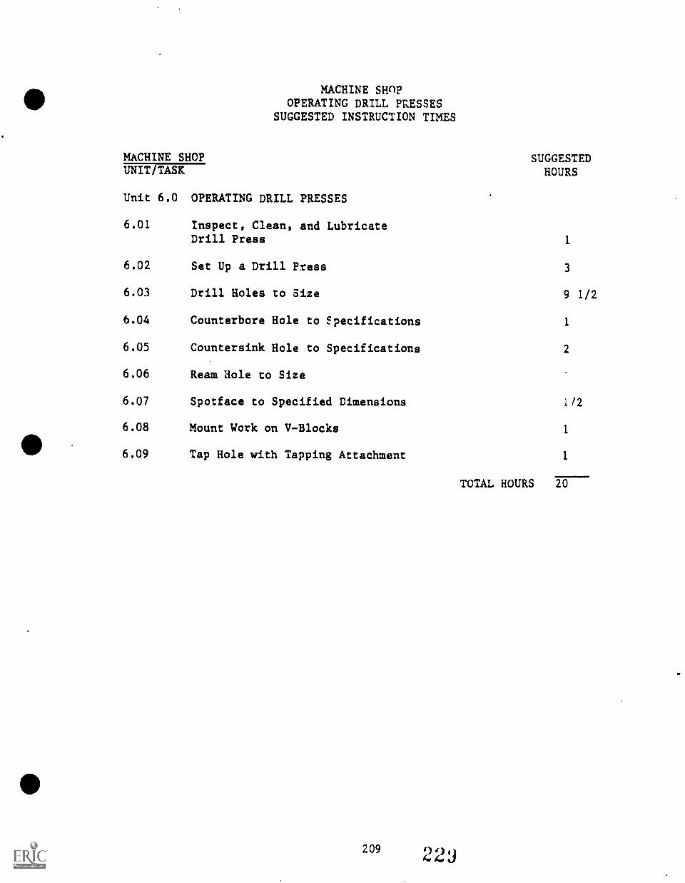
MACHINE SHOPOPERATING DRILL PaESSES
SUGGESTED INSTRUCTION TIMES
MACHINE SHOP SUGGESTEDHOURSUNIT/TASK
Unit 6.0 OPERATING DRILL PRESSES
6.01 Inspect, Clean, and LubricateDrill Press 1
6.02 Set Up a Drill Press 3
6.03 Drill Holes to Size 9 1/2
6.04 Counterbore Hole to specifications 1
6.05 Countersink Hole to Specifications 2
6.06 Ream Hole to Size
6.07 Spotface to Specified Dimensions 1/2
6.08 Mount Work on V-Blocks 1
6.09 Tap Hole with Tapping Attachment 1
TOTAL HOURS 20
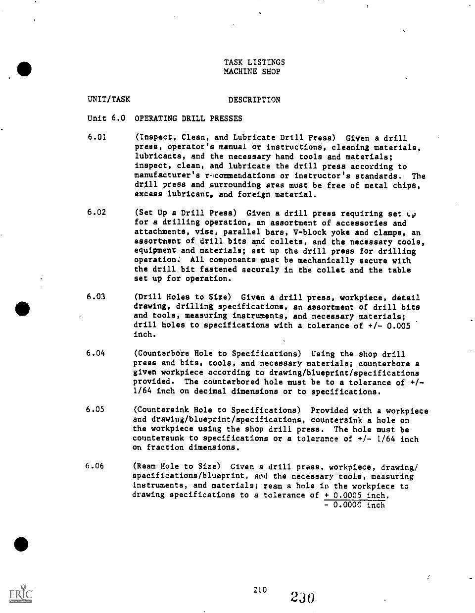
TASK LISTINGSMACHINE SHOP
UNIT/TASK DESCRIPTION
Unit 6.0 OPERATING DRILL PRESSES
6.01 (Inspect, Clean, and Lubricate Drill Press) Given a drillpress, operator's manual or instructions, cleaning materials,lubricants, and the necessary hand tools and materials;inspect, clean, and lubricate the drill press according tomanufacturer's r9commendations or instructor's standards. Thedrill press and ,surrounding area must be free of metal chips,excess lubricant, and foreign material.
6.02 (Set Up a Drill Press) Given a drill press requiring set tofor a drilling operation, an assortment of accessories andattachments, vise, parallel bars, V-block yoke and clamps, anassortment of drill bits and collets, and the necessary tools,equipment and materials; set up the drill press for drillingoperation: All components must be mechanically secure withthe drill bit fastened securely in the collet and the tableset up for operation.
6.03 (Drill Holes to Size) Given a drill press, workpiece, detaildrawing, drilling specifications, an assortment of drill bitsand tools, measuring instruments, and necessary materials;drill holes to specifications with a tolerance of +/- 0.005inch.
6.04 (Counterbo're Hole to Specifications) Using the shop drillpress and bits, tools, and necessary materials; counterbore agiven workpiece according to drawing/blueprint/specificationsprovided. The counterbored hole must be to a tolerance of +/-1/64 inch on decimal dimensions or to specifications.
6.05 (Countersink Hole to Specifications) Provided with a workpieceand drawing/blueprint/specifications, countersink a hole onthe workpiece using the shop drill press. The hole must becountersunk to specifications or a tolerance of +/- 1/64 inchon fraction dimensions.
6.06 (Ream Hole to Size) Given a drill press, workpiece, drawing/specifications/blueprint, apd the necessary tools, measuringinstruments, and materials; ream a hole in the workpiece todrawing specifications to a tolerance of + 0.0005 inch.
- 0.0000 inch
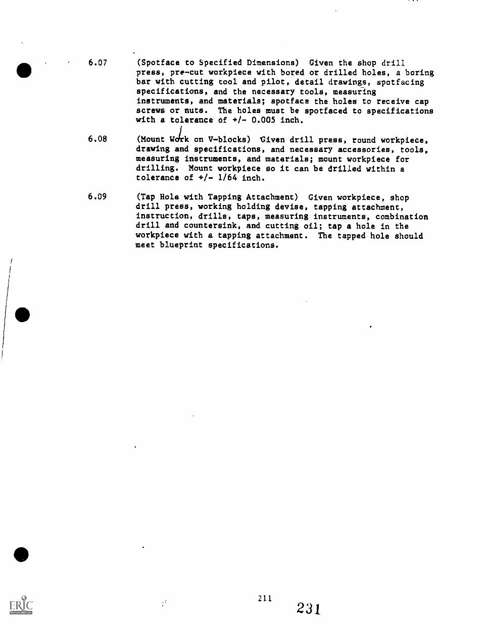
6.07 (Spotface to Specified Dimensions) Given the shop drillpress, precut workpiece with bored or drilled holes, a boringbar with cutting tool and pilot, detail drawings, spotfacingspecifications, and the necessary tools, measuringinstruments, and materials; spotface the holes to receive capscrews or nuts. The holes must be spotfaced to specificationswith a tolerance of +/ 0.005 inch.
6.08 (Mount Wok on Vblocks) Given drill press, round workpiece,drawing and specifications, and necessary accessories, tools,measuring instruments, and materials; mount workpiece fordrilling. Mount workpiece so it can be drilled within atolerance of +/ 1/64 inch.
6.09 (Tap Hole with Tapping Attachment) Given workpiece, shopdrill press, working holding devise, tapping attachment,instruction, drills, taps, measuring instruments, combinationdrill and countersink, and cutting oil; tap a hole in theworkpiece with a tapping attachment. The tapped hole shouldmeet blueprint specifications.
211
231
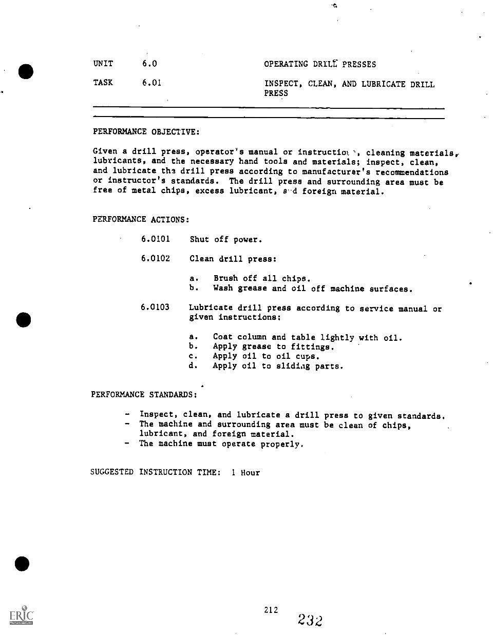
UNIT 6.0 OPERATING DRILL PRESSES
TASK 6.01 INSPECT, CLEAN, AND LUBRICATE DRILLPRESS
PERFORMANCE OBJECTIVE:
Given a drill press, operator's manual or instructiol, cleaning materials,lubricants, and the necessary hand tools and materials; inspect, clean,and lubricate the drill press according to manufacturer's recommendationsor instructor's standards. The drill press and surrounding area must befree of metal chips, excess lubricant, a"d foreign material.
PERFORMANCE ACTIONS:
6.0101
6.0102
Shut off power.
Clean drill press:
a. Brush off all chips.b. Wash grease and oil off machine surfaces.
6.0103 Lubricate drill press according to service manual orgiven instructions:
a. Coat column and table lightly with oil.b. Apply grease to fittings.c. Apply oil to oil cups.d. Apply oil to sliding parts.
PERFORMANCE STANDARDS:
- Inspect, clean, and lubricate a drill press to given standards.- The machine and surrounding area must be clean of chips,
lubricant, and foreign material.- The machine must operate properly.
SUGGESTED INSTRUCTION TIME: 1 Hour
IIIUNIT 6.0 OPERATING DRILL PRESSES
TASK 6.01 INSPECT, CLEAN, AND LUBRICATEPRESS (Con't.)
RELATED TECHNICAL INFORMATION:
- Describe procedures for inspecting and cleaning a drill press.- Explain the necessary safety precautions.- Identify materials used to clean A drill press.- Explain reasons for performing routine inspection and cleaning
of a drill press.- Work holding devices:
Parallels- C-clamps- T-bolts, T-nuts- Angle Plates- Step Blocks- V-blocks- Clamps & Straps
- Safety.
1
-1)
2132 3 ti
Addendum to Task 6.01
DRILL PRESS SAFETY
1. Always wear safety glasses to protect eyes from chips.
2. Always wear tight-fitting clot1Les to prevent them from becomingcaught in revol7ing parts.
3. Never use the drilling press with guards removed.
4. The chuck key or drill drift should be removed immediately afterusing so that it will not be thrown from the chuck and injuresomeone.
5. Remove watches and rings before operating the drill press.
6. Remove chips with a brush, never the hand.
7. Rags should never be used on the drill press while the machine isrunning, and rags should never be left on the table of a runningmachine.
8. Work should always be held in a vise or other work holding device,secured to the table and not held with the hands.
9. Ease up when the drill begins to break through the workpiece sothat it will not grab and cause a large burr.
10. Drill chucks are used to hold straight shank drills and tools.They are not used with tapered shank tools.
11. The drill drift is the only tool that should be used to removetapered shank tools from spindles or sleeves.
12. Never clean or make adjustments to a machine in motion.
13. Avoid burns by never picking up a drill, workpiece, or other toolsthat has just been used and is possibly hot.
14. The drill press table should .be kept clean and free of tools toeliminate accidents and possible damage to tools.
15. Spindle tapers should never be cleaned while the spindle is bringturned by power.
16. When drilling deep holes, interrupt the feed occasionally to breakup chips and k.lear the drill.
17. When using chucks and other tools with tapered shanks, always placea board on the table under the tool so that when the taper isbroken with th,! drill drift, it will not fall and damage the toolor table of the drill press.
214
234

18. Keep work area clean and free of foreign materials.
19. Clean the drill press eAd surrounding floor after use.
20. Clean oil or coolant from drills and other tools and return them toproper storage after use.1
215 23..)
UNIT 6.0 OPERATING DRILL PRESSES
TASK 6.02 SET UP A DRILL PRESS
PERFORMANCE OBJECTIVE:
Given a drill press requiring set up for a drilling operation, anassortment of accessories and attachments, vise, parallel bars, V-blockyoke and clamps, an assortment of drill bits and collets, and thenecessary tools, equipment and materials; set up the drill press for adrilling operation. All components must be mechanically secure with thedrill bit fastened securely in the collet and the table set up foroperation.
PERFORMANCE ACTIONS:
6.0201 Clean drill press.
6.0202 Select proper drill or accessories.
6.0203 Adjust: table, head, and depth adjustments.
6.0204 If straight-shank drill is used, mount drill indrill chuck. If taper-shank drill is used, irsertit directly in spindle,,or in a drill sleeve andthen in spindle.
6.0205 Turn on power to see if drill is running straight.
6.0206 Mount workpiece in holding device.
6.0207 Follow procedures to drill workpiece (See followingtask objectives).
PERFORMANCE STANDARDS:
- Set up a drill press for operation using given accessories andmaterial so that the drill press and components are mechanicallysecure and prepared for the required operation.
SUGGESTED INSTRUCTION TIME: 3 Hours
UNIT 6.0 OPERATING DRILL PRESSES
TASK 6.02 SET U? A DRILL PRESS (Can't.)
RELATED TECHNICAL INFORMATION:
- Identify: Variable speed control, head, motor, power feed,spindle, table, column, base and quill.
- Identify and explain: Drilling, reaming, boring, counterboring,countersinking, and tapping.
- Explain how to calculate speeds and feeds on a drill press.- Identify attachments and accessories for the drill press.- Identify sizes and capacities of various drill presses.- Identify procedures for setting up a drill press.- Explain how to mount a drill bit and collet in a drill press.- Explain how to mount a vise and align a workpiece.- Work holding devices.- Work holding procedures.- Safety.- Drill chucks and tool holding procedures.
217231
UNIT 6.0 OPERATING DRILL PRESSES
TASK 6.03 DRILL HOLES TO SIZE
PERFORMANCE OBJECTIVE:
Given a drill press, workpiece, detail drawing, drilling specifications,an assortment of drill bits and tools, measuring instruments, andnecessary materials; drill holes to specifications with a tolerance of+/- 0.005 inch.
PERFORMANCE ACTIONS:
6.0301
6.0302
6.0303
6.0304
6.0305
6.0306
6.0307
6.0308
6.0309
6.0310
6.0311
6.0312
Assemble materials.
Set up drill press.
Select holding device and accessories.
Secure work-holding device.
Determine hold size.
Align workpiece with center drill in chuck.
Calculate speed.
Set drill press speed.
Center drill speed.
Select and mount drill bit.
Reset speed.
Drill to specifications:
a. Use required lubricant.b. Slow feed as drill penetrates workpiece.c. Deburr hole.
6.0313 Measure drilled hole(s).
PERFORMANCE STANDARDS:
- Drill hole or holes to size in given workpiece with a toleranceof +/- 0.005 or to specifications.
UNIT 6.0 OPERATING DRILL PRESSES
TASK 6.03 DRILL HOLES TO SIZE (Con't.)
SUGGESTED INSTRUCTION TIME: 9 1/2 Hours
RELATED TECHNICAL INFORMATION:
Technique of easing up pressure as drill print breaks throughwork.
Drilling techniques with thin metal.
219
239
4
UNIT 6.0 OPERATING DRILL PRESSES
TASK 6.04 COUNTERBORE HOLE TO SPECIFICATIONS
PERFORMANCE OBJECTIVE:
Using the shop drill press and bits, tools, and necessary materials;counterbore a given workpiece according to drawing/blueprint/specifications provided. The counterbored hole must be to a to atolerance of +/- 1/64 inch on decimal dimensions or to specifications.
PERFORMANCE ACTIONS:
6.0401
6.0402
6.0403
6.0404
6.0405
6.0406
6.0407
6.0408
6.0409
Assemble materials.
Set up drill press.
Center punch hole location.
Secure workpiece in work-holding device.
Locate and clamp workpiece to table.
Center drill workpiece.
Drill workpiece.
Select counterbore and secure in drill press.
Counterbore to specifications:
a. Apply required cutting oil.b. Set speed.c. Set drill press stop.d. Hold cutter in place to complete full cut.
6.0410 Verify measurements of counterbore with tolerances.
PERFORMANCE STANDARDS:
- Counterbore hole to specifications, +/- 1/64 inch on fractiondimensions, using drill press, support tools and materials,and stock provided.
SUGGESTED INSTRUCTION TIME: 1 Hour
2202,10
UNIT 6.0 OPERATING DRILL PRESSES
TASK 6.04 COUNTERBORE HOLE TO SPECIFICATIONS(Con't.)
RELATED TECHNICAL INFORMATION:
- How to set up drill press.- Layout of workpiece.- Operation of drill press.- Explain why and when to use cutting oil.- Precision measuring.- Define counterboring.- Describe how to calculate cutting speed and feed.- Safety.
221 241
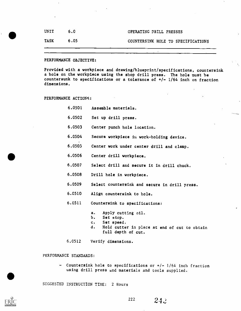
UNIT
TASK
6.0 OPERATING DRILL PRESSES
6.05 COUNTERSINK HOLE TO SPECIFICATIONS
PERFORMANCE OBJECTIVE:
Provided with a workpiece anda hole on the workpiece usingcountersunk to specificationsdimensions.
PERFORMANCE ACTIONS:
6.0501
6.0502
6.0503
6.0504
6.0505
6.0506
6.0507
6.0508
6.0509
6.0510
6.0511
6.0512
drawing/blueprint/specifications, countersinkthe shop drill press. The hole must beor a tolerance of +/- 1/64 inch on fraction
Assemble materials.
Set up drill press.
Center punch hole location.
Secure workpiece iu work-holding device.
Center work under center drill and clamp.
Center drill workpiece.
Select drill and secure it in drill chuck.
Drill hole in workpiece.
Select countersink and secure in drill press.
Align countersink to hole.
Countersink to specifications:
a.
b.
c.
d.
Apply cutting oil.Set stop.Set speed.
Hold cutter in place at end of cut to obtainfull depth of cut.
Verify dimensions.
PERFORMANCE STANDARDS:
- Countersink hole to specifications or +/- 1/64 inch fractionusing drill press and materials and tools supplied.
SUGGESTED INSTRUCTION TIME: 2 Hours
UNIT 6.0 OPERATING DRILL PRESS
TASK 6.05 COUNTERSINK HOLE TO SPECIFICATIONS(Can't.)
RELATED TECHNICAL INFORMATION:
- Set up drill press.- Layout workpiece.- Operation of drill press.- Use of cutting oil.- Precision measuring.- Define countersinking.- Describe how to calculate cutting speed and feed.- Explain use of cutting fluid.- Explain why a standard machine shop countersink is ground to a
certain angle.- Safety.
N
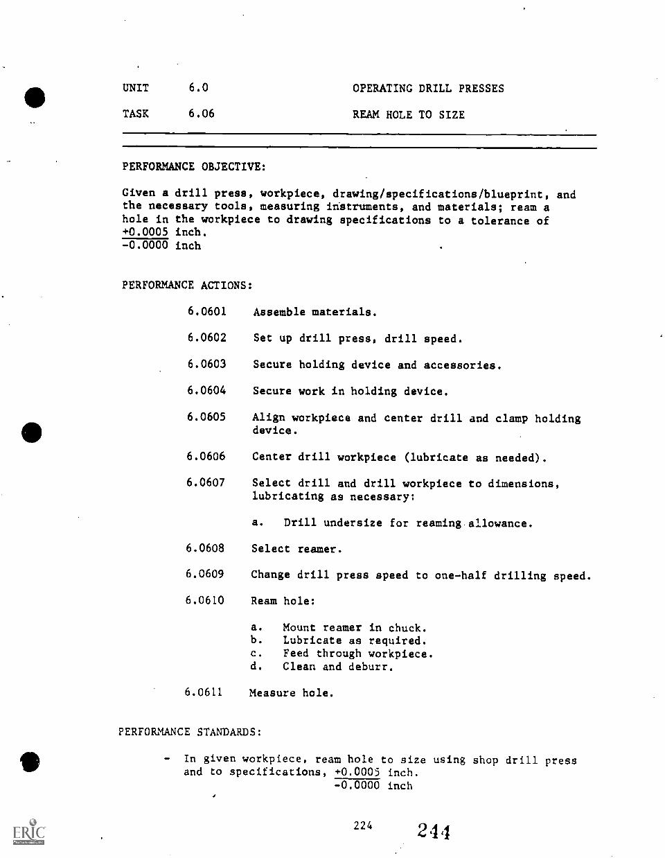
UNIT 6.0 OPERATING DRILL PRESSES
TASK 6.06 REAM HOLE TO SIZE
PERFORMANCE OBJECTIVE:
Given a drill press, workpiece, drawing/specifications/blueprint, andthe necessary tools, measuring instruments, and materials; ream ahole in the workpiece to drawing specifications to a tolerance of+0.0005 inch.-0.0000 inch
PERFORMANCE ACTIONS:
6.0601 Assemble materials.
6.0602 Set up drill press, drill speed.
6.0603 Secure holding device and accessories.
6.0604 Secure work in holding device.
6.0605 Align workpiece and center drill and clamp holdingdevice.
6.0606 Center drill workpiece (lubricate as needed).
6.0607 Select drill and drill workpiece to dimensions,lubricating as necessary:
a. Drill undersize for reaming allowance.
6.0608 Select reamer.
6.0609 Change drill press speed to one-half drilling speed.
6.0610 Ream hole:
a. Mount reamer in chuck.b. Lubricate as required.c. Feed through workpiece.d. Clean and deburr.
6.0611 Measure hole.
PERFORMANCE STANDARDS:
- In given workpiece, ream hole to size using shop drill pressand to specifications, +0.0005 inch.
-0.0000 inch4
224 24 4
UNIT 6.0 OPERATING DRILL PRESSES
TASK 6.06 REAM HOLE TO SIZE (Can't.)
SUGGESTED INSTRUCTION TIME: 1 Hour
RELATED TECHNICAL INFORMATION:
- Identify sizes, types, nomenclature, specifications, selection,and storage of machine reamers.
- Safety.- Reamer care.
UNIT 6.0 OPERATING DRILL PRESSES
TASK 6.07 SPOTFACE TO SPECIFIED DIMENSIONS
PERFORMANCE OBJECTIVE:
Given the shop drill press, pre-cut workpiece with bored or drilledholes, a boring bar with cutting tool and pilot, detail drawings,spotfacing specifications, and the necessary tools, measuring instruments,and materials; spotface the holes to receive cap screws or nuts. Theholes must be spotfaced to specifications with a tolerance of +/- 0.005inch.
PERFORMANCE ACTIONS:
6.0701
6.0702
6,0703
6.0704
6.0705
6.0706
6.0707
6.0708
6.0709
6.0710
6.0711
Assemble materials.
Set up drill press.
Select holding device and accessories.
Secure work in holding device.
Select spotface tool and pilot.
Mount spotfacing tool in drill press.
Set speed of drill (Machinery's Handbook or instructor'sspecifications).
Set atop for depth.
Align workpiece.
Start drill press.
Spotface workpiece:
a.
b.
Lubricant.Face to dimensions.
6.0712 Measure spotface.
6.0713 Re-adjust depth stop and recut spotface as requiredto meet specifications.
UNIT 6.0 OPERATING DRILL PRESSES
TASK 6.07 SPOTFACE TO SPECIFIED DIMENSIONS(Con't.)
PERFORMANCE STANDARDS:
- Spotface a given workpiece to specifications, +/- 0.005 inch,so that the top of the hole produced a bearing surface againstwhich a washer or nut or the head of a cap screw may bebrought flat.
SUGGESTED INSTRUCTION TIME: 1/2 Hour
RELATED TECHNICAL INFORMATION:
- Explain piarpose of spotfacing.- 2xplain why boring bar is used as a'pilot.- Demonstrating mounting cutting tool in boring bar.- Demonstrate set up for spotfacing.- Calculate cutt,ing feed and speed.- Explain use ,ot cutting fluid. .
Describe,piOcedure for spotfacing a hole.- Safety. '
Are
-UNIT 6.0 OPERATING DRILL PRESSES
TASK 6.08 MOUNT WORK ON V-BLOCKS
PERFORMANCE OBJECTIVE:
Given drill press, round workpiece, drawing and specifications, andnecessary accessories, tools, measuring instruments, and materials;mount workpiece for drilling. Mount workpiece so it can be drilledwithin a tolerance of +1- 1/64 inch.
PERFORMANCE ACTIONS:
6.0801
6.0802
6.0803
6.0804
6.0805
6.0806
6.0807
Clean and deburr workpiece.
Clean and deburr V-blocks.
Coat workpiece with layout dye at hole location.
Measure bole location with square and center punchworkpiece.
Mount workpiece in V-blocks.
Place assembly on surface plate.
Locate center punch mark centered on top:
a. Check form each side with square.b. Check from each side with surface gage.
6.0808 Clamp workpiece in V-blocks.
6.0809 Check accuracy of set up.
6.0810 Mount assembly on drill press table.
6.0811 Place center drill in chuck.
6.0812 Locate center punch mark on workpiece under point ofcenter drill.
6.0813 Clamp assembly to table.
6.0814 Turn on drill press and lightly touch workpiece withcenter drill to verify set up.
228 215
UNIT 6.0 OPERATING DRILL PRESSES
TASK 6.08 MOUNT WORK ON V-BLOCKS (Con't.)
PERFORMANCE STANDARDS:
- Mount workpiece on V-blocks so it can be drilled within atolerance of +/- 1/64 inch.
SUGGESTED INSTRUCTION TIME: 1 Hour
229 2,1
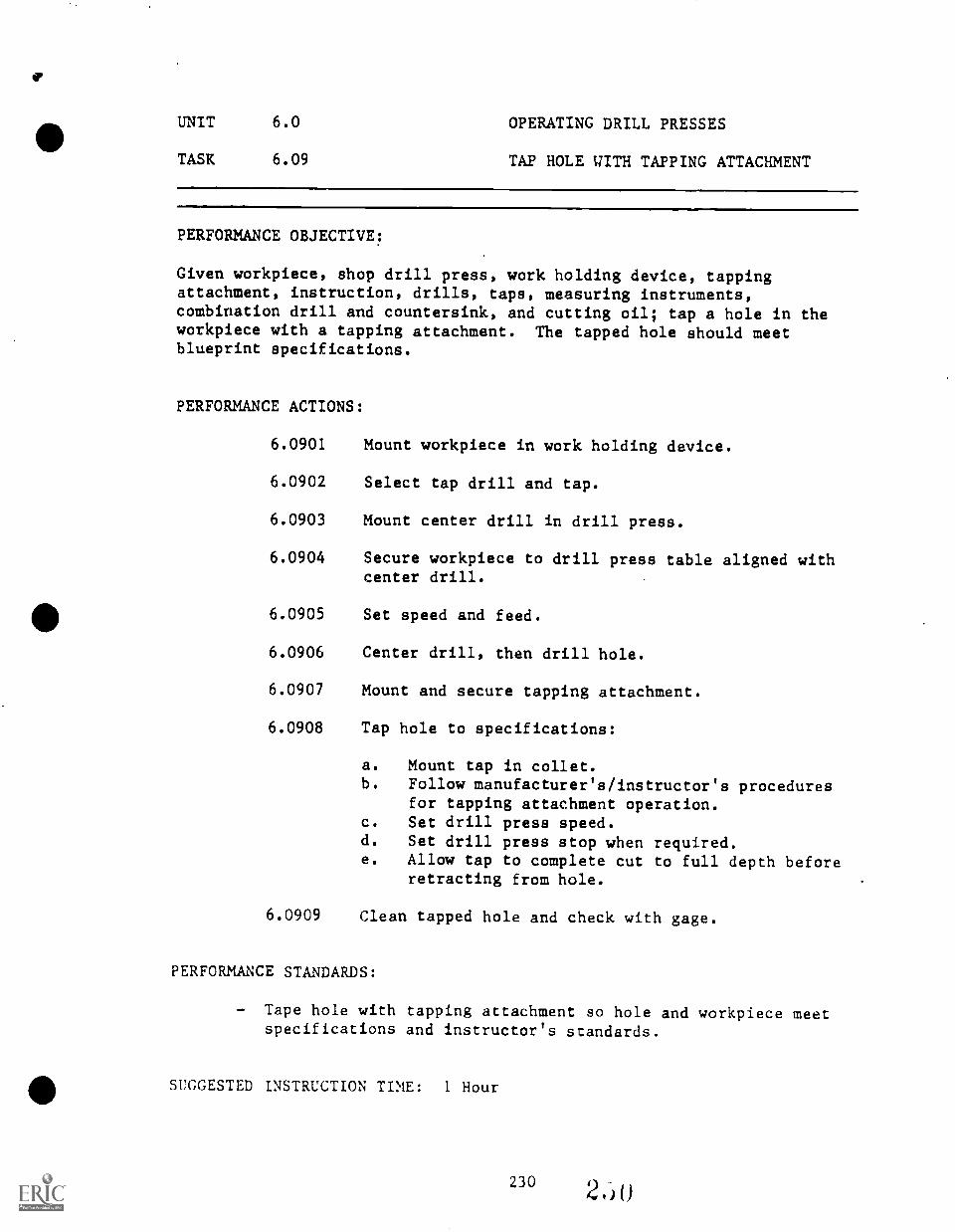
UNIT 6.0 OPERATING DRILL PRESSES
TASK 6.09 TAP HOLE WITH TAPPING ATTACHMENT
PERFORMANCE OBJECTIVE:
Given workpiece, shop drill press, work holding device, tappingattachment, instruction, drills, taps, measuring instruments,combination drill and countersink, and cutting oil; tap a hole in theworkpiece with a tapping attachment. The tapped hole should meetblueprint specifications.
PERFORMANCE ACTIONS:
6.0901 Mount workpiece in work holding device.
6.0902 Select tap drill and tap.
6.0903 Mount center drill in drill press.
6.0904 Secure workpiece to drill press table aligned withcenter drill.
6.0905 Set speed and feed.
6.0906 Center drill, then drill hole.
6.0907 Mount and secure tapping attachment.
6.0908 Tap hole to specifications:
a. Mount tap in collet.b. Follow manufacturer's/instructor's procedures
for tapping attachment operation.c. Set drill press speed.d. Set drill press stop when required.e. Allow tap to complete cut to full depth before
retracting from hole.
6.0909 Clean tapped hole and check with gage.
PERFORMANCE STANDARDS:
Tape hole with tapping attachment so hole and workpiece meetspecifications and instructor's standards.
SUGGESTED INSTRUCTION TIME: 1 Hour

UNIT 7.0
POWER SAWS
For the purpose of this guide, power saws will include:
- Vertical Bandsaw (Contour Saw)- Horizontal Bandsaw- Power Hacksaw, available at 1 career center
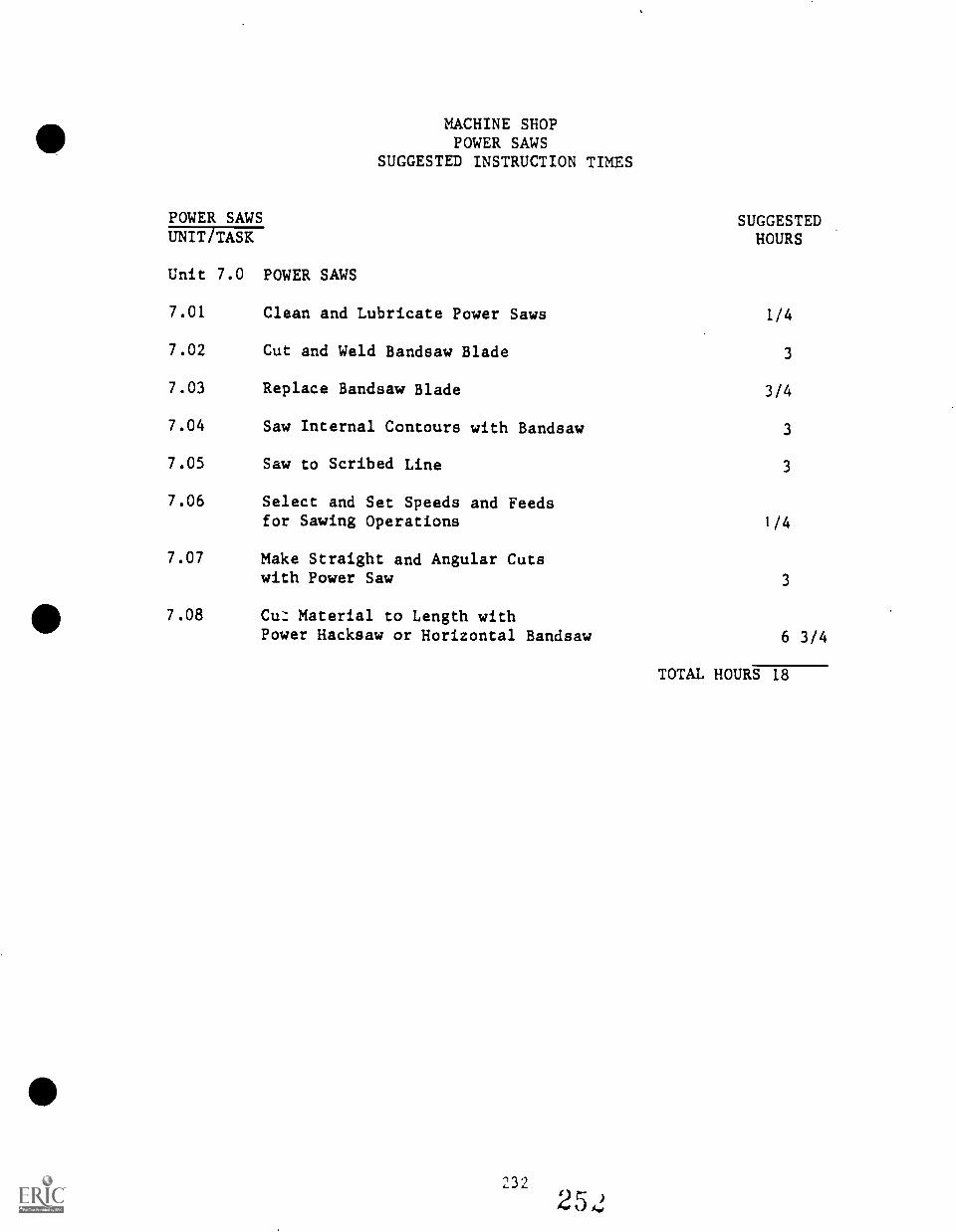
MACHINE SHOPPOWER SAWS
SUGGESTED INSTRUCTION TIMES
POWER SAWS SUGGESTEDHOURSUNIT TASK
Unit 7.0 POWER SAWS
7.01 Clean and Lubricate Power Saws 1/4
7.02 Cut and Weld Bandsaw Blade 3
7.03 Replace Bandsaw Blade 3/4
7.04 Saw Internal Contours with Bandsaw 3
7.05 Saw to Scribed Line 3
7.06 Select and Set Speeds and Feedsfor Sawing Operations 1/4
7.07 Make Straight and Angular Cutswith Power Saw 3
7.08 Cu: Material to Length withPower Hacksaw or Horizontal Bandsaw 6 3/4
TOTAL HOURS 18
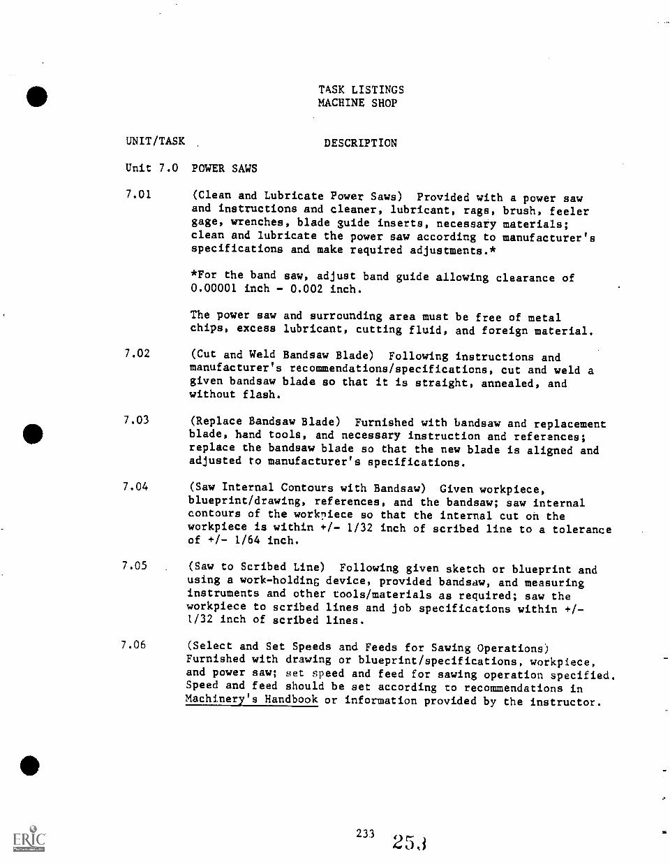
TASK LISTINGSMACHINE SHOP
UNIT/TASK DESCRIPTION
Unit 7.0 POWER SAWS
7.01 (Clean and Lubricate Power Saws) Provided with a power sawand instructions and cleaner, lubricant, rags, brush, feelergage, wrenches, blade guide inserts, necessary materials;clean and lubricate the power saw according to manufacturer'sspecifications and make required adjustments.*
*For the band saw, adjust band guide allowing clearance of0.00001 inch - 0.002 inch.
The power saw and surrounding area must be free of metalchips, excess lubricant, cutting fluid, and foreign material.
7.02 (Cut and Weld Bandsaw Blade) Following instructions andmanufacturer's recommendations/specifications, cut and weld agiven bandsaw blade so that it is straight, annealed, andwithout flash.
7.03 (Replace Bandsaw Blade) Furnished with bandsaw and replacementblade, hand tools, and necessary instruction and references;replace the bandsaw blade so that the new blade is aligned andadjusted to manufacturer's specifications.
7.04 (Saw Internal Contours with Bandsaw) Given workpiece,blueprint/drawing, references, and the bandsaw; saw internalcontours of the workpiece so that the internal cut on theworkpiece is within +/- 1/32 inch of scribed line to a toleranceof +/- 1/64 inch.
7.05 (Saw to Scribed Line) Following given sketch or blueprint andusing a work-holding device, provided bandsaw, and measuringinstruments and other tools/materials as required; saw theworkpiece to scribed lines and job specifications within +/-l/32 inch of scribed lines.
7.06 (Select and Set Speeds and Feeds for Sawing Operations)Furnished with drawing or blueprint/specifications, workpiece,and power saw; set speed and feed for sawing operation specified.Speed and feed should be set according to recommendations inMachinery's Handbook or information provided by the instructor.
23.3
25,1
7.07 (Make Straight and Angular Cuts with Power Saw) Given thehorizontal bandsaw or a power hacksaw, specifications, necessarytools and materials, and a workpiece or stocks; cut givenmetal to the specified dimensions, +/- 1/32 inch.
7.03 (Cut Materials to Length with Power Hacksaw or HorizontalHandsaw) Provided with a power hacksaw, or horizontal bandsaw,instructions concerning operation of the power saw, measuringtools, workpiece; cut workpiece to specified length within atolerance of +/- 1/32 inch.
234
254
UNIT 7.0 POWER SAWS
TASK 7.01 CLEAN AND LUBRICATE POWER SAWS
PERFORMANCE OBJECTIVE:
Provided with a power saw and instructions and cleaner, lubricant, rags,brush, feeler gage, wrenches, blade guide inserts, necessary materials;clean and lubricate the power saw according to manufacturer's specifications and make required adjustment.*
*For the bandsaw, adjust band guide allowing clearance of 0.0001 inch0.002 inch.
The power saw and surrounding area must be free of metal chips, excesslubricant, cuting fluid, and foreign material.
PERFORMANCE ACTIONS: (Omit actions not applicable.)
7.0101
7.0102
7.0103
7.0104
Take safety precautions.
Clean off all chips with brush.
Clean oil and dirt from saw.
Lubricate saw to manufacturer's specifications:
a. Grease fittings.b. Oil in oil cups.c. Oil slides lightly.
7.0105 Inspect saw:
a. Check tension cn blade.b. Check vertical alignment of blade.c. Check blade for sharpness and damage.d. Mount inserts and adjust to tolerance with
feeler gage.
7.0106 Verify adjustments with short test run.
PERFORMANCE STANDARDS:
- Clean and lubricate given power saw(s) according to manu-facturer's instructions so that the saw and surrounding areais clean and the saw is properly lubricated and adjusted andoperates properly.
SUGGESTED INSTRUCTION TIME: 1/4 Hour
235 2'.ut)
e
UNIT 7.0 POWER SAWS
TASK 7.01 CLEAN AND LUBRICATE POWER SAWS(Can't.)
RELATED TECHNICAL INFORMATION:
- Identify power cut-off saws by type, sizes, nomenclature, andrange of work.
- Identify safe practices and work habits on the power saw (beltand pully guards,, loose clothing, jewelry, hair, cutting shortpieces, cutting in an old cut with new blade, personal safety).
- Care of power saws.
236256
UNIT 7.0 POWER SAW
TASK 7.02 CUT AND WELD BANDSAW BLADE
PERFORMANCE OBJECTIVE:
Following instructions and manufacturer's recommendations/specifications,cut and weld a given bandsaw blade so that it is straight, annealed, andwithout flash.
*If welding equipment is not available, this will be an orientationtask.
PERFORMANCE ACTIONS:
7.0201
7.0202
7.0203
7.0204
7.0205
7.0206
Cut off electrical power to saw.
Remove blade tension.
Cut blade (or remove broken blade).
Grind blade ends square.
Clean welder jaws and inserts.
Insert blade in welder jaws:
a. Point saw teeth in.b. Butt ends.c. Center in gap (.040 inch).d. Clamp.
7.0207 Set pressure, wear goggles, and weld using properprocedures for individual machine.
7.0208 Loosen clamps, set for annealing, clamp for annealing.
7.0209 Anneal blade until it reaches a dull cherry redcolor:
a. Jog button, allowing temperature to drop offslowly (5-10 seconds).
b. (NOTE: Typically this will be orientationtraining since skill development mayrequire a few practice welds.)
7.0210 Remove blade from welder.
237 2 5'/
UNIT 7.0 POWER SAW
TASK 7.02 CUT AND WELD BANDSAW BLADE
PERFORMANCE ACTIONS (Can't.):
7.0211 a. Grind off bead or flash from weld being carefulnot to:- Undercut the weld or,- Damage the saw teeth.
b. Anneal blade second time to "straw" color,allowing blade to cool slowly.
7.0212 Pass welded area through band thickness'gage as acheck.
7.0213 Remount blade and adjust proper tension, ensuringthat blade teeth are in proper direction.
7.0214 Test run blade.
PERFORMANCE STANDARDS:
- Cut and weld a bandsaw blade so that it is straight, annealed,and without flash and mount it on the saw for proper operation.
SUGGESTED INSTRUCTION TIME: 3 Hours
RELATED TECHNICAL INFORMATION:
- Safety.- Preparing a blade for welding.- Welding.- Annealing.- Removing, install, and adjusting a blade.
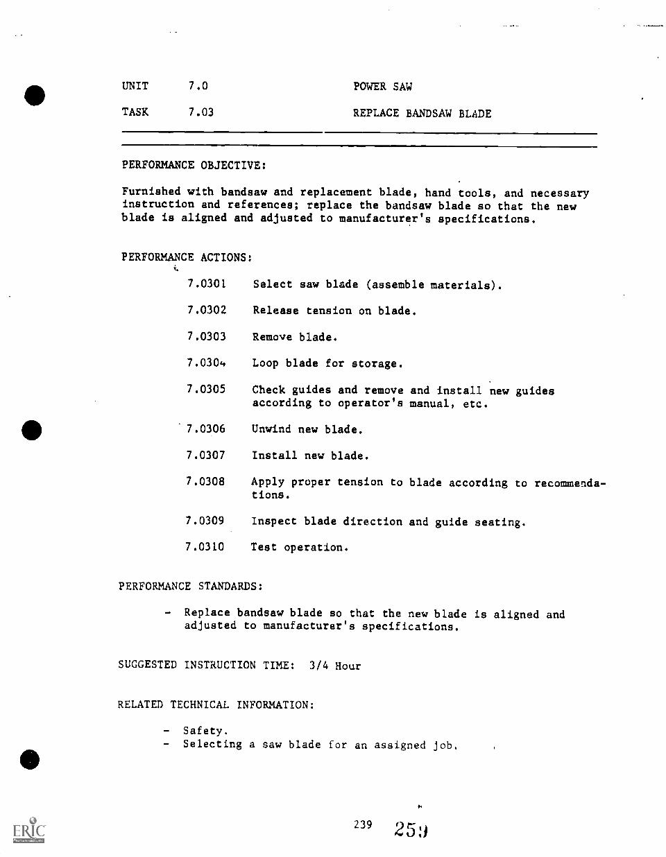
UNIT 7.0 POWER SAW
TASK 7.03 REPLACE BANDSAW BLADE
PERFORMANCE OBJECTIVE:
Furnished with bandsaw and replacement blade, hand tools, and necessaryinstruction and references; replace the bandsaw blade so that the newblade is aligned and adjusted to manufacturer's specifications.
PERFORMANCE ACTIONS:
7.0301 Select saw blade (assemble materials).
7.0302 Release tension on blade.
7.0303 Remove blade.
7.030'. Loop blade for storage.
7.0305 Check guides and remove and install new guidesaccording to operator's manual, etc.
7.0306 Unwind new blade.
7.0307 Install new blade.
7.0308 Apply proper tension to blade according to recommenda-tions.
7.0309 Inspect blade direction and guide seating.
7.0310 Test operation.
PERFORMANCE STANDARDS:
- Replace bandsaw blade so that the new blade is aligned andadjusted to manufacturer's specifications.
SUGGESTED INSTRUCTION TIME: 3/4 Hour
RELATED TECHNICAL INFORMATION:
- Safety.- Selecting a saw blade for an assigned job.
239 25
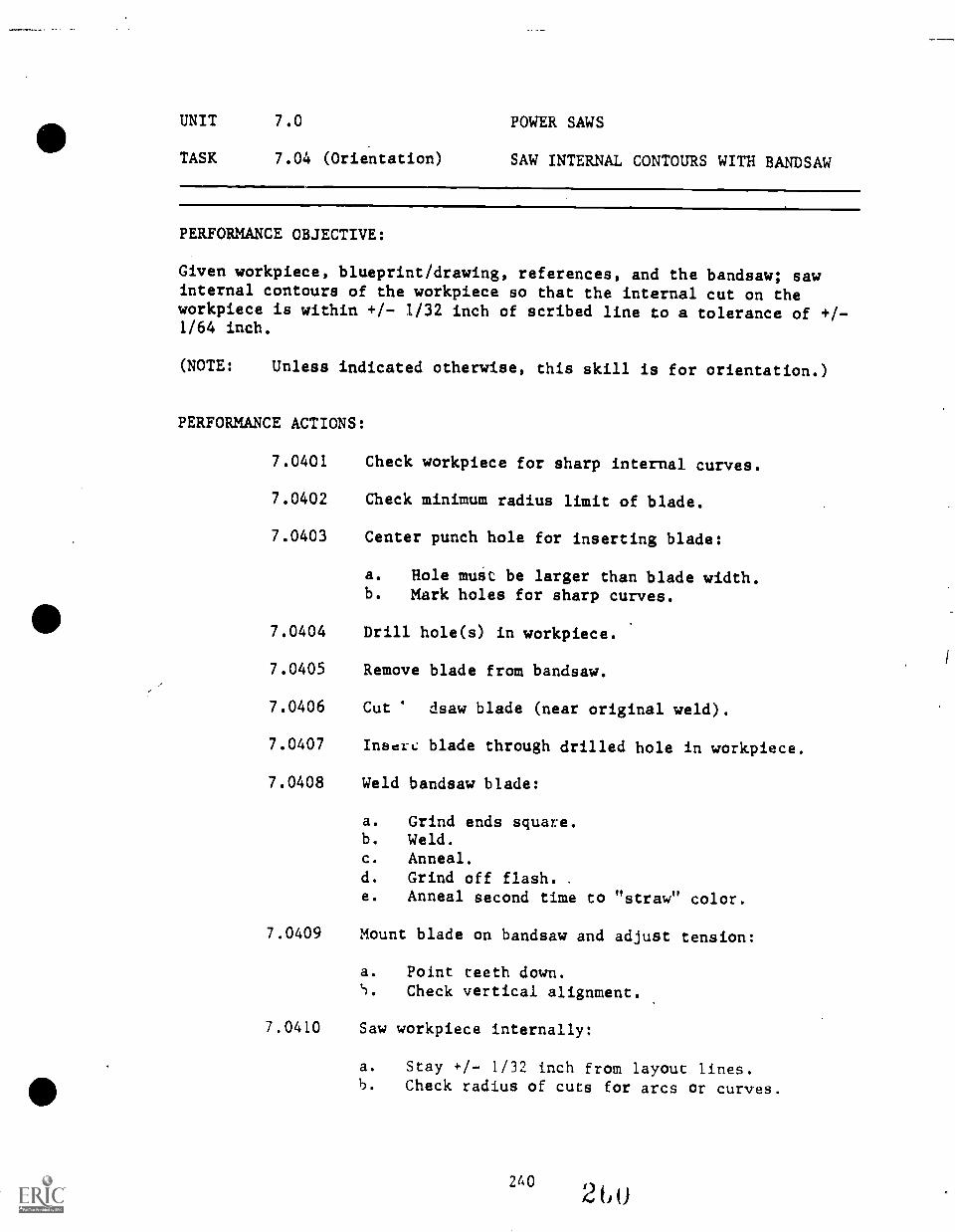
UNIT 7.0 POWER SAWS
TASK 7.04 (Orientation) SAW INTERNAL CONTOURS WITH BANDSAW
PERFORMANCE OBJECTIVE:
Given workpiece, blueprint/drawing, references, and the bandsaw; sawinternal contours of the workpiece so that the internal cut on theworkpiece is within +/- 1132 inch of scribed line to a tolerance of +/-1/64 inch.
(NOTE: Unless indicated otherwise, this skill is for orientation.)
PERFORMANCE ACTIONS:
7.0401
7.0402
7.0403
7.0404
7.0405
7.0406
7.0407
7.0408
Check workpiece for sharp internal curves.
Check minimum radius limit of blade.
Center punch hole for inserting blade:
a. Hole must be larger than blade width.b. Mark holes for sharp curves.
Drill hole(s) in workpiece.
Remove blade from bandsaw.
Cut dsaw blade (near original weld).
Inser,.: blade through drilled hole in workpiece.
Weld bandsaw blade:
a.
b.
c.
d.
e.
Grind ends square.Weld.Anneal.Grind off flash. .
Anneal second time to "straw"
7.0409 Mount blade on bandsaw and adjust
a. Point teeth down.
color.
tension:
5. Check vertical alignment.
7.0410 Saw workpiece internally:
a. Stay +/- 1/32 inch from layout lines.b. Check radius of cuts for arcs or curves.
26026U
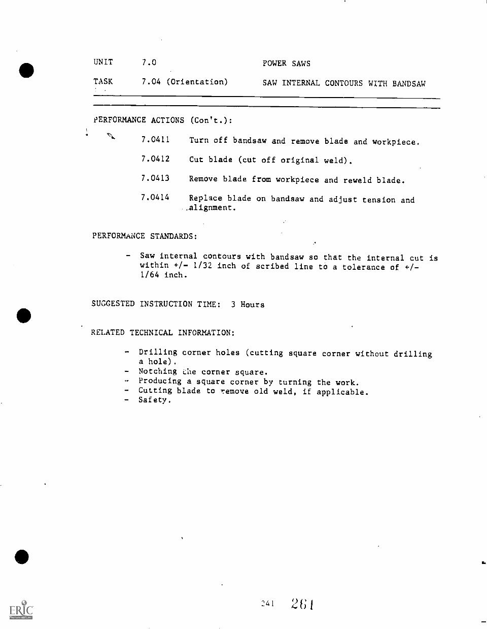
UNIT 7.0 POWER SAWS
TASK 7.04 (Orientation) SAW INTERNAL CONTOURS WITH HANDSAW
PERFORMANCE ACTIONS (Con't.):
7.0411
7.0412
7.0413
7.0414
Turn off bandsaw and remove blade and workpiece.
Cut blade (cut off original weld).
Remove blade from workpiece and reweld blade.
Replace blade on bandsaw and adjust tension and..alignment.
PERFORMANCE STANDARDS:
- Saw internal contours with bandsaw so that the internal cut iswithin +/- 1/32 inch of scribed line to a tolerance of +/-1/64 inch.
SUGGESTED INSTRUCTION TIME: 3 Hours
RELATED TECHNICAL INFORMATION:
- Drilling corner holes (cutting square corner without drillinga hole) .
- Notching ne corner square.- Producing a square corner by turning the work.- Cutting blade to remove old weld, if applicable.- Safety.
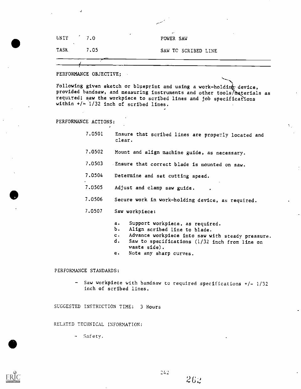
UNIT 7.0 POWER SAW
TASK 7.05 SAW TC SCRIBED LINE
PERFORMANCE OBJECTIVE;-,
Following given sketch or blueprint and using a work-holdinizithdevice,provided bandsaw, and measuring instruments and other tools kterials asrequired; saw the workpiece to scribed lines and job specificalonswithin +/ 1/32 inch of scribed lines.
PERFORMANCE ACTIONS:
7.0501 Ensure that scribed lines are properly located andclear.
7.0502 Mount and align machine guide, as necessary.
7.0503 Ensure that correct blade is mounted on saw.
7.0504 Determine and set cutting speed.
7.0505 Adjust and clamp saw guide.
7.0506 Secure work in work-holding device, as required.
7.0507 Saw workpiece:
a. Support workpiece, as required.b. Align scribed line to blade.c. Advance workpiece into saw with steady pressure.d. Saw to specifications (1/32 inch from line on
waste side).e. Note any sharp curves.
PERFORMANCE STANDARDS:
- Saw workpiece with bandsaw to required specifications +/- 1/32inch of scribed lines.
SUGGESTED INSTRUCTION TIME: 3 Hours
RELATED TECHNICAL INFORMATION:
- Safety.
UNIT 7.0 POWER SAW
TASK 7.06 SELECT AND SET SPEEDS AND FEEDS FORSAWING OPERATIONS
PERFORMANCE OBJECTIVE:
Furnished with drawing or blueprint/specifications, workpiece, and powersaw; set speed and feed for sawing operation specified. Speed and feedshould be set according to recommendations in Machinery's Handbook orinformation provided by the instructor.
PERFORMANCE ACTIONS:
74601 Review print/drawing/specification.
7.0602 Determine material to be sawed.
7.0603 Determine type of saw to be used.
7.0604 Determine type of blade.
7.0605 . Determine machine speed:
7.0606
7.0607
a. Check speed chart on machine, if available.b. Check reference for cutting speed.c. Calculate speed, if required.
Set machine speed according to manufacturer'srecommendations.
Determine feed requirement and set feed according tomanufacturer's recommendations.
PERFORMANCE STANDAyS:
Select and set speeds and feeds for sawing operations accordingto recommendations in Machinery's Handbook or informationprovided by the instructor.
SUGGESTED INSTRUCTION TIME: 1/4 Hour
RELATED TECHNICAL INFORMATION:
- Safety.- Machinery's Handbook.
UNIT 7.0 POWER SAW
TASK 7.07 MAKE STRAIGHT AND ANGULAR CUTS WITHPOWER SAW
PERFORMANCE OBJECTIVE:
Given the horizontal bandsaw or a power hacksaw, specifications, necessarytools and materials, and a workpiece or stocks; cut given metal to thespecified dimensions, +/- 1/32 inch.
PERFORMANCE ACTIONS:
7.0701
7.0702
7.0703
7.0704
Assemble material to cut.
Measure material and scribe/mark lines.
Set up power saw.
Make required cuts to specifications:
a. Straight.b. Angular, as required.
7.0705 Check dimensions.
PERFORMANCE STANDARDS:
- Make straight and angular cuts with power saw to specifi-cations.
SUGGESTED INSTRUCTION TIME: 3 Hours
RELATED TECHNICAL INFORMATION:
- Sawing angle or channel stock.- Sawing pipe or tube.- Selection of blades.- Leaving extra length when cutting off material.
UNIT 7.0
TASK
POWER SAW
7.08 CUT MATERIAL TO LENGTH WITh POWERHACKSAW OR HORIZONTAL BANDSAW
PERFORMANCE OBJECTIVE:
Provided with a power hacksaw or horizontal bandsaw, instructionsconcerning operation of the power saw, measuring tools, workpiece; cutworkpiece to specified length within a tolerance of +/- 1/32 inch.
PERFORMANCE ACTIONS:
7.0801
7.0802
7.0803
7.0804
Review job specifications for dimensions.
Measure to dimensions.
Scribe or mark measurements.
Select saw blade according to references provided,if applicable.
7.080' Mount blade, if applicable.
7.0806 Check vise with square, if applicable.
7.0807 Set saw speed, if applicable.
7.0808 Set saw feed.
7.0809 Clamp workpiece in vise (as applicable):
7.0810
7.0811
7.0812
a. Align blade on waste side of cut.b. Support long pieces with floor stand.
Start saw.
Lower hlade to workpiece and engage feed.
Deburr workpiece and check measurements.
PERFORMANCE STANDARDS:
- Cut material to specified lengths with the power hacksaw orhorizontal bandsaw with an accuracy of +1- 1/32 inch ofspecifications.
- Performance must be to instructor's standards.
SUGGESTED INSTRUCTION TIME: 6 3/4 Hours
245
UNIT 7.0 POWER SAWS
TASK 7.08 CUT MATERIAL TO LENGTH WITH POWERHACKSAW OR HORIZONTAL BANDSAW (Can't.)
RELATED TECHNICAL INFORMATION: (Expanded objectives)
- Set up a power hacksaw or horizontal bandsaw for a cuttingoperation so that all components are mechanically secure.
- Identify and select hacksaw blades (as applicable).- Install a power hacksaw blade with the teeth facing the
direction of cut, the blade mounted securely to the bladeholder or arm with socket head screws and tensioned to s?ecifi-cations with hardened bolts (as applicable).
- Identify and use work-holding devices on the power saw,demonstrating proper positioning of the workpiece.
- Saw straight cuts with the power saw to specifications within+/- 1/32 inch, - .000 inch.
- Saw angular cuts with the power saw to a tolerance of +/- 1degree for squareness and +/- 1/32 inch, - .000 inch fordimensions.
- Identify safety considerations.
UNIT 8.0
BASIC ENGINE LATHE WORK
This Basic Engine Lathe Work unit is designed to provide the secondarystudent with an introduction to the Engine Lathe and the fundamentalskills necessary to operate the Engine Lathe.
During the second year of secondary level training, the student'sknowledge and skills in lathe work will be expanded at a more difficultlevel and will include an introduction to the Turret Lathe.
Although lathe work is described as basic and advanced lathe work andalthough the tasks are distributed over two years of instruction, thetasks may be combined for more effective and efficient instruction asappropriate.
MACHINE SHOPBASIC ENGINE LATHE WORKSUGGESTED INSTRUCTION TIMES
MACHINE SHOPUNIT TASK
Unit 8.0 BASIC ENGINE LATHE WORK
SUGGESTEDHOURS
8.01 Inspect and Clean an Engine Lathe 9
8.02 Set Up Engine Lathe forTurning Operations 9
8.03 Align Lathe Centers Using AccurateMeasurement Techniques 2
8.04 Mount Workpiece Between Centers
8.05 Align Workpiece on Faceplate
8.06 Align Workpiece in FourJaw Chuck
8.07 Make Roughing Cuts
8.08 Make Finishing Cuts
8.09 Turn a Workpiece to Dimensions
8.10 Face a Workplace to Dimensions
8.11 Knurl a Workpiece
8.12 Drill Holes with Lathe
8.13 Ream Holes on the Lathe
8.14 Bore Holes
8.15 Counterbore Holes
8.16 Countersink Holes Using the Lathe
8.17 Tap Holes
8.18 Cut Cyrooves or Recess
8.19 Machine an External Chamfer
8.20 Machine an Internal Chamfer
8.21 Part Workpieces
12
4
24
20
20
10
4
10
2
2
1
2
8.22 File Workpieces 6
8.23 Polish Workpieces 5
TOTAL HOURS (FIRST YEAR) 155
ADVANCED ENGINE LATHE WORK(SECOND YEAR)
8.24 Grind Workpiece with ToolPost Grinder 2
8.25 Machine External Taper 9
8.26 Machine Internal Taper 3
8.27 Machine External Angle 2
8.28 Machine Internal Angle 1
8.29 Set Up Lathe for ThreadingOperations 12
TOTAL HOURS (SECOND YEAR) 29
TOTAL OF ENGINE LATHE INSTRUCTIONAL HOURS: 184
TASK LISTINGSMACHINE SHOP
UNIT/TASK DESCRIPTION
Unit 8.0 BASIC ENGINE LATHE WORK
8.01 (Inspect and Clean an Engine Lathe) Given an engine lathe,operator's manual or instructions, cleaning materi.ts, and thenecessary hand tools and equipment; inspect and clean theengine lathe in accordance with manufacturer's specifications.The lathe and surrounding area must be free of metal chips,excess lubricant, cutting fluid, and foreign material.
8.02 (Set Up Engine Lathe for Turning Operations) Given an enginelathe requiring set up for turning operations, a faceplate anddogs, a three- or four-jaw universal chuck, pre-cut cylindricalstock, toolholder and bit, and the necessary tools, equipment,and materials; set up the engine lathe for turning operationsrequiring a faceplate and chuck. All components must bemechanically secure. The tool bit must be secured in theholder and set at the point of dead center on the stock. Thefaceplate and dog must be mounted so that the tailstockengages the stock in the center. The chuck must be mountedsecurely to the threaded spindle with the jaws tightened tohold the workpiece. Spindle threads must be damaged and mustbe clean and free of chips or lint.
8.03 (Align Lathe Centers Using Accurate Measurement Techniques)Provided with a lathe and measuring instruments, align thelathe centers. Centers must be aligned with tolerance of +/-0.0005 inch.
8.04 (Mount Workpiece Between Centers) Given an engine lathe,pre-cut cylindrical stock with scribed centers, a faceplateand dog, combination drill and countersink, detail drawings,specifications, and the necessary tools, equipment, andmaterials; center drill the workpiece and mount it between thecenters. The workpiece must be center drilled to specificationswith a tolerance of +/- 0.005 inch for location, diameter, anddepth. The workpiece must be mounted with the soft center inthe live (headstock) center and the hardened center in thedeal (tailstock) center to specifications. The tailstock mustbe fastened securely with room for the saddle and tool blockto operate.
8.05 (Align Workpiece on Faceplate) Given a workpiece, lathe,measuring tools, faceplate and all necessary accessories,tools, and materials; align the workpiece on the lathe faceplatewith an accuracy of +/- 0.001 inch.
8.06 (Align Workpiece in Four-Jaw Chuck) Furrishod with workpiece,lathe, and measuring instruments, align workpiece in thefour-jaw chuck with a tolerance of +/- 0.001 inch.
8.07 (Make Roughing Cuts) Given an engine lathe with a mountedworkpiece, a dimensioned drawing or blueprint, toolholder androughing bit, and the necessary tools, measuring instruments,and materials; making roughed cuts of .010 inch per revolution.The workpiece must be roughed to size with 1/32 inch allowedfor a finishing cut. When the workpiece is turned to within1/2 inch of the dog or 1 inch of the chuck jaws, it must beremoved and turned to rough dimensions.
8.08 (Make Finishing Cuts) Given an engine lathe with a rough cutworkpiece mounted in a chuck or in a faceplate, a detaildrawing, toolholder and finishing bit, and the necessarytools, equipment, and materials; make finishing cuts of .003inch per revolution. The workpiece must be finished to sizewith a tolerance of +/- .003 inch.
8.09 (Turn a Workpiece to Dimensions) Given an engine lathe,cylindrical stock, a detail drawing that requires variousdiameters, toolholder and bits, and the necessary tools,measuring instruments, and materials; turn the workpiece todimensions. The diameters and dimensions must meet specifi-cations with a tolerance of +/- 0.005 inch.
8.10 (Face a Workpiece to Dimensions) Given cylindrical stock, adetail drawing that required several facing operations,toolholder and bits, and the necessary tools, measuringinstructions, and materials; face the workpiece to dimensionsusing the engine lathe so that the workpiece meets specifi-cations with a tolerance of +/- 0.005 inch.
8.11 (Knurl a Workpiece) Given an engine lathe, cylindrical stock,a detail drawing of a knurled part, knurling specifications,diamond and straight knurling tools, and the necessary tools,measuring instruments, and materials; knurl the workpiece tospecifications using course, medium, and fine rollers asrequired. The knurl must meet specifications with a -.oleranceof +/- 1/64 inch.
8.12 (Drill Holes with Lathe) Given an engine lathe, cylindricalparts, a detail drawing of parts to be drilled, drillingspecifications, a drill chuck and drill bits, and the necessarytools, measuring instruments, and materials; drill holes inthe parts using the lathe tailstock. The holes must bedrilled to specifications with a tolerance of +/- .003 inchfor location, + .002 inch for diameter, and +/- 1/64 inch fordepth. - .000 inch
8.13 (Ream Holes on the Lathe) Given an engine lathe, cylindricalparts, a detailed drawing of drilled holes to be reamed,reaming sper 1.fications, a drill chuck and reaming tools, andthe necessary tools, measuring instruments, and materials;ream the drilled holes using the lathe tailstock. The holesmust be reamed to specifications with a tolerance of+ 0.005 inch.- 0.000 inch
8.14 (Bore Holes) Given an engine lathe, pre-cut cylindrical stockwith undersized-drilled holes, an assortment of boring tools,a detail drawing, boring specifications, and the necessarytools, measuring instruments, and materials; bore holes usinga steady rest attachment. The holes must be bored to specifi-cations with a tolerance of +/- .001 inch for location,diameter, and depth, and +/- 1 degree for perpendicularity.
8.15 (Counterbore Holes) Given an engine lathe, pre-cut cylindricalstock with bored holes, an assortment of counterboring tools,oldetail drawing, counterboring specifications, and thenecessary tools, attachments, measuring instruments, and thematerials; counterbore the holes. The holes must be counterboredto specifications with a tolerance of +/- 0.001 inch.
8.16 (Countersink Holes Using the Lathe) Provided with an enginelathe, measuring instruments, and assortment of countersinkingtools,. detail drawings, countersinking specifications, and thenecessary tools, attachments, and materials as well as pre-cutcylindrical stock with bored holes; countersink the holes.The holes must be countersunk to specifications.
8.17 (Tap Holes) Given an engine lathe, pre-cut cylindrical orrectangular stock with drilled holes, detail drawings, tappingspecifications, machine taps, and the necessary tools, attach-ments, measuring instruments, and materials; tap requiredholes in the stock. The tapped holes must be threaded tospecifications.
8.18 (Cut Grooves or Recess) Given an engine lathe, cylindricalstock, a detail drawing that required several recesses orgrooves (v-shaped, square, and round). groove or neck specifi-cations, toolholder and tool bits, and the necessary tools,measuring instruments, and materials; turn the grooves ornecks specified for the stock with a tolerance of +/- .005inch.
8.19 (Machine an External Chamfer) Provided with an engine lathe,cylindrical stock, a detail drawing that required an externalchamfer, toolholder and hits, and the necessary tools, measuringinstruments, and materials; machine an external chamfer on thestock. The chamfer must be machined to specifications with atolerances of +/- .005 inch.
8.20 (Machine an Internal Chamfer) Provided with an engine lathe,cylindrical stock, a detail drawing that required an internalchamfer, toolholder and bits, and the necessary tools, measuringinstruments, and materials; machine an internal chamfer in thestock. The chamfer must be machined to specifications with+/- .005 inch.
8.21 (Part Workpieces) Provided with an engine lathe, cylindricalworkpieces requiring parting, detail drawings, parting specifi-cations, toolholder and parting tools, and the necessarytools, measuring instruments, and materials; part the workpiecesto specifications with a tolerance of +/- 1/64 inch.
8.22 (File Workpieces) Provided with an engine lathe, cylindricalworkpieces requiring filing, detail drawings, surfacr. finishspecifications in micro-inches, as assortment of files, andthe necessary tools, measuring instruments, and materials;file the workpieces to specifications for surface finish.
8.23 (Polish Workpieces) Given an engine lathe, cylindricalworkpieces that have been filed, detail drawings, surfacefinish specifications in micro-inches, and assortment ofabrasives, and the necessary tools, measuring instruments, andmaterials; polish workpieces to specifications for surfacefinish.
8.24 (Grind Workpiece with Tool Post Grinder) Provided withblueprint, workpiece, lathe and accessories including toolpost grinder; grind workpiece with tool post grinder. Workmust meet blueprint specifications with a tolerance of +/-0.0005 inches.
8.25 (Machine External Taper) Provided with the engine lathe,workpiece, detail drawing requiring external taper, taperingattachment, taper specifications, toolholder and tool bits,and necessary hand tools, measuring instruments, and materials;machine external taper using tailstocK setover method of thetapering attachment. The taper must be machined to specifi-cations with a tolerance of .001 inches per 4 inches.
8.26 (Machine Internal Taper) Using the engine lathe and providedworkpiece, detail drawing requiring internal taper, taperingattachment, taper specifications, toolholder and tool bits,and the necessary hand tools, measuring instruments, andmaterials; machine internal taper with tapering attachmentmeeting specifications with a tolerance of .001 inch per 4inches.
25327t1
8.27 /11achine External Angle) Given the engine lathe, a workpieceset up for machining an external angle, a detail drawing,
,/ angle specifications, toolholder and tool bits, and the;/ necessary hand tools, measuring instruments, and materials;
machine the external angle using the compound rest method.The angle must be machined to specifications with a toleranceof +/- 30 minutes for the angle and +/- .001 inch for thediameters.
8.28 (Machine Internal Angle) Provided with the engine lathe,workpiece set up for machining an internal angle, detaildrawing, angle specifications, toolholder and tool bits, andnecessary hand tools, measuring instruments, and materials;machine internal angle using compound rest method to specifi-cations with tolerance of +/- 30 minutes for angle and +/-0.10 inch for diameter.
8.29 (Set Up Lathe for Threading Operations) Given the requirementfor various threading operations on the engine lathe, afaceplate and dogs, a universal or independent chuck, pre-cutcylindercial stock, toolholder, and single paint tool bits,and the necessary hand tools, measuring instruments, andmaterials; set up the engine lathe for threading operations.All components must be mechanically secure. The tool bit mustbe secured in the toolholder and set square with the workpiece.The thread chasing dial must be positioned for specifiedthreading operations including even, odd, and fractionaldivisions. The end of each workpiece must be chamfered withthe side of the threading tool to .005 inch below minordiameter of the thread.
254
2 7,1
UNIT 8.0 BASIC ENGINE LATHE WORK
TASK 8.01 INSPECT AND CLEAN AN ENGINE LA1hE
PERFORMANCE OBJECTIVE:
Given an engine lathe, operator's manual or instructions, cleaningmaterials, and the necessary hand tools and equipment; inspect and cleanthe engine lathe in accordance with manufacturer's specifications. Thelathe and surrounding area must be free of metal chips, excess lubricant,cutting fluid, and foreign material.
PERFORMANCE ACTIONS:
8.0101
8.0102
INSPECT THE LATHE:
Given a diagram of a lathe, identify each part orcontrol and describe its u-,1! accurately and list atleast five operations whi can be performed on alathe:
a. Identify engine Lathe types and sizes.b. Identify and describe the purpose of the parts
of a lathe on a diagram provided by theinstructor.(1) Purpose of headstock(2) Standard verses quick change geared(3) "Live center" verses "dead center"
c. List operations which can be performed on alathe.
Given a selection of lathe work holding devices,identify each type of chuck and describe its relativeaccuracy to the instructor's standards:
a. Identify severa3 types of chucks in the shop.b. Drive plates, face plates, collets.c. Carriage accessories: Follower rest, toolpost.d. Lathe bed accessories: Taper attachment,
steady rest, etc.
CLEAN THE LATHE:
8.0103 Be sure electrical switch is off.
8.0104 Do not use compres:3ed air.
8.0105 Do not remove steel chips by hand brushing, er:c.,
becausc of possible inurv.
".0106 ''se a paint brush to remove :1 r: and chips.
at
UNIT 8.0 BASIC ENGINE LATHE WORK
TASK 8.01 INSPECT AND CLEAN AN ENGINE LATHE
PERFORMANCE ACTIONS (Con't.):
8.0107 Remove traces of dirt and sluge with a clean cloth,possibly with a light coat of oil on the cloth toprotect against rust.
8.0108 On a regular schedule, established by the instructor,clean the lathE with kerosene or varsol or similarcleaner provided by the instructor to remove gum andoil stains.
PERFORMANCE STANDARDS:
- Inspect, identify the parts, and clean au engine lathe accordingto manufacturer's specifications and instructor's standards sothat Lhe lathe and surrounding area are free from metal chips,excess lubricant, cutting fluid, and foreign material.
SUGGESTED INSTRUCTION TIME: 9 Hours
RELATED TECHNICAL INFORMATION:
- Explain reasons for performing routine inspection and cleaningof engine lathe.
- Describe procedures for inspecting and cleaning engine lathe.- Describe typical materials used to clean a lathe.- Safety.- Diagram a lathe.- Types of chucks.
EXPANSION OF OBJECTIVE:
Inspect engine lathe components for lr and accuracy and make necessaryadjustments according to the operacir A manual (manufacturer's orinstructor's recommendations).
1. Check wear of bearing surfaces on sides or cross-slide,compound rest, taper attachment, or carriage:a. Adjust flat or tapered gibs to compensate for wear
between mating parts.b. Sliding surfaces are cleaned and lubricated and so that
no play exists between the sliding parts and a slightdrag should be felt when the fe q screws or controls areoperated.
:!5t)
UNIT 8.0 BASIC ENGINE LATHE.WORK
TASK 8.01 INSPECT AND CLEAN AN ENGINE LATHE
EXPANSION OF OBJECTIVE (Con't.):
2. Check shear pins and clutches: (As safety devices)a. Exercise caution in removing or replacing shear pins.b. Never replace a brass shear pin with a steel pin.
Replace shear pins with the proper type, size, and shape.c. 'Adjust slip clutches according to manufacturer's standards.
UNIT 8.0 BASIC ENGINE LATHE WORK
TASK 8.02 SET'VP ENGINE LATHE FOR TURNING '1\OPERATIONS
PERFORMANCE OBJECTIVE:
Given an engine lathe requiring set up for turning operations, a faceplateand dogs, a three- or four-jaw universal chuck, pre-cut cylindricalstock, toolholder and bit, and the necessary tools, equipment, andmaterials; set up the engine lathe for turning operation' requiring afaceplate and chuck. All components must be mechanic '. secure. Thetool bit must be secured in the holder and set 'at the point of deadcenter on the stock. The faceplate and dog must be mthinted so that thetailstock engages the stock in the center. The chuck must be mountedsecurely to the threaded spindle with the jaws tightened to hold theworkpiece. Spindle threads must not be,damaged and must($e clean andfree of chips or lint.
PERFORMANCE ACTIONS:
8.0201 Assemble engine lathe accessories, tool, and materials.
8.0202 Clean the lathe.
8.0203 Mount headstock and tailstock spindles.
8.0204 Check alignment of centers before mountingworkpiece.
8.0205 Install drive plate on headstock spindle and a lathedog of proper size on one end of wcrkpiece.
8.0206
8.0207
Lubricate center hole for tailstock center withwhite lead or a drop of heavy oil before mountingworkpiece.
Place tail of dog in faceplate so that workpiecerest firmly on headstock. Be sure tail of dog isnot binding.
8.0208 Properly tighten tailstock center (not too much) soworkpiece will not become hot and expand.
8.0209 Insert cutting tool in toolholder and clamp securely.Be sure toolholder does not extend out too are fromtool post. Face of tool bit is set at centerheight.
UNIT 8.0 BASIC ENGINE LATHE WORK
TASK 8.02 SET UP ENGINE LATHE FOR TURNINGOPERATIONS
PERFORMANCE ACTIONS (Can't.):
8.0210 Turn toolholder so that cutting edge of tool isdirected slightly toward tailstock end.
8.0211 Move carriage by hand to see that toolholder clearsthe dog so damage will not occur from revolving dogstriking the compound rest.
PERFORMANCE STANDARDS:
- Set up engine lathe for turning operation using a faceplateand chuck.
- All components must be mechanically secure.- The tool bit must be secured in the holder and set at the
point of dead center on the stock.- The faceplate and dog must be mounted so that the tailstock
engages the stock in the center.- The chuck must be mounted securely to the threaded spindle
with the laws tightened to hold the workpiece.- Spindle threads must not be damaged and must be clean and free
of chips or lint.- Performance process must be to the instructor's standards.
SUGGESTED INSTRUCTION TIME: 9 Hours
RELATED TECHNICAL INFORMATION:
- Identify components of an engine lathe:a. headstock j. apronb. pulleys k. toolholder and bitc. gear box i.. clutch knobd. dri,Te motor m. feed change levere. be and ways n. half-nut leverf. lead screw o. feed reverse leverg. tailstock p. back gear leverh. compound rest q. saddlei. tool post
- Identify types of work-hold devices:a. faceplateb. three-jaw universal chuck
. four-jaw Independent chuckd. collet chucke . spindle chuck
UNIT 8.0 BASIC ENGINE LATHE WORK
TASK 8.02 SET UP ENGINE LATHE FOR TURNINGOPERATIONS
RELATED TECHNICAL r&TORMATION (Con't.):
- Identify types of lathe accessories:a. faceplate dogsb. mandrelc. faceplate straps and clampsd. lathe centere. steady restf. follower rest
- Identify typical operations of engine lathe.- Describe procedures for setting up a lathe with a faceplate
and dog.- Describe lie procedure for setting up a lathe with (a) three-
or (b) four-jaw chuc:- Explain how a faceplate dog is attached to the faceplate and
workpiece.- Explain how chuck jaws are attached to the chuck.- Safety precautions.
RELATED TRAINING:
1. Given specifications, correctly choose the appropriate tool for thelathe job and following correct procedures in grinding the tool toproper shape for use on the lathe to the instructor's standards:a. Grinding a lathe tool to proper shape and dimension.b. Selecting a tool for .1 specified job.c. Toolholders and tool post.
2. Given measuring tasks, follow cc-.rect procedures in using followingtools to make measurements:a. Calipers (inside and outside).b. Micrometerc. Snap and plug gages.d. Steel ruler.e. Depth gages.
3. Given appropriate tools, supplies, and equipment, mount and describeuse of lathe attacIsmen3;a. center rest.b. Follower rest.c. Taper attachment.Calculate feeds and speeds.
UNIT 8.0 BASIC ENGINE LATHE WORK
TASK 8.03 ALIGN LATHE CENTERS USING ACCURATEMEASUREMENT TECHNIQUES
PERFORMANCE OBJECTIVE:
Provided with a lathe and measuring instruments, align the lathe centers.Centers must be aligned with a tolerance of +/- 0.0005 inch.
PERFORMANCE ACTIONS:
8.0301 Differentiate between alignment by: (c, d, e foraccuracy)
a. Visually aligning center lines on ends oftailstock.
b. Visually aligning the points of the live anddead centers.
c. (Trial cut method) where a cut is taken at eachend of work and finished diameters are checkedwith micrometer.
d. (Parallel test bar and dial indicator) a fastmethod of align lathe centers. FHIS METHODWILL BE.DESCRIBED FOR ILLUSTRATION)
e. (Micro-set adjustable center) constructed topermit center to be offset slightly.
8.0302 Align centers using a test bar and dial indicator:
a. Clean centers of lathe and test bar.b. Mount test bar snugly between centers and
tighten tailstock spindle clamp.c. Mount a dial indicator in tool post or on the
lathe carriage. (Contact point should be oncenter and indicator plunger should be in ahorizontal position.)
d. Adjust cross side so that indicator needleregisters about one-half a revolution ondiameter at tailstock end.
e. Move carriage to left by hand until indicatorregisters on diameter at headstock end. Noceindicator reading.
f. If readings are not game, move carriage untilindicator again registers at tailstock end.
g. Loosen tailstock clamp nut.h. By means of tailstock adjusting screws, move
tailstock in proper direction the differencebetween the indicat;Qx. readings at the tailstockand headstock ends.
UNIT 8.0 BASIC ENGINE LATHE WORK
TASK 8.03 ALIGN LATHE CENTERS USING ACCURATEMEASUREMENT TECHNIQUES
PERFORMANCE ACTIONS (Con't.):
i. Tighten loose adjusting screw to lock upperpart of tailstock in place.
j. Tighten tailstock clamp nut and recheck to makesure that test bar still fits snugly betweencenters.
k. Repeat measuring and adjustment steps untilindicator readings are same.
PERFORMANCE STANDARDS:
Align lathe centers using accurate measurement techniques.(Demonstrate alignment of centers using test bar and dialindicator method.)Centers must be aligned with a tolerance of +/ 0.0005 inch.
SUGGESTED INSTRUCTION TIME: 2 Hours
UNIT 8.0 BASIC ENGINE LATHE WORK
TASK 8.04 MOUNT WORKPIECE BETWEEN CENTERS
PERFORMANCE OBJECTIVE:
Given an engine lathe, pre-cut cylindrical stock with scribed centers, afaceplate and dog, combination drill and countersink, detail drawings,specifications, and the necessary tools, equipment, and materials;center drill the workpiece and mount it between the centers. Theworkpiece must be center drilled to specifications wita a tolerance of+/- 0.005 inch for location, diameter, and aepth. The workpiece must bemounted with the soft center in the live (headstock) center and thehardened center in the dead (tailstock) center to specifications. Thetailstock must be fastened securely with room for the saddle and toolblock to operate.
PERFORMANCE ACTIONS: (Dial indicator method)
8.0401 Distinguish between chalk method and (dial indicatormethod).
FOR DIAL INDICATOR METHOD:
8.0402 Attach a dial indicator to the lathe tool post orcross-side.
8.0403 Bring indicator into contact with center until itregisters approximately one-quarter of a turn.
8.0504 Revolve the lathe spindle by hand and note indicatorpointer.
8.0505 If center is not running true, indicator pointershows a "runout."
8,0506 If runout is indicated, remove, clean, and replacecenter:
a. Stop lathe, remove center using a knockout bar.b. Throughly clean the headstock spindle taper and
the tapered shank of the center.c. Remove any burrs from both tapers.d. Replace center in headstock spindle with a
sharp snap.
TASK EXPANSION: (True a live center when very close tolerances mustbe met.)
1. Securely hold piece of tcol steel in a three or four-lJw chuck.
t. I4. "...J )
UNIT 8.0 BASIC ENGINE LATHE WORK
TASK 8.04 MOUNT WORKPIECE BETWEEN CENTERS
TASK EXPANSION (Con't.):
2. Swivel the compound rest 30 degrees to right or lathe centerline.
3. Rough turn center, feeding compound rest by hand.
4. Finish turn center with slow hand feed (hone tool before finalcut).
5. Mount workpiece between centers.
6. Adjust lathe dog so that it is driven by the side of one of thechuck jaws.
PERFORMANCE STANDARDS:
- Mount given workpiece between centers by dial indicator methodso that the workpiece is center drilled to specifications witha tolerance of +/- 0.005 inch for location, diameter, anddepth.
- The workpiece must be mounted with the soft center.in the live(headstock) center and the hardened center in the dead (tailstock)center to specifications.
- The tailstock must be fastened securely with room for thesaddle and tool block to operate.
SUGGESTED INSTRUCTION TIME: 12 Hours
RELATED TECHNICAL INFORMATION:
- Identify applications for mounting work between centers.- Explain how to center drill a workpiece on the lathe.- Calculate the feed and speed used for center drilling a
workpiece on the lathe.- Describe the procedure for mounting a workpiece between
centers.- Explain the purpose of a dead center and live center.- Explain why lubrication of the dead center is necessary.- Outline safety precautions.
UNIT 8.0 BASIC ENGINE LATHE WORK
TASK 8.05 ALIGN WORKPIECE ON FACEPLATE
PERFORMANCE OBJECTIVE:
Given a workpiece, lathe, measuring tools, faceplate and all necessaryaccessories, tools, and materials; align the workpiece on the lathefaceplate with an accuracy of +/- 0.001 inch.
PERFORMANCE ACTIONS:
8.0501 Mount workpiece on faceplate:
a. Use straps or bolts.b. Use counterbalance weight as necessary.
8.0502 Roughline line up workpiece:
a. Tighten clamps lightly.b. Turn lathe by hand.
8.0503 Adjust workpiece using chalk or tool holder end.
8.0504 Mount indicator.
8.0505 Adjust workpiece to required accuracy using indicator:
a. Tap with soft hammer.b. Tighten workpiece securely when aligned within
tolerance.
PERFORMANCE STANDARDS:
- Align workpiece on faceplate with an accuracy of +/- 0.001inch.
SUGGESTED INSTRUCTION TIME: 1 Hour
UNIT 8.0 BASIC ENGINE LATHE WORK
TASK 8.06 ALIGN WORKPIECE IN FOUR-JAW CHUCK
PERFORMANCE OBJECTIVE:
Furnished with workpiece, lathe, and measuring instruments, alignworkpiece in the four-jaw chuck with a tolerance of +/- 0.001 inch.
PERFORMANCE ACTIONS:
8.0601 Mount workpiece in four-jaw chuck using rings onface of chuck for rough alignrdent.
8.0602 Center workpiece with chalk using two oppositivejaws each adjustments:
1. Mount toolholder in tool post.b. Rest chalk on toolholder.c. Rotate workpiece holding chalk against workpiece.d. Observe rings on face of chuck for concentricity.
8.0603 Mount indicator on tool post.
8.0604 Check one pair of possible jaws with indicatoragainst workpiece.
8.0605 Adjust one-half of error.
8.0606 Check ocher opposite jaws and adjust one-half error.
8.0607 Repeat measuring and adjustment steps until workpieceis within tolerance and all jaws are tightened.
8.0608 Check tolerance.
PERFORMANCE STANDARDS:
- Align workpiece in four-jaw chuck with a tolerance of +/-0.001 inch.
SUGGESTED INSTRUCTION TIME: 4 Hours
0
L-
UNIX 8.0 BASIC ENGINE LATHE WORK
TASK 8.07 MAKE ROUGHING CUTS
PERFORMANCE OBJECTIVE:
Given an engine lathe with a mounted workpiece, a dimensioned drawing orblueprint, toolholder and roughing bit, and the necessary tools, measuringinstruments, and materials; making roughed cuts of .010 inch per revolution.The workpiece must be roughed to size with 1/32 inch allowed for afinishing cut. When the workpiece is turned to within 1/2 inch of thedog or 1 inch of the chuck jaws, it must be removed and turned to roughdimensions.
PERFORMANCE ACTIONS:
8.0701 Clean centers. Place in headstock and tailstockspindles.
8.0702 Check alignment of centers before mounting workpiece.
8.0703 Install drive plate on headstock spindle and a lathedog of the proper size on one end of workpiece.
8..0704 Lubricate center hole for tailstock center beforemounting the workpiece. Place tail of dog infaceplate so workpiece rests firmly cn headstock andchecking to he sure the tail of the dog is notbinding.
8.0705 Tighten tailstock properly, not too much so thatworkpiece might become hot and expand.
8.0706 Insert cutting tool in toolholder and clamp securely.Be sure toolholder does not extend out too far fromtool post. Set the face of the tool bit at centerheight.
8.0707 Turn toolholder so that the cutting edge of the toolis directed slightly toward the tailstock end.
8.0708 Move carriage by hand to see that the toolholderclears the dog.
8.0709 Move carriage to tailstock end of workpiece. Turnin crossfeed until a chip starts to form.
41.(r!r) i:alculate '.eed and !;'.,eed.
UNIT
TASK 8.07
8.0 BASIC ENGINE LATHE WORK
MAKE ROUGHING CUTS
PERFORMANCE ACTIONS (Con't.):
i
8.0711 Take a trial cut about 1/4 - 1/2 inch long and deepenough to true up the workpiece. Check diameter ofworkpiece.
8.0712 Start lathe. Throw in power longitudinal feed, andtake first roughing cut.
8.0713 Make necessary roughing cuts, two or more, based onsize (oversize) or workpiece.
8.0714 Watch for:
a. Dull cutting tool.b. Workpiece or tool not rigid enough.c. Too much overhand of tool or toolholder.
PERFORMANCE STANDARDS:
Makt roughing cuts of .010 inch per revolution with 1/32 inchallowed for finishing cut.
- When the workpiece is turned to within 1/2 inch of the dog or1 inch of the chuck jaws, it must be removed and other endturned to rough dimensions.
SUGGES'ED INSTRUCTION TIME: 24 Hours
RELATED TECHNICAL INFORMATION:
- Define roughing cut.- Describe procedure for making roughing c,:ts on stock mounted
between centers.- Describe the procedure for making roughing cuts
mounted in a chuck.- Identify tool bits used for roughing cuts.- Explain how tool bit is positioned
Explain how to measure a workpiece with c;;;;;.t.:safety.
(:alculate teed int! ee(!.
UNIT 8.0 BASIC ENGINE LATHE WORK
TASK 8.08 MAKE FINISHING CUTS
PERFORMANCE OBJECTIV
Given an engine lathe with a rough cut workpiece mounted in a chuck orin a faceplate, a detail drawing, toolholder and finishing bit, and thenecessary tools, equipment, and materials; maka finishing cuts of .003
i-lch per revolution. The workpiece must be finished to size with atolerance of +/- .003 inch.
PERFORMANCE ACTIONS:
8.0801 Remove work and roughing tool bit (unless roughingtool is in good condition and will be used forfinish turning).
8.0802 Mount a finishing tool in the toolholder and adjusttoolbit to center height.
8.0803 Set lathe speed and feed for finish turning. (The
feed should be finer that that used for roughturning. A feed of approximately .005 is recommended.)
8.0804 Remount workpiece.
8.0805 Start machine and take a light +/- 1/4 inch long cutat tight hand end of workpiece.
8.0806 Stop machine, measure diameter of trial cut, be surenot to move crossfeed hand or graduated collarsetting.
8.0807 Move carriage to right until tool bit is clean ofwork.
8.0808 Using crossfeed handle, feed cutting tool in one-halfthe difference between trial cut diameter and therequired finished diameter.
Start machine, engage automatic feed, and take abouta 1/4 inch long cut.
8.0810
8.0811
Stop machine aLd recheck diameter for size.
If diameter is required size, continue to cut todesired length.
UNIT 8.0 BASIC ENGINE LATHE WORK
TASK 8.08 MAKE FINISHING CUTS (Con't.)
PERFORMANCE STANDARDS:
- Process must be to instructor's standards and product must beto specifications.
SUGGESTED INSTRUCTION TIME: 20 Hours
UNIT 8.0 BASIC ENGINE LATHE WORK
TASK 8.09 TURN A WORKPIECE TO DIMENSIONS
PERFORMANCE OBJECTIVE:
Given an engine lathe, cylindrical stock, a detail drawing that requiredvarious diameters, toolholder and bits, and the necess,lry tools, measuringinstruments, and materials; turn the workpiece to dimensions. The
diameters and dimensions must meet specifications with a tolerance of+/- 0.005 inch.
PERFORMANCE ACTIONS:
FINISH TURNING:
8.0901 Insert properly ground and honed finishing tool intoolholder.
8.0902 Turn toolholder until cutting edge is slightlytoward tailstock end so tool will not dig intoworkpiece.
8.0903 Place workpiece between centers and lubricate deadcenter.
8.0904 Using cross-feed, spot the tool on the workpiece.Feed a few thousands of an inch short of one-halfthe amount that the workpiece is oversize.
8.0905 Take a trial cut about 1/4 inch long. Measurediameter with micrometer.
3.0906 Move carriage to right of workpiece and set micrometercollar to zero on cross-feed screw. Set cros,-feedfor one-half of material to be removed. Make atrial cut and measure workpiece.
8.0907 Engage carriage feed. Finish first half of workpiece.
8.0908 Place strip of soft metal around finished end andreplace dog.
8.0909 Turn other half of workpiece to size.
SHOULDER TURNING:
8.0910 Face right end of workpiece.
UNIT 8.0 BASIC ENGINE LATHE WORK
TASK 8.09 TURN A WORKPIECE TO DIMENSIONS
PERFORMANCE ACTIONS (Con't.):
8.0911 Using hemaphrodite caliper, lay off specifieddistance from faced end. Caliper is set to requireddistance on steel rule.
8.0912 Place right-hand roughing tool in toolholder.
8.0913 "Neck" workpiece as marked, and rough turn firstdiameter to 0.031 inch oversize.
8.0914 FILLET SHOULDER:
a. If shoulder is to be filleted, start tool 0.031inch away from scribed line and feed it in farenough to undercut workpiece.
b. For finishing, grind required radius on finishingtool and place it in toolholder.
c. Adjust tool so that the small diameter and theshoulder can be completed at one setting.
8.0915 SQUARE SHOULDER:
a. For square shoulders, chalk workpiece andlayout required distance. Scribe withhermaphrodite caliper.
b. Neck workpiece with parting tool to within +.-0/016 or reauired diameter.
c. Replace necking tool with a tool with a slightradius on the point.
d. Rough out small diameter to within 0.010 inchof size.
e. Replace roughing tool with finishing tool andfinish the small diameter to size. Disengagepower and feed last 0.062 inch by hand up toshoulder.
f. Turn cross-feed by hand to face shouldersquare.
PERFORMANCE STANDARDS:
- Turn a workpiece to dimensions +/- 0.005 inch or specifications,demonstrating finish and shoulder turning as required.
- Performance process and product must be to instructor'sstandards.
UNIT 8.0 BASIC ENGINE LATHE WORK
TASK 8.09 TURN A WORKPIECE TO DIMENSIONS(Con't.)
SUGGESTED INSTRUCTION TIME: 20 Hours
RELATED'TECHNICAL INFORMATION:
- Describe how to transfer measurements from a blueprint to theworkpiece.
- Calculate the cutting speed and feed for turning a workpieceto various dimensions.
- Identify tool bits and positions used in turning a workpieceto dimensions.
- Describe procedure for turning a workpiece to dimensions.- Describe how to test the accuracy of lathe center alignment by
turning a workpiece at each end when mounted between centers.- Principles of straight turning and turning to shoulders:
a. Rough turning:(1) Tolerance(2) Setting the compound(3) Toolholder(4) Safety(5) Making trial cut to true up piece(6) Lubricating tail center
b. Finish turning:(1) Selection of cutting tool(2) Use of micrometer
c. Turning to shoulder:(1) Machining a piece to s *veral different diameters(2) Square shoulder(3) Angular shoulder(4) Filleted shoulder(5) Undercut shoulder(6) Using fillet or radius gage
273 21)3
UNIT 8.0 BASIC ENGINE LATHE WORK
TASK 8.10 FACE A WORKPIECE TO DIMENSIONS
PERFORMANCE OBJECTIVE:
Given cylindrical stock, a detail drawing that required several facingoperations, toolholder and bits, and the necessary tools, measuringinstructions, and materials; face the workpiece to dimensions using theengine lathe so that the workpiece meets specifications with a toleranceof +/- 0.005 inch.
PERFORMANCE ACTIONS:
8.1001 Prepare lathe for facing operation. Assemblematerials.
8.1002 Mount chuck on lathe spindle.
8.1003 Mount workpiece in chuck:
a. Check for true running.b. Adjust for true running as necessary.c. Scribe line for length.
8.1004 Mount facing tool in toolholder.
8.1005 Adjust angle of toolholder and tool,
6.1006 Center tool to center of workpiece, vertically.
8.1007 Lock carriage to bed.
8.1008 Select and set speed and feed:
a. Hand feed small workpiece.b. Pover feed large workpiece.
8.1009 Face material removing 1/61 inch to 1/8 inch.
8.1010 Check to verify that ends are faced square to axisof work.
8.1011 Face to scribed line.
PERFORMANCE STANDARDS:
- Face a workpiece to dimensions +/- 0.005 inch on the engineLathe demonstrating recommended procedures.
UNIT 8.0 USIC ENGINE LATHE WORK
TASK 8.10 FACE A WORKPIECE TO DIMENSIONS(Con't.)
SUGGESTED INSTRUCTION TIME: 10 Hours
RELATED TECHNICAL INFORMATION:
- Identify priniciples of faceplate work.- Identify faceplate work accessories:
- End measuring rodSqua.re head bolt
- Faceplate stud- U-clamp- Parallel- Parallel strip- Angle plate- Stop block- Trueing-up work on a faceplate- Counterbalancing- Mounting a workpiece on a faceplate, using T-bolts
and strap clamps.
UNIT 8.0 BASIC ENGINE LATHE WORK
TASK 8.11 KNURL A WORKPIECE
PEqORMANCE OBJECTIVE:
Given an engine lathe, cylindrical stock, a detail drawing of a knurledpart, knurling specifications, diamond and straight knurling tools, andthe necessary tools, measuring instruments, angLmaterials; knurl theworkpiece to specifications using course;10-dfum, and fine rollers asrequired, The knurl must meet specificatAns with a tolerance of +/-1/64 inch.
PERFORMANCE ACTIONS: (Steps may vary with actions 1-5 following7-8.)
dr,
8.1101 Mount workpiece in lathe.
8.1102 Lay off leagth of knurl.
8.1103 Set lathe spe-d and feed to instructor's standards.
8.1104 Turn workpiece to O.L.
8.1105 Select knurling tool.
8.1106 Mount knurling tool in to)1. post.(NOTE: "Lay off knurl" [may be accomplished at
this time instead of above in step 2].)Knurling tool should incline at slight angle towardheadstock so right side of knurls touch workpiecefirst.
8.1107 Move carriage to tailstock end of workpiece.
8.1108 Place lathe in back gears and start lathe on slowspeed.
8.1109 Start lathe and feed knurl, into workpiece:
a. With the hand cross-feed, force rollers about0.016 inch into workpiece.
b. Engage longitudinal power feed.c. Allow knurling tool to travel across workpiece
for about 0.250 inch.d. With brush, apply oil to knurls.
8.1110 Stop operations, check pattern, adjust as required.
UNIT 3.0 BASIC ENGINE LATHE WORK
TASK 8.11 KNURL A WORKPIECE
PERFORMANCE ACTIONS (Con't.):
8.1111 Increase pressure on wheels and continue knurling.
8.1112 Stop lathe when left end of knurling tool reachesleft end of stock.
8.1113 Reverse travel of carriage. Apply pressure toknurls with cross-feed.
8.1114 Engage longitudinal feed and all tool to feed towardtailstock end.
8.1115 Repeat operation until desired knurl depth isobtained.
8.1116 Clean knurl and measure workpiece.
PERFORMANCE STANDARDS:
- Knurl a workpiece to specifications with a tolerance of +/-1/64 inch using proper rollers/wheels to produce desiredpattern.Performaw:e procedures and product must be to instructor's6tandards.
SUGGESTED 'INSTRUCTION TIME: 4 Hours
RELATED TECHNICAL INFORMATION:
- Identify knurling.- Identify knurling patterns:
a. Diamondb. Straight
- Identify knurling toolholders: '
a. Knuckle-joint holderb. Revolving head holderc. Staddle holuer
- Mounting/holding work.- Lubrication.- Cleaning knurls.- Knurl cutting tool.- Safety.
277 2J1
UNIT 8.0 BASIC ENGINE LATHE WORK
TASK 8,.12 DRILL HOLES WITH LATHE
PERFORMANCE OBJECTIVE:
Given an engine lathe, cylindrical parts, a detail drawing of parts tobe drilled, drilling specifications, a drill chuck and drill bits, andthe necessary tools, measuring instruments, and materials; drill holesin the parts using the lathe tailstock. The holes must be drilled tospecifications with a tolerance of +/- .003 inch for location,+ .002 inch for diameter, and +/- 1/64 inch for depth.- .000 inch
PERFORMANCE ACTIONS:
8.1201
8.1202
8.1203
8.1204
8.1205
Mount workpiece in lathe chuck.
Select and set speed.
Face and center drill workpiece.
Select drill (size with drill gage).
Drill workpiece to specifications:
a. Apply lubricant as required.b. Check depth required.c. Use tailstock spindle graduations for depth
adjustment.d. Measure depth with narrow rule.
8.1206 Measure drilled hole.
PERFORMANCE STANDARDS:
- Drill holes with ldthe to specifications or a tolerance of +/-.003-inch for location; +/- .002, -.000 inch for diameter; and+/- 1/64 inch for depth.
- Performance process and product must be to instructor'sstandards.
SUGGESTED INSTRUCTION TIME: 10 Hours
278 296
UNIT 8.0 BASIC ENGINE LATHE WORK
TASK 8.12 DRILL HOLES WITH LATHE (Con't.)
RELATED TECHNICAL INFORMATION:
- Demonstrate mounting of straight-shank drills in lathe.- Calculate cutting speed for drilling operatiOn.- Describe/demonstrate procedure for drilling holes on\the lathe
(pilot drilling, lathe dog, alignment, reaming).- Explain why cutting fluid is necessary when performing a
drilling operation.- *Safety.
279 2 9j
UNIT 8.0 BASIC ENGINE LATHE WORK
TASK 8.13 REAM HOLES ON THE LATHE
PERFORMANCE OBJECTIVE:
Given an engine lathe, cylindrical parts, a detailed drawing of drilledholes to be reamed, reaming specifications, a drill chuck and reamingtools, and the necessary tools, measuring instruments, and materials;ream the drilled holes using the lathe tailstock. The holes must bereamed to specifications with a tolerance of + 0.005 inch.
- 0.000 inch
1 PERFORMANCE ACTIONS:
8.1301 Assemble workpiece and identify hole diameter.
8.1302 Set lathe speed for drilling.
8.1303 Mount workpiece in lathe.
8.1304 Mount drill chuck and center drill in tailstock oflathe.
8.1305 Set lathe speed.
8.1306 Start lathe and face workpiece.
8.1307 Center drill workpiece.
8.1308 Select drill:
a. Drill hole undersize.b. Step drill..
8.1309 Select reamer.
8.1310 Set lathe speed to one-half drilling speed.
8.1311 Ream hole in workpiece using lubricant as required:
a. Mount reamer in tailstock drill chuck.b. Feed reamer into drilled hole at moderate rate.
8.1312 Measure hole and check with plug gage.
280 t3
UNIT 8.0 BASIC ENGINE LATHE WORK
TASK 8.13 REAM HOLES ON THE LATHE (Con't.)
PERFORMANCE STANDARDS:
- Ream holes on the lathe to specifications with a tolerance of+ 0.0005 inch.- 0.0000 inch '
SUGGESTED INSTRUCTION TIME: 2 Hours
RELATED TECHNICAL INFORMATION:
- Explain/demonstrate mounting of reaming tocls in lathe.- Identify types and sizes of reamers.- Calculate cutting speed for a reaming operation.- Describe procedure for reaming holes on a lathe.- Explain why reamer must be withdrawn to remove metal chips
when reaming a deep hole.- Safety.- Machinery's Handbook.- Use of vernier micrometer caliper, hole gage, plug gage.
281301
UNIT 8.0 BASIC ENGINE LATHE WORK
TASK 8.14 BORE HOLES
PERFORMANCE OBJECTIVE:
Given an engine lathe, pre-cut cylindrical stock with undersized-drilledholes, an assortment of boring tools, a detail drawing, boring specifi-cations, and the necessary tools, measuring instruments, and materials,bore holes using a steady rest attachment. The holes must be bored tospecifications with a tolerance of +/- .001 inch for location, diameter,and depth, and +/- 1 degree for perpendicularity.
PERFORMANCE ACTIONS:
8.1401 Center workpiecc in chuck, allowing proper clearanceto protect cbuck from boring tool.
8.1402 Select tool that will clear hole and will be shortenough to eliminate any springing actions.
8.1403 Set boring bar in tool post parallel with axis ofrotation and with cutting edge as a center.
8.1404 Move carriage and cross-feed slide to correctposition, with cutting edge of tool in the hole.
8.1405 Adjust lathe for same spindle speed and feed as forturning.
8.406 Set dial on cross-feed slide to zero. Turn on powerand engage the carriage feed. Take a light cut to"straighten" the hc-e.
8.1407 Disengage carriage feed and stop the spindle. Backtool out of bored hole without disturbing cross-feedsetting.
8.1408 Check hole for size with an inside caliper or atelescoping gage.
8.1409 Start spindle. Then, with handwheel, move tool toworkpiece and engage carriage feed. Take the cut ortake several cuts if there is a good bit of metal toremove.
8.1410 Regrind the tool for the finishing cut. Check holefor "bellmouthing" (Where mouth of hole isthan interior).
282:30 ")
UNIT 8.0 BASIC. ENGINE LATHE WORK
TASK 8.14 BORE HOLES (Con't.)
PERFORMANCE STANDARDS:
- Bore holes in cylindrical stock on the lathe meeting specifi-cations with a tolerance of +/- .001 inch for location,diameter, and depth, and +/- 1 degree for perpendicularity.
SUGGESTED INSTRUCTION TIME: 2 Houzs
RELATED TECHNICAL INFORMATION:
- Describe boring.- Identify methods of boring.- Describe why a drilled hole must be bored.- Select forged boring tool(s).- Identify boring bar holder.- Use measuring tools.- Identify chatter and vibration.- Identify through-boring.- Safety.
EXPANSION OF TASK:
- Taper boring.
UNIT 8.0 BASIC ENGINE LATHE WORK
TASK 8.15 COUNTERBORE HOLES
PERFORMANCE OBJECTIVE:
Given an engine lathe, pre-cut cylindrical stock with bored holes, an
assortment of counterboring tools, a detail drawing, counterboring
specifications, and the necessary tools, attachments, measuring instruments,
and the materials; counterbore the holes. The holes must be counterbored
to specifications with a t:lerance of +/- 0.001 inch.
PERFORMANCE ACTIONS:
8.1501 Set spindle speed for diameter of counterbored hole.
8.1502 Using regular boring tool mounted in the 90 degreehole in the boring bar, rough out the hole within
1/32 in.h of the finished diameter and depth.
8.1503 Mount a suitably ground finishing tool in the 45
degree hole in the bcring bar.
8.1504 Start the machine, feed the boring tool until it
touches the internal diameter, and note the graduated
collar setting.
8.1505 Face (square) the internal shoulder, taking successive
cuts from the center outwards. The cross-feed hand
should be turned counterclockwise to the originalsetting plus .020 to provide a slight undercut atthe shoulder. Where the depth of should must beaccurate, set compound rest 90 degrees to cross-slide
and use compound rest collar to gage depth.
8.1506 Take light trial cut about 1/8 inch long at start of
hole.
8.1507 Stop machine and check diameter of counterbore.
8.1508 Set boring tool to finished diameter, using cross-feed
graduated collar.
8.1509 Start machine, take trial cut, and recheck diameter.
5.1510 Machine internal diameter to the shoulder finishing
bore to specified dimensions.
284304
UNIT 8.0 BASIC ENGINE LATHE WORK
TASK 8.15 COUNTERBORE HOLES (Con't.)
PERFORMANCE STANDARDS:
Counterbore holes to specifications with a tolerance of +/-0.001 inch using the engine lathe.
SUGGESTED INSTRUCTION TIME: 2 Hours
RELATED TECHNICAL INFORMATION:
- Mount boring bar: Select largest bar possible.
UNIT 8.0 BASIC ENGINE LAUF_ WORK
TASK 8.16 COUNTERSINK HOLES USING THE LATHE
PERFORMANCE OBJECTIVE:
Provided with an engine lathe, measuring instruments, an assortment ofcountersinking tools, detail drawings, countersinking specifications,and the necessary tools, attachments, and materials as well as pre-cutcylindrical stock with bored holes; countersink the holes. The holes
must be countersunk to specifications.
PERFORMANCE ACTIONS: (Using Countersink Cutter.)
8.1601
8.1602
8.1603
8.1604
8.1605
8.1606
Check workpiece in lathe.
Select and set lathe speed.
Face and square workpiece.
Center drill workpiece.
Drill workpiece.
Countersink to specifications:
a. Lubricate as necessary.b. Reduce speed.c. Set stop as required.d. Check measurements during operations.
PERFORMANCE STANDARDS:
- Countersink holes using the lathe to specifications.
SUGGESTED INSTRUCTION TIME: 1 Hour
RELATED TECHNICAL INFORMATION:
- Identify applications for countersinking holes on the enginelathe.
- Calculate cutting speed for countersinking operation.- Explain why cutting fluid is necessary when countersinking a
hole.- Describe procedure for countersinking a hole.- Explain how to precision measure a countersunk hole.- Safety.
UNIT 8.0 BASIC ENGINE LATHE WORK
TASK 8.17 TAP HOLES
PERFORMANCE OBJECTIVE:
Given an engine lathe, pre-cut cylindrical or rectangular stock with
drilled holes, detail drawings, tapping specifications, machine taps,and necessary tools, attachments, measuring instruments, and materials;tap rEquired holes in the stock. The tapped holes must be threaded to
specifications.
PERFORMANCE ACTIONS:
8.1701 Mount workpiece in lathe.
8.1702 Face and square workpiece.
8.1703 Center drill workpiece.
8.1704 Drill hole with tap drill.
8.1705 Chamfer hole.
8.1706 Select and secure taper tap and tap wrench.
8.1707 Mount center in tailstock.
8.1708 Start tap in hole (hold tailstock center against endof tap).
8.1709 Tap hole in workpiece:
8.1710
8.1711
8.1712
a. Apply lubricant.b. Back tap occasionally to break chips.c. Clean out chips.
Tap with plug and bottom taps.
Clean out tapped hole..
Measure hole for specifications.
PERFORMANCE STANDARDS:
- Tap required holes in given stock to given specifications.
SUGGESTED INSTRUCTION TIME: 2 Hours
UNIT 8.0 BASIC ENGINE LATHE WORK
TASK 8.17 TAP HOLES (Con't.)
RELATED TECHNICAL INFORMATION:
- Identify applications for tapping a hole on a lathe.- Calculate the cutting speed for a tapping operation.- Describe procedure for tapping a hole on a lathe.
- Explain how to use a plug gage to measure the tapped hole.- Machinery's Handbook.- Safety considerations.
UNIT 8.0 BASIC ENGINE LATHE WORK
TASK 8.18 CUT GROOVES OR RECESS
PERFORMANCE OBJECTIVE:
Given an engine lathe, cylindrical stock, a detail drawing that requiresseveral recesses or grooves (v-shaped, square, and round), grooves orneck specifications, toolholder and tool bits, and the necessary tools,measuring instruments, and materials; turn the grooves or necks specifiedfor the sto,k with a tolerance of +/- .005 Bch.
PERFORMS NCE ACTIONS:
CUTTING A GROOVE OR RECESS
8.1801 Review specifications, assemble materials, and setup lathe.
8.1802 Select proper shaped tool bit for groove or recessto be cut.
8.1803 Set tool in toolholder at right angle to workpiece.
8.1804 Feed tool into workpiece slowly, with reducedspindle speed.
8.1805 Recess by machining a groove on the inside of a holewith a square-nose boring tool.
PERFORMANCE STANDARDS:
- Turn grooves or necks in given stock to specifications +/-.005 inch so that the v-shaped, square, or round grooves ornecks meet the standards of the instructor.
SUGGESTED INSTRUCTION TIME: 2 Hours
RELATED TECHNICAL INFORMATION:
- Define neck.- Identify recesses, grooves, and necks from a blueprint or
drawing.- Calculate cutting speeds and feed for necking operations.- Explain how cutting fluid is used in necking.- Identify necking tool bits used for various grooving operations.- Describe procedure for turning a groove or neck.- Identify safety considerations.
2893W)
UNIT 8.0 BASIC ENGINE LATHE WORK
TASK 8.19 MACHINE AN EXTERNAL CHAMFER
PERFORMANCE OBJECTI:
Provided with an engine lathe, cylindrical stock, a detail drawing thatrequired an external chamfer, toolholder and bits, and the necessarytools, measuring instruments, and materials; machine an external chamferon the stock. The chamfer must be machined to specifications with atolerance of +/- 1/64 inch.
PERFORMANCE ACTIONS: (To be described by instructor.)
PERFORMANCE STANDARDS:
- Machine an external chamfer on the engine lathe to specificationswithin 1/64 inch.
SUGGESTED INSTRUCTION TIME: 2 Hours
RELATED TECHNT.CAL INFORMATION:
- Identify external chamfer from blueprints or drawing.- Calculate cutting speed and feed for machining an external
chamfer on a workpiece.- Describe the procedure for machining an external chamfer.- Explain how to precision measure the chamfer.- Safety considerations.
UNIT 8.0 3ASIC ENGINE LATHE WORK
TASK 8.20 0 MACHINE AN INTERNAL CHAMFER
PERFORMANCE OBJECTIVE:
Providdd with an engine lathe, cylindrical stock, a detail drawing thatrequired an internal chamfer, toolholder and bits, and the necessarytools, measuring instruments, and materials; machine an internal chamferin the stock. The chamfer must be machined to specifications within +/-1/64 inch.
PERFORMANCE ACTIONS: (To be described by instruLtor.)
PERFORMANCE STANDARDS: .
- Machine an internal chamfer to specifications within +/- 1/64inch using the engine lathe.
SUGGESTED INSTRUCTION TIME: 2 Hours
RELATED TECHNICAL INFORMATION:
- Identify internal chamfer from a blueprint or drawing.- Calculate cutting speed and feed for machining an internal
chamfer in a workpiece.- Describe procedure for machining an internal chamfer.- Explain how to precision measure an internal chamfer.- Safety considerations.
UNIT 8.0 BASIC ENGINE LATHE WORK
TASK 8.21 PART WORKPIECES
PERFORMANCE OBJECTIVE:
Provided with an engine lathe, cylindrical workpieces requiring parting,detail drawings, parting specifications, toolholder and parting tools,and the necessary tools, measuring instruments, and materials; part theworkpieces to specifications with a tolerance of +/- 1/64 inch.
PERFORMANCE ACTIONS:
8.2101 Place workpiece in chuck or collet.
8.2102 Select and mount a parting (cutting-off) tool in asecurely fastened toolholder.
8.21.0 Set tool so cutting edge is on center and at rightangle to workpiece and lock tcol in position.
8.2104 Propeely center tool to workpiece to be cut.
8.2105 Adjust lathe to proper speed for parting.
8.2106 Mark location of cut with chalk or layout dye.
8.2107 Feed cutting tool into workpiece slowly and steadilyapplying cutting oil as appropriate.
PERFORMANCE STANDARDS:
- Part workpieces on the engine lathe with a tolerance of +/-1/64 inch of specifications.
47
SUGGESTED INSTRUCTION TIME: 4 Hours
RELATED TECHNICAL INFORMATION:
- Identify various parting tools and their applications.- Describe the procedure for parting a workpiece.- Calculate the cutting speed and feed for parting a workpiece.- Explain how cutting fluid is used in parting a workpiece..- Explain how to precision measure a parted workpiece.
- Explain how to surface finish a parted workpiece.Lubricati6n.
- Identify necessary safety consideration.
292
3 1
UNIT 8.0
TASK 8.22
BASIC ENGINE LATHE WORK
FILE WORKPIECES
PERFORMANCE OBJECTIVE:
Provided with an engine lathe, cylindrical workpieces requiring filing,detail drawings, surface finish specifications in micro-inches, anassortment of files, and the necessary tools, measuring instruments, andmaterials; file the workpieces to specifications for surface finish.
PERFORMANCE ACTIONS:
8.2201 Review surface finish specification.
8.2202 Set up lathe and assemble materials.
8.2203 Select a single -cut mill file or an appropriate filefor the task.
8.2204 Set spindle speed about twice the rpm for roughturning.
8.2205 Loosen dead center slightly and lubricate thecenter.
8.2206 Move carriage out of way toward right acid removetool post.
8.2207 Chalk file to prevent clogging and move file atslight angle to workpiece with uniform forwardstrokes starting near headstock. (Toward headstockon left hand filing of small workpiece. Excelspressure may cause workpiece to become cut ofround.)
8.2208 Keep file clean using file card as necessary.
PERFORMANCE STANDARDS:
- File workpieces to specifications producing the desiredsurface finish.
- Process .and product performance must meet instructor's standards.
SUGGESTED INSTRUCTION TIME: 6 Hours
4
UNIT 8.0 BASIC ENGINE LATHE WORK
TASK 8.22 FILE WORKPIECES (Con't.)
RELATED TECHNICAL INFORMATION:ti
- Describe precision measuring requirements to meet specifications.- Identify symbols and notations for surface finish on blueprints
or drawings.- Explain why all machined surfaces have irregularities..- Describe the procedure for filing a workpiece.- Explain how to use a file on turning stock in a lathe.- Identify surface finished which requtte riling and those which
require polishing.qb - Explain necessary safety consideration3.
294 314
UNIT 8.0 BASIC ENGINE LATHE WORK
TASK 8.23 POLISH WORKPIECES
PERFORMANCE OBJECTIVE:
Given an engine lathe, cylindrical workpieces that have been filed,detail drawings, surface finish specifications in micro-inches, andassortment of abrasives, and the necessary tools, measuring instruments,and materials; polish workpieces to specifications for surface finish.
PERFORMANCE ACTIONS:
8.2301 Review specifications concerning surface finish.
8.2302 -Set up lathe and materials and warkpiece for polishing.
8.2303 Place workpiece between centers and lubricate them.
8.2304 Set lathe RPM about four times speed for turning.
8.2305 Disengage feed rod and lead screw.
8.2306 Place abrasive cloth over a file, or wrap the clotharound the workpiece holding the ends.
8.2307 Move the abrasive cloth back and forth on theworkpiece.
8.1108 Polish to desired finish.
PERFORMANCE STANDARDS:
- Polish workpiece using proper technique for job so thatspecifications for surface finish are met.
SUGGESTED INSTRUCTION TIME: 5 Hours
RELATED TECHNICAL INFORMATION:
- Identify types of abrasives used for polishing workpieces to.0005 inch, 125 micro-inches, 75 micro-inches, 63 micro-inches,and 32 micro-inches.
- Explain how to use precision measuring equipment to determinesurface finish (vernier micrometer caliper).
- Describe procedure for polishing a workpiece on the lathe.- Explain use of abrasives.- Identify safety considerations.
295 315
This pagge precedes Task 8.24
ADVANCED ENGINE LATHE WORK
The following tasks, 8.24 - 8.29, which represent Advanced Engine Lathetraining typically will be introduced during the second year of training.The instructional time represented by these task objectives has beenincluded in the second year plan for the secondary level Machine Shopprogram. For the purpose of organization and to represent the typicalorder of learning development, basic and advanced engine lathe objectivesare not separated.
The second year description of Machine Shop will include a "comment" toidentify that Advanced Engine Lathe training is included in the secondyear "instructional time plan" and to refer the student, instructor, orothers to the second year tasks described in Unit 8.
UNIT 8.0 ADVANCED ENGINE LATHE (1st nr 2ndYear Task)
TASK 8.24 GRIND WORKPIECE WITH TOOL POSTGRINDER
PERFORMANCE OBJECTIVE:
Provided with blueprint, workpiece, lathe and accessories including toolpost grinder; grind workpiece with tool post grinder. Work must meetblueprint specifications with a tolerance of +/- 0.0005 inch.
(NOTE: Grinding on lathe should t.e performed only if a cylindricalgrinder is not available or when a small grinding operationdoes not justify setting up the cylindrical grinder.)
PERFORMANCE ACTIONS:
8.2401 Obtain and mount tool post grinder.
8.2402 a. Check wheel, dress if necessary.b. Mount wheel guard.c. Take safety precautions.
8.2403 Mount workpiece in lathe.
8.2404 Protect lathe from grinding dust.
8.2405 Calculate and set lathe speed (e.g., 80-100 rpm).
8.2406 Set feed on lathe (0.005 inch to 0.007 inch).
8.2407 Turn on power of lathe and grinder.
8.2408 Engage workpiece with grinder (workpiece turninginto grinding wheel).
8.2409 Engage longitudinal feed and grind workpiece tospecifications.
8.2410 Measure workpiece with micrometer.
8.2411 Check for taper and adjust as necessary.
8.2412 Continue light grinding to obtain specifications.
297 31 1/
UNIT 8.0 ADVANCED ENGINE LATHE (1st or 2ndYear Task)
TASK 8.24 GRIND WORKPLECE WITH TOOL POST. GRINDER (Con't.)
PERFORMANCE STANDARDS:
- Grind workpiece with tool post grinder to specificationswithin a tolerance of +/- 0.0005 inch.
- Meet instructor's standards for performance and product.
SUGGESTED INSTRUCTION TIME: 2 Hours
RELATED TECHNICAL INFORMATION:
- Describe how to dress the wheel.- Identify (orientation to) procedure for External Grinding.- Identify (orientation to) procedure for Internal Grinding.- Identify (orientation to) procedure for Grindin& a Lathe
Center.- Describe how,to increase and decrease work speed.- Describe how to increase and decrease wheel speed.- Describe/demonstrate how to align centers.- Watch for fire hazard in using cloth covers on lathes.
UNIT 8.0 ADVANCED ENGINE LATHE (1st or 2ndYear Task)
TASK 8.25 MACHINE EXTERNAL TAPER
PERFORMANCE OBJECTIVE:
Provided with the engine lathe, workpiece, detail drawing requiringexternal taper, tapering attachment, taper specifications, toolholderand stool bits, and necessary hand tools, measuring instruments, andmaterials; machine external taper using tailstock setover method of thetapering attachment. The taper must be machined to specifications witha tolerance of .001 inch per 4 inches.
PERFORMANCE ACTIONS:
8.2501
8.2501
8.2503
8.2504
8.2505
8.2506
8.2507
8.2508
8.2509
Chuck workpiece on lathe.
Select and set speed.
Face and center drill workpiece.
Secure workpiece between centers.
Set taper attachment:
a. Position taper attachment allowing for lengthof taper and clamp.
b. Set attachment for taper required.c. Position tool on center height of workpiece.d. Engage teed 1/2 inch before start of cut (watch
for backlash).
Make roughing cut.
Measure workpiece and make required adjustments.
Check workpiece with gages.*
Finish to specifications.
* GO/NO GO Taper Ring Gage.
PERFORMANCE STANDARDS:
- Machine external taper to specifications with tolerance of.001 inch per 4 inches using tailstock setover method of taperattachment.
299
31J
UNIT 8.0 ADVANCED ENGINE LATHE (1st or 2ndYear Task)
TASK 8.25 MACHINE EXTERNAL TAPER (Con't.)
SUGGESTED INSTRUCTION TIME: 9 Hours
RELATED TECHNICAL INFORMATION:
- Describe how to set up external tapering operation utringtailstock setover method.
- Explain how to set up an external tapering operation usingtapering attachment.
- Outline procedures for machining external taper.Calculate curring speed and feed for machine external taper.
- Demonstrate how to precision measure external taper.- Identify safety considerations.
UNIT 8.0 ADVANCED ENGINE LATHE (1st or 2ndYear Task)
TASK 8.26 MACHINE INTERNAL TAPER
PERFORMANCE OBJECTIVE:
Using the engine lathe and provided workpiece, detail drawing requiringinternal taper, tapering attachment, taper specifications, toolholderand tool bits, and the necessary hand tools, measuring instruments, andmaterials; machine internal taper with attachment meeting specificationswith a tolerance of .001 inch per 4 inches.
PERFORMANCE ACTIONS:
8.2601 Calculate taper for taper attachment from reference.
8.2602 Chuck workpiece in lathe.
8.2603 True workpiece with dial indicator.
8.2604 Select and set speeds as necessary.
8.2605 Center drill workpiece.
8.2606 Step drill to blueprint specifications.
8.2607 Mount boring bar holder and boring bar with tool oncompound rest.
8.2608 Adjust lathe taper attachment:
a. Set swivel bar.b. Tighten binding screw.c. Check cross slide.d. Lubricate taper attachment.
8.2609 Position boring bar and tool to blueprint specifi-cations (set center height).
8.2610 Turn taper and check for accuracy.
8.2611 Take additional cuts, checking workpiece..
8.2612 Finish cut to specifications.
PERFORMANCE STANDARDS:
- Machine internal taper with tapering attachment meetingspecifications with a tolerance of .001 inch per 4 inches.
UNIT 8.0 ADVANCED ENGINE LATHE (1st or 2ndYear Task)
TASK 8.26 MACHINE INTERNAL TAPER (Con't.)
SUGGESTED INSTRUCTION TIME: 3 Hours
RELATED TECHNICAL INFORMATION:
- Explain the set up for internal tapering using the taperingattachment.
- Identify plain and telescoping taper attachments.- Identify applications for internal tapers.- Describe procedure for machining an internal taper.- Calculate curring speed and feed for machining internal taper.- Describe/demonstrate precision measuring of internal taper.
- Explain use of Tapered Plug Gage or equivalent measuring
instrument.- Machinery's Handbook.
302
UNIT 8.0 ADVANCED ENGINE LATHE (1st or 2ndYear Task)
TASK 8.27 MACHINE EXTERNAL ANGLE
PERFORMANCE OBJECTIVE:
Given the engine lathe, a workpiece set up for machining an externalangle, a detail drawing, angle specifications, toolholder and tool bits,and the necessary hand tools, measuring. instrumeLts, and materials;machine the external angle using the compound rest method. The anglemust be machined to specifications withia tolerance of +/- 30 minutesfor the angle and +/- .001 inch for the,dlameters.
PERFORMANCE ACTIONS: (To be identified by instructor.)
PERFORMANCE STANDARDS:
- Machine external angle using compound rest method meetingspecifications with a tolerance of +/- 30 minutes for theangle and +/- .001 inch for the diameter.
SUGGESTED INSTRUCTION TIME: 2 Hours
RELATED TECHNICAL INFORMATION:
- Identify applications for cutting external angle.- Describe how to set up the workpiece and compound rest to
machine an external angle.- Describe procedure for machining external angle using compound
rest.- Calculate cutting speed and feed for machining external angle.- Explain/demonstrate how to precision measure external angle.- Identify safety considerations.
303 3 2J
UNIT 8.0 ADVANCED ENGINE LATHE (1st or 2ndYear Task)
TASK 8.28 MACHINE INTERNAL ANGLE
PERFORMANCE OBJECTIVE:
Provided with the engine lathe, workpiece set up for machining aninternal angle, detail drawing, angle specifications, toolholder andtool bits, and necessary hand tools, measuring instruments, and materials;machine internal angle using compound rest method to specifications withtolerance of +/-:30 minutes for angle and +/- .010 inch for diameter:
PERFORMANCE ACTIONS: (To be identified by instructor.)
PERFORMANCE STANDARDS:
- Machine internal angle using compound rest method to specifi-cations with tolerance +/- 30 minutes for angle and +/- .101inch for diameter.
SUGGESTED INSTRUCTION TIME: 1 Hour
RELATED TECHNICAL INFORMATION:
- Identify applicat )ns for cutting internal angle.- Explain/demonstrate how to set up workpiece and compound rest.- Describe/demonstrate procedures for machining internal angle.- Explain precision measuring internal angle.- Identify safety considerations.
304324
UNIT 8.0 ADVANCED ENGINE LATHE (1st or 2ndYear Task)
TASK 8.29 SET UP LATHE FOR THREADING OPERATIONS
(NOTE: This task is expanded to include threading operations.)
PERFORMANCE OBJECTIVE:
Given the requirement for various threading operations on the enginelathe, a faceplate and dogs, a universal or independent chuck, pre-cutcylinderical stock, toolholder, and single point tool bits, and thenecessary hand tools, measuring instruments, and materials; set up the
engine lathe for threading operations. All components must be mechanicallysecure. The tool bit must be secured in the toolholder and set square
with the workpiece. The thread chasing dial must be positioned forspecified threading operations including even, odd, and fractionaldivisions. The end of each workpiece must be chamfered with the side ofthe threading tool to .005 inch below minor diameter of the thread.
PERFORMANCE ACTIONS:
As a standard for actions, See: Krar, S. F., and J. W. Oswald,Turning Technology, Engine & Turret Lathes, Delmar PublishersInc., pp. 126-142 (Chapter 21, Thread Cutting), 1971.
p. 127, Setting up Lathe for Cutting Right-hand Thread(Nktional Form or Unified)
p. 132, Cutting a Left-hand Threadp. 133, Cutting a Right-hand Acme Threadp. 134, Cutting a Square Threadp. 138, Cutting a Multiple Thread Using the Compound Rest
Method
PERFORMANCE STANDARDS:
- Set up lathe for threading operations.- All components must be mechanically secure.- The tool bit must be secured in the toolholder and set square
with the workpiece.- The thread chasing dial must be positioned for specified
threading operations including even, odd, and fractionaldivisions.
- The end of each workpiece must be chamfered with the side ofthe threading tool to .005 inch below minor diameter of thethread.
SUGGESTED INE'RUCTION TIME: 12 Hours
305 325
UNIT 8.0 ADVANCED ENGINE LATHE (1st or 2ndYear Task)
TASK . 8.29 SET UP LATHE FOR THREADING OPERATIONS(Con't.)
RELATED TECHNICAL INFORMATION:
- Identify/define:- Screw thread- External thread- Internal thread- Major diameter- Minor diameter- -Pitch diameter- TPI- Lead
- Machinery's Handbook.- Calculate feeds and speeds.- Identify safety considerations.
- Root- Crest- Flank or side- Thread depth- Thread angle- Helix or lead angle- Right hand thread- :eft hand thread
EXPANSION OF TASK: ADVANCED ENGINE LATHE - THREADING OPERATIONS
1. COMPUTER AMERICAN NATIONAL THREAD FORM
Given basic dimensions for American National Form threads, computethe following:
- Pitch - Root and crest flats- Pitch diameter - Single depth- Major diameter - Double depth- Minor or root diameter
2. COMPUTER SHAPE N-THREAD FORMULAS
Given screw pitch which has sharp V-thread dimensions and appropriatemeasuring tools, compute the following:
- Thread angle - Minor diameter- Pitch - Pitch diameter- Depth - Major diameter
3. IDENTIFY ACME THREADS
Given screw or bolt with an acme thread form and appropriate gages,measure screw or bolt and identify pitch, depth, and width ofthreads.
306 326
UNIT 8.0 ADVANCED ENGINE LATHE (1st or 2ndYear Task)
TASK 8.29 SET UP LATHE FOR THREADING OPERATIONS
EXPANSION OF TASK (Con't.):
4. IDENTIFY CLASSES OF FITS OF SCREW THREADS
Provided specifications and selection of threads bolts, correctlyidentify screw thread classifications and identify general applicationof the type of screw thread.
- Classes: 11, 2A, 3A, and 1B, 2B, 3B- Unified National Course (UNC), Fine (UNF), and Special
(UNS).
- Fitting requirements.
5. IDENTIFY SQUARE THREADS
Provided with a square threaded bolt and measuring tools, calculatethe pitch, width, and depth of the square thread.
- Identify depth verses pitch.- Identify flank clearance.- Identify clearance on major diameter.- Figure thickness.- Figure pitch, width, and depth.
6. USE THREAD MICROMETER (If applicable)
Measure with given thread micrometer the given sizes of threadsaccurately meeting instructor's standards.
- Identify purpose, parts, and accuracy of threadmicrometer.
- Describe/demonstrate use of thread micrometer: Points of
measurement and reading on scales.
7. MEASURE THREADS WITH THREE-WIRE METHOD (Optional)
Given three-wire gage set and assigned set of bolts or similarthreaded items, accurately gage the threads of the items using thethree-wire method. Meet instructor's standards.
- Figure "best wire size."- Figure pitch diameter with three- Ire method.
8. CHASE EXTERNAL UNIFIED THREADS
Given the engine lathe, cylindrical stock, a detail drawing thatrequired right- or left-hand external unified threads, threadspecifications, a toolholdpr and si%gle point threading tool bits, -
and the necessary hand tools, measuring instruments, and materials;chase external unified threads on stock. Threads must be cut to
307 3 2 7
UNIT 8.0 ADVANCED ENGINE LATHE (1st or 2ndYear Task)
TASK 8.29 SET UP('LATHE FOR THREADING OPERATIONS
EXPANSION OF ":ASK (Con't.):
specifications according to tolerances in Machinery's Handbook forclass and fit.
- Machinery's Handbook (classes and fits).- Set up requirements for chasing right-hand or lefthand
unified t;aeads.- Procedurep for chasing external unified threads.- Measuring external thread's.- Use of cutting fluid in threading operation.- Safety considerations.
9. CHASE INTERNAL UNIFIED THREADS
Provided with the engine lathe, cylindrical stock a detaileddrawing th requires right- or left-hand internal unified threads,thread spec. Acations, a toolholder and single point threading toolbits, and the necessary hand tools, measuring instruments, andmaterials, chase the internal unified threads in the stock. The
threads must be cut to specifications in accordance with thetolerances given in Machinery's Handbook for class and fit.
- Machinery's Handbook.- Set up requirements for chasing right- and left-hand
internal unified threads.- Procedures for chasing internal threads.- Precision measuring of internal unified threads.- Safety.
10. RESET A THREADING TOOL
Given engine lathe with partially threaded workpiece, detaildrawing, thread specifications, toolholder, and single pointthreading tool bits, and necessary hand tools, measuring instruments,and materials; reset threading tool to pick up lead on unifiedexternal threads. Workpiece must be threaded to specificationswithout changing pitch diameter +/- .002 inch.
- Describe how to engage split-nut lever.- Demonstrate method for feeding tool bit into thread
groove.- Procedures for resetting threading tool.- Safety considerations.
(NOTE: As task objects expand, they merge with post-secondary trainingobjectives.)
308 328
UNIT 9.0
BASIC AND ADVANCED MILL WORK
Basic Mill Work is designed to introduce the student to mill work andprovide the fundamental skills essential to the basic use of the millingmachine.
Advanced Mill Work designed to expand the student's competencies at amore difficult level.
Basic and Advanced Mill Work may be combined during the first year ofinstruction or may be distributed over two years of training to obtainthe most effective and efficient training results.
309 32J
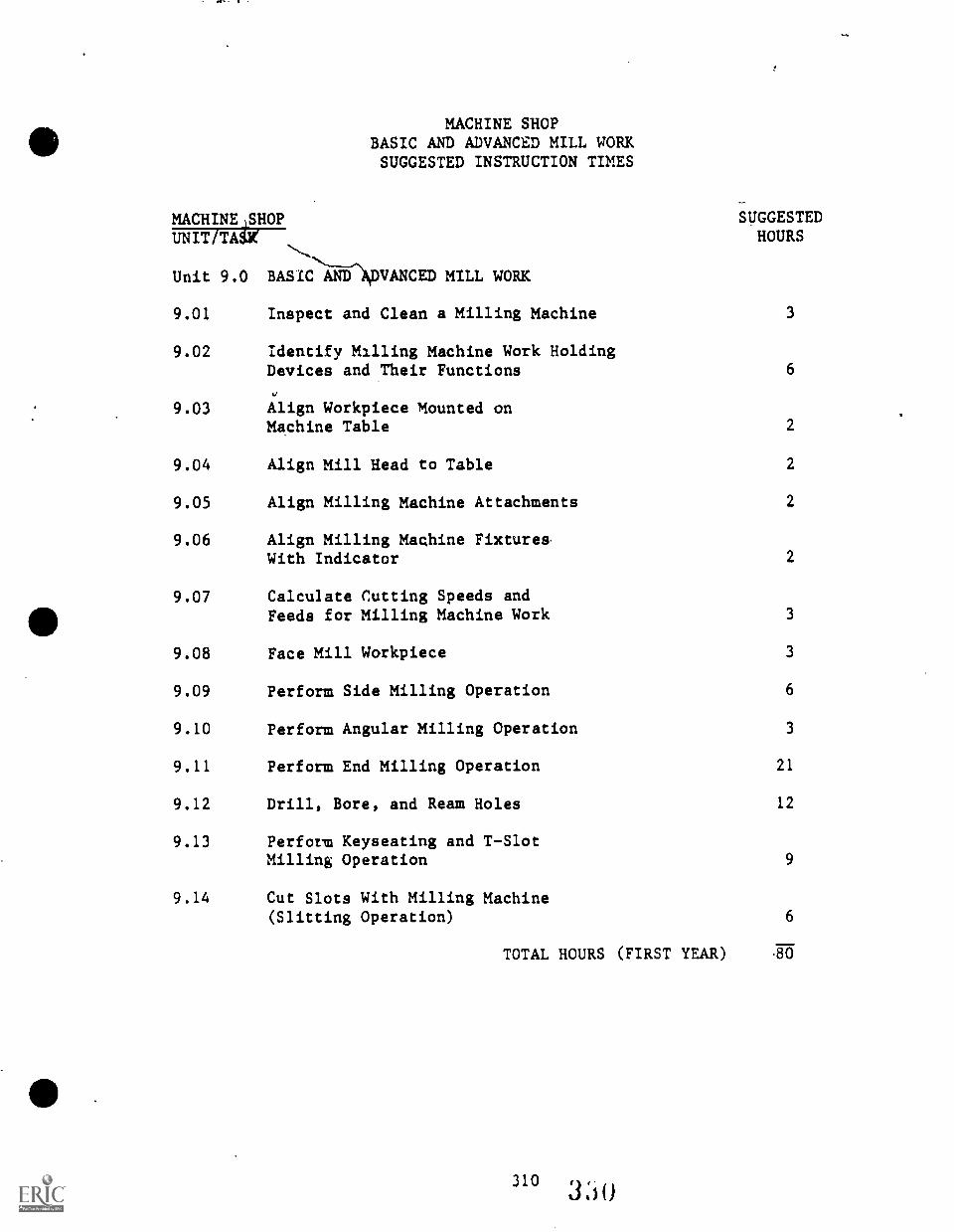
MACHINE SHOPBASIC AND ADVANCED MILL WORKSUGGESTED INSTRUCTION TIMES
MACHINEASHOP SUGGESTEDHOURSUNIT/TAW
Unit 9.0 BASIC AND ADVANCED MILL WORK
9.01 Inspect and Clean a Milling Machine 3
9.02 Identify Milling Machine Work HoldingDevices and Their Functions 6
9.03 Align Workpiece Mounted onMachine Table 2
9.04 Align Mill Head to Table 2
9.05 Align Milling Machine Attachments 2
9.06 Align Milling Machine Fixture&With Indicator 2
9.07 Calculate Cutting Speeds andFeeds for Milling Machine Work 3
9.08 Face Mill Workpiece 3
9.09 Perform Side Milling Operation 6
9.10 Perform Angular Milling Operation 3
9.11 Perform End Milling Operation 21
9.12 Drill, Bore, and Ream Holes 12
9.13 Perform Keyseating and T-SlotMilling Operation 9
9.14 Cut Slots With Milling Machine(Slitting Operation) 6
TOTAL HOURS (FIRST YEAR) 80
310
9.15
9.16
ADVANCED MILL WORK(SECOND YEAR)
Perform Indexing Operations
Perform Graduating andMarking Operations
20
3
9.17 Identify Types of Gears andTheir Functions 3
9.18 Calculate Pitch, Diameters,Working Depth and Clearancesfor Machining Gears 9
9.19 Mill a Gear Rack 12
9.20 Machine a Spur Gear 6
TOTAL HOURS (SECOND YEAR) 53
TOTAL HOURS OF MILL WORK INSTRUCTIONAL TIME: 133
311
331
TASK LISTINGSMACHINE SHOP
UNIT/TASK DESCRIPTION
Unit 9.0 BASIC AND ADVANCED MILL WORK
9.01 (Inspect and Clean a Milling Machine) Provided with a millingmachine (horizontal or vertical), operator's manual, cleaningmaterial°, and the necessary instruction, hand tools, andequipment; inspect and clean tie milling machine according tothe manufacturer's (or instructor's) information. The millingmachine and surrounding area must be free of metal chips,excess lubricant and cutting fluid, and foreign material.
9.02 (Identify Milling Machine Work Holding Devices and TheirFunctions) Given a shop milling machine and work holdingdevices and proper instruction; accurately identify eachdevice and describe the type of work for which the device isdesigned.
9.03 (Align Workpiece Mounted on Machine Table) Given millingmachine, blueprint (drawing), workpiece, and measuring instru-ments; align workpiece on machine table to a tolerance of0.001 inch total indicator run out.
9.04 (Align Mill Head to Table) Given the ram and turret millingmachine and measuring instruments, align the head with thetable to a tolerance of +/- 0.0005 inch.
9.05 (Align Milling Machine Attachments) Given milling machinewith attachments, measuring instruments, hand tools andmaterials; align attachments to a tolerance of 0.001 inch runout at 4 inches.
9.06 (Align Milling Machine Fixtures with Indicator) Given amilling vise, clamping bolts, wrench, dial indicator, mallet,and square; align the fixture on the milling machine tool towithin +/- 0.001 inch total run out.
9.07 (Calculate Cutting Speeds and Feeds for Milling Machine Work)Given a milling machine and accessories, workstock, workassignments and necessary tools and materials; select propercutter and attachment, calculate speed and feed, and installthe cutter. Performance must conform to the Machinery'sHandbook.
9.08 (Face Mill Workpiece) Given a milling machine with workpiecemounted in a jig, detail drawing or blueprint, facing specifi-cations, an assortment or arbors, collars, and milling
312 33ti
cutters, and the necessary hand tools, measuring instruments,and materials; face mill the workpiece to specifications to atolerance of +/- 0.001 inch. Finished work must be smoothwithout gouges or marks.
9.09 (Perform Side Milling Operation) Given a milling machine,selection of cutters, workpiece, detail drawing or blueprint,milling specifications, assortment or arbors, collars, andnecessary hand tools, measuring instruments, and materials;perform side milling operation to a tolerance of +/- 0.001inch of specifications, finishing work without gouges ormarks.
9.10 (Perform Angular Milling Operation) Given milling machine,workpiece, cutters and attachments, work holding device,measuring instruments, detail drawing or blueprint, millingspecifications, and the necessary hand tools and materials;perform angular mill operations to a tolerance of +/- 5minutes and finish the workpiece without gouges or marks.
9.11 (Perform End Milling Operation) Given a milling machine,assortment of cutters, arbors, collars, and the necessarytools, equipment, measuring instruments, and materials;perform an end milling machine operation to bring surfaces tospecifications to a tolerance of +/- 0.001 inches with finishsmooth without gouges or marks.
9.12 (Drill, Bore, and Ream Holes) Given a milling machine,rectangular stock, detail drawing, drill and reaming specifi-cations, and assortment of drill bits, reamers, and holders,and the necessary hand tools, measuring instruments, andmaterials; using the milling machine drill, bore, and reamholes in tha stock to specifications for location and diameter( +1- 0.0005 inch) and perpendicularity (+/- 1 degree).
9.13 (Perform Keyseating and T-Slot Milling Operation) Givenmilling machine. blueprint-drawing, specifications, andnecessary tools and materials; machine a Woodruff keyway(seat) in the workpiece with a tolerance of +/- 0.005 inch tospecifications (+/- 1/64 inch fraction dimensions).
9.14 (Cut Slots With Milling Machine [Slitting Operations]) Givenmilling machine, slitting cutter, attachments, workpiece,blueprint-drawing and specifications, and the necessary tools,measuring instruments, and materials; mill internal slot to atolerance of + 0.010 inch or specifications.
- 0.000 inch
ADVANCED MILL WORK(SECOND YEAR)
9.15 (Perform Indexing Operations) Given milling machine, indexingor dividing head, rectangular or cylindrical stock, detaildrawing that required equally-spaced slots milled in workpiece,milling specifications, assortment of milling cutters andholders, and the necessary hand tools, attachments, measuringinstruments, and materials; mill slot to specifications +/-0.002 inch for location and +/- 0.001 inch for width anddepth.
9.16 (Perform Graduating and Marking Operations) Given millingmachine, accessories, flat or cylindrical sArface workpiece,drawing and specifications, and the necessary tools, measuringinstrument, and materials; cut graduation marks to .001 inchwith a tolerance of +/- 0.0001 inch.
9.17 (Identify Types of Gears and Their Functions) Given selectionof gears and gear arrangements, select and identify each gear.Describe at least three uses of each gear to the instructor'sstandards.
9.18 (Calculate Pitch, Diameters, Working Depth and Clearances forMachining Gears) Given a gear drawing (e.g., spur), calculateall dimensions to a tolerance of +/- 0.001 inch.
9.19 (Mill a Gear Rack) Given the milling machine, drawing,specifications, workpiece, machine accessories and cutters,and necessary tools, measuring instruments, and materials;mill a gear rack to specifications, tolerance of "zero" to.002 inch.
9.20 (Machine a Spur Gear) Given a detail drawing, a pre-cutworkpiece, hand tools, precision measuring instruments, andthe necessary machine tools, accessories, attachments, andmaterials; machine a spur gear. The gear must meet thespecifications of the drawing with a tolerance of +/- 0.002inch for pitch diameter and dimensions.
314 ,
.3 3 4
UNIT 9.0 BASIC MILL WORK
TASK 9.01 INSPECT AND CLEAN A MILLING MACHINE
PERFORMANCE OBJECTIVE:
Provided with a milling machine (horizontal or vertical), operator'smanual, cleaning materials, and the necessary instruction, hand tools,and equipment; inspect and clean the milling machine according to themanufacturer's (or instructor's) information. The milling machine andsurrounding area must be free of metal chips, excess lubricant andcutting fluid, and foreign material.
PERFORMANCE ACTIONS:
9.0101 Review directions for inspection and cleaning thegiven milling machine.
9.0102 Assemble adjustable wrench, screwdriver, wipingcloth, brush, and oil.
9.0103 If machine has automatic oiling system, followmanufacturer's instructions or process as follows(if instructor approves actions for the machine).
9.0104 Check level of oil in each reservoir sight glass(Arbor support, Table and Saddle, Oil Flow Gage,Driving Chain and Motor, Filler Cup for Column, andFiller Cup for Knee).
9.0105 Clean area surrounding filler cup.
9.0106 As necessary, add clean oil of type recommended bymanufacturer to raise oil to proper level on gageglass.
9.0107 Return filler cup and tighten it securely.
9.0108 Check operation of oil pumps, looking for a streamof oil in gage glass when pump is functioning, ifmachine is equipped with flow gage.
9.0109 Locate, clean, and fill oil holes and pockets whichrequire hand oiling.
9.0110 Inspect oiler for damage signs. Report any mal-functioning signs to instructor.

UNIT 9.0 BASIC MILL WORK
TASK 9.01 INSPECT AND CLEAN A MILLING MACHINE
PERFORMANCE ACTIONS (Con't.):
9.0111
9.0112
9.0113
9.0114
9.0115
Replace screw plugs removed in oiling process.
Wipe off excess or dripped oil.
Thoroughly clean and lubricate all flat and roundsliding surfaces which are not automatically oiled.
Clean and lubricate sliding surfaces on overarmbefore changing its position in column.
Clean and oil all exposed screws, such as elevatingscrew for the knee, if not oiled automatically.
EXTENSION OF ACTIONS: (Optional)
9.0116
9.0117
9.0118
9.0119
9.0120
9.0121
9.0122
9.0123
9.0124
The following inspection and cleaning actionstypically are accomplished periodically rather thandaily.
Check height of oil for motor bearings, adding oilto adjust the level properly.
If applicable, lubricate driving chain or check oilsupply if lubricated by spash system.
Check condition of oil filters, if applicable.(Clean or replace this felt pad or screen if it isloaded with particles.)
Remove drain plugs and drain oil from reservoirswhen discoloration or thinning of lubricant indicatesneed for the action. (This action may be scheduledto occur at a period of time.)
Clean out reservoir to remove all sediment which hasaccumulated and flush it out with an oil solventsuch as gasoline or naphtha.
Screw drain plug securely in place.
Refill reservoir with clean oil of he type recommendedby the manufacturer (S.A.E. 30 wi/ht be substituted).
Grease all ball bearings and points requiringgrease.
316 336
N.
UNIT 9.0 BASIC MILL WORK
TASK 9.01 INSPECT AND CLEAN A MILLING MACHINE(Con't.)
PERFORMANCE STANDARDS:
Inspecc and clean a millingor manufacturer's standardsfree of metal chips, excessforeign material.
SUGGESTED INSTRUCTION TIME: 3 Hours
RELATED TECHNICAL INFORMATION:
machine according to the instructor'sso that the surrounding area islubricant, and cutting fluid, and
- Explain purpose of performing routine inspection and cleaningof a milling wachine.
- Describe procedure for inspecting and cleaning a millingmachine.Identify materials used to clean a milling machine.Explain necessary safety precautions.Identify parts and functions of typical milling machine(s):
- Functions of the milling machine.- Column and knee type.- Adjustable spindle type.- Plain and unifersal machines.- Vertical and bed.- End and face milling.- Column.- Knee.- Table.- Spindle.- Overarm.- Coolants and cutting fluids.
UNIT 9.0 BASIC MILL WORK
TASK 9.02 IDENTIFY MILLING MACHINE WORK HOLDINGDEVICES AND THEIR FUNCTIONS
PERFORMANCE OBJECTIVE:
Given a shop milling machine and work holding devices and proper instru-ction; accurately identify each device and describe the type of work forwhich the device is designed.
PERFORMANCE ACTIONS;
9.0201 Identify the following milling machines vises:a. Plain.b. Swivel.
9.0202 Identify fixtures.
9.0203 Describe importance of holding workpiece securelyand accurately.
9.0204
9.0205
Select the appropriate work holding device for agiven job. (Student's selection should be acceptableto the instructor.)
Demonstrate following skills acceptable to instructor:a. Clean and replace vise on bed.b. Align vise by sight.c. Fasten vise by sight.d. Place dial Indicator attachment in mill spindle
or magnetic tool holder.e. Fasten dial indicator to attachment.f. Identify fixed vise jaws.g. Secure clamp bolts.h. Recheck with indicator.
PERFORMANCE STANDARDS:
- Identify milling machine work holding devices and theirfunctions and demonstrate how to mount a given holding deviceson a given milling machine.
- Performance actions and performance must be accurate and meetthe standards of the instructor.
SUGGESTED INSTRUCTION TIME: 6 Hours
3183;38
UNIT 9.0 BASIC MILL WORK
TASK 9.02 IDENTIFY MILLING MACHINE WORK HOLDINGDEVICES AND THEIR FUNCTIONS (Con't.)
RELATED TECHNICAL INFORMATION:
Identify:Milling machine and parts.Work holding devices for given jobs.Types of stock worked with milling machine in typicaltraining.Measuring tools.
319 339
UNIT 9.0 BASIC MILL WORK
TASK 9.03 ALIGN WORKPIECE MOUNTED ON MACHINETABLE
PERFORMANCE OBJECTIVE:
Given milling machine, blueprint (drawing), workpiece, and measuringinstruments; align workpiece on machine table to a tolerance of 0.001inches total indicator run out.
PERFORMANCE ACTIONS:
9.0301
9.0302
9.0303
Clean out slots on milling machine table.
Review blueprint, drawing, etc.:a. Note surface to be'machined.b. Identify type of cutter required.
Place workpiece on machine table:a. Center workpiece longitudinally or table.b. Locate workpiece according to machining operation.
9.0304 Select clamps, blocks, and bolts and clamp workpiecedown lightly in rough position.
9.0305 Clamp indicator assembly on arbor.
9.0306 Adjust indicator contact point toward workpiecesurface.
9.0307 Move table and workpiece next to indicator contactpoint.
9.0308 Move table longitudinally.
9.0309 Adjust workpiece to correctly line up with indicator.
9.0310 Move table and workpiece in contact with indicatorcontact point.
9.0311 Adjust table against indicator about 0.0101 inches.
9.0312 Move table longitudinally the length of the workpiece.
9.0313 Observe total movement of indicator at each end ofworkpiece.
320
340
UNIT 9.0 BASIS MILL WORK
TASK 9.03 ALIGN WORKPIECE MOUNTED ON MACHINETABLE
PERFORMANCE ACTION' (Con't.):
9.0314 Adjust workpiece:a. Adjust workpiece one half difference of end
reading.b. Tap lightly with soft hammer.
9.0315 Check workpiece with indicator for runout.
9.0316 Repeat steps until workpiece is within tolerance.
PERFORMANCE STANDARDS:
- Align workpiece on milling machine table to a tolerance of0.001 inches total indicator run out.
SUGGESTED INSTRUCTION TIME: 2 Hours
RELATED TECHNICAL INFORMATION:
- Use of dial indicator and holder.- Use of straps, clamps, bolts, parallels, etc.
321
341
UNIT 9.0 BASIC MILL WORK
TASK 9.04 ALIGN MILL HEAD TO TABLE
PERFORMANCE OBJECTIVE:
Given the ram and turret milling machine and measuring instruments,
align the head with the table to a tolerance of +/- 0.0005 inch.
PERFORMANCE STANDARDS:
9.0401 Adjust head to "zero" graduation in both directions.
9.0402 Clean table and center under spindle.
9.0403 Mount dial indicator on 90 degree extension rod held
in spindle holder.
9.0404 Position indicator over front of table.
9.0405 Carefully lower spindle under indicator button
touches table.
9.0406 Lower spindle until dial indicator registers about
1/2 revolution and set on "zero."
9.0407 Lock spindle.
9.0408 Carefully rotate spindle 180 degrees by hand (watch
T-slots).
9.0409 Compare front and tack readings.
9.0410 Loose locking nuts and adjust head (reading difference
and lock).
9.0411 Recheck setting and make adjustments.
9.0412 Raise and rotate spindle 90 degrees.
9.0413 Rcpeat steps as necessary.
9.0414 Check readings in both directions.
9.0415 Adjust and check until table is aligned with spindle
to required tolerance.
32234 2
UNIT 9.0 BASIC MILL WORK
TASK 9.04 ALIGN MILL HEAD TO TABLE (Con't.)
PERFORMANCE STANDARDS:
- Align mill head to table to a tolerance of 0.0005 inch.
SUGGESTED INSTRUCTION TIME: 2 Hours
RELATED TECHNICAL INFORMATION:
- Ram and turret milling machine.- Use of dial indicator.
ale
3233.10
UNIT 9.0 BASIC MILL WORK
TASK 9.05 ALIGN MILLING MACHINE ATTACHMENTS
PERFORMANCE OBJECTIVE:
Given milling machine with attachments, measuring instruments, handtools and materials; align attachments to a tolerance of 0.001 inch runout at 4 inches.
PERFORMANCE ACTIONS:
9.0501 Replace draw bar with extended draw bar.
9.0502 Drop quill approximately 3 inches and lock.
9.0503 Insert 90 degree attachment driver in quill andtighten draw bar securely, aligning key with keyway.
9.0504 Position indicating surface parallel with tablemovement.
9.0505 Attach two housing clamp bolts.
9.05r5 Attach magnetic base with. dial indicator.
9.0507 Indicate 90 degree milling attachment for parallelalignment with table movement.
9.0508 Fecure housing clamp bolts.
9.0509 Check for accuracy, repeating steps as needed.
PERFORMANCE STANDARDS:
- Align milling machine attachments provided with a tolerance of0.001 inch run out at 4 inches.
SUGGESTED INSTRUCTION TIME: 2 Hours
RELATED TECHNICAL INFORMATION:
- Identify parts of milling machine.- Identify 90 degree milling attachment.- Identify extended draw bar.- Explain the magnetic base and post.- Describe use of dial indicator.
UNIT 9.0 BASIC MILL WORK
TASK 9.06 ALIGN MILLING MACHINE FIXTURES WITHINDICATOR
PERFORMANCE OBJECTIVE:
Given a milling vise, clamping bolts, wrench, dial indicator, mallet,
and square; align and fixture on the milling machine tool to within +/-
0.001 inch total runout.
PERFORMANCE ACTIONS:
9.0601
9.0602
9.0603
Clean and place vise on bed.
Align vise by sight.
Fasten vise to bed with clamping bolts (don'ttighten yet*).
9.0604 Locate dial indicator in mill spindle or magnetictoolholder.
9.0605 Indicate fixed visl jaw:
a. Perpendicular alignment use square againstcolumn before using dial indicator.
b. Use longitudinal feed or cross feed as required.
9.0606 Check vise jaw at end of jaw.
9.0607 Tap vise one-half difference of reading for correction.
9.0608 Repeat steps until vise aligned.
9.0609 *Tighten clamp bolts.
9.0610 Check with indicator.
PERFORMANCE STANDARDS:
- Align milling machine vise with dial indica o within +/
0.001 inch total run out.
SUGGESTED INSTRUCTION TIME: 2 Hours
UNIT 9.0 BASIC MILL WORK
TASK 9.07 CALCULATE CUTTING SPEEDS AND FEEDSFOR MILLING MACHINE WORK
PERFORMANCE OBJECTIVE:
Given a milling machine and accessories, workstock, work assignment, andnecessary tools and materials; select proper cutter and attachment,
calculate speed and feed, and install the cutter. Performance must
conform to the Machinery's Handbook.
PERFORMANCE ACTIONS:
9.0701 Identify and classify workpiece to be machined.
9.0102 Select cutter to be used.
9.0103 Determine condition of milling machine.
9.0104 Determine depth of cut to be made.
9.0105 Establish material cutting speed.
9.0106 Determine speed setting for machine by using table(or handout) tables.
9.0107 Set speed according to operation manual.
9.0108 Select and set feed, repeating appropriate stepsoutlined above, using tables provided and operationmanual.
PERFORMANCE STANDARDS:
- Calculate cutting speeds and feed for milling machine work,select proper cutter for given workpiece, and set up millingmachine.
- Performance must be to the standards of Machinery's Handbookand the instructor.
SUGGESTED INSTRUCTION TIME: 3 Hours

UNIT 9.0 BASIC MILL WORK
TASK 9.07 CALCULATE CUTTING SPEEDS AND FEEDSFOR MILLING MACHINE WORK (Can't.)
RELATED TECHNICAL INFORMATION:
- Define cutting speed.- Define cutting feed.- Identify factors determining speed and feed.
- Describe tempered cutters.- Describe carbide cutters.- Describe high speed cutters.- Correctly use the cutting speed formula.- Describe/demonstrat3 how to take rough and finish cuts.
327 3 4 If
UNIT 9.0 BASIC MILL WORK
TASK 9.08 FACE MILL WORKPIECE
PERFORMANCE OBJECTIVE:
Given a milling machine with workpiece mounted in a jig, detail drawingor blueprint, facing specifications, an assortment or arbors, collars,
and milling cutters, and the necessary hand tools, measuring instruments,and materials; face mill the workpiece to specifications to a toleranceof +/- 0.001 inch. Finished work must be smooth without gouges or
marks.
PERFORMANCE ACTIONS:
9.0801
9.0802
9.0803
9.0804
Set up milling machine.
Select and mount cutter.
Mount workpiece.
Make cut.
PERFORMANCE STANDARDS:
- Face mill workpiece to specifications to a tolerance of +/-0.001 inch with no gouges or marks in finished workpiece.
SUGGESTED INSTRUCTION TIME: 3 Hours
RELATED TECHNICAL INFORMATION:
- Identify milling cutters used for face milling operations.- Explain how to mount a face milling cutter in the spindle.- Define a face milling operation.- Calculate cutting speed, feed, and depth of cut for face
milling operation.Explain right-hand and left-hand face milling cutters.
- Describe how to mount a cutter:a. Stub arbor.b. Bolted to spindle.
- Explain how to surface finish a face milled workpiece.- Identify safety considerations.
328 3,ici
UNIT 9.0 BASIC MILL WORK
TASK 9.09 PERFORM SIDE MILLING OPERATION
PERFORMANCE OBJECTIVE:
Given a milling machine, selection of cutters, workpiece, detail drawing
or blueprint, milling specifications, assortment of arbors, collars, and
necessary hand tools, measuring instruments, and materials; perform side
milling operation to a tolerance of +/- 0.001 inch of specifications,
finishing work without gouges or marks.
PERFORMANCE ACTIONS:
9.0901
9.0902
9.0903
9.0904
Set up machine for side milling operation.
Select and mount cutter.
Mount workpiece.
Make required cut to specifications.
PERFORMANCE STANDARDS:
- Perform side milling operation to a tolerance of +/- 0.001
inch to specifications, finishing work without gouges or
marks.
SUGGESTED INSTRUCTION TIME: 6 Hours
RELATED TECHNICAL INFORMATION:
- Describe side milling.- Select side milling cutters.- Determine speeds and feeds. ,/
- Select attachments for side- Select holding devices for side milling.
- Align work on milling machine.
3296. 4
UNIT 9.0 BASIC MILL WORK
TASK 9.10 PERFORM ANGULAR MILLING OPERATION
PERFORMANCE OBJECTIVE:
Given milling machine,. workpiece, cutters and attachments, work holdingdevice, measuring instruments, detail drawing or blueprint, millingspecifications, and the necessary hand tools and materials; performangular mill operations to a tolerance of +/- 5 minutes and finish theworkpiece without gouges or marks.
PERFORMANCE ACTIONS:
9.1001
9.1002
9.1003
9.1004
9.1005
9.1006
Identify and classify workpiece (material).
Mount and align angle plate.
Select and mount end mill cutter.
Select and set speed, feed, and depth of cut.
Make cut.
Check surface and tolerance specifications, makingmachine adjustments as necessary.
9.1007 Measure and inspect workpiece.
PERFORMANCE STANDARDS:
- Perform angular milling operation to a tolerance of +/- 5minutes and finish workpiece without gouges or marks.
SUGGESTED INSTRUCTION TIME: 3 Hours
RELATED TECHNICAL INFORMATION:
- Explain an angular milling ope- Identify angular milling cutte- Calculate speeds and feeds.- Select attachments for angular- Select work holding devices.- Align work for angular milling
330
ration.rs.
milling operation.
operation.
35o
UNIT 9.0 BASIC MILL WORK
TASK 9.10 PERFORM ANGULAR MILLING OPERATION(Con't.)
EXPANSION OF TASK:
1. MILL CHAMFER (Optional)
Given chamfering specifications, assortment of angular arbors,
collets, and angular cutters, milling machine, workpiece mounted in
a universal vise, detail drawing, and necessary tools, measuringinstruments, and materials; mill chamfer to specifications +/- .005
inch.
2. MILL BEVEL
Given milling machine, workpiece mounted in universal vise, detail
drawing, bevel specifications, assortment or arbors, collars, andangular cutters, and the necessary hand tools, measuring instruments,and materials; mill the bevel to specifications +/- .005 inch.
UNIT 9.0 BASIC MILL WORK
TASK 9.11 'PERFORM END MILLING OPERATION
PERFORMANCE OBJECTIVE:
Given a milling machine, assortment of cutters, arbors, collars, and thenecessary tools, equipment, measur ng instruments, and materials;
perform an end milling machine opration to bring surfaces to specifi-cations to a tolerance of +/- 0.,601 inch with finish smooth withoutgouges or marks.
PERFORMANCE ACTIONS:
9.1101 Identity and classify workpiece (material).
9.1102 Mount and align vise.
9.1103 Secure workpiece in holding device.
9.1104 Select and mount end mill cutter.
9.1105 Select and set speed and feed.
9.1106 Align workpiece, touch off, and set depth of cut.
PERFORMANCE STANDARDS:
- Perform end milling operation to bring surfaces to specifi-cations +/- 0.001 inch with a smooth finish without gouges ormarks.
SUGGESTED INSTRUCTION TIME: 21 Hours
RELATED TECHNICAL INFORMATION:
- Describe an end milling operation.- Identify end milling cutters.- Calculate speeds and feeds.- Identify attachments.- Identify holding devices.- Describe/demonstrate work alignment.- Identify safety considerations.
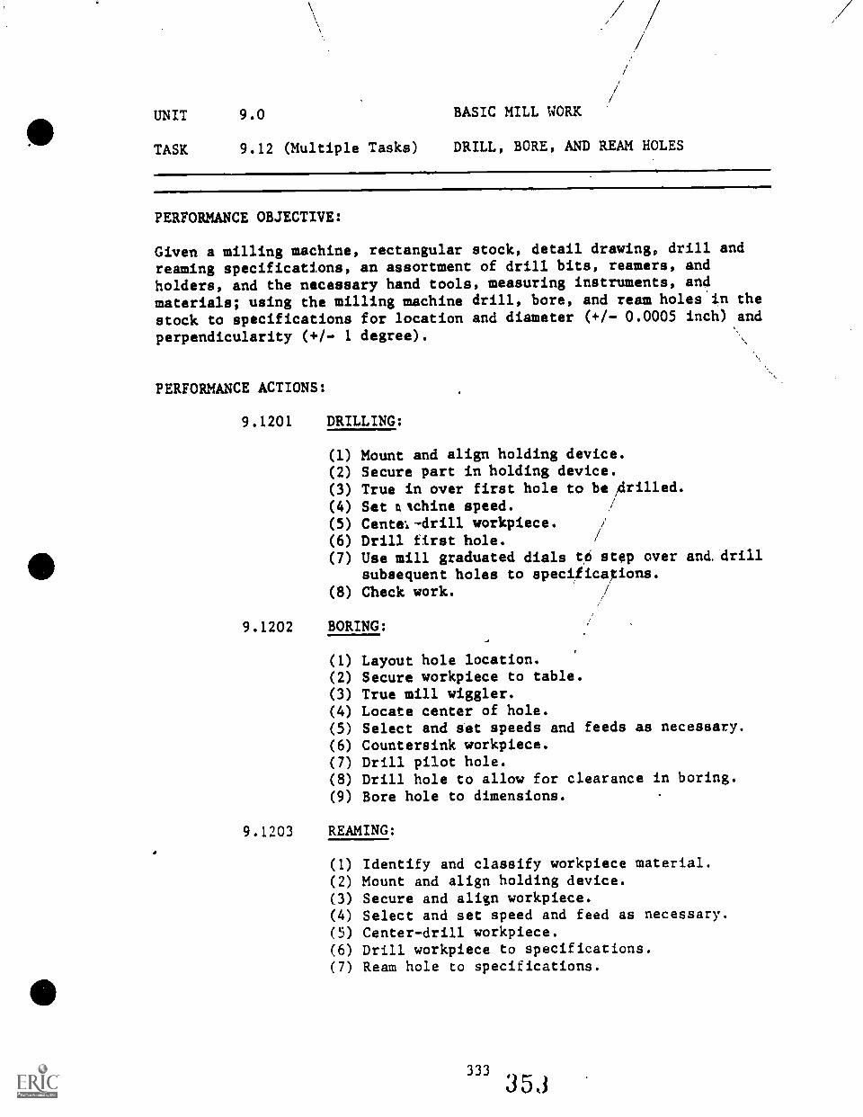
e
UNIT 9.0 BASIC MILL WORK
TASK 9.12 (Multiple Tasks) DRILL, BORE, AND REAM HOLES
PERFORMANCE OBJECTIVE:
Given a milling machine, rectangular stock, detail drawing, drill and
reaming specifications, an assortment of drill bits, reamers, and
holders, and the necessary hand tools, measuring instruments, and
materials; using the milling machine drill, bore, and ream holes in the
stock to specifications for location and diameter (+/- 0.0005 inch) and
perpendicularity (+/- 1 degree).
PERFORMANCE ACTIONS:
9.1201 DRILLING:
(1) Mount and align holding device.(2) Secure part in holding device.(3) True in over first hole to be ;drilled.(4) Set ntchine speed.(5) Cente;-drill workpiece.(6) Drill first hole.(7) Use mill graduated dials to step over and. drill
subsequent holes to specificap.ons.(8) Check work. /
9.1202 BORING:
(1) Layout hole location.(2) Secure workpiece to table.(3) True mill wiggler.(4) Locate center of hole.(5) Select and set speeds and feeds as necessary.(6) Countersink workpiece.(7) Drill pilot hole.(8) Drill hole to allow for clearance in boring.(9) Bore hole to dimensions.
9.1203 REAMING:
(1) Identify and classify workpiece material.(2) Mount and align holding device.(3) Secure and align workpiece.(4) Select and set speed and feed as necessary.(5) Center-drill workpiece.(6) Drill workpiece to specifications.(7) Ream hole to specifications.
333
35(3
4.
UNIT 9.0 BASIC MILL WORK
TASK 9.12 (Multiple Tasks) DRILL, BORE, AND REAM HOLES (Con't.)
PERFORMANCE STANDARDS:
- Drill, bore, and ream holes in given workpii.te to specifi-cations, centered and finished to a tolerance of +1- 0.0005inch.
SUGGESTED INSTRUCTION TIME: 12 Hours
RELATED TECHNICAL INFORMATION:
- DRILLING AND REAMING ON MILL- Identify methods for holuing workpieces for drill and
reaming.- Describe how to layout and drill equally-spaced holes.- Describe procedure for drilling and reaming holes.- Explain use of cutting fluid in drilling and reaming.- Calculate cutting feeds and speeds for drilling and
reaming.- BORING ON MILL
- Describe demonstrate how to adjust boring head.
- Calculate cutting speed and feed for boring operation.- Explain setup requirements for boring operation.- Describe procedure for boring holes with milling machine.- Explain use of cutting fluid.
- Explain how to obtain accuracy.- Identify safety considerations.- Explain how to determine hole sizes.
334 3 5
UNIT 9.0 BASIC MILL WORK
TASK 9.13 PERFORM KEYSEATING AND T-SLOT MILLINGOPERATION
PERFORMANCE OBJECTIVE:
Given milling machine, blueprint-drawing, specifications, workpiece andprecision measuring instruments, and necessary tools and materials;machine a Woodruff keyway (seat) in the workpiece with a tolerance of+/- 0.005 inch to specifications (+/- 1/64 inch fraction dimensions).
PERFORMANCE ACTIONS:
9.1301 KEY SEATING:
(1) Mount, secure, and align vise to table.(2) Select, mount, and secure cutter (Woodruff key
seat) .
(3) Set machine speed.(4) Set center line of cutter on center line of
shaft, close'to holding device.(5) Turn machine on and touch off.(6) Mill to prescribed depth and length.
(See V-TECS Machinist Task 163 for more detailedactions.)(See Milling Machine Work, Albany, NY: DelmarPublishers, Inc., pp. 214-216, 1953, for standards.)
9.1302 T-SLOTTING: (Task Expansion)
(1) Identify and classify workpiece.(2) Secure workpiece to table.(3) Position slotting attachment over table.(4) Select and secure cutter to spindle.(5) Select and adjust stroke length.(6) Align cutter to workpiece.(7) Set speed.(8) Slot to specifications.
PERFORMANCE STANDARDS:
- Machine a Woodruff keyway (seat) in given workpiece to specifi-cations +/- 0.005 inch.
UNIT 9.0 BASIC MILL WORK
TASK 9.13 PERFORM KEYSEATING AND T-SLOT MILLINGOPERATION (Con't.)
SUGGESTED INSTRUCTION TIME: 9,Hours
RELATED TECHNICAL INFORMATION:
- Identify accuracy required.- Identify machine attachments, holding devices, and cutters.- Describe/demonstrate work alignment.- Decide on speeds and feeds.- Determine slot and seat sizes.- Demonstrate how to set up machine.- Demonstrate selection and mounting of cutters.- Demonstrate how to make a cut.- Machinery's Handbook.- Identify safety considerations.
UNIT 9.0' BASIC MILL W RK
TASK 9.14 CUT SLOTS WI 111cIG-MAGHT4(Slitting Operation)
PERFORMANCE OBJECTIVE:
Given milling machine, slitting cutter, attachments, workpiece,blueprint-drawing and specifications, and the necessary tools, measuringinstruments, and materials; mill internal slot to a tolerance of+ 0.010 inch or specifications.- 0.000 inch
PERFORMANCE ACTIONS:
9.1401 Set up mill: 'Select and mount cutter.
9.1402 Mount and align workpiece.
9.1603 Select and set speed, feed, and depth of cut.
9.1404
9.1405
9.1406
(See: Milling Machine Work, Albany, NY: DelmarPublishers Inc., pp. 192-194, 109-120 forpossible enabling objectives, 1953.)
Align workpiece to cutter.
Mill workpiece.
Measure finished part for accuracy.
PERFORMANCE STANDARDS:
- Cut slots with milling machine to specifications within 0.010inch.
SUGGESTED INSTRUCTION TIME: 6 Hours
RELATED TECHNICAL INFORMATION:
- Describe what accuracy is required.- Identify attachment.- Identify holding devices.- Select and mount slitting cutter.- Describe gang slitting.- Align work.- Determine depth of cut and length of feed.- Describe how to measure finished part.
337
35/
This page precedes Task 9.15
ADVANCED MILL WORK
The following tasks, 9.15 - 9.20, which represent Advanced Mill Work
typically will be introduced during the second year of training. The
instructional time represented by these task objectives has been included
in the second year plan for the secondary level Machine Shop program.
For the purpose of organization and to represent the typical order of
learning development, basic and advanced mill work objectives are not
'separated.
The second year description of Machine Shop will include a "comment" toidentify that Advanced Mill Work training is included in the second year
"instructional time plan" and to refer the student, instructor, orothers to the second year tasks described in Unit 9.
UNIT 9.0 ADVANCED MILL WORK
TASK 9.15 PERFORM INDEXING OPERATIONS
PERFORMANCE OBJECTIVE:
Given milling machine, indexing or dividing head, rectangular or
cylindrical stock, detail drawing that required equally-spaced slots
milled in workpiece, milling specifications, assortment of milling
cutters and holders, and the necessary hand tools, attachments, measuringinstruments, and materials; mill slots to specifications +/- 0.002 inch
for location and +/- 0.001 inch for width and depth.
PERFORMANCE ACTIONS:
9.1501
9.1502
9.1503
9.1504
9.1505
Identify and classify workpiece material.
Mount and align dividing head.
Select and mount cutter.
Mount and align holding device and workpiece.
Determine number of indexes that workpiece must berotated.
9.1506 Set up indexing unit of dividing head.
9.1507 Select and set up speed and feed.
9.1508 Touch off, make primary cut, and adjust depth ofcut.
9.1509 Measure for blueprint specifications, making necessaryadjustments.
9.1510 Recut if necessary.
9.1511 Rotate indexing unit for each subsequent cut specified.
9.1512 Inspect and measure finished part to specifications.
PERFORMANCE STANDARDS: (NOTE: Specifications divided in direct andsimple indexing operations.)
339
35:)
UNIT 9.0 ADVANCED MILL WORK
TASK 9.15 PERFORM INDEXING OPERATIONS
PERFORMANCE STANDARDS (Con't.):
- DIRECT INDEXING- Mill slots by direct indexing to specifications with a
tolerance of +/- 0.002 inch for location and +/- 0.001inch for width and depth.
- Disengage worm and turn indexing plate with spindleattached by hand.
- SIMPLE INDEXING- Mill workpiece by simple indexing to specifications with
a tolerance of +.- 1/2 degree for location of cuts and+/- 0.002 inch for all dimensions.
- Correctly use 1:40 ratio in advancing worm.- Correctly use formula for the number of turns of the
crank for indexing.
SUGGESTED INSTRUCTION TIME: 20 Hours
RELATED TECHNICAL INFORMATION:
- Define: Indexing, direct indexing, simple indexing, andangular indexing.
- Explain the construction of an indexing or dividing head.- Explain the operation of an indexing or dividing head.- Explain difference between simple and direct indexing:
Advantages and disadvantages- Explain setup requirements for milling slots by direct indexing.- Describe procedure for milling slots by direct indexing.- Calculate cutting feed, speed, and depth of cut for milling
slots by direct indexing.- Identify applications using the indexing head with tailstock
or chuck.- Explain how to operate dividing head for simple indexing.- Identify applications for using simple indexing to machine
workpiece on a mill.- Explain setup requirements for milling a workpiece by simple
indexing.
- Describe procedures for milling workpiece by simple indexing.- Calculate cutting speed and feed for a simple indexing operation.- Calculate "crank turns" for a simple indexing operation.- Describe work and vise alignment.- Explain accuracy required.- Identify attachments and cutters.- Identify safety considerations.
340 ,
3 (iu
UNIT 9.0 ADVANCED MILL WORK
TASK 9.15 PERFORM INDEXING OPERATIONS (Con't.)
EXPANSION OF TASK: (Optional)
DRILL HOLES BY ANGULAR INDEXING
PERFORMANCE OBJECTIVE:
Given horizontal milling machine, dividing or indexing aead, pre-cutcylindrical stock, detail drawing that requires holes to be drilled inworkpiece at specified angles, hole specifications, assortment of twistdrills and holders, and the necessary hand tools, measuring instruments,and materials; drill the holes in the stock using angular indexing tospecifications with a tolerance of +/- 15 minutes for location.
PERFORMANCE ACTIONS: (To be clarified by instructor.)
PERFORMANCE STANDARDS: (See objective.)
RELATED TECHNICAL INFORMATION:
- Explain calculations required to perform angular indexing.- Calculate cutting speed and feed for angular indexing operation.- Explain setup requirements for drilling holes using angular
indexing method.- Describe procedure for drilling holes by angular in xing.
- Explain differences among direct, simple, and angul, indexing.
- Identify safety considerations.
341
361
UNIT 9.0 ADVANCED MILL WORK
TASK 9.16 PERFORM GRADUATING AND MARKINGOPERATIONS
PERFORMANCE OBJECTIVE:
Given milling machine, accessories, flat or cylindrical surface workpiece,drawing and specifications, and the necessary tools, measuring instrument,..and materials; cut graduation marks to .001 inch with a tolerance of +/-0.0001 inch.
PERFORMANCE ACTIONS:
9.1601
9.1602
9.1bO2
9.1604
Set up machine,
Select and mount cutters.
Cut graduation marks according to standard procedures.
Measure for tolerance.
PERFORMANCE STANDARDS:
- Cut graduation marks to .001 inch with a tolerance of,+/-0.0001 inch on flat or cylindrical surface workpiece.
SUGGESTED INSTRUCTION TIME: 3 Hours
RELATED TECHNICAL INFORMATION:
- Describe accuracy required.- Identify attachments, scriber, tool and arbor, and spacers.- Select speeds and feeds.- Determine graduation degrees.- Describe how tc.-select holding devices.- Describe how to align work.- Describe use of index head and gear train for cylindrical
work, if applicable.- Machinery's Handbook.
UNIT 9.0 ADVANCED MILL WORK
TASK 9.17 IDENTIFY TYPES OF GEARS AND THEIRFUNCTIONS
PERFORMANCE OBJECTIVE:
Given selection of gears and gear arrangements, select and identify each
gear. Describe at least three uses of each gear to the instructor's
standards.
PERFORMANCE ACTIONS:
9.1701 Select, identify, and describe functions of givengears.
9.1702 Identify method of manufacturing (milling) givengears.
PERFORMANCE STANDARDS:
- Identify types of gears and their functions and typicalmethods of milling gears.
- Instructor's standards apply.
SUGGESTED INSTRUCTION TIME: 3 Hours
RELATED TECHNICAL INFORMATION:
Identify:- Spur gears- Worm gears- Rack and pinion gears- Hypoid gears- Bevel gears
- Describe materials used in gear manufacturing.
- Herringbone gears- Helical gears- Planetary sets- Gear ratios
EXPANSION OF TASK: (3 Hours)
- Given gear drawing, label each part (name gear tooth elementson different gears) using correct symbol with 100 percent
accuracy.
3433 6 3
UNIT 9.0 ADVANCED MILL WORK
TASK 9.17 IDENTIFY TYPES OF GEARS AND THEIRFUNCTIONS
EXPANSION OF TASK (Con't.):
3 Identify:- Face- Flank- Pitch circle- Root circle- Addendum- Dedendum- Circular pitch- Working depth- Clearances- Chordal thickness- ?itch and outside diameters.- Pressure angle- Tooth profile
UNIT 9.0 ADVANCED MILL WORK
TASK 9.18 CALCULATE PITCH, DIAMETERS, WORKINGDEPTH AND CLEARANCES FOR MACHININGGEARS
PERFORMANCE OBJECTIVE:
Given a gear drawing (e.g., spur), calculate all dimensions to a toleranceof +/- 0.001 inch.
PERFORMANCE ACTIONS:
9.1801 Using references and procedures outlined by instructor,determine dimensions for given gear with diametralpitch and pressure angle known.
9.1802 If required, expand task to make gear to specifications.
PERFORMANCE STANDARDS:
- Calculate pitch, diameters, working depth and clearances formachining gears with a tolerance of +/- 0.001 inch.
SUGGESTED INSTRUCTION TIME: 9 Hours
RELATED TECHNICAL INFORMATION:
- Use formulas:- Pitch diameter- Diametral pitch- Addendum- Dedendum- Outside diameter- Number of teeth- Tooth thickness- Whole depth- Clearance- Center distance- Center distance- Working depth- Chordal tooth thickness- Chordal addendum- Center distance
- Explain pressure angles.- Machinery's Handbook.
345
3 6;)
UNIT 9.0 ADVANCED MILL WORK
TASK 9.19 MILL A GEAR RACK
PERFORMANCE OBJECTIVE:
Given the milling machine, drawing, specifications, workpiece, machineaccessories and cutters, and necessary tools, measuring instruments, andmaterials; mill a gear rack to specifications, tolerance of "zero" to.002 inch.
PERFORMANCE ACTIONS: (See Task 170, V-TECS Catalog Machinist)
9.1901 Mount dividing bead and tailstock.
9.1902 Secure mandrel to indexing head.
9.1903 Select and secure cutter to mill.
9,1904 Determine and set indexing head to correct division.
9.1905 Center gear blank to nutter.
9.1906 Select and set speed, feed, and depth of cut.
9.1907 Cut gear to specifications.
PERFORMANCE STANDARDS:
- Mill gear rack to specifications with a tolerance of "zero" to.002 inch.
SUGGESTED INSTRUCTION TIME: 12 Hours
RELATED TECHNICAL INFORMATION:
- Identify machine attachments.- Explain index head.- Calculate, cutting feeds, speeds.- Describe/demonowate job setup.- Explain rack nailing attachment.- Calculate dimensions for circular pitch and whole depth.- Select gear tooth cutters.- Demonstrate making trial cuts.- Machinery's Handbook.
346 366
UNIT 9.0 ADVANCED MILL WORK
TASK 9.20 MACHINE A SPUR GEAR
PERFORMANCE OBJECTIVE:
Given a detail drawing, a pre-cut workpiece, hand tools, precisionmeasuring instruments, and the necessary machine tools, accessories,attachments, and materials; machine a spur gear. The gear must meet thespecifications of the drawing with a tolerance of +/- 0.002 inch forpitch diameter and dimensions.
PERFORMANCE ACTIONS:
9.2001 Set up milling machine.
9.2002 Press gear blank on mandrel.
9.2003 Mount dividing head and tailstock on mill.
9.2004 Secure mandrel to indexing head.
9.2005 Select and secure cutter to mill.
9.2006 Determine and set indexing head to correct divisions.
9.2007 Center gear blank to cutter.
9.2008 Select and set speed, feed, and depth of cut.
9.2009 Cut gear to specifications.
PERFORMANCE STANDARDS:
- Machine a spur gear to specifications of the drawing with atolerance of +/- 0.002 inch for pitch diameter and dimensions.
SUGGESTED INSTRUCTION TIME: 6 Hours
RELATED TECHNICAL INFORMATION:
- Identify machine tools necessary to machine a spur gear.- Identify spur, bevel and miter, internal, helical, and work
gears and explain their applications.- Identify parts of a spur gear.- Identify tool and cutters used to machine a spur gear.
34736
UNIT 9.0 ADVANCED MILL WORK
TASK 9.20 MACHINE A SPUR GEAR
RELATED TECHNICAL INFORMATION (Con't.):
- Describe procedures for machining a spur gear.- Identify setup requirements for machining a spur gear.- Calculate cutting speeds and feed used for each machining
operation.- Explain gear blanks.- Calculate dimensions.- Select gear tooth cutters.- Describe how to make trial cuts.- Machinery's Handbook.
348
3 6
LEARNING PROJECTSFIRST YEAR
Secondary machine shop instructors mutually agree concerning the advantagesof using learning projects to help students gain knowledge and skills inbasic machining. Learning projects are employed during the first yearand second year of the Machine Shop programs at the four career centers.
Learning projects may include jobs for other vocational programs, theSchool District, students, or faculty.
Projects might includ' the machining of fasteners, tools, and otheritems for vocational programs as Automotive Mechanics, Air Conditioning-Refrigeration-Heating, and Electricity. Projects for vocational programshave included machining tools from drawings, repairing tools and equipmentand parts, as well as designing and producing parts such as plasticmolded electrical jacks used in electrical training.
Projects for the School District are varied, but include such jobs asmachining keyways, gears, etc., to assist the maintenance department.
Projects for students or faculty may be included if the job taskscontribute to training objectives.
Typical first year machine shop projects may include machining the
410following products.
- Five types of hammers including #4-- 32.11 Veen, Mallet, Rivetting,
and teat tenderizer.- Plumb Bob- Center Holder- Bench Block- Lathe Dog- Parallel Clamps- Gear Puller- Center Finder
Flycutter- Boring Bar- Adjustable Square
It is recommended that each machine shop project include a writtendescription of the training objective,, the key steps to accomplish theobjectives, the minimum acceptable performance standards, and a suggestedtime in which to accomplish the objective.
It is suggested that the description of the seccad year learning projects(Unit 19) be reviewed after reading this description of first yearlearning projects.
INSTRUCTION TIME PLANNED FOR FIRST YEAR LEARNING PROJECTS: 82 Hours
349 36J
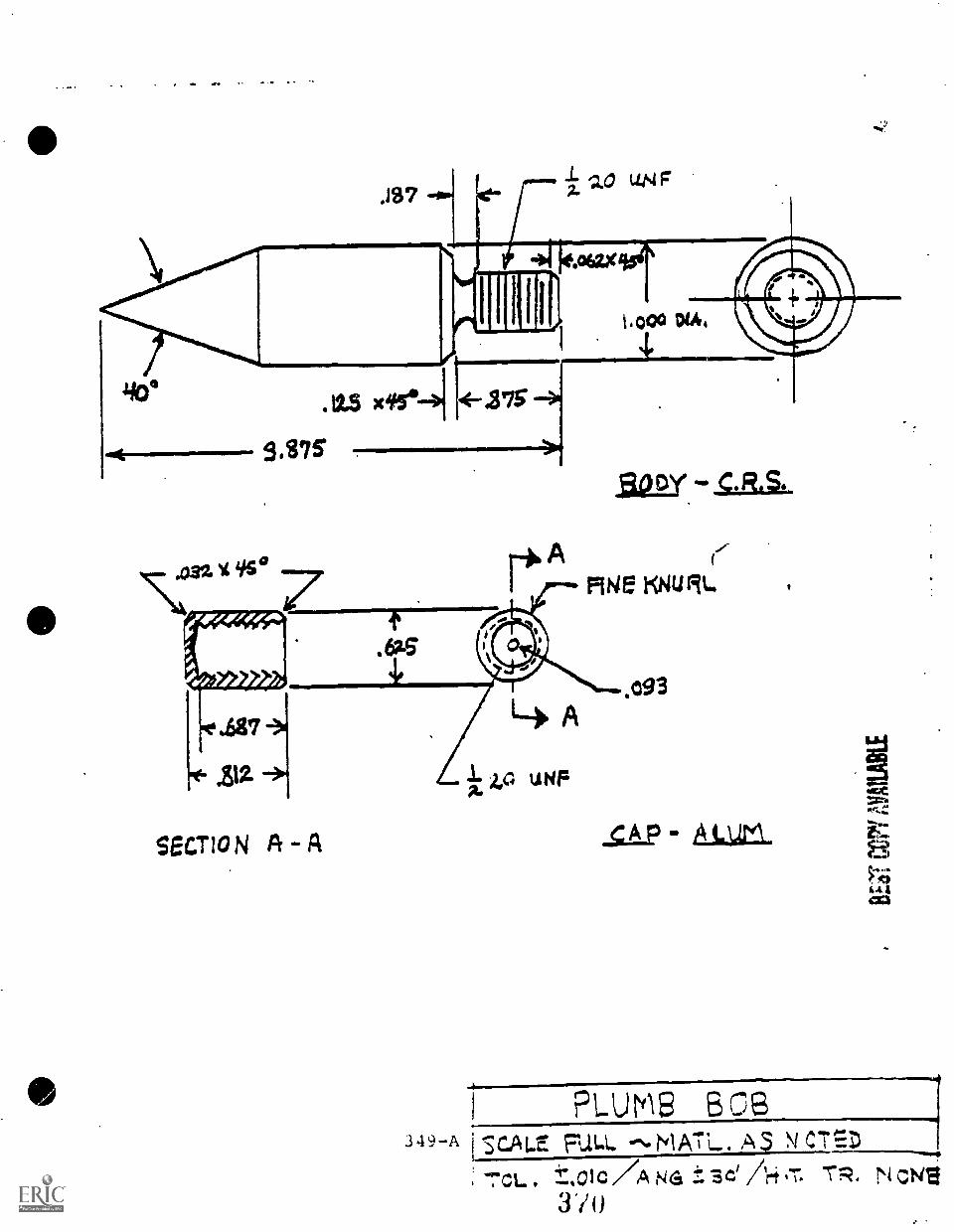
Mir
()/,C ps. 17. VN V010%;
N ""IstYlN14%. 31VIDS1 v-6tc
SO ski.irrld
:17 kArTIV ci-TY
3.3w.
- N oli7VS
'S A-157g.
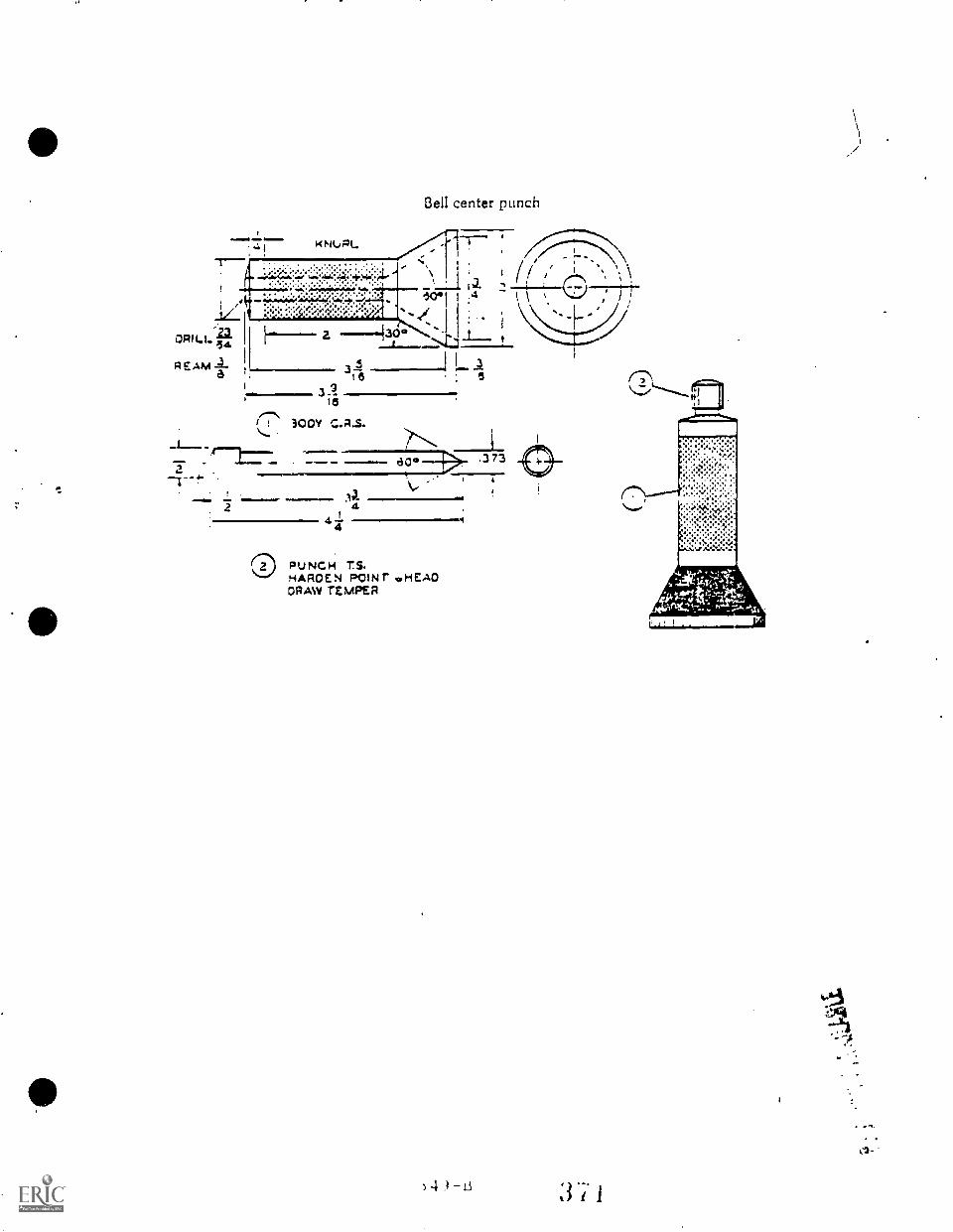
4I
Bell center punch
. (/1z 2
1
.4I
I
opiLa
..4.REAM .4.a16 5
le
300V C.A.S.
,1111110011111.
130° .373
314441
PUNCH T.S.HAPOEN POINr ..HERODRAW TEMPER
) 4 t3
.
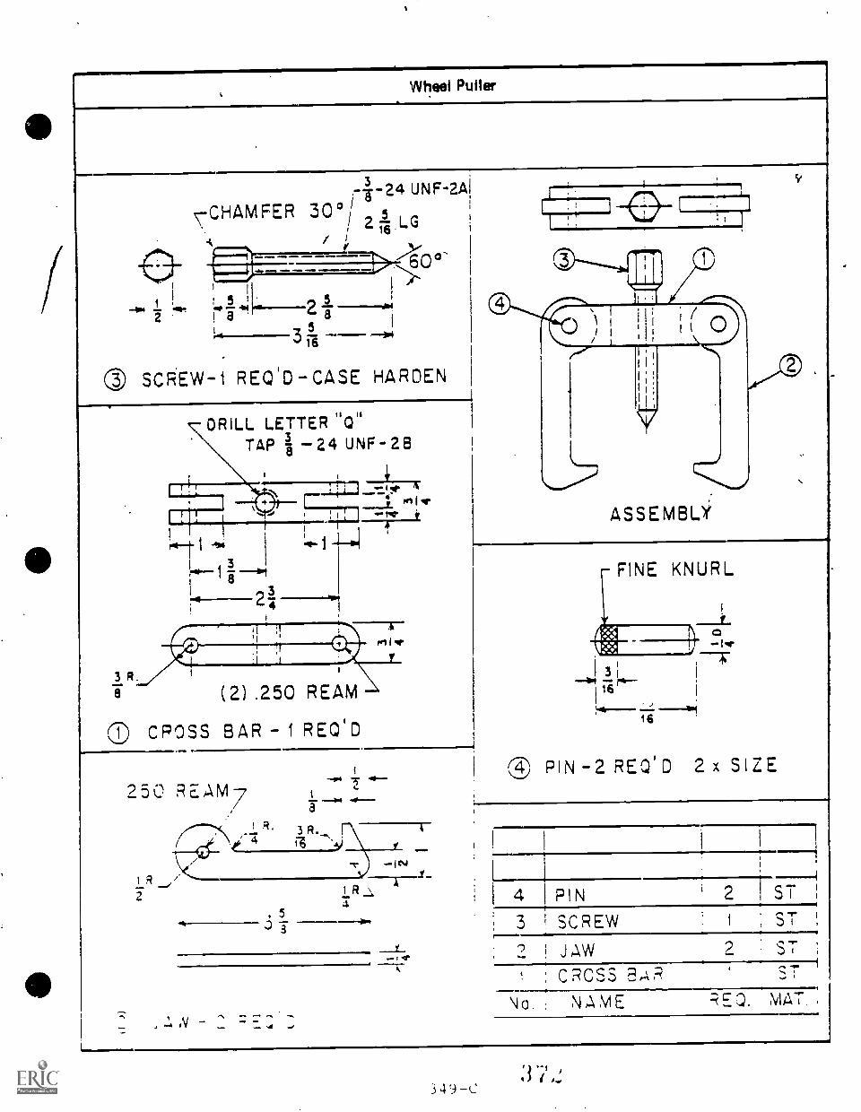
Wheel Puller
24 UNF-2AI
-CHAMFER 30°1 5/ 2 Ts- LG
r I
60'
1 2 Ji! a
0 SCREW-1 REQID-CASE HARDEN
3 R.8
DRILL LETTER "Q"TAP a 24 UNF- 28
wwqr
"1-41.1rill- 1 -11.4
I 3
I 8 3
(2) .250 REAM
CROSS BAR - 1 REOID
250 REAM7R.
.04*
R
2
a
3 R.
--r/4 .1111.0-
353
I R S4.
,VAft,
1111
ASSEMBLY
FINE KNURL
3 I-1114 ritr-
I 16_)
16
® PIN -2 REQI D 2 x SIZE
".r ;
4 PIN i ST
3 SCREW I , ST
i JaW 2 ST
CROSS EAR
No , NAME RE.D. MAT
3
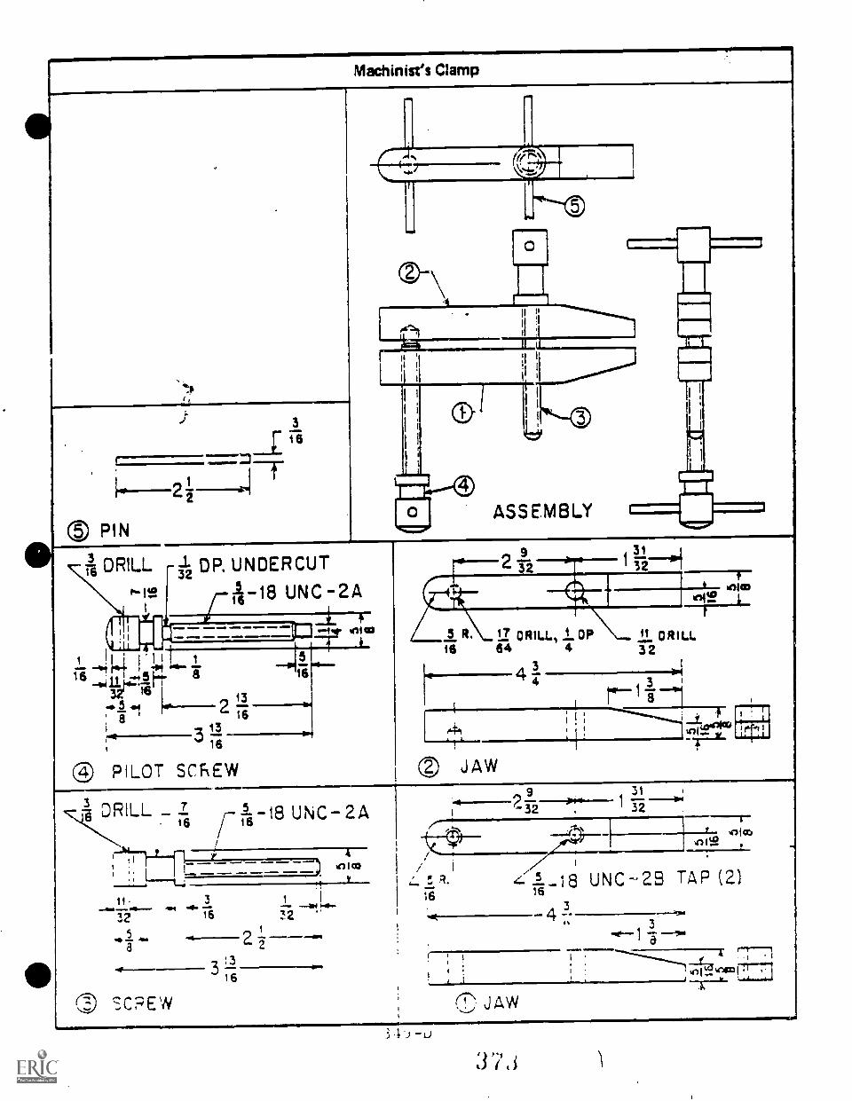
Machinist's Clamp
S PIN
DRILL
3
51.2 DP. UNDERCUT
Jr5 18 UNC 2A
[1:3. m.M.. awliM =1111. MMI1 AIMIIII
10. INIIM .11MM
a 16all
2 16
3'316
® PILOT SCREW
--2 A**31
--5 R. 17 ORILL, 1. OP 11 ORiu.tg 64 4 32
41 3 I
-T" 43
'11
re-11eli ! ; --------...12.00%
PO JAW
3 DRILL _ Z16
SC:=3EW
/-1-18 UNC 2A16
3
16
2
316
9
32
311 -5vm
1
4:1-18 UNC-23 TAP (2)
434
L
,
41(,_,c4c01;,
3 .1.i -u
ti) k-,61
I )
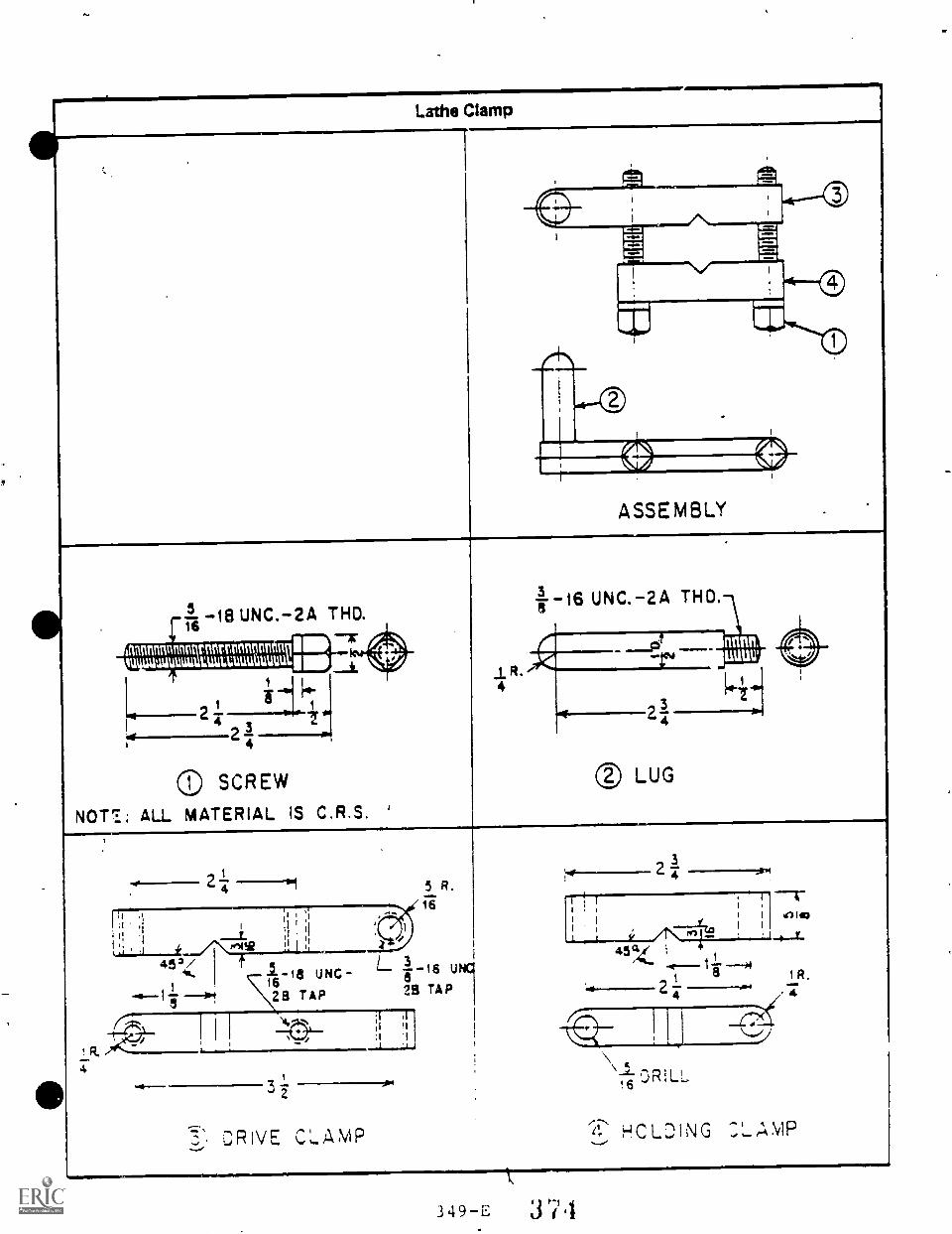
Lathe Clamp
ASSEMBLY
5ri 18 UNC.-2A THO.
inannntortnunntutnnun IWOmutitiuututaluutamuutlup
I Vq.2
24
SCREW
NOT;; ALL MATERIAL IS C.R.S.
4
16 UNC.-2A THO.
nnnn.uuuuy
0 LUG
2
I I
1 11I
11
.1
wsvi
16UNC-
28 TAP
)14,
3i
5 R.16
L8
u
28 TAP
'I:1
DRIVE C,',AMP
1.1 ;
I t1 I %Alt)
, 1 1
45 CZ 4 1
1 1R.
/7
HCL:)ING
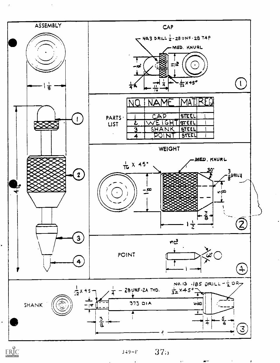
ASSEMBLY
V
mtmingi
CAP
NO.3 DRILL z- 28 UNF -29 TA?
MED, KNURL
PARTS
LIST
NCI NAME MAT RED
STE1: IC P2- w lGHTesrcEei. 1
...a. SHANK TEL I
4 t POINT Vat. I
WEIGHT
Riau
POINT
In0
SHANK
.;2:-"X 5-1
rt
ZS UNFZA 114D.No.13 18S DRILL 1 0 R7
Y45°
'5.73 cZil A
4
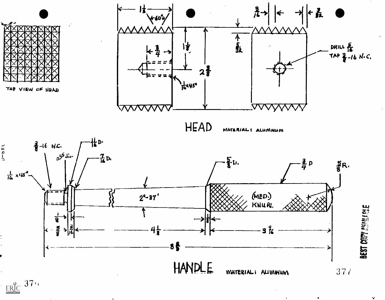
VIEW 130' bikko
1-1CAD ALIAMINu
IR,
I
37
OUTER( AL i AUttAl44141A) 1
U
PARTS LIST
NC. NAME !MAT. QUA
i 1 HE A : 5 TL, I
2 R ..: 0 S rt. i
.3 !-LANDL: CRS, I
l4 xI-1 FLAT4MED(VMKNURL
riEAD
A./63J2) DRILL
HANDLEDRILL N (. :1,02) 12 DEEP%
CHAMFER lig X 45°
411=0
WINO.
334r6
16
r TO FIT HEADROD
=11,..gif
5 ÷ MEN
TO FIT HANDLE/
ASSEMBLY
r25 REAM AT ASS'Y. FOR ,I25 XI PIN
25 REAM AT Ass"YFOR ,125X9/16 PIN
i214
34
16
-18 14.c.
t 3y
37:1
t a-
60
18 N. c./6
IlExAsoN
RIVETING HAMMERt)
*************************** *
***
SECOND YEAR MACHINE SHOP ******************************
SECOND YEAR
' MACHINE SHOP - SECONDARY LEVEL
In practice, there appears to be no definite division between the first
and second year of the Machine Shop instructional program. There
probably will continue to be some overlap between the first yeat and
second year of training at the secondary level because of a variation in
the ability of students in mastering machining skills.
Typically, the first year of training will be completed after themastery of most tasks in the Engine Lathe and Milling Machine units.
Some advanced training on the engine lathe (e.g., tool post grinding)
and on the milling machine (e.g., head alignment) may be included at the
first of the secondary year of training.
Emphasis will be placed on the student mastering objectives in a sequence
of simple to complex tasks and in a sequence of machine operations so
that levels of employable skills (e.g., machine operator to machinist)
are mastered as the student progresses through training.
The intent of the program is to provide that student with specificemployable skills rather than to expose the student to a number of tasks
which will not qualify the student for employment.
The secondary machine shop instructors report that they employ a sequence
of similar instructor developed projects which progress in skill development
to promote learning rather than a task-by-task method of instruction.
As training and skills progress, projects involve tasks from a variety
of units.
(NOTE: Second year Advanced Engine Lathe tasks ale described in Unit
8: Tasks 8.24 - 8.29. Second year Advanced Mill Work tasks
are described in Unit 9: Tasks 9.15 - 9.20, The "instructionalplanning time" for these advanced tasks is included in thesecond year description of Machine Shop.)
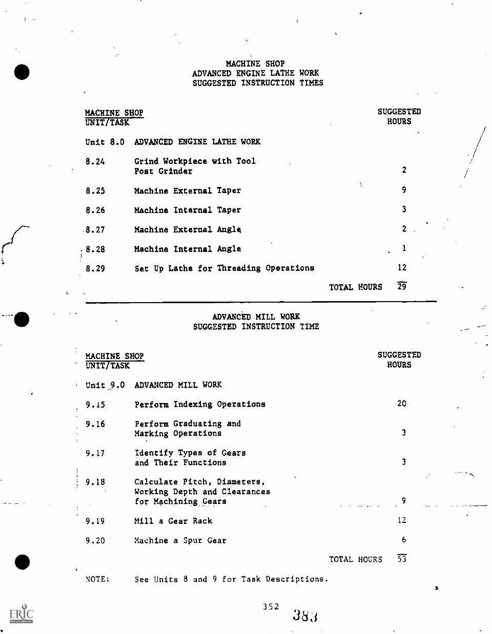
I.
MACHINE SHOPADVANCED ENGINE LATHE WORKSUGGESTED INSTRUCTION TIMES
MACHINE SHOP SUGGESTEDHOURSUNIT TASK
Unit 8.0 ADVANCED ENGINE LATHE WORK
8.24 Grind Workpiece with ToolPost Grinder 2
8.25 Machine External Taper 9
8.26 Machine Internal Taper 3
.8.27 Machine External Angle 2 .
8.28 Machine Internal Angle 1
8.29 Set Up Lathe for Threading Operations 12
TOTAL HOURS 29
ADVANCED MILL WORKSUGGESTED INSTRUCTION TIME
MACHINE SHOP SUGGESTEDHOURSUNIT TASK
Unit 9.0 ADVANCED MILL WORK
9.15 Perform Indexing Operations 20
9.16 Perform Graduating andMarking Operations 3
9.17 Identify Types of Gearsand Their Functions 3
9.18 Calculate Pitch, Diameters,Working Depth and Clearancesfor Machining Gears 9
9.19 Mill a Gear Rack 12
9.20 Machine a Spur Gear 6
TOTAL HOURS 53
NOTE: See Units 8 and 9 for Task Descriptions.
352
3LLI
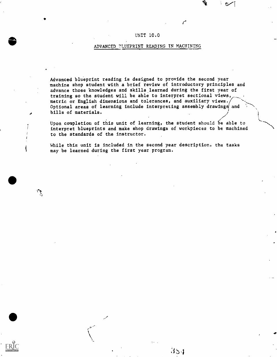
4
UNIT 10.0
ADVANCED 7LUEPRINT READING IN MACHINING
Advanced blueprint reading is designed to provide the second yearmachine shop student with a brief review of introductory principles andadvance those knowledges and skillslearned during the first year oftraining so the student will be able to interpret sectional viewsmetric or English dimensions and tolerances, and auxiliary views.Optional areas of learning include interpreting assembly drawing and
bills of materials.
Upon completion of this unit of learning, the student should e able tointerpret blueprints and make shop drawings of workpieces to be machined
.\
to the standards of the instructor.
While this unit is included in the second year description, the tasksmay be learned during the first year program.
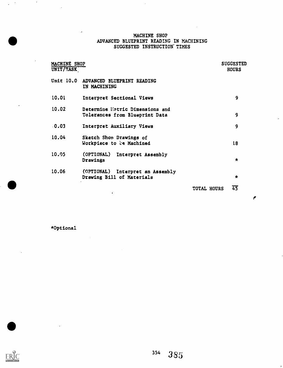
MACHINE SHOPUNIT TASK.
MACHINE SHOPADVANCED BLUEPRINT READING IN MACHINING
SUGGESTED INSTRUCTION.TIMES
SUGGESTEDHOURS
Unit 10.0 ADVANCED BLUEPRINT READINGIN MACHINING
10.01 Interpret Sectional Views 9
10.02 Determine Netric Dimensions andTolerances from Blueprint Data 9
.0.03 Interpret Auxiliary Views 9
10.04 Sketch Shop Drawings ofWorkpiece to Machined 18
10.05 (OPTIONAL) Interpret AssemblyDrawings
10.06 (OPTIONAL) Interpret an AssemblyDrawing Bill of Materials
*Optional
*
*
TOTAL HOURS 45
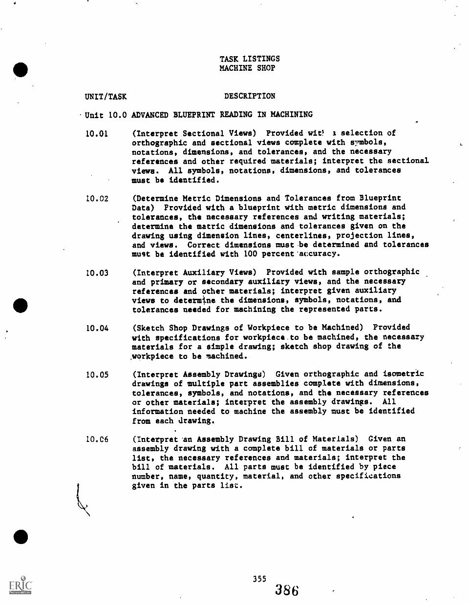
TASK LISTINGSMACHINE SHOP
UNIT/TASK DESCRIPTION
Unit 10.0 ADVANCED BLUEPRINT READING IN MACHINING
10.01 (Interpret Sectional Views) Provided wit! I selection oforthographic and sectional views complete with s7mbols,notations, dimensions, and tolerances, and the necessaryreferences and other required materials; interpret the sectionalviews. All symbols, notations, dimensions, and tolerancesmust be identified.
10.02 (Determine Metric Dimensions and Tolerances from BlueprintData) Provided with a blueprint with metric dimensions andtolerances, the necessary references and writing materials;determine the metric dimensions and tolerances given on thedrawing using dimension lines, centerlines, projection lines,and views. Correct dimensions must.be determined and tolerancesmust be identified with 100 percent' accuracy.
10.03 (Interpret Auxiliary Views) Provided with sample orthographicand primary or secondary auxiliary views, and the necessaryreferences and other materials; interpret given auxiliaryviews to determine the dimensions, symbols, notations, andtolerances needed for machining the represented parts.
10.04 (Sketch Shop Drawings of Workpiece to be Machined) Provided
with specifications for workpiece.to be machined, the necessarymaterials for a simple drawing; sketch shop drawing of the,workpiece to be machined.
10.05 (Interpret Assembly Drawings) Given orthographic and isometricdrawings of multiple part assemblies complete with dimensions,tolerances, symbols, and notations, and the necessary referencesor other materials; interpret the assembly drawings. Allinformation needed to machine the assembly must be identifiedfrom each drawing.
10.C6 (Interpret.an Assembly Drawing Bill of Materials) Given anassembly drawing with a complete bill of materials or partslist, the necessary references and materials; interpret thebill of materials. All parts must be identified by piecenumber, name, quantity, material, and other specificationsgiven in the parts list.
355
386
UNIT 10.0 ADVANCED BLUEPRINT READING
TASK 10.01 INTERPRET SECTIONAL VIEWS
PERFORMANCE OBJECTIVE:
Provided with a selection of orthographic and sectional views completewith symbols, notations, dimensions, and tolerances, and the necessary"references and other required materials; interpret the sectional views.All symbols, notations, dimensions, and tolerances must be identified.
PERFORMANCE ACTIONS:
10.0101 Interpret:
a. Alphabet of lines.b. Section and cutting plane lines.
10.0102 Interpret (as required by instructor). (*SeeRelated Technical Information below.)
a. Full section.b. Half section.c. Broken-out section.d. Revolved section.e. Removed section.f. Offsetsection.g. Aligned section, if required.h. Conventional btaaks, if required.
PERFORMANCE STANDARDS:
Interpret sectional views from given drawings to identifysymbols, notations, dimensions, and tolerances.
SUGGESTED INSTRUCTION TIME: 9 Hours
RELATED TECHNICAL INFORMATION:
- *Identify/describe sectional view:a. fullb. halfc. broken-outd. rotatede. removedf. auxiliaryg. assembly sections
- Explain purpose of sectional view.- Describe procedures for interpreting a section.
356
387
UNIT 10.0 ADVANCED*BLUEPRINT READING
TASK 10.02 DETERMINE METRIC DIMENSIONS ANDTOLERANCES FROM BLUEPRINT DATA
PERFORMANCE OBJECTIVE:
Provided with a blueprint with metric dimensions and tolerances, thenecessary references and writing materials; determine the metric dimensionsand tolerances given on the drawing using dimension lines, centerlines,projection lines, and views. Correct dimensions must be determined andtolerances must be identified with 100 percent accuracy.
PERFORMANCE ACTIONS:
10.0201 Interpret related terminology.
10.0202 Determine dimensions for the following geometricalshapes:
a. Cylinders.b. Holes.c. Prisms.d. Miscellaneous shapes.e. Contour dimensions.
10.0203 Determine:
a. Location dimensions.b. Rounded arid shapes.c. Dimensions on and off views.d. Mating dimensions, etc.
10.0204 Determine dimensions and tolerances, for example:
a. Basic hole system.b. Basic shaft system.c. Clearance fits.d. Interference fits.e. Transition fits.f. Running aid sliding fitsg. Force fits.h. Location fits.
PERFORMANCE STANDARDS:
- Determine correct metric dimensions and tolerances wish 100percent accuracy from given blueprints containing metricdimensions and tolerances.
357388
UNIT 10.0 ADVANCED BLUEPRINT READING
TASK 10.02 DETERMINE METRIC DIMENSIONS ANDTOLERANCES FROM BLUEPRINT DATA(Con't.)
SUGGESTED INSTRUCTION TIME: 9 Hours
RELATED TECHNICAL INFORMATION:
- Solve mathematical problems involving metric numbers.- Explain the metric system of measures, etc., used in machining.- Explain purpose of dimensions and tolerances.- Deacribe how metric dimensions and tolerance are represented
on a blueprint.- Describe the procedure for determining metric dimensions and
tolerances from a blueprint.- Explain the use of a scale in blueprints.- Machinery's Handbook.
358
389
UNIT 10.0 ADVANCED BLUEPRINT READING
TASK 10.03 INTERPRET AUXILIARY VIEWS
PERFORMANCE OBJECTIVE:
Provided with sample orthographic and primary or secondary auxiliaryviews, and the necessary references and other materials; interpret givenauxiliary views to determine the dimensions, symbols, notations, andtolerances needed for machining the represented parts.
(NOTE: The relationship between the orthographic and auxiliary viewsmust be interpreted through identifying the drawing positionon the orthographic view.)
PERFORMANCE ACTIONS:
10.0301 Interpret depth, height, and width auxiliary views.
10.0302 Interpret auxiliary views of objects with symmetricalplanes, asymmetrical planes, and curved surfaces.
PERFORMANCE STANDARDS:
- Interpret auxiliary views for dimensions, symbols, notations,and tolerances needed for machining the represented parts.
SUGGESTED INSTRUCTION TIME: 9 Hours
RELATED TECHNICAL INFORMATION:
- Explain relationship between auxiliary views and orthographicviews.
- Define primary auxiliary view and secondary auxiliary view.- Define procedure for interpreting auxiliary views.- Make freehand skrtches of auxiliary views using coordinate
paper.
359 390

UNIT 10.0 ADVANCED BLUEPRINT READING
TASK 10.04 SKETCH SHOP DRAWINGS OF WORKPIECE TORE MACHINED
PERFORMANCE OBJECTIVE:
Provided with specifications for workpiece to be machined, the necessarymaterials for a simple drawing; sketch shop drawing of the workpiece tobe machined.
*See STANDARDS for detailed requirements of drawing. Instructor'sstandards ipply.
PERFORMANCE ACTIONS:
10.0401 Take dimension3 and tolerances, etc., from givendrawings as, part sample.
10.0402 Draw part (workpiece) showing finishes, tolerances,etc.
10.0403 Sketch shop drawing for part to be machined.
PERFORMANCE STANDARDS:
- Sketch shop drawings of workpiece to be machined using informationand materials provided by the instructor.
- *The shop drawing must have lines that are clean, dense,black, and of uniform weight. Letters and numbers must be'clean, dense, black, and uniformly spaced. Dimensions,notations, and symbols must be applied to the drawing to allowa full understanding of the characteristics of each feature.Each dimension must have a tolerance, either applied directlyor indicated by a notation. The drawings must be neat andfree of smudges and erasure marks. All words should bespelled correctly, and the scale for the drawing must beapplied to the requirements of the drawing. The product andprocedures must be to the instructor's standards.
SUGGESTED INSTRUCTION TIME: 18 Hours
RELATED TECHNICAL INFORMATION:
- Explain what should be included in the shop drawing (articulatedrequirement of program.).
- identify symbols, notations, and dimensions that should beindicated an drawing.
360
391
UNIT 10.0 ADVANCED BLUEPRINT READING
TASK 10.04 SKETCH SHOP DRAWINGS OF WORKPIECE TOBE MACHINED
RELAUD-TiaNICAL INFORMATION (Con't.):
- Describe procedure for making a shop drawing.- Explain how to draw lines: Use of T-square, drawing board,
and triangles- Explain how to read and transfer teasurements.- Demonstrate freehand lettering acceptable to instructor.- Demonstrate methods of drawing circles, arc, and angles.
361
3 b,.:
UNIT 10.0 ADVANCED BLUEPRINT READING
TASK 10.05 (Optional) INTERPRET ASSEMBLY' DRAWING
PERFORMANCE OBJECTIVE:
Given orthographic_ and isometric drawings of multiple part assembliescomplete with dimensions, tolerances, symbols, and notations, and thenecessary references or other materials; interpret the assembly drawings.All information needed to machine the assembly must be identified fromeach drawing.
PERFORMANCE ACTIONS: (To be defined by instructor.)
PERFORMANCE STANDARDS:
- Interpret given assembly drawings identifying all informationneeded to machine the assembly such as dimensions, tolerances,symbols, and notations.
SUGGESTED INSTRUCTION TIME: Optional
RELATED TECHNICAL INFORMATION:
- Define assembly drawing,- Explain purpose of 'balloons' in an assembly drawing.- Explain how drawings indicate multiple parts joined together,
finishes, parts, material, specifications, and tolerances.- Desctibe the procedura for interpreting an assembly drawing.- Make freehand sketches of assemblies and subassemblies using
coordinate piper of plain paper with simple drawing equipment.provided.
362
3'93
UNIT 11.0
TURRET LATHE
The purpose of this unit is to provide secondary machine shop students withan orientation to the turret lathe.
The turret lathe in the secondary machine shop program tpically will varyaccording tc its age and condition as well as according to the availabilityof accessories required for its use.
.
Therefore, this unit on the turret lathe may be considered either as skilldevelopment training or orientation training. In addition, ,nstructionaland maintenance funds at the secondary level have not encouraged maintenance,equipping, use of the turret lathe for training .
Optional orientation. tasks are listed at the back of this unit for advancedor individual training on the turret lathe.
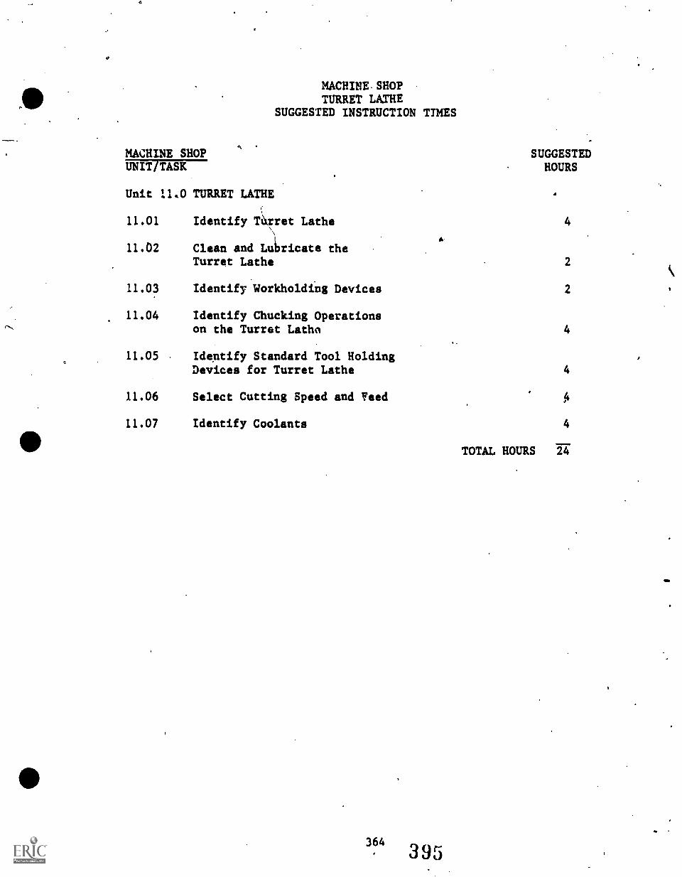
MACHINES SHOPTURRET LATHE
SUGGESTED INSTRUCTION TIMES
MACHINE SHOP SUGGESTEDHOURSUNIT TASK
Unit 11.0 TURRET LATHE
11.01 Identify T4Tet Lathe 4
11.02 Clean and lalricate theTurret Lathe 2
11.03 Identify Workholding Devices 2
11.04 Identify Chucking Operationson the Turret Lathe 4
11.05 Identify Standard Tool HoldingDevices for Turret Lathe 4
11.06 Select Cutting Speed and Voted A
11.07 Identify Coolants 4
TOTAL HOURS 24
UNIT/TASK
Unit 11.0 TURRET LATHE
11.01
. .
TASK LISTINGSMACHINE SHOP .
DESCRIPTION
(Identify Turret Lathe) Giyen a turret lathe and instructions;name and describe the function of the parts of the turretlathe correctly.
11.02 (Clean and Lubricate the Turret Lathe) Given a turret latheand maintenance /cleaning instructions and all necessary tools,cleaning supplies, and materials; clean and lubricate.
(Identify Workholding Devices) Given ,several types of workholdingdevices for the turret lathe, identify the type of.collet andchuck and describe function of the device to the satisfactionof the instructor.
11.03
11.04. (Identify Chucking Operations of the Turret Lathe) Given aturret lathe, and assigned task, stock, chucks,.and handtools; choose the correct.chuck for the jpb and mount thechuck according to correct shop procedures.
11.05 (Identify Standard Tool Holding Devices.4fer Turret Lathe)Given an assortment of standard tool holding devices for theturret lathe, identify and describe correctly the devices tothe instructor's standards.
11.06
11.07
(Select Cutting Speed and Feed) Given a workpiece, jobassignment. and specifications, turret lathe, accessories,tools and materials; set the speed and feed of the turretlathe correctly for the given material. The speed and feedselected must be acceptable to the instructor.
(Identify Coolants) Given workpiece tolathe and necessary tools, accessories,an appropriate coolant for the materialmust meet instructor's standards.
365
396
cut on the turretand materials; selectto be cut. Performance
UNIT 11.0 TURRET LATHE
TASK 11.01 IDENTIFY TURRET LATHE
POIFORMXICE OBJECTIVE:
Given a turret lathe and instructions; name and describe the function ofthe parts of the turret lathe correctly.
PERFORMANCE ACTIONS: 1
.
r1 J
11.0101 Identify turret lathe parts and their functions:
a. Identify advantages of turret lathe.b. Identify disadvantages of turret lathe.c. Identify special features of the turret lathe:
; (1) Trip feed(2) Stop screws
d. Describe operations which can be performed onthe turret lathe.
e. Identify the.parts of a given turret lathe thatis labeled.
.PERFORMANCE STANDARDS:
- Identify the turret lathe including correct identification ofthe parts of a given lathe to the instructor's standards.
SUGGESTED INSTRUCTION TIME: 4 Hours
RELATED TECHNICAL INFORMATION:
- Identify/describe parts of the turret lathe.
366 39?
UNIT 11.0 TURRET LATHE
TASK 11.02 CLEAN AND LUBRICATE THE TURRET LATHE
PERFORMANCE OBJECTIVE:
VIM
Given a turret lathe and maintenance/cleaning instructions and allnecessary tools, cleaning supplies, and materials; clean, and lubricate.
PERFORMANCE ACTIONS:
11.0201 Assemble cleaning materials, instructions, etc.
11.0202 Disconnect power.
11.0203 Clean lathe according to instructions.
11.0204 Lubricate lathe according to instructions.
PERFORMANCE STANDARDS:
- Clean and maintain the turret lathe according to manufacturer'sor instructor's standards (shop procedures) by cleaning,lubricanting, leveling, and making adjustments as inqtructed.
SUGGESTED INSTRUCTION TIME: 2 Hours
RELATED TECHNICAL INFORMATION:
- Explain the value of a shop maintenance schedule.- Describe how to clean the turret lathe.- Describe the procedure for lubricating a.lathe.- Identify acceptable types of cleaning solvents.- Identify acceptable lubricants and greases.- Identify safety hazards of the turret lathe:
a. Machine speedb. Chip guardsc. Personal safety devices such as clothingd. Safe operating procedures for the turret lathee. Starting and stopping the lathe
367 3
UNIT 11.0 TURRET LATHE
TASK 11.03 IDENTIFY WORKHOLDING DEVICES
PERFORMANCE OBJECTIVE:
Given several types of workholding devices for the turret lathe, identifythe type of collet and chuck and describe the function of the device tothe satisfaction of the instructor.
PERFORMANCE ACTIONS:
11.03n1 Identify types of chucks and collets used on theturret lathe in the machine shop.
(NOTE: The age, condition, and accessories of theturret lathe available for training willvary and, therefore, this task willrequire local adaptation.)
11.0302 Describe functions of selected workholding devicesused with the turret lathe.
PERFORMANCE STANDARDS:
- Identify workholding devices used by the shop turret lathe anddescribe the function of the devices to the standards of theinstructor.
SUGGESTED INSTRUCTION TIME: 2 Hours
RELATED TECHNICAL INFORMATION:
- Describe the collet chuck.- Describe the three-jaw chuck.- Describe the four-jaw chuck.- Describe bar chucks.- Describe closing type collet chuck.- Describe spring type collets:
a. Push out typeb. Draw back typec. Stationary type
- Describe power operated collet chuck.
368
333
UNIT 11.0 TURRET LATHE
TASK 11.04 IDENTIFY ('MUCKING OPERATIONS ON THETURRET LATHE
PERFORMANCE OBJECTIVE:
Given a turret lathe, an assigned task, stock, chucks, and hand tools;choose the correct chuck fair the job and mount the chuck according tocorrect shop procedures.
PERFORMANCE ACTIONS:
11.0401 Choose an appropriate chuck 1Jr a specified job andmount it on the turret lathe.
PERFORMANCE STANDARDS:
- For a given job, select the correct chuck and mount it on theturret lathe according to shop practices.
SUGGESTED INSTRUCTION TIME: 4 Hours
RELATED TECHNICAL INFORMATION:
- Choose a holding device for chucking work.- Describe the purpose of holding devices in chucking.- Identify the following types of chucks:
a. Universalb. Independentc. Combinationd. Power operated types
- Explain the function of chuck jaws.- Describe how to mount a chuck.- Describe how to select a chuck.
369
`1(10
UNIT 11.0 TURRET LATHE
TASK 11.05 IDENTIFY STANDARD TOOL HOLDINGDEVICES FOR TURRET LATHE
PERFORMANCE OBJECTIVE:
Given an assortment of standard toolholding devices for the turretlathe, identify and describe correctly the devices to the instructor'sstandards.
PERFORMANCE ACTIONS:
11.0501 Identify standard turret lathe toolholding devicesavailable. .
PERFORMANCE STANDARDS:
- Identify standard toolholding devices for the turret lathe tothe standards of the instructor.
SUGGESTED INSTRUCTION TIME: 4 Hours
RELATED TECHNICAL INFORMATION:
- Identify the objectives of a turret lathe job.- Describe the elements of production time.- Identify/describe universal tooling equipment.- Describe/explain indexing.- Explain the arrangement of tools.- Identify types of tools and how they are applied.- Identify safety considerations.
370
4 01
UNIT 11.0 TURRET LATHE
TASK 11.06 SELECT CUTTING SPEED AND FEED
PERFORMA''CE OBJECTIVE:
Given a workpiece, job assignmentaccessories,tools and materials;correctly for the given material.acceptable to the instructor.
and specifications, turret lathe,set the speed and feed of the turretThe speed and feed selected must be
PERFORMANCE ACTIONS:
11.0601 Set the turret lathe speeds and feeds for a givenjob.
PERFORMANCE STANDARDS:
- Select cutting speed and feed for i given job and to meet thestandards of the instructor.
SUGGESTED INSTRUCTION TIME: 4 Hours
RELATED TECHNICAL INFORMATION:
- Identify factors which affect speed and feed.- Describe how to determine feed and speed.- Describe how to set feed and speed on turret lathe.
rescribe the relationship of quantity of parts verses speed ofoperation.
37140,E
UNIT 11.0 TURRET LATHE
TASK 11.07 IDENTIFY COOLANTS
PERFORMANCE OBJECTIVE:
Given workpiece to cut on the turret lathe and necessary tools,accessories, and materials; select an appropriate coolant for thematerial to be cut. Performance must meet instructor's standards.
PERFORMANCE ACTIONS:
11.0701 Choose appropriate coolant for a given workpiece tobe cut on the turret lathe.
PERFORMANCE STANDARDS:
- Identify coolants and select an appropriate coolant or cuttingcompound for a given workpiece to be cut on the turret lathe.
- !erforlance must be to the instructor's standards.
SUGGESTED INSTRUCTION TIME: 4 Hours
RELATED TECHNICAL INFORMATION:
- Describe purpose of coolants.- Describe procedure for using a coolant.
312 403
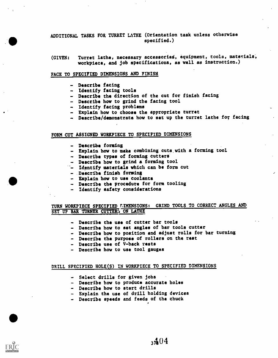
ADDITIONAL TASKS FOR TURRET LATHE (Orientation task unless otherwise
specified.)
(GIVEN: Turret lathe, necessary accessories, equipment, tools, materials,
workpiece, and job specifications, as well as instruction.)
FACE TO SPECIFIED DIMENSIONS AND FINISH
- Describe facing- Identify facing tools- Describe the direction of the cut for finish facing- Describe how to grind the facing tool- Identify facing problems- Explain how to choose the appropriate turret- Describe/demonstrate how to set up the turret lathe for facing
FORM CUT ASSIGNED WORKPIECE TO SPECIFIED DIMENSIONS
- Describe forming- Explain how to make combining cuts, with a forming tool
- Describe types of forming cutters- Describe how to grind a forming tool'- Identify materials which can be form cut- .Describe finish forming- Explain how to use coolants- Describe the procedure for form tooling- Identify safety considerations
TURN WORKPIECE SPECIFIED T,IMENSIONS: GRIND TOOLS TO CORRECT ANGLES AND
SET UP BAR TURNER CUTTERri ON LATHE
- Describe the use of cutter bar tools- Describe how to set angles of bar tools cutter- Describe how to position and adjust rolls for bar turning- Describe the purpose of rollers on the rest- Describe use of V-back rests- Describe how to use tool gauges
DRILL SPECIFIED HOLE(S) IN WORKPIECE TO SPECIFIED DIMENSIONS
- Select drills for given jobs- Describe how to produce accurate holes- Describe how to start drills- Explain the use of drill holding devices- Describe speeds and feeds of the chuck
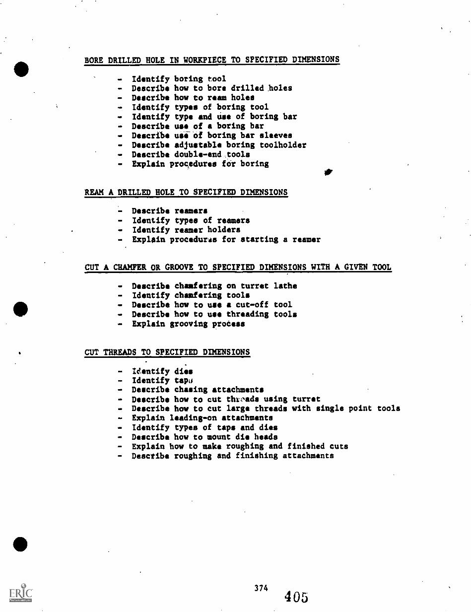
BORE DRILLED HOLE IN WORKPIECE TO SPECIFIED DIMENSIONS
- Identify boring tool- Describe how to bore drilled holes- Describe how to ream holes- Identify types of boring tool- Identify type and use of boring bar- Describe use of a boring bar- Describe ullof boring bar sleeves- Describe adjustable boring toolholder- Describe double-end:tools- Explain procedures for boring
REAM A DRILLED HOLE TO SPECIFIED DIMENSIONS
- Describe reamers- Identify types of reamers- Identify reamer holders- Explain procedural for starting a reamer
CUT A CHAMFER OR GROOVE TO SPECIFIED DIMENSIONS WITH A GIVEN TOOL
- Describe chamfering on turret lathe- Identify chamfering tools- Describe how to use a cut-off tool- Describe how to use threading tools- Explain grooving prodess
CUT THREADS TO SPECIFIED DIMENSIONS
- Identify dies- Identify tape- Describe chasing attachments- Describe how to cut thrads using turret- Describe how to cut large threads with single point tools- Explain leading-on attachments- Identify types of taps and dies- Describe how to mount die heads- Explain how to make roughing and finished cuts- Describe roughing and finishing attachments
UNIT 12.0
SURFACE GRINDER
(NOTE: Bench and pedestal grinders are described in a separate unit.)
Grinder operations on the lathe are included in the unit concerning theengine lathe.
The purpose of this unit concerning the surface grinder is to intoducethe secondary student to the surface grinder and provide the graduatewith basic skills in inspecting, cleaning, setting up, and using thesurface grinder. The skill level described is introductory and typicallythe secondary graduate will be competent only in the use of the surfacegrinder for grinding flat surfaces.
375
406
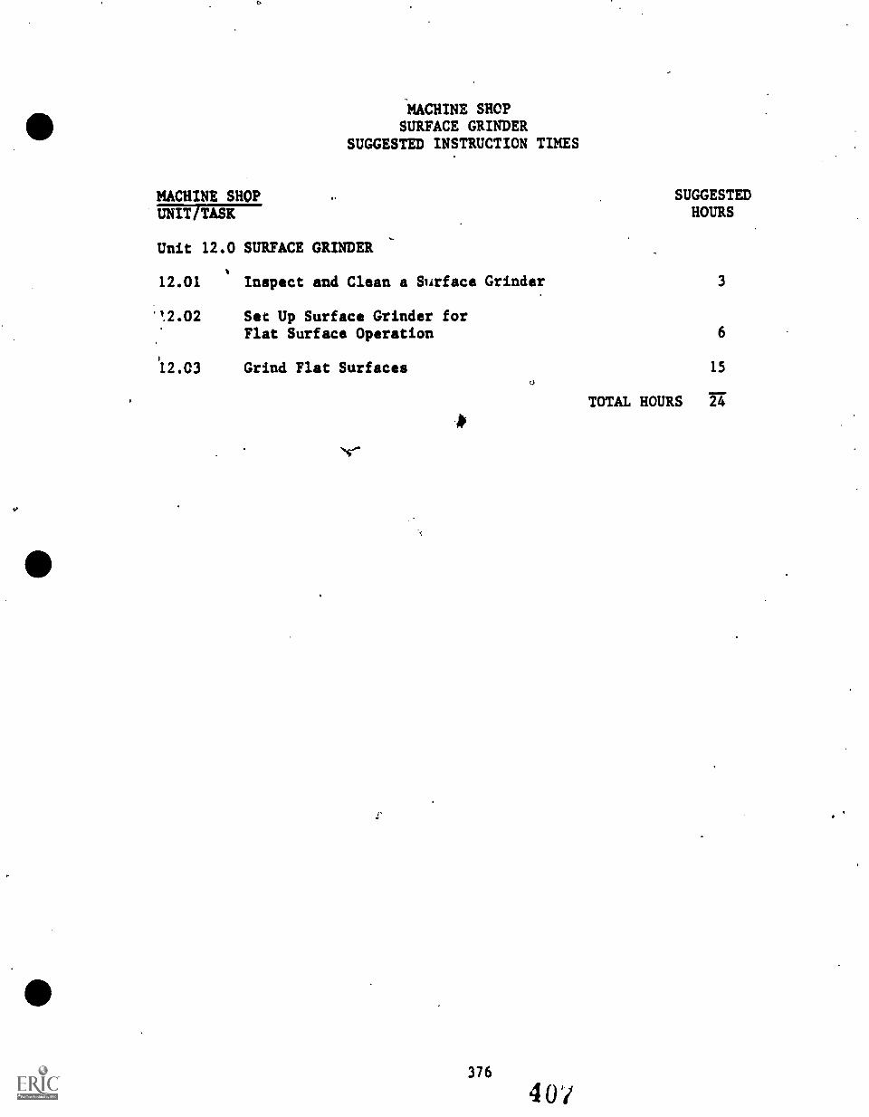
MACHINE SHOPSURFACE GRINDER
SUGGESTED INSTRUCTION TIMES
MACHINE SHOPUNIT TASK
Unit 12.0 SURFACE GRINDER
SUGGESTEDHOURS
12.01 Inspect and Clean a Surface Grinder 3
"1.02 Set Up Surface Grinder forFlat Surface Operation 6
12.03 Grind Flat Surfaces 15
r
376
40/
TOTAL HOURS 24
UNIT/TASK
Unit 12.0 SURFACE GRINDER
TASK LISTINGSMACHINE SHOP
DESCRIPTION
12.01 (Inspect and Clean a Surface Grinder) Given a hurizontal-spindle surface grinder, manual or operator's instructions,cleaning materials selected by the instructor, and the necessaryhand tools and equipment; inspect and clean the surfacegrinder according to the manufacturer's (or instructor's)specifications. The surface grinder and surrounding area mastbe free of metal chips, excess lubricant or cutting fluid, andforeign material.
12.02 (Set Up Surface. Grinder for Flat Surface Operation) Given ahorizontal-spindle surface grinder, operator's instructions,set up specifications, workpieces, grinding wheels, magneticchuck; and the necessary hand tools, measuring instruments,and materials; set up the surface grinder for flat surfacingoperations. The workpiece, magnetic chuck, and grinding wheelmust be aligned with the table +/- .001 inch. The correctgrinding wheel must be selected and mounted on the wheelspindle so that the wheel turns true..
12.03
V
(Grind Flat Surfaces) Given workplaces requiring flatsurfaces machined to a'surface expressed in micro-inches,dimensioned blueprints or drawings, grinding specifications,grinding wheels, magnetic chuck, and the necessary hand tools,attachments, accessories, measuring instruments, and materials;grind the flat surfaces using the horizontal-spindle surfacegrinder. The workpieces must be surface ground to specifi-cations with a tolerance identifiid by the instructor.(32-125 micro-inches if not specified).
3774 08
.7.
e.
UNIT 12.0 SURFACE GRINDER
TASK 12.01 INSPECT AND CLEAN A SURFACE GRI 'ER
PERFORMANCE OBJECTIVE:
Given a horizontal-spindle surface grinder, manual or operator'sinstructions, cleaning materials selected by the instructor, and thenecessary hand tools and equipment; inspect and clean the surfacegrinder according to the manufacturer's (or instructor's) specifi-cations. The su face grinder and surrounding area must be free of metalchips, excess lu ricant or cutting fluid, and foreign material.
PERFORMANCE ACTIONS:
12.0101 Identify surface grinder as horizontal or verticalspindle.
12.0102 Identify major parts of surface grinder toinstructor's standards.
12.0103 Inspect surface grinder to instructor's standards..
12.0104 Clean surface grinder according to recommendationsof manufacturer or instructor.
PERFORMANCE STANDARpS:
- Inspect and clean a surface grinder to specifications given so,that the machine and surrounding area are free of metal chips,
. excess lubricant or cutting fluid, and foreign material. It*
SUGGESTED INSTRUCTION TIME: 3 Hours
RELATED TECHNICAL ITRMATION:
ORIENTATION Td SURFACE GRINDER:(:r
- Identify type of surface grinder: Vertical or horizontal- Identify major parts of surface grinder such as the base,
column, saddle, table, wheelhead, and operating controlssuch as table handwheel, wheel feed handwheel, crossfeedhandwheel, and other controls.
- CLEANING A SURFACE GRINDER:- 'Explain reasons for performing routine inspection and
cleaning of the surface grinder.- Identify materials recommended by manufacturer or
instructor for cleaning surface grinder.- Identify safety considerations.
378409
UNIT 12.0 SURFACE GRINDER
TASK, 12.01 INSPECT AND CLEAN A SURFACE GRINDER
*ELATED TECHNICAL INFORMATION (Con't.):
- Describe procedures for inspecting and cleaning thesurface grinder.
- Review manufacturer's recommendations/specifications for'the Machine.
- Assemble cleaning materials, tools.- Turn power off to machine.- Clean grinder:
qb a. Remove chips with brush.b. Clean machine with cleaner and rags.
- Lubricate grinder according'to instructions provided(manufacturer's information or instructor's atandatds):
a. Oil inoil cups.b. Grease fittings.c. Oil slides and machined surfaces lightly.
- Remove grinding wheel:a. Ring test for cracks.b. Replace. wheel if it is damaged.c. Check blotters and flanges.
- Replace wheel and check wheel cover and guards:a. Never mount a wheel without using washers of some
compressible material.b. Never force wheels on mounting.c. Take care in tightening nut againat flange.d. If necessary, with instructor's permission, dress
wheel that is glazed or "loaded.'- Check exhaust system, if applicable.- Inspect grinder and surrounding area.
379
.4io8
UNIT 12.0 SURFACE GRINDER
TASK 12.02 SET UP SURFACE GRINDER FOR FLATSURFACE OPERATION
PERFORMANCE OBJECTIVE:
Given a horizontal-spindle surface grinder, operator's instructions, setup specifications, workpieces, grinding wheels, magnetic chuck, and thenecessary hand tools, measuring instruments, and materials; set up thesurface grinder for flat surfacing operations. The workpiece, magneticchuckk_and grinding wheel must be aligned with the table +1- .001 inch.
.The..6oFrect grinding wheel must be selected and mounted on the wheelspindl so that the wheel turns true./PERFORMANCE ACTIONS:
12.0201 Set up surface grinder for desired operation.
12.0202 Prepare grinding wheel for operation.
12.0203 Select holding device and mount it on grinder.
12.0204 Mount workpiece.
(See procedures outlined in Grinding Technology, byOswald, Delmar Publishers, pp. 107-110.)
i'ERFORMANCE STANDARDS:
- Set up the surface griniwr for a flat surface operation.- The workpiece, magnetic chuck, and grinding wheel must be
aligned with the table +/- .001 inch.- The correct grinding wheel must be selected and mounted on,the
wheel spindle so that the wheel runs true.
SUGGESTED INSTRUCLON TIME: 6 Hours
RELATED TECHNICAL INFORMATION:
- Identify the basic parts and controls of the surface grinder.- Identify applications for machining with a surface grinder.- Define surface finish and explain how to measure a finish in
micro-iaches.- Explain purpose of table reverse dogs.- Explain how to set up magnetic, electromagnetic, and sine
chucks on a surface grinder.
380411
s)
UNIT 12.0 SURFACE GRINDER
TASK 12.02 SET UP SURFACE GRINDER FOR FLATSURFACE OPERATION
RELATED TECHNICAL INFORMATION (Con't.):
- Define procedure for setting up a surface grinder.- Explain how to mount flat, thin, short, and non-magnetic
workpieces.- Explain why grinding wheel should clear the workpiece at each
end by approximately 1 inch.- Identify safety considerations.
a
/
381 412
UNIT 12.0 SURFACE GRINDER
TASK 12.03 GRIND FLAT SURFACES
PERFORMANCE OBJECTIVE:
Given workpieces requiring flat surfaces machined to a surface expressedin micro-inches, dimensioned blueprints or drawings, grinding specifi-cations, grinding wheels, magnetic chuck, and the necessary hand tools,attachments, accessories, measuring instruments, and materials; grindthe flat surfaces using the horizontal-spindle surface grinder. Theworkpieces must be surface ground to specifications with a tolerance of32-125 micro-inches.
PERFORMANCE ACTIONS:
12.0301 Select proper *grinding wheel for job.
12.0302 Mount grinding wheel on spindle.
12.0303 True and dress grinding wheel as required.
12.0304 Examine magnetic chuck for burrs, removing them asrequired.
12.0305 Remove all burrs from workpiece.
12.0306 Place a piece of paper slightly larger than theworkpiece in the center of the chuck.
12.0307 Mount workpiece "Ind energize chuck, and check thatit is securely fastened.
12.0308 Adjust table reverse dogs so that center of grindingwheel clears each end of work by about 1 inc'.
12.0309 Set crossfeed for type of grinding operation.(Generilly .030 to .050 feed is a starting point.)
12.0310 A ust table by hand until edge of grinding wheelov workpiece by about 1/8 inch.
12.0311 Start grinder.
12.0312 Carefully lower wheelhead until grinding wheel justsparks work. Then, raise wheel .005 inch to cleanany high spots on work. (Alternate method: Withtable moving, lower wheelhead until wheel sparks onhigh spot of workpiece.)
382 413
UNIT 12.0 SURFACE GRINDER
TASK 12.03 GRIND FLAT SURFACES
PERFORMANCE ACTIONS (Con't.):
12.0313 Feed entire workpiece across wheelface to check forhigh spots.
12.0314 Lower wheelhead .002 - .005 inch for roughing cut.(Reduce table speed when taking roughing cuts.)
12.0315 Apply coolant tc clean grinding wheel and coolworkpiece (if machine has coolant system).
12.0316 Engage crossfced and take roughing cut acrossworkpiece.
12.0317 Prior to setting the depth of cut (to preventgrinding surface from being damaged), check toensure that the grinding wheel completely clears theedge of the workpiece.
12.0318 Take the necessary rough cuts to remove machinemarks and bring work close to required specifications.
12.0319 Finish dress grinding wheel.
12.0320 Lower wheel .004.to .001 inch for finish cut.
12.0321 Adjust table traverse speed to produce finishdesired.
12.0322 Shut off coolant and stop table.
12.0323 Allow wheel to revolve for about 1/2 minute toremove coolant.
12.0324 Shut off grinder.
PERFORMANCE STANDARDS:
Grind flat surfaces to specifications with a tolerance of32-125 microinches.
SUGGESTED INSTRUCTION TIME: 15 Hours
383414
UNIT 12.0 SURFACE GRINDER
TASK 12.03 GRIND FLAT SURFACES (Con't.)
RELATED TECHNICAL INFORMATION:
- Identify setup requirements for grinding flat surfaces onsurface grinder.
- Explain how to dress a grinding wheel for a flat surfaceoperation.
- Identify coolant used in surface grinding.- Describe the procedure for grinding a flat surface.- Explain why the grinding wheel should overlap the edge of a
workpiece during flat surfacing.Explain why high spots are ground off before the workpiece isflat surfaces.
- Explain haw to make roughing and finishing cuts with thesurface grinder.
- Identify safety considerations.- Principles of plain grinding.- Principles of face grinding.
POSSIBLE EXPANSION OF TECHNICAL TOPICS:
- Groove and flute grinding.- Profile or form grinding.- Step grinding.
TASKS OMITTED FROM SURFACE GRINDING UNIT
(SECONDARY LEVEL)
These task may be included at the option of the instructor.
GRIND VERTICAL SURFACES
Given a horizontal-spindle surface grinder set up for grinding verticalsurfaces, workpieces requiring vertical surfaces machined to a surfacefinish expressed in micro-inches, dimensioned blueprints or drawings,grinding specifications, grinding wheels, a magnetic chuck, and thenecessary hand tools, attachments, accessories, measuring instruments,and materials; grind the vertical surfaces. The workpieces must beground to specifications with a tolerance of 32-125 micro-inches.
SQUARE WORKPIECE
Given a horizontal-spindle surface grinder, workpiece that requiresgrinding on all sides to a surface finish expressed in micro-inches, adetail drawing, grinding specifications, grinding wheels, a.magneticchuck and angle plate, and the necessary hand tools, attachments,accessories, measuring instruments, and materials; square the workpieceby surface grinding on all sides. The workpiece must be ground square(+/- 5 minutes) and parallel (q- .002 inch) and surface finished tospecified requirements expressed in 32-125 micro-inches.
GRIND ANGULAR SURFACES
Given a horizontal-spindle surface grinder set up for angular grinding,workpieces requiring angular surfaces ground to a surface finishexpressed in micro-inches, detail drawings, grinding specifications,grinding wheels, a magnetic chuck, angle plate, sine bar, gauge blocks,and the necessary hand tools, attachments, accessories, measuringinstruments, and materials, grind the angular surfaces. The workpiecesmust be ground to specifications with a tolerance of 32-125 micro-inches.
UNIT 13.0
SHAPER
The objective of this unit on the shaper machine is to provide the
student with knowledge on how to set up a shaper and make rough and
finished cuts.
386
417
MACHINE SHOPSHAPER
SUGGESTED INSTRUCTION TIME
MACHINE SHOPUNIT TASK
Unit 13.0 SHAPER
13.01 Inspect and Clean a Shaper
13.02 Identify Types, Sizes, Construction,Specifications, Nomenclature, andRange of Work for Shapers
SUGGESTEDHOURS
2
6
13.03 Set Up Shaper for MachiningOperations, Set Speed. and Feed 6
13.04 Make a Rough. and FinishedHorizontal Cut
13.05 Shape Flat Surfaces
13.06 Shape Angular Surfaces
387
41
6
3
6
TOTAL HOURS 29
TASK LISTINGSMACHINE SHOP
UNIT /TASK., DESCRIPTION
Unit 13.0 SHAPER
13.01 (Inspect and Clean a-Shaper) Given a horizontal shaper,operator's instructions, cleaning materials, and the necessaryhand tools or equipment; inspect and clean the shaper andaccording to instructions given. The shaper and surroundingarea must be free of metal chips, excess lubricant and cuttingfluid, and foreign material.
13.02 (Identify Types, Sizes, Construction, Specifications,Nomenclature, and Ranges of Work for Shapers) Given a shaperwith parts marked or tagged, identify each part tagged anddescribe the function of each part with 100 percent accuracy.
13.03 (Set Up Shaper for Machining Operations, Set Speed and Feed)Given a horizontal shaper, setup specifications, workpieces,cutting tools and attachments, a dial indicator, and thenecessary hand tools, measuring instruments, and materials;set up the shaper for various machining operations. Thecorrect cutting tools must be selected, secured, and aligned.The workpiece, attachments, and cutting tools must be alignedwith the table and toolhead to specifications with a toleranceof +/- .001 inch.
For given shaper operation, calculate speed and feed and setmachine up within 10 percent of instructor's calculations,conforming to Machinery's Handbook.
Set up shaper, align shaper attachments, workpiece, andcutter. Cutting toolhead and side clearance must be within 4degrees. Ram stroke must clear workpieca on forward stroke by1/4 inch, and 1/2 inch on return stroke.
13.04 (Make a Rough and Finished Horizontal Cut) Given a horizontalShaper with a workpiece mounted using'a vise and parallelbars, a detail drawing, shaping specifications for horizontalroughing cuts, an assortment of shaper cutting tools andholders, and the necessary hand tools, measuring instructions,and materials; make roughing cuts in the workpiece. The stockmust be rough cut to specified depth to cut using consecutive1/8 inch cuts. The soughing cuts must allow for finishing cutof .005 inch.
Given a horizontal shaper with a workpiece mounted using avise and parallel bars, a detail drawing, shaping specifica-tions for horizontal finishing, cuts, an assortment of shapercutting tools and holders, and the necessary hand tools,measuring instruments, and materials, make finishing cuts
388 41J
p
using consecutive .005 inch cuts, with a tolerance of +/- .005inch for dimensions.
13.05 (Shape Flat Surfaced) Given a horizontal shaper, workpiecesrequiring flat surfaces, detail drawings, shaping Specifi-cations, cutting tools and holders, attachments, and thenecessary hand tools, measuring instruments, and materials;shape flat surfaces on the workpieces. The workpieces must bemachined to specifications with a tolerance of +/- .001 inch.
13.06 (Shape Angular Surfaces) .Given a horizontal shaper,workpieces requiring angular surfaces, detail drawings,shaping specifications, cutting tools and holders, attach-ments, and the necessary hand tools, measuring instruments,and materials; shape angular surfaces on the workpiece. Theworkpieces must be machined to specifications with a toleranceof +/- 1/2 degree.
UNIT 13.0 SHAPER
TASK 13.01 INSPECT AND CLEAN A SHAPER
PERFORMANCE OBJECTIVE:
Given a horizontal shaper, operator's instructions, cleaning materials,and the necessary hand tools or equipment; inspect and clean the shaperaccording to instructions given: The shaper and surrounding area mustbe free of metal chips, excess lubricant and cutting fluid, and foreignmaterial.
PERFORMANCE ACTIONS:
13.0101 Review specifications for cleaning shaper.
13.0102 Assemble materials, tools, etc., required to cleanshaper.
13.0103 Inspect shaper for maintenance needs, etc.
13.0104 Clean and care for the shaper to specificationsmaking necessary adjustments and providing dailymaintenance.
PERFORMANCE STANDARDS:
- Inspect and clean a shaper according to instruction providedand so that the surrounding area is free of metal chips,excess lubricant and cutting fluid, and foreign material.
SUGGESTED INSTRUCTION TIME: 2 Hours
RELATED TECHNICAL INFORMATION:
- Explain reasons for performing routine inspection and cleaningof shaper.
- Describe procedure for inspecting and cleaning a shaper.- Identify materials used to clean the shaper.- Identify safety considerations.- Manufacturer's specifications for cleaning shaper.
390
42l
UNIT 13.0 SHAPER
TASK 13.02 IDENTIFY TYPES, SIZES, CONSTRUCTION,SPECIFICATIONS, NOMENCLATURE, ANDRANGES OF WORK FOR SHAPERS
PERFORMANCE OBJECTIVE:
Given a shaper with parts marked or tagged, identify each part taggedand describe the function of each part with 100 percent accuracy.
PERFORMANCE ACTIONS:
13.0201 Identify the parts and components of the shaper.
13.0202 Describe function of each part with 100 percentaccuracy and meet instructor's standards.
PERFORMANCE STANDARDS:
- Identify shaper parts tagged and describe the function of eachpart to the instructor's standards with 100 percent accuracy.
SUGGESTED INSTRUCTION TIME: 6 Hours
RELATED TECHNICAL INFORMATION:
- Describe/identify:- Function of shaper (cuts that can be made)- Ram motion- Type shaper: Horizontal or vertical- Ratchet and paw mechanism- Work table- Clapper- Apron- Power rapid-traverse lever- Gib znd gib adjustments- Collants and cutting fluids
391
422
UNIT 13.0 SHAPER
TASK 13.03 SET UP SHAPER FOR MACHININGOPERATIONS, SET SPEED AND FEED
PERFORMANCE OBJECTIVES:
Given a horizontal shaper, setup specifications, workpieces, cuttingtools and attachments, a dial indicator, and the necessary hand tools,measuring instruments, and materials; set up the shaper for variousmachining operations. The correct cutting tools must be selected,secured, and aligned. The workpiece, attachments, and cutting toolsmust be alignedwith the table and tool head to specifications with atolerance of +/- .001 inch.
For given shaper operation, calculate speed and feed and set machine upwithin .10 percent of instructor's calculations, conforming toMachinery's Handbook.
Set up shaper, align shaper attachments, workpiece, and cutter. Cuttingtool head and side clearance must be within 4 degrees. Ram stroke mustclear workpiece on forward stroke by 1/4 inch, and 1/2 inch on returnstroke.
PERFORMANCE ACTIONS:
13.0301 Select and set machine speed:
a. Identify and classify workpiece material.b. Determine desired cutting speed by using
formula or table.c. Using formula, approximate machine speed in
cutting strokes per minute.d. Set driving gear or butt wheel to proper
machine speed.
13.0302 Select and set for cutting speed:
a. Identify and classify material of workpiece.b. Identify cutter material to be used.c. Determine cutting speed by using table
specifications.d. Determine setting of cutting speed based on
desired length of cut and shaper strokes perminute.
e. Set shaper for desired cutting speed by usingoperations manual.
UNIT 13.0 SHAPER
TASK 13.03 SET UP SHAPER FOR MACHININGOPERATIONS, SET SPEED AND FEED
PERFORMANCE ACTIONS (Coet.):
13.0303 Select and set feed:
a. Identify and classify material of workpiece.b. Identify cutter material.c. Determine cutting speed.d. Determine depth of cut needed.e. Determine feed according to desired finish.f. Set feed according to operations manual of
instructions provided.
13.0j04 Secure holding device.
13.0305 Mount and align k stock.
13.0306 Square workpiece to rap head.
13.0307 Replace key stock with workpiece.
13.0308 Adjust shaper and cutter to workpiece:
a. Adjust clapper box.b. Adjust for clearance.c. Adjust for length of stroke.
PERFORMANCE STANDARDS:
- Set up shaper for machine operations according to givenspecifications and machining operation(s).
- Correct cutting tools must be selected, secured, and aligned.- Workpiece, attachment, and cutting tools must be aligned with
the table and tool head to specifications with a tolerance of+/- .001 inch.
SUGGESTED INSTRUCTION TIME: 6 Hours
RELATED TECHNICAL INFORMATION:
- Identify following shaper components:a. Ramb. Pedestalc. Tool headd. Stroke indicrtor
393
424
C,
0
UNIT 13.0 SHAPER
TASK 13.03 SET UP SHAPER FOR MACHININGOPERATIONS, SET SPEED AND FEED
RELATED TECHNICAL INFORMATION (Con't.):
e. Feed selectorf. Clutchg. Stroke selectorh. Columni. Tablej. Variable speed controlk. Cross rail1. Saddlem. Clapper boxn. Clapper block
- Explain basic operation of shaper in machining metal.- Identify and explain applications of various types of shapers.- Identify various types of shaper tool bits.- Explain how to adjust shaper head.- Explain how to mount workpiece in vise or bolt workpiece to
table.
- Describe- Describe- Describe- Describe- Describe- Describe
- Describe- Identify- Tell how- Describe- Describe- Describe- Describe
how to calculate speed and feed.how to set strokes per minute (SPM).how to set feed per minute (FPM).how to take rough and finish cuts.rocker arm adjustment.how to set table feed.
stock length and shaper stroke.final checks.to position tool slide.clapper box and tool clearance.how to position work in holder.how to test for parallelism and squareness.how to seat work in vise.
- Describe paper shimming.- Explain how to align angle plate.- Explain how to adjust ram for position and length of stroke.- Describe how to adjust table.
UNIT 13.0 SHAPER
TASK 13.04 MAKE A ROUGH AND FINISHED HORIZONTALCUT
PERFORMANCE OBJECTIVES:
Given a horizontal shaper with a workpiece mounted using a vise andparallel bars, a detail drawing, shaping specifications for horizqptalroughing cuts, an assortment of shaper cutting tools and holders, Andthe necessary hand tools, measuring instructions, and materials; makeroughing cuts in the workpiece. The stock must be rough cut to specifieddepth to cut using consecutive 1/8 inch cuts. The roughing cuts mustallow for finishing cut of .005 inch.
Given a horizontal shaper with a workpiece mounted using a vise andparallel bars, a detail drawing, shaping specifications for horizontalfinishing cuts, an assortment of shaper cutting tools and holders, andthe necessary hand tools, measuring instruments, and materials, makefinishing cuts in the workpiece. The finishing cuts must be made tospecified depth of cut using consecutive .005 inch cuts, with a toleranceof +/- .005 inch for dimensions.
PERFORMANCE ACTIONS:
13.0401 Set up machine and make a rough and a finishedhorizontal cut.
PERFORMANCE STANDARDS:
- Make a rough and finished horizontal cut to the followingspecifications:a. Stock must be rough cut to specified depth of cut using
consecutive 1/8 inch cuts. The roughing cuts must allowfor finishing cut of .005 inch.
b. The finishing cuts must be made to specified depth of cutusing consecutive .005 inch cuts, with a tolerance of +/-.005 inch for dimensions.
SUGGESTED INSTRUCTION TIME: 6 Hours
RELATED TECHNICAL INFORMATION:
- ROUGH CUTS:- Explain how to avoid springing workpiece in vise.- Explain setup requirements for making horizontal roughing
cuts on workpiece.
395
426
UNIT 13.0 SHAPER
TASK 13.04 MAKE A ROUGH AND FINISHED HORIZONTALCUT
RELATED TECHNICAL INFORMATION (Con't.):
- Calculate cutting speed and feed for making roughingcuts.
- Explain why tool slide should be set for as short asoverhang as possible.
- Explain howcontrols operate movement, feed, and directionof cut.
- Identify roughing cut shaper tools aid their applications.- Describe procedure for making roughing cuts on shaper.- Explain how to mount roughing tool in holder or tool
post.- Identify safety considerations.
- FINISH CUTS:- Identify finishing cut shaper tools and their applications.- Explain how to adjust shaper for a cut of .005 inch.- Explain how to precision measure the shaped workpiece.- Describe the procedure for making finished cuts on a
workpiece.- Explain how to mount the finishing tool in, the holder of
tool post.- Identify safety considerations.
UNIT 13.0 SHAPER
TASK 13.05 SHAPE FLAT SURFACES
PERFORMANCE OBJECTIVE:
Given a horizontal shaper, workpieces requiring flat surfaces, detaildrawings, shaping specifications, cutting tools and holders, attach-ments, and the necessary hand tools, measuring instruments, and materiali;shape flat surfaces on the workpieces. The workpieces must be machinedto specifications with a tolerance of +/- .001 inch.
PERFORMANCE ACTIONS:
13.0501 Set up shaper and make cuts to specifications.
PERFORMANCE STANDARDS:
- Shape flat surfaces to specifications with a tolerance of +/-.001 inch.
SUGGESTED IFSTRUCTION TIME: 3 Hours
RELATED TECHNICAL INFORMATION:
- Explain relationship between feed direction and clapper boxswing direction.
- Calculate correct length of stroke, cutting speed, and feed tobe used for shaping a flat surface.
- Describe procedure for shaping a flat surface on a shaper.- Explain why cutting fluid is used during a shaping operation.- Explain how to surface finish a shaped workpiece.- Identify safety considerations.
397
428
UNIT 13.0 SHAPER
TASK 13.06 SHAPE ANGULAR SURFACES
PERFORMANCE OBJECTIVE:
Given a horizontal shaper, workpieces requiring angular surfaces, detail, drawings, shaping specifications, cutting tools and holders, attachments,and the necessary hand tools, measuring instruments, and materials;shape angular surfaces on the workpieces. The workpieces must bemachined to specifications with a tolerance of +/- 1/2 degree.
PERFORMANCE ACTIONS:
13.0601 Set up and cut a compound angle to givenspecifications.
PERFORMANCE STANDARDS:
- Shape angular surfaces to specifications with a tolerance of+I- 1/2 degree.
SUGGESTED INSTRUCTION TIME: 6 Hours
RELATED TECHNICAL INFORMATION:
- Identify setup requirements for shaping angular surfaces on ashaper.
- Calculate correct length of stroke, cutting speed, and feed tobe used for shaping an angular surface.
- Describe procedure for shaping an angular surface on a shaper.- Explain how to surface an angular cut.- Identify safety considerations.
EXPANSION OF TASK:
- Accurately machine a dove tail on the shaper to a tolerance of+/- .001 inch.
UNIT 14.0
TOOL AND CUTTER GRINDER
This unit, Tool and Cutter Grinder, is designed to provide the secondarymachine shop student with an orientation to the tool and cutter grindermachine including how to clean and set up the tool and cutter grinder.
39943 o
MACUTNE SHOPTOOL AND CUTTER GRINDER
SUGGESTED INSTRUCTION TIMES
MACHINE SHOPUNIT TASK
Unit 14.0 TOOL AND CUTTER GRINDER
14.01 Inspect and Clean a Tooland Cutter Grinder 2
14.02 Set Up a Tool and Cutter Grinder 20
14.03 Grind Tools 8
TOTAL HOURS 30
SUGGESTEDHOURS
400 431
TASK LISTINGSMACHINE SHOP
UNIT/TASK DESCRIPTION
Unit 14.0 TOOL AND CUTTER GRINDER
14.01 (Inspect and Clean a Tool and Cutter Grinder) Given a tooland cutter grinder, operator instructions, cleaning materials,and the necessary hand tools and equipment; inspect and cleanthe grinder according to specifications from the manufactureror instructor. The grinder and surrounding area must be freeof metal chips, excess lubricant and cutting fluid, andforeign material.
14.02 (Set Up a Tool and Cutter Grinder) Given a tool and cuttergrinder, a selection of grinding wheels, operator's instruction,dressing tools, and the necessary equipment and materials; setup the tool and cutter grinder for various grinding operations.The grinding wheel must run true, and the grinding surfacemust not be loaded or glazed. The grinder must operateaccording to the manufacturer's specifications.
14.03 (Grind Tools) Given a tool and cutter grinder set up with agrinding tool attachment, grinding specifications, toolsneeding sharpening, and the necessary hand tools, measuringinstruments, and materials; grind the tools.
UNIT 14.0 TOOL AND CUTTER GRINDER
TASK 14.01 INSPECT AND CLEAN A TOOL AND CUTTERGRINDER
PERFORMANCE OBJECTIVE:
Given a tool and cutter grinder, operator instructions, cleaningmaterials, and the necessary hand tools and equipment; inspect and cleanthe grinder according to specifications from the manufacturer orinstructor. The grinder and surrounding area must be free of metalchips, excess lubricant and cutting fluid, and foreign material.
PERFORMANCE ACTIONS:
14.0101 Inspect and identify major parts and controls oftool and cutter grinder.
14.0102 Check points 'of lubrication and adjustment, andrequire periodic cleaning or maintenance.
14.0103 Clean the tool and cutter grinder according tospecifications.
PERFORMANCE STANDARDS:
- Inspect and clean a tool and cutter grinder according to themanufacturer's specifications so that the grinder and srounding area is free of metal chips, excess lubricant ancutting fluid, and foreign material.
SUGGESTED INSTRUCTION T1ME: 2 Hours
RELATED TECHNICAL INFORMATION:
- Explain reasons for performing routine inspection and cleaningof a tool and cutter grinder.
- Describe procedures for inspecting and cleaning a tool andcutter grinder.
- Identify materials used to clean a tool and cutter grinder.- Identify safety considerations.- Identify major parts of a tool and cutter grinder:
- pedestal - wheel guard- motor - coolant reservoir- grinding wheel - tool grinding attachment- tool rest - power switch
402 4 33
UNIT 14.0 TOOL AND CUTTER GRINDER
TASK 14.02 SET UP A TOOL AND CUTTER GRINDER
PERFORMANCE OBJECTIVE:
Given. a tool and cutter grinder, a selection of grinding wheel, operator'sinstruction, dressing tools, and the necessary equipment and materials;set up the tool and cutter grinder for various grinding operations. Thegrinding wheal must run true, and the grinding surface must not beloaded or glazed. The grinder must operate according to the manu-facturer's specifications.
PERFORMANCE ACTIONS:
14.0201 Set up a tool and cutter grinder according to giveninstructions.
PERFORMANCE STANDARDS:
- Set up a tool and cutter grinder according to manufacturer's(instructor's) specifications so that the grinding wheel runstrue and the grinding surface is not loaded or glazed.
- The grinder must operate according to the manufacturer'sspecifications.
SUGGESTED INSTRUCTION TIME: 20 Hours
RELATED TECHNICAL INFORMATION:
- Identify part of tool and cutter grinder.- Identify machine tool cutters and tool bits that can be
sharpened using the grinder.- Identify grinding machine steel, oil-hardened tool steel,
carbide, and cast iron.- Identify defects and types of damage to grinding wheels.- Identify operating speeds used for various grinding operations.- Explain how to mount and balance a grinding wheel.- Identify types of wheel dressers.- Explain how to true and dress & grinding wheel.- Describe procedures for setting up a tool and cutter grinder
for specified operations.- Describe truing and dressing, speeds and feeds.- Describe procedures for sharpening, grinding, and reshaping
machine shop tools.- Identify safety considerations.- Machinery's Handbook.
403
434
UNIT 14.0 TOOL AND CUTTER GRINDER
TASK 14.03 GRIND TOOLS
PERFORMANCE OBJECTIVE:
Given a tool and cutter grinder set up with a grinding tool attachment,twist drill specifications, tools needing sharpening, and the necessaryhand tools, measuring instruments, and materials; grind the tools.
PERFORMANCE ACTIONS:
14.0301 Grind tools to specifications following instructionsgiven.
PERFORMANCE STANDARDS:
- Grind tools to specifications.Performance process and product must be to the instructor'sstandards.
SUGGESTED INSTRUCTION TIME: 8 Hours
RELATED TECHNICAL INFORMATION:
- Identify amour of lip clearance a twist drill must have adrill correctly.
- Explain why a twist drill must have equal angles and lengthson both flutes.
- Identify the following parts of a twist drill:- tang - margin- shank - cutting edge of lip- axis of drill - lip clearance- body - dead center- flute - web- land
- Identify angle and flute length specifications for varioustwist drills.
- Describe the procedure for sharpening a twist drill.- Explain how to set up and mount a twist drill in a drill
grinding attachment.- Identify safety considerations.
CYLINDRICAL GRINDER UNIT
OMITTED FROM GUIDE
The cylindrical grinder has been omitted from the guide becausesecondary career center machine shop programs do not include cylindricalgrinder machinery*
405
436
UNIT 15.0
HEAT TREATMENT
The purpose of this unit is to introduce the secondary machine shopstudent to basic heat treatment processes that can be employed toanneal, harden, and temper workpieces.
406
4 37
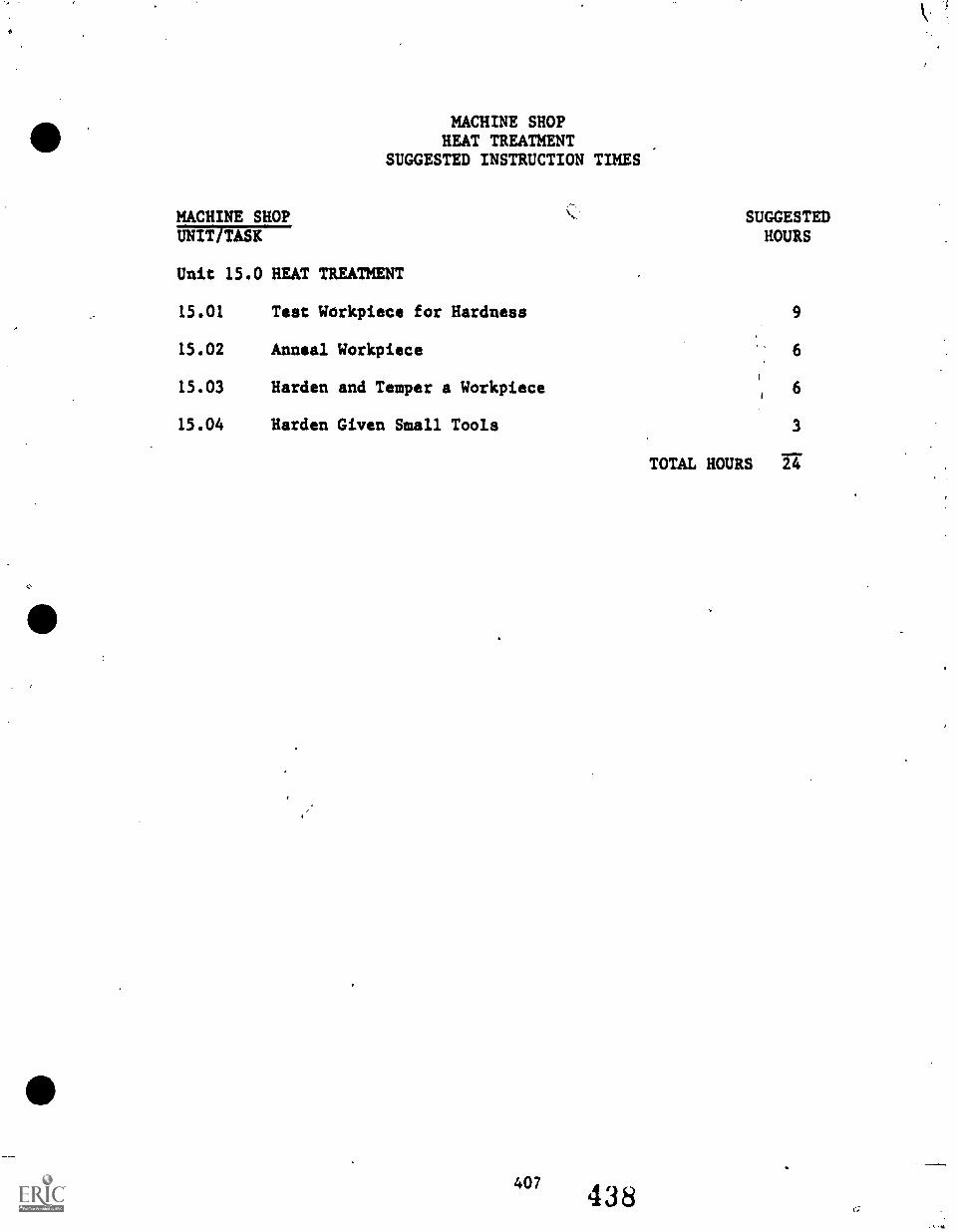
MACHINE SHOPHEAT TREATMENT
SUGGESTED INSTRUCTION TIMES
MACHINE SHOPUNIT TASK
Unit 15.0 HEAT TREATMENT
15.01 Test Workpiece for Hardness
15.02 Anneal Workpiece
15.03 Harden and Temper a Workpiece
15.04 Harden Given Small Tools
407438
SUGGESTEDHOURS
9
6
6
3
TOTAL HOURS 24
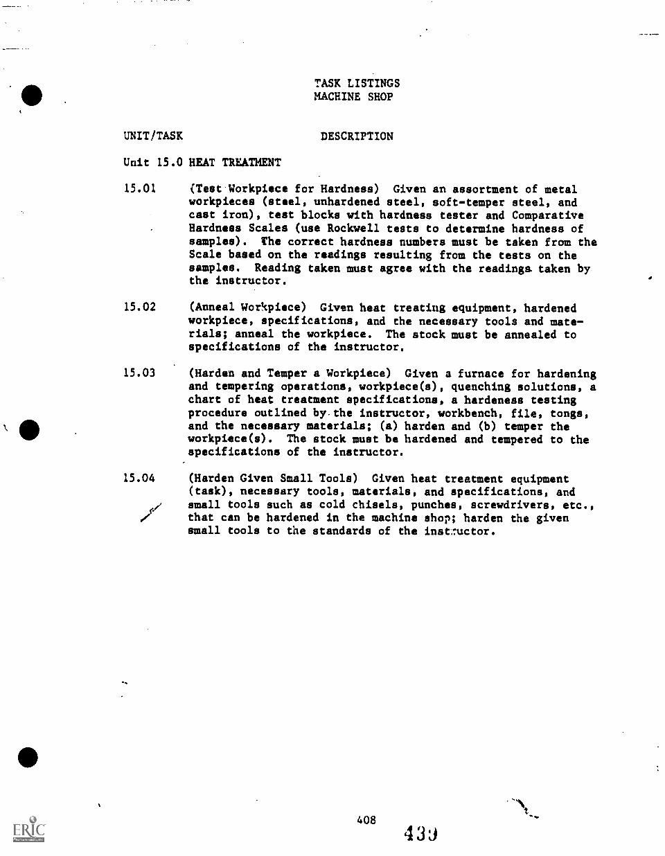
TASK LISTINGSMACHINE SHOP
UNIT/TASK DESCRIPTION
Unit 15.0 HEAT TREATMENT
15.01 (Test Workpiece for Hardness) Given an assortment of metalworkpieces (steel, unhardened steel, softtemper steel, andcast iron), test blocks with hardness tester and ComparativeHardness Scales (use Rockwell tests to determine hardness ofsamples). The correct hardness numbers must be taken from theScale based on the readings resulting from the tests on thesamples. Reading taken must agree with the readings. taken bythe instructor.
15.02 (Anneal Workpiece) Given heat treating equipment, hardenedworkpiece, specifications, and the necessary tools and materials; anneal the workpiece. The stock must be annealed tospecifications of the instructor.
15.03 (Harden and Temper a Workpiece) Given a furnace for hardeningand tempering operations, workpiece(s), quenching solutions, achart of heat treatment specifications, a hardeness testingprocedure outlined bythe instructor, workbench, file, tongs,and the necessary materials; (a) harden and (b) temper theworkpiece(s). The stock must be hardened and tempered to thespecifications of the instructor.
15.04 (Harden Given Small Tools) Given heat treatment equipment(task), necessary tools, materials, and specifications, andsmall tools such as cold chisels, punches, screwdrivers, etc.,that can be hardened in the machine shop; harden the givensmall tools to the standards of the instructor.
408
439
UNIT 15.0 HEAT TREATMENT
TASK 15.01 TEST WORKPIECE
- HARDNESS TEST
FOR HARDNESS
PERFORMANCE OBJECTIVE:
Given an assortment of metal workpieces (steel, unhardened steel,soft-temper steel, and cast iron), test blocks with hardness tester andComparative Hardness Scales (use Rockwell tests to determine hardness ofsamples): The correct hardness numbers must be taken from the Scalebased on the readings resulting from the tests on the samples. Readingtaken must agree with the readings taken by the instructor.
PERFORMANCE ACTIONS: .
15.0101
15.0102
15.0103
15.0104
15.0105
15.0106
i5.0107
Adjust hardness tester.
Apply minor load or 10 kg.
Set dial to zero.
Apply major load.
Remove major 19ad.
Take reading while minor load is still applied*.
Derive hardness number from Scale based.on readingfrom test.
*Workpiece should be tested in at least threedifferent places usint a diamond penetrator andaveraged for a hardness number value (+/- 5 onstandard Rockwell C hardness scales).
PERFORMANCE STANDARDS:
- Test given workpieces (samples) for hardness'using RockwellHardness Test.
- Findings must agree with readings taken by instructor.
SUGGESTED INSTRUCTION TIME: 9 Hours
RELATED TECHNICAL INFORMATION:
- Perform mathematical calculations involving averaging threenumbers.
- Explain difference between ferrous and nonferrous alloys.
409
UNIT 15.0
TASK 15.01
HEAT TREATMENT
TEST WORKPIECE
- HARDNESS TEST
FOR HARDNESS
RELATED TECHNICAL INFORMATION (Con't.):
- Explain difference between machine steel and carbon toolsteel.
- Describe effects of underheating and overheating steel.- Explain how SAE heat treatment numbering system is organized.- Explain why steel is hardened and tempered.- Describe procedure for testing hardness of workpiece.- Explain the Rockwell C hardness scale.- Identify safety precautions.
410441
UNIT 15.0
TASK 15.02
HEAT TREATMENT
ANNEAL WORKPIECE
PERFORMANCE OBJECTIVE:
Given heat treatingthe necessary toolsbe annealed to speci
PERFORMANCE ACTIONS:
15.0201
15.0202
15.0203
15.0204
15.0205
15.0206
15.0207
15.0208
15.0209
equipment, hardened workpiece, specifications, andand materials; anneal the workpiece. The stock mustfications of the instructor.
Review specifications, assemble workpiece, and setupheat treating equipment.
Place workpiece in heat treatment oven using propertools and protective equipment.
Select and set over temperature from informatiBnprovided by the instructor or from referencematerials.
Heat workpiece uniformly to required temperature.
Soak workpiece at temperature one hour per inch ofthickness.
Turn off oven.
Allow workpiece to cool in lime container.
Remove with tongs and protective equipment. (Nextday.)
Test workpiece with corner of file.
PERFORMANCE STANDARDS:
- Anneal workpiece according to specifications provided.
SUGGESTED INSTRUCTION TIME: 6 Hours
UNIT 15.0 HEAT TREATMENT
TASK 15.02 ANNEAL WORKPIECE (Con't.)
RELATED TECHNICAL INFORMATION:
- Define annealing.- Explain why annealing is performed.- Identify the proper annealing temperature (oven setting) for
various metals (identified by the instructor).- Describe the procedure for annealing a workpiece.- Identify safety considerations:
a. Safety tools and procedures.b. Safety clothing, etc.
412
44i
UNIT 15.0 HEAT TREATMENT
/ . TASK 15.03 (Dual Tasks) HARDEN AND TEMPER A WORKPIECE
_
PERFORMANCE OBJECTIVE:
Given a furnace for hardening and tempering operations, workpiece(s),quenching solutions, a chart of heat treatment specifications, a hardnesitesting procedure outlined by the instructor, workbench, file, tongs,and the necessary materials; (a) harden and (b) temper the workpiece(s).The stock must be hardened and temperated to the specifications of theinstructor.
PERFORMANCE ACTIONS:
HARDEN PART:
15.0301 Determine proper hardening temperature for type ofsteel workpiece.
15.0302 Set furnace controls for proper temperature.
15.0303 Using tongs, place part in furnace.
15.0304 Allow part to heat uniformly, not to overheat.
15.0305 Allow part to soak at selected temperature forproper time.
15.0306 Remove part and quench (agitating part in quenchingmedium). Cool to hand temperature.
15.0307 Clean and test part for hardness with hardnesstester.
TEMPER PART: (at, once)
15.0308 Using tongs, place hardened workpiece in furnacethat has been brought up to the proper temperature.
/)
15.0309 Allow time for workpiece to heat uniformly totempering temperature. Allow it to soak at thistemperature for required time.
15.0310 Remove workpiece from furnace and allow it to coolin still air or by quenching.
15.0311 Determine hardness by testing with a file.
"3 44,1
UNIT 15.0 HEAT TREATMENT
TASK 15.03 (Dual Tasks) HARDEN AND TEMPER A WORKPIECE (Con.t)
PERFORMANCE STANDARDS:
- Harden and temper a workpiece according to shop (instructor's)standards and procedures using proper references and informa-tion to determine temperature used to harden and temper themetal.
SUGGESTED INSTRUCTION TIME: 6 Hours
RELATED TECHNICAL INFORMATION:
- Define:a. Hardeningb. Tempering
- Located in reference material provided, the hardening andtempering temperatures of various alloys.
- Identify the uses of tools that have been tempered to: paleyellow, light straw, dark straw, purple, and purple-blue.
- Describe procedure for hardening workpiece.- Describe procedure for tempering workpiece.- Identify safety considerations.
414
445
UNIT 15.0
TASK
HEAT TREATMENT
15.04 HARDEN GIVEN SMALL TOOLS
PERFORMANCE OBJECTIVE:
Given heat treatment equipment (torch), necessary tools, materials, andspecifications, and small tools such as cold chisels, punches, screw-drivers, etc., that can be hardened in the machine shop; harden thegiven small tools to the standards of the instructor.
PERFORMANCE ACTIONS: (Actions provided for punch tool.)
15.0401 Heat punch tq medium red (about 1 inch from tip) toblack (about 2 inches from tip).
15.0402 Cool about half of the red tip by dipping it inclean, cool quinching fluid, until it cools down.
15.0403 Polish punch with a fine abrasive cloth.
15.0404 Observe the color run toward the end as the metalbegins to cool. It will be light straw following bydark straw, yellowish brown, purple, violet, andpale blue.
15.0405 When the desired color (violet +/- 400 degrees F)appears at the point, immediately dip the end in thewater.
PERFORMANCE STANDARDS:
- Harden given small tools in the machine shop according to theinstructor's standards and given information about the metals.
SUGGESTED INSTRUCTION TIME: 3 Hours

UNIT 16.0
THE HYDRAULIC PRESS
MACHINE SHOPTHE HYDRAULIC PRESS
SUGGESTED INSTRUCTION TIMES
MACHINE SHOPUNIT TASK
Unit 16.0 THE HYDRAULIC PRESS
16.01 Lubricate Hydraulic Press 1/2
SUGGESTEDHOURS
16.02 Straighten Parts withHydraulic Press 1/2
16.03 Set Up, Remove, and ReplaceParts with Hydraulic Press
417
446
2
TOTAL HOURS 3
TASK LISTINGSMACHINE SHOP
UNIT/TASK DESCRIPTION
Unit 16.0 THE HYDRAULIC PRESS
16.01 (Lubricate Hydraulic Press) Provided with a hydraulic press,lubricants such as oil and grease, lubricant dispensers,cleaning materials, and required tools; lubricate the hydraulicpress. The standards of the instructor or the manufacturer'sspecifications must be met.
16.02 (Straighten Parts with Hydraulic Press) Given bend metal thatan be straightened under pressure, use the hydraulic press tostraighten the bent part. The part is to be straightenedparallel to the press bed to a. tolerance of +/- 1/64 inch.
16.03 (Set Up, Remove, and Replace Parts with Hydraulic Press)Given specifications/drawing, gears, pulley or wheel, a shaft,etc., with keyway, key lubricant, clamps, and measuringinstruments; set, remove, and replace par s with press.to atolerance of +/- 1/64 inch.
418 449
UNIT 16.0 THE HYDRAULIC PRESS
TASK 16.01 LUBRICATE HYDRAULIC PRESS
PERFORMANCE OBJECTIVE:
Provided with a hydraulic press, lubricants such as oil and grease,lubricant dispensers, cleaning materials, and required tools; lubricatethe hydraulic press. The standards of the instructor or the manu-facturer's specifications must be met.
PERFORMANCE ACTIONS:
16.0101 Disconnect electrical power to press, if applicable.
16.0102 Locate hydraulic fluid drain plug.
16.0103 Drain fluid into bucket, etc.
16.0104 Locate, remove, and inspect filter, if applicable.
16.0105 Clean or replace filter, if needed.
16.0106 Return filter to press.
16.0107 Replace drain plug.
16.0108 Locate hydraulic fluid fill caps.
16.0109 Replace hydraulic fluid.
16.0110 Lubricate moving parts.
16.0111 Hand lubricate ram.
PERFORMANCE STANDARDS:
- Lubricate hydraulic press to instructor's (manufacturer's).standards.
SUGGESTED INSTRUCTION TIME: 1/2 Hour
419 45()
UNIT 16.0 THE HYDRAULIC PRESS
TASK 16.01 LUBRICATE HYDRAULIC PRESS (Con't.)
RELATED TECHNICAL INFORMATION:
Identify parts of hydraulic press.Identify safety considerations in lubricating and cleaning thepress:a. Look for hydraulic fluid leaks.b. Check lowering and railing etc.c. Examine for bent pins.d. Determine if holes are worn.e. Hydraulic fluid level should be at proper level.
420 451
UNIT 16.0 THE HYDRAULIC PRESS
TASK 16.02 STRAIGHTEN PARTS WITH HYDRAULIC PRESS
PERFORMANCE OBJECTIVE:
Given bend metal that can be straightened under pressure, use thehydraulic press to straighten the bent part. The part is to bestraightened parallel to the press bed to a tolerance of +/- 1/64 inch.
PERFORMANCE ACTIONS:
16.0201 Set up hydraulic press.
16.0202 Place bent part properly/safely in press.
16.0203 Press part to straighten it to a parallel toleranceof +/- 1/64 inch.
PERFORMANCE STANDARDS:
- Straighten parts using the hydraulic press.- Procedures and product must meet instructor's standards.
SUGGESTED INSTRUCTION TIME: 1/2 Hour
RELATED TECHNICAL INFORMATION:
- Operation of hydraulic press.- Safety considerations.- Uses of hydraulic press.
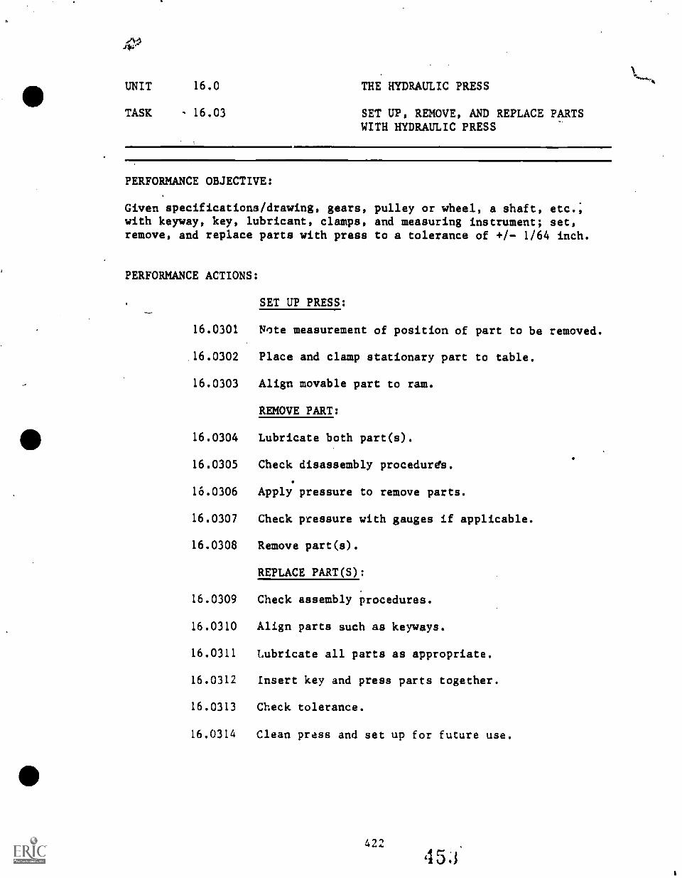
UNIT 16.0 THE HYDRAULIC PRESS
TASK - 16.03 SET UP, REMOVE, AND REPLACE PARTSWITH HYDRAULIC PRESS
PERFORMANCE OBJECTIVE:
Given specifications/drawing, gears, pulley or wheel, a shaft, etc.;with keyway, key, lubricant, clamps, and measuring instrument; set,remove, and replace parts with press to a tolerance of +/ 1/64 inch.
PERFORMANCE ACTIONS:
SET UP PRESS:
16.0301 Note measurement of position of part to be removed.
16.0302 Place and clamp stationary part to table.
16.0303 Align movable part to ram.
REMOVE PART:
16.0304 Lubricate both part(s).
16.0305 Check disassembly procedures.
16.0306 Apply pressure to remove parts.
16.0307 Check pressure with gauges if applicable.
16.0308 Remove part(s).
REPLACE PART(S):
16.0309 Check assembly procedures.
16.0310 Align parts such as keyways.
16.0311 Lubricate all parts as appropriate.
16.0312 Insert key and press parts together.
16.0313 Check tolerance.
16.0314 Clean press and set up for future use.
422
UNIT 16.0 THE HYDRAULIC PRESS
LASK 16.03 SET UP, REMOVE, AND REPLACE PARTSWITH HYDRAULIC PRESS (Con't.)
PERFORMANCE STANDARDS:
- Set up, remove, and replace parts with hydraulic press meetingthe instructor's standards.
SUGGESTED INSTRUCTION TIME: 2 Hours
RELATED TECHNICAL INFORMATION:
- Cleaning and lubricate hydraulic press.- Operation of hydraulic press.- Safety with hydraulic press.
UNIT 17.0
COMPUTER NUMERICALLY CONTROLLED (CNC) MACHINING
In 1983, to introduce secondary machine shop students to the latest,state-of-the-art, hi-tech manufacturing processes, The School Districtof Greenville County acquired EMCO Compact 5 CNC (Computer NumericallyControlled) Trainers for the three secondary machine shop programs.
As this articulated, instruction objectives guide for machine shop isdeveloped, there has not been adequate time for the CNC instructionalobjectives described in this unit to have been validated fully.
The objectives described for CNC training probably will need somerevisions after the three secondary machine shop instructors have had anopportunity to field trial test the CNC trainers and the tentativeobjectives described in this unit.
The basic goals of CNC training include:
a. Introducing secondary machine shop students to NC/CNC concepts.b. Transforming CNC theory into practical applications.c. Transforming written instruction into CNC operations.d. Controlling CNC machine operations.e. Developing skills and knowledges with high transfer to indus-
trial machines with minimum difficulty so students may continuetraining at the post-secondary level.
f. To orient the students to the fundamentals of CNC organizationand peripherial aspects of CNC machining.
This description dies NOT represent the NC/CNC training objectives ofthe post-secondary level program at GTC which uses industrial typeequipment.
s's
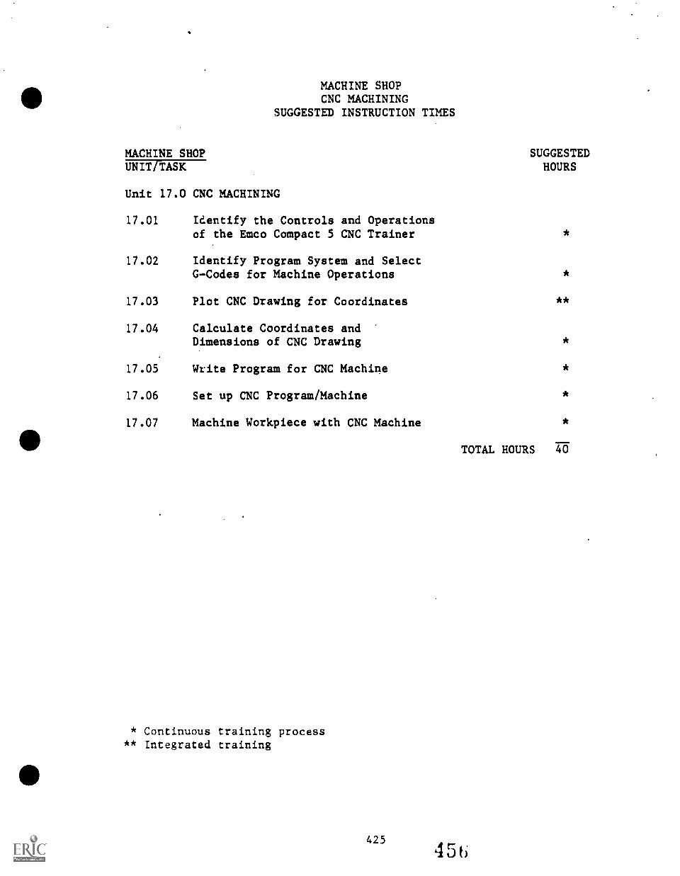
MACHINE SHOPCNC MACHINING
SUGGESTED INSTRUCTION TIMES
MACHINE SHOP SUGGESTEDHOURSUNIT TASK
Unit 17.0 CNC MACHINING
17.01 Identify the Controls and Operationsof the Emco Compact 5 CNC Trainer
17.02 Identify Program System and SelectG-Codes for Machine Operations *
17.03 Plot CNC Drawing for Coordinates **
17.04 Calculate Coordinates andDimensions of CNC Drawing *
17.05 Write Program for CNC Machine *
17.06 Set up CNC Program/Machine *
17.07 Machine Workpiece with CNC Machine *
* Continuous training process** Integrated training
425
TOTAL HOURS 40
45t)
STANDARDS FOR EMCO CNC 5 TRAINER
- Operation of the Emco Compact 5 CNC Trainer will be according tothe Student Handbook-Basis or the instructor's handbook.
- Stock material used will be half-hard aluminum.
- Never chuck workpiece without using live centers. Always use thelive center of the tailstock as support for a long workpiece.Proper chucking is required.
- Preferably, the student should have demonstrated minimum competencieson hand-operated machines prior to instruction on the CNC trainer:However, the situdent does not have to be competent in manualmachines prior to CNC training.
- Emco Compact 5 CNC training is designed for 3-4 students permachine: However, the instructor will determine the number ofstudents to be assigned to a machine for training.
- The accompanying pages indicate standards of terminology andaccessories and tools for the vertical milling drill attachment aswell as for the lathe. (See accompanying pages.)
TASK LISTINGSMACHINE SHOP
UNIT/TASK DESCRIPTION
Unit 17.0 CNC MACHINING
17.01 (Identify the Controls and Operations of the Emco Compact 5CNC Trainer) Given instruction concerning the EMCO Compact 5CNC Trainer, BASIS-the handbook for the trainee, an orienta-tion to the trainer, the CNC machine, and all necessary toolsand materials; identify the controls and operations of theEMCO Compact 5 CNC Trainer.
17.02 (Identify Program System and Select G-Codes for MachineOperations) Given instruction concerning the CNC trainer andthe programming system; identify and select the proper G-Codesto program the desired movements of the CNC trainer.
17.03 (Plot CNC Drawing for Coordinates) Provided with a blueprint-drawing-specifications, CNC machine, student handbook-BASIS,programming tape, and all necessary tools and materials suchas graph paper, etc., plot CNC drawing for coordinates for CNCprogram for a given operation. The program must be to specifi-cations, must correctly operate the CNC machine trainer, andmust be acceptable to the instructor.
17.04 (Calculate Coordinates and Dimensions of CHIC Drawing) Givenblueprint, CNC milling machine, and references; calculatecoordinates and dimensions from the blueprint for the CNCmachine. Dimensions must meet blueprint specifications with atolerance of +.- 0.001 inch.
17.05 (Write Program for CNC Machine) Given blueprint-drawing-specifications, CNC machine, tools, workpiece stock,programming forms, student handbook-BASIS, and other necessarymaterials; write a program to machine the workpiece tospecifications using the CNC trainer with a minimum of toolchanges, returning to the starting point at the end of theprogram.
17.06 (Set up CNC Program/Machine) Given instruction, blueprint/drawing/specifications, cutting tools, workpiece, precision measuringinstruments, student handbook-BASIS, and the CNC trainer; setup the CNC milling machine for machining a given workpiece.The workpiece must be within a tolerance of +/- 0.001 inch orto specifications.
17.07 (Machine Workpiece with CNC Machine) Given the CNC machine,tools, tool program, work-holding devices, measuring instruments,references, blueprint-drawing-specifications, aluminum stock,and the necessary tools and materials; machine the workpieceto specifications within a tolerance of +/- 0.001 inch ofdecimal dimensions and +/- 1/64 inch on fraction dimensions.
427
4 5 d
UNIT 17.0 CNC MACHINING
TASK 17.01 IDENTIFY THE CONTROLS AND OPERATIONSOF THE EMCO COMPACT 5 CNC TRAINER
PERFORMANCE OBJECTIVE:
Given instruction concerning the EMCO Compact 5 CNC Trainer, BASIS-thehandbook for the trainee, an orientation to the trainer, the CNCmachine, and all necessary tools and materials; identify the controlsand operations of the EMCO Compact 5 CNC Trainer.
PERFORMANCE ACTIONS:
17.0101 Pay attention to instructor's introduction of theEmco Compact 5 CNC Trainer.
17.0102 Observe and make notes about operation of machineduring orientation. Ask queetions.
17.0103 Read and follow the student handbook, BASIS, indeveloping knowledge and skill in operating the CNCtrainer.
PERFORMANCE STANDARDS:
- Identify the controls and operations of the Emco Compact 5 CNCTrainer.
- Performance must be according to procedures identified by theinstructor and outlined in the student handbook, BASIS.
- Steps outlined in the student handbook must be followedexactly unless the instructor directs otherwise.
SUGGESTED INSTRUCTION TIME: Integrated
RELATED TECHNICAL INFORMATION:
- Hand operate CNC machine:a. Mount toolholder and right hand side tool without setting
gage.b. Set RPM, speed and traverse slides. Regular feed,
Traverse slides in X- and Z-direction.c. Set LED display to zero. Switch over display.d. Program traverse path.e. Calculate cutting values.f. Clamp workpiece.g. Turn workpiece.h. Measure diameters.
UNIT 17.0 CNC MACHINING
TASK 17.01 IDENTIFY THE CONTROLS AND OPERATIONSOF THE EMCO COMPACT 5 CNC TRAINER
RELATED TECHNICAL INFORMATION (Can't.):
- Mount toolholder and position tool.- Explain:
a. Longitudinal or cross slide.b. Traverse of slide.c. Direction rate.d. Feed rate.
- Explain minus value.- Explain "coding."
UNIT 17.0 CNC MACHINING
TASK 17.07 IDENTIFY PROGRAM SYSTEM AND SELECTG -CODES FOR MACHINE OPERATIONS
PERFORMANCE OBJECTIVE:
Given instruction concerning the CNC trainer and the programming system;identify and select the proper G-Codes to program the desired movementsof the CNC trainer.
PERFORMANCE ACTIONS:
17.0201 Describe the programming system of the Emco Compact5 CNC Trainer: N, G, X, Z, F
17.0202 Select the proper G-Codes for required machineoperations:
Program system: N, G, X, Z, F
N = Block numbers 00-95G = Preparatory command
00 = Rapid traverse01 = Long, turning, facing and taper turning02 + 03 = Circular interpolation (spherical
turning)20 = Programmed stop21 = No operation block22 = Program stop33 = Thread cutting64 = Feed motors without current supply65 = Magnetic tape memory78 = Thread cutting cycle84 = Turning cycle
X + Z = Input step for longitudinal movement in0.01 mm
F = Feed rate input and pitch in 0.01 mm
PERFORMANCE STANDARDS:
- Identify the program system and select G-Codes for CNC trainermachining operations.
- Performance must be to instructor's standards.
SUGGESTED INSTRUCTION TIME: Integrated training
UNIT 17.0 CNC MACHINING
TASK 17.02 IDENTIFY PROGRAM SYSTEM AND SELECTG-CODES FOR MACHINE OPERATIONS(Con't.)
RELATED TECHNICAL INFORMATION:
- Student Handbook-BASIS.- Orientation to CNC Trainer programming.
UNIT 17.0 CNC MACHINING
TASK 17.03 PLOT CNC DRAWING FOR COORDINATES
PERFORMANCE OBJECTIVE:
Provided with a blueprint-drawing-specifications, CNC machine, studenthandbook-BASIS, programming. tape, and all necessary tools and materialssuch as graph paper, etc.; plot drawing for coordinates for CNC programfor a given operation. The program must be to specifications, mustcorrectly operate the CNC machine trainer, and must be acceptable to theinstructor.
PERFORMANCE ACTIONS:
17.0301 Review blueprint-drawing-specifications.
17.0302 Review student handbook, BASIS.
17.0303 Determine the sequence of operations:
a. Determine operations required.b. Determine tools required.
17.0304 Establish reference points (starting and finishing).
17.0305 Calculate required dimensions.
17.0306 Determine tool changes.
17.0307 Write program on program sheet:
a. Note tool changes.13. Note other instructions.
17.0308 Check program.
17.0309 Enter program in machine.
17.0310 Execute operation to check program.
17.0311 Make measurements and make corrections as necessary.
PERFORMANCE STANDARDS:
- Plot drawing for CNC program coordinates.- Taped program must be to specifications, must correctly
operated the CNC trainer, and must be acceptable to theinstructor.
UNIT 17.0 CNC MACHINING
TASK 17.03 PLOT CNC DRAWING FOR COORDINATES(Con't.)
SUGGESTED INSTRUCTION TIME: Integrated training
RELATED TECHNICAL INFORMATION:
- Use of graph paper.- Drawing workpiece.- Measuring.- Use of 1:10 scale for technical drawing.- Identify G-codes.
UNIT 17.0 CNC MACHINING
TASK 17.04 CALCULATE COORDINATES' FOR DIMENSIONSOF CNC DRAWING
PERFORMANCE OBJECTIVE:
Given blueprint, CNC milling machine, and references; calculate coordinatesand dimensions from the blueprint for the CNC machine. Dimensions mustmeet blueprint specifications with a tolerancf. of +/- 0.001 inch.
PERFORMANCE ACTIONS:
17.0401 Identify type of spindle positioning:
a. Determine incremental measurement or,b. Absolute or coordinate measurement.
17.0402 Interpret blueprint data to:
a. Check number of holes same size.b. Check number of holes requiring same operation.
17.0403 Establish starting of absolute zero point:
a. Corner of workpiece.b. Off workpiece for tool changes.
17.0404 Convert all dimensions including angles to decimaldimensions.
17.0405 Calculate dimensions from two adjacent sides as frompoint zero.
17.0406 Verify calculations as within tolerance by addingplus (+) and (-) dimensions in each axis.
17.0407 Check calculations, correcting any error untiltolerance is obtained.
PERFORMANCE STANDARDS:
- Calculate coordinates and dimensions of CNC drawing within atolerance of +/- 0.001 inch.
- Performance must be to instructor's standards.
SUGGESTED INSTRUCTION TIME: Integrated training
(NOTE: This task is jointly conducted with the previouslydescribed and following tasks.)
434
46z)
a
UNIT 17.0 CNC MACHINING
TASK 17.05 WRITE PROGRAM FOR CNC MACHINE
PERFORMANCE OBJECTIVE:
Given blueprint-drawing-specifications, CNC machine, tools, workpiecestock, programming forms, student handbook-BASIS, and other necessarymaterials; write a program to machine the workpiece to specificationsusing the CNC trainer with a minimum of tool changes, returning to thestarting point at the end of the program.
PERFORMANCE ACTIONS:
17.0501 Review blueprint-drawing-specifications.
17.0502 Review student handbook, BASIS.
17.0503 Determine machine set-up requirements.
17.0504 Determine sequence of erationi:
a. Determine operatiabstz,bilerformed.b. Determine order of operations: Plunge, turn,
thread, part, mill, drill, etc.
Determine tools required.
Establish starting and finishing reference points.
Calculate dimensions not on blueprint.
Determine tool changes.
Write program:
a. Note tool changes.b. Note other instructions.
17.0510 Verify program:
17.0505
17.0506
17.0507
17.0508
17.0509
a. Plus valueszero.
b. Plus valueszero.
and minus values of (x) equals
and minus values of (z) equals
UNIT 17.ti CNC MACHINING
TASK 17.05 WRITE PROGRAM FOR CNC MACHINE(Con't.)
PERFORMANCE STANDARDS:
- Write program for CNC machine operations to produce workpieceto given specifications using a minimum of tool changes,returning to the starting point at the end of the program.
SUGGESTED INSTRUCTION TIME: Integrated training
RELATED TECHNICAL INFORMATION:
- BASIS handbook for studen.
UNIT 17.0 CNCMACHINING
TASK 17.06 SET UP CNC PROGRAM/MACHINE
PERFORMANCE OBJECTIVE:
-Given instruction, blueprint-drawing-specifications, cutting tools,workpiece, precision measuring instruments, student handbook-BASIS, andthe CNC trainer; set up the CNC milling machine for machining a givenworkpiece. The workpiece must be within a tolerance of +/- 0.001 inchor to specifications.
PERFORMANCE ACTIONS:
17.0601 a.
b.Review print-drawing.apecifications.Review operator's manual (BASIS).
1.7.0602 Mount workpiece.
17.0603 Center spindle.
17.0604 Place tape in tape reader.
17.0605 Mount tool in toolholder.
17.0606 Input program.
17.0607 Check irogram: Make necessary corrections
a. '!urn first workpiece.b. Measure.c. Switch over to hand-operation.d. Correct starting point.e. Second workpiece will be true to measure.
17.0608 Manufacturer workpiece: Charge tools as necessary.
17.0609 *leas" °e workpiece for tolerances.
PERFORMANCE STANDARDS:
- Set up the CNC program/machine for a given manufacturingoperation.
- Procedures must be according to manufacturer's instructionhandbook.
- Process and product must 'e to instructor's standards.
SUGGESTED INSTRUCTION TIME: Integrated training
UNIT 17.0 CNC MACHINING
TASK 17.06 SET UP CNC PROGRAM/MACHINE (Con't.)
RELATED TECHNICAL INFORMATION:
- Identify type of slide: Longitudinal or cross slide (x & z).- Identify traverse of slide.- Identify direction.- Identify feed rate.- Explain the right hand coordinate system rule.- Identify 2 types of feed.- Explain the G-functions in programming the CNC machine.- Describe rapid transverse (No F-programming).- Describe what measure to take with alarm or false input
(switch off main, start from beginning).[Attention to collision! Use of emergency-stop-button. Useof main power switch.]
- Prepare proper technical drawing to scale of 1:10 on graphoaper to prevent errors in measuring, programming.
UNIT 17.0 CNC MACHINING
TASK 17.07 MACHINE WORKPIECE WITH CNC MACHINE
PERFORMANCE OBJECTIVE:
Given the CNC machine, tools, tool program, work-holding devices,measuring instruments, references, blueprint-drawing-specifications,aluminum stock, and the necessary tools and materials; machine theworkpiece to specifications within a toleranc, of +/- 0.001 inch ofdecimal dimensions and +/- 1/64 inch on fn dimensions.
PERFORMANCE ACTIONS:
17.0701 Review operating instructions.
17.0702 Review blueprint - drawing - specifications.
17.0703 Review tool program OR set up program.
17.0704 Check tools.
17.0705 Mount workpiece in work-holding device.
17.0706 Mount tool.
17.0707 a. Manually operate machine OR,b. Place tape in reader and start reader.
17.0708 Machine workpiece: Check program and make necessarycorrections
17,0709 a. Monitor for tool changes.b. Monitor for depth stops.c. Monitor for other required changes.
17.0710 Remove finished workpiece and deburr.
17.0711 Verify tolerance of workpiece.
PERFORMANCE STANDARDS:
- Machine a workpiece on the CNC machine to specificationswithin a tolerance of +/- 0.001 inch on decimal dimensions and+/- 1/64 inch on fraction dimensions.
- The proper procedures of operation must be followed.- A program entered on tape must be verified as correct.- Performance and product must be to the instructor's standards.
a
UNIT 17.0 CNC MACHINING
TASK 17.07 MACHINE WORKPIECE WITH CNC MACHINE(Con't.)
SUGGESTED INSTRUCTION TIME: Integrated training
RELATED TECHNICAL INFORMATION:
- Identify operation and control elements of the CNC machine.- Hand operate CNC machine.- Describe/demonstrate how to correct measurements in drawing if
raw material (stock) has different dimensions.- Calculate cutting values.- Describe/demonstrate how to clamp workpiece (mount workpiece).- Demonstrate how to turn workpiece, measure workpiece, and
correct diameter.- Demonstrate how to position the tool.
440.
4 111
UNIT 18.0
MACHINING MATH CALCULATIONS
The math calculations summarized in this unit represent mathematicalskills thit the student should master by the latter part of the secondyear of training.
The math calculation.. skills described in this unit may be developedduring the first or second year oc learning and way be associated withrelated machining operations rather than being learned as standalonetasks.
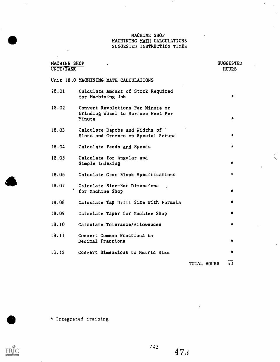
MACHINE SHOPMACHINING MATH CALCULATIONSSUGGESTED INSTRUCTION TIMES
MACHINE SHOPUNIT/TASK
Unit 18.0 MACHINING MATH CALCULATIONS
18.01 Calculate Amount of Stock Requiredfor Machining Job
18.02 Convert Revolutions Per Minute orGrinding Wheel to Surface Feet PerMinute
18.03 Calculate Depths and Widths ofSlots and Grooves on Special Setups
18.04 Calculate Feeds and Speeds
18.05 Calculate for Angular andSimple Indexing
18.06 Calculate Gear Blank Specifications
18.07 Calculate SineBar Dimensionsfor Machine Shop
18.08 Calculate Tap Drill Size with Formula
18.09 Calculate Taper for Machine Shop
18.10 Calculate Tolerance/Allowances
18.11 Convert Common Fractions toDecimal Fractions
18.12 Convert Dimensions to Metric Size
110* Integrated training
442
SUGGESTEDHOURS
*
*
*
*
*
*
*
*
*
*
*
TOTAL HOURS 40
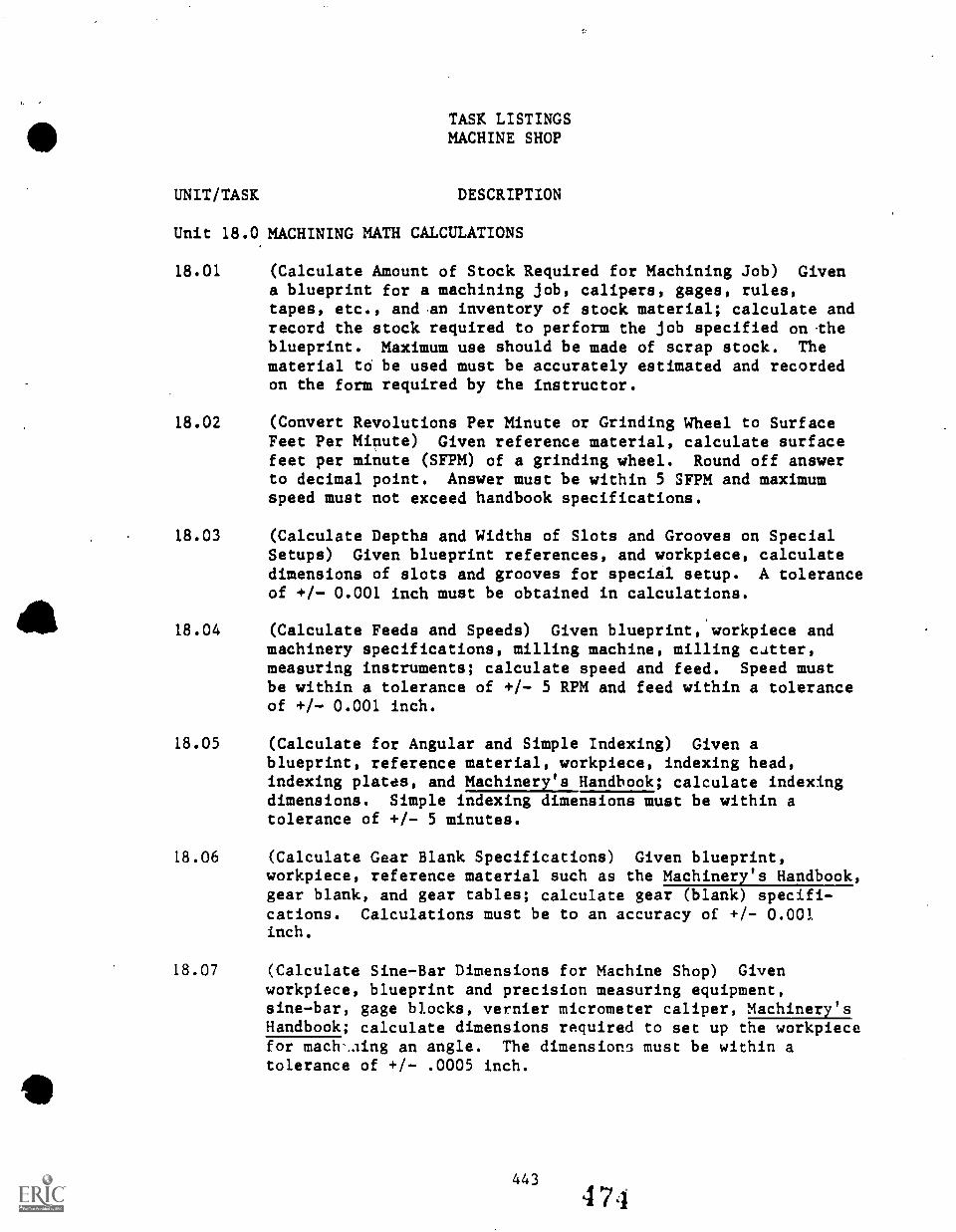
TASK LISTINGSMACHINE SHOP
UNIT/TASK DESCRIPTION
Unit 18.0 MACHINING MATH CALCULATIONS
18.01 (Calculate Amount of Stock Required for Machining Job) Givena blueprint for a machining job, calipers, gages, rules,tapes, etc., and .an inventory of stock material; calculate andrecord the stock required to perform the job specified on theblueprint. Maximum use should be made of scrap stock. Thematerial to be used must be accurately estimated and recordedon the form required by the instructor.
18.02 (Convert Revolutions Per Minute or Grinding Wheel to SurfaceFeet Per MiTiute) Given reference material, calculate surfacefeet per minute (SFPM) of a grinding wheel. Round off answerto decimal point. Answer must be within 5 SFPM and maximumspeed must not exceed handbook specifications.
18.03 (Calculate Depths and Widths of Slots and Grooves on SpecialSetups) Given blueprint references, and workpiece, calculatedimensions of slots and grooves for special setup. A toleranceof +/- 0.001 inch must be obtained in calculations.
18.04 (Calculate Feeds and Speeds) Given blueprint, workpiece andmachinery specifications, milling machine, milling cutter,measuring instruments; calculate speed and feed. Speed mustbe within a tolerance of +/- 5 RPM and feed within a toleranceof +/- 0.001 inch.
18.05 (Calculate for Angular and Simple Indexing) Given ablueprint, reference material, workpiece, indexing head,indexing plates, and Machinery's Handbook; calculate indexingdimensions. Simple indexing dimensions must be within atolerance of +/- 5 minutes.
18.06 (Calculate Gear Blank Specifications) Given blueprint,workpiece, reference material such as the Machinery's Handbook,gear blank, and gear tables; calculate gear (blank) specifi-cations. Calculations must be to an accuracy of +/- 0.001inch.
18.07 (Calculate Sine-Bar Dimensions for Machine Shop) Givenworkpiece, blueprint and precision measuring equipment,sine-bar, gage blocks, vernier micrometer caliper, Machinery'sHandbook; calculate dimensions required to set up the workpiecefor mach-..iing an angle. The dimensions must be within atolerance of +/- .0005 inch.
443
474
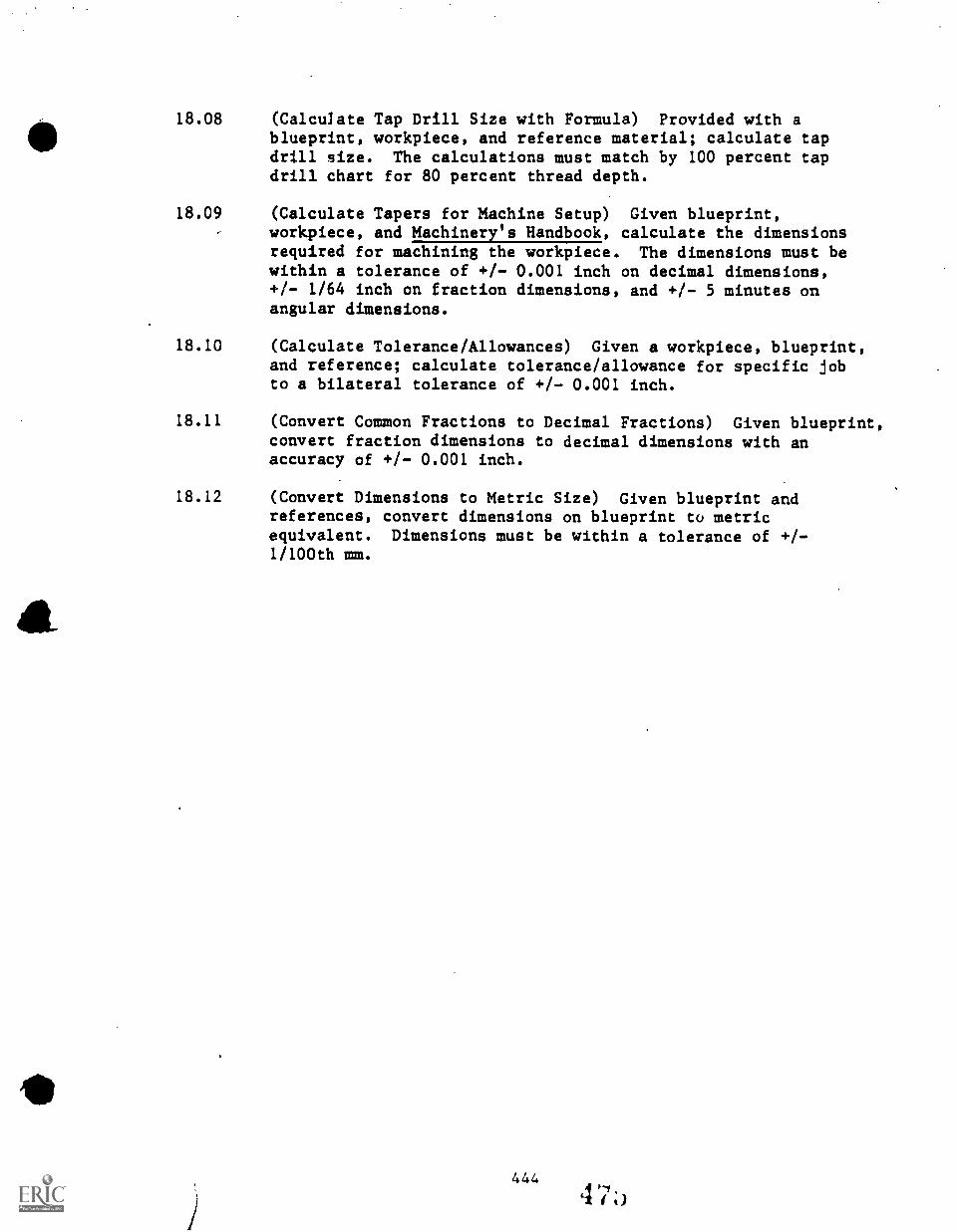
&
18.08 (Calculate Tap Drill Size with Formula) Provided with ablueprint, workpiece, and reference material; calculate tapdrill size. The calculations must match by 100 percent tapdrill chart for 80 percent thread depth.
18.09 (Calculate Tapers for Machine Setup) Given blueprint,workpiece, and Machinery's Handbook, calculate the dimensionsrequired for machining the workpiece. The dimensions must bewithin a tolerance of +/- 0.001 inch on decimal dimensions,+/- 1/64 inch on fraction dimensions, and +/- 5 minutes onangular dimensions.
18.10 (Calculate Tolerance/Allowances) Given a workpiece, blueprint,and reference; calculate tolerance/allowance for specific jobto a bilateral tolerance of +/- 0.001 inch.
18.11 (Convert Common Fractions to Decimal Fractions) Given blueprint,convert fraction dimensions to decimal dimensions with anaccuracy of +/- 0.001 inch.
18.12 (Convert Dimensions to Metric Size) Given blueprint andreferences, convert dimensions on blueprint to metricequivalent. Dimensions must be within a tolerance of +/-1 /100th mm.
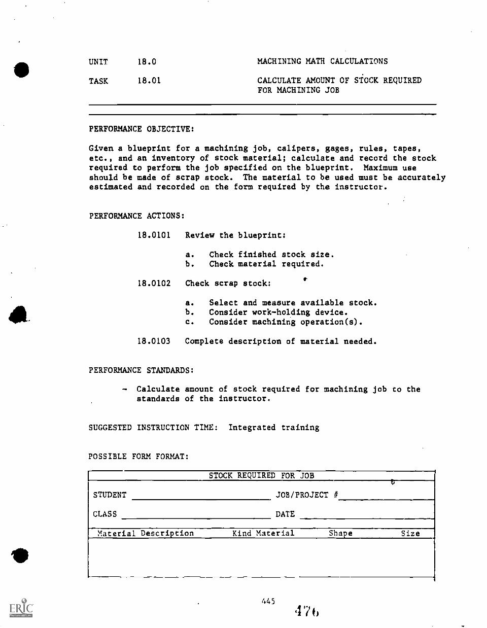
UNIT 18.0 MACHINING MATH CALCULATIONS
TASK 18.01 CALCULATE AMOUNT OF STOCK REQUIREDFOR MACHINING JOB
PERFORMANCE OBJECTIVE:
Given a blueprint for a machining job, calipers, gages, rules, tapes,etc., and an inventory of stock material; calculate and record the stockrequired to perform the job specified on the blueprint. Maximum useshould be made of scrap stock. The material to be used must be accuratelyestimated and recorded on the form required by the instructor.
PERFORMANCE ACTIONS:
18.0101 Review the blueprint:
a.
b.
Check finished stock size.Check material required.
18.0102 Check scrap stock:
a. Select and measure available stock.b. Consider workholding device.c. Consider machining operation(s).
18.0103 Complete description of material needed.
PERFORMANCE STANDARDS:
Calculate amount of stock required for machining job to thestandards of the instructor.
SUGGESTED INSTRUCTION TIME: Integrated training
POSSIBLE FORM FORMAT:
STOCK REQUIRED FOR JOB
STUDENT JOB/PROJECT #
CLASS DATE
Material Description Kind Material Shape Size
UNIT 18.0 MACHINING MATH CALCULATIONS
TASK 18.02 CONVERT REVOLUTIONS PER MINUTE ORGRINDING WHEEL TO SURFACE FEET PERMINUTE
PERFORMANCE OBJECTIVE:
Given reference material, calculate surface feet per minute (SFPM) of agrinding wheel. Round off answer to decimal point. Answer must bewithin 5 SFPM and maximum speed must not exceed handbook specifications.
PERFORMANCE ACTIONS:
18.0201 Check grinding wheel diameter.
18.0202 Check grinding wheel for maximum speed noted.
18.0203 Check speed of grinder.
18.0204 Calculate surface feed per minute (SFPM) using theformula:
SFPM al RPM x D/12 x/re
WhereRPM revolutions per minute
SFPM surface feet per minute
D - diameter of wheel in inches'Tr 3.14
x me multiplication sign
18.0205 Check maximum speed in Machinery's Handbook toensure calculated speed is within handbookspecifications.
PERFORMANCE STANDARDS:
- Convert revolutions per minute of grinding wheel to surfacefeet per minute, rounding off the answer to the decimal point,and not exceeding the maximum speed recommended in theMachinery's Handbook.
SUGGESTED INSTRUCTION TIME: Integrated training
RELATED TECHNICAL INFORMATION:
- Machinery's Handbook.
446 4 7 /
UNIT 18.0 MACHININ; MATH CALCULATIONS
TASK 18.03 CALCULATE DEPTHS AND WIDTHS OF SLOTSAND GROOVES ON SPECIAL SETUPS
PERFORMANCE OBJECTIVE:
Given blueprint references, and workpiece, calculate dimensions of slotsand grooves for special setup. A tolerance of +/- 0.001 inch must beobtained in calculations.
PERFORMANCE ACTIONS:
18.0301 Review blueprint.
18.0302 Determine dimensions needed for machining workpiece.
18.0303 Check machinist's handbook for table or formula.
18.0304 Calculate required dimensions and round off answerto nearest 0.001 inch.
18.0305 Repeat above -steps and check answer.
PERFORMANCE STANDARDS:
- Calculate depths and widths of slots and grooves on specialsetups to a tolerance of +/- 0.001 inch in calculations.
SUGGESTED INSTRUCTION TIME: Integrated training
UNIT 18.0 MACHINING MATH CALCULATIONS
TASK 18.04 CALCULATE FEEDS AND SPEEDS
PERFORMANCE OBJECTIVE:
Given blueprint, workpiece, and machinery specifications, millingmachine, milling cutter, measuring instruments; calculate speed andfeed. Speed must be within a tolerance of +/- 5 RPM and feed within atolerance of +/- 0.001 inch.
PERFORMANCE ACTIONS:
18.0401
18.0402
18.0403
Interpret blueprint.
Measure workpiece.
Determine machining specifications:
a. Amount of stock to be removed.b. Number of cuts.c. Required finish.d. Workpiece material.e. Cutter material and size.f. Size of workpiece.g. Determine depth of cut.
18.0404 Calculate speed of machine:
18.0405
a. Check formula in Machinery's Handbb. Round off to whole number.
/Calculate feed or workpiece:
Refer to Machinery's Handbook.b. Round off to nearest thousandth of
ook.
an inch.
18.0406 Verify calculations as within tolerance of 0.001inch.
PERFORMANCE STANDARDS:
.Calculate feeds and speeds for given situations with a toleranceof +/- 5 RPM for speed and +/- 0.001 inch for feed.
SUGGESTED INSTRUCTION TIME: Integrated training
RELATED TECHNICAL INFORMATION:
- Machinery's Handbook.
448
4Th
UNIT 18.0 MACHINING MATH CALCULATIONS
TASK 18.05 CALCULATE FOR ANGULAR AND SIMPLEINDEXING
ti
PERFORMANCE OBJECTIVE:.11
Given a blueprint, reference material, workpiece, indexing head,plates, and Machinery's Handbook; calculate indexing dimensions.indexing dimensions musti,e within a tolerance of +/- 5 minutes.
PERFORMANCE ACTIONS:
- 18.0501
18.0502
18.0503
18.0504
Review blueprint.
Note-index head and index plates available.
Calculate simple indexing movement:
a.
b.
indexingSimple
Refer to Machinery's Handbook.Use formula to obtain simple indexing movement:
40
No. of Divisions= No, of Turns
c. For partial (fractional) turns reduce orincrease fraction until denominator equalsnumber of holes in index plate:
(e.g., 3 3 3 9E.x = [index plate no.]
d. Use table to check calculations.
Calculate angular indexing dimensions:
a. One full turn on index head equals 9 degrees.b. Calculate number of full turns for each 9
degrees required.c. Select index plate with hole circle divisible
by 9 for degrees less than 9.d. Divide hole circle by 9 to find number of holes
for each degree.e. For angular indexing minutes, convert degrees
to minutes using the formula:
Minutes required Angular indexing minutes540 where degrees Are conver!.,1
to minutes
UNIT 18.0 MACHINING MATH CALCULATIONS
TASK 18.05 CALCULATE FOR ANGULAR AND SIMPLEINDEXING
PERFORMANCE ACTIONS (Con't.):
18.0505 Verify calcu:eations with tables in Machinery'sHandbook.
PERFORMANCE STANDARDS:
- Calculatd for angular and simple indexing to a tolerance of+/- 5 minutes.
SUGGESTED INST^UCTION TIME: Integrated training
UNIT 18.0 MACHINING MATH CALCULATIONS
TASK 18.06 CALCULATE GEAR BLANK SPECIFICATIONS
PERFORMANCE OBJECTIVE:
Given blueprint, workpiece, reference mater!,1 such as the Machinery'sHandbook, gear blank, and gear tables; calculate gear (blank)specifications. Calculations must be to an accuracy of +/ 0.001inches.
PERFORMANCE ACTIONS:
18.0601 Review blueprint.
18.0602 Determine diametrical pitch and number of teeth.
18.0603 Calculate outside diameter of gear blank:
a. OD =N+2
WhereOD = outside diameterN = number of teethP = diametrical pitch
b. Check answer with table of Handbook.
18.0604 Calculate depth of tooth:
a. Use formula:d = 2.157
P
Whered = depth of toothp = diametrical pitch
b. Check answer with table, Handbook, or cutter.
18.0605 Calculate tooth thickness:
a. Use formula:
t = 1.5108
p
Wheret = tooth thicknessp = diametrical pitch
451 482
UNIT 18.0 MACHINING MATH CALCULATIONS
TASK 18.06 CALCULATE GEAR BLANK SPECIFICATIONS
PERFORMANCE ACTIONS (Con't.):
b. Calculate addendum using formula:
a - 1.0
p
Wherea = addendump = diametrical pitch
18.0606 Calculate chordal addendum using formula:
ca = a t2
4D
Whereca = chordal addenduma - addendumt = tooth thicknessD = outside diameter
18.0607 Calculate chordal thickness:
a. lice formula:
ct = D sin (90)
N
Wherect = chordal thicknessD = outside diameterN = number of teeth
b. Verify answers in Machinery's Handbook ortables.
18.0608 Check calculations for allowed tolerance.
PERFORMANCE STANDARDS:
- Calculate gear blank specifications that are accurate to +I-0.001 inch.
SUGGESTED INSTRUCTION TIME: Integrated training
UNIT 18.0 MACHINING n1H CALCULATIONS
TASK 18.07 CALCULATE SINE-BAR DIMENSIONS FORMACHINE SHOP
PERFORMANCE OBJECTIVE:
Given workpiece, blueprint, and precision measuring equipment, sine-bar,gage blocks, vernier micrometer caliper, Machinery's Handbook; calculatedimensions required to set up the workpiece for machining an angle. Thedimensions must be within a tolerance of +/- .0005 innh.
PERFORMANCE ACTIONS:
18.0701 Review blueprint.
18.0702 Note angle require.
18.0703 Select sine-bar.
18.0704 Obtain sine or angle from table.
18.0705 Multiple sine of angle by length of sine-bar fordimension.
18.0706 Verify answer with sina-bar table in Machinery'sHandbook.
PERFORMANCE STANDARDS:
- Calculate sine-bar dimensions for machine setup with anaccuracy of +/- .0005 inch.
SUGGESTED INSTRUCTION TIME: Integrated training
UNIT 18.0 MACHINING.MATH CALCULATIONS
TASK 18.08 CALCULATE TAP DRILL SIZE WITHFORMULA*
PERFORMANCE OBJECTIVE:
Provided with a blueprint, workpiece, and reference material; calculatetap drill size. The calculations must match by 100 percent tap drillchart for 80 percent thread depth.
PERFORMANCE ACTIONS:
18.0801 Review blueprint for threaded hole size.
18.0802 Calculate tap drill size:
a. Use formula:
.0129 x 7; threadHole size in
thread per inch
b. Round off answer to nearest 1/1000th (.001)inch.
18.0803 Select tap drill:
a. Check letter, number and fraction charts fordecimal equivalents.
b. Select drill nearest to calculations.
PERFORMANCE STANDARDS:
Calculate tap drill size with formula with 100 percent accuracyfor tap drill chart and 80 percent for thread depth.
SUGGESTED INSTRUCTION TIME: Integrated training
*Alternate task: Use drill chart.
UNIT 18.0 MACHINING
TASK 18.09 CALCULATE
MATH CALCULATIONS
TAPERS FOR MACHINE SETUP
PERFORMANCE OBJECTIVE:
Given blueprint, workpiece, and Machinery's Handbook; calculate thedimensions requited for machining the workpiece. The dimensions must bewithin a tolerance of +/- 0.001 inch on decimal dimensions, +/- 1/64inch on fraction dimensions, and +/- 5 minutes on angular dimensions.
PERFORMANCE ACTIONS:
18.0901 Study blueprint.
18.0902 Determine dimensions defining taper.
18.0903 Calculate taper per inch using formula:
a. Small diameter, larger diameter, and givenlength, using formula:
b.
c.
T = (D-d)L
WhereT = taper per inchD = large diameter in inchesd = small diameter in inchesL = length of taper in inches
To obtain taper per foot multiply (T) by 12.When small diameter, large diameter, and lengthof taper are given, but overall length islonger than taper use the formula:
tpf = large diameter - small diameterlength of taper (inches)
x 12
d. Calculate tailstock offset using the formula:
Offset = tpf x total length (inches)24
18.0904 Verify calculations with Machinery's Handbook.
UNIT 18.0 MACHINING MATH CALCULATIONS
TASK 18.09 CALCULATE TAPERS FOR MACHINE SETUP(Con't.)
PERFORMANCE STANDARDS:
Calculate tapers for machine setup.Dimensions must be within a tolerance of +/- .001 inches ondecimal dimensions, +/- 1/64 inches on fractions dimensions,and +/- 5 minutes on angular dimensions.
SUGGESTED INSTRUCTION TIME: Integrated training
UNIT 18.0 MACHINING MATH CALCULATIONS
TASK 18.10 CALCULATE TOLERANCE/ALLOW,NCES
PERFORMANCE OBJECTIVE:
Given a workpiece, blueprint, and references; calculate tolerance/allowancefor specific job to a bilateral tolerance of +/- 0.001 inches.
PERFORMANCE ACTIONS:
18.1001 Review blueprint:
a. Note fit required.b. Note tolerance of mating part.c. Note tolerance in references* for desired fit.d. Note nominal diameter.
18.1002 Calculate bilateral tolerance with formula:
a. Maximum size of mating part plus maximumtolerance (for desired fit) of mating partupper limit of workpiece dimension.
b. Minimum size of mating part minus minimum)tolerance (for desired fit) of mating partlower limit of workpiece dimensions.
c. Upper limit minus lower unit si total allowanceof workpiece.
d. Total allowance of workpiece . bilateraltolerance.
18.1003 Verify calculations.
PERFORMANCZ STANDARDS:
- Calculate tolerance/allowance for specific job ro a bilateraltolerance of +/- 0.001 inch.
SUGGESTED INSTRUCTION TIME: Integrated training
*Machinery's Handbook

UNIT 18.0 MACHINING MATH CALCULATIONS
TASK 18.11 CONVERT COMMON FRACTIONS TO DECIMALFRACTIONS
PERFORMANCE OBJECTIVE:
Given blueprint, convert fraction dimensions to decimal dimensions withan accuracy of +/- 0.001 inch.
PERFORMANCE ACTIONS:
. 18.1101 .Note fraction part of dimension.
18.1102 Divide numerator of fraction by denominator offraction.
18.1103 Round answer off to nearest .001 inch.
18.1104 Verify answer by placing number of 100 and reducing.
18.1105 Verify answer with decimal equivalent chard.
PERFORMANCE STANDARDS:
- Convert common fractions to decimal fractions.
SUGGESTED INSTRUCTION TIME: Integrated training
RELATED TECHNICAL INFORMATION:
- Machinery's liandbock.
458 489

UNIT 18.0 MACHINING MATH CALCULATIONS
TASK 18.12 CONVERT DIMENSIONS TO METRIC SIZE
PERFORMANCE OBJECTIVL:
Given blueprint and references, convcrt dimensions on blueprint tometric equivalent. Dimensions must be within a tolerance of +/- 1/100thmm.
PERFORMANCE ACTIONS:
18.1201 Note dimension on blueprint.
18.1202 Convert dimension to metric size:
a. On decimal dimensions multiply by 25.4 and findmillimeters (include whole number).
b. Convert fractions to decimal fraction andmultiply by 25.4 to find millimeters (includewhole number).
18.1203 Verify answer with conversion chart.
PERFORMANCE STANDARDS:
- Convert dimensions to metric size within a tolerance of +/-1 /100th mm.
SUGGESTED INSTRUCTION TIME: Integrated training
4594 )
0
LEARNING PROJECTSSECOND YEAR
Machining projects used during the second year of secondary training aredesigned to strengthen those competencies.mastered during the first yearof training and to develop new skills.
Learning projets during the second year may include machining jobs forother vocational programs, the School District, students, or faculty.(See descriptionlof Learning Projects, First Year.)
Typical second year machine shop projects include machining the following: \
- Sine Bar"T" Handle
- Tap Handle- Arbor Press- Vise
Possibly a Gyroscope or other more difficult machining job
One program has manufactured clocks which incorporated a number ofmachining tasks.
INSTRUCTION TIME PLANNED FORSECOND YEAR LEARNING PROJECTS: 199 Hours
(Approximately 66 days .1. 13 weeks)
460 491
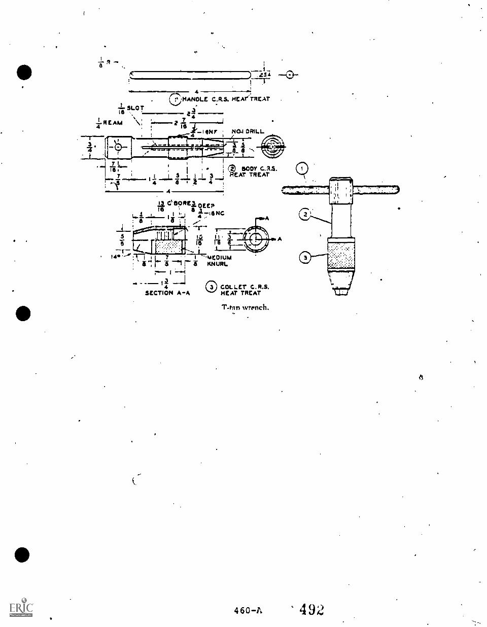
-I- SLOT16 a 3
REAM V,...L4
,16
. .
r-' HANOLE C.R5. NEATiTREAT
254
140.1 DRILL
7trdi
. 7 '
, ;
I 34 a
2-1 2' 44
C spite/ DEERle 6, A7I1... . 1 !..) 4 IINC8 , a . i ,......-
-T-Ik I 1 3la rii r-r
A Aa a
3 600Y CAS.EAT TREAT
14S L 7
...._-
SECTION A-A
'A4E0101.4KNURL
C C.R.S.HEAT TREAT
T-tnn wrench.
4 60-14, 492
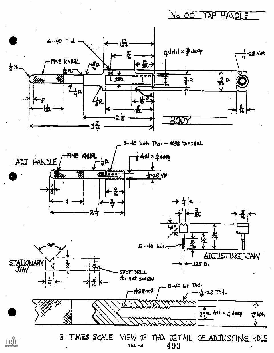
r 5-40 L.K. mci. 038 tAP DMA.
NE 14414%. / *cis,
,L-CLIP*
46.'4,4444.1.)111141111
- 140 L.H.
oar:DRILLfor set sate/
kaILLSrifiG:ZAW(1.-..la6 Di
-4,425 Tha.4#3 8 cid 1 r--
1
4t88..
.;".
-28 Thd.
\ ;7-3-62-74r111%
*4 Asti, IDA-
4,0
1111010414. , ......_3L.
SLIMES SCALE V1SW OF. THD. DETAIL Q.F Atousi:Ne_ RDLB460-B 493 .-
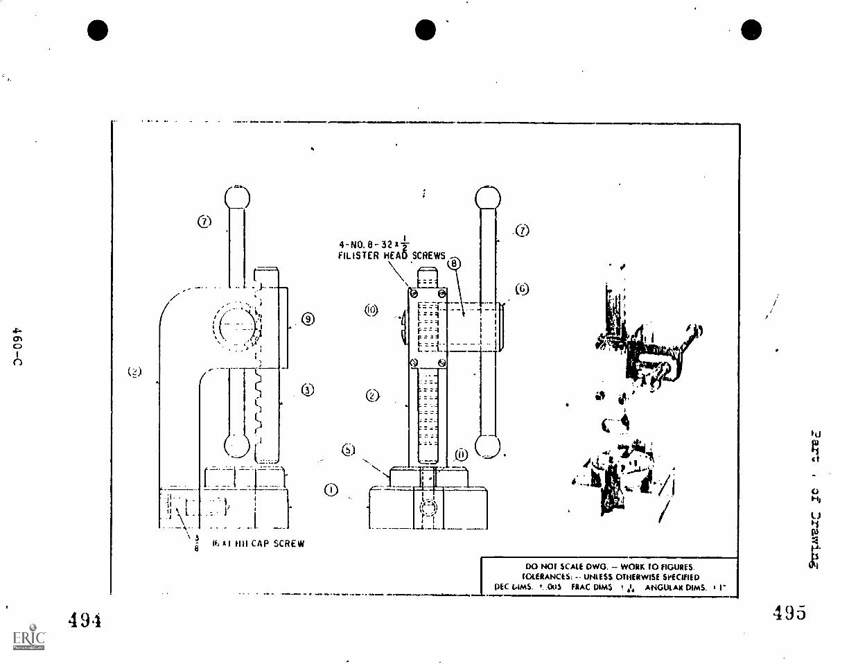
/x
.111411111MV 4.111MNIIIMMIMMOOMNIEMI, .111111.111111.11.
4-N0.8-3212FLUSTER HEAD SCREWS
1
3a IF, I WI CAP SCREW
494
=Nmwa.IsmlI
.0
DO NOT SCALE DWG. WORK TO FIGURES.TOLERANCES: UNLESS OTHERWISE SPECIFIED
DEC LAMS. t. 003 FRAC DIMS ,1 ANGULAR DIMS. I I"
495
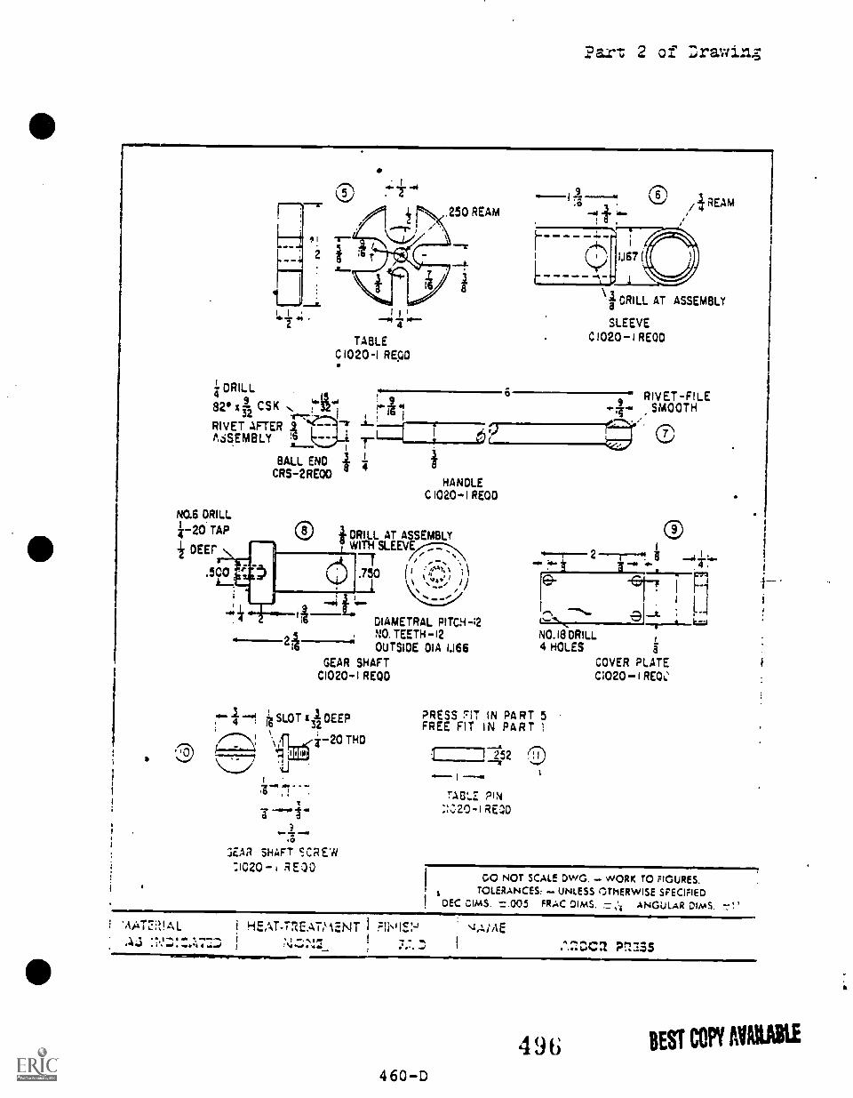
Par.': 2 of Lrawinz
-414 14.4
TABLEC1020-1 RECD
DRILL4
82x3 CSK32 1!14.8EMBLY ?RIVET AFTER 7
NO.6 DRILL
w-20 TAP
DEEP
.500
BALL ENDCRS-2RE00
HANDLEC 1020-1 REDD
® +DRILL AT ASSEMBLYWITH SLEEV
.750 ('11:.4'1, ,//
DIAMETRAL PITCH-;2NO. TEETH - i2OUTSIDE DIA 1.166
GEAR SHAFTC1020-1 REDD
SLOT xi DEEP4
\ I i-20 THD
.0
7,C.la SHAFT SCREW21020 I RE00
1.1671
i REAM
\ 3CRILL AT ASSEMBLY
SLEEVEC1020-1 REOD
RIVET-FILESMOOTH
NO.18 DRILL
--t.k.r.a
4 HOLES a
COVER PLATEC1020 -I REW
O
PRESS ''IT IN PART 5FREE FIT IN PART I
4 ITASL.Z PIN
REOD
DO NOT SCALE DWG. WORK TO FIGURES.TOLERANCES: UNLESS 1THERWISE SPECIFIED
DEC DIMS. =.005 FRAC DIMS. ANGULAR DIMS.
i 1-iEAT-17ZE.ALIAENT I FII11.S;-,,T e-."JAME
460D4 96 BEST COPY MIME
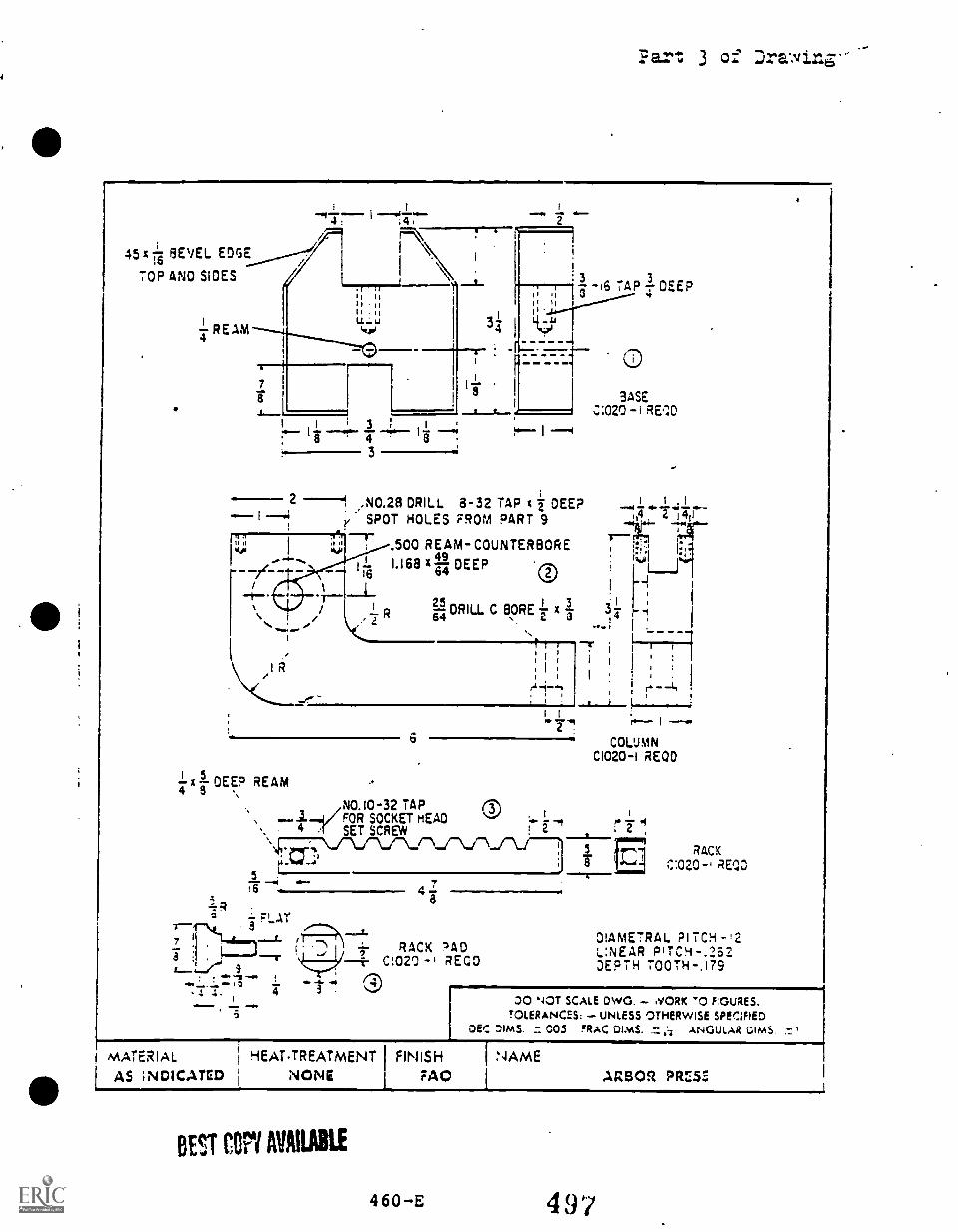
Part. 3 of Drawing-.-
i I.T I4
01.mom ..Isi 14/
ii: Fl\NI
I, I
45x7 8E` /EL EDGE______----7 I \.
TOP AND \D SIDES
;
Lm.....7..] -1-; , ;,
I, .,
I. . IILL ui
4-REAM
7
8 12
3
2
3 3-16 TAP DEEP
4I, II f
I
I -"I
, .N0.28 DRILL 8-32 TAP x 7 DEE?SPOT HOLES FROM PART 9
t T--
....;
2- R
1R/
.500 REAM- COUNTERBORE49I.I68 )1 DEEP64 025DRILL C BORE64
3
3
I
4
4I 5
x DEEP REAM ,41
6
I
.,._.1i/-P
FoR SOCKET HEAD ®,
.
NO. 10-32 TAP
4 .' SET SCREW I i
5T4" " 4 7
a
MATERIAL I HEATTREATMENT
AS INDICATED 1 NONE
RACK ?ADC:020 -I REGO
SASE.2:020 RED
3-41
It
COLUMNC1020-I REDD
5
aRACK
REDD
DIAMETRAL PITCH -L:NEAR PITC!-4-.262DEPTH TOOTH-.179
DO NOT SCALE DWG. .YORK '0 FIGURES.TOLERANCES: UNLESS OTHERWISE SPECIFIED
DEC DIMS. = 005 FRAC OlmS. ANGULAR DIMS.
FINISH I NAMEFAO I ARBOR PRZ57.,
BEST COPY MAIL IE
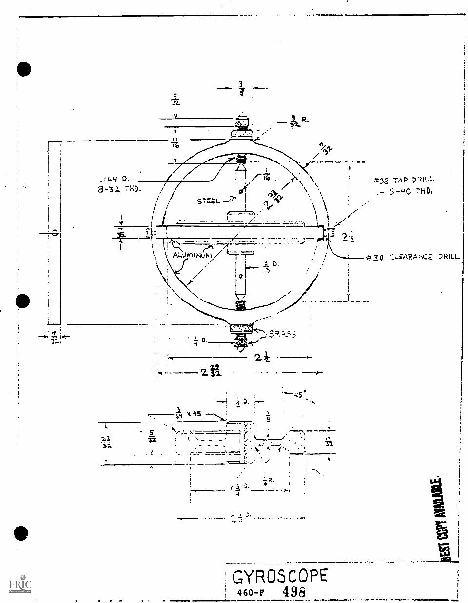
?
0
Li D.
8-32
is I
8*--1
..:11 ,
c \,.... :=70. ......__,_ . _ . . --7.
R..
. \\
( 171,\
1-4
D.Neema...
30
IN2
2i
H1 3..4o
I
I0 X ii5 ---..., i-t
23 ,t- --.....-1 0
i, \
3z \ - - - , '.., --- / "1ii. 11.,
, .. 1____J i. t. 1/4 e
wore
yI t
R.3 D-
4
i
GYROSCOPE460-F 498_ ........
3,9 TA?5-Lic "H D.
UNIT 19.0
MACHINE SHOP PROJECTS/LIVE WORK
An integral part of the secondary machine shop program is the use ofmachine shop projects designed to promote skill development and tosimulate typical machining operations in industry. Occasionally, "live"projects for students, the School District, or the public may be used'for training.
Typically, machine shop projects or "live" work will be used toaccomplish a group of objectives rather than being used in an objective-by-objective method. Machining projects may utilize a combination oftasicifram several different units such as layout, measuring, benchwork,lathe operation, etc.
Learning projects may be designed by the instructor for skill developmentor for the demonstration of competencies in performance processes orproduct production.
Prior to undertaking shop training or "live" projects, a detailed planoutlining objectives, actions necessary to obtain objectives, standardsof performance and production, and the criteria for evaluation should bedeveloped, understood by the student, and followed. (See accompanyingform.)
See the description of First Year Learning Projects following Unit 9 andthe description of the Second Year Learning Projects following thispage.
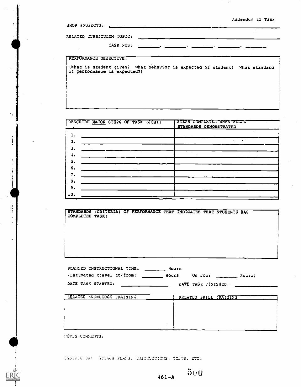
SHO? PROJECTS:
Addendum to Tas
RELATED ZURRICULUM TOPIC:
TASK NOS:
riERFORNANCE OBJECTIVE:
(What is student given? What behavior is expected of student? What standardof performance is expected?)
DESCRIBE MAJOR STEPS OF TASK (JOS): STEPS COMPL4TEu m1=3=STANDARDS DEMONSTRATED-
1..
--1
2.
3.
4.
5.
6.
7.,
a.
9.
10.
[I
S ANDARDS (CRITERIA) OF PERFORMANCE THAT INDICATES THAT STUDENTS HASCOMPLETED TASK:
PLANNED INSTRUCTIONAL TIME:
tEstimateu travel to/from:
Hours
Hours On Joo: :lours)
DATE TASK STARTED: DATE TASK FINISHED:
RELATED KNOWLEDGE :RAINING 1 RELATED SKILL :RAINING
::OT. S COMMENTS :
7-j7s, ZTC.
461 A 5 u0
RATIONAL FOR MACHINE SHOP PROJECTSAND LIVE MACHINE SHOP JOBS FOR PUBLIC
Machine shop projects or "live" machine shop jobs provide an opportunitywhere the secondary student can apply theoretical training and canpractice and develop skillsin simulated or actual job situations.
Shop projects (or "live" jobs) should be coordinated as closely aspossible with theoretical training so that the student logically movesfrom the study of the fundamentals to practical exercises and finally tolive projects or competency testing in a simulit* or actual job situation.
Emphasis in machine shop projects will be or operations that are relateddirectly to the development of knowledges and skills that are beinglearned during the phase of instruction. With the instructor's approval,students often can bring in or accept practical jobs where relatedinstruction has been given and competencies have been mastered.Occasionally, the machine shop program may need to take advantage of"machining opportunities" that may not be repeated at a later date and,under supervision of the instructor, basic instruction and "live" workmay be conducted together in a practical job situation.
Generally, the production of the secondary level, machine shop studentin the training lab (in practical work) will be low and slow compared toindustry because the primary aim is on teaching. Emphasis in themachine shop program is placed on developing the correct skills formachining operations: A job not done "right" may have to be done overby the student.
Machine shop training projects or "live" work provides a unique oppor-tunity for students to encounter, in a controlled setting, day-to-daymachining operations that cannot be simulated. "Hands on" work in themachine shop provides learning experiences that otherwise only can beacquired through trial-and-error co:7 the job.
Worthwhile projects and "live" machining operations, however, requiremore instructor planning. Caraful scheduling is necessary to ensurethat students are competent to accomplish the job within the given timeand resources. In addition, "live" machining operations must be scheduledin the proper instructional sequence so that students can completeassigned projects so that competency development will proceed properly.
Practical learning opportunities involving "live" shop projects may bedesigned for special needs students, for the career interests of student,or to meet the needs of potential employers at a particular time. Asecondary student already employed in a machining or related field maybe able to develop specialized competencies through "additionalexperiences" provided by shop projects or "live" jobs.
462 501
Machine shop projects and "live" jobs provide the instructor with anoptimum situation in which to test student knowledges and skills inrealistic, "hands-on" examinations. In some situations, the "live" shopjob may be utilized by the instructor as a method of conducting a finale_ urination of a unit or units of instruction.
A side benefit that often accompanies shop projects or "live" jobs iswhen students tend to develop good work habits and attitudes in additionto increasing their technical knowledges and skills in machine operations.
463 502
SUGGESTIONS FOR MACHINE SHOP PROJECTS
1. Machining projects should begin with a clear, concise writtenobjective or/and set of specifications.
2. "Live" shop jobs for outside of school use that expend materialsshould not begin until there is a specific dedcription of themachining operation desired and until a depoet to cover costs ofmaterials used has been obtained. The educational program/institutionshould not be (xpected to use the instructional budget to paymachining expeases for outside of program projects.
3. Machining projects and "live" jobs undertaken should be compatiblewith curriculum objectives. Students should not undertake workuntil they have been introduced toothe appropriate theory, techniques,and proceduies required for the job.
4. Each machining project shoed have appropriate checkpoints establishedand work should not progress beyond checkpoints until the job hasbeen approved by the instructor.
5. Stock or parts pr9vfded by outside individuals should be appropriatelyprotected.
6. Students should be able to verbally describe the objectives andpurposes of the specific machining operation they are to perform.
7. A record or log should be kept of all materials or parts used-in alive machining operation (generally omitted in training projects).
8. Students should record their time involved in machining projectsand should indicate their name on the product or job record.
9. Students should not begin a machine operation without authorizationfrom the instructor.
10. Work should nor begin or continue if a safe situation does not' exist.
. 11. Machining equipment should not be used unless the student has beenchecked out in the operation of the equipment, has the instructor'spermission to operate the machine, and has need to use the machine.(INSTRUCTOR: INSERT COPY OF SHOP RULES AND PROCEDURES IN THISGUIDE!)
12. Products of machine *ip projects should be checked by the studentand approved by the instructor.
13. Prior to releasing a product machined for the public, the instructorshould verify the accuracy of the machining operation. Considerationshould be given to obtaining a Limited release of responsibilityfrom the customer, if applicable.
464 503
TOOLROOM WORKER
(OPTIONAL)
Practical activities in the secondary machine shop prograck may includerelated training and experiences in the shop (lab) toolroom. Purposesthat may be served by assigning the student to toolroom duty on arotating basis include the following:
1. Assigning the student to periodic duty in the toolroom, on arotating basis, provides a means of'tontrolling expensive publicproperty, essential to machine sip training.
2. Through toolroom duty, the studellt should learn responsibility, animportant trait to successfully holding a job.
3. Toolroom duty ca.7 contribute directly to a reduction in damaged ormissing tools and equipment. Misuse of tools and equipment can beidentified and a student can be held accountable for the loss oftraining tools or equipment.
4. Through maintaining a log of all tools and equipment signed out andreturned, there will be a current inventory of the tool or equipmentrooms. Tools and equipment in use or borrowed can be identified asto location and user.
5. The activities of the toolroom duty student should include identifyingtools, equipment, and parts by their proper names; proper storageof tools, equipment, and parts; and inspection, cleaning, and careof tools and equipment. This task should include a regular Inventoryof tool boxes, sets of tool items, etc., to identify missing orunserviceable components.
6. In addition, the toolroom duty student may be assigned the task ofassisting the instructor in observing the lab (shop) area forpossible safety infractions and fire hazards. In this task, thestudent can help the instructor ensure that a safe treating environ-ment is maintained.
As a safety observer, the toolroom duty student should take actionto prevent obstructed aisles and cluttered storage areas that mightcause injury to others.
The toolroom duty student should review posted first aid directionsand be prepared to alert the instructor concerning accidents and toassist fellow sti4ents who receive minor injuries.
The toolroom duty student should aid fellow students in followingprescribed safety practices of the shop. For example, the studentmight remind others concerning the use of safety goggles, etc.
465 5 i4'ILi
0
The toolroom duty student should observe the shop for potentialfire hazards. The toolroom duty student should assist in recoveringoily rags and waste material in proper containers and seeing thatflammable solvents, oil, and chemicals are stored in fireproofareas.
The toolroom duty student should observe the shop for potentialsafety hazards such as exposed electrical wires, machines withsafety guards no in place, etc., and alert fellow students topotential hazards.
The toolvom duty student should be prepared to notify the instructorof quesapnable safety situations, locate and use fire extinguishers,and assist students with first aid.
7. The knowledge and skills of the student assigned to toolroom dutymight be expended through individualized study assignments orworksheets selected to prepare the student for career opportunitiesin counter or warehouse work in related fields (e.g., identificationof fasteners, tools, machine parts, etc.).
t

I
,
a
lb
UNIT 20.0
. .
OXYACETYLENE (OAW) CUTTING/WELDING AND BRAZING
t
.1
..(
,
Training Module Addendum
OPTIONALADDENDUM MODULE
MACHINE SHOP WELDING
This optional addendum module concerning machine shop welding includesUnit 20, Oxyacetylene (OAW) Cutting, Welding, and Brazing, and Unit 21,Shielded Metal ARC Welding (SHAW).
The purpose of this module is to provide the secondary level machineshop student with the basic skills and knowledge in gas and electricwelding operations that may be used in the machining trade.
Currently,'only one of the three secondary level machine shop programsis equipped with a variety of welding trainers and is providing weldingtraining. The other machine shop programs may have a small ARC welderand may provide an orientation to ARC welding.
The tasks described in this module were adopted from the Articulated,Performance-based Instruction Objectives Guide for Weldinia0aWid byThe School District of Greenville County in 1983. For expanded training,other tasks may be added to those described in this module. Theinstructional goal of this module is to ensure that welding training,regardless of the vocational program in which it is offered, is designedproperly, articulated, and safe.
NOTE: Post-secondary welding typically is taught by the WeldingDepartment, GTC (post-secondary participant in Articulation).
468
OXYACETYLENE WELDING, CUTTING, AND BRAZING
PREREQUISITES: None
OBJECTIVES: The objective of oxyacetylene welding, cutting, andbrazing (OAW) is to develop entry level gas weldingskills.
Oxyacetylene, welding, cutting, and brazing trainingdevelops the skills necessary to produce high qualitysingle and multi-pass welds on mild steel in the flat,horizontal, vertical, and overhead positions. Themachine shop student is trained to produce high qualityflame cuts through the use of manual gas flame. Themachinist will develop skills in producing high qualitybrazed joints.
Upon completing secondary training, the student should beskilled to set up OAW equipment and perform the require-ments of OAW welding, cutting, and brazing in the machineshop.
469508
It
Unit No. 20 Title: OXYACETYLENE CUTTING/WELDING
MODULE STANDARDS
(Standards that are in effect for the entire module andoptiottal. Standards applicable only to a particular setfunctions will be described on the Performance Standards
1. Select tip.
that are notof tasks orpage.)
a. Proper size for work to be done (thickness of metal).
2. Inspect tip for signs of damage or flaws that could create a hazardor impair performalwe.
a. Seat area:
b. Cutting oxygenorifice:
c. Pre-heat flameorifices:
d. 0-Rings:
3. Install tip.
4. Set gas pressures for desired working pressure.
Smooth and clean to ensure good metal sealwith torch head.Free of slag or spatter or otherobstruction that may deform oxygen streamand render a poor quality cut.Free of obstruction. (Clogged orobstructed orifices will extend requiredpre-heat time and result in poorperformance and cutting efficiency.)Check for deterioration.
MACHINE SHOPGAS WELDING
SUGGESTED INSTRUCTION TIMES
MACHINE SHOPUNIT TASK
Unit 20.0 OXYACETYLENE (OAW) CUTTING/WELDINGAND BRAZING
Oxyacetylene Cutting/Welding Terminology
Oxyacetylene Cutting/Welding Safety
Perform Soap and Water Test (Safety)
20.01
20.02
20.03
20.04 Identify Oxygen and AcetyleneGases and Cylinder Handling
20.05 Set Up Oxyacetylene Cutting/WeldingStation
20.06 Clean Oxyacetylene Cutting/Welding Tips
20.07 Light the Torch
20.08 Adjusting Flame
20.09 Oxyacetylene Cutting
20.10 Preparing the Joint
20.11 Carrying the Puddle (Fuse)
23.12 Run a Bead with Filler Rod
20.13 Weld Open Butt Joint, All Positions
20.14 Fillet Weld, Lap Joint, Flat andOverhead Positions
20.15 Braze Metal
SUGGESTEDHOURS
Times not estimated. (Optional training)
471 510
TASK LISTINGSMACHINE SHOP
UNIT/TASK DESCRIPTION
Unit 20.0 OXYACETYLENE (OAW) CUTTING/WELDING AND BRAZING
20.01 (Oxyacetylene Cutting/Welding Terminology) Given properinstructions, identify standard oxyacetylene cutting/weldingterms, typically used in daily operations, on a written testwith 80 percent accuracy. Use standard oxyacetylenecutting/welding terminology upon completion of the trainingmodule to the standards of the instructor.
20.02 (Oxyacetylene Cutting/Welding Safety) Given proper instructionsconcerning oxyacetylene cutting/welding safety; demonstrateproper use of protective clothing and equipment to protectagainst hazards in gas cutting/welding with 100 percentaccuracy.
20.03 (Perform Soap and Water Test [Safety]) Given oxyacetylenecutting/welding equipment to be tested for leaks, neutral soapand water, and proper instruction; perform a soap and waterleak test. Mark (with tape, etc.) all discovered leaks forrepair- Hoses and torch will not leak after repair and test.
20.04 (Identify Oxygen and Acetylene Gases and Cylinder Handling)Given proper instructions and demonstration, identify with 100percent accuracy characteristics of oxygen and acetylene gasesand demonstrate proper handling of cylinders to the standardsof the instructor.
20.05 (Set Up Oxyacetylene Cutting/Welding Station) Given oxyacetylenetorch, regulators, hoses, check valves, cylinder wrench,oxygen, and fuel cylinders and portable cart; set up a portableor stationary oxyacetylene cutting/welding station. Theoxyfuel equipment will not leak and will operate safety asthe manufacturer intended.
20.06 (Clean Oxyacetylene Cutting/Welding Tips) Given oxyacetylenecutting/welding equipment, tip cleaners, and instructions;clean both cutting/welding tips.
20.07 (Lighting the Torch) Given oxyacetylene cutting/weldingequipment, striker, sample metal to be used in job; lighttorch (for cutting).
20.08 (Adjusting Flame) Given oxyacetylene cutting/welding equipmentincluding striker, adjust flame for job.
20.09 (Oxyacetylene Cutting) Given oxyacetylene cutting equipment,set up the equipment for a cutting job, and cut given metalaccording to instructor's assignment.
472
511
20.10 (Preparing the Joint) Given metal to clean and prepare forwelding, select the best joint and prepare the joint forwedding.
20.11 (Carrying the Puddle [Fuse]) Given oxyacetylene weldingequipment and metal to weld without filler rod, establish a
molten puddle and run straight even beads (without filler) inthe flat or other positions assigned by the instructor.
20.12 (Run a Bead with Filler Rod) Given oxyacetylene weldingequipment, metal, and filler rod, demonstrate the properprocedure for carrying the puddle with filler metal in theflat position or other positions that may be required by theinstructor, to the instructor's standards.
20.13 (Weld Open Butt Joint, All Positions) Given oxyacetylenewelding station, filler rod, metal panels, personal safetyequipment, and necessary tools and materials; groove weld abutt joint in all positions required by the instructor. Thebead should be formed properly, straight, and uniform inripple and width, with even height.
20.14 (Fillet Weld, Lap Joint, All Positions) Given oxyfuel workstation, metal, rods; construct a lap weld in all positions,required by the instructor. The weld will be straight, haveconsistency of width and height, proper build up, and no slag.
20.15 (Braze Metal) Given an oxyacetylene welding station, sheetmetal, brazing rod, flux, personal safety equipment, and thenecessary tools and materials; braze metal. Bead must bestraight and uniform in height and width, have a uniformripple formation and have no undercut, porosity, craters, oroxidation.
UNIT 20.0 OXYACETYLENE
TASK 20.01 OXYACETYLENE CUTTING/WELDINGTERMINOLOGY
PERFORMANCE OBJECTIVE:
Given proper instructions, identify standard oxyacetylene cutting/weldingterms, typically used in daily operations, on a written test with 60percent accuracy. Use standard oxyacetylene cutting/welding terminologyupon completion of the training module to the standards of the instructor.
PERFORMANCE STANDARDS:
20.0101 Eighty percent accuracy in identifying standardterminology typically used in oxyacetylenecutting/welding jobs.
20.0102 Upon completion of Module 4.0, use terminology toinstructor's standards.
Terms and definitions adapted from: Welding, Cutting & Heating Guide,Denton, TX: Victor Equipment Co., pp. 54-57, 1977.
DEFINITIONS
ACETYLENE - Gas composed of two parts of carbon and two parts of hydrogen.When burned in an atmosphere of oxygen, it produces one of the highestflame temperatures obtainable.
ACETYLENE CYLINDER - Specially built container manufactured according toD.O.T. standards. Used ..o store and ship acetylene. (Occasionallycalled "tank" or "bottle.")
ACETYLENE REGULATOR - An automatic valve used to reduce acetylenecylinder pressures to torch pressures and to keep the pressures constant.
BEAD - Denotes the appearance of the finished weld; describes theneatness of the ripples formed by the metal while it was in an semiliquidstate.
BEVEL - Angling the metal edge where welding is to take place.
BOND - Junction of the weld metal and the base metal.
BUILDUP - Amount a weld face is extended above the surface of the metalsbeing joined.
474513
UNIT 20.0
TASK
OXYACETYLENE
20.01 OXYACETYLENE CUTTING/WELDINGTERMINOLOGY
DEFINITIONS CON'T.
BUTT JOINT - An assembly in whichplane, with the edge of one piece
CARBURIZING - A carburizing flameslight excess of the fuel gas.
CONE - Inner visible flame shape of a neutral or near neutral flame.
CONTINUOUS WELD - Making the complete weld in one operation.
CORNER JOINT - Junction formed by edges of two pieces of metal touchingeach other at angle 90 degrees.
CRACKING - Action of opening a valve slightly and then closing the valveimmediately.
the two pieces joined are in the sametouching the edge of the other.
is an oxygen-fuel gas flame with a
CUTTING FLAME - Cutting by a rapid oxidation process at a high temperature.It is produced by a gas flame accompanied by a jet action which blowsthe oxides away from the cut.
CYLINDER - A container used to hold gases used in welding. See (Oxygen,Acetylene.)
EDGE JOINT - Joint formed when two pieces of metal are lapped with atleast one edge of each at an edge of the other.
FILLER ROD - Metal wire that is melted and added to the welding puddleto produce the necessary increase in bead thickness. (See Welding Rod.)
FILLET - Weld metal in the internal vertex, or corner, of the angleformed by two pieces of metal, given the joint additional strength towithstand unusual stresses.
FILLET WELD - Metal fused into a corner formed by two pieces of metalwhose welded surfaces are approximately 90 degrees to each other.
FLAME CUTTING - Cutting performed by an oxygen-fuel as torch which hasan oxygen jet.
FLAT POSITION - A horizontal weld on the upper side of a horizontal 41surface.
FUSION - Intimate mixing of molten metals.
475 514
UNIT 20.0 OXYACETYLENE
TASK 20.01 OXYACETYLENE CUTTING/WELDINGTERMINOLOGY
DEFINITIONS CON'T.
HORIZONTAL POSITION - A weld performed on a horizontal seam at leastpartially on a vertical surface.
HOSE - Flexible medium used to carry gases from regulator to the torch.It is made of fabric and rubber.
JOINT - Where two pieces meet when a structure is made of smallerpieces.
LAP JOINT - A joint in which the edges of the two metals to be joinedoverlap one another.
LENS - A specially !rutted glass through which a welder may look at auintense flame without being injured by the harmful rays, or glare,radiating from this flame.
111NEUTRAL FLAME - Flame which results from combustion of perfect proportionsof oxygen and the welding gas. Used for most welding jobs.
ORIFICE - Opening through which gases flow. It is usually the finalopening; or any opening controlled by a valve.
OUTSIDE CORNER WELD - Fusing two pieces of metal together, with thefusion taking place on the underpart of the seam.
OXIDIZING - Combining oxygen with any other substance. For example, ametal is oxidized when the metal is burned, i.e., oxygen is combinedwith all the metal or parts of it.
OXIDIZING FLAME - Flame produced by a^ excess of oxygen in the torchmixture, leaving some free oxygen which tends to burn the molten metal.
OXYGEN - A gas formed of the element oxygen. When it very activelysupports combustion it is called burning; when it slowly combines with asubstance it is called oxidation.
OXYGEN-ACETYLENE CUTTING - Cuting metal using the oxygen jet which isadded to an oxygen-acetylene preheating flame.
OXYGEN-ACETYLENE WELDING - A method of welding which uses a fuel combina-tion of two gases - oxygen and acetylene.
OXYGEN CYLINDER - A specially built container manufactured according toD.O.T. standards and used to store and ship oxygen.
476 J1J
p
UNIT . 20.0 OXYACETYLENE
TASK 20.01 OXYACETYLENE CUTTING/WELDINGTERMINOLOGY
DEFINITIONS CON'T.
OXYGEN REGULATOR - An automatic valve used to reduce cylinder pressuresto torch pressures and to keep the pressures constant. They are neverto be used as acetylene regulators.
PASS - Weld metal created by one progression along. the weld.,
PENETRATION - Depth of fusion into the base metal as measured from thesurface of the base metal.
PREHEATING - Temperature to which a metal is heated before an operationis performed on the metal (welding, cutting, forming, etc.).
PUDDLE - Portion of a weld that is molten at the place the heat issupplied.
ROOT of WELD - That part of a weld farthest from the application of weldheat and/or filler metal side.
SLAG INCLUSIONS - Non-fused, non metallic substances in the weld metal.
TACK WELD - Small weld used to temporaril7 .gold together components ofan assembly.
T-Joint - Joint formed by placing one metal against another at an angleof 90 degrees. The edge of one metal contacts the surface of the othermetal.
TIP - Part of the torch at the end where the gas burns, producing thehigh-temperature flame. In resistance welding, the electrode ends aresometimes called tips.
TOE of WELD
TORCH - Thecutting, atgas welding
- Junction of the face of the weld and the base !petal.
mechanism which the operator holds during gas welding andthe end of which the gases are burned to perform the variousand cutting operations.
WELDING - Art of fastening metals together by means of interfusing themetals.
WELDMENT - Assembly of romponent parts joined together by welding.
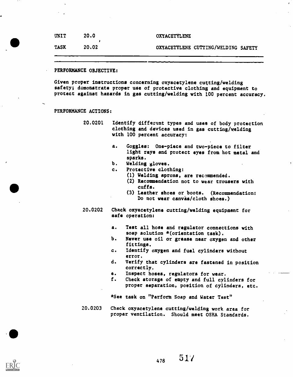
UNIT 20.0 OXYACETYLENE
TASK 20.02 OXYACETYLENE CUTTING/WELDING SAFETY
PERFORMANCE OBJECTIVE:
Given proper instructions concerning oxyacetylene cutting/weldingsafety; demonstrate proper use of protective clothing and equipment toprotect against hazards in gas cutting/welding with 100 percent accuracy.
PERFORMANCE ACTIONS:
20.0201 Identify different types and uses of body protectionclothing and devices used in gas cutting/weldingwith 100 percent accuracy:
a. Goggles: One-piece and two-piece to filterlight rays and protect eyes from hot metal andsparks.
b. Welding gloves.c. Protective clothing:
(1) Welding aprons, are recommended.(2) Recommendation not to wear trousers with
cuffs.(3) Leather shoes or boots. (Recommendation:
Do not wear canvas /cloth shoes.)
20.0202 Check oxyacetylene cutting/welding equipment forsafe operation:
a. Test all hose and regulator connections withsoap solution *(orientation task).
b. Never use oil or grease near oxygen and otherfittings.
c. Identify oxygen and fuel cylinders withouterror.
d. Verify that cylinders are fastened in positioncorrectly.
e. Inspect hoses, regulators for wear.f. Check storage of empty and full cylinders for
proper separation, position of cylinders, etc.
*See task on "Perform Soap and Water Test"
20.0203 Check oxyacetylene cutting/welding work area forproper ventilation. Should meet OSHA Standards.
478 511
UNIT 20.0 OXYACETYLENE
TASK 20.02 OXYACETYLENE CUTTING/WELDING SAFETY
PERFORMANCE ACTIONS (Con't.):
20.0204 Demonstrate Safe Practices:
a. Use caution in pic ng up pieces of hot metal.Use pliers or ton s. Mark "hot" metal left tocool.
b. Keep combustib es from heat.c. Protect other- from heat and hot slag.
. d. Don't weld, completely closed container(Danger of expansion explosion).
PERFORMANCE STANDARDS:
tile
Identify proper saf ty in oxyacetylene cutting/welding on awritten knowledge test to acceptable standards of instructor.Demonst..,ze use of protective equipment used in cutting/welding.Demonstrate safe practices in welding.Practice proper ventilation techniques in cutting/welding.
SUGGESTED*INSTRUCTION TIME:\ Optional training
RELATED TECHNICAL INFORMATION:
Identification of welding equipment.Orientation to dangers of Oxyacetylene cutting/welding fumesof flash to welders.
NOTE: See "Safety Precautions for Oxygen and Acetylene," SouthCarolina Curriculum Guide for Welding, Columbia, SC: SC StateDepartment of Education (Office of Vocational Education),1972.
UNIT 20.0 OXYACETYLENE
TASK 20.03 PERFORM SOAP AND WATER TEST (SAFETY)
PERFORMANCE OBJECTIVE:
Given oxyacetylev.4 cutting/welding equipment to be tested for leaks,neutral soap and water, and proper instruction; perform a soap and waterleak teed. Mark (with tape, etc.) all discovered leaks for repair.Hoses and torch will not leak after repair and test.
PERFORMANCE ACTIONS:
20.0301 Close torch valves.
20.0307 Apply normal pressure.
20.0303 Mix neutral soap and water.
20.0304 Brush soapy water over hoses and valves.
20.0305 Check for bubbles.
20.0306 Mark discovered leaks with tape.
20.0307 Relieve hose pressure:
20.0308 Repair hoses and torch as required.
20.0309 Recheck for leaks.
PERFORMANCE STANDARDS:
- Perform soap and water leak test on oxyacetylene cutting/weldingequipment teinstructor's standards.
SUGGESTED INSTRUCTION TIME: Orientation Task
RELATED TECHNICAL INFORMATION:
- Oxy-fuel cutting/welding equipment.- Proper safety precautions.
UNIT 20.0 OXYACETYLENE
TASK 20.04 IDENTIFYING OXYGEN AND ACETYLENEGASES AND CYLINDER HANDLING
PERFORMANCE OBJECTIVE:
Given proper instructions and demonstration, identify with 100 percentaccuracy characteristics of oxygen and acetylene gases and demonstrateproper handling of cylinders to the standards of the instructor.
PERFORMANCE ACTIONS:
=
20.0401 a. Identify with 100 percent accuracy characteristicsof oxygen and acetylene gases.
b. Describe potential dangers in handling bothgases --d typical pressures under which gasesshould used.
20.0402 Identify difference. between oxygen and acetylenecylinder with 100 percent accuracy.
20.0403 Demonstrate proper handling of gas cylinders:
a. Fasten cylinders securely in upright position.b. Use proper method (or tool) to open/close
cylinder valves.c. Demonstrate proper storage of cylinders.d. Demonstrate proper handling of cylinders in
training.
PERFORMANCE STANDARDS:
- Identify major characteristics of oxygen and acetylene gasesthat apply to welding on a written knowledge test with 100percent accuracy.
- Demonstrate proper handling of gas cylinders to the standardsof the instructor.
SUGGESTED INSTRUCTION TIME: Optional training
UNIT 20.0 OXYACETYLENE
TASK 20.05 SET UP OXYACETYLENE CUTTING/WELDINGSTATION
PERFORMANCE OBJECTIVE:
Given oxyacetylene torch, regulators, hoses, check valves, cylinderwrench, oxygen, and fuel cylinders and portable cart; set up a portableor stationary oxyacetylene cutting/welding station. The oxy-fuelequipment will not leak and will operate safely as the manufacturerintended.
PERFORMANCE ACTIONS:
20.0501 Chain cylinders to cart.
20.0502 Remove cylinder cap.
20.0503 Crack cylinder valves to clean out foreign particlesand inspect threads.
20.0504 Attach regulators.
20.0505 Install check valves.
20.0506 Attach hoses.
20.0507 Attach hoses to torch. (Set proper pressure fortips being used.)
20.0508 Check for leaks.
PERFORMANCE STANDARDS:
Oxy-fuel equipment will not leak and will operate safely asthe manufacturer intended.
- Minimum on knowledge test concerning cylinder handling,regulators, and set up of oxy-fuel welding equipment.
- Set up oxyacetylene cutting/welding station to instructor'sstandards.
SUGGESTED INSTRUCTION TIME: Optional training
UNIT 20.0 OXYACETYLENE
TASK 20.05 SET UP OXYACETYLENE CUTTING/WELDINGSTATION (Con't.)
RELATED TECHNICAL INFORMATION:
- Safety:a. Cylinder storage and handlingb. Purging equipmentc. Gas: (1) Pressures, (2) Ventilationd. Inspection procedures
- Manufacturer's specifications and instructions.
rr
UNIT 20.0 OXYACETYLENE
TASK 20.06 CLEAN OXYACETYLENE CUTTING/WELDINGTIPS
PERFORMANCE OBJECTIVE:
Given oxyacetylene cutting/welding equipment, tip cleaners, andinstructions; clean both cutting/welding tips.
(NOTE: This objective will become standard practice when usingoxyacetylene welding and cutting equipment.)
PERFORMANCE ACTIONS:
20.0601 Examine tip to determine lrifice (opening) size, andcondition of orifice end of tip.
20.0602 Select proper (correct size) tip cleaner(s).
20.0603 (May be optional or orientation only). Smooth flameend of tip if it is scratched or rough (file orificeend) or use tip reamer.
20.0604 Clean tip:
a. Start with tip cleaner two sizes smaller thantip orifice.
b. Use straight push-pull action to eliminateegg-shaped opening.
c. Gradually increase tip cleaner size to originalorifice size.
d. Where possible, insert long tip cleanersthrough back of tip.
PERFORMANCE STANDARDS:
- Clean tips to instructor's standards or manufacturer'srecommendations, avoiding damage to tip, and reporting anddamaged tips to instructor.
SUGGESTED INSTRUCTION TIME: Orientation more than skill development
RELATED TECHNICAL INFORMATION:
- Determine that tips are being used with torches from the samemanufacturer.
- Identify various tips.- Identify typical tip sizes (No standard numbering system).
UNIT 20.0 OXYACETYLENE
TASK 20.07 LIGHTING THE TORCH
PERFORMANCE OBJECTIVE:
Given oxyacetylene cutting/welding equipment, striker, sample metal tobe used in job; light torch (for cutting).
(NOTE: Tasks of (a) lighting the torch and (b) adjusting the flametypically will be accomplished as a continuing action.)
PERFORMANCE ACTIONS:
20.0701 Select proper-tip size for job. (Determine bythickness of metal.)
20.0702 Set regulator pressure for job.
20.0703 a. Open oxygen valve on torch handle.b. Adjust oxygen regu ator to desired delivery
t
range.
20.0704 a. Open fur. valve on torch. handle (1/2 turn).b. Adjust fuel regula or to required delivery
tange.
20.0705 Point torch head (flame direction) away from persons,cylinders, or flammable materials before lighting.
20.0706 a. Open torch fuel valve approximately 1/2 turn.b. Ignite gas. Hold torch in one hand and the
spark lighter in the other hand.
PERFORMANCE STANDARDS:
- Select proper tip for welding job; adjust regulators accordingto text or teacher's instructions or manufacturer's standards;use proper safety equipment; and light torch.(Tash typically will be accomplished jointly with adjustingflame.)
SUGGESTED INSTRUCTION TIME: Optional training
RELATED TECHNICAL INFORMATION:
- Able to set up oxy-fuel cutting/welding station.- Selection of cutting/welding tips.- Wear protective goggles to shield against bright light.
485 524
UNIT 20.0 OXYACETYLENE
TASK 20.08 ADJUSTING FLAME
PERFORMANCE OBJECTIVE:
Given oxyacetylene cutting/welding equipment including striker, adjustflame for job.
(NOTE: Tasks of (a) lighting torch and (b) adjusting flame typicallywill be accomplished as a continuous action.)
PERFORMANCE ACTIONS:
20.0801. Light torch. (Point flame away from persons,: cylinders, or any flammable materials.)
20.0802 a. Keeping opening fuel valve until flame stopssmoking and leaves end of tip by about 1/8inch.
b. Then, slightly reduce fuel supply to bringflame back to tip.
20.0801 Open torch oxygen needle adjustment valve until abright neutral flame (for cutting) is reached.
PERFORMANCE STANDARDS:
- Adjust torch to a neutral flame (for cutting) to meet manu-facturer's specifications, or instructor's standards.
- (Task may be accomplished jointly with lighting the torch.)
SUGGESTED INSTRUCTION TIME: Optional training
RELATED TECHNICAL INFORMATION:
Caution: If backfire or flashback is experiences, immediately turn offoxygen valve, then turn off fuel valve.
- Oxidizing flame.- Carburizing flame.
UNIT 20.0 OXYACETYLENE
TASK 20.09 OXYACETYLENE CUTTING
PERFORMANCE OBJECTIVE:
Given oxyacetylene cutting equipment, set up the equipment for a cuttingjob, and cut given metal according to instructor's assignment.
PERFORMANCE ACTIONS:
20.0901 Make usual preparations for cutting.
20.0902 a. Set oxygen regulator.b. Set acetylene regulator.c. Adjust as necessary.
20.0903 a. Turn on acetylene valve.b. Light torch with sparklighter (striker).
(NOTE: Avoid using butane lighters andmatches!)
20.0904 a. Turn on oxygen preheating valve.b. Adjust to neutral flame.
20.0905 Press' oxygen high-pressure lever and observe pre-heating flame.
20.0906 Position metal.
20.0907 a. Hold torch tip at right angle to metal withinner cones +/- 1/2 inch above metal.
b. Heat edge of metal to bright red (at guideline).c. Press oxygen cutting level and mave.torch
forward along guidelines to begin cut.
20.0908 Move torch fast enough to maintain smooth, even cuton metal. (If cutting actions stops, release oxygencutting level and preheat at end of kerf and continuecut when metal becomes red.)
PERFORMANCE STANDARDS:
- Set up complete oxyacetylene cutting station following propersequence and safety precautions.
- Light and properly adjust flame for cutting job.- Cuts must meet the instructor's standards and industry standards.
(NOTE: Proper cutting speed can be mastered only throughexperience.)
487
526
UNIT 20.0 OXYACETYLENE
TASK 20.09 OXYACETYLENE CUTTING (Can't.)
SUGGESTED INSTRUCTION TIME: Optional training
RELATED TECHNICAL INFORMATION:
- Oxyacetylene safety: Equipment, operation, personal.- Cut lines outlined by soapstone or chalk.
RECOMMENDED:
- Use only enough flame to cut metal.
488
527
UNIT 20.0 OXYACETYLENE
TASK 20.10 PREPARING THE JOINT
PERFORMANCE OBJECTIVE:
Given metal to clean and prepare for welding, select the best joint andprepare the joint for welding.
PERFORMANCE ACTIONS:
20.1001 Select type of joint: (Select simplest joint toproduce strongest weld possible.)
20.1002 a. Lap.b. Butt.
(NOTE: Instructor may require orientation toEdge, Corner, and T joints.)
20.1003 Prepare joint.
20.1004 a. Prepare metal for deep penetration, keepingmetal edges true and straight.
b. Clean and dry metal prior to welding.
PERFORMANCE STANDARDS:
- The best (simplest) ;saint to produce the strongest weldpossible must be chosen as judged by the welding instructorand the joint must be properly prepared for welding, toinclude free from any material that might weaken the weld.
SUGGESTED INSTRUCTION TIME: Optional training
RELATED TECHNICAL INFORMATION:
- Oxyacetylene cutting.- Metal characteristics (thickness and appropriate welding
joints).- Consideration in alignment of long lengths of body panels for
lap weld.
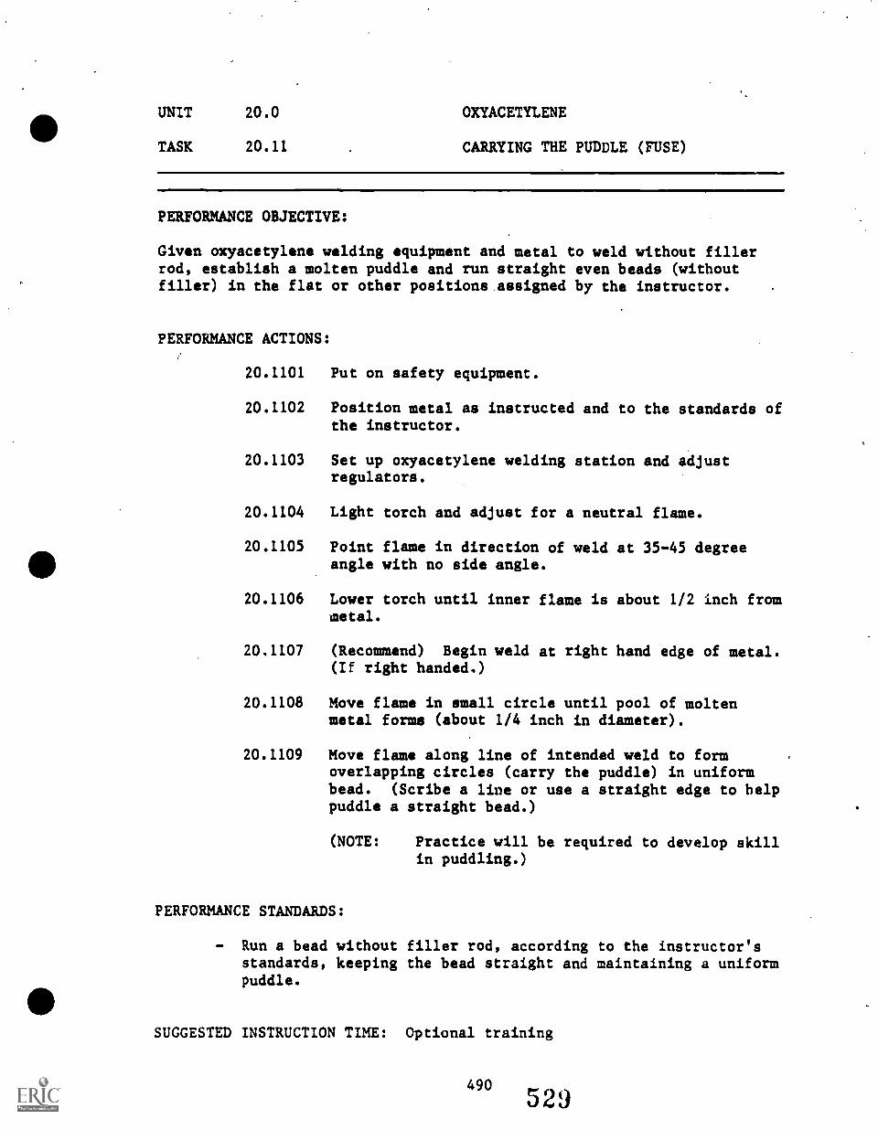
UNIT 20.0 OXYACETYLENE
TASK 20.11 CARRYING THE PUDDLE (FUSE)
PERFORMANCE OBJECTIVE:
Given oxyacetylene welding equipment and metal to weld without fillerrod, establish a molten puddle and run straight even beads (withoutfiller) in the flat or other positions assigned by the instructor.
PERFORMANCE ACTIONS:
20.1101 Put on safety equipment.
20.1102 Position metal as instructed and to the standards ofthe instructor.
20.1103 Set up oxyacetylene welding station and adjustregulators.
20.1104 Light torch and adjust for a neutral flame.
20.1105 Point flame in direction of weld at 35-45 degreeangle with no side angle.
20.1106 Lower torch until inner flame is about 1/2 inch frommetal.
20.1107 (Recommend) Begin weld at right hand edge of metal.(If right handed,)
20.1108 Move flame in small circle until pool of moltenmetal forms (about 1/4 inch in diameter).
20.1109 Move flame along line of intended weld to formoverlapping circles (carry the puddle) in uniformbead. (Scribe a line or use a straight edge to helppuddle a straight bead.)
(NOTE: Practice will be required to develop skillin puddling.)
PERFORMANCE STANDARDS:
- Run a bead without filler rod, according to the instructor'sstandards, keeping the bead straight and maintaining a uniformpuddle.
SUGGESTED INSTRUCTION TIME: Optional training
490529
UNIT 20.0 OXYACETYLENE
TASK 20.11 CARRYING THE PUDDLE (FUSE) (Can't.)
RELATED TECHNICAL INFORMATION:
- Safety procedures.- Setting up oxy-fuel station.- Flame adjustment.
491
530
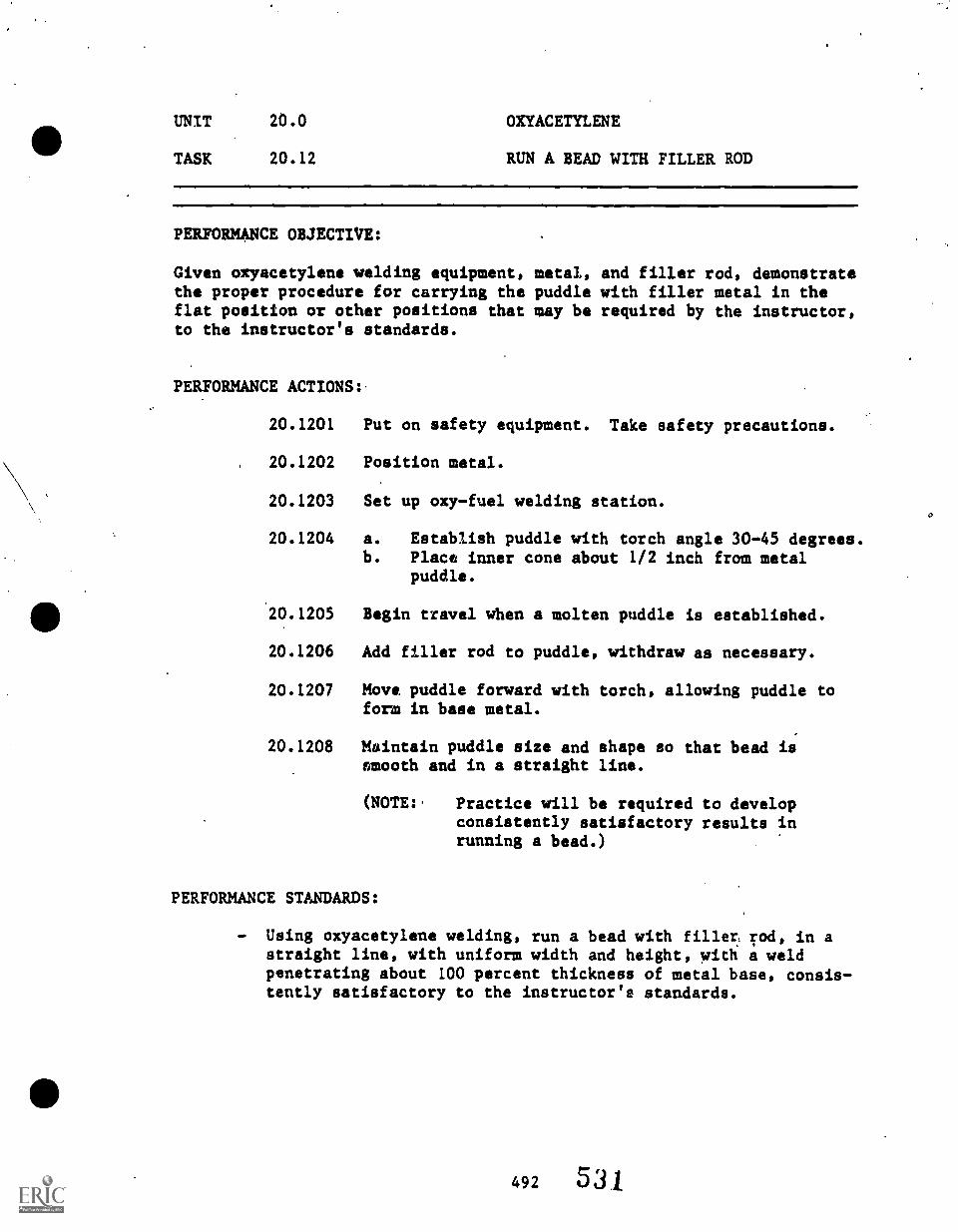
UNIT 20.0 OXYACETYLENE
TASK 20.12 RUN A BEAD WITH FILLER ROD
PERFORMANCE OBJECTIVE:
Given oxyacetylene welding equipment,the proper procedure for carrying theflat position or other positions thatto the instructor's standards.
PERFORMANCE ACTIONS:.
metal, and filler rod, demonstratepuddle with filler metal in themay be required by the instructor,
20.1201 Put on safety equipment. Take safety precautions.
20.1202 Position metal.
20.1203 Set up oxy-fuel welding station.
20.1204 a. Establish puddle with torch angle 30-45 degrees.b. Place inner cone about 1/2 inch from metal
puddle.
20.1205 Begin travel when a molten puddle is established.
20.1206 Add filler rod to puddle, withdraw as necessary.
20.1207 Move puddle forward with torch, allowing puddle toform in base metal.
20.1208 Maintain puddle size and shape so that bead issmooth and in a straight line.
(NOTE:. Practice will be required to developconsistently satisfactory results inrunning a bead.)
PERFORMANCE STANDARDS:
- Using oxyacetylene welding, run a bead with fillers rod, in astraight line, with uniform width and height, with a weldpenetrating about 100 percent thickness of metal base, consis-tently satisfactory to the instructor's standards.
492 5 31
UNIT 20.0
TASK 20.1
OXYACETYLENE
RUN A BEAD WITH FILLER ROD (Con't.)
SUGGESTEp/INSTRUCTION TIME: Optional training
RELA%ED TECHNICAL INFORMATION:
*a.
- Filler rod.- Tip selection.- Puddling.
493 532
UNIT 20.0 OXYACETYLENE
TASK 20.13 WELD OPEN BUTT/ JOINT, ALL POSITIONS*
PERFORMANCE OBJECTIVE:
Given oxyacetylene welding station, filler rod, base metal, personalsafety equipment, and necessary tools and materials; groove weld a buttjoint in all positions required by the instructor. The bead should beformed properly, straight, and uniform in ripple and width, with evanheight.
PERFORMANCE ACTIONS:
20.1301 Prepare for oxy-fuel welding.
20'.1302 Position metal in butt joint, flat position.
20.1303 Tack weld each end of the joint to hold position.
20.1304 Run a bead, using acceptable standards (of industry),to weld a butt joint (all positions).
20.1305 Inspect weld for:
a. Proper penetration (100 percent).b. Build up of weld around 1/16 inch above base
,
surface.c. Bead straight and over center of joint.
PERFORMANCE STANDARDS:
- Weld a butt joint.- The bead must be properly formed, straight, and uniform in
ripple and width, with even height.- There must be no undercut, porosity, craters, or oxidation,
and the weld must be fused with the base metal.
SUGGESTED INSTRUCTION TIME: Optional training
RELATED TECHNICAL INFORMATION:
- Tip and rod selection.- Preparing metal for weld.- Testing of weld.- Safety. #
*ALL POSITIONS Flat, Horizontal, Vertical, and Overhead (to lesserdegree)
494
533
UNIT 20.0 OXYACETYLENE
TASK 20.14 FILLET WELD, LAP JOINT, ALLPOSITI(kAIS*
PERFORMANCE OBJECTIVE:
Given oxy-fuel work station, metal, rods; construct a lap weld in allpositions, required by the instructor. The weld will be straight, haveconsistency of width and height, proper build up, and no slag.
PERFORMANCE ACTIONS:
20.1401 Make necessary preparations for. welding.
20.1402 Position sheet metal for lap welding.
20.1403 Tack weld each of the plates.
20.1404 Start molten pool at end of joint, with or withoutfiller rod and run bead to complete lap joint.
20.1405 Inspect weld for smoothness, even ripple, uniformand complete penetration.
(SPECIAL NOTE: Practice in oxyacetylene lap jointwelding typically will be limitedto conserve practice steel.)
PERFORMANCE STANDARDS:
- Weld/lap joint of metal with oxyacetylene equipment.- The weld must be consistent and uniform, show uniform fusion,
good surface ripple, and have no slag.- The finished weld must meet the instructor's standards.
SUGGESTED INSTRUCTION TIME: Optional training
RELATED TECHNICAL INFORMATION:
- Welding procedures to ensure proper heating of top and bottommetal.
- Safety.
*Secondary training may concentrate on flat position.
495
5341;
UNIT 20.0 OXYACETYLENE
TASK 20.15 BRAZE METAL
PERFORMANCE OBJECTIVE:
Given an oxyacetylene welding station, metal, brazing rod, flux, personalsafety equipment, and the necessary tools and materials; braze metal.Bead must be straight and uniform in height and width, have a uniformripple formation and have no undercut, porosity, craters, or oxidation.
PERFORMANCE ACTIONS:
20.1501 Set up oxyacetylene welding station for brazing.
20.1502 Prepare sheet metal for brazing: Clean appropriately.
20.1503 Position and tack weld metal.
20.1504 Braze weld butt joint using slightly oxidizingflame.
20.1505 a. Use flux coated filler rod. OR(1) Heat end of filler rod.(2) Dip rod in flux allowing flux to cling to
heated metal if not flux coated rod.b. Heat tack welded areas to dull red; apply
filler metal.
20.1506 Inspect weld.
PERFORMANCE STANDARDS:
- Braze weld metal so that the finished weld is flat to slightlyconvex, gold in color and penetrates through the joint.
,SUGGESTED INSTRUCTION TIME: Optional training
RELATED TECHNICAL INFORMATION:
- When/when not to braze.- Precaution against embrittlement.
496 5536

I
Addendum to Unit 20.0
CHECKLIST FOR WELD
CHECK IF WELD PASSES INDUSTRYSTANDARDS (omit if it does not)
Hori- Verti- Over-Flat zontil cal head
1..
Even blad.--..4
2. Even ri..les,in bead.3. Bead uniform in width.4. Proper height in giad
,..._.
(not excessive).5. No holes in weld. .
6. Weld not brittle. .
7. No excessive metal underjoint.
8. Proper penetration.9. No weld cracks.10. End crater filled. .
11. No cold overlapsalong joint seam.
12. Good fusion andenetration.
*Optional task at secondary level.
497 536
UNIT 21.0
SHIELDED METAL ARC WELDING (SMAW)(ARC)
.
498
537
SHIELDED METAL ARC WELDING (SMAW)
(ARC)
PREREQUISITE: None
OBJECTIVE: Shielded Metal Arc Welding (SMAW) is designed to developbasic ARC welding skills for entry-level machine shopwork.
The student will learn the skills of striking the arc,maintain proper arc length, setting up SMAW equipment,and manipulating the electrode..
MACHINE SHOPSHIELDED METAL ARC WELDINGSUGGESTED INSTRUCTION TIMES
MACHINE SHOPUNIT TASK
Unit 21.0 SHIELDED METAL ARC WELDING
21.01
21.02
21.03
21.04
21.05
Introduction (Principles) of Arc Welding
Safety in Arc Welding
Machines and Accessories
Select Electrode
Striking and Maintaining (Substaining)an Arc (Flat Position)
21.06 Chip Slag Using Chipping Hammer
21.07 Run Short Beads, Flat Position(Training Task)
21.08 Run Continuous Beads, FlatPosition (Training Task)
21.09 Prepare Joint
21.10 Construct Open Butt Weld,All Positions
21.11 Construct Lap Joint Weld, 3/8 InchEqual Legs, Three Passes
SUGGESTEDHOURS
Times not estimated. (Optional training)
500
539
UNIT/TASK
TASK LISTINGSMACHINE SHOP
DESCRIPTION
Unit 21.0 SHIELDED METAL ARC WELDING
21.01 (Introduction [Principles] ofand an orientation to variousshielded metal arc welding asarc.
Arc Welding) Given instructionwelding processes, identifya process, describe the electric
21.02 (Safety in Arc Welding) Given instruction concerning arcwelding safety, demonstrate safety precautions recommended bythe instructor and text (industry standards) concerning thehandling of hot metal, high current electricity, toxic fumes,large quantities of ultraviolet rays, droplets of moltenmetals, and proper setting of arc welding machines.
21.03 (Machines and Accessories) Given instruction concerningmachines and accessories for arc welding, demonstrate theproper procedures to set up given shielded metallic arc (ARC)welding equipment to the instructor's standards (standards ofindustry or manufacturer).
21.04 (Select Electrode) Given an orientation to arc weldingelectrodes, select electrode and.describe how to properlystore and conserve electrodes during training.
21.05 (Striking and Maintaining [Suhstaining] and Arc [Flat Position])Given instruction, safety protective equipment, weldingmachine-equipment-accessories, and electrodes, and angle ironor frame channel; strike and maintain an arc co the instructor'sstandards..
21.06 (Chip Slag Using Chipping Hammer) Given a welded joint andchipping hammer; remove slag from weld. Weldment must be freeof all removable slag.
21.07 (Run Short Beads, Flat Position [Training Task]) Giveninstructions, arc welding machine, safety equipment accessories,mild steel plate, and electrode; run short beads to theinstructor's standards. Flat position.
21.08 (Run Continuous Beads, Flat Position [Training Task]) Giveninstructions, arc welding machine-equipment-accessories(including safety clothing), electrode and metal plate; runcontinuous beads to the instructor's standards.
21.09 (Prepare Joint) See related task in Oxyacetylene Welding.Given metal to clean and prepare for welding, select the bestjoint and prepare the joint for arc welding.
21.10 (Construct Open Butt Weld, All Positions) Given a shieldedmetal arc welding station, mild steel coupons, electrodes,personal safety equipment, and the necessary tools and materials,construct open butt welds, 1/16 inch root opening, in allpositions (flat, horizontal, vertical, and overhead). Beadmust be straight and uniform in height and width; have nooxidation,.weld must be fused with base metal and have fullpenetration.
21.11 (Construct Lap Joint Weld, 3/8 Inch Equal Legs, Three Passes)Given a shielded metal arc welding station, mild steel coupons,electrode, personal safety equipment, and the necessary toolsand materials; construct a three pass lap joint weld, 3/8 inchequal legs. Beads must be straight and uniform in height andwidth; have a uniform ripple format!on; and have no undercutporosity; craters, or oxidation. Weld must be fused with basemetal and show no visible penetration on opposite side ofweld.
UNIT 21.0 SHIELDED METAL-ARC WELDING(ARC WELDING)
TASK 21.01 INTRODUCTION (PRINCIPLES) OF ARCWELDING
PERFORMANCE OBJECTIVE:
Given instructions and an orientation to various welding processes,identify shielded metal arc welding as a process, describe the electricarc.
PERFORMANCE ACTIONS:
21.0101 Contrast shielded metal' arc welding (SMAW) as aprocess compared to oxy-fuel, MIG welding processes.
21.0102 Describe the electric arc.
21.0103 Distinguish between AC and DC current.
21.0104 Describe how polarity is used in welding.
21.0105 Interpret and use the terminology of arc welding.
(NOTE: This performance action will occur duringthe entire training period of arc welding.)
21.0106 Describe standards for evaluation of competencies inarc welding.
PERFORMANCE STANDARDS:
- Identify SMAW as a process and interpret and use the termi-nology of arc welding to the standards established by theinstructor.
SUGGESTED INSTRUCTION TIME: Optional training
RELATED TECHNICAL INFORMATION:
- Arc welding terminology.
Addendum to Task 21.01
ARC WELDING TERMINOLOGY
The suggested minimum terminology for arc welding is included forstandardization and was taken from the following source:
Walker, John R. Arc Welding Basic Fundamentals, South Holland, IL: TheGoodheart-Wilcox Company, Inc., pp. 122, 123, 1981.
AC (ALTERNATING CURRENT) - A current that reverses direction regularlyas it rises and falls.
AMPERE - An electrical unit that indicates rate of flow of electricitythrough a circuit.
ARC LENGTH - Distance from end of electrode to surface of molten pool.
ARC VOLTAGE - Voltage across welding arc.
ARC WELDING - Process of joining metals by using heat of an electricarc, but without pressure.
BASE METAL - The metal to be welded.
BEVEL - Angle formed by a line or surface that is not at rig.,t angles toanother line or surface.
BRITTLENESS - In some respects, opposite of toughness. The characteristicthat causes metal to break easily.
BURR - Sharp edge remaining on metal after cutting, stamping or machining.A burr can be dangerous if not removed.
BUTT WELD - A weld made in the joint between two pieces or aetal approxi-mately in the same place.
CASEHARDENING - A process of surface hardening iron base alloys so thatthe surface layer or case is made substantially harder than interior orcore.
CONTINUOUS WELD - A weld which extends without interruption for itsentire length.
CRATER - Depression at end of a weld.
DC (DIRECT CURRENT) - Flow of electric current in one direction only.
DEPOSITED METAL - Metal that has been deposited during welding.
DEPTH OF FUSION - Distance that weld extends into base metal from itsoriginal surface.
EDGE PREPARATION - Contour prepared on edge of a member for welding.
ELECTRODE - A bare of flux coated wire or rod that is melted into basemetal by an electric current passing through it.
ELECTRODE HOLDER - Device used to hold and position the electrode.
FACE OF WELD - Exposed surface of a weld, made by an arc or gas weldingprocess, on the side from which the welding was done.,
FATIGUE - Tendency for metal to break or fracture under repeated orfluctuating stresses.
FILLER METAL - Metal added to the weld.
FILLET WELD - A weld approximately triangular in shape joining twosurfaces approximately at right angles to each other in a lap joint, teejoint or corner joint.
FIXTURE - A device for holding work in position or alignment while it isbeing welded.
FLAT POSITION - Set-up where welding is performed from upper side ofjoint and face of.weld is approximately horizontal. Sometimes calladDOWNHAND WELDING.
FLUX - Fusible material used in brazing and welding to dissolve andfacilitate removal or oxides and other undesirable substances.
FUSION ZONE - Area of base metal melted as determined by inspectingcross-section of a weld.
GROOVE WELD - A weld made'in groove between two members to be joined.
HARDENING - Heating and quenching of certain iron base alloys to producea hardness superior to that of untreated material.
HORIZONTAL POSITION - Set-up where the weld is made in a horizontalplane and against an approximately vertical surface.
INCOMPLETE FUSION - A weld in which there are voids between matingparts.
INTERMITTENT WELDING - pattern of welding where the continuity of therun is broken by unwelded spaces.
LAP JOINT - A joint between two overlapping metal pieces.
LAY OUT - To locate and-scribe points for machining or forming operations.
LEG OF A FILLET WELD - Distance from root of joint to toe of filletweld.
MALLEABILITY - Property of metal that determines ease with which it can
111be shaped when subjected to mechanical working (forging, rolling, etc.).
OVERHEAD POSITION - Set-up where welding is performed from the undersideof the joint.
OVERLAP - Protrustion of weld metal beyond bond at toe of weld.
PASS - A single welding operation along a joint or weld deposit. A weldbead results.
PENETRATION - Distance the fusion zone extends below surface of part ofparts being welded.
POROSITY - Gas pockets or voids in the metal.
PUDDLE - Portion of weld that is molten at place where heat is applied.
REVERSED POLARITY - Arrangement of arc welding leads where the work isnegative pole and electrode is positive pole of arc circuit.
ROOT OF WELD - Points at which bottom of weld intersects base metalsurfaces.
ROOT OPENING - Spacing or separation between metal members to be joinedat the root of the joint.
SLAG INCLUSION - Nonmetallic solid material entrapped in weld metal orbetween weld metal and base metal.
SPATTER - Metal particles expelled during arc or gas welding which donot form a part of the weld.
STANDARD - An accepted base for a uniform system of measurement andquality.
STRING BEAD - Type of weld bead made without a weaving motion.
STRINGER BEAD - The initial bead, same as ROOT PASS.
TASK WELD - A weld (generally short) made to hold parts in properalignment until final welds are made. Used for assembly purposes only.
UNDERCUT - A groove melted into base metal adjacent to toe of weld andleft unfilled by weld metal.
UNHILL-WELDING - A pipe welding term indicating that welds are made frombottom of pipe to top of pipe. The pipe is not rotated.
VERTICAL POSITION - Set-up for welding where the axis of the weld isapproximately vertical.
WEAVING - A technique of depositing metal in which the electrode ismoved in an oscillating motion.
506
WELDING MACHINE - Equipment used to perform welding operation.
WHIPPING - An inward movement of the electrode generally employed invertical welding to avoid undercut.
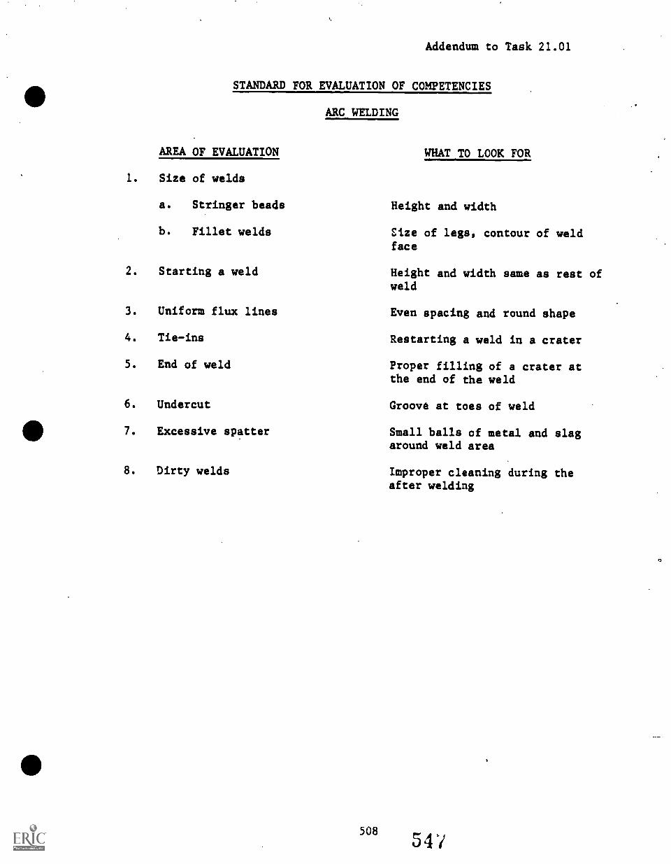
Addendum to Task 21.01
STANDARD FOR EVALUATION OF COMPETENCIES
ARC WELDING
AREA OF EVALUATION WHAT TO LOOK FOR
1. Size of welds
a. Stringer beads Height and width
b. Fillet welds Size of legs, contour of weldface
2. Starting a weld Height and width same as rest ofweld
3. Uniform flux lines Even spacing and round shape
4. Tie-ins Restarting a weld in a crater
5. End of weld Proper filling of a crater atthe end of the weld
6. Undercut Groove at toes of weld
7. Excessive spatter Small balls of metal and slagaround weld area
8. Dirty welds Improper cleaning during theafter welding
508
C/
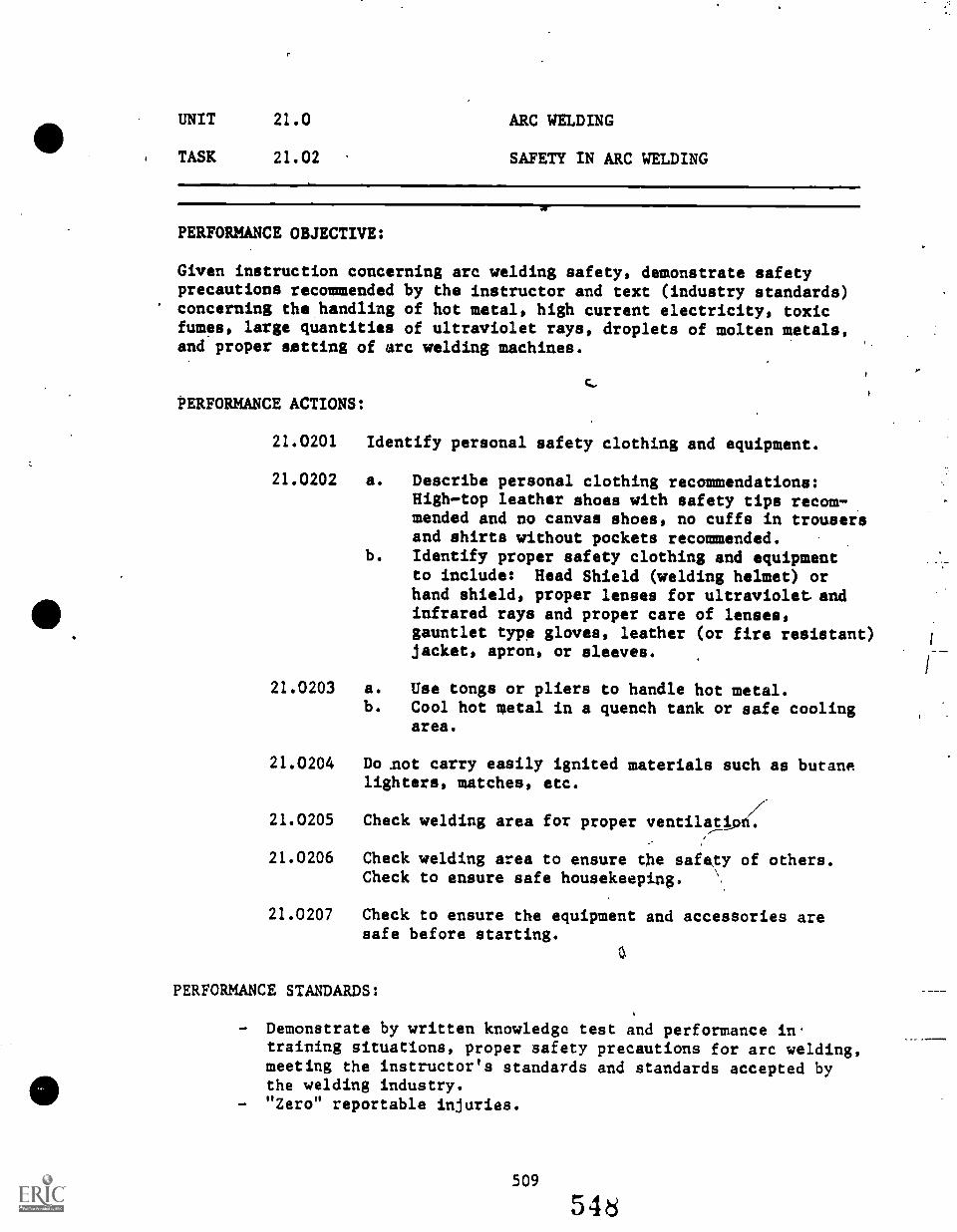
UNIT 21.0 ARC WELDING
TASK 21.02 SAFETY IN ARC WELDING
w
PERFORMANCE OBJECTIVE:
Given instruction concerning arc welding safety, demonstrate safetyprecautions recommended by the instructor and text (industry standards)concerning the handling of hot metal, high current electricity, toxicfumes, large quantities of ultraviolet rays, droplets of molten metals,and proper setting of arc welding machines.
PERFORMANCE ACTIONS:
21.0201 Identify personal safety clothing and equipment.
21.0202 a. Describe personal clothing recommendations:High-top leather shoes with safety tips recom-mended and no canvas shoes, no cuffs in trousersand shirts without pockets recommended.
b. Identify proper safety clothing and equipmentto include: Head Shield (welding helmet) orhand shield, proper lenses for ultraviolet. andinfrared rays and proper care of lenses,gauntlet type gloves, leather (or fire resistant)jacket, apron, or sleeves.
21.0203 a. Use tongs or pliers to handle hot metal.b. Cool hot metal in a quench tank or safe cooling
area.
21.0204 Do .not carry easily ignited materials such as butanelighters, matches, etc.
21.0205 Check welding area for proper ventilati
21.0206 Check welding area to ensure the safety of others.Check to ensure safe housekeeping,
21.0207 Check to ensure the equipment and accessories aresafe before starting.
PERFORMANCE STANDARDS:
- Demonstrate by written knowledge test and performance intraining situations, proper safety precautions for arc welding,meeting the instructor's standards and standards accepted bythe welding industry.
- "Zero" reportable injuries.
UNIT 21.0 ARC WELDING
TASK 21.02 SAFETY IN ARC WELDING (Con't.)
SUGGESTED INSTRUCTION TIME: Optional training
RELATED TECHNICAL INFORMATION:
Proper care with flammable material around welding-shop.Take care in damp or wet areas.Proper care in welding a tank or container, especially if ithas contained flammable material in the past.
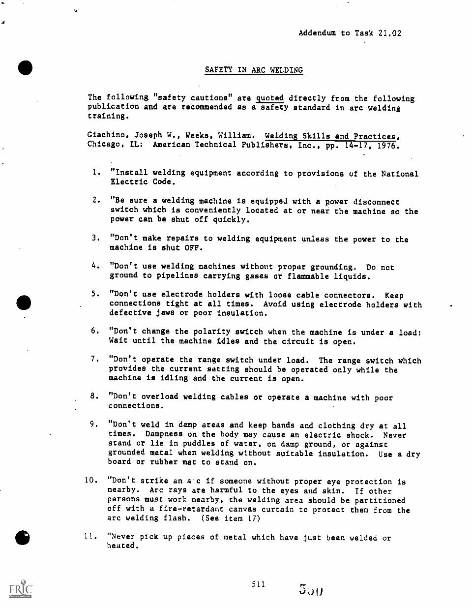
Addendum to Task 21.02
SAFETY IN ARC WELDING
The following "safety cautions" are quoted directly from the followingpublication and are recommended as a safety standard in arc weldingtraining.
Giachino, Joseph W., Weeks, William. Welding Skills and Practices,Chicago, IL: American Technical Publishers, Inc., pp. 14-17, 1976.
1. "Install welding equipment according to provisions of the NationalElectric Code.
2. "Be sure a welding machine is equipped with a power disconnectswitch which is conveniently located at or near the machine so thepower can be shut off quickly.
3. "Don't make repairs to welding equipment unless the power to themachine is shut OFF.
4. "Don't use welding machines without proper grounding. Do notground to pipelines carrying gases or flammable liquids.
5. "Don't use electrode holders with loose cable connectors. Keepconnections tight at all times. Avoid using electrode holders withdefective jaws or poor insulation.
6. "Don't change the polarity switch when the machine is under a load:Wait until the machine idles and the circuit is open.
7. "Don't operate the range switch under load. The range switch whichprovides the current setting should be operated only while themachine is idling and the current is open.
8. "Don't overload welding cables or operate a machine with poorconnections.
9. "Don't weld in damp areas and keep hands and clothing dry at alltimes. Dampness on the body may cause an electric shock. Neverstand or lie in puddles of water, on damp ground, or againstgrounded metal when welding without suitable insulation. Use a dryboard or rubber mat to stand on.
10. "Don't strike an a'c if someone without proper eye protection isnearby. Arc rays are harmful to the eyes and skin. If otherpersons must work nearby, the welding area should be partitionedoff with a fire-retardant canvas curtain to protect them from thearc welding flash. (See item 17)
11011. "Never pick up pieces of metal which have just been welded or
heated.
511
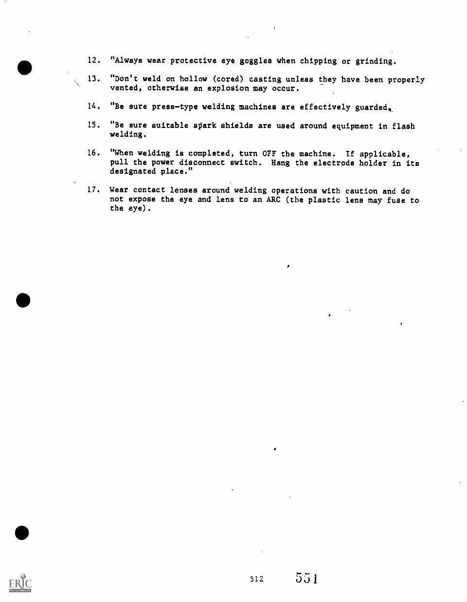
12. "Always wear protective eye goggles when chipping or grinding.
13. "Don't weld on hollow (cored) casting unless they have been properlyvented, otherwise an explosion may occur.
14. "Be sure presstype welding machines are effectively guardedL
15. "Be sure suitable spark shields are used around equipment in flashwelding.
16. "When welding is completed, turn OFF the machine. If applicable,pull the power disconnect switch. Hang the electrode holder in itsdesignated place."
17. Wear contact lenses around welding operations with caution and donot expose the eye and lens to an ARC (the plastic lens may fuse tothe eye).
512 551
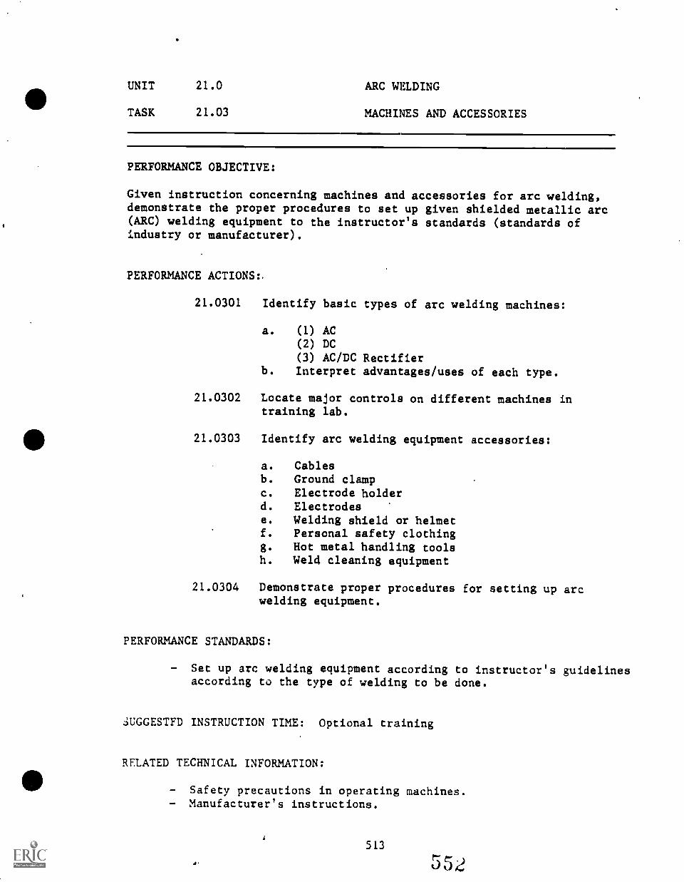
UNIT 21.0 ARC WELDING
TASK 21.03 MACHINES AND ACCESSORIES
PERFORMANCE OBJECTIVE:
Given instruction concerning machines and accessories for arc welding,demonstrate the proper procedures to set up given shielded metallic arc(ARC) welding equipment to the instructor's standards (standards ofindustry or manufacturer).
PERFORMANCE ACTIONS:
21.0301 Identify basic types of arc welding machines:
a. (1) AC(2) DC
(3) AC/DC Rectifierb. Interpret advantages/uses of each type.
21.0302 Locate major controls on different machines intraining lab.
21.0303 Identify arc welding equipment accessories:
a. Cablesb. Ground clampc. Electrode holderd. Electrodese. Welding shield or helmetf. Personal safety clothingg. Hot metal handling toolsh. Weld cleaning equipment
21.0304 Demonstrate proper procedures for setting up arcwelding equipment.
PERFORMANCE STANDARDS:
- Set up arc welding equipment according to instructor's guidelinesaccording to the type of welding to be done.
3UGGESTED INSTRUCTION TIME: Optional training
RELATED TECHNICAL INFORMATION:
- Safety precautions in operating machines.- Manufacturer's instructions.
4.
513
552
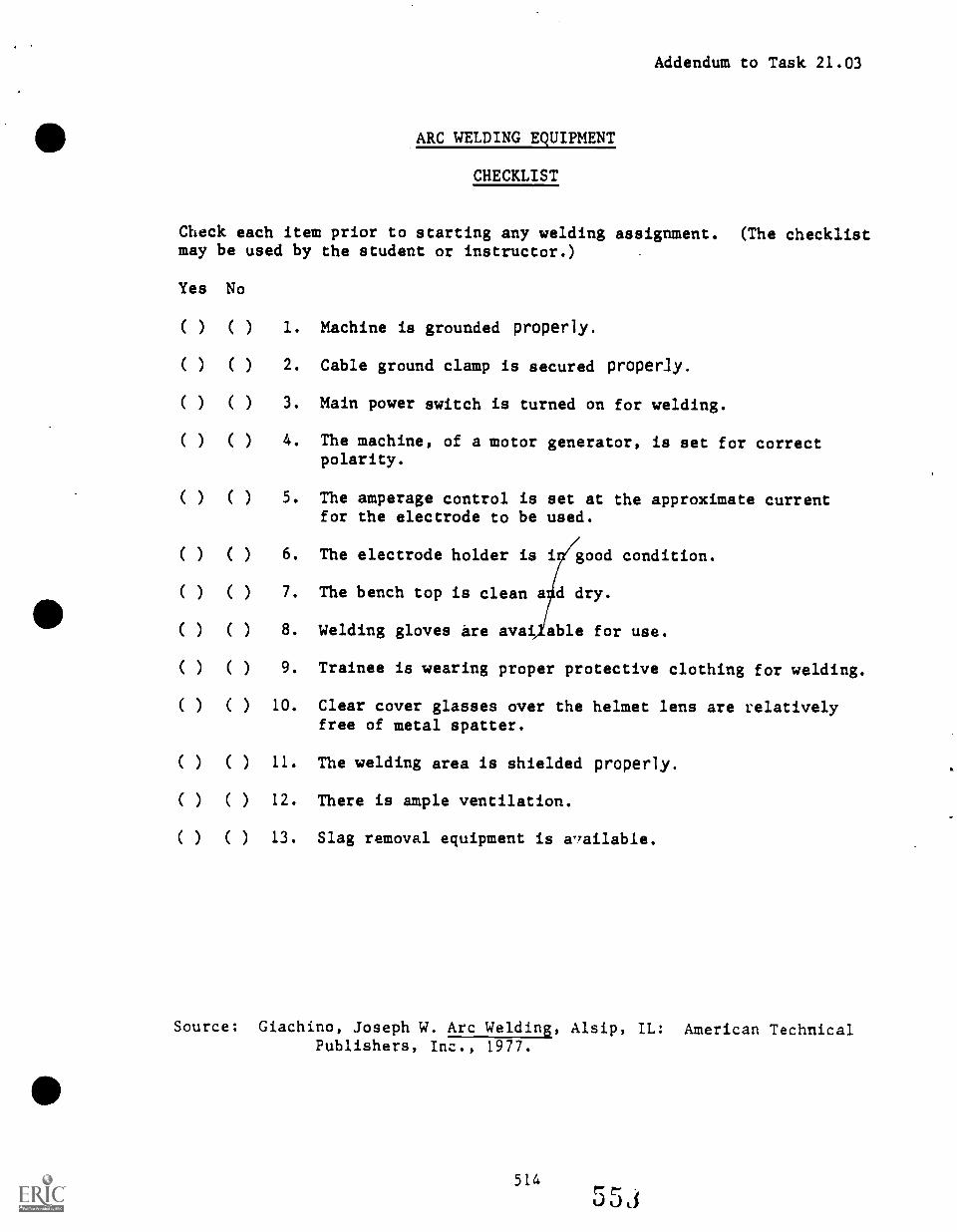
Addendum to Task 21.03
ARC WELDING EQUIPMENT
CHECKLIST
Check each item prior to starting any welding assignment. (The checklistmay be used by the student or instructor.)
Yes No
( ) ( ) 1. Machine is grounded properly.
( ) ( ) 2. Cable ground clamp is secured properly.
( ) ( ) 3. Main power switch is turned on for welding.
( ) ( ) 4. The machine, of a motor generator, is set for correctpolarity.
( ( ) 5. The amperage control is set at the approximate currentfor the electrode to be used.
( ) ( ) 6. The electrode holder is i good condition.
( ) ( ) 7. The bench top is clean a d dry.
( ) ( ) 8. Welding gloves are avai able for use.
( ) ( ) 9. Trainee is wearing proper protective clothing for welding.
( ) ( ) 10. Clear cover glasses over the helmet lens are relativelyfree of metal spatter.
( ) ( ) 11. The welding area is shielded properly.
( ) ( ) 12. There is ample ventilation.
( ) ( ) 13. Slag removal equipment is aailable.
Source: Giachino, Joseph W. Arc Welding, Alsip, IL: American TechnicalPublishers, Inc., 1977.
UNIT 21.0 ARC WELDING
TASK 21.04 SELECT ELECTRODE
PERFORMANCE OBJECTIVE:
Given an orientation to arc welding electrodes, select electrode anddescribe how to properly store and conserve electrodes during training.
PERFORMANCE ACTIONS:
21.0401 Describe the actions of electrodes in arc welding.
21.0402 Identify arc welding electrodes given by instructor.
21.0403 Explain how to properly store electrodes.
21.C404 Describe how to conserve electrodes in training.
21.0405 Demonstrate proper selection of electrodes for givenwelding jobs.
PERFORMANCE STANDARDS:
Describe how to properly store electrodes and how to conserveelectrodes in training.Demonstrate proper selection of alectrodes, storage, andconservation.
SUGGESTED INSTRUCTION TIME: Optional training
UNIT 21.0 ARC WELDING
TASK 21.05 STRIKING AND MAINTAINING(SUBSTAINING) AN ARC (FLAT POSITION)
PERFORMANCE OBJECTIVE:
Given instruction, safety protective equipment, welding machine-equipment-accessories, and electrodes, and angle iron or frame channel;strike and maintain an arc to the instructor's standards.
PERFORMANCE ACTIONS:
21.0501 Prepare for welding. (Take safety precautionsincluded.)
21.0502 Set up given arc machine-equipment-accessories.
21.0503 Position metal.
21.0504 Correctly position electrode in holder and gripholder for welding.
21.0505 a. Strike and maintain an arc. (Use scratch,tapping, etc., method to produce acceptablearc.)
b. Adjust for proper heat.
PERFORMANCE STANDARDS:
- Strike and maintain an arc to the instructor's standards.
SUGGESTED INSTRUCTION TIME: Optional training
RELATED TECHNICAL INFORMATION:
- .Operation of arc machine-equipment-accessories.- Safety precautions.- Electrode identification.
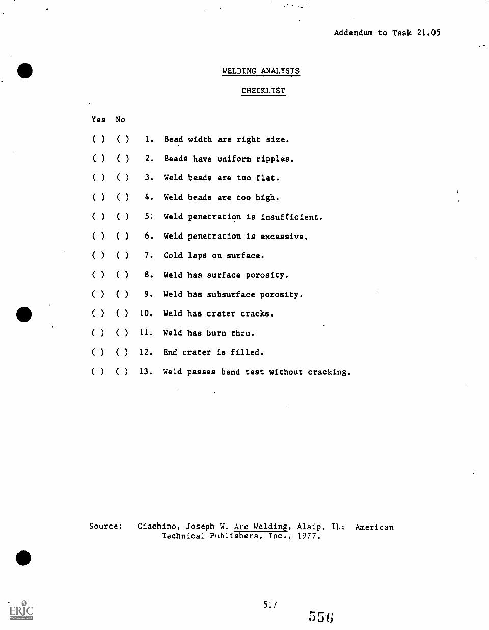
WELDING ANALYSIS
Addendum to Task 21.05
Yes No
CHECKLIST
( ) ( ) 1. Bead width are right size.
( ) ( ) 2. Beads have uniform ripples.
( ) ( ) 3. Weld beads are too flat.
( ) ( ) 4. Weld beads are too high.
( ) ( ) 5. Weld penetration is insufficient.
( ) ( ) 6. Weld penetration is excessive.
( ) ( ) 7. Cold laps on surface.
( ) ( ) 8. Weld has surface porosity.
( ) ( ) 9. Weld has subsurface porosity.
( ) ( ) 10. Weld has crater cracks.
( ) ( ) 11. Weld has burn thru.
( ) ( ) 12. End crater is filled.
( ) ( ) 13. Weld passes bend test without cracking.
Source: Giachino, Joseph W. Arc Welding, Alsip, IL: AmericanTechnical Publishers, Inc., 1977.
517
5 5.f;
UNIT 21.0 ARC WELDING
TASK 21.06 CHIP SLAG USING CHIPPING HAMMER
PERFORMANCE OBJECTIVE:
Given a welded joint and chipping hammer; remove slag from weld.Weldment must be free of all removable slag.
PERFORMANCE ACTIONS:
21.0601 Prepare for chipping: Select safety equipment.
21.0602 Select chipping hammer.
21.0603 Chip slag from weld using side by side method.
21.0604 Brush to clean as required.
PERFORMANCE STANDARDS:
Chip slag from freshly cooled weld so that all removable slagis freed.
SUGGESTED INSTRUCTION TIME: Optional training
RELATED TECHNICAL INFORMATION:
Clean weld area thoroughly of all paint, scale, rust, etc.Uncleaned weld are is the common cause of slag.
UNIT 21.0 ARC WELDING
TASK 21.07 RUN SHORT BEADS, FLAT POSITION(TRAINING TASK)
PERFORMANCE OBJECTIVE:
Given instructions, arc welding machine, safety equipment, accessories,mild steel plate, and electrode; run short beads to the instructor'sstandards. Flat position.
PERFORMANCE ACTIONS:
21.0701 Prepare for arc welding (including safety precautions).
21.0702 Set up arc machine-equipment-accessories.
21.0703 Position plate.
21.0704 a. Run short beads in flat position to instructor's'standards. (Scratch method recommended).
b. Examine weld bead (after each pass).c. Adjust machine us necessary to produce a
satisfactory bead.
21.0705 Clean weld after each pass.
PERFORMANCE STANDARDS:
- Run short beads to instructor's standards.- Beads must be straight, with no undercut, no slag inclusions
or porosity.- Even ripple appearance.
SUGGESTED INSTRUCTION TIME: Optional training
RELATED TECHNICAL INFORMATION:
- Recognizing the sound of an arc that is:a. correct (continuous cracking, frying)b. too long (humming)c. or too short (popping)
- Identify desired puddle appearance.- Check adjustment of welding heat.
UNIT 21.0 ARC WELDING
TASK 21.08 RUN CONTINUOUS BEADS, FLAT POSITION(TRAINING TASK)
PERFORMANCE OBJECTIVE:
Given instructions, arc welding machine-equipment-accessories (includingsafety clothing), electrode and metal plate; run continuous beads to theinstructor's standards.
PERFORMANCE ACTIONS:
21.0801 Prepare for arc welding. (Machine safety equipment,accessories, personal safety, etc.)
21.0802 Mark lines on steel plate and position plate forwelding.
21.0803 Run a continuous bead, starting at left edge ofwork, using the full length of the electrode.
21.0804 a. Remove slag.b. Examine weld.c. Adjust machine if necessary.
'Suggested: At end of weld, stop bead by shorteningarc and quickly backing or "whipping" electrode tobreak the arc.
(NOTE: Running a continuous bead will be repetitiveprocess until the student becomes competentin the task.)
ADDITIONAL SKILL DEVELOPMENT TASKS IN RUNNING BEADS
1. Practice re-striking the arc while running continuous beads.2. Practice padding.
PERFORMANCE STANDARDS:
- Run a continuous bead on given metal plate to the instructor'sstandards.
- Even ripple appearance.- No undercut, porosity, slag inclusions.- Proper penetration.
SUGGESTED INSTRUCTION TIME: Optional training
RELATED TECHNICAL INFORMATION:
- Proper use of electrode in striking the arc
UNIT 21.0 ARC WELDING
TASK 21.09 PREPARE JOINT
PERFORMANCE OBJECTIVE:
(See related task in Oxyacetylene Welding) Given metal to clean andprepare for welding, select the best joint and prepare the joint for arcwelding.
PERFORMANCE ACTIONS:
21.0901 Select type of joint. (It should be simplest jointto adequately do the job.)
21.0902 Prepare the joint so that the weld may penetrateclose to 100 percent (deep penetration).
21.0903 a. Square butt.b. Single bevel groove.c. Single V groove.
21.0904 Clean and dry joints for welding.
PERFORMANCE STANDARDS:
- Prepare joints for welding meeting instructor's standards.
SUGGESTED INSTRUCTION TIME: Optional training
RELATED TECHNICAL INFORMATION:
- Review related task in Oxyacetylene Welding, as necessary.- Metal characteristics.
5215 i)
UNIT 21.0 ARC WELDING
TASK 21.10 CONSTRUCT OPEN BUTT WELD, ALLPOSITIONS
PERFORMANCE OBJECTIVE:
Given a shielded metal arc welding station, mild steel coupons, electrodes,personal safety equipment, and the necessary tools and materials,construct open butt welds, 1/16 inch root opening, in all positions(flat, horizontal, vertical, and overhead). Bead must be straight anduniform in height and width; have no oxidation, weld must be fused withbase metal and have full penetration.
PERFORMANCE ACTIONS:
21.1001 Prepare for ARC welding; select safety equipment.
21.1002 Set up SMAW machine, equipment, and supplies, andoverhead fixture (jig) as applicable.
21.1003 Clean and position plate in proper configuration andposition.
21.1004 Tack weld plates into position.
21.1005 Construct open butt weld, all positions, to specifi-cations.
PERFORMANCE STANDARDS:
- Construct open butt weld, all positions,that the bead is straight and uniform inthere is no oxidation, the weld is fusedthere is full penetration.
- The instructor's standards must be met.
SUGGESTED INSTRUCTION TIME: Optional training
to specifications, soheight and width,with base metal, and
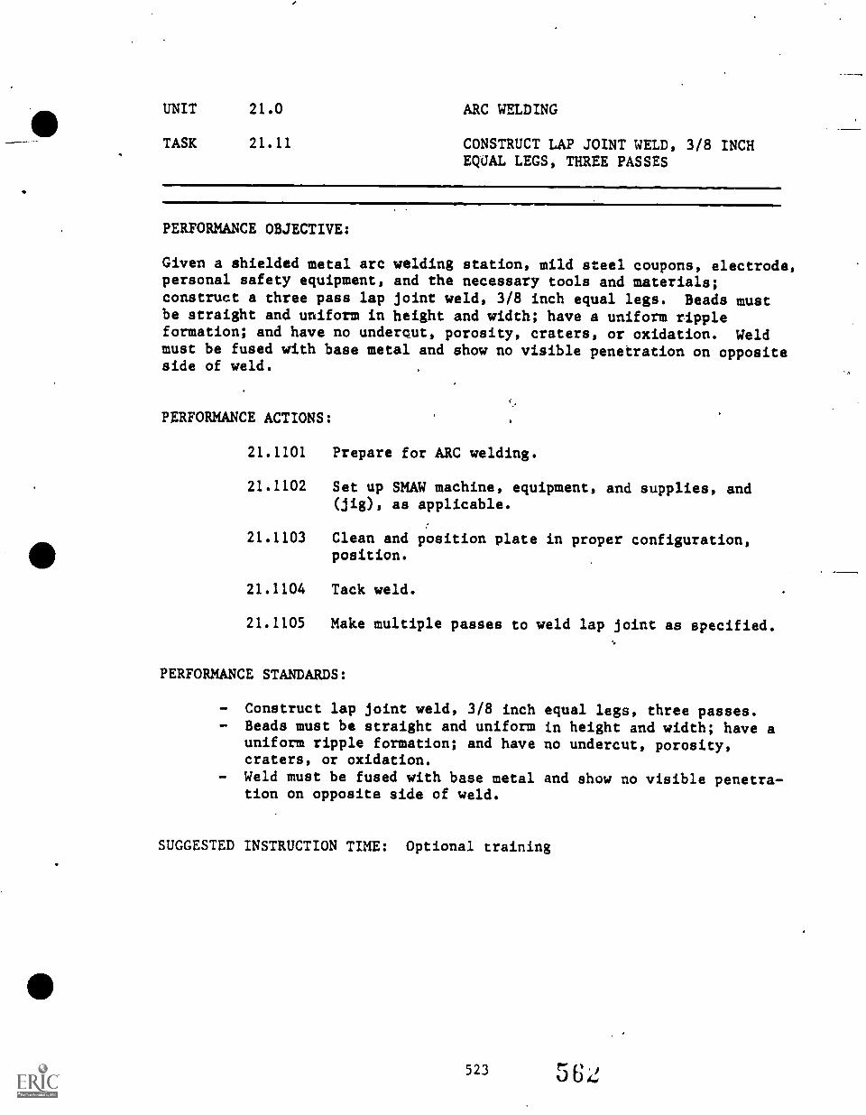
UNIT 21.0 ARC WELDING
TASK 21.11 CONSTRUCT LAP JOINT WELD, 3/8 INCHEQUAL LEGS, THREE PASSES
PERFORMANCE OBJECTIVE:
Given a shielded metal arc welding station, mild steel coupons, electrode,personal safety equipment, and the necessary tools and materials;construct a three pass lap joint weld, 3/8 inch equal legs. Beads mustbe straight and uniform in height and width; have a uniform rippleformation; and have no undercut, porosity, craters, or oxidation. Weldmust be fused with base metal and show no visible penetration on oppositeside of weld.
PERFORMANCE ACTIONS:
21.1101 Prepare for ARC welding.
21.1102 Set up SHAW machine, equipment, and supplies, and(jig), as applicable.
21.1103 Clean and position plate in proper configuration,position.
21.1104 Tack weld.
21.1105 Make multiple passes to weld lap joint as specified.
PERFORMANCE STANDARDS:
- Construct lap joint weld, 3/8 inch equal legs, three passes.- Beads must be straight and uniform in height and width; have a
uniform ripple formation; and have no undercut, porosity,craters, or oxidation.
- Weld must be fused with base metal and show no visible penetra-tion on opposite side of weld.
SUGGESTED INSTRUCTION TIME: Optional training
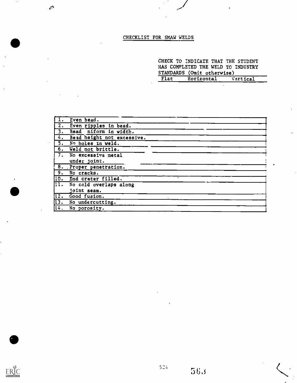
CHECKLIST FOR SMAW WELDS
CHECK TO INDICATE THAT THE STUDENTHAS COMPLETED THE WELD TO INDUSTRYSTANDARDS (Omit otherwise)Flat Horizontal Vertical
1. Even bead.2. Even ripples in bead.3. Bead niform in width.4. Bead height not excessive.5. No holes in weld.6. Weld not brittle.7. No excessive metal
under joint.8. ,Proper penetration.9. No cracks.
10. End crater filled.U. No cold overlaps along
joint seam.112. Good fusion.13. No undercutti14, No porosity.

PROFICIENCY REPORT
3 2 5 564
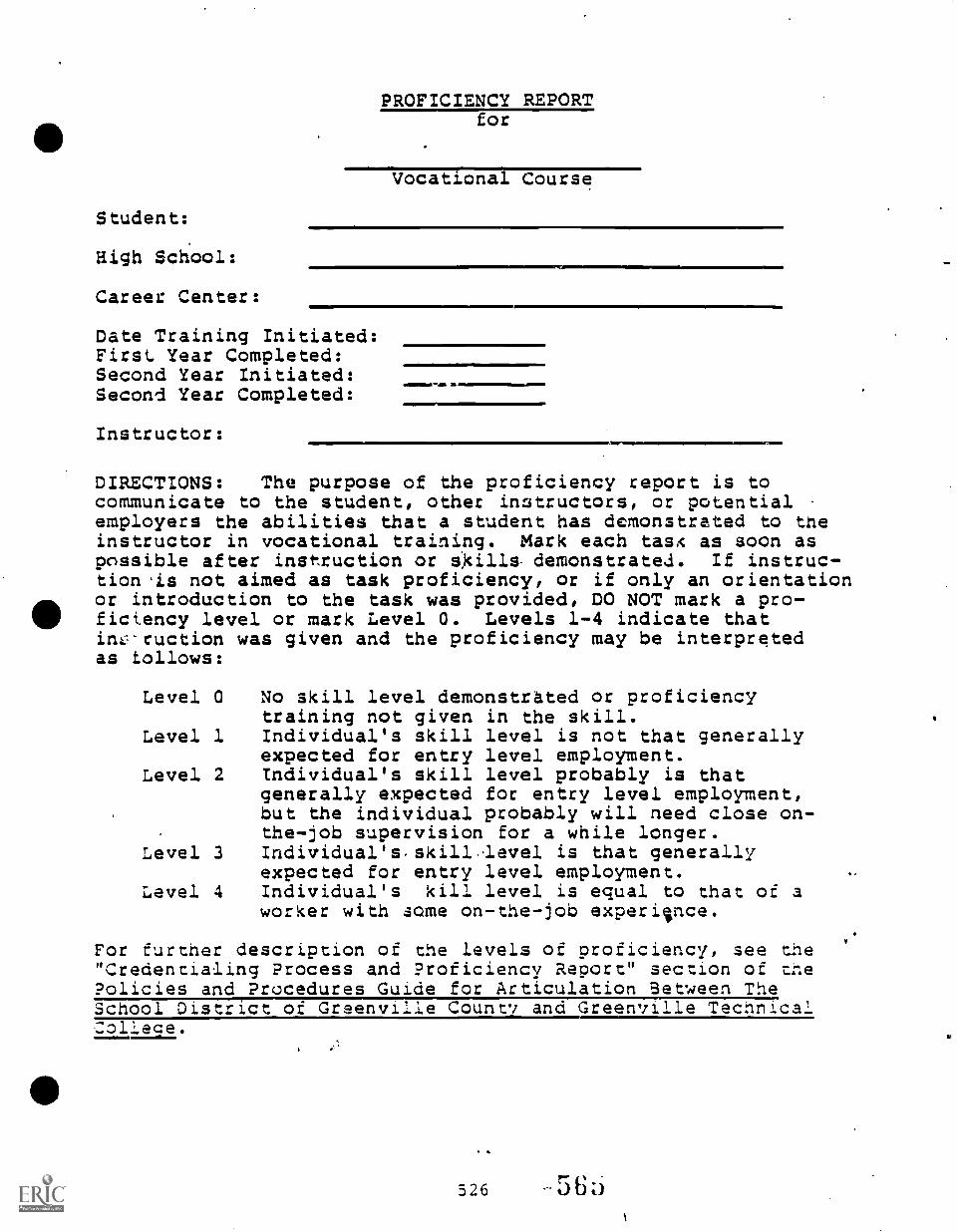
Student:
High School:
Career Center:
PROFICIENCY REPORTfor
Vocational Course
Date Training Initiated:First. Year Completed:Second Year Initiated:Second Year Completed:
Instructor:Mime' t-
DIRECTIONS: The purpose of the proficiency report is tocommunicate to the student, other instructors, or potentialemployers the abilities that a student has demonstrated to theinstructor in vocational training. Mark each tasA as soon aspossible after instruction or skills. demonstrated. If instruc-tion 'is not aimed as task proficiency, or if only an orientationor introduction to the task was provided, DO NOT mark a pro-ficiency level or mark Level 0. Levels 1-4 indicate thatinLl'ruction was given and the proficiency may be interpretedas follows:
Level 0 No skill level demonstrated or proficiencytraining not given in the skill.
Level 1 Individual's skill level is not that generallyexpected for entry level employment.
Level 2 Individual's skill level probably is thatgenerally expected for entry level employment,but the individual probably will need close on-the-job supervision for a while longer.
Level 3 Individual's.skill-level is that generallyexpected for entry level employment.
Level 4 Individual's kill level is equal to that of aworker with some on-the-job experience.
For further description of the levels of proficiency, see the"Credencialing Process and Proficiency Report" section of toPolicies and Procedures Guide for Articulation Between TheSchool District of Greenville County and Greenville TechnicalCollece.
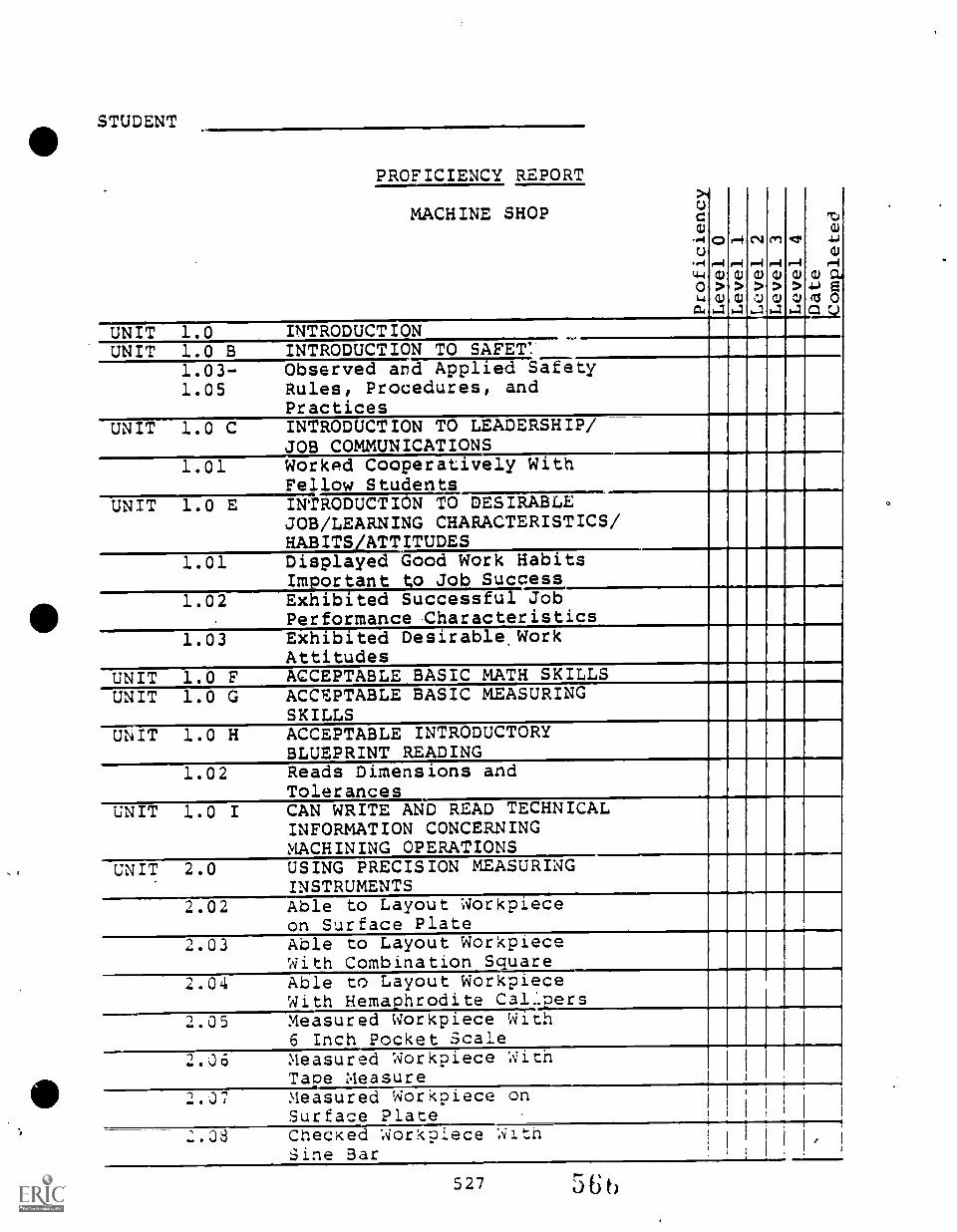
STUDENT
PROFICIENCY REPORT
MACHINE SHOPucw
^(Cor-4C4014:21C..)
...I
(440L.4
a(
ei1)>CD
1.4
1.4a)
>a)
14
r4a)
>,I)
1-1
r..4a1
>a)
)..1
rIa1
>aJ
14
TIw
43(1)
r.4a) Cti4..) E(13 0CL:
UNIT 1.0 INTRODUCTIONUNIT 1.0 B INTRODUCTION TO SAFET!-
1.03-1.05
Observed and Applied SafetyRules, Procedures, andPractices
UNIT 1.0 C
1.01
INTRODUCTION TO LEADERSHIP/JOB COMMUNICATIONSWorked Cooperatively WithFellow Students
UNIT 1.0 E INTRODUCTION TO DESIRABLEJOB/LEARNING CHARACTERISTICS/HABITSYATTITUDES
1.01 Displayed Good Work HabitsImportant to Job Success
1.02 Exhibited Successful JobPerformance Characteristics
1.03 Exhibited Desirable WorkAttitudes
UNIT 1.0 F ACCEPTABLE BASIC MATH SKILLS,
UNIT 1.0 G ACCEPTABLE BASIC MEASURINGSKILLS
UNIT 1.0 H ACCEPTABLE INTRODUCTORYBLUEPRINT READING
4
1.02 Reads Dimensions andTolerances
UNIT 1.0 I CAN WRITE AND READ TECHNICALINFORMATION CONCERNINGMACHINING OPERATIONS
UNIT 2.0 USING PRECISION MEASURINGINSTRUMENTS
2.02 Able to Layout Workpieceon Surface Plate
2.03 Able to Layout WorkpieceWith Combination Sauare
2.04 Able to Layout WorkpieceWith Hemaphrodite Cal1pers
2.05 Measured Workpiece With6 Inch Pocket Scale
2.06 Measured Workpiece WithTape Measure
2.07 Measured Workpiece onSurface Plate
2.08 Checked Workpiece WithSine Bar
527
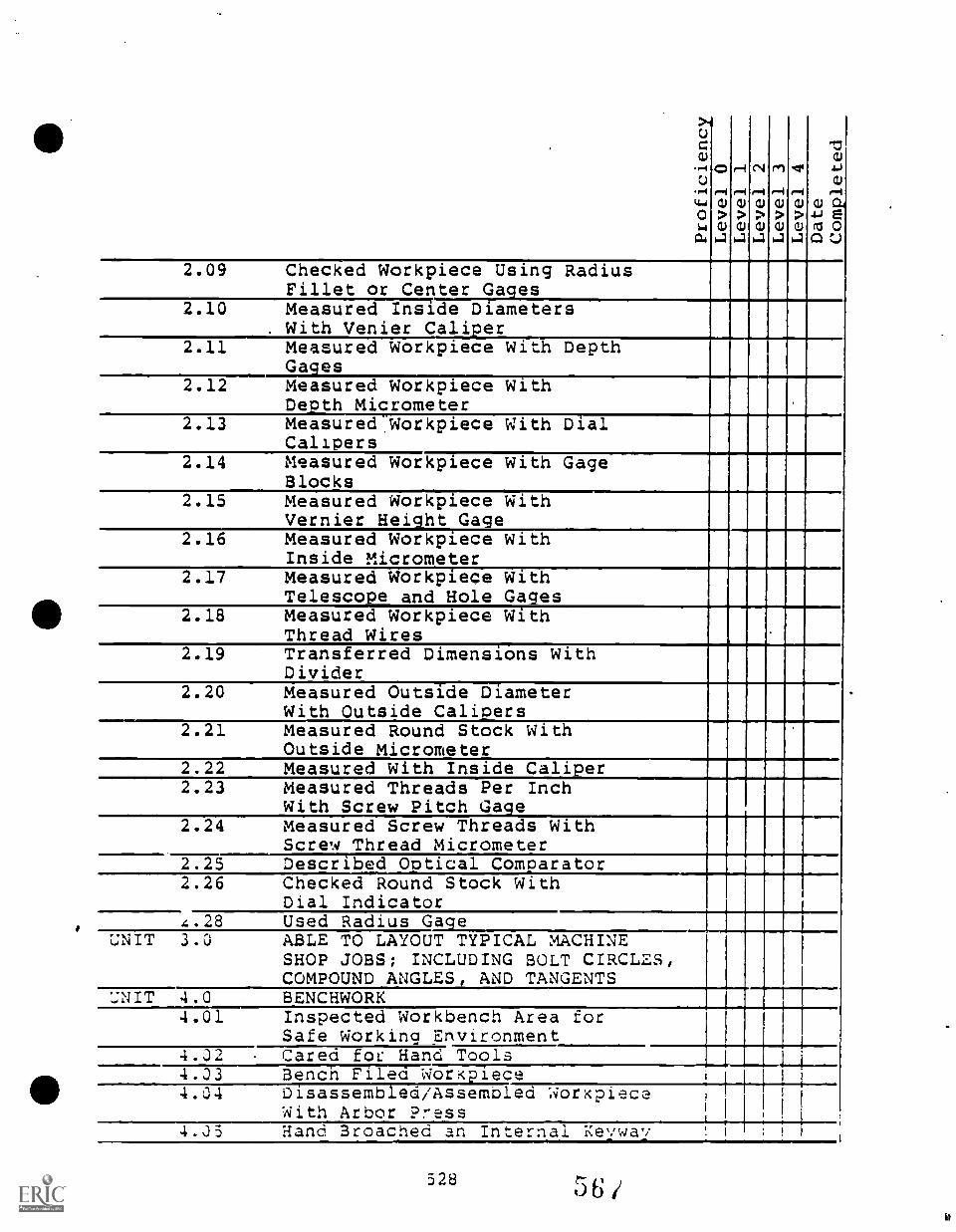
CCl.)
,-IC.)
'POki-1
0CLI
0t-4
C.)
>1.4
r-I
t-4(I)>
1.4
CI
r4CD
>
1.4
rir'i
C.)
>
1.4
er
t-4C.)
>
1.4
"JC.)
.i..)
C.)
r-iCD
4-1 e
C) j
2.09 Checked Workpiece Using RadiusFillet or Center Gages
2.10 Measured Inside Diameters. With Venier Calier
2.11 Measured Workpiece With DepthGages
2.12 Measured Workpiece WithDepth Micrometer
2.13 Measured.Workpiece With DialCalipers
2.14 Measured Workpiece With GageBlocks
2.15 Measured Workpiece WithVernier Height Gage
2.16 Measured Workpiece WithInside Micrometer
2.17 Measured Workpiece WithTelescope and Hole Gages
2.18 Measured Workpiece WithThread Wires
2.19 Transferred Dimensions WithDivider
2.20 Measured Outside DiameterWith Outside Caliers
2.21 Measured Round Stock WithOutside Micrometer
2.22 Measured With Inside Caliper2.23 Measured Threads Per Inch
With Screw Pitch Gage2.24 Measured Screw Threads With
Screw Thread Micrometer2.25 Described Optical Comparator2.26 Checked Round Stock With
Dial Indicator1
4.28 Used Radius GageUNIT 3.0 ABLE TO LAYOUT TYPICAL MACHINE
SHOP JOBS; INCLUDING BOLT CIRCLES,COMPOUND ANGLES, AND TANGENTS
UNIT 4.0 BENCHWORK4.01 Inspected Workbench Area for
Safe Working Environment4.02 Cared for Hand Tools4.03 Bench Filed Workpiece4.04 Disassembled/Assembled Workpiece
With Arbor Press4.33 Hang Broached an Internal Keyway
328 6
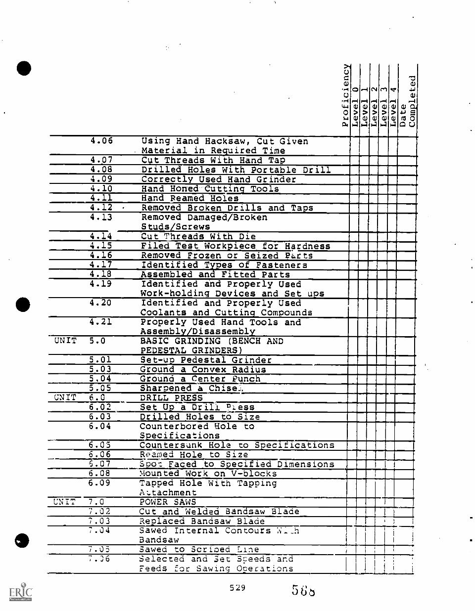
>40cw
..--I
o,-4CI-I0sa04
C)
r-1(1)
>CU
4
r-I
riCD
>CD
1-1
N
r-iCU
>CU
4
01
r-I(1)
>CD
1.4
cr
r-iCU
>CU
4
'Uw
4.1
wP-1
CD a.4J -5.(1 0CI U
4.06 Using Hand Hacksaw, Cut Given. Material in Required Time
4.07 Cut Threads With Hand Tap4.08 Drilled Holes With Portable Drill4.09 Correctly Used Hand Grinder4.10 Hand Honed-Cutting Tools4.11 Hand Reamed Holes4.12 Removed Broken Drills and Taps4.13 Removed Damaged/Broken
Studs/Screws4.14 Cut Threads With Die4.15 Filed Test Workpiece for Hardness4.16 Removed Frozen or Seized 2.rts4.17 Identified Tue.! of Fasteners4.18 Assembled and Fitted Parts4.19 Identified and Properly Used
Work-holding Devices and Set ups4.20 Identified and Properly Used
Coolants and Cutting Compounds4.21 Properly Used Hand Tools and
Assembly /DisassemblyUNIT 5.0 BASIC GRINDING (BENCH AND
PEDESTAL GRINDERS'5.01 Set-up Pedestal Grinder5.03 Ground a Convex Radius5.04 Ground a Center Punch5.05 Sharpened a Chise:i.
UNIT 6.0 DRILL P_ RESS6.02 Set Up a Drill ?Less.-....
6.03 Drilled Holes to Size6.04 Counterbored Hole to
Specifications6.03 Countersunk Hole to Secitications6.06 Reaped Hole to Size6.07 Soot Faced to Specified Dimensions6.08 Mounted Work on V-blocks6.09 Tapped Hole With Tapping
Az.tachmentUNIT 7.0 POWER SAWS
7.02 Cut and Welded Bandsaw Blade7.03 Replaced Bandsaw Blade7.04 Sawea Internal Contours W......h
Bandsaw7.03 Sawed to Scribed Line
J 0 Selected and Set Seeds andFeeds for Sawing Operations
529
L.
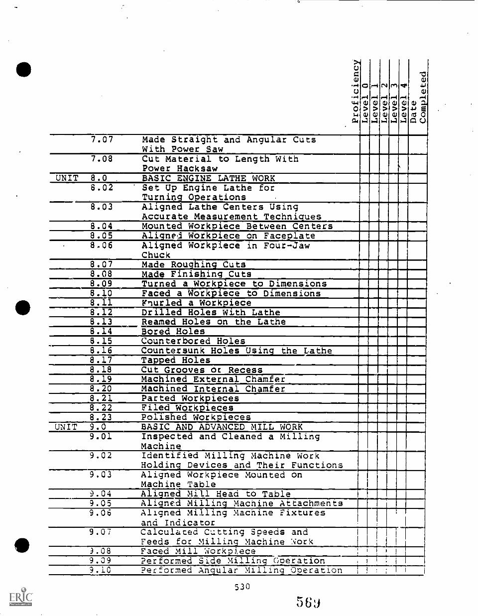
.>iU=CI)
,-4U
--1ti-io1-1
CU
0I-I
CD
>0)4
1--1
ria)
>OJ
1-1
CI
1-4(1)
>0)4
rn
1-4(1)
>0)
I-3
er
t-1CD
>0)4
T:1CU
..JCU
(1)
4-1 eIV 0GI C..)
7.07 Made Straight and Angular CutsWith Power Saw
7.08 Cut Material to Length WithPower Hacksaw
UNIT 8.0 . BASIC ENGINE LATHE WORK8.02 Set Up Engine Lathe for
Turning 0erations8.03 Aligned Lathe Centers Using
Accurate Measurement Techniques8.04 Mounted Workpiece Between Centers8.05 Aligatd Workiece on Facelate8.06 Aligned Workpiece in Four-Jaw
Chuck8.07 Made Rouhin Cuts II8 08 Made Finishing. Cuts8.09 Turned a Workiece to Dimensions8.10 Faced a Workpi.ece to Dimensions8.11 Fnurled a Workiece8.12 Drilled Holes With Lathe8.13 Reamed Holes on the Lathe
II8.14 Bored Holes8.15 Counterbored Holes8.16 Countersunk Holes Using the Lathe8.17 Tapped Holes8.18 Cut Grooves or Recess8.19 Machined External Chamfer8.20 Mac ined Internal Chamfer8.21 Parted Workieces8.22 Filed Workieces il8.23 Polished Workpieces
UNIT 9.0 BASIC AND ADVANCED MILL WORK9.01 Inspected and Cleaned a Milling
Machine9.02 Identified Milling Machine Work
Holding Devices and Their Functions9.03 Aligned Workpiece Mounted on
Machine Table9.04 Aligned mill Head to Table9.05 Aligned Milling Machine Attachments9.06 Aligned Milling Macnine Fixtures
and Indicator9.07 Calculated Cutting Speeds and
Feeds for Milling Machine Work _-__9.08 Faced Mill Workoi
-_ece , . !
9.09 Performed Side Millinc Coeration i
.10 Performed An ular Millin Operation
530
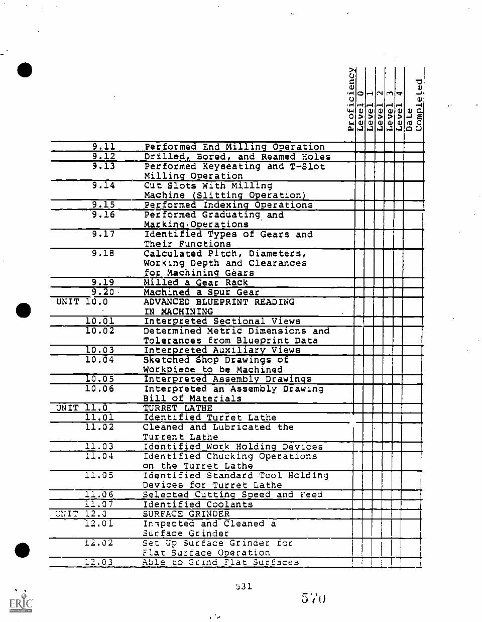
CiUCa,.,-4c)
Cir.4
4-106t
ca4
rlCU
>CU4
,-IN
riCU
>CU4
r...f
CU
>CU4
rn
riCU
>CD4
vr..4
CU
>CU4
13cu
.6)
0emf
CU CIA.1-) aMI 0CI U
9.11 Performed End Milling_Operation9.12 Drilled, Bored, and Reamed Holes9.13 Performed Keyseating and T-Slot
Milling Operation9.14 Cut Slots With Milling
Machine Slittin 0eration9.15 Performed Indexing Operations9.16 Performed Graduating and
Marking.Operations9.17 Identified Types of Gears and
Their Functions9.18 Calculated Pitch, Diameters,
Working Depth and Clearancesfor Machining Gears
9.19 Milled a Gear Rack9.20. Machined a Spur Gear
UNIT 10.0 ADVANCED BLUEPRINT READINGIN MACHINING .
10.01 Interpreted Sectional Views10.02 Determined Metric Dimensions and
Tolerances from Blueprint Data10.03 Interpreted Auxiliary Views10.04 Sketched Shop Drawings of
Workpiece to be Machined10.05 Interpreted Assembly Drawings10.06 Interpreted an Assembly Drawing
Bill of MaterialsUNIT 11.0 TURRET LATHE
11.01 Identified Turret Lathe11.02 Cleaned and Lubricated the
Turrent Lathe11.03 Identified Work Holding Devices11.04 Identified Chucking Operations
on the Turret Lathe11.05 Identified Standard Tool Holding
Devices for Turret Lathe11.06 Selected Cutting Speed and Feed11.07 Identified Coolants
UNIT 12.0 SURFACE GRINDER12.01 Inlpected and Cleaned a
Surface Grinder12.02 Set Up Surface Grinder for
Flat Surface Operation12.03 Able to Grind Flat Surfaces
531
5 7()
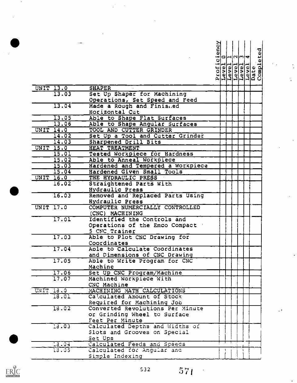
>40Co
P4o.4tW01.4
04
CD
r4a)
>tl)4
rir-ia)
>01-.1
C1
r-Ia)
>tl)*41-11-4
(Ir-ia)
>CU
111
r.4a)
>CU
rao
4.).ari
a) 044..) a
ft1 00 c
UNIT 13.0 SHAPER13.03 Set Up Shaper for Machining
0erations Set Seed and Feed13.04 Made a Rough and FinisL,ed
Horizontal Cut13.05 Able to Shape Flat Surfaces13.06 Able to Shape Angular Surfaces
UNIT 14.0 TOOL AND CUTTER GRINDER14.02 Set Up a Tool and Cutter Grinder14.03 Sharpened Drill Bits
UNIT 15.0 HEAT TREATMENT1.01 Tested Workpiece for Hardness15.02 Able to Anneal Workpiece15.03 Hardened and Temered a Workiece15.04 Hardened G ven Small Tools
UNIT 16.0 THE HYDRAULIC PRESS16.02 Straightened Parts With
Hydraulic Press16.03 Removed andReplaced Parts Using
Hydraulic PressUNIT 17.0 COMPUTER NUMERCIALLY CONTROLLED
(CNC) MACHINING17.01 Identified the Controls and
Operations of the Emco Compact5 rip:, Trainer
17.03 Able to Plot CNC Drawing forCoordinates
17.04 Aole to Calculate Coordinatesand Dimensions of CNC Drawing
17.05 Able to Write Program for CNCMachine
17.06 Set Up CNC Program/Machine17.07 Machined Workpiece With
CNC MachineUNIT 18.0 MACHINING :MATH CALCULATIONS
18.01 Cal.culated Amount of StockRequired for Machining Job
18.02 Converted Revolutions Per Minuteor Grinding Wheel to SurfaceFeet Per Minute
18.03 Calculated Depths and Widths ofSlots and Grooves on SpecialSetUps
, , 1 , -_,____,___, -,___,_ +_ .
13.03 Calculated roc Angular ancSimple Indexing
532
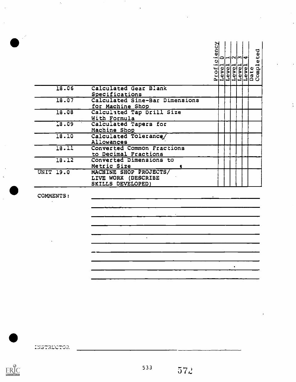
>-,Uza)
-+C.)
P414-4
o64
C14
ar4
CU
>CU4
r-4
r1CU
>CU
1.4
0,4
r4CU
>CU4
Crl
1-4CU
>CU4
4:11
r4CU
>CU4
roa)
-1.4
a)
P.-4
CU a.4-) e(13 0GI C.)
18.06 Calculated Gear BlankSpecifications
- . ,
18.07 Calculated Sine-Bar Dimensionsfor Machine Sho
18.08 Calcullted Tap Drill SizeWith Formula
18.09 Calculated Tapers forMachine Sho
18.10 Calculated TolerancVAllowances
A A
18.11 Converted Common Fractionsto Decimal Fractions
I ,
18.12 Converted Dimensions toMetric Size s
MACHINE SHOP PROJECTS/LIVE WORK (DESCRIBESKILLS DEVELOPED)
UNIT 19.0
COMMENTS:
:;;STRUCT0a
533

I
BIBLIOGRAPHY
534 573
BIBLIOGRAPHY - Machine Shop
Articulation Agreement for Machine Shop/Machine Tool Technology,Bennettsville, SC: Marlboro Vocational School/Chesterfield-Marlboro Technical College, 1979
Career Cluster Project: Final Report: 1972+1976, Columbia, SC:South Carolina Appalachian Council of Governments (AppalachianRegional Commission), 1976
Curriculm Standards for Machine Shop, Montgomery, AL: State ofAlabama Department of Education, 1982
Die Designer Jig and Fixture Designer, <1-TEC, Indianapolis, INState Board of Vocational and Technical Education, 1979
Dixon, Robert G., Benchwork, Albany, NY: Delmar Publishers Inc., 1981
Dixon, Robert G., Benchwork, Instructor's Guide, Alb.any, NY: DelmarPublishers Inc., 1981
Johnson, Harold V., General Indusrtial Machine Shop, 3rd Edition,Peoria, IL: Chas. A. Bennett Co., Inc., 1979
Krar, S. F., and Oswald, J. W., Drilling Technology, Albany, NY:Delmar Publishers Inc., 1977
111 Krar, S. F., and Oswald, J. W., Grinding Technology, Albany, NY:Delmar Publishers Inc., 1974
Krar, S. F., and Oswald, J. W., Grinding Technology, Instructor'sGuide, Albany, NY: Delmar Publishers Inc., 1974
Krar, S. F., and Oswald, J. W., Turning, Technology, Albany, NY:Delmar Publishers Inc., 1971
Krar, S. F., and Oswald, J. W., Turning Technology, Instructor'sGuide, Albany, NY: Delmar Publishers Inc., 1971
Lascoe, Orville D., Nelson, Clyde A., and Porter, Harold W., MachineShop Operations and Setups, 4th Edition, Alsip, IL: AmericanTechnical Publishers, Inc., 1973
Lascoe, Orville D., Nelson, Clyde A., and Porter, Harold W., MachineShop Operations and Setups, Student Guide, 4th Edition, Alsip,IL: American Technical Publishers, Inc., 1973
Lascoe, Orville D., Nelson, Clyde A., and Porter, Harold W.,-MachineShop Operations and Setups, Answer Key to Student Guide, 4thEdition, Alsip, IL: American Technical Publishers, Inc., 1973
Machine Shop I, Stillwater, OK: State Department of Vocational and
111 Technical Education, 1981
5355 7
Machine Shop, Atlanta, GA: Georgia Department of Education (Officeof Adult & Vocational Educaiton), 1974
Machine Shop Post - secondary,, Atlanta, GA: Georgia Department ofEducation, 1981
Machine Shop Series, Milling Machine Work, Albany NY: DelmarPublishers Inc., 1953
Math, Blueprint Reading, and Measuring Tools, Stillwater, OK:Oklahoma State Department of Vocational and Technical Education,1971
Riggs, Ronald D., Print Reading_for Machine Shop, Alsip, IL: America!Technical Publishers, Inc., 1981
Riggs, Ronald DO, Print Reading for Machine Shop, Instructor'sGuide:, Alsip, IL: American Technical Publishers, Inc., 1981
Task Anal sis Guides for Die Desi and Ji and Fixture Desi ner,V-TEC, Indianapolis IN: State :oard of Vocational and TechnicalEducation, 979
Taylor, David L., Drill Press Work, Albany NY: Delmar PublishersInc., 1980
Taylor, David L.., Drill Press Work, Instructor's Guide, Albany, NY:Delm'ar Publishers Inc., 1980
536t; ) ot1/440°'
z :1
CURRICULUM DEVELOPMENT REXERENCES
//411Defined Minimum Pto ram for South Carolina School Districts,
Co umbra, .SC: South Carolina Department of Education, 1980.
Henderson, Wm. Edward, -J:., Introductory Guide to the OccupationalEducation Articulation Program, Greenville, SC: OccupationalEducation Articulation. Program of The School District ofGreenville County. and Greenville Technical College, 1983.
Henderson, Wm. Edward, Jr.\, (ed.) Policies and Procedures Guidefor Articulation, Greeqville, SC: Occupational EducationArticulation Program of The School District of GreenvilleCowl y and Greenville Technical College, 1983.
HenderSo , Wm. Edward, Jr., Worksho Guide I: Su estions forCon ctin a Task Anal s s and Some Sources of Ready-madeTa or CBVE, Greenville, SC: Occupa-tion Educat on At culat on Program of The School District .
of Greenville County and Greenville Technidal College,.1983.
Henderson, Wm. Edward, Jr., Workshop Guide II: Preparing Objec-tives, Performance Actions and Standards for ArticulatedPerformance-based Instruction, Greenville,/SC: OccupationalE ucat on Art culation Program of The School District ofGreenville County and Greenville Technical College, 19113.
Henderson, Wm. Edwardt_Jr,....iilorkshop- Guide /II: Develozing...Outcome-refe-fended Tests, Greenville, SC: OccupationalEducation Articulation Program of The School District ofGreenville County and. Greenville Technical College, 1983.
High School Credit Courses for The School District of GreenvilleCounty, Greenville, SC: The School District of GreenvilleCounty (InstkuctiOnal Services), 1981.
Industrial Division, Greenville Technical Colleges 1982-1984(Catalog), Greenville, SC: Greenville Technical College,.1983-1984.
Outline of High School Credit Courses - State Department ofEducation, Columbia, SC: SC State Department of Education(Accreditation and Educational tImprovement Sectioh), 1980.
South.Carolina-Occ ec_tions.1918-1985L_Columbia,.SC:__South Carolina Employment Security: Commission (Research -41Analysis), 1982.
Technical Division, Greenville Technical Colle e 1982-1984,:Cata og) , Greenville, SC:. Greenvi. le Tec nica Col. ege,1983-1984.
537. 57t
11.
e
Reference 1
Reference 2
Reference 3
Reference 4
Reference 5
ADDITIONAL REFERENCES
(Secondary Ma.hine Shop)
DACUM Matrix for Machinist, SC
DACUM Matrix for NC Operator, Greenville, SC
Suggested Skills: Machinsit, Grinder Operator,Drill Press Operator, Lathe Operator, MillingMachine Operator
Survey of Secondary Level Lab Facilities
Recommended Secondary Level T & I Equipmeat
538 57,
0Reference 1 DACUM Matrix for Machinist, SC
i
539
37d
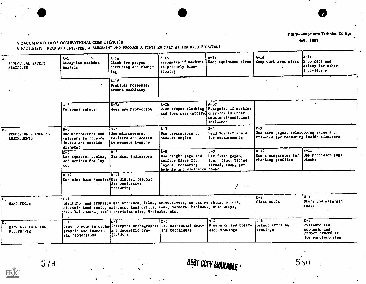
A DACUM MATRIX OF OCCUPATIONAL COMPETENCIES
A !.!ACH1NIST; READ AND INTERPRET A BLUEPRINT AND.PRODUCE A FIN1SHZD PART AS PER SPECIFICATIONS
Hwy. Seorgitown Technical College
HAY, 1983
A.
INDIVIDUAL SAFETYPRACTICES
A-1Recognize machinehazards
A-laCheck foi properfixturing and clamp-ing
A-lb A-lcRecognize if machine Keep equipment cleanis properly func-tioning
A-1dKeep work area clean
A-loShow care andsafety for otherindividuals
A-lfProhibit horseplayaround machinery
A-2
Personal safetyA -2 a
Wear eye protection
PRECISION MEASURINGINSTRUMENTS
HAND TOJLS
8-1
Use micrometers andcalipers to measureinside and outsidediameter
6 -2
Use micrometers,calipers and scalesto measure lengths
8-6Use squares, scales,and scribes for lay-out
8-7
Use dial indicators
B-12
Use sine bars (angles)8-13
Use digital readoutfor productivemeasuring
11A-2b A-3c .
Wear peoper clothingand foot wear (attire)
Recognize if machineOperator is underemotional/medicinalinfluence
8-3 P-4 2-5
Use protractors tomeasure angles
Read vernier scalefor measurements
Use bore gages, telescoping gages andtri-mica for measuring inside diamaters
B-8 9 B-10 H-11
Use height gage andsurface place forlayout, measuringhei hts and dimension
Use fixed gages,i.e., plug, radiusthread, snap, go-no- o
Use a comparator forchecking profiles
Use precision gageblocks
C-1
Identify and properly use wrenches, files, screwdrivers, center punching, pliers,electric hand tools, grinders, hand drills, sawn, hammers, hacksaws, vise grips,parallel clamps, small precision vise, V-blocks, etc.
DRAW AND INTERPRETBLUEPRINTS
D-1
Draw objects in orthographic and isomet-ric projections
0-2
Interpret orthographicand isometric pro-jections
D-3Use mechanical draw-ing techniques
1C-2 C-3
Clean tools Store and maintaintools
u-4
Dimension and taiga-anco drawings
579
1
BET CCPY AVAILABLE
D -S
Detect error ondrawings
0-6
Evaluate theeconomic andproper procedurefor manufacturing
5 )
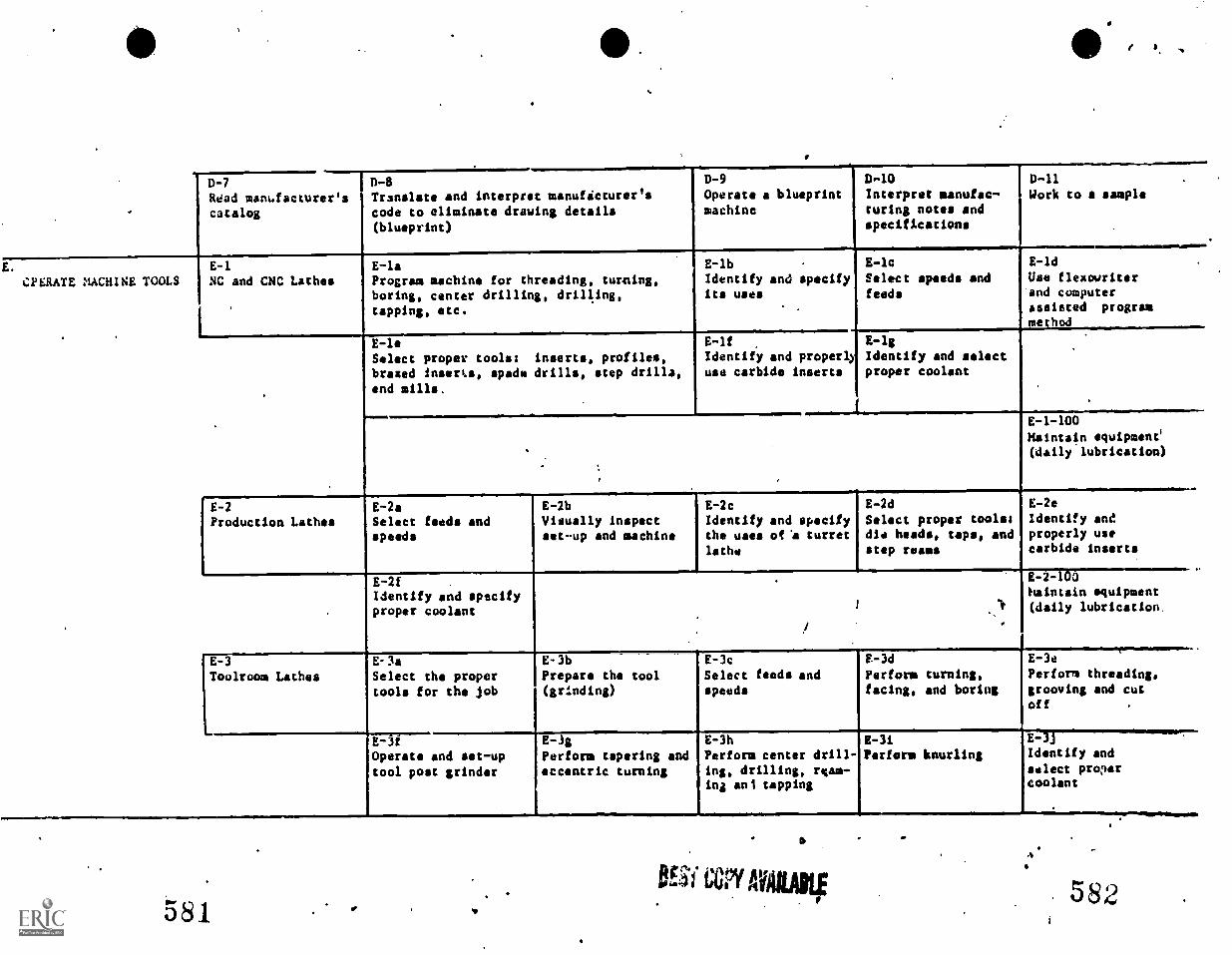
I.
D-7
Read manfacturer'scatalog
I n-sTranslate and interpret manufacturer'scode to eliminate drawing details(blueprint)
D-9Operate a blueprintmachine
D.-10 D-11Interpret aanufac- Work to a samplecuring notes andspecifications
CPERATE MACHINE TOOLSE-1NC and CNC Lathes
E-laProgram machine for threading, turning,boring, center drilling, drilling,tapping, etc.
E-lbIdentify and specifyits uses
E-lcSelect speeds andfeeds
E -ld
Use flexowriterand computerassisted programme hod
E-leSelect proper tools: inserts, profiles,brazed inserts, spade drills, step drilla,end mills,
E-1fIdentify and properlyuse carbide inserts
I
E-12Identify and selectproper coolant
E-1-100Maintain equipment'(daily lubrication)
E-2
Production LathesE-2aSelect feeds andspeeds
E-2bVisually Inspectset-up and machine
E-2c
Identify and specifythe uaes of'a turretlathe
E-2d
Select proper tools:die heads, taps, andstep reams
E-2eIdentify andproperly usecarbide inserts
5-2fIdentify and specifyproper coolant
5-2- '0Maintain equipment(daily lubrication.
Toolroom LathesE- 3a
Select the propertools for the job
E -3f
Operate and set-uptool post grinder
E-3bPrepare the tool(grinding)
E-3c
Select feeds andspeeds
F-3d
Perform turning,facing, and boring
E-3e
Perform threading,grooving and cutoff
E-!gPerform tapering andeccentric turning
E-3hPerform center drill-ing, drilling, ream-ing ant tapping
581
a
0,ESI MILAN
E-3/Perform knurling
4.1
E-1JIdentify and
select proercoolant
582
ANINIMPIN
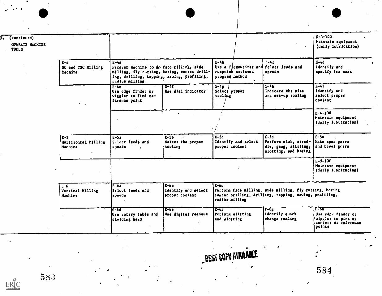
j
(continued)
OPERATE MACHINE. TOOLS
E-4 E-4a
NC and CNC Milling Program machine to do face m11114, sideMachine milling, fly cutting, boring, center drill-
ing, drilling, tapping, sawing, profiling,radius milling
E -4 b
Use a f exowriter andcompute assistedprogra Aathod
E-3-100Maintain equipment(daily lutrication)
E-4eUse edge finder orwiggler to find re-ference point
E -4t
Use dial indicatorE 4g
Seisetool
E-4a
Select feeds andspeeds
E-4d
Identify andspecify its uses
proper Indicate the viseand set-up tooling
E-4iIdentify andselect propercoolant
E-4-100Maintain eqipment(daily lubrication)
E -5 E-5aHortizontal Milling Select feeds andMachine speeds
E -Sb
Select the propertooling
E-5c E-5d E-5e .
Identify and select Perform slab, strad- Make spur gearsproper coolant' die, gang, slitting, and bevel scars
slotting, and boring
E-5-10PMaintain equipment(daily lubrication)
E-6Vertical MillingMachine
E-6aSelect feeds andspeeds
E-6b
Identify and selectproper coolant
E-Use rotary table and
dividing head
Use digital readout
E-6cPerform face milling, side milling, fly cutting, boringcenter drilling, drilling, tapping, sawing, profiling,radius milling
-E-6r
Perform slitting
and slotting
583
,BESI covidatio
EI:legilitify quick
change tooling
p
rz6b
Use edge finder orwiggler to pick upcenters or referencepoints
584
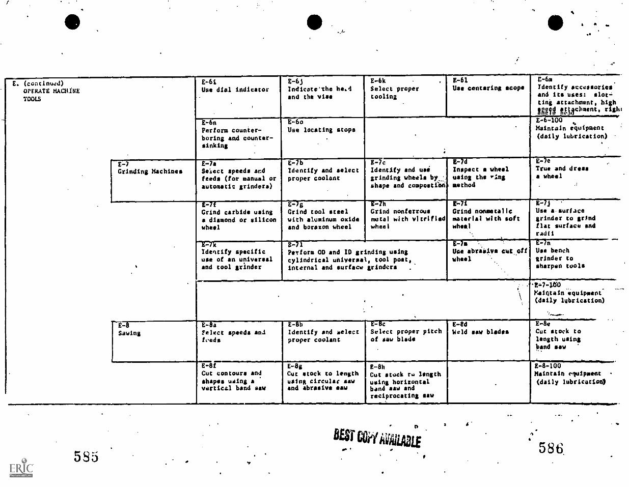
S *
(continued)OPERATE MACHINETOOLS
E-6iUse dial indicator
E-6jIndicate the healand the vise
E-6kSelect propertooling
E-61Use centering scope
C-6mIdentify accessoriesand its uses: slot
ting attachment, highfuig faischment, risk,
E-6n
Perform counter-boring and counter-sinking
E-6oUse locating stops
E-6-100Maintain equipment(daily lubrication)
E-7Grinding Machines
E-7aSelect speeds andfeeds (for manual orautomatic grinders)
E-7bIdentify and selectproper coolant
E-7cIdentify and usegrinding wheels by_.shape and composabO
E-7dInspect a wheelusing the 'Pins
method
E-70True and dressa wheel
E -8
Sawing
E-7fGrind carbide usinga diamond or siliconwheel
E-7kIdentify specificuse of an universaland tool grinder
E-7gGrind tool steelwith aluminum oxideand borazon wheel
E-Itt
Grind nonferrousmetal with vitrifiedwheel
Grind noometalicmaterial with softwheel
E-7j '
Use a. surfacegrinder to grindflat surface andradii
E-71Perform OD and ID grinding usingcylindrical universal, tool post,internal and surface grinders
E-7Uae abralve cwt offwheel
E-7n
Use benchgrinder tosharpen tools
1 E-8aFelect speeds an.!fveds
E-8bIdentify and selectproper coolant
- cSelect proper pitchof saw blade
Xalqtain equipment(daily lubrication)
E -8d
Weld saw blades
E-8fCut contours andshapes using avertical band saw
E-8gCut stock to lengthusing circular sawand abrasive saw
E-8hCut stock to lengthusing horizontalband saw andreciprocating saw
E-8-100Maintain equipment
(daily lubrication)
BESTCl/535
1 A
E-8e
Cut stock tolength usingband saw
5 8 CI'
NIMININNW
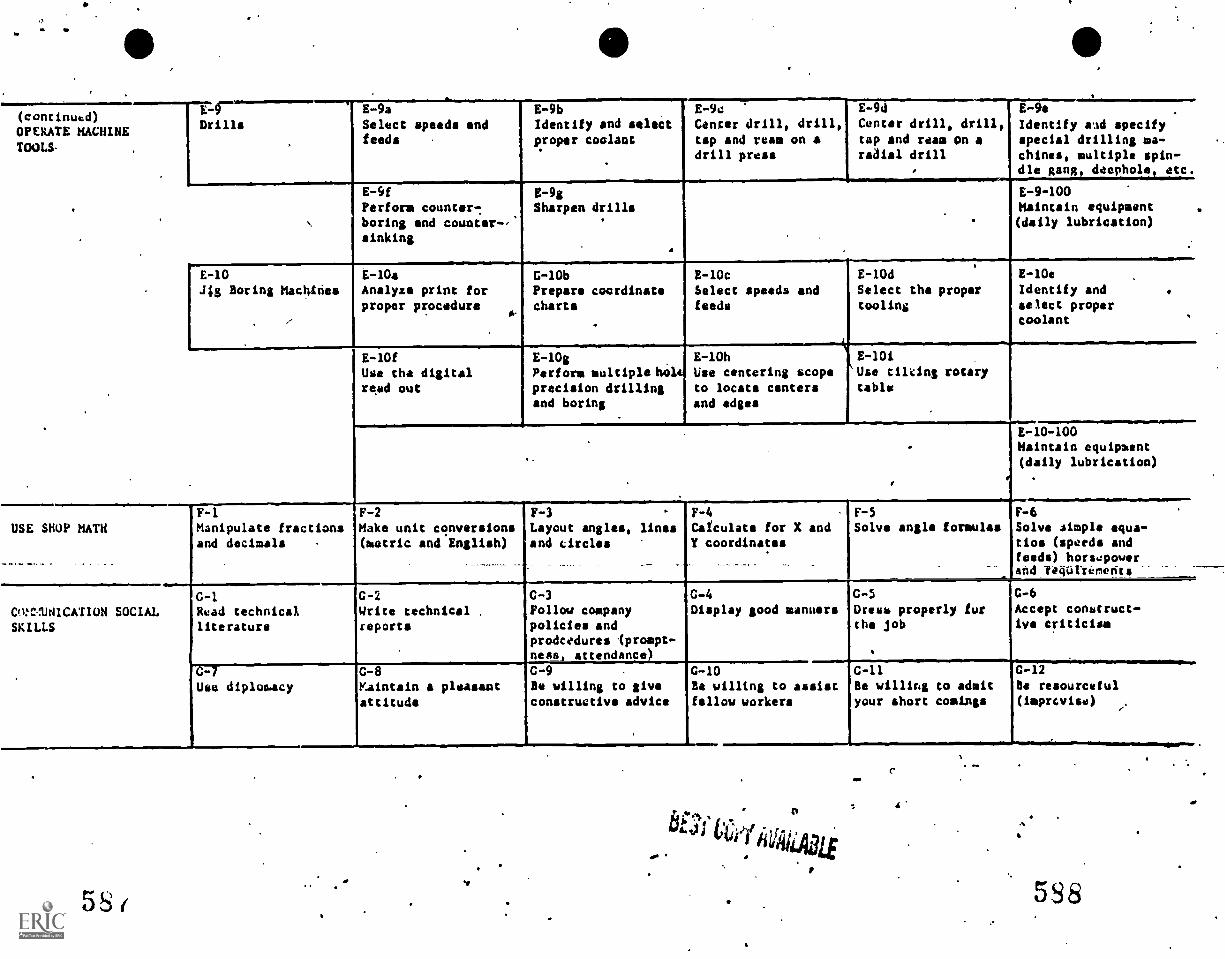
(continued)
OPERATE MACHINETOOLS-
DrillsE-9aSelect speeds andfeeds
E-9bIdentify and selectproper coolant
E-9cCenter drill, drilltsp and ream on adrill press
E-9d
Center drill, drill,tap and ream on aradial drill
E-9f
Perform counter-.
boring and counter-,sinking
E-9gSharpen drills
E-9e
Identify ad specifyspecial drilling ma-chines, multiple spin-dle gang, &whole, etc.
E-9-100Maintain equipment(daily lubrication)
E-10.4g Boring Machtnes
E-10aAnalyse print forproper procedure
E-10fUse the digitalread out
G-10bPrepare coordinatecharts
E-10cSelect speeds andfeeds
E-10dSelect the propertooling
E-10eIdentify andselect propercoolant
E-10gPerform multiple Wiltprecision drillingand boring
E-10hUse centering scopeto locate centersand edges
iE-10iUse tilting rotarytable
E-10-100Maintain equipment(daily lubrication)
USE SHOP MATHF-1Manipulate fractionsand decimals
F-2Hake unit conversions(metric and English)
F-3Layout angles, linesand circles
F-4
Calculate for X andY coordinates
F-5
Solve angle formulasF-6Solve simple equa-tios (speeds andfeeds) horsepowerand TKOttEments
Cii:-:-..UHICATION SOCIAL
SKILLS
G-1Read technicalliterature
C -2
Write technical .
reports
C -3
Follow companypolicies andprodcedures (prompt-ness attendance)
C -4
Display good mannersG-5Dress properly furthe job
G-6Accept construct-ive criticism
Use diplomacyG-8Maintain a pleasantattitude
C -9
As willing to giveconstructive advice
G-10Be willing to assistfellow workers
C-11Be willing to admityour short comings
C-12Be resourceful(imprcvise)
ti
58(
*PM
A
5S8
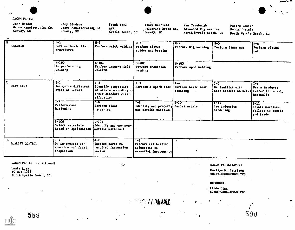
DACUM PANEL:
John W:rdeeGrove Manufacturing Co.Cunway, SC
P 01.
Joey Bledsoe Frank Pate Timmy Barfield Ken Tevebaugh Pobert DamianGrove Manufacturing Co. AVX Wolverine Brass Co. Advanced Engineering Radcar MetalsConway, SC Eyrclo Beach, SC 'Conway, SC North Myrtle Beach, SC North Myrtle Beach, SC
H.
WELDING
.
H-1
Perform basic flatprocedures
H-2
Perform stick weldingH-3
Perform silversolder and brazing
H-4
Perform wig weldingH-5
Perform flame cutH-6
Perform plasmacut
H-100To perform tigwelding
H-101Perform inter-shieldwelding
H-402Perform inductionwelding
U-103Perform spot welding
.
I.
METALLURYI-1
Recognize differenttypes of metals
1-2
Identify propertiesof metals according t.their standard clas-,sification
1-3
Perform a spark test1-4
Perform basic beattreating
1-5Be familiar withheat affects on metal
I-12
Use a hardnesstester (Brindell,Rockwell)
I-7Perform casehardening
1-8Perform flamehardening
1-9Identify and properlyuse carbide material
1-I0
Anneal metals
_.
I-IIUse inductionhardening
I-12.
Relate machine-ability to speedsand feeds
1-100
Select msterialsbased on application
I-101Identify and use non -metalic materials
-- .
J.QUALITY OONTROL
J-1
Do in-process in-spection and finalinspection
J-2
Inspect parts torequired inspectionlevels
J-3Perform calibrationadjustment tomeasuring instruments
.
!
DACUM PANEL: (continued)
Louis RossiPO Bir 1039North.Myrtle Beach, SC
5S9
DACUM FACILITATOR:
Marilyn M. HarrisonNORRY -GEORGETOWN TEC
RECORDER:
Linda LinnHORRY-GEORGETOWN TEC
590
Reference 2 DACUM Matrix for NC Operator, Greenville SC
540
041
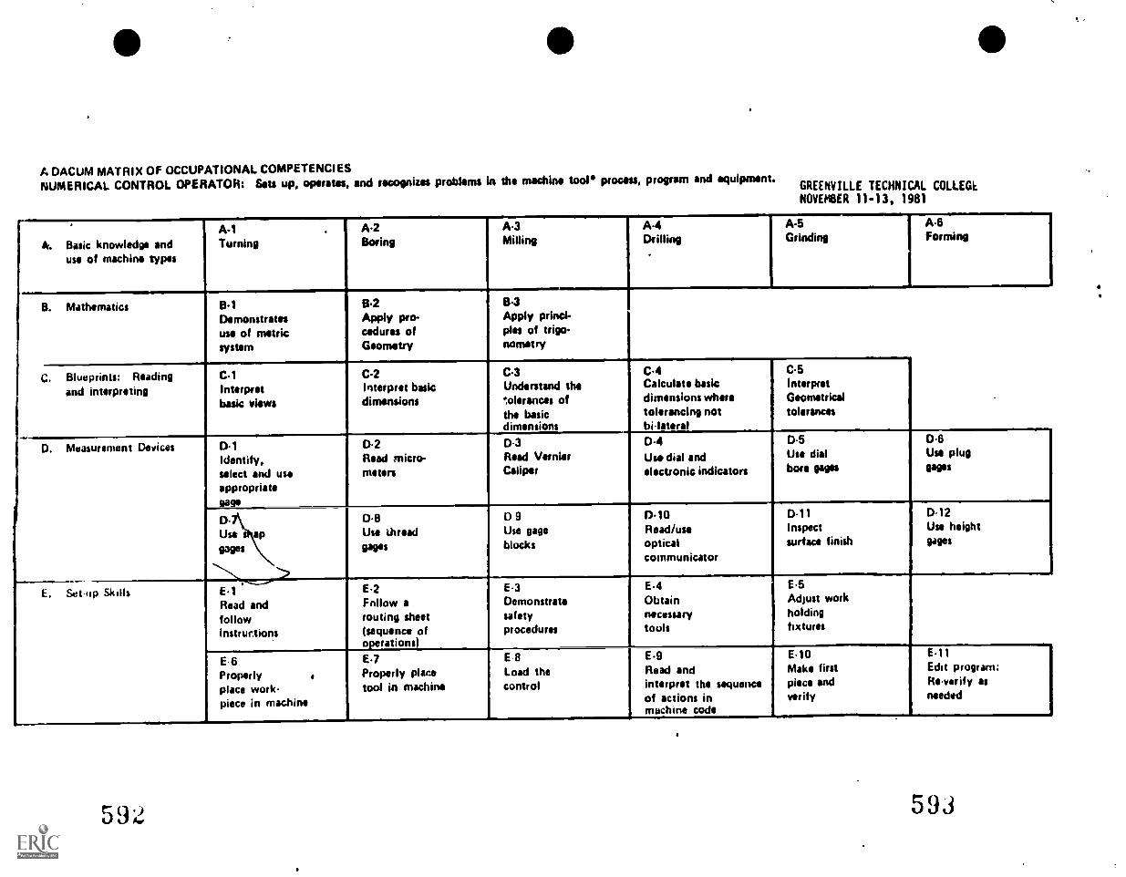
A DACUM MATRIX OF OCCUPATIONAL COMPETENCIESNUMERICAL CONTROL OPERATOR: Sets up, operates, and recognizes problems in the machine tool process, program and equipment.
GREENVILLE TECHNICAL COLLEGENOVEMBER 11-13, 1981
A. Basic knowledge anduse of machine types
A-1Turning
. A2Boring
A.3Milling
A4Drilling
A5Grinding
A.6Forming
B. Mathematics 6.1Demonstratesuse of metricsystem
84Apply Pmcedures ofGeometry
B3Apply princi.,pies of trig!).nometry
.
C. Blueprints: Readingand interpreting
C-1Interpretbasic views
C2Interpret basicdimensions
C3Understand the',tolerances ofthe basicdimensions
C.4Calculate basicdimensions wheretolerancing notbilateral
C5InterpretGeometricaltolerances
0. Measurement Devices 0.1Identify,select and useappropriate
0.2Reed micro-meters
0.3Read VernierCaliper
D-4Use dial andelectronic indicators
D.5Use dialbore gages
D.6Use plugPPS
Use apgages
0.8Use thread
111911s
D 9Use gageblocks
0.10Read/useopticalcommunicator
0.11Inspectsurface finish
0.12Use heightgages
E. Setup Skills E.1Read andfollowinstrur.tions
E.2Follow arouting sheet(sequence ofoperations)
E3Demonstratesafetyprocedures
E.4Obtainnecessarytools
E.5Adjust workholdingfixtures
E 6Properlyplace work-piece in machine
E.7Properly placetool in machine
E 8Load thecontrol
E9Read andinterpret the sequenceof actions inmachine code
E.10Make firstpiece andverify
E.11Edit program:Re.ver if y asneeded
e- .)J A.593
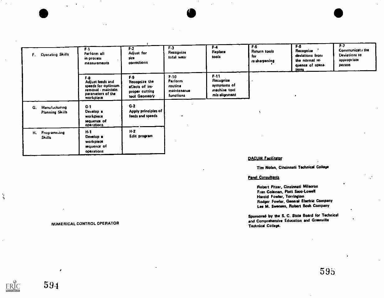
F. Operating SkillsF1Perform alliprocessmeasurements
F2Adjust forsize
corrections
F3Recognizetotal wear
F4Replacetools
F6Return toolsforresharpening
F-8Recognize 'deviations fromthe normal se-quince of opera-Lions
F-7Communical J theDeviations toappropriateperson
F8Adjust feeds andspeeds for optimumremoval .. maintainparameters of theworkpiees
F9Recognize theef:ects of improper cuttingtool Geometry
F10Performroutinemaintenancefunctions
F11Recognizesymptoms ofmachine toolmisalignment .
G. ManufacturingPlanning Skills
G1Develop aworkpitcesequence ofoperations
G2Apply principles offeeds and speeds
.
H. Programn.ingSkills
H1Develop aworkpiecesequence ofoperations
HIEdit program
NUMERICAL CONTROL OPERATOR
591
pAcuPA Facilitator
Tim Nolan, Cincinnati Technical College
Panel ConsuIjI
Robert Pius,. Cincinnati MilacronFran Coleman, Platt Saco oyallHarold Fowler, TorringtonRodger Fowler, Genera/ Electric CompanyLea M. Swertsen, Robert Bosh Company
Sponsored by the S. C. State Board for Technical
and Comprehensive Education and GreenvilleTechnical College.
595
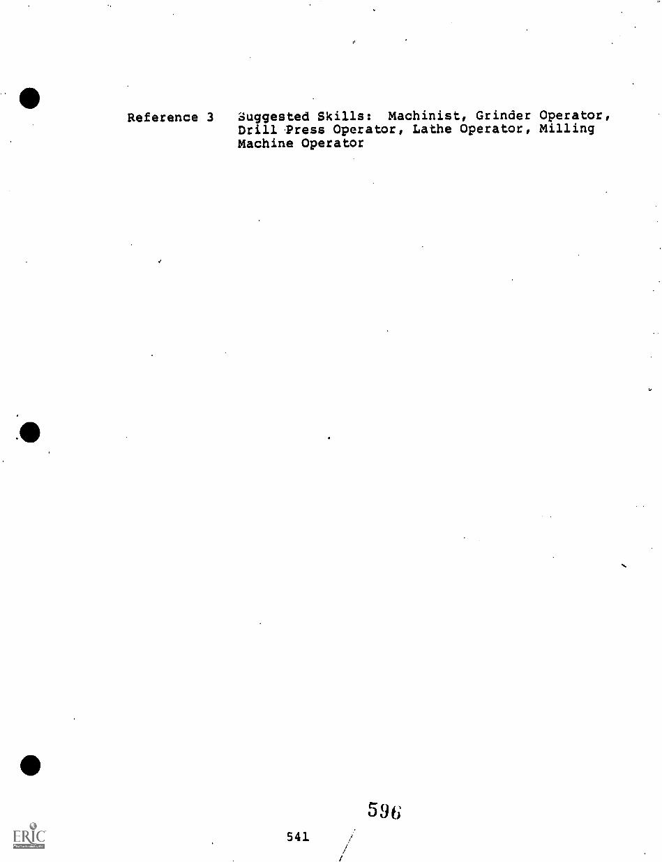
Reference 3
e
Suggested Skills: Machinist, Grinder Operator,Drill 'Press Operator, Lathe Operator, MillingMachine Operator
541
596
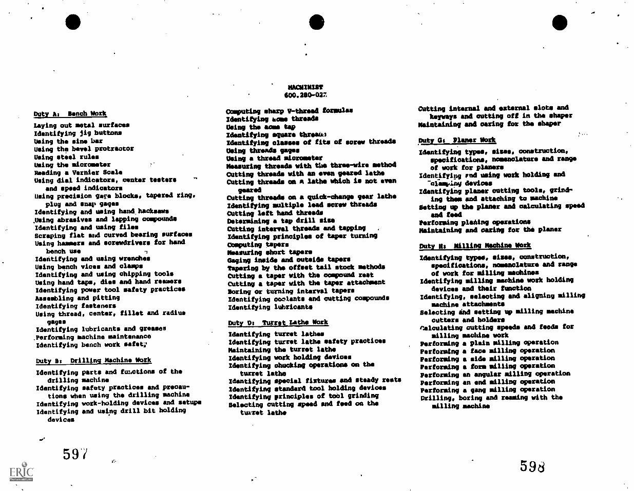
Duty As Bench Mork
Laying out metal surfacesIdentifying jig buttons
Using the sine barUsing the bevel protractorUsing steel rulesUsing the micrometerReading a Vernier ScaleUsing dial indicators, center testers
and speed indicatorsUsing precision gaga blocks, tapered ring,
plug and snap gagesIdentifying and using hand. hacksawsAwing abrasives and lapping compoundsIdentifying and using filesScraping flat and curved bearing surfacesUsing hammers and screwdrivers for hand
bench useIdentifying and using wrenchesUsing bench vices and clampsIdentifying and using chipping toolsUsing hand taps, dies and hand reamersIdentifying power tool safety practicesAssembling and pittingIdentifying fastenersUsing thread, center, fillet and radius
gagesIdentifying lubricants and greases.performing machine maintenanceIdentifying bench work safety
Duty Is Drilling Machine Mork
Identifying parts and fimotions of thedrilling machine
Identifying safety practices and precau-tions when using the drilling machine
Identifying work-holding devices and setupsIdentifying and using drill bit holding
devices
59
MACIUM1Sf600.280-027
Computing sharp 1r-thread formulasIdentifying acme threadsUsing the acme tapIdentifying square throeW3Identifying classes of fits of screw threads
Using threads gagesUsing a thread micrometerMeasuring threads with the three-wire methodCutting threads with an even geared latheCutting threads on n laths which is not even
gearedCutting threads on a quick - change gear latheIdentifying multiple lead screw threadsCutting left hand threadsDetermining a tap drill missCutting interval threads and tapping .
Identifying principles of taper turningComputing tapersMeasuring short tapersGaging inside and outside tapersTapering by the offset tail stock methodsCutting a taper with the compound restCutting a taper with the taper attachmentBoring or turning interval tapersIdentifying coolants and cutting compounds
Identifying lubricants
Duty Os Turret Lathe Work
Identifying turret lathesIdentifying turret lathe safety practicesMaintaining the turret latheIdentifying work holding devicesIdentifying chunking operations on the
turret latheIdentifying special fixtures and steady restsIdentifying standard tool holding devicesIdentifying principles of tool grindingSelecting cutting speed and food on the
turret lathe
Cutting internal and external slots andkeyways and cutting off in the shaper
Maintaining and oaring for the shaper
Duty at Planer Mork
Identifying types, sires, construction,specifications, nomenclature and range
of work for planersIdentifying rod using work holding and
"ofiskIng devicesIdentifying planer cutting tools, grind-
ing them and attaching to machineSetting up the planer and calculating speed
and feedPerforming planing operationsMaintaining and caring for the planer
Duty Ms Milling Machine Mork
Identifying types, minas, construction,specifications, nomenclature and range
of work for milling machinesIdentifying milling machine work holding
devices and their functionIdentifying, selecting and aligning milling
machine attachmentsSelecting it'd setting up milling machine
cutters and holdersflalculating cutting speeds and feeds for
milling machine workPerforming a plain milling operationPerforming a face milling operationPerforming a side milling operationPerforming a form milling operationPerforming an angular milling operationPerforming an end milling operationPerforming a gang milling operationDrilling, boring and reaming with the
milling machine
598
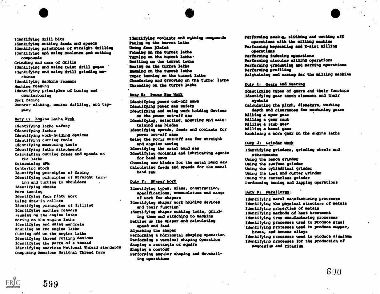
Identifying drill bitsIdentifying cutting feeds and speedsIdentifying principles of straight drillingIdentifying and using coolants and cutting
compoundsGrinding and care of drills'Identifying and using twist drill gagesIdentifying and using drill grinding ma-
chinesIdentifying machine reamersMachine reamingIdentifying principles of boring and
counterboringSpot facingCounter sinking, center drilling, and tap-
ping
Duty Cs Engine Lathe Work
Identifying lathe safety'Identifying lathesIdentifying work-holding devicesIdentifying cutting toolsIdentifying measuring toolsIdentifying lathe attachmentsCalculating cutting feeds and speeds on
the latheDetermining HPNCentering stockIdentifying principles of facingIdentifying principles of straight turn-
ing and turning to shouldersIdentifying checksForm turningIdentifying face plate workUsing draw-in colletsIdentifying principles of drillingIdentifying machine reamersReaming on the engine latheBoring on the engine latheIdentifying and using mandrelsKnurling on the engine latheCutting off on the engine latheIdentifying thread cutting devicesIdentifying the parts of a threadIdentifying American National Thread standardsComputing American National Thread form
599
Identifying coolants and cutting ooppoundsPacing on the turret latheUsing face platesForming on the turret latheTurning on the turret lathe.Drilling on i,:he turret lathe
*boxing on the turret latheMiming on the turret latheTaper turning on the turret latheChamfering and grooving on the turret latheThreading on the turret lathe
Duty is Power Saw Work,
Identifying power cut-off sawsIdentifying power saw safetyIdentifying and using work holding devices
on thm power cut-off sawIdentifying, selecting, mounting and main-
taining saw bladesIdentifying speeds, feeds and coolants for
power out-off sawsUsing the pore cut-off saw for straight
and angular sawingIdentifying the metal band sawIdentifying coolants and lubricating moats
for band sawsChoosing saw blades for the metal band sawCalculating feeds apd speeds for the metal
band saw
Duty Ps Shaper work
Identifying types, sizes, construction,specifications, nomenclature and rangeof work for shapers
Identifying shaper work holding devicesand their function'
Identifying shaper cutting tools, grind-,ing than' and attaching to machine
Setting up the shaperand calculatingspeed and feed
Adjusting the shaperPerforming a horizontal shaping operationPerforming a vertical shaping operationShaping a rectangle or squareShaping a contourPerforming angular shaping and dovetail-
ing operations
Performing sawing, slitting and cutting oftoperations with the milling machine
Postai:ming keynating and T-elot millingoperations
Performing indexing operationsPerforming circular milling operationsPerforming graduating and masking operationsPerforming profilingMaintaining and oaring for the milling machine
Duty I s Gears and Gaud gIdentifying types of gears and their functionIdentifying gear tooth elements and their
symbolsCalculating the pitch, diameters, working
depth and clearanoss for machining gearsMilling a spur gearMilling a gear rackMilling a stub gearMilling a bevel gearMachining a worm gear on the engine lathe
Duty Is Grinder Work
Identifying grinders, grinding wheels and
attachmentsUsing the bench grinderUsing the surface grinderUsing the cylindrical gelatineUsing the tool and cutter grinderUsing the centerline grinderPerforming honing and lapping operations
Duty Ks Metallurgy:
IdentifyingimetaX manufacturing processesIdentifying the physical structure of metalsIdentifying properties of metalsIdentifying methods of heat treatmentIdentifying iron manufacturing processesIdentifying processes used to produce steel'Identifying processes used to produce copper,
brass. and bronze alloysIdentifying processes used to produce aluminumIdentifying processes for the production of
magnesium and titanium
600
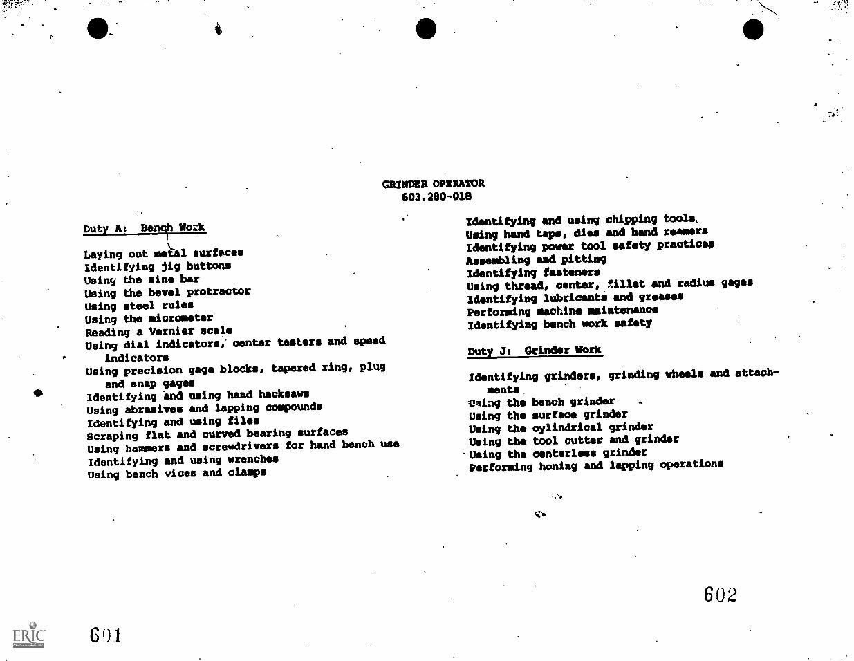
OW"
4
GRINDER OPERATOR603.280-018
Duty As Benc\h Work
Laying out mekal surfacesIdentifying jig buttonsUsing the sine barUsing the bevel protractorUsing steel rulesUsing the micrometerReading a Vernier scaleUsing dial indicators,' center testers and speed
indicatorsUsing precision gage blocks, tapered ring, plug
and snap gagesIdentifying and using hand hacksaws
Using abrasives and lapping compounds
Identifying and using filesScraping flat and curved bearing surfaces
Using hammers and screwdrivers for hand bench use
Identifying and using wrenchesUsing bench vices and clamps
601
Identifying and using chipping tools,
Using hand taps, dies and hand reamers
Identifying power tool safety practice,
Assembling and pittingIdentifying fastenersUsing thread, center, fillet and radius gages
Identifying lubricants and greases
Performing machine maintenanceIdentifying bench work safety
Duty Is Grinder Mork
Identifying grinders, grinding wheels and attach-
mentsOiling the bench grinder .
Using the surface grinderUsing the cylindrical grinderUsing the tool cutter and grinder
Using the centerless grinderPerforming honing and lapping operations
Tio
602
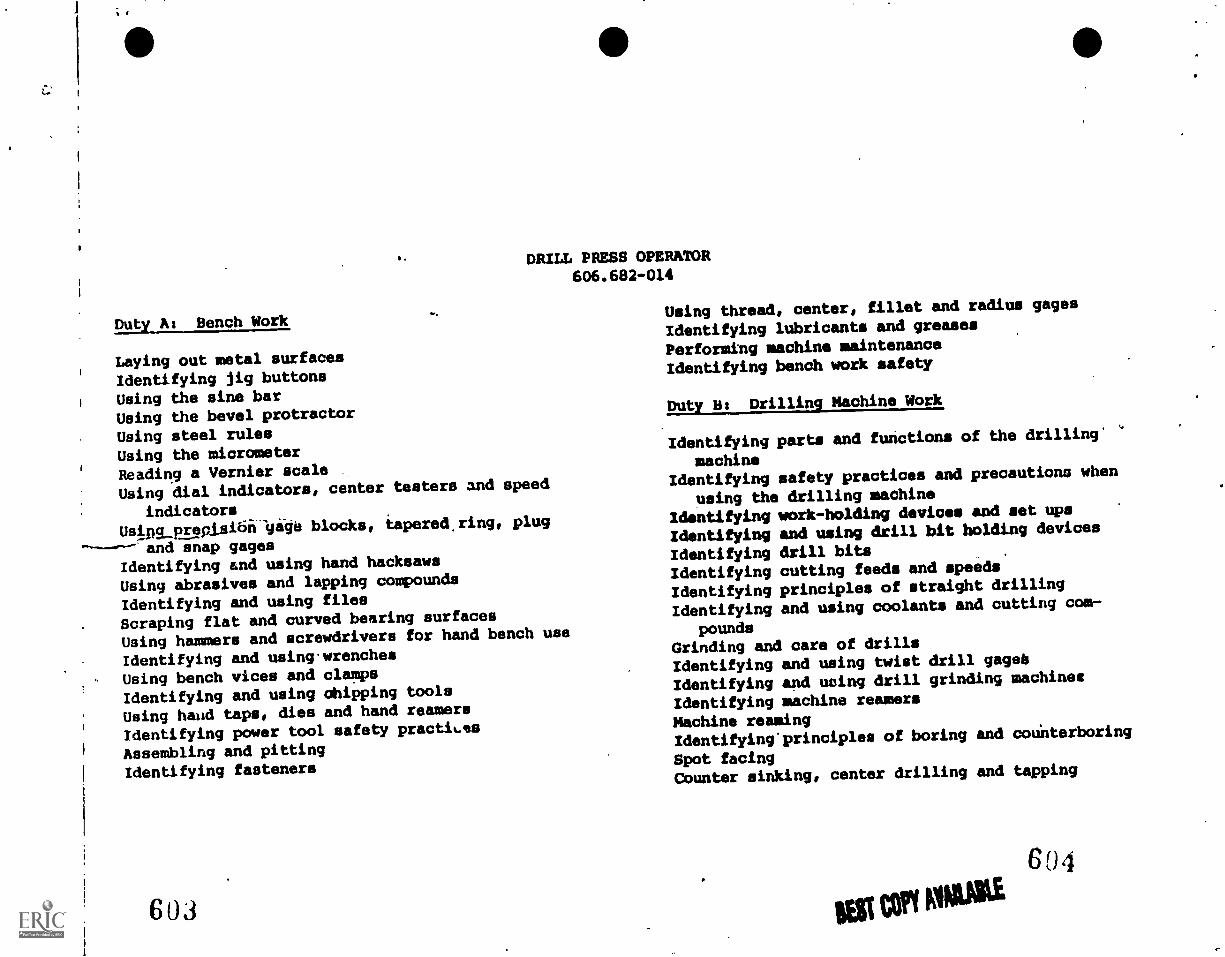
DRILL PRESS OPERATOR606.682-014
Duty A: Bench Work
Laying out metal surfacesIdentifying jig buttonsUsing the sine barUsing the bevel protractorUsing steel rulesUsing the micrometerReading a Vernier scaleUsing dial indicators, center testers and speed
indicatorsUsipg_prepisi61-443 blocks, tapered, ring, plug
and snap gagesIdentifying and using hand hacksaws
Using abrasives and lapping compounds
Identifying and using filesScraping flat and curved bearing surfaces
Using hammers and screwdrivers for hand bench use
Identifying and using-wrenchesUsing bench vices and clamps
Identifying and using chipping tools
Using hand taps, dies and hand reamers
Identifying power tool safety practices
Assembling and pittingIdentifying fasteners
Using thread, center, fillet and radius gages
Identifying lubricants and greases
Performing machine maintenanceIdentifying bench work safety
Duty Bs Drilling Machine Work
Identifying parts and functions of the drilling'
machineIdentifying safety practices and precautions when
using the drilling machine
Identifying work-holding devices and set ups
Identifying and using drill bit holding devices
Identifying drill bitsIdentifying cutting feeds and speeds
Identifying principles of straight drilling
Identifying and using coolants and cutting com-
poundsGrinding and care of drills
Identifying and using twist drill gageb
Identifying and using drill grinding machines
Identifying machine reamers
Machine reamingIdentifying' principles of boring and counterboring
Spot facingCounter sinking, center drilling and tapping
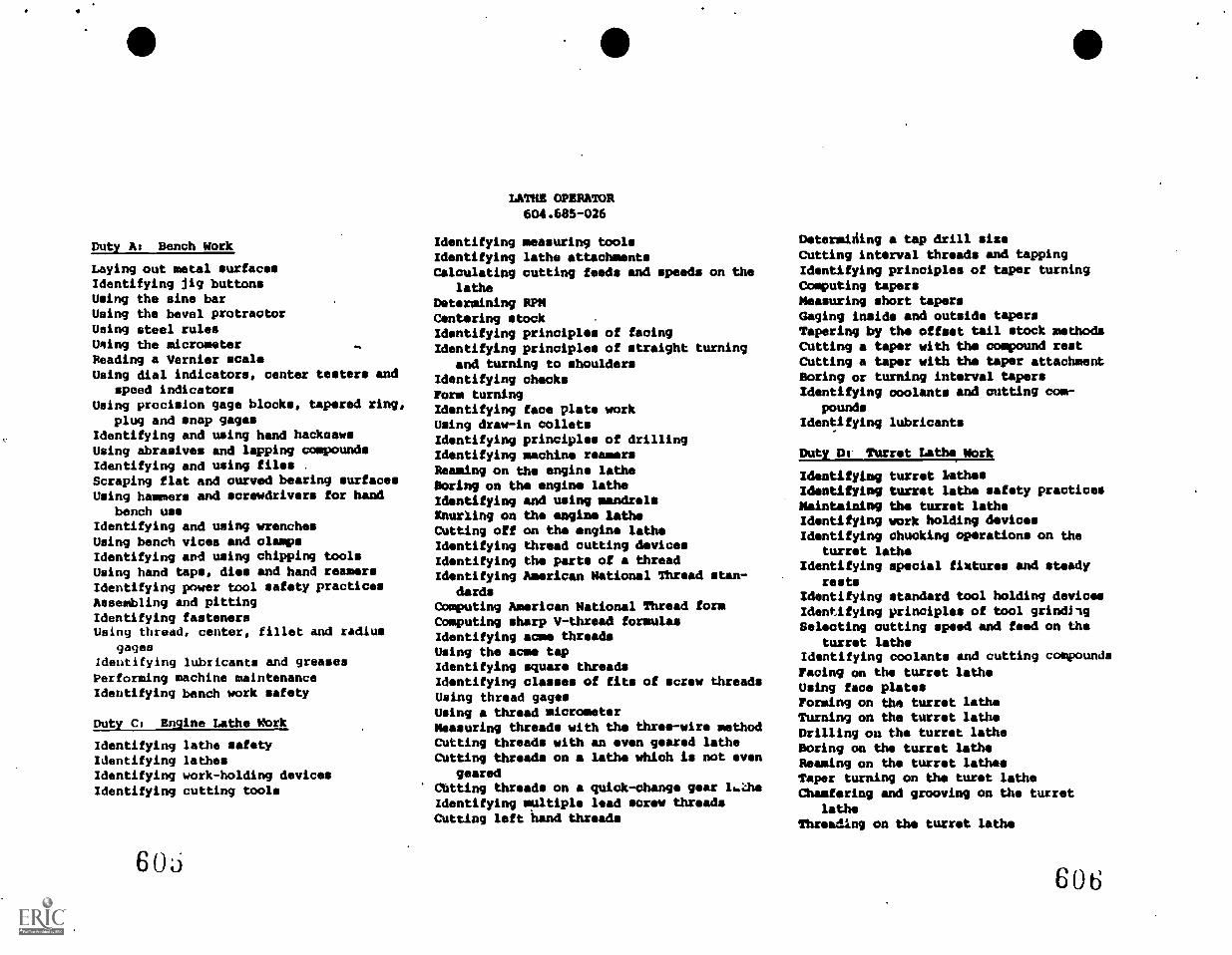
Duty A: Bench Work
Laying out metal surfacesIdentifying jig buttonsUsing the sine barUsing the bevel protractorUsing steel rulesWang the micrometerReading a Vernier scaleUsing dial indicators, center testers and
speed indicatorsUsing precision gage blocks, tapered ring,
plug and snap gagesIdentifying and using hand hacksawsUsing abrasives and lapping compoundsIdentifying and using files .
Scraping flat and curved bearing surfacesUsing hammers and screwdrivers for hand
bench useIdentifying and using wrenchesUsing bench vices and clampsIdentifying and using chipping toolsUsing hand taps, dies and hand reamersIdentifying power tool safety practicesAssembling and pittingIdentifying fastenersUsing thread, center, fillet and radius
gagesIdentifying lubricants and greasesPerforming machine maintenanceIdentifying bench work safety
Duty C: Engine Lathe Work
Identifying lathe safetyIdentifying lathesIdentifying work-holding devicesIdentifying cutting tools
60o
LATHE OPERATOR604.685-026
Identifying measuring toolsIdentifying lathe attachmentsCalculating cutting feeds and speeds on the
latheDetermining RPMCentering stockIdentifying principles of facingIdentifying principles of straight turning
and turning to shouldersIdentifying checksForm turningIdentifying face plate workUsing draw-in colletsIdentifying principles of drillingIdentifying machine reamersReaming on the engine latheBoring on the engine latheIdentifying and using mandrelsInurling on the engine latheCutting off on the engine latheIdentifying thread cutting devicesIdentifying the parts of a threadIdentifying American National Thread stan-
dardsComputing American National Thread formComputing sharp V-thread formulasIdentifying acme threadsUsing the acme tapIdentifying square threadsIdentifying classes of fits of screw threadsUsing thread gagesUsing a thread micrometerMeasuring threads with the three-wire methodCutting threads with an even geared latheCutting threads on a lathe which is not even
gearedChtting threads on a quick-change gear 1...UutIdentifying multiple lead screw threadsCutting left hand threads
Detersitiing a tap drill sizeCutting interval threads and tappingIdentifying principles of taper turningComputing tapersMeasuring short tapersGaging inside and outside tapersTapering by the offset tail stock methodsCutting a taper with the compound restCutting a taper with the taper attachmentBoring or turning interval tapersIdentifying coolants and cutting com-
poundsIdentifying lubricants
Duty Du Turret Laths Work
Identifying turret lathesIdentifying turret lathe safety practicesMaintaining the turret latheIdentifying work holding devicesIdentifying chucking operations on the
turret latheIdentifying special fixtures and steady
restsIdentifying standard tool holding devicesIdentifying principles of tool grindilgSelecting cutting speed and feed on the
turret latheIdentifying coolants and cutting compoundsFacing on the turret latheUsing face platesForming on the turret latheTurning on the turret latheDrilling on the turret latheBoring on the turret latheReaming on the turret lathesTaper turning on the turet latheChamfering and grooving on the turret
latheThreading on the turret lathe
606
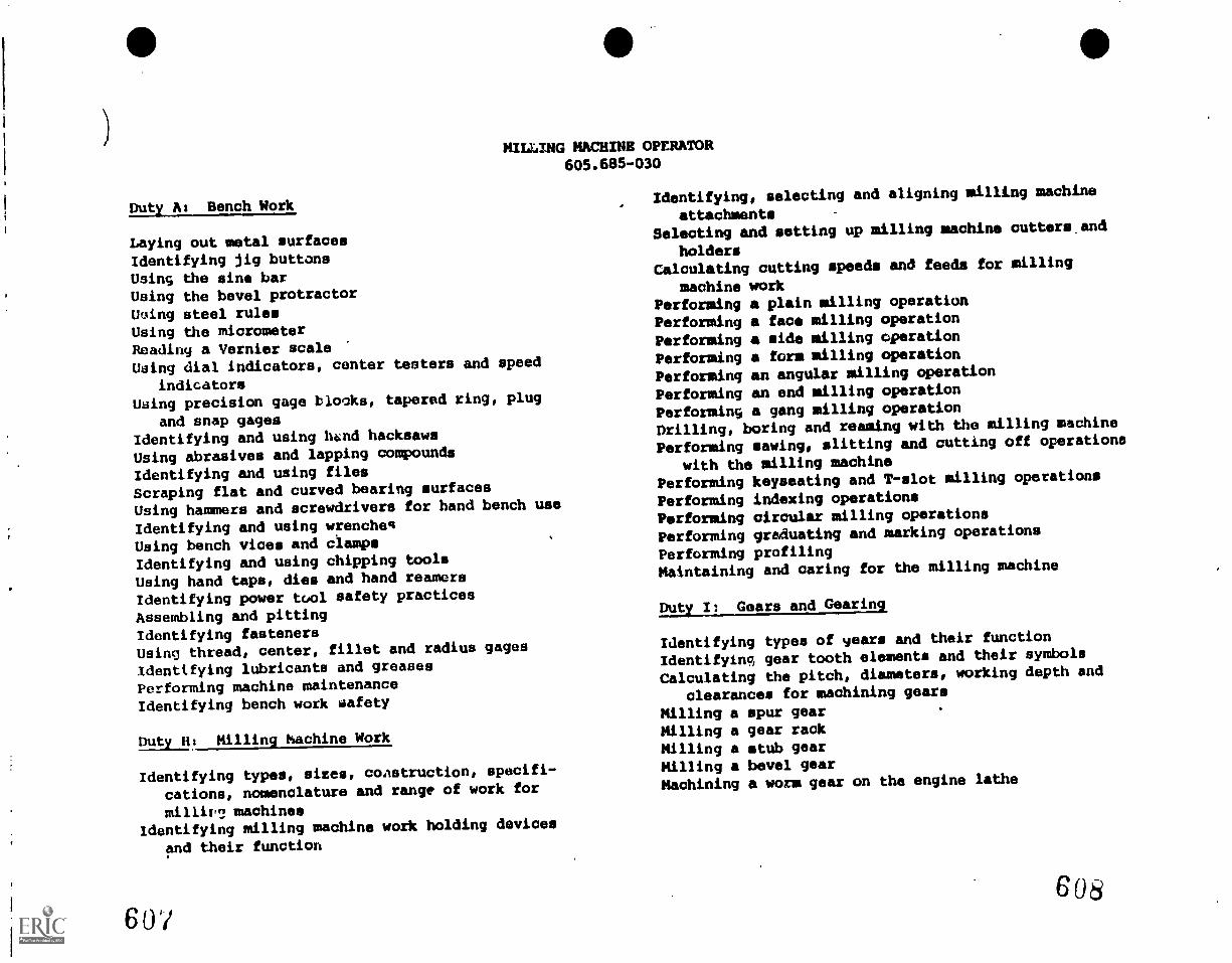
MILLING MACHINE OPERATOR605.685-030
Duty At Bench Work
Laying out metal surfacesIdentifying jig buttonsUsing the sine barUsing the bevel protractorUsing steel rulesUsing the micrometerReading a Vernier scaleUsing dial indicators, center testers and speed
indicatorsUsing precision gage blooks, tapered ring, plug
and snap gagesIdentifying and using bend hacksaws
Using abrasives and lapping compounds
Identifying and using filesScraping flat and curved bearing surfaces
Using hammers and screwdrivers for hand bench use
Identifying and using wrenchesUsing bench vices and clamp.Identifying and using chipping tools
Using hand taps, dies and hand reamersIdentifying power tool safety practices
Assembling and pittingIdentifying fastenersusing thread, center, fillet and radius gages
identifying lubricants and greases
Performing machine maintenanceIdentifying bench work safety
Duty H: Milling Machine Work
Identifying types, sires, construction, specifi-
cations, nomenclature and range of work for
milliv? machinesidentifying milling machine work holding devices
and their function
6 0'/
Identifying, selecting and aligning milling machine
attachmentsSelecting and setting up milling machine cutters and
holdersCalculating cutting speeds and feeds for milling
machine workPerforming a plain milling operationPerforming a face milling operationPerforming a side milling operationPerforming a form milling operationPerforming an angular milling operation
Performing en end milling operation
Performing a gang milling operation
Drilling, boring and reaming with the milling machine
Performing sawing, slitting and cutting off operations
with the milling machinePerforming keyseating and T-slot milling operations
Performing indexing operationsPerforming circular milling operations
Performing graduating and marking operations
Performing profilingMaintaining and caring for the milling machine
Euty.J1 Gears and Gearing
Identifying types of years and their function
Identifying, gear tooth elements and their symbols
Calculating the pitch, diameters, working depth and
clearances for machining gears
Milling a spur gearMilling a gear rackMilling a stub gearMilling a bevel gearMachining a worm gear on the engine lathe
608

Reference 4 Survey of Secondary Level Lab Facilities
542 6Wi
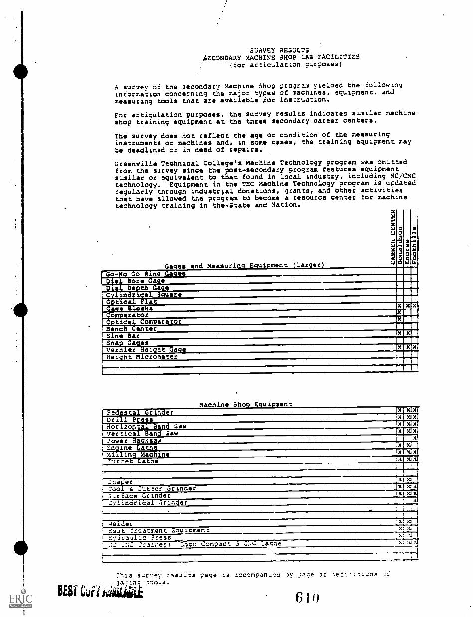
8E81 CCU
SURVEY RESULTSAECONDARY MACHINE SHOP LAB FACILITIES
(for articulatlon purposes)
A survey of the secondary Machine .hop program yielded the followinginformation concerning the major types of machines, equipment, and
measuring tools that are available .tor instruction.
For articulation purposes, the survey results indicates similar machineshop training equipment at the three secondary career centers.
The survey does not reflect the age or condition of the measuringinstruments or machines and, in some cases, the training equipment maybe deadlined or in need of repairs.
Greenville Technical College's Machine Technology program was omittedfrom the survey since the post-secondary program features equipmentsimilar or equivalent to that found in local industry, including NC/CNCtechnology. Equipment in the TEC Machine Technology program is updatedregularly through industrtal donations, grants, and other activitiesthat have allowed the program to become a resource center for machinetechnology training in the.State and Nation.
Gages and Measuring Equipment (larger)
=W
WeC.,
X:431
4:mc00u
00
13,..qRS
a
alCLO
14
aas
mMI
4.4"gdA44
c
Go-No Go Ring Gage!Dial Bore GageDial Depth Mtge ,
Cylind;ical SquareOptical FlatGage Blocks x x x
ComparatorOptical ComparatorBench CenterSine Bar x x
Snap Gages,
Vernier Height Gage x XiHeight Micrometer
...
Machine Shop EquipmentPedestal Grinder x x
Drill Press X . X
mi.xlx
Horizont I Band Saw x
ivertica San Saw x
Power Hacksawxrclei,at.zrl.i.r x
FAIIIIh4-Madhinex xix
Turret Latne x
xi---Th
':(
11.4.1-74.--C.7.-Zsrinder xi:1
x
xi i
IxSurface Grinder tx
''.:1-Incir-icl!xl binder
. .
. .
, .
welder .x xi
:seat :reatment z.auloment .4:x1
Hfarau -c Press V
::. ..:IC :rainer: :::= Comoact 3 .::::(.: Latne x: :Nix
1.
su:ey :salts page .a accompanied iy .;age .)f ieZL:.1-:L.;ns ;f
aqLng :Q0.3.
Ell)
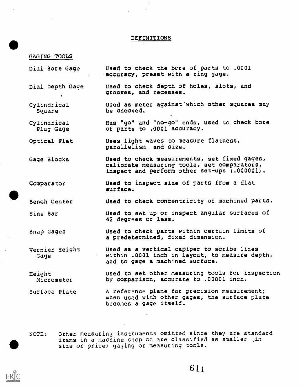
GAGING TOOLS
Dial Bore Gage
Dial Depth Gage
CylindricalSquare
CylindricalPlug Gage
Optical Flat
Gage Blocks
Comparator
Bench Center
Sine Bar
Snap Gages
Vernier HeightGage
HeightMicrometer
Surface Plate
DEFINITIONS
Used to check the bcre of parts to .0001accuracy, preset with a ring gage.
Used to check depth of holes, slots, andgrooves, and recesses.
Used as meter against'which other squares maybe checked.
Has "go" and "no-go" ends, used to check boreof parts to .0001 accuracy.
Uses light waves to measure flatness,parallelism. and size.
Used to check measurements, set fixed gages,calibrate measuring tools, set comparators,inspect and perform other set-ups (.000001).
Used to inspect size of parts from a flatsurface.
Used to check concentricity of machined parts.
Used to set up or inspect angular surfaces of45 degrees or less.
Used to check parts within certain limits ofa predetermined, fixed dimension.
Used as a vertical capiper to scribe lineswithin .0001 inch in layout, to measure depth,and to gage a machined surface.
Used to set other measuring tools for inspectionby comparison, accurate to .00001 inch.
A reference plane for precision measurement;when used with other gages, the surface platebecomes a gage itself.
NOTE: Other measuring instruments omitted since they are standarditems in a machine shop or are classified as smaller (insize or price) gaging or measuring tools.
611
e
\\\
Reference 5 Recomm nded Secondary Level T & I Equipment
543612
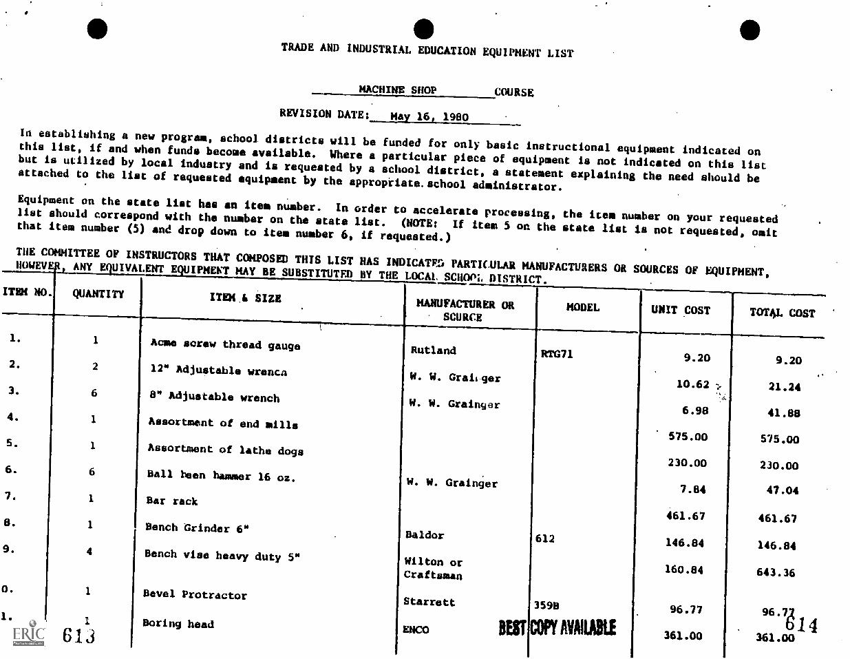
TRADE AND INDUSTRIAL EDUCATION EQUIPMENT LIST
MACHINE SHOP COURSE
REVISION DATE: May 16, 1980
In establishing a new program, school districts will be funded for only basic instructional equipment indicated onthis list, if and when funds become available. Where a particular piece of equipment is not indicated on this listbut is utilized by local industry and is requested by a school district, a statement explaining the need should beattached to the list of requested equipment by the approptiate.school administrator.Equipment on the state list has an item number. In order to accelerate processing, the item number on your requestedlist should correspond with the number on the state list. (NOTE: If item 5 on the state list is not requested, omitthat item number (5) and drop down to item number 6, if requested.)
THE COMMITTEE OF INSTRUCTORS THAT COMPOSED THIS LIST HAS INDICATED PARTICULAR MANUFACTURERS OR SOURCES OF EQUIPMENT,HOWEVER, ANY EQUIVALENT EQUIPMENT MAY BE SUBSTITUTE!) BY THE LOCAL. SCHOOL DISTRICT.
ITEM NO. QUANTITY ITEM,A SIZEMANUFACTURER OR
SOURCEMODEL UNIT COST TOT4L COST
1.
2.
3.
4.
5.
6.
7.
8.
9.
0.
1.
1
2
6
1
1
6
1
1
4
1
613
Acme screw thread gauge
12" Adjustable wrench
8" Adjustable wrench
Assortment of end mills
Assortment of lathe dogs
Ball been hammer 16 oz.
Bar rack
Bench Grinder 6"
Bench vise heavy duty 5"
Bevel Protractor
Boring head
Rutland
W. W. Grailger
W. W. Grainger
W. W. Grainger
Baldor
Wilton orCraftsman
Starrett
ENCO BEST
RTG71
612
3598
COPY AVAILABLE
9.20
10.62
6.98
575.00
230.00
7.84
461.67
146.84
160.84
96.77
361.00
9.20
21.24
41.88
575.00
230.00
47.04
461.67
146.84
643.36
96.721
361.00
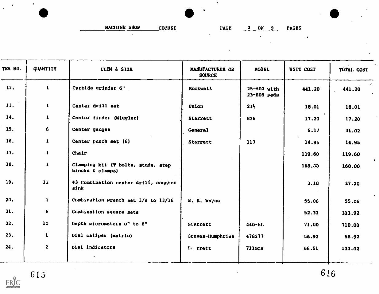
MACHINE SHOP COCKSE PAGE 2 OF 9 PAGES
TEM NO.
f
I QUANTITY ITEM 6 SIZE MANUFACTURER ORSOURCE
MODEL UNIT COST TOTAL COST
12. 1 Carbide grinder 6" . Rockwell 25-502 with 441.20 441.2023-805 peds
13. 1 Center drill set Union 21h 18.01 18.01
14. 1 Center finder (Wiggler) Starrett 828 17.20 17.20
15. 6 Center gauges General 5.17 31.02
16. 1 Center punch set (6) Starrett. 117 14.95 14.95
17. 1 Chair 119.60 119.60
18. 1 Clamping kit (T bolts, studs, stepblocks & clamps)
168.00 168.00
19. 12 13 Combination center drill, countersink
3.10 37.20
Gi. 1 Combination wrench set 3/8 to 13/16 S. K. Wayne 55.06 55.06
21. 6 Combination square sets 52.32 313.92
22. 10 Depth micrometers o" to 6" Starrett 440-6L 71.00 710.00
23. 1 Dial caliper (metric) Graves - Humphries 478277 56.92 56.92
24. 2 Dial indicators fo rrett 711GCS 66.51 133.02
615 616
MACHINE SHOP COURSE PAGE 3 OF 9 PAGES
TEN NO.I
I QUANTITY
ISOURCE
.
ITEM 4 SIZE MANUFACTURER OR MODEL UNIT COST TOTAL COST
.25. 6 4" Divider 8,05 48,30
26, 1 Dividing Head Cincinatti 1055,00 1,955,00
27. 1 Dividing Head 11" Economy 977,50 977,50
28, 3 Drill chucks is" cap. with 12 or 13Morse Taper (Expendable Item)
Jacobs 45,90 73717U
29. 1. Drill grinder, 118 to 1-114 Lisle 91000 356,50 t 356,50
30, 1 Drill point gauge Starrett 22C 13,51 13,51
31, 2 15" Drill press, variable speed . Rockwell 15-467 with49-711 motor
822,25 1,644,50
32, 2 Drill press vise Neal 94,87 189,74
33, 2 Drill sets 1(16 to 1/2 by 64the 58,85 117,70
34. 2 Drive pin punch sets Starrett 565 14,66 29,32
35, 1 Edge finder 879 12,80 12,80
36, 2 Engine lathe 13" (6it, bed) Clausing 11,600,00 23,200.00
37 1 7" Grinder pedestal Baldor SP-7PIND 451.06 451.06
38. 1 12" Grinder pedestal " SP-1221MD 1,092.66 1,092.66--4
611618
MACHINE SHOP COURSE PACE 4 OF 9 PAGES
TEN NOi
I QUANTITY ITEM 6 SIZE MANUFACTURER ORSOURCE
MODEL UNIT COST TOTAL COST
39. I 6 Hack saws 8,05 48,30
40. 1 Hardness tester king 134 1,207,50(
1,207,50
41. i Heat treat furnace (complete) Crest 2,127,50 2,127,50
42. 6 Hermaphrodite caliper 6" Starrett 563 11,04 66,24
43. 1 Set Hole gauges.
.
N 5 -830Y 44.70 '44.70
44, i. Horizontal metal cut off sawq Wells 18 2,064,25 2,064.25
45. 2 Horizontal milling machine Powermatic 333 14,462,40 28,924,80
46. 1 Horizontal milling machine (Universal LUER 16,373,55 16,373.55
47. 6 4" Inside Caliper 8.05 . 48.30
48. 1 Inside micrometer Starrett 124B 70.25 70.25
49. 1 Inside micrometer 143" to 12" N 8238 77.10 77.10
50. 1 Keyseat rule Starrett 237 13.80 13.80
51. 8 15" x 54" LeBlond Geared Head Engine LeBlond 11,850.00 94,800.00Lathe, servo-shift, 12 spindle speedswith hardened and ground replaceablebedways, face plate, inch/metricswitchable dual English/metric dialseinem tuna tnnl nnat,-. 11. si u .e..,..-
with J.I.C. electrics.
6 16;20
MACHINE SHOP COURSE PAGE OF 9 PAGES
7E4 NO. I QUANTITY
ISOURCEITEM 6 SIZE MANUFACTURER OR MODEL UNIT COST TOTAL COST
52. 1 Letter drill set A to 2 62.90 62.90
53. 1 Level 14" cast iron Starrett 1338 87.00 87.00
54. 10. 0-1 Micrometers (Vernier) Starrett 44.26 442.60
55. 2 2" Micrometers 4. 436RL-2" 45.60 91.20
56. 1 3" Micrometer Starrett 436RL-3" 48.40 48.40
57. 1. 4" Micrometer " 436RL -4" 53.50 53.50
58. 1 5" Micrometer 1. 436RL-5" 57.14 57.14
59. 1 6" Micrometer " 436RL-6" 59.00 59.00
60. 1 Micrometer depth gauge w/ratchetstop and lock nut (metric)
Graves-Humphries 478412 44.70 44.70
61. 3 Milling machine vises 4S" plain 345.00 1,035.004S" swivel, 4S" universal
62. 1 Sat Minute man broaches Dumont 110 178.00 178.00
63. 1 Number (wire gauge) drills 1 to 60 Craftsman 55.52 55.52
64. 6 4" Outside caliper Mitutoyo or equiv 8.05 48.30
065. 1 Outside micrometer w/ratchetstop and lock nut (metric)
Graves-Humphries 478372 37.10 37.10
62 t BEST COPY AVAILABLE 622
MACHINE SHOP COURSE PACE 6 OF 9 PACES
OR NO. 1 QUANTITY ITEM 6 SIZE MANUFACTURER ORSOURCE
MODEL UNIT COST TOTAL COST
66. 1. . 1. . Omy-Ace. Welding Outfit . ,271.00 -271.00
67. 2 Sets Parallels Starrett S-384-.7 98.61 197.22
68. 6 Pocket scribers " 70 3.12 18.72
69. 1 Press arbor 2 ton G.H. 341.00 341.00
70. 1 Protractor Rutland 8.05 8.05
71. 2 , Punch and chisel set72.24 144.48
72. 1 Radial drill Rockwell 15-126 2,700.00 2,700.00
73. 1 Radius gauge set Rutland 33.92 33.92
74. 1 Set Reamers 14" to 1" (by 16th) Cleveland 27A 323.43 323.43
75. 2 Revolving head knurlers68.40 136.80
76. 40 Safety glasses7.40 296.00
77. 1 Screw thread mike Starrett 575A-P 113.27 113.27
78. 1 Set of gauge blocks Rutland 470.00 470.00
79. 1 Set of gear cutters 16-14-20 DP,.also other pitches
National ,690.00 690.00
.I , 4
623BESTCOPYANIABLE
624
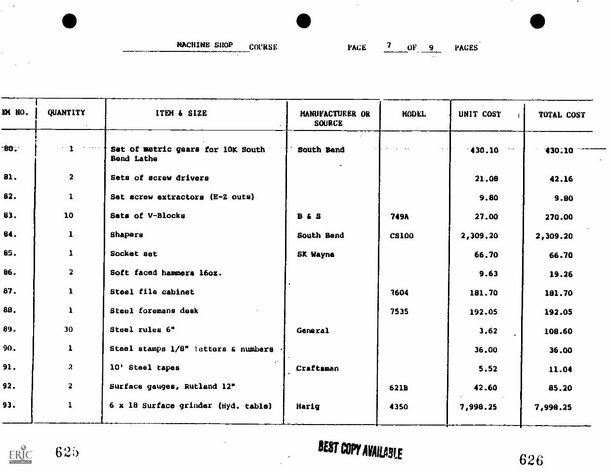
MACHINE SHOP COURSE PAGE 7 OF 9 PAGES
EN NO. I QUANTITY ITEM A SIZE MANUFACTURER ORSOURCE
MODEL UNIT COST i TOTAL COST
[_
'80:- 1 1 Set of metric gears for 10K South South Bend '430.10 430;10Bend Lathe
81. 2 Sets of screw drivers 21.08 42.16
82. 1 Set screw extractors (E-Z outs) 9.80 9.80
83. 10 Sets of V-Blocks B 6 S 74911 27.00 270.00
84. 1 Shapers South Bend CS100 2,309.20 2,309.20
85. 1 Socket set Sit Wayne 66.70 66.70
86. 2 Soft faced hammers 16oz. 9.63 19.26
87. 1 Steel file cabinet 1604 181.70 181.70
88. 1 Steel foremans desk 7535 192.05 192.05
89. 30 Steel rules 6" General 3.62 108.60
90. 1 Steel stamps 1/8" letters & numbers - 36.00 36.00
91. 2 10' Steel tapes.Craftsman 5.52 11.04
92. 2 Surface gauges, Rutland 12" 6218 42.60 85.20
93. 1 6 x 18 Surface grinder (Hyd. table) Harig 4350 7,998.25 7,998.25
62;) BEST COPY AVAILARE626
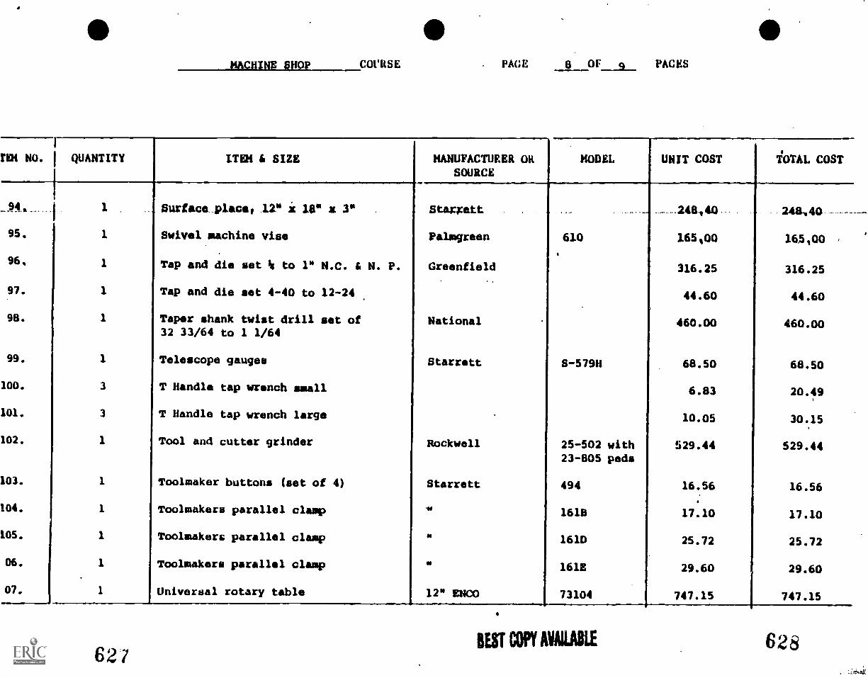
MACHINE SHOP COURSE . PAGE 8 OF q PACES
rim NO.
1
I QUANTITY ITEM il SIZE MANUFACTURER ORSOURCE
MODEL UNIT COST TOTAL COST
1
...944._.. . 1 Surface_placeo 1 2" i 10" a 3" Stamett . . . ......-. ... _248140.- 248,40 --
95. 1 Swivel machine vise Palm green 610 165100 165100
96 1 Tap and die set 14 to 1" N.C. & N. P. Greenfield 316.25 316.25
97. 1 Tap and die set 4-40 to 12-24 44.60 44.60
98. 1 Taper shank twist drill set of National 460.00 460.0032 33/64 to 1 1/64
99. 1 Telescope gauges Starrett 8-5798 68.50 68.50
100. 3 T Handle tap wrench small 6.83 20.49
101. 3 T Handle tap wrench large 10.05 30.15
102. 1 Tool and cutter grinder Rockwell 25-502 with 529.44 529.4423-805 pods
103. 1 Toolmaker buttons (set of 4) Starrett 494 16.56 16.56
104. 1 Toolmakers parallel clamp y 1618 17.10 17.10
105. 1 Toolmakers parallel clamp se 161D 25.72 25.72
06. 1 Toolmakers parallel clamp y1618 29.60 29.60
07. 1 universal rotary table 12" ENO 73104 747.15 747.15
62/BEST COPY AVAILABLE 628
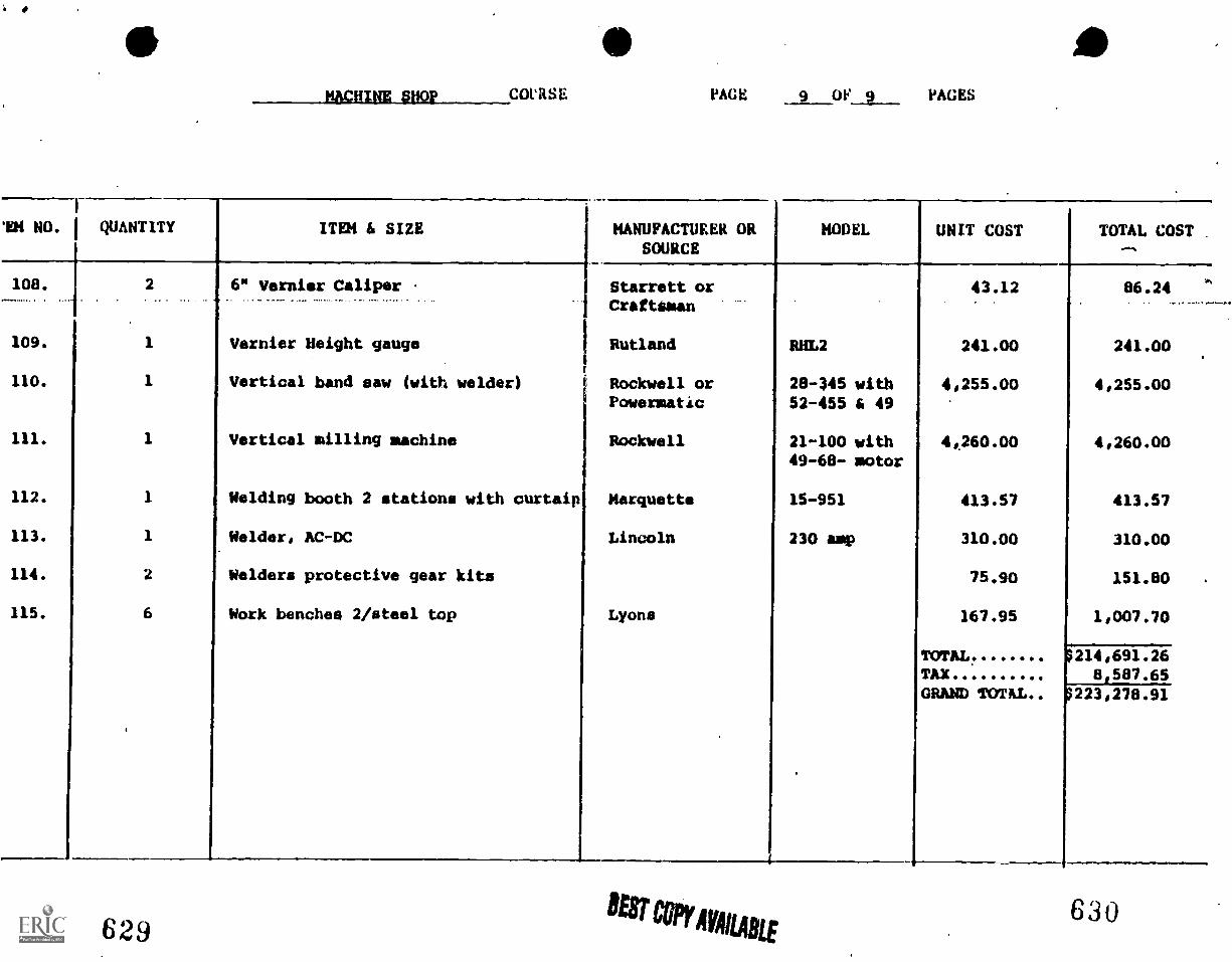
1
S4 NO. 1
108.
109.
110.
112.
113.
114.
115.
WHINE PUor COVRSE PAGE 9 OF 9 PAGES
QUANTITY ITEM is SIZE
2 6" Vernier Caliper
1 Vernier Height gauge
1 Vertical band saw (with welder)
1 Vertical milling machine
1 Welding booth 2 stations with curtaip
1 Welder, AC-DC
2 Welders protective gear kits
6 Work benches 2/steel top
629
MANUFACTURER ORSOURCE
1 Starrett orCrafttman
IRutland
Rockwell or4 Powermatic
Rockwell
Marquette
Lincoln
Lyons
MODEL. UNIT COST TOTAL COST .
RHL2
28 -345 with
52-455 i 49
21-100 with49-68- motor
15-951
230 amp
43.12
241.00
4,255.00
4060.00
413.57
310.00
75.90
167.95
TOTAL.TAX
GRAND TOTAL
86.24
241.00
4,255.00
4,260.00
413.57
310.00
151.80
1,007.70
$214,691.268,587.65
$223,278.91
630
MACHINE SHOP
SAMPLEOUTCOME-REFERENCED TESTS
This articulated, performance-based instruction guide is designedto answer three critical questions necessary for qualityinstruction.
First, what should be taught?
The objectives of the articulated, performance-based voca-tional education program are based on extensive taskanalysis and validation.
The -task objectives represent what employers in businessand industry say is important for entry level job success.
Second, how should it be taught?
It should be taught using the latest "state-of-the-art"instructional technology incorporated into each unit.
Students are taught the knowledges, skills, and attitudesneeded for successful and productive employment.
Third, how should students be evaluated?
Students are evaluated using a° validated, competency-basedapproach to determine student proficiency in vocationalknowledges and skills.
The minimum standards c.re those required for successfulentry into the next higher level of training or for
successful employment.
The sample tests in this guide are included to illustrate how astudent's competency in vocational skills and knowledges may bemeasured with validity and reliability. In addition, the testsamples should promote standardization in the evaluation ofvocational students in similar programs.
Test items have been constructed solely from the objectives oftne vocational program. The statement of the objectives Indi-cate the level of knowledge or skill to be tested. Task forcecommittee participants have attempted to develop tests that
agree with objectives in the behavior requested, the givenconditions, and the desired standards of performance.
's;niess a test is marked "Revised" or "R," tne testsnould be considered a field trial edition currentlyunder evaluation.
63TEST-INSTRUCTION
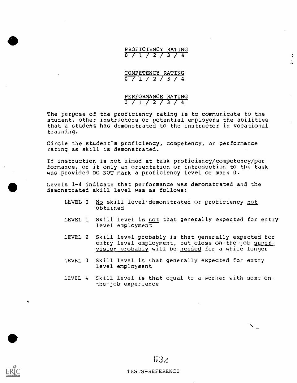
PROFICIENCY RATING0 / 1 / 2 / 3 / 4
COMPETENCY RATING0 / L./ 2 / 3 / 4
PERFORMANCE RATING0 / 1 / 2 / 3 / 4
The purpose of the proficiency rating is to communicate to thestudent, other instructors or potential employers the abilitiesthat a student has demonstrated to the instructor in vocationaltraining.
Circle the student's proficiency, competency, or performancerating as skill is demonstrated.
If instruction is not aimed at task proficiency/competency/per-formance, or if only an orientation or introduction to the taskwas provided DO NOT mark a proficiency level or mark 0.
Levels 1-4 indicate that performance was demonstrated and thedemonstrated skill level was as follows:
LEVEL 0 No skill level demonstrated or proficiency notobtained
LEVEL 1 Skill level is not that generally expected for entrylevel employment
LEVEL 2 Skill level probably is that generally expected forentry level employment, but close on-the-job super-,yisionaollably will be needed for a while longer
LEVEL 3 Skill level is that generally expected for entrylevel employment
LEVEL 4 Skill level is that equal to a worker with some on-the-job experience
I.,
TESTS-REFERENCE
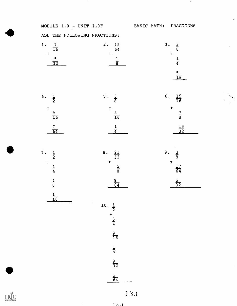
MODULE 1.0 - UNIT 1.0F BASIC MATH: FRACTIONS
ADD THE FOLLOWING FRACTIONS:
1. 7 2. 15 3. 3
16 64 8
+ + +5 1 1
32 8 4
4. 1
2
+916
7
64
5. 3 6.
8
+ +5
16
1
4
8. 21 9.32
5
16
1516
7
8
1932
3
8
+ + +1 5 174 8 64
1 9 5
8 64 32
1
16
10. 1
2
+3
4
916
18
932
5
64
6 3 , i
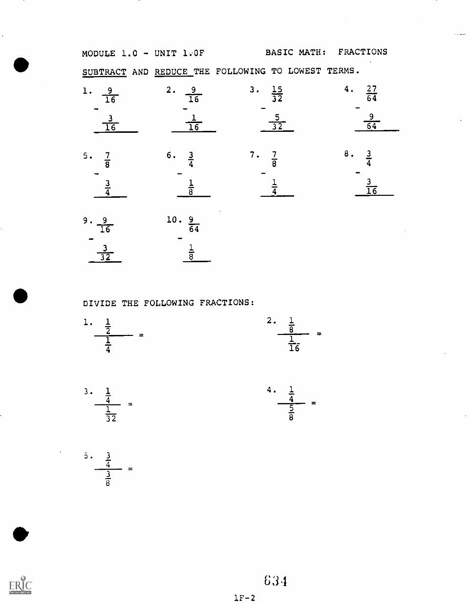
MODULE 1.0 - UNIT 1.0F BASIC MATH: FRACTIONS
SUBTRACT AND REDUCE THE FOLLOWING TO LOWEST TERMS.
1. 9 2. 9 3. 15 4. 27
16 16 32 64
3 1 5 9
16 16 32 64
5. 7 6. 3 7. 7 8. 3
8 4 8 4
,1
3 1 1 3
4 8 4 16
9. 9 10. 9
16 64
3 1
32
DIVIDE THE FOLLOWING FRACTIONS:
1. 1 2. 17 8
1 1
16
3. 1 4. 1
4 4
1 5
32 8
3. 3
4
3
8
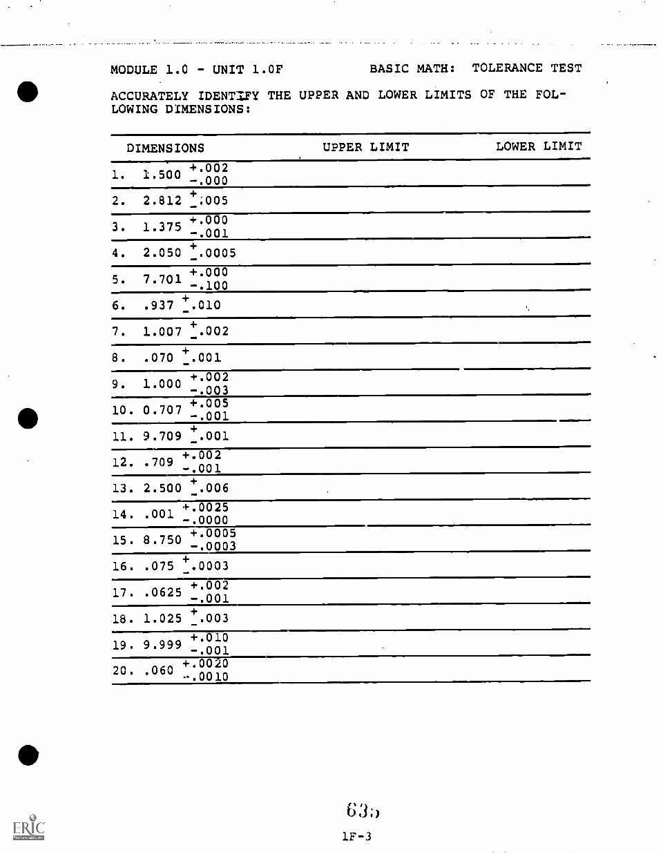
MODULE 1.0 - UNIT 1.0F BASIC MATH: TOLERANCE TEST
ACCURATELY IDENTIFY THE UPPER AND LOWER LIMITS OF THE FOL-LOWING DIMENSIONS:
DIMENSIONS UPPER LIMIT LOWER LIMIT
1. 1.500+002-.000
2. 2.812+.005
3. 1.375+000-.001
4. 2.050+.0005
5. 7.701+.000-.100
6. .937+.010
7. 1.007+.002
8. .070 .001
9. 1.000+002-.003
10. 0.707+005-.001
11. 9.709+.001
12. .709+002-.001
13. 2.500+.006
14. .001+.0025-.0000
15. 8.750+.0005-.0003
16. .075+.0003
17. .0625+002-.001
18. 1.025 +.003
19. 9.999+.010-.001
20. .060+0020-.0010
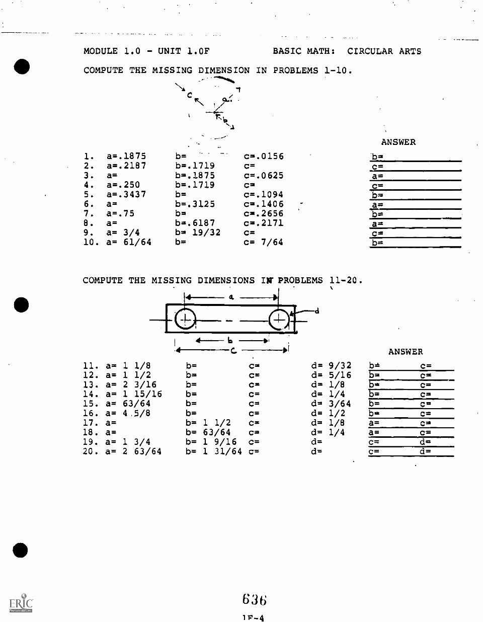
MODULE 1.0 - UNIT 1.0F BASIC MATH: CIRCULAR ARTS
COMPUTE THE MISSING DIMENSION IN PROBLEMS 1-10.
c
ANSWER
1. a=.1875 b= c=.0156 b=2. a=.2187 b=.1719 c= C=3. a= b=.1875 c=.0625 a=4. a=.250 b=.1719 c= C7-1
5. a=.3437 b= c=.1094 b=6. a= b=.3125 c=.1406 a=7. a=.75 b= c=.2656 b=8. a= b=.6187 c=.2171 a=9. a= 3/4 b= 19/32 c= C=10. a= 61/64 b= c= 7/64
COMPUTE THE MISSING DIMENSIONS IN' PROBLEMS
4---- 6 ---";
11. a= 1 1/8 b= C= d=12. a= 1 1/2 b= C= d=13. a= 2 3/16 b= C= d=14. a= 1 15/16 b= C= d=15. a= 63/64 b= C= d=16. a= 4.5/8 b= C= d=17. a= b= 1 1/2 C= d=18. a= b= 63/64 C= d=19. a= 1 3/4 b= 1 9/16 C= d=20. a= 2 63/64 b= 1 31/64 C= d=
11-20.
ANSWER
9/32 b= c=5/16 b= c=1/8 b= c=1/4 b= c=3/64 b= c=1/2 b= c=1/8 a= c=1/4 a= c=
c= d=c= d=
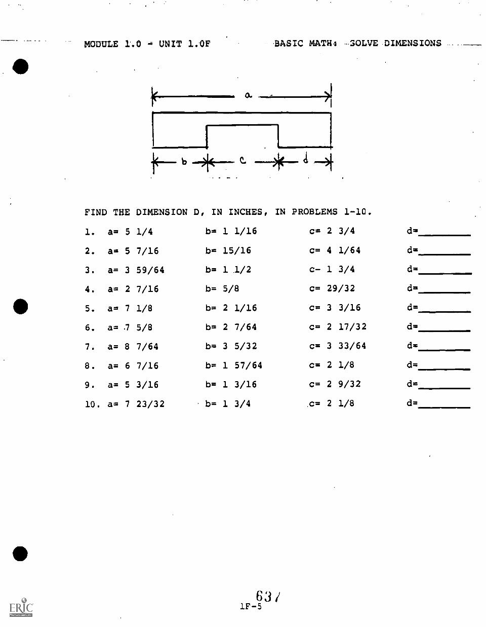
MODULE 1.0 = UNIT 1.0F .BASIC MATR4 -30LVE DIMENSIONS
1
)1E-4-4
FIND THE DIMENSION D, IN INCHES,
1. a= 5 1/4 b= 1 1/16
2. a= 5 7/16 b= 15/16
3. a= 3 59/64 b= 1 .1/2
4. a= 2 7/16 b= 5/8
5. a= 7 1/8 b= 2 1/16
6. a= 7 5/8 b= 2 7/64
7. a= 8 7/64 b= 3 5/32
8. a= 6 7/16 b= 1 57/64
9. a= 5 3/16 b= 1 3/16
10. a= 7 23/32 b= 1 3/4
IN PROBLEMS 1-10.
C=
C=
c-
c=
c=
c=
c=
c=
c=
.c=
2 3/4
4 1/64
1 3/4
29/32
3 3/16
2 17/32
3 33/64
2 1/8
2 9/32
2 1/8
d=
d=
d=
d=
d=
d=
d=
d=
d=
d=
MODULE 1.0- UNIT 1.0G BASIC MEASURING
. . -
. -
- . al
.
oe
63 8 RV COPY MAME
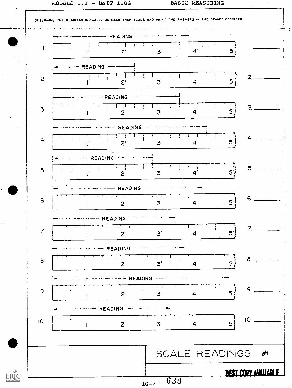
MODULE 1. U - UNIT 1.0G BASIC MEASURING
DETERMINE THE READINGS INDICATED ON EACH SHOP SCALE AND PRINT THE ANSWERS IN THE SPACES PROVIDED.
2.
3.
READING
;
I 2' 3! 4; 5
READING
2' 4
READING
I
2!
3 4'
6
7
8
9
I0
2'
READING
I 2' 3
READING
READING
.- READING
I
I 2'
READING
READING.
2'
READING
I
3
r I
I 2 3
3'
illTI
7
4
14'
4
4
4 5)
4
8
9
10
SCALE READINGS #1
1G-2 639BEST COPY AvaaLE
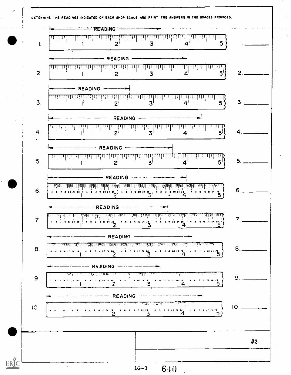
DETERMINE THE READINGS INDICATED ON EACH SHOP SCALE AND PRINT THE ANSWERS IN THE SPACES PROVIDED.
2.
READING
11111111g 1['ittirti11111111ip1Titilifi wrpirTITTipp2 3 4" 5
READING
3.1
13' 2 3' 511
4.
5.
6.
7
8.
9
10
11 ;1111:1111111111111:1111111I I II
5 1 4 2') 24 II 4
READING
II a :4 00 04 OS 00 04 Zs 4 I 4 '4 20 1.4 26 ; 4 S I 00 14 VI
2' 3' 4 5
READING
5
1 , . ..1 111;. ril. I :111101,1-Pill .IIIII IIIITIU I. I :IIII:PI'.1 IIIP,Iillirq11 :I. T,11.11II'liri,l'Il...1:111!TI IIII!!It i! . : I 1 . I .. . , , : . ' . 7.4 4 0 4 20 14 OS I 4 5 1 4 ZO 04 ZI 4 .0 4 20 24 II I I 4 to 14 25 j I 1 4 20 Z 011
I 2 3' 5
8.
9
.! I I .I..1:11.[!1.11.1.11,
T 4 I' 24 '4 , 4
I
4
: "',i':, -I
1, ,a :5
I
4
4.414
I
READING
.11,1111r11111111.11:11111111-1.H .h.;1',1.111;11..1:.,.11;!li q '1'37." :1 !11',1
JO 04 0 I 4 00 04 14 . 4 2 a 00 :4
2'II I 6 11 04 24 4 6
4
READINGI rl,rg f1117..-
1 I 4 0 14 IS I .? '0 04 al 4 0 04 6 a Jc 11
2 5
READING
4 j 6 e.! Za
2.
104 10 74 04 a 4 : VI 04 21 / 4 .
3 4
#2
1G-3 6 4
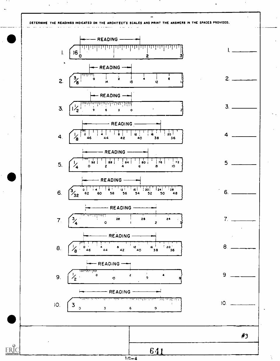
gai
DETERMINE THE READINGS INDICATED ON THE ARCHITECT'S SCALES AND PRINT THE ANSWERS IN THE SPACES PROVIDED._ - . _ - - _ - . -
1.
READING
160 2 3
READING/ pipili pi, T
21
I
i
2.I 3/ 1 o
8 lei 13
412
6II
READING
;qr !,1,11111.1,,y;t0-1-rprii-
3. 1/ ' 9 6 3 0
4.
5.
6.
7
8.
(14
READING
1 1 1 flitie 20 I44 42 40 38 36
920
READING
;1181811111i , 84 I
2 4
1 1
I 80 i
6
1
1
8
1176 1
:i!72
10
READING1
i
077: 4 ! 1;..2; ,
1,61 :io!' 124! :2I8/32 62 60 58 56 54 52 50 48
READING
.3
026 24
I 2
READING1.1 I I
a46
4 8 12 16 I 2044 42 40 38 36
"* READING
2
WITT
9. 0
10.
99
10
#3
MODULE 1.0 UNIT 1.0H BASIC BLUEPRINT READING
MULTIPLE CHOICE:
1. An/a drawing shows how parts are put together.
a. perspectiveb. detailc. assemblyd. isometrice. oblique
2. An assembly drawing has or more objects.
a. oneb. twoc. threed. foure . five
3. Part identification on an assembly drawing is by
a. trianglesb. numbersc. arrowsd. linese . views
4. A detail drawing is a drawing of a/an piece.
a. singleb. doublec. sectionedd. obliquee . specified
5. An assembly drawing is a drawing of or more details.
a. twob. onec. threed. foure. five
6. An assembly drawing is a completely construciton.
a. removedb. separatec. assembledd. detailed
7. The detail drawing is a drawing of a piece.
a. mediumb. =smallc. doubled. Singlee. large
8. An assembly drawing shows how parts are together.
a. cutb. styledc. putd. curvede . detailed
9. Balloons are identifying symbols used on drawings.
a. perspectiveb. detailc. assemblyd. isometrice . framed
10. The true shape of an object with slanted surfaces can onlybe represented by a/an view.
a. cavalierb. perspectivec. auxiliaryd.. isometrice . oblique
11. The usual views of an object do not show the true shapes ofsurfaces.
a. staightb. slanting
. c. isometricd. squaree. triangular
12. True sizes and shapes of slanted surfaces are obtained byprojecting directly from the
a. rightb. sectionc. slantd. finish
13. A draftsman may use a/an drawing as a means ofpresenting his ideas more simply.
a. orthogrphicb. pictorialc. workingd. true viewe. detail
64 31H-2
MODULE 1.0 - UNIT 1.0H BASIC BLUEPRINT READING
1. What system of projection is used? 1
2. What material is the part made of? 2.
3. What pattern was used to cast the part? 3.
4. What is the tolerance on fractions? 4.
5. Which dimensions are not for machining?8. Which dimension is expressed by limits? 6.7. Determine the following dimensions in inches 7.
8. Determine the following dimensions in milli-meters 8.
P PIPE TAP(2) ROLES
0(2) HOLES
Aconversion table
mm inct)
A 114.3 4 1/2B 130.2 5 14C 123.8 4 7/80 41.3 1 stsE 88.9 3 I/2F 69.8 2 3/4O 34.9 1 3/S
H 19.05 3,4I 38.1 1 1/2
J 22.22 /8K 4.8 3/15L 41.3 1 stsM 82.8 3 1/4N 13.5 17/32
28.6258 1.127
28.575 1 125P - i/a NPT0 6.4 1/4
R 63 5 2 1/2
REF
ON4 HOLES
E F
R -11
73:mo -woo- 0 -60
MAKE FROM SPT 10017MATL., CAST STEEL2 RECK).TOLERANCES s 1.51A1i -* 1/161n.
6441H-4
FIRST ANGLE
4:C :4)
A.VHPW
STUV.
W.
BUT COPY MAE
1FST PM/ WW1
MODULE 1.0 - UNIT 1.0H BASIC BLUEPRINT READING
REVIEW THE CRAWING AND ANSWER THE FOLLOWING QUESTIONS.
MA. TARN
LOCATE AT ASSY
IS
13 UNC-2111300 APART ON
I 01A. LC.
SURPACI P suarAgir a PARTIALslot viewww. RAO. 3 X 4S CHAMP01A.
UNC..2A
C. R. s.ALL ONALAIONS a UNIASSOTNiuswisa
GLASHAN MACHINE WORKS ISO.
CARRIAGE MO4MA 1/2
1-111-73A
OIUMAMmA A hic10$ I.6.013
1. What is the drawing number?
2. What is the name of the part?
3. What revision is the drawing?
4. What material is the part made from?
5. Name the views shown.
6. List the different kinds of lines used on the drawing
7. Whit is the scale of the drawing? (Is the scale .... architect's,metric, etc.,?)
8. Determine dimensions A-D.A
B
9. Which dimension is not to scale?
10. What is the maximum size of the 4 inch collar?
11. Determine the minimum value for dimension E.
12. If surface F was machined to a diameter of 2.62605, would itbe within the allowable tolerance?
13. If surface G was machined to a diameter of 2.5040, would 1."be within the allowable tolerance?
14. hat the dxameter of tne oot otrIce for :ne -
tapped noles?
:3. How deep Are tne 1,2 - 13 tapped aos?
MODULE 2.0
411 TRUE-FALSE:
( ) ( ) 1.
( ) ( ) 2.
( ) ( ) 3.
( ) ( ) 4.
( ) ( ) 5.
PRECISION MEASURING INSTRUMENTS
Outside calipers can be used to measure the diameterof holes and round stock
When checking work with a Dial Indicator, a clock-wise movement of the pointer hand indicates anincrease in part size.
An variation in part size less than .001 cannot bedetermined accurately from a Dial Indicator.
Dial indicators are frequently used, not only forchecking machined parts for size vairiations butalso in the setup of such parts before machinging.
A vernier caliper cannot be used to measure partswhere an accuracy greater than .001 is required.
MULTIPLE CHOICE:
6. The amount of tolerance generally permitted on all scalemeasurements is plus or minus
a. .625b. .03125c. .0156
7. The best rule to use when measuring the diameter of roundstock is the
a. plain steel ruleb. outside micrometerc. slide caliper rule
8. Each graduation of line on the thimble of a metric micro-meter equals
a. .01 millimeterb. .1 millimeterc. .5 millimeter
9. To obtain a reading of 6 millimeters on a metric micrometer,starting from the closed position of a zero reading, thethimble must be turned in a connter-clockwise direction
a. 6 complete revolutionsb. 12 complete revolutionsc. complete revolutions
MODULE 2.0. .PRECIS MEASURING INSTRUMENTS
COMPLETION:
10. The of a combination set is frequentlyused to lay out centerlines on the end of round stock.
11. A gage is a tool used inlaying out work to an accuracy of .001.
12. The Vernier Caliper is capable of reading toinch.
13. The universal Bevel Protractor uses ameasure the parts of a circle.
to accurately .
14. are used in layout work to raise thework to a suitable height and provide a solid, accurateseat.
15. An caliper generally is used to measurethe diameter of holes or spaces between two-round shafts.

MODULE 4.0 PRECISION MEASURING INSTRUMENTS
PERFORMANCE TEST:
1. DIRECTIONS: STUDY THE MICROMETER CALIPER READINGS THEN WRITETHE CORRECT READINGS ON THE LINE PROVIDED UNDER EACH ILLUSTRA-TION.
O 1 2 3 4 Slinii II Mill 20
A.
15
o 1 2 3 4ill F 10
za
0 1 2 3Ill(lll III
pow..im..=
15
10
o 1 2 20
GIs
C. Do
MULTIPLE CHOICE:
2. The correct reading of this InsideMicrometer Caliper is
a. .842b. .822c. .817
3. The correct reading of thisMicrometer Depth Gage is
a. .712b. .718c. .825
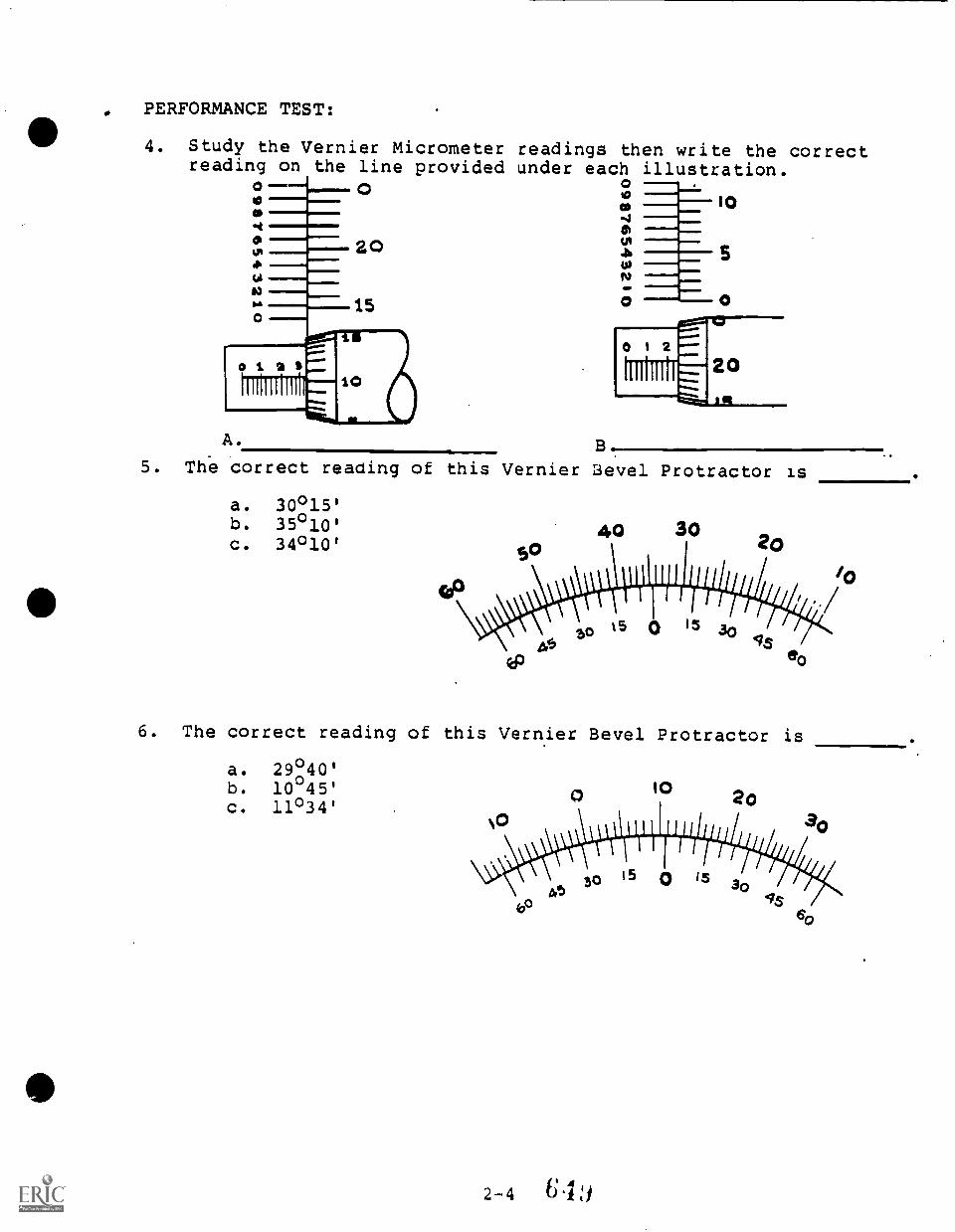
PERFORMANCE TEST:
4. Study the Vernier Micrometer readings then write the correctreading on the line provided under each illustration.
04O .,_._
A40N r-
0 0
0 1 2
A.
5. The correct reading of this Vernier Lievel Protractor is
a. 30°15'b. 35 °10'
c. 34°10'
6. The correct reading of this Vernier Bevel Protractor is
a. 29°40'b. 10 45'c. 11°34'
I0 20
so 15 0 is
UNIT 3.0 WORK LAYOUT
COMPLETION:
1. To layout work is to scribe lines on metal, to show theareas to be
2. Layout work must be performed on ato insure an accurate layout.
3. The tool used to draw a straight line parallel to the edgeof a rule is called a
4. Center punches are used in layout work to locate and markthe centers of
5: The tool used in laying out center lines on round shafts iscalled a rule.
6. The tool used to scribe a circle in laying out a hole iscalled a
7. Work which must be held in a vertical position for layingout should be clamped to an
8. The correct height adjustment of a surface gage must beobtained from the rule of a
9. When dimesions are given on the print in inches or fractions,the acceptable accuracy is +/- inches.
10. Measurements with a rule are not taken directly from theprint because of errors.
MULTIPLE CHOICE:
11. Correct layout work is important to maintain:
a. workpiece accuracyb. reduced scrap partsc. interchangeability cf partsd. all of the above
12. Which of Lhe following statements best describes layout?
a. Measuring from a print and transferring thesemeasurements to the workpiece.
b. Measuring the workpiece and comparing thismeasurement to the print.
c. Scribing of lines on the workpiece surfaces.d. Making a detail drawing on the workpiece.
13. When laying out a casting, which of the following is donefirst?
a. Establish reference centerlines.b. Fill the center of the casting with a piece of
tin to provide for centerlines.c. Measure the overall casting.d. Layout the outline lines from the centerlines,
14. Which of the following surfaces can be laid out to a finerdegree of accuracy?
a. Rough surfacesb. Machined and finished surfacesc. square surfacesd. Round surfaces
15. Which of the following tools is used to transfer machininglocations when making multiple parts?
a. Beam trammelsb. Dividersc. Hermaphrodite calipersd. Templets
UNIT 3.0 WORK LAYOUT
110 PEROFRMANCE TEST:
1. Demonstrate ability to:
a. Use steel rule.
b. Use steel rule to set caliper and divider.
c. Use combination set.
2. Demonstrate ability to:
a. Use outside vernier micrometer.
b. Use the depth micrometer.
c. Use the inside micrometer.
3. Demonstrate the ability to:
a. Use vernier caliper to take inside, outside, anddepth measurements.
b. Use the depth vernier.
c. Use the vernier height gage for layout and inspection.
d. Use the universal bevel protractor to measure angles.
4. Demonstrate ability to:
a. Use gage blocks
b. Use sine bar to set angle
5. Demonstrate ability to perform file and spark test.
NOTE: RATE EACH PERFORMANCE DEMONSTRATED:
PERFORMANCE RATING
1 0/ 1 / 2 / 3/ 4
2 . 0 / 1 / 2 / 3 / 4
3 . 0 / 1 / 2 / 3 / 4
4 . 0 / 1 / 2 / 3 / 4
5 . 0 / 1 / 2 / 3 / 4
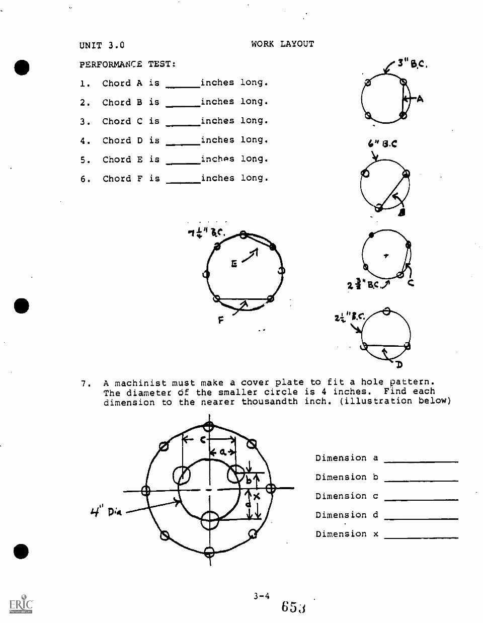
UNIT 3.0
PERFORMANCE TEST:
1. Chord A is
2. Chord B is
3. Chord C is
4. Chord D is
5. Chord E is
6. Chord F is
WORK LAYOUT
inches long.
inches long.
inches long.
inches long.
inches long.
inches long.
4" 13.0
7. A machinist must make a cover plate to fit a holeThe diameter of the smaller circle is 4 inches. F
dimension to the nearer thousandth inch. (illustra
Dimension a
Dimension b
Dimension c
Dimension d
Dimension x
pattern.ind eachtion below)
UNIT 4.0 BENCHWORK - HAND TOOLS
MATCHING:
DIRECTIONS: MATCH THE TERMS ON THE RIGHT WITH THE STATEMENTSON THE LEFT.
1. Easy to break a.b.
ChippingMushroom
2. Angled surface c.d.
TangShearing
3. Pointed end of a file e.f.
DrawfillingBurr
4. Process of making metal g. Hardeningresistant to wear h.
i.
BrittleReference
5. Enlarged area on end of a chisel,caused by striking it with :ahammer
j.
k.
SurfaceTap DrillSizeThreading Die
6. Sharp edge left on a metal part 1: Scalefrom a machining operation m. Chamfer
7. Cutting action of a tool
9. Semi-precision steel rule with graduations
9. Side from which dimensions aretaken or made
10. Tool used to produce external threads
ANSWER KEY:
1. h2. m3. c4. g5. b6. f
7. d8. 1.
9.
10. k
UNIT 4.0 BENCHWORK - HAND TOOLS
IDENTIFY:
DIRECTIONS: GIVEN DRAWINGS OF HAND TOOLS COMMON TO MACHINE SHOPWORK OR GIVEN A DISPLAY OF ACTUAL TOOLS, IDENTIFY THE TOOLSUSING THE PROPER TERMINOLOGY. THE STANDARDS OF THE INSTRUCTORMUST BE MET.
UNIT 4.0 BENCHWORK - HAND TOOLS
COMPLETION:
1. A file which has parallel rows of teeth that cross one anotheris called a file.
2. When "rough" filing, apply pressure only on thestroke of the file, to preveht dulling the.teeth.
3. A wrench which had on solid jaw and one movable jaw is calledan wrench.
4. A hole which does not go entirely through a workpiece isreferred to in the shop as a hole.
5. A tool used to finish drilled holes accurately to size iscalled a
6. The main function of a is to hold and turnnuts, bolts, cap screws, etc.
7. The punch is used to line up holes in workpieces.
MULTIPLE CHOICE:
8. The strength of a steel and its ability to hold a cuttingedge is largely determined by the content of:
Ans.
Ans.
a. siliconb. sulfurc. carbond. phosphrous
9. High-speed steel is a common:
a. alloy steelb. carbon steelc. drill rodd. wrought iron
10. A right-hand threaded fastener advances into a part byturning it in which direction?
a. Clockwiseb. Backward
-c. Counterclockwised. Forward
Ans.
11. Five marks on the head of a bolt would indicate that thestrength of the bolt:is:
a. lowb. mediumc. highd. very high
4-3 656
Ans.
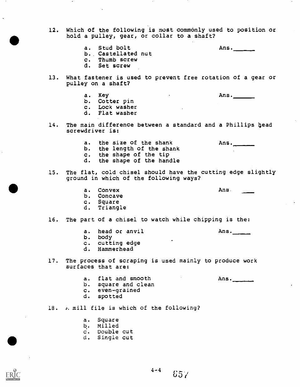
12. Which of the following is most commonly used to position orhold a pulley, gear, or collar to a shaft?
a. Stud boltb. Castellated nutc. Thumb screwd. Set screw
Ans.
13. What fastener is used to prevent free rotation of a gear orpulley on a shaft?
a. Keyb. Cotter pinc. Lock washerd. Flat washer
Ans.
14. The main difference between a standard and a Phillips leadscrewdriver is:
a. the size of the shankb. the length of the shankc. the shape of the tipd. the shape of the handle
Ans.
15. The flat, cold chisel should have the cutting edge slightlyground in which of the following ways?
a. Convexb. Concavec. Squared. Triangle
Ans.
16. The part of a chisel to watch while chipping is the:
a. head or anvilb. bodyc. cutting edged. Hammerhead
Ans.ANINI11.
17. The process of scraping is used mainly to produce worksurfaces that are:
a. flat and smoothb. square and cleanc. even-grainedd. spotted
18. t. mill file is which of the following?
a. Squareb. Milledc. Double cutd. Single cut
Ans.
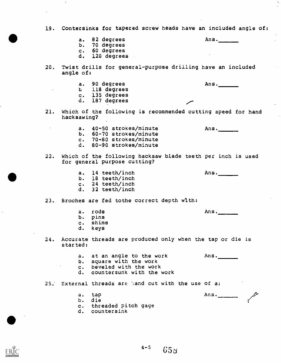
19. Contersinks for tapered screw heads have an included angle of:
a. 82 degreesb. 70 degreesc. 60 degreesd. 120 degrees
Ms.
20. Twist drills for general-purpose drilling have an includedangle of:
a. 90 degreesb 118 degreesc. 135 degreesd. 187 degrees
Ans.
21. Which of the following is recommended cutting speed for handhacksawing?
a. 40-50 strokes/minuteb. 60-70 strokes/minutec. 70-80 strokes/minuted. 80-90 strokes/minute
Ans.
22. Which of the following hacksaw blade teeth per inch is usedfor general purpose cutting?
a. 14 teeth/inchb. 18 teeth/inchc. 24 teeth/inchd. 32 teeth/inch
23. Broches are fed tothe correct depth with:
a. rodsb. pinsc. shimsd. keys
Ans.
Ms.
24. Accurate threads are produced only when the tap or die isstarted:
a. at an angle to the workb. square with the workc. beveled with the workd. countersunk with the work
Ans.
25; External threads are :land cut with the use of a:
a. tapb. diec. threaded pitch gaged. countersink
Ans.
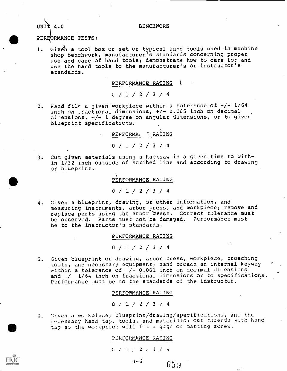
UNA 4.0
PER RMANCE TESTS:
BENCHWORK
1. Givdn a tool box or set of typical nand tools used in machineshop benchs'ork, manufacturer's standards concerning properuse and care of hand tools; demonstrate how to care for anduse the hand tools to the manufacturer's or instructor'sstandards.
PERFORMANCE RATING t
/ 1 / 2 / 3 / 4
2. Hand MP a given workpiece within a tolerance of +/- 1/64Inch on Lractional dimensions, +/- 0.005 inch on decimaldimensions, +/- 1 degree on angular dimensions, or to givenblueprint specifications.
PEPFORMA: 7 RATING
/ / 2 / 3 / 4
3. Cut given materials using a hacksaw in a given time to with-in 1/32 inch outside of scribed line and according to drawingor blueprint.
PERFORMANCE RATING
0 / 1 / 2 / 3 / 4
4. Given a blueprint, drawing, or other information, andmeasuring instruments, arbor press, and workpiece; remove andreplace parts using the arbor-PT-ess. Correct tolerance mustbe observed. Parts must not be damaged. Performance mustbe to the instructor's standards.
PERFORMANCE RATING
0/ 1/ / 3/ 4
5. Given blueptint or drawing, arbor press, workpiece, broachingtools, and necessary equipment; hand broach an internal keywaywithin a tolerance of +/- 0.001 inch on decimal dimensionsand +/- 1/64 inch on fractional dimensions or to specifications.Performance must be to the standards of the instructor.
PERFONMANCE RATING
0 / 1/ 2/ 3/ 4
6. Given a workpiece, blueprint/drawing/specificati(das, ants thenecessary hand tap, tools, and materials; cut t:Irads with handtap so the workpice will fit a gage or matting screw.
PERFORMANCE RATING
0 /* 1 2 i a/ 4
4.-6
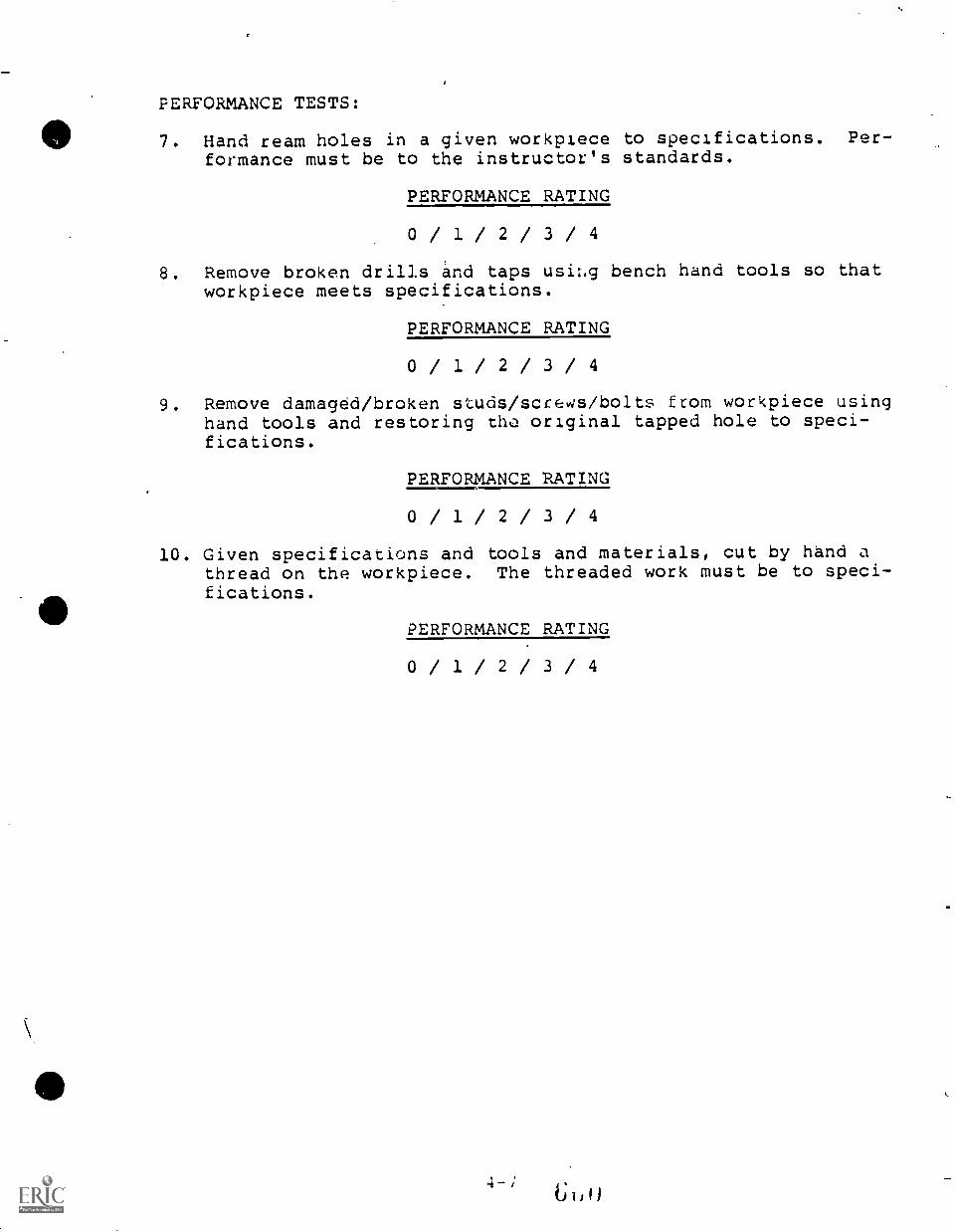
PERFORMANCE TESTS:
7. Hand ream holes in a given workpiece to specifications. Per-formance must be to the instructor's standards.
PERFORMANCE RATING
0 / 1 / 2 / 3 / 4
8. Remove broken drills and taps usi:.g bench hand tools so thatworkpiece meets specifications.
PERFORMANCE RATING
0 / 1 / 2 / 3 / 4
9. Remove damaged/broken studs/screws/bolts from workpiece usinghand tools and restoring tho original tapped hole to speci-fications.
PERFORMANCE RATING
0 / 1 / 2 / 3 / 4
10. Given specifications and tools and materials, cut by hand athread on the workpiece. The threaded work must be to speci-fications.
PERFORMANCE RATING
0 / 1 / 2 / 3 / 4
UNIT 5.0 BASIC GRINDING
COMPLETION:
1. When a grinding wheel becomes dull it generates excessive
2. The usual method for extracting material from the eye is
3. If a work piece is small and soft or thin, instead of beingground it should be
4. Fingers can easily be. trapped if are worn.
5. If there is any questions about a grinding wheel's soundness,it should be tested.
6. Off-center wheels will cut only the point of thestone.
7. It is not _afe to have on when grinding.
8. When you start a grinding wheel, it is best to stand to one
9. A safe, intelligent worker does not grind on theof a wheel.
10. The water pot is for the of the work piece.
UNIT 5.0 BASIC GRINDING
TRUE-FALSE:
It is considered an acceptable practice.to grindon the sides of a grinding wheel.
( ) ( ) 1.
( ) ( ) 2.
( ) ( ) 3.
( ) ( ) 4.
( ) ( ) 5.
( ) ( ) 6.
( ) ( ) 7.
( ) ( ) 8.
( ) ( ) 9..
( ) ( ) 10.
Pliers are acceptable for holding a work piece whengrinding.
If the wheel. passes t ring test, it is always safeto use.
It is safe practice to hold your work piece witha rag.
Never remove tne paper from the sides of the grindingte%eel.
When grinding, gently force material into the wheel.
When sharpening a tool on the grinding wheel, coolthe tool by dipping it in water or allow it to coolin the air.
A combination square can be used to check if theface of the grinding wheel is square with its side.
Before dressing the grinding wheel, adjust the toolrest on the grinder to a point even with the centerof the wheel.
A 60-grit wheel is suitable for general tool sharp-ening.
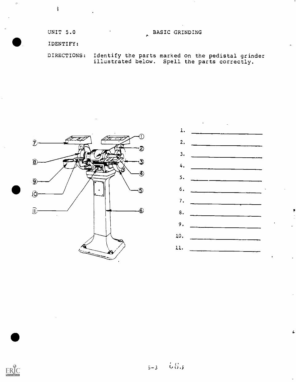
UNIT 5.0 BASIC GRINDING/4
IDENTIFY:
DIRECTIONS: Identify the parts marked on the pedistal grinderillustrated below. Spell the parts correctly.
1.
2.
3.
4.
5.
6.
7.
8.
9.
10.
11.
p
UNIT 5.0 BASIC GRINDING
MULTIPLE CHOICE:
1. The tool rest should be kept within
a. 1/32 inchb. 1/16 inchc. 3/32 inchd . 3/8 inch
2. Grinding wheels generally rotate at speeds of
a. 30 m.p.h.b. 50 m.p.h.c. 75 m.p.h.d . 60 m.p.h.
of the wheel.
3. Do not use a grinding wheel that is worn to less than
its original diameter.
a. 3/4b. 1/2c. 1/4d . 80%
4. A grinding wheel that has become loaded should be
a. shapedb. glazedc. dressedd . trued
5. Which is not an abrasive used in grinding wheels:
a. Aluminum oxiieb. Crocusc. Fiberd . Emery
SHORT ANSWER:
1. Identify the difference between the bench and pedestal grinders.
2. State the reason for the left-hand thread on the left end andright -hang thread on the right end of the grinder shaft.
3. What are the two basic types of a.l.asive grains used co makegrinding wheels?
4. State the two reasons why it is important to use blotters whenmounting a grinding wheel.
3. What is first step in yrinding a screwdLiver blade:?
6
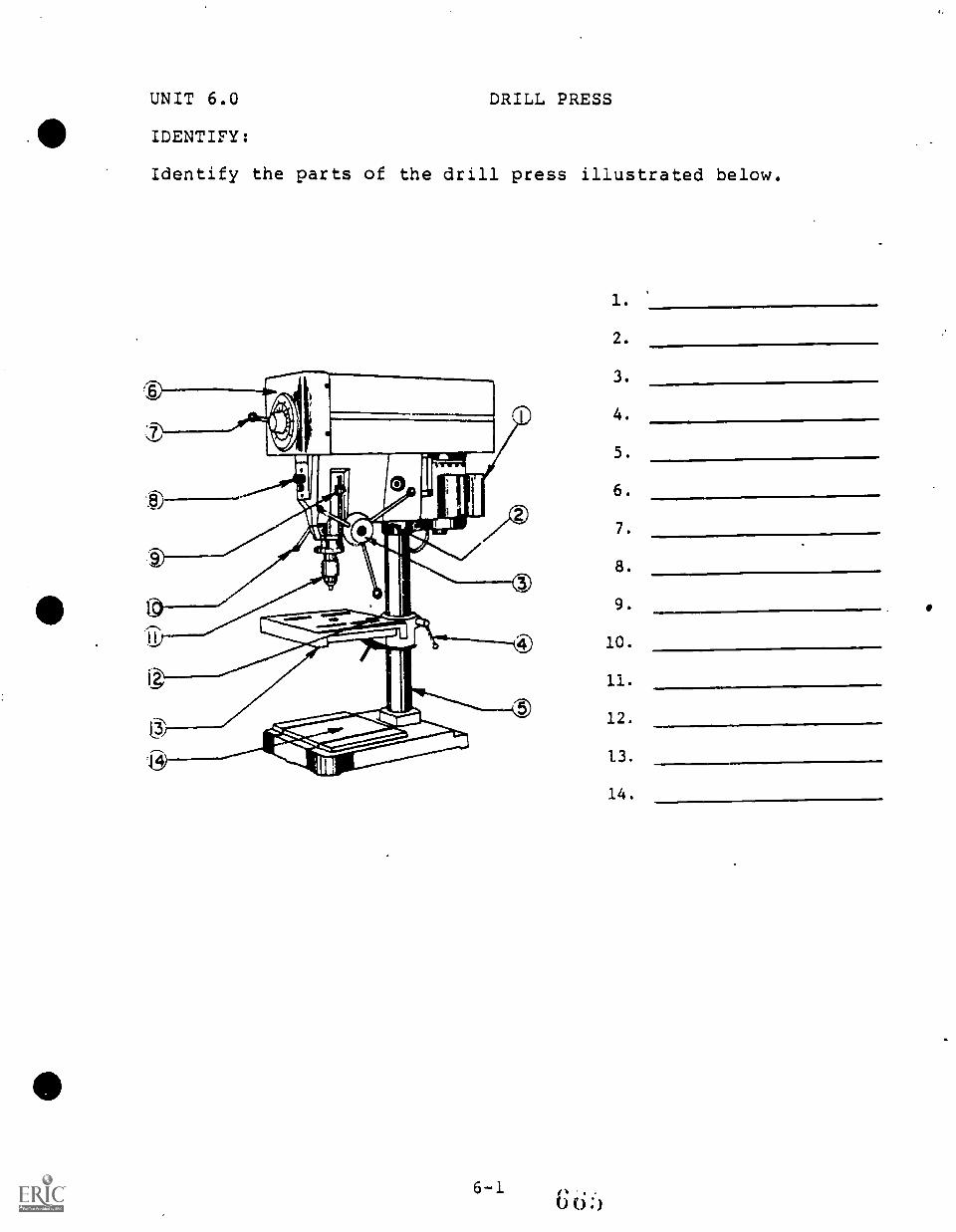
UNIT 6.0 DRILL PRESS
111 IDENTIFY:
Identify the parts of the drill press illustrated below.
1.
2.
3.
4.
5.
6.
7.
8.
9.
10.
11.
12.
1.3.
14.
UNIT 6.0
MULTIPLE CHOICE:
DRILL PRESS
1. The sleeve of a drill press:
a. holds the cutting toolb. rotates the spindlec. covers the armd. carries the spindle
2. The spindle of g drill press:
a. never movesb. supports the workpiecec. holds the cutting toold. holds the head
3. The purpose of the flutes is to:
a. lighten the drillb. reduce frictionc. provide a thin webd. allow chips to escape from the hold
Ans.
Ans.
Ans.
4. The true diameter of a drill is measured across the:
a. body clearanceb. webc. .marginsd. lips
Ans.
5. For normal work, the included angle of a drill point shouldbe:
a. 59 degreesb. 118 degreesc. 135 degreesd . 90 degrees
6. A large dead center will:
a. do a better jobb. reduce wearc. increase frictiond . reduce friction
7. A dull drill may:
a. slideb. produce a rough finishc. cut undersized holesd . not rotate
Ans.
Ans.
Ans.
UNIT 6.0 DRILL PRESS
MULTIPLE CHOICE:
8. Drill lip angle should be checked with a:
a. center gaugeb. plug gaugec. drill gauged. micrometer
9. Drills with worn margins:
a. can still be usedb. are normalc. will slip in the chuckd. should be reground or replaced
Ans.
Ans.
10. If the drill margins are worn, the drill will measure:
a. oversizeb. undersizec. full sized. the same
Ans.
11. When using the drill press, the most common holding device is a:
a. strapb. C clampc. angle plated. vise
12. Step blocks support one end of a:
a. viseb. strapc. V blockd. angle plate
Ans.
Ans.
13. The slot at the small end of the tapered spindle hole ho.lds
the:
a. shankb. tangc. sleeved. key
Ans.
14. A is used to remove toolholding aevices from thespindle.
a. drill chuckb. drill driftc. drill socketd. drill sleeve
Ans.
UNIT 6.0 DRILL PRESS
MULTIPLE CHOICE:
15. Straight shank tools are most often held in a:
a. socketb. drill chuckc. sleeved. spindle hole
Ms.
16. In drilling, the prupose of spotting a hole is to:
a. increasc accuracyb. eliminate setupsc. reduce the drill loadd. save time
17. The rate of speed for spotting should be:
a. automatic, heavy feedb. automatic, light feedc. hand, heavy feedd. hand, light feed
18. The most important step in drilling is:
a. layoutb. spottingc. setupd. drilling
19. Most drill failures result from:
a. too much feedb. too much speedc. poor tool conditiond. hard material
20. Too much speed will:
a. dull tool edgesb. clog flutesc. cause stressd. produce heavy chips
21. Too much feed will:
Ans.
Ans.
Ans.
Ans.
Ms.
a. prevent the drill from cutting the work Ans.b. produce and oversize holec. clot the flutesd. break the outer corners
UNIT 6.0 DRILL PRESS
MULTIPLE CHOICE:
22. A rough hole is the result of:
a. too much speedb. too much feedc. both a and bd. neither a or b
23. Chipped cutting edges result from:
a. too much speedb. insufficient feedc. insufficient lip clearanced. too much lip clearance
24. An 82 degree countersink is mainly used for:
a. burr removalb. center reamingc. beveling a hole to be tapped
25. A 60 degree countersink is used mainly for:
a. burr removalb. center reamingc. beveling a hole to be tappedd. flathead screws
Ans.
Ans.
Ans.
Ans.
UNIT 6.0 DRILL BIT SPEEDS
CALCULATE THE PROPER RPM FORCOMBINATIONS. USING THE FORMULA:
MATERIAL
THE FOLLOWING HOLE SIZE AND MATERIALsfm x 12 ?if=3.14
rpmD" x err
DRILL SI'LE DRILL RPM
1.
2.
Low-carbon steel
Cast iron, soft gray
1/2"
1/4"
3. Brass 9/16"
4. Slate 1/4"
5. Bronze 5/8"
.6. Low-carbon steel 5/16"
7. Medium-carbon steel 5/16"
8. Alloy steel 1/2"
9. Bakelite 3/16"
10. Wood 3/8"
CALCULATECUT
11.
12.
13.
14.
THE PROPER RPMFORMULA: 4
FOR THE FOLLOWING PROBLEMS USING THE SHORT-x sfm
rpm
Low-carbon steel
Cast iron, soft gray
Brass
Slate
D"
1/2"
1/4"
9/16"
1/4"
15. Bronze 5/8"
16. Low-carbon steel 5/16"
17. Medium-carbon steel 5/16"
18. Alloy steel 1/2"
19. Bakelite 3/16"
20. Wood 3/8"
UNIT 6.0
COMPLETION:
DRILL PRESSES
1. The operation of providing a recess at the top of a drilledhole for a flat-head machine screw is called
2. The operation of providing a recess for the head of a enlister-head screw is called
3. A tool used to finish drilled holet to exact size is calleda
4. The operation fo providing a smooth seat or bearing surfacearound a previously drilled hole for a washer or nut iscalled
5. Reamed foles must be drilled inch less than thereamed size specified on the drawing.
PERFORMANCE TEST:
Given a drill press, assortment of drill bits, necessary tools andmaterials, layout, and workpiece; select the proper bits for thejob and drill the workpiece to print specifications. The processand product must meetthe instructor's standards.
PERFORMANCE RATING
0/ 1/ 2/ 3/ 4
6-7
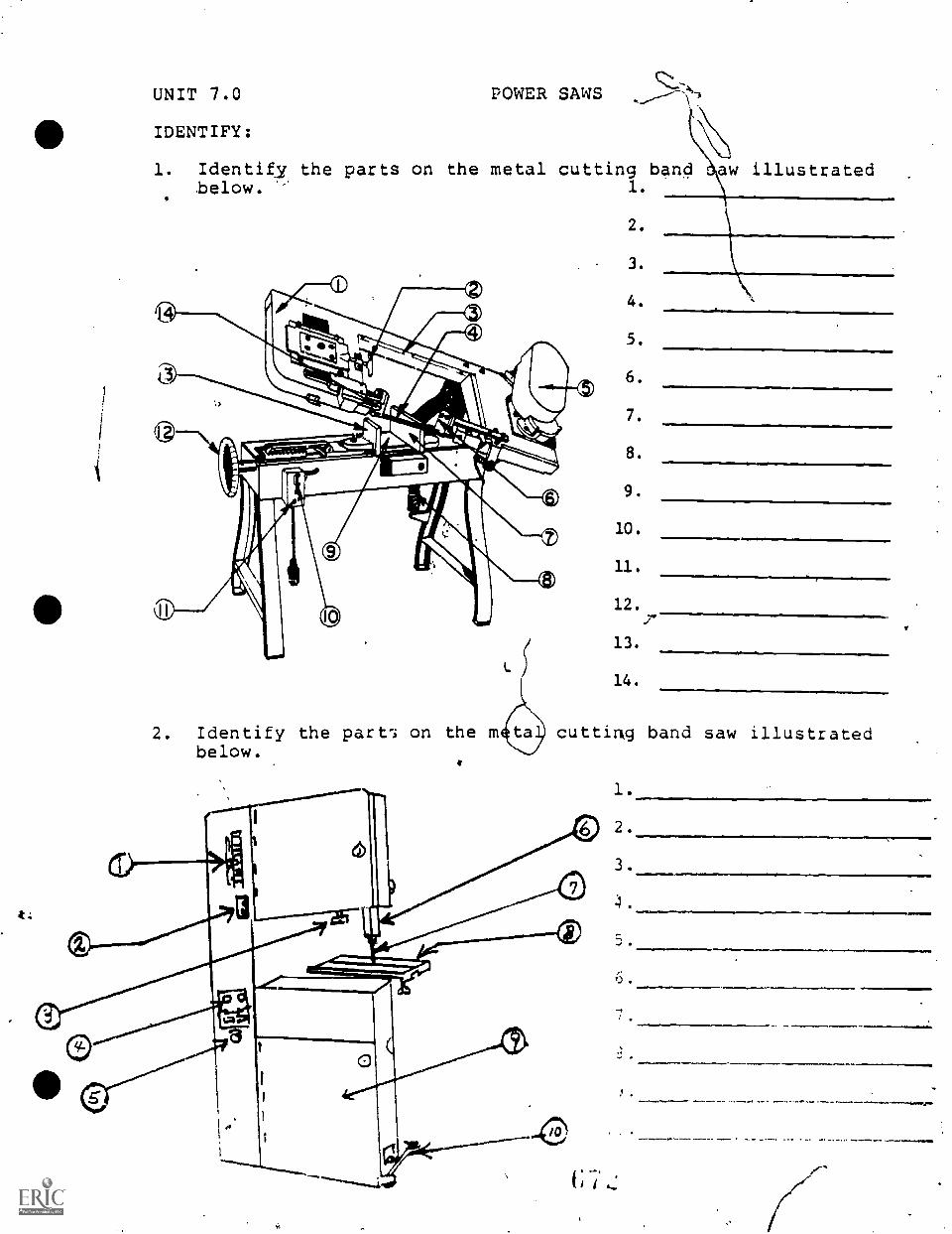
t:
UNIT 7.0
IDENTIFY:
1. Identify the parts on the metal cutting band haw illustratedbelow. ' 1.
POWER SAWS
2. Identify the part-.; on the mbelow.
2.
3.
4.
5.
6.
7.
8.
9.
10.
11.
12.
13.
14.
..
cutting band saw illustrated
UNIT 7.0
COMPLETION:
POWER SAWS
1. When laying out the contours of a part for sawing, it isadvisable to thelayout line, as the layout line may rub off.
2. The wearing of is alwaysadvisable when operating a band saw.
3. When band sawing a pare to a contouredlayout line and afiled finish is required, the saw cut should be made
outside of the layout line.
4. When welding saw blades, the overlaping of the saw bladeends cen be prevented by proper adjustment.
5. Band sawing parts to some irregular shape or form followinga layout line is called sawing.
6. Starting holes which are used when band sawing holes in pieceparts, should always be drilled to thelayout line for the hole.
7. Band sawing a multiple number of piece parts from sheet stockis referred to as sawing.
8. A power saw with a reciprocating cutting motion is calleda power
9. Contoured or curved cuts can only be performed ontype band saw machines,
10. To eliminate the brittleness which occurs due to the weldingof a band saw, the wcId must be
UNIT 7.0 POWER SAWS
SHORT ANSWER:
1. State the Leason why the band saw blade must be clean of oilbefore butt welding.
2. After the blade is welded, state the two additional stepsthat must be done before using the blade.
3. State the four main advantages of the metal-cutting band saw.
4. State the two methods of changing speed on power saws.
5. Give one correct reason for using a cutting fluid when bandsawing.
PERFORMANCE TEST:
Given a vertical band saw with blade installed, workpiece, printor specifications, and all materials needed; saw the workpieceaccording to specifications /plans. Layout must be properly accom-plished and work mist meet -f-h4 instructor's standards.
UNIT 8.0
COMPLETION:
ENGINE LATHE
1. The unit of a lathe which houses the lathe spindle and controllevers for speed selection is called a
2. When drilling work on a lathe, mount the drill in the spindleof the
3. When mounting any large or heavy chuck on the lathe spindleiit should be supported or held in aon the lathe bed until it is secure on the spindle.
4. Lathe work which can not be held in a lathe check can beclamped to a mounted on the headstock spindle.
5. To take up wear on the cross slide of compound rest, theadjustable must be tightened.
6. Ti :e angle on the face of top surface of a tool which slantsLrom the side cutting edge is called a angle.
7. The angles ground into the sides of lathe tools are calledrelief or angles
8. A round-nose tools ground with no rake can be
411used as a right- or left-hand tool.
9. To sheck accurately if stock is centered in a four-jaw chick,a is used.
10. Work which can not be checAtd, because Of. its shape can bemounted on a for facing.
11. The diameter of a finish turned shaft must be checked for sizewith a
12. For a turning operation, the tool bit should be set slightlythe center of the stock.
13. The preferred chuck for mounting small cylindrical work to beturner: is the chuck.
14. When cutting off work, the lathe must be lockedto the lathe bed.
15. The preferred chuck for mounting small cylindrical work to beturned is the chuck.
16. Tailstock centers which do not revolve with the workpiece arereferred to as centers.
17. A device which 0 fastened to the headstock end of a workpiecewhen work is turned between centers is called a
18. Workpieces provided with a reamed hole are mounted on a taperedfor turning between centers.
19. The dovetail surfaces of the compound rest, the carriage, andthe cross slides are provided with adjustableto take up wear.
20. The ground point of a Unified of Vthreading tool must bechecked for accuracy with a
21. The operation of producing and accurately sized hole in a latheusing a tool bit is called a .
22. The width of the tool bit point for cutting athread should be ground to 1/2 the pitch of the thread.
23. Drill chucks when used for drilling operations in a lathe aremounted in the spindle.
24. A is used to supportlong, slender, cylindrical workpieces and is attached directlyto the ways of, the lathe bed.
III25. The process of checking the surface of a piece of work by
rolling depressions into it is called
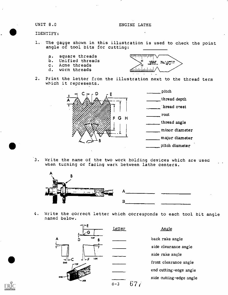
UNIT 8.0
IDENTIFY:
ENGINE LATHE
1.. The gauge shown in this illustration is used to check the pointangle of tool bits for cutting:
A. square threadsb. Unified threadsc. Acme threadsd. worm threads
2. Print the letter from the illustration next to the thread termwhich it represents.
pitch
thread depth
hread crestroot
thread angle
minor diameter
major diameter
pitch diameter
3. Write the name of the two work holding devices which are usedwhen turning or facing work between lathe centers.
A
B
4. Write the correct letter which corresponds to each tool bit anglenamed below.
IMO
Letter
8 - 3 67(
Angle
back rake angle
side clearance angle
side rake angle
front clearance angle
end cutting -edge angle
side cutting-edge angle
UNIT 8.0
110 MULTIPLE CHOICE:
ENGINE LATHE
1. Parts having a square or irregular shape to be machined on alathe can only be mounted in:
a. universal chucksb. independent chucksc. collet chucksd. cam lock chucks
Ans.
2. Which one of the following lathe parts is not provided with apower feed?
a. carriageb. compound restc. cross slide'
Ans.
3. To refinish the points of lathe centers which have becomeworn, grind them to an included angle of:
a. 30 degreesb.. 60 degreesc. 90 degreesd. 82 degrees
Ans.
4. Angles which are ground on the top surfaces or face of a lathetool bit and which slant downward from the side cutting edgeof the tool are called:
a. positive side rake anglesb. negative side rake anglesc. side clearance anglesd. end cutting-edge angles
Ans.
5. Chatter in lathe work which produces a rough surface finish,can be prevented in some cases by regrinding the tool bit to:
a. increase the side cutting-edge angleb. reduce the back rake anglec. increase the side clearance angled. reduce the side cutting-edge angle
Ans.
6. Lathe tool bits made of straight tungsten carbide are notedfor their ability to resist:
a. cateringb. gallingc. weard. shipping
Ans.
7. When straight turning a shaft mounted between lathe centers:
a. set:the compound parallelAns.
to the work axisb. use a lubricantc. set the tool bit slightly above the work centerlined. set the tool bit below the work centerline
8. A single thread screw having a pitch of 10 has:
a. 8 threads/inchb. 10 threads/inchc. 9 threads/inchd. 6 threads/inch
ALs.
9. The tool bit used in cutting an Acme thread must be ground toan angle of:
a. 30 degreesb, 29 degreesc. 14.5 degreesd. 60 degrees
Ans.
10. A good lubricant to use in thread-cutting operations is:
a. graphiteb. white leadc. mineral oild. water soluble oil
Ans.
11. What would be the finish depth of a square thread having a pitchof 1/8 inch?
a. 1/2 inchb. 1/8 inchc. 1/16 inchd. 3/32 inch
12. Short or sharp angled tapers are machined using:
a. a taper attachmentb. the compound restc. the tailstock setover method
Ans.
Ans.
13. When an internal right-hand unified thread is being cut, thelathe compound is set:
a. parallel to the work axis . Ans.__b. 29 degrees to the left of the cross-slide centerlinesc. 90 degrees of the work axisd. 29 degrees to the right of the cross-slide centerlines
8-5
67d
14. Of the following factors listed, which one must be consideredin determining the proper grade of carbide tool to use?
a. the type of operation to be done Ans.b. the type of material to be machinedc. the finish requirements of the machined partd. the speeds to be used in turning the part
15. The lead of a double-thread screw having 8 threads per inchis:
a. .125b. .250c. .110d. .0625
8 -.;
4
Ans.
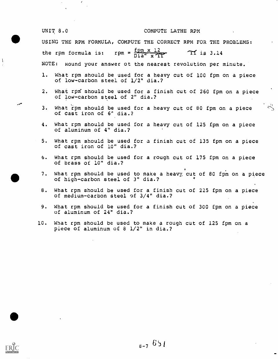
UNIT 8.0 COMPUTE LATHE RPM
USING THE RPM FORMULA, COMPUTE THE CORRECT RPM FOR THE PROBLEMS:
fpm x 12the rpm formula is: rpm = 'if is 3.14Dia x 11
NOTE: Round your answer of the nearest revolution per minute.
1. What rpm should be used for a heavy cut of 100 fpm on a pieceof low-carbon steel of 1/2" dia.?
2. What rprri should be used for a finish cut of 260 fpm on a pieceof low-carbon steel of 2" dia.?
3. What rpm should be used for a heavy cut of 80 fpm on a pieceof east iron of 6" dia.?
4. What rpm should be used for a heavy cut of 125 fpm on a pieceof aluminum of 4" dia.?
5. What rpm should be used for a finish cut of 135 fpm on a pieceof cast iron of 10" dia.?
6. What rpm should be used for a rough cut of 175 fpm on a pieceof brass of 10" dia.?
7. What rpm should be used to make a heavy cut of 80 fpm on a pieceof high-carbon steel of 3" dia.?
8. What rpm should be used for a finish cut of 225 fpm on a pieceof medium-carbon steel of 3/4" dia.?
9. What rpm should be used for a finish cut of 300 fpm on a pieceof aluminum of 24" dia.?
10. What rpm should be used to make a rough cut of 125 fpm on apiece of aluminum of 8 1/2" in dia.?
,)
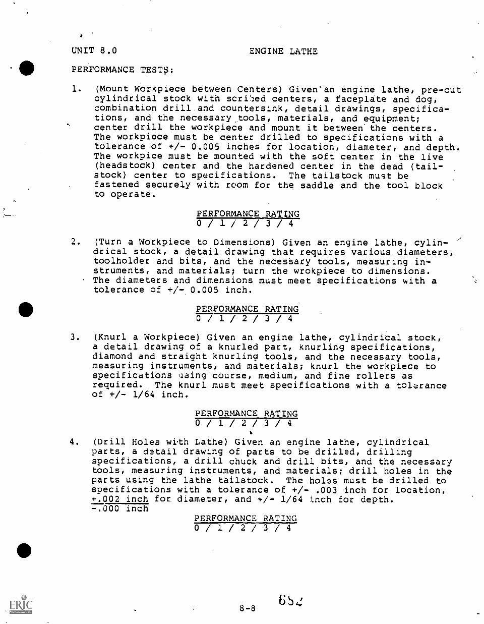
UNIT 8.0
PERFORMANCE TESTS:
ENGINE LATHE
1. (Mount Workpiece between Centers) Given'an engine lathe, pre-cutcylindrical stock with scri!ped centers, a faceplate and dog,combination drill and countersink, detail drawings, specifica-tions, and the necessary.. tools, materials, and equipment;center drill the workpiece and mount it between. the centers.The workpiece must be center drilled to specifications with atolerance of +/- 0.005 inches for location, diameter, and depth.The workpice must be mounted with the soft center in the live(headstock) center and the hardened center in the dead (tail-stock) center to specifications. The tailstock must befastened securely with room for the saddle and the tool blockto operate.
PERFORMANCE RATING0/ 1/ 2/ 3/ 4
2. (Turn a Workpiece to Dimensions) Given an engine lathe, cylin-drical stock, a detail drawing that requires various diameters,toolholder and bits, and the necessary tools, measuring in-struments, and materials; turn the wrokpiece to dimensions.The diameters and dimensions must meet specifications with atolerance of +/-0.005 inch.
PERFORMANCE RATING0/ 1 / 2 / 3 / 4
3. (Knurl a Workpiece) Given an engine lathe, cylindrical stock,a detail drawing of a knurled part, knurling specifications,diamond and straight knurling tools, and the necessary tools,measuring instruments, and materials; knurl the workpiece tospecifications uaing course, medium, and fine rollers asrequired. The knurl must meet specifications with a toleranceof +/- 1/64 inch.
PERFORMANCE RATING0/ 1/ 2/ 3/ 4
4. (Drill Holes with Lathe) Given an engine lathe, cylindricalparts, a detail drawing of parts to be drilled, drillingspecifications, a drill chuck and drill bits, and the necessarytools, measuring instruments, and materials; drill holes in theparts using the lathe tailstock. The holes must be drilled tospecifications with a tolerance of +/- .003 inch for location,+.002 inch for. diameter, and +/- 1/64 inch for depth.-.000 inch
PERFORMANCE RATING0 / 1 / 2 / 3 / 4
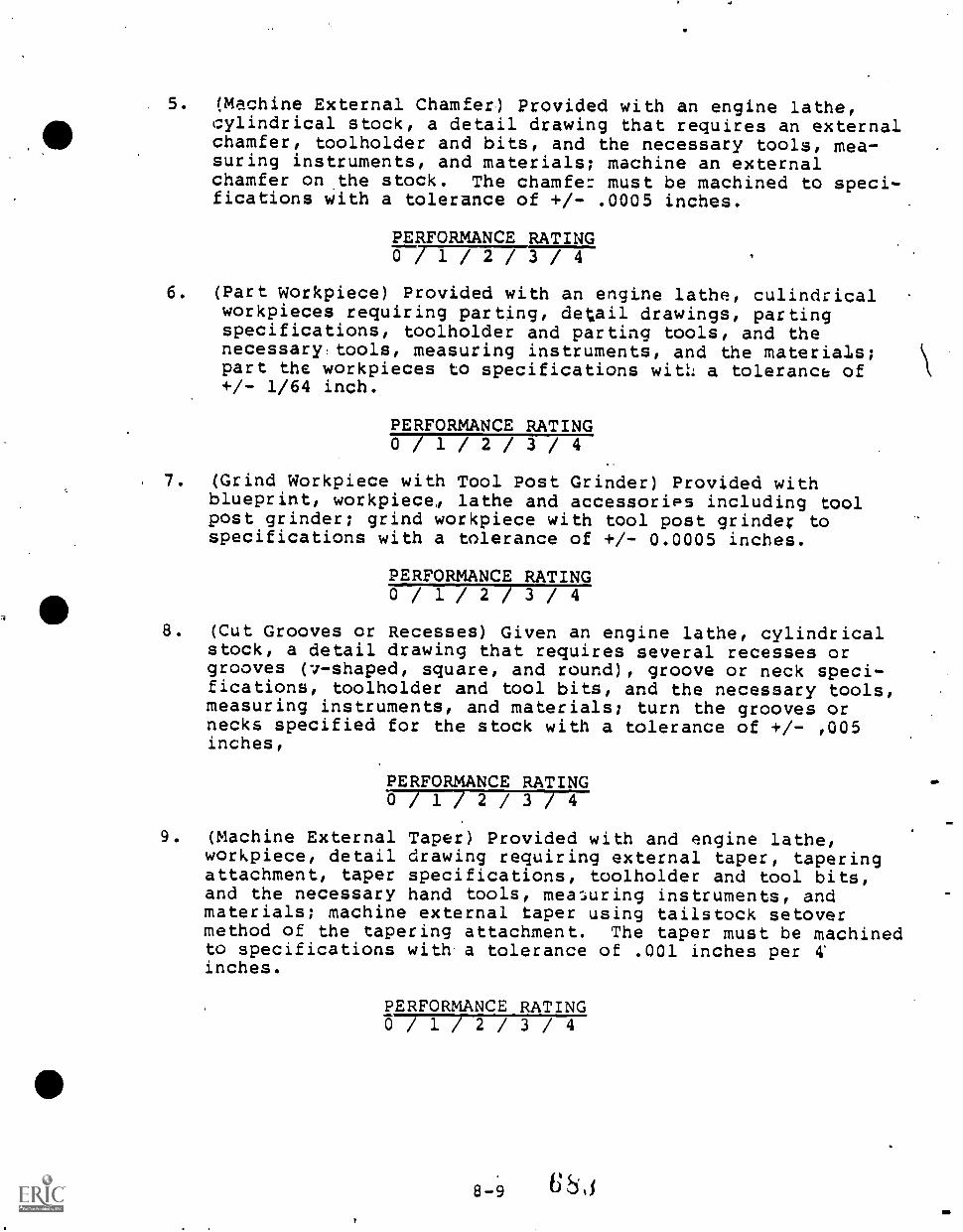
5. (Machine External Chamfer) Provided with an engine lathe,cylindrical stock, a detail drawing that requires an externalchamfer, toolholder and bits, and the necessary tools, mea-suring instruments, and materials; machine an externalchamfer on
withstock. The chamfer must be machined to speci-
fications with a tolerance of +/- .0005 inches.
PERFORMANCE RATING0 71727Th / 4
6. (Part Workpiece) Provided with an engine lathe, culindricalworkpieces requiring parting, detail drawings, partingspecifications, toolholder and parting tools, and thenecessary tools, measuring instruments, and the materials;part the workpieces to specifications with a tolerance of+/- 1/64 inch.
PERFORMANCE RATING0 / 1 / 2 / 3 / 4
7. (Grind Workpiece with Tool Post Grinder) Provided withblueprint, workpiece,, lathe and accessories including toolpost grinder; grind workpiece with tool post grinder tospecifications with a tolerance of +/- 0.0005 inches.
PERFORMANCE RATING0 / 1 / 2 / 3 / 4
8. (Cut Grooves or Recesses) Given an engine lathe, cylindricalstock, a detail drawing that requires several recesses orgrooves (v-shaped, square, and round), groove or neck speci-fications, toolholder and tool bits, and the necessary tools,measuring instruments, and materials; turn the grooves ornecks specified for the stock with a tolerance of +/- ,005inches,
PERFORMANCE RATING0 / 1 / 2 / 3 / 4
9. (Machine External Taper) Provided with and engine lathe,workpiece, detail drawing requiring external taper, taperingattachment, taper specifications, toolholder and tool bits,and the necessary hand tools, measuring instruments, andmaterials; machine external taper using tailstock setovermethod of the tapering attachment. The taper must be machinedto specifications with a tolerance of .001 inches per 4'
inches.
PERFORMANCE RATING0 / 1 / 2 / 3 / 4
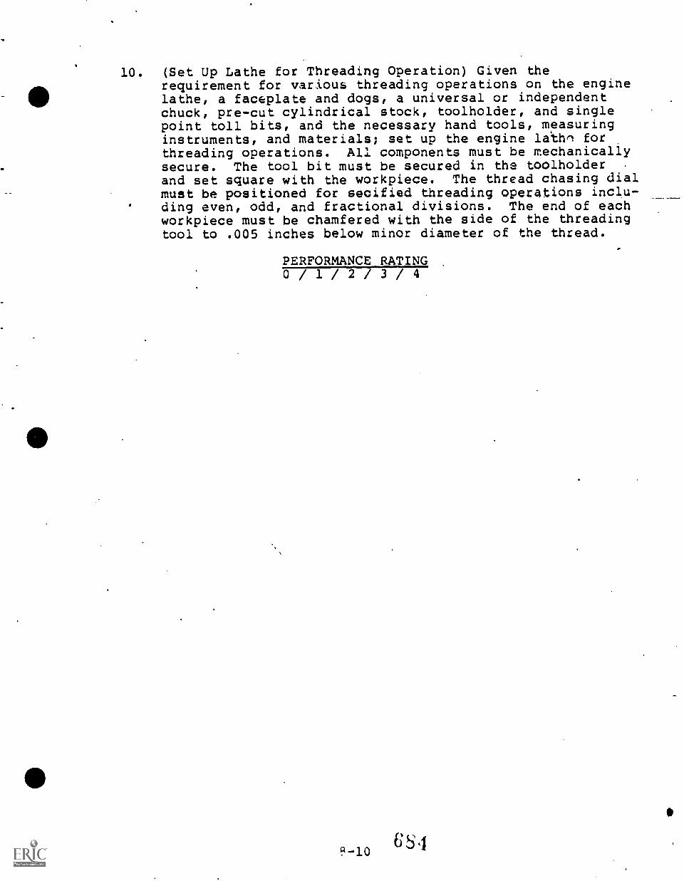
10. (Set Up Lathe for Threading Operation) Given therequirement for various threading operations on the enginelathe, a faceplate and dogs, a universal or independentchuck, pre-cut cylindrical stock, toolholder, and singlepoint toll bits, and the necessary hand tools, measuringinstruments, and materials; set up the engine lathe forthreading operations. All components must be mechanicallysecure. The tool bit must be secured in the toolholderand set square with the workpiece. The thread chasing dialmust be positioned for secified threading operations inclu-ding even, odd, and fractional divisions. The end of eachworkpiece must be chamfered with the side of the threadingtool to .005 inches below minor diameter of the thread.
PERFORMANCE RATING0/ 1 / 2 / 3 / 4
65 49-10
0
UNIT 9.0 MILLING MACHINE
COMPLETION:
1. To prevent springing the arbor of a horizontal millingmachine, the arbor nut should be tightened until the
is ih place.
2. The position Of the is what classifies a millingmachine as being h orizontal or vertical.
3. The depth of cut in horizontal milling operations is ob-tained by raising the which supports thetable saddle.
4. The feed screws of a milling machine table are provided with,dials to permit accurate positioning of the
table.
5. TI-a attachment used on milling machines for indexing iscalled a
6. The first step in calculating the 'correct indexing neededfor a specific job is to divide the constantby the number of divisiods required.
7. The cutters desighed for straddle milling operations arecalled
4
8. The cutting action of athe same as an end mill cutter.
milling cutter is
9. In horizontal milling operations, the feed isused to move the workpiece into or away from the cutter.
10. A style "C" arbor must be used for mountingmill cutters.
11 A quick and accurate way to mill a perfect square on the endof a round shaft is to mount the shaft in a
so the shaft can be indexed.
12. The accurate spacing of teeth in a gear blank requires theuse of a
13. The cutting of helical gears requires the use of amilling machine.
14. A gear tooth vernier caliper is used to measure theand chordal thickness of gear teetn.
15. It is important in milling a helical gear to center theover the mandrel before the table is set to
the helix angle.
UNIT 9,0
MULTIPLE CHOICE:
MILLING MACHINES
1. To index work mounted on a dividing head one complete turn,the index crank must be turned:
a. forty complete turns Ans.b. twenty complete turnsc. ten complete turns
2. The number of index crank.turns needed after each cut tomill eight equally spaced slots in a round shaft is:
a. fourb. sevenc. five
Ans.
3. Only a universal dividing head can be used to perform amilling operation by:
a. plain indexingb. direct indexingc. differential indexing
Ans.
4. When indexing work by degrees, OLe complete turn of the inde.;crank will turn the workpiece:
a. 9 degreesb. 15 degreesc. 7 degrees
Ans.
5. Because the hard scale will dull the cutter teeth, the climbcutting method of cutter rotation should never be used whenmilling:
a. tool steelb. magnesiumc. cast iron
Ms.
6. The measuremnt from center to center of adjacent gear teethtaken on the arc of the pitch circle, is called the:
a. Circular pitchb. chordal pitchc. diametral pitch
Ans.
7. The tooth addendum of a gear having a diametral pitch of 4is:
a.b.
c.
. 250
. 125
. 156
9-2 6 St)
Ans.
8. What would be the proper number of form cutter to use inmilling a gear with 36 teeth?
a. No. 6 cutterb. No. 3 cutter.c. No. 5 cutter
Ans.
9. Helical milling operations can be performed only on a:
a. plain horizontal milling machineb. vertical milling machinec. universal milling machine
Ans.
10. The circumference of the gear blank must be divided by thelead of the helix in helical milling to determine the:
a. angle setting of machine tableb. proper speed usec. proper feed and depth of cut needed
Ans.
UNIT 9.0 MILLING MACHINE
PERFORMANCE TESTS:
1. (Align Workpiece, Mill Head, Machine Attachemtns, andFixture) Given the milling machine, vise, attachments,clamping bolts, wrench, measuring instruments, mallet,squire, workpiece, blueprint/drawing/specifications for:-.ask, and other materials needed; align vise, maelineattachments, mill head, and workpiece to specificationsacceptable in the local machining industry and to theinstructor.
PERFORMANCE RATING0 / 1 / 2 / 3 / 4
2. (Calculate Cutting Speeds and Feeds for Milling MachineWork) Given a milling machine and accessories, workstock,work assignment, and the necessary tools and materials;select proper cutter and attachment, calculate speed and feed,and install the cutter. Performance must conform to theMachinery's Handbook.
PERFORMANCE RATINGU-7 1 / 2 / 3/4
3. (Face Mill Workpiece) Given a milling machine with workpiecemounted in a jig, detail drawing or blueprint, facing speci-fications, an assortment of arbors, collars, and millingcutters, and the necessary hand tools, measuring instruments,and materials; face mill the workpiece to specifications toa tolerance of +/- .001 inches. Finished work must besmooth without gouges or marks.
PERFORMANCE RATING0 / 1 / 2 / 3 / 4
4. (Perform Keyseating and T-Slot Milling Operation) Givenmilling machine, blueprint-drawing, specifications, work-piece and precision measuring instruments, and necessarytools and materials; machine a Woodruff keyway (seat)in the workpiece with a tolerance of +/- ,005 tospecifications (+/- 1/64 inch fraction dimensio s).
PERFORMANCE RATING0 / 1 / 2 / 3 / 4
5. (Perform Indexing Operations) Given milling machine, index-ing or dividing head, rectangular or cylindrical stock,detail drawing that requires equally spaced slots milledin workpiece, milling specifications, assortment of millingcutters and holders, and the necessary hand tools, attach-ments, measuring instruments, and materials; mill slots tospecifications +/- .002 inch for location and +/- .001 inchfor width and depth. Performance and product must be to thestandards of the instructor.
PERFORMANCE RATING0 / 1 / 2 / 3 / 4
6. (Mill a Gear Rack) Given the milling machine, drawing, speci-fications, workpiece, machine accessories and cutters, andnecessary tools, measuring instruments, and materials; milla gear rack to specifications, tolerance of "zero" to .002inches. Performance and product must meet instructor'sstandards.
PERFORMANCE RATING0 / 1 / 2 / 3 / 4
7. (Machine a Spur Gear) Given a detail drawing , a precutworkpiece, hand tools, precision measuring instruments, andthe necessary machine tools, accessories, attachments, andmaterials; machine a spur gear. The gear must meet the speci-fications of the drawing with a tolerance of +/- .002 inchesfor pitch diameter and dimensions. Performance and productmust be to the instructor's standards.
PERFORMANCE RATING0 / 1 / 2 / 3 / 4
UNIJ 11.0 TURRET LATHE
COMPLETION:
1. Stock to be machined on bar-type turret lathes is held orgripped in chucks.
2. Turret lathes so contructed that turning cuts are made bymoving the saddle along the bedways of the machine areclassified as type machines.
3. A tool which is mounted in the hexagon turret for takingheavy turning cuts at high speeds is called a
4. A drill having flat sided and two cutting edges for drill-ing large holes is called a drill.
5. When reaming holes with sloid reamers, mount +he reamer ina holder.
6. The use of a tap when large holes arebeing threaded eliminates having to reverse the rotation ofthe lathe spindle when withdrawing the tap from the hole.
7. When work from the hexagon turret is being bored, theboring bar holding the tool bit must be mounted in, a
8. On a single-spindle screw machines, '3tock cutoff operationsnormally are performed from the tool side.
9. Automatic Turret lathes capable of producing identicalprecision turned parts in large quanities are classifiedas machines.
10. The typical tolerance obtained in turning operations onautomatic crew machines is plus and minus
UNIT 11.0 TURRET LATHE
MULTIPLE CHOICE:
1. Taper turning on a turret lathe requires the use of a taperattachment. The turning cut is then taken from the:
a. square turretb. hexagon turretc. vertical tool sided. rear tool post
Ans.
2. On bar-type turret lathes, work to be machined is grippedor held by:
a. collet chucks Ans.b. universal chucksc. faceplatesd. independent chucks
3. Turret lathes on which long turning cuts are made by move-ment of the saddle along bedways of the mchine are classi-fied as:
a. sadlle-type turret lathesb. ram-type machinesc. carriage-type machinesd. automatic screw machines
Ans.
4. Internal tapers are checked for accuracy using a:
a. micrometerb. telescopic gagec. taper plug gaged. socket gage
5. Short or sharp angled tapers are machined using:
a. a taper attachmentb. the compound restc. the tailstock setover methodd. a form tool ground to the :raper angle
Ans.
Ans.
UNIT 12.04` SURFACE GRINDING
COMPLETION:
1. The grinder which is used to produce flat ground surfacesis called a grinder.
2. The depth of cut on a surface grinder is regulated byraising or lowering the .
3. Most surface grinders are provided with achuck for holding the work to be ground.
4. The type of grinding which involves feeding the grindingwheel into the workpiece is called .
5. The operation of sharpening a grinding wheel is calledwheel
MULTIPLE CHOICE:
6. The grinding wheels employed in surface grinding operationsare classified as:
a. plain grinding wheelsb. cup wheelsc. dished or saucer wheels
Ans.
7. Grinding machines equipped with rotating worktables areclassified as:
a. tool or cutter grindersb. cylindrical grindersc. surface grinders
SHORT ANSWER:
Ans.
8. Name three conditions which indicate that a grinding wheelrequires dressing.
9. List an advantage and disadvantage of dry grinding. Answersmust agree withtextbooks or be acceptable to instructor.
10. When should wet grinding be used?
11. Why is surface finish so important in industrial applica-tions?
12. What unit of measurement is used to indicate surface finish?
13. What two types of tables are found on surface grinders?
14. What factors determine the method of hold a workpiece forgrinding?
dr.
15. Why is it important that the burrs be removed from the work-piece and the chuck face prior to grinding?
16. What two factors are important when properly grinding aflat surface?
17. When is it necessary to balance a grinding wheel?
18. What crossfeed should be used when grinding a falt surface?
19. Why is the table speed reduced when taking a roughing cut?
20. List the procedures for taking a finishing cut on theworkpiece when grinding a flat surface?
UNIT 12.0 SURFACE GRINDING
PERFORMANCE TEST:
1. Given a horizontal spindle surface grinder, operator.'sinstructions, set up specifications, workpieces requiringflat surfaces machined to a surface expressed in micro-inches, dimensioned blueprints or drawings, grinding speci-fications, grinding wheels, magnetic chuck, and the necessaryhand tools, measuring instruments, and materials; set up thesurface grinder for flat surfacing operations and grindthe flat surfaces to specifications with a tolerance of 32-125 micro-inches. Performance process and porduct must meetthe instructor's standards.
PERFORMANCE RATING0 / 1 / 2 / 3 / 4
UNIT 13.0 SHAPER
COMPLETION:
1. So that the depth of any cut can be accurately determined,the tool head feed screw is equipped with acollar graduated in thousandths of an inch.
2. To properly seat work in a shaper vise for machining, thework should be supported on
3. The of the ram stroke is regulated byturning the stroke adjusting.
4. To obtain an equqlspacing of splines around the circumferenceof a shaft by shapiY14), the shaft is mounted between
centers.
5. Shapers equipped with a table that can be swiveled for anglecutting are referred to as shapers.
6. Rotary tables for circular cuts are standards equipment ona shaper.
7. Safe operating practice requires that the shaper bebefore any changes of machine ad-
justments or in the work setup are made.
8. When setting up a shaper, the ram stroke must be adjustedfor both and over thework.
9. The smoothly finished square or rectangular bars used asa a workseat support when shaping work in a vise are called
10. The is a casting that serves as afoundation for the entire shaper.
UNIT 13.0
MULTIPLE-CHOICE:
SHAPER
1. Shapers equipped with universal rather than the conventionaltype tabla are preferred when performing operations such as:
a. vertical shapingb. angle shapingc. slottingd. form cutting gear teeth
Ans.
2. The clapper box usually is set vertically when taking:
a. roughing cutsb. Angular cutsc. horizontal cutsd. vertical cuts
Ans.
3. The factor to be considered in determining shaper size isthe:
a. overall height of the machine Ans.b. the table size with which the machine is equippedc. The maximum table feed movementd. the maximum stroke length of the ram
4. When grinding single point tools for shaper use, what degreeof side clearante normally would be provided?
a. 5 degreesb. 2 degreesc. 15 degreesd. 8 degrees
Ans.
5. To prolong the life of shaper tools after they are ground,they should be:
a. lappedb. sandedc. stonedd. hardened
Ans.
6. What work holding device would be recommended for use when.shaping a keyway in a cylindrical shaft?
a. v-blockb. angle platec. dividing headd. shaper vise
13-2 6 96
Ars.
7. To machine a piece of work 5.5 inches long on a shaper, theminimum stroke length which can be used is:
a. 5.75 inchesb. 5.5 inchesc. 6.25 inches
Ans.
8. The adjustment of the ram-position shaft on a shaper isdone with the ram:
Ans.a. stopped at_the end of the back or return strokeb. in motiJn on the return stroke .
c. stopped midway through the cutting stroke
9. To shape splines in a shaft wiich must be acc:urately spaced,the work is mounted:
a. in a shaper viseb. between indexing centersc. in V-blocksd. in a special fixture
Ans.
10. The reed can be hand or power when using the shaper. Theamount of feed.is based on the:
a. type of material in the cutting tool Ans.b. amount of material being removed at each cutc. depth of cut
qs
UNIT 13,0 TAPER
PERFORMANCE ¶STS:
1. (Set Up Shaper for Machining Operations, Set Speed and Feed)Given a horiiontal shaper, soup specifications, workpieces,cutting tools and attachments, a dial indicator, and thenecessary hand tools, measuring instruments, and materials;set up the shaper for various machining operations. Thecorrect cutting tools must be selected, secured, and aligned.The workpiece, attachments, and cutting tools must bealigned with.the table and toolhead to specifications witha tolerance of +/- .001 inch.
For given shaper operation, calculate speed and feed andset machine up within 10 percent of instructor's calculations,confotming to Machinery's Handbook.
Set up shaper, align shaper attachments, workpiece, andcutter. Cutting toolhead and side clearnace must be withinA degrees. Ram stroke must clear workpiece on forward strokeby 1/4 inch; and 1/2 inch onreturn stroke.
PERFORMANCE RATING0 / 1 / 2 / 3 / 4
2. (Make a Rough and Finished Horizontal Cut) Given a hori-zontal shaper with a workpiece mounted using a vise andparallel bars, a detail drawing, shaping specifications forhorizontal roughing cuts, an assortment of shaper cuttingtools and holders, and the necessary hand tools, measuringinstruments, and materials; make roughing cuts in workpiece..The stock must be rough cut to specified depth of cutusing consecutive.1/8 inch cuts. The roughing cuts mustallow for finishing cut of .005 inch.
PERFORMANCE RATING0 / 1 / 2 / 3 / 4
3. Given a horizontal shaper with a workpiece mounted using avise and parallel bars, a detail drawing, shaping speci-fications for horizontal finishing cuts, an assortment ofshaper cutting tools and holders, and the necessary handtools, measuring instruments, andaaterials, make fin.ishingcuts in workpiece. The finishing cuts must be made betspecified depth of cut using consecutive ,005 inch cuts,with a tolerance of +/- .005 inch for diwensions.
PERFORMANCE RATING0 / / 2 / 3 / 4 .
UNIT 14.0 TOOL AND CC7TER GRINDER
PERFORMANCE TEST:
1. (Set Up a Tool and Cutter Grinder) Given a tool and cuttergrinder, a selection of grinding wheels, operator's inLcruc-tions, dressing tools, and the necessary equipment andmaterials; set up the tool and cutter grinder for variousgrinding operations (e.g., sharpen tool bits). The grindingwheel must run true, and the grinding surface must not belocated or glazed. The grinder must operate according tothe manufacturer's specifications.
PERFORMANCE RATING0 / 1 / 2 / 3 / 4
19-1 69:)
UNIT 15.0
COMPLETION:
HEAT TREATMENT
1. The steels used in cutting tools of high quality have agrain structure.
2. Steel hardens when it is heated and quenched because of thechanges which occur in the structure.
3. The temperature to which steel must be heated so that itwill harden when quenched is called thetemperature.
4. Two processed used in case-hardening steel areand
5. All parts which have been hardened must beto relieve the hardening strains and to increase the tough;ness of the part.
MULTIPLE CHQICE:
1. Steel is made form cast iron by removing all excess:
a. carbonb. siliconc. sulphur
Ans.
2. The most important factor relative to the physical propertiesof stael is:
a. carbonb. siliconc. manganese
Ans.
3. Machine steel or mild steel are terms commonly applied tosteels containing:
a, more than .40 percent carbonb. less than .30 percent carbonc. more than .50 percent carbon
Ans.
4. To alloying elements of steel commonly used as purifiers orcleansing agents are:
a.b.
c.
manganese and siliconvanadium and chromiummolybdenum and nickel
15-1
Ans.
5. Under the color code for marking steel bars so they can bereadily identified as to type of steel, a free cutting steelwould have the end of the bar painted:
a. yellowb. greenc. brown
Ans.
6. A test commonly applied to steel of unknown quality foridentification purposes is the:
a. acid-etch test Ans.b. spark testc. fracture test
7. High alloy steel must be heated slowly and uniformly forhardening, to avoid:
a. scalingb. shrinkagec. warpage
Ans.
8. Case hardening is the only method suitable for hardening:
a. high slloy steelh. high carbon steelc. low carbon steel
Ans.
9. When hardening steel by the carburizing process and thesteel has been heated to the correct temperature for thecorrect amount of time, the furnace is shut off and thesteel is:
a. removed and quenched in waterb. left in the furnace to coolc. removed and cooled in air
Ans..
10. Hardening strains created.in steel after it has been heatedand quenched must be removed by:
a. temperingb. annealingc. normalinzing
Ans.
UNIT 15.0 HEAT TREATMENT
PERFORMANCE TESTS:
1. (Tes+ Workpiece for Hardness) Given an assortment of metalworkpieces (steel, unhardened steel, soft-temper steel, andcast iron), test blocks with hardness tester and ComparativeHardness Scales (use Rockwell tests to determine hardnessof samples). The correct hardness numbers must be takenfrom the tests on the samples. Readings must agree with thereadings taken by the instructor.
PERFORMANCE RATING0 / 1 / 2 / 3 / 4
2. (Harden and Temper Workpiece) Given a furnace for hardeningand tempering operations, workpiece(s), quenching solutions,a shart of heat treatment specifications, a hardness testingprocedures outlined by the instructor, workbench, file, tongs,and the necessary materials; (a) harden and (b) temper theworkpiece(s). The stock must be hardened and tempered tothe specifications of the instructor.
PERFORMANCE RATING0 / 1 / 2 / 3 / 4
3. (Anneal Workpiece) Given heat treating equipment, hardenedworkpiece, specifications, and the necessary tools and ma-terials; anneal the workpiece. The stock must be annealedto specifications of the instructor.
PERFORMANCE RATING0 / 1 / 2 / 3 / 4
Unit 16.0 HYDRAULIC PRESS
PERFORMANCE TEST: (OPTIONAL)
1. (Set Up, Remove, and Replace Parts with Hydraulic Press)Given specifications/drawing, gears pulleys or wheel, ashaft, etc., with keyway, key, lubricant, clamps, and mea-suring instruments; set, remove, and replace parts with pressto a tolerance of +/- 1/64 inch.
PERFORMANCE RATING0 / 1 / 2 / 3 / 4
UNIT 17.0 CNC MACHINE
COMPLETION:
1. The two systems of numerical control are AMM
and the continuous path system.
2. The machine tool to which the system of point-to-pointnumerical control applies is the .
3. The numerical control system which applies to a millingmachine is called the
4. The control unit which commands and guides the movement ofnumerically controlled machine tools is called a
MULTIPLE CHOICZ:
1. The point-to-point system of numerical control can be appliedonly to:
Ans.a. ocnventional drill press of jig boring operationsb. conventioanl milling operationsc., conventional shaper operations
2. The vertical movement of the table on a conventional mill-ing machine is represented in the Catesian coordinate systemas a movement parallel to the:
a. Z-axisb. X -axisc. Y-axis
Ans.
3. The cross feed movement of a conventional milling machinetable is represented in the Cartesian coordinate systemas a movement parallel to the:
a. X -axisb. Z-axisc. Y-axis
Ans.
UNIT 17.0
SHORT ANSWER:
CNC MACHINE
DIRECTIONS: Explain the following terms as used with the CNCCompact 5 Trainer used in machine shop.
1. Longitudinal or cross slide -
2. Direction rate -.
3. Feed rate -
4. "Minus" value -
5. Coding -
UNIT 17.0 CNC MACHINING
PERFORMANCE TESTS:
1. (Set Up CNC Program/Machine) Given instruction, blueprint-drawing-specifications, cutting tools, workpiece, precisionmeasuring instruments, student handbook - BASIS, and the CNCtrainer; set up the CNC milling machine for machining agiven workpiece. The workpiece must be within a toleranceof +/- .001 inch or to specifications.
PERFORMANCE RATING0 / 1 / 2 / 3 / 4
2. (Machine Workpiece with CNC Machine) Given the CNC machine,tools, program, workholding devices, measuring instruments,references, blueprint-drawing-specifications, aluminumstock,. and the necessary tools and materials; machine theworkpiece to specifications within a tolerance of +/- .001inch of decimal dimensions and +/- 1/64 inch on fractionaldimensions.
PERFORMANCE RATING0/ 1 / 2 / 3 / 4
oUNIT 18.0 MACHINING MATH CALCULATIONS
1. (Convert Revolutions Per Minute of Grinding Wheel to SurfaceFeet Per Minute) Given reference material, calculate surfacefeet per minute (SFPM) of a grinding wheel. Round off theanswer to decimal point. Answer ,must be within 5 SFPM andmaximum speed must not exceed handbook specifications.
2. (Calculate Depths and Widths of Slots and Grooves on SpecialSetups) Given blueprint references, and workpiece, calculatedimensions of slots and grooves for special setup. A toler-.ance of +/- 0.001 inches must be obtained in calculations.
3. (Calculate Feeds and Speeds) Given blueprint, workpiece,machinery specifications, milling machine, milling cutter,measuring instruments, and other materials needed; calculatespeed and feed. Speed must be within a tolerance of +/- 5RPM and feed within a tolerance of +/- .001 inches.
4. (Calculate Tolerance/Allowances) Given a workpiece, blueprint,and references; calculate tolerance/allowance for specificjob to a bilateral tolerance of +/- .001 inches.
5. (Convert Common Fractions to Decimal fractions) Given blue-print, convert fraction dimensions to decimal dimensions withan accuracy of +/- .001 inches.
6. (Convert Dimensions to Metric Sizes) Given blueprint andreferences, convert dimensions on blueprint to metric equiva-lents. Dimensions must be with in a tolerance of +/- 1/100th mm.
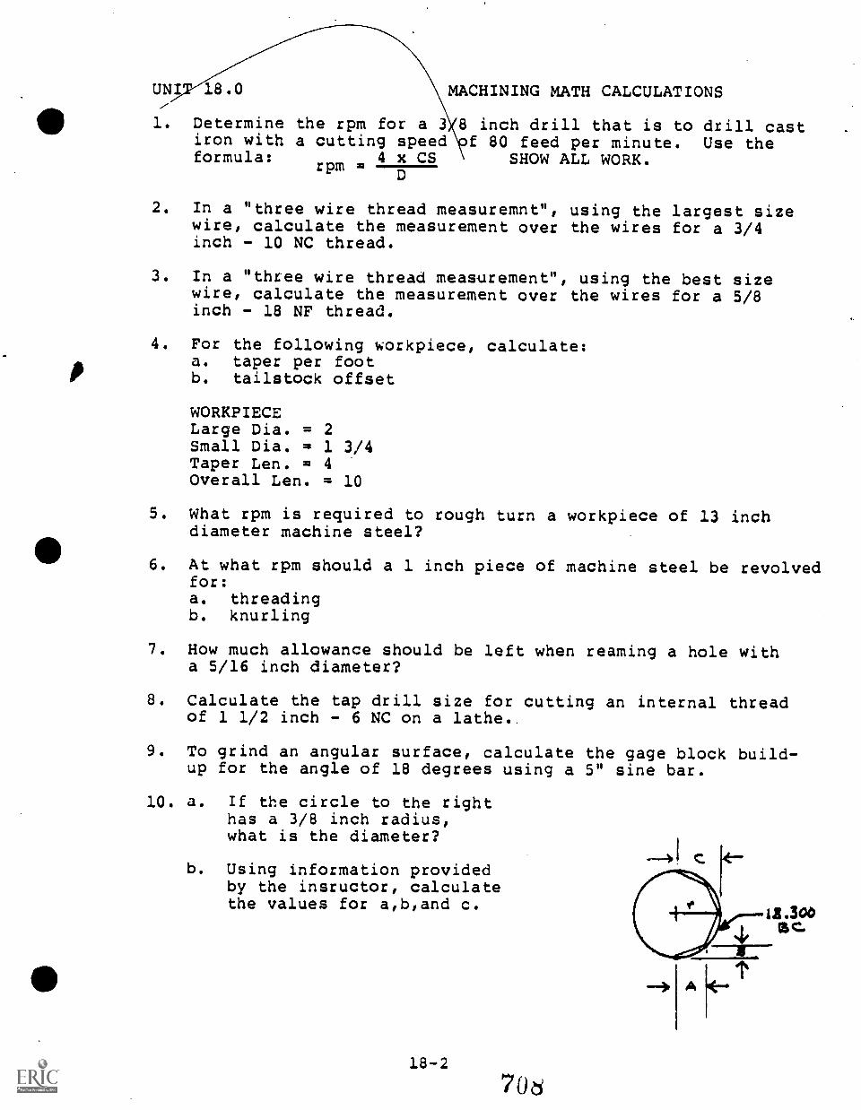
p
UNI' 18.0 MACHINING MATH CALCULATIONS
1. Determine the rpm for a 3 8 inch drill that is to drill castiron with a cutting speed f 80 feed per minute. Use theformula:
rpm =44x CS SHOW ALL WORK.
D
2. In a "three wire thread measuremnt", using the largest sizewire, calculate the measurement over the wires for a 3/4inch - 10 NC thread.
3. In a "three wire thread measurement", using the best sizewire, calculate the measurement over the wires for a 5/8inch - 18 NF thread.
4. For the following workpiece, calculate:a. taper per footb, tailstock offset
WORKPIECELarge Dia. = 2Small Dia. = 1 3/4Taper Len. = 4Overall Len. = 10
5. What rpm is required to rough turn a workpiece of 13 inchdiameter machine steel?
6. At what rpm should a 1 inch piece of machine steel be revolvedfor:a. threadingb. knurling
7. How much allowance should be left when reaming a hole witha 5/16 inch diameter?
8. Calculate the tap drill size for cutting an internal threadof 1 1/2 inch - 6 NC on a lathe..
9. To grind an angular surface, calculate the gage block build-up for the angle of 18 degrees using a 5" sine bar.
10. a. If the circle to the righthas a 3/8 inch radius,what is the diameter?
b. Using information providedby the insructor, calculatethe values for a,b,and c.
18-2
7O
411 APPENDIXES
APPENDIX A
APPENDIX B
APPENDIX C
APPENDIX D
APPENDIX E
APPENDIX F
APPENDIX G
APPENDIX H
APPENDIX I
APPENDIX J
APPENDIX K
JOINT ARTICULATION AGREEMENT
INSTRUCTOR'S SIGNED AGREEMENT TOARTICULATE
PHILOSOPHY OF ARTICULATION GUIDE DESIGN
PURPOSES OF ARTICULATION GUIDE
DEFINITION OF TERMS
PREVIOUS ARTICULATION INFORMATION, IF ANY
CRITERIA FOR SCHOLARSHIP STUDENT
DIRECTIONS FOR TESTS
ANALYST; OF SECONDARY INSTRUCTION TIMES
RESPONSIBILITY SHEET
BINDER DESIGN SHEET
THE SCHOOL DISTRICTOF GREENVILLE COUNTY
APPENDIX A
GRELIVILLE TECHNICAL COLLEGE
All Administrators, Staffs and Faculties, The School District ofGreenville County and Greenville TeChnical College
SUBJECT: Application and Implementation of the Policies and Procedures forthe Articulation of Similar Vocational Training Programs ofInstruction
Since 1976, The School District of Greenville County and GreenvilleTechnical College have bean working toward making the articulation ofvocational education programa a viable and valid reality. Through jointefforts in the Occupational Education Articulation Program, The SchoolDistrict of Greenville County and Greenville Technical College fullysupport the concept of articulation and agree upon the purposes of the
articulation program.
This Policies and Procedural Guide has been developed as a joint effortof The School District of Greenville County and Greenville TechnicalCollege with the assistance of individuals representing the institutionaladministrative units, involved faculty, and the local business andindustrial community. The Policies and Procedures Guide is designed toassist the articulation of very similar programs of vocational trainingbetween the secondary and post-secondary, public, vocational traininginstitutions in Greenville County.
Appreciation is expressed to participants at both institutions for thejoint effort of this endeavor.
J.
SuperintendentThe School District ofGreenville County
amas E. BartonPresidentGreenville Technical Coll"
APPENDIX B
TASK FORCE COMMITTEEAGREEMENT TO ARTICULATEVOCATIONAL EDUCATION
Articulation provides a system whereby secondary and post-secondaryinstructors can cooperate effectively' in providing a continuousoccupational development program where the level and type of voca-tional training that leads to entry-level employment skills will beclear to instructors, other educators, students, and potentialemployers.
The concept of articulation and the articulation program are supportedfully be The School District of Greenville County and GreenvilleTechnical College which have agreed upon a statement of purpose forthe articulation of similar vocational education programs in GreenvilleCounty.
The articulation program in Greenville County is a joint effort of TheSchool District of Greenville County and Greenville Technical Collegeto develop a continuous program of vocational training so that studentsmay continue their career preparation without loss of time or waste ofeffort in repeating tasks which have been learned previously anddemonstrated. Articulation program activities are designed to help re-move unnecessary gaps or overlap in student learning which may occurwhen a student completes a secondary vocational program and continuescareer development at the post-secondary level in a similar occupationalfield.
To implement articulation, instructor representatives from the partici-pating institutions have met as a task force committee to develop thisarticulated, performance-based instruction guide which describes thesecondary vocational program and which provides the parameters forvertical articulation.
Vertical articulation shall include recognition of the occupationalcompetencies demonstrated by secondary graduates of articulatedvocational programs.
It is agreed that...
The task force committee instructor representatives from The SchoolDistrict of Greenville County and Greenville Technical Cc lege mutuallyrecognize the value of occupational education provided by eachinstitution.
The task force committee instzuctcc representatives will take the neces-sary actions, approved by their administrations, to ensure that thisagreement to articulate is fulfilled including interpreting the programto students.
0 It is understood that periodic review of the articulated task objectives,performance actions, minimum standards, and outcome-referenced measureswill be necessary to ensure that a valid training program is servingthe needs of the community and the students.
ach task for-:e committee participant hereby agrees to notify the
others of any changes which modify the articulated, performance-based
vocational program described in this guide so that each articulation.
guide, and where appropriate the articulation program, may be revised
mutually so that articulated occupational training in Greenville
County will conform to the minimum standards outlined in this guide.
This agreement to articulate establishes the necessary framework for
lateral as well as vertical articulation.
AGREED UPON BY THE TAS FORCE COMMITTEE PARTICIPANTS ON THIS DAY,
Apri.) toodate
Name Institution School
.. t- I) 5 ".. et 1 s
APPENDIX C
PHILOSOPHY OF ARTICULATED, PERFORMANCE-BASEDINSTRUCTION GUIDE DESIGN
The design of the articulated, performance-based instructionguides and the articulation program is based on a philosophythat the vocational education curriculum should be for careertraining with few fringe or non-related subjects: The studentshould be given the basis to do useful skilled work upongraduation and employment. The vocational program graduateshould have a background which will allow him/her to learnand advance as rapidly as possible on the job, but it shouldnot include subject matter which will not be applicable tohis/her work for years. When subject matter is introdubed thatwill not be applicable to the graduate's work for years, it mayput the graduate out of perspective. The result might be thatthe graduate may try to force applications which do not exist,simply because the information is in his/her repertoire. Thus,the purpose of vocational training by the articulated,performance-based instruction guides is to prepare graduatesfor successful entry into a skilled trade.
To ensure that the design of the articulated, performance-basedinstruction guides is conforming to the philosophies of boththe secondary and post-secondary institutional participants, aperiodic review of the guide design and philosophy isrecommended.
PURPOSES OF THE ARTICULATED INSTRUCTION GUIDE
The articulated instruction objectives guide are is expected to servethe following purposes:
I. The guide serves as the primary vehicle for the articulation ofsubject matter in similar vocational training programs between thevocational education canters, high schools, and Greenville TechnicalCollege through use by instructors at both levels as a reference inpreparing instruction.
2. The guide provides a listing of the minimum tasks that a student orworker is expected to perform in the conduct of a specific leveljob in the area of vocational training or work of concern.
3. The guides identify the primary detailed instructionperformance objectives wh..111 are based upon the tasktasks are listed in the sequence of complexity, withcomplex task being listed first, except where a taskas a prerequisite to performance of another task.
4. The guides identify the tasks performed (actions, steps, sets ofskills) and related technical information which must be taught andlearned to accomplish each major instruction objective. The tasksperformed represent the minimum skills and related informationrequired for adequate occupational proficiency in the performanceobjectives.
objectives,listings. The
the leastmust be performed
5. The guides designate the instructional contact hours necessary toprovide the required instruction, as required by appropriate edu-cational agencies or offices and as estimated by the instructor-participants on the Vocational Articulation Project Task Forces,and based on the time required to teach the average learner toperform the task. The time estimated is based on having the essentialequipment, facilities and instructional aids required to providethe instruction, whenever the class size is limited to an acceptablenumber.
6. The guides identify the performance standards to be mat for occupa-tional proficiency in the task. Performance standards used arethose considered to be minimum business or industry standards. Theability to meet the listed standards of performance will be consideredas qualification for advanced instruction in the vocational program.
7. The guides provide direction in the conduct of sequential vocationalcompetency instruction by modules or job tasks, resulting in qualif i-cation by the learner to perform limited skill specialist jobs of
9 714
progressively higher skills until the program objective is reached(i.e., file clerk to executives secretary, etc.). As the studentbecomes proficient in the performance of tasks in successively morecomplex modules, more marketable competencies are gained and may beidentified as the lower job qualifications of a specialist.
Through this procedure, even the slower student is provided anopportunity to eventually gain sufficient skills to performadequately as a specialist at some level in the vocational field,even if the student is unable to complete the total program oftraining.
The standardized sequence of activities of the vocationalinstruction modules will facilitate Lateral. articulation betweenvocational education centers in the School District and willsimplify vertical articulation when training is continued atGreenville Technical College articulating to employers.
8. The guides provide a descriptive listing of equipment required toconduct the program of vocational training. The equipment listedis considered to be the type and quantity essential for the conductof instruction to prepare students for entry-level employment inthe vocational field. It may be necessary to delay teaching sometasks involving special equipment, if that equipment is not avail-able at all instructional situ, or to move students and equipmenttogether as necessary to teach skills.
9. The 'guide provides information about requirements or limitationsthat typically are involved in the performance of the task,environmental conditions and physical demands, and able to performthe task.
10. The guides provide a list of standardizid performance test items/and outcome-referenced measures to be used in the determination ofvocational proficiency. As long as the specifics are not provided,the test items listed cannot be compromised easily and could serveas study guides.
11. The tasks listed in the guide are the minimum requirements for jobqualification under average circumstances in a regional market. It
is understood that there may be unlisted tasks that some employersmay require the worker to do in the occupation, when in theiremployment. In addition, there may be unlisted tasks, such asmental process tasks, that are not stated but that may occur andthat should be considered in instructional planning or testing.
Instructors may teach skills and related technical informationother than what is shown in the guides. Provision of additionalinformation should be limited to the students who have completedthe requirements for the tasks emphasized in the instructionalguides. The change of tasks in the guides should be based on taskforce committee agreement to ensure lateral and verticalarticulation.
...
12. It is expected that there will be updating and correction of itemsin the articulated instruction guide. Participants are to be surethat the contents are valid and consistent with business and industryrequirements. Recommendations should be submitted to the VocationalArticulation Program office which will assemble and present them tothe appropriate committee for review and possible adoption.
13. Typically, the teacher/instrUctor should not plan to conduct instructionin a given articulated module unless the capability exists toconduct all of the instruction to meet the instructional objectives,with the result that the successful student is qualified to performthe tasks identified within the module.
14. An underlying philosophy in wcational training is that it isbetter to prepare the student to be fully qualified to perform allof the tasks in.& limited group of modules in a vocational fieldand be qualified at a lower job level rather than to be only familiarwith a large number of task descriptions or duties and qualified toperform none of them fully. For higher levels of job qualificationbeyond the secondary level, the student or worker is encouraged toenroll at Greenville Technical Collage.
15. Generally, vocational programs will include certain basic modulesor courses of instruction without which the student would not beconsidered vocationally qualified at any level. Basic modules
. typically will be identified and taught early in the program sequence.
16. The instruction guides provides information essential to help thevocational student who completes training at the secondary leveland continues career development training at the post-secondarylevel in a similar program receive appropriate credit for thearticulated vocational training that has been mastered at thesecondary level.
11 71
DEFINITIONS OF TERMS
The following definitions of terms are applicable to the articulated,performancebased instruction guides developed as products of theOccupational Education Articulation Program.
Behavior: The actions of a person (specifically, job or job trainingactions). Behavioral actions include both overt, thosethat can be observed, and covert, those not observableoutwardly. Performance may be interchanged with behaviorin the project. (See also Performance Actions).
Concept,: A group of ideas that may be classed togethar"or that aresimilar.
Criteria: A standard by which performance may be measured, usuallyconsidered the minimum standard.
Domain: A. cluster of related jobs.
One of the distinct major activities involved in the workperformed and comprising related tasks.
Evaluation: When comparison is made between a measurement and a standardand judgment is passed on the comparison.
Item: A single stimulus or stimulus pattern that calls for asingle response or set of responses. It is one sample ofbehavior or performance. The response may be simple orcomplex.
Job: The duties or tasks actually performed by a sk.ecifiedindividual.
3nowledgit: In this project, knowledge refers to acquired covertbehavior which facilitates skills and performance, suchas the theoretical information of what should be doneunder given circumstances, and in what order of sequenceperformance should occur to accomplish the eJjective.
Measurement: The process of determining the extent some characteristicis associated with the student.
Module: Modules in the pilot Drafting and Business and OfficeEducation curriculum modifications in the OccuptionalEducation Articulation Program have been designed to
12 717
coincide secondary level training with post-secondarylevel similar areas of training.
Another method of developing modules might be for modulesto represent an identifiable, complicated task or jobarea involving a number of sub-tasks such as "ElectricalSystems" in Automotive Mechanics.
Norm-referenced Evaluation: In norm-referenced evaluation, measures aredependent on a relative standard. Measures compare thecapabilities of one student to those of other students.
Ob active: (See Performance Objective) A stated desired outcome oftraining or the end result of the job, task, or perfor-mance actions. Objectives referred to in this projectwill be terminal objectives, generally representing aspecific job function.
Occupational Education: An organized sequence of learning experiencesconsisting of vocational theory, practice, and skillstaught to students on a regular or systematic basis.*
*Reference: Standards of the Delegate Assembly (Atlanta:Southern Association of Collages and Schools, Commissionon Occupational Education, December, 1972) p. 12.
Outcome-referenced Evaluation: Outcome-referenced, or criterion-referenced, measurement provides a standard of achievement for the individual as compared with specific behavioralobjectives and therefore provides information about the degreeof competence attained by the student.
Performance:
Performance
The outcome - referenced measure is a performance or othermeasure based upon a performance objective, the accomplish-ment of which measures attainment of that objective.
Performance is used in this project to refer to a job ortask which results from a set of sequential actions or steps.
Actions: A series of steps, generally arranged in a sequenceordinarily followed, which when completed may result inthe accomplishment of a performance objective (perfor-mance of a task).
Performance actions may be referred to as a set or setsof skills, functions, or steps. V-TEC (Vocational-TechnicalEducation Consortium of States) catalogs generally describeperformance actions in the "performance guide" of theirformat.
Articulated, Performance-based Instruction Guide: A comprehensive collectionof performance objectives, performance actions to obtainthose objectives, suggested hours for instruction (forplanning purposes), performance standards, related technical
13
information, and outcome-referenced measures, as well asgeneral secondary level and post-secondary level descriptionsof similar courses for the purposes of aiding lateral andvertical articulation concerning the subject area.
Performance-based Instruction: Performance-based (competence-based)instruction is based on the competencies or tasks performedby an-the-job workers. Everything in a performance-basedinstruction system is made public beforehand. There areno surprises for student, teacher, counselor, or employer.When the student begins a program, information is availableto tell the student exactly what competencies are expectedto be developed as a result of the instructional program,how and against what standards or criteria the studentwill be evaluated, and how the student's competencieswill be communicated to the student, instructors, and toemployers. Aperformance-based instructional systemtells the student exactly what the student must learn,teaches the student that skill or knowledge, and thentests on mastery of that specific competence.
Performance Objective: A statement in precise, measurable terms of aparticular behavior to be exhibited by a learner underspecified conditions. It possesses each of the elementsor characteriitics specified below:
Conditions under which the performance is to take place.
Behavior Desired or expected of the student (things to bedone, the performance desired).
Standards to determine how well the performance is to bedone criteria).
Performance Test: A performance test requires the student to demonstrate-------7master) the desired behavior of the objective (accomplish
a job-like task) under controlled conditions and accordingto predetermined standards. The controlled conditionsallow the student to demonstrate the desired behavior andthe conditions remain consistent from student to student.
Skill:
Stet):
Primarily, skill refers to overt, observable performance,however, it is recognized that there are covert skillsrequired in some performances.
Step is used to refer to a task or action, generally as asequence of steps involved in the accomplishment of aperformance objective or job.
Systems Anuroach: The systems approach to instruction emphasizes thespecification of instructional objectives, preciselycontrolled learning experiences to achieve the objectives,criteria for performance, and evaluative information.
Task: A task is a set of skills (sat or sets of functions,actions, or steps) the student must perform to accomplishthe job (training). A task may be described as a logi-cally related set of actions necessary or required tocomplete the job objective. Several tasks could bereferred to as a duty.
,Task Analysis: Task analysis is 'breaking down a learning task (objective)into component tasks each of which must be mastered as aprerequisite to mastery of the total job.
Task List: A listing of tasks (performance objectives) performed byincumbent workers (students in training) within a domainof interest (coursa.of study).
Test: An event during which the student is asked to demonstratesome aspect of knowledge or skill is a test. It can be asingle tt.st item, but usually it consists of severalitems.
Y. 4.
1t
.`.; s. 7
f "..!..k111-1. ;;'1/4'`L'''
t%.*' I'. :
°14 *.
; t ;3 .<1*.. ;
4 C.' : .. .,Vki s'
7 41..143A I4P 1 . , . . L . :
.. ! e. ..` .
:1 .....?.? : ., . ? : .... .. . :. 1 :;.r.:-.,.:. ...pc../....44,0 t -- ........ - ., .:
W.43.' P i -. '.<: 1, ; e!.t44.444. Z - %,/.-1,:?-!. ... 4. ;,. ;.' .-.I .
. . .. .,C,41.r. .fr ' d ,.cr... -,..44;, ..," . 3 6: ' ';'"::: l3%. :' '':..P.°. ,1 r 4.;....4 ,,. .,.... 1.:. *.... 5,,
::4.,,44.,..:;,,. , < . 7
rt : ' .,.. 4. 2.s.f., r., .. ,,., ,. t
. 2
.. ..i :.... -,.. A,:
- '''....:-\' .... ..., ,..,,,,......., ,..3. Ji ,,....aA 4 4...,, ... '.. . , I..... '.... ,
' 4' I:: . . ; . .1 .II. '1;4! 1,i...$-4(.44.4 :24...; ;.: .74..4',".1
Nk-,: Z A. . ...- - , - ' -::PV 4; b tit ;. s'4 4. c 4." ...ti i
c 1 e . -i:-.9 ...4,.'"1",:!;,.. f4 1,1. ;:1. , .; li; :-:... '.
4 St" ; . .: '..1-'..; I% 11. j .41,, 2, 1.1,,, 1
rk ..* .... 4,k
.4. :', .,$-,4 ,,.3 '7 ,-,.-;..\,, :3.
,;. 1,-; -'1..;-; ! ils. t. ,...." :
,' cb.-" - : :: ''
tt.
l, .;:...: t-,1.-': -'4.
qt.. ...1,. ..
' ...4 it , t.1,...,,,..a....., .:... ..II ,t l':,. ::''
.. * ..- t':%., ?, . ,...., 4...44' ,. - $' '
C %. ... .......; '* " . I ;I' ' IN.
... 4.. ,7!-
< .
.
. t. . 1 ,
1 . A . 't :' . :. '.. . 1. , s . I- 3.. .* ., : - , ., ..-: ,i. ..: .. ,,, le" ,:' - .1". 4 ! .t .. . :
;.-, ... 4.i. :, L ..'; " : - : :. : i *. ..i '.74,17: ., .1.'. ' /T.). ' ..,, .4. .. . . .1 1 Af. 4.. ),:., t '., ' . . .
' .4 t' l .....' '.4. 4 . 4' .... ' - - I ' A. It i :. f ''...* 1 ..'. I. , . -.. g .. ...,11' -' I it"T. "°.- 3° I., '.....' t. , '<% '- VA,- ' I ;!.' *. k.< 7'1' 3'',, .....,. -
SI ' .. . '; ,, ';, . .: 3'. .i." s:. : . A :. . ..
'1,,T .. /f. i . . ' 1.' ..:: .' ' I . Vi:,..- ': i i. t -; 4---.V..,. I7 ,ii., ft... I y - ; ,-.. i; t. - i C. , 4 - II* ... 4 0 ;":., .t. 4 ,
A I . ..1"41%.,: I: . ... . .. .
k. ' t. ..,. %.
, . , ...: : ; . .:... . 4 *% li. .4e.... i "4.-2:.,. -.- : i: .. =, ,..
:. >-. ..,
.. ....-...fe: ,,.,..,,.....1/4, . i.t. ..,......... J.., ,..,.,4....,,,,-=. ........- . . ,v,, . fr 1 ....; . .. .,..; >..' '' ?-:."4 '--*.,14,41-.'2`'t(40; .. li - . 1 ,'.; '.- . ..! .
. 4 -..t. ; -- .. f,. 1 :. 3.4.2., , . sAr...: i i ' ?...;.$Z.) 3,,,,tis'k' .1 el,.,"<' t . . ,b, i ...f.- ' i : it ',..` t ;)iii A .,".. . i - jty :' L ;,. ),...."*.". .,. 1L, !. .1 7 ' .1., .44 .14 <4111 et
,: 9. : ,:!`4,3,1 ,,.:Ii.'30 ..:, .. I,. . j3.3.4 4` : : .14.ft ?....- . .-1 ...... .. ;- ,,,..-...-::,...--.... . ,t. J. r...5.-- ).fr ". , t:2; 4' *e......... Z.T..:(y-71 11:! c 1 ., -
i :144 t ? 5:1,.!' !. f ). lb i , :1;* 474s5,a.I: _c.o.' 1 ..' . :.' 4 .',.4...f.i .' : ,..:.'i ,A4P; i;:' I 71.;.43: ,... .::: ...-: ,.. :: 1, 't....1,,,,:p1P..,, ,....k; , .., Ilt ' :1, i.,......9.. vk 3.;....:, :talk .... :, I'll*" ie.,..,-. its.i.., ..,,!..tr . 47,t 4., .... ..ri, . sir.....410.:....t ,....f.
... A -1'C' + ' ; e 1 k ti 1-' 1. :g..4 ',..! .fr.4''t1/4. ' .4i.7 s .r. ," t ti'..!IiLOP`,..ti.t "I. ;,,,4.1. 4.} ...;t:i .V 44. ,.: ,74.1 4 .4. r , ,:' ,,..Z,,-V , .s p ..r-....h.f. ,,2'....,..7...i.. (..,. g..-:;,, sA.,. - ;'..7-..0? ''..4;v" ts..:`, t; ..tfr.. .}... .!.,1,. :.; t:;.0'...,.1% XII
sr.., ....,. . ,,,. , , - .... :., i, i 1.'1...4.....- ::4-ic."0,:.y.:,:.,..1,' .. :1:N.:.;;4s-ft.:Y. h .. . 14-1,7. ;t; .5 411k, t ... ;Ty: .,. 4, '., ,'11". A.; 4 ',., -; -!... i......, .. ,..,c ';-c".:., ! . 1 t,..... ' :pi : :....., 1, 4.. .t,
....--,%. ....v.,: ...."1. ... tit1.4.1....,a; (%,.)....1
.111-'..fvi,r. '',1 11; Y, T.... 4:1:.--: .''.... i :5' I.' 5- IV-Itf." .24..;11.i..1. ......i22: 1.7.tk.,=,4;:!!?.1,14/F.<:1-:' ,... ' ..1. .- ...$4.,..)",-'.':::..:-, . :... le;- , t ' V.I. -1..../. '' , .1, i ry t V. ;!...t, , ... If
.i;..;.;...2;;.4. 4. ,;(4.,try.4,;7..i.i.,i3....r,i, .1,;.. .r.
.'," 4, : CI ...;' TA04., P I'l ,i- ,:-..1.- , .-::,,i,' '4: *, i.-: ''4.`-:-e'e ''. ."*- -.." f
s'it ,0"-it.4 ''''..i.,.,r........, ...,,,,v,,,...
.,:. 41..z.f.,., !ii... - -...z.,- -.." . .. ,, .,,..-+...t ,..,., r., s....1_, .,.,7 ;,,':: el:4:::.F.77's...fliq;?;;;;e. .;Ir.t ,t %.,et.it-.i F.1'.i .: .t.'",t i; -V1'4' fl. r '''' lt.' -:.!
t'l - if, . i- " '...,....e.t..t:. :7t7..e...ii,:.51:41,.4...Mti,e, #1.44....:?:2,4...jft.;,,;.f..4.7`.14e.:,..1-i.i..4.-l,}..t.t.r.: t' 1:4:_:'.F.. e'e:.1:. 12 .., -;,...-1.... -: f ..;-:,.5.:.',t....tai.,`.,?.. - .01,"; . : :11. 1 ' * ' '',,..; 4 5,..4.,..:.---, , r r - l'. ,r ..)...1;i,..":010 4' *-N t":14!).. '.r Vc 1,;.' ` 't.47." L... ":")r/..1'.;':;-4k?n,ot,l-.,;,,*:: V:t:/k, lie-,41.,.:
-Lt. -#
!..... :.e...1. ..- - ,.., -: t.s...i a ,:.. .-r 1r, ....-, 4..
a' * e .
..
, !'' 4 '4?.4: 41-..!4? al.,* ..:',,i111:1.,..r L' ..4,;:,'It)-:: t -4:-5_. ,T: .- 4: n'"?.:* .. . .1'. 14-:. .4 ; I. r; i '- .. It.... 1 ''''' to " ..,'' '... "!. 1 .. :.' .. ,.... !. '. <- Ir..: 'f3 (;::::. 4.., $.:Tg., `- i. 1 ' .-
4.. 1. A "".., '.i. ?"/' 34. t. ' i '.1 'L 1;-';.I...t; 1. 1. :4" ' ./"It .'
.-;;.:.' .7s I...! ,',..;i::. ...3 .4r-....s.4,..;.}.;;.i ,t....; ,:. !..:.t 7..1.`*;17::.;k1.,...:, ;,,..`li..-,-4.,..i...,f.,.:,::=:.....:"....-!.,,,,........!..`::.".`...1'....;.....-..,....:....,-!!.r.k.:...,..-`-...7....3. 1,:t1.4- ,* .i.., ' .' , .' kr. . . '!.:' ''' I r. %..t ..'. . A - li ,!...; i : ....1:1 1.'It:..-t t ;,.'41. t....)...46.t..... ' ' '....,11:. it.7' .. t. IA s' 41 .. ' ' 1 ..;. 1..t': .; .,
.- : .! ..,".. : A a,. :' -l...'.1411.....4.-' :":C44- Vil`!`./t-4;'l
; ;$.-:1. 7-. .. . . ,,,;.p..st-I...., 4 ... ,:. .. ..31..., -. 'A *I' .M1'
i: t ,.. , 'i.. i . 1 .. .,:.;; 1,, ..-ti:rt ; -4..... :.;41 ). Ir.; ..i.,,:":1;- - Pr* . i i ; -1, , i.' : i.. : . .. : 4' .,
4. 1, , "'1%:,!.".; ..-. '....:.' . ,.. :* .',.. ,,,' ; , l "
-::. :%.1.< ' " 5, .., i .. /:.-t::' .. .1 .., . 1- ,..........t. , : -:,. . .. :,` rinatit ;....'t-?"';4. 1°:.1..':: ... t4-;
'. Irr t.. vl. cr ., . . - ..., . -,
. ..., I: 11 .1 '... ' { f ; ' 1.1'i . ,.. 164.,.0,1 ....1 .1,; 1 .
4. . ,.. ,-. z .. , ./.. I. ..... ,1 .. .. . .. f ,..c .,.....,....,:. ..:-...,,,,"i ,,,,......,.. 4 - r -.,,',..i. .c ,J,...,.. . , ; , ;...g . ,t. ... ifr f ' 4 'N , ,
3 . 4 4 3..044 r., .. ; ,%. . S , ,' '3S 3t r.1 ..,.s
4.
-
0
C't
If
I0
j0
hi
5
. ;41.,11,
74.
It `:t - zlAc ,. .1 it. ;.
-* t
IL:LA L.1 I IL:31 CZ L L3 J1 L...1 .ri:61
<
: ,,'
;
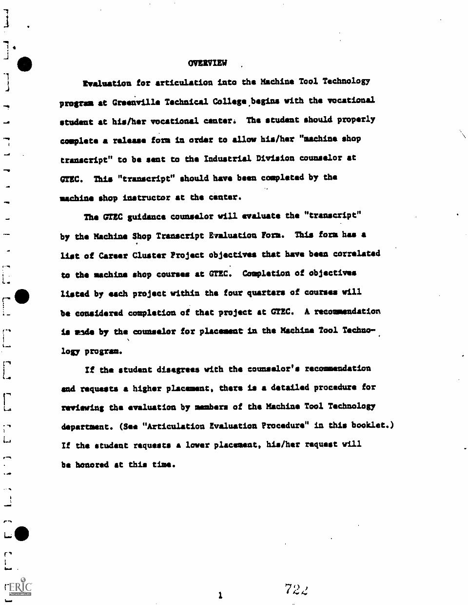
j 4
OVERVIEW
Evaluation for articulation into the Machina Tool Technology
program at Greenville Technical College.begins with the vocational
student at his/her vocational center: The student should properly
complete a release form in order to allow his/her "machine shop
transcript" to be sent to the Industrial Division counselor at
GTEC. This "transcript" should have been completed by the
machine shop instructor at the center.
The GTEC guidance counselor will evaluate the "transcript"
by the Machine Shop Transcript Evaluation Form. This form has a
list of Career Cluster Project objectives that have been correlated
to the machine shop courses at GTEC. Completion of objectives
listed by each project within the four quarters of courses will
be considered completion of that project at GTEC. A recommendation
is wade by the counselor for placement in the Machine Tool Techno-
logy program.
If the student disagrees with the counselor's recommendation
and requests a higher placement, there is a detailed procedure for
reviewing the evaluation by members of the Machine Tool Technology
department. (See "Articulation Evaluation Procedure" in this booklet.)
If the student requests a lower placement, his/her request will
be honored at this time.
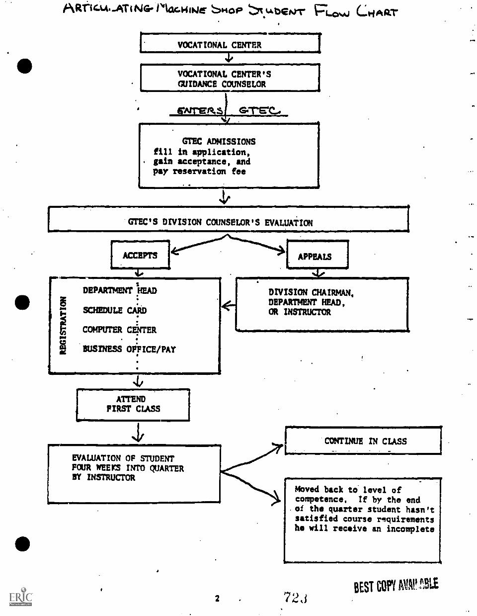
Airelcm..ATiNG-1 4241.11146 SHOP I.L. bGtrrp PLow CLHART
7 VOCATIONAL CENTER
4,
VOCATIONAL CENTER'SGUIDANCE COUNSELOR
orreete.$) Grreto
GTEC ADMISSIONSfill in application,gain acceptance, andpay reservation fee
.ACCEPTS
4.
1
DEPARTMENT HEAD
SCHEDULE CARD
COMPUTER CENTER
BUSINESS OFFICE/PAY
4/111111111101111ONIINENZA
ATTENDFIRST CLASS
EVALUATION OF STUDENTFOUR WEEPS INTO QUARTERBY INSTRUCTOR
[ APPEALS
4./
DIVISION CHAIRMAN,DEPARTMENT HEAD,OR INSTRUCTOR
CONTINUE IN CLASS
Moved back to level ofcompetence. If by the end
.of the quarter student hasn'tsatisfied course requirementshe will receive an incomplete
2 72,3BEST COPY AVAt! 3LE
The work upon which this publication is based was performedpursuant to Grant G00-75 -00453 with the U. S. Office ofEducation, Department of Health, Education, and Welfare.
The project presented or reported herein was performedpursuant to a Grant from the U. S. Office of Education,Department of Health, Education, and Welfare. However,the opinions expressed herein do not necessarily reflectthe position or policy of the U. S. Office of Educationand no official endorsement by the U. S. Office ofEducation should be inferred.
TABLE OF CONTENTS
Overview 1
Flow Chart 2
Articulation Evaluation Procedure 3
Machine Shop Transcript Evalua-tion Form 4, 5, 6
Sample of "Machine. Shop Tran-script" 7, 8
Tuition Scholarship 9
Guidance Information Form 10, 11
Machine Shop Units 12,A.3,
Machine Shop Objectives 15 35
MACHINE TOOL TECHNOLOGY
ARTICULATION GRANT
GREENVILLE TECHNICAL COLLEGE
JUNE, 1976
14
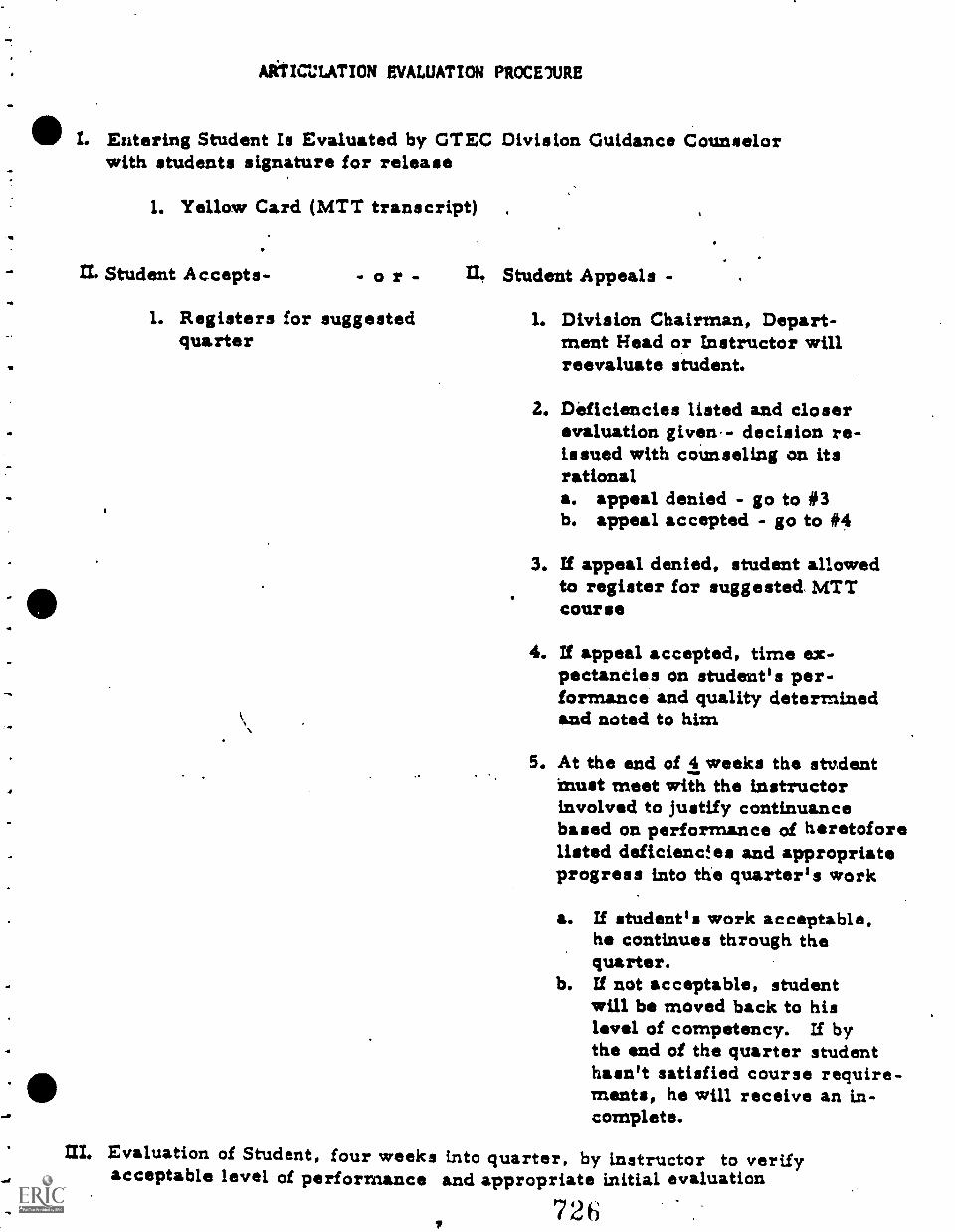
AlitICLATION EVALUATION PROCE1URE
I. Entering Student Is Evaluated by GTEC Division Guidance Counselorwith students signature for release
1. Yellow Card (MTT transcript) .
IL Student Accepts- o r -
1. Registers for suggestedquarter
U. Student Appeals -
1. Division Chairman, Depart-ment Head or Instructor willreevaluate student.
2. Deficiencies listed and closerevaluation given- decision re-issued with counseling on itsrationala. appeal denied - go to #3b. appeal accepted - go to #4
3. If appeal denied, student allowedto register for suggested. MTTcourse
4. If appeal accepted, time ex-pectancies on student's per-formance and quality determinedand noted to him
5. At the end of 4 weeks the studentMust meet with the instructorinvolved to justify continuancebased on performance of heretoforelisted deficiency es and appropriateprogress into the quarter's work
a. If student's work acceptable,he continues through thequarter.
b. If not acceptable, studentwill be moved back to hislevel of competency. If bythe end of the quarter studenthasn't satisfied course require-ments, he will receive an in-complete.
at Evaluation of Student, four weeks into quarter, by instructor to verifyacceptable level of performance and appropriate initial evaluation
72 6
The evaluation instrument development by the SouthCarolina State Department of. Education for theClusttrProjigct in the ARC funded program for MachineShop fin bern included under Machine Tool Technologyby courtesy of the South Carolina State Department ofEducation.
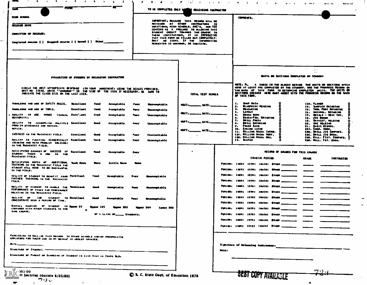
flat
NISI MOM11
a
MILIANII NIS
COMMON of ISIRSAlt
c. for esssa I I Anppell eerie I I Wad l 1 ORbar.
. d
TO is CONPUTIO OILY 1041414114 1010114104
IlflOTAMT. 11/CANS Tull soft* ow. NIageliate OT Wool goossoctolgo INvotATIMAL MINI K.I. ANC'S. AND TICGamma 4, IMAM TS LOANING /NISSIUDINT mn vsoames Ted AIRANI IN/moss losTIvutsomo. IT is INFIOATITI/mat owl room ea POLLAN wt CANPAITILT.SNIT mll IIINA. IP imA ImPaNNATIONateuisIS IN umanasle. M INNIC4III.
4
incluAlliTION Of STUMM' ii NALSISTIND 11MIUGION
COLL( ImK NAST APPIAPNIAIK NISPONSI ON TOUR JUNGININTI MAINE THE 'CASKS finv10111.MIT NO !TKO'S. UNITE "meemiller" TO Tot SINK Of INK ITEM If NICKSSANT. K SUNK TOIPSICATI Tim CLASS Slit ON Tad LAST ITEM.
liessLgeso ANTS WTI r ThAftrt OuUll.
NACINLIIMS am r TOG'S.
GOMM IN YU *Alia INHASTAL
Will, TO ACCONPLItm encesPiOerow.am saidassIS are INISAIM.sees.
INIINIST es yes 'wools's' rogue.
SoILliow la 'unclear AKASINICALLT11111.11 M,S NATN PTIONLIINIn Ind SnOngolt, loco.
volIclfamUS Slowed' Of SUCCIGG IvMoto/ TANIS a ace' In testPlootnINIsI
1040mm of ASSIVIONALMAIMING IN VHS Thstslols1 Peace INS1I .T .Ili. KUM IN 114 sucCiesPIALIn Tel PIILlb.
spILITT TO shosN4 V* SENSPIT NC=violate TRAINING IN INS OnCnimISI
MOILsIT slusarm IN pinnace IndPlOIONNAmet al TASKS Amb ocesousgsogo.migwg to loll MACHINIST PIUS.
AsITITT OF 714 giueepT GITOOSIGNSCOftelniguaa ram resift or gift.
n ocellest mead
sae./lest mead
teme:eat Geed
Lacellet aced
Samilleat dead
n aralret mood
Nacelles* card
Anoortablo Pads Usreatable
iodevtale has Unacceptable
Acceptable Neer Ugmecepulo
Acceptable' row usacceotallo
Acceptable sees Veaccostable
Acceptable her Unacceptable
Acceptable' Peer
%WV Moro Ibse Little I1115 Oar
rigoglleot 0.04
ISTATSIleaS 4114
Glisaaau SATHAINS or slowest All
confabs& erne area sleeted* IN IndWas csunS4.
Acceptable leer Onereeptable
Aceeptable Pent blNeed Umatilla* Pies Nnaciertabla
Oppea Ref Owes 440 Lome ON
er A CLASS STUMUNTI.
UMW&
MSC/
NSGVI
NAPTs
OSPTs
TIIT/4 nil scans
NAVE.
G AUT
NATI.
N one
UNITS ON Iscveaus CIMPLMTISI ow MINN'
MTh Pi. A CNICA IN Ten imams MINIM Nal MUSTS ON UNCTIONS rateN INO At Whit Ore creLIMIN Si TIN INN INN POSANISS 1111nOre ON.Try OUR so toss row vs oet000los CONletSVIN 'MTS. NI OMITS ONlaCTIONO POMO 11II0 Mit *Ott PITS TOK 011601110 061:4010 ON INI I1411OF THIS F.M.
I. Iwo. Nein 0S. OLuosbotov Neale* 0S. IISAWNINA 0a. Levan aS . irescs Iwo 0. gown-Pao. fooloosms aI. SHILL roost 0S . llosu. Galusgss 0si. Pori. limos Q10. Irani LANs UII. NILLINi Magma 10011. 0tie. MILLI** Naar VINT. 0I80. MILLING Saco. Ma. 0Is. iAam 0
ISA.la.IS.$0.IV.111.
IS.SO.SI.SSA.INS.sec.ISO.las.
fAoas 0Sumolgai 4411siu1 0Tow Pest Sa11rlNC 0VuIv0. GaIusgml 0NoTocs - MAT Tov. 0IMO Mem IISanntold. I1045I,1Mc spA1$es
Vtoga. MN.1011 JI4 CUSisis. CSal. 114 444.u.Mu" fist. asorell. 9Mu. Fit. Osoo.
Panossogibm TO Itas .14 1.115 INIComa To oho/ &Twat& nnoolo PsoosscgITssrtoTsos von Immo vsa IN Mm Samna IS nencor CAIAMISSI.
$14118
GIWTAftos NT Snots".
Seemavuout of fAasnV on Gunolovno of Stmosall IS LISS lean 1 TRANS OS,
SOE 26.051oo(This term bocemee obsolete 6/30/10)
Pi 0 1;,,
S. C. Stets Dept. el Education 107$
NEMO Of illMai IN VIII& Giulia
GlAllua 0141411
PONIES. free taros SWINT *MN
PONIES. 4SONI 1111111 'Swami Osumi
hog g 11051 ISM* ISINI MOON
Foams I saw g iamb I Gul ft I Sues
flu MO. I sou tales mufti) emus
flats,. sans It1M1 4 gulag hurt
foe g as g I Nog I set 1wg51 Osseo
Pawing easel ears) IGOINI Musa
Pralliss Isis) OMANI MIN.
Pol1 1141 ISIS) twang Ones
FY/r. fatal Orel MANI 01,401
Pima. Isom lovas loupes *wow
SIAM
OLopAgoro .1 MisLougloo aggetrusiera
P.M.
41,
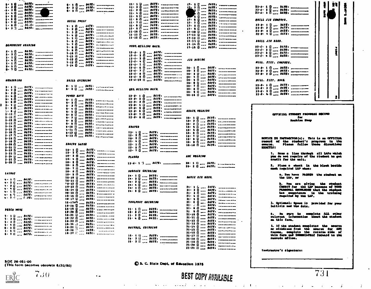
s. $ 0 04f1; amew........rm II- 1 n ___ 1114er I ____,_ II- 1 U -... lift i -...-........-.... 111.. 8 V .... 141.111 ------..........S. In 111f9i -- 3 0 86,1 Is. 2 0 84718 MMI...Mt =MEM 2 .. DATIN8- I n ___ 88781 11' 3 n ... IAN' ..------.... 11- 2 n ___ 114f11 V Safi: ------....--8-- 4 It .._... lift; Is. 4 0 114f1 1 n 04111s. $ n 114f1 e -- 11- I 11 _.- $421; ------....- I 0 _-- NTH;s. s a ___ OAT', ---------- 11- S n ___ 04111 11- 8 Q 8171sI- 1 U ___ 04211 ---- DRILL POIS1 11. 1 0 142lo 81. 1 0 ___ DATE;8- 1 11 ..- '4%31 ------- 1- 1 n ___ ;Arlo 11- S II ___ 04714 11 S 0 ___ DATER11 1 9471: 1- 2 n ___ Sitio 11- n ___ MI' 11- C _-. $4,18
1 3 a ___ 2477, 11-1 n .._ N7', ---------. 11..18 U _- 847181- U 14718 11-11 n ___ $$T18 ----- --_-- 11-11 U -__ 1147l1 -----1- II 0 --. 1013,8 11-12 n ___ Olfgo .........-..... 11-13 II _-- Sir's1. s n ___ 01r11 11-11 U --_ Sills
11601111118f 114111111 1- 1 n ___ SAPS: 11-1 n ___ Dirge118f.MILLIOG MICR1- 4 n 114f10 11.14 0 ___ DATE;
1- n ___ Ness1-1. n 86718 ---------.. 13-A- 1 0 _-_ OAT'; _1-11 0 ___ NS's 13-A- 2 n __ Pills _
1-11 n 8121: 12-4- 8 0 ___ 14fto --, - JIG 10811C1.12 n ... 14,18 12-6" U _-_ 04/ls
1-14 a ___ LATE, ---- 12-A- I n ___ 14ff: _ _ -13.4- 4 n ___ 14flo ---------- 16. 1 n ___ OAT',12-4- 7 0 -__ DATE, 1- 8 0 ___ MI: -----12.4- S 0 _-_ 14111 18- 3 U ___ 114flo12-4- 6 n ___ D4flo 81 n ___ NTS:
M1:Insise 'ILL C1181111141 13-4-16 0 --- 04flo -.-.-- is. s a OAT'; -- -----IS. S 0 OATS: ------.
1- I n _._ 0111. I. 1 n ___ OATS: 18- 1 n ___ OATS 1
8- 1 0 ___ OATS, 11 2 U ___ 'ATI: IR& MILLIS@ M4CM is. S a DATE:
3- 8 0 ___ 041'1 ----- .....Is. I 0 Dill, --
8- n Oiffs rut' Sur. 13-0- 1 0 ___ 84/18 ISIS U smrs8 _______ -.-a- I n ___ 14ft, 1 n ___ air', 13-8- 2 n . _ 14flo2- n Sifts - 8 fl ___ DATE, 12-P- 8 n ___ met,___
1 8- 1 U --. lifts 11-8- 4 0 --- G$T$8 ----4- 8 0 --- 141108- s n ,.. 'Arlo - ii 114f1: 13.1. $ 0 Onto ......---
'4- U __, 174718 I. I 0 ___ 84788 is.o. S 0 Ditto 014Cf. VILI1180
Ir-t3 r ___ 114flo - 11 U Sitio 13-1- 1 0 ___ 147l1_____ .....8-11 n 114flo 11 t U --- 'Ills 12-8- S n ___ 04f14 1- I U ___ OAT',2-12 n ___ Marl: -- ...... -- s. $ 0 14f1: __ 1.- 8 n ___ D4flo2-11 0 14111 4- n airs,
__
1.- 8 n ___ tolft:----- .....1-1. n - 141', 11-111 0 14flt S841,18 1- 11 84flt -..-----8-111 n *Arlo -111 n ___ 'Arlo SO- 6 0 ___ 147li ------s-IS n 0srl, 6-13 U ___ 14flo Is- 1 n 114flo SO- 0 n DATE8 .
1-11 !I 84718 0-18 n 114flo 18- 3 n ___ P4flo ------- 16- 1 U ...-- MI, -..--....1.1, n 84flo 18- 2 n ___ 04718 -- ------- 1- 8 U ..__ 114flo11-11 0 _._ girl, 11- 0 84flo ---------... 1- n ___ OATS'1-36 n ___ OAT,' 181181 LATH 18- 1 n ___ air', ---------- 118 n __. IAN' ----...8-31 n ___ h4flo 18- 6 n _.. 14111 -------2-33 n ... 1418, IS s n 142lo 18- 1 a ___ air's1-33 II 114flo
is. 3 C 114,1:-.--------
2-24 U 'Arlo 18- 8 11 ___ 04f1: PLAINS 1AC 111841108-31 n ___ air', IS- Q Sifts ----I-2 0 ___ 1471, ..-- 18- 6 a airs, 18.A. 17 0411, . Is- s 0 D42lo
14 4 n 84,18 26- 2 0 94f14 -------......14 1 0 114flo
10- S n air', 100814C1 GOIRSIMOL4101? 18- S 11 'Arlo 1- 1 0 ___ OAS',
111-111 U 11Af14 14- 2 n ___ DATE:11411C CIE MISC. 1 n s4rri 12-11 11 14flo 1- 8 0 ___ OATS:4- 3 0 --- $$TI, - 10-13 n ___ 1471, 1 0 ___ 1141114- I 0 --- 04111 --_ ---_ 10-18 n ___ OAT',
_______.31- 1 Cs ..-- 06/381- 1 0 ___ 14flo- 0 ___ /ATI' 16-1 q ___ NT'' -------31- 2 Q gillsso- II n OATS,4. i n airs, rs.i n 11.4718 11- 8 n Sit',
e- 1 -_. $$$18 ---- --- 18-14 n ___ 1411: 31- 0 psis,.
- 1 ___ r:rri is ii Diflo pi. a 442,8
14-s1sn Not, fOOLPOlf 011181104 pi- S Q DAflos01$ a 84fls 31- : n ___ DATE,
1111C1 1041 11-111 0 -__ lifts 11. 1 n DATE, 31- 8 n ___ Dill,
10.11 ri _ Pitt: 16- 2 0 8Atli 31 0 _ 114f',
s- 1 0 air', 10-31 U ___ Ditto 11- 2 n ___ Sifts 11-18 0 114111
S- 3 0 .... 14f1: 14-2 0 .._ SATE, is. a airs, 81-11 0 DATE:
1- $ n ___ Dills 10-38 0 ___ Sifts 31.18 n ___ !Aft:
6' 6 n ___ imre, t1 t d , airs. 81-18 n ___ 114flo----
$ n ___ 14f11 --------- 10-1$ i; &IV!: 111,11L. 081811I1G 31-14 Q 1Aflo
1- 0 11Aft, 10-16 '.. DATE; 31-16 n ___ D4t10to.,/ r ..._ OATCt 111111 n .._ OATE8
----_-_-_-s- 1 0 MT', _-- is. 1 0 114flo 31-11 $1 --_ 14111
is 3 0 OATS: 81-18 n Marls11- 8 0 --- OATS, 21-16 n __. 14f1:
81-38 Ii INTER ----"""_"-11a1 0 ....... Mfg. ...Fe..
o. 1 0 OAT',3. 3 0 84718 _ __ -_ ---a- f 0 11411,
I- 6 n Sifts8- $ n 94flo1- 6 n Sifts1. 84f11
U3E2,0-051-00mils form becomes obsrdote 6/10/10)
*i ow
CI S. C. Stith Diet of education 1171
BEST COPY AVAILABLE
03,4- 1 0 Silts$3.s. 1 0 84211.I3A. 3 n HU*
DRILL JIG COMM*.
83-11- 1 0 84118.33-8- 2 n 8478121.1- 8 0 14,1:33-11- 4 0 14118
HILL JIG OM.
33-C- I 0 _as -C- 8 U.33-C- 1 0 ---33-C- 0
14f11$14111,114f1:14111:
MILL. FIST. commsrs.
81.0- 1 n NU:32-8- n SITS,33-0- I 0 ___ 94,61
MILL. PIM INC&
32-8- I n _ 14flo113-8- n 84111s
134. a 0 14f11:
13-1- 4 94f1I1
-----.....
I
a
it
CRUCIAL =ODOR NODter
Nacklas haws
NM= 110 1111011100300141. Vhle le as OPYWIALreseed et the etedeeee preem ie
d re lteseere. lease teller tmes..ACLU'
1. Over a 1Lae thrdagh all LAP, Akapee de oft weralre a the sleds.% be letere414 tee the melt.
2. Plasm a sheet La the bLeek besidemak required LAP oboes
S. lea 'tore HMSO the student eathe, W. at
h. tee ere lvia the 'WiestMolt ter the LAP besamee at 0000110010MAL 0000111201 that the Mod m%hoe wm
bpstesesla the trelele,
required y the LAP.
3. OptLesels Spade 14 peopidded ler peesLwitlele eat the ate.
S. as ear, to empleta ALL etherreleases tatereetlea .Met the stelae*as thle toss.
I. It the etedeet eamplotos the merleat withdraws tree the means ler AMRcease., complete the reveres ails atthis lam and IMM11123441.2 lemma is therewords ulnae.
Teetreet040 siimateses
7 :31
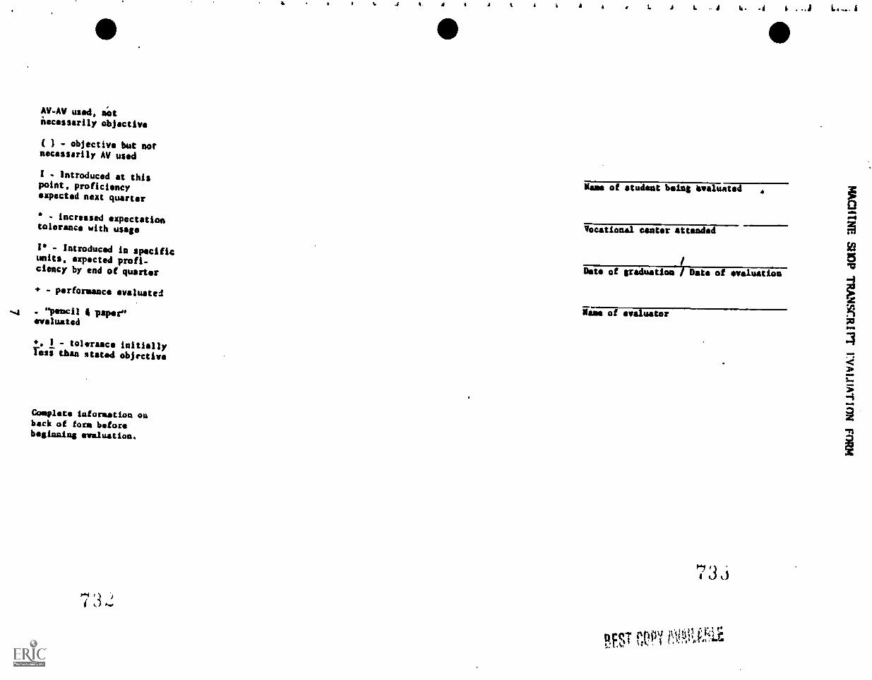
AV-AV used, pot
necessarily objective
( - objective but notnecessarily AV used
I - Introduced at thispoint, proficiencyexpected next quarter
- increased expectationtolerance with usage
l - Introduced in specificunits, expected profi-ciency by end of quarter
+ - performance evaluated
.4 . "pencil i papor"evaluated
I - tolerance initiallyTess than stated objective
Complete information onback of fora before
beginning evaluation.
'
4
rises of student bolus avalunted .
Vocational canter attended
Date of graduation Date of evaluation
Sam of evaluator
zzirrJ
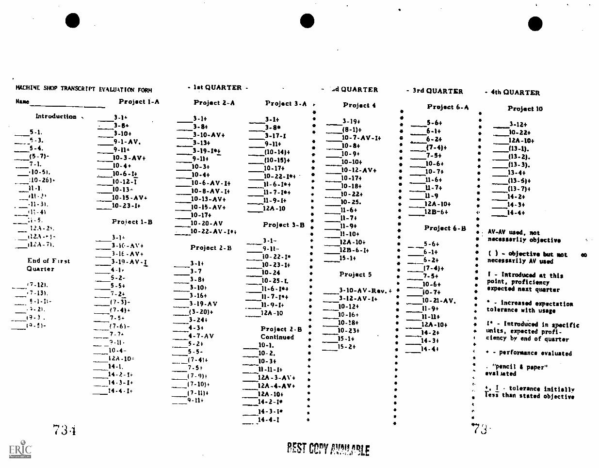
MACHINE SHOP TRANSCRIPT EVALUATION FORM - let QUARTER - - A QUARTER - 3rd QUARTERName Project 1 -A
3-14
Project 2-A
3-1+
Project 3-A
3-1+
r
*
*
Project 4
3-19+
Project 6-A
5-6+*****
***
******
*.
**
*
4
*1.
t-
..
A
Introduction
5-1.3-84 3-8+ 3-8* (8-1)+ 6-1+3-10+ 3-10-AV+ 3-17-I 10-7-AV-I+ 6-2+-3.
5-4.9-1-AV. 3-13+ 9-11+ 10-8+ (7-4)+9-114 3-19-I*+ (10-14)4
(10-15)+10-9+ 7-5+0-7)- 10-3 -AV+
10-4+9-114 10-10+ 10-6+7-1.
'10-51.10-3+ 10-17+ 10-12-AV+ 10-7+10-6-1+ 10-4+ 10- 22-1*+
11-6-I*+10-17+ 11-6+. :10-261 10-124
10-13-10-6-AV-1+ 10-18+ U-7+11-1. 10-8-AV.1+ 11-7-I*+ 10-22+ 11-9
. .11-3).10-15 -AV+ 10-13-AV+ 11-9-1+ 10-25. 1ZA-10+10 -23 -I+ 10-15-AV+ IZA -10 11-6+ 12B-6+111-4)
Project 1 -B10-17+
Project 3-B
3-1-
11-7+
Project 6-B
5-6+6-1+
12.; . 2'.112..N
10-20-AV 11-9+10-22-AV-1.4 11-10+
Project 2-B
3-1+
12A-10+- 71.
End of FtrstQuarter
7-121.
3-1( -AV+ 9-11- 12B-6-I+3-1E-AV+ 10- Z2-1* 15-1+ 6-2+(7-4)+----4-1,
3-19-AV-I 10-23-14Project 5
3-10-AV-Rev.+
3-7 10-24 7-5+5 -2- 3-8+3-10+
10 -25 -I.11-6-I*+
10-6+5-5+10-7+7 -131. 7.24
(7 -3)-3-16+ 11- 7- Is+ 3-12-AV-1+ 10-21-AV.3-19-AV 11 -9 -I+ 10-12+ 11-9+21. (7-4)+ (3 -20)+ 12A -10 10-16+ 11-11+7-5. 3-24+
Project 2-8Continued10-1.
10-18+ 12A -10+19 -.f1- (7-61-
_10-4-12A-10,-
4-3+ 10-23+----15-1+
14-2+4-7-AV14-345-2+
5 -5-15-2+ 14-4+10-2.
(7-41+
7-5+10-3+
14-1. 11-11-I+14-2-1, (7-9)1 12A-3-AV+14-3-1+14-4-1+
(7-10)i
(7.11)+
1ZA-4-AV12A -10+
9-11+ -14-2-1*14-3-1*14 -4 -I
7 3.1
FEU CM PrTIE
- 4th QUARTER
Project 10
3-12+10-22+12A-10+(13-1).(13-2).(13-3).13-4+(13-5)+(13-7)+14-2+14-3+14-4+
AV-AV used, notnecessarily objective
) - objective but sot eonecessarily AV used
I - Introduced at thispoint, proficiencyexpected next quarter
- increased expectationtolerance with usage
I - IntrodUced in specificunits, expected profi-ciency by end of quarter
- performance evaluated
. "pencil 4 paper"evil Jilted
+, I tolerance initiallyTesi than stated objective
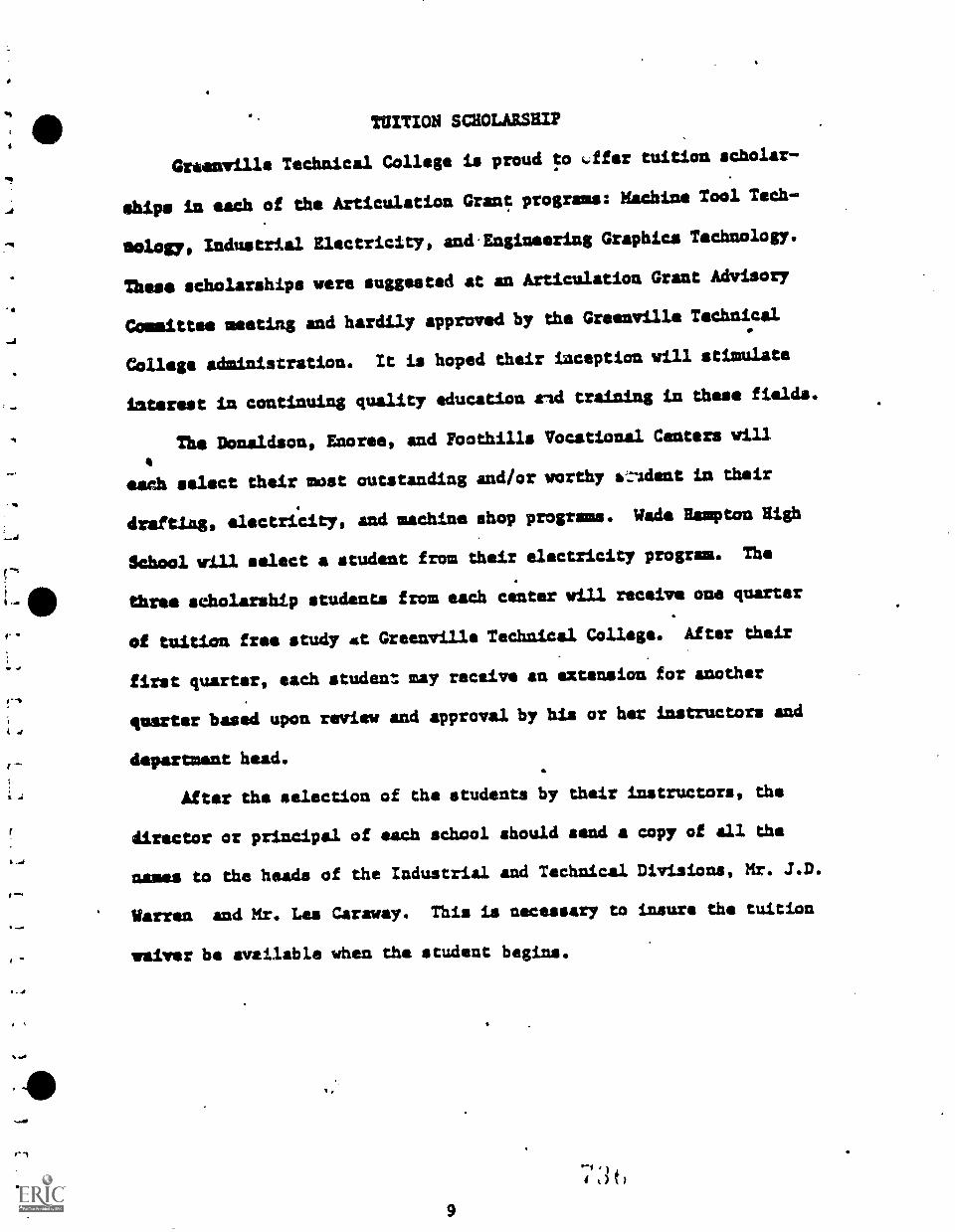
r
(4
f`
I
TUITION SCHOLARSHIP
Greenville Technical College is proud to -ffes tuition scholar-
ships in each of the Articulation Grant programs: Machine Tool Tech -
sology, Industrial Electricity, and. Engineering Graphics Technology.
These scholarships were suggested at an Articulation Grant Advisory
Committee meeting and hardily approved by the Greenville Technical
College administration. It is hoped their inception will stimulate
interest in continuing quality education and training in these fields.
The Donaldson, Enoree, and Foothills Vocational Centers will
each select their must outstanding and/or worthy a;:ldent in their
drafting, electricity, and machine shop programs. Wade Hampton High
School will select a student from their electricity program. The
three scholarship students from each center will receive one quarter
of tuition free study mt. Greenville Technical College. After their
first quarter, each student may receive an extension for another
quarter based upon review and approval by his or her instructors and
department head.
After the selection of the students by their instructors, the
director or principal of each school should sand a copy of all the
names to the heads of the Industrial and Technical Divisions, Mr. J.D.
Warren and Mr. Les Caraway. This is necessary to insure the tuition
waiver be available when the student begins.
9
4t3tl
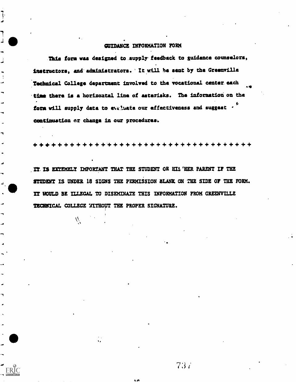
GUIDANCE INFORMATION FORM
This fors was designed to.supply' feedback to guidance counselors,
instructors, and administrators.' ha sent by the Greenville
Technical Collage department involved to the vocational center. each
'time there is a horizontal line of asterisks. The information on the
fore will supply data to avtluate our effectiveness and suggest 1.
continuation or change in our procedures..
+ + + + + + + + + + + + + + + + + + + + + + + + + + + + + + + + + +
IT. IS XTEMELY IMPORTANT THAT' THE STUDENT OR HIS HER PARENT IF THE
STUDEWT IS UNDER 18 SIGNS THE PERMISSION SLANTS ON HE SIDE OF THE FORM.
IT WOULD BE ILLEGAL TO DISEMINATE THIS INFORMATION FROM GREENVILLE
TECHNICAL COLLEGE UITHOUT THE PROPER SIGNATURE.
\X.
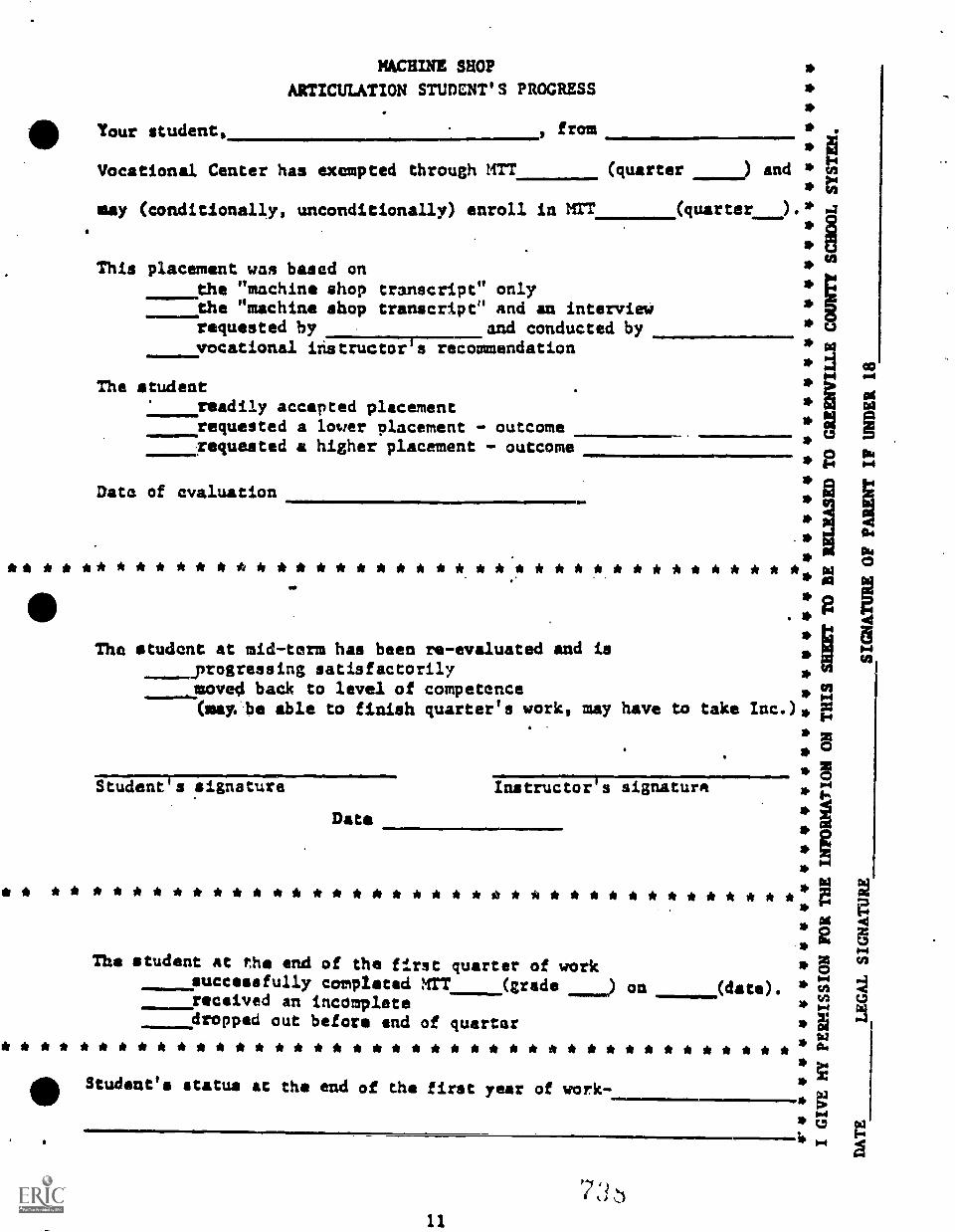
*
Your student,
MACHINE SHOP
ARTICULATION STUDENT'S PROGRESS
, from
*
Vocational Center has exempted through MTT (quarter ) and **
may (conditionally, unconditionally) enroll in MIT
This placement was based onthe "machine shop transcript" onlythe "machine shop transcript" and an interviewrequested by and conducted byvocational instructor's recommendation
The studentreadily accepted placementrequested a lower placement - outcomerequested a higher placement - outcome
Data of evaluation
* * * * * * * * * * * * * * * * * * * *. * ** * * * * *
(quarter )
The student at mid-term has been re-evaluated and is_progressing satisfactorilymoved back to level of competenceOsay...be able to finish quarter's work, may have to take
Student's signature Instructor's signature
Data
* * * * * * * * * * * * * * * * * * * * * * * * * * * * * * * * * * * *
The student at the end of the firstsuccessfully completed nrr
____received an incompletedropped out before and of
* * * * * * * * * * * * * * * * * * * * * *
quarter of work(grade on (date).
quarter
* * * * * * * * * * * * * * * * *
0 Student's status at the end of the first year of work-
11
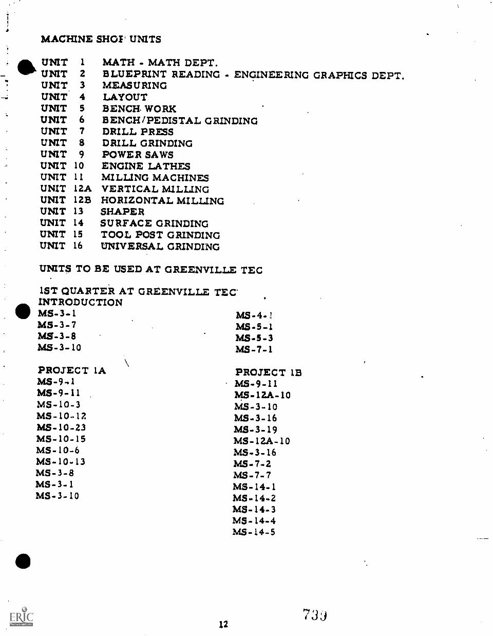
MACHINE SHOT' UNITS
UNIT 1 MATH - MATH DEPT.UNIT 2 BLUEPRINT READING - ENGINEERING GRAPHICS DEPT.UNIT 3 MEASURINGUNIT 4 LAYOUTUNIT 5 BENCH. WORKUNIT 6 BENCH /PEDISTAL GRINDINGUNIT 7 DRILL PRESSUNIT 8 DRILL GRINDINGUNIT 9 POWER SAWSUNIT 10 ENGINE LATHESUNIT 11 MILLING MACHINESUNIT 12A VERTICAL MILLINGUNIT 12B HORIZONTAL MILLINGUNIT 13 SHAPERUNIT 14 SURFACE GRINDINGUNIT 15 TOOL POST GRINDINGUNIT 16 UNIVERSAL GRINDING
UNITS TO BE USED AT GREENVILLE TEC
1ST QUARTER AT GREENVILLE TEC'INTRODUCTION
MS-3-1 MS -4 -1MS-3-7 MS-5-1MS-3-8 MS-5-3MS-3-10 MS-7-1
PROJECT IA PROJECT 1BMS-9,1 MS-9-11MS-9-11 MS- 12A - 10MS-10-3 MS-3-10MS-10-12 MS-3-16MS-10-23 MS-3-19MS-10-15 MS-12A-10MS-10-6 MS-3-16MS-10-13 MS-7-2MS-3-8 MS-7-7MS-3-1 MS-14-1MS-3-10 MS-14-2
MS-14-3MS-14-4MS-14-5
12
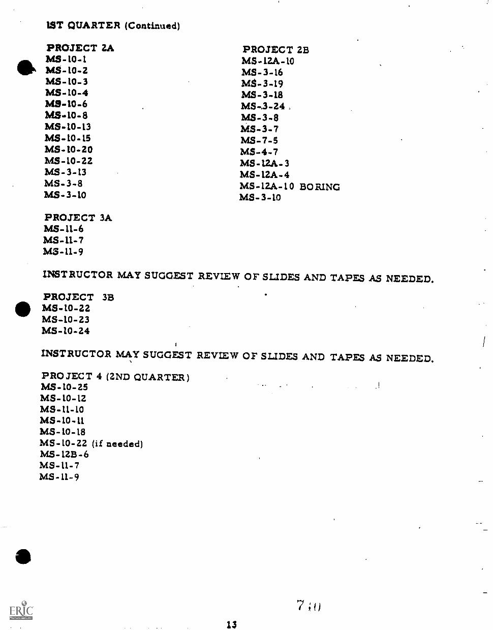
1ST QUARTER (Continued)
PROJECT ZAMS-10-1MS-10-2MS-10-3MS-10-4MS-10-6MS -10 -8MS-10-13MS-10-15MS -10 -20MS-10-22MS -3 -t3MS-3-8MS-3-10
PROJECT 3AMS-11-6MS-11-7MS-11-9
PROJECT 2BMS-12A-10MS-3-16MS-3-19MS-3-18MS-.3-24MS-3-8MS-3-7MS-7-5MS-4-7MS-12A-3MS-12A-4MS- 12A -10 BORINGMS-3-10
INSTRUCTOR MAY SUGGEST REVIEW OF SLIDES AND TAPES AS NEEDED.
PROJECT 3BMS -10 -22MS-10-23MS-10-24
INSTRUCTOR MAY SUGGEST REVIEW OF SLIDES AND TAPES AS NEEDED.
PROJECT 4 (2ND QUARTER)MS-10-25MS-10-12MS-11-10MS-10-11MS-10-18MS-10-22 (if needed)MS-12B-6MS-11-7MS-11-9
13
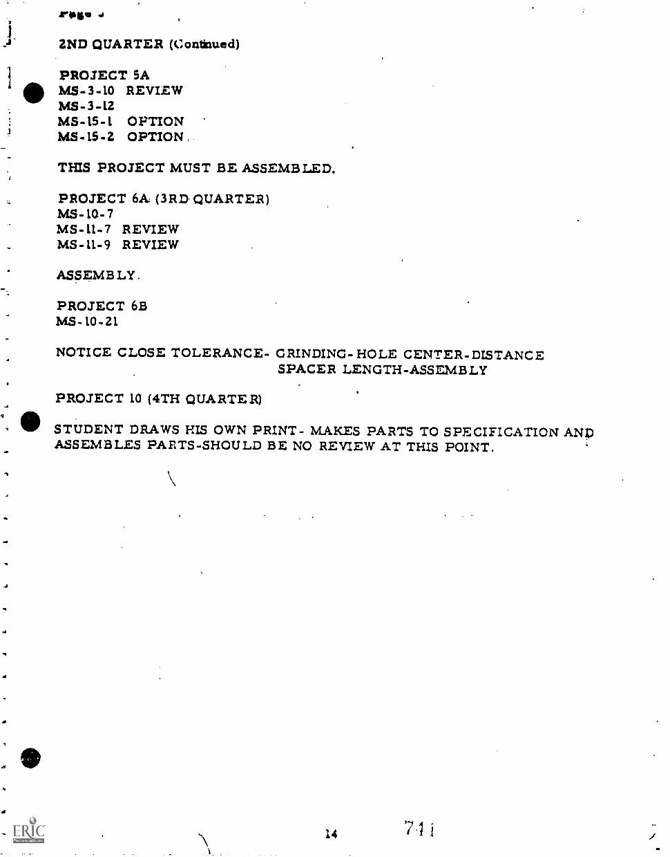
1
2ND QUARTER (Continued)
PROJECT 5AMS-3-10 REVIEWMS-3-12MS -15 -1 OPTIONMS-15-2 OPTION .
THIS PROJECT MUST BE ASSEMBLED.
PROJECT 6A (3RD QUARTER)MS-10- 7MS-L1-7 REVIEWMS-11-9 REVIEW
ASSEMB LY .
PROJECT 6BMS -10 -21
NOTICE CLOSE TOLERANCE- GRINDING-HOLE CENTER-DISTANCESPACER LENGTH-ASSEMBLY
PROJECT 10 (4TH QUARTER)
STUDENT DRAWS HIS OWN PRINT- MAKES PARTS TO SPECIFICATION ANDASSEMBLES PARTS-SHOULD BE NO REVIEW AT THIS POINT.
-a
14 7I
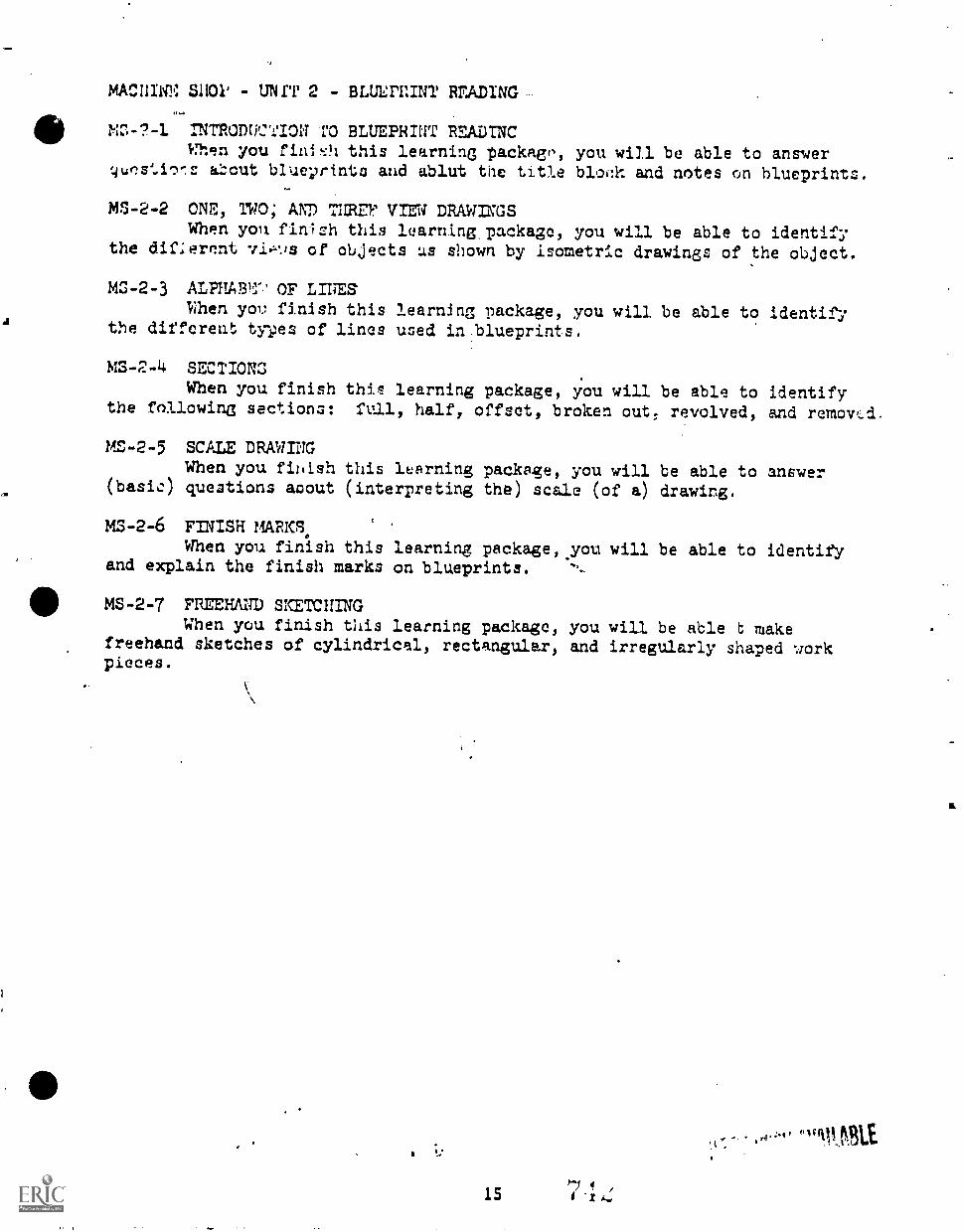
a
MACIIIIC S11011 - UNI'r 2 - BLULITINT RF.ADING
410 MO-?-1 INTRODUCTION ro BLUEPRINT READTNCI.Tlen you fin; :h this learning packago, you will be able to answer
about blueprints and ablut the title b1o,!1'. and notes on blueprints.
MS-2-2 ONE, TWO; AND THREP VIEW DRAWINGSWhen yon finish this luarning.package, you will be able to identify
the difIerent of oUjects us shown by isometric drawings of the object.
M3-2-3 ALPHABT.' OF LINESNhen you finish this leartiJng package, you will be able to identify
the different tyyes of lines used in:blueprints.
MS-2-4 SECTIONSWhen you finish this learning package, you will be able to identify
the following sections: full, half, offset, broken out; revolved, and removed.
MZ-2-5 SCALE DRAWINGWhen you finish this learning package, you will be able to answer
(basic) questions about (interpreting the) scale (of a) drawing.
MS-2-6 FINISH MARKS.When you finish this learning package,you will be able to identify
and explain the finish marks on blueprints.
MS-2-7 FREEHAND SKETCHINGWhen you finish this learning package, you will be able t make
freehand sketches of cylindrical, rectangular, and irregularly shaped workpieces.
.
151I
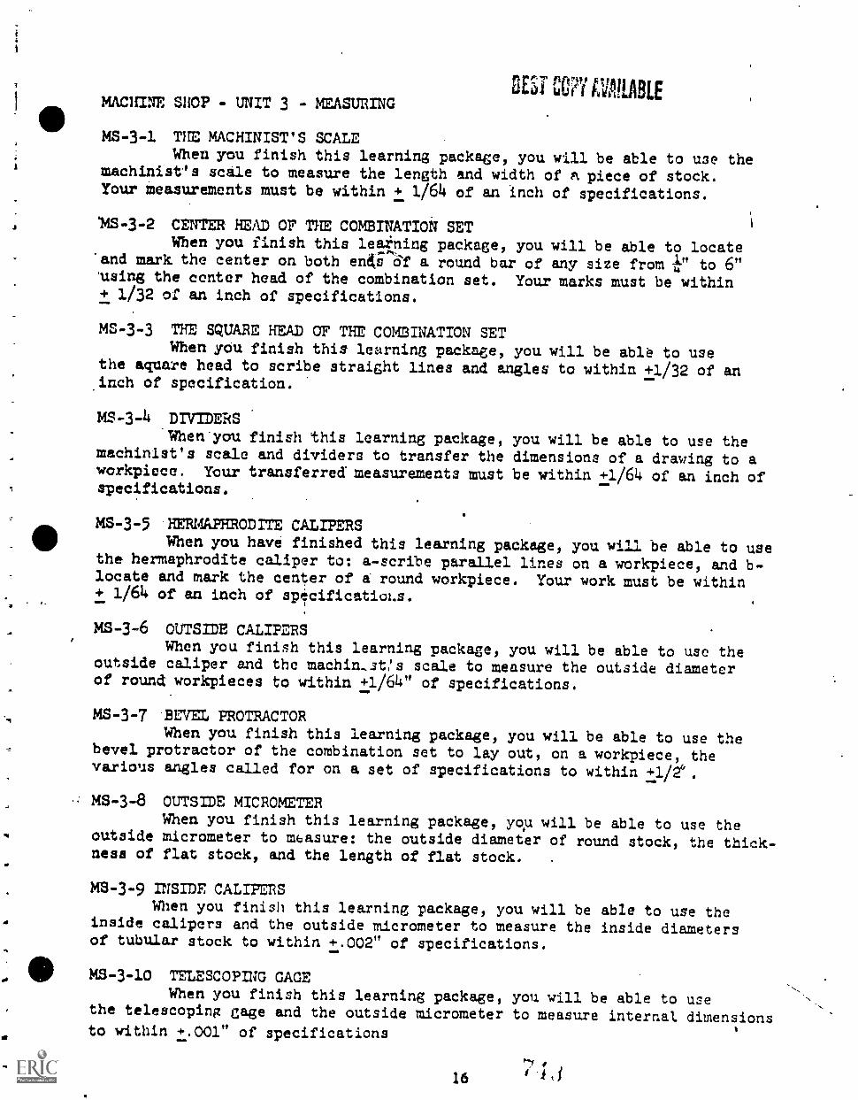
MACHINE SHOP - UNIT 3 - MEASURINGBEST CCNi,1411.1ABLE
MS-3-1 THE MACHINIST'S SCALEWhen you finish this learning package, you will be able to use the
machinist's scale to measure the length and width of A piece of stock.Your measurements must be within + 1/64 of an inch of specifications.
14S-3-2 CENTER HEAD OF THE COMBINATION SETWhen you finish this leatning package, you will be able to locate
'and mark the center on both entiE of a round bar of any size from 11;" to 6"'wing the center head of the combination set. Your marks must be within+ 1/32 of an inch of specifications.
MS-3-3 THE SQUARE HEAD OF THE COMBINATION SETWhen you finish this learning package, you will be able to use
the aquare head to scribe straight lines and angles to within +1/32 of aninch of specification.
MS-3-4 DIVIDERS'When'you finish this learning package, you will be able to use the
machinist's scale and dividers to transfer the dimensions of a drawing to aworkpiece. Your transferred' measurements must be within +1/64 of an inch ofspecifications.
MS-3-5 HERMAPHRODITE CALietaiSWhen you have finished this learning package, you will be able to use
the hermaphrodite caliper to: a-scribe parallel lines on a workpiece, and b-locate and mark the center of a round workpiece. Your work must be within+ 1/64 of an inch of specifications.
MS-3-6 OUTSIDE CALIPERSWhen you finish this learning package, you will be able to use the
outside caliper and the machin.,st!s scale to measure the outside diameterof round workpieces to within +1/64" of specifications.
MS-3-7 BEVEL PROTRACTORWhen you finish this learning package, you will be able to use the
bevel protractor of the combination set to lay out, on a workpiece, thevarious angles called for on a set of specifications to within +1/2°.
MS-3-8 OUTSIDE MICROMETERWhen you finish this learning package, you will be able to use the
outside micrometer to measure: the outside diameter of round stock, the thick-ness of flat stock, and the length of flat stock.
.
ms-3-9 INSIDE CALietaiSWhen you finish this learning package, you will be able to use the
inside calipers and the outside micrometer to measure the inside diametersof tubular stock to within +.002" of specifications.
MS-3-10 TELESCOPING GAGEWhen you finish this learning package, you will be able to use
the telescoping gage and the outside micrometer to measure internal dimensionsto within +.001" of specifications
16 ' i i
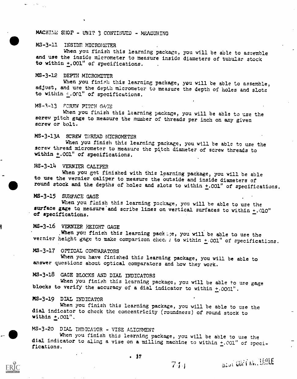
MACHINI; 51101 UNiT 3 CONTItrUEll - MEACURING
MS -3 -11 INSIDE MICROMETERWhen you finish this learning package, you will be able to assemble
and use the inside micrometer to measure inside diameters of tubular stockto within +.001" of specifications.
MS-3-12 DEPTH MICROMETERWhen you finish this learning package, you will be able to assemble,
adjust, and urle the depth micrometer to measure the depth of holes and slotsto within .0101" of specifications.
MS-1-13 PCREW PITCH GPMWhen you finish this learning package, you will be able to use the
screw pitch gage to measure the number of threads per inch on any givenscrew or bolt.
MS-3-13A SCREW TUREAD MICROMETERWhen you finish this learning package, you will be able to use the
screw thread micrometer to measure the pitch diameter of screw threads towithin +.001" of specifications.
MS-3-14 VERNIER CALIPERWhen you get finished with this learning package, you will be able
to use the vernier caliper to measure the outside and inside diameters of
411round stock and the depths of holes and slots to within +.001" of specifications.
MS-3-15 SURFACE GAGEWhen you finish this learning package, you will be able to use the
surface gage to measure and scribe lines on vertical surfaces to within +.010"of specifications.
MS-3-16 VERNIER. HEIGHT GAGEWhen you finish this learning packe, you will be able to use the
vernier height gage to make comparison checi to within +001" of specifications.
MS-3-17 OPTICAL COMPARATORSWhen you have finished this learning package, you will be able to
answer questions about optical comparators and how they work.
MS-3-18 CAGE BLOCKS AND DIAL INDICATORSWhen you finish this learning package, you will be able to use gage
blocks to verify the accuracy of a dial indicator to within +.0001".
MS-3-19 DIAL INDICATORWhen you finish this learning package, you will be able to use the
dial indicator to check the concentricity (roundness) of round stock towithin +.001".
MS-3-20 DIAL INDICATOR - VISE ALIGNMENTWhen you finish this learning package, you will be able to use the
dial indicator to aline a vise on a milling machine to within +.001" of speci-fications.
17
'7 I i
MACHINE SHOP - UNIT 3 CONTINUED - MEASURING
MS-3-21 RADIUS GAGEWhen you finish this learning package, you will be able to use a
radius gage to measure convex and concave radii of parts.
MS-3-22 PLANER GAGEWhen you finish this learning package, you will be able to adjust
the planer gage to a given height.
MS-3-23 VERNIER BEVEL PROTRATORWhen you finish this learning package, you will be able to use the
univeri:al vernier bevel protractor to lay but a given angle, with an accuracyof + 0°5'.
MS-3-24 SINE BARWhen you finish this learning package, you will be able to use a
sine bar to measure and set up various angles with an acuracy of +0°5'.
MC -3 -25 SNAP GAGESWhen you finish this learning package, you will be able to use snap
gages to measure lengths, diameters, and thicknesses of parts.
MS-3-26 GEAR TOOTH VERNIER CALIPERWhen you finish this learning package, you will be able to use a
gear tooth vernier caliper to measure the addendum and the chordal thicknessIll of any gear tooth.
A
18
7/
'1,, MACHTNE 31) - UNIT 4 - LAYOUT
MS-4-1 LITRODUCTION TO LAYOUT TOOLS AND ACCESSORIESWhen you finish this learning package, you will be able to identify
basic layout tools and answer questions about their use.
MS-4-2 USING LAYOUT TOOLS: PART 1When you finish this learning package, you will be able to layout
fluid, scriber, dividers, trammels, hermaphrodite calipers, and prickpunch to do layout work to specifications.
W-4-3 USING LAYOUT TCOLS: PART 2When you finish this learning package, you will
the vernier height gage, magnifying glass, angle. plate,c- clasps, parallel clamps, 1-2-3 step blocks, precisionand sine bar to do layout work to specifications.
M2-4-4 USING LAYOUT TOOLS: PART 3When you finish this learning package, you will be able to use the
combination set, verider protractor, and protractor depth gage to doinspection and layout work to specifications.
be able to usetoolmaker's square,square, gage blocks,
MS-4-5 USING LAYOUT TOOLS: PART 5When you finish this learning package, you will be able to use
the surface gage, dial indicator, planer gage, center punch: and hammerto do layout work to specifications.
MS-4-6 LAYING OUT A T-SLOT CLEANERWhen you finish this learning package, you will be able to layout
a T-slot cleaner to specifications.
MS-4-7 LAY= OUT A DRILL AND TAP BLOCKWhen you finish this learning package, you will be able to layout
a series' of six holes on a drill and tap block.
":'
19
t)
.16
A
MACHINE 3HOP - UNIT 5 -
M3-5-1 INTRODUCTTO:1 TOWhen you finish
basic bench tools.
MS-5-2 THE BENCh VISE
BENCH WORK
BENCH TOOLSthis learning package, you will be able to identify
Whtln you finish this learning package, you will be able to name 1
the parts or a bench vine and do clamping operations on the vise accordingto specificW.A.ons.
MS-5-3 FILES AND FILINGWhen you finish this learning package, you will be able to
basic files used in machining and file work pieces accurately to sp
MS-5-4 HANDWhen
and properly
HACK SAUSyou finish this learning package, you will be able touse hand hack saws to cut metals.
identifyecifications.
identify
MS-5-5 1APS AND DIESWhen you finish this learning package, you will be able to identify
and properly wie taps and dies to cut threads on work pieces to specifications.
MS-5-6 HAND REAMINGWhen you finish this learning package, you will be able to use hand
reamers properly to ream holes in metals to specified sizes.
MS-5-7 HAMMERS, SCREW DRIVERS, CHISELS, PLIERS, MID WRENCHESWhen you finish this learning package, you will be able to identify
and properly use hammers, screw drivers, chisels, pliers, and wrenches.
BEST pfilti,
Ir
20I
411 MACHINE STOP - UNIT 6 - BENCH AND PEDESTAL GRINDING
MS-6-1 GETFDING WHEELSWhen you finish this learing package, you will be able to use
reference charts to select proper grinding wheels. You will be able toinstall the wheels on a grinder, adjust the wheels, and adjust the tool
rest.
MS-6-2 DRESSING WHEELSWhen you finish this learning
and dress a grinding wheel for normal
MS-6-3 GRINDING A RADIUSWhen youbfinish this learning
a e radius to fit a e gage.
utis tit;t1;1114}ag,
21/
package,grinding
package,
you will be able to trueoperations.
you will be able to grind
7 1 3
MACHINE SHOP - UNIT 7 - DRILL PRESS
III MS-7-1 INTRODUCTION TO DRILL :MSSWhen :or. finish this learning package, you will be able to name
each control on a upright drill press and tell what each control does.
MS-7-2 SETUPS FOR DRILLINGWhen you finish this learning package, you will be able to use
the proper holing devices to set up for the following drilling tasks:
round stock, flat stock, sheet metal, irregular shapes.
MS-7-3 DRILL PRESS CUTTING TOOLSWhen you Cininh this learning parsker!e, you will be able to identify
cutting tools uaud In a drill press and tell what each one does.
MS-7-4 ADAPTERS AND SLEEVESWhen you finish this learning package, you will be able to use
sleeves and/or chucks to change the holding capacity of a drill press spindle.
MS-7-5 DRILLING HOLESWhen you finish this learning par!kage, you will be able to choose
correct fteds and speeds for drilling holes in steel and aluminum.
Accuracy will be + 1/32".
MS-7-6 DEPTH DRILLINGWhen you finish this learning package, you will be able to use
Ill the drill press depth stops to drill holes to a specified depth, with an
accuracy of + 1/16".
MS-7-7 COUNTERBORING, COUNTERSINKING, AND SPOT FACINGWhen yon finish this learning package, you will be able to use the
proper tool to counter sink, counterbore, and spot face drilled holes to
a tolerance of 4- 1/32".
MS-7-8 .ANGUMAR HOLESWhen you finish this learning package, you will be able to make
table adjustments and use proper holding devices to drill angular holes
in matal, to an accuracy of + 1/32".
MS-7-9 RADIAL DRILL PRESSWhen you finish this package, you will be able to answer questions
about the parts and controls of a radial drill press and tell what each does.
MS-7-10 REAMINGWhen you finish this learning package, you will be able to use
a straight or taper shank reamer to ream holes to a specified size,
with an accuracy of + 1/64".
MS-7-11 MACHINE TAPPINGWhen you finish this learning package, you will be able to use
the proper tap drill size, tap, and tapping attachment to drill tap holes
as shown on drawings, with an accuracy of + 1/32".
i.
22
WHTNIr. 'MOP - UNIT 7 CONTTNUM - DRILL Immo
Mr.-712 PAP= OF A TWICT DRILLWhen you finish this learning package, you will be able to name
the parts of a twist drill and tell the purpose of each.
MS-7-13 TWIST DRILL SIZESWhen you finish this learning package, you will be able to use
charts and drill gages to select the proper size drill for a given
application.
MS,7-14 TRANSFERRING HOLESMinn you finish this learning package, you will be able to
trmnnfer holes from on piece of work to another by spotting with a twist
drill, using a transfer punch, and using transfer scrcws.
;.
23
j
A
MID
-4
MACHINE SHOP - UNIT 8 - DRILL GRINDING
MS-8-1 FREEHAND MILL SEARPENINGWhen you finish this learning package, you will be able to use the
bench or pedestal grinder to sharpen a dull twist drill. Using a drillbit gage as a guide, you will be able to: keep the point angle to within+ i° and keep the point centered to within + 1/64" drill lip length.
MS-8-2 MACHINE DRILL SHARPENINGWhen you finish this learning package, you will be able to set up
and operaLe a machine drill grinder to sharpen a two-lip twist drill anda three or four-lip core d2.11.
MACHINE SHOP - UNIT 9 - POWER SAWS
M3 -9-1 POWER SAWS: PARTS AND COITTROLSWhen you finish this learning package, you will be able to name
the main parts and controls of the horizontal band saw, the vertical bandsaw, and the power hack saw.
MS-9-2 CHOOSING POWER UAW BLADES A
When you finish this learning package, you eill be able to choosethe correct power saw blade for a given application.
MS-9-3 FREQUENT SAWING PROBLEMSWhen you finish this learning package, you will be able to answer
questions about diagnosing and correcting problems often met when usingthe power hacksaw, vertical band saw, and horizontal band saw.
MS-9-4 SETT= BLADE SPEEDSWhen you finish this learning package, you will be able to use
charts or a job dial selector to choose the proper speed of a band sawblade for a given job.
N1S-9-5 SETTINZ UP POWER SAW CONTROLSWhen you finish this learning package, you will be able to et up
the operational controls of a power hack :taw and a power band saw for asawing operation.
MS-9-6 MOUNTING BAND SAW BLADES AND CUTTING STOCKWhen you finish this learning package, you will be able to select,
mount guides, and install blades on the vertical band saw, and cut stockwith a vertical band saw to an accuracy of + 1/16".
MS-9-7 WELDING BAND SAW BLADESWhen you finish this learning package, you will be able to use the
bulk blade provided and the welding attachment on the vertical band saw toweld band saw blades. You will weld blades to specified lengths for par-ticular sawn and to the thickness required by the blade thickness gage onthe vertical band saw.
MS-9-8 VERTICAL BAND SAW: CUTTING CIRCLES, CONTOURS, AND STRAIGHT LINESWhen you finish this learning package, you will be able to use
the vertical band saw to cut contours, circles, and straight lines withan accuracy of + 1/16".
MS-9-9 FRICTION SAWINGWhen you finish this learning package, you will be able to set up
a vertical band saw for friction sawing of thins sheet metal.
MS-9-10 BAND FILINGWhen you finish this learning package, you will be able to select
and set up a band file for a band filing job.
25
4
MACHIN?: SHOP - UNIT 9 CONTfl a - POWER SAWS
MS-9-11 HORIZONTAL PAM SAW: STRAIGHT MID ANGLE CUTS
When you finish this learning package, you will be able to use
the horizontal band saw to cut stock, with an accuracy of 4. 1/1C" and to
make angular cuts with an accuracy of .+ 10.
MS-9-12 FINISHING A T-SLOT CLEANERWhen you finish this learning package, you will be able to finish
a T-slot cleaner to blueprint specifications.
MS-9-13 FINISHING A DRILL AND TAP BLOCKWhen you finish thi3 learning package, you will be able to finish
a drill and tap block to blueprint specifications.
14/611121 E
264
% 11.1)
MPCN1NE SHOP - UNIT 10 - ENGINE LATHE
MS -10 -1
out the
LATHE PART; AND CONTROLSWhen you finish this learning packace, you will be able to pointmain par%s and controls of an engine lathe.
MS-10-2 CUTTING SPZEDS AND FEEDSWhen you finish this learning package, you will be able to choose
proper feeds and speeds used to machine different kinds of metals on the lathe.
MS-10-3 INSTALLING CHUCKSWhen you finish this learning package, you will be able to install
all of the chucks used on a lathe.
MS-10-4 TOOL BIT GRINDINGWhen you finish this learning package, you will be able to: identify
and sketch basic lathe tools, grind a general purpose tool bit for use onthe engine lather.
MO-10-5 FOUR-JAU CHUCK TRUINGWhen you finish this learning package, you will be able to true
a piece of rouns stock in a 4-jaw chuch.
MS-10-6 FACING TO LENGTHWhen you finish this learning package, you will be able to machine
a workpinec to a given length using a facing tool on an engine lathy withan accuracy of +.001".
MS-10-7 COLLET ASSEMBLY AND CENTER'- RILLINGWhen you have finished this 'earning package, you will be able to
set up a collet. assembly on a lather, center drill a workpiece on the lathe.
MS-10-8 GRADUATED MICROMETER COLLAR: ROUGH AND FINISH TURNING.When you finish this learning package, you will be able to use a
graduated micrometer collar to turn a workpiece to a specified diameter,with an accuracy of + .001".
MS-10-9 NECKINGWhen you finish this learning package, you will be able to do a
necking operation on an engine lathe.
MS-10-10 MOUNTING WORK BETWEEN CENTERSWhen you finish this learning package, you will be able to mount
a workpiece between centers properly.
MS-10-11 ALIGNING THE TAILSTOCKWhen you finish this learning package, you will be able to adjust
the lathe tailstock properle for turning a work between centers with anaccuracy of + .001".
) e
I
27 7
MACHINE SHOP - UNIT 10 CONTINUED - ENGINE LATHE
IIIMS-10-12 DRILLING AND REAMING ON THE LATHE
When you 1:inish this learning package, you will be able to drilland ream a workpicca on an engine lathe to a specified size.
MS-10-13 TURNING WC= ON A MANDRELWhen you finish this learning package, you will be able to use a'
mandrel to turn a .orkpiece to a specified diameter.
vop
.aa
. 4
AO
.1
MS-10-14 TURNING TO SQUARE AND FILLETED SHOULDERSWhen you finish '.his learning package, you will be able to cut
a square and a filleted shoulder mioperly.
MS-10-15 FILING AND POLISHINGWhen you finish th-s package, you will be able to file and polish
a work piece un a lathe to a specified stze.
MS-10-16 KNURLuWhen you finish this learning package; you will. be able to knurl
a workpiecc on a lathe.
MS-10-17 TAPER TURNING WITH A "'":.fFOUtL, RESTWhen you finish this J. ..ping package, you will ,e able to turn
a taper on a workpiece using the compcund rest.
MS-10-17A CALCUTATING TAPERSWhen you finish this learning package, you will be able to:
calculate proper compound rest angle settings for turning tapers usingformulas and trigonometric tables and calculate taper per foot and taperper inch using formulas.
MS-10-18 TAPER TURNING AND TAPER ATTACHMENTWhen you finish this learning package, you will be able to turn
a taper using the taper attachment for the lathe.
MS-10-19 TAPER TURNING WITH OFFSET TAILS TOOKWhen you finish this learning package, you will be able to cut a
taper using the offset tailstock method.
MS-10-20 7XTERNAL THREADING WITH THREADING DIE AND HOLDERWhen you finish this learning package, you will be able to use
the engine lathe to cut threads on a workpiece with a threading die andholder.
MS-10-21 TURNING ON THE LATHEWhen you finish this learning package, you will be able to cut
an internal thread with the lathe by using a trap and holder.
MS-10-22 THREAD= ON THE LATHE: EXaliNAL THREAD clasIrcWhen you. finish this learning package, you will be able to
cut threads on a workpiecc by using the lathe thread cutting mechanismsand chase external threads using a latne.
111MACHINE caop - UNIT 10 CONTINUED - ENGINE LATHE
MS-10-23 BORING PARWhen you finish this learning package, you will be able to bore
et. hole to size on a lathe.
MS-10-24 INTERNAL THREADINGWhen you finish this learning package, you will be able to cut
internal tl,reads using the thread chasing mechanism. .
MS-10-25 STEADY RESTWhen you finish thi, . learning package, you will be able to set
up and reehine a long workpiece using a steady rest.
MS-10-26 FOLLOW RESTWhen you finish this learning package, will be able to set
up and machine a workpiece using the follow rest.
MS -J0-27 FORM TURNINGWhen you finish this learning package, you will be able is turn a
radius on the lathe by hand.
29
CO? i\k.rtl!.91,E
MACHINE SHOP - UUIT 11 - MILLING : INTRODUCTION
MS-11-1 KINDS OF MILLING MACHINESWhen you finish this learning package, you will be able to
point out and name six different kinds of milling machines and briefly
describe their uses.
MS-11-2 LUBRICATION AND PREVENTINE MAINTENANCEWhen you finlsh this learning package, you will be able to
lubricate and perform preventive maintenance on milling machines.
M2-11-3 SPEEDS AND FEEDSWhen you finish this learning package, you will be able to
figure speeds and feeds on a milling machine for,given cutters and wort"
materials.
MS-11-4 CUTTING FLUIDS AND OILSWhen you finish this learning package, you vill be able to identify,
mix, and apply cutting fluids and oils in milling machine operations.
MS-11-5 ACCESSORMS AND ATTACHMENTSWhen you finish this learning package, you will be able to point
out and name several milling machine attachments and tell whit is used for.
MS-11-6 INDEXING HEADS AND DIRECT INDEXINGWhen you finish this learning package, you will be able to: point
out and name the five basic parts of an indexing head, descbe the use ofeach part, and set an indexing head up for direct indexing.
N .11-7 SIMPLE INDEXINGWhen you finsh this learning package, you will be able to change
an index plate and set up an indexing head for simple indexing.
MS-11-8 ANGULAR INDEXINGWhen you finish this learning package, you will be able to: set up
an indexing head for angular indexing and use the proper formulas to figure
angular indexing settings.
MS-11-9 PREPARING THE HEAD FOR INDEXINGWhen you finish this learning package, you will be able to prepare
an indexing head along with the footstock (tailstock).
MS-11-10 INDEXING: ALIGNMENT R CENTERSWhen you finish th.l.s learning package, you will be able to align
the centers of an indexing head and tailstock with an aligning bar anddial indicator.
MS-11-11 VISE AND TABLE II,IGNMENTWhen you finish this learning package, you will be able to:
align a milling machine vise with a square, a dial indicator, and the:parks on the vise base and align the table of a milling machine with the
column face.
i f
MS-11-12 ROTARY TABLE AND SLOTTING ATTACHMENTWhen you finish this learning package, you will be able to identify
and briefly describe the uses of the rotary table and slotting attachment.
MACHINE SHOP - UNIT 12 - MILLING MACHINES: VERTICAL AND HORIZONTALSECTION A - VERTICAL MILLING MACHINES
MS-12A-1 SOUTH BEND RAM TURDET: PARTS AND CONTROLSWhen you finish this learning package, you will be able to name
the parts and controls of a South Bend Ram Turret vertical milling machineand describe what each control does.
NS-12A-2 CINCINNATI NO. 3: PARTS AND CONTROLSWhen you finish this learning package, you will be able to point
out and n9me the parts and controls of the Cincinnati No. 3 vertical millingmachine. and describe what each control does.
MS-12A-3 ODEL "J" BRIDGEPORT: PARTS AND COafROLSWhen you finish this learning package, you will be able to point
out and ncme the parts and controls of the Model "J" Bridgeport verticalhead milling machine and describe what each control does.
MS-12A-4 MODEL "J" BRIDGEPORT: VERTICAL HEAD ALIGNMENT"When you fIllish this learning package, you will be able to align
the head of a Model "J" Bridgeport vertical heel milling machine.
MS-12A-5 MODEL "2J" BRIDGEPORT: PARTS AND CONTROLSWhen you finish this learning package, you will he able to point
out and name the parts and controls of thesModel "2J" Bridgeport verticalbead Wiling machine and describe what each control does.
MS-12A-6 CINCINNATI MODEL "D" TOOLMASTER: PARTS AND CONTROLSWhen you finish this learning package, you will be able to point
out and name the parts and controls of the Cincinnati Model "D" Toolmastervertical milling machine and describe what each control does.
L-NIS-12A-7 VAN NORMAN MODEL 13: PARTS AND CONTROLS
When you finish this learning package, you will be able to pointout and name the parts and controls of the Van Norman Model 13 millingmachine and describe what each control does.
MS-12A-8 VERTICAL MILLING MACHINE CUTTERSWhen you finish this learning package, you will be able to point
out and name cutters used in vertical milling operations and describe theiruses.
MS-12A-9 MOUNTING CUTTERS AND CUTTING A KEYSEATWhen you finish this learning package, you will be able to mount
vertical milling machine cutters properly and cut a keyseat, using a4-flute end mill.
MS-12A-10 VERTICAL MILLING SETUPS AND OPERATIONSWhen you finish this learning package, you will be able to identify
and make setups on a vertical milling machine.
S MACHINE CHOP - UNIT 12 - MILLING MACHINES: VERTICAL AND HORIZONTAL
SECTION B HORIZONTAL MILLING MACHINES
MS-12B-1 CINCINNATI UNIVERSAL NO. 2: FARTS AND CONTROLS
When you finish this learning pacirme, you will be able to name
and point out the parts and control on the above milling machine and
describe what each control does.
MS-12B-2 HORIZONTAL MILLIM MACHINE CUTTERS
When you finish this learning package, you will be able to
point out and name cul.ters used in horizontal milling operations and
describe their uses.
MS -12B -3 MOUNTING HORIZONTAL MILLING CUTTERS
When you finish this learning package, you will be able to mount
horizontal milling machine cutters properly.
MS- 12B- -4 HORIZONTAL MMLING SETUPS AND OPERATIONS
When you finish this learning package, you will be able to identify
and make setups on a horizontal milling machine.
MS-12B-5 INSTALLING A VERTICAL HEAD ATTACHMENT
When you finish this learning package, you will be able to install,
lubricate, and operate a velLical head milling attachment.
MS-12B-6 CUTTING A SPUR GEARWhen you finish this learning package, you will be able to set
up a horizontal column and knee type milling machine for cutting a spur
gear and cut a spur gear according to blueprint specifications.
MS-12B-7 CUTTING A RACK GEARWhen you finish this learning package, you will be able to set
up a horizontal column and knee type milling machine for cutting a rack
rear and cut a rack gear according to blueprint specifications.
MS-12B-8 'CUTTING A HELICAL GEARWhen you finish this learning package, you will be able co set
up a horizontal column and knee type rfilling machine for cutting a helical
gear and cut a helical gear according to blueprint specifications.
32
I WI
Alk MACHINE SHOP - UNIT 13 - SHAPER
MS-13-1 SHAPER: PARTS AND LUBRICATIONWhen you finish with this learning package, you will be able to
name the main parts of a shaper and lubricate a shaper to manufacturer'sspecifications.
M3-13-2 SHAPER CONTROLSWhen you finish this learning package, you will be able to name
the operating controls of the shaper and tell what each does.
MS-13-3 CUTTING TOOLSWhen you finirih this learning packace, you will be able to
name common cutting tools used on the shaper and describe and tell thepurpose of the angles ground on each tool.
MS-13-4 VISE ALIG Jim : SHAPER SAFETYWhen you finish this learning package, you will be able to:
level and align a shaper vise using a dial indicator and a precision squareor parallel, and state important safety rules about the shaper swivelhead and vertical tool head.
MS-13-5 MACHINING A FLAT, HORIZONTAL SURFACEWhen you finish this learning package, you will be able to set
up and machine a flat, horizontal surface on a shaper.
MS-13-6 SETUPS FOR VERTICAL ArD ANGULAR CUTSWhen you finish this learning package, you will be able to set
up a shaper and machine vertical and ar4ular cuts on a workpiece togiven specifications.
MS-13-7 FEEDS AND SFEEDSWhen you finish this learning package, you will be able to figure
proper feeds and speeds for different shaper operations, using formulasand charts and set a shaper ft.r a given cutting speed, number of strokesper minute, and feed per stroke
7 )
33
MACHINE SHOP - UNIT 14 - SURFACE GRINDING
MS-14-1
the main.
SURFACE GRINDER PARTS AND CONTROLSWhen you finish this learning package, you will be able to name
parts and controls of a surface grinder.
MS-14-2 SELECTING AND CHANGING GRINDING WHEELSWhen you finish this learnini package, you will be able to selects
and change grinding wheels on a surface grinder to meet requirements of the
material to be ground.
MS-14-3 MOUNTING AND DRESSING GRINDING WHEELSWhen you finish this learning package, you will be able to select,
test, mount, and dress the proper grinding wheel for a given job by using
the diamond tip dresser to true the wheel in relation to the magnetic chuck.
MS-14-4 MAGNETIC CHUCKSWhen you finish this learning
and secure a workpiece on the magneticalign the workpiece surface so that itgrinding wheel) using a dial indicator
package, you will be able to.positionchuck of the surface grinder andis parallel to the face of theto get an accuracy of +.001".
MS-14-5 GRINDING A WORKPIECEWhen you finish this learning package, you will be able to make
a finish drawing and grind two parallel birs to the specifications of that
drawing with an accuracy of:t.0005".
MS-14-6 WHEEL DRESSING: CONVEX OR CONCAVE RADIUSWhen you finish this learning package, you will be able to set up
a radius dresser and dress a grinding wheel to a convex or concave radius.
34
MACHINE SHOP - UNIT 15 - TOOL POST GRINDING
M3-15-1 SETTING UP A TOOL POST GRINDERWhen you finish this learning package, you will be able to set
up a lathe and tool post grinder for a grinding operation.
MS-15-2 EXTERNAL' TOOL POST GRINDINGWhcn you finish this learning package, you will be able to grind
a lather center point properly to fit a center gage in 55 minutes.
MS-15-3 REAMER SHARPENING ON THE TOOL POST GRINDERWhen you finish this learning package, you will be able to sharpen
a machine reamer properly on a tool post grinder in lj hours.
MS-15-4 INTERNAL TOOL POST GRINDINGWhen you finish this learning package, you will be able to grind
a drill bushing bore to blueprint specifications with a tool post grinderin one hour and twenty minutes.
APPENDIX G
SUGGESTED CRITERIASELECTION OF SCHOLARSHIP STUDENT
TOGREENVILLE TECHNICAL COLLEGEMACHINE TECHNOLOGY PROGRAM
There is agreement among the three secondary machine shopinstructors that some following criteria should be applied toselecting the "most outstanding or worthy student" from thesecondary Machine Shop program to be awarded a scholarship tothe Machine Technology Program.
There, however, is a greater need at present to encouragesecondary machine shop graduates to continue their vocationaleducation at the post-secondary technical college level. Someof the reasons that students given for not accepting a scholar-ship or continuing their training include; not being able toafford the minimum costs of books or travel that accompanyscholarships, the desire for immediate employment and earning,etc.
APPENDIX H
111 INSTRUCTIONS FOR ANSWERING OUTCOME-REFERENCED TEST ITEMS
Typically, eleven (11) different types of outcome-referenced testitems may be used in the competency test.
1. True-False2. Completion (Fill-in Blanks)3. A Combination of True-False and Completion4. Multiple-Choice5. Matching6. Identification7. Short Answer8. Long Answer9. Program Product of Performance Test
10. Simulated Performance Test11. Actual Performance Test
An example of each type of test item ia included. Carefully studythe illustration test item and the directions for answering thequestion. These directions will not be given again. Your testquestions may vary slightly in the format, however, the instructionshould be applicable. Where necessary, the instructor will supple-ment these instructions for answering outcome-referenced test items.
IIIDo not guess. Guessing does not add to your knowledge, even if youhappen to guess right. If you do not know the answer skip the testitem and go to the next question. Remember: Enter your answers inthe blanks provided on the separate answer sheet, if used.
1. TRUE-FALSE
Directions: Read the statement carefully. Cecide whetherit is true or false. Answer by marking .T or Fin the blank provided to the right (or, if answersheet requires, mark "X" in the appropriate (T)or (F) parenthesis, or "circle" T or F) .
Example: Lumber shrinks across the grainof the board. (T) (F)
2. COMPLETION (Fill-in Blanks)
Directions: Complete the statement b: printing on the blankline the word or words which make a completeand correct statement.
Example: Proper edge spacing will restrictand gu()d
penetration.
twi
-listornor.
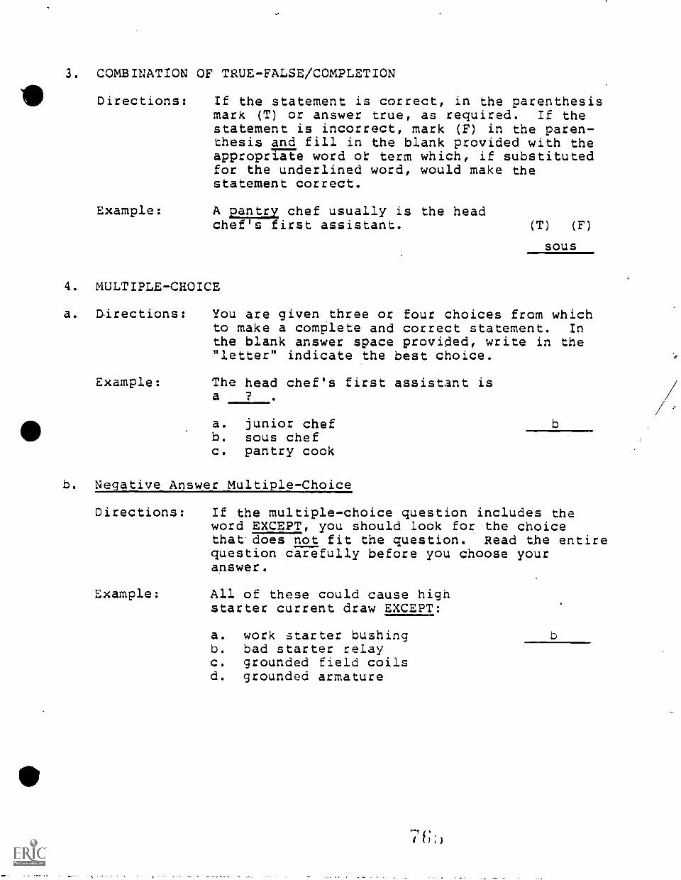
3. COMBINATION OF TRUE-FALSE/COMPLETION
Directions: If the statement is correct, in the parenthesismark (T) or answer true, as required. If thestatement is incorrect, mark (F) in the paren-thesis and fill in the blank provided with theappropriate word of term which, if substitutedfor the underlined word, would make thestatement correct.
Example: A pantry chef usually is the headchef's first assistant. (T) (F)
SOUS
4. MULTIPLE-CHOICE
a. Directions: You are given .ttree or four choices from whichto make a complete and correct statement. Inthe blank answer space provided, write in the"letter" indicate the best choice.
Example: The head chef's first assistant isa ? .
a. junior chefb. sous chefc. pantry cook
b. Negative Answer Multiple-Choice
Directions:
b
If the multiple-choice question includes theword EXCEPT, you should look for the choicethat does not fit the question. Read the entirequestion carefully before you choose youranswer.
Example: All of these could cause highstarter current draw EXCEPT:
a. work starter bushingb. bad starter relayc. grounded field coilsd. grounded armature
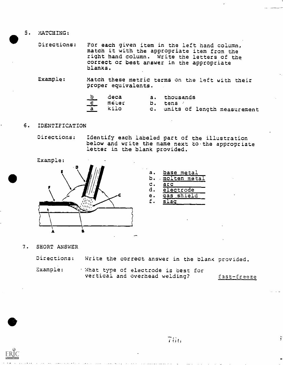
5. MATCHING:
Directions: For each given item in the left hand column,match it with the appropriate item from theright hand column. Write the letters of thecorrect or best answer in the appropriateblanks.
Example: Match these metric terms on the left with theirproper equivalents.
6. IDENTIFICATION
Directions:
Example:
b deca a. thousandsc meter b. tensa kilo c. units of length measurement
Identify each labeled part of the illustrationbelow and write the name next to .the appropriateletter in the blank provided.
7. SHORT ANSWER
a. base metalb. . molten metalc. arcd. electrodee. gas shieldf. slag
Directions: Write the correct answer in the blanK provided.
Example: What type of electrode is best forvertical and overhead welding? fast-freeze
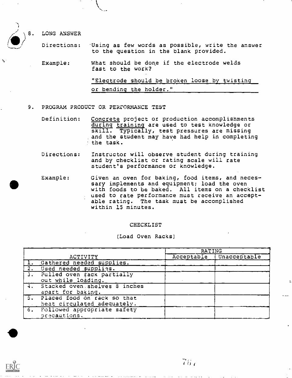
1
(ii8. LONG ANSWER
,/ Directions:
Example:
'Using as few words as possible, write the answerto the question in the blank provided.
What should be done if the electrode weldsfast to the work?
"Electrode should be broken loose b twistin
or bending the holder."
9. PROGRAM PRODUCT OR PERiORMANCE TEST
Definition: Concrete project or production accomplishmentsduring training are used to test knowledge orskill. Typically, test pressures are missingand the student may have had help in completingthe task.
Directions:
Example:
Instructor will observe student during trainingand by checklist or rating scale will ratestudent's performance or knowledge.
Given an oven for baking, food items, and neces-sary implements and equipment; load the ovenwith foods to be baked. All items on a checklistused to rate performance must receive an accept-able rating. The task must be accomplishedwithin 15 minutes.
CHECKLIST
(Load Oven Racks)
ACTIVITYRATING
Acceptable..
Unacceptable1. Gathered needed supplies.2. Used needed pupplils.3. Pulled oven rack partially
out while loctidin.4. Stacked oven.shelves 8 inches
apart for baking.5. Placed food on rack so that
heat circulated adequately.6. Followed appropriate safety
precautions.
10. SIMULATED PERFORMANCE
4V
Definition: Contrived situation, resembling tasks thegraduate will be required to do on the job.
sThis form of test is useful for evaluatingtransferable skills such as reasoning, attitudes,and psychomotor.skills necessary for occupationalsuccess.
11. ACTUAL PERFORMANCE TEST
Definition: Exhibits the-advantage of realism, but may betoo late to help either the student or thevocational program correct failures.
Example Given an automobile with a leaking pinion seal,access to proper tools and equipment, replacementparts, and service manual; replace the pinionseal according to manufacturer's recommendedprocedures. The job should be completed within2 hours. The manufacturer's specificationsmust be met and the completed job must meet theinstructor's standards.
7t6
11
APPENDIX I
ANALYSIS OF SECONDARY INSTRUCTIONAL TIDIES
Instructional times and tasks have been described based on aState of.South Carolina requirement that 3-hour blocks oftraining total 540 hours per year or 1,080 hours for two yearprograms.
Currently vocational programs in career centers typically areccnducted on the 3-hour block time frame. Most vocationalprograms currently are offered for a two year period. Somevocational courses, such as office occupations areas, may beoffered for only one or two hours of training daily.
While the "suggested instruction times" for the tasks in thisguide have been allocated based on a 3-hour vocationalinstruction day, many vocational students in reality are notin the classroom :or a full three hours. Students, typically,must be but to and from feeder high schools with transittimes typically of about 15-30 minutes per trip one way. Inaddition, students typically are given at least one breakduring instruction and some instructional time is lost asstudents change clothes for shop work and then change backinto regular school clothing. Add to this lost time thepossible time lost to feeder high school activities such as'pep ralleys' and other activities and the resulting vocationalinstructional day probably is less than 1.5 to 2 hours per dayof actual instruction or training.
Realistically, a total instruction time of from 270 to 360hours of vocational training probably is more accurate for a3-hour block program in one year than 540 hours.
It is import to recognize this potential situation asvocational instruction is planned and evaluated.
APPENDIX J
THIS DOCUMENT AND BINDER ARE THE PROPERTY OF THE SCHCCE. DISTRICT
OP GREENVILLE COUNTY OR GREENVILLE TECHNICAL COLLEGE
The production of this curriculum guide and binder by the Occupational Education
Articulation Program was funded through the South Carolina Appalachian Council
of Governments. This guide and binder are t!-- property of The Sch:v1 District
of Greenville County or Greenville Technical College.
Except for document and binder copies that have been placed in libraries or
shared with educational organizations, the documents and binders are issued on
an accountability basis.
Documents and binders issued to instructor participants remain the property of
the issuing institution. Should a vocational instructor leave the employment
of The School District of Greenville County or Greenville Technical College, the
document and binder must be returned to the principal, vocational center .
director, or department head so the instruction guide may be used by replacement
personnel.
Corrections, modifications, and notes may be made on the pages of the documents
for the purpose of modifying the field trial edition or to improve the instruc-
tional value of the document. Please share any corrections, modifications, and .
recommendations concerning this document with the Occupational Education
Articulation Program.
Illegible or blank document page replacements may be requested at no cost through
the Occupational Education Articulation Program. For replacement pages, please
indicate:
Document TitleModule Numbs"Task Number or Page Number
Replacement costs for this document and binder are:
1" Binder - $2.80V' Binder - $5.00Document - .050 per page (1982)
Who to contact:
Occupational Education Articulation ProgramThe School District of Greenville Countyc/o Donaldson Vocational Centel.Donaldson CenterGreenville, SC 29605
(or) .
AI& Consultant, Vocational Education7m. . The School District of Greenville County
(or)Associate Vice President for EducationGreenville Technical College
77()
APPENDIX K
BINDER DESIGN
(Occupational Education Articulation Program)
The binder design is simple and straightforward.
Two triangular figures, in balance, represent the two institutionsparticipating in articulation.
Two levels of training are represented by the placement of thetriangular figures and the identification of the two institutions.
Horizonal and vertical lines represent lateral and verticalarticulation.
The diagonal across the design represents the progressive movementcareer development for successful job performance.
The two figures are not closed when they face, but allow forinteraction and are linked by the document title: Articulated,Performance-based Instruction Guide.
".61;-Zip.
Copyright © 2022 FDOKUMEN