PRODUCT CATALOGUE 2015 - Espar of Michigan
86
Eberspächer Eberspächer A W O R L D O F C O M F O R T P R O D U C T C A T A L O G U E 2 0 1 5 C O M P L E T E H E A T I N G S Y S T E M S F R O M E B E R S P A E C H E R O C T O B E R 2 0 1 5
-
Upload
khangminh22 -
Category
Documents
-
view
0 -
download
0
Transcript of PRODUCT CATALOGUE 2015 - Espar of Michigan

EberspächerEberspächerA WORLD OF COMFORT
PRODUCT CATALOGUE 2015
COMPLETE HEATING SYSTEMS FROM EBERSPAECHER
OCTOBER 2015

Eberspaecher heaters have become one of the most popular money
saving products available in the heavy-duty truck market today.
Typical savings using an Airtronic D2 can be as much as $6,000 per
unit per year based on current fuel prices. Below you will find the
most popular selling kit numbers for our air and coolant heater models.
For a detailed listing of our complete product line including heater
kits, accessories and controllers for heavy truck, light truck, school
bus, industrial and oilfield markets please see the following pages.
All the heater products mentioned on the Quick-Reference pages are
EPA Verified and CARB compliant for worry-free operation anywhere in
the United States.
AIRTRONIC D2
DIESEL AIR HEATER / TRUCK BUNK HEATER
The Airtronic D2 puts out 7,500 BTU of clean comfortable heat and is
ideal for bunk heating in all makes of heavy-duty trucks. It has a higer
heat output than competitive models and is equipped with a standard
fan-mode for nights when air circulation is preferred instead of heating.
The most popular Airtronic D2 kit is listed below. It comes with every-
thing needed for installation including: Heater, Digi-Max Controller,
fuel system, mounting hardware kit and all ducting.
Airtronic D2 – Truck Kit with Digi-Max Controller 20 2820 69 0263
The Digi-Max Controller is the latest generation of heater controls and
is an Eberspaecher exclusive. It provides an easy to set digital display,
an onboard ambient air temperature sensor, an adjustable auto shut-
off, adjustable low voltage protection, records maintenance hours and
displays trouble shooting tips for fault codes displayed.
HYDRONIC D5
DIESEL COOLANT HEATERT / ENGINE PRE-HEATER
The Hydronic D5 generates 17,500 BTU of heat for quickly pre-heating
your trucks engine on those cold winter mornings. It is typically timer
operated and can be programmed to begin work up to an hour before
you are ready to start work, pre-heating the entire cooling system and
providing an easier start along with instant cab heat and window
defros ting. Manual start and stop is also available.
The most popular Hydronic D5 kits are listed below. One comes in a
rugged-duty box for protection and long-life in external mountings.
The kits come with: Heater, 7-day timer, fuel system and necessary
components for a typical truck installation.
Hydronic D5 – Boxed Unit w/ 7 Day Timer 25 2822 19 0541
Hydronic D5 – Unboxed w/ 7 Day Timer 25 2822 19 0521
Use of an engine pre-heater reduces cold start wear on internal
components, reduces stress on the starting/cranking system, and can
help extend DOC/DPF regen and replacement cycles by reducing cold-start
white smoke.
COMBO KITS
DIESEL AIR AND COOLANT HEATER PACKAGES
In some markets the weather is cold enough that drivers may prefer to
run the Airtronic D2 for cab heat and the Hydronic D5 for engine pre-
heating. In this case the driver will typically use the D2 for a comfort-
able night’s sleep and turn the engine pre-heater on about an hour
before getting up – ensuring a reliable engine start and quicker start
of operation. Combo Kits are specially priced and include both the D2
with Digi-Max Controller and D5 with 7-Day timer along with the
mounting components mentioned above.
The most popular numbers for combo kits with Hydronic D5 w/7-Day
Timer & Airtronic D2 w/Digi-Max Controller are:
Airtronic D2 with Digi-Max Controller and Hydronic
D5 with EasyStart timer 20 2812 15 20 56
Airtronic D2 with Digi-Max controller and Boxed
Hydronic D5 with EasyStart timer 20 2812 15 20 60
HEATER INSTALLATION TIPS
For a time saving video showing a typical Class 8 truck installation for
each of these products please visit the Eberspaecher website at
www.eberspaecher-na.com and see the links along the right side of
the main Downloads page.See your local dealer for special pricing on
quantity purchases of money-saving Eberspaecher heaters.
| PRODUCT CATALOGUE 2015
QUICK-REFERENCE GUIDE
2
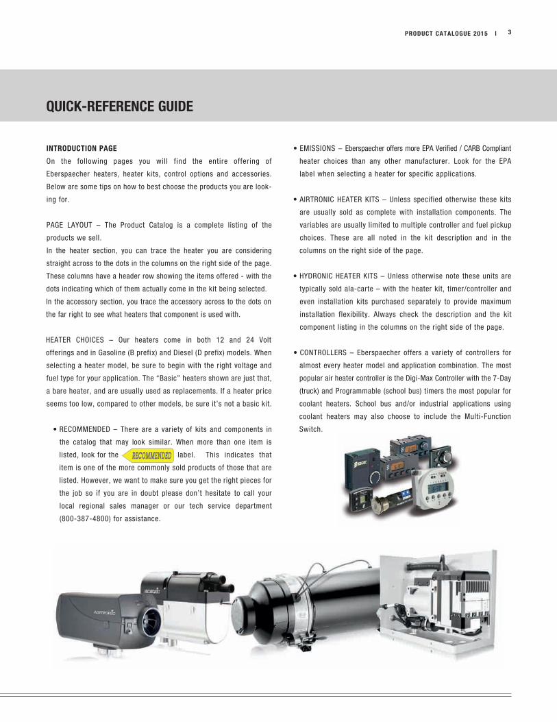
INTRODUCTION PAGE
On the following pages you will find the entire offering of
Eberspaecher heaters, heater kits, control options and accessories.
Below are some tips on how to best choose the products you are look-
ing for.
PAGE LAYOUT – The Product Catalog is a complete listing of the
products we sell.
In the heater section, you can trace the heater you are considering
straight across to the dots in the columns on the right side of the page.
These columns have a header row showing the items offered - with the
dots indicating which of them actually come in the kit being selected.
In the accessory section, you trace the accessory across to the dots on
the far right to see what heaters that component is used with.
HEATER CHOICES – Our heaters come in both 12 and 24 Volt
offerings and in Gasoline (B prefix) and Diesel (D prefix) models. When
selecting a heater model, be sure to begin with the right voltage and
fuel type for your application. The “Basic” heaters shown are just that,
a bare heater, and are usually used as replacements. If a heater price
seems too low, compared to other models, be sure it’s not a basic kit.
• RECOMMENDED – There are a variety of kits and components in
the catalog that may look similar. When more than one item is
listed, look for the label. This indicates that
item is one of the more commonly sold products of those that are
listed. However, we want to make sure you get the right pieces for
the job so if you are in doubt please don’t hesitate to call your
local regional sales manager or our tech service department
(800-387-4800) for assistance.
• EMISSIONS – Eberspaecher offers more EPA Verified / CARB Compliant
heater choices than any other manufacturer. Look for the EPA
label when selecting a heater for specific applications.
• AIRTRONIC HEATER KITS – Unless specified otherwise these kits
are usually sold as complete with installation components. The
variables are usually limited to multiple controller and fuel pickup
choices. These are all noted in the kit description and in the
columns on the right side of the page.
• HYDRONIC HEATER KITS – Unless otherwise note these units are
typically sold ala-carte – with the heater kit, timer/controller and
even installation kits purchased separately to provide maximum
installation flexibility. Always check the description and the kit
component listing in the columns on the right side of the page.
• CONTROLLERS – Eberspaecher offers a variety of controllers for
almost every heater model and application combination. The most
popular air heater controller is the Digi-Max Controller with the 7-Day
(truck) and Programmable (school bus) timers the most popular for
coolant heaters. School bus and/or industrial applications using
coolant heaters may also choose to include the Multi-Function
Switch.
3PRODUCT CATALOGUE 2015 |
QUICK-REFERENCE GUIDE

FUEL PICK-UP / FMP OPTIONS:
Eberspaecher makes a number of fuel pickup and fuel pump mounting
options to help streamline installations. Below you will find a summary
of some of those choices.
• UNIVERSAL PICKUP – Unless designated otherwise, Eberspaecher
heater kits that show to have a fuel pickup tube come with
our “Universal Pickup.” This offers the flexibility of a typical
cut-the-tank installation or the ability to remove the center
NPT fitting for installation in a NPT port on the fuel tank (if
available).
• NO PICKUP - Kits marked “No Pickup” do not have a fuel pickup
tube. A variety of pickup tubes, including those for specialty use
or to be used with NPT compression fittings, are located in the
fuel section. Choosing the right fuel pickup can save time and
provide a custom installation.
• VENT PICKUP – Kits marked “Vent Pickup” come with a fuel
pickup tube made for installation using the trucks fuel system
vent port.
• EXTERNAL / INTERNAL FMP – The Eberspaecher FMP’s, or fuel
metering pumps, can pull fuel 6’ and push it approximately 20’,
thus the FMP needs to be located within 6’ of the primary fuel
source. Coolant heater kits with an External FMP typically are
used when the heater is located more than 6’ from the fuel source.
BOXED:
Kits marked “Boxed” means the heater comes installed in a rugged
metal enclosure for protection and long-life. The box is usually frame
rail mounted but can also be used in a variety of industrial or heavy
equipment applications. Eberspaecher’s large coolant heater models
use a heavy-duty box and carries a direct replacement footprint for
many legacy heaters in the field.
SPECIALTY KITS:
Eberspaecher manufactures several specialty kits to provide the best
heater life and maximum levels of reliability and safety for end-users.
• HIGH ALTITUDE – Eberspaecher provides a number of options to
get the best performance from units operating at higher altitudes
where the air is thin and heaters tend to run rich. These
include: A full heater truck kit - OR - a fuel metering pump
adjusted for full-time high altitude operation or a plug-and-
play module for leaning out fuel delivery. The latter two can be
used to modify a standard heater kit for HA operation. All are
geared toward heaters in applications spending longer
amounts of time operating above 4,900 ft.
4 | PRODUCT CATALOGUE 2015
QUICK-REFERENCE GUIDE

5PRODUCT CATALOGUE 2015 |
CONTENTS
CHAPTER TITLE CONTENT PAGE
I Contents Table of Contents 5
HEATERS AND KIT BREAKDOWN (Scope of Delivery)
1 AIR HEATERS AIRTRONIC D2, Truck Kits 7
AIRTRONIC D2/D4, Basic Kits 8
AIRTRONIC D2, Spare parts 9
AIRTRONIC D4 / B4 10
AIRTRONIC D4 / B4, Spare parts 11
B1LC compact 12
AIRTRONIC B / D5 13
D8LC 14
ECHO 5 / ECHO 8 Cargo Kits 15
AIRTRONIC NG2 CNG Heater 16
2 COOLANT HEATERS HYDRONIC B / D5 SC 17
HYDRONIC B / D5 SC, Basic Kits 18
HYDRONIC B / D5 SC, Spare parts 19
Pick-Up Truck Kits (After Market) 20
HYDRONIC II B / D5 E / HYDRONIC II COMFORT 21
HYDRONIC B / D5 S 22
COMBO KIT - AIRTRONIC D2 and HYDRONIC D5 Truck Kit 23
COMBO KIT - AIRTRONIC D2 and HYDRONIC D5 Boxed Truck Kit 23
COMBO KIT - AIRTRONIC D4 and HYDRONIC D5 Truck Kit 24
HYDRONIC 10 / M, Spare parts 25
HYDRONIC M-II, Spare parts 26
HYDRONIC M-II, Basic Kits 27
E-Guardian 28
HYDRONIC L-II / 16 / 24 / 30 / 35 29
HYDRONIC M-II L-II Boxed Off Highways Kits 30
MOBILE FLEX-COOL 31
MOBILE FLEX-COOL Accessories & Parts 32
3 Accessories Parts Guide Timers and Controlers Table 34
Control Options and Timers 35-37
Testers, Adapters and Special Tools 38-39
Fuel System 40-43
Mounting Parts 44-46
Bulk Wiring 47
Fuse Holders, Fuses and Breakers 48-49
Terminals and Connectors 50-53
Power Converters 12V to 24V 54
Exhaust 56-59
Ducting 60-68
Coolant Pumps 69
Plumbing 70-73
Fuel System Guide 74
Ducting Rating Guide 75-85

1
2
3
NOTES:
6 | PRODUCT CATALOGUE 2015

1
2
3
PRODUCT CATALOGUE 2015 | 7
Hardware Kit INCLUDES: Fuel System INCLUDES:
Fuel Clamps Grommets Ducting Clamps End Caps Clamps
Nuts Exhaust Clamps Washers Exhaust Brackets 5mm Fuel Line
Cable Ties Mounting Screws Routing Clamps Plastic Fuel Line
3.5mm Fuel Line
Refer to the Accessories Section for ducting components and additional accessories.
For the addition of engine preheat, refer to the Combo Truck Kits Section.
AIRTRONIC 2 DIESEL AIR HEATER - 7,500 BTU
SCOPE OF DELIVERY
Hea
ter
Harn
ess
Fu
el
Sys
tem
Du
cti
ng
Mou
nti
ng
Bra
ck
et
Con
trol
Op
tion
s /
Tim
ers
Fu
el
Pic
ku
p P
ipe
Hard
wa
re K
it
Exh
au
st P
ipe
Inta
ke
Pip
e
Man
uals
DESCRIPTION PART NUMBER
AIRTRONIC D2 - Carb Approved
Basic Heater 12V with fuel pump - No installation parts 25 2069 05 0000 • •
Basic Heater 24V with fuel pump - No installation parts 25 2070 05 0000 • •
Eberspaecher Universal Installation Kit 12V and 24V 20 2820 69 0280 • • • • • • •
AIRTRONIC D2 - Carb Approved
HEATER WITH INSTALLATION KIT
Truck Kit 12V w/ Digi-Max Controller w/ Universal pick up 20 2820 69 0263 • • • • • • • • • • •
Truck Kit 12V w/ Digi-Max Controller, no fuel pick-up pipe 20 2820 69 0261 • • • • • • • • • •
Truck Kit 24V w/ Digi-Max Controller w/ Universal pick up pipe 20 2820 70 0285 • • • • • • • • • • •
HIGH ALTITUDE COMPENSATION KITS - FOR UNRESTRICTED HEATER USE OVER 5000 FEET
High altitude fuel pump 24 0222 00 00 00
High altitude compensator - Can not be used with heaters that have "H-Kit" on factory label 20 2900 70 00 07
High altitude sensor - Only use with heaters that show “H-Kit” on their factory label 22 1000 33 22 00
AIRTRONIC TRAINING KIT
Airtronic D2 - with carrying case 20 2820 69 02 83
1
2
3
8 | PRODUCT CATALOGUE 2015
Hea
ter
Harn
ess
Fu
el
Sys
tem
Du
cti
ng
Mou
nti
ng
Bra
ck
et
Con
trol
Op
tion
s /
Tim
ers
Fu
el
Pic
ku
p P
ipe
Hard
wa
re K
it
Exh
au
st P
ipe
Inta
ke
Pip
e
Man
uals
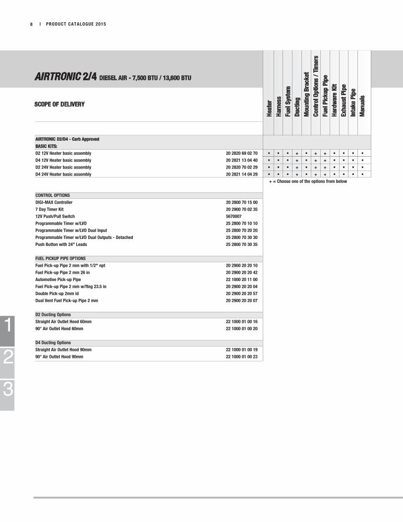
AIRTRONIC 2/4 DIESEL AIR - 7,500 BTU / 13,600 BTU
SCOPE OF DELIVERY
AIRTRONIC D2/D4 - Carb Approved
BASIC KITS:
D2 12V Heater basic assembly 20 2820 69 02 70 • • • + • + + • • • •
D4 12V Heater basic assembly 20 2821 13 04 40 • • • + • + + • • • •
D2 24V Heater basic assembly 20 2820 70 02 29 • • • + • + + • • • •
D4 24V Heater basic assembly 20 2821 14 04 29 • • • + • + + • • • •
+ = Choose one of the options from below
CONTROL OPTIONS
DIGI-MAX Controller 20 2800 70 15 00
7 Day Timer Kit 20 2900 70 02 35
12V Push/Pull Switch 5670007
Programmable Timer w/LVD 25 2800 70 10 10
Programmable Timer w/LVD Dual Input 25 2800 70 20 20
Programmable Timer w/LVD Dual Outputs - Detached 25 2800 70 30 30
Push Button with 24" Leads 25 2800 70 30 35
FUEL PICKUP PIPE OPTIONS
Fuel Pick-up Pipe 2 mm with 1/2" npt 20 2900 20 20 10
Fuel Pick-up Pipe 2 mm 26 in 20 2900 20 20 42
Automotive Pick-up Pipe 22 1000 20 11 00
Fuel Pick-up Pipe 2 mm w/ftng 23.5 in 20 2900 20 20 04
Double Pick-up 2mm id 20 2900 20 20 57
Dual Vent Fuel Pick-up Pipe 2 mm 20 2900 20 20 07
D2 Ducting Options
Straight Air Outlet Hood 60mm 22 1000 01 00 16
90° Air Outlet Hood 60mm 22 1000 01 00 20
D4 Ducting Options
Straight Air Outlet Hood 90mm 22 1000 01 00 19
90° Air Outlet Hood 90mm 22 1000 01 00 23
1
2
3
PRODUCT CATALOGUE 2015 | 9
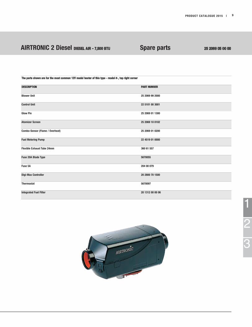
AIRTRONIC 2 Diesel DIESEL AIR - 7,500 BTU Spare parts 25 2069 05 00 00
The parts shown are for the most common 12V model heater of this type - model #-, top right corner
DESCRIPTION PART NUMBER
Blower Unit 25 2069 99 2000
Control Unit 22 5101 00 3001
Glow Pin 25 2069 01 1300
Atomizer Screen 25 2069 10 0102
Combo-Sensor (Flame / Overheat) 25 2069 01 0200
Fuel Metering Pump 22 4519 01 0000
Flexible Exhaust Tube 24mm 360 61 557
Fuse 20A Blade Type 5670055
Fuse 5A 204 00 079
Digi-Max Controller 20 2800 70 1500
Thermostat 5670097
Integrated Fuel Filter 20 1312 00 00 06

1
2
3
| PRODUCT CATALOGUE 201510
Hardware Kit INCLUDES: Fuel System INCLUDES:
Fuel Clamps Ducting Clamps Clamps
Nuts Washers 5mm Fuel Line
Cable Ties Routing Clamps Plastic Fuel Line
Grommets End Caps 3.5mm Fuel Line
Exhaust Clamps Exhaust Brackets
Mounting Screws
Refer to the Accessories Section for ducting components and additional accessories.
For the addition of engine preheat, refer to the Combo Truck Kits Section.
AIRTRONIC 4 DIESEL AIR HEATER - 13,600 BTU
SCOPE OF DELIVERY
Hea
ter
Harn
ess
Fu
el
Sys
tem
Du
cti
ng
Mou
nti
ng
Bra
ck
et
Con
trol
Op
tion
s /
Tim
ers
Fu
el
Pic
ku
p P
ipe
Hard
wa
re K
it
Exh
au
st P
ipe
Inta
ke
Pip
e
Man
uals
DESCRIPTION PART NUMBER
AIRTRONIC B4 GASOLINE
Gasoline Basic Heater 12V with fuel pump 20 1812 05 00 00 • •
AIRTRONIC D4 DIESEL - Carb Approved
Basic Heater 12V with fuel pump - No installation parts 25 2113 05 00 00 • •
Basic Heater 24V with fuel pump - No installation parts 25 2114 05 00 00 • •
Universal Install Kits
Eberspaecher Universal Installation Kit 12V and 24V 20 2821 13 04 80 • • • • • • • •
AIRTRONIC D4 TRUCK KITS - Carb Approved
HEATER WITH INSTALLATION KIT
Truck Kit 12V with Digi-Max Controller 20 2821 13 04 23 • • • • • • • • • • •
Truck Kit 24V w/Digi-Max Controller 20 2821 14 04 85 • • • • • • • • • • •
AIRTRONIC B4 GASOLINE TRUCK KIT
12v with Digi-Max Controller 20 2818 12 04 85 • • • • • • • • • • •
AIRTRONIC 4 CARGO KITS
Cargo Kit 12V with Thermostat 20 2900 00 04 01 • • • x • • • • •
x = cargo bracket
= exhaust with plate

1
3
PRODUCT CATALOGUE 2015 | 11
2
AIRTRONIC 4 DIESEL AIR HEATER - 13,600 BTU Spare parts 25 2113 05 00 00
The parts shown are for the most common 12V model heater of this type - model #-, top right corner
DESCRIPTION PART NUMBER
Blower Unit 25 2113 99 2000
Control Unit 22 5101 00 3005
Glow Pin 25 2069 01 1300
Atomizer Screen 25 2069 10 0102
Combo-Sensor (Flame / Overheat) 25 2069 01 0200
Fuel Metering Pump 22 4519 01 0000
Flexible Exhaust Tube, 24mm 360 61 550
Fuse 20A Blade Type 5670055
Fuse 5A 204 00 079
Digi-Max Controller 20 2800 70 1500
Thermostat 5670097
Integrated Fuel Filter 20 1312 00 00 06
1
2
3
12 | PRODUCT CATALOGUE 2015
Hea
ter
Harn
ess
Fu
el
Sys
tem
Du
cti
ng
Mou
nti
ng
Bra
ck
et
Con
trol
Op
tion
s /
Tim
ers
Fu
el
Pic
ku
p P
ipe
Hard
wa
re K
it
Exh
au
st P
ipe
Inta
ke
Pip
e
Man
uals
Hardware Kit INCLUDES: Fuel System INCLUDES:
Fuel Clamps Ducting Clamps Clamps
Nuts Washers 5mm Fuel Line
Cable Ties Routing Clamps Plastic Fuel Line
Grommets End Caps 3.5mm Fuel Line
Exhaust Clamps Exhaust Brackets
Mounting Screws
Refer to the Accessories Section for ducting components and additional accessories.
For the addition of engine preheat, refer to the Combo Truck Kits Section.
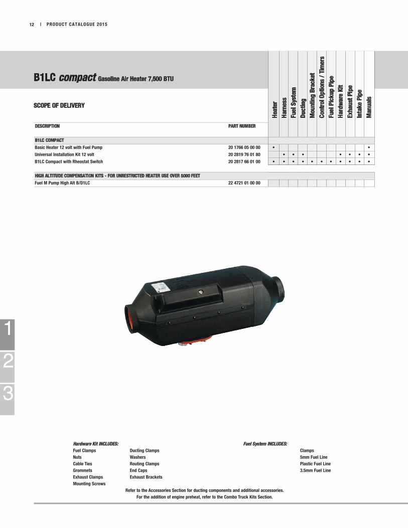
B1LC compact Gasoline Air Heater 7,500 BTU
SCOPE OF DELIVERY
DESCRIPTION PART NUMBER
B1LC COMPACT
Basic Heater 12 volt with Fuel Pump 20 1766 05 00 00 • •
Universal Installation Kit 12 volt 20 2819 76 01 80 • • • • • • •
B1LC Compact with Rheostat Switch 20 2817 66 01 00 • • • • • • • • • • •
HIGH ALTITUDE COMPENSATION KITS - FOR UNRESTRICTED HEATER USE OVER 5000 FEET
Fuel M Pump High Alt B/D1LC 22 4721 01 00 00

1
2
3
PRODUCT CATALOGUE 2015 | 13
AIRTRONIC B5 GASOLINE AIR HEATER - 18,800 BTU
AIRTRONIC D5 DIESEL AIR HEATER - 18,800 BTU
SCOPE OF DELIVERY
Heate
r
Ha
rness
Fu
el S
yste
m
Du
cti
ng
Mo
un
tin
g B
rack
et
Con
trol
Op
tion
s /
Tim
ers
Fu
el P
ick
up
Pip
e
Ha
rdw
are
Kit
Exh
au
st P
ipe
Inta
ke
Pip
e
Ma
nu
als
Hardware Kit INCLUDES: Fuel System INCLUDES:
Fuel Clamps Ducting Clamps Clamps
Nuts Washers 5mm Fuel Line
Cable Ties Routing Clamps Plastic Fuel Line
Grommets End Caps 3.5mm Fuel Line
Exhaust Clamps Exhaust Brackets
Mounting Screws
Refer to the Accessories Section for ducting components and additional accessories.
For the addition of engine preheat, refer to the Combo Truck Kits Section.
DESCRIPTION PART NUMBER
AIRTRONIC B5 - GASOLINE
Basic Heater 12V with fuel pump with outlet hood 20 1859 05 00 00 • •
AIRTRONIC D5 - Carb Approved - DIESEL
Basic Heater 12V with fuel pump with outlet hood 25 2361 05 00 00 • •
Basic Heater 24V with fuel pump with outlet hood 25 2362 05 00 00 • •
UNIVERSAL INSTALL KITS
JE Universal Installation Kit 12V and 24V 25 2361 80 00 00 • • • • • •
Eberspaecher Universal Installation Kit 12V and 24V 20 2823 61 05 80 • • • • • • •
AIRTRONIC D5 TRUCK KITS - Carb Approved - DIESEL
Truck Kit 12V (no control) 20 2823 61 05 10 • • • • • • • • •
Truck Kit 12V w/Thermostat 20 2823 61 05 11 • • • • • • • • •
CARGO KITS
Cargo Kit 12V w/Thermostat Does Not Include Heater 20 2900 00 05 50 • • • • • • •
Echo 5 Cargo Kit (See page 13) 20 2823 61 05 18 • • • • • • • • • • •
HIGH ALTITUDE COMPENSATION KITS - FOR UNRESTRICTED HEATER USE OVER 5000 FEET
Fuel M Pump 24V for 25 2362 05 22 4522 03 00 00
= cargo bracket
= exhaust with plate
1
2
3
Refer to the Accessories Section for ducting components and additional accessories.
| PRODUCT CATALOGUE 201514
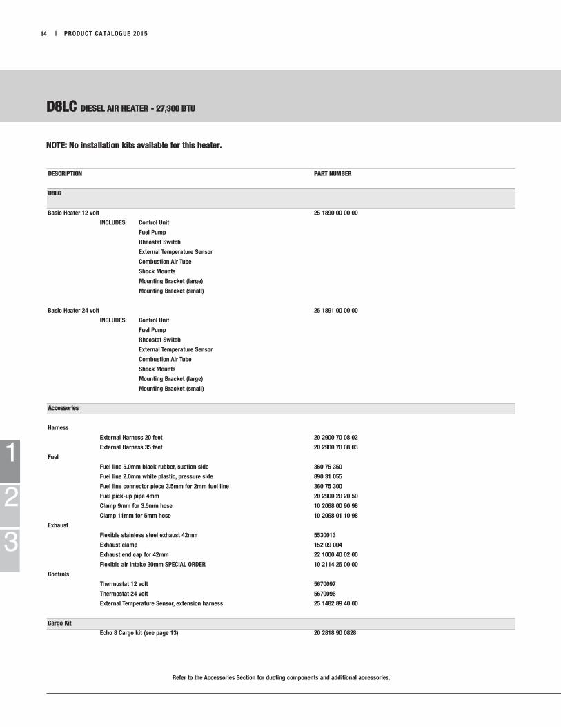
D8LC DIESEL AIR HEATER - 27,300 BTU
NOTE: No installation kits available for this heater.
DESCRIPTION PART NUMBER
D8LC
Basic Heater 12 volt 25 1890 00 00 00
INCLUDES: Control Unit
Fuel Pump
Rheostat Switch
External Temperature Sensor
Combustion Air Tube
Shock Mounts
Mounting Bracket (large)
Mounting Bracket (small)
Basic Heater 24 volt 25 1891 00 00 00
INCLUDES: Control Unit
Fuel Pump
Rheostat Switch
External Temperature Sensor
Combustion Air Tube
Shock Mounts
Mounting Bracket (large)
Mounting Bracket (small)
Accessories
Harness
External Harness 20 feet 20 2900 70 08 02
External Harness 35 feet 20 2900 70 08 03
Fuel
Fuel line 5.0mm black rubber, suction side 360 75 350
Fuel line 2.0mm white plastic, pressure side 890 31 055
Fuel line connector piece 3.5mm for 2mm fuel line 360 75 300
Fuel pick-up pipe 4mm 20 2900 20 20 50
Clamp 9mm for 3.5mm hose 10 2068 00 90 98
Clamp 11mm for 5mm hose 10 2068 01 10 98
Exhaust
Flexible stainless steel exhaust 42mm 5530013
Exhaust clamp 152 09 004
Exhaust end cap for 42mm 22 1000 40 02 00
Flexible air intake 30mm SPECIAL ORDER 10 2114 25 00 00
Controls
Thermostat 12 volt 5670097
Thermostat 24 volt 5670096
External Temperature Sensor, extension harness 25 1482 89 40 00
Cargo Kit
Echo 8 Cargo kit (see page 13) 20 2818 90 0828

1
2
3
PRODUCT CATALOGUE 2015 | 15
ECHO CARGO KIT
SCOPE OF DELIVERY
DESCRIPTION PART NUMBER
ECHO 5 (AIRTRONIC D5 HEATER Nose Mount) 20 2823 61 05 18
INCLUDES: Mounting Box
Mounting Bracket
Exhaust shield
Fuel metering pump and Mounting box
DIGI MAX Controller with remote temp sensor
Heater
Harness
Fuel lines
Air Ducting
Fuel Pickup pipe
Lid ECHO 5 Box White 20 2900 40 05 02
ECHO 8 (D8LC Nose Mount) 20 2818 90 08 28
INCLUDES: Mounting Box
Mounting Bracket
Exhaust shield
Fuel metering pump and Mounting box
DIGI MAX Controller with remote temp sensor
Heater
Harness
Fuel lines
Air Ducting
Fuel Pickup pipe
ECHO 8 Mounting Box Base 20 2900 40 80 01
ECHO 8 Mounting Box Lid 20 2900 40 80 02
Shield SS 20 2900 40 80 03
Mounting Bracket 20 2900 40 80 04
Power Receptable Box Assy ECHO 8 20 2900 40 80 05

1
2
3
| PRODUCT CATALOGUE 201516
DESCRIPTION PART NUMBER
AIRTRONIC NG2
Basic Heater 12V (Operating pressure: 50 mbar or 0.725 PSI) 20 2824 05 12 01
Airtronic NG2 Installation Kit 20 2800 90 10 00
INCLUDE:
Thermostat 20 2800 70 20 00
Harness
High pressure regulator
Low pressure regulator
CNG 8mm steel pipe
Stainless steel tubing ¼”
Air ducting
Exhaust pipe
AIRTRONIC NG2 CNG HEATER - 7,500 BTU
SCOPE OF DELIVERY

1
2
3
PRODUCT CATALOGUE 2015 | 17
HYDRONIC D5 SC DIESEL COOLANT HEATER - 17,100 BTU
SCOPE OF DELIVERYIf installation is more than 6 feet from the fuel tank, kits with external fuel pumps are required.
Refer to the Accessories Section for ducting components and additional accessories.
For the addition of cab heat, refer to the Combo Truck Kits Section.
Hea
ter
Harn
ess
Fu
el
Sys
tem
*
Coola
nt
Hose
Mou
nti
ng
Bra
ck
et
Con
trol
Op
tion
s /
Tim
ers
Fu
el
Pic
ku
p P
ipe
Hard
wa
re K
it o
Exh
au
st P
ipe
Inta
ke
Pip
e
Boxe
d
Man
uals
DESCRIPTION PART NUMBER
HYDRONIC D5 SC - DIESEL
Basic Heater 12 volt 25 2219 05 00 00 • •
Universal Installation Kit 12 volt 25 2800 90 05 10 • • • • • • •
Universal Installation Kit 12 volt w/Relay 25 2800 90 05 12 • • • • • • •
Basic Heater 12 volt with External Fuel Pump 25 2325 05 00 00 • •
Universal Installation Kit 12 volt 25 2800 90 05 11 • • • • • • •
Basic Heater 24 volt 25 2147 05 00 00 • •
Universal Installation Kit 24 volt 25 2009 80 00 00 • • • • • • •
HYDRONIC D5SC (INTERNAL FMP) TRUCK KITS - DIESEL
12 volt Kit 25 2822 19 05 20 • • • • • • • • •
12 volt Kit with 7 day timer 25 2822 19 05 21 • • • • • • • • • •
12 volt Boxed Kit 25 2822 19 05 40 • • • • • • • • • •
HYDRONIC D5SC (EXTERNAL FMP) TRUCK KITS - DIESEL
12 volt Kit 25 2823 25 05 20 • • • • • • • • •
12 volt Kit with 7 day timer 25 2823 25 05 21 • • • • • • • • • •
12 V Kit with FMP Pre-heater 25 2823 25 05 24 • • • • • • • • •
12 volt Boxed Kit 25 2823 25 05 40 • • • • • • • •
12 volt boxed Kit with FMP Preheater 25 2823 25 05 42 • • • • • • • • •
HYDRONIC D5 SC OFF-HIGHWAY KITS - DIESEL
24 volt with External Fuel Pump 25 2821 47 05 20 • • • • • • • • •
Boxed 24 volt with External Fuel Pump 25 2821 47 05 55 • • • • • • • • • •
HYDRONIC B5 SC - GASOLINE
Basic Heater 12 volt with external fuel pump 20 1820 05 00 00 • •
Universal Installation Kit 12 volt 25 2800 90 05 11 • • • • • • •
HYDRONIC B5SC TRUCK KIT - GASOLINE
12 volt with External Fuel Pump 20 2818 20 05 20 • • • • • • • • •
HYDRONIC B5 SC AUTOMOTIVE PICK-UP KIT - GASOLINE
12 volt with External Fuel Pump 20 2818 20 05 22 • * • • • • • • • • •
HYDRONIC 4/5 SC COOLANT PUMP SERVICE KIT 25 2800 60 00 05
• = includes blower relay connection
* = harness has blower relay

HYDRONIC D5 SC DIESEL COOLANT HEATER - 17,100 BTU
SCOPE OF DELIVERYIf installation is more than 6 feet from the fuel tank, kits with external fuel pumps are required.
1
2
3
| PRODUCT CATALOGUE 201518
Hea
ter
Harn
ess
Fu
el
Sys
tem
*
Coola
nt
Hose
Mou
nti
ng
Bra
ck
et
Con
trol
Op
tion
s /
Tim
ers
Fu
el
Pic
ku
p P
ipe
Hard
wa
re K
it o
Exh
au
st P
ipe
Inta
ke
Pip
e
Boxe
d
Man
uals
DESCRIPTION PART NUMBER
HYDRONIC D5 SC
BASIC KITS:
Heater Basic Assembly - 12 V 25 2822 19 05 29 • • • • + + • • • •
HYDRONIC D5SC (EXTERNAL FMP) TRUCK KITS - DIESEL
Heater Basic Assembly - 12 V 25 2823 25 05 29 • • • • + + • • • •
HYDRONIC D5 SC OFF-HIGHWAY KITS - DIESEL
Heater Basic Assembly FMP Out - 24 V 25 2821 47 05 29 • • • • + + • • • •
HYDRONIC D5E H-II
D5E H-II HYDRONIC Heater Basic Assembly - 12 V 25 2825 26 05 29 • • • • • + + • • • •
HYDRONIC D5E H-II
D5E H-II Boxed Basic Assembly - 12 V 25 2825 26 05 49 • • • • • + + • • • • •
+ = Choose one of the options from below
CONTROL OPTIONS
Timer 7 Day w/Diagnostic 22 1000 30 36 00
Timer 7 Day Air + Brkt + Bezel 20 2900 70 02 30
EasyStart Timer 22 1000 34 15 00
Multi-Max F-1000 Controller 20 2800 70 16 00
Programmable timer with LVD 25 2800 70 10 10
Programmable timer with LVD Dual Input 25 2800 70 20 20
Programmable timer with LVD Dual Output Switch 25 2800 70 30 30
Push Button with 24" Leads 25 2800 70 30 35
FUEL PICK-UP PIPE OPTIONS
Fuel Pick-up Pipe 2 mm WITH 1/2" NPT 20 2900 20 20 10
Fuel Pick-up Pipe 2 mm 26IN 20 2900 20 20 42
Automotive Pick-Up Pipe 22 1000 20 11 00
Fuel Pick-up Pipe 2 mm w/Ftng 23.5 in 20 2900 20 20 04
Double Pick-up 2 mm ID 20 2900 20 20 57
Dual Vent Fuel Pick-Up Pipe 2 mm 20 2900 20 20 07

1
2
3
HYDRONIC 5 SC DIESEL COOLANT HEATER - 17,100 BTU Spare parts 25 2219 05 00 00
HYDRONIC 5 SC DIESEL COOLANT HEATER - 17,100 BTU W/EXTERNAL FUEL PUMP 25 2325 05 00 00
The parts shown are for the most common 12V model heater of this type - model #-, top right corner
DESCRIPTION PART NUMBER
Combustion Air Blower 20 1819 99 16 00
Electronic Control Unit (HYDRONIC 4) 22 5201 04 00 06
Electronic Control Unit (HYDRONIC 5) 22 5201 04 00 11
Coolant Pump 25 2219 25 00 00
Glow Pin with Cable 25 2106 01 10 00
Fuel Metering Pump internal 22 4504 03 00 00
Fuel Metering Pump external 22 4517 04 00 00
Flame Sensor 25 1920 37 00 00
Overheat Sensor with Cable 25 2219 01 23 00
Fuse 25A Blade Type 204 00 089
Flexible Exhaust Tube, 24mm 360 61 550
Timer, 7-Day 22 1000 30 36 00
Programmable Timer, 12 Volt 5670433
Integrated Fuel Filter 20 1312 00 00 06
H1 FMP Pre-Heater (for heater with external FMP only) 25 2800 70 00 19
PRODUCT CATALOGUE 2015 | 19
Spare parts shown are common for Hydronic 4 + 5 heaters.
Hydronic 5 Heaters used in ParkSmart + Max Power Systems may have a different control unit.
Please refer to serial # on heater.

1
2
3
Hea
ter
Harn
ess
Fu
el
Sys
tem
Coola
nt
Hose
Mou
nti
ng
Bra
ck
et
Con
trol
Op
tion
s /
Tim
ers
Fu
el
Pic
ku
p P
ipe
Hard
wa
re K
it
Exh
au
st P
ipe
Inta
ke
Pip
e
Boxe
d
Man
uals
PICK-UP TRUCK KITS
HYDRONIC D5 DIESEL COOLANT HEATER - 17,100 BTU
SCOPE OF DELIVERYIf installation is more than 6 feet from the fuel tank, kits with external fuel pumps are required.
| PRODUCT CATALOGUE 201520
Hardware Kit INCLUDES: Fuel System INCLUDES:
Fuel Clamps Grommets Ducting Clamps End Caps Clamps
Nuts Exhaust Clamps Washers Exhaust Brackets 5mm Fuel Line
Cable Ties Mounting Screws Routing Clamps Plastic Fuel Line
3.5mm Fuel Line
For spare parts refer to Hydronic D5 listing on page 17
Refer to the Accessories Section for ducting components and additional accessories.
DESCRIPTION PART NUMBER
PICK-UP TRUCK KITS (AFTER MARKET)
DODGE KITS
2003 - 2007 5.9 L with mini timer 25 2822 19 05 32 • * • • • • • • • •
GM DURAMAX KITS
Frame dimensions not larger than 225mm high, 77mm wide
Mini Timer and external FMP Right side mount 25 2823 25 05 75 • • • • • • • • • •
UNIVERSAL PICK UP TRUCK INSTALLATION KIT
D5E Diesel Pick Up Truck kit 25 2825 26 05 22 • • • • • • • • •
B5E Gasoline Pick Up Truck kit 25 2819 04 05 00 • • • • • • • • • •
RELATED PARTS
Blower Control Module 12/24V 25 2800 70 40 40
EasyStart T Controller 22 1000 32 88 00
* = harness has blower relay

1
2
3
PRODUCT CATALOGUE 2015 | 21
Hea
ter
Harn
ess
Fu
el
Sys
tem
Coola
nt
Hose
Mou
nti
ng
Bra
ck
et
Con
trol
Op
tion
s /
Tim
ers
Fu
el
Pic
ku
p P
ipe
Hard
wa
re K
it
Exh
au
st P
ipe
Inta
ke
Pip
e
Boxe
d
Man
uals
HYDRONIC II B/D5 E COOLANT HEATER - 17,100 BTU
HYDRONIC II Comfort COOLANT HEATER - 17,100 BTU
SCOPE OF DELIVERY
DESCRIPTION PART NUMBER
HYDRONIC II D5 E - DIESEL
Basic Heater 12 V 25 2526 05 00 00 • •
HYDRONIC II D5E TRUCK KIT - DIESEL
12 V with External Water and Fuel Pump 25 2825 26 05 20 • • • • • • • • •
12 V Automotive installation kit 25 2825 26 05 22 • • • • • • • • • •
Boxed 12 V with External Water and Fuel Pump 25 2825 26 05 40 • • • • • • • • • •
HYDRONIC II B5E - GASOLINE
Basic Heater 12 V 20 1904 05 00 00 • •
12 V Automotive Kit 25 2819 04 05 00 • • • • • • • • • •
JE Universal installation kit 12 V 25 2526 80 00 00 • • • • • • • •
HYDRONIC II COMFORT
Basic Heater 12 V Diesel 25 2598 05 00 00 • •
Basic Heater 12 V Gasoline 20 1928 05 00 00 • •
JE Universal installation kit 25 2598 80 00 00 • • • • • •
HYDRONIC B/D 5E HYDRONIC II Comfort

Hea
ter
Harn
ess
Fu
el
Sys
tem
Coola
nt
Hose
Mou
nti
ng
Bra
ck
et
Con
trol
Op
tion
s /
Tim
ers
Fu
el
Pic
ku
p P
ipe
Hard
wa
re K
it
Exh
au
st P
ipe
Inta
ke
Pip
e
Boxe
d
Man
uals
DESCRIPTION PART NUMBER
HYDRONIC D5 S - DIESEL
Basic Heater 12 volt 25 2217 05 00 00 • •
Basic Heater 12 volt w/Universal install kit 25 2386 05 00 00 • • • • • • • • •
Basic Heater 24 volt 25 2218 05 00 00 • •
Universal Installation Kit 24 volt (Limited Stock) 25 2218 80 00 00 • • • • • • •
Basic Heater 24 volt 25 2146 05 00 00 • •
Universal Installation Kit 24 volt 25 2009 80 00 00 • • • • • • •
HYDRONIC D5S TRUCK KIT - DIESEL
12 volt with External Water and Fuel Pump 25 2822 17 05 20 • • • • • • • • •
12 volt with External Water and Fuel Pump with timer 25 2822 17 05 21 • • • • • • • • • •
Boxed 12 volt with water pump and fuel pump mounted inside box 25 2822 17 05 45 • • • • • • • • • •
HYDRONIC D5S OFF-HIGHWAY KIT - DIESEL
24 volt with External Water and Fuel Pump 25 2822 18 05 20 • • • • • • • • •
HYDRONIC B5 S - GASOLINE
Basic Heater 12 volt with external water and fuel pump 20 1819 05 00 00 • •
• = includes blower relay connection
1
2
3
| PRODUCT CATALOGUE 201522
HYDRONIC B5 S GASOLINE COOLANT HEATER - 17,100 BTU
HYDRONIC D5 S DIESEL COOLANT HEATER - 17,100 BTU
SCOPE OF DELIVERYIf installation is more than 6 feet from the fuel tank, kits with external fuel pumps are required.

PRODUCT CATALOGUE 2015 | 23
1
2
3
Refer to the Accessories Section for ducting components and additional accessories.
For the addition of engine preheat, refer to the Combo Truck Kits Section.
DESCRIPTION PART NUMBER
AIRTRONIC 2 / HYDRONIC 5 SC - DIESEL
Truck Kit INCLUDES: EasyStart Timer 20 2812 15 20 56 • • • • • d • • • •
Digi-Max Controller
Truck Kit with External Fuel Pump INCLUDES: EasyStart Timer 20 2812 15 20 58 • • • • • d • • • •
Digi-Max Controller
AIRTRONIC 2 / HYDRONIC 5 S - DIESEL
Truck Kit INCLUDES: EasyStart Timer 20 2812 15 20 63 • • • • • d • • • •
Digi-Max Controller
Boxed Truck Kit INCLUDES: EasyStart Timer 20 2812 15 20 60 • • • • • d • • • • •
Digi-Max Controller
AIRTRONIC 2 / HYDRONIC 5 E - DIESEL
Truck Kit No Timer 20 2812 15 20 61 • • • • • d • • • •
Digi-Max Controller
Boxed Truck Kit No Timer 20 2812 15 20 62 • • • • • d • • • • •
Digi-Max Controller
d = double fuel Pick-up pipe
Hea
ter
Harn
ess
Fu
el
Sys
tem
Coola
nt
Hose
Mou
nti
ng
Bra
ck
et
Con
trol
Op
tion
s /
Tim
ers
Fu
el
Pic
ku
p P
ipe
Hard
wa
re K
it
Exh
au
st P
ipe
Inta
ke
Pip
e
Boxe
d
Man
uals
AIRTRONIC 2 / HYDRONIC 5 Combo Kits DIESEL 12 volt only
SCOPE OF DELIVERY
1
2
3
| PRODUCT CATALOGUE 201524
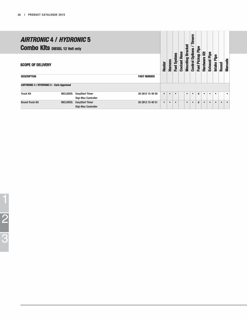
DESCRIPTION PART NUMBER
AIRTRONIC 4 / HYDRONIC 5 - Carb Approved
Truck Kit INCLUDES: EasyStart Timer 20 2812 15 40 50 • • • • • d • • • •
Digi-Max Controller
Boxed Truck Kit INCLUDES: EasyStart Timer 20 2812 15 40 51 • • • • • d • • • • •
Digi-Max Controller
AIRTRONIC 4 / HYDRONIC 5
Combo Kits DIESEL 12 Volt only
SCOPE OF DELIVERY
Hea
ter
Harn
ess
Fuel
Sys
tem
Coola
nt
Hose
Mou
nti
ng
Bra
ck
et
Con
trol
Op
tion
s /
Tim
ers
Fuel
Pic
ku
p P
ipe
Hard
wa
re K
it
Exh
au
st P
ipe
Inta
ke
Pip
e
Boxe
d
Man
uals
1
2
3
PRODUCT CATALOGUE 2015 | 25
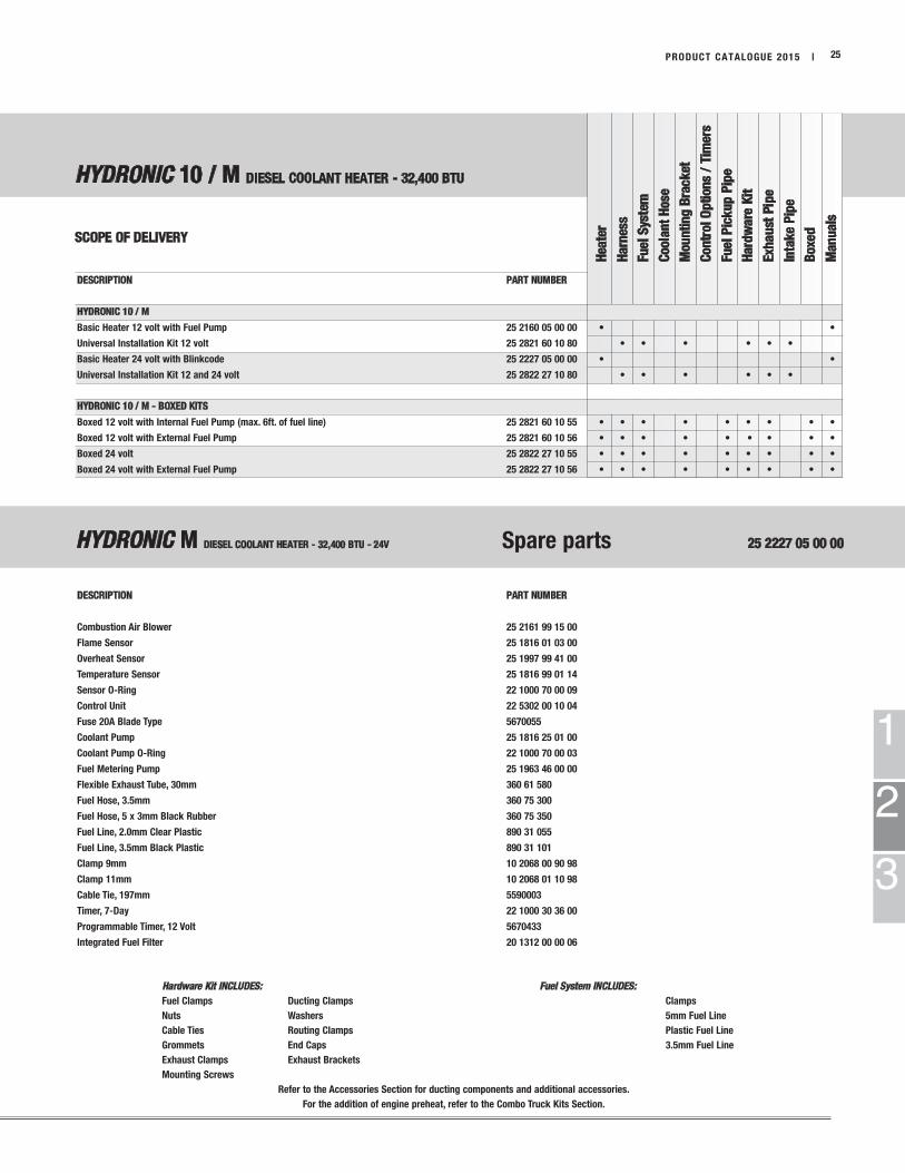
DESCRIPTION PART NUMBER
HYDRONIC 10 / M
Basic Heater 12 volt with Fuel Pump 25 2160 05 00 00 • •
Universal Installation Kit 12 volt 25 2821 60 10 80 • • • • • •
Basic Heater 24 volt with Blinkcode 25 2227 05 00 00 • •
Universal Installation Kit 12 and 24 volt 25 2822 27 10 80 • • • • • •
HYDRONIC 10 / M - BOXED KITS
Boxed 12 volt with Internal Fuel Pump (max. 6ft. of fuel line) 25 2821 60 10 55 • • • • • • • • •
Boxed 12 volt with External Fuel Pump 25 2821 60 10 56 • • • • • • • • •
Boxed 24 volt 25 2822 27 10 55 • • • • • • • • •
Boxed 24 volt with External Fuel Pump 25 2822 27 10 56 • • • • • • • • •
DESCRIPTION PART NUMBER
Combustion Air Blower 25 2161 99 15 00
Flame Sensor 25 1816 01 03 00
Overheat Sensor 25 1997 99 41 00
Temperature Sensor 25 1816 99 01 14
Sensor O-Ring 22 1000 70 00 09
Control Unit 22 5302 00 10 04
Fuse 20A Blade Type 5670055
Coolant Pump 25 1816 25 01 00
Coolant Pump O-Ring 22 1000 70 00 03
Fuel Metering Pump 25 1963 46 00 00
Flexible Exhaust Tube, 30mm 360 61 580
Fuel Hose, 3.5mm 360 75 300
Fuel Hose, 5 x 3mm Black Rubber 360 75 350
Fuel Line, 2.0mm Clear Plastic 890 31 055
Fuel Line, 3.5mm Black Plastic 890 31 101
Clamp 9mm 10 2068 00 90 98
Clamp 11mm 10 2068 01 10 98
Cable Tie, 197mm 5590003
Timer, 7-Day 22 1000 30 36 00
Programmable Timer, 12 Volt 5670433
Integrated Fuel Filter 20 1312 00 00 06
HYDRONIC 10 / M DIESEL COOLANT HEATER - 32,400 BTU
SCOPE OF DELIVERY
Hea
ter
Harn
ess
Fuel
Sys
tem
Coola
nt
Hose
Mou
nti
ng
Bra
ck
et
Con
trol
Op
tion
s /
Tim
ers
Fuel
Pic
ku
p P
ipe
Hard
wa
re K
it
Exh
au
st P
ipe
Inta
ke
Pip
e
Boxe
d
Man
uals
Hardware Kit INCLUDES: Fuel System INCLUDES:
Fuel Clamps Ducting Clamps Clamps
Nuts Washers 5mm Fuel Line
Cable Ties Routing Clamps Plastic Fuel Line
Grommets End Caps 3.5mm Fuel Line
Exhaust Clamps Exhaust Brackets
Mounting Screws
Refer to the Accessories Section for ducting components and additional accessories.
For the addition of engine preheat, refer to the Combo Truck Kits Section.
HYDRONIC M DIESEL COOLANT HEATER - 32,400 BTU - 24V Spare parts 25 2227 05 00 00
1
2
3
| PRODUCT CATALOGUE 201526
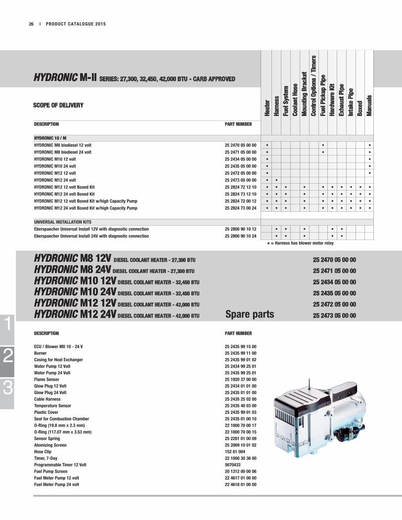
DESCRIPTION PART NUMBER
HYDRONIC 10 / M
HYDRONIC M8 biodiesel 12 volt 25 2470 05 00 00 • • •
HYDRONIC M8 biodiesel 24 volt 25 2471 05 00 00 • • •
HYDRONIC M10 12 volt 25 2434 05 00 00 • •
HYDRONIC M10 24 volt 25 2435 05 00 00 • •
HYDRONIC M12 12 volt 25 2472 05 00 00 • •
HYDRONIC M12 24 volt 25 2473 05 00 00 • •
HYDRONIC M12 12 volt Boxed Kit 25 2824 72 12 10 • • • • • • • • • •
HYDRONIC M12 24 volt Boxed Kit 25 2824 73 12 10 • • • • • • • • • •
HYDRONIC M12 12 volt Boxed Kit w/high Capacity Pump 25 2824 72 00 12 • • • • • • • • • •
HYDRONIC M12 24 volt Boxed Kit w/high Capacity Pump 25 2824 73 00 24 • • • • • • • • • •
UNIVERSAL INSTALLATION KITS
Eberspaecher Universal Install 12V with diagnostic connection 25 2800 90 10 12 • • • • •
Eberspaecher Universal Install 24V with diagnostic connection 25 2800 90 10 24 • • • • •
* = Harness has blower motor relay
DESCRIPTION PART NUMBER
ECU / Blower MII 10 - 24 V 25 2435 99 15 00
Burner 25 2435 99 11 00
Casing for Heat Exchanger 25 2435 99 01 02
Water Pump 12 Volt 25 2434 99 25 01
Water Pump 24 Volt 25 2435 99 25 01
Flame Sensor 25 1920 37 00 00
Glow Plug 12 Volt 25 2434 01 01 00
Glow Plug 24 Volt 25 2435 01 01 00
Cable Harness 25 2435 25 02 00
Temperature Sensor 25 2435 40 03 00
Plastic Cover 25 2435 99 01 03
Seal for Combustion Chamber 25 2435 01 00 10
O-Ring (19.8 mm x 2.3 mm) 22 1000 70 00 17
O-Ring (117.07 mm x 3.53 mm) 22 1000 70 00 15
Sensor Spring 25 2281 01 00 09
Atomizing Screen 25 2069 10 01 02
Hose Clip 152 61 004
Timer, 7-Day 22 1000 30 36 00
Programmable Timer 12 Volt 5670433
Fuel Pump Screen 20 1312 00 00 06
Fuel Meter Pump 12 volt 22 4617 01 00 00
Fuel Meter Pump 24 volt 22 4618 01 00 00
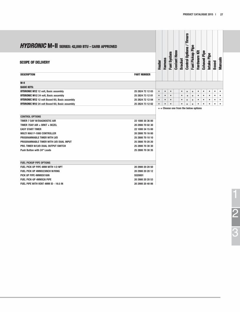
HYDRONIC M-II SERIES: 27,300, 32,450, 42,000 BTU - CARB APPROVED
SCOPE OF DELIVERY
Hea
ter
Harn
ess
Fuel
Sys
tem
Coola
nt
Hose
Mou
nti
ng
Bra
ck
et
Con
trol
Op
tion
s /
Tim
ers
Fuel
Pic
ku
p P
ipe
Hard
wa
re K
it
Exh
au
st P
ipe
Inta
ke
Pip
e
Boxe
d
Man
uals
HYDRONIC M8 12V DIESEL COOLANT HEATER - 27,300 BTU 25 2470 05 00 00
HYDRONIC M8 24V DIESEL COOLANT HEATER - 27,300 BTU 25 2471 05 00 00
HYDRONIC M10 12V DIESEL COOLANT HEATER - 32,450 BTU 25 2434 05 00 00
HYDRONIC M10 24V DIESEL COOLANT HEATER - 32,450 BTU 25 2435 05 00 00
HYDRONIC M12 12V DIESEL COOLANT HEATER - 42,000 BTU 25 2472 05 00 00
HYDRONIC M12 24V DIESEL COOLANT HEATER - 42,000 BTU Spare parts 25 2473 05 00 00
1
2
3
HYDRONIC M-II SERIES: 42,000 BTU - CARB APPROVED
SCOPE OF DELIVERY
PRODUCT CATALOGUE 2015 | 27
Hea
ter
Harn
ess
Fu
el
Sys
tem
Coola
nt
Hose
Bra
cket
Con
trol
Op
tion
s /
Tim
ers
Fu
el
Pic
ku
p P
ipe
Hard
wa
re K
it
Exh
au
st P
ipe
Inta
ke
Pip
e
Boxe
d
Man
uals
DESCRIPTION PART NUMBER
M-II
BASIC KITS:
HYDRONIC M12 12 volt, Basic assambly 25 2824 72 12 03 • • • • + + • • • • •
HYDRONIC M12 24 volt, Basic assambly 25 2824 73 12 01 • • • • + + • • • • •
HYDRONIC M12 12 volt Boxed Kit, Basic assambly 25 2824 72 12 04 • • • • + + • • • • •
HYDRONIC M12 24 volt Boxed Kit, Basic assambly 25 2824 73 12 02 • • • • + + • • • • •
+ = Choose one from the below options
CONTROL OPTIONS
TIMER 7 DAY W/DIAGNOSTIC AIR 22 1000 30 36 00
TIMER 7DAY AIR + BRKT + BEZEL 20 2900 70 02 30
EASY START TIMER 22 1000 34 15 00
MULTI MAX F-1000 CONTROLLER 20 2800 70 16 00
PROGRAMMABLE TIMER WITH LVD 25 2800 70 10 10
PROGRAMMABLE TIMER WITH LVD DUAL INPUT 25 2800 70 20 20
PRO. TIMER W/LVD DUAL OUTPUT SWITCH 25 2800 70 30 30
Push Button with 24" Leads 25 2800 70 30 35
FUEL PICKUP PIPE OPTIONS
FUEL PICK UP PIPE 4MM WITH 1/2 NPT 20 2900 20 20 50
FUEL PICK UP 4MMX23INCH W/RING 20 2900 20 20 12
PICK UP PIPE 4MMIDX16IN 5520001
FUEL PICK-UP 4MMX26 PIPE 20 2900 20 20 53
FUEL PIPE WITH VENT 4MM ID - 19.5 IN 20 2900 20 40 06

Hea
ter
Harn
ess
Fu
el
Sys
tem
Coola
nt
Hose
Mou
nti
ng
Bra
ck
et
Con
trol
Op
tion
s /
Tim
ers
Fu
el
Pic
ku
p P
ipe
Hard
wa
re K
it
Exh
au
st P
ipe
Inta
ke
Pip
e
Boxe
d
Man
uals
E-Guardian DIESEL / WATER
SCOPE OF DELIVERY
1
2
3
| PRODUCT CATALOGUE 201528
Hardware Kit INCLUDES: Fuel System INCLUDES:
Fuel Clamps Ducting Clamps Clamps
Nuts Washers 5mm Fuel Line
Cable Ties Routing Clamps 1.5mm Fuel Line
Grommets End Caps 3.5mm Fuel Line
Exhaust Clamps Exhaust Brackets
Mounting Screws
For spare parts refer to the Hydronic D5 listing on page 13, and the Hydronic M-II refer to page 21
Refer to the Accessories Section for ducting components and additional accessories.
DESCRIPTION BTU PART NUMBER
E-Guardian HYDRONIC D5 KITS - Carb Approved
Boxed D5 E-Guardian 12V Kit 17,100 BTU 25 2823 25 0507 • • • • • • • • • • •
Boxed D5E H-II E-Guardian 12V Kit 17,100 BTU 25 2825 26 0500 • • • • • • • • • • •
Boxed D5 E-Guardian 12V New York Kit 17,100 BTU 25 2823 25 0505 • • • • • • • • • • •
E-Guardian HYDRONIC M-II KITS - Carb Approved
Boxed M-II 12 KW Heater 12 V Kit 42,000 BTU 25 2824 72 12 02 • • • • • • • • • • •
Boxed M-II 12 KW Heater 12 V New York Kit 42,000 BTU 25 2824 72 12 06 • • • • • • • • • • •
Spare Parts:
E-Guardian Coolant Pump 25 2596 25 01 00
E-Guardian 12 Replacement Heater 25 2596 05 00 00
1
2
3
PRODUCT CATALOGUE 2015 | 29
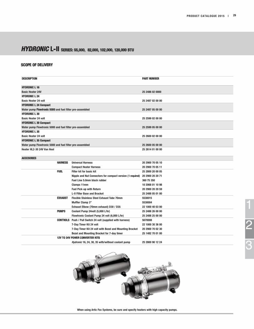
DESCRIPTION PART NUMBER
HYDRONIC L 16
Basic Heater 24V 25 2486 02 0000
HYDRONIC L 24
Basic Heater 24 volt 25 2487 02 00 00
HYDRONIC L 24 Compact
Water pump Flowtronic 5000 and fuel filter pre-assembled 25 2487 05 00 00
HYDRONIC L 30
Basic Heater 24 volt 25 2599 02 00 00
HYDRONIC L 30 Compact
Water pump Flowtronic 5000 and fuel filter pre-assembled 25 2599 05 00 00
HYDRONIC L 35
Basic Heater 24 volt 25 2600 02 00 00
HYDRONIC L 35 Compact
Water pump Flowtronic 5000 and fuel filter pre-assembled 25 2600 05 00 00
Heater HL2-30 24V Van Hool 25 2614 01 00 00
ACCESORIES
HARNESS Universal Harness 20 2900 70 05 10
Compact Heater Harness 20 2900 70 05 11
FUEL Filter kit for basic kit 25 2800 20 00 05
Nipple and Nut Connectors for compact version (1 required) 20 2900 20 20 71
Fuel Line 5.0mm black rubber 360 75 350
Clamps 11mm 10 2068 01 10 98
Fuel Pick-up with Return 20 2900 20 20 59
L-II Filter Base and Bracket 25 2488 05 01 00
EXHAUST Flexible Stainless Steel Exhaust Tube 70mm 5530015
Muffler Clamp 3” 5530004
Exhaust Elbow (70mm exhaust) D30 / D35 22 1000 40 03 00
PUMPS Coolant Pump 24volt (5,000 L/hr) 25 2488 26 00 00
Flowtronic Coolant Pump 24 volt (6,000 L/hr) 25 2488 25 00 00
CONTROLS Push / Pull Switch 24 volt (supplied with harness) 5670008
7-Day Timer Kit 24 volt 22 1000 30 36 00
7-Day Timer Kit 24 volt with Bezel and Mounting Bracket 20 2900 70 02 30
Bezel and Mounting Bracket for 7-day timer 25 1482 70 01 00
12V TO 24V POWER CONVERTER KITS
Hydronic 16, 24, 30, 35 with/without coolant pump 25 2800 90 12 24
HYDRONIC L-II SERIES: 55,000, 82,000, 102,000, 120,000 BTU
SCOPE OF DELIVERY
When using Artic Fox Systems, be sure and specify heaters with high capacity pumps.

1
2
3
HYDRONIC M-II OFF HIGHWAY KITS HYDRONIC L-II
OFF HIGHWAY KITS
SCOPE OF DELIVERY
| PRODUCT CATALOGUE 201530
Hea
ter
Harn
ess
Fu
el
Sys
tem
Coola
nt
Hose
Mou
nti
ng
Bra
ck
et
Con
trol
Op
tion
s /
Tim
ers
Fu
el
Pic
ku
p P
ipe
Hard
wa
re K
it
Exh
au
st P
ipe
Inta
ke
Pip
e
Boxe
d
Man
uals
DESCRIPTION PART NUMBER
M-II OFF HIGHWAY
HYDRONIC 12 M-II Boxed Off-Highway Assembly 12V 25 2824 72 12 20 • • • • • • • • • • •
L-II OFF HIGHWAY
HYDRONIC 16 L-II Boxed Off-Highway Assembly 12V 25 2800 10 1612 • • * • • • •
HYDRONIC 16 L-II Boxed Off-Highway Assembly 24V 25 2800 10 1600 • • * • • • •
HYDRONIC 24 L-II Boxed Off-Highway Assembly 12V 25 2800 10 2412 • • * • • • •
HYDRONIC 24 L-II Boxed Off-Highway Assembly 24V 25 2800 10 2400 • • * • • • •
HYDRONIC 30 L-II Boxed Off-Highway Assembly 12V w/6000 L pump 25 2800 10 3612 • • * • • • •
HYDRONIC 30 L-II Boxed Off-Highway Assembly 24V w/6000 L pump 25 2800 10 3600 • • * • • • •
HYDRONIC 35 L-II Boxed Off-Highway Assembly 12V w/6000 L pump 25 2800 10 5612 • • * • • • •
HYDRONIC 35 L-II Boxed Off-Highway Assembly 24V w/6000 L pump 25 2800 10 5624 • • * • • • •
* = Mounting holes on base. No mounting hardware included
Fuel
Hose Fuel 5 x 3mm black rubber 360 75 350
FUEL PICK UP PIPE 4MM WITH 1/2" NPT 20 2900 20 20 50
Clamp 11mm 10 2068 01 10 98
Controls
* See Control Options and Timers in accessories section
• Packaged for Off-Highway and oilfield applications
• 12 and 24 volt options
• Eliminate cold starts
• Minimize diesel exhaust emissions
• Rugged, compact
• Versatile fluid pre-heating
• Standard with pre-heated nozzle

1
2
3
PRODUCT CATALOGUE 2015 | 31
MOBILE FLEX-COOL
SCOPE OF DELIVERY
DESCRIPTION TYPE PART NUMBER
Mobile Flex-Cool 5F STANDARD 81 0000 00 04 18
Mobile Flex-Cool 8F STANDARD 81 0000 00 04 19
Mobile Flex-Cool 14F STANDARD 81 0000 00 04 20
Mobile Flex-Cool 22F STANDARD 81 0000 00 04 16
Mobile Flex-Cool 37C STANDARD 81 0000 00 03 60
Mobile Flex-Cool 37F STANDARD 81 0000 00 03 61
Mobile Flex-Cool 87C STANDARD 81 0000 00 03 62
Mobile Flex-Cool 87F STANDARD 81 0000 00 03 63
Mobile Flex-Cool 190C STANDARD “Coming soon”
Mobile Flex-Cool 190F STANDARD “Coming soon”
Mobile Flex-Cool 242C STANDARD 81 0000 00 03 64
Mobile Flex-Cool 242F STANDARD 81 0000 00 03 65
Mobile Flex-Cool 5FH PHARMA 81 0000 00 04 23
Mobile Flex-Cool 8FH PHARMA 81 0000 00 04 24
Mobile Flex-Cool 14FH PHARMA 81 0000 00 04 25
Mobile Flex-Cool 22FH PHARMA 81 0000 00 01 99
Mobile Flex-Cool 37CH PHARMA 81 0000 00 03 93
Mobile Flex-Cool 37FH PHARMA 81 0000 00 03 94
Mobile Flex-Cool 87CH PHARMA 81 0000 00 03 95
Mobile Flex-Cool 87FH PHARMA 81 0000 00 03 96
Mobile Flex-Cool 190CH PHARMA “Coming soon”
Mobile Flex-Cool 190FH PHARMA “Coming soon”
Mobile Flex-Cool 242CH PHARMA 81 0000 00 03 97
Mobile Flex-Cool 242FH PHARMA 81 0000 00 03 98
1
2
3
| PRODUCT CATALOGUE 201532
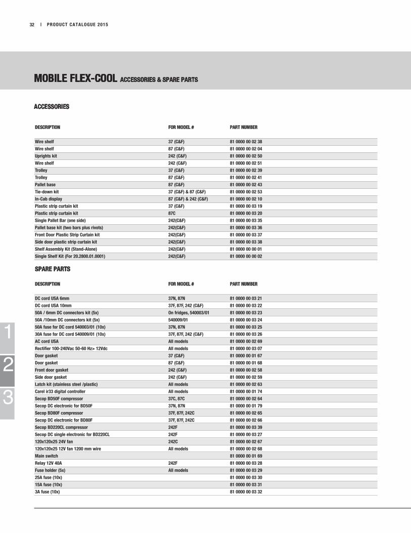
MOBILE FLEX-COOL ACCESSORIES & SPARE PARTS
ACCESSORIES
DESCRIPTION FOR MODEL # PART NUMBER
Wire shelf 37 (C&F) 81 0000 00 02 38
Wire shelf 87 (C&F) 81 0000 00 02 04
Uprights kit 242 (C&F) 81 0000 00 02 50
Wire shelf 242 (C&F) 81 0000 00 02 51
Trolley 37 (C&F) 81 0000 00 02 39
Trolley 87 (C&F) 81 0000 00 02 41
Pallet base 87 (C&F) 81 0000 00 02 43
Tie-down kit 37 (C&F) & 87 (C&F) 81 0000 00 02 53
In-Cab display 87 (C&F) & 242 (C&F) 81 0000 00 02 10
Plastic strip curtain kit 37 (C&F) 81 0000 00 03 19
Plastic strip curtain kit 87C 81 0000 00 03 20
Single Pallet Bar (one side) 242(C&F) 81 0000 00 03 35
Pallet base kit (two bars plus rivots) 242(C&F) 81 0000 00 03 36
Front Door Plastic Strip Curtain kit 242(C&F) 81 0000 00 03 37
Side door plastic strip curtain kit 242(C&F) 81 0000 00 03 38
Shelf Assembly Kit (Stand-Alone) 242(C&F) 81 0000 00 00 01
Single Shelf Kit (For 20.2800.01.0001) 242(C&F) 81 0000 00 00 02
SPARE PARTS
DESCRIPTION FOR MODEL # PART NUMBER
DC cord USA 6mm 37N, 87N 81 0000 00 03 21
DC cord USA 10mm 37F, 87F, 242 (C&F) 81 0000 00 03 22
50A / 6mm DC connectors kit (5x) On fridges, 540003/01 81 0000 00 03 23
50A /10mm DC connectors kit (5x) 540009/01 81 0000 00 03 24
50A fuse for DC cord 540003/01 (10x) 37N, 87N 81 0000 00 03 25
30A fuse for DC cord 540009/01 (10x) 37F, 87F, 242 (C&F) 81 0000 00 03 26
AC cord USA All models 81 0000 00 02 69
Rectifier 100-240Vac 50-60 Hz> 12Vdc All models 81 0000 00 03 07
Door gasket 37 (C&F) 81 0000 00 01 67
Door gasket 87 (C&F) 81 0000 00 01 68
Front door gasket 242 (C&F) 81 0000 00 02 58
Side door gasket 242 (C&F) 81 0000 00 02 59
Latch kit (stainless steel /plastic) All models 81 0000 00 02 63
Carel ir33 digital controller All models 81 0000 00 01 74
Secop BD50F compressor 37C, 87C 81 0000 00 02 64
Secop DC electronic for BD50F 37N, 87N 81 0000 00 01 79
Secop BD80F compressor 37F, 87F, 242C 81 0000 00 02 65
Secop DC electronic for BD80F 37F, 87F, 242C 81 0000 00 02 66
Secop BD220CL compressor 242F 81 0000 00 03 39
Secop DC single electronic for BD220CL 242F 81 0000 00 03 27
120x120x25 24V fan 242C 81 0000 00 02 67
120x120x25 12V fan 1200 mm wire All models 81 0000 00 02 68
Main switch 81 0000 00 01 69
Relay 12V 40A 242F 81 0000 00 03 28
Fuse holder (5x) All models 81 0000 00 03 29
25A fuse (10x) 81 0000 00 03 30
15A fuse (10x) 81 0000 00 03 31
3A fuse (10x) 81 0000 00 03 32

DRIVING THE MOBILITY OF TOMORROW
ACCESSORIES PARTS GUIDE
CHAPTER TITLE CONTENT PAGE
3 PARTS GUIDETimers and Controlers Table 34Control Options and Timers 35-37Testers, Adapters and Special Tools 38-39Fuel System 40-43Mounting Parts 44-46Bulk Wiring 47Fuse Holders, Fuses and Breakers 48-49Terminals and Connectors 50-53Power Converters 12V to 24V 54Exhaust 56-59Ducting 60-68Coolant Pumps 69Plumbing 70-73Fuel System Guide 74Ducting Rating Guide 75-85
AIRTRONIC 2 76-77AIRTRONIC 4 78-79B1LC compact 80-81AIRTRONIC 5 82-83D8LC 84-85
1
2
3
PRODUCT CATALOGUE 2015 | 33

1
2
3
AVAILABLE FUNCTIONS DIGI-MAX EASY START TIMER PROGRAMABLE 7 DAY MULTI-FUNCTION
CONTROLLER TIMER TIMER SWITCH
Programmable Timer · · ·Multiple Starts - Day / Week · ·Ambient Air Temp Sensor · Cabin temp AVAILABLE
sensor
Diagnostic Code Retrieval · · ·Standard Fan Mode · ·10-Hour Automatic Shutoff · 2 hour max.
programmed run time
Manual Start Mode · · · · ·Program Memory · · ·Programmable LVD · ·Accepts External Inputs · · AVAILABLE
AIR HEATERS · · ·COOLANT HEATERS · · · ·
34 | PRODUCT CATALOGUE 2015
TIMERS AND CONTROLLERS

1
2
3
PRODUCT CATALOGUE 2015 | 35
AIR
TR
ON
IC D
2
AIR
TR
ON
IC D
4
B1LC
C /
B3
LCC
AIR
TR
ON
IC D
5 B
5
D8LC
HY
DR
ON
IC 4
/5
HY
DR
ON
IC I
I 5
E
HY
DR
ON
IC 1
0 /
M
HY
DR
ON
IC M
-II
8/1
0/1
2
HY
DR
ON
IC 1
6/2
4/3
0/3
5
DESCRIPTION PART NUMBER
AIR HEATERS
Digi-Max Controller with Diagnostic 12V & 24V 20 2800 70 1500 • • •
Thermostat 12 volt 5670097 • • • • •
Thermostat 24 volt 5670096 • • • • •
Thermostat Harness (4.6M or 15 feet) 20 2900 70 01 09 •
7-Day Timer with Diagnostics 12 and 24 volt 22 1000 30 40 00 • • • • •
7-Day Timer Kit 20 2900 70 02 35 • • • • •
Rheostat Switch 12 volt 25 1895 71 00 00 • • • • •
Rheostat Switch 24 volt 25 1896 71 00 00 • • • • •
Thermostat Switch Harness (4.6M or 15 feet) 20 2900 70 01 11 • • •
Thermostat Bunk Relay Kit 12 volt for Heat Exchanger Blower 20 2900 70 00 97 • • • • •
Thermostat only (On/Off) 29 2100 30 01 84 • • • • • • • • • •
AIR HEATERS
CONTROL OPTIONS AND TIMERS
I AUTO O RUN P
P 1...7 h m
1 2 3 4 5 6 7 P M
R
1 2
1
2
3
| PRODUCT CATALOGUE 201536
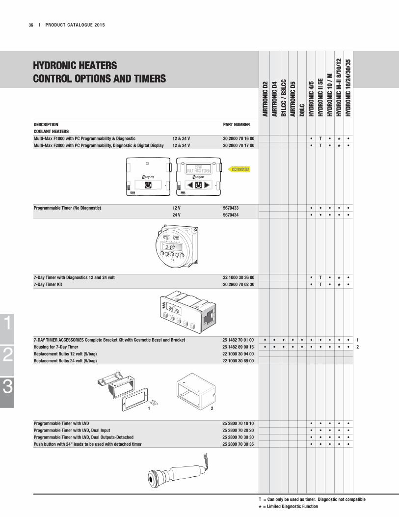
HYDRONIC HEATERS
CONTROL OPTIONS AND TIMERS
AIR
TR
ON
IC D
2
AIR
TR
ON
IC D
4
B1LC
C /
B3
LCC
AIR
TR
ON
IC D
5
D8LC
HY
DR
ON
IC 4
/5
HY
DR
ON
IC I
I 5
E
HY
DR
ON
IC 1
0 /
M
HY
DR
ON
IC M
-II
8/1
0/1
2
HY
DR
ON
IC 1
6/2
4/3
0/3
5
DESCRIPTION PART NUMBER
COOLANT HEATERS
Multi-Max F1000 with PC Programmability & Diagnostic 12 & 24 V 20 2800 70 16 00 • T • * •
Multi-Max F2000 with PC Programmability, Diagnostic & Digital Display 12 & 24 V 20 2800 70 17 00 • T • * •
Programmable Timer (No Diagnostic) 12 V 5670433 • • • • •
24 V 5670434 • • • • •
7-Day Timer with Diagnostics 12 and 24 volt 22 1000 30 36 00 • T • * •
7-Day Timer Kit 20 2900 70 02 30 • T • * •
7-DAY TIMER ACCESSORIES Complete Bracket Kit with Cosmetic Bezel and Bracket 25 1482 70 01 00 • • • • • • • • • • 1
Housing for 7-Day Timer 25 1482 89 00 15 • • • • • • • • • • 2
Replacement Bulbs 12 volt (5/bag) 22 1000 30 94 00
Replacement Bulbs 24 volt (5/bag) 22 1000 30 89 00
Programmable Timer with LVD 25 2800 70 10 10 • • • • •
Programmable Timer with LVD, Dual Input 25 2800 70 20 20 • • • • •
Programmable Timer with LVD, Dual Outputs-Detached 25 2800 70 30 30 • • • • •
Push button with 24” leads to be used with detached timer 25 2800 70 30 35 • • • • •
T = Can only be used as timer. Diagnostic not compatible
* = Limited Diagnostic Function
Comman dC a l l ®
1 2 3
1 2
1
2
3
PRODUCT CATALOGUE 2015 | 37
HYDRONIC HEATERS
CONTROL OPTIONS AND TIMERS
AIR
TR
ON
IC D
2
AIR
TR
ON
IC D
4
B1LC
C /
B3
LCC
AIR
TR
ON
IC D
5
D8LC
HY
DR
ON
IC 4
/5
HY
DR
ON
IC I
I 5
E
HY
DR
ON
IC 1
0 /
M
HY
DR
ON
IC M
-II
8/1
0/1
2
HY
DR
ON
IC 1
6/2
4/3
0/3
5
DESCRIPTION PART NUMBER
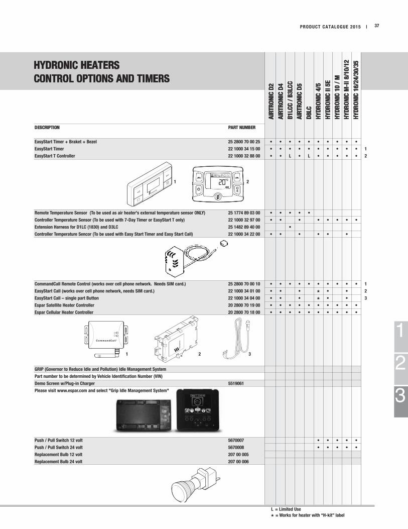
EasyStart Timer + Braket + Bezel 25 2800 70 00 25 • • • • • • • • • •
EasyStart Timer 22 1000 34 15 00 • • • • • • • • • • 1
EasyStart T Controller 22 1000 32 88 00 • • L • L • • • • • 2
Remote Temperature Sensor (To be used as air heater's external temperature sensor ONLY) 25 1774 89 03 00 • • • • •
Controller Temperature Sensor (To be used with 7-Day Timer or EasyStart T only) 22 1000 32 97 00 • • • • • • • •
Extension Harness for D1LC (1830) and D3LC 25 1482 89 40 00 •
Controller Temperature Sencor (To be used with Easy Start Timer and Easy Start Call) 22 1000 34 22 00 • • • • • •
CommandCall Remote Control (works over cell phone network. Needs SIM card.) 25 2800 70 00 10 • • • • • • • • • • 1
EasyStart Call (works over cell phone network, needs SIM card.) 22 1000 34 01 00 • • • * • • 2
EasyStart Call – single part Button 22 1000 34 04 00 • • • * • • 3
Espar Satellite Heater Controller 20 2800 70 19 00 • • • • • • • • • •
Espar Cellular Heater Controller 20 2800 70 18 00 • • • • • • • • • •
GRIP (Governor to Reduce Idle and Pollution) Idle Management System
Part number to be determined by Vehicle Identification Number (VIN)
Demo Screen w/Plug-in Charger 5519061
Please visit www.espar.com and select "Grip Idle Management System"
Push / Pull Switch 12 volt 5670007 • • • • •
Push / Pull Switch 24 volt 5670008 • • • • •
Replacement Bulb 12 volt 207 00 005
Replacement Bulb 24 volt 207 00 006
L = Limited Use
* = Works for heater with “H-kit” label
AIRTRONICdiagnosticconnector
8 to 6 pinadapter
20 2900 70 50 46
20 2900 70 50 28
Example of hook-up
1
2
3
| PRODUCT CATALOGUE 201538
TESTERS / ADAPTERS / SPECIAL TOOLS
AIR
TR
ON
IC D
2
AIR
TR
ON
IC D
4
B1LC
com
pact
B3LC
com
pact
AIR
TR
ON
IC D
5
D8LC
HY
DR
ON
IC 4
/5
HY
DR
ON
IC 1
0 /
M
HY
DR
ON
IC 1
6/2
4/3
0/3
5
HY
DR
ON
IC M
-II
HY
DR
ON
IC 5
E
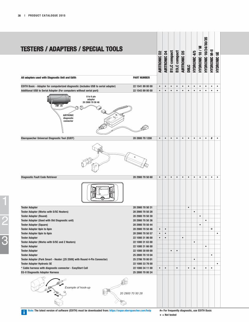
All adapters used with Diagnostic Unit and Edith PART NUMBER
EDITH Basic - Adapter for computerized diagnostic (includes USB to serial adapter) 22 1541 89 00 00 • • • • • • • • • • •
Additional USB to Serial Adapter (For computers without serial port) 22 1543 89 00 00 • • • • • • • • • • •
Eberspaecher Universal Diagnostic Tool (EUDT) 20 2800 70 1200 • • • • • • • • • # •
Diagnostic Fault Code Retriever 20 2900 70 50 60 • • • • • • • • • • •
Tester Adapter 20 2900 70 50 31 •
Tester Adapter (Works with S/SC Heaters) 20 2900 70 50 28 •
Tester Adapter (Round) 20 2900 70 50 30 •
Tester Adapter (Used with Old Diagnostic unit) 20 2900 70 50 36 •
Tester Adapter (Square) 20 2900 70 50 44 •
Tester Adapter 8pin to 6pin 20 2900 70 50 46 • • °Tester Adapter 8pin to 6pin 20 2900 70 50 57 • • •
Tester Adapter 22 1000 31 86 00 • • •
Tester Adapter (Works with S/SC and Z Heaters) 22 1000 31 63 00 •
Tester Adapter 22 1000 31 66 00 •
Tester Adapter 22 1000 30 69 00 • •
Tester Adapter 25 2800 70 10 04 •
Tester Adapter (Park Smart - Heater: [25 2509] with Round 4-Pin Connector) 25 2786 70 00 01 •
Tester Adapter Hydronic 5E 22 1000 33 78 00 •
* Cable harness with diagnostic connector - EasyStart Call 22 1000 34 11 00 • • • • * • •
EG-II Diagnostic Adaptor Harness 25 2800 70 00 24
Note: The latest version of software (EDITH) must be downloaded from: https://espar.eberspaecher.com/help #= For frequently diagnostic, use EDITH Basic
* = Not tested

1
2
TESTERS / ADAPTERS / SPECIAL TOOLS
AIR
TR
ON
IC D
2
AIR
TR
ON
IC D
4
B1LC
com
pact
B3LC
com
pact
AIR
TR
ON
IC D
5
D8LC
HY
DR
ON
IC 4
/5
HY
DR
ON
IC 1
0 /
M
HY
DR
ON
IC 1
6/2
4/3
0/3
5
HY
DR
ON
IC M
-II
1
2
3
PRODUCT CATALOGUE 2015 | 39
DESCRIPTION PART NUMBER
Terminal Removal Tool 1.6mm 206 00 205 • 1
Terminal Removal Tool 2.8mm 206 00 215 • • • • • • • • • • 2
Wire Crimper 5670003 • • • • • • • • • •
Fuel Line Cutter 5520003 • • • • • • • • • •
Brass Glow Plug Brush 5590002 • • • • • • •
AIRTRONIC D2 Demo Kit 12 volt 20 2820 69 02 83
1 2 6 5 3 9 10 11
4
8
7
12
no
graphic
FUEL SYSTEM
AIR
TR
ON
IC D
2
AIR
TR
ON
IC D
4
B1LC
com
pact
B3LC
com
pact
AIR
TR
ON
IC D
5
D8LC
HY
DR
ON
IC 4
/5
HY
DR
ON
IC 1
0 /
M /
M-I
I
HY
DR
ON
IC 1
6/2
4/3
0/3
5
1
2
3
| PRODUCT CATALOGUE 201540
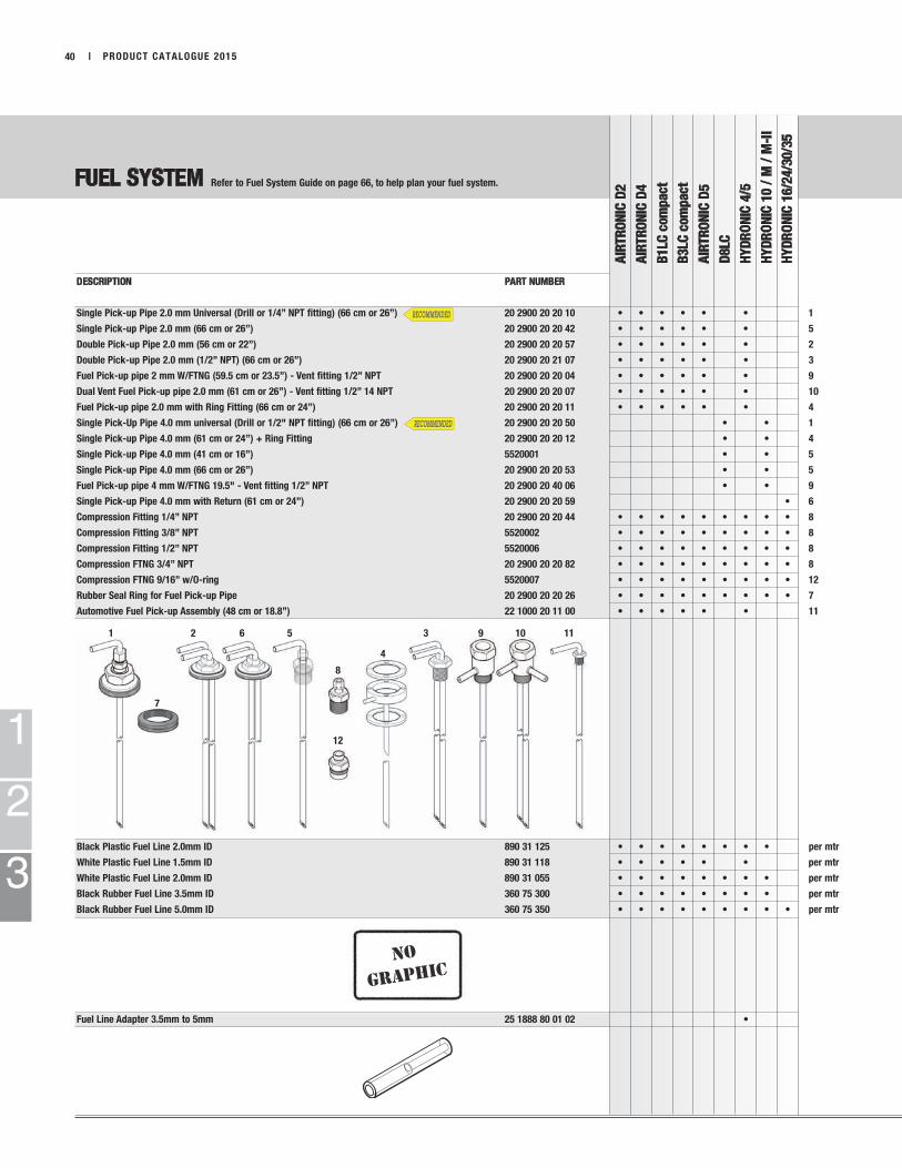
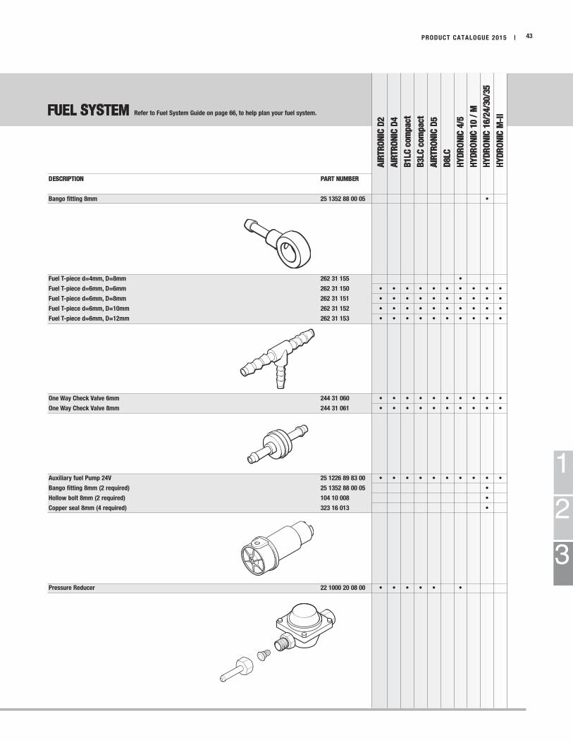
Refer to Fuel System Guide on page 66, to help plan your fuel system.
DESCRIPTION PART NUMBER
Single Pick-up Pipe 2.0 mm Universal (Drill or 1/4” NPT fitting) (66 cm or 26”) 20 2900 20 20 10 • • • • • • 1
Single Pick-up Pipe 2.0 mm (66 cm or 26”) 20 2900 20 20 42 • • • • • • 5
Double Pick-up Pipe 2.0 mm (56 cm or 22”) 20 2900 20 20 57 • • • • • • 2
Double Pick-up Pipe 2.0 mm (1/2” NPT) (66 cm or 26”) 20 2900 20 21 07 • • • • • • 3
Fuel Pick-up pipe 2 mm W/FTNG (59.5 cm or 23.5”) - Vent fitting 1/2” NPT 20 2900 20 20 04 • • • • • • 9
Dual Vent Fuel Pick-up pipe 2.0 mm (61 cm or 26”) - Vent fitting 1/2” 14 NPT 20 2900 20 20 07 • • • • • • 10
Fuel Pick-up pipe 2.0 mm with Ring Fitting (66 cm or 24”) 20 2900 20 20 11 • • • • • • 4
Single Pick-Up Pipe 4.0 mm universal (Drill or 1/2" NPT fitting) (66 cm or 26”) 20 2900 20 20 50 • • 1
Single Pick-up Pipe 4.0 mm (61 cm or 24”) + Ring Fitting 20 2900 20 20 12 • • 4
Single Pick-up Pipe 4.0 mm (41 cm or 16”) 5520001 • • 5
Single Pick-up Pipe 4.0 mm (66 cm or 26”) 20 2900 20 20 53 • • 5
Fuel Pick-up pipe 4 mm W/FTNG 19.5" - Vent fitting 1/2” NPT 20 2900 20 40 06 • • 9
Single Pick-up Pipe 4.0 mm with Return (61 cm or 24”) 20 2900 20 20 59 • 6
Compression Fitting 1/4” NPT 20 2900 20 20 44 • • • • • • • • • 8
Compression Fitting 3/8” NPT 5520002 • • • • • • • • • 8
Compression Fitting 1/2” NPT 5520006 • • • • • • • • • 8
Compression FTNG 3/4” NPT 20 2900 20 20 82 • • • • • • • • • 8
Compression FTNG 9/16” w/O-ring 5520007 • • • • • • • • • 12
Rubber Seal Ring for Fuel Pick-up Pipe 20 2900 20 20 26 • • • • • • • • • 7
Automotive Fuel Pick-up Assembly (48 cm or 18.8”) 22 1000 20 11 00 • • • • • • 11
Black Plastic Fuel Line 2.0mm ID 890 31 125 • • • • • • • • per mtr
White Plastic Fuel Line 1.5mm ID 890 31 118 • • • • • • per mtr
White Plastic Fuel Line 2.0mm ID 890 31 055 • • • • • • • • per mtr
Black Rubber Fuel Line 3.5mm ID 360 75 300 • • • • • • • • per mtr
Black Rubber Fuel Line 5.0mm ID 360 75 350 • • • • • • • • • per mtr
Fuel Line Adapter 3.5mm to 5mm 25 1888 80 01 02 •
1
2
FUEL SYSTEM
AIR
TR
ON
IC D
2
AIR
TR
ON
IC D
4
B1LC
com
pact
B3LC
com
pact
AIR
TR
ON
IC D
5
D8LC
HY
DR
ON
IC 4
/5
HY
DR
ON
IC 1
0 /
M
HY
DR
ON
IC 1
6/2
4/3
0/3
5
HY
DR
ON
IC M
-II
1
2
3
PRODUCT CATALOGUE 2015 | 41
DESCRIPTION PART NUMBER
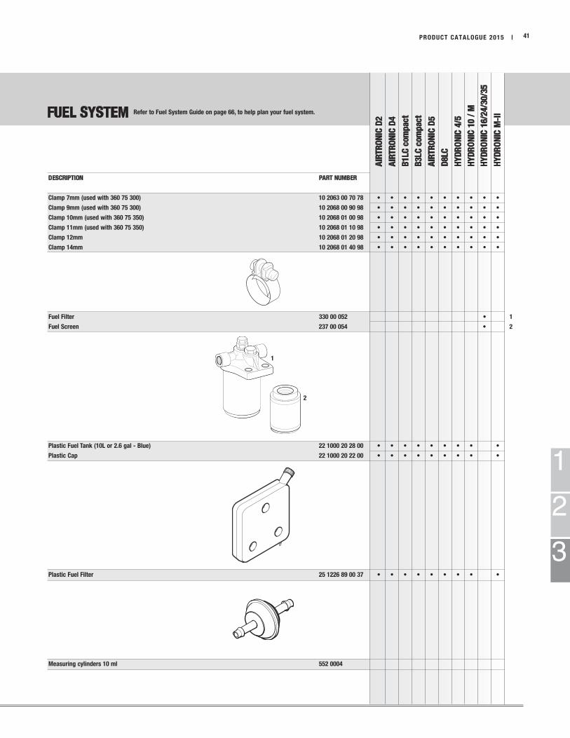
Clamp 7mm (used with 360 75 300) 10 2063 00 70 78 • • • • • • • • • •
Clamp 9mm (used with 360 75 300) 10 2068 00 90 98 • • • • • • • • • •
Clamp 10mm (used with 360 75 350) 10 2068 01 00 98 • • • • • • • • • •
Clamp 11mm (used with 360 75 350) 10 2068 01 10 98 • • • • • • • • • •
Clamp 12mm 10 2068 01 20 98 • • • • • • • • • •
Clamp 14mm 10 2068 01 40 98 • • • • • • • • • •
Fuel Filter 330 00 052 • 1
Fuel Screen 237 00 054 • 2
Plastic Fuel Tank (10L or 2.6 gal - Blue) 22 1000 20 28 00 • • • • • • • • •
Plastic Cap 22 1000 20 22 00 • • • • • • • • •
Plastic Fuel Filter 25 1226 89 00 37 • • • • • • • • •
Measuring cylinders 10 ml 552 0004
Refer to Fuel System Guide on page 66, to help plan your fuel system.

FUEL SYSTEM
AIR
TR
ON
IC D
2
AIR
TR
ON
IC D
4
B1LC
com
pact
B3LC
com
pact
AIR
TR
ON
IC D
5
D8LC
HY
DR
ON
IC 4
/5
HY
DR
ON
IC 1
0 /
M
HY
DR
ON
IC 1
6/2
4/3
0/3
5
HY
DR
ON
IC M
-II
1
2
3
| PRODUCT CATALOGUE 201542
DESCRIPTION PART NUMBER
Clamp 34mm for Fuel Metering Pump 152 00 200 • • • • • •
FMP Holder for Noise Reduction (small pumps) 22 1000 50 03 00 • • • • • •
FMP Holder for Noise Reduction (large pumps) 22 1000 50 07 00 • • • • •
Fuel Metering Pump Holder 25 1156 20 00 11 • •
Fuel Connector Nipple and Nut 20 2900 20 20 71 •
Plastic Fuel Filter (installed in front of fuel metering pump) 25 1156 20 00 09 • • • • • • • • • •
FMP Bracket 20 2900 40 01 04 • • •
Refer to Fuel System Guide on page 66, to help plan your fuel system.
FUEL SYSTEM
AIR
TR
ON
IC D
2
AIR
TR
ON
IC D
4
B1LC
com
pact
B3LC
com
pact
AIR
TR
ON
IC D
5
D8LC
HY
DR
ON
IC 4
/5
HY
DR
ON
IC 1
0 /
M
HY
DR
ON
IC 1
6/2
4/3
0/3
5
HY
DR
ON
IC M
-II
1
2
3
PRODUCT CATALOGUE 2015 | 43
DESCRIPTION PART NUMBER
Bango fitting 8mm 25 1352 88 00 05 •
Fuel T-piece d=4mm, D=8mm 262 31 155 •
Fuel T-piece d=6mm, D=6mm 262 31 150 • • • • • • • • • •
Fuel T-piece d=6mm, D=8mm 262 31 151 • • • • • • • • • •
Fuel T-piece d=6mm, D=10mm 262 31 152 • • • • • • • • • •
Fuel T-piece d=6mm, D=12mm 262 31 153 • • • • • • • • • •
One Way Check Valve 6mm 244 31 060 • • • • • • • • • •
One Way Check Valve 8mm 244 31 061 • • • • • • • • • •
Auxiliary fuel Pump 24V 25 1226 89 83 00 • • • • • • • • • •
Bango fitting 8mm (2 required) 25 1352 88 00 05 •
Hollow bolt 8mm (2 required) 104 10 008 •
Copper seal 8mm (4 required) 323 16 013 •
Pressure Reducer 22 1000 20 08 00 • • • • • •
Refer to Fuel System Guide on page 66, to help plan your fuel system.

1
1 2
2
1
2
MOUNTING PARTS
AIR
TR
ON
IC D
2
AIR
TR
ON
IC D
4
B1LC
com
pact
B3LC
com
pact
AIR
TR
ON
IC D
5
D8LC
HY
DR
ON
IC 4
/5
HY
DR
ON
IC 1
0 /
M
HY
DR
ON
IC 1
6/2
4/3
0/3
5
HY
DR
ON
IC M
-II
1
2
3
| PRODUCT CATALOGUE 201544
DESCRIPTION PART NUMBER
Mounting Plate with Seal 5540001 • • • •
Side Frame Mounting Tray for Boxed Heaters 20 2900 40 00 57 •
20 2900 40 00 75 °
Cargo Bracket 20 2900 40 00 34 • • • • • 1
Cargo Bracket Support 20 2900 40 00 35 • • • • • 2
Angle Mounting Bracket 20 2900 40 00 23 • 1
Mounting Bracket 5540016 • • • • 2
Saddle Bracked 25 1864 80 00 01 • 1
Mounting Bracket (model 25 2217 / 2218 / 2219 / 2257) 25 2220 80 00 01 • 2
° = E-Guardian
Eberspächer
5.25”
9.25”
12.25”
1.25”
13.5”
17”
12.5”
7.875”
8.75”1 2
MOUNTING PARTS
AIR
TR
ON
IC D
2
AIR
TR
ON
IC D
4
B1LC
com
pact
B3LC
com
pact
AIR
TR
ON
IC D
5
D8LC
HY
DR
ON
IC 4
/5
HY
DR
ON
IC 1
0 /
M
HY
DR
ON
IC 1
6/2
4/3
0/3
5
HY
DR
ON
IC M
-II
1
2
3
PRODUCT CATALOGUE 2015 | 45
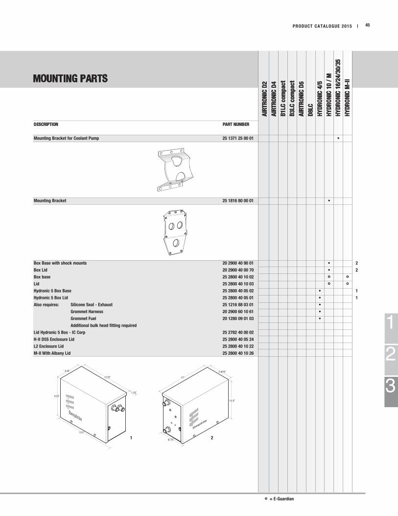
DESCRIPTION PART NUMBER
Mounting Bracket for Coolant Pump 25 1371 25 00 01 •
Mounting Bracket 25 1816 80 00 01 •
Box Base with shock mounts 20 2900 40 90 01 • 2
Box Lid 20 2900 40 00 70 • 2
Box base 25 2800 40 10 02 ° °Lid 25 2800 40 10 03 ° °Hydronic 5 Box Base 25 2800 40 05 02 • 1
Hydronic 5 Box Lid 25 2800 40 05 01 • 1
Also requires: Silicone Seal - Exhaust 25 1216 88 03 01 •
Grommet Harness 20 2900 60 10 61 •
Grommet Fuel 20 1280 09 01 03 •
Additional bulk head fitting required
Lid Hydronic 5 Box - IC Corp 25 2782 40 00 02
H-II D5S Enclosure Lid 25 2800 40 05 24
L2 Enclosure Lid 25 2800 40 10 22
M-II With Albany Lid 25 2800 40 10 26
° = E-Guardian

1
2
3
1 2 3 4
MOUNTING PARTS
AIR
TR
ON
IC D
2
AIR
TR
ON
IC D
4
B1LC
com
pact
B3LC
com
pact
AIR
TR
ON
IC D
5
D8LC
HY
DR
ON
IC 4
/5
HY
DR
ON
IC 1
0 /
M
HY
DR
ON
IC 1
6/2
4/3
0/3
5
HY
DR
ON
IC M
-II
1
2
3
| PRODUCT CATALOGUE 201546
DESCRIPTION PART NUMBER
Metal Angle Bracket for Fuel Metering Pump 20 1348 03 00 02 • • • • • • • • • 1
20 1348 03 00 04 • • • • • • • • • 2
20 1533 88 00 07 • • • • • • • • • 3
“C” Clamp 10mm 152 00 139 • • • • • • • • •
“C” Clamp 25mm (for 22mm Exhaust/Air Intake) 152 10 048 • • • • • • • • •
“C” Clamp 28mm (for 24mm Exhaust) 152 09 010 • • • • • • • • •
“C” Clamp 34mm (for 30mm Exhaust) 152 09 008 • • • • • • • • •
“C” Clamp 41mm (for large Fuel Metering Pumps) 152 10 039 • • • • • • • • •
“C” Clamp 50mm 152 09 011 • •
Metal / Rubber Shock Mounts
8mm H, Hex Body 20 1185 00 00 01 • • • • • • • • • 1
15mm H, Round Body, M8 330 09 002 • • • • • • • • • 2
1inch H, Round Body, 5/16 x 18 NC 5540014 • 3
25mm H, Round Body, M6 20 1609 05 00 04 • 4

no
graphic
BULK WIRING
AIR
TR
ON
IC D
2
AIR
TR
ON
IC D
4
B1LC
com
pact
B3LC
com
pact
AIR
TR
ON
IC D
5
D8LC
HY
DR
ON
IC 4
/5
HY
DR
ON
IC 1
0 /
M
HY
DR
ON
IC 1
6/2
4/3
0/3
5
HY
DR
ON
IC M
-II
1
2
3
PRODUCT CATALOGUE 2015 | 47
DESCRIPTION PART NUMBER
Bulk Wiring
8ga - 2 Core Red, Brown 20 2900 70 59 02 • • • • • • • • • per ft.
10ga - 1 Core Red 5670136 • • • • • • • • • per ft.
10ga - 2 Core Red, Brown 20 2900 70 59 03 • • • • • • • • • per ft.
12ga - 2 Core Red, Brown 20 2900 70 59 23 • • • • • • • • • per ft.
14ga - 2 Core Red, Brown 20 2900 70 59 05 • • • • • • • • • per ft.
16ga - 2 Core Green, Brown 20 2900 70 09 15 • • • • • • • • • per ft.
18ga - 2 Core Green, Brown 20 2900 50 59 01 • • • • • • • • • per ft.
18ga - 3 Core Red, Brown, Yellow 20 2900 70 09 17 • • • • • • • • • per ft.
18ga - 4 Core Red, Brown, Yellow, Blue 20 2900 70 09 13 • • • • • • • • • per ft.
18ga - 6 Core Red, Brown, Yellow, Blue, Grey, Black 20 2900 70 90 09 • • • • • • • • • per ft.
18ga - 7 Core Red, Brown, Yellow, Blue, Grey, Brown w/white stripe, Grey w/red stripe. 20 2900 70 09 14 • • • • • • • • • per ft.
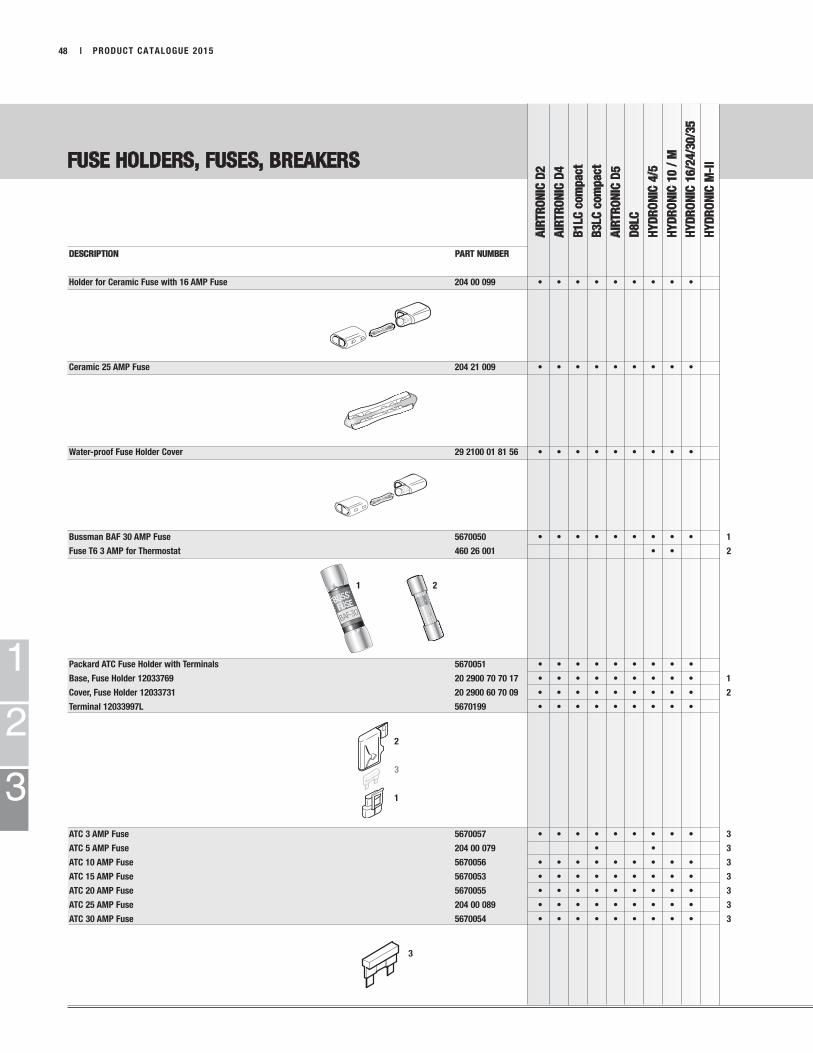
BUSS®
BAF-30 FUSE
1 2
2
3
1
3
FUSE HOLDERS, FUSES, BREAKERS
AIR
TR
ON
IC D
2
AIR
TR
ON
IC D
4
B1LC
com
pact
B3LC
com
pact
AIR
TR
ON
IC D
5
D8LC
HY
DR
ON
IC 4
/5
HY
DR
ON
IC 1
0 /
M
HY
DR
ON
IC 1
6/2
4/3
0/3
5
HY
DR
ON
IC M
-II
1
2
3
| PRODUCT CATALOGUE 201548
DESCRIPTION PART NUMBER
Holder for Ceramic Fuse with 16 AMP Fuse 204 00 099 • • • • • • • • •
Ceramic 25 AMP Fuse 204 21 009 • • • • • • • • •
Water-proof Fuse Holder Cover 29 2100 01 81 56 • • • • • • • • •
Bussman BAF 30 AMP Fuse 5670050 • • • • • • • • • 1
Fuse T6 3 AMP for Thermostat 460 26 001 • • 2
Packard ATC Fuse Holder with Terminals 5670051 • • • • • • • • •
Base, Fuse Holder 12033769 20 2900 70 70 17 • • • • • • • • • 1
Cover, Fuse Holder 12033731 20 2900 60 70 09 • • • • • • • • • 2
Terminal 12033997L 5670199 • • • • • • • • •
ATC 3 AMP Fuse 5670057 • • • • • • • • • 3
ATC 5 AMP Fuse 204 00 079 • • 3
ATC 10 AMP Fuse 5670056 • • • • • • • • • 3
ATC 15 AMP Fuse 5670053 • • • • • • • • • 3
ATC 20 AMP Fuse 5670055 • • • • • • • • • 3
ATC 25 AMP Fuse 204 00 089 • • • • • • • • • 3
ATC 30 AMP Fuse 5670054 • • • • • • • • • 3

2
1
FUSE HOLDERS, FUSES & BREAKERS
AIR
TR
ON
IC D
2
AIR
TR
ON
IC D
4
B1LC
com
pact
B3LC
com
pact
AIR
TR
ON
IC D
5
D8LC
HY
DR
ON
IC 4
/5
HY
DR
ON
IC 1
0 /
M
HY
DR
ON
IC 1
6/2
4/3
0/3
5
HY
DR
ON
IC M
-II
1
2
3
PRODUCT CATALOGUE 2015 | 49
DESCRIPTION PART NUMBER
Breaker 30 Amp (D7WB) 5670059 • • • • • • • • •
Breaker 25 Amp (D5WB-oldstyle) 5670046 • • • • • • • • •
Fuse Holder Base 204 31 004 • • • • • • • • • 1
Fuse Holder Cover 204 31 005 • • • • • • • • • 2
Fuse Holder Kit 5A, 15A, 25A 22 1000 31 06 00 • • • • • • • • •
INCLUDES: Fuses and Terminals
Relay 24 volt (D1L/D3L/V7S/D12W) 203 00 066 • •

1 2 3
4 5 6
2
3
4
4
2
3
1
1
2
3
TERMINALS AND CONNECTORS
AIR
TR
ON
IC D
2
AIR
TR
ON
IC D
4
B1LC
com
pact
B3LC
com
pact
AIR
TR
ON
IC D
5
D8LC
HY
DR
ON
IC 4
/5
HY
DR
ON
IC 1
0 /
M
HY
DR
ON
IC 1
6/2
4/3
0/3
5
HY
DR
ON
IC M
-II
| PRODUCT CATALOGUE 201550
DESCRIPTION PART NUMBER
10ga - 12ga Female, Tabs 5670174 • • • • • • • • • 4
14ga - 18ga Female, Tabs 5670394 • • • • • • • • • 4
Terminal Fuse Holder 206 00 004 • • • • • • • • • 5
Flat Terminal 206 73 016 • • 1
Mini Terminal, AWG 16-20 206 73 052 • • • • 6
Flat Terminal 5670186 • • • • • • • • • 4
10ga - 12ga Female, No Tabs 5670171 • • • • • • • • • 4
14ga - 18ga Female, No Tabs 5670172 • • • • • • • • • 4
10ga - 12ga Male 5670176 • • • • • • • • • 1
14ga - 18ga Male 5670175 • • • • • • • • • 1
Mini Terminal, AWG 16-20 206 36 018 • • • • 3
Terminal with Tab, AWG 18 5670394 • • • • • • • • • 4
Terminal with Sensor FE 5670187 • • • • 4
Mini Terminal, AWG 14-18 206 00 182 • • • • 6
Terminal 12033997L 5670199 • • • • • • • • • 4
Terminal with Sensor MALE 5670188 • • • • 2
Ring Terminal (3/8”) AWG 10-12 5670178 • • • • • • • • •
Socket AWG 14 5670268 • 2
Deutch Connector AWG 18 Pin 5670266 • 3
Seal Plug 5670325 • 4
Socket 5670272 • 1
Connector, Female DTHD-04-18P 5670321 • 2
Connector, Male DTHD-06-18S 5670323 • 3
Deutch Connector Power Pin AWG 10 5670270 • 4
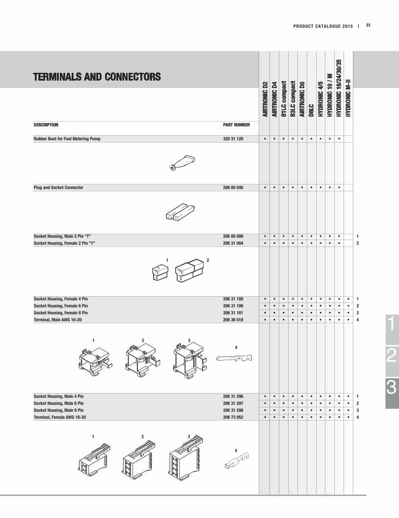
1 2 3
4
1 2 3
4
1 2
TERMINALS AND CONNECTORS
AIR
TR
ON
IC D
2
AIR
TR
ON
IC D
4
B1LC
com
pact
B3LC
com
pact
AIR
TR
ON
IC D
5
D8LC
HY
DR
ON
IC 4
/5
HY
DR
ON
IC 1
0 /
M
HY
DR
ON
IC 1
6/2
4/3
0/3
5
HY
DR
ON
IC M
-II
1
2
3
PRODUCT CATALOGUE 2015 | 51
DESCRIPTION PART NUMBER
Rubber Boot for Fuel Metering Pump 320 31 120 • • • • • • • • •
Plug and Socket Connector 206 00 040 • • • • • • • • •
Socket Housing, Male 2 Pin “T” 206 00 099 • • • • • • • • • 1
Socket Housing, Female 2 Pin “T” 206 31 004 • • • • • • • • • 2
Socket Housing, Female 4 Pin 206 31 100 • • • • • • • • • • 1
Socket Housing, Female 6 Pin 206 31 106 • • • • • • • • • • 2
Socket Housing, Female 8 Pin 206 31 101 • • • • • • • • • • 3
Terminal, Male AWG 16-20 206 36 018 • • • • • • • • • • 4
Socket Housing, Male 4 Pin 206 31 296 • • • • • • • • • • 1
Socket Housing, Male 6 Pin 206 31 297 • • • • • • • • • • 2
Socket Housing, Male 8 Pin 206 31 298 • • • • • • • • • • 3
Terminal, Female AWG 16-20 206 73 052 • • • • • • • • • • 4
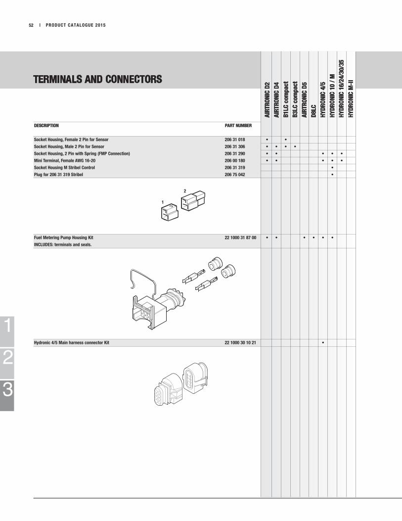
2
1
1
2
3
TERMINALS AND CONNECTORS
AIR
TR
ON
IC D
2
AIR
TR
ON
IC D
4
B1LC
com
pact
B3LC
com
pact
AIR
TR
ON
IC D
5
D8LC
HY
DR
ON
IC 4
/5
HY
DR
ON
IC 1
0 /
M
HY
DR
ON
IC 1
6/2
4/3
0/3
5
HY
DR
ON
IC M
-II
| PRODUCT CATALOGUE 201552
DESCRIPTION PART NUMBER
Socket Housing, Female 2 Pin for Sensor 206 31 018 • •
Socket Housing, Male 2 Pin for Sensor 206 31 306 • • • •
Socket Housing, 2 Pin with Spring (FMP Connection) 206 31 290 • • • • •
Mini Terminal, Female AWG 16-20 206 00 180 • • • • •
Socket Housing M Stribel Control 206 31 319 •
Plug for 206 31 319 Stribel 206 75 042 •
Fuel Metering Pump Housing Kit 22 1000 31 87 00 • • • • • •
INCLUDES: terminals and seals.
Hydronic 4/5 Main harness connector Kit 22 1000 30 10 21 •

TERMINALS AND CONNECTORS
AIR
TR
ON
IC D
2
AIR
TR
ON
IC D
4
B1LC
com
pact
B3LC
com
pact
AIR
TR
ON
IC D
5
D8LC
HY
DR
ON
IC 4
/5
HY
DR
ON
IC 1
0 /
M
HY
DR
ON
IC 1
6/2
4/3
0/3
5
HY
DR
ON
IC M
-II
1
2
3
PRODUCT CATALOGUE 2015 | 53
DESCRIPTION PART NUMBER
7 day timer 12 pin connector housing 206 31 293 • • • • • • • • • •
Mini terminal, female AwG 16-20 206 00 180 • • • • • • • • • •
Hydronic M square connector housing 206 31 319 • •
Hydronic M square connector w/pins 22 1000 31 93 00 • •
Mini terminal stribel AwG 16-20 206 36 154 • •
EasyStart Call / EasyStart Timer - Single part electrical connection parts 22 1000 34 26 00 • • • • • • •
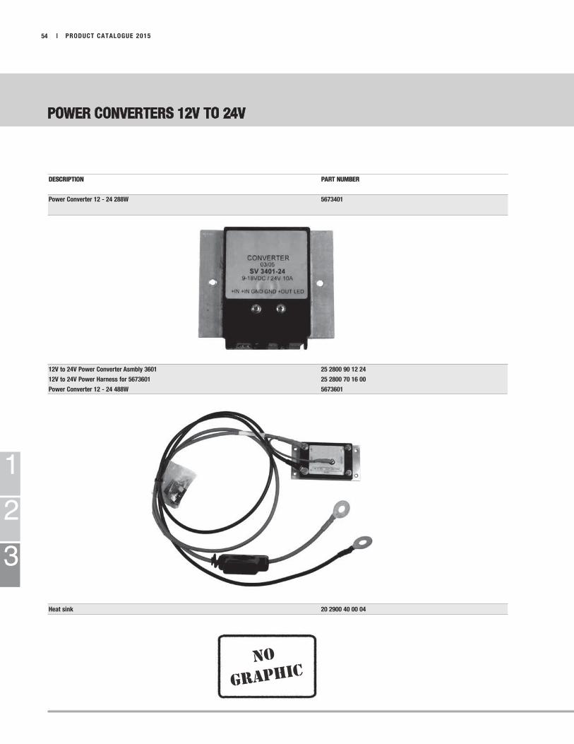
no
graphic
1
2
3
POWER CONVERTERS 12V TO 24V
| PRODUCT CATALOGUE 201554
DESCRIPTION PART NUMBER
Power Converter 12 - 24 288W 5673401
12V to 24V Power Converter Asmbly 3601 25 2800 90 12 24
12V to 24V Power Harness for 5673601 25 2800 70 16 00
Power Converter 12 - 24 488W 5673601
Heat sink 20 2900 40 00 04

NOTES:
1
2
3
PRODUCT CATALOGUE 2015 | 55
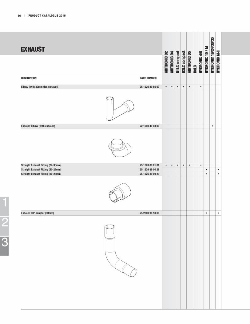
EXHAUST
AIR
TR
ON
IC D
2
AIR
TR
ON
IC D
4
B1LC
com
pact
B3LC
com
pact
AIR
TR
ON
IC D
5
D8LC
HY
DR
ON
IC 4
/5
HY
DR
ON
IC 1
0 /
M
HY
DR
ON
IC 1
6/2
4/3
0/3
5
HY
DR
ON
IC M
-II
1
2
3
| PRODUCT CATALOGUE 201556
DESCRIPTION PART NUMBER
Elbow (with 30mm flex exhaust) 25 1226 89 55 00 • • • • • •
Exhaust Elbow (with exhaust) 22 1000 40 03 00 •
Straight Exhaust Fitting (24-30mm) 25 1520 80 01 01 • • • • • •
Straight Exhaust Fitting (30-28mm) 25 1226 89 00 28 • •
Straight Exhaust Fitting (30-26mm) 25 1226 89 00 29 • •
Exhaust 90° adapter (30mm) 25 2800 30 10 00 • •

1
2
3
EXHAUST
AIR
TR
ON
IC D
2
AIR
TR
ON
IC D
4
B1LC
com
pact
B3LC
com
pact
AIR
TR
ON
IC D
5
D8LC
HY
DR
ON
IC 4
/5
HY
DR
ON
IC 1
0 /
M
HY
DR
ON
IC 1
6/2
4/3
0/3
5
HY
DR
ON
IC M
-II
PRODUCT CATALOGUE 2015 | 57
DESCRIPTION PART NUMBER
Flexible Stainless Steel Exhaust 24mm (1.3 mtr) 360 61 557 • • • • • • each
Flexible Stainless Steel Exhaust 24mm x 1.0M with end cap 25 1774 80 02 00 • • • • • •
Flexible Stainless Steel Exhaust 30mm x 1.3M with end cap 25 1816 80 08 00 • •
Flexible Stainless Steel Exhaust 40mm (when elbow is used) 5530012 • per mtr
Flexible Stainless Steel Exhaust 42mm (direct connect) 5530013 • per mtr
Flexible Stainless Steel Exhaust 24mm (one layer) 360 61 550 • • • • • • per mtr
Flexible Stainless Steel Exhaust 24mm (two layer) 360 61 299 • • • • • • per mtr
Flexible Stainless Steel Exhaust 30mm (one layer) 360 61 580 • • per mtr
Flexible Stainless Steel Exhaust 30mm (two layers) 360 61 300 • • • • • • • per mtr
Flexible Stainless Steel Exhaust 70mm (direct connect) 5530015 • per mtr

1 2
EXHAUST
AIR
TR
ON
IC D
2
AIR
TR
ON
IC D
4
B1LC
com
pact
B3LC
com
pact
AIR
TR
ON
IC D
5
D8LC
HY
DR
ON
IC 4
/5
HY
DR
ON
IC 1
0 /
M
HY
DR
ON
IC 1
6/2
4/3
0/3
5
HY
DR
ON
IC M
-II
1
2
3
| PRODUCT CATALOGUE 201558
DESCRIPTION PART NUMBER
Exhaust Muffler for 24mm (Slimmer-New) 22 1000 40 09 00 • • • • • • 1
Exhaust Muffler for 24mm (Wider-Old) 25 1864 81 01 00 • • • • • • 2
Exhaust Muffler 30mm 25 1226 89 58 00 • • • • •
Exhaust Muffler 30mm 25 1806 80 01 00 • •
Exhaust Insulation Sock 1” for 22mm-24mm ID Exhaust 5530001 • • • • • per ft.
Exhaust Insulation Sock 2” for 24mm-42mm ID Exhaust 5530002 • • • • • • • per ft.
Exhaust Insulation Sock 3” for 70mm ID Exhaust 5530003 • per ft.
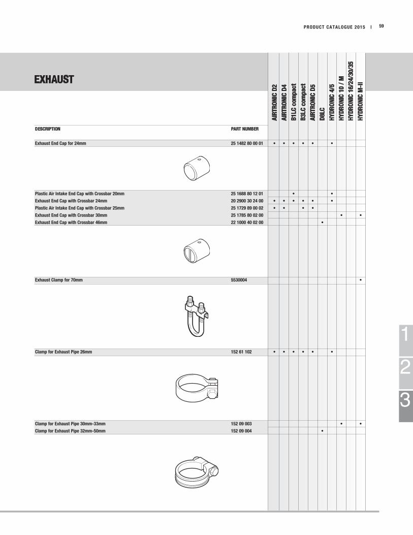
EXHAUST
AIR
TR
ON
IC D
2
AIR
TR
ON
IC D
4
B1LC
com
pact
B3LC
com
pact
AIR
TR
ON
IC D
5
D8LC
HY
DR
ON
IC 4
/5
HY
DR
ON
IC 1
0 /
M
HY
DR
ON
IC 1
6/2
4/3
0/3
5
HY
DR
ON
IC M
-II
1
2
3
PRODUCT CATALOGUE 2015 | 59
DESCRIPTION PART NUMBER
Exhaust End Cap for 24mm 25 1482 80 00 01 • • • • • •
Plastic Air Intake End Cap with Crossbar 20mm 25 1688 80 12 01 • •
Exhaust End Cap with Crossbar 24mm 20 2900 30 24 00 • • • • • •
Plastic Air Intake End Cap with Crossbar 25mm 25 1729 89 00 02 • • • •
Exhaust End Cap with Crossbar 30mm 25 1785 80 02 00 • •
Exhaust End Cap with Crossbar 46mm 22 1000 40 02 00 •
Exhaust Clamp for 70mm 5530004 •
Clamp for Exhaust Pipe 26mm 152 61 102 • • • • • •
Clamp for Exhaust Pipe 30mm-33mm 152 09 003 • •
Clamp for Exhaust Pipe 32mm-50mm 152 09 004 •
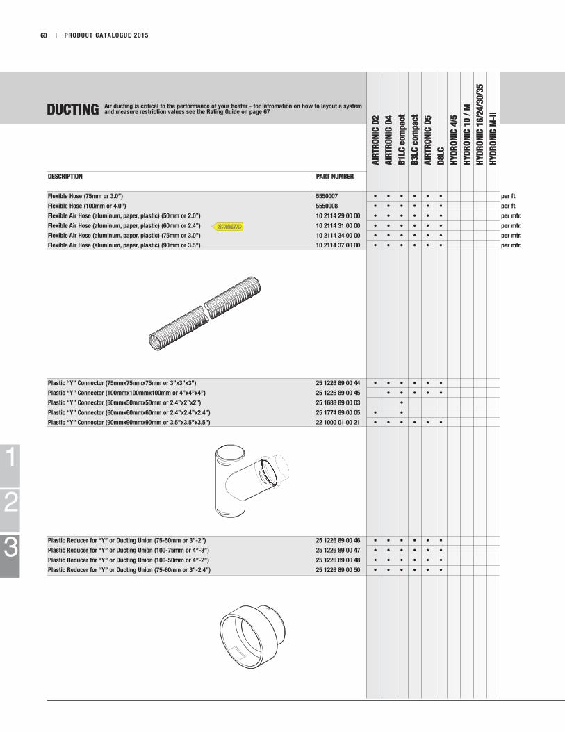
DUCTING
AIR
TR
ON
IC D
2
AIR
TR
ON
IC D
4
B1LC
com
pact
B3LC
com
pact
AIR
TR
ON
IC D
5
D8LC
HY
DR
ON
IC 4
/5
HY
DR
ON
IC 1
0 /
M
HY
DR
ON
IC 1
6/2
4/3
0/3
5
HY
DR
ON
IC M
-II
1
2
3
| PRODUCT CATALOGUE 201560
DESCRIPTION PART NUMBER
Flexible Hose (75mm or 3.0”) 5550007 • • • • • • per ft.
Flexible Hose (100mm or 4.0”) 5550008 • • • • • • per ft.
Flexible Air Hose (aluminum, paper, plastic) (50mm or 2.0”) 10 2114 29 00 00 • • • • • • per mtr.
Flexible Air Hose (aluminum, paper, plastic) (60mm or 2.4”) 10 2114 31 00 00 • • • • • • per mtr.
Flexible Air Hose (aluminum, paper, plastic) (75mm or 3.0”) 10 2114 34 00 00 • • • • • • per mtr.
Flexible Air Hose (aluminum, paper, plastic) (90mm or 3.5”) 10 2114 37 00 00 • • • • • • per mtr.
Plastic “Y” Connector (75mmx75mmx75mm or 3”x3”x3”) 25 1226 89 00 44 • • • • • •
Plastic “Y” Connector (100mmx100mmx100mm or 4”x4”x4”) 25 1226 89 00 45 • • • • •
Plastic “Y” Connector (60mmx50mmx50mm or 2.4”x2”x2”) 25 1688 89 00 03 •
Plastic “Y” Connector (60mmx60mmx60mm or 2.4”x2.4”x2.4”) 25 1774 89 00 05 • •
Plastic “Y” Connector (90mmx90mmx90mm or 3.5”x3.5”x3.5”) 22 1000 01 00 21 • • • • • •
Plastic Reducer for “Y” or Ducting Union (75-50mm or 3”-2”) 25 1226 89 00 46 • • • • • •
Plastic Reducer for “Y” or Ducting Union (100-75mm or 4”-3”) 25 1226 89 00 47 • • • • • •
Plastic Reducer for “Y” or Ducting Union (100-50mm or 4”-2”) 25 1226 89 00 48 • • • • • •
Plastic Reducer for “Y” or Ducting Union (75-60mm or 3”-2.4”) 25 1226 89 00 50 • • • • • •
Air ducting is critical to the performance of your heater - for infromation on how to layout a systemand measure restriction values see the Rating Guide on page 67

1 2
DUCTING
AIR
TR
ON
IC D
2
AIR
TR
ON
IC D
4
B1LC
com
pact
B3LC
com
pact
AIR
TR
ON
IC D
5
D8LC
HY
DR
ON
IC 4
/5
HY
DR
ON
IC 1
0 /
M
HY
DR
ON
IC 1
6/2
4/3
0/3
5
HY
DR
ON
IC M
-II
1
2
3
PRODUCT CATALOGUE 2015 | 61
DESCRIPTION PART NUMBER
Hood Adapter (60-75mm or 2.4”-3”) 25 1688 89 00 10 • • 1
Hood Adapter (90-100mm or 3.5”-4”) black plastic 20 1607 80 00 01 • • • 2
Hood Adapter (100mm or 4”) 20 2900 50 20 02 • • • 2
Ducting Union (60-60mm) 22 1000 01 00 05 • • • • • •
Ducting Union (75-75mm) 22 1000 01 00 06 • • • • • •
Ducting Union (90-90mm) 22 1000 01 00 24 • • • • • •
Ducting Union (100-100mm) 22 1000 01 00 07 • • • • • •
Straight Air Outlet Hood (60mm) 22 1000 01 00 16 •
Straight Air Outlet Hood (75mm) 22 1000 01 00 17 •
Straight Air Outlet Hood (75mm) 22 1000 01 00 18 •
Straight Air Outlet Hood (90mm) 22 1000 01 00 19 •
Straight Air Outlet Hood (60mm) 25 1688 80 03 00 •
Straight Air Outlet Hood (75mm) 25 1688 89 02 00 •
Straight Air Outlet Hood (75mm) 25 1822 80 01 00 •
Straight Air Outlet Hood (90mm) 25 1822 89 01 00 •
Complete Rear Air Outlet Hood (90mm) 25 1729 01 09 00 •
90o Bend di=60mm, da=60mm 25 1688 89 00 01 • •
90o Bend di=75mm, da=75mm 25 1482 89 00 05 • •
Air ducting is critical to the performance of your heater - for infromation on how to layout a systemand measure restriction values see the Rating Guide on page 67
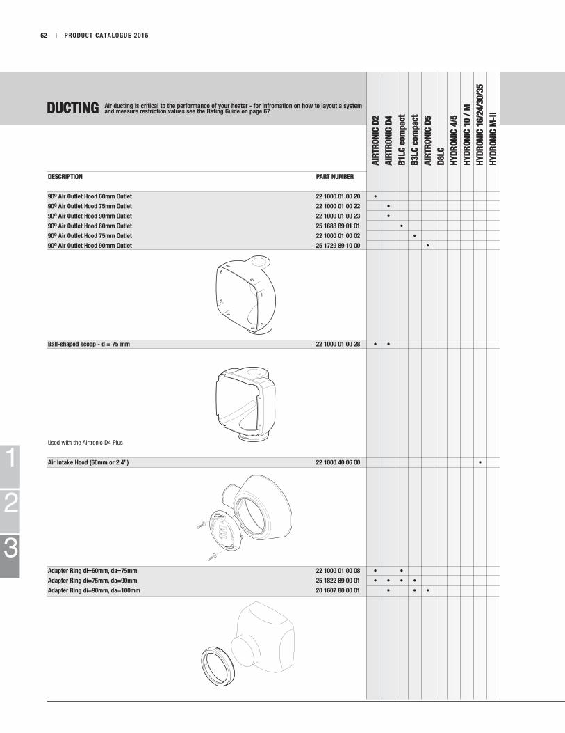
DUCTING
AIR
TR
ON
IC D
2
AIR
TR
ON
IC D
4
B1LC
com
pact
B3LC
com
pact
AIR
TR
ON
IC D
5
D8LC
HY
DR
ON
IC 4
/5
HY
DR
ON
IC 1
0 /
M
HY
DR
ON
IC 1
6/2
4/3
0/3
5
HY
DR
ON
IC M
-II
1
2
3
| PRODUCT CATALOGUE 201562
DESCRIPTION PART NUMBER
90o Air Outlet Hood 60mm Outlet 22 1000 01 00 20 •
90o Air Outlet Hood 75mm Outlet 22 1000 01 00 22 •
90o Air Outlet Hood 90mm Outlet 22 1000 01 00 23 •
90o Air Outlet Hood 60mm Outlet 25 1688 89 01 01 •
90o Air Outlet Hood 75mm Outlet 22 1000 01 00 02 •
90o Air Outlet Hood 90mm Outlet 25 1729 89 10 00 •
Ball-shaped scoop - d = 75 mm 22 1000 01 00 28 • •
Used with the Airtronic D4 Plus
Air Intake Hood (60mm or 2.4”) 22 1000 40 06 00 •
Adapter Ring di=60mm, da=75mm 22 1000 01 00 08 • •
Adapter Ring di=75mm, da=90mm 25 1822 89 00 01 • • • •
Adapter Ring di=90mm, da=100mm 20 1607 80 00 01 • • •
Air ducting is critical to the performance of your heater - for infromation on how to layout a systemand measure restriction values see the Rating Guide on page 67
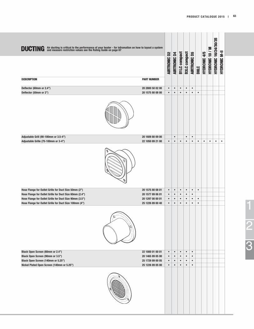
DUCTING
AIR
TR
ON
IC D
2
AIR
TR
ON
IC D
4
B1LC
com
pact
B3LC
com
pact
AIR
TR
ON
IC D
5
D8LC
HY
DR
ON
IC 4
/5
HY
DR
ON
IC 1
0 /
M
HY
DR
ON
IC 1
6/2
4/3
0/3
5
HY
DR
ON
IC M
-II
1
2
3
PRODUCT CATALOGUE 2015 | 63
DESCRIPTION PART NUMBER
Deflector (60mm or 2.4”) 20 2800 50 02 00 • • • • •
Deflector (50mm or 2”) 20 1575 80 08 00 • • • • • •
Adjustable Grill (90-100mm or 3.5-4”) 20 1609 80 09 00 • • •
Adjustable Grille (75-100mm or 3-4”) 22 1050 89 21 00 • • • • • • • • • •
Hose Flange for Outlet Grille for Duct Size 50mm (2”) 20 1575 80 08 01 • • • • • •
Hose Flange for Outlet Grille for Duct Size 60mm (2.4”) 20 1577 89 06 01 • • • • •
Hose Flange for Outlet Grille for Duct Size 90mm (3.5”) 20 1297 00 00 01 • • • • • •
Hose Flange for Outlet Grille for Duct Size 100mm (4”) 25 1226 89 00 40 • • • • • •
Black Open Screen (60mm or 2.4”) 22 1000 01 00 01 • • • • •
Black Open Screen (90mm or 3.5”) 20 1465 89 05 00 • • • • •
Black Open Screen (140mm or 5.25”) 25 1729 89 00 05 • • • • •
Nickel Plated Open Screen (140mm or 5.25”) 25 1226 89 05 00 • • • • •
Air ducting is critical to the performance of your heater - for infromation on how to layout a systemand measure restriction values see the Rating Guide on page 67
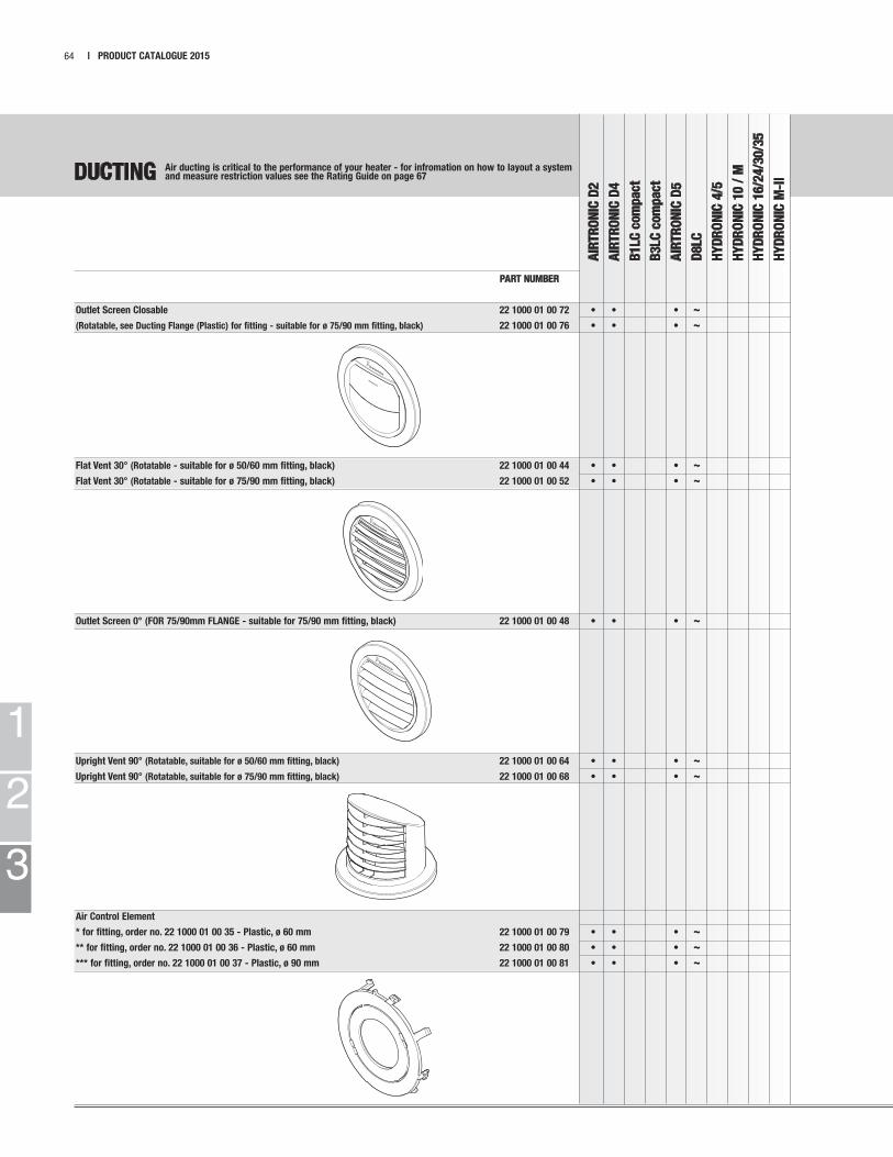
1
2
3
DUCTING
AIR
TR
ON
IC D
2
AIR
TR
ON
IC D
4
B1LC
com
pact
B3LC
com
pact
AIR
TR
ON
IC D
5
D8LC
HY
DR
ON
IC 4
/5
HY
DR
ON
IC 1
0 /
M
HY
DR
ON
IC 1
6/2
4/3
0/3
5
HY
DR
ON
IC M
-II
| PRODUCT CATALOGUE 201564
PART NUMBER
Outlet Screen Closable 22 1000 01 00 72 • • • ~
(Rotatable, see Ducting Flange (Plastic) for fitting - suitable for ø 75/90 mm fitting, black) 22 1000 01 00 76 • • • ~
Flat Vent 30° (Rotatable - suitable for ø 50/60 mm fitting, black) 22 1000 01 00 44 • • • ~
Flat Vent 30° (Rotatable - suitable for ø 75/90 mm fitting, black) 22 1000 01 00 52 • • • ~
Outlet Screen 0° (FOR 75/90mm FLANGE - suitable for 75/90 mm fitting, black) 22 1000 01 00 48 • • • ~
Upright Vent 90° (Rotatable, suitable for ø 50/60 mm fitting, black) 22 1000 01 00 64 • • • ~
Upright Vent 90° (Rotatable, suitable for ø 75/90 mm fitting, black) 22 1000 01 00 68 • • • ~
Air Control Element
* for fitting, order no. 22 1000 01 00 35 - Plastic, ø 60 mm 22 1000 01 00 79 • • • ~
** for fitting, order no. 22 1000 01 00 36 - Plastic, ø 60 mm 22 1000 01 00 80 • • • ~
*** for fitting, order no. 22 1000 01 00 37 - Plastic, ø 90 mm 22 1000 01 00 81 • • • ~
Air ducting is critical to the performance of your heater - for infromation on how to layout a systemand measure restriction values see the Rating Guide on page 67
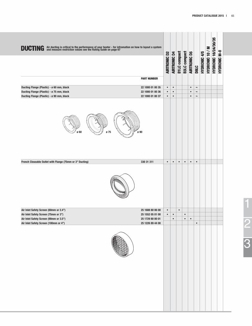
1
2
3
ø 60 ø 75 ø 90
DUCTING
AIR
TR
ON
IC D
2
AIR
TR
ON
IC D
4
B1LC
com
pact
B3LC
com
pact
AIR
TR
ON
IC D
5
D8LC
HY
DR
ON
IC 4
/5
HY
DR
ON
IC 1
0 /
M
HY
DR
ON
IC 1
6/2
4/3
0/3
5
HY
DR
ON
IC M
-II
PRODUCT CATALOGUE 2015 | 65
PART NUMBER
Ducting Flange (Plastic) - ø 60 mm, black 22 1000 01 00 35 • • • ~
Ducting Flange (Plastic) - ø 75 mm, black 22 1000 01 00 36 • • • ~
Ducting Flange (Plastic) - ø 90 mm, black 22 1000 01 00 37 • • • ~
French Closeable Outlet with Flange (75mm or 3” Ducting) 330 31 311 • • • • • •
Air Inlet Safety Screen (60mm or 2.4”) 25 1688 80 06 00 • •
Air Inlet Safety Screen (75mm or 3”) 25 1552 05 01 00 • • •
Air Inlet Safety Screen (90mm or 3.5”) 25 1729 80 00 01 • • •
Air Inlet Safety Screen (100mm or 4”) 25 1226 89 44 00 •
Air ducting is critical to the performance of your heater - for infromation on how to layout a systemand measure restriction values see the Rating Guide on page 67
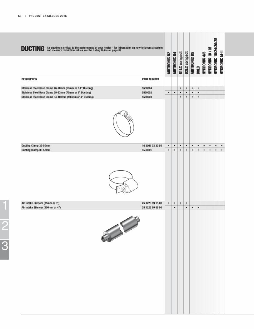
DUCTING
AIR
TR
ON
IC D
2
AIR
TR
ON
IC D
4
B1LC
com
pact
B3LC
com
pact
AIR
TR
ON
IC D
5
D8LC
HY
DR
ON
IC 4
/5
HY
DR
ON
IC 1
0 /
M
HY
DR
ON
IC 1
6/2
4/3
0/3
5
HY
DR
ON
IC M
-II
1
2
3
| PRODUCT CATALOGUE 201566
DESCRIPTION PART NUMBER
Stainless Steel Hose Clamp 46-70mm (60mm or 2.4” Ducting) 5550004 • • • •
Stainless Steel Hose Clamp 59-83mm (75mm or 3” Ducting) 5550002 • • • • • •
Stainless Steel Hose Clamp 84-108mm (100mm or 4” Ducting) 5550003 • • • •
Ducting Clamp 32-50mm 10 2067 03 20 50 • • • • • • • • • •
Ducting Clamp 33-57mm 5550001 • • • • • • • • • •
Air Intake Silencer (75mm or 3”) 25 1226 89 15 00 • • • •
Air Intake Silencer (100mm or 4”) 25 1226 89 56 00 • • • •
Air ducting is critical to the performance of your heater - for infromation on how to layout a systemand measure restriction values see the Rating Guide on page 67

DUCTING
AIR
TR
ON
IC D
2
AIR
TR
ON
IC D
4
B1LC
com
pact
B3LC
com
pact
AIR
TR
ON
IC D
5
D8LC
HY
DR
ON
IC 4
/5
HY
DR
ON
IC 1
0 /
M
HY
DR
ON
IC 1
6/2
4/3
0/3
5
HY
DR
ON
IC M
-II
1
2
3
PRODUCT CATALOGUE 2015 | 67
DESCRIPTION PART NUMBER
Combustion Air Intake Flex Hose 30mm ID 10 2114 25 00 00 • per mtr
End Cap 25 1480 89 04 00 •
Hose Comb. Air 25mm (1m) 360 00 006 • •
Hose - 20mm APK Comb Air (1m) 360 00 099 •
Plastic “T” Piece, 60mmx60mmx60mm or 2.4”x2.4”x2.4” 25 1688 89 00 02 • •
Plastic “T” Piece, d = 75 mm 22 1000 01 00 27 • •
Plastic “T” Piece, d = 90 mm 22 1000 01 00 26 •
Plastic “Y” Piece, d =60mm, d =50mm 25 1688 89 00 03 • • 1
Metal “Y” Piece, d =75mm, d =50mm 25 1482 80 08 00 • • • • • • 1
Plastic “Y” Piece, d =75mm, d =60mm 22 1000 01 00 82 • • 2
Plastic “Y” Piece, d =90mm, d =60mm 22 1000 01 00 83 • • ~ 2
Plastic “Y” Piece, d =90mm, d =75mm 22 1000 01 00 84 • 2
Air ducting is critical to the performance of your heater - for infromation on how to layout a systemand measure restriction values see the Rating Guide on pages 75 - 85.

DUCTING
AIR
TR
ON
IC D
2
AIR
TR
ON
IC D
4
B1LC
com
pact
B3LC
com
pact
AIR
TR
ON
IC D
5
D8LC
HY
DR
ON
IC 4
/5
HY
DR
ON
IC 1
0 /
M
HY
DR
ON
IC 1
6/2
4/3
0/3
5
HY
DR
ON
IC M
-II
1
2
3
| PRODUCT CATALOGUE 201568
DESCRIPTION PART NUMBER
Plastic Reducer di=60mm, D=75mm 25 1688 89 00 10 • • • • •
Plastic Reducer di=75mm, D=100mm 25 1226 89 00 47 • • • • • •
Plastic Reducer di=75mm, D=50mm 25 1226 89 00 46 • • • • •
Plastic Reducer di=75mm, D=60mm 25 1226 89 00 50 • • • • • •
Plastic Reducer di=100mm, D=50mm 25 1226 89 00 48 • • • • •
Operating Cable for 330 00 174 REQUIRES air regulating valve 22 1000 01 03 00 • • • • •
Air Regulating Valve 60mm 330 00 174 • • •
Air Regulating Valve 90mm REQUIRES operating cable 330 00 175 • • • • •
Air ducting is critical to the performance of your heater - for infromation on how to layout a systemand measure restriction values see the Rating Guide on pages 75 - 85.

COOLANT PUMPS
AIR
TR
ON
IC D
2
AIR
TR
ON
IC D
4
B1LC
com
pact
B3LC
com
pact
AIR
TR
ON
IC D
5
D8LC
HY
DR
ON
IC 4
/5
HY
DR
ON
IC 1
0 /
M
HY
DR
ON
IC 1
6/2
4/3
0/3
5
HY
DR
ON
IC M
-II
1
2
3
PRODUCT CATALOGUE 2015 | 69
DESCRIPTION PART NUMBER
Coolant Pump (700 L/hr) 12 volt 25 1815 25 01 00 •
Coolant Pump (700 L/hr) 24 volt 25 1816 25 01 00 •
Coolant Pump (800 L/hr) 12 volt 25 2275 25 00 00 •
Coolant Pump (900 L/hr) 24 volt 25 2009 25 00 00 •
Flowtronic Coolant Pump (5000 L/hr) 24 volt 25 2488 26 00 00 •
High Capacity Pump 12 volt Albany (2280 L/hr) 20 2900 60 01 39 • •
High Capacity Pump 24 volt Albany (2280 L/hr) 20 2900 70 01 40 • •
Flowtronic Coolant Pump 24 volt (6000 L/hr) 25 2488 25 00 00 •
Water Check Valve D = 20 mm, d = 20 mm 22 1000 10 07 00 • • •
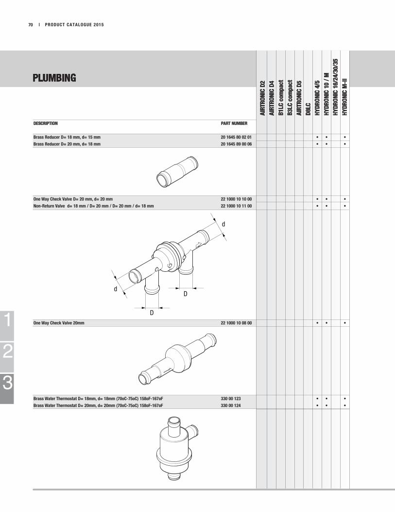
PLUMBING
AIR
TR
ON
IC D
2
AIR
TR
ON
IC D
4
B1LC
com
pact
B3LC
com
pact
AIR
TR
ON
IC D
5
D8LC
HY
DR
ON
IC 4
/5
HY
DR
ON
IC 1
0 /
M
HY
DR
ON
IC 1
6/2
4/3
0/3
5
HY
DR
ON
IC M
-II
1
2
3
| PRODUCT CATALOGUE 201570
DESCRIPTION PART NUMBER
Brass Reducer D= 18 mm, d= 15 mm 20 1645 80 02 01 • • •
Brass Reducer D= 20 mm, d= 18 mm 20 1645 89 00 06 • • •
One Way Check Valve D= 20 mm, d= 20 mm 22 1000 10 10 00 • • •
Non-Return Valve d= 18 mm / D= 20 mm / D= 20 mm / d= 18 mm 22 1000 10 11 00 • • •
One Way Check Valve 20mm 22 1000 10 08 00 • • •
Brass Water Thermostat D= 18mm, d= 18mm (70oC-75oC) 158oF-167oF 330 00 123 • • •
Brass Water Thermostat D= 20mm, d= 20mm (70oC-75oC) 158oF-167oF 330 00 124 • • •

2
1
PLUMBING
AIR
TR
ON
IC D
2
AIR
TR
ON
IC D
4
B1LC
com
pact
B3LC
com
pact
AIR
TR
ON
IC D
5
D8LC
HY
DR
ON
IC 4
/5
HY
DR
ON
IC 1
0 /
M
HY
DR
ON
IC 1
6/2
4/3
0/3
5
HY
DR
ON
IC M
-II
1
2
3
PRODUCT CATALOGUE 2015 | 71
DESCRIPTION PART NUMBER
5 Way Valve with Thermostat 25 2014 80 72 00 • • • • 1
6 Way Valve with Thermostat 25 2014 80 62 00 • • • • 2
1 2
Conversion Kit for Water Pump 22 1000 10 01 00 •
Clamp 16-25mm ID 10 10 2067 01 60 25 • • • • • • • • • •
Clamp 20-32mm ID 10 10 2066 02 00 32 • • • • • • • • • •
Pump Clamp 48mm 22 22 1000 50 10 00 • • 1
Rubber Ring for Large FMP 20 1449 00 10 01 • 2
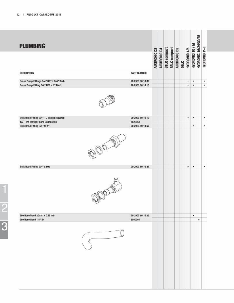
PLUMBING
AIR
TR
ON
IC D
2
AIR
TR
ON
IC D
4
B1LC
com
pact
B3LC
com
pact
AIR
TR
ON
IC D
5
D8LC
HY
DR
ON
IC 4
/5
HY
DR
ON
IC 1
0 /
M
HY
DR
ON
IC 1
6/2
4/3
0/3
5
HY
DR
ON
IC M
-II
1
2
3
| PRODUCT CATALOGUE 201572
DESCRIPTION PART NUMBER
Brass Pump Fittings 3/4” NPT x 3/4” Barb 20 2900 60 10 02 • • •
Brass Pump Fitting 3/4” NPT x 1” Barb 20 2900 60 10 15 • • •
Bulk Head Fitting 3/4” - 2 pieces required 20 2900 60 10 10 • • •
1/2 - 3/4 Straight Barb Connection 5520068
Bulk Head Fitting 3/4” to 1” 20 2900 60 10 57 • •
Bulk Head Fitting 3/4” x 90o 20 2900 60 10 37 • • •
90o Hose Bend 20mm x 0.29 mtr 20 2900 60 10 23 •
90o Hose Bend 1.5” ID 5560001 •
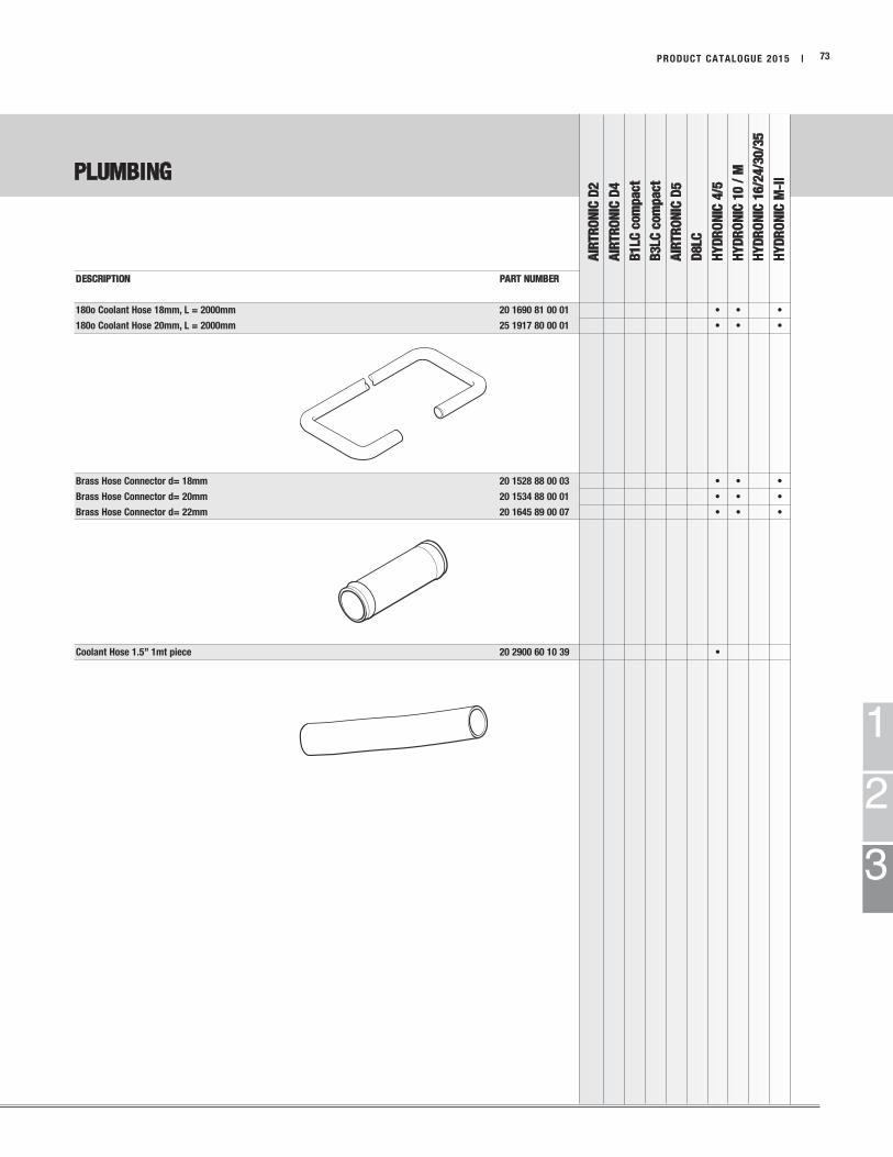
PLUMBING
AIR
TR
ON
IC D
2
AIR
TR
ON
IC D
4
B1LC
com
pact
B3LC
com
pact
AIR
TR
ON
IC D
5
D8LC
HY
DR
ON
IC 4
/5
HY
DR
ON
IC 1
0 /
M
HY
DR
ON
IC 1
6/2
4/3
0/3
5
HY
DR
ON
IC M
-II
1
2
3
PRODUCT CATALOGUE 2015 | 73
DESCRIPTION PART NUMBER
180o Coolant Hose 18mm, L = 2000mm 20 1690 81 00 01 • • •
180o Coolant Hose 20mm, L = 2000mm 25 1917 80 00 01 • • •
Brass Hose Connector d= 18mm 20 1528 88 00 03 • • •
Brass Hose Connector d= 20mm 20 1534 88 00 01 • • •
Brass Hose Connector d= 22mm 20 1645 89 00 07 • • •
Coolant Hose 1.5” 1mt piece 20 2900 60 10 39 •

FUELTANK
57
5
38
8
6
6
2
2
FUELTANK
55
6
Optional - and only iflength specifications are
adhed to
611
11
FUELTANK
5
34
2
6 6
2
3
11
FUELTANK
11
2
2
4
3
1 3
1. Fuel Pipe Reducer
2. Clamp 9mm
3. Rubber Connector 3.5mm
4. White Plastic Fuel Line 2.0mm
5. Rubber Connector / Fuel Line 5.0mm
6. Clamp 11mm
7. Black Plastic Fuel Line 2.0mm
8. White Plastic Fuel Line 1.5mm
LEGEND
1
2
3
FUEL SYSTEM GUIDE
74 | PRODUCT CATALOGUE 2015
This guide is to help in selecting which size fuel line, rubber hose and clamps are required for a specific heating system.
Refer to the Fuel System section of this manual for specific part numbers.
Cross-reference this information with the corresponding heater manual for maximum height and length specifications.
AIRTRONIC 2
AIRTRONIC 4
B1LC compact
B3LC compact
D/B5LC
D8LC
HYDRONIC 10
HYDRONIC 4
HYDRONIC 5
HYDRONIC 16
HYDRONIC 24
HYDRONIC 30
HYDRONIC 35
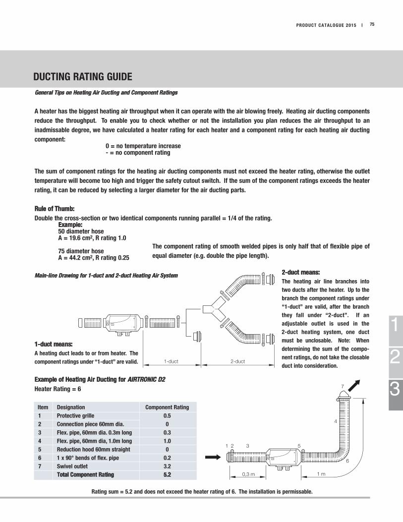
1-duct 2-duct
7
75
Main-line Drawing for 1-duct and 2-duct Heating Air System
The component rating of smooth welded pipes is only half that of flexible pipe of
equal diameter (e.g. double the pipe length).
2-duct means:
The heating air line branches into
two ducts after the heater. Up to the
branch the component ratings under
“1-duct” are valid, after the branch
they fall under “2-duct”. If an
adjustable outlet is used in the
2-duct heating system, one duct
must be unclosable. Note: When
determining the sum of the compo-
nent ratings, do not take the closable
duct into consideration.
1-duct means:
A heating duct leads to or from heater. The
component ratings under “1-duct” are valid.
DUCTING RATING GUIDE
PRODUCT CATALOGUE 2015 |
1
2
3
General Tips on Heating Air Ducting and Component Ratings
A heater has the biggest heating air throughput when it can operate with the air blowing freely. Heating air ducting components
reduce the throughput. To enable you to check whether or not the installation you plan reduces the air throughput to an
inadmissable degree, we have calculated a heater rating for each heater and a component rating for each heating air ducting
component:0 = no temperature increase- = no component rating
The sum of component ratings for the heating air ducting components must not exceed the heater rating, otherwise the outlet
temperature will become too high and trigger the safety cutout switch. If the sum of the component ratings exceeds the heater
rating, it can be reduced by selecting a larger diameter for the air ducting parts.
Rule of Thumb:
Double the cross-section or two identical components running parallel = 1/4 of the rating.Example:50 diameter hoseA = 19.6 cm2, R rating 1.0
75 diameter hoseA = 44.2 cm2, R rating 0.25
Example of Heating Air Ducting for AIRTRONIC D2
Heater Rating = 6
Item Designation Component Rating
1 Protective grille 0.5
2 Connection piece 60mm dia. 0
3 Flex. pipe, 60mm dia. 0.3m long 0.3
4 Flex. pipe, 60mm dia, 1.0m long 1.0
5 Reduction hood 60mm straight 0
6 1 x 90° bends of flex. pipe 0.2
7 Swivel outlet 3.2
Total Component Rating 5.2
Rating sum = 5.2 and does not exceed the heater rating of 6. The installation is permissable.
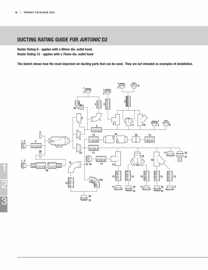
3
2
20
3
2
13
12
13 13 13 13 13
1
1
1
3a
7
1
8 9
9
10
141615
15
15
6
4
1 1918
525
21
24
3
2
3
2
2
11 21
13
17
17
17 17 17
3
13
13
13a
22
16
16
15
16
26 23
1
2
3
76 | PRODUCT CATALOGUE 2015
Heater Rating 6 - applies with a 60mm dia. outlet hood.
Heater Rating 12 - applies with a 75mm dia. outlet hood
The sketch shows how the most important air ducting parts that can be used. They are not intended as examples of installation.
DUCTING RATING GUIDE FOR AIRTONIC D2
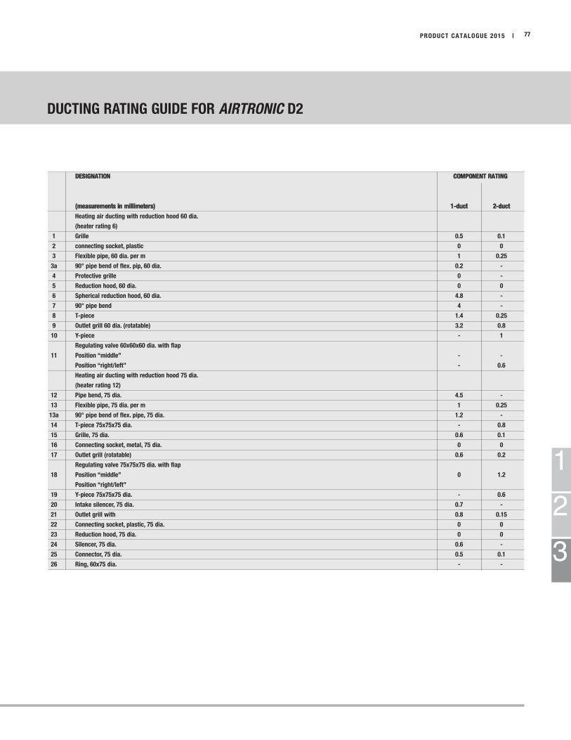
1
2
3
DESIGNATION COMPONENT RATING
(measurements in millimeters) 1-duct 2-duct
Heating air ducting with reduction hood 60 dia.
(heater rating 6)
1 Grille 0.5 0.1
2 connecting socket, plastic 0 0
3 Flexible pipe, 60 dia. per m 1 0.25
3a 90° pipe bend of flex. pip, 60 dia. 0.2 -
4 Protective grille 0 -
5 Reduction hood, 60 dia. 0 0
6 Spherical reduction hood, 60 dia. 4.8 -
7 90° pipe bend 4 -
8 T-piece 1.4 0.25
9 Outlet grill 60 dia. (rotatable) 3.2 0.8
10 Y-piece - 1
Regulating valve 60x60x60 dia. with flap
11 Position “middle” - -
Position “right/left” - 0.6
Heating air ducting with reduction hood 75 dia.
(heater rating 12)
12 Pipe bend, 75 dia. 4.5 -
13 Flexible pipe, 75 dia. per m 1 0.25
13a 90° pipe bend of flex. pipe, 75 dia. 1.2 -
14 T-piece 75x75x75 dia. - 0.8
15 Grille, 75 dia. 0.6 0.1
16 Connecting socket, metal, 75 dia. 0 0
17 Outlet grill (rotatable) 0.6 0.2
Regulating valve 75x75x75 dia. with flap
18 Position “middle” 0 1.2
Position “right/left”
19 Y-piece 75x75x75 dia. - 0.6
20 Intake silencer, 75 dia. 0.7 -
21 Outlet grill with 0.8 0.15
22 Connecting socket, plastic, 75 dia. 0 0
23 Reduction hood, 75 dia. 0 0
24 Silencer, 75 dia. 0.6 -
25 Connector, 75 dia. 0.5 0.1
26 Ring, 60x75 dia. - -
PRODUCT CATALOGUE 2015 | 77
DUCTING RATING GUIDE FOR AIRTRONIC D2

32 20
3
2 11 1213
111
1a
7
18
9
10
28141615
64
1
19
5 1824
29 30 24
25
21
32
1
23
1120
21
24
3 2
3 2
21
3
2 11 12
13
17 3
22
26 13
16
22
26 3
27
3116
16 26 3
2216
23
1
2
3
78 | PRODUCT CATALOGUE 2015
Heater Rating 3 - applies with a 75mm dia. outlet hood.
Heater Rating 10 - applies with a 90mm dia. outlet hood
The sketch shows how the most important air ducting parts that can be used. They are not intended as examples of installation.
DUCTING RATING GUIDE FOR AIRTRONIC D4

1
2
3
DESIGNATION COMPONENT RATING
(measurements in millimeters) 1-duct 2-duct
Heating air ducting with reduction hood 75 dia.
(heater rating 3)
Heating air ducting with reduction hood 90 dia.
(heater rating 10) 75 90 75 90
1 Flexible pipe, 75 dia. per m 1 - 0.2 -
1a 90° pipe bend of flex. pipe, 75 dia. 0.2 - - -
2 Connecting socket, metal, 75 dia. 0.0 - 0.0 -
3 Grille 0.4 0.1 0.1 0.03
4 Grille, 75 dia. 2.0 - - -
5 Intake silencer, 75 dia. 0.8 - - -
6 Reduction hood, 75 dia. 0 - - -
7 Spherical reduction hood, 75 dia. 0.8 - - -
8 T-piece 75x75x75 dia. - - 0.5 -
Regulating valve 75x75x75 dia. with flap
9 Position “middle” - - - -
Position “right/left” - - 1.8 -
10 Branch piece 75x75x75 dia. - - 0.6 -
11 Outlet grill (rotatable) 75 dia. 0.8 - 0.2 -
12 Connector, 75 dia. 0 - 0 -
13 Outlet grill 1.1 - 0.3 -
14 Connector, 75 dia. - 0.5 - 0.1
15 Ring, 75x90 dia. 0.5 - - -
16 Flexible pipe, 90 dia. per m - 1 - 0.25
17 Connector socket, 90 dia. with grille - 0 - 0
18 Reduction hood, 90 dia. - 0 - -
19 Spherical reduction hood, 90 dia. - 5 - -
20 Round outlet, 75 dia. - - - -
21 Outlet grill (rotatable) 100 dia. - 2.1 - 0.5
22 Outlet grill (rotatable) 90 dia. - 2.2 - 0.5
23* Grille, round, 90x100 dia. - 0 - -
24 Flexible pipe, 100 dia. per m - 0.4 - -
25 Y-piece 100x100x100 dia. - - - 0.5
26 Connector, 90 dia., with exhauster pos. 13 - - - 0
Regulating valve 90x90x90 dia.
27 Position “middle” - 1.2 - -
Position “right/left” - 1.4 - -
28 Silencer, 90 dia. - 0.7 - -
29 Silencer, 100 dia. - 0.5 - -
30 Connector, 100 dia. - 0.1 - -
31 Y-piece 90x90x90 dia. - - - 0.3
32 Reduction piece, 100 dia. - 75 dia. - - - 0.8
* Pos. 23 - if used as adapter 90x100 dia., cut out the mesh.
PRODUCT CATALOGUE 2015 | 79
DUCTING RATING GUIDE FOR AIRTRONIC D4

3
2
20
20
3 3
21
1
1
9
9
78
9
10
16
15
6
4
1
19
19
18
5
28
21
21
21
24
3
2
3
2
12
13 14
11 11
17
17
17 17
17
27
25 25
26
3
2230
28
29
23
1
2
3
80 | PRODUCT CATALOGUE 2015
Heater Rating 6 - applies with a 60mm dia. outlet hood.
Heater Rating 15 - applies with a 75mm dia. outlet hood
The sketch shows how the most important air ducting parts that can be used. They are not intended as examples of installation.
DUCTING RATING GUIDE FOR B1LC COMPACT
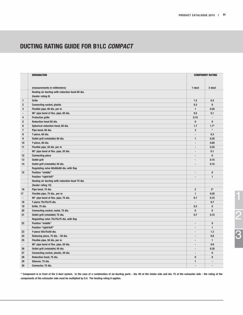
1
2
3
DUCTING RATING GUIDE FOR B1LC COMPACT
DESIGNATION COMPONENT RATING
(measurements in millimeters) 1-duct 2-duct
Heating air ducting with reduction hood 60 dia.
(heater rating 6)
1 Grille 1.2 0.4
2 Connecting socket, plastic 0.3 0
3 Flexible pipe, 60 dia. per m 1 0.25
- 90° pipe bend of flex. pipe, 60 dia. 0.5 0.1
4 Protective grille 0.15 -
5 Reduction hood 60 dia. 0 0
6 Spherical reduction hood, 60 dia. 1.7 1.7*
7 Pipe bend, 60 dia. 3 *
8 T-piece, 60 dia. - 0.3
9 Outlet grill (rotatable) 60 dia. 1 0.25
10 Y-piece, 60 dia. - 0.85
11 Flexible pipe, 50 dia. per m - 0.25
- 90° pipe bend of flex. pipe, 50 dia. - 0.1
12 Connecting piece - 0
13 Outlet grill - 0.15
14 Outlet grill (rotatable) 50 dia. - 0.15
Regulating valve 60x60x60 dia. with flap
15 Position “middle” - 0
Position “right/left” - 1
Heating air ducting with reduction hood 75 dia.
(heater rating 15)
16 Pipe bend, 75 dia. 2 2*
17 Flexible pipe, 75 dia., per m 1 0.25
- 90° pipe bend of flex. pipe, 75 dia. 0.7 0.15
18 T-piece 75x75x75 dia. - 0.7
19 Grille, 75 dia. 0.3 0
20 Connecting socket, metal, 75 dia. 0 0
21 Outlet grill (rotatable) 75 dia. 0.7 0.15
Regulating valve 75x75x75 dia. with flap
22 Position “middle” - 0
Position “right/left” - 1
23 Y-piece 50x75x50 dia. - 1.3
24 Reducing piece, 75 dia. - 50 dia. - 0.8
25 Flexible pipe, 50 dia. per m - 1
- 90° pipe bend of flex. pipe, 50 dia. - 0.8
26 Outlet grill (rotatable) 50 dia. - 0.35
27 Connecting socket, plastic, 50 dia. - 0
28 Reduction hood, 75 dia. 0 0
29 Silencer, 75 dia. 1 -
30 Connector, 75 dia. - -
* Component is in front of the 2-duct system. In the case of a combination of air-ducting parts - dia. 60 at the intake side and dia. 75 at the exhauster side - the rating of the
components at the exhauster side must be multiplied by 0.4. The heating rating 6 applies.
PRODUCT CATALOGUE 2015 | 81
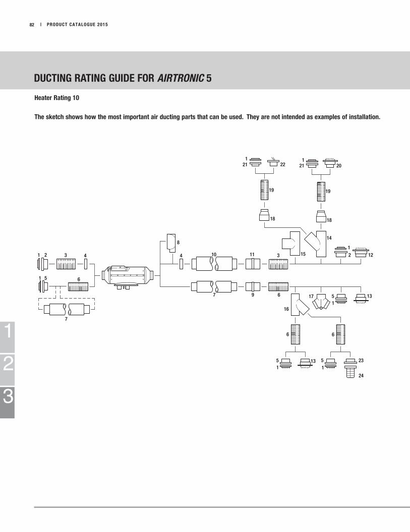
1 2 3 4
51 6
7
8
4 10
7 9 6
16
6
51
13 51
6
17 51
13
23
24
1212
14
18
1919
18
3 1511
20211
22211
1
2
3
82 | PRODUCT CATALOGUE 2015
Heater Rating 10
The sketch shows how the most important air ducting parts that can be used. They are not intended as examples of installation.
DUCTING RATING GUIDE FOR AIRTRONIC 5
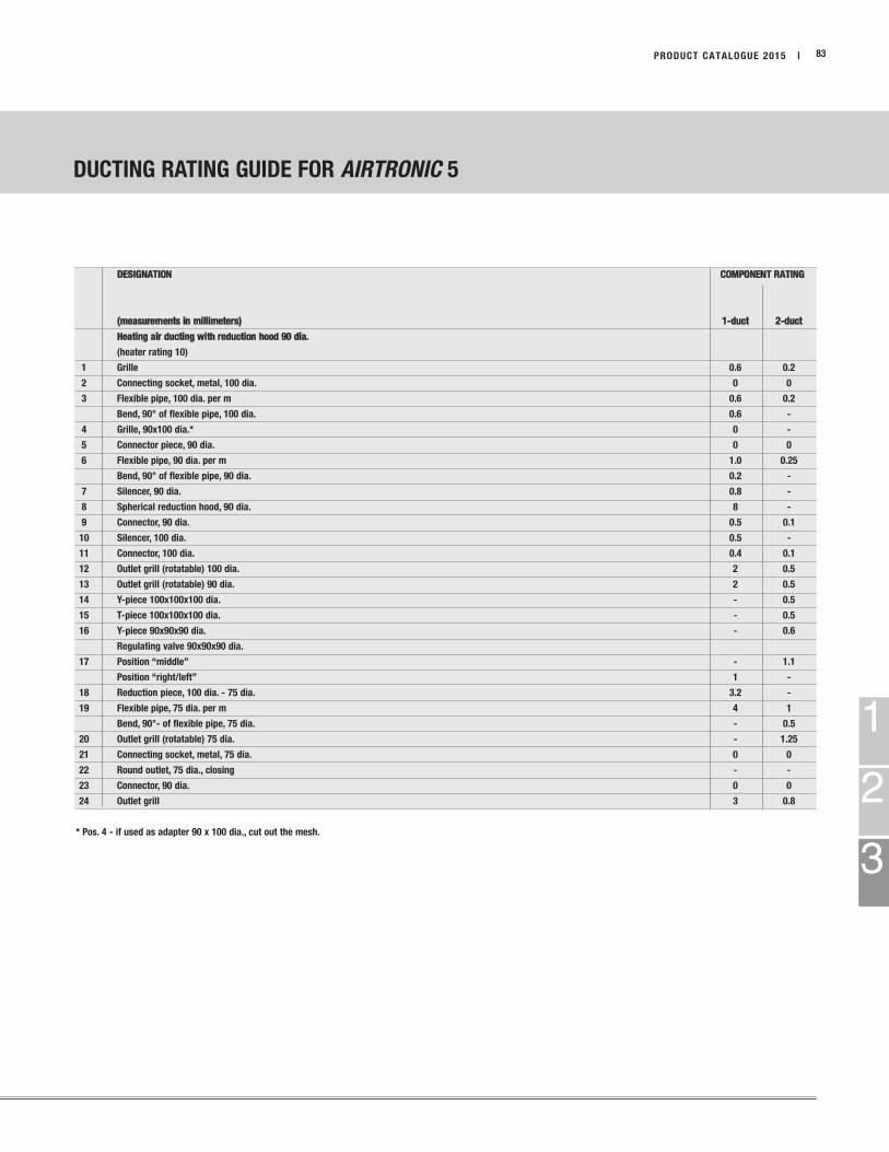
1
2
3
DESIGNATION COMPONENT RATING
(measurements in millimeters) 1-duct 2-duct
Heating air ducting with reduction hood 90 dia.
(heater rating 10)
1 Grille 0.6 0.2
2 Connecting socket, metal, 100 dia. 0 0
3 Flexible pipe, 100 dia. per m 0.6 0.2
Bend, 90° of flexible pipe, 100 dia. 0.6 -
4 Grille, 90x100 dia.* 0 -
5 Connector piece, 90 dia. 0 0
6 Flexible pipe, 90 dia. per m 1.0 0.25
Bend, 90° of flexible pipe, 90 dia. 0.2 -
7 Silencer, 90 dia. 0.8 -
8 Spherical reduction hood, 90 dia. 8 -
9 Connector, 90 dia. 0.5 0.1
10 Silencer, 100 dia. 0.5 -
11 Connector, 100 dia. 0.4 0.1
12 Outlet grill (rotatable) 100 dia. 2 0.5
13 Outlet grill (rotatable) 90 dia. 2 0.5
14 Y-piece 100x100x100 dia. - 0.5
15 T-piece 100x100x100 dia. - 0.5
16 Y-piece 90x90x90 dia. - 0.6
Regulating valve 90x90x90 dia.
17 Position “middle” - 1.1
Position “right/left” 1 -
18 Reduction piece, 100 dia. - 75 dia. 3.2 -
19 Flexible pipe, 75 dia. per m 4 1
Bend, 90°- of flexible pipe, 75 dia. - 0.5
20 Outlet grill (rotatable) 75 dia. - 1.25
21 Connecting socket, metal, 75 dia. 0 0
22 Round outlet, 75 dia., closing - -
23 Connector, 90 dia. 0 0
24 Outlet grill 3 0.8
* Pos. 4 - if used as adapter 90 x 100 dia., cut out the mesh.
PRODUCT CATALOGUE 2015 | 83
DUCTING RATING GUIDE FOR AIRTRONIC 5
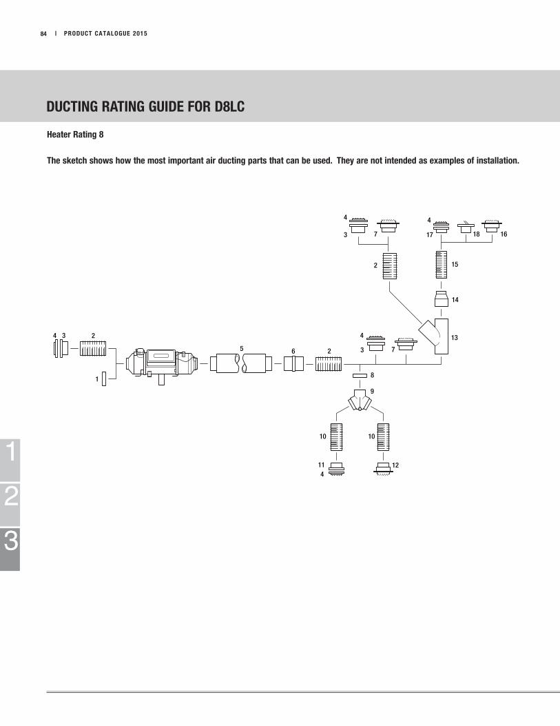
4 3 2
1
5 6 2
4
3 7
8
9
13
14
15
161817
4
73
4
2
10 10
114
121
2
3
DUCTING RATING GUIDE FOR D8LC
84 | PRODUCT CATALOGUE 2015
Heater Rating 8
The sketch shows how the most important air ducting parts that can be used. They are not intended as examples of installation.

1
2
3
DUCTING RATING GUIDE FOR D8LC
PRODUCT CATALOGUE 2015 | 85
DESIGNATION COMPONENT RATING
(measurements in millimeters) 1-duct 2-duct
Heating air ducting with reduction hood 100 dia.
(heater rating 8)
1 Grille, 100 dia. 0.1 -
2 Flexible pipe, 100 dia., per m 1.0 0.25
- Pipe bend, 90°, of flex. pipe, 100 dia. 0.5 0.15
3 Connecting socket, metal, 100 dia. 0 0
4 Grille, painted, 100 dia. 1.8 0.1
- Grille, nickel-plated, 100 dia. 1.8 0.1
5 Silencer, 100 dia. 1.1 0.25
6 Connector socket, 100 dia. 0.5 0.1
7 Outlet grill (rotatable), 100 dia. 5.5 1.2
8 Grille, 90x100 dia.* 0 -
9 Regulating valve 100x100x100 dia. - 2.6
10 Flexible pipe, 90 dia., per m 3 0.8
11 Connecting socket, metal, 90 dia. 0 0
12 Outlet grill (rotatable) 90 dia. - 1.4
13 Y-pipe 100x100x100 dia. - 0.4
14 Reduction piece, 100 dia. - 74 dia. 6.1 -
15 Flexible pipe 75 dia. per m - 2
- Pipe bend, 90° of flex. pipe, 75 dia. - 1.1
16 Outlet grill (rotatable) 75 dia. - -
17 Connector socket, 75 dia. 0 0
18 Connecting socket, metal, 75 dia. - -
*Pos. 8 - if used as adapter 90x100 dia., cut out the mesh.

Eberspächer
Espar Products, Inc.
(800) 387-4800
(905) 670-0960
(905) 670-0728 Fax
www.eberspaecher-na.com
Ver
sio
n 1
0/2
015
Su
bje
ct t
o c
ha
ng
e w
ith
ou
t n
oti
fica
tion