Production and characterization of polycaprolactone nanofibers via forcespinning™ technology
C A R B O N 4 9 ( 2 0 1 1 ) 1 8 7 3 – 1 8 8 3
. sc iencedi rec t . com
ava i lab le a t wwwjournal homepage: www.elsevier .com/ locate /carbon
Processing and properties of polymer composites containingaligned functionalized carbon nanofibers
Chee-Sern Lim, Alejandro J. Rodriguez, Mauricio E. Guzman, Joseph D. Schaefer,Bob Minaie *
Department of Mechanical Engineering, Wichita State University, Wichita, KS 67260, USA
A R T I C L E I N F O
Article history:
Received 23 September 2010
Accepted 5 January 2011
Available online 11 January 2011
0008-6223/$ - see front matter � 2011 Elsevidoi:10.1016/j.carbon.2011.01.010
* Corresponding author: Fax: +1 316 978 3236E-mail address: [email protected]
A B S T R A C T
AC electric field was used to align functionalized carbon nanofibers (CNFs), carboxylic acid-
functionalized CNFs (O-CNFs) and amine-functionalized CNFs (A-CNFs), in an epoxy resin.
The resulting composites were characterized for dispersion and alignment structure as
well as for their mechanical and electrical properties in the CNF alignment direction. Opti-
cal images of the composites revealed uniform distribution and alignment of the CNFs in
the direction of the electric field. Due to the similarity in the alignment structure, it was
observed that alignment of the functionalized CNFs was independent of the functional
groups attached to the CNFs. Compression tests (parallel to the direction of the aligned
A-CNFs) of A-CNF/epoxy composites showed an increase of 19% in compressive modulus
and 9% in compressive strength at a CNF concentration of 4.5 wt.%, with respect to the neat
composite. Electrical resistivity of composites measured parallel to the direction of aligned
CNFs (containing up to 4.5 wt.% O-CNFs and A-CNFs) were found to be approximately three
orders of magnitude lower than composites with non-aligned CNFs. The electrical resistiv-
ity percolation threshold for composites with aligned O-CNFs and A-CNFs occurred at
approximately 0.75 wt.%. Discussion regarding the contribution of CNF type towards the
mechanical and electrical properties is also presented.
� 2011 Elsevier Ltd. All rights reserved.
1. Introduction
Carbon nanofibers (CNFs) continue to excel as nano-rein-
forcement in polymeric composites due to their high aspect
ratio and unique combination of mechanical [1,2] and electri-
cal properties [3,4]. CNF/polymer composites have been syn-
thesized for several applications such as electromagnetic
interference (EMI) shielding [5], electrostatic dissipation [6],
rubber reinforcement [7] and even biological implants [8]. In
addition, CNFs are also being incorporated into fiber-rein-
forced composites to primarily enhance through-thickness
direction properties [9–13]. Combining their low cost and
availability, CNFs are potential building blocks in fabricating
polymeric composites with improved properties.
er Ltd. All rights reserved
.(B. Minaie).
In order to manufacture CNF/polymer composites with
outstanding properties, the following conditions must be
met: (1) CNFs must be uniformly dispersed in the matrix so
that the external load can be transferred and distributed to
the nanofibers, and (2) the existence of chemical linkage be-
tween CNFs and matrix for better load transfer as well as pre-
venting CNFs from slipping relative to the matrix when
sustaining external load. However, the aforementioned con-
ditions are often challenged by CNF agglomeration due to
their high aspect ratio coupled with van der Waals interac-
tion. Therefore, to uniformly disperse the CNFs in polymer
resins and provide effective chemical compatibility between
them and the matrix, different mixing [14–16] and functional-
ization [17–19] schemes have been employed.
.
1874 C A R B O N 4 9 ( 2 0 1 1 ) 1 8 7 3 – 1 8 8 3
In recent years, studies have shown that carbon nanopar-
ticle/polymer composites with outstanding mechanical and
electrical properties can be fabricated at lower nanoparticle
content by selectively orienting them into a preferential direc-
tion through AC electric field [20–24], magnetic field [25,26],
flow induction [27,28], in situ growth [29,30] and mechanical
stretching [31]. Among these methods, the use of AC electric
field is one of the most promising methods since it has proven
to be effective in promoting alignment of carbon nanoparticle
in organic solvent [22] or polymer resins [20,21,23]. Experi-
ments aimed at aligning CNFs using AC electric field in poly-
mer resins have so far been limited to pristine CNFs [23] and
none have reported the study of composites with aligned
functionalized CNFs (carboxylic acid-functionalized and
amine-functionalized CNFs). Since functionalized CNFs, espe-
cially amine-functionalized CNFs, have previously been
shown to disperse uniformly in polymer resins and are capa-
ble of having high interaction with the matrix [18,19], it is
of great interest to pursue the study of the alignment effect
of these CNFs on the mechanical and electrical properties of
composites. Furthermore, no reports have shown the
mechanical properties of composites with aligned functional-
ized CNFs tailored by AC electric field.
In this work, investigation into the effect of functionalized
CNFs aligned in the direction of electric field on the mechan-
ical and electrical properties of composites was performed.
Alignment of the CNFs in the polymer resin was achieved
using AC electric field. Mixing of the CNFs with the resin
was carried out through a novel process involving a combina-
tion of high-speed shear mixing, calendering and planetary
centrifugal mixing. The resulting composites were character-
ized for dispersion and alignment, electrical resistivity, and
compressive strength and modulus parallel to the direction
of the aligned CNFs.
2. Experimental
2.1. Materials
The nanofibers used in this study were PR-24-XT-PS CNFs (Ap-
plied Science Inc.). According to the supplier, the as-received
CNFs (AR-CNFs) had an average diameter of approximately
100 nm and length of 30–100 lm, containing iron impurity of
less than 14,000 ppm and polyaromatic hydrocarbons of less
than 1 mg PAH/g fiber. EPON 862 epoxy resin and EPIKURE
W curing agent (Hexion) were selected as the two-part
epoxy-amine resin system. This system was selected because
it is widely used in aircraft industry due to its excellent
mechanical properties, adhesion and chemical resistance. A
two-part silicon rubber and a Teflon block (McMaster Carr)
were used as molds for curing the composites due to their
high electrical and temperature resistance. All other materi-
als and chemicals were obtained from Fisher Scientific and
used as-received.
2.2. Functionalization of CNFs
The procedures followed for carboxylic acid- and amine-func-
tionalization of CNFs were adapted from the literature [11,12].
Carboxylic acid-functionalized CNFs (O-CNFs) were obtained
through one step nitric acid oxidation process using AR-CNFs
as starting material. In terms of amine-functionalized CNFs
(A-CNFs), previously functionalized O-CNFs were subjected
to a two-stage procedure, which consisted of acylation using
thionyl chloride and amidation using ethylenediamine. After-
ward, both O-CNFs and A-CNFs were grinded and stored in a
desiccator until further processing. The functionalized CNFs
were characterized using Fourier transform infrared (FTIR)
spectroscopy and thermogravimetric analysis (TGA). The de-
tails and confirmation of functional groups on O-CNFs and
A-CNFs can be found in [11,12].
2.3. Preparation of functionalized CNF/epoxy mixture
In this study, composites with six different concentrations of
functionalized CNFs were studied: 0.25, 0.5, 0.75, 1.5, 3 and
4.5 wt.%. Mixing of functionalized CNFs with the resin system
was performed following a novel methodology which con-
sisted of four major steps: sonication, high-speed shear mix-
ing, calendering and planetary centrifugal mixing. To prepare
O-CNF/epoxy mixture, O-CNFs were first sonicated with
150 ml acetone for 10 min at high power followed by evapora-
tion of acetone in a convection oven until it became a semi-
dry mixture. Epoxy resin (185.92 g) was added to the mixture
and hand-stirred to saturate the O-CNFs. Then, the mixture
was homogenized in a water bath using a high-speed homog-
enizer at three different speeds for 15 min to disentangle the
large agglomerates. Subsequently, the mixture was calen-
dered by passing it through a three-roll-mill set at three dif-
ferent combinations of gap size and speed. Afterwards,
49.08 g of curing agent was added to the mixture and further
mixed using a planetary centrifugal mixer for four repetitions
at 2000 rpm (each repetition consisted of 5 min of mixing with
vacuum and 5 min of cooling at room temperature). The cen-
trifugal mixing process provided a non-intrusive method for
mixing the whole blend and removal of air bubbles using vac-
uum simultaneously.
In the case of A-CNF/epoxy mixture, A-CNFs were first son-
icated with 150 ml of ethanol for 3 min at medium power.
Then, 118.7 g of preheated epoxy resin (to reduce its viscosity)
was added to the mixture and sonicated for additional 10 min
followed by evaporation of ethanol with the assistance of
mechanical stirring on a hot plate. This mixing method was
different from the one used to mix O-CNFs due to two reasons.
First, since the sonication input was lower, additional stirring
was required to break large agglomerates. Second, because
ethanol has higher boiling point than acetone, the evaporation
process takes longer and it might induce the formation of
agglomerates in the absence of mechanical stirring. Therefore,
this process was completed with mechanical stirring to accel-
erate evaporation of ethanol and maintain uniform disper-
sion. Afterward, the blend was cooled in a freezer to
drastically increase the viscosity of the blend. In this regard,
high viscosity mixture will experience more shear mixing ef-
fect than low viscosity one during calendering and thus elim-
inate the existence of large agglomerates. The blend was then
homogenized, calendered and centrifugally mixed using the
same profile as the one followed for O-CNFs. The amount of
curing agent for the A-CNF/epoxy mixture was 31.3 g.
C A R B O N 4 9 ( 2 0 1 1 ) 1 8 7 3 – 1 8 8 3 1875
2.4. Preparation of test samples
To prepare mechanical test samples, the mixture was casted
into an in-house made silicone rubber mold followed by addi-
tional degassing process for 15 min to remove air that was
introduced during the casting process. For composites with
aligned CNFs, two stainless steel plates, which were
31.75 mm apart, were used as electrodes to apply AC
electric field. The sinusoidal AC electric field used was
630 Vpeak-to-peak/cm at 2 kHz and was applied using a combi-
nation of function generator (GW Instek) and high voltage
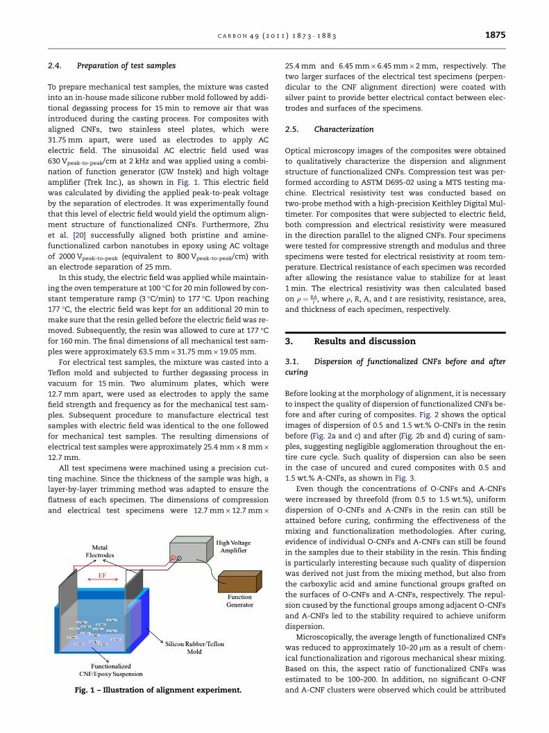
amplifier (Trek Inc.), as shown in Fig. 1. This electric field
was calculated by dividing the applied peak-to-peak voltage
by the separation of electrodes. It was experimentally found
that this level of electric field would yield the optimum align-
ment structure of functionalized CNFs. Furthermore, Zhu
et al. [20] successfully aligned both pristine and amine-
functionalized carbon nanotubes in epoxy using AC voltage
of 2000 Vpeak-to-peak (equivalent to 800 Vpeak-to-peak/cm) with
an electrode separation of 25 mm.
In this study, the electric field was applied while maintain-
ing the oven temperature at 100 �C for 20 min followed by con-
stant temperature ramp (3 �C/min) to 177 �C. Upon reaching
177 �C, the electric field was kept for an additional 20 min to
make sure that the resin gelled before the electric field was re-
moved. Subsequently, the resin was allowed to cure at 177 �Cfor 160 min. The final dimensions of all mechanical test sam-
ples were approximately 63.5 mm · 31.75 mm · 19.05 mm.
For electrical test samples, the mixture was casted into a
Teflon mold and subjected to further degassing process in
vacuum for 15 min. Two aluminum plates, which were
12.7 mm apart, were used as electrodes to apply the same
field strength and frequency as for the mechanical test sam-
ples. Subsequent procedure to manufacture electrical test
samples with electric field was identical to the one followed
for mechanical test samples. The resulting dimensions of
electrical test samples were approximately 25.4 mm · 8 mm ·12.7 mm.
All test specimens were machined using a precision cut-
ting machine. Since the thickness of the sample was high, a
layer-by-layer trimming method was adapted to ensure the
flatness of each specimen. The dimensions of compression
and electrical test specimens were 12.7 mm · 12.7 mm ·
Fig. 1 – Illustration of alignment experiment.
25.4 mm and 6.45 mm · 6.45 mm · 2 mm, respectively. The
two larger surfaces of the electrical test specimens (perpen-
dicular to the CNF alignment direction) were coated with
silver paint to provide better electrical contact between elec-
trodes and surfaces of the specimens.
2.5. Characterization
Optical microscopy images of the composites were obtained
to qualitatively characterize the dispersion and alignment
structure of functionalized CNFs. Compression test was per-
formed according to ASTM D695-02 using a MTS testing ma-
chine. Electrical resistivity test was conducted based on
two-probe method with a high-precision Keithley Digital Mul-
timeter. For composites that were subjected to electric field,
both compression and electrical resistivity were measured
in the direction parallel to the aligned CNFs. Four specimens
were tested for compressive strength and modulus and three
specimens were tested for electrical resistivity at room tem-
perature. Electrical resistance of each specimen was recorded
after allowing the resistance value to stabilize for at least
1 min. The electrical resistivity was then calculated based
on q ¼ RAt , where q, R, A, and t are resistivity, resistance, area,
and thickness of each specimen, respectively.
3. Results and discussion
3.1. Dispersion of functionalized CNFs before and aftercuring
Before looking at the morphology of alignment, it is necessary
to inspect the quality of dispersion of functionalized CNFs be-
fore and after curing of composites. Fig. 2 shows the optical
images of dispersion of 0.5 and 1.5 wt.% O-CNFs in the resin
before (Fig. 2a and c) and after (Fig. 2b and d) curing of sam-
ples, suggesting negligible agglomeration throughout the en-
tire cure cycle. Such quality of dispersion can also be seen
in the case of uncured and cured composites with 0.5 and
1.5 wt.% A-CNFs, as shown in Fig. 3.
Even though the concentrations of O-CNFs and A-CNFs
were increased by threefold (from 0.5 to 1.5 wt.%), uniform
dispersion of O-CNFs and A-CNFs in the resin can still be
attained before curing, confirming the effectiveness of the
mixing and functionalization methodologies. After curing,
evidence of individual O-CNFs and A-CNFs can still be found
in the samples due to their stability in the resin. This finding
is particularly interesting because such quality of dispersion
was derived not just from the mixing method, but also from
the carboxylic acid and amine functional groups grafted on
the surfaces of O-CNFs and A-CNFs, respectively. The repul-
sion caused by the functional groups among adjacent O-CNFs
and A-CNFs led to the stability required to achieve uniform
dispersion.
Microscopically, the average length of functionalized CNFs
was reduced to approximately 10–20 lm as a result of chem-
ical functionalization and rigorous mechanical shear mixing.
Based on this, the aspect ratio of functionalized CNFs was
estimated to be 100–200. In addition, no significant O-CNF
and A-CNF clusters were observed which could be attributed

Fig. 2 – Optical images of dispersion of 0.5 wt.% O-CNFs (a) before, (b) after curing and 1.5 wt.% O-CNFs (c) before, (d) after
curing of composites.
Fig. 3 – Optical images of dispersion of 0.5 wt.% A-CNFs (a) before, (b) after curing and 1.5 wt.% A-CNFs (c) before, (d) after
curing of composites.
1876 C A R B O N 4 9 ( 2 0 1 1 ) 1 8 7 3 – 1 8 8 3
to repeated micro-gap shear mixing during homogenization
and calendering process.
During the course of the experiments, it was observed that
the mixing process involving calendering of resin and CNFs
C A R B O N 4 9 ( 2 0 1 1 ) 1 8 7 3 – 1 8 8 3 1877
with concentrations higher than 1.5 wt.% became difficult be-
cause the resulting mixture changed from viscous state to
paste-like state. Hence, the use of three-roll-mill to disperse
CNFs was found to be effective until a CNF concentration of
approximately 1.5 wt.%.
3.2. Morphology of alignment
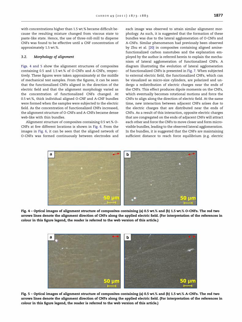
Figs. 4 and 5 show the alignment structures of composites
containing 0.5 and 1.5 wt.% of O-CNFs and A-CNFs, respec-
tively. These figures were taken approximately at the middle
of mechanical test samples. From the figures, it can be seen
that the functionalized CNFs aligned in the direction of the
electric field and that the alignment morphology varied as
the concentration of functionalized CNFs changed. At
0.5 wt.%, thick individual aligned O-CNF and A-CNF bundles
were formed when the samples were subjected to the electric
field. As the concentration of functionalized CNFs increased,
the alignment structure of O-CNFs and A-CNFs became dense
web-like with thin bundles.
Alignment structure of composites containing 0.5 wt.% O-
CNFs at five different locations is shown in Fig. 6. From the
images in Fig. 6, it can be seen that the aligned network of
O-CNFs was formed continuously between electrodes and
Fig. 4 – Optical images of alignment structure of composites con
arrows lines denote the alignment direction of CNFs along the
colour in this figure legend, the reader is referred to the web ve
Fig. 5 – Optical images of alignment structure of composites con
arrows lines denote the alignment direction of CNFs along the
colour in this figure legend, the reader is referred to the web ve
each image was observed to attain similar alignment mor-
phology. As such, it is suggested that the formation of these
bundles was due to the lateral agglomeration of O-CNFs and
A-CNFs. Similar phenomenon had previously been observed
by Zhu et al. [20] in composites containing aligned amine-
functionalized carbon nanotubes and the explanation em-
ployed by the author is referred herein to explain the mecha-
nism of lateral agglomeration of functionalized CNFs. A
diagram illustrating the evolution of lateral agglomeration
of functionalized CNFs is presented in Fig. 7. When subjected
to external electric field, the functionalized CNFs, which can
be visualized as micro-size cylinders, are polarized and un-
dergo a redistribution of electric charges near the ends of
the CNFs. This effect produces dipole moments on the CNFs,
which eventually becomes rotational motions and force the
CNFs to align along the direction of electric field. At the same
time, new interaction between adjacent CNFs arises due to
the electric charges that are distributed near the ends of
CNFs. As a result of this interaction, opposite electric charges
that are congregated on the ends of adjacent CNFs will attract
each other and force the CNFs to move closer and form micro-
visible bundles, leading to the observed lateral agglomeration.
In the bundles, it is suggested that the CNFs are maintaining
sufficient distance to reach force equilibrium (e.g. electric
taining (a) 0.5 wt.% and (b) 1.5 wt.% O-CNFs. The red two
applied electric field. (For interpretation of the references in
rsion of this article.)
taining (a) 0.5 wt.% and (b) 1.5 wt.% A-CNFs. The red two
applied electric field. (For interpretation of the references in
rsion of this article.)

Fig. 6 – Optical micrograph of alignment structure of composites containing 0.5 wt.% O-CNFs at different locations. The red
two arrows line denotes the alignment direction of CNFs along the applied electric field.
Fig. 7 – Illustration showing the evolution of lateral agglomeration of O-CNF or A-CNF when subjected to electric field. The
oval shape ‘‘ ’’ in the top right diagram shows the possible interaction between opposite electric charge of adjacent CNF at
both ends.
1878 C A R B O N 4 9 ( 2 0 1 1 ) 1 8 7 3 – 1 8 8 3
force and van der Waals force) rather than chemically bond-
ing to each other [20].
For samples with higher concentration, since the amount
of O-CNFs and A-CNFs per unit volume was higher, this auto-
matically elevated the interactive activity of adjacent O-CNFs
and A-CNFs upon the application of electric field and thus,
more aligned O-CNFs and A-CNFs bundles can be identified
locally. By comparing the alignment morphologies of samples
with different concentrations of O-CNFs and A-CNFs, it was
observed that the alignment structure for both samples were
similar. This suggests that the alignment morphology of func-
tionalized CNFs is independent of the functional groups
grafted to the CNFs.
3.3. Mechanical properties
3.3.1. O-CNF/epoxy compositesFrom Figs. 8 and 9, it can be seen that all the O-CNF/epoxy
composites showed increase in compressive strength with re-
spect to the neat composite. Interestingly, the strength of
samples with (OCNF-EF) and without (OCNF-NF) electric field
increased exponentially as a function of O-CNF concentra-
tion. The compressive strength of samples containing 4.5
wt.% OCNF-EF and OCNF-NF increased by 8.36% and 6.09%,
respectively, over the neat composite. Throughout the entire
range of O-CNF loading in the resin, the strength of OCNF-
EF samples was higher than OCNF-NF samples. The aligned
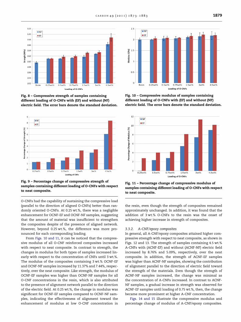
Fig. 8 – Compressive strength of samples containing
different loading of O-CNFs with (EF) and without (NF)
electric field. The error bars denote the standard deviation.
Fig. 9 – Percentage change of compressive strength of
samples containing different loading of O-CNFs with respect
to neat composite.
Fig. 10 – Compressive modulus of samples containing
different loading of O-CNFs with (EF) and without (NF)
electric field. The error bars denote the standard deviation.
Fig. 11 – Percentage change of compressive modulus of
samples containing different loading of O-CNFs with respect
to neat composite.
C A R B O N 4 9 ( 2 0 1 1 ) 1 8 7 3 – 1 8 8 3 1879
O-CNFs had the capability of sustaining the compressive load
(parallel to the direction of aligned O-CNFs) better than ran-
domly oriented O-CNFs. At 0.25 wt.%, there was a negligible
enhancement for OCNF-EF and OCNF-NF samples, suggesting
that the amount of material was insufficient to strengthen
the composites despite of the presence of aligned network.
However, beyond 0.25 wt.%, the difference was more pro-
nounced for each corresponding loading.
From Figs. 10 and 11, it can be noticed that the compres-
sive modulus of all O-CNF reinforced composites increased
with respect to neat composite. In contrast to strength, the
changes in modulus for both types of samples increased lin-
early with respect to the concentration of CNFs until 3 wt.%.
The modulus of the composites containing 3 wt.% OCNF-EF
and OCNF-NF samples increased by 11.37% and 7.44%, respec-
tively, over the neat composite. Like strength, the modulus of
OCNF-EF samples was higher than OCNF-NF samples for all
O-CNF concentrations in the resin, which is also attributed
to the presence of alignment network parallel to the direction
of the electric field. At 0.25 wt.%, the change in modulus was
significant for OCNF-EF samples compared to OCNF-NF sam-
ples, indicating the effectiveness of alignment toward the
enhancement of modulus at low O-CNF concentration in
the resin, even though the strength of composites remained
approximately unchanged. In addition, it was found that the
addition of 3 wt.% O-CNFs to the resin was the onset of
achieving higher increase in strength of composites.
3.3.2. A-CNF/epoxy compositesIn general, all A-CNF/epoxy composites attained higher com-
pressive strength with respect to neat composite, as shown in
Figs. 12 and 13. The strength of samples containing 4.5 wt.%
A-CNFs with (ACNF-EF) and without (ACNF-NF) electric field
increased by 8.76% and 5.09%, respectively, over the neat
composite. In addition, the strength of ACNF-EF samples
was higher than ACNF-NF samples, showing the contribution
of alignment parallel to the direction of electric field toward
the strength of the materials. Even though the strength of
ACNF-NF samples increased, the change was minimal as
the concentration of A-CNFs increased. In contrast to ACNF-
NF samples, a gradual increase in strength was observed for
ACNF-EF samples until loading of 0.75 wt.%, then, the change
became more prominent at higher A-CNF concentration.
Figs. 14 and 15 illustrate the compressive modulus and
percentage change of modulus of A-CNF/epoxy composites.

Fig. 12 – Compressive strength of samples containing
different loading of A-CNFs with (EF) and without (NF)
electric field. The error bars denote the standard deviation.
Fig. 13 – Percentage change of compressive strength of
samples containing different loading of A-CNFs with respect
to neat composite.
Fig. 14 – Compressive modulus of samples containing
different loading of A-CNFs with (EF) and without (NF)
electric field. The error bars denote the standard deviation.
Fig. 15 – Percentage change of compressive modulus of
samples containing different loading of A-CNFs with respect
to neat composite.
Fig. 16 – Comparison between percentage change of
compressive strength of 4.5 wt.% O-CNF and A-CNF
reinforced composites with respect to neat composite.
1880 C A R B O N 4 9 ( 2 0 1 1 ) 1 8 7 3 – 1 8 8 3
The compressive modulus of samples with 4.5 wt.% ACNF-EF
and ACNF-NF increased by 19% and 10.88%, respectively, over
the neat composite. Like compressive strength, the addition
of A-CNFs also enhanced the modulus of the neat composite.
Furthermore, an interesting observation can also be drawn by
comparing the percentage change of modulus for different
concentrations of ACNF-EF with ACNF-NF samples. From
Fig. 15, it is found that the percentage change of modulus
for ACNF-EF samples was approximately two to three times
greater than ACNF-NF samples. This finding could be
explained by the combination of enhanced compatibility
between A-CNFs and the resin and the presence of aligned
A-CNFs parallel to the direction of electric field.
As mentioned previously, the grafting of amine functional
groups would improve the compatibility between CNFs and
matrix. As such, both compressive strength and modulus of
O-CNF/epoxy and A-CNF/epoxy composites were compared.
From Fig. 16, it is shown that the addition of 4.5 wt.% O-CNFs
and A-CNFs to the resin resulted in similar strength for sam-
ples with and without electric field, respectively. In this re-
gard, it is suggested that the strength of the composites is
independent of the type of functionalized CNFs for the con-
centrations studied. Fig. 17 shows the comparison of com-
pressive modulus of composites containing 4.5 wt.% O-CNFs
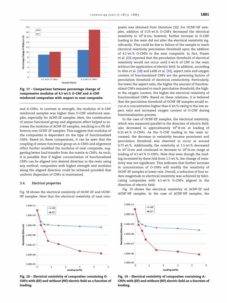
Fig. 17 – Comparison between percentage change of
compressive modulus of 4.5 wt.% O-CNF and A-CNF
reinforced composites with respect to neat composite.
C A R B O N 4 9 ( 2 0 1 1 ) 1 8 7 3 – 1 8 8 3 1881
and A-CNFs. In contrast to strength, the modulus of A-CNF
reinforced samples was higher than O-CNF reinforced sam-
ples, especially for ACNF-EF samples. Here, the combination
of amine functional group and alignment effect helped to in-
crease the modulus of ACNF-EF samples, resulting in a 9% dif-
ference over OCNF-EF samples. This suggests that modulus of
the composites is dependent on the type of functionalized
CNFs. Based on these comparisons, it can be seen that the
coupling of amine functional group on A-CNFs and alignment
effect further modified the modulus of neat composite, sug-
gesting better load transfer from the matrix to CNFs. As such,
it is possible that if higher concentration of functionalized
CNFs can be aligned into desired direction in the resin using
any method, composites with higher strength and modulus
along the aligned direction could be achieved provided that
uniform dispersion of CNFs is maintained.
3.4. Electrical properties
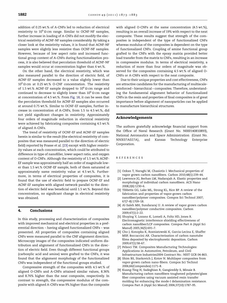
Fig. 18 shows the electrical resistivity of OCNF-EF and OCNF-
NF samples. Note that the electrical resistivity of neat com-
Fig. 18 – Electrical resistivity of composites containing O-
CNFs with (EF) and without (NF) electric field as a function of
loading.
posite was obtained from literature [32]. For OCNF-NF sam-
ples, addition of 0.25 wt.% O-CNFs decreased the electrical
resistivity to 109 X cm; however, further increase in O-CNF
loading in the resin did not alter the electrical resistivity sig-
nificantly. This could be due to failure of the sample to reach
electrical resistivity percolation threshold upon the addition
of 4.5 wt.% O-CNFs to the neat composite. In fact, Prasse
et al. [23] reported that the percolation threshold of electrical
resistivity would not occur until 6 wt.% of CNF in the resin
without the application of electric field. In addition, according
to Ahn et al. [18] and Lafdi et al. [32], aspect ratio and oxygen
content of functionalized CNFs are the governing factors of
percolation threshold of electrical conductivity. Particularly,
the lower the aspect ratio, the higher the amount of function-
alized CNFs required to reach percolation threshold; the high-
er the oxygen content, the higher the electrical resistivity of
functionalized CNFs. Based on these relations, it is believed
that the percolation threshold of OCNF-NF samples would oc-
cur at a concentration higher than 6 wt.% owing to the low as-
pect ratio and increased oxygen content of O-CNF during
functionalization process.
In the case of OCNF-EF samples, the electrical resistivity,
which was measured parallel to the direction of electric field,
also decreased to approximately 109 X cm at loading of
0.25 wt.% O-CNFs. As the O-CNF loading in the resin in-
creased, the decrease in resistivity became prominent and
percolation threshold was observed to occur at around
0.75 wt.%. Additionally, the resistivity at 1.5 wt.% decreased
to 107 X cm and continued to decrease to 106 X cm range at
loading of 4.5 wt.% O-CNFs. Note that even though the load-
ing increased by three fold from 1.5 wt.%, the change of resis-
tivity was not significant. This indicates that further increase
in concentration of O-CNFs will modify the resistivity of
OCNF-EF samples at lower rate. Overall, a reduction of four or-
ders magnitude in electrical resistivity was achieved by fabri-
cating composites with 4.5 wt.% O-CNFs aligned in the
direction of electric field.
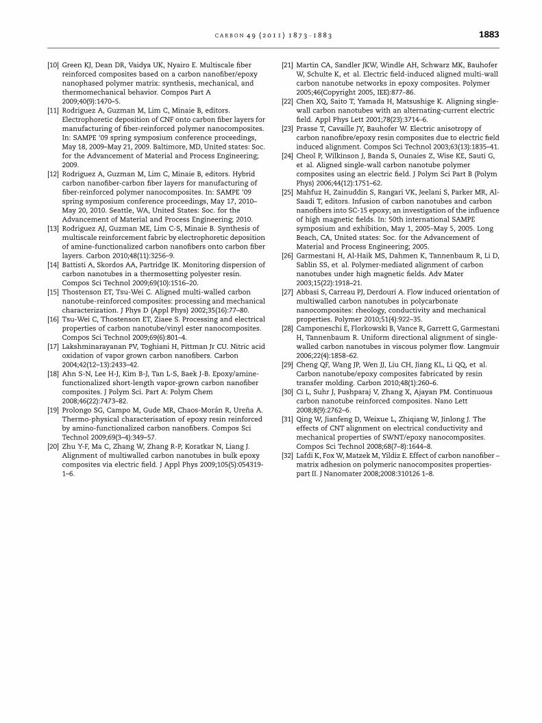
Fig. 19 shows the electrical resistivity of ACNF-EF and
ACNF-NF samples. In the case of ACNF-NF samples, the
Fig. 19 – Electrical resistivity of composites containing A-
CNFs with (EF) and without (NF) electric field as a function of
loading.
1882 C A R B O N 4 9 ( 2 0 1 1 ) 1 8 7 3 – 1 8 8 3
addition of 0.25 wt.% of A-CNFs led to reduction of electrical
resistivity to 109 X cm range. Similar to OCNF-NF samples,
further increase in loading of A-CNFs did not modify the elec-
trical resistivity of ACNF-NF samples considerably. By taking a
closer look at the resistivity values, it is found that ACNF-NF
samples were slightly less resistive than OCNF-NF samples.
However, because of low aspect ratio and increased func-
tional group content of A-CNFs during functionalization pro-
cess, it is also believed that percolation threshold of ACNF-NF
samples would occur at concentration higher than 6 wt.%.
On the other hand, the electrical resistivity, which was
also measured parallel to the direction of electric field, of
ACNF-EF samples decreased to a value slightly lower than
109 X cm at 0.25 wt.% O-CNF concentration. The resistivity
of 1.5 wt.% ACNF-EF sample dropped to 106 X cm range and
continued to decrease to slightly lower than 106 X cm range
at concentration of 4.5 wt.%. From Fig. 18, it can be seen that
the percolation threshold for ACNF-EF samples also occurred
at around 0.75 wt.%. Similar to OCNF-EF samples, further in-
crease in concentration of A-CNFs, from 1.5 to 4.5 wt.%, did
not yield significant changes in resistivity. Approximately
four orders of magnitude reduction in electrical resistivity
were achieved by fabricating composites containing 4.5 wt.%
of aligned A-CNFs.
The trend of resistivity of OCNF-EF and ACNF-EF samples
herein is similar to the result (the electrical resistivity of com-
posites that was measured parallel to the direction of electric
field) reported by Prasse et al. [23] except with higher resistiv-
ity values at each concentration, which could be attributed to
difference in type of nanofiller, lower aspect ratio, and oxygen
content of O-CNFs. Although the resistivity of 1.5 wt.% ACNF-
EF sample was approximately half an order of magnitude low-
er than 1.5 wt.% OCNF-EF sample, both of them saturated at
approximately same resistivity value at 4.5 wt.%. Further-
more, in terms of electrical properties of composites, it is
found that the use of electric field to prepare OCNF-EF and
ACNF-EF samples with aligned network parallel to the direc-
tion of electric field was beneficial until 1.5 wt.%. Beyond this
concentration, no significant change in electrical resistivity
was obtained.
4. Conclusions
In this study, processing and characterization of composites
with improved mechanical and electrical properties in a pref-
erential direction – having aligned functionalized CNFs – was
presented. All properties of composites containing aligned
CNFs were measured parallel to the CNF alignment direction.
Microscopy images of the composites indicated uniform dis-
tribution and alignment of functionalized CNFs in the direc-
tion of electric field. Even though different functional groups
(carboxylic acid and amine) were grafted to the CNFs, it was
found that the alignment morphology of the functionalized
CNFs was independent of the functional groups studied.
Compressive strength of the composites with 4.5 wt.% of
aligned O-CNFs and A-CNFs attained similar values, 8.36%
and 8.76% higher than the neat composite, respectively. In
contrast to strength, the compressive modulus of the com-
posite with aligned A-CNFs was 9% higher than the composite
with aligned O-CNFs at the same concentration (4.5 wt.%),
resulting in an overall increase of 19% with respect to the neat
composite. These results suggest that strength of the com-
posites is independent of the type of functionalized CNFs
whereas modulus of the composites is dependent on the type
of functionalized CNFs. Coupling of amine functional group
grafted to the CNFs with the epoxy matrix provided better
load transfer from the matrix to CNFs, resulting in an increase
in compressive modulus. In terms of electrical resistivity, a
reduction of more than four orders of magnitude was ob-
served for the composites containing 4.5 wt.% of aligned O-
CNFs or A-CNFs with respect to the neat composite.
Due to their unique properties and cost effectiveness, CNFs
are attractive candidates for the manufacturing of multiscale-
reinforced – hierarchical – composites. Therefore, understand-
ing the fundamental alignment behavior of functionalized
CNFs in the resin and properties of final composites is of great
importance before alignment of nanoparticles can be applied
to manufacture hierarchical structures.
Acknowledgements
The authors gratefully acknowledge financial support from
the Office of Naval Research (Grant No. N000140810893),
National Aeronautics and Space Administration (Grant No.
NNX07A027A), and Kansas Technology Enterprise
Corporation.
R E F E R E N C E S
[1] Ozkan T, Naraghi M, Chasiotis I. Mechanical properties ofvapor grown carbon nanofibers. Carbon 2010;48(1):239–44.
[2] Lawrence JG, Berhan LM, Nadarajah A. Elastic properties andmorphology of individual carbon nanofibers. ACS Nano2008;2(6):1230–6.
[3] Tibbetts GG, Lake ML, Strong KL, Rice BP. A review of thefabrication and properties of vapor-grown carbonnanofiber/polymer composites. Compos Sci Technol 2007;67(7–8):1709–18.
[4] Al-Saleh MH, Sundararaj U. A review of vapor grown carbonnanofiber/polymer conductive composites. Carbon2009;47(1):2–22.
[5] Shuying Y, Lozano K, Lomeli A, Foltz HD, Jones R.Electromagnetic interference shielding effectiveness ofcarbon nanofiber/LCP composites. Compos Part A (Appl SciManuf) 2005;36(5):691–7.
[6] Cho J, Konopka K, Rozniatowski K, Garcia-Lecina E, ShafferMSP, Boccaccini AR. Characterisation of carbon nanotubefilms deposited by electrophoretic deposition. Carbon2009;47(1):58–67.
[7] Pelsoci TM. Composites Manufacturing Technologies:Applications in Automotive, Petroleum, and CivilInfrastructure Industries2004 Contract No.: NIST GCR 04-863.
[8] Shim BS, Starkovich J, Kotov N. Multilayer composites fromvapor-grown carbon nano-fibers. Compos Sci Technol2006;66(Compendex):1171–8.
[9] Kuang-Ting H, Sadeghian R, Gangireddy S, Minaie B.Manufacturing carbon nanofibers toughened polyester/glassfiber composites using vacuum assisted resin transfermolding for enhancing the mode-I delamination resistance.Compos Part A (Appl Sci Manuf) 2006;37(10):1787–95.
C A R B O N 4 9 ( 2 0 1 1 ) 1 8 7 3 – 1 8 8 3 1883
[10] Green KJ, Dean DR, Vaidya UK, Nyairo E. Multiscale fiberreinforced composites based on a carbon nanofiber/epoxynanophased polymer matrix: synthesis, mechanical, andthermomechanical behavior. Compos Part A2009;40(9):1470–5.
[11] Rodriguez A, Guzman M, Lim C, Minaie B, editors.Electrophoretic deposition of CNF onto carbon fiber layers formanufacturing of fiber-reinforced polymer nanocomposites.In: SAMPE ‘09 spring symposium conference proceedings,May 18, 2009–May 21, 2009. Baltimore, MD, United states: Soc.for the Advancement of Material and Process Engineering;2009.
[12] Rodriguez A, Guzman M, Lim C, Minaie B, editors. Hybridcarbon nanofiber-carbon fiber layers for manufacturing offiber-reinforced polymer nanocomposites. In: SAMPE ‘09spring symposium conference proceedings, May 17, 2010–May 20, 2010. Seattle, WA, United States: Soc. for theAdvancement of Material and Process Engineering; 2010.
[13] Rodriguez AJ, Guzman ME, Lim C-S, Minaie B. Synthesis ofmultiscale reinforcement fabric by electrophoretic depositionof amine-functionalized carbon nanofibers onto carbon fiberlayers. Carbon 2010;48(11):3256–9.
[14] Battisti A, Skordos AA, Partridge IK. Monitoring dispersion ofcarbon nanotubes in a thermosetting polyester resin.Compos Sci Technol 2009;69(10):1516–20.
[15] Thostenson ET, Tsu-Wei C. Aligned multi-walled carbonnanotube-reinforced composites: processing and mechanicalcharacterization. J Phys D (Appl Phys) 2002;35(16):77–80.
[16] Tsu-Wei C, Thostenson ET, Ziaee S. Processing and electricalproperties of carbon nanotube/vinyl ester nanocomposites.Compos Sci Technol 2009;69(6):801–4.
[17] Lakshminarayanan PV, Toghiani H, Pittman Jr CU. Nitric acidoxidation of vapor grown carbon nanofibers. Carbon2004;42(12–13):2433–42.
[18] Ahn S-N, Lee H-J, Kim B-J, Tan L-S, Baek J-B. Epoxy/amine-functionalized short-length vapor-grown carbon nanofibercomposites. J Polym Sci. Part A: Polym Chem2008;46(22):7473–82.
[19] Prolongo SG, Campo M, Gude MR, Chaos-Moran R, Urena A.Thermo-physical characterisation of epoxy resin reinforcedby amino-functionalized carbon nanofibers. Compos SciTechnol 2009;69(3–4):349–57.
[20] Zhu Y-F, Ma C, Zhang W, Zhang R-P, Koratkar N, Liang J.Alignment of multiwalled carbon nanotubes in bulk epoxycomposites via electric field. J Appl Phys 2009;105(5):054319-1–6.
[21] Martin CA, Sandler JKW, Windle AH, Schwarz MK, BauhoferW, Schulte K, et al. Electric field-induced aligned multi-wallcarbon nanotube networks in epoxy composites. Polymer2005;46(Copyright 2005, IEE):877–86.
[22] Chen XQ, Saito T, Yamada H, Matsushige K. Aligning single-wall carbon nanotubes with an alternating-current electricfield. Appl Phys Lett 2001;78(23):3714–6.
[23] Prasse T, Cavaille JY, Bauhofer W. Electric anisotropy ofcarbon nanofibre/epoxy resin composites due to electric fieldinduced alignment. Compos Sci Technol 2003;63(13):1835–41.
[24] Cheol P, Wilkinson J, Banda S, Ounaies Z, Wise KE, Sauti G,et al. Aligned single-wall carbon nanotube polymercomposites using an electric field. J Polym Sci Part B (PolymPhys) 2006;44(12):1751–62.
[25] Mahfuz H, Zainuddin S, Rangari VK, Jeelani S, Parker MR, Al-Saadi T, editors. Infusion of carbon nanotubes and carbonnanofibers into SC-15 epoxy; an investigation of the influenceof high magnetic fields. In: 50th international SAMPEsymposium and exhibition, May 1, 2005–May 5, 2005. LongBeach, CA, United states: Soc. for the Advancement ofMaterial and Process Engineering; 2005.
[26] Garmestani H, Al-Haik MS, Dahmen K, Tannenbaum R, Li D,Sablin SS, et al. Polymer-mediated alignment of carbonnanotubes under high magnetic fields. Adv Mater2003;15(22):1918–21.
[27] Abbasi S, Carreau PJ, Derdouri A. Flow induced orientation ofmultiwalled carbon nanotubes in polycarbonatenanocomposites: rheology, conductivity and mechanicalproperties. Polymer 2010;51(4):922–35.
[28] Camponeschi E, Florkowski B, Vance R, Garrett G, GarmestaniH, Tannenbaum R. Uniform directional alignment of single-walled carbon nanotubes in viscous polymer flow. Langmuir2006;22(4):1858–62.
[29] Cheng QF, Wang JP, Wen JJ, Liu CH, Jiang KL, Li QQ, et al.Carbon nanotube/epoxy composites fabricated by resintransfer molding. Carbon 2010;48(1):260–6.
[30] Ci L, Suhr J, Pushparaj V, Zhang X, Ajayan PM. Continuouscarbon nanotube reinforced composites. Nano Lett2008;8(9):2762–6.
[31] Qing W, Jianfeng D, Weixue L, Zhiqiang W, Jinlong J. Theeffects of CNT alignment on electrical conductivity andmechanical properties of SWNT/epoxy nanocomposites.Compos Sci Technol 2008;68(7–8):1644–8.
[32] Lafdi K, Fox W, Matzek M, Yildiz E. Effect of carbon nanofiber –matrix adhesion on polymeric nanocomposites properties-part II. J Nanomater 2008;2008:310126 1–8.
Copyright © 2022 FDOKUMEN