PROCESS IMPROVEMENT OF JET ENGINE REPAIR WORK SHOP Extended essay -MM 508 – Manufacturing science...
26
PROCESS IMPROVEMENT OF JET ENGINE REPAIR WORK SHOP Thusitha Rodrigo 2013/PgD.MM/38 Faculty of Graduate Studies University of Colombo Date: 21 st May 2014
-
Upload
independent -
Category
Documents
-
view
4 -
download
0
Transcript of PROCESS IMPROVEMENT OF JET ENGINE REPAIR WORK SHOP Extended essay -MM 508 – Manufacturing science...

PROCESS IMPROVEMENT OF JET
ENGINE REPAIR WORK SHOP
Thusitha Rodrigo
2013/PgD.MM/38
Faculty of Graduate Studies
University of Colombo
Date: 21st May 2014
Extended essay -MM 508 – Manufacturing science I
2013/PgD.MM/38 – Thusitha Rodrigo Page 2
Table of Contents
List of symbols, acronyms, and abbreviations ............................................................................................................... 3
Chapter 1 - Introduction ........................................................................................................................................... 5
1.1 Title.............................................................................................................................................................. 5
1.2 Introduction .................................................................................................................................................. 5
1.2 Background .................................................................................................................................................. 5
1.3 Statement of problem ................................................................................................................................... 6
1.4 Research objectives ...................................................................................................................................... 6
Chapter 2 - Literature Review .................................................................................................................................. 7
Chapter 3 - Methodology ......................................................................................................................................... 8
Chapter 4 - Present and Proposed process Analysis and Recommendations ......................................................... 9
4.1 Overview ...................................................................................................................................................... 9
4.2 Present engine repair process ....................................................................................................................... 9
4.4 Observations on non-value added processes .............................................................................................. 12
4.5 Proposals for Improvement ........................................................................................................................ 13
4.6 Cultural Transformation .................................................................................................................................... 15
4.7 Proposed Engine Repair Procedure ............................................................................................................ 15
4.8 Present Status Value Stream Map (the areas to be developed are marked in red) ............................................ 17
4.9 Proposed future state value stream map (proposed improvements are highlighted in green) .................... 18
Chapter 5 - Difficulties observed in implementing theoretical Manufacturing philosophies in a military
environment 19
5.1 Observation One ....................................................................................................................................... 19
5.2 Observation Two ........................................................................................................................................ 19
5.3 Observation Three ..................................................................................................................................... 19
Chapter 6 - Conclusion ........................................................................................................................................... 20
Appendix (Detailed Literature Review) ................................................................................................................ 21
Theory Of Constraints (TOC) ................................................................................................................................. 21
Just-In-Time (JIT) System ...................................................................................................................................... 22
Lean Production ...................................................................................................................................................... 22
Value stream Mapping (VSM) ................................................................................................................................ 23
Total Quality Management (TQM) ......................................................................................................................... 24
Six-Sigma ................................................................................................................................................................ 24
Key Roles of Six-Sigma Implementation ................................................................................................................ 25
Bibliography ................................................................................................................................................................ 26
Extended essay -MM 508 – Manufacturing science I
2013/PgD.MM/38 – Thusitha Rodrigo Page 3
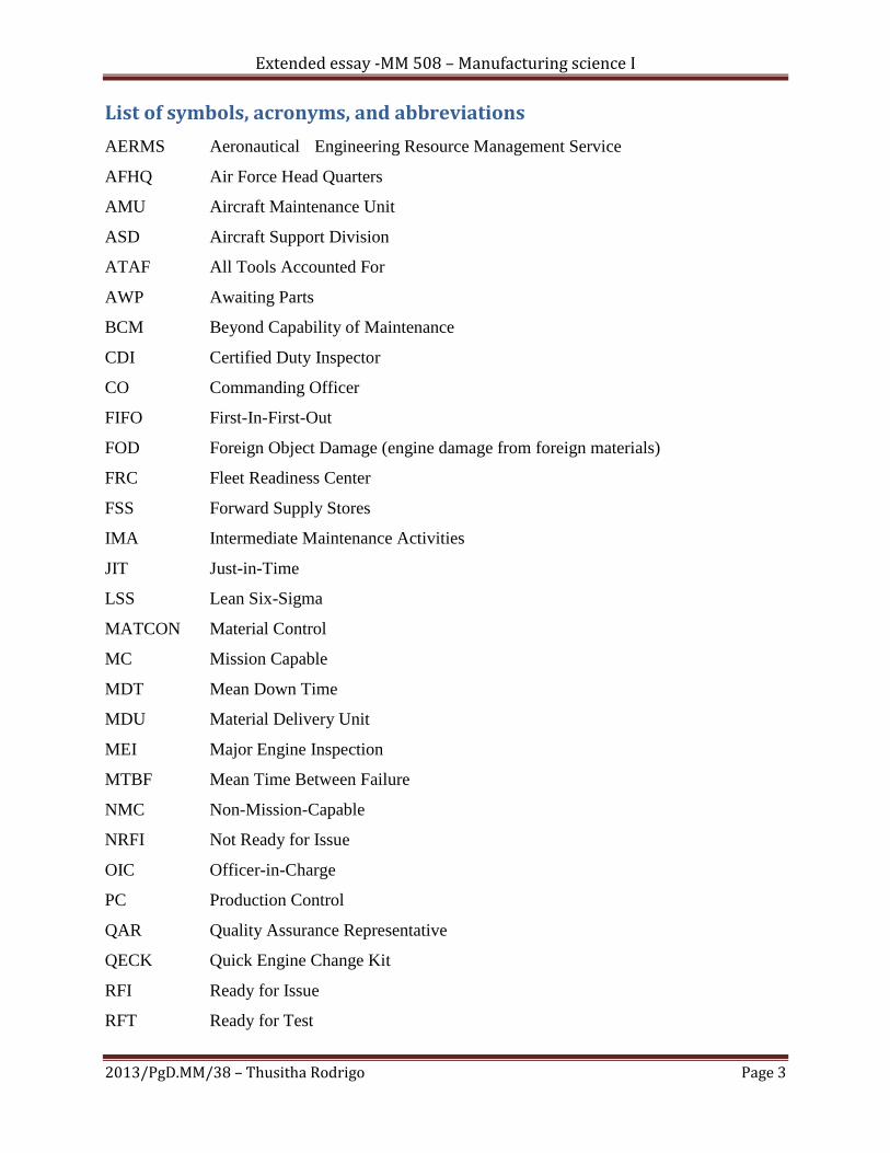
List of symbols, acronyms, and abbreviations
AERMS Aeronautical Engineering Resource Management Service
AFHQ Air Force Head Quarters
AMU Aircraft Maintenance Unit
ASD Aircraft Support Division
ATAF All Tools Accounted For
AWP Awaiting Parts
BCM Beyond Capability of Maintenance
CDI Certified Duty Inspector
CO Commanding Officer
FIFO First-In-First-Out
FOD Foreign Object Damage (engine damage from foreign materials)
FRC Fleet Readiness Center
FSS Forward Supply Stores
IMA Intermediate Maintenance Activities
JIT Just-in-Time
LSS Lean Six-Sigma
MATCON Material Control
MC Mission Capable
MDT Mean Down Time
MDU Material Delivery Unit
MEI Major Engine Inspection
MTBF Mean Time Between Failure
NMC Non-Mission-Capable
NRFI Not Ready for Issue
OIC Officer-in-Charge
PC Production Control
QAR Quality Assurance Representative
QECK Quick Engine Change Kit
RFI Ready for Issue
RFT Ready for Test
Extended essay -MM 508 – Manufacturing science I
2013/PgD.MM/38 – Thusitha Rodrigo Page 4
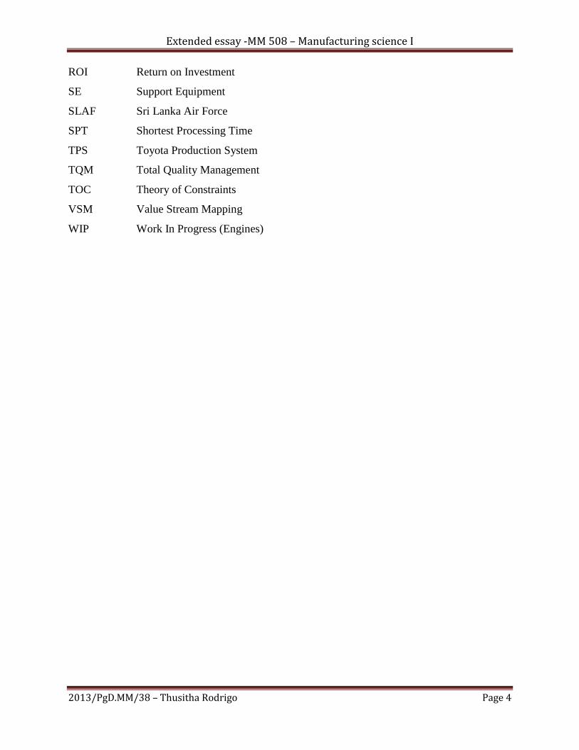
ROI Return on Investment
SE Support Equipment
SLAF Sri Lanka Air Force
SPT Shortest Processing Time
TPS Toyota Production System
TQM Total Quality Management
TOC Theory of Constraints
VSM Value Stream Mapping
WIP Work In Progress (Engines)

Extended essay -MM 508 – Manufacturing science I
2013/PgD.MM/38 – Thusitha Rodrigo Page 5
Chapter 1 - Introduction
1.1 Title
Process improvement of Jet engine repair work shop at the Aircraft Maintenance Unit
(AMU) of No 12 Fighter Squadron
1.2 Introduction
This study focuses on the Fighter Jet engine repair process at the Aircraft Maintenance
Unit (AMU) of No 12 Fighter Squadron, Air Force Base Katunayake. The aim of this project is
to identify the current non value added processes of the jet engine repair process and to conduct a
qualitative analysis as to how the AMU could incorporate a productive methodology and to
examine the effects of its application in relation to repair cycle time reduction and overall
aircraft readiness level enhancement.
1.2 Background
For many years, Sri Lanka Air Force measured overall performance and mission success
according to aircraft operational availability or readiness rate. As guidance, the Air Force Head
Quarters (AFHQ) periodically publishes a set of standards for all Flying formations to maintain
where the individual Commanding Officers (Cos’) aim not only to surpass this standard, but to
achieve perfection. Though COs' are successful in attaining Mission Capable (MC) rates above
the AFHQ’s set readiness standard, many overlook the actual cost of achieving such rates.
With a mindset of reporting the highest operational availability rate, COs’ and
maintenance engineers instinctively compete for replacement parts, personnel, and higher repair
capability according to the level of maintenance their units are allowed to accomplish. Because
of the same, redundant or non-value-added procedures and management practices have been
culturally ingrained among maintenance crew, which unnoticeably contribute to fluctuations in
the levels of production and readiness. On the other hand, decades of ―in house‖ competition has
resulted in an accumulation of excessive spare parts, unnecessary personnel utilizations, and
redundant repair procedures.
Extended essay -MM 508 – Manufacturing science I
2013/PgD.MM/38 – Thusitha Rodrigo Page 6
1.3 Statement of problem
There are two ways of achieving a high level of operational availability. The first is to
exceed the required level of spares needed and the other is to improve Mean Time Between
Failures (MTBF), decrease Maintenance Down Time (MDT), and reduce total cycle time. As a
result there is a rooted practice of stocking excess spare parts in an effort to reduce equipment
down time by eliminating lead time for replacement parts and achieving a small percentage
increase in readiness. Because of this perceived value created from having available parts on site,
a huge quantity of excessive spare parts becomes the alternative solution for readiness rate
issues, which results in accountability problems and shortage of spare parts at other maintenance
facilities and with a huge inventory carrying cost. Facilities experiencing a shortage of parts ends
up resorting to cannibalization which poses an adverse impact on equipment repair cycle time
(i.e., turnaround time). At present, lack of control and accountability over inventory and
equipment are two major management challenges faced by the SLAF.
Further, measures are to be initiated to close the gap between supply and maintenance
departments, synchronize maintenance activities’ differing mission objectives, and to introduce a
new work culture vastly different than what most maintenance personnel learned and embraced
from their predecessors. Therefore it is to be analyzed how the above concepts are implemented
at a military repair facility and what benefits will these improvements would provide to the
repair cycle time and aircraft availability of the Fighter Jet fleet? What other areas in the logistics
pipeline should be improved on to further increase aircraft availability? These are the questions
that are addressed in this study.
1.4 Research objectives
Critically analyze the present Jet Engine repair process
Identify the non-value added activities
Propose solutions using Manufacturing theories
Proposing an improved Repair process for the Engine work shop
Extended essay -MM 508 – Manufacturing science I
2013/PgD.MM/38 – Thusitha Rodrigo Page 7
Chapter 2 - Literature Review
Following manufacturing theories and philosophies are used to identify the existing non value added
processes and to propose recommendations for future development,
Theory Of Constraints TOC
Just In Time JIT
Lean Production
Value Stream Mapping VSM
Total Quality Management TQM
Six Sigma and Key roles in Six Sigma implementation
However due to the restriction on the number of words allotted for the extended essay, the detailed
illustration of the above is annexed in the appendix.
Extended essay -MM 508 – Manufacturing science I
2013/PgD.MM/38 – Thusitha Rodrigo Page 8
Chapter 3 - Methodology
The study is conducted in the following sequence
The present Jet engine repair process is subdivided in to sub-processes to identify the
value added, non-value added and necessary non value added sub processes.
An initial value stream map (VSM) is plotted accordingly and the identified non value
added sub processes were highlighted.
Then an attempt was initiated to identify the system constraints and to exploit them and
to elevate them through implementation of several manufacturing philosophies introduced in the
―Manufacturing Science I‖ module and the ―Total Quality Management‖ Module.
A modified ―Engine Repair Process‖ is proposed with the above recommendations and
the same was submitted to the administration hierarchy of the No 12 Sqn AMU where the same
was approved as a pilot project.
A proposed future state value stream map is plotted accordingly where the average cycle
times of the modified/newly added sub processes are to be taken in to account upon actual
implementation of the same in future.
The actual outcome of the new process is planned to be measured in comparison to the
previous one, both qualitatively and quantitatively during my dissertation for the Master’s
Degree in Manufacturing Management.
Extended essay -MM 508 – Manufacturing science I
2013/PgD.MM/38 – Thusitha Rodrigo Page 9
Chapter 4 - Present and Proposed process Analysis and
Recommendations
4.1 Overview
Engine removal is categorized as scheduled and unscheduled. Scheduled engine removal
is performed on engines that are within minus 10% of an operating cycle. The operating cycle
interval for engine is 1,100 flight hours. Unscheduled engine removal is triggered by unplanned
events such as engines damaged from foreign object ingestion, unacceptable flight performance
parameters, failing oil samples, or characteristics of an internal leak.
The engine removal process begins from the time the discrepancy is reported to or
identified by the squadron Maintenance Control. Maintenance Control would direct the Line
Division to tow the aircraft from the flight line to the hangar bay. The Aircraft Division would
remove and mount the discrepant engine on a mobile or wheeled-engine rack. The
Administrative Division would perform part and serial number verification of the engine and its
associated components to ensure that the part and serial numbers match with the engine logbook
records. After the quality assurance inspection, the squadron’s supply Division would verify the
serial number and part number of the engine to match them with the (AERMS)
AeronauticalEngineering Resource Management Service and collect the required logbook
records from the Administrative Division; and transfer the engine to the (AMU) Aircraft
Maintenance Unit.
The entire engine removal process, from the time the discrepancy is discovered to the time the
engine is received by AMU, takes on average 13 hours, with a minimum of 8 hours and a
maximum of 16 hours.
4.2 Present engine repair process
The screening process begins by assessing whether the engine is within AMU’s repair
capability or beyond capability of maintenance (BCM). A certified duty inspector (CDI)
performs this function. After the CDI screens the engine, the AMU waits for the screening unit to

Extended essay -MM 508 – Manufacturing science I
2013/PgD.MM/38 – Thusitha Rodrigo Page 10
induct it for repair or transfer it to a Depot facility if BCM. The screening process normally takes
between 1.5 and 2 hours.
Once AMU inducts the engine for repair, the floor supervisor assigns a repair crew who
will be responsible for the repair of the engine from the teardown to the buildup process, a
practice known as engine ownership concept. A repair crew normally consists of one CDI (crew
leader) and four technicians. The same crew may have other not ready for issue (NRFI) engines
at different stages of repair waiting to be processed.
The crew leader prioritizes which engines should be worked on that day based on the
availability of resources. These resources can be personnel, replacement parts from Supply, or
parts that can be cannibalized. If the inducted NRFI engine can not be processed, it will be
preserved and parked to be repaired at a later time. Parked engines are also used for parts
cannibalization to repair other engines.
Engines inducted for repair are further categorized as either requiring a major engine
inspection (MEI) or repair (Quick Fix). MEI engines are disassembled into individual
components for a more detailed inspection, while Quick Fix engines are only disassembled as
necessary to access areas for inspection and component replacement.
The crew leader would log-in to the AERMS computer to put the engine job order Work
In Progress (WIP), and then other assigned mechanics would log-in to record their start times. A
member would then check out a tool box at the Tool Room. After getting issued a tool box, the
mechanic would inventory its contents at the site to ensure an all tools accounted for (ATAF)
condition as part of the acceptance process. The average time mechanics spend on this process is
0.5 hours and this procedure occurs at a minimum of 12 times per day—at the beginning and end
of each shift, and the beginning and end of each job order.
From the Tool Room, the mechanic then returns to the shop, reopens the job order in the
AERMS computer, enters the tool box number and his initials to record the ATAF condition,
rolls the tool box to the engine location, and reinventories its contents before any engine work
can begin. Mechanics would remove only the parts that would lead them to the suspect damaged
component or bad engine module and separate these parts between a quick engine change kit
(QECK) and non-QECK.
QECK is a composite of various categories of hardware, hoses, tubing, clamps,
connectors, and small repairable items that are normally replaced during the repair process.
Extended essay -MM 508 – Manufacturing science I
2013/PgD.MM/38 – Thusitha Rodrigo Page 11
QECK parts are placed in small cardboard boxes. While the teardown is in progress, the crew
leader orders a replacement for the suspect damaged component or engine module from the
AERMS computer.
Production Control (PC) assigns a document number under the job order and forwards it
to Aircraft Supply Depot (ASD), which then checks if the item on order is available ―on station‖
for immediate issue. If the item is not available on station, ASD forwards the requisition ―off
station‖ to be filled by the supply system, and PC assigns the job order an awaiting parts (AWP)
status until the part is received. Partially disassembled engines in AWP status are preserved and
parked at the NRFI section of the shop and become sources for cannibalization.
After the tear-down process, the same crew would spend another 4.5 days on average
cleaning and inspecting parts removed from the engine. Serviceable parts are stowed in the
orphanage area, while replacements for unserviceable parts are ordered in the supply system.
Replacement parts normally arrive within three weeks of placing the part on order.
The engine build-up process would begin as soon as the replacement item is received
from ASD. Similar to the screening process, ASD would ask for a CDI to screen and receive the
part. Once PC directs the shop to resume work, the shop would assign a build-up crew to de-
preserve the NRFI engine and roll it to the build station. The crew leader would place the job
order from AWP to WIP status in the AERMS computer, direct someone to perform the tool
check-out process, and the rest of the crew would begin gathering the non-QECK components.
The completely assembled engine would be inspected by the floor supervisor, followed
by the QAR who would approve the engine as ready-for-test (RFT). This process would take an
average of 2.5 hours to complete. After the inspection, it would be moved to the local engine test
facility, where it would be leak-checked and tested to see if it meets flight condition parameters.
The test would take an average of 8 hours. After passing the test, it would be moved back to the
shop for a posttest inspection and the installation of the QECK. This process would take an
average of 6 hours to complete.
Consequently, PC would direct the Administration Division to put together the engine
records (logbook) for part number verification. Administrative personnel would wait until the
engine returns to the shop to perform the physical part verification.
After the installation of QECK, a QAR would conduct one final inspection for half an
hour and report the completion to PC. Once PC is satisfied with the accuracy of the engine
Extended essay -MM 508 – Manufacturing science I
2013/PgD.MM/38 – Thusitha Rodrigo Page 12
logbook and repair procedures, they would sign off on the completed work order in the AERMS
Computer, which completes the engine repair cycle. The RFI engine would then become
available to fill any bare firewalls in the Jet Fleet.
4.4 Observations on non-value added processes
Although engine ownership concept promotes competition, crew sense of pride, and
accountability for producing more and good quality engines, it can also easily turn production
into a serious state of disarray.
Because different repair crews are overseeing multiple engines at various stages of repair,
engines and major components are scattered everywhere on the production floor which leads to a
significant waste of time and manpower.
Theoretically, the repair processing time of MEI engines should be constant, but the
variable lead time of replacement parts misleads crew leaders with their prioritization techniques
and results in crews migrating from one engine to another. Recognizing the constant processing
time of MEI engines is important in determining which prioritization rule should be enforced.
A long waiting line of mechanics is formed at the tool counter during start and the end of
the shifts to check in/out their individual tool boxes.
Although the tear-down process would normally last an average of 3 days, some partially
torn down MEI (Main Engine Inspection) engine stays in AWP (Awaiting Parts) status at an
average of 6 (without cannibalization) and an average of 10 (with cannibalization) weeks due to
various factors.
During the buildup process, the crew members would search for items that are tagged
with the same engine serial number. Previous cannibalization actions for other engines have
often led to misplaced items or items not having been properly retagged. Because of this,
depending on the mechanic’s familiarity with the part, the search would take an average of 1.2
hours. This includes backtracking documentation in the pass-down book and ASD Computer, or
looking at diagrams in the maintenance manuals.
Without using roll-away carts to transfer non-QECK parts and heavy engine components,
the crew has to take several trips from the dissembling area. This operation takes an average of
0.5 hour, depending on the location and accessibility of the engine on the floor.
Extended essay -MM 508 – Manufacturing science I
2013/PgD.MM/38 – Thusitha Rodrigo Page 13
During the build-up process, quality assurance representatives (QARs) are called upon to
occasionally perform in-process inspections. The entire build-up process for an MEI engine
would normally take an average of 2.5 weeks, and sometimes up to several months, due to work
stoppages caused by late identification of a failed part with long lead time requirements.
Improper document swaps from previous cannibalization actions have caused
Administration Division to spend an average of 7 hours to organize an engine record.
4.5 Proposals for Improvement
An analysis of the present repair process reveals many non-value-added steps and following
system constraints are identified:
1. Engine Tear Down Process
2. Engine Assembling Process
3. Buffer size of the RFI section
These areas require the application of the JIT management, First-In-First-Out (FIFO) scheduling
systems, and transforming the culture of the shop with TQM techniques. The following
recommendations are proposed for the AMU to implement:
AMU could differentiate MEI from Quick Fix engines based on the variations in repair
time and apply the FIFO and Shortest Processing Time (SPT) prioritization methods. The floor
supervisor determines the order of engine induction at the NRFI engine waiting line using FIFO
and SPT, alternating between MEI and Quick Fix engines.
Under this new process, all MEI engines are to be completely disassembled. Major
components are to be placed at a specific designated location in the shop and this location is to
be well labeled. For easy reference the place will be called Forwards Supply Store (FSS), where
it will permit better visibility.
The FIFO system could be used for building up engines from components prepositioned
in the Forward Supply Stores (FSS) area. The alternating SPT method is used for inducting MEI
or Quick Fix engines. FIFO system makes the incorporation of buffer and JIT systems more
suitable. AMU and ASD should collaboratively establish a buffer in the system and adapt JIT
pull system for inventory and production management.
Extended essay -MM 508 – Manufacturing science I
2013/PgD.MM/38 – Thusitha Rodrigo Page 14
After analyzing the system constraints, the buffer sizes of five spare engines to be
established at the RFI section and five subassembly parts at the Forward Supply Stores (FSS).
Availability of manpower, spare parts, and shop capacity limits the size of buffers that can be
introduced in the system. It is proposed to use a buffer size of five in the FSS because the facility
can only accommodate five disassembled engines.
ASD should produce five sets of consumable and selected repairable parts for the
subassembly buffer. The pull system works so that upon drawing an engine from the RFI buffer
for local flying, the crew replenishes it by pulling a NRFI engine from the queue for a Quick Fix
repair or teardown, if an MEI engine, while simultaneously building an engine using the
subassembly parts from the FSS. The buffer system eliminated three weeks’ worth of AWP
status in the repair process.
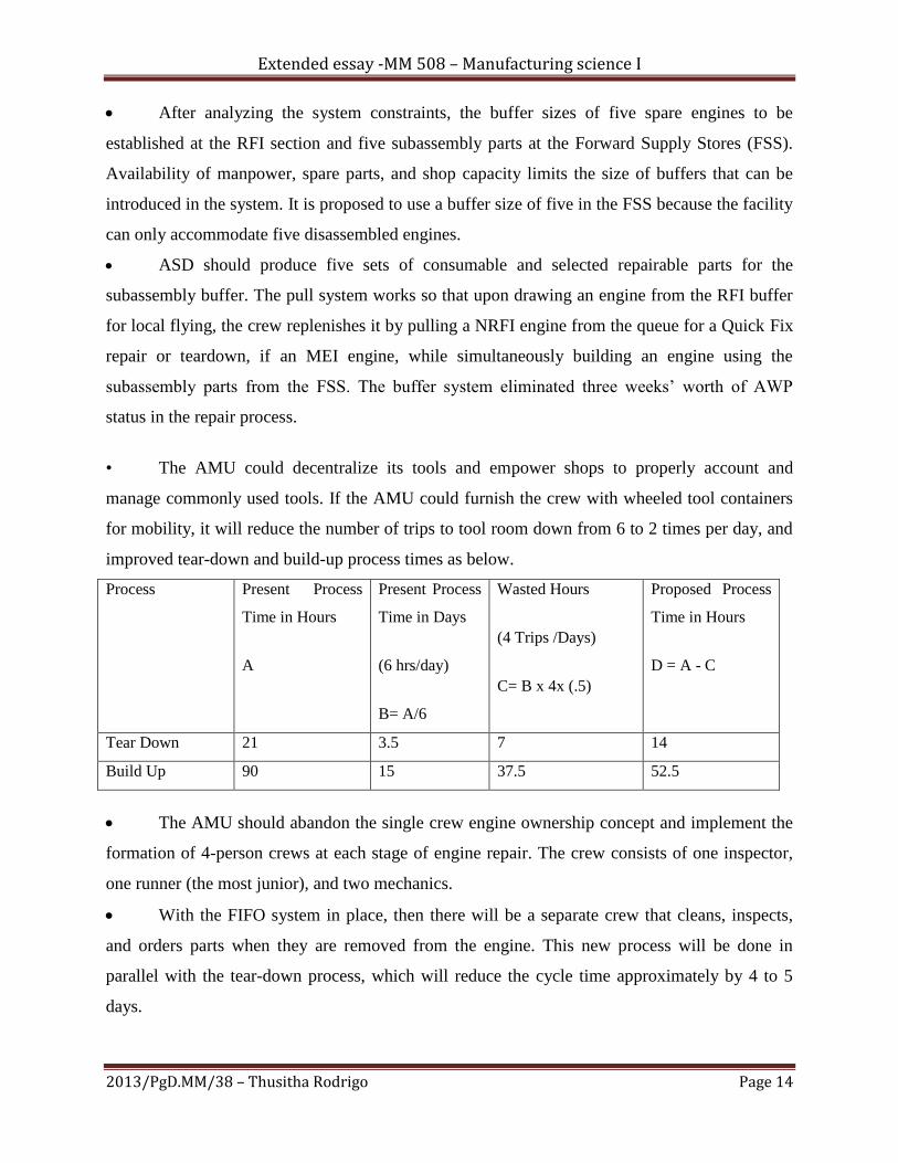
• The AMU could decentralize its tools and empower shops to properly account and
manage commonly used tools. If the AMU could furnish the crew with wheeled tool containers
for mobility, it will reduce the number of trips to tool room down from 6 to 2 times per day, and
improved tear-down and build-up process times as below.
Process Present Process
Time in Hours
A
Present Process
Time in Days
(6 hrs/day)
B= A/6
Wasted Hours
(4 Trips /Days)
C= B x 4x (.5)
Proposed Process
Time in Hours
D = A - C
Tear Down 21 3.5 7 14
Build Up 90 15 37.5 52.5
The AMU should abandon the single crew engine ownership concept and implement the
formation of 4-person crews at each stage of engine repair. The crew consists of one inspector,
one runner (the most junior), and two mechanics.
With the FIFO system in place, then there will be a separate crew that cleans, inspects,
and orders parts when they are removed from the engine. This new process will be done in
parallel with the tear-down process, which will reduce the cycle time approximately by 4 to 5
days.
Extended essay -MM 508 – Manufacturing science I
2013/PgD.MM/38 – Thusitha Rodrigo Page 15
The AMU could assign dedicated QECK, consumable and repairable parts kitting on roll-
away carts for each MEI engine. For additional accountability, carts are to be silhouetted to mark
where parts are supposed to be placed. Any unfilled silhouette must have a document number
that signifies that the part is already ordered in the supply system. This improvement will capture
several hours into the build-up process.
4.6 Cultural Transformation
These are changes required to eliminate non value shop norms that may seem to pose minor,
short-term effects in cycle time, but will have greater long-term impact in productivity. These
norms are items and practices that provide personal comfort such as long breaks, personal
lockers, and lounge areas on shop floors. So following changes are proposed:
Reorganization of the production floor and removal of non-production related
materials (Ex: Stand-up personal lockers, chairs, magazines)
Shop decking (A 5S Shop floor plan) is to be marked with corresponding stations
(EX: Teardown, buildup, FSS, QECK, orphanage)
Personnel breaks are to be reduced to one hour per shift to capture more work
hours per day(One half-hour for lunch/dinner and two 15-minute breaks).
4.7 Proposed Engine Repair Procedure
Upon implementation of the aforesaid changes, and with a buffer system in place, the shop
would not draw any NRFI engine (e.g., MEI or Quick Fix) from the induction line for
disassembly or repair, and consequently assemble another unless the system is ―triggered.‖
Issuing an RFI engine from the RFI buffer creates an empty RFI spot that triggers the system to
build an engine to replenish it; thus, describing the ―pull‖ system of inventory. The process is
further described below:
A bad engine at the squadron would pull an RFI engine from the RFI buffer.
AMU production control would initiate a job order in AERMS to build an engine and
induct an NRFI engine. The floor supervisor would form three repair crews to simultaneously
build the cold and hot sections of the engine, and teardown an NRFI engine. Each crew should
Extended essay -MM 508 – Manufacturing science I
2013/PgD.MM/38 – Thusitha Rodrigo Page 16
consist of one inspector or crew leader, one runner, and two experienced mechanics. One person
from each crew would inventorize the assigned tool box and roll it to their designated station
(build, repair, or tear-down pits).
The crew leader would enter the rest of the crew in the AERMS, enter his initials for
ATAF, and place the job order in IW status . With the proposed process in place, estimated times
to complete each task would be:
Four hours to build the cold section of the engine
Sixteen hours to build the hot section of the engine
Two to five days to tear down the NRFI engine
Parts removed from the NRFI engine during the tear-down process are to be immediately
transferred to the Component Shop by another runner. The Component Shop would disassemble,
clean, process for inspection, order parts that failed the inspection, assemble and then move RFI
parts to the orphanage area and the FSS. This portion of the process would take between 4 and 5
days to complete. The lead time for parts placed on order will be between 2 and 3 weeks. When
they arrive, they would be inspected and placed to fill the empty spaces at the orphanage and
FSS buffers.
Completed hot and cold sections of the engine are to be moved and joined together at one
of two external pits on the floor. The same crew that build the hot section would perform this
task as well as the remaining tasks leading up to the RFT condition. This process would take 14
hours to complete. The completely assembled engine would be inspected by the floor supervisor,
followed by the QAR who would approve the engine as RFT. This process would take 2.5 hours
to complete.
The engine would be tested at the test cell facility, which takes 8 hours to complete.
After passing the test cell run, it would be moved back to the shop for a Post test
inspection, followed by QECK installation. This process would take between 4 and 8 hours to
complete.
A QAR would conduct the final inspection, which would take approximately half an
hour. When the final inspection is satisfactory, PC would sign off the job order in NALCOMIS
and the RFI engine would be moved to replenish the RFI buffer , completing the build-up
process.

Extended essay -MM 508 – Manufacturing science I
2013/PgD.MM/38 – Thusitha Rodrigo Page 17
4.8 Present Status Value Stream Map (the areas to be developed are marked in
red)
ENGINE REMOVAL AND TURN-IN PROCESS
13 hours
AMU ACCEPTANCE PROCESS
2 hours
PRETEST CELL INSPECTION/ENGINE TEST CELL
Pretest cell inspection takes 2.5 hours and the engine testing process takes 8 hours.
POSTTEST CELL INSPECTION/QECK INSTALLATION 6 hours
ENGINE RECORDS PREPARATION*
7 hours
*The additional time required to organize an engine logbook due to improper cannibalization
documentation
READY FOR ISSUE
ENGINE TEAR-DOWN PROCESS
3 days
ENGINE BUILD-UP PROCESS
3 weeks
POSTTEST CELL INSPECTION/QECK INSTALLATION 6 hours
REPLACEMENT PARTS LEAD TIME
3 weeks
PARTS CLEANING/INSPECTION/ORDERING
5 days MAINTENANCE STOPPAGE • 6 wks. without cannibalization performed on
• 10 wks. with cannibalization *This period includes:
• Cleaning/inspecting/ordering parts
• Replacement parts lead time
• Equipment downtime
• Personnel issues
• Cannibalization actions
• Administrative support

Extended essay -MM 508 – Manufacturing science I
2013/PgD.MM/38 – Thusitha Rodrigo Page 18
4.9 Proposed future state value stream map (proposed improvements are
highlighted in green)
ENGINE REMOVAL AND TURN-IN PROCESS
13 working hours
PARTS CLEANING/INSPECTION/ORDERING
AMU ACCEPTANCE PROCESS
2 hours
ENGINE TEAR-DOWN PROCESS
Will be improved by new tool management system
T
BUILD HOT SECTION BUILD COLD SECTION
PRETEST CELL INSPECTION/ENGINE TEST CELL
Pretest cell inspection takes 2.5 hours and the engine testing process takes 8 hours.
MATE COLD AND HOT SECTION PLUS EXTERNALS
POSTTEST CELL INSPECTION/QECK INSTALLATION
6 hours
FINAL INSPECTION
0.5 hours
ENGINE RECORDS PREPARATION*
7 hours
*The additional time required to organize an
engine logbook due to improper cannibalization
documentation
READY FOR ISSUE
Orphanage/Forward Supply Stores and devision of the Engine in to Hot and Cold
sections
Extended essay -MM 508 – Manufacturing science I
2013/PgD.MM/38 – Thusitha Rodrigo Page 19
Chapter 5 - Difficulties observed in implementing theoretical
Manufacturing philosophies in a military environment
There are some doubts as to how effectively the Lean process could be implemented in a military
environment, which is vastly different from the corporate business world. Below are some of the
observations on these issues:
5.1 Observation One
How is Green Belt/Black Belt status being applied in a hierarchical leadership structure?
It is obvious that program Black Belts and Green Belts at SLAF AMU would play no significant
differentiation of roles as staff positions in the military hierarchical rank structure override the
latter. In most of the cases, all recommendations for improvements are vetted through the senior
leadership of the command, who in turn makes the final decision on whether to implement any
recommended process improvement or changes in direction for the betterment of the command.
5.2 Observation Two
The goal of Lean is to achieve ―Zero Waste,‖ therefore, how can the military achieve Lean in
such a vast area of uncertainty and variability? Under the environment that SLAF operates in, the
goal of achieving zero waste is impractical. Thus, the concept of Lean has to be slightly modified
to adjust for the uncertainty and variability of Local aviation maintenance demands. Therefore,
the future Fleet Readiness Centers (FRCs) need to have the correct buffer size to address
unforeseeable failures that could cause peak demands. Having the proper buffer level would
provide the FRC with the ability to meet the initial demand in order to reduce backlog.
5.3 Observation Three
What are the incentives for technicians to seek continuous improvements (Kaizen)? It is
unreasonable to expect to utilize the corporate world’s incentives for promoting the Lean process
in the military. The military does not have the same incentive packages as the business world,
which makes it much more difficult for military personnel to seek continuous improvements.
However, military personnel would do it for the sense of pride in accomplishing their duties and
knowing that what they are doing will be beneficial to our war fighters on the front line. Thus,

Extended essay -MM 508 – Manufacturing science I
2013/PgD.MM/38 – Thusitha Rodrigo Page 20
military organizations should focus on non-monetary awards to provide incentives to their
personnel.
Chapter 6 - Conclusion
In conclusion it is obvious that the SLAF Jet Fleet AMU could achieve its original objective of
reducing the engine repair cycle time through the application of methodologies sanctioned
above. Thus, the proposed repair process meet the expectation of a cost-wise performance by
increasing the efficiency and production capacity of the crew, and by eliminating excessive spare
parts on the production floor. Additionally, an optimized process offers the opportunity for
increased engine availability for the SLAF Jet fleet.
However the attempt to achieve cost-wise performance by emulating proven manufacturing
concepts does have following drawbacks:
• The incentives awarded to corporate employees are not authorized in the military.
• The inherent military attitude of resistance to change, in conjunction with individual
leadership management styles, does not encourage the implementation of above
recommendations.
• It also needs a motivated leader (or Leaders) with positional continuity, proper training,
and the qualifications to effectively establish the initial foundation.
Therefore AMU needs to further investigate the return on investment (ROI) this process is
providing. The above concepts might be well established in the corporate world, but not in the
military. So it is to be statistically calculated whether the ROI reaped from implementing above
process exceed the unmeasured inventory holding cost triggered by this program? The AMU
needs to initiate a cost benefit analysis comparing the cost savings and true inventory holding
cost generated from the implementation of the above process. Therefore, the lack of RFI engines
in the supply system might lead an individual to wonder if the AMU has the right objectives in
mind. These are planned to be critically analyzed in my dissertation for the MMM upon
physical implementation of the above process at the engine repair work shop.
Extended essay -MM 508 – Manufacturing science I
2013/PgD.MM/38 – Thusitha Rodrigo Page 21
Appendix (Detailed Literature Review)
Theory Of Constraints (TOC)
The TOC, which was created by Eliyahu M. Goldratt, is a management philosophy and business
unit strategy that improves the performance of a system by focusing on its constraints. TOC
methodology views organizations as systems consisting of resources, which are linked by the
processes they perform (interdependencies). Inherent in such systems are variability in its
processes, suppliers, and customers. Within that system, a constraint is defined as any element
that restricts the flow of the system. A market, vendor, or an internal resource can be a
constraint. Just as the strength of a chain is governed by the weakest link, TOC maintains that the
ability of the organization to achieve its goal is governed by the capability of a single or very few
constraints. To adequately implement TOC requires following five-steps:
1) Identify the system’s constraint.
2) Decide how to exploit the system’s constraint.
a. Maximize the constraint so throughput is maximized now and in the
future.
3) Subordinate everything else to the above decision.
a. Once the constraint has been identified, do not allow the improvement
initiatives to interfere with the high priority of the above decisions.
4) Elevate the systems constraint.
a. Generate more sales if market is a constraint.
b. Acquire new sources for material (vendor constraint).
c. Purchase more equipment, hire more employees, reduce setup costs, add
additional shifts, etc. (internal resource constraint).
5) Decide if the constraint has been broken.
a. If the constraint is not broken, return to step 4; if it is, return to step 1.
b. Do not allow inertia to become the system’s constraints. When a constraint
is broken, go back to step 1
However, prior to the identification of the constraint, it is important to understand the basic facts
about the system. It starts by categorizing what a firm does with its money in three ways:
• Throughput : The rate at which the organization generates money
through sales
• Inventory/Investment : All of the money that the organization spends on things it
intends to turn into throughput
• Operating Expense : All of the money the organization spends in order to turn
inventory into throughput.
Extended essay -MM 508 – Manufacturing science I
2013/PgD.MM/38 – Thusitha Rodrigo Page 22
Just-In-Time (JIT) System
JIT in time concept was initiated in Japan making the Toyota as its mater piece. JIT is system
whether company starts manufacturing/purchasing once the customer orders the good effectively
making zero inventories. In other words, in a JIT environment materials are purchased and
produced as and when it is needed. The whole idea is based on the phrase provide the goods just
in time as promised when the order is placed by the customer. The opposite of the JIT production
is known as JIC (Just in case) system where it produces goods for inventory with the intention of
having goods just in case a customer places an immediate order.
JIT production system identifies the hidden problems in the value chain and reduces the
production waste of the system while increasing the throughout (Sales- Raw Material Cost).
Even though the JIT system seems to be interesting and less complicated it requires lot of
coordination with supply chain to avoid delays in the production schedule. The whole concept of
the JIT is differentiated from traditional productions systems using push vs. pull systems of
production. The push system of production pushes materials to the next stage of the production
irrespective of whether time and resources are needed at the next level of production creating lot
of inventories at each level of the production flow. The traditional manufacturing organizations
adopt push system where they produce for inventory and work in progress. The pull system of
production is where the materials are pulled by next level of the production only when is
signaled or required by the next stage of production. This drastically reduces the inventory held
as it does not keep any work in progress. JIT concept is built based on the concept of pull
production which eliminates the total inventory.
Lean Production
Lean is a process improvement strategy that focuses on the ability to make everything, every
day, in the exact quantity required, with no defects. The goal is to achieve perfection through the
total elimination of waste in the value stream of the process. Lean uses incremental improvement
to constantly expose waste to balance operational and standard work flows.
Lean is the name used by James Womack in his book The Machine that Changed the World to
best describe Japan’s Toyota manufacturing plant methodology, ( Toyota Production System -
TPS). The word Lean in manufacturing involves eliminating non-value-added processes, which
in the history of manufacturing has been applied by many U.S. manufacturers to cut costs and
mass produce within a short period of time, long before Lean became popular. The first of such
innovations in the United States was the use of templates or patterns in gun-making to make
parts interchangeable. The innovation sparked the dawn of the American System of
manufacturing, which was believed to have helped the United States defeat Germany and Japan
during World War II by producing more and bigger war equipment. After the war, two Japanese
engineers, Taiichi Ohno and Shigeo Shingo, began analyzing the American manufacturing
techniques to boost Toyota’s production AMUst capital constraints. Ohno and Shingo improved
the American manufacturing processes and tailored it to meet Toyota’s needs, which conceived
the TPS or Lean Manufacturing. The Lean philosophy revolves around constant identification
and elimination of waste across all activities, from producing the product to its delivery to the
Extended essay -MM 508 – Manufacturing science I
2013/PgD.MM/38 – Thusitha Rodrigo Page 23
end-user. To apply this philosophy, one must first understand how and where to find waste.
Ohno identified seven types of waste in the manufacturing process:
• Overproduction – Manufacturing an item before it is actually required.
• Transportation – Moving products between processes costs time and
an opportunity for quality to deteriorate.
• Unnecessary Inventory – Work in progress is considered inventory that
consumes floor space, increases lead times, and
delays identification of problems.
• Waiting – Goods that are not moving or being processed.
• Inappropriate Processing – Using expensive high-precision equipment
that a simple tool can perform. Another example is
floor plan layout where associated operations are
located far apart.
• Unnecessary/Excess Motion – Involves bending, stretching, walking, lifting, and
reaching.
• Defects – Defects result in rework and scrap.
The eighth waste has been added in the book, Lean Thinking, as Underutilization of
Employees, which involves underutilization of workers’ creative ideas.
Value stream Mapping (VSM)
Value stream improvement, sometimes called ―flow level kaizen,‖ is the best tool for identifying
and planning opportunities for process kaizen. People often mistake value stream mapping for
process mapping. Process mapping simply involves mapping any process. Value stream mapping
involves mapping information and product flow for a given value stream. The mapping is done
in such a way that allows one to visualize the current state and to plan and implement a future
state with measurable goals.
Before value stream mapping was popular in the United States, organizations utilized process
kaizen tools while largely ignoring their effect on the entire value stream. This led to successes
in individual areas without the ability to demonstrate significant improvement to the value
stream as a whole. Value stream mapping allows organizations to target the right areas for
process kaizen and to track, measure, and demonstrate the effects that process kaizen
improvements will have.
How does it do this? Firstly, current state value stream mapping allows an organization to
identify waste and sources of waste. It forces people to ask why things are done a certain way,
which uncovers many opportunities for improvement. The current state provides a baseline from
which people can work to create a lean future state.
Future state mapping is a process by which organizations identify a lean future condition. This
future condition includes things like continuous flow manufacturing wherever possible,
supermarkets or FIFO lanes (depending on the degree to which the products are custom) where

Extended essay -MM 508 – Manufacturing science I
2013/PgD.MM/38 – Thusitha Rodrigo Page 24
continuous flow is not possible, and level production. Finally, they identify the types of process
improvements that need to be made to achieve the future state. We recommend conducting a
brainstorming session to identify such improvements.
After the future state has been created, a critical part of value stream mapping is creating an
implementation plan. Based on the future state map, an implementation plan identifies each
activity required to achieve the future state, the responsible team/individual, and the due
date. Activities on an implementation plan will typically include kaizen events and "Six Sigma"
type projects. Targeting such activities improves their bottom-line effectiveness since each
activity will be leading to value stream improvement.
Value Stream Mapping is primarily a planning tool. It allows an organization to identify waste
and sources of waste for a given value stream, systematically create a lean future state with less
waste, and plan the implementation of the future state.
Total Quality Management (TQM)
The origins of TQM come from W. Edward Deming, who is credited with starting a quality
revolution in Japan during the mid-1940s. Around that same time period, Armand V.
Feigenbaum, who worked at General Electric, was developing quality principles for his
organization. TQM concepts became widespread in U.S. organizations during the 1980s. TQM is
simply a customer-focused approach centered on quality. It demands that one knows exactly who
is being served, what they need, and why.
In institutions that deal with manufacturing, quality assurance is usually addressed through
various statistical methods. One of the ways that this is done is through a sampling of a
completely random selection of product. The sample is tested in areas that have been determined
to be significant to potential consumers. Failures that are found are studied until the cause is
determined and changes to the design process are not made until the cause is eliminated and the
quality of the product is improved.
Six-Sigma
TQM eventually worked its way into Six-Sigma, or Lean Six-Sigma, which was created by Bill
Smith of Motorola during the mid-1980s. Originally, it was defined as a metric that was used for
improving quality and measuring defects, and also a methodology that was used in order to
reduce the level of defects below 3.4 defects taking place for every one million defect
opportunities. In other words, less than 3.4 products, on average, could be defective for every
one million produced if everything was working properly in the company. The Six-Sigma
approach was designed for the control of defects, but it has since grown beyond that. Now the
definition of Six-Sigma is closer to a methodology that is used to manage the variations in
processes that cause the defects and are generally defined as the unacceptable deviations that are
seen from the target (the mean). The goal of Six-Sigma is to work toward a systematic
management of the variation until defects are eliminated from the product, and to deliver
reliability, performance, and value to the customer or the end user on a world-class level.

Extended essay -MM 508 – Manufacturing science I
2013/PgD.MM/38 – Thusitha Rodrigo Page 25
1. Methodology of Six-Sigma
There are two key methodologies that are involved with Six-Sigma—Define, Measure, Analyze,
Improve, Control (DMAIC) and Define, Measure, Analyze, Design, Verify (DMADV). DMAIC
is used in the improvement of an existing process in an existing business, and DMADV is used
to create either new process designs or product designs in a way that results in mature,
predictable, and defect-free performance for the company.
The basic DMAIC methodology consists of five specific phases—define, measure, analyze,
improve, and control. It is important to define what the goals are when it comes to process
improvement and how these are consistent with both enterprise strategy and customer demands.
Measure involves a baseline of the current processes so that future comparisons can be made.
The third phase includes analyzing the relationship between the factors based on causality. The
fourth phase includes improving and optimizing the process based on the analysis that was
created. The last phase includes controlling the process capability, the production transition, and
future processes. It is also important to ensure that the changes that have been made are
continuously monitored so that future variances can be seen and quickly corrected before they
are allowed to result in defects.
The DMADV methodology also has five phases, but some are slightly different from those seen
in the other methodologies. The define step in DMADV is the same as in DMAIC. It is
important to define the activity design and goals as they relate to the enterprise strategy and
customer demand. After which, it is important to measure the production process capabilities,
the product capabilities, the risk assessment, and other issues. Once this has been completed, one
must analyze the alternatives for design and create or evaluate different design elements until
one is chosen. From there, the selected design will be developed in detail, optimized, verified,
and require some simulation tests to be conducted. The last step is to verify the design that was
chosen, address some pilot runs, implement the process that was agreed on, and then hand the
process over to the owners of the company.
Key Roles of Six-Sigma Implementation
The Six-Sigma approach, however, cannot just be implemented without a great deal of
dedication toward the process. There are five key roles that must be addressed for a Six-Sigma
approach to be successful in its implementation
Executive leadership
Champions
Master Black Belts
Black Belts
Green Belts
The first key role, executive leadership, includes not only the CEO, but other top management as
well. These individuals are responsible for the actual development of the vision that they will use
for the Six-Sigma implementation. These individuals also empower others that have specific
roles so that they have the resources and the freedom to explore new ideas and make
Extended essay -MM 508 – Manufacturing science I
2013/PgD.MM/38 – Thusitha Rodrigo Page 26
improvements. The second key role is that of the champions who are charged with the duty of
integrating Six-Sigma into the organization. The next level, master Black Belts, are identified
and selected by the champions, and they are in-house experts to coach others on Six-Sigma. All
of their time is spent on this, and they help assist the champions and guide the Black Belts and
the Green Belts. In addition to working with statistics, they also spend time to ensure that the
Six-Sigma approach is integrated across all departments and functions. The Black Belts operate
under these individuals to make sure that the Six-Sigma approach is applied to certain specific
projects. They also devote all of their time to Six-Sigma and generally focus most of their
attention on the project execution. The last level the Green Belts, are standard employees who
work on Six-Sigma in addition to the rest of their duties. They work under the guidance of the
Black Belts and they help to support them so that overall results can be achieved.
Bibliography Almyta Systems, ―History of Lean Manufacturing,‖ retrieved from
http://systems.almyta.com/articles/Inventory_Management_History_7.asp
Sri Lanka Air Force Aviation Maintenance Program, Vol. I, Chapter 18
Dolcemascolo, D. ―Seven Wastes of the Extended Value Stream,‖ EMS Consulting
Group, retrieved from http://www.emsstrategies.com/dd120104article1.html
Value Stream Mapping,‖ EMS Consulting Group, retrieved from
http://www.emsstrategies.com/dd020105article.html
―Lean Production Control: Pull Systems,‖ retrieved from
http:/emsstrategies.com/dd100105article.html
―Lean and the Extended Value Stream,‖ retrieved from
http://www.lean-supply-chain.com
McBride, D., ―Lean Culture,‖ retrieved from
http://www.emsstrategies.com/dm070104article1.html
McMullen, T.B., Introduction to the Theory of Constraints (TOC) Management System,
Boca Raton: FL: St. Lucie Press, 1998.
―The 7 Manufacturing Wastes,‖ retrieved from
http://www.emsstrategies.com/dm090203article2.html
Factory Physics [3rd
Edition] by Wallace J. Hopp and Mark L. Spearman