Proceedings CSNI specialist meeting on operating experience ...
399
ARCHIVES NUCLEAR SAFETY DIVISION Restricted CSNI Report No.115 Volume I NEA OPERATING EXPERIENCE RELATING TO ON-SITE ELECTRIC POWER SOURCES Proceedings of a Specialist Meeting London, United Kingdom 16th-18th October 1985 FEBRUARY 1986 COMMITTEE ON THE SAFETY OF NUCLEAR INSTALLATIONS OECD NUCLEAR ENERGY AGENCI^ 38, boulevard Suchet, 75016 Paris, France \
-
Upload
khangminh22 -
Category
Documents
-
view
1 -
download
0
Transcript of Proceedings CSNI specialist meeting on operating experience ...

A R C H I V E S
NUCLEAR SAFETY DIVISION
Restricted CSNI Report No.115
Volume I
N E A
O P E R A T I N G E X P E R I E N C E
R E L A T I N G TO
O N - S I T E E L E C T R I C P O WE R S O U R C E S
Proceedings of a Specialist Meeting
London, United Kingdom 16th-18th October 1985
FEBRUARY 1986
COMMITTEE ON THE SAFETY OF NUCLEAR INSTALLATIONS OECD NUCLEAR ENERGY AGENCI^
38, boulevard Suchet, 75016 Paris, France \

NUCLEAR SAFETY DIVISIONRESTRICTEDCSNI REPORT NO. 115VOLUME I
ISSUED: FEBRUARY 1986
CSNI SPECIALIST MEETING ON OPERATING EXPERIENCE
RELATING TO ON-SITE ELECTRIC POWER SOURCES
LONDON/ UNITED KINGDOM
16TH - 18TH OCTOBER 1985
PROCEEDINGS
HOSTED BY
H.M. NUCLEAR INSTALLATIONS INSPECTORATE
HEALTH AND SAFETY EXECUTIVE
35120


The NEA Committee on the Safety of Nuclear Installations (CSNI) Is an International committee made up of scientists and engineers who have responsibilities for nuclear safety research and nuclear licensing. The Committee was set up 1n 1973 to develop and co-ordinate the Nuclear Energy Agency's work 1n nuclear safety matters, replacing the former Committee on Reactor Safety Technology (CREST) with Its more limited scope.
The Committee's purpose 1s to foster International co-operation in nuclear safety amongst the OECD Member countries. This 1s done 1n a number of ways. Full use 1s made of the traditional methods of co-operation, such as Information exchanges, establishment of working groups, and organisation of conferences. Some of these arrangements are of Immediate benefit to Member countries, for example by enriching the data base available to national regulatory authorities and to the scientific community at large. Other questions may be taken up by the Committee Itself with the aim of achieving an International consensus wherever possible. The traditional approach to co-operation 1s Increasingly being reinforced by the creation of co-operative (International) research projects, such as PISC and LOFT, and by a novel form of collaboration known as the International standard problem exercise, for testing the performance of computer codes, test methods, etc. used 1n safety assessments. These exercises are now being conducted 1n most sectors of the nuclear safety programme.
The greater part of the CSNI co-operative programme 1s concerned with safety technology for water reactors. The principal areas covered are operating experience and the human façtor^ reactor system response during abnormal transients, various aspects of primary circuit Integrity, the phenomenology of radioactive releases 1n reactor accidents, and risk assessment. The Committee also studies the safety of the fuel cycle, conducts periodic surveys of reactor safety research programmes and operates an International mechanism for exchanging reports on power plant Incidents.
The Committee has set up a sub-Commlttee on Licensing which examines a variety of nuclear regulatory problems, provides a forum for the free discussion of licensing questions and reviews the regulatory Impact of the conclusions reached by CSNI.
* * * * *
A "Restricted" OECD document should not be communicated except for official purposes. The Secretariat and Member governments of the OECD are requested to take the necessary action to ensure the security of these documents.
The opinions expressed and arguments employed 1n this document are the responsibility of the authors and do not necessarily represent those of the OECD.
Requests for additional copies of this report should be addressed to:
Nuclear Safety Division OECD Nuclear Energy Agency
38 boulevard Suchet F-75016 Paris
FRANCE

onTABLE OF CONTENTS
VOLUME I
FOREWORD......................................... ......................
PROGRAMME GROUP MEMBERS............................ ..........................
OPENING ADDRESS Mr. R.D. Anthony, Chief Inspector, HMNII.............. 3
SESSION 1: OPERATING EXPERIENCE
Chairman: Dr. K. Kotthoff (GRS)
SUMMARY OF SESSION 1........................................................ 7
1.1 Operating Experience with Diesel Generators 1n Belgian Nuclear Power PlantsR. Merny, Association Vlnçotte, Belgium.................. . . . 9
1.2 Emergency AC Power Systems Operating Experience at U.S. Nuclear Power Plants — 1976 through 1983R. E. Battle, ORNL, U.S.A.................. ........... .....21
1.3 Operating Experience and Licensing Criteria Relating to 0n-S1te Electric Power Systems In ItalyS. C1attagl1a, G. Grimaldi, ENEA/DISP, Italy...,........... 33
1.4 Main Problems Experienced on Diesel Generators of French 900 MWe Operating UnitsG. Dredemls, F. Jude, CEA/IPSN, France......................59
1.6 Emergency Diesel Generators Manufactured by Transamerlca Délavai Inc.: Problems, their Resolution, and Lessons LearnedC.H. Berllnger, E.L. Murphy, USNRC, U.S.A...................67
1.7 Experiences with 0n-S1te Power Sources at KCBB.M.A. Heljnen, Borssele, Netherlands....................... 79
SESSION 2: RELIABILITY STUDIES
Chairman: Mr. J. Petrie (HMNII)
SUMMARY OF SESSION 2....... ........................................... ....89
2.1 A Methodology and Success/Fa1lure Criteria for Determining Emergency Diesel Generator ReliabilityH. L. Wyckoff, EPRI, U.S.A.................................. 91
2.2 Evaluation of Reliability of 0n-S1te A.C. Power Systems Based on Maintenance RecordsG. Basso, S. P1a, ENEA, ItalyW. Fusarl, G. Soressl, G. Vaccarl, ENEL, Italy............ 105

011)
2.3 Reliability of Diesel Generators at the Finnishand Swedish Nuclear Power PlantsU. Pulkklnen, VTT, Finland.................................119
2.4 Reliability of the Emergency Diesel GeneratorC. Verstegen, K. Kotthoff, GRS, F.R.G..................... 131
2.5 Reliability Evaluation of Emergency AC Power Systems Based on Operating Experience atU.S.
♦ Nuclear Power PlantsP.W. Baranowsky, USNRC, U.S.A..............................143
» 2.6 Electrical System Design and Reliability atOntario Hydro Nuclear Generating StationsC.J. Royce, Ontario Hydro, Canada.......... ............... 155
VOLUME II
SESSION 3: TESTING AND MAINTENANCE
Chairman: Dr. P. Baranowsky (USNRC)
SUMMARY OF SESSION 3 ..................................................... 177
3.1 Emergency Diesel Generating Sets for the 900 MW PWR Units. Operation and Maintenance PolicyA. Gulllon, M. LalHer, EOF, France....................... 179
3.2 Soft Start Technique for Diesel Generator SetsL. Fredlund, SSPB, Sweden..................................187
3.3 Test and Maintenance of the Emergency Power Supply 1n the Nuclear Power Plant B1bl1sK. Kotthoff, GRS, F.R.G.H. Hüren, RWE, F.R.G....................................... 197
3.4 Surveillance Testing of On-S1te Electrical Power Systems. Several Cases of Standards Misinterpretation 1n SpainI. Recarte, R. C1d, CSN, Spain............................. 211
3.5 Some Failures of Diesel Generators during Commissioning Tests of 1300 MWe PWRA.F. Colas, CEA/IPSN, FranceC. Morzelle, EDF, France................................... 225
3.6 Operational Reliability of the Point Lepreau G.S.Standby GeneratorsD. A. Loughead, A.T. McGregor, Point Lepreau, Canada......243

SESSION 4: 0ESI6W IMPROVEMENT AND SAFETY TARGETS FOR POWER SUPPLIES
Chairmen: Mr. B. Fourest (CEA) and Or. B.E. Horne (CEGB)
SUMMARY OF SESSION 4 (I).................................................. 259
4.1 Gas Turbine Installations 1n Nuclear Power Plants1n Sweden *L. Sevestedt, SSPB, Sweden................................. 261
4.2 The CEGB Approach to Defining the Commissioning Tests *for Prime MoversB.E. Horne, CEGB, U.K............................. ......... 275
4.3 Experience with Emergency Diesels at the Swiss NPP Goesgen (KKG)W. Steffen, HSK, Switzerland...... .................. ......285
4.4 0n-S1te Electric Power Source Facility for Japanese Nuclear Power PlantsT. Oohara, NUPEC, Japan.......... ............... ........ ..295
4.5 Review of Electricity Supply Failures and Plant Improvements over 25 Years Operation of the Harwell Materials Test ReactorsD.J. Taylor, UKAEA Harwell, U.K............................ 321
4.6 Development of the 0n-S1te Power Supply 1n German Nuclear Power PlantsM. Simon, GRS, F.R.G...................................... ..331
SUMMARY OF SESSION 4 (II)................................................. 339
4.7 An Examination of the Proposals for the 0n-S1te Electrical Power Sources at the Slzewell B PWRP.A. Woodhouse, HMNII, U.K............ 341
4.8 Evolution of the 0n-S1te Electric Power Sourceson French 900 MWe PWRs *J. Bera, CEA/IPSN, France.................................. 351
4.9 On-S1te A.C. Electric Power Sources for 900 MWe •French Nuclear Power Reactors: Reliability andImportance for SafetyJ.L. Mllhem, G. Gros, CEA/IPSN, France.....................363
4.10 How to Handle Station Black OutsF. Relsch, SKI, Sweden......................................375
(1v)

( V)
CLOSING ADDRESS Mr. R.D. Anthony, Chief Inspector, HMNII..........387
ACKNOWLEDGEMENTS Mr. B. Fourest, Chairman of CSNI PWG 1............391
LIST OF PARTICIPANTS................................ .................. ...393
«
»
N.B. Paper 1.5 was withdrawn.


FOREWORD
The reliability of on-s1te electric power sources of nuclear power plants, usually consisting of diesel generators, gas turbine generators and DC power sources, has been a matter of concern during reactor operations. The frequent recurrence and the Important consequences of failures relating to on-s1te electric power sources have led to a general consensus that they form one of the most significant features Influencing the total performance of the safety systems. This has also been confirmed by surveys performed on the Incidents reported through the NEA Incident Reporting System (1RS).
Accordingly, a recommendation to organise a Specialist Meeting on the subject was made at the third annual meeting of CSNI Principal Working Group No. 1 (Operating Experience and Human Factors). At the 12th meeting of the CSNI held In November 1984, the Committee endorsed the proposal and accepted an offer by the United Kingdom to host and organise the Specialist Meeting.
The Specialist Meeting, sponsored by the CSNI, was held 1n London, United Kingdom from 16th to 18th October 1985. It was hosted by H.M. Nuclear Installations Inspectorate of the Health and Safety Executive. The purpose of the meeting was to promote the exchanga of Information on operating experience relating to on-s1te electric power sources and to look for measures to further Improve their reliability 1n the areas of design, operation and licensing.
The meeting was organised by a Programme Group which Included nominated members of CSNI PWG No. 1 (see page 2). the Programme Group met 1n May and June 1985 1n Paris to agree on the programme and practical arrangements for the meeting. As a result of the review of the abstracts which had been contributed 1n response to the Call for Papers [SIND0C(85)3], 28 papers were accepted for presentation during the meeting.
Approximately 60 delegates from 13 Member countries, and the NEA Secretariat, attended the meeting. Mr. R. D. Anthony, Chief Inspector of H.M. Nuclear Installations Inspectorate, acted as General Chairman of the whole meeting. Each session was chaired by a person nominated by the Programme Group. Session summaries prepared by the respective session chairmen are Included prior to the papers presented 1n that session.
An optional half-day visit to the Dungeness nuclear power stations was arranged 1n full co-operation with the Central Electricity Generating Board (CEGB). In association with the subject of the Specialist Meeting the emphasis of the visit was placed on the electrical systems of the plants, Including emergency diesel generators, batteries, etc.

- 2 -
Proaramme Grouo Members
Canada Mr. G. IshackDirectorate of Reactor Regulation Atomic Energy Control Board P.0. Box 1046 Ottawa KIP 5S9
France Mr. B. Fourest CEA/1PSN/DASCentre d'Etude Nucléaire B.P. No. 6F-92260 Fontenay-aux-Roses
Federal ReoubHc of Germany
Dr. K. KotthoffGesellschaft fur Reaktors1cherhe1t mbH Schwertnergasse 1 D-5000 Kôln 1
United Kinadom Mr. J.S. MacleodSuperintending InspectorH.M. Nuclear Installations InspectorateThames House SouthM111bankLondon SW1P 4QJ
United States Dr. P. BaranowskyOffice of Nuclear Regulatory Research U.S. Nuclear Regulatory Commission Washington DC 20555 Mall Stop 1130 - SS
OECD Nuclear Enerav Aaencv
Mr. K. Morlmoto (Secretary) Nuclear Safety Division 38 blvd. Suchet 75016 Paris France

OPENING ADDRESS
- 3 -
Nr. R.D. Anthony, Chief Inspector (HMN1I)
Ladles and Gentlemen, Welcome to the Nuclear Energy Agency's Specialist
Neeting on Operating Experience relating to On-site Electric Power Sources. I do not need to emphasise the importance of this subject, and after more than
20 years of nuclear power it is perhaps a good time to review our operating
experience. I am hot suggesting that we havè not reviewed it in the past, but
it seems appropriate to do so after 20 years of experience. It is also
interesting to remind ourselves that we are very close to two quite Important
and Interesting anniversaries. In eleven days time precisely, we celebrate 20 years since the first meeting of the Committee on Reactor Safety Technology
which was the forerunner of CSNI. So you see again, we are near our
20th birthday. This Committee first mit 20 years ago under the Chairmanship
of Nr. Farmer, and I think the organisation has very good reason to
congratulate itself on its first 20 years. Perhaps not quite so directly
connected but nevertheless interesting, is that in 23 days from today we
celebrate 90 years since the Dutch born scientist Wilhelm Roentgen discovered
X-rays in 1895 at thé University of Wurtzburg Bavaria. This was the beginning
of radiology and all its developments, and, iri a way, is the basis for our
concern with the reliability of on-site felectric power sources for nuclear
installations.
Your meeting is being held in the Institution of Civil Engineers. I
think you will agree that it is quite à magnificent building. Perhaps for
some of our friends from overseas who might bë wohdering why it is called the
Institution of Civil Engineers, well it is simply that in the last century
when this Institution was founded, it was thought important to distinguish the
Civil Engineers from the Hilitary Engineers which most engineers had been up
to that time.
Your host for this meeting is the United Kingdom's Health and Safety
Executive, an organisation to which all the Safety Inspectorates in the
United Kingdom belong. I am the Chief Inspector of the Nuclear Installations,
and of course the Nuclear Installations Inspectorate is one of those Inspectorates. I hope this evening at a cocktail party in this building that
you will have the opportunity to meet the Director General of the Executive,
Nr. John Rimmington.

- 4 -
Turning to the subject of our conference today, experience has
demonstrated the need for reliable on-site electric power sources, although of
course 1t 1s Important to take Into account the reliability also of off-s1te
power sources. We could perhaps go further and say that on-s1te electrical
sources are the most Important single component 1n the performance of the
whole safety system. The title of our conference emphasises operating
experience, and I think you will agree that even the most advanced techniques
of safety and reliability analysis require good data, which means 1n my view
data obtained from experience. We can predict the future only with a good
understanding of the past. I believe also we must look not only at the major
components of the electrical sources on site, but we must look at the whole
system and Its reliability. Reliable diesel generators require reliable
switchgear and distribution systems and reliable Initiation equipment. We
must also not forget that electrical generators themselves require other
supplies, batteries, air supplies, cooling water and of course, fuel, and all
these must be protected against external events such as fire and explosions.
The total system operating environment 1s also very Important. Systems and
components are designed, constructed, commissioned, operated and maintained by
human beings who can contribute to reliability, but of course can also,
unfortunately, contribute to unreliability. The titles of our conference sessions, Operating Experience, Reliability Studies, Testing and Maintenance,
Design Improvement and Safety Targets for Power Supplies give an Indication of
the wide coverage of the subject of this conference. It appears from the
papers that diesel generators are the most widely used form of prime mover for
electrical sources. The Inventor of the diesel engine would have smiled to
see h1s rather old technology used to back up the failure of very modern
technology.
In the U.K. we have several nuclear and other power stations which use
gas turbines for electrical on-s1te sources. Perhaps the conference will
provide a comparison of gas turbines and diesel reliability. However, I am sure the collection of papers we have 1s Impressive and we can look forward to
a very Interesting and useful conference. I hope also that 1t will be
enjoyable, and again 1f I could remind you of part of that enjoyment, the
cocktail party this evening. I also hope that those who are going on the
visit to Dungeness Nuclear Power Stations will have an enjoyable and useful
trip.

- 5 -
*
SESSION 1
OPERATING EXPERIENCE
CHAIRMAN
DR. K. KOTTHOFF (GERMANY)


- 7 -
SUMMARY OF SESSION 1
OPERATING EXPERIENCE
SESSIION CHAIRMAN: K. KOTTHOFF (GRS. GERMANY)
The papers of this session covered a wide variety of topics. Therefore there are some problems to summarise the presentations without going through some of the papers.
Important problems with diesel generators of Belgium plants have been caused by lack of lubrication, internal leakage of the engine, bearing failure and failure of the overspeed trip device and the starting air system.Improvements and corrective actions âfter the incidents have been discussed in detail. An evaluation of the incidêiits showed, that the type of the incidents is independent of the manufacturers and the operating crew.Furthermore no individual part of thé fié could be identified as being the main cause for the incidents.
Mr. Battle presented diesel generator reliability parameters which have been derived from an investigation of success and failure data of test and emergency starts of diesel generators at US nuclear power plants. The probability of failure to start a fiG has been decreasing since 1976. The calculated failure on demand using Dfi performance during loss of off-site power comes out to be higher by about a factor of 2 compared to the failure probability calculated from DG perTbrinihce during tests. Two-thirds of the diesel generator failures were caused by five such systems. Except for valve failures in the air start system, there were no other dominant failure modes.
The most significant events of on-site electrical power supply degradation in Italian NPPs took place in coincidence with severe atmospheric conditions or lightning. Essential instrumentation was lost in two cases so that, for some time, no indication of the plant status was possible. Corrective actions and improvements resulting frbrri the events have been presented.In addftion an outline was given with respect to design and safety analysis of new plants which are now carried out with the help of reliability studies and probabilistic risk assessment.
Mr. Dredemis's presentation described problems with the DGs in the standardised 900 MWe PWRs in France. Major incidents were due to fuel injection pipe ruptures, creaking of connecting rods and cylinder lubrification failures. All these incidents showed generic problems. Therefore, it was important, to determine the seriousness with respect to àll of the 900 MWe PWRs and the urgency of actions to take. Exampies were discussed in detail.
The presentation of Mr. Bërlinger focussed on problems with a special type of DG installed in some US NPPs. This DGs experienced a number of major incidents such as fracture of crankshaft, engine block failure, piston failure and cracked and leaking cylinder heads. The problems appear to stem from deficiencies in design and manufacturing quality by the engine manufacturer.The paper gave a comprehensive description of the incidents as well as the requalification program and the improvements on the engine and the test strategies.
The design of the NPP Borssele is of the late sixties. The paper given by Mr. Heijneu discussed problems with respect to the on-site power supply resulting from the design as well as operating experiences gained. There have been a lost of improvements in the past, which have been discussed in the presentation. The most significant example is the installation of a total new and independent decay heat removal system with DG of his own.

- 8 -
All speakers stressed the importance of adequate periodic tests and controls of the OGs as well as good preventive maintenance programs to detect incipient failures and weak points at an early stage. Operating experiences should be evaluated systematically to eliminate deficiencies by improvements and corrective actions.

PAPER NO. 1.1.
OPERATING EXPERIENCE WITH DIESEL GENERATORS IN BELGIAN NUCLEAR
POWER PLANTS
R. MernyAssociation Vinçotte Brussels.
ABSTRACTVarious problems have occurred op the diesel generators in the Belgian nuclear power plants, Independently of the D.G. manufacturer or from the operating crew* Furthermore no individual part of the D.G. can be Incriminated as being the main cause of the incidents. The incidents reported in this paper are chosen because pf the importance for the safety or for the long repair period.The unavailability of a D.G. cap only be detected by periodic tests and controls. Combined with a good preventive maintenance, the risks of incidents can be reduced.
RESUME
Divers problèmes affectant les groupes diesels ont eu lieu dans les centrales nucléaires belges, indépendamment du constructeur des diesels ou des opérateurs^ En plus, aucun composant particulier ne peut être mis en cause comme étant à la base des incidents. Les Incidents décrits ont été choisis soit pour leur importance pour la sûreté soit pour la longue durée de réparation. L * indisponibilité d'un diesel ne peut être détectée pue par des essais et contrôles périodiques. Combiné avec une bonne maintenance préventive, le risque d'incidents peut être réduit.

- 10 -
Introduction
Belgium has seven nuclear power units in operation» two of the having been commissioned this year. All of them are pressurize water reactors. The capacity is 5450 M W e » covering roughly 50 % of the installed power.
Table 1.
The four new plants have an emergency system in addition to and separated from the normal engineered safety features (E.S.F). This emergency system is located in a hardened building and is able to cope with external events such as aircraft crashes or gas cloud explosions.Thus, in case of a loss of offsite power with complete destruction or failure of all the ESF diesels, the emergency diesels will start and will power the emergency systems to maintain the plant in a safe condition.Both the safety and the emergency systems consist of three trains of 50 X each, which are electrically and physically independent of each other.
The diesel generator potential for the different plants is asfollows :
- D o e l 1 and 2, which are twin units have 4 safety diesel generators of
- Doel 3 and 4 have each 3 safety D» emergency D.G's of about 2,2 MWe a power non safety related equipment
- Tihange 1 has 2 safety D.G's of ab- Tihange 2 and 3 have each 3 safety
emergency D.G's of about 2,2 MWe.On each site there exists one more s as an installed reserve, and connect different units of the site (except
sharing some safety systems about 2 MWe each,
G's of about 5 MWe and 3 nd 2 auxiliary D.G's to »out 3,5 MWe,D.G's of about 5 MWe and 3
afety D.G., to be considered able manually to the Doel 1 and 2).
Q. S

Operating experience
Various problems have occurred on the D.G*s In the Belgian nuclear power plants» independently of the D.G. manufacturer or from the operating crew* Some of them will be described here. To understand some of them it must be noted that the diesel engines are provided with a prelubrication and a preheating system which starts automatically when the diesel engine is shutdown and which maintains adequate starting conditions. Some of the incldéntS were already treated in 1RS no 427.
1. At various occasions in 1983» at Doel 3 and Tlhange 2» the D.G's of the emergency systems have tripped by overspeed during startup tests of the D.G. » well before the engine had reached its nominal speed*Figure 1 shows a schematics of the oUerspeed protectionsystem.The trip system is normally triggered by the differential pressure through a venturi E2, gué to the flow rate induced by the opening of valve V2 under overspeed conditions.During normal operation or standby with prelubrication when a given oil pressure is maintained in the oil collector» the only flow rate through E2 is due to minor leaks through D and V 2 to the crankcsse» and Is insufficient to trigger the differential pressure Setpoint*
Moreover, when the D.G. is stopped without prelubrication, the relative levels of tank El and the rocker arms and overspeed system are such that A positive oil pressure is maintained on E2 and V2» which cSn cope with the leaks during several weeks; the venting of R1 takes place through the rocker arms IB, a check valve VI prevents the oil of leaking to the crankcase through the main lubrication circuit. Accordingly, no air can normally enter the overspeed protection system.However, after some maintenance operations, or due to the particular layout of the oil circuit, air may be emprisoned between E2 and V2. Then at thé D.G* startup, the rapid pressure rise compresses the air and induces a flow rate and consequently a differential pressure through E2, trigging the overspêed mechanism.In Tihange 2, due to the élévation of the external oil heat exchanger (e.g. 2 m above the top of the engine)» air can accumulate in the highest part of the exchanger due to the natural degazing of the oil and due to accidental leakages into the circuit, for example at the pump packages.
12 -
When no venting is performed, this accumulation can go on and at a given moment during startup or shutdown, the pressure changes can be sufficient to carry away the air into the lubrication circuit. Due to the leaks, air can then reach the overspeed protection system.To eliminate this problem, the manufacturier installed a venting line on the high point of the heat exchanger going to a point of the lubrication circuit beneath the minimum crankcase level.Moreover, to protect the overspeed system completely against accidental air entries, the system was modified as shown in figure 2.
The lubrication of the rocker arms will be performed by an independent circuit.The tank R2 will be continually vented and so the introduced air, accidental or due to the degazing, will be circulated to R1 •The modifications were made at all the D.G.'s of the same type in Doel and in Tihange. With these systems Installed however, it is still necessary to desaerate the system carefully and regularly and especially after maintenance operations, otherw- wisespurious overspeed trips can still occur like it was demonstrated on a few occasions after the modifications were made.
2. On 26. January 83, the plant of Tihange 1 was at full power and safety D6 no 2 was started for periodic testing. After 12 minutes of functioning the engine was automatically shutdown on a low lubrication oil pressure signal.The expertise report states that for one cylinder the big-end bearing was broken and jam appeared on the big-end, the piston and the crankpin. Some lead-tin layers were destroyed or damaged.The damage would be due to one or more previous operations with overspeed which would have destroyed the PbSn layer and which resulted in overheating and deformation of the parts. This could be confirmed by the prints of the inlet and outlet valves on all the piston crowns.The type of engine incriminated is also used in several French nuclear power plants and it was observed that the leadtin layers were frequently damaged and were warn faster then foreseen. This brought EDF to make an investigation on these layers, which showed that there was probably a differential migration of Pb and Sn throughout the layer inducing a softening of the layer. The resulting deformation can obstruct the lubrication holes from the connecting rods resulting in jamming of the piston.The DG was returned to the manufacturor and as a preventive action, all the layers for this type of engines were replaced by others containing a Nickel layer preventing this phenomenon.

- 13 -
3. On 21. March 1983, Doel 3 was at full power and safety D.G.l was running for periodic test, when an alarm "low oil pressure" appeared in the control room. The operators did not pay immediate attention to the alarm and the engine stopped 29 minutes later probably due to a very low lubrication pressure. The damages observed on one cylinder could be explained as follows :- due to a lack, of lubrication the big-end bearing has moved- the lubrication hole of the connecting rod was obstructed- jamming of the corresponding piston- damage on an adjacent big-end bearingSome other anomalies were found but they remain unexplained :- big-end bolts were found in the crankcase; they did not
show any significant faults and moreover they had been seen in their correct location shortly before the event;
- the fall of some nuts from the rocker arm support has been discovered, the nuts were intact
- there was soot on all the piston heads but this was probably due to the rejection of the 4MW load before Shutdown ofthe engine.
The lack of lubrication is due to the loss of viscosity of the lubrication oil due to a dilution with fuel (3,3 X for oil which was replaced 16 months earlier).The inleakage of fuel in the oil happened through the clearances of the injection pumps when the motor was stopped and the oil pressure of 0,350 bar was Insufficient to compensate the static pressure of the fuel in the return line to the day tank (0,58 bar).On the supply line there is no problem because at the shutdown of the engine the supply solenoid valves close automatically. Oil samples taken after the incident on the other D.G.'s of the same type revealed also the presence of fuel but in lesser concentrations.As a corrective action a check valve was Installed on the return line of the fuel to the day tank and as a preventive action oil samples are regularly taken and analyzed.During such a periodic check on the 8. January 85 fuel was found in the lubrication oil of D.G. 2 in Doel 3, probably due to leakage of the check valve. No damages occurred.The other types op D.G.'s were also investigated but the return of the fuel does not go to the day tank but to the storage tank on a lower location.During the time of repair, Doel 3 was shutdown in hot standby in respect with the technical specifications because the reserve D.G. was not completely operational at that time.

14 -
4. On 22. April 83, Tihange 1 was at full power when a periodic test vas performed on D.G. 1. The D.G. refused three times to start on air injection in the cylinders, the fourth time it started with the pneumatic starter. After 3 minutes of no load functioning the engine was stopped when abnormal noices and vibrations were noticed. The damages observed were two broken cylinder liners, one broken piston, a damaged crankshaft, prints of the exhaust valves on the pistons, damaged or destroyed PbSn layers.The origin seems to be an excessive air pressure in the cylinders due to a damaged air distributor which maintained the compressed air valve open for a longer time then necessary.Starting with the air injection in the cylinders was made impossible but the pneumatic starter could overcome the excessive air pressure; it compressed the air to about twice the maximum allowed pressure. As a consequence the white- metal layers were destroyed and the bearings warped on the cylinders which were in their compression stroke, so the pistons could hit the exhaust valves. At the same time the lubrication holes were obstructed and together with the excessive pressure, the cylinder liners were broken. As only a little jamming is visible and the fracture is brittle, it can be concluded that there was a fast evolution of the incident which confirms the initial assumption. The prints of the exhaust valves in the pistons are also a consequence of the deformation of the bearing.As a corrective action, the air distributor was modified and the test procedure changed to take into account inspections to be made after a missed startup.
5. On 29. April 83, Doel 3 was at full power when maintenance work was decided on the instrument air system. Due to a mistake in the logging, the air was shut off on the air operated valves of the fire water spray systems of the D.G.'s. As these valves are from a "fail-open” concept, all the safety D.G.'s and the auxiliary D.G.'s were sprayed together with some electrical panels. The spraying of the panels generated erroneous signals causing the scram of the reactor together with a safety injection. On the D.G.'s no damage occurred and after drying and controlling the alternator characteristics the D.G.'s were put into service again.This incident shows a possible common mode failure, especially because the compressed air system for the fire protection was not safety related. In case of an external black-out the compressors w o n ’t be feeded and after a given time the D.G.'s would be sprayed and put out of service causing a station black-out.In Doel 3 the system was modified and the valves are now hydraulically actuated by the fire water system itself.In Doel 4 the pneumatic valves were replaced by electrical ones. In the other plants, the different lay-out makes such an incident impossible.

- 15 -
6. On 16. April 84 during preoperational testing on D.G. 1 of Doel 4 and on 6. June 84 during a periodic test on D.G. 1 of Doel 3, water was found in one of the cylinders. In Doel
< 4 a low level alarm in the cooling water expansion tank,led the operator to inspect the cylinders before a new startup, by opening the indicator cocks and so he discovered the water. In Doel 3 the leakage was discovered when trying to find the cause of the incident described next. It must be mentioned immediately that the cause of the next Incident has nothing to do with the water inleakage. The leakage happened through the bushings of the injector. No mechanical damage occurred but a potential for large damage exists.The mounting procedures were revised but a final solution is still to be found.Note that the same problem occurred at the Finnish plant of T.V.O. 2 but on a different type of D.G. Here, 3 types of bushings, e.g. with O-ring, threaded and mangled were used. After investigation it was shown that the 0-ring bushing was the most problematic although minor leaks on the other types were also detected. Here too, the investigations into the problem have not yet been completed.
7. On the 6. June 84, Doel 3 was àfc full power and D.G;1 was out of service for revision. The deflection of the crankschaft was measured* like it is yearly done, and a value of 0,2 mm. was found. Further inspection revealed a visible crack on one crankshaft pin (figure 3). The crack was visible over about a quarter of the circumference and 70mm deep and went to one of the lubrication holes. The crack is typical for a fatigue crack and it seemed to have started on a porosity in the metal at a location of high stress concentration. Although the Chemical analysis agreed with the” regulations, the nitrogen content was such that porosities in castings could appear. The forging method used afterwards was insufficient to eliminate thèse porosities.The same manufacturing method was used for the crankschaft of the two other safety D . G . ’s Installed at Doel 3, but no cracks were found. The damaged crankshaft was replaced and the two others will be examined more frequently.It must be noted that although the porosity was of great Importance for the crack initiation, an other important parameter was that the engine was the first of this type and was used for the various tunings of the engine, causing additional stresses.
8. On 9. January 85, with Tihange 1 at full power, during a 3- monthly routine inspection of the lubrication oil of D.G. 2, which analyses the oil on almost all the possible metal elements, traces of aluminium were found (18,5 ppm). The investigation showed on two cylinders molten packing rings, a moved big-end bearing, jamming of the piston and a warped combustion chamber.
- 16 -
Moreover prints of the inlet and outlet valves were visible on the piston crown.The damages seem to indicate that the origin is a lack of lubrication and a deformation of the bearing.Referring to the description of incident no 2, a softening of the layer with an obstruction of the lubrication hole seems to be the most likely cause of the incident.The liner, the piston and the connecting rod were replaced on the two cylinders and the cylinder head and the push bars of the rocking lever on one of them.It must be noted that during the previous test nothing abnormal was identified.This incident shows the benefits of routine preventive surveillance and inspection.
9. On 23. April 1985, Tihange 2 was at full power and for a periodic test D.G. 2 did not start. Upon investigation it appeared that the mechanical overspeed system, functioning with compressed air, had tripped so the engine could not start neither on a test signal nor on an emergency signal This unavailability was not signalled in the control room.The cause of the tripping was the leakage of a 3-way valve on the compressed air system which put enough pressure on the overspeed rack to trip it. A low pressure alarm exists on the compressed air bottle but the automatically starting air compressors compensated for the small leak.In Tihange 2 an alarm will be installed to warn the operators of this unavailability.
CONCLUSIONS.The incidents reported here were chosen because of the importance for the safety or for the length of time of the unavailability. They did not influence the availability of the plant because the reserve D.G. was coupled In place of the damaged one during the time of repair.The type of incidents are independent of the manufacturers or from the operating crew. Furthermore no individual part of the D.G, can be incriminated as being the main cause for the incidents.This means that the unavailability of a D.G. can only be detected by periodic tests and controls. This must be combined with a good preventive maintenance program to reduce the risks of Incidents.

* As an example Che analysis of the lubtication oil can be cited.Regularly samples of oil are tàkèn and analyzed to detect any foreign matter in it. Some years ago, Only Some important
. parameters were verified btit nowadays almost every componentwhich could indicate some abnortdàl wear (ë.g. metals, water or fuel) is looked at.Loss of lubrication capability was detected ift this way in Doel 3 (fuel) and Tlhange 1 (water) before damage occurred. Also in Tihange 1 damage was limited On a D.G. when metal parts were found in the oil Circuit Which was followed by a thorough inspection of the engine.
4 -

18

- 19 -

20

- 21
By accgptwic* of this articla, the publisher or recipient acknowladgM the U.S. Government's right toretein e nonexclusive, royelty-free PAPER NO. 1.2.license in end to eny copyright covering the erticle.
EMERGENCY AC POWER SYSTEMS OPERATING EXPERIENCE AT U.S. NUCLEAR POWER PLANTS - 1976 THROUGH 1983
R. E, RattleOak Ridge National Laboratory?
Oak Ridge, Tennessee, U.S.A.
ABSTRACT
Success and failure data of test and emergency starts of emergency ac power sources (diesel generators) at U.S. nuclear power plants were collected and evaluated to estimate diesel generator reliability parameters. A regression analysis of the estimates of the probability of failure to start based on surveillance test data from 1976 through 1983 indicates that the probability of failure to start has been decreasing. However, the reliability of diesel generator performance during losses of off-site power for 1981 through 1983 was less than expected based on the test data estimates. The failures that occurred during losses of off-site power were reviewed to determine why the calculated failure to start was greater than expected, and possible explanations for this high value are presented. The subsystems involved in diesel generator subsystem failures were categorized to determine whether there were any dominant failure modes. The results indicate that further significant improvement in diesel generator reliability will require improvement of many subsystems.
«Operated by Martin Marietta Energy Systems, Inc., for the U.S. Department of Energy under Contract No, DE^ACOS-SMORaHJOO.

- 22 -
INTRODUCTIONThe U.S. Nuclear Regulatory Commission (NRC) classifies the loss of all ac
power at a nuclear power plant an unresolved safety issue (USI A*-44) [1] because such power failures have occurred and because many systems in a nuclear power plant depend on ac power. Oak Ridge National Laboratory (ORNL) performed reliability analyses of emergency ac power systems for the NRC [2,3] to provide a technical basis for resolving USI ArM. The emergency ac power system report prepared at ORNL [2] used diesel generator (DG) data from 1976 through 1980; subsequently, the NRC contracted with ORNL to examine DG performance for 1981 through 1983 to determine whether DG reliability changed from that calculated for 1976 through 1980 (in ref. 2). The purpose of this paper Is to report the results of an analysis of the data for 1981 through 1983 [*0 and to compare these results with those in ref. 2. The most significant results reported here deal with independent DG failure, but also included is information on DG unavailability during routine testing and maintenance (T&M), DG repair times, and failure to run. A companion paper [5] addresses system reliability and multiple failure events.
The scope of this study was to collect DG failure and success data for 1981 through 1983» estimate industry average probabilities of failure, and examine trends of diesel performance. In addition, the subsystems involved in the DG failures were examined to determine the dominant contributors to DG failure.
The definition of DG failure is based on the assumption that a loss of coolant accident does not occur simultaneously with a loss of off^-site power. Therefore, DG events reported by nuclear plant licensees were categorized as follows:Failure: A test or actual demand in which a DG would not have supplied ac power to an emergency bus if a loss of off-site power occurred and that event is not an autostart failure.Autostart failure: A test or actual demand in which a DG would not or did not supply ac power to the emergency bus, but by operator action, power could be restored Immediately.Nonfailure: A reported event that is not a failure or autostart failure. These events include technical specification violations and failures for nonvalid demands. A valid demand is an actual demand or test other than for DG repair or troubleshooting. This category includes events in which a diesel was found failed during an inspection.
Detailed DC success data reported by nuclear plant licensees [6] were used to estimate a probability of failure on demand. Estimates of the number of demands based on monthly testing would be inaccurate for many plants because many DGs are tested more frequently. Also, the number of demands per year varies significantly from year to year at some plants. A weakness of the reporting method is that the failure data reported in the Licensee Event Reports (LERs) are not always adequate to categorize the event; therefore, all of the DG failures may not be included in the estimates of failure to start. Some events that would not have been considered failures during a loss of off*-site power may have been categorized as failures based on an LER description. Similarly, unreported events may have occurred, but these incomplete data should not be significant because standard technical specifications (prior to 198H) required that DG failures be reported in an LER. A company's not reporting DG failures could be a result of misinterpretation of the reporting requirements or by exceptions to the standard specification reporting requirements.

- 23 -
TESTING PROCEDURE
A typical single-reactor nuclear power plant in the United States has two emergency DGs, one of which is adequate to shut down the reactor safely. The DG starts automatically and on loss of voltage is loaded by a load sequencer to the emergency safety features (ESF) bus, or the DG starts automatically but does not load (unless ac power fails) on emergency safety features actuation signal (ESFAS). Starts by either of these signals are actual demands.
A normal surveillance schedule tests each diesel monthly on a staggered basis. A typical monthly start checks the DG subsystems such as lube oil level, temperature, starting air pressure, and valve alignments. The diesel is started, run parallel to off-site power, loaded and operated for 1 h. Other surveillance tests are performed every 8 h as required by technical specifications while the redundant ESF division is out of service. Special tests are performed at intervals of 1, 1.5, and 5 years. Monthly surveillance tests do not test a DG as it would be required to function for an actual loss of off^site power because the DG is synchronized with the normal ac power source and gradually loaded by an operator. During monthly tests, all DG trip circuits are unbypassed. Special tests every 1.5 years simulate a loss of off-site power and a safety injection signal. These tests are more complete tests of a DG than the monthly tests. Although most diesels are scheduled to be tested monthly, many are tested much more often as reported in the next section.
DATABASE
The database consists of successful and failed DG starts and runs. The successful starts were documented for most operating diesel generators in response to NRC generic letter 84-15. Some of these responses documented the date of each DG start for a period including 100 starts, while others reported start and completion dates for 100 tests. These data were used to calculate the average number' of DG starts per year. This average number of starts per year varies considerably as shown by the histogram in Figure 1. Nineteen responses (not included in Figure 1) did not contain enough information to calculate the average number of demands per year, so the demand data for these plants were taken from ref. 2, which included diesel-start data reported by nuclear plant licensees in response to an earlier NRC questionnaire. However, because the number of demands per year varies from year to year at some plants, data from ref. 2 may not accurately represent the number of demands per year for 1981 through 1983.
Many diesels are tested much more frequently than a monthly testing schedule indicates, as shown in Figure 1. Therefore, to estimate a probability of failure on demand, the operating history of the DGs being analyzed should be known.
Diesel generator failure data were collected from the LER reporting system. Using these data presents two problems: (1) some events were not described accurately enough to determine whether the DGs involved would have failed in an emergency and (2) all of the DG failures may hot have been reported. In addition, comparisons with other data sources are difficult because of the different definitions of failure and the different time periods covered.
There were 219 failures and 21 autostart failures for the 159 DGs included in the study for 1981 through 1983. Four of the failures and one autostart failure occurred during losses of off-site power. The data for emergency starts caused by losses of off-site power were examined separately and compared to the test data.

- 24
ORNL-OWQ •6C-14»14 >
Fig. 1. Distribution, mean, and median of average number of diesel generator starts per year.
STATISTICAL ANALYSIS
Probabilities of failure on demand were estimated for each plant site by dividing the total number of failures of all emergency DGs at a site by the total number of demands of all emergency DGs at that site. The failure and success data and the calculated failure on demand by plant are listed in Table I. Failure per DG^year is included in Table I for information although no further analysis of these data was performed. The time period used was 1981 through 1983 except for the plants that began operation within that period, in which case the time period was from the date of operating license through 1983. The mean, standard deviation, lower 5$ and upper 95$ bounds, and median of the probabilities of failure on demand collectively and by year are listed in Table II. The statistics for 1976 through 1980 were calculated from data reported in ref. 2. A least^squares regression analysis [7] was used to examine the trend of DG performance from 1976 through 1983. The input data to the regression analysis were the probabilities of failure on demand for each plant; the resulting curve is shown in Figure 2. The estimate of the intercept is 0.026, and the standard error is 0 .0 0 3; the estimate of the slope is <-0.0015, and the standard error is 0.0006.A t<-test of the hypothesis that the slope is zero yields a 98$ confidence level that the hypothesis of zero slope is false.
Additional DG reliability characteristics including unavailability for TAM, a failure rate for failure to run, and average repair times were reported in ref. 2; but the responses to generic letter 84^15 and the LER data did not contain enough

- 25 -
Table I. Number of demand failures and calculated failures per demand for most operating nuclear plants, 1981 «*1983
Plant nameNo. of demands
No. of fail urea
Failures per demand
No. of DCs
Failures per DG-year
Arkansas Nuclear 1, 2 208* 5 0.024 4 0.42Arnold 153 0 0 2 0Beaver Valley 1 99 2 0.020 2 0.33Big Rock Point 333 2 0.006 1 0.67Browns Ferry 1 , 2 , 3 744t 10 0.013 8 0.42Brunswick 1, 2 144 14 0.097 4 1.17Calvert Cliffs 1, 2 1137 13 0.011 3 1.44Connecticut Yankee 1861 2 0.011 2 0.33D. C. Cook 1, 2 303 7 0*023 4 0.58Cooper 160* 8 0.0$0 2 1.33Crystal River 3 186 7 0*038 2 1.17Davis-Besse 234* 2 0.009 2 0.33Dresden 2, 3 276 6 0.022 3 0.67J. M. Farley 1, 2 1050* 12 0.011 5 0.80J. A. Fitzpatrick 249* 1 0.004 4 0.08Fort Calhoun 81 1 0.012 2 0.17Fort St. Vrain 1861 4 0.022 2 0.67R. E. Ginna 169* 0 0 2 0Grand Gulf 154 17 0.110 3 1.41E. I. Hatch 1,2 837* 12 0.014 5 0.80Indian Point 2 561 0 0 3 0Indian Point 3 150 0 0 3 0Kewaunee 465 2 0.002 2 0.33LaCrosse 256* 2 0.0 0 8 2 0.33LaSalle 146 1 0.007 5 0.15McGuire 126 4 0.032 4 0.56Maine Yankee 97* 2 0.021 2 0.33Millstone 1, 2 641* 5 0.008 3*» 0.56Monti cello 102 1 0,010 2 0.17Nine Mile Point 77* 1 0.013 2 0.17North Anna 1, 2 384* 5 0.013 4 0.42Oyster Creek 267 2 0,007 2 0.33Palisades 78 4 0.051 2 0.67Peach Bottom 1, 2 789 2 0*003 4 0.17Pilgrim 228 2 0.009 2 0.33Point Beach 1,2 237 1 0.004 2 0.17Prairie Island 1, 2 264* 0 0 2 0Quad Cities 1, 2 253* 4 0.016 3 0.44Rancho Seco 111 1 0.009 2 0.17H. B. Robinson 104 2 0.019 2 0.33

- 26 -
Table I. (continued)
Plant NameNo. of demands
No. of failures
Failure per demand
No. of DCs
Failure per DG*year
St. Lucie 1, 2 2271 3 0.013 4 0.60Salem 1, 2 474 8 0.017 6 0.44San Onofre 1, 2, 3 575 9 0.016 6 0.62Sequoyah 1, 2 359 11 0.031 4 1.00V. C. Summer 49 3 0.061 2 1.12Surry 1, 2 157 1 0.006 3 0.11Susquehanna 136 1 0.007 4 0.18Trojan 117 0 0 2 0Turkey Point 3, 4 402 4 0.010 2 0.67Vermont Yankee 159 2 0.013 2 0.33Yankee Rowe 189 1 0.005 3 0.11Zion 1, 2 960 9 0.009 5 0.60
*N umber o f demands c a lcu la ted from pi ante-specific data reported in NUREG/CRr2989.
tln du stry average of 31 d/DG c a lcu la ted from NUREG/CRtr2989.««Millstone 1 also has a gas turbine that was not included in the analysis.
Table II. Estimates of the probabilities of failure on demand by year
Year MeanStandarddeviation
No. of plants Median 5%
Bounds95%
1976 0.023 0.029 31 0.014 0 0.1041977 0.025 0.030 35 0.016 0 0.1001978 0.021 0.024 35 0.017 0 0.0741979 0.025 0.035 35 0.015 0 0.1221980 0.025 0.027 35 0.021 0 0.0861981 0.021 0.027 48 0.014 0 0.0771982 0.016 0.025 53 0.006 0 0.0751983 0.013 0.020 53 0.007 0 0.0541976*80 0.024 0.029 171* 0.016 0 0.0941981*83 0.017 0.024 154* 0.009 0 0.0671976*83 0.020 0.027 325* 0.013 0 0.080
•Number of data points, not number of plants.

ORMl-OWO
- 27
Fig, 2, Least-squares curve fit for yearly means of diesel generator failure on demand.
information to estimate these reliability parameters for the more recent data (1981^83). Estimates of these parameters are as follows; failure to run -0.0024/h; unavailability for T&M • 0.006; and median repair time - 8 h [2]. The estimate of failure to run was calculated from tests that were scheduled to run 6 h or longer^ an estimate of the failure rate was calculated by dividing the number of failures by the total run time; however, little failure to run data were available. Because DG repairs were performed only when ac power was available and not during emergency situations, there is additional uncertainty in the repair data, but precise estimates of repair times may not be significant because most off-site power losses are expected to be short [33* The unavailability for T&M was calculated for each DG, and only the downtime during reactor operation was used in the calculations.
DG FAILURES DURINO LOSSES OF OFF^SITE POWER
The performance of each DG during a loss of off-site power was examined and compared to the probability of failure calculated from the test data. DG failures that occurred during a loss of offrsite power from 1981 through 1983 are listed with comments in Table III, The probabilities of failure and DG unavailability calculated from DG failures during loss of off-site power are summarized in Table IV. The calculated DG failure on demand based on losses of offc-.site power from 1981 through 1983 was 0.080. If the probability of failure on demand has a normal distribution as we have assumed, there is a 0,131 probability that the data point, 0.08, is a member of a normal distribution calculated from the DG test data. Because of this result, the DG failures that occurred during losses of off-site power were examined to determine how these failures might be different from failures during tests. Table III summarizes the data for the following discussion. The loss of power to the ESF bus at Brunswick 2 occurred while the diesel was operating. The DG output breaker failed to close because of the faulty timing of

- 28 -
Table III. DG failures for loss of off*site power occurrencesfrom 1981 through 1983
Plant name LER No. Date Failure Type
Brunswick 2 82-123 10/10/83 FailureThe DG3 output breaker failed to close when a power transfer from a unit auxiliary transformer to a startup transformer failed. The DG had been started prior to the transfer, but the DG output breaker failed to close when it received simultaneous close and open signals. This was a design error which has been corrected. A subsequent investigation revealed that an operator could have restarted the DG, but he did not know the proper procedures at the time of the event.
Crystal River 3 83^33, 06/16/81 Failure81^30
A lightning strike caused a loss of all off-site power and a reactor trip, but DG B failed to start because of a misadjusted timing relay. The action taken to repair DG B was not reported.
Fort St. Vrain 83*-18 05/17/83 Autostart failure
The reactor was shut down, DG 1B was paralleled to offc-site power, and DG 1A was unavailable because of scheduled maintenance. OffSsite power failed, and DG 1B tripped because load-shedding relays failed to function. The load-shed relays had to be reset by removing fuses because of special actions taken when DG 1A was taken out of service for maintenance. On-site power was restored by DG 1B after 25 min and by DG 1A after M5 min.
Millstone 2 81-5 01/02/81 Failure
The reactor tripped when an operator mistakenly deenergized a dc bus. Division B lost off-site power and DG B started but tripped after 20 min when a service water leak sprayed the governor. DG A could not power division A because of the loss of dc control power, but division A never lost off-site power. The repair time for DG B was not reported. After dc power was restored, DG A could have been restored by resetting the shutdown relay at the DG local control panel.
Quad Cities 2 82-12 06/22/82 Failure
Unit 2 tripped from 53* power, DG 2 and DG 1/2 started but DG 1/2 tripped 20 min later when a service water pump was started. Restart attempts of DG 1/2 failed. The DG 1/2 was restarted 3 h after the loss of off-site power by resetting a lockout relay. DG 1 was out of service, but Unit 1 did not lose off-site power.

- 29 -
the relay logic circuitry which did not have to start the DG (because it was already running) but only had to close the output breaker. This DG failure would not be found by a normal surveillance test.
The DG failure during the loss of off^site power at Quad Cities 2 was caused by an underexcitation relay trip, which should have been blocked by an autorestart relay. This failure was caused by design error and probably would not have occurred during monthly testing because the method of loading the DG normally would not cause underexcitation. Also, underexoitation is not bypassed during testing, so the design deficiency would not be suspected.
The DG failures at Brunswick 2 and Quad Cities 2 were caused by design deficiencies that would be found only during special conditions including the loss of power to the ESF buses. Because these two failures would not be found by testing but would most likely occur only after a loss of off»site power, they contribute to a data point that would not be estimated by the test data statistical results. If many such design deficiencies remain uncorrected, the probability of DG failure on demand based on the surveillance test data would be underestimated. However, if these two failures were removed from the loss of off1-site power database, the calculated failure on demand for the loss of off*-site power would be 0.04. This gives a 14< probability of 0.04 being a member of the normally distributed test data.
Losses of off-site power (1976^83) for which each of the four DGs listed in Table IV were unavailable ocourred after the reactors were shut down. The unavailability calculations based on the test data in ref. 2 and the loss of off-site power data for 1981 through 1983 indicate that DG unavailability during reactor operation does not contribute significantly to DG unreliability.
Table IV. Calculated DG failure per demand and unavailability during losses of offrsite power
Timeperiod
No. Of DG demands
Failures Autostart UnavailableNo.
Perdemand No.
1»erdemand No.
Perdemand
1976-1980 78 2 0.026 2 0,026 3* 0.038
1981-1983 50 4 Q. 080 1 0,020 1* 0.020
1976-. 1983 128 6 0.047 3 0.023 4» 0.031
*The reactors were shut down prior to the losses of off*site power.
SUBSYSTEM FAILURESThe numbers and percentages of DG failures by subsystem for 1981 through 1983
are listed in Table V. This table reveals which subsystems cause the majority of DG failures. Five subsystems were involved in approximately two-thirds of the DG failures. In order of highest to lowest percentage of failures, they are control logic and instrumentation, governor, cooling water system, fuel oil system, and air start system. Of the five subsystems that were involved in most of the

- 30 -
failures, only the air start system had a dominant failure mode. Valve failure caused 50% of the air start system failures, which may have been caused by moisture in the starting air. Moisture in the compressed air may be the cause of many air start failures although there is not sufficient information to determine this [8], Human errorc-frdesign error, maintenance error, and operator errors contributed to at least 16JC of all DG failures. Poor maintenance procedures were identified in ref. 2 to be a significant contributor to DG common^cause failure, thus improved maintenance procedures may reduce the probability of DG failure. DG performance has been improving since 1976, but continued improvement will require higher reliability in many subsystems and fewer human errors.
Table V. DG failures by subsystem
DG subsystemNo. of
failuresPercentage of failures
Airstart 22 10Air cooling system (radiator) 2 1Control air system 6 3Control logic and instrumentation 37 17Cooling water system 30 14Electric start 2 1Engine 11 5Exciter 5 2Exhaust 2 1Fuel oil system 23 10Governor 33 15Lube oil system 13 6Output breaker 8 4Turbocharger 5 2Voltage regulator 11 5Unkoown 9 4
TOTAL 219 100
CONCLUSIONS
The probability of failure to start a DG has been decreasing since 1976, based on calculations from detailed test data, but the calculated failure on demand using DG performance during a loss of offc-site power does not appear to be a member of normal distribution of the test data. However, two of the DG failures during losses of o f s i t e power would occur only during test conditions not normal for scheduled tests or for a loss of of fr-site power. If these two at y pi cal failures that would not occur during normal testing were deleted from the database, the calculated failure on demand for the loss of offt-site power would be a member of the distribution of test data. If many design errors that cause DG failure only during off*site power failure remain uncorrected, the estimate of the probability of failure on demand based on the test data would be too low.However, if these conditions have been eliminated, the calculated probability of failure on demand based on the test data is a reasonably accurate estimation.
Two-thirds of the DG failures were caused by five subsystems; except for valve failures in the air start system, there were no other dominant failure modes. Many of the air start system failures appear to have been caused by moisture in

- 31
the compressed air. Human errors were involved in at least 16> of all DG failures. Improving DG reliability requires improving the performance of many subsystems and improving the quality of operating and maintenance procedures. For the indus try-, average performance to be improved significantly, many nuclear plant licensees would have to attend to many details.
REFERENCES
1. "Unresolved Safety Issues Summary," NUREG*0606, Vol. 7, No. 2, June 1985.
2. Battle, R. E. and Campbell, D. J., "Reliability of Emergency ao Power Systems at Nuclear Power Plants," NUREG/CR-2989, ORNL/TM->8545, July 1983.
3. Battle, R. E., "Collection and Evaluation of Complete and Partial Losses of Off-Site Power at Nuclear Power Plants," NUREG/CRj-3 9 9 2, ORNL/TMr9384,February 1985.
4. Battle, R. E., "Emergency Diesel Generator Operating Experience, 1981*1983," NUREG/CR*4347, ORNL/m-9739, to be published.
5. Baranowsky, P. W., "Reliability Evaluation of Emergency AC Power Systems Based on Operating Experience at U.S. Nuclear Power Plants," CSNI Specialist Meeting on Operating Experience Relating to On*site Electric Power Sources, London, October 16*18, 1985.
6. USNRC letter from D. G. Eisenhut to all nuclear plant licenses, "Proposed Staff Actions to Improve and Maintain Diesel Generator Reliability," Generic Letter 84-15, July 2, 1984.
7. SAS computer code, SAS Institute, Inc., Box 8000, Cary, NC 27511.
8. Boner, G.-L. and Hanners, H. W., "Enhancements of OnnSite Emergency Diesel Generator Reliability," NUREG/CRr0660, January 1979.

- 33 -
PAPER NO. 1.3.
OPERATING EXPERIENCE AND LICENSING CRITERIA RELATING TO ON-SITE ELECTRIC POWER SYSTEMS IN ITALY
S.Ciattaglia, G.Grimaldi EN&A/PISP Rome/Italy
Abstract
The most significant events of onsite eleotrical power supplydegradation in Italian plants took place in coincidence with severeatmospheric conditions or with the propagation of disturbances bylightning stroke inside the plant* Essential Instrumentation was lost in
*two-cases so that, for some time, no indication of the plant status was allowed. In both cases the recovery of the plant was achieved by restoration of external power supply* Corrective actions included both improvement in immunity to disturbances, redundancy, capability and phisical separation and D/G's reliability demonstration* Design and safety analysis of new plants are now carried out with the help of reliability studies and probabilistic risk assessment. As a result, design changes were performed on new plants to improve the reliability of D/Gs start-up and the indipendence of the electrical emergencydivisions.

In tro d u c tio n
Apart from some events of inoperability of single diesel/generator (D/G) during periodic tests, few cases of partial or total loss of the onsite power supply brought to devote more general attention to the electric power systems for all plants, together with the specific actions carried out for each event.The analysis of operating experience has shown:- the important role of extreme atmospheric conditions as potential
common cause failure both for onsite and outside loss of power;- the necessity of larger capability and reliability both for a.c. and
d.c. power systems;- the opportunity of phisical separation between the electrical
divisions.On this basis backfitting actions were carried out in the electrical systems, on the occasion of the long term (ten years) review.Nowadays a more reliable external grid can be expected as well.Design and safety analysis of new plakits are now carried out with the help of reliability studies and probabilistic risk assessment (PRA). These studies brought to individuate the weaker parts of the power systems and to assess the relative effectiveness of the corrective actions.Moreover a research program has been set-up on lightning propagation phenomena and consequent protection features and techniques. This program involves the Italian Safety Authority (ENEA/DISP) and the Electrical Energy Department of Rome University.

- 35 -
A. OPERATING EXPERIENCE
A.l Total black-out of ESSOR reactorESSOR Is a nuclear plant of the Economic European Community research center at iBpra (Italy), 25 MWt rated power. The onsiteelectrical power systems include two redundant d.c. divisions (127 V), and three D/Gs. fcn electromagnetic clutch, supplied by the d.c. batteries, connects each diesel to its generator. Onsite power systems are designed for continuing operation also in case of loss of offsite power (LOOSP).On July 6, 1969 the operating personnel on the plant had been alerted for possible problems in consideration of the severe atmospheric conditions in the region. At 2,29, with the reactor in steady state condition at 88% rated power, a LOOSP occurred. The reactor scrammed and the D/Gs started-up, but without taking load, as the electromagnetic clutch failed to actuate for all D/Gs. The d.c. voltage dropped far below the rated value (about 70V).The analysis performed after the event, brought to individuate the low d.c. voltage as the root cause of the failed coupling of diesels to their generators.All the attempts to restore the power supply from D/Gs were unsuccessfull. Few minutes later (probably 2) the external power supply was allowable again, making it possible a progressive recovery of the plant by manual restoration of the electric loads. The instrumentation and control system became allowable only 18 minutes later, making it difficult to know the plant condition during the event. In any case the nuclear fuel was not damaged.A specific analysis was performed on the 127 V d.c. system, aimed

- 36 -
to verify:- if the batteries were defective or not sufficently charged at
the moment of the event,- if the battery charger system had worked properly;- if an abnormal load request occurred during the event (i.e. for
a short circuit).The defective behaviour of both redundant divisions brought to', suppose a common cause failure. Verifications performed on the1 entire d.c. system and battery charger brought to exclude a component failure. The good condition of the batteries, the battery chargers and fuses was verified.Furthermore a few LOOSPs were simulated, aimed to verify the full operation of the electrical systems. In all cases D/Gs started-up and took load correctly and the d.c. system worked properly. So that a temporary failure and/or a transient condition were supposed. As a lightning stroke occurred at the same time of the LOOSP, it was believed that disturbances due to the lightning, propagated inside the d.c. system, through the) cable connecting the external emergency lamps to the d.c. system. Such disturbances caused likely an abnormal transient status of the relay 12.4 (Fig. 1), due to the unexpected charging of the delay condenser by the lightning surge. This caused the early actuation of the relay 12.4. As a consequence the relay 36.1 failed to actuate and the batteries supplied their loads through the diodes, instead of a direct connection. The consequent low voltage on d.c. buses prevented definitively the actuation of the relay 36.1 and the correct operation of the D/Gs. Such hypothesis was confirmed by experimental tests performed specifically after the event.Corrective actions, aimed to avoid repetition of the event,

- 37 -
included the replacement of the relay 12.4 by a relay with a mechanical delay, insensible to electrical disturbances. The electrical supply of the external lamps from the d.c. system was also eliminated.
A.2 Total black-out of GAR10LIAN0 power plantGarigliano NPP is an old BWR plant, General Electric type, 160 MWe rated power, in operation from 1964 to 1978, now in decommissioning. Two offsite supply lines were provided (LI Astroni and L2 Latina at 220 KV), besides a preferred supply line with an hydroelectric generating station (Suio at 60 KV). Two indipendent trains of d.c. batteries and only one a.c. standby D/G were provided as onsite power supply. Most reactor instrumentation was supplied by a d.c./a.c. inverter.On February 15, 1970 severe weather condition affected the region. At 13.37, with the reactor in operation at 131MWe, the L2 external line breaked down at Latina switchyard, far-away from the plant. Due to a defective command circuit, the same line failed to open at Garigliano switchyard.At 13.50 a lightning stroke affected the plant switchyard, causing the temporaty disconnection of LI line and a permanent ground fault on L2 line.That caused the turbine trip, the reactpr scram, the containment isolation. As a consequence the auxiliary loads switched to the preferred external line. The standby D/G failed to start-up and was manually actuated.After that, many efforts were made to restore the normal supply by L2 line without success. At 14.25 the related breaker exploded.An hour later Suio line was lost as well. Then the emergency

- 38 -
loads were supplied by the standby D/G. Further efforts were made to restore the external supply by LI line.At 15.40 the D/G tripped for overtemperature, due to the fault of the cooling fan. Consequently a total black-out occurred for the following five minutes. The preferred power supply was restored, and lost again at 15.55 for ten minutes and then again for seven minutes at 16.40. Finally a stable supply condition was reached at 18.05 by restoration of LI line.During the event the water level in the primary circuit went down, due to the following causes:- the auxiliary feedwater was lost during the repeated total
blakouts;- the most concern of the operating staff was to avoid an
overpressurization of the primary circuit, so that repeated actuations of the emergency condenser were made;
- large preexisting leaks in the auxiliary steam generators caused further loss of primary water.
The analysis of the temperatures reached in the primary circuit during the event, showed that the water level in the RPV had reached the top of the core, but without fuel uncovering. Immediate corrective actions, performed after the event, included improvement of the water level instrumentation and a general revision of the D/G and its auxiliary systems.Improvements to the external lines were completed as well, aimed at large reliability and immunity from lightning disurbances. Furthermore installation of new redundant D/Gs was planned in the contest of the realization of new engineering safeguards (ECCS), according to new safety criteria.

A.3 Loss of redundant D/Gs due to freezingAt the beginning of 1985 very infrequent cold weather affected North Italy. Temperatures about -25°C were reached in the region around Caorso NPP (BWR 860MWe rated power).On January 9, with the plant at full power, the unusual cold suggested improved verification? on the plant. Stand-by D/Gs were verified as well, particularly their radiators, placed outside the auxiliary building. Some leaks were found in the radiator of one D/G, due to tube ruptures.Verification of the other D/Gs showed that the refrigeration circuit of another D/G was freezed, but without tube ruptures. Consequently the reactor was brought in cold shutdown, to comply with technical specification requirements.Refrigeration circuits are designed to withstand suchtemperatures, but repeated refillings of the circuits withdemineralyzed water by the operating personnel, had lowered the concentration of antifreeze below the designed value.The failed radiator was then repaired and the appropriate concentration of antifreeze was restored in all circuits. So the plant restarted on January 14, 1985.The operating personnel was conveniently trained and the refill valves were locked, so that only the maintenance personnel will access the circuits for future maintenance and verification.The event was notified to Trino NPP (PWR 160MWe rated power,in operation from 1964), where comparable low temperatures had been reached at that time.As a precaution, more antifreeze was added to the radiators, so that the circuits could withstand temperatures till to -45°C.Few days later, on January 16, with the plant at full power, a ground fault alarm was received from one D/G. Verification in the

- 40 -
auxiliary building showed large quantity of water on the D/G room floor, coming down from the ceiling, in correspondance of an electrical penetration, on the rotor ring of the affected D/G. Water had been accumulated on the floor in the upper local, coming out from a drain tube of the demineralyzed tank used to refill the D/GS radiators few days before. A valve was found improperly opened on that line.The analysis of the event brought to conclude that the affected valve had been left partially opened during the last D/Gs radiator refilling. At the end of that operation the water inside the valve had become frozen, so that the operator believed, but improperly,that the valve were fully closed. Few days later, when the temperature went up, the water in the valve thawed, and large amount of water from the demineralyzed tank went out flooding the floor.The actions taken after the event included modification of the line, so that the portion exposed to cold condition were normally drained. The conduits through the ceiling were sealed and protected with rises on the floor. Adeguate personnel training was also performed.
B. BACKFITTING
At the beginning of 1985 the long term review of the two old Italian NPPs (Latina and Trino) has been completed, based on the evaluation of the plant status and on the accident analysis revision, on the basis of updated safety philosophy and criteria. As a conclusion, new operating rules were carried out for future operation, some modifications were made to the safety related systems, further modifications were planned,

- 41
to be performed in next future. Some improvements refer to the onsite power supply systems as well.As a result more reliable and safe operation is expected, keeping into account also the better condition of the external grid after the general revision performed by the national utility about in 1970.
B.l Long term review of Latina plantLatina NPP is an old gas cooled reactor, 160 MWe rated power, in operation from 1963. The cooling gas (CO^) in the primary circuit is carried on by 6 blowers at variable speed, supplied by two auxiliary turbo-generators, driven by the nuclear steam. Two non-nuclear steam boilers are also installed, to drive the auxiliary turbo-generators in accident condition (i.e. primary circuit depressurization), 3 standby D/Gs are also installed to supply the essential loads, including the auxiliary motors of the blowers.Improvements carried out on the onsite power supply refer to D/Gs auxiliary systems and to the non-nuclear steam boilers as follows:
| - a new redundant air compressor has been installed to improve D/Gstart-up reliability;
- new instrumentation has been installed on the compressed air lines, to alarm improper line-up of the compressors to the D/Gs;
- valves has been installed on the sea water refrigeration circuit, with automatic opening at 500 r.p.m., after D/G start-up;
- the auxiliary systems of the non-nuclear boilers has been supplied by D/G, instead of the external grid;
- preheating of the boilers has been actuated as well, to improve start-up reliability.
Finally the utility is evaluating the possibility to supply the main motors of the blowers by the external grid as well, through an appropriate variable speed moto-generator.

- 42 -
B.2 Trlno plant long ter» reviewThe long term review of TRINO plant brought to the installation of new engeneering safeguards, according to more recent safety criteria.Referred to the onsite electrical power systems the following improvements were made:- installation of two redundant D/Gs, to supply new safeguards;- revision of the preexisting on-site electric power supply system,
based on reliability demonstration of the old D/Gs and on increased capacity and reliability of vital d.c./a.c. power supply by new larger, redundant and qualified batteries;
- revision of the electrical load distribution.Moreover seismic reevalutaion of some lines and equipments are in progress.

- 43 -
C. DESIGN OF NEW PLANTS
C.l Licensing CriteriaItalian safety authority for NPP (ENEA/DtSP) recently issued the general design criteria in view of the development of PWR standard plant for the Italian nuclear program.The most relevant aspects of these criteria are outlined below with particular reference to the electric power systems.A preventive safety and protection approach has been adopted in compiling the criteria in order to devote the maximum of available resources to the aim of avoiding the occurrence of accidents.Radiation-protection targets for the general public are referred to plant conditions that in turn are defined on thebasis of probability thresholds.Development of the design shall be accompanied by the interactive execution of a Probabilistic Safety Study (PSS) in order to :- evaluate the plant safety features performance with regard to
accidental sequences in which the core eoolability condition and fuel enthalpy limits are challenged;
- identify, through systematic verification of plant behaviour possible areas where it might be considered opportune Or necessary to introduce improvements in systems and components.
For each single sequence the annual probability of exceeding-6the core coolability limits is required to be less than 10

- A4 -
The annual overall probability of exceeding the above mentioned-5coolability limits shall not be higher than 10 .
Design alternative referring to known phénoménologies and utilizing proved components will be considered, aimed to reduce the above probability limits of a factor of ten.PSS shall developed taking into account the following aspects:- all plant internal events, including area events as flood,
fire, missile, are to be considered initiating events for accident;
- sensitivity analyses shall be performed, where necessary; so as to point out the influence of variation of different parameters on probability assessments;
- effects of dependent failures must be taken intoconsideration: particular attention shall be paid to thecontribution of common cause failures to system failureprobability. Unavailability of no-diversified systems will
-5not be considered lower than 10 because of the abovecontribution. The probability of failure of the complex ofsafety functions, needed to stop an incidental sequence,
-4shall not be considered lower than 10 if the related functions are not performed at least by two indipendent and diversified systems.
The following minimum requirements are stated for safety systems :- single failure criterion;- indipendence of redundant parts ;- design to withstand internal design basis events and
external natural ones;

The plant shall he designed to withstand special external events caused by human activities with the hypothesis that off-site power supply is unavailable for 24 hours in consequence of such event.Structures and components of relevant systems shall be classified, in relation to their importance, into safety classes.Structural, mechanical, electrical, quality assurance, seismic and environmental qualification requirements are associated with each class and for each omogeneous group of components.The onsite electric power supply system shall satisfy the above minimum requirements and shall be designed so as to achieve a level of reliability commensurate with the safety targets established by PSS.The off-site electric power supply shall connect the transmission network with the plant distribution system through two phisically separated circuits designed and located in such a manner to reduce the probability of their simultaneous failure under operating conditions and design basis events.The connections shall be realized on network points which are independent as far as possible. The two trasmission lines shall be routed on separated towers. A sufficient stability shall be guaranteed also against events like the removal of the largest load from the network, the loss of the most relevant power supply in the grid and the loss of the most critical transmission line.In case of the following events:

- 46 -
- the loss of power generated by nuclear power unit;- the loss of power from the transmission network;- the loss of power from the onsite electric power supplies, provisions shall be taken to make minimum the probability of the loss of any remainning power supply.
C.2 Design changes performed on Alto Lazio onsite electric power systems as a result of reliability analysisIn the construction permit phase of Alto Lazio NPP, on ENEA/DISP request,the utility (ENEL) performed a reliability analysis at plant level: ALSRA (Alto Lazio Station Reliability Analysis).Initiating events, derived essentially from R.G. 1.70 and Nuclear Safety Operational Analysis (NSOA), were considered in the analysis, acceptance criteria for transients and accidents were based on licensing criteria, the most significant scenarious and related event trees were identified, fault tree evaluations for safety systems involved were performed.An extensive Fault Mode and Effect Analysis (FMEA) gave the bases for fault tree analysis and pointed out dependences between systems.ALSRA pointed out that LOOSP contribution to the Core Damage
-6Frequency (CDF) is 36.9% (2.16 10 /y).Moreover the presence of a dedicated (and redundant) system (SEHR) to withstand the special external events contributes more than a factor of ten to lower the probability of a core damage.

- 47 -
As additional results FMEA produced several design change recommendations.The most important ones regarding onsite emergency power system (see fig. 3) were the following: a) Modification of Heating, Ventilating and Air Conditioning
system (HVAC) for Control Building (C.B.) and Control Room (C.R.).The probability of failure per year of one HVAC train, withsimultaneous failure to Start or to align of the redundant
-3train is relatively high (âbbüt 10 /y). The consequentrapid temperature increase could cause the breakers failureof the emergency buses with possible loss of the Controlroom Ventilation and isolation of the reactor (see fig. 4).This sequence was determined to be the main one for the risk
-5of core damage (more than 10 /y).Moreover the division 3, dedicated to High Pressure Core Sprây (HPCS), wa§ dependent upon division 1 and 2 during the short term after LOOSP because the C.B. HVAC was supplied by division 1 and 2.The design change consisted in the addition of:- a redundant room cooler in the pre-existing trains;- a room cooler fed by electrical and cooling water division 3 for thé cooling of HPCS Components areas;
- free cooling mode Of operation by smoke extractors in control room supplied by electrical division 3, as a back up of the normal control room ventilation.

- 48 -
These changes lowered the above sequence probability morethan a factor of ten. The new values for CDF are
-6 - 6 ,0.48 10 /y and 0.11 10 /y for C.B. and C.R. HVAC lossevent (which are respectively 8.2% and 1.936 of CDF).
b) Modification of D/G start-up logic (see fig. 5).D/G start-up logic was changed from 3/3 to 2/3 logic to
-2increase the system reliability (up to 3 10 / demand.)The 2/3 logic maintains a sufficient protection against the
-4spurious L00SP signal (that is equal 1.7 10 /y).Others design change recommendations referred to theelectrical load list, logics and set-points, interfaces between emergency electrical system and electrical system dedicated for special external events.
C.3 Results from probabilistic Bafety study (PSS) related to the electric power system of PUNThe "Progetto Unificato Nucleare" (PUN) is PWR Italian standard plant design.A semplified one line diagram for onsite emergency power systems is shown in figure 6.The division C and D are designed to withstand also the special external events derived from human activities.The frequency and the recovery time of L00SP are derived from the ENEL experience.The adopted initial value of L00SP in PSS was 2.2 10 */y.The following table shows D/G failure contribution to the unavailability of 6KV emergency system buses.

- 49 -
BUS D/G RANDOM failure
D/G COMMON CAUSE FAILURE (CCF)
1 80% —
2 70% 10%3 40% 50%4 -mmm 98%
_5The failure probability of all fbut* D/G is 4.39 10 /demand.Event trees related to LOOSE fend to total stàtion blackout were modeled^The main results weré the followings- the contribution to the CdE due to LOOSE is about 7.6%;- the total station blackout contribution to the CDF is about
4% .The results of ESS Showed also some critical areas from the point of view of coolability Of the reactor core related to components failures.As a consequence, several sensitivity studies were performed. Most significant recommendations related to electrical systems concern the availability of the Off-Site power and vital AC-DC electrical systems. The loSs of each system contributes about 7.6% to CDF.It is possible to adopt a Wore realistic value of L00SP
* frequency for certain sites as a consequence of an high meshingof network and the presence of an indipëndent power supply source.An improvement of vital AC-DC power system availability can be achieved by providing, in the back-up supply line, an automatic switch instead of the manual switch (see fig. 6).

- 50 -
The contribution to the reduction of CDF by doubling the 380 V a.c. buses has been evaluated to be negligible.
C.4 Lightning protection and EMI problem. A joint group has been set-up this year with the partecipation of ENEA/DISP and the Electrical Energy Department of Rome University about studies and researches in the field of features and techniques to assure protection against lightning events. Main aspects caraeterizing the problems are the following:- operating experience calls for a higher degree of such
protection;- there is not a complete set of reference rules;- use of solid-state components particularly susceptable to
EMI, is increasing in NPP.Lightning events are potential common cause failure sources for electrical power system particularly for off-site power supply.Other significant EMI can derive from on-site electric power system operation.The main objectives of this research program are the following:- to characterize the atmospheric discharge, correlating to the
plant protection features;- to perform a critical and comparative revision of
international rules;

- 51
- to define guidelines related to lightning protection and ground systems design and test program to check the systems efficiency;
- to characterise the electromagnetic interference level in NPP areas.
First results are expected for next year.


- 53 -
l i e. i GMUOUVU' Stilt ion simplified ehvtr ie power supply
380
V

O

55
%
Ott«*
Z T
- so 5« wS? < « « «U £1
® sft. *to X «J <J t- S
u>>
' s* K«f ù 58i» 2 «A*S1 Sa* sW <*.
4O
O«>X
(J
OU»<LClZ
ON«-J
O
iT

- 56 -
ALT
O
la
?iO
N PP
:£>
/s
Sim
pl
ifie
ù
TAUL
T tr
ee

- 57 -

58 -
REFERENCES *
1. "Comunicazione Tecnica N° 047/69" C.C.R. EURATOM-Ispra Service ESSOR Exploitation.
2. "Relazione sul disservizio del 15/2/70". ENEL Centrale Elettronucleare del Garigliano.
3. "Rapporto quadro per la modifica della licenza di esercizio della centrale di Trino Vercellese". DISP/ESE/REDEC/ June 1985.
4. "Rapporto quadro per la modifica della licenza di esercizio della centrale di Latina". DISP/ESE/REDEC Junuary 1985.
5. "General Design Criteria for PWR NPP, July 1984" DISP. t
6. "Alto Lazio Station Reliability Analysis, 1984". General Electric.
7. "PUN - Probabilist Safety Study, July 1984" NIRA.

- 59 -
PAPER Np. 1.4.MAIN PROBLEMS EX PER IEN C ED ON D IE S E L GENERATORS
OF FRÇNGfl $00 ^ E OPERAT UNITS
G e o ffr o y Dredemi s (GO) - F r a n ç o is Ju g e ( F J ) C e n tre d 'E fù d p s N u ç î f l f f è s F o n t e n a y - a u r - R o s e s - F r a O c e
ABSTRACTEach u n it o f a l l th e fre n ç h n u p le a r power p la n t I s equipped w ith two d ie s e l emergency g e n e ra to r s e t s .F o r th e t o t a l i t y q f s ta n d a r d ize d pWRs p f 900 MWe, th e y a re Id e n d ic a l. We p re se n t in t h i s c ô ffn ù n fc atld n th e most s i g r t i f i t * t i v e f a i l u r e s w et w ith d ie s e l engines on o p e ra tin g u h it S t sqch I t f u l t q r p ô f ifucl in j e c t io n p ip e s , b re ak in g o f th e co n n e c tin p r d d s , and dytfnlier TphHnti|1pn fellMres*A l l th e se i n c i d e n t s , which a ffe c t e d th e power sources o f concernedu n i t s , had g e n e ric c h a r a c t e r i s t i c s .In view o f t h e i r p o te n tia l consequences, i t was proceeded in each case t o an immediate c o n tro l o f th e fpiapphefttS coh^efhed p f p i t P^R 900 MWe d ie s e l eng in e s .A t th e same t im e , s tu d ie s were s ta r te d AS tp what m o d ific a tio n s w ould p e rm itto s o lv e r a p id ly each one p f th e prpoVéWS met w it h .

- 60 -
1. INTRODUCTION
The incidents presented in this paper are deemed as those being the most significant incidents occurring on the generator sets installed in back up to the offsite power sources for French 900 MWe Pressurized Water Reactors.
These incidents caused a partial or total loss of emergency electrical power supplies.
Moreover, each incident showed up a generic failure liable to affect all the 900 MWe PWRs, all the sets installed in these plants being of the same type.
2. EMERGENCY GENERATOR SET INCIDENTS
2.1. Fessenheim unit 1 incident, January 14, 1982
The unit was operating at 100 % of its rated capacity. As per the operating technical specifications, the generator set on train A being out of service, the train B generator was started up and was operating off load.
While in service, Diesel B was partially destroyed. A connecting rod assembly had perforated the motor casing.
Examination of the damaged parts showed that the origin of the damage to the engine was the breakage of the end of the rod due to fatigue cracking, which initiated at the fillet of the connection of the recess on the rod end assembly nut bearing surface.
When the Fessenheim unit 2 was shut down on February 11, 1982, the opportunity to inspect the two generator sets was taken. One of the two engines -showed similar cracks on several rods.
Given this finding, a program of endoscopic examinations and then eddy current tests were run on all 900 MWe PWR Diesel engines. Theses tests showed up a crack in the same location on one of the Bugey unit 2 Diesel engine sets.
This incident was deemed as significant, especially since the failure at Fessenheim reactor 1 had caused an internal power loss for several hours and given it pointed to a common failure mode likely to affect all the 900 MWe PWR Diesel sets in service.
Urgent actions were taken :
- Fessenheim unit 1 : the reactor was held in biphasic intermediate shutdown and a gas turbine was installed to alleviate the failure of the internal sources ;
- Fessenheim unit 2 : reactor was held in biphasic intermediate shutdown ;
- an endoscopic inspection was made of all 900 MWe PWR diesel engines within less than a week.

- 61
Furthermore, a periodic rod eddy current inspection schedule was setup.
Regarding research into the cause of the cracking, an inspection and test programm was launched. This cracking phenomenon was attributed to a concentration of variable strains at the left-side connection of the rod end with the left assembly nut seating recess.
The connection fillet was extended on all the rod assemblies of the engines in service. This change significantly reduced strain in this region.
Periodic inspections have not shown up any new cracks.
2.2. Dampierre unit 4 Incident, April 21, 1983
This incident occured while the reactor was shut down for refueling. The Diesel engine of one of the emergency electrical train was being run in after an overhaul. During running 1n, the generator set tripped out due to an overpressure in the motor oil casing.
Examination of the failed Diesel engine showed that one of the pistons had fused.
This was caused by a lubrification failure in turn due to the blow out of a blanking plug in a hole machined in oil Injector body under the piston. The blow out was due to the poor suitability of the product used (Loctite) to lock the plug in the injector (see figures 1 and 2).
This failure was considered as generic and consequently, likely to affect all the generator sets Installed at the 900 MWe PWRs.
Given the potential risk of losing onsite power sources, all the oil jets were relocked with reconditioned Loctlte.
After a series of experiments, it was found that this solution was inadequate. A new procedure for locking the plugs on the reactor diesel engines was implemented. The plugs were locked at the bottom of the jet tapping threading with the addition of Loctlte which only serves for sealing.
Two other actions were undertaken :
- plug torque inspection was made part of scheduled maintenance ;
- a check was made to make sure no other assemblies were locked with Loctite whose disassembly would cause the failure of the emergency generator set.
2.3. Cruas Unit 1 Incident, August 15, 1983
The reactor was in cold shutdown and the train A generator sets were undergoing scheduled testing. During operation at 30 % of its load, one of the Diesel rods has broken.
The rod was broken at the running section of the rod arm. Examination and testing by the manufacturer showed that the break was due to fatigue.

- 62 -
An evaluation of the stress on the broken section of the rod bore out a safety factor of 1.54 with respect to the stress limit* Conversely, traces of impact were observed near the breaking point, this was attributed to the fan effect following the impact which caused the increase in stress.
Among conclusions drawn from this incident, the most important ledto :
- the drafing of a procedure specifying the precautions to take when working on the rod assemblies and describing the procedure to remove any marks ;
- an analysis of the mechanical behavior of the rod assemblies under all possible operating conditions.
2.4. Blayais unit 3 Incident, November 28, 1983
During work to eliminate cut-out failure on the 400 kV bus, a human error caused the simulation of a power loss on the bus. An attempt to operate on house failed resulted in a turbine trip.
Following doubts as to the satisfactory operation of circuit breaker enabling repowering of train A with auxiliary offsite power, the operator purposefully coupled the emergency diesel set to the train A vital bus.
After return to normal configuration, the operator went to the Diesel room (lh45 after the Diesel was locked in) to shut it off. He discovered a major fuel leak in the side gallery along the Diesel (aroud 250 to 300 1). This leak was due to the rupture of the Diesel cylinder fuel injection pipes.
The clue likely to alert the operators in the control room was the Single'Diesel fault alarm whose sensing line is connected at the top of the drip pan.
Although, it was not designed to take care of such a large leak (1/4 of a liter), its rapid fill up should have alerted the operator in the control room.
Given its small capacity the pan used to fill up often and trigger the single Diesel fault alarm. In the case of this incident the alarm was present for several days.
Several conclusions were drawn from this incident :
- regarding the rupture of the fuel injection pipe, several similar breaks has occured during the preoperational test of these diesels. A change was underway to install a cut-off valve on the injection pipes so that they could be replaced while the Diesel was running : the incident only confirmed the necessity of the change underway ;
- the alarms in the control room for the generator sets grouped faults together of all kinds and without regard to order of importance. Furthermore, the operator did not have any data on the reactor computer which would enable him to determine the incident causing the alarm.

- 63 -
A study was carried out to improve the hierarchization of the alarms and their reporting to the reactor computer for breaking down the groups into details ;
- this incident showed up the need to schedule inspection rounds in the Diesel rooms when they are operating in back up on the electrical bus.
3. CONCLUSION
All French 900 MWe Pressurized Water Reactors are installed with the same type of emergency generator sets. This is why whenever a design, fabrication or assembly problem arose, it was often a generic problem involving various levels according to the type of failure observed of the safety of the 900 MUe PWRs.
Consequently, for each of the observed incidents, the adopted procedure consisted in first, determining the seriousness with respect to all of the 900 MWe PWRs and second, the urgency of the actions to take.
The rod cracks which occurred at the Fessenheim reactor is an example. This incident was deemed especially significant when inspection of the second reactor showed up similar cracks. This was the basis for performing a similar inspection of all the generator sets installed in 900 MWe PWRs within a very short time frame.
The use of a standardized type of generator set for 900 MWe PWRs presents several advantages, especially, in view of the experienced collected in the operation of this type of equipment and the corrective procedures to employ when incidents occur.
So as to fully profit for this experience, it is of upmost importance that any incidents observed during operation or during scheduled inspection and maintenance be incorporated in a systematic on-going search for precursor failures likely to affect all the generator sets and requiring urgent atten- ti on.

64 -
Blanking plug imperfectly locked (see detail on figure 2)
FIGURE 1

. 6 5 '

- 67 -
PAPER NO. 1.6.
"EMERGENCY DIESEL GENERATORS MANUFACTURED BY
TRANSAMERICA DELAVAL, INC.
PROBLEMS, THEIR RESOLUTION AND LESSONS LEARNED"
C. H. Berlinger and E. L. Murphy United States Nuclear Regulatory Commission
Washington, D.C. 20555
ABSTRACT
Emergency standby diesel generators manufactured by Transamerica Délavai, Inc. experienced a number of major problems during preopera- tional qualification testing at several U.S. nuclear sites. Most notably'these have included a complete fracture of a crankshaft, an engine block failure, piston failures, and cracked and leaking cylinder heads. These problems appear to stem from deficiencies in design and manufacturing quality by the engine manufacturer. This paper discusses some of the more significant problems experienced and actions taken by the nuclear utility owners and the NRC to reestablish confidence in the reliability of these engines and to qualify these engines for nuclear service.

- 68 -
1. Introduction and Background
During the 1970s, many utilities ordered diesel generators from Transamerica Délavai, Inc. (TDI) for installation at nuclear plants in the USA. The first of these engines to become operational at an operating plant were at San Onofre Unit 1 in 1977. However, nuclear plant operating experience with TDI Emergency Diesel Generators (EDGs) remained very limited until preoperational test programs were commenced at Shoreham and Grand Gulf Unit 1 in the early 1980's.
Concerns regarding the reliability of large bore* medium speed diesel generators manufactured by TDI for application at domestic nuclear plants were first prompted by a crankshaft failure at Shoreham in August 1983. However, a broad pattern of deficiencies in critical engine components subsequently became evident at Shoreham and at other nuclear and non-nuclear facilities employing TDI diesel generators. These deficiencies stem from inadequacies in design, manufacture and quality assurance/quality control (QA/QC) by TDI.
In response to these problems, 11 (now 13) U.S. nuclear utility owners formed a TDI Diesel Generator Owners Group to address operational and regulatory issues relative to diesel generator sets used for standby emergency power. On March 2, 1984, the Owners Group submitted a proposed program to the NRC which, through a combination of design reviews, quality revalidations, engine tests and component inspections, was intended to provide an in-depth assessment of the adequacy of the respective utilities' TDI engines to perform their safety related function [1].
The Owners Group Program Plan involved the following major elements:
1. Phase I: Resolution of known generic problem areas intended by the Owners Group to serve as a basis for the licensing of plants during the period prior to completion of Phase II of the Owners Group PrÔgram.
2. Phase II: A design review/quality revalidation (DR/QR) of a large set of important engine components to assure that their design and manufacture; including specifications, quality control and quality assurance and operational surveillance and maintenance, are adequate.
3. Expanded engine tests and inspections as needed to support Phases I and II.
Under Phase I, the Owners Group has performed a comprehensive review of operating history of TDI Series DSR-4 engines in both nuclear and non-nuclear service for purposes of identifying significant problem areas The Owners Group has evaluated the causes of these problems and issued recommendations to the individual owners concerning actions they should take to resolve these problems including needed component upgrades or modifications, component inspections, and engine tests.

- 69 -
Phase II of the Owners Group Program has proceeded beyond known problem areas to systematically consider all components (approximately 150 to 170 component types per engine) important to the operability and reliability of the engines. Phase II is intended primarily to ensure that significant new problem areas do not develop in the future due to deficiencies in design or quality of manufacture. The Owners Group performed the Phase II design reviews and, as was the case for Phase I, recommended needed component upgrades and modifications and component inspections to validate quality of manufacture and/or assembly. A major element of the Phase II Program was the preparation of a comprehensive engine maintenance and surveillance program to be implemented by the individual owners.
The staff has concluded that the Owners Group Program Plan incorporates the essential elements needed to resolve the outstanding concerns relating to the reliability of the TDI EDGs for nuclear service [1]. The staff expects to complete its final evaluation of the Owners Group findings and recommendations stemming from this program in the Fall of 1985. In the interim, the staff has concluded that issues warranting priority attention have been adequately resolved at several plants such that the TDI EDGs will provide reliable service through at least the first refueling outage (by which time the staff will have completed its overall review). This finding has permitted the staff to proceed with issuance of operating licenses for these plants and has generally been based on (1) actions taken by the Owners Group and the individual owners to resolve known problem areas, (2) implementation of an acceptable engine maintenance and surveillance program, and (3) incorporation of plant Technical Specification requirements and operating procedures which ensure that the engines will not be operated in an overstressed condition.
Section 2 of this paper focuses on several of the known problem areas considered under Phase I of the Owners Group Program and describes how these problems have been resolved to the satisfaction of both the owners and the NRC staff. Section 3 of this paper focuses on the role of periodic maintenance and surveillance in ensuring the continued reliability/operability of the TDI engines for the life of the plant, and also addresses certain testing and operational considerations.
2.0 Some Significant Problem Areas and their Resolution
2.1 Crankshafts for TDI Model DSR-48 Engines
TDI Model DSR-48 engines (used at Shoreham and River Bend) are 8 cylinder inline engines with a 3500 kw nameplate rating and a 3900 kw 2 hour overload rating. The Shoreham crankshaft failure in August 1983 occurred in the emergency diesel generator (EDG) 102 engine during a two hour overload test at 3900 kw. At the time of the failure, the affected engine had been run for a total of 671 hours, including 254 hours at loads è 3500 kw and 19 hours at loads è 3900 kw. Crankshafts in the Shoreham EDG-101 and EDG-103 engines were subsequently inspected and also found to contain severe cracks.
70 -
Subsequent investigation by Failure Analysis Associates, Inc.(FaAA), a consultant for the subject utility and also later for the Owners Group, revealed the failures to be fatigue related, caused by torsional vibration. Independent analyses performed by FaAA established that the crankshaft had been overstressed relative to the Diesel Engine Manufacturers Association (OEMA) standards [2].
The original crankshafts at Shoreham that had 11 inch diameter crankpins with 1/2 inch fillets were replaced with new crankshafts having 12 inch diameter crankpins with 3/4 inch fillets. Independent analyses performed by an expert consultant to Pacific Northwest Laboratories (PNL) on behalf of the NRC indicated that the crankshafts did not meet DEMA at 3500 kw for combined orders. PNL and the NRC staff concluded that there was insufficient evidence to either approve or disapprove the replacement crankshafts for operation at engine loads at or above the 3500 kw nameplate continuous rating. However, PNL and the NRC staff concluded that unlimited fatigue life for the crankshafts could be demonstrated by testing one of the Shoreham engines for 107 engine stress cycles (about 750 hours). That test would be conducted at a load at or above the maximum emergency service load which could be placed on the engines during a design basis event. The test load would be designated the "qualified load" for the engine. Successful completion of such a test would be considered sufficient by PNL and the NRC staff to demonstrate that the "qualified load" is below the fatigue endurance limit [3].
In response to the NRC staff position, a 107 cycle test was completed for the Shoreham EDG-103 engine which established 3300 kw as the qualified load level for the Shoreham engines. Subsequent NDE inspection of the crankshaft confirmed the absence of cracks at critical fillet and oil hole locations, and provided the basis for approving operation of these engines at loads up to 3300 kw.
Although the River Bend engines were identical to the Shoreham engines', the River Bend diesel generator set torsional characteristics were found to be somewhat different from those at Shoreham due to differences in their flywheels and generators. Based on the 107 cycle tests conducted at Shoreham, the River Bend engines were approved for a qualified load of 3130 kw; a load which produces comparable crankshaft stresses as those in the Shoreham engines operating at 3300 kw [4].
Plant Technical Specifications and engine operating procedures at Shoreham and River Bend have been revised to ensure that the qualified load levels at the respective plants will not be exceeded in future service.
2.2 Crankshafts for TDI Model DSRV-20 Engines
San Onofre 1 is the only U.S. plant with TDI DSRV-20 engines. This model is a 20 cylinder engine in a "Vee" configuration with a continuous rating of 8800 kw. After over 1190 starts and 1275 hours of running time, inspections performed as part of the Owners Group program revealed
- 71
linear indications in the vicinity of the oil holes in various main bearing journals. The indications were subsequently removed by either increasing the diameter of the oil holes or by modifying the entry radius to the oil hole.
Analyses by FaAA, and torsiograph testing established that the San Onofre crankshaft stresses were well within DEMA allowables at rated load. However, transient torsiograph testing and subsequent analysis revealed that, under startup and coastdown conditions, stresses can be developed which exceed the endurance limit and which could therefore lead to crack initiation. The level of strass was determined by FaAA to be dependent on the type of startup (rapid starts produce the maximum stress) arid the angular position of the crankshaft prior to a rapid start [5].
FaAA analyses and PNL analyses performed oh behalf of the NRC staff have indicated three closely spaced cHticals occurring at 217, 240, and 264 RPM, respectively, which provide a possible explanation for the sensitivity of stress to fast starts. In this situation the vibrations initiated by the first critical could Still be ‘'ringing" when the shaft hits the next critical, and be once again augmented by the third critical leading to large vibrational amplitudes!
A fracture mechanics analysis by EâAA determined that crack depths up to 18 mils deep could be tolerated before the cracks would be subject to rapid propagation under steady state cyclic stress conditions. FaAA concluded that if the oil hole regions are inspected using NDE techniques sufficiently sensitive to detect 10 mil cracks, then the number of start- stop sequences to propagate a crack from 10 to 18 mils should establish • the effective life of the Crankshafts. Based on predicted crack growth rates, FaAA conservatively recommended that the crankshafts should be inspected at intervals of 50 Start-stop séquences.
Thé NRC staff and its PNL consultants have not yet completed their final evaluation of the FaAA findings and recommendations. In the interim, however, the staff has authorised operation of San Onofre 1 to its next refueling cycle [6] baSed on thé fact that (1) all of the observed cracks were removed during the previous outage, (2) the crankshafts will be reinspected at the next outage, and (3) the engines will not be operated above 4500 kw.
2.3 Connecting Rod Bearing Shells
Connecting rod bearings in TDI Series DSR-4 engines consist of two half-shells assembled into each connecting rod. The half-shells are fabricated from aluminum-6% tin (Alcoa alloy B850) and are electroplated on the inner surface with a lead based babbit to form the bearing surface on the connecting riod journal.

72
Inspections performed subsequent to the crankshaft failure in the Shoreham EDG-102 engine revealed that one upper bearing shell from the EDG-102 engine and three upper shells from the EDG-103 engine were cracked through the thickness of the shells. One of the cracked shells from engine EDG-103 had actually fractured into two pieces although it had not affected the operability of the engine up to the time it was discovered.
Analyses of the failed bearing shells indicated that they were of the proper composition and ultimate strength. Metallurgical and analytic evaluation suggested that three factors contributed to the observed cracking: 1) the geometry of the connecting rod and bearing shell was such that a small unsupported length of bearing shell occurred at its extreme end; 2) the calculated peak oil pressure was 29,700 psi, which exceeds the 26,000 psi commonly used in normal industrial practice; and 3) edge loading of the bearings resulted in the concentration of the operating loads on the unsupported bearing ends. In addition, scanning electron microscopy of the fracture surface of one of the cracked bearings revealed voids approximately 0.020 to 0.030 inches in diameter that appeared to be the initiation site for the cracks [7].
New 12 inch diameter bearings were installed in the Shoreham engines consistent with the 12 inch diameter crackpin journals of the replacement crankshafts. The new 12-inch bearing eliminated the unsupported length of the bearing shell. Although the edge loading condition was not changed in the new design, the Owners Group analysis showed that the larger 12-inch diameter journal reduced the maximum tensile stress to 50% of the value in the original 11-inch design. Stress distributions in the 13-inch bearings used in TDI Model DSRV-16-4 and DSRV-20-4 engines are approximated by those calculated by the Owners Group for the 12-inch bearings used in the DSR-48 engines. Acceptance criteria were developed by the Owners Group, based on fracture mechanics analyses, concerning maximum allowable void sizes in the aluminum bearings which could be tolerated without degrading their fatigue performance. The Owners Group has recommended that each owner perform a radiographic inspection of all connecting rod bearings to ensure compliance with these criteria. Application of these criteria have led to the replacement of numerous bearing shells at a number of plants.
2.4 Engine Block
Cracks have been reported in cylinder blocks of both TDI DSR-4 (in-line) and DSRV-4 ("Vee") engines in nuclear and non-nuclear applications. Numerous "ligament cracks", which are vertical cracks extending between the cylinder counterbore and an adjacent cylinder head stud hole, had been observed on the top surfaces of all three Shoreham engine blocks prior to March, 1984. In March, 1984, a "stud to stud" crack was initially observed in engine EDG-103 which extended vertically (from the block top) between adjacent stud holes of adjacent cylinders to a depth of 1.50 inches.

- 73 -
In April 1984, engine EDG-103 experienced an abnormal load excursion while being operated at full load (3500 kw). Subsequent to the load excursion, engine EDG-103 was subjected to a 3900 kw overload test. At a point less than 2 hours into the test, a crack was observed to extend from a stud hole at the top of the block to approximately 5 inches down the front of the block. The engine was shutdown and subsequent inspection revealed additional stud to stud cracks. The original stud to stud crack first observed in March 1984 was determined to have grown to a depth of 3.9 inches. The owner elected to replace the block for the EDG-103 engine. Subsequent metallurgical tests and photomicrographs established that whereas the block material for EDGs 101 and 102 at Shoreham exhibited the appearance and ultimate tensile strength of normal gray cast iron, Class 40, the material of the original EDG-103 block was found to be of a degenerate (Widmanstàetten) graphite composition with an ultimate tensile strength much inferior to that of typical gray cast iron, Class 40.
At the Owners Group recommendation, other Utility owners have also checked their blocks for similar degenerate graphite microstructure. To date, only one other block (at Washington Nuclear 1) has been found with this microstructure and is being replaced.
Based on the results of strain gage tests and calculations using two dimensional analytical models, PaAA Has reported (8] that for material exhibiting minimum acceptable tensile strength, initiation of "ligament cracks" is predicted to occur after accumulating operating hours at high load and/or engine starts to high load. Ligament cracks are not a significant concern in-of-themselves; however, such cracks do result in increased stress and thus increase the potential for crack initiation between the stud holes of adjacent cylinders. Such "stud to stud" cracks are considered to be more serious than ligament cracks since they can potentially degrade the overall mechanical integrity of the block and its ability to withstand piston firing pressures.
An FaAA cumulative damage analysis has indicated that given the existence of ligament cracks and thé absence of stud to stud cracks prior to a loss of off-site power/loss of coolant accident (L00P/L0CA) event, even if a stud to stud crack were to initiate during such an event, the crack would not propagate sufficiently during the évent to impair the operability of the engine. FaAA has recommended that blocks be periodically inspected for ligament cricks. For blbcks with ligament cracks, FaAA has recommended that the Ibsehce of "stud to stud" cracks be confirmed by eddy current inspection subsequent to any period of operation above 50% of rated load. The NRC staff has required that these recommendations be incorporated into the engine maintenance and surveillance programs for each plant [ 3 ] , [4].
2.5 Piston Skirts
Piston skirts in the two-piece piston design for the TDI R-4 series engines have been undergoing an evolution since their original introduction in 1970. This evolution has been largely in response to problems identified during service experience with nuclear and non-nuclear applications.

Early TOI DSR-4 engines employed type AF piston skirts. In response to problems with type AF skirts relating to the use of spherical washers in the stud boss attachment region, TDI introduced "modified" type AF skirts and type AH skirts. The modified type AF skirts incorporated machining modifications (primarily as a field retrofit) to the stud boss attachment region to permit use of a double stack of Belleville washers. Pistons of this design were provided by TDI to a number of nuclear plants
During an early inspection at Shoreham, all "modified" type AF skirts were observed to contain linear indications in the skirt-to-crown attachment bosses which were later confirmed by metallurgical examination to be fatigue cracks. Similar indications were later found in "modified" AF skirts at Grand Gulf Unit 1. Experimental and analytical evaluations by the Owners Group indicated that although fatigue cracks may initiate if the engines are operated near full rated load, the cracks will not continue to grow after they have moved out of the highly stressed region near the boss [9]. The Owners Group concluded that the modified AF piston skirts are adequate for service provided that they are inspected for cracks prior to use, and periodically thereafter.
The Owners Group findings notwithstanding, the modified AF piston skirts at Shoreham, Grand Gulf Unit 1, and at other plants have been replaced with an improved piston skirt design, type AE, discussed below[3],[10]. To date, San Onofre Unit 1 has been the only plant to seek NRC approval to operate with "modified" AF pistons installed. NRC approved use of modified AF skirts at San Onofre for one refueling cycle based upon a number of considerations including (1) that 25% sample inspection revealed no evidence of cracks, (2) that the San Onofre engines will not be operated above 4500 kw which correspond to a cylinder firing pressure of about 50% of the firing pressures at normal rated load conditions for TDI DSR-4 engines, and (3) that similar piston skirts at a non-nuclear facility in Homestead, Florida have operated for more than 107 cycles (750 hours) at loads comparable to those at San Onofre with no evidence of cracks during subsequent inspections [6]. The staff expects to reach a final conclusion in the Fall, 1985, regarding the acceptability of the San Onofre pistons for use beyond the next refueling outage.
TDI engines at a number of other nuclear plants were initially supplied with type AH pistons skirts. This skirt was manufactured from type AF casting patterns which were modified to accommodate in the "as cast" skirt the aforementioned machining modifications to convert type AF skirts to "modified" type AF skirts. Owners Group analyses [11] indicate that type AH skirts may initiate cracks in the stud boss region under transient thermal conditions associated with engine start-ups prior to reaching steady state conditions. As in the case of the modified type AF pistons, however, the Owners Group predicts that any cracks will not propagate beyond the stud boss region. Nonetheless, type AH skirts at plants seeking near term operating licenses (Comanche Peak Unit 1 and Perry Unit 1) have been replaced with the improved type AE skirts as a conservative measure.

- 75 -
Another piston design, type AN, has been found by the Owners Group to be unsuited for nuclear standby service [11]. Although geometrically similar to type AH and modified AF pistons, many type AN pistons have experienced relatively high levels of residual stress due to differences in thermal treatment received by these pistons. Although many AN pistons have reportedly been operated satisfactorily for extended periods, there have been numerous reports of cracks including instances of actual breaking of the piston skirt into numerous pieces with catastrophic consequences to the engine (non-nuclear). Accordingly, AN piston skirts at Catawba Unit 1 have been replaced with type AE skirts [12].
The AE piston skirt design was introduced by TDI in 1982 to alleviate problems with the AN design. It incorporates an increased stud boss thickness (relative to "modified" AF, AH, and AN piston skirts) and a stress relief to relieve residual stresses believed to have been responsible for the observed cracking in AN skirts. Owners Group analyses indicate stress levels to be substantially reduced over earlier skirt designs. Furthermore, operating experience provides considerable confidence that this design will provide adequate service. Two type AE pistons were run in a TDI test engine for 622 hours at 514 RPM and at a peak firing pressure 20% higher than in TDI engines in nuclear service. The 622 hours of operating time corresponds to 9.6 x 10⁶ stress cycles. Subsequent inspections revealed no cracks. In addition, type AE pistons were installed in the Shoreham EDG-103 engine during the 746 hour endurance test (107 stress cycles) at 3300 kw discussed earlier in Section 2.1. Again, subsequent inspection revealed no evidence of crack initiation.
2.6 Cylinder Heads
Numerous instances of cracks and leaks in TDI cast steel cylinder heads have been reported in both nuclear and non-nuclear application.From an operability standpoint, the major concern is that cracks in the jacket water passages can result in the leakage of water into the affected cylinder when the engine is in a standby mode. If an attempt is made to start an engine with water present in one or more cylinders, severe structural damage can result.
TDI cylinder heads have been classified by the Owners Group as belonging to one of three groups [13]. Group I heads include all those cast prior to October 1978. Group II heads include those cast between October 1978 and September 1980. Group III heads include those cast after September 1980. The distinction among groups involves both design changes to facilitate better casting control and improvements in heat treatment and quality control. Most instances of cracked heads have involved Group I heads. Only five instances of Cracks resulting in water leaks have been reported in heads of Groups II and III, and these have all been in marine applications. Most of these cracks were observed to have originated at the stellite-faced valve seats.

- 76 -
To minimize the potential for leaks, the individual utilities have inspected the cylinder head fire decks and valve seats for cracks pursuant to recommendations by the Owners Group. In addition the fire decks have been checked for proper thickness.
To further verify the absence of cracks which may allow water leakage into the cylinder, the staff has required that the surveillance program for TDI engines include provisions for air rolling of the engine at appropriate intervals with open cylinder cocks before and after each planned operation. The staff has concluded that such air rolls should be performed 4 to 8 hours and again 24 hours following any engine operation and, thereafter, prior to any planned start [2].
2.7 Turbocharger Thrust Bearings
TOI diesel generators in nuclear service employ turbochargers manufactured by the Elliot Company. Elliot Model 90 G are used for TDI Models DSR-48 and DSRV-16 and Elliot Model 65G for TDI Model DSRV-20. Turbochargers at several nuclear plants have experienced rapid deterioration and failures of the combination thrust/radial bearings. It was recognized that bearing and bearing lubrication systems inherent in the turbocharger designs were not adequate to provide lubrication of the bearing thrust pads and rotor thrust collars under fast startup conditions to high loads. In response to this problem, the oil drip system was modified to provide for increased flow toward the bearings at all times during engine standby. In addition, an auxiliary prelubrication pump was provided by TDI to direct a substantial oil flow to the bearings immediately prior to all planned starts.
The Owners Group recommended that the owners maintain oil filtration at 10 microns or better and utilize spectrochemical and ferrographic oil analyses regularly as part of the preventive maintenance programs at their plants. The Owners Group has also recommended that one bearing be inspected at a plant following an initial 100 starts of any nature. Furthermore, any bearing experiencing 40 automatic starts without manual prelube should be inspected. Finally, the Owners Group has concurred with TDI recommendations for monitoring turbocharger rotor axial clearances. The Owners Group has emphasized the need not only to confirm that the clearance is within TDI/Elliot specifications but, also to trend any increase in clearance which may be indicative of thrust bearing degradation [14].
3. Maintenance and Surveillance, Testing, and Operational Considerations
Periodic maintenance inspections and engine surveillance to be performed in conjunction with periodic engine tests will provide the primary means for monitoring the effectiveness of the Owners Group program in resolving known problem areas and in validating the design and manufacturing adequacy of key engine components. In addition to a confirmatory role, it is clear from the preceeding discussion of known problems areas that periodic inspections and surveillance practices as recommended by the Owners Group or as required by the NRC are an integral

- 77 -
element of the technical resolution of these issues. In some cases (e.g., DSRV-20-4 crankshafts, engine blocks, cylinder heads, turbocharger thrust bearings), the initiation of cracks or abnormal wear during future service cannot be precluded on the basis of operating experience and/or analysis. Periodic inspections are, therefore, critical from the standpoint of assuring that any problems are identified and corrective actions taken on a timely basis.
The Owners Group has prepared a comprehensive set of maintenance and surveillance recommendations as part of the Design Review/Quality Revalidation Report prepared for each plant. These recommendations reflect Owners Group findings stemming from both its Phase I and Phase II efforts and also reflect review by the Owners Group of TOI Instruction Manuals, TDI Service Information Mentos, and TDI correspondence on specific components. The staff believes that these recommendations should be followed by each owner in developing its plant-specific maintenance/surveillance program. In addition, each owner should implement an operational surveillance program to monitor and record key engine parameters while the engine is being operated. These include temperatures and pressures at key locations in and about the engine. By monitoring and recording key engine parameters, trends in degradation can be detected, allowing timely preventive maintenance. The staff has required that each owner commit to implementation of an acceptable maintenance and surveillance program prior to issuance of an operating license.
In Generic Letter 84-15, the NRC has encouraged utilities to propose changes to the Technical Specifications to address staff concerns regarding the effects of frequent fast start tests on engine wear and tear for TDI and non-TDI engines alike. As one example, frequent fast start, fast load tests during preoperational testing was an aggravating factor contributing to the rapid deterioration of the turbocharger thrust bearings in several TDI engines as a result of inadequate prelubrication. Technical Specifications currently being prepared for River Bend specify that each surveillance test may be preceded by ah engine prelube period. Further, all surveillance tests, with the exception of once per 184 days, may also be preceeded by warm-up procedures and may also include gradual loading (> 150 seconds) as recommended by the manufacturer [4].
It has also been customary for plant Technical Specifications to require that monthly surveillance testing be performed at the nameplate engine rating specified by the manufacturer, with a 2 hour overload test every 18 months. For the TDI engines, however, the staff is concerned that such testing could overstress certain components (such as DSR-48 crankshafts, for example) and thus, increase the potential for a premature failure during a loss of offsite power event. Therefore the staff has required that surveillance testing not exceed the "qualified" load of such components as established on the basis of appropriate analysis, testing, and/or operating experience. However, surveillance testing must meet or exceed the maximum emergency load requirements (as specified in the plant FSARs) for a design basis LOOP or L00P/L0CA event. In addition, the utility must have adequate operating procedures and operator training to ensure that operators have proper guidance and instruction against overloading the diesels above the qualified load [3],[4].

- 78 -
References
[1] United States Nuclear Regulatory Commission (U.S. NRC), "Safety Evaluation Report, Transamerica DeLaval, Inc., Diesel Generator Owners Group Program Plan", Washington, D.C., August 13, 1984.
[2] Failure Analysis Associates (FaAA), "Emergency Diesel Generator Crankshaft Failure Investigation, Shoreham Nuclear Power Station, "FaAA Report No. FaAA-83-10.2.1, Palo Alto, CA, October, 1983.
[3] U.S. NRC, "Supplemental Safety Evaluation Report, Shoreham Nuclear Power Station, Docket 50-322," Washington, D.C., December, 1984.
[4] U.S. NRC, "Safety Evaluation Report related to the Operation of River Bend Station, Docket 50-458", NUREG-0989, Supplement 3, Washington, D.C., (to be published in August 1985)
[5] FaAA, "Evaluation of Transient Conditions on Emergency Diesel Generator Crankshafts at San Onofre Nuclear Generating Station Unit 1," FaAA-84-12-14, Palo Alto, CA, April 1975.
[6] U.S. NRC, "Safety Evaluation Report, San Onofre Nuclear Generating Station 1, Reliability of TDI Diesel Generators, Docket No. 50-206, Washington, D.C., November 19, 1984.
[7] FaAA, "Design Review of Connecting Rod Bearing Shells for Transamerica Délavai Enterprise Engines, FaAA-84-3-1, Palo Alto, CA, March, 1984.
[8] FaAA, "Design Review of TDI R-4 Series Emergency Diesel Generator Cylinder Blocks and Liners", FaAA-84-5-4, Palo Alto, CA, June 1984.
[9] FaAA, "Investigation of Types AF and AE Piston Skirts", FaAA-84-2-14, Palo Alto, CA, May 1984.
[10] U.S. NRC, "Safety Evaluation Report related to be Operation of Grand Gulf Nuclear Station, Units 1 and 2, Docket Nos. 50-416 and 50-417", NUREG-0831, Supplement No. 6, Washington, D.C., August 1984.
[11] FaAA, "Investigation of Type AN and AH Piston Skirts," FaAA-84-10-30, Palo Alto, CA, November 1984.
[12] U.S. NRC, "Safety Evaluation Report related to the Operation of Catawba Nuclear Station, Units 1 and 2, Docket Nos. 50-413 and 50-414," NUREG-0954, Supplement 4, Washington, D.C., December 1984.
[13] FaAA, "Evaluation of Cylinder Heads of Transamerica Délavai Inc. Series R-4 Diesel Engines," FaAA-84-5-12, Palo Alto, CA, August 1984. 14
[14] FaAA, "Design Review of Elliot Model 90G Turbocharger used on Transamerica Délavai DSR-48 and DSRV-16 Emergency Diesel Generators Sets", FaAA-84-5-7, Palo Alto, CA, July 1984.

/ - 79 -
PAPER NO. 1.7.
EXPERIENCES WITH ON-SIÎE POWER SOURCES AT KCB
M r. B .M .A . H e ljn e n B o rs s e le N u c le a r Power S ta tio nN .V . P . Z . E . M .The N e th e rla n d s
ÀftStftÀÇf
The design o f the n u c le a r pçh»ef* s t a t io n Is o f the l a t e s i x t i e s .The exp e rie n ces w ith the o n - s it e power S o u rc e s . s ig n a ! p ro ce ssin g and some o f the r e s u lt in g m o d ific a tio n s o f th e design O f th e power p la n t are m entioned.In o rd e r to l e t th e design s a t i s f y a i mübh as p o s s ib le p re s e n t Ideas about s a f e t y , 1 t was decided to r é a l i t é à t O t t l new and Independent decay heat removal system .W ith t h is system a s e c o n d ln d e p e n d e n t o n - s it e power system Is a t dispo sal 1n case o f a c c id e n t s it u a t io n s *

80
1. INTRODUCTION
The nuclear power plant Borssele (KCB) in the Netherlands is owned by the N.V. Provinciale Zeeuwse Energie Maatschappij.The power station is a P.W.R. with two loops and with an electrical gross power output of 480 MW. The average operating time from the commissioning of the station (October 1973) is ca 80%.The on-site power system comprises two redundant rail systems, emergency diesel generatorsets (3x100%), rectifier with batteries 24V= and 220V= and no-break sets.This is indicated in a diagram in figure 1. The connection of the system components with the rail system is in such a way that the power station can be brought into the cold undercritical situation via one redundant rail system.In case of failure of the normal and off-site power 2 diesel generator- sets (DG sets) are automatically switched on.The system components which are needed are automatically switched on afterwards dependent on the situation of the plant.The shortcomings in the design of the KCB according to modern insights can be characterized as follows:
. no spatial separation of redundant system components and/or electrical cable work in many places.
. limited component diversity.
. possibilities of common mode failures.
2. EXPERIENCES AND MEASURES WITH REGARD TO THE ON-SITE POWER SOURCES
2.1. The diesel generator set
The original DG-set consists of a water cooled diesel engine 3600 PS at 1500 r.p.m., coupled to a synchronous generator
' (2950 kVA and 6kV).The DG sets start automatically with the help of starting air if the voltage of the no-break rail is less than 4,8 kV (< 80%). The 3 DG sets are identical and have the following common systems.
. cooling water
. starting air
. fuel
. starting conditions
In this case common mode failures are potentially possible and these have actually occurred.

- 81
C o o lin g w ate r
A t th e c o o le rs o f thé DG s e ts f o u li n g has take n p lace a t th e same tim e . In o rd e r to a v o id t h i s * e x tr a f i l t e r s have been i n s t a l l e d .To be ensured o f c o o lin g w a te r in d e p e n d e n tly from th e r i v e r , in case o f extrem e w eather c o n d it io n s , ah e x tr a c o o lin g w a te r pump has been i n s t a l l e d , t h i s pump takes th e w a te r from th e main c o o lin g w a te r canal f o r th e c o o lin g of S a fe ty r e la te d components.
S t a r t i n g a i r
The DG sets were connected t o I common s e t o f s t a r t in g a i r c y l in d e r s . D u rin g an upset s it u a t io n one DG s e t re c e iv e d s e ve ra l s t a r t in g s ig n a ls , one a f t e r a n o th e r , q u ic k ly w ith o u t a pause and because o f t h i s a l l starting a i r c y lin d e r s became p r e s s u re le s s . Gy i n s t a l l i n g e x tr a va lu e s a se p a ra te a i r c y lin d e r per DG s e t is now available.C o rro s io n 1n th e tubes o f th e starting air system caused f a i l u r e s , these tubes now have been re p la ce d by s ta in le s s s te e l tu b e s .
Fu e l
A q u a l it y c o n tro l o f th é fu e l has been In tro d u c e d b e fo re s to ra g e a f t e r i t appeared t h a t th e s u p p lie d fu e l had been p o llu te d w ith fu e l o i l .
S t a r t in g c o n d itio n s
'B e f o r e a DG is sw itched o n to a r a i l , I t Is checked w hether a l l sw itches o f t h a t t i l l a re Opened. I f t h i s Check is n o t c o r r e c t , thé r e le v a n t r a i l w i l l n o t be Coupled t o th e DG. In o rd e r t o In c re a se th e r e l i a b i l i t y O f th e c o u p lin g th e n o t s a fe ty r e la te d Components have been removed from th e emergency power r a i l .
The d ie s e l engine
From th e Commissioning ( i t th e th d o f 1 1 7 3 ) , m a lfu n c tio n s o f th e v a lv e s p r in g s , push r o d s , c y lin d e r heads and c y lin d e r l in in g s o f the d ie s e l engines have happened r e g u l a r l y .Because o f fr a c tu r e o f V a lv e Stems a b ig damage t o th e engine was caused, t h i s was th e reason t h a t in 1 9 7 7 , a f t e r e x te n s iv e t e s t s a t a s p e c ia l t e s t p l a n t , th e DG s e ts have been m o d ifie d w ith re gard to thèse weak p o i n t s . A t the same tim e one o f th e th re e DG sets Mas re p la c e d by an u n i t o f a d i f f e r e n t make.T h is DG s e t is equipped w ith a i r c o o lin g and placed 1n a se p arate room. W ith t h i s hew DG s e t ty p e d i v e r s i t y as w e ll as Independence o f c o o lin g w a te r su p p ly and S p a tia l s é p a ra tio n has been o b ta in e d . The p r o b a b il it y o f common Mode f a il u r e s has been reduced by t h i s .

- 82 -
The testing procedure of a DG set
During the original periodical tests the DG was loaded immediately after starting with the full power of ca. 2.5 MVA. After the modification in 1977 the DG set is now first pre-heated during approximately 10 minutes at a low speed, (each week one DG set is tested). After this the engine is started again and the DG set is fully loaded for an hour. Through this adapted test procedure, the diesel motor will be less thermally loaded, and therefore the possibility of damage because of the regular tests is reduced.
2.2 The 220V=rectifier
There was one 220V=rectifier per rail. When one of the rectifiers failed in 1974 because of a short circuit in a coil, the availability of the power station was directly restricted because of Licence requirements with regard to these rectifiers.After this incident an extra rectifier has been installed, however, this one is not coupled with the battery set.At the moment it is considered to install two rectifiers for each rail, each of them coupled with a set of batteries.
2.3 The 24V= and 220V= batteries
All of the battery sets are tested periodically for their capacity. In the first years their capacity gave a variable picture. This was due to different causes, i.a.:
. method of measurement
. whether or not an extra preliminary charging had taken place -. defective battery cells
With the installation of two rectifiers, each of them coupled with their own set of batteries per rail, the possibility exists to charge a set of batteries during the normal operation of the power station. In this way the capacity of these batteries can be better guaranteed.
2.4 The starting transformer
In May 1980 the transformer for own power supply had become totally defect caused by an Internal short circuit. The cause of this failure has never been found. The manufacturing of a new transformer took approximately 7 months. Such a failure in the start up transformer could lead to a huge financial loss. Therefore it was decided to order a new start-up transformer. The delivery will take place in 1986.

- 83 -
2.5 The limited spatial redundance
In many places of the power plant there is no spatial separation between the redundant components and/or signal cables.This spatial separation cannot be realised anymore afterwards.Fire in the rooms where the electronic as well as the switch equipment cabinets are placed will cause the cutting out of several systems and redundances.In order to reduce the consequences of fire, automatic Hal on fire extinguishers have been Installed afterwards in these spaces.Also the rooms with the DG sets have been provided of this fire extinguisher.
3. ALTERNATIVE DECAY HEAT REMOVAL SYSTEM
As mentioned before because of not having everywhere a strict separation between redundances in a spatial and electrical sense, the possibility of mutual influence of system components is present.In order to be able to control an accident situation up to to-days standards, 1t was decided to install an alternative decay heat removal system (RSS). This system has instrumentation, signal processing, electric power supply, watersupply and so on of its own, and is therefore completely independent of the existing safety systems of the KCB. With the realization of this RSS a second Independent on-site power system has been obtained.The aim of this system is to come automatically Into operation without interference of control room personnel, in case of an emergency condition and to keep the reactor minimal for 10 hours subcritical and to remove the decay heat during that time.The postulated failures under the condition that the primary system has no leakage, are:
. control room personnel cannot interfere,
. cooling water not available,
. feed water not available,
.station black-out,
. the electric (control system) signals are not reliable (for instance caused by fire, lightning).
The RSS is available during all operational conditions of the plant and during the refuelling.

- 84 -
3.1 Characteristics of the RSS
The RSS has two spatially separated redundant systems.Each system consists of:
. supply of borated water to the primary system to make up for the shrinkage of primary water as a consequence of the decreasing temperature,
. supply of cooling water to the secundary side of the steam generator for the removal of decay heat,
. Independent power supply as well as from the grid (lOkV grid) as by a DG set (diagram In figure 2).
The starting of the system occurs automatically by an Independent reactor safety system (two out of three system).Only a limited interference by the control room personnel 1s possible under strict conditions.The building time of the RSS was two and a half year and the costs were appr. FL 55.10& ($ 17.10«).The system is operational since april 1985.

- 85 -
-A
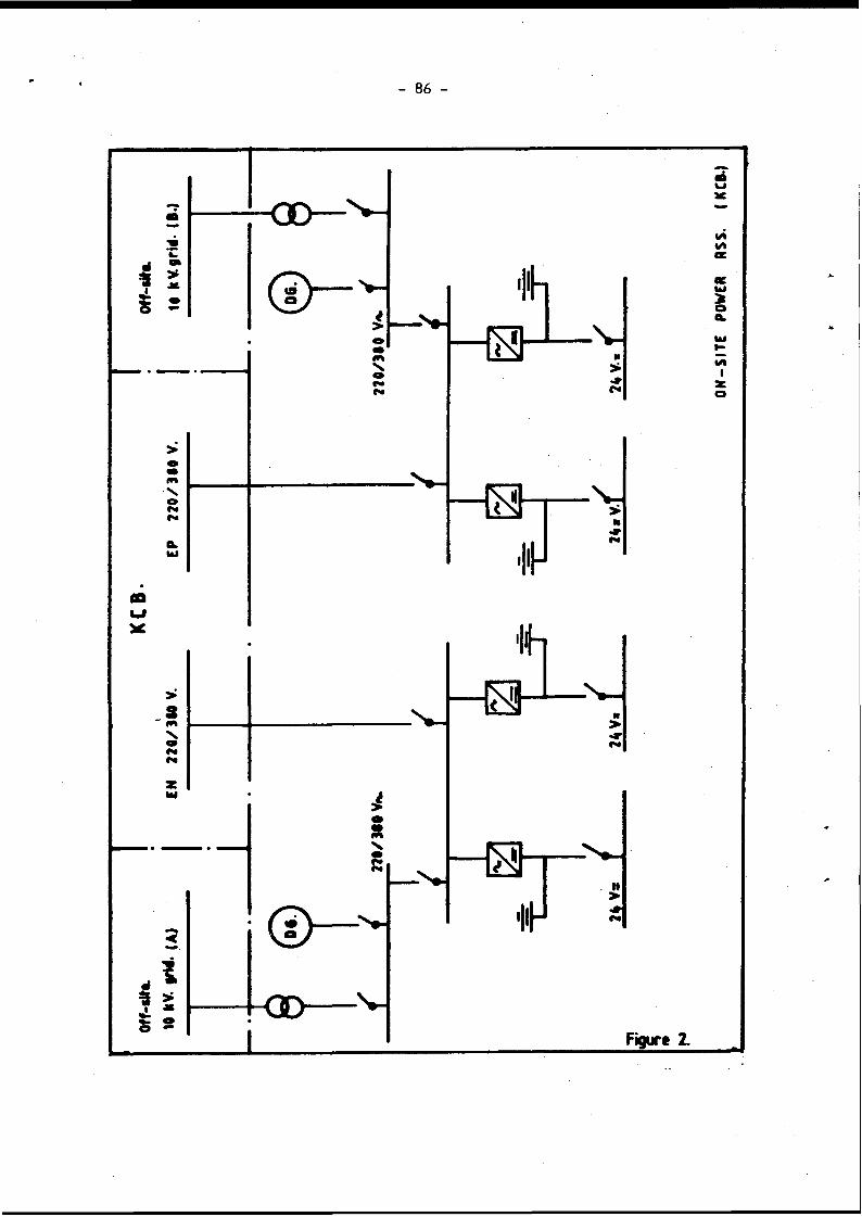
- 86 -

SESSION 2
RELIABILITY STUDIES
CHAIRMAN
MR. J. PETRIE (UNITED KINGDOM)
89 -
SUMMARY OF SESSION 2
RELIABILITY STUDIES
Session Chairman: J.L. Petrie (HMNII, U.K.)
In the second session six interesting papers, dealing with reliability studies, were presented.
Diesel generators are the most widely used on-site power sources. The general experience covering a large number of machines in many countries and of different manufacture, was that they were very reliable.
It emerged that there was a need for a better definition of success and failure if data is to be used for system reliability studies. In particular the USNFC Regulatory Guide 1.108 appeared to require very conservative assumptions.
It was common practice to require diesel generators to start and accept load in 10 seconds, to deal with a DOCA situation. Since this was on the limit of their capability- and was a source of failures and lower reliability, consideration should be given to the need for this requirement.
Attempts had been made to establish common mode failure rates, the probabilities of corrective action following failures and the effect of changing the test period
As might be expected, testing placed the majority of demands on essential systems and unavailability was largely determined by maintenance activities.
A proposal was described for up-grading the main generating plant on a multiple reactor site in order to provide emergency power for large loads.

- 91
PAPER N O . 2 . 1 .
A METHODOLOGY AND SUCCESS/FAILURE CRITERIA FOR DETERMINING
EMERGENCY DIESEL GENERATOR RELIABILITY
H.L. WyckoffElectric Power Research Institute
Palo Alto, California, U.S.A.
Abstract
In the U.S., comprehensive records of nationwide emergency diesel generator (EDG) reliability at nuclear power plants have not been consistently collected. Those surveys that have been undertaken have not always been complete and accurate. Moreover, they hive been based On an extremely conservative methodology and success/fallure criteria that are specified 1n U.S. Nuclear Regulatory Commission Reg. Guide 1.108. This Reg. Guide was one of the NRC's earlier efforts and does not yield the caliber of statistically defensible reliability values that are now needed.
On behalf of the U.S. utilities, EPRI is taking the lead in organizing, Investigating, and compiling a realistic database of EDG operating success/failure experience for the years 1983* 1984, and 1985. These data will be analyzed to provide an overall picture of EDG reliability. This paper describes the statistical methodology and start and run success/- fai lure criteria that EPRI 1s using. The survey is scheduled to be completed in March 1986.

92
INTRODUCTION
The U.S. Nuclear Regulatory Commission (NRC) is currently evaluating Its present regulations and considering new regulations bearing on the capability of nuclear plants to avoid station blackouts and to cope with station blackouts if they occur. This makes 1t essential that the nuclear Industry and the NRC have accurate data on the reliability experience of off-site and on-site AC power sources at nuclear plants.
The reliability of off-site power in the U.S. has been studied by EPRI and the records are being kept current by the Electric Power Research Institute. The data show that, contrary to earlier impressions, the reliability of U.S. off-site power is excellent. EPRI's goals for this database are very demanding. For each event it investigates to determine how long all off-site power is truly unavailable. This is to be contrasted to having an alternate source available but not used, or having a source become available but not used. For example, following the loss of all off-site power, the emergency diesel generators assume load. Even though it would be possible, if necessary, to resupply plant loads from off-site power very quickly, most plants are comfortable staying on the diesels until a convenient moment presents itself for switching back to off-site power. Also, in many events backup off-site power is available but not used and this important fact goes unreported. To acquire the detail necessary to discover these subtleties, it was necessary to review or reinvestigate past events.
The data show that for the 3 most recent years (1982-83-84) there were 0.013 events per site year lasting longer than 30 minutes compared to0.049 events per site year for the years prior to 1982. The median duration of loss of off-site power has been slightly less than 1/2 hour and the longest duration has been 8 hours and 54 minutes. The improvement with the passage of years 1s to be expected since losses of off-site power should continue to decline for many reasons. All plants that have had repetitive problems have completed or have underway major corrective actions. The improvements appear to have been very effective. Moreover, every new nuclear plant, fossil plant, and switchyard added to the U.S. grid further reduces the average size and exposure of relay protected zones. Also, the newer plants all have highly redundant switchyard arrangements. Nonrandom losses of off-site power that are repetitive are corrected as they are indentified and there is little doubt they will cease to be a factor. It is expected that future losses of off-site power will be mostly random and few in number.
The database for off-s1te power reliability developed by EPRI is essentially identical to that developed by NRC. These databases are now being used in industry and NRC deliberations. EPRI's database has been published as an EPRI report "Losses of Off-Site Power at U.S. Nuclear Power Plants - All Years Through 1984" (NSAC-85). These results are one of the important inputs that is needed to determine the risk of core damage from station blackout.

- 93 -
The reliability of the emergency diesel generators (EDGs) 1s another element Important in assessing the risk from station blackout. Comprehensive records of nationwide diesel generator reliability at U.S. nuclear plants have not been consistently collected. Those surveys that have been undertaken have been based on the success/failure criteria and methodology that 1s specified 1n NRC Reg. Guide 1,108. However, the Reg. Guide 1.108 method of determining EDG reliability was one of the NRC's earlier efforts and emphasizes arbitrary conservatism. It does not yield the caliber of statistically defensible reliability values that are now needed. The Reg. Guide Is Inaccurate for three reasons:
Reason 1: According to the method of determining EDG reliability that is specified in Reg. Guide 1.108, the EDG must start and run at greater than 50% load for longer than one hour to qualify as a countable run and success. Start-only (start without loading) and short load runs, even though the EDG successfully meets all the requirements placed on 1t, are not counted as runs and successes. On the other hand, start-only attempts that fall are counted as runs and failures.
Experience shows that there are many instances when an EDG is started manually or automatically, but there is no need to pick up load, and hence it is intentionally shut down. At least at some plants, this occurs more than 5 times as often as there are countable runs per Reg. Guide 1.108 (that is >50% load for >1 hour). The net result is that the database from which failures are counted is considerably larger than the database from which successes are counted.
Reason 2: Reg. Guide 1.108 calls for EDG reliability to be determined using data that includes the last 100 load-run demands, as such demands are defined in the Reg. Guide. At some plants the last 100 load-runs demands that are to be counted per the Reg. Guide reach back to the mid- 1970‘s. During this prolonged period most, 1f not all, EDGs have been modified many times to correct the underlying causes of identified problems. EDG reliability used 1n risk determinations should reflect conditions during the recent past and avoid the inclusion of data that represents the EDG and its operating environment in a much earlier state that no longer exists.
Reason 3: Failures as defined by Reg. Guide 1.108 include start attempts where the diesel required longer than 10 seconds to reach rated speed and voltage. However, it is not proper to classify all such events as failures since a fast start 1s required only 1f a large break LOCA occurs concurrent with a loss of off-site power, M l Past bonafide EDG starts have been for a loss-of-off-site power without a LOCA. A loss of all off-s1te power concurrent with a LOCA will occur rarely, if ever. Reliability values for application to the station blackout issue should reflect this.

- 94 -
Even with the large arbitrary conservatisms that are inherent in the success/failure criteria presently specified by Reg. Guide 1.108, the overall performance of EDGs at U.S. nuclear plants 1s very good. A study by R.E. Battle at Oaks Ridge National Laboratory* arrived at the following conclusions:
Estimates of the mean and median probabilities of failureon demandb
Mean Median
LER data 0.017 0.011
Data supplied in response to a request in NRC generic letter 84-15
0.027 0.019
A study by P.W. Baranowsky of the NRCc also found the average failure per demand to be about 0.02 with a significant spread from the highest to the lowest. The following summarizes the Baranowsky results.
Diesel generator start attempts and failures for tests and actual demands*d
Start attempt category
No of demands
No of failures
Failures per demand
Test 13,665 253 0.019
Loss of offsite power
100 5 0.05
All emergency demands
539 14 0.026
Summarizes the responses to diesel generator reliability questionnaires beased on 45 nuclear power plants, with 86 diesel generators, for operating year 1976 through 1980.
aBattle, R.E., "Emergency Diesel Generator Operating Experience, 1981-1983", Oak Ridge National Laboratory, NUREG/CR 4347, 1985.
bIb1d. p.15.
cBaranowsky, P.W., "Evaluation of Station Blackout Accidents at Nuclear Power Plants", Technical Findings Related to Unresolved Safety Issue A-44, Office of Nuclear Regulatory Research, DRAFT NUREG-1032, 1985.
dIbid. p.4-6.

- 95 -
The results of the above two studies are reassuring. But even these favorable results may be unduly pessimistic because they are based on and Impacted by the overconservatism of the Reg. Guide 1.108 success/fallure criteria and by the overall lack of complete and consistent industry-wide data. To help assure that industry and the NRC have available accurate emergency diesel generator reliability data, EPRI is taking the lead in organizing and preparing a realistic database of EDG operating success/fallure experience for the years 1983, 1984 and 1985. As with the off-site power database, the EOG database is being structured to provide reliability values that are realistic and that give a true measure of the impact that EOG reliability has on plant risk. This paper describes the methodology and success/fai lure criteria that are being used in preparing this database.
*

- 96 -
EPRI*S CRITERIA FOR CLASSIFYING EDG STARTS AND RUNS AS SUCCESSES OR FAILURES
A. GENERAL
The methodology and criteria presented here are being used in the EPRI survey to determine which EDG starts and runs are successes and which are considered failures. The methodology yields a reliability value that accurately reflects the contribution of an EDG's reliability to plant risk. Successes and failures for starts only and truncated load-runs, as well as for countable load-runs are included in the reliability determination.
It is recognized that there are also factors other than reliability that affects an EDG's overall contribution to plant risk. Availability is one such factor, because when an EDG is out of service for purposes such as maintenance and repair, it is not available for emergences. However, the present greatest uncertainty is EDG unreliability and EPRI is making this aspect its first priority. Beginning next year (1986), the Institute of Nuclear Power Operations will collect information on both reliability and availability on an on-going basis.
B. BROAD METHODOLOGY
Bl. For the purpose of determining the impact on plant risk, EDG reliability is considered to have two elements:
a. Start reliability
b. Load-run reliability
It can be viewed that there are two phases to EDG operation; the start phase and the load-run phase. The start phase ends when the EDG begins a countable load-run as defined in criteria Dl, or is shut down.
B2. EDG reliability = (start reliability) x (load-run reliability).
B3. Start reliability is defined as:
______Number of successful startsTotal number of valid demands to start
Load-run reliability is defined as:
Number of successful load-runs Total number of valid demands to load
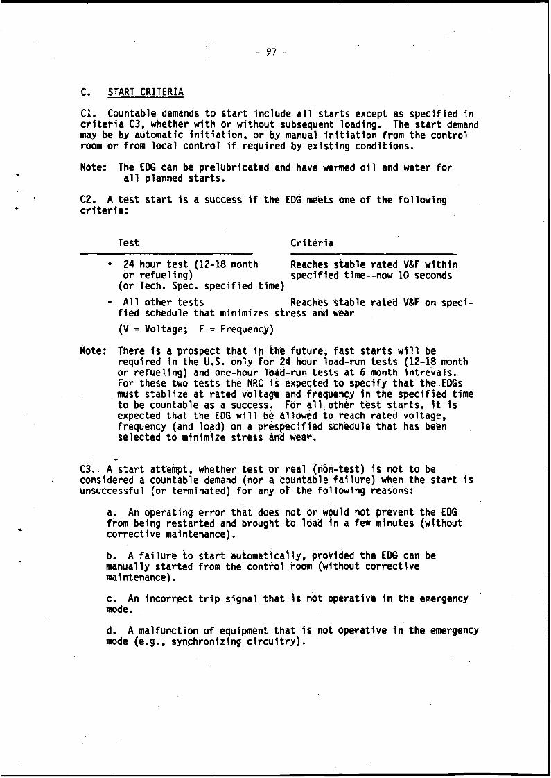
- 97 -
C. START CRITERIA
Cl. Countable demands to start include all starts except as specified 1n criteria C3, whether with or without subsequent loading. The start demand may be by automatic Initiation, or by manual initiation from the control room or from local control if required by existing conditions.
Note: The EDG can be prelubricated and have warmed oil and water for all planned starts.
C2. A test start is a success if the EDG meets one of the following criteria:
Test Criteria
• 24 hour test (12-18 month Reaches stable rated V&F withinor refueling) specified time— now 10 seconds(or Tech. Spec, specified time)
• All other tests Reaches stable rated V&F on specified schedule that minimizes stress and wear
(V = Voltage; F * * Frequency)
Note: There is a prospect that in this future, fast starts will berequired in the U.S. only for 24 hour load-run tests (12-18 month or refueling) and one-hour load-run tests at 6 month intrevals.For these two tests the NRC it expected to specify that the EDGs must stablize at rated voltage and frequency 1n the specified time to be countable as a success. For all other test starts, it 1s expected that the EDG will be allowed to reach rated voltage, frequency (and load) on a prespecified schedule that has been selected to minimize stress ând wéâh.
C3. A start attempt, whether test or real (non-test) 1s not to be considered a countable demand (nor a fcountâblë failure) when the start 1s unsuccessful (or terminated) for any of the following reasons:
a. An operating error that does not or would not prevent the EDG from being restarted and brought to load in a few minutes (without corrective maintenance).
b. A failure to start automatically, provided the EDG can be manually started from the control room (without corrective maintenance).
c. An incorrect trip signal that is not operative in the emergency mode.
d. A malfunction of equipment that is not operative in the emergency mode (e.g., synchronizing circuitry).

98 -
e. Minor water leaks and minor oil leaks that would not preclude operation of the EDG in an emergency.
Note: Test starts that are terminated before completion because of an abnormal condition that would ultimately have resulted in EDG damage or failure are countable demands and failures.
C4. A real (non-test) start demand is a success 1f the EDG is stable at rated frequency and voltage within 5 minutes from the first demand attempt. A real demand occurs whenever an operating occurrence in the plant requires that the EDG start in the interest of plant safety. The demand may be via automatic circuitry or through operator action, and may be valid or inadvertent.
Note: To help assure that the EDG reliability values reflect as closely as possible the EDG1s true contribution to plant risk, the success/fallure criteria for real starts (whether valid or inadvertent) are slightly different than the success/failure criteria for test starts. Even for a real loss of all off-site power to the safety buses, the time required to reach rated frequency and voltage does not significantly impact overall plant risk so long as the unit is ready to assume load within some fraction of an hour. The selection of a particular permissible start time (5 minutes) for real demands is arbitrary but reasonable.
0. LOAD-RUN CRITERIA
Dl. The load-run phase begins when load is applied to the EDG. A load- run demand 1s countable, except as specified in criteria D4, if the EDG operates so that the load-run meets one of the folowing criteria:
a? An intention to meet the plant's load and duration specifications for Its 1-month, 6-month, 18-month, or other test required by plant Tech. Specs.
b. An Intention at any time to operate at greater than 50% of plant emergency safety feature load rating for one hour or longer.
c. Any load and load-run duration that derives from an automatic or manual real (non-test) signal, whether valid or inadvertent.
Note: Demand to load is defined to occur only after a successful start. Thus a failure to start is not counted as a failure to load-run (just as a successful start 1s not counted as a successful load- run). The start reliability includes the performance of the EDG until the unit is loaded or shutdown. The load-run reliability is determined by the performance 1n meeting the provisions of criteria Dl and D2.
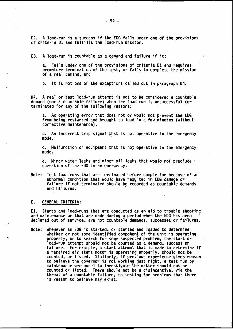
- 99 -
D2. A load-run 1s a success if the EDG falls under one of the provisions of criteria D1 and fulfills the load-run mission.
03. A load-run is countable as a demand and failure 1f it:
a. Falls under one of the provisions of criteria 01 and requires premature termination of the test, or falls to complete the mission of a real demand, and
b. It is not one of the exceptions celled out in paragraph D4.
D4. A real or test load-run attempt 1s not to be considered a countable demend (nor e counteble failure) when the loed-run is unsuccessful (or terminated for any of the following reasons:
e. An opereting error thet does not or would not prevent the EDG from being resterted end brought to load in a few minutes (without corrective maintenance).
b. An incorrect trip signal that is not operative in the emergency mode.
c. Malfunction of equipment that i£ not operative in the emergency mode.
d. Minor water leaks and minor oil leaks that would not preclude operation of the EDG in an emergency.
Note: Test load-runs that are terminated before completion because of an abnormal condition that would have resulted in EDG damage or failure if not terminated should be recorded as countable demands and failures.
E. GENERAL CRITERIA:
El. Starts and load-runs that are conducted as an aid to trouble shooting and maintenance or that are made during a period when the EOG has been declared out of service, are not countable demands, sqpcésses or failures.
Note: Whenever an EDG is started, or started qnd loaded to determinewhether or not some identified component of t!he unit is operating properly, or to search for some suspected problem, the start or load-run attempt should not be counted as a demand, success or failure. For example, a start attempt that is made to determine if a repaired air start motor 1s operating properly, should not be counted, or listed. Similarly, if previous experience gives reason to believe the governor is not working just right, a test run by maintenance personnel to investigate the matter should not be counted or listed. There should not be a disincentive, via the threat of a countable failure, to testing for problems that there is reason to believe may exist.

100 -
E2. Start or load-run failures that occur during successive retry attempts, and that are caused by the same malfunction before 1t is realized that an underlying problem exists, should be considered to be one demand and one failure, for the start phase or load-run phase, whichever is applicable, unless the EDG 1s maintained, declared operable and returned to service between attempts.
Note: On the other hand, there have been instances where an EOG received corrective maintenance following a failure and was believed to be fixed. It was placed back in service, but on a later demand again failed from the same cause, that in reality had not been found.Such a multiple failure with interposing corrective action should be counted as a multiple demand and failure.
E3. A planned load-run of shorter than one hour or less than 5035 load is not countable per criteria Dl. In the infrequent instances when such a planned load-run is initiated and a failure occurs during the run, the failure is to be counted as a failure of the start phase and not as a load-run attempt and failure.
Note: Such a load-run cannot be counted as a success because 1t does not meet the criteria of paragraph Dl. Therefore, to be even handed, if it fails it cannot be counted as a load-run failure. However, to keep the results as realistic as possible, the failure should not be ignored, hence it is best included as a failure of the start phase.
The following three exhibits show an example of the form that U.S. utilities are being asked to fill out for each EDG year and instructions that are pertinent to the form.

101
“ I
il 1il*
?
Io'_un Sc*;o3 1
XLU
|
■Si 5£!« oiO O UJcles 0.
«-il ; cci 42!Ï
-.t 82 < 8S H 1 ujO CAS>■ CE Z “ 0 3sg C 9te U SS * 2 S uj J ui 0«e
•*
?
1mtJC«1£3caS■c
?Crcc£3u«£
<BS£4Lc<0(/)Vi*UL>9y)
*oBg
s
Occ
asio
n 1
la D
em
an
d
1
t l -
i i ! * *
i nP l Sisi - . n . I i || l | ! | J i l i l i f i | i i ïJ i f ! i l i l lo Û Ù) 4L f: OC 4- 4- f
"1 r*«
û r c i en
V)c3
S
i
M Î
vnUNONm
Z
L » -
</> TUN
mr•
z
ù. 5 \
“ X<y>
a ï x5 9 55 o x32.
mZ$
l |I I e l
o rΠ^
Vi
Run
Ti
me
(hr
mm
) LHO«M
5<Cro-g
zû. s
“ 1 S
ren
2
à 5
« T S
Dat
e M
o /D
ay
<XX/XX( On«NJ
Occ
asi
on
lo
i D
em
an
d tî SSi 'N 'S"s "s'SS 's%s 's's'ss SSO T C i "s •s s
[ Lo
ad
Ru
ns
|R
un
Ti
me
(h
r m
in) ac o«NiO«M
P-
O«MOOO UNO UNO UN
moOenpn*
OmpHo o o
oUNO•HoATO3S
ZLL S S Z
y) T •Ss 'SS 's's"s S's 'Si Ss SV)s
55
ZLS\ "s Z
en T s'Sis'ss's 's 's'S%'S 'sSis s Ss265°|5 ?
cLO'V.«NJOCO«NJ«NJO
enenO«NJ«NJTTOo«n««ro
r”»mUNO
enCvCCOen
OvOOrs.O
enr--O«\a-*«.aca
UN«NJCOOen•"NiCOo
CgOCNoena>om•sOTT«SiiZï
a~4rNIMP“to*SCg
1?3U2s-V
i!n

102
Exhibit B.
HEADY REFERENCE
CRITERIA FOR OETERMININC NHICH E K STARTS A * RUNS ARE SUCCESSES AND FAILURES
STARTS
START DEMAND TYPE* COWCNTS SUCCESS CRITERIA*
Felt Test Sterts e 24 hour test (12-
18 «nth or refuel Ing)
• 8 aontb. 1 hour test In future
• For this survey, successful fest Stert red'd only for 24 hour,(12-18 aonth) test
• /In future. NRC *ey req. fest stert > \for 1 hour test et 6 aonth Intervals/
Reech steble reted VRF within specified tl*e— now 10 seconds (or Tech. Spec, specified tiae!
Slow Test Sterts • For this survey, ell test sterts other then the 24 hour (12-16 *onth) test
• Cen stert et rete to *1ni*ite stress 8 veer
/If there ere successive \ 'failures to stert, see 1E2 !
• Reech steble reted vif on specified schedule (thet alnl arizes stress end weer).
Reel Sterts (Non-Test)• Autonetic or annual, end
velid or inedvertent
• blent operating occurrence requires Stert
• If there ere successive feilures to stert, tee 1E2
• Reech steble rated vtF within 5 minutes, end
• Be capable of fulfilling mission in an emergency.
Test sterts for trouble- snooting or maintenance or wnile declered inooereole
• Not countable— do not list
*See paragraph C3 for unsuccessful And terminated st*rt attempts th*t would not prevent the EDG fro* fufulHng its mission in «n emergency. These should be entered with en *H" rether then e */■ in the fellure column, end not counted.
LOAD RUNS
LOAD-RUN DEMAND type” OWEN'Stmse am* r v a i w n a^ « « « r e « e m s e w m s
SUCCESS criteria”i w a n i f f e n t a s e e tia s a iq ia a s u s s e aaramwa
Test Load-Runs• 2* hour test (12-18 aonth)• 1 hour test (6 month-future)• 1 hour-test (I aonth)• any tech spec req'd tests• any test, >S01 ESF load
for longer then 1 hour
Meet load end duration coamit- aent of test
Truncated Test Load-Runs A truncated test load-run is any test load-run not meeting any criterion of SOI
Not countable as a load-run. if fails during truncated run, counts as a failure of the start
Reel Load-Runs (Non-Test) w Automatic or manual, end valid or inedvertent
All reel load-run demands ere countable as successes or failures regardless of the load or «ration
• Meet actual Toed end duration requirements of real (non-test) demand
• Be capable of fulfilling mission In an emergency.
loed-Runs for troubleshooting or maintenance or while declered inoperable
• Not countable— do not list
aaaaaa w* ae am mama * •-* aawmawM ■ae ••*§ewnmma mm a wwm * a ««a am«aesamaoeaseM •aooo eaareaqaaaMN seaeeaeee m i n u i i m
**See peregreph DA for unsuccessful end tensineted stert attempts thet would not prevent the EOS fro* fufulling Its aission In en emergency. These should be entered with en *N" rether then e */* in the fellure column, end not counted.
DIESEL HAKE COPE
Al AlCO NB NordbergCB Cooper Bessemer T01 Transamerica DélavaiFM Fairbanks Morse NO Horthington6H general Motors

- 103 -
Exhibit C
INSTRUCTIONS FOR FILLING OUT RECORD SHEETS
1. In most Instances there will be one record sheet for each EDG for each of the whole calendar years, 1983, 1984, 1985.
2. Filling out the records in pencil will result 1n the greatest speed and flexibility.
3. The outcome of all start and load-run demands, with the exception noted below, should be recorded in the main table of the record sheet.
Note: The only start and load-run attempts that are not to be recorded are those referred to 1n General Criteria.El. These are attempts related to trouble shooting, maintenance, and whenever the unit has been declared out of service.
4. Those start or load-run demands that are unsuccessful for reasons that would not preclude operation in an emergency and hence are not countable, as described 1n paragraphs C3 and C4, are to be listedIn the main table and failures table by placing an *'N" rather than a V " in the appropriate failure column (start or load-run).
5. Every event entry in the main table will record a start demand and the occasion for the demand. If the event continued to the load-run phase, it will also record that information. Where there was a load-run failure, the "run time" is the time to failure.
6. All events that are entered in the "failure column" of the main table either with a V " or an "N", are also to be entered 1n the lower table.
Note: If an LER has not been prepared for an event, leave the LER entry blank. The "cause of failure" description should be brief but -indicate the immediate and next level cause of the problem. If the event 1s not to be counted ("N"), very briefly Indicate the reason. If additional space 1s needed for description, use any unused lines. Legible, reproducible handwriting 1s fine.
7. Add up the columns, excluding "N" entries, and enter in the appropriate spaces at the end of the main table and In the upper right- hand corner of the record sheet. The demands are the total of both successes and failures. "N"s are not to be counted, either as demands or failures.

104 -
PRESENT STATUS
The U.S. utilities are currently collecting and recording the great amount of information called for by the survey. EPRI's goal is to Include the reliability history of all EDG's at U.S. nuclear plants for the years of 1983, 1984, and 1985. The history is to include start and load-run experience that occurred after the diesel units achieved stable performance following initial startup and shakedown. Fifty three nuclear power plant sites, having 160 EDG's have been asked to provide information for the survey. They represent about 450 EDG years of operation during the period 1983-1985.
EPRI hopes to receive and evaluate the data for the years 1983 and1984 during the fourth quarter of 1985. The EDG reliability results for1985 will be received during the first quarter of 1986.

- 105 -
PAPER NO. 2.2.
EVALUATION OF RELIABILITY O F ON SITE A C. POW ER SYSTEMS BASED ON MAINTENANCE RECORDS
G.Basso/*1 W.Fusari,(**> S.Pia/*’ G.Soressi/*"' G-Vaccari/**’’
(*) ENEA, Rome, ITALY (*) ENEL, Rome, ITALY (-*) ENEL, Milan, ITALY
AbstractTo the end of ascertain in what extent the evaluation til Reliability of emergency diesel generators (D.G.) can be improved by means of a deeper knowledge of their opeRltirig history à study has been carried-out on 21 D.G. sets: 4 D.G. of the Caorso nuclear plant (BWR, 870 MWe) and l7 D.G. in service at 6 steam-electric fossil- fuelled plants.The major points of interest resulting from this study Ire:1) reliability assessments of A.C. on-site power systems, made oh thé basis of outcomes of surveillance tests, mas-
lead to results which overestimate the teal performance.2) the unreliability of i redundant systeih of étihd-Eÿ cdrhpohents is determined in large extent by
unavailabilities due to scheduled and unscheduled ihtiihtënânéé, litem failures, tests.
ResumePour vérifier dans quelle mesure l’évàlùatiori dé la fiabilité des diëïél-élèctrOgénes de secours peut être améliorée au moyen d'unë connaissance plus étendue et détaillé! dé leurs histoire dë fonctionnement, on a effectué un étude concernant 21 diesel électrogènes: 4 apparténànts i la ëéritRàle nucléaire de Caorso (BWR, 870 MWe) et 17 en service auprès de 6 centrales électriques i huile combustible Ou charbon.Les indications les plus significatives fournies par cet éttide sont lés suivantes:1) Les évaluatons de fiabilité effectucés surtout stir la basé dei issues des essais de fonctionnement peuvent
conduire à des résultats qui surestiment la performance reélle.2) La fiabilité des systèmes redondants des cohipOsihtS en stand-by ést affecteé en large mésure par les
indisponibilités dues aux opérations d ’éntretien systématiques, aux interventions d ’urgence, aux défaillances latentes, aux essais de fonctionnement, etc...

106 -
1. PRELIMINARY CONSIDERATIONS
Difficulties encountered when assessing reliabilitv/availability of stand-by components and systems are well known. On the other hand-these components and systems should assure the main machinery protection in a nuclear plant as well as the prevention of accidents that could have dangerous -effects on the population. Such difficulties are due chiefly to two different factors:
— insufficient quantity of information about the operating experience of components and systems similar to those to be assessed.
— incompleteness of information: single events are notified in an excessively synthetic wav; this does not allow the analyst to make sound assessments.
In order to ascertain in what extent the evaluation of reliability of these components can be improved by means of a deeper and detailed knowledge of their operating history, a study has been carried out on 21 emergency diesel generators: four ot them in a modern nuclear power plant and seventeen in six Italian fossil-fuelled electric plants.In the following paragraphs the documents analysed, the criteria adopted and the results obtained are described.
2. — DOCUMENTATION
Information required by this study has been taken from:
— for the 4 diesel generator sets of the Caorso nuclear power plant (BWR, 870 MWe):a) events notified by the licensee to the nuclear safety authority, according to the Technical Guide DISP/
ENEA n . l l .b) events stored in the licensee data bank: about 1500 reports referred to the interval 1978-1984c) Diary of machine of the 4 diesel generators retrieved from the maintenence file of the licensee’s data bank.
Information given by the diary1 are: progressive number and date of issue of the work permits; start and end dates of maintenance works; type of intervention (planned, unplanned, system modifications); availability of diesel generators before the intervention and during the works; cause of failure; man-hours required by the works, short description of the works and of the component affected. Up to 31.8.84 452 work permits had been issued for the 4 diesel generators.
— for the 17 diesel generators of the 26 fossil-fuelled units of Tavazzano 1-6, Piacenza 1-4: Turbigo 1-4; Casella 1-4; Ostiglia 1-4; La Spezia 1-4: the diaries of diesel generators retrieved from the licensee’s data bank. For about 123 units-year of operating experience the diaries of machine gave data of 1571 work permits.
Table 1 shows some data referred to the mentioned power plants and relative diesel generators.
The present study took advantage and inspiration from other previous reports about reliability of stand-bycomponents in general and of Diesel generators in particular.Some of these reports are cited in bibliography.

- 107 -
3 — SHORT DESCRIPTION OF MORE COMMON UNAVAILABILITIES AND OF DUTY CYCLE OF EMERGENCY GENERATORS.
Duty cycle: the normal duty cycle of a diesel generator follows generally the cycle of the plant. When the plant cycle is annual, then so is the cycle of its diesel generators.During the annual planned outage of the plant also the diesel generators can. undergo a complete overhauling followed by a functional test under load. For the rest of the year each diesel generator set is weekly or monthly subject to surveillace tests. Generally frequency and nature of maintenance are decided according to troubles or symptoms noticed during the tests.Diesel generators are tested at full power for 1 hour. Therefore the negative tests are credible while positive ones do not fully demonstrate their capabilities of reliable operation for an extended period of time.Fig. 1 shows schematically the actual and theoretical diagrams of unavailability of a diesel generator under the hypothesis of an unavailability probability which is proportional to time.Maintenance: in a nuclear plant the availability of diesel generators must be assured even when the reactor is shut-down, because core cooling capability must be maintained in case of loss of the outside power (L.O.O.P.). In conventional plants this problem is not encountered (★ ); therefore the intervals of planned outage of the plant allow a greater freedom in doing the diesel generator overhaul activities.
The licensee can perform maintenance according to one of the following models:— symptomatic maintenance: the interventions on diesel generators take place only in cases of failure under test
or on demand.— preventive maintenance: the interventions on diesel generators take place at planned intervals of time for
repetitive works; in addition interventions are performed as suggested by functional anomalies verified during surveillance tests even though a test failure did not occur.
Unavailability of diesel generators: for the purpose of the reliability evaluation it is convenient to distinguish the following conditions in which a diesel generator can be:— unavailability due to a failure, awaiting for the repair work beginning.— unavailability during maintenance: some kinds of intervention require preventive disconnection of actuation
logics aud the diesel generator has to be considered as unavailable.— latent unavailabilities: often surveillance tests ascertain an unavailability state preceding the start of the test.
The beginning date of this unavailability cannot be determined. As a first approximation it can be assumed that in the period of time elapsed from the previous surveillance test the diesel generator has been unavailable during one half of such time.
— unavailability due to surveillance tests: during a surveillance test a diesel generator cannot respond automatically to an undervoltage signal of its bus-bar. H ie unavailability time is very short when the test is succesful. In case of failure or functional anomalie», unavailability is prolonged if the diesel generator is put out of service or submitted to maintenance.
Repair time: in the cases of failure to start or failure to run, the knowledge of the average time required for repairing the failure and putting again in service the diesel generator, has a particular importance. Even though technical specifications require a maximum time of about 30 seconds for start up and loading, it is evident that negative consequences of a plant black-out have their effect at least after 30 minutes-1 hour. Some simplest failures, therefore, can be repaired within this reasonable time. Many other failures, however, require longer times, generally more than 10 hours.
(♦ ) excluding the cues where, during planned maintenance, the alternator left in a hydrogen atmosphere, is concerned. In this case the availability of the emergency power supply for the hydrogen seal systems is strictly required.

108 -
4 — INTERPRETATION OF OPERATING EXPERIENCE DATA
The instant probability of mission failure of a stand-by component is generally evaluated as the ratio between the number of negative outcomes and the number of operation demands:
Po
where:N, = number of start-up demands;n, « negative outcomes of the N, demands;
111 +N, ♦ Na
N2 = number of periodical surveillance tests; n2 * negative outcomes of the N, tests.
This evaluation criterion gives not much credible results, because of the following reasons:a) the surveillance tests are not equivalent to a real operation under load.
In generaln? * _üi_ with N2*N ,n 2 n ,
Therefore the probability p0 is determined by the results of the surveillance tests (many but with a low degree of credibility) rather than by the few results of the real demands in case of need.
b) in order that the probability of failure on demand, p0, has a physical meaning, its indipendence on the demand frequency should be demonstrated. In other words, if the hypothesis is made that the number of demands doubles or is reduced to a half, p0 should have to remain constant:
Pon’N 7
nnN* * const.
On the contrary the operating experience shows that p0 is not independent on the demand frequency. When N is low, p0 decreases when N grows, then, grows when the frequency of demands is higher than a certain threshold^ value.Two other criteria for evaluating the time-average probability of failure of a stand-by component are the following:— mixed criterion unavailability/failure on demand. In the period tc when the component unavailability is
ascertained, the probability of failure on demand is 1. In the periods of presumed availability the probability of failure is assumed as equal to the ratio between the number of negative outcomes and the total number of demands N. Therefore the average probability of failure during T is given by:
Pi tc + (1 _ _*£_) x nT T N
2)
— criterion of the availability factor. Being t( the total duration of the ascertained unavailabilities and t, that of the latent unavailabilities in the period T under consideration, the average probability of failure on demand is:
p2 = <c * . 3)
In fact, each demand of operation is seen by the stand-by component as equivalent to a random occurence; thus the probability that the demand occurs during an unavailability (with a failure) is measured by the ratio (tf + t,)/T.

- 109 -
This cannot be said in the case of the surveillance tests that are performed only when the component is assumed as available. The duration of the latent unavailability, t,, can be evaluated on the basis of the number and modalities of failure under test and on demand. The failure causes and the works performed to eliminate them allow in general to ascertain whether the unavailability existed before the test or occurred as a consequence of the test. In the first case the supposed duration of the latent unavailability can be assumed as equal to the half of the time elapsed from the previous test.
The selection of one of the 1). 2), 3) criteria depends on the quality and quantity of the available information.In the case of a diesel generator subject to symptomatic maintenance (small unavailability) the application of the criterion 1) can give reliable results when the frequency of actual demands is high, in the opposite case the ratio between failures and demands does not allow a credible evaluation.Criterion 3) considers only the times of ascertained and latent unavailability. For diesel generators subject to preventive maintenance and to few actual demands it gives results more reliable than those given by criterion 1). However it can introduce noticeable errors when the probability of failure under test has the same order of magnitude as, or higher than , the unavailability factor.Criterion 2) appears to give results less affected by errors, as a consequence of the possible unbalance between unavailability and frequency of demands.In the framwork of the present study the evaluation of the failure probabilities have been made with the 3 mentioned criteria.
The recovery time of a D.G. after a mission failure has been evaluated, as well as the probability that after 1,2..., n hours subsequently to the failure the diesel generator is returned to service.The recovery times after a failure under test (the only data available) have to be considered longer than those strictly required, because in these cases there is not a real need to regain at any cost the D.G. operability. An other factor capable to affect the time to repair of one D.G. il the reliability of the on-site emergency power system as well as the reliability of the off-site power-grid. For instance the Caorso nuclear power plant has four diesel generator sets; only one of them is required. In addition the plant is connected to two indipendent transmission lines, respectively 380 and 110 KV. Caorso is connected also to a small hydroelectric power plant, about 5 km away.
5. ESTIMATION OF THE FAILURE PROBABILITY FOR THE 4 DIESEL GENERATORS OF CAORSO NUCLEAR POWER PLANT
Among about 1300 operational events analysed, 38 concerned the diesel generators. 31 of them are referred to individual sets and the remaining events to two or more sets, namely:
— 4 events common (or potentially common) to 4 aets.— 2 events common to 2 sets.— 1 automatic start of a set couple on spurious signal.
The analysis of the diaries of machine allowed to find other unavailabilities of the 4 sets (due mainly to planned maintenances). By means of both data sources it Has been possible to reproduce the time sequence of unavailabilities and of failed tests.
The number of maintenance operations listed in the diaries of machine during the period 1/7/1978 - 31/8/84 are 452.332 of them concern failure repair while 120 are referred to other maintenance works without component failures (sampling, instrument recalibration, etc.).243 interventions have been performed on D.G. aets available before and during maintenance works;

- 110 -
191 in te rve n tio n s have been p erfo rm ed on D . G . sets available before the start o f w o rk s b u t disconnected (and then unavailable) d u rin g w o rks. F in a lly in 18 instance D . G . sets w ere unavailable before the m aintenance and d u rin g the w orks.
Ta b le 2 contain data requ ired b y the evaluation o f the mission fa ilu re p ro b a b ility according to the p reviously m entioned crite ria 1), 2) and 3). T h e exa m in a tio n o f data contained in this table suggests that:
— the m ission fa ilure p ro b a b ility is about 0,06. T h is value can ben considered as norm al w h e n m aintenance unavailabilies are taken in to account;
— the latent u n a va ila b ility o f diesel generators subject to m o n th ly surveillance tests has the same o rd e r o f m agnitude as the ascertained unava ila b ility.
Fig. 2 shows the tren d o f p ro b a b ility p that a diesel generator fails to be re co ve re d a fte r 1,2,3,... n h o urs elapsed fro m a m ission failure.
I t can be seen that the p ro b a b ility to re co ve r a diesel generator w ith in fe w h o urs is v e r y lo w . T h is can be related to the freq uency and q u ality o f the m aintenance in te rve n tio n s: the m ore tr iv ia l fa ilu re causes are elim inated and the D . G . ra re ly fails on dem and. H o w e v e r these rare events requ ire m ore than 24 hours o f re p a ir tim e. I t can ben predicted that the diesel generator perform ance could be d iffe re n t, i f m aintenance in te rve n tio n s w e re less frequent.
6. EVALUATION OF THE MISSION FAILURE PROBABILITY OF 17 D.G. OF ITALIAN FOSSIL- FUELLED POWER PLANTS.
T h e analysis o f 1571 w o rk perm its, p e rfo rm ed b y means o f the same c rite ria as those adopted fo r the 4 C aorso diesel generators, gave the results show n in Ta b le 3. O n the average the m aintenance occurrences have been 12.8 per u n it p e r year... 5.6 o f them h a ve been p e rfo rm ed being the diesel generator unavailable because o f a previo u s fa ilure o r as a consequence o f the nature o f th e w o rk s to be made. T h e average h o urs o f ascertained u n a va ila b ility are 228 h per u n it p e r yea r w h ile 58 are the hours o f latent u n a va ila b ility. T h e m ission failures u n d e r test are not u n ifo rm ly d istrib u te d am ong the 17 generators. T h is can be due to tw o factors:
— th e non u n ifo rm ity o f c rite ria in use at the 6 conventional plants in consid ering a test as a m ission failure.
— the in te rve n tio n o f the operator in ord er to assure the success o f the test, re m o vin g possible causes o f failure.
N o m ission fa ilure results to be occurred in the case o f loss o f connection to the g rid (L .O .O .P . ) .
T h e average p ro b a b ility o f fa ilure, about 0.04, is lo w e r and b e tte r o f that resulting fo r the 4 C aorso diesel generators. T h is can be at least p a rtia lly e xp lained b y the d iffe re n t size o f the sets: the C aorso diesel-generators have a 5400 K W u n it pow er, w h ile the p o w e r o f the 17 sets o f the conventional plants ranges betw een 500 and 700 K W . F u rth e rm o re it m ust be noticed that statistics concerning C aorso and co nventional plants can be used fo r p re d ictive purposes v e ry cautiously. In fact:
a) the significance o f the “ nuclear” sample is, statistically, lo w ; this can reflect nega tively on the average values found ;
b) the safety fun ctio n s o f the “ nuclear” diesel generators require a h ig h er m aintenance standard. T h is implies m ore freq u en t in te rve n tio n s, then longer u n a va ila b ility times;
c) the technical specifications fo r operations o f “ nuclear” diesel-generators are u n d o u b te d ly m ore stringent; this c o n trib u te to de fin e as failures events that in the co n te xt o f fossil-fuelled plants w o u ld not be classified as anomalies.
F ig . 3 shows that the non re co ve ry p robab ility after a mission failure e xh ib its a tre n d sim ilar to that o f C aorso D .G .

- 111
7. COMMON CAUSES OF FAILURE AND UNAVAILABILITY
The analysis of anomalous operation events and work permits concerning the 21 diesel generators under study has shown few cases of multiple and contemporary unavailabilities. The cases where it has been verified that the failure in a D.G. was due to causes existing also in the Other D.G. are more frequent.
The following cases are a sample of the multiple unavailabilities verified:
Caorso, February 1979 • In-leakage of water from man-way in to the common fuel storage tank. 2500 liters of water discharged. Unavailability: 170 hours. If the 4 diesel generators had to operate in those conditions, they probably had tripped because of the fuel pollution.
Caorso, June 1979 • While the diesel generator-2 Was running, 4 decrease of the power output occurred. It has been found out that the load set-point of the governor drifted because of the engine vibrations. A test immediately performed on diesel generators 1,3 and 4 revealed the exixtence of the same problem.
Caorso, January 198$ - Because of the particularly low weather temperature ( -2 2 °C ) and of the insufficient concentration of antifreeze in the diese] engine cooling water loop, the water freezed inducing the unavailability of all diesel generators during 48 hours. According to technical Specifications the plant was shut-down for the same time.
Tavazzano 1-2, September - Because of leakages from the fuel storage tank, the diesel generators remained unavailable during 120 hours.
Case 11a August 1979 - The D.G.-4 has been unavailable during 564 hours because of maintenance works. During the same period works have been done on D.G. 1,2,3. Along 36 hours only 2 D.G. have been available.
Common cause failures occurring in a redundant system of diesel generators depend on their design characteristics and on the maintenance model adopted.
All the 21 diesel generators taken into consideration have indipendent auxiliary systems. Only the fuel cycle has components common to all the diesel generators of the tame plant; in some plants each D.G. has a daily tank fed by one storage tank. The failures of the storage tank (piping» level meter, etc.) can, thus, determine contemporary unavailabilities for all diesel generators.
The probability that a potential cause determines contemporary multiple failures can be considered mainly as a function of the maintenance model. The operation history and the diaries of machine of the 21 generators show that preventive maintenance is often able to find out in advance the potential causes of common failure allowing to intervene by means of suitable actions.During the about 140 units x year of operating esperienze of the diesel generators, as analysed in this study, never a mission failure single or multiple occurred following a real demand. Furthermore the execution of surveillance tests in different days for the diesel generators of the same plant, does not allow to verify whether the potential causes of common failures could have been really evidenced. Nevertheless a detailed analysis of data recorded in the diaries of machine induces to think about the credibility of evaluations based exlusively upon logic-mathematical criteria.
For instance the failure probability of the redundant system of 4 Caorso diesel generators, as computed under the hypothesis of independence of failure probabilities of the 4 sets, should be equal to:
P’ « p* * 1.3 x 10^’The common unavailabilities, ascertained or latent, account for 240 hours in 51.500 service hours. Even assuming

112
that only 1/3 of this unavailability should be considered in evaluating the system unreliability, we have:P” „ 1/3 _ 2 4 0 _ + p< , 0.00155 + 0.000013 3 1.56 x 10~}
51500
In practice the probability of system failure is determined by the few hours/year of contemporary unavailabilities. This must not surprise since the probabilities of failure of single diesel generators are not independent as a hasty analysis of available data could suggest. In fact:— surveillance tests are performed in different times for the diesel generators of a plant and when there are no
reason to think that a set is unavailable.— not all the maintenance operations are preceded by a functional test. So some latent unavailabilities cannot be
reavealed.
It is reasonable to think that:— if surveillance tests were performed at the same time for all the diesel generators of one plant the potential
common cause failures should determine contemporary unavailabilities with a frequency higher than that presently found.
— if surveillance tests were performed rigidly at fixed times (for instance at 10 a.m. of each Wednesday) without taking into account che diesel generator operability conditions and the state of the plant, it can ben predicted that some failures presently unrevealed could occur.
— if each maintenance, planned or unplanned, with the plant shutdown or at power, were preceded by a functional test, it can be expected that some latent unavailabilities presently unknown could be put into evidence.
This should not be interpreted as a reccomendation to modify present criteria for D.G. testing and maintenance, only for the purpose of improving the quality of data to be used for reliability analysis. We want only to point out that incompleteness and unreliability of information presently available, even though useful and significant, do not allow to obtain credible results from sophisticated logic-mathematical models as offered by the reliabilitv theory.
An empiric evaluation taking into consideration non statistical parameters (e.g. the maintenance quality, the onsite stock of spare parts and consumable materials) appears more appropriate considering the complex nature of the problem and the limited reliability of data at hand.
References
/ l / J.P.Poloski, N.H.Sullivan: “ Data Summaries of Licensee Event Repons of Diesel Generators at U.S. Commercial Nuclear Plants” NUREG/CR 1362, March 1980.
/2/ Silvana Pia: “ Comportamento in esercizio dei gruppi elettrogeni d'emergenza in Italia” — ENEA/TERM, Rapporto tecnico interno NRBY 1TP4B013, Nov.1982.
/3/ Silvana Pia: “ Esperienza di funzionamento dei gruppi diesel elettrogeni d ’emergenza delle centrali LWR americane” — ENEA/TERM Rapporto tecnico 84/1, Jan.1984.
/4/ J.W. Minarick and C.A.Kukielka: “ Precursor to potential severe core damage accidents: 1969-1979 A status report" — NUREG/CR-2497 — June 1982.
/5/ IAEA — TEC DOC — 332 « “ Safety aspects of station black-out at nuclear power plants” Vienna, 1985.

- 113 -
(%> Axpii^ii^AïNn
Fig.
1 - Q
ualita
tive
diagra
ms o
f real
and
theor
etical
unav
ailabi
lities
for a
stan
d-by
Diese
l Gen
erator

114
Fig. 2 • Non-recovery probability p of a D.G. aet 1,2,3......... n hours after an unsuccessfulperiodic test (average data for 4 DG sets of CAORSO)
0 . 2 -
0.01__ i___ L0 L
J-----1----- 1___i i8 12 16
J ------ 1____ L_20 2L-J--- 1---1___i___ i »-28 32 36
HOURS
Fig. 3 - Non-recovery probability p of a D.G. aet 1,2,3,...... n hours after an unsuccessfulperiodic test (average data for 17 D.G. sets of fossil-fuelled plants).

115 -
Table 1 • General data on power planta p d tbeir etnerjency Diesel-Generstors (D.G.) selected for the reliability analysis.
Name of the plant and units Fuel capacity
MWD*t* M
I" ParallelNumber of D.G. sets
TAVAZZANO 1 OIL 70 4 1952TAVAZZANO 2 OIL ?P 9 1952TAVAZZANO 3 OIL 140 5 1959 3TAVAZZANO 4 OIL Î4Q 12 1963TAVAZZANO 5 OIL 320 12 1981TAVAZZANO 6 OIL 320 9 1982
PIACENZA 1 OIL 70 4 1953PIACENZA 2 OIL 70 11 1953 2PIACENZA 3 OIL 320 9 1965PIACENZA 4 OIL 320 10 1967TURB1GO 1 pIL 200 5 1967TURBIGO 2 OIL 260 4 1970 2TURBIGO 3 OIL 260 8 1970TURBIGO 4 OIL 260 11 1970
OSTIGLIA 1 OIL 320 12 1967OSTIGUA 2 Oil. 320 4 1973 3OSTIGLIA 3 OIL 32P 1 1974
- OSTIGUA 4 OIL 320 7 1974
LA SPEZIA 1 COAL |?0 8 1962LA SPEZIA 2 COAL 320 5 1964 3LA SPEZIA 3 COAL 640 7 1967LA 5PEZIA 4 COAL 640 7 1967
CASEL.M 1 OIL 320 7 1971CASELLA 2 OIL 320 12 1971 4CASELLA 3 OIL 320 6 1972CASELLA 4 OIL 320 5 1973
CAORSO 1 NUCLEAR 870 5 1978 4
T«al 2»

Table
2 • C
AORS
O NP
P. Per
forma
nce o
f the
4 D.
G. in
the
indica
ted o
bserva
tion p
eriods.
- 116 -
d ooOoocs
To
tal
4
D.
16
8
1 1 1 s r e N
39
71
25
20 rsi
ITS
r -
©
ITSres
©
rgs r1rsO
*-■ c T © o
•v à00ON ••
. « O
00 rsi rsi rsi *
OITSO csi I 1 1 1 rg
Os o rsi s rres
ITSc.E
Q O ' 00 ©•*< o o o o
org o " o * o * *n
>NV)
rsi rg Zr.00 ITS
CsiTT
«SA o r - soON o
QONON
1 1 1 rg —O00
OOo
O ' r—o
rg Cso
. wO
mm rsi o o * O ' t/i
mît o
E CM 00 CN«6
0 oITSON rg I 1 1 1
ITS00
osO e s
e srsi
SOST
s rrrsCfa 5 ON NO res o o o
CM © © o * E
csj4Ts
Os
oT
DG
l
rsi1 1 1 — l 6
64 O
sOrrs OO
00ersrsiO
■a-ITSs rO
rg•vr s
ucc«c4/
fM o ' © o C
<N EIA e S
o pON•■a ON I 1 1 I . sO
GOosO
Vr*S. o
r -soirs -D
4100Os«■4
a<NI
rrs © _o *
o© “ ©
CCCO
•N
•mm **>
fNION
29
r *sO
00SO
rr\00 C
oe
1 o sDf+\ rg VN
rsi NO©
rg Os© "O
o fSI © * o o ‘ c«0
00 CL
Osmm
•
*N
g
fN|O '*-<
29
1 o res rsj©NO
Boo
e srsi
Osoresrsi
00sO
ca
o00 Q• fNI © ©mm V
Eg mm <N
ON ITS o . r - rsi res- o(O
£ g 29
1 o rsi er\ rsiIA
ooo 2
6 sO ©res
ITSrg
QfNI © o 1£
TO
’ tcm >4* tcvo «O • « c«0
•54#
4
m
*5>
©etoc
a
e m > 4»»s TS 9 c
9me
►4»
v* •C g a* c a 4» 9 wc4*>
co 1
« c 1c*>
4*e
C« # # •u
w s§
- c
1
Eo
JS
V»• aCmE
• a
EV
T 3
s.2*1.
• o
§«1
i
sm
OVO
t9
i -
©
£9
1
*5
gJS
*©
ea
c
: i•B
%o
& 6Lr»
a .
aMVfc.
J l«5
U .
2 o c
89O .
%f)*5Urn £ 1 ac
©s
oz «

Table
J - P
erform
ance
data
of 17
D.G.
sets
at 6
fossil
-fuelle
d pow
er pla
nts
- 117
Powe
r plan
t
! i 1571
C2 ' r—'N Ç* C *o & o*coo o c o'
£
J£ E 5 » S 1 * | S ’ 1•O- IO IO5 - Rc o o o' c* o'
S 5 J£ r~*«*R1 i 3 I * 1 §. . « os*g 5 Scoo o c o'— 2 r-IA♦M — = s — •*■ai? S -. £.c c. c
1
K <=S i * - s 1 1 1 s c Osj Om o o o' o'S « - ©K lieCoo o' o o'
04 r K; « c » § s ® * i i » | e*»«C Oc o o o o- £ a 2 e S c ; J i ç “ R 'r — S c ll
1•3R Jg r* e•C5 o ;c **■ s rs o. wg ?COOo" o o'
V S J « c « £ _ _ r-vP£ÜR 1 = «•= r!o o o o' o' o'es* R -e ~ e £ 2 5 £o o o- 5; >o £ oS 2 5:0 0 0
0 0 0
j
N 2 © —04fOJUssgsi— «•"s <«- >ô «_T —rs —MOOO 0 o’ 0
- Ç \S - NX?5=*ii=!sC ©»2 g gsesc c c
*N X -' - s ? S «S4 - £ O* OC S^^CC"SSC- ïS S £ £0 0 c
- C £r—■ e*a!*s£vc«£r:SRR-J — »M A ^ OC î\ O — — 0 0' C
Event
ë1
■fill 155ÈS5
5i f - |
jS s s f j ' i j•g | i | | I h 2
êli'èélàë
£ £ £ £ £ £:

119 -
PAPER NO, 2.3.
RELIABILITY OF DIESEL GENERATORS AT THE FINNISH AND SWEOISH NUCLEAR POWER PLANTS
Urho PulkMnenTechnical Research Centre of Finland Espoo, Finland
ABSTRACT
The operating experiences Of 40 stand-by diesel generators at the Finnish and Swedish nuclear power plants have been analysed with special emphasis on the impact of the frequency Of surveillance testing and of the test procedure on diesel generator reliability, the contribution of design, manufacturing, testing and maintenance errors and the potential and actual common cause failures, The results pf the analyses consisted both practical recommendations and mathematical reliability models and useful reliability data.

120 -
1. INTRODUCTION
The operating experiences of the stand-by diesel generators in the Finnish and Swedish nuclear power plants have been analysed with special emphasis on
impact of the frequency of surveillance testing, and of the test procedure
- contribution of design and manufacturing errorscontribution of the testing and maintenance errors, and the error mechanismspotential of actual multiple failures (common cause failures).
This paper is based on a reliability study of diesel generators in Finnish and Swedish nuclear power plants which was financed by Swedish Nuclear Power Inspectorate and Finnish utilities [1].
Similar studies have been done on diesel generators at U.S. nuclear power plants, see for example [2] - [3].
2. THE DATA BASE
2.1 Plants and their diesel generators
The operating experience of 40 diesel generators at Finnish and Swedish nuclear power plants has been covered in this study. The list of studied plants with some technical data is presented in table I. The failures until the end of 1981 are covered in this study. The data base contained 40 diesel generators with about 150 accumulated diesel generator years, about 4500 starts and about 6000 hours of DG operation.
The failure data were collected from the Finnish nuclear power plants by Technical Research Centre of Finland and from the Swedish nuclear power plants by ASEA-ATOM. Analysis and interpretation of failure information has been done in co-operation with personnel of the nuclear power plants.
The diesel generator (OG) assembly is defined here to consist of diesel engine with auxiliaries, generator, starting air system and starting automatics and generator breaker.
The failure information, is obtained from descriptions in work orders and failure reports and in A m -reports.
In many cases the failures were inadequately described, but the most important information about the criticality of failure could be found out. The failure cases were also analysed and interpreted in co-operation with plant personel.
2.2 Test procedures
Testing of diesel generator varies from plant to plant. Test intervals vary one week to one month (four weeks). Also different test types are in use. In some cases the testing procedure has been changed during plant operation. 1
(1) = Data bank for the Swedish nuclear power plants including also TVO plant in Finland.

Table
I. Plants and their
diesel generators.
121
P02UO pp<U a»O CO CO«S 02 0) Z Z Z Z Z Z Z yM-l • P c d> 3 £3 p> u o U 0 U O •J ->3 *o H H H H < < < < < < < <C Ô0 Z S S Z CO 00 CO CO CO CO C/5 005 «P BZ O 02
MPO
U 5 O O O O o o o o o o o o02 <r o O o o o un m o o o o3 CO VO nD vO V0 S0 vO r*. rp vO vD 00 000 O P H P CM CM fP «p CM <Neu O
U CA02 aJ3 aR CM CM CM CM sfr <r sT <r3 CPZ O
un m r-s O rP ko un 00 o n. o'U r-» ns r*- n* 00 00 n* ns n> 00 00O) ON O' ON ON ON ON ON ON ON ON ON ONP p fp fp »p fp (p fp fp fp p H pU0) fp p r-s r-s CM vD fp un On CM CM p
<0 P H o O o o •p o O o O o c fp■U P O(Q o p P »p fp H o o «n! p CM 00 00 sJQ a uw O C O o fp fp o o o fp o o
fp CM un n. o fp v0 un On o ns fpCO 3 ns n* r-s 00 00 n*. ns n* 00 n» 00•p O on ON On O' On ON ON ON ON On ON OnU rH P «p fp fp fp p fp p fp fpP P02 CO vO CM n* r-» CM sO H un o O un CM
P B O P O O fp o o o p fp o OCD • • • • 9 • • • • • •
O (X P CM un •p fp O o fp fp O n ON s3*O O tp O rP O o fp fp O o O O O
cO
.pPC0 fp <r un n* o tP <T -S 00 O ns ON f-s n* n* n-. 00 oo ns n» ns 00 r-s 00
• P ON O n ON On ON O n ON ON On O n ONC P p P p fp rP p i »p fp fp fp fpO •
P P 00 O m en nO rP o 00 O* CM CM fpCA O o fp o o O O p o O O o fpP c • • • • • • • . • • • •
•P ON un fp un n» sfr ns CM 00 00 sjU* CO «P O fp CM o CM fP fp O fp o o
p O stf un o O en ■sJ 00 On r-s o•p n* n* r--. ns qo r-s. n* ns n» fs. n* 00p On On ON ON a h ON On on O' ON ON On(0 H P •P •P P rp p l p fp fpU
P ■p CM CN P CM <r rP CO vp r-» o p o"CA p H O O O o rP t s O O P O pP • p • . • • • * • • • ♦ •
• P p CM CO 00 CM un r-s © On fp m O r-slu U •P O fp O CM fp CM p CM p CM rp • •
CAU
021p
3U
U
ceiP CM Up
p CM 3C ç fp CM fp CM cE B J * fp CM ce(0 CO o V M M CA (A
B
J= r * . :ce :co P P rP f p <e ce
CA CA J O J3 «e ce ce ce CA CAP P P 02 02 B B JZ St fp CM • p • p 02d CC C0 CO CA (A CA oo oc •H • pce P P P p c B o o > > 02P CA CA CO CO O o •p •H > O oeu o o CO 0Q l u l u Ce; p£ H H J sJ o SA
CM:
Société
Alsacienne d
e Cons
truc
tion
s Mé
caniques
de M
ulhouse
(France)
MTU: M
otoren u
nd T
urbinen
Union
(FRG)

122
At Swedish plants and at TVO 1 and TVO 2 two kinds of tests are applied: start tests in which diesels are started but not loaded and load tests in which diesels are started and runned with load for some time. A new testing method is so called soft start, in which diesel is started, but the engine speed is not accelerated so rapidly as in other testing methods (Ringhals 1, 2, 3). At Loviisa only load tests are applied.
The different test procedures and their changes are presented 1n table II.
2.3 Failure data
The collected data covers over 150 OG-years with 4500 DG-stars and 6000 hours of OG-running time. The number of starts consists of
1143 start tests 3214 load tests 163 real demands.
The total number of failures reported was 436.
Table II. Test procedures.
Plant Test interval [weeks]
Start tests Load tests Remarks
Oskarshamn 1 - 2 Start tests not usualOskarshamn 2 - 2 II
Barsebâck 1 - 2 Some start testsBarsebâck 2 - 2 H
Forsmark 1 1 4Forsmark 2 1 4Ringhals 1 2 Some start testsRinghals 2 2 II
TVO 1 1 4 Test procedure2 4 changed in August 1981
TVO 2 1 4 II
2 4Loviisa 1 4 Test procedure
1 changed in October 1980Loviisa 2 4
1
H

- 123 -
3. ANALYSES OF FAILURES
3.1 Failure criticality
The failures were classified according to their criticality. Failures were classified critical (C) if they could have prevented the emergency function of diesel generator, that is* if they have prevented diesel start or if they have caused diesels to stop in a short time after successful start. Also the failures which have prevented the generator to accept load were classified critical. After critical failure diesel is immediately unavailable. Failures are classified nbn-critical (NCÎ if they have not prevented the emergency functio i.è; diesel Start and run even though the failure has occurred. The noh-criticàl failures contribute to the DG-unavailability only through the repair down tinte. In some cases it was rather difficult to asses failure criticality bëcause of inadequate data.The best assessment were made 1n Co-opérâtioh with plant personnel. The number of critical failures was 65 and the numbèr of non-critical failures was 371.
3.2 Causes of failures
The failure data have been classified according to the causes of failures. The results of failure causé analyses are in tablé III. It is important to notice the large contribution of testing and maintenance errors.
The failures caused by design) testing add maintenance, or manufactoring and installation errors âré classified as dépendent failures because the basic fault or errpr may bayé bèén present in other redundant DG-units also, and could have lead tocànmpncàùsè/modèfailure. Random failures occure diesel generator sÿstÜ litfr^ât only deterministic cause and independently on other failures in Sôftè systéih or redundant systems.
Table III. Test causes of fail Ores.
Failure cause Number of critical Number of non-criticalfailures [%] failures [%]
Random 30 46.2 264 71.2
Errors in testing and mai ntenance
17 26.2 . 37 10.0
Design errors 11 16.9 36 9.7Errors in manufacturing and installation
6 9.2 34 9.1
External events 1 1.5 0 0
Total dependent 35 53.8 107 28.8
Total 65 100 371 100

- 124 -
The most typical design errors were cases in which failure occured due to some external event for which there were no protection. Some maintenance and testing errors could have been classified design errors, because their non-recurrence (changed test procedures). The most usual manufacturing and installation errors were leakages caused by unsatisfactory welding seams.
Due to their large contribution the failures caused by testing or maintenance errors were analyzed in more detail. The results of the detailed testing and maintenance error analyses are in references [1] and [4].
3.3 Reliability of diesel generator subsystems
The diesel generator systems were divided to 10 subsystems which are listed with occured failures in table IV.
Table IV. Failures of diesel generator sybsystems.
Sub-system Number of critical failures [%]
Number of non-critical failures [%]
Cooling system 16 24.6 112 30.2Starting system 15 23.1 34 9.2Ex./volt. reg. 9 13.9 16 4.3Generator 8 12.3 8 2.2Engine 5 7.7 30 8.1Governor 3 4.6 10 2.7Fuel oil system 3 4.6 94 25.3Instr'. & automation 3 4.6 11 2.9Lube oil system 2 3.1 55 14.8Gen. breaker 1 1.5 1 0.3
Total 65 100.0 371 100.0
The most unreliable subsystem is cooling system, the failures of which were either leakages or blockings of cooling water tubes of heat exchangers.
The critical failures in starting air system have been valve failures of Instrumentation failures. The starting air valve failures have occured due to maintenance errors (valves left closed, impurities due to maintenance) or due to random causes. The non-critical failures in starting air system have been mostly small air leakages and starting air compressor failures.
The critical generator failures have been mechanical failures in generator of electrical Instrumentation failures, which have caused DG trips. The critical failures in engine have been mechanical failures in cylinders or in other parts of the engine. Most severe engine and generator failures have often been caused by human errors in testing.

- 125 -
At many plants the fuel oil system has been a severe problem due to non-critical failures which have been mostly fuel oil leakage from injector pipes. This problem has caused many DG switch-offs, but fortunately the repair time for fuel oil leakages is rather short. Also in lube oil system there have been many non-critical failures, such as lube oil leakages and prelubrication pump failures. The most usual non-critical failures in engine have been leakages of exhaust gases.
3.4 Detection of failures
The failures were detected in four different situations: start tests, load tests, actual demands and by monitoring or inspecting during stand-by time. The classification of failures according to the way of detection is presented in table V.
Table V. Detection of failures.
Number of critical Number of non-criticalfailures [%] failures [%]
Start test 8 12.3 26 7.0Load test 45 69.2 221 59.6Demands 5 7.7 0
Starts together 58 89.2 247 66.6
Otherwise 7 10.8 124 33.4
Total- 65 100 371 100
Because diesel generators are stand-by equipments the latent unavailability due to critical failures revealed only at starts has the most dominant contribution to the total unavailability. This contribution may be decreased by improving methods to detect failures during stand-by period without testing. The failures which can be detected only at test are here called latent failures, the other failures are called monitored failures.
4. FAILURE PROBABILITIES AND REPAIR TIMES
The mean stand-by failure rates and failure probabilities/start of diesel generators in Nordic nuclear power plants are presented in Table VI. Two conclusions can be drawn: the failure probability is rather low compared with U.S. diesel generators and the probability of non-critical failures is also rather high. It should be stated that the set of diesel generators was not homogeneous and the failure probabilities varied from plant to plant.

126 -
Table VI. Failure probabilities.
Stand-by failure Failure probabilityra_V , 10 * 5 h 1
per start 10"^/start
«
Critical failures 3.9 1.2
Non-critical failures 25.5 7.6*
The age dependence of failure rates was also studied. Any signifigance ageing phenomena was not detected. This may be due to rather new diesel generators; the oldest diesels were younger than ten years.
The mean repair times of diesel generators are presented in tableVII.
Table VII. Repair times.
[»•]
Critical failures 22.6
Non-critical failures 9.7
The longest repair times exceeded two months and they were due to major failures in engine or generators.
5. IMPACT OF TEST INTERVAL
The impact of test Interval on critical failure probability is studied in figure 1 where also a statistical fit of model
P(t> * l-e’^+ q e " ^ » q+\t, if q and xt « 1 (1)
with q = probability of time-independent failure modesX a stand-by failure ratet = time elapsed from the previous start (test).
Time-independent testing and maintenance errors for which the failure probability is constant during the stand-by period. Other contributors to q are the failure mdoes that are characteristic to the start-up or to the change of the state, and which are caused by temperature transients, peak loading etc. (assuming that their contribution to the fai lue probability is independent of the time elapsed from the previous testing). Additional contributors to the time-independent part are faults not detected in surveillance testing (the stationary value).

127 -
The stand-by failure rate represents the contribution of the latent faults that accumulate during the stand-by period. Typical examples are degrading of materials, fatigue due to dynamic loads, corrosion, accumulation of impurities etc.
The above model was fitted both for latent critical and latent non-critical failures (see chapter 3.4). The values of parameters q and x are listed in table VIII.
Table VIII. Parameters of stand-by failure model.
Critical failures Non-critical failures
q 8.1-10"1 2 3 0
X 2.1-10-5-4 -1
3.2-10 h
The failures which were detected by monitoring can not cause latent unavailability and they were modelled with constant failure rate
6. TOTAL UNAVAILABILITY OF DIESEL GENERATORS
The total unavailability of a stand-by diesel generator consists fo (see figure 2)
1) the latent unavailability caused by critical failures (Al q )_2) the repair unavailability due to latent critical failures (Ârl c)3) the repair unavailability due to other critical failures (Ar m c*4) the repair unavailabilty due to non-critical failures (Â^).
- The first two unavailability contributions are highly dependent on the test interval, while the very other two contributions are not sensitive to test i nterval.
The test interval dependency of diesel generator unavailability is presented in figure 2. The optimun test interval is between 1-4 weeks.
7. CONCLUSIONS
The study has resulted in the following conclusions and recommendations:
1) The reliability of the diesel generators in Nordic nuclear power plants is rather high.
2) The calculated optimum test interval is compatible with the current test intervals. Because the test may degrade the diesels the test interval may be longered or the test procedure may be changed. The results of analyses of test and maintenance errors confirm this conclusion.
3) The development of different check lists for specific items checked during test improves the efficiency of tests and thus decrease latent unavailability.

128 -
4) The development of monitoring inspections during stand-by interval helps the early detection of failures.
5) The continuous follow up of the failure histories and operating experience helps to avoid major failures. In this respect the change of experiences between utilities is most usefull, however it requires much better failure description and more complete work orders.
REFERENCES 1 2 3 4
[1] Pulkkinen, U., et.al., “Reliability of Diesel Generators in the Finnish and Swedish Nuclear Power Plants", Interim Report, Research Report SAH 7/82, Technical Research Centre of Finland, Espoo,Finland, June 1982.
[2] Mankamo, T., Pulkkinen, U., "Dependent Failurs of Diesel Generators", Nuclear Safety, Vol. 23, No 1, January - February 1982.
[3] McClymont, A., McLagan, G., "Diesel Generator Reliability of Nuclear Power Plants: Data and Preliminary Analysis", Interim Report EPRI NP-2433, Electric Power Research Institute, June 1982.
[4] Norros, L., Wahlstrom, B., "Human Errors In Ensuring the Operability of Stand-by Systems", Report NKA/LIT-1(83)212, Technical Research Centre of Finland, May 1983.
UP/lk

FAIL
URE
PROB
ABIL
ITY
129
1
!iIi
i
1
!}
I
Il
I!
COLU
■ _h-'- »—1 cn_J o
_J h-H ~2ZLU CD ZD□ < OO CD CD2: O
cr LULl. Q_ CDO
LU LUh- Œ Qh-t ZD K-HU- _1 U_i—* Z
<X o<r u. oCD 1»—( CD **h- LU ocn > cnt—i txf— LU X
cn h-f— CD 1— 1in o 3
i!I
-i
\ _
in oo o
o o o
Figure 1. The impact of test interval on failure probability
0.00
50
0.00
10
00.00
TEST IN
TERV
AL (HOURS)
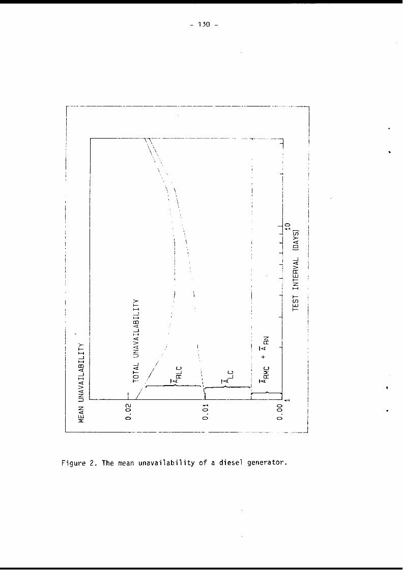
MEAN
UN
AVAI
LABI
LITY
o o o
Figure 2. The mean unavailability of a diesel generator
TEST
IN
TERV
AL (DAYS)

131
PAPER NO. 2.A.
RELIABILITY OF THE EMERGENCY DIESEL GENERATOR
C. VerstegenK. Kotthoff
Gesellschaft für Reaktorsicherheit (GRS) mbHCologne, FRG
»
ABSTRACT
The paper deals with a statistical investigation on the availability of diesel generators, which has been performed recently. The investigation is based on the operating experiences of a total of 40 diesel generators in 10 german NPP's. Both unavailability of the diesel generators due to failures and due to maintenance and repair have been considered . The probability of diesel failure^during start and short-time operation amounts to about 8 x 10“vdemand. The probability of common mode failures is approximately one order of magnitude smaller. The influence of various parameters on the failure probability has been 'discussed. A statistically significant dependence could not be identified. In addition the investigation shows that the unavailability of the diesel generators due to maintenance and repair is about of the same order magnitude as the probability of diesel failures.

132
1. IntroductionIn the past the extent of fault tree analyses performed during licensing procedure has grown. Risk analyses and precursor studies gained more and more importance. For this reason there was an increasing need for detailed reliability data.In case of loss of off-site power supply or normal on-site power supply the emergency diesel sets have to provide power supply for all safety systems. In German nuclear power plants nearly all pumps of safety systems are electrically driven. Examples are low and high pressure injection pumps, auxiliary feedwater pumps and so on. Therefore availability of the emergency diesel sets is of high importance in such a case.In the early seventies„in German fault tree analyses a failure probability of 5 x 10” /demand for diesel generators was used, based on rather questionable literature data. In the German risk study, which was published in 1980, a value of 2,5 x 10”z/ demand was used. It was derived from the operating experience of German NPPs, but the records which were available involved some uncertainties.Recently there has been another investigation of emergency diesel generator failure data. This investigation has been performed by the TÜV's and the GRS. Its objective was to assess the reliability of diesel generators on the basis of a detailed description of the operating experience of all diesel generators in German NPPs. The essential results of this investigation are presented in this paper.2. Scope of the InvestigationThe investigation includes the operating experiences of all emergency diesel generators in german NPPs starting with commercial operation up to the end of September 1980. In total 40 emergency diesel of 10 NPP were considered.Major goals of the investigation were:
data for independent failure and common mode failure of emergency diesel generatorsunavailability of the emergency diesel generators due to maintenance
- potential dependence of the failure data on various parameters, such as operating hours of the diesels or number of starts.
The informations on operating experiences and maintenance work needed for the investigation have been delivered by the utilities. The evaluation of the data has been performed by the TÜV's and the GRS. The results of this evaluation have been discussed with the utilities.

133 -
3. Data base and definitionsAfter a first screening of the operating experiences it became necessary to restrict the investigation to 9 plants with a total of 35 emergency diesel generators. The reason for this is, that the design of the emergency power supply with respect to the emergency diesel generators differs in one plant essentially from the design of all other plants. Whereas in all plants the emergency diesel generators start independently from each other, in one plant the diesel generators have to run up to full speed synchronously. In this plant failure of one emergency diesel generator causes failure of all other emergency diesel generators. Thus failures of emergency diesel generators in this plant are not representative for the other plants.The following table summarizes some data on the statistical basis of the investigation.
RatedPowerIKW]
Number OperatingHours
Starts CalendarYears
800 - 1800
6 2847 3255 59
2500 - 3000
13 1864 2248 45
3200 - 3500
16 2892 1653 52
Total 35 7540 7156 156
The emergency diesel generators considered have been manufactured by 3 different manufacturers. The rated power of more than 80% of the emergency diesel generators ranges from 2500 kW to 3500 kW. About 60% of the operating hours and starts are allotted to emergency diesel generators of this power range. The remaining class contains emergency diesel generators having smaller rated power. These emergency diesel generators are installed in older plants. This explains their comparably high part of the overall operating hours and starts. From the table an average number of starts per diesel and year of 48 starts and an average operating time per start of 1 hour may be derived.In general reliability data of a component depends strongly on the definition of the component boundary. For example there may be large differences considering a component as such or in

134
eluding instrumentation, control and power supply. The definition of the emergency diesel generator boundary used within this paper is illustrated in fig. 1. Besides the engine and the generator all auxiliary equipment directly associated with the diesel generator and located in the diesel building, such as the starting air system, fuel and lube oil system or internal cooling water system are are regarded as part of the diesel generator. External auxiliary systems, which are also asigned to other components or systems, such as the component cooling water, emergency switchgear or reactor protection system are not taken into account.For comparison it's necessary to give an exact definition of the kind of failures which have been evaluated. In this paper the following kinds of failures are discussed:
Independent failure of the emergency diesel generator This includes failure during start or run up and automatical or manual trip of the diesel during short-time operation U 2h)Common mode failure of emergency diesel generators Failure of more than one diesel generator during start or short-time operationUnavailability due to maintenance and repair
The mean operating time per start differs from one plant to the other. It ranges between 0.45 h and 2.1 h. With respect to an individual plant the operating time per start varies too. It may reach from several minutes to about 100 hours. Since detailed informations on long-time runs have not been available, the failure data evaluated during the investigation are only representative of short operating times (i 2h).4. Results4.1 Independent failure of emergency diesel generatorsThe results, which have been evaluated for independent failure of emergency diesel generators, are summarized in the next table. The table shows the probability of failure per demand during
startshort-time operationstart and short-time operation ($ 2h)
All probabilities given in the table are mean values. Besides the overall failure probabilities for all plants the minimum and maximum values with respect to the individual plants are given in the table.

135 -
Failure Number Failure Probability/DemandMode of All Plants Individual Plants
Failures Min Max
Start or 58 8.1 X 10⁻³ 1.7 X 10“3 1.6 X 10“2OperationStart 23 3.2 X 10"3 1.2 X 10"3 9.7 X io-3Operation 35 4.9 X 10“3 0.4 X IQ’3 1.5 X 10"2
For better comparison a probability of failure per start has been calculated for failure during short-time operation. The overall probability- of failure during start or operation amounts to 8.1 x 10 per demand.In case of some events it was difficult to assign these events to start failures or operating failures in a unique way. For example the diesel generator may fail during operation as a consequence of problems witch occurred before or at start. Therefore the values shown for start failures and operation failures have some uncertainty with respect to each other. Taking this uncertainty into account it may be derived that start failures and operating failures have about the some order of magnitude.Fig 2 and 3 illustrate the distribution of failures and maintenance with respect to the subsystems of the diesel and the main components. The dotted part of the bars indicates the number of failures, the rest the number of maintenance works.Broken down by subsystems the major contribution to the failures comes up from the engine with about 40%. The remaining 60% are shared among the other subsystems. The individual contributions to the failure probability are smaller than the contribution of the engine. They range from some percent to about 20%. Special weak points cannot be derived.This statement is confirmed by fig. 3. There the failure probability has been broken down by contributions of the main components of the diesel generator. The engine itself contributes about 30%, which is less than the contribution of the subsystem engine in fig.2. This is due to the fact, that the subsystem engine incorporates some components, such as coupling and gear, which are shown separately in fig.3. Again the contributions of the other components span a wide range from some percent to about 15%. From this point of view special weak points cannot be found either.If one computes the probability of diesel failure for each of the- 9 plants separately- then the values extend from 1.7 x 10~'J/demand to 1.6 x 10 z/demand, that is the results for the

136 -
individuell plants differ up to about one order of magnitude. To explain this behavior a more detailed analysis has been carried out. One result is that looking at an individual plant the failure probability of the emergency diesel generators may differ up to one order of magnitude too. As an example the data for one plant are given in the following table:
Diesel generator Failure ProbabilityNumber per Demand
1 3.7 x 10 ^ «
2 0.45 x 10“23 1.5 x 10"24 0.98 x 10⁻²
Fig 4 summarizes the corresponding data of all diesel generators of the 9 plants. If a diesel generator has not experienced failures, an upper estimate (95% confidence limit) has been used. For statistical reasons diesel generators with no failures have been omitted if the upper estimate exceeded the mean value of the failure probability of all those diesel generators, that experienced one or more failures.In the figure the probability of start failure or short-time operation failure is plotted versus the fraction of diesel generators with less or equal failure probability. Like in the example the failure probability of all diesel generators varies over a wide range. The same is true to more or less extent for the diesel generators of the individual plants. Since test and maintenance within a plant is done by the same people according to the same instructions, differences of test and maintenance in the plants can play only a minor role to explain the wide range of the failure probability of diesel generators.Furthermore the influence of the following parameters on the failure probability has been considered in detail:
calendar time operating time number of starts manufactureroperating time per startrated output of the diesel generatortime of commissioning
As examples fig. 5 and 6 show the dependence of the probability of start failures and short-time operation failures on calendar time and operating time respectively. Plotted are the sum of failures per diesel generator versus calendar time and operating time. E.g. in fig. 5, up to spring 1972 only 3 diesel

137 -
generators of one plant have been in operation. Thus each failure of a diesel has been weighted by a factor of 1/3. In the following years additional 3 diesel generators went in operation. Diesel failures, which occured in this period, have been weighted by a factor of 1/6. At the end of the observation time, with all 35 diesel generators in operation, each failure has been weighted by a factor of 1/35.The plotted points fit with a straight line especially in the range with small statistical uncertainty. That means the failure probability per demand stays constant throughout the observation time.Fig. 6 shows the failure probability versus operating time of the diesel generators. Again the points fit well with a straight line. Thus, within to the statistical uncertainties the failure probability (start and short-time operation failures) of the diesel generators is independent of the operating time of the diesel generators too.Similar conclusions can be derived for all parameters mentioned above. In summary a statistical significant dependence of the failure probability of the diesel generators on one of these parameters could net be found.4.2 Common mode failure of emergency diesel generatorsA common mode failure of diesel generators has been defined as failure of more than one diesel generator on demand for the same reason. Usually the diesel generators of a plant are tested time staggered against each other. Simultaneous starts of all diesel generators are rare. Therefore throughout this investigation failures for the same reason occuring during successive test of different diesel generators have been counted as common mode failures.The probability of common mode failure of diesel generators has been related to the fictitious number of simultaneous starts of the diesel generators of the individuel plants. The number of simultaneous starts aproximately has been calculated by summing up the quotient of the total number of starts and the number of diesel generators for all plants.With regard to the definition 2 common mode failures of diesel generators have been observed. From this a probability of commoru mode failure (start and short-time operation) of about 10" per demand can be derived. Compared to the probability of an independent failure of a diesel generator this value is approximately one order of magnitude smaller.

138
4.3 Unavailibility due to maintenance and repairIn general there are two reasons for unavailibility of diesel generators on demand.- The diesel generator fails to start or operate
The diesel generator is not available due to maintenance and repair
For this reason the contribution of maintenance and repair to the unavailibility of the diesel generators has been investigated.Primarily maintenance and repair may be important during outages, especially the refuelling outage. Since german plants are provided with a highly redundant emergency power supply (usually 4 x 50% trains), maintenance and repair during operation is permitted in some plants to a certain extent. Thus maintenance and repair may not only be considered for outages but also for operation.To evaluate the contribution of maintenance and repair all maintenance and repair work performed on the diesel generators and the respective times of diesel unavailibilities have been considered. The results are summarized in the next table.
Probability/UnavailabilityAll Plants Individual Plants
Min Max
Independent FailureMaintenance/Repair
Operation Operation and Outage
The table shows that unavailability of the diesel generators during operation due to maintenance and repair comes up to the same oder of magnitude as unavailability due to failures. The differences between the plants are large. The results for plants performing no regular maintenance work during operation are situated in the lower part of the range spanned by the plants.If one considers operation and outages, the contribution of maintenance and repair to the overall unavailability of the diesel generators becomes larger than the unavailability due to diesel failures. This may be explained by the fact, that maintenance and repair work is mainly performed during the refuelling outage, since demands on the emergency power supply are usually not as high during refuelling outage as during operation.
8 . 1 x 1 0 ~ 3 1 . 7 X 1 0 - 3 1 . 6 X
CM1o
7 x 1 0 “ 3 1 X i o - 3 1 . 7 X 1 0 - 2
1 . 3 x 1 0 “ 2 4 X 1 0 " 3 2 . 7 X 1 0 - 2

- 139 -
5. SummaryFailures and unavailability due to maintenance and repair work of 35 diesel generators from 9 german NPP's have been investigated. A probability of diesel generator failure of 8.1 x 10” / demand has been evaluated. A statistical significant dependence on parameters, such as manufacturer, operating hours, number of starts and so on could not be identified.The probability calculated for a common mode failure of diesel generators _is of significant order of magnitude. With a value of 1 x 10“vdemand it amounts to approximately 10% of the pro- bality of independent diesel failure. Operating experiences gained in the meantime seem to confirm this result.The unavailability of diesel generators during operation due to maintenance and repair has the same order of magnitude as the unavailability due to diesel failures. If no regular maintenance and repair work is performed during operation, the contribution of maintenance and repair becomes significantly smaller. Considering operation and outages the unavailability due to maintenance and repair exceedes the unavailability due to diesel failures by about 50%.
ReferencesStatistische Untersuchung der Zuverlàssigkeit von Notstromdie- selanlagen in deutschen Kernkraftwerken (VdTÜV)Verlag TÜV Rheinland, Kôln

140 -
PL Pre-Lube System
Fig. 1 Boundarys of Diesel Unit (KTA 3702.1)
70o 60 o§50&cÎS 40| 30 rat 20
J510E2 0
□ Start/Operation□ Maintenance
•<?
&^ J y
£
$
/So' < ^ 3
ai? J? <§" FO ' C o 'r? &
&&> ^ g So
£
O
4?i>
/ / #< 3
fpC0c^
Fig. 2 Failure and Maintenance versus Subsystems
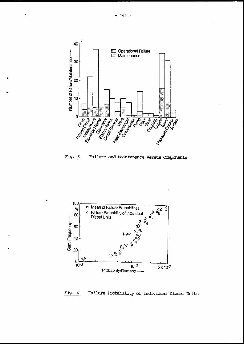
141
Fig. 3 Failure and Maintenance versus Components
100 %
I 80a Mean of Failure Probabilities 02 4 0 Failure Probability of Individual o9 °8
Diesel Units 7I1 °4c 60 3o<DD , nn 2o° 6S' 1-9° 06i£ 40 o°9
É 2o°7 °5M 201 1o°4§
0in1 °
— 2 -------------------1----------------- 1------------1---------1— L ■ ! .1—J------------------------------ L
Probability/Demand ——
Fig- 4 Failure Probability of Individual Diesel Units

142
Fig. 5 Probability of Diesel Failure as Funktion of Calendar Time
Fi9-- -6 Probability of Diesel Failure as Funktion of Operating Hours

- 143 -
PAPER NO. 2.5.
RELIABILITY EVALUATION OF EMERGENCY AC POWER SYSTEMS BASED ON OPERATING EXPERIENCE AT
U.S. NUCLEAR POWER PLANTS
P. W. ParanowskyU.S. Nuclear Regulatory Commission
Washington, DC, U.S.A.
ABSTRACT
The reliability of emergency AC power systems has been under study at the U.S. Nuclear Regulatory Commission and by its contractors for several years. This paper provides the results of work recently performed to evaluate past U.S. nuclear power plant emergency AC power system reliability performance using system level data. Operating experience involving multiple diesel generator failures, unavailabilities, and simultaneous occurrences of failures and out of service diesel generators were used to evaluate reliability performance at individual nuclear power plants covering a 9 year period from 1976 through 1984. The number and nature of failures and distributions of reliability evaluation results are provided. The results show that plant specific performance varied considerably during the period with a large number achieving high reliability performance and a smaller number accounting for lower levels of reliability performance.

144
Introduction
The U.S. Nuclear Regulatory Commission has been studying aspects of unresolved safety issue A-*'1, Station Blackout, including onsite emergency AC power system reliability since 1979. This activity has resulted in the publication of two reports by Oak Ridge National Laboratory[l,2] and an NRC report[3] which deal, at least in part, with the reliability of emergency AC power systems at U.S. Nuclear Power Plants. This paper provides the results of work recently performed to evaluate past U.S. nuclear power plant emergency AC power reliability performance using system level failure and unavailability data.
The emergency AC power system provides an alternate or backup power supply to the offsite power sources. If the offsite power system is lost, an undervoltage condition will exist on the safety buses, causing actuation of the emergency AC power system. Emergency AC power will also be activated on an emergency safety features actuation signal even if offsite power is available. The emergency AC power system provides sufficient functional capability and redundancy of the power requirements for the systems needed to mitigate the consequences of a design-basis accident. This typically includes a requirement to actuate emergency AC power supplies and make them available for loading within about 10 seconds after receiving an actuation signal. The emergency AC power system also meets the single-failure criterion when applied to design-basis accidents.
Emergency AC power is generally provided by diesel generator systems, although other sources such as gas turbine generators or hydroelectric power are used at some plants. Because of the preponderance of diesel generator usage, that power supply type will be the principal focus of emergency AC power system discussions in this paper.
Emergency AC power systems typically consist of two diesel generators, either one of which is sufficient to meet AC power load requirements for a design-basis accident. This configuration has been designated by its success criterion: one-out-of-two or more simply 1/2. In some cases, three, four, or more diesel generators are used at single-unit sites, and in others, diesel generators are shared at multi-unit sites. These systems also can be described by their success criteria, or number of diesel generators required per number provided. The emergency AC power configurations that exist in the U.S. have been identified in Table I.
Emergency diesel generators vary in size from as small as 200kw to more than 5000kw. Newer plants tend to use these larger power sources. Most generators are driven by a single diesel, but a few use tandem drivers. The design variability of emergency AC power systems is further complicated by dependencies on certain support systems that, by themselves, have a multitude of designs. These support systems include cooling systems (air cooled radiator or service water), DC control power, and heating, ventilation, and

- 145 -
Table I. Emergency AC Power Supply Configurations in the U.S.
Dedicated to one unit Shared between two units
1 of 2 1 of 21 of 3 2 of 31 of 4 2 of 42 of 4 ? (or 3) of 5
Shared between three units
3 of 8 or? of 4 intertied with 1 of 4
air conditioning (HVAC) systems. Moreover, maintenance and testing activities vary considerably, which can affect the reliability of the emergency AC power system.
Approach
The approach taken in this study was to review and classify known multiple diesel generator events and use these events as directly as possible to measure system reliability performance. Only events involving multiple diesel generators out of service for maintenance during operational modes when technical specifications allow extended outages were omitted. This is similar to approaches taken to ascertain individual diesel generator demand failure rates anc unavailabilities, but using system level information. In this way less emphasis is placed on analytic models and parameter estimation techniques which may be very complex and usually contain some generic or industry average aspects as well as analysts' judgment. Certainly some analysts' judgment is required in interpreting and classifying event descriptions and in instances where diesel generator demand information is sparse. However, it is informative to consider reliability performance when measured as directly as possible by the operating experience of each individual plant without averaging or other manipulations of the data. This same information can then be used to derive reliability parameters for modeling applications in which future expectations as well as past performance are assessed.
This more direct approach to looking at individual system reliability is only possible if sufficient operating experience exists. In this regard, data was collected covering the 9-year period inclusive of 1976 through 1984. There were approximately 528 plant-years of operation included in this study during that time period. The data observation period was sub

146 -
divided at the end of 1980 to give two intervals and some sense of differences that may exist as operating experiences is gained. Plants were omitted from either interval when operating experience was less than 2 years during the interval, or if the emergency AC power system was particularly unique (e.g., one diesel generator, hydroelectric power source). Data was obtained from references \ and 2, and supplemented with additional licensee event report (LEP.) searches and information available in other sources[4-6l. References 1, 2, and information available through reference 6 were useful in obtaining diesel generator demand data in addition to failure information. Operating experience relevant to multiple diesel generator events occurring in 1985 were also reviewed, but this information is incomplete and was only used to assure that qualitative insights obtained from the 1976-84 events were as complete as possible.
It should be noted that LER data since the beginning of 1984 is less complete do to the NRC's relaxation of reporting requirements at that time. However, most significant, multiple failure events are still reportable. A recent program undertaken by EPRI's Nuclear Safety Analysis Cer,ter[6] should improve data quality for events and numbers of demands since the beginning of 1983.
The number of complete emergency AC power system demands that occur at nuclear power plants is relatively small in comparison to single division demands. Complete system demands occur during actual demands when there is a loss of offsite power feeding emergency AC power electrical buses, during operational events causing engineered safety features actuation singals, and during full system simulation tests, typically performed only during refueling outages. When deriving system reliability performance at individual plants, the limited number of complete system demands is insufficient to provide useful quantitative reliability information. Thus it was necessary to use single division demands in addition to the complete system demands to derive an equivalent total number of system demands for each plant.
Summary of Operating Experience
From 1976 through 1984 there were on the order of 690 emergency diesel generator failures reported and approximately 33,500 valid demands. This results in aruindustry average diesel generator demand performance rate of about 2 x 10 . Because of reporting limitations exact numbers cannot beprovided. Additional information on individual diesel generator reliabil ity performance during that time period is contained in a companion paper to this one[8]. It has been observed that the mean failure rate of emergency diesel generators has been varying year by year with some apparent improvement in recent years. It has also been observed that individual plants exhibit emergency diesel generator failure rates significantly better or worse than the industry average. Moreover, the performance of emergency diesel generators during actual demand seems to be less reliable than during surveillance testing. On this latter point it should be noted that the seriousness of the failures occurring during actual demands has not been such as to cause lengthly loss of function in most cases.
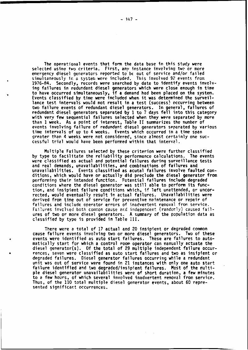
- 147 -
The operational events that form the data base in this study were selected using two criteria. First, any instance involving two or more emergency diesel generators reported to be out of service and/or failed simultaneously ir. a system were included. This involved 9? events from 1976-84. Secondly, records were searched by date to identify events involving failures in redundant diesel generators which were close enough in time to have occurred simultaneously, if a demand had been placed on the system. Events classified by time were included when it was determined the surveillance test intervals would not result in a test (success) occurring between two failure events of redundant diesel generators. In general, failures of redundant diesel generators separated by 1 to 7 days fell into this category with very few sequential failures selected when they were separated by more than 1 week. As a point of interest, Table II summarizes the number of events involving failure of redundant diesel generators separated by various time intervals of up to 4 weeks. Events which occurred in a time span greater than 4 weeks were not considered, since almost certainly one successful trial would have been performed within that interval.
Multiple Failures selected by these criterion were further classified by type to facilitate the reliability performance calculations. The events were classified as actual and potential failures during surveillance tests and real demands, unavailabilities, and combinations of failures and unavailabilities. Events classified as acutal failures involve faulted conditions, which would have or actually did preclude the diesel generator from performing their intended function. Potential failures include degraded conditions where the diesel generator was still able to perform its function, and insipient failure conditions which, if left unattended, or uncorrected, would eventually result in actual failures. Unavailabilities were derived from time out of service for preventive maintenance or repair of failures and include operator errors of inadvertent removal from service. Failures involved both common cause end independent (randomly) caused failures of two or more diesel generators. A summary of the population data as classified by type is provided in Table III.
There were a total of 17 actual and 20 insipient or degraded common cause failure events involving two or more diesel generators. Two of these events were identified as auto start failures. These are failures to automatically start for which a control room operator can manually actuate the diesel generator(s). Of the total of 29 multiple independent failure occurrences, seven were classified as auto start failures and two as insipient or degraded failures. Diesel generator failures occurring while a redundant unit was out of service were found in 21 instances with only one auto start failure identified and two degraded/insipient failures. Most of the multiple diesel generator unavailabilities were of short duration, a few minutes to a few hours, of which several involved inadvertent removal from service. Thus, of the 110 total multiple diesel generator events, about 60 represented significant occurrences.

148
Table II. Number of Redundant Diesel Generator Failures Separated by Various time Intervals
ObservationPeriod 3D
Time Intervals/Number of 4D-lwk l-2wk
Failures2-3wk 2-4wk
1976-1980 3 7 6 1 21981-1984 5 8 11 2 01976-1984 8 15 17 3 2
Table III. Population Data for Various Multiple Diesel Failures and Unavailabilities
Generator
Observation Common Cause Multiple Multiple Indep. +Group Totals Actual Potential Unavail. Indep. Unavail.
1976-80 54 8 8 15 6a17a
1981-84 56 9 12 8 15b 12b1976-84 110 17 20 23 21b 29°
2/2C • 40 7 9 13 7 42/3 18 3 0 1 6 83/3 6 1 3 1 °b lb
2/4 or 5 38 4 4 7 8b 15°3/4 or 5 4 1 1 1 0 14/4 or 5 4 2 3 0 0 0
a. Includes one insipient/degraded failure events.b. Includes two insipient/degraded failure events.c. Notation X/Y represents number of failed units per number of units in
the system.

- 149 -
The failure observations were found to fall into four general groups:
(1) Design and hardware failures related to mechanical integrity or various failure modes in the diesel generator subsystems, such as fuel quality and contamination, cooling and starting component failures, and output breaker failure to close;
(2) Operation and maintenance errors related to the correctness and adequacy of procedures or training, errors of commission such as inadvertent removal from service and errors of omission such as failure to restore a subsystem to operability after test or maintenance;
(3) Failures that occur in support systems, or at interfaces with support systems and other systems, "that can involve DC control power, service (or raw) water cooling, environmental control (air temperature and quality), and interface with the normal AC power system (loss of offsite power sensing and actuation circuitry).
(4) Failure due to environmental conditions for which adequate protection is not provided. These conditions can include fire, flood, dust, corrosive elements in the air, or temperature and humidity extremes.
Common cause diesel generator failures occurred when a fault or degradation existed involving a common factor or dependency among two or more diesel generators related to the failure observations listed above.
Evaluation of Emergency AC Power System Reliability
For each nuclear power plant included in this study the number of diesel generators required to meet the success criteria were identified and then only those events involving at least that number of diesel generators for that plant were used to derive system reliability performance figures. Only actual failures and unavailabilities were used in the analysis. The system reliability was calculated using the following equation:
R = ^CCF + ^IND + Qu + u3where Q-.p is the number of system failures per system demand due to common
r cause failures
QlND is the number of system failures per system demand due to u concurrent, independently occurring failures
OU is the system unavailability due to combinations of failed and out of service diesel generators

150 -
U is the unavailability due to multiple diesel generators being out of service simultaneously
The term in parentheses is the unreliability of the system. In this study it includes both system unavailability and system failure per demand. For common cause and multiple independent failures, the number of system demands was approximated by dividing the number of individual diesel generator demands by the number of diesel generators in the system. For independent failures occurring concurrent with unavailable diesel generators and for instances of multiple diesel generators out of service simultaneously, system unavailability was computed from the downtime to uptime ratio. The downtime consists of both repair time and the time for which the diesel generators were unable to perform prior to detection of faults.
A summary of the results is provided in Table IV. Shown are total period, interval, and configuration average unreliabilities, and numbers of systems falling within different unreliability bands. The average unreliability has stayed relatively constant at about 2 x 10" . However, significant differences have been observed between plants and to a lesser degree between configurations with their differences in success criteria.
In the interval 1976-80, 60 percent of the plants did not have a system level failure, while 75 percent achieved that same performance level during 1981-84. Over the total period, 50 percent of the plants did not have a system failure while 30 percent showed reliability improvement and 15 percent showed a reliability decline. The highest observed unreliability was approximately 2 x 10 . The contribution to system unreliability do tosimultaneous unreliability not involving failures was found to be relatively small.
-Table IV. Emergency AC Power Systems Unreliability Results
Observation Average Unreliability Intervals/Numbers of SystemsGroup Unreli-
ability 1D"2 10"3 10''4 10-5
1976-80 2.0 x 10"? 3 7 4 5 301981-84 1.8 x 10"r 3 5 0 3 431976-84 2.0 x io"; 3 15 2 7 271/2 1.9 x 10"~ 2 10 1 7 152/3 a 6.9 x 10": 1 2 0 0 1l/3+a 1.2 x 1 0 ~ * 0 3 1 0 11
a. The 1/3 + group includes 1/3, 1/4, 2/4, 2/5, 3/5 configurations.

- 151
Because plants were being added on-line during the study period, an apparent anomoly exists in the results: the 1976-84 average is greater than the average of the intervals. If only plants on-line in 1976-80 were considered in 1981-84, the total period average would be 1.7 x 1C- while the 1981-84 average would be 1.4 x 10 . This type of evaluation was madefor each configuration showing a similar trend. The results are tabulated in Table V.
It should be pointed out that a few of the failures included in these evaluations were autostart failures. These less serious failures to automatically initiate can usually be remedied by simple operator actions. However, since the number of autostart failure that contributed to system failures was small (only five instances), these results would not change significantly if they were not included.
Another comparison which was made with the results of this study was with generic reliability estimates available in reference 3. Figure 1 shows this comparison. It is interesting to observe that while the average system reliability calculated for each configuration in this work falls close to that derived with generic analyses, there are a large number of results which fall well off, both high and low, from the generic estimates. The largest discrepency occurs in the highest redundancy group.
Table V.
Configuration and plant operating date 1976-80
System Unreliability 1981-84 1976-84
1/2 online before 1978 1/2 all plants8
1.7 x 10"3 1.1 x 1C”3 1.6 x 10”J
1.4 x 1C”3 1.9 x 100
2/3 online before 1978 2/3 all plants
7.8 x 10"3 4.7 x 10”3 6.9 x 10”3
♦ 1/3+** online before 1978 1/3+ all plants
8.6 x 10”4 6.9 x 10⁻⁴ 1.1 x 10”'5
7.7 x 10“4 1.2 x 10”J
a combined online pre 1978 combined all plants
2 x 10”3 1.4 x 10”3 1.8 x 10”J
1.7 x 10”3 2.0 x 10⁻³
a. All plants in this study.b. The 1/3+ group includes 1/3, 1/4, 2/4, 2/5, 3/5 configurations.

EMERGE
NCY AC
POWER
UNREL
IABILI
TY
152
system level operating experience.
4
»
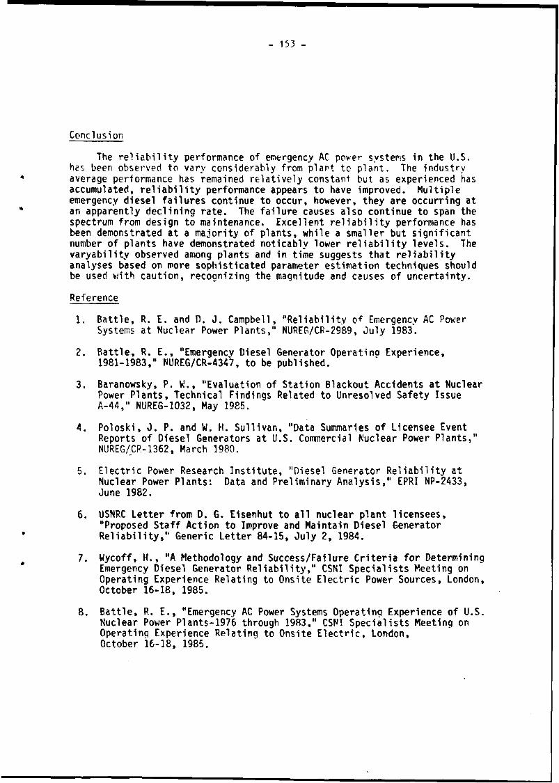
153
Conclusion
The reliability performance of emergency AC power systems in the U.S. has been observed to vary considerably from plant to plant. The industry average performance has remained relatively constant but as experienced has accumulated, reliability performance appears to have improved. Multiple emergency diesel failures continue to occur, however, they are occurring at an apparently declining rate. The failure causes also continue to span the spectrum from design to maintenance. Excellent reliability performance has been demonstrated at a majority of plants, while a smaller but significant number of plants have demonstrated noticably lower reliability levels. The varyability observed among plants and in time suggests that reliability analyses based on more sophisticated parameter estimation techniques should be used with caution, recognizing the magnitude and causes of uncertainty.
Reference
1. Battle, R. E. and D. J. Campbell, "Reliability of Emergency AC Power Systems at Nuclear Power Plants," NUREG/CP-2989, July 1983.
2. Battle, R. E., "Emergency Diesel Generator Operatina Experience, 1981-1983," NUREG/CR-4347, to be published.
3. Baranowsky, P. V!., "Evaluation of Station Blackout Accidents at Nuclear Power Plants, Technical Findings Related to Unresolved Safety Issue A-44," NUREG-1032, May 1985.
4. Poloski, 0. P. and W. H. Sullivan, "Data Summaries of Licensee Event Reports of Diesel Generators at U.S. Commercial Nuclear Power Plants,"NUREG/CR-1362, March 1980.
5. Electric Power Research Institute, "Diesel Generator Reliability at Nuclear Power Plants: Data and Preliminary Analysis," EPRI NP-2433, June 1982.
6. USNRC Letter from D. G. Eisenhut to all nuclear plant licensees, "Proposed Staff Action to Improve and Maintain Diesel Generator Reliability," Generic Letter 84-15, July 2, 1984.
7. Wycoff, H., "A Methodology and Success/Failure Criteria for Determining Emergency Diesel Generator Reliability," CSNI Specialists Meeting on Operating Experience Relating to Onsite Electric Power Sources, London, October 16-18, 1985.
8. Battle, R. E., "Emergency AC Power Systems Operating Experience of U.S. Nuclear Power Plants-1976 through 1983," CSNI Specialists Meeting on Operating Experience Relating to Onsite Electric, London,October 16-18, 1985.

- 155 -
PAPER NO. 2.6.ELECTRICAL SYSTEM DESIGN AND RELIABILITY AT ONTARIO HYDRO NUCLEAR GENERATING STATIONS
C.J. Royce Ontario Hydro
Toronto, Canada
ABSTRACTThis paper provides an overview of design practice and the predicted and
actual reliability of electrical station service systems at Ontario Nuclear Generating Stations. Operational experience and licensing changes have indicated the desirability of improving reliability in certain instances. For example, the requirement to start large emergency coolant injection pumps resulted in the turbine generator units in a multi-unit station being used as a back-up power supply. Results of reliability analyses are discussed. To mitigate the effects of common mode events Ontario Hydro adopted a 'two group' approach to the design of safety related systems. This 'two group' approach is reviewed and a single fully environmentally qualified standby power supply is proposed for future use.
RESUME
Ce rapport donne une vue d'ensemble de la politique de la conception et de la fiabilité prévue et actuelle des systèmes auxiliaires électriques employés dans les centrales nucléaires d'Ontario Hydro. L'ex-périence acquise au cours de l'exploitation et les modifications apportées aux règlements d'autorisation ont démontré l'avantage d'une amélioriation de la fiabilité de ces systèmes dans certains cas, tels que les contraintes de démarrage des grandes pompes de secours servant â Injecter le fluide de refroidissement qui ont mené à l'emploi des groupes turbo-alternateurs en tant que bloc d'alimentation de secours dans une centrale â tranches multiples. Des résultats d'analyses de fiabilité sont discutés. Afin d'atténuer les effets des évenêments du mode commun, Ontario Hydro a décidé d'utiliser une méthode de 'deux groupes' en abordant la conception des systèmes ayant rapport â la sQrétê. On examine cette méthode de 'deux groupes' et on présente un futur bloc d'alimentation de secours dans une seule unité qui satisfait aux normes de protection de 1 'environnement.

1*6 -
1.0 ELECTRICAL SYSTEM DESCRIPTION
Ontario Hydro (OH) is presently operating and constructing 3 major nuclear energy sites, the Pickering A and B stations with a total of 8 x 515 MW units, Bruce A and B stations with a total of 8 x 800 MW units and the Darlington station with 4 x 880 MW units. The Darlington electrical system schematic is typical of OH practice and is shown in Figure 1.
Each station has a 230 or 500 kV switchyard with multiple line connections to the provincial grid, which has ties to other utilities. Each unit is connected to the station switchyard by two HV lines, one to the main output transformer and one to the station service transformer (reserve or start-up transformer). The unit service distribution system is supplied either from the generator via a unit service transformer or from the grid via the station service transformer. The normal mode of operating is with the unit service being supplied by the generator (for the Pickering station unit service is shared by the generator and grid).
Power is distributed at 13.8 kV, 4.16 kV, and 600V ac and 250V dc.Control power is distributed at 120 Vac and 48V dc. Combustion turbine driven generators provide backup power to the standby (essential) buses. The dc sources are supplied by batteries and rectifiers or supplied by converters backed-up by a higher voltage battery source. The ac control power is provided by an uninterruptible power supply (UPS) (motor-generator sets for Pickering A) with back-up from the standby power buses.
An automatic transfer system switches the unit service power source from the generator to the grid source on loss of generator output. (For the Pickering station the transfer is automatic on loss of either supply). An emergency transfer system automatically initiates standby generator starting, bus switching and loading on loss of both grid and generator sources.Automatic switching connects the ac control buses to the standby power bus on failure of the UPS. For the Pickering and Bruce stations automatic switching occurs between the dc buses.
For the Pickering B, Bruce B and Darlington stations two groups (No. 1 and No. 2) of independent and physically separated equipment are provided.Reactor shutdown and cooldown is assured by the survival of one of the groups following common mode events such as major fire, earthquake and tornado. The system of distribution and power sources described above is part of the Group 1 equipment. An emergency power system including dedicated generators is provided to support Group 2 equipment.
2.0 OFF-SITE (GRID) POWER SUPPLIES
2.1 Predicted Reliability of Off-site (Grid) power Supplies
Several studies within Ontario Hydro have been carried out on loss of grid frequency and duration and on the probability of grid failure given a large unit trip (LOCA). The results of these studies are shown in Table 1.
The studies of frequency and probability of loss of the grid were conducted by our System Planning Division. For each generating site these studies considered the transmission connections to the site, losses of major circuits, rights of way, switching stations, generators and inter-connections.

157 -
The study used actual experience to estimate the frequency of loss of an element, however judgement was applied to estimate the probability between loss of an element and loss of the grid. It was assumed that the loss of a single large generator will not cause loss of the grid when the grid is free of other stresses. Calculations indicate the grid is under stress = 10~3 yr/yr.
The restoration probability with time was assessed by our Power Systems Operation Division and was based on judgement and experience under simulated loss of grid conditions.
2.2 Actual Reliability of Off-Site (Grid) Power Supplies
Loss of grid supplies to specific stations has been reviewed. At the Pickering A station loss of grid supplies to the whole station has not occurred, however loss to a pair of units (grid connections serve 2 units) has occurred once and an islanding situation (separated areas of generation and load) has also occurred Once. The station has been operating for 14 years.
During the life of Bruce A station grid supplies were lost only once to a single unit during commissioning when only a single unit was in operation.The outage lasted 7 minutes and was caused by human error during testing in the switchyard.
Early this year tornadoes caused loss of several 500 and 230 kV lines with the result that 3 Bruce units were rejected with one failing to survive (maintain its own auxiliaries). Subsequently further damage to the Transmission System caused the Bruce station to be islanded for approximately 12 minutes. The Bruce switchyards remained energized from surviving on-site generation and some local loads were supplied. The Bruce site was successfully re-synchronized with the grid and the running units brought upto full power.
2.3 Comments on Reliability of Ontario Hydro Off-Site power Supplies
The actual OH experience suggest that our predicted frequency of loss of off-site power is conservative.
The facility for inter-unit HV and MV connections on multi-unit sites provides increased connection paths from the grid to any one unit. Therefore HV equipment failures specific to a unit does not fail the grid supply to the station. In the case of the Pickering the predicted frequency for loss of HV lines to a unit is 0.26 f/yr compared to 0.17 f/yr for loss to the site.
Ontario Hydro predictions relate to multi-unit sites and can not be directly related to the reliability of single unit sites, however the comparison with other work suggests Ontario Hydro predicted numbers are conservative. The NSAC Report No. 85 [1] quotes frequency of loss of grid as 0.039 events per site year for durations greater than 30 minutes based on U.S. experience. The paper by Argent and Manning [2] predicts a total frequency of loss of off-site power as 0.02 f/yr for the Sizewell site.

158 -
3.0 ON-SITE POWER SUPPLIES3.1 Main Turbine Generator
The candu reactor design uses natural uranium as a fuel which gives low reactivity and a limited ability to overcome xenon production and consequential 'poison-out'. Following a loss of power the reactor should be returned to greater than 60% power within approximately 30 minutes to avoid 'poison-out'.
Because a 'poison-out' lasts approximately 36 hours and would cause a major loss of generation following a loss of line or loss of grid, the Candu units are designed to maintain their own house load with the reactors at = 60% thermal power. This is achieved by the turbine generator automatically running back to support the unit service load only (« 7% load) and stepping back the reactor to 60% load. The mis-match between steam supply and demand is controlled to dumping steam directly to the condenser or to atmosphere. This feature enhances power supply reliability by automatically maintaining the unit as a generation source following a loss of grid.
The Bruce A station has used this feature extensively for generator rejection which maintains grid stability when transmission capacity is impaired. Experience indicates 90% success for the unit surviving a rejection (opening HV breakers and maintain its own auxiliaries).
The Pickering A station does not require generation rejection and therefore has only been subject to loss of grid type events to 4 units in total. Experience indicates a 50% success based on this limited number of events. Design changes on Pickering A and B stations have now been incorporated to improve the probability of units surviving the loss of grid.
3.2 standby Power Systems
At the Pickering stations standby power is provided by any one of three standby generators. Combustion turbine units are the prime mover. The standby generators are sized and connected to provide power to a pair of reactor units. Therefore 2 sets of 3 standby generators at each of the A and B stations are provided.
A common standby generator arrangement also is applied to each of the Bruce A and B stations. Standby power for all 4 reactor units is provided by any 2 of 4 standby combustion turbine generators. Power is distributed by common station buses. A similar arrangement is applied to the Darlington station except the standby power for safety related loads is supplied by any 1 of the 4 generators.
3.2.1 Predicted Reliability for Pickering B and Bruce B
The reliability of standby generation for the Pickering B and Bruce B stations was assessed as part of a Safety Design Matrix assessment. This matrix is an event tree of mitigating systems and actions which show the response to a design basis event. The assessment of standby power reliability

- 1 5 9 -
used a simple model of unavailability (planned and forced), start reliability and running failure rate. The data used past experience gained by the testing of standby generators at the A stations plus equipment specification values. The data used and assessment method for system reliability are shown in Table 2.
3.2.2 Actual Reliability for Pickering A and Bruce A
Standby generators are each test started on average once per week and the resultant unavailability, start failures and running failures recorded. This information is reported quarterly. To obtain a measure of standby power system reliability the test data is used in a model developed by our Operating Branch. The test data and reliability model are shown in Table 3.
3.2.3 Predicted Reliability for Darlington
A probabilistic risk assessment (PRA) is being conducted on the Darlington station. The response of mitigating systems for each design basis event is being analysed by the fault tree (FT) analysis method. The reliability data for standby generators is an input to the fault tree and is based on past experience from other Ontario Hydro stations.
The FT will be utilized to review the reliability of the standby power system however preliminary analysis indicates a probability of failure to establish standby power following a loss of normal power of < 10~3, where any 1 of 4 standby generators can supply the load. Following a LOCA the probability of failure is < 10-2 where any 2 of 4 generators can supply the increased LOCA load. These reliability results and the standby generator data used are shown on Table 4.
Because of the lack of extended running hours during testing at Pickering A and Bruce A the running failure rate based on total failures per total running hours gives an unrealistic result. Successful tests are typically terminated within 1 hour when stable thermal conditions are reached.. By reviewing the total history of running the standby generators including extended running acceptance tests by the manufacture then a hazard plot analysis gives an improved failure rate prediction. For example, the equivalent MTTF being 650 hours for a 36 hour mission.3.3 Emergency Power Systems
In addition to the standby power system the Pickering B, Bruce B andDarlington station have an independent and separate emergency power system. This emergency power system is sized to supply minimum nuclear safety loads (Group 2) only. The system is qualified or protected from common mode incidents such as steam line break, tornado and earthquakes.
This system is normally powered from the grid source, but has two combustion turbine generators for emergency use.3.3.1 Predicted Reliability
For the Pickering B and Bruce B stations the target for probability of failure to establish emergency power is 10~2. The analysis indicates this target will be met.

160 -
For the Darlington station the target for probability of failure to establish emergency power is 5 x 10~3 and the probability of failure to establish power and complete a 36 hour mission is 8 x 10~3. Results of this analysis are given in Table 5.3.3.2 Actual Reliability
The emergency power systems installed at Pickering B and Bruce B have only been in operation approximately one year. System derived past unreliability is not presently available.
Similar generators to Pickering B are installed at our Lennox Station.The Lennox experience was used for the generator data in predicting the reliability of the Pickering B system. As noted above this prediction is within the target.
3.4 uninterruptible Power Systems
The Candu steam generators have sufficient water inventory to allow at least 40 minutes of decay heat removal following a trip without boiler feed. The batteries supporting the dc and ac uninterruptible power systems are sized to supply power for 40 minutes while providing full instrumentation, control and emergency lighting. This time also allows for some restart attempts should the standby generators fail to start automatically. However any operator action is not credited in the reliability assessment of standby power system.
3.5 Comments on Reliability of OH On-Site Power Supplies
Pickering and Bruce Predicted and Actual Standby Power Reliability
A comparison of the predicted and actual standby generator data and system reliability (Tables 2 and 3) shows that the predicted reliability as used in the safety analysis is conservative.
Darlington Predicted Reliability
For Darlington more stringent targets were set for both standby power and emergency power systems. Therefore more demanding reliability requirements were included in the equipment specification and a 1 out of 4 SG arrangement was selected for standby power. Also the predicted generator data and system reliability reflected the more stringent requirement. Experience from Bruce supports the Darlington predictions.
4.0 DESIGN CHANGES TO IMPROVE RELIABILITY
4.1 High Pressure ECI Pump Power Supply
The Pickering B station is provided with a HPECI system that requires fast starting of a 3500 HP pump. The Canadian regulations state that for 'special safety systems' the unavailability (probability of failure to establish the function on demand) âhall be < 10”3. Therefore the HPECI pump power supply was required to have a~probability of failure of < 10~4.

161
At the time, the normal off-site power supply was reviewed and a probability of failure of 10-3, following a large generator trip (LOCA) was considered supportable by Ontario Hydro System Planning Department. This number was also used by the WASH 1400 study, subsequent analysis has estimated the probability of failure of the grid to be ~ 10~* following a large generator trip see Section 2.1. It was also desirable to provide a back-up supply to the ECI system.
Because of the lack of standby generator capacity and the relatively slow starting (4 minutes), additional fast start diesels were considered. An alternative means of providing standby power was to utilize the on-site turbine generator units. As noted above the Candu system is designed to support its own service load on loss of off-site supplies. The decision was to use the on-site turbine generator units at Pickering A and B station to supply an accident unit.
A site electrical system was introduced to provide interconnection between all units at 4 kv level together with automatic connections between pairs of units at the 230 kv level. The high pressure ECI pumps are automatically switched from normal supply to the back-up supply which is taken from the site electrical system.
The predicted probability of failure of power supplies given the tripping of one unit (LOCA) is 5 x 10“3.
4.2 ECI Injection Valve Power Supply
The Pickering A station is being back-fitted with a high pressure ECI system. The A station will utilize the high pressure pumps provided for the B station as described above. The injection path will use the shutdown cooling system piping and valves.
The injection valves are required to open fast and have a highly reliable power supply. The original power supply being from the standby generator system which had a relatively slow re-energization time of 4 minutes. The existing non-interruptible power supplies (M/G sets with battery source) have insufficient capacity to drivé ’this valve load.
The site electrical system as described previously was therefore selected to be the prime source of power following a LOCA. A manually controlled connection to the standby power system was retained' to ensure use of the shutdown cooling system in the event of loss of grid and all turbine generators. The predicted probability of failure of the valve power supplies given the tripping of one unit (LOCA) is 7.9 x 10~5.4.3 Comments on Design Changes
The above examples illustrate how on-site power system reliability was used to provide standby power without the need for additional generators with the associated life time testing and maintenance costs.
The system adopted provided considerable flexibility in power exchange between units and provided reliable power to the ECI system.

162
5.0 FUTURE POSSIBILITIES
5.1 Loss of Off-site and On-Site Sources (Station Blackout)By reviewing the Darlington station power sources we can show that the
off-site grid, on-site turbine generators and standby generators together have sufficient reliability to make an extended station black-out effectively incredible. This is illustrated for various initiating event as follows:
Frequency/Year Probability Probability Frequency/YearLoss of off-site greater than 1/2 hour (1)0.17 . 0.45
Loss of on-site T/G (2)(0.2 + 0.8 . 0.1)4
Loss of standby power system 10*4
Station blackout (3) = 10-7
LOCA10-2
Loss of off-site 10-4
Loss of standby power system 10-2
o«HV
Loss of operatingunit4
Loss of off-site IQ’4
Loss of standby power systemIQ-4
< 10-7
Note (1) Probability of restoration in 30 minutes is 0.45.
(2) 80% availability of the unit, 0.1 non-survival of the unit and 4 units is used.
(3) 10~7 is conservatively used as a cut-off for credible events.
The above reliability does not credit the use of the emergency power system.
5.2 Class IE Type Approach
The above illustrates that the emergency power system is only needed to mitigate against common mode events e.g., earthquake, steam line break. For reduced cost it appears desirable to upgrade the standby power system and so replace the emergency power system. If this is done the standby power system would have to meet certain criteria including the following:
1. Electrically isolated and physically separated divisions (train of equipment).
This would meet the single failure criteria and mitigate against localized incidents e.g., water/steam releases, fire.
2. Qualified or protected from common mode type events e.g., earthquake, tornado, main steam line breaks.

163 -
3. Adequate reliability, that in combination with other mitigating systems effectively respond to design basis events. This is illustrated above.
The present electrical system arrangement provides electrical isolation and physical separation between divisions. Stringent application of division separation would be required possibly resulting in some modification to i&c and mechanical loads.
The original concept for the emergency power system was a simple manually « operated system which restricted the quantity of equipment and support
buildings requiring environmental and seismic qualification. Going from Pickering B to Bruce B to Darlington it has become desirable to expand the
« system requirements to have the system normally operating and to providequalified dc and ac control power. However experience has shown that providing seismically qualified and environmentally qualified equipment is quite feasible and the incremental cost for larger quantities of qualified equipment is small.5.3 Conclusion
The reliability values presented above illustrate that removing the emergency power system and environmentally and seismically qualifying the standby power system (Class IE approach) is supportable from a reliability viewpoint. The licensing implications and apparent cost savings (capital and operating) require further study.

164 -
6.0 REFERENCES1. Wyckoff, H., "Losses of Off-Site Power at U.S. Nuclear Power Plants,
All Years Through 1984". Nuclear Safety Analysis Center ReportNo. 85, June 1985.
2. Argent, S.J., and Manning, P.T., "Reliability of the Transmission Connections to a Nuclear Power Station - A Case Study", 12th Inter-RAM Conference for the Electric Power industry.
1
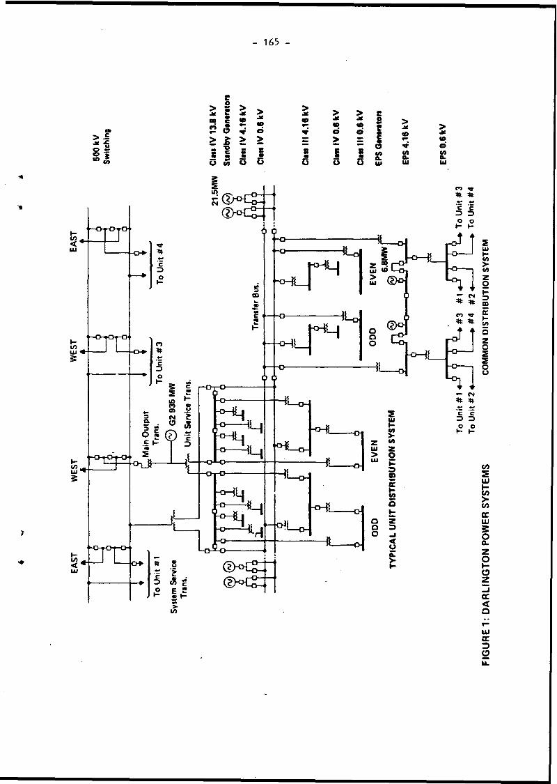
165
gl8 I
e
Î2 Ô » o> £ > >a c ? «S a S a
>JC > > e<0 j« «0
J*<0 8 >
* >d o 8 (0> 25 J <0
• mm *“ a d8 i s c/) c/> c/>48O
•u
Va a.Ul auUl a.Ui
UJcc3o

166 -
Table IReliability of Off-Site (Grid) Power Supplies
Reliability Measure Pickerinq Bruce DarlingtonFrequency of loss of - lower bound 0.16 0.09 0. 1of off-site power f/yr
- upper bound 0.26 0.26 0.17
Probability of loss of - lower bound 0.06 0.73 0.14all off-site power - upper bound following a large T/P trip (e.g., LOCA) x 10“4
Probability of restoration
0.28 0.91 0.32
after - 30 min 0.55 0.5 0.45- 60 min 0.95 0.9 0.85- 2 hrs 0.97 0.95 0.95- 6 hrs - - 0.99- 24 hrs 0.99 - -

167
Predicted Reliability of Standby Power Supplies ____________Standby Generator Data______________
T a b le I I
Bruce B0.080.02
0.10.0566 0.02 f/hr
Pickering B Model
Probability of the standby power system failing to complete a mission on demand is:
Qs = P(1 of 2 SG's fail to start and run when one on maintenance)+ P(transfer switching of 1 SG fails when 2 SG's are on planned or forced
maintenance)+ P(none of 3 start or run when none on maintenance)= 3(F + M) (A + Q + Z)2 + 3F(2M + F)A+ 1 - 3(F + M) - 3F(2M + F) (A2 + 2A(Q + Z)2 + (Q + Z)3)
Where Z * 1 - e~*T, T is taken as 30 min. for establishing emergency powergenerators.
Pickering B
Planned Maintenance Prob. M 0.05Forced Outage Prob. F 0.03ETS Failing/Bus Prob. A 0.01Failure to Start Prob. Q 0.05Failure to Run Prob. z 0.01Running failure rate \ c 0.02 f/hr
Standby Power System Prediction
Qs = 1.68 x IQ"3
Bruce B Model
Probability of the standby power system failing to complete a mission on demand is:
Qs * P(all 4 SG's are on maintenance, or fails to start or fail to run)+ P(1 SG starts and runs and 3 SG's are on maintenance or fail to start or fail to run)
■ Qsg * + - Qs g} (Qs g)3
Where QSg = M + F + (1 - M + F) (Q + (1 - Q)Z)
Qs = 4.3 x 10~2— L —Where Z is approximated by x + 1,.
TT is taken as 3 hours for off-site
restoration

- 168 -
Table IIIAPickering A Standby Generator Data
January 1983 - December 1983
StartingAttempts Failures
RunningHours Failures
Unavailability (hours) Forced Maintenance
012 GroupSGI 66 0 103.4 0 41.4 166.2SG2 80 0 294.7 0 0 96.8SG3 62 1 648.5 0 95.1 148.9
034 Group
SGI 59 0 57.1 0 1.3 177.6SG2 62 0 71.5 1 61.7 66.7SG3 61 1 106.0 1 251.9 240.6
January 1984 - December 1984
Starting Running Unavailability (hours)Attempts Failures Hours Failures Forced Maintenance
012 Group
SGI 38 4 37.5 0 375.9 1 838.2SG2 57 0 68.1 0 8.9 857.8SG3 46 0 68.7 0 0 1 061.7
034 GroupSGI . 59 5 52.5 0 723.3 1 082.3SG2 64 0 71.9 2 2.3 577.3SG3 58 0 55.3 1 16.5 570.9
The following data is in units of ’per SG" with the exception of the derivedpast unreliability which is for the group <of three SG* s. The data is for arunning year.
1983 1984012 Group 034 Group 012 Group 034 Group
Forced Outage Probability F 0.005 0.013 0.026 0.038Maintenance Outage Prob. M 0.016 0.018 0.143 0.085Starting Unreliability Q 0.005 0.005 0.028 0.028Running Failure Rate X 0 0.009 0 0.017Running Unreliability z 0 0.032 0 0.059Breaker Failure Prob. A 0.0004 0.0004 0.0004 0.0004Derived Past Unreliability ÜD 6x10“® 2.6x10“* 1.4xl0“3 5.5 x 10“3

- 169 -
Table IIIB
Pickering A System Derived Past Unreliability ° Un
The probability o£ an individual SG being unable to provide emergency service for its entire mission time is:
P = (Probability the unit is already down)+ (Probability the unit fails in the transition between the passive and
active states)
+ (Probability the unit fails in the active state before the end of its mission time)
P - M + F + Q + Z + A
Where Z « 1 - e“*T, T is based on a postulated grid outage time.
Since an operating policy exists to restrict planned maintenance to one SG in a bank at a time, M will only be of concern when considering the unavailability of an entire bank.
Therefore, P = F + Q + Z + A
Since 1 out of 3 satisfies the power requirement for an SG bank, we have fail the entire bank to encounter an actual unavailability, °This could occur in two ways:
(a) all three SGs fail when none are on maintenance, or
(b) the remaining two SGs fail when one is on maintenance.
Using these two possibilities as the unreliability of the SG bank,
UD * P(a) + P(b)
■ (1 - 3M) (F + Q + Z + A)3 + 3M(F + Q + Z + A)2
Î
9

Bruce A
Unavai
labi
lity o
f Standby
Power
Genera
tors
170
CO COu w O xz a z zM 3> M Dz .-5 fO CO H* z ►J ni CN VOz ►H pH z M3) < D <« Z z x
O oz •PS. 00 (N 00 00 SO z so ON oM z CO m r** o VO GO w w CO in VOz £ z • • • • • z £ z • • • •z M sc un VO pH un 00 z HH z pH rn pHD Eh w pH on r- pH on 3 Eh W r- ON CN r-X H pH (N un z pH pH
O CO O COz w Z COM (X •J fH z
< n> < Eh DEh z o HT pH m m m & Z p3 Ht m mO < M pH o < wH ÉH< H Eh <co X COX
u CO U COz ÉH z EhJ ►HCL M X< EH £ r- r-* un m IN < Eh £ ON CO r-E? IX W m in in pH Eh Z CO VD VO VOO < Eh IN o < EhH H Eh Eh Eh EHCO< CO<
CO COO W rn 00 00 rn IN a X VO o CO 00U O CO pH 00 o \£> r- X o CO o m CNrn u < X * • • • • N 1 u < Z • • t •00 z E-* 32 TT <N IN N* m CO z Eh z 00 o IN unon o D w pH IN IN o ON o O CN rn ONpH X O pH pH X O
». *pH pHrn mu u0> 0)-O jQe £0) a>u CO u CO0) W a» WQ X O Q X o
< H <O ►HH o M Eh4 J J D jj J1 D
W O M om CQ rn m in O pH CD r- o O o00 < U — * vo CN CN n- CO 00 < w «P» m o r-o n J u CO • • • • • ON J u CO • • • •ph z z rn r- o 00 ON pH l-H z z un 00 CO
< < z CO un in ON GO < < X CN o m* > z CN r- CO un O S * > z V rn unpH < w pH pH < COz Eh z Eh>1 » z >1 D ZU M in M
10 < 10 <3 £ 3 £C CID (0
*0
CO• • t-2 • »u < uID ««• PH I N rn nt ÉH 10 pH I N m0) o O 0> oX CO Eh X CO TO
TALS
1749.47
196.12
278
14
464.09

- 171
Bruce A Standby Generator Reliability Statistics
1983 1984
T a b le H ID
Forced Outage Rate Probability F = 3.138 X 10"3 5.89 x 10⁻³Maintenance Outage Probability M « 2.270 X 10⁻¹ 1.997 x 10"3(Of the Group of SG's)
Starting Unavailability Q = 6.130 X 10“2 5.036 x 10⁻²
Running Failure Rate \ = 2.340 X 10*2 3.016 x 10⁻²Running Unreliability Z » 2.020 X 10“2 2.445 x 10⁻²
Derived Unavailability of the UD - 6.909 j( 10"3 5.75 x 10*3Group of SG's.
STANDBY POWER SYSTEM DERIVED PAST UNRELIABILITY “ UD
« P (none of 4 available when none are on maintenance)+ P (none of 3 available when one on maintenance)+ P (3 SGs of 4 are not available when none on maintenance)+ P (2 of 3 SGs are not available when one on maintenance)* (1-M) (F+R)4
+ M (F+R)3
+ 4 (1-M) (F+R)3
+ 3M (F+R)2
= (1-M) (F+R)4 + (4-3M) (F+R)3 + 3 M ( F + R ) 2
Where R = Q+Z, Z = l-e~*T, T is based on the postulated grid outage time.

- 172 -
Table IV
Darlington Standby Power Supply PredictionStandby Generator (SG) Data
Availability (A) - 0.94(Planned Maintenance and Forced Outage)
Start Reliability (Rs) » 0.96
Running Failure Rate = = 3^ hrs
Running Reliability (Rr) = e"*1
Standby Power Supply ModelProbability of an SG being available, starting and completing a mission is:
PSG = A x Rs x Rr
Probability of the standby power system failing (Qs ) to complete a mission on demand is:
Qs (1/4) = (1 - PSG)4 where 1 out of 4 SG's running is success
= 2 x 10“4 for the first 8 hours
Qs (2/4) = 4 PSG (1 - PSG)3 + (1 - PSG>4 where 2 out of 4 SG’srunning is success
- 6.6 x 10“3 for the first 8 hours
The distribution system, transfer and reloading control contribute an additional * 10-4.
The above conservative model considers the SG contribution for an 8 hour period. The actual requirement is 36 hours. The use of a more complex model (non-coincident planned maintenance, repair after 8 hours, and improved running reliability) is planned and is expected to yield similar results to the above.
Target Values
The target for failing to establish power and complete a 36 hour mission on demand is 0.005 following loss of normal power and 0.01 following a LOCA.

- 173 -
Darlington Emergency Power Supply Prediction
Emergency Power Generator (EPG) Data
Availability (Planned Maintenance and Forced Outage) (A)Start Reliability (Rs )
• MTTF
^ Emergency Power Supply Model
Conservative Non-Repair Model
Probability of an EPG (AEp q) being available and starting aEPG = A x Improbability of an EPG (Pe p g ) being available» starting and completing a mission is:
PEPG = A x Rs x (1 ~ Pr )
Table V
= 0.95 = 0.98 = 650 hrs
Where Pp the probability of not running for a certain mission time is determined from the hazard plot technic.
Probability of the emergency power generators failing to establish power on demand is: UE = (1 - Agpç)2Probability of the emergency power generators failing to establish power and to complete a mission on demand is:
Qe = (1 - Pe p g I2 where 1 of 2 EPG's running is success.
For an 8 hour mission QE = 0.012 For a 36 hour mission Qe = 0.018
UE = 0.0047
Repair ModelThe Quality Engineering Department of Ontario Hydro have developed a model that incorporates repair and acceptable power interruption limits. Using this model for a total mission of 36 hours with a 0.5 hour power interruption after 8 hours being allowed then:
Qe = 0.007
Target Values
The target for failing to establish power on demand is 0.005. The target for failing to established power and complete a 36 hour mission is 0.008.

Restricted CSNI Report No.115
Volume II
NUCLEAR SAFETY DIVISION
N E A
O P E R A T I N G E X P E R I E N C E
R E L A T I N G TO
O N - S I T E E L E C T R I C P O WE R S O U R C E S
Proceedings of a Specialist Meeting
London, United Kingdom 16th-18th October 1985
FEBRUARY 1985
COMMITTEE ON THE SAFETY OF NUCLEAR INSTALLATIONS OECD NUCLEAR ENERGY AGENCY
38, boulevard Suchet, 75016 Paris, France

RESTRICTEDCSNI REPORT NO. 115VOLUME II
ISSUED: FEBRUARY 1986
CSNI SPECIALIST MEETING ON OPERATING EXPERIENCE
RELATING TO ON-SITE ELECTRIC POWER SOURCES
LONDON/ UNITED KINGDOM
16th " 18TH OCTOBER 1985
PROCEEDINGS
HOSTED BY
H.M. NUCLEAR INSTALLATIONS INSPECTORATE
HEALTH AND SAFETY EXECUTIVE

O )
The NEA Committee on the Safety of Nuclear Installations (CSNI) 1s an International committee made up of scientists and engineers who have responsibilities for nuclear safety research and nuclear licensing. The Committee was set up 1n 1973 to develop and co-ordinate the Nuclear Energy Agency's work 1n nuclear safety matters, replacing the former Committee on Reactor Safety Technology (CREST) with Its more limited scope.
The Committee's purpose 1s to foster International co-operation In nuclear safety amongst the OECO Member countries. This 1s done 1n a number of
* ways. Full use 1s made of the traditional methods of co-operation, such as Information exchanges, establishment of working groups, and organisation of conferences. Some of these arrangements are of Immediate benefit to Member
• countries, for example by enriching the data base available to national regulatory authorities and to the scientific community at large. Other questions may be taken up by the Committee Itself with the aim of achieving an International consensus wherever possible. The traditional approach to co-operation Is Increasingly being reinforced by the creation of co-operative (International) research projects, such as PISC and LOFT, and by a novel form of collaboration known as the International standard problem exercise, for testing the performance of computer codes, test methods, etc. used 1n safety assessments. These exercises are now being conducted 1n most sectors of the nuclear safety programme.
The greater part of the CSNI co-operative programme Is concerned with safety technology for water reactors. The principal areas covered are operating experience and the human factor, reactor system response during abnormal transients, various aspects of primary circuit Integrity, the phenomenology of radioactive releases 1n reactor accidents, and risk assessment. The Committee also studies the safety of the fuel cycle, conducts periodic surveys of reactor safety research programmes and operates an International mechanism for exchanging reports on power plant Incidents.
The Committee has set up a sub-Comm1ttee on Licensing which examines a variety of nuclear regulatory problems, provides a forum for the free discussion of licensing questions and reviews the regulatory Impact of the conclusions reached by CSNI.
* * * * *
*
A "Restricted" OECD document should not be communicated except for official purposes. The Secretariat and Member governments of the OECD are requested to take the necessary action to ensure the security of these documents.
The opinions expressed and arguments employed 1n this document are the responsibility of the authors and do not necessarily represent those of the OECD.
Requests for additional copies of this report should be addressed to:
Nuclear Safety Division OECD Nuclear Energy Agency
38 boulevard Suchet F-75016 Paris
FRANCE

TABLE OF CONTENTS
VOLUME I
FOREWORD..................................................................... 1
PROGRAMME GROUP MEMBERS......................................... .2
OPENING ADDRESS Mr. R.D. Anthony, Chief Inspector, HMNII...............3
SESSION 1: OPERATING EXPERIENCE
Chairman: Dr. K. Kotthoff (GRS)
SUMMARY OF SESSION 1............................................7
1.1 Operating Experience with Diesel Generators in Belgian Nuclear Power PlantsR. Merny, Association Vinçotte, Belgium....................... 9
1.2 Emergency AC Power Systems Operating Experience at U.S. Nuclear Power Plants — 1976 through 1983R. E. Battle, ORNL, U.S.A....................................21
1.3 Operating Experience and Licensing Criteria Relating to On-Site Electric Power Systems in ItalyS. Ciattaglia, G. Grimaldi, ENEA/DISP, Italy................33
1.4 Main Problems Experienced on Diesel Generators of French 900 MWe Operating UnitsG. Dredemis, F. Jude, CEA/IPSN, France...................... 59
1.6 Emergency Diesel Generators Manufactured by Transamerica Délavai Inc.: Problems, their Resolution, and Lessons LearnedC.H. Berlinger, E.L. Murphy, USNRC, U.S.A................... 67
1.7 Experiences with On-S1te Power Sources at KCBB.M.A. Heijnen, Borssele, Netherlands....................... 79
SESSION 2: RELIABILITY STUDIES
Chairman: Mr. J. Petrie (HMNII)
SUMMARY OF SESSION 2.......................................... 89
2.1 A Methodology and Success/Failure Criteria for Determining Emergency Diesel Generator ReliabilityH. L. Wyckoff, EPRI, U.S.A.................................. 91
2.2 Evaluation of Reliability of On-Site A.C. Power Systems Based on Maintenance RecordsG. Basso. S. Pia, ENEA, ItalyW. Fusari, G. Soressi, G. Vaccari, ENEL, Italy.... ........105

(111)
2.3 Reliability of Diesel Generators at the Finnishand Swedish Nuclear Power PlantsU. Pulkklnen, VTT, Finland................................. 119
2.4 Reliability of the Emergency Diesel GeneratorC. Verstegen, K. Kotthoff, GRS, F.R.G......................131
2.5 Reliability Evaluation of Emergency AC Power Systems Based on Operating Experience at U.S.Nuclear Power PlantsP.W. Baranowsky, USNRC, U.S.A......................... .....143
2.6 Electrical System Design and Reliability at Ontario Hydro Nuclear Generating StationsC.J. Royce, Ontario Hydro, Canada..........................155
VOLUME II
SESSION 3: TESTING AND MAINTENANCE
Chairman: Dr. P. Baranowsky (USNRC)
SUMMARY OF SESSION 3 ..................................................... 177
3.1 Emergency Diesel Generating Sets for the 900 MU PUR Units. Operation and Maintenance PolicyA. Gulllon, M. LalHer, EOF, France........................179
3.2 Soft Start Technique for Diesel Generator SetsL. Fredlund, SSPB, Sweden.................................. 187
3.3 Test and Maintenance of the Emergency Power Supply In the Nuclear Power Plant B1b1IsK. Kotthoff, GRS, F.R.G.H. Hüren, RUE, F.R.G....................................... 197
3.4 Surveillance Testing of 0n-S1te Electrical Power Systems. Several Cases of Standards Misinterpretation 1n SpainI. Recarte, R. C1d, CSN, Spain............................. 211
3.5 Some Failures of Diesel Generators during Commissioning Tests of 1300 MUe PURA.F. Colas, CEA/IPSN, FranceC. Morzelle, EOF, France................................... 225
3.6 Operational Reliability of the Point Lepreau G.S.Standby GeneratorsD. A. Loughead, A.T. McGregor, Point Lepreau, Canada......243

<1v)
S ES S IO N 4 : D ES IG N IMPROVEMENT AND S A FE T Y TARGETS FOR POWER S U P P L IE S
C h airm en : N r . B . F o u r e s t (C E A ) and D r . B . E . H orne (C EG B )
SUNNARY OF SESSION 4 (I).................................................. 259
4.1 Gas Turbine Installations 1n Nuclear Power Plants1n Sweden *L. Sevestedt, SSPB, Sweden......................... ..261
4.2 The CEGB Approach to Defining the Commissioning Tests for Prime NoversB.E. Horne, CEGB, U.K....................................... 275
4.3 Experience with Emergency Diesels at the Swiss NPP Goesgen (KKG)W. Steffen, HSK, Switzerland............ 285
4.4 0n-S1te Electric Power Source Facility for Japanese Nuclear Power PlantsT. Oohara, NUPEC, Japan.................................... 295
4.5 Review of Electricity Supply Failures and Plant Improvements over 25 Years Operation of the Harwell Naterlals Test ReactorsD.J. Taylor, UKAEA Harwell, U.K............................ 321
4.6 Development of the 0n-S1te Power Supply 1n German Nuclear Power PlantsN. Simon, GRS, F.R.G........................................331
SUNNARY OF SESSION 4 (II)................................................. 339
4.7 An Examination of the Proposals for the 0n-S1te Electrical Power Sources at the Slzewell B PWRP.A. Woodhouse, HNNII, U.K..................................341
4.8 Evolution of the 0n-S1te Electric Power Sources on French 900 NWe PWRsJ. Bera, CEA/IPSN, France.................................. 351
4.9 0n-S1te A.C. Electric Power Sources for 900 NWe French Nuclear Power Reactors: Reliability andImportance for Safety *J.L. N1 lhem, G. Gros, CEA/IPSN, France.....................363
4.10 How to Handle Station Black OutsF. Relsch, SKI, Sweden......................................375

(V)
CLOSING ADDRESS Mr. R.D. Anthony, Chief Inspector, HMNII..........387
ACKNOWLEDGEMENTS Mr. B. Fourest, Chairman of CSNI PWG 1............391
LIST OF PARTICIPANTS.............. ....................................... 393
ê
0
N.B. Paper 1.5 was withdrawn.

- 175 -
SESSION 3
TESTING AND MAINTENANCE
CHAIRMAN
DR. P. BARANOWSKY (UNITED STATES)
*

- 177 -
SUMMARY OF SESSION 3
TESTING AND MAINTENANCE
SESSION CHAIRMAN: P. BARANOWSKY (USNRC)
Session 3 on testing and maintenance experiences relating to on-site electric power supplies included six presentations. Information was provided relevant to good practices and lessons learned from previous experiences.
These included:
(1) Operation and maintenance policies for diesel generator sets at French 900MW PWRs. Diesel generators are started only when needed to reduce thermal cycles and mechanical stress. Operational duty cycle measurement for determining maintenance requirements includes the number of starts in addition to running hours.
(2) At Ringhals Nuclear Power Plant the potentially damaging effects of rapid diesel generator starts is lessened by using a "soft start technique". The governor has been modified to limit fuel flow during the first 30 seconds of a test start. The soft start mechanism is bypassed in an emergency. Also, a mobile diesel generator set is provided to temporarily replace a stationary diesel generator whenin maintenance.
(3) Test and maintenance requirements of emergency power supplies at German4-loop PWRs (Biblis) was described. Test and maintenance activities for diesel generators and direct current power sources are taylored to plant mode (operation and refuelling) as well as consideration of intervals between required actions. Less stringent examinations are conducted most often while extensive test and maintenance is performed either annually or every 4 years.
(4) Instances of standards misinterpretation relating to surveillance testing of on-site electrical power systems has been reported in Spain. Improper classification of diesel generator tests has resulted in failure to meet test frequency recommendations defined in Regulatory Guide 1.108. Perhaps more significantly, improper battery sizing has led to discharge cycle testing in excess of that recommended by standards.
(5) Extensive commissioning tests have been used to qualify diesel generators for reliability at a French 1300 MWe PWR. These tests were successfulin discovering deficiencies in sensors, injection pumps, speed governors, fuel purity, and in fuel and lubrication lines which cracked due to vibration.

- 178 -
(6) Operational reliability/availability targets have been set for the Point Lapreau (Canada) Generating Station standby generators. Test and maintenance records show that these targets have been met during the past three years of operation. Routine weekly testing is used to demonstrate availability while more rigorous emergency performance testing is performed at intervals ranging from six months to two years to demonstrate safety related capabilities. Tests are of 3 hours duration. Start and run failure experience has been examined to determine causes and appropriate corrective actions. Of particular importance has been vibration induced failures for which design modifications have been made.
Following the six presentations, a discussion was held related to observations on the contribution of test and maintenance activities to common cause failure of diesel generators. Staggering of activities, good procedures, quality of monitoring, and knowledge of common cause failure potential were mentioned as potentially important considerations.
»

- 179 -
PAPER NO. 3.1.
EMERGENCY DIESEL GENERATING SETS FOR THE 900 MW PWR UNITS OPERATION
AND MAINTENANCE POLICY
A. Guillon and M. Lai Her Electricité de France Paris (France)
ABSTRACT
In order to improve the reliability of the emergency diesel generating EDFhas taken steps to ensure that :
- sets are only started up when they are really needed, in order to reduce the thermal cycles and the mechanical stresses associated with start-up.
- the maintenance policy is adapted to the conditions of use, by including the notion of a start-up being equivalent to a predetermined number of hours of operation.
RESUME
Afin d'améliorer la fiabilité des groupes diesels de secours, EDF a pris des mesures visant à :
- démarrer les groupes que lors des sollicitations justifiées afin de réduire les cyclages thermiques et les contraintes mécaniques liées aux démarrages.
- adopter la politique de maintenance aux conditions d'utilisation en incluant en particulier la notion d'heure équivalente de marche à un démarrage.

180 -
C O N T E N T S
I Introduction
II Operating conditions of sets
III Harmful effects of start-ups
IV Reduction of the number of start-ups
V Adaptation of the maintenance policy
VI Conclusion

181
I - INTRODUCTION
EDF's complete park of diesel motor generating sets of 900 MW PWR units will comprise :
. 10 AGO V16 motors, and
. 58 AGO V20 motors.
To manufacture these motors, the same technique has been employed by SACM - Mulhouse - France. Only the number of cylinders differs.
The main characteristics are as follows :
AGO V16 AGO V20
Power KW 3 600 4.000
Speed of rotation r.p.m. 1 500 1 500
Number of cylinders 16 20
Bore diameter mm 240 240
At present, 64 sets are in full operating service and the last four are soon to be commissioned.
This large park of motors, all of the same technological design has enabled EDF rapidly to acquire the experience needed to formulate a suitable policy for their maintenance and operation.
182
II - OPERATING CONDITIONS OF SETS
Four operating stages characterize the operating conditions of a standby generating set :
. A waiting stage during which the set is pre-heated and pre-lubricated to reduce the thermal stresses engendered by rapid start-ups.
. A start-up stage followed by setting the voltage of the generator to relay the assisted auxiliary équipement. The increase in speed is rapid, of the order of eight seconds, and full load can be reached within 30 to 40 seconds.
. An on-load operating stage of variable duration.
. A load-shedding stage and return to the waiting stage.
Actual cases of emergency pick-ups of the network are rare (two cases have been recorded at EDF), to that periodical tests are necessary to check the availability of sets.
The statistics show that a set operates on average for a half an hour for each start-up and that the number of annual start-ups has been of the order of 150 to 200, ie, three or four times more than the expected number of start-ups.
Ill - HARMFUL EFFECTS OF RAPID START-UP
The stage of rapid increase in speed produces greater thermal and mechanical stresses on the motor than those encountered in operation for the following main reasons :
. Despite the pre-lubrification, lubrification is not optimum during the rapid pick-up of speed, especially of the sleeves and pistons. Friction is thus more substantial and wear consequently greater.
. Despite pre-heating, combustion is poor. The racks of the injection pumps are maintained as thrust bearings blocks by the regulator driving the maximum rate of flow of the fuel, but the air flow is insufficient because of the mechanical inertia of the turbo-compressor. As a result, combustion takes longer, and the pressure gradients and the combustion pressure peaks are higher. Production of soot is also increased.
. The still low temperature of the cylinder heads, sleeves and pistons favours the production of sulphuric acid originating from the combustion of sulphur. This acid oxidizes the oil (still a low quantity) and produces soot-impregnated gums which can be deposited in the grooves of segments, hampering their movement. The resulting lack of imperviousness then increases the thermal gradients.

- 183 -
. For safety reasons, diesel generating sets must pick up speed In a very short time. This produces an overspeed peak which the regulator cannot totally smooth out.
. In this stage, the resulting mechanical stresses are 21 %
higher than the stresses at rated speed. Consequently, the reliability of emergency sets depends heavily on the number of start-ups. EDF has therefore taken action to limit the number of start-ups of motors to the strict minimum, and to adapt maintenance policy to the actual operating conditions of these sets.
IV - REDUCTION OF THE NUMBER OF START-UPS
The frequency of indicents affecting the emergency generating sets of PWR power stations bears a relation ship to the excessive number of start-ups of these sets.
IV.1 - Reasons for starting up generating sets
Generating sets are started up for the reasons set out below :
1. Periodical tests
2. Re-qualification tests
3. Triggering of automatic protection systems.
IV.1.1. Periodical tests
Standby generating sets are the internal source of electrical supply for the safety functions of PWR power stations.
To guarantee the reliability of this function, periodical tests are required :
. To check the ability of the sets to supply electrical energy. These tests are conducted with the protective relays in service. The frequency of tests is :
- off-load operation, monthly;- operation at 30 % of rated power, monthly;- operation at 100 % of rated power, once a year.

184
. To check the operation of the automatic systems triggering the generating sets. The frequency of these tests is :
- protection of the nuclear boiler, monthly;- RPR channel A, monthly;- RPR channel B, monthly.
IV.1.2. Re-qualification tests
Respect of the quality control rules involves conducting a re-qualification test after any activity affecting the generating set or its auxiliary equipment. The number of these tests thus varies.
IV.1.3. Start-ups on automatic command
During unit shutdowns, in the course of work or re-qualification of automatic systems, untimely commands can trigger start-up of the generating sets.
IV.2 Proposed actions
IV.2.1. Grouping periodical tests
These periodical tests which are compatible should be grouped as far as possible. In addition, these tests should be combined with a re-qualification test where this latter is programmed.
IV.2.2. Tests of automatic devices conducted with the generating set treated as a blocked actuator.
By modification of the automatic systems, the generating set can be treated as a blocked actuator while preserving its availability on appearance of the warning "voltage shortfall" on the electrical panel.
IV.2.3. Preventing untimely start-ups of generating sets during unit shutdowns.
The device inhibiting the modification mentioned above should be used during operation or the re-qualification of the relaying of the automatic protection systems of the nuclear boiler.

- 185 -
V. ADAPTATION OF MAINTENANCE POLICY
In 1982, study of the different incidents and observations made during the programmed inspections of sets showed that maintenance policy needed be changed. Most of the anomalies recorded originated from phenomena wear and fatigue from thermal and mechanical oligocyclic stresses occuring during start-ups.
New maintenance programmes were established at that time by introducing the idea of equivalent hours of operation (E.H.O.) to determine new frequencies of maintenance.
The following formulation was used :
E.H.O. = Ho + Ns x k
with,
E.H.O.
Ho
Ns
k
equivalent hours of operation
actual number of hours on - or off - load operation
number of start-ups
equivalence coefficient of a start-up in hours.
Given EDF's still limited knowledge of the behaviour of these sets, the Manufacturer's experience and the number of start-ups scheduled per year (50 start-ups a year), the decision was taken to use a value of 25 for the coefficient k.
k = 25 hours per start-up
This value was purposely set too high pending a more complete analysis of experience, to be certain that the new doctrine would enhance the reliability of emergency diesel sets. The frequency of maintenance of the installation as a whole (diesel motor and auxiliary start-up and cooling equipment) has thus been based on the concept of equivalent hours of operation. VI
VI CONCLUSION
The reduction of the number of start-ups of sets associated with the new maintenance policy, which comprises additional non-destructive checks, has markedly improved the reliability of the standby diesel motors of 900 MW PWR units.

- 186 -
However, the frequencies defined in 1982 do not correspond satisfactorily to the stresses exerted on equipment during the different operating stages described in section III. Accordingly, EDF is now conduction a study jointly with SACM to revise the present maintenance policy to take account of :
. The analysis of the further experience gained since 1982, especially relating to the more precise estimate of the harmful effects of start-ups.
. The improvements made to various components.
The present view is that the final policy, which whould be implemented in 1986, will be based on two concepts :
. Equivalent hours of operation or the number of start-ups for the parts of units of equipment affected by thermal and mechanical oligocyclic stresses due to start-ups.
. Calendar based frequencies for the other units of equipment.

PAPER NO. 3.2.SOFT START TECHNIQUE FOR DIESEL GENERATOR SETS
Lars FredlundDeputy manager operations unit 4 Swedish State Power Board Ringhals Nuclear Power Plant Vârbbacka, Sweden.
A diesel motor in a nuclear power plant should be of a well-proven design. It is designed for long periods of troublefree duty, but not for the frequent and rapid test starts called for by the technical specifications. In order to decrease the dynamic forces and thermal stresses, a soft-start scheme has been implemented. By limiting the fuel injection the diesel generator will reach full speed in appr 30 seconds. The fuel limiter is a pneumatic cylinder which mechanically limits the travel of the terminal shaft of the governor.

- 188 -
1. Electrical layout
Ringhals Nuclear Power PLant has 4 units, 1 BWR (750 MW) and 3 PWR (800 MW, 915 MW and 915 MW). Each unit has two turbines.
The plant internal electrical system is divided into two main divisions, each divided into two subdivisions. Thus each unit has four trains. The AC power distributions is at 6,6 kV and 0,5 kV. The6,6 kV system is divided in two parts, ordinary net and diesel net, with two interconnecting breakers in series. Both breakers open on the black-out signal from the diesel sequencing equipment. Each 6,6 kV net has parallell transformers to 0,5 kV, also divided into ordinary net and diesel net.
The diesel generators are connected to the 6,6 kV diesel net, one for each of the four subdivisions. As the connected loads are the same for each pair of diesels (E.g. DG310 and DG320 in figure 1) there is an interconnecting tie which could be used for handling crosswise faults during loss of offsite power.
Also the DC and inverter fed AC systems are four trains, with the exception of some systems which only feed the turbin auxiliaries.
2. Diesel generator data
R1, R2 R3, R4
Manufacturer SACM , France NOHAB, Sweden
Speed 1500 rpm 1000 rpm
Diesel motor output 2944 kW 2650 kW
Overload capacity 1 h each 24 h
3018 kW
Diesel generator power 3450 kVA 3450 kVA
Power factor 0,8 0,8
Unit voltage 6,9 kV 6,9 kV
The diesels are water-cooled and with air starting system.They have no shared auxiliary equipment. Supervision from the central control room is by sum of alarm for each diesel, one for tripping faults and one for non-tripping faults.

189 -
3. Reason for soft-start
The technical specifications for a nuclear power plant calls for regular tests to demonstrate the capability of the diesel sets to start, maintain speed and voltage and verify loaded conditions.
These tests are normally carried out by performing a simulated automatic start. The DG set will reach no-load speed in 6-8 seconds.
A diesel motor in a nuclear power plant should be of a well- proven design, which means that the original motor is normally a stationary or marine diesel. The motor is designed for long periods of troublefree duty, but is not intended for frequent starting in the manner set out in the technical specifications.The rapid starts cause large dynamic forces and thermal stresses, which in the long run will cause damage. [1]
During the commissioning period of Ringhals unit 3 and 4 it was found that the diesel motor cylinders were scratched because the oil film dried out between two test starts (once every two weeks). A number of contributing factors were recognized. A simple and straight forward solution to the problem was introduced. The test interval 1 was shortened to once every week, and thus the oil film could be renewed before drying out. It should be noted that the problem was not a safety issue, but a question of testing procedures and guarantee.
However this frequent starting could be a contributing factor towards a higher unavai1ibi1ity. Some method of limiting the acceleration should decrease the stresses, and lessen the risk for failure of the diesel motor due to too m a n y starting attempts.
By increasing the starting time the acceleration would decrease. This could be acheived by limiting the fuel injection during start-up of the diesel motor. At the same time the method must not in any way interfere with emergency starts. Thus the soft-start technique was developed and inplemented.
4. Soft-start equipment
The fuel limiter is a pneumatic cylinder with spring return which mechanically limits the travel of the terminal shaft of the gover nor. The travel of the cylinder is adjusted so that maximum starting time (25-30 seconds) is achieved and still there is a suitable margin to the point where the diesel will not start and accelerate (figur 2).
Spurious fuel limiting is prevented in two ways.
The diesel sets have three modes of operation: auto, hand and test. Normal stand-by mode is auto. The soft start equipment can only be energized in the test mode, and only for a preset period of time, 10-15 seconds longer than soft-start starting time.The air supply valve has three ports and vents the soft start cylinder to the air when not energized.

190 -
The air supply to the soft start equipment is manually closed when not in use and the soft start cylinder vented to the air. (Figure 3).
Also the position of the soft start cylinder is supervised by a limit switch.
5. Periodic testing
The technical specifications for all Ringhals units specify the same periodic testing requirements.
- Starting once every two weeks
- Load running for 1 hour every month
All these tests are soft-started. Only once every third month, before a load test, the diesel is started without fuel limiting.
In addition to the requirements, the R3 and R4 diesels are soft-started every week in order to lessen the risk for cylinder scratches.
During a soft start the same components and auxilaries are tested as during a rapid start. The only parts not thourouÿily tested are the governor and the overspeed equipment because the limited acceleration gives a very slight speed overshoot. However, a fault in the governor would certainly be noticed by oscillating operation speed. The probable failure modes of the overspeed equipment are not very dependant on the speed overshoot and it should also be noted that on a real demand the base load is connected before nominal speed is reached and thus decreases the overshoot.
6. The mobile diesel generator set
In order to even more improve the reliability of the onsite power sources, Ringhals has bought a mobile diesel generator set. This can replace any of the 16 stationary diesels.
The dieselmotor is the same as in units 3 and 4, but the motor is air-cooled. Directly connected to the motor is a hydraulic pump feeding the ventilating fans.
The mobile set is docked outside the diesel generator which should be replaced. Through a hatch the 6,6 kV cables are connected together with 0,5 kV, control and supervision and also a fuel hose. Mounted on the vehicle is only a 3 cubic meters fuel tank which means that the set is intended for using the stationary diesel fuel day tank.
As all the auxiliaries are on the vehicle, even the batteries for control and power, the diesel set is only depending on a 0,5 kV feeder and a fuel connection from the unit. (Figure 4)

- 191
After operatina two isolators, opening the fuel valves and putting a switch in the local diesel control room in position "mobile", the mobile diesel generator set has completely replaced the stationary one. As the mobile set behaves exactly the same as the ordinary stationary set, diesel sequencing equipment and other control systems are not affected.
The technical specifications calls for cold shutdown if one out of four diesel generators of a unit is not operable for more than 48 hours. The mobile set is intented for minimizing the risk of this forced shutdown.
As the vehicle is selfpowared, the estimated time for docking, connecting and testing before declared operational is 4-12 hours.
The potentially best and most probable use of the mobile set is for replacing the stationary set during maintenance. Thus the diesel overhaul can be carried out outside refuelling outage.
References
[1] NRC Questions Diesel TestingNuclear Industry October 1984 p 16-24

Figure 1. Main one-line diagram Ringhals 3

193 -
Percentage of synchronous speed
1. Rapid start. Dashed with connection of base load.
2. Soft start.
Figure 2. Typical acceleration curves.

194
s_t o+->CD
OtO
CD
C3S-
u0)“Dcr— C
<cs-o
to o>E c3 •»-a) uC Q. Q_ CD
â / " > 'x V O O O Of O O O O C K H
*3j-o
w v „
i-oQl
to a) 3 >c *— rO tos >
ca> &_> 3I— -MfO <D> s-4-> CDi. c0 -r- O. S-1 Q.co tn
Figure 3. Mechanical equipment for soft s ta rt

Figure 4. The mobile diesel generator set

197 -
PAPER NO. 3.3.
TEST AND MAINTENANCE OF THE EMERGENCY POWER SUPPLY IN THE NUCLEAR POWER PLANT BIBLIS -
K. KotthoffGesellschaft für Reaktorsicherheit (GRS) mbH
Cologne, FRGH. Hüren
Rheinisch-Westfâlisches Elektrizitàtswerk AG Betriebsverwaltung Biblis
Biblis, FRG
ABSTRACT
Besides design and construction test and maintenance play an important role for the availability of the emergency power supply. As an example test and maintenance provided for the emergency power supply in a german 4-loop PWR will be desribed. In general one has to differentiate between test and maintenance performed during power operation of the plant and those carried out during the refuelling outage. For both periods of operation detailed information will be given including type, extent and frequency of test and maintenance work. The results of test and maintenance up to now will be discussed.

- 198 -
1. IntroductionThe paper deals with test and maintenance on the components of the emergency power supply. Main emphasis is be put on emergency diesel generators and batteries, since for these components the scope of the tests as well as the number of defects is the largest. Besides the results of the tests the experience gained and the measures resulting from it are presented.2. General Information on the Nuclear Power Plant BiblisThe NPP Biblis has two units and is located 10 km north of the city of Worms on the east bank of the Rhine River. Operator of the plant is the Rheinisch-Westfàlisches Elektrizitatswerk. The two units have a design output of- 1204 MWe (unit A) and- 1300 MWe (unit B)The reactors are 4-loop pressurized water reactors which have been delivered as turnkey plants by Kraftwerk Union (KWU). First power to the grid was produced on- unit A: August 25, 1974 and- unit B: April 25, 1976Gross power production since commissioning until May 31, 1985:- unit A: 76702 GWh and- unit B: 65087 GWh3. Concept of the Emergency Power Supply SystemEach unit is provided with a complete self-contained emergency power supply, which consists of four emergency diesel generators in agreement with the design concept incorporating 4 x 50% trains for emergency core cooling. The redundant trains are functional and physical separated. Each diesel generator is associated with one train. During normal operation, the 10 kv emergency switchgears are fed by the switchgears of the normal power supply system.The major loads responsible for the emergency cooling and decay heat removal of the reactor are connected to the emergency switchgears. Each of the four 10 kV A.C. emergency switchgears feeds its own 380 V A.C. emergency switchgears (see figure 1).A voltage drop of more than 20% in one of the 10 kV emergency switchgears causes an automatic starting of the associated diesel generating set and separation of the affected power section from the normal power supply system. Once the emergency diesel has run up to full speed, it is loaded in accordance with technical requirements, but with such time staggering of load groups that intolerable speed drops and generator voltage drops are avoided.

- 199 -
Each emergency diesel set is provided with a protection, consisting of five protection criteria. The individual criteria are listed in the following table.
Emergency Diesel Trip Signal
TripLogic
Effective for Design BasisAccident
• • ••
Low Lube Oil Pressure 1/1 No
High Lube Oil Temperature 1/1 NO
High Cooling Water Temperature 1/1 NO
Over Speed 2/2 YesOver Current 2/2 Yes
If one of the protection signals is initiated during test or loss of normal power supply without a simultaneous accident, the affected diesel generator is tripped. In the case of an accident the trip-signals in a 1 out of 1 logic are blocked. Thus the availability of the emergency diesel sets will be increased for an accident in connection with loss of normal power supply, because failures of an one-channel protective design do not lead to a trip of an emergency diesel generator.
4. Technical Data of the Emergency Diesel GeneratorsThe important technical data of the diesel engines and the diesel generators are given in the next table:
Unit A Unit B
Diesel Engine
Manufacturer Rated Output Number of Cylinders Operating Mode Starting System Year of Construction
MTU MTU2950 355016 16continuous and short-time Air-to-cylinder cranking 1973 1974

- 200 -
Generator
Manufacturer Siemens SiemensContinuous Rating (kVA) 3380 3900Voltage (kV) 10 10Rated speed (Rpm) 1500 1500
The operating hours and the number of starts of the individual diesel sets from the commissioning until June 1985 are shown in the next table. It may be seen that despite frequent tests the average number of 500 operating hours is very small.
Unit A Unit B
OperatingHours Starts OperatingHours Starts
Emergency Diesel 1 501 515 502 510Emergency Diesel 2 534 580 536 510Emergency Diesel 3 555 485 470 485Emergency Diesel 4 499 500 445 455
5. Test and Maintenance on the Emergency Diesel Sets
Concerning test and maintenance one has to distinct between- recurrent tests which are executed in periodic intervals
independent of the state of the plantand- preventiv maintenance causing unavailability of a diesel
and recurrent tests which are executed only during refuelling outage
The content of these tests and maintenance work as well as the respective test and maintenance intervals are summarized in the following table.

- 201
Interval Plant Status Type of Test/Maintenance
Operation RefuellingOutage
•* monthly X Test run of the emergency diesel sets . including automatic reconnection of the loads
« bi-annually X Full power test run of the emergency diesel sets
bi-annually X Examination of diesel fuel in the fuel tanks
annually X Maintenance on diesel engines (small inspection)
every 4 yr X Maintenance on diesel engines (large inspection)
every 4 yr X Maintenance on diesel generators
every 4 yr X Test of protection, instrumentation and control of the emergency diesel sets
upon delivery
Quality test of fuel upon delivery
5.1 Recurrent TestsTwo types of recurrent tests of the emergency diesels and one quality test of the diesel fuel are performed.Test 1; Test of the emergency diesel set including its auxili
ary systems as well as the automatic reconnection of the loads
The test is either started by simulating the loss of power signal on one of the four emergency power buses by a test switch in the reactor protection system or by opening the connection of the emergency bus to the main 10 kV bus. Thus the unit auxiliary bus is disconnected from the corresponding emergency power bus in one train.The test sequence is identical to the sequence in the case of loss of on-site power, except for the difference that the test is not performed simultaneously in several trains. Figure 2 shows the automatic start-sequence for an emergency diesel set.

- 202
The functions which are tested in this test run are as follows:- switch-off of the circuit breakers between the main bus
and the emergency busswitch-off of all loads from the emergency bus
- switch-on of the pre-lube oil pump- opening of the starting air valve- switch-on of the fuel pump- switch-on of the excitation- run up of the emergency diesël set to full speed
rise of the generator voltage to nominal voltage- switch-on of the diesel circuit breaker to the
emergency bus- time-staggered automatic reconnection of the loads
to the emergency bus.The tests are performed monthly i.e. each week one of the four trains is being tested. In this test a load of some 30% is observed. The run time of the diesel is approximately 80 min.Test 2: Full power diesel testThe test is performed by synchronization of the diesel generator with the unit auxiliary power grid. Each emergency diesel set has a synchronizing and parallel switching device of its own. By the speed adjusting device of the diesel engine the power output to the grid may be governed steadily up to 100%. The test interval is bi-annually. The test run time is 4 hours.The next table summarizes til now. One can see that of emergency diesel units
some data of the tests performed un- with some 1100 tests only 8 failures are recorded.
Monthly Test Bi-annual Test
Runningtime of Diesels during Test (h) 1,5 4Load on Diesels (%) 30 100Number of Tests Performed 1) 960 160Number of Failures 5 3
1) Sum for all 8 emergency diesels in unit A and unit B
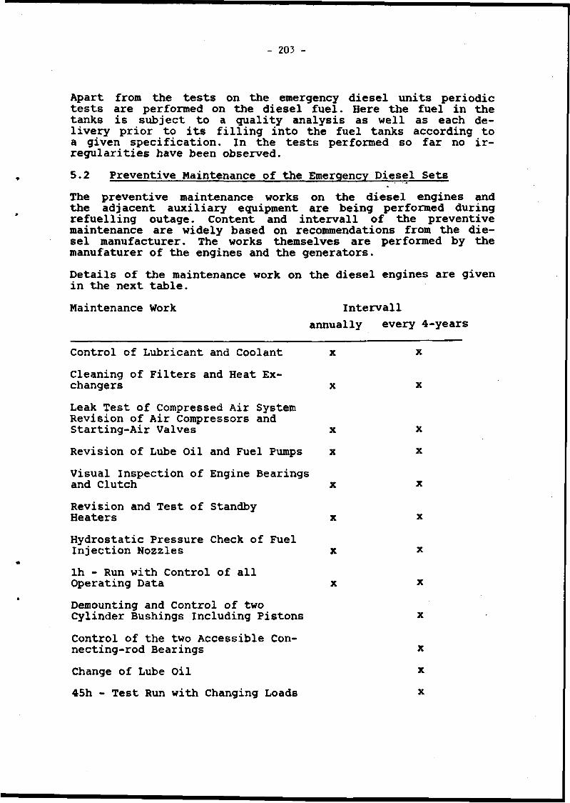
- 203 -
Apart from the tests on the emergency diesel units periodic tests are performed on the diesel fuel. Here the fuel in the tanks is subject to a quality analysis as well as each delivery prior to its filling into the fuel tanks according to a given specification. In the tests performed so far no irregularities have been observed.5.2 Preventive Maintenance of the Emergency Diesel SetsThe preventive maintenance works on the diesel engines and the adjacent auxiliary equipment are being performed during refuelling outage. Content and intervall of the preventive maintenance are widely based on recommendations from the diesel manufacturer. The works themselves are performed by the manufaturer of the engines and the generators.Details of the maintenance work on the diesel engines are given in the next table.Maintenance Work Intervall
annually every 4-years
Control of Lubricant and Coolant x xCleaning of Filters and Heat Exchangers x xLeak Test of Compressed Air System Revision of Air Compressors andStarting-Air Valves x xRevision of Lube Oil and Fuel Pumps x xVisual Inspection of Engine Bearingsand Clutch x xRevision and Test of StandbyHeaters x xHydrostatic Pressure Check of FuelInjection Nozzles x xlh - Run with Control of allOperating Data x xDemounting and Control of twoCylinder Bushings Including Pistons xControl of the two Accessible Connecting-rod Bearings xChange of Lube Oil x45h - Test Run with Changing Loads x

- 204 -
Preventive maintenance on the diesel generator is performed every 4 years and includes
visual control of stator winding- insulation test of stator winding- visual control of stator stack of sheets- visual control of rotor winding
insulation test of rotor winding- visual control of rotor stack of sheets
visual controll of bearings, change of lubricant- visual control of slip-rings, exchange of brushes if
necessarycheck of generator instrumentation
6. Operating Experience with the Emergency Power Diesel Sets
In the first years of operation a number of failures occurred during recurrent tests as well as in test runs after maintenance. Besides 5 start-up failures and 3 operating failures some other failures occured which would have allowed a continuation of operation only for a limited period (about 12 hours) without remedial action. Such disturbances were declared longtime failures .The observed failures predominantely occurred on peripheric installations and auxiliary systems of the diesel engines, such as
leaks on coolant pipes leaks on fuel pipes failure of tachometerfailure of check valve in the starting-air valve failure of standby heaterfailure and drifting of temperature sensors.
The reason for the comparably high number of defects in the first years of commercial operation of the plant was the small overall operating time of the emergency diesel sets.Each emergency diesel only had acceptance tests of 12 h, six of which took place at the manufacturer and six at the site. Until 1978 for each unit the operating time has been increased by some 80-100 h.An overall operating time of this order of magnitude is definitely too short to detect weakpoints. In particular, leaks on coolant, fuel and air pipes which may be traced back to inadequate design can only be detected by longer test runs. The KTA-

205
standard 3702 in the meantime requires for German plants a running time of the emergency diesel sets of 200 h prior to first criticality of a plant.For integral control and detection of further weakpoints all 8 emergency diesel sets were subject to a long time test with changing loads in 1977/78. The running times amounted to 150 h per diesel. After termination of the test runs a revision was made to remedy the deficiencies and add some improvements. Since this time the frequency of defects is considerably smaller (see figure 3).For an early detection of developing failures the following rules were set up:
prolonged running times in the monthly tests from approximately 15 min to 80 min. During the test the diesels are contro led for leaks, quietness and other irregularities.after failure and renewal of components subjected to changing loads a 45 h rim is performed. These 45 h correspond to more than 4 x 10° revolutions of the crankshaft, with this load changing frequency the fatigue strength is reached.
7. Technical Data of the Batteries and RectifiersThe 24-V and 220-V batteries are consisting of stationary cells with large surface plates in narrow seat design according to DIN 40738. The abbreviated battery notation for this is GroE. The cell vessels are made of glasclear plastic and are capped with tight plastic covers. Degassing is accomplished through porous ceramic plugs.Batteries and rectifiers work in compensating charge operation. Technical data of the batteries are:- density of acid: 1.22 + 0.01 kg/dm^ at 20°C- compensating charge voltage of one cell: 2.20 - 2.30 V- number of cells per battery: 24 V = 13 cells
220 V = 108 cells
8. Tests on Batteries and RectifiersAs on the emergency power diesels likewise intensive recurrent tests are performed in particular on the batteries. They stretch from daily visual controls of the batteries and battery rooms, where particular attention is paid to a possible vessel damage and subsequent vessel leakage, up to an every-four-years capacity test including measurement of the associated drop of voltage and of the current at the connectors.Scope and interval of the tests are based on the recommendations of the manufacturer and widely on operating experience. Details of the recurrent tests on batteries and rectifiers are summarized in the following table:

Recurrent Test Intervalldaily bi-annually every 4-years
monthly annually
Visual ControlControl of Temperature of Battery RoomsControl of Electrolyte Level on all CellsMeasurement of Cell- voltage on all CellsMeasurement of Acid Density of all CellsVisual Control of Plates (Color, Formation of Crystals, Deposits)Visual Control of Pole Penetrations (Pole Corrosion)Filling up of Cells to Maximum LevelFunctional Test of Charging DevicesCapacity Test of BatteriesMeasurement of Voltage Drop at Cell ConnectorsMeasurement of Current on Parallel Cell Connectors
x
x
x
X
x
X
X
X
XX
X
X
9. Operating Experience with Batteries and Rectifiers
The batteries work in compensating charge operation, i.e. with an undisturbed state of the plant no request is made for the batteries. A difficulty results from the fact that it is hard to determine from the outer appearance as well as from measured data if a battery will supply the required power on demand. Therefore a consequent performance of the described tests is indispensable in our opinion.The defects observed on the batteries in both Biblis reactors are listed in the next table.
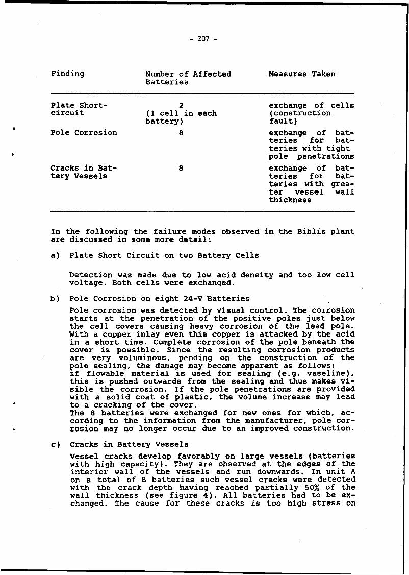
- 207 -
Finding Number of Affected Batteries
Measures Taken
Plate Short- circuit (1 cell in each
battery)2 exchange of cells
(construction fault)
♦ Pole Corrosion 8 exchange of batteries for batteries with tight pole penetrations
Cracks in Battery Vessels
8 exchange of batteries for batteries with greater vessel wall thickness
In the following the failure modes observed in the Biblis plantare discussed in some more detail:a) Plate Short Circuit on two Battery Cells
Detection was made due to low acid density and too low cell voltage. Both cells were exchanged.
b) Pole Corrosion on eight 24-V BatteriesPole corrosion was detected by visual control. The corrosion starts at the penetration of the positive poles just below the cell covers causing heavy corrosion of the lead pole, with a copper inlay even this copper is attacked by the acid in a short time. Complete corrosion of the pole beneath the cover is possible. Since the resulting corrosion products are very voluminous, pending on the construction of the pole sealing, the damage may become apparent as follows: if flowable material is used for sealing (e.g. vaseline), this is pushed outwards from the sealing and thus makes visible the corrosion. If the pole penetrations are provided with a solid coat of plastic, the volume increase may lead to a cracking of the cover.The 8 batteries were exchanged for new ones for which, according to the information from the manufacturer, pole corrosion may no longer occur due to an improved construction.
c) Cracks in Battery VesselsVessel cracks develop favorably on large vessels (batteries with high capacity). They are observed at the edges of the interior wall of the vessels and run downwards. In unit A on a total of 8 batteries such vessel cracks were detected with the crack depth having reached partially 50% of the wall thickness (see figure 4). All batteries had to be exchanged. The cause for these cracks is too high stress on

- 208 --
the plastic material from the weight of the positive lead plates, which are fixed to supporting edges of the vessel, as well as from the weight of the acid. This stress causes strong buckling of the side walls and subsequently crack formation in the edges. The new vessels have stronger walls. In addition, the vessel construction was changed such that all edges were rounded off and thus are less susceptible to crack formation. As a very effective countermeasure has proved the placing of the battery vessels into so-called earthquake-protected rack arrangements. Apart from their seismic design the racks have the advantage that they enclose the vessels tightly and thus preclude bulking.
d) Increased Contact Resistance at Cell ConnectorsMeasurement of voltage drop at cell connectors has also proved important (see figure 5). With this method a number of bad soldered joints could be detected (defects during construction).Capacity measurements showed good values this far on all batteries. None of them fell short of nominal capacity. With charging devices good experience has been made as well. No remarkable defects have been observed on these devices.
11. SummaryThe emergency power supply systems of both units of the nuclear power plant Biblis work reliable.Scope and intervals of the recurrent tests and preventive maintenance measures have proved necessary and appropriate. They largely correspond to the KTA-standards 3702 (emergency power supply facilities with diesel units) and 3703 (emergency power supply facilities with batteries and rectifiers).Extensive test runs with diesel units are essential prior to plant acceptance by the operator to detect deficiencies and weakpoints and to remove them.

- 209 -
Fi g . : 1 EMERGENCY POWER SUPPLY OF NPP BIBLIS B - SIMPLIFIED DIAGRAM
| circuit breaker 1
_ . , \ circuit breaker 2Diesel ___J.
-Ufg = 10 kV--------Main distribution board
circuitbreaker
® D
ï<i nr<i iu<^(<0.8 U N)
Emergency distribution board (train 1)
22
,2S 0,
circuit breaker 1.2 off
all consumers off starting-air valve open
excitation on 4-
fuel pump on«-
pre-lube oil pump on«-
Diesel circuit breaker on
■ Load groups 1 -7
,3s 0,
I.H» 0.
,14s 0,
,19s 0, ]
,24 s O,
1,29s 0
► L I 'o n
► L 2 o n
► L 3 o n
» L 4 on
’ L 5 o n
■ L 6 o n
► L 7 on
F i g 2 DIESEL GENERATOR -AUTOMATIC START SEQUENCE

- 210 -
Number of Disturbances
1978 1979 1980 year 1981
Time — ►
Fig.: 3 NUMBER OD DISTURBANCES AFTER LONG TIME TEST IN 1977/78
Fig.: 4 BATTERY VESSEL CRACKS
Fig.: 5 VOLTAGE DROP MEASUREMENT AT BATTERY CONNECTORS

- 211
♦
PAPER NO. 3.A.
SURVEILLANCE TESTING OP ONSITE ELECTRICAL POWER SYSTEMS. SEVERAL CASES OF STANDARDS MISINTERPRETATION IN S P A IN .
I . Re c a r t e R. C idC o n s e j o de S e g u r i d a d N u c l e a r M a d r i d . S p a i n .
Two events related with the onsite electric systems of Spanish nuclear power plants are discussed.
The f i r s t o f them i s r e l a t e d w i t h d i e s e l g e n e r a t o r s , i t s comp l i a n c e w i t h t e c h n i c a l s p e c i f i c a t i o n s ; w i t h t h e v a l i d t e s t , f a i l u r e c l a s s i f i c a t i o n and f r e c u e n c y o f t e s t s a s d e f i n e d in Reg u l a t o r y Gu ide 1 . 1 0 6 .
The other problem concerns of the direct current batteries. Presently they are subject by technical specifications to testing of a discharge cycle for which they were not designed.

- 212 -
Two e v e n t s o f i n t e r e s t , h ap p ened i n t h e o n s i t e e l e c t r i c s y s t e m s o f t h e S p a n i s h N u c l e a r Pow er P l a n t s , a r e d i s c u s s e d .
The f i r s t o f them i s r e l a t e d w i t h t h e D i e s e l g e n e r a t o r s , t h e i r p e r f o r m a n c e i n a c c o r d a n c e w i t h t h e t e c h n i c a l s p e c i f i c a t i o n s and t h e r e g u l a t o r y g u i d e 1 .1 0 8 i n what r e f e r s t o t e s t f a i l u r e , v a l i d t e s t s and f r e c u e n c y o f t h e s e .
The s e c o n d e v e n t c o n c e r n s t h e b a t t e r i e s o f d i r e c t c u r r e n t , i t s d e s i g n , a c c o r d i n g w i t h t h e d u t y c .y c le , t h e l o a t i s r e a l l y c o n n e c t e d and t h e a p p l i c a t i o n o f t e c h n i c a l s p e c i f i c a t i o n s o f o p e r a t i o n w h i c h do n o t a g r e e w i t h t h e d e s i g n i t s e l f o f t h e b a t t e r i e s .
The l e g a l r e g u l a t i o n s e x i s t i n g i n S p a i n r e q u i e r e , t h a t i n t h e l a c k o f a n u c l e a r - l e g i s l a t i o n o f o u r own, t h e i n t e r n a t i o n a l r u l e s and t h o s e o f t h e c o u n t r y o f o r i g i n o f t h e t e c h n o l o g y u s e d , a r e e m p lo y e d . B e c a u s e o f i t , i t i s r e q u i r e d t h e o b s e r v a n ce o f t h e Code o f F e d e r a l R e g u l a t i o n s , t h e IE E E , A N S I , ASKE, e t c . o f t h e U n i t e d S t a t e s .
T h i s f a c t i m p l i e s t h e a r i s i n g o f a w h o l e s e r i e s o f p r o b l e ms o r m i s i n t e r p r e t a t i o n s in a p p l i y i n g them. T h i s t a k e s t o t h a t , when t h e p u r p o s e i s t o r e a c h t h e maximum c o n t r o l i n t h e a p p l i a n c e o f t h e s a i d r u l e s , u n f u l f i l l m e n t s o f them a p p e a r .
As a f o l l o w i n g , we w i l l comment two r e l e v a n t a s p e c t s , i n r e l a t i o n w i t h t h e o n s i t e e l e c t r i c s y s t e m s o f t h e S p a n i s h N u c l e a r Pow er P l a n t s . They a p p e a r e d i n December 1984 and i n May 1985. The f i r s t i s r e l a t e d w i t h t h e D i e s e l g e n e r a t o r s o f t h e ASCO Power P l a n t , and t h e l a s t had t o s e e w i t h t h e d i r e c t c u r r e n t b a t t e r i e s o f ALKARAZ Pow er P l a n t . Bo th m a t t e r s a r e c o n n e c t ed w i t h t h e t e c h n i c a l s p e c i f i c a t i o n s o f o p e r a t i o n , t a k i n g f o r g r a n t e d t h a t b o t h Power P l a n t s a r e in c o m m e r c i a l e x p l o i t a t i o n .
D i e s e l g e n e r a t o r s o f t h e ASCO P o w e r P l a n t
The ASCO N u c l e a r Pow er P l a n t i s composed o f two p r e s s u r i z ed w a t e r r e a c t o r s o f t h e W e s t i n g h o u s e k i n d . Each U n i t d i s p o s e s o f two d i e s e l g e n e r a t o r s , o f t h e A l s a c i a n S o c i e t y o f M e c h a n i c a l C o n s t r u c t i o n s ( S A C M ) . Each d i e s e l g e n e r a t o r c o n s i s t s o f two mot o r s o f 16 c y l i n d e r s e ach o n e , and an a l t e r n a t o r o f t h e sand w i c h t y p e , w i t h a power on t h e w h o l e o f 5625 KWA, c o s t 0 . 8 .
D u r i n g t h e p e r i o d i c a l t e s t i n g c a r r i e d ou t t h e 2 0 t h . 1 2 .8 4 i n t h e U n i t I i n t h e d i e s e l g e n e r a t o r B, t o o k p l a c e t h e a c t u a t i o n o f t h e o v e r p r e s s u r e p r o t e c t i o n o f th e c r a n k c a s e t r i p i n g th e d i e s e l g e n e r a t o r . Once t h i s one s t o p p e d t h e p r e s s u r e s w i t c h was t e s t e d ; n o t i c i n g t h a t i t was c o r r e c t and b a s i n g t h e m s e l v e s in i t , t h e o w n e r d e c i d e d t o s t a r t up a g a i n t h e d i e s e l g e n e r a t o r , p o i n t i n g o u t t h a t i t was due t o an s p u r e o u s b e h a v i o u r o f t h e c r a n k c a s e h i g h p r e s s u r e s w i t c h .
Once s t a r t e d u p , t h e y d e c i d e d 14 m in u t e s l a t e r t o t r i p man u a l l y t h e d i e s e l g e n e r a t o r , b e c a u s e a b n o rm a l n o i s e s w e r e h e a r - e d . Once s t o p p e d , and in t h e w ie w o f t h e dammage s u f f e r e d in one o f t h e m o t o r s , i t was d e c i d e d t o r e p l a c e i t b y one o f t h e m o t o r s o f t h e d i e s e l g e n e r a t o r B o f th e u n i t I I , s o t h a t t h i s u n i t was in p r e n u c l e a r t e s t i n g .
The C . S . N . s a i d t h a t t o t h i s "new" d i e s e l g e n e r a t o r t h e t e s t s r e q u i r e d i n t h e t e c h n i c a l s p e c i f i c a t i o n s o f o p e r a t i o n wer e t o be d o n e , t o p r o o f t h e o p e r a b i l i t y o f t h e s a i d g e n e r a ^

- 213 -
t o r . D u r i n g t h e p e r i o d i c a l t e s t s r e q u i r e d by t h e C . S . N . , i t t o ok p l a c e i n t h i s "n e w ” d i e s e l g e n e r a t o r t r i p o f t h e same, due t o h i g h c r a n k c a s e p r e s s u r e , c a u s i n g t h e b r e a k a g e o f an a d m i s s i on v a l v e o f c y l i n d e r number 10 o f t h e motor p r o c e e d i n g o f t h e u n i t I I .
Once r e v i s e d b y members o f t h e t e c h n i c a l s t a f f o f t h e CSN, t h e d a t a r e l a t e d w i t h t h e p e r i o d i c a l t e s t s o f t h e d i e s e l g e n e r a t o r s ( t h e f r e q u e n c y o f t h e t e s t d ep e n d s o f t h e amount o f f a i l u r e s a c c u m u la t e d i n t h e l a s t h u n d r ed v a l i d t e s t s , a s i t i s s p e c i f i e d i n t h e R e g u l a t o r y G u ide 1 .1 0 8 C 1 3 ) . i t t o o k t o t h e c o n c l u s i o n t h a t t h e ASCO I was i n t e r p r e t i n g a s v a l i d t e s t e v e r y s o r t o f s t a r t up o f t h e d i e s e l g e n e r a t o r s , f o r i n s t a n c e , s t a r t s up i n w h ich t h e o p e r a t i o n t im e was o f o n l y f i v e m i n u t e s , o r th o s e i n w h ic h t h e l o a d had been i n f e r i o r t o t h e 50# o f t h e nomin a l . I t was d e d u c e d o f t h i s a n a l y s i s o f t h e d a t a t h a t , o f t h e 189 t e s t c o n s i d e r e d a s v a l i d b y ASCO I , s i n c e t h e c o m m e rc i a l e x p l o i t a t i o n b e g a n , o n l y 114 f u l f i l l e d t h e r e q u i s i t e s d e f i n e d i n t h e t e c h n i c a l s p e c i f i c a t i o n s o f o p e r a t i o n .
C o n s i d e r i n g t h a t ASCO I had t h a t c o m p u t a t i o n o f v a l i d t e s t s , i n t h e l a s t h u n d r e d v a l i d t e s t s i t o n l y had t h r e e f a i l u r e s a c c u m u l a t e d , w i t h w h ic h i n a c c o r d a n c e w i t h t h e R .G . 1 .1 0 8 and t h e t e c h n i c a l s p e c i f i c a t i o n s o f o p e r a t i o n , t h e p e r i o d i c a l t e s t s s h o u ld be done once e a c h s e v e n d a y s . The C o u n c i l i n s p e c t i o n ( C S N ) i h a v i n g c o n s i d e r e d t h a t o n l y 114 o f the 189 w e re v a l i d t e s t s , i n d i c a t e d t o ASCO I t h a t t h e number o f f a i l u r e s a c c u m u l a t e d i n t h e l a s t 100 v a l i d t e s t s was 6 , d u e t o t h e f a c t t h a t t h e c o m p u t a t i o n o f v a l i d t e s t s w as i n f e r i o r and t h u s a l l t h e f a i l u r e s w e re y e t i n s i d e o f t h e l a s t 100 v a l i d t e s t s . W i th t h a t th e p e r i o d i c a l t e s t f r e q u e n c y c h a n g e d f r o m a t e s t e ac h s e v e n d a y s , t o a t e s t e ac h t h r e e d a y s .
The r e a s o n f o r t h e d i f f e r e n t f a i l u r e s h ap p e n e d i n t h e d i e s e l g e n e r a t o r s o f ASCO I w e re t h e f o l l o w i n g :- F a i l u r e number 1: I t was c o n t i n o u s l y p r e s s e d t h e p u s h e r o f
em ergency sh u tdow n d u e t o c e r t a i n c o n t a c t s m a i n t a i n e d c l o s e d by a s p r i n g o u t o f i t s p l a c e .
- F a i l u r e number 2 : B r e a k e r o f t h e g e n e r a t o r d i e s e l t o i t s b u s d i d not c l o s e .
- F a i l u r e number 3 : The same th a n t h e p r e v i o u s one and i n t h e same d a y , ASCO made t e s t s b e tw e e n b o th f a i l u r e s , c o n s i d e r i n g t h a t t h e p r o b l e m o f f a i l u r e number 2 , was s o r t e d o u t .
- F a i l u r e number 4: I t d i d n o t c o u p l e t o t h e b u s n o r t h r o u g h t h e a u t o m a t i c , n o r m a n u a l l y .
- F a i l u r e number f i v e : ASCO I s t o p p e d d i e s e l g e n e r a t o r a f t e r 14 m in u t e s o f t h e b e g i n n i n g o f t h e t e s t , d u e t o t h e a b n o r m a l n o i s e s t h a t c o u l d be h e a r d . As r e s u l t s o f t h i s f a i l u r e , t h e dar- ramaged motor was r e p l a c e d b y one o f t h e u n i t I I .
- F a i l u r e number 6: The "new" d i e s e l g e n e r a t o r t r i p p e d b e c a u s e o f c r a n k c a s e h i g h p r e s s u r e , when t h e b r e a k a g e o f an a d m m i s s i - on v a l v e i n c y l i n d e r number t e n t o o k p l a c e .
We h a v e d o u b t s a b o u t i f t h e r e i s a n o t h e r f a i l u r e e x i s t i n g p r e v i o u s l y t o t h e f i f t h b e i n g s o t h a t i t t r i p by c a u s e o f t h e p r o t e c t i o n o f h i g h p r e s s u r e i n t h e c r a n c k a s e . ASCO I s t u d i e d th e p r e s s u r e s w i t c h com in g t o t h e c o n c l u s i o n t h a t i t was cor r e c t ; once t h i s was c h e c k e d , t h e d i e s e l g e n e r a t o r was s t a r t e d up and s t o p p e d 14 m in u te s l a t e r . The f a c t o f s t o p p i n g i t b e c a u

- 214 -
s e o f dammages i n t h e a s s e m b l y c o n n e c t i n g r o d - c r a n k s h a f t and c o n n e c t i n g r o d - b i e l e t a can t a k e t o t h e c o n c l u s i o n t h a t t h e h i g h c r a n k c a s e p r e s s u r e p r o t e c t i o n had b e h a v e d c o r r e c t l y , and n o t in an s p u r i o u s w ay , S i n c e t h i s i s a p r o t e c t i o n n o r m a l l y b y - p a s s e d i n e m e rg e n c y c o n d i t i o n s , i t must be i n t e r p r e t e d and c o u n te d a s a v a l i d t e s t and f a i l u r e , w i t h w h i c h t h e y woul<J b e 7 i n s t e a d o f 6 , t h e f a i l u r e s a c c u m u la t e d i n t h e l a s t 100 v a l i d t e s t s .
F a i l u r e s number f i v e and s i x o f t h e d i e s e l g e n e r a t o r s b r o u g h t ASCO I t o s t a y i n c o l d shu tdow n s i n c e t h e 2 0 t h . 1 2 .8 4 . u n t i l the 1 2 . 0 1 . 8 5 , what show s t h a t c o r r e c t m a in t e n a n c e o f t h e d i e s e l g e n e r a t o r s , i s o f i m p o r t a n c e , and not o n l y f o r t h e g e n e r a t o r s t h e m s e l v e s , b u t f o r t h e b i g im p a c t t h a t t h e y h a v e , f a c e t o t h e e x p l o i t a t i o n o f t h e Power P l a n t .
On t a b l e s I and I I i t i s shown w h ich was t h e c o m p u t a t i o n o f v a l i d t e s t s , f a i l u r e s and f r e q u e n c y o f t h e t e s t s , a c c o r d i n g t o ASCO I and CSN r e s p e c t i v e l y .
TABLE I
TOTAL NUMBER OF VALID TEST
189
NUMBER OF FAILURES IK THE LAST 100 VALID TEST
3
TABLE I I
TEST FREQUENCY APPLICABLE
7 d ay s
TOTAL NUMBER OF VALID TEST
NUMBER OF FAILURES IN TEST FREQUENCY THE LAST 100 VALID TEST APPLICABLE
114 6 3 d ay s
In f i g u r e number 1 can b e o b s e r v e d t h e d i f f e r e n t i n t e r p r e t a t i o n o f what i s a v a l i d t e s t , g i v e n b y ASCO I and b y t h e CSN, o f t h e R .G . 1. 108.
In f i g u r e number 2 t h e t e s t f r e q u e n c y f o l l o w e d b y ASCO I i s a n a l y z e d , i n c o m p a r i s o n w i t h t h e one t h a t s h o u l d h a v e been f o l l o w e d a c c o r d i n g v/ith CSN. B e i n g s o t h a t o n l y 114 o f t h e 1t>9 t e s t s , w e r e c o n s i d e r e d a s v a l i d , by t h e CSN i n s p e c t i o n .
I t h a s b e e n t a k e n i n t o a c c o u n t , i n a c c o r d a n c e w i t h t h e t e c h n i c a l s p e c i f i c a t i o n s o f o p e r a t i o n , t h a t when t h e pow er p l a n t h a s been i n c o o l s h u td o w n , t h e r e i s t o t e s t o n l y one o f t h e two d i e s e l g e n e r a t o r s .
On f i g u r e number 3* t h e o p e r a t i o n a l h i s t o r y i s shown , r a n g i n g s i n c e t h e o p e r a t i n g l i c e n s e was i s s u e d , u n t i l t h e 31 Dece mber 1984 ; i n t h e l i c e n s e , t h e modes 5 and 6 o p e r a t i o n c o r r e s p ond t o c o o l sh u tdow n and r e f u e l i n g , and modes 1 -4 g o e s f r o m th e s t a r t up t o t h e 100# o f p o w e r . I n t h i s f i g u r e i t s t a n d s out t h a t s i n c e t h e 7 t h . 4 . 8 5 , d a t e on w h i c h r e v i s i o n 7 o f t h e t e c h n i c a l s p e c i f i c a t i o n s was a p p r o v e d , t h e p e r i o d i c a l t e s t o f t h e d i e s e l g e n e r a t o r s must h av e b e en c a r r i e d o u t a t t h e 100# o f i t s n o m in a l p o w e r , t h o u g h a c c o r d i n g w i g h R .G . 1 .108 a r e v a l i d t h o s e i n w h ic h t h e d i e s e l a c c e p t s t h e 50# o f l o a d . B e s i d e s , i n t h i s f i g u r e i s p o i n t e d o u t i n n o te 1, t h a t t h e r e w as some p e r i o d o f t im e c o r r e s p o n d i n g t o t h r e e c o n s e c u t i v e t e s t i n t e r v a l s d u r i n g w h ich t h e t im e l i m i t was e x c e e d i n g t h e p e r m i t t e d t im e l i m i t o f
♦
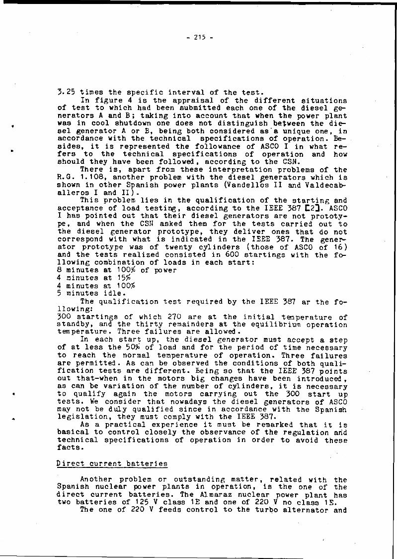
- 215
3 .2 5 t i n e s t h e s p e c i f i c i n t e r v a l o f t h e t e s t .I n f i g u r e 4 i s t h e a p p r a i s a l o f t h e d i f f e r e n t s i t u a t i o n s
o f t e s t t o w h ic h had b e en s u b m i t t e d e ach one o f t h e d i e s e l ge n e r a t o r s A and B ; t a k i n g i n t o a c c o u n t t h a t when t h e p ow e r p l a n t
w a s i n c o o l sh u tdow n one d o e s n o t d i s t i n g u i s h b e t w e e n t h e d i e s e l g e n e r a t o r A o r B , b e i n g b o t h c o n s i d e r e d a s ' a u n i q u e o n e , i n a c c o r d a n c e w i t h t h e t e c h n i c a l s p e c i f i c a t i o n s o f o p e r a t i o n . Bes i d e s , i t i s r e p r e s e n t e d t h e f o l l o w a n c e o f ASCO I i n what r e f e r s t o t h e t e c h n i c a l s p e c i f i c a t i o n s o f o p e r a t i o n and how s h o u l d t h e y h a v e b e en f o l l o w e d , a c c o r d i n g t o t h e CSN.
T h e r e i s , a p a r t f r o m t h e s e i n t e r p r e t a t i o n p r o b l e m s o f t h e R . G . 1 . 1 0 8 , a n o t h e r p r o b l e m w i t h t h e d i e s e l g e n e r a t o r s w h ic h i s show n in o t h e r S p a n i s h pow er p l a n t s ( V a n d e l l o s I I and V a l d e c a b - a l l e r o s I and I I ) .
T h i s p r o b l e m l i e s i n t h e q u a l i f i c a t i o n o f t h e s t a r t i n g and a c c e p t a n c e o f l o a d t e s t i n g , a c c o r d i n g t o t h e IEEE 387 C 2 3 . ASCO I h a s p o i n t e d o u t t h a t t h e i r d i e s e l g e n e r a t o r s a r e n o t p r o t o t y p e , and when t h e CSN a s k e d them f o r t h e t e s t s c a r r i e d o u t t o t h e d i e s e l g e n e r a t o r p r o t o t y p e , t h e y d e l i v e r o n e s t h a t do n o t c o r r e s p o n d w i t h what i s i n d i c a t e d i n t h e IEEE 387 . The g e n e r a t o r p r o t o t y p e was o f t w e n t y c y l i n d e r s ( t h o s e o f ASCO o f 1 6 ) and t h e t e s t s r e a l i z e d c o n s i s t e d i n 600 s t a r t i n g s w i t h t h e f o l l o w i n g c o m b i n a t i o n o f l o a d s in e ac h s t a r t :8 m in u t e s a t 100# o f power 4 m in u t e s a t 15#4 m in u t e s a t 100#5 m in u t e s i d l e .
The q u a l i f i c a t i o n t e s t r e q u i r e d b y t h e IEEE 387 a r t h e f o l l o w i n g :300 s t a r t i n g s o f w h ic h 270 a r e a t t h e i n i t i a l t e m p e r a t u r e o f s t a n d b y , and t h e t h i r t y r e m a i n d e r s a t t h e e q u i l i b r i u m o p e r a t i o n t e m p e r a t u r e . T h r e e f a i l u r e s a r e a l l o w e d .
In e ach s t a r t up , t h e d i e s e l g e n e r a t o r must a c c e p t a s t e p o f a t l e s s t h e 50# o f l o a d and f o r t h e p e r i o d o f t im e n e c e s s a r y t o r e a c h t h e n o rm a l t e m p e r a t u r e o f o p e r a t i o n . T h r e e f a i l u r e s a r e p e r m i t t e d . A s can be o b s e r v e d t h e c o n d i t i o n s o f b o t h q u a l i f i c a t i o n t e s t s a r e d i f f e r e n t . B e i n g s o t h a t t h e IEEE 387 p o i n t s o u t t h a t - w h e n i n t h e m o t o r s b i g c h a n g e s h a v e b e en i n t r o d u c e d , a s can be v a r i a t i o n o f t h e number o f c y l i n d e r s , i t i s n e c e s s a r y
« t o q u a l i f y a g a i n t h e m o to r s c a r r y i n g ou t t h e 300 s t a r t upt e s t s . We c o n s i d e r t h a t n ow adays t h e d i e s e l g e n e r a t o r s o f ASCO may n o t be d u l y q u a l i f i e d s i n c e in a c c o r d a n c e w i t h t h e S p a n i s h l e g i s l a t i o n , t h e y must c om p ly w i t h t h e IEEE 387.
As a p r a c t i c a l e x p e r i e n c e i t must be r e m a rk e d t h a t i t i s b a s i c a l t o c o n t r o l c l o s e l y t h e o b s e r v a n c e o f t h e r e g u l a t i o n arid t e c h n i c a l s p e c i f i c a t i o n s o f o p e r a t i o n i n o r d e r t o a v o i d t h e s e f a c t s .
D i r e c t c u r r e n t b a t t e r i e s
A n o t h e r p r o b l e m o r o u t s t a n d i n g m a t t e r , r e l a t e d w i t h th e S p a n i s h n u c l e a r power p l a n t s i n o p e r a t i o n , i s t h e one o f t h e d i r e c t c u r r e n t b a t t e r i e s . The A l m a r a z n u c l e a r pow e r p l a n t has two b a t t e r i e s o f 125 V c l a s s 1E and one o f 220 V no c l a s s 1E.
The one o f 220 V f e e d s c o n t r o l t o t h e t u r b o a l t e r n a t o r and

- 216 -
t o t h e o i l pumps o f t h e t u r b i n e d r i v e n pumps o f a u x i l i a r y f e e d w a t e r .
The 125 V a r e on d u ty w i t h s a f e t y r e l a t e d e q u ip m e n t s and some l o a d s non s a f e t y r e l a t e d .
The 125 V b a t t e r i e s c a p a c i t y i s o f 2100 Ah - f o r t h e d i s c h a r g e r a t e o f e i g h t h o u r s and o f 1792 Ah i n f o u r h o u r s . P r e s e n t l y t h e y a r e s u b j e c t by t h e t e c h n i c a l s p e c i f i c a t i o n s , t o t h e c o n d i t i o n s o f t h e d i s c h a r g e c y c l e f o r w h ich t h e y w e r e n o t d e s i g n e d and b e s i d e s , t h e s e s p e c i f i c a t i o n s a r e , p a r t i a l l y , i n c o n t r a d i c t i o n w i t h t h e f i n a l s a f e t y a n a l y s i s r e p o r t .
The d i s c h a r g e c y c l e w i t h w h ic h t h e A l m a r a z b a t t e r i e s w e re d e s i g n e d , i s t h e one shown on f i g u r e 5. A c c o r d i n g w i t h t h i s d i s c h a r g e c y c l e , t h e n e c e s s a r y s i z e o f t h e c e l l s i s t h e q u o t e d in t h e c a l c u l a t i o n o f t a b l e I I I , i n a c c o r d a n c e w i t h t h e IEEE 485
TABLE I I I
LOAD LOAD DURATION TIKE TO THE RT REQUIRED CELLA CHANGE ( M i n ) END OF SECTION CAPACITY POS. NES.
464 463 1 240 32 14. 5423 -161 239 239 32 5 . 0 3303 120 1 1 140
00•o
1 5 .3 5 .03
TOTAL : 1 0 .27
C e l l s w i t h o u t c o r r e c t : 10. 27C o r r e c t i o n t h r o u g t t e m p e r a t u r e : 1 . 0 D e s i g n m a rg in : 1.1 A g i n g f a c t o r : 1 .2 5C e l l s i z e = 1 0 .2 7 x 1.1 x 1 .2 5 = 1 4 .1 2
The b a t t e r y s h o u l d h av e 15 p o s i t i v e p l a t e s , r o u n d i n g o f f b y e x c e s s a s t h e r u l e recommends . I n A lm a ra z t h e y w e re b o u g h t w i t h 14 p o s i t i v e p l a t e s , t h a t i s t o s a y , r o u n d i n g o f f by d e f - f e c t .
T h i s d i s c h a r g e r a t e r e q u i r e s t h e b a t t e r y t o p r o v i d e 1222 Ah i n f o u r h o u r s . S i n c e t h e b a t t e r y c a p a c i t y f o r t h e f o u r h o u r s c y c l e i s o f 1792 Ah , when t h e b a t t e r y s e r v i c e t e s t i s c a r r i e d o u t , w i t h t h e d e s i g n c y c l e , t h e b a t t e r y i s s u b m i t t e d t o a d i s c h a r g e o f t h e 68 %.
The p r o b l e m a r i s i n g i s t h a t t h e l o a d s r e a l l y c o n n e c t e d t o t h e b a t t e r i e s e x c e e d t h e p r e d i c t i o n s e f f e c t e d . The p r o f i l e o f t h e c u r v e c o r r e s p o n d i n g t o t h e l o a d s c o n n e c t e d , i s r e f l e c t e d i n f i g u r e 6 , b e i n g t h e a m p e r e s - h o u r consumed 1676 in t h i s d i s c h a r ge c y c l e o f f o u r h o u r s . S i n c e t h e b a t t e r y f o r f o u r h o u r s has a c a p a c i t y o f 1792 Ah , t h i s r e a l d i s c h a r g e c y c l e i m p p l i e s t o d i s c h a r g e t h e b a t t e r y i n a 93% o f i t s c a p a c i t y . T h e r e f o r e t h e b a t t e r y i s i n f rad iramensi oned and f o r t h e c y c l e o f l o a d s r e a l l y c o n n e c t e d i t s h o u l d h av e t h e c a p a c i t y d ed uced f rom t h e c a l c u l a t i o n s o f t h e f o l l o w i n g t a b l e :

- 217 -
TABLE IV
LOAD LOAD DURATION TIME TO THE RT CELL REQUIREDA CHANGE ( K i n ) END OP SECTION CAPACITY POS. NEG.
638 638 1 240 32 • * 1 9 . 9416 -2 2 2 239 239 32 6 . 9501 85 1 1 140 0 . 6
7 U 7 T 6 . 9
TOTAL: 1 3 .6
S i z e o f t h e c e l l w i t h o u t c o r r e c t 13 .6 C o r r e c t i o n t h r o u g t t e m p e r a t u r e : 1 . 0 D e s i g n m a r g i n : 1. 1 A s i g n f a c t o r : 1 .25S i z e o f t h e c e l l = 13*6 x 1 . 1 . x 1 . 2 5 = 1 8 .7
The b a t t e r y t h u s s h o u l d have 19 p o s i t i v e p l a t e s , and a c c o r d i n g w i t h f i g u r e 7, t h e c a p a c i t y o f t h e b a t t e r y r e q u i r e d i s o f 2774 Ah, f o r t h e 8 h o u r s c y c l e .
P r e s e n t l y t h e number o f p o s i t i v e p l a t e s i s 14, and i s t h e one a p p e a r i n g a s s i z e o f t h e c e l l w i t h o u t c o r r e c t i n t h i s l a s t c a l c u l a t i o n . The p r e s e n t b a t t e r y has not t h e d e s i g n m a rg in and t h e a g i n g f a c t o r recommended b y t h e IEEE 485 , due t o t h e e x c e s s o f l o a d s c o n n e c t e d .
Ir: t h e c a l c u l a t i o n s e f f e c t e d i n th e p r e s e n t w o r k , i t h as not been t a k e n i n t o a c c o u n t th e c o r r e c t i o n f a c t o r f o r t h e m in i mum t e m p e r a t u r e e x p e c t e d o f t h e e l e c t r o l y t e .
The d i s c h a r g e t e s t s r e q u i r e d by th e t e c h n i c a l s p e c i f i c a t i ons o f o p e r a t i o n , a r e in p r i n c i p l e , t h e o n e s d e f i n e d i n t h e IEEE 450 T 4 ] . The p r o b l e m t h a t a r i s e s w i t h t h e t e c h n i c a l s p e c i f i c a t i o n s o f o p e r a t i o n i s , t h a t t h e y a r e n o t c o r r e c t l y d e f i n e d and d e v e l o p p e d , b e c a u s e th e s e r v i c e t e s t r e q u i r e d must h av e a d u r a t i o n o f e i g h t h o u r s , b e i n g t h e r e a l c y c l e r e q u i r e d t o t h e b a t t e r y o f f o u r h o u r s . A c c o r d i n g w i t h th e IEEE 450, t h e s e r v i c e t e s t must be d e v e l o p p e d i n t h e most s i m i l a r p o s s i b l e way t o t h e p r o f i l e o f t h e c u r v e c o r r e s p o n d i n g t o t h e l o a d s r e a l l y conne c ted . B e s i d e s , t h e p e r f o r m a n c e t e s t , t h a t m ust be r e a l i z e d e a c h 60 m on th s , a c c o r d i n g t o t h e t e c h n i c a l s p e c i f i c a t i o n s a p p r o v e d ,
« r e q u i r e t o be done im m e d i a t e l y a f t e r t h e s e r v i c e t e s t . T h i s i si n c o n t r a d i c t i o n w i t h t h e l a s t S t a n d a r d S p e c i f i c a t i o n s f o r t h e p r e s s u r i z e d w a t e r r e a c t o r s o f t h e W e s t i n g h o u s e k i n d , a s i t i s
* d e f i n e d in t h e NUREG 0452 C 5 3 -The aim o f t h e s e r v i c e t e s t i s t o check a t l e s s one t im e
e a c h 18 m on th s , t h a t t h e b a t t e r y i s a b l e t o f e e d a l l t h e l o a d s r e a l l y c o n n e c t e d d u r i n g t h e t im e f i x e d i n t h e f i n a l s a f e t y a n a l y s i s r e p o r t . W i t h t h e p e r f o r m a n c e t e s t i t i s in t e n d e d t o d e m o n s t r a t e , a t l e s s one t im e eac h 60 m onths , t h a t t h e b a t t e r y h a s , a s a minimum, th e 80# o f t h e n o m in a l c a p a c i t y g i v e n b y t h e m a n u f a c t u r e r .
The p r e s e n t s i t u a t i o n o f A l m a r a z , due t o t h e e x c e s s o f l o a d s c o n n e c t e d t o t h e b a t t e r i e s i s such t h a t w i t h t h e s e r v i ce t e s t i t i s b e i n g c h e ck ed and r e q u i r i n g t h a t t h e b a t t e r y has a c a p a c i t y s u p e r i o r t o t h e 93# o f t h e n o m i n a l . T h i s s i t u a t i o n

- 218 -
h a s t o b e c o r r e c t e d i m m e d i a t e l y s i n c e e a c h 18 months i t i s b e i n g r e q u i r e d i t s c a p a c i t y t o be s u p e r i o r t o t h e 93# o f t h e n o m in a l o n e , and a c c o r d i n g w i t h t h e IEEE 450, t h e NUREG 0452 and t h e t e c h n i c a l s p e c i f i c a t i o n s o f o p e r a t i o n , i t i s e a c h 60 m on th s when i t h a s t o be c h e c k e d t h a t t h e b a t t e r y h a s a c a p a c i t y s u p e r i o r t o t h e 8 0 # . When t h e b a t t e r y s h o w s s i g n s o f d e g r a d a t i o n , t h e t e s t i n t e r v a l o f 60 months i s r e d u c e d t o a y e a r , b u t r e q u i r i n g i t s c a p a c i t y t o b e s u p e r i o r t o t h e 8 0 # ,
T h e r e f o r e t h e p h i l o s o f y o f t h e t e s t d e f i n e d i n t h e t e c h n i c a l s p e c i f i c a t i o n s i s b e i n g i n v e r t e d , s i n c e e ac h 18 months t h e A l m a r a z b a t t e r i e s a r e b e i n g s u b m i t t e d t o a more s e v e r e c o n d i t i o n t h a t t h e one t o w h ic h t h e y s h o u l d b e s u b m i t t e d e a c h 60 m o n th s , i f t h e r e a r e not s i g n s o f d e g r a d a t i o n i n t h e b a t t e r i e s .
The t e c h n i c a l s t a f f o f t h e CSN has p o i n t e d ou t t o A lm a ra z t h e need o f u n d e r t a k i n g a c o m p l e t e s t u d y o f t h e b a t t e r i e s t o e l i m i n a t e t h e non s a f e t y l o a d s i n su ch a way , t h a t t h e p r o f i l e o f t h e l o a d s r e a l l y c o n n e c t e d w o u ld be i n f e r i o r , o r i f n o t , o t h e r b a t t e r i e s o f non c l a s s 1E s h o u ld be p l a c e d . In t h e s e t h e l o a d s non c l a s s 1E a s can be t h e c o n t r o l o f t h e s w i t c h y a r d o f 400 and 200 K v , e t c , s h o u l d be c o n n e c t e d .
B e s i d e s , i t h as been s a i d t h a t s h o u ld submmit a r e v i s i o n p r o p o s a l o f t h e t e c h n i c a l s p e c i f i c a t i o n s , t o a d e q u a t e them t o t h e Power P l a n t r e a l i t y , and t o t h e s t a n d a r d t e c h n i c a l s p e c i f i c a t i o n s .
R e f e r e n c e s
1 R .G . 1 . 1 0 8 . P e r i o d i c t e s t i n g o f d i e s e l g e n e r a t o r u n i t s u s e d a s o n s i t e e l e c t r i c p ow e r s y s t e m s a t n u c l e a r pow e r p l a n t s . R e v . 1 . 1977.
2 IEEE 387. S t a n d a r d c r i t e r i a f o r d i e s e l g e n e r a t o r u n i t a p p l i e d a s s t a n d a r d p ow e r s u p p l i e s f o r n u c l e a r g e n e r a t i n g s t a t i o n s . 1977.
3 IEEE 4 8 5 . Recommended p r a c t i c e f o r s i z i n g l a r g e l e a d s t o r a g e b a t t e r i e s f o r g e n e r a t i n g s t a t i o n s and s u b s t a t i o n s . 1978.
4 IEEE 450. Recommended p r a c t i c e f o r m a i n t e n a n c e , t e s t i n g and r e p l a c e m e n t o f l a r g e l e a d s t o r a g e b a t t e r i e s f o r g e n e r a t i n g s t a t i o n s and s u b s t a t i o n s . 1980.
5 NUREG 0 4 5 2 . R ev . 4 . S t a n d a r d t e c h n i c a l s p e c i f i c a t i o n s f o r W e s t i n g h o u s e p r e s s u r i z e d w a t é r r e a c t o r s . 1961.
6 F i n a l S a f e t y a n a l y s i s r e p o r t A lm a ra z I and I I N u c l e a r Po w e r P l a n t .

219
FIGURE JL

1 I I . - ■ • •«
ij ,
!
_ o.
~i1
!1
!
1 U»
i!!
1i!
iiii
I' - ' O 2 T C J l n t n
ii>NOcU3
i1 i
9 C3fr.U-.
k T j4 »:■
ü»
i
i 1
1________1
1|i
1ii
■ *>, “11 !
:
i 1 îi i i
. i ____ i__ _______l s r i
— * : f fI
—
1 1— 1 ' .
' ] - 8i l
< ! ►— »— i
m •
(sÂep) qsaq uaawqaq auî|
CVILUOZ
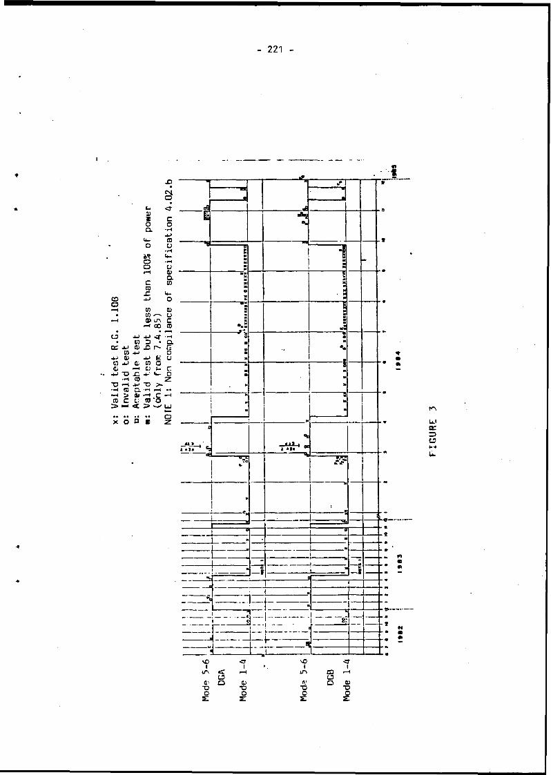
Vali
d test R
.G.
1.108
Invalid
test
221
I.uoQ.
oo
cCD•C
a
coCDu
u<Da.co
coco 0 lA ^ GO4-J <fD •xi r'-^ f; CO C G) fc-Xco ;^ *D >*
af-ouco
D.4»C;<—I C ' CO *o
> IX O a b
c£
jn_4 A* « 9 *3---- C&
_d .
vO■ <7■ t sOi1IA < 1 ’ . VlA aa aQ> o 0) rt' o a>*U T3 -o X)O O O os: s;
GURF

222
i
FIGU
RE

- 223 -
AMPERES
AMPERES
Xlm
ff-3h
TIME
Battery loads conected
FIGURE 6
-//■J
3h59m
400
300
Tls4hAls464 T2=3h59rn --- *
A2=302.8 T 3=lm.A3=422T8
A*
Ilm i h 3h
TIME
i y i3h59m
Battery Cycle designed
FIGURE 5

TY
PE
F
HC
CM0) to-3T- ■*130 83d S n O A
3 Al 1 iSOd 83d S800H 383dWV
*
FIGURE 7

I - 225 -
PAPER NO. 3.5.SOME FAILURES OF DIESEL-GENERATORS
DURING COMMISSIONING TESTS OF 1300 MWe PWR
A.F.COLASDépartement d 'Analyse de Sûreté. CEA/IPSNCentre d'Etudes Nucléaires de Fontenay-aux-Roses (FRANCE)C. MORZELLEService Etudes et Projets Thermiques et Nucléaires EdF Lyon (FRANCE)
ABSTRACT
During commissioning tests of the French 1300 MWe units, which are equipped with different diesel generator from the 900 MWe units, some devices and components failures were experienced.
These components include :
- Alarm sensors on fuel, lubricating, cooling circuits.- Injection pumps and speed governors.- Fuel delivery.- Vibrations of fuel and lubrication lines.
This paper will try to show how and when the above elements can affect the reliability of Diesel-generator units and how commissioning tests should show the defects.
RESUME
Pendant les essais de mise en service des réacteurs 1300 MWe français qui sont équipés de diesels alternateurs différents de ceux dont sont pourvus les PWR 900 MWe, quelques défaillances d'équipements et d'organes surgirent.
Ces matériels comprennent :
- capteurs d’alarmes sur combustible, lubrification et refroidissement,- pompes d'injection et régulateurs de vitesse- alimentation en combustible- vibrations de tuyauteries de combustible et de lubrification.
Cet exposé essaiera de montrer comment et quand les éléments cités ci-dessus peuvent affecter la fiabilité des diesels-alternateurs et comment les essais de mise en service ont mis ces défauts en évidence.

- 226 -
SUMMARY
I Positions and role of diesels generators in electric power distributionII Diesel engine-Alternator descriptionIII Commissioning tests program. Failures related to testsIV Sensors defectsV Speed regulation troublesVI Injection pumps seizuresVII Fuel purityVIII Piping failuresIX Conclusion
I POSITION AND ROLE OF DIESELS UNITS (see fig n° 1)
The generator is connected to the network by two SF6 type breakers : the generator breaker and the line breaker. Between these breakers, a connection line goes to the stepdown transformer ; this 405 kV/6.8 kV three- phase transformer has three 32 MVA secondary windings and supplies power to the unit equipment. A second power source is provided by a 405 kV/6.8 kV three-phase transformer with two 32 MVA secondary windings.
The onsite power supply is ensured by two independent 7560 kW diesel generator sets ; each of them is connected to one safety line and is located in a separate protected building. The auxiliary equipments for startup and fuel supply are redundant and the generator reaches the nominal speed and voltage within 10 seconds after the startup signal. Each diesel generator is capable of :
- allowing the safe shutdown of the unit without damage to the equipment and ensuring reactor cooling,
- supplying power, without any time limit, to all the equipment necessary for emergency core cooling and minimizing offsite releases in case of reactor accident (for example a LOCA).
As the generator cannot be immediately loaded with all users, these are first disconnected and then reconnected, when the generator has reached the rated conditions, according to a reloading sequence which depends on the plant conditions when the loss of offsite power occurs (mainly with or *without a reactor accident).
In case of total black-out (loss of the two 400 kV sources and ^failure of both diesel units), after 15 seconds, a steam turbine driven generator system (LLS) provides electrical power in order to maintain water injection to the reactor coolant pumps seals and to feed essential controls necessary to operate the reactor according to emergency procedures. Two steam driven pumps are used to feed steam generators in order to cool the core.

- 227 -
II. DIESEL ENGINE - ALTERNATOR DESCRIPTION
II.a).- EngineThe on site generators are powered by a diesel engine of Vee 16 type. General arrangment and data can be seen on figures n° 2 & 3.
i - StartingAir compressed at AO bars in two vessels can operate a series of 5 startings .
»
- Speed governorIts loops include :
a) speed measurement by magnetic sensor giving pulses of voltage.
b) Electrical sensors taking speed signals and giving electromagnetic control on the hydraulic action of the speed governor.
c) A mechanical device taking centrifugal action from rotation speed in order to control the hydraulic actuator pushing or pulling the injection gear. This mechanical device includes an overspeed safety
d) A booster giving full hydraulic pressure at injection control when engine is launched.
- Diesel fuel supplyStorage tanks, when full up, allow 7 days of operation at full power (7200 kWe). The minimum fuel level to be kept in storage ensures at least 24 hours of operation at full power. From storage tanks, the fuel is pumped into a "day tank" the content of which is always kept above 30 minutes of autonomy. When engine is started this day tank is automatically filled up.From the day tank, injections pumps are fed by an electropump and a driven pump, each of these 2 pumps being able to supply the full flow.On the feeding line a self cleaning filter prevents suspended particles to reach the injection pumps.
II.b) Cooling circuits
There are 3 water cooling circuits :
r a) A main circuit with a driven pump (240 m3/h - 4.3 bars), cooling cylinders and cylinders heads when engine is running. When the engine is stopped, an electropump (12 m3/h) drives water through an electric
» heater, in order to keep cylinders and pre-lubricating oil at goodtemperature (45°C).
b) A low temperature water circuit with a driven pump cooling both lubricating oil and air from turbo-chargers.
c) An injector cooling water circuit with two electropumps.Heat from these 3 cooling water circuits is evacuated to outer atmosphere through dry air exchangers.

- 228 -
I. c) Lubricating circuits
There are 3 lubricating circuits :
a) Engine lubrication circuit, with a driven pump (145 m3/h - 7 bars) and a 30 pm filter.
b) Camshaft and rockers arms lubrication with 2 electropumps (1 pump running) (900 1/h).
c) Pre-lubricating circuit with an electropump (20 m3/h).
The oil reserve tank contains at least enough oil for 84 hours at full power consumption.
II. b) Expected performancesAs said in previous page, the unit must be able to deliver correct
tension (6,6 kV) and frequency (50 Hz) within 10 seconds after first signal.
Then it has to supply power, without any time limit, to all the equipments necessary for safe shut-down or, eventually, for emergency core cooling and limitation of internal pressure in reactor building.
During loading sequence : frequency must be kept è 47.5 Hz and alternator voltage must remain è 4950 V.
Frequency must be reset è 49 Hz and voltage ^ 5940 volt within 40 % of time interval between 2 successive steps of the loading sequence.
III. COMMISSIONING TESTS PROGRAM
In order to check real capabilities of emergency power units, a whole tests-program is carried out during reactors commissioning period (cf. commissioning tests diagram).
III.a) Commissioning tests proceduresEach commissionning test is completed according to a test-form
which contains detailed operating instructions, performances required, safety criteria, etc...
Odd performances or defects occuring during commissioning tests must be mentionned in the "test results forms" or in "events information forms".
In addition to commissioning tests shown in the diagram, a 8 days run is also performed at different load rates.

- 229 -

- 230 -
III.b) Failures in relation to tests
The first tests performed following procedures TP 012, 014, 015, revealed that a certain type of pressure sensors was unable to fit the duty conditions.
These tests have shown that the low pressure sensors, used to watch over diesel oil tanks level or low pressure in cooling circuits, were subject to leakages or even failures.
The engine starting tests (TP 101, 104, 107) have shown defects in regulation of speed.
Bad performances were registered in fast loading tests (starting engine with a 1300 kW low pressure injection pump connected to the emergency bus, for example).
As injection pump seizures happened too often during these tests, it was obvious that some generic defect was to be sorted out.
During starting tests and particularly during the 8 days running test, some pipes cracked up or wore out severly at supports contacts.
IV. SENSORS DEFECTSIn order to keep engines in good operating conditions as well as in
order to prevent their breakdown because of any auxiliary circuit defect, many sensors are used to watch over pressures, temperatures, levels, etc...
A certain type of sensor had been chosen because it is very accurate for low pressure detection. It uses diaphragm moving adjustable switches. So it can operate for very small variations of low pressure. This is very useful to detect abnormalities or trespassing of thresholds in such matter as tanks levels, pressure in cooling circuit, etc....
Unfortunately it appeared to be fragile when exposed to vibrations, peaks and pulsations of pressure. On many occasions diaphragms were torn with leakage of fuel or cooling water. A new model of pressure sensor was supplied, perhaps less accurate but far more resistant. As far as emergency systems for nuclear reactor are concerned, one has to prefer toughness to accuracy when opposed one to another.
It is indeed essential that any part of the auxiliary devices of the emergency units must be able to resist hard duty and environmental aggressions (e.g. variations of temperatures).
V. SPEED REGULATION TROUBLES
Large variatious of alternator power must not affect the operating speed of the engine. For response and stability are the most important qualities to be fulfilled by the regulation device.
As usually fuel quantity is adjusted by means of a rack-and-pinion system controlling the injection pump's plungers angular position.

- 231
So the position of helicoidal cavity around the piston of each pump, in regard of fuel intake orifices on pump's cylinder is controlled by the speed governor (see fig n° 4).
Movement from speed governor to injection pumps is transmitted by means of linkage (see fig. n° 5).
r 16 injection pumps are connected to the control linkage (8 pumps toeach side of the Vee engine). This involves numerous causes of mechanical resistances to governor's action.
Alterations of governor response are introduced by levers, rods, gears, connections, etc...
Before coupling the governor arm to the regulation linkage it is necessary to measure the force needed to move this device. Of course this force must be quite inferior to the maximum governor output, as inertia, vibrations, elasticity will increase the mechanical impedance of the regulation system.
So, it is easy to see how important are the design, construction and adjustments of the whole regulation linkage.
A suitable governor speed must give a strong and quick response to any variation of engine speed. In case of reactor accident the load on each diesel unit will be connected as follows.
t = 0 starting ordert S 10 sec : Alternator voltage è 6600 & frequency = 50 Hz
oc sec : 380 V auxiliaries to the diesel-alternator (LHP-DVD) : 238 kW
+ 05 sec Intermediate pressure emergency injection pump (RIS) : 1400 kW
10 sec : Low pressure emergency injection pump RIS - ISBP : 560 kW
20 sec Containment spray pump EAS : 630 kW
25 sec : Chemical and volume control system pump 500 kW
30 sec Auxiliary feedwater to steam generators (ASG pump) : 630 kW
35 sec Intermediate cooling circuit (1 pump RRI) : 630 kW
40 sec Essential service cooling water circuit (SEC pump) : 500 kW
45 sec Compressed air : 1 compressor (SAP) + spent fuel : cooling pump (PTR) + auxiliaries :
~ 1000 kW
50 sec Chilled water circuit compressor & pump (DEL) : 50 kW
55 sec • Control room air conditioning and sea water filter : 225 kW
TOTAL : ~ 6363 kW

- 232 -
If a reactor accident occurs while the diesel is on "normal" loading sequence, the 1400 kW step is postponed to the 8 position of the loading sequence.
Figures n° 6 & 7 show the most typical reactions of speed control system in both cases.
During emergency tests, different bad reactions from speed control system were observed. As one can see in fig N°8 the reaction was often late. During the first milliseconds following large step of load increase, the supplement of energy is taken from the engine-alternator momentum.
The slope of the tangent to the speed decreasing curve at its origin may be considered as a linear function of the ratio of energy demand (M.ui) on rotating mass momentum (I. u> /2). It was found on records that the reaction of the governor was strong enough to reset 49 Hz frequency within 2 seconds but began too late.
Any attempt to increase the quickness of the governer response leads to instability of speed control and particularly to an overshoot of speed on startup. Overshoot had the inconvenience of delaying over 10 seconds the "correct frequency" signal necessary with "correct voltage" to start loading sequences. Improvements are to be searched in the direction of smooth control linkages but as well as in the direction of more powerful and more sophisticated governors.
While awaiting for new governor model, a compromise must be obtained. It appears possible to reach the reset of frequency and voltage minimum values (49 Hz, 5940 volts) within 2 seconds. This is the essential condition to engage the successive steps of loading sequences.
VI. INJECTION PUMPS SEIZURESUnfortunately smooth linkages are not sufficient to obtain a safe
response of speed control system. We had opportunities to notice that even only one seizing injection pump out of the 16 of the engine, can introduce troubles.
If one injection pump seizes while the engine runs at low power, the resistance of this one pump to its plunger rotation makes useless any effort from the governor, aimed to an increase of power. A compressible spring on the other side of rack allows a general movement toward reduction of power or stop, (see fig. n° 4)
If one of the 16 injection pumps seizes, the speed control will be unable to compensate the loss of this 1/16 of power even at constant power rate demand. Such troubles occurred several times during commissioning tests, particularly when engines performed their 8 days runs.
Pumps seizures repetitions were at first attributed to fuel pollution but after fuel analysis and pumps overhauls it appeared that something was to be done concerning pumps quality.
- 233 -
Since only one unsound injection pump jeopardises the whole diesel generator reliability, the only way to reduce this menace consists into a drastic improvement of fabrication and controls quality. Controls at every stages of fabrication must be severe and adequate. We have obtained a review of these controls quality in workshop. We do recommend also to operate at least 20 hours operation test for each pump supplied to nuclear power plant diesels, either new ones or pumps brought back from repair.
A test bench must be available in order to perform the minimum running test which can eliminate the unsound pumps. (Seizures due to surfaces defects or bad clearances appear generally within the first hours of operation).
Commissioning tests operators must also pay particular attention to any sign of abnormality such as low temperature at one or two cylinder exhausts. Free movement and return to precise stop position of racks and regulation linkage are to be carefully checked.
VII. FUEL PURITY
After dealing with injection pumps, it is absolutely necessary to be certain of the permanent purity of fuel oil. As small solid particles in the fuel may generate seizings of injection pumps plungers, one has to be very careful about fuel purity and filtration.
Concerning the purification of the fuel-oil, we think it would be very helpful to centrifugate it when it is in storage tanks. A centrifugal separator can eliminate most of the impurities and contribute largely to maintain purity of the fuel.
A common mode of complete failure was indeed caused by a fuel delivery from a contaminated tanker lorry. This event gives a lot to think about, as a serious warning. The tanker lorry was filled with fuel oil without being cleaned from its previous content which was formic acid. The chemical reaction in the mixture gave thick coagulations in the fuel inside the feeding line.
It is easy to imagine that such a contaminated lorry may deliver half of this content to fill up the storage tank of the first diesel unit and deliver the rest in the second unit storage tank with all the consequences involved. Since this warning each delivery has to undergo preliminary controls and it is forbiden to share any lorry content between two different unit storages.
It may appear trivial to add that the cleanliness of any part of the fuel circuit between the last fine filter and the injection pumps must be perfect. Still closer examinations after troubles have shown that weldings and brazings in fuel pipes must be carefully scoured. First flow of fuel through the feeding line has to be drained for a long time and samples have to be taken for tests.

- 234 -
VIII. PIPING FAILURES
Following several failures occurring on pipes (e.g : oil, cooling water, lubricating oil), different improvements have been designed and are in progress.
Clamps on pipes sections making junction beetween parts fastened to the motor and parts fixed on the building concrete structures are particulars targets for improvements. Measurements of pipes vibrations in correlation with motor's vibrations are also under way.
Conclusion
Informations gathered from commissioning tests of six 1300 MW reactors gave opportunities for improvements on diesel units and other systems. New tests, now underway give possibilities to check these modifications and to look after any other undetected deficiencies.
ACKNOWLEDGEMENTS
The authors wish to express their gratitude to the EDF Test departments engineers and technicians who performed commissioning tests at FLAMAN- VILLE, PALUEL and St ALBAN and co-operate to the common aim : improvement of nuclear safety.
Biliography :
- Electricité de France.Direction de l'Equipement. Service d'Equipement Nucléaire Extérieur 11, Ave de Friedland - 75008 PARISEdF 1300 MWe Nuclear Power Plants Short Technical Description.
- Alsthom - Atlantique Mécanique diesels - Saint Nazaire Semt- Pielstick PC Engine Description

Positi
ons
of M
e <?
diesel
s-unit
s in M
e
Electr
ic Po
wer D
istrib
ution
Syst
em
ONE-L
INE
DIAG
RAM

piston
236

237
sl* +rVI s *12 * êhî8 c s c j 1 I s ? P I ??Sf3?|j? H p | | Si«s| |||f 11|| S | ISCSIS

238

239
«
à

240 -
ST
AR
ri

241

- 243 -
PAPER 3.6 OPERATIONAL RELIABILITY OF THEPOINT LEPREAU GS STANDBY GENERATORS
D.A. Loughead & A.T. McGregor Point Lepreau GSNew Brunswick Electric Power Commission Lepreau, New Brunswick, Canada.
ABSTRACT
Performance of the two Point Lepreau GS standby generators during the first three years of licensed station operation is reviewed. It is shown that the mandated reliability/availability requirements have been met. The nature of starting and running failures has been examined and the consequences, in terms of design and procedural changes, discussed. A brief review of standby generator outages is included to permit estimates of standby generator availability and total Class III standby power unavailability. A pair of simple equations is introduced as a means of estimating the probable economic penalty, both cumulative and incremental, associated with the running failure of one standby generator while the other is on a maintenance outage.

244 -
1.0 Introduction
Point Lepreau GS is a 600 MWe, sea-water cooled, CANDU plant located on the Bay of Fundy in southwestern New Brunswick, Canada, significant historical dates are: first Operating Licence granted 82-07-20; first criticality 82-07-25; first synchronization 82-09-11; first nuclear-powered electricity 82-09-26; and in-service data 83-02-01.
Point Lepreau GS is one of four identical operating nuclear units with nuclear steam supply designed by Atomic Energy of Canada Limited, AECL. As the balance of plant design is different for each of the four plants, the conclusions of this study should be regarded as directly applicable only to one. Furthermore, Operational Reliability depends not only on the design and operating practices at each station, it also is a strong function of the licensing environment and restrictions. As only two of the four plants are located in Canada, broad generic comparisons are inadvisable.
2.0 Standby Class III Power
At Point Lepreau GS standby, or emergency, Class III power is provided by either of two KHD diesel generators having a continously-rated full power output of 4.5 MWe at 4.16 kv and 60 Hz with the engine running at 900 RPM. Some details of each standby generator, SG, are given in Table I.
Normal station electrical power, class IV, is supplied from the Station Service Transformer, SST, to the ODD 13.8 kv bus and through the Unit Service Transformer, UST, directly from the 26 kv main generator output, to the EVEN 13.8 kv bus. Power to the Class III system is derived from these busses by transformation to 4.16 kv. In the event of a Loss of Class IV power, LOCLIV, the two standby generators each power one of the 4.16 kv Class III busses. Table II gives some of the requirements for the Class III system. In essence, either Class III power train from the 4.16 kV bus downward is capable of maintaining the plant in a safe shut down configuration following a Loss of Coolant Accident, LOCA, compounded by a LOCLIV.
There is no need for synchronization of Class III emergency power. During an upset, each diesel generator and its sequencer act independently of the other to power process loads. The maximum load requirement for a single operating SG is slightly less than 4.5 MWe. When the SGs have been run unsynchronized in support of outage work on the associated 13.8 kv bus, loadings of 2.5 MWe were the norm.
In the past three years of operation, one of the most significant licensing requirements has been the need to operate one SG while the other was unavailable. As the statistics of Section 4 will show, this commitment has led to almost 100 diesel outage support runs in comparison with 123 runs performed for scheduled routine testing. From 82-07-01 until 85-06-30, both SGs had been in operation for a total of 3038.1 running hours.
3.0 Fulfillment of Testing Commitments
To meet corporate commitments to the Canadian regulatory authority - the Atomic Energy Control Board, AECB - the following testing is performed:

- 245 -
TABLE I: DIESEL GENERATOR CHARACTERISTICS
COMPONENTFUNCTION
DETAILS
Engine: Deutz Supercharged Pielstick 18 Cylinder PA6-280 900 RPM Normal Operating Speed
Generator: 4,500 kW, 4.16 kV at 60 Hz with Basler automatic & manual voltage regulation.
Speed Control: Woodward Governor EG-A/EG-B10C Electrical/Mechanical
Overspeed Shutdown Unit:
Noris
Starting Air: From either of two independent tanks each with its dedicated compressor, electric or diesel. Normal tank pressure sufficient for more than 20 starts.
Coolant: 50/50 ethylene glycol/water, Cooled via 2 independently cooled 100% HXers, one supplied by Firewater other by Recirculated Cooling Water.
Preheater: With engine shut down, lube oil continuously circulated by primer pump. Oil is circulated through whole engine for 1 minute and to the sump for the next 5 minutes being warmed in a heat exchanger within the Preheater section.
Fuel Oil: Fuel pumped from Main Storage Tank outside to Day Tank inside SG room. It is sent to the injectors by an engine driven main pump or an electric standby lift pump.
a) Routine availability demonstration of each SG. A minimum duration three hour run at 4.0 MWe - 4.5 MWe and 0.85 - 0.95 pf lagging is performed every two weeks by Shift Operations personnel.
b) Emergency start of each SG once every six months. In this exercise, each SG is manually started via starting air with starting electrical control power removed. A routine 3 h run ensues.
c) Annually, each SG is started automatically via a LOCA signal. Once the engine is running at speed, it is manually synchronized and connected to the 4.16 kV bus then loaded and run for 3 h before being shut down and poised auto.
d) Every two years, each SG is started by a true LOCLIV signal. The preferred signal is generated by opening the Class IV 13.8 kV feeder breaker. Should a partial or total LOCLIV occur in that period it may be credited as satisfying the test requirement.

TABLE II: POINT LEPREAU GS DESIGN & LICENSING REQUIREMENTS FOR CLASS III
NUCLEAR STEAM SUPPLY: 600 MWe CANDU with on-line fuelling and horizontal
BALANCE OF PLANT:
NORMAL ELECTRICAL SUPPLY, CLASS IV:
CLASS III STANDBY SUPPLY:
A. Design Requirements
1. ODD and EVEN supplies separate and totally redundant.
2. SG's start & load automatically on 4.16 kv undervoltage.
3. SG's start automatically in response to LOCA signal.
4. Load sequencers signal permissive to pick up pre-determined loads in a preferred order. Process signals used for conditioning the need to pick up each load.
5. Either ODD or EVEN supply capable of maintaining plant services during response to LOCLIV from full power, when on extended outage, or following worst process failure - the large LOCA.
6. For testing purposes, SG's to be manually synchronized to Class IV.
B. Licensing Requirements
1. Each SG to be tested to confirm claimed Reliability/Availability.
2. One SG to be run when the other is unavailable. Half hour response time. One SG to be run when both 13.8 kv busses are supplied from UST for more than 2h.
3. An SG to be run in support of outages of the Class II Inverters on same power train, EVEN or ODD. Half hour response time.
4. Reactor to be shut down within 8 hours of start of dual SG outage.
pressure tubes. Designed by Atomic Energy of Canada Limited.
Generator output at 26 kv feeds station primary busses at 13.8 kv via UST. Designed by New Brunswick Electric Power and CANATOM.
Class IV divided into separate ODD & EVEN supplies from SST and UST connected to Ring Bus with 2 345 kv lines, L3003 & L3009, to the GRID. Auto-transfer provided.
4.16 kv ODD & EVEN separately supplied by SG1 and SG2 respectively. Provision for manual inter-tie of 4.16 kV busses should either diesel fail to start.
Loads on each bus are sequenced automatically after diesel breaker is connected to its bus in response to an automatic start signal.

- 247 -
Item a) encompassing 52 tests per year far outweighs the others in terms of manpower and fuel costs.
Procedures have been written for all four of these distinctive tests so that those procedures can be used not only during routine testing but also during plant upsets.
Although the minimum test run requirement is 3 h, it is often exceeded as maintenance personnel co-ordinate minor work on the other diesel or on an inverter with a scheduled SG run. That is the main reason why Table V indicates a mean test run duration of 4.8 h for routine testing.
From time to time an SG is operated for some reason other than routine testing. When Shift personnel operate that SG in accordance with the routine test run duration and loading requirements, that run may be credited in lieu of an operational test. Consequently, although the "required" bi-weekly testing over 3 years should result in 156 identified tests. Table VI shows that a total of only 123 were recorded. No scheduled tests have been missed. Thus the difference indicates the extent to which "other" runs have been used to satisfy the testing commitment.
4.0 Statistical Results of SG Operations
In addition to Station Log entries, records of Standby Generator operations are based upon returned, completed procedures which include a special Operational Reliability Form. That form is completed for every run of each SG.
4.1 Overview
Table III is a comparison of design estimates [1] made in 1980/81 with the last three year's operating experience. Those estimates were based upon engineering judgement, and a range of published data - most of which was not directly applicable to 4.5 MWe units. The overall agreement is heartening. Starting failure probability and running failure rates are remarkably close to design estimates. Forced outage frequency estimates are low by a factor of four mainly because insufficient allowance was made for exposure. The design estimate of 1.92 events per year was based entirely on bi-weekly testing with no allowance for SG operations in support of other plant testing, planned maintenance activities, or runs required to satisfy other licensing commitments.
Following maintenance work on a diesel generator or its bus breaker, that SG is run to demonstrate the availability of the unit. Design estimates did not include this run time. In addition, the design allowance for SG maintenance hours was about a factor of two too low. That discrepancy was due partly to design deficiencies in the SG control and auxiliaries circuitry. Those components were mounted close to the operating machines and vibrated excessively. Design changes have since been made that reduce the vibration-related effects and so it is expected that required maintenance will become less. At least from that source!
4.2 Start Failure Experience
A start failure is declared whenever an SG cannot be run up to rated

- 248 -
TABLE III: COMPARISON OF OPERATING EXPERIENCE WITH DESIGN TARGETS
Design OperatingStatistic Target Experience Comments
1. Starting Failure 0.05 0.046 SG1 : 11 failures in 239 attemptsprobability 0.030 SG2: 7 failures in 237 attempts
0.038 Both:18 failures in 476 attempts(Failures to start/ start attempts)
2. Running Failure Rate, 0.002 Total running failures dividedf/h by total run time.
a) while lightly loaded/ 0.001 Operating experience has shownunloaded that the mean failure rates for
b) while loaded for 0.004 the intervals 0--Mh, 1h— »4h,LOCLIV response 4h—— »8h, >8h of SG running are
c) while loaded for LOCA 0.012 0, 0.0028, 0.0050, and 0.0013response f/h respectively.
3. Forced Outages
a) Frequency of single 1.92 7.7 Design target based only uponSG outage event/per 5.1 26 bi-weekly tests done annuallyyear. 6.5 and a 50h repair time.
Operating experience quoted inb) Single Unit 0.01 0.007 order of SGI, SG2, Average.
Unavailability 0.006 Includes start & running0.0065 failure contributions plus
other operational reasons. The mean duration of a forced outage is 8.7h.
4. Maintenance & PlannedOutages
a) Events/year _ 22.3 Values are for one SG.b) Duration, hours/year 148 283.4c) Single Unit
Unavailability0.017 0.032
5. Diesel Simultaneous 0.0035 0.000042 Based upon 1.1 hours of dualOutage Probability outage between 82-07-01 and
85-06-30.
speed, loaded and continue running Cor 15 minutes after the initiating signal is produced. Synchronizing failures are not included as start- failures.
While an SG is on a maintenance outage, it is assumed that any "failed" diagnostic start attempt or short run is part of the maintenance outage, hence those events do not appear as failures in the quoted statistics. A

- ?A9 -
maintenance outage is considered to end at the start of the availability run used to declare the SG back in-service. The successful start attempt and the successful run - usually only a few minutes long - are included in the operating reliability data-base.
Of the 476 start attempts made in the last three years there were 18 failures to start, 11 for SGI and 7 for SG2. Table IV identifies these 18 failures and indicates that corrective actions were possible in 8 cases.
Referring to Table IV, those corrective actions were:
1. Addition of panel lights on breaker cubicle doors to indicate the position of the breaker during routine walk-around inspections.
2. Starting an SG immediately following shut down is now forbidden. There is a 55 second delay needed so that the diesel may come to rest, and have process logic reset before the next start attempt.
3. Status of the Turning Gear limit switch is a permissive for both auto and manual starts. It is being removed as a permissive from the auto-start circuit and becoming an annunciation only.
4. Procedures have been modified to clarify requirements for specific operator actions needed to treat identified problems.
5. Operator and maintenance personnel training has been enhanced to emphasize more strongly those areas where known problems can occur.
6. The location of the Start pushbutton is such that operators have great difficulty monitoring the speed of the starting engine. Procedure requires the button to be kept depressed until a specific rpm is reached. The Start pushbutton and speed gauge are being relocated closer to each other.
It is significant that in 33% of these start failures, Operations personnel contributed to the problem. It is equally significant, that identified design and procedural changes should greatly reduce the recurrence frequency of more than 33% of these failure mechanisms.
4.3 Run Failure Experience
Table V illustrates the distribution of SG runs in terms of two distinct parameters, namely the run duration and its purpose. The largest number of runs, in the intervals chosen, fall into the 2 h - 4 h category.The second largest group is the "up-to-15-minute" category. Each grouping is relatively easily identified with routine bi-weekly testing and availability demonstrations following SG maintenance, respectively.
There are a considerable number of extended SG runs, i.e. greater than one 8-hour shift long, necessitated by the policy of operating one SG while the other is on outage. Those long runs account for two-thirds of the operating life-time but for only one-third of the running failures. However, the number of observed running failures is small enough that rather wide error-bounds are needed to indicate properly their statistical significance.

TABLE IV: CHARACTERISTICS OF START FAILURES
Occur rence CorrectiveNo. Date Actions Commentary
Data for SG1
1 82-07-15 Unknown.2 82-07-15 Faulted Starting Air PRV.3 82-10-03 1, 4, 5 Diesel Breaker to Class III bus not fully
racked-in.4 83-02-24 2 Start attempt just after a shut down.5 83-07-08 Failed during loading.6 83-10-14 3 Engine locked-out by out-of-adjustment
Turning Gear limit switch.7 84-01-22 One cylinder Decompression Valve was
leaking, SG shut down manually.8 84-01-29 Tripped and locked out. Cause unknown.9 84-03-15 Tripped and locked out on reverse power.
Reason unknown.10 84-12-13 4, 5, 6 During Emergency Start Test, Operator held
Start button depressed for too long.11 85-05-22 4, 5 Fuel Blow-out Valve was left open during
pre-start checks.
Data for SG2
1 82-08-10 Cause unknown.2 82-08-10 Restarted but failed due to sticking speed
switch.3 82-11-24 Governor failure. Diesel would not load.4 83-02-03 4, 5 Open Fuel Blow-out Valve.5 83-07-28 5 Air-bound fuel line due to stop lever
being left in wrong position during pre-start checks.
6 85-06-12 5 Small leak in fuel oil line caused partial draining. Before line was primed, engine shut down on overcrank.
7 85-06-26 Loose air distributor cam.
The characteristics of the six running failures - one of SG2, theremaining five of SG1 - are described in Table VI. In three of those casesprocedural and training changes have been introduced to lower the recurrence frequency. In Table VI, corrective Actions 4 and 5 have the same meaning as quoted earlier for Table IV. The additional corrective actions are:
7. A fast-acting over/under frequency relay was installed in the control circuitry for each SG. This relay opens the Class IV incomer to the 4.16 kV bus, protecting both the SG and the loadsit is supplying. This feature is useful at times when the SG issynchronized to Class IV, such as during routine testing or licensing support for an unavailable SG or inverter.

251
TABLE V: DISTRIBUTION OF RUN DURATIONS & RUN STATISTICS A. By Duration
RUN DURATIONNUM]3ER OF RUNS tot;\L DURAIPION RUNN [NG f;M LURE
(h) SG1 SG2 BOTH SG1 SG2 BOTH SG1 SG2 BOTH
0 - 0.25 48 55 103 3.9 5.2 9.1 N/A N/A N/A
0.25 - 0.50 15 13 28 5.8 4.9 10.7 0 0 0
0.50 - 1.0 16 18 34 11.3 13.0 24.3 0 0 0
1 - 2 26 24 50 38.8 33.5 72.3 1 0 1
2 - 4 59 56 115 184.1 172.5 356.6 1 0 1
4 - 8 42 36 78 225.4 206.2 431.6 2 0 2
> 8 33 35 68 1027.9 1105.6 2133.5 1 1 2
TOTALS 239 237 476 1497.2 1540.9 3038.1 5 1 6
B. By Purpose
NUf4BER OF RUNS MEAN RUN DURATION (h)
PURPOSE OF RUN SG1 SG2 BOTH SG1 SG2 BOTH
Routine Testing 63 60 123 4.7 5.0 4.8
After SG Maintenance 79 76 155 1.8 1.4 1.6
Other SG Unavailable 51 45 96 14.6 21.1 17.7
Inverter Unavailable 7 8 15 * * *
Other Plant Support 52 55 107 ★ * ★
TOTALS 25 2 244 496 5.94 6.31 6.13
♦These quantities are not yet evaluated automatically

- 252 -
TABLE Vis CHARACTERISTICS OF RUN FAILURES
No.Run Start
DateCorrect ive Act ions Commentary
1 83-04-25 6 56.1 h into run SG2 tripped on Reverse Power while SG1 was on overhaul. Trip due to a load rejection which caused turbine to overspeed.
2 83-05-10 7 5.9 h into a run to support SG2 outage. SGI was manually shut down for 0.5h to repair a fuel leak.
3 84-01-23 4, 5 81.5 h into a run to support an SG2 outage» the fuel filter clogged up shortly after new fuel was delivered into the supply tank.
4 84-02-17 7 1.4 h after SG1 start, it was shut down to repair a failed fuel line on the fuel blow-out valve.
5 84-05-12 4, 5 2.5 h into a routine test run SG1 ran out of fuel. Plant was on annual outage and transfer pump electrical supply had been isolated.
6 85-01-12 4, 5 5.1 h into run to support work on SG2, SG1 tripped on low lube oil pressure when a wrong valve was opened to obtain a lube oil sample.
TABLE VII: OUTAGE STATISTICS FOR THE PERIOD 82-07-01 TILL 85-06-30
OUTAGE TYPE
NUMB!:r OF OUII1 AGES ♦MEAN OfITAGE DURJYTION (h)
SG1 SG2 BOTH SG1 SG2 BOTH
Dormant 8 6 14 36.7 101 64.4
Forced 23 16 39 8.0 9.8 8.7
Maintenance 65 61 126 7.9 5.2 6.6Planned 3 5 8 122 100 108.4
TOTALS 99 88 187 13.7 18.0 15.7
♦Total Outage Time for SG1 * 1360.2 h and Annually = 453.4 hSG2 = 1582.8 527.6 hMean = 1471.5 490.5 h

- 253 -
8. In addition to these two running failures due to fuel line leaks there were a significant number of maintenance outages associated with fuel line problems due to incorrect materials selection and line vibration. Several different types of fuel lines were tried. Finally, a rubber line with additional bracing was chosen. This re-design greatly reduced the problem of fuel line leaks/breaks.
9. One possible reason for filter clogging was poor quality fuel. In this case two policy changes were introduced. First, all new fuel supplies are sampled and must be found acceptable before delivery is taken. Second, whenever possible, fuel is added to its main storage tank when the SG is shut down. If that is impracticable, the amount of fuel which can be added to the tank is limited to prevent stirring up materials which may have sunk to the bottom.
A glance at Table VI shows that it was possible to take measures to reduce the frequency of all detected running failure modes. Failures 5 and 6 recorded in that table, were clearly communications or lack of knowledge problems. They account for a third of the running failures. The remainder were attributable to design or policy decisions.
4.4 Outage Experience
In the past three years 67% of all outages have been maintenance outages. However they have accounted for only 28% of cumulative outage duration. Table VII summarizes data for each of the four outage types. It is useful to note that the mean duration of forced and maintenance outages is less than 10 hours. This is a consequence both of preferred maintenance policy and of the need to run one SG when the other is unavailable.
The outage type labelled DORMANT may seem unusual. Its existence is determined by the detection of unannunciated failures. In many cases, dormant faults are discovered during start attempts. However, the number of outages included in the tables, and their mean duration, include problems discovered during routine inspections as well as during SG runs. The duration of each DORMANT outage has been assessed directly from available information. When that was insufficient to decide otherwise, half the interval from fault discovery to the previous SG shutdown was assigned.
The need for an average of 21 maintenance outages of each SG per year reflects the amount of trouble-shooting that has been done, the number of design changes made to control circuitry & to solve vibration-related problems and the performance of routine calibrations, oil changes and other preventive maintenance activities, it should be possible to reduce the number of these outages as the number of necessary design changes decreases, and, in particular, by combining several preventive maintenance functions into each outage.
Some planned outages of the standby generators involve a partial strip-down, so that they last, on average, over 100 h. There has been a need to replace cams & rollers twice on one unit and once on the other during such planned outages due to unexpectedly high rates of wear. The need for these changes was identified through routine surveillance.

- 254 -
In summary, operating experience has not been characterized by an inordinate number of forced or dormant outages. The number of maintenance outages does seem high. That is partly explained by the number of late changes made to the units and partly to the number of running hours. While it is perhaps fortuitous that there have been no major outages, it can also be claimed that a policy of careful surveillance has detected potentially-major problems at an early stage.
4.5 Dual Outages
There have been four simultaneous outages of SGs for a total of 1.1 standby Class III power unavailable hours. In three cases, SG2 was on a maintenance or planned outage when SG1 became unavailable once for each of the following reasons; a fuel leak, a clogged fuel filter, and when manually shut down to investigate oil foaming in the turbocharger. In the fourth case, SG2 tripped on reverse power during a Class IV load rejection while SG1 was on outage.
5.0 Economic Penalty of Extending Outages
Up to this point, failure and outage histories have been discussed. In this section, it is intended to provide a cost indicator, based upon previous operating experience, which can be used in planning the duration of standby generator outages.
In the past, when one diesel was taken out of service for maintenance, Plant policy has been to perform round-the-clock work until the job was done. The expressions of Equations (1) and (2) quantify the likely economic penalty associated with failure of a running diesel when the other is on outage, or of extending that outage by one additional hour, respectively.
The scenario is dependent upon existing licensing constraints and consists of the following:
Both SGs are available initially. The one not to undergo maintenance is successfully started and loaded to run throughout the maintenance period of the other. If the running SG fails before the other is restored to service, a total loss of standby Class III power occurs. When at least one of those SG's cannot be made available within 8 hours, the reactor must be shut down. Once shut down, the reactor will poison out and no generation can occur until the poison decays.The "probable cost" expressions are:
Penalty (t) = [Prob of Run Failure]x[Prob of Repair too late]x [Outage Cost]
= [1 - exp(-^t)][1 - P][C.h] Eq(1)
Incremental Penalty (t) =/[1 - P][C.h] expt-^t) Eq(2)
Penalty (t) = Probable cost of replacement power for a ■ maintenance outage lasting for t hours.

- 255 -
where t = time instant measured from start o£ the outageP « the probability of restoring Class III within 8 h C = Economic cost of a forced plant outage in dollars per hour h - is duration of consequential plant poison outage when
Class III cannot be restored.
As a straightforward example of the predictions made by Eq(1) and Eq(2), choose
P = 0.50C = $500,000/day = $20,833.33/h h = 35 h
and, using \ = 0.002 f/h from Table III, obtain
Penalty (t) * 364,600 [1 - exp(-0.002t)]
Incremental Penalty (t) = 729 exp(-0.002t)
The probable costs as a function of outage duration are shown below
TABLE VIII: ECONOMIC PENALTY OP ONE SG OUTAGE
OUTAGE LENGTH (h)
PROBABLE DOLLAR PENALTY $
INCREMENTAL PENALTY $/h
1 728 7285 3,628 722
10 7,219 715
50 34,700 660
100 66,100 597
200 120,200 489
500 230,500 26 8
More realistic estimates can be made when P, C 4 h are definitive values. Then, if there is choice about the duration of an outage, the cumulative dollar penalty could become a factor in maintenance planning policy.

256 -
6.0 ConclusionThe first three years of operation have shown that the Standby
Class III power system has met its licensing targets.
Routine inspection and maintenance have maintained each SG free from major starting and running failures.
Failures which have occurred have been quite diverse as corrective measures have been taken to obviate frequent recurrence of known problems.
The response of Shift and maintenance personnel has kept forced and maintenance outage durations relatively short.
The mean running failure rate of 0.002 failures/hour leads to a running reliability of 0.998, 0.996, 0.992, 0.984 for run durations of 1, 2, 4, and 8 hours. Combined with the starting success probability of 0.962, those values lead to the estimate that an SG, thought to be available, has a probability of 0.960, 0.958, 0.954, 0.947 of starting successfully & completing a run of 1,2, 4 or 8 hours duration.
7.0 Reference
1. Point Lepreau Safety Design Matrix Study: 87RS-10 "Loss ofElectrical Power", pp 14-26, June 1981, by Licensing Dept., AECL Engineering Company, Sheridan Park Research Community, Mississauga Ontario, Canada.

257
SESSION 4
DESIGN IMPROVEMENT
AND
SAFETY TARGETS FOR POWER SUPPLIES
CHAIRMEN
MR. B. FOUREST (FRANCE)
DR. B.E. HORNE (UNITED KINGDOM)

- 259 -
Summary of Session 4(1)
Design Improvement and Safety Targets for Power Supplies
Session Chairman: B. Fourest (CEA, France)
Given the wide variety of topics that the speakers of this session selected to cover, it is difficult to summarise what has been presented without going through some of the individual papers.
Up to recently, Sweden was one of the few countries which had Installed gas turbines as an Integral part of the on-site power supply, therefore Nr. Lars Sevestedt's presentation was especially welcomed at this meeting.His paper gave a comprehensive description of the various gas turbines provided on Swedish nuclear power sites as well as their mode of operation. Although originally designed to cover peak load demand from the grid, these machines play an important role in the overall safety of the plants and are covered by Operating Technical Specifications.
Optimisation of diesel generator test frequency was touched upon in Session 3. Nr. Horne's paper focussed on those tests which are to be performed during commissioning. He provided interesting insight on methodology based on reliability techniques used at the CEGB. This method resulted in a number of tests high enough to get sufficient confidence in the reliability achieved by the diesel generator while remaining reasonable enough to avoid wearout characteristics in the machine.
Mr. Steffen's presentation described the problem history of the diesel generators at the Swiss NPP Goesgen. Most of these problems resulted in mechanical failure of the engine. Detailed information was given on the design modifications or testing programme improvements which were decided as corrective actions after these incidents.
The three last speakers emphasised the scope of their presentations to cover not only on-site power but off-site power and electrical distribution systems as well, to provide an overall picture of power supply to plant safety related components. They have shown how in Japan, F.R G. and on some U.K. test reactors these power supplies were improved over the years, either because of evolutions in safety requirements or from the experiences to prevent incident recurrence. Besides specific corrective actions to eliminate minor design deficiencies, there is a general trend to increase the redundancy of the AC and DC systems. The reported reduction both in number and seriousness of events related to electrical facilities prove that these improvements have been successful.

- 261
PAPER NO. 4.1.
GAS TURBINE INSTALLATIONS IN NUCLEAR POWER PLANTSIN SWEDEN
by Lars Sevestedt Manager OperationsElectrical Equipment and Gas Turbines Swedish State Power Board Ringhals Nuclear Power Plant Sweden
ABSTRACT
At each of the four nuclear power stations in Sweden (Ringhals, Forsmark, Oskarshamn, Barsebâck) gas turbine generating sets have been installed.These units are normally used for peak load operation dictated of grid and system requirements but they are also connected to supply the electrical auxiliary load of the nuclear plant as reserve power sources. The gas turbines have automatic start capability under certain abnormal conditions (such as reactor trips, low frequency grid etc) but they can also be started manually from several different locations. Starting time is approximately 2- 3 minutes from start up to full load.
RESUME
Des turbines à gaz sont implantées à proximité de tous les quatre centrales nucléaires en Suède (Ringhals, Forsmark, Oskarshamn et Barsebâck). Normalement ces machines sont accouplées pous réprondre aux besoins spécifiques des pointes, mais ils ont aussi une utilisation intermédiaires entre les machines et la centrale nucléaire somme une source de l'énergie de secours.
Les turbines télécommandées (par un arrêt d'urgence d un réacteur on une déviation de fréquence) ou commandées à la main sont capables d atteindre leur plaine charge deux à trois minutes après le démarrage.

- 262 -
INTRODUCTION
Sweden has four Nuclear Power Plants located in the southern half of the country, two on the east coast and two on the west coast. Two of the nuclear power plants, Ringhals and Forsmark are owned by the Swedish State PowerBoard and the two others Oskarshamn and Barsebâck by private companiesOskarshamns Power Group Limited (OKG) and Sydkraft AB. The Swedish 400 KV national grid system connects the four nuclear power plants to each other and to the remaining sources of production, principally hydro power which is situated mostly in the northern part of the country. These are all directed from a central grid control which is located at Vattenfall head office in Râcksta a suburb of Stockholm.
Grid calculations have shown that it is justifiable to install a certain percentage of the total capacity of a large power system, such as ours, in the form of gas turbines which are able to start quickly and provide peakload power. When large production units trip off the grid it is necessary tocompensate quickly for this loss of power and drop in frequency. Primarily this increase is done by hydro power but as the hydro power stations are mainly situated in the north of Sweden and heavy consumers in the south, transmission and stability problems can occur. In this application gas turbines are a good alternative due to the short run up time and high peak power availability which in times of low water reserves hydro power cannot give. Under normal circumstances the operating period for gas turbine plants are less than 100 hours per year. System and grid requirements usually dictate that peak load units should be installed adjacent to the load producing centres such as nuclear power plants. The transmission system is usually strong and therefore easier to connect the units to the grid. A harbour is usually situated nearby for ease of fuel transportation. The gas turbines can also be used as stand by power sources for the nuclear power plants in the event of a grid failure and/or turbine house load operation.
The Swedish authorities demand that two installed gas turbine units or at least two halves of two separate units are available before start and during running of the nuclear power plant. The gas turbines are connected to the local 130 KV grid (in Forsmark 70 KV) and can be started without any external supplies.
At each of the four nuclear power stations in Sweden gas turbine generating sets have been installed. The nuclear power plants in Forsmark, Oskarshamn and Barsebâck have similar gas turbine installations and use them in similar ways. Ringhals, however has gas turbines supplied by a different manufacturer and they are also used in a different way. The description has therefore been divided into two parts. One for Ringhals and one for the other three nuclear power stations.
Starting reliability, number of starts and operating hours are all noted in the supplied tables (Table 1).

- 263 -
FORSMARK, OSKARSHAMN, BARSEBÀCK.
General
Situated adjacent to each of the three BWR nuclear power stations is a gas turbine plant. Each of these plants is equipped with 2 "Stal Laval PPD4 Power Pac Duet" gas turbines which are each rated at 40 MW. The units are identical and are used in similar ways with regard to standby power but in the case of peak generation their usage is slightly different. It is for this reason that this description will be more of a general nature outlining their use as standby power sources and also a brief description of the unit itself.
The gas turbines were originally designed for peak load power when grid requirements necessitated this, also for start up and standby power to the nuclear power plant. High fuel prices have governed that only peak load production for operating periods of 20-30 h/year is typical. This is over and above the operating periods demanded by the authorities.
Peak load power
When the grid requires more electrical power production the gas turbines can be started manually and syncronized to the grid in about 2 minutes. Three operating modes can be used. "Peak power" mode means that after a manually initiated start the unit automatically runs up and syncronizes and leads up to a desired load following a loading curve which can be selected from a range of different loading curves. "Operating double" means that both ends of the unit start and syncronize. The loading must be done manually. "Operating single" means that only one end of the unit starts and syncronizes. Loading must be done manually. All starts for peak load power are initiated by request from the central control room in Stockholm. The actual start is carried out from the remote controlroom in the nuclear power station or from the local controlroom at the gas turbine plant. In Forsmark the start is automatically initiated from a low frequency relay (about 5 seconds time delay). If one of the units should be in operation when something occurs requiring standby power, then the unit can be disconnected from the grid and transferred to the standby power system without having to be stopped and then restarted. This means that the unit must be capable of full-load rejection without tripping due to overspeed.
Starting power
The nuclear power plant is not allowed to operate without both 400 KV and 130 KV (Forsmark 70 KV) grid in service. Gas turbines cannot in this case provide the required starting power.
The authorities demand further more that one gas turbine unit or two halves of two separate units are available before starting the nuclear process.

- 264 -
Standby power
The operational safety of a nuclear power plant depends to a great extent on the constant availability of the electrical supplies. An electrical failure within the station can cause tripping of the generator from the external grid and transferring over to house load operation. In some circumstances this can be unsuccessful due to disturbances in the various control systems being unable to cope with such transients resulting in a turbine trip and reactor scram. In circumstances such as these essential site supplies are battery or diesel generator secured but in the event of 6 KV supply failure in conjunction with a major pipe failure in the reactor the water level in the reactor would start to fall eventually exposing the reactor core. Calculations have shown that feed water or core cooling must be supplying water to the reactor within two minutes to avoid core exposure. With an electrical system backed up with gas turbines, supplies can be made available to the essential components quickly thus avoiding the risk of core exposure.
The electrical auxiliaries in the nuclear station are fed from two separate, fully segregated systems. Furthermore all electrical components essential for the safety of the plant are duplicated, half being fed from one system the other half being fed from the other. These are in turn each "backed up" with a gas turbine set, electrically and mechanically independent of each other which can deliver half or full load into these essential supply boards (20 and 40 MW respectively).
The gas turbines have two operating modes which are:
1) Automatic emergency start. This initiates when certain trip sequences occur in the nuclear power plant. These safety related trip functions are initiated from various monitoring instruments within the station which monitor various parameters both during operation as well as shut down. When any of these emergency functions occur the gas turbine units start automatically and run in standby mode until they are required. If the normal 130 KV grid fails and the 6 KV network voltage falls below 65 % the gas turbine breakers close and the units supply power to the nuclear plant.
2) Manual start. If for some reason the auto start 1s unsuccessful or there is a risk that the 130 KV grid should fail the gas turbines can be started manually. This can be done from several different locations, these being central controlroom, diesel-controlroom and local control- room.
The gas turbine units with their auxiliary equipment are tested once per year after the overhaul period. Testing of the gas turbines only is carried out every month.

265 -
BRIEF DESCRIPTION OF STAL-LAVAL GAS TURBINE PPD4
General
The PPD4 gas turbine unit is a standard Power Pac Duetpower plant, consisting of two gas generators, two power turbines, one alternator, governing, control and axuiliary systems, and prefabricated soundinsulated buildings (figure 1). Essential items in the governing, control, and auxiliary systems have been duplicated further to increase the starting and operating reliability, and free-wheel couplings between the power turbines and the alternator are included as standard. At maximum load the PPD4 can deliver 43 MW.
Gas generators
The gas generators are reconditioned Pratt & Whitney JT4A-11 aircraft jet motors which have been modified for stationary service. One of these modifications is the provision of smoke reducing burner cans, which permits the use of diesel fuel and reduces the emission.
Power turbines
The power turbines are three-stage axial turbines mechanically separate from their gas generators. The power transmission between the gas generators and the power turbines is performed by the gas flow from the gas generators. There are thus no gears between the rapidly rotating parts in the gas generators and the alternator drive shafts.
Free-wheel couplings
Between each power turbine and the alternator is a free-wheel coupling. The SSS (Synchro-Self-Shifting) coupling automatically disconnects the drive if the speed of the power turbine drops below the speed of the alternator. In this way the two halves of the unit can be run independently of each other. The alternator can also be used for synchronous condenser operation. If a fault occurs in the one half of the unit during operation, the speed of this power turbine will drop and the free-wheel coupling will automatically disengage, but operation will continue without interruption with the other power turbine and gas generator still driving, although the output will, of course, be reduced to half.
Alternator
The alternator is a three-phase two-pole machine, arranged for direct air cooling through filters.

- 266 -
Auxiliaries
Black start (when isolated from the external grid) is ensured by air starting and the units own batteries. During starting, the electric energy for ignition and other auxiliaries are taken from the starting batteries. When the gas generator has reached idling speed the starting equipment is disconnected. The PPD4 is completely independent of external power supplies for starting and running.
Turbine governing
Fuel flow to the gas generators is regulated by a hydraulic control unit which receives electrical signals from the electronic turbine governing equipment and operates an electro-hydraulic servo.The following governing modes are used in the operation of the PPD4: Freguency governing.Acceleration governing of the power turbine.Load limiting.Load sharing.Stator current limiting.The gas generators are thus controlled by these five governing functions together with the fuel control belonging to each gas generator. The final control signal derived from the turbine governor operates an electro- hydraulic converter which provides hydraulic operation of the fuel valves.
RINGHALS / LAHALL
General
The Lahall gas turbine station is situated approximately 5 km from the Ringhals nuclear power plant. The gas turbine plant comprises of 4 English Electric-AEI(GEC) Quad AVON (DEA2)machines. These units are installed for peak load operation but two of them, Lahall 1 and 2 are also connected to supply the electrical auxiliary load of the nuclear power plant Ringhals 1 (BWR 750 MW).

- 267
Peak load power
When more power is required in the electrical system the gas turbines can be started up and synchronized automatically. This is initiated when the frequency falls below 49,7 Hz for more than 0.5 sek in the case of unit 1 and 2, and for unit 3 and 4 49.5 Hz without any time delay. The gas turbines can also be started from a remote control centre in Stockholm or from the control room in Ringhals 1. After a start has been initiated the unit 1s automatically synchronized and run up to full power (60 MW). Starting can also be initiated from the local controlroom for each unit in Lahall. Generator output can be varied between peak load (60 MW), intermediate load (53 MW), and base load (45 MW). The units can also run with only one turbine at 30 MW and operate as synchronous condensers. Manual start of the units can be initiated from the control centre in Stockholm, from the central controlroom in Ringhals unit 1 or local in Lahall itself.
Starting power
The nuclear power plants are not allowed to start operating before both the 400 and 130 KV grids are available. The authorities also demand that one gas turbine unit (unit 1 or 2) or two separate halves of two gas turbine units are available before start and during running of the nuclear power plant.
Standby power
The gas turbines in Lahall were built for peak load operation only. During the period when the nuclear power unit 1 (BWR) in Ringhals was being comissioned the designers observed a special operating case. Ringhals is unique in so much as the auxiliary feed water and core injection pumps are turbine driven. These pumps are provided to supply water to the reactor in the event of the normal condensate and feed water pumps being out of service. The system comprises of one turbine driven high pressure auxiliary feed water pump and two high pressure core injection pumps. In the suction line of core injection pumps a low pressure pump is positioned. Preceding a reactor trip in conjunction with faults in both the 400 KV and 130 KV grid the auxiliary feed water pump would start to supplement the reactor water level. If the level in the reactor falls below a certain level the HP core injection pump would start. In the unlikely case where both the 400 KV and 130 KV supplies are disrupted together with the two HP core injection pumps being out of service and a pipe break with a leakage rate of 40 kg/s, which is the capacity of the HP auxiliary feed water pump, the water level can only be maintained above the core for 30 minutes through the auxiliary feed water pump. During that time the normal 6 KV supplies must have been reinstated so that the normal duty condensate and feed pumps can be restarted to maintain reactor level.

- 268 -
Lahall units 1 and 2 have an installed emergency manual start for delivering power to Ringhals 1 so that if such an eventuality should occur the 6 KV net can be secured and the normal condensate and feed system pumps started within the 30 minutes mentioned. This emergency start is tested every year after the annual outage before the plant 1s allowed to operate.
The emergency start is initiated from the control room for Ringhals 1. Both gas turbine units 1 and 2 start up, one of the units delivers power to Ringhals 1 electrical net whilst the other runs in standby mode. If for some reason the first gas turbine trips then the other will take over the load.
Units 1 and 2 at Lahall are test run once per month whilst units 3 and 4 are tested only every 3rd month. The units are operationally checked once per year after the overhaul period.
BRIEF DESCRIPTION OF GAS TURBINE UNITS DEA2 IN LAHALL.
General
The English Electr1c-AEI DEA2 60 MW unit utilizes four gas generators and two power turbines - the power turbines being coupled through clutches to opposite ends of a common ac generator. With this latter arrangement it is possible to operate at half load on maximum efficiency using either of the duplicate gas turbines. Either end can be used to run the generator up to speed when synchronous condenser operation is required.
The considerable experience to date with the DEA2 has been on peak-load generation. This paper covers typical plant - detailed information will be provided for specific requirements of duty cycles, ambient conditions and extent of equipment required.
Gas generators
The gas generators selected for these units is the Rolls Royce Avon engine which, in addition to its proven reliability as an aero-engine, has now amassed extensive industrial experience in both base-load and peak-load applications. It is a simple open-cycle single-shaft engine with a seven- teen-stage axial-flow compressor, tube-annular combustion chambers and a three-stage axial-flow turbine.
The Avon is operated on light distillate fuel. Comprehensive protection devices are included to ensure safe operation. The generator mountings incorporate service connections designed for quick engine replacement. Starting is by a 110 volt d.c. starter motor.

- 269 -
Power turbine
The power turbine casing is so supported as to allow complete freedom from loading due to thermal expansion. The two-stage rotor comprising separate discs, is overhung from the shaft which is supported in plain bearings completely separated from the gas path. Cooling air, bled from the gas generator compressors, is fed to the stator and rotor assemblies to limit thermal stresses during all conditions of operation. The power turbine and the gas generators are connected by a separate transition duct.
Generator and Free-wheel couplings
The English Electric-AEI a.c. generator is of the cylindrical shaft turbotype driven directly from the power turbine shaft through a flexible gear- type coupling. Machines are air-cooled using closed-air-circuit water coolers. The bearings are lubricated by oil pumped from the power turbine system. An automatic-clutch is incorporated to allow the generator to be used as a synchronous compensator for control of power factor or transmission line stability.
Control system
The control system provides for automatic push button starting and includes a local control and instrument panel, governor, synchronizer, automatic voltage regulator and alarm system. The plant requires a d.c. supply during the initial start-up period and for emergency shut-down condition, made independent of external supplies for "dead" station starting by the provision of batteries.
Average/year/unit Ringhals (Lahall)
Forsmark Oskarshamn Barsebàck
Starting reliability 90 95 99 98
lumber of starts >eak load operation
5 2 1 2
lumber of starts Stand by operation
0 3 1 2
lumber of starts total
25 35 35 35
Operating hours total
20 30 25 30
Table 1

270 -
20.
M W
15
Generator output
c
B Peak load C Maximum peaking
5J
0
-20
20 40 60 80 100 120 °FM l , J - . - . . I . I I 1 1 - S
-10 0 10 20 30 40 50

Sch
emat
ic
elec
tric
al
diag
ram
B
arse
bac
k
- 271
J* - -
1
j 1 1 WK A ni
3
! « H "
-* ■
*
§
» a5 3a 2
C4
n
n
a ~
-K-
— ( 0 ^ - *
r 6 ? H
1
< B
0 Ç -
«
Ü
■ < 0 ® - 4
*< i-H-
^®©"®shcH* g
■ € Ç
j - 0 ^ -
— 0 ^ * “
■+ sto
Ui

1 Po w e r turbine2 Turbine air-blast air-cooler3 Exhaust stack and silencer4 A .C . generator5 Exciter6 Generator connections7 Generator cooling-air intake and filter8 Generator cooling-air exhaust and silencer9 Lubricating oil package
10 Lubricating oil air-blast cooler11 A v o n gas generator12 Lubricating oil air-blast cooler13 Air intake silencer K Air intake filter15 By-pass doors16 Liquid/gas fuel supply cubicle17 Liquid/gas fuel control cubicle18 S w itch ge ar cabin19 C o n tr o l cabin
20 Battery room21 5 ton crane
Generator output M W

- 273 -
I r * ® s
*<X)—®s _ *'GD—® s
*<x>XXx
E2O)(0 • M B
T3
(0O
$0)
c 3 i 2
E 5<D t=i J Z ? o.E C/)CC
r *
X
5
< x > © s
X < 3 >
lc3
® s
* --------------- G D - r * — - ® §CO
£«
X - <3> ® 8
S,
8
G T H * — - ® S
G C h x ------ '
M

- 275 -
PAPER NO. 4.2.
THE CEGB APPROACH TO DEFINING THE COMMISSIONING TESTS FOR PRIME MOVERS
Dr B E HorneCEGB, Generation Development and Construction Division
* Gloucester, England.
ABSTRACT
This paper describes the CEGB approach to demonstrating during commissioning the adequacy of the reliability of the large on-site essential electrical power sources Installed In the CAGR power stations. In this approach the reliability requirements of the essential electrical supplies at the power Stations are defined and then the reliability requirements of the particular gas turbine and diesel generator installations derived. The paper outlines the probabilistic methods used In arriving at the specific start and run test programmes which were subsequently carried out. The results achieved in these test programmes in demonstrating that the reliability requirements were satisfied, are presented in the paper.

- 276 -
1. INTRODUCTION
In common with all nuclear power reactors, the AGR requires cooling following all planned shutdown and fault Initiated reactor trips. Post trip heat removal systems are provided to remove stored heat and decay heat and thus prevent the fuel overheating and damage to the reactor structures.These post trip systems are, In an AGR, dependent upon the provision of electrical supplies. The off-site grid supplies normally provide these supplies but In the event of failure of the grid then the essential electrics are provided by on-slte power sources, le. diesel generators or gas turbines. These power sources are therefore required to operate with reliabilities which are consistent with overall safety objectives.
This Paper describes the approach adopted by CEGB to demonstrating during commissioning the adequacy of the reliability of the large on-slte essential electrical power sources Installed at the CAGR power stations.
2. ESSENTIAL SYSTEM RELIABILITY REQUIREMENTS
Although the post trip safeguards systems in the early AGR's were designed basically to satisfy deterministic criteria, probabilistic safety assessment methods were progressively used as an aid to judgement when assessing the adequacy of the designs. Overall targets were therefore derived from considerations of the potential magnitude of radioactivity release against the predicted annual frequency. An overall target that the probability of not obtaining sufficient post trip cooling should not exceed 10-7 per year per fault group was adopted as an objective. This target figure was therefore used in assessing the adequacy of the reliability of the overall electric supplies as derived from off-site and on-site sources, and the requirements for the reliability of the on-slte prime movers were derived from this basis.The derivation of reliability requirements for the individual diesel generators or gas turbines required an assessment of the requirements of three principal initiating fault sequences. These were:
a) a pressurised reactor trip and a consequent disconnection of the grid supply,
b) a depressurised reactor trip and a consequent disconnection of the grid supply,
c) a loss of grid supply to the station with a consequent pressurised reactor trip.
Frequencies were assigned to these events as design targets, and not necessarily solely derived from practical data available at the time. These frequencies are shown in Table I. As a result of applying these frequencies to the fault sequences above, the frequencies of sequences(a) and (c) were identical. Therefore the requirements for the essential power sources collectively were based on two post trip reactor conditions in these fault sequences, ie pressurised and depressurised.

- 277 -
These two fault sequences considered imposed different requirements on the essential cooling functions, principally in primary and secondary coolant flow, le. gas flow through the reactor core and feedwater flow In the boilers. Differences In the power outputs from the essential electrical power sources for the two fault sequences therefore resulted.
3. ELECTRICAL PRIME MOVER RELIABILITY REQUIREMENTS
The different electrical power outputs required collectively from the essential on-slte power sources for the two reactor tripped conditions considered, In conjunction with the specific arrangements of the essential plant on the essential electrical distribution boards, led to different levels of prime mover redundancy for the two fault sequences. For example In one Instance, for a pressurised reactor trip condition any one diesel generator (out of a possible total of six) was required as a minimum to ensure adequate essential cooling, whereas for a depressurised reactor trip condition two diesels (out of a possible four) were required as a minimum. In another Instance account had to be taken of the association of particular gas turbines with particular gas circulators.
The calculation of the target reliability requirements for the Individual gas turbines or diesel generators were therefore based on these considerations together with the other practical conditions which could Influence the avallebllity of this plant, eg. maintenance.Maintenance outages were scheduled on a staggered basis and permissible outages of essential plant for power operation of a reactor to continue were strictly defined by Identified Operating Instructions. Therefore only specifically defined plant availability conditions had to be considered in calculating the reliability requirements. Scheduled maintenance outages were assigned as 45 days per year for a gas turbine and 32 days per year for a diesel generator.
The period for which the reliability of the prime movers was considered was typically a 12 hour period. In some Instances the timescale of the requirements for essential post trip cooling permitted some benefit to be claimed from grid restoration. In some such cases a probability of grid restoration of 0.7 within this period was assumed.
Common mode failure effects were not considered to Impose additional constraints on the calculation of the individual prime mover reliability requirements because these effects had been considered In the design of the electrical distribution systems. For example, for the more frequent reactor trip conditions the provision of the essential electrics could be claimed from diverse power sources. Diversity in these situations was achieved either from the use of diesel generators having different manufacturers and of different sise, or from the use of gas turbines and diesel generators.
Operator actions in attempting to start an essential prime mover after it had initially failed, usually in an automatic start sequence, were not claimed in the derivation of the target reliabilities.

- 278 -
Equations for calculating the target reliabilities of the prime movers In the two basic reactor tripped conditions were therefore constructed.
For a requirement of not less than 2 prime movers out of a total of 4 these were typically:10-7 /•frequency of \ x fprob. of \ x
^initiating event^ ^grid 10887 (3p2 4M355 A ., 3 » 365-4M •*p 3 é r J
where P ■ prime mover failure probability to start and run.M “ scheduled maintenance period for each prime mover per year.
No benefit for grid restoration Is contained in this particular calculation.
From these equations the target reliabilities for the prime movers for the two reactor tripped conditions were typically
91- 92Z start reliability for the depressurised reactor condition.92- 931 start reliability for the pressurised reactor condition.
For the prime movers to satisfy both the conditions In this example, the requirements of the pressurised reactor trip condition were therefore overriding, le. a reliability of 92-93Z was required. Experience from other examples has been that the requirements of the pressurised reactor trip generally were the overriding conditions*
4. ELECTRICAL PRIME MOVER RELIABILITY DEMONSTRATION METHOD
4.1 The Definition of the Test Criteria
Having established a reliability target for the essential prime movers, the requirement was then to derive a practical method for demonstrating that this target had been satisfied and was continuing to be satisfied over the lifetime of the plant. The method adopted consisted of two stages:
a) the completion of a programme of commissioning tests against defined criteria,
b) the establishment of a programme of regular in-service testing to demonstrate that the reliability requirement was being maintained during the station operation.
This Paper is concerned with the definition of the criteria for the programme of commissioning tests.
The practical implications of carrying out the number of tests required to demonstrate conclusively a reliability of the order expected of the prime movers were considerable* The hundreds of tests required to produce a reasonable number of failures were likely to produce wearout characteristics in the machines due to thermal cycling fatigue, apart from being extremely difficult and expensive to accommodate and resource in the commissioning programme, particularly at the rate of 1 or 2 tests per day per machine. In order to reduce the number of tests to a manageable size

- 279 -
and yet still produce meaningful results, two approaches have been used by the CEGB for defining the criteria of test programmes.These approaches were based on the use of two different methods of deducing reliability estimates from tests in which only a small number of failures has occurred. One was based on a Bayesian method of analysis and the other was based on a confidence limit method. Both approaches derived criteria for:
a) the total number of failures to start, in a series of test starts where the results for each prime mover were added together,
b) the number of failures to start for each prime mover, in the series of test starts, where the results for each prime mover were considered separately.
In deriving the criteria for the total number of failures for all the prime movers the fundamental assumption made was that the failure characteristics were identical, le. generic to that type and model of prime mover.
The application of the Bayesian approach can be considered as particularly suited to deriving a test programme when some prior information on the failure characteristics of the plant exists. In this situation the confidence limit approach which takes no account of such prior information would result in a pessimistically stringent test programme. In situations where prior information on the failure characteristics of the plant is not available, for example with new or extensively modified plant, then the confidence limit approach is a more rigorous method to apply for small samples, although still pessimistic.
Typical test programmes resulting from the application of a Bayesian method were derived for demonstrating a failure probability of a prime mover to start of 0.07 ie. a start reliability of 93Z. These programmes, for testing a 4 unit installation, stipulated the number of test starts typically as:
20 tests per unit, le. 80 tests in total - not greater than4 failures.
or 30 tests per unit, le. 120 tests in total - not greater than7 failures.
or 40 tests per unit, le. 160 tests in total - not greater than10 failures.
In the confidence level approach it was recognised that the choice of a confidence level for demonstrating a reliability target was subjective and influenced by a number of considerations. For example, whether a high confidence in achieving an automatic start to a particular reliability was necessary when there was the possibility of operator intervention in achieving a successful start. It was recognised also that the method of calculating the reliability target included a nunber of factors for which ranges of values could be more appropriate rather than the pessimistic point values asstmed. A lower reliability target figure was therefore derived, and for the example in which an initial target reliability

- 280 -
of 92-93Z vas derived a lover target reliability figure of 90Z was also derived. Different confidence levels were therefore identified with the target reliability and the lover bound reliability, vlth the objective that similar test requirements resulted from each assuming binomial distribution theory. For the example considered a 95Z confidence limit vas attached to the achievement of the lover target reliability of 90Z, and a 70Z confidence limit attached to the target of 92-93Z.
Typical test programmes for testing the 4 unit Installation vere:
20 tests per unit, le. 80 tests in total - not greater than3 failures.
or 30 tests per unit, ie. 120 tests in total - not greater than6 failures.
or 40 tests per unit, le. 160 tests in total - not greater than9 failures.
The tvo approaches therefore stipulated similar criteria for test programmes.
Both approaches also derived criteria on the limit to the permitted number of failures for an individual prime mover in these tests. This evolved from recognizing the need to demonstrate that a rogue machine vas not part of the installation, ie. one vhich vas significantly less reliable than the others. These criteria again stipulated the number of failures that could be considered as acceptable out of the nimber of test starts on each unit, ie. typically as:
30 tests per unit - not greater than 2 failures.
4.2 The Derivation of a Practical Test Schedule
The different criteria derived for the different test programmes represented requirements vhich vere more stringent for the smaller samples of tests. If the reliability of the prime movers in an installation vere significantly better than the target value derived then it vas likely that a test programme could be demonstrated vhich vas based on a smaller sample of tests. In such a case a further minimisation of the number of tests to be carried out in the commissioning could be achieved.
A practical test schedule vas therefore constructed vhich recognised this possibility and an example of such a schedule is shown in Figure 2 for a four unit diesel generator installation. This schedule identifies the acceptable failures associated vith 20, 30 and 40 tests per diesel, on an overall basis and on an individual basis, in a progressive manner. In the event of a particular test programme being unsatisfactory then Increases in the tests on the diesel generators are stipulated in units of 10 up to a maximum of a possible 50 tests on an individual diesel. The programme of 20 tests per diesel vas regarded as the minimum for yielding meaningful information on the reliability of a diesel generator.

- 281
4.3 Test Results
Start testa were completed on a 4 unit diesel generator Installation to the Test Schedule illustrated In Figure 1. The results of these tests are shown In Table II. It can be seen that the diesel generators demonstrated compliance with the test programme containing the smallest nunber of test starts, le. 20. The nunber of tests In the commissioning phase had therefore been minimized effectively.
5. CONCLUDING COMMENTS
The various factors, nunerleal targets and methods used in deriving the criteria of the test schedule for the commissioning tests of the essential prime movers have been described. A practical test schedule which resulted from these criteria has been described. The results obtained during commissioning of an installation of four diesel generators have been provided to demonstrate the way in which this schedule was satisfied.
Programmes of regular in-service testing of gas turbines and diesel generators have been established for all the currently operational AGR's. These programmes provide the assurance required that.the target reliabilities continue to be satisfied, and safeguard against any degradation in reliability performance.
Probabilistic safety studies have also been completed, in which the prime mover installations have been modelled in detail in fault tree analyses of all the essential cooling and es>entl*l supporting systems. These studies have confirmed that the reliability targets derived for the commissioning tests of the prime movers were consistent with the overall probabilistic safety targets for the provision of essential cooling at each installation.
6. ACKNOWLEDGEMENTS
The Author is pleased to acknowledge the work of Mr P D Jenkins and Mr P Nichols in the development of the Bayesian approach to defining the criteria of the programme of commissioning tests described in this Paper.
This Paper is published by permission of the Central Electricity Generating Board.

- 282 -
Table I: Initiating Event Frequencies Assigned.
J Event | Fr equency I per An nun 1
11| Pressurised Reactor
11 10
11
1 Trip 1 1I 1I1| Depressurised | 10-3 to 10-“
11
| Reactor Trip 1 1| 111| Loss of Grid | 10-1
11
| as Initiating Event 1
11
11
| Loss of Grid 1 1| Consequential upon | 10-2 per event 1| Reactor Trip 1
1 11

- 283 -
Table II; Test Programne Results for the particular 4 diesel generator Installation
T1 | Tests j Failures 111 Machine 1
1| 20 1 0
11
1 Machiné 2 1 21 1 1 11 Machine 3 1 21 I 1 !11
Machine 4 | 20 1 o 11
11 TOTAL j 82 ! 2
11
A

284

- 285 -
PAPER NO. 4.3.
EXPERIENCE WITH EMERGENCY DIESELS AT THE SWISS NPP GOESGEN (KKG)
W. SteffenFederal Office of EnergySwiss Federal Nuclear Safety InspectorateWLirenlingen, Switzerland
Abstract
The Goesgen nuclear power plant, a 970 MWe KWU pressurized water reactor, is fitted with 4 x 50 % emergency diesels and 2 x 100 % special emergency (Not- stand) diesel units. Since the start-up tests of the diesels in 1977 several severe incidents occurred. As a consequence, different back-fitting actions were taken on the diesels and the emergency electrical system.
The presentation will treat the following subjects:- lay-out of the onsite electrical power sources- experiences and problems- back-fitting measures- periodic testing of the diesels

- 286 -
Experience with Emergency Diesels at the Swiss NPP Goesgen (KKG)
1. Introduction
Goesgen is a Kraftwerk Union (KWU) pressurized water reactor generating 970 MW(e) with 3 primary system loops. It follows the basic concept of its German predecessors Biblis B and Neckarwestheim with:- 4 x 50 X emergency diesel generators- 4 x 50 X systems for emergency core cooling (ECC)
and residual heat removal (RHR)- 4 x 50 X emergency feedwater supplies
In addition, Goesgen has a separate and independent special emergency system (SES) for decay heat removal during and following an external event (air plane crash, fire in the control room, third party intervention etc.). This has 2 x 100 X redundancies, each with its own SES diesel generator unit.
Goesgen was built between 1973 and 1979 and, since start-up, has operated with very high availability. However, during pre-operational testing, as well as during the 6 years of commercial operation, the emergency diesels have regularly suffered from severe problems, which often resulted in a major overhaul. Similar problems have occurred in foreign plants.
We believe that a summary of the experience gained at Goesgen is of general interest and worthwhile presenting at this meeting.
2. Lay-out of the Emergency Power Supplies at KKG
Goesgen has a standard on-site power supply (Fig. 1) with 4-redundancies, each having buses at 10 kV/6 kV and 380/220 V. Each redundancy may be supplied with its full-power requirement for normal plant operation:- through the main-transformers from the 400 kV grid (generator breaker open)- from the generator (27 kV) operating on house load
with the 400 kV grid open, and- from the 220 kV grid.
Cross-connections are available only between the 380 V-buses (OE-qualified), which are for normal plant operation and do not have emergency power supplies. Each 6 kV-bus "B", together with its secondary 380 V distribution buses “E", can be supplied with emergency power from its own diesel-generator unit.These emergency diesels have the following characteristics:
16 cylinder "V" engine1500 rpm, 3 MW continuous ratingCompressed air starting systemEngine heating and continuous lubrication when not running (pre-lubrication)
The independent and bunkered special emergency system (SES) is equipped with 2 smaller SES diesel-generator units each rated at 900 kW/380 V, and each supplying its independent SES buses "F".
If a loss of power occurs in a redundancy for more than 2 seconds, then the corresponding diesel starts automatically and in a programmed sequence supplies its load.

- 287 -
3. Occurrences and Measures Taken to Improve the Reliability of the Emergency Diesels_________
The 4 emergency diesels have been a source of problems at KKG since their preoperational testing. On the other hand difficulties have not been experienced with the smaller SES diesels. The following provides a history of the occurrences on the emergency diesels, together with the specific measures taken to improve their reliability. These measures involved close cooperation between the plant owner, engine manufacturer and the regulatory authority.
1977During pre-operational endurance testing, 36 hours at full-load, 2 stay bolts securing a valve rocker-arm bracket broke (Fig. 2). The cause was deficient material quality/finish and insufficient quality control. Measures taken included checking the stress calculations, installing better necked-down bolts, improving quality control and repeating the endurance run.
Similar damage occurred at the Brunsb'uttel NPP at about the same time. It must be judged as a potential common-mode failure.
1979In several NPPs damage to cylinder block surfaces was discovered on diesels with relatively high operating hours. Piston ring arrangement, and the material on some of the rings, were changed to resolve this difficulty. At the same time big-end bearings of new construction were installed.
These measures may be considered as preventative maintenance to improve the endurance characteristics of the diesels. Prior to this KKG had already refined its diesel test programme by introducing a warm-up run.
1981Cracks were discovered in the cylinder heads of emergency diesels at various NPPs. The resulting inspection of the KKG diesels gave no crack indications, which was credited to the warming-up programme introduced into the periodic diesel functional tests.
1982One diesel was completely destroyed by pistons seizing-up, breaking connecting rods and damaging the crank-shaft (IRS-Report 207). After investigating the damaged motor at the diesel's factory, the probable incident scenario, its cause and the ensuing damage were reconstructed as follows:
- As a result of maintenance in an electronics cabinet during the annual shutdown, the emergency diesel started inadvertently. After running for 9 minutes the motor seized-up and stopped.
- Whilst the motor was running a bolt on a big-end bearing cap came loose, and worked outwards (Fig. 2). The bolt damaged the 1ubrication/coolant spray nozzle for its corresponding two cylinders and pistons. Due to the loss of lubrication and through overheating, tne pistons cut into the cylinder and finally seized-up. The bearing caps of the seized pistons then broke, as the crank shaft continued to rotate.

- 288 -
The cause of the incident is believed to be a failure to tighten correctly and secure the bolt during engine assembly.
As with the other incidents, the question of it being a common-mode or random failure was raised. An immediate inspection of the remaining diesels showed no other loose bolts, which confirmed the assumption of a fortuitous occurrence.
Immediate measures included improvements to the torque requirements on the relevant bolts. In addition, as a long-term improvement, a system to measure exhaust gas temperature on each cylinder was installed. This provides an indication of the individual perfomance of each cylinder. In practice the temperature measurement has proved to be very sensitive and useful.
1984Damage to another diesel (IRS-Report 430).During the test runs of the diesel generators at the end of the 1984 shutdown, one of the four diesel motors had to be stopped because of abnormal noise. The subsequent inspection showed failure of a big-end bearing (Fig. 2). Tne crank shaft was damaged and had to be replaced. The failure of the bearing shell was due to a loss of the bearing metal. Other big-end bearing shells showed also partially damaged bearing metal.
After repair of the damaged diesel motor, a second and a third diesel motor were inspected. Some bearings showed also a partial loss of bearing metal.The fourth diesel had more recent shells, installed after the damage and total repair of 1982. It was inspected at a later date and the bearings were found to be in good condition.
The most probable cause of the bearing damage is believed to be a diffusion of material between the thin outer layer of white metal (Pb-Sn) and the underlying lead-bronze shell (Pb-Cu-Sn). The intermetal 1ic (Cu-Sn) layer so formed is brittle and grows slowly at a temperature dependent rate. As a result of the varying loads on this brittle intermediate layer, adhesion of the white metal can be reduced until it flakes off.
A remarkable finding from ensuing checks on diesels in other countries (D, NL, F, E, B, CH) was that only diesels with mineral lubrication oil suffered bearing damage. Those with synthetic lubricant show (still) no evidence of damage.
This incident, which was rightly suspected to be a common-cause failure, led to action being taken by safety authorities, particularly in Germany. As an immediate measure in KKG, all 4 diesels received new bearings of the same type, one after the other, over a 4 month period. Various minor improvements to the pre-lubrication and main lubrication were introduced, and the bearings were run-in with an 18 hour engine test-run.As a preventative measure KKG also changed to synthetic lubricating oil.
In the meantime KKG installed an external emergency power supply from a nearby hydro-station, which delivers, when required, a maximum of 12 MW to the house-loads. This supply was tested in the 1985 refuelling outage and was shown to have adequate frequency and voltage stability. By this means KKG has a reliable back-up emergency power supply, similar to that in other Swiss NPPs, which will be able to relieve the diesels during a loss of auxiliary power over a long period.

- 289 -
KKG is planning, as a long term measure, to change the bearing shells on all the diesel motors to a new type with an intermediate nickel layer, which will largely prevent interlayer metal diffusion. Until these new bearings are installed, spotchecks on the unreliable bearings are to be carried out.
There was never any need to limit reactor operation throughout these difficulties. This was because:
1) The defective diesel was repaired and ready for operation at the start of nuclear power operations following the refuelling outage. The diesel damaged in 1982 received new bearings then, so that 2 diesels were considered as fully serviceable, the other two were considered as serviceable but not fully reliable for long time operation.
2) A period of about 4 weeks was needed to complete the revision of another remaining diesel. During this short period of plant operation with one unreliable diesel, and one diesel in revision (design bases: 1 diesel in revision plus one single failure) the probability of the event LOCA plus loss of auxiliary power was considered as negligibly small.
3) All external grid supplies were operational.
4) Both SES diesels, which supply sufficient power to SES auxiliaries to bring the reactor to cold shutdown, were available.
4. Functional Test Programmes
In the beginning the KKG-diesels were functionally tested monthly, and then in2-monthly intervals. Since 1979 a warming-up programme prior to the functional test was introduced. Speed and power histories $re shown in Fig. 3. Following the damage to the big-end bearings, the programme since 1984 has again been slightly modified. To avoid a long period of running with zero load, the diesels are synchronized and loaded after about 4 minutes as soon as rated speed is achieved. The worry that the initial speed of 900 - 1000 revs/min would damage the bearings because of insufficient lubrication has proven to be unfounded. Full oil-pressure is available by 700 revs/min.
Every time a diesel undergoes a revision it is afterwards subjected to a special 6 hour functional test.
5. Concluding Remarks
Despite the three severe occurrences, KKG diesel generator sets show reliability figures which, against all expectation,are still in the range of normal values. Individual data up to summer 1985 is given in the following table and compared with figures from the Rasmussen and the German Risk Study-Phase I reports.

- 290 -
Motor Starts Running Hours Failures to Start Operational Failures
EY « 360 165 EY 21 295 165 EY 31 225 180 EY 41 255 210
0111
Total 1135 720 5 3
Failure Probability KKG " " German Risk Study " " Wash 1400
5 x 10⁻³ 3 x 10⁻² 3 x 10⁻² per
demanc
4 x 10⁻³ 4.5 x 10⁻³
3 x 10~3 perrunni ng hour
These figures and our experience show that on one hand the auxiliaries and the electrical components of the diesel generator sets worked reliabley with no failures. On the other hand, despite their apparently adequate reliability values, the diesel motors have proven to be a weak point for the long term emergency power supply.
From the viewpoint of the Swiss safety authority, the KKG high-powered, fastrunning, emergency diesel motors have proven to be sensitive and demanding components having a potential risk of common mode failure. Diversity in emergency power supplies is therefore desirable. In Switzerland we are relieved to have now in KKG an additional, back-up emergency power supply from a nearby hydro-station.

- 291
U. U.
Ma tu

- 292 -
Bif bearing Cran k -Shaft
Tiq-Z Cross-Section of an E m e r g e n c y d i e s e l

- 293 -
Tio. 3 Functional Test Program m e
S peed i Powerfrp m ] iM W j
4S00-/
4000 - -3/
5 0 0 -- 1 Power
■1
I
c 40
€ " " . .....
i è s t o f B f l a i h e e r e d
$0fêfH*nts K&fnireM eht

- 295 -
ON-SITE ELECTRIC POWER SOURCE FACILITY FOR JAPANESE NUCLEAR POWER PLANT
T. OoharaNuclear Power Safety Information Research Center
Nuclear Power Engineering Test Center Tokyo» Japan
Trends of construction of nuclear powér plants in Japan» occurrence rate of incidents/failureS of electric facilities» major example of incidents/failUres» their countermeasure to prevent recurrence are introducedè Furthermore» safety administration system of the Government, electric utilities and manufacturers, and various countermeasures to prevent incident/ failure of electrical facilities from the hardware and softwaresides are discussed
- 296 -
I. Introduction
Nineteen years has been experienced on operation of nuclear power plant in Japan. Nuclear power plant under operation reached 30 units as of end of July, 1985. During this period, incidents or failures which caused trouble in electrical facilities were 33 cases.
The incidents/failures to be reported to the government are defined as follows : (11 Automatic shutdown (2) Unscheduled manual shutdown 13) Failure of reactor facilities which is found during periodical inspection and might cause trouble on reactor operation.
Utility companies are obliged to report such incidents/ failures to the government under the terms of the Law for Regulations of Nuclear Source Material, Nuclear Fuel Material, and Reactors and the Electric Utility Industry Law.
At the same time, Japanese Electric Utilities have their own duty to supply electricity by the Law and to respond such duty, utilities usually perform voluntary inspection and maintenance in addition to the periodical inspection and other activities required by regulations.
In the presentation, general trends and some practical example on incidents/failures of on-site electric power source failures are explained and discussed.

- 297 -
II. Experiences of On-site Electric Power Supply System for Japanese Unclear Power Plant;
In Japan, almost no incidents and failures for DC supply and emergency power supply equipments have been experienced in the past. In this presentetibn, therefore, operating experiences are introduced including plant power supply such as generator.
1. Trends of Troubles on Electric Power Supply Equipments in Japanese Nuclear Powat Plant
1-1 Number of Nuclear Power Plants and Average Annual Number of Events on Electric Facility per Unit (Figure 1-1)
The initial commercial operations for GCR, BWR and PWR were 1966, 1969 and 1970* respectively, and the number of nuclear power plant has been increased since 1968, approximately 1.8 unit/year, and reached to 30 units as of end of July 1985 *
The number of incidents and failures on electrical facility was slightly increased according to increase of nuclear power plant. However, the average annual number of e ants on electrical facility per unit decreased with some fluctuation and became less than 0.1 events/unit/ year after 1977 as shown in Figure 1-1.

- 298 -
1-2 Number of Incidents and Failures Classified by PlantFacilities and by Electrical Facilities and Components (Figure 1-2)
The bar chart which is the left side of Figure 1-2 shows number of incidents and failures classified by facilities including reactor and turbine facility during the period of 1966 through 1983. Of the total incidents and failures, approximately 10% is attributed to electrical facility.
The breakdown of causes by facility is : Electrical transmission line (27%), generator (27%) instrumentation power supply (24%) and others. Except for the electrical transmission facility, whose trouble was caused by natural phenomena such as lightning strike, experiences on incidents/failures and improvements for generator facility and instrumentation power supply are explained in the following sections.
2. Safety Administration System (Table II)
(1) Improvement of regulatory system of the government
i) Permanent stay of an operation management specialist at each site.
ii) Mandatory inspection on the self-imposed security and administrations of the electric utilities once a year.
iii) Adoption of a qualification system for nuclear power plant operating supervisor.

- 299 -
iv) Establishment of the Nuclear Power SafetyInformation Research Center (NUSIRC) of the Nuclear Power Engineering Test Center aiming to effective use of operational information such as incidents and failures etc.
2 Improvement of the self-imposed security and administration system of electric utilities
i) Conclusive execution of quality control concerning to careful maintenance and repair work, etc.
Ü) Development of technology represented by Upgrading and Standardization Plan for Light Water Reactor.
iii) Enhancement of education and training for theoperators and maintenance personnel through the effective use of th§ operation and maintenance training center.
iv) Improvement of international and domesticinformation transmission and mutual information exchange of electric utilities through the Nuclear Information Center (NIC) of the Central Research Institute Electric Power Industry.
3 Agressive cooperation of manufactureras to electric utilities
i) Full cooperation of manufactureras to electricutilities for investigation of cause and countermeasures for incident and failure whenever itoccures.

- 300 -
ii) Establishment of manufactureras * cooperation system for operation at each site.
3. Examples of Operating Experiences and Improvements
3-1 Historical Trend of On-site Bus Configuration (Figure3-1)As for BWR, examples of the on-site bus configuration of plants operated in early 1970's (on the left side) and that of recent plants after 1980 (right side) are shown in Figure 3-1.
Consolidation and reduplication of the start-up transformer and house transformer will be understood from the figure.
As for PWR, examples of the bus configuration is shown at the lower side of Figure 3-1. After 1990, a generator load breaker (G.L.B) will be installed. The new system reduces frequency of bus transfer and failure in bus transfer operation from house transformer to start-up transformer at start-up/shutdown or generator trip.
3-2 Modification on Control Circuit (Figure 3-2)
This is an example of incident which did not cause reactor scram but reduced plant output to about 87% from full power due to partial loss of off-site power source.

- 301
Loss of important power source for primary loop recirculation (PLR) pump speed control system occurred and a scoop tube of the fluid drive moved until the scoop tube blocking occurred and the reactor power decreased.
In this case, the duration of power loss was fortunately very short (2 second), but it has rather higher possi.r bility of reactor scram for restartup of the power source.
The modification was made from this viewpoint that the power source for PLR control system is connected to the vital bus instead of normal instrument bus.
Improvement of Generator Field Regulator (Figure 3-3)
The next presentation is an example of incidents and failures and improvements regarding the generator.The major causes for generator trouble were excitor, especially the trouble on the contact between rotating and stationaly parts. One case is for excitation (70 R) slide resistor and others are related to brush and collector of excitor.
Example of Improvements of Vital Power Source Facility M-M-G Set (1) (Figure 3-4)
In this case, while switching operation to "Automatic" from "DC Operation" during startup after replacement of DC motor brushes, a changeover switch was over-rided

- 302 -
to "OFF", consequently loss of power source occurred.The changeover switch was modified to two changeover switch with two position from one changeover switch with four position to prevent the recurrence.
3-5 Example of Improvements of Vital Power Source Facility M-M-G Set (2) (Figure 3-5)
During switching operation to the stand-by power source, M-M-G was mistakenly stopped before synchronization of vital power source, and it caused vital power source failure. An interlock was added to prevent recurrence of this kind of misoperation.
3-6 Example of Improvements of Vital Power Source Facility M-M-G Set (3) (Figure 3-6)
For BWR plant, M-M-G system was adopted in 1970*s. Recently, as reliability of the static components have been improved, trend to adopt the static components became more apparant. In some existing plant, modification was limited to the extent as example 1 and 2. However, the static type facility is basically adopted in the new BWR plant and the static equipment has been used in PWR from the early plant.

- 303 -
3-7 Example of Reliability, Frequency of Periodical Test and Repair on Emergency Diesel Generator (Figure 3-7)
(1) Reliability (Start-up failure rate : 1.21 x 10“VDemand)
On October 1984, 27 nuclear power plants were operating with 55 diesel generators. By this time, 18 cases of start-up failures out of 14,878 timesof start-up test.!
On the first half of 1970's, troubles occurred due to low lubricating oil pressure and misadjustment of governor etc. Recently, the reliability has been improved as follows:
a) Period of investigation Fiscal year 1970 through 1983
b) Definition of start-up failurei) Diesel generator could not start on start
up testii) Diesel generator automatically tripped by
actuation of the protection system after started on start-up test.
c) Results of investigationi) Total number of start-up 14,878ii) Humber of start-up failures 18iii) Start-up failure rate of emergency diesel
generator
P ~ =?= 1.21 x 10 3/Demand
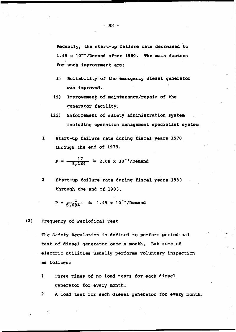
- 304 -
Recently, the start-up failure rate decreased to 1.49 x 10”■*/Demand after 1980. The main factors for such improvement are:
i) Reliability of the emergency diesel generator was improved.
ii) Improvement of maintenance/repair of the generator facility.
iii) Enforcement of safety administration systemincluding operation management specialist system
1 Start-up failure rate during fiscal years 1970 through the end of 1979.
P * — ^ ^ 2.08 x 10“’/Demand
2 Start-up failure rate during fiscal years 1980 through the end of 1983.
P = g--g^4 . = 1.49 x 10"“/Demand
(2) Frequency of Periodical Test
The Safety Regulation is defined to perform periodical test of diesel generator once a month. But some of electric utilities usually performs voluntary inspection as follows:
1 Three times of no load tests for each diesel generator for every month.
2 A load test for each diesel generator for every month.

- 305 -
(3) Examples of Repair (2 cases)
Two examples of repair are shown as follows:
1 Capacitor in the generator synchronizing circuit damaged due to bum out. The capacitor, of which the withstand voltage is improved, was replaced.
2 Air leakage occurred from the fitting part of a root valve of start-up air pressure detector.The fitting part was modified to welding type from screw type.
4. Conclusion
4-1 Improvement of Hardware (Figure 3-1 through 3-7)
4-2 Upgrading of Software
Enhancement of training
1 BWR Training Center (BTC), Nuclear Power Training Center (NTC)
i) Standard Operator Training Courseii) Operator Re-training Courseiii) Advanced Operator Training Courseiv) Family Training Course
2 Nuclear Power Plant Training Centeri) CRD exchange workii) Welding workiii) Refueling floor work

- 306 -
4-3 Conclusive Execution of Countermeasure to Prevent Recurrence
As previously mentioned it is respectedly emphasize that "Conclusive execution of investigation of causes and countermeasures to prevent recurrence of incidents and failures" is the most important factor.
When incident or failure occurred, the government, electric utilities and manufactureres cooperate each other to conclusively execute investigation of causes and countermeasures to prevent recurrence of the incident or failure.
Furthermore preventive maintenance and repair are effectively taken through the intimate information exchange between electric utility and manufactureres.
Those execution explained above are believed to be main factore reduced incidents and failures in Japan.

307
<Z8MQ4 JtBaxonn jo jaqumti
♦
*
J
§COjjc$w<Mo
«
S><0
<
•ogC04J§au«
gv
I
+j•Hs9
•P
8h
M-l0Vl
1z
«u•HU•PoVHw
VVi§.

- 308 -
c •H C 0<3 i—1 i—I•H M-i 01 A «A o o V P 0)p A M 0c fa c 3 P 34) 0 •—i43 >i •H p 0-»-4■Q p A P (0O o <MC TJ A N A \M « p a 0) Afa P •H P«H c <P c0 -H A •H A03 TJ H 43P A * ■H t 4 •H0) A o U OÛ H A c (0 cg O P •H tp 1-13 oz Z
oO O00
♦
[
[
~ £in s-T— i8 8
u«ooa*»TT°* XJ*TXT«Wf *>•« 3tn»tpca 3VAH
J |<9TxT3tj mnoa udtvTC x»rtT3»i T»=î*v>*ia AWTITwnf »UT<t»a •UTOXrvi mtns
HAOdf.-\TTT3»i x»«od«Ta »^***
A»TtT3»J toa^uoo U°T1®TS*H *5TTT=»J
. »6»a04S/6uTTP“»H T»°ioonwwnwmi
|faTfto»4 aoMcmi
fl«»3*AS Aujxooo Asuafi na ■»3t/s Êuxxooo aoiamma
mm)
saanxxe.3 pue s^usptoui jo aaqumti
Figure 1
-2
Numb
er of
Incidents
and
Fail
ures
Cla
ssif
ied
by F
acil
itie
s and by
Electr
ical
Fac
ilit
ies
and
Comp
onen
ts

- 309 -
Table II. Safety Administration System
1 Improvement of administration system of the government
Permanent residence of an operation management specialist at each site.Mandatory inspection on the self-imposed security and administrations of the electric utilities.Adoption of a qualification system for nuclear power plant operating supervisor.Establishment of the ttyclear Power Safety Information Research Center (NUSIRC) of the Nuclear Power Engineering Test Center aims to effective of operational information such as incidents and failures etc.
2 Improvement of the self-imppsed security and administration system of electric utilities
i) Conclusive execution of quality control concerning to careful maintenance and repair work etc.
ii) Development of technology represented by upgrading and Standardization Plan for Light Water Reactor,
iii) Enhancement of education and training for theoperators and maintenance personnel through the effective use of the operation and maintenance training center.
i)
ii)
iii)
iv)

- 310 -
iv) Improvement of international and domesticinformation transmission and mutual information exchange of electrical utilities through the Nuclear Information Center (NIC) of the Central Research Institute Electric Power Industry.
3 All aspect cooperation of manufactureras with electric utilities
i) Full cooperation of manufactureras to electric utilities for investigation of cause and countermeasure for incident and failure whenever it occurred.
ii) Establishment of manufactureras cooperation system for operation at each site.

- 311 -m
S>1üc3>O'klO)I
s
3O&c«O'h
*
Figure 3-1 Historical Trend of On-site Bus Configuration

- 312 -
500 kVTransmissionLine
0
1AHouseTransformer IB
6 6 kVTransmission Line
‘ t*
6 6 kVBus
TSt1 SA|Tr
tart-up Transformer] 1 SB
Speed Control speed ControlSystem A System A
(System B was modified the same as system A)
480V 10-1 480VI ID— 1
Event Discription:During the outage of 66 kV No. 1 power transmission line due to the scheduled test No. 2 power transmission line had been hitted by lightning. Subsequently, loss of on-site power source for two second occurred and plant output was decreased to 87% from full power.Event Cause:Erroneous moving of scoop tube due to loss of primary loop recirculation pump speed control signal caused by loss of instrument pcwer source.Action Taken:Power source for primary loop recirculation pump speed control system was connected to the vital bus from 120 V instrument Bus.
Figure 3-2 Modification on Control Circuit

- 313 -
F'lgure 3-3 Improvement, of Generator Field Regulator
No. Event Description Event cause Action Taken
1 Arc occurred at the. gap between brush and brush holder of excitation (70 R) slide resistor
o Too narrow of the gap
o Adherence of dust to the gap*
o Gap between brush and brush holder was modified to 0.3 ran from 0.1 mm
o Installation of cover for dust proof
2 Spark occurred at the gap between brush and collector. Subsequently, it flushed over.
o Defective performance of brush spring
o Insufficient confirmation on wear of brushes
o Replacement of brush and holder
o Brush and brush holder was changed to cartridge type in order to easily perform inspection and maintenance
/ Trend : Brushless type will be \ I adopted, and it had been j \ used at thermal power plant J
o All brushes werepainted yellow stripes in order to confirm on wear of brushes.

- 314 -
AC Bus AC Bus DC Bus
Automatic DC Operation
OFF
Event Description:
While switching operation to "A.C. Operation" (automatic) from "D.C Operation" during restart-up after replacement of D.C motor bushes, loss of vital power source occurred.Event Cause:Misoperation of a changeover switch (switch over-ride)
Action Taken:
The changeover switch was modified to two changeover switches with two position from one changeover switch with four position.
Automatic DC Operation
Modification of Changeover Switch
Figure 3-4 Example of Improvement of Vital Power Source Facility (1)

- 315 -
Figure 3-5 Examples of Improvements of Vital Power Source Facility (2)

316 -
AC Bus AC Bus DC Bus DC Bus AC Bus
Figure 3-6 Example of Improvement of Vital Power Source Facility (3)
(1) Reactor trip due to loss of vital power source formsabout 25% of the incidents and failures due to electrical causes. In 1970's plant, improvement and/or modification to the static equipment (one' system in general) has been performing.In 1980's plant, the static equipment (dual systems) has been adopted from design stage.
(2)

- 317 -
Reliability, Test and Repair on Emergency Diesel Generator
(1) Reliability (Start-up failure rate : 1.21 x 10"3)
On October 1984, 27 nuclear power plants were operating with 55 diesel generators. By this time, 18 cases of start-up failures out of 14,878 times of start-up test.
On the first half of 1970's, troubles occurred due to low lubricating oil pressure and misadjustment of governor, etc. Recently, the reliability has been improved as follows:
(i) During fiscal years 1970 through the end of 1979 : 2.08 X 10“3/Demand
(ii) During fiscal years 1980 through the end of 1983 : 1.49 x 10“**/Demand
(2) Frequency of Periodical Test
(i) Three times of no load tests for each diesel generator for every month.
(ii) A load test for each diesel generator for everymonth

318 -
(3) Examples of Repair for Diesel Generator Facilities
(i) Example 1Event description : Capacitor in the generator synchronizing circuit damaged due to burn out.
replaced capacitor was modified to DC 1,260 V from 630 V.
(ii) Example 2Event description s Air leakage occurred from the fitting part of a root valve of start-up air pressure detector.
Action taken s The fitting part was modified towelding type from screw type. -h
Action taken The withstand voltage of the
>
Emergency Diesel GeneratorStart-up Air -System
Figure 3-7 Repair on Emergency Diesel Generator

- 319 -
Table 4. Summary
I. Improvement of hardware
♦ (i) Temporary countermeasure
*(ii) Eternal countermeasure(iii) Design change
II. Upgrading of softwareEnhancement of trainingBTC, NTC(i) Standard Operator Training Course(ii) C^erator Retraining 0onr«e(iii) Advanced Operator Training Course(iv) Family Training Course
Nuclear Power Plant Training Cent®* (for maintenance)
(i) CRU exchange work(ii) Welding work(iii) Refueling floor work
ill. countermeasure %o prevent recurtfnce '!
(i) Hardware(ii) Software

- 321 -
PAPER NO. 4.5.! .
REVIEW OF ELECTRICITY SUPPLY FAILURES AND PLANT IMPROVEMENTS OVER 25 YEARS OPERATION OF THE HARWELL MATERIALS TEST REACTORS
REVUE DES MANQUES DE COURANT CONSTATÉS ET DES PERFECTIONNEMENTS APPORTES AU MATERIAL ELECTRIQUE PENDANT 25 ANS D' EXPLOITATION DES RÉACTEURS MTR À HARWELL
DfJ. Taylor UKAEA Harwell V.K.
abstract
The evolution of the on-site electric#! power sources is described, operational experience is reported and shortcomings are identified. Disturbances in the external power supplies to the reactors are listed for the past 25 years and failure probabilities are derived from this historical data. The 132 kV overhead supply to the Harwell site is identified as the source of nearly 90% of the disturbances*
RÉSUMÉ
L'auteur décrit l'évolution des sources d'énergie électrique implantées sur le terrain du Centre de Harwell, rend compte des expériences de leurs exploitation et an indique les imperfections. Il présente une liste des perturbations de l'alimentation électrique des réacteurs à partir de sources externes pendant les derniers 25 ans, d'où il déduit dos probabilités de défaillance. Les lignes aériennes d'alimentation I 132 kV sont R l'origine de presque 90% des perturbations. I
Iii
!

- 322 -
1. Introduction
Harwell has operated research reactors since 1947 and the first reactor built in Europe, GLEEP is still operating there. As a low power, stable reactor it has no need for emergency cooling but it has an alternative supply for instrumentation from the site standby electrical system. The larger Materials Testing Reactors (MTR) have always had individual standby generators in a variety of systems. This paper deals with the experience at the two similar MTR’s currently operating, DIDO and PLUTO, which have together accumulated over 57 reactor years of operation.
2. Reactor DescriptionThe reactors are heavy water (D2O) moderated and cooled at low pressure
and a temperature of 70°C. The operating power is 25 MW thermal from 25 highly enriched aluminium clad fuel elements giving neutron fluxes of 2.101* cm-2s-1 thermal and 1.5.101** cm“2s"’1 fast. Although the total power output is insignificant in comparison with power reactors, the power density in the core is 80 MW m-3, which is comparable. The requirement for shutdown or emergency core cooling (ECCS) is therefore similar in intensity although much smaller in scale and complexity.
Three glandless pumps circulate the D2O in a closed circuit through heat exchangers. They have a rundown time to zero flow of approximately three seconds when the electrical supply is switched off. During this period one of two Shutdown Pumps starts automatically and maintains a cooling flow for the removal of fission product decay heating. These shutdown pumps are fed from a guaranteed on-site supply and so still operate if the main pumps stop due to failure of the normal mains electrical supply. Emergency Core Cooling (ECCS) is provided by a further three pumps, also fed from the guaranteed supply, which return leaked D20 from the plant room to the reactor vessel above it.
3. Electricity Supply to Harwell Reactor Site
The supply is by twin overhead lines at 132 kV, which is derived from the 400 kV Supergrid system at a sub-station near Oxford. At AERE there are five 132/11 kV transformers two of which supply the reactor site sub-station via an 11 kV ring main. There are four 11 kV/415 V transformers at the reactor site, two of which supply DIDO and two PLUTO. There is thus full duplication of supply right through from the CEGB Supergrid to the reactor electrical plantroom. All 11 kV and 415 V distribution on the Harwell site is by underground cable.4. Reactor Electrical Supplies
There are three categories of supply to the reactor, all 415 V,3 phase, which in the terms used at Harwell are described as follows:

- 323 -
Normal Mains
j This is the supply described in section 3 and it is the only supply available for ouch of the reactor plant.Guaranteed (No-break)
A supply which is designed to continue without interruption when the normlal mains fails. It is ultimately derived from local diesel generators. This' supply feeds all vital plant.
Standby
A supply which is normally fed from the normal mains and which is restored within 10 seconds from their failure and isolation, by an automatically started and switched local diesel generator. This supply feeds plant which is indispensable but which can be allowed to have a short interruption in supply without detriment to the safety of the reactor.
ij The above supplies are independent for each reactor and there is no provision for cross connection. The only common plant is an additional mobile diesel generator which can be connected to the standby switchboard as a replacement for the installed generator*
Originally all these supplies were concentrated in plant rooms adjoining the containment building? which gays the risk of total electrical failure in the event of a fire.
5. Guaranteed Supply
In the original system this was fed directly from the normal mains.One pf two motor-generators floated on the busHbars, the D.C. motor being supplied from a 220V battery. The battery was in turn continuously charged by a rectifier fed from the normal mains. On mains failure the guaranteed switchboard was isolated and the supply was maintained without interruption by the motor-generator, with a battery endurance of 30 minutes at full load.
Within this period the standby diesel generator, which started automatically, could be manually synchronised with the guaranteed switchboard to maintain the supply in the longer term,
: The main shortcoming of this system was that the guaranteed supply was subject to all the disturbances on the normal mains supply. On one occasion the mains failure transient was so severe that it tripped the guaranteed motor-generator and the supply was completely lost. On many occasions voltage transients were sufficient to trip the reactor via the nucleonic instrumentation but the mains supply did UPt actually fail. There was also only one diesel generator and if this failed the guaranteed supply battery would be exhausted in less than one hour.
The lack of reliability, segregation and redundancy, the need for operator action to synchronise generators and the maintenance of a lead acid

- 324 -
battery and D.C. motors, added up to a generally unsatisfactory system. It was replaced after six years by multiple "No-break" generators.6. No-break Supply
Three identical sets are installed In a separate building to give segregation from the other electrical supplies. Each set consists of:
An Induction motor, flywheel and generator on one shaftA diesel engine with a magnetic clutch to the same shaft.
The motor is fed from the normal mains and drives continuously the flywheel and generator. The guaranteed supply is thus isolated from the normal mains and the inertia provided by the flywheel smooths out transients, so that the reactor instrumentation is not affected by disturbances on the mains. The induction motor drive means that the guaranteed supply frequency is approximately i hz less than the mains frequency, which is acceptable in view of the advantage described below.
When the mains fail, the guaranteed supply is maintained by the energy stored in the flywheel, while the diesel engine automatically starts and clutches on to the shaft. This is accomplished within 3 seconds, with a drop in supply frequency of less than 1 hz, depending on the generator load.
When the mains supply again becomes available the diesel engine stops automatically and the induction motor drive is resumed without any need for synchronisation. The system can therefore cope with mains failure and resumption without requiring any action from an operator.
Two sets are operated in parallel so that should one fail the other is able to carry the load and motor the other set. This is satisfactory under normal mains supply but has caused difficulty under engine power. If one diesel is clutched on but fails to deliver power then the other diesel tries to keep it turning and this leads to instability and disruption of the supply. Reverse power protection has been applied to overcome this difficulty by de-energising the clutch.
A shortcoming of the system is that should both diesel engines fail, there is insufficient energy storage in the flywheels to allow time for operator action to avoid an interruption in the supply. At half load the generator will maintain its output voltage down to a frequency of 34 hz, when it collapses. This decline occupies a period of approximately 50 seconds, which is too short for effective action, as the diesel generator plant room is not continuously manned.7. Standby Supply
This is a straightforward system in which after failure of the normal mains, a diesel generator automatically starts and switches itself on to an isolated section of the bus-bars, to restore a supply to a limited amount of indispensable plant. It was generally satisfactory in operation, the majority of the running time was incurred during the 4 weekly test runs on

- 325 -
load* However both engines suffered catastrophic failure during a standard test run, PLUTO's after 21 years and DIDO's after 25 years. The failures were due to fracture of a piston/connecting rod which broke through the cylinder and çtacked the main frame of the engine. The total number of starts of each engine would have been between 300 - 400 with a total operating time of about 1000 hours.
The wreckage was such that no Initiating defect could be identified.The pnly recommendation from the engine manufacturers was that during testing the {generator should always be run at full load to achieve maximum temperatures.
A portable generator was hired immediately after each accident to provide the standby supply while new diesel generating sets by a different manufacturer were ordered and installed.
8. Normal Mains Supply, Failures and Transients
The historical list of events given in the Appendix derives from records over the past 26 years. It covers all interruptions in the mains supply to the reactors, but not every voltage transient which has produced a noticeable effect.
Most of the events have been voltage transients or interruptions measured in seconds which have been restored by automatic reclosure of circuit breakers. The only interruption which would have caused concern over reactor cooling, if the single diesel generator of that time had not operated, was the first on the list, of 139 minutes. The second one of 30 minutes would not have been of concern at the lower reactor powers of 1963, but under the same conditions of total failure of diesel generators, could today lead to bulk boiling in the D2O. Such failure is currently much less likely with 3 or 4 diesel generators available.
The effectiveness of the guaranteed supply motor-flywheel-generators, in isolating the reactor instrumentation from voltage transients can be seen in the numerous occasions when the trip was initiated by the deliberately delayed pump starter low volt trip (± sec approx) or the low D20 flow trip (1 sec approx) and not the very sensitive nucleonic instrumentation.
9. Normal Mains Supply Failure Probability
In the period covered, from September 1959 to August 1985, there have been nominally 338 reactor operating cycles of 4 weeks each. Eight total interruptions are listed, with durations from 2 sec to 139 minutes. Thus the probability of total failure has been:
2.4 x lCT2 per cycle or 3.1 x 10“1 per annum.
Seven other events also resulted in DIDO and/or PLUTO tripping, giving a total of 15, so the probability of an electrical supply disturbance causing a reactor trip has been greater than:

326 -
4.A x 10“2 per cycle or 5.8 x 10_1 per annum.
Of the 17 events listed, 15 (88%) arose on the 132 kV system, so the vulnerability of the extra-high voltage overhead supply by comparison with the underground 11 kV and 415 V distribution systems is clearly demonstrated.
The faults are summarised in a table at the end of the paper. This shows that 6 of the 8 complete interruptions were due to system faults, whereas 7 of the 9 transients were due to weather conditions. The overall picture therefore shows an approximately equal division, 8 events due to system faults and 9 events due to weather.10. Proposals for Future Installation * 11
A design study is being carried out into the replacement of DIDO with a new reactor of similar design but operating at a power of 50 MW. The four11 kV/415 V transformers at the reactor site sub-station will form the basis of a quadruple system. Four 415 V feeders will supply pairs of distribution switchboards at the reactor and each switchboard will have its own diesel generator and battery backed inverter Uninterruptible Power Supply (UPS).There will thus be two segregated supply systems each completely duplicated to simplify switching for maintenance and alternative supplies.
On mains failure it is envisaged that the paired switchboards will separate, yielding four independant systems each supplied by its own diesel generator. Non essential plant will have been tripped by no-volt releases while vital plant fed from the UPS will have been undisturbed. Essential plant will be re-supplied after a short interruption while the diesels are starting.
The diesel generators will also form the long term energy source for the UPS which must have sufficient surge suppression, battery buffer capacity and smoothing to isolate the reactor instrumentation and control systems from any disturbances on the mains supply.
No-volt detectors on circuit-breakers in the distribution system and on starters and contactors for plant whose stopping or starting would cause a reactor trip, should have a time delay to reduce the number of unnecessary reactor trips caused by voltage transients on the mains supply.
The start sequence for the essential supply diesel generators should have a time delay, to prevent unnecessary starting. The generator circuit breakers must be electrically interlocked with their associated incoming supply and bus-section circuit breakers to ensure that the mains supply is isolated before the generators are switched on to the bus-bars.
Delayed tripping is thus of very much greater importance for the systems proposed for DIDO 2, in which a voltage transient on the mains will escalate to a total mains failure if it trips the supply circuit breakers. Without adequate delays the number of total failures and thus demands on the diesel generators to start, could be at least the higher figure, of 5.8 x 10“* per annum, of section 9.

- 327 -
11. Conclusions
The on-site UPS and essential power generation has been provided by various configurations of diesel-generators. Failures of the system have occurred but recovery has always been achieved by manual Intervention within a short time, such that the safety of the reactor has not been challenged.The source of most of the electrical supply disturbances is the 132 kv overhead supply to Harwell, which will not bè influenced by any provisions for on-site standby generation. However proposals are being made to improve the diversity of this generation to provide a reliability which is consistant with current fault tree analysis and probability studies.
SUMMARY 6 t APPENDIX
System Interruptions due to
Weather Faults
Transients due to
Weather Faults
132 kV 2 4 7 2
11 kv 1
415 V 1
9

- 328 -
APPENDIX
DISTURBANCES AND FAILURES OF HARWELL ELECTRICAL SUPPLYAFFECTING REACTOR OPERATION
DATE DURATION CAUSE EFFECTS
Sept. 1959 139 minutes Sub-Station 1 Protective Equipment Fault
DIDO and PLUTO tripped. DIDO lost all power for 10 mins.
May 1963 30 minutes Earth fault on the single grid supply in service.
DIDO and PLUTO tripped.
7/ 8/70 13 seconds Violent thunderstorm. DIDO and PLUTO tripped.
29/ 5/73 2 seconds H.V. cable fault from Sub Sta. 15.
DIDO and PLUTO tripped.
29/ 5/76 30 seconds Grid fault between Harwell and Steventon.
DIDO and PLUTO tripped.
9/ 6/76 VoltageTransient
Thunderstorm. GLEEP tripped.
14/ 6/77 VoltageTransient
Violent thunderstorm. GLEEP tripped. DIDO l^O pumps, fans and other plant tripped at different times. No reactor trip.
13/11/78 14 minutes R-B phase fault both grid lines at Drayton, OCB's failed to re-close.
DIDO and PLUTO tripped.
23/ 6/80 10 seconds One grid line out for maintce. Lightning struck other.
PLUTO and GLEEP tripped. DIDO on scheduled shutdown.
27/ 1/81 Severe Flashover of generator CB DIDO trip viavoltagereduction
at Didcot (foggy). ECCS actuator relay, PLUTO did not trip (relay slugged).

- 329 -
DATE DURATION CAUSE EFFECTS25/ 4/81 Repeated
voltagetransients
Snow and high winds* Prolonged power failures in district 12-24 hrs.
DIDO 2 D20 pump operation. Trip from low flow. DIDO standby diesel failed to start - started on manual.
13/12/81 Repeatedvoltagetransients
Severe winter weàther, snow and sub-seto temps.
DIDO and PLUTO poisoned out.
14/ 7/82 Repeatedvoltagetransients
Local thunderstorm* PLUTO tripped, low D20 flow. 2 pumps on, but pumps did not stop.
20/10/84 Sub-Station 11 No* 1 transformer switched out, then No. 2 transformer tripped*
Inadvertent during maintenance . 30 minutes
Intermittent partial & total loss of 415 V supplies to PLUTO, which tripped.
4/ 1/85 Severe voltage reduction due to fault thrower one phase, to Trip Drayton line No.l and reclose after isolating T2A.
Grid trans T2A false trip due to control wiring fault from aux earthing transformer Bucholts protection*
»
DIDO and PLUTO tripped, low D20 flow.
10/ 1/85 Repeat of 4/1/85
Ditto DIDO tripped on low D2O flow; PLUTO on scheduled shutdown.
20/ 5/85 Voltagetransient
Violent thunderstorm. DIDO tripped, D20 Flow. Other plant stopped as well. GLEEP tripped.
PLUTO on scheduled shutdown

- 331 -
PAPER NO. 4.6.
DEVELOPMENT OF THE ON-SITE POWER SUPPLY IN GERMAN NUCLEAR POWER PLANTS
Gesellschaftby M*Simon
(GRS) mbH
ABSTRACT
The design of the on-site poweç supply is different in German Nuclear Power Plants, depending oh age aha size of the plant. The cause for this is the eyoïütipn ô£ the safety requirements. The general development of tho design of safety systems, which resulted in a strict seperatiop rdgundant trains is also reflected in the design of thé emergency’power system and even the complete on-site power supply system? This will be demonstrated by different examples. The advantages of this design with respect to the availability o£ bh?$it '',p'pwer will be explained and verified by meahs of operating |h^ri|hçe.

1. Design of On-Site Power Supply in German Nuclear Power PlantsThe on-site power supply can be subdivided into two parts:- The normal power supply and the- emergency power supplyBoth supplies are normally fed by the plant's switchyard. After loss of off-site power (LOP) the safety systems are supplied by the Diesel Generators (DG). For safety reasons the preferred source for supplying the safety systems should be the switchyard and not the DGs, expecially under accident conditions. So the normal power supply is also of safety-relevancy from this point of view.The technical specifications for the on-site power supply of Nuclear Power Plants (NPP) in Germany require therefore three indi- pendent possibilities for feeding the plant's electrical distribution system (Fig. 1):(1) power supply from the main grid via the station transformers(2) power supply from the reserve grid via the auxiliary trans
formers(3) the additional supply by the turbine generator (island opera
tion) if both external supplies are lost.Only if all three sources are no longer available the DGs are started.The design of the on-site power supply in German NPPs is different from plant to plant and depends on plant age and size. In older plants the electrical distribution system is seperated into two trains. The 4-Loop design of the newer plants (PWR) and the association of the plant components to the different loops caused a consequent seperation into 4 trains also within the normal power supply.The advantages of such a seperation in case of a voltage loss on one 10 kV normal bus are:- as the number of components supplied by one train is reduced
the impact on the plant is minor- as every 10 kV normal bus is connected to only one emergency
bus the number of DG starts is smaller2. Design of the Emergency Power SupplyEspecially the systems for Safety Injection (SI) and Residual Heat Removal (RHR) are essential for the desicp of the Emergency Power Supply (EPS). In older plants the residual heat removal system consists of 2 trains with redundant components for each train. The pumps are connected to a common piping which ramifies to the different loops. The lay-out of the emergency supply with 3 x 50% DGs and two trains of the electrical distribution system complies with the mechanical arrangement of the pumps. The pump motors are equipped with tie breakers and/or are attached to the

- 333 -
two electrical trains in such a way that after loss of one train a sufficient number of pumps is operable. The low voltage buses are automatically coupled so that both sides are supplied further on (Fig. 2).In the new PWRs another technical concept for the safety systems was applied. The German guidelines require that the safety systems including power supply, instrumentation and control must consist of redundant and seperated trains and the single failure criterion must be fulfilled also during maintenance or test of one train.Due to the (n + 2) principle in the newer PWRs, beginning with NPP Biblis A, the safety systems and their power supplies are constructed of 4 x 50% trains. To each loop a SI-and RHR-system is appointed to. That means that the concept of the physical and electrical seperation of the safety systems into 4 trains has to be applied on the emergency power system, too. Fig. 4 shows an emergency power supply with 4 seperated trains. The advantages of this design compared with the two-train-design are:- four totally indipendent trains- no connections between the trains necessary- ho load transfer from one bus to the other after DG failure necessary.
Therefore the risk of dependent failure is reduced in the 4 train design.Besides this emergency power system (ÈPS) I described previously, there is another EPS, the EPS II. ihe German guidelines require that the shutdown and cooling of the reactor must be guaranteed even when the auxiliary building is destroyed after exterior events like earthquake, missile attack, and gas explosion. Therefore the German plants are equipped with additional bunkered emergency systems. Thé new Convoi plants for example have a spécial emergency building, containing protected systems for boration of the reactor, Cooling of the steam generators and decay heat removal. The power supplies for these systems, including reactor protection system and control, are also located in this building (Fig. 2).3. Sources and Voltage Levels,,in the Emergency Power SupplyBesides the DG supply an Uninterruptablé Power Supply (UPS) is required for the safe operation of the reactor protection system (RPS), plant control and instrumentation and containment isolation during LOP events. In the UPS also the design of seperated trains is used. In German NPPs the UPS consists of seperated 200 V - and 24 V supplies and of a 3Ô0 V AC supply (Fig. 4) . The un- intèrruptable AC supply Which consists of Motor-Generator (MG) sets or inverters is of less importance than in some foreign plants, as the safety-related equipment - RPS and control - is not supplied by the nôn-interruptâblè AC supply.The DC supplies consist of rectifiers and batteries. The 220 V DC supply mainly serves for feeding the MG sets as well as for

- 334 -
generating the control voltage to start the DGs and to actuate the breakers in the electrical distribution system. The 24 V DC supply serves for feeding the complete electronic equipment like sensors, electronic devices for remote and automatic control and for feeding the complete RPS. The 24 V DC supply is the most important within the UPS. Therefore it is required that a loss of one source of the DC supply may not cause the loss of voltage for the load connected to that source. To fulfil this demand the DC buses are buffered by batteries and most of the load is supplied twice. Fig. 5 shows an advanced design with seperated DC buses and cyclic double supply from different redundancies for the electronic cabinets.4. Operating Experience with On-Site Power Supply in German
Nuclear Power Plants__________ __ ________To estimate the reliability of the on-site power supply operating experience was used. The German Licensee Event Reports, which are stored in a data bank system at GRS, were selected and evaluated with regard to events including LOP, loss of vital AC power, and loss of DC power. The period abserved encloses 96 reactor years.Lop events: twenty-four events with LOP have been found in the data bank. Eight of them have been mastered by turbine run back to inhouse load, six of them by in house load transfer to the auxiliary grid. In the other sixteen events the plant's emergency power supply has been required.Events with emergency power supply (EPS): from the incidents requiring EPS by starting all DGs eleven events occured during plant outage. In these cases no turbine run back was possible, and there was also no possibility of in house load transfer to the auxiliary grid because of inoperable devices or missing prerequisites. During power operation only five incidents requiring EPS occured. The DGs started as designed and power supply from the DGs was successful. There is only one event with a complete loss of EPS, which happened some years ago in a plant which was equipped with an obsolete EPS and which is now out of service.In Fig. 6 the number of EPS events per year is shown and additionally-rated to the number of existing commercial nuclear power plants in the FRG from 1972 to 1985.The figure shows a decreasing tendency for the probability of EPS events. The data used in the German risk study (0.1/year and plant) is confirmed by this evaluation.Uninterruptable AC Power supply (UPS): Twenty-five events concerning failure of one Motor-Generator (MG) set have been found in the data bank. The influence of this failure on the plant was unimportant, as an automatic transfer to the interruptable power supply was performed and the reserve MG set was started. During two events a total loss of the UPS occured. The plants involved still had the old design of not seperated trains. As the Reactor Protection System and Plant Control Systems were fed by the UPS,

- 335 -
the plants suffered severe transients before AC power could be restored. One of the plants was shut down for ever, in the other one the AC power supply has been improved.Vital DC Power Supply: Another seventeen events involved failure of one rectifier. The examination has shown that there was no influence on the plant, as the DC trains are buffered by batteries. Even the loss of one DC bus revealed no consequences, as the plant control and protection system is supplied twice by redundant DC buses.Up to now two incidents resulting in a complete loss of vital DC supply (+ 24V) have occured. Both incidents happened in the same plant during plant outage.The DC-loss lasted 20 to 30 minutes. As the plant was shut down there were only minor effects on the plant itself. In both cases the cause for the DC-loss was an operator error aggravated by the fact that the vital DC supply consisted of only two trains. The design was modified. The reactor protection system and plant control are now supplied by four redundant and seperate DC-buses. At the worst the loss of two DC buses can thus result in the unavailability of only one train.5. ConclusionsThe design of off-site power supply with three power sources has proved true. This has been demonstrated by the small number of challenges of thè plant's emergency power supply during power operation after loss of off-site power. Beside of this it turned out that a consequent sepëràtion of the on-site and emergency power supply into four trains is advantageous, because there are onlÿ minor effects on the plant due to the high grade of redundancy if a failure in the on-site power supply will occur. The double - supply of most of the vital loads through redundant trains plays another important part. Operating experience has shown that these ridig requirements on design do not only guarantee a high safety level but have also a positiv result on the availability of German nuclear power plants.

- 336 -
i
Simplified Diagram of Emergency Power Supply (2 Train Design)
Em
erge
ncy
Nor
mal
Pow
er S
uppl
yP
ower
Sup
ply

- 337 -
*
Normal On-Site Power Supply
Diesel
10 kV
660V
380/220 V
220 V =
Inverter
380/220 V
24 V =
Interruptable > Emergency
supply
Non-> interruptable ? Emergency
supply
Voltages and Sources of the Emergency Power Supply I

- 338 -
Non-Interruptable + 24 V DC Power Supply
o 16r© C L L L 1 2 :i i ® s :Z O.E 4 -
£3 r
o1110-2
2 -
*5
i ?1 -
1972
Events with Challenge of Emergency Supply
- 339 -
SUMMARY OF SESSION 4(11)
DESIGN IMPROVEMENTS AND SAFETY TARGETS FOR POWER SUPPLIES
SESSION CHAIRMAN: B. E. HORNE (CEGB, UK)
Design Inprovements provided On the French 900 MWe FWR's to improve safety if both off-site and on-site power sources are lost were described byJ. Bera of CEA. These inprovements not only covered additional electrical power sources such as a mobile gas turbine generator, but also included the provision of a steam driven turbine alternator providing power for seal water injection.
The approach used for assessing the adequacy of these inprovements was described by j. Milham and G. Gros of IPSN. A detailed probabilistic analysis demonstrated that the importance of the 06 sets and back up sources is almost the same# and that the addition Of steam turbine alternator is more important to safety than new additional power source provided by the mobile GT generator.
In the case of Sizewell 'B', Mr. Wbodhouse described some of the criteria vbich the Nil used in assessing the adequacy of the on-site electrical power souces for the proposed British FWR. Probabilistic and deterministic criteria were identified as well as principles to be adopted for installation practice.
Finally, the methods used to cope with station black outs in PWR and BWR installations in different countries were summarised in a study byF. Reisch (Sweden).

- 341
PAPER NO. 4.7.csia. i iE E ix i i f i oi: Q U z S U Z p o w e r s o u r c e s
übJilü QÇIQBIE JilÊS
AN EXAMINATION OF THE PROPOSALS FOR THE ON-SITE ELECTRICAL POWER SOURCES AT THE SIZEWELL B PWR.
P A 'Jo od h ous eHi' H u c l e a r I n s t a l l a t i o n s I n s p e c t o r a t e
London , E n g l a n d .
ABSTRACT
O ve r t h e p a s t f ew y e a r s ' . there nas beer, sn i n c r e a s e in t h e . a t t e n t i o n be inf . r i v e n t o t h e a d e q u a c y and r e l i a b i l i t y o f a l t e r n a t i v e s o u r c e s o f ' power p r o v i d e d t o s u p p l y s a f e t y e q u i p ment s h o u l d o f f s i t e e l e c t r i c a l s o u r c e s f a i l .
T h i s p a p e r d i s c u s s e s t h e r a t i o n a l e o f KM N u c l e a r I n s t a l l a t i o n s I n s p e c t o r a t e s a s s e s s m e n t o f t h e e l e c t r i c a l s y s tems p r o p o s e d f o r t he U K ' s f i r s t P r e s s u r i z e d W a t e r R e a c t o r , S i z e w e l l 0. Trie r e o . u i r e i r e n t s f o r o n - s i t e s o u r c e s a r e g i v e n , and a d i s c u s s i o n i s p r o v i d e d o f t h e N i l ' s A s s e s s e r i e n t P r i n c i p l e s ' i n c l u d i n g com:.on node- f a i l u r e , s i n g l e f a i l u r e c r i t e r i o n and r e l i a b i l i t y t a r g e t s . W he re t h e a s s e s s m e n t has r e s u l t e d in m o d i f i c a t i o n s t o t he o r i r . o n a l d e s i g n the r e a s o n s a r e . g i v e n .
The U N ’ s l a r g e i n t e r c o n n e c t e d G r i d s y s t e m makes c o m p l e t e l o s s e s o f o f f - s i t e power c c r . i p a r i t i v e l y r a r e . The p o t e n t i a l e x i s t s h o w e v e r anti t h i s p a p e r sh ows how t h e c u r r e n t a p p r o a c h e n s u r e s t h a t n e t o n l y a r e a d e q u a t e o n - s i t e s o u r c e s a v a i l a b l e b u t a l s o t h a t t h e i r s i t i n g , m a i n t e n a n c e and t e s t i n g a r e s uch t h a t l o s s o f o f f - s i t e power w i l l n o t c a u s e an u n a c c e p t a b l e r i s k t o the p u b l i c .

- 342 -
AN EXAMINATION OF THE PROPOSALS FOR THE ON-SITE ELECTRICAL POWER SOURCES AT THE SIZEWELL B PWR
P A Woo dho useHM N u c l e a r I n s t a l l a t i o n s I n s p e c t o r a t e
L o n do n , E n g l a n d .
1.0 IntroductionOv er the p a s t f ew y e a r s t h e r e has b e e n an i n c r e a s e in
t he a t t e n t i o n b e i n g ^ i v e n t o t he a d e q u a c y and r e l i a b i l i t y o f a l t e r n a t i v e s o u r c e s o f o o u e r p r o v i d e d t o s u p p l y s a f e t y e q u i p ment s h o u l d o f f - s i t e e l e c t r i c a l s o u r c e s f a i l .
T h i s p a p e r d i s c u s s e s the r a t i o n a l e o f HM N u c l e a r I n s t a l l a t i o n s I n s p e c t o r a t e s a s s e s s m e n t o f t h e e l e c t r i c a l s y s tems p r o p o s e d f o r the UKs f i r s t P r e s s u r i z e d H a t e r R e a c t o r , S i z e w e l l B. The r e q u i r e m e n t s f o r o n - s i t e s o u r c e s a r e r i v e n , and a d i s c u s s i o n i s p r o v i d e d o f t he N i l ’ s A s s e s s m e n t P r i n c i p l e s i n c l u d i n g common mode f a i l u r e , s i n g l e f a i l u r e c r i t e r i o n and r e l i a b i l i t y t a r g e t s . Where t he a s s e s s m e n t has r e s u l t e d in m o d i f i c a t i o n s t o t h e o r i g . i o n a i d e s i g n the r e a s o n s a r e r i v e n .
The U K ' s l a r g e i n t e r c o n n e c t e d G r i d s y s t e m makes c o m p l e t e l o s s e s o f o f f - s i t e pov/er c o m p a r a t i v e l y r a r e . The p o t e n t i a l e x i s t s h ow e v e r and t h i s p a p e r shows how t h e c u r r e n t a p p r o a c h e n s u r e s t h a t n ot o n l y a r e a d e q u a t e o n - s i t e s o u r c e s a v a i l a b l e but a l s o t h a t t h e i r s i t i n g , m a i n t e n a n c e and t e s t i n g a r e such t h a t l o s s o f o f f - s i t e power w i l l n o t c a u s e an u n a c c e p t a b l e r i s k t o the p u b l i c .
2.0 BackgroundI n t he U n i t e d Kingdom t h e l i c e n s e e i e , t h e u t i l i t y o r
g e n e r a t i n g b o a r d i s r e s p o n s i b l e f o r t he s a f e t y o f n u c l e a r power s t a t i o n s w h i c h i t b u i l d s and o p e r a t e s and i t i s p a r t o f t h e wo r k o f Hi! N u c l e a r I n s t a l l a t i o n s I n s p e c t o r a t e ( N i l ) t o

- 343 -
a s s e s s and m o n i t o r the s a f e t y a s p e c t s o f t h e d e s i g n , c o n s t r u c t i o n and o p e r a t i o n o f t h e p l a n t , r e q u i r i n g imp ro v eme nt s t o the. d e s i g n a t any t ime i f s a t i s f a c t o r y s t a n d a r d s a r e n ot met. A l t h o u g h i n f o r m a t i o n and s t a t i s t i c s i n s u p p o r t o f the s a f e t y c a s e a r e n o r m a l l y s u p p l i e d t o t he I n s p e c t o r a t e by the l i c e n s e e i n c o n f i d e n c e , the P r e - C o n s t r u c t i o n S a f e t y R e p o r t and s u p p o r t i n g r e p o r t s w e r e made p u b l i c l y a v a i l a b l e i n c o n n e c t i o n w i t h the r e c e n t P u b l i c I n q u i r y i n t o t he b u i l d i n g o f S i z e w e l l B,
3.0 Safety PrinciplesThe p r i n c i p l e s and c r i t e r i a u s ed by t h e M i l when e x a m i n
i n g t he a c c e p t a b i l i t y o f a r e a c t o r d e s i g n a r e c o n t a i n e d i n a s e t o f S a f e t y A s s e s s m e n t P r i n c i p l e s [ 1 ] f Thes e w e r e p r e p a r e d to g i v e g u i d a n c e t o a s s e s s o r s and f o rm a f r a m e w o r k w h i c h can be us e d a s a r e f e r e n c e f o r j u d g e m e n t s t h a t must be made i n t h e e v a l u a t i o n p r o c e s s . I n c a r r y i n g p u t ap a s s e s s m e n t i t i s i n t e n d e d t h a t t he a s s e s s o r j u d g e s t he e x t e n t t o w h i c h t he s a f e t y c a s e p r o v i d e d by t he l i c e n s e e c o n f o r m s w i t h t h e s e p r i n c i p l e s . The P r i n c i p l e s a r e a l s o a s e t o f o b j e c t i v e s w h i c h a r e t o be met a s f a r a s r e a s o n a b l y p r a c t i c a b l e , a l t h o u g h a s in t h e c a s e o f m e e t i n g a maximum- p e r m i s s i b l e d o s e t h e r e a r e d e f i n i t e l i m i t i n g r e q u i r e r , tents w h i c h must be n e t .
4.0 Requirements for on-site electrical systems4.1 D e s i g n B a s i s
The e s s e n t i a l e l e c t r i c a l s u p p l i e s a r e t h o s e w h i c h may be r e q u i r e d f o r t he f u n c t i o n i n g o f p l a n t p r o t e c t i o n s y s t e m s , e n g i n e e r e d s a f e g u a r d s , s a f e t y r e l a t e d i t e m s and s e r v i c e s t o e n s u r e n u c l e a r s a f e t y . The N u c l e a r I n s p e c t o r a t e s p r i n c i p l e s s t a t e t h a t o n - s i t e e l e c t r i c a l p ow er s u p p l i e s s h a l l be p r o v i d ed and be c a p a b l e o f s u p p l y i n g a d e q u a t e p ow er t o c o p e w i t h any d e s i g n b a s i s f a u l t i n t h e a b s e n c e o f o f f - s i t e s u p p l i e s .
4 . 2 S i z e w e l l B E l e c t r i c a l Sys t em
The p r o p o s e d e l e c t r i c a l s y s t e m f o r S i z e w e l l B i s shown iri F i g u r e s 1 and ?.. The two main g e n e r a t o r s p r o d u c e e l e c t r i c a l e n e r g y 23 » 5kV 'which i s t r a n s m i t t e d to g e n e r a t o r t r a n s f o r mers w h i c h r a i s e the v o l t a g e t o 400! ;V, The main g e n e r a t o r s a l s o s u p p l y power t o the s t a t i o n d i s t r i b u t i o n s y s t e m v i a a u n i t t r a n s f o r m e r w h i c h r e d u c e s t h e v o l t a g e t o 11kV.
Power t o S i z e w e l l B can a l s o be i m p o r t e d v i a two s t a t i o n t r a n s f o r m e r s f eed ing - the i n t e r n a l s y s t e m a t 11 k V . S w i t c h d i s c o n n e c t o r s a r e to be p r o v i d e d t o e n a b l e power t o be i m p o r t e d v i a t he same l i n e s n o r m a l l y u s ed f o r e x p o r t .
The main ac v o l t a g e s a r e 11kV, 3 . 3kV and 4 15 V . ' T h e r e a r e two p a i r s o f 11kV b o a r d s . One o f e a c h p a i r , ( t h e u n i t b o a r d ) i s s u p p l i e d e i t h e r f r om a main g e n e r a t o r o r f r om t he g r i d by a u n i t t r a n s f o r m e r . The o t h e r , ( t h e s t a t i o n b o a r d ) i s s u p p l i e d

- 344 -
f r om t h e G r i d by a s t a t i o n t r a n s f o r m e r . An i n d u c t i v e c o n n e c t i o n i s p r o v i d e d b e t w e e n e a c h u n i t b o a r d and the c o r r e s p o n d i n g s t a t i o n b o a r d t o a l l o w them t o be i n t e r c o n n e c t e d q u i c k l y f o l l o w i n g f a i l u r e o f t h e s u p p l y t o e i t h e r b o a r d .
The e s s e n t i a l s y s t e m i s b a s e d on f o u r 3 . 3 kV b o a r d s e ac h f e d f r om one o f t he f o u r 11 kV b o a r d s and c a p a b l e o f b e i n g s u p p l i e d by one o f f o u r d i e s e l g e n e r a t o r s . The 3 . 3 k V e s s e n t i a l b o a r d s s u p p l y t he e q u i p m e n t n e c e s s a r y f o r m a i n t a i n i n g r e a c t o r s a f e t y , s u c h a s t h e h i g h head s a f e t y i n j e c t i o n and r e s i d u a l h e a t r e m o v a l pumps. Each 3 . 3kV b o a r d a l s o s u p p l i e s a number o f 415V b o a r d s w h i c h f e e d t h e c o n t a i n m e n t f a n c o o l e r s , a p r o p o r t i o n o f t h e p r e s s u r i s e r h e a t e r s and r e s e r v e u l t i m a t e h e a t s i n k f a n s , p l u s b a t t e r y c h a r g e r s f o r t h e e s s e n t i a l dc s y s t e m s .
S e v e r a l l o w v o l t a g e ac and dc s y s t e m s a r e a l s o p r o v i d e d . Those i m p o r t a n t t o r e a c t o r s a f e t y a r e ba ck e d by b a t t e r i e s and c o m p r i s e two s e p a r a t e d i v e r s e s y s t e m s a s shown in F i g u r e 2. T h e i r p r i n c i p a l l o a d s i n c l u d e the r e a c t o r p r o t e c t i o n s y s t e m , e s s e n t i a l i n s t r u m e n t s u p p l i e s , e me rg e nc y l i g h t i n g , and a c t u a t i o n and s w i t c h i n g s u p p l i e s f o r p r o t e c t i o n equipment - .
4.3 Reliability CriteriaThe r e v i e w p r o c e s s on w h i c h t h e P r i n c i p l e s a r e b a s e d i s
c o n c e r n e d w i t h d i s c r e t e f a u l t s e q u e n c e s . The p r o d u c t o f t he f r e q u e n c y o f a f a u l t o c c u r r i n g and t he p r o b a b i l i t y o f f a i l u r e o f the p r o t e c t i o n p r o v i d e d a g a i n s t t h e f a u l t s h o u l d be o f t he o r d e r o f 10“ ' p e r annum.The i n s p e c t o r a t e a l s o i m p o s e s a l i m i t a t i o n o f one f a i l u r e p e r 10-* t o l O 5 demands , d e p e n d i n g on t h e c o m p l e x i t y and n o v e l t y o f t h e s y s t e m , on t h e c l a i m e d r e l i a b i l i t y o f a s y s t e m e m p l o y i n g r e d u n d a n t e l e c t r i c a l c o m p o n e n t s . T h u s e g , a l t h o u g h f o u r main d i e s e l g e n e r a t o r s may be p r o v i d e d , w i t h an a s s e s s e d i n d i v i d u a l u n r e l i a b i l i t y o f 3 . 0 x 1 0 “ f a i l u r e s p e r demand, a common mode c u t o f f o f 10” ^ i s u s e d i n p r o b a b i l i s t i c a n a l y s e s f o r t h e f a i l u r e t o s t a r t o f a l l f o u r d i e s e l s . The a d o p t i o n o f t h i s common mode c u t o f f means t h a t f o r a f a u l t w h i c h i s j u d g e d t o o c c u r a t a f r e q u en c y o f g r e a t e r t h a n 10“ ^ p e r annum, d i v e r s i t y i s r e q u i r e d i n o r d e r t o meet a r e l i a b i l i t y r e q u i r e m e n t b e t t e r t h a n 10” w h i c h t h i s i m p l i e s .
D i v e r s i t y i s o f two b a s i c t y p e s , f u n t i o n a l d i v e r s i t y and e q u i p m e n t d i v e r s i t y . F u n c t i o n a l d i v e r s i t y i n v o l v e s u s i n g d i f f e r e n t p h y s i c a l m e a s u r e m e n t s and o u t p u t a c t i o n s . E q u i pm e nt d i v e r s i t y i n v o l v e s d i f f e r e n t d e s i g n s o f e q u i p m e n t p r e f e r a b l y f r o m d i f f e r e n t m a n u f a c t u r e r s . The d e g r e e o f d i v e r s i t y p o s s i b l e w i l l v a r y w i t h d i f f e r e n t s y s t e m s .
The d i v e r s i t y e x t e n d s f r o m t h e m e a s u r i n g o f p l a n t p a r a m e t e r s s u c h a s t e m p e r a t u r e o r p r e s s u r e , w h i c h a r e u s e e t o i n i t i a t e t h e p r o t e c t i o n , t h r o u g h r e a c t o r t r i p s y s t e m s t o t h e e q u i p m e n t n e c e s s a r y t o m i t i g a t e t h e e f f e c t s o f t h e f a u l t .
The R e a c t o r P r o t e c t i o n Sys t em ( R P S ) , p r o p o s e d f o r S i z e w e l l B and d e v e l o p e d by W e s t i n g h o u s e , i n c o r p o r a t e s m i c r o p r o c e s s o r s f o r s i g n a l p r o c e s s i n g and l o g i c s y s t e m s i n the

- 345 -
P r i m a r y P r o t e c t i o n Sys t em ( P P S ) and u s e s o p t i c a l f i b r e l i n k s f o r d a t a t r a n s m i s s i o n . The S e c o n d a r y P r o t e c t i o n Sys t em ( S P S ) i s b a s e d on l a d d i e m o d u l e s and a n a l o g u e s i g n a l p r o c e s s i n g as u s e d i n p r e v i o u s UK n u c l e a r power s t a t i o n s , and i s p r o v i d e d a s a d i v e r s e means o f p r o t e c t i o n a g a i n s t f r e q u e n t f a u l t s . SPS s e n s o r s a r e d i f f e r e n t f r om PPS s e n s o r s and t he SPS t r i p s t h e r e a c t o r u s i n g means w h i c h a r e d i v e r s e f r om t h o s e u s e d by t h e PPS. Bo t h s y s t e m s r e q u i r e an u n i n t e r u p t e d s u p p l y o f e l e c t r i c a l power and t h i s p r o v i d e d by t h e p r i m a r y b a t t e r i e s i n t he c a s e o f t he PPS and t he d i v e r s e s e c o n d a r y b a t t e r i e s i n t h e c a s e o f t h e SPS.
Two o f t h e a u x i l i a r y f e e d pumps and t h e e m e r g e n c y c h a r g i n g pumps a r e d r i v e n by s t e a m f r o m t h e s t e a m g e n e r a t o r s . The f o r m e r p r o v i d e a d i v e r s e means o f s u p p l y i n g f e e d s h o u l d t he mot or d r i v e n f e e d pumps f a i l . The e me rg e nc y c h a r g i n g pumps can a l s o be o p e r a t e d i n d e p e n d e n t l y o f t h e ac p ow er s y s t e m t o c h a r g e t h e p r i m a r y c i r c u i t and e n s u r e r e a c t o r c o o l a n t pump s e a l i n t e g r i t y .
4.4 Losses Of Off Site PowerAs was s t a t e d a b o v e , t h e o n - s i t e e l e c t r i c a l s y s t e m s must
be c a p a b l e o f s u p p l y i n g e s s e n t i a l p ow er i n t h e a b s e n c e o f o f f s i t e s u p p l i e s u n t i l s u c h t ime a s t he o f f - s i t e s u p p l i e s can be r e s t o r e d . The f r e q u e n c y and d u r a t i o n o f t h e l o s s o f o f f - s i t e power i s i m p o r t a n t i n a s s e s s i n g t h e r e q u i r e m e n t s f o r o n - s i t e
s i n c e b a t t e r i e s can o n l y be p r a c t i c a l l y s i z e d t o be f o r a l i m i t e d p e r i o d and d i e s e l g e n e r a t o r c a p a c i t y t o be a d j u s t e d ,
u n d e r t a k e n by t he CEG3, t h e l i c e n s e a p p l i c a n t f o r B, and a s s e s s e d by t h e I n s p e c t o r a t e h as c o n c l u d e d f r e q u e n c y o f l o s s o f o f f - s i t e power a t t h e S i z e w e l l
o r d e r o f :
7 5 x 1 0 " ~ / y r 1 0 x 1 < T | / y r
s o u r c e s , o p e r a t e d may need A n a y s i s S i z e w e l l t h a t t he B s i t e w i l l be o f the
Dur a t i on
0 - 2 h r s 2 - 1 2 l i r s
>12 h r sThe a n a l y s i s t o o k
due t o f a i l u r e s o f w e a t h e r , f i r e s , a i r c r a f t t a p e and f r e q u e n c y a v e r a g e d o v e r t h e l i f e
5 x 1 0 " - V y ra c c o u n t o f t h e l o s s o f o f f - s i t e power
t r a n s m i s s i o n e q u i p m e n t , e x t r e m e s o f i m p a c t s and a l s o t he e f f e c t s o f v o l - f l u c t u a t i o n s . T h e a b o v e v a l u e s a r e o f t h e s t a t i o n and w i l l be s l i g h t l y
h i g h e r f o r t h e y e a r s when r e p a i r s a r e i n p r o g r e s s on the t r a n s m i s s i o n l i n e s .
I n t he c a s e o f a d r o p i n g r i d s y s t e m f r e q u e n c y t o 48 .5 Hz a u t o m a t i c shedding o f d i s t r i b u t i o n l o a d s f r o m t h e g r i d w i l l t a k e p l a c e t o a t t e m p t t o r e s t o r e s y s t e m c o n d i t i o n s . S h o u l d t h e f r e q u e n c y o r v o l t a g e e x c e e d p r e d e t e r m i n e d l i m i t s , S i z e v/ e l l B w i l l be d i s c o n e c t e d f r om the G r i d and t h e e s s e n t i a l e q u i p m e n t w i l l be s u p p l i e d by t h e e m e r g e n c y d i e s e l g e n e r a t o r s . The m a j o r i t y o f f a u l t s a f f e c t i n g t r a n s m i s s i o n

- 346 -
l i n e s a r e o r s h o r t d u r a t i o n and t h e p r o v i s i o n o f a u t o r e c l o s e s y s t e m s on t h e 400kV n e t w o r k p r o v i d e f o r r a p i d r e s t o r a t i o n o f s u p p l i e s .
4.5 Design ModificationsAs a r e s u l t o f more d e t a i l e d a n a l y s i s by t h e CEGB and
a f t e r d i s c u s s i o n s w i t h t he I n s p e c t o r a t e v a r i o u s d e s i g n mod i f i c a t i o n s n ave been p r o p o s e d . F u r t h e r minor m o d i f i c a t i o n s nay be c o n s i d e r e d n e c e s s a r y a s t h e d e s i g n d e v e l o p s . M o d i f i c a t i o n s t o d a t e w h i c h w i l l a f f e c t t h e e l e c t r i c a l s u p l i e s r e l i a b i l i t y a r e t he i n c o r p o r a t i o n o f g e n e r a t o r l o a d s w i t c h e s and t he p r o v i s i o n o f two a d d i t i o n a l b a t t e r y c h a r g i n g d i e s e l s . Theg e n e r a t o r s w i t c h e s w i l l a l l o w power t o be drawn f r o m t h e g r i dt h r o u g h t he g e n e r a t o r and u n i t t r a n s f o r m e r s d u r i n g p e r i o d s when a t u r b i n e g e n e r a t o r i s o u t o f s e r v i c e . T h i s i s i n a d d i t i o n t o t he two " n o r m a l " power i m p o r t i n g r o u t e s t h r o u g h t h e s t a t i o n t r a n s f o r m e r s , and w i l l r e s u l t i n t h e r e b e i n g f o u r r o u t e s a v a i l a b l e by w h i c h power may be i m p o r t e d f r o m t h e g r i d d u r i n g p o s t t r i p o p e r a t i o n . The a d d i t i o n a l d i e s e l s w e r e c o n s i d e r e d n e c e s s a r y a s i n t he o r i g i n a l d e s i g n a common modef a i l u r e o f t h e 3 .3kV o r 415V b o a r d s w ou l d h ave r e s u l t e d i n aan i n a b i l i t y t o c h a r g e the e s s e n t i a l dc b a t t e r i e s n e c e s s a r y f o r a c t i v a t i n g and c o n t r o l l i n g t he s t ea m d r i v e n e m er g en cy p l a n t . T h i s c h a ng e a l s o means t h a t s h o u l d o f f - s i t e s u p p l i e s and t he main d i e s e l g e n e r a t o r s be l o s t th en p ow er w i l l be a v a i l a b l e f o r an e x t e n d e d p e r i o d t o r e s t o r e t h e o f f - s i t e s u p p l i e s . P r i o r t o t h i s d e s i g n m o d i f i c a t i o n t h e e s s e n t i a l b a t t e r i e s w e r e t o be s i z e d to c a r r y t h e i r l o a d s f o r up t o 1 2 h r s . The CEGB now p r o p o s e t o r e d u c e t h i s p e r i o d t o 200 mi n u t e s a l l o w i n g s m a l l e r b a t t e r i e s t o be u s e d .
4 . 6 30 M i n u t e R u l e
A n o t h e r p r i n c i p l e w h i c h t h e I n s p e c t o r a t e r e q u i r e s the l i c e n s e e t o meet i s t h a t p r o t e c t i o n e q u i p m e n t i n c l u d i n g on s i t e e s s e n t i a l s u p p l i e s , s h o u l d be a u t o m a t i c a l l y i n i t i a t e d and s h a l l n o t r e q u i r e o p e r a t o r a c t i o n t o e n s u r e s a f e t y i n a t i m e s c a l e o f 30 m i n u t e s . The d e s i g n s h o u l d be such t h a t the o p e r a t o r can i n i t i a t e t he s y s t e m b u t c a n n o t p r e v e n t c o r r e c t p r o t e c t i v e a c t i o n . The d i e s e l g e n e r a t o r s a t S i z e w e l l D a r e t o be d e s i g n e d t o s t a r t on a l o s s o f v o l t s t o t h e i r r e s p e c t i v e 3 .3kV b o a r d o r i f t h e v o l t a g e o r f r e q u e n c y on t he b o a r d s g o e s o u t s i d e p r e s e t l i m i t s . They w i l l a l s o s t a r t on s a f e t y i n j e c t i o n and r e a c t o r t r i p s i g n a l s . The l a t t e r p r o v i s i o n i s t o be i n c o r p o r a t e d so t h a t s h o u l d o f f - s i t e s u p p l i e s be l o s t s u b s e q u e n t t o t he t r i p t h e d i e s e l g e n e r a t o r s w i l l be r u n n i n g and t h e r e f o r e i m m e d i a t e l y a v a i l a b l e f o r s u p p l y i n g t he e s s e n t i a l l o a d s .
4 . 7 S i n g l e F a i l u r e C r i t e r i o n

- 347 -
A f u r t h e r I n s p e c t o r a t e r e q u i r e m e n t w h i c h a f f e c t s the > s y s t e m d e s i g n i s t e rme d t he " s i n g l e f a i l u r e c r i t e r i o n " . T h i s
s t a t e s t h a t no s i n g l e f a i l u r e w i t h i n t h e p r o t e c t i o n s y s t e m s h o u l d p r e v e n t any p r o t e c t i v e a c t i o n a c h i e v i n g i t s r e q u i r e d p e r f o r m a n c e i n t h e p r e s e n c e o f any s p e c i f i e d f a u l t o r e x t e r n a l h a z a r d i n i t i a t i n g a demand upon t he p r o t e c t i o n s y s t e m . T h i s c r i t e r i o n a p p l i e s b o t h t o a c t i v e and p a s s i v e component s s u c h a s c i c u i t b r e a k e r s , b u s b a r s and b a t t e r i e s .
4.8 SegregationG i v e n t h a t s u f f i c i e n t l y r e l i a b l e o n - s i t e power s o u r c e s
a r e t o be p r o v i d e d t h e I n s p e c t o r a t e n e e d s t o be s a t i s f i e d t h a t a d e q u a t e c o n s i d e r a t i o n h as b e e n g i v e n t o t h e d i s p o s i t i o n o f t he e s s e n t i a l e l e c t r i c a l e q u i p m e n t s o a s t o m i n i m i s e unwanted i n t e r a c t i o n s and t h e e f f e c t s o f h a z a r d s s uch as f i r e , m i s s i l e s , f l o o d i n g e t c . . To t h i s end S i z e w e l l 3 i s t o h av e s t r i c t 4 - w a y s e g r e g a t i o n o f a l l t h a t e q u i p m e n t and c a b l i n g n e c e s s a r y t o e n a b l e t h e p l a n t t o be t a k e n t o and m a i n t a i n e d i n a s a f e h o t sh ut do wn s t a t e . The c a b l e s w i l be r un i n d e d i c a t e d c a b l e w a y s , c o l o u r c o d ed t o e n a b l e a v i s u a l c h e c k t o be made and s e p a r a t e d f r o m e a c h o t h e r by p r i n c i p a l f i r e b a r r i e r s . Where p r a c t i c a b l e t h e s e b a r r i e r s t a k e t he f o rm o f b u i l d i n g s t u c t u r e s . I n t h e c a s e q f t h e main d i e s e l s two s e p a r a t e b u i l d i n g s a r e p r o v i d e d . Two d i e s e l s s e p a r a t e d by f u l l y r a t e d f i r e b a r r i e r s a r e l o c a t e d in t he c o n t r o l b u i l d i n g and two a r e s e g r e g a t e d i n t he a u x i l i a r y s hutdown b u i l d i n g . T h i s f u r t h e r r e d u c e s t h e p o s s i b i l i t y t h a t a h a z a r d s uch a s a f i r e c o u l d d i s a b l e a l l f o u r main d i e s e l g e n e r a t o r s .
4 . 9 E q u i p m e n t Q u a l i f i c a t i o n
The I n s p e c t o r a t e must a l s o s a t i s f y i t s e l f t h a t t he o n s i t e p owe r s o u r c e s w i l l o p e r a t e u n d e r t h e c o n d i t i o n s w h i c h may be e x p e r i e n c e d a s t h e r e s u l t o f a p l a n t f a u l t o r h a z a r d o c c u r i n g . The CEG3 must t h e r e f o r e s u b m i t a q u a l i f i c a t i o n p r o gramme d e f i n i n g t he c o n d i t i o n s f o r w h i c h e a c h i t e m i s t o be q u a l i f i e d t o g e t h e r w i t h t he m e t h o d o l o g y f o r d e m o n s t a t i n g t h i s . The I n s p e c t o r a t e ' s p r e f e r r e d method i s by t y p e t e s t i n g w h e r e p r a c t i c a b l e . S u i t a b l e m a r g i n s must a l s o be i n c l u d e d in any a n a l y s i s t o a c c o u n t f o r no rma l v a r i a t i o n s due t o t he manu f a c t u r i n g p r o c e s s .
5 . 0 C o n c l u s i o n
T h i s p a p e r has h i g h l i g h t e d some o f t h e main p r i n c i p l e s and c r i t e r i a w h i c h t he M u c l e a r I n s t a l l a t i o n s I n s p e c t o r a t e h as u s e d when e x a m i n i n g t h e s a f e t y c a s e f o r t h e o n - s i t e e l e c t r i c a l p owe r s o u r c e s f o r t he p r o p o s e d p r e s s u r i z e d w a t e r r e a c t o r t o be b u i l t a t S i z e w e l l 3 . As s t a t e d e a r l i e r the P r i n c i p l e s a r e a f r a m e w o r k f o r u s e by an a s s e s s o r i n j u d g i n g t he a c c e p t a b i l i t y o f a l i c e n s e e ' s s a f e t y c a s e , s o t h a t t he I n s p e c t o r a t e c an be s a t i s f i e d t h a t t he s t a t i o n h as a r e l i a b l e

- 348 -
and q u a l i f i e d e s s e n t i a l e l e c t r i c a l s y s t e m c a p a b l e o f c a r r y i n g o u t t he t a s k f o r w h i c h i t w as d e s i g n e d t o t he r e q u i r e d s t a n d a r d . .
I t s h o u l d be n o t e d t h a t a s s e s s m e n t c o n t i n u e s t h r o u g h o u t t h e d e s i g n , c o n s t r u c t i o n and o p e r a t i o n a l p e r i o d s o f a n u c l e a r p l a n t . I t i s n o t p r a c t i c a b l e o r n e c e s s a r y f o r t h e I n s p e c t o r a t e t o e x a mi n e e v e r y f a c e t o f a n u c l e a r i n s t a l l a t i o n i n the d e t a i l n e c e s s a r y f o r d e s i g n e r s and hence t h e p r i n c i p l e s a r e a g r e e d and o n l y t h e main s a f e t y i s s u e s a r e s e l e c t e d f o r e x a m i n a t i o n . The i n t e n t i o n i s t o e n s u r e t h a t p r i o r t o a s i t e l i c e n s e b e i n g g r a n t e d t h o s e s a f e t y c o n c e r n s w h i c h c o u l d have a s i g n i f i c a n t e f f e c t upon t h é d e s i g n o f t he p l a n t h av e been i d e n t i f i e d and r e s o l v e d . I n c o n c l u s i o n t h e a u t h o r w i s h e s t o t h a n k t he C h i e f I n s p e c t o r o f HMNII f o r a l l o w i n g t h i s p a p e r t o be p r e s e n t e d and p o i n t o u t t h a t t h e v i e w s e x p r e s s e d i n t he p a p e r a r e t h o s e o f t h e a u t h o r and s h o u l d n o t n e c e s s a r i l y be t a k e n a s r e p r e s e n t i n g t h o s e o f t h e N u c l e a r I n s t a l l a t i o n s I n s p e c t o r a t e .
References[ 1 . ] HI’ N u c l e a r I n s t a l l a t i o n s I n s p e c t o r a t e : S a f e t y a s s e s s m e n t p r i n c i p l e s f o r n u c l e a r power r e a c t o r s . HSE, A p r i l 1979/HMSO 1982. IS3H 0 11 8836420 .

- 349 -Sizewel! B Power StationMain and essential electrical systems cSagram
Nov S3
Figure X -

350
i s
E S S E N T I A L POWER S Y S T E M DIAGRAM IN S TR U M EN T S U P P L Y ftO . C . POWER S Y S T E M S ( 2. OF V T.TA iN S SHOWN )
FIG ?

- 351 -
EVOLUTION OF THE ON-SITE ELECTRIC POWER SOURCES ON FRENCH 900 MWe PWR's
Jean BERACommissariat à l ’ Energie AtomiqueCentre d 'E tudes N uc léa ires de Fontenay-aux-RosesDépartement de Sûreté N uc léa ireService d 'Analyse FonctionnelleFRANCE
ABSTRACT
Additionnai means have been provided on the French 900 MWe PWR's to improve sa fe ty i f both the o f f - s i t e and o n -s ite power sources are lo s t , namely :
- a primary pump se a l water in je c t io n device » one fo r two un its ;- a gas tu rb ine generator fo r each R ite »- supplying any f a i l i n g un it with e le c t r io power from a house load
operating un it ;• supplying a un it from a d ie s e l generato r o f another u n it .
RESUIS
Sur le s c en tra le s fran ç a ise s REP 900 MWe, des moyens supplém entaires ont été mis en p lace pour am élio rer l a sû reté en cas de perte simultanée des sources é le c tr iq u e s de puissances externes et in te rn es , à s a v o ir :
- une in s t a l la t io n d 'in je c t io n d 'eau aux jo in ts des pompes p rim aires , commune à deux tranches ;
- une tu rb ine à gaz par s i t e ;- 1 'a lim en tation d 'une tranche d é fa i l la n te par une au tre tranche du s ite
ilÔ té e j- l 'a lim e n ta t io n d'une tranche par un groupe d ie s e l d 'une autre tranche.

- 352 -
EVOLUTION OF THE ON-SITE ELECTRIC POWER SOURCES ON FRENCH 900 MWe PWR's
I - MAIN CHARACTERISTICS OF THE ELECTRIC POWER SOURCES ON A UNIT -
1.1 - Electric architecture (see figure 1) -
The electric architecture is made up of three 6,6 KV switch boards main types :- First type : nuclear plant unit auxiliaries (powered from the LGA -
LGC switchboards)
The operation of these auxiliary supplies is directly linked to the energy output of the nuclear plant unit. During an extended shutdown, all these auxiliaries can be rendered inoperative.
Examples :
- primary pumps- alternator auxiliaries- circulating water- feedwater plant- steam generator feedwater supplies- condenser vacuum system.
- Second type : permanent auxiliaries (powered from the LGB - LGCswitchboards)
These auxiliaries belong to the nuclear plant unit but must nevertheless be powered when the nuclear plant unit is shut down, whether the status of the power transmission line is "on" or "off". It should be noted that this does not mean providing these auxiliaries with a more reliable supply, but simply increasing the flexibility or ease of operation.
Examples :
- turning gear- compressed air- nuclear auxiliary building switchboards- auxiliary steam system- non-priority raw water system.
- Third type : backed-up auxiliaries (powered from the LHA - LHBswitchboards)
These are all the emergency and essential auxiliaries. Each of them can be powered from any source, including diesel generators.
Emergency auxiliaries :These are auxiliaries that are used to prevent, limit, or reduce the
release of radioactive material. These auxiliaries operate in systems that maintain the integrity of the barriers in normal or accident conditions.

m
- 353 -
Example :
- safety injection pumps.
Essential auxiliaries :
These auxiliaries ensure the operational secureness of the major equipment in the nuclear plant unit and it ehould be possible to power then when the normal source has disappeared. Example : - pipe tracing.
All switchboards are divided in two independent cabling channels : A (train A + common switchboards) and B (train 8),
All the other switchboards t 380 VAC. 125 V DC, 48 V DC and continuous 220 V AC ; are sub-switchboards of the 6,8 kV switchboards (see figure 2)
1.2 - Off-site and on-site soufoeji (before improvements)
Two off-site sources -
- a main 225 KV or 400 KV source. It can supply all types of auxiliaries by means of the 24 KV/6,6 KV Unit Service Transformer UST.
- an auxiliary 63 KV or 225 KV source. It can supply Both permanent auxiliaries and backed-up auxiliaries by means of the two Auxiliary Transformers AT.
Two on-site sources -
Two Diesel Generators.
Each one can supply the backed»up auxiliaries of one train.
II - IMPROVEMENTS INTRODUCED IN THE 900 MWe PWR*s UNITS
Since TMI's accident and ppst-TMI investigations, the loss of power sources has been considered as possible. Other means have been therefore set up to supply the devices.
II. 1 r Primary pump seal water ia.lector device (see fig. 3)
The loss of all electrical sources leads to the loss of injection in the seals of the primary pumps, and at short date to a primary leak. Therefore EDF had decided to assure this injection with a new device.
The new device is named LLS and includes :
- a turbo-alternator on each unit (141 KW for cos p s 0,9)- a switchboard for two units which supply following systems :
. the test pump (common to the both units),
. coding of the test pump local,
. strain and water-valves,

354 -
. equipment to control the loss of voltage on each backed-up switchboard,
. equipment to control the cooling of the reactor,
. lighting of the control room.
II.2 - Gas turbine generator (see figure 4)
Long-dated, if the injection in the primary pump seal is not satisfactory, you have to supply at least backed-up auxiliaries of one train. That's the purpose of the gas turbine generator.
The corresponding device includes *
- the gas turbine generator with its specific connection cabinet, each site has a connection stand to set up this device. Thus you have one gas turbine generator for four units.
- a fish-plate cabinet for two units.
On a site, units are grouped in pairs : unit 1 with unit 2,and unit 3 and 4.
These pairs have common switchboards and common devices, for example : the test pump and the switchboards which supplies it ordinary. Nevertheless the units of the pairs are quite independent as regards safety.
II.3 - Other possibilities (see figure 5-6 )
Beside new devices (primary pump seal water injection and gas generator), EDF has explored new means to supply a unit when another unit operates properly.
Two new means have been retained :
- power re-fed by a house load unit of the site,- power re-fed by a diesel generator from another unit.
This means will be reported further in the next paragraph.
Ill - OPERATION OF THE ELECTRIC INSTALLATION -
1. Before start up of the alternator
The 400 kV link is used to power the auxiliaries via the stepdown transformer which is the normal power source during nuclear plant unit shutdown and startup operations. This provides a safe power source.
When the alternator has been started up, it is connected by turning on the circuit breaker switch. The power source for the auxiliaries is transferred with no cutout.
2. Normal service
The nuclear plant unit supplies energy to the grid.

The 225-or 400-kV line is used to transfer the power output of the alternator to the national grid whilst powering the auxiliaries in the nuclear plant unit.
3. House load operation
In cases of external electrical faults, it is possible to house load a nuclear plant unit by disconnecting the alternator froni the grid by switching off the line breaker, in which case the alternator only generates the exact amount of energy that is required to power the auxiliaries.
Power supply by the auxiliary source
If house loading fails, and if the normal 225- or 400-kV line is unavailable, the nuclear power plant auxiliaries are powered by the auxiliary source which provides a separate power source from the previous one, in compliance with the prescribed safety criteria.
The power supply is switched to the auxiliary system automatcally with a 6.6 kV loss of power ; i.e. a short Cutout will occur.
5. Power supply by the diesel generators
If both the external sources are lost, 10 s after loss of voltage on the backed-up switchboards, the two diesel generators start.
If just one diesel generator starts, you have a specific procedure.
6. Automatical injection with the.test pump
15 s after loss of voltage on the two backed-up switchboards, the turbo alternator LLS automatically starts. Less than 2 mn later, injection must be operating properly.
7. Power supply by a house load unit (figure 5)
If one of the site is house load, you use it to supply the failing unit by means of the 400 KV switchyard*
8. Power supply by the gas turbine (figure 4)
Three hours after the loss of voltage, the gas turbine must be ready to supply one backed-up switchboard.
9. Power supply by a diesel generator from another unit (figure 6)
In last resort, if there is still loss of voltage, you can use the fish-plate cabinet to supply one backed-up switchboard of the failing unit by means of a diesel generator from another unit.
IV - PRESENT TIME REPORT OF THE IMPROVEMENTS ON THE FRENCH 900 MWe PWR*s -
The 9 sites of the 31 nuclear units in service are equiped with a connection stand and a gas turbine generator.

- 356 -
All the primary pump seal water injection device will be in service in 1986 on all sites.REMARK -
On 1300 MWe PWR’s similar improvements have been introduced ; but you find, compared with 900 MWe PWR’s, differences on the new devices and how they operate.

- 357 -
225kV
400kv\ \
UNIT AUXILIARIESm
1 PERMANENT AUXILIARIES
Diesel generatorsBACKED-UP AUXILIARIES• Fig. 1
FRENCH 900 MWe PWR'S ELECTRIC ARCHITECTURE
UST GAS
CEN-FAR DAS/SAF July 1905

358 -
Unit 1
i iy. J
Uni
t 2FR
ENCH
90
0 M
W e
P
WR
'S
PR
IMA
RY
PU
MP
SEA
L W
AT
ER
INJE
CTIO
N
DEV
ICE
CE
N-F
AR
-
DA
S/S
AF
Ju
ly 19
85

- 359 -

- 360 -
cvj
to o
Û- to |Oi o -
Q Q
<l/)\(/)<oo c<i .
U J |ce lu

- 361
r
00 oo* LU
° - < 5û l y . Z
CTI O
O
x oc cl
z < rLU LUO U ^11
û - LUI D
tnCOO*
■ 3

- 362 -
Loss of 400 kV
3s ---(fto
8s
10to13s
use load}E E T ^
NO
m 2 -(■225 kV )• Trfes
NOJIES
U M -----{2 d ie se ls^ l diesel)1~ IY E S IY E SE 3 B m j ] Fig 8I 4 A . B
Fig. 7FRENCH 900 MWe PWR'S
LOGIC DIAGRAM OF VOLTAGE LOSS INCIDENT PROCEDURE I
15s
~1h
~3h
f
Fig. 8FRENCH 900 MWe PWR'S
LOGIC DIAGRAM OF VO LTAG E LOSS - H3 PROCEDURESCEN-FAR DAS/SAF july 1985

- 363 -
PAPER NO. 4.9.ON-SITE A.C. ELECTRIC POKER SOURCES FOR 900 NKe
FRENCH NUCLEAR POKER REACTORS: RELIABILITY AND IMPORTANCE FOR SAFETY
J.L. Hi1hem - G. GrosInstitut de Protection et de Sûreté Nucléaire
Département d1Analyse de Sûreté Fontehay-aüX-Roses - France
ABSTRACT:
After presenting briefly the new provisions U i d down by the Electricité de France to meet à total electrifeâl power loss, the Main elements of the probabilistic study concerning the corresponding risk described: reliability data of internal sources used, results of risk Improvement brought by the new measures, importance for internal source before and after implementation of the new measures.
RESUME :
Après avoir brièvement présente les nouvelles dispositions prévues par Electricité de France pour répondre à une perte totale des alimentations électriques, seront fournis les principaux éléments oe l'étude probabiliste du risqué correspondante : données de fifbilitê des sources internes utilisées, résultats dé l'étude de risque, gain apporté pèr les nouvelles mesures, importance pour la sûreté des sources internes avant et après la mise en place des nouvelles mesures.

- 364 -
1. Introduction
When PWRs were introduced in France in the seventies, the approach adopted to safety was a deterministic approach based on the study of a limited number of conventional situations called sizing conditions for which the consequences of radioactive discharge had to be proved as being less than the limits set. The design of reactor safety systems was geared to observing these conditions and in addition, by applying the unique failure criterion.
Albeit this approach still lies at the base of French reactor design, since 1975, the necessity of including the examination of the loss of the main redundant safety systems, especially, reactor electrical power supply systems has made itself felt.
The Ministry of Industry specified in 1977 that power loss analysis should be based on a prooablistlc approach so as to situate the probability of unacceptable consequences with respect to the risk objective set at 1U~? per family of events and per year, and to propose any design changes that this may imply.
This approach is briefly described hereafter. After presenting briefly the new provisions laid down by the Electricité de France to meet a total electrical power loss, the main elements of the probabilistic study concerning the corresponding risk described: reliability data of internal sources used, results of risk improvement brought by the new measures, importance for internal source before and after implementation of the new measures.

- 365 -
2 . Description of defences proposed by the Electricité de France
The EOF proposed a set of measures (Procedure H3) to cope with a total loss of electrical power. These measures cover the procedures and the means needed:
• to resupply the systems with electrical power in less than 3 hours via an ultimate source (for further information, see the paper by Hr. BERA),
- to repower the control and monitoring systems needed to handle the situation and to light the control room (Installation of a turbo*alternator: for further information, see the paper byMr. BERA),
- to automatically ensure primary pump seal cooling backup,
- to ensure a water supply to the primary circuit when it 1 s open,
- to be able, under certain conditions» to reach a safe standby state that can be maintained.
Considering that an accident can occur during any one of the reactor states, the EDF has divided Procedure N3 into two parts:
- operating Rules H3.1: RHR not connected situations,
- operating Rules H3.2: RHR connected Situations.

- 366 -
3. Reliability Data Used
Only the reliability data of the internal sources used in the French risk studies will be presented here.
3.1 Data Collection
Electricité de France has set up an organization dubbed "Système de Recueil de Données de Fiabilité (SRUF)" - Reliability Data Collection System - which will supply and calculate the reliability parameters concerning the components used in the French nuclear power station. This system was set up as soon as the six 90U MWe reactors in Fessenheim and Uugey were commissioned, for 1,500 equipment items approximately. The SRDF was gradually extended to the other power stations in operation. Currently, thirty one 900 MWe reactors and two 1,300 MWe reactors are connected to the system.
3.2 Diesel Power Generating Sets
The values given here are based on feedback and experience with the back-up power generating units in Fessenheim and Bugey from reactor commissioning up to early 1983. This 48 "year x diesel" cumulated experience represents 2,500 hours of operation for the generating sets for 1,350 start-ups and 400,000 hours on standby.
. Failure Rate in Operation
Given the wide repair time dispersion, a mean value would bemeaningless :
1.2 10-3/h ( 0.3 10-3 . 3 io-3/h ) Tj = 7 h
X 2s 0.4 lü-3/h ( 0.02 10-3 . 2 10‘3/h ) *2 * 6.85 h
. Common Mode Failure Rate
The SRDF can only be used to obtain an increase in the 8 factor. In fact, no failure can be taken into account as a failure with a common cause out of 27 complete failures.
0,7Hence: (? ç.---= 0.03
27
. Start-Up Failure Rate
7 = 1.7 10-2/d ( 1.2 10-2 . 2.5 10-2/d ) = 10 h
. Values Retained for Risk Studies
.. In Operation Failure Rate Values from the SRDF are used as they are.

- 367 -
•*
•• The Mean Time to Repair values are increased to take into account the difference between the repair tines and the unavailability period.
Hence: ■ 13 h*<l » 13 h
.. The Start-Up Failure Rate values are increased to take into account the possible unavailability of one ot the aiesel engine for preventive maintenance reasons.
According to the operating technical specifications, the unavailability due to preventive maintenance with the reactor operating is 46 h a year, hence:
1h * 5.2 10-3
It should be noted that only one of the two diesels can oe subjected to preventive maintenance. Hence, the following start-up failure rate mean value has to be considered:
t . i v r T
where Tj: Start-up failure of the 1st diesel generator either oue to a fault or a programmed unavailability.
T2: Start-up failure of the second diesel generator due to a fault.
That is: Ti * Ï 2 + In,, \ * 1.7 10-<7d
Hence: Ï * 2 10'2/d
These values are applicable for a 1 month interval between tests.
.. As to the failure rate with a common cause, the value Q = 0.1, based on the American experience has been used so far.
The following value (start-up and operation) 0 * 0.03 has been retained in a recent survey by a CEA/EDF/FRAMATOME work group.
3.3. Gas Turbine Power Generating Set
In France, this type of equipment is new in nuclear power stations. As our experience is limited in this field, gas turbine power generating sets are put in the same category as diesel generators for the reliability data.

- 368 -
3.4. Operating on House Load
The value based on experience gives a success rate of 63%. This value is based on statistics for the French nuclear power stations over the years 1979, 1980 and 1981. In 1982, the success rate was 58% and 75% in 1983.
However, these figures must be considered carefully insofar as planned on house load operation has a success rate of 80%, while accidental on house *load operation has only a 50% success rate. The last value is the value retained for risk studies.
*Furthermore, the on house load operation failure rate in operation is
arbitrarily (expert opinion) set at 10‘3/h. There is no justification for this rate insofar as successful on house load operation has always deliberately been interrupted after a short period (3.5 h maximum)
4

- 369 -
4. Serious Accident Risk Study
After.reviewing the initiators considered in the risk probability study in the event of total power supply loss, the results of this study and the advantages of the new measures implemented will be assessed, and the equipment importance factor for the safety will then be defined with the evolution of this parameter before and after the introduction of the new measures.
4.1. Initiators considered
Given the backup means available in case of total loss of electrical power, this event is divided into two families. In effect, in the case of the loss of the 6.6 kV power supplies due to the loss of the redundant LHA and LHB Switchboards, the ultimate electrical power sources (gas turbine or power from a Diesel set at another plant) cannot be envisaged as a defence. We have defined two families of events:
- loss of the'two safety switchboards,
- loss of the sources.
Furthermore, if an accident occurs, the reactors may be in any one of the following states:
- run up, hot standby, hot shutdown (T\> 180*C or P > 45 bars),
- shutdown on AFWS (T*< 180’C and P c 4 5 bars),
- shutdown under RHR, SG available,
- shutdown unoer RHR primary open, water level at nozzle median plane,
- shutdown on RHR, open primary, pool full.
We have considered 5 states and 2 families of events, hence 1U initiators possible:
RUN UPSHUTDOWNON
AFWS
SHUTDOWNONRHR
RCS OPEN LOW WATER LEVEL
RCS OPEN POOL FULL
Time in state/year 9 months 1 month 1 month 15 days 15 days
Sourcesloss El E3 E5 E7 E9
Switchboards loss E2 E4 E6 Eb E10

- 370 -
4.2. Results of the probability study on 900 MWe reactors
The calculation of the probability of the total loss of 6.6 kV power supplies was made using the fault tree technique. If the time spent in each of these states is known, the probability for each Initiator can be determined..
INITIATOR PROBABILITY (PER YEAR AND PER REACTOR)
RUN UPSHUTDOWNON
AFWS
SHUTDOWNONRHR
RCS OPEN LOW WATER
LEVEL
RCS OPEN POOL FULL
Sources El E3 E5 E7 E9loss 1.65 H T 5 3.6 10~6 3.6 H T 6 1.75 ur6 1.75 1U"6
Swi tch- E3 r E4 . E6 E8 E10 'boards loss 3.1 10- 6 2.9 10- 6 6 10“ 7 3 10" 7 3 1Û- 7
Evaluation of the risk of backup electrical power being lost was made using the event tree method.
The probability of the sequences leading to core meltdown is given in the following table for each initiator and the reactor states considered.
PROBABILITY OF MELTDOWN (PER YEAR AND PER REACTOR)
RUN UPSHUTDOWN
ONAFWS
SHUTDOWNONRHR
RCS OPEN LOW WATER LEVEL
RCS OPEN POOL FULL
Sources El _ E3 o E5 „ E7 o E9loss 5.0 1Ü"8 0.8 10“8 1 .2 10"8 l.i u r 8 e
Switch- E8 o E4 E6 E8 ElUboards loss 3.3 lO"8 e 5.4 10‘ 9 7.9 10- 9 £
8.3 10*8 0.8 10-8 1.7 10*8 1.9 10“8 e
Or an overall risk of 1.3 10”? year x reactor (error factor 1U).
4.3. Gain from H3
To calculate the gain in risk limitation using H3, it is necessary to calculate the probability of serious accident without Procedure H3 and its associated systems.
The value of the corresponding risk is equal to 1.1 x 10"8/year x reactor.

- 371
The overall gain provided by Procedure H3 can be estimated at:
6H31.1 10-5 ,— .---------- 851.3 io-7 !— 1
%
♦
«

- 372 -
4.4. Importance of safety systems
To evaluate the importance of various safety systems, we propose reasoning on the basis of the increase in risk due to the unavailability of a system. Importance can be characterized by the ratio of the annual risk increase due to the unavailability of a system over the risk objective per family of events (10"').
Importance factor
Increase of risk due to unavailability of a system *
Risk objective per family of events
The importance factors are given for the on-site electric power sources. Two cases are distinguished: without and with H3.
WITHOUT “H3" WITH “H3"
UNAVAILABLE SYSTEM INCREASE IN ANNUAL RISK
I FACTOR INCREASE IN ANNUAL RISK
I FACTOR
Diesel generator 1 io-4 1000 1.5 10-6 15
Ultimate sources (gasturbine, aiesel generator of another plant)
• • 4 10“ 7 4
Turbine alternator("LLS") - - 10-5 100

- 373 -
The f o l lo w i n g can he e s t a b lis h e d :
1 ) The im p o rta n ce o f a d ie s e l g e n e r a tin g s e t f o r th e s a fe t y has s i g n i f i c a n t l y decreased s in c e a d d it io n a l f a c i l i t i e s have been i n s t a l l e d t o c o u n te r a c t th e e f f e c t s o f a power s u p p ly l o s s .
2 ) Tne im p o rta n ce o f th e d ie s e l g e n e r a tin g s e ts and backup sources is a lm o s t th e same.
3) The A d d it io n o f th e L L S t u r b in e a l t e r n a t o r t o c o u n te r a c t in p a r t i c u l a r th e im m ediate e f f e c t s o f power s u p p ly lo s s i s more im p o r ta n t f o r th e s a fe t y th e n new a d d it io n a l power sou rces which become in f a c t re d u n d a n t a f t e r 3 h o u rs (tim e r e q u ir e d t o p u t them i n t o o p e r a t i o n ) . The t u r b in e a l t e r n a t o r has a d o u b le f u n c t i o n :
. Power s u p p ly th e stand b y i n j e c t i o n pump f o r th e s e a ls
. Power s u p p ly th e command c o n t r o l re q u ire d f o r c o n d it io n fo llo w -u p and r e a c to r f i n e c o n t r o l .
I t s h o u ld be s tre s s e d t h a t c r im in a l a c ts a re n o t ta k e n i n t o acco u nt in th e p r o b a b i l i t y s t u d ie s . T a k in g i n t o a c c o u n t ip a d e t e r m in is t ic way th e lo s s o f e x t e r n a l power s u p p lie s th ro u g h c r im in a l a c ts nay le a d t o g iv in g more im p o rta n c e t o th e sta n d b y power s u p p lie s : d ie s e l and gas t u r b in e power g e n e r a tin g s e t s .
•ft
«

- 374 -
5. Conclusions
The probability studies made by the Institut de Protection et de Sûreté Nucléaire have shown that the value for the probability of core meltdown resulting from total loss of electrical power Is arouno 10"'/reactor/year for 900 MWe PWRs, with an error factor of less than 10. This result led the safety authorities to decide that the measures proposed by the EOF to counter electrical power loss were acceptable.
These studies also enabled quantification of the Importance systans to safety based on the determination of the Importance factor for each system.
Concerning operating rules, the safety authorities position is to take the importance factor into account for specifying scheduled testing.
Given the values of this factor, it has been decided that the ILS turbine alternator and the gas turbine generating set should be subjected to periodical tests.
This importance factor is also used for determining the permissible operating time in the event of system unavailability. In practice, these times are calculated with a risk Increase tolerance of 10~7 per unvailability case. Under these conditions, their values are the reverse of the Importance factor for the safety.
Finally, studies are to be made to determine the programmed unavailabilty rule (due especially to maintenance operations during reactor shutdowns for reloading) to hold the reactor induced risk at an acceptable level.
The various results given show the advantage of probabilistic risk analyses for the designer and user as much as for the safety expert: the quantified results provide a strong basis to direct the design choice, set the operating rules depending on the importance of the equipment, and assess the safety of the installation.

- 375 -
PAPER NO. 4.10.
HOW TO HANDLE STATION BLACK OUTS
Frigyes ReischSwedish Nuclear Power Inspectorate
S-10252 Stockholm
*
Station black out is defined as the loss of all high voltage alternating current at a nuclear power site. An international study was made to survey the practices in the different countries. The best way to handle station black out is to avoid it therefore briefly the normal off site and emergency on site power supplies are discussed. The ways in use to enhance nuclear power plants using Bolling Water Reactors or Pressurized Water Reactors to cope with a station black out are discussed in some detail.
RESUME
Comment traiter la perte complète des alimentations électrique externe- interne dans une cetrale nucléaire.
La perte complète des alimentations électrique externe-interne est de- finie comme le manque de tout le courant alternatif de haute tension dans un site nucléaire. Un rapport international a été préparé pour étudier les pratiques de certains pays industriels. La meilleure méthode de traiter la perte des alimentations électrique externe-interne est 1'éviter, pour cela la normale alimentation électrique externe et les sources de secours électriques internes sont discutées brièvement. Les méthodes qui sont employées pour renforcer les centrales nucléaires - qui utilisent les réacteurs avec l'eau bouillante ou les réacteurs avec l'eau sous pression - pour élucider la perte complète des alimentations électrique externe-interne sont discutées dans certain detail.
«

- 376 -
HOW TO HANDLE STATION BLACK OUTS
1. Introduction2. Normal off-site and emergency on-site power supplies3. How to handle a station black-out
3.1 Pressurized Water Reactors ability to cope with a station black-out
3.2 Boiling Water Reactors ability to cope with a station black-out
4. Conclusions
1. Introduction
During this conference and also in the littérature (1), (2) the high reliability of the normal off-site and emergency on-site electrical power supplies has been described in details.
However high reliability does not mean certainity i.e. that electricity is always available at a nuclear site. Therefore studies (3), (4) were made to examine the nuclear power plants capacities to withstand the simultaneous loss of all external and internal power sources.
Every nuclear power plant can survive unharmed the deprivation of its electrical sources for a limited time. Further there is equipment in use which enhance the possibilities to keep a reactor cooled much longer time than the original design allows would a station black-out occur.
Some aspects of the normal off-site and emergency on site power sources will be discussed before introducing the different solutions which increase the time a nuclear station can stand a station black-out.
2. Normal off-site and emergency on-site power supplies.
Most of the world's nuclear power plants are using two high voltage connections to the grid as normal off-site power supply anjd two diesel generators as emergency on-site power supply (see Figure 1). The causes of the loss of high voltage off-site power supply is divided into the following groups- failure at the plant itself- grid fai lure- severe weater conditions
Statistics has shown that one loss of off-site power supply occured per 10 years and reactor. This figure varies widely from site to site na/ertheless probably as an average value can be expected for the future. With more then 500 reactors in operation and under construction quite a few loss of off-site power occur every year at nuclear sites.

- 377 -
The backbone of the emergency power supply is the diesel generators.« The causes of their failures are divided into the following groups
- hardware- operation
* - support system- external
Diesel generators are tested often, therefore there is plenty of data to make statistics. As an average a diesel generator fails to operate two times out of 100 demands. An average repair takes about 8 hours. Using the statistical values the range of unavailability of the emergency on-site power is estimated to be of 10-it to 1 0 ” 2 per demand.
According to analyses the range of frequency of station black-out is estimated to be of 10"5 to 10"3 per year. Until now about 4.10^ reactor years are accumulated and 2 station black-outs were reported.
The best way to handle a station black-out is to avoid it. This can be done by improving the reliability of the off-site and on-site power supplies. The major factors are as follows- training of the personal
redundency and- diversity of the on-site and near by power sources.
Should a station black-out occur, evéry effort should be made to recover the normal and emergency power supplies as soon as possible.
3. How to handle a station black-out;
Every nuclear power plant can Stand unharmed a station black-out for a short time even without additional cooling water because the heat capacity of the coolant in the reactor vessel can absorb the residual heat for a while without the cord beeihg uncovered. The duration de-
- pends on the past history of the tore. Hôwéver miny PWRs and BWRshave equipment faci1itatingcore cooling for a longer time in spite of a station black-out. For both reactor types however there are some
* prerequisities which are inevitable to cope with a station black-outof longer duration, these are:- trained personal- sufficient battery capacity- sufficient water storage capacity- sufficient compressed air capacity
3.1 Pressurized Water Reactors ability to cope with station black-out
The classical PWR design contains one steam turbine driven auxiliary feed water pump, see Figure 2. Granted the earlier mentioned prerequisites are provided such a station can stand a station black-out for several hours. However, make up water is not supplied to the

- 378 -
primary system. If a primary leak occurred the situation could quickly deteriorate.
Therefore some stations are equipped with one more turbine generator feeding the electrical motor of a high pressur pump which inject water to the seals of the reactor coolant pumps thus compensating for an occasional loss of primary coolant. The same generator charges the batteries too, see Figure 3* This configuration can endure station black out for much longer time than the original design.
Some PWRs got no steam driven auxiliary feed water pumps. Those stations are equipped with emergency feed water pumps driven directly by diesel engines and located in an emergency feed water building, see Figure 4.
3.2 Boiling Water Reactors ability to cope with stations black-out.
The older type of BWRs are equipped with an isolation condenser, see Figure 5. As long as feed water isaipplied to the shell side the residual heat is removed. However there is no replenishment of the primary water.
This is taken care of at the later design, see Figure 6. Here a steam turbine driven high pressure pump can take suction either from the condensate storage tank or from the suppression pool and inject water into the reactor thus taking care of the core cooling and compensate for an occasional primary leakage.
An example of up dating an older BWR is given in Figure 7. There are originally installed redundant steam turbine driven high pressure core spray pumps, however they are booster coupled with electrical motor driven pumps connected to the safety buses, thus they cannot be used during a station black-out. Lately an electric motor driven high pressure coolant injection pump was installed, the motor is the only object connected to a dedicated diesel generator, this pump together with a steam turbine driven auxiliary feed water pump assures core cooling at a station black-out event.
4. Conclusions
Nuclear pcwer plants can stand a station black-out. However the duration they can cope with depend on the preparations made previously to meet such an eventuality.

- 379 -
References :
1) NRC, Evaluation of Station Blackout Accidents at Nuclear Power Plants. NUREG 1032. NRC Washington DC USA, Jan 1985
2) Reisch, F. "Sweden's December 1983* Grid Collapse and the Nuclear Power Plants' Responses". Nuclear Safety, vol. 26, No 2, p 153, March-Apri1 1985.
3) IAEA, Safety Aspects of Station Blackouts at Nuclear Power Plants, TECDOC “332, IAEA, Vienna, March 1985.
A) Reisch, F. "Coping with Station Blackout". Nuclear Engineering International, October 1985.
t

- 380 -
Transmission System "A " Transmission System "B"
Figure 1.
Simplified diagram of nuclear power plant normal high voltage off-site and emergency on-site AC electrical power supply

381
aien«
Ea>4-1l/l>•ina>
xi«4)
>-10
X3<0e4)>
4)CJ3U3
E.84-1 L.W O4->'t U O <04)E >- «u u O) V(0 4->••5 3
§■8 — N U- —i.“O 3 0) (ACM — (A U- a>0) — UU a.3 CLO) .f £iZ i/> u.

- 382 -
Simplified flow diagram of PWR with two steam driven turbines

- 383 -
♦
Containment
s H S h
Tl
O
T
Annulu:
api r
«-«•«•
NormalSteam Supply to Turbine
1) Normal Feedwater Supply 2} Auxiliary Feedwater Supply
(Powered by diesel generators Of emergency power systems )
É t o 0 o g o illEmergency Feed Building
Emergency Feed Pump Diesel Engine
Figure
Simplified flow diagram of PWR plant with emergency feed building

- 384 -
c
o£ -I< l/> L J L UQ oLUQ
IA
<U1_3O)
Simplified d
iagram of
typical
isolation
condenser
design for boiling water
reactor

- 385 -
Figure 6
Slroplied flow diagram ôf stééM turbine driven high pressure coolant injection system for BWR

386
</)U(0.oin3JDO<EOu
c0)X»c0)Q .<L>“OC
<nE0>•M(/)>*</>enc"O3Uc
</>£0)•Ml/ i>*<nenc
p^. •—
0) O i- O 3 U en— 0) U. i-o
U
ce<20
o0)aECD
5
(U Q ,E c o™ reQ) .> _ i_i-i a i/l -o X w

387 -
CLOSING ADDRESS
M r. R .D . A n th o n y , C h ie f In s p e c to r (H M N II)
Gentlem en, I th in k you w i l l a l l agree t h a t we have had a v e ry w e ll w o rth w h ile conference 1n th e l a s t th re e d a y s , b rin g in g to g e th e r w orldw ide o p e ra tin g e xp e rie n c e and e x p e r t is e . How ever, g ive n th e v e ry w ide range o f to p ic s th e confere nce has a d d re ss e d , 1 t 1s v e ry d i f f i c u l t f o r me t o summarise 1 t In a few w ord s.
In our f i r s t s e s s io n , O p e ra tin g E x p e r ie n c e , we saw th e common problems and th e methods adopted by v a rio u s c o u n trie s t o overcome them . These Includ ed th ë n e c e s s ity to d e fin e success and f a i l u r e c r i t e r i a t o make use o f th e d a ta . We saw t h a t th e tim e sca le s f o r s t a r t in g and load in g o f d ie s e l g e n e ra to rs should r e f l e c t both re q u ire m e n ts . Wë saw th e Im portance o f I d e n t i f y i n g and d e s ig n in g a g a in s t common mode f a i l u r e and f i n a l l y , we saw th e need f o r c lo s e l ia is o n between c o u n trie s over t h e i r v a rio u s m e th o d o lo g ie s.
In our second se ssio n on R e l i a b i l i t y we had s ix v e ry In t e r e s t in g p a p e rs . Common e xp e rie n c e shows th a t d ie s e l g e n e rato rs a re now q u it e r e li a b l e and we showed t h a t th e requirem ent f o r d ie s e l g e n e ra to rs t o s t a r t and accept load 1n 10 seconds 1s w orth re vie w in g àk 1 t appears to be a source o f f a i l u r e and hence, o f u n r e l i a b i l i t y . The s tu d ie s 1h th é U n ite d S ta te s 1n t h i s area w i l l , I am sure be o f s p e c ia l In te r e s ts and t o mè 1 t seems s u r e ly p r e fe r a b le t o be somewhat le s s a m b itio u s In th o se ta r g e ts i f , by so d o in g , we a c h ie ve b e t t e r r e l i a b i l i t y . I t 1s b e t t e r t o o b ta in s t a r t in g tim es o f 20 seconds o r 40 seconds w ith h ig h e r r e l i a b i l i t y . We saw t h a t common mode f a i l u r e ra te s a re bein g s tu d ie d , to g e th e r w ith th e e f f e c t s o f changing th e t e s t p e r io d , and f i n a l l y 1n t h a t se ssio n a pro posal was made f o r th e u pgrading o f g e n e ra tin g p la n t on m u ltip le re a c to r s it e s t o p ro v id e emergency power f o r larg e lo a d s .
«

- 388 -
There were six presentations 1n the Testing and Maintenance session, and those provided good Information on the practices and lessons learnt from
previous experience. These lessons Included the realisation that testing and
maintenance should match the operational needs and this was emphasised by
German experience from the BlbUs plant. The common experience 1s that too severe tests can be damaging. The Rlnghals slow start technique provided a
good example of reducing the severity of routine testing. The paper from ♦
Spain showed the Importance of defining standards and how plant testing solved
a problem of Incorrect battery sizes. An Interesting paper from France showed •
the Importance of thorough commissioning and testing before operating and how
faults may be detected and rectified by a pre-test1ng programme. The Canadian paper described the experience of setting operational reliability and
availability targets and the use of maintenance records to confirm these
targets. The studies Into vibration Induced failure and the design
modifications used to overcome these failures, were of particular Importance.
We had two sessions on Design Improvements and Safety Targets for power
supplies. Of particular Interest was the Swedish experience of the use of gas
turbines as part of the Integral on-s1te power supplies. United Kingdom
experience with the methodology of defining safety targets 1n the
commissioning of plants also provided an Interesting Insight Into the CEGB's
use of reliability techniques. The description of Improvements 1n power
supplies and hence Improvements In plant safety In the United Kingdom, Japan
and Germany showed how experience and the evolution of safety requirements can prevent recurrence of Incidents. The French approach to assessing the
adequacy of on-s1te power sources and the review of experience 1n handling
station blackouts concluded a stimulating meeting. I was also extremely
Impressed by the French data collection system which 1s obviously already
producing Impressive data and analysis which will be helpful to all other
countries. •*
For me, of all the Important matters that delegates have discussed,
perhaps one has been dominant. It 1s the recognition by all countries that a
balance must be achieved between assuring the reliability of on-s1te power
sources, and at the same time ensuring that the testing to provide this
assurance does not Itself cause unreliability.

- 389 -
Our meeting has demonstrated the great value of such meetings. The
discussions following each paper are very helpful, but what has Impressed me
has been the discussions which have taken place outside the meeting. To me
that Illustrates the real value of such meetings; that 1s the opportunity
they provide for experts to meet together to discuss their problems.
Some of you had the opportunity to visit Oungeness, and I hope you
found the visit of Interest, t regret that we did not have sufficient time to
allow you to visit both stations, nevertheless, I hope you found the
arrangements satisfactory.
Finally gentlemen, I would like to thank those who have been concerned
with running this Conference. First of all the Institution of Civil Engineers
for allowing us to use their magnificent building and providing the various
facilities. I would like to thank the Nuclear Energy Agency organising
committee under the Chairmanship of Nr. Macleod and the Chairmen of the various sessions for their work. I would like to thank Nr. Nacleod and h1s
staff for assisting 1n all the various detailed matters that have to be
attended to 1n conferences of this kind. I must thank the CEGB for permission to visit Dungeness power stations, and last but perhaps not least, I must
thank my Director General, Nr. John R1mm1ngton for his permission for my staff
to be engaged 1n preparing for this conference and for h1s attendance at our
cocktail party on the first evening of the conference. I think that brings me
Gentlemen to the end of my summary. Thank you.
4

- 391
ACKNOWLEDGEMENTS
Mr. B. Fourest (CEA), Chairman of CSNI PWG 1
I am here as the representative of the organisation which has
initiated and sponsored this meeting. That 1s» Principal Working Group No. 1
(PWG 1) of the Committee on the Safety of Nuclear Installations, from the
Nuclear Energy Agency of the OECD 1n Paris. PWG 1•s role 1s to review
operating experience among Member countries and 1t also operates the Incident
Reporting System (1RS). It 1s my duty as this meeting comes to a close to
make several offers of thanks, and 1t 1s a duty I shall fulfil with great
pleasure.
*y first thanks go to all of you who have attended this meeting and contributed through your presentations and discussions. I am sure that
besides the agreement reached today 1n London, you will remember much
Interesting Information or new Ideas to further Improve the reliability of on-s1te power sources 1n your country.
I am personally convinced that this kind of meeting, not too ambitious
but with a very specific scope, not too numerous, but with people who are real
experts 1n their field, 1s the most efficient way of sharing experience and
future prospects at the International level.
I would also like to thank the Health and Safety Executive, especially
the Nuclear Installations Inspectorate, for organising and hosting this
meeting. In order to attain the goal of promoting exchange of Information
among Member countries, the NEA relies heavily on co-operation from those
countries. Certainly such meetings would not be possible 1f some Member
countries were not willing to host them.
As most of the worldwide nuclear operating experience 1s accumulating
on LWR, people 1n the U.K. may feel that they do not benefit as much as they
would wish from the experience of others, and vice versa. However, problems
with on-s1te power sources are common to all Member countries, regardless of
the type of reactor. Therefore I think 1t has been particularly appropriate
to choose this subject for the Specialist Meeting held 1n the U.K.

- 392 -
Last, but not least, my thanks go to Mr. Macleod of the H.M. Nuclear Installations Inspectorate. He had the responsibility of organising this
meeting and taking care of all the detailed arrangements. I know very well that 1t 1s not easy. He performed this task with dedication and great success
and he deserves our congratulations.

- 393 -
«
LIST OF PARTICIPANTS
-*
«

- 395 -
BELGIUM/BELGIOUE Hr. R. Merny Association Vlnçotte Avenue du Ro1 157 B-1060 Bruxelles
Tel: 2/539 12 00Tlx: 22550 *Telefax: 2/539 12 00 m
CANADA♦
PhD. A.T. McGregorSafety and Compliance GroupNew Brunswick Electric Power Commission
»Point Lepreau Generating Station P.O.Box 10 Lepreau New Brunswick E0G 2H0
Tel: 506-659-2220 Ext. 266 Tlx: 014-47320
Mr. C.J. Royce Ontario Hydro 700 University Avenue TorontoOntario M5G 1X6
Tel: 416-592-5544 Tlx: 06 217 662 Telefax: 416 592 2753
FINLAND/FINLANDE Mr. A.E.S. KontuManager of Electrical Engineering Industrial Power Company Ltd. (TVO) 27160 Olklluoto
Tel: (938) 18220 Tlx: 65154 tvo sf
•*
Mr. T.A. Juntunen Imatran Volma OY P.0. Box 138 00101 Helsinki 10
» Tel: 358 0 6942211
*Tlx: )24608 VOIMA SF Telefax: 358 0 6940253
4Mr. U. PulkklnenTechnical Research Centre of Finland Vuor1m1ehent1e 5 SF-02150 Espoo
Tel: 358 0 4561 Tlx: 123704 vttte Telefax: 455 0115

- 396 -
Mr. S. KolvulaFinnish Centre for Radiation and Nuclear SafetyP.0. Box 268 SF-00101 Helsinki
Tel: 358 0 61671 Tlx: 122691 STUK SF
FRANCE Mr. J. BeraIngénieurCommissariat à L'Energie Atomique Institut de Protection et Sûreté Nucléaire Département d'Analyse de SûretéB.P. No. 692260 Fontenay-aux-Roses
Tel: (1) 46 54 78 25 Tlx: SURIN 270049 F
Mr. A. Colas IngénieurCommissariat à l'Energie Atomique Institut de Protection et Sûreté Nucléaire 4 Département d'Analyse de SûretéB.P. No. 692260 Fontenay-aux-Roses
Tel: (1) 46 54 74 05 Tlx: SURIN 270049 F
Mr. G. Dredemls IngénieurCommissariat à l'Energie Atomique Institut de Protection et Sûreté Nucléaire Département d'Analyse de Sûreté B.P. No. 692260 Fontenay-aux-Roses
Tel: (1) 46 54 73 18 Tlx: SURIN 270049 F
Mr. B. Fourest IngénieurCommissariat à l'Energie Atomique Institut de Protection et Sûreté Nucléaire Département d'Analyse de Sûreté B.P. No. 692260 Fontenay-aux-Roses
Tel: (1) 46 54 75 06 Tlx: SURIN 270049 F
r* -A
- 397 -
«
»
FEDERAL REPUBLIC OF GERMANV/REPUBLIQUE FEDERAL D'ALLEMAGNE
•*
*
Mr. G. Gros IngénieurCommissariat à l'Energie Atomique Institut de Protection et Sûreté Nucléaire Département d*Analyse de Sûreté B.P. No. 692260 Fontenay-aux-Roses
Tel: (1) 46 54 83 86 Tlx: SURIN 270049 F
Mr. A. GüillonIngénieurEDFService de la Production Thermique 3, rue de Messine 75384 Paris CEDEX 08
Tel: (1) 47 64 65 24 Tlx: 643542 F
Mr. C. HermantElectricité de France - Septen 12-14, avenue Dutrlevoz 69628 Villeurbanne CEDEX
Tel: 78 94 47 11
Mr. M. LalHer EDFService de la Production Thermique Département Exploitation Sûreté Nucléaire 3, rue de Messine 75384 Paris CEDEX 08
Tel: (1) 47 64 44 80
Mr. H. HürenRhe1n1sch-Westfâl1sches Elektrlz1tatswerkNuclear Power StationB1bl1s
Tel: 06245/21-2253 Tlx: 465 111 kb1b d Telefax: 06245-5500
Dr. K. KotthoffGesellschaft fûr Reaktorslcherhelt (GRS) mbH Schwertnergasse 1 D-5000 Kôln 1
Tel: 0221/2068-419 Tlx: 8881807 grs d Telefax: 2068-442

- 398 -
ITALY/ITALIE
D1pl. Ing. W. Metz Rhe1n1sch-Westfal1sches Elektr1z1tâtswerk AG Kruppstrasse 5 D-4300 Essen
Tel: 201/185-2992 Tlx: 08 57 851 Telefax: 201/185-4313
Mr. H. Muller ♦Gemelnschaftskernkraftwerk Neckar GmbHPostfach0-7129 Neckarwesthelm c
Tel: 07133/13-2323 Tlx: 7 28 314 gkn Telefax: 071 33 25 72
Mr. M. SimonGesellschaft für Reaktorslcherhelt mbH Schwertnergasse 1 D-5000 Kôln 1
Tel: 0221-20680 Tlx: 8 881807 grs d Telefax: 2068 442
01pl. Ing. C. Verstegen Gesellschaft für Reaktorslcherhelt mbH Schwertnergasse 1 D-5000 Kôln 1
Tel: 0221/2068-260 Tlx: 8 881807 grs d
Mr. H. Volkmann Kraftwerk Union Erlangen Dept. V 391 Hammerbacher Strasse D-8520 Erlangen
Tel: 09131/18-6466 Tlx: 62929-50 KWU D
m
Mr. S. Clattaglla ENEA/DISPVia Vital1ano Brancatl, 48 * 00144 Roma
Tel: 8528 2177Tlx: 43 612167 ENEUR I

- 399 -
Mr. G. Grimaldi ENEA/DISPVia Vital1ano Brancatl, 48 00144 Roma
Tel: 8528 2006Tlx: 43 612167 ENEUR I
Dr. S. P1aENEA/TERM/VAOEC
« C.R.E. Casacda via Angulllarese00100 Roma
Tel: 6948-3217Tlx: 43 61167 CASACCIA
Mr. G. Soressl ENELCentro d1 Rlcerca Termlca e Nucl.Via Rubattlno, 54 1-20134 Milano
Tel: (2)-88471 Tlx: 323018 ENELM1 I
JAPAN/3AP0N Mr. T. OharaManagerInddent/Fallure Analysis and Evaluation Office Nuclear Power Safety Information Research Centre Nuclear Power Engineering Test Centre 2nd FloorShuwa-Kamlyacho Bldg.3-13, 4-Chome Toranomon M1nato-ku Tokyo 105
Tel: (03) 459-1611 Telefax: (03) 459 - 1616
Mr. T. Takahashi Senior EngineerInternational Co-operation OfficeNuclear Power Safety Information Research CentreNuclear Power Engineering Test Centre
• 2nd FloorShuwa-Kamlyacho Bldg.3-13, 4-Chome
* Toranomon M1nato-kuTokyo 105
Tel: (03) 459-1611 Telefax: (03) 459 - 1616

- 400 -
NETHERLANDS/PAYS-BAS
SPAIN/ESPAGNE
SWEDEN/SUEDE
Mr. B.H.M. Heynen N.V. PZEM Postbus 48 4330 AA Mlddleburg
Tel: 01105-1720 (ext. 484)Tlx: 55399
Mr. I. Recarte Consejo de Segurldad Nuclear Sor Angela de la Cruz, 3 Madrid 28016
Tel: 456-18.12/51 Tlx: 45869 CSNM E
Mr. L. Fredlund Swedish State Power Board Rlnghals Nuclear Power Plant S-430 22 Vârôbacka
Tel: 340 67087 Tlx: 3495 SVVKPR S Telefax: 340 651 84
Mr. E. LundbergSwedish Electrotechnical Commission Box 5177S-102 44 Stockholm
Tel: 46 8 233195 Tlx: 17109 El norm S
Dr. F. RelschSwedish Nuclear Power Inspectorate S-102 52 Stockholm
Tel: 46 8 635560 Tlx: 11961 SWEAT0M S Telefax: 46 8 619086
Mr. L. Sevestedt Swedish State Power Board Rlnghals Nuclear Power Plant S-430 22 Vârôbacka
Tel: 340 67000 Tlx: 3495 SVVKPRS Telefax: 340 651 84
Mr. A. Hârmark Main OfficeSwedish State Power Board S-162 87 Valltngby
Tel: 8 739 50 00 Tlx: 11914 SVVSTH S
*
L
*

- 401 -
Mr. F. Rônnkvlst Forsmark Nuclear Power Plant Swedish State Power BoardS-742 00 Osthammar
Tel: 173 810 00 Tlx: 76065 SVVKF S
Mr. I. Wetterholm Oskarshamn Power Group
« SimpevarpS-570 93 Flgeholm 1
* Tel: 0491 86000Tlx:
SWITZERLAND/SUISSE 01pl. Ing. W. MefNuclear Power Plant Beznau Nordostschwelzer1sche Kraftwerke AG CH-5312 DoettIngen
Tel: 056/40 11 71 ext. 2522 Tlx: 58027Telefax: 056/40 11 71
Mr. W. Steffen Federal Offlçe of Energy Swiss federal Nuclear safety Inspectorate CH-5303 WQrenlIngen
Tel: 056 99 38 11 Tlx: 59058
Mr. R. 0. AnthonyChief Inspector of Nuclear Installations Health and Safety Executive H.M. Nuclear installations Inspectorate Thames House South Hlllbank London SW1P 4Q3
Tel: (1) 211 4498 Tlx: 918777 ENERGY G Telefax (1) 834 5370
Mr. fC.F. BaileyHM Nuclear Installations Inspectorate Thames House SouthMlllbankLondon SHIP 4QJ
Tel: 01 21i 5200 Tlx: 918777 ENERGY G
UNITED KINGDOM/ ROYAUME-UNI

- 402 -
Mr. R.O. ByeHM Nuclear Installations Inspectorate Thames House North Millbank London SW1P 4QJ
Tel: 01 211 6814 Tlx: 27366 DTHQ Telefax: 01 834 5370
Miss. S.R. HookHM Nuclear Installations Inspectorate Thames House South Millbank London SW1P 4QJ
Tel: 01 211 5200 Tlx: 918777 ENERGY G
Dr. B.E. Horne CEGBGeneration Development and Construction DivisionBarnett WayBarnwoodGloucester GL4 7RS
Tel: 0452 652596 Tlx: 43501 CEGB 6D G Telefax: 0452 65 2776
Mr. P.J.F. HumbleNational Nuclear CorporationBooths HallKnutsfordCheshire WA16 8QZ
Tel: 0565 3800 Tlx: 666000
Mr. J.S. MacleodHM Nuclear Installations Inspectorate Thames House South Mill bank London SW1P 4QJ
Tel: 01 211 5200 ext. 5353 Tlx: 918777 ENERGY G Telefax: (1) 834 5370
Mr. 0. McGowan-Docherty Safety & Reliability Directorate UK Atomic Energy Authority CulchethWarrington WA3 4NE
Tel: 0925 31244 ext 1271 Tlx: 629301 Telefax: 0925 766681