probes - World Radio History
64
THE PROFESSIONAL MAGAZINE FOR ELECTRONICS AND COMPUTER SERVICING G1E01'11011' Servicinc & Technolocy January 1994/$3.00 Annual Article/Profax Indexes Test equipment sk- s probes
-
Upload
khangminh22 -
Category
Documents
-
view
0 -
download
0
Transcript of probes - World Radio History

THE PROFESSIONAL MAGAZINE FOR ELECTRONICS AND COMPUTER SERVICING
G1E01'11011'Servicinc & Technolocy January 1994/$3.00
Annual Article/Profax Indexes
Test equipment sk- s
probes

ctronicsLance Flaxmer has been a fan of the Sencore
instrument line since his business was founded in 1986.Lance started his business like many of the servicecenters throughout the country. He had a strong interestand curiosity in electronics that pointed him towardservicing from a small building next to his house. Lancewas fortunate to outgrow the original building during thefirst year of business, and is now in a 9,000 square footbuilding, and doing warranty work for RCA, GE, Sharp,Toshiba, Sanyo/Fisher, and soon to add Magnavox. Hisgrowth primarily came from his ability to diversify in theproducts being serviced.
Lance attributes his success to his business layoutthat allows his customers to see his well equipped servicebench from the customer counter. MP Electronics'reputation for quality servicing, advertising in localpapers and radio, yellow page listing (which he attributesas his main advertising source), and his test instrumentshave helped to build his business to what it is today.
Everyone uses the SC3100 "AUTO TRACKER" atMP Electronics. They tell us the autoranging, built-inmeter, and ohmmeter are the most popular features of the"AUTO TRACKER." With the "AUTO TRACKER" onthe bench and business coming in the door, we look forMP Electronics to expand even further.
listermications
Rick Aldon made the decision to get involved inelectronics when he failed a 13th grade physics class. Itwas from that point he decided that electronics was notgoing to defeat him. His business began as a hobby in1970 and grew into a full-time business by 1976. Most ofthe advertising for Northstar Communications is by"word of mouth" and a yellow pages ad. Rick feels byproviding good quality service to his customers, hisreputation will speak for itself.
Sencore's Tech Tips and dedication to providing agood quality "after -the -sale support" is the biggestadvantage in working with Sencore, says Rick. He claimsthey are essential in the fact that he can learn fromsomeone else's experience. Rick depends on his VG91Universal Video Generator and TVA92 TV VideoAnalyzer to reduce the time spent troubleshooting, and inmost cases to help him diagnose down to the componentlevel. Combining the VG91 and TVA92 with thetechnical support he receives from Sencore, Rick feelshe's ready to tackle any video problem that comes hisway.
New Year Greetings!
This is a time of .oy and celebration, time to spendwith the family and fiends, time to reminisce all of thegood things that happened during the year. It's time tothank the maker of all things for another year of life andtime to hope that the next year brings health andprosperity for ourselves, our families, our country, andhopefully for the whole world.
It is also time, he'e at Sencore, to remind ourselvesof what we are all about. It's time to remember thatengineering, manufacturing, marketing, and selling couldnot be done if it were not for you - yes, you, our valuablecustomers. We're honoring our most important asset -our customers - and having a lot of fun. We've startedour "Customer Appreciation Celebration" process byselecting service centers throughout the country to sharetheir success story. We felt that our customers would beinte-ested in seeing what other service professionalshave done in their business. It's like a get-together forthe service industry -a kind of a holiday for us, theservice professionals.
What Is This "Customer AppreciationCelebration" All About?
"Customer Appreciation Celebration" SpecialFinancing Terms: This is one of the most aggressiveinvestment options that Sencore has ever madeavailable: 12 Month Investment Plan, With $0 DownPayment, And 0% APR. This special interestextravaganza absolutely ends January 20, 1994.
Holiday Greetings!
George GonosGonosDirector Of Sales Aid MarketincSencore, Inc.
Call 1 -800-SENCORE And SeeHow We Can Help Your BusinessTo Succeed!
CHOICESYSTEM
Call 1 -800-SENCORE(736-2673)

11C01=1CUSTOMER SPOTLIGHT:
"When you work 0,1 today's consumer products, you need S encoreinstruments. If you don 1 have the equipment, you simclyproltably fix the products."
CUSTOMER SPOTLIGHT:
'When all you c'o is service work, your test instruments can make'he difference."
IMP El.(Customer Name: Lance Flaxmer, OwnerBusiness Name: MP ElectronicsCity: HickoryState: North CarolinaYears In Business: 7 yearsProducts Serviced: TV, VCR, audio,
moiitors, camcorders, and projection TVNumber Of Employees:
3 technicians (Lance, Bruce, and Paula)Wife - Carol (books)
Key To Business Success: Diversificationin products serviced.
Senc3re Instruments Owned: SC3100,VC93, CVA94, VR940, CR70, PR57,TF46, SC61, VA62, ST66, LC76
Advice To Other Servicers: Disregard thebad image of doing warranty work anddo it anyway. It helps fill the slow times,cai help pay the bills, and provides anessential service to your customers.
NordCOMMUICustomer Name: Rick Aldon, OwnerBusiness Name: Northstar CommunicatiorsCity: OntarioProvince: QuebecYears In Business: 17 yearsProducts Serviced: TV, VCR, audio,
monitors, camcorders, CB radio, andvideo games
Nu nber Of Employees: 2 techniciansKei To Business Success: Have the right
equipment for all types of service workand get involved in many different area;3f servicing.
Sencore Instruments Owned: VG91, TVA92Advice To Other Servicers: If you're just
starting out or have been in the business.take advantage of Sencore's financingprogram - make the equipment pay foritself. Plus it helps free up your workirrgcapital.

1\1CC:01=1
Steve Thompson, VC93 Owner
SNCC:01=13200 Sencore Drive, Sioux Falls, SD 57107Phone (605) 339-0100 Fax (605) 339-0317
Gil Foley. CVA94 & VR940 Owner
Andres Ventura. CR70 & PR57 Owner
David Joavenat, LC: 02 Owner
Pill Casella, CM2000 Owner
Don Hollinger, SM20C1 Service Center Manager
Sencore - RealPeople MakingA DifferenceCall 1 -800-SENCORE
(736-2673)Circle (44) on Reply Card

Contents
!Lige 8
FEATURES
6 Diagnostic softwareBy John A. RossBecause the software loaded intothe computer determines whatfunction the computer will per-form, the computer can become adiagnostic tool to diagnose manyof its own problems. Featured hereis a description of the experiencesof one of our regular authors usinga specific diagnostic program.Also included in this feature is alist of the names, addresses andtelephone numbers of computerdiagnostic and utility programmanufacturers.
22 Test equipment probes-Part 3By Vaughn MartinThe first two parts of this seriescovered some of the fundamentalsof test equipment probes. Thissegment will look at how to inter-pret probe specifications and howto select the best probe for a givenapplication.
pa -c 28
Volume 14, No. 1 January 1994
+Vcc0
poweroutputamp
1C301STR-0100-11
+Vce0 1 ohm3W
---NAA'-1 ohm6-1A,A,-* 3W
1000uF
9 100C
3W
1 ohm3W0
-Vee
EDITORIAL INDEX
In this issue, ES&T presents its annu-al update on the articles, departmentsand Profax schematics that we havepublished in 1993.
54 Article Index
57 Department Index
58 Prolax Index
DEPARTMENTS
2 Editorial
4 News
21 Business CornerWill Total Quality Managementwork for you?-Part 6
26 Computer CornerCMOS RAM battery failure-Part 4
ME PROFESSIONAL MAGAZINE FOR ELECTRONICS AND COMPUIER SEPVION, 28 Audio Corner
ELECTRONIC Should you consider commercialsound?-Public address, paging
Servicing & lechnologv and intercom systems
33 Profax
46 Test Your Electronics Knowledge
47 literature
48 Products
50 What Do You Know AboutElectronics?Tunnel diodes are alive and well
53 Books
66 News
70 Readers' Exchange
72 Advertisers' Index
ON THE COVERVery few consumer electronics ser-vice procedures are completed with-out hooking up the unit to some kindof test equipment. Between the unitbeing serviced and the test equipmentthere are test probes. It's important tomake sure that the test probes beingused are adequate to the task. (Photocourtesy ITT Pomona)
January 1994 Electronic Servicing & Technology 1

Editorial
Another attempt to restrictchoice of servicing
It seems to be a growing trend. Thetendency for a number of manufactur-ers to attempt to rigidly control the ser-vicing of their products is distressing.Not too long ago, there was the courtfight between a California company,Image Technical Services, and Kodakover whether Kodak had the right torefuse to sell replacement parts to non -authorized service center as a way tomonopolize service.
You may remember that in the edito-rial in this magazine in October 1991,we reported that Image TechnicalService (ITS), which services officeequipment, had sued Eastman KodakCompany in an attempt to force Kodakto sell replacement parts to them.
Back in 1985, ITS was servicingKodak equipment such as microfichereaders and microfilm equipment. ITSbecame so successful in competingwith Kodak's own service organizationthat Kodak halted sales of replacementparts to independent servicers through-out the U.S. A lawsuit brought by ITSand others to force Kodak to sellreplacement parts to independent ser-vicers was thrown out by a federal judgein San Francisco. Subsequently, anappellate panel ordered it back for trial.The Supreme Court had agreed to hearKodak's appeal for dismissal.
As we reported in the editorial in theSeptember 1992 issue, the ruling by theSupreme Court had the effect in thiscase that Kodak may not require peo-ple who bought their office products toalso buy the service from Kodak.
This decision returned the case to theSan Francisco District Court, the onethat had originally ruled in favor ofKodak. However, that court's originalruling, that a company that does nothave monopolistic power in the sale ofits products can't have monopoly
power in the servicing of that product,was overturned by the Supreme Court'sdecision.
More recently, NESDA has an-nounced that a computer company,MAI Systems, has sued a service com-pany, Peak Computers, for copyrightinfringement. According to the newsitem (see the News section in this issue),MAI claims that when the computer isturned on a copy of the software iscopied into the computer's RAM, andthat it is a copyright infringement foranyone not specifically authorized bythe company to thus use the company's"intellectual property."
Amazingly, the courts have so farupheld MAI Systems' claim.
As pointed out by the NESDAannouncement of this imbroglio, if thisruling is not struck down in a highercourt, not only will it make servicing ofthese products illegal for any indepen-dent service center, but it will set aprecedent that could make it possiblefor other manufacturers to follow suit.After all, the NESDA argument goes,".... if this ruling is allowed to stand, allmanufacturers of computers, automo-biles, office products, and eventuallyalmost every type of product manufac-tured; including appliances, radios, TVsets, heating and air conditioning con-trols, etc.; could claim a similar "right"to "intellectual property."
Actually, if you give it a little thought,restricting the use of "intellectual prop-erty" of the company to only the man-ufacturer and the purchaser of the prod-uct is a little bit like making it illegalfor anyone but the purchaser of a bookto read it. Extend this concept to musicon tape or CD, and it would be permis-sible for you to listen to your music, butwoe be to you if you have some friendsover to listen to music, or let a friend
borrow some of your CDs.We certainly hope that the legal
action that NESDA is pursuing in thiscase, as described in this months News,is successful. But if it's not, here's a sug-gestion. Every product from every man-ufacturer that tries to keep the servicingof its products to itself or only a fewauthorized dealers, either by legalmeans, or by refusing to sell serviceinformation or replacement parts,should come with a warning label, sim-ilar to the warnings that come on ciga-rette packages and alcoholic beverages.Something like this ought to do:
WARNING: Purchase of this productcould be hazardous to your freedom ofchoice in servicing. The manufacturersof this product have chosen to restrictservicing of this product to itself and afew carefully chosen service centers. Ifthis product fails for any reason, ownerwill not be able to bring it to his or herlocal, friendly, competent service cen-ter. Owner will be forced to return it tothe factory for service or exchange atwhatever rates the manufacturer choos-es to set.
Of course that won't happen. But ifmanufacturers are successful in adopt-ing a policy such as this in order toattempt to limit service choice, ser-vicers everywhere should do every-thing in their power to make the publicaware of the policy. If consumers buythese products they may have no choiceof where to have it serviced. But if theyare aware of such policies, consumersdo have a choice of whose product tobuy in the first place.
cr.& eten,v.41
2 Electronk Servicing & Technology January 1994

QUALITY or IAN/ 0041Get Both From LeaderNew DC Power Supplies#
110V 3A
35V 10A
30V 3A41111011111W
MUM. M.50
75V 5A
-4
18V 20A
18V 5A
PM .13-;.-011 001P
111111 .
18V 3A
0MOMMI "- .0.415
0 0 it IDCOPOSP .70% PM COMM
.4 &IN*
60V 3A'11411111111b*
18V 10A
-800 IBLILJ
Call toll -free
1 800 645-5104In NY State
516 231-6900
RFOR PROFESSIONALS WHO KNOW
THE DIFFERENCE
Leader Instruments Corporation. 380 Oser Avenue, Hauppauge, New York 11788Regional Offices: Chicago, Dallas, Los Angeles, Atlanta. In Canada call Omnitroefix Ltd., 416 828-6221
Circle (38) For Product Information Only Circle (39) For Product Information & Demonstration

NewsDigital HDTV alliance makes key
technology decisionsThe Digital HDTV "Grand Alliance"
today announced a series of importanttechnology decisions on key buildingblocks that will make up the digital high -
definition television system being pro-posed to the Federal CommunicationsCommission (FCC).
The technologies selected-for digitalvideo compression, transport, scanningformats and audio technology-reflect theGrand Alliance's commitment to systemexcellence and responsiveness to the needsand concerns of consumers, broadcasters,cable operators, computer interests and thetelecommunications industry.
Representatives of the Grand Alliancepresented the technologies today to theTechnical Subgroup to the FCC's Advis-ory Committee on Advanced TelevisionService, which endorsed the technologydecisions. Today's technology decisionsincorporate modifications of the GA sys-tem that had been recommended earlierby the Technical Subgroup.
Following approvalory Committee, the Grand Alliance canproceed with construction of most aspectsof the prototype system, which is expect-ed to be tested next year.
Because of the Grand Alliance sys-tem's interoperability between entertain-ment television and computer and tele-communications technologies, today'sdecisions represent significant progresstoward the establishment of the NationalInformation Infrastructure.
Beyond entertainment television appli-cations, digital HDTV can be an enginethat helps drive deployment of the Na-tional Information Infrastructure-by ad-vancing the development of receiverswith high -resolution displays and of ahigh -data -rate path to the home for thedelivery of a multitude of entertainment,education and information services.
Since the Grand Alliance was formed,the seven organizations involved havebeen evaluating technologies to decide onkey elements that will be at the heart ofthe "best of the best" HDTV system.
The video compression and transporttechnologies selected by the Grand Alli-ance are based on proposed internationalMPEG-2 (Moving Picture Experts
Group) standards. The scanning formatsselected are focused primarily on com-puter -friendly progressive scanning,while offering an interlaced mode impor-tant to some broadcasters. The audio tech-nology selected is a six -channel, CD -quality digital surround sound system.The last major technical decision-thebroadcast and cable transmission subsystem-is expected in early 1994 followingtesting of competing technologies.
The Digital HDTV Grand Alliance, an-nounced on May 24, represents the merg-ing of technologies developed by thethree groups that had been vying for thedigital HDTV standard in the UnitedStates: AT&T and Zenith ElectronicsCorporation, General Instrument Corp-oration and the Massachusetts Institute ofTechnology, and a consortium composedof Thomson Consumer Electronics, Phil-ips Consumer Electronics and the DavidSarnoff Research Center.
Home electronics installationassociation sets '94 Expo
CEDIA, the Custom Electronic Designand Installation Association, has an-nounced that its 1994 Fall ManagementConference and Trade Expo will be heldin Dallas, September 8-11, 1994. Exhibitsand workshops will be located at the In-fomart and the Fairmont Hotel will be thesite for the popular banquet and officialheadquarters lodging for the event.
According to Eric Bodley, CEDIApresident, last year's event, also held atthe Infomart, was the association's largestever and attracted more than 2,100 atten-dees and nearly 100 exhibitors. It was sosuccessful that the committee did not findit necessary to consider alternative sites.
The 1993 Expo was the first thatCEDIA held at the Infomart, an exhibi-tion -only venue with 87,000 square feetof exhibit space. It proved so popular toattendees and exhibitors, Bodley said,that the only discussion about venue wasclearing the dates.
Bodley noted that while the agenda hasnot been finalized, he expects there to bemore hands-on panels and workshopsthan last year and is looking forward to aseries of educational panels which willfocus on both the basics and the evolvingnature of the custom electronics installa-
tion industry. "While the specifics willnot be final until later in the year," he said,"I think it is safe to say that we will havemajor sessions on Home Entertainmentand Systems Integration."
In addition, he said that an innovationof the 1993 Expo would be continued for`94. "We had such support for the manu-facturers' seminars from both attendeesand exhibitors that we will probably ex-pand them."
CEDIA is a national trade associationof companies which specialize in plan-ning or installing electronic systems forthe home-typically, single- or multi -room home entertainment systems, hometheaters, media rooms, home automation,security systems, communications sys-tems, and other residential electronics.The association was founded in 1989, andhas approximately 500 members.
For further information (incl. frereferrals to qualified custom installa-
tion companies around the world), con-tact Billilynne Keller, executive director,CEDIA, 8335 Allison Pointe Trail, In-dianapolis, IN 46250. 1-800-CEDIA-30.
NESDA/ISCET/NIAS file anotherSupreme Court friend -of -the -court
brief in behalf of independent serviceThe National Electronics Service Deal-
ers Association (NESDA)-including itstwo other divisions, the International so-ciety of Certified Electronics Technicians(ISCET), and the National IndependentAppliance Servicers (NIAS), and manyof its associate state organizations-willsoon have another legal presence in theU.S. Supreme Court. NESDA, its divi-sions, and its associate organizations rep-resent several thousands of independentsmall-business service dealers and pro-fessional electronics technicians in everyconceivable field throughout the UnitedStates and in many foreign countries. Theservice organizations filed a Friend -of-
the -Court brief in Washington DC onNovember 22, 1993 on behalf of PeakComputer Corporation and the interest ofindependent service.
Peak Computer Corporation was suedby MAI Systems Inc. for alleged viola-tions of the U.S. Copyright Act. MAI saysthat the software that operates its com-
(Continued on page 66)
4 Electronic Servicing & Technology January 1994

THE PROFESSIONAL MAGAZINE FOR Eric LNONICS AND COMPUTER SEMACING
ELECTRONICServicing & Technology
Electronic Servicing & Technology is edited for ser-vicing professionals who service consumer electronics
equipment. This includes service technicians, field ser-
vice personnel and avid servicing enthusiasts who repair
and maintain audio, video, computer and other con-sumer electronics equipment.
EDITORIALNils Conrad Persson, EditorLinda Romanello, Assistant Editor
CONSULTING EDITORSHomer L.Davidson, TV Servicing ConsultantVictor Meeldijk, Components ConsultantJohn E. Shepler, Audio ConsultantSam Wilson, Electronics Theory Consultant
PRODUCTIONElizabeth Ryan, Art DirectorBarbara Terzo, Assistant Art DirectorSusan Reale, ArtistEdmond Pesonen, Electronic Composition Mgr.Dorothy Kehrwieder, Production ManagerEmily Kreutz, ProductionPat Le Blanc, Phototypographer
BUSINESSRichard A. Ross, PublisherDorothy Kehrwieder, General ManagerFrank V. Fuzia, ControllerCatherine Ross, Circulation DirectorMelissa Kehrwieder, Data Processing ManagerCarol Licata, Data ProcessingDenise Fyne, Customer Service
SALES OFFICEElectronic Servicing & Technology76 N. Broadway, Hicksville, NY 11801516-681-2922; FAX 516-681-2926
Diane G. Klusner, Director of AdvertisingEmily Kreutz, Sales Assistant
EDITORIAL CORRESPONDENCE
NE5OA
ETA
Member. ElectronicServicing Dealers
Association
AFSPA0.4 lIfFERNATIONAL
ASSOCIATION FOR SERVICESMANAGEMENT INTERNATIONAL
P.O. Box 12487Overland Park, KS 66212913-492-4857Electronic Servicing & Technology (ISSN 0278-9922)is published 13 times a year by CO Communications.Inc. 76 N. Broadway, Hicksville, NY 11801. Telephone(516) 681-2922. Second class postage paid at
Hicksville, NY and additional offices. Subscriptionprices (payable in US dollars only): Domestic-oneyear $24, two years $40. Foreign countries-one year$30, two years $52. Entire contents copyright 1993 byCO Communications, Inc. Electronic Servicing & Tech-nology or CO Communications, Inc. assumes noresponsibility for unsolicited manuscripts. Allow sixweeks for delivery of first issue and for change ofaddress. Printed in the United States of America.
Postmaster: Please send change of address notice toElectronic Servicing & Technology, 76 N. Broadway.Hicksville, NY 11801.
CO Communications, Inc. is publisher of CO The RadioAmateur's Journal, Popular Communications, Corn-puterCraft, CO Radio Amateur (Spanish CO), COAmateur Radio Equipment Buyer's Guide, CO AmateurRadio Antenna Buyer's Guide. Popular CommunicationsCommunications Guides, and Electronic Servicing &Technology.
The Meter to PickWhen You Have
Things to Fix-
,s. ,,
No Other DMM , 4.,.. (§, ;< s 0 .* b
Makes So Many c! , i ..;" ,''. ,;.-;' : 4°4' ?V ,--, .1Measurements i Fy `t"
ct. I e sCM
So Many Ways! 4 'e '44
VOLTAGE CURRENT
Digital ReadoutBacklit 4 -digit display with bignumerals (17mm, 5/81,
V 6/ V V 6/ V 6/ 6/ 6/ V 6/ 6/ 6/ 6/
Analog Bar Graph 1.1.10.1,1,1.bl V V 6/ V V VSimulates an analog meter to indicatetrends and changes.
V V V V V
Probe Hold"'Store your last stable reading for later:allows safer meter operation becauseyou can kee3 your eyes on your work.
Peak BohrMeasure an i store peaks as short as1ms. Detect transients, measure inrushcurrents, arr1 determine crest factors.
Auto Min Maim with Averaging V V VRecord tie -ninimum, the maximumand the average reading, unattended.Fully autora -Kling for maximumresolution.
6/ V V V V V V V
V V V V V
V V
V V V
V V V V V V V V V
Auto ReITM Relative ModeRead the dilerence between thepresent and previously stored values.Fully aut3raiging for maximumresolution
6/6/6/6/6/6/
Intermittent DetectorLocate intemrittents, broken wires,loose coinections quickly and easily.Once you've used Wavetek's exclusiveFault Finier", you'll never want to bewithout 1.
V V V V
The Wavetek Model 2030 DMM is packed
w th powerful tools for to igh trouble-
sl- ooting jobs. The exclusive Fault Finder
pinpoint; intermittents faster than any other multi -
meter. Memory modes can store readings while
your har.ds and eyes are busy. True mis, as we I
as peak headings, help hunt down damaging
power harmonics.
And th2re's a big, I0,000 -count backlit dis
play, and an easy -to -use MENU system that
lets you ump between all these zapabilities
without -laving to drag out the manual.The Wavetek 2030. It's the one meter
you'll cl-oose when it's time to
fix something.
milkMEM
Wavetek Corporation9145 Balboa AvenueSan Diego, ZA 92123
(800) 854-2708(619) 27)-220001993 Wavetek Corporation
MWEINUSA.
V
V 6/
V6/1/ V 6/V V
6/ V V 6/
4/80/7,cv
Circle (25) on Fbply CardJanuary 1994 Electronic Servicing & Technology 5

A personal computer is a collection ofelectronics components interconnected insuch a way as to perform a useful func-tion. Based on that description, a comput-er is very much like a TV, VCR or cam-corder. Right?
As far as it goes, that description is pret-ty much correct. The problem is it doesn'tgo far enough. If we only consider theelectronic nature of a computer, it's pret-ty much like any other electronic product.But the definition of a computer requiresthat we add the words "under the controlof a software program." That qualifiermakes a computer very much differentfrom any other electronics product.
A computer is really not just a comput-er. It's really an all-purpose informationprocessing machine. Load up a word-pro-cessing program into a "computer" andit's a word processor. Recent studies haveshown that well over half of all "comput-ers" are used almost exclusively as wordprocessors.
Load a database program into a "com-puter" and it's a data processor, allowingthe user to store, sort, print out, etc. all the
UnderstandingcomputerdiagnosticsIntroduction
names and addresses or other data in thecomputer in any specified way.
Load a spreadsheet program into a"computer" and it truly becomes a com-puter, allowing the user to input and ma-nipulate numbers, perform calculations,and execute other jobs.
Something else that differentiates acomputer, at least an IBM or compatible,from most other electronics products isthat it can be pieced together according tothe buyer's specifications. When you buya computer these days, you ordinarilyhave the choice of whether it will have an80386 or 80486 processor. Of course,there are other processors available, butmost compatibles sold these days arebased on one or the other of these proces-sors. And with either processor, you canspecify if it is to be an SX (16 -bit bus) orDX (32 -bit bus).
Once you've specified the type ofprocessor, you then decide on the amountof RAM you need. The buyer can stickwith 640K of RAM, or go all the way upto several megabytes. And how about thedisk drive? 20Mbytes, 40, 80,130M bytes?
More? And which kind of drive will it be?RLL? MFM? IDE?
Will you want to have a mouse in-stalled? How about a modem? What kindof video display?
Obviously, there are a lot of choices, soany technician called in to service some-one's computer will not necessarily knowwhat he's working on. And most likely,unless he's very technical, the owner lethimself be guided by the sales person, orjust bought an attractively priced packageand doesn't really know what the systemconsists of.
Diagnostic software
One of the wonderful things about com-puters is that because the software loadedinto the computer determines what func-tion the computer will perform, it's possi-ble to load software into the computer thatturns it into a diagnostic tool. Even better,it can be used to diagnose many of its ownproblems.
Furthermore, software can be made thatwill probe the computer, determine what'sin the computer, and report that on the
6 Electronic Servicing & Technology January 1994

screen or in printed form or a file on disk.So many diagnostic programs contain notonly the diagnostic software, but softwarethat will tell the technician or userwhether there's a mouse installed, or amodem, and how much RAM there is, andthe capacity of the disk drive.
As long as a disk drive, the CPU, andcertain portions of the memory are oper-ating properly, when a computer exhibitsproblems, a diagnostic software program
will allow the service technician to per-form many diagnostic checks. It's kind oflike turning the computer into a test in-strument to check itself out.
Some of the tests
One of the checks that a diagnostic pro-gram can do is check out memory (RAM)to see if it's all operating properly. Theprogram writes a pattern of bits into mem-ory and then reads it, and checks whatcame out with what was written in. It doesthis repeatedly. If the information read outof memory is different from what waswritten in, it reports that that portion ofmemory is faulty.
Other tests check other portions of thecomputer. For example, some diagnosticprograms perform repeated reads andwrites to the hard disk. If any areas of thedisk give inconsistent results, the pro-gram flags them as bad so the computerwon't attempt to write on those areas.
Some diagnostic programs check onlya few specific areas of the computer, oth-ers are comprehensive and check almosteverything. Some diagnostics operate un-der DOS, some under Windows, and stillothers use their own operating system.
The diagnostic software program usedby any technician should be carefullyselected, depending on his level of exper-tise, how deeply he plans to get into com-puter servicing, and how much he wantsto spend.
POST cardsWhen you turn a computer on, it goes
through a series of checks to make sureeverything is operating properly beforestarting up. If certain portions of the com-puter check out as faulty, the computerjust shuts down. That procedure is knownas the power -on self test (POST). Whenthe POST senses a problem and shuts the
computer down, there's no indication ofwhy the computer didn't boot up. It'salmost impossible to determine the causewithout a lot of trial and error.
There is a handy device, however,called a POST card, manufactured by anumber of manufacturers, that will pro-vide a visual indication of each step of thePOST, and holds an indication of the lastPOST step performed before the com-puter shut down. That provides the tech-nician with an indication of where to lookto find the problem.
A diagnostic program exampleDiagnostic products for technicians are
similar but different. That is, three differ-ent oscilloscopes from three differentmanufacturers will have three differentlooks about the front panel, will havethree different approaches to the controlsthat manipulate the trace, and will havethree different approaches to reading outwaveform parameters. But all oscillo-scopes are made for observing wave-forms, so once you have learned aboutone, you know a little something about allof the products in that category.
Something similar is true of diagnostic
programs. They're all different. Theytake different approaches to checking acomputer's innards, have different userinterfaces, some are more comprehensivein their set of tests, some are easier to usethan others, and some are more sensitiveand accurate.
However, once you've learned the fea-tures of one diagnostic software package,you know something about diagnosticsthat's applicable to all diagnostics.
For that reason, we're presenting herea description of the experiences of one ofour regular authors using one specificdiagnostic program, with the intentionthat it will provide readers with a feel forwhat diagnostics in general can do to helpin servicing of computers.
Take your choice
In addition to the description of the fea-tures of one diagnostic program, we pre-sent a list of the names and addresses andtelephone numbers of a number of man-ufacturers of computer diagnostic andutility programs. If you think that com-puter diagnostics will be of use to you,contact one or several to find out whatthey have to offer.
4b. illi 11, IXLM
4),t
Switch to B+K PRECISION for the rightfunction generator at the right price.Don't 1t tight budgets keen you from the funct on generator performance you need.B+K PRECISION has the industry's most complete line of cost-effective generators...from150 kHz to 13 MHz. All are rugged lab -grade instruments that will perform as promised,every time. Here are just two examples.13 MHz Universal Function Generator wit,Frequency Counter 2 MHz Function Generator 0.1 I- z to 13 MHz output II 0.2 Hz to 2 MHz
Sine, square, triangle, rarrp, pulse, triggered, Sine, square, triangle, ramp andgated burst, TTL outputs TTL or CMOS output
Two built-in generators can be used Four -digit frequency displayindependently or togethe- for AM or FM Variable DC offset
1000:1 sweep range Variable symmetry Variable symmetry for unlimited wavefo-ms Model 30118 Built-in 30 MHz frequency counter
Model 3040 $1,19500 $25900For mote information on the complete line of B+1-: PRECISION function generators or fcrimmediate delivery, contact lour local distributor or B+K PRECISION.
0
lk11%"kIegliAA I Domestic and International SalesA ,,.... BK gillailorg`01116Mr 6470 W. Cortland St., Chicago, IL 60635
MAI TES INTERNATIONAL COPP. 3:2-889-1448 FAX: 312-794-9740
Circle (31) on Reply Card

Computer diagnostic productreviewBy John A Ross
As a microcomputer specialist, I am al-ways looking for new products that willhelp me complete technical repairs faster.Unfortunately, the sheer number of mi-crocomputer products on today's marketmakes finding such a product a challenge.Compounding the challenge, some of theproducts that all of us encounter are eitherno longer manufactured, include no man-ufacturer's service information, or con-tain unlabeled components.
However, several third -party manufac-turers have introduced products that helpin diagnosing problems in microcomput-ers. One of those manufacturers, Micro2000, a California -based company, hasintroduced a microcomputer diagnostickit, Microscope, Version 5.0, that coversmany service needs. Pictured in Figure 1the complete kit features a software diag-nostic application, a POST reader card,two technical manuals, a set of three wrapplugs, and a copy of the text, "Upgradingand Repairing PCs."
This diagnostic software package uti-lizes a proprietary environment that al-lows it to work independently of the mi-crocomputer operating system. Conse-quently, it skirts many of the DOS func-tions that may obscure system faults. Thesoftware provides different types of sys-tem information, a wide range of diagnos-tic test routines, and a set of comprehen-sive utilities.
System informationAccessing the system information
menu allows the user to find informationabout the microcomputer system board,adapter cards, the read-only memory(ROM), interrupt request (IRQ) lines,drive partitions, and processor registers.When a system fails, technicians can usethis information to not only track the fail-ure symptom, but also to reconfigure thesystem. The system information menu
Ross is a technical writer and microcomputer consultantfor Ft. Hays State University, Hays, KS.
Figure 1. This diagnostic software kit features a software diagnostic application, a POST reader card, two technical manuals, a set of three wrap plugs, and a copy of the text, "Upgrading andRepairing PCs."
breaks down into sub -menus that will bedescribed below.
System configurationThrough the system configuration
menu, the software runs a series of rou-tines that display the system type, therevision date for the BIOS (basic input/output system), and a listing of the detect-ed system hardware. One list shows de-vices detected by the software. This listcontains information about the type of mi-croprocessor used in the system, whetherthe system contains a coprocessor, and thetype of coprocessor installed.
In addition, the list shows the numberof attached floppy disk drives and thenumber of attached hard disk drives, aswell as information about the videoadapter, serial and parallel ports, and thesystem memory. The memory informa-tion breaks down into video memory,base memory, extended memory, and ex-panded memory.
A second list shows how the devicesare set in the CMOS data area by the user.
If the information detected by the soft-ware disagrees with the configurationstored in the battery -backed CMOSROM, the diagnostic software marks theitem with an asterisk. Like the first list,the second shows if a coprocessor is in-stalled. Furthermore, the list shows thenumber and types of floppy drives set inthe CMOS, and the number and types ofhard disk drives set in the CMOS. Con-cerning the CMOS system memory set-tings, the list shows the amount of basememory and it shows the amount of ex-tended memory.
Active ROM searchMany hard disk and video controller
cards include an additional ROM BIOSthat works in tandem with the main sys-tem BIOS. The active ROM search dis-plays the memory addresses used by theextended BIOS in hex form. Using thisform, the software displays the 256 -byteincrement signature of the memory ad-dress, the length of the ROM, and the end-ing offset of the ROM.
8 Electronic Servicing & Technology January 1994

MICRO -SCOPE UN:VERSAL DIAGNOSTICS, Ver 5.06Batch Menu Diagnostics Utilities
Status/Information
1
System InformationDisplay Interrupt
Quit
1 Interrupt Assignments 1
Syste IRQ Status I/O Ports Devices Memory Vector,
Activ 0 Enabled Timer F000:FEA5
IRQ A 1 Enabled Keyboard F000:E987
Parti 2 Enabled Cascade PIC Slave F000:EA97CMOS 3 Active 0360 02F8 03E8 Lan Ser Ser F000:EA97
4 Active 03F8 Ser F000:EA975 Active 02E8 Ser F000:EA976 Enabled Floppy F000:EF577 Active 0278 0378 Par Par F000:FF538 Disabled RTC F000:EA429 Enabled Available Redir Cascade F000:EED2
10 Disabled Available F000:EA97
11 Disabled Available F000:EA9712 Disabled Available F000:EA9713 Disabled Coprocesscr F000:EEDB14 Enabled 01F0 Fixed Disk F000:E84515 Disabled Available F000:8DOC
Registered to: Micro 2000, Inc.(ESCAPE) EXIT 1 (C) CHECK INTERRUPTS 1 (U) USER DEFINED
Figure 2. The Interrupt Assignment display screen shows the IRQ number, the status of the interrupt, the I/O port used. the type of device usingthe interrupt, and the memory vector for the interrupt.
As the manual shows, this informationis important because each adapter has aspecific, configurable, ROM BIOS ad-dress. Address conflicts can result in themalfunctioning of one or more adapters.To further aid technicians, the activeROM search identifies the ROM exten-sion and attempts to match it with a re-spective device.
IRQ assignments
As a follow-up to the active ROMsearch display, this software also displaysthe system interrupt request or IRQ as-signments. The information provided bythis section is important for anyone whoinstalls additional equipment into the mi-crocomputer system. Many times, tech-nicians will spend valuable time attempt-ing to solve interrupt conflicts afterinstalling additional serial ports, mo-dems, or local -area network communica-tion cards. As Figure 2 shows, the inter-rupt assignment display screen shows theIRQ number, the status of the interrupt,the I/O port used, the type of device usingthe interrupt, and the memory vector forthe interrupt.
By pressing either the "C" key for
"check interrupts" or the "U" key for "us-er defined," a technician can check the en-abled or disabled state of the interruptmasked register in the 8259 programma-ble interrupt controller. Additionally,technicians can check the I/O port ad-dresses of any attached communicationsdevice that use non -dedicated IRQs. De-vices using dedicated IRQs, such as key-boards and fixed disks, are shown in a sep-arate "devices" column.
Partition tablesThe fourth menu selection under sys-
tem configuration provides informationabout the hard disk drive partition table.Fixed disks may have as many as fourphysical partitions with the first partitioncontaining the master boot record. Alongwith showing the partition status, the par-tition table also shows the starting andending head, the starting and ending sec-tor, and the starting and ending cylinderfor the hard disk drive. In addition, thetable shows the type of DOS used.
Choosing to access the partition tabledisplay/edit menu shows the display fea-tured in Figure 3. At times, a corruptedpartition boot sector or volume boot sec-
tor will prevent the accessing of a harddisk drive. The display/edit menu allowstechnicians to correct those sectors. As il-lustrated in the figure, the display/editscreen shows the number of bytes per sec-tor, the number of sectors per cluster, andthe number of sectors reserved for theboot sector.
In addition, the screen depicts the num-ber of file allocation table (FAT) copies,the maximum number of root directories,the total number of sectors per volume,the number of sectors per FAT, and thenumber of sectors per track on the disk.Particularly helpful, the screen alsoshows the number of heads contained inthe hard disk drive and the number of hid-den sectors.
CMOS display/editThrough the CMOS display/edit menu,
technicians can check the CMOS batterycondition and the status of the real-timeclock registers. Also, they can edit spe-cific areas of the system configuration in-formation contained in the CMOS. Thisinformation becomes useful if the CMOSbattery should fail or if a power surge cor-rupts the CMOS RAM. Among the areas
January 1994 Electronic Servicing & Technology 9

MICRO -SCOPE UNIVERSAL DIAGNOSTICS,Batch Menu DiagnosticsTables
Ver 5.06System InformationDisplay/Edit Partition
Utilities Quit
1 Master Boot Record Display/Edit
Number: 0
Partition 1NON -BOOT
0
1
226DOS-EXT
7
46901
83168248768
Physical Disk:
Partition TablePartition StatusStarting HeadStarting SectorStarting Cyl.Partition TypeEnding HeadEnding SectorEnding CylinderStart Abs. Sec.Number of SectorsBoot Signature
0 Partition
Partition 0BOOTABLE
1
1
0BIGDOS
7
46225
4683122
55AA
H
Partition 2 Partition 3NON -BOOT NON -BOOT
0 00 00 0
UNKNOWN UNKNOWN
0 1 00 1 0
0 00 00 0
-i Registered to: Micro 2000,1 (P) PARTITION 1 (E) EDIT(D) PHYSICAL DISK
Inc.1 (W) WRITE I (ESCAPE) EXIT
Figure 3. Choosing to access the partition table display/edit menu shows this display. At times, a corrupted partition boot sector or volume boot sec-tor will prevent the accessing of a hard disk drive. The display/edit menu allows the technician to correct those sectors. As illustrated here, the dis-play/edit screen shows the number of bytes per sector, the number of sectors per cluster, and the number of sectors reserved for the boot sector.
available for editing are the date and time,the number and media type of floppy diskdrives, the number and type of hard diskdrives, the type of video adapter, the sta-tus of the coprocessor, and the amount ofbase and extended memory.
When used with systems that utilize theMCA or micro -channel architecture, theCMOS edit/display screen displays theprogrammable option select registers uti-lized by that type of system. Those of youwho work with IBM's MCA systems real-ize that each adapter installed in the sys-tem requires an adapter description file.As the system boots, it compares theadapter ID number with the informationcontained in the adapter description file.The ADF is contained in the CMOSROM. If the compared information dif-fers, the system must be reconfigured.
Batch menusIn addition to showing the system con-
figuration settings, this software also con-tains a complete set of system diagnos-tics. The diagnostics cover the systemboard, the coprocessor, the system mem-ory, floppy and hard disk drives, com-
munications ports, and the video memo-ry. The batch menus give technicians sev-eral choices for using the preliminary testroutines. Technicians can run all testscontinuously or for a set number of rou-tines and select single tests. As with otherdiagnostic packages, this one also recordsdiscovered errors in an error log.
The preliminary system board testscover the processor, the 8237A -series di-rect memory access (DMA) ICs, and the8259 -series programmable interrupt con-trollers. While the system memory testscheck the base, cache, extended, and ex-panded memory areas, the video memo-ry tests check specific amounts of videomemory. The batch menu tests run thefloppy disk drives through standard readand format tests.
I)iagnostics menusThe diagnostics menus provide a more
extensive set of tests for the same com-ponents tested through the batch menu. Inaddition, the tests break down into sepa-rate routines for different types of Inteland Intel -compatible microprocessors.These routines check both 16 -bit and 32 -
bit registers, the logical instruction sets,and the arithmetic functions of the micro-processors.
For the DMAs, the tests cover the fourchannels of the single DMA used in XT -style microcomputers and the eight chan-nels of the two DMAs used in AT -stylesystems. The interrupt controller testsverify the operation of the programmableinterrupt controller ICs. Since the systemboard tests are more extensive, though,they also cover the 82C206 integratedperipheral controllers on newer boards.
Throughout the base memory tests, thesoftware displays the test, the base mem-ory area tested, the segment tested, andthe number of passes. The software checksthe cache memory by causing subsequentwrites to the physically -mapped area ofthe cache. As the text explains, this caus-es the cache reads and writes to stay with-in the static RAM rather than the mainsystem memory.
Extended memory tests check the ex-tended memory area above 1024 kilo-bytes. Like the base memory tests, the ex-tended memory diagnostics show the typeof test, the tested area, the tested offset,
10 Electronic Servicing & Technology January 1994

I Display/Edit Hard Disk, Ver 5.06
0 1 2 3 4 5 6 7 8 9ABCDEF000 FA 33 CO 8E DO BC 00 7C 8B F4 50 07 50 IF FB FC010 BF 00 06 B9 00 01 F2 A5 EA 1D 06 00 00 BE BE 07020 B3 04 80 3C 80 74 OE 80 3C 00 75 1C 83 C6 10 FE030 CB 75 EF CD 18 8B 14 8B 4C 02 8B EE 83 C6 10 FE040 CB 74 lA 80 3C 00 74 F4 BE 8B 06 AC 3C 00 74 OB050 56 BB 07 00 B4 OE CD 10 5E EB FO EB FE BF 05 00060 BB 00 7C B8 01 02 57 CD 13 5F 73 OC 33 CO CD 13070 4F 75 ED BE A3 06 EB D3 BE C2 06 BF FE 7D 81 3D080 55 AA 75 C7 8B F5 EA 00 7C 00 00 49 6E 76 61 6C090 69 64 20 70 61 72 74 69 74 69 6F 6E 20 74 61 62OAO 6C 65 00 45 72 72 6F 72 20 6C 6F 61 64 69 6E 67OBO 20 6F 70 65 72 61 74 69 6E 67 20 73 79 73 74 65OCO 6D 00 4D 69 73 73 69 6E 67 20 6F 70 65 72 61 74ODO 69 6E 67 20 73 79 73 74 65 6D 00 00 00 00 00 000E0 00 00 00 00 00 00 00 00 00 00 00 00 00 00 00 00OFT 00 00 00 00 00 00 00 00 00 00 00 00 00 00 00 00
Next Access - Drive = 0 Cylinder = 0 Head =Current Access - Drive = 0 Cylinder = 0 Head =
1 Registered to: Micro 2000, Inc.(M)odify (A)scii Modify (R)ead (W)rite (C)ylinder
0123456789ABCDEF.3 ..... I..P.P...
...<.t..<.0 .....
.t..<.t ..... <.t
V
...W.._s.3...Ou } -
U.0 ..... I..Inval
id partition table.Error loadingoperating syste
m.Missing operating system
0 Sector0 Sector
1
1
(S)ector I (H)ead
Figure 4. The memory display window shows the 1024K of real mode memory from segment 00000 through segment F0000. At the bottom of thewindow, the segment, offset, and actual address also is shown. Technicians car use the memory display and the Active ROM search option tofind whether a program is currently utilizing the system memory.
the tested segment. and the number of per-formed tests. Instead of checking memo-ry addresses, the expanded memory testscheck the action of the expanded memo-ry software drivers. The drivers shouldcause the correct paging of the expandedmemory into the base memory.
Various tests exist for both the floppydisk and hard disk drives. Looking at thefloppy disk drive menu, technicians mayuse the software to select the drive num-ber and media type with the listed mediatypes ranging from the 51/4 inch. 360K to3.5 inch, 2.88M. In addition, the softwareallows the user to manually define mediatypes so that non-standard media typesmay be tested as well as media types thatmay he developed in the future. Afterchoosing the drive and media types, tech-nicians can select the format diskette, but-terfly, read, or write test.
The format test checks the formattingcapabilities of the drive through the appli-cation of a non -DOS format. While theread and write tests sequentially check thereading and writing of a floppy disk bythe drive, the butterfly test uses the read
test functions in a different way. It readsthe first sector, the last sector, the secondsector, the second from last sector, andthen follows that pattern while readinginward. This test works the head and driveelectronics to their limits. When the testreaches the middle of the disk, it revers-es and reads outward. All this helps to de-tect intermittent, drive alignment, andelectronic component failures in the drive.
As in the case of the floppy disk drivetests, the hard disk drive diagnostics al-low technicians to select the drive andperform the read, write, and butterflychecks. Because of the differences be-tween hard and floppy disk drives andbecause of the variety of available harddisk drive types, other tests also remain.
For MFM and RLL hard disk drives.technicians can set the interleave and de-termine drive parameters. For MFM,RLL, and IDE drives, the diagnostics alsoallow the mapping of bad sectors and low-level formatting. Because ESDI and SCSIdrives rely on the controller card BIOSfor a low-level format routine, the soft-ware has an option for using the BIOS
routine. In addition, technicians can testthe separate controller cards used by theMFM, RLL, ESDI, and SCSI disk drivesand the integrated controller card usedwith IDE disk drives.
As with many other diagnostics, thissoftware offers tests for the serial and par-allel ports. With the serial port tests, tech-nicians can check the external and inter-nal line status, the keyboard, mouse, andmodem. In addition, technicians can se -lea. display, and test the selected port,IRQ, I/O. Baud, and UART.
Just as important. technicians also canset the port configuration. baud rate, par-ity. and the data and stop bits. The sametype of select, display, and test routinesapply to the parallel port signals. pins, andstatus. Additionally, the tests check theparallel port data. control and status latch-es, and the interrupt level.
Finally, this diagnostics software teststhe video adapter. The tests check thememory, video attributes, the video char-acter set, the screen alignment, text andgraphics modes, and the screen paging.While the attributes test shows the bits
January 1994 Electronic Servicing & Technology 11

IMMMMMMMMMMMMMMMMMMMMM5 Display/Edit Hard Disk, Ver 5.05 FMNIMM141001101MNIMMNIMPIMMti ;Current Buffer is Empty
012 3 4 5 6 7 8 9 A B C D E F 0123456789ABCDEF000 00 00 00 00 00 00 00 00 00 00 00 00 00 00 00 00010 00 00 00 00 00 00 00 00 00 00 00 00 00 00 00 00020 00 00 00 00 00 00 00 00 00 00 00 00 00 00 00 00030 00 00 00 00 00 00 00 00 00 00 00 00 00 00 00 00040 00 00 00 00 00 00 00 00 00 00 00 00 00 00 00 00050 00 00 00 00 00 00 00 00 00 00 00 00 00 00 00 00060 00 00 00 00 00 00 00 00 00 00 00 00 00 00 00 00070 00 00 00 00 00 00 00 00 00 00 00 00 00 00 00 00080 00 00 00 00 00 00 00 00 00 00 00 00 00 00 00 00090 00 00 00 00 00 00 00 00 00 00 00 00 00 00 00 00OAO 00 00 00 00 00 00 00 00 00 00 00 00 00 00 00 00080 00 00 00 00 00 00 00 00 00 00 00 00 00 00 00 00OCO 00 00 00 00 00 00 00 00 00 00 00 00 00 00 00 00ODO 00 00 00 00 00 00 00 00 00 00 00 00 00 00 00 000E0 00 00 00 00 00 00 00 00 00 00 00 00 00 00 00 00OFO 00 00 00 00 00 00 00 00 00 00 00 00 00 00 00 00
Next Access - Drive = 0 Cylinder = 0 Head = 0 Sector = 1
HMIIIIMMMMMIIMM1011414145 Registered to: Home Electronics Service FMVINIMMMIIMMMMINNIMMIWIC(M)odify 3 (A)scii Modify 3 (R)ead 3 (W)rite 3 (C)ylinder 3 (S)ector 3 (H)ead
Figure 5. Using the appropriate editors, a technician can edit the contents of either a floppy or hard disk. In each case, a display/edit windowshowsthe disk information in both hex and ASCII. This illustration shows how the window would appear for a fixed disk drive.
and hex locations for different displaycombinations, the screen alignment testdisplays a crosshatch pattern. An optionalso exists for checking the convergence.
UtilitiesAnother set of valuable service options
is shown under the utilities menu. Thoseoptions give technicians the capability fordisplaying the contents of the systemmemory, editing the disk contents, clean-ing the floppy disk drive, and resetting thedisplay attributes from monochrome tocolor. From that list, the system memoryand disk options warrant the most de-tailed discussion.
As shown in Figure 4, the memory dis-play window shows the 1024K of realmode memory from segment 00000through segment F0000. At the bottom ofthe window, the segment, offset, and actu-al address also is shown. Technicians canuse the memory display and the activeROM search option to find whether a pro-gram is currently utilizing the system mem-ory. The manual provides details aboutthe system ROM BIOS, ROM BIOSextension, controller card ROM BIOSsegment addresses, and driver addresses.
Using the respective editors, a techni-cian can edit the contents of either a flop-
py or hard disk. In each case, a dis-play/edit window shows the disk infor-mation in both hex and ASCII. Figure 5shows how the window would appear fora fixed disk drive. Again in each case, theedit menus provide the options for mod-ifying, reading, and writing with specificcylinders, sectors, and heads. The fixeddisk option under the utility menu also al-lows the rebuilding of the master bootsector. Often, when a fixed disk drive failsto boot, the information usually found inthe master boot record is either missingor corrupt.
POSTTroubleshooting "dead" PCs is often a
challenging endeavor. All microcomput-er systems go through a power -on self test(POST) during the boot -up process. Dur-ing this POST, the computer scans andtests many of its circuits. The failure ofany of a number of subsystems can pre-vent the powering up of the main system.
The only way to determine which of themany subsystems in the computer was theone that caused it to fail to boot is to re-move power, insert a POST reader cardin one of the computer's expansion slots,and again turn the system on. A POSTreader card displays the diagnostic sig-
nals and POST codes simultaneously, al-lowing technicians to monitor the systemas it boots.
Figure 6 shows the POST Probe, Micro2000's POST reader card. The LEDs,switches, jumpers, probe and pads, andhex display on the card are labeled. Whilefour LEDs monitor bus voltages, fourother LEDs indicate whether the addresslatch enable, I/O write, I/O read, andmemory read/write functions of the BIOSare operating. Other LEDs show the pres-ence of the RESET, clock high/low sig-nals, and the oscillator high/low signals.
Without the correct clock frequencies,the internal functions of the micropro-cessor will not occur. In older systems,the oscillator signal controls the systemtiming. To aid the interpretation of theLED readouts, the manual lists the signalfunctions and probable symptom causes.
With the addition of a test probe, thisPOST reader card also doubles as a logicprobe for testing CMOS and TTL ICs.Three LEDs display the high -state (above2.6Vdc), tri-state (between 0.8Vdc and2.6Vdc), and low -state (less than 0.8Vdc)logic transitions. Using combinations ofthe LEDs, the logic probe indicates thepresence of voltages ranging from +12Vdc to -5Vdc and -l2Vdc.
12 Electronic Servicing & Technology January 1994

In addition to the logic probe, this unitalso features a two -LED hexadecimal dis-play. As soon as the diagnostics tool de-tects a system fault, the display shows acode that corresponds with the error codeslisted in the manual. Technicians cancross-reference those codes with expect-ed fault areas found in the troubleshoot-ing guide. Figure 7 shows an example ofthe troubleshooting reference section.
Since the POST reader card installs intoboth IBM-compatible and micro -channelmicrocomputer systems, it features con-figuration jumpers and dip switches. Inone position, the jumpers set the card forISA/EISA diagnostics; the other positionworks for MCA systems. The DIP switch-es set the input/output port for the card asit works with ISA, EISA, and MCA.
Product supportPart of good product support involves
having adequate technical manuals. Themanuals that come with these products in-clude more than the necessary essentials.The software manual contains informa-tion about troubleshooting computers anddescribes errors generally displayed bythe diagnostics.
The manual for the probe provides thesame type of detail. While 31 pages of themanual cover the POST routines for ma-jor BIOS manufacturers, 139 pages showthe POST codes, text descriptions for thecodes, plus possible reasons for failureand suggestions for troubleshooting. Inboth the routine and code sections, theinformation is broken down according tomanufacturer.
The POST probe manual also includesa 60 -page "chip pinouts" section thatcould easily double as a primer for manytechnicians. Figure 8 provides an exam-ple of the information found in that sec-tion. Providing product support also in-volves support for the product after itspurchase. The company offers phone sup-port for its products through a technicalsupport line. Knowledgeable technicalsupport personnel answer questions from8:00 a.m. to 5:00 p.m. PST. When I at-tempted to contact the support personnel,I waited approximately two hours beforethey returned my call.
Conclusion about the productI encountered few problems when
working with the software. On one occa-sion, my staff and I used the software to
pei Alto'PI .1 I 37
NU roc.. :11.7.
114- 0-0-0.. . .1400- 0-1-02 ..-ibery301 3-1-0-0 -441-131111. ..... , gaal
a Voltage LEDs
ALE LED
IOW LED
IOR LED
13 Memory IOW HD
13 Voltage Pads
/3 Reset LED
113 Clock High/Low
1:11 OSC. High/Low
l)ip Switch10
POST -PROBE DIAGRAM
13
FOST1)13PLA
CAUTION:INSERT CARO
WITH ARROW TO7 REAR OF
COMPUTER
ill R,
M Jumper Block
EEI Logic Probe
EEI POST Hex Display
Figure 6. A POST reader card, such as this one, allows the technician to determine the causewhen the computer fails to boot up.
diagnose a CMOS problem in a Micro -tech 80386SX-based microcomputer thatuses the AMI BIOS. Because of the CMOSproblem, the system configuration haddisappeared. After the owner had told usthat the system contained an 80 -megabytehard disk drive and we had entered theconfiguration data for that drive into theCMOS, the software showed that the sys-
tern had an 80 -megabyte drive. Since wecould not make the system boot withthose drive parameters, we removed thecase and found that the system actuallycontained a 120 -megabyte disk drive.
As we interpreted the manual, theCMOS display/edit portion of the systemconfiguration menu should have shownthat a configuration mismatch was en -
January 1994 Electronic Servicing & Technology 13

POST COMES - IBM PS/2 (MCA) BIOS POST COMES - IBM PS/2 WA BIOS
I/O 680CODE TEST DESCRIPTION POSSIBLE FAILURE TROUBLESHOOT
SECTION REF.
49 TIMER 0 TEST 49 PIT CHIPS SEC. B.4,6
4A TIMER 2 TEST 4A PIT CHIPS SEC. B.4,6
4B TIMER INITERRUPT OCCURED 4B PIT CHIPS SEC. B.4,6
4C TIMER 0 FAST/SLOW TEST 4C PIT CHIPS SEC. 8.4,6
41) TIMER 0 INTERRUPT TEST 4D PIT CHIPS SEC. B.4,6
4E 8042 BUFFER FREE 4E 8042 CHIP,CMOS SEC. B.9
4F 8042 SOFT/HARD RESET 4F 8042 CHIP SEC. B.9
50 PREPARE FOR PROTECTED MODE 50 8042,BIOS SEC. B.9
51 ENTER PROTECTED MODE 51 8042 CHIP,BIOS SEC. B.9
52 PROTECTED MEMORY TEST 52 MEMORY CHIP SEC. B.8
53 MEMORY TEST COMPLETE 53 MEMORY,CMOS SEC. B.5,6,8
S4 EXIT PROTECTED MODE 54 8042,BIOS SEC. B.9
55 TEST FOR LOOP 55 JUMPER SET TO LOOP N/A
56 8042 DISABLE 56 8042 CHIP SEC. 3.9
57 8042 SELF TEST COMNI AN I) 57 8042 CHIP SEC. B.9
58 8042 CHECK FOR ERRORS 58 8042 CHIP SEC. B.9
59 KEYBOARD TEST 59 8042,KEYBOARD SEC. B.9
SA INITIALIZE MOUSE 5A RAM, MOUSE SEC. 8.9
5B DISABLE MOUSE SB N/A N/A
SC INITIALIZE BIOS VECTORS SC BIOS,RAM,PIT SEC. B.8
SD INITIALIZE BIOS VECTORS SD BIOS,RAM PIT SEC. 13.8
5E INITIALIZE BIOS VECTORS SE BIOS,RAM,PIT SEC. B.8
SF BIOS DATA AREA SF BIOS DMA, PIT SEC. 8.2,4,6
60 DETERMINI. DISKETTE RATE 60 FDC/DRIVE SEC. A
Figure 7. As soon as the POST reader card detects a system fault, the display shows a code that corresponds with the error codes listed in themanual. Technicians can cross-reference those codes with expected fault areas found in the troubleshooting guide.
tered into the CMOS. An asterisk indi-cates a mismatch. However, no mismatchsymbol appeared. From the manual, wehad determined that Microscope wouldnot only show the connection of a fixeddrive into the system, but would also ap-proximate or sense the parameters of theinstalled drive. When we called the com-pany about this problem, they assured usthat the drive identification feature existsin the software. A later edition of the Mi-croscope manual will document the fea-ture for its users.
Despite those few problems, this is auseful diagnostic product. It is function-al and simple to use. The software incor-
porates many options into one packagepreviously seen only in many differentpackages. In addition, the software offersfunctions-such as the IDE low-level for-mat-not seen in some other packages.Because of the well -written manual andthe easily -followed menuing system,even novice technicians can solve diffi-cult problems.
As if to illustrate this point, an ATT6286 came into our service area with sev-eral failure symptoms. The symptoms in-cluded intermittent printing problems andfloppy disk errors. Our least experiencedtechnician took the call and attempted toidentify the faults with the software. With-
in two minutes, through the use of the but-terfly test, she found that the floppy diskdrive had intermittent read problems.
Checks of the system board and the par-allel port disclosed no further errors. Acall to the user confirmed the technician'ssuspicion that the printing problems oc-curred only when the operator was usingthe floppy disk drive.
Conclusion about the POSTreader card
Like the software, the POST probe of-fers functionality and simplicity. Thecombination of the hexadecimal displayon the card and the troubleshooting ref -
14 Electronic Servicing & Technology January 1994

82C206xl4zidelzisk101212141+134111
7$ VCR
10101$
11014
1101311012
11011
lai$1111111111111111
sisWRY*
DAM114012
OACItt
13ACK0
$376 _IL_77
74 10
79 49
SO 46
111 04010 00100 47
52 IRO!1107
[111101120208 45
53 66
64 11406
i041601
INTEGRATEDI MOS PERIPHERAL LAO
2 100$ CONTROLLER 10.1-9-
42
3 1603 RA2 41
4 1001 RA3 40
5 A23 RA4 31
6 A22LRAI" j9-37421
6 520 SA? 34
9 All RAS 35
to 11111 1A9
11 AU reg 33
11,38 3188888888U
=1d4.41w14,1eNdmini44P1141,14$4121
The 82C206 Integrated Peripheral Controller incorporates two8237 DMA controllers, two 8259 Interrupt controllers, one 8254Timer/Counter, one MC146818 Real Time Clock, 74B612 memorymapper, in addition to several other TTL/SS1 interface logic chipsto offer a single chip integration of all the peripherals attached tothe peripheral bus (X -Bus) in the IBM PC AT while offering a com-plete compatibility to the IBM PC AT architecture, the chip offersenhanced features and improved speed performance, Theseinclude an additional 64 bytes of user RAM for the Real TimeClock, and drastically reduced recovery specifications for the 8237,8259 and 8254. Variable wait state options are provided for theDMA cycles. Programmable delays are provided for the CPU accessto the internal registers of the chip. The chip also provides anoption to select 8 or 4 MHz system clock.
The 82C206, along with the CS8220 PC AT Compatible CHIPSet,provides a highly integrated high performance solution for a PCAT compatible implementation.
The 82C206 is implemented using advanced CMOS technologyand is packaged in an 84 -in PLCC>
Figure 8. The POST reader card manual also includes a 60 -page "chip pinouts" section thatwould make a good primer for many technicians.
erence section in the manual make thePOST probe a valuable tool for trouble-shooting "dead" PCs. Furthermore, theaddition of the logic probe, tri-state indi-cators, and the MCA adapter make thediagnostic tool even more attractive. Thefollowing case history verifies the use-fulness of the POST probe.
Working with a "no -name" microcom-puter that refused to power -up, we in-stalled the POST probe in an effort to findthe detect. Within seconds, the diagnos-tic tool showed that the proper voltages
were in place on the system bus. Referringto the LED indicator on the card and tothe list of error codes in the referencemanual, we found that a defect existed inthe CMOS area. After inspecting the sys-tem board, we discovered a broken con-nection on one IC pad. Inserting the POSTprobe, finding the defect, and correctingthe problem took about ten minutes.
Microcomputer diagnostic kitThe Microscope software and POST
probe are available separately, or as a
complete kit from: Micro 2000, Inc., 1100East Broadway, Suite 301, Glendale, CA91205. 818-547-0125 or 818-547-0397.
Some PC diagnostic tools
There are a lot of personal -computerdiagnostic products available to techni-cians, and more are being produced everyday. In an attempt to make sense of thediagnostic market, we'll describe 38 pop-ular diagnostic tools, separated into sixcategories. These six categories will sug-gest when you would need a product fromthat category, describe what the productin that category is supposed to do, andexplain what to look for when purchasinga product in that category.
The diagnostic tools described here fallinto the following six categories:
?OST reader cards Diagnostic software Fixed disk drive utilities Floppy disk drive utilities Virus utilities Windows utilities
The software products in each catego-ry are listed in alphabetical order by prod-uct name. At the end of the article, thecompanies are listed in alphabetical orderby company name.
POST reader cardsA POST reader card is used to deter-
mine the cause of failure on a dead PC. Adead PC is a PC that will not boot fromeither the floppy or hard drive. When adead PC is turned on, nothing will hap-pen. A cryptic set of beeps will be emit-ted or some general failure descriptionwill be displayed on the monitor.
Every BIOS does a power -on self test(POST) when you turn the system on. ThePOST can normally identify the exactcause of failure on a non-bootable sys-tem, but the operator has no idea what thatcause is, because there's nothing on thecomputer to display it.
By plugging a POST reader card intoan expansion slot in the computer, thetechnician can monitor and display thesystems signals and POST codes duringboot. By checking the signal or codeagainst the documentation that came withthe POST reader card, the technician candetermine the exact cause of failure.
January 1994 Electronic Servicing & Technology 15

Documentation is the most importantfeature of a good POST reader card. Thedocumentation that comes with manyPOST reader cards only references thetest being performed, and doesn't identi-fy the chip or device that causes the testto fail. Without proper documentation thecard is useless.
The standard ISA bus architecturePOST reader card will work in ISA orEISA slots. If you work on Micro -chan-nel systems, you will need a card with aMicro -channel adapter. The card shouldhave the ability to monitor I/O ports 80,84, 90, 300, and 680. These are the I/0ports to which the BIOS manufacturersemit POST codes.
Make sure the POST reader card hasseparate LED's to monitor the power sup-ply, oscillator signals, clock signals, resetsignal, address latch enable signal, mem-ory signal, I/0 write signals, and I/O readsignals. This will allow you to determinethe exact failure on a system that failedbefore the BIOS could start POST.
Engineers will want a card with a tri-state logic probe connected to the card sothey can do pin level testing with onehand. A Technical Support Line is a must.
Some of the POST reader cards are list-ed here:
Kickstart I-Landmark ResearchInternational Corp.
Kickstart II-Landmark ResearchInternational Corp.
Pocket Post II-Data Depot Post Probe-Micro 2000 Inc. Racer II-Ultra X Inc. Racer PSII-Ultra X Inc.
Diagnostic softwareDiagnostic software is used to deter-
mine and correct problems on a bootablesystem. A bootable system is one that youcan boot from either the floppy drive orthe hard drive. Problems can range fromhardware failures, hardware configura-tion problems, software corruption, andsoftware configuration problems.
Diagnostic software should have theability to determine the difference be-tween hardware problems and softwareproblems. Once the hardware problem isidentified and corrected, or if it is deter-mined that there is no hardware problem,then you can move on to software prob-lems. Software corruption such as
CMOS, partitions, FATs, root directories,sub directories, data, and viruses shouldbe able to be identified and fixed quick-ly, and, more important, without the lossof data.
Software configuration problems be-tween the operating system, software dri-vers, Windows, and applications pro-grams are so numerous that diagnosticsoftware products only briefly addressthem, but a knowledgeable technical sup-port line will be able to help.
A diagnostic program that doesn't relyon the DOS operating system will allowthe technician to boot any system, regard-less of the operating system, and to deter-mine the difference between hardwareand software problems since none of theoriginal software is loaded.
The diagnostic should also be able tobe loaded under the DOS operating sys-tem to determine software problems,since the original software that might becausing the problem needs to be loadedto be tested. This is done after determin-ing whether a hardware problem exists.
The diagnostic software product shouldbe able to display, edit, and test the fol-lowing: Hardware configuration, CMOS
Portable Computer Monitor Tester
Checker I (photo)- Color patterns for CGA,EGA,&VGAmonitors. Battery or AC operation $229.95Checker II- 720X350 graphics pattern (cross hatch) formono monitors, battery operated $99.95
Special, Both Checker I & II $299.95
NEW!..Checker VI- Stand alone color pattern generator for up to SIX,VGA monitors, 604X480 mode. It displays 64 color boxes(8x8), thatshift every 3 minutes to reduce the chance of pattern burn $349.95
For additional information Ca11:1(800)466-4411Computer & Monitor Maint. Inc.
Circle (33) on Reply Card
Improve Your Form.342a r+ A continuous feed form
" used for customerc.o.d. service or parts/accessory salesreceipts (N3CS-X). Not for warrantybilling.
mart A continuous feed formfor warranty billing.
7 -Part A universal snapoutform (N7SN) designed
for both customer service c.o.d. andmanufacturer warranty billing.Complies fully with the requirementsof state and local ordinances.including California.
DISCOi'ntS CarbonlessNESDA Forms
are available to NESDA members atadditional savings. For pricinginformation and samples, orinformation regarding other NESDAmembership benefits, contact the NESDA office.
The NESDA Form2708 West Berry St.
Fort Worth, TX 76109(817) 921-9061; Fax (817) 921-3741
16 Electronic Servicing & Technology January 1994

configuration, ROM addressing con-flicts, IRQ conflicts, I/O conflicts, parti-tion corruption, POS registers, processor,coprocessor, PIC's (8259), DMA's(8254), 640k base memory (includingwhere the operating system [0/S] is
loaded), 256k cache memory, all expand-ed memory, all extended memory (mustbe able to deal with 16 meg BIOS read-dressing), all video memory (must be ableto set SVGA modes to test above 256k).
Outside of the central portion of thecomputer itself, the diagnostic should beable to exercise floppy drives (must beable to set any media format), hard drives(must be able to low-level format all drivetypes including IDE drives), serial ports(must be able to do internal and externaltest and be able to set any port configu-ration), parallel ports (must be able to dointernal and external test and be able toset any port configuration), video adap-ters (must be able to set modes, align cath-ode tubes, and test up to 2 meg memory),floppy and hard drive editors (must beable to edit track zero), and batch testing(must be selectable). A technical supportline is a must.
Some of the diagnostic software pack-ages are listed here:
AMIDiag (Software)-AmericanMegatrends, Inc.
AMI Diagnostic Kit (Card andSoftware)-American Megatrends, Inc.
Check It Pro-Touchstone SoftwareCorp.
Micro Scope-Micro 2000 Inc. PC Certify-Landmark Research In-
ternational Corp. PC Clinic Pro-Data Depot Inc. PC Probe-Landmark Research In-
ternational Corp. PC Technician-Windsor Technolo-
gies QA Plus/FE-Diagsoft Inc. QA Plus-Diagsoft Inc. Quick Tech II Plus-Ultra X Inc. SB Probe-Renasonce Service Diagnostics-Landmark Re-
search International Corp. Trouble Shooter-All Micro Inc.
Fixed disk utilitiesA fixed disk utility is required when the
hard drive can not be accessed at all butthere is not a hardware failure, or whenthe hard drive fails to boot but can beaccessed from the "A" prompt after boot-
ing from the floppy drive, or when thehard drive can be booted and accessed butthere are still problems.
These errors can be caused by improp-er CMOS configuration, hard drive jump-ers, controller jumpers, partition corrup-tion, data corruption, bad sectors, hard -hardware failures, and software configu-ration problems.
A fixed disk utility is used to test, fix,and perform data recovery on a hard drive.
Fixed disk utilities are 0/S specific. Getthe utility that applies to the 0/S that youare working on (normally DOS). The util-ity must not rely on the DOS structure tobe intact since this is normally where theproblem resides. An easy -to -use editorwhich can display in hex or ASCII in 256byte or 512 byte screens is required.
The editor should have features to re-pair (in order): The bootloader, partitiontables, boot signature, volume boot sec-tor, volume boot signature, FAT 1, FAT 2,root directories, subdirectories, and datafiles. Automated features save time butthere should be manual capabilities for allof the above features. A bit string searchis helpful when the DOS structure hascompletely collapsed. A technical sup-port line is a must.
Some of the hard drive utilities are list-ed here:
CPR Data Recovery-Tech AssistInc.
Disk Technician Gold-Disk Tech-nician Corp.
Mace-Fifth Generation Systems Norton Utilities-Symantec Corp. PC Tools-Central Point Software
Inc. Spinrite-Gibson Research Corp.
Floppy disk drive utilitiesA floppy disk drive utility is used when
the floppy drive reports an error and it isnot the floppy diskette.
Floppy utilities should test, clean, andhelp realign floppy drives.
Floppy utilities should be able to run ahead cleaning routine that moves the flop-py heads across the entire surface of thecleaning diskette. If a problem still existsafter cleaning, the utility should be ableto test and find the floppy problem.
Ordinarily, it is not worth a technician'stime to realign a floppy drive, but for tech-nicians who do realign drives, realign-ment can be attempted on most floppy dri-
ves in about 20 minutes with a floppy util-ity with realignment capabilities. Datarecovery is normally not performed onfloppy diskettes either, but if it is criticaldata you will find that fixed disk utilitieshave data recovery capabilities for flop-py diskettes.
Some of the floppy disk -drive utilitiesare listed here:
Drive Probe-Accurite TechnologiesInc_
Rescue-All Micro Inc. Trackmate-Trackmate
Virus utilitiesA virus utility is useful when you sus-
pect that there may be a virus present.These occasions include: Cases when aknown virus has attacked a system, caseswhen there is no hardware failure but thesystem is having problems and a virus issuspected, and on a routine basis to findand delete a virus that may be on the sys-tem but has not been activated yet.
A virus utility will run a string searchfor all known viruses either manually bythe technician or automatically in thebackground on the system by the utility.
FREE ,,CATALOG EA lf
CALL TOLL FREE
1-800-338-0531
The tree catalogis sent via bulkmail to U.S.
0 % addresses. Forexpress delivery.please send
*PH = $2.50 to cover1st classpostage. Foreigndestinationcustomers,please send$5.00 to coverpostage.
Parts Express is a full -line distributorof electronic parts and accessories,geared toward the consumerelectronics industry and thetechnical hobbyist. We stock anextensive line of replacement partsfor TV and VCR repair. Call for yourFREE 172 page catalog today.
340 E. First St., Dayton, Ohio 45402
Circle (41) on Reply CardJanuary 1994 Electronic Servicing & Technology 1q

If a virus is found, the utility will let theuser know and then correct.
All virus utilities are 0/S specific. Youwill need a virus utility for the 0/S thatyou are using (normally DOS). 90% ofthe viruses on the market locate in thebootloader of the master partition. Theutility should have the ability to write ageneric DOS bootloader onto the harddrive over the bootloader virus. This willdelete the virus and the system will bootif the virus has not performed a destruc-tive feature such as formatting the driveand erasing all the data.
The last 10% of the viruses will haveto be found with a bit string search. Thiswill only work if the virus utility knowswhat to look for. A new and unknownvirus which has not been recorded ontothe virus utility will not be found. The util-ity should be able to manually and auto-matically do all of the above.
Some virus utilities are listed here:
McAfee-McAfee Associates Norton Antivirus-Symantec Corp. PC Tools-Central Point Software,
Inc. Vi Spy Professional Edition-RG
Software Inc.
Windows utilitiesA Windows utility is used when you are
having a problem, but only when runningunder Windows.
It should detect Windows and softwareconfiguration problems.
A Windows utility should be a programthat does not run under Windows but canlook at Windows and the software run-ning under Windows, and detect the con-figuration problem.
Unfortunately, all Windows utilitieshave to be run under Windows. If you arehaving a Windows problem, 90% of thetime you will not be able to run theWindows utility. Use diagnostic softwareto determine if a hardware failure oc-curred or not. If not, start to reconfigureDOS, Windows, and all the software pro-grams running under Windows until yousolve the problem.
Some Windows utilities are:
Norton Desktop for Windows-Sy-mantec Corp.
QA Plus Win-Diagsoft Inc. Skylight-Renasonce
Win Probe-Landmark Research In-ternational Corp.
Winsleuth Gold Plus-Dariana Soft-ware
Names and addresses of companies thatmanufacture the products named in thisarticle are:
Accurite Technologies Inc.231 Charcot AvenueSan Jose, CA 95131408-433-7980
All Micro Inc.1250 Rogers Street. Suite DClearwater FL, 34616813-446-6660
American Megatrends, Inc.6145-F Northbelt ParkwayNorcross, GA 30071404-263-8181
Central Point Software Inc.15220 NW Greenbrier Parkway,Suite 200Beaverton, OR 97006800-445-4064
Dariana Software5241 Lincoln Avenue, Suite B5Cypress, CA 90630714-236-1380
Data Depot1710 Drew Street, Suite 5Clearwater, FL 34615813-446-3402
Diagsoft Inc.5615 Scotts Valley Drive, Suite 140Scotts Valley, CA 95066408-438-8247
Disk Technician Corp.1940 Garnet AvenueSan Diego, CA 92109619-274-5000
Fifth Generation Systems10049 N Reiger RoadBaton Rouge, LA 70809-4562504-291-7221
Gibson Research Corp.35 Journey AvenueAliso Viejo, CA 92656714-362-8800
The information presented in "Some PC diagnostic tools," beginning on page 15,
20 Electronic Servicing & Technology January 1994
Landmark Research InternationalCorp703 Grand Central StreetClearwater, FL 34616800-683-6696
McAfee Associates Inc.2710 Walsh Avenue, Suite 200Santa Clara, CA 95051408-988-3832
Micro 20001100 E Broadway, Suite 301Glendale, CA 91205818-547-0125
Renasonce5173 Waring Road, Suite 115San Diego, CA 92120619-287-3348
RG Software Inc.6900 E. Camelback Road, Suite 630Scottsdale, AZ 85251602-423-8000
Symantec Corp.10201 Torre AvenueCupertino, CA 95014-2132800-554-4403
Tech Assist Inc.5590 Ulmerton RoadClearwater, FL 34620800-274-3785
Touchstone Software Corp.2130 Main Street, Suite 250Huntington Beach, CA 92648714-969-7746
Trackmate5305 E. Shore DriveConyers, GA 30208800-486-5707
Ultra -X Inc.2005 De La Cruz Boulevard, Suite 115Santa Clara, CA 95050800-722-3789
Windsor Technologies130 Alto StreetSan Raphael, CA 94901415-456-2200
is courtesy of micro 2000, Inc.

Business Corner=
InBusiness Corner, for the past fivemonths we have been looking at the man-agement theory called Total Quality Man-agement. In this installment, we'll talkabout Point 6 of the TQM concept pro-pounded by W. Edwards Deming.
TQM point 6Institute training on the job.All of us would agree with TQM Point
1 as Deming identified employee trainingas an important part of implementingquality. However, looking at Point 5, itbecomes evident that he intends to takethe emphasis on training to another level.As managers, many of us totally rely onthe passing of knowledge from one em-ployee to another or on self -training asmethods for training employees. In someinstances, employee training only ap-pears as an afterthought. Understandably,the reasons for the lack of formal employ-ee training include a lack of time, a lackof money, and an overemphasis on short-term goals.
With his sole emphasis on institutingtraining in Point 6, Deming is attemptingto drive a key point home about quality.
The problem of miscommunicationBefore we move to his emphasis, think
back to elementary classroom exercisecalled "gossip." In this exercise, theteacher would have the pupils stand in a
Ross is a technical writer and microcomputer consultantfor Ft. Hays State University, Hays, KS
Will Total QualityManagementWork for You?Point 6By John A. Ross
line and would whisper a sentence to thefirst child in the line. Then, that childwould whisper the same sentence to thenext child. Going down the line, eachchild repeated the sequence. When thelast child said the line aloud, it had be-come something completely differentthan the original sentence whispered bythe teacher. The exercise illustrates howwords-and information-can changewhen passed from individual to individual.
When we have a total reliance on self -training or the passing of knowledge fromone employee to another, two things canhappen. If we are lucky enough to correct-ly interpret everything that we read orhave an employee who has some teach-ing skills, everyone may benefit. Timeand money savings combine with thepassing of quality knowledge.
However, the opposite may also occur.Many employees learn their skills fromeither other poorly trained employees, thewrong experiences, or poorly writtendocumentation. Like the children in thegossip game, many different-and some-times incorrect-interpretations of thesame information can emerge. In the elec-tronics industry, the incorrect interpreta-tion of information may lead to costlydowntime, wasted parts, and decreasedprofitability.
The importance of trainingTop-level managers and owners must
realize that training needs must be met be-
fore employees begin to make errors onthe job. Although finding sources of train-ing for employees is not difficult, main-taining the commitment to training ismore difficult because it involves plan-ning and an investment. Manufacturers,universities and consulting firms offerboth technical and management trainingon a variety of levels and scales.
A manager or owner should view theshort time spent away from the job ontraining as a long-term investment. Em-ployers should never consider training asa fringe benefit for their employees or assomething implemented only when thingsgo wrong. So that employees realize theimportance of their training, many firmseither offer time off or partial payment foremployee training.
Training is essentialManagement and employee training is
not something accomplished only duringthe weekend, evenings, or when time per-mits. If considered a spare -time activity,training usually does not happen. Aftermaking your commitment to formal em-ployee training, make learning a plannedpart of the work day.
When your employees see the com-mitment that their ownership and man-agement has made to their on-the-job per-formance, their loyalty, pride -in -work-manship, and commitment to quality willbecome readily apparent. Other benefitswill follow.
January 1994 Electronic Servicing & Technology 21

Test equipment probesBy Vaughn Martin
The first two parts of this series coveredsome of the fundamentals of test equip-ment probes. This segment will look athow to interpret probe specifications andhow to select the best probe for a givenapplication.
How does probe loadingaffect measurements?
A high -impedance probe is importantfor both pulse risetime and amplitudemeasurements. But the capacitive and re-sistive elements of the impedance are notequally important in both measurements.
In pulse risetime measurements, capac-itance is more important than resistancebecause minimizing probe capacitancereduces risetime error. For flat top (ampli-tude) measurements, probe capacitance isless important if the pulse duration is atleast five times longer than the RC timeconstant. However, the probe capacitancestill degrades the risetime.
When measuring pulse amplitude, ahigh resistance probe (10%1) will giveminimum amplitude error; however, anysignificant tip capacitance will still de-grade the leading edge.
For sinewave amplitude measurements,a probe should have the highest possibleimpedance at the frequency of interest.Loading varies directly with frequency.
What is the waveform risetime?Observed risetime is the speed with
which a scope responds to a changing sig-nal level. For active (FET) probes, ob-served risetime is approximately equal tothe square root of the sum of the squaresof all the risetimes in the system (scope,probe and DUT). However, passiveprobes don't follow this rule.
In fact, some passive probes actuallyenhance the performance of specific scopesby working in conjunction with a scope'sinput circuitry to provide a system band-width greater than that obtained by inject-ing the signal directly into that input.
As a general rule, however, take thelower of the two bandwidth figures as the
Martin k Chief Engineer in the Automatic Test systemDivision at Kelly Air Force Base.
Part 3
Tektronix P6109 (10X)ana P6009 (100X) Voltage Derating vs Frequency
30 kV!
derating @ 25°Cderating @ 55`C
2 20 kV
- 15 kV -13 kV10 kV
With Dielectric Fluid
Without Dielectric Fluid
0
10 Hz 100 Hz 1 kHz 10 kHz 100 kHz 1 MHzFrequency
10 MHz 100 MHz
Tektronix P6015 (1000X) Voltage Derating vs Frequency
Figure 1. A voltage derating vs frequency graph for two commercially available probes.
limit. For example, for a 150MHz scopeand a 250MHz probe, assume the systembandwidth is 150MHz. For a 300MHzscope and a 350MHz probe, assume thesystem bandwidth is 300MHz. Accur-ately measuring very fast DUT risetime re-quires minimal probe and scope risetimes.
What is the peak voltage?If you are measuring signals in circuits
that have large voltage peaks, then youneed a probe that can safely handle thesignals. For passive probes, the maximuminput voltage is typically 500V peak. Ac-tive probes usually have a small dynam-ic range: typically ±0.6V to ±60V. Highvoltage probes can handle peak voltagefrom 2kV to 40kV, depending on type. Allprobes follow a voltage derating with fre-quency and/or pulse width specification(Figure I ).
What is the waveform amplitude?Manufacturers state probe maximum
input voltage for passive probes (or dy-namic range for active probes) as dc pluspeak ac. To cover all situations, dc max(dc plus peak ac) is also the maximumsafe input before electrical damage oc-curs. For example, ignoring frequencyderating, we can say that a passive probeis linear from OV to 500V.
Dynamic range specifications imply alinear operating range. Outside the rangewe have the maximum safe input specifi-cation (before damage). For example, forthe Tektronix P6201 FET Probe, the dy-namic range is ±0.6V (or ±200V withattenuators).
What is the duty cycle?A waveform's duty cycle is the ratio of
the pulse train's "on" time to its period.
22 Electronic Servicing & Technology January 1994

ADVANTAGES
Can cancel or offset the DC component
Can extend the range for unidirectional pulses or pulse trains
100 rnA
1111
10 TURNS
DISADVANTAGES
1 A DC PLUS SIGNAL
AMPERE -TURNS
May degrade hf performance
Figure 2. DC current blocking.
A symmetrical square wave has a 50 per-cent duty cycle (also called "duty fac-tor"). That is important only when you areusing the probe near its maximum peakpulse limits-with high voltage probes,in particular. For example, Tektronixspecifies its P6015 High -Voltage probe at40kV peak with a 10 percent maximumduty cycle.
What is the bandwidth?For amplitude accuracy, the bandwidth
of your scope/probe combination must bewider than the DUT bandwidth. As a rule -of -thumb, use a scope/probe combinationthat has a risetime at least four times fasterthan the measurement you expect to make.A 4:1 ratio gives you a risetime measure-ment within 3%.
A narrow probe band \\ kith I t clad e to
the DUT's maximum frequency content)attenuates high -frequency sinewaves androunds the edges of pulses. Probe band-width is affected by the probe resistanceand capacitance, as well as by the cableand connector transmission characteristics.
How important aresystem aberration specs?
Aberrations are variations in the signalcaused by the probe or scope, or both.Typically, ±4% peak -to -peak aberrationsare tolerable. This percentage is a mea-sure of the deviation from the flat sectionfollowing the leading edge, assuming anideal step function at the input.
Is timing importantto your measurement?
When WA) or more signals are being
Current probes convert flux fields to voltage by transformer action - by surroundingthe conductor under test with a magnetic circuit and capturing some of its field.
vo,
Figure 3. The principle of operation for a current probe.
compared, it may be important to consid-er the effects, if any, of any differences intransit time through the probe cables. Ap-plications where transit time is importantare: time coincidence measurements, prop-agation delay measurements and powermeasurements (when a combination ofvoltage and current probes are used).
Transit time is a fixed quantity and is afunction of the length and propagation ve-locity of a specific probe cable. A typicalprobe cable has a propagation velocity ofabout 4.2 nanoseconds per meter.
Phase shift implies a frequency com-ponent and is stated in degrees.
Factors contributing to phase error are:
The cable length (because it affectstransit time).
The difference between the two tran-sit times.
Capacitive loading, which causesslew (degraded risetime) at the source,which in turn causes timing errors.
Digital miscounting caused by capac-itive loading induced slew.
Note: probes that have wide compen-sation ranges ( 15pF to 60 pF) and high -tip capacitance can introduce high errorproblems. It can be shown that probeswith an excessive compensation rangehave a necessarily high tip capacitance,all other factors being equal. That's whyprobes generally limit the upper com-pensation range to cover only the scopeinput capacitance they are designed towork with.
How to select the best probefor your needs
The process of selecting a probe maybe as simple as selecting the probe sup-plied or recommended by the manufac-turer of the scope, or as complex as select-ing a probe to make high current measure-ments on new power supply designs.
The correct attenuator (10X) or activeprobe should provide specified band-width at the probe tip. With few excep-tions, probes are not designed to increasethe bandwidth of your scope. Bearingthese facts in mind, check the followingguidelines for the type of application areayou are interested in and then refer tomanufacturer spec sheets for your scopemodel, or if not listed, select a probe tomatch your scope's bandwidth and inputcapacitance.
Remember probe I n1ni 1me maiitifac-
January 1994 Electronic Servicing & Technology 23

turer are compatible with other manufac-turer's scopes, provided that the basic re-quirements of bandwidth and input capaci-tance are met. Even probes that incorpo-rate features of a given manufacturer, suchas CRT or knob -skirt read-out and iden-tify functions, are also compatible withscopes not incorporating these features:however, they will be non-functional.
Selection guidelines forgeneral purpose,
maximum bandwidth applications1. Select or use the probe specified by
the scope manufacturer as the standardaccessory or recommended accessoryprobe for that scope.
2. Select an active 10 X probe provid-ing about 2pF capacitive loading andI OMS1 input resistive loading if your cir-cuit output level is no greater than 12Vpp,or 120Vpp with a 100X attenuation probe(for 1M0 or 500 inputs).
Selection guidelines forgeneral purpose,
maximum sensitivity applicationsI. Select a I X/ 10 X switchable probe
that gives you high sensitivity at 1 X atreduced bandwidth (about I 2MHz) andlow capacitive and resistive loading at 10X, up to 200MHz.
Selection guidelines formaximum sensitivity applications1. For low frequency use, choose a I X
probe for low-cost wide dynamic range,and low bandwidth applications (up to30MHz). Use 10 X probes for generalpurpose work.
2. For high -frequency use, choose anactive probe (FET) with a 1 X sensitivi-ty. These will provide high sensitivity,low capacitive loading and wide band-width (up to 900MHz). Trade-offs are theirprice, as well as narrow dynamic range.
Selection guidelines for minimumcircuit loading at high frequenciesI. Select a passive 500 type probe pro-
viding about 1pF capacitive loading ifyour circuit can accept a resistive loadingof 5000 (10 X) or 5k0 (100 X). This re-quires that the scope be able to accept a500 input provision.
2. Select an active 10 X probe provid-ing about 2pF capacitive loading and10M0 input resistive loading if your cir-cuit output level is no greater than 12Vpp,
The Tektronix active current probes utilize a Hall -effect device in addition to apassive current transformer.
-3 dB
HALLDEVICE
BIAS
A AMPLITUDE
DC
-3 dB
100 kHz
500
LOWFREQUENCY
AMP
f
100 kHz
3 dB
BANDWIDTH CURVES
50 MHz
HIGHFREQUENCY
AMP
5051
50 MHz
Figure 4. The principle of operation for an active current probe.
or 120V with a 100 X attenuation probe(for IMO / 500 inputs).
3. Select a bias/offset probe for highspeed ECL probing. This provides about1.3pF loading and 4500 resistive load-ing. The dc offset feature helps cancel theeffects of probe resistive loading underuser -selectable conditions.
For high voltagesHigh -voltage probes are derated with
frequency, so it is important to know yoursignal characteristics before choosing aspecific probe. If your signals are from dcto about 100kHz, you can select a high -voltage probe from its maximum dc volt-age specs.
If your signals are beyond about 100 -kHz, or are pulses, single -shot or repeti-tive, you will need to consult the 111111111-
facturer's detail specs to determine if yourfirst -look probe will do the job.
Selecting the right current probeCurrent can be derived from voltage
measurements made across an added orexisting resistor and simply applyingOhm's Law: I = E/R. This may be a validmethod for some applications, but in mostcases, the added resistance and/or probecapacitive loading can change the circuitoperation and, therefore, produce inaccu-rate test results.
A current probe offers the minimumcircuit loading possible and, therefore,gives the most accurate test results. Cur-rent probes are classified as ac respond-ing (ac) or ac and dc responding (dc), andare either a fixed core or split -core con-figuration. You need to know a lot more
24 Electronic Servicing & Technology January 1994

FOR 10:1 RATIO
R2 = R1 x9FOR 100:1 RATIO
R2 = R1 x 99
Figure 5. Using current shunts to increase current measuring capabilities by a factor of 10and 100.
about the total signal being measuredwhen selecting a current probe.
An application example:repetitive signals.
To illustrate the use of the catalog infor-mation, we will take a typical switchingpower supply application as an example.You need to measure current, risetime,repetition rate (frequency) and monitorwaveshape. Output signal is undirection-al, based at ground potential.
What probe do you need? The basicspecs involved in selecting a currentprobe for making either continuous or sin-gle -shot measurements.
Selection steps: This is a repetitivewaveform with a substantial dc content(because it's undirectional). Most ac cur-rent probes cannot handle more than 0.5Adc without special techniques, such asdc current bucking (Figure 2); so we willonly consider dc current probes for thisapplication, refer to Figures 3, 4 and 5.
The final installment of this article ser-ies, which will be published in the Januaryissue, will provide a number of tips on us-ing oscilloscope probes.
TUNER PROBLEM?DTC has the solution!DTC Innefiretrarc MI imo_WFM10111 IWO MI UP
TV Tuner Replacements & ServiceElectronic UHF/VHF Surface MountPhase Lock Loop MechanicalSuperband/Combo Varactor
Thousands in Stock! Priced from $17.95 to $49.95- ALSO AVAILABLE -
TV Mainboards Complete Chassis Monitors
Call Today For Your FREE PTS Catalog!
1-800-844-78714941 ALLISON STREET #11ARVADA, COLORADO 80002
Customer Service: 1-800-331-3219Local: 303-423-7080Fax: 303-422-5268
Corporate Headquarters:5233 HIGHWAY 37 SOUTH
BLOOMINGTON, INDIANA 47401Customer Service: 1.800-844-7871
Local: 812-824-9331Fax: 1.800-844-3291
25 years ofexperience
on all majormakes & models
110 MOPAC ROADLONGVIEW, TEXAS 75602
Local: 903-757-62001-800-264-5082
Circle (48) on Reply CardJanuary 1994 Electronic Servicing & Technology 25

=Computer Corner
CMOS RAM battery failureBy David Presnell
The past three installments of Comput-er Corner, in the October, November andDecember 1993 issues, discussed CMOSRAM, and the battery used to maintainthe information that is entered into thisRAM to tell the BIOS how the computeris configured. A case history of the au-thor's experience with a failing CMOSbattery was also presented with a descrip-tion of how the author replaced the bat-tery and got the system back up and run-ning again.
Last month's installment describeshow to confirm that a problem is causedby CMOS battery failure, and, in gener-al, how to install a new battery and restorethe configuration information that waslost when the battery failed.
When nothing goes as it should, thereare drastic measures you can try, but onlyas a last resort. Under no circumstancesshould you partitiondrive. Also, there are some "tricks of thetrade," including some other helpful soft-ware utilities. We will discuss some ofthem in this, the final installment of thisComputer Corner series.
If all else failsAfter you have replaced a CMOS back-
up battery and nothing goes as it shouldin trying to restore the configuration in-formation lost when the battery quit, thereare drastic measures you can try, but onlyas a last resort. Again, under no circum-stances should you partition or format thedisk drive. First, if you have no programsor data to assist you with the setup pro-cedure, you can try entering a type num-ber in setup and then booting from thehard disk (no floppy in drive A:).
This can be a long process. The idea isto select a type then save it, restart thecomputer to attempt to get the C:\ prompt.You may have to go through 46 types tofind the correct one. If it happens to be atype 47 (user definable) you might trylooking on the case of the hard drive. The
Presnell is owner of an independent computer servicingbusiness and a freelance technical writer.
information you need may be written di-rectly on the drive cover.
Trying this procedure could very welllock up the system requiring you to re-move the CMOS battery and start all over.As a professional, it is assumed by thepublic that you have the necessary toolsto do an adequate job. For profitability'ssake, I would advise you to obtain the nec-essary tools and software before you at-tempt any work on a computer.
You will find out quickly, as you domore computer related work, that you willbe forced to purchase more and more soft-
ware programs to aid in the diagnosticsand repair of computers. Many tasks suchas CMOS setup can be done withoutthem; but time is money. Manual setupcan take an hour or more. With softwaresuch as Disk Manager, setup can be com-pleted in seconds. Thus, you can pay for
By following these guidelines andmaking use of programs such as DiskBase, Disk Manager, DOSUTILS, andothers, you should have the system backup and running in no time. As you maynow realize, replacing a CMOS backupbattery can be much more than simply re-placing a battery.
Tricks of the tradeThere is available a 6V AA battery hold-
er from Dalco Electronics (Part Number98855) for about $1.75. These can be fit-ted with standard AA batteries andplugged directly into a modern AT moth-erboard's external battery port. Change ajumper setting and now your CMOSRAM is protected by this battery pack. Ialso have one of these battery holders towhich I have soldered a dummy CMOSbattery. This device will fit directly intomany on -board battery holders. I alsocarry one that can be hardwired directlyto the motherboard.
As a computer service technician, youare expected to get the customer's com-puter up and running fast. When you ar-rive on -site and discover an AT with a
Part 4
dead CMOS battery, you might be able toplug in the AA battery pack and set up theCMOS as outlined within this article.Your customer is back up and running inabout an hour or less.
Then, when you obtain the necessarylithium replacement battery, you can re-turn and install the new battery, removeyour temporary battery pack, check thesetup (which you should have recorded),and be on your way to another service callwithin a few minutes. These little AA bat-tery packs can be very valuable. I carryseveral in my service kit, and I suggestyou do too.
PreventionAs you may know, much of this setup
work can be prevented, provided somemeasures are taken prior to CMOS bat-tery failure. DOSUTILS (and other suchprograms) has a utility called Disk Look(DL) that will automatically backup andrestore crucial areas of the hard disk thatdefine its logical structure, includingFATs (file allocation tables) and root di-rectories. This critical backup should bedone on all computers.
Next, there are programs available thatbackup the CMOS setup information. Forexample, I know of two shareware pro-grams that provide this function.
REPLICA (from Scott M. Russell, P.O.Box 534, Thorndale, PA 19372-9998)will create a copy of your system's start-up information including your partitiontable, boot sectors, FATs, CONFIG.SYSfile, AUTOEXEC.BAT file, and relateddevice drivers. Replica will create a boot -able disk in the event your hard diskcrashes. CMOSMGR (from S.B. Beh-man, The Whizard, 20581 Ashley Way,Saratoga, CA 95070) will capture andstore your current CMOS setup settingsto a file and should your CMOS ever needto be restored, it will use that file to do so.
You should check with your sharewaresupplier or contact the people mentionedabove and obtain a copy of each of theseprograms. Then use them. By using
26 Electronic Servicing & Technology January 1994
CMOSMGR before the CMOS batteryfails, you will be able to get your cus-tomer's computer up and running in onlya few minutes when the battery does go.If the FAT and boot sector files are notavailable on floppy disk, should a crashoccur in one of these vital areas, data lossis likely to occur. That's another article.
There are many programs that can helpyou with CMOS backup. You might alsogive Norton Utilities a try. Whatever youchoose, read any documentation thatcomes with it. If it's shareware, by allmeans register it. Learn how to use theprograms before you erase a customer'shard disk.
Replace batteries regularlyto avoid problems
The best way to avoid problems is topre -sell your customers on the idea ofCMOS battery replacement every threeyears. When you arrive, first look at theBIOS setup, then make a written recordof the standard and advanced CMOSsetup tables. Also, make a disk backup ofthe setup if you have the software avail-able. Next, power down, remove the cov-er, replace the battery (which you haveobtained in advance); setup the CMOSfrom your record, power up and test outthe system, power down and replace thecover, and you're finished. This proce-dure will take about 10 to 15 minutes.
You can generally charge about $50 to$70 for the procedure, including the bat-tery. For this procedure I carry a PortasolModel P -1K Cordless Butane Gas Oper-ated Soldering Tool Kit, the replacementbattery (type obtained when I first dis-cussed the need with the customer), anAA battery pack (in case the replacementbattery won't work for some reason), anda clip -on static strap. I also have all thenecessary diagnostic software with me aswell. When all should be simple, it's usu-ally not.
Occasionally, you will come upon acustomer who has tried to replace the bat-tery himself. In most cases, all you willhave to do is set up the CMOS tables.However, I arrived on -site to a computerin which the customer had installed thebattery, setup the hard drive type differ-ent from the original and had proceededto partition and format the hard disk. Hisquestion to me was "What has happened
to all my client's records? All I did wasreplace the battery!"
In such a case, you can use one of manyfile recovery programs to attempt to un-format the drive. If new files have notbeen written over the disk, your chancesare good. In this case, I used DOSUTILSrecovery utility, and within an hour or sohad this hard disk back in operation withall files intact.
SummaryIn conclusion, I will suggest a few ser-
vice business practices I believe will beof use to someone just getting started incomputer service.
I. Never assume a simple job will besimple.
2. Never tell the customer what you
think the problem is or how long it willtake to fix. Simply tell them you'll lookat it and give them a call.
3. Never guarantee when a job will beready. It will usually take longer.
4. Take your time. Look at the screenbefore you start hammering down on thekeyboard. Read and follow instructions.
5. Know how to back your way out ofa program. It is possible to get so deep insome diagnostic programs that you willend up with a locked up computer.
6. Learn the fastest and lowest costways of correcting a problem. There aremany paths but only one profitable one.
7. Do not underestimate your cost.8. When you come across a dead
CMOS battery, be calm and follow thisarticle to success.
Use Your FreeReader Service Card For More
Information On CompaniesAdvertising In This Issue.
TANDY DISTRIBUTOR SALESCOMPUTER CABLES & ACCESSORIES
Tandy Distributor Sales has computer cables and accessories to helpinstall and protect your computer system/s.Computer Cables/Accessories - On -Shore Technology has manydifferent computer cables and accessories to meet your computer needs.Some of the products available include: extension cables for V24 andCentronics interfaces, cables for IBM & clones, computer to printer cables.Right angle, miniature DIN and 0.05 edge card connectors are available.Power Protection Devices - SL Waber offers a Whole House SurgeArrester which protects your equipment from transient voltage surges. SLWaber also offers Surge and Noise Suppressors for phone line protectionfor modems, fax machines and other communications equipment.D -Sub Connectors/Junction Shells - 3M/Electronic Specialty Productsoffers either preassembled or two piece cover D -Sub connectors. Thejunction shells provide EMI/ESD protection similar to aluminum die cast.
For more information on these and other products available from
Tandy Distributor Sales: CALL 800-322-3690 Ext. 378
Circle (46) on Reply Card
January 1994 Electronic Servicing & Technology 27
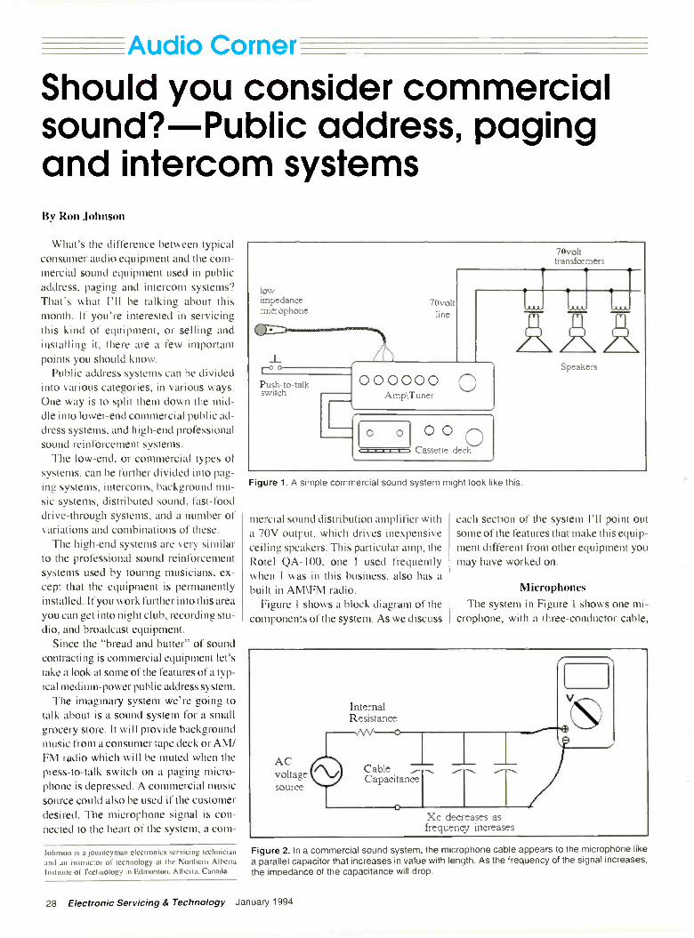
= A I !di° Corner
Should you consider commercialsound?-Public address, pagingand intercom systemsBy Ron Johnson
What's the difference between typicalconsumer audio equipment and the com-mercial sound equipment used in publicaddress, paging and intercom systems?That's what I'll be talking about thismonth. If you're interested in servicingthis kind of equipment, or selling andinstalling it, there are a few importantpoints you should know.
Public address systems can be dividedinto various categories, in various ways.One way is to split them down the mid-dle into lower -end commercial public ad-dress systems, and high -end professionalsound reinforcement systems.
The low -end, or commercial types ofsystems, can be further divided into pag-ing systems, intercoms, background mu-sic systems, distributed sound, fast-fooddrive -through systems, and a number ofvariations and combinations of these.
The high -end systems are very similarto the professional sound reinforcementsystems used by touring musicians, ex-cept that the equipment is permanentlyinstalled. If you work further into this areayou can get into night club, recording stu-dio, and broadcast equipment.
Since the "bread and butter" of soundcontracting is commercial equipment let'stake a look at some of the features of a typ-ical medium -power public address system.
The imaginary system we're going totalk about is a sound system for a smallgrocery store. It will provide backgroundmusic from a consumer tape deck or AM/FM radio which will be muted when thepress -to -talk switch on a paging micro-phone is depressed. A commercial musicsource could also be used if the customerdesired. The microphone signal is con-nected to the heart of the system, a com-
lowimpedancemicrophone
J_roPush -to -talkswitch
7Ovoltline
000000A mp\Tuner
0 0Cassette deck
L
70volttransformer
ii..1
Speakers
Figure 1. A simple commercial sound system might look like this.
mercial sound distribution amplifier witha 70V output, which drives inexpensiveceiling speakers. This particular amp, theRotel QA -100, one I used frequentlywhen I was in this business, also has abuilt in AM\FM radio.
Figure 1 shows a block diagram of thecomponents of the system. As we discuss
each section of the system I'll point outsome of the features that make this equip-ment different from other equipment youmay have worked on.
1 icro p hones
The system in Figure I shows one mi-crophone, with a three -conductor cable,
Xc decreases asfrequency increases
Johnson is a journeyman electronics servicing technician Figure 2. In a commercial sound system, the microphone cable appears to the microphone likeand an instructor of technology at the Northern Alberta a parallel capacitor that increases in value with length. As the frequency of the signal increases,Institute of Technology in Edmonton. Alberta, Canada. the impedance of the capacitance will drop.
28 Electronic Servicing & Technology January 1994

Low Impedance Microphonewith XLR Connector
High Impedance Microphone withPhone Plug
Figure 3. Microphone connections will depend on whetherthe cable is a balanced or an unbalanced line.
connected to the amplifier. This amplifi-er can accept two low -impedance micro-phones (balanced or unbalanced) or onelow -impedance and one high -impedancemicrophone. The low -impedance micsare connected to screw terminals on theback of the amp, while the high -imped-ance one uses a quarter -inch phone plug,which plugs into the front panel.
If you're new to microphones or (likethe rest of us) need to brush up on your
Figure 4. Microphone preamps using operational amplifiers make use of the com-mon -mode rejection characteristics of the op amp to cancel out the noise on bothsides of the line. This is a difference amp configuration that accomplishes this.
theory about input impedances, etc., thenext couple of paragraphs will give youa quick overview.
Microphone impedanceI've already mentioned that there are
two categories of microphone imped-ances: low and high. Although there isquite a bit of theory behind the subject,for practical purposes we can simplifythis a bit.
First, low -impedance microphones areused when running long microphone lines(up to about 200 feet) because they don'tattenuate the high frequencies as much ashigh -impedance microphones do. Thinkof the microphone itself as an ac voltagesource with an internal resistance (orimpedance) in series with it. The cablelooks like a parallel capacitor which in-creases in value with length (Figure 2).
As the frequency of the signal increas-
Are you looking for the most complete andcost-efficient computer service informationavailable today?
Check with SamsFIRST!
From our vast library of technical service documentation, Howard W. Sams, a leader in the repairindustry since 1946, offers schematics and troubleshooting aids for most popular brands of com-puter equipment sold since 1984.
We offer service documentation for: Manufacturers include: Computer System UnitsV Disk Drives Monitors Self -Contained Systems
System BoardsTo order, contact your authorized Sams distributor or talk to acustomer service representative at our toll -free number
Howard W. Sams & Company2647 Waterfront Pkwy., E. Dr.Indianapolis, IN 46214-2041Phone 1-800-428-7267FAX 1-800-552-3910
AmdekAmstradAT&T
AtariCitohCasioCommodoreCompaqEpson
FranklinHewlett PackardIBM
Leading EdgeMagnavoxMGA-MitsubishiOkidataOsbornePanasonicPCs Limited
OumeRadio ShackRana
SanyoShugart
SinclairSperryStar
TandonTandyTeac
Texas
Instruments
TimexZenith Data
Systems
Circle (43) on Reply Card
January 1994 Electronic Servicing & Technology 29
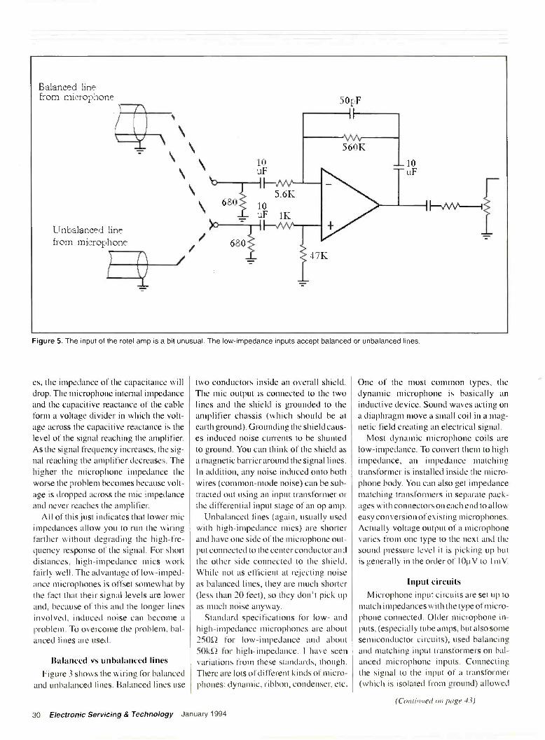
Balanced linefrom microphone
680
uF10
HAM5.6K
10uF 1K
Unbalanced linefrom microphone
50pF
II
560K
Figure 5. The input of the rotel amp is a bit unusual. The low -impedance inputs accept balanced or unbalanced lines.
es, the impedance of the capacitance willdrop. The microphone internal impedanceand the capacitive reactance of the cableform a voltage divider in which the volt-age across the capacitive reactance is thelevel of the signal reaching the amplifier.As the signal frequency increases, the sig-nal reaching the amplifier decreases. Thehigher the microphone impedance theworse the problem becomes because volt-
age is dropped across the mic impedanceand never reaches the amplifier.
All of this just indicates that lower micimpedances allow you to run the wiringfarther without degrading the high -fre-quency response of the signal. For shortdistances, high -impedance mics workfairly well. The advantage of low -imped-ance microphones is offset somewhat bythe fact that their signal levels are lowerand, because of this and the longer linesinvolved, induced noise can become aproblem. To overcome the problem, bal-anced lines are used.
Balanced vs unbalanced lines
Figure 3 shows the wiring for balancedand unbalanced lines. Balanced lines use
two conductors inside an overall shield.The mic output is connected to the twolines and the shield is grounded to theamplifier chassis (which should be atearth ground). Grounding the shield caus-es induced noise currents to be shuntedto ground. You can think of the shield asa magnetic barrier around the signal lines.In addition, any noise induced onto bothwires (common -mode noise) can be sub-tracted out using an input transformer orthe differential input stage of an op amp.
Unbalanced lines (again, usually usedwith high -impedance mics) are shorterand have one side of the microphone out-put connected to the center conductor andthe other side connected to the shield.While not as efficient at rejecting noiseas balanced lines, they are much shorter(less than 20 feet), so they don't pick upas much noise anyway.
Standard specifications for low- andhigh -impedance microphones are about25052 for low -impedance and about501M for high -impedance. I have seenvariations from these standards, though.There are lots of different kinds of micro-phones: dynamic, ribbon, condenser, etc.
One of the most common types, thedynamic microphone is basically aninductive device. Sound waves acting ona diaphragm move a small coil in a mag-netic field creating an electrical signal.
Most dynamic microphone coils arelow -impedance. To convert them to highimpedance, an impedance matchingtransformer is installed inside the micro-phone body. You can also get impedancematching transformers in separate pack-ages with connectors on each end to alloweasy conversion of existing microphones.Actually voltage output of a microphonevaries from one type to the next and thesound pressure level it is picking up butis generally in the order of 1011V to I mV.
Input circuitsMicrophone input circuits are set up to
match impedances with the type of micro-phone connected. Older microphone in-puts, (especially tube amps, but also somesemiconductor circuits), used balancingand matching input transformers on bal-anced microphone inputs. Connectingthe signal to the input of a transformer(which is isolated from ground) allowed
30 Electronic Servicing & Technology January 1994
(Continued on page 43)

Audio Corner ,from page 30) _-
AM
75-FM 300 AMIFM Tuner(DLD
Mic1 Bat
q7"Unbal
Mic2 Bal
Mic Preamp 1
Unbal(1), Mic Preamp 2
Aux -PhonoMusic
Muting
Aux/ Amp
ToneControl
Amp
TunerOut
Power Supply Circuit
Preamp PowerC ut Amp In
Music Muting Circuit
Unite/Separate
Power Amp Circuit
Figure 6. This block diagram shows the layout of a typical PA amp.
the signal to be connected through to theamplifier while rejecting the noise pre-sent on both lines (because they wereequal and opposite going into the trans-former so they canceled).
Microphone preamps using operationalamplifiers make use of the common -moderejection characteristics of the op amp tocancel out the noise on both sides of theline. Figure 4 shows a difference amp con-figuration that accomplishes this. If R1equals R3 and R2 equals R4 the gain issimplified to the ratio of R2 divided by R I .As long as the resistor values are exact,and the op amp specifications are good,practically all of the common -mode noisesignal should be rejected.
The input of the Rotel amp is a bit un-usual. First, the low -impedance inputs ac-cept balanced or unbalanced lines. Youdon't often see this on public address am-plifiers. Analyzing the circuit suggeststhey have made some design compro-mises to accomplish this. The result is amore versatile input amp which probablydoesn't reject common -mode noise as
efficiently as it should. See Figure 5.They've used a 4558 dual op amp and
capacitively coupled the inputs, outputsand even the feedback loop. The two68052 resistors from each input terminalto ground create the input load impedancereflected back to the microphone. (Thesensitivity of the microphone varies de-pending on the terminating impedance.)As Figure 5 shows, the input amp is a dif-ference configuration when connected inbalanced mode. The unusual aspect ofthis design is that the resistors are notmatched as in the previous example. Thismeans common -mode signals will not becompletely rejected. The reason for usingthis design is unclear but may relate tounbalanced operation.
When an unbalanced input is connect-ed, the input to the op amp's inverting in-put is left open. Because the coupling ca-pacitor is relatively large (10p F), it lookslike a low resistance to all but the lowestfrequencies. This has the effect of con-necting that input to ground through the68052 resistor, creating a non -inverting
configuration. The gain of this configura-tion works out to be about 90.
A switching jack changes the input ampinto a "virtual" buffer amp (unity gain)when a high impedance microphone isplugged in. I say virtual because it con-nects 10p F into the feedback loop which,again, is a very low resistance for all butthe lowest audio frequencies. The reasonfor this is the high -impedance micro-phone doesn't require as much gain as thelow -impedance one.
The public address amp
Before we talk about the output stage,let's see how the amp itself is laid out anddiscuss a few other features.
Figure 6 shows the block diagram ofthe Rotel amp. The tuner module has aterminal block that allows the connectionof an antenna or cable. The output of thetuner is connected to the preamplifier butis also brought out to an RCA jack so youcould connect it to another amp or otherdevice. In addition to the microphone in-puts to the preamp module, an auxiliary
January 1994 Electronic Servicing & Technology 43

+v
Q302
Input
Q301
Monolithic+Vcc power
outputamp
mw
Feedback
DifferentialAmp
-Vee
IC301STR-0100-II
00
+ Vcc9 1 ohm
3W
ow0
0 OM
0-Vee
1 ohm3W
1 ohm3W
1000uF
HIS1000uF
ohm3W
OutputTransformer
70volt
OV
16
8
4
Figure 7. Simplified diagram of the output of a public address amplifier.
input and a phono input can be pluggedinto RCA jacks. The phono input acceptsmagnetic cartridge output levels and per-forms the standard RIAA equalization onthe signal.
All of these signals are mixed togetherthrough resistors onto a bus before beingapplied to the next stage which incorpo-rates the bass and treble controls. A mut-ing circuit, consisting of a couple of NPNtransistor switches, is connected to thepoint where the tuner, aux and phono sig-nals come together. A contact closureacross the muting input terminals effec-tively shorts these program signals toground through one of these transistors.The microphones are unaffected by themuting function. By connecting a momen-tary switch on the paging mic to the mut-ing input, paging can be accomplished.
This amp also has the output of the pre -amp and the input to the power ampbrought out to RCA jacks. The unite/sep-arate switch allows you to disconnect thepreamp from the power amp and use thejacks to insert an equalizer or other de-
vice. You could also mix in signals fromother sources. This feature makes trou-bleshooting the amp easier because youcan check for preamp output, and injecta signal into the power amp at this point.
The power amp
This amp, being a fairly new design,uses a monolithic power amp module inits output. The rated power output is100WRMS, a respectable figure as pub-lic address amplifiers go. Figure 7 showsa somewhat simplified diagram of theoutput stage, including the differentialinput stage made up of discrete transis-tors and the output transformer used todrive the speaker load. In past articles I'vediscussed quasi -complimentary transis-tor power amps and push-pull tube amps.This one really isn't all that much differ-ent in concept, just simpler because of theuse of a chip.
The input signal is fed into Q301 whichis one side of the differential input stage.The other side of the amp comes from theoutput of the power chip and gives the
negative feedback necessary to minimizenoise and distortion, and maintain stabil-ity in the amplifier. Q302 is basically aconstant current source to the emitters ofthe difference amplifier (diff amp). Itsemitter current is set by the voltage acrossthe two diodes connected to its base. Theoutput of the diff amp goes through Q308and Q307 before driving the chip.
Notice the two 10000 capacitors inseries with the output load (the transform-er). These are good suspects if you'rehaving trouble with an amp like this. Alsokeep an eye on the output resistors. Theyare l0, 3W resistors and could go openin the event of a catastrophic failure. Thisamp is pretty forgiving (partly because ofthe transformer in the output), but noth-ing is indestructible.
The 70V output
The final aspect of this system that Iwant to look at is the 70V output. This isprobably the most characteristic-andleast understood-aspect of commercialsound systems.
44 Electronic Servicing & Technology January 1994

Seventy -volt lines are used in soundsystems for the same reason high -voltagelines are used in power distribution sys-tems. When you have to put in long speak-er wire runs, losses in the wire become aproblem. You want to deliver the samepower to a speaker some distance awaybut you don't want high levels of currentin your speaker lines. By increasing thevoltage, the same amount of power can bedelivered using less current. This meanslighter gauge wire can be used.
But there is another advantage to 70Voutputs on public address amplifiers.With a typical consumer or sound rein-forcement amplifier the speaker load isusually pretty standard. The amp is ratedto deliver some specified power into aspecified load such as 160, 80, or 40. Ifyou make the load too small, the amplifi-er will exceed its maximum power out-put. The load is determined by the type ofspeakers and the arrangement in whichthey are connected.
These arrangements are standard (be-cause you don't usually have very manyspeakers), but they're not very flexible. Itdoesn't take many 80 speakers connect-ed in parallel to bring the load impedancebelow the minimum value. Series -paral-lel networks can be used but don't lendthemselves very well to the physical lay-out of typical public address systems.
With public address systems-espe-cially distributed, or ceiling speaker sys-tems-you may want to connect manyspeakers to the system in a variety of loca-tions. Usually you don't need more thana few watts out of each speaker becausethey are relatively close to the listener buttwenty or thirty speakers wouldn't be un-common in a medium-sized grocerystore. The maximum output power of theamplifier is still the limiting factor in whatyou connect to the output but you need away of doing it that doesn't cause prob-lems for the amp.
The answer is to use standard 80speakers with small impedance matchingtransformers which allow them to be con-nected to the 70 volt, high impedancespeaker line. All speaker transformers inthe system are connected in parallelacross the 70V line making it simple toadd speakers to the system. To control theoutput level of the speakers, the trans-formers have various taps to which to
connect the speaker. The taps arc labeledin terms of watts. In its simplest form, theprocedure is to total up the watts of all thespeakers connected. The total should notexceed the power rating of the amplifier.
Some drawbacksThere is more to the determination of
actual output and input impedances thanI have mentioned but I've tried to con-centrate on the practical side of it. In real-ity, 70V systems have some drawbacks.Often the quality of the transformers useddegrades the frequency response out ofthe speakers. Inexpensive transformersalso add insertion losses because they dis-sipate power themselves.
Older tube amps, which have inherent-ly high output impedances, could oftendrive 70V lines directly. Semiconductoroutputs are low -impedance, so a step-uptransformer is generally used to create the70V output. The transformer on the Rotelamp we've been looking at has multipletaps on its output. The lower taps match40, 80 and 160 speaker systems whilethe highest tap on the transformer drivesthe 70V line. Keep in mind, though, thatonly one output can be used at a time:either 70V or one of the others.
The other important thing to rememberis that, when using the 70V line, all speak-ers must have impedance matching trans-formers. If you connect a standard 80speaker to the 70V line the least you canexpect is loud, distorted sound. The worstcase scenario involves smoke billowingout of your amplifier. Rotel, in its wis-dom, installed a circuit breaker betweenthe power output and the transformer.
Well, there is so much more about pub-lic address that could be said. I couldn'thope to do it justice here but maybe thiswill help you decide whether you're inter-ested in getting involved. Really, it's afield unto itself, related to other areas ofelectronics but with its own foibles andinteresting technologies.
1nm:brill/darken' MI IVM II MirVCF MECHANICAL REPLACEMENT BOOKLETS
CAN HELP YOU EASILYSOLVE VCR FAILURES
These booklets provide the mechanical in-formation for a wide variety of VCR makesand models. Each booklet includes detailed,easy to follow mechanical diagrams, with acomplete listing of mechanical parts andassemblies.
EACH INNERWORKS BOOKLET ... Provides information for 15-20 VCR Models
of a particular manufacturer. Provides the facts you need to easily
determine which models use similar parts. Is color coded for fast group identification.InnerWorks Booklets are just 49'6 each
For complete details call ...1-800-558-9572
FAX: 1-800-887-2727"First In Quality, Service and Delivery"
EMIUMPARTS's--ELECTRONICS COMPANY
P. 0. Box 28 . Whitewater, Wisconsin 53190-0028
ULTRA -LOW COSTLINEAR PROGRAMMABLE
POWER SUPPLIES
User-friendly with LCD readoutsat analog prices
Output Voltage, Current Programming and Readback
is LCD Panel
Data Entry with Front Panel Keypad
r3ower off Memory
Aicroprocessor Controlled
Voltage and Current Step-up/Step-down Function
iuperior Line/Lood Regulation
Output Enable/Disable
Intelligent Forced Air Fan Operation
Optional RS -232 Interface for Remote Operation
'standard on CPS 3051
American Reliance, Inc.11801 Goldring Road. Arcadia, CA 91006
(800) 654-9838 Fax: (818) 358-3838
January 1994Circle (30) on Reply Card
Electronic Servicing & Technology 45

Test your electronics knowledgeTry this tough quizBy J.A. Sam Wilson
u) 3
02 --
1 -
2 3
MICROSECONDS
4 5
4 Figure 1.
We haven't had a tough TYEK test fora long time. At least that's what somereaders tell me. OK. If you can get sevencorrect answers on this test you're asupertech! But, then, if you read ES&Tyou're a supertech even if you don't getseven right!
1. What is the percent duty cycle for thewaveform shown in Figure 1?
2. Tune the resonant circuit in Figure 2to a lower frequency by moving the platesof C2
A. closer together.B. further apart.
3. Which of the following is used to re-move parasitic oscillations in amplifiers?
Wilson is the electronics theory consultant for ES&T.
Figure 2. -II"
A. Bead ledgeB. ElastomerC. Ferrite coreD. None of the choices is correct.
4. The voltage (K) across a certaincharging capacitor is calculated by theequation
Vc = 15 1-1/( "0-06)1How long does it take the voltage
across the capacitor to reach 10\t?
5. What is the power factor of the cir-cuit in Figure 3?
6. A certain transmission line has acharacteristic impedance of 3000. Whenconnected to a source having an internalimpedance of 375Q and a load impedanceof 2200, what is the surge impedance ofthe transmission line?
-4- Figure 4.
Figure 3.
7. A diversity antenna system is effec-tive against
A. adjacent channel interference.B. co -channel interference.
*Figure 5.
46 Electronic Servicing & Technology January /994

C. re -radiation.D.(none of these choices is correct.)
Literature8. Your frequency counter cannot count
to a value sufficiently high for your appli-cation. You can use your frequency coun-ter if you use a
9. Which of the following can be usedto measure a voltage?
A. CapacitorB. InductorC. PotentiometerD. None of these choices is correct.
10. What is the third harmonic of a1.277kHz sinewave signal?
A. 0.426kHzB. 3.831kHzC. Neither choice is correct.
Bonus Question (10 points)
Refer to Figure 4. A logic 0 is deliv-ered to A. Which (if any) of the LEDswill be ON?
A. LED #1B. LED #2C. Both LEDsD. Neither LED
(Answers on page 52)
SAVETIME
For fast, accurate service,please remove the peeloff label used to addressyour magazine, andattach it to the ReaderService Card, the AddressChange Card or to anycorrespondence yousend us regarding yoursubscription.
Mail AllCorrespondence To:Electronic Servicing &
Technology76 North BroadwayHicksville, NY 11801
Catalog oftest and measurement products
Analogic Corporation announces anew test and measurement catalog fea-turing its complete line of high precisioninstrumentation products. This catalogpresents 72 pages of instruments and isintended to help design and test engineerssolve their complex application problems.Featured in the catalog is the company'scomplete family of waveform generatorsand synthesizers, waveform analyzers,and general purpose instrumentation.
The catalog showcases high -precisionarbitrary waveform synthesizers, which,offer performance up to 800 Ms/s. Ten re-cently introduced waveform generatorsextend the product line to offer featuresand a price to suit almost every applica-tion. The new products include both stan-dard and programmable function genera-tors, arbitrary function generators, high -bandwidth arbitrary waveform genera-tors. and a flexible pulse generator usefulfor comparator and device testing, tele-communications, and ATE.
Also featured are waveform analyzers,including the recently introduced Model6500. This DSP-based analyzer performsreal-time analysis in both the time and fre-quency domains. Six plug-in modulescomplement the analyzers for use in ap-plications such as radar, vibration, med-ical research, wideband video, compo-nent and circuit testing, acoustics, audio,and communications. Completing theproduct line are general purpose instru-ments, including digital multimeters, dcvoltage standards, electronic loads, and aPC -compatible waveform digitizer.
Circle (100) on Reply Card
Brochure details UPS productsTripp Lite's new UPS systems bro-
chure showcases the company's batterybackup model line. Included in the full -color, I2 -page brochure are completespecifications and benefits of the compa-ny's standby UPS systems and on-line,sine wave UPS systems.
New products, like the company'sadapter for UPS, software for automatic,unattended shutdown of any network anda complete line of international 230 UPSmodels are also described.
The brochure also discusses why net-work power protection is a crucial re-quirement for today's network installa-tions, details the various waveformoutputs available in current UPS designs
and lists various options, like extendedbattery capability, rack mount kits and re-mote turn -on.
Circle (101) on Reply Card
Power protection catalogA power protection catalog, from Best
Power Technology, Inc., helps users ofsensitive electronics products define andsolve power problems. It shows how tosave money by protecting equipmentfrom power problems such as surges,sags, spikes, noise, brownouts, blackouts,and lightning.
The catalog is a power protection ref-erence manual. Colorful, easy -to -read,tabbed sections move readers from sec-tion to section. Along with brief descrip-tions and specifications of the company'sproducts, the catalog offers these handysections:
The power problem analysis and solu-tions section gives a brief review of manycommon power problems, symptoms thatmake their identification simple, and abrief discussion of which type of powerprotection technology will best solve theproblem and why.
The how -to -buy a UPS/SPS sectionmakes selecting the right power protec-tion as easy as asking a few very basicquestions about the system that needs pro-tection. Readers then select the appropri-ate level of power protection based ontheir answers.
The latest advances in UPS communi-cation software section explains how,with communications software, UPSusers need never worry that their systemwill crash because of unattended opera-tion during long outages.
Circle (102) on Reply Card
January 1994 Electronic Servicing & Technology 47

ProductsInstant bonding kit
Planned Products introduces the 4300Circuit Works Quick -Bond Gel Kit toprovide rugged, instant bonding of met-als, rubbers and plastics. The kit includesan accelerator that can be applied direct-ly over the adhesive to assure instantbonding results.
Developed for design, prototype andrepair applications, the kit provides a onepart, cyanoacrylate gel that will not
migrate to unwanted areas after applica-tion. Useful for filling gaps, wide toler-ances, and bonding dissimilar materials,the gel can be used alone or with the sup-plied accelerator for instant bonding. Theaccelerator can be brushed on difficult toreach areas, or applied directly over thegel adhesive. Bonding is instantaneous asthe accelerator contacts the adhesive,assuring reliable results in any environ-ment regardless of temperature or humid-ity. The accelerator is applied using thekit's poly brush or pipette.
The cured gel is a colorless solid thatresists shock, impact and temperaturecycling. Cured adhesive provides an alu-minum to aluminum tensile strength of3770 psi and a working temperature rangeof -65F to 200F (-54C to 93C). Softeningbegins at 329F (165C). The dielectricstrength of the cured adhesive is
I 1.6KV/mm.Applications include bonding jumper
wires to circuit boards, fixturing surfacemount components, component mount-ing, strain relief, shallow potting, andgeneral instant bonding.
Each kit includes the gel adhesive,accelerator, with an applicator brush andpipette for applying the accelerator.
Circle (50) on Reply Card
Surface mount and thru-holesoldering system
PACE announces the introduction of
the ST 20, designed specifically for pro-duction soldering of thru-hole and sur-face mount components.
The system incorporates SensaTemptechnology providing the high capaci-ty/low temperature heating required tosafely handle all production applications.While the unit permits setting accuratehonest tip temperatures between 200Fand 900F, most routine surface mountsoldering tasks, even on high pin countpackages, are performed at temperaturesas low as 525F. If desired, a specific tem-perature can be locked in to prevent unau-thorized tampering.
The product's electronics incorporatean auto -off safety system which powersoff the unit automatically after 90 min-utes of inactivity. This feature increasestip/heater life and saves energy.
Circle (51) on Reply Card
Intelligent FET probesLeCroy introduces a new line of active
FET probes, together with the ProbusInterface.This interface system is a com-plete measurement solution from probetip to oscilloscope display. The interfacesupplies power to active probes and auto-matic attenuation sensing, and alsoenables direct control of the probe offsetand input coupling from the instrument's
front panel. In addition, it automaticallycalibrates the gain and offset at the probetip-it can even compensate for non-lin-earities-providing the most accuratemeasurements.
Two FET probes are already equippedwith the system: Models AP020 andAP021 offer 1GHz and 800MHz band-width respectively. AP020 features a x10signal attenuation. The AP021 offers a x5attenuation. The AP003 1GHz FETprobe is equipped with a standard BNCconnector and can be used with any oscil-loscope with a 501/ input.
FET probes provide the oscilloscopeuser with a higher level of measurementcapability. Compared with passiveprobes, they offer low circuit loading,low capacitance and high bandwidth.
Circle (52) on Reply Card
Needle -tip pen oiler
A new pen oiler filled with a lubricantcontaining Teflon that is ideal for main-taining a wide -variety of products rang-ing from scientific instruments to cam-eras, guns, and fishing tackle is beingintroduced by Syon Corporation ofAshland, MA.
The Lubit-8 Pen Oiler is filled with ablend of natural and synthetic oils con-taining microminiature particles ofTeflon and Fluon held in permanent sus-pension. Featuring a needle -tip whichprecisely dispenses the lubricant, onedrop at a time, this oiler is for use wheresprays and oil cans are impractical.
Designed to be clipped to a shirt pock-et or carried in a field service kit or othersmall tool box, the oiler is about the sizeof a fountain pen. The lubricant is unaf-fected by -60F to +500F temperatures, is
48 Electronic Servicing & Technology January 1994

very slippery, resists dust, does not coag-ulate, and leaves no oily residue.
Circle (53) on Reply Card
DMM/thermometer/relativehumidity meter
Newport Electronics introduces theModel HHM25, a portable handheldDMM which features true RMS func-tions, with the capability of measuringup to 3 type K thermocouples using theincluded adaptor. The DMM measures
voltage from 0.01mV to 1000Vdc or1000Vac, current from 0.01mA to 10Afor ac and dc, frequency from 1Hz to19.99kHz, capacitance from 0.001nF to99.99g, resistance values from 4000 to40M0. The temperature measurementswill allow for up to three type K ther-mocouple inputs for measurements ofeither T1, T2, T3 or T1 -T2 with a tem-perature range of -346F to 2498F(-200C to 1370C).
Standard features include a 41/, digitdisplay which indicates the measure-ment functions, measurement units,thermocouple or relative humidityprobe, display hold, overrange and lowbattery warning and a bar graph display.
The meter is supplied with 3 type Kbeaded wire thermocouples, thermo-couple adaptor, heavy duty rubber pro-tective boot, rugged carrying case, 9Vbattery and operator's manual. Anoptional humidity probe may be usedallowing the user to measure relativehumidity over the range of 15% to 95%.
Circle (54) on Reply Card
Disposable wrist bandDispos-A-Strap from Richmond
Static Control Services, is a new, one-piece grounding strap designed to bethrown away after one use. The designincludes a sturdy elastic strap contain-
ing conductive filaments positionedabove the inner layer for maximumskin contact and conductivity for pro-tection against ESD. The convenientfive-foot straight wire features a built-in IMO resistor and an easy -to -adaptbanana configuration plug for easy, yetsolid grounding. The wrist strap andstraight wire are yellow.
The strap is useful for inclusion in thefactory packaging of personal comput-ers and other electronic equipment thatmay require elementary service or repairby the end user. It is also designed foruse by field service technicians whenmaking repair and service calls on elec-tronic equipment containing PC boards,such as computers, copiers, printers andfax machines, to insure protection fromelectrostatic damage to sensitive inte-grated circuits.
Circle (55) on Reply Card
Digital scopes
Tektronix announces two new oscillo-scopes: the 50MHz TDS 310 and the200MHz TDS 350 digital, real timeoscilloscopes featuring high-speedoversampling. The digital scopesacquire and display signals similar toanalog scopes, eliminating the potentialfor aliasing of the waveform. The TDS310's two channels digitize at a rate of200 megasamples per second and theTDS 350 at one gigasample per second,providing accurate representations ofwaveforms at the full bandwidth of eachscope, even for single -shot events.
The series communication optionincludes GPIB, RS232 and Centronics -type interfaces for hard copies. In addi-tion to over 20 waveform measure-ments, the oscilloscope offers fouracquisition modes: sample, envelope.average and peak detect.
Circle (56) on Reply Card
eo.
42,3738TRONICELEuCOMPONENTS
Whether you order 1 part orall 42,738...MOUSER stocksand...ships same day!!
CALL...(800) 992-9943
for yourFREE
CATALOG2401 Hwy. 287 N.
Mansfield, TX 76063
MOUSERELECTRONICS
Sales & Stocking Locations Nationwide
Circle (40) on Reply Card
ISCET
VCRCross Reference
VCR Model Number Cross Referenceand VCR Parts Cross Reference
IIIIIIIIII
ItII
J 4th Edition.Contains both model- and parts -lumber cross-references for morethan 1300 additional parts, and morethan 50 brand names. $36.00
shipping 3.00One 31/2" disc, orTwo 51/2" 360K discs.
Version 5.0, for IBM PC AT/XT orcompatibles. Requires hard drive andDOS 2.1 or greater. $69.95
shipping 3.00
=I Special Combo Offer.Your choice of discs, plus 4th EditionVCR Cross Reference.
$95.00shipping 3.00
Allow 4 6 weeks delivery when using personal checks VISA.MasterCard money orders arid c)irars checks processed
rnmediately.
Amount
II Cad NoO Visa CIMasterCatd
Exp.
I r;ss...'elsC"Pt'ne
Member 13NESDA: CSISCET
I Texas residents multraly dollar amount by 7-3/4% lot 'aria.Foreign shipments please add International postageSend to ISCET. 2706 West Berry St Ft Worth TX 76109
Slate Z
IIII
II
IIIII
IIIII
January 1994 Electronic Servicing & Technology 49

What Do You Know About Electronics?
Tunnel diodes are alive and wellBy J.A. Sam Wilson
AnnouncementFor those of you who need information
about or from any technician organiza-tion such as the CET programs, CET test-ing, activities of technicians, etc., I wouldlike to inform you that 1 am no longer amember of any of these groups. Therefore,you may want to try contacting the fol-lowing memberships that are involvedwith CET testing (in alphabetical order):
Electronics Technicians Association-ETA604 N. Jackson StreetGreencastle, IN 46135
International Society of CertifiedElectronics Technicians-ISCET2708 West Berry StreetFt. Worth, TX 76109
For those of you who are not aware ofit, the following entry is your contact forbuying tunnel diodes:Wilson is the electronics theory consultant for ES&T.
Germanium Power Devices Corp.300 Brickstone SquareP.O. Box 3065Andover, MA 01810Sales Manager: Rick Kassiotis
Apparently, the big companies haveabandoned all germanium devices. Thetunnel diode is just one example. I sup-pose this means that someday they willabandon all silicon devices in favor of thegallium arsenide devices. That is what isknown as progress. (?)
LettersI have received two letters I want to
share with you. The first is from FM inDarien, IL.:
Mr. Wilson:I believe the answer to problem 3 in Test
Your Electronics Knowledge is wrong andshould have been 151 instead of 97. Theproblem was to decode BCD number10010111.
# Figure 1. A voltage is induced in a conductor anytime there is a changein the magnetic field around the conductor.
Figure 2. The voltage induced in a coil with an iron core will be greaterthan the voltage induced in the same coil with an air core because ofthe lower magnetic reluctance of the iron core. -110 -
The first four digits to the left are 144in decimal and to the right the last fourdigits are 7 in decimal. This brings the to-tal to 151 decimal.
Thank you.
Sam Says:If you have been following WDYKAE?
you already know that the BCD numberis divided into groups of four binary num-bers. Each four -bit binary number is thendecoded into a decimal number between0 and 9. So, 97 is the correct answer.
I want to thank FM for his very profes-sional letter. There are two important les-sons to be learned from this. The first isthat it can take an awful long time to getan answer. The second is that sometimessomething seems to be wrong, but, it turnsout to be right. Note that Frank Massi didnot jump all over me with insults. Maybeby printing his letter as a model we canall learn a better way to correspond.
The second letter is from Erich Hol-lingswood. He says he and the Chief Tech
50 Electronic Servicing & Technology January 1994

of Halls TV in Prentiss, MS really enjoyour articles. He adds-Keep up the goodwork, gentlemen!!!
I don't have room to print the complete(very professional) letter, but, this is theidea he proposes. He says that the methodof decoding the BCD number couldn'twork because 01111111 would decode as7F and that is not a decimal number.
He proposes that the method of decod-ing that I gave would really convert thebinary string to a hexadecimal number.
Actually, he makes an important point.In the BCD decoding no four -digit num-ber can be greater than 1001-that is tosay, none of the four -digit numbers canbe greater than decimal 9. I should havemade that clear.
Of course, BCD stands for binary-coded decimal. It does not mean binary-coded hexadecimal.
Many, many thanks to the writers of theabove letters.
Inductance as determinedby magnetism
I have had a discussion with a very in-telligent person. He likes to give me ideasabout basics that I can write about. In this
case it is about the way the magnetic fieldis represented in electromagnetic devices.I'll use an inductor as an example.
Faraday's Law states that any timethere is relative motion between a mag-netic field and a conductor, a voltage isgenerated. The mathematical expressionfor Faraday's Law is expressed in two dif-ferent ways, but both are saying the samething in different ways.
V = -N (de/d,) and V = -L 040
In these equations, V is the inducedvoltage or counter voltage, N is the num-ber of turns in the coil, and, L is the induc-tance of the coil. The mathematical ex-pression do/d, means the rate of change offlux, and, chid, means the rate of change ofcurrent that produces the changing flux.
It doesn't matter whether the flux ismoving and the conductors are motion-less, or, the conductor is moving and theflux is motionless.
Refer to Figure 1. Note that the flux isshown in the center of the coil and thatflux, represented by broken lines, isshown with arrows. This illustration issometimes accompanied with a statement
like "the greater the flux the greater theinduced voltage.
You might get the idea that a voltage isinduced in the coil by the flux lines in thecore. Also, from the arrows on the fluxlines you might get the idea that the fluxlines are moving.
There is no physical law or effect thatrelates the flux in the center of a coil tothe voltage induced in the coil. To explainwhat is being illustrated I have providedthe illustrations in Figure 2. Note thatthere are two cases being shown. In thefirst case, the core of the coil is air. In thesecond case, it is iron.
At the peak of one-half cycle the fluxaround the conductor marked with an Xreaches across only two adjacent conduc-tors. That means an induced voltage willoccur only in those conductors. The samething happens with all of the other con-ductors. Therefore, there is not much totalinduced voltage.
In the case of the coil with the iron core,the low reluctance of the iron results inthe peak flux reaching across all of theturns of wire. So, the peak flux aroundconductor Y induces a voltage in all ofthe other conductors. Observe in Figure
ORGANIZE AND PROTECTYOUR COPIES OF
ES&TNow there's an easy way to organize and keep copies of
your favorite magazine readily available for future reference.
Designed exclusively for ES&T by Jesse Jones Industries,these custom-made titled cases and binders provide the luxu-ry look that makes them attractive additions to your bookshelf,desk or any location in your home or office.
Whether you choose cases or binders, you'll have a stor-age system that's durable and well organized to help protectyour valuable copies from damage.
Cases and binders designedto hold a year's issues (mayvary with issue sizes).
Constructed of reinforcedboard. covered with durablered leather -like material.
Free personalization foil forindexing year.
Cases V -notched for easyaccess.Binders have special springmechanism to hold individ-ual rods which easily snapin. This allows magazines tobe fully opened for easyreadability.
Title hot - stamped in gold.
'E2
a)
cn
6(0)
coC.)
O
a)0
cnL.r)
69C61 69
10 al 10a! a? a!P.. 1- 01
U 69C61 l'13
49
c xO 1- U)
etai ("1 6-c> << 0
E
cc -0
a) 7=CL
in
U
to)0 >co Nc47) 49 00 4 0CL
15u).c
ca 00 0 aC C
S. rl1- di(A IC
.0'0 6.<
cO.
a,
0
.o
Ca'
00
N
20
a)Ta0
w
at
Ca
isC
'CT)
0 'aE
<
January 1994 .Electronic Servicing & Technology 51

1 that the flux lines in the center of thecoil will add to produce a good healthyflux density in the core.
The arrows on flux lines do not indi-cate flux motion. Instead, they show thepath that a unit north pole would move ifthere was such a thing. A unit north poleis a very small magnet that has a northmagnetic pole but no south magneticpole. People are spending lifetimes look-ing for those things but none has ever beenfound. If they do find one you will hear
the sound of one hand clapping.To summarize, the flux in the center of
the core is the result of adding the fluxesaround each turn. However, the counter -voltage induced in the coil is the sum ofthe voltages induced in each winding byadjacent windings.
Frone Smix has passed his first quarterin his post -high course in electronics. Hisstudy of magnetism has given him an ideahe believes he can patent. Since the fluxpassing through the center of the core
To Order BackIssues
Send $3.50 Per Issue (Check.Money Order, Mastercard,VISA, Discover and AMEX.
Send AllCorrespondence To:
CQ Communications76 North BroadwayHicksville, NY 11801
Or Call516-681-2922
FAX 516-681-2926
Test your electronicsknowledgeAnswers to the quiz(from page 46)
1. 20%. Percent duty cycle is equal tothe ON time divided by the time for onecycle multiplied by 100.
2. A. Moving the plates closer gives ahigher capacitance and a lower resonantfrequency.
3. D. The correct answer is ferritebead. Resistors have also been used.
4. About 66ms. This type of problemwas worked in last month's"WDYKAE?".
5. See Figure A.
6. 30052. The surge impedance is thesame as the characteristic impedance.
7. D. The diversity antenna system is
effective against fading. This antennasystem consists of a receiver and a num-ber of antennas spaced a wavelength (or.two wavelengths) apart.
8. Prescaler. That is what a prescalerdoes.
9. C. Potentiometer is a name used fora variable resistor. It is also a name usedfor an instrument that measures voltage.
10. C. Sinewaves have no harmonics.
Solution To Bonus Question(10 points)
The answer is B. LED #2.
does not produce the counter voltagecharacteristic of inductance, then, whynot make the core hollow? According toFrone, that would give us much lighterinductors and transformers.
Of course, it will not work because de-creasing the cross section of the iron corecauses an increase in the core reluctance.That, in turn, will reduce the number offlux linkages.
Calculator practiceNothing clears the air better than an
arithmetic problem that everyone under-stands. Here is one you can pass around.
Enter any three -digit number on yourcalculator. Without clearing, repeat thesame three numbers. For example, if youchose 432 for the first 3 -digit number youwould now have 432432 displayed.
Divide that number by 11. Divide theresult by 7.
Divide that result by 13. You shouldhave the original number.
Technician hazardsI have warned technicians many times
in WDYKAE? about the hazards of leadand lead solder. In some cases, techni-cians have picked up the very dangeroushazard of holding solder in their mouthduring the soldering process. In otherwords, they are using their mouth as athird hand. Do that for a little while andthe result is Big Casino! In other words,the technician assumes room tempera-ture. (In electronics we never say die.)
The first sign of lead poisoning is lossof memory. Also, there is a reduction ofmath skills. These things make it very dif-ficult to diagnose in some students.
Another symptom is loss of circulation.A tingling sensation in the fingers is awarning sign.
According to an Associated Press re-lease, a technician in Ohio began to noticeall of those symptoms. He was diagnosedas having 10 times the lead level in nor-mal humans.
People who knew him gave this clue:He was fond of chewing on the insulationscraped off wires. That plastic coating hasa high level of lead! It was the cause ofthe high level of lead in the technician.
Understand this important point: Oncethe lead gets into you it is nearly impos-sible to get out.
52 Electronic Servicing & Technology January 1994

Books
Electronic Troubleshooting, by Daniel R.Tomal and Neal S. Widmer, TAB Books,384 pages, 317 illus., $24.95 paper, $34.95hardcover.
A full revision and update of Daniel To-mal's Principles and Practice of Electricaland Electronic Troubleshooting, this compactreference puts state-of-the-art troubleshootingtechniques at the fingertips of electronics tech-nicians, students, and hobbyists.
Included in this book is an ample supply oftime -saving diagnostic tables and charts thatmake pinpointing problems with electronicequipment quick and easy. Authors Tomal andWidmer show readers how to troubleshoot andrepair electric motors and generators, resi-dential and industrial wiring, digital circuits,microprocessor -based systems, industrialcontrols, radios and televisions, sequentialdigital circuits, and biomedical equipment.Also included at the end of each chapter areexamination questions/problems.
Tomal is an assistant professor in the tech-nology and engineering department at PurdueUniversity, North Central. Neal S. Widmer isan associate professor of electrical engineer-ing technology at Purdue University.
TAB Books, McGraw-Hill, Inc.,Blue Ridge Summit, PA 17294-0850
Practical Filter Design, By Jack Mid-dlehurst, Prentice Hall, 259 pages, includes342 inch DOS disk, $35.00, paper.
Although filters are basically easy to un-derstand, you don't get this impression frommost books. This is a non -mathematical treat-ment for electronics hobbyists and techni-cians. This book looks at the circumstanceswhere filters are needed, indicates which onesto choose for specific applications, and dis-cusses their limitations. Details are given ofthe circuits, construction and tuning of LC fil-ters, as well as simple active filters. But-terworth, Chebychev and elliptic forms oflow-pass, high-pass, band-pass and band -reject filters are described, as well as activeand passive crossover and notch filters. Totruly remove any difficulties with mathemat-ics, computer programs in GW BASIC areprovided on disk so that filters and their prop-erties can be easily designed and predicted.
Prentice Hall, Englewood Cliffs, NJ 07632
Build Your Own 386/386SX and Save aBundle, 2nd Edition, By Aubrey Pilgrim,TAB Books, 248 pages, $18.95, paper.
Windcrest has two words for people whothink they can't afford high -power personalcomputing-Aubrey Pilgrim. He wrote thebook on how to build a state-of-the-art PC athome for a fraction of the cost of a new store-
bought system. Build Your Own 386/386SXand Save a Bundle, 2nd Edition. the latest inPilgrim's bestselling Save a Bundle series,shows how anyone, regardless of their levelof computer or electronics skill, can assembletheir very own 80386 -based microcomputerusing inexpensive mail-order parts.
Pilgrim's clear, step-by-step instructionsand close-up photographs lead do-it-yourselfPC builders through each phase of the assem-bly process, explaining not only where eachcomponent goes, but also what it does and howit does it. A revised edition of the national best-seller Build Your Own 80386 IBM Compatibleand Save a Bundle, this volume now includesmaterial on the new 386SX and 486SX micro-processors, as well as expert advice on how-to -build a computer that takes full advantageof DOS 5 and Windows 3.1. Pilgrim also fur-nishes complete, up-to-date information oncomponent prices and availability, parts sup-pli- ers, troubleshooting techniques, peripher-als, and software.
TAB Books, McGraw-Hill, Inc.,Blue Ridge Summit, PA 17294-0850
Professional Photocopier Trouble-shooting and Repair, By Eric Kuaimoku,TAB Books, 352 pages, 240 illus., $29.95,hardcover.
For licensed technicians and apprenticeswho want to add photocopier repair expertiseto their resumes, Professional PhotocopierTroubleshooting and Repair provides a com-prehensive course in the tools and techniquesemployed by working professionals.
Eric Kuaimoku takes an in-depth look ateach photocopier component and subsys-tem-including optical devices, developerdrums and sensors, fusing mechanisms, andpaper transfer rollers and belts-pinpointingthe sources and solutions to problems that typ-ically arise through extended use. This hard-cover edition will give technicians and stu-dents all the background information andpractical know-how they need to service andrepair a full line of personal and businessphotocopiers.
TAB Books, McGraw-Hill, Inc..Blue Ridge Summit, PA 17294-0850
Zen and the Art of the Internet: A Be-ginner's Guide, By Brendan Kehoe, Pren-tice Hall, 112 pages, $22.00, paperback.
Are you lost in the Internet? If you have everhad any questions about the Internet, this newbook is for you. Prentice Hall proudlyannounces the publication of Zen and the Artof the Internet: A Beginner's Guide byBrendan Kehoe, a guide to navigating throughthe Internet.
Zen and the Art of the Internet is the firsteasy -to -read introduction to the Internet forboth computing novices and experts. Readerswill find a practical and complete guide to nav-igating through the Internet and using the net-work to the fullest extent. The book is operat-ing system neutral, and can be used as a quickreference readers can use at a minute's notice.It covers topics such as the Internet, UUCP,bitnet, Electronic Mail, FTP, and CommercialServices (eg. electronic journals, newsletters,and Clarinet News).
Contents: Foreword; Preface; Acknowl-edgements; Chapter I, Network Basics;Chapter 2, Electronic Mail; Chapter 3,Anonymous FTP; Chapter 4, Usenet News;Chapter 5, Telnet; Chapter 6, Various Tools;Chapter 7, Commercial Services; Chapter 8,Things You'll Hear About; Chapter 9, FindingOut More; Conclusion; Appendix A-Gettingto Other Networks; Appendix B-RetrievingFiles Via Email; Appendix C-NewsgroupCreation; Appendix D-Items Available forFTP; Appendix E-Country Codes; Glossary;Bibliography; and Index.
Prentice Hall, Simon & Schuster Education Group.Englewood Cliffs, NJ 07632
Digital Oscilloscope Handbook, Test &Measurement Series, By Charles G. Masi,Butterworth/Heinemann, 250 pages,$29.95, hardcover.
The Digital Oscilloscope Handbook pro-vides a complete reference for what you needto know about using digital scopes. It coversthe essentials, starting at a level comprehen-sible to anyone with an electronics back-ground and is broad enough to cover offeringsfrom all major vendors as well as most class-es of applications.
This Handbook serves as an introduction todigital oscilloscopes as well as a treasury ofinformation for experienced digital scopeusers seeking a deeper understanding of thesepowerful instruments. This new book bringstogether in one place information that has beenavailable only in scattered trade magazine arti-cles or manufacturer application notes. It cov-ers everything from basic principles to adetailed look at the circuitry that makes digi-tal scopes work. The book also demonstratesreal -world applications for novices as well asusers who are already familiar with the use ofdigital scopes.
Contents include hardware fundamentals,an introduction to digital oscilloscopes, digi-tal oscilloscope circuitry, basic measurementapplications, data acqui- sition and timedomain reflectometry.
Butterworth/Heinemann. Stoneham, MA 02180
January 1994 Electronic Servicing & Technology 53

1993 ARTICLE INDEX
BASICSBasics of active filteringBy Dale C. ShackelfordControlling static at the service benchBy Bob WestGremlins in the power linesBy Bob PolkMultimeter update: Component testing withthe DMM, power supply and trackerBy Ron C. JohnsonNew consumer electronics technology-A special reportBy The ES&T StaffNotes about the homemade isolationtransformerBy R.D. ReddenPractical active filtersBy Dale ShackelfordPrinciples of switching power suppliesBy The ES&T StaffRestoring scratched compact discsBy Matt J. McCullarServicing consumer electronics on siteBy Homer L. DavidsonSetting up a service bench: Build this variableisolation ac power sourceBy Homer L. DavidsonSpecial purpose semiconductor diodesBy Dale C. ShackelfordUnraveling the parts numbering mazeBy Vaughn D. MartinWhat is CMOS RAM?By David PresnellWhere are they now?By Victor Meeldijk
Month Page
Jan
Sep
Nov
Sep
Sep
Sep
Sep
Sep
Jul
Feb
May
Jul
Apr
Nov
Feb
COMPUTER/MONITOR SERVICINGTape backups for IBM compatible computersBy Sheldon Fingerman JunUnderstanding and troubleshooting personalcomputers-Parts I, II, and IIIBy John Kull Jul
CONTINUING EDUCATIONTechnical training and literature-Knowledgeby the poundBy Matt J. McCullarTechnical training and literature-Sources ofschematics and technical informationBy Victor MeeldijkTechnical training and literature-Usingmanufacturers' tech help linesBy Sheldon Fingerman
Jul
Aug
Aug
6
6
12
12
20
48
52
19
51
11
10
47
22
49
21
24
6
6
9
14
PARTS AND EQUIPMENT PURCHASING1993 Buyer's GuideBy The ES&T StaffDistributors showcaseBy The ES&T StaffReplacement parts showcaseBy The ES&T Staff Aug 46Replacement parts/servicing informationsourcebookBy The ES&T Staff Dec 8
Selecting replacement electrolytic capacitorsBy Ralph W. Muller Dec 28Sources of replacement partsBy Victor Meeldijk Dec 18
Sources of technical informationBy Victor Meeldijk May 50
Mar
Apr
SERVICING/TROUBLESHOOTINGTECHNIQUESApplying lateral thinking to troubleshootingBy Ron C. JohnsonSetting up a service bench: Heart of theservice centerBy Conrad PerssonServicing personal headphone stereosBy Sheldon FingermanTroubleshooting flat tension mask CRT's-Video circuitry in the ZCM-1492By John A. RossTroubleshooting microwave oven highvoltage circuitsBy Homer L. DavidsonTroubleshooting the Philips S1/S4 chassisBy Dale ShackelfordTV power supply troubleshootingBy Brian E. JacksonUnderstanding compact disc troubleshootingconcepts-Part 1By Marcel R. RiallandUnderstanding compact disc troubleshootingconcepts-Part 2By Marcel R. Rialland
4
41
Sep 58
May 6
Apr 18
Jan 10
Feb 16
Aug 16
Jun 48
Oct 15
Nov 24
SOFTWAREComputer software for service centermanagement Feb 6
TOOLS/TEST EQUIPMENTAll about transformersBy Homer L. Davidson Apr 10
Modern scopes for modern circuitsBy Brian Phelps Apr 6Planning the technician's toolkitBy Conrad Persson May 17
54 Electronic Servicing & Technology January 1994

TELEVISION DTC rinritriran;re Replacement Tuners
Mainboards
Complete Chassis
Projection Sets
ALSO SERVICINGAND SELLING
COMPUTERMONITORS
(See reverse side forSPECIAL OFFER)
If PTS's Postcard is MissingCircle (47) on Reply Card
Mr 11=1111111,1111111 I 111.1_111111/P
Your Single Source for All Major Brands ofTELEVISION TUNERS & MAINBOARDS
ATSAVINGS UP TO
60%JP MORE
When Compared Te Manufacturer Replacement
Tuner Replacement 1795-4999
CALL TODAY TOYOUR FREE PTE
AOC Hitachi NEC SanyoBohsei JC Penney Panasonic SearsCurtis Mathes JVC Philco SharpDaewoo KTV Philips SonyDumont Magnavox Proscan SymphonicEmerson Matsushita Quasar TatungFisher MGA Radio Shack TeknikaFunai Midland RCA TCE
General Ele:tric Mitsubishi Sampo ToshibaGold Star NAP Samsung Wards
Zenith
RECEIVECATALOG 1-800-844-7871
r
CALL MCMELECTRONICS
FOR ALLYOUR
ELECTRONICPARTS NEEDS
1-800-543-4330FAX 1-513-434-6959
0 MCM ELECTRONICS
If MCM's Postcard is MissingCircle (98) on Reply Card
ES&TPostcardsAn EasyWay to GetImmediateAction.
Business Name
Your Name
Address
TIME TO BUY,CALL MCMWhen it's time to buy electronic parts or compo-nents. MCM has over 20,C00 top-quality items instock and ready to ship with-
/ in 24 hours. You'll also gettimely advice from our Toll -
Free Technical Assistance Line,
Isn't it time you tried MCM?
For A FREE Catalog Call:
1-800-543-4330To Order by FAX: 1-513-434-6959 For
Prod ice Questions: 1-800-824-TECH(8324)
City
State Zip
Phone ( ESTC-13
#4204H, $39.95
CALL TOLL FREET 1-300-822-8158or FAX: 717-794-2080
SATISFACTION GUARANTEED
Turn faulty VCRs into Profits
You've got the know-how-now get therepair tips you need to successfullyrepair any VCR malfunction in MAIN-TAINING AND REPAIRING VCRS-3rdEd. by Robert A. Goodman. This newedition takes an illustrated, problem-sc lying approach to fixing every VHS,8mm and camcorder in the business-from diagnosing the problem to servic-ing any potential problem. This "in-siders" guide to the latest VCRtechnology, service data, and trouble-shooting tips will help you boost yourearning power. 400 pp., 400 illus.
Name
Address
City
State/ZipOrders are statnect to creel! approval and barvlance by McGraw Hill
(Dlease
Easily fix: jammed video cassettes programming controls mechanical noises power supplies
roller guides
sound/video circuits and more.
After 15 days honor our invoice for $39 95 plus
postage. handling, and stale and local sales Nsor return the book and owe nothing.
XSign Here: invalid without signature.
INI4ETI
$500 DTC MbrortinaircWar
4941 Allison Street, #11Arvada, CO 80002
1-800-331-3219
$5°° OFF
m(.1)
-4
m
Corporate Headquarters5233 South Highway 37Bloomington, IN 47401
1-800-844-7871
(MasterCard
ACCEPTED
$50° OFF
110 Mopac RoadLongview, TX 75602
1.800-264-5082
BUSINESS REPLY MAILFIRST CLASS MAIL PERMIT NO 4182 DAYTON OH
POSTAGE WILL BE PAID BY ADDRESSEE
MCM ELECTRONICS650 CONGRESS PARK DRDAYTON OH 45459-9954
I, 1..1.1.1.,1,.1.1.1.1.1..1.1..1.11.11.11,1111.11.11
$5°° OFFES&T 1/94
NO POSTAGEREQUIRED IF
MAILED INTHE UNITED
STATES
r
DETACH AND SEND this cardwith your next repair order ormention this "ES & T Postcard"when placing a phone orderand receive $500 OFF
any TV Tuner or Mainboard,
PLUS AFREESET OF
/i!
DU RA
SEVENALIGN
MENTTOOLS
UseES&TPostcardsForQuickResponse.
BUSINESS REPLY MAILFIRST CLASS MAIL PERMIT NO. 9 BLUE RIDGE SUMMIT. PA
POSTAGE WILL BE PAID BY ADDRESSEE
TAB/McGraw-Hill, Inc.Blue Ridge Summit, PA 17214-9979
NO POSTAGENECESSARYIF MAILED
IN THEUNITED STATES
ES&TPostcardsAn EasyWay to GetImmediateAction.
I..,111m1,1,1,..11.1.11.1..1.1.,1,..11.11 I I I I

June 1986RCA CTC125 chassisRCA 207 series weather clock
July 1986GE NF chassisGE PM -C chassis
August 1986RCA CTC136 chassis
September 1986RCA CTC130-S I chassis
October 1986GE X110 chassis, B&W TVGE TV/AM/FM clock radio
Profax #20852086
20872088
2089
2090
20912092
November 1986RCA B&W TV basic service data, UVM chassis 2093GE 14 -inch portable color TV, RS -A chassis 2094
December 1986GE X110 chassis (cont.)RCA UWJ chassis
January 1987GE color TV, MK -2 chassis
February 1987RCA color TV supplement, CTC117-S2GE color TV, MK -1 chassis
April 1987Hitachi color TV, CT2250B, CT2250W chassis
May 1987RCA color TV, VDM140 chassisGE color TV, NF chassis updateGE 5 -inch B&W TV, 7-7130A chassis
June 1987Hitachi color TV, CT1358 chassisRCA color TV, CTC135 chassis
July 1987Zenith color TV, D 13085/D1910B chassisGE color TV, MK -1 chassis, model 8-1938
August 1987Zenith color TV, D2500W chassisHitachi color TV, CT2020W, CT2020B chassis
September 1987Zenith color TV, SD2501W chassisHitachi color TV, CT2250B, CT2250W chassis
October 1987RCA color TV, CTC134 chassis
20952096
2097
20982099
3000
300230033004
30053006
30073008
30093010
30113012
3013
November 1987 Profax #GE color TV, CTC140 chassis 3014
December 1987Hitachi color TV, chassis CT0911Zenith color TV, chassis SD2097S
January 1988Zenith PV800 color monitorHitachi color TV, CT1358 chassis
30153016
30173018
February 1988GE VCR, 1VCR2018W model 3019
March 1988GE 8-4500 projection TV
April 1988NAP projection TV, E54-10 chassisZenith color TV, C2020H chassis
May 1988RCA PVM050 color TVHitachi CT2652, CT2653 color TVs
3020
30213022
30233024
June 1988Hitachi color TVs, CT2647/CT2648/CT2649 chassis 3025NAP projection TV, E54-15 chassis 3026
July 1988GE model 1VCR2006W VCRZenith color TV, CM -139/13-0 (B) chassis
August 1988Hitachi color TV, CT1344 chassisNAP color TV, E51-56 chassis
September 1988RCA color TV, PVM035 chassisGE color TV, NC-05X3/06X1 chassis
30273028
30293030
30313032
October 1988Hitachi CT3020W/CT3020B color TV 3033Zenith CM -139/B-3 (I) SD2511G/SD2581H color TV 3034
November 1988Hitachi VHS VCR, model VT -63A 3035NAP RD4502SL/RLC312SL color TV monitors 3036
December 1988GE projection TV, PW chassis, model 40PW3000KA013037
January 1989Hitachi color TV, CT1955, NP85XA chassis 3038NAP color TV, series 19C2 chassis (Magnavox) 3039
February 1989RCA/GE color TV, CTC145/146 chassisZenith color TV, CM -140/b -2(G) chassis(models SE2503G/SE2505P, SE2507N/SE2509H)
30403041
January 1994 E'ectronic Servicing & Technology 59

March 1989NAP color TV, chassis E34-11Hitachi color TV, chassis CT1941/CTI 9A2,NP83X chassis
April 1989GE VHS VCR, model I VCR2002XHitachi CT1955 color TV
May 1989Zenith CM -14-0/B-3(1) color TV(models SE2721H/SE2725R/SE2727H)GE color TV, 1987 CTC136
Profax #3042
3043
30443045
3046
3047
June 1989RCA P42000 -S1 projection TV 3048(additional models: RVM46700, 46GW700, P46000)NAP color TV, chassis E54-15 3049(Magnavox RD8518 and RD8520; Philco model P8190S;Sylvania PSC410 and PSC420)
July 1989Hitachi CT2066 color TVRCA CTC135 color TV
August 1989GE CTC135-S1 color TVZenith CM -140/B -2(I) color TV
30503051
30523053
September 1989RCA CSM055 color TV/AM/FM/clock radio 3054
October 1989Hitachi CT2086 B/W chassis G7NU3 color TV 3055Zenith PV4661H rear -projector color TV 3056
November 1989GE 1987 8-4500 projection color TVRCA/GE CTC145/146 color TV
30573058
December 1989ZENITH CM-140/DIGITAL(C) chassis color TV 3059(Models SE3135P/SE3191H/SE3535H/ZB2771H/ZB2771H2/ZB2777H/ZB2777H2/ZB2797P/ZB2797P2/ZB2797Y/ZB2797Y2/ZB3193H/ZB3193Y/ZB3539T/ZB3539Y)
January 1990Hitachi CT1395W G7NSU2 color TV 3060
February 1990Zenith CM -139/B1 (Y) and (K) Color TV Recievers 3061Models SD2097S (Y) and SD1327W3, SD1327Y,SD1327Y3(K)
March 1990RCA/GE CTC148/149-S2 chassis color TV 3062
April 199(1 Profax #Hitachi G7XU2/3 chassis color TV 3063G7XU2 - models CT2087B/W, A087 (MT2870through MT2878)G7XU3 - models CT2088B/W, A088 (MT2880,MT2886, MT2887)
May 1990Zenith PV-140/Digital (G) Rear Proj. digital TV 3064receiver, Zenith surround stereo system
June 1990Hitachi CT4580K, VP7X2 chassis projection TV 3065
July 1990Zenith PV454-1P chassis color TV 3066
August 1990RCA/GE TX81 chassis color TV 3067
September 1990RCA/GE CTC156 chassis color TV 3068
October 1990Hitachi VP9X1 chassis color TV 3069
November 1990RCA/GE CTC169 (PV) chassis Color TV 3070
December 1990RCA CTC91 chassis color TV 3071
January 1991RCA CTC99 chassis color TV 3072
February 1991RCA CTC107 chassis color TV 3073
March 1991RCA/GE CTC168 chassis color TV 3074
April 1991RCA/GE CTC86 chassis color TV 3075
May 1991RCA/GE KCS203 chassis B&W TV 3076
June 1991RCA CTC96 chassis color TV 3077
July 1991RCA CTC107 chassis color TV 3078
August 1991Hitachi CT1947/CT19A7 chassis color TV 3079
September 1991Hitachi CT2541/2542 chassis color TV 3080
60 Electronic Servicing & Technology January 1994

Profax Ten -Year Directory(January 1984 -December 1993)
January 1984RCA KCS206 B&WNAP E34 chassis
February 1984NAP I9C2 chassisRCA KCS2I3 B&W
March 1984GE AF/C chassis
Profax #20332034
20352036
2037
April 1984GE GL/X chassis 2038GE XK B&W chassis 2039NAP E32 chassis 2040
May 1984RCA CTC111 series 2041
June 1984GE XJ B&W chassis 2042NAP E32-58, -59 chassis 2043
July 1984GE EC/K chassis 2044NAP K10 chassis 2045
August 1984RCA CTC123 series 2046NAP RD425SI & RXC192SL chassis 2047
September 1984NAP E53-45, -46 ,-47, -48 chassis 2048GE XE B&W chassis 2049
October 1984RCA CTC132/132 series 2050
November 1984GE AB/AC chassis 2051NAP BD 3911 SLOT B&W chassis 2052
December 1984RCA KCS B&W AM/FM/clock 2053Hitachi NP81X chassis 2054
January 1985GE CM chassis 2055NEC C13 -304A chassis 2056GE XM-E chassis 2057
February 1985GE PC -A chassis 2058Hitachi CT25I6 chassis 2059
March 1985GE GK chassisHitachi CQ4X chassis
April 1985RCA CTC 117 chassisNAP UXC chassis
May 1985GE EC -A chassisNEC DJ-60EN(R) chassis
June 1985GE EP -B chassis
July 1985GE 19PC-FM chassis
August 1985GE PM -B chassis
Profax #20602061
20622063
20642065
2066
2067
2068
September 1985NAP EC -31-52, -56 & -58 chassis 2069RCA CTC1I8 chassis 2070
October 1985NAP E-34- 18, -32 & -33 chassis 2071RCA CTC121 chassis 2072
November 1985GE BC -N chassis 2073GE EP chassis 2074
December 1985GE PC -J chassis 2075RCA CTC126 chassis 2076
January 1986RCA MMC 100, video monitor 2077GE PM -A chassis 2078
February 1986GE BC -A chassisRCA 117 chassis
March 1986RCA CTC 133 chassis
20792080
2081
April 1986GE 25 PC(J) chassis 2082RCA CTC120 chassis 2083
May 1986GE HP chassis, tuning & control systems 2084AGE HP chassis, chroma 2084B
58 Electronic Servicing & Technology January 1994

Soldering devicesBy Sheldon FingermanTest equipment probes-Part IBy Vaughn D. MartinTest equipment probes-Part 2By Vaughn MartinTest equipment showcaseBy The ES&T StaffTest equipment update: Analog signatureanalyzers-Part I of three partsBy Vaughn MartinTest equipment update: Analog signatureanalyzers-Part IIBy Vaughn MartinTest equipment update:Analog signatureanalyzers-Part IIIBy Vaughn D. MartinTest equipment update: Understandingmeasurements in horizontal output stagesBy Glen Kropuenske
TV SERVICINGA primer on color TVBy Vaughn Martin
Nov
Oct
Nov
Dec
Jun
6
6
29
44
14
Jul 18
Aug 22
Jun 8
Sep 28
Horizontal output transistor problemsBy Homer L. DavidsonServicing an unusual Magnavox TV problemBy Homer DavidsonServicing monochrome televisionsBy Dale ShackelfordTen RCA CTC140 chassis symptomsBy Homer DavidsonTuner and control problemsBy Homer DavidsonUnderstanding TV horizontal output/deflection circuitsBy Glen Kropuenske
VCR SERVICINGCD alignmentsBy Sheldon FingermanInspection, cleaning and lubrication ofcamcordersBy The ES&T StaffVCR servicingBy Victor Meeldijk
1993 DEPARTMENT INDEXAUDIO CORNERBetter audio through digital compressionThe Digital potDigital compact cassetteLightning protection for audio gearMore musical instrument amps and otherMI equipmentRadio broadcast data is hereServicing musical instrument electronicsShould you become a sound contractor?Sound adviceThe "super tuner"Why radio sometimes sounds inferior toCD or tape
BUSINESS CORNERThe SBA goes on-lineUsing a service formWill Total Quality Management work for you?Will Total Quality Management work for you-Part 2Will Total Quality Management work for you?-Part 3Will Total Quality Management work for you?-Part 4Will Total Quality Management work for you?-Part 5
COMPUTER CORNERBeware of emulationThe CD-ROM primer-the first of a three-part seriesThe CD-ROM primer-part II of a three-part seriesThe CD-ROM primer-the conclusion of athree-part series
Month PageJul 58Jan 23Feb 61Jun 64
Nov 54Aug 42Oct 58Dec 62Sep 66Mar 61
May 66
Jan 44Jul 60Aug 44
Sep 61
Oct 62
Nov 53
Dec 43
Jul 57
Apr 28
May 64
Jun 64
CMOS battery failureCMOS battery failure-Part 2Symptoms of CMOS battery failure-Part 3
VIDEO CORNERBuild this tester for infrared remote controlMovable heads drive circuitryOn -screen video display technology-Part IIIServicing the Hitachi VM series camcorderThe unusual Magnavox problem solvedVideo Update: Setting VCR head switching
SUCCESSFUL SERVICINGDiversification in servicing?Pyramid Electronics
Nov 16
Jun 28
Jun 44
Jul 42
Oct 46
May 20
Oct 23
May 47
Jun 53
Oct 56Nov 66
Mar 58Apr 56Jan 50Nov 60Sept 62Feb 50
Feb 46Jan 47
TECHNOLOGY/TROUBLESHOOTING TIPSJVC HRD-3I OU VCR: Noise in theplayback picture Feb 55Mitsubishi model CS- 1347R: No audio Jan 54Z-axis adhesive tape Feb 63
WHAT DO YOU KNOW ABOUTELECTRONICS?Constructing a microcomputer-Part IIConversion factorsGraphical solutions-ContinuedMore about computer memoriesMore about graphical solutionsMore about tunnel diodesMore on the AM radio detector for IR remotesSam -Science and Math?Some things to think aboutThe tunnel diodeThe tunnel diode oscillator circuit
Mar 50Sep 64Nov 63Apr 54Dec 55Jun 59Feb 56Jan 57Oct 52May 58Jul 53
January 1994 Electronic Servicing & Technology 57

October 1991RCA/GE CTC167 chassis color TV
November 1991RCA/GE CTC166 chassis color TV
December 1991RCA/GE CTC169 chassis color TV
January 1992RCA/GE CTC 168 Chassis color TV
February 1992Hitachi AP13 Color TV
March 1992Hitachi VT-M40A Color TV
April 1992Hitachi 3267E VCR
May 1992RCA/GE CTC 168-53 Color TV
June 1992Hitachi VT-M231A VCR
July 1992Hitachi VT-F551A VCR
August 1992RCA/GE Color TV No 7-7800A
September 1992RCA/GE TX82 Color TV
October 1992Sharp Model 13C -M100 Color TV
November 1992Sharp Model 27C-5200 Color TV
December 1992Hitachi VT M150A VCR
Profax #3081
3082
3083
3084
3085
3086
3087
3088
3089
309()
3091
3092
3093
3094
3095
1992/1993 Profax Schematics Special Issue:Curtis Mathes Projection TV: Models SMP 4100, 4600, 5210Hitachi Camcorder Model UM-E2AMemorex Pocketvision 26, Catalog Number 16-163Mitsubishi VCR Model HS -U55Panasonic Color TV Model SR400EKRCA/GE VCR Model VG4202Sharp Color TV Model 27SV65Toshiba Color TV Model CF2077A: CX21772Zenith Color TV: Models SD5515/SD5535/SD555G
January 1993Sharp Model 20C-5300 Color TV 3096
February 1993Sharp Chassis No. 25S1 Color TVSharp VCR Model VCA45U
March 1993Sharp Model 20C -S200Sharp VCR Model VC-H86U/C
April 1993Sharp Model 27SV70
Profax #30973098
30993100
3101
May 1993Sharp VCR Model VC-H870U/C, VC-8870U/C 3102Sharp Model 20SB65 Color TV 3103
June 1993Sharp VCR Model VC-A503U, VC-A504U/C 3104
July 1993Sharp VCR Model VC-H903U/C, VC-H904U/C 3105
August 1993Sharp VCR Model VC-H87U/C 3106
September 1993Sharp Models 19E-M4OR, l9E-M5OR Color TV 3107
October 1993RCA Color TV Model CTC176 3108
November 1993Hitachi Proj. Color TV Models 55EX7K, 50EX6K, 310946EX3B/4K, 50ESIB/K 46EX3BS/4KS
December 1993Sharp Color TV Model 19E -M50 3110
1993/1994 Profax Schematics Special Issue:Curtis Mathes VCR/Model GV730/740Hitachi TV/Model NP 83LXIBM Monochrome Display/Model 8503Magnavox TV/Model RD0945C101, RD0946T101Memorex Portable Compact Disc Player/Model CD -3360Memorex VCR/Model 29Mitsubishi TV/Model CS-3535R/CK-3536R,
CS3135R/CK-3136RPanasonic CTM1353RJC Penney TV/Model 2003Sharp Color TV/Sigma 9700 ChassisThomson Consumer Electronics Color TV/RCA CTC 175Toshiba VCR/Model M222, M222C, M227C, M227L
Profax number index -1984-1993
Profax #2033-20342035-2036
MonthJanFeb
Year8484
January 1994 Electronic Servicing & Technology 61

17661. Menuep ABoloutpai g 5upituas otuoipaig
£6 int' col C
£6 unf 1701(
£6 XelAI £0 I £
£6 AnIAI £01£ £6 iclv 101£
£6 Jew 00 I £
£6 Jew 660£ £6 qad 860£ £6 clad L60£
£6 uuf 960£ Z6 oaa g60£ Z6 noN 1760£
Z6 130 £60£ Z6 das Z60£
Z6 21y 160£
Z6 Int' 060C Z6 unf 680£ Z6 ,CE V1 880£ Z6 iclv L80£ Z6 JEW 980£ Z6 qad g80£ Z6 lief 1780£
16 330 £80£ 16 noN Z80£ 16 PO 180£ 16 das 080£ 16 2nV 6LO£
16 in f SLOE
16 unf LLOE
I6 AnIAI 9LOE
I6 idv gLO£
I 6 Jew 17L0£
I () qad UK 16 Int* ZLO£
06 Dau 1LO£
06 nos' OLO£
06 PO 690£ 06 doS 890£ 06 2nv L90£ 06 1111 990£ 06 unf g90£ 06 Xew 1790£
06 JcIv £90£ 06 Jew Z90£ 06 god 190£ 06 UEf 090£ 68 Jacj 6g0£ 68 noN 8g0£-LgO£ 68 PO 9S0£-gg0£ 68 das 17g0£
68 and £S0£-ZgO£
68 in f I g0£-OgO£ 68 unf 6170£-8170£
68 XnIAI Lt70£-9170£
68 iclv g170£1t0£ 68 Jew £170£-Z170£
68 clad 1170£-0170£
68 LIE f 6£0£-8£0£
88 33(1 WE 88 itoiq 9£0£-g£0£ 88 PO 17£0£-££0£
88 das Z£0£-1£0£ 88 2nd 0£0£-6Z0£ 88 in f 8Z0£-LZO£
88 unf 9Z0£-CZO£ 88 Aew PZ0£-£Z0£
88 Jciv ZZOC- I ZO£
88 Jew OZO£
88 gad 610£ 88 LIEf 810£-L10£ L8 3a4 910£-510£ L8 noN 1710£
L8 PO £10£ L8 das ZIOC-110£
L8 2nv 010£-600f. L8 In f 800£-L00£ L8 unf 900£-500£ L8 gnIAI £00£-200£ L8 iclv 000£
(paddpis aJam 666Z-00IZ siaqwnu :aloN)
L8 qad 660Z -860Z
L8 LIE f L6OZ
98 3au 9602-g60Z 98 noN 1760Z-E6OZ
98 PO Z60Z-160Z
98 das 060Z 98 2nd 680Z 98 inf 880Z-L80Z
98 unf 980Z-g80Z 98 Am 81780Z-Vt780Z
98 Ay £80Z-Z8OZ
98 JEW 180Z
98 qad 080Z-6LOZ
98 UE f 8LOZ-LLOZ
g8 3au 9LOZ-gLOZ
g8 noN PLOZ-£LOZ
g8 PO ZLOZ-ILOZ
g8 das 0L0Z-690Z
g8 5nv 890Z
g8 in f L9OZ
g8 unf 990Z g8 XulAI g90Z-1790Z
g8 iclv £90Z-Z90Z g8 Jew 190Z -090Z g8 qad 6g0Z-8gOZ g8 UEf LSOZ-SCOZ
178 paci t' gOZ-£ gOZ
t8 noN ZgOZ-IgOZ
178 PO OgOZ
t'8 dos 6170Z -8170Z
II 2nd L170Z-9V0Z
178 inf. g170Z-i170Z
ti? unf EVOZ-ZVOZ
il AriAl 1170Z
178 Jclv 0170Z-8£OZ
178 Jew L£OZ
# mold agaA # xejoad isaA wow glum'

Profax #
31063107310831093110
Month
AugSepOctNovDec
Company index -1984-1993
CURTIS MATHESProjection TV Set: Models
SMP 4100, 4600, 5210VCR Model GV 730/740
Year
9393939393
Profax # Month/Year
GENERAL ELECTRICAF/C chassisGL/X chassisXK B&W chassisXi B&W chassisEC/K chassisXE B&W chassisAB/AC chassisCM chassisXM-E chassisPC -A chassisGK chassisEC -A chassisEP -B chassis19PC-FM chassisPM -B chassisBC -N chassisEP chassisPC -J chassisPM -A chassisBC -A chassis25 PC(J) chassisHP chassis, tuning and control
systemsHP chassis, chromaNF chassisPM -C chassisX110 chassis, B&W TVTV/AM/FM clock radio14 -inch portable color TVX110 chassis (cont.)CTC140 chassis, color TVMK -1 chassis, model 8-1938MK -1 chassisMK -2 chassisNF chassis update, color TV7-7130A chassis, 5 -inch B&W1VCR2006W model, VCR1VCR2018W model, VCRNC-05X3/06X1 chassis, color TVProjection TV 8-4500PW chassis, model 40PW3000KA01
projection TV
Special 1992/93Special 1993/94
2037 Mar 842038 Apr 842039 Apr 842042 Jun 842044 Jul 842049 Sep 842051 Nov 842055 Jan 852057 Jan 852058 Feb 852060 Mar 852064 May 852066 Jun 852067 Jul 852068 Aug 852073 Nov 852074 Nov 852075 Dec 852078 Jan 862079 Feb 862082 Apr 86
2084A May 862084B May 86
2087 Jul 862088 Jul 862091 Oct 862092 Oct 862094 Nov 862095 Dec 863014 Nov 873008 Jul 872099 Feb 872097 Jan 873003 May 873004 May 873027 Jul 883019 Feb 883032 Sep 883020 Mar 88
3037 Dec 88
Prot'ax # Month/Year
VHS VCR, model 1VCR2002XColor TV, 1987 CTC136CTC135-S1 color TV1987 8-4500 projection color TV
HITACHIProjection Color TV, Models55EX7K, 50EX6K,
46EX3B/4K, 50ESIB/K,46EX3BS/4KSCamcorder Model UM-E2AColor TV, Chassis AP13NP81X chassisCT2516 chassisCQ4X chassisCT1358 chassis, color TVCT2020W, CT2020B chassisCT2250B, CT2250W chassisCT2250B, CT2250W chassisCT1344 chassis color TVCT1358 chassis color TVCT2647/CT2648/CT2649 chassis
color TVsCT2652, CT2653 color TVsCT3020W/CT3020BVHS VCR, model VT -63ACT1955 color TV, NP85XA chassisColor TV, chassis CT1941/CT19A2,
NP83X chassisCT1955 color TVCT2066 color TVCT2086 B/W chassis G7NU3
color TVCT1395W G7NSU2 color TVG7XU2/3 chassis color TVG7XU2 - models CT2087B/W, A087(MT2870 through MT2878)G7XU3 - models CT2088B/W, A088(MT2880, MT2886, MT2887)CT4580K, VP7X2 chassis proj. TVNP 83LX Color TVVP9X1 chassis color TVCT1947/CT19A7 chassis color TVCT2541/2542 chassis color TVVCR Model 3267E 3087VCR Model VT-F551AVCR Model VT-M40AVCR Model VT -150AVCR Model VT-M231A
3044304730523057
Apr 89May 89Aug 89Nov 89
3109 Nov 93Special 1992/93
3085 Feb 922054 Dec 842059 Feb 852061 Mar 853005 Jun 873010 Aug 873000 Apr 873012 Sep 873029 Aug 883018 Jan 88
3025 Jun 883024 May 883033 Oct 883035 Nov 883038 Jan 893043 Mar 89
3045 Apr 893050 Jul 89
3055 Oct 893060 Jan 903063 Apr 90
3065 Jun 90Special 1993/94
3069 Oct 903079 Aug 913080 Sep 913087 Apr 923090 Jul 923086 Mar 923095 Dec 92
IBMModel 8503 Monochrome Display Special 1993/94
MAGNAVOXModel RD0945C101, RD0946T101Color TV Special 1993/94
January 1994 Electronic Servicing & Technology 63

Profax # Month/Year Profax # Month/Year
MEMOREXPocketvision 26 TV, CatalogNumber 16-163Model CD -3360 Portable CompactDisc PlayerModel 29 VCR
MITSUBISHIModel CS-3535R/CK-3535RCS3135R/CK3136R Color TVVCR Model HS -U55
NAPE34 chassis19C2 chassisE32 chassisE32-58, -59 chassisK10 chassisRD 42551 & RXC 192SL chassisE53-45, -46, -47, -48 chassisBD3911 SLO1 B&W chassisUXC chassisEC -31-52, -56 & -58 chassisE-34-18, -32 & -33 chassisE51-56 chassis, color TVE54-10 chassis, projection TVE54-15 chassis, projection TVRD4502SURLC312SL color
TV monitorsColor TV, series 19C2 chassis
(Magnavox)Color TV, chassis E34-11Color TV, chassis E54-15(Magnavox RD8518 and RD8520;Philco model P8190S;Sylvania PSC410 and PSC420)
NECC13 -304A chassisDJ-60EN(R) chassis
PANASONICModel CTM1353R Color TVModel SR400EK Color TV
JC PENNEYModel 2003 Color TV
RCAKCS206 B&WKCS213 B&WCTC111 seriesCTC123 seriesCTC131/132 seriesKCS B&W AM/FM clockCTC117 chassisCTC118 chassis
Special
SpecialSpecial
Special
Special
1992/93
1992/931992/93
1992/93
1992/93
2034 Jan 842035 Feb 842040 Apr 842043 Jun 842045 Jul 842047 Aug 842048 Sep 842051 Nov 842063 Apr 852069 Sep 852071 Oct 853030 Aug 883021 Apr 883026 Jun 88
3036 Nov 88
303930423049
Jan 89Mar 89Jun 89
2056 Jan 852065 May 85
SpecialSpecial
Special
20332036204120462050205320622070
1993/41992/93
1993/94
Jan 84Feb 84Mar 84Apr 84Oct 84Dec 84Apr 85Sep 85
CTC121 chassisCTC126 chassisMMC100, video monitorCTC117 chassisCTCI33 chassisCTC120 chassisCTC125 chassis207 series weather clockCTC136 chassisCTC130-S1 chassisB&W TV basic service dataUWJ chassisCTC117-S2 color TV supplementCTC134 chassis, color TVCTC135 chassis, color TVVDM140 chassis, color TVPVM035 chassis color TVPVM050 color TVP42000 -S1 projection TV(additional models: RVM46700,46GW700, P46000)CTC135 color TVCSM055 color TV/AM/FM/clock radioCTC91 chassis color TVCTC99 chassis color TVCTC107 chassis color TVCTC96 chassis color TVCTC107 chassis color TVCTC175 Chassis Color TVCTC176 Chassis Color TV
207220762077208020812083208520862089209020932096209830133006300230313023
3048305130543071
3072307330773078
Special3108
RCA/GE (Thomson Consumer Electronics)Color TV, Model 7-7800AColor TV, CTC145/146 chassisCTC145/146 color TVCTC148/149-S2 chassis color TVCTC156 chassis color TVCTC169 (PV) chassis Color TVCTC168 chassis color TVCTC86 chassis color TVKCS203 chassis B&W TVCTC167 chassis color TVCTC166 chassis color TVCTC168 chassis color TVCTC168-53 chassis color TVCTC169 chassis color TVTX81 chassis color TVTX82 chassis color TVVCR Model VG4202
3091304030583062306830703074307530763081308230843088308330673092
Special
SHARPModel 13C -M100 Color TV 3093Model 19E -M50 3110Model 19E-M4OR, 19E-M5OR
Color TV 3107Model 20C-5300 Color TV 3096Model 20C -S200 Color TV 3099
Oct 85Dec 85Jan 86Feb 86Mar 86Apr 86Jun 86Jun 86
Aug 86Sep 86
Nov 86Dec 86Feb 87Oct 87Jun 87
May 87Sep 88
May 88
Jun 89Jul 89
Sep 89Dec 90Jan 91Feb 91Jun 91Jul 91
1993/94Oct 93
Aug 92Feb 89
Nov 89Mar 90Sep 90Nov 90Mar 91Apr 91
May 91Oct 91
Nov 91Jan 92
May 92Dec 91Aug 90Sep 92
1992/93
Oct 92Dec 93
Sep 93Jan 93
Mar 93
64 Electronic Servicing & Technology January 1994

Model 20SB65 Color TV25S1 Chassis Color TVModel 27C-5200 Color TVModel 27SV65 Color TVModel 27SV70Sigma 9700 Chassis Color TVVCR Model VC-A45UVCR Model VC-A504U/CVCR Model VC-H86U/CVCR Model VC-H87U/CVCR Model VC-H870U/C,VC-8870U/CVCR Model VC-H903U/C,VC-H904U/C
TOSHIBAColor TV Model CF2077A:CX21772,VCR Model M222, M222C,M227C, M227L
Profax # Month/Year
3103 May 933097 Feb 933094 Nov 92
Special 1992/933101 Apr 93
Special 1993/943098 Feb 933104 Jun 933100 Mar 933106 Aug 93
3102 May 93
3105 Jul 93
Special 1992/93
Special 1993/94
ZENITHD2500W chassis, color TV 3009 Aug 87D 13085/D1910B chassis, color TV 3007 Jul 87SD2501W chassis, color TV 3011 Sep 87CM -139/B-0 (B) chassis color TV 3028 Jul 88CM -139E-3 (I) SD2511G/SD2581H 3034 Oct 88C2020H chassis color TV 3022 Apr 88PV800 color monitor 3017 Jan 88Color TV, CM -140/b -2(G) chassis 3041 Feb 89CM -14-0/13-3(1) color TV 3046 May 89(models SE2721H/SE2725R/SE2727H)CM -140/B -2(I) color TV 3053 Aug 89PV4661H rear -projector color TV 3056 Oct 89CM -139/B2 Models SD5515,SD5535, SD555G Special 1992/93CM-140/DIGITAL(C) chassis
color TV 3059 Dec 89(Models SE3135P/SE3191H/SE3535H/ZB277 I H/ZB2771H2/ZB2777H/ZB2777H2/ZB2797P/ZB2797P2/ZB2797Y/ZB2797Y2/ZB3193H/ZB3 I 93Y/ZB3539T/ZB3539Y)CM -139/B1 (Y) and (K) Color TV
Recievers 3061 Feb 90Models SD2097S (Y) and SD1327W3,SD1327Y,SD 1327Y3(K)PV-140/Digital (G) Rear Proj.digital TV 3064 May 90receiver, Zenith surround stereo systemPV454-1P chassis color TV 3066 Jul 90
Logical Solution to Service Control Problems
DESIGNED FOR THE INDUSTRY z.CDA SERVICE MANAGER has been designed specifically for the serviceindustry. This compithensive program will provide complete control forcrucial areas such as:
ELECTRONC CLAIMS PROCESSING PARTS INVE4TORY PURCHASE )RDERS WARRANTY FORMS / PRINTING & TRACKING 3ED PARTY :ONTRACT CONTROL WORK ORD:RS SERIAL NUMBER TRACKING COD INVOLIING AND TRACKING MANUFACT1RER LABOR RATES CONTROL PART VEND DRS CONTROL TICHNICIA-4 PRODUCTION & ASSIGNMENT REPORTS Rr.VENUE REPORTS COMPLETE UNIT STATUS REPORTS MULTI STOW SERVICING & STATUS REPORTS MODEL NUMBER SERVICE REPORTS PARTS ORD:R TRACKING BATCH WAFRANTY & 3RD PARTY INVOICING C=IMPLAIN" & SERVICE CODE SENSITIVE MUCH. MUCH MORE...
PROVEN EFFECTIVECDA SERVICE MANAGER has been in sac by hundreds of Service Centersthroughout:he country Nrice 1987. Wean contsnously updsang oul aiding (eaten.,as the induary's needs raw so you can be sae your software system will not becomeobsolete_
CDA SERVICE MANAGER
FREE DEMO DISK(800) 451-0137 FAX: (410) 661-3942
System RanumatesteIBMs PC, PC/XT. AT OR IOCAb COMP.5121 AVAMABLE MEMORY (RAM)HARD DISE DRIVEMS/DOP VERSION 33 OR RICHER
C US TORDAT
Invs. LI. C10 73234
Circle (29) on Reply Card
O
13% 0 tHighlight
this opportunityto enrich your skills
at the 1994 National ProfessionalElectronics Convention, August 8-13,
in Portland, Oregon. Programs will include Hands-on Technical Training Certification
Management Seminars Industry Trade Show. Register and pay by January 31 to$AVE UP TO $130 PER PERSON.
For a registration form or more information,rush te following to NESDA:
Name
Business
Address
City State
Zip
Phone
N eesonal Electronics Unmet
NESDAD ashers Association, Inc.
2708 W. Berry St.Ft. Worth TX 76109
(817) 921-9061
January 1994 Electronic Servicing & Technology 65

News ((root page 4)
puters is only licensed to the people whobought and own the computers and thatonly those owners who are licensed mayturn the computer on. They charged thatPeak -and any other independent ser-vice company not approved or licensedby MAI-may not turn the computer onfor service without breaking the law.They contend-and two lower courtsagreed-that, when a computer is turnedon, a "copy" of the operating program ismade into the computer's RAM, and thatthis violates § 117 of the U.S. CopyrightAct. The latest decision was rendered inthe Ninth U.S. Circuit Court of Appealsin California.
NESDA recognizes that if this ruling isallowed to stand, all manufacturers ofcomputers, automobiles, office products,and eventually almost every type of prod-uct manufactured-including appliance,radios, TV sets, heating and air-condi-tioning controls, etc.-could claim a sim-ilar "right" to its "intellectual property."NESDA Executive Director, Clyde Na-bors, said that, "NESDA has no choicebut to oppose this lower -court ruling asforcefully as legally possible. MAI didthis," he said, "because they could notstand up to their service competitors on alevel playing field." He sees this as "anoth-er of a long string of thinly -veiled attemptsby some manufacturers to eliminate com-petition from independent service."
The NESDA brief will challenge theruling on several points of law as well asother issues. The other issues include itsimpact upon the independent service in-dustry and the fact that it counters a recentdecision of the Supreme Court in the Ko-dak case. In that Kodak case, NESDA hadalso filed a brief that was instrumental ininfluencing a favorable ruling. There, theSupreme Court ruled that manufacturersmay not be allowed to make the sale of aproduct or repair part conditional uponthe factory service of that product. Thecited brief along with the other serviceorganization briefs as proof that a marketfor the service of a product does existbeyond the sale of the product. They usedthis to state that a manufacturer that doesnot have a monopoly in the market for thesale of its products may still be chargedwith illegally trying to monopolize theservice of those products.
This brief, dubbed the "Service Indus-
try Signal," is being filed on behalf ofNESDA/ISCET/NIAS and their Associ-ate organizations by noted antitrust attor-ney, Ron Katz, of the San Francisco lawoffice of New York -based Coudert Broth-ers. Coudert also has offices throughoutthe world.
Joining the NESDA brief were theseassociate organizations: (1) Arizona StateElectronics Association (Phoenix AZ);(2) Chesapeake Electronics Association(Abingdon MD); (3) Electronic Tech-nicians Guild of Massachusetts (ArlingtonMA); (4) Florida Electronics Sales &Service Association (Jacksonville FL); (5)Missouri Electronics Service Dealers As-sociation (St. Louis MO); (6) NebraskaElectronics Service Association (ColeridgeNE); (7) NESDA of New York State(Oceanside NY); (8) NES-DA of Ohio (Willoughby Hills OH); (9)Oregon Professional Electronics Associa-tion (Portland OR); (10) Profes-sional Electronics Association of Florida(Ft. Lauderdale FL); (11) The ElectronicsService Association of Connecticut (Led -yard CT); (12) Tennessee ElectronicsService Dealers Association (Soddy DaisyTN); (13) Virginia Electronics Association(Virginia Beach VA); and (14) WisconsinElectronics Sales/Service Dealers Associa-tion(Milwaukee WI).
To recover the costs of this brief-andto be prepared to send future such "sig-nals" from the service industry-NESDAis asking all affected service dealers andtechnicians and their associations to con-tribute to the "S.I.S." legal defense fund.Contributions may be sent to: SIS Fund,c/o NESDA, 2708 W. Berry St., FortWorth TX 76109. For more information,call 817-921-9061.
Video product sales up
Unit sales of video products rose sixpercent in October, and 11 percent in thefirst two months of the 1994 holiday sell-ing season, according to the ElectronicIndustries Association's Consumer Elec-tronics Group (EIA/CEG).
Four of the six video product categoriesposted gains in October, led by color tele-visions, which rose 16 percent for an all-time record on the strength of the first onemillion unit week in history in the lastweek of the month. Sales in the year-to-
date were up 11 percent. Large -screensets with screens of 27 inches and overled the market with sales of about 497,000units, a gain of 51 percent.
"The sales momentum in our industry'score product-color television-contin-ues to build," says Gerald M. McCarthy,president of Zenith Sales Company. "Therecord October sales to dealers perfor-mance means we're off to a very strongfourth quarter and, based on the overallsales rates this year, we expect to see anall-time unit sales record for 1993.
"We also have every indication thatsales from retailers to consumers are con-tinuing at a very strong rate."
Projection TV sales rose 12 percent inOctober, and have risen 12 percent in theyear-to-date. The continuing good newsfor the projection TV market is thestrength of sets 50 inches and over. Vol-ume of these models totaled just over26,600 units, up 19 percent from themonth of October 1992.
Camcorder sales rose two percent inOctober, and are up 12 percent in the year-to-date. The two percent overall gain wasbuoyed by a five percent gain in sales offull-size models and a one percent gain insales of compact units.
TV/VCR combination units rose 88percent in October, and have posted a gainof 65 percent in the year-to-date. VCRdeck sales fell 13 percent in October, withstereo deck sales virtually unchangedfrom last year. Laserdisc players declinedsix percent, compared to October 1992,although in the year-to-date, sales are uptwo percent.
Second annual fiber optic installers'conference to be held in Long Beach,
CA, July 25-28, 1994
The second annual Fiber Optic Install-ers' Conference has been scheduled fornext summer in Long Beach, CA. Theconference will include a combination ofclassroom seminars and hands-on work-shops like the inaugural conference inNashville last summer, but is expandingto include the building of a demonstrationfiber optic cable network as part of thetraining program.
The Fiber Optic Installers' Conferenceis the only hands-on training conferencefor fiber optics. It began with the 1993
66 Electronic Servicing & Technology January 1994

meeting as a way to offer fiber optic in-stallers an opportunity to get hands-ontraining from a large number of vendorsduring a short period of time and at a rea-sonable cost. Two hundred attendeescame to Nashville and participated in 18seminars and 90 hands-on workshops.
For the Long Beach meeting in 1994,several changes will be made based onparticipant feedback from Nashville.First, there will be a "novice track" forthose just getting started in fiber optics.There will be more seminars specificallyfor the novice, starting with the basics offiber optics, and hands-on sessions tomake certain they are familiar with thefundamentals of pulling, splicing and ter-minating cables. For the more experi-
enced attendees, there will be more timeto get hands-on training from an expand-ed list of vendors and more advancedseminars about LANs, CATV, and telcofiber optics.
The demo cable plant is an expansionof the "demo area" in Nashville, wherethe vendors displayed tools, componentsand test equipment and showed atterdeeshow to prepare and pull cable. At theLong Beach Conference, a complete fiberoptic network will be built, with virtual-ly every type of fiber optic component.
The network will be big, using a 5.000square foot ballroom indoors and a 4,000square foot tent outdoors to simulate thetypical environments of a fiber optic net-work. It will be built during the confer-
ence by vendor personnel and attendeesas part of their training. Attendees will betrained on pulling cable through the con-duit in the network, splicing and termi-nating cables and testing installed cablesin a realistic setting.
The conference is sponsored by a groupof fiber optic vendors which includes al-most all the top companies in the field.The conference coordination is providedby Fotec, Inc.. the fiber optic test equip-ment company, who originated the ideafor the conference last year.
For more information on the confer-ence, contact Jim Hayes, ConferenceChairman, at Fotec, Inc. 800-537-8254,Fax 617-241-8616 or email @ MCImail:JHAYES ID# 541-0037.
Look What's New From COCQ's 1994 Amateur Radio AlmanacThere's Absolutely Nothing Else Like It!
Over
500Pages
If you're like most hams, you'll be fascinated by the thousands of facts, tables,graphs, maps, and other information to be uncovered in the CQ 1994Amateur Radio Almanac.CQ's 1994 Amateur Radio Almanac is a resource you'll refer to overand over again. At only $19.95 this is the one book you can't pass up.
The SOURCE7,..YheeaBriigngeRsetvieFwasieRszleFsu&rthReesgts.GRegpreaaptehrisc
StatsPropagation Awards Contests Space Postal Regs UsefulTables Silent Keys Thousands of Facts & Figures
1994 RadioClassics Calendar
Imagine ham radio history beingdisplayed on your wall with CQ'snew 1994 Radio ClassicsCalendar.If you enjoy nostalgia, you'll wantCQ's 1994 Radio ClassicsCalendar. Reminisce eachmonth about radio history withstriking color photography ofrare morse keys, antique radiosand radio tubes.
Size: 111/2 x 171/2
1994 AmateurRadio Calendar
There's no better addition toyour shack or office than CQ'snew 1994 Amateur RadioCalendar.If your interest is toweringantennas with stunning sceneryand shacks that go beyondbelief, then the 1994 AmateurRadio Calendar is for you.Envision professional colorphotographs of some of thebiggest stations in the world!
You'll refer to your 1994 CQ Calendar's time after time as you search for the schedules of upcoming hamevents and conventions. Public holidays and useful astronomical data will be right by your side, too! Receive 15months of use (Jan 94 through Mar 95)-with all -new photography-at the unbeatable price of $9.95 from CQ!
j Order Toll Free 800-853-9797CQ Communications, Inc., 76 N. Broadway, Hicksville, NY 11801 516-681-2922 FAX 516-681-2926
January 1994 Electronic Servicing & Technology 67

ClassifiedClassified advertising is available by the word or per column inch.By -the word. $1.65 per word, per insertion, pre -paid Minimum charge is $35 per insertion. Initials and abbreviations count as full words. Indicate free category head-ing (For Sale, Business Opportunities, Miscellaneous, Wanted). Blind ads (replies sent to ES&T for forwading) are $40 additional. No agency discounts are allowedfor classified advertising by the word. Contact Linda Romanello at 516-681-2922 to place your classified ad (by -the -word). Mastercard, VISA, American Express andDiscover are accepted for FAX or mail orders.Per column Inch (classified Display): $235 per column inch, per insertion, with frequency discounts available, 1" minimum, billed at 1/4" increments after that 10"maximum per ad. Blind ads are $40 addition. Reader Service Number $25 additional to cover processing and handling costs. (Free to 4 -inch or larger ads.) For moreinformation regarding classified display advertising please call 516-681-2922. Optional color (determined by magazine) $150 additional per insertion.
Send your order, materials and payments to:Electronic Servicing & Technology, 76 North Broadway, Hicksville, New York 11801
Attn: Linda RomanelloPhone: 516-681-2922 FAX: 516-681-2926
FOR SALE
HELLO! Doctors Do It! Airlines Do It! Lawyers Do It!TVNCR TECHNICIANS SHOULD DO IT!In any profession, knowledge coupled withthe ability to quickly access case or servicehistory PAYS BIG!! A doctor's ability to diagnosequickly and confidently is largely attributed to useof and access to data and information of previous-ly diagnosed symptoms. Lawyers can predict theoutcome of their present case by using prior casehistories exhibiting similar symptoms. A productiveTVNCR technician will not rely on memory aloneto diagnose symptoms and part numbers. Insteadthey will call upon past case histories, which willenable the smart servicer to avoid the costly mis-takes of mis-diagnosed part orders and loss ofextremely valuable time . From the original WorldWide TECH -TIP Program comes 2.5 Million Dollarsworth of actual solid repairs. 1987 through August1993. Whether you are computerized or not, ourTech -Tip program provides the most current com-prehensive published paper format that there istoday. You may also wish to choose our Tech -Tipcomputer program, licensed World Wide under(PARADOX) by The Boreland International Co.We're not fooling around and you shouldn't either.Remember it's not the quantity of tips but the con-stant update quality of part numbers and solutionsthat makes the difference. Our initial 10,000 TECH -TIPS cover VCR-VCP-TV/ VCR combo CD LD-FAX-Camcorder-VHS/ SVH/ C/8MM-Stereo-Moni-tors-Amps Projection Front and Rear -Microwave -Satellite. Category is easily cross-referencedfirst by Model, Chassis or FCC ID Number and print-ed out or simply scanned by Make and Category.Unlike other programs, we provide OEM Part num-bers and substitutes. Our on -going program is actu-al day-to-day repairs written on the Bench by tech-nicians for technicians. No need for you to spendtime updating your data base or paper binders. Wesend you a complete revised program at eachupdate of your choice (Computer or Paper Format).Outside technicians and students love the porta-bility and say it is a must in the field where time isvery critical. As an added Extra, we provide an FCCID Cross -Reference list which saves the expenseof purchasing Service Manuals you may alreadyhave and just don't know it. This program was pro-duced by Ed Erickson technician and owner of TV -Man Sales & Service, Inc., and President of TheProfessional Electronics Association of SouthFlorida. The PHONE CALL is "FREE" and so is theDisk or Paper Sample Demonstration. CALL (800)474-3588 or Write TV -Man (TECH -TIPS), 7040 W.PAL. PK. RD. #2-112, Boca Raton, FL. 33433.
Extensive database, Electronic Part Distributors,Listed by Manufacturer. IBM -$34.95, Mastercard/Visa 1-800-580-4562. TECH RESOURCE, P.O.Box 1414, Noblesville, IN 46060. Brochureavailable.
FOR SALE
' The TIP COMPUTER PROGRAM * 12,000 plus TIPS -one of the LARGEST tip data-bases in the COUNTRY -90% TV's & VCR's.HIGH QUALITY PROFESSIONAL SOLUTIONSwith up to 8 LINES of problem solving infor-mation (not just 1 line like in other programs). ADDyour own tips to the program and find them FAST.Stop writing YOUR valuable repair tips onschematics. PRINT any tip. EASY to operate -ANYONE can use the TIP Program. Special DATAEXCHANGE feature INCLUDED with everyprogram, allows Service Centers with the TIPProgram to exchange tips using diskettes. This isthe BEST technical tip database program on themarket today. If you want to use only one tip pro-gram this is the TIP Program to buy. Pays foritself in 2 or 3 repairs. Used by National, State &Local Electronic Association Members & Officers.Have your own tips? Ask about our TIPEXCHANGE policy. P.S.-can't find the right soft-ware for your business or other interests? We writeCUSTOM SOFTWARE to fit your needs. CALLNOW!!! (516) 643-7740 HIGHER INTELLI-GENCE SOFTWARE, 60 Farmington Lane,Melville, NY 11747
Zenith TV Module Repairs You Can Do tocomponent level. 110 profitable cures for modu es9-152 thru 9-1119. Cost-cutting symptom/cureformat -all tested, reliable REPAIRS THATWORK. $10/sample or $100 complete: ZMEX, 807Queen Palm Lane, Sarasota, FL 34243.
TEST EQUIPMENT BOUGHT & SOLD: OSCIL-LOSCOPES, ETC. 1-408-738-4206. FAX 1-408-736-6946.
VCR AND TV SERVICERS " Make those hardrepair jobs easy with our up to date symcure infor-mation - 10,000 item VCR symcure file only$85.00 and 1200 item TV tough dog symcure tilealso only $85.00. Each available on IBM compat-ible disk and print out. Quarterly supplementalupdates and technical support services available.Send check or money order to VCR Tune UpCenter, 2610 Bay Road, Redwood City, CA 94063.
INTRODUCING SERVICE TIPS The BEST Technical Tips Computer Programavailable today containing over 15,000 CURRENTTIPS including TV's - AUDIO EQUIPMENT &Other Electronic Equipment ONLY $199.95 DemoDisk & Quarterly Updates Available - Call or WriteElectronic Software Developers Inc. 826 S.Main Street South Farmingdale NY 11735. Phone(516) 221-6403.
FOR SALE
VHS -VCR Repair Solution Sets I, II, III IV, V, VI,VII, VIII. Each contains 150 symptoms and cures,updated cross reference chart, free assistance,$11.95 each, all eight $79.95. Schematics avail-able. Visa/MC. Eagle Electronics, 52053 LocksLane, Granger, IN 46530.
ZENITH MODULE REPAIRSSave Money Repair Your Own ZENITH Modu-les 248 CURES 9-124 THRU A-9740LASER PRINTOUT $29.95 INCLUDES S/H MAILCHECK TO: Electronic Software DevelopersInc. 826 S. Main Street, South Farmingdale,NY 11735
SENCORE EQUIPMENT. EXCELLENT CONDI-TION. VA62, $1600.00; SC61, $1600.00; SG165,$500.00; CR31A CRT checker with universaladaptor, $500.00; Cricket (ac), $150.00.1-914-687-4309.
Attention Professional Technicians. TechFixTMhas over 5500 tips for TVs, VCRs, Camcorders.Get features not available elsewhere. SymptomCodes, Similar Models and Chassis, Word search-es. EIA code compliant. Add your own tips.Updates available by mail or modem. $295.00 getsyou all of this! Call (404) 968-3715 for information.TIPS, Inc., Box 1681 Forest Park, GA 30051-1681.
TECHNICIANS, FINALLY A BREAKTHROUGHIN SMD REMOVAL! CHIP QUIKTM SMDREMOVAL KIT. NO DAMAGE TO CHIP ORBOARD LOW OPERATING TEMPERATUREEASY TO USE INEXPENSIVE. $12.00 per kit +$20.00 S&H. 24 hr. Fax for credit card orders (508)879-7727. Info available, call MTS ELECTRON-ICS (508) 879-3131.
REDUCED 85%. Diehl Mark III $69, Diehl Mark VHorizontal circuit tester $179. New. Conductivecoating for remote control keypads $9.99 ppd.WEEC, 2805 University Ave., Madison, WI 53705.608-238-4629, 608-233-9741. Established VCRclinic serving Ft. Collins & Loveland Colorado.Excellent Reputation. $9,900. Will train. 1 -800-217 -VCRs. VIDEO MASTER VCR Clinic.
TV CASE HISTORIES: Booklet with 1,750+ his-tories. Satisfaction assured. Only $35 (two-day pri-ority shipping, add $1.90). Mike's Repair Service.P.O. Box 217, Aberdeen Proving Ground, MD21005. Same mailing address 29 years. SendSASE for samples.
68 Electronic Servicing & Technology January 1994
FOR SALE BUSINESS OPPORTUNITIES MISCELLANEOUS
SALVAGED electronics parts: tuners, tubes,yokes, circuit boards, transistors, capacitors. Thecharge for these items is $5.00 per pound for anassortment, plus shipping. Smith, 1054 SouthElizabeth, Kokomo, IN 46902
The Dog Catcher 2.1 is a computer based repairtips program. The best program for newer models.The best value. Updated monthly. Our tips comefrom a network of technicians who currently useThe Dog Catcher. The Dog Catcher 2.1 is avail-able at a price of $99.95. Call us at 1-800-967-5924 for more information.
BUSINESS OPPORTUNITIES
FOR SALE: Electronics Sales & Service Businessin the beautiful mountains of North Central Idaho.208-983-0429
Well -established service center. Factory autho-rized for 24 major brands. Fully -staffed, excellentlocation, professional facilities, supporting sever-al dealers in the Jacksonville, FL. area. Ownerfinancing available. Call Nancy, (904) 645-0133.
MOVE TO THE LARGEST REPAIR PROFITMARKET IN THE COUNTRY - SUNNY SOUTHFLORIDA Think about it, our clients bring theirREPAIRS & MONEY from all parts of the world.Annual Gross 375,000k, take home 80 - 95,000k.Owner retiring, Fully staffed & operated in thelargest growth area of Ft. Lauderdale Established12 years. No competition. Authorized 15 majorbrands. Totally computerized. Simple to operateBusiness. Price is 150,000k, Owner financing avail-able. (305) 474-2677.
ESTABLISHED VCR CLINIC serving Ft. Collins& Loveland Colorado. Excellent reputation.$9,900. Will train. 1-800-217-VCRS. Video MasterVCR Clinic.
SPECIALTY PRODUCTS FOR SERVICE. Oneof a kind specialty cleaners, roller and beltconditioners, and the revolutionary INSTA-PLASTIK GEAR AND PLASTIC REPAIR KIT.Used in over 3000 business equipment servicedepartments, INSTA-PLASTIK can repair brokenparts, gears, and gear teeth! This two-part formu-la will bond to most material including nylon, plas-tic, metal, and rubber. INSTA-PLASTIK hardensinstantly and can be shaped by trimming or filingAND 1,N MOST CASES IS STRONGER THANTHE ORIGINAL MATERIAL BEING REPAIRED!For our complete product line brochure and pric-ing call ALTERNATIVE TECHNICAL SERVICES800-343-3530.
CALL 516-681-2922OR FAX 516-681-2926
TO PLACE YOURORDER TODAY!!
Readers' ExchangeReaders' Exchange has been reinstated as a free
service.The following restrictions apply to Readers'
Exchange: Only individual readers may use Readers'
Exchange. and items must be restricted to thosethat are ordinarily associated with consumer elec-tronics as a business or hobby. If you're in busi-ness to sell the item(s) you want to offer for sale,the appropriate place for your message is in a paidadvertisement, not Readers' Exchange.
Readers' Exchange items must be restricted10 no more than three items each for wanted andfor sale, and may be no more than approximately!Our magazine column lines in length (about 20words).
All submissions must he typed or printedclearly!
Send your Readers' Exchange submissions to:
Readers' ExchangeElectronic Servicing &
Technology76 N. Broadway
Hicksville, NY 11801
WANTED
Will pay for a working service manual or schemat-ic for a Leading Edge monitor, model CM 1330U.Phone 512-321-1326. N. Clar Rt. 3, Box 95, CedarCreek, TX 78612.
Looking for Sencore model TF46 in good condi-tion. Gordon W.T. Oliver, Box #2327 Sechelt B.C.,VON 3A0, Canada. 604-885-9800 (after 6:00 p.m.)
Schematics needed, service manual or a SamsPhotofacts for a Fisher VCR model FVH-980. Willcopy and return or pay for copies at a reasonablecost. John Senchak, P.O. Box 0427. Seymour. CT06483-0427.
Flyback for Mitsubishi Proj. TV model US5 I5U,part #3341307006. AudioNideo ServiceTechnicians, 101 N. SR 7. Ste. 205, Margate, FL33063. 305-968-4778.
Current address of ISKRA Electronics Inc. former-ly of 8 Greenfield Rd., Syosset NY. Need armaturefor Perles model XS2100, XS210 electric drill. Sendto Robert J. Nathman, 240 N.E. Cambridge Circle,Corvallis OR 97330.
In need of a Pioneer IC PA100IA for model SX880stereo. There is no cross that I know of. It is not atransistor. Any price within reason. Please contactDave Douglas. 22 Sheldon Dr., Poughkeepsie, NY914-454-0767.
One Pioneer IC PAI00 IA for Pioneer model5X880. Do not suggest an ECG Cross since it is anIC not a transister. Pioneer no longer makes it. DaveDouglas, 22 Sheldon Dr., Poughkeepsie, NY 12603.914-454-0767
AT&T 6300 computer factory service manual orSams Computerfacts. Will pay for copies/shipping.James Chilen, P.O. Box 26071, Honolulu, HI96825.
Looking for six FET 2SK7II transistors. A.R.Vickery, The Music Shop, 548 Main Street.Torrington, CT 06790-3796.
Old tube tester of the 30's or 40s. Must be in goodcondition and have test chart. Max Seligsohn, 1455-55th St., Brooklyn. NY /1219.
Need volume control for Marantz receiver modelnumber 2325 (dual pot w/tap), need Flyback trans-former for Cortland 5 inch color TV. Number onFlyback is HRY 1201-87252. Wayne Vokey CET.7908 35th Ave. SW, Seattle, WA 98126. 206-935-6326.
For RCA Model EFR 293S, Chassis CTC-115, needcapacitor C468 (0.0042 pF, ±2%. I .2KV), part#149728 and rod antenna, part #10E0113. Willaccept new or good used parts. Dave's Electronics.P.O. Box 151, Poway. CA 92074-0151.
Flyback transformer, part #MSHIFBA05, for aPortland DCB-415PR color TV, new or used. MartyKilgore, 1807 Bufflehead Dr., Chesapeake. VA23320. 804-545-1912.
Owner's manual or copies of it for transmitterHallicrafter, model HT -40 (Mark -I). Willing to pay.Andre Pelletier, 500 -Dineen. Apt. #300, LabradorCity, Nfld., A2V 1E6, Canada. 709-944-2540.
Looking for flyback for a Mitsubishi big screenmodel VS-506-MGA Part #15 334607006. MGAsays this is no longer available. Andy Nickols, 206-783-6425, 206-743-9800, or Fax 206-742-3411.
Telephone test equipment like B&K 1045 A orE.D.S.Teletester III -69B. Call 717-652-1703 (P.M.Best) or write: Roger Goldberger, do HR. Fix -it.3909 Dora Circle, Harrisburg, PA 17110.
Sharp VC363 owners manual and/or repair manu-al., SIG 2527V Shift Register, 8 or more needed.Joe, 12705 Crossburn Ave., Cleveland, OH 44/35.216-257-0639.
Sams Photofacts 2537-2592 and 2768-2921. DuaneConger. 4321 Herrick Lane, Madison, WI 53711.608-238-4629.
January 1994 Electronic Servicing & Technology 69

Flyback -483514067025, for Sylvania chassis E31-32, model CAB I I 8WR. Tony Marek, 4590 GilmoreDr., Liberty, N.C. 27298. 919-622-3569.
Power transformer for Emerson stereo modelMC1600CA part # 500071-0150-9. New or used.Call Ray collect at 205-788-5416.
Operator's manual for an Alpine model 8110 vehi-cle alarm. Will purchase or copy. Donald G. HarrisSr., 3332 North 57th Ave., Phoenix, AZ85031-3230.1-602-247-7020.
Sears FBT part #46-801075-3 (FD5 I ). Anchor VCR& TV Repair, 5890 Washburn Way, Klamath Falls,OR 97603. 503-884-5985.
FOR SALE
SC6I, VA62, NT64, VC63, LC53, included cables.covers, boxes, operational and service manuals.Asking $4200.00. Ron Graham, 115 Bimey,Essexville, MI 48732 6075.
Scopes TEK model 7904 500MHz main frame withcart plus two 7A26, one 7B53A, one 7B92,$1,495.00. TEK 454 150MHz, $350.00. TEK 45350MHz, $250.00. Andy Bagatta, P.O. Box 1036,Marlboro, NY 12542.914-236-4773.
Sencore VA62 with NT -64. NTS pattern generatorand VC -63. VCR test accessory, $1,700.00.Sencore SC6I scope, $1,500.00 Sencore SG165stereo analyzer, $600.00. All in excellent condition,original cartons. George Lazoryszak. 3003Chestnut St., Lafayette Hill. PA 19444.
Proton HVT P.M. 29-2134. W-01-000. FBT P625.New, never used. $45.00. Samuel M. Pearlman.7513 E. Camino De Querabi, Tucson. AZ 85715.
Sams Photofacts. I through 1079, Radio AutoSeries 19 through 171. Riders volume 9 to 16. Jay'sTV. 151/2 W. Lake St., Chisholm, MN 55719 orcall 1-218-254-4421.
Several assorted Sams Photofacts #14 through#484. 92 in all. Asking $1.00 per folder plus ship-ping. C.E. Hess. 2 Oloso Oak St., Buchanan. MI49/07.Kelvin Pro 400 digital multimeter with leads andmanual in excellent condition, $50.00, RCA servicemanuals (1955-1961, 1967-1968, 1969-1970).$7.00 each set, RCA Pict -o -Guide vol. I and vol. 2(1949). $5.00 for both, National Radio Institute TV& Radio Repair Course (1951). $5.00, Sylvaniatube and technical manual (1964), $5.00. All plusshipping. 412-483-3072.
Sencore SC -61 Waveform Analyzer, like new, inbox, $1,500.00, or best offer. Also, Cricket transis-tor/F.E.T. tester. $180.00. C.O.D. is o.k. A.S.A.P.806-352-5007.
SC3080 and B&K isolating tranformer modelTR110 unused with manual, leads and boxes,$2,600.00 on package. Gomez 718-267-0288. 7p.m. E.S.T.
Sencore VA62 and VC63 for $2000.00; also Heath40MHz scope with Heath leads $450.00. All inexcellent condition used once. All leads and man-uals. Call Al, 718-829-9213.
C6I, VA62, NT64, VC63, LC53, included cables,covers, boxes, operational and service manuals.Asking $4200.00. Ron Graham. 115 Birney,Essexville, M148732 6075.
Entire Sencore TVNCR bench system for sale inoriginal boxes, never been used. All jacks, acces-sories and literature included. SC6I, VA62 system.CR70, LC75. PR57, more. $5,500.00. Call Br.van205-983-6320.
Tentel VCR test accessories, Sencore VC93 ana-lyzer, SC3100 auto tracker analyzer. $5000.00.Chuck. 310-798-2708, will ship.
Riders I through 16 Sams Photofacts I through1094. T.V. and radio tubes new. Ann Bichanich,Jay's TV. 151/2W. Lake St., Chisholm, MN 55719.1-2/8-254-4421 (after dinner).
Approx. 100 Sams Photofacts folder sets. Mostlyolder sets 179- 1260. Make offer plus shipping. Newtubes in original boxes, Supreme manuals, and otherservice data. Elmer J. Alderman. 135-1 Theatre Rd..Madison, NC 27025.
Sencore VA62A available. Buy outright or takeover payments. 1-806-857-2027. Ask for Scott.
Electronic Technician Tekfax books from 1955 to1970. Write to (Jay's)Ann Bickanick, 151/2W. LakeSt.. Chisholm, MN 55719.
Sencore VC93-$1700.00, Sencore VA62A-$1400.00, Tentel gauges -$1100.00, all used onlysix months and like new. Gary, 206-932-1384.
Sencore VA62A; ST66; NT64; CR70; VC93. Alllike new! Sell all for $6,000.00 or b/o Tony 415-964-6098.
Sencore SC3080 waveform analyzer & SencoreVC93 VCR analyzer in original cartons. $2000.00each or best offer. both are only 1 year old. Tony,Call 3/3-326-5981.
Complete Sams from 1835 through 2752-$1834.00.With four cabinets -$2234 plus freight. Call CarlMcDonald, 509-837-8800 or write 417 S. 6th.Sunnyside, WA 98944.
Sencore SC6I waveform analyzer -$2000.00 OBO.Four Tentel gauges and stand $1200.00 OBO. Allnew, never used. Neal Fangue, 102 Santa Anita.Bush, LA 70431. 504-893-1433.
Tektronix scope 22I5A, 60MHz-$550.00, 465100MHz delay time -$650.00. B&K 466 CRT testerrejuvenator with adapters and instruction manual -$400.00. All in excellent condition. Plus shipping.Lee 408-279-4935.
5500 tubes. Bankrupt distributor stock. Full rangeof numbers -$1.00 each for all. Somewhat higher insmaller quantity. Bob Nelson. 602-855-5400.
Sencore SC -3080 waveform analyzer, excellentcondition. Used one year. $2300.00 or best offer.Complete with all probes, accessories and manualsin original box. Includes shipping. Kent Wilke, 3724El -Char Lane, St. Louis. MO63125. 314-892-5682.
EICO 369 variable sweep generator -$75.00. I47Asignal tracer -$50.00, 955 cap checker -$30.00, 324RF Generator -$40.00, with manuals, cables, ship-ping extra. 918-426-2743.
Text books, service manuals, parts. tubes -90% offlist price. Send 2-29 cent stamps. M. Seligsohn,1455 -55th St., Brooklyn, NY 11219. 718-851-6487.
475 new tubes. 720 good used tubes. Miscellaneous,new & used TV parts. Best offer. Send SASE forlist. Heathkit sweep generator, model TS -4A,$25.00. Call 305-771-0406, or write: 2/25 N.E. 63Court.. Ft.. Lauderdale, FL 33308. Ask for George.
Sams Photofacts service manuals, numbers 1000 to2210 plus extras. Also have Fisher. Superscope,Hitachi, and Mitsubishi. Would prefer to sell as"Box Lots" but will consider singles. RaymondEllsworth, I 1 1 Long Lake Ave., Alpena, M149707.517-354-5636.
TV modules and parts; 9 page list. Electrolytic andmisc. TV & radio capacitors: now I3 -page list.Please send SASE for each set and specify group.Chuck Vaccaro. 708 Booth Lane #E, Ambler, PA19002. 215-646-3641.
Sencore SC6I waveform analyzer $1990.00 plusshipping. Sal Cribari, 1312 Well Drive, Camp Hill,PA 17011. 717-763-1855.
Will make copies of diagrams, service manuals forall types of B&W or color TVs. radios, stereos,parts, etc. Send a S.A.S.E. and list your needs. Ray'sTV Sales & Service, 223 Botts, Gonzales, 7X 78629:210-672-2794.
Sencore SGI65 used once, & many other items:M9150, TC I 62 tube checkers, LC53 meter. SASE(legal size) for info. to: Fred Ingersoll. 6845Lather's, Garden City, M148135.
5-812A (SYL). 3-811 A (RCA). New in originalboxes -$20.00 each. Norm's TV, Box 477, Carstairs,Alta., Canada TOM ONO. 403-337-3466.
Sencore model SC60A 2 channel 60MHz oscillo-scope purchased in 1983 and never used (list priceof $1900.00) is for sale for $1000.00. Contact PaulReino during the day at 215-344-9933 or at nightat 215-873-9898. Located in Philadelphia suburbs.
Sencore SC6I -$1500.00, VA62-$1500.00, R667-$400.00, and ex 231-$75.00. Will take offers.Excellent condition, original carton. 1-216-923-4989 Ohio. Charlene.
Sencore VC93 VCR analyzer. New, never used -$1300.00. Call Tern at 619-948-0937 or write:P.O. Box 400729. Hesperia, CA 92340.
ORDER YOURBACK ISSUES
TODAY!!$3.50 per issue
(Check, Money Order, Mastercard,VISA, Discover & American Expressaccepted)
Call1-800-853-9797
FAX516-681-2926
70 Electronic Servicing & Technology January 1994

Books and VideosThe Quad AntennaHams love antenna book!and this book is no excep-tion Written by worldrenowned author Bob Havi-land, W4MB. The QuadAntenna is the authoritativetechnical book on Ill,design, construction, characteristics and applicationsof Quad Antennas. Discoverhow to easily build a quadantenna for your station thatwill help you fill your logbookwith rare DX that you have only dreamed about be ore.
Order No. QUAD 515.95
The Quadjireniiii
The Packet Radio Operator's ManualThis book is written by COcolumnist and Amateur RadioPacket authority Buck Rogers.K4ABT An all new introduc-tion and guide to packet oper-ation, it is the perfect singlesource. whether you're an ad-vanced user or just startingout. Learn about packet radiowithout all the technical jar-gon Also included aredetailed hookups for dozensof radio/packet controller/computer combinations, making this book the definitiveresource for the active packet user
Order No. PROM $15.95
Ham Radio Horizons: The BookWritten by Peter O'DeflWB2D. this is a book aboutham radio that every beginnercan enjoy! If you want to get inon the fun and excitement ofAmateur Radio, Ham RadioHorizons is the perfect way toget started. HRH is full of tipsfrom expert hams in: DXing.Contesting. Serving thePublic, Ham Radio in Space.Experimenting. Digital Com-munications - you name it!This exciting book is an excellent gift to a prospective hamor for use in your club's licensing classes and library.
Order No. BHOR $12.95
The Vertical Antenna HandbookTake advantage of the 20 years of research and practicalexperience of naval communications engineer Capt PaulH. Lee, USN(ret), N6PL. Learn the basic theory. design,and practice of the vertical antenna. Discover easy con-struction projects such as a four -band DX vertical or abroadband array for 80 meters Ever wonder how to builda functional directive vertical system? Paul Lee can getyou started today!
Order No. VAH $9.95
The CO 1994 Amateur Radio AlmanacFirst EditionThe most exciting ham radiobook in years, here you haveit all at your fingertips-thou-sands of facts and figures,maps, graphs. photos of hamsand stations, a beautiful colorinsert, and more-in onehandy volume you'll be sure torefer to over and over again.For the History... the Records...the Rules, order the Source!
Order No. BALM $19.95
Get Started with CQ's New Video Library!Getting Started in Packet RadioThis video will nelpde -mystify the excitingbut sometimes confus-ing world of oacketradio. Learn how to getstarted using yourcomputer on the radio.Included are step-by-step instructions onmaking packet cor tacts and using packet bulletin boards.networks and satellites
Order No. VPAC.. S19.95
Getting Started in Ham RadioThis is a last -pacedvideo introduction tothe fascinating wold ofham radio CO'sexperts show how toselect equipment andantennas: which bandsto use. how to userepeater stations forimproved VHF coverage: he importance of grounding andthe basics of soldering How to get the most out of yourstation, whether it's home -based, mobile or hand-held
Order No. VHR $19.95
Getting Startec in ContestingFor the newcomer tocontesting or an expe-rienced veteran, thisvideo is for you! You'llget advice and operat-ing tips from some ofcontesting's most suc-cessful competitorsincluding Ken Wolff.K1EA, Dick Newe I, AK1A. and CO's own contest colum-nist, John Dorr, K1AR. Here's lust a sample of what you'llsee: what contesting's all about, explaining contestjargon. tips for beginners, how to compete from a smallstation, operating secrets from the "pros". live OSOs fromworld class stations. VHF/UHF contesting
Order No. VCON $19.95
Ge..ng Started in
Getting Started in Amateur SatellitesLearn with this videohow veteran operatorsset up their satellite sta-tions. Find out how toocate and track hamsatellites with easeWatch as operatorsaccess current satel-lites and contact farranging countries around the world. This video is filled witheasy to Jriderstand advice and tips that can't be foundanywhere else Order No. VSAT $19.95
'eut Satellites
Soopeas i.e.. ..10.1111.
00.0,1111
Getting Started in DXingTop DXers share tn.experience withment. antennas. op,ating skills, airsOSLing. You'll see!lams work rare DXaround the world. Ifyou're new to DXing,this video is for you! Allthis variable information may well give you the competi-tive edge you need to master the exciting world of DXing
Order No. VDX $19.95
Ham Radio Horizons: The VideoThis introduction to AmateurRadio is an excellent comple-ment to the Ham Radio Horizonsnook. Enjoy seeing all aspectsof ham iodic, ranging from who't takes and costs) to get start-
ed to haw you can get your hamlicense. Designed for the gen-eral public, HRH is ideal for pub-lic events, presentations tocommunity groups and as anopening to your club's licensingcourses! There's no better wayto introduce someone to hamradio.
Order No. VHOR Si 9.95
1994 Radio Classics Calendar
Imagine ham radio history beingdisplayed on your wall with CQ'snew 1994 Radio ClassicsCalendar.If you enjoy nostalgia, you'll wantCQ's 1994 Radio ClassicsCalendar. Each month you'llreminisce about radio historywith striking photography of raremorse keys, antique radios andradio tubes.And there's more ...You'll refer to your 1994 Radio Classics Calendar timeafter time as you search for the schedules of upcom-ing ham events and conventions. Public holidays anduseful astronomical data will be at right by your side,too!
Receive 15 months of use (Jan '94 - Mar '95) withcustom photography that has never been publishedanywhere else. And all at the low price of only $9.95each. CO's 1994 Radio Classics Calendar a greatproduct for every nostaligia buff
Order No. CCAL $9.95
199.
1994 Amateur Radio Calendar
-here's no better addition toyour shack or office than CO'snew 1994 Amateur RadioCalendar.
If your interest is towering anten-nas with stunning scenery andshacks that go beyond belief,then the 1994 Amateur RadioCalendar is for you. Envisionseeing professional photo-graphs of some of the biggeststations in the world!
b -.if Jarmo, 1994
CQ's 1994 Amateur Radio Calendar contains datesfor major operating events and conventions. Inaddition, it's chock -filled with public holiday andcommemorative dates plus valuable astronomicalinformation.
With CO's 1994 Amateur Radio Calendar, youactually 'eceive 15 months of use (Jan '94 - Mar '95)-and with all -new photography that can't be beat! Atonly $9.95 each, this is a real bargain from CO
Order No. HRCAL $9.95
For Fastest Service, Order Toll Free 1-800-853-9797Or FAX 516-681-2926 Also available at your local dealer!

ResolveMonitor Repair
Database900 Repairs75 Monitors30 ManufacturersComponent SourcesManufacturer'sCross Reference4 Updates per year
Call for FREE Demo
1-800-999-0304
CORPORATIONPO Boa MOO J (,r7(>0 Lan& Afmhe,SI NH 0.7031
Circle (32) on Reply Card
"Sperry Tech'sPricing Guide"Updated new 6th edition.. .aframework for setting ratesthat apply to Hi -Tech pro-ducts...a formula thatguarantees SUCCESS!'Call Toll Free for details1-800-228-4338
Circle (45) on Reply Card
TUBES -TUBES -TUBESWorld's Largest Range
Over 2,000 Types, Domestic & Foreign
UP TO 85% OFF pr icAske liforstInternational Components CorporationToll Free 800-645-9154 N V State 516-293-1500105 Makess Road. Melville, New York 11747
Circle (36) on Reply Card
Wholesale Electronics, Inc.-vORIGINAL PARTS:HITACHI PIONEERGE RCA ZENITH=
FAX: 605-996-4300 ORDER 800-351-2233
Circle (99) on Reply Card
To Order Back IssuesSend $3.50 Per Issue
(Check, Money Order, Mastercard,VISA,Discover and AMEX).
CO Communications76 North BroadwayHicksville, NY 11801
Order Toll -Free1-800-853-9797
FAX 516-681-2926
Advertiser's Index
CompanyPage
Number
ReaderServiceNumber
AdvertiserHotline
American Reliance 45 30 800/654-9838
Anatek Corporation 72 32 800/999-0304
B & K Precision 7 31 312/889-1448
Baldwin Inc., Vance IBC 19 800/432-8542
Computer Monitor Maintenance..16 33 800/466-4411
Custom Data 65 29 800/451-0137
Fluke Corporation BC 34 800/87FLUKE
ICS 17 35 800/992-8765
International Components Corp..72 36 800/645-9154
Iscet 49 817/921-9101
Jensen Tools 17 37 602/968-6231
Jesse Jones Industries 51 800/825-6690
Leader Instruments 3 38,39 ....800/645-5104
MCM Electronics 55 98 800/543-4330
Mouser Electronics 49 40 800/992-9943
NESDA 16,65 817/921-9061
PTS Corporation 25,55 48,47 ....800/844-7871
Parts Express 19 41 800/338-0531
Premium Parts + 45 800/558-9572
Sams, Howard & Company....17,29 42,43 ....800/428-7267
Sencore IFC, IFCA, IFCB 44 800/SENCORE
Sperry Tech 72 45 800/228-4338
Tab Books 55
Tandy Distributor Sales 27 46 800/322-3690
Wavetek Corporation 5 25 800/854-2708
Wholesale Electronics 72 99 800/351-2233
We'd like to see your company listed here too. Call DianeKlusner at 516/681-2922 to work out an advertisingprogram tailored to suit your needs.
SALES OFFICE
PHONE (516) 681-2922
FAX (516) 681-2926
72 Electronic Servicing & Technology January 1994

PHILIPSMAGNAVOX
SYLVANIA
AMBICOChemtronics
CABLE CONNECTIONS TOOLS TEST EQUIPMENT FLYBACKS CHEMICALS
SURGE PROTECTORS AUDIO & VIDEO ACCESSORIES
INTERCOMS
-)V\ILL\I1 1' C 0 R 12 0 R A 7' E D
Authorized For:
PanasonicHITACHITechnics
HIMOFLUKERCA
I RI \11Lifti
PROSCANPHILCO
NAPMatsushitaClua-Sar
ASK ABOUT OUR DIRECT LINK!r ru rlr riMENTION THIS AD .AND GET A 5 fi
DISCOUNT ON YOUR NEXT PURCHASE!
DIODS LAMPS VIDEO HEADS
REMOTE CONTROLS ANTENAS BATTERIES CASES AMPLIFIERS
SPEAKERS
2207 SOUTH ANDREWS AVENUE, FORT LAUDEFDALE, FL 333161 IL) A' tl /I 'JP CPG /1"1 (PHONE) ... C2 tl ek "V 1 A 'I 11 .
CO 6-FG 1"10t.11_1""L'''14-11'.0 1 (UAX)
, the new price/part numberaccess software from Quest, Inc., is full ofcapabilities to increase your productivity.
Quick Price/Part Number Access: DataQuest
DataQuest
Substitute Part Information:
DataQuest
0 Replaces Existing Microfiche Cards andCatalogues:
Dab: Quest,
0 Allows You to be Self -Sufficient
0 Increases Your Business: DataQuestAvailabli? on 3.5"or 5.25- 1-0 discs.''Low dens iy discs available upon request
Features: Quick price/part
number access
Substitute PartInformation
Replace existingmicrofiche cardsand catalogues
Allows you to beself-sufficient
Increases yourbusiness
DaloQuest's
DataQuest
$149.95 DataQuest
$99.95
To order DataQuest, call1 800 432-8542
Distributed by:Vance Baldwin, Inc.
Ft. Lauderdale Miami West Palm Beach Tampa
Circle (19) on Reply Card

The Fluke 79:More Of A Good Thing
More high-performance features.More advanced measurement capa-bilities. More of the vital informationyou need to troubleshoot even thetoughest problems - with both ana-log and digital displays.
Meet the latest, greatest memberof our best selling 70 Series H family- the new Fluke 79 digital multimeter.
It picks up where the original fam-ily left off. In fact, it's a quantum leapforward - in performance, value andaffordability.
It's got the features you'd expectfrom Fluke. Including high resolution.Fast autoranging. Patented, automaticTouch Hold-. A quick continuitybeeper. Diode test. Automatic self -test. Battery -conserving sleep mode.And it's just as rugged and reliable asthe rest of the 70 Series II family.Easy to operate, too - with one hand.
And thanks to the Fluke 79'sproprietary new integrated circuittechnology, that's only the beginning.When it comes to zeroing in on toughelectrical problems, the Fluke 79leaves the competition behind:
HzFrequency: The Fluke 79's built-in frequencycounter lets you measure from below 1 Hz toover 20 kHz. And while you view frequency onthe digital display, the analog bar graph showsyou AC voltage. So you can see it potentiallyhazardous voltage is present.
1101111
Fast 63 -segment analog bar graph: The Fluke79's bargraph moves as fast as the eye can see,updating at a rate of 40 times per second tosimulate the functionality of an analog needle.You get the high speed and high resolution youneed to detect peaking, nulling and trending.
Capacitance: No No need to carry a separatededicated capacitance tester; the Fluke 79measures capacitance from 10 pF to 9999 µF.
0.11))ri 11 n INW
1=1 U. LI. U. U .Ty()DFICz0 1 2 3 40
T000011101001111011911001101100111111I1t11111111I
111): -0÷40f.
PFESSRANGE® an
AuTORANGE, 400 MDQ (TOUCH HOLD) "s- 44- cos
FUSED
Actual Size
zionOhms range: Our proprietary Lo -Ohms
nction lets you measure resistance as low as01 ohms. High noise rejection and a test lead
o Calibration function make the Fluke 79eal for detecting small resistance changes.
SMOOTHING`' Omoothingm: Our exclusive new Smoothing
ode gives you a stable digital readout forUnstable signals - by displaying the runningverage of eight readings. No more jitter or
..."digit rattle" due to noisy signals.
Get a good thing going: To put:l more meter to work for you - at a
price that works for you, too - headfor you nearest Fluke distributor. For
.1`the name of your nearest distributor,or for more product information, call1 -800 -87 -FLUKE.
::The Fluke 79 comes with ayellow holster and patentedFlex -Stand'" - easy tohang from a door or pipe.clip onto a belt or toolkit, or stand at virtuallyany viewing angle.There's even storagespace for test leads.
uke 79 Series II
99-
Count Digital Display 19999 in Hz. capacitance,Lo-Ohms1
segment Analog Bar Graph
.3% Basic DC Voltage Accuracy
omatic Touch Hold
Test. Audible Continuity Beeper
ranging. Manual Ranging
ster with Flea -Stand
fluency Counter to over 20 kHz
amtance 10 pF to 9999 pF
Ohms Range with Zero Calibration
clothing
Hours Battery Life (alkaline)
Year Warranty
Suggested U S list price
Fluke Corporation P.0 Box 9090. M/S 250E Everett.WA 98206. Copyright 1993 Prices and specificationssubject to change without notice Ad No 00512
FLUKECircle (34) on Reply Card


![ESOPS] - World Radio History](https://static.fdokumen.com/doc/165x107/631e25131aedb9cd850f9e54/esops-world-radio-history.jpg)


